one-step spray processing of high power all-solid-state supercapacitors
TRANSCRIPT
One-step spray processing of high powerall-solid-state supercapacitorsChun Huang & Patrick S. Grant
Department of Materials, University of Oxford, Parks Road, Oxford, OX1 3PH, UK.
Aqueous suspensions of multi-wall carbon nanotubes (MWNTs) in dilute H2SO4 were sprayed onto bothsides of a Nafion membrane and dried to fabricate flexible solid-state supercapacitors. A single cell withMWNT-only electrodes had a capacitance of 57 F g21 per electrode at 2 mV s21 and 44 F g21 at 150 mV s21
but with low H1 mobility. Cells with MWNT 1 ionomer hybrid electrodes showed higher H1 mobility, andthe electric double layer (EDL) capacitance increased to 145 F g21 at 2 mV s21 and 91 F g21 at 150 mV s21.The energy and power densities of one electrode charged to 1 V at 1 A g21 were 12.9 Wh kg21 and 3.3 kWkg21 respectively. Three solid-state supercapacitor cells connected in series charged to 3 V at 1 and 2 A g21
provided a device power density of 8.9 kW kg21 at 1 A g21 and 9.4 kW kg21 at 2 A g21, the highest forall-solid-state EDL supercapacitors.
Portable electronic devices such as mobile phones, tablets, notebook computers and some medical devices areincreasingly seeking thin, lightweight and flexible energy storage technologies to enable future designs1,2.The primary energy storage technologies for existing designs are batteries such as Li-ion, although there are
niche applications emerging for higher power density but lower energy density supercapacitors3–5. However, theproduction of thin, lightweight and flexible energy storage devices of any type using processes scalable tocommercial implementation remains challenging6. For example, the design flexibility for Li ion battery andsupercapacitor devices is somewhat constrained by current electrode manufacturing techniques based on slurrycasting of 40–200 mm thick electrodes, and the need to robustly package and contain the potentially inflammableand toxic liquid electrolytes that are in widespread use.
The configuration of a conventional supercapacitor is an ion-permeable, electrically insulating separatorsandwiched between two very high surface area electrodes (usually based on activated carbon) flooded with aliquid electrolyte and sealed in a package that is required to retain the electrolyte (preventing leakage and possiblecombustion) and to provide mechanical integrity. Although liquid electrolytes generally provide high ion (usuallyLi1) mobility, there are continuing efforts to replace these electrolytes with more benign aqueous-based and evensolid-state electrolytes in order to realise potential savings in unit, production and lifetime costs. Theseapproaches essentially trade a lower operating voltage, typically reduced from ,3 V for Li1 containing organicelectrolytes to ,1 V for aqueous electrolytes3, for improved environmental compatibility; for a solid-stateelectrolyte, reduced ion mobility is traded for greater design flexibility, especially for flexible or conformal batteryor supercapatior designs, and greater safety7.
Most of the solid-state supercapacitor configurations studied have shown encouraging mechanical flexibilityand comprised a gel-form electrolyte of polyvinyl alcohol (PVA) mixed with a strong acid such as H2SO4 orH3PO4. The acid-PVA gels act as both electrolyte and electrical separator, with the two electrodes on either side ofthe acid-PVA gel. Meng et al.8 reported a capacitance of 332 F g21 for polyaniline (PANI)/carbon nanotube(CNT) electrode materials with a H2SO4-PVA gel electrolyte, but with a low power density of 2.1 kW kg21.Hu et al.9 reported 116 F g21 at 2 mV s21 for carboxylic functionalised single-wall carbon nanotubes (SWNTs)on cotton paper with a H3PO4-PVA gel electrolyte. Liu et al.10 reported 477 F g21 at 0.4 mA mm22 for PANI/SWNT/TiO2 nanocomposite on highly oriented pyrolytic graphite (HOPG) electrodes with a H3PO4-PVAelectrolyte.
However, hot pressing of the electrodes onto the electrolyte gel to promote infiltration and to form a simplethin supercapacitor cell is hard to regulate and it is difficult to avoid electrical shorts across the gel. Further, thestability of the gel electrolyte can be sensitive to environmental conditions, and flexibility and performance tend todeteriorate over time as the electrolyte dries. More mechanically robust solid-state electrolytes have been inves-tigated, for example, a Li2S-P2S5 glass-ceramic electrolyte with MWNT electrodes but which had a low capacit-ance of 7.7 F g2111; a polyvinylidene fluoride (PVDF)/lithium trifluoromethanesulfonate (LiTFS) separator with
OPEN
SUBJECT AREAS:ELECTRONIC PROPERTIES
AND MATERIALS
STRUCTURAL PROPERTIES
SYNTHESIS AND PROCESSING
CARBON NANOTUBES ANDFULLERENES
Received17 April 2013
Accepted19 July 2013
Published9 August 2013
Correspondence andrequests for materials
should be addressed toC.H. ([email protected])
SCIENTIFIC REPORTS | 3 : 2393 | DOI: 10.1038/srep02393 1
poly(thylene oxide) (PEO)/lithium perchlorate (LiClO4) polymerelectrolyte infiltrated with K3Fe(CN)6/K4Fe(CN)6 mediatorsachieved 139 F g21 at 10 mV s21 with porous carbon electrodes,but again with a low power density of 1.3 kW kg2112; and aH4SiW12O40 (SiWA)-H3PO4-PVA polymer electrolyte provided1 mF cm22 at 1 V s21 with graphite electrodes13 and 50 mF cm22
at 500 mV s21 with RuO2/TiO2 electrodes14.In this paper, an all-solid-state supercapacitor was fabricated by
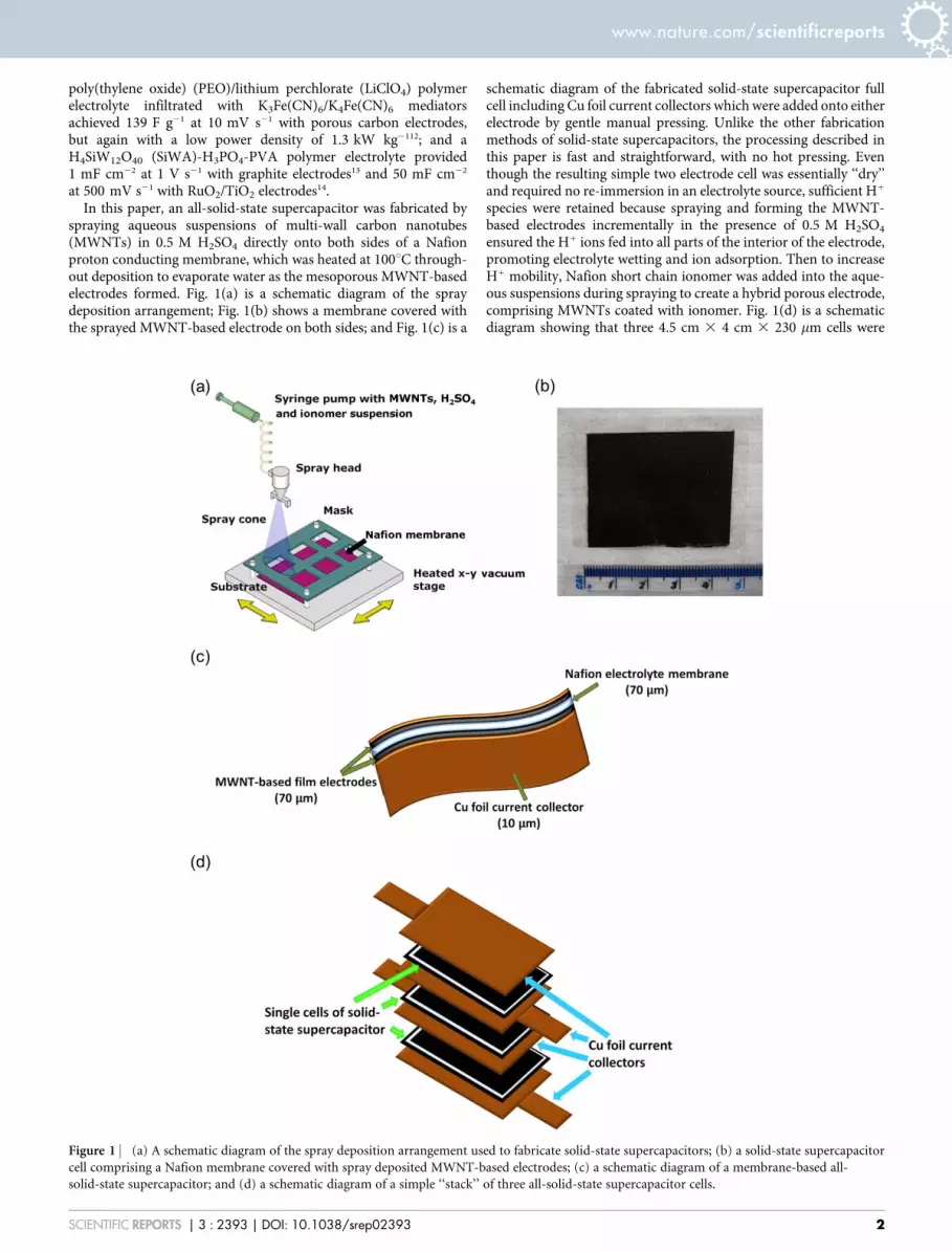
spraying aqueous suspensions of multi-wall carbon nanotubes(MWNTs) in 0.5 M H2SO4 directly onto both sides of a Nafionproton conducting membrane, which was heated at 100uC through-out deposition to evaporate water as the mesoporous MWNT-basedelectrodes formed. Fig. 1(a) is a schematic diagram of the spraydeposition arrangement; Fig. 1(b) shows a membrane covered withthe sprayed MWNT-based electrode on both sides; and Fig. 1(c) is a
schematic diagram of the fabricated solid-state supercapacitor fullcell including Cu foil current collectors which were added onto eitherelectrode by gentle manual pressing. Unlike the other fabricationmethods of solid-state supercapacitors, the processing described inthis paper is fast and straightforward, with no hot pressing. Eventhough the resulting simple two electrode cell was essentially ‘‘dry’’and required no re-immersion in an electrolyte source, sufficient H1
species were retained because spraying and forming the MWNT-based electrodes incrementally in the presence of 0.5 M H2SO4
ensured the H1 ions fed into all parts of the interior of the electrode,promoting electrolyte wetting and ion adsorption. Then to increaseH1 mobility, Nafion short chain ionomer was added into the aque-ous suspensions during spraying to create a hybrid porous electrode,comprising MWNTs coated with ionomer. Fig. 1(d) is a schematicdiagram showing that three 4.5 cm 3 4 cm 3 230 mm cells were
Figure 1 | (a) A schematic diagram of the spray deposition arrangement used to fabricate solid-state supercapacitors; (b) a solid-state supercapacitor
cell comprising a Nafion membrane covered with spray deposited MWNT-based electrodes; (c) a schematic diagram of a membrane-based all-
solid-state supercapacitor; and (d) a schematic diagram of a simple ‘‘stack’’ of three all-solid-state supercapacitor cells.
www.nature.com/scientificreports
SCIENTIFIC REPORTS | 3 : 2393 | DOI: 10.1038/srep02393 2
stacked and connected in series to operate at 3 V and 1 and 2 A g21
and produced a power density of 8.9 kW kg21 at 1 A g21 and 9.4 kWkg21 at 2 A g21.
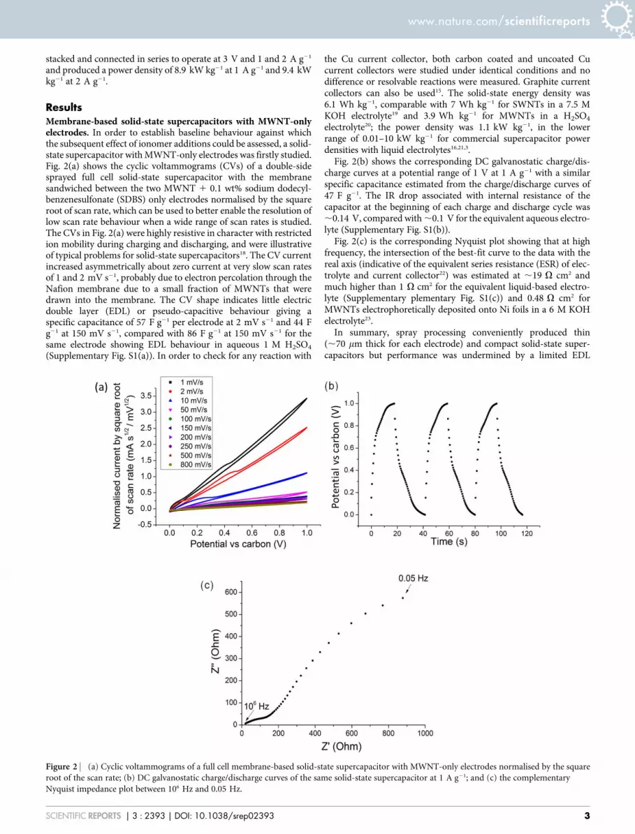
ResultsMembrane-based solid-state supercapacitors with MWNT-onlyelectrodes. In order to establish baseline behaviour against whichthe subsequent effect of ionomer additions could be assessed, a solid-state supercapacitor with MWNT-only electrodes was firstly studied.Fig. 2(a) shows the cyclic voltammograms (CVs) of a double-sidesprayed full cell solid-state supercapacitor with the membranesandwiched between the two MWNT 1 0.1 wt% sodium dodecyl-benzenesulfonate (SDBS) only electrodes normalised by the squareroot of scan rate, which can be used to better enable the resolution oflow scan rate behaviour when a wide range of scan rates is studied.The CVs in Fig. 2(a) were highly resistive in character with restrictedion mobility during charging and discharging, and were illustrativeof typical problems for solid-state supercapacitors18. The CV currentincreased asymmetrically about zero current at very slow scan ratesof 1 and 2 mV s21, probably due to electron percolation through theNafion membrane due to a small fraction of MWNTs that weredrawn into the membrane. The CV shape indicates little electricdouble layer (EDL) or pseudo-capacitive behaviour giving aspecific capacitance of 57 F g21 per electrode at 2 mV s21 and 44 Fg21 at 150 mV s21, compared with 86 F g21 at 150 mV s21 for thesame electrode showing EDL behaviour in aqueous 1 M H2SO4
(Supplementary Fig. S1(a)). In order to check for any reaction with
the Cu current collector, both carbon coated and uncoated Cucurrent collectors were studied under identical conditions and nodifference or resolvable reactions were measured. Graphite currentcollectors can also be used15. The solid-state energy density was6.1 Wh kg21, comparable with 7 Wh kg21 for SWNTs in a 7.5 MKOH electrolyte19 and 3.9 Wh kg21 for MWNTs in a H2SO4
electrolyte20; the power density was 1.1 kW kg21, in the lowerrange of 0.01–10 kW kg21 for commercial supercapacitor powerdensities with liquid electrolytes16,21,3.
Fig. 2(b) shows the corresponding DC galvanostatic charge/dis-charge curves at a potential range of 1 V at 1 A g21 with a similarspecific capacitance estimated from the charge/discharge curves of47 F g21. The IR drop associated with internal resistance of thecapacitor at the beginning of each charge and discharge cycle was,0.14 V, compared with ,0.1 V for the equivalent aqueous electro-lyte (Supplementary Fig. S1(b)).
Fig. 2(c) is the corresponding Nyquist plot showing that at highfrequency, the intersection of the best-fit curve to the data with thereal axis (indicative of the equivalent series resistance (ESR) of elec-trolyte and current collector22) was estimated at ,19 V cm2 andmuch higher than 1 V cm2 for the equivalent liquid-based electro-lyte (Supplementary plementary Fig. S1(c)) and 0.48 V cm2 forMWNTs electrophoretically deposited onto Ni foils in a 6 M KOHelectrolyte23.
In summary, spray processing conveniently produced thin(,70 mm thick for each electrode) and compact solid-state super-capacitors but performance was undermined by a limited EDL
Figure 2 | (a) Cyclic voltammograms of a full cell membrane-based solid-state supercapacitor with MWNT-only electrodes normalised by the square
root of the scan rate; (b) DC galvanostatic charge/discharge curves of the same solid-state supercapacitor at 1 A g21; and (c) the complementary
Nyquist impedance plot between 106 Hz and 0.05 Hz.
www.nature.com/scientificreports
SCIENTIFIC REPORTS | 3 : 2393 | DOI: 10.1038/srep02393 3
response because of a combination of high ESR and limited ionicmobility when compared with aqueous electrolyte equivalents.
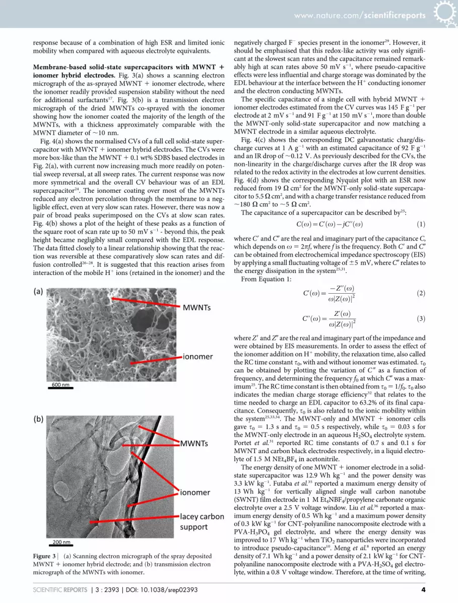
Membrane-based solid-state supercapacitors with MWNT 1ionomer hybrid electrodes. Fig. 3(a) shows a scanning electronmicrograph of the as-sprayed MWNT 1 ionomer electrode, wherethe ionomer readily provided suspension stability without the needfor additional surfactants17. Fig. 3(b) is a transmission electronmicrograph of the dried MWNTs co-sprayed with the ionomershowing how the ionomer coated the majority of the length of theMWNTs, with a thickness approximately comparable with theMWNT diameter of ,10 nm.
Fig. 4(a) shows the normalised CVs of a full cell solid-state super-capacitor with MWNT 1 ionomer hybrid electrodes. The CVs weremore box-like than the MWNT 1 0.1 wt% SDBS based electrodes inFig. 2(a), with current now increasing much more readily on poten-tial sweep reversal, at all sweep rates. The current response was nowmore symmetrical and the overall CV behaviour was of an EDLsupercapacitor24. The ionomer coating over most of the MWNTsreduced any electron percolation through the membrane to a neg-ligible effect, even at very slow scan rates. However, there was now apair of broad peaks superimposed on the CVs at slow scan rates.Fig. 4(b) shows a plot of the height of these peaks as a function ofthe square root of scan rate up to 50 mV s21 - beyond this, the peakheight became negligibly small compared with the EDL response.The data fitted closely to a linear relationship showing that the reac-tion was reversible at these comparatively slow scan rates and dif-fusion controlled26–28. It is suggested that this reaction arises frominteraction of the mobile H1 ions (retained in the ionomer) and the
negatively charged F2 species present in the ionomer29. However, itshould be emphasised that this redox-like activity was only signifi-cant at the slowest scan rates and the capacitance remained remark-ably high at scan rates above 50 mV s21, where pseudo-capacitiveeffects were less influential and charge storage was dominated by theEDL behaviour at the interface between the H1 conducting ionomerand the electron conducting MWNTs.
The specific capacitance of a single cell with hybrid MWNT 1
ionomer electrodes estimated from the CV curves was 145 F g21 perelectrode at 2 mV s21 and 91 F g21 at 150 mV s21, more than doublethe MWNT-only solid-state supercapacitor and now matching aMWNT electrode in a similar aqueous electrolyte.
Fig. 4(c) shows the corresponding DC galvanostatic charg/dis-charge curves at 1 A g21 with an estimated capacitance of 92 F g21
and an IR drop of ,0.12 V. As previously described for the CVs, thenon-linearity in the charge/discharge curves after the IR drop wasrelated to the redox activity in the electrodes at low current densities.Fig. 4(d) shows the corresponding Nyquist plot with an ESR nowreduced from 19 V cm2 for the MWNT-only solid-state supercapa-citor to 5.5V cm2, and with a charge transfer resistance reduced from,180 V cm2 to ,5 V cm2.
The capacitance of a supercapacitor can be described by25:
C vð Þ~C’ vð Þ{jC’’ vð Þ ð1Þ
where C9 and C0 are the real and imaginary part of the capacitance C,which depends on v 5 2pf, where f is the frequency. Both C9 and C0
can be obtained from electrochemical impedance spectroscopy (EIS)by applying a small fluctuating voltage of 65 mV, where C0 relates tothe energy dissipation in the system25,31.
From Equation 1:
C’ vð Þ~ {Z’’ vð Þv Z vð Þj j2
ð2Þ
C’’ vð Þ~ Z’ vð Þv Z vð Þj j2
ð3Þ
where Z9 and Z0 are the real and imaginary part of the impedance andwere obtained by EIS measurements. In order to assess the effect ofthe ionomer addition on H1 mobility, the relaxation time, also calledthe RC time constant t0, with and without ionomer was estimated. t0
can be obtained by plotting the variation of C 0 as a function offrequency, and determining the frequency f0 at which C0 was a max-imum25. The RC time constant is then obtained from t0 5 1/f0. t0 alsoindicates the median charge storage efficiency32 that relates to thetime needed to charge an EDL capacitor to 63.2% of its final capa-citance. Consequently, t0 is also related to the ionic mobility withinthe system25,33,34. The MWNT-only and MWNT 1 ionomer cellsgave t0 5 1.3 s and t0 5 0.5 s respectively, while t0 5 0.03 s forthe MWNT-only electrode in an aqueous H2SO4 electrolyte system.Portet et al.31 reported RC time constants of 0.7 s and 0.1 s forMWNT and carbon black electrodes respectively, in a liquid electro-lyte of 1.5 M NEt4BF4 in acetonitrile.
The energy density of one MWNT 1 ionomer electrode in a solid-state supercapacitor was 12.9 Wh kg21 and the power density was3.3 kW kg21. Futaba et al.35 reported a maximum energy density of13 Wh kg21 for vertically aligned single wall carbon nanotube(SWNT) film electrode in 1 M Et4NBF4/propylene carbonate organicelectrolyte over a 2.5 V voltage window. Liu et al.36 reported a max-imum energy density of 0.5 Wh kg21 and a maximum power densityof 0.3 kW kg21 for CNT-polyaniline nanocomposite electrode with aPVA-H3PO4 gel electrolyte, and where the energy density wasimproved to 17 Wh kg21 when TiO2 nanoparticles were incorporatedto introduce pseudo-capacitance10. Meng et al.8 reported an energydensity of 7.1 Wh kg21 and a power density of 2.1 kW kg21 for CNT-polyaniline nanocomposite electrode with a PVA-H2SO4 gel electro-lyte, within a 0.8 V voltage window. Therefore, at the time of writing,
Figure 3 | (a) Scanning electron micrograph of the spray deposited
MWNT 1 ionomer hybrid electrode; and (b) transmission electron
micrograph of the MWNTs with ionomer.
www.nature.com/scientificreports
SCIENTIFIC REPORTS | 3 : 2393 | DOI: 10.1038/srep02393 4

the energy and power densities achieved here are likely the highest forsolid-state supercapacitors that make use of EDL capacitance only,and competitive with liquid electrolyte-based equivalents. Table 1summarises the specific capacitances, energy and power densities ofthe MWNT-based electrode in both 1 M H2SO4 liquid electrolyteand in the full cell solid-state configuration, with all figures normal-ised to the performance of one electrode.
Aqueous electrolytes have limited voltage windows (typically,1 V) if electrolysis of the water component is to be avoided30,37.Room temperature ionic liquids (RTILs) are complex liquid salts thatare being intensively researched to provide a wider electrochemicalstability (voltage) window without the need for air sensitive organicsolvents38. However, solid-state supercapacitors also offer possibil-ities for a higher operating voltage window without resorting toorganic liquids or RTILs since no solvents are required. As the energyand power densities depend on the operating voltage squared25, evensmall increases in voltage are advantageous, providing increases inresistance are avoided. Fig. 5(a) shows DC galvanostatic charge/dis-charge curves for a solid-state hybrid electrode supercapacitorcharged to 2 V, with little change in charging and discharging shape
over time even at the higher voltage. Fig. 5(b) shows the energy andpower densities of a solid-state hybrid electrode supercapacitor,charged across voltage windows in the range of 2 to 2.7 V at 1 Ag21. For voltage windows larger than 3 V, additional broad peaks inthe CVs suggested polymer breakdown and current collector oxida-tion. In this case, total mass of both the electrode and the currentcollector were taken in account to reflect more realistic gravimetricenergy and power performance.
Solid-state supercapacitor devices made of cell stacks. Connectingsolid-state supercapacitors in series by stacking the cells togetherthrough current collectors allows a higher working voltage andincreases specific power and energy densities. In most previousstudies, the dimensions of the fabricated solid-state supercapacitorstacks were relatively small (e.g. 5 mm 3 5 mm in10), and scaling uptowards the device scale posed difficulties in fabricating homogenousnanostructured electrodes over comparatively large areas, preventingshort circuits over larger areas, etc. Here, the 4.5 cm 3 4 cm cellswere readily stacked at a scale consistent with a medium formatmobile device.
Figure 4 | (a) Cyclic voltammograms of a full cell membrane-based solid-state supercapacitor with MWNT 1 ionomer electrodes normalised by
the square root of the scan rate; (b) a plot of redox peak height from the CVs against square root of scan rate; (c) DC galvanostatic charge/discharge curves
of the same solid-state supercapacitor at 1 A g21; and (d) the complementary Nyquist impedance plot between 106 Hz and 0.05 Hz.
Table 1 | A summary of the performance of MWNT-based electrodes in 1 M H2SO4 and in a solid-state symmetrical membrane-based cellconfiguration. All values are calculated per electrode
Electrode Testing environment Capacitance (F g21) Energy density (Wh kg21) Power density (kW kg21)
MWNT 1 M H2SO4, half cell 86 12 3.4MWNT Solid-state configuration, full cell 44 6.1 1.1MWNT 1 ionomer hybrid Solid-state configuration, full cell 91 12.9 3.3
www.nature.com/scientificreports
SCIENTIFIC REPORTS | 3 : 2393 | DOI: 10.1038/srep02393 5
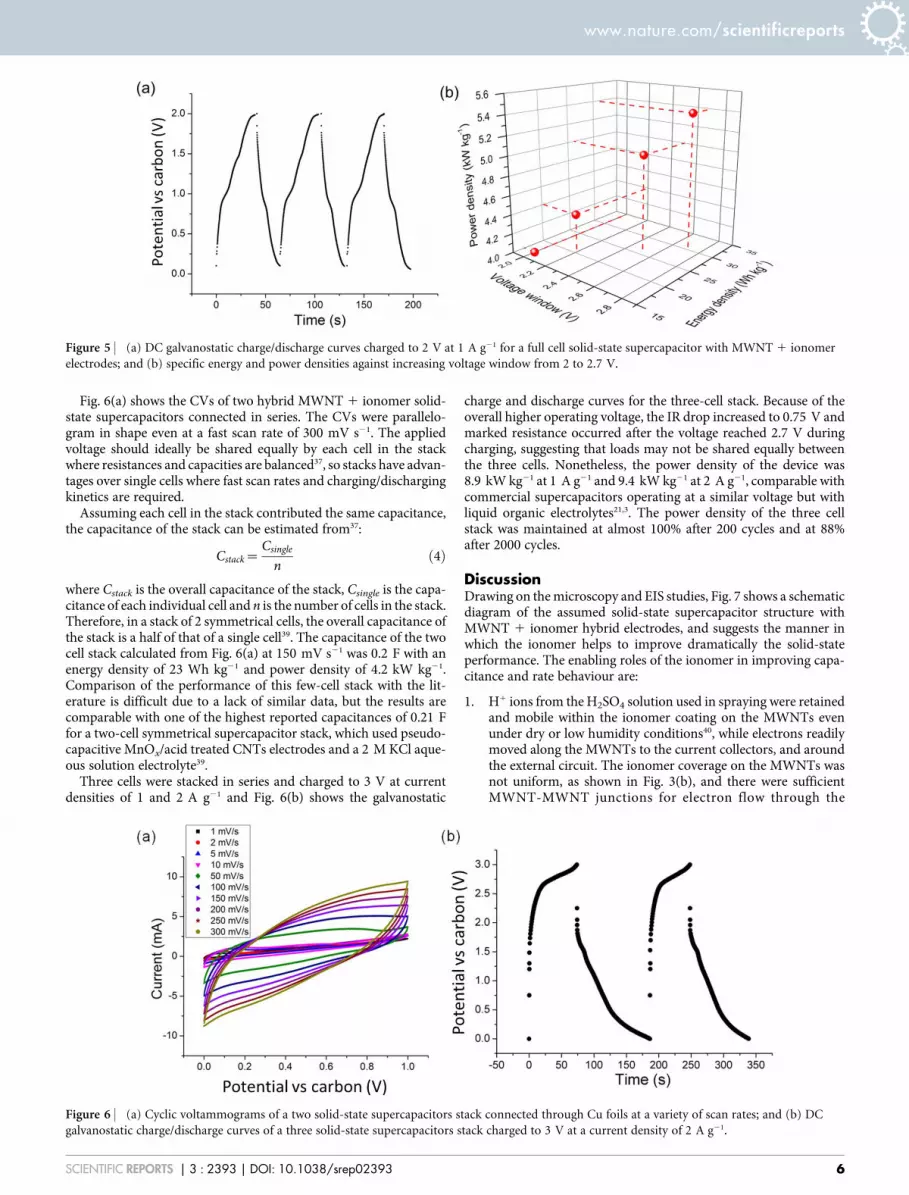
Fig. 6(a) shows the CVs of two hybrid MWNT 1 ionomer solid-state supercapacitors connected in series. The CVs were parallelo-gram in shape even at a fast scan rate of 300 mV s21. The appliedvoltage should ideally be shared equally by each cell in the stackwhere resistances and capacities are balanced37, so stacks have advan-tages over single cells where fast scan rates and charging/dischargingkinetics are required.
Assuming each cell in the stack contributed the same capacitance,the capacitance of the stack can be estimated from37:
Cstack~Csingle
nð4Þ
where Cstack is the overall capacitance of the stack, Csingle is the capa-citance of each individual cell and n is the number of cells in the stack.Therefore, in a stack of 2 symmetrical cells, the overall capacitance ofthe stack is a half of that of a single cell39. The capacitance of the twocell stack calculated from Fig. 6(a) at 150 mV s21 was 0.2 F with anenergy density of 23 Wh kg21 and power density of 4.2 kW kg21.Comparison of the performance of this few-cell stack with the lit-erature is difficult due to a lack of similar data, but the results arecomparable with one of the highest reported capacitances of 0.21 Ffor a two-cell symmetrical supercapacitor stack, which used pseudo-capacitive MnOx/acid treated CNTs electrodes and a 2 M KCl aque-ous solution electrolyte39.
Three cells were stacked in series and charged to 3 V at currentdensities of 1 and 2 A g21 and Fig. 6(b) shows the galvanostatic
charge and discharge curves for the three-cell stack. Because of theoverall higher operating voltage, the IR drop increased to 0.75 V andmarked resistance occurred after the voltage reached 2.7 V duringcharging, suggesting that loads may not be shared equally betweenthe three cells. Nonetheless, the power density of the device was8.9 kW kg21 at 1 A g21 and 9.4 kW kg21 at 2 A g21, comparable withcommercial supercapacitors operating at a similar voltage but withliquid organic electrolytes21,3. The power density of the three cellstack was maintained at almost 100% after 200 cycles and at 88%after 2000 cycles.
DiscussionDrawing on the microscopy and EIS studies, Fig. 7 shows a schematicdiagram of the assumed solid-state supercapacitor structure withMWNT 1 ionomer hybrid electrodes, and suggests the manner inwhich the ionomer helps to improve dramatically the solid-stateperformance. The enabling roles of the ionomer in improving capa-citance and rate behaviour are:
1. H1 ions from the H2SO4 solution used in spraying were retainedand mobile within the ionomer coating on the MWNTs evenunder dry or low humidity conditions40, while electrons readilymoved along the MWNTs to the current collectors, and aroundthe external circuit. The ionomer coverage on the MWNTs wasnot uniform, as shown in Fig. 3(b), and there were sufficientMWNT-MWNT junctions for electron flow through the
Figure 5 | (a) DC galvanostatic charge/discharge curves charged to 2 V at 1 A g21 for a full cell solid-state supercapacitor with MWNT 1 ionomer
electrodes; and (b) specific energy and power densities against increasing voltage window from 2 to 2.7 V.
Figure 6 | (a) Cyclic voltammograms of a two solid-state supercapacitors stack connected through Cu foils at a variety of scan rates; and (b) DC
galvanostatic charge/discharge curves of a three solid-state supercapacitors stack charged to 3 V at a current density of 2 A g21.
www.nature.com/scientificreports
SCIENTIFIC REPORTS | 3 : 2393 | DOI: 10.1038/srep02393 6
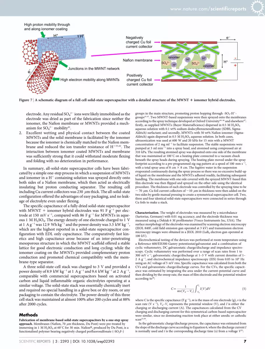
electrode. Any residual SO422 ions were likely immobilised as the
electrode was dried as part of the fabrication since neither theionomer, the Nafion membrane or MWNTs provided a mech-anism for SO4
22 mobility41.2. Excellent wetting and physical contact between the coated
MWNTs and the solid membrane is facilitated by the ionomerbecause the ionomer is chemically matched to the Nafion mem-brane and reduced the ion transfer resistance of H133,42. Theinteraction between ionomer coated MWNTs and membranewas sufficiently strong that it could withstand moderate flexingand folding with no deterioration in performance.
In summary, all-solid-state supercapacitor cells have been fabri-cated by a simple one-step process in which a suspension of MWNTsand ionomer in a H1 containing solution was sprayed directly ontoboth sides of a Nafion membrane, which then acted as electricallyinsulating but proton conducting separator. The resulting cellincluding Cu current collectors was 230 mm thick. The all-solid-stateconfiguration offered the advantages of easy packaging, and no leak-age of electrolyte even under flexing.
The specific capacitance of a fully dried solid-state supercapacitorwith MWNT 1 ionomer hybrid electrodes was 91 F g21 per elec-trode at 150 mV s21, compared with 86 F g21 for MWNTs in aque-ous 1 M H2SO4. The energy density of one electrode charged to 1 Vat 1 A g21 was 12.9 Wh kg21 and the power density was 3.3 kW kg21,which are the highest reported in a solid-state supercapacitor con-figuration with EDL only capacitance. The comparatively fast kin-etics and high capacitance arose because of an inter-penetratingmesoporous structure in which the MWNT scaffold offered a stablelattice for good electronic conduction and long cycling; while theionomer coating on the MWNTs provided complementary protonconduction and promoted chemical compatibility with the mem-brane-type separator.
A three solid-state-cell stack was charged to 3 V and provided apower density of 8.9 kW kg21 at 1 A g21 and 9.4 kW kg21 at 2 A g21,comparable with commercial supercapacitors based on activatedcarbon and liquid inflammable organic electrolytes operating at asimilar voltage. The solid-state stack was essentially chemically inertand required no special handling in a glove box or dry room, or anypackaging to contain the electrolyte. The power density of this threecell stack was maintained at almost 100% after 200 cycles and at 88%after 2000 cycles.
MethodsFabrication of membrane-based solid-state supercapacitors by a one-step sprayapproach. Membranes (Nafion, 70 mm thickness, Du Pont) were pre-treated byimmersing in 1 M H2SO4 at 60uC for 30 min. NafionH, produced by Du Pont, is afunctionalised polymer bearing negatively charged perfluorosulfonate (-SO2F-)
groups in the main structure, promoting proton hopping through -SO3-H1-groups41,43. Two MWNT-based suspensions were then sprayed onto the membranesaccording to the spray technique developed at Oxford University44–46 and elsewhere47:firstly, as supplied MWNTs (Bayer MaterialScience) dispersed in 0.5 M H2SO4
aqueous solution with 0.1 wt% sodium dodecylbenzenesulfonate (SDBS, Sigma-Aldrich) surfactant; and secondly, MWNTs with 50 wt% Nafion ionomer (Sigma-Aldrich) again dispersed in 0.5 M H2SO4 aqueous solution. In both cases,ultrasonication was used at 600 W and 20 kHz for 15 min with a MWNTconcentration of 2 mg ml21 to facilitate suspension. The stable suspensions werepumped at 3 ml min21 into a spray head, and atomised using compressed air at310 kPa. The resulting atomised spray was deposited onto one side of the membranethat was maintained at 100uC on a heating plate connected to a vacuum chuckbeneath the spray heads during spraying. The heating plate moved under the sprayfootprint according to a pre-programmed zig-zag pattern at a speed of 100 mm s21,with a total spray area of 8 cm 3 8 cm. The fugitive water in the suspensionevaporated continuously during the spray process so there was no excessive build-upof liquid on the membrane and the MWNTs adhered readily, facilitating subsequenthandling. The membrane with one side covered with the sprayed MWNT-based thinfilm electrode was then flipped and sprayed on the other side using the identicalprocedure. The thickness of each electrode was controlled by the spraying time to be, 70 mm. Cu foil current collectors of ,10 mm in thickness were then added on thetwo sides by gentle manual pressing to create a symmetrical supercapacitor cell. Two,three and four identical solid-state supercapacitors were connected in series throughCu foils to make a stack.
Characterisation. The weight of electrodes was measured by a microbalance(Sartorius, Germany) with 0.01 mg accuracy, and the electrode thickness wasmeasured using a Dektak 6 M profilometer (Veeco Instruments Inc, USA). Thesurface morphology of the electrodes was examined by scanning electron microscopy(JEOL 840F, cold field emission gun operated at 3 kV) and transmission electronmicroscopy images were obtained in a JEOL 2010 (LaB6 electron gun operated at100 kV).
Electrochemical testing of the devices was performed at room temperature usinga Reference 600/EIS300 Gamry potentiostat/galvanostat and a combination ofcyclic voltammetry, DC galvanostatic charge/discharge and impedance spectro-scopy. Cyclic voltammetry was performed over a range of scan rates from 1 to300 mV s21, galvanostatic charge/discharge at 1–3 V with current densities of 1–2 A g21, and electrochemical impedance spectroscopy (EIS) from 0.05 to 106 Hzusing an AC voltage of 5 mV rms. Specific capacitance was calculated from both theCVs and galvanostatic charge/discharge curves. For the CVs, the specific capacit-ance was estimated by integrating the area under the current-potential curve andthen dividing by the sweep rate, the mass of film electrode and the potential windowaccording to48:
C~1
mv Va{Vcð Þ
ðVc
Va
I Vð ÞdV ð5Þ
where C is the specific capacitance (F g21), m is the mass of one electrode (g), v is thescan rate (V s21), Va–Vc represents the potential window (V), and I is either thecharging or discharging current (A). The capacitances calculated from the CVcharging and discharging current for this symmetrical carbon-based supercapacitorwere similar, since no dominating reaction took place at either anodic or cathodicscan25,49.
In the galvanostatic charge/discharge process, the capacitance was estimated fromthe slope of the discharge curve according to Equation 6, where the discharge current Iis normally used and t is the corresponding discharge time (s) from a voltage V25:
Figure 7 | A schematic diagram of a full cell solid-state supercapacitor with a detailed structure of the MWNT 1 ionomer hybrid electrodes.
www.nature.com/scientificreports
SCIENTIFIC REPORTS | 3 : 2393 | DOI: 10.1038/srep02393 7
C~I
mdVdt
ð6Þ
The maximum energy E and power density P can be expressed as25:
E~12
CV2
mð7Þ
P~V2
4Rsmð8Þ
where Rs is the equivalent internal resistance50.In order to compare the performance of the solid-state supercapacitors and the
equivalent electrode performance in a conventional liquid 1 M H2SO4 electrolyte,electrochemical characterisation of a single sprayed electrode was also conductedusing a three-electrode configuration for the MWNT-based film on a stainless steelsubstrate (2 cm 3 1 cm) as the working electrode, and with Ag/AgCl and Pt wire asthe reference and counter electrodes respectively.
1. Kim, T. H. et al. Full-colour quantum dot displays fabricated by transfer printing.Nat. Photonics. 5, 176–182 (2011).
2. Bae, J. et al. Single fiber based hybridization of energy converters and storage unitsusing graphene as electrodes. Adv. Mater. 23, 3446–3449 (2011).
3. Conway, B. E. Electrochemical Supercapacitors, Scientific Fundamentals andTechnological Applications. Kluwer Academic Plenum Publishers (1999).
4. Nam, K. T. et al. Virus-enabled synthesis and assembly of nanowires for lithiumion battery electrodes. Science. 312, 885–888 (2006).
5. Naoi, K., Naoi, W., Aoyagi, S., Miyamoto, J. & Takeo, K. New generation‘‘nanohybrid supercapacitor’’ Acc. Chem. Res. 46, 1075–1083 (2013).
6. Hu, L. et al. Stretchable, porous, and conductive energy textiles. Nano. Lett. 10,708–714 (2010).
7. Naoi, K. & Morita, M. Advanced polymers as active materials and electrolytes forelectrochemical capacitors and hybrid capacitor systmes. Electrochem. Soc.Interface. 44–48 (2008).
8. Meng, C. Z., Liu, C. H., Chen, L. Z., Hu, C. H. & Fan, S. S. Highly flexible and all-solid-state paperlike polymer supercapacitors. Nano. Lett. 10, 4025–4031 (2010).
9. Hu, S., Rajamani, R. & Yu, X. Flexible solid-state paper based carbon nanotubesupercapacitor. Appl. Phys. Lett. 100, 104103 (2012).
10. Liu, Q., Nayfeh, O., Nayfeh, M. H. & Yau, S. T. Flexible supercapacitor sheetsbased on hybrid nanocomposite materials. Nano Energy 2, 133–137 (2012).
11. Grancisco, B. E., Jones, C. M., Lee, S. & Stoldt, C. R. Nanostructured all-solid-statesupercapacitor based on Li2S-P2S5 glass-ceramic electrolyte. Appl. Phys. Lett.100, 103902-1–4 (2012).
12. Zhou, J., Cai, J., Cai, S., Zhou, X. & Mansour, A. N. Development of all-solid-statemediator-enhanced supercapacitors with polyvinylidene fluoride/lithium tri-fluoromethanesulfonate separators. J. Power Sources 196, 10479–10483 (2011).
13. Gao, H. & Lian, K. High rate all-solid electrochemical capacitors using protonconducting polymer electrolytes. J. Power Sources 196, 8855–8857 (2011).
14. Gao, H. & Lian, K. Characterizations of proton conducting polymer electrolytesfor electrochemical capacitors. Electrochimica Acta. 56, 122–127 (2010).
15. Porada, S. et al. Water desalination using capacitive deionization withmicroporous carbon electrodes. Appl. Mater. Interfaces 4, 1194–1199 (2012).
16. Simon, P. & Gogotsi, Y. Materials for electrochemical capacitors. Nat. Mater. 7,845–854 (2008).
17. Zhang, J. et al. Dispersion of single-walled carbon nanotubes by Nafion in water/ethanol for preparing transparent conducting films. J. Phys. Chem. C 112,16370–16376 (2008).
18. Frackowiak, E., Jurewicz, K., Delpeux, S. & Beguin, F. Nanotubular materials forsupercapacitors. J. Power Sources 97–8, 822–825 (2001).
19. Obreja, V. V. N. On the performance of supercapacitors with electrodes based oncarbon nanotubes and carbon activated material - A review. Physica E. 40,2596–2605 (2008).
20. Signorelli, R., Ku, D. C., Kassakian, J. G. & Schindall, J. E. Electrochemical double-layer capacitors using carbon nanotube electrode structures. Proc. IEEE. 97,1837–1847 (2009).
21. An, K. H. et al. Electrochemical properties of high-power supercapacitors usingsingle-walled carbon nanotube electrodes. Adv. Funct. Mater. 11, 387–392 (2001).
22. Wang, Y. et al. Supercapacitor devices based on graphene materials. J. Phys. Chem.C 113, 13103–13107 (2009).
23. Du, C. & Ning, P. High power density supercapacitor electrodes of carbonnanotube films by electrophoretic deposition. Nanotechnology 17, 5314–5318(2006).
24. Hughes, M., Chen, G. Z., Shaffer, M. S. P., Fray, D. J. & Windle, A. H.Electrochemical capacitance of a nanoporous composite of carbon nanotubes andpolypyrrole. Chem. Mater. 14, 1610–1613 (2002).
25. Taberna, P. L., Simon, P. & Fauvarque, J. F. Electrochemical characteristics andimpedance spectroscopy studies of carbon-carbon supercapacitors. J.Electrochem. Soc. 150, 292–300 (2003).
26. Kemp, T. J. Instrumental Methods In Electrochemistry SouthamptonElectrochemistry Group. John Wiley & Sons (1985).
27. Beguin, F. & Frackowiak, E. Carbons For Electrochemical Energy Storage AndConversion Systems. CRC Press (2010).
28. Pell, W. G. & Conway, B. E. Analysis of power limitations at porous supercapacitorelectrodes under cyclic voltammetry modulation and dc charge. J. Power Sources96, 57–67 (2001).
29. Kerres, J. A. Development of ionomer membranes for fuel cells. J. Membrane. Sci.185, 3–27 (2001).
30. Niu, C., Sichel, E. K., Hoch, R., Moy, D. & Tennent, H. High powerelectrochemical capacitors based on carbon nanotube electrodes. Appl. Phys. Lett.70, 1480–1482 (1997).
31. Portet, C., Yushin, G. & Gogotsi, Y. Electrochemical performance of carbononions, nanodiamonds, carbon black and multiwalled nanotubes in electricaldouble layer capacitors. Carbon. 45, 2511–2518 (2007).
32. Beguin, F. & Frackowiak, E. Supercapacitors, Materials, Systems and Applications.Wiley-VCH (2013).
33. Choi, B. G., Hong, J., Hong, W. H., Hammond, P. T. & Park, H. S. Facilitated iontransport in all-solid-state flexible supercapacitors. ACS Nano. 5, 7205–7213(2011).
34. Cole, K. S. & Cole, R. H. Dispersion and absorption in dielectrics I. alternatingcurrent characteristics. J. Chem. Phys. 9, 341–351 (1941).
35. Futaba, D. N. et al. Shape-engineerable and highly densely packed single-walledcarbon nanotubes and their application as super-capacitor electrodes. Nat. Mater.5, 987–994 (2006).
36. Liu, Q., Nayfeh, M. H. & Yau, S. T. Brushed-on flexible supercapacitor sheets usinga nanocomposite of polyaniline and carbon nanotubes. J. Power Sources 195,7480–7483 (2010).
37. Zhou, X., Peng, C. & Chen, G. Z. 20 V stack of aqueous supercapacitors withcarbon (2), titanium bipolar plates and CNT-polypyrrole composite (1). AIChEJ. 58, 974–983 (2012).
38. Wei, D. & Ng, T. W. Application of novel room temperature ionic liquids inflexible supercapacitors. Electrochem. Commun. 11, 1996–1999 (2009).
39. Zhang, S., Peng, C., Ng, K. C. & Chen, G. Z. Nanocomposites of manganese oxidesand carbon nanotubes for aqueous supercapacitor stacks. Electrochimica Acta 55,7447–7453 (2010).
40. Ahn, S. Y., Lee, Y. C., Ha, H. Y., Hong, S. A. & On, I. H. Effect of the ionomers inthe electrode on the performance of PEMFC under non-humidifying conditions.Electrochimica Acta. 50, 673–676 (2004).
41. Doyle, M., Lewittes, M. E., Roelofs, M. G., Perusich, S. A. & Lowrey, R. E.Relationship between ionic conductivity of perfluorinated ionomeric membranesand nonaqueous solvent properties. J. Membrane. Sci. 184, 257–273 (2001).
42. Lufrano, F. & Staiti, P. Conductivity and capacitance properties of asupercapacitor based on Nafion electrolyte in a nonaqueous system. Electrochem.Solid. St. 7, 447–450 (2004).
43. Kreuer, K. D. Proton conductivity: materials and applications. Chem. Mater. 8,610–641 (1996).
44. Zhao, X. et al. Spray deposition of steam treated and functionalized single-walledand multi-walled carbon nanotube films for supercapacitors. Nanotechnology 20,065605 (2009).
45. Mendoza-Sanchez, B., Rasche, B., Nicolosi, V. & Grant, P. S. Scaleable ultra-thinand high power density graphene electrochemical capacitor electrodesmanufactured by aqueous exfoliation and spray deposition. Carbon 52, 337–346(2012).
46. Huang, C. et al. Layer-by-layer spray deposition and unzipping of single-wallcarbon nanotube-based thin film electrodes for electrochemical capacitors.Carbon 61, 525–536 (2013).
47. Singh, N. et al. Paintable Battery. Sci. Rep. 2, 481; doi:10.1038/srep00481(2012).48. Srinivasan, V. & Weidner, J. W. Capacitance studies of cobalt oxide films formed
via electrochemical precipitation. J. Power Sources 108, 15–20 (2002).49. Jones, T. W., Lewandowski, A. P. & Donne, S. W. Discharge performance of a
primary alkaline CuO cathode material prepared via a novel non-aqueousprecipitation method. Electrochimica Acta 56, 4996–5002 (2011).
50. Stoller, M. D. & Ruoff, R. S. Best practice methods for determining an electrodematerial’s performance for ultracapacitors. Energy Environ Sci. 3, 1294–1301(2010).
AcknowledgmentsThe authors would like to thank Prof John Sykes, Dr Colin Johnston and Dr Chaopeng Fufor their advice. This work was supported by the Korea Institute of Energy TechnologyEvaluation and Planning (KETEP) (20128510010080).
Author contributionsC.H. performed the experiments, analysed data and co-wrote the manuscript. P.S.G.directed the study, read and guided the data analysis, co-wrote and edited the paper.
Additional informationSupplementary information accompanies this paper at http://www.nature.com/scientificreports
Competing financial interests: The authors declare no competing financial interests.
www.nature.com/scientificreports
SCIENTIFIC REPORTS | 3 : 2393 | DOI: 10.1038/srep02393 8

How to cite this article: Huang, C. & Grant, P.S. One-step spray processing of high powerall-solid-state supercapacitors. Sci. Rep. 3, 2393; DOI:10.1038/srep02393 (2013).
This work is licensed under a Creative Commons Attribution-NonCommercial-NoDerivs 3.0 Unported license. To view a copy of this license,
visit http://creativecommons.org/licenses/by-nc-nd/3.0
www.nature.com/scientificreports
SCIENTIFIC REPORTS | 3 : 2393 | DOI: 10.1038/srep02393 9