omni cresco
TRANSCRIPT
Omni Cresco
INDEX 1 OPERATORS ................................................................................................................... 5 2 CONTROL PANEL ........................................................................................................... 6 3 DISPLAY ........................................................................................................................ 11 4 GENERAL PARAMETERS ............................................................................................ 12 5 PARAMETERS DESCRIPTIONS ................................................................................... 13 6 TURNING ON ................................................................................................................. 18 7 LOADING AND UNLOADING ........................................................................................ 19 8 PAUSE ........................................................................................................................... 19 9 RESET ............................................................................................................................ 20 10 RESTARTING AFTER AN EMERGENCY STOP ......................................................... 20 11 SETTING THE PARAMETER VALUE CYCLE ............................................................ 21 12 OPERATING IN AUTOMATIC MODE – STANDARD WRAPPING CYCLES .............. 21 13 CUSTOMIZED CYCLE ................................................................................................. 24 14 CREATION OF A CUSTOMIZED CYCLE .................................................................... 24 15 USE OF A CUSTOMIZED CYCLE ............................................................................... 25 16 MANUAL MODE........................................................................................................... 25 17 “PLAY BACK” CYCLE ................................................................................................ 25 18 CREATION OF A “PLAY BACK” CYCLE ................................................................... 26 19 USING A “PLAY BACK” CYCLE ................................................................................ 28 20 FORMATTING SAVED DATA ...................................................................................... 29 21 LOCKING AND UNLOCKING THE BUTTONS ........................................................... 30 22 ALARMS ...................................................................................................................... 30 23 DIAGNOSTIC ............................................................................................................... 32 24 STANDARD FILM ROLL CARRIAGE .......................................................................... 33 25 POWER PRE-STRETCH CARRIAGE .......................................................................... 36
With a view to continuous improvement of this machine’s functions, some of its components and/or characteristics could be modified without notice and without prejudice to the validity of this document. If differences are found between the contents of this manual and the actual machine operation, please communicate them to the builder.
CRESCO UCP REV10 3
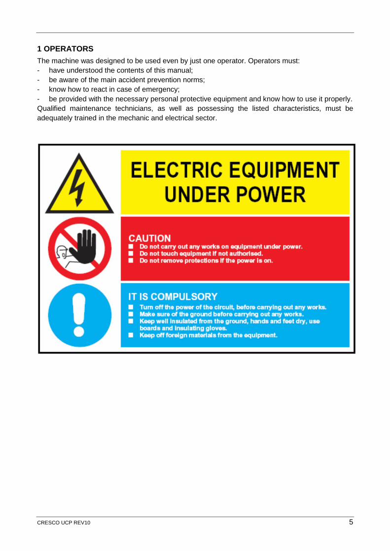
1 OPERATORS The machine was designed to be used even by just one operator. Operators must: - have understood the contents of this manual;- be aware of the main accident prevention norms;- know how to react in case of emergency;- be provided with the necessary personal protective equipment and know how to use it properly.Qualified maintenance technicians, as well as possessing the listed characteristics, must beadequately trained in the mechanic and electrical sector.
CRESCO UCP REV10 5
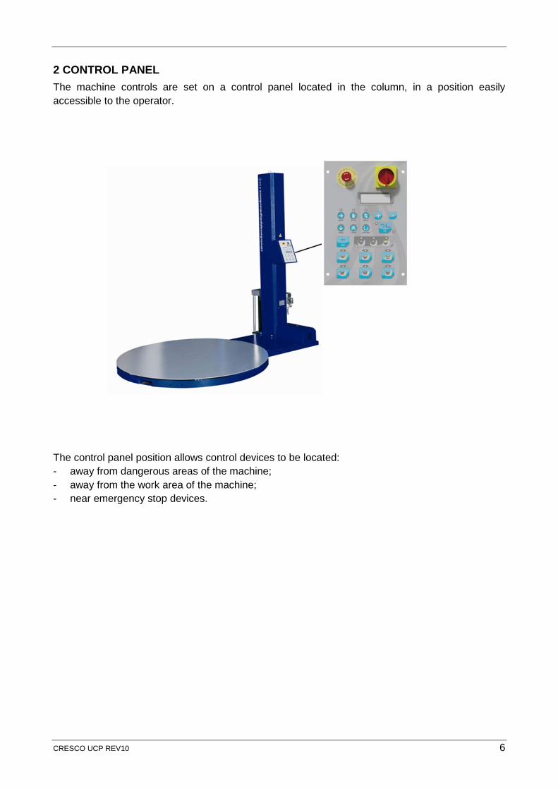
2 CONTROL PANEL The machine controls are set on a control panel located in the column, in a position easily accessible to the operator.
The control panel position allows control devices to be located: - away from dangerous areas of the machine;- away from the work area of the machine;- near emergency stop devices.
CRESCO UCP REV10 6
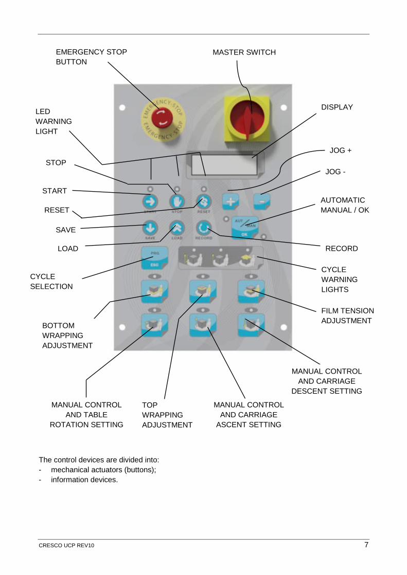
The control devices are divided into: - mechanical actuators (buttons);- information devices.
DISPLAY LED WARNING LIGHT
JOG +
JOG -
AUTOMATIC MANUAL / OK RESET
START
STOP
CYCLE SELECTION
CYCLE WARNING LIGHTS
BOTTOM WRAPPING ADJUSTMENT
FILM TENSION ADJUSTMENT
MANUAL CONTROL AND TABLE
ROTATION SETTING
TOP WRAPPING ADJUSTMENT
MANUAL CONTROL AND CARRIAGE
ASCENT SETTING
MANUAL CONTROL AND CARRIAGE
DESCENT SETTING
SAVE
LOAD RECORD
EMERGENCY STOP BUTTON
MASTER SWITCH
CRESCO UCP REV10 7
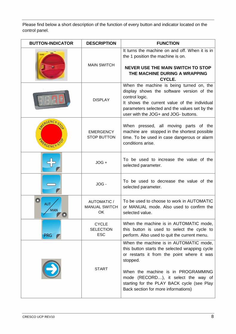
Please find below a short description of the function of every button and indicator located on the control panel.
BUTTON-INDICATOR DESCRIPTION FUNCTION
MAIN SWITCH
It turns the machine on and off. When it is in the 1 position the machine is on.
NEVER USE THE MAIN SWITCH TO STOP THE MACHINE DURING A WRAPPING
CYCLE.
DISPLAY
When the machine is being turned on, the display shows the software version of the control logic. It shows the current value of the individual parameters selected and the values set by the user with the JOG+ and JOG- buttons.
EMERGENCY STOP BUTTON
When pressed, all moving parts of the machine are stopped in the shortest possible time. To be used in case dangerous or alarm conditions arise.
JOG + To be used to increase the value of the selected parameter.
JOG - To be used to decrease the value of the selected parameter.
AUTOMATIC / MANUAL SWITCH
OK
To be used to choose to work in AUTOMATIC or MANUAL mode. Also used to confirm the selected value.
CYCLE SELECTION
ESC
When the machine is in AUTOMATIC mode, this button is used to select the cycle to perform. Also used to quit the current menu.
START
When the machine is in AUTOMATIC mode, this button starts the selected wrapping cycle or restarts it from the point where it was stopped.
When the machine is in PROGRAMMING mode (RECORD…), it select the way of starting for the PLAY BACK cycle (see Play Back section for more informations)
CRESCO UCP REV10 8
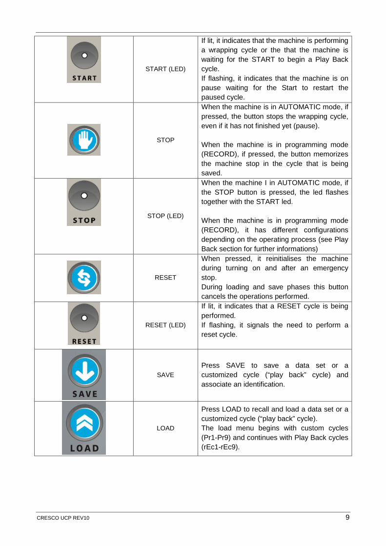
START (LED)
If lit, it indicates that the machine is performing a wrapping cycle or the that the machine is waiting for the START to begin a Play Back cycle. If flashing, it indicates that the machine is on pause waiting for the Start to restart the paused cycle.
STOP
When the machine is in AUTOMATIC mode, if pressed, the button stops the wrapping cycle, even if it has not finished yet (pause).
When the machine is in programming mode (RECORD), if pressed, the button memorizes the machine stop in the cycle that is being saved.
STOP (LED)
When the machine I in AUTOMATIC mode, if the STOP button is pressed, the led flashes together with the START led.
When the machine is in programming mode (RECORD), it has different configurations depending on the operating process (see Play Back section for further informations)
RESET
When pressed, it reinitialises the machine during turning on and after an emergency stop. During loading and save phases this button cancels the operations performed.
RESET (LED)
If lit, it indicates that a RESET cycle is being performed. If flashing, it signals the need to perform a reset cycle.
SAVE Press SAVE to save a data set or a customized cycle (“play back” cycle) and associate an identification.
LOAD
Press LOAD to recall and load a data set or a customized cycle (“play back” cycle). The load menu begins with custom cycles (Pr1-Pr9) and continues with Play Back cycles (rEc1-rEc9).
CRESCO UCP REV10 9
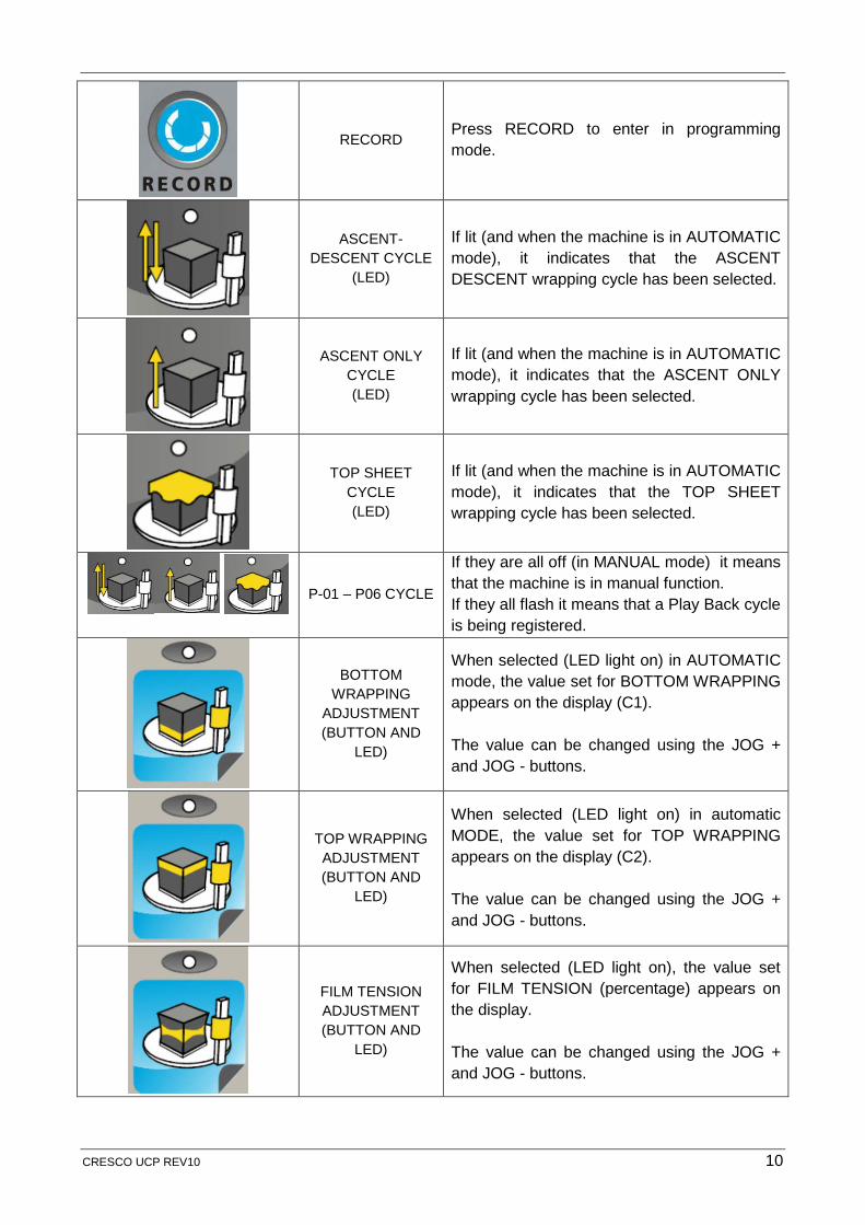
RECORD Press RECORD to enter in programming mode.
ASCENT-DESCENT CYCLE
(LED)
If lit (and when the machine is in AUTOMATIC mode), it indicates that the ASCENT DESCENT wrapping cycle has been selected.
ASCENT ONLY CYCLE (LED)
If lit (and when the machine is in AUTOMATIC mode), it indicates that the ASCENT ONLY wrapping cycle has been selected.
TOP SHEET CYCLE (LED)
If lit (and when the machine is in AUTOMATIC mode), it indicates that the TOP SHEET wrapping cycle has been selected.
P-01 – P06 CYCLE
If they are all off (in MANUAL mode) it means that the machine is in manual function. If they all flash it means that a Play Back cycle is being registered.
BOTTOM WRAPPING
ADJUSTMENT (BUTTON AND
LED)
When selected (LED light on) in AUTOMATIC mode, the value set for BOTTOM WRAPPING appears on the display (C1).
The value can be changed using the JOG + and JOG - buttons.
TOP WRAPPING ADJUSTMENT (BUTTON AND
LED)
When selected (LED light on) in automatic MODE, the value set for TOP WRAPPING appears on the display (C2).
The value can be changed using the JOG + and JOG - buttons.
FILM TENSION ADJUSTMENT (BUTTON AND
LED)
When selected (LED light on), the value set for FILM TENSION (percentage) appears on the display.
The value can be changed using the JOG + and JOG - buttons.
CRESCO UCP REV10 10
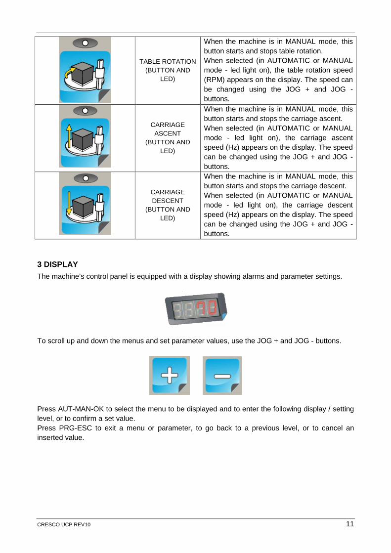
TABLE ROTATION (BUTTON AND
LED)
When the machine is in MANUAL mode, this button starts and stops table rotation. When selected (in AUTOMATIC or MANUAL mode - led light on), the table rotation speed (RPM) appears on the display. The speed can be changed using the JOG + and JOG - buttons.
CARRIAGE ASCENT
(BUTTON AND LED)
When the machine is in MANUAL mode, this button starts and stops the carriage ascent. When selected (in AUTOMATIC or MANUAL mode - led light on), the carriage ascent speed (Hz) appears on the display. The speed can be changed using the JOG + and JOG - buttons.
CARRIAGE DESCENT
(BUTTON AND LED)
When the machine is in MANUAL mode, this button starts and stops the carriage descent. When selected (in AUTOMATIC or MANUAL mode - led light on), the carriage descent speed (Hz) appears on the display. The speed can be changed using the JOG + and JOG - buttons.
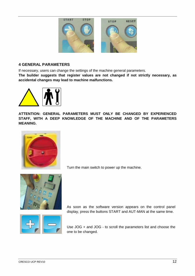
3 DISPLAY The machine’s control panel is equipped with a display showing alarms and parameter settings.
To scroll up and down the menus and set parameter values, use the JOG + and JOG - buttons.
Press AUT-MAN-OK to select the menu to be displayed and to enter the following display / setting level, or to confirm a set value. Press PRG-ESC to exit a menu or parameter, to go back to a previous level, or to cancel an inserted value.
CRESCO UCP REV10 11
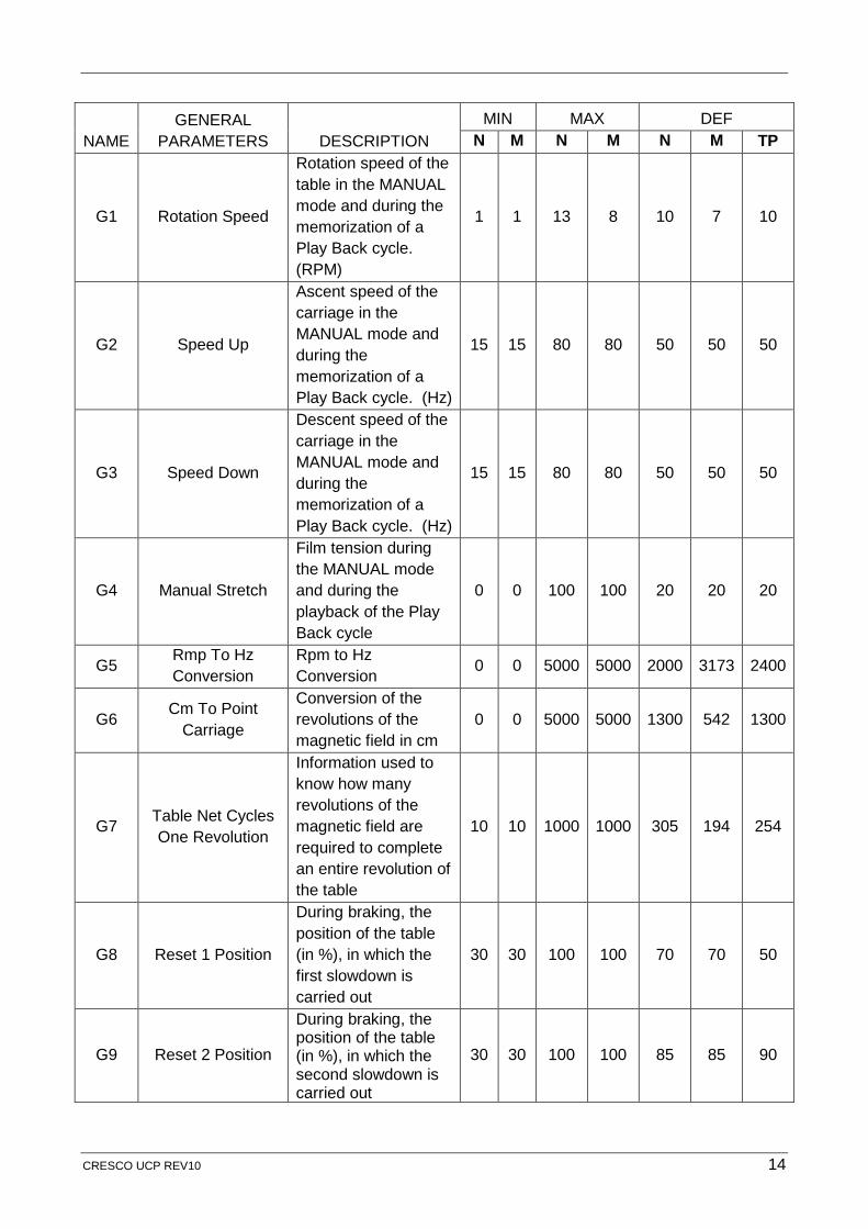
4 GENERAL PARAMETERS If necessary, users can change the settings of the machine general parameters. The builder suggests that register values are not changed if not strictly necessary, as accidental changes may lead to machine malfunctions.
ATTENTION: GENERAL PARAMETERS MUST ONLY BE CHANGED BY EXPERIENCED STAFF, WITH A DEEP KNOWLEDGE OF THE MACHINE AND OF THE PARAMETERS MEANING.
Turn the main switch to power up the machine.
As soon as the software version appears on the control panel display, press the buttons START and AUT-MAN at the same time.
Use JOG + and JOG - to scroll the parameters list and choose the one to be changed.
CRESCO UCP REV10 12

Press AUT-MAN to access the parameter.
Use JOG + and JOG - to set the parameter value.
Press AUT-MAN to save the new set value.
5 PARAMETERS DESCRIPTIONS N = Standard M = Motus TP = Cresco TP
NAME CYCLE PARAMETERS DESCRIPTION MIN MAX DEF
N M N M N M C1
Low Revolutions
Number of revolutions of the table, when the wrapping machine is wrapping the lower part of the object, requiring packing (listed).
0 0 10 10 1 1
C2
High Revolutions
Number of revolutions of the table, when the wrapping machine is wrapping the upper part of the object, requiring packing, after completion of the “Overflow Delay”. (listed)
0 0 10 10 1 1
C3 Stretch Film tension during the playback of a cycle 0 0 100 100 50 50
C4 Rpm Rotation Standard table rotation speed. (RPM) 1 1 13 8 11 7
C5 Ascent Speed Carriage speed in the ascent stage (Hz) 15 15 80 80 65 50
C6 Descent Speed Carriage speed in the descent stage (Hz) 15 15 80 80 65 50
CRESCO UCP REV10 13
NAME GENERAL
PARAMETERS DESCRIPTION MIN MAX DEF
N M N M N M TP
G1 Rotation Speed
Rotation speed of the table in the MANUAL mode and during the memorization of a Play Back cycle. (RPM)
1 1 13 8 10 7 10
G2 Speed Up
Ascent speed of the carriage in the MANUAL mode and during the memorization of a Play Back cycle. (Hz)
15 15 80 80 50 50 50
G3 Speed Down
Descent speed of the carriage in the MANUAL mode and during the memorization of a Play Back cycle. (Hz)
15 15 80 80 50 50 50
G4 Manual Stretch
Film tension during the MANUAL mode and during the playback of the Play Back cycle
0 0 100 100 20 20 20
G5 Rmp To Hz Conversion
Rpm to Hz Conversion 0 0 5000 5000 2000 3173 2400
G6 Cm To Point Carriage
Conversion of the revolutions of the magnetic field in cm
0 0 5000 5000 1300 542 1300
G7 Table Net Cycles One Revolution
Information used to know how many revolutions of the magnetic field are required to complete an entire revolution of the table
10 10 1000 1000 305 194 254
G8 Reset 1 Position
During braking, the position of the table (in %), in which the first slowdown is carried out
30 30 100 100 70 70 50
G9 Reset 2 Position
During braking, the position of the table (in %), in which the second slowdown is carried out
30 30 100 100 85 85 90
CRESCO UCP REV10 14
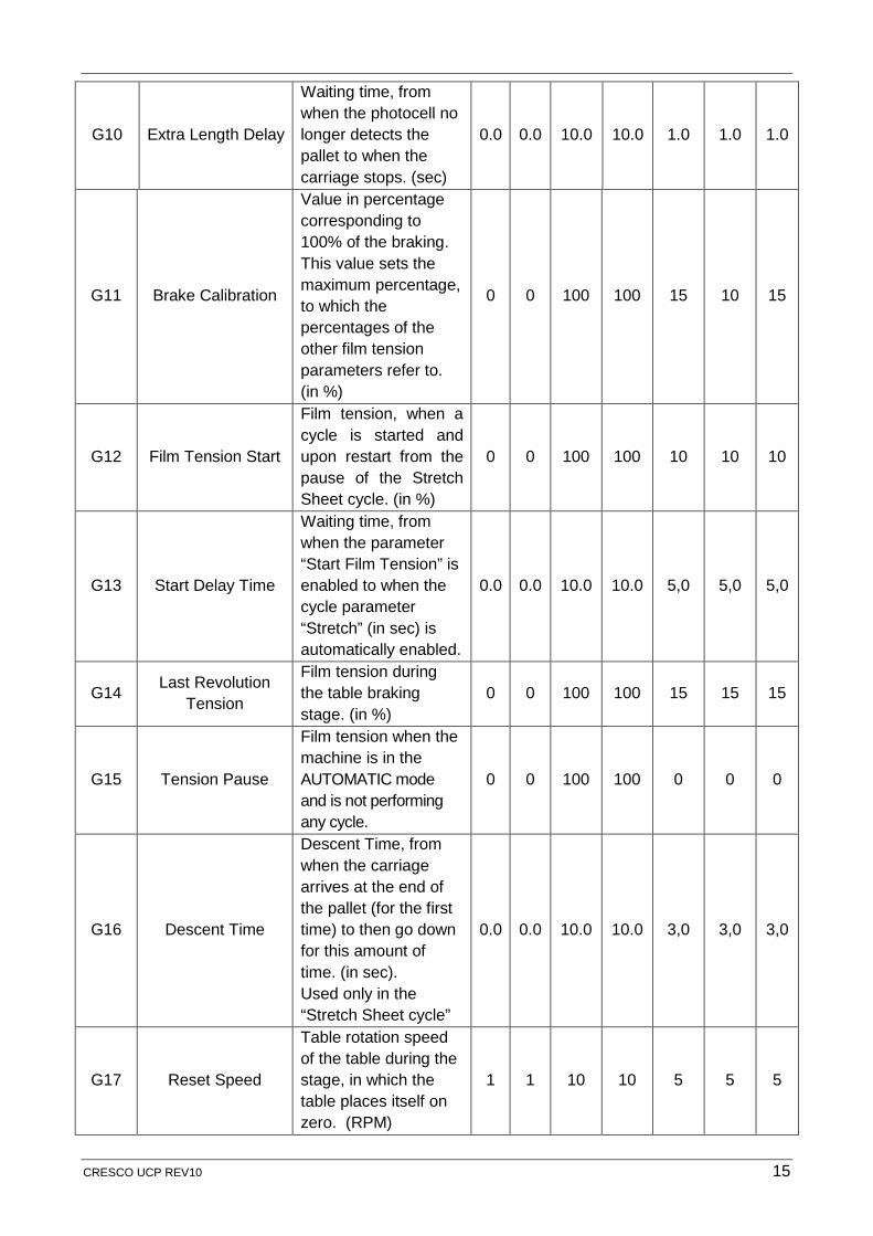
G10 Extra Length Delay
Waiting time, from when the photocell no longer detects the pallet to when the carriage stops. (sec)
0.0 0.0 10.0 10.0 1.0 1.0 1.0
G11 Brake Calibration
Value in percentage corresponding to 100% of the braking. This value sets the maximum percentage, to which the percentages of the other film tension parameters refer to. (in %)
0 0 100 100 15 10 15
G12 Film Tension Start
Film tension, when a cycle is started and upon restart from the pause of the Stretch Sheet cycle. (in %)
0 0 100 100 10 10 10
G13 Start Delay Time
Waiting time, from when the parameter “Start Film Tension” is enabled to when the cycle parameter “Stretch” (in sec) is automatically enabled.
0.0 0.0 10.0 10.0 5,0 5,0 5,0
G14 Last Revolution Tension
Film tension during the table braking stage. (in %)
0 0 100 100 15 15 15
G15 Tension Pause
Film tension when the machine is in the AUTOMATIC mode and is not performing any cycle.
0 0 100 100 0 0 0
G16 Descent Time
Descent Time, from when the carriage arrives at the end of the pallet (for the first time) to then go down for this amount of time. (in sec). Used only in the “Stretch Sheet cycle”
0.0 0.0 10.0 10.0 3,0 3,0 3,0
G17 Reset Speed
Table rotation speed of the table during the stage, in which the table places itself on zero. (RPM)
1 1 10 10 5 5 5
CRESCO UCP REV10 15
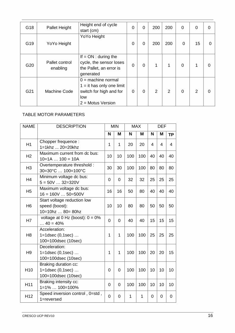
G18 Pallet Height Height end of cycle start (cm) 0 0 200 200 0 0 0
G19 YoYo Height YoYo Height
0 0 200 200 0 15 0
G20 Pallet control enabling
If = ON : during the cycle, the sensor loses the Pallet, an error is generated
0 0 1 1 0 1 0
G21 Machine Code
0 = machine normal 1 = it has only one limit switch for high and for low 2 = Motus Version
0 0 2 2 0 2 0
TABLE MOTOR PARAMETERS NAME DESCRIPTION MIN MAX DEF
N M N M N M TP
H1 Chopper frequence : 1=1khz ... 20=20khz 1 1 20 20 4 4 4
H2 Maximum current from dc bus: 10=1A … 100 = 10A 10 10 100 100 40 40 40
H3 Overtemperature threshold : 30=30°C … 100=100°C 30 30 100 100 80 80 80
H4 Minimum voltage dc bus: 5 = 50V … 32=320V 0 0 32 32 25 25 25
H5 Maximum voltage dc bus: 16 = 160V … 50=500V 16 16 50 80 40 40 40
H6 Start voltage reduction low speed (boost): 10=10hz … 80= 80hz
10 10 80 80 50 50 50
H7 voltage at 0 Hz (boost): 0 = 0% … 40 = 40% 0 0 40 40 15 15 15
H8 Acceleration: 1=1dsec (0,1sec) … 100=100dsec (10sec)
1 1 100 100 25 25 25
H9 Deceleration: 1=1dsec (0,1sec) … 100=100dsec (10sec)
1 1 100 100 20 20 15
H10 Braking duration cc: 1=1dsec (0,1sec) … 100=100dsec (10sec)
0 0 100 100 10 10 10
H11 Braking intensity cc: 1=1% … 100=100% 0 0 100 100 10 10 10
H12 Speed inversion control , 0=std , 1=reversed 0 0 1 1 0 0 0
CRESCO UCP REV10 16
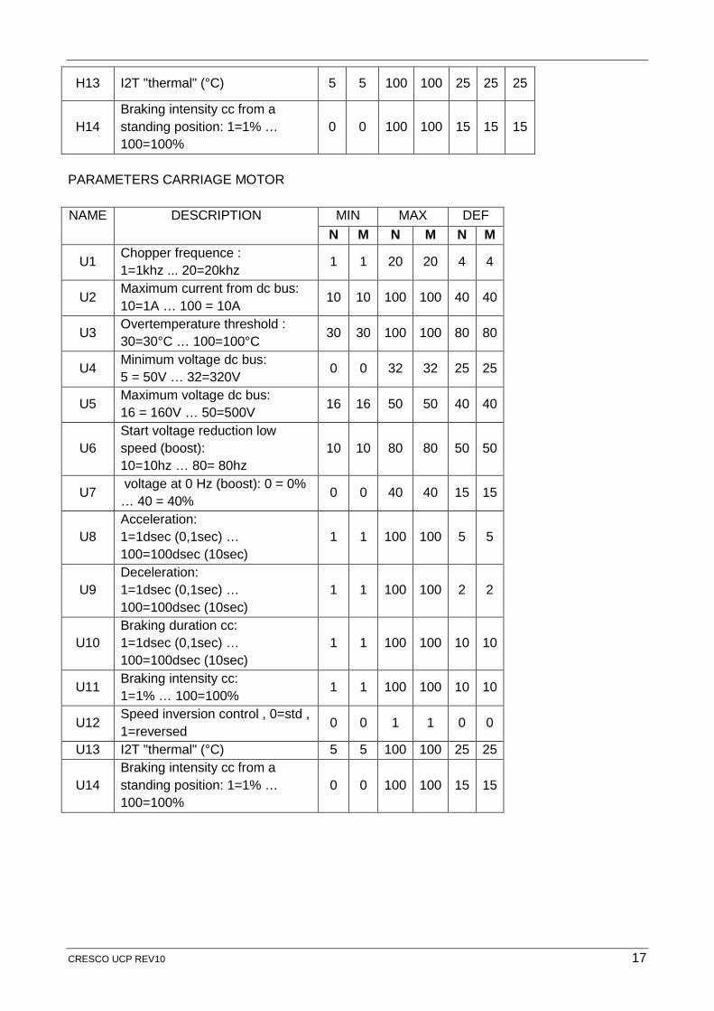
H13 I2T "thermal" (°C) 5 5 100 100 25 25 25
H14 Braking intensity cc from a standing position: 1=1% … 100=100%
0 0 100 100 15 15 15
PARAMETERS CARRIAGE MOTOR NAME DESCRIPTION MIN MAX DEF
N M N M N M
U1 Chopper frequence : 1=1khz ... 20=20khz 1 1 20 20 4 4
U2 Maximum current from dc bus: 10=1A … 100 = 10A 10 10 100 100 40 40
U3 Overtemperature threshold : 30=30°C … 100=100°C 30 30 100 100 80 80
U4 Minimum voltage dc bus: 5 = 50V … 32=320V 0 0 32 32 25 25
U5 Maximum voltage dc bus: 16 = 160V … 50=500V 16 16 50 50 40 40
U6 Start voltage reduction low speed (boost): 10=10hz … 80= 80hz
10 10 80 80 50 50
U7 voltage at 0 Hz (boost): 0 = 0% … 40 = 40% 0 0 40 40 15 15
U8 Acceleration: 1=1dsec (0,1sec) … 100=100dsec (10sec)
1 1 100 100 5 5
U9 Deceleration: 1=1dsec (0,1sec) … 100=100dsec (10sec)
1 1 100 100 2 2
U10 Braking duration cc: 1=1dsec (0,1sec) … 100=100dsec (10sec)
1 1 100 100 10 10
U11 Braking intensity cc: 1=1% … 100=100% 1 1 100 100 10 10
U12 Speed inversion control , 0=std , 1=reversed 0 0 1 1 0 0
U13 I2T "thermal" (°C) 5 5 100 100 25 25
U14 Braking intensity cc from a standing position: 1=1% … 100=100%
0 0 100 100 15 15
CRESCO UCP REV10 17
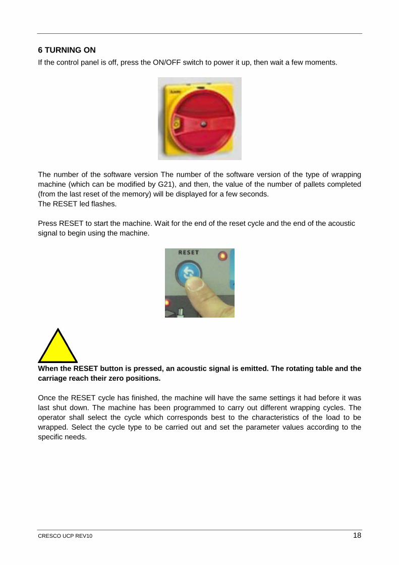
6 TURNING ON If the control panel is off, press the ON/OFF switch to power it up, then wait a few moments.
The number of the software version The number of the software version of the type of wrapping machine (which can be modified by G21), and then, the value of the number of pallets completed (from the last reset of the memory) will be displayed for a few seconds. The RESET led flashes. Press RESET to start the machine. Wait for the end of the reset cycle and the end of the acoustic signal to begin using the machine.
When the RESET button is pressed, an acoustic signal is emitted. The rotating table and the carriage reach their zero positions. Once the RESET cycle has finished, the machine will have the same settings it had before it was last shut down. The machine has been programmed to carry out different wrapping cycles. The operator shall select the cycle which corresponds best to the characteristics of the load to be wrapped. Select the cycle type to be carried out and set the parameter values according to the specific needs.
CRESCO UCP REV10 18
7 LOADING AND UNLOADING Place the load to be wrapped on the rotating table in the correct way, and check its stability. Fix the film end to the pallet.
The load must be well balanced to avoid risks. At the end of the wrapping cycle, cut the film, unload the wrapped product and load a new pallet. If the machine is not in the correct position when it stops, press the RESET button and it will go back to its initial position.
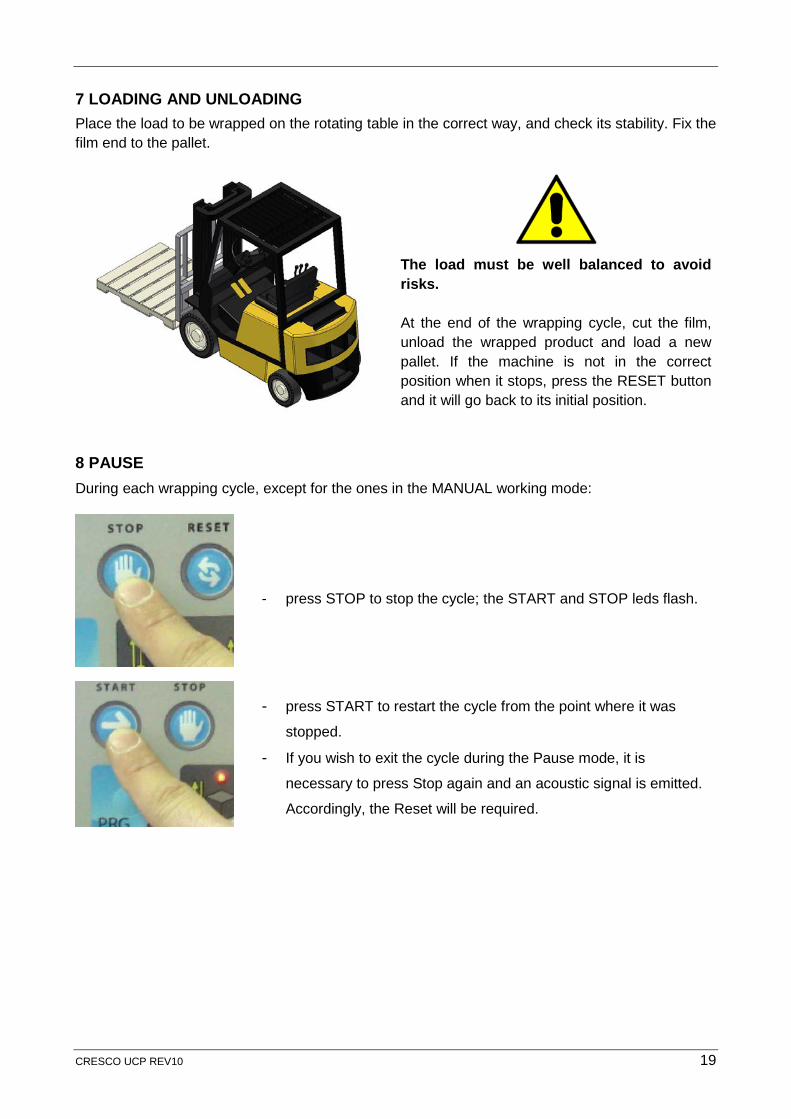
8 PAUSE During each wrapping cycle, except for the ones in the MANUAL working mode:
- press STOP to stop the cycle; the START and STOP leds flash.
- press START to restart the cycle from the point where it was
stopped. - If you wish to exit the cycle during the Pause mode, it is
necessary to press Stop again and an acoustic signal is emitted.
Accordingly, the Reset will be required.
CRESCO UCP REV10 19
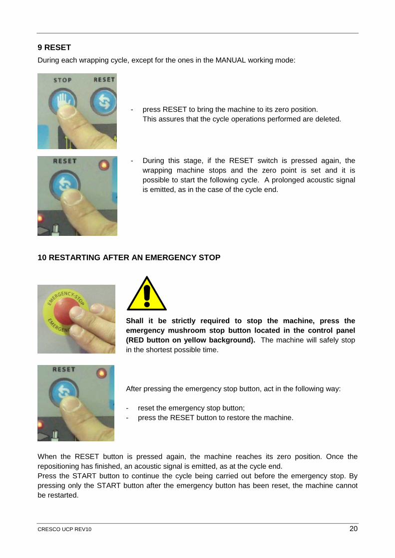
9 RESET During each wrapping cycle, except for the ones in the MANUAL working mode:
- press RESET to bring the machine to its zero position. This assures that the cycle operations performed are deleted.
- During this stage, if the RESET switch is pressed again, the wrapping machine stops and the zero point is set and it is possible to start the following cycle. A prolonged acoustic signal is emitted, as in the case of the cycle end.
10 RESTARTING AFTER AN EMERGENCY STOP
Shall it be strictly required to stop the machine, press the emergency mushroom stop button located in the control panel (RED button on yellow background). The machine will safely stop in the shortest possible time.
After pressing the emergency stop button, act in the following way: - reset the emergency stop button; - press the RESET button to restore the machine.
When the RESET button is pressed again, the machine reaches its zero position. Once the repositioning has finished, an acoustic signal is emitted, as at the cycle end. Press the START button to continue the cycle being carried out before the emergency stop. By pressing only the START button after the emergency button has been reset, the machine cannot be restarted.
CRESCO UCP REV10 20
Before restoring the machine after an emergency stop, make sure that the danger situation has been appropriately eliminated.
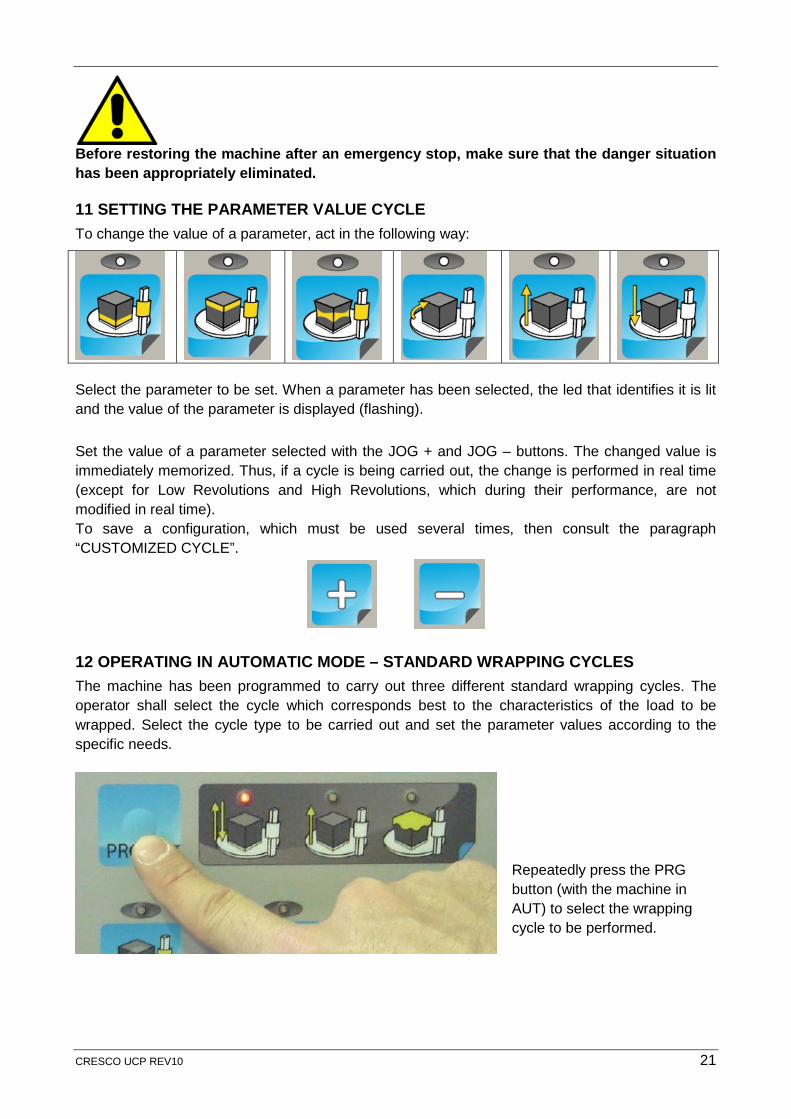
11 SETTING THE PARAMETER VALUE CYCLE To change the value of a parameter, act in the following way:
Select the parameter to be set. When a parameter has been selected, the led that identifies it is lit and the value of the parameter is displayed (flashing).
Set the value of a parameter selected with the JOG + and JOG – buttons. The changed value is immediately memorized. Thus, if a cycle is being carried out, the change is performed in real time (except for Low Revolutions and High Revolutions, which during their performance, are not modified in real time). To save a configuration, which must be used several times, then consult the paragraph “CUSTOMIZED CYCLE”.
12 OPERATING IN AUTOMATIC MODE – STANDARD WRAPPING CYCLES The machine has been programmed to carry out three different standard wrapping cycles. The operator shall select the cycle which corresponds best to the characteristics of the load to be wrapped. Select the cycle type to be carried out and set the parameter values according to the specific needs.
Repeatedly press the PRG button (with the machine in AUT) to select the wrapping cycle to be performed.
CRESCO UCP REV10 21
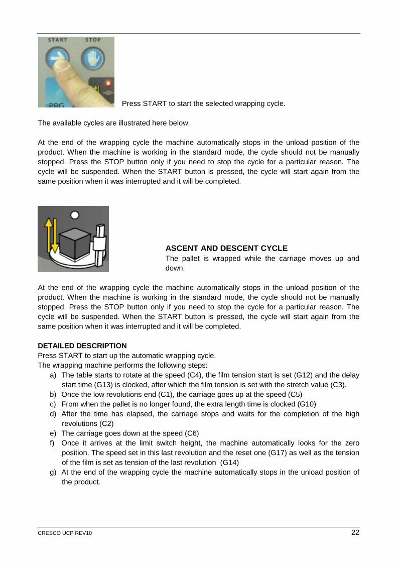
Press START to start the selected wrapping cycle. The available cycles are illustrated here below. At the end of the wrapping cycle the machine automatically stops in the unload position of the product. When the machine is working in the standard mode, the cycle should not be manually stopped. Press the STOP button only if you need to stop the cycle for a particular reason. The cycle will be suspended. When the START button is pressed, the cycle will start again from the same position when it was interrupted and it will be completed.
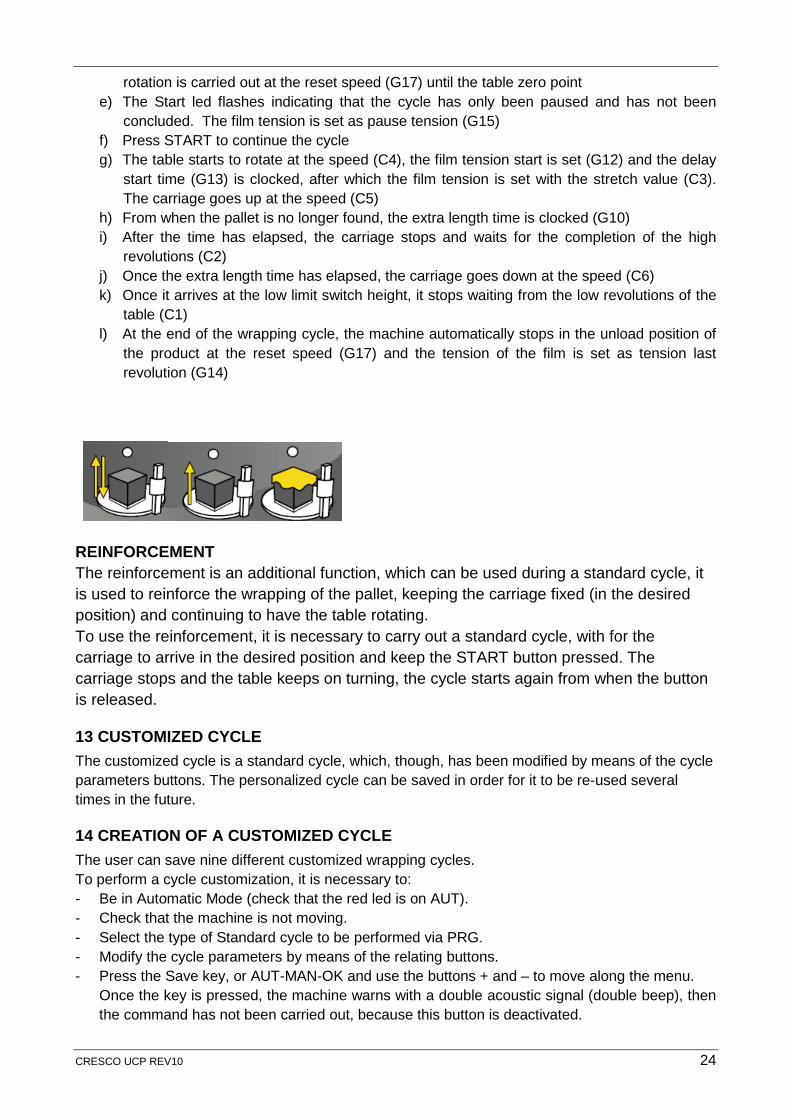
ASCENT AND DESCENT CYCLE The pallet is wrapped while the carriage moves up and down.
At the end of the wrapping cycle the machine automatically stops in the unload position of the product. When the machine is working in the standard mode, the cycle should not be manually stopped. Press the STOP button only if you need to stop the cycle for a particular reason. The cycle will be suspended. When the START button is pressed, the cycle will start again from the same position when it was interrupted and it will be completed. DETAILED DESCRIPTION Press START to start up the automatic wrapping cycle. The wrapping machine performs the following steps:
a) The table starts to rotate at the speed (C4), the film tension start is set (G12) and the delay start time (G13) is clocked, after which the film tension is set with the stretch value (C3).
b) Once the low revolutions end (C1), the carriage goes up at the speed (C5) c) From when the pallet is no longer found, the extra length time is clocked (G10) d) After the time has elapsed, the carriage stops and waits for the completion of the high
revolutions (C2) e) The carriage goes down at the speed (C6) f) Once it arrives at the limit switch height, the machine automatically looks for the zero
position. The speed set in this last revolution and the reset one (G17) as well as the tension of the film is set as tension of the last revolution (G14)
g) At the end of the wrapping cycle the machine automatically stops in the unload position of the product.
CRESCO UCP REV10 22
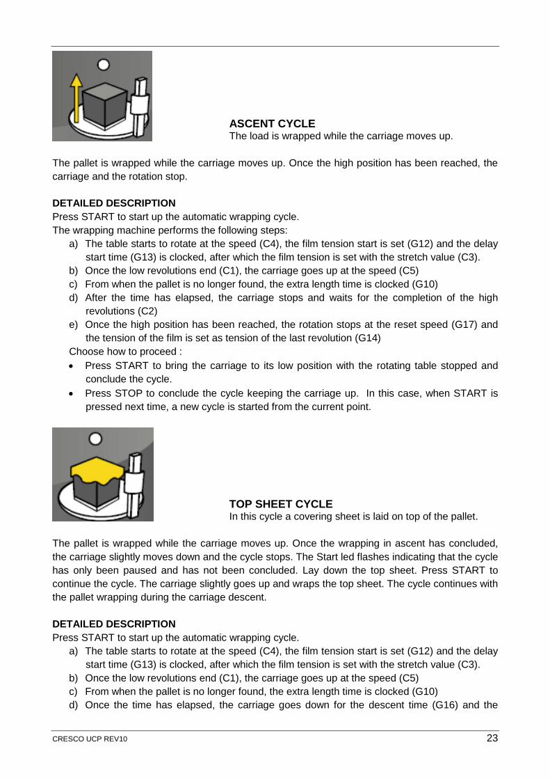
ASCENT CYCLE The load is wrapped while the carriage moves up.
The pallet is wrapped while the carriage moves up. Once the high position has been reached, the carriage and the rotation stop. DETAILED DESCRIPTION Press START to start up the automatic wrapping cycle. The wrapping machine performs the following steps:
a) The table starts to rotate at the speed (C4), the film tension start is set (G12) and the delay start time (G13) is clocked, after which the film tension is set with the stretch value (C3).
b) Once the low revolutions end (C1), the carriage goes up at the speed (C5) c) From when the pallet is no longer found, the extra length time is clocked (G10) d) After the time has elapsed, the carriage stops and waits for the completion of the high
revolutions (C2) e) Once the high position has been reached, the rotation stops at the reset speed (G17) and
the tension of the film is set as tension of the last revolution (G14) Choose how to proceed : • Press START to bring the carriage to its low position with the rotating table stopped and
conclude the cycle. • Press STOP to conclude the cycle keeping the carriage up. In this case, when START is
pressed next time, a new cycle is started from the current point.
TOP SHEET CYCLE In this cycle a covering sheet is laid on top of the pallet.
The pallet is wrapped while the carriage moves up. Once the wrapping in ascent has concluded, the carriage slightly moves down and the cycle stops. The Start led flashes indicating that the cycle has only been paused and has not been concluded. Lay down the top sheet. Press START to continue the cycle. The carriage slightly goes up and wraps the top sheet. The cycle continues with the pallet wrapping during the carriage descent. DETAILED DESCRIPTION Press START to start up the automatic wrapping cycle.
a) The table starts to rotate at the speed (C4), the film tension start is set (G12) and the delay start time (G13) is clocked, after which the film tension is set with the stretch value (C3).
b) Once the low revolutions end (C1), the carriage goes up at the speed (C5) c) From when the pallet is no longer found, the extra length time is clocked (G10) d) Once the time has elapsed, the carriage goes down for the descent time (G16) and the
CRESCO UCP REV10 23
rotation is carried out at the reset speed (G17) until the table zero point e) The Start led flashes indicating that the cycle has only been paused and has not been
concluded. The film tension is set as pause tension (G15) f) Press START to continue the cycle g) The table starts to rotate at the speed (C4), the film tension start is set (G12) and the delay
start time (G13) is clocked, after which the film tension is set with the stretch value (C3). The carriage goes up at the speed (C5)
h) From when the pallet is no longer found, the extra length time is clocked (G10) i) After the time has elapsed, the carriage stops and waits for the completion of the high
revolutions (C2) j) Once the extra length time has elapsed, the carriage goes down at the speed (C6) k) Once it arrives at the low limit switch height, it stops waiting from the low revolutions of the
table (C1) l) At the end of the wrapping cycle, the machine automatically stops in the unload position of
the product at the reset speed (G17) and the tension of the film is set as tension last revolution (G14)
REINFORCEMENT The reinforcement is an additional function, which can be used during a standard cycle, it is used to reinforce the wrapping of the pallet, keeping the carriage fixed (in the desired position) and continuing to have the table rotating. To use the reinforcement, it is necessary to carry out a standard cycle, with for the carriage to arrive in the desired position and keep the START button pressed. The carriage stops and the table keeps on turning, the cycle starts again from when the button is released.
13 CUSTOMIZED CYCLE The customized cycle is a standard cycle, which, though, has been modified by means of the cycle parameters buttons. The personalized cycle can be saved in order for it to be re-used several times in the future.
14 CREATION OF A CUSTOMIZED CYCLE The user can save nine different customized wrapping cycles. To perform a cycle customization, it is necessary to: - Be in Automatic Mode (check that the red led is on AUT). - Check that the machine is not moving. - Select the type of Standard cycle to be performed via PRG. - Modify the cycle parameters by means of the relating buttons. - Press the Save key, or AUT-MAN-OK and use the buttons + and – to move along the menu.
Once the key is pressed, the machine warns with a double acoustic signal (double beep), then the command has not been carried out, because this button is deactivated.
CRESCO UCP REV10 24
15 USE OF A CUSTOMIZED CYCLE - Press the LOAD key with the machine in the AUTOMATIC mode and check that the machine is
not carrying out a cycle. When pressing the key, if the machine emits an acoustic warning (double beep), then the command has not been carried out, due to the presence of a situation, in which the LOAD is deactivated.
- Press JOG + and JOG - to select the programme number (L-Pr1 – L-Pr9) to be run. The led of the cycle programe flashes thus showing which standard cycle has been saved in the selected customized cycle. By pressing a cycle button, the display shows the letter “L”, as well as the value next to it, with which the parameter in that selected cycle has been saved.
- Press LOAD or AUT-MAN-OK to load the selected cycle. An acoustic warning confirms the loading and the display shows the total number of pallets processed by the machine.
- Press START to start the cycle.
16 MANUAL MODE The Manual mode is used to manually control the machine. If the carriage is going down and finds an obstacle, the machine enters into the safety (“Sic”) mode and passes directly in the Manual mode in order for the operator to exit from this dangerous situation. In the Manual mode, the following buttons are used: - Table rotation: until the button is pressed, the table rotates; in case of prolonged pressing of
the button, an acoustic warning is emitted and releasing the button, the table continues to turn. Press the button again to stop table rotation.
- Carriage ascent: until the button is pressed, the carriage goes up. - Carriage descent: until the button is pressed, the carriage goes down. - Film tension adjustment: by a simple pressure of the button, it is possible to modify film tension. Each time one of these buttons is pressed, the value of the relating set parameter is displayed (flashing) and it can be modified instantly by means of the + and - buttons.
17 “PLAY BACK” CYCLE The machine can carry out nine different non-standard wrapping cycles, which are totally user-configured. The cycles are characterised by a sequence of operations and by their duration. These operations and their duration are decided by the user through a saving procedure in the “PLAY BACK” cycle.
CRESCO UCP REV10 25
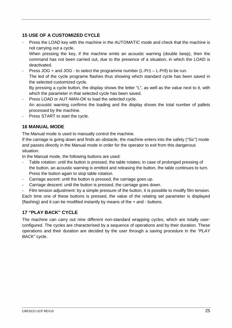
18 CREATION OF A “PLAY BACK” CYCLE When the machine is at rest, press RECORD, the START led flashes and the “-rEc” wording is displayed. The machine waits for the pressure of the START button to continue.
After the pressure of the START button, the wording “StArt” is displayed and the STOP, TABLE ROTATION, CARRIAGE ASCENT and CARRIAGE DESCENT leds flash. At this point, the user chooses how to start the cycle, which must be recorded: - Pressing STOP: the machine will start the registration with a pause. - Pressing STOP, TABLE ROTATION, CARRIAGE ASCENT or
CARRIAGE DESCENT: the machine will start recording the relating control of the pressed button.
After pressing one of the shown buttons, the registration starts, the three standard cycle leds flash and the wording “StP” is displayed as well as the number of steps, matching with the commands, ordered by the user. Moment by moment, the machine detects the movement sequence, their duration and the time elapsing between one movement and the next one.
CRESCO UCP REV10 26
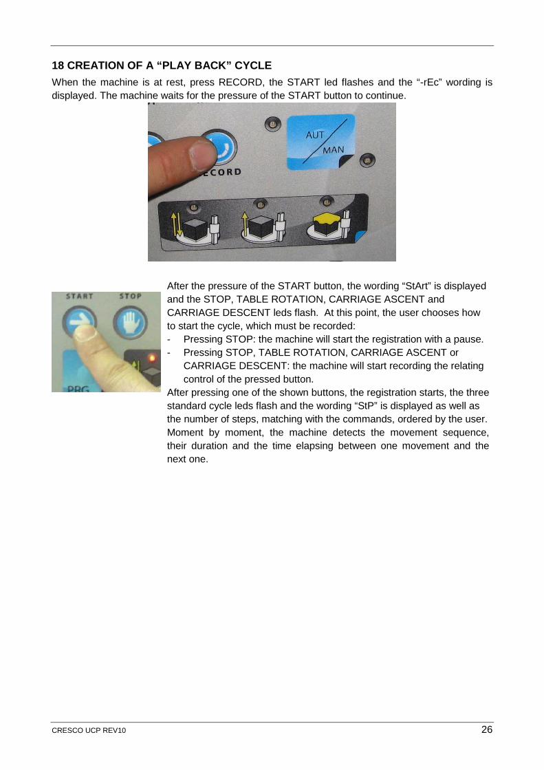
Use the buttons to create the movement sequence. A beep will be emitted for each command, ordered to the machine. The values of the cycle parameters do not change during the registration of the Play Back cycle. NOTE: it is not possible to modify the values of the cycle parameters, during the registration of the Play Back cycle. The machine programme takes into account in any case the information detected by the movement control limit switches. The user programming can, therefore, never come into conflict with the safe use of the machine. Up to 99 different steps can be memorised for each cycle.
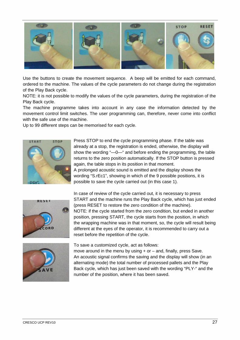
Press STOP to end the cycle programming phase. If the table was already at a stop, the registration is ended, otherwise, the display will show the wording “—0—“ and before ending the programming, the table returns to the zero position automatically. If the STOP button is pressed again, the table stops in its position in that moment. A prolonged acoustic sound is emitted and the display shows the wording “S.rEc1”, showing in which of the 9 possible positions, it is possible to save the cycle carried out (in this case 1).
In case of review of the cycle carried out, it is necessary to press START and the machine runs the Play Back cycle, which has just ended (press RESET to restore the zero condition of the machine). NOTE: if the cycle started from the zero condition, but ended in another position, pressing START, the cycle starts from the position, in which the wrapping machine was in that moment, so, the cycle will result being different at the eyes of the operator, it is recommended to carry out a reset before the repetition of the cycle.
To save a customized cycle, act as follows: move around in the menu by using + or – and, finally, press Save. An acoustic signal confirms the saving and the display will show (in an alternating mode) the total number of processed pallets and the Play Back cycle, which has just been saved with the wording “PLY-“ and the number of the position, where it has been saved.
CRESCO UCP REV10 27
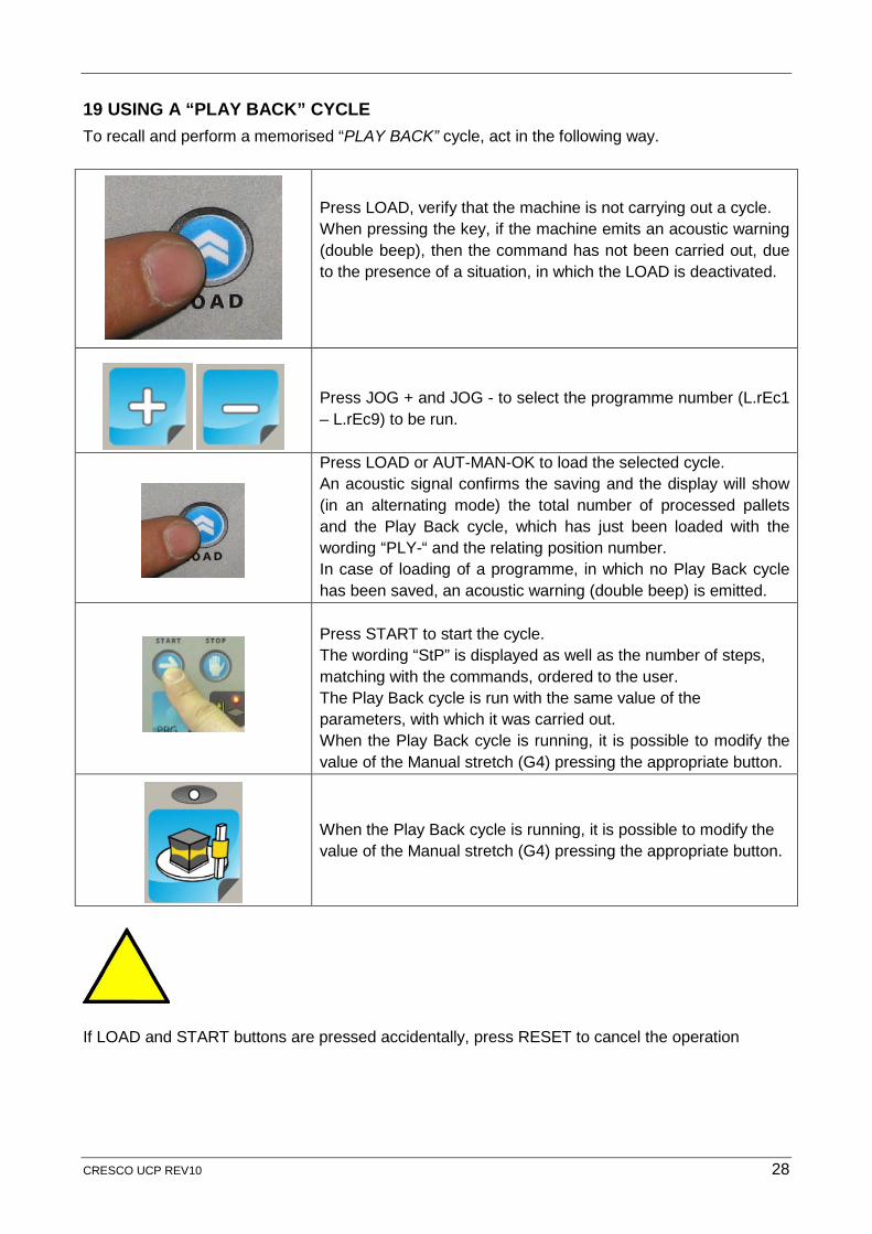
19 USING A “PLAY BACK” CYCLE To recall and perform a memorised “PLAY BACK” cycle, act in the following way.
Press LOAD, verify that the machine is not carrying out a cycle. When pressing the key, if the machine emits an acoustic warning (double beep), then the command has not been carried out, due to the presence of a situation, in which the LOAD is deactivated.
Press JOG + and JOG - to select the programme number (L.rEc1 – L.rEc9) to be run.
Press LOAD or AUT-MAN-OK to load the selected cycle. An acoustic signal confirms the saving and the display will show (in an alternating mode) the total number of processed pallets and the Play Back cycle, which has just been loaded with the wording “PLY-“ and the relating position number. In case of loading of a programme, in which no Play Back cycle has been saved, an acoustic warning (double beep) is emitted.
Press START to start the cycle. The wording “StP” is displayed as well as the number of steps, matching with the commands, ordered to the user. The Play Back cycle is run with the same value of the parameters, with which it was carried out. When the Play Back cycle is running, it is possible to modify the value of the Manual stretch (G4) pressing the appropriate button.
When the Play Back cycle is running, it is possible to modify the value of the Manual stretch (G4) pressing the appropriate button.
If LOAD and START buttons are pressed accidentally, press RESET to cancel the operation
CRESCO UCP REV10 28
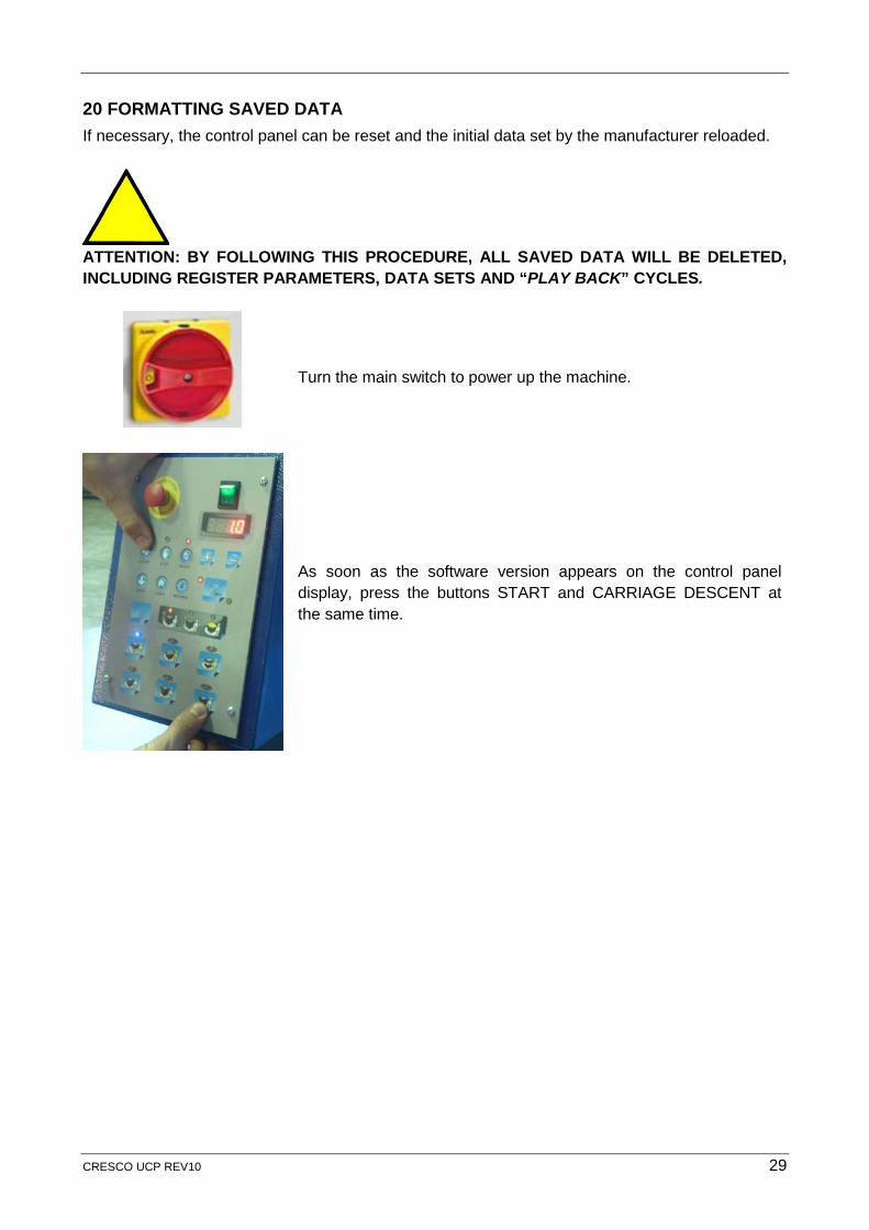
20 FORMATTING SAVED DATA If necessary, the control panel can be reset and the initial data set by the manufacturer reloaded.
ATTENTION: BY FOLLOWING THIS PROCEDURE, ALL SAVED DATA WILL BE DELETED, INCLUDING REGISTER PARAMETERS, DATA SETS AND “PLAY BACK” CYCLES.
Turn the main switch to power up the machine.
As soon as the software version appears on the control panel display, press the buttons START and CARRIAGE DESCENT at the same time.
CRESCO UCP REV10 29
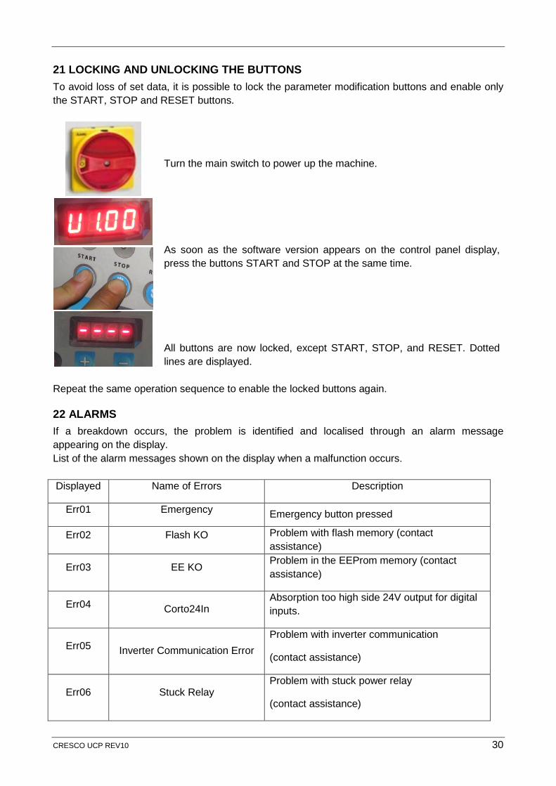
21 LOCKING AND UNLOCKING THE BUTTONS To avoid loss of set data, it is possible to lock the parameter modification buttons and enable only the START, STOP and RESET buttons.
Turn the main switch to power up the machine.
As soon as the software version appears on the control panel display, press the buttons START and STOP at the same time.
All buttons are now locked, except START, STOP, and RESET. Dotted lines are displayed.
Repeat the same operation sequence to enable the locked buttons again.
22 ALARMS If a breakdown occurs, the problem is identified and localised through an alarm message appearing on the display. List of the alarm messages shown on the display when a malfunction occurs. Displayed Name of Errors Description
Err01 Emergency Emergency button pressed
Err02 Flash KO Problem with flash memory (contact assistance)
Err03 EE KO Problem in the EEProm memory (contact assistance)
Err04 Corto24In Absorption too high side 24V output for digital inputs.
Err05 Inverter Communication Error Problem with inverter communication
(contact assistance)
Err06 Stuck Relay Problem with stuck power relay
(contact assistance)
CRESCO UCP REV10 30
Err07 Current limiting resistor break Problem with black tablet (power resistor) (contact assistance)
Err08 Low Voltage Table Inverter Problem with table inverter relating to low bus voltage
Err09 High Temperature Table Inverter Problem with high temperature of table inverter
Err10 High Voltage Table Inverter Problem with high tension Table Inverter
Err11 Maximum Current Table Inverter Problem with inverter high current table
Err12 Short Circuit Table Inverter Problem with Inverter table short circuit
Err13 Inverter Table I2T Problem with inverter table with maximum thermal current I2T
Err14 Low Voltage Inverter Carriage Problem inverter carriage relating to low bus voltage
Err15 High Temperature Inverter Carriage
Problem with high temperature of carriage inverter
Err16 High Voltage Inverter Carriage Problem high Voltage Inverter Carriage
Err17 Maximum Current Carriage Inverter
Problem with inverter high current table
Err18 Short Circuit Inverter Carriage Problem inverter carriage short circuit
Err19 Inverter Carriage I2T Problem inverter carriage with maximum thermal current I2T
Err20 Carriage out of position
If the pallet moves during wrapping (G21 = 02 “machine Motus”) and the parameter G20 is enabled, this error is generated
Err21 YoYo Fail
If during reset, while going down, the carriage meets the low limit switch before the YoYo sensor, this error is generated (G21 = 02 “machine Motus”)
CARRIAGE SAFETY LIMIT SWITCH If the carriage safety limit switch is pressed due to an obstacle, then, the carriage blocks instantly and goes up until the limit switch is unblocked and the machine passes automatically in the Manual mode. The display shows the wording “-SiC-“ and a prolonged acoustic warning is emitted.
CRESCO UCP REV10 31
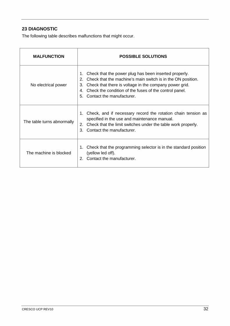
23 DIAGNOSTIC The following table describes malfunctions that might occur.
MALFUNCTION
POSSIBLE SOLUTIONS
No electrical power
1. Check that the power plug has been inserted properly. 2. Check that the machine’s main switch is in the ON position. 3. Check that there is voltage in the company power grid. 4. Check the condition of the fuses of the control panel. 5. Contact the manufacturer.
The table turns abnormally
1. Check, and if necessary record the rotation chain tension as
specified in the use and maintenance manual. 2. Check that the limit switches under the table work properly. 3. Contact the manufacturer.
The machine is blocked
1. Check that the programming selector is in the standard position
(yellow led off). 2. Contact the manufacturer.
CRESCO UCP REV10 32
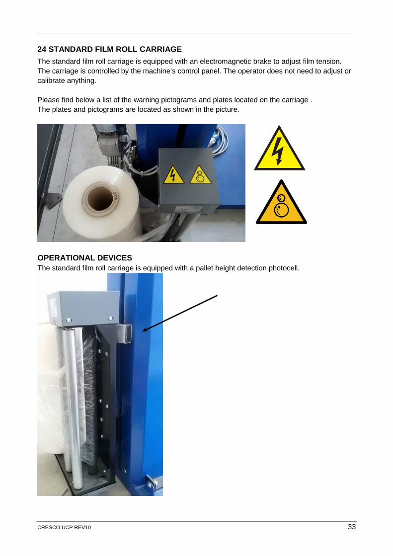
24 STANDARD FILM ROLL CARRIAGE The standard film roll carriage is equipped with an electromagnetic brake to adjust film tension. The carriage is controlled by the machine’s control panel. The operator does not need to adjust or calibrate anything. Please find below a list of the warning pictograms and plates located on the carriage . The plates and pictograms are located as shown in the picture.
OPERATIONAL DEVICES The standard film roll carriage is equipped with a pallet height detection photocell.
CRESCO UCP REV10 33
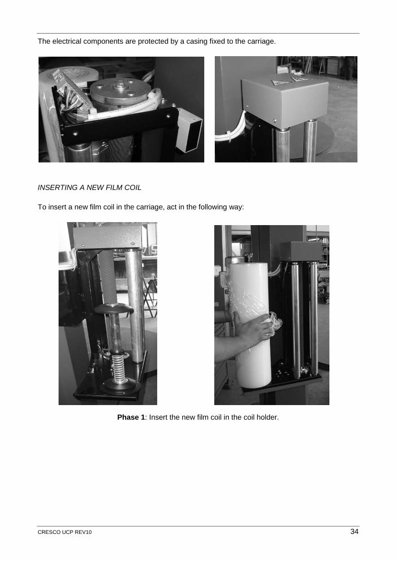
The electrical components are protected by a casing fixed to the carriage.
INSERTING A NEW FILM COIL To insert a new film coil in the carriage, act in the following way:
Phase 1: Insert the new film coil in the coil holder.
CRESCO UCP REV10 34
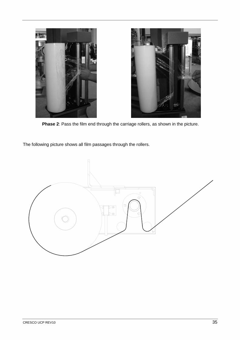
Phase 2: Pass the film end through the carriage rollers, as shown in the picture.
The following picture shows all film passages through the rollers.
CRESCO UCP REV10 35
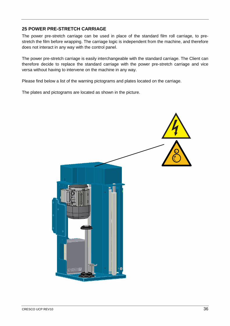
25 POWER PRE-STRETCH CARRIAGE The power pre-stretch carriage can be used in place of the standard film roll carriage, to pre-stretch the film before wrapping. The carriage logic is independent from the machine, and therefore does not interact in any way with the control panel. The power pre-stretch carriage is easily interchangeable with the standard carriage. The Client can therefore decide to replace the standard carriage with the power pre-stretch carriage and vice versa without having to intervene on the machine in any way. Please find below a list of the warning pictograms and plates located on the carriage. The plates and pictograms are located as shown in the picture.
CRESCO UCP REV10 36
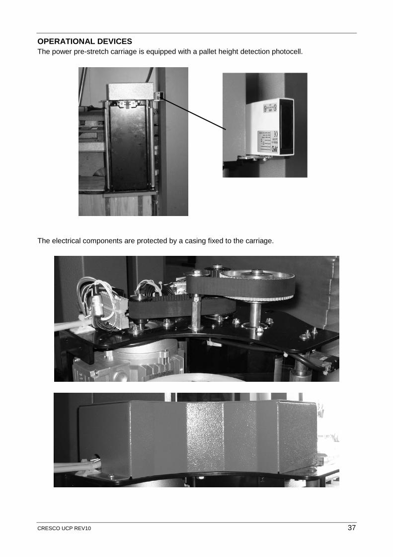
OPERATIONAL DEVICES The power pre-stretch carriage is equipped with a pallet height detection photocell.
The electrical components are protected by a casing fixed to the carriage.
CRESCO UCP REV10 37
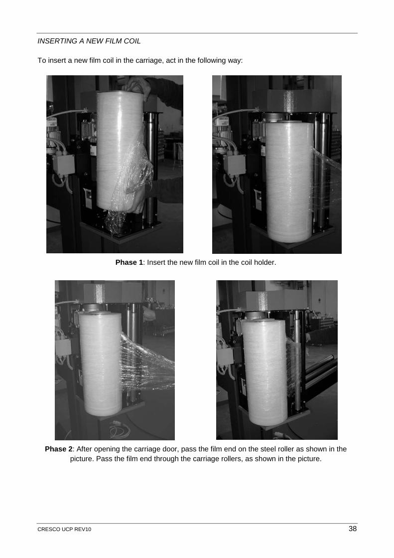
INSERTING A NEW FILM COIL To insert a new film coil in the carriage, act in the following way:
Phase 1: Insert the new film coil in the coil holder.
Phase 2: After opening the carriage door, pass the film end on the steel roller as shown in the
picture. Pass the film end through the carriage rollers, as shown in the picture.
CRESCO UCP REV10 38
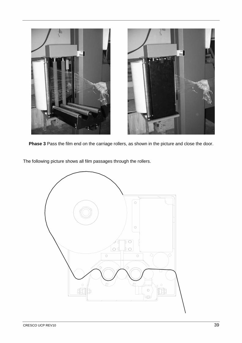
Phase 3 Pass the film end on the carriage rollers, as shown in the picture and close the door.
The following picture shows all film passages through the rollers.
CRESCO UCP REV10 39
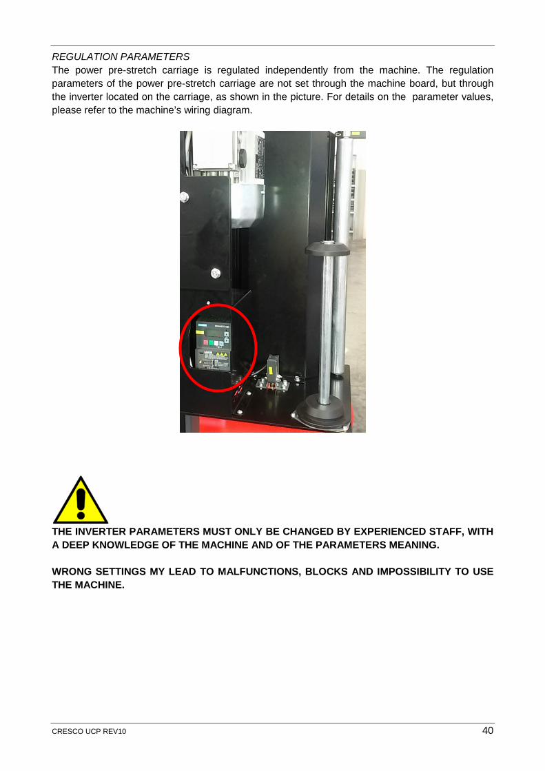
REGULATION PARAMETERS The power pre-stretch carriage is regulated independently from the machine. The regulation parameters of the power pre-stretch carriage are not set through the machine board, but through the inverter located on the carriage, as shown in the picture. For details on the parameter values, please refer to the machine’s wiring diagram.
THE INVERTER PARAMETERS MUST ONLY BE CHANGED BY EXPERIENCED STAFF, WITH A DEEP KNOWLEDGE OF THE MACHINE AND OF THE PARAMETERS MEANING. WRONG SETTINGS MY LEAD TO MALFUNCTIONS, BLOCKS AND IMPOSSIBILITY TO USE THE MACHINE.
CRESCO UCP REV10 40
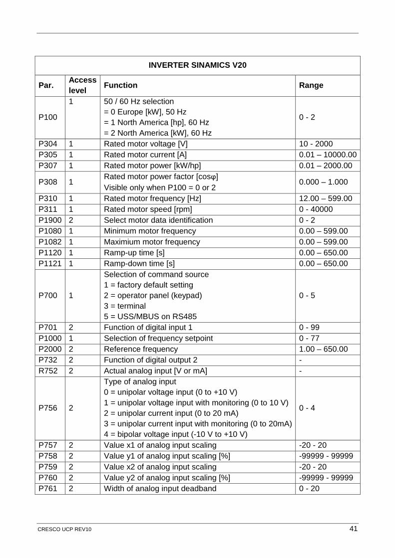
INVERTER SINAMICS V20
Par. Access level Function Range
P100
1 50 / 60 Hz selection = 0 Europe [kW], 50 Hz = 1 North America [hp], 60 Hz = 2 North America [kW], 60 Hz
0 - 2
P304 1 Rated motor voltage [V] 10 - 2000 P305 1 Rated motor current [A] 0.01 – 10000.00 P307 1 Rated motor power [kW/hp] 0.01 – 2000.00
P308 1 Rated motor power factor [cosϕ] Visible only when P100 = 0 or 2
0.000 – 1.000
P310 1 Rated motor frequency [Hz] 12.00 – 599.00 P311 1 Rated motor speed [rpm] 0 - 40000 P1900 2 Select motor data identification 0 - 2 P1080 1 Minimum motor frequency 0.00 – 599.00 P1082 1 Maximium motor frequency 0.00 – 599.00 P1120 1 Ramp-up time [s] 0.00 – 650.00 P1121 1 Ramp-down time [s] 0.00 – 650.00
P700 1
Selection of command source 1 = factory default setting 2 = operator panel (keypad) 3 = terminal 5 = USS/MBUS on RS485
0 - 5
P701 2 Function of digital input 1 0 - 99 P1000 1 Selection of frequency setpoint 0 - 77 P2000 2 Reference frequency 1.00 – 650.00 P732 2 Function of digital output 2 - R752 2 Actual analog input [V or mA] -
P756 2
Type of analog input 0 = unipolar voltage input (0 to +10 V) 1 = unipolar voltage input with monitoring (0 to 10 V) 2 = unipolar current input (0 to 20 mA) 3 = unipolar current input with monitoring (0 to 20mA) 4 = bipolar voltage input (-10 V to +10 V)
0 - 4
P757 2 Value x1 of analog input scaling -20 - 20 P758 2 Value y1 of analog input scaling [%] -99999 - 99999 P759 2 Value x2 of analog input scaling -20 - 20 P760 2 Value y2 of analog input scaling [%] -99999 - 99999 P761 2 Width of analog input deadband 0 - 20
CRESCO UCP REV10 41

Our Promise is to respond promptly and resolve effectively so you can rely unconditionally on what we do. For us it is...
Omni Group has been Engineering to Perfection Packaging Solutions for over 25 years. The Omni Brand is renowned for providing quality and customised Packaging Solutions as a result of continual innovation and development to perfect its whole range.
As specialists in pallet load containment and end of line packing solutions, you can rely on us as the industry experts. As a result our of experience and knowledge in the industry, our strong reputation has come from cutting edge product innovation with the focus to reduce the cost and environmental impact of packaging products. Industry innovators are the industry leaders.
Offices : Victoria (Head Office) 15-23 Logistics St, Keilor Park VIC 3042New South Wales 100 Wharf Rd, Melrose Park NSW 2114
Distribution Centres : Victoria 15-23 Logistics St, Keilor Park VIC 3042New South Wales Unit 1, 5 Aero Road, Ingleburn, NSW 2565South Australia 160 Churchill Road, North Cavan, SA 5094Queensland 60 Fulcrum St, Richlands, QLD 4077Western Australia 800 - 820 Abernethy Road, Forrestfield WA 6058New Zealand 1 Wilco Place, Manukua NZ 2104