ogc portal - open geospatial consortium
TRANSCRIPT
1 Copyright © 2021 Open Geospatial Consortium
Open Geospatial Consortium Submission Date: 2020-12-07
Approval Date: 2021-02-15
Publication Date: 2021-02-25
External identifier of this OGC® document: http://www.opengis.net/doc/BP/DGIWG-GeoTIFF/2.3
Internal reference number of this OGC® document: 20-095
Version: 2.3.1
Category: OGC® Best Practice
Editor: DGIWG
Defence Geospatial Information Working Group (DGIWG) GeoTIFF/TIFF Profile for Imagery & Gridded Data 2.3.1
Copyright notice
Copyright © 2021 Open Geospatial Consortium To obtain additional rights of use, visit http://www.opengeospatial.org/legal/.
Warning
This document defines an OGC Best Practice on a particular technology or approach related to an OGC standard. This document is not an OGC Standard and may not be referred to as an OGC Standard. It is subject to change without notice. However, this document is an official position of the OGC membership on this particular technology topic.
Recipients of this document are invited to submit, with their comments, notification of any relevant patent rights of which they are aware and to provide supporting documentation.
Document type: OGC® Best Practice Document subtype: Document stage: Approved Document language: English
2 Copyright © 2021 Open Geospatial Consortium
License Agreement
Permission is hereby granted by the Open Geospatial Consortium, ("Licensor"), free of charge and subject to the terms set forth below, to any person obtaining a copy of this Intellectual Property and any associated documentation, to deal in the Intellectual Property without restriction (except as set forth below), including without limitation the rights to implement, use, copy, modify, merge, publish, distribute, and/or sublicense copies of the Intellectual Property, and to permit persons to whom the Intellectual Property is furnished to do so, provided that all copyright notices on the intellectual property are retained intact and that each person to whom the Intellectual Property is furnished agrees to the terms of this Agreement.
If you modify the Intellectual Property, all copies of the modified Intellectual Property must include, in addition to the above copyright notice, a notice that the Intellectual Property includes modifications that have not been approved or adopted by LICENSOR.
THIS LICENSE IS A COPYRIGHT LICENSE ONLY, AND DOES NOT CONVEY ANY RIGHTS UNDER ANY PATENTS THAT MAY BE IN FORCE ANYWHERE IN THE WORLD.
THE INTELLECTUAL PROPERTY IS PROVIDED "AS IS", WITHOUT WARRANTY OF ANY KIND, EXPRESS OR IMPLIED, INCLUDING BUT NOT LIMITED TO THE WARRANTIES OF MERCHANTABILITY, FITNESS FOR A PARTICULAR PURPOSE, AND NONINFRINGEMENT OF THIRD PARTY RIGHTS. THE COPYRIGHT HOLDER OR HOLDERS INCLUDED IN THIS NOTICE DO NOT WARRANT THAT THE FUNCTIONS CONTAINED IN THE INTELLECTUAL PROPERTY WILL MEET YOUR REQUIREMENTS OR THAT THE OPERATION OF THE INTELLECTUAL PROPERTY WILL BE UNINTERRUPTED OR ERROR FREE. ANY USE OF THE INTELLECTUAL PROPERTY SHALL BE MADE ENTIRELY AT THE USER’S OWN RISK. IN NO EVENT SHALL THE COPYRIGHT HOLDER OR ANY CONTRIBUTOR OF INTELLECTUAL PROPERTY RIGHTS TO THE INTELLECTUAL PROPERTY BE LIABLE FOR ANY CLAIM, OR ANY DIRECT, SPECIAL, INDIRECT OR CONSEQUENTIAL DAMAGES, OR ANY DAMAGES WHATSOEVER RESULTING FROM ANY ALLEGED INFRINGEMENT OR ANY LOSS OF USE, DATA OR PROFITS, WHETHER IN AN ACTION OF CONTRACT, NEGLIGENCE OR UNDER ANY OTHER LEGAL THEORY, ARISING OUT OF OR IN CONNECTION WITH THE IMPLEMENTATION, USE, COMMERCIALIZATION OR PERFORMANCE OF THIS INTELLECTUAL PROPERTY.
This license is effective until terminated. You may terminate it at any time by destroying the Intellectual Property together with all copies in any form. The license will also terminate if you fail to comply with any term or condition of this Agreement. Except as provided in the following sentence, no such termination of this license shall require the termination of any third party end-user sublicense to the Intellectual Property which is in force as of the date of notice of such termination. In addition, should the Intellectual Property, or the operation of the Intellectual Property, infringe, or in LICENSOR’s sole opinion be likely to infringe, any patent, copyright, trademark or other right of a third party, you agree that LICENSOR, in its sole discretion, may terminate this license without any compensation or liability to you, your licensees or any other party. You agree upon termination of any kind to destroy or cause to be destroyed the Intellectual Property together with all copies in any form, whether held by you or by any third party.
Except as contained in this notice, the name of LICENSOR or of any other holder of a copyright in all or part of the Intellectual Property shall not be used in advertising or otherwise to promote the sale, use or other dealings in this Intellectual Property without prior written authorization of LICENSOR or such copyright holder. LICENSOR is and shall at all times be the sole entity that may authorize you or any third party to use certification marks, trademarks or other special designations to indicate compliance with any LICENSOR standards or specifications. This Agreement is governed by the laws of the Commonwealth of Massachusetts. The application to this Agreement of the United Nations Convention on Contracts for the International Sale of Goods is hereby expressly excluded. In the event any provision of this Agreement shall be deemed unenforceable, void or invalid, such provision shall be modified so as to make it valid and enforceable, and as so modified the entire Agreement shall remain in full force and effect. No decision, action or inaction by LICENSOR shall be construed to be a waiver of any rights or remedies available to it.
3 Copyright © 2021 Open Geospatial Consortium
Preface This OGC Best Practice was developed by the Defence Geospatial Information Working Group to address defense and intelligence user community requirements. As such, the Best Practice utilizes standardized military Coordinate Reference System (CRS) definitions, which may not be applicable to other user communities.
This Best Practice also defines a GEO_METADATA tag, which may be of more general interest.
DGIWG 108
GeoTIFF profile for Georeferenced Imagery
Document type: Standard Document date: 7 July 2020 Edition number: 2.3.1 Supersedes: This document supersedes DGIWG 108 Ed. 2.3, GeoTIFF profile
for Georeferenced Imagery, 23 January 2020. Responsible Party: Defence Geospatial Information Working Group Audience: This document is approved for public release and is available on
the DGIWG website, http://www.dgiwg.org/dgiwg/ Abstract: This profile specifies the requirements and encoding rules that
shall be used for the exchange of georeferenced imagery when opting to use the Tagged Image File Format (TIFF) and Geographic Tagged Image File Format (GeoTIFF) file format structures. The aim of this profile is to promote interoperability of rectified quadrilateral grid coverages within the military community. The 2nd edition extends the profile for TIFF compressions and additional multi-band capabilities (5 to 8 bands). Version 2.2.1 provides an additional optional TIFF_RSID tag as a unique file identifier for the TIFF file. Version 2.3 adds support / extension for the OGC GeoTIFF 1.1 and still handles GeoTIFF 1.0.
Copyright: © Copyright DGIWG. Licensed under the terms in CC BY 4.0.
STD-DP-08-089r6 7 July 2020
ii
i. Document points of contact
All questions regarding this document shall be directed to the editor ([email protected]) or the contributor organisations.
ii. Contributing nations and organizations
Nation Organization
France Institut Géographique National
Spain Cartographic Coordination Unit
Sweden Swedish Armed Forces Geo SE
United States National Geospatial-Intelligence Agency iii. Revision history
Date Release Primary clauses modified Description 02/09/2008 0.1 All Initial version submitted to A11 22/10/2008 0.2 Part 2 + Annex B Addition of conformance and test suite parts 27/10/2008 0.3 All First version submitted to review before Brussels
DGIWG TP 18/11/2008 0.4 All Correction after editing meeting in Brussels TP
(refer to comments file Comments_and_Actions_for_GeoTIFF_Profile_draft_0.3.doc)
26/01/2009 0.5 All Correction after editing teleconference on 17/12/2008 (refer to comments file Comments_and_Actions_for_GeoTIFF_Profile_draft_0.4.doc)
05/02/2009 1.0 All Finalization of profile after editing teleconference on 30/01/2009 (refer to comments file Comments_and_Actions_for_GeoTIFF_Profile_draft_0.5.doc)
22/04/2009 1.1 Addition of Future work (cover page) 4.25 transparency mask 12.4 Vertical reference Table 3 (VerticalCSTypeGeoKey & VerticalCitationGeoKey)
Finalization of profile after editing meeting in Ålesund on 22/04/2009 (refer to comments file Comments_and_Actions_GeoTIFF_Profile_1.0.doc)
14/12/2011 1.2 All, with addition of include XML metadata specification
Revision to address new requirements including alignment with ISO metadata standards
15/10/2012 1.3 All, with removal of annex specifying additional metadata
Final draft for review prior to publication of version 2.0
08/01/2013 2.0 Additional “13.4 Intellectual property rights information” Additional number of bands (5 to 8) in “13.10 Number of Bands” Additional baseline, LZW and JPEG compressions in “13.12 Compression” Updated Annex B.3
Additional warning about the impact on the geolocation of objects identified in a downgraded image with lossy JPEG compression
STD-DP-08-089r6 7 July 2020
iii
Date Release Primary clauses modified Description 30/01/2014
+ 17/03/2014
2.0.1 13.12 Compression A.1. Table 1 Value for JPEG compression B.2.6
13.12: Clarification of text, between Baseline of profile (based on baseline TIFF), and compression extension / conformance class (based on LZW and JPEG extensions) Table 1 Compression tag: Value of 7 instead of 6 (which is “old style/obsolete”).
Change of value 6 to 7 for JPEG. 20/10/2016 2.1 9 Reference Systems + 13.5
13.11 Range Value Data Types and Precision Table 3 (Annexe A.2) B.2.4 Class ED: Elevation data conformance class B3 Implementation Conformance Reports
Application of 2 change requests – DGIWG TP October 2016: - Alignment for Vertical Reference systems throughout the profile (Section 9, 13, and Annex B for conformance class ED - Additional signed 32 bits for elevation values Alignment for tables referenced in Annex B Adjust Format of reference to Tables and addition in table of contents.
14/11/2017 2.2 8 Additional XML metadata 13.2 Georeference 13.15 File Naming and Identification Table 1 (Annex A.1) Table 5 (Annex B.3)
Change type of GEO_METADATA tag from ASCII to Binary (in order to allow for UTF8 characters) Addition of TIFF_RSID tag (50908) + clarification in Section 2 (Conformance) + update or normative references URLs in 3.1 + clarification of georeferencce mechanism in 13.2 in PixelIsArea case: location of upper left corner
8/12/2017 2.2.1 1, 6.2, 13.10, 13.12, Table 1 (PhotometricInterpretation) Addition of Table 3 B.2.1 (alignment for consistency) B.2.6 B3 (YCbCr)
Addition of YCbCr color space in case of JPEG compression (in order to answer NATO requirement)
23/01/2020 2.3 Foreword, 3.1.3, 4, 13.5, A.2 (Table 5)
Support / extension for the OGC GeoTIFF 1.1 (with change of names of GeographicTypeGeoKey to GeodeticCRSGeoKey, VerticalCSTypeGeoKey to VerticalGeokey and Citation Geokeys) Adjustment of term definitions in order to solve DGIWG terminology issues + addition of tile definition.
7/07/2020 2.3.1 Table 4 A.2 Corrigendum for GeoKeyDirectoryTag in order to enable OGC version 1.1
STD-DP-08-089r6 7 July 2020
iv
Foreword
Encoding is a key issue for the use of imagery because of the high volume of imagery data (a common volume unit is now the Gigabyte). Specific techniques such as image compression and tiling are used to minimise the data volume or to speed up access to portions of the data; these techniques are closely related to the encoding format.
The only standards published by DGIWG for imagery that have been implemented (but with a limited use) are the DGIWG product specifications for raster maps, ASRP (ARC Standard Raster Product) and USRP (UTM/UPS Standard Raster Product). These specifications are based on the historical DIGEST (DIgital Geographic information Exchange STandard).
ISO standards currently available for geospatial imagery are:
- JPEG2000 Part 1: ISO/IEC 15444-1 Information technology -- JPEG 2000 image coding system: Core coding system. JPEG2000 is widely used for medical imagery and is an emergent standard for geospatial imagery. However its powerful capabilities should quickly develop its use for geospatial imagery.
- BIIF: ISO/IEC 12087-5 Information technology -- Computer graphics and image processing -- Image Processing and Interchange (IPI) -- Functional specification -- Part 5: Basic Image Interchange Format and its U.S. profile, documented in MIL-STD-2500C, the National Imagery Transmission Format Version 2.1.
The US Geospatial Intelligence Standards Working Group (GWG) has just produced the ECRG (Enhanced Compressed Raster Graphic or MIL-PRF-32283) product specification based on both BIIF and the BPJ2K (ISO/IEC BIIF Profile for JPEG 2000) profile for JPEG 2000 compression.
Up to now, DGIWG has not proposed any profile for Defence of these standards. Defence users often use GeoTIFF as a “de facto” standard for the exchange of imagery data, because this standard is widely implemented in software and systems, and it is widely used within the civilian sector. However, GeoTIFF has many options which often result in non-interoperability of non-baseline capabilities.
This implementation profile is developed to help meet objectives for deployment of GeoTIFF-related capabilities within the DGIWG community that will also be widely supported within the civilian sector.
GeoTIFF, like other formats popular in the civilian sector, is not robust enough in its defined structure to fully carry even the minimal set of metadata needed to promote interoperability within the DGIWG nations. This profile identifies informative requirements to supplement missing information not captured by the current GeoTIFF data structures.
This implementation profile specifies the requirements and encoding rules that shall be used for the exchange of georeferenced imagery when opting to use the Tagged Image File Format (TIFF) and Geographic Tagged Image File Format (GeoTIFF) file format structures. The aim of this profile is to enable the interchange of rectified quadrilateral grid coverages (subclass CV_RectifiedGrid of CV_ContinuousQuadrilateralGridCoverage from Quadrilateral Grid package of the ISO 19123 UML data model). It contains a description of the bounds and constraints for the use of TIFF and GeoTIFF within the design objectives of promoting interoperability for the exchange of GeoTIFF files within the DGIWG nations.
STD-DP-08-089r6 7 July 2020
v
Warning
For maximum interoperability (conformance to TIFF Baseline), the baseline of this profile only allows TIFF baseline compressions, which are Packbits and Modified Huffman (which may both be efficient on bi-level imagery). It also allows for the LZW and JPEG compression as specified in TIFF extension for other imagery types. However these TIFF extensions may not be supported by all software and COTS applications.
Producers and users may also use LZW compression and tools (externally by zipping the GeoTIFF file) on GeoTIFF files if LZW proves to perform efficiently (e.g. it occurs when large areas have the same pixel values), and the volume of data is a strong constraint. However, it is recommended by DGIWG to prefer uncompressed mode unless any other specific constraint exist and to evaluate the modern and efficient standard compression for continuous tone digital still images, in other words JPEG2000 and to use JPEG2000 encoding within JPEG2000-enabled formats.
Compatibility
Version 2.2 is compatible with the previous version 2.1. It extends the type of values in the GEO_METADATA tag from ASCII to Binary (in order to allow for UTF8 characters) and provides an additional optional TIFF_RSID tag in order to provide a unique file identifier for the TIFF file. It also allows the use of YCbCr colorspace only in the case of imagery compressed with JPEG. This version 2.3 adds support / extension for the OGC GeoTIFF 1.1 published in September 2019, thus the use of up-to-date EPSG registry codes and parameters (therefore this version still handles GeoTIFF 1.0 compatible data).
STD-DP-08-089r6 7 July 2020
vi
Contents
1 Scope ......................................................................................................................................................... 1 2 Conformance .............................................................................................................................................. 1 3 References ................................................................................................................................................. 2 3.1 Normative references ..............................................................................................................................2 3.1.1 Industry Specifications 2 3.1.2 InternationalStandards 2 3.1.3 National Specifications 3 3.2 Informative references.............................................................................................................................3 4 Terms and definitions ................................................................................................................................. 4 5 Abbreviations .............................................................................................................................................. 8 6 Overview ..................................................................................................................................................... 9 6.1 TIFF and GeoTIFF overview ...................................................................................................................9 6.2 Specification scope .................................................................................................................................9 6.3 Applicability and Use ............................................................................................................................ 10 7 Data content and structure ....................................................................................................................... 11 8 Additional XML Metadata ......................................................................................................................... 11 9 Reference systems ................................................................................................................................... 12 10 Data quality ............................................................................................................................................... 13 11 Data capture ............................................................................................................................................. 13 12 Data delivery ............................................................................................................................................. 13 13 TIFF and GeoTIFF Requirements ............................................................................................................ 14 13.1 General File Structure and Data Value Types ..................................................................................... 14 13.2 Georeference / georectification ............................................................................................................ 15 13.3 Security Classification .......................................................................................................................... 16 13.4 Intellectual property rights information ................................................................................................. 16 13.5 Coordinate Reference Systems and Datums ....................................................................................... 16 13.6 Units of Measure .................................................................................................................................. 17 13.7 Date and Time ...................................................................................................................................... 17 13.8 Collection and Maintenance Constraints.............................................................................................. 17 13.9 Tiling ..................................................................................................................................................... 17 13.10 Number of Bands ................................................................................................................................. 18 13.11 Range Value Data Types and Precision .............................................................................................. 19 13.12 Compression ........................................................................................................................................ 19 13.13 Void areas ............................................................................................................................................ 19 13.14 Image file implementation .................................................................................................................... 20 13.14.1 Image encoding (first IFD) 20 13.14.2 Transparency mask encoding (second IFD - optional) 20 13.15 File Naming and Identification .............................................................................................................. 21 Annex A - TIFF / GeoTIFF Format Constraints 22 A - 1 TIFF Format ......................................................................................................................................... 22 A - 2 GeoTIFF Format ................................................................................................................................... 31 Annex B - Conformance test suites 37 B - 1 Purpose, scope, and methodology ....................................................................................................... 37 B - 2 Implementation Conformance Tests (normative) ................................................................................. 38 B - 3 Implementation Conformance Reports (for information) ...................................................................... 40
STD-DP-08-089r6 7 July 2020
vii
Tables Table 1: Baseline TIFF Fields specifications of this profile ............................................................................. 23 Table 2: TIFF extension JPEG fields (Compression JPEG) ± New style JPEG in TIFF (compression tag
value = 7) ......................................................................................................................................... 29 Table 3: TIFF extension YCbCR: use of TIFF fields (restricted for JPEG compression JPEG) ..................... 30 Table 4: GeoTIFF tags and parameter keys specifications of this profile ....................................................... 31 Table 5: GeoTIFF Vertical CS parameter keys specifications of this profile ................................................... 36 Table 6: TIFF ICR (Implementation Conformance Report) ............................................................................. 40 Table 7: GeoTIFF ICR (Implementation Conformance Report) ...................................................................... 42
STD-DP-08-089r6 7 July 2020
1
1 Scope
This GeoTIFF implementation profile is developed to allow for the interchange of Defence georeferenced imagery or other rectified quadrilateral grid coverages (subclass CV_RectifiedGrid of CV_ContinuousQuadrilateralGridCoverage from Quadrilateral Grid package of the ISO 19123 UML data model) based on GeoTIFF with the corresponding set of format options necessary to promote GeoTIFF georeferenced imagery interoperability for Defence community.
The general objective of this profile is a minimum specification that a GeoTIFF reader / driver must support for achieving interoperability for exchange and access to Defence georeferenced imagery. It specifies an interoperable encoding for imagery and gridded data, in a way that is flexible enough to allow for the wide variety of context and use cases.
This profile applies to all kinds of geospatial imagery that can be encoded as TIFF/GeoTIFF, i.e. bi-level, greyscale, palette color image, RGB (full color), 4 to 8 bands imagery, as well as to elevation data. When JPEG compression is used, YCbCr colorspace is also allowed in addition to RGB, as specified in the Minimum Requirements for YCbCr Images (specified as a TIFF extension in Section 21: YCbCr Images).
This document mostly relies on “Baseline TIFF / GeoTIFF” but also documents required options outside these baselines.
2 Conformance
According to ISO 19106:2004, this DGIWG profile of the TIFF/GeoTIFF “de facto standard” is of class 2 conformance to the TIFF and GeoTIFF baselines. It uses three extensions specified in TIFF and GeoTIFF specifications, namely multiple subfile for transparency mask, internal tiling and support for vertical data. It also uses some values for parameters outside the TIFF and GeoTIFF specifications (refer to Annex B-2 for more details). Therefore, mandatory requirements of the base TIFF and GeoTIFF standards remain mandatory. Differences to the base standard (options, extensions) will be made explicit by a note in the appropriate clause.
Six conformance classes are specified for the management of the extensions stated in this DGIWG profile:
- B: Profile baseline: baselines TIFF / GeoTIFF, with restrictions specified in this profile, - TM: Transparency Mask conformance class, with support of second subfile for
transprency mask, - IT: Internal tiling, with support of TIFF internal tiling extension - ED: Elevation data, with support of TIFF extension for elevation values encoding and
GeoTIFF vertical parameters extension. - MB: Multi-band data, with support of 4 to 8 bands (as specified in 13.10) - CO: Compression, with support of LZW and JPEG compression as specified in TIFF
extension. Conformance classes TM, IT, ED, MB and CO all inherit from conformance class B. A GeoTIFF file may conform to more than one class: for example, a file conformant to TM, IT, MB and CO classes (full conformance, except Elevation data).
Defense systems are recommended to specify support for conformance classes TM, IT, MB and CO and with support for TM as 2nd subfile, internal tiling, for imagery data, and support for
STD-DP-08-089r6 7 July 2020
2
conformance class ED for vertical data (signed or float values). Support for all conformance classes insures full interoperability.
Conformance testing test that the files really do conform to the relevant conformance classes. All files must be tested against the requirements for class B.
Annex B provides a set of TIFF/GeoTIFF conformance tests for:
- A producer system generating compliant data with this profile - A user system interpreting data in compliance with this profile - A product or data compliant with this profile
3 References
3.1 Normative references
The following referenced documents are indispensable for the application of this document. For dated references, only the edition cited applies. For undated references, the latest edition of the referenced document (including any amendments) applies
3.1.1 Industry Specifications
The format and contents of the TIFF and GeoTIFF are based upon the following industry specifications:
[GEOTIFF 1.0] GEOTIFF format specification, Revision 1.0, Specification Version 1.8.2, Last Modified: 28 December, 2000
[TIFF] TIFF format specification, Revision 6.0 Specification, Final 03/06/92
[EPSG] EPSG Geodetic Parameter Dataset
NB: GeoTIFF specification is available at: http://trac.osgeo.org/geotiff/
TIFF specification is available at: https://www.itu.int/itudoc/itu-t/com16/tiff-fx/docs/tiff6.pdf
EPSG Online Registry is available at: http://www.epsg-registry.org/
Note: GeoTIFF specification also lists EPSG codes for use in GeoTIFF keys. When a discrepency exists between the codes in the online registry and the codes listed in the GeoTIFF profile, the registry codes take precedence. This is the case for the EGM2008 ellipsoid (code 3855).
3.1.2 InternationalStandards
The ARC System, as defined in DIGEST Support Document 3 on http://www.dgiwg.org/DGIWG_Geodetic_Codes/
ISO 19115 Geographic information ± Metadata
ISO 19115-2 Geographic information ± Metadata extensions for imagery
ISO 19139 Geographic information ± Metadata - XML schema implementation
[GeoTIFF 1.1] OGC 19-008r4 ± OGC GeoTIFF Standard version 1.1
STD-DP-08-089r6 7 July 2020
3
3.1.3 National Specifications
NGA.STND.0036 1.0.0 WGS84, Department of Defense World Geodetic System 1984: Its Definition and Relationships with Local Geodetic Systems, 8 July 2014 http://earth-info.nga.mil/GandG/publications/NGA_STND_0036_1_0_0_WGS84/NGA.STND.0036_1.0.0_WGS84.pdf
NGA.STND.0037 2.0.0 GRIDS, Universal Grids and Grid Reference Systems, 28 February 2014 http://earth-info.nga.mil/GandG/publications/NGA_STND_0037_2_0_0_GRIDS/NGA.STND.0037_2.0.0_GRIDS.pdf
NGA.SIG.0012_2.0.0_UTMUPS: The Universal Grids: Universal Transverse Mercator (UTM), Universal Polar Stereographic (UPS) - 25 March 2014 http://earth-info.nga.mil/GandG/publications/NGA_SIG_0012_2_0_0_UTMUPS/NGA.SIG.0012_2.0.0_UTMUPS.pdf
3.2 Informative references The following referenced standards are cited in this document. These standards are available on International Standards Organization publications website: http://www.iso.org/iso/store.htm :
ISO 19101-2 Geographic information - Reference model - Part 2: Imagery
ISO 19103 Geographic information ± Conceptual Schema Language
ISO 19105 Geographic information ± Conformance and testing
ISO 19106 Geographic information ± Profiles
ISO 19107 Geographic information ± Spatial schema
ISO 19111 Geographic information ± Spatial referencing by coordinates
ISO 19113 Geographic information ± Data quality
ISO 19123 Geographic information ± Schema for coverage geometry and functions
ISO 19131 Geographic information ± Data product Specifications
ISO/IEC 10918-1Information technology ± Digital compression and coding of continuous-tone still images: Requirements and guidelines (JPEG)
ISO/IEC 12087-5 Information technology ± Computer graphics and image processing ± Image Processing and Interchange (IPI) ± Functional specification ± Part 5: Basic Image Interchange Format (BIIF)
STD-DP-08-089r6 7 July 2020
4
4 Terms and definitions Note: Generally the terms and definitions of the base standards ISO 19106 and ISO 19131 apply to this profile as well. For a better understanding of this document, the main terms and definitions are cited below. For the purposes of this document, the terms and definitions given in the TIFF and GeoTIFF specifications apply, in addition to the following:
4.1 channel one logical component of the image
Note 1: A channel may be a direct representation of one component from the codestream, or may be generated by the application of a palette to a component from the codestream.
Note 2: In the GeoTIFF context, codestream is to be understood as the TIFF raster data
Note 3: In this specification, the term band is often used as a synonym for channel. Channel or band is to be understood as an image component, and not the range of wavelengths of an electromagnetic radiation.
[ISO/IEC 15444-1:2016, modified]
4.2 coordinate one of a sequence of numbers designating the position of a point in N-dimensional space
Note: In a coordinate reference system, the numbers must be qualified by units.
[ISO 19111:2007]
4.3 coordinate reference system coordinate system that is related to an object (of the real world) by a datum
Note: For geodetic and vertical datums, the object will be the Earth.
[ISO 19111:2007]
4.4 coverage feature that acts as a function to return values from its range for any direct position within its spatial, temporal, or spatiotemporal domain
Examples: a digital image, raster map, and digital elevation matrix.
Note: A coverage is a feature that has one or multiple value(s) for each attribute type, where each direct position within the geometric representation of the feature has a single value for each attribute type.
[ISO 19123:2005, modified]
4.5 coverage geometry configuration of the domain of a coverage described in terms of coordinates
[ISO 19123:2005, modified]
4.6 data compression reducing either the amount of storage space required to store a given amount of data, or the length of message required to transfer a given amount of information.
Note 1: Adapted from ANSI T1.523-2001.
STD-DP-08-089r6 7 July 2020
5
Note 2: Data compression is probabilistic in nature based on particular instances of imagery, gridded or coverage data and is related to encoding and is outside the scope of this Technical Specification.
[ISO/TS 19129:2009]
Note 3: image compression: process that alters the way digital image data are encoded to reduce the size of an image file [ISO 12233:2017]
4.7 dataset identifiable collection of data
Note: A dataset may be a smaller grouping of data which, though limited by some constraint such as spatial extent or feature type, is located physically within a larger dataset. Theoretically, a dataset may be as small as a single feature or feature attribute contained within a larger dataset. A hardcopy map or chart may be considered a dataset.
[ISO 19115-1:2014]
4.8 direct position position described by a single set of coordinates within a coordinate reference system
[ISO 19107:2003]
4.9 domain well-defined set
Note: Domains are used to define the domain set and range set of attributes, operators and functions.
[ISO/TS 19103:2005]
4.10 evaluation <coverage> determination of the values of a coverage at a direct position within the domain of the coverage
[ISO 19123:2005]
4.11 grid network composed of two or more sets of curves in which the members of each set intersect the members of the other sets in an algorithmic way
[ISO 19123:2005]
4.12 gridded data data whose attribute values are associated with positions on a grid coordinate system
[ISO 19115-2:2009]
4.13 imagery representation of phenomena as images produced electronically and/or optical techniques [ISO 19101-2:2008]
4.14 metadata information about a resource [ISO 19115-1:2014]
STD-DP-08-089r6 7 July 2020
6
4.15 NULL value value having no value or existence
[DGIWG glossary]
4.16 orthorectified grid georectified grid created using ground control points and elevation data where constant scale is maintained throughout the grid
[NGA.IP.001_2.0]
4.17 pixel smallest element of a digital image to which attributes are assigned.
Note 1: This term originated as a contraction of “picture element”.
Note 2: Related to the concept of a grid cell.
Note 3: The intensity of each pixel is variable; in color systems, each pixel has typically three or four dimensions of variability such as red, green and blue, or cyan, magenta, yellow and black.
[ISO 19101-2:2008, modified]
4.18 quality layer a coverage consisting of graphics information associated to geospatial data together with associated metadata.
Note: The associated metadata mostly identify the meaning of color codes used in graphics.
4.19 range <coverage> set of feature attribute values associated by a function with the elements of the domain of a coverage
[ISO 19123:2005]
4.20 rectified grid grid for which there is an affine transformation between the grid coordinates and the coordinates of an external coordinate reference system
Note: If the coordinate reference system related to the earth by a datum, the grid is georectified.
[ISO 19123:2005]
4.21 referenceable grid grid associated with a transformation that can be used to convert grid coordinate values to values of coordinates referenced to an external coordinate reference system.
Note: If the coordinate reference system is related to the earth by a datum, the grid is a georeferenceable grid.
[ISO 19123:2005]
4.22 resolution (of imagery) smallest distance between two uniformly illuminated objects that can be separately resolved in an image.
[ISO/TS 19130-2:2014]
STD-DP-08-089r6 7 July 2020
7
4.23 tessellation partitioning of a space into a set of conterminous subspaces having the same dimension as the space being partitioned.
Note: A tessellation composed of congruent regular polygons or polyhedra is a regular tessellation. One composed of regular, but non-congruent polygons or polyhedra is semi-regular tessellation. Otherwise, the tessellation is irregular.
[ISO 19123:2005]
NOTE 2: tiling is used as a synonym of tessellation. In this document, tiling is the GeoTIFF file internal tiling (see 13.9).
4.24 tile a rectangular array of points on the reference grid, registered with and offset from the reference grid origin and defined by a width and height
Note: The tiles which overlap are used to define tile-components.
[ISO/IEC 15444-1:2016]
4.25 tiling See tessellation, 4.24
4.26 transparency mask the delineation of visible pixels of another image in the same TIFF file (that may be organised as an irregularly shaped region of visible pixels)
Note: The 1-bits (bits with a value of 1) define the visible pixels; the 0-bits define transparent pixels.
[TIFF, modified]
STD-DP-08-089r6 7 July 2020
8
5 Abbreviations ARC Equal Arc-Second Raster Chart ASCII American Standard Code for Information Interchange CS Coordinate System DGIWG Defence Geospatial Information Working Group GCS Geographic Coordinate System GCSE Geographic Coordinate System, Ellipsoid Only GeoTIFF Geographic Tagged Image File Format GIS Geospatial Information System/Geographic Information System IEEE Institute of Electrical and Electronic Engineers IFD Image File Directory IHO International Hydrographic Organization ISO International Organization for Standardization JPEG Joint Photographic Experts Group LZW Lempel-Ziv-Welch compression algorithm RGB Red, Green ,Blue STANAG Standardization Agreement TIFF Tagged Image File Format UTC Coordinated Universal Time UPS Universal Polar Stereographic UTM Universal Transverse Mercator WGS 84 World Geodetic System 1984 YCbCr Luminance; Chroma:Blue; Chroma: Red
STD-DP-08-089r6 7 July 2020
9
6 Overview
6.1 TIFF and GeoTIFF overview Tagged Image File Format (TIFF) [TIFF Format Specification, TIFF Revision 6.0] is a public domain format originally developed by Aldus Corporation, as an image file format used for storing and interchanging raster images. It is a portable and widely used format. It defines tags to identify several different types of coding and allows "private" tags for extensions. This extensibility allows community users and software vendors to define their own options, and in some cases results in poor interoperability.
TIFF specifies Part 1: Baseline restricted to 1 bit (bi-level), 4 or 8 bits greyscale or color-coded, and 8 bits per component RGB imagery. Packbits and Huffman are the only compression options allowed by baseline TIFF; however these compression options are not efficient on geospatial imagery. TIFF also specifies Part 2: Extensions that addresses, for example, tiling, other colorimetric spaces (e.g., YCbCr) and other compression options such as LZW and JPEG.
GeoTIFF [GeoTIFF Format Specification, GeoTIFF Revision 1.0 or OGC GeoTIFF Standard version 1.1] instantiates TIFF by specifying additional georeferencing metadata as a set of TIFF tags (extensions to the Baseline TIFF Format) for the management of geospatial imagery (georeferenced or geocoded imagery).
The aim of GeoTIFF is to support a geodetically sound raster data georeferencing capability for tying a raster image to a known model space or map projection, and for describing those projections. The geographic content supported in GeoTIFF tag structure includes its cartographic projection, datum, ground pixel dimension and other geographic variables.
The GeoTIFF format is popular because of the following reasons:
- It is widely implemented by GIS and imagery software
- Its image data can also be viewed in a non-georeferenced fashion using widely available TIFF software.
TIFF files are limited to 4 GB, due to the 32 bits size of the offset as specified by TIFF.
6.2 Specification scope The general scope of this specification applies to datasets whose contents are georeferenced imagery / gridded coverage data for the specified extent, which may contain any of the following data:
- Imagery from any sensor
- Raster maps
- Terrain elevation
- Bathymetric data
- Other gridded data such as land occupation
This profile’s main characteristics allow:
- All types of imagery conformant to TIFF Baseline: bi-level, grayscale, palette color image (thematic maps), 3-bands RGB (full color) or 4-bands. Other color spaces are not compliant with this profile, except YCbCr when JPEG compression is used.
STD-DP-08-089r6 7 July 2020
10
- Optional use of GDAL_NODATA tag in order to declare NULL or void values, and/or use of transparency mask for representing void or padding areas; transparency mask is specified in Section 7 of TIFF Baseline and encoded in a second TIFF subfile and specified by an optional second IFD1. A single subfile indicates there is no padding associated to the image.
- Optional TIFF tiling (TIFF extension specified in section 15 of TIFF) for high volume data. This option can not be used in conjunction with TIFF striping. The use of this option may cause some interoperability problems, and must be identified as such at a different conformance level.
- Optional capability for vertical data encoding and georeferencing.
- Optional use of Geo_metadata tag for additional XML metadata, either embedded in TIF file within this tag, or external in a XML file that may be referenced with this tag.
- The use of any private TIFF or GeoTIFF tags, other than those included in Annex A, is prohibited by this profile2.
- Additional metadata that may be required by the producer should be included only in the additional XML file.
6.3 Applicability and Use
This TIFF/GeoTIFF profile is applicable to the exchange of georeferenced imagery and gridded data for Defense communities.
Producers using this profile are encouraged to develop a product specification to capture the detailed design for the production of TIFF/GeoTIFF encoded data, and to provide the application-specific schema for metadata that fulfills the users requirements. Consequently it is up to this product specification to conform the rules specified in “DGIWG Profile of ISO 19131 Data Product Specification“.
The metadata contained in TIFF/GeoTIFF tags are only dedicated to the following capabilities:
- Imagery file exchange
- Display and printing
- Creation date/time (optional)
- Pixel georeference / geolocation.
1 TIFF specification does not require TIFF Baseline readers to read any IFD beyond the first one (though multiple IFD is specified within TIFF Baseline). 2 Reader software should ignore the unknown tags (or send a warning) instead of causing an error and stop.
STD-DP-08-089r6 7 July 2020
11
7 Data content and structure
Imagery data consists of a set of image values (pixels) - or more generally coverage values - together with metadata describing these values or helping their exploitation. The spatial schema for the imagery values is a coverage schema.
For this profile, the spatial schema for georeferenced imagery is more precidely a Quadrilateral Grid Coverage as defined in ISO 19123, and the data content is the dataset (defined by ISO TC211 ± ISO 19115) consisting in a single coverage.
As specified by ISO TC211, a dataset is a logical entity that can be identified by associated metadata. A dataset can be transferred over a network or stored on a physical medium.
8 Additional XML Metadata
This profile addresses TIFF/GeoTIFF metadata shortfalls to support fundamental imagery metadata requirements. This profile allows additional metadata to be embedded within the GeoTIFF file, or to be provided as an external file.
A Private TIFF Geo_Metadata tag has been created to support the option of embedding this XML file within the TIFF/GeoTIFF encoding. The GEO_METADATA TIFF Tag (Tag 50909 in Table 1) may be used more than once in a TIFF/GeoTIFF file, with a total of up to 4GB of additional information incorporated into the file (based on the maximum file size for TIFF/GeoTIFF). The type of this tag is Byte, in order to allow for UTF8 characters for metadata.
Producers may alternatively choose the option of providing that additional information in an external XML file which consequently is not applied to the 4GB limit. Software interpreters are required to read the XML data whether it is carried within the TIFF tag or provided external to the file.
Additional metadata may not be required in all cases (for example a WCS service may only provide a simple GeoTIFF file, the associated metadata being provided by another service). Additional metadata is required for orthoimagery, elevation products and other GeoTIFF data used within NATO, in order to provide the required security and releasability statements. Other implementations of TIFF/GeoTIFF may require the additional XML metadata to be present in order to describe some aspect of the data that cannot be described using the baseline TIFF tags. For example, it may be required when data quality must be described, or when descriptions of the individual bands within multiband data are needed.
The additional metadata accommodates individual and multi-composite (composed of two or more separately collected (sensed) images) GeoTIFF files.
GeoTIFF data that includes additional XML metadata should define the metadata elements to describe the content, reference system, quality, or other characteristics of the data that cannot be described in the baseline TIFF/GeoTIFF tags and keys. The additional metadata elements shall be in conformance with the ISO TC 211 metadata standards including 19115, 19115-2, 19139 and 19139-2. An ISO 19106-conformant profile of the ISO standards may be used instead of the standards themselves.
The additional XML metadata do not substitute to the TIFF/GeoTIFF tags specified in this profile.
Some redundancy may occur between information provided by TIFF/GeoTIFF tags and XML metadata. The producers of imagery data conformant to this profile are supposed to ensure consistency between the TIFF/GeoTIFF data and tags and the XML metadata. However, in
STD-DP-08-089r6 7 July 2020
12
case of inconsitency between XML metadata information and TIFF/GeoTIFF tag, the information provided by the tags shall prevail.
9 Reference systems
In order to simplify the integration of data, DGIWG makes use of only one Coordinate Reference System (CRS) for data production : the World Geodetic System 1984 (WGS 84) which is mandatory for the military community.
The Horizontal Coordinate system of imagery, raster map and other coverage products must be either (cf. Table 4):
- Geographic. The ARC System3 (Equal Arc-Second Raster Chart/Map geographic system), specified by DGIWG (see DIGEST Support Document 3 - The ARC System) is the recommended system for geographic data in Defense products. GeographicTypeGeoKey (name in GeoTIFF 1.0) / GeodeticCRSGeoKey (name in GeoTIFF 1.1) shall be used with recommended value of EPSG code 4326.
- Projected. UTM/UPS (Universal Transverse Mercator / Universal Polar System) is the recommended system for projected data in Defense products. ProjectedCSTypeGeoKey / (name in GeoTIFF 1.0) / ProjectedCRSGeoKey (name in GeoTIFF 1.1) shall be used with recommended value of EPSG codes as indicated in Table 4.
The Vertical Coordinate system for elevation (or sounding) coverage products must be either (cf. Table 5) :
- WGS84 3D ellipsoid (EPSG code 4979) - EGM96 geoid (EPSG code 5773) - EGM08 geoid (EPSG code 3855) - EGM84 geoid (EPSG code 5798) - MSL height vertical reference system (EPSG code 5714) - MSL depth vertical reference system (EPSG code 5715) - or other Sounding datums (EPSG code 32767).
This profile is therefore compliant with DGIWG policy for Geodetic Codes and Parameters (refer to http://www.dgiwg.org/DGIWG_Geodetic_Codes/index.htm ).
However other projections are allowed by this standard; these must be in conformance with DGIWG Geodetic Codes and Parameters Registry, and encoded in conformance with EPSG Geodetic Parameter [EPSG].
3 The ARC system provides a georefencing mechanism in WGS84 based on following main features: - 16 non-polar zones and the 2 polar zones of the system; - a system of zone distribution rectangles (ZDRs) for raster images; - the relative coordinate system used for pixels in the zone distribution rectangles (being row & column); - the conversion method which relate the row & column coordinates to geographical coordinates (longitude, latitude).
STD-DP-08-089r6 7 July 2020
13
10 Data quality
There are no fields nor any mechanism for storing data quality information (positional accuracy, currency, quality information etc.) in the GeoTIFF format or in the additional metadata requirements specified in this profile. Additional metadata should be used to address data quality descriptions, and additional quality mask or layer should be used to provide quality information4 for each pixel of the coverage.
11 Data capture
TIFF provides 2 fields / tags for specifying the scanner / instrument manufacturer and model: Make and Model. These fields may be populated according to product specification requirements.
However the production process is usually far more complex than the simple acquisition of an image by a scanner or a camera, and the full process needs to be documented by additional metadata.
Use of Make and Model tags is consequently optional: in case they are populated, the information should be consistent with additional XML metadata, if scanner make and model are documented there.
12 Data delivery
Data conformant to this profile may be delivered on media such as CDROM or DVDROM, hard drive, or via networks.
This profile specifies the structure of single TIFF/GeoTIFF files with one single image (IFD) for image/coverage data that may be augmented with only one image (IFD) for a transparency mask.
Delivery of image / coverage data encoded in TIFF/GeoTIFF format may consist of one or more TIFF/GeoTIFF files.
4 For example, some producers define (and identify) suspect areas (for elevation data) as those with elevation values that fall outside of the dataset’s range of logical consistency (i.e. spikes and valleys).
STD-DP-08-089r6 7 July 2020
14
13 TIFF and GeoTIFF Requirements
13.1 General File Structure and Data Value Types
The TIFF structure includes an 8-byte image file header that points to the first Image File Directory (IFD).
According to TIFF specification, bytes 0 and 1 of the Image File header have one of the following values:
- either both equal to "I" (ASCII) (49 in hexadecimal) which specifies that byte order used for TIFF file encoding is ‘Little-Endian’,
- or both equal to "M" (ASCII) (4D in hexadecimal) which specifies that byte order used for TIFF file encoding is ‘Big-Endian’.
There must be at least 1 IFD in a TIFF file and each IFD must have at least one entry. The IFD contains information about the image, as well as pointers to the actual data. This profile constrains the number of IFDs to two, with the second IFD only used to support a transparency mask.
All of the GeoTIFF information is encoded in six TIFF tags, which are designed to store a wide range of georeferencing information, catering for geographic as well as projected coordinate systems. GeoKeys are used within the tags to store the projection parameters and coordinate system information. All keys are referenced from one tag, the GeoKeyDirectoryTag.
The GeoTIFF specification requires interpret (reader) implementations to support all documented TIFF 6.0 tag data-types, and in particular requires the Institute of Electrical & Electronic Engineers (IEEE) double-precision floating point ‘DOUBLE’ type tag. The documented data types for use with TIFF tags are:
x BYTE = 8-bit unsigned integer
x ASCII = 8-bit byte that contains a 7-bit American Standard Code for Information Interchange (ASCII) code, the last byte must be NUL (binary zero)
x SHORT = 16-bit (2-byte) unsigned integer
x LONG = 32-bit (4-byte) unsigned integer
x FLOAT = Single precision (4-byte) IEEE format
x DOUBLE = Double precision (8-byte) IEEE format
x RATIONAL = Two LONGs: the 1st represents the numerator of a fraction; the 2nd, the denominator
x SBYTE = 8-bit signed (twos complement) integer
x UNDEFINED = 8-bit byte containing anything, depending on the definition of the field.
x SSHORT = 16-bit (2-byte) signed (twos complement) integer
x SLONG = 32-bit (4-byte) signed (twos complement) integer
x SRATIONAL = Two SLONGs: the first represents the numerator of a fraction; the second, the denominator.
STD-DP-08-089r6 7 July 2020
15
Note: Annex A identifies which data type applies to each tag selected for use by this implementation profile.
TIFF implicitly types all range values (data sample values) as unsigned integer values.
The BitsPerSample field in the TIFF Image File Directory defines the number of bits per component.
However, the representation of gridded data range values requires the ability to store the range (data) values in additional representations such as signed integer and floating point. Section 19 of the TIFF specification (TIFF Extensions) presents a scheme for describing a variety of data sample formats.
13.2 Georeference / georectification A georeferenced grid is one that has a relationship between the grid positions and a geographic or projected coordinate reference system.
A rectified grid is one that is related to the Earth by an affine transform, so that straight lines on the Earth are represented by straight lines on a georectified image, and parallel lines by parallel lines. However, scale and angle variations may be introduced by georectification.
An orthorectified grid is a rectified grid that is created using elevation data so that scale and angles are constant throughout the grid. A rectified grid may become a georectified grid with the additional use of ground control points.
A referenceable grid is one that can be referenced by some other specified coordinate transform (for example, by a physical sensor geometry model or by a functional fit model of rational polynomials).
This profile is concerned only with georeferenced / rectified grids and orthorectified grids. It does not address referenceable grids; for example, those associated with oblique imagery.
Georeference for this GeoTIFF profile is only based on the following mechanism: use of “ModelTiePoint” on a single reference point in the image (upper left corner) (row and column image coordinates and associated geographic coordinates) + “ModelPixelScale” containing pixel sizes in X (column wise), Y (line wise) and Z (vertically) – if applicable (for elevation data), otherwise equal to 0.
Other mechanisms such as ModelTransformationTag5 are not compliant with this profile.
Other ModelTiePoints must not be taken into account for georeference.
NOTE:
- Geographic coordinates in WGS84 include longitude followed by latitude, in decimal degrees. Values are within –180° and +180° (longitude) and within -90° et +90° (latitude).
- Cartographic coordinates (UTM projection) include Easting followed by Northing, in meters, plus a zone number. Zone numbers are within 1 and 60.
The choice of origin for raster space depends on the type of data. For imagery, the upper left corner of the grid cell is the origin (GTRasterTypeGeoKey = RasterPixelIsArea). For elevation data, the grid intersections are used as the origin of the raster space (GTRasterTypeGeoKey = RasterPixelIsPoint). 5 In some cases (e.g for equidistant-sampled data), the raster data requires rotation to fit into the defined model space. The GeoTIFF ModelTransformationTag allows this information to be provided. However, ModelPixelScale and ModelTransformationTag must not be used simultaneously. This profile only allows the mechanism based on ModelTiePoint and ModelPixelScale, and subsequently directly displayable data.
STD-DP-08-089r6 7 July 2020
16
13.3 Security Classification There are no dedicated fields for storing security classification information in TIFF / GeoTIFF. Additional metadata should be used to associate security markers and dissemination controls for content of GeoTIFF files. However, in the case of classified GeoTIFF data, inclusion of the security constraint information within the baseline GeoTIFF tag structure is also required so that the data file will always include security marking information, The security marking must be present in both the ImageDescription tag and in the additional XML metadata (if present) when the data is classified. When the data is not classified, there is no requirement to declare this condition in the tag or the additional metadata.
13.4 Intellectual property rights information In case of any copyright to the data or any restriction of usage, the TIFF tag “Copyright” gives the information about copyright notice of the person or organization that claims the Intellectual property rights. The complete copyright statement should be listed in this field including any dates and statements of claims.The XML metadata should also include this information (use of MD_LegalConstraints).
13.5 Coordinate Reference Systems and Datums
The GeoTIFF Configuration GeoKeys establish the general configuration of the file’s coordinate system. This profile’s use of these GeoKeys is indicated below with their general description followed by limitations and constraints established by this profile:
- GTModelTypeGeoKey – Tag 1024. The GTModelTypeGeoKey defines the general type of model coordinate system used – geographic (e.g ARC) or projected (e.g UTM) except otherwise specified.
- GTRasterTypeGeoKey– Tag 1025. The GTRasterTypeGeoKey establishes if the raster pixel value is located at a point value or if the value fills the square grid cell.
Horizontal datum – GeoTIFF has many datums to choose from in the Geodetic Datum numerical codes contained in [EPSG]. This profile recommends the use of World Geodetic System 1984 (WGS84) as the horizontal datum, but allows other datums.
Vertical datum – This profile allows the use of any of the vertical datums (Vertical CRS) for elevation data defined in table A.4 or any other user-defined vertical datum; for specific local vertical reference systems.
The identification of the Vertical CRS should be based on EPSG code (as in EPSG active registry6) provided by the VerticalCSTypeGeoKey (name in GeoTIFF 1.0) or VerticalGeoKey (name in GeoTIFF 1.1) tag.The VerticalCitationGeoKey shall provide an ASCII identification of the Vertical CRS, based on EPSG name (e.g EGM96), or the reference of the sounding datum
6 Warning (Please note that this is solved in GeoTIFF 1.1): There is a discrepancy between the EPSG codes as specified in GeoTIFF revision 1.0 specification, implemented in the libgeotiff opensource library and EPSG registry. OSGeo maintenance of libgeotiff is aware of this discrepancy, libgeotiff and EPSG registry (cf. Ticket 24 http://trac.osgeo.org/geotiff/ticket/24 and GeoTIFF guidance for Vertical Coordinate Systems and Datums http://trac.osgeo.org/geotiff/wiki/VerticalCS. In the libgeotiff release version 1.4.0, vertical datum, as defined in the file named epsg_vertcs.inc, allows for geoids defined by EPSG codes 5001 to 5033 and 5101 to 5106, or WGS 84 ellipsoid, identified by code 5030. These codes are not consistent with the corresponding codes in EPSG registry. As libgeotiff is commonly used by systems and COTS, users should be aware that they should - as long as this discrepancy is not solved by OSGeo - adjust the codes in epsg_vertcs.inc and generate the corresponding library or executables in order to handle this specification (and EPSG registry). Other COTS handle the EPSG codes for Vertical CRS correctly.
STD-DP-08-089r6 7 July 2020
17
in the DGIWG Geodetic Codes and Parameters registry (http://www.dgiwg.org/DGIWG_Geodetic_Codes) for the other hydrographic datum, or the description of user-defined vertical CRS.
Coordinate systems – This profile limits expression of coordinate references to longitude and latitude (geographic coordinate system) or the UTM Grid System Easting and Northing (projected / cartographic coordinate system).
13.6 Units of Measure
This profile requires the declaration of the unit(s) of measure where applicable according to GeoTIFF specifications and rules. Units of measure are specified in the following keys by this profile:
- GeogAngularUnitsGeokey – Tag 2054 (required for user defined geographic CS, optional otherwise for geographic data): decimal degree is the recommended unit (9102),
- ProjLinearUnitsGeoKey – Tag 3076 (required for user defined projected CS, optional otherwise for projected data): meter is the recommended unit (9001),
- VerticalUnitsGeoKey – Tag 4099 (when describing elevation data): meter is the recommended unit (9001).
Default units are :
- decimal degrees for longitude and latitude (geographic coordinate system)
- meters for UTM Grid System Easting and Northing (projected / cartographic coordinate system).
13.7 Date and Time The DateTime field in TIFF allows for storing the date and time of image creation. The format for the field in ASCII type is “YYYY:MM:DD HH:MM:SS” with 24 hour time used for the hours and one space character between the date and time, and one terminating NUL character. The length of the string, including the terminating NUL, is 20 bytes. All dates and times shall be expressed in Coordinated Universal Time (UTC).
Use of this tag is recommended in order to support discovery of the data, wherever possible. This information should then be consistent with additional XML metadata, if present. Absence of this tag indicates this information was not available. The Date/Time stamp that will be represented in the TIFF DateTime field shall be the date/time when the imagery values were collected. Revision dates (processing dates) may be declared in the additional XML metadata.
13.8 Collection and Maintenance Constraints There are several TIFF tags that can carry and address a variety of collection information. These tags should not be populated for the purpose of this profile. The additional XML metadata should be used to carry this type of information when needed.
13.9 Tiling TIFF Baseline offers a stripping mechanism for improving Input/Output buffering which is no longer efficient on large grids / images (greater than 8192 x 8192).
STD-DP-08-089r6 7 July 2020
18
TIFF extensions offer an internal TIFF tiling mechanism which should be used on large grids / images, based on the most common tiling scheme which is a rectangular grid, by specifying additional fields for rectangular tiles, for example width and length of tile. Tile dimensions must be a multiple of 16 (TIFF specifies TileWidth and TileLength be a multiple of 16 (for performance in some graphics environments and compression schemes such as JPEG). This internal TIFF tiling extension may not always be supported by commercial or public domain software, especially older TIFF readers.
TIFF internal tiling must NOT be used in conjunction with stripping. When using internal tiles, the grid data may need to be padded to tile boundaries when the grid size is not an integer multiple of the selected tile size.
Generally, for small grids, the data should be organized as a single TIFF file with no tiling, in order to maximize interoperability.
For large grids (greater than 8192 x 8192), TIFF tiling become a helpful option, the recommended tile size are commonly 256 x 256, 512 x 512, 1024 x 1024, 1536 x 1536 or 2048 x 2048.
For large grids, another option is external tiling when each tile is typically stored within separate files; this option is outside the scope of this profile.
13.10 Number of Bands The number of bands within a GeoTIFF grid may be either 1 (monochrome or transparency mask), 3 (RGB or YCbCr when JPEG compression is used), or multi-band (4 to 8 bands). Multi-band images of more than 8 bands shall not be encoded using GeoTIFF. For the 3 and multi-band cases, the band interleave shall be the TIFF ‘chunky’ format (band interleaved by pixel) or planar (band sequential). The TIFF specification does not address the multi-band case, and therefore a combination of TIFF tags must be used in order to identify a multi-band image (see Table 1).
For multi-band data, the following TIFF fields are documented as follows; SamplesPerPixel = 4, PhotometricInterpretation = 2 (RGB), PhotometricInterpretation = 6 (YCbCr, only in case JPEG compression is used), ExtraSamples count = (number of bands – 3) (refer to table A.1).
When opacity data is present, the ExtraSamples count = (number of bands – 3 + 1 for the opacity data).
For example, for 5-bands with opacity data, Extrasamples value = 0,0,1 (0s = additional bands, 1 = opacity data). For RGB data with opacity data, Extrasamples value = 1 (no extra bands, only opacity data).
The order of bands within the pixel data in the TIFF/GeoTIFF file for the multiband case must be described in the additional XML metadata. The band order can be:
- in order of increasing wavelength, which is the most commonly used, e.g. Blue, Green, Red, Near InfraRed (NIR).
- or, in the case of multiband including RGB bands, with the first three bands ordered as RGB, e.g. Red, Green, Blue, NIR (in order to facilitate visualization based on these 3 bands on the basis of the PhotometricInterpretation tag.
For elevation data, the number of band is 1 (altitude or sounding) and PhotometricInterpretation = 1.
STD-DP-08-089r6 7 July 2020
19
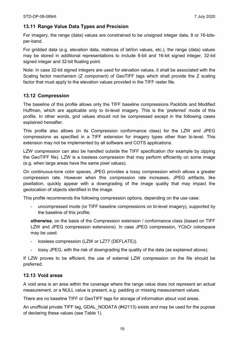
13.11 Range Value Data Types and Precision For imagery, the range (data) values are constrained to be unsigned integer data, 8 or 16-bits-per-band.
For gridded data (e.g. elevation data, matrices of lat/lon values, etc.), the range (data) values may be stored in additional representations to include 8-bit and 16-bit signed integer, 32-bit signed integer and 32-bit floating point.
Note: In case 32-bit signed integers are used for elevation values, it shall be associated with the Scaling factor mechanism (Z component) of GeoTIFF tags which shall provide the Z scaling factor that must apply to the elevation values provided in the TIFF raster file.
13.12 Compression The baseline of this profile allows only the TIFF baseline compressions Packbits and Modified Huffman, which are applicable only to bi-level imagery. This is the ‘preferred’ mode of this profile. In other words, grid values should not be compressed except in the following cases explained hereafter.
This profile also allows (in its Compression conformance class) for the LZW and JPEG compressions as specified in a TIFF extension for imagery types other than bi-level. This extension may not be implemented by all software and COTS applications.
LZW compression can also be handled outside the TIFF specification (for example by zipping the GeoTIFF file). LZW is a lossless compression that may perform efficiently on some image (e.g. when large areas have the same pixel values).
On continuous-tone color spaces, JPEG provides a lossy compression which allows a greater compression rate. However when this compression rate increases, JPEG artifacts, like pixellation, quickly appear with a downgrading of the image quality that may impact the geolocation of objects identified in the image.
This profile recommends the following compression options, depending on the use case:
- uncompressed mode (or TIFF baseline compressions on bi-level imagery), supported by the baseline of this profile;
otherwise, on the basis of the Compression extension / conformance class (based on TIFF LZW and JPEG compression extensions). In case JPEG compression, YCbCr colorspace may be used.
- lossless compression (LZW or LZ77 (DEFLATE)).
- lossy JPEG, with the risk of downgrading the quality of the data (as explained above).
If LZW proves to be efficient, the use of external LZW compression on the file should be preferred.
13.13 Void areas A void area is an area within the coverage where the range value does not represent an actual measurement, or a NULL value is present, e.g. padding or missing measurement values.
There are no baseline TIFF or GeoTIFF tags for storage of information about void areas.
An unofficial private TIFF tag, GDAL_NODATA (#42113) exists and may be used for the pupose of declaring these values (see Table 1).
STD-DP-08-089r6 7 July 2020
20
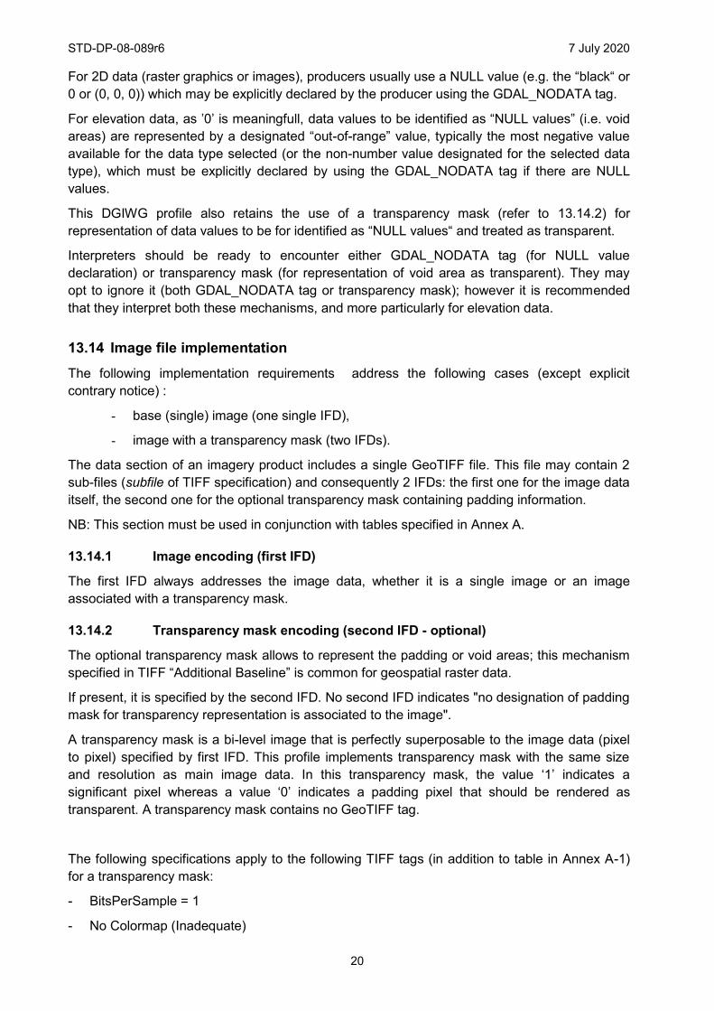
For 2D data (raster graphics or images), producers usually use a NULL value (e.g. the “black“ or 0 or (0, 0, 0)) which may be explicitly declared by the producer using the GDAL_NODATA tag.
For elevation data, as ’0’ is meaningfull, data values to be identified as “NULL values” (i.e. void areas) are represented by a designated “out-of-range” value, typically the most negative value available for the data type selected (or the non-number value designated for the selected data type), which must be explicitly declared by using the GDAL_NODATA tag if there are NULL values.
This DGIWG profile also retains the use of a transparency mask (refer to 13.14.2) for representation of data values to be for identified as “NULL values“ and treated as transparent.
Interpreters should be ready to encounter either GDAL_NODATA tag (for NULL value declaration) or transparency mask (for representation of void area as transparent). They may opt to ignore it (both GDAL_NODATA tag or transparency mask); however it is recommended that they interpret both these mechanisms, and more particularly for elevation data.
13.14 Image file implementation The following implementation requirements address the following cases (except explicit contrary notice) :
- base (single) image (one single IFD),
- image with a transparency mask (two IFDs).
The data section of an imagery product includes a single GeoTIFF file. This file may contain 2 sub-files (subfile of TIFF specification) and consequently 2 IFDs: the first one for the image data itself, the second one for the optional transparency mask containing padding information.
NB: This section must be used in conjunction with tables specified in Annex A.
13.14.1 Image encoding (first IFD)
The first IFD always addresses the image data, whether it is a single image or an image associated with a transparency mask.
13.14.2 Transparency mask encoding (second IFD - optional)
The optional transparency mask allows to represent the padding or void areas; this mechanism specified in TIFF “Additional Baseline” is common for geospatial raster data.
If present, it is specified by the second IFD. No second IFD indicates "no designation of padding mask for transparency representation is associated to the image".
A transparency mask is a bi-level image that is perfectly superposable to the image data (pixel to pixel) specified by first IFD. This profile implements transparency mask with the same size and resolution as main image data. In this transparency mask, the value ‘1’ indicates a significant pixel whereas a value ‘0’ indicates a padding pixel that should be rendered as transparent. A transparency mask contains no GeoTIFF tag.
The following specifications apply to the following TIFF tags (in addition to table in Annex A-1) for a transparency mask:
- BitsPerSample = 1
- No Colormap (Inadequate)
STD-DP-08-089r6 7 July 2020
21
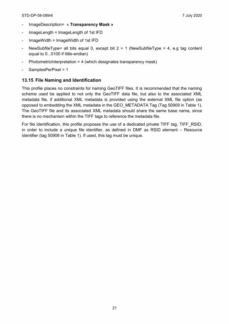
- ImageDescription= « Transparency Mask »
- ImageLength = ImageLength of 1st IFD
- ImageWidth = ImageWidth of 1st IFD
- NewSubfileType= all bits equal 0, except bit 2 = 1 (NewSubfileType = 4, e.g tag content equal to 0...0100 if little-endian)
- PhotometricInterpretation = 4 (which designates transparency mask)
- SamplesPerPixel = 1
13.15 File Naming and Identification This profile places no constraints for naming GeoTIFF files. It is recommended that the naming scheme used be applied to not only the GeoTIFF data file, but also to the associated XML metadata file, if additional XML metadata is provided using the external XML file option (as opposed to embedding the XML metadata in the GEO_METADATA Tag (Tag 50909 in Table 1). The GeoTIFF file and its associated XML metadata should share the same base name, since there is no mechanism within the TIFF tags to reference the metadata file.
For file identification, this profile proposes the use of a dedicated private TIFF tag, TIFF_RSID, in order to include a unique file identifier, as defined in DMF as RSID element ± Resource Identifier (tag 50908 in Table 1). If used, this tag must be unique.
STD-DP-08-089r6 7 July 2020
22
Annex A - TIFF / GeoTIFF Format Constraints (normative)
The following tables specify the required content and rules for TIFF and GEOTIFF tags used for georeferenced imagery in this profile. It also specifies the TIFF and GeoTIFF tags that are not used by this profile, and in some cases that must not be used when conforming this profile.
These tables address the 2 following cases: base (single) image, image with a transparency mask. Following information addresses these 2 cases, except explicit contrary notice.
Legend for following tables:
- Columns Field, Description, Tag and Type refer to corresponding specification items of tag (resp. geokey) according to TIFF (resp. GeoTIFF) specifications.
- Card column specifies cardinality of the item.
- ROCI column specifies presence of the item:
- R : required
- O : optional
- C : conditional (condition must be specified)
- I : inadequate for profile (not applicable for georeferenced imagery conformant to this profile)
- Restricted values for the profile: indicates (when applicable) required values for tag or geokey for this profile.
- TM: transparency mask.
A - 1 TIFF Format NB: An asterisk next to the tag number indicates the additional TIFF fields and extensions needed to support the profile. These asterisked tags are in addition to those listed in the TIFF baseline (Section 8 of [TIFF]).
STD-DP-08-089r6 7 July 2020
23
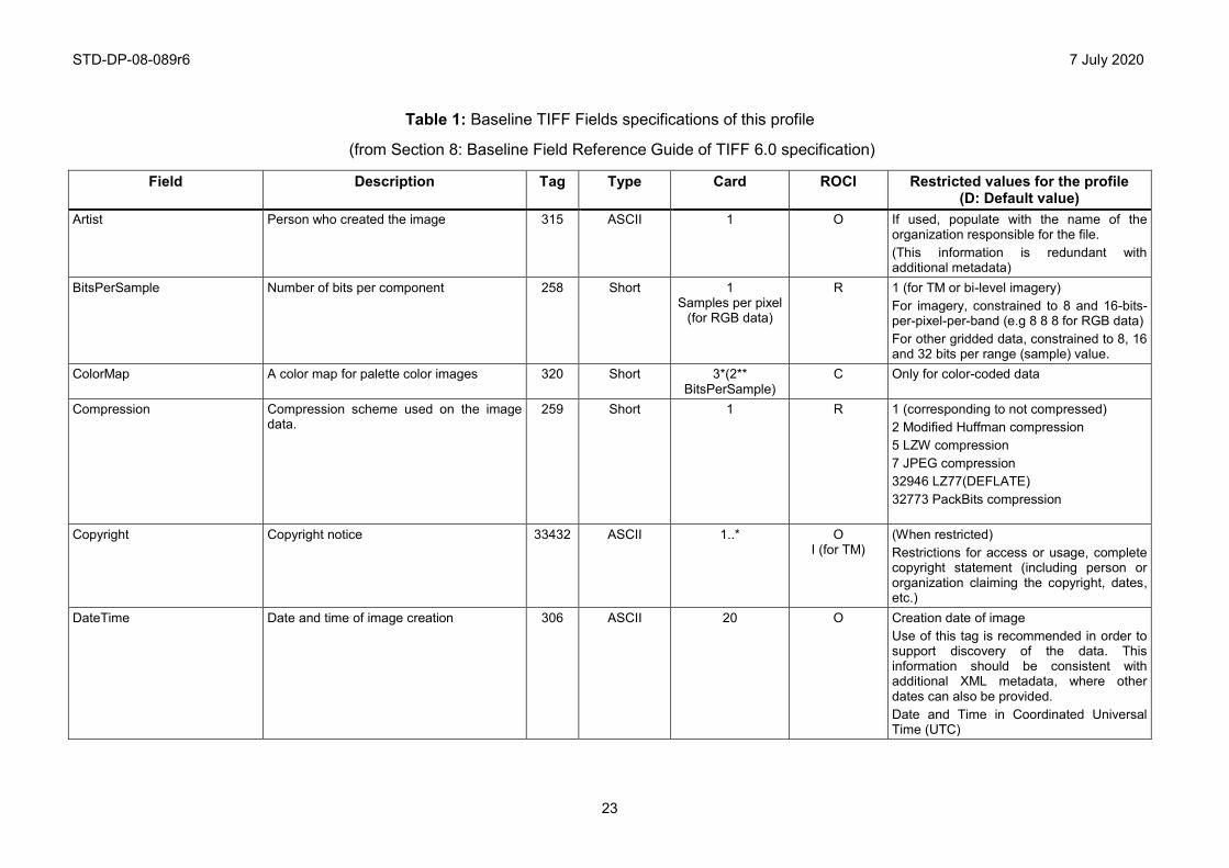
Table 1: Baseline TIFF Fields specifications of this profile
(from Section 8: Baseline Field Reference Guide of TIFF 6.0 specification)
Field
Description
Tag Type Card ROCI Restricted values for the profile (D: Default value)
Artist Person who created the image 315 ASCII 1 O If used, populate with the name of the organization responsible for the file. (This information is redundant with additional metadata)
BitsPerSample Number of bits per component
258 Short 1 Samples per pixel
(for RGB data)
R 1 (for TM or bi-level imagery) For imagery, constrained to 8 and 16-bits-per-pixel-per-band (e.g 8 8 8 for RGB data) For other gridded data, constrained to 8, 16 and 32 bits per range (sample) value.
ColorMap A color map for palette color images 320 Short 3*(2** BitsPerSample)
C Only for color-coded data
Compression Compression scheme used on the image data.
259 Short 1 R 1 (corresponding to not compressed) 2 Modified Huffman compression 5 LZW compression 7 JPEG compression 32946 LZ77(DEFLATE) 32773 PackBits compression
Copyright Copyright notice
33432 ASCII 1..* O I (for TM)
(When restricted) Restrictions for access or usage, complete copyright statement (including person or organization claiming the copyright, dates, etc.)
DateTime Date and time of image creation
306 ASCII 20 O
Creation date of image Use of this tag is recommended in order to support discovery of the data. This information should be consistent with additional XML metadata, where other dates can also be provided. Date and Time in Coordinated Universal Time (UTC)
STD-DP-08-089r6 7 July 2020
24
Field
Description
Tag Type Card ROCI Restricted values for the profile (D: Default value)
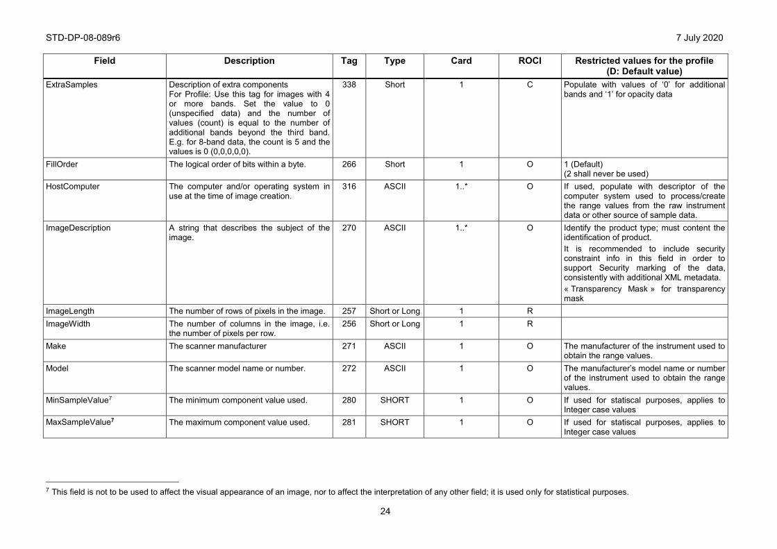
ExtraSamples Description of extra components For Profile: Use this tag for images with 4 or more bands. Set the value to 0 (unspecified data) and the number of values (count) is equal to the number of additional bands beyond the third band. E.g. for 8-band data, the count is 5 and the values is 0 (0,0,0,0,0).
338 Short 1 C Populate with values of ‘0’ for additional bands and ‘1’ for opacity data
FillOrder The logical order of bits within a byte.
266 Short 1 O 1 (Default) (2 shall never be used)
HostComputer The computer and/or operating system in use at the time of image creation.
316 ASCII 1..* O If used, populate with descriptor of the computer system used to process/create the range values from the raw instrument data or other source of sample data.
ImageDescription A string that describes the subject of the image.
270 ASCII 1..* O
Identify the product type; must content the identification of product. It is recommended to include security constraint info in this field in order to support Security marking of the data, consistently with additional XML metadata. « Transparency Mask » for transparency mask
ImageLength The number of rows of pixels in the image. 257 Short or Long 1 R ImageWidth The number of columns in the image, i.e.
the number of pixels per row. 256 Short or Long 1 R
Make The scanner manufacturer 271 ASCII 1 O The manufacturer of the instrument used to obtain the range values.
Model The scanner model name or number.
272 ASCII 1 O The manufacturer’s model name or number of the instrument used to obtain the range values.
MinSampleValue7 The minimum component value used.
280 SHORT 1 O If used for statiscal purposes, applies to Integer case values
MaxSampleValue7 The maximum component value used.
281 SHORT 1 O If used for statiscal purposes, applies to Integer case values
7 This field is not to be used to affect the visual appearance of an image, nor to affect the interpretation of any other field; it is used only for statistical purposes.
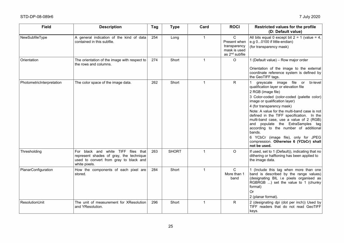
STD-DP-08-089r6 7 July 2020
25
Field
Description
Tag Type Card ROCI Restricted values for the profile (D: Default value)
NewSubfileType A general indication of the kind of data contained in this subfile.
254 Long 1 C Present when transparency mask is used as 2nd subfile
All bits equal 0 except bit 2 = 1 (value = 4, e.g 0...0100 if little-endian) (for transparency mask)
Orientation The orientation of the image with respect to the rows and columns.
274 Short 1 O 1 (Default value) ± Row major order Orientation of the image to the external coordinate reference system is defined by the GeoTIFF tags.
PhotometricInterpretation The color space of the image data. 262 Short 1 R 1 greyscale image file or bi-level qualification layer or elevation file 2 RGB (image file) 3 Color-coded (color-coded (palette color) image or qualification layer) 4 (for transparency mask) Note: A value for the multi-band case is not defined in the TIFF specification. In the multi-band case, use a value of 2 (RGB) and populate the ExtraSamples tag according to the number of additional bands. 6 YCbCr (image file), only for JPEG compression. Otherwise 6 (YCbCr) shall not be used.
Thresholding For black and white TIFF files that represent shades of gray, the technique used to convert from gray to black and white pixels.
263 SHORT 1 O If used, set to 1 (Default)), indicating that no dithering or halftoning has been applied to the image data.
PlanarConfiguration How the components of each pixel are stored.
284 Short 1 C More than 1
band
1 (Include this tag when more than one band is described by the range values) (designating BIL i.e pixels organised as RGBRGB ...) set the value to 1 (chunky format) Or 2 (planar format).
ResolutionUnit The unit of measurement for XResolution and YResolution.
296 Short 1 R 2 (designating dpi (dot per inch)) Used by TIFF readers that do not read GeoTIFF keys.
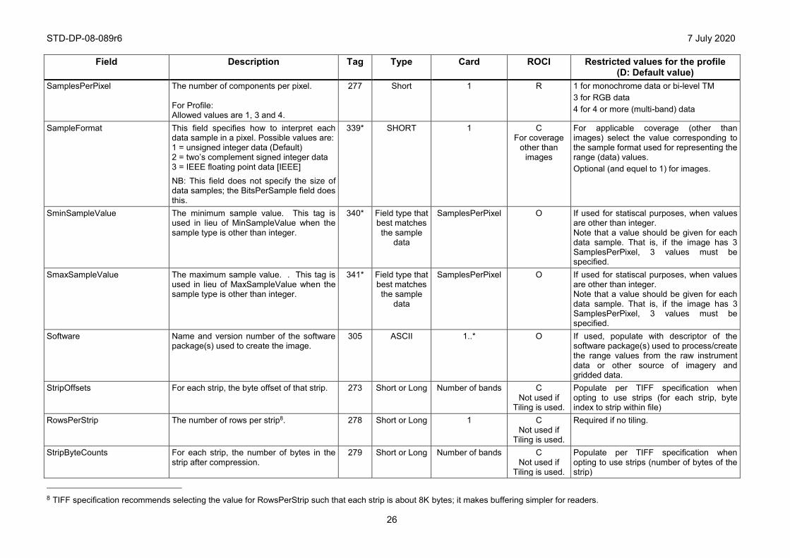
STD-DP-08-089r6 7 July 2020
26
Field
Description
Tag Type Card ROCI Restricted values for the profile (D: Default value)
SamplesPerPixel The number of components per pixel. For Profile: Allowed values are 1, 3 and 4.
277 Short 1 R 1 for monochrome data or bi-level TM 3 for RGB data 4 for 4 or more (multi-band) data
SampleFormat This field specifies how to interpret each data sample in a pixel. Possible values are: 1 = unsigned integer data (Default) 2 = two’s complement signed integer data 3 = IEEE floating point data [IEEE]
NB: This field does not specify the size of data samples; the BitsPerSample field does this.
339* SHORT 1 C For coverage
other than images
For applicable coverage (other than images) select the value corresponding to the sample format used for representing the range (data) values. Optional (and equel to 1) for images.
SminSampleValue The minimum sample value. This tag is used in lieu of MinSampleValue when the sample type is other than integer.
340* Field type that best matches the sample
data
SamplesPerPixel O If used for statiscal purposes, when values are other than integer. Note that a value should be given for each data sample. That is, if the image has 3 SamplesPerPixel, 3 values must be specified.
SmaxSampleValue The maximum sample value. . This tag is used in lieu of MaxSampleValue when the sample type is other than integer.
341* Field type that best matches the sample
data
SamplesPerPixel O If used for statiscal purposes, when values are other than integer. Note that a value should be given for each data sample. That is, if the image has 3 SamplesPerPixel, 3 values must be specified.
Software Name and version number of the software package(s) used to create the image.
305 ASCII 1..* O If used, populate with descriptor of the software package(s) used to process/create the range values from the raw instrument data or other source of imagery and gridded data.
StripOffsets For each strip, the byte offset of that strip.
273 Short or Long Number of bands C Not used if
Tiling is used.
Populate per TIFF specification when opting to use strips (for each strip, byte index to strip within file)
RowsPerStrip The number of rows per strip8. 278 Short or Long 1 C Not used if
Tiling is used.
Required if no tiling.
StripByteCounts For each strip, the number of bytes in the strip after compression.
279 Short or Long Number of bands C Not used if
Tiling is used.
Populate per TIFF specification when opting to use strips (number of bytes of the strip)
8 TIFF specification recommends selecting the value for RowsPerStrip such that each strip is about 8K bytes; it makes buffering simpler for readers.
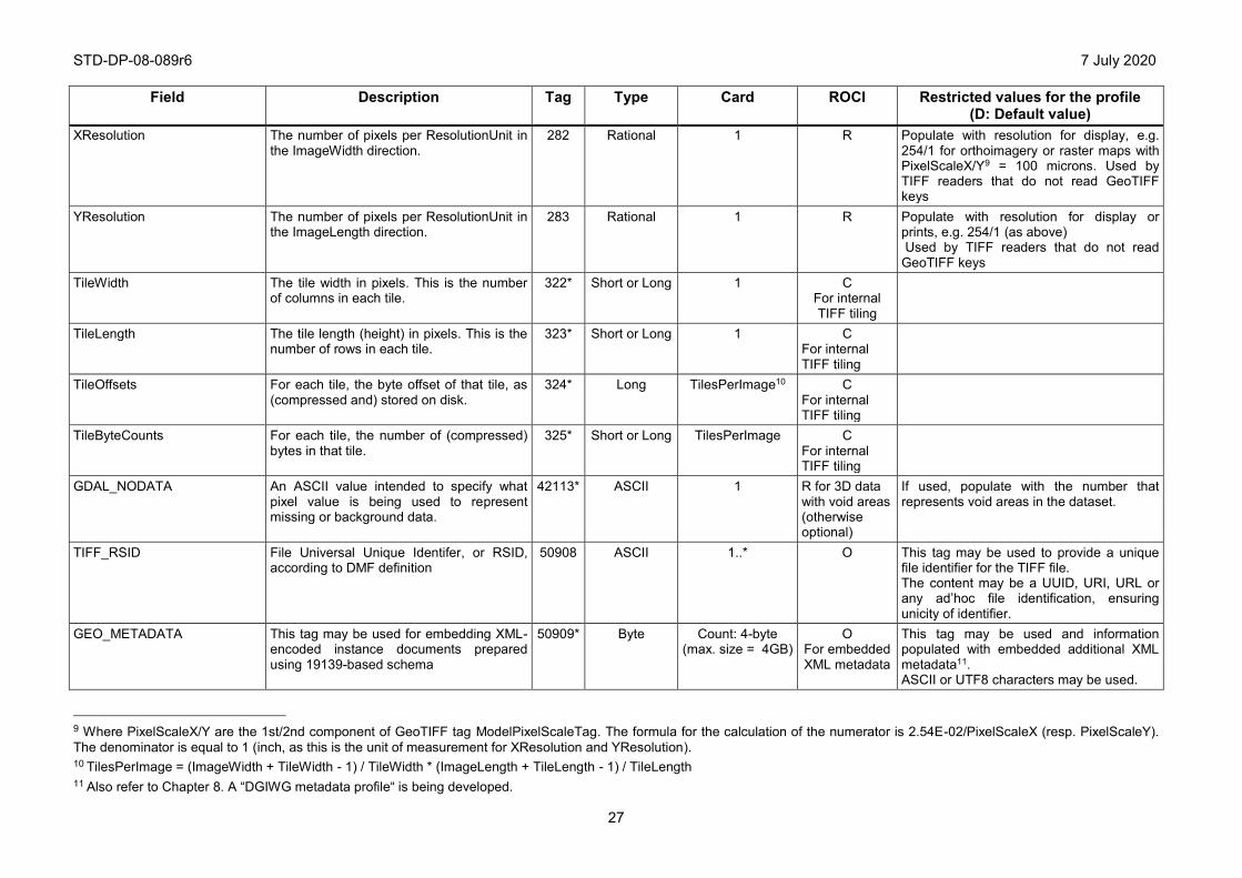
STD-DP-08-089r6 7 July 2020
27
Field
Description
Tag Type Card ROCI Restricted values for the profile (D: Default value)
XResolution The number of pixels per ResolutionUnit in the ImageWidth direction.
282 Rational 1 R Populate with resolution for display, e.g. 254/1 for orthoimagery or raster maps with PixelScaleX/Y9 = 100 microns. Used by TIFF readers that do not read GeoTIFF keys
YResolution The number of pixels per ResolutionUnit in the ImageLength direction.
283 Rational 1 R Populate with resolution for display or prints, e.g. 254/1 (as above) Used by TIFF readers that do not read GeoTIFF keys
TileWidth The tile width in pixels. This is the number of columns in each tile.
322* Short or Long 1 C For internal TIFF tiling
TileLength The tile length (height) in pixels. This is the number of rows in each tile.
323* Short or Long 1 C For internal TIFF tiling
TileOffsets For each tile, the byte offset of that tile, as (compressed and) stored on disk.
324* Long TilesPerImage10
C For internal TIFF tiling
TileByteCounts For each tile, the number of (compressed) bytes in that tile.
325* Short or Long TilesPerImage C For internal TIFF tiling
GDAL_NODATA An ASCII value intended to specify what pixel value is being used to represent missing or background data.
42113* ASCII 1 R for 3D data with void areas (otherwise optional)
If used, populate with the number that represents void areas in the dataset.
TIFF_RSID File Universal Unique Identifer, or RSID, according to DMF definition
50908 ASCII 1..* O This tag may be used to provide a unique file identifier for the TIFF file. The content may be a UUID, URI, URL or any ad’hoc file identification, ensuring unicity of identifier.
GEO_METADATA This tag may be used for embedding XML-encoded instance documents prepared using 19139-based schema
50909* Byte Count: 4-byte (max. size = 4GB)
O For embedded XML metadata
This tag may be used and information populated with embedded additional XML metadata11. ASCII or UTF8 characters may be used.
9 Where PixelScaleX/Y are the 1st/2nd component of GeoTIFF tag ModelPixelScaleTag. The formula for the calculation of the numerator is 2.54E-02/PixelScaleX (resp. PixelScaleY). The denominator is equal to 1 (inch, as this is the unit of measurement for XResolution and YResolution). 10 TilesPerImage = (ImageWidth + TileWidth - 1) / TileWidth * (ImageLength + TileLength - 1) / TileLength
11 Also refer to Chapter 8. A “DGIWG metadata profile“ is being developed.
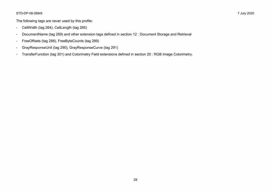
STD-DP-08-089r6 7 July 2020
28
The following tags are never used by this profile:
- CellWidth (tag 264), CellLength (tag 265)
- DocumentName (tag 269) and other extension tags defined in section 12 : Document Storage and Retrieval
- FreeOffsets (tag 288), FreeByteCounts (tag 289)
- GrayResponseUnit (tag 290), GrayResponseCurve (tag 291)
- TransferFunction (tag 301) and Colorimetry Field extensions defined in section 20 : RGB Image Colorimetry.
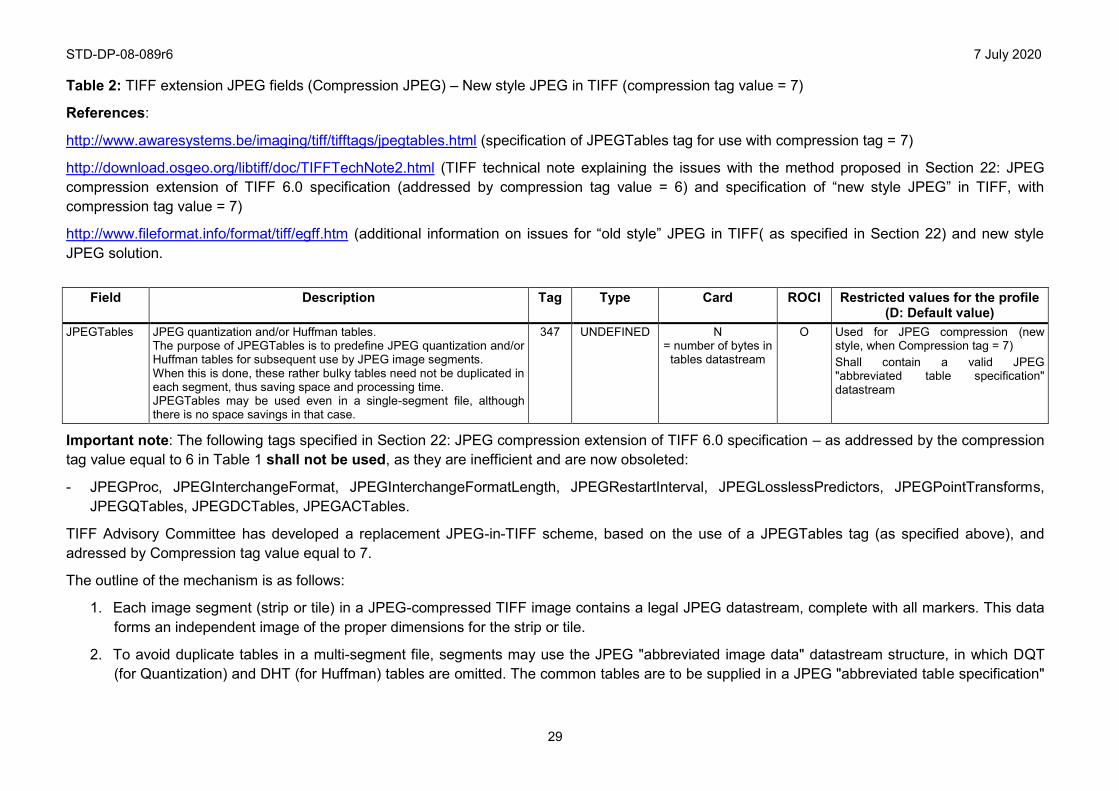
STD-DP-08-089r6 7 July 2020
29
Table 2: TIFF extension JPEG fields (Compression JPEG) – New style JPEG in TIFF (compression tag value = 7)
References:
http://www.awaresystems.be/imaging/tiff/tifftags/jpegtables.html (specification of JPEGTables tag for use with compression tag = 7)
http://download.osgeo.org/libtiff/doc/TIFFTechNote2.html (TIFF technical note explaining the issues with the method proposed in Section 22: JPEG compression extension of TIFF 6.0 specification (addressed by compression tag value = 6) and specification of “new style JPEG” in TIFF, with compression tag value = 7)
http://www.fileformat.info/format/tiff/egff.htm (additional information on issues for “old style” JPEG in TIFF( as specified in Section 22) and new style JPEG solution.
Field
Description
Tag Type Card ROCI Restricted values for the profile
(D: Default value) JPEGTables JPEG quantization and/or Huffman tables.
The purpose of JPEGTables is to predefine JPEG quantization and/or Huffman tables for subsequent use by JPEG image segments. When this is done, these rather bulky tables need not be duplicated in each segment, thus saving space and processing time. JPEGTables may be used even in a single-segment file, although there is no space savings in that case.
347 UNDEFINED N = number of bytes in
tables datastream
O Used for JPEG compression (new style, when Compression tag = 7) Shall contain a valid JPEG "abbreviated table specification" datastream
Important note: The following tags specified in Section 22: JPEG compression extension of TIFF 6.0 specification – as addressed by the compression tag value equal to 6 in Table 1 shall not be used, as they are inefficient and are now obsoleted:
- JPEGProc, JPEGInterchangeFormat, JPEGInterchangeFormatLength, JPEGRestartInterval, JPEGLosslessPredictors, JPEGPointTransforms, JPEGQTables, JPEGDCTables, JPEGACTables.
TIFF Advisory Committee has developed a replacement JPEG-in-TIFF scheme, based on the use of a JPEGTables tag (as specified above), and adressed by Compression tag value equal to 7.
The outline of the mechanism is as follows:
1. Each image segment (strip or tile) in a JPEG-compressed TIFF image contains a legal JPEG datastream, complete with all markers. This data forms an independent image of the proper dimensions for the strip or tile.
2. To avoid duplicate tables in a multi-segment file, segments may use the JPEG "abbreviated image data" datastream structure, in which DQT (for Quantization) and DHT (for Huffman) tables are omitted. The common tables are to be supplied in a JPEG "abbreviated table specification"
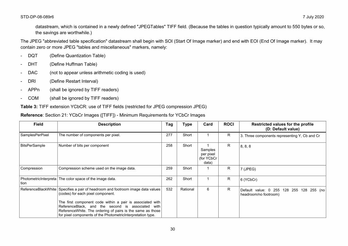
STD-DP-08-089r6 7 July 2020
30
datastream, which is contained in a newly defined "JPEGTables" TIFF field. (Because the tables in question typically amount to 550 bytes or so, the savings are worthwhile.)
The JPEG "abbreviated table specification" datastream shall begin with SOI (Start Of Image marker) and end with EOI (End Of Image marker). It may contain zero or more JPEG "tables and miscellaneous" markers, namely:
- DQT (Define Quantization Table)
- DHT (Define Huffman Table)
- DAC (not to appear unless arithmetic coding is used)
- DRI (Define Restart Interval)
- APPn (shall be ignored by TIFF readers)
- COM (shall be ignored by TIFF readers)
Table 3: TIFF extension YCbCR: use of TIFF fields (restricted for JPEG compression JPEG)
Reference: Section 21: YCbCr Images ([TIFF]) - Minimum Requirements for YCbCr Images
Field
Description
Tag Type Card ROCI Restricted values for the profile (D: Default value)
SamplesPerPixel The number of components per pixel. 277 Short 1 R 3. Three components representing Y, Cb and Cr
BitsPerSample Number of bits per component
258 Short 1 Samples per pixel
(for YCbCr data)
R 8, 8, 8
Compression Compression scheme used on the image data. 259 Short 1 R 7 (JPEG)
PhotometricInterpretation
The color space of the image data. 262 Short 1 R 6 (YCbCr)
ReferenceBlackWhite Specifies a pair of headroom and footroom image data values (codes) for each pixel component. The first component code within a pair is associated with ReferenceBlack, and the second is associated with ReferenceWhite. The ordering of pairs is the same as those for pixel components of the PhotometricInterpretation type.
532 Rational 6 R Default value: 0 255 128 255 128 255 (no headroom/no footroom)
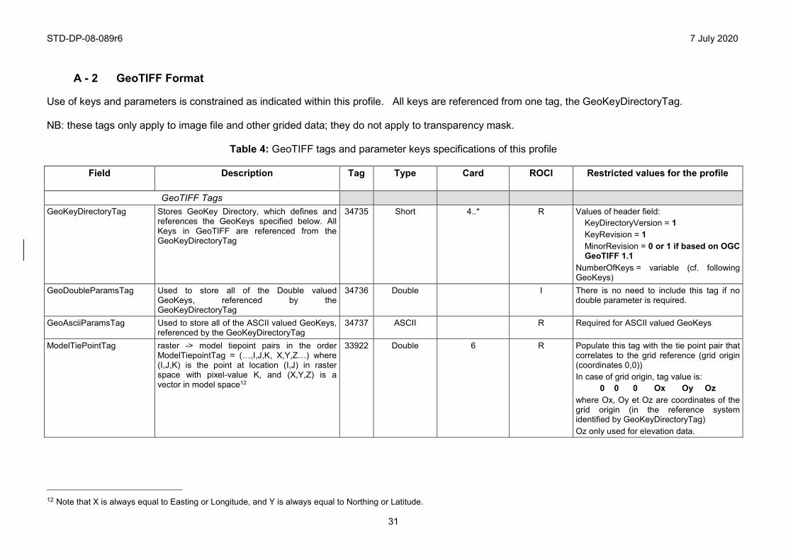
STD-DP-08-089r6 7 July 2020
31
A - 2 GeoTIFF Format Use of keys and parameters is constrained as indicated within this profile. All keys are referenced from one tag, the GeoKeyDirectoryTag. NB: these tags only apply to image file and other grided data; they do not apply to transparency mask.
Table 4: GeoTIFF tags and parameter keys specifications of this profile
Field
Description
Tag Type Card ROCI Restricted values for the profile
GeoTIFF Tags GeoKeyDirectoryTag Stores GeoKey Directory, which defines and
references the GeoKeys specified below. All Keys in GeoTIFF are referenced from the GeoKeyDirectoryTag
34735 Short 4..* R Values of header field: KeyDirectoryVersion = 1 KeyRevision = 1 MinorRevision = 0 or 1 if based on OGC GeoTIFF 1.1
NumberOfKeys = variable (cf. following GeoKeys)
GeoDoubleParamsTag Used to store all of the Double valued GeoKeys, referenced by the GeoKeyDirectoryTag
34736 Double I There is no need to include this tag if no double parameter is required.
GeoAsciiParamsTag
Used to store all of the ASCII valued GeoKeys, referenced by the GeoKeyDirectoryTag
34737 ASCII R Required for ASCII valued GeoKeys
ModelTiePointTag raster -> model tiepoint pairs in the order ModelTiepointTag = (…,I,J,K, X,Y,Z…) where (I,J,K) is the point at location (I,J) in raster space with pixel-value K, and (X,Y,Z) is a vector in model space12
33922 Double 6 R Populate this tag with the tie point pair that correlates to the grid reference (grid origin (coordinates 0,0)) In case of grid origin, tag value is:
0 0 0 Ox Oy Oz where Ox, Oy et Oz are coordinates of the grid origin (in the reference system identified by GeoKeyDirectoryTag) Oz only used for elevation data.
12 Note that X is always equal to Easting or Longitude, and Y is always equal to Northing or Latitude.
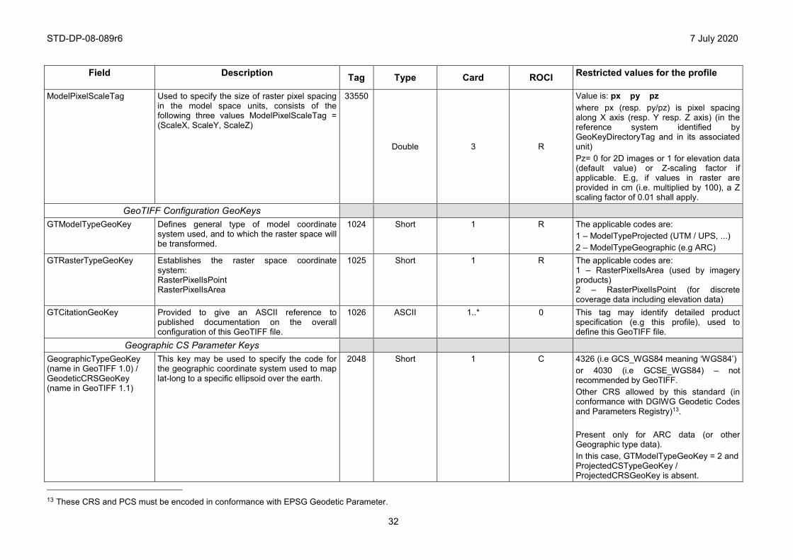
STD-DP-08-089r6 7 July 2020
32
Field
Description
Tag Type Card ROCI Restricted values for the profile
ModelPixelScaleTag Used to specify the size of raster pixel spacing in the model space units, consists of the following three values ModelPixelScaleTag = (ScaleX, ScaleY, ScaleZ)
33550
Double 3 R
Value is: px py pz where px (resp. py/pz) is pixel spacing along X axis (resp. Y resp. Z axis) (in the reference system identified by GeoKeyDirectoryTag and in its associated unit) Pz= 0 for 2D images or 1 for elevation data (default value) or Z-scaling factor if applicable. E.g, if values in raster are provided in cm (i.e. multiplied by 100), a Z scaling factor of 0.01 shall apply.
GeoTIFF Configuration GeoKeys GTModelTypeGeoKey Defines general type of model coordinate
system used, and to which the raster space will be transformed.
1024 Short 1 R The applicable codes are: 1 – ModelTypeProjected (UTM / UPS, ...) 2 – ModelTypeGeographic (e.g ARC)
GTRasterTypeGeoKey Establishes the raster space coordinate system: RasterPixelIsPoint RasterPixelIsArea
1025 Short 1 R The applicable codes are: 1 – RasterPixelIsArea (used by imagery products) 2 – RasterPixelIsPoint (for discrete coverage data including elevation data)
GTCitationGeoKey Provided to give an ASCII reference to published documentation on the overall configuration of this GeoTIFF file.
1026 ASCII 1..* 0 This tag may identify detailed product specification (e.g this profile), used to define this GeoTIFF file.
Geographic CS Parameter Keys GeographicTypeGeoKey (name in GeoTIFF 1.0) / GeodeticCRSGeoKey (name in GeoTIFF 1.1)
This key may be used to specify the code for the geographic coordinate system used to map lat-long to a specific ellipsoid over the earth.
2048 Short 1 C 4326 (i.e GCS_WGS84 meaning ‘WGS84’) or 4030 (i.e GCSE_WGS84) – not recommended by GeoTIFF. Other CRS allowed by this standard (in conformance with DGIWG Geodetic Codes and Parameters Registry)13. Present only for ARC data (or other Geographic type data). In this case, GTModelTypeGeoKey = 2 and ProjectedCSTypeGeoKey / ProjectedCRSGeoKey is absent.
13 These CRS and PCS must be encoded in conformance with EPSG Geodetic Parameter.
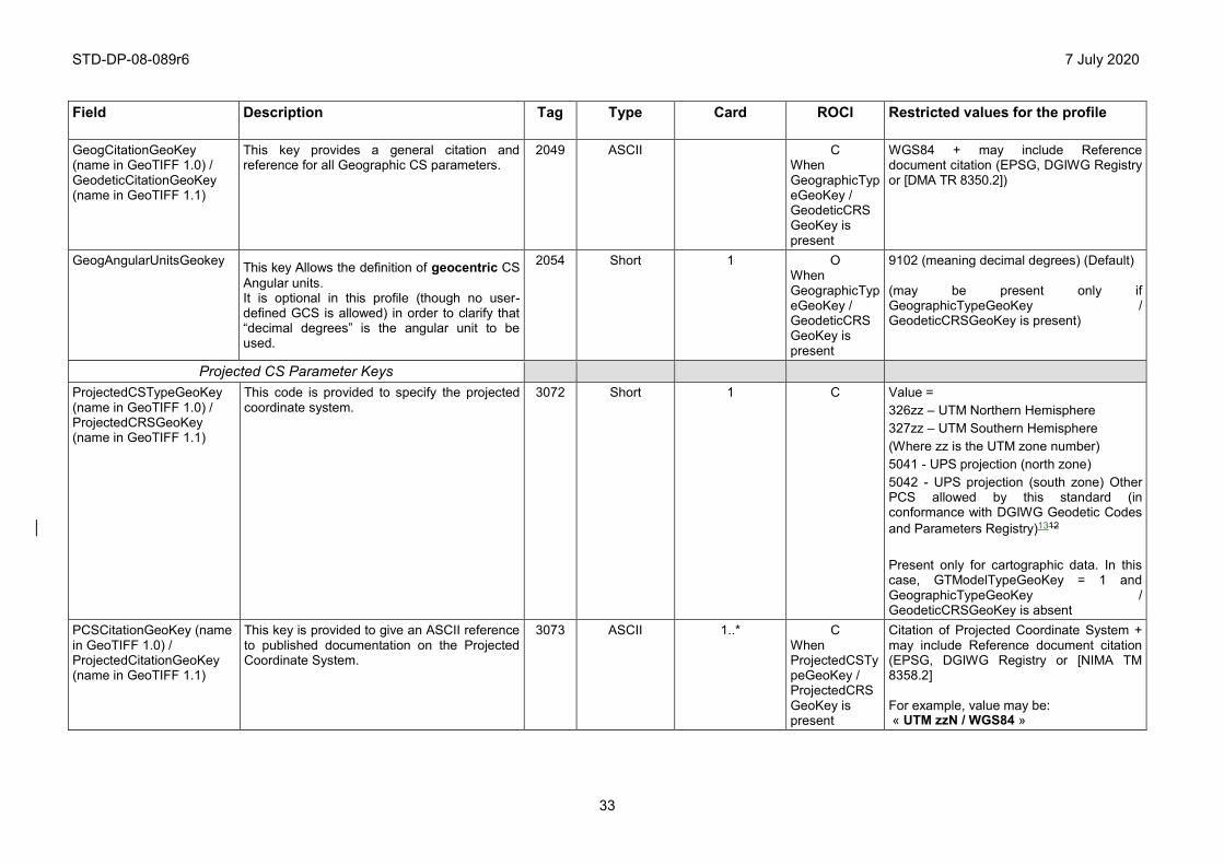
STD-DP-08-089r6 7 July 2020
33
Field
Description
Tag Type Card ROCI Restricted values for the profile
GeogCitationGeoKey (name in GeoTIFF 1.0) / GeodeticCitationGeoKey (name in GeoTIFF 1.1)
This key provides a general citation and reference for all Geographic CS parameters.
2049 ASCII C When GeographicTypeGeoKey / GeodeticCRSGeoKey is present
WGS84 + may include Reference document citation (EPSG, DGIWG Registry or [DMA TR 8350.2])
GeogAngularUnitsGeokey This key Allows the definition of geocentric CS Angular units. It is optional in this profile (though no user-defined GCS is allowed) in order to clarify that “decimal degrees” is the angular unit to be used.
2054 Short 1 O When GeographicTypeGeoKey / GeodeticCRSGeoKey is present
9102 (meaning decimal degrees) (Default) (may be present only if GeographicTypeGeoKey / GeodeticCRSGeoKey is present)
Projected CS Parameter Keys ProjectedCSTypeGeoKey (name in GeoTIFF 1.0) / ProjectedCRSGeoKey (name in GeoTIFF 1.1)
This code is provided to specify the projected coordinate system.
3072 Short 1 C Value = 326zz – UTM Northern Hemisphere 327zz – UTM Southern Hemisphere (Where zz is the UTM zone number) 5041 - UPS projection (north zone) 5042 - UPS projection (south zone) Other PCS allowed by this standard (in conformance with DGIWG Geodetic Codes and Parameters Registry)1312 Present only for cartographic data. In this case, GTModelTypeGeoKey = 1 and GeographicTypeGeoKey / GeodeticCRSGeoKey is absent
PCSCitationGeoKey (name in GeoTIFF 1.0) / ProjectedCitationGeoKey (name in GeoTIFF 1.1)
This key is provided to give an ASCII reference to published documentation on the Projected Coordinate System.
3073 ASCII 1..* C When ProjectedCSTypeGeoKey / ProjectedCRSGeoKey is present
Citation of Projected Coordinate System + may include Reference document citation (EPSG, DGIWG Registry or [NIMA TM 8358.2] For example, value may be: « UTM zzN / WGS84 »
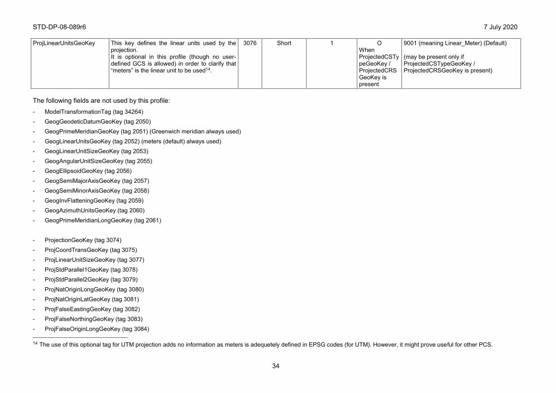
STD-DP-08-089r6 7 July 2020
34
ProjLinearUnitsGeoKey This key defines the linear units used by the projection. It is optional in this profile (though no user-defined GCS is allowed) in order to clarify that “meters” is the linear unit to be used14.
3076 Short 1 O When ProjectedCSTypeGeoKey / ProjectedCRSGeoKey is present
9001 (meaning Linear_Meter) (Default) (may be present only if ProjectedCSTypeGeoKey / ProjectedCRSGeoKey is present)
The following fields are not used by this profile:
- ModelTransformationTag (tag 34264) - GeogGeodeticDatumGeoKey (tag 2050) - GeogPrimeMeridianGeoKey (tag 2051) (Greenwich meridian always used)
- GeogLinearUnitsGeoKey (tag 2052) (meters (default) always used) - GeogLinearUnitSizeGeoKey (tag 2053)
- GeogAngularUnitSizeGeoKey (tag 2055) - GeogEllipsoidGeoKey (tag 2056)
- GeogSemiMajorAxisGeoKey (tag 2057) - GeogSemiMinorAxisGeoKey (tag 2058)
- GeogInvFlatteningGeoKey (tag 2059) - GeogAzimuthUnitsGeoKey (tag 2060)
- GeogPrimeMeridianLongGeoKey (tag 2061)
- ProjectionGeoKey (tag 3074) - ProjCoordTransGeoKey (tag 3075) - ProjLinearUnitSizeGeoKey (tag 3077)
- ProjStdParallel1GeoKey (tag 3078) - ProjStdParallel2GeoKey (tag 3079)
- ProjNatOriginLongGeoKey (tag 3080) - ProjNatOriginLatGeoKey (tag 3081)
- ProjFalseEastingGeoKey (tag 3082) - ProjFalseNorthingGeoKey (tag 3083)
- ProjFalseOriginLongGeoKey (tag 3084) 14 The use of this optional tag for UTM projection adds no information as meters is adequetely defined in EPSG codes (for UTM). However, it might prove useful for other PCS.

STD-DP-08-089r6 7 July 2020
35
- ProjFalseOriginLatGeoKey (tag 3085)
- ProjFalseOriginEastingGeoKey (tag 3086) - ProjFalseOriginNorthingGeoKey (tag 3087)
- ProjCenterLongGeoKey (tag 3088) - ProjCenterLatGeoKey (tag 3089)
- ProjCenterEastingGeoKey (tag 3090) - ProjCenterNorthingGeoKey (tag 3091)
- ProjScaleAtNatOriginGeoKey (tag 3092) - ProjScaleAtCenterGeoKey (tag 3093)
- ProjAzimuthAngleGeoKey (tag 3094) - ProjStraightVertPoleLongGeoKey (tag 3095)
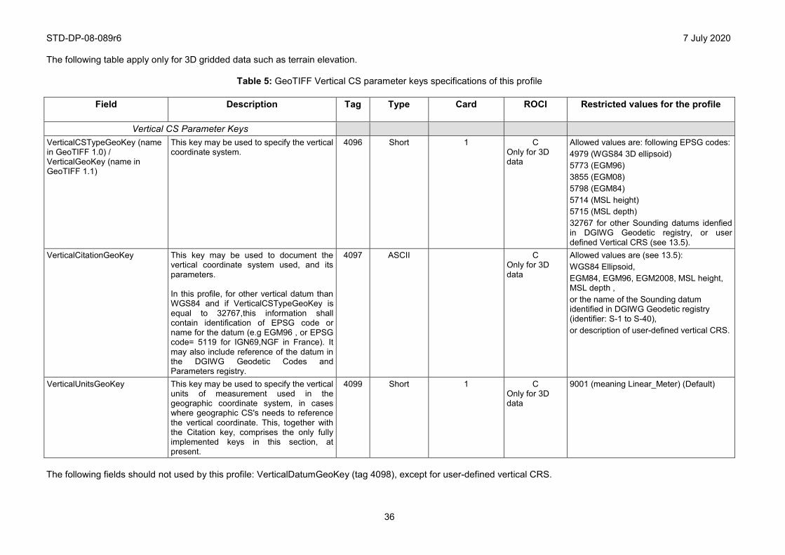
STD-DP-08-089r6 7 July 2020
36
The following table apply only for 3D gridded data such as terrain elevation.
Table 5: GeoTIFF Vertical CS parameter keys specifications of this profile
Field
Description
Tag Type Card ROCI Restricted values for the profile
Vertical CS Parameter Keys VerticalCSTypeGeoKey (name in GeoTIFF 1.0) / VerticalGeoKey (name in GeoTIFF 1.1)
This key may be used to specify the vertical coordinate system.
4096 Short 1 C Only for 3D data
Allowed values are: following EPSG codes: 4979 (WGS84 3D ellipsoid) 5773 (EGM96) 3855 (EGM08) 5798 (EGM84) 5714 (MSL height) 5715 (MSL depth) 32767 for other Sounding datums idenfied in DGIWG Geodetic registry, or user defined Vertical CRS (see 13.5).
VerticalCitationGeoKey This key may be used to document the vertical coordinate system used, and its parameters. In this profile, for other vertical datum than WGS84 and if VerticalCSTypeGeoKey is equal to 32767,this information shall contain identification of EPSG code or name for the datum (e.g EGM96 , or EPSG code= 5119 for IGN69,NGF in France). It may also include reference of the datum in the DGIWG Geodetic Codes and Parameters registry.
4097 ASCII C Only for 3D data
Allowed values are (see 13.5): WGS84 Ellipsoid, EGM84, EGM96, EGM2008, MSL height, MSL depth , or the name of the Sounding datum identified in DGIWG Geodetic registry (identifier: S-1 to S-40), or description of user-defined vertical CRS.
VerticalUnitsGeoKey This key may be used to specify the vertical units of measurement used in the geographic coordinate system, in cases where geographic CS's needs to reference the vertical coordinate. This, together with the Citation key, comprises the only fully implemented keys in this section, at present.
4099 Short 1 C Only for 3D data
9001 (meaning Linear_Meter) (Default)
The following fields should not used by this profile: VerticalDatumGeoKey (tag 4098), except for user-defined vertical CRS.
STD-DP-08-089r6 7 July 2020
37
Annex B - Conformance test suites
(normative) This annex introduces the methodology for the conformance tests for this profile, and provides the conformance test suites relevant to TIFF and GeoTIFF profiling, specified in their respective conformance statements tables.
B - 1 Purpose, scope, and methodology Purpose
To determine the extent a system or product conforms to this profile for the interpretation and generation of GeoTIFF files as constrained by this implementation profile.
Scope
Conformance testing will focus on the GeoTIFF features capabilities of the tested system or product. Testers will check for conformance with this profile and also with the standards and specifications that were used as normative documents in the construction of this profile. The intent is to provide a high level of confidence that an implementation conforms to the profile. The term ‘GeoTIFF’ as used within the context of this appendix generally means TIFF and GeoTIFF as specified by this profile.
Methodology
The GeoTIFF testing methodology uses a combination of test cases designed to address the ability of the Implementation Under Test (IUT) to interpret and/or generate GeoTIFF compliant data files.
The test sponsor fills out the Implementation Conformance Statements (ICS) shown in B-3 (using √ adequately). The tester uses this information to design the test scenarios and set of test cases to be used in the test campaign. The test scenarios and test cases exercise the following test strategy:
- Use: The use portion of GeoTIFF compliance testing determines the degree to which a GeoTIFF application can properly use / interpret GeoTIFF formatted files. Interpret applications, at a minimum, must be robust enough to unpack, interpret, and display any GeoTIFF compliant file. Testers present the IUT with test case files designed to exercise the minimum required capabilities for all interpret applications. Testers also present the IUT with test case files designed to exercise the optional GeoTIFF features the IUT is required to support as designated by the test sponsor.
- Produce: The produce portion of GeoTIFF compliance testing determines the degree to which a system can generate fully compliant GeoTIFF formatted files. For produce / generate testing, the test sponsor designates the specific GeoTIFF capabilities and features the IUT is required to support for generation of GeoTIFF files. Testers design test scenarios for production of GeoTIFF files (test cases) that exercise the required capabilities and features against the applicable test criteria. The IUT operator generates test case files under the guidance of these test scenarios. The testers evaluate the output test case files for compliance with the applicable portions of the GeoTIFF profile using automated test tools (when available) and visual inspection.
- Data Conformance: Criteria used in the test campaign to evaluate data conformance include:
1. Completeness: checks for presence of mandatory (required) elements. A comparison test shall also be performed to determine if all tags/keys/elements defined as conditional are present when the conditions described in the profile apply.
STD-DP-08-089r6 7 July 2020
38
2. Maximum occurrence (all levels of obligation): ensures each TIFF or GeoTIFF field occurs no more than the number of times specified in this profile.
3. Data Type (all levels of obligation): the value of each provided field is tested to ensure its data type adheres to the data type specified.
4. Restricted values: the values of each tag element are tested to ensure they fall within the specified restricted values.
5. File Format (TIFF structure): The TIFF file structure is as defined by the TIFF specification, and as constrained by this profile.
6. GeoTIFF (GeoTIFF tags): The GeoTIFF tag structures are as defined by the GeoTIFF specification, and as constrained by this profile.
B - 2 Implementation Conformance Tests (normative) B.2.1 Class B: Profile Baseline
All required tags in tables A.1 and A.2 must be present in conformant data, data produced by conformant generator, and may be displayed on conformant use / interpret systems.
According to data instance, if condition applies, relevant requirements must be fulfilled.
This conformance class is based on a strict application of TIFF and GeoTIFF baselines rules.
The restrictions specified by this profile are the following:
x TIFF restrictions: - Multi-band data: use of BIL (TIFF ‘chunky’ format, specified by Tag PlanarConfiguration
= 1) or planar (band sequential)
- No internal compression (specified by Tag Compression = 1), or Modified Huffman, LZW, JPEG (new style), LZ77 (DEFLATE) or PackBits compression.FillOrder (pixel Arrangement within a byte) : value of 2 is forbidden.
x GeoTIFF restrictions:
- Geooreference model: projected (UTM/UPS) or geographic (e.g ARC) (GTModelTypeGeoKey = 1 or 2)
- use of one single ModelTiePoint for georeferencing (associated with ModelPixelScaleTag). Consequently, use of ModelTransformation tag is forbidden
- units: meters for projected data coordinates (UTM) or decimal degrees for geographic coordinates (if these tags are populated, ProjLinearUnitsGeoKey = 9001 or GeogAngularUnitsGeokey = 9102).
B.2.2 Class TM: Transparency Mask conformance class
This class makes use of multi-file capability of TIFF specification, addressed by multiple IFD.
Transparency mask uses a second subfile, addressed by second IFD.
The TIFF restriction specified by this profile for TM conformance class is the following: for 2nd IFD (Transparency Mask), NewSubfileType = 4.
B.2.3 Class IT: Internal tiling conformance class
This class makes use of internal tiling capability of TIFF specification, defined in TIFF extensions.
STD-DP-08-089r6 7 July 2020
39
The TIFF restriction specified by this profile for IT conformance class is the following: if tiling is implemented, Tile dimensions (Tile Length and Width) must be multiple of 16.
NB: It should also be noticed that, according to TIFF specification, use of strip tags is forbidden when using internal tiling.
B.2.4 Class ED: Elevation data conformance class
This class makes use of elevation data encoding (TIFF extension for signed integer or float data) and vertical georeference (GeoTIFF extension).
The TIFF extension specified by this profile for ED conformance class is the following: support of GDAL_NODATA private tag for void areas.
The GeoTIFF restriction specified by this profile for ED conformance class are the following:
- VerticalUnitsGeoKey value = 9001 (meter)
- VerticalCSTypeGeoKey (name in GeoTIFF 1.0) or VerticalGeoKey (name in GeoTIFF 1.1) = Vertical CRS values in table A415 (recommended), or 32767 (user defined)
- VerticalCitationGeoKey = WGS84 or EGM84 or EGM96 or EGM2008 or hydrographic datum name.
B.2.5 Class MB: Multi-band conformance class
This class makes use of the multi-band (4 to 8 bands) capability of TIFF specification, as extended in this specification in 13.10 based on the TIFF extension tag ExtraSamples.
The TIFF extension specified by this profile for MB conformance class is the following: for multi-band data, the following TIFF fields are required:
- SamplesPerPixel = 4, PhotometricInterpretation = 2 (RGB), ExtraSamples count = (number of bands ± 3) (refer to table A.1);
- when opacity data is present, the ExtraSamples count = (number of bands ± 3 + 1 for the opacity data).
B.2.6 Class CO: Compression conformance class
This class makes use of the TIFF LZW and JPEG extensions of TIFF specification, as extended in this specification in 13.12 based on:
- the TIFF extended value for Compression tag for Modified Huffman: 2
- the TIFF extended value for Compression tag for LZW : 5
- the TIFF extended value for Compression tag for JPEG : 7 and the JPEG extension tags as defined in table A2.
- the TIFF extended value for Compression tag for LZ77(DEFLATE): 32946
the TIFF extended value for Compression tag for PackBits: 32773
The restrictions specified by this profile are the following:
- Use of YCbCr colorspace only in case of JPEG compression. 15 Recommended solution, in order to facilitate the use of software / applications (without having to parse textual field and have the agility to identify Vertical CRS inside).
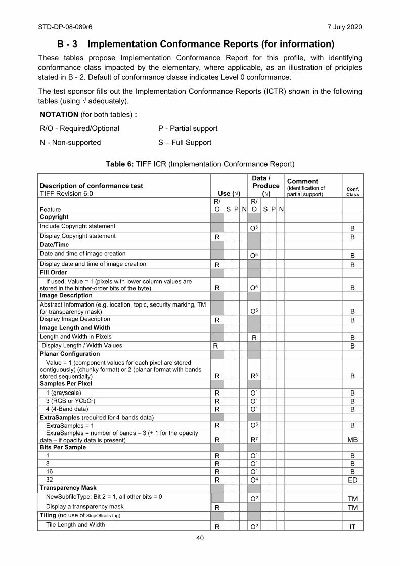
STD-DP-08-089r6 7 July 2020
40
B - 3 Implementation Conformance Reports (for information) These tables propose Implementation Conformance Report for this profile, with identifying conformance class impacted by the elementary, where applicable, as an illustration of priciples stated in B - 2. Default of conformance classe indicates Level 0 conformance.
The test sponsor fills out the Implementation Conformance Reports (ICTR) shown in the following tables (using √ adequately).
NOTATION (for both tables) :
R/O - Required/Optional P - Partial support
N - Non-supported S – Full Support
Table 6: TIFF ICR (Implementation Conformance Report)
Description of conformance test TIFF Revision 6.0 Use (√)
Data / Produce
(√)
Comment (identification of partial support)
Conf. Class
Feature R/O S P N
R/O S P N
Copyright Include Copyright statement O5 B Display Copyright statement R B Date/Time Date and time of image creation O5 B Display date and time of image creation R B Fill Order
If used, Value = 1 (pixels with lower column values are stored in the higher-order bits of the byte) R O5 B Image Description Abstract Information (e.g. location, topic, security marking, TM for transparency mask) O5 B Display Image Description R B Image Length and Width Length and Width in Pixels R B Display Length / Width Values R B Planar Configuration
Value = 1 (component values for each pixel are stored contiguously) (chunky format) or 2 (planar format with bands stored sequentially) R R3 B Samples Per Pixel
1 (grayscale) R O1 B 3 (RGB or YCbCr) R O1 B 4 (4-Band data) R O1 B
ExtraSamples (required for 4-bands data) ExtraSamples = 1 R O6 B ExtraSamples = number of bands – 3 (+ 1 for the opacity
data – if opacity data is present) R R7 MB Bits Per Sample
1 R O1 B 8 R O1 B 16 R O1 B 32 R O4 ED
Transparency Mask NewSubfileType: Bit 2 = 1, all other bits = 0 O2 TM Display a transparency mask R TM
Tiling (no use of StripOffsets tag) Tile Length and Width R O2 IT
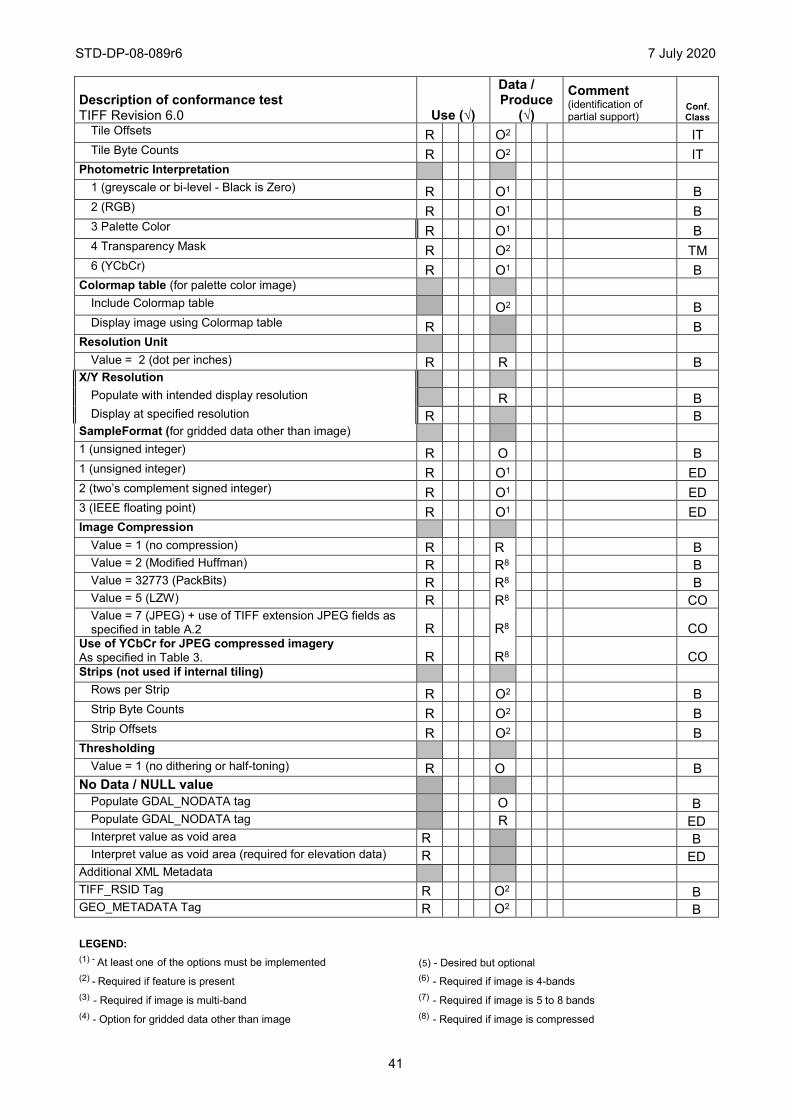
STD-DP-08-089r6 7 July 2020
41
Description of conformance test TIFF Revision 6.0 Use (√)
Data / Produce
(√)
Comment (identification of partial support)
Conf. Class
Tile Offsets R O2 IT Tile Byte Counts R O2 IT
Photometric Interpretation 1 (greyscale or bi-level - Black is Zero) R O1 B 2 (RGB) R O1 B 3 Palette Color R O1 B 4 Transparency Mask R O2 TM 6 (YCbCr) R O1 B
Colormap table (for palette color image) Include Colormap table O2 B Display image using Colormap table R B
Resolution Unit Value = 2 (dot per inches) R R B
X/Y Resolution Populate with intended display resolution R B Display at specified resolution R B
SampleFormat (for gridded data other than image) 1 (unsigned integer) R O B 1 (unsigned integer) R O1 ED 2 (two’s complement signed integer) R O1 ED 3 (IEEE floating point) R O1 ED Image Compression
Value = 1 (no compression) R R B Value = 2 (Modified Huffman) R R8 B Value = 32773 (PackBits) R R8 B Value = 5 (LZW) R R8 CO Value = 7 (JPEG) + use of TIFF extension JPEG fields as specified in table A.2 R R8 CO
Use of YCbCr for JPEG compressed imagery As specified in Table 3. R R8 CO Strips (not used if internal tiling)
Rows per Strip R O2 B Strip Byte Counts R O2 B Strip Offsets R O2 B
Thresholding Value = 1 (no dithering or half-toning) R O B
No Data / NULL value Populate GDAL_NODATA tag O B Populate GDAL_NODATA tag R ED Interpret value as void area R B Interpret value as void area (required for elevation data) R ED
Additional XML Metadata TIFF_RSID Tag R O2 B GEO_METADATA Tag R O2 B LEGEND:
(1) - At least one of the options must be implemented (5) - Desired but optional (2) - Required if feature is present (6) - Required if image is 4-bands (3) - Required if image is multi-band (7) - Required if image is 5 to 8 bands (4) - Option for gridded data other than image (8) - Required if image is compressed
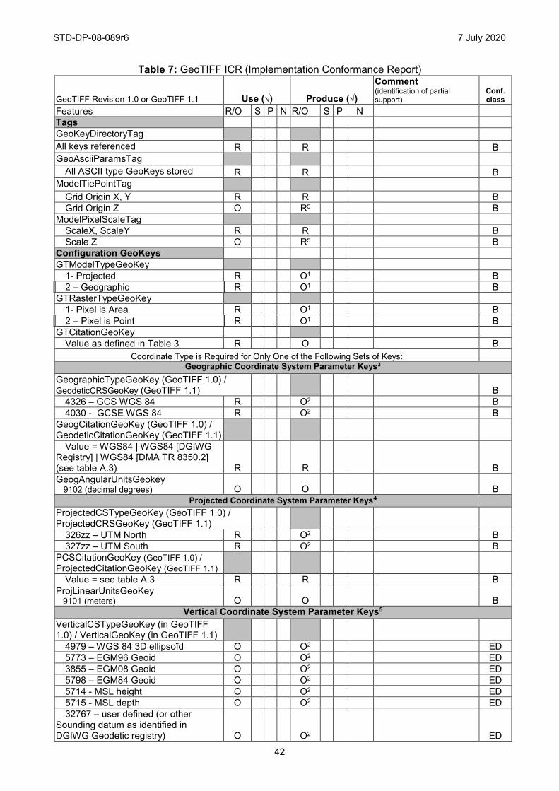
STD-DP-08-089r6 7 July 2020
42
Table 7: GeoTIFF ICR (Implementation Conformance Report)
GeoTIFF Revision 1.0 or GeoTIFF 1.1 Use (√) Produce (√)
Comment (identification of partial support)
Conf. class
Features R/O S P N R/O S P N Tags GeoKeyDirectoryTag All keys referenced R R B GeoAsciiParamsTag
All ASCII type GeoKeys stored R R B ModelTiePointTag
Grid Origin X, Y R R B Grid Origin Z O R5 B
ModelPixelScaleTag ScaleX, ScaleY R R B Scale Z O R5 B
Configuration GeoKeys GTModelTypeGeoKey
1- Projected R O1 B 2 ± Geographic R O1 B
GTRasterTypeGeoKey 1- Pixel is Area R O1 B 2 ± Pixel is Point R O1 B
GTCitationGeoKey Value as defined in Table 3 R O B
Coordinate Type is Required for Only One of the Following Sets of Keys: Geographic Coordinate System Parameter Keys3
GeographicTypeGeoKey (GeoTIFF 1.0) / GeodeticCRSGeoKey (GeoTIFF 1.1) B
4326 ± GCS WGS 84 R O2 B 4030 - GCSE WGS 84 R O2 B
GeogCitationGeoKey (GeoTIFF 1.0) / GeodeticCitationGeoKey (GeoTIFF 1.1)
Value = WGS84 | WGS84 [DGIWG Registry] | WGS84 [DMA TR 8350.2] (see table A.3) R R B GeogAngularUnitsGeokey 9102 (decimal degrees) O O B
Projected Coordinate System Parameter Keys4 ProjectedCSTypeGeoKey (GeoTIFF 1.0) / ProjectedCRSGeoKey (GeoTIFF 1.1)
326zz ± UTM North R O2 B 327zz ± UTM South R O2 B
PCSCitationGeoKey (GeoTIFF 1.0) / ProjectedCitationGeoKey (GeoTIFF 1.1)
Value = see table A.3 R R B ProjLinearUnitsGeoKey 9101 (meters) O O B
Vertical Coordinate System Parameter Keys5 VerticalCSTypeGeoKey (in GeoTIFF 1.0) / VerticalGeoKey (in GeoTIFF 1.1)
4979 ± WGS 84 3D ellipsoïd O O2 ED 5773 ± EGM96 Geoid O O2 ED 3855 ± EGM08 Geoid O O2 ED 5798 ± EGM84 Geoid O O2 ED 5714 - MSL height O O2 ED 5715 - MSL depth O O2 ED 32767 ± user defined (or other
Sounding datum as identified in DGIWG Geodetic registry) O O2 ED
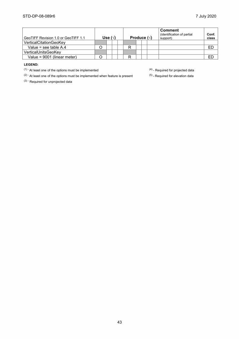
STD-DP-08-089r6 7 July 2020
43
GeoTIFF Revision 1.0 or GeoTIFF 1.1 Use (√) Produce (√)
Comment (identification of partial support)
Conf. class
VerticalCitationGeoKey Value = see table A.4 O R ED
VerticalUnitsGeoKey Value = 9001 (linear meter) O R ED
LEGEND:
(1) - At least one of the options must be implemented (4) - Required for projected data (2) - At least one of the options must be implemented when feature is present (5) - Required for elevation data (3) - Required for unprojected data