odms open data management server - bailey net 90 and infi
TRANSCRIPT
®®
ODMS
Open Data Management Server
Process Control andAutomation Solutionsfrom Elsag Bailey Group

WARNING notices as used in this instruction apply to hazards or unsafe practices that could result inpersonal injury or death.
CAUTION notices apply to hazards or unsafe practices that could result in property damage.
NOTES highlight procedures and contain information that assists the operator in understanding theinformation contained in this instruction.
WARNING
INSTRUCTION MANUALSDO NOT INSTALL, MAINTAIN, OR OPERATE THIS EQUIPMENT WITHOUT READING, UNDERSTANDING,AND FOLLOWING THE PROPER Elsag Bailey INSTRUCTIONS AND MANUALS; OTHERWISE, INJURY ORDAMAGE MAY RESULT.
RADIO FREQUENCY INTERFERENCEMOST ELECTRONIC EQUIPMENT IS INFLUENCED BY RADIO FREQUENCY INTERFERENCE (RFI). CAU-TION SHOULD BE EXERCISED WITH REGARD TO THE USE OF PORTABLE COMMUNICATIONS EQUIP-MENT IN THE AREA AROUND SUCH EQUIPMENT. PRUDENT PRACTICE DICTATES THAT SIGNS SHOULDBE POSTED IN THE VICINITY OF THE EQUIPMENT CAUTIONING AGAINST THE USE OF PORTABLE COM-MUNICATIONS EQUIPMENT.
POSSIBLE PROCESS UPSETSMAINTENANCE MUST BE PERFORMED ONLY BY QUALIFIED PERSONNEL AND ONLY AFTER SECURINGEQUIPMENT CONTROLLED BY THIS PRODUCT. ADJUSTING OR REMOVING THIS PRODUCT WHILE IT ISIN THE SYSTEM MAY UPSET THE PROCESS BEING CONTROLLED. SOME PROCESS UPSETS MAYCAUSE INJURY OR DAMAGE.
NOTICE
The information contained in this document is subject to change without notice.
Elsag Bailey, its affiliates, employees, and agents, and the authors and contributors to this publication specifi-cally disclaim all liabilities and warranties, express and implied (including warranties of merchantability and fit-ness for a particular purpose), for the accuracy, currency, completeness, and/or reliability of the informationcontained herein and/or for the fitness for any particular use and/or for the performance of any material and/or equipment selected in whole or part with the user of/or in reliance upon information contained herein.Selection of materials and/or equipment is at the sole risk of the user of this publication.
This document contains proprietary information of Elsag Bailey, Elsag Bailey Process Automation, and isissued in strict confidence. Its use, or reproduction for use, for the reverse engineering, development ormanufacture of hardware or software described herein is prohibited. No part of this document may bephotocopied or reproduced without the prior written consent of Elsag Bailey.
WBPEEUI
Preface
Open Data Management Server (ODMS) is a software platformfor collection, organization, integration and application ofreal-time plant data. An industry standard application pro-gramming interface (API) such as structured query language(SQL), dynamic data exchange (DDE), or an ODMS specificapplication programming interface can be used to allow openaccess to the open data management server system. TheODMS system can access data from a local platform or aremote platform using a TCP/IP or DECnet network.
Server platforms supported are:
• DEC™ Alpha™ AXP™ (Open VMS™ operating system).
• DEC VAX™ (Open VMS operating system).
• HP9000® (HP-UX® operating system).
Client platforms supported are:
• DEC Alpha AXP (Open VMS™ operating system).
• DEC VAX (VMS™ operating system).
• HP9000 (HP-UX operating system).
• 486-based personal computer (or higher) with Microsoft®Windows™ 3.1 or Windows 95.
Network communication protocols for graphic console systemclient terminals are:
• TCP/IP (HP-UX, VAX/Open VMS, DEC Alpha AXP/OpenVMS or PC platforms).
• DECnet® (VAX/Open VMS, DEC Alpha AXP/Open or PCplatforms).
This instruction provides information on how to install therequired software, hardware requirements, operating instruc-tions and error messages.
350003B0

®
List of Effective Pages
Total number of pages in this instruction is 239, consisting of the following:
Page No. Change Date
Preface OriginalList of Effective Pages Original
iii through ix Original1-1 through 1-9 Original2-1 through 2-6 Original3-1 through 3-66 Original4-1 through 4-6 Original5-1 through 5-45 Original6-1 through 6-12 Original7-1 through 7-34 OriginalA-1 through A-18 OriginalB-1 through B-4 OriginalC-1 through C-5 OriginalD-1 through D-2 OriginalE-1 through E-20 Original
Index-1 through Index-3 Original
When an update is received, insert the latest changed pages and dispose of the super-seded pages.
NOTE: On an update page, the changed text or table is indicated by a vertical bar in the outer mar-gin of the page adjacent to the changed area. A changed figure is indicated by a vertical bar in theouter margin next to the figure caption. The date the update was prepared will appear beside thepage number.
WBPEEUI350003B0
Table of Contents
WBPEEUI
Page
SECTION 1 - INTRODUCTION....................................................................................................1-1OVERVIEW ..................................................................................................................1-1INTENDED USER.........................................................................................................1-1SYSTEM DESCRIPTION................................................................................................1-2SOFTWARE DESCRIPTION...........................................................................................1-2FEATURES...................................................................................................................1-3INSTRUCTION CONTENT .............................................................................................1-4REQUIREMENTS .........................................................................................................1-5
Hardware...............................................................................................................1-5Software ................................................................................................................1-6
REFERENCE DOCUMENTS..........................................................................................1-7DOCUMENT CONVENTIONS ........................................................................................1-8GLOSSARY OF TERMS AND ABBREVIATIONS .............................................................1-9
SECTION 2 - DESCRIPTION AND OPERATION........................................................................2-1INTRODUCTION...........................................................................................................2-1HARDWARE DESCRIPTION..........................................................................................2-1
Configurations .......................................................................................................2-2INFI 90 OPEN Interface ..........................................................................................2-3
SYSTEM DESCRIPTION................................................................................................2-3ODMS SYSTEM OPERATION ........................................................................................2-3
ICI Interface ...........................................................................................................2-4Time Synchronization ............................................................................................2-4ICI Data Gathering.................................................................................................2-4
SETCIM OPERATION....................................................................................................2-6Configurable Data Structures ................................................................................2-6Event Driven Processing.........................................................................................2-6Client/Server Architecture .....................................................................................2-7SQL Database Query .............................................................................................2-7Real-Time and Historical Data................................................................................2-7Database Access Subroutines ................................................................................2-7
SECTION 3 - INSTALLATION .....................................................................................................3- 1INTRODUCTION...........................................................................................................3-1INSTALLATION (OPEN VMS OPERATING SYSTEM).......................................................3-1
VMS System Requirements ....................................................................................3-2VMS System Parameters ........................................................................................3-3User Accounts .......................................................................................................3-5Network Configuration ...........................................................................................3-5MOTIF Software Version ........................................................................................3-6ORACLE Open Installation .....................................................................................3-6Open Data Management Server Installation (VMS) .................................................3-7Post Installation Procedure (VMS) ........................................................................3-27
GCS CLIENT INSTALLATION ......................................................................................3-29POST INSTALLATION PROCEDURE (GCS) ..................................................................3-34INSTALLATION (HP-UX OPERATING SYSTEM) ...........................................................3-34
HP-UX System Requirements ...............................................................................3-34HP-UX System Parameters ...................................................................................3-35Open Data Management Server Installation (HP-UX) ............................................3-37Post Installation Procedure (HP-UX) .....................................................................3-46
350003B0 iii
Table of Contents (continued)
®
Page
SECTION 3 - INSTALLATION (continued)GCS CLIENT INSTALLATION...................................................................................... 3-51POST INSTALLATION PROCEDURE (GCS CLIENT) ..................................................... 3-54TSK_CONSOLE SCRATCH RECORDS ........................................................................ 3-55WINDOWS CLIENT TERMINAL INSTALLATION .......................................................... 3-55
Microsoft Windows Client Terminal Requirements ............................................... 3-56GCS Console Installation ..................................................................................... 3-56
Personal Computer Client (Wollongong TCP/IP) ............................................. 3-60Personal Computer Client (DECnet Pathworks).............................................. 3-61Personal Computer Client (TCP/IP Pathworks) .............................................. 3-61VAX Server (TCPware) ................................................................................... 3-62VAX Server (UCX and SETCIM 4.5A).............................................................. 3-62VAX Server (DECnet) ..................................................................................... 3-63VAX Server (TGV Multinet) ............................................................................ 3-64HP Server (HP CLIENT) .................................................................................. 3-65HP Server (PC CLIENT) .................................................................................. 3-66
SECTION 4 - CONFIGURATION.................................................................................................4-1INTRODUCTION .......................................................................................................... 4-1OFF-LINE CONFIGURATION........................................................................................ 4-1ON-LINE CONFIGURATION.......................................................................................... 4-1EXAMPLE CONFIGURATION........................................................................................ 4-2
SECTION 5 - OPERATING PROCEDURES................................................................................5-1INTRODUCTION .......................................................................................................... 5-1OPEN DATA MANAGEMENT SERVER START UP ......................................................... 5-1MENU ACCESS ........................................................................................................... 5-2DEFAULT SECURITY ................................................................................................... 5-2MENU COLORS ........................................................................................................... 5-2MAIN MENU ................................................................................................................ 5-3
Open Data Management Server Operations Menu .................................................. 5-3Summaries and Event Logs ............................................................................. 5-3Ad Hoc Trending ............................................................................................. 5-7History Data View Menu.................................................................................. 5-8Operating Parameters.................................................................................... 5-12Interface Statistics ........................................................................................ 5-16Message Output ............................................................................................ 5-19Ad Hoc Query................................................................................................ 5-21
Applications ........................................................................................................ 5-22Utilities ............................................................................................................... 5-23
Access........................................................................................................... 5-23History File Utilities....................................................................................... 5-24Off-Line Database Loader .............................................................................. 5-24Off-Line Database To ASCII File..................................................................... 5-24Document Definition Records ........................................................................ 5-24Document Database Records......................................................................... 5-24
Configuration Menu............................................................................................. 5-25Database....................................................................................................... 5-25System.......................................................................................................... 5-29Interface Control ........................................................................................... 5-40History Data View/Edit ................................................................................. 5-41
Customer Defined Displays.................................................................................. 5-45
iv WBPEEUI350003B0
WBPEEUI
Table of Contents (continued)
Page
SECTION 6 - SOFTWARE DETAILS...........................................................................................6-1INTRODUCTION...........................................................................................................6-1SIMULATED KEYS DEFINITION RECORD ....................................................................6-1AUTOMATING VAX START-UP......................................................................................6-3
Open Data Management Server Start-Up After a Boot ............................................6-3Adding ODMS Functions to a User Session Manager Menu ....................................6-4Operator Console Start-Up on User Log-In .............................................................6-5Operator Console Start-Up After a Boot ..................................................................6-6
AUTOMATING HP START-UP........................................................................................6-7Open Data Management Server Start-Up After a Boot ............................................6-7GCS Console Start-Up on User Log-In ....................................................................6-8GCS Console Start-Up on System Boot or Log-Out .................................................6-8TCP/IP Communications to OSM Modules .............................................................6-9ODMS and ICI Interface Communication Files........................................................6-9
WINDOWS CLIENT AUTOMATIC START-UP .................................................................6-9GUIDELINES FOR CREATING CLIENT PROGRAMS ....................................................6-10OPEN DATA MANAGEMENT SERVER DATABASE FILE FORMAT ...............................6-10QUALITY PRIORITIES.................................................................................................6-10OFF-LINE INTERFACE TESTING ................................................................................6-12PERMANENT LICENSE INSTALLATION ......................................................................6-12
SECTION 7 - ERROR MESSAGES AND RECOVERY ...............................................................7-1INTRODUCTION...........................................................................................................7-1SYSTEM MESSAGES....................................................................................................7-1ERROR MESSAGES ...................................................................................................7-17
APPENDIX A - QUICK REFERENCE......................................................................................... A-1INTRODUCTION.......................................................................................................... A-1VAX/VMS SYSTEM ..................................................................................................... A-1HP-UX SYSTEM .......................................................................................................... A-7PERSONAL COMPUTER .............................................................................................A-11MENU COLORS AND CONVENTIONS .........................................................................A-14
APPENDIX B - HARDWARE CONFIGURATION....................................................................... B-1INTRODUCTION.......................................................................................................... B-1INSTALLING THE SOFTWARE KEY ............................................................................. B-1
NTMP01 Termination Unit .................................................................................... B-1NIMP01 Termination Module................................................................................. B-1
ICI INTERFACE CONFIGURATION............................................................................... B-3
APPENDIX C - PASSWORD SECURITY ................................................................................... C-1INTRODUCTION.......................................................................................................... C-1DEFAULT DISPLAY SECURITY .................................................................................... C-1
APPENDIX D - CONSOLE ALARM CONFIGURATION ............................................................ D-1INTRODUCTION.......................................................................................................... D-1SYSTEM GLOBAL ALARM ACKNOWLEDGE/SILENCE ................................................ D-1PROCESS TAGS .......................................................................................................... D-2N90STA TAGS ............................................................................................................. D-2
350003B0 v

Table of Contents (continued)
®
Page
APPENDIX E - ODMS DATABASE............................................................................................ E-1INTRODUCTION ..........................................................................................................E-1TAG TYPES..................................................................................................................E-1QUALITY STATUS DESCRIPTIONS...............................................................................E-2OPEN DATA MANAGEMENT SERVER DATABASE FIELDS ...........................................E-2
vi WBPEEUI350003B0
List of Figures
No. Title Page
WBPEEUI
4-1. Database Configuration Tag Selection Screen .........................................................4-34-2. Tag Configuration Screen .......................................................................................4-44-3. Tag Specification Configuration Screen ..................................................................4-65-1. Summaries and Event Logs Screen ........................................................................5-45-2. Tag Summary Screen .............................................................................................5-55-3. User Change Log Screen ........................................................................................5-55-4. Tag Operating Parameter Window ..........................................................................5-75-5. View History Data Screen.......................................................................................5-9 5-6. Tag List Screen (View History Data) ......................................................................5-105-7. Tag History Summary Screen ...............................................................................5-115-8. Tag Specification History Detail Window...............................................................5-115-9. Tag Exception History Detail Window ...................................................................5-125-10. Operating Parameters Tag Selection Screen..........................................................5-135-11. Tag List Screen (Operating Parameters) ................................................................5-145-12. ICI Status Screen .................................................................................................5-175-13. ICI Performance Screen........................................................................................5-185-14. Message Output Display Screen ...........................................................................5-205-15. ASCII Text Message Detail Window.......................................................................5-215-16. ANSI Standard SQL Query Screen........................................................................5-225-17. Database Configuration Tag Selection Screen .......................................................5-265-18. Tag List Screen (Database Configuration) .............................................................5-265-19. Tag Configuration Screen .....................................................................................5-275-20. Tag Specification Configuration Screen ................................................................5-285-21. Database Snapshots Screen .................................................................................5-305-22. Database Snapshot Detail Screen ........................................................................5-305-23. Disk History File Screen.......................................................................................5-325-24. Disk History File Detail Window (Page One) ..........................................................5-325-25. Disk History File Detail Window (Page Two) ..........................................................5-335-26. Engineering Units Screen.....................................................................................5-345-27. Logic State Descriptors Screen .............................................................................5-355-28. Global Switches Screen ........................................................................................5-365-29. Define ICI Interface Screen...................................................................................5-375-30. Set System Time Screen .......................................................................................5-395-31. INFI 90 OPEN Interface Control Screen ................................................................5-405-32. Edit History Data Screen......................................................................................5-415-33. Tag List Screen (History Data View/Edit) ..............................................................5-435-34. Tag History Summary Screen ...............................................................................5-435-35. Exception History Detail Window (View and Edit) .................................................5-44B-1. NIMP01 Assignments and Jumper Settings ........................................................... B-2B-2. NTMP01 Assignments and Jumper Settings .......................................................... B-2B-3. INICT03 Module Board Layout .............................................................................. B-4
350003B0 vii
No. Title Page
List of Tables
®
1-1. Server Platforms .................................................................................................... 1-21-2. Client Platforms..................................................................................................... 1-21-3. GCS Client/ODMS Server Configurations .............................................................. 1-31-4. Remote API Applications/ODMS Server Configurations .......................................... 1-31-5. Reference Documents ............................................................................................ 1-71-6. Glossary of Terms and Abbreviations ..................................................................... 1-93-1. Time Zones.......................................................................................................... 3-213-2. Configuration Options (PC Client to ODMS Server) .............................................. 3-605-1. Trended Attributes (Ad Hoc Trending) .................................................................... 5-85-2. Field Definitions (ICI Status Screen) .................................................................... 5-175-3. Field Definitions (ICI Performance Screen) ........................................................... 5-186-1. Key Definition Records (Example) .......................................................................... 6-27-1. ODMS System and Error Messages ........................................................................ 7-17-2. ODMS Error Messages......................................................................................... 7-177-3. ICI Error Codes ................................................................................................... 7-237-4. Sub Level Error Codes ......................................................................................... 7-267-5. Message Driver Error Codes................................................................................. 7-277-6. Device Driver Error Codes ................................................................................... 7-29A-1. VAX/Open VMS and Alpha AXP System Keyboard Mapping ...................................A-1A-2. HP-UX System Keyboard Mapping .........................................................................A-8A-3. Personal Computer Keyboard Mapping ................................................................A-11A-4. GCS Console Screen Color Definitions .................................................................A-15B-1. Dipswitch Settings (UMB01, INICT03 Module) .......................................................B-3B-2. Dipswitch Settings (LMB2, INICT03 Module) ..........................................................B-3B-3. Dipswitch Settings (LLB3, INICT03 Module) ...........................................................B-3B-4. Dipswitch Settings (UUB0, INICT03 Module) ..........................................................B-3C-1. ODMS Default Security Levels ...............................................................................C-2E-1. INFI 90 OPEN Tag Types........................................................................................E-1E-2. Open Data Management Server Database Fields ....................................................E-4
viii WBPEEUI350003B0
WBPEEUI
Trademarks and Registrations
Registrations and trademarks used in this document include:
™ Alpha Trademark of Digital Equipment Corporation.
™ AXP Trademark of Digital Equipment Corporation.
™ CALC Trademark of Aspen Technology, Incorporated.
™ DA Trademark of Aspen Technology, Incorporated.
™ DEC Trademark of Digital Equipment Corporation.
® DECnet Registered trademark of Digital Equipment Corporation.
™ DESK Trademark of Aspen Technology, Incorporated.
™ Ethernet Trademark of Xerox Corporation.
™ GCS Trademark of Aspen Technology, Incorporated.
® HP Registered trademark of Hewlett-Packard Company.
® HP9000 Registered trademark of Hewlett-Packard Company.
® HP-UX Registered trademark of Hewlett-Packard Company.
® INFI 90 Registered trademark of Elsag Bailey Process Automation.
® INFI-NET Registered trademark of Elsag Bailey Process Automation.
® Intel Registered trademark of Intel Corporation.
® Microsoft Registered trademark of Microsoft Corporation.
™ MOTIF Trademark of Open Software Foundation, Incorporated.
® MS Registered trademark of Microsoft Corporation.
™ Open VMS Trademark of Digital Equipment Corporation.
® ORACLE Registered trademark of Oracle Corporation.
™ PATHWORKS Trademark of Digital Equipment Corporation.
™ Q Trademark of Aspen Technology, Incorporated.
™ VAX Trademark of Digital Equipment Corporation.
™ VMS Trademark of Digital Equipment Corporation.
® SequeLink Registered trademark of Techgnosis International, Incorporated.
® SETCIM Registered trademark of Aspen Technology, Incorporated.
™ SQLplus Trademark of Aspen Technology, Incorporated.
™ Windows Trademark of Microsoft Corporation.
™ X Windows Trademark of Massachusetts Institute of Technology.
™ @aGlance/IT Trademark of Intuitive Technology Corporation.
350003B0 ix
SECTION 1 - INTRODUCTION
WBPEEUI
OVERVIEW
The Open Data Management Server (ODMS) is a software plat-form for collection, organization, integration and application ofreal-time plant data. Industry standard application program-ming interfaces (API) such as dynamic data exchange (DDE),structured query language (SQL), or an open data managementserver specific application programming interface can be usedto allow open access to the open data management server. Anopen data management server user can access open data man-agement server data from a local client or a remote client usinga TCP/IP or DECnet network.
The open data management server provides data managementand historization, client/server based graphical user interfac-ing, spreadsheet functions for calculations, SPC/SQC func-tions, SQL query functions, event logging, and reportgeneration. Additionally, the open data management serverprovides the capability to join its database to external rela-tional database files on a local or remote platform and to inter-face with Windows applications through a DDE or SQLinterface. The open data management server operates on mul-tiple client/server platforms and operating systems.
INTENDED USER
This manual is an open data management server user manual.The users are intended to be engineering and programmingpersonnel, plant operators, plant managers and supervisors,and corporate management and personnel (such as MIS per-sonnel).
Engineers and programmers who maintain, configure, andmodify the system require the highest level of system access.Installation of SETCIM®, open data management server andrelated server software requires an individual with systemadministrator experience in the applicable operating system(Open VMS or HP-UX).
Plant operators require access to the system information thatprovides them with the real time and historical data requiredin the daily operation of the plant. This information is availablein reports, summary displays, ad hoc queries, etc. Generally,plant operators can function with a lower security level accessthan plant engineers.
Management personnel are usually restricted to a view onlymode, which allows them to view and analyze data and gener-ate reports.
OVERVIEW
350003B0 1 - 1
INTRODUCTION ®
SYSTEM DESCRIPTION
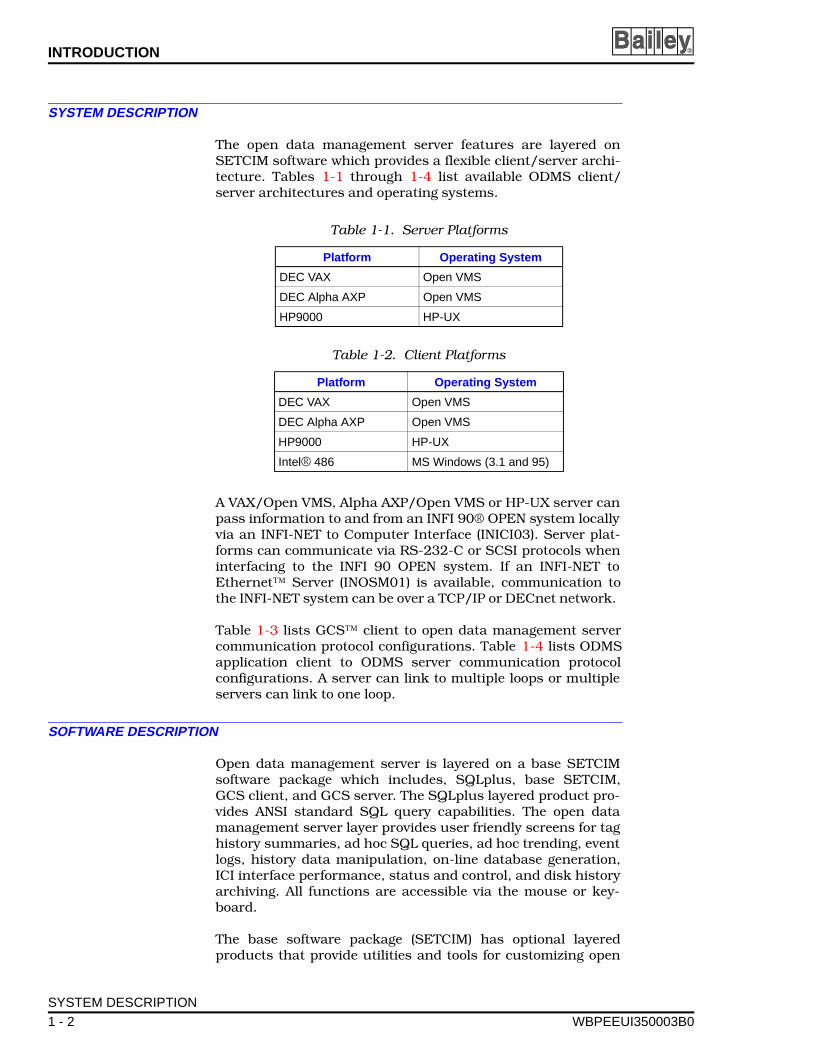
The open data management server features are layered onSETCIM software which provides a flexible client/server archi-tecture. Tables 1-1 through 1-4 list available ODMS client/server architectures and operating systems.
A VAX/Open VMS, Alpha AXP/Open VMS or HP-UX server canpass information to and from an INFI 90® OPEN system locallyvia an INFI-NET to Computer Interface (INICI03). Server plat-forms can communicate via RS-232-C or SCSI protocols wheninterfacing to the INFI 90 OPEN system. If an INFI-NET toEthernet™ Server (INOSM01) is available, communication tothe INFI-NET system can be over a TCP/IP or DECnet network.
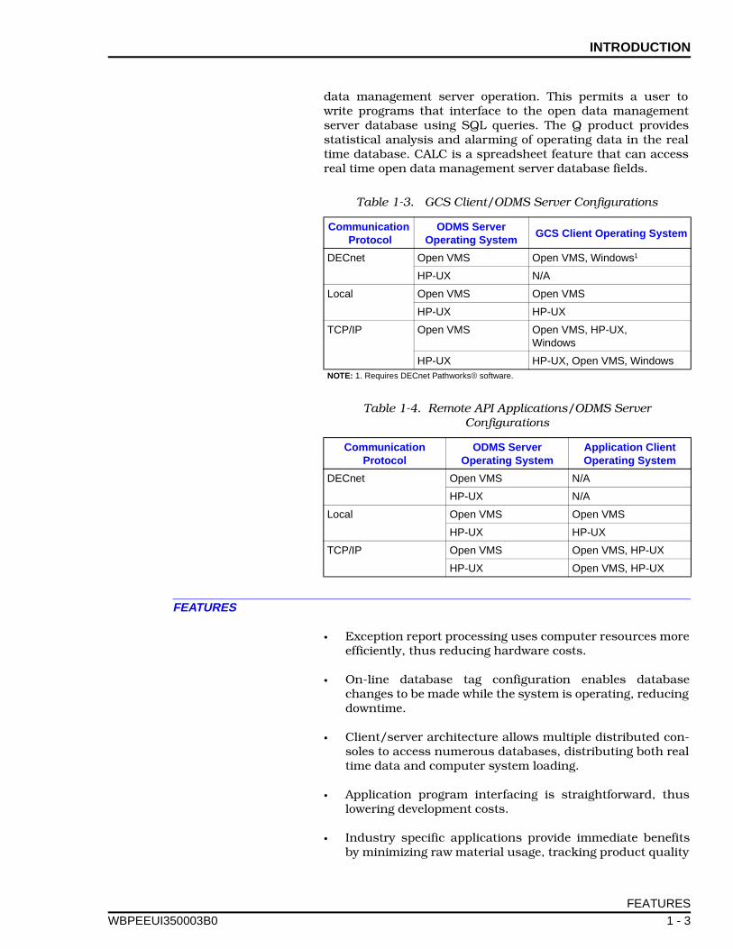
Table 1-3 lists GCS™ client to open data management servercommunication protocol configurations. Table 1-4 lists ODMSapplication client to ODMS server communication protocolconfigurations. A server can link to multiple loops or multipleservers can link to one loop.
SOFTWARE DESCRIPTION
Open data management server is layered on a base SETCIMsoftware package which includes, SQLplus, base SETCIM,GCS client, and GCS server. The SQLplus layered product pro-vides ANSI standard SQL query capabilities. The open datamanagement server layer provides user friendly screens for taghistory summaries, ad hoc SQL queries, ad hoc trending, eventlogs, history data manipulation, on-line database generation,ICI interface performance, status and control, and disk historyarchiving. All functions are accessible via the mouse or key-board.
The base software package (SETCIM) has optional layeredproducts that provide utilities and tools for customizing open
Table 1-1. Server Platforms
Platform Operating System
DEC VAX Open VMS
DEC Alpha AXP Open VMS
HP9000 HP-UX
Table 1-2. Client Platforms
Platform Operating System
DEC VAX Open VMS
DEC Alpha AXP Open VMS
HP9000 HP-UX
Intel® 486 MS Windows (3.1 and 95)
SYSTEM DESCRIPTION
1 - 2 WBPEEUI350003B0
INTRODUCTION
WBPEEUI
data management server operation. This permits a user towrite programs that interface to the open data managementserver database using SQL queries. The Q product providesstatistical analysis and alarming of operating data in the realtime database. CALC is a spreadsheet feature that can accessreal time open data management server database fields.
FEATURES
• Exception report processing uses computer resources moreefficiently, thus reducing hardware costs.
• On-line database tag configuration enables databasechanges to be made while the system is operating, reducingdowntime.
• Client/server architecture allows multiple distributed con-soles to access numerous databases, distributing both realtime data and computer system loading.
• Application program interfacing is straightforward, thuslowering development costs.
• Industry specific applications provide immediate benefitsby minimizing raw material usage, tracking product quality
Table 1-3. GCS Client/ODMS Server Configurations
Communication Protocol
ODMS Server Operating System
GCS Client Operating System
DECnet Open VMS Open VMS, Windows1
HP-UX N/A
Local Open VMS Open VMS
HP-UX HP-UX
TCP/IP Open VMS Open VMS, HP-UX, Windows
HP-UX HP-UX, Open VMS, WindowsNOTE: 1. Requires DECnet Pathworks® software.
Table 1-4. Remote API Applications/ODMS Server Configurations
Communication Protocol
ODMS Server Operating System
Application Client Operating System
DECnet Open VMS N/A
HP-UX N/A
Local Open VMS Open VMS
HP-UX HP-UX
TCP/IP Open VMS Open VMS, HP-UX
HP-UX Open VMS, HP-UX
FEATURES
350003B0 1 - 3
INTRODUCTION ®
on-line, identifying critical down-time problems, and otherindustry specific solutions.
• The ODMS interface supports all INFI 90 OPEN tag types(except trend block and text selector), redundant INICI03INFI-NET to Computer Interfaces (ICI) or INOSM01 OpenSystem Manger, and controlled multitask access to theINICI03 or INOSM01 interfaces.
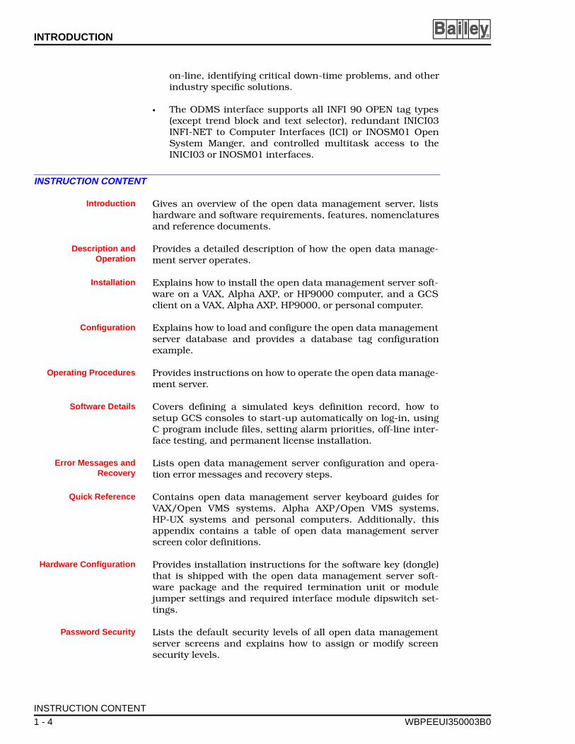
INSTRUCTION CONTENT
Introduction Gives an overview of the open data management server, listshardware and software requirements, features, nomenclaturesand reference documents.
Description andOperation
Provides a detailed description of how the open data manage-ment server operates.
Installation Explains how to install the open data management server soft-ware on a VAX, Alpha AXP, or HP9000 computer, and a GCSclient on a VAX, Alpha AXP, HP9000, or personal computer.
Configuration Explains how to load and configure the open data managementserver database and provides a database tag configurationexample.
Operating Procedures Provides instructions on how to operate the open data manage-ment server.
Software Details Covers defining a simulated keys definition record, how tosetup GCS consoles to start-up automatically on log-in, usingC program include files, setting alarm priorities, off-line inter-face testing, and permanent license installation.
Error Messages andRecovery
Lists open data management server configuration and opera-tion error messages and recovery steps.
Quick Reference Contains open data management server keyboard guides forVAX/Open VMS systems, Alpha AXP/Open VMS systems,HP-UX systems and personal computers. Additionally, thisappendix contains a table of open data management serverscreen color definitions.
Hardware Configuration Provides installation instructions for the software key (dongle)that is shipped with the open data management server soft-ware package and the required termination unit or modulejumper settings and required interface module dipswitch set-tings.
Password Security Lists the default security levels of all open data managementserver screens and explains how to assign or modify screensecurity levels.
INSTRUCTION CONTENT
1 - 4 WBPEEUI350003B0
INTRODUCTION
WBPEEUI
Console AlarmConfiguration
Contains instructions on how to configure the OIS global alarmacknowledge and silence functions.
ODMS Database Fields Lists open data management server database field definitionsand other information that are required when configuring adatabase such as the INFI 90 OPEN tag types that are sup-ported, default values, and database field format.
REQUIREMENTS
The following details the hardware and software requirementsfor open data management servers and clients.
Hardware
An open data management server VAX-based system and clientplatform requires:
• A DEC VAX system.
• A four millimeter digital audio tape (DAT) drive (required forsoftware installation).
• An RS-232-C or SCSI port if using an INICI03 INFI-NET toComputer Interface. A TCP/IP or DECnet network connec-tion if using an INOSM01 INFI-NET to Ethernet Server.
A open data management server Alpha AXP-based system andclient platform requires:
• A DEC Alpha system.
• A four millimeter digital audio tape (DAT) drive (required forsoftware installation).
• An RS-232-C or SCSI port if using an INICI03 INFI-NET toComputer Interface. A TCP/IP or DECnet network connec-tion if using an INOSM01 INFI-NET to Ethernet Server.
A open data management server HP-based system and clientplatform requires:
• An HP9000 system.
• A four millimeter DAT drive (required for software installa-tion).
• An RS-232-C or SCSI connection to an INICI03 INFI-NET toComputer Interface. A TCP/IP network connection if usingan INOSM01 OPEN Data Manager.
A personal computer client terminal requires:
REQUIREMENTS
350003B0 1 - 5
INTRODUCTION ®
• A 486DX-based computer minimum.
• At least 8 megabytes of memory for GCS console and MS®Windows software.
• At least 40 megabytes of hard disk drive space.
Memory requirements for VAX, Alpha AXP, and HP9000 serv-ers and client platforms are dependent upon the SETCIM soft-ware license size and tag configuration. Hard disk drive spacerequirements are based on the SETCIM software license size,tag configuration and tag event summary and historianrequirements. Contact your Elsag Bailey representative forhelp on determining memory and disk space requirements.
Software
DEC VAX server software requirements are:
• The open data management server software package(includes ODMS client).
• An Open VMS 6.1 operating system or higher.
• MOTIF™ 1.2 software.
Alpha AXP server software requirements are:
• The open data management server software package(includes ODMS client).
• An Open VMS 6.2 operating system or higher.
• MOTIF 1.2 software.
HP9000 server software requirements are:
• The open data management server software package(includes one ODMS client).
• An HP-UX 9.x.x operating system.
• MOTIF 1.2 software.
VAX/Open VMS client software requirements are:
• The ODMS client software.
• A VMS 6.1 operating system or higher.
• MOTIF 1.2 software.
REQUIREMENTS
1 - 6 WBPEEUI350003B0
INTRODUCTION
WBPEEUI
Alpha AXP\Open VMS client software requirements are:
• The ODMS client software.
• An Open VMS 6.2 operating system or higher.
• MOTIF 1.2 software.
HP-UX client software requirements are:
• The ODMS client software.
• An HP-UX 9.x.x operating system.
• MOTIF 1.2 software.
Personal computer client software requirements are:
• Microsoft Windows 3.1 or Windows 95.
• TCP/IP network software (for HP®, VAX, or Alpha AXPinterface), or DECnet (for VAX and Alpha AXP interface).
• The ODMS client software.
• An X Windows™ software package (optional).
NOTE: Some open data management server functions cannot beaccessed via a personal computer client without X Windows (i.e.,utilities and application). Application products which cannot beaccessed without X Windows are SQLplus and CALC.
REFERENCE DOCUMENTS
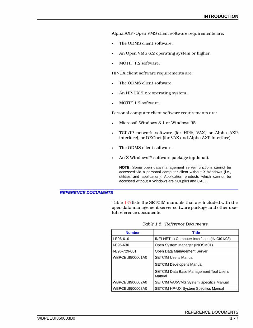
Table 1-5 lists the SETCIM manuals that are included with theopen data management server software package and other use-ful reference documents.
Table 1-5. Reference Documents
Number Title
I-E96-610 INFI-NET to Computer Interfaces (INICI01/03)
I-E96-630 Open System Manager (INOSM01)
I-E96-729-001 Open Data Management Server
WBPCEUI900001A0 SETCIM User’s Manual
SETCIM Developer’s Manual
SETCIM Data Base Management Tool User’s Manual
WBPCEUI900002A0 SETCIM VAX/VMS System Specifics Manual
WBPCEUI900003A0 SETCIM HP-UX System Specifics Manual
REFERENCE DOCUMENTS
350003B0 1 - 7
INTRODUCTION ®
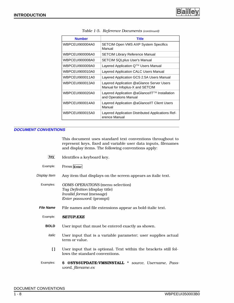
DOCUMENT CONVENTIONS
This document uses standard text conventions throughout torepresent keys, fixed and variable user data inputs, filenamesand display items. The following conventions apply:
Identifies a keyboard key.
Example: Press
Display Item Any item that displays on the screen appears as italic text.
Examples: ODMS OPERATIONS (menu selection)Tag Definition (display title)Invalid format (message)Enter password: (prompt)
File Name File names and file extensions appear as bold-italic text.
Example: SETUP.EXE
BOLD User input that must be entered exactly as shown.
italic User input that is a variable parameter; user supplies actualterm or value.
[ ] User input that is optional. Text within the brackets still fol-lows the standard conventions.
Examples: $ @SYS$UPDATE:VMSINSTALL * source, Username, Pass-word, filename.ex
WBPCEUI900004A0 SETCIM Open VMS AXP System Specifics Manual
WBPCEUI900006A0 SETCIM Library Reference Manual
WBPCEUI900008A0 SETCIM SQLplus User’s Manual
WBPCEUI900009A0 Layered Application Q™ Users Manual
WBPCEUI900010A0 Layered Application CALC Users Manual
WBPCEUI900011A0 Layered Application GCS 2.5A Users Manual
WBPCEUI900013A0 Layered Application @aGlance Server Users Manual for Infoplus-X and SETCIM
WBPCEUI900020A0 Layered Application @aGlance/IT™ Installation and Operations Manual
WBPCEUI900014A0 Layered Application @aGlance/IT Client Users Manual
WBPCEUI900015A0 Layered Application Distributed Applications Ref-erence Manual
Table 1-5. Reference Documents (continued)
Number Title
keyy
Enter
DOCUMENT CONVENTIONS
1 - 8 WBPEEUI350003B0
INTRODUCTION
WBPEEUI
GLOSSARY OF TERMS AND ABBREVIATIONS
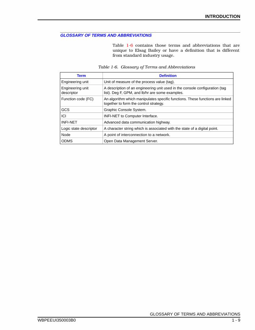
Table 1-6 contains those terms and abbreviations that areunique to Elsag Bailey or have a definition that is differentfrom standard industry usage.
Table 1-6. Glossary of Terms and Abbreviations
Term Definition
Engineering unit Unit of measure of the process value (tag).
Engineering unit descriptor
A description of an engineering unit used in the console configuration (tag list). Deg F, GPM, and lb/hr are some examples.
Function code (FC) An algorithm which manipulates specific functions. These functions are linked together to form the control strategy.
GCS Graphic Console System.
ICI INFI-NET to Computer Interface.
INFI-NET Advanced data communication highway.
Logic state descriptor A character string which is associated with the state of a digital point.
Node A point of interconnection to a network.
ODMS Open Data Management Server.
GLOSSARY OF TERMS AND ABBREVIATIONS
350003B0 1 - 9
SECTION 2 - DESCRIPTION AND OPERATION
WBPEEUI
INTRODUCTION
This section gives a brief description of the Open Data Manage-ment Server (ODMS). The open data management server is aclient/server based software product for collection, organiza-tion, integration and application of real-time plant data. Anindustry standard application programming interface (API)such as dynamic data exchange (DDE) or structured query lan-guage (SQL) and an open data management server specificapplication programming interface can be used by Elsag Baileyor other industry application programs to access data from theopen data management server. An ODMS client can accessopen data management server data from a local or remote opendata management server using an Ethernet (TCP/IP or DEC-net) communication network.
The open data management server provides data managementand historization, graphical user interface spreadsheet func-tions for calculations, SPC/SQC functions, batch reporting,SQL query functions, alarm logging, and report writing. Inaddition, the open data management server with SQLplus andother optional relational database software provides the capa-bility to join its database to external relational database fileson a local or remote platform and to interface with Windowsapplications through an optional (DDE) interface. The opendata management server operates on multiple client/serverplatforms and operating systems.
HARDWARE DESCRIPTION
There are numerous hardware configuration choices availablefor implementing open data management server. Server plat-forms supported are:
• DEC VAX (Open VMS operating system).• Alpha AXP (Open VMS operating system).• HP9000 (UNIX operating system).
Client platforms supported are:
• DEC VAX (Open VMS operating system).• Alpha AXP (Open VMS operating system).• HP9000 (UNIX operating system).• 486-based personal computer (or higher) with Windows 3.1
or Windows 95 installed.
INTRODUCTION
350003B0 2 - 1
DESCRIPTION AND OPERATION ®
Network communication protocols for graphic console systemclient terminals are:
• Ethernet (TCP/IP). • DECnet (VAX only).
Configurations
A number of hardware configurations can be implementedbecause of the SETCIM and open data management server lay-ered software structure.
•VAX/Open VMS and Alpha AXP/Open VMS servers can link to an INFI 90 OPEN system (INFI-NET® communication net-work) via an INFI-NET to computer (ICI) interface(RS-232-C or SCSI link). VAX/Open VMS and Alpha AXP/Open VMS servers can also link to an INFI 90 OPEN cabi-net via an INOSM01 Open System Manager and a TCP/IPor DECnet network. Linking to multiple INFI 90 OPENloops with multiple interfaces is possible.
• VAX/Open VMS and Alpha AXP/Open VMS servers canlink to other servers and clients via Ethernet TCP/IP(HP-UX, VAX/Open VMS, or Alpha AXP/Open VMS) orDECnet (VAX/Open VMS and Alpha AXP/Open VMS only)networks.
• HP-UX servers can link to an INFI 90 OPEN system(INFI-NET communication system) via an INFI-NET to com-puter (ICI) interface (RS-232-C or SCSI link). HP-UX serv-ers can also link to an INFI 90 OPEN cabinet via anINOSM01 INFI-NET to Ethernet Server and a TCP/IP net-work. Linking to multiple INFI 90 OPEN loops with multipleinterfaces is possible.
• HP-UX servers can link to other servers and clients viaEthernet TCP/IP (HP-UX or Open VMS).
• Personal computer clients using Windows can be linked toservers on an Ethernet TCP/IP network (also DECnet net-work for VAX/Open VMS and Alpha AXP/Open VMS serv-ers). These client platforms can be set up to operate as GCSterminals or they can be used to obtain server data for Win-dows applications such as Excel and Lotus spreadsheetsusing optional @aGlance/IT software.
• VAX/Open VMS and Alpha AXP/Open VMS systems andHP-UX systems can also be set up as client terminals witha GCS graphical link or X windows.
HARDWARE DESCRIPTION
2 - 2 WBPEEUI350003B0
DESCRIPTION AND OPERATION
WBPEEUI
INFI 90 OPEN Interface
The INFI 90 OPEN interface consists of an INFI-NET to Com-puter Interface (INICI03). Refer to the INFI-NET to ComputerInterface (INICI03) instruction for a physical description ofthe ICI interface (refer to Table 1-5 for document numbers).The INOSM01 Open System Manager is an optional INFI 90OPEN interface. Refer to the Open System Manager(INOSM01) instruction for a physical description of the inter-face.
SYSTEM DESCRIPTION
The open data management server operates on multiple plat-forms and operating systems. SETCIM software provides theclient/server technology foundation that the open data man-agement server utilizes to provide open access to Elsag BaileyINFI 90 OPEN system data.
The open data management server stores historical tag dataand provides access to this data by other applications. Indus-try standard application programming interfaces such as DDEand SQL are used by Elsag Bailey programmed applicationsand third party programmed applications to access data fromthe open data management server database. The open datamanagement server expands upon a third party informationmanagement system (SETCIM). Elsag Bailey layers applica-tions onto this software product to produce the open datamanagement server.
ODMS SYSTEM OPERATION
The open data management server is a user-friendly databasemanagement tool. The open data management server databasecan be configured on-line or off-line. On-line system setup andconfiguration is done through easy to use (point and click witha mouse) configuration displays.
The open data management server operates in a manner thatrequires the user to make a minimum number of configurationdecisions. Because it is layered on the SETCIM system, it is aconfigured application package which allows for flexibility inincorporating site specific requirements. For example, whilethe SETCIM database is highly configurable, the open datamanagement server database has all INFI 90 OPEN tag typesand all database tag attributes predefined. The databasedesign is such that future tag types (user defined) andattributes can be easily added to the system.
Tag history summaries are viewed through user friendly dis-plays. Specification data and exception data for every tag canbe viewed and edited. Tag summaries are arranged by tag typegroups. Event logs are provided for historical data and user
SYSTEM DESCRIPTION
350003B0 2 - 3
DESCRIPTION AND OPERATION ®
modifications to the configuration. Events include alarms,boolean state changes, and actions by the user which includeenabling or disabling tag data access, manual substitution ofattributes and enabling or disabling tag messages.
ICI Interface
The ICI interface is embedded within the open data manage-ment server. This program provides access to INFI 90 OPENexception data, general tag data I/O functions and a time syn-chronization function. It also accesses the open data manage-ment server database through SETCIM furnished API routines.The ICI interface exception data access function populates theopen data management server database with real-timedynamic data. Additionally, the ICI interface provides the capa-bility of outputting real-time data from the open data manage-ment server database to the INFI 90 OPEN system.
Time Synchronization
Time synchronization setup is done via the open data manage-ment server. Time synchronization can be configured by theuser to be driven by the open data management server soft-ware or by the INFI 90 OPEN system. If the INFI 90 OPEN sys-tem synchronizes time, the open data management serverreceives the INFI 90 OPEN time messages and updates itsclock. If the open data management server synchronizes thetime, a time synchronization message is transmitted to theINFI 90 OPEN system periodically or whenever a system timesetting is made.
ICI Data Gathering
ICI data access function updates the open data managementserver periodically to obtain exception report data and othermessages (such as INFI 90 OPEN module status and moduleconfiguration changes). The data access function interpretsthese exception reports and messages and populates the asso-ciated open data management server dynamic real-time data-base with the data received. This includes such items as value,quality, station status, ASCII string values, etc. Static opendata management server database information, defined in theINFI 90 OPEN block specifications, is obtained by the ICI inter-face and by exception messages on interface start-up, and pop-ulated into the open data management server static tagattribute database.
The open data management server supplies a display functionfor ICI interface activity (including exceptions per second fromeach interface, loading, and data access function loading). Thisdata is also made available in database tags and is available
ODMS SYSTEM OPERATION
2 - 4 WBPEEUI350003B0
DESCRIPTION AND OPERATION
WBPEEUI
via an application programming interface. The open data man-agement server allows manual ICI interface restarts and indi-cates the status of the interfaces. ICI interfaces areautomatically restarted when an off-line status is detected orwhen they recover from a failure.
The data access function provides a selectable option to timestamp incoming data with open data management server timeor to use the INFI 90 OPEN time stamps contained within theINFI 90 OPEN messages. This option is selectable on an inter-face basis. When the INFI 90 OPEN time stamp option is cho-sen, the millisecond time stamp is converted to tenth of asecond time stamp supported by the open data managementserver. However, the millisecond offset (i.e., 1/100 and 1/1000second) is also stored as a separate database attribute. Thisattribute is historically archived in the open data managementserver database with the tenth of a second time stamp.
The data access function is capable of recognizing when INFI90 OPEN communication to or from an ICI interface is lost andchanges the qualities of affected open data management serverdatabase tags to indicate a loss of communication. Addition-ally, a message can be generated to the open data managementserver event/alarm log indicating the ICI number and status.When communications are restored, the open data manage-ment server insures that all database values and states repre-sent the current state of the process and system. A message isgenerated to the open data management server event/alarmlog when ICI communications are restored.
The data access function prevents data loss when the datainput from the ICI interfaces is at a rate that cannot be accom-modated by the open data management server. The data accessfunction can buffer several minutes of data. The data accessfunction can feed data to the open data management serverdatabase as quickly as the open data management server data-base is capable of receiving it.
A single open data management server can support multipledata access functions. The data access function can share ICIinterfaces with other applications, but sharing ICI interfacescan affect performance.
The data access function allows multiple ICI device drivers(and ICI interfaces) to be configured for redundant operation(hot standby). The built in capability of the INFI 90 OPEN inter-face routines and ICI device drivers to handle redundancy isutilized. Failure recovery is automatic. A failure of any ICIinterface results in a message being sent to the data accessfunction. This message is sent to the event log in the open datamanagement server.
ODMS SYSTEM OPERATION
350003B0 2 - 5
DESCRIPTION AND OPERATION ®
SETCIM OPERATION
SETCIM software provides a number of features which areavailable through the open data management server including:data management and historization, client/server basedgraphical user interfacing, spreadsheet capability to performsophisticated calculations (CALC), SPC/SQC capability (Q),SQL Query capability (SQLplus), alarming capability (baseSETCIM), and report writing capability (CALC, SQLplus,@aGlance/IT, and DESK™). In addition, SETCIM software pro-vides capability to join its database to external relational data-base files on either local or remote platforms and capability tointerface with Windows applications through @aGlance/ITsoftware.
NOTE: Some of the software products mentioned are optional.
Configurable Data Structures
Data structures within the database can be modified two ways.First, the repeat areas in an individual data record may beexpanded or contracted while the system is in operation. Therepeat areas contain historical values and time stamps foreach point. Data may be stored in random access memory(RAM) or on disk at the option of the user. For each point in theopen data management server database, the user can decidehow many historical values to retain and whether to retainthese on disk, in RAM memory, or some combination of both.The user has the ability to adjust the way historical values arestored so that changing circumstances can be accommodatedwithout any interruption of normal open data managementserver activities.
The second method involves the creation of custom definitionrecords. A definition record defines the structure or templatethat other records are built against. It specifies the fieldsincluded, their order in the record and the types of processingavailable on each field. It defines both fixed and repeat areasfor each record. All data records defined against an individualdefinition record will have the same types of fixed and repeatareas, although the data in each field may differ. SETCIM soft-ware allows new definition records to be defined by the user ordeveloper.
Event Driven Processing
Acquiring, processing, and displaying data is event driven.Therefore, data is processed internally and displayed on thegraphic console system to provide immediate notification of asystem change. Immediate display update is achieved usingdynamic GCS display fields instead of fields that are updatedon a poll. In some applications, scheduling tasks at regularintervals may be desirable. With open data management server
SETCIM OPERATION
2 - 6 WBPEEUI350003B0
DESCRIPTION AND OPERATION
WBPEEUI
event driven data processing, a scheduling parameter can besetup to increment periodically.
Client/Server Architecture
Open data management server software provides a flexiblegraphic console system (GCS) client/server architecture thateliminates problems in response time and resource problems.ODMS database files reside on a host that acts as a data serverfor GCS clients. The GCS display files can reside on the localclient or on the server. When the display files reside locally,only data, not graphics are transmitted over the communica-tion link. Additionally, data is transmitted to objects that areupdated only when a value changes in the database. Thisarchitecture produces rapid response time because it is fasterto access graphic displays from a local disk than from a net-work system. There is less network traffic because only eventdriven data is sent, not graphic displays. When display filesreside on the data server, any device that can support X Win-dows and TCP/IP or DECnet can be used as a GCS client.
SQL Database Query
SQLplus is a base SETCIM product that provides for ANSIstandard SQL queries into any data in the database. It canlook at historical data, current (real-time) data, and configura-tion data. This is an X Window-based interface that providesfast ad hoc access to information. When a query is developed itcan be stored as a record in a SETCIM database and executedby an operator action or by a database event. Stored queriescan be tied to a graphic display and executed as menu optionsby users who are unfamiliar with SQL syntax. The results of anSQL query can be displayed, written to files, or written to data-base records. A GCS screen can be used to enter an SQL query.
Real-Time and Historical Data
Historical data and real-time data are stored in the samerecord, resulting in the integration of current and real-timedata. The repeat areas of a record store historical values andtime stamps. The number of repeat areas is determined by theuser and can be modified on-line. All of the SETCIM databasemanagement tools (Q, SQLplus, and CALC) are compatiblewith both historical and real-time data.
Database Access Subroutines
The open data management server software provides an opendatabase by including a library of optional database accessroutines and remote procedure calls. These subroutines areused to develop interfaces to other programs or devices. SQLbased routines are also included.
SETCIM OPERATION
350003B0 2 - 7
SECTION 3 - INSTALLATION
WBPEEUI
INTRODUCTION
This section contains software installation procedures forinstalling SETCIM and the Open Data Management Server(ODMS) software on the following systems:
• Alpha AXP/Open VMS.• VAX/Open VMS. • HP-UX.
It also includes instructions for installing GCS clients on thefollowing systems:
• Alpha AXP/Open VMS.• VAX/Open VMS.• HP-UX.• Personal computer with MS Windows (3.1 or 95).
The SETCIM software installation requires a software licensecode. Refer to the release documentation for details on obtain-ing the required license code. Software installation alsorequires a password. This password is supplied with the soft-ware package. Installation will fail without this password.
All INFI-NET interface connections require a software key (don-gle), otherwise any installed software will not function. A soft-ware key is provided with the open data management serversoftware package for each interface connection purchased.Refer to Appendix B for information on installing the softwarekey. It is recommended that the software key be installed andall INFI-NET to Computer Interface (ICI) hardware be config-ured prior to software installation.
INSTALLATION (OPEN VMS OPERATING SYSTEM)
This section covers the following installation stages:
• General VMS requirements including modifying VMS oper-ating system parameters.
• Installing the base SETCIM software and the open datamanagement server software.
• Installing the GCS client and the open data managementserver client software.
NOTE: The procedures in this section apply to both Alpha AXP andVAX installations. Procedural differences are noted as required.
INTRODUCTION
350003B0 3 - 1
INSTALLATION ®
VMS System Requirements
The following hardware and software are required to installand operate the open data management server software pack-age:
• A VAX system with at least an Open VMS 6.1 operating sys-tem or a DEC Alpha system with at least an Open VMS 6.2operating system.
• MOTIF version 1.2 software.
• Sufficient system memory (16 Mbytes of memory mini-mum). Contact Elsag Bailey for specific memory require-ments.
• 60 Mbtyes of disk space on target disk drive. This does notinclude any additional space required for historical datastorage. Contact Elsag Bailey for specific memory require-ments.
• 30 Mbytes of free disk space on the system disk. This diskspace is required temporarily. It is used by the installationprocess.
If installing and using a remote GCS client the server shouldinclude at least one of the following:
• DECNET_VAX for Open VMS 6.0.
- or -
• TCPware for VMS or Open VMS, version 4.0 or higher.
- or -
• TCP/IP services for VMS or Open VMS, version 2.0B orhigher.
If using TCPware, make sure the USC$IPC.OLB library is inthe SYS$LIBRARY path.
Software is distributed on digital audio (DAT) tape, therefore anappropriate tape drive is required. Installation of these soft-ware packages requires a familiarity with the use of the tapedrive.
It is recommended that the system manager perform anyrequired adjustments of system setup parameters (SYSGEN). Aknowledge of the VMS operating system is required.
INSTALLATION (OPEN VMS OPERATING SYSTEM)
3 - 2 WBPEEUI350003B0
INSTALLATION
WBPEEUI
VMS System Parameters
The following SYSGEN parameters should be checked (theseparameters apply to only the server unless otherwise noted):
GBLPAGFIL. Increase this parameter by the size of thedatabase. To calculate the number of pages needed to con-tain the database, for VAX systems divide the databaseword size by 256 words, for DEC Alpha systems divide thedatabase word size by the page size (256, 512, 1,024, or2,048 words). For example a 1,500,000 word databaserequires that the GBLPAGFIL parameter be increased by5,860 pages (1,500,000/256). If the size of the database isnot known, use the size listed on the tape label. The sizelisted on the tape is the maximum license size purchased.SYSGEN parameters can be adjusted later if needed.
VIRTUALPAGECNT. This parameter must exceed twice theglobal page-file size (GBLPAGFIL) by 8,192. Using theexample of a 1,500,000 word database, VIRTUALPAGECNTis at least 19,912 pages (5,860 x 2 + 8,192). On Alpha/AXPplatforms, ignore the internal values number.
MAXPROCESSCNT. The open data management server cre-ates one detached process for every file specified in theSETCIM.RUN file. Additionally, one task is active for everyGCS console. For a typical system, MAXPROCESSCNTshould be 30 greater than the number of tasks active whenthe open data management server system is not running.
MAXBUF. This parameter must be at least 4,096 to meetthe requirements of the INFI 90 OPEN communicationinterface.
PQL_DFILLM. This parameter is the maximum number offiles a process can open. It should be large enough to allowthe process with the heaviest use to open all required files.The SETCIM task DHISARM (the historical data collectionprogram) opens three files plus one file for every archive filelisted in the TSK_DHIS task record repeat area. For adefault configuration this number would be three plus tenautomatic archive files plus five manual archive files (18files total). This allows for historical data storage, whichmaintains the last ten automatically generated archive fileson-line and up to five manually selected archive files. Analternative to setting this parameter is to modify theDHISARM line in the SETCIM.RUN file to include a param-eter /FILE_LIMIT=XX, where XX is the maximum numberof files required.
INSTALLATION (OPEN VMS OPERATING SYSTEM)
350003B0 3 - 3

INSTALLATION ®
System parameters can be checked using the following com-mands:
$ MCR SYSGEN
SYSGEN> SHOW MAXBUF (or any other parame-ter)
SYSGEN> EXIT
If any of these parameters require adjustment, the systemMODPARAMS.DAT file should be updated. The following is anexample of how to update the MODPARAMS.DAT file using astandard screen editor.
$ set def SYS$SYSTEM
$ edit MODPARAMS.DAT
Add the following lines to the end of the file.
ADD_GBLPAGFIL = 5860 !ODMS
MIN_VIRTUALPAGECNT = 19,912 !ODMS
MIN_MAXBUF = 4096 !ODMS
To end the edit session, press -Z, then type EXIT.
The ADD_ command increases the current value by theamount specified and the MIN_ command increases the param-eter to the specified value if the current value is less. Explicitlysetting parameter values in MODPARAMS.DAT is not recom-mended, other packages installed on the computer may havegreater requirements. Always set values using the MIN_ andADD_ commands.
To update the VMS operating system to the new parameters,from a DCL prompt, use AUTOGEN to verify that the parame-ters are correct. To invoke AUTOGEN, type:
$ @SYS$UPDATE:AUTOGEN SAVPARAMSGENPARAMS CHECK_FEEDBACK
This procedure generates a report (usually named SYS$SYS-TEM:AGEN$PARAMS.REPORT) that should be reviewed. Inparticular, check the SCSI system ID. This parameter shouldbe:
(DECNET area) x 1024 + (DECNET sub-address)
For example, a DECnet address of 10.188 would have a SCS-SYSTEMID of 10428 (1024 x 10 + 188). This parameter mustbe set correctly for the system to work properly.
Enter
Enter
Enter
Enter
Enter
Enter
Enter
Enter
Ctrl
Enter
INSTALLATION (OPEN VMS OPERATING SYSTEM)
3 - 4 WBPEEUI350003B0
INSTALLATION
WBPEEUI
If all parameters are satisfactory, at the DCL prompt enter:
$ @SYS$UPDATE:AUTOGEN SETPARAMS REBOOT
This will set the system parameters and reboot the system.Take care when rebooting a system. Have all users log off thesystem and allow all applications to complete their tasks andexit.
User Accounts
For existing user accounts that will be accessing the open datamanagement server database, set the PGFLQUOTA parameterto at least 10,000 greater than the number of 256 word pagesneeded for the database. Check and modify this parameterusing the standard VMS AUTHORIZE utility:
$ set def SYS$SYSTEM $ run authorize UAF> sh odms_user UAF> modify odms_user/PGFLQUO= XX UAF> exit
where odms_user is the name of the existing VMS accountaccessing the open data management server and XX is the cal-culated PGFLQUO size (XX > GLBPAGFIL + 10,000). Refer toVMS System Parameters for information on calculatingGLBPAGFIL.
The UIC number associated with SETCIM users should benoted because it is required later in the installation procedure.
Network Configuration
If DECnet is being used for console communication or the INFI90 OPEN interface communication protocol adjust the follow-ing parameters:
MAX LINKS. The maximum number of active links for thesystem. The open data management server requires 24links for each INFI 90 OPEN interface. Increase this param-eter by the number of required links. Typically, this param-eter defaults to 32 and should be reset to 100.
ALIAS MAX LINKS. This parameter parallels the MAXLINKS parameter and should be increased in proportionMAX LINKS parameter.
MAX OBJECTS. The total number of network objects thatcan be active on a system. Every INFI 90 OPEN interfacethat is configured for DECnet requires five network objects.Every GCS client that connects to this server using DECnet
Enter
Enter
Enter
Enter
Enter
Enter
INSTALLATION (OPEN VMS OPERATING SYSTEM)
350003B0 3 - 5
INSTALLATION ®
requires one object. The SQLplus system requires oneobject for every interface configured for DECnet (see SQL-plus installation for details). Typically this parameterdefaults to 30 and should be increased to 50.
To check or modify these parameters, use the command:
$ MCR NCP NCP> SHOW EXECUTOR CHARACTERISTICS
Executing this command generates a list of parameters includ-ing the network configuration parameters. Use the SET com-mand to update the system during operation. Use the DEFINEcommand to update the system configuration permanently.
NCP> SET EXECUTOR MAX OBJECT 50 NCP> DEFINE EXECUTOR MAX OBJECT 50 NCP> SET EXECUTOR MAX LINKS 100 NCP> DEFINE EXECUTOR MAX LINKS 100
NCP> SET EXECUTOR ALIAS MAX LINKS 100
NCP> DEFINE EXECUTOR ALIAS MAX LINKS 100
NCP> EXIT
MOTIF Software Version
Check the version of MOTIF software loaded on the systemusing the following command:
$ analyse/image/header sys$system:decw$uilmotif.exe
This provides information about the MOTIF executable, includ-ing the version of MOTIF software. This information is near thetop of the output, under the sub-heading Image Identifica-tion Information. The image file identification number shouldbe DW V1.2-(xxxxx), where xxxxx are internal revision anddate information.
ORACLE Open Installation
The open data management server provides the SQLplus pack-age, This package can link to ORACLE databases using anORACLE open access module. If the ORACLE open accessmodule is being installed, the ORACLE logical names must bedefined. To check for defined names:
$ SHOW LOGICAL ORA_RDBMS
Enter
Enter
Enter
Enter
Enter
Enter
Enter
Enter
Enter
Enter
Enter
INSTALLATION (OPEN VMS OPERATING SYSTEM)
3 - 6 WBPEEUI350003B0

INSTALLATION
WBPEEUI
Open Data Management Server Installation (VMS)
This installation procedure contains two parts. The first partretrieves a command procedure. The second part uses thecommand procedure to perform several VMSINSTAL com-mands to install the SETCIM software and the open data man-agement server software.
ODMS installation requires that all previous versions ofODMS/SETCIM be removed from the system prior to installingthe current version. If this is an upgrade of an existing ODMSsystem the following steps should be taken before installation.
1. Save a snapshot file of the database using DBMT or Eng-con.
2. Shut down the ODMS system.
3. Save the snapshot file made in Step 1 in another directory(outside of the ODMS and SETCIM directory trees).
4. Save the SETCIM.RUN file (if customized features exist) inthe same outside directory.
5. Save any disk history data files and archive files in thesame outside directory.
6. Delete all files in the GCS and SETCIM directory treesincluding the directories themselves.
7. Edit SYS$MANAGER:SYSTARTUP_VMS.COM and removeall ODMS and SETCIM related items.
8. Reboot the system to remove all references to ODMS. Thestandard installation procedure can now be started.
When installation is complete, follow the upgrade instructionsprovided by SETCIM to restore any tags or other configuration.
NOTE: Only modify records listed in to OKTOMODIFY.INP file.
To install the base server software:
1. Log-in to the SYSTEM account on the computer on whichthe open data management server is being installed.
2. Load the tape entitled LDODM Server in the tape drive.
3. Issue this command at the DCL prompt:
$ @SYS$UPDATE:VMSINSTAL ODMSSY_SRV source Enter
INSTALLATION (OPEN VMS OPERATING SYSTEM)
350003B0 3 - 7

INSTALLATION ®
where source is the name of the tape drive (for example,MKA500) containing the product kits to be installed.
4. The system generates warnings for users that do not havecertain privileges and quotas. If your account does not havesufficient privileges or quotas, then exit the procedure andadjust the account before starting the procedure. Verify theSYSTEM account is being used for this installation.
If other users or nonsystem processes are currently active onthe system, a list of these users and processes is displayed.
% VMSINSTAL-W-ACTIVE, The following processes are stillactive:
a list of processes and/or users
•
•
•
Do you want to continue anyway [NO]?
Type N, then press to cancel software installation, or typeY, then press to continue.
5. If continuing, the system responds with:
Are you satisfied with the backup of the your system disk[YES]?
If a backup is required, type N to cancel installation so that abackup can be done. Type Y or press to continue.
6. The system responds with:
Please mount the first volume of the set on XXXXXX:
* Are you ready?
where XXXXXX is the name of the tape drive. To start the opendata management server installation process, type Y when thetape is ready to be accessed. The VMS installation procedureshould conclude, without any further prompts or questions,and load a command procedure to finish the remainder of theinstallation.
7. To continue the installation process enter the commands:
$ set def sys$update $ @ODMS_INSTALL_SERVER source
Enter
Enter
Enter
Enter
Enter
INSTALLATION (OPEN VMS OPERATING SYSTEM)
3 - 8 WBPEEUI350003B0

INSTALLATION
WBPEEUI
where source is the tape device used in Step 3. This commandprocedure performs several installations and other miscella-neous work, which includes:
• Installs SequeLink® software (if required).• Process all SETCIM kits (including SQLplus).• Creates a SETCIM group.• Process the open data management server kit.• Perform post installation steps.
8. The installation procedure prompts to install theSequeLink software.
Should SequeLink software be installed [Y]?
Press if this software is to be installed. If this software isalready installed, then type N and the procedure skips to Step 15.
If other users or nonsystem processes are currently active onthe system, a list of these users and processes is displayed.
% VMSINSTAL-W-ACTIVE, The following processes are stillactive:
list of services
•
•
•
9. The system then responds with:
Please mount the first volume of the set on XXXXXX:.
* Are you ready?
where XXXXXX is the name of the tape drive specified in Step7. Answer Y when the tape is ready to be accessed.
NOTE: Several messages appear during the installation of the SET-CIM system. These are informational messages and should beexpected.
Enter
INSTALLATION (OPEN VMS OPERATING SYSTEM)
350003B0 3 - 9

INSTALLATION ®
The screen lists the software products that are loaded duringthis procedure. The following products are processed:
DNSRV V_._ (SequeLink only)UCXTCPSRV V_._ (SequeLink only)
where V_._ is the revision number of the SequeLink software.
10. As the installation continues, the system responds with:
Do you want to purge files replaced by this installation [YES]?
Type Y to continue.
11. A prompt requests the disk/directory location to load theSequeLink software. If there was a previous installation theuser can override it.
Do you want to use existing SQLNK$ROOT definition [y]?
If this is a new installation:
Rooted Directory name [SYS$SPECIFIC]:
This is the directory into which the SequeLink software isinstalled. The default can be accepted or another directoryassigned. If a user supplied directory is entered, it must be arooted directory (i.e., it must end in a period). For example,DKA100:[SQLNK.] is a rooted directory.
12. A prompt requests the account that will own the installedfiles. This UIC number can be any account, but usually it is theSYSTEM account. Using the SYSTEM account insures that theaccount is available and has the required privileges and quo-tas.
UIC for created directory and files [[SYSTEM]]:
Press to accept the default.
13. The SequeLink installation continues with a series of notesand the following prompt. At each prompt:
Press Enter to continue [YES]?
Press to continue with the installation.
Update SequeLink.Ins_Log ...
Decnet server for SequeLink installation completed successfully.
14. When the SequeLink installation completes, the procedurecontinues by installing the UCXTCPSRV product. At eachprompt, press to accept the default?
Enter
Enter
Enter
INSTALLATION (OPEN VMS OPERATING SYSTEM)
3 - 10 WBPEEUI350003B0
INSTALLATION
WBPEEUI
Do you want to purge file replace by this installation [YES]?
Are DEC TCP/IP services for Open VMS installed [Y]? Y
Do you want to use existing SQLNK$ROOT definition [Y]?
As the UCXTCPSRV product is being installed a series of noteswill be displayed. At the prompt:
Press RETURN to continue
Press to continue.
SequeLink UCX Server installation completed successfully.
15. The system continues with:
Process all SETCIM kitsOpenVMS VAX Software Product Installation Procedure V6.2
•
•
Please mount the first volume of the set on XXXXX:Are you ready?
where XXXXXX is the name of the tape drive. Answer Y whenthe tape is ready to be accessed.
The screen lists the software products that are loaded duringthis procedure.
%MOUNT-I-MOUNTED, ODMS mounted on _PIMS90$MKA400:The following products will be processed:
$SETCIM V4.6$SETCIM_BATCHTRACK V4.6$SETCIM_CIMCALC V4.6$SETCIM_CIMCC V4.6$SETCIM_CIMIO V 4.6$SETCIM_CIMIOEX V4.6$SETCIM_CIMNET V4.6$SETCIM_CIMQ V4.6$SETCIM_DAC V4.6 (for VAX only)$SETCIM_DAS V4.6 (for VAX only)$SETCIM_DBMT V4.6$SETCIM_GCSLINK V4.6$SETCIM_SQLPLUS V4.6
16. The user is required to enter password information. Referto the customer order form (Sheet 2) for the password that isinitially required.
Enter
INSTALLATION (OPEN VMS OPERATING SYSTEM)
350003B0 3 - 11
INSTALLATION ®
This installation procedure will exit if you do not know yourSETCIM license password.
Do you know your SETCIM license password? [YES]?
After pressing or typing YES to continue, the followingprompt is shown:
Enter SETCIM license password:
where the license password is provided with the system. Enterthe license code as it appears on the customer order form toactivate all products for a limited time.
This process can be repeated if necessary by using the follow-ing command and entering the original password.
RUN SETCIMCODE:makelicense
Entering the initial password generates a license code. Enterthe license code in the white background box on the customerorder form (Sheet 2). Fax or mail the customer order to theElsag Bailey Open Data Management Server Coordinator at thefollowing address:
Elsag Bailey29801 Euclid Ave.Wickliffe, Ohio 44092
ATTENTION: Open Data Management Server Coordinator,Mail Stop 3N3
FAX the form to:
Open Data Management Server CoordinatorMail Stop 3N3FAX No. (216) 585-8756
The Open Data Management Server Coordinator assigns finallicense numbers and returns them to the customer contactidentified on Sheet 1 of the customer order form. The finallicense numbers are placed in the gray boxes on Sheet 2 of thecustomer order form.
NOTE: The initial license provided on the customer order form isvalid for approximately 60 days. All system functions cease opera-tion after 60 days unless a final license code is entered into the sys-tem. Refer to PERMANENT LICENSE INSTALLATION in Section 6for information on installing the final license code.
17. As the installation continues, the system responds with:
Do you want to purge files replaced by this installation [YES]?
Enter
Enter
INSTALLATION (OPEN VMS OPERATING SYSTEM)
3 - 12 WBPEEUI350003B0

INSTALLATION
WBPEEUI
Existing versions of SETCIM files should be purged to free diskspace. Type Y to continue. This prompt is repeated for all prod-ucts installed.
18. At the prompt, enter the name of the disk device whereSETCIM is to be loaded (i.e., DKA200).
Enter disk device for SETCIM [SYS$SYSDEVICE:]:
19. When prompted, enter a root directory for the base SETCIMsystem.
Enter directory name for SETCIM root [[SETCIM]]:
SECTIM is offered as the default directory. Either accept thedefault directory name or enter a directory name. Then answerthe following prompt to define the scope of the open data man-agement server.
Should SETCIM logical names also be defined in the systemtable? [YES]:
If all users are accessing the same version of SETCIM and opendata management server software, the logical names should bedefined in the system table. Answer yes by typing Y. If multipleversions of SETCIM and open data management server soft-ware are being installed, answer no by typing N. The logicalnames are defined in the group logical table for multiple ver-sions of SETCIM and open data management server software.This allows multiple copies of the open data managementserver to be installed on the same machine. Each version (andits users) require a unique VMS group.
20. When each product begins to load there is a prompt topurge existing files. Existing files should always be purged.
Do you want to purge files replaced by this installation [YES]?
21. Layered products may generate questions or promptsdepending on which layered products are provided on the tape.In general, accept the defaults for questions or prompts untilthe SETCIM_CIMIO package is reached. For theSETCIM_CIMIO package, the following prompt is generated:
Do you want to purge files replaced by this installation [YES]?
A program is provided with CIM I/O to test the systems API.Should this test program be installed [YES]?
Typically, the CIMIO package is not used and the test programis not required. Answer the prompt by typing N unless thispackage is to be used. If this package is being installed type Yto install the test program.
INSTALLATION (OPEN VMS OPERATING SYSTEM)
350003B0 3 - 13

INSTALLATION ®
22. For the SETCIM_CIMIOEX package the following promptsare generated:
Do you want to purge files replaced by this installation [YES]?
Do you wish to install source without building executables [NO]?
Type Y to only install the source code but not the executables.Type N or to create and install the executables.
23. For VAX systems only, the SETCIM_DAC product isinstalled at the prompts:
Do you want to purge files replaced by this installation [YES]?Enter device for SETCIM DA client [DKA500:]:Enter directory name for SETCIM DA root [[SETCIM]]:
Accept the defaults for these prompts, and allow this part ofthe installation to complete.
24. For the SETCIM_GCSLINK package, the following promptappears:
Do you wish to install all of these communications options [NO]?
When prompted to select the communication methods offered(RS-232-C, DECnet, and TCPware/UCX) by the layered prod-uct, select all by typing YES. This loads all communicationmethods. The actual communication method to be used isselected later in the installation.
Proceeding with installation of the SETCIM_DDELINK interface...
Do you wish to use the same communications options as forGCS [YES]?
Select the same communications options that were selected forGCSLINK by pressing or type Y.
25. The next product to be installed is the SQLplus product.The SQLplus product supports links to a number of otherproducts. Prompts are generated for the links to be installed.Only select links for products that are licensed for themachine. Some of the prompts may not appear if the requiredsoftware is not available.
Do you want install the ORACLE Open Access Module [N]?
The ORACLE Open Access Module allows the SQLplus productto link to an ORACLE database. This product requires thatORACLE software be installed on the system.
Do you want install the RDB Open Access Module [N]?
Enter
Enter
INSTALLATION (OPEN VMS OPERATING SYSTEM)
3 - 14 WBPEEUI350003B0

INSTALLATION
WBPEEUI
The RDB Open Access Module allows the SQLplus product tolink to an RDB database. This product requires that RDB soft-ware be installed on the system.
Do you want install the SETCIM Open Access Module [N]?
The SETCIM Open Access Module allows the SQLplus productto link to other SETCIM databases. These databases can beremote open data management servers. This product is pro-vided with SQLplus software and is usually installed, if multi-ple SETCIM systems are configured.
Do you want install the DESK Server [N]?
The DESK Server allows the SQLplus product to be accessedby the DESK PC product. The DESK product requires that thislink be installed.
Type Y at the appropriate prompts to install a link, or type N tocontinue.
NOTE: Warnings for missing platform libraries are issued if any linksare selected that require software that has not been installed. Thesewarnings do not affect the ODMS installation.
26. The following procedure is activated following the installa-tion of all SETCIM products. This procedure creates a SETCIMgroup and completes the setup of the base SETCIM system.
Enter UIC group number (octal) for SETCIM [200]:
At the prompt enter the UIC group number or press toaccept the default group number (200). This is the group iden-tifier of all the SETCIM users. UIC group numbers can beviewed using the VMS authorize utility, or using the VMS com-mand $ show process .
27. The initial database for the base SETCIM system is config-ured.
Creating SETCIM:[GROUP200] directory ...
The following standard .RLD files are in the SETCIM:[ETC] direc-tory:
Load CIMVALS.RLDLoad CIMDCOM.RLDDo NOT load CIMMVDEG.RLDLoad CIMCALC.RLDLoad CIMNETC.RLDLoad CIMNETS.RLDLoad CIMSYSCMD.RLDLoad CIMCC.RLDLoad CIMCCSCHED.RLD
Enter
Enter
INSTALLATION (OPEN VMS OPERATING SYSTEM)
350003B0 3 - 15

INSTALLATION ®
Load CIMIO.RLDLoad CIMIOSIMUL.RLDLoad SQLPLUS.RLD (?)
The .RLD files contain an ASCII version of various databaserecords. These records comprise the initial open data manage-ment server database. Answer no by typing NO at the nextprompt and take the default for all products until the promptfor the CIMIO.RLD file. If the CIMIO package was not installed,answer NO to this prompt. This prevents the recload file frombeing processed. In general, if any optional SETCIM package isnot to be used, its recload file should not be processed.
If the CIMIO.RLD file is processed and the CIMIO executablewas not built, then the open data management server will notstart. The SETCIM.RUN file will have an entry for CIMIO tasksthat do not exist. Correct this by removing the entries from theSETCIM.RUN file.
Do you agree with the default recommendations for .RLD files[YES]?
Do you wish to load CIMVALS.RLD [YES]?Do you wish to load CIMDCOM.RLD [YES]?Do you wish to load CIMMVDEG.RLD [NO]?Do you wish to load NEWCIMQ.RLD [YES]?Do you wish to load CIMCALC.RLD [YES]?Do you wish to load CIMNETC.RLD [YES]?Do you wish to load CIMNETS.RLD [YES]?Do you wish to load CIMSYSCMD.RLD [YES]?Do you wish to load CIMCC.RLD [YES]?Do you wish to load CIMCCSCHED.RLD [YES]?Do you wish to load CIMIO.RLD [YES]? Do you wish to load CIMSQLPLUS.RLD [YES]?
28. At the prompt for the database sizing information, enterthe maximum size that the database is expected to reach (usu-ally the size that was purchased). This size determines theupper limit of the database. A typical number for a small opendata management server is 1,000,000. The size of the databasepurchased is listed on the tape.
What is the maximum expected database size in words[300000]? 1000000
Now starting SETCIM and loading .RLD files ...
NOTE: It is very important to enter the correct database size. Thedatabase size must be greater than 700,000. If the default isaccepted, the installation will fail in a later step.
At this point the SETCIM system is started, and the various.RLD files are loaded. When the loading is complete a message
INSTALLATION (OPEN VMS OPERATING SYSTEM)
3 - 16 WBPEEUI350003B0

INSTALLATION
WBPEEUI
similar to that shown below is displayed. The actual databasesizes may differ.
TOTAL WORDS have been increased from 185819 to 189828
Text Records Loaded from File SETCIM:[ETC]CIMSQLPLUS.RLD(1418 lines)
Finished loading records from .RLD files
29. The next sequence generates a new disk history file. Thisfile is required to collect historical data and to store systeminformation.
Do you wish to create a new disk history file [YES]?
Press or type YES to create a disk history file.
Enter new disk history file name [DHISTORY.DAT]:
The default file name can be accepted by pressing orenter another name.
DKA200: has 50349 free blocksEnter disk history file size (blocks) [200]? 2000
The size of the file should be 2,000 blocks. This file containsonly standard system historical information. Point historicalinformation is stored in a historical file automatically createdlater in the installation.
30. At the prompt for the database snapshot file name, enter aname, or accept the default by pressing .
Enter database snapshot file to be created [SETCIM.SNP]:
The open data management server stores information in adatabase that is loaded from a snapshot at start-up time. Asnapshot is a copy of the database as it exists in system mem-ory and is taken at scheduled intervals.
NOTE: The name of the snapshot file, setcim.snp by default, islisted in the setcim.run file in the group directory in the SETCIMdirectory tree. This snapshot is loaded into the database on subse-quent open data management server start-ups. To insure there is nodata loss, take periodic snapshots to update this file. Take a data-base snapshot after any major database change and before systemshut down (minimum). Failure to do so could result in the loss of allchanges made to the database since the last snapshot was taken.
31. The installation procedure checks for existing accountsthat have access to the UIC group selected in Step 26. If anyaccounts are found, they are listed. At least one account mustexist. This account is used later in the installation.
Enter
Enter
Enter
INSTALLATION (OPEN VMS OPERATING SYSTEM)
350003B0 3 - 17

INSTALLATION ®
Do you wish to create one or more accounts [No]?
Type N or press to not create new accounts and to skip toStep 32. Type Y if there are no accounts found or if there aremore accounts to be added and the following will occur:
The account creation procedure requests the following infor-mation:
• A unique member number (must be an octal number lessthan or equal to 777).
• The account name (any character string without embeddedspaces).
• The name of the user (the full name of the user or any char-acter string including spaces),
• The initial password for the account.
• The default device and directory for the account.
The actual device can be any location, but in general each usershould have a unique location and this location should not bewithin the SETCIM or open data management server directorytrees.
Enter the requested information as each of the followingprompts appear. Some of the prompts show an example userinput.
There are no accounts with UIC group number 200
Do you wish to create one or more accounts [YES]?
Enter a unique UIC member number (octal): 1
Enter user name: ODMS_USER
Creating ODMS_USER account now with UIC [200,1] ...
%UAF-I-ADDMSG, user record successfully added
%UAF-I-RDBADDMSGU, identifier ODMS_USER value:[000200,000001] added to rights data base
Modifying privileges and quotas...
%UAF-I-MDFYMSG, user record(s) updated
%UAF-I-MDFYMSG, user record(s) updated
Enter owner name [ODMS_USER]: John Smith
Enter
INSTALLATION (OPEN VMS OPERATING SYSTEM)
3 - 18 WBPEEUI350003B0

INSTALLATION
WBPEEUI
%UAF-I-MDFYMSG, user record(s) updated
Enter password (not echoed to terminal):
%UAF-I-MDFYMSG, user record(s) updated
Setting password to expire after first login.
%UAF-I-MDFYMSG, user record(s) updated
Enter login device [SYS$SYSDEVICE:]: DKA200
Enter login directory [ [ODMS_USER] ]: [USER.ODMS_USER]
Creating DKA200:[USER.ODMS_USER] directory ...
%UAF-I-MDFYMSG, user record(s) updated
Do you wish to create another account [NO]?
32. The SETCIM/open data management server needs to beoperating for the user account that is entered in this step forthe remainder of the installation procedure. The followingprompt will verify that the system is ready for start-up:
Found group xxx, OK to startup ODMS system for it [Y/N]:
where xxx is the UIC for the SETCIM group for start-up. Theuser must be a member of this group. Type Y to start-up theopen data management server system.
33. The procedure continues with the open data managementserver specific installation, which includes processing anotherVMS installation kit.
The system generates warnings for users that do not have cer-tain privileges and quotas. If your account does not have suffi-cient privileges or quotas, then exit the procedure and adjustthe account before starting the procedure.
If other users or nonsystem processes are currently active onthe system, a list of these users and processes is displayed.ODMS tasks are displayed in the form TSK_XXX as shown inthe example below.
% VMSINSTAL-W-ACTIVE, The following processes are stillactive:
a list of processes and/or users
TSK_DBCLOCKTSK_DHISTSK_DHIS_ARMTSK_SAVE
INSTALLATION (OPEN VMS OPERATING SYSTEM)
350003B0 3 - 19

INSTALLATION ®
The system responds with:
Please mount the first volume of the set on XXXXXX:.
* Are you ready?
where XXXXXX is the name of the tape drive. To continue, typeY when the tape is ready to be accessed.
The following products will be processed:
$ODMSSY_SRV v_._
NOTE: Some informational messages and warnings may appearduring this part of the installation. They may be safely ignored.
34. At the prompt, enter the name of an ODMS account thatwas assigned in Step 31.
Account to run SETCIM from [ODMS_USER]:
35. If a single version of SETCIM and open data managementserver software is being installed, define the logical names inthe system table. If multiple versions of SETCIM and open datamanagement server are being installed, define the logicalnames in the group logical table. Additional versions of SET-CIM and open data management server software must beinstalled under a unique VMS groups.
Should ODMS logical names also be defined in the system table[Y]?
At the prompt, type Y or press for single version installa-tion or type N for a multiple version installation.
36. Next the installation procedure loads the open data man-agement server database, modifies the SETCIM start-up file(SETCIM.RUN) and creates an initial disk history file. It willthen update time zone configuration information for the sys-tem.
Enter the time zone for the ODMS system:
Enter a number between -12 and 12 for the time zone. Thisnumber represents the hours east of Greenwich mean time,(for example, -5 is the Eastern Standard Time Zone in theUnited States). Table 3-1 lists the time zones of the world andthe appropriate number to enter for that time zone.
This procedure updates any INFI 90 OPEN interfaces that aredefined in the database. If any interfaces are predefined, thefollowing prompts will appear. If no interfaces are predefined,skip to Step 37.
Enter
INSTALLATION (OPEN VMS OPERATING SYSTEM)
3 - 20 WBPEEUI350003B0
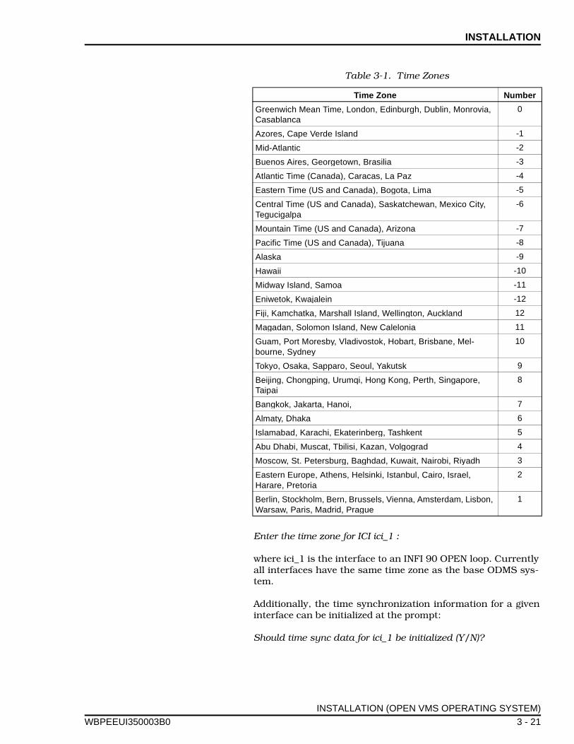
INSTALLATION
WBPEEUI
Enter the time zone for ICI ici_1 :
where ici_1 is the interface to an INFI 90 OPEN loop. Currentlyall interfaces have the same time zone as the base ODMS sys-tem.
Additionally, the time synchronization information for a giveninterface can be initialized at the prompt:
Should time sync data for ici_1 be initialized (Y/N)?
Table 3-1. Time Zones
Time Zone Number
Greenwich Mean Time, London, Edinburgh, Dublin, Monrovia, Casablanca
0
Azores, Cape Verde Island -1
Mid-Atlantic -2
Buenos Aires, Georgetown, Brasilia -3
Atlantic Time (Canada), Caracas, La Paz -4
Eastern Time (US and Canada), Bogota, Lima -5
Central Time (US and Canada), Saskatchewan, Mexico City, Tegucigalpa
-6
Mountain Time (US and Canada), Arizona -7
Pacific Time (US and Canada), Tijuana -8
Alaska -9
Hawaii -10
Midway Island, Samoa -11
Eniwetok, Kwajalein -12
Fiji, Kamchatka, Marshall Island, Wellington, Auckland 12
Magadan, Solomon Island, New Calelonia 11
Guam, Port Moresby, Vladivostok, Hobart, Brisbane, Mel-bourne, Sydney
10
Tokyo, Osaka, Sapparo, Seoul, Yakutsk 9
Beijing, Chongping, Urumqi, Hong Kong, Perth, Singapore, Taipai
8
Bangkok, Jakarta, Hanoi, 7
Almaty, Dhaka 6
Islamabad, Karachi, Ekaterinberg, Tashkent 5
Abu Dhabi, Muscat, Tbilisi, Kazan, Volgograd 4
Moscow, St. Petersburg, Baghdad, Kuwait, Nairobi, Riyadh 3
Eastern Europe, Athens, Helsinki, Istanbul, Cairo, Israel, Harare, Pretoria
2
Berlin, Stockholm, Bern, Brussels, Vienna, Amsterdam, Lisbon, Warsaw, Paris, Madrid, Prague
1
INSTALLATION (OPEN VMS OPERATING SYSTEM)
350003B0 3 - 21
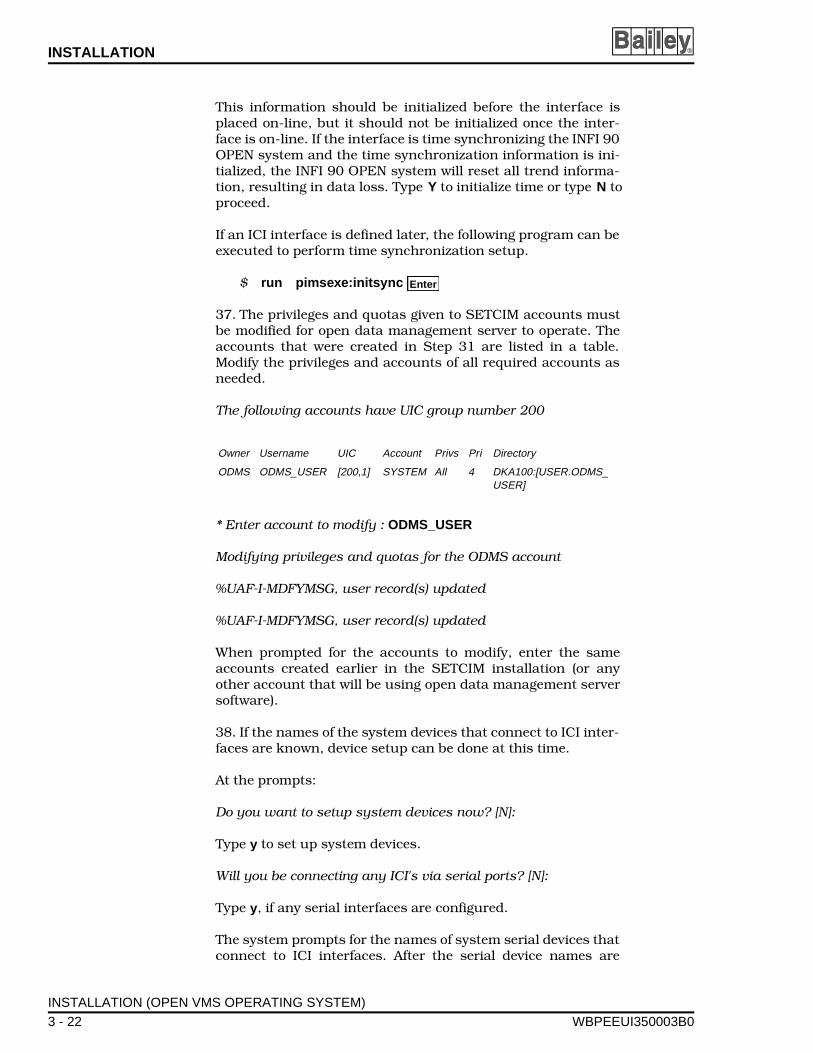
INSTALLATION ®
This information should be initialized before the interface isplaced on-line, but it should not be initialized once the inter-face is on-line. If the interface is time synchronizing the INFI 90OPEN system and the time synchronization information is ini-tialized, the INFI 90 OPEN system will reset all trend informa-tion, resulting in data loss. Type Y to initialize time or type N toproceed.
If an ICI interface is defined later, the following program can beexecuted to perform time synchronization setup.
$ run pimsexe:initsync
37. The privileges and quotas given to SETCIM accounts mustbe modified for open data management server to operate. Theaccounts that were created in Step 31 are listed in a table.Modify the privileges and accounts of all required accounts asneeded.
The following accounts have UIC group number 200
* Enter account to modify : ODMS_USER
Modifying privileges and quotas for the ODMS account
%UAF-I-MDFYMSG, user record(s) updated
%UAF-I-MDFYMSG, user record(s) updated
When prompted for the accounts to modify, enter the sameaccounts created earlier in the SETCIM installation (or anyother account that will be using open data management serversoftware).
38. If the names of the system devices that connect to ICI inter-faces are known, device setup can be done at this time.
At the prompts:
Do you want to setup system devices now? [N]:
Type y to set up system devices.
Will you be connecting any ICI's via serial ports? [N]:
Type y, if any serial interfaces are configured.
The system prompts for the names of system serial devices thatconnect to ICI interfaces. After the serial device names are
Owner Username UIC Account Privs Pri Directory
ODMS ODMS_USER [200,1] SYSTEM All 4 DKA100:[USER.ODMS_USER]
Enter
INSTALLATION (OPEN VMS OPERATING SYSTEM)
3 - 22 WBPEEUI350003B0

INSTALLATION
WBPEEUI
entered, the system prompts for the operating parameters ofeach serial device that was entered. The operating parametersentered for each serial device must match those of the connect-ing ICI interface. At the prompt:
Enter a VMS system serial device that will connect to an ICI. (RETURN if no more devices):
Type a device name, such as tta2 and press . The previousprompt appears again. Enter another device name and repeatuntil all device names are entered. Press at the promptafter all the system serial devices have been entered.
Enter the system serial device operating parameters at theprompts:
Please enter the required parameters for serial port TTA2.Baud rate: Parity (EVEN,ODD or NONE):
Enter 19200 for the baud rate, then press . Enter none forparity, then press .
Will you be connecting any SCSI ICI's? [N]:
Type y, if any SCSI interfaces are configured.
The system asks for the device names of the SCSI ICI inter-faces.
SCSI device names have the following form: DDCU:.
where DD is a two-letter device code, C is a one-letter controllerdesignator, and U is a unit number between 0 and 65535.
Although the device code can consist of any two letters that donot conflict with the device code for any existing installeddevice Elsag Bailey recommends using the DEC device codenaming standard for VMS by using the device code letters GKfor all installed SCSI ICI interfaces. This prevents a possibleconflict if two separate device drivers attempt to use the samedevice code.
A controller designator is a single alpha character (A to Z). Thespecific SCSI bus in which the ICI interface is installed deter-mines the controller designator. For systems with only oneSCSI bus, the controller designator is A. For systems with morethan one SCSI bus, the controller designators are A, B, C etc.,up to the number of SCSI buses installed in the system. Thephysical location of the SCSI buses associated with controllerdesignators varies with each system model. Consult the systemdocumentation to verify the physical location of the systemSCSI buses.
Enter
Enter
Enter
Enter
INSTALLATION (OPEN VMS OPERATING SYSTEM)
350003B0 3 - 23
INSTALLATION ®
Setting the ICI interface SCSI address determines the deviceunit number. Determine the device unit number using the fol-lowing formula:
device unit number = (ICI SCSI address) * 100
For example, if the ICI interface SCSI address is set to 7 and itis installed in SCSI bus B, then the correct device name wouldbe GKB700:. For more information on determining SCSI devicenames refer to the VMS system documentation.
Do you wish to re-read this message [N]:
Type N to continue, type Y to read this message again.
Enter a SCSI device name that will be associated with a SCSIICI. (RETURN if no more devices):
Enter a SCSI device name, such as GKA400 , then press .The prompt appears again. Either enter another SCSI devicename or press to complete the ICI configuration.
Future changes to the current ICI device configuration can bemade by editing two files. Edit the file NCPORT.COM to makechanges to serial device operating parameters. Edit the fileSETUP.COM to make changes to access protection of serialdevices or changes to SCSI device names. To add new devices,copy the commands in these files and replace the currentdevice names with new device names.
39. This step covers ICI device configuration. The installationprocedure proceeds to prompt for INFI 90 OPEN interface con-figuration information. This information includes the numberof ICI modules, their physical device types and names, and thecommunication interfaces to these devices.
If this information is not available, it can be manually enteredat a later time. To manually execute this program type:
$ run pimsexe:iciconf
If you are manually configuring the ICI interface setup, thereare two files should be edited to match the data entered in theiciconf file. Edit the files:
pimsexe:ncports.compimsexe:setup.com
The following prompts will appear.
Define ICI Logical Configuration (Y/N)?
Type Y to display a list of currently configured devices (if anyexists). Type N to exit.
Enter
Enter
Enter
INSTALLATION (OPEN VMS OPERATING SYSTEM)
3 - 24 WBPEEUI350003B0

INSTALLATION
WBPEEUI
Enter Logical ICI to update/define (0=exit):
Each interface should be defined. The number selected for theinterface is arbitrary, but it must match the ICI_X recordsdefined in the database. For example an ICI_1 record, appearson a display as interface 1. This record requires that a logicalICI be defined with number 1. The following provides an exam-ple for logical ICI1 defined as a serial interface. The appropriateinput is shown with the screen prompts.
Enter Logical ICI to update/define (0=exit): 1
Physical ICI: TTA2ICI Node Name:ICI Network Type (0-DECNET,1-TCPIP,2-LOCAL): 0Physical ICI Backup:ICI Backup Node:ICI Backup Network Type (0-DECNET,1-TCPIP,2-LOCAL):
The Physical ICI must be an existing device. This includesRS-232-C ports (such as TTA2:), LAT type devices (such asLTA19:), SCSI devices (such as A400:), and ENET if connectingto an INOSM01 interface.
NOTE: SCSI devices will appear in the system as GKA400 butshould be entered as A400 in this program.
The ICI node should be filled in with the open data manage-ment server node name (DECnet name if network type is 0,TCP/IP host if network type is 1, or can be left blank if networktype is 2). This field allows the interface to communicate withremote ICI devices. If the ICI node is an INOSM01 it should beOSM node name.
The network type can be any of the valid choices. For TCP/IP,the DEC product TCP/IP services or the TCPware productmust be installed. For DECnet, the DEC product DECnet mustbe installed.
If a redundant INFI 90 OPEN interface is required, the backupdevice should be entered. For nonredundant interfaces allremaining fields can be left blank.
To blank a field that has an entry, enter a single space in thefield.
Is this correct (Y/N)?
At the prompt, verify that the entries are correct. Type Y toaccept the entries or type N to continue editing the entries.
Enter Logical ICI to update/define (0=exit):
INSTALLATION (OPEN VMS OPERATING SYSTEM)
350003B0 3 - 25

INSTALLATION ®
Enter any other logical ICI interfaces that need defining. Afterall logical ICI interfaces are defined, enter 0 to exit and begindefining ICI physical properties.
This section allows a user to define the physical port character-istics for a given port.
Define ICI Physical Properties for an ICI (Y/N) ?
Type Y to define ICI physical properties, type N to exit.
Enter the Physical ICI: TTA2
If this physical device is already defined, a listing of its defini-tion is displayed and a prompt asks for new values to beentered. Press for any input to keep the current value. Ifthe device is not defined, the following prompts are displayed:
TCP/IP port for this device:
This is the TCP/IP port assigned to the ICI interface. The opendata management server INFI 90 OPEN interface does not usethe TCP/IP protocol to connect to the ICI interface. Therefore,set this value to 0.
Connection Type (3 - Serial,4 - SCSI):
The ICI interface connection type is either serial or SCSI. Selectthe number that matches the type of hardware in use. If theSCSI is selected, no more prompts appear. If serial is selected,prompts for the communication parameters defined by the ICIinterface hardware appears.
RS-232 Baud Rate:
Enter the baud rate of the ICI hardware notifies (usually19,200).
Refer to Table B-1 for BAUD rate dipswitch settings.
Data Bits:
This prompt is asking for the number of data bits in each wordreceived by or sent from the ICI interface. This is usually set for8 bits.
(1 - NONE, 2 - EVEN, 3 - ODD)Parity:
Enter the parity for the port as it is configured on the ICI inter-face. Usually this is configured for NONE.
Stop Bits:
Enter
INSTALLATION (OPEN VMS OPERATING SYSTEM)
3 - 26 WBPEEUI350003B0
INSTALLATION
WBPEEUI
This prompt asks for the number of stop bits associated withthe communication channel. This is usually set to 1.
Is this correct (Y/N)?
At the prompt, verify that the entries are correct. Type Y toaccept the entries or type N to continue editing the entries.
Define ICI Physical Properties for an ICI (Y/N) ?
Type Y to define additional physical devices, type N to exit.
This completes the installation of SETCIM and open data man-agement server software.
Post Installation Procedure (VMS)
The following steps contain instructions for configuring theopen data management server system. Do these steps after allinstallation operations are complete. Some of the post installa-tion steps require that the database be loaded and all pointsconfigured before they are performed.
1. Add the following line to the LOGIN.COM file of everyaccount that uses the open data management server system.This command sets up symbols and other settings required torun the SETCIM and open data management server software.
$ @SETCIMCOM:SETCIMSYLOGIN
2. A proxy account must be defined if ICI interface communi-cation is via DECnet or a GCS client communicates via DEC-net. Any of the defined open data management server useraccounts can be used. The following commands define a proxyaccount and create the proxy database if one does not exist:
$ set def sys$system $ run authorize UAF> show /proxy *
This requires SYSPRV (or system account).
If an error results, the proxy database must be created usingthe command:
UAF> create/proxy
If the server node does not have a proxy for internal access,create one. An internal access proxy is for the open data man-agement server node name. (i.e., if the DECnet node name isserver1 then a proxy could be server1::* odms_user (D) )
UAF> add/proxy server1::* odms_user/default UAF> exit
Enter
Enter
Enter
Enter
Enter
Enter
Enter
INSTALLATION (OPEN VMS OPERATING SYSTEM)
350003B0 3 - 27
INSTALLATION ®
This command creates a proxy for all users (*) to theODMS_USER account on node server1, where ODMS_USER isthe name of a valid Open VMS account. If this does not provideenough security, add individual proxies for each user that willbe using the ODMS system (including the system account forinstallation).
3. Complete the remaining steps (3 through 7) from one of thevalid open data management server user accounts estab-lished earlier in this procedure. After all installation operationsare complete and all points are configured in the system, verifythat the historical files are sized correctly. To do this, executethe file:
$ run setcimcode: sizedhis
This program will prompt for the disk history task recordname. Check at least the following records:
TSK_DHIS (corresponds to dhistory.dat file)TSK_DHS1 (corresponds to dhistor1.dat file)
If any additional historical task records are configured, theyshould be checked. This program reports the required disksizes. To verify the disk history file sizes, check the size of theactual disk history file. The file names can be viewed using thedisk history file display. To display the current disk file sizesuse the command:
$ dir/siz setcimgrp:*.dat
The following commands can be invoked, to increase the size ofa disk history file if the open data management server is shutdown.
$ set def setcimgrp $ run setcimcode: incrdhis
This program displays prompts asking for a disk history filename. Enter the disk history file name requiring a sizeincrease. When prompted for a new size, enter a size that islarger than the size specified by the sizedhis program.
If the ODMS system is active this file can be resized on-lineusing the disk history configuration screens that are providedby the GCS software. Refer to Disk History Files in Section 5for information on how to use the disk history configurationscreens.
4. For all GCS client connections, task console scratchrecords are required. Create one set of task console scratchrecords for each GCS client prior to client installation. Createthese records using the tsk_console.com procedure (refer toTSK_CONSOLE SCRATCH RECORDS).
Enter
Enter
Enter
Enter
INSTALLATION (OPEN VMS OPERATING SYSTEM)
3 - 28 WBPEEUI350003B0
INSTALLATION
WBPEEUI
5. Verify that all updates have been completed, then save asnapshot file using the DBMT utility.
6. Restart the open data management server using the follow-ing command:
$ @setcimcom:startsetcim
This command will stop the open data management server andstart it. It will also start-up any ICI interfaces and GCS server(allowing incoming GCS client connections).
7. This installation procedure generates an X Windowsresource default file which sets the fonts and colors for thewindows interface. Fonts or colors can be changed by copyingthis file to the log-in directory and modifying it.
Enter the following command:
$ COPY sys$common:[DECW$DEFAULTS.USER]IQ.DATSYS$LOGIN
GCS CLIENT INSTALLATION
The open data management server should be available andoperating when installing the GCS client software. If the serveris not operating, errors result. These errors are not fatal to thesystem, but require manual intervention to correct.
1. Log in to the SYSTEM account.
2. Load the LSGCS Graphic Client tape in the tape drive.
3. Use this command at the DCL prompt:
$ @SYS$UPDATE:VMSINSTAL ODMSSY_CLTsource
where source is the name of the tape device in Step 2.
The system issues warnings for users that do not have certainprivileges and quotas. If other users are currently on the sys-tem, a list of users is shown at the prompt:
% VMSINSTAL-W-ACTIVE, The following processes are stillactive:
list of services/programs
•
•
•
Do you want to continue anyway [NO]?
Enter
Enter
Enter
GCS CLIENT INSTALLATION
350003B0 3 - 29
INSTALLATION ®
If any of the processes listed are standard GCS processes, suchas ACCESS or OPCON, press and exit the installationprocedure. These processes are installed again by this proce-dure and should not be operating during this installation pro-cedure. Other processes that are operating should not causeany problems.
Type N, then press to cancel software installation.
Type Y, then press to continue.
If continuing, the system responds with:
Are you satisfied with the backup of the your system disk[YES]?
If a system backup is required, type N to cancel installation sothat a system backup can be done. Type Y or press tocontinue with the installation. The procedure will check toinsure that the tape is ready to process.
Are you ready?
Enter Y at the prompt when the tape is ready.
4. When the installation of ODMSSY_CLT is completed, enterthe following commands:
$ SET DEF SYS$UPDATE $ @ODMS_INSTALL_CLIENT source
where source is the name of the drive used in Step 2. This com-mand procedure processes the various save sets needed toinstall the GCS client software. This includes custom GCS andopen data management server features. The save sets areinstalled using the VMSINSTALL command.
The system generates warnings for users that do not have cer-tain privileges and quotas. If other users are currently on thesystem, a list of users is shown at the prompt:
% VMSINSTAL-W-ACTIVE, The following processes are stillactive:
list of services/programs
•
•
•
Please mount the first volume of the set on XXXXX:
Are you ready?
Enter
Enter
Enter
Enter
Enter
Enter
GCS CLIENT INSTALLATION
3 - 30 WBPEEUI350003B0

INSTALLATION
WBPEEUI
where XXXXX is the name of the tape source used in Step 3.Type Y when the tape is ready to be accessed, then press to continue.
5. At this point, the GCS system begins installation of GCSv-2.5. The installation procedure prompts for required infor-mation:
Do you want to purge files replaced by this installation [YES]?
If this installation is replacing a previous GCS release, old filescan be purged to recover disk space. If disk space is not anissue, old files can be retained. Answer Y to purge the replacedfiles.
6. The installation procedure prompts for the device wherethe GCS software is to be installed.
Enter disk device for GCS [SYS$SYSDEVICE:]: DKAXXX:
where DKAXXX is the name of the disk device where the GCSsoftware is being installed (for example DKA200).
7. The installation procedure prompts for the directory namein which the GCS is to be installed.
Enter directory name for GCS root [[GCS]]:
The system provides the default name of [GCS], If this defaultis acceptable, press . Otherwise, enter the name of a direc-tory.
8. The following prompt is displayed.
Should GCS logicals names also be defined in the system table?[YES]?
The GCS system requires that certain logical names be defined.These names can be defined in the system logical name tableor in a group table. If the names are defined in the systemname table, all users will be accessing the same GCS system. Ifindividual user groups wish to operate their own personal cop-ies of the GCS system, use group logical tables. To use a sys-tem table to define GCS logicals answer Y. If group logicaltables are being used answer N.
At this point, the installation procedure creates the requireddirectories and installs the software.
9. A prompt for the database option is displayed. The onlyvalid options for a open data management server are SETCIM,NONE, or other for Alpha/AXP.
Choose a local database option [NONE]?
Enter
Enter
GCS CLIENT INSTALLATION
350003B0 3 - 31

INSTALLATION ®
If the SETCIM database option is selected, the GCS package islocally linked. A local link allows the GCS system to only com-municate with a given product/version such as SETCIM 4.2. Ingeneral, the GCS package is not locally linked (NONE). Thispermits the database interface to communicate over a physicalcommunication link (i.e., DECnet or TCP/IP). Accept thedefault for DECnet or TCP/IP connections. If the GCS softwareis being installed on a remote client, the NONE option must bechosen.
NOTE: If GCS is locally linked, the display validation performed inStep 13 will fail. Use ACCESS to modify all the displays to have theirdefault node set to 0 instead of 1. After this change, all displaysneed to be validated manually.
The following prompts appear:
Found group 200 OK to startup ODMS system for it [Y/N]?
Answer Y
10. The next procedure installs the open data managementserver specific files:
Please mount the first volume of the set on XXXXX:
Are you ready?
where XXXXX is the name of the tape source used in Step 3.Type Y when the tape is ready to be accessed, then press to continue.
A user account is required to access the GCS functions.
Account to run GCS from [ODMS_USER]?
Enter the name of an account using the GCS system. Thisaccount must exist on the system. If the system has anODMS_USER account, the default can be accepted.
11. The GCS system requires the name of the directory thatcontains all displays.
Directory that contains GCS displays [DISPLAYS]?
Enter a directory name. The directory [DISPLAYS] is thedefault, but any existing GCS display directory can be used.
12. If desired, include the standard SETCIM displays in thedirectory selected above.
Should Base SETCIM displays be copied to the display direc-tory? [Y]:
Enter
GCS CLIENT INSTALLATION
3 - 32 WBPEEUI350003B0
INSTALLATION
WBPEEUI
In general, the base SETCIM displays should be included.However, it is possible to limit the number of displays in thedisplay system, not all the base SETCIM displays are required.If you answer N to this prompt, then manually update the dis-play directory with the required displays.
13. The GCS system requires configuration to connect to aopen data management server. Any existing configuration issaved prior to creating an initial configuration in CON-SOLE.DAT_SAVE. If no initial configuration exists an errormessage may occur. The following steps provide an initial con-figuration.
Valid server connection types are DECNET or LOCAL.
Enter the type of connection to server: [DECNET]
Select the appropriate server connection. The link to the opendata management server can be via a locally linked GCS client,a DECnet connection or a TCP/IP connection. The appropriateoption must be installed from Step 9. The default for VMS sys-tems is DECnet.
For network connections, the name of the server node isrequired.
Enter the ODMS server node name?
When DECnet or TCP/IP is selected, specify the name of a opendata management server that can be accessed for databaseinformation. The name, for DECnet systems, is the DECnetNode name of the server. For a TCP/IP connection the name isthe host name of the server.
14. The installation process finishes moving any displays. Itconverts the displays from .ASC to .DSP files. The display filesare validated against the database on the open data manage-ment server. These steps can require several minutes to severalhours depending on the CPU and type of connection. Some dis-plays may generate validation errors if the displays are for apackage that was not installed (such as CIMIO), the messageshould be expected. SETCIM displays are generally namedafter its package. If the open data management server is notavailable, the displays will not validate. When the server isavailable, the displays can be manually validated using theACCESS utility. If the display validation fails and the open datamanagement server was available, check the connection to theopen data management server. Use the ACCESS utility tocheck the connection. Refer to the GCS Users Manual forinformation on using the ACCESS utility.
GCS CLIENT INSTALLATION
350003B0 3 - 33
INSTALLATION ®
POST INSTALLATION PROCEDURE (GCS)
1. Add the following line to the LOGIN.COM file of everyaccount using the GCS system.
$ @GCS:[COMMANDS]GCSLOGIN.INC
This command sets up symbols and other settings required bythe GCS software.
2. Task console scratch records are required, for all GCS cli-ent connections. These records can be created using thetsk_console.com procedure (refer to TSK_CONSOLESCRATCH RECORDS).
INSTALLATION (HP-UX OPERATING SYSTEM)
This section covers the following installation stages:
• Modifying HP-UX operating system parameters.
• Installing the base SETCIM and open data managementserver software (including SQLplus software).
• Installing the GCS client and the open data managementserver client only software.
HP-UX System Requirements
Installing and operating the SETCIM and open data manage-ment server software requires
• A Hewlett-Packard HP9000 Series 800 computer.
• An HP system with a HP-UX 9.x.x operating system.
• A tape drive and device file for it.
• The HP computer should have the following amounts ofdisk space free: 100,000 blocks for SETCIM and the opendata management server, and 60,000 blocks for GCS-cli-ent.
NOTE: These are the installation requirements. The software pack-ages require less disk space after installation is complete.
Software is distributed on DAT tape. Therefore, an appropriatetape drive is required. A familiarity with the use of the tapedrive is required.
It is recommended that the system manager perform anyrequired adjustments of system parameters. These parametersare changed using the System Administration Manager utility
POST INSTALLATION PROCEDURE (GCS)
3 - 34 WBPEEUI350003B0
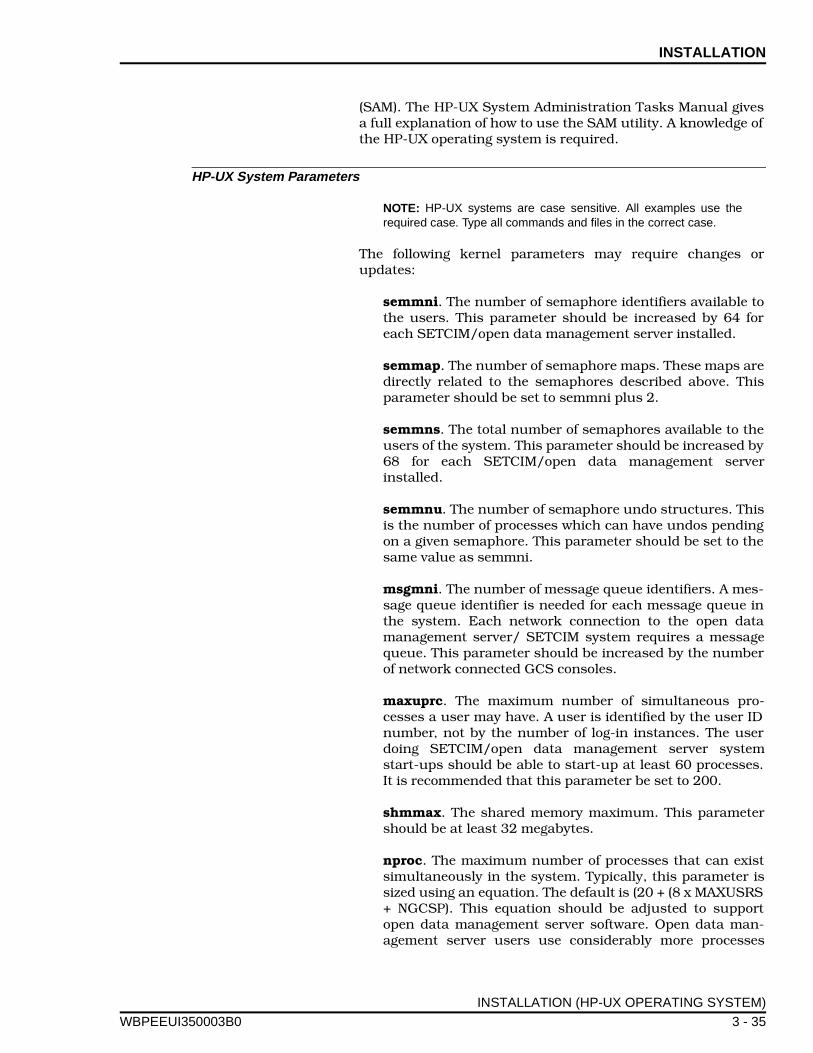
INSTALLATION
WBPEEUI
(SAM). The HP-UX System Administration Tasks Manual givesa full explanation of how to use the SAM utility. A knowledge ofthe HP-UX operating system is required.
HP-UX System Parameters
NOTE: HP-UX systems are case sensitive. All examples use therequired case. Type all commands and files in the correct case.
The following kernel parameters may require changes orupdates:
semmni. The number of semaphore identifiers available tothe users. This parameter should be increased by 64 foreach SETCIM/open data management server installed.
semmap. The number of semaphore maps. These maps aredirectly related to the semaphores described above. Thisparameter should be set to semmni plus 2.
semmns. The total number of semaphores available to theusers of the system. This parameter should be increased by68 for each SETCIM/open data management serverinstalled.
semmnu. The number of semaphore undo structures. Thisis the number of processes which can have undos pendingon a given semaphore. This parameter should be set to thesame value as semmni.
msgmni. The number of message queue identifiers. A mes-sage queue identifier is needed for each message queue inthe system. Each network connection to the open datamanagement server/ SETCIM system requires a messagequeue. This parameter should be increased by the numberof network connected GCS consoles.
maxuprc. The maximum number of simultaneous pro-cesses a user may have. A user is identified by the user IDnumber, not by the number of log-in instances. The userdoing SETCIM/open data management server systemstart-ups should be able to start-up at least 60 processes.It is recommended that this parameter be set to 200.
shmmax. The shared memory maximum. This parametershould be at least 32 megabytes.
nproc. The maximum number of processes that can existsimultaneously in the system. Typically, this parameter issized using an equation. The default is (20 + (8 x MAXUSRS+ NGCSP). This equation should be adjusted to supportopen data management server software. Open data man-agement server users use considerably more processes
INSTALLATION (HP-UX OPERATING SYSTEM)
350003B0 3 - 35

INSTALLATION ®
than the eight listed in the default equation. This equationshould be updated to allow 30 processes per user. Thenproc parameter is used in equations for several kernelparameters.
dst. This parameter is a flag indicating Daylight SavingTime. This parameter should be set to 0. Open data man-agement server time synchronization and module timestamping require that this option be disabled.
timezone. This parameter is the time zone for this com-puter system. This time zone is entered in minutes west ofGreenwich mean time. This parameter is the opposite ofthe time zone entered in during the open data managementserver installation (open data management server requestsminutes east of Greenwich mean time). A typical value forthis time zone would be 300 for Eastern Standard TimeZone in the United States.
The SETCIM/open data management server software requiresuser accounts that are members of the same group. Eachgroup has an ID associated with it. The group ID is used toestablish ownership of certain files in the HP-UX operating sys-tem. The following steps explain how to examine the usergroups, and modify the kernel parameters if necessary. If agroup already exists, it can be used.
1. Log in to the system as root.
2. At the # prompt, type sam to open the system administra-tor manager (SAM) window and wait for the window to open.
3. Select Users and Groups option from the list.
4. Select the Groups option.
5. When the groups window opens, select Add under theactions menu and click OK.
6. Enter the name of the new group (for example, SETCIM).
7. Select the newly created group name in the list.
8. Select Modify under the actions menu.
9. Select a user name from the Non-members list and clickAdd to place the user into the group. Repeat this step for eachuser that belongs to the group. Click OK when finished.
10. Return to the SAM main menu.
11. Select Previous Level.
INSTALLATION (HP-UX OPERATING SYSTEM)
3 - 36 WBPEEUI350003B0
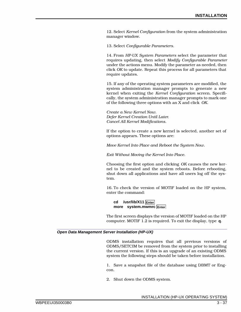
INSTALLATION
WBPEEUI
12. Select Kernel Configuration from the system administrationmanager window.
13. Select Configurable Parameters.
14. From HP-UX System Parameters select the parameter thatrequires updating, then select Modify Configurable Parameterunder the actions menu. Modify the parameter as needed, thenclick OK to update. Repeat this process for all parameters thatrequire updates.
15. If any of the operating system parameters are modified, thesystem administration manager prompts to generate a newkernel when exiting the Kernel Configuration screen. Specifi-cally, the system administration manager prompts to mark oneof the following three options with an X and click OK.
Create a New Kernel Now.Defer Kernel Creation Until Later.Cancel All Kernel Modifications.
If the option to create a new kernel is selected, another set ofoptions appears. These options are:
Move Kernel Into Place and Reboot the System Now.
Exit Without Moving the Kernel Into Place.
Choosing the first option and clicking OK causes the new ker-nel to be created and the system reboots. Before rebooting,shut down all applications and have all users log off the sys-tem.
16. To check the version of MOTIF loaded on the HP system,enter the command:
cd /usr/lib/X11 more system.mwmrc
The first screen displays the version of MOTIF loaded on the HPcomputer. MOTIF 1.2 is required. To exit the display, type q.
Open Data Management Server Installation (HP-UX)
ODMS installation requires that all previous versions ofODMS/SETCIM be removed from the system prior to installingthe current version. If this is an upgrade of an existing ODMSsystem the following steps should be taken before installation.
1. Save a snapshot file of the database using DBMT or Eng-con.
2. Shut down the ODMS system.
Enter
Enter
INSTALLATION (HP-UX OPERATING SYSTEM)
350003B0 3 - 37

INSTALLATION ®
3. Save the snapshot file made in Step 1 in another directory(outside of the ODMS and SETCIM directory trees).
4. Save the SETCIM.RUN file (if customized features exist) inthe same outside directory.
5. Save any disk history data files and archive files in thesame outside directory.
6. Delete all files in the GCS and SETCIM directory treesincluding the directories themselves.
7. Delete all /tmp/*LOCK files. These files relate to ODMS andICI interface communication.
8. Reboot the system to remove all references to ODMS. Thestandard installation procedure can now be started.
When installation is complete, follow the upgrade instructionsprovided by SETCIM to restore any tags or other configuration.
NOTE: Only modify records listed in to OKTOMODIFY.INP file.
To install the SETCIM/open data management server software:
1. Log in to the system as root.
2. An empty temporary directory is required to receive thetape distribution. To create the temporary directory, enter thecommand:
mkdir /temp
where temp is the name of the directory being created.
3. Load the SETCIM tape titled LDODM Server in the tapedrive.
4. Change directories to the temporary directory using thecommand:
cd /temp
where temp is the name of the directory created in Step 2.
5. Load the files from the tape into the temporary directory byentering:
tar -xv
- or -
tar -xf /dev/rmt/Nm
Enter
Enter
Enter
INSTALLATION (HP-UX OPERATING SYSTEM)
3 - 38 WBPEEUI350003B0

INSTALLATION
WBPEEUI
where /dev/rmt is the device name for the tape drive and Nm isthe tape drive logical unit number such as 0m. This commandloads a command file and directory structure into the tempo-rary directory.
tar is a standard UNIX command where:
-x indicates extract file.-v indicates verbose, list all files as they are extracted.-f indicates from listed devices.
If the -f option is omitted and only one device is present it willdefault to that device.
6. At the # prompt, start the installation shell script by typing:
./odms_install_server.sh
This script prompts for information to be entered, then loadsthe SETCIM and open data management server systems.
7. After the installation begins, password information isrequired. The initial required password is included in the dis-tribution package.
Do you know your SETCIM license password? [YES]?
After pressing or typing YES to continue, the followingprompt appears:
Enter SETCIM license password:
where the license password is provided with the system. Thelicense password should be entered as it appears on the cus-tomer order form. The password permits operation of all prod-ucts for a limited time.
This process can be repeated if necessary by using the follow-ing command and entering the original password.
makelicense
Entering the initial password generates a license code. Enterthe license code in the white background box on the customerorder form (Sheet 2). Fax or mail the customer order to theElsag Bailey Open Data Management Server Coordinator at thefollowing address:
Elsag Bailey29801 Euclid Ave.Wickliffe, Ohio 44092
ATTENTION: Open Data Management Server Coordinator,Mail Stop 3N3
Enter
Enter
INSTALLATION (HP-UX OPERATING SYSTEM)
350003B0 3 - 39

INSTALLATION ®
FAX the form to:
Open Data Management Server CoordinatorMail Stop 3N3FAX No. (216) 585-8756
The Open Data Management Server Coordinator assigns finallicense numbers and returns them to the customer contactidentified on Sheet 1 of the customer order form. The finallicense numbers are in the gray boxes on Sheet 2 of the cus-tomer order form.
NOTE: The initial license provided on the customer order form isvalid for approximately 60 days. All system functions cease opera-tion after 60 days unless a final license number is entered into thesystem. Refer to PERMANENT LICENSE INSTALLATION inSection 6 for information on installing the final license code.
8. SETCIM files are copied to subdirectories of the SETCIMroot directory. The SETCIM root directory and its subdirecto-ries are created by this installation procedure. At the prompt:
where should the SETCIM root directory be created [/setcim]:
Press will accept the default directory /setcim. Enter anew base directory if a different disk device or name is desired,then press .
The installation script creates the required directory tree andinstalls the SETCIM software.
9. The ODMS specific installation process is invoked. TheSQLplus product supports links to a number of other prod-ucts. Prompts are generated for the links to be installed. Onlyselect the products that are licensed for the machine. Someprompts may not appear if the required software is not avail-able.
Do you want install the ORACLE Open Access Module [N]?
The ORACLE Open Access Module allows the SQLplus productto link to an ORACLE database. This product requires thatORACLE software be installed on the system.
Do you want install the RDB Open Access Module [N]?
The RDB Open Access Module allows the SQLplus product tolink to an RDB database. This product requires that RDB soft-ware be installed on the system.
Do you want install the SETCIM Open Access Module [N]?
The SETCIM Open Access Module allows the SQLplus productto link to other SETCIM databases. These databases can be
Enter
Enter
INSTALLATION (HP-UX OPERATING SYSTEM)
3 - 40 WBPEEUI350003B0

INSTALLATION
WBPEEUI
remote SETCIM or open data management server systems.This product is provided with SQLplus software and is usuallyinstalled, if multiple SETCIM systems are configured.
Do you want install the DESK Server [N]?
The DESK server allows the SQLplus product to be accessed bythe DESK PC product. The DESK server requires that thisinterface be installed.
Type Y at the appropriate prompts to install a link, or type N tocontinue.
10. The installation procedure loads the SequeLink softwareneeded for network communication.
Enter the full path of the SequeLink Root Directory [/setcim/sequelink]:
The default directory is the root directory selected during theSETCIM software installation and the /SequeLink subdirectory.The default directory can be accepted in most cases.
If CIMDESK was selected in Step 9 a prompt is displayedrequesting the license code.
Enter SequeLink license key for CIMDESK (26 characters long):
Enter the license code as it appears on the license. The licensecode is displayed and prompt is displayed to verify the licensecode.
Is this correct (Y/N) ? [Y]
If the license code is incorrect type N to enter the license codeagain. If it is correct press enter to continue.
11. If SETCIM was selected in Step 9 a prompt is displayedrequesting a SequeLink license key for SETCIM:
Enter SequeLink license key for SETCIM (26 characters long):
Enter the license code as it appears on the license. The licensecode is displayed and prompt is displayed to verify the licensecode.
Is this correct (Y/N) ? [Y]
If the license code is incorrect, type N to enter the license codeagain. If it is correct press enter to continue.
12. The installation software prompts to create a group direc-tory for the SETCIM/open data management server system ifone is needed.
Enter
Enter
INSTALLATION (HP-UX OPERATING SYSTEM)
350003B0 3 - 41
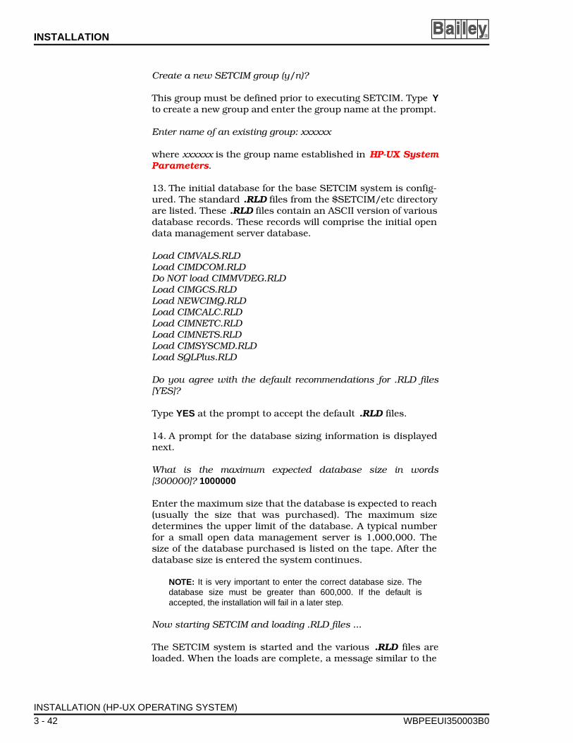
INSTALLATION ®
Create a new SETCIM group (y/n)?
This group must be defined prior to executing SETCIM. Type Yto create a new group and enter the group name at the prompt.
Enter name of an existing group: xxxxxx
where xxxxxx is the group name established in HP-UX SystemParameters.
13. The initial database for the base SETCIM system is config-ured. The standard .RLD files from the $SETCIM/etc directoryare listed. These .RLD files contain an ASCII version of variousdatabase records. These records will comprise the initial opendata management server database.
Load CIMVALS.RLDLoad CIMDCOM.RLDDo NOT load CIMMVDEG.RLDLoad CIMGCS.RLDLoad NEWCIMQ.RLDLoad CIMCALC.RLDLoad CIMNETC.RLDLoad CIMNETS.RLDLoad CIMSYSCMD.RLDLoad SQLPlus.RLD
Do you agree with the default recommendations for .RLD files[YES]?
Type YES at the prompt to accept the default .RLD files.
14. A prompt for the database sizing information is displayednext.
What is the maximum expected database size in words[300000]? 1000000
Enter the maximum size that the database is expected to reach(usually the size that was purchased). The maximum sizedetermines the upper limit of the database. A typical numberfor a small open data management server is 1,000,000. Thesize of the database purchased is listed on the tape. After thedatabase size is entered the system continues.
NOTE: It is very important to enter the correct database size. Thedatabase size must be greater than 600,000. If the default isaccepted, the installation will fail in a later step.
Now starting SETCIM and loading .RLD files ...
The SETCIM system is started and the various .RLD files areloaded. When the loads are complete, a message similar to the
INSTALLATION (HP-UX OPERATING SYSTEM)
3 - 42 WBPEEUI350003B0
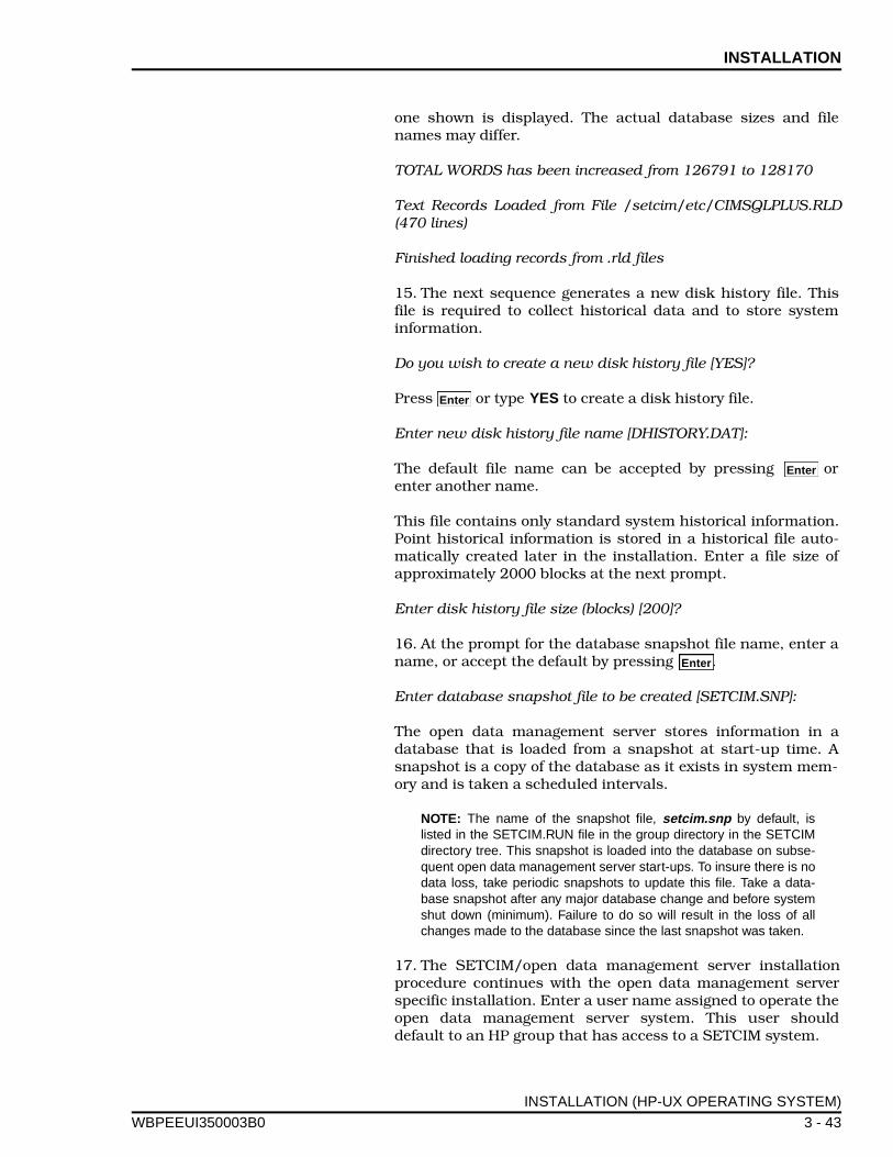
INSTALLATION
WBPEEUI
one shown is displayed. The actual database sizes and filenames may differ.
TOTAL WORDS has been increased from 126791 to 128170
Text Records Loaded from File /setcim/etc/CIMSQLPLUS.RLD(470 lines)
Finished loading records from .rld files
15. The next sequence generates a new disk history file. Thisfile is required to collect historical data and to store systeminformation.
Do you wish to create a new disk history file [YES]?
Press or type YES to create a disk history file.
Enter new disk history file name [DHISTORY.DAT]:
The default file name can be accepted by pressing orenter another name.
This file contains only standard system historical information.Point historical information is stored in a historical file auto-matically created later in the installation. Enter a file size ofapproximately 2000 blocks at the next prompt.
Enter disk history file size (blocks) [200]?
16. At the prompt for the database snapshot file name, enter aname, or accept the default by pressing .
Enter database snapshot file to be created [SETCIM.SNP]:
The open data management server stores information in adatabase that is loaded from a snapshot at start-up time. Asnapshot is a copy of the database as it exists in system mem-ory and is taken a scheduled intervals.
NOTE: The name of the snapshot file, setcim.snp by default, islisted in the SETCIM.RUN file in the group directory in the SETCIMdirectory tree. This snapshot is loaded into the database on subse-quent open data management server start-ups. To insure there is nodata loss, take periodic snapshots to update this file. Take a data-base snapshot after any major database change and before systemshut down (minimum). Failure to do so will result in the loss of allchanges made to the database since the last snapshot was taken.
17. The SETCIM/open data management server installationprocedure continues with the open data management serverspecific installation. Enter a user name assigned to operate theopen data management server system. This user shoulddefault to an HP group that has access to a SETCIM system.
Enter
Enter
Enter
INSTALLATION (HP-UX OPERATING SYSTEM)
350003B0 3 - 43

INSTALLATION ®
Enter user name: (default: odms, <quit> to exit):
where the user name is from the HP-UX System Parameterssection. The procedure uses this account to install variousopen data management server sections.
18. The installation procedure displays the action that it isready to perform and provides a prompt to continue or abortthe action.
Do you want to continue (y/n)?
Type Y to continue or type N to exit the installation procedureand abort the entire installation process.
19. The installation procedure creates two script files to sourceon HP log-in. Refer to Post Installation Procedure (HP-UX) formore information on these script files.
20. The system executes several command procedures. Theseprocedures install the ODMS specific database. All messagesare logged to .err files in the /ODMS/com subdirectory of theSETCIM directory tree. This provides access to the files toreview the messages at a later time.
21. Prompts for INFI 90 OPEN interface configuration informa-tion are displayed. The information requested by variousprompts includes the number of ICI modules, their physicaldevice types and names, and the communication interface tothese devices. If this information is not available it can be man-ually entered at later time. The following prompt will appear.
Define ICI Logical Configuration (Y/N)?
Answer by typing Y to this prompt to display a list of currentlyconfigured devices (if any).
Each interface requires definition. The number of the interfaceis arbitrary, but it must match the ICI_X records defined in thedatabase. For example, an ICI_1 record appears on a display asinterface 1. This record requires that a logical ICI interface bedefined as number 1. The user inputs shown at the promptsprovides an example of how to define logical ICI_1 as a serialinterface. Entries for prompts with no user input shown arealso explained.
Enter Logical ICI to update/define (0=exit): 1
The Physical ICI must be an existing device (RS-232 ports)such as ttya.
Physical ICI: ttya
INSTALLATION (HP-UX OPERATING SYSTEM)
3 - 44 WBPEEUI350003B0

INSTALLATION
WBPEEUI
The ICI node name can be left blank. This field allows the inter-face to communicate with remote ICI devices.
ICI Node Name:
The Network Type can be any of the valid choices, a local con-nection is recommended.
ICI Network Type (0-DECNET,1-TCPIP,2-LOCAL): 2
If a redundant INFI 90 OPEN interface is required, the backupdevice should be defined using the same network type inputused for the primary interface. For nonredundant interfaces,the remaining fields can be left blank.
Physical ICI Backup:ICI Backup Node:ICI Backup Network Type (0-DECNET,1-TCPIP,2-LOCAL):
Is this correct (Y/N)?
At the prompt, verify that the entries are correct. Type Y toaccept the entries or type N to continue editing the entries.
Enter Logical ICI to update/define (0=exit):
Enter any other logical ICI interfaces that need defining. Afterall logical ICI interfaces are defined, enter 0 to exit and begindefining ICI physical properties.
Define ICI Physical Properties for an ICI (Y/N) ?
Type Y to define ICI physical properties, type N to exit.
This section allows a user to define the physical port character-istics for a given port.
Enter the Physical ICI: ttya
If this physical device is already defined, a listing of its defini-tion is displayed and a prompt asks for new values to beentered. Press for any input to keep the current value. Ifthe device is not defined, the following prompts are displayed:
Connection Type (3 - Serial,4 - SCSI):
The ICI interface connection type is either serial or SCSI. Selectthe number that matches the type of hardware in use. If theSCSI is selected, no more prompts appear. If serial is selected,prompts appear for the communication parameters defined bythe ICI interface hardware.
RS-232 Baud Rate:
Enter
INSTALLATION (HP-UX OPERATING SYSTEM)
350003B0 3 - 45
INSTALLATION ®
Enter the baud rate of the ICI interface (usually 19200).
Data Bits:
This prompt is asking for the number of data bits in each wordreceived by or sent from the ICI interface. This is usually set for8 bits.
(1 - NONE, 2 - EVEN, 3 - ODD)Parity:
Enter the parity for the port as it is configured on the ICI. Usu-ally this is configured for NONE.
Stop Bits:
This prompt asks for the number of stop bits associated withthe communication channel. This is usually set to 1.
Is this correct (Y/N)?
At the prompt, verify that the entries are correct. Type Y toaccept the entries or type N to continue editing the entries.
Define ICI Physical Properties for an ICI (Y/N)?
Type Y to define additional physical devices, type N to exit.vices.
22. The user is given the option to configure the services file fora port number for GCS link to the SETCIM/open data manage-ment server.
Enter the port number for GCS Links?
The value of the port number should be a unique value in the/etc/services file greater than 5000 and less than 32767. Thisnumber will be updated into the services file in the PIMSEXEdirectory. This file is an example of the lines that should bedefined in the /etc/services file.
Post Installation Procedure (HP-UX)
All open data management server users are required to com-plete the following steps.
1. Change to the default directory of each open data manage-ment server user, and add start-up commands to the .loginand .profile files of each user. On HPVUE systems the file-name .vueprofile should be edited to uncomment a reference
INSTALLATION (HP-UX OPERATING SYSTEM)
3 - 46 WBPEEUI350003B0

INSTALLATION
WBPEEUI
to one of the previously mentioned files. Using your editor ofchoice, edit these files as follows:
a. For Bourne and Korn shell user, add the followinglines to the end of the .profile file, immediately before the #done line:
# Run base SETCIM/ODMS login file if [ -f /setcim/commands/setcimlogin.sh ]; then ./setcim/commands/setcimlogin.sh fi
# Set ODMS variables if [ -f /setcim/ODMS/odms.sh ]; then ./setcim/ODMS/odms.sh fi
# done with ODMS setu p
b. For C shell users, add the following lines to the .loginfile:
# Set up the SETCIM environment source /setcim/commands/setcimlogin.csh # Set the ODMS environment source /setcim/ODMS/odms.csh
# done with odms setup
These command scripts append directories to the path. Thepath should not be explicitly set by the .login file or by the.cshrc file.
If time synchronization is required, all ODMS users shoulddefine the TZ variable in their environment. For example:
TZ = EST5
To add these lines to the .profile file using the vi editor. Usethe following commands:
cd (change to the home directory)
vi .profile
Use to move to the end of the file.
i (enter insert mode)
Type the commands as listed in Step 1a.
Press escape to exit insert mode.
: (for line mode)
Enter
Enter
Enter
Enter
Enter
Enter
Enter
Enter
Enter
Enter
Enter
Enter
↑
Esc
INSTALLATION (HP-UX OPERATING SYSTEM)
350003B0 3 - 47

INSTALLATION ®
w (to write change to file)
q (to quit the editor)
The following command may be useful when editing a file:
dd (deletes a line)
2. Update the /etc/services file for ICI connections and forGCS connections. Examples of these updates for ICI connec-tions are:
DD_ttya 20000/tcpDD_ttyb 20001/tcp
where 20000 and 20001 are port numbers. Examples of theseupdates for GCS connections are:
gcsberk 5401/tcpcim200 5402/tcp
3. Log in to an ODMS user account for the following steps.Start up the SETCIM/open data management server system.Use the following command to start the system:
startsetcim.sh
This command starts all open data management server pro-cesses including GCS client support and ICI interface support.
4. For all GCS client connections, task console scratchrecords are required. Create a set of task console scratchrecords for each GCS client prior to installation of the client.These records can be created using the tsk_console.sh proce-dure (refer to TSK_CONSOLE SCRATCH RECORDS).
5. When all updates are complete, use the DBMT utility tosave a snapshot file.
6. After all installation operations are complete and all pointsare configured in the system, verify that the historical files aresized correctly. To do this, execute the file:
$ cd $SETCIMCODE $ sizedhis
NOTE: Execute these programs from one of the valid SETCIM/opendata management server user accounts established earlier in thisprocedure.
Enter
Enter
INSTALLATION (HP-UX OPERATING SYSTEM)
3 - 48 WBPEEUI350003B0

INSTALLATION
WBPEEUI
This program will prompt for the disk history task recordname. Check at least the following records:
TSK_DHIS (corresponding to dhistory.dat file)TSK_DHS1 (corresponding to dhistor1.dat file)
If any additional historical task records are configured, theyshould be checked also. This program reports the requireddisk sizes. To verify the disk history file sizes, check the size ofthe actual disk history file. The file names can be viewed usingthe historical configuration display. Divide the file size by 512to get the block size. Compare the block size to the block sizeset in Step under Open Data Management Server Installa-tion (HP-UX). To display the current disk file sizes:
$ cd /setcim/group200 $ ls -l *.DAT
where /setcim is the directory in which SETCIM is installedand group200 is the group directory created during the instal-lation procedure. The group number may be different ifanother HP-UX group was used to install the open data man-agement server software. The files are the files that are listed inthe history display.
The following commands can be invoked, to increase the size ofa disk history file if the open data management server is shutdown.
$ cd /setcim/group200 $ $SETCIMCODE/incrdhis
This program displays prompts asking for a disk history filename. Enter the disk history file name requiring a sizeincrease. When prompted for a new size, enter a size that islarger than the size specified by the sizedhis program.
If the ODMS system is active this file can be resized on-lineusing the disk history configuration screens that are providedby the GCS software. Refer to Disk History Files in Section 5for information on how to use the disk history configurationscreens.
7. To set the ICI time zone information, enter the commands:
$ cd $PIMSEXE $ initsync
It will then update time zone configuration information for thesystem.
Enter the time zone for the ODMS system:
Enter
Enter
Enter
Enter
Enter
Enter
INSTALLATION (HP-UX OPERATING SYSTEM)
350003B0 3 - 49

INSTALLATION ®
Enter a number between -12 and 12 for the time zone. Thisnumber represents the hours east of Greenwich mean time,(for example, -5 is the Eastern Standard Time Zone in theUnited States). Refer to Table 3-1 for a list of time zones world-wide.
This procedure updates any INFI 90 OPEN interfaces that aredefined in the database. If any interfaces are predefined, thefollowing prompts will appear. If no interfaces are predefined,the prompts will not appear.
Enter the time zone for ICI ici_1 :
where ici_1 is the interface to an INFI 90 OPEN loop. Currentlyall interfaces have the same time zone as the base ODMS sys-tem.
Additionally, the time synchronization information for a giveninterface can be initialized at the prompt:
Should time sync data for ici_1 be initialized (Y/N)?
This information should be initialized before the interface isplaced on-line, but it should not be initialized once the inter-face is on-line. If the interface is time synchronizing the INFI 90OPEN system and the time synchronization information is ini-tialized, the INFI 90 OPEN system will reset all trend informa-tion, resulting in data loss. Type Y to initialize time or type N toproceed.
8. If DESK software is added to the system at a later date,update the SequeLink licenses. These licenses are in the fol-lowing file:
/setcim/sequelink/servermap.tcp
where /setcim is the directory into which SETCIM was loaded.This file contains the licenses listed:
CIMDESK*LSPCIMDES*licenseSETCIM*LSPSETCIM*license
where license is the 26 character SequeLink license.
9. The SequeLink server must be started before either DESKor the SETCIM Open Access Modules can be used. To start theSequeLink server, log in as root and type the following com-mands:
cd $SETCIM/sequelink ./starttcpserver
Enter
Enter
INSTALLATION (HP-UX OPERATING SYSTEM)
3 - 50 WBPEEUI350003B0
INSTALLATION
WBPEEUI
When the server starts, it checks the licenses in server-map.tcp. To verify that the licenses are valid, check the $SET-CIM/sequelink/tcpsrv.log file.
GCS CLIENT INSTALLATION
To install a GCS client:
1. Log in to the system as the root user.
NOTE: For those installing the GCS client only (i.e., this was notalready done under Open Data Management Server Installation(HP-UX)), delete the existing GCS directory before creating a newone. Use the command rm -r gcs to delete the gcs directory.
2. Create a temporary directory to contain the tape distribu-tion, if needed. A temp directory should exist from the SETCIMinstallation procedure. If not, create the directory by enteringthe command:
mkdir /temp
where temp is the name of the directory being created.
3. Load the LSGCS client tape in the tape drive.
4. Change directories to the temporary directory using thecommand:
cd /temp
5. Load the files from the tape into the temporary directory byentering:
tar -xv
- or -
tar -xf /dev/rmt/Nm
where /dev/rmt is the device name for the tape drive and Nm isthe tape drive logical unit number such as 0m. The commandloads a command file and directory structure into the tempo-rary directory.
6. At the # prompt, start the installation command file by typ-ing:
./odms_install_client.sh
The script generates various prompts and loads the GCS clientsystem.
Enter
Enter
Enter
GCS CLIENT INSTALLATION
350003B0 3 - 51

INSTALLATION ®
7. At the prompt enter the root GCS directory name, if it is notdefined.
Enter the directory that is to contain the GCS Package?
The directory should be a complete directory, such as /gcs . Ifthis directory does not exist, the installation procedureprompts the user to create it.
Directory does not exist, create it (y/n)?
Type Y to create a new directory. A no response causes the sys-tem to prompt for a valid directory.
The installation procedure verifies that the directory is set cor-rectly. The GCS directory is defined as follows:
$GCS=/gcsDo you want to continue with this value? (y/n)
If this is the correct directory, type Y. The script will create allneeded subdirectories and expand the archives.
8. The GCS system can be defined to access any SETCIM/open data management server system or it can be locked to alocal SETCIM/open data management server system.
Do you want GCS to be locally linked? (y/n)
This local linkage allows the GCS system to only communicatewith a given product version (such as SETCIM 4.2). In general,the GCS system is not locally linked and the user should enteran N, to allow for the database interface to communicate over aphysical communications link (i.e., TCP/IP).
NOTE: If GCS is locally linked, the display validation that is donelater in the installation will fail. Use ACCESS to modify all the dis-plays to have their default node set to 0 instead of 1. After thischange, all displays need to be validated manually.
9. The installation procedure processes the open data man-agement server specific items. These items require the name ofthe directory that will contain the displays.
Enter the directory that contains the standard displaysDefault will be 'displays'?
The default is usually accepted. The installation procedure cre-ates this directory, the only time a different directory is valid isif this system is being updated and a different directory wasused by the old version.
10. Enter the name of an ODMS user who will be using GCS toaccess the open data management server system.
GCS CLIENT INSTALLATION
3 - 52 WBPEEUI350003B0

INSTALLATION
WBPEEUI
Enter user name?
This user must be a valid user. The activities that are to be per-formed are displayed and a prompt asks for confirmation tocontinue or exit.
Do you want to continue (y/n)?
Exiting the installation procedure requires that the installationprocedure be started again at the beginning. A prompt asks forthe type of connection to the open data management server.
Will connection to server be via locally linked GCS (Y/N)?
If the GCS client was installed as locally linked in Step 8,answer yes by typing Y. Typically, the GCS is not locally linked.If this is the case with this installation answer no by typing N.
11. If responding with no in Step 10, enter the name of theopen data management server that connects to the GCS clientat the next prompt. This name is the network host name of theopen data management server.
Enter the name of the host server?
12. Copy the standard SETCIM displays to the GCS displaysdirectory.
Should standard SETCIM displays be loaded into /gcs/dis-plays?
where /gcs/displays is the name of the GCS display directoryenter in Step 9. This step is recommended, although it cantake several minutes to several hours. The standard displaysprovide access to functions such as easy trending.
NOTE: During the course of display validation the screen may notupdate. To check the progress of display validation, open anotherterminal, access the display directory to examine the date and timefor the display files.
The installation procedure processes all displays, convertingthem from .asc to .dsp and validating them. This proceduremay take several minutes to several hours depending on theCPU in use. Any resulting errors are echoed to the screen andto the files /gcs/odms/gcsconv.err and /gcs/odms/gcs-name.err.
GCS CLIENT INSTALLATION
350003B0 3 - 53

INSTALLATION ®
POST INSTALLATION PROCEDURE (GCS CLIENT)
All users who are to be GCS client users are required to per-form the following steps.
1. Change to the default directory of each user, and addstart-up commands to the .login and .profile files of eachopen data management server user. Using any text editor, editthese files as follows:
a. For Bourne and Korn shell users, add the followinglines to the end of the .profile file, just before the '# done'line:
# GCS Login/Startup variables if [ -f /gcs/odms/odms_gcs.sh ] then . /gcs/odms/odms_gcs.sh fi
b. For C shell users, add the following to the .login file:
# Set up the GCS Login/Startup environment source /gcs/odms/odms_gcs.csh
These command scripts append directories to the path. Thepath should not be explicitly set by the .login file or by the.cshrc file.
To add these lines to the .profile file using the vi editor, theuse the following commands:
cd (change to the home directory)
vi .profile
Use to move to the end of the file.
i (enter insert mode)
Enter the commands that are listed in Step 1a.
Press to exit the insert mode.
: (to get to line mode)
w (to write change to file)
q (to quit the editor)
The following command may be useful when editing a file:
dd (deletes a line)
Enter
Enter
Enter
Enter
Enter
↑
Esc
POST INSTALLATION PROCEDURE (GCS CLIENT)
3 - 54 WBPEEUI350003B0
INSTALLATION
WBPEEUI
2. Log out of the root account and log in as a GCS user. For allGCS client connections, task console scratch records arerequired. It is recommend that each GCS client have at leasttwo sets of scratch records defined. These records can be cre-ated using the tsk_console.sh procedure (refer toTSK_CONSOLE SCRATCH RECORDS).
TSK_CONSOLE SCRATCH RECORDS
The open data management server requires that all GCS clientsystems have a set of scratch records defined in the server.These records can be defined using one of the following com-mands depending on the system. These commands must beexecuted while the ODMS system is running. If the system isnot running, start it using following the commands:
$ @setcimcom:startsetcim for VAX systems
startsetcim.sh for HP-UX systems
To define scratch records:
For VAX based servers:
@PIMS$COM:TSK_CONSOLE "node_name" c_type
where node_name is the node name of the GCS client enclosedin quotation marks and c_type is the type of connection (onlyDECNET or TCPIP connections are valid).
NOTE: For TCP/IP connections the node name is case sensitive.
For HP based servers:
tsk_console.sh node_name
where node_name is the node name of the GCS client. All con-nections to an HP host must use a TCP/IP connection.
These commands updates the open data management serverdatabase. After the TSK_CONSOLE scratch records are cre-ated, take a database snapshot to insure these changes are notlost. Snapshots can be saved using the DBMT tool or ENGCONutility, see the SETCIM Users Manual for more information.The default name of the snapshot file for open data manage-ment server systems is listed in the SETCIM.RUN file.
WINDOWS CLIENT TERMINAL INSTALLATION
This section covers the following information:
• Microsoft Windows client terminal requirements.
• Installing a GCS console on a personal computer.
Enter
Enter
Enter
Enter
TSK_CONSOLE SCRATCH RECORDS
350003B0 3 - 55
INSTALLATION ®
• Guidelines for configuring a GCS console on a personalcomputer using Wollongong TCP/IP software.
• Guidelines for configuring a GCS console on a personalcomputer using DECnet Pathworks software.
• Guidelines for configuring a GCS console on a personalcomputer using TCP/IP Pathworks software.
• Guidelines for connecting a PC-based console to a GCSconsole on a VAX server using TCPware software.
• Guidelines for connecting a PC-based console to a GCSconsole on a VAX server using UCX software.
• Guidelines for connecting a PC-based console to a GCSconsole on a VAX server using DECnet software.
• Guidelines for connecting a PC-based console to a GCSconsole on an HP server.
Microsoft Windows Client Terminal Requirements
Installing and operating a GCS console from a Windows clientterminal requires:
• A 486DX-based computer minimum.
• At least 8 megabytes of memory for GCS console and Win-dows software.
• At least 40 megabytes of hard disk drive space.
• An X Windows software package.
• TCP/IP (VAX/VMS or HP-UX open data management serv-ers) or DECnet Pathworks (VAX/VMS open data manage-ment servers) networking software.
GCS Console Installation
This procedure is an example procedure that explains how tosetup a GCS console on a personal computer using WollongongPathways TCP/IP software to communicate with a open datamanagement server on a VAX using TCPware software. Otherinstallations may use different protocols or software packages,but the concepts are similar.
NOTE: Install the TCPware (VAX) and Pathways TCP/IP (PC) soft-ware before proceeding with the GCS console installation proce-dure. Refer to the instruction guides for those software packages forinstallation instructions.
WINDOWS CLIENT TERMINAL INSTALLATION
3 - 56 WBPEEUI350003B0

INSTALLATION
WBPEEUI
To install GCS console for windows:
1. Insert the first GCS console floppy disk into the floppy diskdrive.
2. From within Windows, select run from the file pulldownmenu.
3. Enter a:/setup and click on the OK button to start theinstallation process.
4. The installation process opens several windows. Each win-dow asks for information to be entered. The requested informa-tion is:
• The target drive and directory.
• The default cursor size: none, small cross hair or largecross hair.
• The object focus option: (standard, no default focus or fol-low cursor).
• The communication type: DECnet, NETBIOS, TCP/IP[3COM], TCP/IP [Lan Workplace], TCP/IP [Wollongong] orNETIPC/ARPA.
For this configuration select TCP/IP [Wollongong].
• The name of a scratch drive for temporary files.
• If the system should write communication errors to a logfile.
• Switch mouse buttons for left-handed people.
After all prompts have been answered, the installation willautomatically process disks 1 through 5. Insert each disk asthe system requests it.
5. The installation process (if permitted) updates the con-fig.sys and autoexec.bat files for GCS console required vari-ables. It creates a program group and start-up icon andconcludes installation.
6. When the installation completes, install disk 6 in the driveand bring up a DOS window and enter the following com-mands:
cd c:\gcswin\displays a:\scdisps a:\odmdisps install.bat
Enter
Enter
Enter
Enter
WINDOWS CLIENT TERMINAL INSTALLATION
350003B0 3 - 57

INSTALLATION ®
where c:\gcswin is the directory where the GCS console isinstalled, \display is the default display directory and a: is thefloppy disk drive.
These steps extract the open data management server displaysand add them to the GCS displays directory, convert the dis-plays from .ASC file format to .DSP file format, and set up theconsole configuration. The scdisps.exe file is a self extractingzip file that loads the SETCIM specific displays. The odm-disps.exe file is a self extracting zip file that loads the baseopen data management server displays. The script file willreplace several base SETCIM display files. The install.bat fileconverts the displays and provides an initial GCS console con-figuration.
7. Type exit to return to Windows.
8. Exit Windows, remove the floppy disk from the floppy diskdrive, boot the system, and start-up Windows.
9. Click on the GCS icon. Do the following steps to completethe GCS configuration and validate the displays.
a. From the ACCESS main menu, select Setup.
b. Select GCS from the setup menu and wait for the Sys-tem Configuration Utility display.
c. Select the Node-Names option.
d. Set up at least one logical node for the open data man-agement server. The following example is for a VAX opendata management server named ODMSRV using TCPWAREfor a TCP/IP connection.
This server has a communications task named BGCS-BERK. The individual communications tasks depend onthe type of network connection (DECnet or TCP/IP), servertype (HP or VAX) and the actual network software runningon the server and host. Refer to the GCS Users Manual formore information. Refer to the appropriate section forinformation on various connection types following the GCSconsole installation procedure.
Select a unique node driver address between 82 and 99. Anexample entry for Wollongong TCP/IP is:
1 LOGICAL NODES ODMSRV//BGCSBERK 1NODE TASK IDENTIFIER
85 NODE DRIVER ADDRESS
Refer to Table 3-1 for a summary of the available options,and the required SETCIM.RUN file server line and GCSConfiguration line for those options.
WINDOWS CLIENT TERMINAL INSTALLATION
3 - 58 WBPEEUI350003B0

INSTALLATION
WBPEEUI
Refer to the GCS User Manual for more information onconfiguring the interface. Verify that any other configura-tion aspects of connecting a personal computer client to aHP or VAX server are completed.
e. When completed, exit this display using the cancelmouse button and quit the System Configuration Utilitymenu.
10. After communications are established, all the system dis-plays must be validated to connect the client displays to theserver database.
NOTE: The server must be up and operating the open data man-agement server application while proceeding with this activity.
The display validation operation attempts to establish a com-munications connection (for example, via TCP/IP) with theserver that was defined earlier in the GCS setup (node name =ODMSRV in the example in Step 9). If this connection is notestablished, the display validation appears to be working, butall displays will report validation errors.
Verify that the message Remote connection established...appears in the access messages window during Step d. If itdoes not, verify that the client and server platforms are cor-rectly configured and validate the display again. To validatedisplays:
a. Enter the GCS Access Utility.
b. Select the Utilities option, then select the Validationoption.
c. From the validation menu, select Names to open theValidate Tag Names.
d. Select the All option, then select the Use option to beginthe validation process. Verify there is a Remote connectionestablished... message as the validation process begins.
e. Successful validation of the displays takes several min-utes to several hours, depending on the types of client andserver platforms.
f. Exit to the access utility main menu.
g. Select the Console option and verify that the client con-nects to the server again, and executes the open data man-agement server/GCS console displays.
This will conclude the GCS portion of the setup.
WINDOWS CLIENT TERMINAL INSTALLATION
350003B0 3 - 59
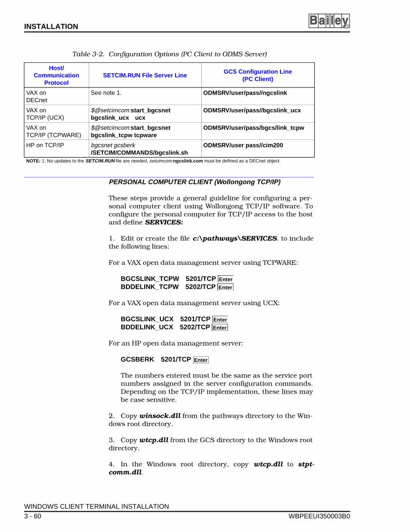
INSTALLATION ®
PERSONAL COMPUTER CLIENT (Wollongong TCP/IP)
These steps provide a general guideline for configuring a per-sonal computer client using Wollongong TCP/IP software. Toconfigure the personal computer for TCP/IP access to the hostand define SERVICES:
1. Edit or create the file c:\pathways\SERVICES. to includethe following lines:
For a VAX open data management server using TCPWARE:
BGCSLINK_TCPW 5201/TCP BDDELINK_TCPW 5202/TCP
For a VAX open data management server using UCX:
BGCSLINK_UCX 5201/TCP BDDELINK_UCX 5202/TCP
For an HP open data management server:
GCSBERK 5201/TCP
The numbers entered must be the same as the service portnumbers assigned in the server configuration commands.Depending on the TCP/IP implementation, these lines maybe case sensitive.
2. Copy winsock.dll from the pathways directory to the Win-dows root directory.
3. Copy wtcp.dll from the GCS directory to the Windows rootdirectory.
4. In the Windows root directory, copy wtcp.dll to stpt-comm.dll.
Table 3-2. Configuration Options (PC Client to ODMS Server)
Host/Communication
Protocol SETCIM.RUN File Server Line
GCS Configuration Line (PC Client)
VAX on DECnet
See note 1. ODMSRV/user/pass//ngcslink
VAX onTCP/IP (UCX)
$@setcimcom:start_bgcsnet bgcslink_ucx ucx
ODMSRV/user/pass//bgcslink_ucx
VAX on TCP/IP (TCPWARE)
$@setcimcom:start_bgcsnet bgcslink_tcpw tcpware
ODMSRV/user/pass/bgcs/link_tcpw
HP on TCP/IP bgcsnet gcsberk/SETCIM/COMMANDS/bgcslink.sh
ODMSRV/user pass//cim200
NOTE: 1. No updates to the SETCIM.RUN file are needed, setcimcom:ngcslink.com must be defined as a DECnet object.
Enter
Enter
Enter
Enter
Enter
WINDOWS CLIENT TERMINAL INSTALLATION
3 - 60 WBPEEUI350003B0
INSTALLATION
WBPEEUI
5. Create or edit a file named hosts (no extension) in the path-way directory to include the names and IP addresses of allopen data management servers.
PERSONAL COMPUTER CLIENT (DECnet Pathworks)
These steps provide a general guideline for configuring a per-sonal computer client using DECnet Pathworks software. Toconfigure the personal computer for access to the host:
1. Make sure that DECnet Pathworks is configured and thatthe client computer is fully configured.
2. Using the NCP utility
NCP> define node ODMS_SRV address 10.670
where ODMS_SRV is the name of the open data managementserver node and 10.670 is the address of the server.
3. No other steps should be required on the personal com-puter for DECnet type connections.
PERSONAL COMPUTER CLIENT (TCP/IP Pathworks)
These steps provide a general guideline for configuring a per-sonal computer client using TCP/IP Pathworks. To configurethe personal computer to access the host.
1. Make sure that TCP/IP Pathworks is configured and thatthe client computer is fully configured.
2. Edit the hosts file in the pathworks directory to include thename of the client and of the open data management server.
3. Edit the services file in the pathworks directory to includethe following lines:
For a VAX open data management server using TCPWARE:
BGCSLINK_TCPW 5201/TCP BDDELINK_TCPW 5202/TCP
For a VAX open data management server using UCX:
BGCSLINK_UCX 5201/TCP BDDELINK_UCX 5202/TCP
For an HP open data management server:
GCSBERK 5201/TCP GCSBERK 5202/TCP
Enter
Enter
Enter
Enter
Enter
Enter
Enter
WINDOWS CLIENT TERMINAL INSTALLATION
350003B0 3 - 61
INSTALLATION ®
The numbers entered must be the same as the service portnumbers assigned in the server configuration commands.
4. No other steps should be required on the PC for TCP/IPtype connections.
VAX SERVER (TCPware)
These steps provide a guideline for connecting a VAX serverusing TCPware software to a GCS console.
1. Edit the file device:[tcpware]services by adding the follow-ing lines:
BGCSLINK_TCPW 5201/tcp #GCSLINK TCP/IP BDDELINK_TCPW 5202/tcp #DDELINK TCP/IP
where any unused service port numbers are used for the portnumbers in the command lines.
2. Edit the file SETCIM.RUN by adding the following com-mands:
$ @SETCIMCOM:start_bgcsnet bgcslink_tcpwtcpware
$ @SETCIMCOM:start_bddenet bddelink_tcpwtcpware
where SETCIM.RUN is the open data management serverstart-up file found in the group directory.
3. Edit the TCPware HOSTS file to include the IP addressesand names of all clients.
VAX SERVER (UCX and SETCIM 4.5A)
These steps provide a guideline for connecting a VAX serverusing UCX software to a GCS console.
Enter
Enter
Enter
Enter
WINDOWS CLIENT TERMINAL INSTALLATION
3 - 62 WBPEEUI350003B0
INSTALLATION
WBPEEUI
1. Issue the following commands from the system account:
$ UCXUCX> SET SERVICE BGCSLINK_UCX -
_UCX> /FILE=DISK1:[SETCIM.COMMANDS]BGCSLINK_UCX.COM- _UCX> /PORT=5201 /PROCESS_NAME =
BGCSLINK_UCX - _UCX> /USER_NAME=ODMS_USER
UCX> SET SERVICE BSPDDE_UCX - _UCX> /FILE=DISK1:[SETCIM.COMMANDS]BSPDDE_UCX.COM _UCX> /PORT=5202 /PROCESS_NAME =
BSPDDE_UCX - _UCX> /USER_NAME=ODMS_USER
UCX> ENABLE SERVICE BSPDDE_UCX UCX> EXIT
where DISK1: is the disk device and SETCIM. is the directoryinto which SETCIM was installed, 5201 is a unique port num-ber that corresponds to the port numbers used in the GCSconsole (PC), and ODMS_USER is the name of any valid SET-CIM/ODMS user created during server installation.
2. Edit the file SETCIM.RUN by adding the following com-mands:
$ @SETCIMCOM:start_bgcsnet bgcslink_ucx ucx $ @SETCIMCOM:start_bddenet bspdde_ucx ucx
where SETCIM.RUN is the open data management serverstart-up file found in the group directory.
3. Edit the UCX HOSTS file to include the IP addresses andnames of all clients.
VAX SERVER (DECnet)
These steps provide a guideline for connecting a VAX serverusing DECnet software to a GCS console.
1. Configure the operating system for network objects to sup-port GCS connections. The following commands will create aGCS connection:
$ MCR NCP NCP> def obj ngcslink number 0 file
setcimcom:ngcslink.com NCP> set obj ngcslink number 0 file
setcimcom:ngcslink.com NCP> exit
Enter
Enter
Enter
Enter
Enter
Enter
Enter
Enter
Enter
Enter
Enter
Enter
Enter
Enter
Enter
Enter
WINDOWS CLIENT TERMINAL INSTALLATION
350003B0 3 - 63

INSTALLATION ®
where ngcslink is the name of the service that remote clientsare using for a connection.
2. Make sure that all clients are defined in the DECnet (NCP)database. Use the following commands to show and define newnodes.
$ MCR NCP NCP> show know nodes NCP> def node 10.670 name ODMS_CLT NCP> set node 10.670 name ODMS_CLT NCP> exit
where ODMS_CLT is the node name of the client.
3. No additional configuration is required for a DECnet typeconnection.
VAX SERVER (TGV Multinet)
TGV Multinet support requires that the UCX support libraryUCX$IPC.OLB be copied from MULTINET_COMMON_ROOT:[MULTINET .LIBRARY] to SYS$LIBRARY directory, prior toinstallation of the ODMS system. When installing the ODMSclient system, select Multinet as the communication option.
1. Multinet must be configured to support the bgcslink ser-vice. To configure, issue the following commands at the appro-priate screen prompts shown:
$ MULTINET CONFIGURE/SERVICE
MultiNet Server configuration Utility[Reading in configuration from MULTINET:SERVICES.MASTER_SERVER]SERVER-CONFIG> addbgcslink
[Adding new configuration entry for service “BGSLINK”]Protocol: [TCP]TCP Port number: 5001Program to run: NONE
[Added service BGCSLINK to configuration][Selected service is now BGCSLINK]SERVER-CONFIG> set service none
[Service action of BGCSLINK set to NONE]SERVER-CONFIG> set program[Program to run for BGCSLINK set to NONE]SERVER-CONFIG> diable bgcslinkSERVER-CONFIG> show/full bgcslinkService “BGCSLINK”: ***DISABLED***
TCP socket (AF_INET, SOCK_STREAM), port 5001
Enter
Enter
Enter
Enter
Enter
WINDOWS CLIENT TERMINAL INSTALLATION
3 - 64 WBPEEUI350003B0
INSTALLATION
WBPEEUI
Socket Options = SO_KEEPALIVEINIT () = TCP_InitLISTEN () = TCP_ListenCONNECTED() = TCP_Connected
SERVER-CONFIG> exit[writing configuration to MULTINET_COMMON_ROOT:[MULTINET] SERVICES. MASTER_SERVER]
2. Edit the file SETCIM.RUN by adding the following com-mands:
$ @SETCIMCOM:start_bgcsnet bgcslink_ucx ucx $ @SETCIMCOM:start_bddenet bspdde_ucx ucx
where SETCIM.RUN is the open data management serverstart-up file found in the group directory.
3. Edit the UCX HOSTS file to include the IP addresses andnames of all clients.
HP SERVER (HP CLIENT)
These steps provide a guideline for connecting an HP server toan HP-based GCS consoles:
1. Edit the /etc/services file on both the server and client byadding the following line:
gcsberk 5401/tcp #GCSLINK TCP/IP (HP client)
where any unused service port number is used for the serviceport number in the command.
2. On the server, edit the SETCIM.RUN file by adding the fol-lowing line:
bgcsnet gcsberk /SETCIM/COMMAND/bgcslink.sh
where SETCIM.RUN file is the open data management serverstart-up file found in the group directory.
3. Edit the /etc/hosts file to include the IP addresses andnames of all clients.
Enter
Enter
WINDOWS CLIENT TERMINAL INSTALLATION
350003B0 3 - 65

INSTALLATION ®
HP SERVER (PC CLIENT)
These steps provide a guideline for connecting an HP server toan PC-based GCS consoles:
1. Edit the /etc/services file on the server by adding the fol-lowing line:
cim200 5402/tcp #GCSLINK TCP/IP (PC client)
where any unused service port number is used for the serviceport number in the command.
2. On the server, edit the /etc/inetd.conf file by adding thefollowing line:
cim200 stream tcp nowait odms /setcim/commands/cimgcsi_bs.sh cimgcsi
where odms is a valid user account.
3. Edit the /etc/hosts file to include the IP addresses andnames of all clients.
4. Reset the TCP/IP process with the following command:
inetd -c.
WINDOWS CLIENT TERMINAL INSTALLATION
3 - 66 WBPEEUI350003B0
SECTION 4 - CONFIGURATION
WBPEEUI
INTRODUCTION
This section explains how to configure a tag in the open datamanagement server database. Tag configuration can be doneon-line via the Open Data Management Server (ODMS) data-base configuration screens or off-line using SETCIM utilityprograms RECSAVE and RECLOAD. The configuration exam-ple provided in this section explains how to do an on-line tagconfiguration using the open data management server data-base configuration screens.
OFF-LINE CONFIGURATION
An INFI 90 OPEN tag database can be prepared off-line andthen loaded into the open data management server using SET-CIM utility programs RECSAVE and RECLOAD. The RECSAVEprogram saves the open data management server databaserecord as an ASCII file. The RECLOAD program is used to loadthe ASCII representations of the open data management serverdatabase records into the open data management server data-base. For information on how to set up database records to besaved as ASCII files, formatting requirements, options, loadingdatabase files, and using the utility programs, refer to the SET-CIM Users Manual. To be sure that all ODMS tags and fieldsare set up properly, off-line configuration should be done byElsag Bailey.
ON-LINE CONFIGURATION
INFI 90 OPEN tags can be individually configured on-line andplaced into the open data management server database via thedatabase configuration screens. Tag configuration is easy andstraightforward using this method. The database configurationscreens provide user entry fields (gray fields with green fore-ground) that show what database fields can be configured,updated or deleted by the user. Each of these screen fields cor-respond to an open data management server database fieldthat must be defined by the user. All database fields are listedin Table E-2 with the following information provided:
• The database field name.
• Tag type supported.
• If the field is on-line changeable.
• The database field default value.
INTRODUCTION
350003B0 4 - 1
CONFIGURATION ®
• If user definition is required.
• If the field is updated by the INFI 90 OPEN system.
• The required format or restrictions of the field.
• A description of the database field and further explanationof the format (if required).
After the tag database fields have been configured, the recordcan be updated or created. Additionally, existing tags can bedeleted using the tag configuration screen. All open data man-agement server screens can be accessed without a passwordfor viewing only. An engineers level password is required to cre-ate, update, or delete tag database records.
EXAMPLE CONFIGURATION
The following steps provide an example configuration thatshows how to create and configure a station tag record for theopen data management server database. This example uses astation tag which is a complex tag to configure. All other tagsare configured using the same steps, but may require less con-figuration information and steps. Whenever configuring a par-ticular open data management server database tag type, referto the Function Code Applications Manual for informationthat relates to its use or application within an INFI 90 OPENcontrol system. Refer to Appendix E for information on how thetag needs to be configured within the open data managementserver.
To configure an open data management server station tagrecord:
1. From the main menu, highlight Configuration and clickwith the mouse or press , or press to access the config-uration menu.
2. Highlight Database and click with the mouse or press, or press to access the database configuration tag
selection screen (Fig. 4-1).
3. There are three entry fields on the database tag configura-tion selection screen, Tag Name, Tag Type, History Area.
a. Enter the desired tag name for the tag being created byhighlighting the gray field next to Tag Name and type in thename. A Tag does not exist in the database messageappears below the tag name if this tag name does notbelong to any tag already existing in the database.
If an existing tag name is not known, highlight View TagListings and click with the mouse or press , or press
Enter F4
Enter F1
Enter
EXAMPLE CONFIGURATION
4 - 2 WBPEEUI350003B0
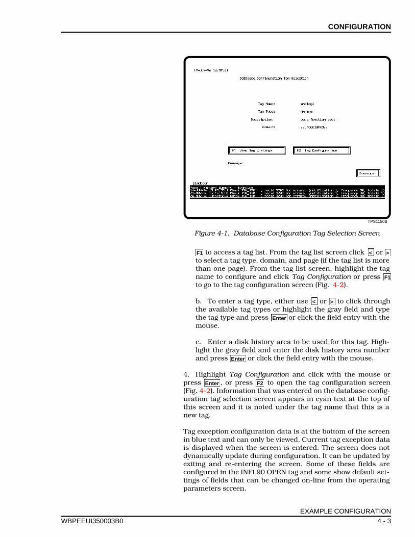
CONFIGURATION
WBPEEUI
to access a tag list. From the tag list screen click or to select a tag type, domain, and page (if the tag list is morethan one page). From the tag list screen, highlight the tagname to configure and click Tag Configuration or press to go to the tag configuration screen (Fig. 4-2).
b. To enter a tag type, either use or to click throughthe available tag types or highlight the gray field and typethe tag type and press or click the field entry with themouse.
c. Enter a disk history area to be used for this tag. High-light the gray field and enter the disk history area numberand press or click the field entry with the mouse.
4. Highlight Tag Configuration and click with the mouse orpress , or press to open the tag configuration screen(Fig. 4-2). Information that was entered on the database config-uration tag selection screen appears in cyan text at the top ofthis screen and it is noted under the tag name that this is anew tag.
Tag exception configuration data is at the bottom of the screenin blue text and can only be viewed. Current tag exception datais displayed when the screen is entered. The screen does notdynamically update during configuration. It can be updated byexiting and re-entering the screen. Some of these fields areconfigured in the INFI 90 OPEN tag and some show default set-tings of fields that can be changed on-line from the operatingparameters screen.
TPS1150B
Figure 4-1. Database Configuration Tag Selection Screen
F1 < >
F1
< >
Enter
Enter
Enter F2
EXAMPLE CONFIGURATION
350003B0 4 - 3
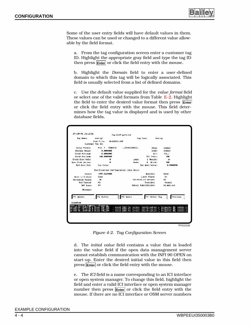
CONFIGURATION ®
Some of the user entry fields will have default values in them.These values can be used or changed to a different value allow-able by the field format.
a. From the tag configuration screen enter a customer tagID. Highlight the appropriate gray field and type the tag IDthen press or click the field entry with the mouse.
b. Highlight the Domain field to enter a user-defineddomain to which this tag will be logically associated. Thisfield is usually selected from a list of defined domains.
c. Use the default value supplied for the value format fieldor select one of the valid formats from Table E-2. Highlightthe field to enter the desired value format then press or click the field entry with the mouse. This field deter-mines how the tag value is displayed and is used by otherdatabase fields.
d. The initial value field contains a value that is loadedinto the value field if the open data management servercannot establish communication with the INFI 90 OPEN onstart-up. Enter the desired initial value in this field thenpress or click the field entry with the mouse.
e. The ICI field is a name corresponding to an ICI interfaceor open system manager. To change this field, highlight thefield and enter a valid ICI interface or open system managernumber then press or click the field entry with themouse. If there are no ICI interface or OSM server numbers
TPS1151B
Figure 4-2. Tag Configuration Screen
Enter
Enter
Enter
Enter
EXAMPLE CONFIGURATION
4 - 4 WBPEEUI350003B0
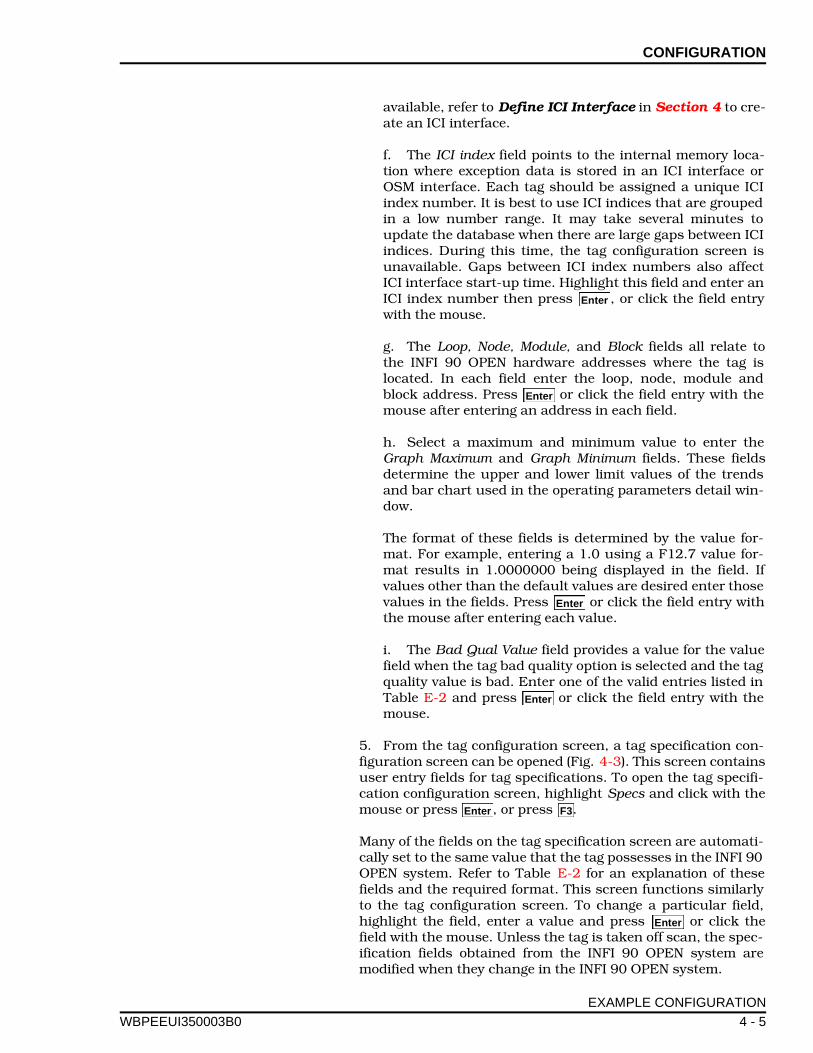
CONFIGURATION
WBPEEUI
available, refer to Define ICI Interface in Section 4 to cre-ate an ICI interface.
f. The ICI index field points to the internal memory loca-tion where exception data is stored in an ICI interface orOSM interface. Each tag should be assigned a unique ICIindex number. It is best to use ICI indices that are groupedin a low number range. It may take several minutes toupdate the database when there are large gaps between ICIindices. During this time, the tag configuration screen isunavailable. Gaps between ICI index numbers also affectICI interface start-up time. Highlight this field and enter anICI index number then press , or click the field entrywith the mouse.
g. The Loop, Node, Module, and Block fields all relate tothe INFI 90 OPEN hardware addresses where the tag islocated. In each field enter the loop, node, module andblock address. Press or click the field entry with themouse after entering an address in each field.
h. Select a maximum and minimum value to enter theGraph Maximum and Graph Minimum fields. These fieldsdetermine the upper and lower limit values of the trendsand bar chart used in the operating parameters detail win-dow.
The format of these fields is determined by the value for-mat. For example, entering a 1.0 using a F12.7 value for-mat results in 1.0000000 being displayed in the field. Ifvalues other than the default values are desired enter thosevalues in the fields. Press or click the field entry withthe mouse after entering each value.
i. The Bad Qual Value field provides a value for the valuefield when the tag bad quality option is selected and the tagquality value is bad. Enter one of the valid entries listed inTable E-2 and press or click the field entry with themouse.
5. From the tag configuration screen, a tag specification con-figuration screen can be opened (Fig. 4-3). This screen containsuser entry fields for tag specifications. To open the tag specifi-cation configuration screen, highlight Specs and click with themouse or press , or press .
Many of the fields on the tag specification screen are automati-cally set to the same value that the tag possesses in the INFI 90OPEN system. Refer to Table E-2 for an explanation of thesefields and the required format. This screen functions similarlyto the tag configuration screen. To change a particular field,highlight the field, enter a value and press or click thefield with the mouse. Unless the tag is taken off scan, the spec-ification fields obtained from the INFI 90 OPEN system aremodified when they change in the INFI 90 OPEN system.
Enter
Enter
Enter
Enter
Enter F3
Enter
EXAMPLE CONFIGURATION
350003B0 4 - 5
CONFIGURATION ®
6. When both the tag configuration and tag specification con-figuration screens have been completed satisfactorily, highlightUpdate and click with the mouse or press , or press tocreate the tag.
7. Confirmation is required to create the tag record or abort itby clicking on yes or no when prompted. If there is an error inthe tag record an error message is displayed and the tag is notcreated.
8. Delete tag records by highlighting delete and click with themouse or press , or press .
9. Confirmation is required to delete the tag record or abortdeletion by clicking on yes or no when prompted. If the tagdoes not exist an error message is displayed stating the tag wasnever created.
10. Configure another tag from this screen by highlightingselect tag and click with the mouse or press , or press
to return to the database configuration tag selection screen.
11. Use the right button on the mouse or click to exitthe database configuration screens.
TPS1152B
Figure 4-3. Tag Specification Configuration Screen
Enter F1
Enter F2
Enter
F4
Previous
EXAMPLE CONFIGURATION
4 - 6 WBPEEUI350003B0
SECTION 5 - OPERATING PROCEDURES
WBPEEUI
INTRODUCTION
This section explains how to use the open data managementserver manager. The open data management server software ismenu driven and user friendly. The steps presented show howto use the open data management server functions. For infor-mation on operating the SETCIM layered products refer to theappropriate SETCIM instruction manual. The applications cov-ered in separate manuals include:
• CALC™.• Q.• SQLplus.• ACCESS utility.• Database management tool (DBMT).• DA™.• DESK.• @aGlance/IT.
OPEN DATA MANAGEMENT SERVER START UP
To start up the open data management server manager:
1. Log-in to the server as an open data management serverOpen VMS or Alpha AXP user. For VAX systems, enter the com-mand @SETCIMCOM:STARTSETCIM. For HP systems, enter thecommand startsetcim.sh .
NOTE: The open data management server can be configured tostart up automatically on a system boot. Refer to Section 6.
2. Start up the GCS operator console. For VAX systems, enterthe command OPCON from any directory. For HP systems,change to the GCS directory by entering cd $GCSDIS , thenenter the command opcon .
NOTE: The GCS operator console can be configured to start upautomatically on login. Refer to Section 6.
3. Use the mouse to click or press to access the mainmenu. The cover screen accesses the main menu automaticallyafter 15 seconds if no action is taken.
4. To exit the GCS operator console, go to the ODMS titlescreen, click the right button on the mouse (click the left but-ton on a left handed mouse), then type e and press .
F1 Enter
Enter
INTRODUCTION
350003B0 5 - 1
OPERATING PROCEDURES ®
MENU ACCESS
There are several ways to access menu items.
• Press the associated function key (refer to Appendix A forVAX/Open VMS, Alpha AXP/Open VMS, HP-UX and PCterminal key assignments).
• Use the mouse pointer to highlight a menu item descrip-tion, then click with the mouse, or press .
• To escape a screen or menu, click which returnsthe user through the display hierarchy. Selecting the undokey or clicking the right button on the mouse returns theuser to the previous screen.
• There are hot keys which can be used to access functionson the screens. Shift-function keys are dedicated displaykeys. Shift-control keys are user defined keys. Refer toAppendix A for a list of all the hot key assignments for eachoperating system. Refer to the GCS Users Manual forinformation on how to assign functions to user-definedkeys using the ACCESS utility.
DEFAULT SECURITY
All open data management server displays have default secu-rity levels. Some displays are accessible without a password.Others require either an operator password or an engineerpassword. There are 10 possible security levels which can beassigned to passwords. The highest security level is 10. Thelowest security level is one. A security level zero has no pass-word security.
Refer to Appendix C for a list of the default security levels forall open data management server display screens. It alsoexplains how to assign or modify security level passwords andchange the number of password security levels using theACCESS utility.
MENU COLORS
The GCS console screen fields and text have color assignmentsthat make functional identification easy and consistent fromscreen to screen. Refer to Appendix A for a list of GCS consolescreen color assignments and style guide.
Enter
Previous
MENU ACCESS
5 - 2 WBPEEUI350003B0
OPERATING PROCEDURES
WBPEEUI
MAIN MENU
There are five selections from the main menu. Those selectionare:
Operations
Applications
Utilities
Configuration
Customer defined
Open Data Management Server Operations Menu
There are seven selections from the open data managementserver operations menu. Those selections are:
Summaries and event logs
Ad hoc trending
History data view
Operating parameters
Interface statistics
Message output
Ad hoc query
SUMMARIES AND EVENT LOGS
Selecting summaries and event logs from the open data man-agement server operations menu opens the summaries andevent logs screen. Refer to Figure 5-1.
The summaries and event logs are divided into the followinggroups:
• Summary of all tags for a selected tag type (tag type sum-maries).
• Summary of bad quality tag types listed by time of occur-rence (condition list summary).
• Summary of manually substituted tags listed by time ofoccurrence (condition list summary).
• Summary of off scan tags (condition list summary).
MAIN MENU
350003B0 5 - 3
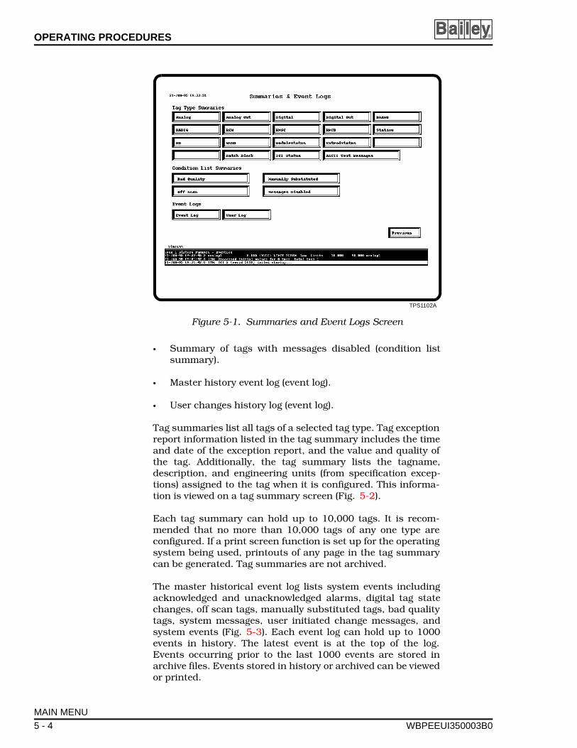
OPERATING PROCEDURES ®
• Summary of tags with messages disabled (condition listsummary).
• Master history event log (event log).
• User changes history log (event log).
Tag summaries list all tags of a selected tag type. Tag exceptionreport information listed in the tag summary includes the timeand date of the exception report, and the value and quality ofthe tag. Additionally, the tag summary lists the tagname,description, and engineering units (from specification excep-tions) assigned to the tag when it is configured. This informa-tion is viewed on a tag summary screen (Fig. 5-2).
Each tag summary can hold up to 10,000 tags. It is recom-mended that no more than 10,000 tags of any one type areconfigured. If a print screen function is set up for the operatingsystem being used, printouts of any page in the tag summarycan be generated. Tag summaries are not archived.
The master historical event log lists system events includingacknowledged and unacknowledged alarms, digital tag statechanges, off scan tags, manually substituted tags, bad qualitytags, system messages, user initiated change messages, andsystem events (Fig. 5-3). Each event log can hold up to 1000events in history. The latest event is at the top of the log.Events occurring prior to the last 1000 events are stored inarchive files. Events stored in history or archived can be viewedor printed.
TPS1102A
Figure 5-1. Summaries and Event Logs Screen
MAIN MENU
5 - 4 WBPEEUI350003B0
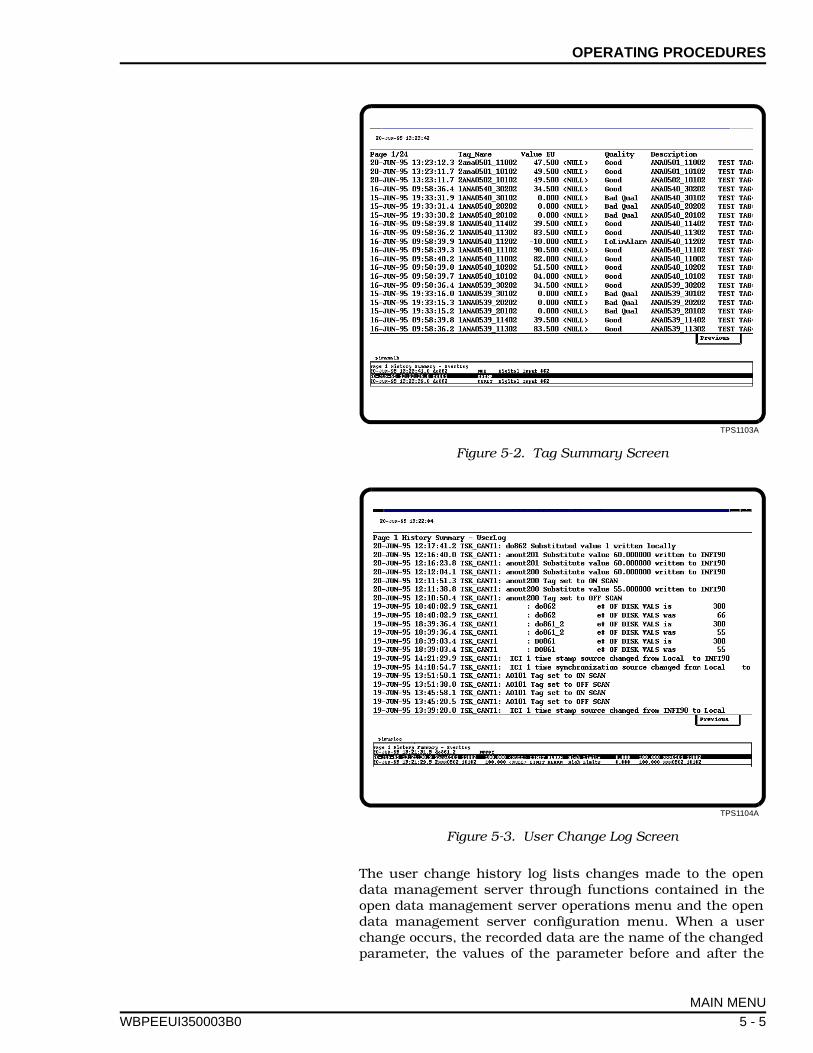
OPERATING PROCEDURES
WBPEEUI
The user change history log lists changes made to the opendata management server through functions contained in theopen data management server operations menu and the opendata management server configuration menu. When a userchange occurs, the recorded data are the name of the changedparameter, the values of the parameter before and after the
TPS1103A
Figure 5-2. Tag Summary Screen
TPS1104A
Figure 5-3. User Change Log Screen
MAIN MENU
350003B0 5 - 5

OPERATING PROCEDURES ®
change occurred, the console name, time of message, and thetime the change occurred. Like the historical event log, this logholds up to 1,000 events in history with the latest event at thetop of log. User change messages that occurred prior to the last1,000 events are archived and can be printed or viewed. Auto-matic printing of events requires additional database recordconfiguration.
A specific tag can be selected from any of the tag type summaryscreens or tag condition summary screens for a detailed dis-play of tag parameters. Tag parameters are displayed on anoperating parameters screen (Fig. 5-4).
To use the summaries and event logs:
1. From the open data management server operations menupress , or highlight the selection and click with the mouse.Figure 5-1 shows the summaries and event logs screen.
2. Use the mouse to click the appropriate selection for a tagtype summary or event log, or use the arrow keys to highlight aselection, then press .
3. There are two event logs, one that lists historical events(event log), and one that lists user changes (user log). Accessthese logs by clicking the appropriate selection or use thearrow keys to highlight a selection, then press .
If a tag type summary is selected, a screen appears that lists allthe tags of the selected tag type. Tag type summary tags arelisted in the order they are created (Fig. 5-2). For all other tagsummaries and event logs, tags and messages are listed by thetime of occurrence (Fig. 5-3).
For tag summaries such as Off-line or Bad Quality, tags arelisted in those summaries in the order received (i.e., the mostrecent on top). Therefore, time stamps will not be in chronolog-ical order. For example, if an exception is received for a tagalready on the list, its entry displays a time stamp for the latestexception but its position on the list does not change.
Each tag summary can hold up to 10,000 entries. Event logscan hold up to 1,000 messages in history order, additionalmessages can be stored in archival files. The most recent mes-sage written to an event log or any tag summary is at the top ofthe log. When the number of messages exceeds the limit of thesummary or log, the oldest message is overwritten.
Column width allocation for tag summaries varies with tagtype. Therefore, summaries such as Off-line will not appear inalignment.
4. Click a tag with the mouse and a tag operating parameterwindow opens (Fig. 5-4). From that window, all of the operat-
F1
Enter
Enter
MAIN MENU
5 - 6 WBPEEUI350003B0
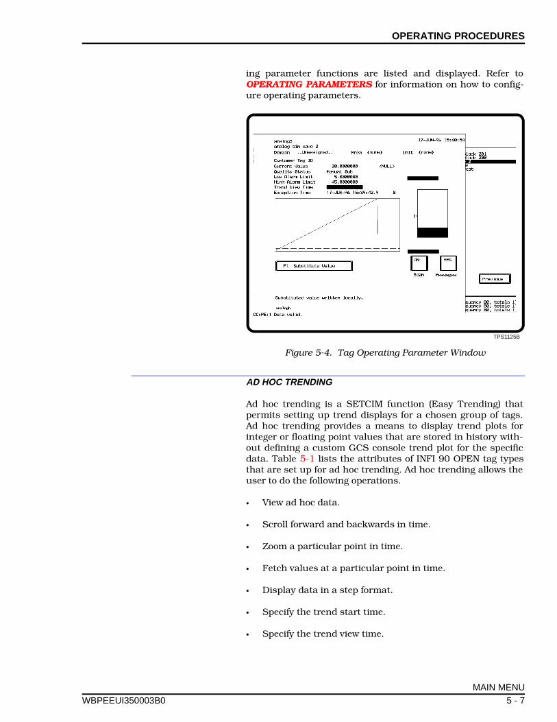
OPERATING PROCEDURES
WBPEEUI
ing parameter functions are listed and displayed. Refer toOPERATING PARAMETERS for information on how to config-ure operating parameters.
AD HOC TRENDING
Ad hoc trending is a SETCIM function (Easy Trending) thatpermits setting up trend displays for a chosen group of tags.Ad hoc trending provides a means to display trend plots forinteger or floating point values that are stored in history with-out defining a custom GCS console trend plot for the specificdata. Table 5-1 lists the attributes of INFI 90 OPEN tag typesthat are set up for ad hoc trending. Ad hoc trending allows theuser to do the following operations.
• View ad hoc data.
• Scroll forward and backwards in time.
• Zoom a particular point in time.
• Fetch values at a particular point in time.
• Display data in a step format.
• Specify the trend start time.
• Specify the trend view time.
TPS1125B
Figure 5-4. Tag Operating Parameter Window
MAIN MENU
350003B0 5 - 7
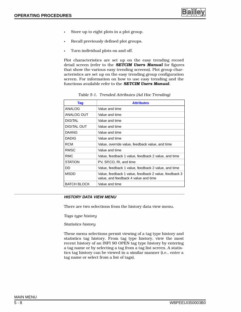
OPERATING PROCEDURES ®
• Store up to eight plots in a plot group.
• Recall previously defined plot groups.
• Turn individual plots on and off.
Plot characteristics are set up on the easy trending recorddetail screen (refer to the SETCIM Users Manual for figuresthat show the various easy trending screens). Plot group char-acteristics are set up on the easy trending group configurationscreen. For information on how to use easy trending and thefunctions available refer to the SETCIM Users Manual.
HISTORY DATA VIEW MENU
There are two selections from the history data view menu.
Tags type history
Statistics history
These menu selections permit viewing of a tag type history andstatistics tag history. From tag type history, view the mostrecent history of an INFI 90 OPEN tag type history by enteringa tag name or by selecting a tag from a tag list screen. A statis-tics tag history can be viewed in a similar manner (i.e., enter atag name or select from a list of tags).
Table 5-1. Trended Attributes (Ad Hoc Trending)
Tag Attributes
ANALOG Value and time
ANALOG OUT Value and time
DIGITAL Value and time
DIGITAL OUT Value and time
DAANG Value and time
DADIG Value and time
RCM Value, override value, feedback value, and time
RMSC Value and time
RMC Value, feedback 1 value, feedback 2 value, and time
STATION PV, SP,CO, RI, and time
DD Value, feedback 1 value, feedback 2 value, and time
MSDD Value, feedback 1 value, feedback 2 value, feedback 3 value, and feedback 4 value and time
BATCH BLOCK Value and time
MAIN MENU
5 - 8 WBPEEUI350003B0
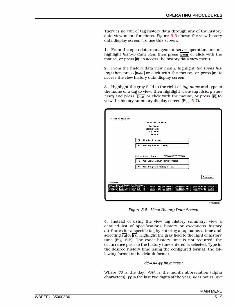
OPERATING PROCEDURES
WBPEEUI
There is no edit of tag history data through any of the historydata view menu functions. Figure 5-5 shows the view historydata display screen. To use this screen.
1. From the open data management server operations menu,highlight history data view then press or click with themouse, or press to access the history data view menu.
2. From the history data view menu, highlight tag types his-tory then press or click with the mouse, or press toaccess the view history data display screen.
3. Highlight the gray field to the right of tag name and type inthe name of a tag to view, then highlight view tag history sum-mary and press or click with the mouse, or press toview the history summary display screen (Fig. 5-7).
4. Instead of using the view tag history summary, view adetailed list of specifications history or exceptions historyattributes for a specific tag by entering a tag name, a time andselecting or . Highlight the gray field to the right of historytime (Fig. 5-5). The exact history time is not required, theoccurrence prior to the history time entered is selected. Type inthe desired history time using the configured format, the fol-lowing format is the default format.
dd-AAA-yy hh:mm:ss.t
Where dd is the day, AAA is the month abbreviation (alphacharacters), yy is the last two digits of the year, hh is hours, mm
TPS1108B
Figure 5-5. View History Data Screen
Enter
F3
Enter F1
Enter F2
F3 F4
MAIN MENU
350003B0 5 - 9
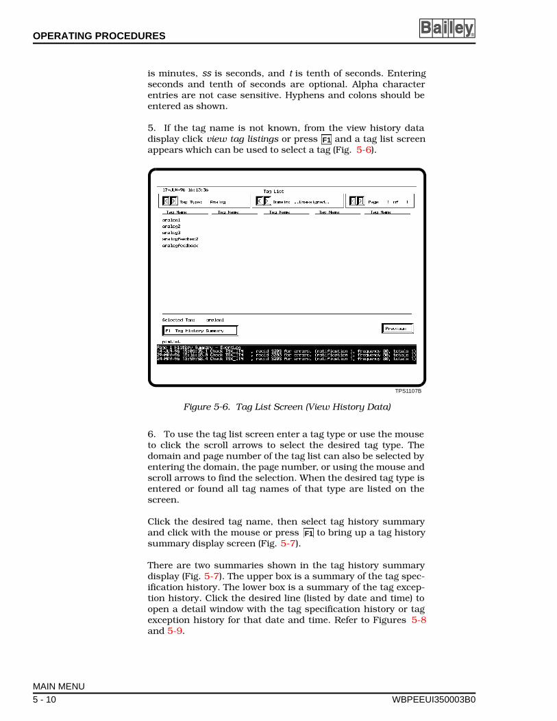
OPERATING PROCEDURES ®
is minutes, ss is seconds, and t is tenth of seconds. Enteringseconds and tenth of seconds are optional. Alpha characterentries are not case sensitive. Hyphens and colons should beentered as shown.
5. If the tag name is not known, from the view history datadisplay click view tag listings or press and a tag list screenappears which can be used to select a tag (Fig. 5-6).
6. To use the tag list screen enter a tag type or use the mouseto click the scroll arrows to select the desired tag type. Thedomain and page number of the tag list can also be selected byentering the domain, the page number, or using the mouse andscroll arrows to find the selection. When the desired tag type isentered or found all tag names of that type are listed on thescreen.
Click the desired tag name, then select tag history summaryand click with the mouse or press to bring up a tag historysummary display screen (Fig. 5-7).
There are two summaries shown in the tag history summarydisplay (Fig. 5-7). The upper box is a summary of the tag spec-ification history. The lower box is a summary of the tag excep-tion history. Click the desired line (listed by date and time) toopen a detail window with the tag specification history or tagexception history for that date and time. Refer to Figures 5-8and 5-9.
TPS1107B
Figure 5-6. Tag List Screen (View History Data)
F1
F1
MAIN MENU
5 - 10 WBPEEUI350003B0
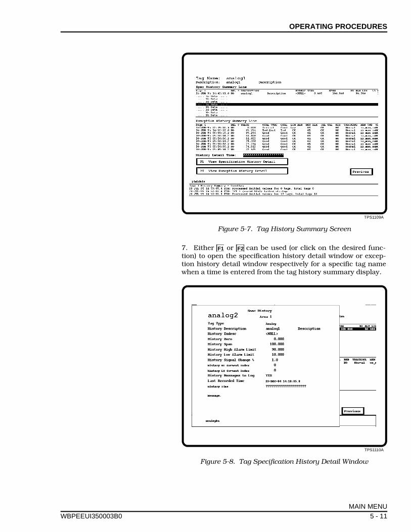
OPERATING PROCEDURES
WBPEEUI
7. Either or can be used (or click on the desired func-tion) to open the specification history detail window or excep-tion history detail window respectively for a specific tag namewhen a time is entered from the tag history summary display.
TPS1109A
Figure 5-7. Tag History Summary Screen
TPS1110A
Figure 5-8. Tag Specification History Detail Window
F1 F2
MAIN MENU
350003B0 5 - 11
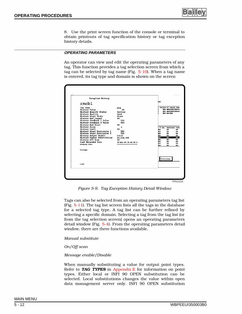
OPERATING PROCEDURES ®
8. Use the print screen function of the console or terminal toobtain printouts of tag specification history or tag exceptionhistory details.
OPERATING PARAMETERS
An operator can view and edit the operating parameters of anytag. This function provides a tag selection screen from which atag can be selected by tag name (Fig. 5-10). When a tag nameis entered, its tag type and domain is shown on the screen
Tags can also be selected from an operating parameters tag list(Fig. 5-11). The tag list screen lists all the tags in the databasefor a selected tag type. A tag list can be further refined byselecting a specific domain. Selecting a tag from the tag list (orfrom the tag selection screen) opens an operating parametersdetail window (Fig. 5-4). From the operating parameters detailwindow, there are three functions available.
Manual substitute
On/Off scan
Message enable/Disable
When manually substituting a value for output point types.Refer to TAG TYPES in Appendix E for information on pointtypes. Either local or INFI 90 OPEN substitution can beselected. Local substitutions changes the value within opendata management server only. INFI 90 OPEN substitution
TPS1111A
Figure 5-9. Tag Exception History Detail Window
MAIN MENU
5 - 12 WBPEEUI350003B0
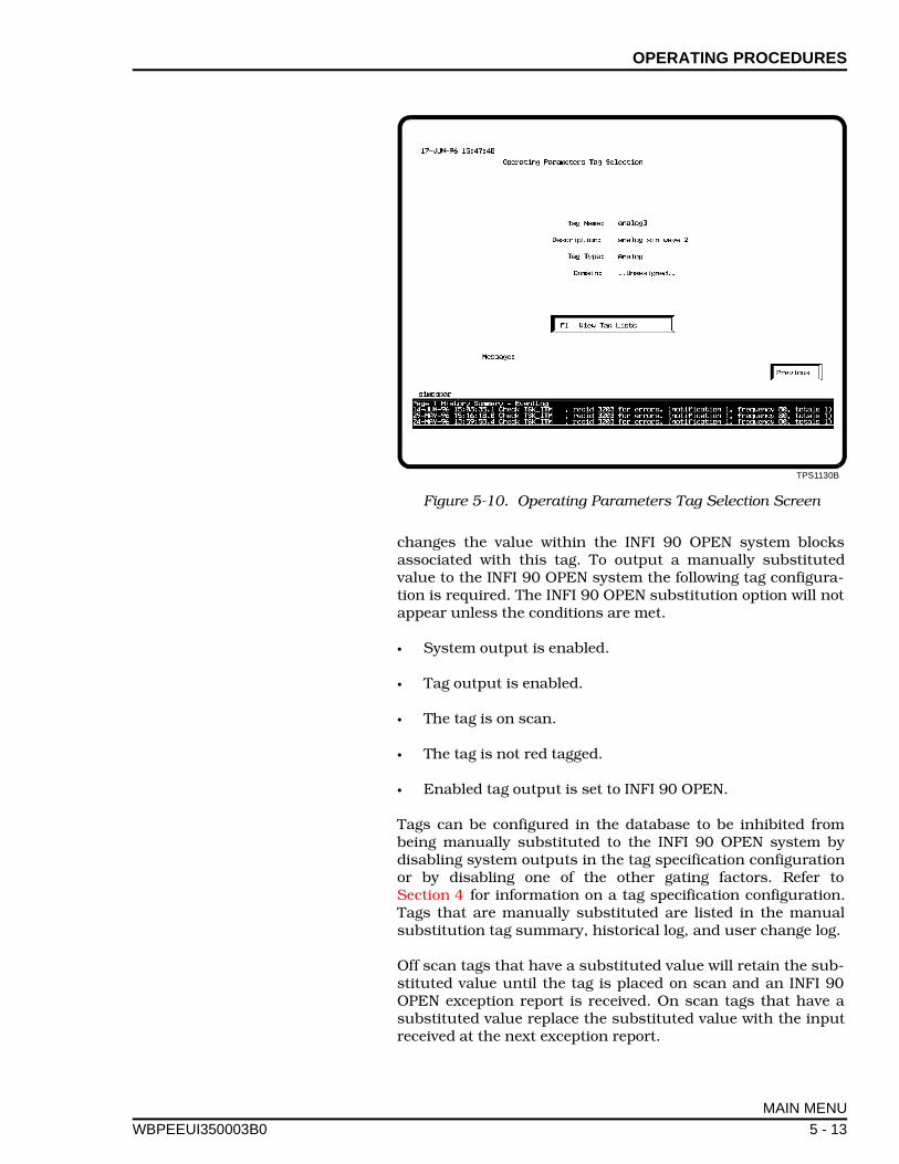
OPERATING PROCEDURES
WBPEEUI
changes the value within the INFI 90 OPEN system blocksassociated with this tag. To output a manually substitutedvalue to the INFI 90 OPEN system the following tag configura-tion is required. The INFI 90 OPEN substitution option will notappear unless the conditions are met.
• System output is enabled.
• Tag output is enabled.
• The tag is on scan.
• The tag is not red tagged.
• Enabled tag output is set to INFI 90 OPEN.
Tags can be configured in the database to be inhibited frombeing manually substituted to the INFI 90 OPEN system bydisabling system outputs in the tag specification configurationor by disabling one of the other gating factors. Refer toSection 4 for information on a tag specification configuration.Tags that are manually substituted are listed in the manualsubstitution tag summary, historical log, and user change log.
Off scan tags that have a substituted value will retain the sub-stituted value until the tag is placed on scan and an INFI 90OPEN exception report is received. On scan tags that have asubstituted value replace the substituted value with the inputreceived at the next exception report.
TPS1130B
Figure 5-10. Operating Parameters Tag Selection Screen
MAIN MENU
350003B0 5 - 13
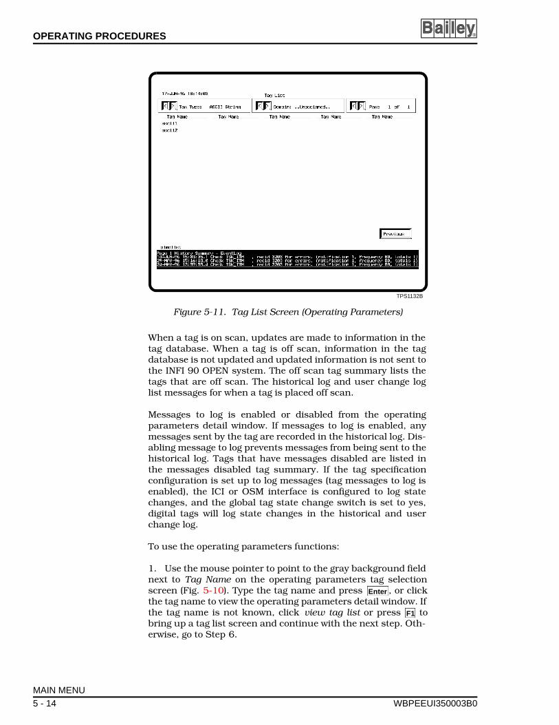
OPERATING PROCEDURES ®
When a tag is on scan, updates are made to information in thetag database. When a tag is off scan, information in the tagdatabase is not updated and updated information is not sent tothe INFI 90 OPEN system. The off scan tag summary lists thetags that are off scan. The historical log and user change loglist messages for when a tag is placed off scan.
Messages to log is enabled or disabled from the operatingparameters detail window. If messages to log is enabled, anymessages sent by the tag are recorded in the historical log. Dis-abling message to log prevents messages from being sent to thehistorical log. Tags that have messages disabled are listed inthe messages disabled tag summary. If the tag specificationconfiguration is set up to log messages (tag messages to log isenabled), the ICI or OSM interface is configured to log statechanges, and the global tag state change switch is set to yes,digital tags will log state changes in the historical and userchange log.
To use the operating parameters functions:
1. Use the mouse pointer to point to the gray background fieldnext to Tag Name on the operating parameters tag selectionscreen (Fig. 5-10). Type the tag name and press , or clickthe tag name to view the operating parameters detail window. Ifthe tag name is not known, click view tag list or press tobring up a tag list screen and continue with the next step. Oth-erwise, go to Step 6.
TPS1132B
Figure 5-11. Tag List Screen (Operating Parameters)
Enter
F1
MAIN MENU
5 - 14 WBPEEUI350003B0

OPERATING PROCEDURES
WBPEEUI
2. Select a tag type by clicking or , or type in a tag type inthe green highlighted tag type field and press . All tagnames for that tag type are listed on the screen.
3. If the tag has been assigned a specific domain, the domaincan be selected by clicking or , or entering the domain inthe green highlighted field and press . This filters the listof tags displayed to the tags grouped in that domain.
4. If more than one page of tags exists, the page can beselected by clicking or , or by entering a page number inthe green highlighted field and press .
5. From the tag list, click a tag name to view the operatingparameters detail window (Fig. 5-4).
6. To change a tag attribute click the appropriate selection tomanually substitute a value, put a tag on or off scan, andenable or disable messages. A high level operator password isrequired to change any tag or display attribute.
7. Click the scan icon to turn on or off exception reporting forthe given tag. The state shown in black text on the face of thescan icon indicates the action that will take place when theicon is activated. The current state is displayed in green text.Whenever the scan icon is activated, a message is shown inyellow text that indicates the action taken.
8. Click the messages icon to enable or disable sending mes-sages to the event log and user change log. Like the scan icon,the message icon toggles this function. Whenever the messagesicon is activated, a message is shown (in yellow text) that indi-cates if sending messages to log is enabled or disabled. Addi-tionally, the cyan text updates to show if messages to log isenabled or disabled.
9. Click Substitute Value or press to manually substitute avalue for the tag output. Three editable fields may appeardepending on the type of action or point type desired, SubsValue, Subs Quality Status, and Output Enable (fields vary withtag type). Make the appropriate entry in each field then clickyes to confirm and execute the manual substitution. Actiontypes include local substitution or outputting to INFI 90 OPEN.In local substitution, the value is inserted into the ODMS data-base where it is accessible to all ODMS and SETCIM applica-tions, but it is not reported to the INFI 90 OPEN system. Inoutputting to INFI 90 OPEN, the value is written via the inter-face to the INFI 90 OPEN system. The INFI 90 OPEN systemwill generate an exception report. This exception report willthen update the ODMS database. This form of outputting isavailable for all point types except module status, ext modulestatus, ICI status, batch blocks, analog, and digital. Analogand digital point types support local substitution.
< >
Enter
< >
Enter
< >
Enter
F1
MAIN MENU
350003B0 5 - 15

OPERATING PROCEDURES ®
10. The trending view field can be edited to change the timespan of the trend view graph. This requires a level 6 password.To change the trend view time, click the trend view time field sothat it is highlighted and type in a new entry in with the follow-ing format.
phhhhh:mm:ss.t
Where p is a sign indicating direction (a plus sign for timefuture and a minus sign for time past), h is hours, m is min-utes, s is seconds, and t is tenth of seconds.
11. The graph maximum and graph minimum attributes at thetop and bottom of the bar graph can be modified by typing anew attribute in those fields. This requires level 6 password.Point to the attribute fields to highlight and type in an entry.
12. To exit the tag detail window, click the right button on themouse or click .
INTERFACE STATISTICS
The ICI interface maintains general performance statistics.These statistics include the number of exceptions received andsent, the exception report rate, ICI access rate and time syn-chronization status. These statistics are available via the opendata management server database. From the interface statis-tics menu there are two selections.
ICI status
ICI performance
ICI Status
The ICI status screen lists the status of an ICI interface andtime synching information (Fig. 5-12). Table 5-2 lists the ICIstatus screen fields and provides an explanation of field con-tent.
To view the ICI interface status:
1. Select ICI status from the interface statistics menu.
2. Enter an ICI number to view the status of that particularICI interface.
3. To exit the ICI status screen, click the right button on themouse or click .
Previous
Previous
MAIN MENU
5 - 16 WBPEEUI350003B0
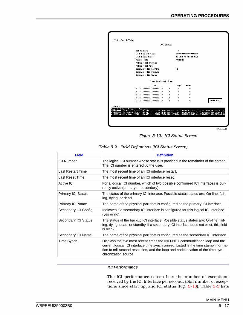
OPERATING PROCEDURES
WBPEEUI
ICI Performance
The ICI performance screen lists the number of exceptionsreceived by the ICI interface per second, total number of excep-tions since start up, and ICI status (Fig. 5-13). Table 5-3 lists
TPS1112B
Figure 5-12. ICI Status Screen
Table 5-2. Field Definitions (ICI Status Screen)
Field Definition
ICI Number The logical ICI number whose status is provided in the remainder of the screen. The ICI number is entered by the user.
Last Restart Time The most recent time of an ICI interface restart.
Last Reset Time The most recent time of an ICI interface reset.
Active ICI For a logical ICI number, which of two possible configured ICI interfaces is cur-rently active (primary or secondary).
Primary ICI Status The status of the primary ICI interface. Possible status states are: On-line, fail-ing, dying, or dead.
Primary ICI Name The name of the physical port that is configured as the primary ICI interface.
Secondary ICI Config Indicates if a secondary ICI interface is configured for this logical ICI interface (yes or no).
Secondary ICI Status The status of the backup ICI interface. Possible status states are: On-line, fail-ing, dying, dead, or standby. If a secondary ICI interface does not exist, this field is blank.
Secondary ICI Name The name of the physical port that is configured as the secondary ICI interface.
Time Synch Displays the five most recent times the INFI-NET communication loop and the current logical ICI interface time synchronized. Listed is the time stamp informa-tion to millisecond resolution, and the loop and node location of the time syn-chronization source.
MAIN MENU
350003B0 5 - 17
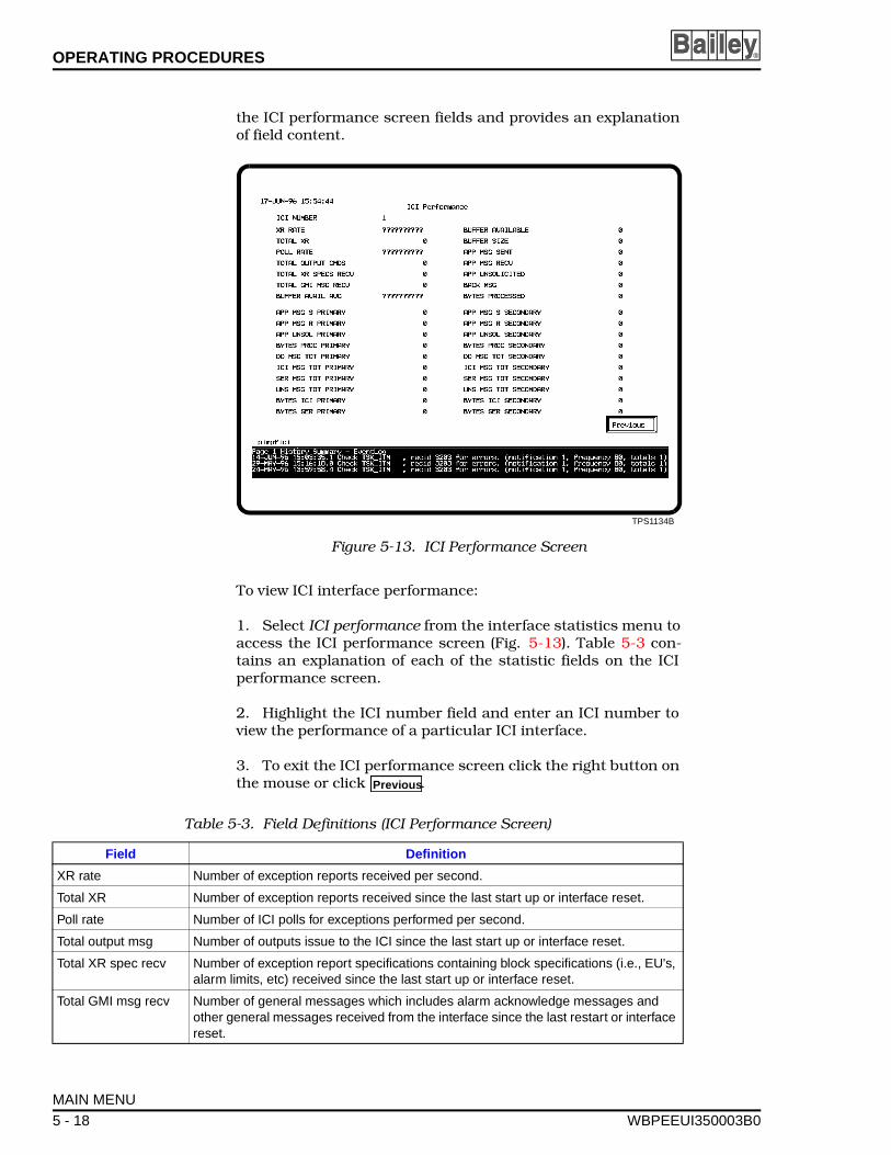
OPERATING PROCEDURES ®
the ICI performance screen fields and provides an explanationof field content.
To view ICI interface performance:
1. Select ICI performance from the interface statistics menu toaccess the ICI performance screen (Fig. 5-13). Table 5-3 con-tains an explanation of each of the statistic fields on the ICIperformance screen.
2. Highlight the ICI number field and enter an ICI number toview the performance of a particular ICI interface.
3. To exit the ICI performance screen click the right button onthe mouse or click .
TPS1134B
Figure 5-13. ICI Performance Screen
Previous
Table 5-3. Field Definitions (ICI Performance Screen)
Field Definition
XR rate Number of exception reports received per second.
Total XR Number of exception reports received since the last start up or interface reset.
Poll rate Number of ICI polls for exceptions performed per second.
Total output msg Number of outputs issue to the ICI since the last start up or interface reset.
Total XR spec recv Number of exception report specifications containing block specifications (i.e., EU's, alarm limits, etc) received since the last start up or interface reset.
Total GMI msg recv Number of general messages which includes alarm acknowledge messages and other general messages received from the interface since the last restart or interface reset.
MAIN MENU
5 - 18 WBPEEUI350003B0
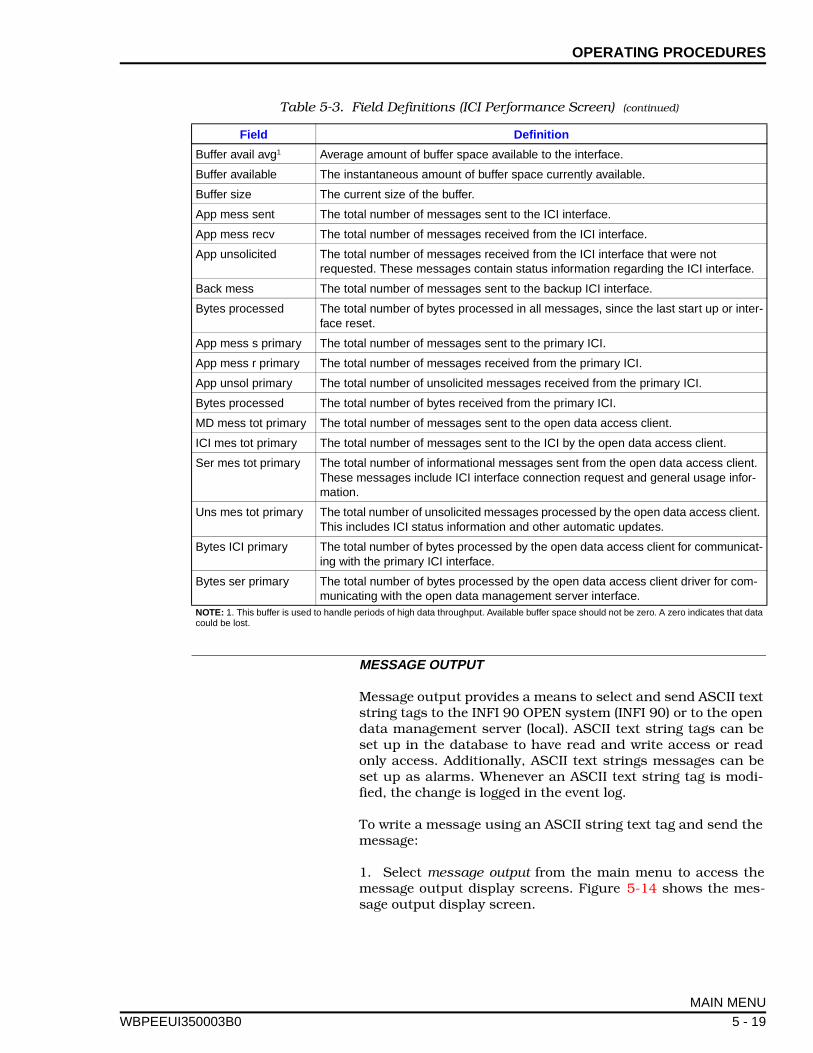
OPERATING PROCEDURES
WBPEEUI
MESSAGE OUTPUT
Message output provides a means to select and send ASCII textstring tags to the INFI 90 OPEN system (INFI 90) or to the opendata management server (local). ASCII text string tags can beset up in the database to have read and write access or readonly access. Additionally, ASCII text strings messages can beset up as alarms. Whenever an ASCII text string tag is modi-fied, the change is logged in the event log.
To write a message using an ASCII string text tag and send themessage:
1. Select message output from the main menu to access themessage output display screens. Figure 5-14 shows the mes-sage output display screen.
Buffer avail avg1 Average amount of buffer space available to the interface.
Buffer available The instantaneous amount of buffer space currently available.
Buffer size The current size of the buffer.
App mess sent The total number of messages sent to the ICI interface.
App mess recv The total number of messages received from the ICI interface.
App unsolicited The total number of messages received from the ICI interface that were not requested. These messages contain status information regarding the ICI interface.
Back mess The total number of messages sent to the backup ICI interface.
Bytes processed The total number of bytes processed in all messages, since the last start up or inter-face reset.
App mess s primary The total number of messages sent to the primary ICI.
App mess r primary The total number of messages received from the primary ICI.
App unsol primary The total number of unsolicited messages received from the primary ICI.
Bytes processed The total number of bytes received from the primary ICI.
MD mess tot primary The total number of messages sent to the open data access client.
ICI mes tot primary The total number of messages sent to the ICI by the open data access client.
Ser mes tot primary The total number of informational messages sent from the open data access client. These messages include ICI interface connection request and general usage infor-mation.
Uns mes tot primary The total number of unsolicited messages processed by the open data access client. This includes ICI status information and other automatic updates.
Bytes ICI primary The total number of bytes processed by the open data access client for communicat-ing with the primary ICI interface.
Bytes ser primary The total number of bytes processed by the open data access client driver for com-municating with the open data management server interface.
NOTE: 1. This buffer is used to handle periods of high data throughput. Available buffer space should not be zero. A zero indicates that datacould be lost.
Table 5-3. Field Definitions (ICI Performance Screen) (continued)
Field Definition
MAIN MENU
350003B0 5 - 19
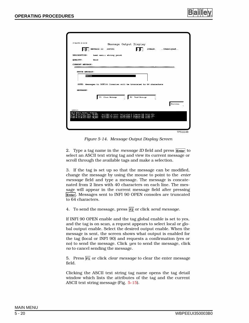
OPERATING PROCEDURES ®
2. Type a tag name in the message ID field and press toselect an ASCII text string tag and view its current message orscroll through the available tags and make a selection.
3. If the tag is set up so that the message can be modified,change the message by using the mouse to point to the entermessage field and type a message. The message is concate-nated from 2 lines with 40 characters on each line. The mes-sage will appear in the current message field after pressing
. Messages sent to INFI 90 OPEN consoles are truncatedto 64 characters.
4. To send the message, press or click send message.
If INFI 90 OPEN enable and the tag global enable is set to yes,and the tag is on scan, a request appears to select local or glo-bal output enable. Select the desired output enable. When themessage is sent, the screen shows what output is enabled forthe tag (local or INFI 90) and requests a confirmation (yes orno) to send the message. Click yes to send the message, clickno to cancel sending the message.
5. Press or click clear message to clear the enter messagefield.
Clicking the ASCII text string tag name opens the tag detailwindow which lists the attributes of the tag and the currentASCII text string message (Fig. 5-15).
TPS1114B
Figure 5-14. Message Output Display Screen
Enter
Enter
F2
F1
MAIN MENU
5 - 20 WBPEEUI350003B0
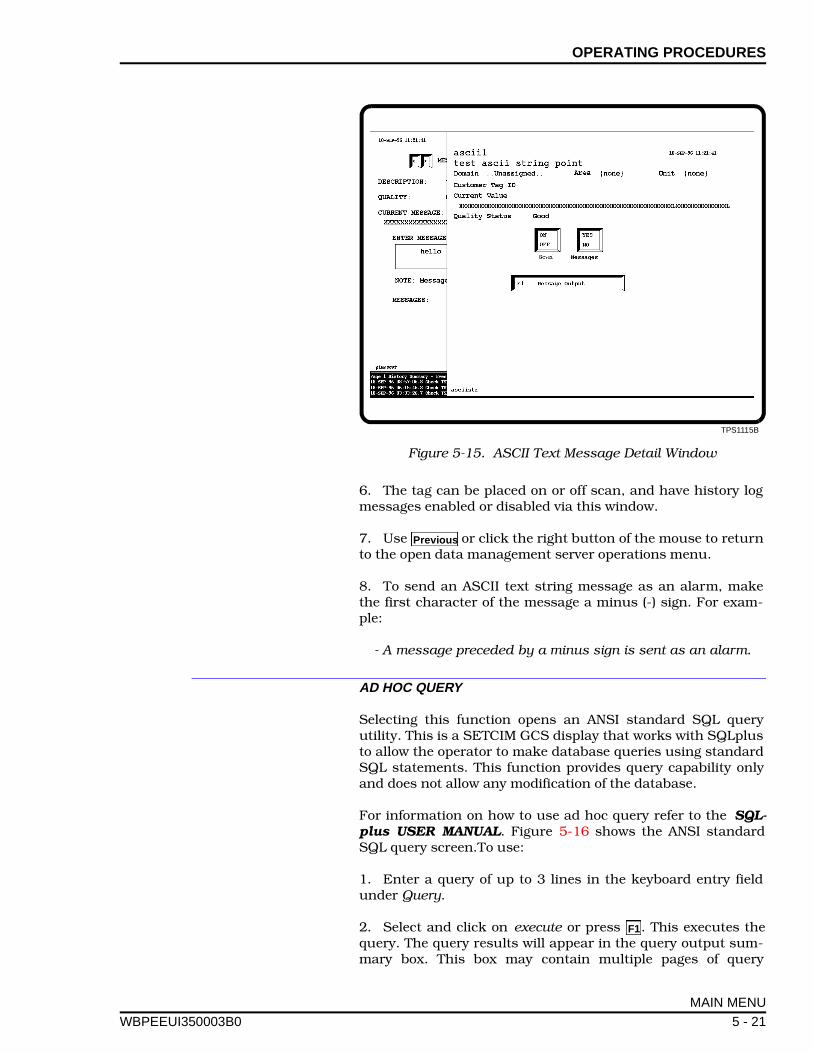
OPERATING PROCEDURES
WBPEEUI
6. The tag can be placed on or off scan, and have history logmessages enabled or disabled via this window.
7. Use or click the right button of the mouse to returnto the open data management server operations menu.
8. To send an ASCII text string message as an alarm, makethe first character of the message a minus (-) sign. For exam-ple:
- A message preceded by a minus sign is sent as an alarm.
AD HOC QUERY
Selecting this function opens an ANSI standard SQL queryutility. This is a SETCIM GCS display that works with SQLplusto allow the operator to make database queries using standardSQL statements. This function provides query capability onlyand does not allow any modification of the database.
For information on how to use ad hoc query refer to the SQL-plus USER MANUAL. Figure 5-16 shows the ANSI standardSQL query screen.To use:
1. Enter a query of up to 3 lines in the keyboard entry fieldunder Query.
2. Select and click on execute or press . This executes thequery. The query results will appear in the query output sum-mary box. This box may contain multiple pages of query
TPS1115B
Figure 5-15. ASCII Text Message Detail Window
Previous
F1
MAIN MENU
350003B0 5 - 21
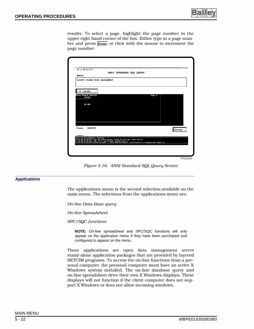
OPERATING PROCEDURES ®
results. To select a page, highlight the page number in theupper right hand corner of the box. Either type in a page num-ber and press or click with the mouse to increment thepage number.
Applications
The applications menu is the second selection available on themain menu. The selections from the applications menu are:
On-line Data Base query
On-line Spreadsheet
SPC/SQC functions
NOTE: On-line spreadsheet and SPC/SQC functions will onlyappear on the application menu if they have been purchased andconfigured to appear on the menu.
These applications are open data management serverstand-alone application packages that are provided by layeredSETCIM programs. To access the on-line functions from a per-sonal computer, the personal computer must have an active XWindows system installed. The on-line database query andon-line spreadsheet drive their own X Windows displays. Thesedisplays will not function if the client computer does not sup-port X Windows or does not allow incoming windows.
TPS1116A
Figure 5-16. ANSI Standard SQL Query Screen
Enter
MAIN MENU
5 - 22 WBPEEUI350003B0
OPERATING PROCEDURES
WBPEEUI
Selecting on-line database query executes the SQLplus pro-gram. This program has read and write access to the databasevia a standard SQL queries. This program generates its owndisplays. Refer to the appropriate SETCIM instruction for infor-mation on how to use the SQLplus program.
Selecting on-line spreadsheet query executes the CALC pro-gram. All displays for the program are generated by the pro-gram. The CALC program can generate a spreadsheet usingElsag Bailey tag type attributes as cell values. Refer to theappropriate SETCIM instruction for information on how to usethe CALC program.
Selecting SPC/SPQ functions allows access to the Q program.This program is used to develop charts and histograms fromsystem statistics. The charts and histograms are used to ana-lyze plant performance. All displays for the program are gener-ated by the Q program. Refer to the appropriate SETCIMinstruction for information on how to use the Q program.
Utilities
The utilities menu invokes a number of SETCIM programs thatcan be used for the utility functions listed.
ACCESS
History File Utilities
Off-line database loader
Off-line database to ASCII file
Document definition records
Document database records
NOTE: Client platforms that are not equipped with active X Windowssoftware cannot use the utilities from the utility menu. Detailed infor-mation on the use of utilities can be found in SETCIM documenta-tion.
ACCESS
ACCESS is a SETCIM utility program that can be used to cre-ate and custom design GCS console screens and assign func-tions to certain keyboard keys. This program operatesindependently of the open data management server. Refer tothe GCS Graphics Console System Users Manual for infor-mation on using ACCESS. When accessing this function from aremote GCS client, all display modifications are performed atthe server display level.
MAIN MENU
350003B0 5 - 23
OPERATING PROCEDURES ®
HISTORY FILE UTILITIES
The history file utility has two selections.
Fix Disk History File
Estimate History File Size
Each of the selections are SETCIM programs. When selected,the SETCIM program provides prompts explaining what action(i.e., disk history file name) is required to start up the program.
OFF-LINE DATABASE LOADER
The off-line database loader utility moves ASCII data into theopen data management server database. To use the off-linedatabase load utility, select it from the utilities menu and fol-low the program prompts.
OFF-LINE DATABASE TO ASCII FILE
The off-line database to ASCII file utility moves data from theopen data management server database to an ASCII file. To usethe off-line database to ASCII file utility, select it from the utili-ties menu and follow the program prompts.
DOCUMENT DEFINITION RECORDS
The document definition records utility documents the struc-ture of definition records in the open data management serverdatabase. To use the document definition records utility, selectit from the utilities menu and follow the program prompts.
DOCUMENT DATABASE RECORDS
The document database records utility documents the con-tents of open data management server database records(including open data management server tags). To use the doc-ument database records utility, select it from the utilities menuand follow the program prompts.
MAIN MENU
5 - 24 WBPEEUI350003B0
OPERATING PROCEDURES
WBPEEUI
Configuration Menu
The open data management server configuration menu con-tains the following selections.
Database
System
Interface Control
History Data View/Edit
The functions in this menu allow the user to configure opendata management server specific databases and systemparameters. An engineer security level password is required tocreate, modify and delete all tag types. No password is requiredfor viewing. Refer to Appendix C for a complete list of functionsaccessible at each password security level. Section 5 providesinformation on how to create, configure, add, or update an INFI90 OPEN tag in a database and gives an example configura-tion. This section provides an overview of how the databaseconfiguration screens operate.
DATABASE
The database configuration function contains four displays.
• Database configuration tag selection display (Fig. 5-17).
• Tag list display (Fig. 5-18).
• Tag configuration display (Fig. 5-19).
• Tag specification configuration display (Fig. 5-20).
The database configuration display is accessed by selectingdatabase from the configuration menu. This display allows:
• Requesting a tag list display to view a list of tags for theselected tag type.
• Entering a tag name and then requesting the database con-figuration of that tag.
• Entering a new tag to create the tag.
NOTE: Statistics tag types such as averaging, totalizing, summingintegrating, and weighted average must be created off-line using theDBMT or ENGCON tool.
The tag list display is accessed by clicking view tag listing orpressing on the database configuration tag selection display(Fig. 5-17). The tag list is used if the tag name is not known,
F1
MAIN MENU
350003B0 5 - 25
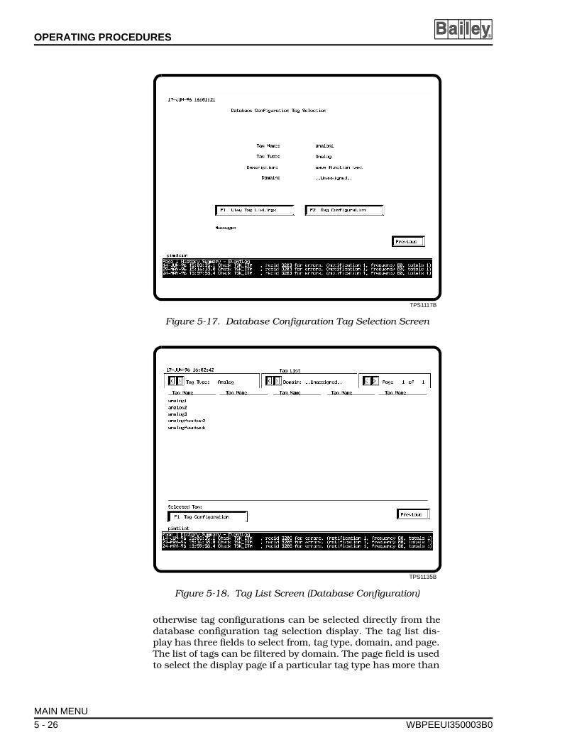
OPERATING PROCEDURES ®
otherwise tag configurations can be selected directly from thedatabase configuration tag selection display. The tag list dis-play has three fields to select from, tag type, domain, and page.The list of tags can be filtered by domain. The page field is usedto select the display page if a particular tag type has more than
TPS1117B
Figure 5-17. Database Configuration Tag Selection Screen
TPS1135B
Figure 5-18. Tag List Screen (Database Configuration)
MAIN MENU
5 - 26 WBPEEUI350003B0
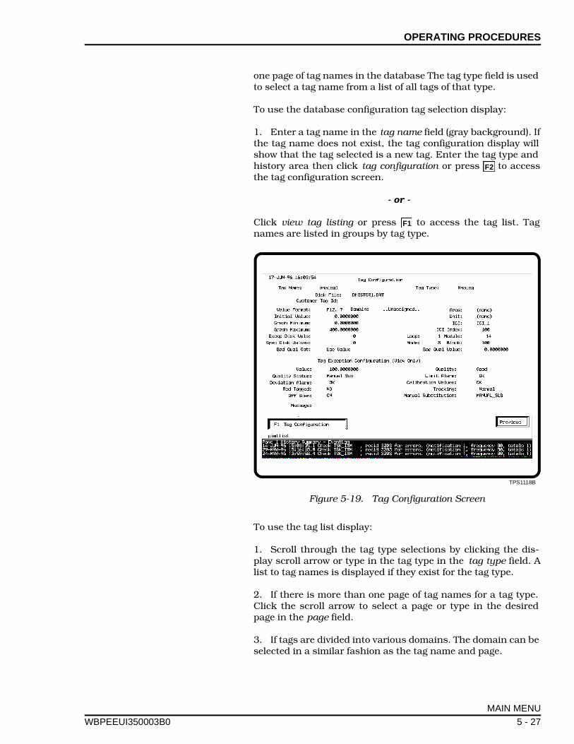
OPERATING PROCEDURES
WBPEEUI
one page of tag names in the database The tag type field is usedto select a tag name from a list of all tags of that type.
To use the database configuration tag selection display:
1. Enter a tag name in the tag name field (gray background). Ifthe tag name does not exist, the tag configuration display willshow that the tag selected is a new tag. Enter the tag type andhistory area then click tag configuration or press to accessthe tag configuration screen.
- or -
Click view tag listing or press to access the tag list. Tagnames are listed in groups by tag type.
To use the tag list display:
1. Scroll through the tag type selections by clicking the dis-play scroll arrow or type in the tag type in the tag type field. Alist to tag names is displayed if they exist for the tag type.
2. If there is more than one page of tag names for a tag type.Click the scroll arrow to select a page or type in the desiredpage in the page field.
3. If tags are divided into various domains. The domain can beselected in a similar fashion as the tag name and page.
TPS1118B
Figure 5-19. Tag Configuration Screen
F2
F1
MAIN MENU
350003B0 5 - 27
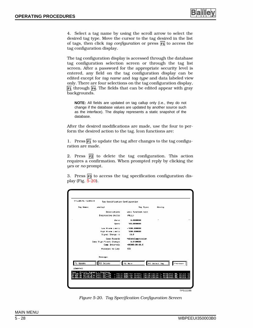
OPERATING PROCEDURES ®
4. Select a tag name by using the scroll arrow to select thedesired tag type. Move the cursor to the tag desired in the listof tags, then click tag configuration or press to access thetag configuration display.
The tag configuration display is accessed through the databasetag configuration selection screen or through the tag listscreen. After a password for the appropriate security level isentered, any field on the tag configuration display can beedited except for tag name and tag type and data labeled viewonly. There are four selections on the tag configuration display,
through . The fields that can be edited appear with graybackgrounds.
NOTE: All fields are updated on tag callup only (i.e., they do notchange if the database values are updated by another source suchas the interface). The display represents a static snapshot of thedatabase.
After the desired modifications are made, use the four to per-form the desired action to the tag. Icon functions are:
1. Press to update the tag after changes to the tag configu-ration are made.
2. Press to delete the tag configuration. This actionrequires a confirmation. When prompted reply by clicking theyes or no prompt.
3. Press to access the tag specification configuration dis-play (Fig. 5-20).
TPS1119B
Figure 5-20. Tag Specification Configuration Screen
F1
F1 F4
F1
F2
F3
MAIN MENU
5 - 28 WBPEEUI350003B0
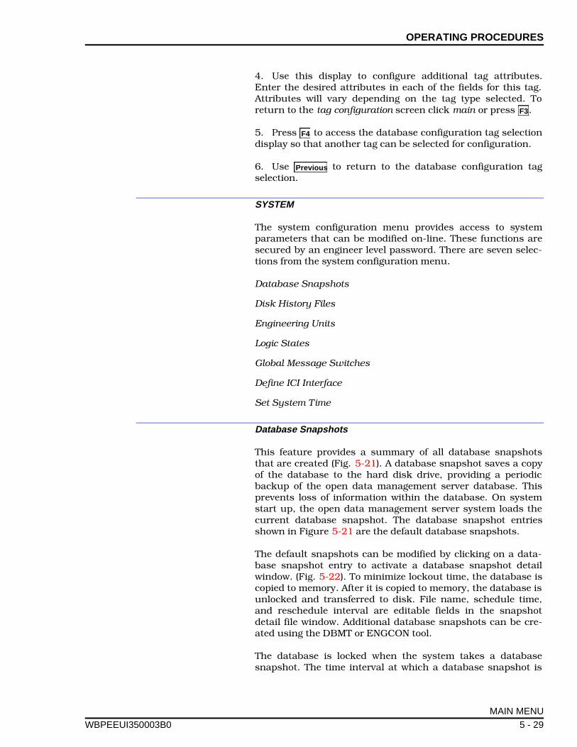
OPERATING PROCEDURES
WBPEEUI
4. Use this display to configure additional tag attributes.Enter the desired attributes in each of the fields for this tag.Attributes will vary depending on the tag type selected. Toreturn to the tag configuration screen click main or press .
5. Press to access the database configuration tag selectiondisplay so that another tag can be selected for configuration.
6. Use to return to the database configuration tagselection.
SYSTEM
The system configuration menu provides access to systemparameters that can be modified on-line. These functions aresecured by an engineer level password. There are seven selec-tions from the system configuration menu.
Database Snapshots
Disk History Files
Engineering Units
Logic States
Global Message Switches
Define ICI Interface
Set System Time
Database Snapshots
This feature provides a summary of all database snapshotsthat are created (Fig. 5-21). A database snapshot saves a copyof the database to the hard disk drive, providing a periodicbackup of the open data management server database. Thisprevents loss of information within the database. On systemstart up, the open data management server system loads thecurrent database snapshot. The database snapshot entriesshown in Figure 5-21 are the default database snapshots.
The default snapshots can be modified by clicking on a data-base snapshot entry to activate a database snapshot detailwindow. (Fig. 5-22). To minimize lockout time, the database iscopied to memory. After it is copied to memory, the database isunlocked and transferred to disk. File name, schedule time,and reschedule interval are editable fields in the snapshotdetail file window. Additional database snapshots can be cre-ated using the DBMT or ENGCON tool.
The database is locked when the system takes a databasesnapshot. The time interval at which a database snapshot is
F3
F4
Previous
MAIN MENU
350003B0 5 - 29
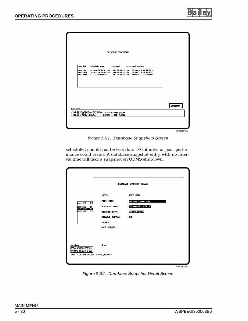
OPERATING PROCEDURES ®
scheduled should not be less than 10 minutes or poor perfor-mance could result. A database snapshot entry with no inter-val time will take a snapshot on ODMS shutdown.
TPS1120A
Figure 5-21. Database Snapshots Screen
TPS1121A
Figure 5-22. Database Snapshot Detail Screen
MAIN MENU
5 - 30 WBPEEUI350003B0

OPERATING PROCEDURES
WBPEEUI
There are two database snapshots configured during installa-tion (SAVE_DAY and SAVE_HOUR). These snapshots are exe-cuted on system start up. Thereafter, the SAVE_HOURsnapshot is taken hourly and the SAVE_DAY snapshot is takenat midnight. These snapshots can be used to recover priordatabase states if on-line database changes need to be made.Configure additional database snapshot records using theDBMT tool.
To use this function:
1. Select database snapshots from the system configurationmenu.
2. Click the database snapshot to be viewed. The snapshot filedetail window opens (Fig. 5-22). The default database snap-shots can be modified from this window.
3. Any modifications can be made by highlighting the desiredfield (gray background fields) and typing a new entry. Click themouse or press for the field to update. Use the right but-ton on the mouse to exit the snapshot file detail window.
Disk History Files
This feature provides a summary of all disk history files thatare created (Fig. 5-23). From this summary, a disk history filedetail window can be opened that allows set up of a backup filename, archive file name, and a backup and archive schedule(Fig. 5-24). A second page of this window shows the disk sta-tus such as disk history status, disk blocks used, lost blocks,file errors, etc. (Fig. 5-25). Disk history files are created usingthe DBMT or ENGCON tool. Once the disk history files are setup, take a snapshot of the database so that the disk historyfile configuration is saved for the next start up.
Using the disk history file screens is similar to the other opendata management server screens.
1. Select disk history files from the system configurationmenu.
2. Click the disk history to be viewed. The disk history filedetail window will open.
3. Modifications can be made by highlighting the desired field(gray fields, green when highlighted) and typing a new entry.Click the mouse for the entry to update.
To increase the size of a disk history file, select the File Inc MaxBlocks field and enter the new maximum size for the disk his-tory file. This function does not check if enough disk space isavailable for the new file size.
Enter
MAIN MENU
350003B0 5 - 31
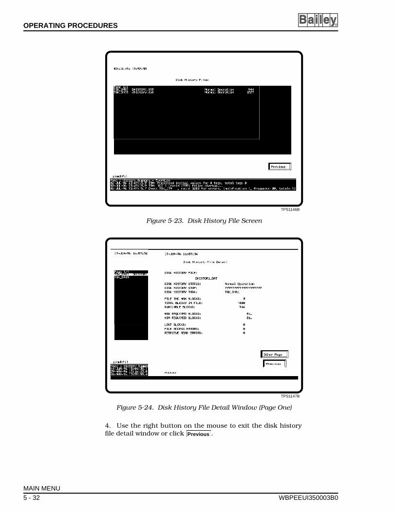
OPERATING PROCEDURES ®
4. Use the right button on the mouse to exit the disk historyfile detail window or click .
TPS1146B
Figure 5-23. Disk History File Screen
TPS1147B
Figure 5-24. Disk History File Detail Window (Page One)
Previous
MAIN MENU
5 - 32 WBPEEUI350003B0
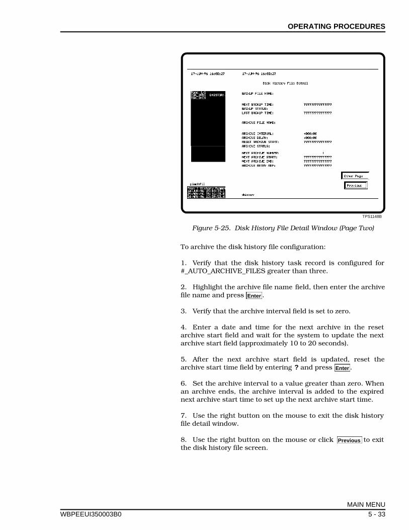
OPERATING PROCEDURES
WBPEEUI
To archive the disk history file configuration:
1. Verify that the disk history task record is configured for#_AUTO_ARCHIVE_FILES greater than three.
2. Highlight the archive file name field, then enter the archivefile name and press .
3. Verify that the archive interval field is set to zero.
4. Enter a date and time for the next archive in the resetarchive start field and wait for the system to update the nextarchive start field (approximately 10 to 20 seconds).
5. After the next archive start field is updated, reset thearchive start time field by entering ? and press .
6. Set the archive interval to a value greater than zero. Whenan archive ends, the archive interval is added to the expirednext archive start time to set up the next archive start time.
7. Use the right button on the mouse to exit the disk historyfile detail window.
8. Use the right button on the mouse or click to exitthe disk history file screen.
TPS1148B
Figure 5-25. Disk History File Detail Window (Page Two)
Enter
Enter
Previous
MAIN MENU
350003B0 5 - 33
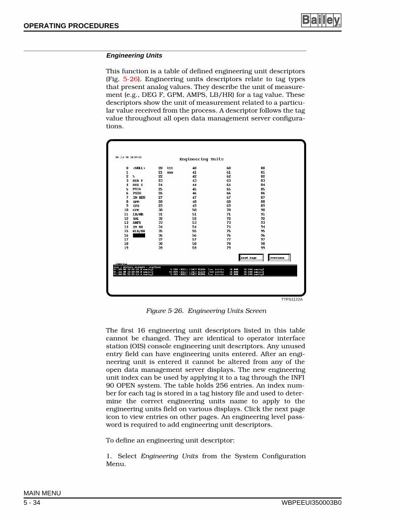
OPERATING PROCEDURES ®
Engineering Units
This function is a table of defined engineering unit descriptors(Fig. 5-26). Engineering units descriptors relate to tag typesthat present analog values. They describe the unit of measure-ment (e.g., DEG F, GPM, AMPS, LB/HR) for a tag value. Thesedescriptors show the unit of measurement related to a particu-lar value received from the process. A descriptor follows the tagvalue throughout all open data management server configura-tions.
The first 16 engineering unit descriptors listed in this tablecannot be changed. They are identical to operator interfacestation (OIS) console engineering unit descriptors. Any unusedentry field can have engineering units entered. After an engi-neering unit is entered it cannot be altered from any of theopen data management server displays. The new engineeringunit index can be used by applying it to a tag through the INFI90 OPEN system. The table holds 256 entries. An index num-ber for each tag is stored in a tag history file and used to deter-mine the correct engineering units name to apply to theengineering units field on various displays. Click the next pageicon to view entries on other pages. An engineering level pass-word is required to add engineering unit descriptors.
To define an engineering unit descriptor:
1. Select Engineering Units from the System ConfigurationMenu.
TTPS1122A
Figure 5-26. Engineering Units Screen
MAIN MENU
5 - 34 WBPEEUI350003B0
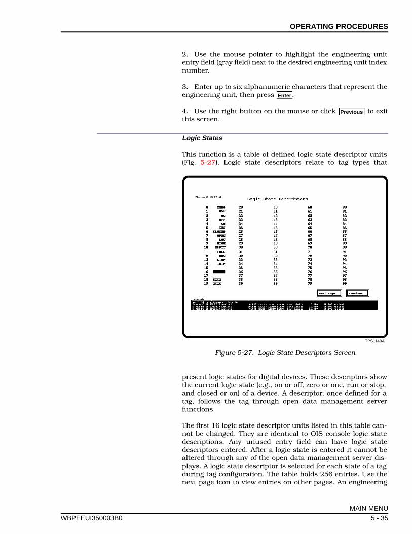
OPERATING PROCEDURES
WBPEEUI
2. Use the mouse pointer to highlight the engineering unitentry field (gray field) next to the desired engineering unit indexnumber.
3. Enter up to six alphanumeric characters that represent theengineering unit, then press .
4. Use the right button on the mouse or click to exitthis screen.
Logic States
This function is a table of defined logic state descriptor units(Fig. 5-27). Logic state descriptors relate to tag types that
present logic states for digital devices. These descriptors showthe current logic state (e.g., on or off, zero or one, run or stop,and closed or on) of a device. A descriptor, once defined for atag, follows the tag through open data management serverfunctions.
The first 16 logic state descriptor units listed in this table can-not be changed. They are identical to OIS console logic statedescriptions. Any unused entry field can have logic statedescriptors entered. After a logic state is entered it cannot bealtered through any of the open data management server dis-plays. A logic state descriptor is selected for each state of a tagduring tag configuration. The table holds 256 entries. Use thenext page icon to view entries on other pages. An engineering
Enter
Previous
TPS1149A
Figure 5-27. Logic State Descriptors Screen
MAIN MENU
350003B0 5 - 35
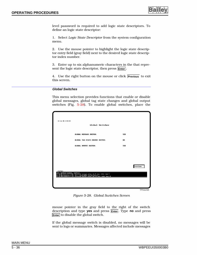
OPERATING PROCEDURES ®
level password is required to add logic state descriptors. Todefine an logic state descriptor:
1. Select Logic State Descriptor from the system configurationmenu.
2. Use the mouse pointer to highlight the logic state descrip-tor entry field (gray field) next to the desired logic state descrip-tor index number.
3. Enter up to six alphanumeric characters in the that repre-sent the logic state descriptor, then press .
4. Use the right button on the mouse or click to exitthis screen.
Global Switches
This menu selection provides functions that enable or disableglobal messages, global tag state changes and global outputswitches (Fig. 5-28). To enable global switches, place the
mouse pointer in the gray field to the right of the switchdescription and type yes and press . Type no and press
to disable the global switch.
If the global message switch is disabled, no messages will besent to logs or summaries. Messages affected include messages
Enter
Previous
TPS1123A
Figure 5-28. Global Switches Screen
Enter
Enter
MAIN MENU
5 - 36 WBPEEUI350003B0
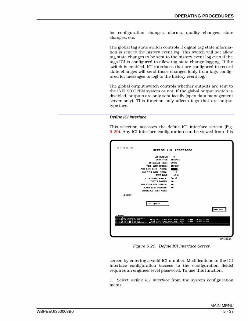
OPERATING PROCEDURES
WBPEEUI
for configuration changes, alarms, quality changes, statechanges, etc.
The global tag state switch controls if digital tag state informa-tion is sent to the history event log. This switch will not allowtag state changes to be sent to the history event log even if thetags ICI is configured to allow tag state change logging. If theswitch is enabled, ICI interfaces that are configured to recordstate changes will send those changes (only from tags config-ured for messages to log) to the history event log.
The global output switch controls whether outputs are sent tothe INFI 90 OPEN system or not. If the global output switch isdisabled, outputs are only sent locally (open data managementserver only). This function only affects tags that are outputtype tags.
Define ICI Interface
This selection accesses the define ICI interface screen (Fig.5-29). Any ICI interface configuration can be viewed from this
screen by entering a valid ICI number. Modifications to the ICIinterface configuration (access to the configuration fields)requires an engineer level password. To use this function:
1. Select define ICI interface from the system configurationmenu.
TPS1124A
Figure 5-29. Define ICI Interface Screen
MAIN MENU
350003B0 5 - 37
OPERATING PROCEDURES ®
2. To view an ICI configuration, highlight the ICI number fieldwith the mouse pointer. Enter the ICI number and press .
3. To modify an existing configuration, highlight the desiredfield with the mouse pointer. Enter a configuration choice ineach field. Configuration choices are:
• Loop type is Plant Loop or INFI-NET.
• Interface type is local or remote.
• Time sync source is INFI 90, local (open data managementserver), or none.
• Minimum time difference is selected by the user in millisec-onds. This is the minimum time difference between theremote time synchronization source and the local timebasethat will be corrected. If set to zero this function is off.
• Maximum time difference is selected by the user in minutes.This is the maximum time difference between the remotetime synchronization source and the local time base thatwill be corrected. If set to zero this function is off.
• Time zone is based on Greenwich Mean Time (GMT) and isset by the user. This number can be negative (number oftime zones to the west of GMT time) or positive (number oftime zones to the east of GMT time). Valid entries are -12 to12 hours. For example, -5 sets the time zone for EasternStandard Time in the United States.
• Time stamp source is INFI 90 or local (open data manage-ment server).
• Events logged, tag state change events, and alarm transfersupport are set to yes or no to enable or disable the func-tion.
• The interface node name is used to specify remote inter-faces. Currently this option is not supported. This fieldshould be configured for the server node name.
4. When the ICI interface configuration is set up as desired,click update or press to update the configuration andrestart the ICI interface using the new configuration.
5. If the ICI number entered does not currently exist, there isa confirmation prompt for creating a new record. Highlight yesor no, and click with the mouse or press to create a newrecord or abort the process.
System messages may be displayed if certain fields haveinvalid entries. Refer to Section 7 for a list of system messagesand corrective actions.
Enter
F1
Enter
MAIN MENU
5 - 38 WBPEEUI350003B0
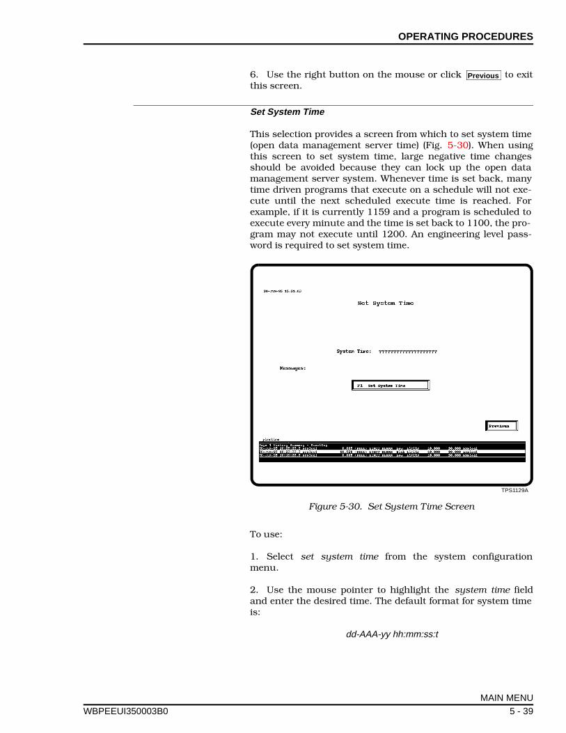
OPERATING PROCEDURES
WBPEEUI
6. Use the right button on the mouse or click to exitthis screen.
Set System Time
This selection provides a screen from which to set system time(open data management server time) (Fig. 5-30). When usingthis screen to set system time, large negative time changesshould be avoided because they can lock up the open datamanagement server system. Whenever time is set back, manytime driven programs that execute on a schedule will not exe-cute until the next scheduled execute time is reached. Forexample, if it is currently 1159 and a program is scheduled toexecute every minute and the time is set back to 1100, the pro-gram may not execute until 1200. An engineering level pass-word is required to set system time.
To use:
1. Select set system time from the system configurationmenu.
2. Use the mouse pointer to highlight the system time fieldand enter the desired time. The default format for system timeis:
dd-AAA-yy hh:mm:ss:t
Previous
TPS1129A
Figure 5-30. Set System Time Screen
MAIN MENU
350003B0 5 - 39

OPERATING PROCEDURES ®
Where dd is the day, AAA is the month abbreviation (alphacharacters), yy is the last two digits of the year, hh is hours, mmis minutes, ss is seconds, and t is tenth of seconds. Alpha char-acter entries are not case sensitive. Hyphens and colonsshould be entered as shown.
3. When the time is set correctly click set system time or press. If an invalid format is entered an error message replies
(invalid data). Valid entries reply with a data valid message.
4. Confirm or abort the time setting by highlighting yes or noat the confirm prompt, and click with the mouse or press .
5. Use the right button on the mouse or click to exitthis screen.
INTERFACE CONTROL
This selection provides an INFI 90 OPEN interface controlscreen for ICI interface restarts and resets (Fig. 5-31).
To use this function:
1. Select interface control from the open data managementserver configuration menu.
2. Use the mouse pointer to highlight the desired field andselect the interface to reset or restart.
F1
Enter
Previous
TPS1126B
Figure 5-31. INFI 90 OPEN Interface Control Screen
MAIN MENU
5 - 40 WBPEEUI350003B0
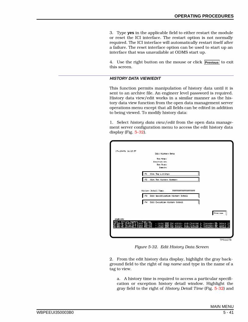
OPERATING PROCEDURES
WBPEEUI
3. Type yes in the applicable field to either restart the moduleor reset the ICI interface. The restart option is not normallyrequired. The ICI interface will automatically restart itself aftera failure. The reset interface option can be used to start up aninterface that was unavailable at ODMS start up.
4. Use the right button on the mouse or click to exitthis screen.
HISTORY DATA VIEW/EDIT
This function permits manipulation of history data until it issent to an archive file. An engineer level password is required.History data view/edit works in a similar manner as the his-tory data view function from the open data management serveroperations menu except that all fields can be edited in additionto being viewed. To modify history data:
1. Select history data view/edit from the open data manage-ment server configuration menu to access the edit history datadisplay (Fig. 5-32).
2. From the edit history data display, highlight the gray back-ground field to the right of tag name and type in the name of atag to view.
a. A history time is required to access a particular specifi-cation or exception history detail window. Highlight thegray field to the right of History Detail Time (Fig. 5-32) and
Previous
TPS1127B
Figure 5-32. Edit History Data Screen
MAIN MENU
350003B0 5 - 41

OPERATING PROCEDURES ®
type in the desired history time. The following format is thedefault format.
dd-AAA-yy hh:mm:ss.s
Where dd is the day, AAA is the month abbreviation (alphacharacters), yy is the last two digits of the year, hh is hours,mm is minutes, ss is seconds, and t is tenth of seconds.Alpha character entries are not case sensitive. Hyphensand colons should be entered as shown. This format can bechanged using DBMT or ENGCON.
b. Use or , or highlight and click Edit SpecificationHistory Detail or Edit Exception History Detail to open thespecification history detail window or exception historydetail window
3. If the tag name is not known, select a tag by clicking View TagListings or press from the edit history data display and a taglist screen appears which can be used to select a tag (Fig. 5-33).
a. To use the tag list screen click or in the tag typefield to scroll through and select the desired tag type. Thedomain or page number of the tag list can also be selected byclicking or in the domain or page fields to scrollthrough the selections. When the desired tag type is foundall tag names of that type are listed on the screen (Fig. 5-33).
b. Click the desired tag name then click Tag History Sum-mary or press to bring up a tag history summary displayscreen (Fig. 5-34).
4. If the tag name is known but the time is not known, clickView Tag History Summary, on the edit history data screen, orpress to bring up the tag history summary display screen.
5. Two summaries appear on the tag history summary displayscreen. The upper box is a summary of the tags specificationhistory. The lower box is a summary of the tag exception his-tory. Click the desired line (listed by date and time) to open adetail window with the tag specification history detail or tagexception history detail for that date and time. Figure 5-35shows the exception history detail window.
With the history time entered, the specification history detailwindow or exceptions history detail window can be opened bypressing or , or highlight and click Edit Specification His-tory Detail or Edit Exception History Detail.
6. From the exception history detail window or specificationdetail window, any of the gray background fields can be editedby highlighting that field with the mouse pointer and typing thedesired modification.
F3 F4
F1
< >
< >
F1
F2
F1 F2
MAIN MENU
5 - 42 WBPEEUI350003B0
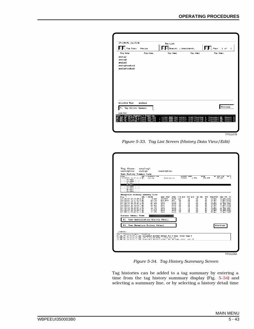
OPERATING PROCEDURES
WBPEEUI
Tag histories can be added to a tag summary by entering atime from the tag history summary display (Fig. 5-34) andselecting a summary line, or by selecting a history detail time
TPS1107B
Figure 5-33. Tag List Screen (History Data View/Edit)
TPS1109A
Figure 5-34. Tag History Summary Screen
MAIN MENU
350003B0 5 - 43
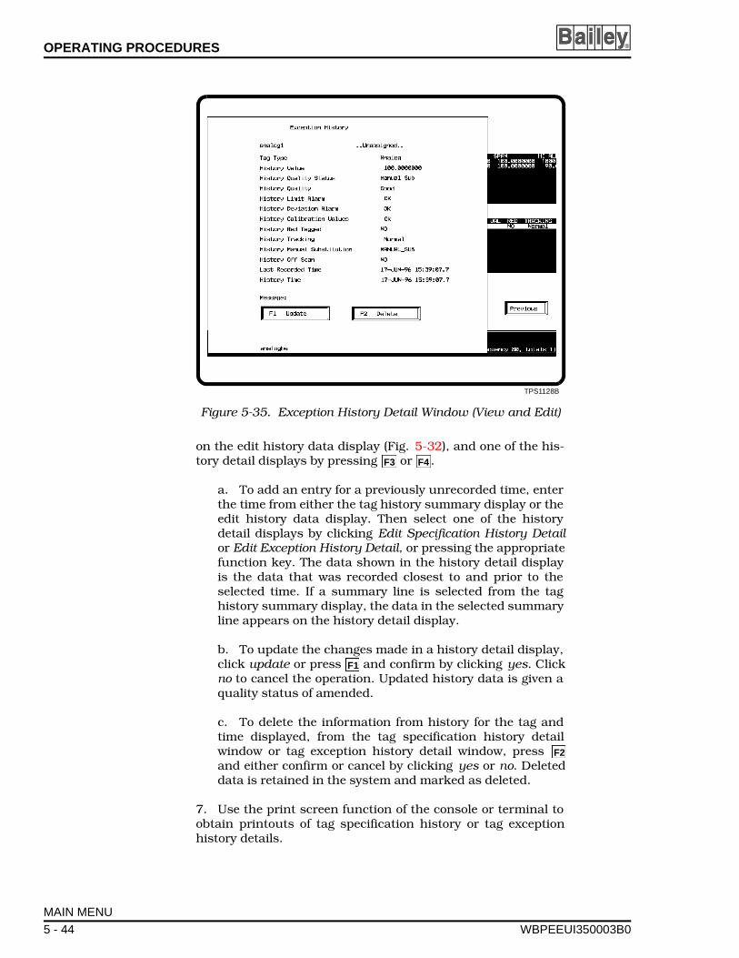
OPERATING PROCEDURES ®
on the edit history data display (Fig. 5-32), and one of the his-tory detail displays by pressing or .
a. To add an entry for a previously unrecorded time, enterthe time from either the tag history summary display or theedit history data display. Then select one of the historydetail displays by clicking Edit Specification History Detailor Edit Exception History Detail, or pressing the appropriatefunction key. The data shown in the history detail displayis the data that was recorded closest to and prior to theselected time. If a summary line is selected from the taghistory summary display, the data in the selected summaryline appears on the history detail display.
b. To update the changes made in a history detail display,click update or press and confirm by clicking yes. Clickno to cancel the operation. Updated history data is given aquality status of amended.
c. To delete the information from history for the tag andtime displayed, from the tag specification history detailwindow or tag exception history detail window, press and either confirm or cancel by clicking yes or no. Deleteddata is retained in the system and marked as deleted.
7. Use the print screen function of the console or terminal toobtain printouts of tag specification history or tag exceptionhistory details.
TPS1128B
Figure 5-35. Exception History Detail Window (View and Edit)
F3 F4
F1
F2
MAIN MENU
5 - 44 WBPEEUI350003B0

OPERATING PROCEDURES
WBPEEUI
Customer Defined Displays
This selection from the main menu is available for customerdefined displays or menu of displays created with the ACCESSutility. This blank display is stored under the display file namecustdef. Either modify the existing custdef display or create anew one. Refer to the GCS Graphic Console System UsersManual for information on how to create and define a display.
MAIN MENU
350003B0 5 - 45

SECTION 6 - SOFTWARE DETAILS
WBPEEUI
INTRODUCTION
This section contains procedures that can be used to custom-ize how the SETCIM and open data management server soft-ware packages will operate. Set up procedures in this sectioninclude:
• How to invoke an initial display other than the open datamanagement server display by defining a simulated keysdefinition record.
• How to add open data management server functions to asession manager menu (VAX/Open VMS, Alpha AXP/OpenVMS, and HP-UX servers).
• How to set up a MS Windows 3.1 client terminal to auto-matically start up as a GCS console.
• How to set up an operator console to automatically start upas a GCS console on user log-in (VAX/Open VMS, AlphaAXP/Open VMS, and HP-UX servers).
• How to set up an operator console to automatically start upas a GCS console on boot-up (VAX/Open VMS, Alpha AXP/Open VMS, and HP-UX servers).
• General guidelines for creating custom database applications.
• Setting alarm priorities using QualToStruct records.
• Performing off-line interface testing.
• How to install a permanent software license.
SIMULATED KEYS DEFINITION RECORD
Users may modify their console records to invoke a displayother than the open data management server main menu ( pim-menu). One simulated keys definition record is required foreach GCS console in the system. The record is called Inv-MenuXxXxXxN, where XxXxXx is the console identifier (i.e.,node-name) and N the console number (i.e., 1, 2 or 3 etc.). Thisrecord invokes the primary display on the console. Table 6-1lists the record fields and gives a description of the field con-tent. The information in Table 6-1 is an example of how thesimulated keys record invokes the file semodm which containsthe desired display.
INTRODUCTION
350003B0 6 - 1
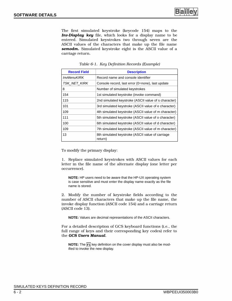
SOFTWARE DETAILS ®
The first simulated keystroke (keycode 154) maps to theInv-Display key file, which looks for a display name to beentered. Simulated keystrokes two through seven are theASCII values of the characters that make up the file namesemodm. Simulated keystroke eight is the ASCII value of acarriage return.
To modify the primary display:
1. Replace simulated keystrokes with ASCII values for eachletter in the file name of the alternate display (one letter peroccurrence).
NOTE: HP users need to be aware that the HP-UX operating systemis case sensitive and must enter the display name exactly as the filename is stored.
2. Modify the number of keystroke fields according to thenumber of ASCII characters that make up the file name, theinvoke display function (ASCII code 154) and a carriage return(ASCII code 13).
NOTE: Values are decimal representations of the ASCII characters.
For a detailed description of GCS keyboard functions (i.e., thefull range of keys and their corresponding key codes) refer tothe GCS Users Manual.
NOTE: The key definition on the cover display must also be mod-ified to invoke the new display.
Table 6-1. Key Definition Records (Example)
Record Field Description
InvMenuKIRK Record name and console identifier
TSK_NET_KIRK Console record, last error (0=none), last update
8 Number of simulated keystrokes
154 1st simulated keystroke (invoke command)
115 2nd simulated keystroke (ASCII value of s character)
101 3rd simulated keystroke (ASCII value of e character)
109 4th simulated keystroke (ASCII value of m character)
111 5th simulated keystroke (ASCII value of o character)
100 6th simulated keystroke (ASCII value of d character)
109 7th simulated keystroke (ASCII value of m character)
13 8th simulated keystroke (ASCII value of carriage return)
F1
SIMULATED KEYS DEFINITION RECORD
6 - 2 WBPEEUI350003B0
SOFTWARE DETAILS
WBPEEUI
AUTOMATING VAX START-UP
This section contains instructions on configuring a VAX systemto:
• Automatically start up the ODMS software after a systemboot.
• Configure a user session manager menu to include fre-quently used open data management server functions. Thisprocedure assumes that OPA0: and the client terminalscan support X Windows.
• Automatically bring up the open data management serveroperator console on user log-in.
• Automatically bring up the open data management serveroperator console on OPA0: after a system reboot.
Open Data Management Server Start-Up After a Boot
This procedure will insure the open data management server isrunning and available to any open data management serveruser after a boot operation.
1. Append the file PIMS$COM:AUTOSTART_ODMS.COM tothe file SYS$MANAGER:SYSTARTUP_V5.COM.
2. Edit SYSTARTUP_V5.COM or SYSTARTUP_VMS.COM andreplace the USER = ****** wildcard with the valid name of a validopen data management server user (i.e., USER = ODMS_USER).
Where ODMS_USER is the name of a valid ODMS user account.
Save the file and exit.
3. Set the SYSGEN parameter USERD1 to a nonzero value. Anonzero value enables this feature. For example, enter:
$ MCR SYSGEN SYSGEN> SET USERD1 1 SYSGEN> WRITE CURRENT SYSGEN> EXIT
4. Shut down the operating system, then do a boot operation.When the system is available, log-in and enter show sys to ver-ify the system is running.
Enter
Enter
Enter
Enter
AUTOMATING VAX START-UP
350003B0 6 - 3
SOFTWARE DETAILS ®
Adding ODMS Functions to a User Session Manager Menu
To add open data management server menu items to the ses-sion manager menus, do the following:
1. Log in to the users account.
2. Issue the following commands to copy the files required toconfigure the session manager. These files are copied to theusers log-in directory.
SET DEF SYS$LOGIN
COPY PIMS$COM:vue$gcs.com *.* COPY PIMS$COM:vue$dd.com *.* COPY PIMS$COM:vue$terminal.com *.* COPY PIMS$COM:vue$gcsll.com *.* COPY PIMS$COM:vue$tool_mgr *.*
3. Under the session manager OPTIONS menu, select theMENU option and define the menu items in Steps 3a to 3i. TheGCS system is installed as a remote link or local link to theopen data management server database (i.e., none or SETCIM,respectively, was specified as the link option at GCS installa-tion). The DCL commands for both types of GCS systems(remote or local) are given with the menu items listed below.The first line in Steps 3a to 3i is a suggested menu title.
a. GCS OPERATOR CONSOLERemote DCL command: @sys$login:vue$gcs.com opconLocal DCL command: @sys$login:vue$gcsll.com opcon
b. GCS ACCESSRemote DCL command: @sys$login:vue$gcs.comaccessLocal DCL command: @sys$login:vue$gcsll.com access
c. GCS DISPLAY DEFINITIONRemote DCL command: @sys$login:vue$dd.com dd
d. DBMT TOOL MANAGERDCL command: @setcimdbmt:tool_mgr.com
e. ENGINEERING CONSOLEDCL command: @sys$login:vue$terminal engcon"ENGCON"
f. START ODMSDCL command: @setcimcom:startsetcim
g. STOP ODMSDCL command: @setcimcom:stopsetcim
Enter
Enter
Enter
Enter
Enter
Enter
AUTOMATING VAX START-UP
6 - 4 WBPEEUI350003B0
SOFTWARE DETAILS
WBPEEUI
h. CIMCALCDCL command: @sys$login:vue$terminal cimcalc"CIMCALC"
i. SQLPLUSDCL command: run setcimcode:iq
Other terminal applications which do not require X Windowsmay be defined as menu items in a similar fashion as the engi-neering console. The DCL command is:
sys$login:vue$terminal application_name“window_name” application_directory
Where application_name is what the user would enter at a termi-nal to activate the application (e.g., CIM-CALC). window_nameis the name given to the X Window terminal and its icon (e.g.,CIM-CALC). application_directory is the directory the applicationshould be run from (e.g., setcim:[spreadsheet]).
4. Create a menu named ODMS and add the menu itemsdefined in Step 3 to this menu. The menu and menu itemnames may be configured as desired.
5. Open the ODMS menu from the options menu bar.
6. Save the session manager.
7. End the session, then log in to the user account. Verify thatthe session manager has the open data management serveroptions and that the open data management server selectionsfunction properly.
NOTE: There is no need to create the GCS operator console menuitem in this step if it was created to support operator console start upon user log-in.
Operator Console Start-Up on User Log-In
To configure a user account to bring up the open data manage-ment server operator console on log-in, perform the stepsbelow. This will not affect log-in from a non X Windows termi-nal.
1. Add a GCS operator console menu item by following thesteps in Adding ODMS Functions to a User Session Man-ager Menu.
2. Log-in to the users account. Under the Session ManagerOPTIONS menu, select the automatic start up option. Select theitem named GCS OPERATOR CONSOLE.
AUTOMATING VAX START-UP
350003B0 6 - 5

SOFTWARE DETAILS ®
3. Add this menu item to the automatic start up menu. Savethe session manager, exit, log-in to the users account, and ver-ify that the GCS operator console starts up.
An optional method of configuring the operator console to startup on user log-in is to use one of the configured sessionsincluded with the open data management server software.
The configured sessions are in the files:
PIMS$COM:vue$profile.vue$profilePIMS$COM:vue$profile.ver2
For a secures system, copy PIMS$COM:vue$profile.vue$pro-file to the users log-in directory. Rename the file as vue$pro-file.vue$dat. This session has limited access to other systemfunctions.
For a less secure system, copy PIMS$COM:vue$profile.ver2to the users log-in directory and rename it as vue$pro-file.vue$dat.
Operator Console Start-Up After a Boot
This option will causes the GCS operator console to be auto-matically displayed on OPA0: after a reboot. OPA0: will be ded-icated to the GCS operator console function. A log-in window isprovided for access to other functions. A open data manage-ment server account name for log-in at reboot is required toconfigure this option. Additionally, this account must be con-figured for automatic operator console start up on user log-in.The system must be configured for automatic open data man-agement server start up after a boot (refer to Operator ConsoleStart-Up on User Log-In and Open Data ManagementServer Start-Up After a Boot).
1. Add the commands in PIMS$COM:SYSTARTUP_V5.ADD toSYSTARTUP_V5.COM (VMS 5.X) or SYSTARTUP_VMS.COM(Open VMS 6.X or higher). The commands should be executedafter the VMS options and open data management server havebeen started. Edit the file to assign the AUTOSTR-TUP$ACCOUNT logical to the open data management serveraccount that will be logged into at start up and assignAUTOSTRTUP$DIR and AUTO$DEFDIR to the account defaultdirectory.
2. Copy PIMS$COM:DECW$PRIVATE_APPS_SETUP.COM. toSYS$MANAGER:DECW$PRIVATE_APPS_SET UP.COM.
3. Copy PIMS$COM:AUTOSTRTUP$STARTAPPS.COM,PIMS$COM:AUTOSTRTUP$APPS.COM,
AUTOMATING VAX START-UP
6 - 6 WBPEEUI350003B0
SOFTWARE DETAILS
WBPEEUI
PIMS$COM:AUTOSTRTUP$STARTSM.COM, andPIMS$COM:LOGIN_WINDOW.COM to the default directory forthe account that will be logged into at reboot.
4. Set the SYSGEN parameter USERD2 to a nonzero value. Azero value disables this feature. The SYSGEN parameterUSERD1 (to automatically start up open data managementserver after a reboot) should also be set to a nonzero value.
5. The session manager for the log-in account needs to becustomized as a secure user, refer to Operator ConsoleStart-Up on User Log-In.
6. To allow a shutdown of the system from the log-in window,comment out the STOP/QUEUES/ON_NODE command inSYS$SYSTEM:SHUTDOWN.COM.
7. To disable operator console messages, add the followinglines to the system start up file SYSTARTUP_VMS.COM (forOpen VMS 6.0 or greater) or SYSTARTUP_V5.COM (for VMS5.5-2):
$ Define/user sys$command OPAO:$ Reply/Display$ Set terminals/pers/Nobro OPAO:
AUTOMATING HP START-UP
This section contains procedures to configure an HP consoleto:
• Start up open data management server automatically onsystem boot.
• Start up a GCS console automatically on log-in.
• Start up a GCS console screen automatically on a systemboot or log-out.
Additional information includes:
• How to set up TCP/IP communication to OSM modules.
• How to remove *LOCK files prior to ODMS system start-up.
Open Data Management Server Start-Up After a Boot
To configure an HP console to start up open data managementserver automatically after a system boot:
1. Change the directory to /etc.
AUTOMATING HP START-UP
350003B0 6 - 7
SOFTWARE DETAILS ®
2. Edit the file RC by adding the following line to the local RCfunction, as one line in the file, where nnn is the SETCIM groupnumber such as 200.
/setcim/odms/exe/cmd nnn ‘sh-c “./setcim/commands/setcimlogin.sh;. /setcim/odms/odms.sh; startsetcim.sh” ‘
Where the directory /setcim is the default directory chosen dur-ing installation. If another directory is used, substitute thatdirectory in place of /setcim .
GCS Console Start-Up on User Log-In
To configure a GCS console to start up on user log-in:
1. Change the directory to /etc.
2. Edit the file Passwd. Modify any accounts that are tobecome dedicated GCS consoles to start up the operators con-sole as part of the shell. The end of each line in the file is theshell script to start for the given user. Once the shell scriptstart up is modified, the user will only be able to start up as aGCS operators console.
If the user starts sh. , change the end of the line from /bin/sh to/gcs/ODMS/shell_gcs.sh where /gcs is the directory where GCSis installed.
To make this a secure user account, the user account shouldhave a /.VUE directory that contains the VUEWMRC file.
For example, mv /gcs/ODMS/vuewmrc /user/Dedicated_1/.VUE where /gcs is the directory into which GCS is installedand /user is the default directory for the new user. If the .VUEsubdirectory does not exist, it can be created by issuing the fol-lowing command:
mkdir /user/Dedicated_1/.VUE
where /user/Dedicated_1/.VUE is the default directory of thegiven user.
GCS Console Start-Up on System Boot or Log-Out
To automatically start up a GCS console on a system boot orlog-out:
1. Do the steps under Operator Console Start-Up on UserLog-In and GCS Console Start-Up on User Log-In.
2. Change the directory to /usr/vue/config.
Enter
AUTOMATING HP START-UP
6 - 8 WBPEEUI350003B0
SOFTWARE DETAILS
WBPEEUI
3. Edit the file Xaccess, adding the line:
Hostname.domain.com BYPASS_LOGIN account
where Hostname.domain.com is usually just the HP computernode name, and account is the user login as Dedicated_1.
TCP/IP Communications to OSM Modules
For TCP/IP communication (between the ODMS interface tasksand/or the OSM modules), the user needs to have a blindrshell. A blind rshell does not require a password for remoteexecution of a command on a target machine. For example, thefollowing command should not require password entry:
remsh “host_name” ls
where “host_name” is the target machine.
To add a blind rshell, add the “host_name” to the /etc/hostsfile.
ODMS and ICI Interface Communication Files
The ODMS and ICI interface create *LOCK files at the /tmpdirectory on ODMS start up. These files should only exist whenthe ODMS system is running. Any existing *LOCK files must beremoved prior to ODMS start up using the following command:
rm -r /tmp/*LOCK
WINDOWS CLIENT AUTOMATIC START-UP
This procedure assumes that the GCS console software and allother open data management server software are loaded inWindows. To set up a Windows client for automatic start up:
1. If there is a Windows start up group, open it. If not, createone and open it.
2. Copy the icons for the various open data managementserver programs to the start up group.
a. Copy the GCS for Windows icon to the start up group.
b. Copy the DDELINK icon to the start up group.
c. For CIMDESK installation, follow the procedures in theCIMDESK Users Manual.
3. Restart Windows in the enhanced 386 mode to activate theautomatic start up installation. If there is sufficient memoryand swapfile available, Windows will automatically start in this
WINDOWS CLIENT AUTOMATIC START-UP
350003B0 6 - 9
SOFTWARE DETAILS ®
mode by typing WIN at the DOS prompt. Otherwise type WIN/3to start Windows and click on the GCS console icon to start upthe client terminal.
GUIDELINES FOR CREATING CLIENT PROGRAMS
The configuration file read by the client program contains con-nection information and other client and server parameters forone or more SETCIM database nodes. When a client programcalls INISETC () a configuration file is read to obtain connectioninformation and other client and server parameters for eachnode. The configuration file is located by the SETCIMRPC envi-ronment variable in UNIX systems or the SETCIMRPC logicalin VMS systems. If the SETCIMRPC environment variable orlogical is not defined, the client program will assume that a filenamed SETCIMRPC.CFG is in the current directory. If the con-figuration file is not found then the INISETC () call will fail. Theconfiguration file consists of one or more lines in a text file. Thefirst line in a configuration file is the default node. For accessroutines, such as NAME2RECID, that search all nodes to finddata, the nodes are searched in the order listed in the configu-ration file. Refer to the SETCIMRPC Users Manual for infor-mation on how to set up a configuration file.
OPEN DATA MANAGEMENT SERVER DATABASE FILE FORMAT
Refer to Appendix E for a list of open data management serverdatabase field names. A listing of file format and other informa-tion such as default value, tag types supported, and field sizeare listed in Table E-2.
QUALITY PRIORITIES
QualToStruct records (QualToStruct01throughQualToStruct19)are provided with open data management server which allowsomeone with an engineer level password to modify the priorityassociated with individual qualities. Refer to Table E-1 inAppendix E for a list of the QualToStruct record numbers andtheir corresponding tag type. The quality priority determineswhich qualities will be reported on various displays. In the eventthat multiple qualities for a given point occur simultaneously,the quality with the lowest priority number (highest priority) willbe displayed. Priority numbers are set by the engineer usingDBMT or ENGCON. Refer to the appropriate SETCIM productinstruction for information on how to use DBMT or ENGCON.Each record contains a repeat area that contains a block forevery quality attribute that is available for the given point type.When modifying QualToStruct records, only the PRIORITY fieldshould be changed. The PRIORITY field should contain a uniquenumber for each quality attribute in a given point type.
The following record structure is an example of a QualToStructrecord. The PRIORITY field in this record can be changed to set
GUIDELINES FOR CREATING CLIENT PROGRAMS
6 - 10 WBPEEUI350003B0

SOFTWARE DETAILS
WBPEEUI
the precedence of the quality strings. No other field should bechanged.
Record Contents QualToStruct01Definition Record QualToStructdef
QualToStruct01 NAMEQuality-Status01 QUALITY_STATUS_FIELD
10 REPEAT_AREA_INDEX 1 1 PRIORITY
Manual Sub 1 QUALITY STATUS d-AnalogB eMANUAL SUBSTITUTION 1 FIELD_LOCATION
1 1 VALUE 2 2 PRIORITY
Off Scan 2 QUALITY STATUS d-AnalogB eOFF SCAN 2 FIELD_LOCATION
1 2 VALUE 3 3 PRIORITY
Bad Qual 3 QUALITY STATUS d-AnalogB eQUALITY 3 FIELD_LOCATION
1 3 VALUE 4 4 PRIORITY
HiLimAlarm 4 QUALITY STATUS d-AnalogB eLIMIT ALARM 4 FIELD_LOCATION
2 4 VALUE 5 5 PRIORITY
LoLimAlarm 5 QUALITY STATUS d-AnalogB eLIMIT ALARM 5 FIELD_LOCATION
1 5 VALUE 6 6 PRIORITY
HiDevAlarm 6 QUALITY STATUS d-AnalogB eDEVIATION ALARM 6 FIELD_LOCATION
2 6 VALUE 7 7 PRIORITY
LoDevAlarm 7 QUALITY STATUS d-AnalogB eDEVIATION ALARM 7 FIELD_LOCATION
1 7 VALUE 8 8 PRIORITY
CalibrtnVl 8 QUALITY STATUS d-AnalogB eCALIBRATION VALUES 8 FIELD_LOCATION
1 8 VALUE 9 9 PRIORITY
Red Tagged 9 QUALITY STATUS d-AnalogBeRED TAGGED 9 FIELD_LOCATION
1 9 VALUE 10 10 PRIORITY
Tracking 10 QUALITY STATUS d-AnalogB eTRACKING 10 FIELD_LOCATION
1 10 VALUE
QUALITY PRIORITIES
350003B0 6 - 11

SOFTWARE DETAILS ®
OFF-LINE INTERFACE TESTING
The ICI interface should be tested prior to the initial start up ofthe ODMS server or any time problems occur using the icitestprogram. This program will allow the user to connect to an ICIinterface and obtain general information about the interface.
PERMANENT LICENSE INSTALLATION
After entering the temporary license password and the result-ing license code has been sent to the Open Data ManagementServer Coordinator at Elsag Bailey, a series of permanentlicense codes will be received.
To install the permanent license:
1. Enter these license codes into ODMS using the followingprogram.
For VAX and Alpha AXP type:
$ RUN SETCIMCODE: UPDATELICENSE
For HP-UX type:
cd SETCIMCODEUPDATELICENSE
The program will respond with prompts for entering the licensecode.
Do you want to enter a product code (Yes/No) [Yes?]
2. Press to enter the product code.
Please enter product code
3. Enter the 16 character license code and repeat for alllicense codes received when prompted.
4. Restart the ODMS system to activate the new licenses.
Enter
OFF-LINE INTERFACE TESTING
6 - 12 WBPEEUI350003B0
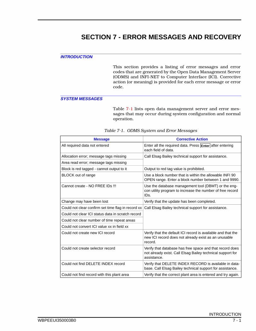
SECTION 7 - ERROR MESSAGES AND RECOVERY
WBPEEUI
INTRODUCTION
This section provides a listing of error messages and errorcodes that are generated by the Open Data Management Server(ODMS) and INFI-NET to Computer Interface (ICI). Correctiveaction (or meaning) is provided for each error message or errorcode.
SYSTEM MESSAGES
Table 7-1 lists open data management server and error mes-sages that may occur during system configuration and normaloperation.
Table 7-1. ODMS System and Error Messages
Message Corrective Action
All required data not entered Enter all the required data. Press after entering each field of data.
Allocation error; message tags missing Call Elsag Bailey technical support for assistance.
Area read error; message tags missing
Block is red tagged - cannot output to it Output to red tag value is prohibited.
BLOCK out of range Use a block number that is within the allowable INFI 90 OPEN range. Enter a block number between 1 and 9990.
Cannot create - NO FREE IDs !!! Use the database management tool (DBMT) or the eng-con utility program to increase the number of free record IDs.
Change may have been lost Verify that the update has been completed.
Could not clear confirm set time flag in record xx Call Elsag Bailey technical support for assistance.
Could not clear ICI status data in scratch record
Could not clear number of time repeat areas
Could not convert ICI value xx in field xx
Could not create new ICI record Verify that the default ICI record is available and that the new ICI record does not already exist as an unusable record.
Could not create selector record Verify that database has free space and that record does not already exist. Call Elsag Bailey technical support for assistance.
Could not find DELETE INDEX record Verify that DELETE INDEX RECORD is available in data-base. Call Elsag Bailey technical support for assistance.
Could not find record with this plant area Verify that the correct plant area is entered and try again.
Enter
INTRODUCTION
350003B0 7 - 1
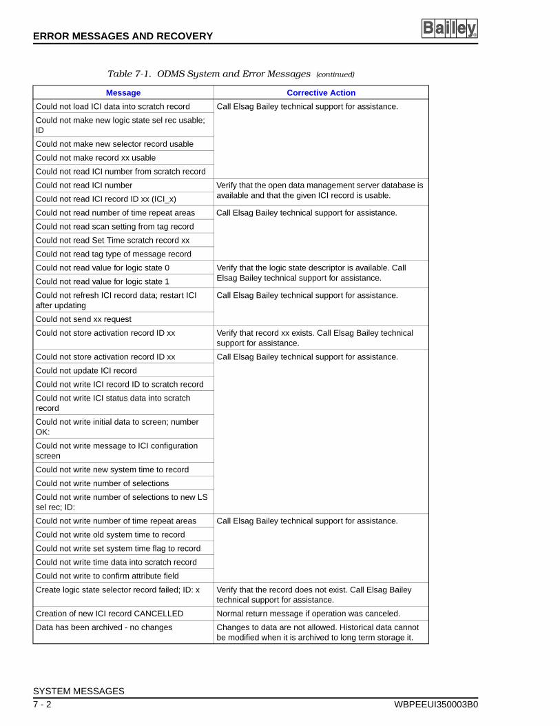
ERROR MESSAGES AND RECOVERY ®
Could not load ICI data into scratch record Call Elsag Bailey technical support for assistance.
Could not make new logic state sel rec usable; ID
Could not make new selector record usable
Could not make record xx usable
Could not read ICI number from scratch record
Could not read ICI number Verify that the open data management server database is available and that the given ICI record is usable.Could not read ICI record ID xx (ICI_x)
Could not read number of time repeat areas Call Elsag Bailey technical support for assistance.
Could not read scan setting from tag record
Could not read Set Time scratch record xx
Could not read tag type of message record
Could not read value for logic state 0 Verify that the logic state descriptor is available. Call Elsag Bailey technical support for assistance.Could not read value for logic state 1
Could not refresh ICI record data; restart ICI after updating
Call Elsag Bailey technical support for assistance.
Could not send xx request
Could not store activation record ID xx Verify that record xx exists. Call Elsag Bailey technical support for assistance.
Could not store activation record ID xx Call Elsag Bailey technical support for assistance.
Could not update ICI record
Could not write ICI record ID to scratch record
Could not write ICI status data into scratch record
Could not write initial data to screen; number OK:
Could not write message to ICI configuration screen
Could not write new system time to record
Could not write number of selections
Could not write number of selections to new LS sel rec; ID:
Could not write number of time repeat areas Call Elsag Bailey technical support for assistance.
Could not write old system time to record
Could not write set system time flag to record
Could not write time data into scratch record
Could not write to confirm attribute field
Create logic state selector record failed; ID: x Verify that the record does not exist. Call Elsag Bailey technical support for assistance.
Creation of new ICI record CANCELLED Normal return message if operation was canceled.
Data has been archived - no changes Changes to data are not allowed. Historical data cannot be modified when it is archived to long term storage it.
Table 7-1. ODMS System and Error Messages (continued)
Message Corrective Action
SYSTEM MESSAGES
7 - 2 WBPEEUI350003B0
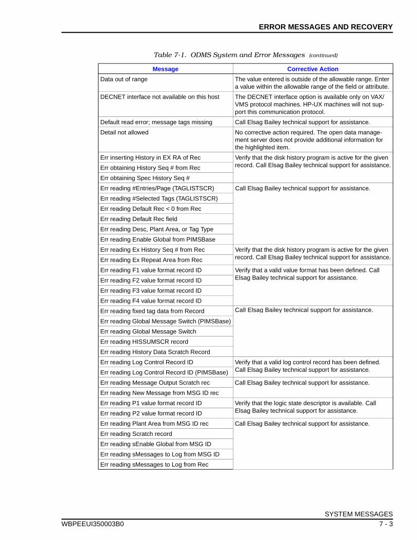
ERROR MESSAGES AND RECOVERY
WBPEEUI
Data out of range The value entered is outside of the allowable range. Enter a value within the allowable range of the field or attribute.
DECNET interface not available on this host The DECNET interface option is available only on VAX/VMS protocol machines. HP-UX machines will not sup-port this communication protocol.
Default read error; message tags missing Call Elsag Bailey technical support for assistance.
Detail not allowed No corrective action required. The open data manage-ment server does not provide additional information for the highlighted item.
Err inserting History in EX RA of Rec Verify that the disk history program is active for the given record. Call Elsag Bailey technical support for assistance.Err obtaining History Seq # from Rec
Err obtaining Spec History Seq #
Err reading #Entries/Page (TAGLISTSCR) Call Elsag Bailey technical support for assistance.
Err reading #Selected Tags (TAGLISTSCR)
Err reading Default Rec < 0 from Rec
Err reading Default Rec field
Err reading Desc, Plant Area, or Tag Type
Err reading Enable Global from PIMSBase
Err reading Ex History Seq # from Rec Verify that the disk history program is active for the given record. Call Elsag Bailey technical support for assistance.Err reading Ex Repeat Area from Rec
Err reading F1 value format record ID Verify that a valid value format has been defined. Call Elsag Bailey technical support for assistance.Err reading F2 value format record ID
Err reading F3 value format record ID
Err reading F4 value format record ID
Err reading fixed tag data from Record Call Elsag Bailey technical support for assistance.
Err reading Global Message Switch (PIMSBase)
Err reading Global Message Switch
Err reading HISSUMSCR record
Err reading History Data Scratch Record
Err reading Log Control Record ID Verify that a valid log control record has been defined. Call Elsag Bailey technical support for assistance.Err reading Log Control Record ID (PIMSBase)
Err reading Message Output Scratch rec Call Elsag Bailey technical support for assistance.
Err reading New Message from MSG ID rec
Err reading P1 value format record ID Verify that the logic state descriptor is available. Call Elsag Bailey technical support for assistance.Err reading P2 value format record ID
Err reading Plant Area from MSG ID rec Call Elsag Bailey technical support for assistance.
Err reading Scratch record
Err reading sEnable Global from MSG ID
Err reading sMessages to Log from MSG ID
Err reading sMessages to Log from Rec
Table 7-1. ODMS System and Error Messages (continued)
Message Corrective Action
SYSTEM MESSAGES
350003B0 7 - 3
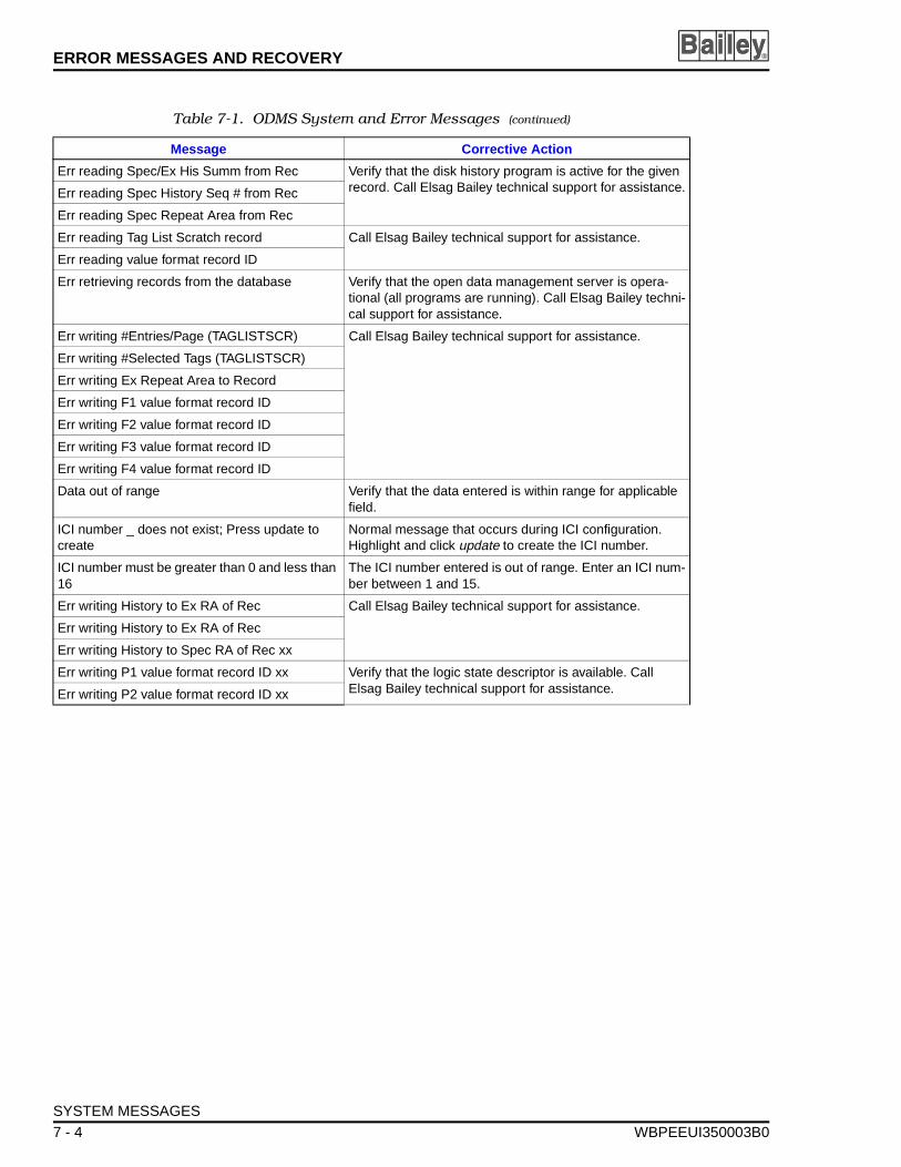
ERROR MESSAGES AND RECOVERY ®
Err reading Spec/Ex His Summ from Rec Verify that the disk history program is active for the given record. Call Elsag Bailey technical support for assistance.Err reading Spec History Seq # from Rec
Err reading Spec Repeat Area from Rec
Err reading Tag List Scratch record Call Elsag Bailey technical support for assistance.
Err reading value format record ID
Err retrieving records from the database Verify that the open data management server is opera-tional (all programs are running). Call Elsag Bailey techni-cal support for assistance.
Err writing #Entries/Page (TAGLISTSCR) Call Elsag Bailey technical support for assistance.
Err writing #Selected Tags (TAGLISTSCR)
Err writing Ex Repeat Area to Record
Err writing F1 value format record ID
Err writing F2 value format record ID
Err writing F3 value format record ID
Err writing F4 value format record ID
Data out of range Verify that the data entered is within range for applicable field.
ICI number _ does not exist; Press update to create
Normal message that occurs during ICI configuration. Highlight and click update to create the ICI number.
ICI number must be greater than 0 and less than 16
The ICI number entered is out of range. Enter an ICI num-ber between 1 and 15.
Err writing History to Ex RA of Rec Call Elsag Bailey technical support for assistance.
Err writing History to Ex RA of Rec
Err writing History to Spec RA of Rec xx
Err writing P1 value format record ID xx Verify that the logic state descriptor is available. Call Elsag Bailey technical support for assistance.Err writing P2 value format record ID xx
Table 7-1. ODMS System and Error Messages (continued)
Message Corrective Action
SYSTEM MESSAGES
7 - 4 WBPEEUI350003B0
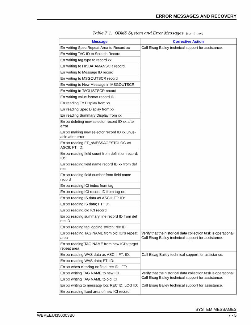
ERROR MESSAGES AND RECOVERY
WBPEEUI
Err writing Spec Repeat Area to Record xx Call Elsag Bailey technical support for assistance.
Err writing TAG ID to Scratch Record
Err writing tag type to record xx
Err writing to HISDATAMANSCR record
Err writing to Message ID record
Err writing to MSGOUTSCR record
Err writing to New Message in MSGOUTSCR
Err writing to TAGLISTSCR record
Err writing value format record ID
Err reading Ex Display from xx
Err reading Spec Display from xx
Err reading Summary Display from xx
Err xx deleting new selector record ID xx after error
Err xx making new selector record ID xx unus-able after error
Err xx reading FT_sMESSAGESTOLOG as ASCII; FT: ID:
Err xx reading field count from definition record; ID:
Err xx reading field name record ID xx from def rec
Err xx reading field number from field name record
Err xx reading ICI index from tag
Err xx reading ICI record ID from tag xx
Err xx reading IS data as ASCII; FT: ID:
Err xx reading IS data; FT: ID:
Err xx reading old ICI record
Err xx reading summary line record ID from def rec ID
Err xx reading tag logging switch; rec ID:
Err xx reading TAG NAME from old ICI's repeat area
Verify that the historical data collection task is operational. Call Elsag Bailey technical support for assistance.
Err xx reading TAG NAME from new ICI's target repeat area
Err xx reading WAS data as ASCII; FT: ID: Call Elsag Bailey technical support for assistance.
Err xx reading WAS data; FT: ID:
Err xx when clearing xx field; rec ID:, FT:
Err xx writing TAG NAME to new ICI Verify that the historical data collection task is operational. Call Elsag Bailey technical support for assistance.Err xx writing TAG NAME to old ICI
Err xx writing to message log; REC ID: LOG ID: Call Elsag Bailey technical support for assistance.
Err xx reading fixed area of new ICI record
Table 7-1. ODMS System and Error Messages (continued)
Message Corrective Action
SYSTEM MESSAGES
350003B0 7 - 5
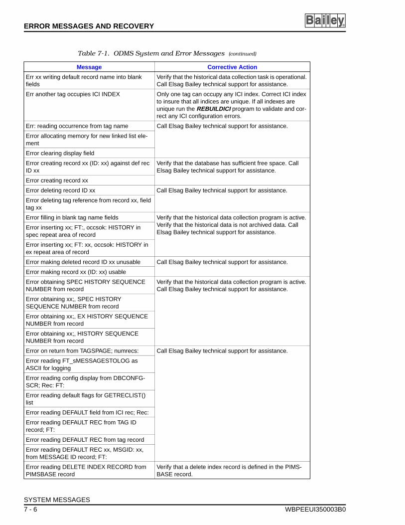
ERROR MESSAGES AND RECOVERY ®
Err xx writing default record name into blank fields
Verify that the historical data collection task is operational. Call Elsag Bailey technical support for assistance.
Err another tag occupies ICI INDEX Only one tag can occupy any ICI index. Correct ICI index to insure that all indices are unique. If all indexes are unique run the REBUILDICI program to validate and cor-rect any ICI configuration errors.
Err: reading occurrence from tag name Call Elsag Bailey technical support for assistance.
Error allocating memory for new linked list ele-ment
Error clearing display field
Error creating record xx (ID: xx) against def rec ID xx
Verify that the database has sufficient free space. Call Elsag Bailey technical support for assistance.
Error creating record xx
Error deleting record ID xx Call Elsag Bailey technical support for assistance.
Error deleting tag reference from record xx, field tag xx
Error filling in blank tag name fields Verify that the historical data collection program is active. Verify that the historical data is not archived data. Call Elsag Bailey technical support for assistance.
Error inserting xx; FT:, occsok: HISTORY in spec repeat area of record
Error inserting xx; FT: xx, occsok: HISTORY in ex repeat area of record
Error making deleted record ID xx unusable Call Elsag Bailey technical support for assistance.
Error making record xx (ID: xx) usable
Error obtaining SPEC HISTORY SEQUENCE NUMBER from record
Verify that the historical data collection program is active. Call Elsag Bailey technical support for assistance.
Error obtaining xx;, SPEC HISTORY SEQUENCE NUMBER from record
Error obtaining xx;, EX HISTORY SEQUENCE NUMBER from record
Error obtaining xx;, HISTORY SEQUENCE NUMBER from record
Error on return from TAGSPAGE; numrecs: Call Elsag Bailey technical support for assistance.
Error reading FT_sMESSAGESTOLOG as ASCII for logging
Error reading config display from DBCONFG-SCR; Rec: FT:
Error reading default flags for GETRECLIST() list
Error reading DEFAULT field from ICI rec; Rec:
Error reading DEFAULT REC from TAG ID record; FT:
Error reading DEFAULT REC from tag record
Error reading DEFAULT REC xx, MSGID: xx, from MESSAGE ID record; FT:
Error reading DELETE INDEX RECORD from PIMSBASE record
Verify that a delete index record is defined in the PIMS-BASE record.
Table 7-1. ODMS System and Error Messages (continued)
Message Corrective Action
SYSTEM MESSAGES
7 - 6 WBPEEUI350003B0
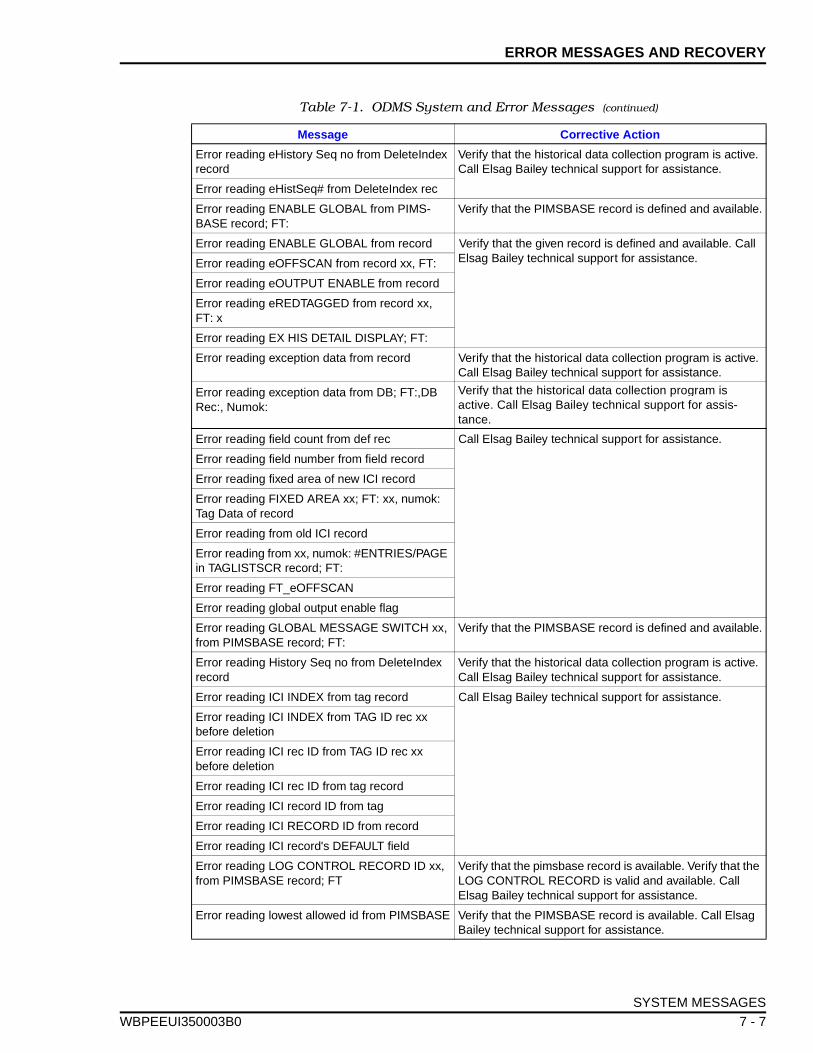
ERROR MESSAGES AND RECOVERY
WBPEEUI
Error reading eHistory Seq no from DeleteIndex record
Verify that the historical data collection program is active. Call Elsag Bailey technical support for assistance.
Error reading eHistSeq# from DeleteIndex rec
Error reading ENABLE GLOBAL from PIMS-BASE record; FT:
Verify that the PIMSBASE record is defined and available.
Error reading ENABLE GLOBAL from record Verify that the given record is defined and available. Call Elsag Bailey technical support for assistance.Error reading eOFFSCAN from record xx, FT:
Error reading eOUTPUT ENABLE from record
Error reading eREDTAGGED from record xx, FT: x
Error reading EX HIS DETAIL DISPLAY; FT:
Error reading exception data from record Verify that the historical data collection program is active. Call Elsag Bailey technical support for assistance.
Error reading exception data from DB; FT:,DB Rec:, Numok:
Verify that the historical data collection program is active. Call Elsag Bailey technical support for assis-tance.
Error reading field count from def rec Call Elsag Bailey technical support for assistance.
Error reading field number from field record
Error reading fixed area of new ICI record
Error reading FIXED AREA xx; FT: xx, numok: Tag Data of record
Error reading from old ICI record
Error reading from xx, numok: #ENTRIES/PAGE in TAGLISTSCR record; FT:
Error reading FT_eOFFSCAN
Error reading global output enable flag
Error reading GLOBAL MESSAGE SWITCH xx, from PIMSBASE record; FT:
Verify that the PIMSBASE record is defined and available.
Error reading History Seq no from DeleteIndex record
Verify that the historical data collection program is active. Call Elsag Bailey technical support for assistance.
Error reading ICI INDEX from tag record Call Elsag Bailey technical support for assistance.
Error reading ICI INDEX from TAG ID rec xx before deletion
Error reading ICI rec ID from TAG ID rec xx before deletion
Error reading ICI rec ID from tag record
Error reading ICI record ID from tag
Error reading ICI RECORD ID from record
Error reading ICI record's DEFAULT field
Error reading LOG CONTROL RECORD ID xx, from PIMSBASE record; FT
Verify that the pimsbase record is available. Verify that the LOG CONTROL RECORD is valid and available. Call Elsag Bailey technical support for assistance.
Error reading lowest allowed id from PIMSBASE Verify that the PIMSBASE record is available. Call Elsag Bailey technical support for assistance.
Table 7-1. ODMS System and Error Messages (continued)
Message Corrective Action
SYSTEM MESSAGES
350003B0 7 - 7
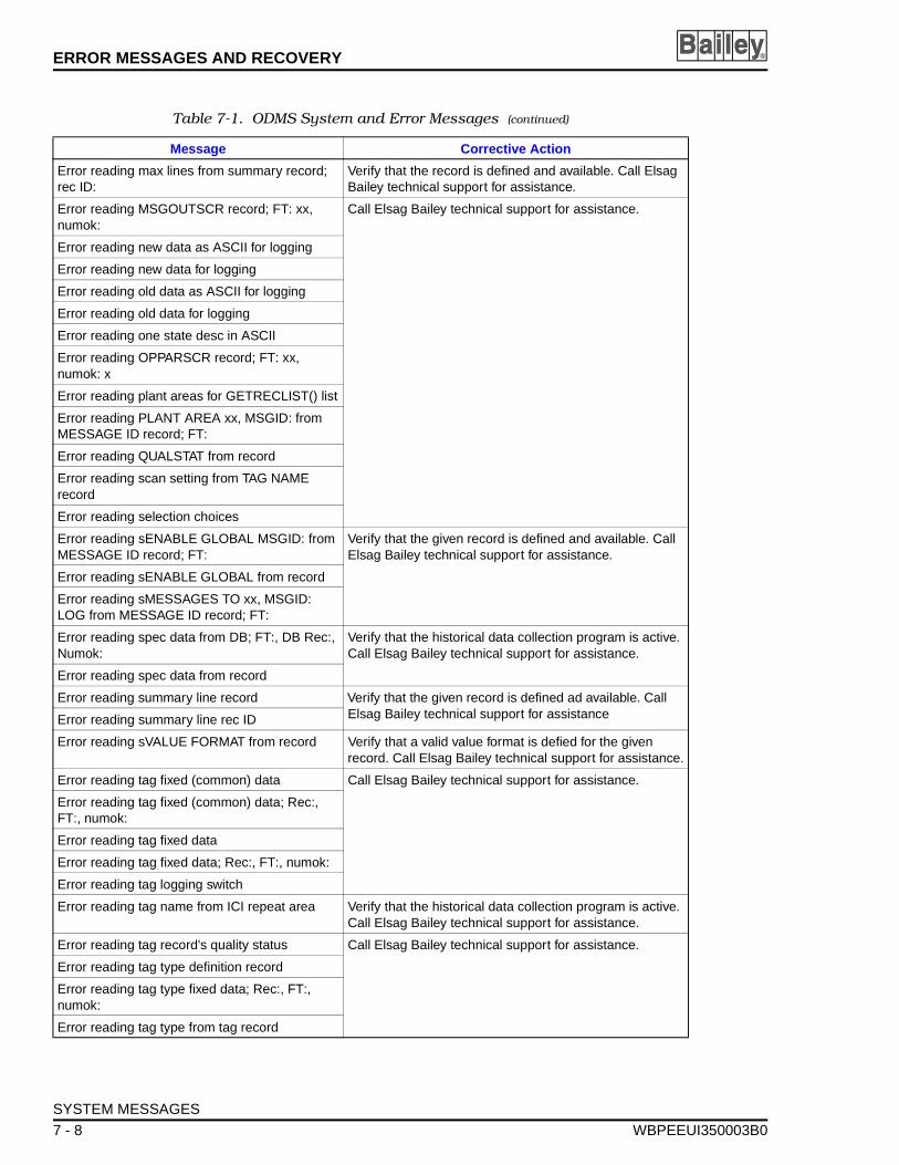
ERROR MESSAGES AND RECOVERY ®
Error reading max lines from summary record; rec ID:
Verify that the record is defined and available. Call Elsag Bailey technical support for assistance.
Error reading MSGOUTSCR record; FT: xx, numok:
Call Elsag Bailey technical support for assistance.
Error reading new data as ASCII for logging
Error reading new data for logging
Error reading old data as ASCII for logging
Error reading old data for logging
Error reading one state desc in ASCII
Error reading OPPARSCR record; FT: xx, numok: x
Error reading plant areas for GETRECLIST() list
Error reading PLANT AREA xx, MSGID: from MESSAGE ID record; FT:
Error reading QUALSTAT from record
Error reading scan setting from TAG NAME record
Error reading selection choices
Error reading sENABLE GLOBAL MSGID: from MESSAGE ID record; FT:
Verify that the given record is defined and available. Call Elsag Bailey technical support for assistance.
Error reading sENABLE GLOBAL from record
Error reading sMESSAGES TO xx, MSGID: LOG from MESSAGE ID record; FT:
Error reading spec data from DB; FT:, DB Rec:, Numok:
Verify that the historical data collection program is active. Call Elsag Bailey technical support for assistance.
Error reading spec data from record
Error reading summary line record Verify that the given record is defined ad available. Call Elsag Bailey technical support for assistanceError reading summary line rec ID
Error reading sVALUE FORMAT from record Verify that a valid value format is defied for the given record. Call Elsag Bailey technical support for assistance.
Error reading tag fixed (common) data Call Elsag Bailey technical support for assistance.
Error reading tag fixed (common) data; Rec:, FT:, numok:
Error reading tag fixed data
Error reading tag fixed data; Rec:, FT:, numok:
Error reading tag logging switch
Error reading tag name from ICI repeat area Verify that the historical data collection program is active. Call Elsag Bailey technical support for assistance.
Error reading tag record's quality status Call Elsag Bailey technical support for assistance.
Error reading tag type definition record
Error reading tag type fixed data; Rec:, FT:, numok:
Error reading tag type from tag record
Table 7-1. ODMS System and Error Messages (continued)
Message Corrective Action
SYSTEM MESSAGES
7 - 8 WBPEEUI350003B0
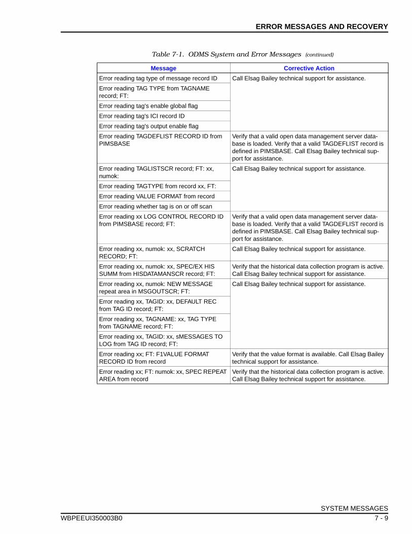
ERROR MESSAGES AND RECOVERY
WBPEEUI
Error reading tag type of message record ID Call Elsag Bailey technical support for assistance.
Error reading TAG TYPE from TAGNAME record; FT:
Error reading tag's enable global flag
Error reading tag's ICI record ID
Error reading tag's output enable flag
Error reading TAGDEFLIST RECORD ID from PIMSBASE
Verify that a valid open data management server data-base is loaded. Verify that a valid TAGDEFLIST record is defined in PIMSBASE. Call Elsag Bailey technical sup-port for assistance.
Error reading TAGLISTSCR record; FT: xx, numok:
Call Elsag Bailey technical support for assistance.
Error reading TAGTYPE from record xx, FT:
Error reading VALUE FORMAT from record
Error reading whether tag is on or off scan
Error reading xx LOG CONTROL RECORD ID from PIMSBASE record; FT:
Verify that a valid open data management server data-base is loaded. Verify that a valid TAGDEFLIST record is defined in PIMSBASE. Call Elsag Bailey technical sup-port for assistance.
Error reading xx, numok: xx, SCRATCH RECORD; FT:
Call Elsag Bailey technical support for assistance.
Error reading xx, numok: xx, SPEC/EX HIS SUMM from HISDATAMANSCR record; FT:
Verify that the historical data collection program is active. Call Elsag Bailey technical support for assistance.
Error reading xx, numok: NEW MESSAGE repeat area in MSGOUTSCR; FT:
Call Elsag Bailey technical support for assistance.
Error reading xx, TAGID: xx, DEFAULT REC from TAG ID record; FT:
Error reading xx, TAGNAME: xx, TAG TYPE from TAGNAME record; FT:
Error reading xx, TAGID: xx, sMESSAGES TO LOG from TAG ID record; FT:
Error reading xx; FT: F1VALUE FORMAT RECORD ID from record
Verify that the value format is available. Call Elsag Bailey technical support for assistance.
Error reading xx; FT: numok: xx, SPEC REPEAT AREA from record
Verify that the historical data collection program is active. Call Elsag Bailey technical support for assistance.
Table 7-1. ODMS System and Error Messages (continued)
Message Corrective Action
SYSTEM MESSAGES
350003B0 7 - 9
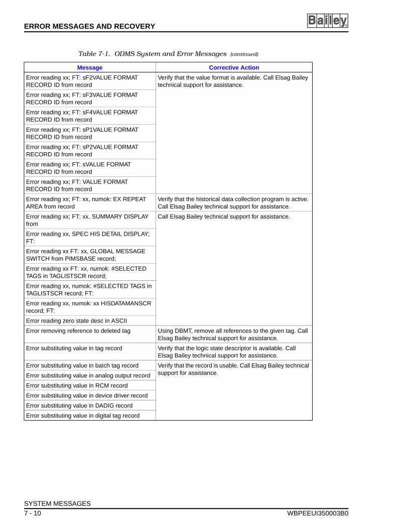
ERROR MESSAGES AND RECOVERY ®
Error reading xx; FT: sF2VALUE FORMAT RECORD ID from record
Verify that the value format is available. Call Elsag Bailey technical support for assistance.
Error reading xx; FT: sF3VALUE FORMAT RECORD ID from record
Error reading xx; FT: sF4VALUE FORMAT RECORD ID from record
Error reading xx; FT: sP1VALUE FORMAT RECORD ID from record
Error reading xx; FT: sP2VALUE FORMAT RECORD ID from record
Error reading xx; FT: sVALUE FORMAT RECORD ID from record
Error reading xx; FT: VALUE FORMAT RECORD ID from record
Error reading xx; FT: xx, numok: EX REPEAT AREA from record
Verify that the historical data collection program is active. Call Elsag Bailey technical support for assistance.
Error reading xx; FT: xx, SUMMARY DISPLAY from
Call Elsag Bailey technical support for assistance.
Error reading xx, SPEC HIS DETAIL DISPLAY; FT:
Error reading xx FT: xx, GLOBAL MESSAGE SWITCH from PIMSBASE record;
Error reading xx FT: xx, numok: #SELECTED TAGS in TAGLISTSCR record;
Error reading xx, numok: #SELECTED TAGS in TAGLISTSCR record; FT:
Error reading xx, numok: xx HISDATAMANSCR record; FT:
Error reading zero state desc in ASCII
Error removing reference to deleted tag Using DBMT, remove all references to the given tag. Call Elsag Bailey technical support for assistance.
Error substituting value in tag record Verify that the logic state descriptor is available. Call Elsag Bailey technical support for assistance.
Error substituting value in batch tag record Verify that the record is usable. Call Elsag Bailey technical support for assistance.Error substituting value in analog output record
Error substituting value in RCM record
Error substituting value in device driver record
Error substituting value in DADIG record
Error substituting value in digital tag record
Table 7-1. ODMS System and Error Messages (continued)
Message Corrective Action
SYSTEM MESSAGES
7 - 10 WBPEEUI350003B0
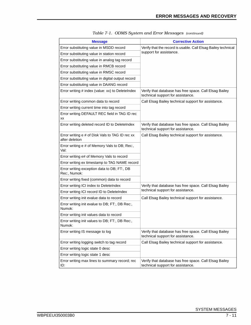
ERROR MESSAGES AND RECOVERY
WBPEEUI
Error substituting value in MSDD record Verify that the record is usable. Call Elsag Bailey technical support for assistance.Error substituting value in station record
Error substituting value in analog tag record
Error substituting value in RMCB record
Error substituting value in RMSC record
Error substituting value in digital output record
Error substituting value in DAANG record
Error writing # index (value: xx) to DeleteIndex Verify that database has free space. Call Elsag Bailey technical support for assistance.
Error writing common data to record Call Elsag Bailey technical support for assistance.
Error writing current time into tag record
Error writing DEFAULT REC field in TAG ID rec xx
Error writing deleted record ID to DeleteIndex Verify that database has free space. Call Elsag Bailey technical support for assistance.
Error writing e # of Disk Vals to TAG ID rec xx after deletion
Call Elsag Bailey technical support for assistance.
Error writing e # of Memory Vals to DB; Rec:, Val:
Error writing e# of Memory Vals to record
Error writing ex timestamp to TAG NAME record
Error writing exception data to DB; FT:, DB Rec:, Numok:
Error writing fixed (common) data to record
Error writing ICI index to DeleteIndex Verify that database has free space. Call Elsag Bailey technical support for assistance.Error writing ICI record ID to DeleteIndex
Error writing init evalue data to record Call Elsag Bailey technical support for assistance.
Error writing init evalue to DB; FT:, DB Rec:, Numok:
Error writing init values data to record
Error writing init values to DB; FT:, DB Rec:, Numok:
Error writing IS message to log Verify that database has free space. Call Elsag Bailey technical support for assistance.
Error writing logging switch to tag record Call Elsag Bailey technical support for assistance.
Error writing logic state 0 desc
Error writing logic state 1 desc
Error writing max lines to summary record; rec ID:
Verify that database has free space. Call Elsag Bailey technical support for assistance.
Table 7-1. ODMS System and Error Messages (continued)
Message Corrective Action
SYSTEM MESSAGES
350003B0 7 - 11
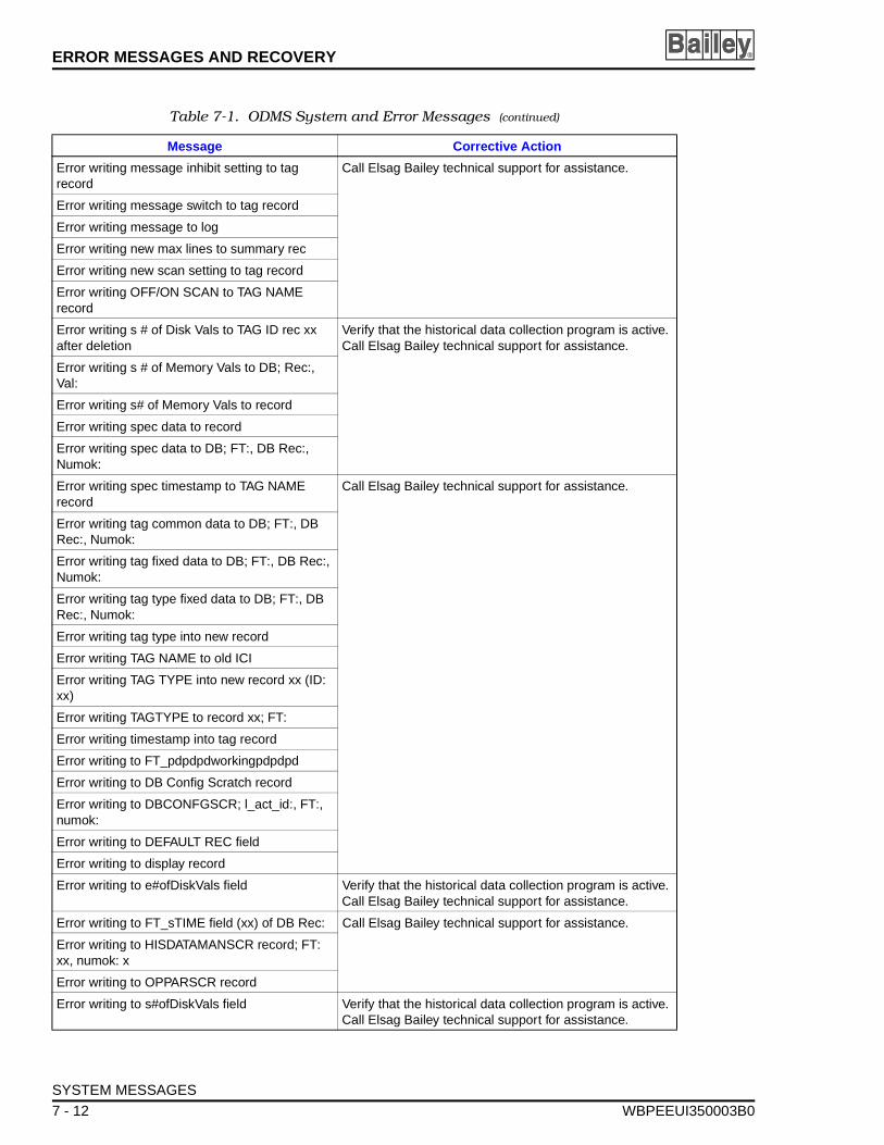
ERROR MESSAGES AND RECOVERY ®
Error writing message inhibit setting to tag record
Call Elsag Bailey technical support for assistance.
Error writing message switch to tag record
Error writing message to log
Error writing new max lines to summary rec
Error writing new scan setting to tag record
Error writing OFF/ON SCAN to TAG NAME record
Error writing s # of Disk Vals to TAG ID rec xx after deletion
Verify that the historical data collection program is active. Call Elsag Bailey technical support for assistance.
Error writing s # of Memory Vals to DB; Rec:, Val:
Error writing s# of Memory Vals to record
Error writing spec data to record
Error writing spec data to DB; FT:, DB Rec:, Numok:
Error writing spec timestamp to TAG NAME record
Call Elsag Bailey technical support for assistance.
Error writing tag common data to DB; FT:, DB Rec:, Numok:
Error writing tag fixed data to DB; FT:, DB Rec:, Numok:
Error writing tag type fixed data to DB; FT:, DB Rec:, Numok:
Error writing tag type into new record
Error writing TAG NAME to old ICI
Error writing TAG TYPE into new record xx (ID: xx)
Error writing TAGTYPE to record xx; FT:
Error writing timestamp into tag record
Error writing to FT_pdpdpdworkingpdpdpd
Error writing to DB Config Scratch record
Error writing to DBCONFGSCR; l_act_id:, FT:, numok:
Error writing to DEFAULT REC field
Error writing to display record
Error writing to e#ofDiskVals field Verify that the historical data collection program is active. Call Elsag Bailey technical support for assistance.
Error writing to FT_sTIME field (xx) of DB Rec: Call Elsag Bailey technical support for assistance.
Error writing to HISDATAMANSCR record; FT: xx, numok: x
Error writing to OPPARSCR record
Error writing to s#ofDiskVals field Verify that the historical data collection program is active. Call Elsag Bailey technical support for assistance.
Table 7-1. ODMS System and Error Messages (continued)
Message Corrective Action
SYSTEM MESSAGES
7 - 12 WBPEEUI350003B0
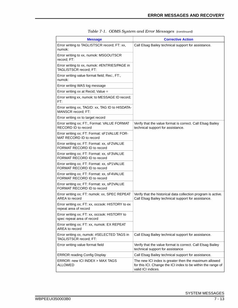
ERROR MESSAGES AND RECOVERY
WBPEEUI
Error writing to TAGLISTSCR record; FT: xx, numok:
Call Elsag Bailey technical support for assistance.
Error writing to xx, numok: MSGOUTSCR record; FT:
Error writing to xx, numok: #ENTRIES/PAGE in TAGLISTSCR record; FT:
Error writing value format field; Rec:, FT:, numok:
Error writing WAS log message
Error writing xx at Recid; Value =
Error writing xx, numok: to MESSAGE ID record; FT:
Error writing xx, TAGID: xx, TAG ID to HISDATA-MANSCR record; FT:
Error writing xx to target record
Error writing xx; FT:, Format: VALUE FORMAT RECORD ID to record
Verify that the value format is correct. Call Elsag Bailey technical support for assistance.
Error writing xx; FT: Format: sF1VALUE FOR-MAT RECORD ID to record
Error writing xx; FT: Format: xx, sF2VALUE FORMAT RECORD ID to record
Error writing xx; FT: Format: xx, sF3VALUE FORMAT RECORD ID to record
Error writing xx; FT: Format: xx, sP1VALUE FORMAT RECORD ID to record
Error writing xx; FT: Format: xx, sF4VALUE FORMAT RECORD ID to record
Error writing xx; FT: Format: xx, sP2VALUE FORMAT RECORD ID to record
Error writing xx; FT: numok: xx, SPEC REPEAT AREA to record
Verify that the historical data collection program is active. Call Elsag Bailey technical support for assistance.
Error writing xx; FT: xx, occsok: HISTORY to ex repeat area of record
Error writing xx; FT: xx, occsok: HISTORY to spec repeat area of record
Error writing xx; FT: xx, numok: EX REPEAT AREA to record
Error writing xx, numok: #SELECTED TAGS in TAGLISTSCR record; FT:
Call Elsag Bailey technical support for assistance.
Error writing value format field Verify that the value format is correct. Call Elsag Bailey technical support for assistance
ERROR reading Config Display Call Elsag Bailey technical support for assistance.
ERROR: new ICI INDEX > MAX TAGS ALLOWED
The new ICI index is greater then the maximum allowed for this ICI. Change the ICI index to be within the range of valid ICI indices.
Table 7-1. ODMS System and Error Messages (continued)
Message Corrective Action
SYSTEM MESSAGES
350003B0 7 - 13
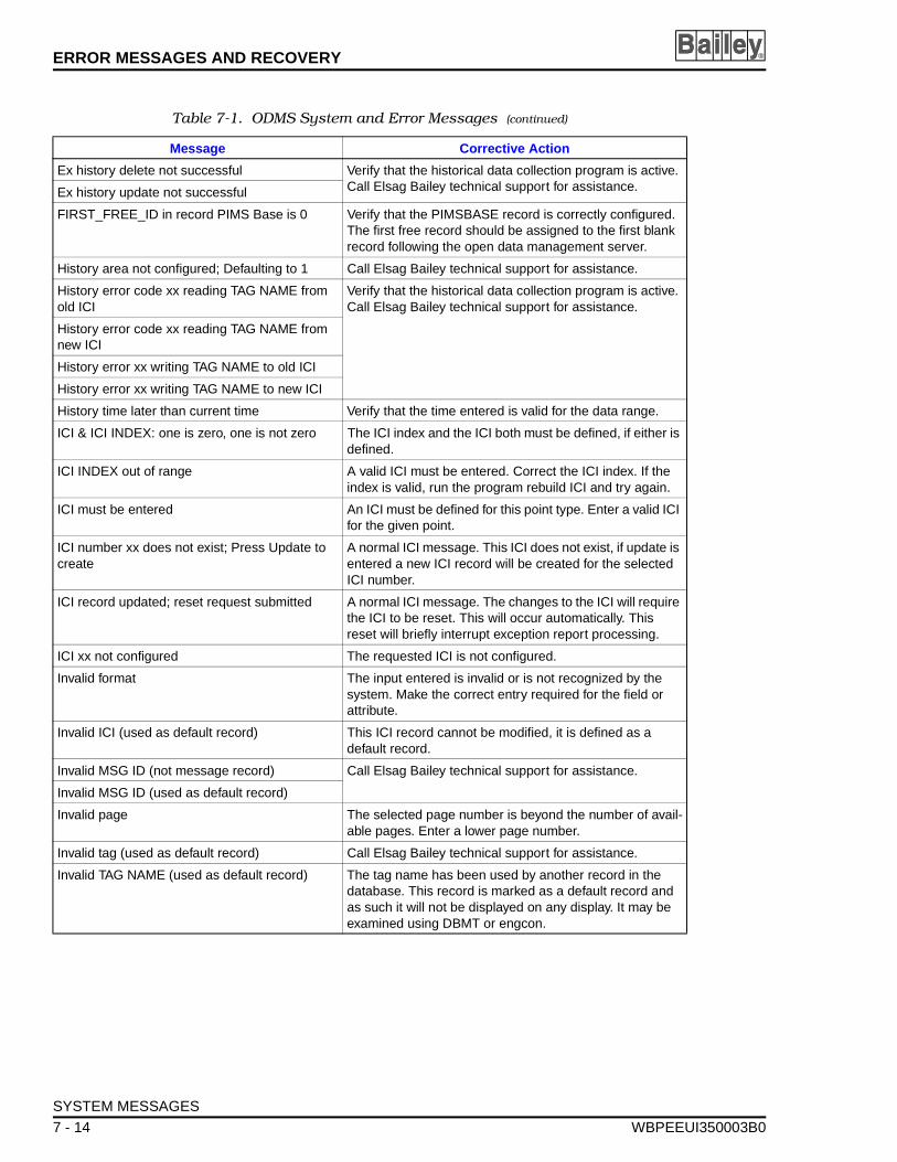
ERROR MESSAGES AND RECOVERY ®
Ex history delete not successful Verify that the historical data collection program is active. Call Elsag Bailey technical support for assistance.Ex history update not successful
FIRST_FREE_ID in record PIMS Base is 0 Verify that the PIMSBASE record is correctly configured. The first free record should be assigned to the first blank record following the open data management server.
History area not configured; Defaulting to 1 Call Elsag Bailey technical support for assistance.
History error code xx reading TAG NAME from old ICI
Verify that the historical data collection program is active. Call Elsag Bailey technical support for assistance.
History error code xx reading TAG NAME from new ICI
History error xx writing TAG NAME to old ICI
History error xx writing TAG NAME to new ICI
History time later than current time Verify that the time entered is valid for the data range.
ICI & ICI INDEX: one is zero, one is not zero The ICI index and the ICI both must be defined, if either is defined.
ICI INDEX out of range A valid ICI must be entered. Correct the ICI index. If the index is valid, run the program rebuild ICI and try again.
ICI must be entered An ICI must be defined for this point type. Enter a valid ICI for the given point.
ICI number xx does not exist; Press Update to create
A normal ICI message. This ICI does not exist, if update is entered a new ICI record will be created for the selected ICI number.
ICI record updated; reset request submitted A normal ICI message. The changes to the ICI will require the ICI to be reset. This will occur automatically. This reset will briefly interrupt exception report processing.
ICI xx not configured The requested ICI is not configured.
Invalid format The input entered is invalid or is not recognized by the system. Make the correct entry required for the field or attribute.
Invalid ICI (used as default record) This ICI record cannot be modified, it is defined as a default record.
Invalid MSG ID (not message record) Call Elsag Bailey technical support for assistance.
Invalid MSG ID (used as default record)
Invalid page The selected page number is beyond the number of avail-able pages. Enter a lower page number.
Invalid tag (used as default record) Call Elsag Bailey technical support for assistance.
Invalid TAG NAME (used as default record) The tag name has been used by another record in the database. This record is marked as a default record and as such it will not be displayed on any display. It may be examined using DBMT or engcon.
Table 7-1. ODMS System and Error Messages (continued)
Message Corrective Action
SYSTEM MESSAGES
7 - 14 WBPEEUI350003B0
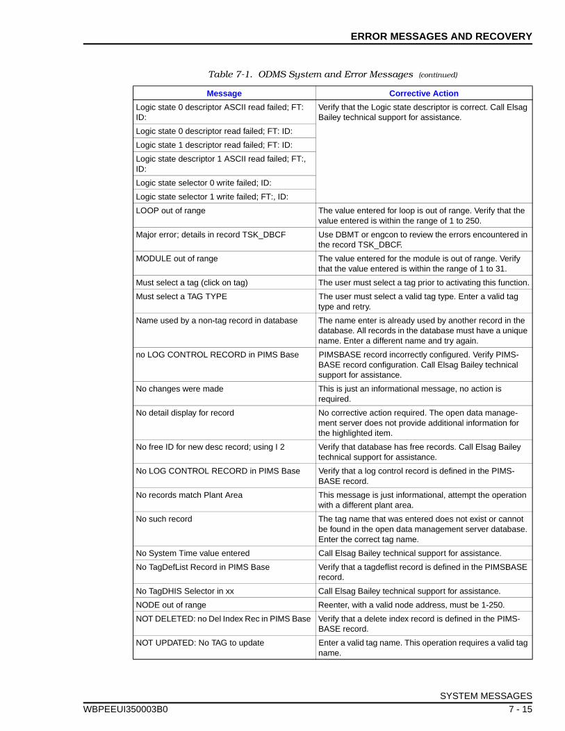
ERROR MESSAGES AND RECOVERY
WBPEEUI
Logic state 0 descriptor ASCII read failed; FT: ID:
Verify that the Logic state descriptor is correct. Call Elsag Bailey technical support for assistance.
Logic state 0 descriptor read failed; FT: ID:
Logic state 1 descriptor read failed; FT: ID:
Logic state descriptor 1 ASCII read failed; FT:, ID:
Logic state selector 0 write failed; ID:
Logic state selector 1 write failed; FT:, ID:
LOOP out of range The value entered for loop is out of range. Verify that the value entered is within the range of 1 to 250.
Major error; details in record TSK_DBCF Use DBMT or engcon to review the errors encountered in the record TSK_DBCF.
MODULE out of range The value entered for the module is out of range. Verify that the value entered is within the range of 1 to 31.
Must select a tag (click on tag) The user must select a tag prior to activating this function.
Must select a TAG TYPE The user must select a valid tag type. Enter a valid tag type and retry.
Name used by a non-tag record in database The name enter is already used by another record in the database. All records in the database must have a unique name. Enter a different name and try again.
no LOG CONTROL RECORD in PIMS Base PIMSBASE record incorrectly configured. Verify PIMS-BASE record configuration. Call Elsag Bailey technical support for assistance.
No changes were made This is just an informational message, no action is required.
No detail display for record No corrective action required. The open data manage-ment server does not provide additional information for the highlighted item.
No free ID for new desc record; using I 2 Verify that database has free records. Call Elsag Bailey technical support for assistance.
No LOG CONTROL RECORD in PIMS Base Verify that a log control record is defined in the PIMS-BASE record.
No records match Plant Area This message is just informational, attempt the operation with a different plant area.
No such record The tag name that was entered does not exist or cannot be found in the open data management server database. Enter the correct tag name.
No System Time value entered Call Elsag Bailey technical support for assistance.
No TagDefList Record in PIMS Base Verify that a tagdeflist record is defined in the PIMSBASE record.
No TagDHIS Selector in xx Call Elsag Bailey technical support for assistance.
NODE out of range Reenter, with a valid node address, must be 1-250.
NOT DELETED: no Del Index Rec in PIMS Base Verify that a delete index record is defined in the PIMS-BASE record.
NOT UPDATED: No TAG to update Enter a valid tag name. This operation requires a valid tag name.
Table 7-1. ODMS System and Error Messages (continued)
Message Corrective Action
SYSTEM MESSAGES
350003B0 7 - 15
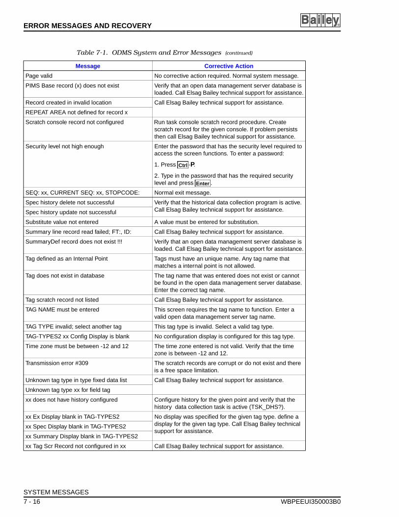
ERROR MESSAGES AND RECOVERY ®
Page valid No corrective action required. Normal system message.
PIMS Base record (x) does not exist Verify that an open data management server database is loaded. Call Elsag Bailey technical support for assistance.
Record created in invalid location Call Elsag Bailey technical support for assistance.
REPEAT AREA not defined for record x
Scratch console record not configured Run task console scratch record procedure. Create scratch record for the given console. If problem persists then call Elsag Bailey technical support for assistance.
Security level not high enough Enter the password that has the security level required to access the screen functions. To enter a password:
1. Press -P.
2. Type in the password that has the required security level and press .
SEQ: xx, CURRENT SEQ: xx, STOPCODE: Normal exit message.
Spec history delete not successful Verify that the historical data collection program is active. Call Elsag Bailey technical support for assistance.Spec history update not successful
Substitute value not entered A value must be entered for substitution.
Summary line record read failed; FT:, ID: Call Elsag Bailey technical support for assistance.
SummaryDef record does not exist !!! Verify that an open data management server database is loaded. Call Elsag Bailey technical support for assistance.
Tag defined as an Internal Point Tags must have an unique name. Any tag name that matches a internal point is not allowed.
Tag does not exist in database The tag name that was entered does not exist or cannot be found in the open data management server database. Enter the correct tag name.
Tag scratch record not listed Call Elsag Bailey technical support for assistance.
TAG NAME must be entered This screen requires the tag name to function. Enter a valid open data management server tag name.
TAG TYPE invalid; select another tag This tag type is invalid. Select a valid tag type.
TAG-TYPES2 xx Config Display is blank No configuration display is configured for this tag type.
Time zone must be between -12 and 12 The time zone entered is not valid. Verify that the time zone is between -12 and 12.
Transmission error #309 The scratch records are corrupt or do not exist and there is a free space limitation.
Unknown tag type in type fixed data list Call Elsag Bailey technical support for assistance.
Unknown tag type xx for field tag
xx does not have history configured Configure history for the given point and verify that the history data collection task is active (TSK_DHS?).
xx Ex Display blank in TAG-TYPES2 No display was specified for the given tag type. define a display for the given tag type. Call Elsag Bailey technical support for assistance.
xx Spec Display blank in TAG-TYPES2
xx Summary Display blank in TAG-TYPES2
xx Tag Scr Record not configured in xx Call Elsag Bailey technical support for assistance.
Table 7-1. ODMS System and Error Messages (continued)
Message Corrective Action
Ctrl
Enter
SYSTEM MESSAGES
7 - 16 WBPEEUI350003B0
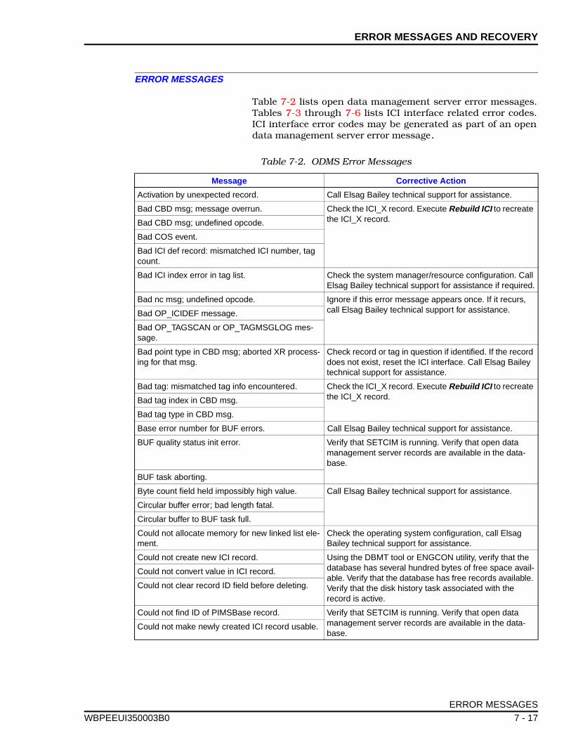
ERROR MESSAGES AND RECOVERY
WBPEEUI
ERROR MESSAGES
Table 7-2 lists open data management server error messages.Tables 7-3 through 7-6 lists ICI interface related error codes.ICI interface error codes may be generated as part of an opendata management server error message.
Table 7-2. ODMS Error Messages
Message Corrective Action
Activation by unexpected record. Call Elsag Bailey technical support for assistance.
Bad CBD msg; message overrun. Check the ICI_X record. Execute Rebuild ICI to recreate the ICI_X record.Bad CBD msg; undefined opcode.
Bad COS event.
Bad ICI def record: mismatched ICI number, tag count.
Bad ICI index error in tag list. Check the system manager/resource configuration. Call Elsag Bailey technical support for assistance if required.
Bad nc msg; undefined opcode. Ignore if this error message appears once. If it recurs, call Elsag Bailey technical support for assistance.Bad OP_ICIDEF message.
Bad OP_TAGSCAN or OP_TAGMSGLOG mes-sage.
Bad point type in CBD msg; aborted XR process-ing for that msg.
Check record or tag in question if identified. If the record does not exist, reset the ICI interface. Call Elsag Bailey technical support for assistance.
Bad tag: mismatched tag info encountered. Check the ICI_X record. Execute Rebuild ICI to recreate the ICI_X record.Bad tag index in CBD msg.
Bad tag type in CBD msg.
Base error number for BUF errors. Call Elsag Bailey technical support for assistance.
BUF quality status init error. Verify that SETCIM is running. Verify that open data management server records are available in the data-base.
BUF task aborting.
Byte count field held impossibly high value. Call Elsag Bailey technical support for assistance.
Circular buffer error; bad length fatal.
Circular buffer to BUF task full.
Could not allocate memory for new linked list ele-ment.
Check the operating system configuration, call Elsag Bailey technical support for assistance.
Could not create new ICI record. Using the DBMT tool or ENGCON utility, verify that the database has several hundred bytes of free space avail-able. Verify that the database has free records available. Verify that the disk history task associated with the record is active.
Could not convert value in ICI record.
Could not clear record ID field before deleting.
Could not find ID of PIMSBase record. Verify that SETCIM is running. Verify that open data management server records are available in the data-base.
Could not make newly created ICI record usable.
ERROR MESSAGES
350003B0 7 - 17
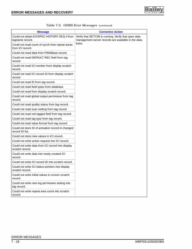
ERROR MESSAGES AND RECOVERY ®
Could not obtain EX/SPEC HISTORY SEQ # from tagname record.
Verify that SETCIM is running. Verify that open data management server records are available in the data-base.Could not read count of synch time repeat areas
from ICI record.
Could not read data from PIMSBase record.
Could not read DEFAULT REC field from tag record.
Could not read ICI number from display scratch record.
Could not read ICI record ID from display scratch record.
Could not read ID from tag record.
Could not read field types from database.
Could not read from display scratch record.
Could not read global output permissive from tag record.
Could not read quality status from tag record.
Could not read scan setting from tag record.
Could not read red tagged field from tag record.
Could not read tag type from tag record.
Could not read value format from tag record.
Could not store ID of activation record in changed record ID list.
Could not store new values in ICI record.
Could not write action request into ICI record.
Could not write data from ICI record into display scratch record.
Could not write data into newly created ICI record.
Could not write ICI record ID into scratch record.
Could not write ICI status pointers into display scratch record.
Could not write initial values to screen scratch record.
Could not write new log permissive setting into tag record.
Could not write repeat area count into scratch record.
Table 7-2. ODMS Error Messages (continued)
Message Corrective Action
ERROR MESSAGES
7 - 18 WBPEEUI350003B0
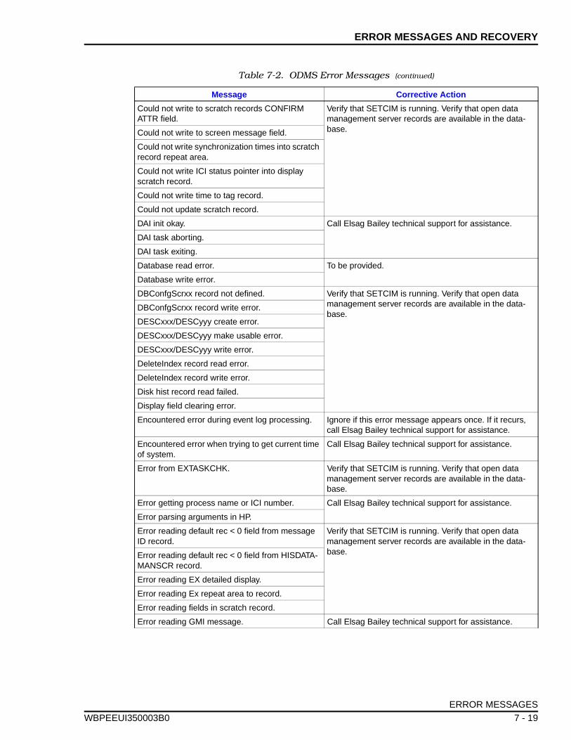
ERROR MESSAGES AND RECOVERY
WBPEEUI
Could not write to scratch records CONFIRM ATTR field.
Verify that SETCIM is running. Verify that open data management server records are available in the data-base.Could not write to screen message field.
Could not write synchronization times into scratch record repeat area.
Could not write ICI status pointer into display scratch record.
Could not write time to tag record.
Could not update scratch record.
DAI init okay. Call Elsag Bailey technical support for assistance.
DAI task aborting.
DAI task exiting.
Database read error. To be provided.
Database write error.
DBConfgScrxx record not defined. Verify that SETCIM is running. Verify that open data management server records are available in the data-base.
DBConfgScrxx record write error.
DESCxxx/DESCyyy create error.
DESCxxx/DESCyyy make usable error.
DESCxxx/DESCyyy write error.
DeleteIndex record read error.
DeleteIndex record write error.
Disk hist record read failed.
Display field clearing error.
Encountered error during event log processing. Ignore if this error message appears once. If it recurs, call Elsag Bailey technical support for assistance.
Encountered error when trying to get current time of system.
Call Elsag Bailey technical support for assistance.
Error from EXTASKCHK. Verify that SETCIM is running. Verify that open data management server records are available in the data-base.
Error getting process name or ICI number. Call Elsag Bailey technical support for assistance.
Error parsing arguments in HP.
Error reading default rec < 0 field from message ID record.
Verify that SETCIM is running. Verify that open data management server records are available in the data-base.Error reading default rec < 0 field from HISDATA-
MANSCR record.
Error reading EX detailed display.
Error reading Ex repeat area to record.
Error reading fields in scratch record.
Error reading GMI message. Call Elsag Bailey technical support for assistance.
Table 7-2. ODMS Error Messages (continued)
Message Corrective Action
ERROR MESSAGES
350003B0 7 - 19
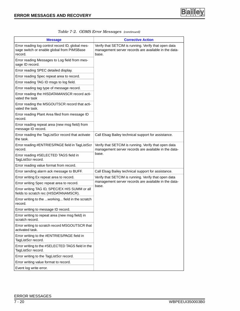
ERROR MESSAGES AND RECOVERY ®
Error reading log control record ID, global mes-sage switch or enable global from PIMSBase record.
Verify that SETCIM is running. Verify that open data management server records are available in the data-base.
Error reading Messages to Log field from mes-sage ID record.
Error reading SPEC detailed display.
Error reading Spec repeat area to record.
Error reading TAG ID msgs to log field.
Error reading tag type of message record.
Error reading the HISDATAMANSCR record acti-vated the task
Error reading the MSGOUTSCR record that acti-vated the task.
Error reading Plant Area filed from message ID record.
Error reading repeat area (new msg field) from message ID record.
Error reading the TagListScr record that activate the task.
Call Elsag Bailey technical support for assistance.
Error reading #ENTRIES/PAGE field in TagListScr record.
Verify that SETCIM is running. Verify that open data management server records are available in the data-base.Error reading #SELECTED TAGS field in
TagListScr record.
Error reading value format from record.
Error sending alarm ack message to BUFF. Call Elsag Bailey technical support for assistance.
Error writing Ex repeat area to record. Verify that SETCIM is running. Verify that open data management server records are available in the data-base.
Error writing Spec repeat area to record.
Error writing TAG ID, SPEC/EX HIS SUMM or all fields to scratch rec (HISDATANAMSCR).
Error writing to the ...working... field in the scratch record.
Error writing to message ID record.
Error writing to repeat area (new msg field) in scratch record.
Error writing to scratch record MSGOUTSCR that activated task.
Error writing to the #ENTRIES/PAGE field in TagListScr record.
Error writing to the #SELECTED TAGS field in the TagListScr record.
Error writing to the TagListScr record.
Error writing value format to record.
Event log write error.
Table 7-2. ODMS Error Messages (continued)
Message Corrective Action
ERROR MESSAGES
7 - 20 WBPEEUI350003B0
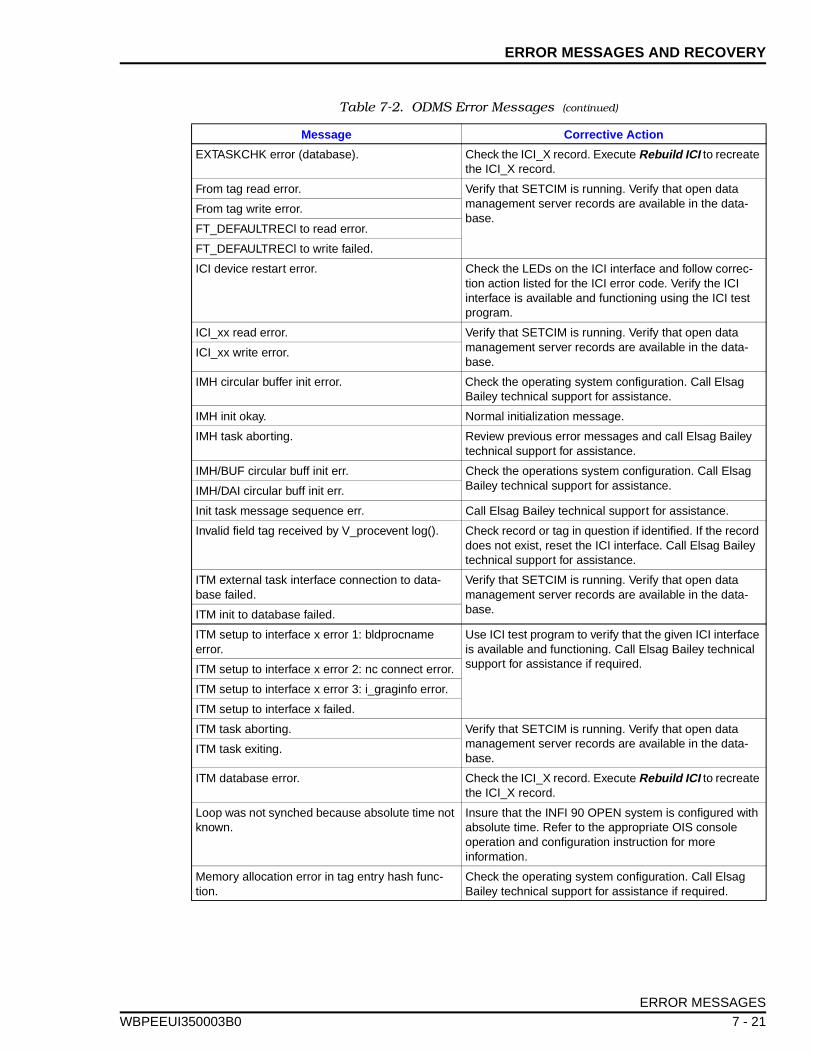
ERROR MESSAGES AND RECOVERY
WBPEEUI
EXTASKCHK error (database). Check the ICI_X record. Execute Rebuild ICI to recreate the ICI_X record.
From tag read error. Verify that SETCIM is running. Verify that open data management server records are available in the data-base.
From tag write error.
FT_DEFAULTRECl to read error.
FT_DEFAULTRECl to write failed.
ICI device restart error. Check the LEDs on the ICI interface and follow correc-tion action listed for the ICI error code. Verify the ICI interface is available and functioning using the ICI test program.
ICI_xx read error. Verify that SETCIM is running. Verify that open data management server records are available in the data-base.
ICI_xx write error.
IMH circular buffer init error. Check the operating system configuration. Call Elsag Bailey technical support for assistance.
IMH init okay. Normal initialization message.
IMH task aborting. Review previous error messages and call Elsag Bailey technical support for assistance.
IMH/BUF circular buff init err. Check the operations system configuration. Call Elsag Bailey technical support for assistance.IMH/DAI circular buff init err.
Init task message sequence err. Call Elsag Bailey technical support for assistance.
Invalid field tag received by V_procevent log(). Check record or tag in question if identified. If the record does not exist, reset the ICI interface. Call Elsag Bailey technical support for assistance.
ITM external task interface connection to data-base failed.
Verify that SETCIM is running. Verify that open data management server records are available in the data-base.ITM init to database failed.
ITM setup to interface x error 1: bldprocname error.
Use ICI test program to verify that the given ICI interface is available and functioning. Call Elsag Bailey technical support for assistance if required.ITM setup to interface x error 2: nc connect error.
ITM setup to interface x error 3: i_graginfo error.
ITM setup to interface x failed.
ITM task aborting. Verify that SETCIM is running. Verify that open data management server records are available in the data-base.
ITM task exiting.
ITM database error. Check the ICI_X record. Execute Rebuild ICI to recreate the ICI_X record.
Loop was not synched because absolute time not known.
Insure that the INFI 90 OPEN system is configured with absolute time. Refer to the appropriate OIS console operation and configuration instruction for more information.
Memory allocation error in tag entry hash func-tion.
Check the operating system configuration. Call Elsag Bailey technical support for assistance if required.
Table 7-2. ODMS Error Messages (continued)
Message Corrective Action
ERROR MESSAGES
350003B0 7 - 21
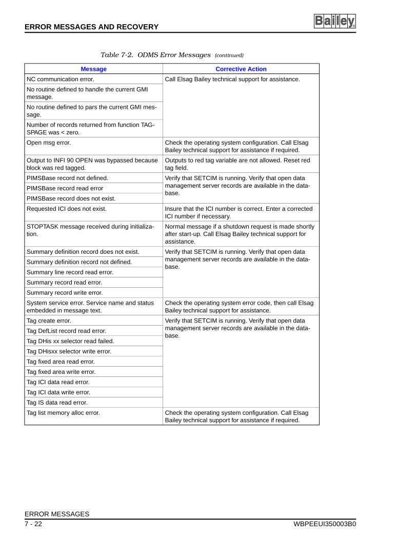
ERROR MESSAGES AND RECOVERY ®
NC communication error. Call Elsag Bailey technical support for assistance.
No routine defined to handle the current GMI message.
No routine defined to pars the current GMI mes-sage.
Number of records returned from function TAG-SPAGE was < zero.
Open msg error. Check the operating system configuration. Call Elsag Bailey technical support for assistance if required.
Output to INFI 90 OPEN was bypassed because block was red tagged.
Outputs to red tag variable are not allowed. Reset red tag field.
PIMSBase record not defined. Verify that SETCIM is running. Verify that open data management server records are available in the data-base.
PIMSBase record read error
PIMSBase record does not exist.
Requested ICI does not exist. Insure that the ICI number is correct. Enter a corrected ICI number if necessary.
STOPTASK message received during initializa-tion.
Normal message if a shutdown request is made shortly after start-up. Call Elsag Bailey technical support for assistance.
Summary definition record does not exist. Verify that SETCIM is running. Verify that open data management server records are available in the data-base.
Summary definition record not defined.
Summary line record read error.
Summary record read error.
Summary record write error.
System service error. Service name and status embedded in message text.
Check the operating system error code, then call Elsag Bailey technical support for assistance.
Tag create error. Verify that SETCIM is running. Verify that open data management server records are available in the data-base.
Tag DefList record read error.
Tag DHis xx selector read failed.
Tag DHisxx selector write error.
Tag fixed area read error.
Tag fixed area write error.
Tag ICI data read error.
Tag ICI data write error.
Tag IS data read error.
Tag list memory alloc error. Check the operating system configuration. Call Elsag Bailey technical support for assistance if required.
Table 7-2. ODMS Error Messages (continued)
Message Corrective Action
ERROR MESSAGES
7 - 22 WBPEEUI350003B0
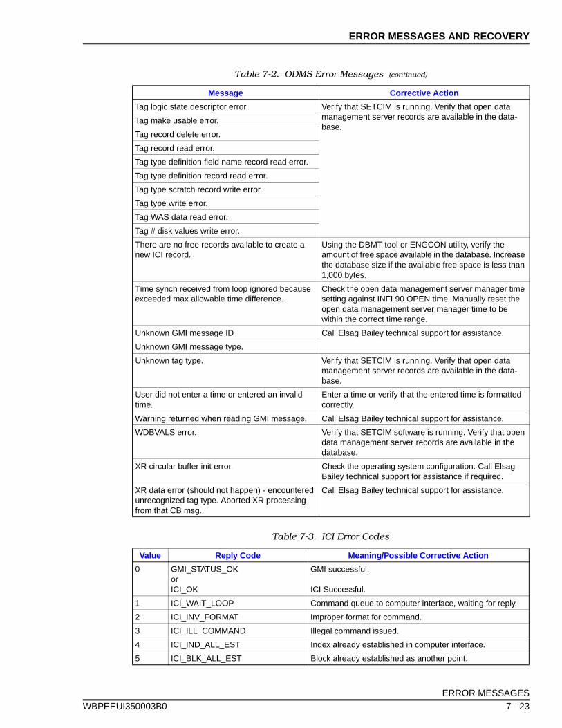
ERROR MESSAGES AND RECOVERY
WBPEEUI
Tag logic state descriptor error. Verify that SETCIM is running. Verify that open data management server records are available in the data-base.
Tag make usable error.
Tag record delete error.
Tag record read error.
Tag type definition field name record read error.
Tag type definition record read error.
Tag type scratch record write error.
Tag type write error.
Tag WAS data read error.
Tag # disk values write error.
There are no free records available to create a new ICI record.
Using the DBMT tool or ENGCON utility, verify the amount of free space available in the database. Increase the database size if the available free space is less than 1,000 bytes.
Time synch received from loop ignored because exceeded max allowable time difference.
Check the open data management server manager time setting against INFI 90 OPEN time. Manually reset the open data management server manager time to be within the correct time range.
Unknown GMI message ID Call Elsag Bailey technical support for assistance.
Unknown GMI message type.
Unknown tag type. Verify that SETCIM is running. Verify that open data management server records are available in the data-base.
User did not enter a time or entered an invalid time.
Enter a time or verify that the entered time is formatted correctly.
Warning returned when reading GMI message. Call Elsag Bailey technical support for assistance.
WDBVALS error. Verify that SETCIM software is running. Verify that open data management server records are available in the database.
XR circular buffer init error. Check the operating system configuration. Call Elsag Bailey technical support for assistance if required.
XR data error (should not happen) - encountered unrecognized tag type. Aborted XR processing from that CB msg.
Call Elsag Bailey technical support for assistance.
Table 7-3. ICI Error Codes
Value Reply Code Meaning/Possible Corrective Action
0 GMI_STATUS_OKorICI_OK
GMI successful.
ICI Successful.
1 ICI_WAIT_LOOP Command queue to computer interface, waiting for reply.
2 ICI_INV_FORMAT Improper format for command.
3 ICI_ILL_COMMAND Illegal command issued.
4 ICI_IND_ALL_EST Index already established in computer interface.
5 ICI_BLK_ALL_EST Block already established as another point.
Table 7-2. ODMS Error Messages (continued)
Message Corrective Action
ERROR MESSAGES
350003B0 7 - 23
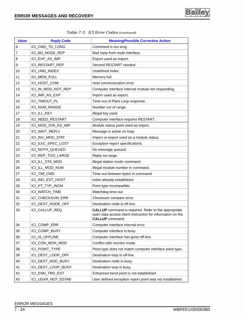
ERROR MESSAGES AND RECOVERY ®
6 ICI_CMD_TO_LONG Command is too long.
7 ICI_BD_NODE_REP Bad reply from node interface.
8 ICI_EXP_AS_IMP Export used as import.
9 ICI_RESTART_REP Second RESTART needed.
10 ICI_UND_INDEX Undefined index.
11 ICI_MEM_FULL Memory full.
12 ICI_HOST_COM Host communication error.
13 ICI_IN_MOD_NOT_REP Computer interface internal module not responding.
14 ICI_IMP_AS_EXP Import used as export.
15 ICI_TIMOUT_PL Time-out of Plant Loop response.
16 ICI_NUM_RANGE Number out of range.
17 ICI_ILL_KEY Illegal key used.
18 ICI_NEED_RESTART Computer interface requires RESTART.
19 ICI_MOD_STA_AS_IMP Module status point used as import.
20 ICI_WAIT_REPLY Message is active on loop.
21 ICI_INV_MOD_STAT Import or export used as a module status.
22 ICI_EXC_SPEC_LOST Exception report specifications.
23 ICI_NOTH_QUEUED No message queued.
24 ICI_REP_TOO_LARGE Reply too large.
25 ICI_ILL_STA_MOD Illegal station mode command.
26 ICI_ILL_MOD_NUM Illegal module number in command.
27 ICI_TIM_CMD Time-out between bytes in command.
28 ICI_IND_EST_HOST Index already established.
29 ICI_PT_TYP_INCM Point type incompatible.
30 ICI_WATCH_TIME Watchdog time-out.
31 ICI_CHECKSUM_ERR Checksum compare error.
32 ICI_DEST_NODE_OFF Destination node is off-line.
33 ICI_CALLUP_REQ CALLUP command is required. Refer to the appropriate open data access client instruction for information on the CALLUP command.
34 ICI_COMP_ERR Computer interface internal error.
35 ICI_COMP_BUSY Computer interface is busy.
36 ICI_IS_OFFLINE Computer interface has gone off-line.
37 ICI_CON_MON_MOD Conflict with monitor mode.
38 ICI_POINT_TYPE Point type does not match computer interface point type.
39 ICI_DEST_LOOP_OFF Destination loop is off-line.
40 ICI_DEST_NOD_BUSY Destination node is busy.
41 ICI_DEST_LOOP_BUSY Destination loop is busy.
42 ICI_ENH_TRD_EST Enhanced trend point is not established.
43 ICI_UDXR_NOT_ESTAB User defined exception report point was not established.
Table 7-3. ICI Error Codes (continued)
Value Reply Code Meaning/Possible Corrective Action
ERROR MESSAGES
7 - 24 WBPEEUI350003B0
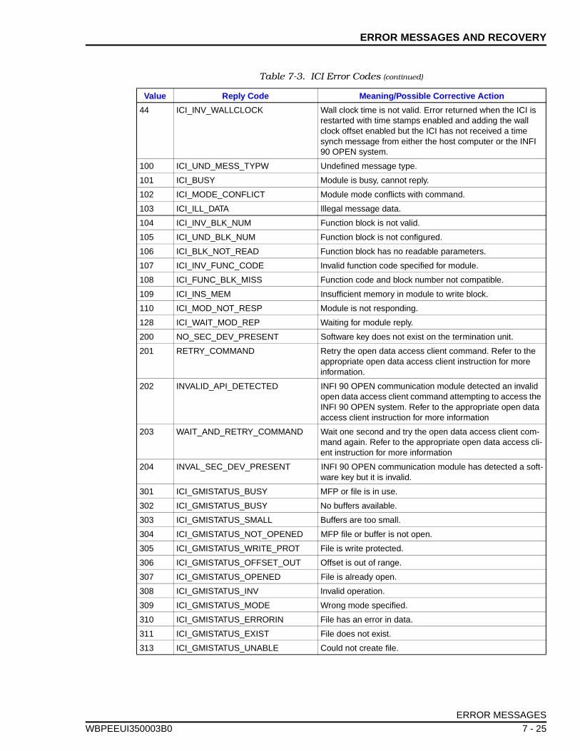
ERROR MESSAGES AND RECOVERY
WBPEEUI
44 ICI_INV_WALLCLOCK Wall clock time is not valid. Error returned when the ICI is restarted with time stamps enabled and adding the wall clock offset enabled but the ICI has not received a time synch message from either the host computer or the INFI 90 OPEN system.
100 ICI_UND_MESS_TYPW Undefined message type.
101 ICI_BUSY Module is busy, cannot reply.
102 ICI_MODE_CONFLICT Module mode conflicts with command.
103 ICI_ILL_DATA Illegal message data.
104 ICI_INV_BLK_NUM Function block is not valid.
105 ICI_UND_BLK_NUM Function block is not configured.
106 ICI_BLK_NOT_READ Function block has no readable parameters.
107 ICI_INV_FUNC_CODE Invalid function code specified for module.
108 ICI_FUNC_BLK_MISS Function code and block number not compatible.
109 ICI_INS_MEM Insufficient memory in module to write block.
110 ICI_MOD_NOT_RESP Module is not responding.
128 ICI_WAIT_MOD_REP Waiting for module reply.
200 NO_SEC_DEV_PRESENT Software key does not exist on the termination unit.
201 RETRY_COMMAND Retry the open data access client command. Refer to the appropriate open data access client instruction for more information.
202 INVALID_API_DETECTED INFI 90 OPEN communication module detected an invalid open data access client command attempting to access the INFI 90 OPEN system. Refer to the appropriate open data access client instruction for more information
203 WAIT_AND_RETRY_COMMAND Wait one second and try the open data access client com-mand again. Refer to the appropriate open data access cli-ent instruction for more information
204 INVAL_SEC_DEV_PRESENT INFI 90 OPEN communication module has detected a soft-ware key but it is invalid.
301 ICI_GMISTATUS_BUSY MFP or file is in use.
302 ICI_GMISTATUS_BUSY No buffers available.
303 ICI_GMISTATUS_SMALL Buffers are too small.
304 ICI_GMISTATUS_NOT_OPENED MFP file or buffer is not open.
305 ICI_GMISTATUS_WRITE_PROT File is write protected.
306 ICI_GMISTATUS_OFFSET_OUT Offset is out of range.
307 ICI_GMISTATUS_OPENED File is already open.
308 ICI_GMISTATUS_INV Invalid operation.
309 ICI_GMISTATUS_MODE Wrong mode specified.
310 ICI_GMISTATUS_ERRORIN File has an error in data.
311 ICI_GMISTATUS_EXIST File does not exist.
313 ICI_GMISTATUS_UNABLE Could not create file.
Table 7-3. ICI Error Codes (continued)
Value Reply Code Meaning/Possible Corrective Action
ERROR MESSAGES
350003B0 7 - 25
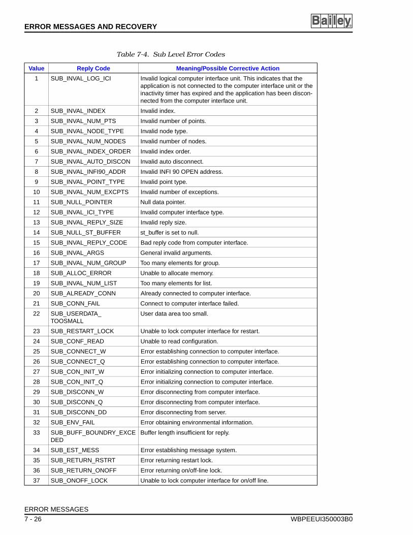
ERROR MESSAGES AND RECOVERY ®
Table 7-4. Sub Level Error Codes
Value Reply Code Meaning/Possible Corrective Action
1 SUB_INVAL_LOG_ICI Invalid logical computer interface unit. This indicates that the application is not connected to the computer interface unit or the inactivity timer has expired and the application has been discon-nected from the computer interface unit.
2 SUB_INVAL_INDEX Invalid index.
3 SUB_INVAL_NUM_PTS Invalid number of points.
4 SUB_INVAL_NODE_TYPE Invalid node type.
5 SUB_INVAL_NUM_NODES Invalid number of nodes.
6 SUB_INVAL_INDEX_ORDER Invalid index order.
7 SUB_INVAL_AUTO_DISCON Invalid auto disconnect.
8 SUB_INVAL_INFI90_ADDR Invalid INFI 90 OPEN address.
9 SUB_INVAL_POINT_TYPE Invalid point type.
10 SUB_INVAL_NUM_EXCPTS Invalid number of exceptions.
11 SUB_NULL_POINTER Null data pointer.
12 SUB_INVAL_ICI_TYPE Invalid computer interface type.
13 SUB_INVAL_REPLY_SIZE Invalid reply size.
14 SUB_NULL_ST_BUFFER st_buffer is set to null.
15 SUB_INVAL_REPLY_CODE Bad reply code from computer interface.
16 SUB_INVAL_ARGS General invalid arguments.
17 SUB_INVAL_NUM_GROUP Too many elements for group.
18 SUB_ALLOC_ERROR Unable to allocate memory.
19 SUB_INVAL_NUM_LIST Too many elements for list.
20 SUB_ALREADY_CONN Already connected to computer interface.
21 SUB_CONN_FAIL Connect to computer interface failed.
22 SUB_USERDATA_TOOSMALL
User data area too small.
23 SUB_RESTART_LOCK Unable to lock computer interface for restart.
24 SUB_CONF_READ Unable to read configuration.
25 SUB_CONNECT_W Error establishing connection to computer interface.
26 SUB_CONNECT_Q Error establishing connection to computer interface.
27 SUB_CON_INIT_W Error initializing connection to computer interface.
28 SUB_CON_INIT_Q Error initializing connection to computer interface.
29 SUB_DISCONN_W Error disconnecting from computer interface.
30 SUB_DISCONN_Q Error disconnecting from computer interface.
31 SUB_DISCONN_DD Error disconnecting from server.
32 SUB_ENV_FAIL Error obtaining environmental information.
33 SUB_BUFF_BOUNDRY_EXCEDED
Buffer length insufficient for reply.
34 SUB_EST_MESS Error establishing message system.
35 SUB_RETURN_RSTRT Error returning restart lock.
36 SUB_RETURN_ONOFF Error returning on/off-line lock.
37 SUB_ONOFF_LOCK Unable to lock computer interface for on/off line.
ERROR MESSAGES
7 - 26 WBPEEUI350003B0
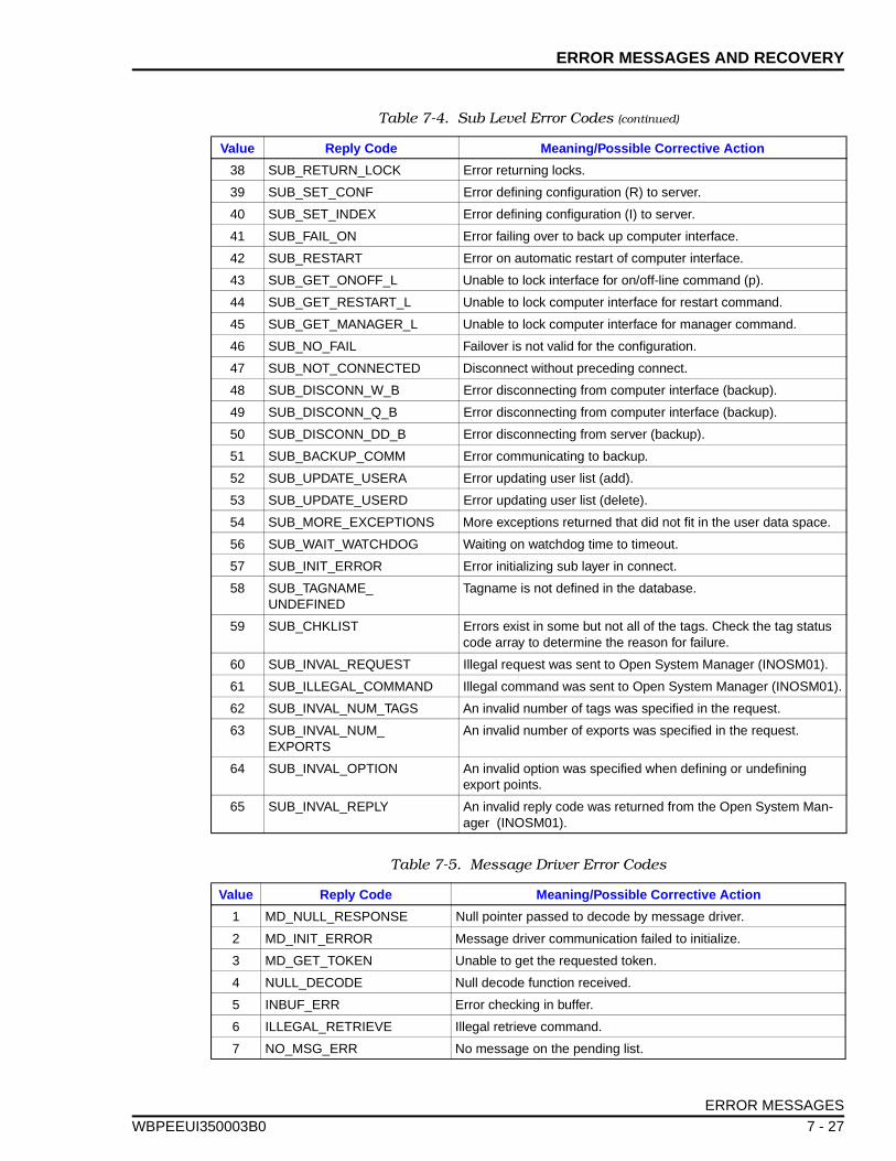
ERROR MESSAGES AND RECOVERY
WBPEEUI
38 SUB_RETURN_LOCK Error returning locks.
39 SUB_SET_CONF Error defining configuration (R) to server.
40 SUB_SET_INDEX Error defining configuration (I) to server.
41 SUB_FAIL_ON Error failing over to back up computer interface.
42 SUB_RESTART Error on automatic restart of computer interface.
43 SUB_GET_ONOFF_L Unable to lock interface for on/off-line command (p).
44 SUB_GET_RESTART_L Unable to lock computer interface for restart command.
45 SUB_GET_MANAGER_L Unable to lock computer interface for manager command.
46 SUB_NO_FAIL Failover is not valid for the configuration.
47 SUB_NOT_CONNECTED Disconnect without preceding connect.
48 SUB_DISCONN_W_B Error disconnecting from computer interface (backup).
49 SUB_DISCONN_Q_B Error disconnecting from computer interface (backup).
50 SUB_DISCONN_DD_B Error disconnecting from server (backup).
51 SUB_BACKUP_COMM Error communicating to backup.
52 SUB_UPDATE_USERA Error updating user list (add).
53 SUB_UPDATE_USERD Error updating user list (delete).
54 SUB_MORE_EXCEPTIONS More exceptions returned that did not fit in the user data space.
56 SUB_WAIT_WATCHDOG Waiting on watchdog time to timeout.
57 SUB_INIT_ERROR Error initializing sub layer in connect.
58 SUB_TAGNAME_UNDEFINED
Tagname is not defined in the database.
59 SUB_CHKLIST Errors exist in some but not all of the tags. Check the tag status code array to determine the reason for failure.
60 SUB_INVAL_REQUEST Illegal request was sent to Open System Manager (INOSM01).
61 SUB_ILLEGAL_COMMAND Illegal command was sent to Open System Manager (INOSM01).
62 SUB_INVAL_NUM_TAGS An invalid number of tags was specified in the request.
63 SUB_INVAL_NUM_EXPORTS
An invalid number of exports was specified in the request.
64 SUB_INVAL_OPTION An invalid option was specified when defining or undefining export points.
65 SUB_INVAL_REPLY An invalid reply code was returned from the Open System Man-ager (INOSM01).
Table 7-5. Message Driver Error Codes
Value Reply Code Meaning/Possible Corrective Action
1 MD_NULL_RESPONSE Null pointer passed to decode by message driver.
2 MD_INIT_ERROR Message driver communication failed to initialize.
3 MD_GET_TOKEN Unable to get the requested token.
4 NULL_DECODE Null decode function received.
5 INBUF_ERR Error checking in buffer.
6 ILLEGAL_RETRIEVE Illegal retrieve command.
7 NO_MSG_ERR No message on the pending list.
Table 7-4. Sub Level Error Codes (continued)
Value Reply Code Meaning/Possible Corrective Action
ERROR MESSAGES
350003B0 7 - 27
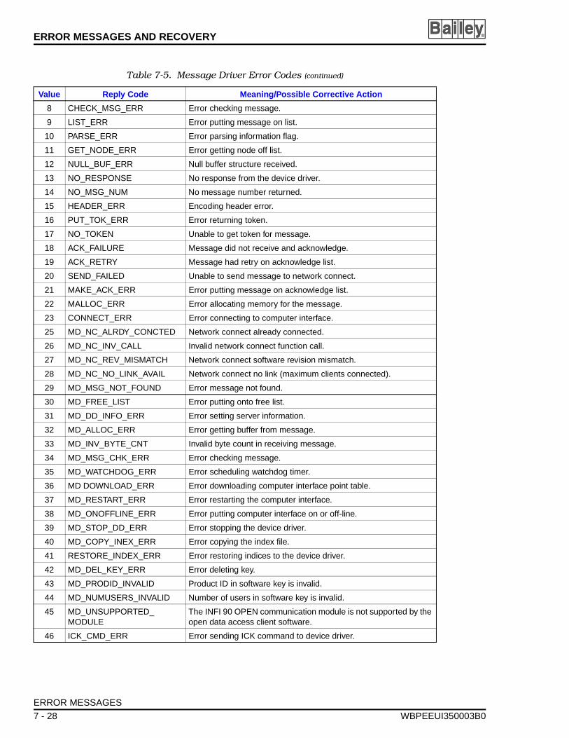
ERROR MESSAGES AND RECOVERY ®
8 CHECK_MSG_ERR Error checking message.
9 LIST_ERR Error putting message on list.
10 PARSE_ERR Error parsing information flag.
11 GET_NODE_ERR Error getting node off list.
12 NULL_BUF_ERR Null buffer structure received.
13 NO_RESPONSE No response from the device driver.
14 NO_MSG_NUM No message number returned.
15 HEADER_ERR Encoding header error.
16 PUT_TOK_ERR Error returning token.
17 NO_TOKEN Unable to get token for message.
18 ACK_FAILURE Message did not receive and acknowledge.
19 ACK_RETRY Message had retry on acknowledge list.
20 SEND_FAILED Unable to send message to network connect.
21 MAKE_ACK_ERR Error putting message on acknowledge list.
22 MALLOC_ERR Error allocating memory for the message.
23 CONNECT_ERR Error connecting to computer interface.
25 MD_NC_ALRDY_CONCTED Network connect already connected.
26 MD_NC_INV_CALL Invalid network connect function call.
27 MD_NC_REV_MISMATCH Network connect software revision mismatch.
28 MD_NC_NO_LINK_AVAIL Network connect no link (maximum clients connected).
29 MD_MSG_NOT_FOUND Error message not found.
30 MD_FREE_LIST Error putting onto free list.
31 MD_DD_INFO_ERR Error setting server information.
32 MD_ALLOC_ERR Error getting buffer from message.
33 MD_INV_BYTE_CNT Invalid byte count in receiving message.
34 MD_MSG_CHK_ERR Error checking message.
35 MD_WATCHDOG_ERR Error scheduling watchdog timer.
36 MD DOWNLOAD_ERR Error downloading computer interface point table.
37 MD_RESTART_ERR Error restarting the computer interface.
38 MD_ONOFFLINE_ERR Error putting computer interface on or off-line.
39 MD_STOP_DD_ERR Error stopping the device driver.
40 MD_COPY_INEX_ERR Error copying the index file.
41 RESTORE_INDEX_ERR Error restoring indices to the device driver.
42 MD_DEL_KEY_ERR Error deleting key.
43 MD_PRODID_INVALID Product ID in software key is invalid.
44 MD_NUMUSERS_INVALID Number of users in software key is invalid.
45 MD_UNSUPPORTED_MODULE
The INFI 90 OPEN communication module is not supported by the open data access client software.
46 ICK_CMD_ERR Error sending ICK command to device driver.
Table 7-5. Message Driver Error Codes (continued)
Value Reply Code Meaning/Possible Corrective Action
ERROR MESSAGES
7 - 28 WBPEEUI350003B0
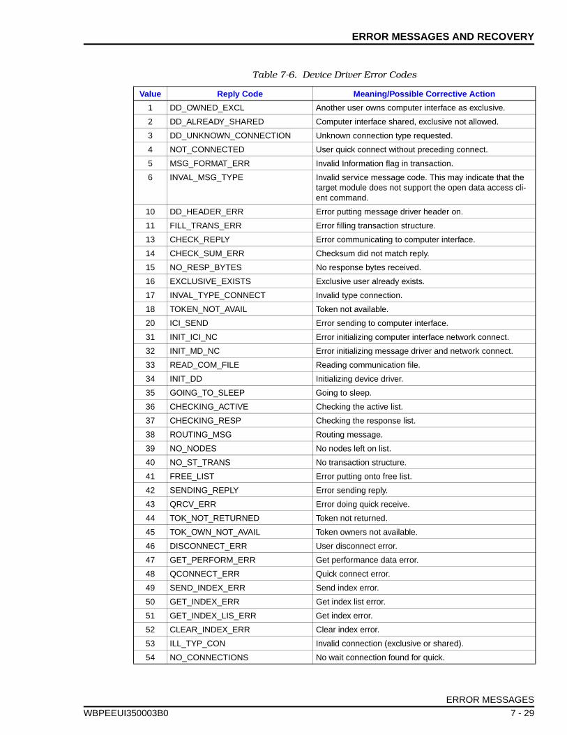
ERROR MESSAGES AND RECOVERY
WBPEEUI
Table 7-6. Device Driver Error Codes
Value Reply Code Meaning/Possible Corrective Action
1 DD_OWNED_EXCL Another user owns computer interface as exclusive.
2 DD_ALREADY_SHARED Computer interface shared, exclusive not allowed.
3 DD_UNKNOWN_CONNECTION Unknown connection type requested.
4 NOT_CONNECTED User quick connect without preceding connect.
5 MSG_FORMAT_ERR Invalid Information flag in transaction.
6 INVAL_MSG_TYPE Invalid service message code. This may indicate that the target module does not support the open data access cli-ent command.
10 DD_HEADER_ERR Error putting message driver header on.
11 FILL_TRANS_ERR Error filling transaction structure.
13 CHECK_REPLY Error communicating to computer interface.
14 CHECK_SUM_ERR Checksum did not match reply.
15 NO_RESP_BYTES No response bytes received.
16 EXCLUSIVE_EXISTS Exclusive user already exists.
17 INVAL_TYPE_CONNECT Invalid type connection.
18 TOKEN_NOT_AVAIL Token not available.
20 ICI_SEND Error sending to computer interface.
31 INIT_ICI_NC Error initializing computer interface network connect.
32 INIT_MD_NC Error initializing message driver and network connect.
33 READ_COM_FILE Reading communication file.
34 INIT_DD Initializing device driver.
35 GOING_TO_SLEEP Going to sleep.
36 CHECKING_ACTIVE Checking the active list.
37 CHECKING_RESP Checking the response list.
38 ROUTING_MSG Routing message.
39 NO_NODES No nodes left on list.
40 NO_ST_TRANS No transaction structure.
41 FREE_LIST Error putting onto free list.
42 SENDING_REPLY Error sending reply.
43 QRCV_ERR Error doing quick receive.
44 TOK_NOT_RETURNED Token not returned.
45 TOK_OWN_NOT_AVAIL Token owners not available.
46 DISCONNECT_ERR User disconnect error.
47 GET_PERFORM_ERR Get performance data error.
48 QCONNECT_ERR Quick connect error.
49 SEND_INDEX_ERR Send index error.
50 GET_INDEX_ERR Get index list error.
51 GET_INDEX_LIS_ERR Get index error.
52 CLEAR_INDEX_ERR Clear index error.
53 ILL_TYP_CON Invalid connection (exclusive or shared).
54 NO_CONNECTIONS No wait connection found for quick.
ERROR MESSAGES
350003B0 7 - 29
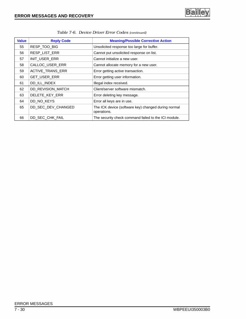
ERROR MESSAGES AND RECOVERY ®
55 RESP_TOO_BIG Unsolicited response too large for buffer.
56 RESP_LIST_ERR Cannot put unsolicited response on list.
57 INIT_USER_ERR Cannot initialize a new user.
58 CALLOC_USER_ERR Cannot allocate memory for a new user.
59 ACTIVE_TRANS_ERR Error getting active transaction.
60 GET_USER_ERR Error getting user information.
61 DD_ILL_INDEX Illegal index received.
62 DD_REVISION_MATCH Client/server software mismatch.
63 DELETE_KEY_ERR Error deleting key message.
64 DD_NO_KEYS Error all keys are in use.
65 DD_SEC_DEV_CHANGED The ICK device (software key) changed during normal operations.
66 DD_SEC_CHK_FAIL The security check command failed to the ICI module.
Table 7-6. Device Driver Error Codes (continued)
Value Reply Code Meaning/Possible Corrective Action
ERROR MESSAGES
7 - 30 WBPEEUI350003B0
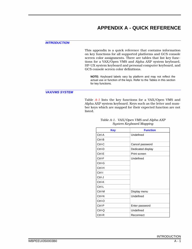
APPENDIX A - QUICK REFERENCE
WBPEEUI
INTRODUCTION
This appendix is a quick reference that contains informationon key functions for all supported platforms and GCS consolescreen color assignments. There are tables that list key func-tions for a VAX/Open VMS and Alpha AXP system keyboard,HP-UX system keyboard and personal computer keyboard, andGCS console screen color definitions.
NOTE: Keyboard labels vary by platform and may not reflect theactual use or function of the keys. Refer to the Tables in this sectionfor key functions.
VAX/VMS SYSTEM
Table A-1 lists the key functions for a VAX/Open VMS andAlpha AXP system keyboard. Keys such as the letter and num-ber keys which are mapped for their expected function are notlisted.
Table A-1. VAX/Open VMS and Alpha AXP System Keyboard Mapping
Key Function
Ctrl-A Undefined
Ctrl-B
Ctrl-C Cancel password
Ctrl-D Dedicated display
Ctrl-E Print screen
Ctrl-F Undefined
Ctrl-G
Ctrl-H
Ctrl-I
Ctrl-J
Ctrl-K
Ctrl-L
Ctrl-M Display menu
Ctrl-N Undefined
Ctrl-O
Ctrl-P Enter password
Ctrl-Q Undefined
Ctrl-R Reconnect
INTRODUCTION
350003B0 A - 1
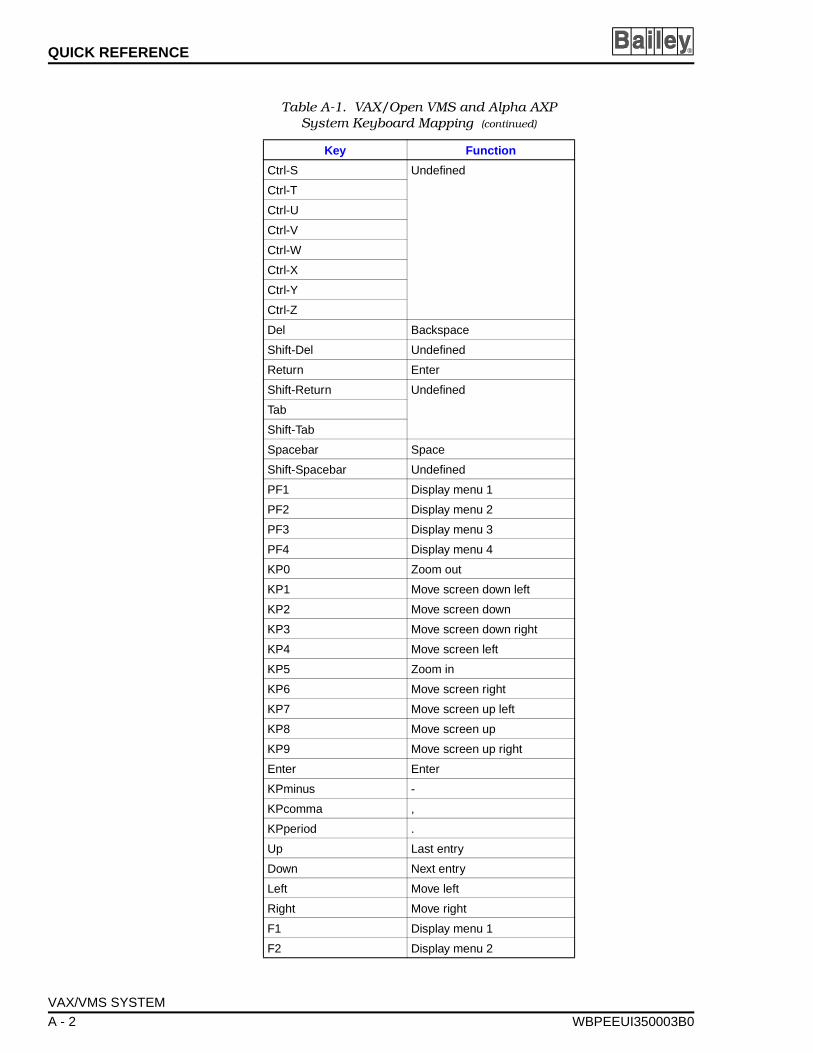
QUICK REFERENCE ®
Ctrl-S Undefined
Ctrl-T
Ctrl-U
Ctrl-V
Ctrl-W
Ctrl-X
Ctrl-Y
Ctrl-Z
Del Backspace
Shift-Del Undefined
Return Enter
Shift-Return Undefined
Tab
Shift-Tab
Spacebar Space
Shift-Spacebar Undefined
PF1 Display menu 1
PF2 Display menu 2
PF3 Display menu 3
PF4 Display menu 4
KP0 Zoom out
KP1 Move screen down left
KP2 Move screen down
KP3 Move screen down right
KP4 Move screen left
KP5 Zoom in
KP6 Move screen right
KP7 Move screen up left
KP8 Move screen up
KP9 Move screen up right
Enter Enter
KPminus -
KPcomma ,
KPperiod .
Up Last entry
Down Next entry
Left Move left
Right Move right
F1 Display menu 1
F2 Display menu 2
Table A-1. VAX/Open VMS and Alpha AXP System Keyboard Mapping (continued)
Key Function
VAX/VMS SYSTEM
A - 2 WBPEEUI350003B0
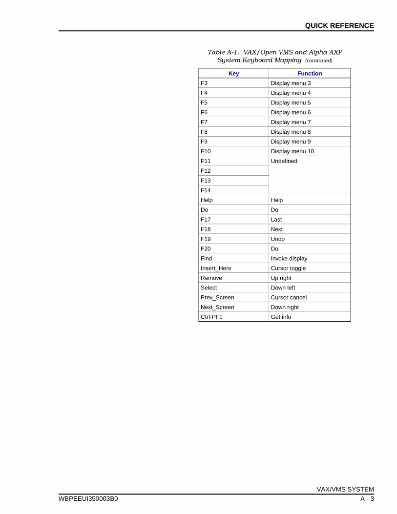
QUICK REFERENCE
WBPEEUI
F3 Display menu 3
F4 Display menu 4
F5 Display menu 5
F6 Display menu 6
F7 Display menu 7
F8 Display menu 8
F9 Display menu 9
F10 Display menu 10
F11 Undefined
F12
F13
F14
Help Help
Do Do
F17 Last
F18 Next
F19 Undo
F20 Do
Find Invoke display
Insert_Here Cursor toggle
Remove Up right
Select Down left
Prev_Screen Cursor cancel
Next_Screen Down right
Ctrl-PF1 Get info
Table A-1. VAX/Open VMS and Alpha AXP System Keyboard Mapping (continued)
Key Function
VAX/VMS SYSTEM
350003B0 A - 3
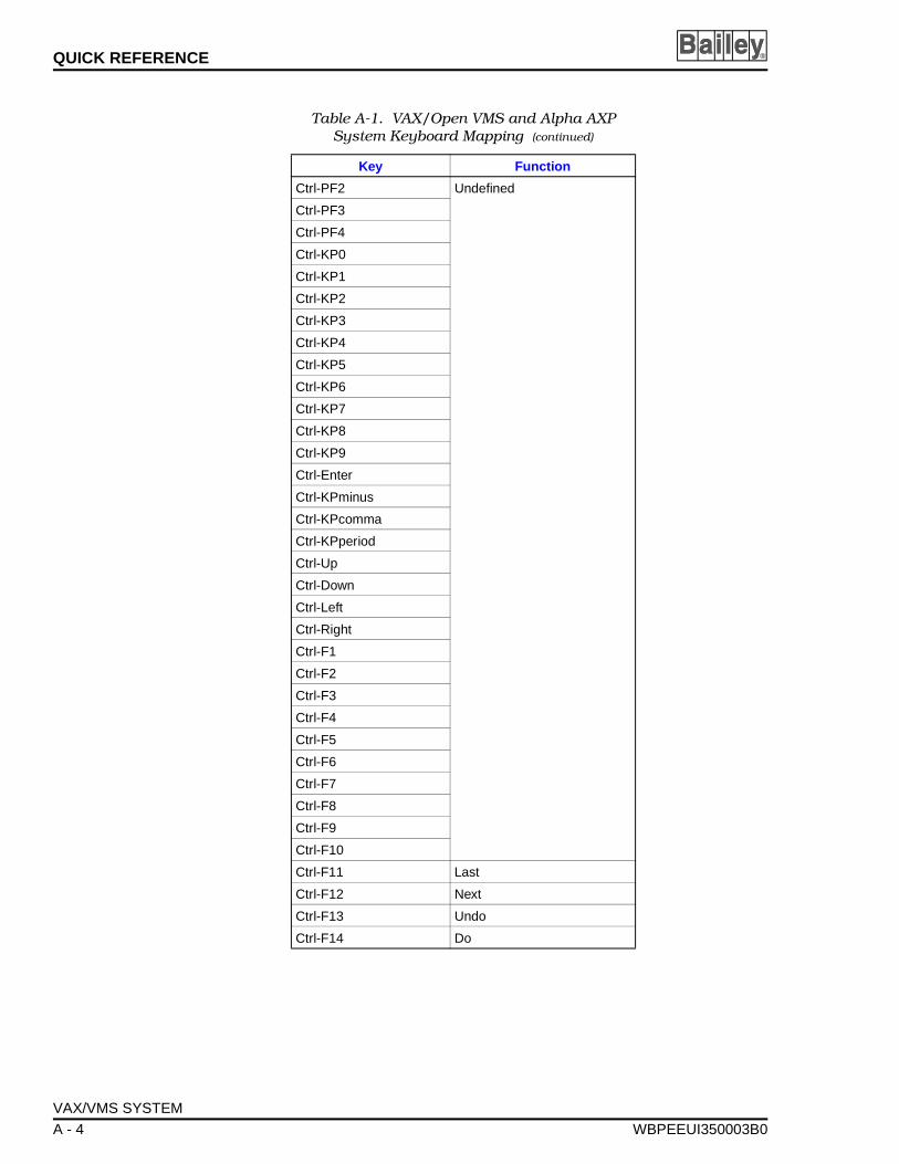
QUICK REFERENCE ®
Ctrl-PF2 Undefined
Ctrl-PF3
Ctrl-PF4
Ctrl-KP0
Ctrl-KP1
Ctrl-KP2
Ctrl-KP3
Ctrl-KP4
Ctrl-KP5
Ctrl-KP6
Ctrl-KP7
Ctrl-KP8
Ctrl-KP9
Ctrl-Enter
Ctrl-KPminus
Ctrl-KPcomma
Ctrl-KPperiod
Ctrl-Up
Ctrl-Down
Ctrl-Left
Ctrl-Right
Ctrl-F1
Ctrl-F2
Ctrl-F3
Ctrl-F4
Ctrl-F5
Ctrl-F6
Ctrl-F7
Ctrl-F8
Ctrl-F9
Ctrl-F10
Ctrl-F11 Last
Ctrl-F12 Next
Ctrl-F13 Undo
Ctrl-F14 Do
Table A-1. VAX/Open VMS and Alpha AXP System Keyboard Mapping (continued)
Key Function
VAX/VMS SYSTEM
A - 4 WBPEEUI350003B0
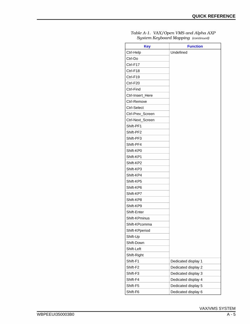
QUICK REFERENCE
WBPEEUI
Ctrl-Help Undefined
Ctrl-Do
Ctrl-F17
Ctrl-F18
Ctrl-F19
Ctrl-F20
Ctrl-Find
Ctrl-Insert_Here
Ctrl-Remove
Ctrl-Select
Ctrl-Prev_Screen
Ctrl-Next_Screen
Shift-PF1
Shift-PF2
Shift-PF3
Shift-PF4
Shift-KP0
Shift-KP1
Shift-KP2
Shift-KP3
Shift-KP4
Shift-KP5
Shift-KP6
Shift-KP7
Shift-KP8
Shift-KP9
Shift-Enter
Shift-KPminus
Shift-KPcomma
Shift-KPperiod
Shift-Up
Shift-Down
Shift-Left
Shift-Right
Shift-F1 Dedicated display 1
Shift-F2 Dedicated display 2
Shift-F3 Dedicated display 3
Shift-F4 Dedicated display 4
Shift-F5 Dedicated display 5
Shift-F6 Dedicated display 6
Table A-1. VAX/Open VMS and Alpha AXP System Keyboard Mapping (continued)
Key Function
VAX/VMS SYSTEM
350003B0 A - 5
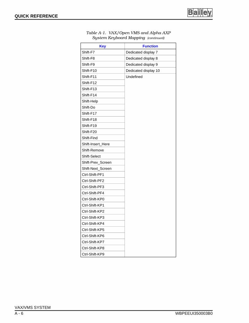
QUICK REFERENCE ®
Shift-F7 Dedicated display 7
Shift-F8 Dedicated display 8
Shift-F9 Dedicated display 9
Shift-F10 Dedicated display 10
Shift-F11 Undefined
Shift-F12
Shift-F13
Shift-F14
Shift-Help
Shift-Do
Shift-F17
Shift-F18
Shift-F19
Shift-F20
Shift-Find
Shift-Insert_Here
Shift-Remove
Shift-Select
Shift-Prev_Screen
Shift-Next_Screen
Ctrl-Shift-PF1
Ctrl-Shift-PF2
Ctrl-Shift-PF3
Ctrl-Shift-PF4
Ctrl-Shift-KP0
Ctrl-Shift-KP1
Ctrl-Shift-KP2
Ctrl-Shift-KP3
Ctrl-Shift-KP4
Ctrl-Shift-KP5
Ctrl-Shift-KP6
Ctrl-Shift-KP7
Ctrl-Shift-KP8
Ctrl-Shift-KP9
Table A-1. VAX/Open VMS and Alpha AXP System Keyboard Mapping (continued)
Key Function
VAX/VMS SYSTEM
A - 6 WBPEEUI350003B0
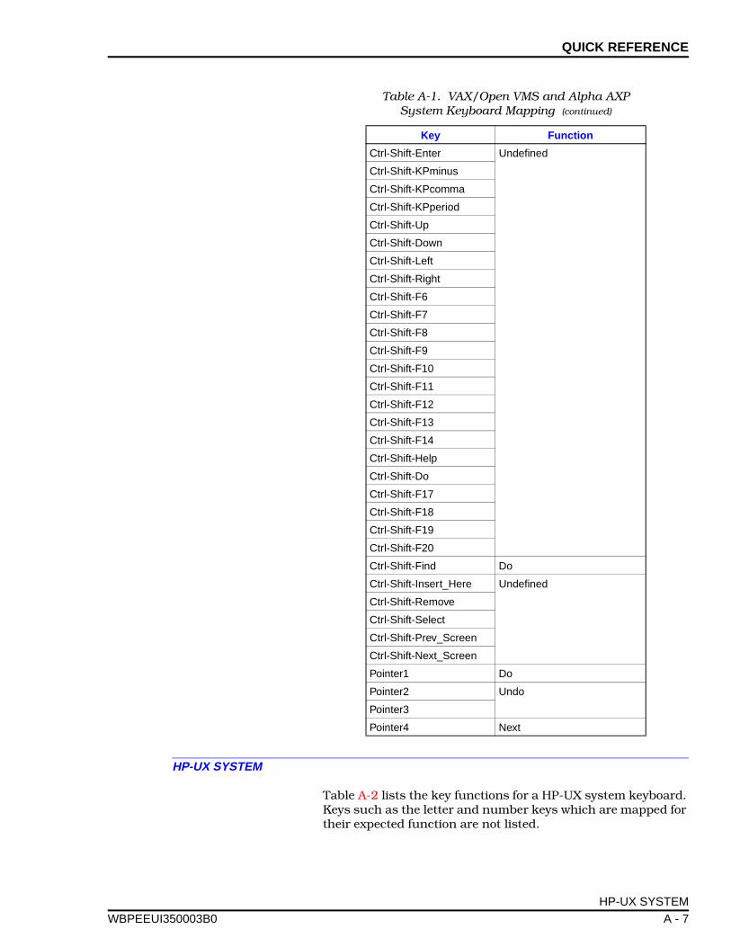
QUICK REFERENCE
WBPEEUI
HP-UX SYSTEM
Table A-2 lists the key functions for a HP-UX system keyboard.Keys such as the letter and number keys which are mapped fortheir expected function are not listed.
Ctrl-Shift-Enter Undefined
Ctrl-Shift-KPminus
Ctrl-Shift-KPcomma
Ctrl-Shift-KPperiod
Ctrl-Shift-Up
Ctrl-Shift-Down
Ctrl-Shift-Left
Ctrl-Shift-Right
Ctrl-Shift-F6
Ctrl-Shift-F7
Ctrl-Shift-F8
Ctrl-Shift-F9
Ctrl-Shift-F10
Ctrl-Shift-F11
Ctrl-Shift-F12
Ctrl-Shift-F13
Ctrl-Shift-F14
Ctrl-Shift-Help
Ctrl-Shift-Do
Ctrl-Shift-F17
Ctrl-Shift-F18
Ctrl-Shift-F19
Ctrl-Shift-F20
Ctrl-Shift-Find Do
Ctrl-Shift-Insert_Here Undefined
Ctrl-Shift-Remove
Ctrl-Shift-Select
Ctrl-Shift-Prev_Screen
Ctrl-Shift-Next_Screen
Pointer1 Do
Pointer2 Undo
Pointer3
Pointer4 Next
Table A-1. VAX/Open VMS and Alpha AXP System Keyboard Mapping (continued)
Key Function
HP-UX SYSTEM
350003B0 A - 7
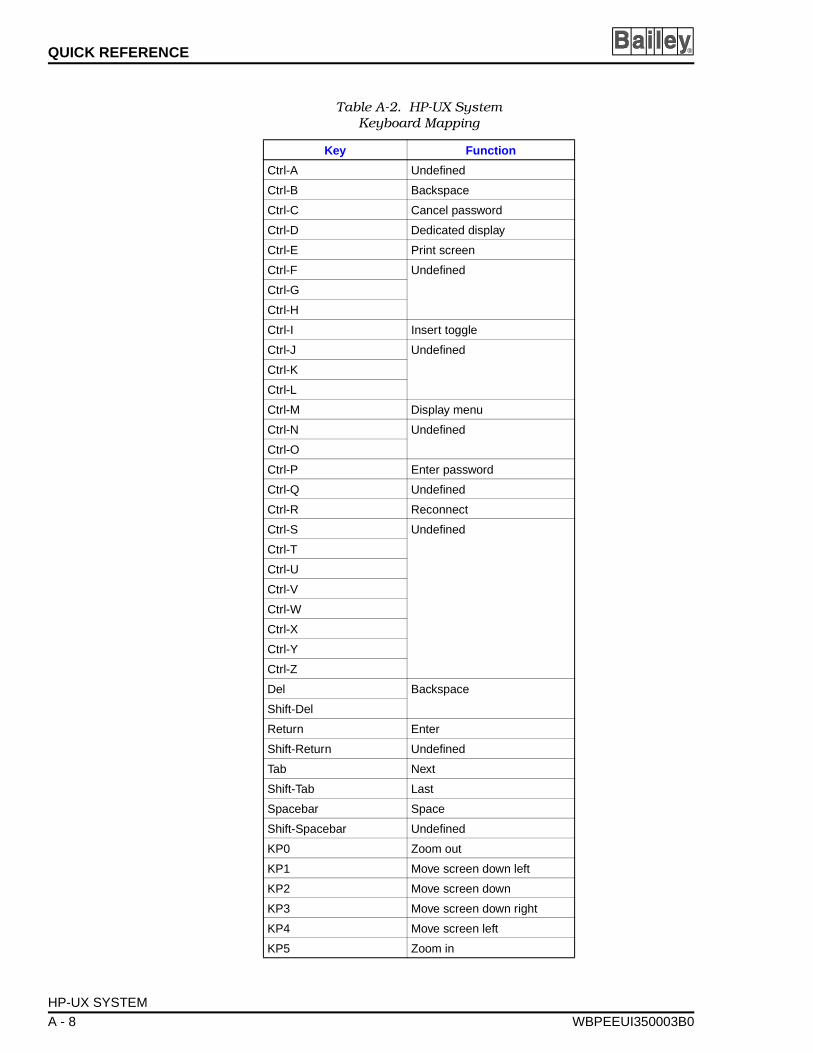
QUICK REFERENCE ®
Table A-2. HP-UX SystemKeyboard Mapping
Key Function
Ctrl-A Undefined
Ctrl-B Backspace
Ctrl-C Cancel password
Ctrl-D Dedicated display
Ctrl-E Print screen
Ctrl-F Undefined
Ctrl-G
Ctrl-H
Ctrl-I Insert toggle
Ctrl-J Undefined
Ctrl-K
Ctrl-L
Ctrl-M Display menu
Ctrl-N Undefined
Ctrl-O
Ctrl-P Enter password
Ctrl-Q Undefined
Ctrl-R Reconnect
Ctrl-S Undefined
Ctrl-T
Ctrl-U
Ctrl-V
Ctrl-W
Ctrl-X
Ctrl-Y
Ctrl-Z
Del Backspace
Shift-Del
Return Enter
Shift-Return Undefined
Tab Next
Shift-Tab Last
Spacebar Space
Shift-Spacebar Undefined
KP0 Zoom out
KP1 Move screen down left
KP2 Move screen down
KP3 Move screen down right
KP4 Move screen left
KP5 Zoom in
HP-UX SYSTEM
A - 8 WBPEEUI350003B0
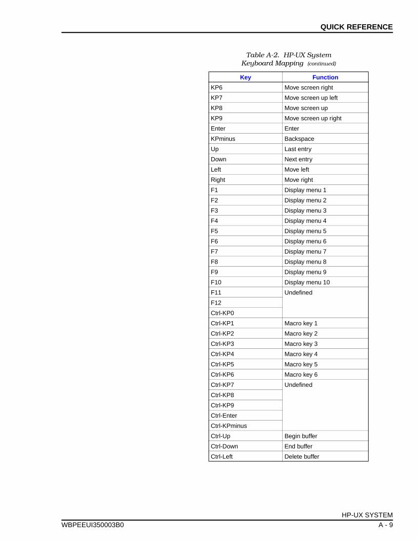
QUICK REFERENCE
WBPEEUI
KP6 Move screen right
KP7 Move screen up left
KP8 Move screen up
KP9 Move screen up right
Enter Enter
KPminus Backspace
Up Last entry
Down Next entry
Left Move left
Right Move right
F1 Display menu 1
F2 Display menu 2
F3 Display menu 3
F4 Display menu 4
F5 Display menu 5
F6 Display menu 6
F7 Display menu 7
F8 Display menu 8
F9 Display menu 9
F10 Display menu 10
F11 Undefined
F12
Ctrl-KP0
Ctrl-KP1 Macro key 1
Ctrl-KP2 Macro key 2
Ctrl-KP3 Macro key 3
Ctrl-KP4 Macro key 4
Ctrl-KP5 Macro key 5
Ctrl-KP6 Macro key 6
Ctrl-KP7 Undefined
Ctrl-KP8
Ctrl-KP9
Ctrl-Enter
Ctrl-KPminus
Ctrl-Up Begin buffer
Ctrl-Down End buffer
Ctrl-Left Delete buffer
Table A-2. HP-UX SystemKeyboard Mapping (continued)
Key Function
HP-UX SYSTEM
350003B0 A - 9
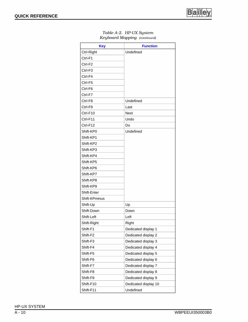
QUICK REFERENCE ®
Ctrl-Right Undefined
Ctrl-F1
Ctrl-F2
Ctrl-F3
Ctrl-F4
Ctrl-F5
Ctrl-F6
Ctrl-F7
Ctrl-F8 Undefined
Ctrl-F9 Last
Ctrl-F10 Next
Ctrl-F11 Undo
Ctrl-F12 Do
Shift-KP0 Undefined
Shift-KP1
Shift-KP2
Shift-KP3
Shift-KP4
Shift-KP5
Shift-KP6
Shift-KP7
Shift-KP8
Shift-KP9
Shift-Enter
Shift-KPminus
Shift-Up Up
Shift-Down Down
Shift-Left Left
Shift-Right Right
Shift-F1 Dedicated display 1
Shift-F2 Dedicated display 2
Shift-F3 Dedicated display 3
Shift-F4 Dedicated display 4
Shift-F5 Dedicated display 5
Shift-F6 Dedicated display 6
Shift-F7 Dedicated display 7
Shift-F8 Dedicated display 8
Shift-F9 Dedicated display 9
Shift-F10 Dedicated display 10
Shift-F11 Undefined
Table A-2. HP-UX SystemKeyboard Mapping (continued)
Key Function
HP-UX SYSTEM
A - 10 WBPEEUI350003B0
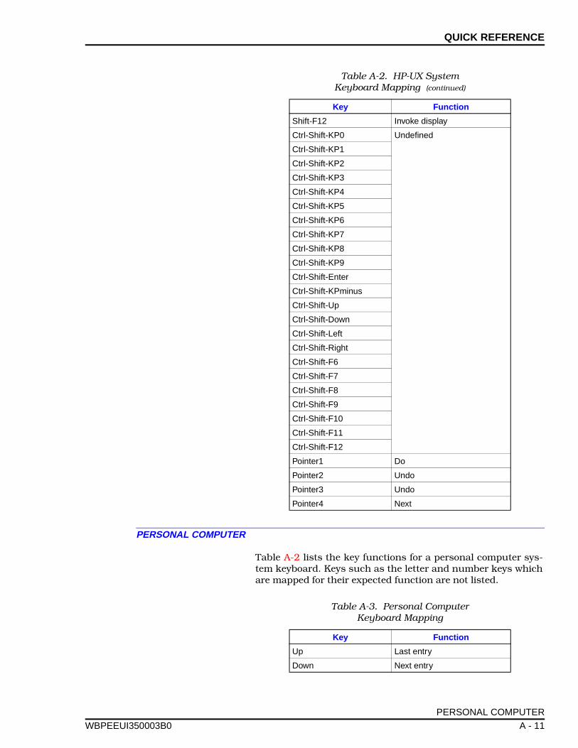
QUICK REFERENCE
WBPEEUI
PERSONAL COMPUTER
Table A-2 lists the key functions for a personal computer sys-tem keyboard. Keys such as the letter and number keys whichare mapped for their expected function are not listed.
Shift-F12 Invoke display
Ctrl-Shift-KP0 Undefined
Ctrl-Shift-KP1
Ctrl-Shift-KP2
Ctrl-Shift-KP3
Ctrl-Shift-KP4
Ctrl-Shift-KP5
Ctrl-Shift-KP6
Ctrl-Shift-KP7
Ctrl-Shift-KP8
Ctrl-Shift-KP9
Ctrl-Shift-Enter
Ctrl-Shift-KPminus
Ctrl-Shift-Up
Ctrl-Shift-Down
Ctrl-Shift-Left
Ctrl-Shift-Right
Ctrl-Shift-F6
Ctrl-Shift-F7
Ctrl-Shift-F8
Ctrl-Shift-F9
Ctrl-Shift-F10
Ctrl-Shift-F11
Ctrl-Shift-F12
Pointer1 Do
Pointer2 Undo
Pointer3 Undo
Pointer4 Next
Table A-2. HP-UX SystemKeyboard Mapping (continued)
Key Function
Table A-3. Personal ComputerKeyboard Mapping
Key Function
Up Last entry
Down Next entry
PERSONAL COMPUTER
350003B0 A - 11
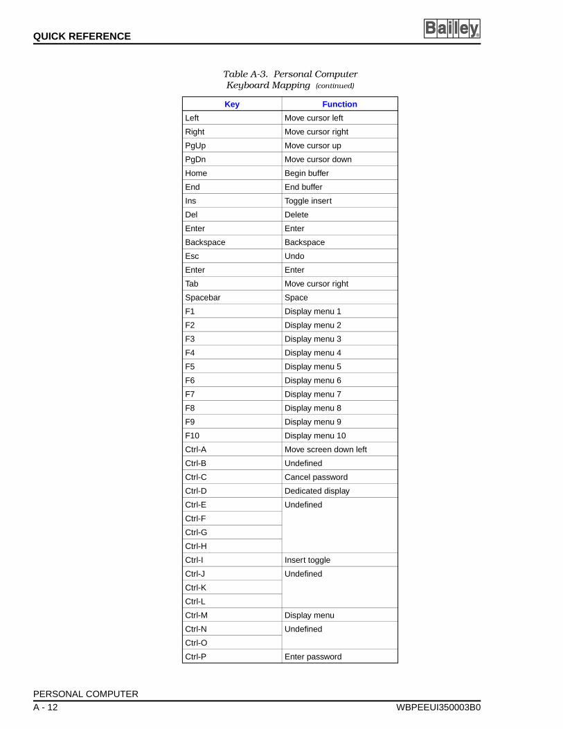
QUICK REFERENCE ®
Left Move cursor left
Right Move cursor right
PgUp Move cursor up
PgDn Move cursor down
Home Begin buffer
End End buffer
Ins Toggle insert
Del Delete
Enter Enter
Backspace Backspace
Esc Undo
Enter Enter
Tab Move cursor right
Spacebar Space
F1 Display menu 1
F2 Display menu 2
F3 Display menu 3
F4 Display menu 4
F5 Display menu 5
F6 Display menu 6
F7 Display menu 7
F8 Display menu 8
F9 Display menu 9
F10 Display menu 10
Ctrl-A Move screen down left
Ctrl-B Undefined
Ctrl-C Cancel password
Ctrl-D Dedicated display
Ctrl-E Undefined
Ctrl-F
Ctrl-G
Ctrl-H
Ctrl-I Insert toggle
Ctrl-J Undefined
Ctrl-K
Ctrl-L
Ctrl-M Display menu
Ctrl-N Undefined
Ctrl-O
Ctrl-P Enter password
Table A-3. Personal ComputerKeyboard Mapping (continued)
Key Function
PERSONAL COMPUTER
A - 12 WBPEEUI350003B0
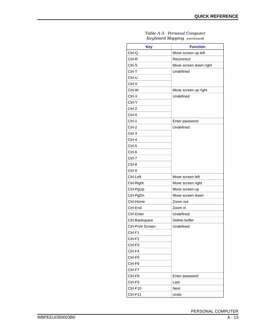
QUICK REFERENCE
WBPEEUI
Ctrl-Q Move screen up left
Ctrl-R Reconnect
Ctrl-S Move screen down right
Ctrl-T Undefined
Ctrl-U
Ctrl-V
Ctrl-W Move screen up right
Ctrl-X Undefined
Ctrl-Y
Ctrl-Z
Ctrl-0
Ctrl-1 Enter password
Ctrl-2 Undefined
Ctrl-3
Ctrl-4
Ctrl-5
Ctrl-6
Ctrl-7
Ctrl-8
Ctrl-9
Ctrl-Left Move screen left
Ctrl-Right Move screen right
Ctrl-PgUp Move screen up
Ctrl-PgDn Move screen down
Ctrl-Home Zoom out
Ctrl-End Zoom in
Ctrl-Enter Undefined
Ctrl-Backspace Delete buffer
Ctrl-Print Screen Undefined
Ctrl-F1
Ctrl-F2
Ctrl-F3
Ctrl-F4
Ctrl-F5
Ctrl-F6
Ctrl-F7
Ctrl-F8 Enter password
Ctrl-F9 Last
Ctrl-F10 Next
Ctrl-F11 Undo
Table A-3. Personal ComputerKeyboard Mapping (continued)
Key Function
PERSONAL COMPUTER
350003B0 A - 13
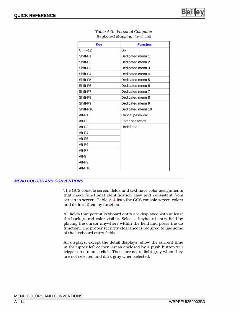
QUICK REFERENCE ®
MENU COLORS AND CONVENTIONS
The GCS console screen fields and text have color assignmentsthat make functional identification easy and consistent fromscreen to screen. Table A-4 lists the GCS console screen colorsand defines them by function.
All fields that permit keyboard entry are displayed with at leastthe background color visible. Select a keyboard entry field byplacing the cursor anywhere within the field and press the dofunction. The proper security clearance is required to use someof the keyboard entry fields.
All displays, except the detail displays, show the current timein the upper left corner. Areas enclosed by a push button willtrigger on a mouse click. These areas are light gray when theyare not selected and dark gray when selected.
Ctrl-F12 Do
Shift-F1 Dedicated menu 1
Shift-F2 Dedicated menu 2
Shift-F3 Dedicated menu 3
Shift-F4 Dedicated menu 4
Shift-F5 Dedicated menu 5
Shift-F6 Dedicated menu 6
Shift-F7 Dedicated menu 7
Shift-F8 Dedicated menu 8
Shift-F9 Dedicated menu 9
Shift-F10 Dedicated menu 10
Alt-F1 Cancel password
Alt-F2 Enter password
Alt-F3 Undefined
Alt-F4
Alt-F5
Alt-F6
Alt-F7
Alt-8
Alt-F9
Alt-F10
Table A-3. Personal ComputerKeyboard Mapping (continued)
Key Function
MENU COLORS AND CONVENTIONS
A - 14 WBPEEUI350003B0
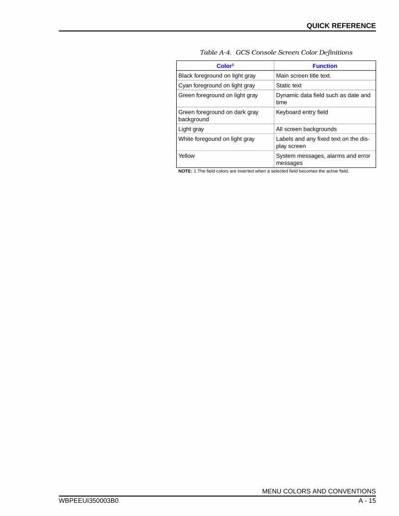
QUICK REFERENCE
WBPEEUI
Table A-4. GCS Console Screen Color Definitions
Color 1 Function
Black foreground on light gray Main screen title text.
Cyan foreground on light gray Static text
Green foreground on light gray Dynamic data field such as date and time
Green foreground on dark gray background
Keyboard entry field
Light gray All screen backgrounds
White foregound on light gray Labels and any fixed text on the dis-play screen
Yellow System messages, alarms and error messages
NOTE: 1.The field colors are inverted when a selected field becomes the active field.
MENU COLORS AND CONVENTIONS
350003B0 A - 15
APPENDIX B - HARDWARE CONFIGURATION
WBPEEUI
INTRODUCTION
The Open Data Management Server (ODMS) software requiresa software key (provided with the software) to enable systemoperation. The software key (a dongle) is installed on one of thetermination units or modules of an INFI-NET to ComputerInterface or Open System Manager. This section contains therequired hardware jumper settings and provide installationinstructions. This section also includes dipswitch and jumpersettings that are recommended for the INICI03 interface config-uration.
INSTALLING THE SOFTWARE KEY
The software key is used with either the NTMP01 terminationunit or the NIMP01 termination module of an INICI03 orINOSM01 interface. Use the appropriate procedure to installthe software key and to set the jumpers.
NTMP01 Termination Unit
If using an NTMP01 termination unit:
1. Connect the male end of the software key to the portlabeled P6 (printer port) on the NTMP01 termination unit.Refer to Figure B-1 for the location of P6.
2. Set jumpers J1, J3, J8, J9, J10 and J18 on the NTMP01 ter-mination unit as shown in Figure B-1.
NIMP01 Termination Module
If using an NIMP01 termination module:
1. Connect the male end of the software key to the 25 pin endof the 9-to-25 pin adapter.
2. Connect the 9 pin end of the 9-to-25 pin adaptor to the portlabeled P6 (printer port) on the NIMP01 termination module.Refer to Figure B-1 for the location of the port.
3. Set jumpers J1, J8, J9, J10, J13 and J20 on the NIMP01termination module as shown in Figure B-1.
INTRODUCTION
350003B0 B - 1
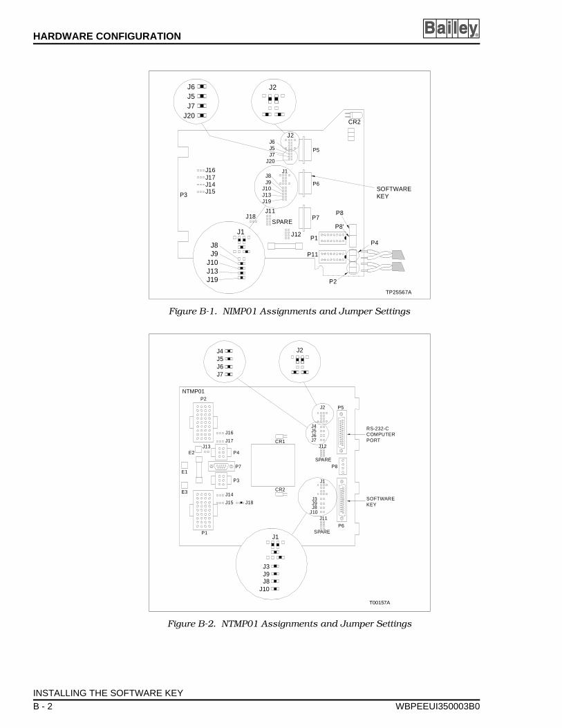
HARDWARE CONFIGURATION ®
Figure B-1. NIMP01 Assignments and Jumper Settings
Figure B-2. NTMP01 Assignments and Jumper Settings
P3
P5
P6
P7
J14J15
J16J17
J2
CR2
P1
P11
J11J18
SPARE
J12
SOFTWAREKEY
P8'
TP25567A
J1
J1
P2
P4
P8
J8J9
J10J13J19
J8J9
J10J13J19
J6J5J7
J20
J6J5J7
J20
J2
P5
P8
J2
J4J5J6J7
J12
SPAREP7
P3
P4
CR2
CR1
P1
P2
J16
J17
T00157A
J13
J18
E1
E2
E3 J14
J15
P6
J11
NTMP01
SPARE
J1
J3J9J8
J10
SOFTWAREKEY
RS-232-CCOMPUTERPORT
J1
J3J9J8
J10
J4J5J6J7
J2
INSTALLING THE SOFTWARE KEY
B - 2 WBPEEUI350003B0
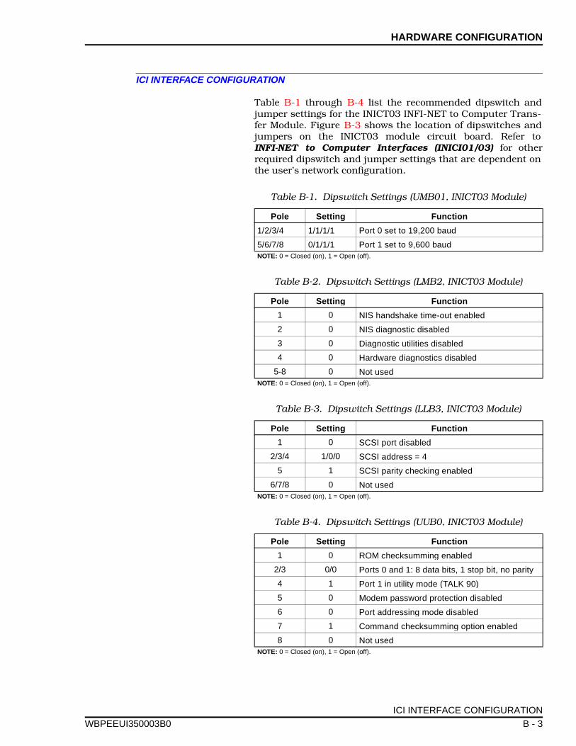
HARDWARE CONFIGURATION
WBPEEUI
ICI INTERFACE CONFIGURATION
Table B-1 through B-4 list the recommended dipswitch andjumper settings for the INICT03 INFI-NET to Computer Trans-fer Module. Figure B-3 shows the location of dipswitches andjumpers on the INICT03 module circuit board. Refer toINFI-NET to Computer Interfaces (INICI01/03) for otherrequired dipswitch and jumper settings that are dependent onthe user’s network configuration.
Table B-1. Dipswitch Settings (UMB01, INICT03 Module)
Pole Settin g Function
1/2/3/4 1/1/1/1 Port 0 set to 19,200 baud
5/6/7/8 0/1/1/1 Port 1 set to 9,600 baudNOTE: 0 = Closed (on), 1 = Open (off).
Table B-2. Dipswitch Settings (LMB2, INICT03 Module)
Pole Settin g Function
1 0 NIS handshake time-out enabled
2 0 NIS diagnostic disabled
3 0 Diagnostic utilities disabled
4 0 Hardware diagnostics disabled
5-8 0 Not usedNOTE: 0 = Closed (on), 1 = Open (off).
Table B-3. Dipswitch Settings (LLB3, INICT03 Module)
Pole Settin g Function
1 0 SCSI port disabled
2/3/4 1/0/0 SCSI address = 4
5 1 SCSI parity checking enabled
6/7/8 0 Not usedNOTE: 0 = Closed (on), 1 = Open (off).
Table B-4. Dipswitch Settings (UUB0, INICT03 Module)
Pole Settin g Function
1 0 ROM checksumming enabled
2/3 0/0 Ports 0 and 1: 8 data bits, 1 stop bit, no parity
4 1 Port 1 in utility mode (TALK 90)
5 0 Modem password protection disabled
6 0 Port addressing mode disabled
7 1 Command checksumming option enabled
8 0 Not usedNOTE: 0 = Closed (on), 1 = Open (off).
ICI INTERFACE CONFIGURATION
350003B0 B - 3
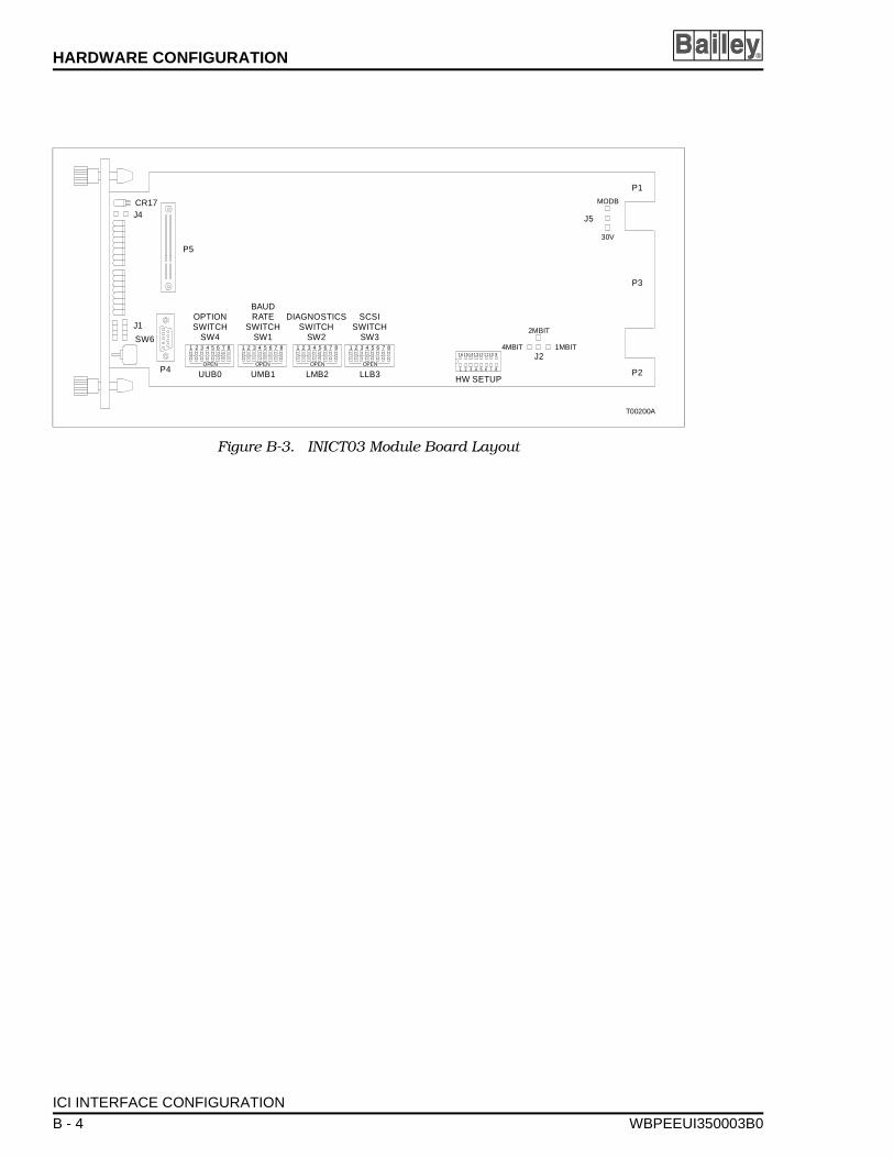
HARDWARE CONFIGURATION ®
Figure B-3. INICT03 Module Board Layout
T00200A
CR17
SW6
J4
J1
P5
P4 UUB0 UMB1 LMB2 LLB3
J2
P3
P1
P2
2MBIT
1MBIT4MBIT
OPTIONSWITCH
SW4
SCSISWITCH
SW3
BAUDRATE
SWITCHSW1
DIAGNOSTICSSWITCH
SW21 2 3 4
OPEN
5 6 7 8 1 2 3 4
OPEN
5 6 7 8 1 2 3 4
OPEN
5 6 7 8 1 2 3 4
OPEN
5 6 7 8
HW SETUP1
16
2
15
3
14
4
13
5
12
6
11
7
10
8
9
30V
MODB
J5
ICI INTERFACE CONFIGURATION
B - 4 WBPEEUI350003B0
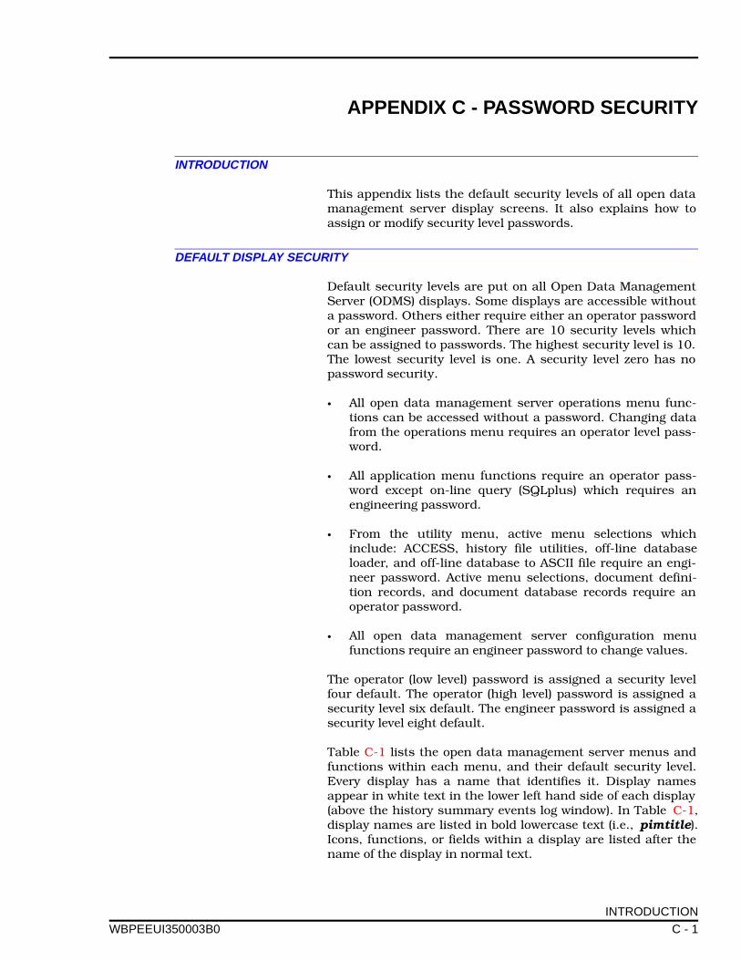
APPENDIX C - PASSWORD SECURITY
WBPEEUI
INTRODUCTION
This appendix lists the default security levels of all open datamanagement server display screens. It also explains how toassign or modify security level passwords.
DEFAULT DISPLAY SECURITY
Default security levels are put on all Open Data ManagementServer (ODMS) displays. Some displays are accessible withouta password. Others either require either an operator passwordor an engineer password. There are 10 security levels whichcan be assigned to passwords. The highest security level is 10.The lowest security level is one. A security level zero has nopassword security.
• All open data management server operations menu func-tions can be accessed without a password. Changing datafrom the operations menu requires an operator level pass-word.
• All application menu functions require an operator pass-word except on-line query (SQLplus) which requires anengineering password.
• From the utility menu, active menu selections whichinclude: ACCESS, history file utilities, off-line databaseloader, and off-line database to ASCII file require an engi-neer password. Active menu selections, document defini-tion records, and document database records require anoperator password.
• All open data management server configuration menufunctions require an engineer password to change values.
The operator (low level) password is assigned a security levelfour default. The operator (high level) password is assigned asecurity level six default. The engineer password is assigned asecurity level eight default.
Table C-1 lists the open data management server menus andfunctions within each menu, and their default security level.Every display has a name that identifies it. Display namesappear in white text in the lower left hand side of each display(above the history summary events log window). In Table C-1,display names are listed in bold lowercase text (i.e., pimtitle).Icons, functions, or fields within a display are listed after thename of the display in normal text.
INTRODUCTION
350003B0 C - 1

PASSWORD SECURITY ®
Use the ACCESS utility to change the default security levelsand assign passwords. To assign passwords to security levels:
1. Select Utilities from the main menu.
2. Select ACCESS from the utilities menu with the mouse orpress . An engineer level password is required to use theACCESS utility.
If a security level not high enough message is displayed whileattempting to execute the ACCESS utility, press - andenter the engineer password at the Password>< prompt.
3. Start up the access utility.
4. Use the mouse or and to highlight Setup at the bot-tom of the of ACCESS utility screen. Click on the selectionusing the mouse or press .
5. Select GCS using the mouse or keyboard.
6. From the System Configuration Utility screen select Secu-rity to bring up the password definition screen.
The top entry shows the number of passwords available. Thisentry can be modified from zero to 10 to set up the number ofpassword levels to use. If zero is entered in the number of pass-words field there is no password security for any screen orfunction. To the left of each password level listed is a four char-acter field in which a password can be defined.
7. To define a password, highlight a password field by point-ing to it with the mouse, then type in the password to be usedfor that security level, then press . Define as many pass-word security levels as desired.
8. When finished click, the left button on the mouse to exitthe password definition screen.
9. To exit the ACCESS Utility, select quit using the mouse orkeyboard to exit a particular menu level.
Table C-1. ODMS Default Security Levels
Display Name or IconSecurity Level
Data1 Display Icon 2
pimtitle N/A 0 N/A
F1 N/A N/A 0
pimmenu N/A 0 N/A
F1 Operations N/A N/A 0
F2 Applications N/A N/A 0
F3 Utilities N/A N/A 0
F1
Ctrl P
← →
Enter
Enter
DEFAULT DISPLAY SECURITY
C - 2 WBPEEUI350003B0
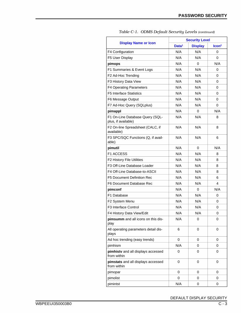
PASSWORD SECURITY
WBPEEUI
F4 Configuration N/A N/A 0
F5 User Display N/A N/A 0
pimops N/A 0 N/A
F1 Summaries & Event Logs N/A N/A 0
F2 Ad-Hoc Trending N/A N/A 0
F3 History Data View N/A N/A 0
F4 Operating Parameters N/A N/A 0
F5 Interface Statistics N/A N/A 0
F6 Message Output N/A N/A 0
F7 Ad-Hoc Query (SQLplus) N/A N/A 0
pimappl N/A 0 N/A
F1 On-Line Database Query (SQL-plus, if available)
N/A N/A 8
F2 On-line Spreadsheet (CALC, if available)
N/A N/A 8
F3 SPC/SQC Functions (Q, if avail-able)
N/A N/A 6
pimutil N/A 0 N/A
F1 ACCESS N/A N/A 8
F2 History File Utilities N/A N/A 8
F3 Off-Line Database Loader N/A N/A 8
F4 Off-Line Database-to-ASCII N/A N/A 8
F5 Document Definition Rec N/A N/A 6
F6 Document Database Rec N/A N/A 4
pimconf N/A 0 N/A
F1 Database N/A N/A 0
F2 System Menu N/A N/A 0
F3 Interface Control N/A N/A 0
F4 History Data View/Edit N/A N/A 0
pimsumm and all icons on this dis-play
N/A 0 0
All operating parameters detail dis-plays
6 0 0
Ad hoc trending (easy trends) 0 0 0
pimhism N/A 0 0
pimhistv and all displays accessed from within
0 0 0
pimstats and all displays accessed from within
0 0 0
pimopar 0 0 0
pimolist 0 0 0
pimintst N/A 0 0
Table C-1. ODMS Default Security Levels (continued)
Display Name or IconSecurity Level
Data1 Display Icon 2
DEFAULT DISPLAY SECURITY
350003B0 C - 3
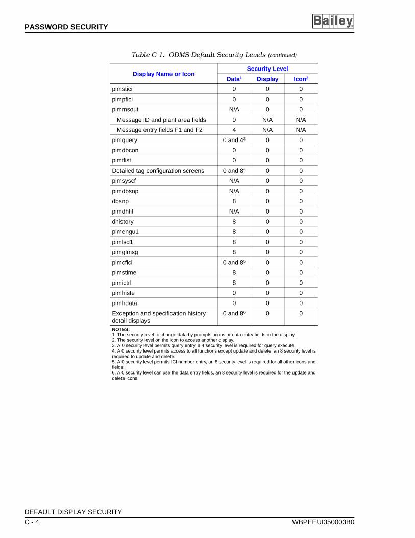
PASSWORD SECURITY ®
pimstici 0 0 0
pimpfici 0 0 0
pimmsout N/A 0 0
Message ID and plant area fields 0 N/A N/A
Message entry fields F1 and F2 4 N/A N/A
pimquery 0 and 43 0 0
pimdbcon 0 0 0
pimtlist 0 0 0
Detailed tag configuration screens 0 and 84 0 0
pimsyscf N/A 0 0
pimdbsnp N/A 0 0
dbsnp 8 0 0
pimdhfil N/A 0 0
dhistory 8 0 0
pimengu1 8 0 0
pimlsd1 8 0 0
pimglmsg 8 0 0
pimcfici 0 and 85 0 0
pimstime 8 0 0
pimictrl 8 0 0
pimhiste 0 0 0
pimhdata 0 0 0
Exception and specification history detail displays
0 and 86 0 0
NOTES: 1. The security level to change data by prompts, icons or data entry fields in the display.2. The security level on the icon to access another display.3. A 0 security level permits query entry, a 4 security level is required for query execute.4. A 0 security level permits access to all functions except update and delete, an 8 security level isrequired to update and delete.5. A 0 security level permits ICI number entry, an 8 security level is required for all other icons andfields.6. A 0 security level can use the data entry fields, an 8 security level is required for the update anddelete icons.
Table C-1. ODMS Default Security Levels (continued)
Display Name or IconSecurity Level
Data1 Display Icon 2
DEFAULT DISPLAY SECURITY
C - 4 WBPEEUI350003B0
APPENDIX D - CONSOLE ALARM CONFIGURATION
WBPEEUI
INTRODUCTION
The Open Data Management Server (ODMS) is capable ofreceiving operator interface station (OIS) alarm acknowledgeand silence messages. This appendix contains instructions onhow to configure the OIS global alarm acknowledge and silencefunction. The console global alarm acknowledge and silencefunction requires configuration of three distinct attributes:
• System global alarm acknowledge/silence.• Process tags.• Console/computer Network 90 status tags.
For detailed information refer to the OIS configuration sectionof the appropriate OIS operation and configuration manual.
SYSTEM GLOBAL ALARM ACKNOWLEDGE/SILENCE
To configure system global alarm acknowledge/silence:
From the general functions menu, select A: OIS CONFIGURA-TION to access the OIS configuration menu.
From the OIS configuration menu, select E: SYSTEM to accessthe system configuration menu.
1. From the system configuration menu, select A: SYSTEM toaccess the OIS system configuration menu.
2. Select B or C: GLOBAL ALARM ACKNOWL/SILENCE fromthe OIS system configuration menu to access the alarm man-agement - global alarm acknowledge/silence screen and theappropriate node list page.
NOTE: Selecting B or C is based on which node list is being defined.Refer to the appropriate OIS operation and configuration manual forinformation on defining node lists.
From this screen configure the four selections at the top of thescreen to meet the system requirements.
A: Receive Global Alarm Acknowledge (Yes/No) B: Send Global Alarm Acknowledge (Yes/No)C: Receive Global Silence (Yes/No)D: Send Global Silence (Yes/No)
INTRODUCTION
350003B0 D - 1
CONSOLE ALARM CONFIGURATION ®
PROCESS TAGS
To configure process tag attributes:
1. From the general functions menu, select A: OIS CONFIGU-RATION to access the OIS configuration menu.
2. Select A: DATABASE from the OIS configuration menu toaccess the database configuration menu.
3. Select A: TAG from the database configuration menu toaccess the tag database.
4. Set the Broadcast Tag Ack field to yes for each tag in thedatabase to be broadcasted to other nodes.
N90STA TAGS
To configure N90STA tags:
1. From the general functions menu, select A: OIS CONFIGU-RATION to access the OIS configuration menu.
2. Select A: DATABASE from the OIS configuration menu toaccess the database configuration menu.
3. Select A: TAG from the database configuration menu toaccess the tag database.
4. Set the Broadcast Tag Ack field to yes for each N90STA tagin the database to be broadcasted to other nodes.
5. Set the Broadcast - Ack Sil field to yes for each N90STA tagin the database to be broadcasted to other nodes and requirethe receipt of an acknowledge or silence.
NOTE: The global acknowledge/silence function requires that allnodes participating in the broadcast process have Network 90 statustags for all other nodes, plus itself.
PROCESS TAGS
D - 2 WBPEEUI350003B0
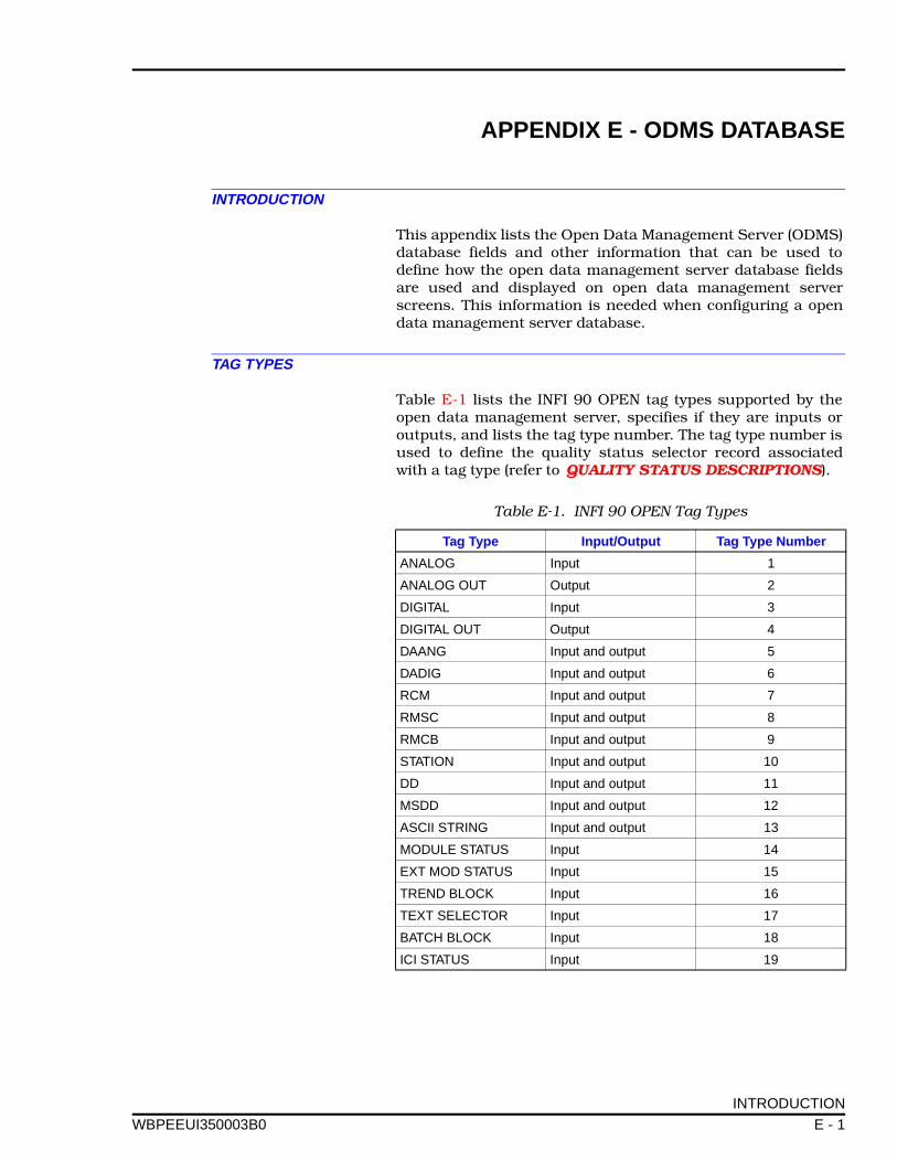
APPENDIX E - ODMS DATABASE
WBPEEUI
INTRODUCTION
This appendix lists the Open Data Management Server (ODMS)database fields and other information that can be used todefine how the open data management server database fieldsare used and displayed on open data management serverscreens. This information is needed when configuring a opendata management server database.
TAG TYPES
Table E-1 lists the INFI 90 OPEN tag types supported by theopen data management server, specifies if they are inputs oroutputs, and lists the tag type number. The tag type number isused to define the quality status selector record associatedwith a tag type (refer to QUALITY STATUS DESCRIPTIONS).
Table E-1. INFI 90 OPEN Tag Types
Tag Type Input/Output Tag Type Number
ANALOG Input 1
ANALOG OUT Output 2
DIGITAL Input 3
DIGITAL OUT Output 4
DAANG Input and output 5
DADIG Input and output 6
RCM Input and output 7
RMSC Input and output 8
RMCB Input and output 9
STATION Input and output 10
DD Input and output 11
MSDD Input and output 12
ASCII STRING Input and output 13
MODULE STATUS Input 14
EXT MOD STATUS Input 15
TREND BLOCK Input 16
TEXT SELECTOR Input 17
BATCH BLOCK Input 18
ICI STATUS Input 19
INTRODUCTION
350003B0 E - 1
ODMS DATABASE ®
QUALITY STATUS DESCRIPTIONS
Quality status descriptions are defined or modified in theQUALITY-STATUSXX selector record, where XX is a numberthat represents the tag type (refer to Table E-1 ). Each tag typeuses different status descriptions. Some typical quality statusstate descriptions are: Bad, Clamped Low, Clamped High, Sus-pect, No Status, Good, Initial, Manual Sub, Off Scan, BadQuality, Red Tagged, Tracking, etc.
Quality status state descriptions can be given display priori-ties. Refer to SOFTWARE DETAILS in Section 6 for informa-tion on configuring displays using quality to structure recorddisplay priorities.
OPEN DATA MANAGEMENT SERVER DATABASE FIELDS
Table E-2 lists the open data management server databasefields that are used to build a open data management serverdatabase and information on each of the field. The informationin Table E-2 includes:
ODMS Database FieldName
The database field name or attribute that is contained in adatabase record.
Supported Tag Type Lists the open data management server tag types that supportthe database field name.
Changeable On-line Some database fields can be changed on-line. This column liststhose fields and any restrictions to modifying the tag on-line.Tags that are fully changeable on-line can be changed via theopen data management server tag configuration or operatingparameters screens.
Default Value Shows what appears on applicable screens when the open datamanagement server is first started. Some database fields canhave their default values configured to other values before asystem start-up. When a change to a default value is made, itapplies to all such tags.
User Defined List of database fields that must be initially defined by the userbefore a system start-up.
INFI 90 OPEN Update Lists the open data management server database fields thatare updated by INFI 90 OPEN exception reports.
Format An explanation of how the database field must be formatted.Fields that cannot be modified by the user may list not applica-ble as the field format or indicate how the field is defined. Somefields are defined by other attributes or database fields.
QUALITY STATUS DESCRIPTIONS
E - 2 WBPEEUI350003B0

ODMS DATABASE
WBPEEUI
Description Provides a description of the field, explains how the databasefield works, and gives additional information on the field for-mat if needed.
OPEN DATA MANAGEMENT SERVER DATABASE FIELDS
350003B0 E - 3
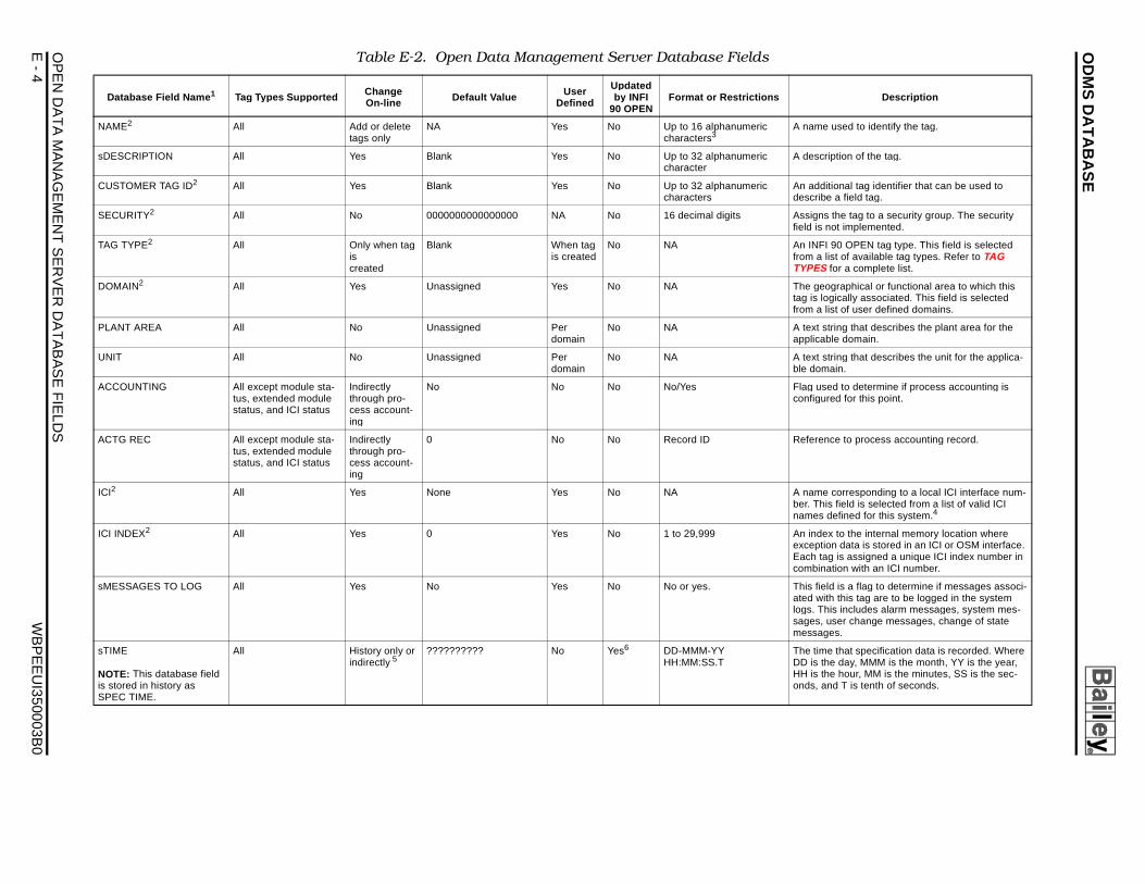
OD
MS
DA
TA
BA
SE
OP
EN
E
- 4
W
BP
EE
UI350003B
0
Table E-2. Open Data Management Server Database Fields
Change User Updated Descri ption
A name used to identify the tag.
A description of the tag.
An additional tag identifier that can be used to describe a field tag.
Assigns the tag to a security group. The security field is not implemented.
An INFI 90 OPEN tag type. This field is selected from a list of available tag types. Refer to TAG TYPES for a complete list.
The geographical or functional area to which this tag is logically associated. This field is selected from a list of user defined domains.
A text string that describes the plant area for the applicable domain.
A text string that describes the unit for the applica-ble domain.
Flag used to determine if process accounting is configured for this point.
Reference to process accounting record.
A name corresponding to a local ICI interface num-ber. This field is selected from a list of valid ICI names defined for this system.4
An index to the internal memory location where exception data is stored in an ICI or OSM interface. Each tag is assigned a unique ICI index number in combination with an ICI number.
This field is a flag to determine if messages associ-ated with this tag are to be logged in the system logs. This includes alarm messages, system mes-sages, user change messages, change of state messages.
The time that specification data is recorded. Where DD is the day, MMM is the month, YY is the year, HH is the hour, MM is the minutes, SS is the sec-onds, and T is tenth of seconds.
DA
TA
MA
NA
GE
ME
NT
SE
RV
ER
DA
TA
BA
SE
FIE
LDS
Database Field Name 1 Tag Types Supported On-line Default Value Defined by INFI 90 OPEN
Format or Restrictions
NAME2 All Add or delete tags only
NA Yes No Up to 16 alphanumeric characters3
sDESCRIPTION All Yes Blank Yes No Up to 32 alphanumeric character
CUSTOMER TAG ID2 All Yes Blank Yes No Up to 32 alphanumeric characters
SECURITY2 All No 0000000000000000 NA No 16 decimal digits
TAG TYPE2 All Only when tag is created
Blank When tag is created
No NA
DOMAIN2 All Yes Unassigned Yes No NA
PLANT AREA All No Unassigned Per domain
No NA
UNIT All No Unassigned Per domain
No NA
ACCOUNTING All except module sta-tus, extended module status, and ICI status
Indirectly through pro-cess account-ing
No No No No/Yes
ACTG REC All except module sta-tus, extended module status, and ICI status
Indirectly through pro-cess account-ing
0 No No Record ID
ICI2 All Yes None Yes No NA
ICI INDEX2 All Yes 0 Yes No 1 to 29,999
sMESSAGES TO LOG All Yes No Yes No No or yes.
sTIME
NOTE: This database field is stored in history as SPEC TIME.
All History only or indirectly 5
?????????? No Yes6 DD-MMM-YY HH:MM:SS.T
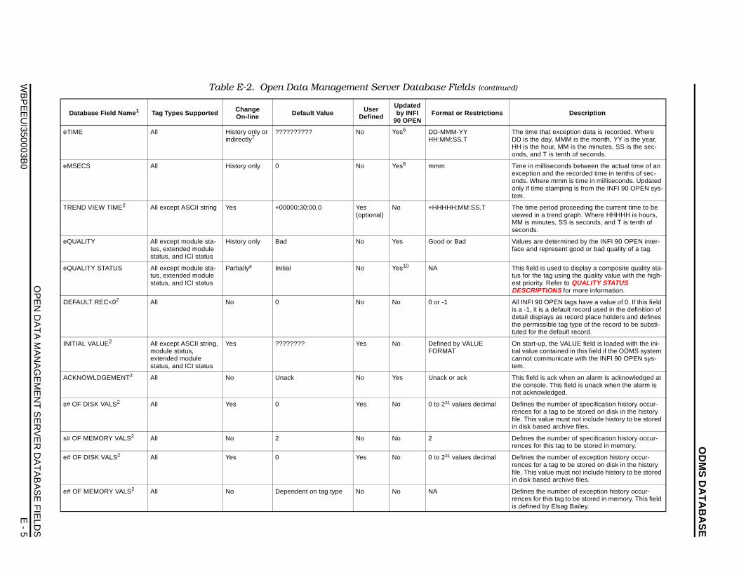
OD
MS
DA
TA
BA
SE
OP
EN
DA
TA
MA
NA
GE
ME
NT
SE
RV
ER
DA
TA
BA
SE
FIE
LDS
WB
PE
EU
I350003B0
E - 5
eTIM t exception data is recorded. Where y, MMM is the month, YY is the year, ur, MM is the minutes, SS is the sec- is tenth of seconds.
eMS seconds between the actual time of an d the recorded time in tenths of sec- mmm is time in milliseconds. Updated tamping is from the INFI 90 OPEN sys-
TRE riod proceeding the current time to be trend graph. Where HHHHH is hours, es, SS is seconds, and T is tenth of
eQU etermined by the INFI 90 OPEN inter-resent good or bad quality of a tag.
eQU used to display a composite quality sta-g using the quality value with the high-efer to QUALITY STATUS
ONS for more information.
DEF PEN tags have a value of 0. If this field default record used in the definition of ys as record place holders and defines ible tag type of the record to be substi- default record.
INIT the VALUE field is loaded with the ini-ntained in this field if the ODMS system municate with the INFI 90 OPEN sys-
ACK ack when an alarm is acknowledged at This field is unack when the alarm is edged.
s# O number of specification history occur- tag to be stored on disk in the history ue must not include history to be stored d archive files.
s# O number of specification history occur-is tag to be stored in memory.
e# O number of exception history occur- tag to be stored on disk in the history ue must not include history to be stored d archive files.
e# O number of exception history occur-is tag to be stored in memory. This field Elsag Bailey.
Da Descri ption
E All History only or indirectly7
?????????? No Yes6 DD-MMM-YY HH:MM:SS.T
The time thaDD is the daHH is the hoonds, and T
ECS All History only 0 No Yes6 mmm Time in milliexception anonds. Whereonly if time stem.
ND VIEW TIME2 All except ASCII string Yes +00000:30:00.0 Yes (optional)
No +HHHHH:MM:SS.T The time peviewed in a MM is minutseconds.
ALITY All except module sta-tus, extended module status, and ICI status
History only Bad No Yes Good or Bad Values are dface and rep
ALITY STATUS All except module sta-tus, extended module status, and ICI status
Partially8 Initial No Yes10 NA This field is tus for the taest priority. RDESCRIPTI
AULT REC<02 All No 0 No No 0 or -1 All INFI 90 Ois a -1, it is adetail displathe permisstuted for the
IAL VALUE2 All except ASCII string, module status, extended modulestatus, and ICI status
Yes ???????? Yes No Defined by VALUE FORMAT
On start-up,tial value cocannot comtem.
NOWLDGEMENT2 All No Unack No Yes Unack or ack This field is the console.not acknowl
F DISK VALS2 All Yes 0 Yes No 0 to 231 values decimal Defines the rences for afile. This valin disk base
F MEMORY VALS2 All No 2 No No 2 Defines the rences for th
F DISK VALS2 All Yes 0 Yes No 0 to 231 values decimal Defines the rences for afile. This valin disk base
F MEMORY VALS2 All No Dependent on tag type No No NA Defines the rences for this defined by
Table E-2. Open Data Management Server Database Fields (continued)
tabase Field Name 1 Tag Types Supported ChangeOn-line Default Value User
Defined
Updated by INFI
90 OPENFormat or Restrictions
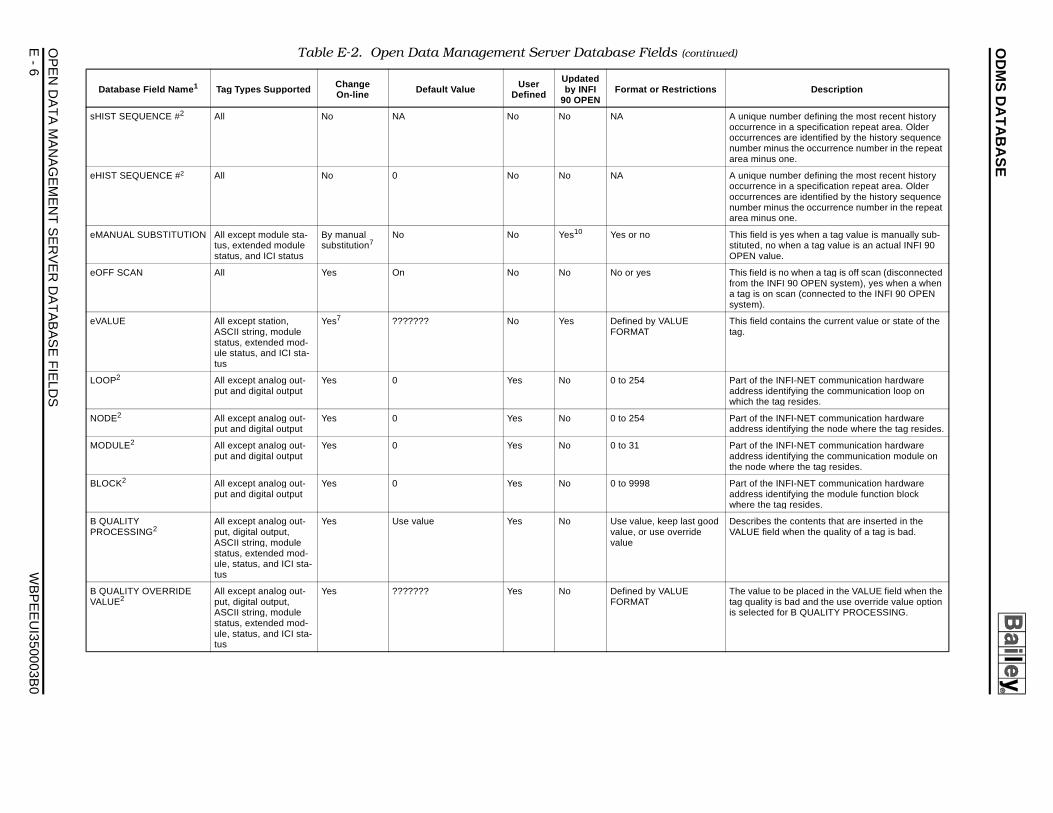
OD
MS
DA
TA
BA
SE
OP
EN
E
- 6
W
BP
EE
UI350003B
0
A unique number defining the most recent history occurrence in a specification repeat area. Older occurrences are identified by the history sequence number minus the occurrence number in the repeat area minus one.
A unique number defining the most recent history occurrence in a specification repeat area. Older occurrences are identified by the history sequence number minus the occurrence number in the repeat area minus one.
This field is yes when a tag value is manually sub-stituted, no when a tag value is an actual INFI 90 OPEN value.
This field is no when a tag is off scan (disconnected from the INFI 90 OPEN system), yes when a when a tag is on scan (connected to the INFI 90 OPEN system).
This field contains the current value or state of the tag.
Part of the INFI-NET communication hardware address identifying the communication loop on which the tag resides.
Part of the INFI-NET communication hardware address identifying the node where the tag resides.
Part of the INFI-NET communication hardware address identifying the communication module on the node where the tag resides.
Part of the INFI-NET communication hardware address identifying the module function block where the tag resides.
od Describes the contents that are inserted in the VALUE field when the quality of a tag is bad.
The value to be placed in the VALUE field when the tag quality is bad and the use override value option is selected for B QUALITY PROCESSING.
Table E-2. Open Data Management Server Database Fields (continued)
Change User Updated Descri ption
DAT
A M
AN
AG
EM
EN
T S
ER
VE
R D
AT
AB
AS
E F
IELD
S
sHIST SEQUENCE #2 All No NA No No NA
eHIST SEQUENCE #2 All No 0 No No NA
eMANUAL SUBSTITUTION All except module sta-tus, extended module status, and ICI status
By manual substitution7
No No Yes10 Yes or no
eOFF SCAN All Yes On No No No or yes
eVALUE All except station, ASCII string, module status, extended mod-ule status, and ICI sta-tus
Yes7 ??????? No Yes Defined by VALUEFORMAT
LOOP2 All except analog out-put and digital output
Yes 0 Yes No 0 to 254
NODE2 All except analog out-put and digital output
Yes 0 Yes No 0 to 254
MODULE2 All except analog out-put and digital output
Yes 0 Yes No 0 to 31
BLOCK2 All except analog out-put and digital output
Yes 0 Yes No 0 to 9998
B QUALITY PROCESSING2
All except analog out-put, digital output, ASCII string, module status, extended mod-ule, status, and ICI sta-tus
Yes Use value Yes No Use value, keep last govalue, or use override value
B QUALITY OVERRIDE VALUE2
All except analog out-put, digital output, ASCII string, module status, extended mod-ule, status, and ICI sta-tus
Yes ??????? Yes No Defined by VALUE FORMAT
Database Field Name 1 Tag Types Supported On-line Default Value Defined by INFI 90 OPEN
Format or Restrictions
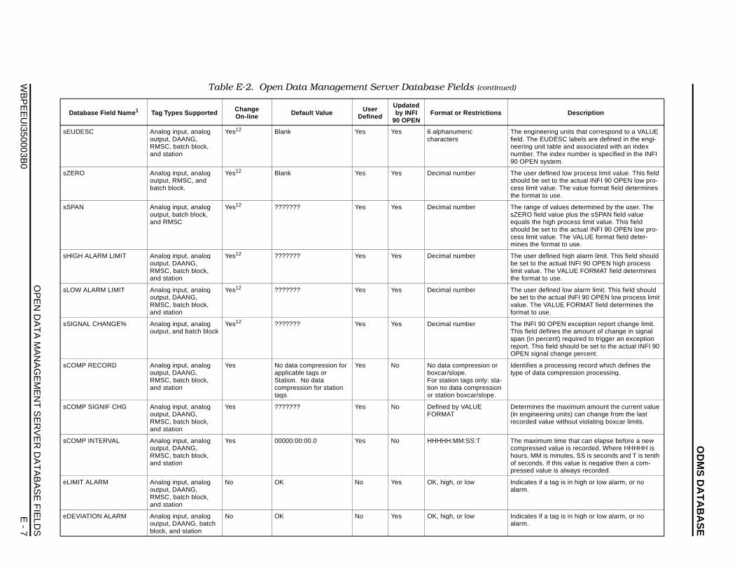
OD
MS
DA
TA
BA
SE
OP
EN
DA
TA
MA
NA
GE
ME
NT
SE
RV
ER
DA
TA
BA
SE
FIE
LDS
WB
PE
EU
I350003B0
E - 7
sEU ring units that correspond to a VALUE DESC labels are defined in the engi-
table and associated with an index index number is specified in the INFI stem.
sZER fined low process limit value. This field t to the actual INFI 90 OPEN low pro-lue. The value format field determines use.
sSPA f values determined by the user. The value plus the sSPAN field value igh process limit value. This field t to the actual INFI 90 OPEN low pro-lue. The VALUE format field deter-rmat to use.
sHIG fined high alarm limit. This field should actual INFI 90 OPEN high process he VALUE FORMAT field determines use.
sLOW fined low alarm limit. This field should actual INFI 90 OPEN low process limit ALUE FORMAT field determines the e.
sSIG OPEN exception report change limit. fines the amount of change in signal cent) required to trigger an exception field should be set to the actual INFI 90 l change percent.
sCO rocessing record which defines the compression processing.
sCO the maximum amount the current value ing units) can change from the last lue without violating boxcar limits.
sCO m time that can elapse before a new value is recorded. Where HHHHH is s minutes, SS is seconds and T is tenth If this value is negative then a com-e is always recorded.
eLIM tag is in high or low alarm, or no
eDE tag is in high or low alarm, or no
Da Descri ption
DESC Analog input, analog output, DAANG, RMSC, batch block, and station
Yes12 Blank Yes Yes 6 alphanumeric characters
The engineefield. The EUneering unitnumber. The90 OPEN sy
O Analog input, analog output, RMSC, and batch block.
Yes12 Blank Yes Yes Decimal number The user deshould be secess limit vathe format to
N Analog input, analog output, batch block, and RMSC
Yes12 ??????? Yes Yes Decimal number The range osZERO fieldequals the hshould be secess limit vamines the fo
H ALARM LIMIT Analog input, analog output, DAANG, RMSC, batch block, and station
Yes12 ??????? Yes Yes Decimal number The user debe set to thelimit value. Tthe format to
ALARM LIMIT Analog input, analog output, DAANG, RMSC, batch block, and station
Yes12 ??????? Yes Yes Decimal number The user debe set to thevalue. The Vformat to us
NAL CHANGE% Analog input, analog output, and batch block
Yes12 ??????? Yes Yes Decimal number The INFI 90This field despan (in perreport. This OPEN signa
MP RECORD Analog input, analog output, DAANG, RMSC, batch block, and station
Yes No data compression for applicable tags or Station. No data compression for station tags
Yes No No data compression or boxcar/slope.For station tags only: sta-tion no data compression or station boxcar/slope.
Identifies a ptype of data
MP SIGNIF CHG Analog input, analog output, DAANG, RMSC, batch block, and station
Yes ??????? Yes No Defined by VALUE FORMAT
Determines (in engineerrecorded va
MP INTERVAL Analog input, analog output, DAANG, RMSC, batch block, and station
Yes 00000:00:00.0 Yes No HHHHH:MM:SS:T The maximucompressedhours, MM iof seconds. pressed valu
IT ALARM Analog input, analog output, DAANG, RMSC, batch block, and station
No OK No Yes OK, high, or low Indicates if aalarm.
VIATION ALARM Analog input, analog output, DAANG, batch block, and station
No OK No Yes OK, high, or low Indicates if aalarm.
Table E-2. Open Data Management Server Database Fields (continued)
tabase Field Name 1 Tag Types Supported ChangeOn-line Default Value User
Defined
Updated by INFI
90 OPENFormat or Restrictions
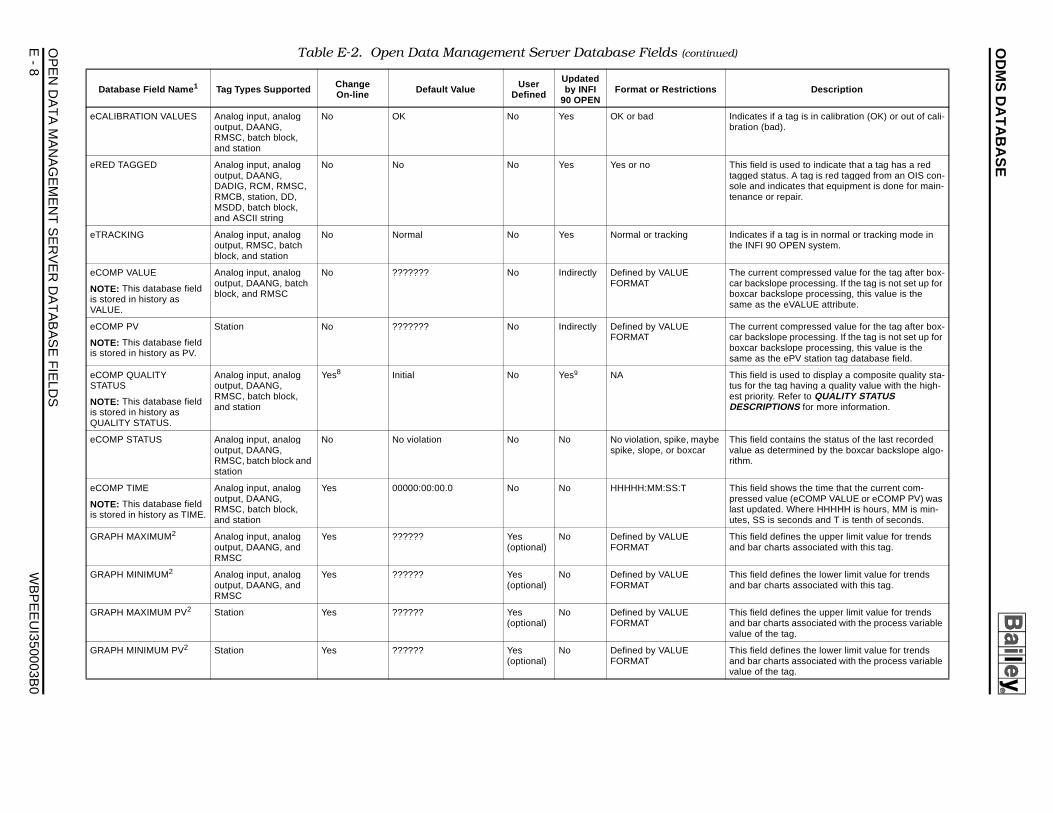
OD
MS
DA
TA
BA
SE
OP
EN
E
- 8
W
BP
EE
UI350003B
0
Indicates if a tag is in calibration (OK) or out of cali-bration (bad).
This field is used to indicate that a tag has a red tagged status. A tag is red tagged from an OIS con-sole and indicates that equipment is done for main-tenance or repair.
Indicates if a tag is in normal or tracking mode in the INFI 90 OPEN system.
The current compressed value for the tag after box-car backslope processing. If the tag is not set up for boxcar backslope processing, this value is the same as the eVALUE attribute.
The current compressed value for the tag after box-car backslope processing. If the tag is not set up for boxcar backslope processing, this value is the same as the ePV station tag database field.
This field is used to display a composite quality sta-tus for the tag having a quality value with the high-est priority. Refer to QUALITY STATUS DESCRIPTIONS for more information.
be This field contains the status of the last recorded value as determined by the boxcar backslope algo-rithm.
This field shows the time that the current com-pressed value (eCOMP VALUE or eCOMP PV) was last updated. Where HHHHH is hours, MM is min-utes, SS is seconds and T is tenth of seconds.
This field defines the upper limit value for trends and bar charts associated with this tag.
This field defines the lower limit value for trends and bar charts associated with this tag.
This field defines the upper limit value for trends and bar charts associated with the process variable value of the tag.
This field defines the lower limit value for trends and bar charts associated with the process variable value of the tag.
Table E-2. Open Data Management Server Database Fields (continued)
Change User Updated Descri ption
DAT
A M
AN
AG
EM
EN
T S
ER
VE
R D
AT
AB
AS
E F
IELD
S
eCALIBRATION VALUES Analog input, analog output, DAANG, RMSC, batch block, and station
No OK No Yes OK or bad
eRED TAGGED Analog input, analog output, DAANG, DADIG, RCM, RMSC, RMCB, station, DD, MSDD, batch block, and ASCII string
No No No Yes Yes or no
eTRACKING Analog input, analog output, RMSC, batch block, and station
No Normal No Yes Normal or tracking
eCOMP VALUE
NOTE: This database field is stored in history as VALUE.
Analog input, analog output, DAANG, batch block, and RMSC
No ??????? No Indirectly Defined by VALUE FORMAT
eCOMP PV
NOTE: This database field is stored in history as PV.
Station No ??????? No Indirectly Defined by VALUEFORMAT
eCOMP QUALITY STATUS
NOTE: This database field is stored in history as QUALITY STATUS.
Analog input, analog output, DAANG, RMSC, batch block, and station
Yes8 Initial No Yes9 NA
eCOMP STATUS Analog input, analog output, DAANG, RMSC, batch block and station
No No violation No No No violation, spike, mayspike, slope, or boxcar
eCOMP TIME
NOTE: This database field is stored in history as TIME.
Analog input, analog output, DAANG, RMSC, batch block, and station
Yes 00000:00:00.0 No No HHHHH:MM:SS:T
GRAPH MAXIMUM2 Analog input, analog output, DAANG, and RMSC
Yes ?????? Yes (optional)
No Defined by VALUE FORMAT
GRAPH MINIMUM2 Analog input, analog output, DAANG, and RMSC
Yes ?????? Yes (optional)
No Defined by VALUE FORMAT
GRAPH MAXIMUM PV2 Station Yes ?????? Yes (optional)
No Defined by VALUE FORMAT
GRAPH MINIMUM PV2 Station Yes ?????? Yes (optional)
No Defined by VALUE FORMAT
Database Field Name 1 Tag Types Supported On-line Default Value Defined by INFI 90 OPEN
Format or Restrictions
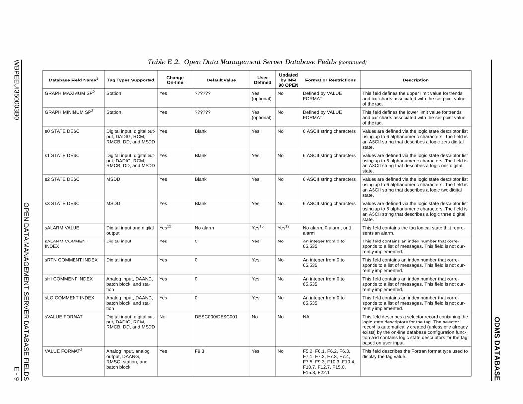
OD
MS
DA
TA
BA
SE
OP
EN
DA
TA
MA
NA
GE
ME
NT
SE
RV
ER
DA
TA
BA
SE
FIE
LDS
WB
PE
EU
I350003B0
E - 9
GRA fines the upper limit value for trends rts associated with the set point value
GRA fines the lower limit value for trends rts associated with the set point value
s0 S efined via the logic state descriptor list 6 alphanumeric characters. The field is ing that describes a logic zero digital
s1 S efined via the logic state descriptor list 6 alphanumeric characters. The field is ing that describes a logic one digital
s2 S efined via the logic state descriptor list 6 alphanumeric characters. The field is ing that describes a logic two digital
s3 S efined via the logic state descriptor list 6 alphanumeric characters. The field is ing that describes a logic three digital
sALA ntains the tag logical state that repre-rm.
sALAINDE
ntains an index number that corre- list of messages. This field is not cur-
ented.
sRTN ntains an index number that corre- list of messages. This field is not cur-
ented.
sHI C ntains an index number that corre- list of messages. This field is not cur-
ented.
sLO ntains an index number that corre- list of messages. This field is not cur-
ented.
sVAL scribes a selector record containing the escriptors for the tag. The selector tomatically created (unless one already e on-line database configuration func-tains logic state descriptors for the tag er input.
VALU scribes the Fortran format type used to ag value.
Da Descri ption
PH MAXIMUM SP2 Station Yes ?????? Yes (optional)
No Defined by VALUE FORMAT
This field deand bar chaof the tag.
PH MINIMUM SP2 Station Yes ?????? Yes (optional)
No Defined by VALUE FORMAT
This field deand bar chaof the tag.
TATE DESC Digital input, digital out-put, DADIG, RCM, RMCB, DD, and MSDD
Yes Blank Yes No 6 ASCII string characters Values are dusing up to an ASCII strstate.
TATE DESC Digital input, digital out-put, DADIG, RCM, RMCB, DD, and MSDD
Yes Blank Yes No 6 ASCII string characters Values are dusing up to an ASCII strstate.
TATE DESC MSDD Yes Blank Yes No 6 ASCII string characters Values are dusing up to an ASCII strstate.
TATE DESC MSDD Yes Blank Yes No 6 ASCII string characters Values are dusing up to an ASCII strstate.
RM VALUE Digital input and digital output
Yes12 No alarm Yes15 Yes12 No alarm, 0 alarm, or 1 alarm
This field cosents an ala
RM COMMENT X
Digital input Yes 0 Yes No An integer from 0 to 65,535
This field cosponds to arently implem
COMMENT INDEX Digital input Yes 0 Yes No An integer from 0 to 65,535
This field cosponds to arently implem
OMMENT INDEX Analog input, DAANG, batch block, and sta-tion
Yes 0 Yes No An integer from 0 to 65,535
This field cosponds to arently implem
COMMENT INDEX Analog input, DAANG, batch block, and sta-tion
Yes 0 Yes No An integer from 0 to 65,535
This field cosponds to arently implem
UE FORMAT Digital input, digital out-put, DADIG, RCM, RMCB, DD, and MSDD
No DESC000/DESC001 No No NA This field delogic state drecord is auexists) by thtion and conbased on us
E FORMAT2 Analog input, analog output, DAANG, RMSC, station, and batch block
Yes F9.3 Yes No F5.2, F6.1, F6.2, F6.3, F7.1, F7.2, F7.3, F7.4, F7.5, F9.3, F10.3, F10.4, F10.7, F12.7, F15.0, F15.8, F22.1
This field dedisplay the t
Table E-2. Open Data Management Server Database Fields (continued)
tabase Field Name 1 Tag Types Supported ChangeOn-line Default Value User
Defined
Updated by INFI
90 OPENFormat or Restrictions
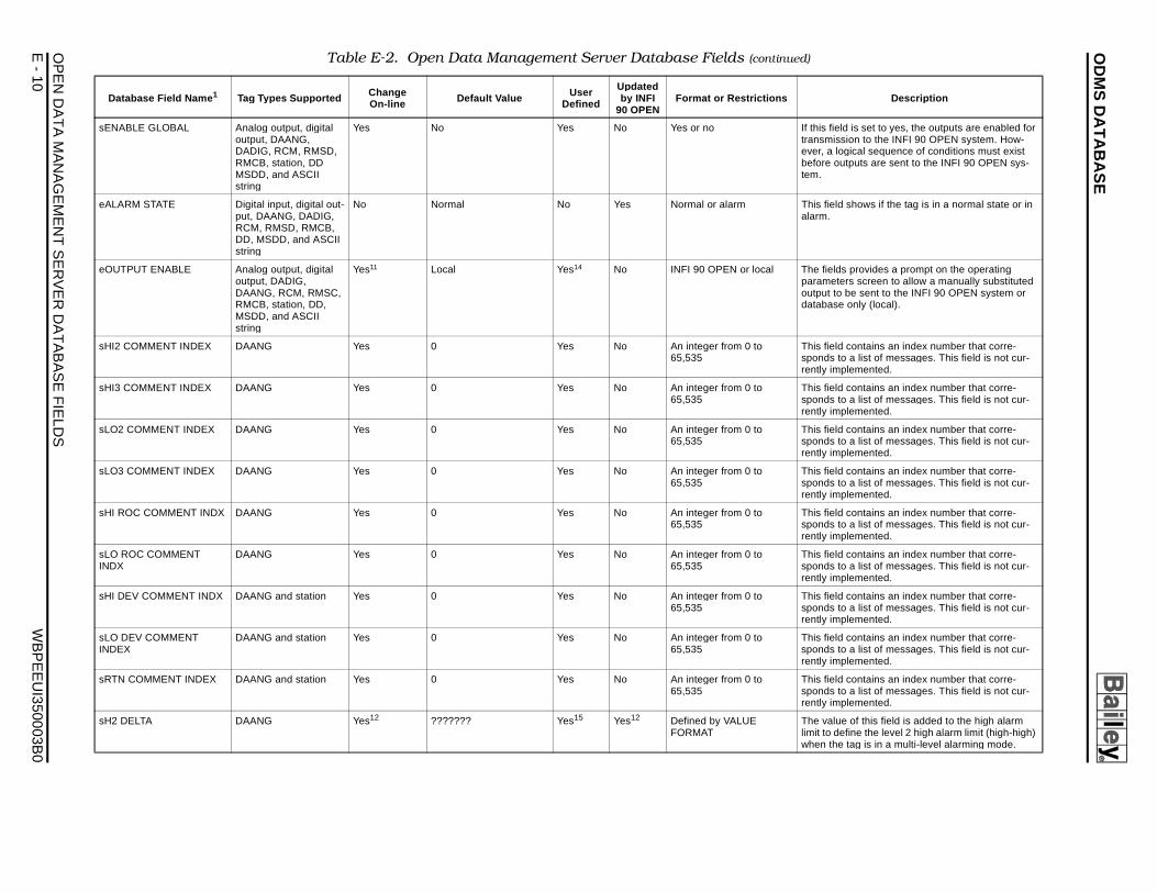
OD
MS
DA
TA
BA
SE
OP
EN
E
- 10
W
BP
EE
UI350003B
0
If this field is set to yes, the outputs are enabled for transmission to the INFI 90 OPEN system. How-ever, a logical sequence of conditions must exist before outputs are sent to the INFI 90 OPEN sys-tem.
This field shows if the tag is in a normal state or in alarm.
The fields provides a prompt on the operating parameters screen to allow a manually substituted output to be sent to the INFI 90 OPEN system or database only (local).
This field contains an index number that corre-sponds to a list of messages. This field is not cur-rently implemented.
This field contains an index number that corre-sponds to a list of messages. This field is not cur-rently implemented.
This field contains an index number that corre-sponds to a list of messages. This field is not cur-rently implemented.
This field contains an index number that corre-sponds to a list of messages. This field is not cur-rently implemented.
This field contains an index number that corre-sponds to a list of messages. This field is not cur-rently implemented.
This field contains an index number that corre-sponds to a list of messages. This field is not cur-rently implemented.
This field contains an index number that corre-sponds to a list of messages. This field is not cur-rently implemented.
This field contains an index number that corre-sponds to a list of messages. This field is not cur-rently implemented.
This field contains an index number that corre-sponds to a list of messages. This field is not cur-rently implemented.
The value of this field is added to the high alarm limit to define the level 2 high alarm limit (high-high) when the tag is in a multi-level alarming mode.
Table E-2. Open Data Management Server Database Fields (continued)
Change User Updated Descri ption
DAT
A M
AN
AG
EM
EN
T S
ER
VE
R D
AT
AB
AS
E F
IELD
S
sENABLE GLOBAL Analog output, digital output, DAANG, DADIG, RCM, RMSD, RMCB, station, DD MSDD, and ASCII string
Yes No Yes No Yes or no
eALARM STATE Digital input, digital out-put, DAANG, DADIG, RCM, RMSD, RMCB, DD, MSDD, and ASCII string
No Normal No Yes Normal or alarm
eOUTPUT ENABLE Analog output, digital output, DADIG, DAANG, RCM, RMSC, RMCB, station, DD, MSDD, and ASCII string
Yes11 Local Yes14 No INFI 90 OPEN or local
sHI2 COMMENT INDEX DAANG Yes 0 Yes No An integer from 0 to 65,535
sHI3 COMMENT INDEX DAANG Yes 0 Yes No An integer from 0 to 65,535
sLO2 COMMENT INDEX DAANG Yes 0 Yes No An integer from 0 to 65,535
sLO3 COMMENT INDEX DAANG Yes 0 Yes No An integer from 0 to 65,535
sHI ROC COMMENT INDX DAANG Yes 0 Yes No An integer from 0 to 65,535
sLO ROC COMMENT INDX
DAANG Yes 0 Yes No An integer from 0 to 65,535
sHI DEV COMMENT INDX DAANG and station Yes 0 Yes No An integer from 0 to 65,535
sLO DEV COMMENT INDEX
DAANG and station Yes 0 Yes No An integer from 0 to 65,535
sRTN COMMENT INDEX DAANG and station Yes 0 Yes No An integer from 0 to 65,535
sH2 DELTA DAANG Yes12 ??????? Yes15 Yes12 Defined by VALUE FORMAT
Database Field Name 1 Tag Types Supported On-line Default Value Defined by INFI 90 OPEN
Format or Restrictions
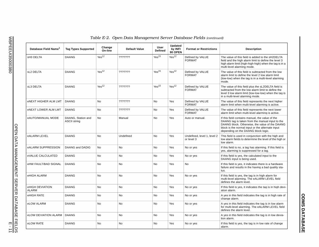
OD
MS
DA
TA
BA
SE
OP
EN
DA
TA
MA
NA
GE
ME
NT
SE
RV
ER
DA
TA
BA
SE
FIE
LDS
WB
PE
EU
I350003B0
E - 11
sH3 f this field is added to the sH2DELTA high alarm limit to define the level 3 mit (high-high-high) when the tag is in a larming mode.
sL2 f this field is subtracted from the low define the level 2 low alarm limit en the tag is in a multi-level alarming
sL3 f this field plus the sL2DELTA field is rom the low alarm limit to define the larm limit (low-low-low) when the tag is el alarming mode.
eNE f this field represents the next higher hen multi-level alarming is active.
eNE f this field represents the next lower hen multi-level alarming is active.
eAU ontains manual, the value of the is taken from the manual input to the ck. Otherwise, the value of the DAANG normal input or the alternate input n the DAANG block logic.
eALA used in conjunction with the high and lds to determine the level of the high or
eALA no, a tag has alarming. If this field is g is suppressed for a tag.
eVAL yes, the calculated input to the ut is being used.
eHW yes, it indicates there is a hardware esults in the having a bad quality sta-
eHIG yes, the tag is in high alarm for larming. The eALARM LEVEL field alarm level.
eHIGALA
yes, it indicates the tag is in high devi-
eHIG field indicates the tag is in high rate of m.
eLO field indicates the tag is in low alarm el alarming. The eALARM LEVEL field alarm level.
eLO field indicates the tag is in low devia-
eLO yes, the tag is in low rate of change
Da Descri ption
DELTA DAANG Yes12 ??????? Yes15 Yes12 Defined by VALUE FORMAT
The value ofield and thehigh alarm limulti-level a
DELTA DAANG Yes12 ??????? Yes15 Yes12 Defined by VALUE FORMAT
The value oalarm limit to(low-low) whmode.
DELTA DAANG Yes12 ??????? Yes15 Yes12 Defined by VALUE FORMAT
The value osubtracted flevel 3 low ain a multi-lev
XT HIGHER ALM LMT DAANG No ??????? No Yes Defined by VALUE FORMAT
The value oalarm limit w
XT LOWER ALM LMT DAANG No ??????? No Yes Defined by VALUE FORMAT
The value oalarm limit w
TO/MANUAL MODE DAANG, Station and ASCII string
No Manual No Yes Auto or manual. If this field cDAANG tagDAANG bloblock is the depending o
RM LEVEL DAANG No Undefined No Yes Undefined, level 1, level 2 or level 3
This field is low alarm fielow alarm.
RM SUPPRESSION DAANG and DADIG No No No Yes No or yes If this field isyes, alarmin
UE CALCULATED DAANG No No No Yes No or yes If this field isDAANG inp
FAULT/BAD SIGNAL DAANG No No No Yes No If this field isfailure and rtus.
H ALARM DAANG No No No Yes No or yes If this field ismulti-level adefines the
H DEVIATION RM
DAANG No No No Yes No or yes If this field isation alarm.
H RATE DAANG No No No Yes No or yes A yes in thischange alar
W ALARM DAANG No No No Yes No or yes A yes in thisfor multi-levdefines the
W DEVIATION ALARM DAANG No No No Yes No or yes A yes in thistion alarm.
W RATE DAANG No No No Yes No or yes If this field isalarm.
Table E-2. Open Data Management Server Database Fields (continued)
tabase Field Name 1 Tag Types Supported ChangeOn-line Default Value User
Defined
Updated by INFI
90 OPENFormat or Restrictions
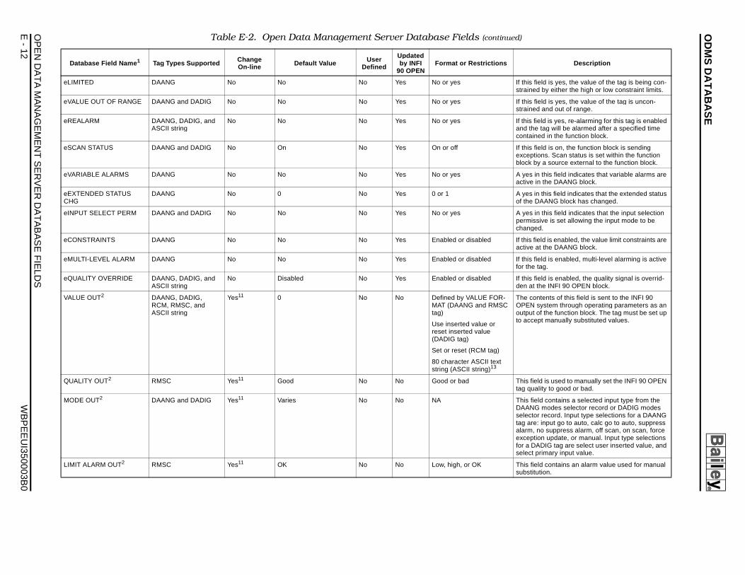
OD
MS
DA
TA
BA
SE
OP
EN
E
- 12
W
BP
EE
UI350003B
0
If this field is yes, the value of the tag is being con-strained by either the high or low constraint limits.
If this field is yes, the value of the tag is uncon-strained and out of range.
If this field is yes, re-alarming for this tag is enabled and the tag will be alarmed after a specified time contained in the function block.
If this field is on, the function block is sending exceptions. Scan status is set within the function block by a source external to the function block.
A yes in this field indicates that variable alarms are active in the DAANG block.
A yes in this field indicates that the extended status of the DAANG block has changed.
A yes in this field indicates that the input selection permissive is set allowing the input mode to be changed.
If this field is enabled, the value limit constraints are active at the DAANG block.
If this field is enabled, multi-level alarming is active for the tag.
If this field is enabled, the quality signal is overrid-den at the INFI 90 OPEN block.
-C
The contents of this field is sent to the INFI 90 OPEN system through operating parameters as an output of the function block. The tag must be set up to accept manually substituted values.
This field is used to manually set the INFI 90 OPEN tag quality to good or bad.
This field contains a selected input type from the DAANG modes selector record or DADIG modes selector record. Input type selections for a DAANG tag are: input go to auto, calc go to auto, suppress alarm, no suppress alarm, off scan, on scan, force exception update, or manual. Input type selections for a DADIG tag are select user inserted value, and select primary input value.
This field contains an alarm value used for manual substitution.
Table E-2. Open Data Management Server Database Fields (continued)
Change User Updated Descri ption
DAT
A M
AN
AG
EM
EN
T S
ER
VE
R D
AT
AB
AS
E F
IELD
S
eLIMITED DAANG No No No Yes No or yes
eVALUE OUT OF RANGE DAANG and DADIG No No No Yes No or yes
eREALARM DAANG, DADIG, and ASCII string
No No No Yes No or yes
eSCAN STATUS DAANG and DADIG No On No Yes On or off
eVARIABLE ALARMS DAANG No No No Yes No or yes
eEXTENDED STATUS CHG
DAANG No 0 No Yes 0 or 1
eINPUT SELECT PERM DAANG and DADIG No No No Yes No or yes
eCONSTRAINTS DAANG No No No Yes Enabled or disabled
eMULTI-LEVEL ALARM DAANG No No No Yes Enabled or disabled
eQUALITY OVERRIDE DAANG, DADIG, and ASCII string
No Disabled No Yes Enabled or disabled
VALUE OUT2 DAANG, DADIG, RCM, RMSC, and ASCII string
Yes11 0 No No Defined by VALUE FORMAT (DAANG and RMStag)
Use inserted value or reset inserted value (DADIG tag)
Set or reset (RCM tag)
80 character ASCII textstring (ASCII string)13
QUALITY OUT2 RMSC Yes11 Good No No Good or bad
MODE OUT2 DAANG and DADIG Yes11 Varies No No NA
LIMIT ALARM OUT2 RMSC Yes11 OK No No Low, high, or OK
Database Field Name 1 Tag Types Supported On-line Default Value Defined by INFI 90 OPEN
Format or Restrictions
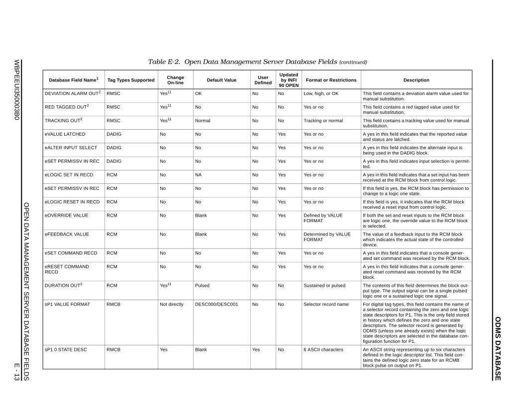
OD
MS
DA
TA
BA
SE
OP
EN
DA
TA
MA
NA
GE
ME
NT
SE
RV
ER
DA
TA
BA
SE
FIE
LDS
WB
PE
EU
I350003B0
E - 13
DEV ntains a deviation alarm value used for stitution.
RED ntains a red tagged value used for stitution.
TRA ntains a tracking value used for manual
eVAL field indicates that the reported value re latched.
eALT field indicates the alternate input is in the DADIG block.
eSE field indicates input selection is permit-
eLO field indicates that a set input has been the RCM block from control logic.
eSE yes, the RCM block has permission to logic one state.
eLO yes, it indicates that the RCM block eset input from control logic.
eOV et and reset inputs to the RCM block e, the override value to the RCM block
eFEE f a feedback input to the RCM block tes the actual state of the controlled
eSE field indicates that a console gener-mand was received by the RCM block.
eREREC
field indicates that a console gener-ommand was received by the RCM
DUR s of this field determines the block out-e output signal can be a single pulsed a sustained logic one signal.
sP1 g types, this field contains the name of cord containing the zero and one logic tors for P1. This is the only field stored ich defines the zero and one state
The selector record is generated by ss one already exists) when the logic tors are selected in the database con-
nction for P1.
sP1 ring representing up to six characters e logic descriptor list. This field con-
fined logic zero state for an RCMB on output on P1.
Da Descri ption
IATION ALARM OUT2 RMSC Yes11 OK No No Low, high, or OK This field comanual sub
TAGGED OUT2 RMSC Yes11 No No No Yes or no This field comanual sub
CKING OUT2 RMSC Yes11 Normal No No Tracking or normal This field cosubstitution.
UE LATCHED DADIG No No No Yes Yes or no A yes in thisand status a
ER INPUT SELECT DADIG No No No Yes Yes or no A yes in thisbeing used
T PERMISSV IN REC DADIG No No No Yes Yes or no A yes in thisted.
GIC SET IN RECD RCM No NA No Yes Yes or no A yes in thisreceived at
T PERMISSV IN REC RCM No No No Yes Yes or no If this field ischange to a
GIC RESET IN RECD RCM No No No Yes Yes or no If this field isreceived a r
ERRIDE VALUE RCM No Blank No Yes Defined by VALUE FORMAT
If both the sare logic onis selected.
DBACK VALUE RCM No Blank No Yes Determined by VALUE FORMAT
The value owhich indicadevice.
T COMMAND RECD RCM No No No Yes Yes or no A yes in thisated set com
SET COMMAND D
RCM No No No Yes Yes or no A yes in thisated reset cblock.
ATION OUT2 RCM Yes11 Pulsed No No Sustained or pulsed The contentput type. Thlogic one or
VALUE FORMAT RMCB Not directly DESC000/DESC001 No No Selector record name For digital taa selector restate descripin history whdescriptors.ODMS (unlestate descripfiguration fu
0 STATE DESC RMCB Yes Blank Yes No 6 ASCII characters An ASCII stdefined in thtains the deblock pulse
Table E-2. Open Data Management Server Database Fields (continued)
tabase Field Name 1 Tag Types Supported ChangeOn-line Default Value User
Defined
Updated by INFI
90 OPENFormat or Restrictions
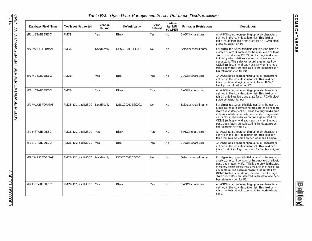
OD
MS
DA
TA
BA
SE
OP
EN
E
- 14
W
BP
EE
UI350003B
0
An ASCII string representing up to six characters defined in the logic descriptor list. This field con-tains the defined logic one state for an RCMB block pulse on output on P1.
For digital tag types, this field contains the name of a selector record containing the zero and one logic state descriptors for P2. This is the only field stored in history which defines the zero and one state descriptors. The selector record is generated by ODMS (unless one already exists) when the logic state descriptors are selected in the database con-figuration function for P2.
An ASCII string representing up to six characters defined in the logic descriptor list. This field con-tains the defined logic zero state for an RCMB block pulse off output for P2.
An ASCII string representing up to six characters defined in the logic descriptor list. This field con-tains the defined logic one state for an RCMB block pulse off output for P2.
For digital tag types, this field contains the name of a selector record containing the zero and one logic state descriptors for F1. This is the only field stored in history which defines the zero and one logic state descriptors. The selector record is generated by ODMS (unless one already exists) when the logic state descriptors are selected in the database con-figuration function for F1.
An ASCII string representing up to six characters defined in the logic descriptor list. This field con-tains the defined logic zero for feedback 1 signal.
An ASCII string representing up to six characters defined in the logic descriptor list. This field con-tains the defined logic one state for feedback signal 1.
For digital tag types, this field contains the name of a selector record containing the zero and one logic state descriptors for F2. This is the only field stored in history which defines the zero and one logic state descriptors. The selector record is generated by ODMS (unless one already exists) when the logic state descriptors are selected in the database con-figuration function for F2.
An ASCII string representing up to six characters defined in the logic descriptor list. This field con-tains the defined logic zero state for feedback sig-nal 2.
Table E-2. Open Data Management Server Database Fields (continued)
Change User Updated Descri ption
DAT
A M
AN
AG
EM
EN
T S
ER
VE
R D
AT
AB
AS
E F
IELD
S
sP1 1 STATE DESC RMCB Yes Blank Yes No 6 ASCII characters
sP2 VALUE FORMAT RMCB Not directly DESC000/DESC001 No No Selector record name
sP2 0 STATE DESC RMCB Yes Blank Yes No 6 ASCII characters
sP2 1 STATE DESC RMCB Yes Blank Yes No 6 ASCII characters
sF1 VALUE FORMAT RMCB, DD, and MSDD Not directly DESC000/DESC001 No No Selector record name
sF1 0 STATE DESC RMCB, DD, and MSDD Yes Blank Yes No 6 ASCII characters
sF1 1 STATE DESC RMCB, DD, and MSDD Yes Blank Yes No 6 ASCII characters
sF2 VALUE FORMAT RMCB, DD, and MSDD Not directly DESC000/DESC001 No No Selector record name
sF2 0 STATE DESC RMCB, DD, and MSDD Yes Blank Yes No 6 ASCII characters
Database Field Name 1 Tag Types Supported On-line Default Value Defined by INFI 90 OPEN
Format or Restrictions
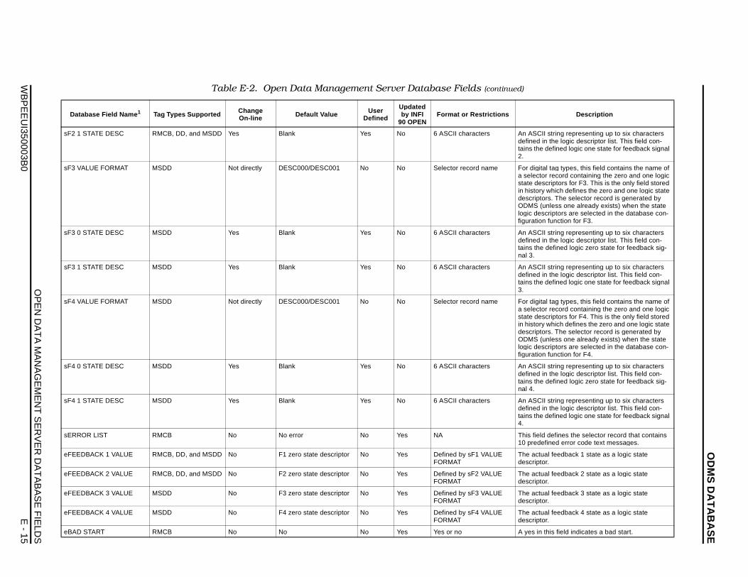
OD
MS
DA
TA
BA
SE
OP
EN
DA
TA
MA
NA
GE
ME
NT
SE
RV
ER
DA
TA
BA
SE
FIE
LDS
WB
PE
EU
I350003B0
E - 15
sF2 ring representing up to six characters e logic descriptor list. This field con-ined logic one state for feedback signal
sF3 g types, this field contains the name of cord containing the zero and one logic tors for F3. This is the only field stored ich defines the zero and one logic state
The selector record is generated by ss one already exists) when the state tors are selected in the database con-
nction for F3.
sF3 ring representing up to six characters e logic descriptor list. This field con-
fined logic zero state for feedback sig-
sF3 ring representing up to six characters e logic descriptor list. This field con-ined logic one state for feedback signal
sF4 g types, this field contains the name of cord containing the zero and one logic tors for F4. This is the only field stored ich defines the zero and one logic state
The selector record is generated by ss one already exists) when the state tors are selected in the database con-
nction for F4.
sF4 ring representing up to six characters e logic descriptor list. This field con-
fined logic zero state for feedback sig-
sF4 ring representing up to six characters e logic descriptor list. This field con-ined logic one state for feedback signal
sER fines the selector record that contains d error code text messages.
eFEE eedback 1 state as a logic state
eFEE eedback 2 state as a logic state
eFEE eedback 3 state as a logic state
eFEE eedback 4 state as a logic state
eBA field indicates a bad start.
Da Descri ption
1 STATE DESC RMCB, DD, and MSDD Yes Blank Yes No 6 ASCII characters An ASCII stdefined in thtains the def2.
VALUE FORMAT MSDD Not directly DESC000/DESC001 No No Selector record name For digital taa selector restate descripin history whdescriptors.ODMS (unlelogic descripfiguration fu
0 STATE DESC MSDD Yes Blank Yes No 6 ASCII characters An ASCII stdefined in thtains the denal 3.
1 STATE DESC MSDD Yes Blank Yes No 6 ASCII characters An ASCII stdefined in thtains the def3.
VALUE FORMAT MSDD Not directly DESC000/DESC001 No No Selector record name For digital taa selector restate descripin history whdescriptors.ODMS (unlelogic descripfiguration fu
0 STATE DESC MSDD Yes Blank Yes No 6 ASCII characters An ASCII stdefined in thtains the denal 4.
1 STATE DESC MSDD Yes Blank Yes No 6 ASCII characters An ASCII stdefined in thtains the def4.
ROR LIST RMCB No No error No Yes NA This field de10 predefine
DBACK 1 VALUE RMCB, DD, and MSDD No F1 zero state descriptor No Yes Defined by sF1 VALUE FORMAT
The actual fdescriptor.
DBACK 2 VALUE RMCB, DD, and MSDD No F2 zero state descriptor No Yes Defined by sF2 VALUE FORMAT
The actual fdescriptor.
DBACK 3 VALUE MSDD No F3 zero state descriptor No Yes Defined by sF3 VALUE FORMAT
The actual fdescriptor.
DBACK 4 VALUE MSDD No F4 zero state descriptor No Yes Defined by sF4 VALUE FORMAT
The actual fdescriptor.
D START RMCB No No No Yes Yes or no A yes in this
Table E-2. Open Data Management Server Database Fields (continued)
tabase Field Name 1 Tag Types Supported ChangeOn-line Default Value User
Defined
Updated by INFI
90 OPENFormat or Restrictions
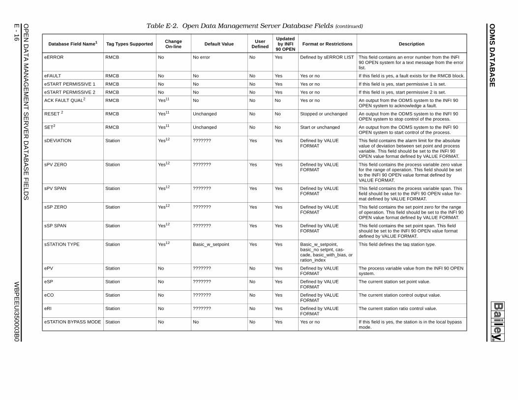
OD
MS
DA
TA
BA
SE
OP
EN
E
- 16
W
BP
EE
UI350003B
0
ST This field contains an error number from the INFI 90 OPEN system for a text message from the error list.
If this field is yes, a fault exists for the RMCB block.
If this field is yes, start permissive 1 is set.
If this field is yes, start permissive 2 is set.
An output from the ODMS system to the INFI 90 OPEN system to acknowledge a fault.
An output from the ODMS system to the INFI 90 OPEN system to stop control of the process.
An output from the ODMS system to the INFI 90 OPEN system to start control of the process.
This field contains the alarm limit for the absolute value of deviation between set point and process variable. This field should be set to the INFI 90 OPEN value format defined by VALUE FORMAT.
This field contains the process variable zero value for the range of operation. This field should be set to the INFI 90 OPEN value format defined by VALUE FORMAT.
This field contains the process variable span. This field should be set to the INFI 90 OPEN value for-mat defined by VALUE FORMAT.
This field contains the set point zero for the range of operation. This field should be set to the INFI 90 OPEN value format defined by VALUE FORMAT.
This field contains the set point span. This field should be set to the INFI 90 OPEN value format defined by VALUE FORMAT.
or
This field defines the tag station type.
The process variable value from the INFI 90 OPEN system.
The current station set point value.
The current station control output value.
The current station ratio control value.
If this field is yes, the station is in the local bypass mode.
Table E-2. Open Data Management Server Database Fields (continued)
Change User Updated Descri ption
DAT
A M
AN
AG
EM
EN
T S
ER
VE
R D
AT
AB
AS
E F
IELD
S
eERROR RMCB No No error No Yes Defined by sERROR LI
eFAULT RMCB No No No Yes Yes or no
eSTART PERMISSIVE 1 RMCB No No No Yes Yes or no
eSTART PERMISSIVE 2 RMCB No No No Yes Yes or no
ACK FAULT QUAL2 RMCB Yes11 No No No Yes or no
RESET 2 RMCB Yes11 Unchanged No No Stopped or unchanged
SET2 RMCB Yes11 Unchanged No No Start or unchanged
sDEVIATION Station Yes12 ??????? Yes Yes Defined by VALUE FORMAT
sPV ZERO Station Yes12 ??????? Yes Yes Defined by VALUE FORMAT
sPV SPAN Station Yes12 ??????? Yes Yes Defined by VALUE FORMAT
sSP ZERO Station Yes12 ??????? Yes Yes Defined by VALUE FORMAT
sSP SPAN Station Yes12 ??????? Yes Yes Defined by VALUE FORMAT
sSTATION TYPE Station Yes12 Basic_w_setpoint Yes Yes Basic_w_setpoint, basic_no setpnt, cas-cade, basic_with_bias, ration_index
ePV Station No ??????? No Yes Defined by VALUE FORMAT
eSP Station No ??????? No Yes Defined by VALUE FORMAT
eCO Station No ??????? No Yes Defined by VALUE FORMAT
eRI Station No ??????? No Yes Defined by VALUE FORMAT
eSTATION BYPASS MODE Station No No No Yes Yes or no
Database Field Name 1 Tag Types Supported On-line Default Value Defined by INFI 90 OPEN
Format or Restrictions
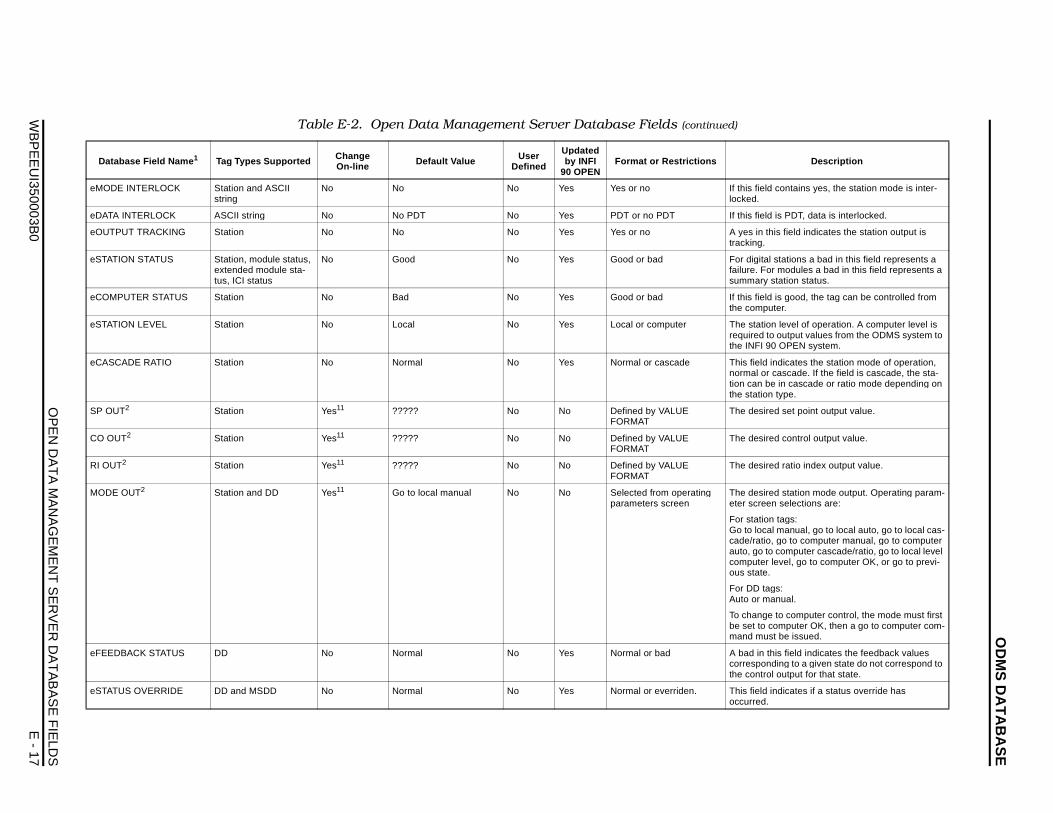
OD
MS
DA
TA
BA
SE
OP
EN
DA
TA
MA
NA
GE
ME
NT
SE
RV
ER
DA
TA
BA
SE
FIE
LDS
WB
PE
EU
I350003B0
E - 17
eMO ontains yes, the station mode is inter-
eDA PDT, data is interlocked.
eOU field indicates the station output is
eSTA tations a bad in this field represents a odules a bad in this field represents a
ation status.
eCO good, the tag can be controlled from r.
eSTA level of operation. A computer level is utput values from the ODMS system to
OPEN system.
eCA icates the station mode of operation, scade. If the field is cascade, the sta-
in cascade or ratio mode depending on ype.
SP O set point output value.
CO O control output value.
RI O ratio index output value.
MOD station mode output. Operating param-selections are:
ags:anual, go to local auto, go to local cas-
o to computer manual, go to computer omputer cascade/ratio, go to local level vel, go to computer OK, or go to previ-
:ual.
o computer control, the mode must first mputer OK, then a go to computer com-be issued.
eFEE field indicates the feedback values ng to a given state do not correspond to utput for that state.
eSTA icates if a status override has
Da Descri ption
DE INTERLOCK Station and ASCII string
No No No Yes Yes or no If this field clocked.
TA INTERLOCK ASCII string No No PDT No Yes PDT or no PDT If this field is
TPUT TRACKING Station No No No Yes Yes or no A yes in thistracking.
TION STATUS Station, module status, extended module sta-tus, ICI status
No Good No Yes Good or bad For digital sfailure. For msummary st
MPUTER STATUS Station No Bad No Yes Good or bad If this field isthe compute
TION LEVEL Station No Local No Yes Local or computer The station required to othe INFI 90
SCADE RATIO Station No Normal No Yes Normal or cascade This field indnormal or cation can be the station t
UT2 Station Yes11 ????? No No Defined by VALUE FORMAT
The desired
UT2 Station Yes11 ????? No No Defined by VALUE FORMAT
The desired
UT2 Station Yes11 ????? No No Defined by VALUE FORMAT
The desired
E OUT2 Station and DD Yes11 Go to local manual No No Selected from operating parameters screen
The desiredeter screen
For station tGo to local mcade/ratio, gauto, go to ccomputer leous state.
For DD tagsAuto or man
To change tbe set to comand must
DBACK STATUS DD No Normal No Yes Normal or bad A bad in thiscorrespondithe control o
TUS OVERRIDE DD and MSDD No Normal No Yes Normal or everriden. This field indoccurred.
Table E-2. Open Data Management Server Database Fields (continued)
tabase Field Name 1 Tag Types Supported ChangeOn-line Default Value User
Defined
Updated by INFI
90 OPENFormat or Restrictions
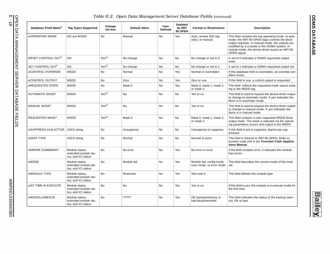
OD
MS
DA
TA
BA
SE
OP
EN
E
- 18
W
BP
EE
UI350003B
0
This field contains the tag operating mode. In auto mode, the INFI 90 OPEN logic controls the block output requests. In manual mode, the outputs are modified by a console or the ODMS system. In remote mode, the device driver tracks an INFI 90 OPEN signal.
A set to 0 indicates a ODMS requested output reset.
A set to 1 indicates a ODMS requested output set.
If this database field is overridden, an override con-dition exists.
If this field is one, a control output is requested.
2, This field reflects the requested mask values exist-ing in the MSDD tag.
This field is used to request the device driver output to change to automatic mode. A yes indicates the block is in automatic mode.
This field is used to request the device driver output to change to manual mode. A yes indicates the block is in manual mode.
2, This field contains a user requested MSDD block output mask. The mask is selected via the operat-ing parameters screen and output to the MSDD.
s If this field is set to suppress, alarms are sup-pressed.
This field is internal to INFI 90 OPEN. Refer to function code 194 in the Function Code Applica-tions Manual .
If the field contains error, it indicates the module has errors.
e, de
This field describes the current mode of the mod-ule.
This field defines the module type.
If this field is yes, the module is in execute mode for the first time.
This field indicates the status of the backup mem-ory, OK or bad.
Table E-2. Open Data Management Server Database Fields (continued)
Change User Updated Descri ption
DAT
A M
AN
AG
EM
EN
T S
ER
VE
R D
AT
AB
AS
E F
IELD
S
eOPERATING MODE DD and MSDD No Manual No Yes Auto, remote (DD tag only), or manual.
RESET CONTROL OUT2 DD Yes11 No change No No No change or set to 0
SET CONTROL OUT2 DD Yes11 No change No No No change or set to 1
eCONTROL OVERRIDE MSDD No Normal No Yes Normal or overridden
eCONTROL OUTPUT MSDD No Zero No Yes Zero or one
eREQUESTED STATE MSDD No Mask 0 No Yes Mask 0, mask 1, mask or mask 3
AUTOMATIC MODE2 MSDD Yes11 No No No Yes or no
MANUAL MODE2 MSDD Yes11 No No No Yes or no
REQUESTED MASK2 MSDD Yes11 Mask 0 No No Mask 0, mask 1, mask or mask 3
eSUPPRESS ALM ACTIVE ASCII string No Unsuppress No No Unsuppress or suppres
eDATA TYPE ASCII string No Normal No No Normal or echo
eERROR SUMMMARY Module status, extended module sta-tus, and ICI status
No No error No Yes No error or error
eMODE Module status, extended module sta-tus, and ICI status
No Module fail No Yes Module fail, config modexec mode, or error mo
eMODULE TYPE Module status, extended module sta-tus, and ICI status
No Reserved No Yes See note 5
eIST TIME IN EXECUTE Module status, extended module sta-tus, and ICI status
No No No Yes Yes or no
eMISCELLANEOUS Module status, extended module sta-tus, and ICI status
No ????? No Yes OK backup/memory or bad bkup/memfaild
Database Field Name 1 Tag Types Supported On-line Default Value Defined by INFI 90 OPEN
Format or Restrictions
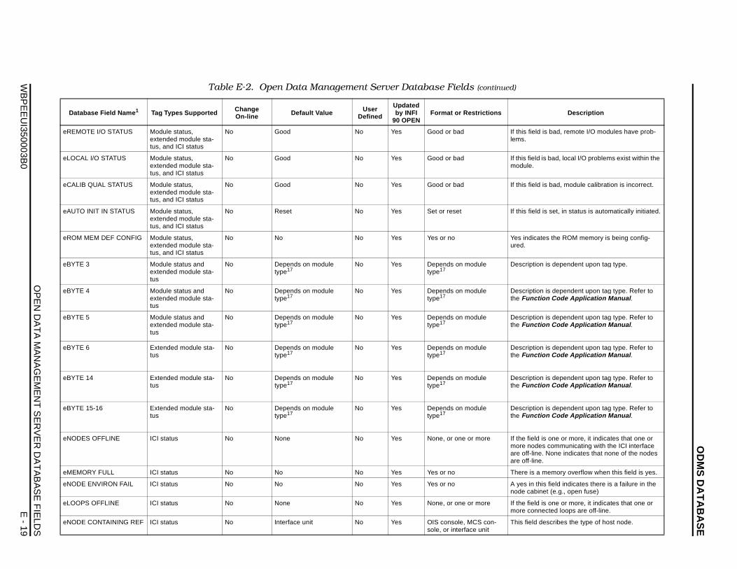
OD
MS
DA
TA
BA
SE
OP
EN
DA
TA
MA
NA
GE
ME
NT
SE
RV
ER
DA
TA
BA
SE
FIE
LDS
WB
PE
EU
I350003B0
E - 19
eRE bad, remote I/O modules have prob-
eLO bad, local I/O problems exist within the
eCA bad, module calibration is incorrect.
eAU set, in status is automatically initiated.
eRO s the ROM memory is being config-
eBY is dependent upon tag type.
eBY is dependent upon tag type. Refer to Code Application Manual .
eBY is dependent upon tag type. Refer to Code Application Manual .
eBY is dependent upon tag type. Refer to Code Application Manual .
eBY is dependent upon tag type. Refer to Code Application Manual .
eBY is dependent upon tag type. Refer to Code Application Manual .
eNO one or more, it indicates that one or communicating with the ICI interface None indicates that none of the nodes
eME emory overflow when this field is yes.
eNO field indicates there is a failure in the t (e.g., open fuse)
eLO one or more, it indicates that one or cted loops are off-line.
eNO scribes the type of host node.
Da Descri ption
MOTE I/O STATUS Module status, extended module sta-tus, and ICI status
No Good No Yes Good or bad If this field islems.
CAL I/O STATUS Module status, extended module sta-tus, and ICI status
No Good No Yes Good or bad If this field ismodule.
LIB QUAL STATUS Module status, extended module sta-tus, and ICI status
No Good No Yes Good or bad If this field is
TO INIT IN STATUS Module status, extended module sta-tus, and ICI status
No Reset No Yes Set or reset If this field is
M MEM DEF CONFIG Module status, extended module sta-tus, and ICI status
No No No Yes Yes or no Yes indicateured.
TE 3 Module status and extended module sta-tus
No Depends on module type17
No Yes Depends on module type17
Description
TE 4 Module status and extended module sta-tus
No Depends on module type17
No Yes Depends on module type17
Description the Function
TE 5 Module status and extended module sta-tus
No Depends on module type17
No Yes Depends on module type17
Description the Function
TE 6 Extended module sta-tus
No Depends on module type17
No Yes Depends on module type17
Description the Function
TE 14 Extended module sta-tus
No Depends on module type17
No Yes Depends on module type17
Description the Function
TE 15-16 Extended module sta-tus
No Depends on module type17
No Yes Depends on module type17
Description the Function
DES OFFLINE ICI status No None No Yes None, or one or more If the field ismore nodesare off-line. are off-line.
MORY FULL ICI status No No No Yes Yes or no There is a m
DE ENVIRON FAIL ICI status No No No Yes Yes or no A yes in thisnode cabine
OPS OFFLINE ICI status No None No Yes None, or one or more If the field ismore conne
DE CONTAINING REF ICI status No Interface unit No Yes OIS console, MCS con-sole, or interface unit
This field de
Table E-2. Open Data Management Server Database Fields (continued)
tabase Field Name 1 Tag Types Supported ChangeOn-line Default Value User
Defined
Updated by INFI
90 OPENFormat or Restrictions
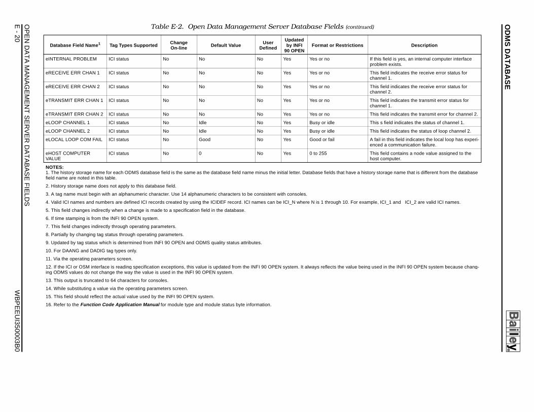
OD
MS
DA
TA
BA
SE
OP
EN
E
- 20
W
BP
EE
UI350003B
0
If this field is yes, an internal computer interface problem exists.
This field indicates the receive error status for channel 1.
This field indicates the receive error status for channel 2.
This field indicates the transmit error status for channel 1.
This field indicates the transmit error for channel 2.
This s field indicates the status of channel 1.
This field indicates the status of loop channel 2.
A fail in this field indicates the local loop has experi-enced a communication failure.
This field contains a node value assigned to the host computer.
history storage name that is different from the database
example, ICI_1 and ICI_2 are valid ICI names.
being used in the INFI 90 OPEN system because chang-
Table E-2. Open Data Management Server Database Fields (continued)
Change User Updated Descri ption
DAT
A M
AN
AG
EM
EN
T S
ER
VE
R D
AT
AB
AS
E F
IELD
S
eINTERNAL PROBLEM ICI status No No No Yes Yes or no
eRECEIVE ERR CHAN 1 ICI status No No No Yes Yes or no
eRECEIVE ERR CHAN 2 ICI status No No No Yes Yes or no
eTRANSMIT ERR CHAN 1 ICI status No No No Yes Yes or no
eTRANSMIT ERR CHAN 2 ICI status No No No Yes Yes or no
eLOOP CHANNEL 1 ICI status No Idle No Yes Busy or idle
eLOOP CHANNEL 2 ICI status No Idle No Yes Busy or idle
eLOCAL LOOP COM FAIL ICI status No Good No Yes Good or fail
eHOST COMPUTER VALUE
ICI status No 0 No Yes 0 to 255
NOTES: 1. The history storage name for each ODMS database field is the same as the database field name minus the initial letter. Database fields that have afield name are noted in this table.
2. History storage name does not apply to this database field.
3. A tag name must begin with an alphanumeric character. Use 14 alphanumeric characters to be consistent with consoles.
4. Valid ICI names and numbers are defined ICI records created by using the ICIDEF record. ICI names can be ICI_N where N is 1 through 10. For
5. This field changes indirectly when a change is made to a specification field in the database.
6. If time stamping is from the INFI 90 OPEN system.
7. This field changes indirectly through operating parameters.
8. Partially by changing tag status through operating parameters.
9. Updated by tag status which is determined from INFI 90 OPEN and ODMS quality status attributes.
10. For DAANG and DADIG tag types only.
11. Via the operating parameters screen.
12. If the ICI or OSM interface is reading specification exceptions, this value is updated from the INFI 90 OPEN system. It always reflects the value ing ODMS values do not change the way the value is used in the INFI 90 OPEN system.
13. This output is truncated to 64 characters for consoles.
14. While substituting a value via the operating parameters screen.
15. This field should reflect the actual value used by the INFI 90 OPEN system.
16. Refer to the Function Code Application Manual for module type and module status byte information.
Database Field Name 1 Tag Types Supported On-line Default Value Defined by INFI 90 OPEN
Format or Restrictions
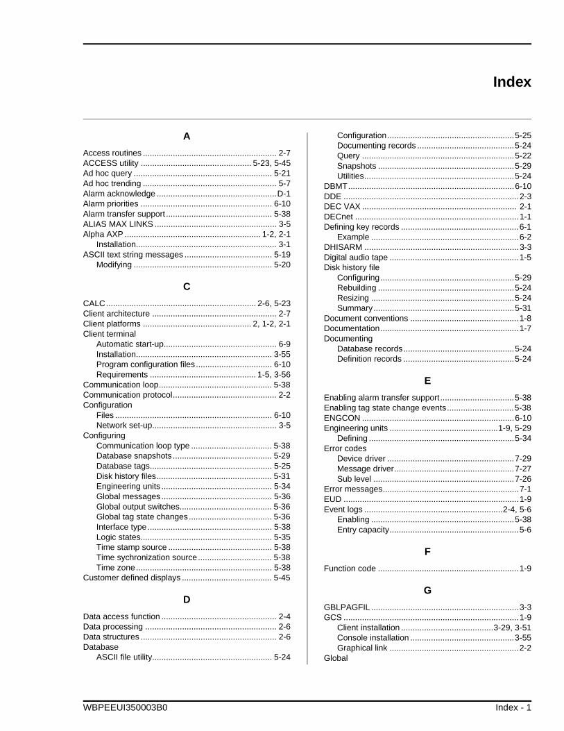
Index
A
Access routines .......................................................... 2-7ACCESS utility ................................................ 5-23, 5-45Ad hoc query ............................................................ 5-21Ad hoc trending .......................................................... 5-7Alarm acknowledge ....................................................D-1Alarm priorities ......................................................... 6-10Alarm transfer support .............................................. 5-38ALIAS MAX LINKS ..................................................... 3-5Alpha AXP ........................................................... 1-2, 2-1
Installation............................................................. 3-1ASCII text string messages ...................................... 5-19
Modifying ............................................................ 5-20
C
CALC................................................................. 2-6, 5-23Client architecture ...................................................... 2-7Client platforms ............................................... 2, 1-2, 2-1Client terminal
Automatic start-up................................................. 6-9Installation........................................................... 3-55Program configuration files ................................. 6-10Requirements .............................................. 1-5, 3-56
Communication loop................................................. 5-38Communication protocol............................................. 2-2Configuration
Files .................................................................... 6-10Network set-up...................................................... 3-5
ConfiguringCommunication loop type ................................... 5-38Database snapshots ........................................... 5-29Database tags..................................................... 5-25Disk history files.................................................. 5-31Engineering units ................................................ 5-34Global messages................................................ 5-36Global output switches........................................ 5-36Global tag state changes.................................... 5-36Interface type...................................................... 5-38Logic states......................................................... 5-35Time stamp source ............................................. 5-38Time sychronization source................................ 5-38Time zone........................................................... 5-38
Customer defined displays ....................................... 5-45
D
Data access function .................................................. 2-4Data processing ......................................................... 2-6Data structures ........................................................... 2-6Database
ASCII file utility.................................................... 5-24
Configuration.......................................................5-25Documenting records ..........................................5-24Query ..................................................................5-22Snapshots ...........................................................5-29Utilities.................................................................5-24
DBMT........................................................................6-10DDE ............................................................................2-3DEC VAX ................................................................... 2-1DECnet .......................................................................1-1Defining key records ...................................................6-1
Example ................................................................6-2DHISARM ...................................................................3-3Digital audio tape ........................................................1-5Disk history file
Configuring..........................................................5-29Rebuilding ...........................................................5-24Resizing ..............................................................5-24Summary.............................................................5-31
Document conventions ...............................................1-8Documentation............................................................1-7Documenting
Database records................................................5-24Definition records ................................................5-24
E
Enabling alarm transfer support ................................5-38Enabling tag state change events.............................5-38ENGCON ..................................................................6-10Engineering units ...............................................1-9, 5-29
Defining ...............................................................5-34Error codes
Device driver .......................................................7-29Message driver....................................................7-27Sub level .............................................................7-26
Error messages...........................................................7-1EUD ............................................................................1-9Event logs ............................................................2-4, 5-6
Enabling ..............................................................5-38Entry capacity........................................................5-6
F
Function code .............................................................1-9
G
GBLPAGFIL ................................................................3-3GCS ............................................................................1-9
Client installation ........................................3-29, 3-51Console installation .............................................3-55Graphical link ........................................................2-2
Global
WBPEEUI350003B0 Index - 1
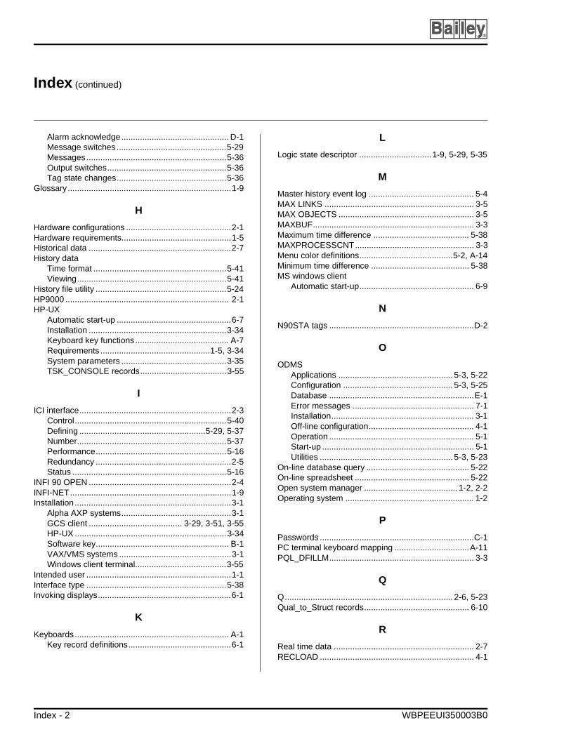
Index (continued)
®
Alarm acknowledge.............................................. D-1Message switches ...............................................5-29Messages............................................................5-36Output switches...................................................5-36Tag state changes...............................................5-36
Glossary......................................................................1-9
H
Hardware configurations .............................................2-1Hardware requirements...............................................1-5Historical data .............................................................2-7History data
Time format .........................................................5-41Viewing................................................................5-41
History file utility ........................................................5-24HP9000 ...................................................................... 2-1HP-UX
Automatic start-up .................................................6-7Installation ...........................................................3-34Keyboard key functions........................................ A-7Requirements ...............................................1-5, 3-34System parameters .............................................3-35TSK_CONSOLE records.....................................3-55
I
ICI interface.................................................................2-3Control.................................................................5-40Defining ......................................................5-29, 5-37Number................................................................5-37Performance........................................................5-16Redundancy ..........................................................2-5Status ..................................................................5-16
INFI 90 OPEN .............................................................2-4INFI-NET.....................................................................1-9Installation...................................................................3-1
Alpha AXP systems...............................................3-1GCS client ........................................ 3-29, 3-51, 3-55HP-UX .................................................................3-34Software key......................................................... B-1VAX/VMS systems ................................................3-1Windows client terminal.......................................3-55
Intended user ..............................................................1-1Interface type ............................................................5-38Invoking displays.........................................................6-1
K
Keyboards.................................................................. A-1Key record definitions............................................6-1
L
Logic state descriptor ...............................1-9, 5-29, 5-35
M
Master history event log ............................................. 5-4MAX LINKS ................................................................ 3-5MAX OBJECTS .......................................................... 3-5MAXBUF..................................................................... 3-3Maximum time difference ......................................... 5-38MAXPROCESSCNT................................................... 3-3Menu color definitions........................................5-2, A-14Minimum time difference .......................................... 5-38MS windows client
Automatic start-up................................................. 6-9
N
N90STA tags ..............................................................D-2
O
ODMSApplications ................................................. 5-3, 5-22Configuration ............................................... 5-3, 5-25Database ..............................................................E-1Error messages .................................................... 7-1Installation............................................................. 3-1Off-line configuration............................................. 4-1Operation .............................................................. 5-1Start-up ................................................................. 5-1Utilities ......................................................... 5-3, 5-23
On-line database query ............................................ 5-22On-line spreadsheet ................................................. 5-22Open system manager ........................................ 1-2, 2-2Operating system ....................................................... 1-2
P
Passwords ..................................................................C-1PC terminal keyboard mapping ................................A-11PQL_DFILLM.............................................................. 3-3
Q
Q........................................................................ 2-6, 5-23Qual_to_Struct records............................................. 6-10
R
Real time data ............................................................ 2-7RECLOAD .................................................................. 4-1
Index - 2 WBPEEUI350003B0
Index (continued)
RECSAVE .................................................................. 4-1Redundancy ............................................................... 2-5Reference documents ................................................ 1-7Requirements
Client platform....................................................... 1-5Server platform ..................................................... 1-5Software................................................................ 1-6
RS-232-C ................................................................... 1-5
S
SCSI ........................................................................... 1-5Security levels .....................................................5-2, C-1Server architecture ..................................................... 2-7Server platforms .............................................. 2, 1-2, 2-1Session manager menu ............................................. 6-4Setting alarm priorities.............................................. 6-10Setting time
Maximum time difference.................................... 5-38Minimum time difference..................................... 5-38
Silence messages ......................................................D-1Software configuration................................................ 6-1Software key............................................................... 3-1Software key installation.............................................B-1Software license registration .................................... 3-12Software requirements ............................................... 1-6SPC/SPQ functions .................................................. 5-22Spreadsheet query ................................................... 5-23SQL ............................................................................ 2-3SQL query ......................................................... 2-7, 5-21SQLplus............................................................. 2-6, 5-23System administrator.................................................. 1-1System configuration................................................ 5-29System parameters
HP-UX................................................................. 3-35VAX/VMS.............................................................. 3-3
System time.............................................................. 5-29Format ................................................................ 5-39Setting................................................................. 5-39
T
Tag history summaries............................... 2-3, 5-6, 5-42Entry capacity........................................................5-6
Tag state change events...........................................5-38Termination module jumper settings.......................... B-1Termination unit jumper settings................................ B-1Time stamp ..........................................................2-5, 2-6
Source.................................................................5-38Time synchronization .........................................2-4, 5-38Time zone .................................................................5-38TSK_CONSOLE records ..........................................3-55
Creating...............................................................3-55
U
User changes history log ............................................5-4
V
VAX/VMSAutomatic start-up .................................................6-3Installation .............................................................3-1Keyboard key functions........................................ A-1Requirements ........................................................1-5Session manager menu ........................................6-4System parameters ...............................................3-3System requirements ............................................3-2TSK_CONSOLE records.....................................3-55
VIRTUALPAGECNT ...................................................3-3
W
Windows ..............................................................1-2, 1-7
X
X Windows ..................................................................1-7
WBPEEUI350003B0 Index - 3

Visit Elsag Bailey on the World Wide Web at http://www.bailey.com
Our worldwide staff of professionals is ready to meet your needs for process automation. For the location nearest you, please contact the appropriate regional office.
AMERICAS29801 Euclid AvenueWickliffe, Ohio USA 44092Telephone 1-216-585-8500Telefax 1-216-585-8756
ASIA/PACIFIC152 Beach RoadGateway East #20-04Singapore 189721Telephone 65-391-0800Telefax 65-292-9011
EUROPE, AFRICA, MIDDLE EASTVia Puccini 216154 Genoa, ItalyTelephone 39-10-6582-943Telefax 39-10-6582-941
GERMANYGraefstrasse 97D-60487 Frankfurt MainGermanyTelephone 49-69-799-0Telefax 49-69-799-2406
Form WBPEEUI350003B0 Litho in U.S.A. 397Copyright © 1997 by Elsag Bailey Process Automation, As An Unpublished Work® Registered Trademark of Elsag Bailey Process Automation™ Trademark of Elsag Bailey Process Automation