ocean drilling program technical note 8
TRANSCRIPT
HANDBOOK FOR SHIPBOARD SEDIMENTOLOGISTS
Jim MazzulloDepartment of GeologyTexas A&M University
College Station, Texas 77843
Anne Gilbert GrahamOcean Drilling ProgramTexas A&M University
College Station, Texas 77843
Ocean Drilling Program
Texas A&M University
Technical Note No. 8First printing 1988
Philip W RabiDirector
lòMAudrey W. MeyerManager off Science Operations
Louis E GarrisonDeputy Director
This publication is supplemented by ODP Technical Notes 1, 2, and 3TN1: http://iodp.tamu.edu/publications/TN/TN1-SS-Pt1-Atlas-inter.pdfTN2: http://iodp.tamu.edu/publications/TN/TNote_2.pdfTN3: http://iodp.tamu.edu/publications/TN/TNote_3.pdf
Material in this publication may be copied without restraint forlibrary, abstract service, educational or personal research purposes;however, republication of any portion requires the written consent of theDirector, Ocean Drilling Program, Texas A&M University Research Park, 1000Discovery Drive, College Station, Texas 77840, as well as appropriateacknowledgment of this source*
Technical Note 8First Printing 1988
Distribution
Copies of this publication may be obtained from the Director,Ocean Drilling Program, Texas A&M University Research Park, 1000 DiscoveryDrive, College Station, Texas 77840. In some cases, orders for copies mayrequire a payment for postage and handling.
This publication was prepared by the Ocean Drilling Program, TexasA&M University, as an account of work performed under the internationalOcean Drilling Program which is managed by Joint OceanographicInstitutions, Inc., under contract with the National Science Foundation.Funding for the program is provided by the following agencies:
Department of Energy, Mines and Resources (Canada)Deutsche Forschungsgemeinschaft (Federal Republic of Germany)Institut Francais de Recherche pour 1'Exploitation de la Mer (France)Ocean Research Institute of the University of Tokyo (Japan)National Science Foundation (United States)Natural Environment Research Council (United Kingdom)European Science Foundation Consortium for the Ocean Drilling Program
(Belgium, Denmark, Finland, Iceland, Italy, Greece, the Netherlands,Norway, Spain, Sweden, Switzerland, and Turkey)
Any opinions, findings and conclusions or recommendationsexpressed in this publication are those of the author(s) and do notnecessarily reflect the views of the National Science Foundation, theparticipating agencies, Joint Oceanographic Institutions, Inc., Texas A&MUniversity, or Texas A&M Research Foundation.
-iii-
HANDBOOK FOR SHIPBOARD SEDIMENTOLOGISTS
TABLE OF CONTENTS
INTRODUCTION,
CHAPTER 1. GENERAL CORE HANDLING AND RESPONSIBILITIES OF SHIPBOARDSEDIMENTOLOGISTS 2
1. SEDIMENTOLOGISTS1 DUTIES2. CORE HANDLING
A. CORE DECK ROUTINEB. CORE LAB PROCEDURES
CHAPTER 2. VISUAL DESCRIPTIONS OF CORES: METHODS AND TERMINOLOGY 111. BED THICKNESS AND ATTITUDE2. SEDIMENTARY STRUCTURES AND BEDDING PLANES
A. INTERNAL SEDIMENTARY STRUCTURESB. BEDDING PLANES
3. BED COLOR AND LITHOLOGY4. DRILLING DISTURBANCE
CHAPTER 3. CORE DESCRIPTIONS 171. VISUAL CORE DESCRIPTION2. SMEAR SLIDE/THIN SECTION DESCRIPTION3. BARREL SHEETS4. LITHOSTRATIGRAPHIC SECTIONS OF THE HOLE SUMMARIES
CHAPTER 4. PROCEDURES AND ANALYTICAL EQUIPMENT 321. PETROGRAPHIC METHODS OF ANALYSIS
A. EQUIPMENTB. PETROGRAPHIC MEDIAC. PETROGRAPHIC METHODS
2. GRAIN-SIZE ANALYSIS BY PARTICLE-SIZE ANALYZER3. GEOCHEMICAL AND X-RAY-DIFFRACTION ANALYSIS4. SAMPLING METHODS AND ANALYTICAL PROCEDURES
REFERENCES 43
APPENDIX I ODP SEDIMENT CLASSIFICATION SCHEME 44APPENDIX II LIST OF REFERENCES PERTINENT TO THE STUDY OF SEDIMENTARY
ROCKS THAT ARE AVAILABLE ABOARD SHIP 64APPENDIX III BIBLIOGRAPHY OF ODP TECHNICAL NOTES .... 67
-iv-
LIST OF FIGURES
Figure 1. Core being carried to the catwalk from the rig floor.
Figure 2 Diagram of the lab stack's bridge deck, containing core entry,core splitting, sedimentology, physical properties, andpaleomagnetics laboratories.
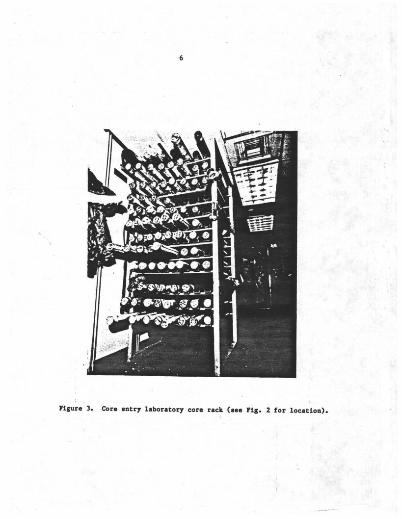
Figure 3. Core entry laboratory core rack (see Fig. 2 for location).
Figure 4. Core splitting room (see Fig. 2 for location).
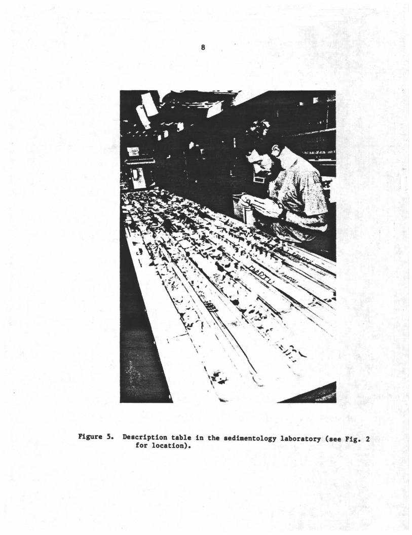
Figure 5. Description table in the sedimentology laboratory (see Fig. 2for location).
Figure 6. Core photograph of core sections with voids blocked by spacers(Core 117-723A-25X).
Figure 7. Blank Visual Core Description form.
Figure 8. Sedimentary structure and deformation symbol codes.
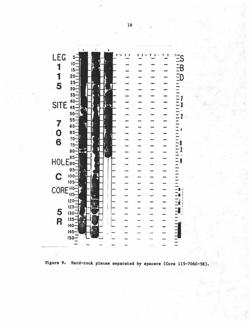
Figure 9. Hard-rock pieces separated by spacers (Core 115-706C-5R).
Figure 10. Two examples of completed Visual Core Description forms.a. Section containing soft sediment.
b. Section containing hard sedimentary rock.
Figure 11. Blank Smear Slide/Thin Section Description form.
Figure 12. Blank Barrel Sheet.Figure 13. Standard lithologic codes and symbols used in "Graphic
Lithology" column on barrel sheets (see Fig. 12).
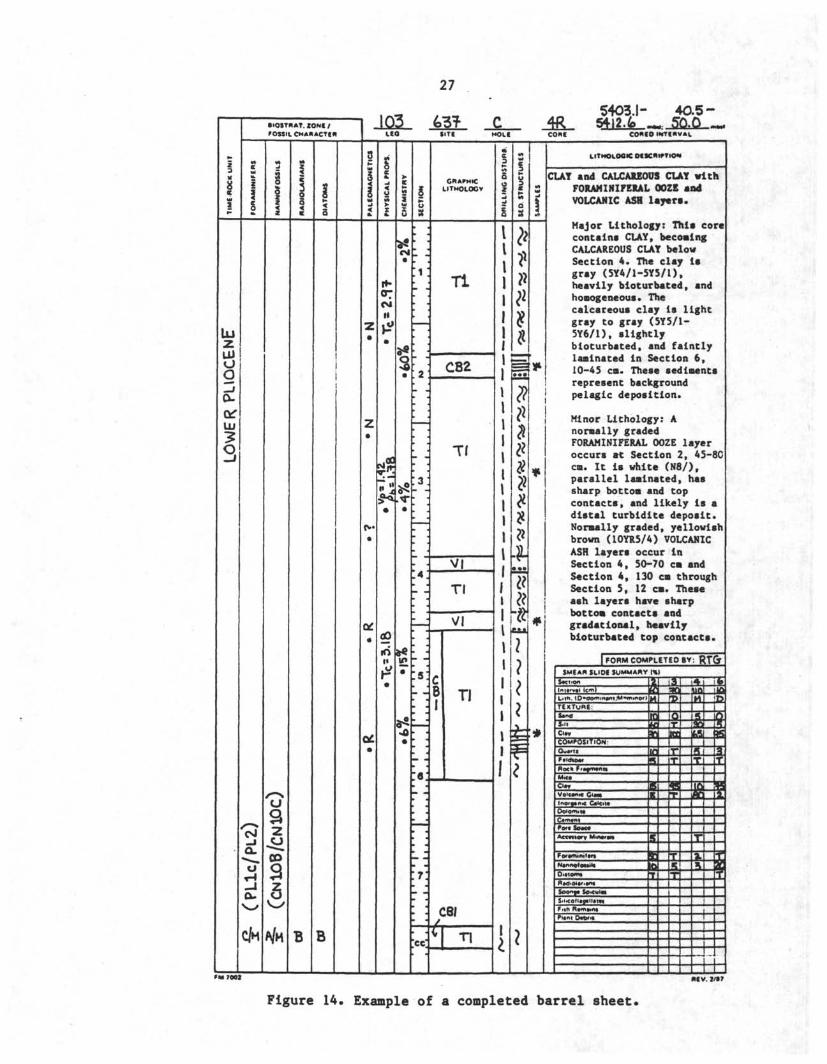
Figure 14. Example of a completed barrel sheet.
Figure 15. Three examples of illustrations from "Lithostratigraphy"sections of Hole Summaries.a Figure showing cored intervals, recovery, lithology, and
lithologic units from Site 749 (Leg 120).b Figure showing sedimentary structures in recovered
cores,c Figure showing grain size data from Hole 754A (Leg 121).
Figure 16. Comparison chart for visual percentage estimation (after Terryand Chilingarian, 1955).
Figure 17. Example of the Glagolev-Chayes point-count method.
INTRODUCTION
The shipboard sedimentologists are responsible for describing thelithology and stratigraphy of sediments and sedimentary rocks that arerecovered by the Ocean Drilling Program (ODP). They provide the firstcomplete descriptions of the cores, which are used by shipboard andshore-based scientists as the basis for further sampling and study and forforming the first general conclusions about the geologic history of thedrilling site. The shipboard sedimentologists have a tremendousresponsibility to the scientific community at large, for they are commonlythe only scientists who have the opportunity to see all cores from eachdrilling site. Thus, it is extremely important that they describe thelithology and stratigraphy of sediments and sedimentary rocks in a mannerthat is both complete and consistent from leg to leg.
ODP, in consultation with scientists who have been involved with theDeep Sea Drilling Project (DSDP) and ODP in the past, has attempted todefine the types of data most useful to the scientific community and theprocedures that should be used routinely to describe sediments andsedimentary rocks recovered by ODP. The results of this attempt aresummarized in this Handbook for Shipboard Sedimentologists.
This handbook is divided into four chapters plus appendixes. Chapter 1discusses the routine of core handling and study for all shipboardscientists in general, and outlines the basic responsibilities of theshipboard sedimentologists in particular. Chapter 2 describes the generalmethods and terminology for the description of the lithostratigraphy ofsediments and sedimentary rocks. Chapter 3 covers procedures for thegraphic and written summary of the core descriptions. Chapter 4 details thelithologic analysis of sediment, including sampling procedures, the typesof analytical equipment available aboard JOIDES Resolution, and the formatsfor summary and presentation of lithologic data.
The handbook is appended with a description of the classificationscheme used by shipboard sedimentologists to describe recovered sedimentsand sedimentary rocks. This classification scheme was approved by theJOIDES Planning Committee in November 1987 and implemented by the OceanDrilling Program beginning on Leg 119 (December 1987). The second appendixcontains references available aboard ship which are pertinent to the studyof sediments and sedimentary rocks. The third appendix lists ODP technicalnotes which are also available aboard ship.
CHAPTER 1GENERAL CORE HANDLING AND
RESPONSIBILITIES OF SHIPBOARD SEDIMENTOLOGISTS
SEDIMENTOLOGISTSf DUTIES
The primary responsibility of shipboard sedimentologists is to describethe lithology and stratigraphy of sediments and sedimentary rocks in coresand to provide a written interpretation about the geologic history of thedrilling site. The shipboard sedimentologists also pursue their ownscientific interests and assist with other scientific and curatorialduties, but their first obligation is to describe and interpret cores.
Organizing the responsibilities of the shipboard party is the job ofthe Co-Chief Scientists. At the beginning of the cruise, either at thepre-cruise port call or during the transit to the first site, the Co-Chiefshold a meeting to set up specific responsibilities and schedules so thatthe work load is evenly divided among all shipboard scientists. SomeCo-Chief Scientists divide the sedimentologists into two teams to work onopposite twelve-hour shifts, and a "chief sedimentologist" is designatedfor each site or hole. The Co-Chief Scientists may also specify workinggroups or individuals to write the "Lithostratigraphy" chapters for theHole Summaries and to produce the barrel sheets. In addition, all shipboardscientists share the work of sampling for shipboard and shore-basedrequestors; this means a set schedule for each scientist of some number ofhours per day at the sampling table, in addition to other obligations.
The transit to the first site is the best time to become familiar withthe ship and its routines. The marine technicians and staff scientist holdmini-classes to familiarize scientists with such subjects as core handlingprocedures in the core lab, core sampling procedures, and word-processingand graphics capabilities of the computer system. Working-group meetingsmay be held to coordinate shipboard duties. The staff scientist will alsoexplain terms, forms, procedures, and routines beyond the scope of thishandbook.
CORE HANDLINGCORE DECK ROUTINE
After a core is cut and brought from beneath the seafloor to thedrilling platform, it is removed with its protective core liner from theouter core barrel and carried to the catwalk outside the core laboratory(Fig. 1). The 9.5-m core liner containing the cored material is set onbrackets attached to the catwalk railing, the exterior is wiped clean, andthe liner is marked and cut into 1.5-m sections starting from the top ofthe recovered material. The last section may be shorter than 1.5 m,depending on the total length of recovered core. Each section of the coreis capped with blue endcaps at the top and clear endcaps at the bottom ofeach section, using acetone to seal the caps to the liner. Material in thecore catcher of the outer core barrel is placed in a short section of coreliner, similarly capped, and placed below the last core section. A smallportion of material recovered in the core catcher is removed and takenimmediately to the paleontology lab for age-dating.
Whole-round samples of a core section or sections may be removed fororganic geochemistry, interstitial water, or physical properties studies.Yellow endcaps are put on these sections to indicate where a whole-roundsample has been removed (usually at the bottom of a section). The core
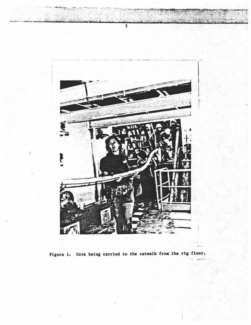
Figure l Core being carried to the catwalk from the rig floor.
sections are then carried into the core laboratory (Fig. 2) and placed on astorage rack (Fig. 3). Each section is permanently labeled with itsidentification number: leg number, site number, hole letter, core numberand type ("H" - advanced hydraulic piston core, "X" « extended core barrel,"R" » rotary core barrel, etc ), and section number. For example, thesecond section of the tenth (rotary-drilled) core from Hole 723A is labeled"117-723A-10R-2"; the core catcher section from that core is labeled"117-723A-10R, CC."
CORE LAB PROCEDURESInformation about each core is written on the core entry lab's data
"white board" (Item 1 in Fig. 2) by the operations superintendent or coringtechnician and logged into the computer database by the marine technicians.After a core is permanently labeled and its data entered, it can beaccessed for study, first by the shipboard scientists who require whole-round core sections, rather than split core sections, for their analyses.The first analyses conducted on the core sections usually include physicalproperties measurements (e.g., bulk density [GRAPE], sonic, and thermalconductivity), and paleomagnetics measurements (e.g., magneticsusceptibility), as well as other measurements that may be required tofulfill the scientific objectives of the leg. In the case of thermalconductivity measurements, the core sections must equilibrate to roomtemperature, causing a delay in processing of about 4 hours.
After the completion of whole-core analyses, the core sections arecarried into the core splitting room (Figs. 2 and 4), where they are halvedlengthwise with rotary saws or wire "cheese-cutters" by the marinetechnicians. One half of the split core (called the "working half") istaken to the sampling table, where the curatorial representative overseesthe collection of samples for shipboard and shore-based scientists. Theother half of the split core (called the "archive half") is usually runthrough the cryogenic magnetometer for paleomagnetic measurements and thentaken to the sedimentology laboratory.
The description table in the sedimentology lab is 4.5 m long and 1.4 mwide, and can hold the archive halves of two complete cores (Figs. 2 and5). The table is equipped with three sets of flat core racks, meter sticks,and overhead track lights. The core sections are oriented with theirblue-capped tops toward the stern of the ship, with the first core sectionon the starboard side of the table.
The description work of the shipboard sedimentologists begins as soonas the archive half of a core (all sections) is placed on the descriptiontable. It is important to check first that the half-caps of each coresection are securely fastened and that the tops of each section areproperly labeled with identification numbers. The marine technicians whosplit the core sections will take care of endcap or labeling problems. Inaddition, the shipboard sedimentologists should check to see that voids inthe core sections have been blocked with spacers so that the sediment orsedimentary rock cannot move along its core liner (Fig. 6). If there areopen voids in the core section, the curatorial representative or marinetechnicians will block off the voided intervals and ensure that the archivecore halves correspond exactly to the working core halves.
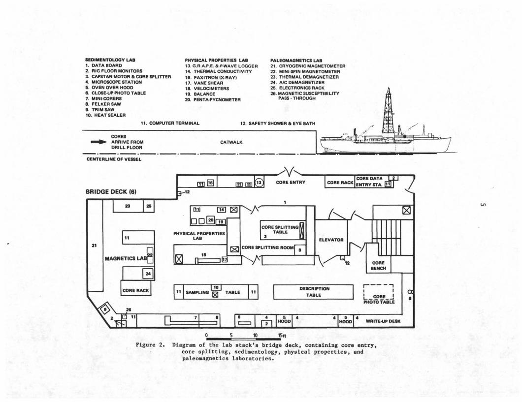
SEDIMENTOLOGY LAB1. DATA BOARD2. RIG FLOOR MONITORS3. CAPSTAN MOTOR & CORE SPLITTER4. MICROSCOPE STATION5. OVEN OVER HOODβ. CLOSE-UP PHOTO TABLE7. MINI-CORERS8. FELKERSAW9. TRIM SAW10. HEAT SEALER
PHYSICAL PROPERTIES LAB13. G.R.A.P.E. & P-WAVE LOGGER14. THERMAL CONDUCTIVITY16. FA×ITRON (X-RAY)17. VANE SHEAR18. VELOCIMETERS19. BALANCE20. PENTA-PYCNOMETER
PALEOMAGNETICS LAB21. CRYOGENIC MAGNETOMETER22. MINI-SPIN MAGNETOMETER23. THERMAL DEMAGNETIZER24. A/C DEMAGNETIZER25. ELECTRONICS RACK26. MAGNETIC SUSCEPTIBILITY
PASS - THROUGH
12. SAFETY SHOWER & EYE BATH
CORESARRIVE FROMDRILL FLOOR
CORE SPLITTING λTABLE 1/
Lπ
10 15ft
Figure 2. Diagram of the lab stack*s bridge deck, containing core entry,core splitting, sedimentology, physical properties, andpaleomagnetics laboratories.
6
Yy
Figure 3 Core entry laboratory core rack (see Fig. 2 for location),
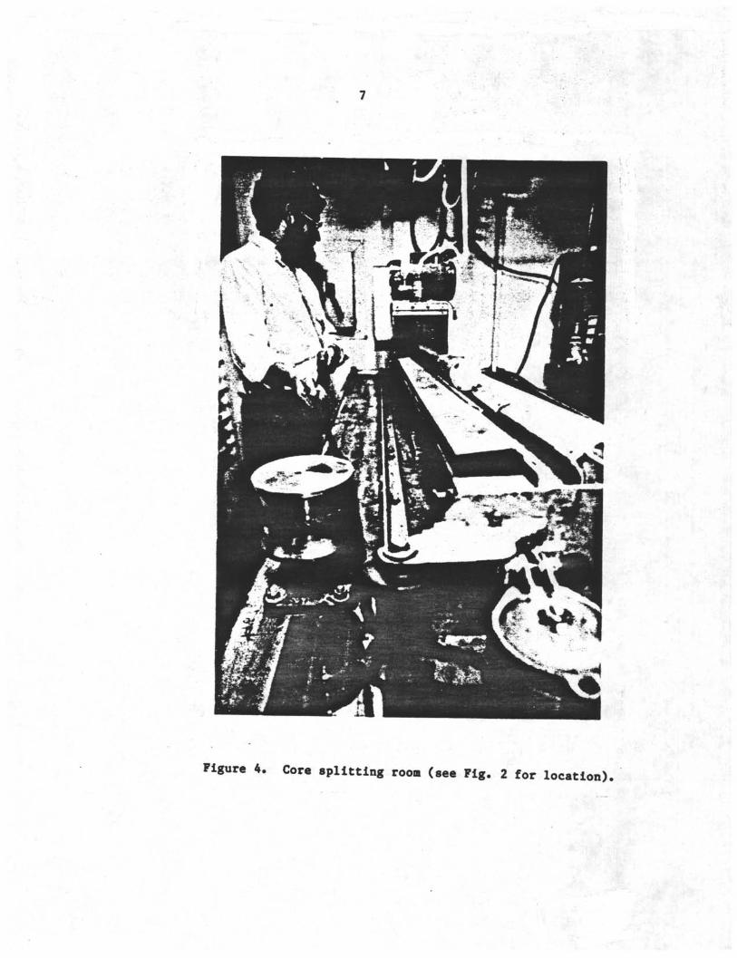
Figure 4. Core splitting room (see Fig. 2 for location).
8
Figure 5. Description table in the sedimentology laboratory (see Fig, 2for location).
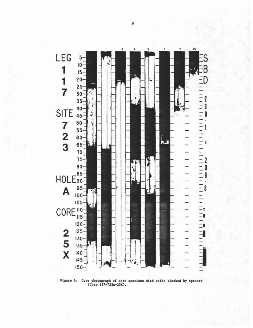
Figure 6. Core photograph of core sections with voids blocked by spacers(Core 117-723A-25X).
11
CHAPTER 2VISUAL DESCRIPTIONS OF CORESMETHODS AND TERMINOLOGY
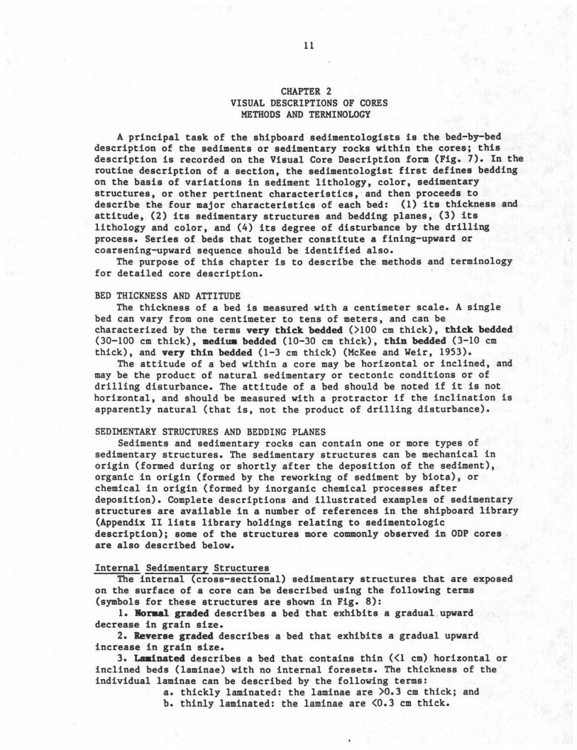
A principal task of the shipboard sedimentologists is the bed-by-beddescription of the sediments or sedimentary rocks within the cores; thisdescription is recorded on the Visual Core Description form (Fig. 7). In theroutine description of a section, the sedimentologist first defines beddingon the basis of variations in sediment lithology, color, sedimentarystructures, or other pertinent characteristics, and then proceeds todescribe the four major characteristics of each bed: (1) its thickness andattitude, (2) its sedimentary structures and bedding planes, (3) itslithology and color, and (4) its degree of disturbance by the drillingprocess. Series of beds that together constitute a fining-upward or .coarsening-upward sequence should be identified also.
The purpose of this chapter is to describe the methods and terminologyfor detailed core description.
BED THICKNESS AND ATTITUDEThe thickness of a bed is measured with a centimeter scale. A single
bed can vary from one centimeter to tens of meters, and can becharacterized by the terms very thick bedded (>IOO cm thick), thick bedded(30-100 cm thick), medius bedded (10-30 cm thick), thin bedded (3-10 cmthick), and very thin bedded (1-3 cm thick) (McKee and Weir, 1953).
The attitude of a bed within a core may be horizontal or inclined, andmay be the product of natural sedimentary or tectonic conditions or ofdrilling disturbance. The attitude of a bed should be noted if it is nothorizontal, and should be measured with a protractor if the inclination isapparently natural (that is, not the product of drilling disturbance).
SEDIMENTARY STRUCTURES AND BEDDING PLANESSediments and sedimentary rocks can contain one or more types of
sedimentary structures. The sedimentary structures can be mechanical inorigin (formed during or shortly after the deposition of the sediment),organic in origin (formed by the reworking of sediment by biota), orchemical in origin (formed by inorganic chemical processes afterdeposition). Complete descriptions and illustrated examples of sedimentarystructures are available in a number of references in the shipboard library(Appendix II lists library holdings relating to sedimentologicdescription); some of the structures more commonly observed in ODP coresare also described below.
Internal Sedimentary StructuresThe internal (cross-sectional) sedimentary structures that are exposed
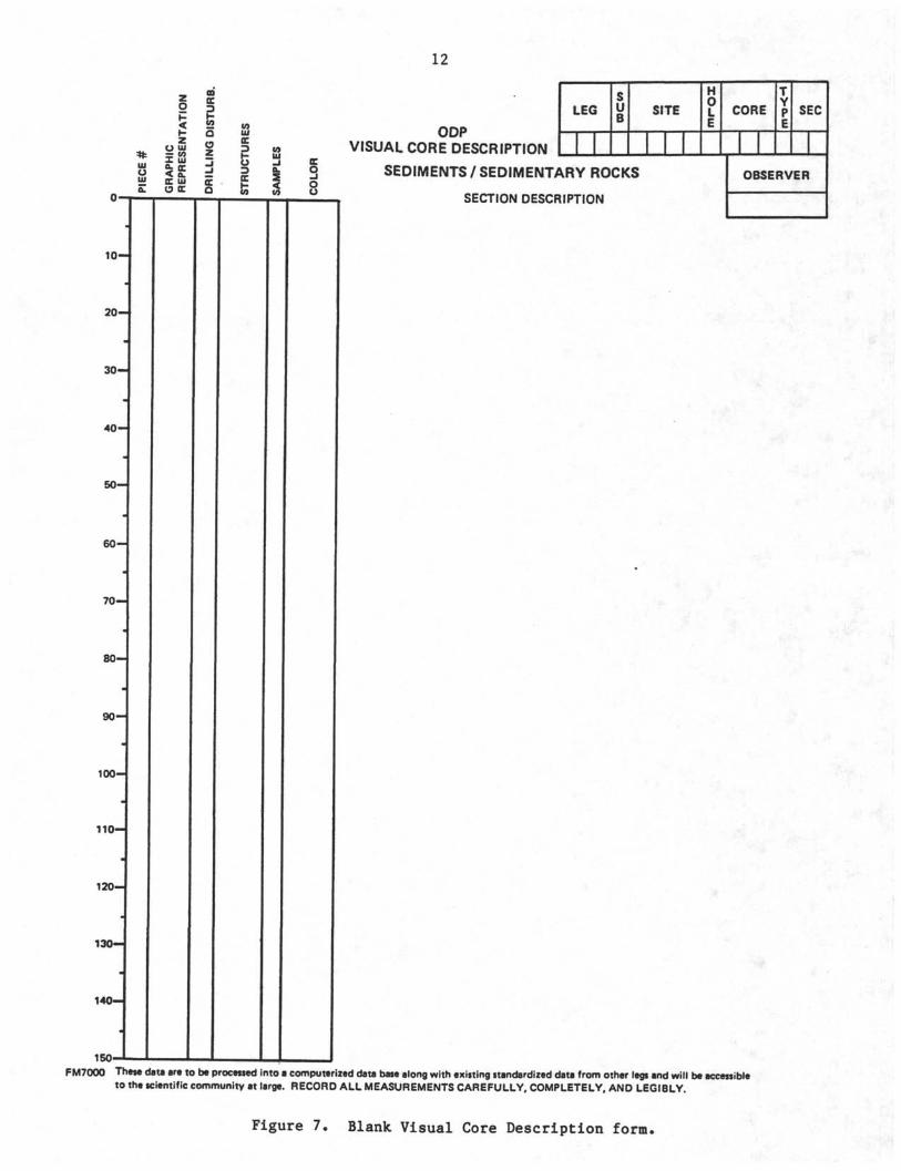
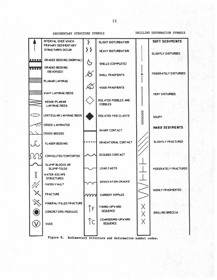
on the surface of a core can be described using the following terms(symbols for these structures are shown in Fig. 8):
1. Normal graded describes a bed that exhibits a gradual upwarddecrease in grain size.
2. Reverse graded describes a bed that exhibits a gradual upwardincrease in grain size.
3. Laminated describes a bed that contains thin (<l cm) horizontal orinclined beds (laminae) with no internal foresets. The thickness of theindividual laminae can be described by the following terms:
a. thickly laminated: the laminae are >0.3 cm thick; andb. thinly laminated: the laminae are <0.3 cm thick.
_ ID
O 3
< S2
* iJ3o è?ui cc Siα O OC
12
ODPVISUAL CORE DESCRIPTION
LEG SITE CORE SEC
1 0 -
2 0 -
3 0 -
4 0 -
5 0 -
6 0 -
7 0 -
8 0 -
9 0 -
100-
110-
1 2 0 -
1 3 0 -
140—
150-
SEDIMENTS/SEDIMENTARY ROCKS
SECTION DESCRIPTION
OBSERVER
FM7000 These data are to be processed into a computerized data base along with existing standardized data from other legs and will be accessibleto the scientific community at large. RECORD ALL MEASUREMENTS CAREFULLY, COMPLETELY, AND LEGIBLY.
Figure 7. Blank Visual Core Description form.
13
SEDIMENTARY STRUCTURE SYMBOLS DRILLING DEFORMATION SYMBOLS
t
XX
JJ
X
INTERVAL OVER WHICH
PRIMARY SEDIMENTARY
STRUCTURES OCCUR
GRADED BEDDING (NORMAL)
GRADED BEDDING
(REVERSED)
PLANAR LAMINAE
WAVY LAMINAE/BEDS
VEDGE-PLANAR
LAMINAE/BEDS
LENTICULAR LAMINAE/BEDS
CROSS-LAMINATED
CROSS-BEDDED
FLASER BEDDING
CONVOLUTED/CONTORTED
SLUMP BLOCKS OR
SLUMP FOLDS
WATER-ESCAPE
STRUCTURES
MICRO-FAULT
FRACTURE
MINERAL-FILLED FRACTURE
CONCRETIONS/NODULES
VUGS
<S
o
"V~V
F
C
SLIGHT BIOTURBATION
HEAVY BIOTURBATION
SHELLS (COMPLETE)
SHELL FRAGMENTS
WOOD FRAGMENTS
ISOLATED PEBBLES AND
COBBLES
ISOLATED MUD CLASTS
SHARP CONTACT
GRADATIONAL CONTACT
SCOURED CONTACT
LOAD CASTS
DESICCATION CRACK5
CURRENT RIPPLES
FINING-UPWARD
SEQUENCE
COARSENING-UPWARD
SEQUENCE
SOFT SEDIMENTS
SLIGHTLY DISTURBED
MODERATELY DISTURBED
VERY DISTURBED
SOUPY
HARD SEDIMENTS
SLIGHTLY FRACTURED
MODERATELY FRACTURED
HIGHLY FRAGMENTED
DRILLING BRECCIA
Figure 8. Sedimentary structure and deformation symbol codes.
14
The geometry of Individual laminae can be described by the following terms:a planar laminated: the laminae are bounded by parallel andplanar bedding planes, and are continuous in thickness acrossthe width of the core;b. wavy laminated: the laminae are bounded by one or two wavyand parallel bedding planes, and are continuous but variable inthickness across the width of the core;c wedge-planar laminated: the laminae are bounded bynon-parallel and planar bedding planes, and pinch out in onedirection across the width of the core; andd. lenticular: the laminae are bounded by one or two wavy andnon-parallel bedding planes, and pinch out in two directionsacross the width of the core.
Lamination of fine sediments is generally the result of slight changesin texture or composition which may be due to organic action (as instromatolites) or to variations in current velocity and turbulence,sediment supply, or climate (as in varves or muddy turbidites). Laminationof coarser grained (sand and gravel) sediment is generally the result ofupper flat-bed flow, sheet flow, or wind-ripple migration (e.g., Harms etal., 1982).
4. Cross-laminated describes a bed that contains thin horizontal orinclined laminae less than 1 cm in thickness with inclined internalforesets The thickness of the individual laminae can be described asthickly or thinly laminated, and their geometry as planar, wavy, wedge-planar, or lenticular (see above). The type of cross-laminations can bedescribed by the following terms:
a tabular: the foresets are planar and parallel, andintersect the lower bedding plane at an angle; andb. trough: the foresets are curved and parallel and intersectthe lower bedding plane tangentially.
Cross-lamination is generally the product of ripple migration.5. Cross-stratified (or cross-bedded) describes a bed that contains
inclined internal foresets (and possibly subhorizontal topsets andbottomsets) greater than 1 cm in thickness. The cross-bedding may bedescribed as either tabular or trough cross-bedded, using the same criteriathat are described for cross-laminated sediments. Cross-bedding isgenerally a product of dune (sand wave and megaripple) migration.
6. Flaser-bedded describes a bed that contains thin horizontal orinclined laminae with inclined internal foresets and thin (less than 1 cm)lenses of another sediment type within their troughs. Flaser beds aregenerally the products of variations in current energy (e.g., flaser-beddedtidal sand and mud or turbidite silt-mud units); the lenses are commonlyfine-grained sediment that accumulates in the troughs of ripples duringlow-energy periods.
7. Convoluted describes a single bed whose internal laminations havebeen intricately folded. The folding does not generally extend to thebedding planes or into adjacent beds. Convoluted beds or slump folds aregenerally gravity-induced soft-sediment deformation structures, and aremost common to sand and silt.
8. Water-escape pipes (fluid-escape structures) are features producedby the escape of fluids from a bed after deposition, including "dish,""pillar," and "vertical sheet" structures.
9. Micro-faulted describes a single bed whose internal lamination hasbeen disrupted and vertically displaced by micro-faults. The faults do not
15
generally extend to the bedding planes or into adjacent beds. They aregravity-induced soft-sediment deformation structures, and are common tobeds that are deposited on high slopes (e.g., dune avalanche faces).
10. Fractured describes a bed that is naturally fractured or jointedalong planes which extend through its bedding planes and into adjacentbeds. The fracture may be empty or partly or completely filled byauthigenic minerals.
11. Nodular describes a bed that contains discrete nodules of adifferent sediment type. Nodules are generally formed by syn- or post-depositional precipitation or recrystallization of chert, pyrite, halite,anhydrite, gypsum, phosphorites, calcite, manganese, and other minerals onthe surface of or within a bed.
12. Nodular-βosaic describes a bed that contains coalesced nodules ofchemical minerals. Nodular-mosaic beds are commonly formed by thesyn-depositional precipitation of evaporites within a bed. The nodules growwithin, and eventually displace and replace, the original sediment in thebed, and merge to form sutured contacts. Remnants of the original sedimentare commonly present within and between the nodules.
13. Vuggy describes a bed with large cavities or pores ("vugs"). Thevugs are generally formed by shrinkage (as in birdseye limestone),dissolution (as in moldic pores or true vugs), bioturbation (as inborings), and framework growth (as in reefs), and may be partly orcompletely filled by detritus or authigenic minerals.
14. Slightly bioturbated describes a bed that has been partiallydisturbed by bioturbation. Trace fossils from burrowing organisms arepresent and perhaps abundant on the exposed surface of the bed (and shouldbe described), but the bed
fs primary depositional stratification is still
apparent.
15. Heavily bioturbated describes a bed whose original stratificationhas been highly or completely disturbed by bioturbation.
16. Massive or structureless describes a bed that is homogeneous inlithology and color and exhibits no bedding, cross-bedding, grading,bioturbation, or bed disturbance. Massive beds are the products of rapidsedimentation, grain-flow deposition, or bioturbation, but show no evidencefor their origins. They are also common to coarse sand and gravel deposits,as well as to supermature sediments.
17. Fossiliferous describes a bed containing one or more macrofossils.The fossil types should be identified, if possible.
18. Pebbles, cobbles, and mid clasts should be identified when theyoccur isolated in a section; for example, glacial dropstones and rip-up mudchips.
Bedding Planes
A description of the sedimentary structures of a bed should alsoinclude a description of the types of bedding planes and, if observable,any structures or markings upon them (surface and sole marks). A beddingplane can be described as sharp or gradational and planar or wavy; thesurface and sole marks can be described by the following terms (Fig. 8):
1. Scours: sharp, wavy lower bedding planes that clearly truncateunderlying beds.
2. Load marks: small knobby depressions on an upper bedding plane(with corresponding load casts on the underside of the overlying bed) thatare formed by the sinking of a more dense sediment into a less densesediment.
16
3. Desiccation cracks: downward-tapering v-shaped fractures on anupper bedding plane.
4. Ripple marks: wavy upper bedding plane formed by symmetrical orasymmetrical ripple crests.
BED COLOR AND LITHOLOGYBed color is determined by visual comparison with the Geological
Society of America Rock-Color Chart or Munsell Soil Color Charts (availableaboard ship). Bed color should be described as soon as the core has beensplit and while the sediment is still wet, because drying and oxidation ofexposed sediment can have drastic effects on its original color.
The lithology of the sediment in a bed is determined by an analysis ofits texture and composition by visual study of the core, petrographic studyof smear slides and thin sections, X-ray diffraction analysis, andgeochemical analysis. Given these data, the lithology of the sediment in abed is described by a principal name that defines its sediment type andclass, and major and minor modifiers that describe its texture and compo-sition. Appendix I contains the sediment classification scheme used by ODP.
DRILLING DISTURBANCEThree types of drilling disturbance features are common to sediments
and sedimentary rocks recovered by ODP (Fig. 8):1. Bed flexures: beds of soft sediment can be flexed and bowed
downward by the weight of the drill stem, or can be flexed and bowed upwardas the core barrel is pulled from the hole. This deformation can becharacterized as slightly deformed (when beds are only flexed along theiredges), moderately deformed (the beds are entirely flexed across the widthof the core), and very deformed (when the beds are completely disturbed orexhibit diapir-like structures).
2. Soupy beds: beds of water-saturated or under-consolidated softsediment will often flow upwards through a core barrel under the weight ofthe drill stem, and will thereby lose all traces of their original bedding.This is very common to sand, calcareous grainstones, and ooze, and isfrequently observed in the first core which penetrates the poorlyconsolidated sediment on the surface of the sea bed.
3. Fractures: beds of hard sedimentary rock can be fractured by excessdrill pressures. The rock can be considered slightly fractured when it isbroken into a few large pieces by a small number of well-defined fractures,moderately fractured when core pieces are in place or partly discplaced butoriginal orientation is maintained, or highly fractured when pieces areprobably in correct stratigraphic sequence (although they may not representthe entire sequence) but original orientation is lost. Drilling breccia isrock crushed and broken into many small and angular pieces, with originalorientation and stratigraphic position lost; often drilling breccia iscompletely mixed with drilling slurry. Beds of soft sediment can also besplit along their bedding planes by the rotation of the core barrel duringrotary coring. In this case, the fracturing produces disc-shaped drillingbiscuits that commonly float within a matrix of soupy sediment. Drillingbiscuits can be very common in rotary-cored sections, and can be difficultif not impossible to identify.
Drilling disturbance should be brought to the attention of theOperations Superintendent, because it can sometimes be lessened orprevented by changing drilling or coring techniques. Disturbance can becaused also by the tools used for splitting cores, and the marinetechnicians may be able to minimize core disturbance from this source.
17
CHAPTER 3CORE DESCRIPTIONS
There are four types of graphic and written summaries of the coredescriptions which must be completed by the shipboard sedimentologistsbefore the end of the cruise: Visual Core Descriptions, Smear Slide/ThinSection Descriptions, Barrel Sheets, and the "Lithostratigraphy" sectionsof the Hole Summaries.
VISUAL CORE DESCRIPTIONA Visual Core Description (VCD) form is completed for each section of
each core (including the core catcher). The VCD is the most detailedsummary of the stratigraphy, bed thickness, lithology, and structures ofthe sediments or sedimentary rocks at the drilling site, and must becompleted with careful attention.
A blank VCD form for sediments and sedimentary rocks is shown in Figure7. The VCD form consists of three no-carbon-required sheets which aredestined for different parts of the data storage system. The VCD form mustbe filled out with a black ball-point pen (not pencil, felt-tipped pen,fountain pen, blue, red, or green ball-point pen, or other writingimplement) and a firm and legible hand so that the data are recordedclearly on all three sheets. The text on the VCD must be written inEnglish.
Title boxes in the upper right corner of the VCD form identify the coresection described on that page. The title boxes are filled (before startingthe section description) with the leg and site numbers, hole letter, corenumber and type, section number, and the initials of the observer.
The left side of the VCD form contains a series of columns that arebordered by a linear scale in centimeters. The columns are used tographically represent different properties of the sediments or sedimentaryrocks in the core section.
Piece #: Number pieces of broken indurated core. When a core sectioncontains broken rock, the sedimentologists on watch and the curatorialrepresentative fit the pieces together along fractures, or (when a fit isnot obvious) separate the pieces with spacers (Fig. 9). Each piece orrefitted group of pieces is marked with a number, starting with "1" at thetop of each section, and each piece within a refitted group is furtherdistinguished by a letter, starting with "A" at the top of each refittedgroup (e.g., 2A, 2B, 2C).
Graphic Representation: Illustrate the arrangement and approximate sizeand shape of the pieces or refitted groups of pieces. Also illustrate anysedimentary features mentioned in the written description (see below).
Drilling Disturbance: Record the effects of drilling upon the internalstratification of sediments and sedimentary rocks. The graphic symbols fordrilling disturbances are shown in Figure 8.
Structures: Illustrate the bedding planes, thickness, and sedimentarystructures of each bed in the core section. Bedding planes are generallyillustrated by solid or dashed lines (for abrupt and gradational contacts,respectively) that are planar or wavy (and inclined when the bedding isinclined); additional symbols are employed for erosive lower bedding planesand for bedding planes with distinctive surface and sole marks (Fig. 8).The types of internal sedimentary structures and their vertical sequenceswithin a bed are also graphically represented in this column (Fig. 8).
18
455 0 -5 5 -6065TO758 0 -
12125-I3O~135140145150-
r- i r 1 f t - 4 t « i r t—
- - - - ED
- 1 2
- _ - _ r2
_ i
Figure 9. Hard-rock pieces separated by spacers (Core 115-706C-5R)
19
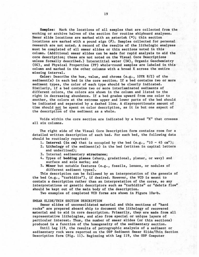
Samples: Mark the locations of all samples that are collected from theworking or archive halves of the section for routine shipboard analyses.Smear slide locations are marked with an asterisk (*); thin sectionlocations are marked with a pound sign (#). Samples collected for personalresearch are not noted. A record of the results of the lithologic analysesmust be completed of all smear slides or thin sections noted in thiscolumn. (Additional smear slides can be made for rapid analysis to aid thecore description; these are not noted on the Visual Core Descriptionsunless formally described.) Interstitial water (IW), Organic Geochemistry(OG), and Physical Properties (PP) whole-round samples are labeled in thiscolumn and marked in the other columns with a broad X across the entiremissing interval.
Color: Describe the hue, value, and chroma (e.g., 10YR 8/2) of thesediment(s) in each bed in the core section. If a bed contains two or moresediment types, the color of each type should be clearly indicated.Similarly, if a bed contains two or more interlaminated sediments ofdifferent colors, the colors are shown in the column and listed to theright in decreasing abundance. If a bed grades upward from one color toanother, the colors at the extreme upper and lower parts of the bed shouldbe indicated and separated by a dashed line. A disproportionate amount oftime should not be spent on color description, as it is but one aspect ofthe description of the sediment as a whole.
Voids within the core section are indicated by a broad "X" that crossesall six columns.
The right side of the Visual Core Description form contains room for adetailed written description of each bed. For each bed, the following datashould be routinely reported:
1. Interval (in c•) that is occupied by the bed (e.g., "10 - 45 cm");2. Lithology of the sediment(s) in the bed (written in capital letters
and underlined);3. Internal sedimentary structures;4. Types of bedding planes (sharp, gradational, planar, or wavy) and
surface and sole marks; and5. Minor but notable features (e.g., fossils, lenses, or nodules of
different sediment types).This description can be followed by an interpretation of the genesis of
the bed (e.g., "turbidite"), if desired. However, the VCD is meant tocontain a description rather than an interpretation of the cores, so anyinterpretations or genetic descriptors such as "turbidite" or "debris flow"should be kept out of the main body of the description.
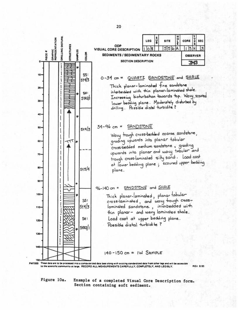
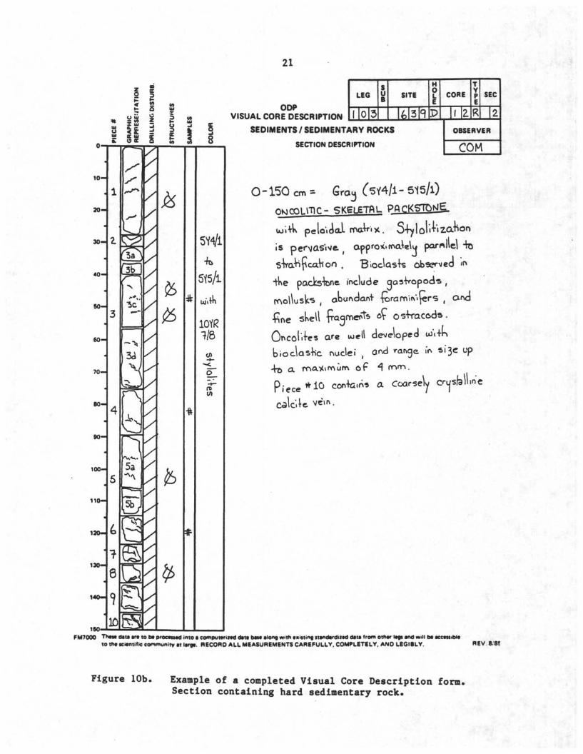
Two examples of completed VCD forms are shown in Figure lOa-b.
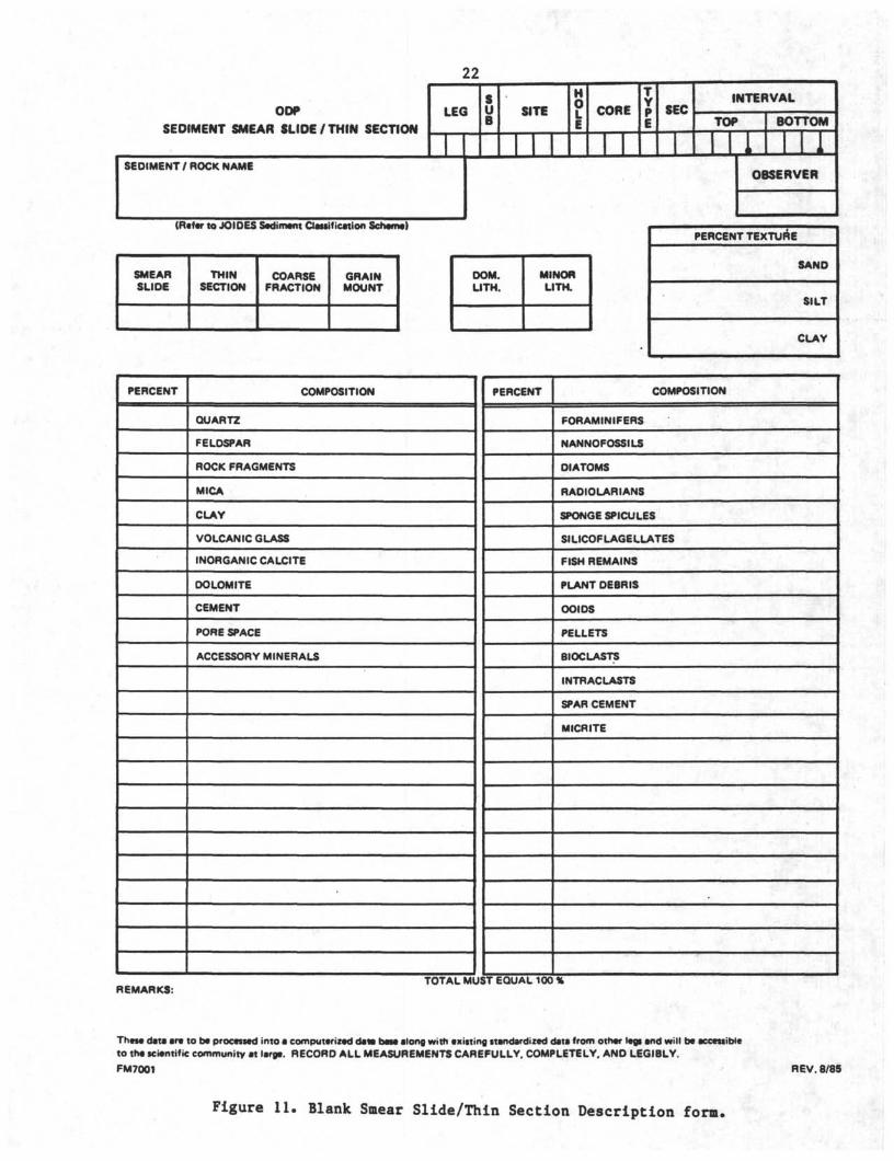
SMEAR SLIDE/THIN SECTION DESCRIPTIONSmear slides of unconsolidated material and thin sections of "hard
rocks" are prepared aboard ship to document the lithology of recoveredmaterial and to aid in core description. Primarily, they are made from allrepresentative lithologies, and also from special or unique layers ofparticular interest. Thus, the number of smear slides (or thin sections)produced is a function of the homogeneity of the sedimentary section.
Until Leg 119, the results of petrographic analysis of a sediment orsedimentary rock were reported on the ODP Sediment Smear Slide/Thin SectionDescription form (Fig. 11). Beginning with Leg 119, the ODP Computer
20
< S2
£ 2_ u»OCC
iSi I
10-1
20-4
30-4
40-4
50-4
soH
i H
tio-4
120-J
130-4
150-
SS5Y4/3
5*5/4
5S:
ODPVISUAL CORE DESCRIPTION
LEG
1 0
u SITE
5 5 (o
SEDIMENTS/SEDIMENTARY ROCKS
SECTION DESCRIPTION
0-3-1 cm* QUARTZ. SANDSTONE
H0L
A
CORE
i 3
TYPE
H
SEC
3
OBSERVER
IMS
and SHALE
W planar-laminated T ^Cirk^rbedJβd «*i'fK "*Wm planar-laminated s eIncrβaatwa klo KirbaKon -ta-iards "fep. VsJavu (scoorejlotoer DβdcJinq plane NjocieraVβiy disturbed DudinHi>g . Rjssibl dislal 4urbiciile ?
cm SANDSTONE
Wavu irou3k cross-bedded coarse
üp
3a upwards ,'n+β planar
Cross-bedcied me^um sands+one ,
ioards <n+o planar arvd ujavtj
f•roua cross-laminated <δ>lKj Sand . Load
a* lou>er l>rddina plane j scoured
plane.
%-l40an SftNDS TOKlg and SHflUE
U a i - e d , planar TabuJar-planar-Umin
lam na>ed 7 ar\é uxiv/u 4rouan Cnoss
lamina>ed Sands•tenc ; interbedded tüi•+
•iWin planar- and wav/ij larnincèed skalβ.
Load cas\ aV upper beddina plane,.
Possible A s W 4urbidik ? "
- 1 5 0 c m * IvJ
FM7000 Th w d*t» are to bt proctuad into a coπ>put riz d data best along with txuting ttandardiz d data <rom oth r l gi and will b acc ttibito th ici niific community at larg . RECORO ALL MEASUREMENTS CAREFULLY. COMPLETELY. AND LEGIBLY. REV 8 85
Figure lOa Example of a completed Visual Core Description form.Section containing soft sediment.
21
2 ?
g ü 1
1 0 -
3 0 -
3 0 -
4 0 -
5 0 -
6 0 -
70—
8 0 -
9 0 -
100-
110-
130-
130-
140-1
3c
- >
^
/
fc
h
5V4/1
•fe
5Y5/L
10YR
Φ
O
fD
ODPVISUAL CORE DESCRIPTION
LEG
I 0
u SITE
3
H0L
P
SEDIMENTS / SEDIMENTARY ROCKS
SECTION DESCRIPTION
CORE
i z
YPE
R
SEC
2
OBSERVER
COM
•s pe^VCisWe
O -150 cm » Srα3 C5Y4/i - 515/l)
- SKSLETftL PflrKSTOM•S.
pβloiáαi mαW x . S fyloiiT zα•π
pproKirr αMu parallel
Bioclasts observed
packs•fene include d
usk^ , aoundani (
fine skell faqmerts of
Oncol < eβ are uoell developed UJ\+K
b i o c l a s t nuclei , and range »* ^'
4o a ma•><vfv>ùm c f
ar»d
P i e c e * 1 0 con+a.π* a Coarsely crijslailinc
FM7000 Thate dau ara to ba procauad into a computariiad data ba$a along with a• ttin« ttandardnad data from otnar lagi and will ba ace uibiato th iciantific community at large. RECORO ALL MEASUREMENTS CAREFULLY. COMPLETELY. AND LEGI8LY. REV. 8/8!
Figure 10b. Example of a completed Visual Core Description form,Section containing hard sedimentary rock.
22
ODP
SEDIMENT SMEAR SLIDE/THIN SECTION
LEG U SITE CORE
πSEC
INTERVAL
TOP BOTTOM
SEDIMENT / ROCK NAMEOBSERVER
(Rafar to JOIDES Sediment Classification Schamt)
SMEARSLIDE
THINSECTION
COARSEFRACTION
GRAINMOUNT
DOM.LITH.
MINORLITH.
PERCENT TEXTURE
SAND
SILT
CLAY
PERCENT COMPOSITION
QUARTZ
FELDSPAR
ROCK FRAGMENTS
MICA
CLAY
VOLCANIC GLASS
INORGANIC CALCITE
DOLOMITE
CEMENT
PORE SPACE
ACCESSORY MINERALS
PERCENT COMPOSITION
FORAMINIFERS
NANNOFOSSILS
DIATOMS
RADIOLARIANS
SPONGE SPICULES
SILICOFLAGELLATES
FISH REMAINS
PLANT DEBRIS
OOIDS
PELLETS
BIOCLASTS
INTR AC LASTS
SPAR CEMENT
MICRITE
REMARKS:TOTAL MUST EQUAL 100 %
These data are to be processed into a computerized data base along with existing standardized data from other legs and will be accessibleto the scientific community at large. RECORD ALL MEASUREMENTS CAREFULLY. COMPLETELY. ANO LEGIBLY.
FM7001 REV. 8/85
Figure 11. Blank Smear Slide/Thin Section Description form.
23
Services Group installed software (called SLIDES) that allows these data tobe entered directly into the shipboard computer system in a format similarto that of the paper forms.
SLIDES is a computerized data collection and reporting package designedto handle entry and updating of information from smear slides, thinsections, grain mounts, and coarse-fraction slides. SLIDES then can preparetwo types of reports: a Barrel Summary to be attached directly to thecore's barrel sheet (see below), and a downhole stacked line graph of thenormalized abundance of five user-selected sedimentary components.
To use SLIDES, the scientist types onto a computerized screen form theslide identification information, the 10-letter assigned component codesfor the observed components, and the components1 percentages. A list of thecomponent codes is kept in the sedimentology lab. SLIDES ensures thequality of the data collected by submitting it to a variety of checks.The paper Smear Slide/Thin Section Description form should be used in placeof SLIDES if the SLIDES program is unavailable for any reason.
The FINDCOMP report routine allows selection of records from across theentire leg based on the appearance of an individual component, or based ona percentage level of a group of components. Users* guides have beenwritten for SLIDES and for FINDCOMP. There is also online help within theprograms, and further assistance is available aboard ship from the ComputerSystem Manager.
Sets of representative smear slides and mineral grain mounts areavailable aboard ship for comparison purposes.
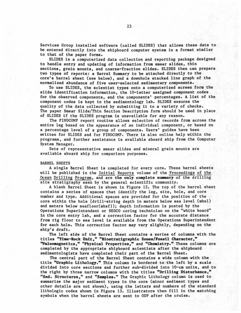
BARREL SHEETSA single Barrel Sheet is completed for every core. These barrel sheets
will be published in the Initial Reports volume of the Proceedings of theOcean Drilling Program, and are the only complete summary of the drillingsite stratigraphy seen by the general scientific community.
A blank Barrel Sheet is shown in Figure 12. The top of the barrel sheetcontains a series of spaces that identify the leg, site, hole, and corenumber and type. Additional spaces are provided for the position of thecore within the hole [drill-string depth in meters below sea level (mbsl)and meters below seafloor(mbsf)]; depth information is posted by theOperations Superintendent or SEDCO coring technician on the "white board"in the core entry lab, and a correction factor for the accurate distancefrom rig floor to sea level is available from the Operations Superintendentfor each hole. This correction factor may vary slightly, depending on theship's draft.
The left side of the Barrel Sheet contains a series of columns with thetitles "Time-Rock Unit," "Biostratigraphic Zones/Fossil Character,""Paleomagnetics," "Physical Properties," and "Chemistry." These columns arecompleted by the appropriate shipboard scientists after the shipboardsedimentologists have completed their part of the Barrel Sheet.
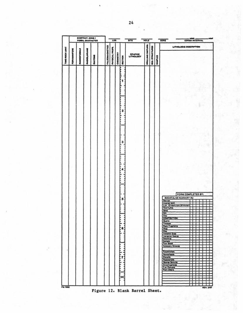
The central part of the Barrel Sheet contains a wide column with thetitle "Graphic Lithology." This column is bordered to the left by a scaledivided into core sections and further sub-divided into 10-cm units, and tothe right by three narrow columns with the titles "Drilling Disturbance,""Sed. Structures," and "Samples." The Graphic Lithology column is used tosummarize the major sediment types in the core (minor sediment types andother details are not shown), using the letters and numbers of the standardlithologic codes shown in Figure 13. Illustrators then fill in the matchingsymbols when the barrel sheets are sent to ODP after the cruise.
24
• lOtTN AT. lOM /FOWL CHAUACTIH l•O MT• HOU COMO INTtftVM.
β :
T:
OMAfMICUTNOLθβV
UTNOVOOW otscm
[ f OBM COMPLtTtO BY:SMIAN ILIO< SUMMARY Ml
I<tnawwnw>•< km)
TtXTUWt:
Ci *COMPOSITION
Figure 12. Blank Barrel Sheet*ntv.a/ y
25
GRANULAR SEDIMENTS
PELAGIC SEDIMENTSCtlcar M
o α α αa α α α αα o α α
t ; > ^ Tt i t+—7-<
a-o-o-o-o-α
SUICMM
m
SILICICLASTIC SEDIMENTS
SMI
1 1 1 1 1 1 j: : :m
^11M l
VOLCANICLASTIC SEDIMENTS
V lwm AA/T««fTTTTTTTT
vvvwvvvv*
NERITIC SEDIMENTS••iiwëWd>•
JXL
MIXED SEDIMENTS
T r T
\
lyiwtot f r i
CHEMICAL SEDIMENTS
mConcr t>on
H U
S tMMOfvβ βwtft fV^^ β• l
SPECIAL ROCK TYPES ADDITIONAL SYMBOLS
AM
MMMK7T [
;•_• •_•_•_•-•.
Λ^
Figure 13. Standard lithologic codes and symbols used in "GraphicLithology" column on barrel sheets (see Fig 12).
26
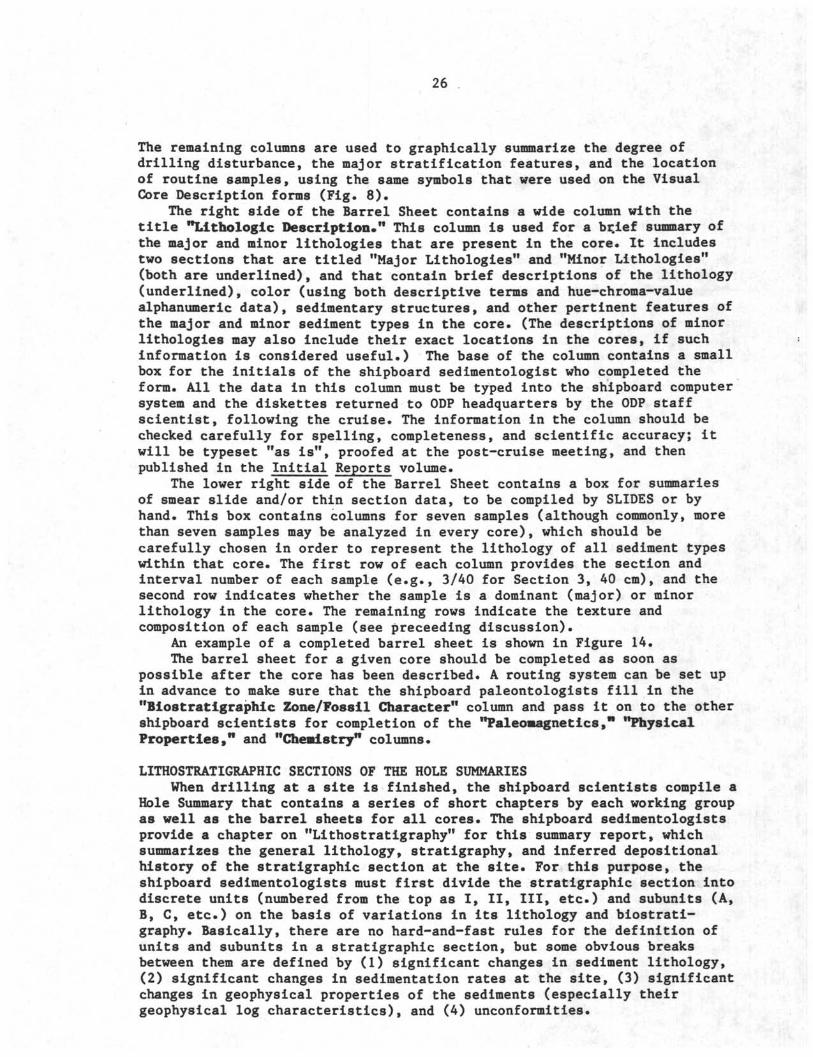
The remaining columns are used to graphically summarize the degree ofdrilling disturbance, the major stratification features, and the locationof routine samples, using the same symbols that were used on the VisualCore Description forms (Fig. 8).
The right side of the Barrel Sheet contains a wide column with thetitle "Lithologic Description." This column is used for a bçief summary ofthe major and minor lithologies that are present in the core* It includestwo sections that are titled "Major Lithologies" and "Minor Lithologies"(both are underlined), and that contain brief descriptions of the lithology(underlined), color (using both descriptive terms and hue-chroma-valuealphanumeric data), sedimentary structures, and other pertinent features ofthe major and minor sediment types in the core. (The descriptions of minorlithologies may also include their exact locations in the cores, if suchinformation is considered useful.) The base of the column contains a smallbox for the initials of the shipboard sedimentologist who completed theform. All the data in this column must be typed into the shipboard computersystem and the diskettes returned to ODP headquarters by the ODP staffscientist, following the cruise. The information in the column should bechecked carefully for spelling, completeness, and scientific accuracy; itwill be typeset "as is", proofed at the post-cruise meeting, and thenpublished in the Initial Reports volume.
The lower right side of the Barrel Sheet contains a box for summariesof smear slide and/or thin section data, to be compiled by SLIDES or byhand. This box contains columns for seven samples (although commonly, morethan seven samples may be analyzed in every core), which should becarefully chosen in order to represent the lithology of all sediment typeswithin that core. The first row of each column provides the section andinterval number of each sample (e.g., 3/40 for Section 3, 40 cm), and thesecond row indicates whether the sample is a dominant (major) or minorlithology in the core. The remaining rows indicate the texture andcomposition of each sample (see preceeding discussion).
An example of a completed barrel sheet is shown in Figure 14.The barrel sheet for a given core should be completed as soon as
possible after the core has been described. A routing system can be set upin advance to make sure that the shipboard paleontologists fill in the"Biostratigraphic Zone/Fossil Character" column and pass it on to the othershipboard scientists for completion of the "Paleomagnetics," "PhysicalProperties," and "Chemistry" columns.
LITHOSTRATIGRAPHIC SECTIONS OF THE HOLE SUMMARIESWhen drilling at a site is finished, the shipboard scientists compile a
Hole Summary that contains a series of short chapters by each working groupas well as the barrel sheets for all cores. The shipboard sedimentologistsprovide a chapter on "Lithostratigraphy" for this summary report, whichsummarizes the general lithology, stratigraphy, and inferred depositionalhistory of the stratigraphic section at the site. For this purpose, theshipboard sedimentologists must first divide the stratigraphic section intodiscrete units (numbered from the top as I, II, III, etc.) and subunits (A,B, C, etc.) on the basis of variations in its lithology and biostrati-graphy. Basically, there are no hard-and-fast rules for the definition ofunits and subunits in a stratigraphic section, but some obvious breaksbetween them are defined by (1) significant changes in sediment lithology,(2) significant changes in sedimentation rates at the site, (3) significantchanges in geophysical properties of the sediments (especially theirgeophysical log characteristics), and (4) unconformities.
27
m
RO
CK
UN
I
1
luz
O
0-OfLU
MIN
IF I
HI
1
CL
o1
o-
C/H
••OSTRAT. SONS /
POSSIL CHARACTER
or
OS
SIL
S
2
i
u9zoo
35
A/H
M
i1
B
3«s
B
1 Λ•9
3
M4
AG
NS
TI
w
<
_
z
•
fY
•
LEO
1
ISA
z
l
1 ^
> * *
αO
lOII
>CB3
5
•
?
.Ni
in•
Ir,a
•
1•
- -
7
" 3
• •
- .
"5"
-
m .
• ;
7'
- ~
- ;
cc;
é>ótSITE 1
GRAPHICLITHOLOGY
Ti
CB2
TI
V|
TI
VI
cB1
TI
Cβl
X TI
5403,1- 40.5 —
;•OLE CORE COREO INTERVAL
e
INC
DIS
TU
ILL
II
II
1
j
I
%Λ
\
BQm
*
?
*
*
1
>*
IM
LITHOLOGIC DESCRIPTION
CLAY and CALCAREOUS CLAY withFORAMINIFERAL OOZE andVOLCANIC ASH layer*.
Major Lithology: This corecontains CLAY, beco•lngCALCAREOUS CLAY below
Section 4. The clay lgray (5Y4/1-5Y5/1),heavily bioturbated, andho•ogeneous. Thecalcareous clay Is l ightgray to gray (5Y5/1-5Y6/1), s l i ght lybioturbated, and faintlylaminated In Section 6,10-45 ca. These sedl•entirepresent background
pelagic deposition.
Minor Lithology: Anormally gradedFORAMINIFERAL OOZE layeroccurs at Section 2, 45-8Cen. I t Is white (N8/),paral le l laminated, hassharp bottom and topcontacts, and l ike ly Is ad is ta l turbidite deposit.
Normally graded, yellowishbrown (10YR5/4) VOLCANICASH layers occur InSection 4, 50-70 c• andSection 4, 130 c• throughSection 5, 12 c•. Theseash layers have sharp
gradational, heavilybioturbated top contacts.
1 FORM COMPLETED BY. R t Q r
SMEAR SLIDE SUMMARY (»l
Swtionimtrv i (cm)L t v tD do *iin«m.«l fm»orl
TEXTURE:
Ejgj
Ci v
COMPOSITION:
Ow rtl
Ci v
Voicwuc Gi a
Inort > < C lc>lOo<om MCtm mPof Scwc
Accn•αry MHI >M*
FcK mmittn
N nno eMü
O• iom
P S S r> ntSoonf So<cui >
Sii•<oli otii n tF,ih Rtm intPlant O fer
2ftraaif
βn
n9c
3
u
rp
0
ITT
TT
WiT
T
T
*
T
k
r
b
ID
-
,—1
1
&
IS
3T
I
!CT
Figure 14. Example of a completed barrel sheet.
28
The first part of the "Lithostratigraphy" chapter is usually an"Introduction" containing a brief summary of the overall lithology and ageof the stratigraphic section; the number of units and subunits; the generalage, lithology, thickness, and distinctive characteristics of each unit andsubunit; and other appropriate information.
The second part is usually titled "Description of Units," and containsa series of sections on each unit and subunit. Each section begins with anunderlined title that states the unit number, the numbers and sections ofthe cores in each hole that contain that unit, the age of the unit, and thedepth of each unit (in meters below seafloor).
EXAMPLE Unit I: Hole 645A, Core 1HHole 645B, Cores 1X-18XHole 645C, Core lX-Core 17X, Section 5Age: Holocene - PleistoceneDepth: 0 - 168 mbsf
If the unit is not divided into subunits, the header is followed by adescription of the lithostratigraphy which summarizes all the visual coredescriptions and petrographic analyses as well as pertinent geochemical,geophysical, and/or paleontological data. If the unit is divided intosubunits, the header for the unit is followed by a brief and generaldescription of the unitfs lithology and stratigraphy, the definition of thenumber of subunits within it, and a brief and general description of thelithostratigraphy of each subunit. Following this, each subunit isintroduced with its own header (similar to the header for the unit) and isgiven a detailed description of its lithostratigraphy and other pertinentcharacteristics.
The third part is usually titled "Interpretation" and is an opportunityfor shipboard sedimentologists to interpret the stratigraphic section1sorigins. This part should begin with a broad interpretation of the entirestratigraphic section, and then proceed to a detailed interpretation of thesedimentation history, depositional environments, and/or diagenetic historyof each unit and subunit. The content of this part varies from cruise tocruise. The Co-Chief Scientists may want most interpretation in the"Summary and Conclusions" section, since interpretation usually involvesinformation from other shipboard studies as well.
The "Lithostratigraphy" chapter must be accompanied by a "References"section that lists (in alphabetical order and complete ODP format) allpublications cited within the chapter.
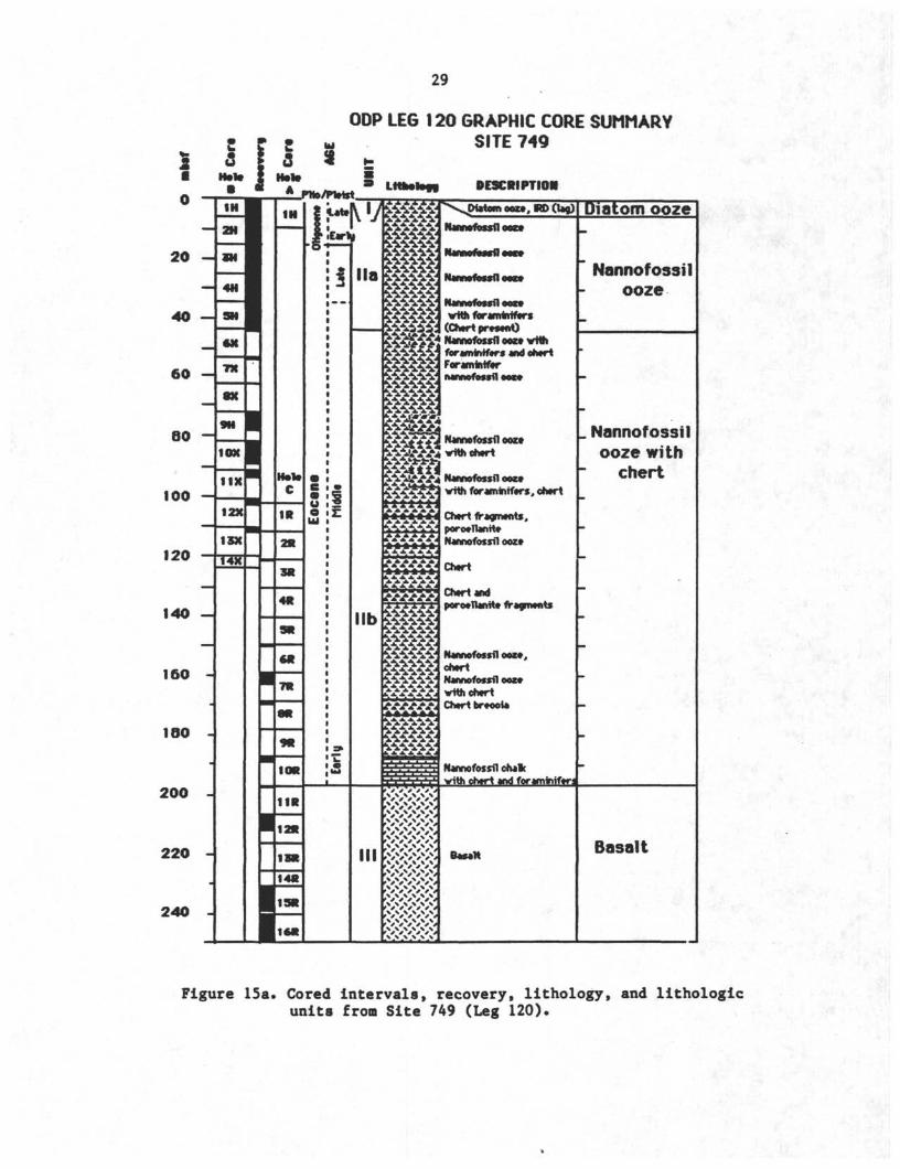
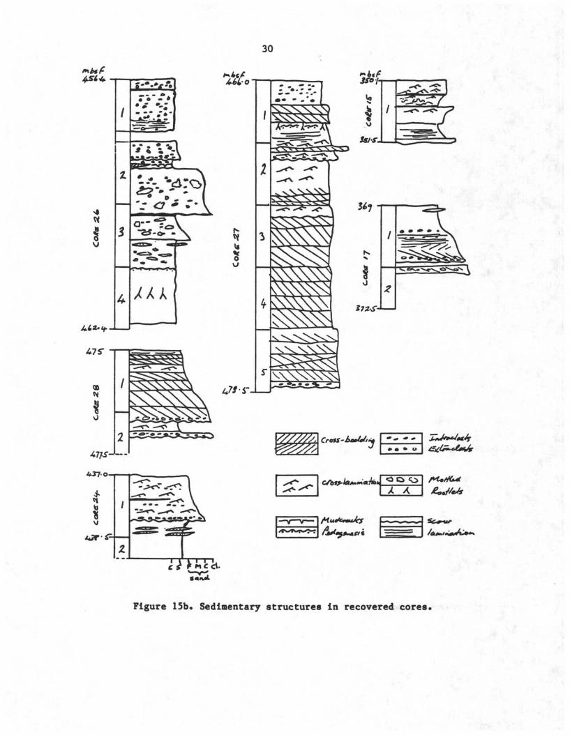
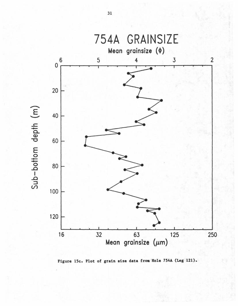
Finally, the "Lithostratigraphy" chapter should contain tables andillustrations of pertinent data that were collected routinely from thecores (e.g., tables or plots of the carbonate content of pelagic sediments,the mean grain size and sorting of clastic sediments, or the mineralogy ofterrigenous clays; pertinent closeup photographs of the cored section; andso on). Of particular value is a table listing the lithologic units, theirboundaries (in cores and mbsf), thicknesses, and major characteristics. Anexample of a composite lithostratigraphy figure showing cored intervals,recovery, lithology, and lithologic units is shown in Figure 15a. Examplesof other types of data that can be presented in this fashion are shown inFigures 15b-c.
29
|
20 -
40 —
60 -
80 -
100 -
ODP LEG 120 GRAPHIC CORE SUMMARYSITE 749
120
140 —
160 -
100
200 -
220 -
240 -
10ft
11R
/Pfetst.tatt
LMfe l f i DESCRIPTION
E<rkf
Ha
SΛΛAZZ* Nannofossil oozt
j j f e j g A g Nannofossil oozt^ ^ with foramiruf rs, ohtrt
a
lib
III
Diatom oozt, W>(iaç)
Nannofossil oozt
Nannofossil oozt
Nannofossil oozt
Nannofossil ooztwnn for anwnrtrs
(Chtrt prtstntjΛ Nannofossil oozt vtth
ForaminiftrπannofMsfl
II.*.*.*.*.*.*
Chtrt fragments,pore nanrt*Nannofossil oozt
Ctwrt
Chtrt and
Nannofossil oozt.
Nannofossil ooztwith chtrtChtrt brtooi
Nannofossil chalcvith oncrt and forarninif r j
Ba*«H
Diatom ooze
Nannofossilooze
_ Nannofossilooze with
chert
Basalt
Figure 15a. Cored intervals, recovery, lithology, and lithologicunits from Site 749 (Leg 120).
30
"3
k\
• β
o cλ
-i_r-|_
Λ
Figure 15b Sedimentary structures in recovered cores.
31
0
2θ[-
40 I-
CL
6 0 I—
oI
so µ
100 I—
120 µ
16
754A GRAINSIZEMean grainsize (Φ)
5 4 3r- ,
J
• <
1 . . \
1 " ^
>>
i ,
>
>
i ~1"
32 63 125Mean grainsize (µm)
250
Figure 15c. Plot of grain size data from Hole 754A (Leg 121)
32
CHAPTER 4PROCEDURES AND ANALYTICAL EQUIPMENT
The laboratories on JOIDES Resolution contain equipment that can beused by the shipboard sedimentologists for lithologic analysis. Generally,four classes of analyses are performed routinely by shipboardsedimentologists and geochemists: (1) petrographic analysis of thinsections, grain mounts, and smear slides; (2) grain-size analysis with amechanical, laser-operated particle-size analyzer; (3) geochemical analysisof carbonate and organic carbon content; and (4) X-ray-diffraction analysisof mineralogy. In this chapter, we describe the purposes of these analyses,the types of equipment available for them, and the methods of data summaryand presentation.
PETROGRAPHIC METHODS OF ANALYSISPetrographic analysis is the technique that is used most commonly by
sedimentologists to determine the texture and composition of sediments andsedimentary rocks. JOIDES Resolution is equipped with petrographicmicroscopes and all ancillary equipment and supplies necessary for thispurpose.
EQUIPMENTThe sedimentology laboratory has two Zeiss standard WL petrographic
microscopes and two Zeiss SR stereomicroscopes. The lab is also equippedwith a hot plate under a benchtop fume absorber, a variety of permanentmounting media (including Canada balsam, Hyrax, Piccolite, Permount, cloveoil, gum tragacanth, Norland optical adhesive, and Eukitt, a Germansynthetic balsam), and supplies (petrographic slides, cover glasses,sieves, sampling tools, etc.) for the preparation of smear slides and grainmounts. The microscope laboratory next to the paleo-prep lab has fouradditional Zeiss transmitted light microscopes (including two ZeissPhotomicroscope Ills) that can also be used by the shipboardsedimentologists, in conjunction with the paleontologists and petrologists.
All transmitted light microscopes on the ship have interchangeableobjectives (2.5x, lOx, 40x, 63x, and lOOx), ocular pieces (with micrometerscales), and filters. Micrometer slides (for calibrating the ocularscales), reflected-light equipment, and TV camera-monitor hook-ups areavailable. The photomicroscopes accept 35-mm film as well as Polaroidpositive (Type 52) and Polaroid positive/negative (Type 55) films.
At the forward end of the sedimentology lab, a copystand is set up forcloseup core photography (Item 6 in Fig. 2). Closeup photos of designatedcore intervals for hole summaries and publications may be taken by theshipboard photographer at the request of individual scientists; a requestform for this purpose is available in the core lab. The copystand may beused also for closeups for personal research, with scientists* own 35-mmcameras and film; the marine technicians can assist.
There is a limited supply of film for the photomicroscopes and closeupcore photography, and this supply is reserved for routine shipboardstudies. If you require photographs or photomicrographs for your personalresearch, you must bring the necessary film with you. The PhotographyTechnician may develop and provide contact sheets of film on atime-available basis, but will print only closeups and photomicrographsrequired for the Hole Summaries.
The thin section laboratory has been outfitted to make thin sectionsmanually or automatically, depending upon the number of samples. When one
33
or two thin sections are required, they are made manually with a BuehlerPetro-thin thin-sectioning system and thin-section grinder. When largerbatches of thin sections are requested, they are made with the Logitechsystem, which includes an LP-30 lapping machine and a WG-2 polishingsystem. The thin section laboratory is equipped also with a Logitech CS-1Othin-section cutoff saw, a Leco VC-50 varispeed diamond saw, and an IU-20impregnation unit that can be used to impregnate a coarse-grained sedimentsample or a friable and porous sedimentary rock. Both clear and blue-dyedepoxy (which accentuates the pore system) is available. The thin sectionlaboratory is also equipped with a variety of mineral stains, includingMethylene blue, Malachite green, Rose bengal, Alizarin red S, Safranin 0,and sodium cobaltinitrite
PETROGRAPHIC MEDIAThe lithology of sediments and sedimentary rocks can be determined by
the examination of three types of petrographic media with the petrographicmicroscope:
1. S ear slides: permanent mounts of fine (silt- and clay-sized)granular sediment. Smear slides are generally made from samples ofwell-sorted, fine-grained clastic and biogenic sediments (mud, ooze,micrite, etc.). They can also be made from the fine-grained fractions thatare mechanically extracted (by sieving) from more poorly sorted sediments.
2. Grain aounts: permanent mounts of coarse (sand-sized) granularsediment. Generally, grain mounts are made from samples of well-sorted,coarse-grained clastic and biogenic sediments (sands, grainstones, etc.).They can be made also from the coarse-grained fractions that aremechanically extracted (by sieving) from more poorly sorted sediments.
3. Thin sections: permanent mounts of both granular and chemicalsediments. Thin sections can be made from samples of fine-grained andcoarse-grained clastic and biogenic sedimentary rocks, from samples ofchemical sedimentary rocks, and from artificially impregnated samples ofcoarse granular sediment.
Common techniques for the preparation of smear slides, thin sections,and grain mounts are described below.
Smear SlidesPreparation of a smear slide requires an extremely small ("toothpick")
sample collected either directly from the archive half of the core or froma larger sample that is collected from the working half of the core on thesampling table (see Sampling Methods, below). To make smear slides, thefollowing supplies and equipment are provided:
1. cover glass (24 x 40 mm) - #1 thickness2. toothpick3. water dropper4. glass petrographic slide (25 x 75 mm)5. permanent mounting medium6. glass rod7. hot plate8. tweezers9. pencil with new eraser10. slide label
The hot plate is located under a benchtop fume adsorber directly tostarboard of the core description table (Item 5 in Fig. 2). The hot plateshould be set constantly on "Low." A small beaker or uncapped bottle of
34
mounting media is usually kept on (if appropriate, to reduce its viscosity)or near the hot plate under the portable hood at all times. Large bottlesof mounting media are kept with the remaining supplies in the cabinetdrawers directly below the hot plate; supplies are replenished from theshipfs stores by the marine technicians upon request.
Although there are several methods of making a smear slide, most ofthem are variations on the following. Take a cover glass in hand and placea few drops of distilled water in its center. Collect a tiny fraction ofthe sample with the flat end of the toothpick, and mix it into the water onthe cover glass. Spread the wet sediment with the flat end of the toothpickuntil it forms a thin translucent coat across the entire cover glass, andthen place the cover glass (with the sediment smear up) on the surface ofthe hot plate to dry.
You will note that this preparation of the smear is inevitablyfabric-destructive, and destroys all grain-to-grain and grain-to-cementcontacts. Moreover, it can also be grain-destructive, especially todelicate microfossils (e.g., foraminifer tests and coccospheres), but thiscan be minimized by keeping the sediment sufficiently wet as it is smeared,and by smearing it slowly and gently across the cover glass. In addition,you will note that if the sediment contains some coarse clastic or biogenicgrains (e.g., sand, foraminifers, or shell debris), they will be scatteredtowards the edges of the smear slide and the fine sediment will concentratein its center. This segregation cannot be prevented easily, and can biasthe results of petrographic study (see below).
While the smear on the cover glass dries, place a slide label on theglass petrographic slide, and label it with the leg, site, hole, core, coretype, section, and sample interval data. Place a few drops of mountingmedium in the center of the petrographic slide with the glass rod, and setit on the surface of the hot plate to warm. When the smear on the coverglass is dry, use the tweezers to place the cover glass (with the sedimentsmear down) on the mounting medium on the petrographic slide. Press downand slowly rotate the cover glass with the clean eraser-end of the pencilto spread the mounting medium across the petrographic slide and to expelgas bubbles. If there is not sufficient mounting medium to cover the entiresmear, use a clean toothpick to drip one or two drops of mounting mediumonto the petrographic slide at the edge of the cover glass, where they willbe drawn by capillary action under the cover glass. Finally, return thesmear slide to the hot plate for 3-5 minutes to allow it to cure.
Grain Mounts 3
The preparation of a grain mount requires approximately 1-3 cm ofcoarse-grained sediment (depending upon its sorting) collected from theworking half of the core on the sampling table (see Sampling Methods,below). This sample should be dried on the hot plate or in the drying oven,and may be sieved with a 63-micron sieve before mounting in order to removefine-grained detritus. In order to prepare a grain mount, the followingsupplies and equipment are provided:
1. petrographic slide (25 x 75 mm)2. slide label3. permanent mounting medium4. glass rod5. sieve (optional)6. toothpick7. cover glass (24 x 40 mm)
35
8. hot plate9. pencil with new eraser
Place the slide label on the petrographic slide, and fill in the leg,site, hole, core number and type, section, and sample interval. Place thepetrographic slide on the hot plate, and use the glass rod to place a fewdrops of the permanent mounting medium on it Spread the mounting mediumacross the slide, and allow any bubbles to escape. The mounting mediumshould be spread thickly, so that all the grains will settle into it
Once the sample is dried (and sieved if necessary), the grains shouldbe sprinkled onto the petrographic slide and then spread evenly across theslide with the flat end of the toothpick. Allow the grains to settle intothe mounting medium (adding a few more drops of mounting medium with theglass rod if necessary), and then place the cover glass over the mount.Press down and slowly rotate the cover glass with the clean eraser-end ofthe pencil to spread the mounting medium across the petrographic slide andto expel gas bubbles. If there are large bubbles present in the mount,place one or two drops of mounting medium on the petrographic slide at theedge of the cover glass, and they will be drawn by capillary action underthe cover glass. Finally, keep the grain mount on the hot plate for 3-5minutes to allow it to cure, and then remove it and allow the mount tocool.
Thin SectionsPreparation of a thin section from a granular or chemical sedimentary
rock can be prepared in two ways: as a coarse-grain mount or as anartificially impregnated thin section. Preparation of a coarse-grain mountrequires a 1-2-cm-thick quarter-wedge that is collected from the workinghalf of the core on the sampling table. This sample must be dried on a hotplate or in the drying oven and it may be sieved to remove fine-graineddetritus. A thin section from an artificially impregnated coarse sedimentrequires 3-5 cm of sample (depending upon sorting), and is made like ahard-rock thin section, preserving bedding structure.
A marine technician assigned to the thin-section laboratory producesthin sections from lithified or nonlithified samples at the written requestof the shipboard sedimentologists. When requesting a thin section, theshipboard sedimentologists must specify (1) the desired thickness of thethin section, (2) the type (clear or blue) of epoxy (when appropriate), (3)whether a permanent cover glass should be affixed, or (4) any other specialprocedures.
Thin sections can be made without a permanent fixed cover glass so thatstains can be applied later. During petrographic examination, the thinsection can be coated with a temporary mounting medium (glycerin or mineraloil) and covered with a cover glass, but this cover glass should be removedand the thin section cleaned in soapy water after examination.
The thin section laboratory is supplied with a variety of stains thatcan be used to facilitate the identification of minerals in thin sections.This staining can be done under the hoods in the chemistry laboratory bythe shipboard sedimentologist or a marine technician.
The most commonly used stain for carbonate sedimentary rocks isAlizarin red S, which is an effective stain for calcite. The procedure forthe staining of a thin section with Alizarin red S is as follows:
1. prepare a solution of Alizarin red S by dissolving 0.1 gram ofAlizarin red S (solid) in 100 milliliters of 0.2% hydrochloric acid ofcommercial grade;
36
2. place the thin section in dilute (0 l%) hydrochloric acid ofcommercial grade for 2-3 minutes, or until some relief can be seen on itssurface with a hand lens or a binocular microscope;
3. pour the Alizarin red S solution into a shallow pan, and soak thethin section in this solution for 1-3 minutes.
The calcite will be stained a deep red color by the Alizarin red Swithin 3 minutes, while dolomite will remain unstained* After petrographicexamination, wash the stain from the surface of the thin section with soapywater.
A common stain for clastic sedimentary rocks is sodium cobaltinitrite,which is an effective stain for potassium feldspar. The procedure for thestaining of a thin section with sodium cobaltinitrite is as follows:
1. prepare a 5% solution of barium chloride;2. pour concentrated (52%) hydrofluoric acid into an etching vessel to
within 5 mm of the top, and place the thin section (rock slab down) acrossthe top of the etching vessel for 1 minute, or until some relief can beseen on its surface with a hand lens or a binocular microscope.
CAUTION: Before hydrofluoric acid ±s^ used, the OperationsSuperintendent and Co-Chief Scientists must be notified. They willnotify the Captain, who may require that the ship's heading bechanged so that adequate ventilation is achieved. Hydrofluoricacid may be used only under certain designated fume hoods, and usemay be restricted in certain weather conditions. Only very limitedquantities are kept aboard ship.
3. remove the thin section, dip it quickly into distilled water, dip itquickly twice into the barium chloride solution, and then rinse withdistilled water;
4. pour the sodium cobaltinitrite solution into a shallow pan, andimmerse the thin section into this solution for 1 minute;
5. remove the thin section and rinse with distilled water. Thepotassium feldspar will be stained bright yellow;
6. (Optional) immerse the thin section in rhodizonate reagent (0.05 gmof rhodizonic acid potassium salt dissolved in 20 milliliters of water),which will stain the plagioclase feldspar yellow.
A description of other stains and staining techniques can be found inRobert Carverfs "Procedures in Sedimentary Petrology," which is in theshipboard library.
All staining must be done under a hood to prevent the escape of acidfumes in the laboratory, and use of hydrofluoric acid requires a speciallydesignated fume hood.
PETROGRAPHIC METHODSTwo properties of a sediment or sedimentary rock can be examined and
described with the petrographic microscope: texture (in granularsediments) and composition (in granular and chemical sediments). Thetexture of grains can be measured with the aid of the micrometer scale onthe ocular eyepiece of the petrographic microscope, which is calibratedwith a micrometer slide. The composition of sediments is determined bytheir optical properties (form, color, relief, extinction, birefringence,cleavage, and so on) in plane and polarized light.
The sedimentology laboratory contains a file of smear slides and thinsections of different types of sediment types (e.g., ooze, sand,
37
grainstone), minerals (e.g., quartz, apatite, glass), and biogenic grains(e.g. forams, radiolarians, diatoms), which are an excellent source ofreference. We strongly recommend (especially to first-time shipboardsedimentologists) that you examine these reference slides and becomefamiliar with their components before you reach the first drilling site.
TextureThe first step in a shipboard petrographic analysis is to estimate the
texture of clastic and biogenic grains (when present) in the sample. Thiscan be done by two techniques: visual estimation and point-counting.
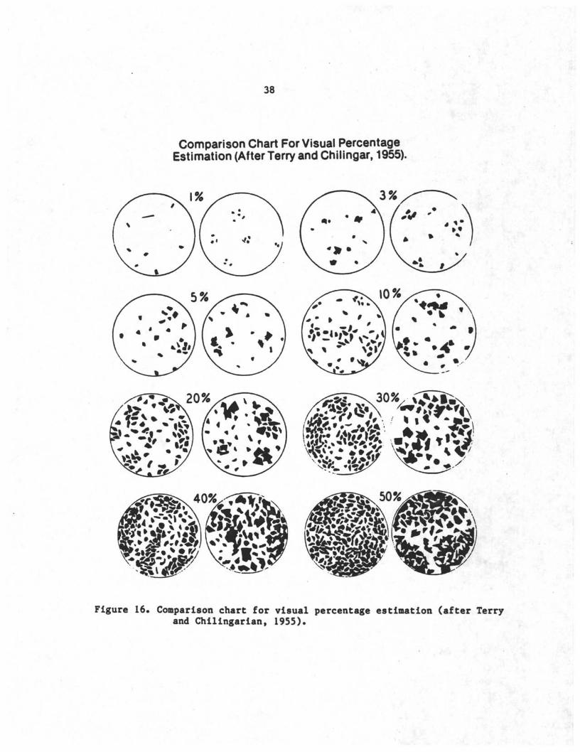
The visual estimation technique uses a standard visual comparison chartto estimate the relative abundances of sand, silt, and clay (Fig. 16). Forthis purpose, it is important to note the equivalent 63-micron length (theboundary between sand and silt) and the equivalent 4-micron length (theboundary between silt and clay) on your ocular eyepiece scale.
The point-counting technique uses the ocular eyepiece scale to measurethe long axis (or any other dimension) of individual clastic and biogenicgrains. Generally, the size of only one biogenic grain type (e.g., forams)or clastic mineral type (e.g., quartz) is measured in the samples in orderto minimize any size variation that may be a function of compositionalvariation. In point-counting, the smear slide, grain mount, or thin sectionis scanned across its length, and the size of every targeted grain typethat is intersected by the cross-hairs is measured (this is called the"ribbon method" of point-counting). Point-counting should proceed until 50and 200 grains have been measured in the sample, and the resultant datashould be used to calculate mean grain size and sorting.
Point-counting is much more time-consuming than visual estimation ofsediment texture and is only done if time permits and scientific needdictates. Textural data can also be derived from a particle-size analyzeravailable aboard ship (see below).
CompositionThe second step in petrographic analysis is estimating the composition
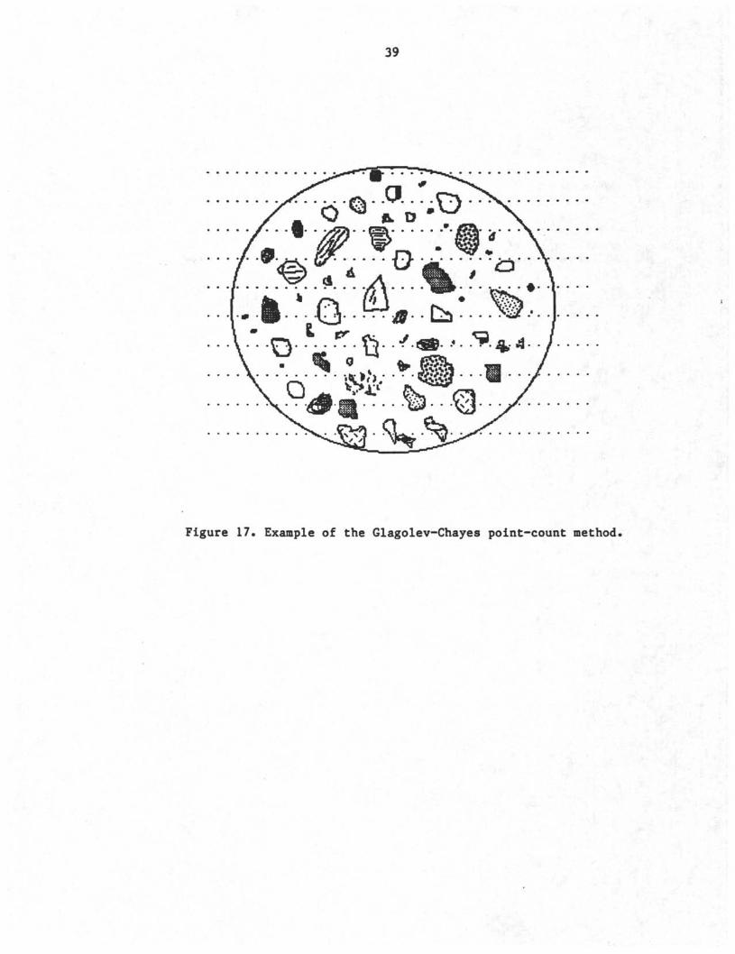
of the sample. Once again, this can be done by visual estimation and point-counting, but the point-counting should use the Glagolev-Chayes method,rather than the ribbon method, to select grains for study. In the Glagolev-Chayes method, the composition of the sediment is analyzed at a series ofequally spaced points along a line, rather than continuously along the line(as in the ribbon method) (Fig. 17)• This point-counting method determinesthe area percentage of the various grain and cement components, and is agood estimate of their relative volumes in the sediment.
Comparison of Visual Estimates and Point-countingThe visual estimation technique is rapid, and is consequently useful
for the petrographic analysis of a large suite of samples. However, it isalso subject to varying degrees of operator bias and error, the greatestsource of which is the "memory effect" - that is, the operator uses visualcomparison charts to estimate relative abundances of textural classes andgrain and cement types with diligence for the first few samples, and thenrelies upon his/her memory of the visual comparison from that point onward(Griffiths, 1967). In attempts to minimize this source of error, visualcomparison charts are posted directly behind the petrographic microscopes,where they can be seen by the operator during petrographic analysis.
38
Comparison Chart For Visual PercentageEstimation (After Terry and Chilingar, 1955).
Figure 16. Comparison chart for visual percentage estimation (after Terryand Chilingarian, 1955).
39
Figure 17. Example of the Glagolev-Chayes point-count method.
40
The error in visual estimation can also be increased by factors relatedto the sample preparation process, and particularly to the preparation ofsmear slides. There are two sources of error inherent in smear slides:
l the segregation of grain sizes. It was previously noted that thepreparation of smear slides of poorly sorted sediment will segregate coarsefrom fine grain sizes. Thus, if the operator scans only the center of thesmear slide and ignores its perimeter (or vice versa), he/she will have abiased view of both the texture and the composition (which is a function oftexture) in the sample.
2. the thickness of the smear. The use of the visual comparison chartassumes that the petrographic image that is being examined by the operatoris entirely filled with grains, cement, or matrix. However, if a smearslide is too thin and diffuse, it will have a large amount of void space,while if it is too thick, the grains will be stacked one upon another. Ineither case, it will be difficult to correctly estimate the relativeabundances of textural classes and grain and cement types with the visualcomparison charts.
The point counting technique is slow, and usually can be used only on asmaller suite of select samples. It is particularly useful for thecompositional analysis of coarse-grained clastic and biogenic sediments,and for the textural analysis of coarse-grained clastic sediments.
GRAIN-SIZE ANALYSIS BY PARTICLE-SIZE ANALYZER
A Lab Tec 100 particle size analyzer (PSA) is available aboard ship foruse by shipboard sedimentologists to provide rapid percentage measurementsof silt- and clay-sized particles to aid in smear slide interpretation.This equipment uses a focused laser diode light source (0.8 x 2.0 microns)to measure the sizes of individual particles in solution. The PSA can beoperated in either of two size ranges: 250-<4 microns and 125-<2 microns,respectively, with eight size intervals measured for each range. Theparticle size is determined by the length of time a particular particletakes to pass through the laser beam. Since the beam is scanned at aconstant velocity normal to the direction of fluid flow, the particle sizeis determined by
D » VT
where D - size of the particle, V - scanning velocity of the beam, and T -time that the particle is in the beam.
GEOCHEMICAL AND X-RAY-DIFFRACTION ANALYSIS
The petrographic microscope is well suited for the study of thecomposition of coarse-grained clastic and biogenic sediments andsedimentary rocks. However, it is less reliable and precise forfine-grained clastic and biogenic sediments and sedimentary rocks, becausethe grains are close to or below its limits of resolution. For this reason,the petrographic analysis of fine-grained sediments and sedimentary rocksmust be supplemented with other, more precise analytical techniques.
The two supplementary analytical techniques that must be used onfine-grained sediments and sedimentary rocks are (1) geochemical analysisof carbonate content and organic carbon content, and (2) X-ray-diffractionanalysis. The former technique must be routinely applied to all pelagicsediments and fine-grained marly sediments in order to measure the relative
41
abundance of calcareous and noncalcareous detritus; the latter techniquemust be routinely applied to all fine-grained clastic sediments andfine-grained marly sediments in order to determine the mineralogy of theclastic detritus. These two techniques can also be employed on other typesof sediments at the discretion of the sedimentologist For example, westrongly recommend that the carbonate content of coarse-grained marlysediments and sedimentary rocks be measured in order to gauge the relativeabundance of calcareous and clastic detritus.
The laboratories aboard JOIDES Resolution are well equipped forgeochemical analysis and X-ray-diffraction analysis. The chemistrylaboratory, for example, is equipped with a Delsi Nermag Rock-Eval II PlusTOC, which evaluates the type and maturity of organic carbon, calculatespetroleum potential, and detects oil shows; a Perkin-Elmer CHNS ElementalAnalyzer, which automatically measures the amount of organic carbon,hydrogen, nitrogen, and sulfur in up to 60 samples at a time; a CoulometricAnalyzer, which accurately measures the carbonate content of sediment; aLabconco-39-port freeze drier, which removes water from sediment samples upto 15 cm in size; Cahn 29 and Scientech balances for accurately weighingsmall and large samples; agate mortars and grinders and a hardened-steel-ball Spex mill grinder for homogenized dried sediment samples; a Barnsteadwater purifier, which produces 100 liters of both lab and reagent gradewater by osmotic pressure; and three fume hoods for solvents and chemicalreactions (see ODP Technical Notes 6 and 7 for further information).
The X-ray laboratory is equipped with a Philips ADP 3520 X-raydiffractometer. This instrument is fully automated, has auto-sampleloading, and is supported by a DEC Micro-11 computer with a 28-megabytedisk drive. The computer software includes quantitative and qualitativeanalyses, search-match of JCPDS and user data bases, line profile analysis,and statistical analysis programs. The laboratory is also equipped with anApplied Research Laboratory 8400 hybrid spectrometer for X-ray fluorescenceand elemental analysis (which is not generally used for sediments andsedimentary rocks), and a variety of devices for sample disaggregation andsample fusion.
The chemistry laboratory is staffed by marine technicians who prepare,run, and analyze routine samples. On the basis of decisions by the Co-ChiefScientists at their pre-cruise meeting, the X-ray laboratory may be runeither by dedicated marine technicians or by members of the shipboard partywho are trained by the marine technicians. In general, the responsibilityof the shipboard sedimentologists is to select the location and size ofsamples to be analyzed.
SAMPLING METHODS AND ANALYTICAL PROCEDURES
The types of analyses that are conducted on sediments and sedimentaryrocks, and the sizes of samples for these analyses, vary with composition.
For pelagic sediments, two types of analyses are required: geochemicalanalysis and petrographic analysis. The former analysis is used todetermine the relative abundance of carbonate and organic carbon in thesediment; the latter analysis is used to determine the texture and relativeabundance of biogenic and clastic grains. The petrographic media aregenerally smear slides, but thin sections may be used for well-lithifiedsediments.
For neritic and coarse-grained clastic sediments, a petrographicanalysis of sediment texture and composition is the only required analysis.
42
The most common medium for this analysis is the thin section, but grainmounts may also be used for poorly consolidated sediment.
For fine-grained clastic sediments, two types of analyses are required:X-ray diffraction and petrographic analysis. The former analysis is used todetermine the composition of the sediment, and the latter is used todetermine the texture and relative abundance of clastic minerals andbiogenic grains. The petrographic medium is generally smear slides, butthin sections may also be used for well-lithified sediments.
For coarse-grained mixed sediments, a petrographic analysis of sedimenttexture and composition (in thin section or grain mounts) is the onlyrequired analysis. For fine-grained mixed sediments, three types ofanalysis are required: X-ray analysis (for the composition of the fineclastic grains), geochemical analysis (for carbonate and organic carboncontent), and petrographic analysis of smear slides or thin sections (foroverall texture and composition).
For chemical sediments, a petrographic analysis of sediment compositionin thin section is the only required analysis.
SAMPLING METHODS 3The analysis of pelagic sediment requires approximately 5 cm of
sample, and this sample must be collected from the working half of the coreon the sampling table. The sedimentologist uses a small flag marked"SED/CHEM" (available on the sampling table) to pinpoint the position ofthe sample in the working half. The sample is collected by the scientistson the sampling shift and entered into SAM, the computer sampling database. This sample is placed in a small bag or aluminum tray labeled withthe leg, site, hole, core type, section, and sample interval, and is setaside for the sedimentologist The sedimentologist uses the flat end of atoothpick to collect a small piece of the sample for smear slidepreparation, and passes the remainder of the sample in its tray to thechemistry laboratory technicians for geochemical analysis.
The analysis of neritic sediment, coarse-grained clastic sediment,coarse-grained mixed sediment, and all types of chemical sediments requiresthe collection of a 2-rcm-thick quarter-wedge of sediment (for thinsections) or a 1-3-cm plug of sediment (for grain mounts) from the workinghalf of the core. The location of the desired sample is noted on theworking core by a small flag marked "SED/PET," and the sample is collectedby the scientists on the sampling shift. This sample is placed in a samplebag that is marked with the leg, site, hole, core, core type, section, andsample interval, and will be set aside for the sedimentologist If thesample is to be thin-sectioned, it should be passed directly to the thinsection laboratory technician. If it is to be grain-mounted, the sampleshould be removed from the sample bag, placed in a marked aluminum sampletray, dried on the hot plate or in the drying oven, and sieved to removeany fine-grained sediment (which may be separately studied in smear slide).. The analysis of fine-grained clastic sediment requires approximately 5
cm of sample that is collected from the working half of the core. Thelocation of the desired sample is noted on the working half by a small flagthat is marked "SED/XRD," and is collected by the Curatorial Representativeor his/her assistants. This sample will be placed in a sample bag(appropriately marked), and will be set aside for the sedimentologist Thesedimentologist will use the flat end of the toothpick to collect a part ofthe sample for smear slide, and the remainder of the sample will be sent tothe X-ray laboratory technician for analysis. If a thin section is to be
43
3made from the sediment, a 10-cm sample should be bagged and sent to theX-ray laboratory technician; the second half should be bagged and sent tothe thin-section laboratory technician.
The analysis of fine-grained nonclastic sediments requiresapproximately 5-10 cm of sample that is collected from the working half ofthe core. The location of the desired sample is noted on the working halfby a small flag that is marked either "SED/XRD" or "SED/CHEM." The sampleshould be split in half after sampling. One half of the sample should beplaced in a labeled aluminum tray, sampled for smear slide analysis, andpassed on to the chemistry laboratory technicians; the second half shouldbe bagged and sent to the X-ray laboratory technicians. If a thin sectionis made of the sediment, a larger (20 cm ) sample will have to be collectedfrom the working half.
There are two things to note about the sampling procedures. First,whenever there are two or more analyses to be conducted on the sediment,they should all be conducted on a split of the same sample. Second, thearchive half of the core which is being described by the shipboardsedimentologists should not be sampled for any routine lithologic analysis.The archive half may be scraped for a smear slide in order to determine thegeneral lithology of the sediment (if it is not readily apparent). However,once this determination is made, a larger sample must be collected from theworking half of the core for the full complement of petrographic,geochemical, and/or X-ray analyses.
Please note that all smear slides, grain mounts, and thin sections arethe property of the Ocean Drilling Program, and are collected by theCuratorial Representative at the end of drilling at each site. However, anyof these petrographic slides can be requested for further shore-basedanalysis on loan from the Curatorial Representative.
REFERENCES
Griffiths, J. C., 1967. Scientific Method in Analysis of Sediments: NewYork (McGraw-Hill).
Harms, J. C., Southard, J. B., and Walker, R G., 1982. Structures andsequences in clastic rocks: Lecture notes for Short Course 9, Soc.Econ Paleontol. Mineral.
McKee, E. D., and Weir, G. W., 1953. Terminology for stratification andcross-stratification in sedimentary rocks. Geol. Soc. Am. Bull.,64:381-390.
Terry, R D , and Chilingarian, G V., 1955. Summary of "Concerning someadditional aids in studying sedimemtary formations" by M SShetsov. J. Sed. Petrol., 25:229-234.
44
APPENDIX I
NEW SEDIMENT CLASSIFICATION SCHEMEFOR THE OCEAN DRILLING PROGRAM
by
Jim Mazzullo1'2, Audrey Meyer2'3, and Robert Kidd4.
*Department of Ge o l o g y , Texas A & M U n i v e r s i t yO c e a n D r i l l i n g P r o g r a m , Texas A & M U n i v e r s i t y.Department of Oc e a n o g r a p h y , Texas A & M U n i v e r s i t yD e p a r t m e n t of E a r t h S c i e n c e s , University College of Sw a n s e a , U.K.
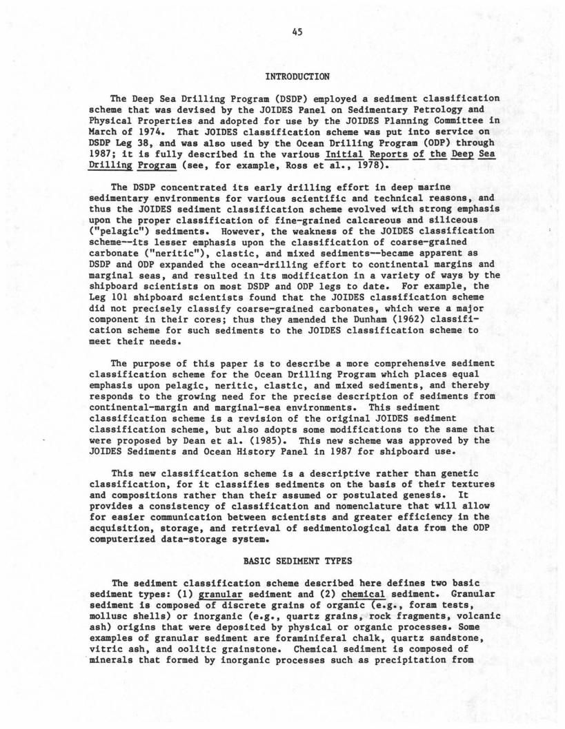
45
INTRODUCTION
The Deep Sea Drilling Program (DSDP) employed a sediment classificationscheme that was devised by the JOIDES Panel on Sedimentary Petrology andPhysical Properties and adopted for use by the JOIDES Planning Committee inMarch of 1974. That JOIDES classification scheme was put into service onDSDP Leg 38, and was also used by the Ocean Drilling Program (ODP) through1987; it is fully described in the various Initial Reports of the Deep SeaDrilling Program (see, for example, Ross et al., 1978).
The DSDP concentrated its early drilling effort in deep marinesedimentary environments for various scientific and technical reasons, andthus the JOIDES sediment classification scheme evolved with strong emphasisupon the proper classification of fine-grained calcareous and siliceous("pelagic") sediments. However, the weakness of the JOIDES classificationscheme—its lesser emphasis upon the classification of coarse-grainedcarbonate ("neritic"), clastic, and mixed sediments—became apparent asDSDP and ODP expanded the ocean-drilling effort to continental margins andmarginal seas, and resulted in its modification in a variety of ways by theshipboard scientists on most DSDP and ODP legs to date. For example, theLeg 101 shipboard scientists found that the JOIDES classification schemedid not precisely classify coarse-grained carbonates, which were a majorcomponent in their cores; thus they amended the Dunham (1962) classifi-cation scheme for such sediments to the JOIDES classification scheme tomeet their needs.
The purpose of this paper is to describe a more comprehensive sedimentclassification scheme for the Ocean Drilling Program which places equalemphasis upon pelagic, neritic, clastic, and mixed sediments, and therebyresponds to the growing need for the precise description of sediments fromcontinental-margin and marginal-sea environments. This sedimentclassification scheme is a revision of the original JOIDES sedimentclassification scheme, but also adopts some modifications to the same thatwere proposed by Dean et al. (1985). This new scheme was approved by theJOIDES Sediments and Ocean History Panel in 1987 for shipboard use.
This new classification scheme is a descriptive rather than geneticclassification, for it classifies sediments on the basis of their texturesand compositions rather than their assumed or postulated genesis. Itprovides a consistency of classification and nomenclature that will allowfor easier communication between scientists and greater efficiency in theacquisition, storage, and retrieval of sedimentological data from the ODPcomputerized data-storage system.
BASIC SEDIMENT TYPES
The sediment classification scheme described here defines two basicsediment types: (1) granular sediment and (2) chemical sediment. Granularsediment is composed of discrete grains of organic (e.g., foram tests,mollusc shells) or inorganic (e.g., quartz grains, rock fragments, volcanicash) origins that were deposited by physical or organic processes. Someexamples of granular sediment are foraminiferal chalk, quartz sandstone,vitric ash, and oolitic grainstone. Chemical sediment is composed ofminerals that formed by inorganic processes such as precipitation from
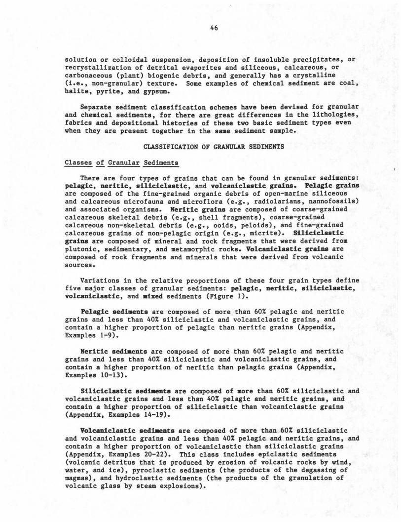
46
solution or colloidal suspension, deposition of insoluble precipitates, orrecrystallization of detrital evaporites and siliceous, calcareous, orcarbonaceous (plant) biogenic debris, and generally has a crystalline(i.e., non-granular) texture. Some examples of chemical sediment are coal,halite, pyrite, and gypsum.
Separate sediment classification schemes have been devised for granularand chemical sediments, for there are great differences in the lithologies,fabrics and depositional histories of these two basic sediment types evenwhen they are present together in the same sediment sample.
CLASSIFICATION OF GRANULAR SEDIMENTS
Classes of Granular Sediments
There are four types of grains that can be found in granular sediments:pelagic, neritic, siliciclastic, and volcaniclastic grains. Pelagic grainsare composed of the fine-grained organic debris of open-marine siliceousand calcareous microfauna and microflora (e.g., radiolarians, nannofossils)and associated organisms. Neritic grains are composed of coarse-grainedcalcareous skeletal debris (e.g., shell fragments), coarse-grainedcalcareous non-skeletal debris (e.g., ooids, peloids), and fine-grainedcalcareous grains of non-pelagic origin (e.g., micrite). Siliciclasticgrains are composed of mineral and rock fragments that were derived fromplutonic, sedimentary, and metamorphic rocks. Volcaniclastic grains arecomposed of rock fragments and minerals that were derived from volcanicsources.
Variations in the relative proportions of these four grain types definefive major classes of granular sediments: pelagic, neritic, siliciclastic,volcaniclastic, and •ixed sediments (Figure 1).
Pelagic sediments are composed of more than 60% pelagic and neriticgrains and less than 40% siliciclastic and volcaniclastic grains, andcontain a higher proportion of pelagic than neritic grains (Appendix,Examples 1-9).
Neritic sediments are composed of more than 60% pelagic and neriticgrains and less than 40% siliciclastic and volcaniclastic grains, andcontain a higher proportion of neritic than pelagic grains (Appendix,Examples 10-13).
Siliciclastic βedi•ents are composed of more than 60% siliciclastic andvolcaniclastic grains and less than 40% pelagic and neritic grains, andcontain a higher proportion of siliciclastic than volcaniclastic grains(Appendix, Examples 14-19).
Volcaniclastic sediments are composed of more than 60% siliciclasticand volcaniclastic grains and less than 40% pelagic and neritic grains, andcontain a higher proportion of volcaniclastic than siliciclastic grains(Appendix, Examples 20-22). This class includes epiclastic sediments(volcanic detritus that is produced by erosion of volcanic rocks by wind,water, and ice), pyroclastic sediments (the products of the degassing ofmagmas), and hydroclastic sediments (the products of the granulation ofvolcanic glass by steam explosions).
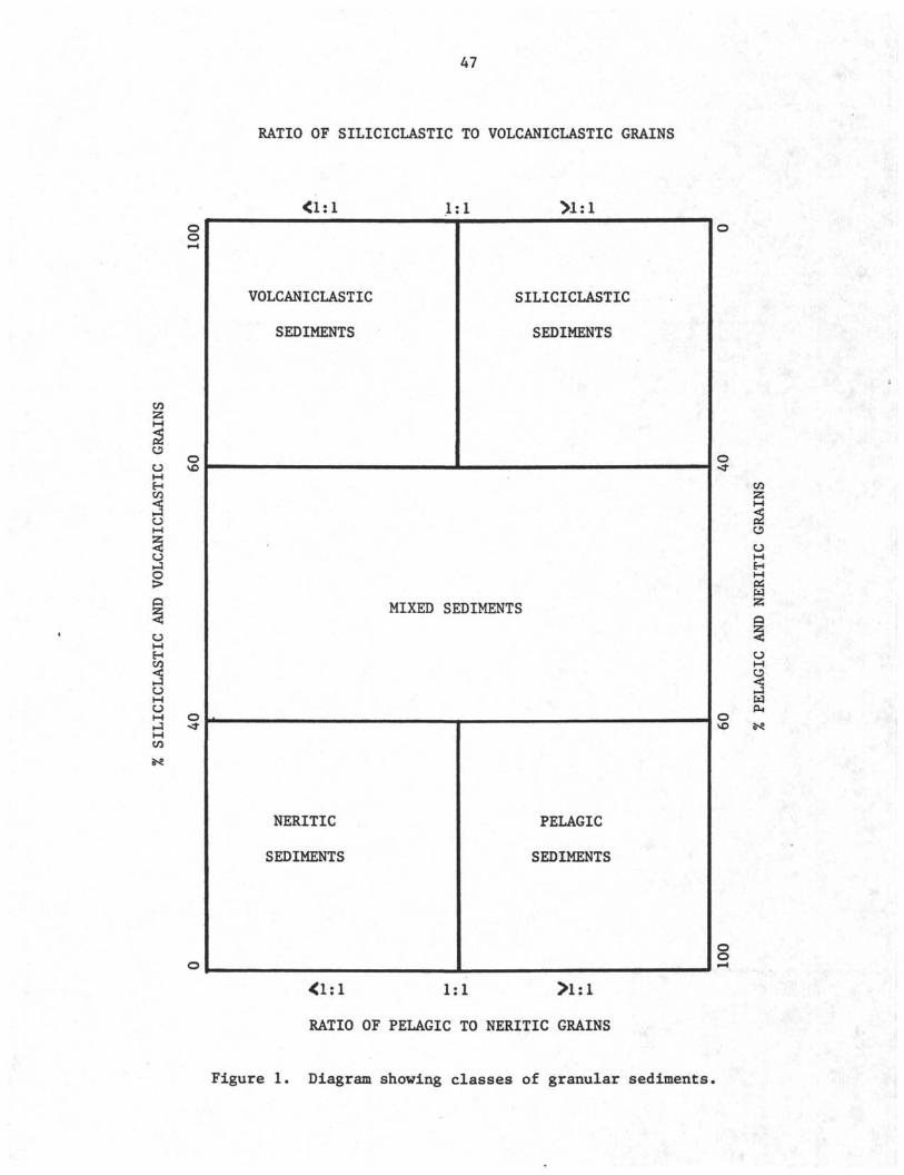
47
RATIO OF SILICICLASTIC TO VOLCANICLASTIC GRAINS
1:1oo
CΛ
53
O
MH
OMH
OHO
M O
CΛ
VOLCANICLASTIC
SEDIMENTS
•
SILICICLASTIC
SEDIMENTS
MIXED SEDIMENTS
NERITIC
SEDIMENTS
PELAGIC
SEDIMENTS
1:1
RATIO OF PELAGIC TO NERITIC GRAINS
CΛ
o
MHMP
mçus
oo
Figure 1. Diagram showing classes of granular sediments.
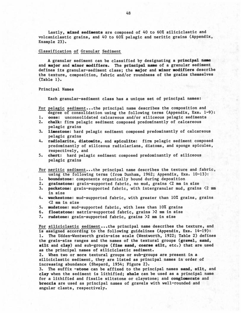
A8
Lastly, mixed sediments are composed of 40 to 60% siliciclastic andvolcaniclastic grains, and 40 to 60% pelagic and neritic grains (Appendix,
Example 23).
Classification of Granular Sediment
A granular sediment can be classified by designating a principal nameand •ajor and minor modifiers. The principal name of a granular sedimentdefines its granular-sediment class; the major and minor modifiers describethe texture, composition, fabric and/or roundness of the grains themselves
(Table 1).
Principal Names
Each granular-sediment class has a unique set of principal names:
For pelagic sediment...the principal name describes the composition and
degree of consolidation using the following terms (Appendix, Exs. 1-9):
1. ooze: unconsolidated calcareous and/or siliceous pelagic sediments
2. chalk: firm pelagic sediment composed predominantly of calcareouspelagic grains
3. limestone: hard pelagic sediment composed predominantly of calcareouspelagic grains
4. radiolarite, diatomite, and spiculite: firm pelagic sediment composed
predominantly of siliceous radiolarians, diatoms, and sponge spicules,
respectively, and
5. chert: hard pelagic sediment composed predominantly of siliceous
pelagic grains
For neritic sediment...the principal name describes the texture and fabric,using the following terms (from Dunham, 1962; Appendix, Exs. 10-13):
1. boundstone: components organically bound during deposition2. grainstone: grain-supported fabric, no mud, grains <2 mm in size3. packstone: grain-supported fabric, with intergranular mud, grains <2 mm
in size4. wackestone: mud-supported fabric, with greater than 10% grains, grains
<2 mm in size
5. mudstone: mud-supported fabric, with less than 10% grains
6. floatstone: matrix-supported fabric, grains >2 mm in size7. rudβtone: grain-supported fabric, grains >2 mm in size
For siliciclastic sediment... the principal name describes the texture, andis assigned according to the following guidelines (Appendix, Exs 14-19):
1. The Udden-Wentworth grain-size scale (Wentworth, 1922; Table 2) definesthe grain-size ranges and the names of the textural groups (gravel, sand,silt and clay) and sub-groups (fine sand, coarse silt, etc.) that are usedas the principal names of siliciclastic sediment.
2. When two or more textural groups or sub-groups are present in asiliciclastic sediment, they are listed as principal names in order ofincreasing abundance (Shepard, 1954; Figure 2).
3. The suffix -stone can be affixed to the principal names sand, silt, andclay when the sediment is lithified; shale can be used as a principal namefor a lithified and fissile siltstone or claystone; and conglomerate andbreccia are used as principal names of gravels with well-rounded andangular clasts, respectively.
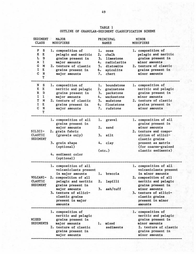
49
TABLE 1OUTLINE OF GRANULAR-SEDIMENT CLASSIFICATION SCHEME
SEDIMENTCLASS
P SE EL DA IG MI EC N
T
N SE ER DI IT MI EC N
T
SILICI-CLASTICSEDIMENT
VOLCANI-CLASTICSEDIMENT
MAJORMODIFIERS
1.
2.
1.
2.
1.
2.
3.
4.
1.
2.
3.
composition ofpelagic and neriticgrains present inmajor amountstexture of clasticgrains present inmajor amounts
composition ofneritic and pelagicgrains present inmajor amountstexture of clasticgrains present inmajor amounts
composition of allgrains present inmajor amountsgrain fabric(gravels only)
grain shape(optional)
sediment color(optional)
composition of allvolcaniclasts presentin major amountscomposition of allpelagic and neriticgrains present inmajor amountstexture of silici-clastic grainspresent in majoramounts
PRINCIPAL1
1.2.3.4.5.6.7.
1.2.3.4.5.6.7.
1.
2.
3.
4.
9AMES
oozechalklimestoneradiolaritediatomitespiculitechert
boundstonegrainstonepackstonewackestonemudstonefloatstonerudstone
gravel
sand
silt
clay
(etc
1.
2.
3.
breccia
lapilli
ash/tuff
MINORMODIFIERS
1.
2.
1.
2.
1.
2.
1.
2.
3.
composition ofpelagic and neriticgrains present inminor amountstexture of clasticgrains present inminor amounts
composition ofneritic and pelagicgrains present inminor amountstexture of clasticgrains present inminor amounts
composition of allgrains present inminor amountstexture and compo-sition of silici-clastic grainspresent as matrix(for coarse-grainedclastic sediments)
composition of allvolcaniclasts presentin minor amountscomposition of allneritic and pelagicgrains present inminor amountstexture of silici-clastic grainspresent in minoramounts
1. composition ofneritic and pelagic
MIXED grains present inSEDIMENTS major amounts
2. texture of clasticgrains present inmajor amounts
1 mixedsediments
composition ofneritic and pelagicgrains present inminor amounts2. texture of clasticgrains present inminor amounts
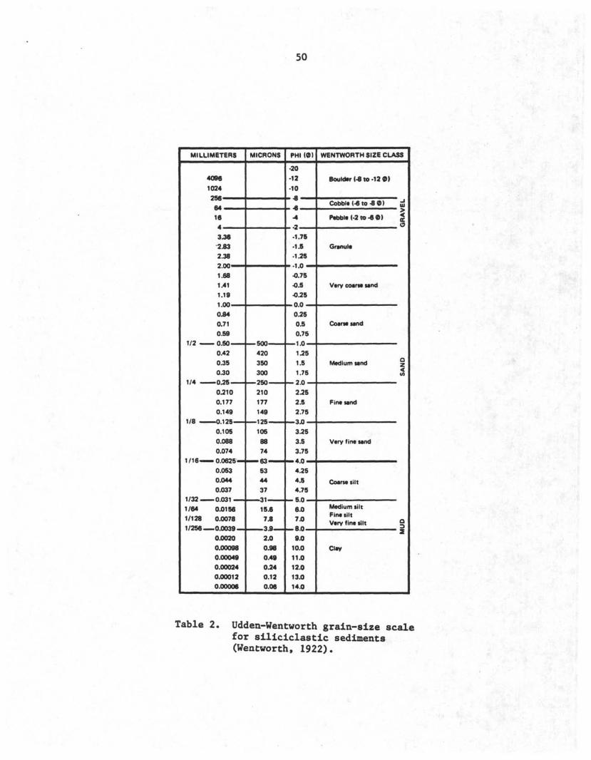
50
MILLIMETERS
1/8 —
1/32 —
1/64
1/128
1/256
4096
1024
16
3.36
2.83
2.38
1.68
1.41
1.19
0.84
0.71
0.59
0.42
0.35
0.30
0.210
0.177
0.149
0.105
0.088
0.074
0.053
0.044
0.037- n m i -«-«..
0.0156
0.0078
„ o 0039
0.0020
0.00098
0.00049
0.00024
0.00012
0.00006
MICRONS
420
350
300
210
177
149
105
88
74
53
44
37, _^«
15.6
7.8
11 ... 3 fl2.0
0.98
0.49
0.24
0.12
0.06
PHI (Φ)
•20
•12
-10
-4
•1.76
•1.5
-1.25
•0.75
•0.5
•0.25
0.25
0.5
0.75
1.25
1.5
1.75
2.25
2.5
2.75"* n
3.25
3.5
3.75
4.25
4.5
4.75
6.0
7.0
— 8 0
9.0
10.0
11.0
12.0
13.0
14.0
WENTWORTH SIZE CLASS
Boulder (-8 to -12 0 )
Cobbl < βto•βΦ)
Pβtobl (-2 to •β Φ)
Granule
Very coarse sand
Coarse sand
Medium sand
Pine sand
Very fine sand
Coarse silt
Medium silt
Pine siltVery fine silt
Clay
w
oc
QZIΛ
O
_ 2S
Table 2. Uddeu-Wentworth grain-size scalefor siliciclastic sediments(Wentworth, 1922).
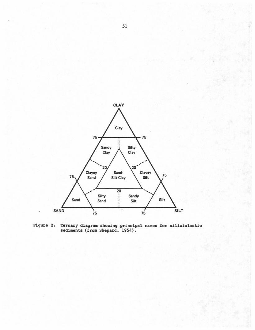
51
CLAY
Clay
7 x
/ Sand
/
ClayeySand
y"
' Sandy
Clay
^20/
/ S
SiltySand
λN
Sand*ilt-Clay
201
111
\SiltyClay
V
SandySilt
\
Clayey
Silt
\ XSilt \
SAND 75 75 SILT
Figure 2. Ternary diagram showing principal names for siliciclasticsediments (from Shepard, 1954).
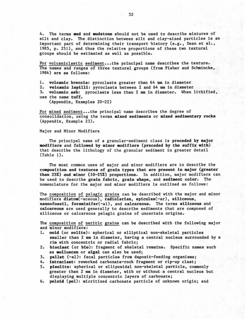
52
4. The terms and and Mudstone should not be used to describe mixtures ofsilt and clay. The distinction between silt and clay-sized particles is animportant part of determining their transport history (e.g., Dean et al.,1985, p. 251), and thus the relative proportions of these two texturalgroups should be estimated as well as possible.
For volcaniclastic sediment...the principal name describes the texture.The names and ranges of three textural groups (from Fisher and Schmincke,1984) are as follows:
1. volcanic breccia: pyroclasts greater than 64 mm in diameter2. volcanic lapilli: pyroclasts between 2 and 64 mm in diameter3. volcanic ash: pyroclasts less than 2 mm in diameter. When lithified,use the name tuff.
(Appendix, Examples 20-22)
For mixed sediment...the principal name describes the degree ofconsolidation, using the terms aixed sediments or mixed sedimentary rocks(Appendix, Example 23).
Major and Minor Modifiers
The principal name of a granular-sediment class is preceded by majormodifiers and followed by minor modifiers (preceded by the suffix with)that describe the lithology of the granular sediment in greater detail(Table 1).
The most common uses of major and minor modifiers are to describe thecomposition and textures of grain types that are present in major (greaterthan 25Z) and minor (10-25Z) proportions. In addition, major modifiers canbe used to describe grain fabric, grain shape, and sediment color. Thenomenclature for the major and minor modifiers is outlined as follows:
The composition of pelagic grains can be described with the major and minormodifiers diato•(-aceous), radiolarian, spicules(-ar), siliceous,nannofossil, foraminifer(-al), and calcareous. The terms siliceous andcalcareous are used generally to describe sediments that are composed ofsiliceous or calcareous pelagic grains of uncertain origins.
The composition of neritic grains can be described with the following majorand minor modifiers:1. ooid (or oolite): spherical or elliptical non-skeletal particles
smaller than 2 mm in diameter, having a central nucleus surrounded by arim with concentric or radial fabric;
2. bioclast (or bio): fragment of skeletal remains. Specific names suchas •olluscan or algal can also be used;
3. pellet (-al): fecal particles from deposit-feeding organisms;4. Intraclast: reworked carbonate-rock fragment or rip-up clast;5. pisolite: spherical or elliposidal non-skeletal particle, commonly
greater than 2 mm in diameter, with or without a central nucleus butdisplaying multiple concentric layers of carbonate;
6. pelold (pel): micritized carbonate particle of unknown origin; and
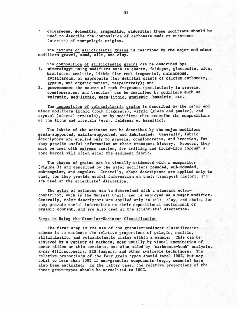
53
7. calcareous, dolomitic, aragonitic, sideritic: these modifiers should beused to describe the composition of carbonate muds or mudstones(micrite) of non-pelagic origins.
The texture of siliciclastic grains is described by the major and minormodifiers gravel, sand, silt, and day.
The composition of siliciclastic grains can be described by:1. mineralogy: using modifiers such as quartz, feldspar, glauconite, mica,
kaolinite, zeolitic, lithic (for rock fragments), calcareous,gypsiferous, or sapropelic (for detrital clasts of calcium carbonate,gypsum, and organic matter, respectively); and
2. provenance: the source of rock fragments (particularly in gravels,conglomerates, and breccias) can be described by modifiers such asvolcanic, sed-lithic, meta-lithic, gneissic, basaltic, etc.
The composition of volcaniclastic grains is described by the major andminor modifiers lithic (rock fragments), vitric (glass and pumice), andcrystal (mineral crystals), or by modifiers that describe the compositionsof the liths and crystals (e.g., feldspar or basaltic).
The fabric of the sediment can be described by the major modifiersgrain-supported, matrix-supported, and imbricated. Generally, fabricdescriptors are applied only to gravels, conglomerates, and breccias, forthey provide useful information on their transport history. However, theymust be used with extreme caution, for drilling and fluid-flow through acore barrel will often alter the sediment fabric.
The shapes of grains can be visually estimated with a comparitor(Figure 3) and described by the major modifiers rounded, sub-rounded,sub-angular, and angular. Generally, shape descriptors are applied only tosand, for they provide useful information on their transport history, andare used at the scientists* discretion.
The color of sediment can be determined with a standard color-comparitor, such as the Munsell Chart, and is employed as a major modifier.Generally, color descriptors are applied only to silt, clay, and shale, forthey provide useful information on their depositional environment ororganic content, and are also used at the scientists* discretion.
Steps in Using the Granular-Sediment Classification
The first step in the use of the granular-sediment classificationscheme is to estimate the relative proportions of pelagic, neritic,siliciclastic, and volcaniclastic grains within a sample. This can beachieved by a variety of methods, most usually by visual examination ofsmear slides or thin sections, but also aided by "carbonate-bomb" analysis,X-ray diffractometry, SEM imagery, and other available techniques. Therelative proportions of the four grain-types should total 100%, but maytotal to less than 100% if non-granular components (e.g., cements) havealso been estimated. In the latter case, the relative proportions of thethree grain-types should be normalized to 100%.
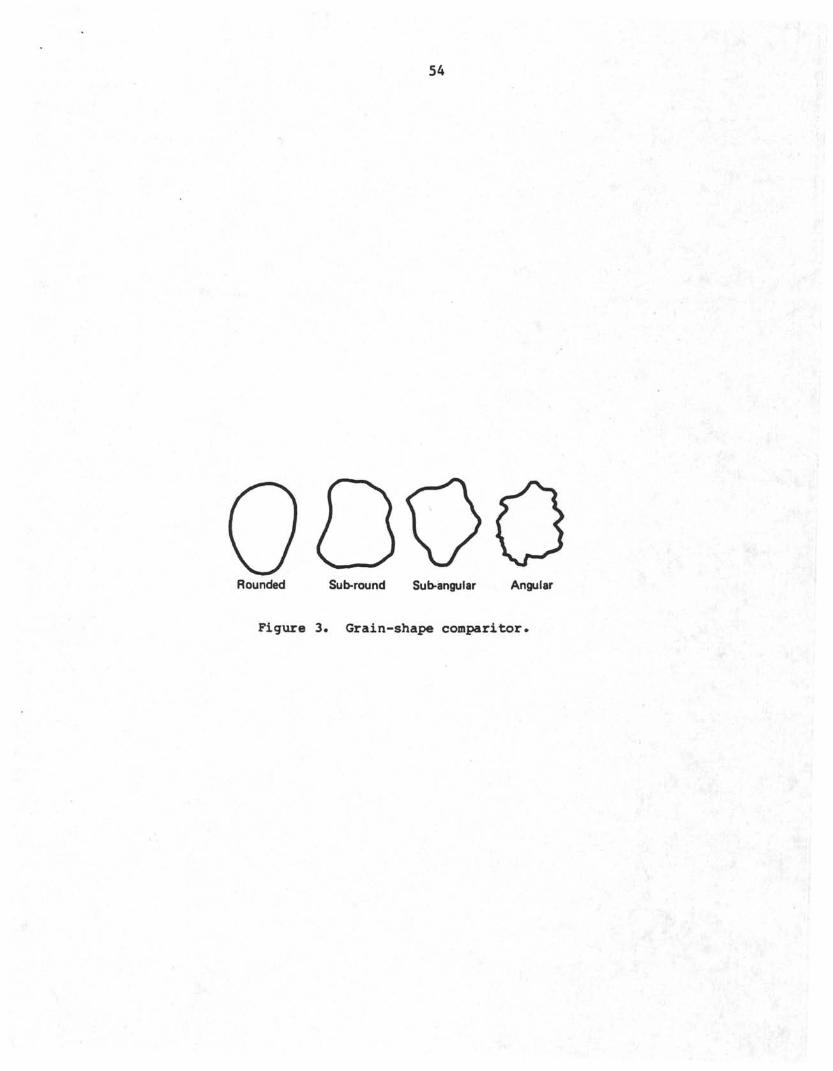
54
Rounded Sub-round Sub-angular Angular
Figure 3. Grain-shape comparitor
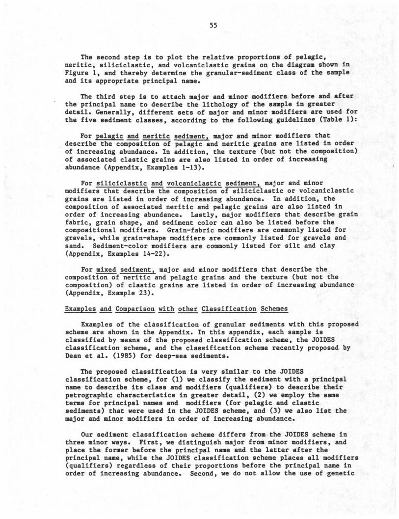
55
The second step Is to plot the relative proportions of pelagic,neritic, siliciclastic, and volcaniclastic grains on the diagram shown inFigure 1, and thereby determine the granular-sediment class of the sampleand its appropriate principal name.
The third step is to attach major and minor modifiers before and afterthe principal name to describe the lithology of the sample in greaterdetail. Generally, different sets of major and minor modifiers are used forthe five sediment classes, according to the following guidelines (Table 1):
For pelagic and neritic sediment, major and minor modifiers thatdescribe the composition of pelagic and neritic grains are listed in orderof increasing abundance. In addition, the texture (but not the composition)of associated clastic grains are also listed in order of increasingabundance (Appendix, Examples 1-13).
For siliciclastic and volcaniclastic sediment, major and minormodifiers that describe the composition of siliciclastic or volcaniclasticgrains are listed in order of increasing abundance. In addition, thecomposition of associated neritic and pelagic grains are also listed inorder of increasing abundance. Lastly, major modifiers that describe grainfabric, grain shape, and sediment color can also be listed before thecompositional modifiers. Grain-fabric modifiers are commonly listed forgravels, while grain-shape modifiers are commonly listed for gravels andsand. Sediment-color modifiers are commonly listed for silt and clay(Appendix, Examples 14-22).
For mixed sediment, major and minor modifiers that describe thecomposition of neritic and pelagic grains and the texture (but not thecomposition) of clastic grains are listed in order of increasing abundance(Appendix, Example 23).
Examples and Comparison with other Classification Schemes
Examples of the classification of granular sediments with this proposedscheme are shown in the Appendix. In this appendix, each sample isclassified by means of the proposed classification scheme, the JOIDESclassification scheme, and the classification scheme recently proposed byDean et al. (1985) for deep-sea sediments.
The proposed classification is very similar to the JOIDESclassification scheme, for (1) we classify the sediment with a principalname to describe its class and modifiers (qualifiers) to describe theirpetrographic characteristics in greater detail, (2) we employ the sameterms for principal names and modifiers (for pelagic and clasticsediments) that were used in the JOIDES scheme, and (3) we also list themajor and minor modifiers in order of increasing abundance.
Our sediment classification scheme differs from the JOIDES scheme inthree minor ways. First, we distinguish major from minor modifiers, andplace the former before the principal name and the latter after theprincipal name, while the JOIDES classification scheme places all modifiers(qualifiers) regardless of their proportions before the principal name inorder of increasing abundance. Second, we do not allow the use of genetic
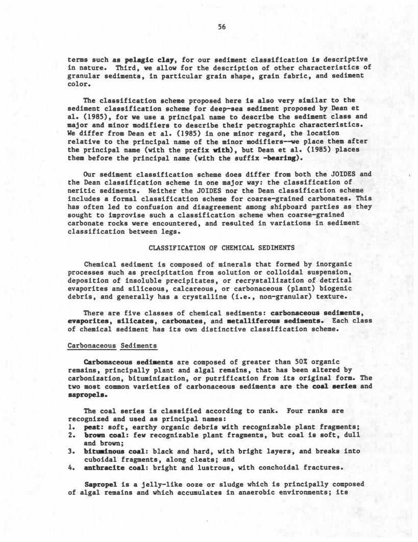
56
terms such as pelagic clay, for our sediment classification is descriptivein nature. Third, we allow for the description of other characteristics ofgranular sediments, in particular grain shape, grain fabric, and sedimentcolor.
The classification scheme proposed here is also very similar to thesediment classification scheme for deep-sea sediment proposed by Dean etal. (1985), for we use a principal name to describe the sediment class andmajor and minor modifiers to describe their petrographic characteristics.We differ from Dean et al. (1985) in one minor regard, the locationrelative to the principal name of the minor modifiers—we place them afterthe principal name (with the prefix with), but Dean et al. (1985) placesthem before the principal name (with the suffix -bearing).
Our sediment classification scheme does differ from both the JOIDES andthe Dean classification scheme in one major way: the classification ofneritic sediments. Neither the JOIDES nor the Dean classification schemeincludes a formal classification scheme for coarse-grained carbonates. Thishas often led to confusion and disagreement among shipboard parties as theysought to improvise such a classification scheme when coarse-grainedcarbonate rocks were encountered, and resulted in variations in sedimentclassification between legs.
CLASSIFICATION OF CHEMICAL SEDIMENTS
Chemical sediment is composed of minerals that formed by inorganicprocesses such as precipitation from solution or colloidal suspension,deposition of insoluble precipitates, or recrystallization of detritalevaporites and siliceous, calcareous, or carbonaceous (plant) biogenicdebris, and generally has a crystalline (i.e., non-granular) texture.
There are five classes of chemical sediments: carbonaceous sediments,evaporites, silicates, carbonates, and metalliferous sediments. Each classof chemical sediment has its own distinctive classification scheme.
Carbonaceous Sediments
Carbonaceous sediments are composed of greater than 50% organicremains, principally plant and algal remains, that has been altered bycarbonization, bituminization, or putrification from its original form. Thetwo most common varieties of carbonaceous sediments are the coal series andsapropels.
The coal series is classified according to rank. Four ranks arerecognized and used as principal names:1. peat: soft, earthy organic debris with recognizable plant fragments;2. brown coal: few recognizable plant fragments, but coal is soft, dull
and brown;3. bituminous coal: black and hard, with bright layers, and breaks into
cuboidal fragments, along cleats; and4. anthracite coal: bright and lustrous, with conchoidal fractures.
Sapropel is a jelly-like ooze or sludge which is principally composedof algal remains and which accumulates in anaerobic environments; its
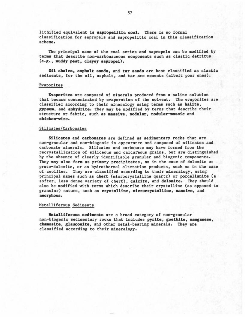
57
lithified equivalent is βapropelitic coal. There is no formalclassification for sapropels and sapropelitic coal in this classificationscheme.
The principal name of the coal series and sapropels can be modified by
terms that describe non-carbonaceous components such as clastic detritus
(e.g., •uddy peat, clayey sapropel).
Oil shales, asphalt sands, and tar sands are best classified as clasticsediments, for the oil, asphalt, and tar are cements (albeit poor ones).
Evaporites
Evaporites are composed of minerals produced from a saline solutionthat became concentrated by evaporation of the solvent. The evaporites areclassified according to their mineralogy using terms such as halite,gypsum, and anhydrite. They may be modified by terms that describe theirstructure or fabric, such as massive, nodular, nodular-mosaic andchicken-wire.
Silicates/Carbonates
Silicates and carbonates are defined as sedimentary rocks that arenon-granular and non-biogenic in appearance and composed of silicates andcarbonate minerals. Silicates and carbonate may have formed from therecrystallization of siliceous and calcareous grains, but are distinguishedby the absence of clearly identifiable granular and biogenic components.They may also form as primary precipitates, as in the case of dolomite orproto-dolomite, or as hydrothermal alteration products, such as in the caseof zeolites. They are classified according to their mineralogy, usingprincipal names such as chert (microcrystalline quartz) or porcellanite (asofter, less dense variety of chert), calcite, and dolomite. They shouldalso be modified with terms which describe their crystalline (as opposed togranular) nature, such as crystalline, microcrystalline, massive, andamorphous.
Metalliferous Sediments
Metalliferous sediments are a broad category of non-granularnon-biogenic sedimentary rocks that includes pyrite, goethite, manganese,chamosite, glauconite, and other metal-bearing minerals. They areclassified according to their mineralogy.
58
REFERENCES
Dean, W. E., Leinen, M. and Stow, D.A V., 1985. Classification of deep-seafine-grained sediments. Jour. Sed. Petrology, 55(2):250-256.
Dunham, R., 1962. Classification of carbonate rocks according todepositional texture. In Ham, W.E. (Ed.), Classification ofCarbonate Rocks. Tulsa, Amer. Assoc. Petrol. Geol., 108-121.
Fisher, R. V., and Schmincke, H.-ü., 1984. Pyroclastic rocks. Berlin(Springer-Verlag), 472 p.
Ross, D. A., Neprochnov, Y. P., and Supko, P. R., 1978. Introduction andexplanatory notes, Leg 42B, Deep Sea Drilling Project. In Ross, D.A., Neprochnov, Y. P., et al., Init. Repts. DSDP, 42(2): Washington(U.S. Govt Printing Office), 3-15.
Shepard, F., 1954. Nomenclature based on sand-silt-clay ratios. Jour. Sed.Petrology, 24:151-158.
Wentworth, C.K., 1922. A scale of grade and class terms for clasticsediments. Jour. Geology, 30:377-392.
59
EXAMPLES OF GRANULAR-SEDIMENT CLASSIFICATION
PELAGIC SEDIMENTS
Example 1. Firm, fine-grained sediment composed of 100Z nannofossils.
Proposed classification: nannofossil chalkJOIDES classification: nannofossil chalkDean et al. (1985) classification: nannofossil chalk
Example 2. Firm, fine-grained sediment composed of 100% diatoms.
Proposed classification: diatomiteJOIDES classification: diatomiteDean et al. (1985) classification: diatomite
Example 3. Soft, fine-grained sediment composed of 60% nannofossils and40% diatoms.
Proposed classification: diatom nannofossil oozeJOIDES classification: diatom nannofossil oozeDean et al. (1985) classification: diatom nannofossil ooze
Note that the composition of the pelagic grains are listedin order of increasing abundance.
Example 4. Firm, fine-grained sediment composed of 30% diatoms, 50%radiolarians, and 20% mollusc shells.
Proposed classification: diatom radiolarite w/bioclastsJOIDES classification: bioclast diatom radiolariteDean et al. (1985) classification: bioclast-bearing diatom
radiolarite
Note that bioclasts are not clearly distinguished as aminor component in the JOIDES classification.
Example 5. Hard, fine-grained sediment composed of 60% forams, 5% diatoms,and 35% quartz-silt.
Proposed classification: silty foram limestoneJOIDES classification: silty foram limestoneDean et al. (1985) classification: silty foram limestone
Note that diatoms, present in proportions of 5%, are notnoted in the proposed classification. Also, note that thetexture but not the composition of the clastic grains isnoted.
60
Example 6. Soft, fine-grained sediment composed of 100% unspecifiedcarbonate grains.
Proposed classification: calcareous oozeJOIDES classification: calcareous oozeDean et al. (1985) classification: calcareous ooze
Example 7. Soft, fine-grained sediment composed of 951 unspecifiedsiliceous grains and 5% diatoms.
Proposed classification: siliceous oozeJOIDES classification: siliceous oozeDean et al. (1985) classification: siliceous ooze
Example 8. Firm, fine-grained sediment composed of 65% forams, 20% ash,and 15% radiolarians.
Proposed classification: foram chalk w/radiolarians and ashJOIDES classification: ashy radiolarian foram chalkDean et al. (1985) classification: rad-bearing, ash-bearing
foraa chalk
Note that ash and radiolarians are not clearlydistinguished as minor components in the JOIDESclassification.
Example 9. Hard, fine-grained sediment composed of 65% diatoms and 35%clay.
Proposed classification: clayey diato• chertJOIDES classification: clayey diatom chertDean et al. (1985) classification: clayey diatom chert
NERITIC SEDIMENTS
Example 10. Grain-supported carbonate rock with intergranular mud; grainsare composed of 60% ooids and 40% bioclasts.
Proposed classification: bioclast ooid packstoneJOIDES classification: no formal classificationDean et al. (1985) classification: no formal classification
Example 11. Matrix-supported carbonate rock with 30% intraclasts
Proposed classification: intraclast wackestoneJOIDES classification: no formal classificationDean et al. (1985) classification: no formal classification
61
Example 12. Grain-supported carbonate rock with no mud; grains are composedof 40% peloids, 30% pellets, 20% bioclasts, and 10% quartz-sand.
Proposed classification: pellet peloid grainstone w/βand andbioclasts
JOIDES classification: no formal classification
Dean et al. (1985) classification: no formal classification
Note that the composition of the sand grains is not noted.
Example 13. Carbonate rock with 60% micrite (low-Mg calcite), 30% quartz-
silt, and 10% forams
Proposed classification: silty calcareous •udstone w/foramsJOIDES classification: no formal classification
Dean et al. (1985) classification: no formal classification
SILICICLASTIC SEDIMENTS
Example 14. Sediment with 100% sand, composed of well-rounded quartz-
grains.
Proposed classification: rounded quartz sand or quartz sandJOIDES classification: quartz sandDean et al. (1985) classification: quartz sand
The term rounded is optional to the new classificationscheme. Note also that the composition of clastic grainsis only used as a modifier in the classification ofsiliciclastic sediments.
Example 15. Hard sediment with 70% medium and 30% fine sandstone, composed
of quartz (60%), feldspar (30%) and mica (10%).
Proposed classification: feldspar quartz fine-mediumsandstone w/mica
JOIDES classification: mica feldspar quartz sandstoneDean et al. (1985) classification: mica-bearing feldspar
quartz sandstone
Note that mica is not clearly distinguished as a minorcomponent in the JOIDES classification.
62
Example 16. Sediment with 80% gravel composed of gneissic rock fragments,and 20% intergranular sand composed of quartz.
Proposed classification: grain-supported gneissic gravelw/quartz-sand
JOIDES classification: sandy gneissic gravelDean et al. (1985) classification: sand-bearing gneissic
gravel
Generally, both the composition and texture of the matrixin coarse-grained siliciclastic sediments are noted.
Example 17. Hard sediment with 50Z clay, 35% quartz-silt, and 15% forams,red in color.
Proposed classification: red silty claystone w/fora•sJOIDES classification: foraa silty claystoneDean et al. (1985) classification: fora•-bearing silty
claystone
Note that the term red is optional to the newclassification scheme.
Example 18. Hard sediment with 60% sand-sized volcanic rock fragments(non-pyroclastic in origin) and 40% bioclasts.
Proposed classification: bioclast volcanic sandstoneJOIDES classification: bioclast volcanic sandstoneDean et al. (1985) classification: bioclast volcanic
sandstone
Example 19. Sediment with 60% quartz-silt and 40% ash.
Proposed classification: ashy quartz siltJOIDES classification: ashy quartz siltDean et al. (1985) classification: ashy quartz silt
VOLCANICLASTIC SEDIMENTS
Example 20. Sediment with 100% basaltic rock fragments of volcaniclasticorigin and greater than 64 mm in diameter.
Proposed classification: lithic breccia or basaltic brecciaJOIDES classification: lithic brecciaDean et al. (1985) classification: no formal classification
63
Example 21 Sediment with 80% fine-grained volcanic glass and 20%
nannofossils*
Proposed classification: vitric ash w/nannofossilsJOIDES classification: nannofossil vitric ashDean et al. (1985) classification: nannofosβil-bearing vitric
ash
Example 22. Sediment with 40% fine-grained volcanic glass, 35% sand, and
25% smectite clay.
Proposed classification: sandy vitric ash w/smectite clayJOIDES classification: clayey sandy vitric ashDean et al. (1985) classification: no formal classification
Note that the total proportion of clastic grains is 75%,but that volcaniclastic grains (glass) exceedssiliciclastic grains (sand) in abundance.
MIXED SEDIMENTS
Example 23. Soft sediment with 45% nannofossils, 35% quartz-sand, and 20%
shell debris.
Proposed classification: sandy nannofossil Mixed sedi•entw/bioclasts
JOIDES classification: marly nannofossil oozeDean et al. (1985) classification: no formal classification
Note that the composition of the sand grains is not noted.
64
APPENDIX II: LIST OF REFERENCES PERTINENT TO THE STUDY OF SEDIMENTARY ROCKSTHAT ARE AVAILABLE ABOARD SHIP
GC 377 P44 Hsu, Kenneth J., Jenkyns, Hugh C Pelagic sediments, on landand under the sea: proceedings of ji symposium held at theSwiss Federal Institute of Technology, Zurich, 25-6 September1973. International Assoc, of Sedimentologists EuropeanGeophysical Society.
QE 363.B MacKenzie, W.S. and Guilford, C. Atlas of rock-formingM32 1984 minerals in thin section.Scope Lab
QE 369 06 Kerr, P. F. (lst-2nd ed. by Rogers, A. F., and P.F. Kerr).R63 1977 Optical mineralogy.Scope Lab
QE 369 06 Shelley, David. Manual £f optical mineralogy.S49 1983
QE 389.61 Lippmann, Friedrich. Sedimentary carbonate minerals.L 56
QE 389.625 Brindley, G.W. and Brown, G. Crystal structures of clayC79 1980 minerals and their X-ray identification.
QE 433 G7 Griffiths, John Cedric. Scientific method JJI analysis o£sediments.
QE 433 H87 Hutchison, Charles S. Laboratory handbook of petrographicPetrology Lab techniques.
QE 434 W73 Williams, H., Turner, F. J., and Gilbert, C. M.1982b Petrography: an introduction to the study of rocks
in thin sections.
QE 471 A28 Adams, A.E., Mackenzie, W.S., and Guilford, C. Atlas of1984 sedimentary rocks under the microscope.
QE 471 A73 Scholle, Peter A. and Schulger, Paul R., eds. Aspects ofdiagenesis: based on symposia (sponsored by theEastern and by the Rock Mountain Sections, the Societyof Economic Paleontologists and Mineralogists).
QE 471 B65 Blatt, H., Middleton, G. V., and Murray, R. C. Origin of1980 sedimentary rocks.
QE 471 C37 Carver, Robert E. Procedures in sedimentary petrology.
65
QE 471 McDonald, David A., and Surdam, Ronald C., eds.C573 1984 Clastic diagenesis.
QE 471 L33 Larsen, Gunnar, and Chilingarian, George V.1979 Diagenesis in sediments and sedimentary rocks.(vol. 1 on ship)
QE 471 L461984
QE 471 0651979
QE 471 P441964b
Lewis, D. W. Practical sedimentology.
American Association of Petroleum Geologists Bulletin.Origin of evaporties; selected papers reprinted fromAAPG bulletin.
Pettijohn, F.J., and Potter, P.E. Atlas and glossary ofprimary sedimentary structures (translations into Spanish,French, and German).
Pettijohn, F.J., Potter, Paul Edwin, and Siever, Raymond.Sand and sandstone.
Reineck, H.-E. and Singh, I B Depositional sedimentaryenvironments: with reference to terrigenous clastics.
Bathurst, Robin G.C. Carbonate sediments and theirdiagenesis.
Harris, Paul M., ed. Carbonate buildups, ja core workshop:Dallas, April 16-17, 1983.
Schneidermann, N. and Harris, Paul M. Carbonate cements:based on symposium. Society of Economic Paleontologistsand Mineralogists.
Harris, Paul M , ed. Carbonate sands, ji core workshop:San Antonio, May 19-20, 1984.
QE 471P457 1973
QE 471R425 1980
QE 471 15C3 B37 1981
QE 471.15CE Cl 1983
QE 471.15C3 C321985
QE 471.15C3 C38 1984
QE 471 Cook, Harry E , Hine, Albert C., and Mullins, Henry T.,C3 C66 1983 Platfrom margin and deep water carbonates: lecture notes for
short course no. 12. Society of Economic Paleontologists andMineralogists.
QE 471.15 Friedman, Gerald M and All, Syed A., comp Diagenesis ofC3 D5 1981 carbonate rocks: cement-porosity relationships: selected
papers reprinted from Journal of sedimentary petrology andSEPM special publication no. 13.
QE 471.15 Scholle, Peter A. /L color illustrated guide _to carbonate C3S36 1983 rock constituents, textures, cements and porosities.
[Spine title: A color guide to carbonates]
QE 471.15 Garrison, R , Kastner, M and Zenger, D., eds. DolomitesD6 D62 1984 o£ the Monterey Formation and other organic-rich units.
66
QE 471.15 Hanford, C., Robertson, Loucks, R.G., and Davies, GrahamE8 D46 1982 R., eds. Depositional and diagenetic spectra £f evaporites:
a core workshop. Calgary, Canada, June 26-27, 1982.
QE 471.15 Chambre syndicale de la recherche et de la production duE8 D4613 1981 petrole et du gaz naturel Sous-comm lab. de geologie
Evaporite deposits; illustration and interpretation of someenvironmental sequences.
QE 471.15 Dean, Walter Edward, and Schreiber, B Marine evaporites:E8 Ml 1981 lecture notes for short course no. 4.
QE 471.15 McBride, Earle F., comp Diagenesis of sandstone:S25 D5 cement-porosity relationships: selected papers reprinted
from the Journal of Sedimentary Petrology.
QE 471.15 All, Syed A., and Friedman, Gerald M , comps DiagenesisS25 D524 jç>f sandstones. American Association of Petroleum Geologists.
QE 471.15 Potter, P. E., Maynard, J. B., and Pryor, W.A. SedimentologyS5 P67 ££ shale: study guide and reference source.
QE 472 A44 Allen, John R.L. Sedimentary structures, their character 1984and physical basis.
QE 472 B67 Bouma, A.H. Methods for the study of sedimentary structures.1979
QE 472 H2 Harms, J. C., Southard, J. B., and Walker, R. G. Structures1982 and sequences in clastic rocks. Lecture notes for short
course no. 9. Society of Economic Paleontologists andMineralogists.
QE 651 W52 Wilson, James Lee. Carbonate facies in geologic history.
QE 720.5 Curran, H. Allen ed. Biogenic structures: their use inB5 1985 interpreting depositional environments (papers from a
symposium at annual SEPM-AAPG meeting, 1980, & tracefossil session at 26th Intfl Geological Congress).
QE 720.5 Ekdale, A A., Bromley, R G Pemberton, S G Ichnology: theE5 1984 use of trace fossils in sedimentology and stratigraphy. Soc.
Economic Paleontologists and Mineralogists.
QE 720.5 Basan, Paul B., ed (et al.). Trace fossil concepts.T72 1978
QH 212 S3 Goldstein, Joseph (et al.). Scanning electron microscopyS29 1984 and X-ray microanalysis; a text for biologists, materials
scientists, and geologists.
67
APPENDIX III
BIBLIOGRAPHY OP THE OCEAN ERTT.T.TNB PROGRAM
following technical notes are available from the Ocean DrillingProgram, 1000 Discovery Drive, College Station, Texas 77040.
Technical Note #1 Preliminary time estimates for coring operations(REVISED EDITION, December 66)
Technical Note #2 Operational and laboratory capabilities of JOIDESRESOLUTION (June 85)
Technical Note #3 Shipboard scientist's handbook (REVISED EDITION, July1987)
Technical Note #4 Five papers on the Ooean Drilling Program from "OCEANS'85M (May 86)
Technical Note #5 Water Chemistry Procedures aboard JOIDES RESOLUTION(September 86)
Technical Note *6 Organic Geochemistry aboard JOIDES RESOLUTION - An Assay(September 86)
Technical Note #7 Shipboard Organic Geochemistry on JOIDES RESOLUTION(September 86)
Technical Note #8 Shipboard Sedimentologists' Handbook'<this documerft)
Technical Note #9 Deep Sea Drilling Project Data File Documents (January88)
Technical Note #10 A Guide to CDP Tools for Downhole Measurements (June 88)