numerical evaluation of cyclone application for impurities removal from molten aluminum
TRANSCRIPT

Numerical Evaluation of Cyclone Application for ImpuritiesRemoval from Molten Aluminum
A.N. TURCHIN, D.G. ESKIN, and L. KATGERMAN
The purification of gaseous and liquid media by means of a cyclone concept is well known andhas been successfully applied in different industries. While the impurities removal from moltenmetal has been an important issue for many years, to the best of our knowledge, the applicationof a cyclone concept has rarely been considered for molten metal applications. The presence ofimpurities in cast products is detrimental to their quality. In this article, computer simulationsare used to evaluate the possibilities of cyclone application in molten aluminum processing bydetermining the following: the fluid flow for flow velocities of 0.01, 0.1, and 1 m/s; the particlebehavior for discrete particle sizes in the range of 20 to 100 lm; and the collection efficiency ofthe cyclone. The geometrical features are discussed. The results show that the cyclone conceptcan be effectively used as an alternative method to remove the impurities from a stream ofmolten aluminum in a wide range of flow regimes.
DOI: 10.1007/s11663-008-9127-9� The Minerals, Metals & Materials Society and ASM International 2008
I. INTRODUCTION
A cyclone separator is one of the most popular unitsin the industrial practice of separation or removal ofimpurities from a gas or liquid. The advantages of thecyclone that make it attractive for industrial applicationinclude the absence of moving parts, low operationalcosts, and design simplicity.
Impurities in casting practice are always a crucialissue determining the quality of cast products.Entrapped oxides in the form of films and particles arethe most common incidents in the solidified metal.[1] Thelevel of oxides and inclusions in the molten metal intoday’s cast house is controlled by filter boxes[2] anddegassing units.[3,4] However, the application of suchsystems, i.e., filter boxes, can be limited. During thetransfer of molten metal through these systems, the pickup of earlier removed impurities occurs, leading to thevarying efficiency of the filter (i.e., filter aging).[5]
Moreover, expensive filters have to be replaced regu-larly. While the impurities removal from molten metalhas remained the important issue for many years, to thebest of our knowledge, the application of a cyclone formolten metal processing has rarely been considered untilrecently.[6,7] The removal of entrained in the molten steellow density particles (alumina) in a cyclone with anaxial, cylindrical capture surface has been studiednumerically, using commercially available software withincorporated turbulence models by Slack and Wraith.[6]
By assuming particle adhesion to the solid core,
optimizing the design of the cyclone, and applying theprocess conditions corresponding to the practical scale,they demonstrated using the Reynolds stress model(RSM) that all particles larger in size than 35 lm and aconsiderable portion of those between 15 and 30 lmwere removed from the stream of molten steel. Later,Zuidema adapted a more conventional cyclone designfor alumina removal from the stream of molten alumi-num.[7] A series of calculations using the renormalizedgroup model (RNG, k - e) aimed at the efficiency of thecyclone resulted in a patent.[8] However, the results ofthis work were obtained only for a fixed inlet velocity of0.01 m/s, which is far less than those commonlyoccurring in a cast house.In spite of the fact that the operation of hydrocy-
clones acting mostly with an air core has been suffi-ciently understood and improved owing to thedevelopment of computational fluid dynamics andrecent advances in computational power, many ques-tions still remain answered in regards to transferring thecyclone concept to molten metal processing. What arethe consequences of operating the cyclone without freesurface or air core? In particular, how does the flowpattern in the cyclone operating with the moltenaluminum on an industrial scale affect the behavior ofimpurities with density close to that of the fluid, andwhat is the cyclone performance for discrete particles?What is the cyclone efficiency in the range of inletvelocities from 0.01 to 1 m/s? What is the height ofmolten metal at the inlet required to provide a metal-lostatic pressure driving the melt through the cyclone?In this article, the numerical simulations of fluid and
particle flows are presented for the following twotypes of cyclones: the first using the dimensions pro-posed by Zuidema;[7] and the second using a containerfor impurity deposition. The cyclones are appliedfor impurities removal from the stream of molten
A.N. TURCHIN, PhD Student, and D.G. ESKIN, Senior Scientist,are with the Netherlands Institute for Metals Research, 2628CDDelft, The Netherlands. L. KATGERMAN, Professor, is with theDepartment of Materials Science and Engineering, Delft Universityof Technology, 2628CD Delft, The Netherlands. Contact e-mail:[email protected]. Contact e-mail: [email protected]
Manuscript submitted July 11, 2007.Article published online February 20, 2008.
364—VOLUME 39B, APRIL 2008 METALLURGICAL AND MATERIALS TRANSACTIONS B
aluminum. The article is organized as follows: we startwith engineering aspects for cyclone application inmolten metal processing and general concept descriptionin Section II; the validation of the code used to modelthe cyclone performance operating with molten alumi-num is presented in Section III; the formulation of theproblem with specific assumptions, the equations com-prising the model used, and general computationalprocedures are described in Section IV; the results anddiscussion are highlighted in Section V; and finally,Section VI is devoted to conclusions. A nomenclature ofsymbols is given at the end of the article.
II. DEVICE AND CONCEPT DESCRIPTION
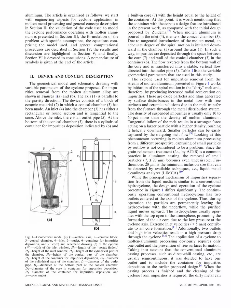
The geometrical model and schematic drawing withvariable parameters of the cyclone proposed for impu-rities removal from the molten aluminum alloy areshown in Figures 1(a) and (b). The axis (1) is parallel tothe gravity direction. The device consists of a block ofceramic material (2) in which a conical chamber (3) hasbeen made. An inlet (4) into the chamber (3) has either arectangular or round section and is tangential to thecone. Above the inlet, there is an outlet pipe (5). At thebottom of the conical chamber (3), there is a cylindricalcontainer for impurities deposition indicated by (6) and
a built-in core (7) with the height equal to the height ofthe container. At this point, it is worth mentioning thatthe container with the core is a design feature introducedin the present work, as compared with the initial designproposed by Zuidema.[7] When molten aluminum ispoured in the inlet (4), it enters the conical chamber (3).Due to tangential introduction of the molten metal, anadequate degree of the spiral motion is initiated down-ward in the chamber (3) around the axis (1). In such away, impurities are deposited through the space betweenthe core (7) and wall of the conical chamber (3) in thecontainer (6). The flow reverses from the bottom wall ofthe core and is transferred into a stable, vertical flowdirected into the outlet pipe (5). Table I lists the variablegeometrical parameters that are used in this study.The cyclone used for impurities removal from the
stream of molten aluminum presented in Figure 1 worksby initiation of the spiral motion in the ‘‘dirty’’ melt and,therefore, by producing increased radial acceleration onimpurities. These are oxide particles and films generatedby surface disturbances in the metal flow with freesurfaces and ceramic inclusions due to the melt transferfrom the furnace through the metal distribution system.The density of suspended impurities is usually only 10 to60 pct more than the density of molten aluminum.Tangential inflow of the melt results in a stronger forceacting on a larger particle with a higher density, pushingit helically downward. Smaller particles can be easilycaptured by the outgoing melt flow.[9] Looking at thisphenomenon occurring in molten aluminum processingfrom a different prospective, capturing of small particlesby outflow is not considered to be a problem. Since thegrain refinement treatment (i.e., by AlTiB) is a commonpractice in aluminum casting, the removal of smallparticles (dp £ 20 lm) becomes even undesirable. Fur-thermore, 20 lm is the minimum inclusion size that canbe detected by available techniques, i.e., liquid metalcleanliness analyzer (LIMCA).[10]
While the principal mechanism of impurities separa-tion from the liquid media is similar to a conventionalhydrocyclone, the design and operation of the cyclonepresented in Figure 1 differs significantly. The continu-ously operating conventional hydrocyclone has twooutlets centered at the axis of the cyclone. Thus, duringoperation the particles are permanently leaving thehydrocyclone with the underflow, while the purifiedliquid moves upward. The hydrocyclone usually oper-ates with the top open to the atmosphere, promoting theformation of the air core due to the low pressure at thecyclone axis. Extreme inlet velocities (>5 m/s) contrib-ute to air core formation.[11] Additionally, two outletsand high inlet velocities result in a high pressure dropthrough the cyclone.[12] The application of a cyclone tomolten-aluminum processing obviously requires onlyone outlet and the prevention of free surfaces formation.Taking into account that the conventional aluminumcasting processes, such as direct-chill casting, etc., areusually semicontinuous, it was decided to have oneoutlet and to include the container for impuritiesdeposition to the earlier proposed design.[6] When thecasting process is finished and the cleaning of thecyclone from impurities is required, the dirty metal can
Fig. 1—Geometrical model (a) (1—vertical axis, 2—ceramic block,3—conical chamber, 4—inlet, 5—outlet, 6—container for impuritiesdeposition, and 7—core) and schematic drawing (b) of the cyclone(W1—width of the inlet window, H0—length of the ‘‘vortex finder,’’H1—height of the inlet window, H2—height of the cylindrical part ofthe chamber, H3—height of the conical part of the chamber,H4—height of the container for impurities deposition, D0—diameterof the cylindrical part of the chamber, D1—diameter of the outletpipe, D2—diameter of the bottom part of the conical chamber,D3—diameter of the core in container for impurities deposition,D4—diameter of the container for impurities deposition, andA—cone angle).
METALLURGICAL AND MATERIALS TRANSACTIONS B VOLUME 39B, APRIL 2008—365

be extracted thought the opening in the bottom part ofthe cyclone. The phenomenon of air core may causeadditional problems, such as enhanced entrapment ofoxide films from the free surface, etc., and, therefore,should be avoided. The flow velocities through melt-guiding systems in casting practice are considered to benot more than 1 m/s. In terms of efficiency, it is wellknown that a higher inlet velocity or pressure generallyresults in the increased performance of a hydrocyclone,since the removal of the particles with underflow can besignificantly intensified.[13] The present design is aimedat the collection of the impurities in the body of thecyclone and, therefore, bringing us to the question ofhow will it affect the efficiency.
III. FORMULATION OF THE PROBLEM
The multiphase flow problem for the cyclone can besolved by consistent treatment of each phase. In thisarticle, we considered a cyclone operating at a constantinlet velocity and without internal air core. The cycloneis intended for the removal of impurities from the streamof molten aluminum. Heat transfer between the moltenmetal and interior surface of the cyclone is neglected, asit is assumed to be made from refractory material. Onlyspherical particles are considered. Furthermore, it isassumed that due to a relatively low volumetric concen-tration of the particles (inclusion size in the range 20 to100 lm), the fluid motion is not affected by the particlemotion. Based on the last assumption, a two-step
approach common in modeling of two-phase flowproblems is implemented. First, the fluid flow equationsare solved without considering the particles in thesystem. Second, as the steady-state solution for the flowin the system is reached, the particle transport calcula-tions are performed in a constant steady-state velocityfield.The governing equations for the velocity field in an
incompressible fluid and for the particles affected byfluid motion can be described by the Navier–Stokesequations with some additional terms (Eq. [1]), by amass continuity equation (Eq. [2]), and by a particletransport equation (Eq. [3]) presented in Table II.[14]
The flow in the conical chamber of a cyclone istypically turbulent. A strong swirl, flow reversal, etc.,additionally introduces anisotropy and strain into theturbulence. The use of a suitable turbulence model in thenumerical calculations of a cyclone is crucial for correctprediction of flow pattern and separation efficiency.Many attempts have been made to investigate turbu-lence models for the flow pattern in a hydrocyclone.Bhaskar et al.[15] have compared the experimental andsimulation results generated using different turbulentmodels, such as k - e, RNG k - e, and RSM. In thek - e model, it is assumed that turbulence is isotropicand only one scalar-velocity fluctuation is modeled. Dueto this assumption, the swirling component of velocity ina hydrocyclone is shown to be unrealistically small, andthe k - e model provides a solution with an error ofapproximately 15 to 20 pct. The results obtainedwith the RNG k - e turbulence model[16] indicate a
Table I. Dimensions of Cyclones Considered in the Present Study
Cyclone Type
Dimension as Indicated in Figure 1(b) (m)
W1 Ho H1 H2 H3 H4 D0 D1 D2 D3 D4 A�
1* 0.03 0.3 0.1 0.1 0.5 — 0.3 0.05 0.1 — — 252** 0.03 0.3 0.1 0.1 0.5 0.15 0.3 0.05 0.1 0.075 0.3 25
*Cyclone according to Zuidema.[7]**With container attached.�A in deg.
Table II. Main Equations Comprising the Model Used[14]
Navier–Stokes equation @dt quð Þ þ r� quuð Þ ¼ �rpþr� sð Þ þ qgþ F [1]
Continuity equation @qdt þr� quð Þ ¼ 0 [2]
Particle transport for spherical particle p6 d
3pqp
@updt ¼ p
6 d3p
qpg�rp� �
þ 12CD
p4 d
2pq u� up� �
u� up�� �� [3]
Turbulence kinetic energy @@t qkð Þ þ @
dxiqkuið Þ ¼ @
dxjakleff
@k@xj
� �þ Pþ G� qe [4]
Turbulence dissipation rate @@t qeð Þ þ @
dxiqeuið Þ ¼ @
dxjaeleff
@e@xj
� �þ ce1
ek Pþ ce3Gð Þ � c�e2q
e2k
[5]
Supplementary equations for turbulence model leff ¼ lþ lt [6]lt ¼ qcl
k2
e [7]c�e2 ¼ ce2 þ clqg3 1�g=g0ð Þ
1þbg3 [8]g ¼ Sij
ke
[9]
Sij ¼ 12
@ui@xjþ @uj
@xi
� �[10]
Supplementary equations for particle transport CD ¼ 24ReDþ 6
1þffiffiffiffiffiffiffiffiReD
p þ 0:4 [11]
ReD ¼dp u�upð Þ
v
[12]
366—VOLUME 39B, APRIL 2008 METALLURGICAL AND MATERIALS TRANSACTIONS B

reasonably good prediction for the flow field. Bhaskaret al.[15] found for throughput and water split in thecyclone that the simulated results, using the RNG k - emodel, match with the experimental results with an errorof 8 to 15 pct. Due to the fact that the RSM model[17]
solves the transport equation for each individualReynolds stress, it enables one to model anisotropicturbulence and strained flow with a much betterprecision, namely with an error of 4 to 8 pct,[15] forthe swirling flow. Finally, the increased computationalpower allows one to apply the large eddy simulations forthe problems, where large turbulent structures have tobe predicted with high accuracy.[18] However, two lastmodels still require significant computational effortsthat make them impractical for the three-dimensional(3-D) simulations of cyclone performance.
In the present article, the RNG k - e model has beenchosen for the simulation of the turbulent flow in thecyclone, being a compromise between the computationaltime and the accuracy of the results.
The RNG k - e model applies statistical methods forderivation of the averaged equations for turbulencequantities, such as turbulent kinetic energy, k (Eq. [4]),and its dissipation rate, e (Eq. [5]) (Table II). Theequations are similar to the equations for the k - emodel. However, equation constants that are foundempirically in the standard k - e model are derivedexplicitly in the RNG k - e model.[14]
The turbulence quantities in the RNG k - e modelimplemented in Flow-3D are calculated by the transportEqs. [6] through [10] shown in Table II. Some additionalempirical constants used in Eqs. [4] through [10] are thecoefficients cl = 0.0845, ce1 = 1.42, ce2 = 1.68, g0 =4.38, b = 0.012, ak = 0.72, and ae = 0.72 (Table II).[14]
The particle flow in the cyclone is simulated using thetracking technique where each particle can be treated asan isolated body. When tracking the motion of particlesin the cyclone, a Lagrangian frame of reference isemployed in order to solve the particle momentumequation (Eq. [3] in Table I).
In the equation of particle motion, inertia is includedin the particle mass, represented by the density of theparticle material. Buoyancy comes from the combina-tion of the gravity and fluid pressure terms in Eq. [3].The lift of the particle due to buoyancy is also taken intoaccount, but not due to a nonzero shear.[14]
The effect of turbulence on the particle trajectoriescan play a major role on particle behavior when theinertia of the particle is small, and it responds to thevelocity fluctuations of the continuous phase caused byturbulence. Otherwise, it can be neglected. However, inthe calculations presented in this paper the turbulanceeffect has not been taken into account. Note thatparticles do not interact with each other.[14]
There are no experimental data available on theinteraction between the inclusions in molten aluminumand refractory material in casting practice. This inter-action is described in the model using the coefficient ofrestitution, c, which defines the ratio of the normalcomponents of the particle velocity after and before theimpact with a wall. One can expect that either theinclusion will stick to the wall of refractory material or
its velocity will be significantly reduced and it will bebrought downward by the axial flow, i.e., down tocontainer in a type 2 cyclone. Both scenarios, mostprobably, will increase the efficiency of the cyclone.However, in order to complicate the simulation, weassumed that there is a loss of particle kinetic energyduring reflection, but it is not significant, and therefore,c = 0.95.The simulations were carried out on two types of
cyclones with the dimensions given in Table I. A moltenAl–4.5 pct Cu alloy is considered, with the physicalproperties available elsewhere.[19] A Cartesian-coordinate system is used. The turbulence modeldescribed previously is included into the code. Thegoverning Navier–Stokes equations are solved in thecode for the defined values of convergence, which is 10-6
for momentum equations. In this article, the generalminimum residual pressure–velocity coupling techniqueis employed. The equations are discredited by a finite-volume method, using the second-order monotonicity-preserving upwind-difference algorithm. More details onthe pressure–velocity coupling algorithm, discretisationscheme, set of equations, and models used can be foundelsewhere.[14]
A 3-D domain with a structured uniform mesh with acell size of 0.007 m includes the conical chamber, inletwith a rectangular cross section, and outlet as a roundpipe. The cell size used is required, according to thepreliminary parametric study, for a correct solution forthe velocity pattern within reasonable computationaltime without a significant reduction in accuracy of flowpattern and cyclone performance compared with a finergrid. The flow pattern is obtained for the three inlet flowvelocities of 0.01, 0.1, and 1 m/s. The fixed pressureboundary conditions are used at the outlet. Theinclusions are modeled as discrete mass particles witha size range of 20 to 100 lm and densities in the rangeof 2660 to 3980 kg/m3. The density interval covers thefollowing values of density of the inclusions commonlypresent in molten aluminum: qSiO2
¼ 2660 kg=m3,qc�Al2O3
¼ 3200 kg=m3, qMgO ¼ 3580 kg=m3, qAl2MgO4¼
3640 kg=m3, and qa�Al2O3¼ 3980 kg=m3.[20]
Three series of calculations were performed for thefollowing purposes: (1) to determine the efficiency of thecyclone for discrete particle sizes having an identicaldensity of 3300 kg/m3; (2) to obtain qualitatively theparticle distribution in the cyclone depending on theparticle size and density; and (3) to determine the metalhead at the inlet necessary for cyclone operation.For the first series of calculations, the particles were
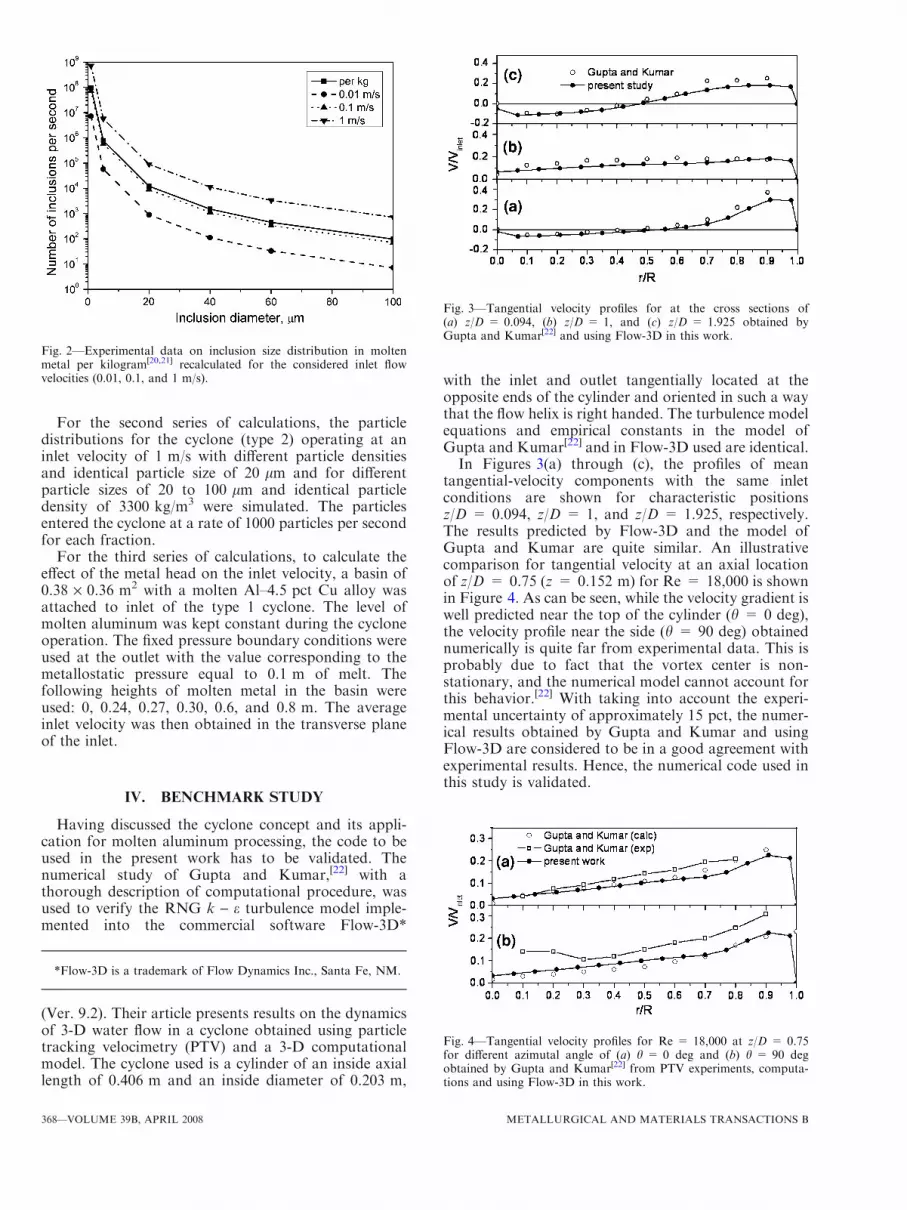
randomly and uniformly generated at the inlet windowwith the generation rate according to the reference dataon typical inclusion size distribution in molten alumi-num[20,21] and recalculated for the considered flowvelocities (Figure 2). The operation of the cyclone withthe injected particles continued until the steady state inthe number of particles trapped by the cyclone reached,i.e. 10 to 1000 seconds, depending on the flow velocityand number of particles. Finally, the efficiency of thecyclone under different process conditions was obtainedas a slope of the function, i.e., particle number trappedby the cyclone vs time.
METALLURGICAL AND MATERIALS TRANSACTIONS B VOLUME 39B, APRIL 2008—367
For the second series of calculations, the particledistributions for the cyclone (type 2) operating at aninlet velocity of 1 m/s with different particle densitiesand identical particle size of 20 lm and for differentparticle sizes of 20 to 100 lm and identical particledensity of 3300 kg/m3 were simulated. The particlesentered the cyclone at a rate of 1000 particles per secondfor each fraction.
For the third series of calculations, to calculate theeffect of the metal head on the inlet velocity, a basin of0.38 · 0.36 m2 with a molten Al–4.5 pct Cu alloy wasattached to inlet of the type 1 cyclone. The level ofmolten aluminum was kept constant during the cycloneoperation. The fixed pressure boundary conditions wereused at the outlet with the value corresponding to themetallostatic pressure equal to 0.1 m of melt. Thefollowing heights of molten metal in the basin wereused: 0, 0.24, 0.27, 0.30, 0.6, and 0.8 m. The averageinlet velocity was then obtained in the transverse planeof the inlet.
IV. BENCHMARK STUDY
Having discussed the cyclone concept and its appli-cation for molten aluminum processing, the code to beused in the present work has to be validated. Thenumerical study of Gupta and Kumar,[22] with athorough description of computational procedure, wasused to verify the RNG k - e turbulence model imple-mented into the commercial software Flow-3D*
(Ver. 9.2). Their article presents results on the dynamicsof 3-D water flow in a cyclone obtained using particletracking velocimetry (PTV) and a 3-D computationalmodel. The cyclone used is a cylinder of an inside axiallength of 0.406 m and an inside diameter of 0.203 m,
with the inlet and outlet tangentially located at theopposite ends of the cylinder and oriented in such a waythat the flow helix is right handed. The turbulence modelequations and empirical constants in the model ofGupta and Kumar[22] and in Flow-3D used are identical.In Figures 3(a) through (c), the profiles of mean
tangential-velocity components with the same inletconditions are shown for characteristic positionsz/D = 0.094, z/D = 1, and z/D = 1.925, respectively.The results predicted by Flow-3D and the model ofGupta and Kumar are quite similar. An illustrativecomparison for tangential velocity at an axial locationof z/D = 0.75 (z = 0.152 m) for Re = 18,000 is shownin Figure 4. As can be seen, while the velocity gradient iswell predicted near the top of the cylinder (h = 0 deg),the velocity profile near the side (h = 90 deg) obtainednumerically is quite far from experimental data. This isprobably due to fact that the vortex center is non-stationary, and the numerical model cannot account forthis behavior.[22] With taking into account the experi-mental uncertainty of approximately 15 pct, the numer-ical results obtained by Gupta and Kumar and usingFlow-3D are considered to be in a good agreement withexperimental results. Hence, the numerical code used inthis study is validated.
Fig. 2—Experimental data on inclusion size distribution in moltenmetal per kilogram[20,21] recalculated for the considered inlet flowvelocities (0.01, 0.1, and 1 m/s).
Fig. 3—Tangential velocity profiles for at the cross sections of(a) z/D = 0.094, (b) z/D = 1, and (c) z/D = 1.925 obtained byGupta and Kumar[22] and using Flow-3D in this work.
Fig. 4—Tangential velocity profiles for Re = 18,000 at z/D = 0.75for different azimutal angle of (a) h = 0 deg and (b) h = 90 degobtained by Gupta and Kumar[22] from PTV experiments, computa-tions and using Flow-3D in this work.
*Flow-3D is a trademark of Flow Dynamics Inc., Santa Fe, NM.
368—VOLUME 39B, APRIL 2008 METALLURGICAL AND MATERIALS TRANSACTIONS B
V. RESULTS AND DISCUSSION
A. Flow Pattern
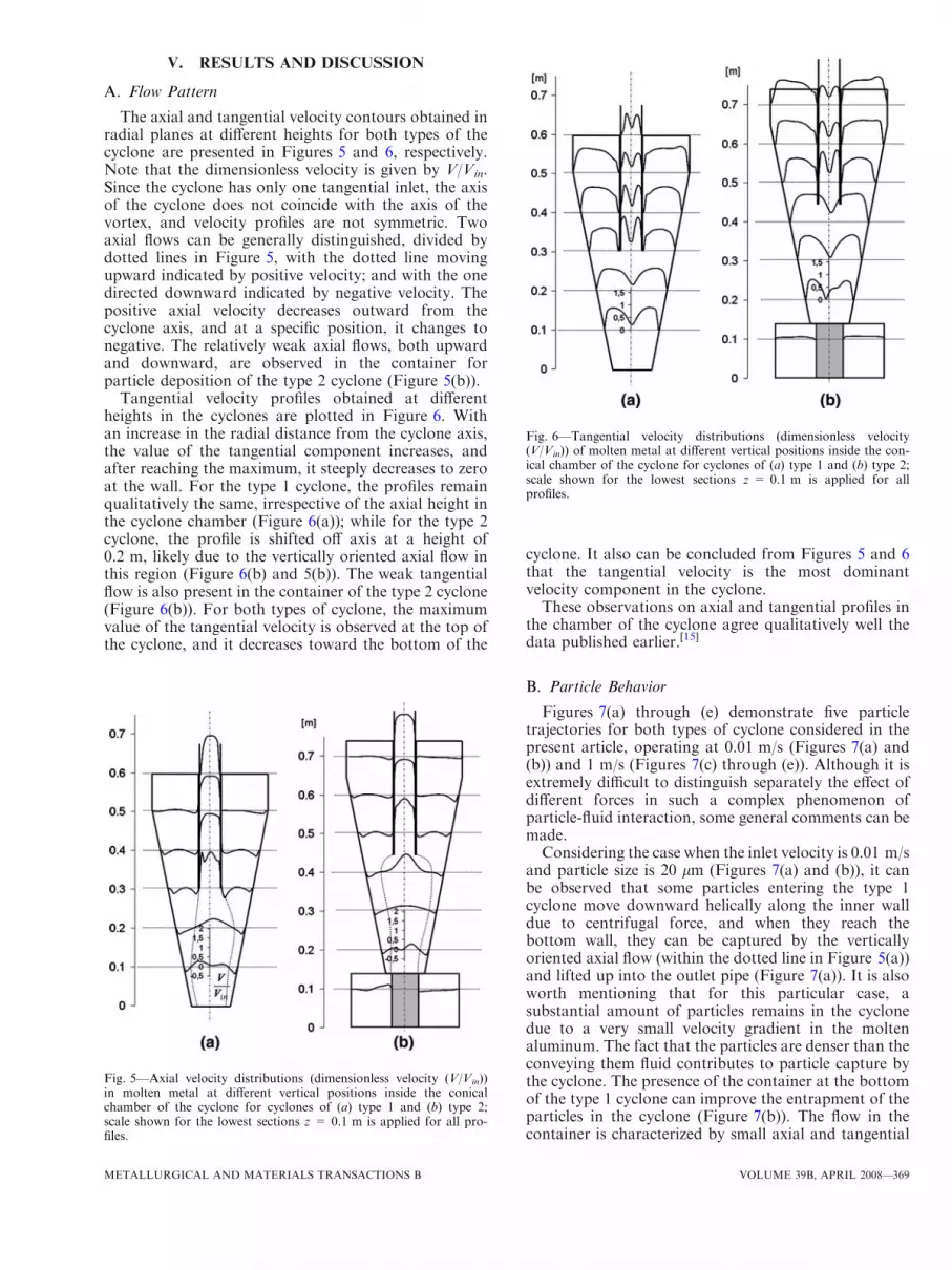
The axial and tangential velocity contours obtained inradial planes at different heights for both types of thecyclone are presented in Figures 5 and 6, respectively.Note that the dimensionless velocity is given by V/Vin.Since the cyclone has only one tangential inlet, the axisof the cyclone does not coincide with the axis of thevortex, and velocity profiles are not symmetric. Twoaxial flows can be generally distinguished, divided bydotted lines in Figure 5, with the dotted line movingupward indicated by positive velocity; and with the onedirected downward indicated by negative velocity. Thepositive axial velocity decreases outward from thecyclone axis, and at a specific position, it changes tonegative. The relatively weak axial flows, both upwardand downward, are observed in the container forparticle deposition of the type 2 cyclone (Figure 5(b)).
Tangential velocity profiles obtained at differentheights in the cyclones are plotted in Figure 6. Withan increase in the radial distance from the cyclone axis,the value of the tangential component increases, andafter reaching the maximum, it steeply decreases to zeroat the wall. For the type 1 cyclone, the profiles remainqualitatively the same, irrespective of the axial height inthe cyclone chamber (Figure 6(a)); while for the type 2cyclone, the profile is shifted off axis at a height of0.2 m, likely due to the vertically oriented axial flow inthis region (Figure 6(b) and 5(b)). The weak tangentialflow is also present in the container of the type 2 cyclone(Figure 6(b)). For both types of cyclone, the maximumvalue of the tangential velocity is observed at the top ofthe cyclone, and it decreases toward the bottom of the
cyclone. It also can be concluded from Figures 5 and 6that the tangential velocity is the most dominantvelocity component in the cyclone.These observations on axial and tangential profiles in
the chamber of the cyclone agree qualitatively well thedata published earlier.[15]
B. Particle Behavior
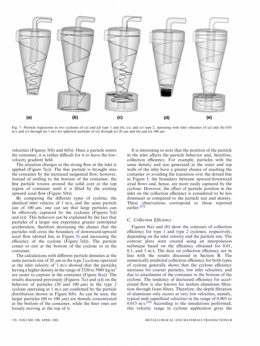
Figures 7(a) through (e) demonstrate five particletrajectories for both types of cyclone considered in thepresent article, operating at 0.01 m/s (Figures 7(a) and(b)) and 1 m/s (Figures 7(c) through (e)). Although it isextremely difficult to distinguish separately the effect ofdifferent forces in such a complex phenomenon ofparticle-fluid interaction, some general comments can bemade.Considering the case when the inlet velocity is 0.01 m/s
and particle size is 20 lm (Figures 7(a) and (b)), it canbe observed that some particles entering the type 1cyclone move downward helically along the inner walldue to centrifugal force, and when they reach thebottom wall, they can be captured by the verticallyoriented axial flow (within the dotted line in Figure 5(a))and lifted up into the outlet pipe (Figure 7(a)). It is alsoworth mentioning that for this particular case, asubstantial amount of particles remains in the cyclonedue to a very small velocity gradient in the moltenaluminum. The fact that the particles are denser than theconveying them fluid contributes to particle capture bythe cyclone. The presence of the container at the bottomof the type 1 cyclone can improve the entrapment of theparticles in the cyclone (Figure 7(b)). The flow in thecontainer is characterized by small axial and tangential
Fig. 5—Axial velocity distributions (dimensionless velocity (V/Vin))in molten metal at different vertical positions inside the conicalchamber of the cyclone for cyclones of (a) type 1 and (b) type 2;scale shown for the lowest sections z = 0.1 m is applied for all pro-files.
Fig. 6—Tangential velocity distributions (dimensionless velocity(V/Vin)) of molten metal at different vertical positions inside the con-ical chamber of the cyclone for cyclones of (a) type 1 and (b) type 2;scale shown for the lowest sections z = 0.1 m is applied for allprofiles.
METALLURGICAL AND MATERIALS TRANSACTIONS B VOLUME 39B, APRIL 2008—369
velocities (Figures 5(b) and 6(b)). Once a particle entersthe container, it is rather difficult for it to leave the low-velocity gradient field.
The situation changes as the strong flow at the inlet isapplied (Figure 7(c)). The fine particle is brought intothe container by the increased tangential flow; however,instead of settling to the bottom of the container, thefine particle rotates around the solid core at the topregion of container until it is lifted by the existingupward axial flow (Figure 5(b)).
By comparing the different types of cyclone, theidentical inlet velocity of 1 m/s, and the same particlesize of 100 lm, one can see that large particles canbe effectively captured by the cyclones (Figures 7(d)and (e)). This behavior can be explained by the fact thatparticles of a larger size experience greater centripetalacceleration, therefore decreasing the chance that theparticles will cross the boundary of downward/upwardaxial flow (dotted line in Figure 5) and increasing theefficiency of the cyclone (Figure 7(d)). The particlecomes to rest at the bottom of the cyclone or in thecontainer.
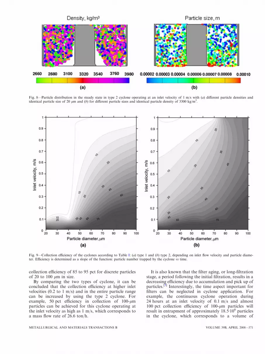
The calculations with different particle densities at thesame particle size of 20 lm in the type 2 cyclone operatedat the inlet velocity of 1 m/s showed that the particleshaving a higher density in the range of 3320 to 3980 kg/m3
are easier to capture in the container (Figure 8(a)). Theresults discussed previously (Figures 7(c) and (e)) on thebehavior of particles (20 and 100 lm) in the type 2cyclone operating at 1 m/s are confirmed by the particledistribution shown in Figure 8(b). As can be seen, thelarger particles (60 to 100 lm) are densely concentratedat the bottom of the container, while the finer ones areloosely moving at the top of it.
It is interesting to note that the position of the particlein the inlet affects the particle behavior and, therefore,collection efficiency. For example, particles with thesame density and size generated at the outer and topwalls of the inlet have a greater chance of reaching thecontainer or avoiding the transition over the dotted linein Figure 5, the boundary between upward/downwardaxial flows and, hence, are more easily captured by thecyclone. However, the effect of particle position in theinlet on the collection efficiency is considered to be lessdominant as compared to the particle size and density.These observations correspond to those reportedearlier.[23]
C. Collection Efficiency
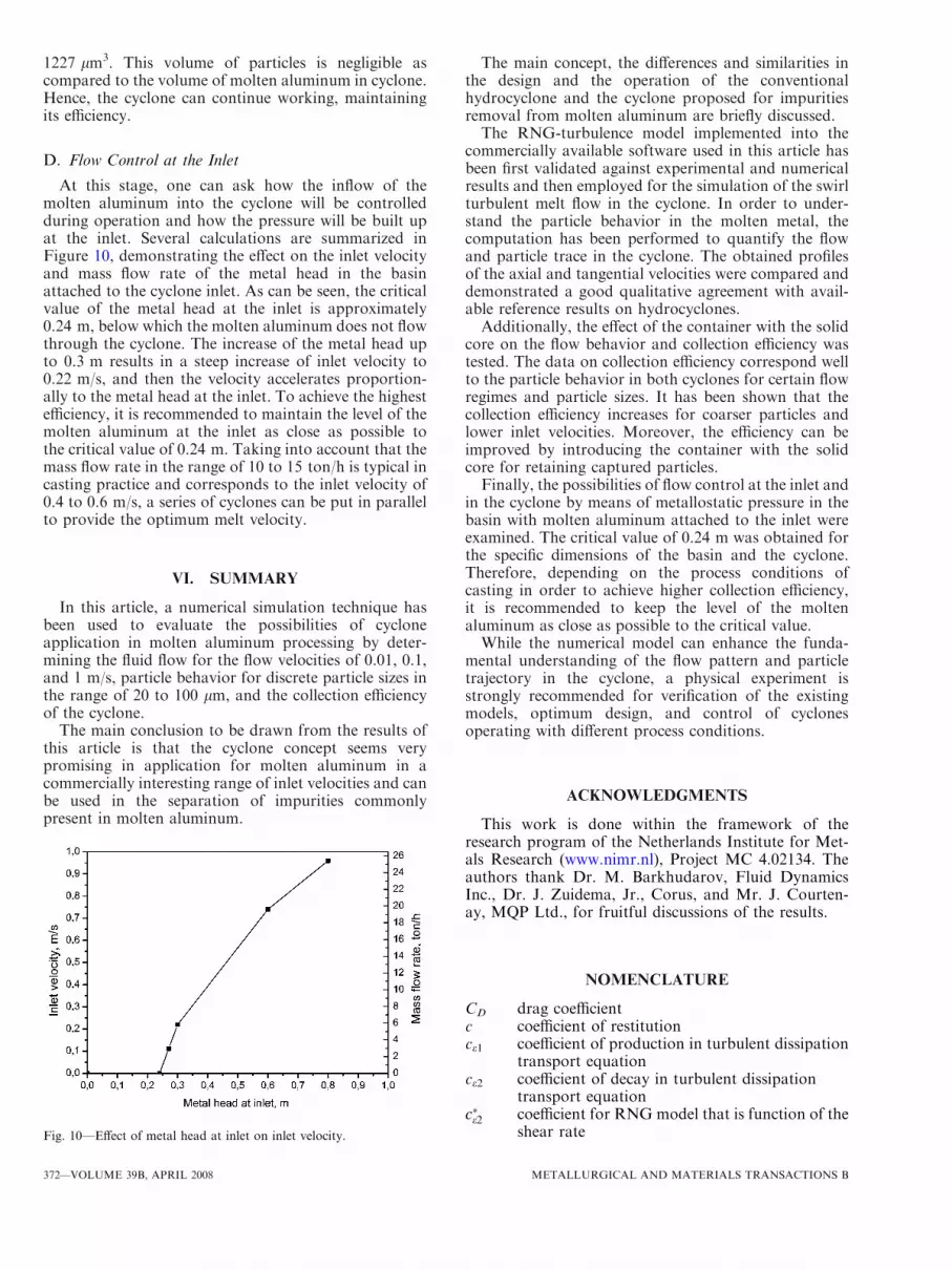
Figures 9(a) and (b) show the contours of collectionefficiency for type 1 and type 2 cyclones, respectively,depending on the inlet velocity and the particle size. Thecontour plots were created using an interpolationtechnique based on the efficiency obtained for 0.01,0.1, and 1 m/s. The data on collection efficiency are inline with the results discussed in Section B. Thenumerically predicted collection efficiency for both typesof cyclone generally shows that the cyclone efficiencyincreases for coarser particles, low inlet velocities, anddue to attachment of the container to the bottom of thecyclone. The tendency of decreased efficiency for accel-erated flow is also known for molten aluminum filtra-tion through foam filters. Therefore, the depth filtrationof aluminum only occurs at very low velocities, namely,typical melt superficial velocities in the range of 0.005 to0.015 m/s.[24] According to the simulations performed,this velocity range in cyclone application gives the
Fig. 7—Particle trajectories in two cyclones of (a) and (d) type 1 and (b), (c), and (e) type 2, operating with inlet velocities of (a) and (b) 0.01m/s and (c) through (e) 1 m/s for spherical particles of (a) through (c) 20 lm and (d) and (e) 100 lm.
370—VOLUME 39B, APRIL 2008 METALLURGICAL AND MATERIALS TRANSACTIONS B
collection efficiency of 85 to 95 pct for discrete particlesof 20 to 100 lm in size.
By comparing the two types of cyclone, it can beconcluded that the collection efficiency at higher inletvelocities (0.2 to 1 m/s) and in the entire particle rangecan be increased by using the type 2 cyclone. Forexample, 50 pct efficiency in collection of 100-lmparticles can be achieved for this cyclone operating atthe inlet velocity as high as 1 m/s, which corresponds toa mass flow rate of 26.6 ton/h.
It is also known that the filter aging, or long-filtrationstage, a period following the initial filtration, results in adecreasing efficiency due to accumulation and pick up ofparticles.[5] Interestingly, the time aspect important forfilters can be neglected in cyclone application. Forexample, the continuous cyclone operation during24 hours at an inlet velocity of 0.1 m/s and almost100 pct collection efficiency of 100-lm particles willresult in entrapment of approximately 18.5Æ106 particlesin the cyclone, which corresponds to a volume of
Fig. 8—Particle distribution in the steady state in type 2 cyclone operating at an inlet velocity of 1 m/s with (a) different particle densities andidentical particle size of 20 lm and (b) for different particle sizes and identical particle density of 3300 kg/m3.
Fig. 9—Collection efficiency of the cyclones according to Table I: (a) type 1 and (b) type 2, depending on inlet flow velocity and particle diame-ter. Efficiency is determined as a slope of the function: particle number trapped by the cyclone vs time.
METALLURGICAL AND MATERIALS TRANSACTIONS B VOLUME 39B, APRIL 2008—371
1227 lm3. This volume of particles is negligible ascompared to the volume of molten aluminum in cyclone.Hence, the cyclone can continue working, maintainingits efficiency.
D. Flow Control at the Inlet
At this stage, one can ask how the inflow of themolten aluminum into the cyclone will be controlledduring operation and how the pressure will be built upat the inlet. Several calculations are summarized inFigure 10, demonstrating the effect on the inlet velocityand mass flow rate of the metal head in the basinattached to the cyclone inlet. As can be seen, the criticalvalue of the metal head at the inlet is approximately0.24 m, below which the molten aluminum does not flowthrough the cyclone. The increase of the metal head upto 0.3 m results in a steep increase of inlet velocity to0.22 m/s, and then the velocity accelerates proportion-ally to the metal head at the inlet. To achieve the highestefficiency, it is recommended to maintain the level of themolten aluminum at the inlet as close as possible tothe critical value of 0.24 m. Taking into account that themass flow rate in the range of 10 to 15 ton/h is typical incasting practice and corresponds to the inlet velocity of0.4 to 0.6 m/s, a series of cyclones can be put in parallelto provide the optimum melt velocity.
VI. SUMMARY
In this article, a numerical simulation technique hasbeen used to evaluate the possibilities of cycloneapplication in molten aluminum processing by deter-mining the fluid flow for the flow velocities of 0.01, 0.1,and 1 m/s, particle behavior for discrete particle sizes inthe range of 20 to 100 lm, and the collection efficiencyof the cyclone.
The main conclusion to be drawn from the results ofthis article is that the cyclone concept seems verypromising in application for molten aluminum in acommercially interesting range of inlet velocities and canbe used in the separation of impurities commonlypresent in molten aluminum.
The main concept, the differences and similarities inthe design and the operation of the conventionalhydrocyclone and the cyclone proposed for impuritiesremoval from molten aluminum are briefly discussed.The RNG-turbulence model implemented into the
commercially available software used in this article hasbeen first validated against experimental and numericalresults and then employed for the simulation of the swirlturbulent melt flow in the cyclone. In order to under-stand the particle behavior in the molten metal, thecomputation has been performed to quantify the flowand particle trace in the cyclone. The obtained profilesof the axial and tangential velocities were compared anddemonstrated a good qualitative agreement with avail-able reference results on hydrocyclones.Additionally, the effect of the container with the solid
core on the flow behavior and collection efficiency wastested. The data on collection efficiency correspond wellto the particle behavior in both cyclones for certain flowregimes and particle sizes. It has been shown that thecollection efficiency increases for coarser particles andlower inlet velocities. Moreover, the efficiency can beimproved by introducing the container with the solidcore for retaining captured particles.Finally, the possibilities of flow control at the inlet and
in the cyclone by means of metallostatic pressure in thebasin with molten aluminum attached to the inlet wereexamined. The critical value of 0.24 m was obtained forthe specific dimensions of the basin and the cyclone.Therefore, depending on the process conditions ofcasting in order to achieve higher collection efficiency,it is recommended to keep the level of the moltenaluminum as close as possible to the critical value.While the numerical model can enhance the funda-
mental understanding of the flow pattern and particletrajectory in the cyclone, a physical experiment isstrongly recommended for verification of the existingmodels, optimum design, and control of cyclonesoperating with different process conditions.
ACKNOWLEDGMENTS
This work is done within the framework of theresearch program of the Netherlands Institute for Met-als Research (www.nimr.nl), Project MC 4.02134. Theauthors thank Dr. M. Barkhudarov, Fluid DynamicsInc., Dr. J. Zuidema, Jr., Corus, and Mr. J. Courten-ay, MQP Ltd., for fruitful discussions of the results.
NOMENCLATURE
CD drag coefficientc coefficient of restitutionce1 coefficient of production in turbulent dissipation
transport equationce2 coefficient of decay in turbulent dissipation
transport equationc�e2 coefficient for RNG model that is function of the
shear rateFig. 10—Effect of metal head at inlet on inlet velocity.
372—VOLUME 39B, APRIL 2008 METALLURGICAL AND MATERIALS TRANSACTIONS B

ce3 coefficient of buoyancy in turbulent dissipationtransport equation
cl coefficient in turbulent viscosity evaluationd diameter (m)F overall external forces acting on fluid (N)G buoyancy production termg acceleration due to gravity (m/s2)k turbulence kinetic energy (m2/s2)pin inlet pressure (Pa)p pressure (Pa)P shear production termRe fluid Reynolds numberReD particle Reynolds numberSij mean strain-rate tensor (s-1)t time (s)u overall velocity vector (m/s)up particle velocity (m/s)Vin inlet velocity (m/s)_m mass flow rate (kg/s)x axis (m)
GREEK SYMBOLS
ae inverse effective Prandtl number for eak inverse effective Prandtl number for kb constante turbulence dissipation rate (m2/s3)g0 constantleff effective fluid viscosity (kg/m s)h azimutal angle (grad)l molecular fluid viscosity (kg/m s)lt ‘‘eddy’’ fluid viscosity (kg/m s)m kinematic fluid viscosityq fluid density (kg/m3)s stress tensor (N/m2)
SUBSCRIPTS
i, j 1, 2p particle
REFERENCES1. J. Campbell: Mater. Sci. Technol., 2006, vol. 22, pp. 127–45.2. C. His, A. Matthews, and J. Braun: Giesserei, 1998, vol. 85,
pp. 51–54.3. R. Davis and R.N Dokken: Proc. 116th TMS Light Metals Annual
Meeting, Denver, CO, Feb. 24–26, 1987, TMS, Warrendale, PA,1987, pp. 711–16.
4. S. Shivkumar, L. Wang, and D. Apelian: JOM, 1991, vol. 43,pp. 26–32.
5. F.A. Acosta G. and A.H. Castillejos E.: Metall. Mater. Trans. B,2000, vol. 31B, pp. 503–14.
6. M.D. Slack and A.E. Wraith: Proc. Quality in Non-FerrousPyrometallurgy, Vancouver, BC, Aug. 20–24, 1995, CanadianInstitute of Mining, Metallurgy and Petroleum, Montreal, PQ,1995, pp. 227–38. .
7. L. Katgerman and J. Zuidema: Proc. 134th TMS Light MetalsAnnual Meeting, San Francisco, CA, Feb. 13–17, 2005, TMS,Warrendale, PA, 2005, pp. 927–31.
8. Patent Nos. WO2004001078-A1, NL 1020919-C2, andAU2003248155-A1.
9. B. Wang and A.B. Yu: Miner. Eng., 2006, vol. 19, pp. 1022–33.10. M. Li and R.I.L. Guthrie:Metall. Mater. Trans. B, 2000, vol. 31B,
pp. 767–77.11. M. Narasimha, M. Brennan, and P. Holtham: Int. J. Miner.
Process., 2006, vol. 80, pp. 1–14.12. K. Rietema: Chem. Eng. Sci., 1961, vol. 15, pp. 303–09.13. K. Rietema: Chem. Eng. Sci., 1961, vol. 15, pp. 310–19.14. Flow-3D Version 9.2, User’s Manual, 2007 Flow Science Inc.,
Santa Fe, NM.15. K.U. Bhaskar,Y.R.Murthy,M.R.Raju, S. Tiwari, J.K. Srivastava,
and N. Ramakrishnan: Miner. Eng., 2007, vol. 20, pp. 60–71.16. V. Yakhot and S.A. Orszag: J. Sci. Comput., 1986, vol. 1, pp. 3–51.17. B.E. Launder, G.J. Reece, and W. Rodi: J. Fluid Mech., 1975,
vol. 68, pp. 537–66.18. M.S. Slack, R.O. Prasad, A. Bakker, and F. Boysan: Trans. Inst.
Chem. Eng., 2000, vol. 78A, pp. 1098–1104.19. J. Vreeman and F.P. Incropera: Int. J. Heat Mass Transfer, 2000,
vol. 43, pp. 687–704.20. X. Cao: Int. J. Cast. Met. Res., 2006, vol. 19, pp. 371–74.21. L. Zhang: Proc. 134th TMS Annual Meeting: Characterization of
Minerals Meals. and Materials, Orlando, FL, Feb. 25–Mar. 1,2007, TMS, Warrendale, PA, 2007, pp. 35–45.
22. A. Gupta and R. Kumar: Int. J. Heat Fluid Flow, 2007, vol. 28,pp. 249–61.
23. L. Ma, D.B. Ingham, and X. Wen: J. Aerosol Sci., 2000, vol. 31,pp. 1097–119.
24. L.S. Aubrey and J.E. Dore: Proc. 122nd TMS Light Metals AnnualMeeting, Denver, CO, Feb. 21–25, 1993, TMS, Warrendale, PA,1993, pp. 1009–20.
METALLURGICAL AND MATERIALS TRANSACTIONS B VOLUME 39B, APRIL 2008—373