ntpc-bhel power project private limited - nbppl
TRANSCRIPT
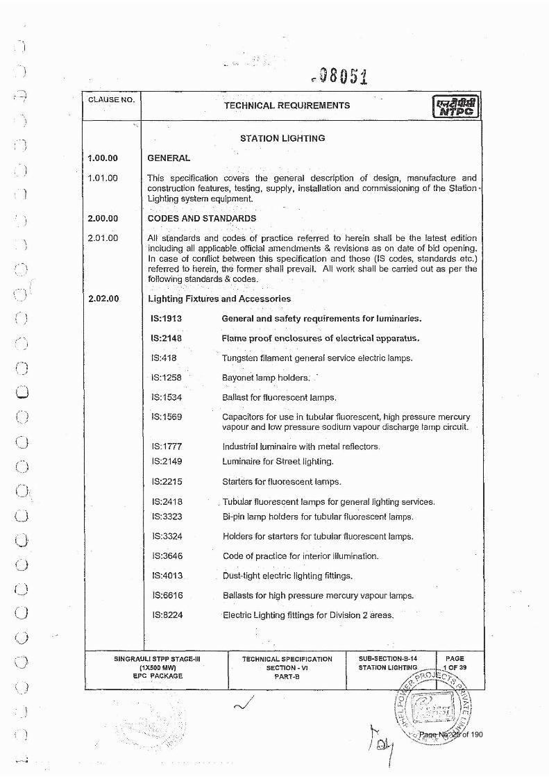
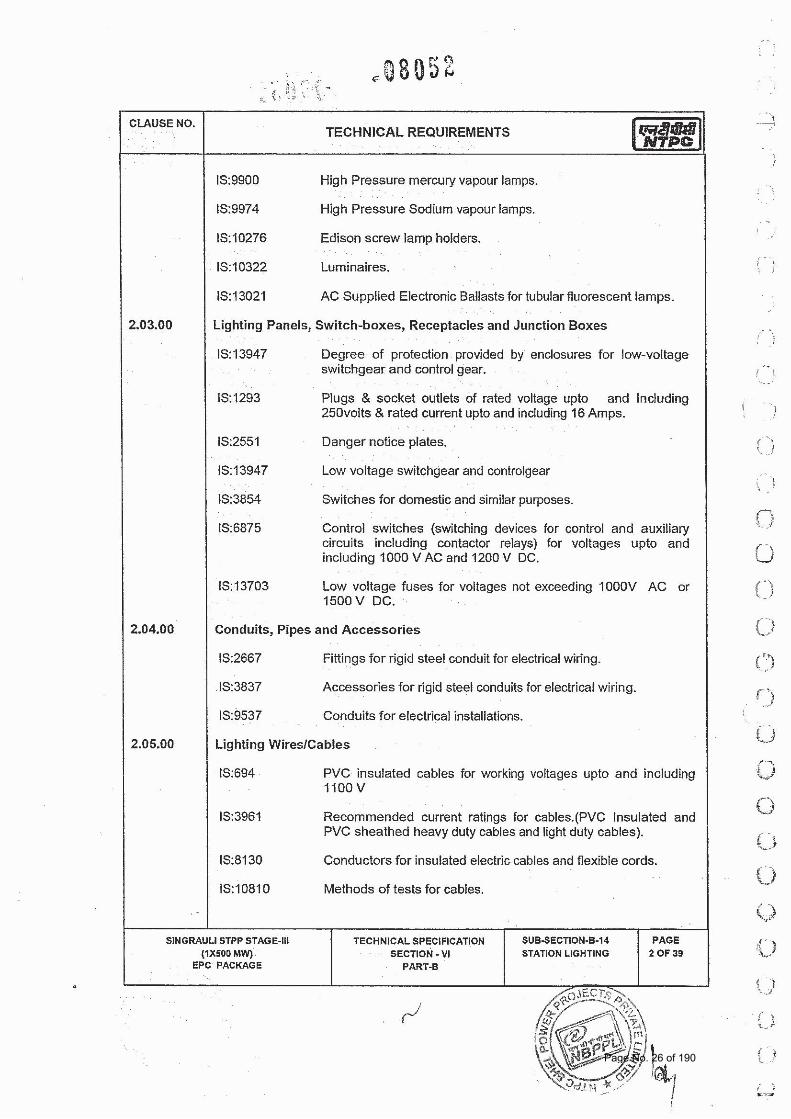
TECHNICAL SPECIFICATIONS OF STATION LIGHTING PACKAGE
FGUTPP STAGE‐IV (1X 500 MW) AT UNCHAHAR
BHEL SPEC. NO. :PE-TS-401-558-E001 Rev. No.: Dated : 17.07.2014
TECHNICAL SPECIFICATIONS DOC. NO.: NBPPL-004-202-06-P4E-A Rev. No.:00
NTPC-BHEL POWER PROJECT PRIVATE LIMITED
(A Joint Venture Company of NTPC & BHEL)
TECHNICAL SPECIFICATIONS OF
STATION LIGHTING PACKAGE FOR
FGUTPP-STAGE IV (1X500 MW) AT UNCHAHAR (UP)
SPECIFICATION NO: NBPPL-004-202-06-P4E-A
REVISION: 00
OWNER: NTPC LIMITED
ARCHITECT ENGINEERING FIRM
BHARAT HEAVY ELECTRICALS LIMITED Project Engineering Management
Power Sector, PPEI Building Sector-16A, Noida-210301
Page No. 1 of 190
TECHNICAL SPECIFICATIONS OF STATION LIGHTING PACKAGE
FGUTPP STAGE‐IV (1X 500 MW) AT UNCHAHAR
BHEL SPEC. NO. :PE-TS-401-558-e001 Rev. No.: Dated : 17.07.2014
VOLUME:I TECHNICAL CONDITIONS OF
CONTRACT
DOC. NO.: NBPPL-004-202-06-P4E-A Rev. No.:00
TECHNICAL SPECIFICATIONS
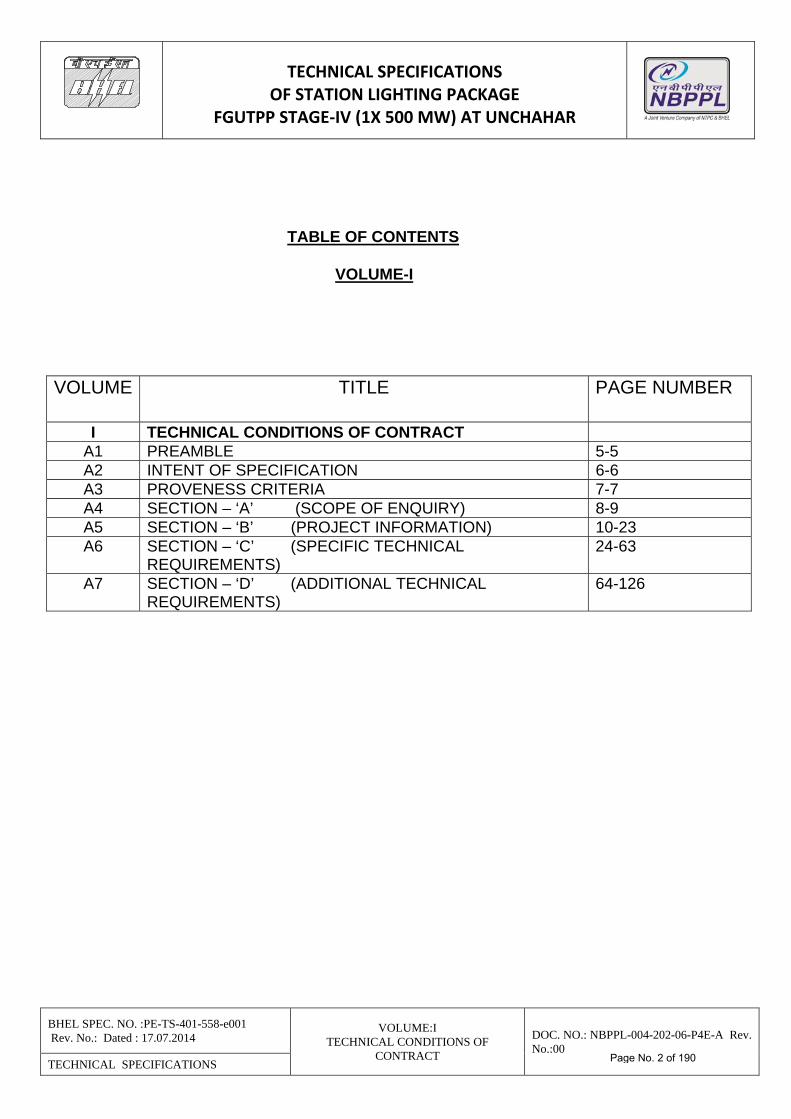
TABLE OF CONTENTS
VOLUME-I VOLUME TITLE PAGE NUMBER
I TECHNICAL CONDITIONS OF CONTRACT A1 PREAMBLE 5-5 A2 INTENT OF SPECIFICATION 6-6 A3 PROVENESS CRITERIA 7-7 A4 SECTION – ‘A’ (SCOPE OF ENQUIRY) 8-9 A5 SECTION – ‘B’ (PROJECT INFORMATION) 10-23 A6 SECTION – ‘C’ (SPECIFIC TECHNICAL
REQUIREMENTS) 24-63
A7 SECTION – ‘D’ (ADDITIONAL TECHNICAL REQUIREMENTS)
64-126
Page No. 2 of 190
TECHNICAL SPECIFICATIONS OF STATION LIGHTING PACKAGE
FGUTPP STAGE‐IV (1X 500 MW) AT UNCHAHAR
BHEL SPEC. NO. :PE-TS-401-558-e001 Rev. No.: Dated : 17.07.2014
VOLUME:I TECHNICAL CONDITIONS OF
CONTRACT
DOC. NO.: NBPPL-004-202-06-P4E-A Rev. No.:00
TECHNICAL SPECIFICATIONS
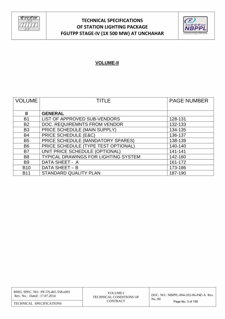
VOLUME-II VOLUME TITLE PAGE NUMBER
II GENERAL B1 LIST OF APPROVED SUB-VENDORS 128-131 B2 DOC. REQUIREMNTS FROM VENDOR 132-133 B3 PRICE SCHEDULE (MAIN SUPPLY) 134-135 B4 PRICE SCHEDULE (E&C) 136-137 B5 PRICE SCHEDULE (MANDATORY SPARES) 138-139 B6 PRICE SCHEDULE (TYPE TEST OPTIONAL) 140-140 B7 UNIT PRICE SCHEDULE (OPTIONAL) 141-141 B8 TYPICAL DRAWINGS FOR LIGHTING SYSTEM 142-160 B9 DATA SHEET - A 161-172
B10 DATA SHEET – B 173-186 B11 STANDARD QUALITY PLAN 187-190
Page No. 3 of 190
TECHNICAL SPECIFICATIONS OF STATION LIGHTING PACKAGE
FGUTPP STAGE‐IV (1X 500 MW) AT UNCHAHAR
BHEL SPEC. NO. :PE-TS-401-558-e001 Rev. No.: Dated : 17.07.2014
VOLUME:I TECHNICAL CONDITIONS OF
CONTRACT
DOC. NO.: NBPPL-004-202-06-P4E-A Rev. No.:00
TECHNICAL SPECIFICATIONS
VOLUME-I
Page No. 4 of 190
TECHNICAL SPECIFICATIONS OF STATION LIGHTING PACKAGE
FGUTPP STAGE‐IV (1X 500 MW) AT UNCHAHAR
BHEL SPEC. NO. :PE-TS-401-558-e001 Rev. No.: Dated : 17.07.2014
VOLUME:I TECHNICAL CONDITIONS OF
CONTRACT
DOC. NO.: NBPPL-004-202-06-P4E-A Rev. No.:00
TECHNICAL SPECIFICATIONS
PREAMBLE
1. The Tender documents contain Two (2) volume. The bidder shall meet the requirement of the volume. VOLUME – I Technical Condition of Contract This volume is sub-divided in to following sections:- Section – A This section outlines the Scope of Enquiry Section – B This section provides “Project Information”.
Section – C This section indicates Technical Requirements specific to Contract Section – D This section indicates Additional Technical Requirements general VOLUME – II General Technical Specification
2. The requirements mentioned in Section-C shall prevail and govern in case of conflict between the same and the corresponding requirements mentioned in the descriptive portion in Section-D (Additional Technical Requirements).
Page No. 5 of 190
TECHNICAL SPECIFICATIONS OF STATION LIGHTING PACKAGE
FGUTPP STAGE‐IV (1X 500 MW) AT UNCHAHAR
BHEL SPEC. NO. :PE-TS-401-558-e001 Rev. No.: Dated : 17.07.2014
VOLUME:I TECHNICAL CONDITIONS OF
CONTRACT
DOC. NO.: NBPPL-004-202-06-P4E-A Rev. No.:00
TECHNICAL SPECIFICATIONS
INTENT OF SPECIFICATION
The intent of this specification covers the design, manufacture, assembly, inspection and testing at manufacturer's works, proper packing and delivery to 1x500 MW UNCHAHAR STPP STAGE-IV site, storage erection & commissioning of STATION LIGHTING SYSTEM as mentioned in different sections of this specification for the project as indicated in Section B (Project Information). Lighting fixture complete with lamps & accessories, Lighting Panels, Receptacles, Switch boxes, Conduits, Lighting wires, ceiling fans, with regulators, Lighting poles, Lighting Masts, Earth wires and rods, Junction boxes, Battery operated automatic self-contained lighting fixtures, maintenance ladders shall in the scope of the contract.
Page No. 6 of 190
TECHNICAL SPECIFICATIONSOF STATION LIGHTING PACKAGE
FGUTPP STAGE‐IV (1X 500 MW) AT UNCHAHAR
BHEL SPEC. NO. :PE-TS-401-558-e001 Rev. No.: Dated : 17.07.2014
VOLUME:I TECHNICAL CONDITIONS OF
CONTRACT
DOC. NO.: NBPPL-004-202-06-P4E-A Rev. No.:00
TECHNICAL SPECIFICATIONS
PROVENNESS CRITERIA / PREQUALIFICATION REQUIREMENT
The Bidder should have designed, supplied, installed and commissioned at least one (1) number of Lighting System including associated cabling of contract value not less than Rs.10 million (Rupees Ten Million) or in equivalent in Foreign currency (exchange rate applicable as on date of techno-commercial bid opening) in Power Plants/Refinery/Steel/Process industries and the system should be in successful operation for atleast 1 (one) year and should have been com-missioned during last 10 (Ten) years from the date of techno-commercial bid opening.
--------------------------------------------------------------------- BIDDER’S STAMP & SIGNATURE
TECHNICAL SPECIFICATIONS OF STATION LIGHTING PACKAGE
FGUTPP STAGE‐IV (1X 500 MW) AT UNCHAHAR
BHEL SPEC. NO. :PE-TS-401-558-e001 Rev. No.: Dated : 17.07.2014
VOLUME:I TECHNICAL CONDITIONS OF
CONTRACT
DOC. NO.: NBPPL-004-202-06-P4E-A Rev. No.:00
TECHNICAL SPECIFICATIONS
SECTION – A
(SCOPE OF ENQUIRY)
Page No. 8 of 190
TECHNICAL SPECIFICATIONS OF STATION LIGHTING PACKAGE
FGUTPP STAGE‐IV (1X 500 MW) AT UNCHAHAR
BHEL SPEC. NO. :PE-TS-401-558-e001 Rev. No.: Dated : 17.07.2014
VOLUME:I TECHNICAL CONDITIONS OF
CONTRACT
DOC. NO.: NBPPL-004-202-06-P4E-A Rev. No.:00
TECHNICAL SPECIFICATIONS
SCOPE OF ENQUIRY
1.0 This specification covers the design, manufacture, assembly, inspection and testing at manufacturer's works, proper packing and delivery to 1x500 MW UNCHAHAR STPP STAGE-IV site, storage erection & commissioning of STATION LIGHTING SYSTEM as mentioned in different sections of this specification for the project as indicated in Section B (Project Information). Lighting fixture complete with lamps & accessories, Lighting Panels, Receptacles, Switch boxes, Conduits, Lighting wires, ceiling fans, with regulators, Lighting poles, Lighting Masts, Earth wires and rods, Junction boxes, Battery operated automatic self-contained lighting fixtures, maintenance ladders shall in the scope of the contract.
2.0 It is not the intent to specify herein all the details of design & manufacture. However, the
equipment shall conform in all respects to high standards of design engineering and workmanship and shall be capable of performing in continuous commercial operation up to bidder's guarantee.
3.0 The general terms and conditions, instructions to bidders and other attachment referred to
elsewhere be hereby made part of technical specification. 4.0 The bidders shall be responsible for and governed by all requirements stipulated
hereinafter. 5.0 Requirements of the specification including the QP shall be agreed upon for total
compliance by Bidders without any deviations. Price offers of only those bidders complying with the above requirement shall be acceptable.
6.0 The documents shall be in English language and MKS system of units.
7.0 For every shipment made to site, a shipping list, containing item reference [item number and description as per specification Bill of Materials or package drawings], and quantity of the same [in nos./ weight] shall be provided by vendor at the time of despatch of materials to site.
Page No. 9 of 190
TECHNICAL SPECIFICATIONS OF STATION LIGHTING PACKAGE
FGUTPP STAGE‐IV (1X 500 MW) AT UNCHAHAR
BHEL SPEC. NO. :PE-TS-401-558-e001 Rev. No.: Dated : 17.07.2014
VOLUME:I TECHNICAL CONDITIONS OF
CONTRACT
DOC. NO.: NBPPL-004-202-06-P4E-A Rev. No.:00
TECHNICAL SPECIFICATIONS
SECTION – B
(PROJECT INFORMATION)
Page No. 10 of 190
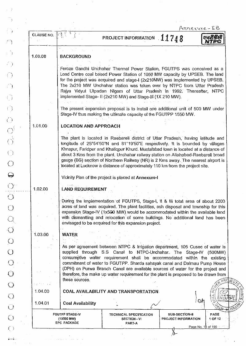
( BACKGROUND
~ ~ I I M , ~ C < ~ , Y C - - Li3
Feroze Gandhi Unchahar Thermal Power Station, FGUTPS was conceived as a Load Centre coal based Power Station of 1050 MW capacity by UPSEB. The land for the project was acquired and stage-l (2x210MW) was implemented by UPSEB. The 2x210 MW Unchahar station was taken over by NTPC from Uttar Pradesh Rajya Vidyut Utpadan Nigam of Uttar Pradesh in 1992. Thereafter, NTPC implemented Stage- II (2x210 MW) and Stage-lll(1X 210 MW).
CLAUSE NO
-
The present expansion proposal is to install one additional unit of 500 MW under Stage-IV thus making the ultimate capacity of the FGUTPP 1550 MW.
LOCATION AND APPROACH
'7' ? ' ' < PROJECT INFORMATION 6 2 7 4 8
The plant is located in Raebareli district of Uttar Pradesh, having latitude and longitude of 25O54'50"N and 8lo19'50"E respectively. It is bounded by villages Khnapur, Faridpur and Khaliqpur Khurd. Mustafabad town is located at a distance of about 3 Kms from the plant. Unchahar railway station on Allahabad-Raebareli broad gauge (BG) section of Northern Railway (NR) is 2 Kms away. The nearest airport is located at Lucknow a distance of approximately 110 km from the project site.
I I Vicinity Plan of the project is placed at Annexure-I I 1.02.00 I LAND REQUIREMENT I
During the implementation of FGUTPS, Stage-I, II & Ill total area of about 2203 acres of land was acquired. The plant facilities, ash disposal and township for this expansion Stage-IV (Ix5QO MW) would be accommodated within the available land with dismantling and relocation of some buildings. No additional land has been envisaged to be acquired for this expansion project.
1 1.03.00 / WATER
As per agreement between NTPC & Irrigation department, 105 Cusec of water is supplied through S.S Canal to NTPC-Unchahar. The Stage-IV (500MW) consumptive water requirement shall be accommodated within the existing commitment of water to FGUTPP. Sharda sghayak canal and Dalmau Pump House (DPH) on Purwa Branch Canal are available sources of water for the proiect and therefore, the make up these sources.
COAL AVAILABILITY
Coal Availability
FGUTPP STAGE-IV (IXSOO MW)
EPC PACKAGE
AND TRANSPORTATION
SECTION - VI I PROJECT INFORMATION PART-A 1 'OFi2 I Page No. 11 of 190
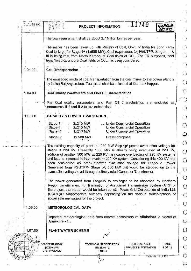
I I The coal requirement shall be about 2.7 Million tonnes per year. I The matter has been taken up with Ministry of Coal, Govt. of lndia for Long Term Coal Linkage for Stage-IV (1x500 MW)..Coal requirement for FGUTPP, Stage-l ,I1 & Ill is being met from North Karanpura Coal fields of CCL. For FR purposes, coal from North Karanpura Coal fields of CCL has been considered.
I Coal Transportation
The envisaged mode of coal transportation from the coal mines to the power plant is by Indian Railways rakes. The rakes shall be unloaded at the track hopper.
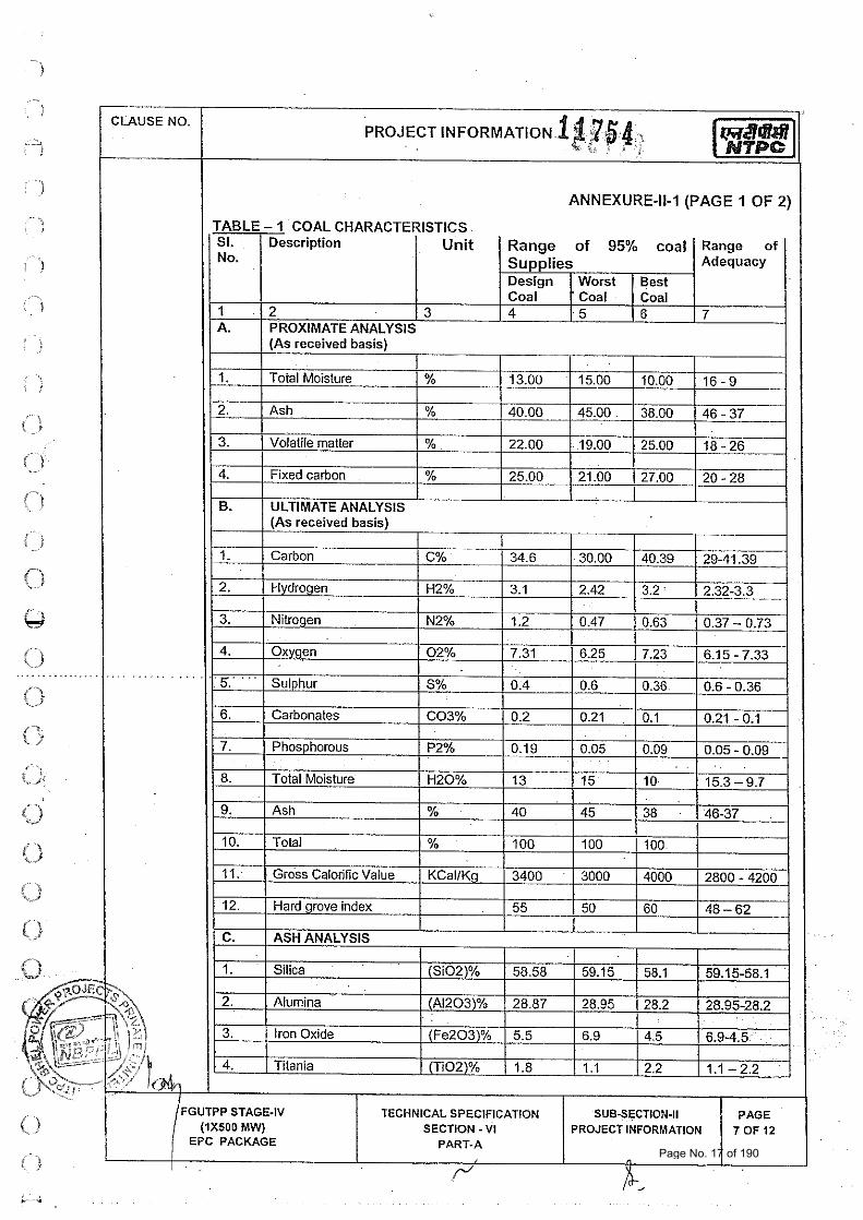
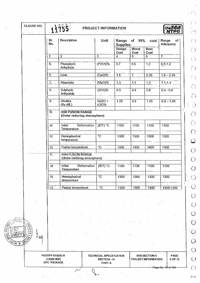
I Coal Quality Parameters and Fuel Oil Characteristics
I CAPACITY 8 POWER EVACUATION I : I
- -
Stage- I : 2x210 MW _ Under Commercial Operation Stage-ll : 2x210 MW Under Commercial Operation Stage-Ill : 1x210 MW Under Commercial Operation
The Coal quality parameters and Fuel Oil Characteristics are enclosed as, 1 ) Annexures-11-1 and 11-2 to this subsection. I 0
1 Stage-N I x 500 MW Present proposal . .. --
I 1 1.07.00 1 PLANT WATER SCHEME
The existing capacity of plant is 1050 MW Step up/ power evacuation voltage for station is 220 KV. Presently 1000 MW is already being evacuated at 220 KV, addition of another 500 MW at 220 KV may cause overloading of 220 KV systems and lead to increase in fault levels at 220 KV system. Considering this 400 KV has been considered as step-uplpower evacuation voltage for Stage-IV. Power Generated from FGUTPP- Stage IV, 500 MW unit would be stepped up to the evacuation voltage level through suitably rated Generator Transformer.
The power generated from Stage-IV is envisaged to be absorbed by Northern Region beneficiaries. For finalisation of Associated Transmission System (ATS) of the project, the matter would be taken up with Power Grid Corporation of lndia Ltd. (PGC1L)ICEAlappropriate authority depending on the various routes/options of
r sale envisaged for the project.
GICAL DATA
Important meteorological data from nearest observatory at Allahabad is placed at Annexure - Ill.
-
0 TECHNICAL SPECIFICATION SUB-SECTION-I1
(2 EPC PACKAGE .
if
CI
0 !3 0 (3r
0 0
0
Page No. 12 of 190
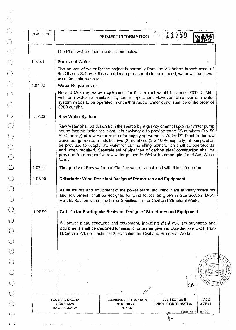
/ The Plant weter scheme is described below.
Source of Water
The source of water for the project is normally from the Allahabad branch canal of the Sharda Sahayak link canal. During the canal closure period, water will be drawn from the Daimau canal.
Water Requirement
Normal Make up water requirement for this project would be about 2000 Cu.Mlhr with ash water re-circulation system in operation. However, whenever ash water system needs to be operated in once thru mode, water drawl shall be of the order of 3300 cumlhr.
I 1 .OT.03 I Raw Water System 1 Raw water shall be drawn from the source by a gravity channel upto raw water pump house located inside the plant. It is envisaged to provide three (3) numbers (3 x 50 % Capacity) of raw water pumps for supplying water to Water PT Plant in the raw water pump house. In addition two (2) numbers (2 x 100% capacity) of pumps shall be provided to supply raw water for ash handling plant which shall be operated as and when required. Separate set of pipelines of carbon steel construction shall be provided from respective raw water pumps to Water treatment plant and Ash Water tanks.
The quality of Raw water and Clarified water is enclosed with this sub-section I I 108.00 / Criteria for Wind Resistant Design of Structures and Equipment . . . . . . . .
All structures and equipment of the power plant, including plant auxiliary structures and equipment, shall be designed for wind forces as given in Sub-section- 0-01, Part-B, Section-VI, i.e. Technical Specification for Civil and Structural Works.
1 1.09.00 / Criteria for Earthquake Resistant Design of Structures and Equipment I All power plant structures and equipment, including plant auxiliary structures and equipment shall be designed for seismic forces as given in Sub-section- D-01, Part- B, Section-VI, i.e. Technical Specification for Civil and Structural Works.
FGUTPP STAGE-IV (1x500 MW)
EPC PACKAGE
TECHNICAL SPECIFICATION SECTION - V I
PART-A
SUB-SECTION-II PROJECT INFORMATION
PAGE 3 OF 12
Page No. 13 of 190
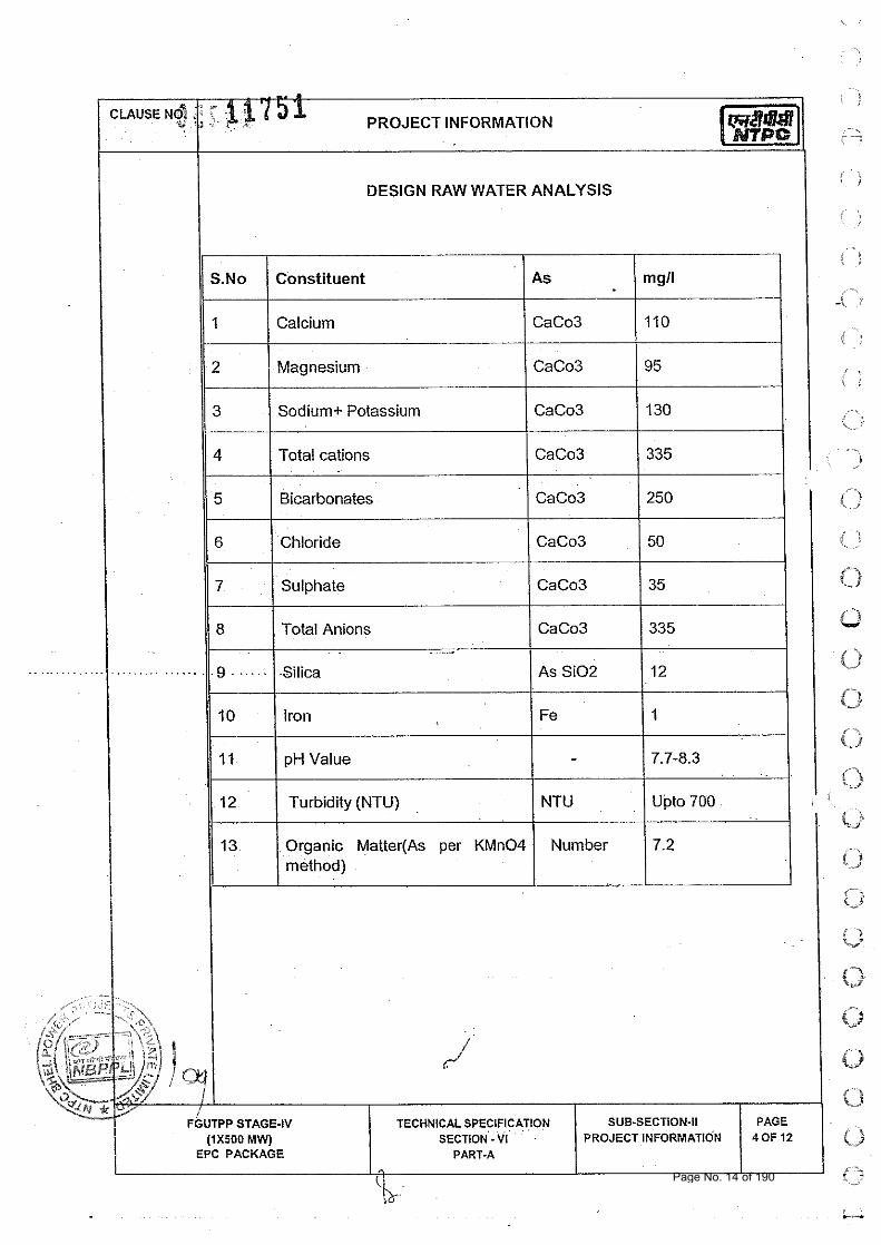
DESIGN RAW WATER ANALYSIS I - r
S.No Constituent As mgll
1 Calcium CaCo3 110
2 Magnesium CaCo3 95
3 Sodium+ Potassium CaCo3 130
4 Total cations CaCo3 335
5 Bicarbonates CaCo3 250
6 Chloride CaCo3 50
7 Sulphate CaCo3 35
11 8 1 Total Anions 1 CaCo3 1335 I
10 Iron Fe 1
11 pH Value - 7.7-8.3
12 Turbidity (NTU) NTU Upto 700
13 Organic Matter(As per KMn04 Number 7.2 method)
Page No. 14 of 190
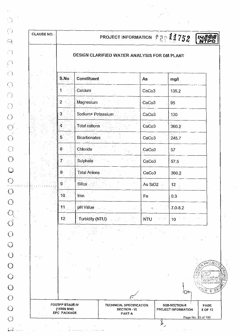
DESIGN CLARIFIED WATER ANALYSIS FOR DM PLANT
Page No. 15 of 190
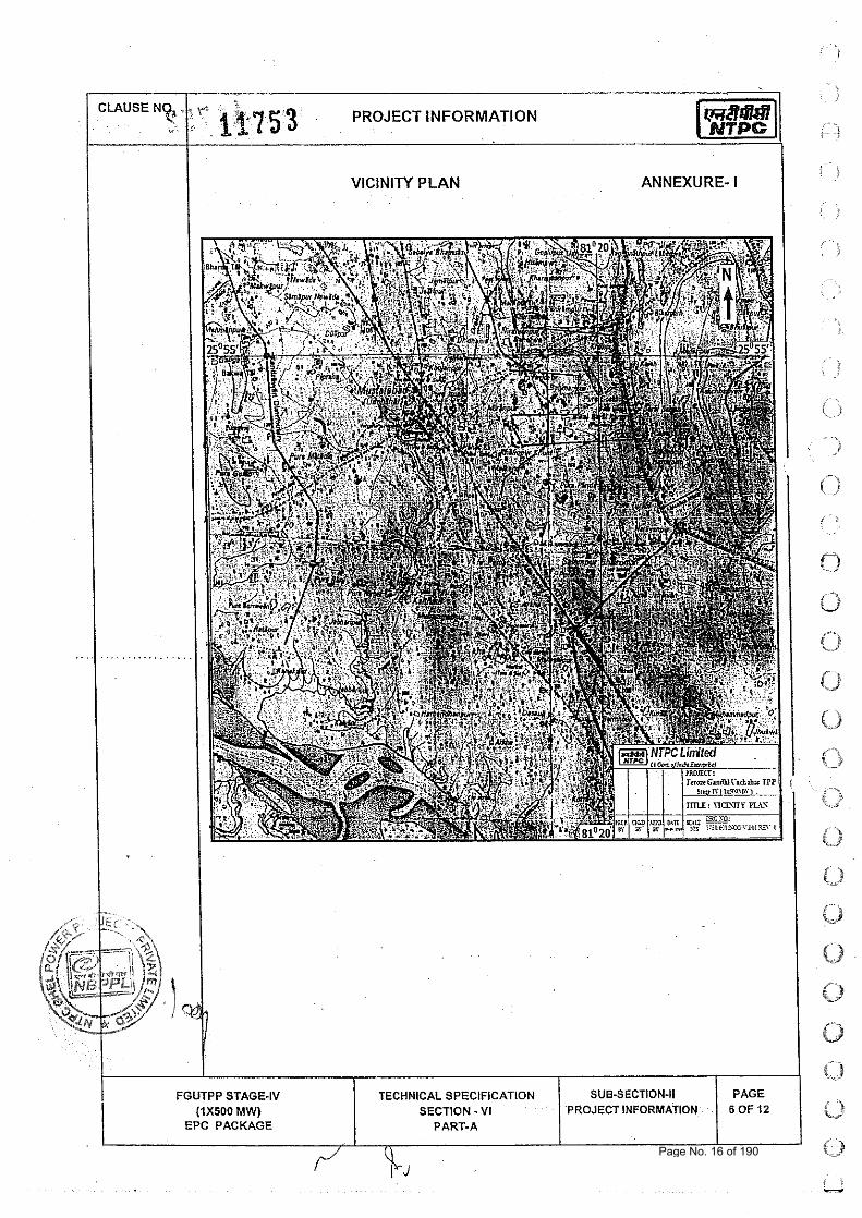
VICINITY PLAN
.
ANNEXURE-I 1
CLAUSE Nf&.
*: , i x~ i 5'3' , PROJECT INFORMATION
Page No. 16 of 190
CLAUSE NO. . -.
~~ ~. PROJECT INFORMATION.^$^?,^;- - ti b ,
'
ANNEXURE-11-1 (PAGE 1 OF 2)
C 1
: : I r / "
<
FGUTPP STAGE-IV (1x500 MW)
EPC PACKAGE
TECHNICAL SPECIFICATION SECTION - VI
PART-A
SUB-SECTION-II PROJECT INFORMATION 1 :t:FZ!
Page No. 17 of 190
St. Description Unit Range of 95% coal Range of No. Supplies Adequacy
Design Worst Best Coal Coal . Coal
1 7 'i A 15 I fi 7
I I FGUTPP STAGE-IV TECHNICAL SPECIFICATION SUB-SECTION-I1 PAGE
! (1x500 MW) SECTION - VI PROJECT INFORMATlOEi 8 OF 12 EPC 'PACKAGE PART-A
4 0 Page No. 18 of 190
. . .
EPC PACKAGE
--- .
CLAUSE NO.
..
. . . . , . . . . . . , . . . . .
-
.at 7 6pRo,,,, INFORMATIO~ :?, 3 :. . . * * : . . la1 ANNEXURE-11-2 (PAGE 1 OF 2)
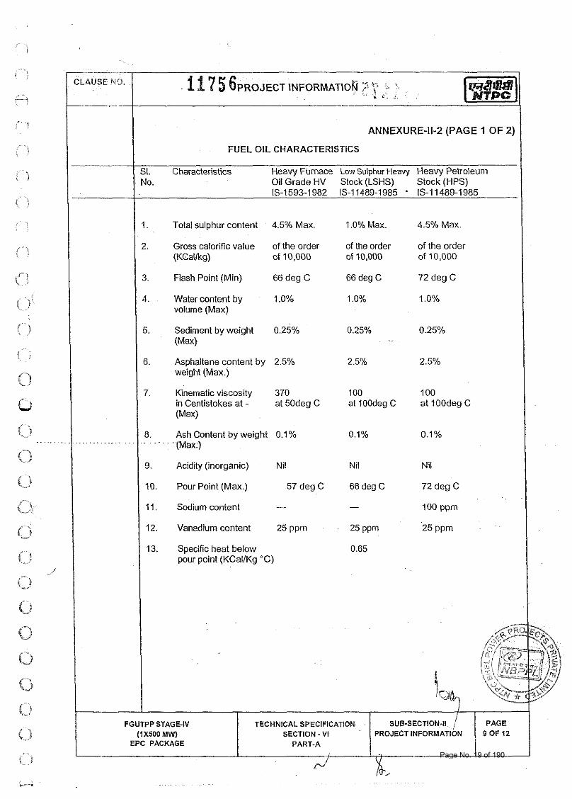
FUEL OIL CHARACTERISTICS
SI. Characteristics Heavy Furnace Low Sulphur Heavy Heavy Petroleum No. Oil Grade HV Stock (LSHS) Stock (HPS)
IS-I 593-1 982 15-1 1489-1985 ' 15-1 1489-1 985
1. Total sulphur content 4.5% Max. 1.0% Max. 4.5% Max.
2. Gross calorific value of the order of the order of the order (KCallkg) of 10,000 of 10,000 of 10,000
3. Flash Point (Min) 66 deg C 66 deg C 72 deg C
4. Water content by 1 .O% 1 .O% 1.0% volume (Max)
5. Sediment by weight 0.25% 0.25% 0.25% (Max)
6. Asphaltene content by 2.5% 2.5% 2.5% weight (Max.)
7. Kinematic viscosity 370 100 100 in Centistokes at - at 50deg C at 100deg C at 100deg C (Max)
8. Ash Content by weight 0.1% 0.1% . . . . . . . .
0.1% {Max:)
9. Acidity (inorganic) Nil Nil Nil
10. Pour Point (Max.) 57 deg C 66 deg C 72 deg C . .
11. Sodium content - - 100 ppm
12. ~ a n a d i h n content 25 P P ~ 25 ppm 25 P P ~
13. Specific heat below 0.65 pour point (KCallKg "C)
Page No. 19 of 190
CLAUSE NO. 1 a u r .
18 7 5 7 PROJECT INFORMATIO~ - 3
....
ANNEXURE-11-2 (PAGE 2 OF 2)
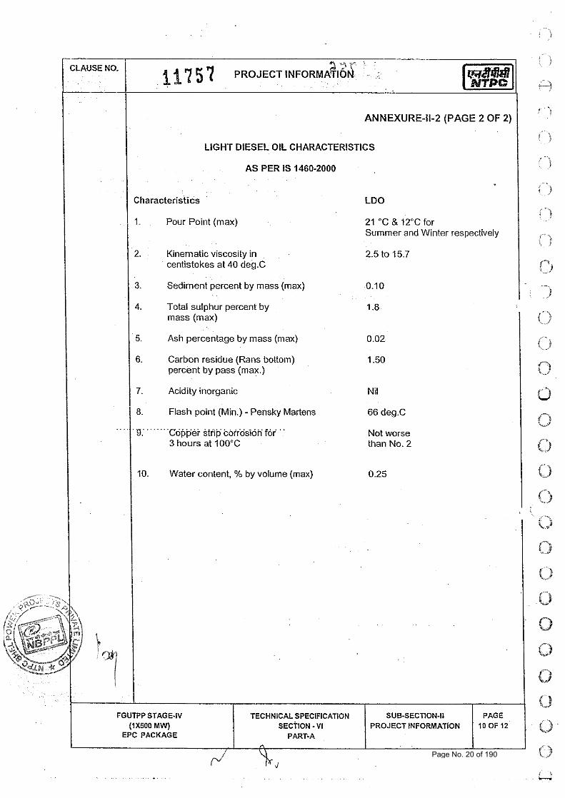
LIGHT DIESEL OIL CHARACTERISTICS
AS PER IS 1460-2000
Characteristics LDO
1. Pour Point (max) 21 "C & 12°C for Summer and Winter respectively
2. Kinematic viscosity in 2.5 to 15.7 centistokes at 40 deg.C
3. Sediment percent by mass (max) 0.10
4. Total sulphur percent by 1 .8 mass (max)
5. Ash percentage by mass (max) 0.02
6. Carbon residue (Rans bottom) 1.50 percent by pass (max.)
7. Acidity inorganic Nil
8. Flash point (Min.) - Pensky Martens 66 deg.C
. g,. .. . ....cGFp.& 6tiip k6ir.o.si6"f6r. . . Not worse 3 hours at 100°C than No. 2
10. Water content, % by volume (max) 0.25
!.
' ~. i i ' i
{,' -%j
.. . l )
, > , '
( 1
t-t r_) - -. 1
'-) i/
K-
0 .. Y
0 t-t w
0 0 O
Page No. 20 of 190
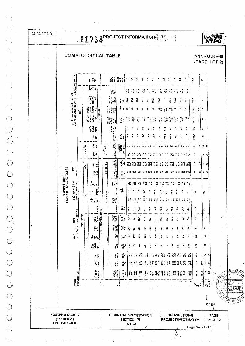
CLIMATOLOGICAL TABLE ANNEXURE-Ill
- ----- - -- --- --- - -
- - ..c. M" NS ->, - * y o - - ' - " *- - m o+ -- " S *D 0- " Y -I "," =.. n.r *- n s "- no - - z z 2 z z z = z - - -
-1 ^- D" D m ' - - o m - - n* -- n O ̂ /- N D '*g "3 "6 "& - = - - 3 " '. -I D % O* "i ..: z ? 2 - - - -
- - - - - - - - - --- - - - - -- -- -- - - - - - - - -
- - - - - - - - - - - - -- - - -- - - - - - . - - - - - - - - - - - -
Page No. 21 of 190
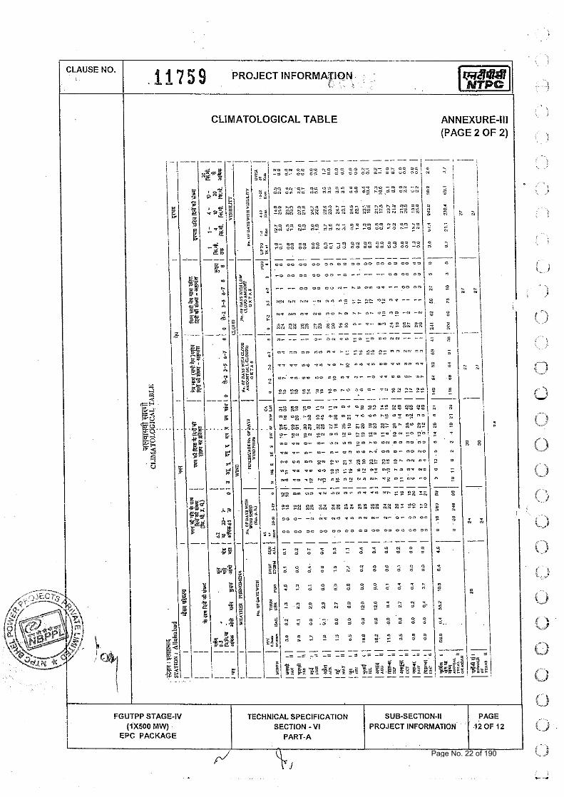
CLIMATOLOGICAL TABLE
CLAUSE NO.
ANNEXURE-Ill (PAGE 2 OF 2)
, ,
1 1 7 5 9 PROJECT INFORMATION, . ; i . - i ' .
FGUTPP STAGE-IV (1x500 MW)
EPC PACKAGE
TECHNICAL SPECIFICATION SECTION - VI
PART-A
SUB-SECTION-II PROJECT INFORMATION
PAGE 12 OF 12
Page No. 22 of 190
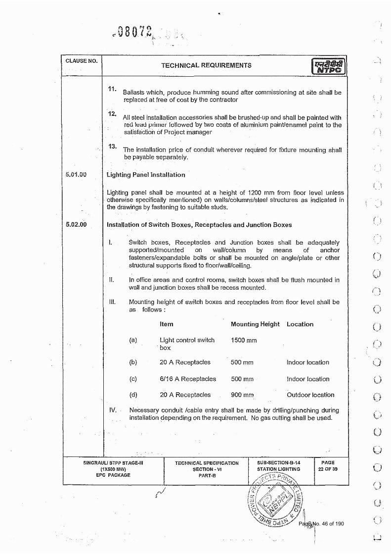
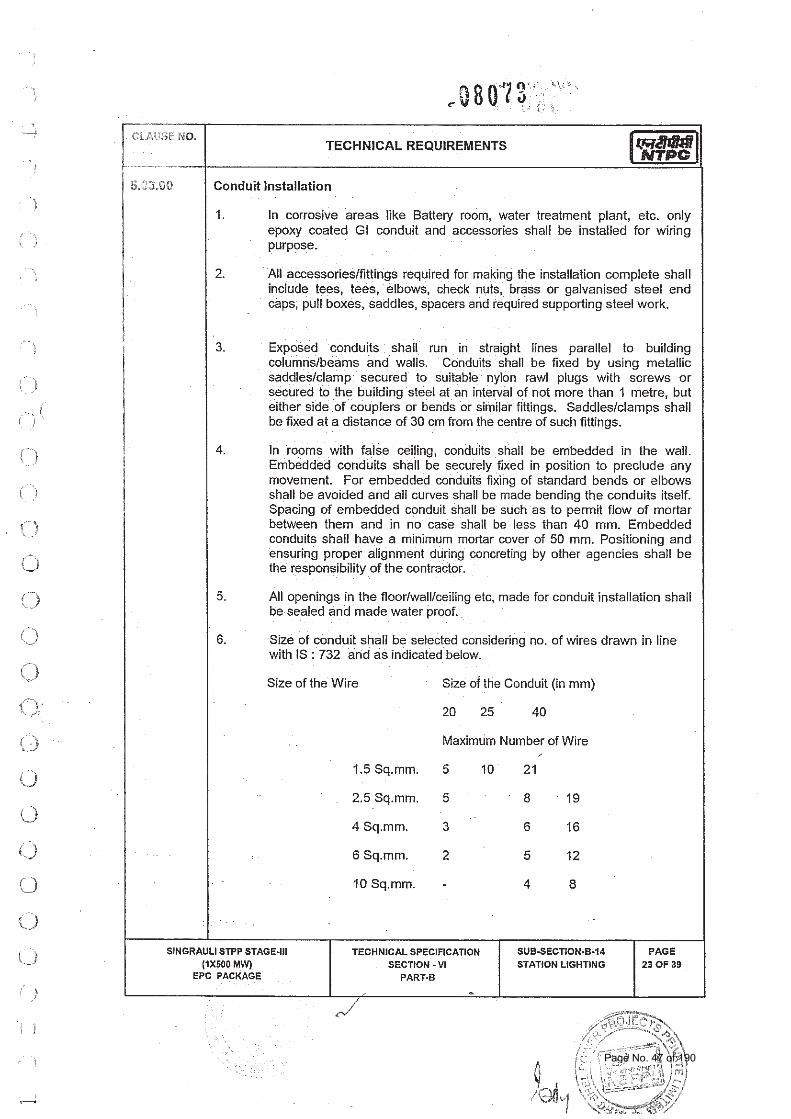
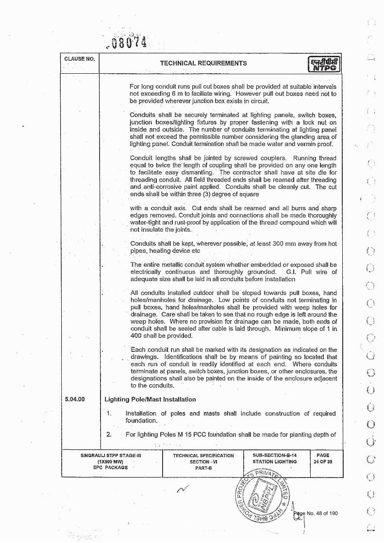
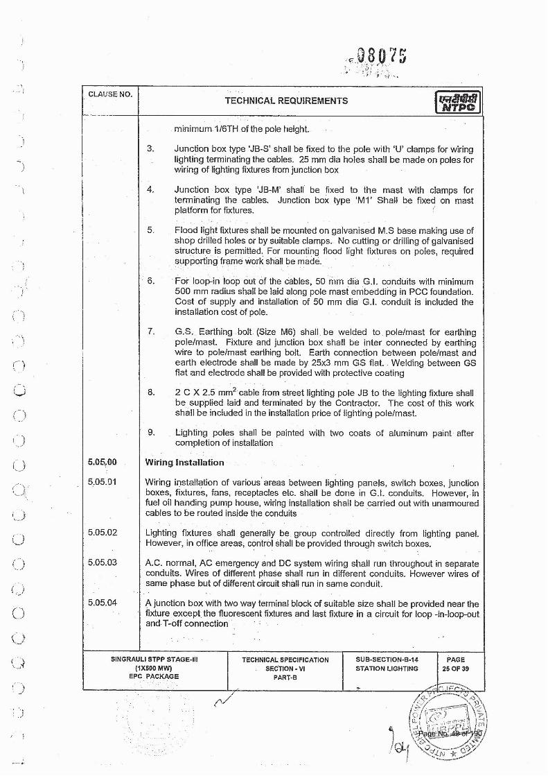
i -- NO. TECHNICAL REQUIREMENTS
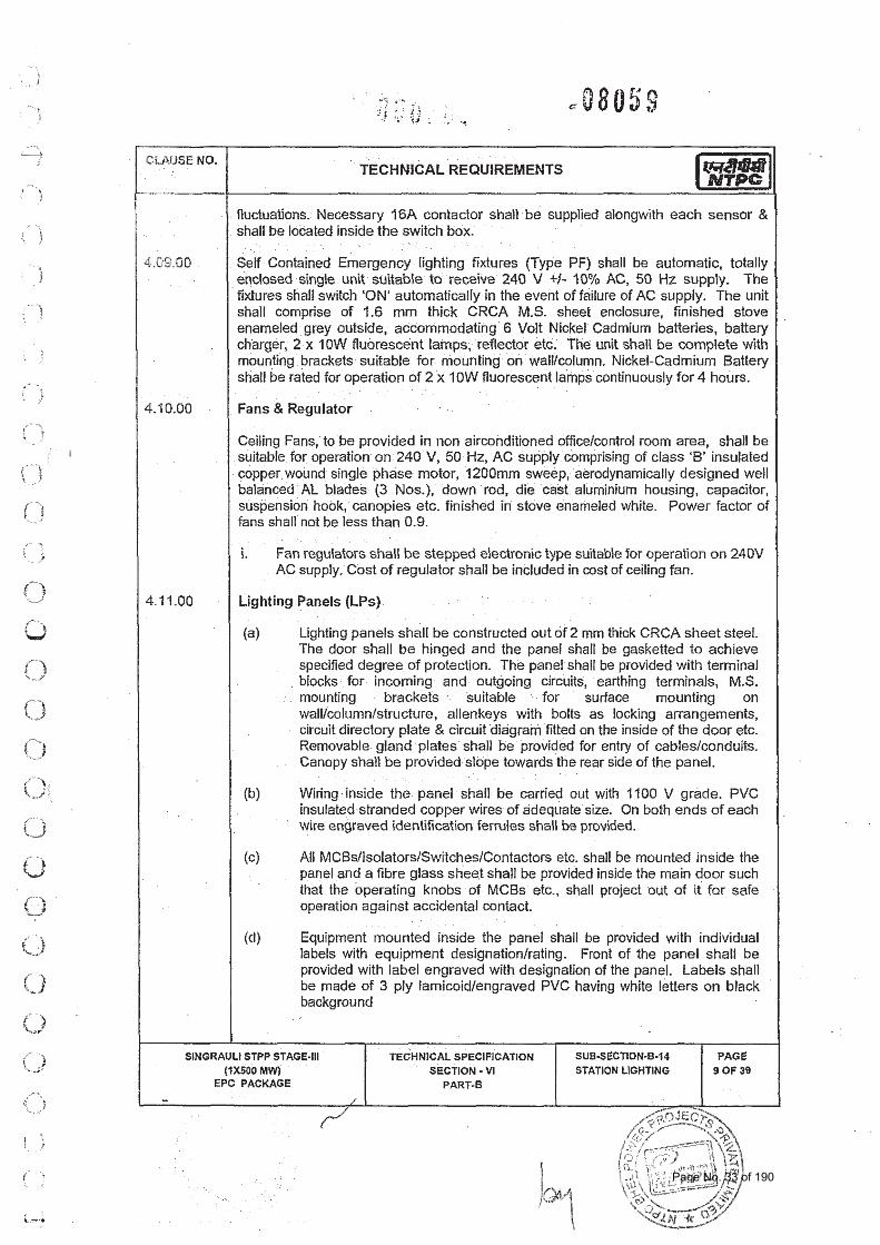
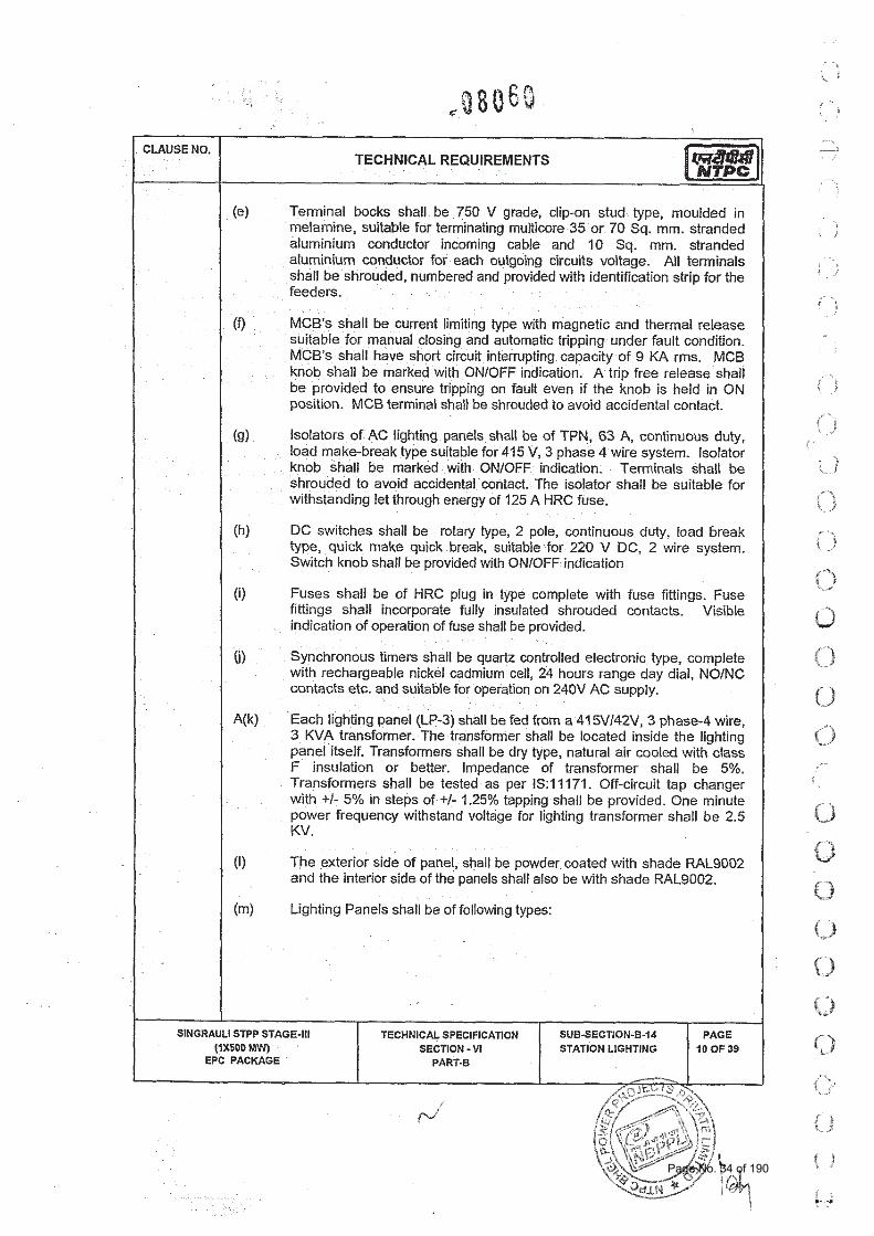
I General Requirements
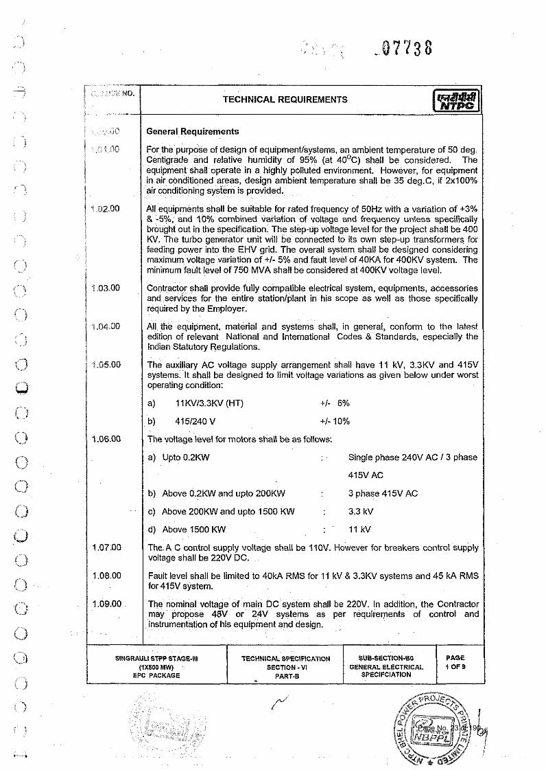
For the purpose of design of equipment/systems, an ambient temperature of 50 deg. Centigrade and relative humidity of 95% (at 40'~) shall be considered. The equipment shall operate in a highly polluted environment. However, for equipment in air conditioned areas, design ambient temperature shall be 35 deg.C, if 2~100% air conditioning system is provided.
All equipments shall be suitable for rated frequency of 50Hz with a variation of +3% & -5%. and 20% combined variation of voltage and frequency unless specifically brought out in the specification. The step-up voltage level for the project shall be 400 KV. The turbo generator unit will be connected to its own step-up transformers for feeding power into the EHV grid. The overall system shall be designed considering maximum voltage variation of +I- 5% and fault level of 40KA for 400KV system. The minimum fault level of 750 MVA shall be considered at 400KV voltage level.
Contractor shall provide fully compatible electrical system, equipments, accessories and services for the entire stationlplant in his scope as well as those specifically required by the Employer.
All the equipment, material and systems shall, in general, conform to the latest edition of relevant National and International Codes & Standards, especially the Indian Statutory Regulations.
The auxiliary AC voltage supply arrangement shall have 11 kV, 3.3KV and 415V systems. It shall be designed to limit voltage variations as given below under worst operating condition:
I a) 11 KVl3.3KV (HT) +I- 6% I The voltage level for motors shall be as follows:
a) Upto 0.2KW Single phase 240V AC 13 phase
415V AC
/ b) Above OZKW and upto 2OOKW 3 phase 415V AC I I c) Above 20OKW and upto 1500 KW 3.3 kV I I d) Above 1500 KW 11 kV I The A C control supply voltage shall be IIOV. However for breakers control supply voltage shall be 220V DC.
Fault level shall be limited to 40kA RMS for 11 kV & 3.3KV systems and 45 kA RMS for 415V system. I The nominal voltage of main DC system shall be 220V. In addition, the Contractor may propose 48V or 24V systems as per requirements of control and instrumentation of his equipment and design.
SINGRAULI STPP STAGE-Ill (1XbOO MW)
EPC PACKAGE
TECHNlCAL SPEClFlCATlON SECTION - Vl
PART-B - SUB-SECTION-BO
GENERAL ELECTRICAL SPECIFCIATION
PAGE 1 OF9
Page No. 23 of 190
TECHNICAL SPECIFICATIONS OF STATION LIGHTING PACKAGE
FGUTPP STAGE‐IV (1X 500 MW) AT UNCHAHAR
BHEL SPEC. NO. :PE-TS-401-558-e001 Rev. No.: Dated : 17.07.2014
VOLUME:I TECHNICAL CONDITIONS OF
CONTRACT
DOC. NO.: NBPPL-004-202-06-P4E-A Rev. No.:00
TECHNICAL SPECIFICATIONS
SECTION – ‘C’
(SPECIFIC TECHNICAL REQUIREMENTS)
Page No. 24 of 190
Page No. 25 of 190
Page No. 26 of 190
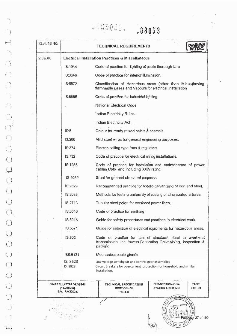
IS: 8623 Low voltage switchgear and control gear assemblies IS: 8828 Circuit Breakers for overcurrent protection for household and similar installation.
Page No. 27 of 190
Page No. 28 of 190
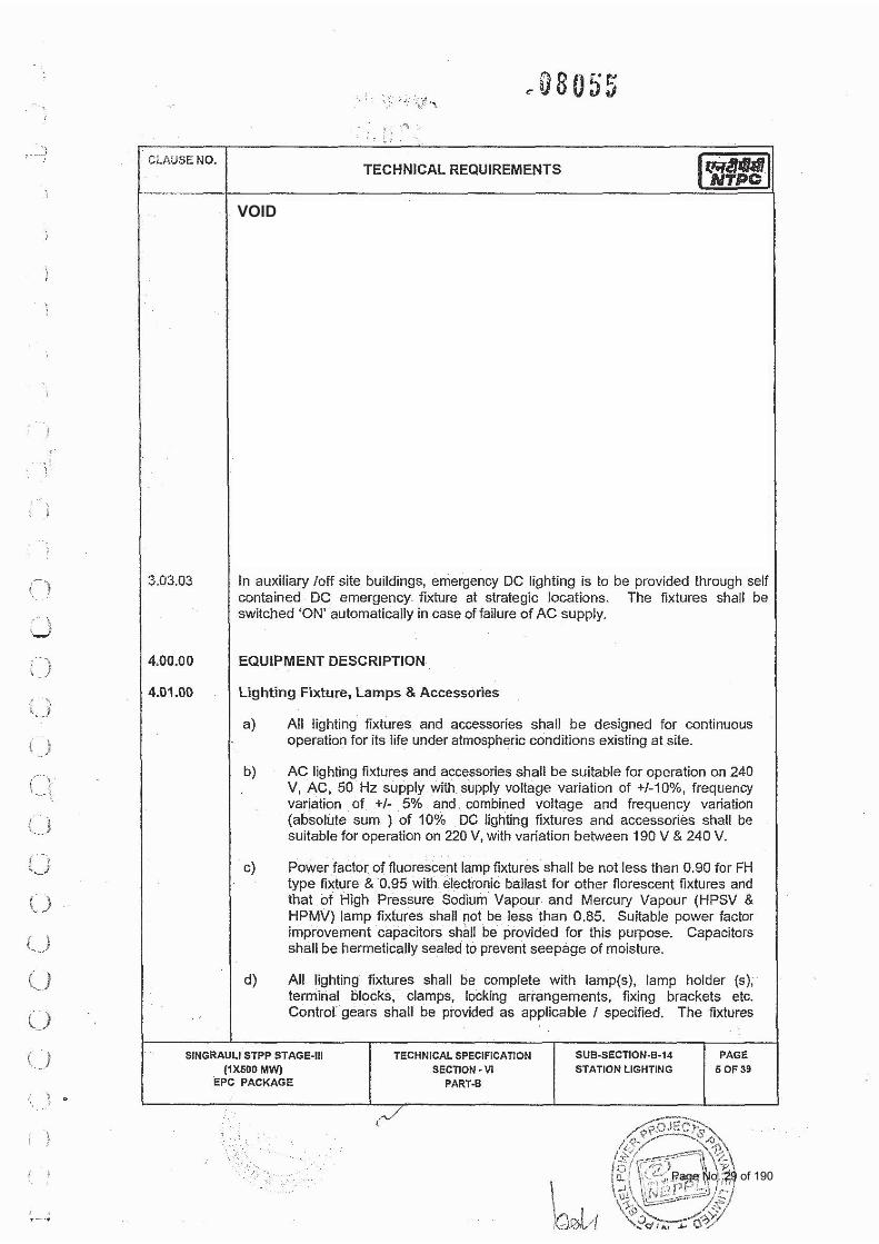
VOID
Page No. 29 of 190
Page No. 30 of 190
Page No. 31 of 190
Page No. 32 of 190
Page No. 33 of 190
Page No. 34 of 190
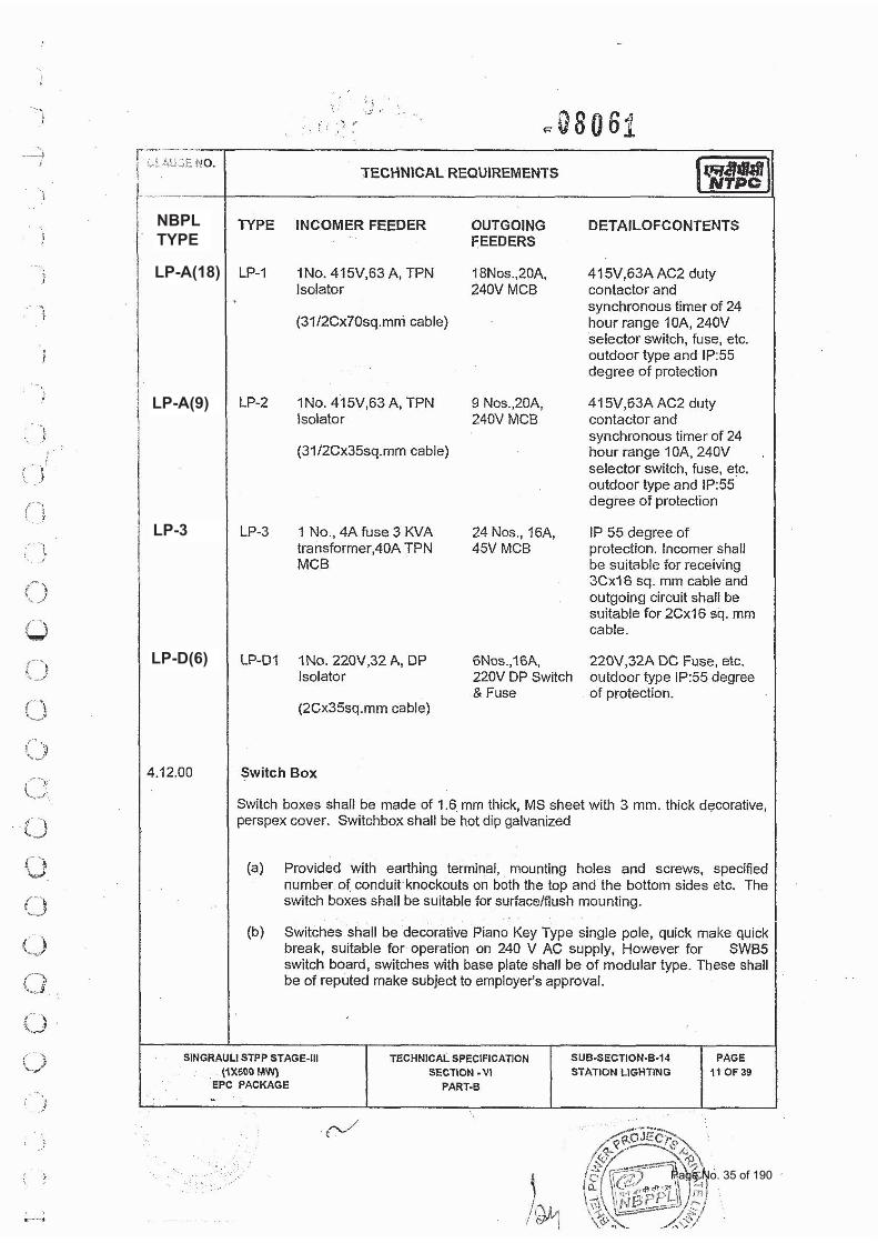
NBPL TYPE
LP-A(18)
LP-A(9)
LP-3
LP-D(6)
Page No. 35 of 190
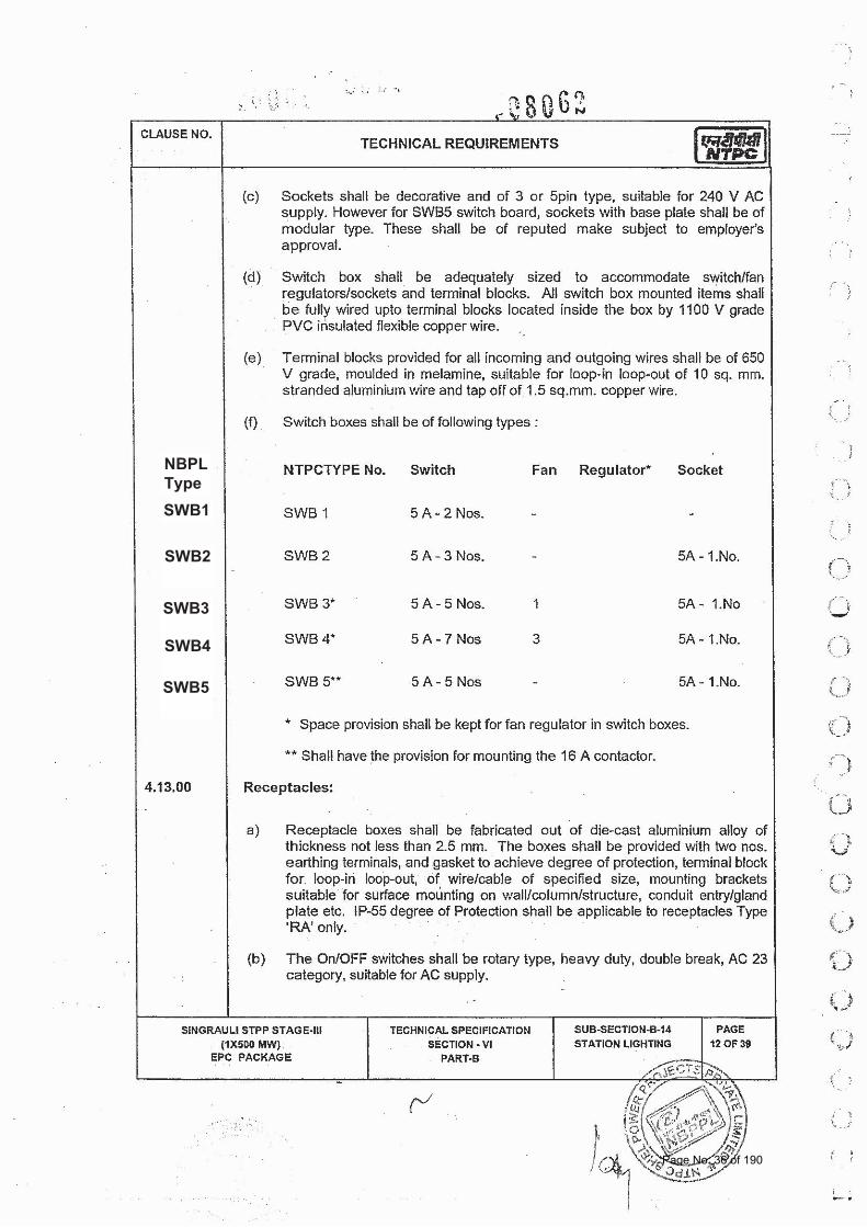
NBPL Type SWB1
SWB2
SWB3
SWB4
SWB5
Page No. 36 of 190
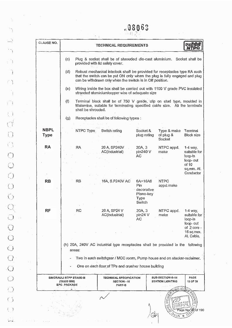
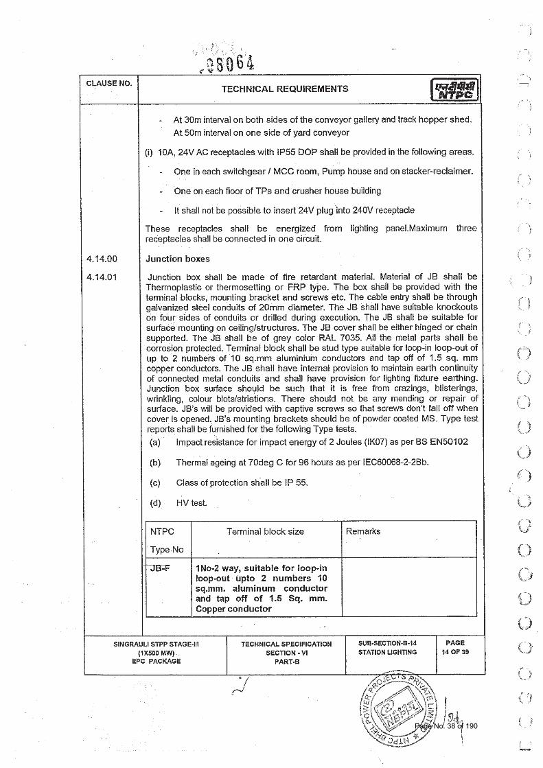
NBPL Type
RA
RB
RF
Page No. 37 of 190
Page No. 38 of 190
Page No. 39 of 190
Page No. 40 of 190
Page No. 41 of 190
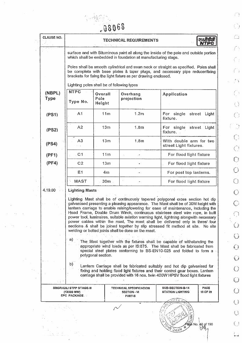
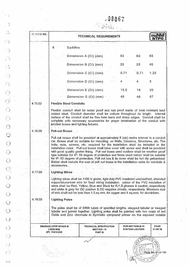
(NBPL) Type
(PS1)
(PS2)
(PS4)
(PF1)
(PF4)
Page No. 42 of 190
Page No. 43 of 190
Page No. 44 of 190

Page No. 45 of 190
Page No. 46 of 190
Page No. 47 of 190
Page No. 48 of 190
Page No. 49 of 190
Page No. 50 of 190
Page No. 51 of 190
Page No. 52 of 190
Page No. 53 of 190
Page No. 54 of 190
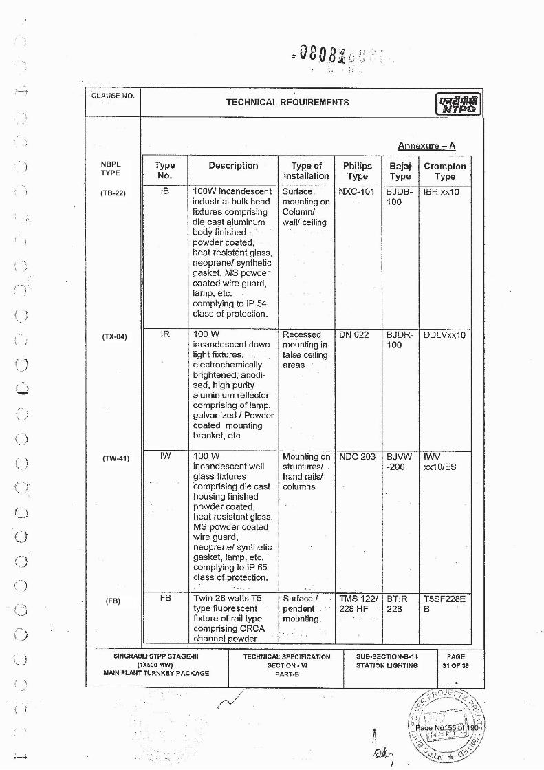
NBPL TYPE
(TB-22)
(TX-04)
(TW-41)
(FB)
Page No. 55 of 190
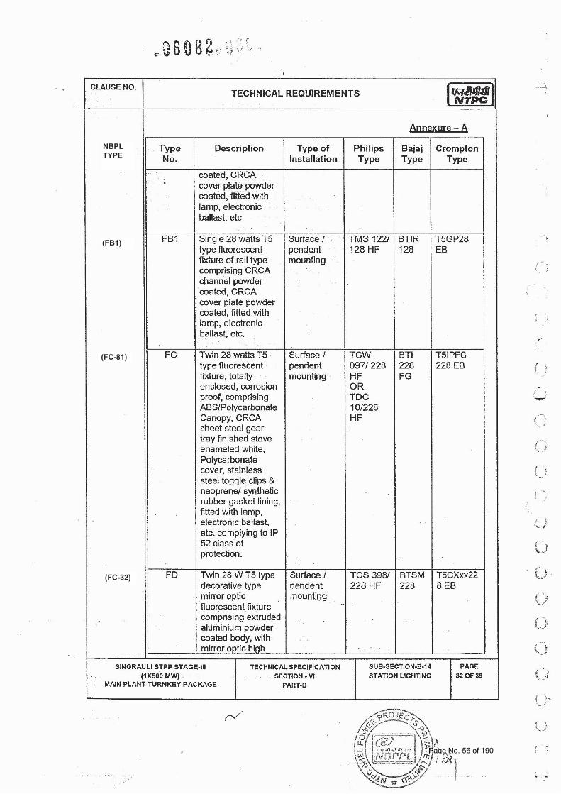
NBPL TYPE
(FB1)
(FC-81)
(FC-32)
Page No. 56 of 190
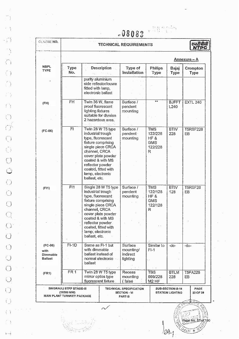
NBPL TYPE
(FH)
(FC-06)
(FI1)
(FC-06)with Dimmable Ballast
(FR1)
Page No. 57 of 190
NBPL TYPE
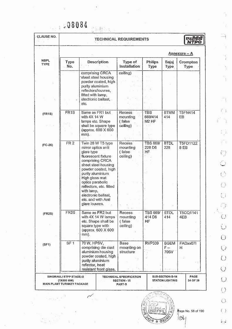
(FR1S)
(FC-26)
(FR2S)
(SF1)
Page No. 58 of 190
NBPL TYPE
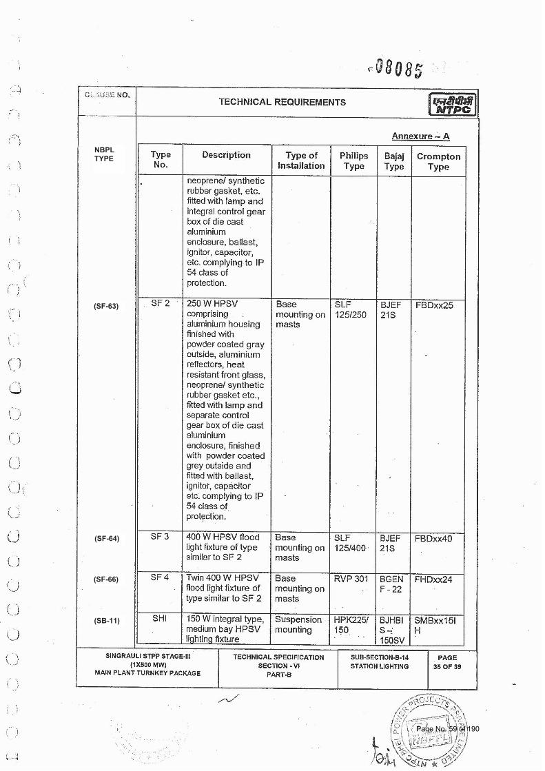
(SF-63)
(SF-64)
(SF-66)
(SB-11)
Page No. 59 of 190
NBPL TYPE
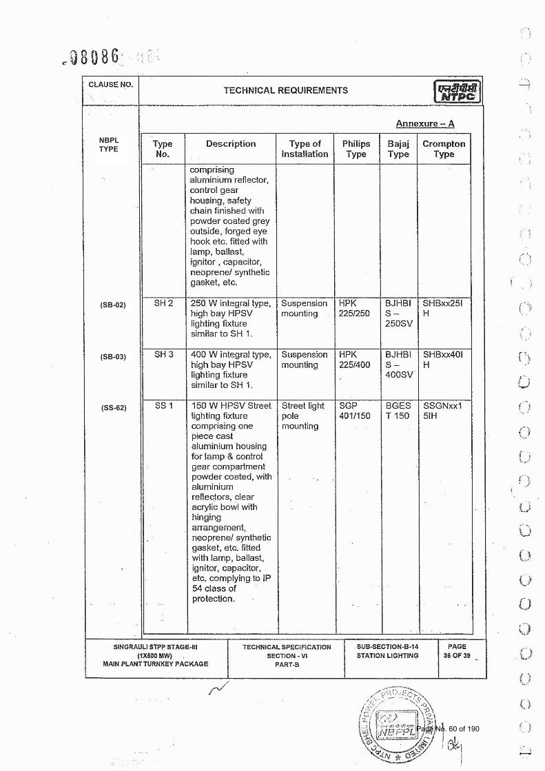
(SB-02)
(SB-03)
(SS-62)
Page No. 60 of 190
NBPL TYPE
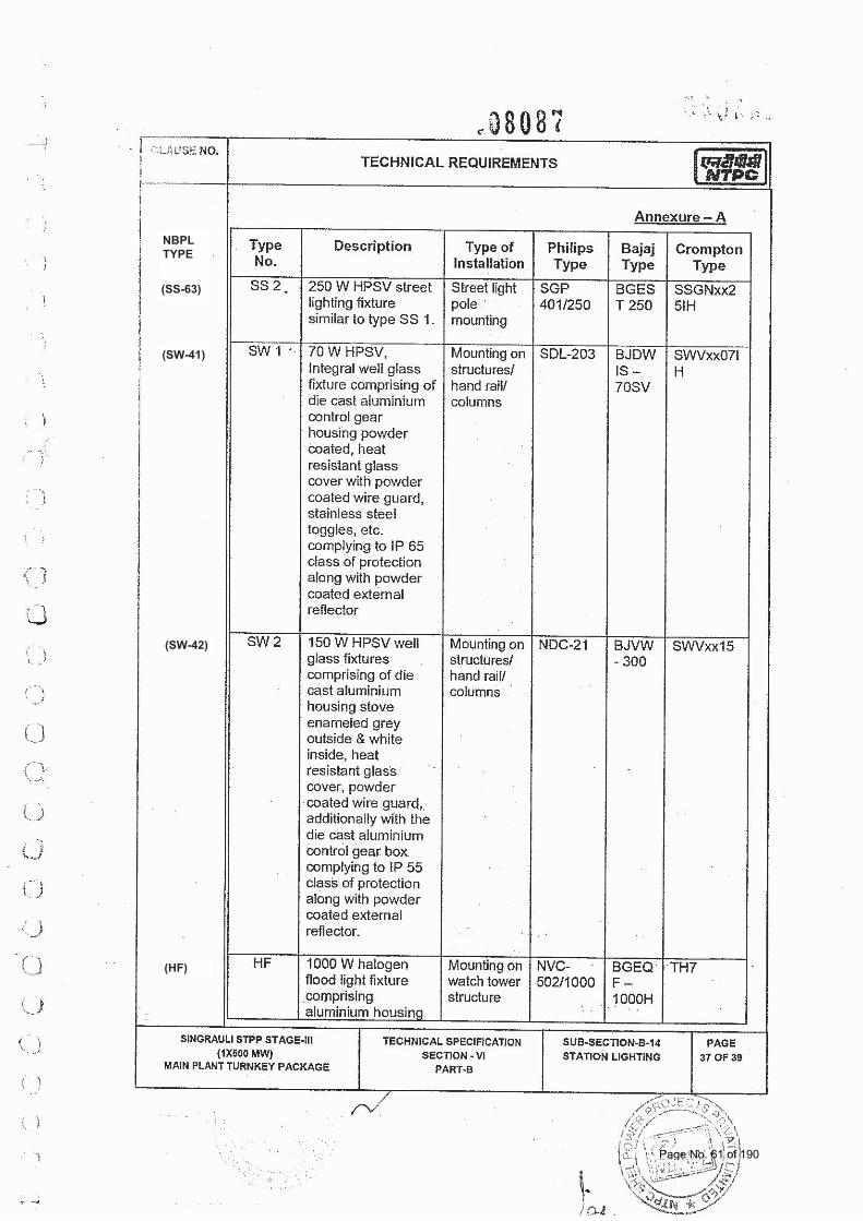
(SS-63)
(SW-41)
(SW-42)
(HF)
Page No. 61 of 190
NBPL TYPE
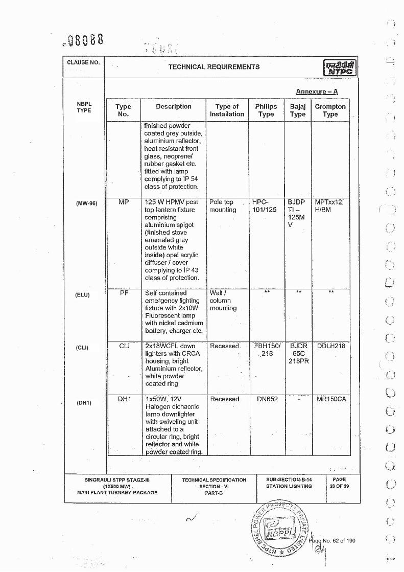
(MW-96)
(ELU)
(CLI)
(DH1)
Page No. 62 of 190
NBPL TYPE
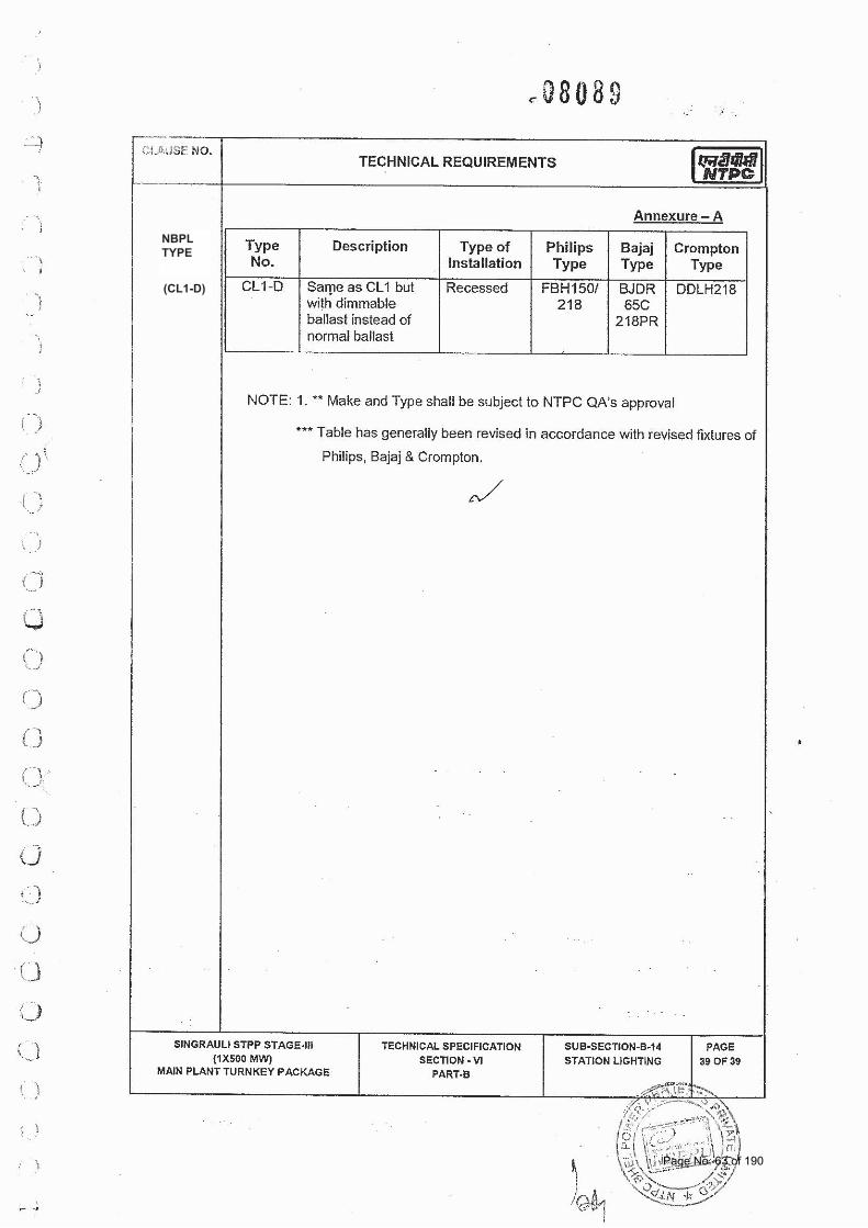
(CL1-D)
Page No. 63 of 190
TECHNICAL SPECIFICATIONS OF STATION LIGHTING PACKAGE
FGUTPP STAGE‐IV (1X 500 MW) AT UNCHAHAR
BHEL SPEC. NO. :PE-TS-401-558-e001 Rev. No.: Dated : 17.07.2014
VOLUME:I TECHNICAL CONDITIONS OF
CONTRACT
DOC. NO.: NBPPL-004-202-06-P4E-A Rev. No.:00
TECHNICAL SPECIFICATIONS
SECTION – ‘D’
(ADDITIONAL TECHNICAL REQUIREMENTS)
Page No. 64 of 190
TECHNICAL SPECIFICATIONS OF STATION LIGHTING PACKAGE
FGUTPP STAGE‐IV (1X 500 MW) AT UNCHAHAR
BHEL SPEC. NO. :PE-TS-401-558-e001 Rev. No.: Dated : 17.07.2014
VOLUME:I TECHNICAL CONDITIONS OF
CONTRACT
DOC. NO.: NBPPL-004-202-06-P4E-A Rev. No.:00
TECHNICAL SPECIFICATIONS
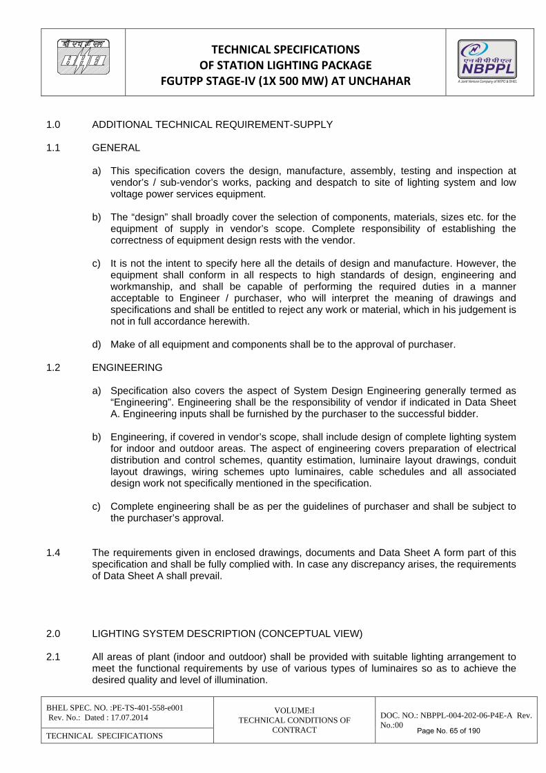
1.0 ADDITIONAL TECHNICAL REQUIREMENT-SUPPLY 1.1 GENERAL
a) This specification covers the design, manufacture, assembly, testing and inspection at vendor’s / sub-vendor’s works, packing and despatch to site of lighting system and low voltage power services equipment.
b) The “design” shall broadly cover the selection of components, materials, sizes etc. for the
equipment of supply in vendor’s scope. Complete responsibility of establishing the correctness of equipment design rests with the vendor.
c) It is not the intent to specify here all the details of design and manufacture. However, the
equipment shall conform in all respects to high standards of design, engineering and workmanship, and shall be capable of performing the required duties in a manner acceptable to Engineer / purchaser, who will interpret the meaning of drawings and specifications and shall be entitled to reject any work or material, which in his judgement is not in full accordance herewith.
d) Make of all equipment and components shall be to the approval of purchaser.
1.2 ENGINEERING
a) Specification also covers the aspect of System Design Engineering generally termed as “Engineering”. Engineering shall be the responsibility of vendor if indicated in Data Sheet A. Engineering inputs shall be furnished by the purchaser to the successful bidder.
b) Engineering, if covered in vendor’s scope, shall include design of complete lighting system
for indoor and outdoor areas. The aspect of engineering covers preparation of electrical distribution and control schemes, quantity estimation, luminaire layout drawings, conduit layout drawings, wiring schemes upto luminaires, cable schedules and all associated design work not specifically mentioned in the specification.
c) Complete engineering shall be as per the guidelines of purchaser and shall be subject to
the purchaser’s approval. 1.4 The requirements given in enclosed drawings, documents and Data Sheet A form part of this
specification and shall be fully complied with. In case any discrepancy arises, the requirements of Data Sheet A shall prevail.
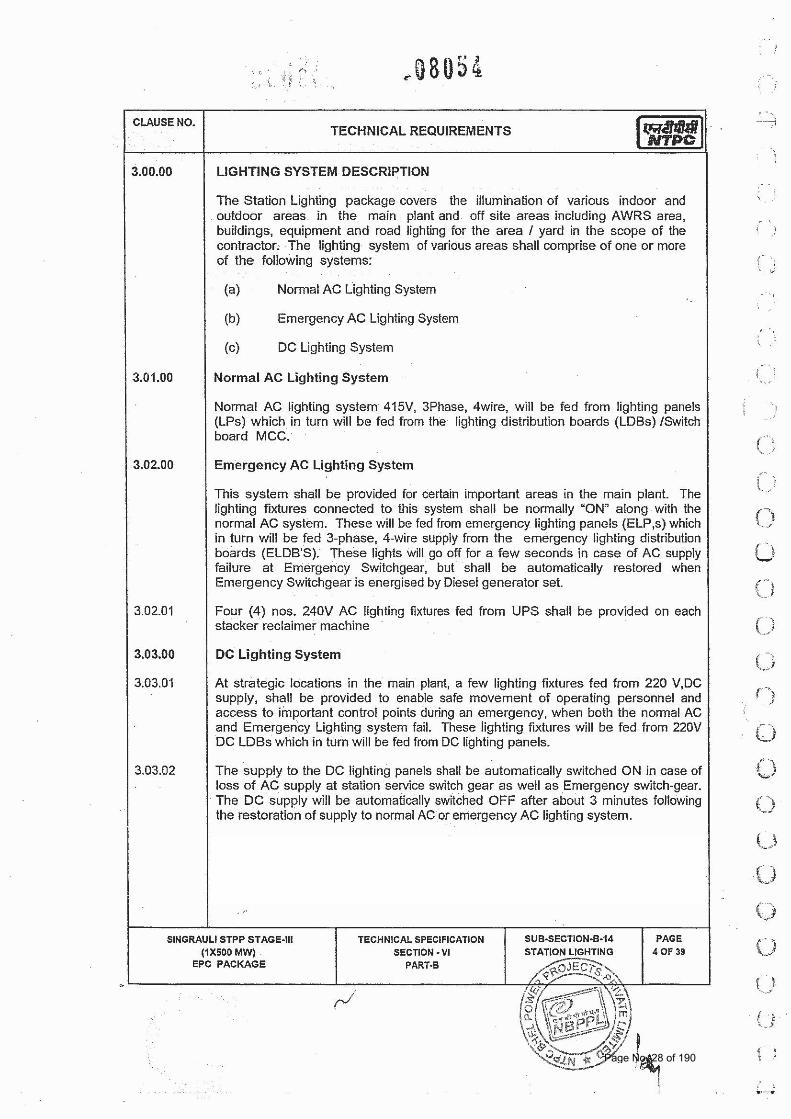
2.0 LIGHTING SYSTEM DESCRIPTION (CONCEPTUAL VIEW) 2.1 All areas of plant (indoor and outdoor) shall be provided with suitable lighting arrangement to
meet the functional requirements by use of various types of luminaires so as to achieve the desired quality and level of illumination.
Page No. 65 of 190
TECHNICAL SPECIFICATIONS OF STATION LIGHTING PACKAGE
FGUTPP STAGE‐IV (1X 500 MW) AT UNCHAHAR
BHEL SPEC. NO. :PE-TS-401-558-e001 Rev. No.: Dated : 17.07.2014
VOLUME:I TECHNICAL CONDITIONS OF
CONTRACT
DOC. NO.: NBPPL-004-202-06-P4E-A Rev. No.:00
TECHNICAL SPECIFICATIONS
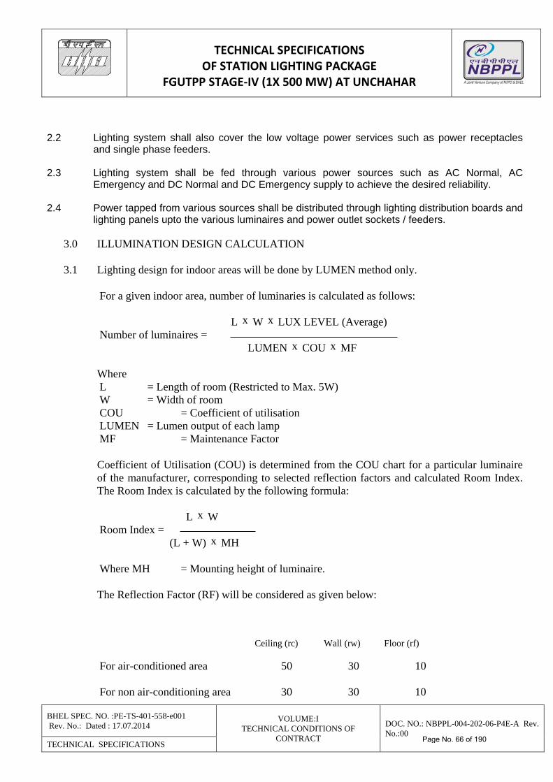
2.2 Lighting system shall also cover the low voltage power services such as power receptacles
and single phase feeders. 2.3 Lighting system shall be fed through various power sources such as AC Normal, AC
Emergency and DC Normal and DC Emergency supply to achieve the desired reliability. 2.4 Power tapped from various sources shall be distributed through lighting distribution boards and
lighting panels upto the various luminaires and power outlet sockets / feeders.
3.0 ILLUMINATION DESIGN CALCULATION 3.1 Lighting design for indoor areas will be done by LUMEN method only.
For a given indoor area, number of luminaries is calculated as follows:
L x W x LUX LEVEL (Average) Number of luminaires = LUMEN x COU x MF Where L = Length of room (Restricted to Max. 5W) W = Width of room COU = Coefficient of utilisation LUMEN = Lumen output of each lamp MF = Maintenance Factor Coefficient of Utilisation (COU) is determined from the COU chart for a particular luminaire
of the manufacturer, corresponding to selected reflection factors and calculated Room Index. The Room Index is calculated by the following formula:
L x W Room Index = (L + W) x MH Where MH = Mounting height of luminaire. The Reflection Factor (RF) will be considered as given below: Ceiling (rc) Wall (rw) Floor (rf) For air-conditioned area 50 30 10 For non air-conditioning area 30 30 10
Page No. 66 of 190
TECHNICAL SPECIFICATIONS OF STATION LIGHTING PACKAGE
FGUTPP STAGE‐IV (1X 500 MW) AT UNCHAHAR
BHEL SPEC. NO. :PE-TS-401-558-e001 Rev. No.: Dated : 17.07.2014
VOLUME:I TECHNICAL CONDITIONS OF
CONTRACT
DOC. NO.: NBPPL-004-202-06-P4E-A Rev. No.:00
TECHNICAL SPECIFICATIONS
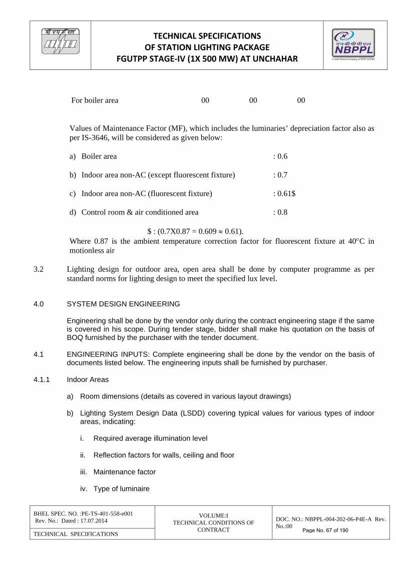
For boiler area 00 00 00 Values of Maintenance Factor (MF), which includes the luminaries’ depreciation factor also as
per IS-3646, will be considered as given below: a) Boiler area : 0.6 b) Indoor area non-AC (except fluorescent fixture) : 0.7 c) Indoor area non-AC (fluorescent fixture) : 0.61$ d) Control room & air conditioned area : 0.8 $ : (0.7X0.87 = 0.609 0.61). Where 0.87 is the ambient temperature correction factor for fluorescent fixture at 40C in
motionless air
3.2 Lighting design for outdoor area, open area shall be done by computer programme as per standard norms for lighting design to meet the specified lux level.
4.0 SYSTEM DESIGN ENGINEERING Engineering shall be done by the vendor only during the contract engineering stage if the same
is covered in his scope. During tender stage, bidder shall make his quotation on the basis of BOQ furnished by the purchaser with the tender document.
4.1 ENGINEERING INPUTS: Complete engineering shall be done by the vendor on the basis of
documents listed below. The engineering inputs shall be furnished by purchaser. 4.1.1 Indoor Areas
a) Room dimensions (details as covered in various layout drawings) b) Lighting System Design Data (LSDD) covering typical values for various types of indoor
areas, indicating:
i. Required average illumination level ii. Reflection factors for walls, ceiling and floor iii. Maintenance factor iv. Type of luminaire
Page No. 67 of 190
TECHNICAL SPECIFICATIONS OF STATION LIGHTING PACKAGE
FGUTPP STAGE‐IV (1X 500 MW) AT UNCHAHAR
BHEL SPEC. NO. :PE-TS-401-558-e001 Rev. No.: Dated : 17.07.2014
VOLUME:I TECHNICAL CONDITIONS OF
CONTRACT
DOC. NO.: NBPPL-004-202-06-P4E-A Rev. No.:00
TECHNICAL SPECIFICATIONS
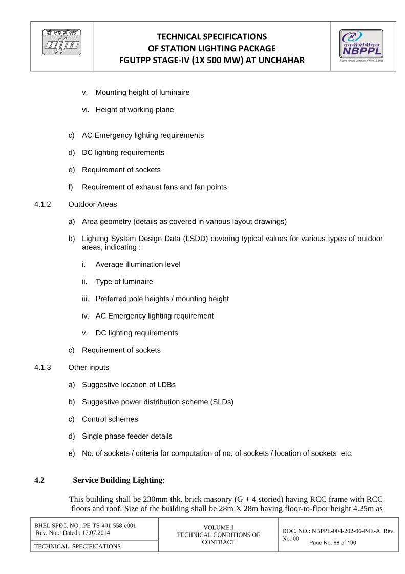
v. Mounting height of luminaire vi. Height of working plane
c) AC Emergency lighting requirements d) DC lighting requirements e) Requirement of sockets f) Requirement of exhaust fans and fan points
4.1.2 Outdoor Areas a) Area geometry (details as covered in various layout drawings) b) Lighting System Design Data (LSDD) covering typical values for various types of outdoor
areas, indicating :
i. Average illumination level ii. Type of luminaire iii. Preferred pole heights / mounting height iv. AC Emergency lighting requirement v. DC lighting requirements
c) Requirement of sockets
4.1.3 Other inputs
a) Suggestive location of LDBs b) Suggestive power distribution scheme (SLDs) c) Control schemes d) Single phase feeder details e) No. of sockets / criteria for computation of no. of sockets / location of sockets etc.
4.2 Service Building Lighting:
This building shall be 230mm thk. brick masonry (G + 4 storied) having RCC frame with RCC
floors and roof. Size of the building shall be 28m X 28m having floor-to-floor height 4.25m as
Page No. 68 of 190
TECHNICAL SPECIFICATIONS OF STATION LIGHTING PACKAGE
FGUTPP STAGE‐IV (1X 500 MW) AT UNCHAHAR
BHEL SPEC. NO. :PE-TS-401-558-e001 Rev. No.: Dated : 17.07.2014
VOLUME:I TECHNICAL CONDITIONS OF
CONTRACT
DOC. NO.: NBPPL-004-202-06-P4E-A Rev. No.:00
TECHNICAL SPECIFICATIONS
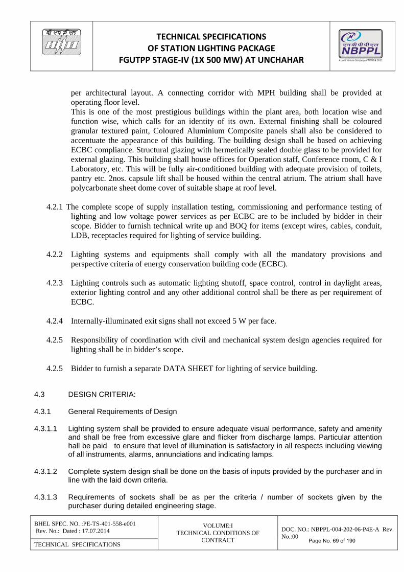
per architectural layout. A connecting corridor with MPH building shall be provided at operating floor level.
This is one of the most prestigious buildings within the plant area, both location wise and function wise, which calls for an identity of its own. External finishing shall be coloured granular textured paint, Coloured Aluminium Composite panels shall also be considered to accentuate the appearance of this building. The building design shall be based on achieving ECBC compliance. Structural glazing with hermetically sealed double glass to be provided for external glazing. This building shall house offices for Operation staff, Conference room, C & I Laboratory, etc. This will be fully air-conditioned building with adequate provision of toilets, pantry etc. 2nos. capsule lift shall be housed within the central atrium. The atrium shall have polycarbonate sheet dome cover of suitable shape at roof level.
4.2.1 The complete scope of supply installation testing, commissioning and performance testing of
lighting and low voltage power services as per ECBC are to be included by bidder in their scope. Bidder to furnish technical write up and BOQ for items (except wires, cables, conduit, LDB, receptacles required for lighting of service building.
4.2.2 Lighting systems and equipments shall comply with all the mandatory provisions and
perspective criteria of energy conservation building code (ECBC). 4.2.3 Lighting controls such as automatic lighting shutoff, space control, control in daylight areas,
exterior lighting control and any other additional control shall be there as per requirement of ECBC.
4.2.4 Internally-illuminated exit signs shall not exceed 5 W per face. 4.2.5 Responsibility of coordination with civil and mechanical system design agencies required for
lighting shall be in bidder’s scope. 4.2.5 Bidder to furnish a separate DATA SHEET for lighting of service building.
4.3 DESIGN CRITERIA: 4.3.1 General Requirements of Design 4.3.1.1 Lighting system shall be provided to ensure adequate visual performance, safety and amenity
and shall be free from excessive glare and flicker from discharge lamps. Particular attention hall be paid to ensure that level of illumination is satisfactory in all respects including viewing of all instruments, alarms, annunciations and indicating lamps.
4.3.1.2 Complete system design shall be done on the basis of inputs provided by the purchaser and in
line with the laid down criteria. 4.3.1.3 Requirements of sockets shall be as per the criteria / number of sockets given by the
purchaser during detailed engineering stage.
Page No. 69 of 190
TECHNICAL SPECIFICATIONS OF STATION LIGHTING PACKAGE
FGUTPP STAGE‐IV (1X 500 MW) AT UNCHAHAR
BHEL SPEC. NO. :PE-TS-401-558-e001 Rev. No.: Dated : 17.07.2014
VOLUME:I TECHNICAL CONDITIONS OF
CONTRACT
DOC. NO.: NBPPL-004-202-06-P4E-A Rev. No.:00
TECHNICAL SPECIFICATIONS
4.3.2 Sources of Power Supply 4.3.2.1 The lighting system shall be provided with the power from the following sources : a) AC - normal b) AC - emergency c) DC - emergency 4.3.2.2 AC emergency supply is made available from purchaser’s AC emergency Board. 4.3.2.3 Arrangement and distribution of power shall depend upon the functional requirements of areas
and therefore supply from all types of power sources shall not be made available to all areas. 4.3.2.4 Power from the purchaser’s supply sources shall be brought upto the Lighting Distribution
Boards (LDBs) of various types. Each LDB shall in turn feed power to various Lighting Panels (LPs).
4.3.2.5 Power to the AC normal luminaires shall be available through AC normal LDB & LP. Power to
the AC emergency luminaires shall be available through AC emergency LDB & AC emergency LP. Power to DC normal luminaires shall be available through DC normal LP, which in turn shall be fed directly from DCDB / Sub-DCDB. However power to the DC emergency luminaires shall be available through DC emergency LDB & LP.
4.3.2.6 Complete power distribution system shall be designed keeping following criteria in view : a) Simplicity b) Controlled voltage drop c) Cost effectiveness 4.3.2.7 Area Classification The detailed requirements of luminaires depending upon type of power supply source for each
area shall be as per the details to be furnished by purchaser during contract engineering. Area classification on the basis of type of luminaires to be provided shall be as under :
a) Area A : AC normal, AC emergency and DC emergency luminaires. b) Area B : AC Normal and AC emergency luminaires c) Area C : AC Normal luminaires. d) Area D : AC Normal luminaires and portable emergency lighting. 4.4 Lighting Philosophy 4.4.1 In the normal course, for areas A and B, all the AC luminaires shall remain switched on
through two different sources of supply i.e. AC normal and AC emergency.
Page No. 70 of 190
TECHNICAL SPECIFICATIONS OF STATION LIGHTING PACKAGE
FGUTPP STAGE‐IV (1X 500 MW) AT UNCHAHAR
BHEL SPEC. NO. :PE-TS-401-558-e001 Rev. No.: Dated : 17.07.2014
VOLUME:I TECHNICAL CONDITIONS OF
CONTRACT
DOC. NO.: NBPPL-004-202-06-P4E-A Rev. No.:00
TECHNICAL SPECIFICATIONS
4.4.2 In case of failure of AC normal supply the following shall apply:
a) Areas A shall automatically get illuminated from DC emergency luminaires. This supply
shall be available till AC emergency power is restored and stabilised. b) Areas B shall remain temporarily dark till the AC emergency supply is restored from diesel
generator set. c) Areas C shall remain dark till the AC normal supply is restored.
4.4.3 As soon as the AC emergency supply is restored, the AC emergency luminaires shall come into operation. DC emergency luminaires shall have time delayed switching off after a specified duration to ensure that the AC emergency supply is stabilised.
4.4.4 When the AC normal supply is restored, the following shall apply :
a) DC emergency luminaires shall be switched off immediately, if they are switched on. b) AC emergency luminaires shall switch off momentarily when AC emergency board
incoming supply is changed over from diesel generator to the AC normal supply.
4.4.5 Street Lighting / Flood Lighting Street lights / flood lights will be fed from Street Lighting Panel (SLP). The number of street
lights / flood lights shall be grouped in such a way that they will be fed from the nearest SLP available. Street lights shall have provision of automatic switching ON and OFF in any one of the following modes and as per the purchaser’s scheme:
a) Manual b) Automatic through 00 - 24 hrs time switch c) Automatic through combination of 00 - 24 hrs time switch and a remote sensing device for
monitoring external illumination level.
Each SLP shall be provided with a time switch and a remote light sensing device. 4.4.6 Number of Luminaires 4.4.6.1 All calculations shall be done as per the input data covered under “Engineering Inputs”. 4.4.6.2 Total AC luminaires Indoor Areas : Total number of AC luminaires shall be calculated by the Lumen Method for
average light intensity.
Page No. 71 of 190
TECHNICAL SPECIFICATIONS OF STATION LIGHTING PACKAGE
FGUTPP STAGE‐IV (1X 500 MW) AT UNCHAHAR
BHEL SPEC. NO. :PE-TS-401-558-e001 Rev. No.: Dated : 17.07.2014
VOLUME:I TECHNICAL CONDITIONS OF
CONTRACT
DOC. NO.: NBPPL-004-202-06-P4E-A Rev. No.:00
TECHNICAL SPECIFICATIONS
Outdoor Areas : Total number of AC luminaires for outdoor areas shall be calculated on the basis of point to point method by an established computer program. Optimisation criteria shall form part of street lighting calculations.
4.4.6.3 AC Normal & AC Emergency Luminaires Area A, B & C : A specified percentage of total AC luminaires shall be considered as AC
emergency luminaires. The percentage shall be informed after award of contract. The remaining luminaires shall be AC normal luminaires.
Area D: All the luminaires shall be considered as AC normal luminaires. 4.4.6.4 DC Normal & DC Emergency Luminaires The vendor shall consider the quantities of DC emergency luminaires as suggested by
purchaser. Unless otherwise indicated, DC luminaires are for the functional purpose only and no design calculations are to be done. Vendor shall ensure that adequate number of DC emergency lights are provided for essential operations of the plant and shall suggest the changes in purchaser’s DC lighting stipulations, if required.
4.4.6.5 Independent DC Luminaires In areas comparatively remote from power house building, emergency illumination, where
required will be provided by rechargeable emergency units. Such units will be installed at suitable location without plug and socket and will be permanently connected to normal AC supply. These emergency units will automatically light-up upon failure of normal AC supply.
4.4.7 Layout Considerations 4.4.7.1 General Layout Considerations
a) Layout of equipment such as LDBs and LPs shall be on the basis of following criteria :
i. Ease of operation ii. Maintainability iii. Aesthetics
b) Luminaires shall be located to meet the functional requirements of the area. Aesthetics
shall form part of layout considerations. c) Due considerations shall be given to the mounting arrangement depending upon location
and type of area.
d) While preparing lighting system layout drawings for air conditioned control rooms/areas having false ceilings, the vendor shall be required to coordinate with the Air Conditioning / Ventilation Duct layout and false ceiling layout drawings to avoid fouling / interference.
Page No. 72 of 190
TECHNICAL SPECIFICATIONS OF STATION LIGHTING PACKAGE
FGUTPP STAGE‐IV (1X 500 MW) AT UNCHAHAR
BHEL SPEC. NO. :PE-TS-401-558-e001 Rev. No.: Dated : 17.07.2014
VOLUME:I TECHNICAL CONDITIONS OF
CONTRACT
DOC. NO.: NBPPL-004-202-06-P4E-A Rev. No.:00
TECHNICAL SPECIFICATIONS
4.4.7.2 Conduit System
a) Unless indicated otherwise, conduits shall originate from respective lighting panels and shall continue upto the luminaires for all indoor areas.
b) Conduits shall run in straight runs, parallel to building columns, walls etc. as far as
practicable. c) Unnecessary bends and crossings shall be avoided. d) In the corrosive environment, conduit installations shall be made with corrosion proof
conduits. Such requirements shall be clearly indicated while preparing BOQ. 4.4.7.3 Wiring
a) Each circuit starting from LP shall be taken in a separate conduit. b) Receptacle wiring conduits shall be distinct from lighting conduits.
c) Wiring shall be designed for the uniformly distributed spread of luminaires on each phase
i.e. R, Y & B. Distribution of luminaires on these phases shall be such that there is generally uniform light intensity in the event of failure of one or two phases.
d) Luminaires located in the offices, stores, laboratories, toilets etc. shall be individually or
group controlled. 4.4.7.4 Cabling
a) Cables shall be considered wherever it is not desirable to run the insulated wires due to long runs or for any other valid reason.
b) Cable Schedule shall be prepared for all cable connections.
4.5 ENGINEERING OUTPUTS: Vendor shall prepare and submit following documents and drawings for purchaser’s approval :
a) Lighting calculations for indoor areas covering details such as room dimensions (length, width, height), illumination level, reflection factors (walls, ceiling, floor), maintenance factor, type of luminaire, mounting height of luminaire, room index, coefficient of utilisation, no. of luminaires (AC Normal & AC Emergency), lumen output of each luminaire, reference drawings and remarks.
b) Lighting calculations for outdoor areas covering average illumination level, type of
luminaire, chart for illumination level at various points in the area; location (coordinates), number and height of poles; type, number (normal + emergency) and orientation of luminaires etc. Calculated values of average and minimum illumination level as obtained through computer package shall also be furnished. Dot density plots for lux level shall be furnished if available in the computer package.
Page No. 73 of 190
TECHNICAL SPECIFICATIONS OF STATION LIGHTING PACKAGE
FGUTPP STAGE‐IV (1X 500 MW) AT UNCHAHAR
BHEL SPEC. NO. :PE-TS-401-558-e001 Rev. No.: Dated : 17.07.2014
VOLUME:I TECHNICAL CONDITIONS OF
CONTRACT
DOC. NO.: NBPPL-004-202-06-P4E-A Rev. No.:00
TECHNICAL SPECIFICATIONS
c) Single line diagrams of power distribution upto Lighting Panels. Separate drawing for
complete lighting distribution shall also be prepared by vendor. d) Control schemes for DC and street lighting. e) Loads on each phase of LP and LDB with consideration of diversity factor for sockets. f) Layout drawings for each indoor area indicating location of luminaires, sockets, fan points,
exhaust fans, LDBs and LPs. Details of type of luminaires, source of power supply (AC Normal, AC Emergency, DC Normal and DC Emergency). Bill of Material shall also be covered which shall include unit wise requirements of luminaires and other items.
g) Layout drawings for each outdoor area indicating location of poles / towers, orientation of
luminaires, sockets and LPs. Details of pole height / mounting height, type of luminaires, source of power supply (AC Normal, AC Emergency, DC Normal and DC Emergency). Bill of Material shall also be covered for various types of luminaires.
h) Conduit layout drawings with wiring and load distribution details as superimposed on the
area layout drawings indicated above. Drawings shall include Bill of Material for conduits, wires etc.
i) Wiring and load distribution details for outdoor areas. j) Master Bill of Material (to be submitted at regular intervals).
5.0 LUMINAIRES, ACCESSORIES AND LAMPS 5.1 GENERAL REQUIREMENTS OF LUMINAIRES 5.1.1 All luminaires and accessories shall be designed for continuous operation and shall be suitable
for the system design data given in Data Sheet A. 5.1.2 Luminaires shall be complete with accessories mounted inside the luminaire assembly. Lamps
shall be supplied separately as per BOQ. 5.1.3 All luminaires and accessories shall be suitable for operation in the atmospheric conditions
prevailing at site. 5.1.4 Void 5.1.5 Luminaires shall be designed for minimum glare. No bright spots should appear from the lamp
or from the reflectors. 5.1.6 All accessories shall be wired upto a terminal block or a separate weather proof metallic
terminal box suitable for 2.5 sq. mm. copper wire termination.
Page No. 74 of 190
TECHNICAL SPECIFICATIONS OF STATION LIGHTING PACKAGE
FGUTPP STAGE‐IV (1X 500 MW) AT UNCHAHAR
BHEL SPEC. NO. :PE-TS-401-558-e001 Rev. No.: Dated : 17.07.2014
VOLUME:I TECHNICAL CONDITIONS OF
CONTRACT
DOC. NO.: NBPPL-004-202-06-P4E-A Rev. No.:00
TECHNICAL SPECIFICATIONS
5.1.7 All internal wiring shall be of PVC or silicon rubber insulation, capable of withstanding the maximum temperature to which it will be subjected under specified service conditions without deterioration.
5.1.8 All luminaires and accessories including the breathing holes shall be vermin proof. 5.1.9 Surface Treatment:
a) All surfaces after manufacture shall be thoroughly cleaned and degreased. Pre-treatment of surfaces shall be as per the applicable standard. Pretreated surfaces shall be free from rust, sharp edges, scales and burrs.
b) Finish of surfaces shall be non-porous, smooth and unfaded.
5.1.10 All metal parts of the luminaires shall be bonded and connected to the earthing terminal.
Earthing terminal shall be suitable for connecting 14 SWG GI wire. 5.1.11 Flood lights shall be provided with base frame / base plate for mounting on structural steel
members / wall. 5.1.12 All weather proof luminaires shall have the control gear housed in a weather proof enclosure
with necessary gaskets, mounting bracket, locking screws etc. 5.2 LUMINAIRE TYPES General requirements depending upon type of luminaire are listed below. Specific
requirements of each luminaire are indicated in “Luminaire Details” enclosed as Annexure-II. 5.2.1 Channel Mounted Luminaires (Fluorescent Luminaires) 5.2.1.1 Channel mounting luminaires, except the special purpose luminaires, shall have CRCA sheet
steel base plate / rail / channel / box / side panels / housing as per “Luminaire Details”. Sheet shall be completely stove enameled unless mentioned vitreous enameled in “Luminaire Details”. Colour of enamel shall be grey on all non-reflecting surfaces and white on reflecting surfaces.
5.2.1.2 Twin fluorescent luminaires shall be wired in lead-lag circuit to minimise stroboscopic effect. 5.2.1.3 Luminaires suitable for surface mounting shall also be suitable for pendant mounting.
Knockouts of 20mm ET conduit fixation shall be provided for this purpose. 5.2.1.4 Decorative Fluorescent Luminaires
a) Decorative luminaires shall be provided with one of the following as per “Luminaire Details” : i. Perspex acrylic diffuser. ii. High purity, anodised aluminium, mirror optic reflectors with anodised aluminium matt
finish transverse fins to control glare. iii. Opal polystyrene louvers and sheet steel side panels.
Page No. 75 of 190
TECHNICAL SPECIFICATIONS OF STATION LIGHTING PACKAGE
FGUTPP STAGE‐IV (1X 500 MW) AT UNCHAHAR
BHEL SPEC. NO. :PE-TS-401-558-e001 Rev. No.: Dated : 17.07.2014
VOLUME:I TECHNICAL CONDITIONS OF
CONTRACT
DOC. NO.: NBPPL-004-202-06-P4E-A Rev. No.:00
TECHNICAL SPECIFICATIONS
iv. Vertical metallic louvers finished in stove enamelled white and with sheet steel side
panels. b) End plates of decorative luminaires shall be of high impact polystyrene or sheet metal
finished in black colour. c) Diffusers and louvers for the fluorescent lamps shall be made of high impact polystyrene
sheet and shall have no yellowing property over a prolonged period of use. d) Recessed type decorative luminaires shall be suitable for mounting with gypsum boards /
luxalon / plaster of paris false ceiling of standard size as per Data Sheet A and “Luminaire Details”.
5.2.1.5 Industrial Fluorescent Luminaires (General Purpose)
a) Industrial luminaires shall be provided with vitreous enameling, if specified in “Luminaire Details”.
b) Additional reflectors, wherever provided, shall be easily removable type.
5.2.1.6 Industrial Fluorescent Luminaires (Special Purpose)
a) Luminaires for chemical vapour (acidic / alkaline) laden environment shall be of cast aluminium controlgear box and end boxes. Controlgear housing shall have detachable, one piece neoprene gasket cover to make it weather proof. Design shall be suitable for chemically charged environment.
b) Luminaires for corrosive and dust laden environment shall be made of tray type sheet steel
housing and transparent acrylic visor supported by a galvanised sheet steel frame, fitted to the housing with gasket all around. Cable entry shall be from the side of luminaire. Luminaire shall be totally dust and vapour proof.
c) Luminaires for highly corrosive environment shall have fiberglass reinforced polyester
controlgear housing, CRCA sheet steel controlgear tray with a stove enamelled white reflector. A clear acrylic cover of dish shape, secured to canopy by stainless steel toggle and neoprene gasket lining, shall be provided at the bottom.
d) Luminaires for drip proof environment such as street lighting fluorescent luminaire shall
have sheet aluminium canopy, a detachable reflector-cum-controlgear housing, clear ribbed acrylic cover held in aluminium frame. Luminaire shall have the degree of protection IP : 54 unless mentioned otherwise in Data Sheet A. Luminaire shall be suitable for side entry mounting with the pole bracket arm.
5.2.2 Bay Type Luminaires 5.2.2.1 Luminaires shall be designed for following indoor applications: a) High bay above 8 metres
Page No. 76 of 190
TECHNICAL SPECIFICATIONS OF STATION LIGHTING PACKAGE
FGUTPP STAGE‐IV (1X 500 MW) AT UNCHAHAR
BHEL SPEC. NO. :PE-TS-401-558-e001 Rev. No.: Dated : 17.07.2014
VOLUME:I TECHNICAL CONDITIONS OF
CONTRACT
DOC. NO.: NBPPL-004-202-06-P4E-A Rev. No.:00
TECHNICAL SPECIFICATIONS
b) Medium bay 6 - 8 metres c) Low bay below 6 metres 5.2.2.2 Luminaires shall have top mounted, cast aluminium controlgear housing. Housing shall have
cooling fins and canopy for easy access to the components. Canopy shall be hinged at one end and wing screw bolted at the other end.
5.2.2.3 Controlgear shall be connected to the detachable lamp housing at the bottom such that heat
dissipation is proper and distributed. 5.2.2.4 Lamp housing-cum-reflector shall be made from spun aluminium, electrochemically brightened
and anodised. 5.2.2.5 Lamp housing for the dust laden environment shall be totally enclosed type. A clear toughened
glass cover shall be attached to the lamp housing with an aluminium frame and neoprene gasket. Luminaire shall be provided with a safety chain for toughened glass.
5.2.2.6 Mounting arrangement shall consist of MS brackets with an anti-vibration eye-bolt. 5.2.2.7 Side mounted controlgear box shall be provided for low bay luminaires, if mentioned in
“Luminaire Details”. 5.2.3 Well Glass Luminaires 5.2.3.1 Well glass luminaires shall be suitable for dust and vapour laden environment. 5.2.3.2 Luminaires shall be provided with a die-cast aluminium canopy and heat resistant well glass,
fitted with a ring type gasket. 5.2.3.3 All well glass luminaires shall be provided with vitreous enamelled reflector. 5.2.3.4 Zinc plated MS wire guard shall be provided for protection of well glass. 5.2.3.5 Separate side mounted and top connected controlgear box shall be provided for use with
HPMV & HPSV lamps. Separate, non-integral controlgear box is also acceptable. 5.2.3.6 Integral controlgear box, where applicable, shall be of die cast aluminium material with one
piece neoprene gasket between the box and its cover to make it dust and vapour proof. 5.2.3.7 Void.
5.2.3.8 Flame Proof Well Glass Luminaires
a) Housing material shall be cast aluminium alloy LM6. Housing outer surface shall be provided with cooling fins.
b) Flame proof luminaires shall be provided with heavy toughened well glass cemented in a
retaining ring.
Page No. 77 of 190
TECHNICAL SPECIFICATIONS OF STATION LIGHTING PACKAGE
FGUTPP STAGE‐IV (1X 500 MW) AT UNCHAHAR
BHEL SPEC. NO. :PE-TS-401-558-e001 Rev. No.: Dated : 17.07.2014
VOLUME:I TECHNICAL CONDITIONS OF
CONTRACT
DOC. NO.: NBPPL-004-202-06-P4E-A Rev. No.:00
TECHNICAL SPECIFICATIONS
c) Zinc-coated / chrome-plated MS chain connected to the main body and glass retaining ring
shall be provided. d) A detachable terminal box at the top shall be provided. e) Neoprene gaskets, where needed, shall be provided for weather proof construction and
indoor and outdoor application. g) Two cable entries of 20mm ET conduit shall be provided with one flame proof plug. h) Mounting shall be through eye-bolt or MS galvanised strap as per Data Sheet A. i) Luminaires shall be suitable for the hazardous areas as classified in Data Sheet A. Design
of flame proof luminaire shall be supported by the type test report for flame proofness from a government or government approved independent laboratory.
5.2.4 Street Lighting Luminaires (Other than Fluorescent Luminaire) 5.2.4.1 These luminaires shall be suitable for street lighting and general purpose outdoor area lighting. 5.2.4.2 Luminaire housing shall be one piece cast aluminium alloy to accommodate lamp housing and
controlgear in two different compartments for lamp wattage upto 125 Watts. For lamp wattage above 125 Watts, controlgear housing shall be of cast aluminium alloy whereas lamp housing shall be of deep drawn aluminium.
5.2.4.3 Inside finish of the lamp housing shall be stove enamelled white. Optical control shall be
provided with two high purity, electro brightened and anodised side reflectors. 5.2.4.4 Clear acrylic bowl fitted with a rubber gasket and easily removable type shall be secured to the
lamp housing. 5.2.4.5 Provision shall be made for adjustment of lamp location for proper focussing. 5.2.4.6 Luminaires shall be suitable for mounting with pole bracket arm. 5.2.5 Flood Lighting Luminaires 5.2.5.1 Flood light lamp housing and reflector shall be separate from controlgear box. Requirements of
controlgear box are specified elsewhere. 5.2.5.2 Lamp reflectors shall be of high purity spun aluminium attached to the cast aluminium lamp
holder housing at the rear. Lamp holder housing shall be provided with cooling fins. 5.2.5.3 Reflector shall be closed from the front by heat resistant toughened glass and synthetic “S”
type weather proof gasket. 5.2.5.4 Luminaire shall be provided with special lamp centering and focussing device ensuring good
beam control.
Page No. 78 of 190
TECHNICAL SPECIFICATIONS OF STATION LIGHTING PACKAGE
FGUTPP STAGE‐IV (1X 500 MW) AT UNCHAHAR
BHEL SPEC. NO. :PE-TS-401-558-e001 Rev. No.: Dated : 17.07.2014
VOLUME:I TECHNICAL CONDITIONS OF
CONTRACT
DOC. NO.: NBPPL-004-202-06-P4E-A Rev. No.:00
TECHNICAL SPECIFICATIONS
5.2.5.5 MS mounting bracket shall allow fixation of the flood light in any position in a horizontal plane
and the flood light can be locked in at any set angle in the vertical plane. Cast iron base and / or two protector scales shall also be provided where specified in “Luminaire Details”
5.2.5.6 Design shall permit replacement of lamp from the rear without disturbing the previously set
aiming angles. Special guide pins shall also be provided for protecting the lamps from damage while replacing.
5.2.5.7 Halogen Flood Lighting Luminaire
a) Luminaires shall be compact in design with aluminium alloy housing and three piece highly polished and anodised reflector assembly.
b) Toughened glass panel in the front shall be provided with silicon gaskets. c) Lamp replacement from the front is also acceptable.
5.2.6 Post Top Lanterns 5.2.6.1 Luminaire shall comprise of a spun aluminium canopy, opal acrylic diffuser and a cast
aluminium spigot. 5.2.6.2 Controlgear shall be integral type and shall be housed in the spigot. 5.2.6.3 Luminaire shall be supplied without mounting pole. 5.2.7 Bulk Head Luminaires 5.2.7.1 Bulk Head (Flame Proof)
a) Bulk head luminaires shall be used for the locations where explosion or fire hazard exists. b) Luminaire shall be made of cast iron housing with integral terminal box. c) Front of the luminaire shall be covered with flat toughened glass cemented into a retaining
ring. d) Lamp replacement shall be from the front. e) Controlgear box for HPMV lamps shall be integral to the housing. f) MS fixing straps shall be provided for mounting. g) Luminaire shall be stove enameled grey outside and white inside. h) Terminal box shall be provided with 20 mm ET conduit entry.
Page No. 79 of 190
TECHNICAL SPECIFICATIONS OF STATION LIGHTING PACKAGE
FGUTPP STAGE‐IV (1X 500 MW) AT UNCHAHAR
BHEL SPEC. NO. :PE-TS-401-558-e001 Rev. No.: Dated : 17.07.2014
VOLUME:I TECHNICAL CONDITIONS OF
CONTRACT
DOC. NO.: NBPPL-004-202-06-P4E-A Rev. No.:00
TECHNICAL SPECIFICATIONS
i) Complete luminaire shall be suitable for the hazardous area as classified in Data Sheet A. Type test certificate for flame proofness test from government or government approved independent laboratory shall be submitted.
5.2.7.2 Bulk Head (Weather Proof)
a) Luminaire shall be suitable for indoor / outdoor applications having weather proof features. b) The luminaire shall comprise of die cast aluminium alloy body of dish shape. c) Luminaire shall have a heat resistant prismatic cover held in a weather proof gasket. d) Luminaire shall be stove enamelled grey outside and white inside. e) Glass cover shall have a galvanised wire protection. f) Luminaire shall be provided with locking arrangement with Allen key to prevent pilferage. g) Luminaire shall be suitable for use with incandescent lamp upto 100W. h) Provision for 20 mm ET conduit entry shall be provided at the bottom.
5.2.8 Emergency Lighting Luminaires 5.2.8.1 The luminaire shall be automatic, 40W incandescent bulb unit having in-built battery. 5.2.8.2 Battery shall have integral charging unit. Battery rating shall be 4 hours i.e. during AC supply
failure emergency lighting shall operate for 4 hours without recharging. 5.2.8.3 Charger shall be suitable for operation as per system design data. 5.2.8.4 Battery shall be maintenance free sealed lead-acid type unless mentioned otherwise in Data
Sheet A as Ni-Cd battery. 5.2.8.5 The battery enclosure shall be suitably painted and ventilated for the performance with sealed
lead acid battery, as applicable. 5.3 CONTROLGEAR BOX (NON-INTEGRAL TYPE) 5.3.1 Non-integral controlgear boxes shall be of 1.6 mm thick CRCA sheet steel construction unless
specified otherwise in Data Sheet A. 5.3.2 Boxes shall have weatherproof construction and shall be provided with one piece neoprene
gasket. Unless mentioned otherwise in Data Sheet A, degree of protection shall be IP:55. 5.3.3 Boxes shall be provided with HRC fuse mounted on a removable tray. Boxes shall be provided
with all necessary components having a neat layout arrangement such that it is possible to test, inspect or replace any component without difficulty.
Page No. 80 of 190
TECHNICAL SPECIFICATIONS OF STATION LIGHTING PACKAGE
FGUTPP STAGE‐IV (1X 500 MW) AT UNCHAHAR
BHEL SPEC. NO. :PE-TS-401-558-e001 Rev. No.: Dated : 17.07.2014
VOLUME:I TECHNICAL CONDITIONS OF
CONTRACT
DOC. NO.: NBPPL-004-202-06-P4E-A Rev. No.:00
TECHNICAL SPECIFICATIONS
5.3.4 Boxes shall be suitable for mounting on structures, walls and columns. 5.3.5 Unless mentioned otherwise in Data Sheet A, boxes shall be galvanised. 5.3.6 Suitable number of terminals shall be provided for looping-in and looping-out of cable
connections and also connections to the luminaire(s). 5.3.7 Cable / conduit knock-outs shall be for each loop-in and loop-out connection and also
connection to the luminaire(s). 5.4 REFLECTORS 5.4.1 Reflectors shall be made of sheet steel or aluminium as applicable. 5.4.2 The aluminium reflectors shall be made of high purity aluminium sheet. Sheet will be polished,
electrochemically brightened and anodised. 5.4.3 Wherever reflectors are separate from housing, they shall be securely attached to the
luminaire by means of easily accessible fastening devices such that they are readily removable from the housing for maintenance.
5.5 LAMP HOLDERS 5.5.1 Holders shall be resistant to wear and shall be smooth in operation. 5.5.2 Contacts shall be of durable quality. 5.5.3 Holders shall hold the lamp under condition of shock and vibration. 5.5.4 Lamp holders for fluorescent lamp shall be spring loaded, bi-pin, rotor type with low contact
resistance. 5.5.5 Live parts of the holder shall not be exposed when the lamp is inserted or removed in case of
fluorescent luminaires. 5.5.6 Lamp holders for HPMV & HPSV lamps shall be of porcelain material. 5.5.7 Holders shall be screw type for HPSV & HPMV lamps. Holders for incandescent lamps shall
be screw type, unless mentioned otherwise in Data sheet A. 5.5.8 Lamp holders for incandescent lamps shall be of brass or porcelain. 5.6 STARTER HOLDERS 5.6.1 Starter holders shall be designed and manufactured as per the applicable standard. 5.7 VOID. 5.8 STARTERS
Page No. 81 of 190
TECHNICAL SPECIFICATIONS OF STATION LIGHTING PACKAGE
FGUTPP STAGE‐IV (1X 500 MW) AT UNCHAHAR
BHEL SPEC. NO. :PE-TS-401-558-e001 Rev. No.: Dated : 17.07.2014
VOLUME:I TECHNICAL CONDITIONS OF
CONTRACT
DOC. NO.: NBPPL-004-202-06-P4E-A Rev. No.:00
TECHNICAL SPECIFICATIONS
5.8.1 Starters shall be made of aluminium material. Plastic or any other material if used shall be
subject to purchaser’s approval. 5.8.2 Starters shall have bi-metal electrodes. 5.8.3 Starter shall be replaceable without the use of any tool and without disturbing any accessory or
lamp. 5.8.4 Starters shall have high mechanical strength. 5.8.5 Starters shall be provided with radio interference suppressing capacitors. 5.8.6 Starters shall have brass contacts. 5.9 CAPACITORS 5.9.1 Capacitors shall have constant value of capacitance, suitable for operation at supply voltage. 5.9.2 Capacitors shall be hermetically sealed, preferably in a metal enclosure to prevent seepage of
impregnant and ingress of moisture. 5.10 LAMPS
Type of Lamps a) Fluorescent Lamp
i. They shall be of the “cool daylight” type. ii. Anode rings shall be provided to prevent blackening of the ends. iii. Lamp caps shall be two pin type at each end.
b) Incandescent (GLS) Lamps
i. Incandescent lamps shall be “clear” type. ii. Lamp caps shall be screw type.
c) Mercury Vapour Lamps
i. Lamps shall have outer envelope with colour corrected fluorescent powder, unless mentioned otherwise in Data Sheet A.
ii. Lamp caps shall be screw type.
d) Sodium Vapour Lamps
Page No. 82 of 190
TECHNICAL SPECIFICATIONS OF STATION LIGHTING PACKAGE
FGUTPP STAGE‐IV (1X 500 MW) AT UNCHAHAR
BHEL SPEC. NO. :PE-TS-401-558-e001 Rev. No.: Dated : 17.07.2014
VOLUME:I TECHNICAL CONDITIONS OF
CONTRACT
DOC. NO.: NBPPL-004-202-06-P4E-A Rev. No.:00
TECHNICAL SPECIFICATIONS
i. Lamps shall be ovoid shaped with diffusing powder coating. ii. Lamps shall be provided with external igniters and rapid restart facility. iii. Lamp caps shall be screw type.
e) Halogen Lamps
i. Lamps shall be double ended linear type. ii. Lamps shall be of immediate start type. iii. Design of lamps shall ensure high performance and high efficiency.
6.0 DESIGN REQUIREMENTS (MAIN EQUIPMENT EXCEPT LUMINAIRES AND LAMPS) 6.1 LIGHTING DISTRIBUTION BOARD (LDB) 6.1.1 General Requirements of LDBs 6.1.1.1 LDBs shall be totally enclosed, modular in construction, indoor type and suitable for electrical
system data as specified in Data Sheet A. The LDB shall be free standing type suitable for installation on cable trenches / floor.
6.1.1.2 LDBs shall be constructed from CRCA sheet and structural sections. Sheet thickness for load
bearing members shall be 2.0 mm and that for non-load bearing members shall be 1.6 mm, unless specified otherwise in Data Sheet A. The design and construction of LDBs shall ensure adequate rigidity.
6.1.1.3 Vertical cable chambers / alleys of adequate width but not less than 250 mm shall be provided
for incoming / outgoing cables of each panel. 6.1.1.4 LDBs shall have only one operational front. Door shall be provided at the front of each module
to give full access to all the components. 6.1.1.5 LDBs shall consist of dust and vermin proof cubicles without the use of louvers (except the
transformer compartment, where applicable). 6.1.1.6 Good quality synthetic rubber / neoprene gaskets shall be put around the door, cover edges
and cutout edges for pushbutton, lamps etc. for protection against dust. The door when closed, shall compress the gasket uniformly.
6.1.1.7 Cutout edges for instruments, relays etc. shall have sufficient overlap surface to minimize the
dust entry. The arrangement for the front mounting of switch handles shall render the LDB reasonably dust free such that the normal operations are not affected.
6.1.1.8 Degree of protection for completed LDBs (Distribution Board) shall be IP:52 unless mentioned
otherwise in Data Sheet A.
Page No. 83 of 190
TECHNICAL SPECIFICATIONS OF STATION LIGHTING PACKAGE
FGUTPP STAGE‐IV (1X 500 MW) AT UNCHAHAR
BHEL SPEC. NO. :PE-TS-401-558-e001 Rev. No.: Dated : 17.07.2014
VOLUME:I TECHNICAL CONDITIONS OF
CONTRACT
DOC. NO.: NBPPL-004-202-06-P4E-A Rev. No.:00
TECHNICAL SPECIFICATIONS
6.1.1.9 The LDBs shall be designed to prevent contact with live parts both within the modules and in
the cable alley. 6.1.1.10 The ratings of all components shown in the enclosed drawings are indicative only. The bidder
shall be responsible to check and coordinate the MCB characteristic with back up fuses etc. provided. Any change in size / ratings of components required for final arrangement may be complied with and provided by the vendor at no extra cost.
6.1.1.11 All equipment shall be constructed of non-hygroscopic and non-inflammable materials. 6.1.1.12 All components mounted in the LDBs shall be accessible and shall not impede access to
wiring or terminals. All faults except busbar fault which may occur within any individual unit shall be confined within that unit only and shall not cause shutdown of any section of the board other than the affected unit itself. Maintenance and inspection shall be possible in any individual unit without affecting other units.
6.1.1.13 Incoming unit shall comprise of either switch-fuse / composite fuse-switch unit as per scheme /
Data Sheet A. Outgoing units shall be a switch-fuse. 6.1.1.14 The rated continuous current of the equipment and components shall be as given in the
schemes. These ratings shall be obtained with the components mounted in their housing as in service without exceeding the permissible temperature rise.
6.1.1.15 Interlock between compartment door and modules shall be provided such that the door cannot
be opened without switching off the power supply to the module. 6.1.1.16 Defeat interlock shall be provided for the units comprising of switch or moulded case circuit
breaker as a means of isolation device, such that it is possible to open the door with device ON. It shall not be possible to close the door till the interlock has been reinstated.
6.1.1.17 Each LDB shall be fitted with base frame made of angle or channel. 6.1.1.18 All fixing nuts and bolts together with grounding bolts shall be provided. 6.1.1.19 Lifting lugs shall be provided for each shipping section of LDB. Removal of such lugs or hooks
shall leave no opening in the LDB. 6.1.2 LDBs with transformers (Additional Features) 6.1.2.1 The lighting distribution board shall be arranged in two adjacent but separate compartments,
one compartment for the lighting transformer and the other for the incoming & outgoing feeders etc.
6.1.2.2 The transformer shall be mounted on the base channel and it shall be possible to easily
remove the transformer from the cubicle after opening the door. Necessary portable ramp made of mild steel shall be supplied along with each LDB.
Page No. 84 of 190
TECHNICAL SPECIFICATIONS OF STATION LIGHTING PACKAGE
FGUTPP STAGE‐IV (1X 500 MW) AT UNCHAHAR
BHEL SPEC. NO. :PE-TS-401-558-e001 Rev. No.: Dated : 17.07.2014
VOLUME:I TECHNICAL CONDITIONS OF
CONTRACT
DOC. NO.: NBPPL-004-202-06-P4E-A Rev. No.:00
TECHNICAL SPECIFICATIONS
6.1.2.3 Independent gasket hinged door with operating handle shall be provided for access to transformer & its taps. Operating handle shall have built-in key locking arrangement.
6.1.2.4 Suitable ventilation arrangement for the transformer compartment to dissipate the heat of the
transformer shall be provided. The arrangement shall be in the form of louvers and the same shall be provided with galvanised wire mesh with dust catchers on the inside.
6.1.2.5 The degree of protection for transformer compartment shall be IP:42 unless mentioned
otherwise in Data Sheet A. 6.1.2.6 Connections between transformer secondary terminals and the busbars shall be made by
using PVC insulated flexible copper cables or busbars. 6.1.2.7 Warning plate shall be provided on transformer enclosure. The inscription of warning plate
shall be as given below : - DO NOT OPEN DOORS WHEN ENERGISED - KEEP TAPS AT SAME POSITION FOR ALL PHASES 6.1.2.8 Transformer enclosure shall be provided with a danger plate. 6.1.3 Lighting Transformer 6.1.3.1 Lighting transformer, where specified, shall form an integral part of lighting distribution board. 6.1.3.2 Lighting transformer shall be dry type, natural air cooled and suitable for mounting inside the
lighting distribution board. Transformer shall be non-encapsulated type, unless specified otherwise in Data Sheet A.
6.1.3.3 Rating of transformer shall be 50 kVA or 100 kVA as per type of LDB. 6.1.3.4 Voltage rating shall be as given in Data Sheet A. 6.1.3.5 Percentage impedance shall be 3% for 50 kVA and 4% for 100 kVA transformers, unless
specified otherwise in Data Sheet A. 6.1.3.6 Off circuit tap changers / links shall be provided for +5% in steps of 2.5%. 6.1.3.7 Transformer winding insulation shall be class “B” or better. 6.1.3.8 Transformer shall be of vector group Dyn1. 6.1.3.9 Winding shall be of copper material and maximum winding temperature at full load and under
site conditions shall not exceed 120 oC. 6.1.3.10 Transformer shall be suitable for cable connections on the primary side and flexible cable or
busbar connection on the secondary side.
Page No. 85 of 190
TECHNICAL SPECIFICATIONS OF STATION LIGHTING PACKAGE
FGUTPP STAGE‐IV (1X 500 MW) AT UNCHAHAR
BHEL SPEC. NO. :PE-TS-401-558-e001 Rev. No.: Dated : 17.07.2014
VOLUME:I TECHNICAL CONDITIONS OF
CONTRACT
DOC. NO.: NBPPL-004-202-06-P4E-A Rev. No.:00
TECHNICAL SPECIFICATIONS
6.1.3.11 The secondary neutral of the transformer shall be brought out for getting a grounded 4 wire supply system.
6.1.3.12 The transformer neutral shall be brought outside the LDB for earthing. The neutral bus bar
shall be insulated from the LDB enclosure. 6.1.3.13 Transformers shall be provided with the rollers, pulling holes, lifting lugs, jacking positions etc. 6.1.4 Busbars, Connections and Joints 6.1.4.1 Busbars shall be made of aluminium grade E 91E or high conductivity copper (ETC). Busbar
material shall generally be aluminium unless mentioned otherwise in Data Sheet A. 6.1.4.2 Busbars shall be supported on non-hygroscopic and non-inflammable insulators of material
such as glass reinforced moulded plastic material, epoxy cast resin etc. Separate supports shall be provided for each phase of the busbars. Insulation level of neutral busbar shall be same as that of phase busbars.
6.1.4.3 Busbars shall be contained in a separate vermin-proof compartment within the LDB and shall
have bolted sheet steel covers for providing suitable access. 6.1.4.4 Busbar clearances in the air shall be as per applicable standard for 500V, 3 phase system. 6.1.4.5 Temperature for busbars, droppers and connections shall not exceed 90oC for an ambient of
50oC while carrying maximum continuous current. 6.1.4.6 The busbar, busbar connections and supports shall have sufficient strength to withstand
thermal and electromechanical stresses produced by the specified short circuit level of the system.
6.1.4.7 Busbars (including neutral busbar) shall be capable of carrying the short-time current specified
in Data Sheet A. The duration of short-time current shall be 1 sec unless mentioned otherwise in Data Sheet A. For the specified current and duration, there shall be no damage to the equipment.
6.1.4.8 The neutral bus shall be rated same as phase bus. 6.1.4.9 Main busbars and connections shall be prominently marked and displaced for standard
sequence counting from rear to front, top to bottom, or left to right as viewed from the switching device operating mechanism side.
6.1.4.10 Busbars and connections shall be provided with colour coded PVC sleeves. All live parts shall
be properly shrouded with insulating material. 6.1.4.11 Earth busbar shall be provided separately. Material of earth busbar shall be GI unless
mentioned otherwise in Data Sheet A. 6.1.4.12 Busbar Joints
Page No. 86 of 190
TECHNICAL SPECIFICATIONS OF STATION LIGHTING PACKAGE
FGUTPP STAGE‐IV (1X 500 MW) AT UNCHAHAR
BHEL SPEC. NO. :PE-TS-401-558-e001 Rev. No.: Dated : 17.07.2014
VOLUME:I TECHNICAL CONDITIONS OF
CONTRACT
DOC. NO.: NBPPL-004-202-06-P4E-A Rev. No.:00
TECHNICAL SPECIFICATIONS
a) Busbar and tap off joints shall be bolted type. b) Busbars shall be thoroughly cleaned before jointing. Suitable contact grease shall be
applied to remove oxide film just before jointing. c) For copper busbars, the connecting portion shall be tinned or silver plated.
6.1.5 Wiring and Terminals 6.1.5.1 All internal wiring for connections to remote equipment shall be brought to terminal boards.
Spare contacts of devices shall also be wired upto terminal board as per schemes. Wires shall not be jointed or teed-off except at terminal points.
6.1.5.2 All wiring shall be made with the Colour Codes specified below : a) 3 phase AC Connections Phase 1 (R) Red Phase 2 (Y) Yellow Phase 3 (B) Blue Neutral Black b) 1 phase AC Connections Phase Red / Yellow / Blue (as per associated circuit) Neutral Black c) DC Connections Positive White Negative Grey d) Earth Connection Green 6.1.5.4 Where wiring passes from one compartment to another, the aperture shall be ‘Bushed’ to
prevent damage to wires against sheet metal edges. Bushes may comprise of good quality rubber / PVC grommets.
6.1.5.5 Every wire end shall be fitted with numbered ferrules of white or yellow colour having glossy
finish with identification number engraved in black. Ferrules shall be made of moisture and oil resisting insulating material. Ferrules shall be of interlocked type or tight fitting type. Ferrules shall be so fitted that they will not get detached, when the wire is removed from the terminal.
6.1.5.6 System of marking of wiring shall be as per applicable standard. 6.1.5.7 All wires used internally shall have crimped on tinned copper lugs for terminations.
Page No. 87 of 190
TECHNICAL SPECIFICATIONS OF STATION LIGHTING PACKAGE
FGUTPP STAGE‐IV (1X 500 MW) AT UNCHAHAR
BHEL SPEC. NO. :PE-TS-401-558-e001 Rev. No.: Dated : 17.07.2014
VOLUME:I TECHNICAL CONDITIONS OF
CONTRACT
DOC. NO.: NBPPL-004-202-06-P4E-A Rev. No.:00
TECHNICAL SPECIFICATIONS
6.1.5.8 Terminal boards shall be stud type with insulating barriers of adequate height. 6.1.5.9 Terminal boards shall have separate terminals for incoming and outgoing wires with not more
than two wires connected to any one terminal. 6.1.5.10 Terminal boards shall be mounted vertically or in the horizontal rows and properly spaced to
have clean wiring arrangement, adequate access for putting ferrules, making terminations etc. It shall be possible to read the ferrule numbers when the wiring is complete. Where terminals may be live when the equipment is isolated from the main supply, these shall be clearly marked near the terminal boards.
6.1.6 Controls The controls shall be provided as per purchaser’s requirements covered in the specification
and control schemes. 6.1.7 VOID. 6.1.8 Cable Terminations 6.1.8.1 All cables, either incoming or outgoing to the LDB, shall be terminated in a cable chamber. For
each panel, there shall be a cable chamber on the side. The door of cable chamber should open or be locked with the help of a tool. Unless stated otherwise in Data Sheet A, all cables shall enter from the bottom.
6.1.8.2 Removable undrilled gland plates of sheet steel shall be provided in the cable chamber for
entry of cables. Minimum thickness of gland plate shall be 3mm. The gland plate shall be of adequate size for connecting requisite number of cable glands for power and control cables.
6.1.8.3 Heavy duty bolt-on termination tinned copper lugs of compression type shall be used in for
power cable termination. 6.1.8.4 For supporting and clamping of cable cores at regular interval in cable alleys, suitable slotted
angle upto the respective terminal blocks shall be provided. 6.1.8.5 The supply of tinned copper cable lugs for power cables forms part the supply of equipment. 6.1.9 Earthing 6.1.9.1 An earth busbar of adequate size of galvanised MS shall be provided at the bottom for the
entire length of the LDB. 6.1.9.2 Every metal part other than those forming parts of an electrical circuit shall be connected to the
earth bus by means of high conductivity copper wire of size not less than 2.5 sq. mm. cross-sectional area.
6.1.9.3 Doors shall have a flexible copper wire for earth connection to fixed unit.
Page No. 88 of 190
TECHNICAL SPECIFICATIONS OF STATION LIGHTING PACKAGE
FGUTPP STAGE‐IV (1X 500 MW) AT UNCHAHAR
BHEL SPEC. NO. :PE-TS-401-558-e001 Rev. No.: Dated : 17.07.2014
VOLUME:I TECHNICAL CONDITIONS OF
CONTRACT
DOC. NO.: NBPPL-004-202-06-P4E-A Rev. No.:00
TECHNICAL SPECIFICATIONS
6.1.9.4 Each LDB shall be fitted with two earthing studs located in accessible position on sides for
connection of internal earth busbar to the external earthing connection. 6.1.9.5 Earth busbar shall be brought outside LDB for making external connections. 6.1.10 Types of LDBs The LDBs shall be of following type : a) LDB-H (n) - AC LDB with 100 kVA transformer b) LDB-F (n) - AC LDB with 50 kVA transformer c) LDB-D (n) - DC LDB NOTE : (n) indicates number of outgoing feeders. 6.1.10.1 AC LDBs (LDB-H, LDB-F, LDB-N) Each LDB shall comprise of the following and comply with the enclosed single line diagrams :
a) One lighting transformer (LDB-H & LDB-F). b) One incomer of TP / TPN switch-fuse unit as per Data Sheet A. It shall be provided on the
primary side of transformer for LDB type LDB-H &LDB-F. c) Set of busbars with 3 phase and neutral. d) TPN switchfuse units for each outgoing circuit. e) Three indicating lamps with fuses for indicating bus supply ON. f) CT operated ammeter with selector switch. g) VT operated voltmeter with selector switch. h) Power & control terminals, earth-stud, earth busbar, designation labels, internal wiring,
power cable lugs, glands etc. shall be provided to complete the LDB in all respects. 6.1.10.2 DC LDBs (LDB-D) Each LDB shall comprise of the following and comply with the enclosed single line diagrams:
a) One incomer of two pole switch-fuse unit. b) Two pole DC contactor on the incoming circuit for changeover to DC in case of AC normal
supply failure.
Page No. 89 of 190
TECHNICAL SPECIFICATIONS OF STATION LIGHTING PACKAGE
FGUTPP STAGE‐IV (1X 500 MW) AT UNCHAHAR
BHEL SPEC. NO. :PE-TS-401-558-e001 Rev. No.: Dated : 17.07.2014
VOLUME:I TECHNICAL CONDITIONS OF
CONTRACT
DOC. NO.: NBPPL-004-202-06-P4E-A Rev. No.:00
TECHNICAL SPECIFICATIONS
c) One under voltage relay of suitable range, if specified in Data Sheet A. d) One ON delay timer. e) One test push button. f) Set of busbars for positive and negative. g) Two pole switch-fuse units for outgoing feeders. h) Two indicating lamps with fuses for indicating bus supply ON. i) Power & control terminals, earth-stud, earth busbar, designation labels, internal wiring,
power cable lugs, glands etc. shall be provided to complete the LDB in all respects. 6.1.10.3 Lighting Panels:
Type of Lighting Panels
a) LP-A (n) - AC Lighting Panel
b) LP-D (n) - DC Lighting Panel c) LP-F (n) - Fancy Lighting Panel (Decorative) d) LP-S (n) - Street Lighting Panel NOTE : (n) indicates number of outgoing circuits. All Indoor and Outdoor Lighting Panels are with Timer. 6.2.1 Street Lighting Panel (LP-S) 6.2.1.1 Street Lighting Panels shall be provided for feeding power supply to luminaires of street light
poles, flood lighting poles, lighting masts etc. 6.2.1.2 Each Street Lighting Panel shall comprise of the following : a) One TPN door interlocked switch-fuse unit. Interlock defeat feature shall also be provided. b) Three pole AC Contactor c) 00 - 24 hrs timer and a photo-electric switch for automatic switching of contactor d) Three phase & neutral busbars e) Single pole or three pole MCBs for each outgoing circuit as per Data Sheet A f) Two lamps for bus supply ON & OFF indications
Page No. 90 of 190
TECHNICAL SPECIFICATIONS OF STATION LIGHTING PACKAGE
FGUTPP STAGE‐IV (1X 500 MW) AT UNCHAHAR
BHEL SPEC. NO. :PE-TS-401-558-e001 Rev. No.: Dated : 17.07.2014
VOLUME:I TECHNICAL CONDITIONS OF
CONTRACT
DOC. NO.: NBPPL-004-202-06-P4E-A Rev. No.:00
TECHNICAL SPECIFICATIONS
g) Complete wiring arrangement as per control scheme. h) Auto-Manual selector switch i) ON push button j) OFF push button k) Photo switch 6.2.1.3 Switching ON and switching OFF shall be through both 00 - 24 hrs timer and light sensor in
automatic mode. 6.2.1.4 One number light sensor in weather proof enclosure having IP:55 degree of protection shall be
supplied loose along with each SLP. 6.2.1.5 Internal power wiring shall be done with PVC insulated Cu wire of suitable size. All control
wiring inside the panel shall be carried out with 1100 V grade, PVC insulated flexible copper wires.
6.3 LIGHTING POLES 6.3.1 Each street lighting pole shall be suitably provided with weather proof, galvanised steel
junction box and two numbers fixing brackets suiting the diameter of the pole. The requirements of junction box are stipulated elsewhere. The fixing brackets shall be supplied loose.
6.3.2 Street lighting pole shall be provided with wiring hole. The location shall be coordinated with
mounting position of street lighting pole JB. The diameter of hole shall be 20 mm. The hole shall be provided with a rubber / PVC grommet.
6.3.3 Flood lighting pole shall be provided with painted MS plate and shall be suitable for the number
of flood lighting luminaires and controlgear boxes as per enclosed drawings. 6.3.4 Provision for earthing shall be provided for flood / street lighting poles at a height 1 metre
above the ground. 6.3.5 Types of Lighting Poles Exact type and designation of lighting pole is as given in Data Sheet A. Basic types are as
follows: a) PS1 - Street Lighting Pole height 11m for one luminaire with 1200mm bracket arm b) PS2 - Street Lighting Pole height 13m for one luminaire with 1800mm bracket arm. c) PS4 - Street Lighting Pole height 13m for two luminaires with 1800mm bracket arm each.
Page No. 91 of 190
TECHNICAL SPECIFICATIONS OF STATION LIGHTING PACKAGE
FGUTPP STAGE‐IV (1X 500 MW) AT UNCHAHAR
BHEL SPEC. NO. :PE-TS-401-558-e001 Rev. No.: Dated : 17.07.2014
VOLUME:I TECHNICAL CONDITIONS OF
CONTRACT
DOC. NO.: NBPPL-004-202-06-P4E-A Rev. No.:00
TECHNICAL SPECIFICATIONS
h) PF1 - Flood Lighting height 11m Pole for one luminaire. i) PF2 - Flood Lighting height 11m Pole for two luminaires
j) PF3-. Flood Lighting height 13m Pole for one luminaire k) PF4- Flood Lighting height 13m Pole for two luminaire
6.4 VOID 6.5 JUNCTION BOXES The junction boxes shall be of following types: Type of junction boxes: Type Description
JB-F Provided with two (2) way stud type terminals for terminating upto 2Nos. 10 mm2 stranded aluminium conductors on each terminal, suitable for outdoor installations.
JB-FE Same as above but with an additional epoxy coating of 50micron thickness. JB-S Provided with four (4) way stud type terminals, each terminal suitable for
terminating upto two nos. of 16mm2 stranded aluminium conductors & with one no.6A HRC fuse and link.
JB-M1 Provided with four (4) way stud type terminals, each terminal suitable for
terminating upto two nos. of incoming 35mm2 stranded aluminium conductors, with three nos. 25A HRC fuses, one link, and one number 32A TPN switch, and four way stud type terminals each suitable for terminating 16sq.mm. Al conductor outgoing cable.
JB-SW1 Provided with four (4) way stud type terminals each terminal suitable for
terminating to 10mm2 stranded aluminium conductor. JB-SW2 Similar to the JB-SW1 but provided with ten (10) way terminals. JB-SW3 Similar to JB-SW1 but provided with eighteen (18) way terminals.
6.6 RECEPTACLES 6.6.1 Type RC: It shall have the following:
Page No. 92 of 190
TECHNICAL SPECIFICATIONS OF STATION LIGHTING PACKAGE
FGUTPP STAGE‐IV (1X 500 MW) AT UNCHAHAR
BHEL SPEC. NO. :PE-TS-401-558-e001 Rev. No.: Dated : 17.07.2014
VOLUME:I TECHNICAL CONDITIONS OF
CONTRACT
DOC. NO.: NBPPL-004-202-06-P4E-A Rev. No.:00
TECHNICAL SPECIFICATIONS
a) 63A, 415V, 3-phase-neutral earth, metal clad socket with cover, similar to `Crompton Greaves’ type CS63.
b) Rotary, heavy duty 63A switches conforming to applicable standard. c) Shrouded, die-cast aluminium plug similar to `Crompton Greaves’ type CP63 d) It shall be combined, interlocked weather proof industrial unit. e) Mechanical interlock shall be same as that are applicable for RA type receptacles f) The receptacle boxes shall be suitable for entry and exit of 3.5CX70 mm2 Al conductor
PVC cable and loop-in loop-out terminals for the same shall be provided such that not more than one core is terminated at one terminal. Removable, undrilled cable gland plate shall be provided. Tinned copper lugs and double compression cable glands shall also be supplied by the bidder.
6.6.2 Type RD: 125A, 415 V TPN with Earth surface mounting 5 pin industrial type 6.7 CEILING FAN & REGULATORS 6.7.1 The bidder shall supply the following ceiling fans complete with suspension rod, canopy and
accessories and regulators: i) 1200 mm sweep ii) 1400 mm sweep 6.7.2 The fan motor shall be totally enclosed. The motor winding shall be of copper wire provided
with double or reinforced class-E insulation. 6.7.3 The fan shall have three (3) well balanced blades. Precaution shall be taken in the
manufacture of fan as well as regulators to ensure reasonable degree of silence at all speeds. 6.7.4 The regulator shall be conventional/electronic type with stepped/smooth (stepless) control of
approved make. 6.7.5 The ceiling fans shall generally conform to relevant IS. 7.0 COMPONENTS OF MAIN EQUIPMENT (OTHER THAN LUMINARIES) 7.1 SWITCH-FUSE UNITS 7.1.1 These units shall preferably comprise of switches having integral fuses, called composite units.
Alternatively, combination units of separate switch and fuse may also be acceptable. 7.1.2 These units shall be provided for general purpose i.e. incoming or outgoing units.
Page No. 93 of 190
TECHNICAL SPECIFICATIONS OF STATION LIGHTING PACKAGE
FGUTPP STAGE‐IV (1X 500 MW) AT UNCHAHAR
BHEL SPEC. NO. :PE-TS-401-558-e001 Rev. No.: Dated : 17.07.2014
VOLUME:I TECHNICAL CONDITIONS OF
CONTRACT
DOC. NO.: NBPPL-004-202-06-P4E-A Rev. No.:00
TECHNICAL SPECIFICATIONS
7.1.3 The units shall be of the air break air insulated type and designed to ensure safety to operating personnel.
7.1.4 Composite units shall have integral fuses i.e. fuse carrier with fuse link (fuse link forming the
moving contact). The design shall ensure that the moving contact is not live when switch is open i.e. in OFF position, so as to facilitate removal of fuse.
7.1.5 The switch shall be capable making and carrying the system prospective fault current, but
limited in magnitude and duration by the cut off characteristics of the largest HRC fuse link that may be fitted to that unit.
7.1.6 The fixed contact shall be so shrouded that maintenance of the unit can be carried out in
safety with the busbars live. 7.1.7 Where one isolating switch is used as the incoming device, the incoming side fixed contacts
shall be shrouded to ensure that maintenance can be carried out with the remote fuse and switch closed.
7.1.8 Composite switch-fuse or the combination of switch and fuse shall meet the requirements of its
components as follows: 7.1.9 Isolating Switch
a) Switches shall be air-break, quick make, quick break heavy duty type conforming to applicable standard.
b) All switches shall have visible ON / OFF position indication and shall be padlockable in any
(ON / OFF) position. c) Switches shall be door interlocked such that it shall not be possible to gain access to
inside the unit unless the isolating switch is in OFF position. d) The switches shall be suitable for independent manual operation. e) The switch contacts shall be of silver alloy or silver plated copper and springs of non-
corrosive material. f) Inter-phase barriers shall be provided to prevent possibilities of phase to phase fault in the
switch. The switch shall also be shrouded from all sides to prevent access to live parts on the switch after opening the unit door. The barriers and shrouding shall extend upto the height of switch to fully enclose both side terminals of the device. The arrangement shall permit easy maintenance.
7.1.10 High Rupturing Capacity (HRC) Fuses
a) The fuse serving as the short-circuit protective device in isolating fuse-switch units shall be of HRC cartridge, current limiting and plug-in non-deteriorating type.
Page No. 94 of 190
TECHNICAL SPECIFICATIONS OF STATION LIGHTING PACKAGE
FGUTPP STAGE‐IV (1X 500 MW) AT UNCHAHAR
BHEL SPEC. NO. :PE-TS-401-558-e001 Rev. No.: Dated : 17.07.2014
VOLUME:I TECHNICAL CONDITIONS OF
CONTRACT
DOC. NO.: NBPPL-004-202-06-P4E-A Rev. No.:00
TECHNICAL SPECIFICATIONS
b) The fuse carriers shall be easily withdrawable for replacement of fuse. Insulated fuse pullers shall be provided where fuses are not mounted in insulating carriers to remove and replace fuses in live conditions.
c) Fuses shall preferably be fitted with a device to indicate operation (i.e. when the fuse has
blown). d) Live terminals of fuse bases shall be shrouded to prevent contact with personnel where
fuse links are not mounted in carriers and are directly plugged into the fuse base. Inter- phase barriers extending throughout the length of the fuse base shall be provided to prevent inter-phase short circuit. They shall be shrouded from all sides to prevent accidental contact.
e) Fuse carriers and bases shall be of good quality moulded insulating material. Porcelain
fuse bases and carriers will not be accepted. f) The rating and characteristics of fuse links shall be chosen appropriately for short circuit
protection of circuits downstream.
7.2 VOID
7.3 INDICATING METERS 7.3.1 Meters shall be panel mounted, flush type and suitable for rear terminal connection. 7.3.2 Meters and instruments shall be enclosed in dust proof, moisture resistant black finished cases
and shall be suitable for tropical use. Instruments shall be suitable for operation from the secondary windings of CTs and VTs.
7.3.3 All instruments shall be calibrated to enable direct reading of primary quantities. Instruments
shall be adjusted and calibrated at manufacturer’s works and shall have means of calibration, checking and zero adjustment at site.
7.3.4 Instruments pointer shall have 900 movement. All the divisions and the quantity to be
measured shall be clearly marked. Instruments shall conform to applicable standard and shall have accuracy class 1.5 or better having black numerals and lettering on white anti-parallax dial with knife edge pointer. Indicating instruments shall be of moving iron type for AC and moving coil type for DC circuits.
7.3.5 Ammeter, voltmeter etc. shall be of 96mm x 96mm (minimum) size. 7.3.6 Instruments having metallic cases shall be fitted with earthing terminals. 7.4 CONTACTORS 7.4.1 Contactors shall be of the air break type fitted with arc shields.
Page No. 95 of 190
TECHNICAL SPECIFICATIONS OF STATION LIGHTING PACKAGE
FGUTPP STAGE‐IV (1X 500 MW) AT UNCHAHAR
BHEL SPEC. NO. :PE-TS-401-558-e001 Rev. No.: Dated : 17.07.2014
VOLUME:I TECHNICAL CONDITIONS OF
CONTRACT
DOC. NO.: NBPPL-004-202-06-P4E-A Rev. No.:00
TECHNICAL SPECIFICATIONS
7.4.2 The operating coil shall be suitable for satisfactory operation in the range of 85% - 110% of nominal voltage specified under the Data Sheet A. The coil shall be tropicalized having insulation not less than class ‘E’.
7.4.3 Electrically independent auxiliary contacts not less than 2NO + 2NC for interlocking and
indication shall be fitted to individual power contactor. 7.4.4 All springs shall be made out of a corrosion proof material. 7.5 RELAYS 7.5.1 Relays shall be provided on the various circuits as per schemes. Relays shall be flush
mounted on front of the board. Relay case shall be painted with dull black or egg shell black enamel and with back connected terminals. Metal cases and frames of relay shall be earthed.
7.5.2 All relays shall be of withdrawable type with built-in testing facilities, with provision for
inspection, maintenance and replacement. Where built-in test facility is not provided for a particular relay, separate suitable test block shall be provided on the board for this purpose.
7.5.3 Relay performance shall not alter due to mechanical shock or vibration or external magnetic
field which may be present at the place of mounting. 7.5.4 Each relay shall not have less than two independent pairs of contacts. 7.6 CURRENT TRANSFORMERS 7.6.1 CTs shall be air insulated having insulation class E or better, cast resin type and shall be
capable to withstand the thermal and mechanical stresses resulting from maximum short circuit.
7.6.2 The short time current duration for CTs shall be one second. 7.6.3 CT primary current shall not be less than the full load thermal rating of the associated circuit.
CT secondary shall have 5Amp rating unless specified otherwise in Data Sheet A. Polarity shall be marked in a suitable manner. The ratings shall be adequate to cater for the burden of connected instruments.
7.6.4 Measuring CTs shall have accuracy class 1.0 and instrument security factor less than 5. 7.6.5 CTs shall be of bar primary / wound primary / ring type capable of carrying the rated primary
current. 7.7 VOLTAGE TRANSFORMER 7.7.1 Voltage transformers (VT) shall be dry, cast resin type comprising of single phase or three
phase units. They shall have their primary windings protected by current limiting fuses with interrupting capacity corresponding to that of the lighting board / panel.
Page No. 96 of 190
TECHNICAL SPECIFICATIONS OF STATION LIGHTING PACKAGE
FGUTPP STAGE‐IV (1X 500 MW) AT UNCHAHAR
BHEL SPEC. NO. :PE-TS-401-558-e001 Rev. No.: Dated : 17.07.2014
VOLUME:I TECHNICAL CONDITIONS OF
CONTRACT
DOC. NO.: NBPPL-004-202-06-P4E-A Rev. No.:00
TECHNICAL SPECIFICATIONS
7.7.2 VT secondary windings shall be earthed in LDB / LP through link, which can be removed for insulation testing.
7.7.3 Three phase voltage transformers shall have 110 V secondary voltage unless mentioned
otherwise in Data Sheet A. Single phase VTs shall have voltage rating of : (Nominal System Voltage / 3) V / (110 / 3 ) V So that secondary voltage shall be 110 volts phase to phase when the secondary winding is
star connected. The accuracy class of VTs shall be 1.0. VTs shall have an output rating adequate to cater to the burden connected to them.
7.8 MINIATURE CIRCUIT BREAKERS 7.8.1 The use of miniature circuit breakers (MCBs) combining thermal overload and magnetic short
circuit protection shall be application for the outgoing circuits of Lighting Panels. 7.8.2 MCBs shall have suitable rating but not less than 20A, 9kA. 7.8.3 MCBs shall be suitable for housing in the lighting panel and for connection of copper link bus
bar at the incoming and copper lugs at the outgoing ends. 7.8.4 The terminals of MCB and ON / OFF positions shall be clearly and indelibly marked. 7.9 SELECTOR SWITCHES 7.9.1 The rating and other features of the switches shall be suitable for the application. The number
of positions and the number of contacts required for each switch shall be as indicated in the schemes enclosed.
7.9.2 Selector switches shall be stay put type, provided with properly designated escutcheon plates clearly marked to show operating position.
7.9.3 Terminals carrying potential above 120 Volts shall be shrouded to prevent accidental contact
with personnel. 7.9.4 Ammeter selector switches shall have make before break contacts. 7.9.5 The switches shall be suitable for semi-flush mounting with the front plate and operating
handle projecting out. All connection to the switches shall be from the back. 7.9.6 The arrangement for front mounting of these devices shall be such as to make them
reasonably dust free so as not to interfere with normal operation. 7.10 INDICATION LAMPS 7.10.1 Indication lamps shall be complete with lens covers and holders. 7.10.2 Each lamp shall be fitted with a durable resistance integrally wired in series with the lamp.
Alternatively, lamps with built in transformers are acceptable.
Page No. 97 of 190
TECHNICAL SPECIFICATIONS OF STATION LIGHTING PACKAGE
FGUTPP STAGE‐IV (1X 500 MW) AT UNCHAHAR
BHEL SPEC. NO. :PE-TS-401-558-e001 Rev. No.: Dated : 17.07.2014
VOLUME:I TECHNICAL CONDITIONS OF
CONTRACT
DOC. NO.: NBPPL-004-202-06-P4E-A Rev. No.:00
TECHNICAL SPECIFICATIONS
7.10.3 The lamp cover (lens) shall be translucent of appropriate colour. 7.10.4 Bulbs and covers shall be interchangeable, easily replaceable from the front without the need
for any special means. 7.10.5 Terminals having potential above 120V shall be shrouded to prevent contact with personnel. 7.11 PUSH BUTTONS 7.11.1 Push button shall be heavy duty, flush mounted suitable for the application. 7.11.2 Push button shall be provided with integral escutcheon plates marked with its function
identified as per schemes. 7.11.3 Colour shall be appropriate to the function. 7.11.4 Minimum number of contacts shall be 1 NO + 1 NC or as per the requirements of control
scheme. 7.12 TERMINALS 7.12.1 Terminals shall be stud type of copper material. 7.12.2 Terminals shall be provided with transparent cover(s). 7.12.3 Separate terminals shall be available for each termination of loop-in and loop-out power
connections. 7.12.4 Terminals shall be suitable for ring type copper cable lugs of size depending upon the circuit
rating. 7.13 CABLE GLANDS 7.13.1 Whether specifically mentioned or not, cable glands of suitable sizes shall be supplied along
with each equipment for power and control cables. 7.13.2 Cable glands shall be single compression type of brass material. 7.13.3 Cable glands shall be nickel plated, unless specified otherwise in Data Sheet A. 7.13.4 Rubber components used in the gland shall be of neoprene. 7.13.5 Name / trade name of manufacturer, type no. and applicable range of outer diameter of cable
shall be engraved / indelibly printed on the cable gland. 7.14 CABLE LUGS 7.14.1 All equipment shall be supplied with the power and control cable lugs of suitable size, whether
specifically mentioned or not.
Page No. 98 of 190
TECHNICAL SPECIFICATIONS OF STATION LIGHTING PACKAGE
FGUTPP STAGE‐IV (1X 500 MW) AT UNCHAHAR
BHEL SPEC. NO. :PE-TS-401-558-e001 Rev. No.: Dated : 17.07.2014
VOLUME:I TECHNICAL CONDITIONS OF
CONTRACT
DOC. NO.: NBPPL-004-202-06-P4E-A Rev. No.:00
TECHNICAL SPECIFICATIONS
7.14.2 Cable lugs shall be of tinned copper. 7.14.3 Name / trade name and size of lug shall be engraved/ indelibly printed on each cable lug. 7.15 TIMERS 7.15.1 Time Switch
a) Time switch shall be suitable for automatic switching ON and OFF of street lighting / flood lighting circuits.
b) Time switch have 00 - 24 hrs clock base. c) Time switch shall indicate actual time and shall permit accurate time setting. d) Time switch shall be rugged, independent of normal fluctuations of voltage / frequency and
free from maintenance. e) Contact rating, clock accuracy, rated voltage rating and frequency rating of timer shall be
suitable to its application. f) Time switch shall be provided with Ni-Cd battery. g) Time switch shall be suitable for mounting inside the panel.
7.15.2 On Delay Timer
a) On delay timer shall be required for continuation of DC supply for a limited duration when the AC Emergency supply has been restored and DG set is under stabilisation.
b) Timer shall be fully static and suitable for operation on normal frequency and system
voltage. c) Timer shall have high setting accuracy, high repeat accuracy, low reset time and low
power consumption. d) Timer shall have the time setting range of 24 - 240 seconds, unless mentioned otherwise
in Data Sheet A. e) Timer shall be suitable for mounting inside the panel.
8.0 LABELING 8.1 Labels to identify all the Main assemblies, Sub-assemblies and components of the LDBs and
LPs shall be provided. 8.2 Name and rating plate / marking shall be provided as required by relevant standard applicable
to each component / assembly to be identified.
Page No. 99 of 190
TECHNICAL SPECIFICATIONS OF STATION LIGHTING PACKAGE
FGUTPP STAGE‐IV (1X 500 MW) AT UNCHAHAR
BHEL SPEC. NO. :PE-TS-401-558-e001 Rev. No.: Dated : 17.07.2014
VOLUME:I TECHNICAL CONDITIONS OF
CONTRACT
DOC. NO.: NBPPL-004-202-06-P4E-A Rev. No.:00
TECHNICAL SPECIFICATIONS
8.3 Labels shall be of two colour, three layer plastic material with matt or semi matt finish or of the
anodised aluminium sheet. 8.4 All labels other than “Danger” or “Warning” labels shall have black lettering on a white
background. Danger labels shall be as per applicable standard and shall not be affixed on to removable parts.
8.5 All labels shall be securely fixed on to the equipment by means of self tapping screws or other
approved means. 8.6 Stick-on type labels of good quality and permanent mounting shall be acceptable for internally
mounted components only. 8.7 A list of all such items to be labeled and text and type of labels to be provided is given below : a) BOARD DESIGNATION (MAIN EQUIPMENT LABEL) i. Inscription: Designation & LDB number for LDBs. Designation and LP number for LPs. ii. Location: Top centre in the front of the LDB. Top centre in the front of the LP. iii. Material: 3 Layer plastic material, fixation by self tapping, non-rusting screws,
black inscription on white back ground. b) OUTGOING - FEEDER DESIGNATION i. Inscription: Module number, LP number / purpose. ii. Material: Black engraving on white anodised aluminium plate of thickness 1.6
mm or more. Plate to be secured with screws. c) COMPONENT DESIGNATION i. Inscription: Letter symbol / Legend as assigned in schemes. ii. Location: Near or on the component iii. Material: Stick-on type 8.8 CIRCUIT DIAGRAM / DIRECTORY PLATE 8.8.1 A diagram is to be prepared for fixing to the inside cover of every lighting panel giving details of
the points controlled by each circuit.
Page No. 100 of 190
TECHNICAL SPECIFICATIONS OF STATION LIGHTING PACKAGE
FGUTPP STAGE‐IV (1X 500 MW) AT UNCHAHAR
BHEL SPEC. NO. :PE-TS-401-558-e001 Rev. No.: Dated : 17.07.2014
VOLUME:I TECHNICAL CONDITIONS OF
CONTRACT
DOC. NO.: NBPPL-004-202-06-P4E-A Rev. No.:00
TECHNICAL SPECIFICATIONS
8.8.2 The circuit list shall be typed or printed stating the location of the equipment served, rating of the protective unit and the circuit loadings.
8.8.3 The list shall be mounted on the inside of the cover door and shall be protected by an acrylic
sheet cover to be easily removable to permit circuit modifications. 9.0 SURFACE TREATMENT 9.1 All metal parts and the surfaces (exterior & interior) of equipment, unless stated otherwise in
case of reflectors, shall be degreased by dipping in hot alkaline solution and rubbed with wire brush to remove oil & scale from them & then rinsed in water.
Alternatively, they may be shot / sand blasted. 9.2 Parts shall be pickled by dipping in hydrochloric acid tank to remove the rust from the surfaces
formed during storage of sheets & then rinsed to remove traces of the acid. The cleaning and pretreatment of all metal parts shall be as per applicable standard.
9.3 The surfaces to be painted shall then be prepared by phosphatizing to protect them from
further rusting & to create a good bond with the paint. The pretreatment shall conform to the applicable standard.
9.4 All parts shall then be subjected to a coat of red oxide primer paint. 9.5 All inside and outside surfaces of panel shall be spray painted with synthetic enamel of the
shade as per Data Sheet A. 9.6 Paint thickness shall be minimum 80 microns unless specified otherwise in Data Sheet A. 9.7 Electrostatic or powder painting shall be acceptable subject to purchaser’s approval. 9.8 Wherever possible, finished parts shall be coated with peelable compound by spraying method
to protect the finished product from scratches, grease, dirty and oily spots during handling and transportation.
10.0 PACKING 10.1 Packing procedure shall conform to the General Technical Conditions (Volume IIC). 10.2 Specification for the sea worthy packing, if enclosed, for the export jobs shall form part of the
specification. 11.0 GUARANTEED PERFORMANCE REQUIREMENTS 11.1 The vendor shall guarantee satisfactory performance of the equipment supplied under all
conditions and requirement as laid down by this specification.
Page No. 101 of 190
TECHNICAL SPECIFICATIONS OF STATION LIGHTING PACKAGE
FGUTPP STAGE‐IV (1X 500 MW) AT UNCHAHAR
BHEL SPEC. NO. :PE-TS-401-558-e001 Rev. No.: Dated : 17.07.2014
VOLUME:I TECHNICAL CONDITIONS OF
CONTRACT
DOC. NO.: NBPPL-004-202-06-P4E-A Rev. No.:00
TECHNICAL SPECIFICATIONS
11.2 For the general requirements of performance guarantees refer to other parts of the
specification. 12.0 INSPECTION & TESTING 12.1 Inspection and testing of Lighting equipment shall be performed as per NBPPL standard
Quality Plans. Bidder shall sign and stamp the Quality Plans for conforming compliance. The equipment which are not covered in the Quality Plan shall be tested as per the QP to be submitted by bidder. Purchaser’s comments shall be incorporated and final QPs shall be submitted for purchaser’s approval during contract engineering stage. Modifications in the QP shall be incorporated without any cost implication to the purchaser.
12.2 All the components and completely assembled equipment shall be tested as per the latest
edition of standards indicated in Annexure-I. 12.3 All the specified type and routine tests shall be carried out to verify the rating and performance
of the equipment. Where valid type test certificates in evidence of equipment performance claimed are available & approved by purchaser, the requirements for conducting type tests may be waived. The general arrangement of object under test shall be to purchaser’s approval.
12.4 Functional testing shall be carried out for Lighting Distribution Boards. 12.5 All manufacturing processes viz. machining, sheet forming, electroplating, wire routing,
cleating & crimping, assembly, surface preparation shall conform to good manufacturing practices.
12.6 Inspection for dimensional & visual checks especially of the following, with respect to contract
drawings, documents & standards shall be conducted: a) General sturdiness & rigidity of equipment. b) Surface finishing. c) Gasketting. d) Inter-changeability. e) Constructional features viz. location, accessibility & marking of components, segregation,
accessibility to live parts (shrouding) etc. f) Completeness of scope. 12.7 Safety interlocking verification shall be done. 12.8 Each lighting transformer shall be routine tested and one transformer of each rating shall be
type tested in accordance with relevant standard in case type test certificates of similar transformers are not available / not acceptable to the purchaser.
Page No. 102 of 190
TECHNICAL SPECIFICATIONS OF STATION LIGHTING PACKAGE
FGUTPP STAGE‐IV (1X 500 MW) AT UNCHAHAR
BHEL SPEC. NO. :PE-TS-401-558-e001 Rev. No.: Dated : 17.07.2014
VOLUME:I TECHNICAL CONDITIONS OF
CONTRACT
DOC. NO.: NBPPL-004-202-06-P4E-A Rev. No.:00
TECHNICAL SPECIFICATIONS
12.9 Equipment shall be liable for rejection if tolerances on the values of dimensions, power
consumption, impedances, temperature rise etc. exceed the specified values by purchaser and / or standards.
13.0 QUANTITY VARIATION 13.1 The price shall remain firm for any increase or decrease in order value up to +/- 30%. NBPPL
shall have the right to increase / decrease quantity and scope up to the above order value and tenderer shall be bound to accept the same price without any price escalation
14.0 SPARES 14.1 A list of commissioning spares and O&M spares’ quantities for a duration specified in Data
Sheet A shall be filled up in the applicable schedule / format and submitted by bidder along with offer.
14.2 The bidder shall indicate any additional start-up and O&M spares and their recommended
quantities, which may be required as per vendor’s usual practice. However, the acceptance of the same shall not be binding on purchaser.
15.0 TOOLS AND TACKLE 15.1 Tools & tackle which are essential to facilitate assembly, adjustments, erection, maintenance &
dismantling of equipment shall be provided as part of equipment supplied. 15.2 The above tools shall be supplied along with the initial consignment of equipment so as to be
available prior to erection but may not be used for erection purposes. 15.3 Vendor shall also submit a list of recommended tools and tackle. Acceptance of these tools
and tackle shall not be a binding on the purchaser. 15.4 Schedule of tools & tackle shall be filled up by bidder.
16.0 DOCUMENTATION 16.1 Purchaser’s documents as part of tender Purchaser’s single line diagrams, schematic drawings, documents etc. being enclosed in the
specification are listed in Data Sheet A. Specification of sea-worthy packing forms part of the specification for export jobs. 16.2 Documents to be submitted by the Bidder along with the bid.
a) Complete technical literature on luminaires, accessories and lamps.
Page No. 103 of 190
TECHNICAL SPECIFICATIONS OF STATION LIGHTING PACKAGE
FGUTPP STAGE‐IV (1X 500 MW) AT UNCHAHAR
BHEL SPEC. NO. :PE-TS-401-558-e001 Rev. No.: Dated : 17.07.2014
VOLUME:I TECHNICAL CONDITIONS OF
CONTRACT
DOC. NO.: NBPPL-004-202-06-P4E-A Rev. No.:00
TECHNICAL SPECIFICATIONS
b) Quality Plans enclosed with the tender with bidder’s seal and signature of acceptance on
each sheet. c) Quality Plan for additional items. d) Catalogues / technical leaflets of all major components. e) Deviations from the technical specification, if any f) Unpriced Price Schedules g) Schedule of quantities of commissioning spares. h) Schedule of quantities of O&M spares.
16.3 Documents to be submitted by the vendor immediately after award of contract (Along with Data
Sheet B). a) General arrangement drawings for all types of LDBs with following details : i. Dimensions of each panel and overall dimensions. ii. Arrangement of panels / modules. iii. Floor mounting details and cut out details. iv. Single Line Diagram. v. Rating of components. vi. Bill of quantities. b) General arrangement drawing of Lighting Transformer. c) Bar chart of activities of manufacture, testing, inspection and despatch. 16.4 Documents to be submitted during detailed engineering of contract 16.4.1 Engineering documents (refer clause 4.3) to be generated by the vendor, if applicable. a) Lighting calculations for indoor areas. b) Lighting calculations for outdoor areas. c) SLD of power distribution upto LPs. d) Control schemes for DC and street lighting e) Power load on each LP & LDB
Page No. 104 of 190
TECHNICAL SPECIFICATIONS OF STATION LIGHTING PACKAGE
FGUTPP STAGE‐IV (1X 500 MW) AT UNCHAHAR
BHEL SPEC. NO. :PE-TS-401-558-e001 Rev. No.: Dated : 17.07.2014
VOLUME:I TECHNICAL CONDITIONS OF
CONTRACT
DOC. NO.: NBPPL-004-202-06-P4E-A Rev. No.:00
TECHNICAL SPECIFICATIONS
f) Layout drawings for indoor areas g) Layout drawings for outdoor areas. h) Conduit layout drawings. i) Wiring and load distribution details for outdoor areas. j) Master Bill of Material. 16.4.2 Other documents : a) Final Quality Plans b) Polar curves, zonal flux diagram and CoU charts of luminaires. c) Complete design calculations for arriving at number of luminaires. d) Fixing / mounting details of luminaires and other items. e) General arrangement drawings of following : i. Luminaires ii. Controlgear boxes iii. LPs iv. Lighting Poles v. Lighting Masts vi. Street Lighting Pole JBs vii. Fuse Boxes viii. Receptacles ix. 24 V Supply module f) Field Quality Plan as per General Technical Conditions. g) Rating and diagram plate drawing for lighting transformer. h) Structural design calculations for lighting tower. i) Foundation design calculations for lighting tower. j) Control Scheme for fluorescent, HPMV and HPSV luminaires.
Page No. 105 of 190
TECHNICAL SPECIFICATIONS OF STATION LIGHTING PACKAGE
FGUTPP STAGE‐IV (1X 500 MW) AT UNCHAHAR
BHEL SPEC. NO. :PE-TS-401-558-e001 Rev. No.: Dated : 17.07.2014
VOLUME:I TECHNICAL CONDITIONS OF
CONTRACT
DOC. NO.: NBPPL-004-202-06-P4E-A Rev. No.:00
TECHNICAL SPECIFICATIONS
k) Schematic drawings for LDBs / LPs. l) Type test certificates. m) Catalogues / leaflets 16.4.3 Operation and maintenance (O&M) manual : 16.4.3.1 The document shall comprise of installation, operating and maintenance instructions for
various items / components. The O&M manual shall include the following : a) Write ups / instructions / procedures for i. Storage at site. ii. Unpacking. iii. Handling at site.
iv. Erection. v. Pre-commissioning / commissioning tests. vi. Operating procedures. vii. Maintenance procedures. viii. Precautions to be taken during operation and maintenance work. ix. Trouble shooting charts covering problems, cause and solution. b) Approved Technical Data Sheets. c) Characteristic curves of HRC fuses, MCCBs, MCBs etc. d) Technical leaflet of various items / components. e) Copies of the type, acceptance and routine test certificates in bound volume. f) Details of all components liable to be replaced during the life of the equipment. g) List of maintenance tools required. h) List of testing equipment required. 16.4.3.2 Draft O & M manual shall be submitted for approval 16.4.3.3 Final O&M shall be submitted in bound volume. 16.5 AS BUILT DRAWINGS
Page No. 106 of 190
TECHNICAL SPECIFICATIONS OF STATION LIGHTING PACKAGE
FGUTPP STAGE‐IV (1X 500 MW) AT UNCHAHAR
BHEL SPEC. NO. :PE-TS-401-558-e001 Rev. No.: Dated : 17.07.2014
VOLUME:I TECHNICAL CONDITIONS OF
CONTRACT
DOC. NO.: NBPPL-004-202-06-P4E-A Rev. No.:00
TECHNICAL SPECIFICATIONS
16.5.1 In case Engineering is the scope of vendor, the preparation of As Built Drawings shall be the
scope of vendor. 16.5.2 The As Built Drawings shall be prepared on the basis of marked up copies received from the
erection contractor. 16.5.3 Entire work of As Built Drawings shall be to the satisfaction of purchaser. Requisite number of
prints and RTFs shall be submitted by vendor. 16.6 Number of copies of documents to be submitted by vendor shall be as per section-C of
specification.
17.0 CONDUITS 17.1 INSPECTION 17.1.1 The following stages of manufacture shall be stage inspected by Purchaser or his duly
authorized representative. 17.1.2 Inspection of manufacturing processes such as shearing, punching, bending, welding,
galvanizing etc. 17.1.3 Inspection of packing material and procedure. 17.1.4 Inspection of finished product. 17.1.5 The inspection will be carried out as per agreed quality plan. 17.2 TESTING 17.2.1 Rigid Conduits
a) Acceptance Tests: As per IS: 9537 Part 1 & 2 upto 63mm OD and IS:1239 above 63mm OD.
i) Dimension checks ii) Bending test (below 32mm OD) iii) Compression test b) Special Tests (as acceptance test) as applicable to galvanizing. 17.2.2 Flexible Steel Conduits a) Acceptance Tests: As per IS: 3480. i) Dimension checks ii) Linear breaking test
Page No. 107 of 190
TECHNICAL SPECIFICATIONS OF STATION LIGHTING PACKAGE
FGUTPP STAGE‐IV (1X 500 MW) AT UNCHAHAR
BHEL SPEC. NO. :PE-TS-401-558-e001 Rev. No.: Dated : 17.07.2014
VOLUME:I TECHNICAL CONDITIONS OF
CONTRACT
DOC. NO.: NBPPL-004-202-06-P4E-A Rev. No.:00
TECHNICAL SPECIFICATIONS
iii) Test for flexibility iv) Bend fracture test v) Crushing test b) Special Tests (as acceptance test) as applicable to galvanizing. 17.2.3 PVC Conduits a) Type Tests: As per IS: 9537 (Part 1 & 3). i) Dimension checks ii) Bending test iii) Compression test iv) Impact test v) Collapse test vi) Resistance test vii) Resistance to burning viii) Electrical Characteristics b) Acceptance tests: As per IS: 9537 (Part 1 & 3). i) Dimension checks ii) Bending test iii) Compression test
iv) Collapse test v) Resistance to burning
vi) Electrical characteristics 17.2.4 Sampling for the tests shall be done as per applicable standards mentioned above. 17.2.5 The testing shall be carried out as per agreed quality plan. 17.3 PACKING 17.3.1 The material shall be packed as per manufacturer’s standard. Packing procedure shall be to
the purchaser’s approval. 17.3.2 DRAWING, DATA AND DOCUMENTS REQUIRED 17.3.3 The following information shall be furnished within two weeks of award of contract, for
purchaser’s approval. a) Data Sheet-B b) Final quality plan
Page No. 108 of 190
TECHNICAL SPECIFICATIONS OF STATION LIGHTING PACKAGE
FGUTPP STAGE‐IV (1X 500 MW) AT UNCHAHAR
BHEL SPEC. NO. :PE-TS-401-558-e001 Rev. No.: Dated : 17.07.2014
VOLUME:I TECHNICAL CONDITIONS OF
CONTRACT
DOC. NO.: NBPPL-004-202-06-P4E-A Rev. No.:00
TECHNICAL SPECIFICATIONS
17.3.4 TECHNICAL DETAILS OF CONDUITS Refer Annexure-1 as “TECHNICAL DETAILS OF CONDUITS “.
ANNEXURE-1 TECHNICAL DETAILS OF CONDUITS
1.0 APPLICABLE STANDARDS : IS 2.0 RIGID STEEL CONDUITS & STEEL PIPES a) Material : Cold rolled mild steel to IS:226 b) Applicable standard i) Upto 63mm OD : IS:9537 Part I & II ii) Above 63mm OD : IS:1239 c) Surface treatment : Hot dip galvanizing inside & outside as per IS:2629 d) Min. Weight of zinc : 340 upto 32 mm dia coating (gm/m2) 460 above 32 mm & upto 50 mm dia e) Duty : Heavy duty type f) Fittings : Screw type as per IS:2667 2.1 Sheet thickness (minimum) : 1.6 mm upto 32 mm dia 2.0mm above 32 mm & upto 50 mm dia 2.2 Min. Thickness of zinc : 48 upto 32 mm dia coating (microns) [By Elcometer] 65 above 32 mm & upto 50 mm dia 2.3 Standard length approximate : 3 - 5 meters 3.0 FLEXIBLE CONDUITS: a) Material : Strip steel cold rolled and annealed b) Standard applicable : IS: 3480 c) Surface treatment : Electro galvanized as per IS: 3480
Page No. 109 of 190
TECHNICAL SPECIFICATIONS OF STATION LIGHTING PACKAGE
FGUTPP STAGE‐IV (1X 500 MW) AT UNCHAHAR
BHEL SPEC. NO. :PE-TS-401-558-e001 Rev. No.: Dated : 17.07.2014
VOLUME:I TECHNICAL CONDITIONS OF
CONTRACT
DOC. NO.: NBPPL-004-202-06-P4E-A Rev. No.:00
TECHNICAL SPECIFICATIONS
d) Whether lead coated : YES e) Minimum thickness : 25 microns of zinc coating
Page No. 110 of 190
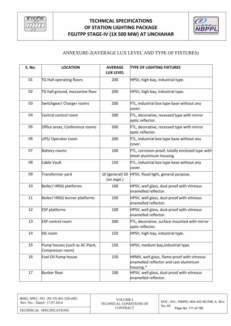
TECHNICAL SPECIFICATIONS OF STATION LIGHTING PACKAGE
FGUTPP STAGE‐IV (1X 500 MW) AT UNCHAHAR
BHEL SPEC. NO. :PE-TS-401-558-e001 Rev. No.: Dated : 17.07.2014
VOLUME:I TECHNICAL CONDITIONS OF
CONTRACT
DOC. NO.: NBPPL-004-202-06-P4E-A Rev. No.:00
TECHNICAL SPECIFICATIONS
ANNEXURE-2(AVERAGE LUX LEVEL AND TYPE OF FIXTURES) S. No. LOCATION AVERAGE
LUX LEVEL TYPE OF LIGHTING FIXTURES
01 TG Hall operating floors 200 HPSV, high bay, industrial type.
02 TG hall ground, mezzanine floor 200 HPSV, high bay, industrial type.
03 Switchgear/ Charger rooms 200 FTL, industrial box type base without any cover.
04 Central control room 300 FTL, decorative, recessed type with mirror optic reflector.
05 Office areas, Conference rooms 300 FTL, decorative, recessed type with mirror optic reflector.
06 UPS/ Operator room 200 FTL, industrial box type base without any cover.
07 Battery rooms 100 FTL, corrosion proof, totally enclosed type with sheet aluminium housing.
08 Cable Vault 150 FTL, industrial box type base without any cover.
09 Transformer yard 10 (general) 50 (on eqpt.)
HPSV, flood light, general purpose.
10 Boiler/ HRSG platforms 100 HPSV, well glass, dust proof with vitreous enamelled reflector.
11 Boiler/ HRSG burner platforms 100 HPSV, well glass, dust proof with vitreous enamelled reflector.
12 ESP platforms 100 HPSV, well glass, dust proof with vitreous enamelled reflector.
13 ESP control room 300 FTL, decorative, surface mounted with mirror optic reflector.
14 DG room 150 HPSV, high bay, industrial type.
15 Pump houses (such as AC Plant, Compressor room)
150 HPSV, medium bay,industrial type.
16 Fuel Oil Pump house 150 HPMV, well glass, flame proof with vitreous enamelled reflector and cast aluminium housing.*
17 Bunker floor 100 HPSV, well glass, dust proof with vitreous enamelled reflector.
Page No. 111 of 190
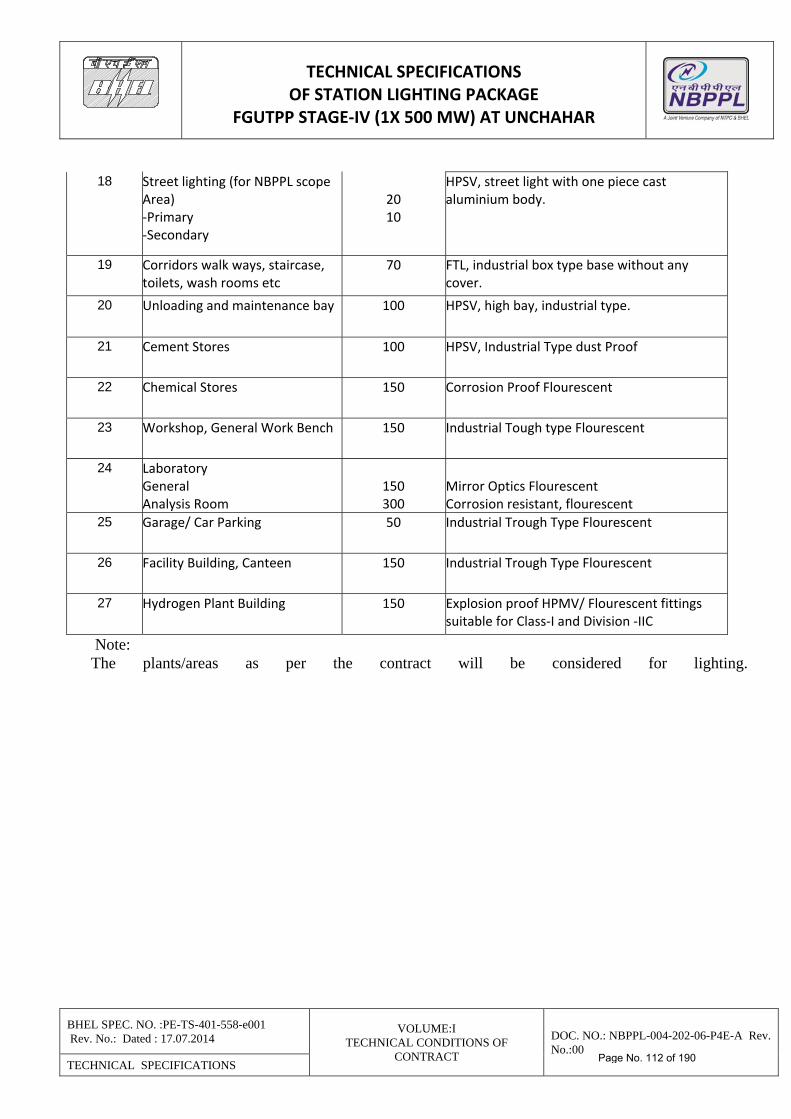
TECHNICAL SPECIFICATIONS OF STATION LIGHTING PACKAGE
FGUTPP STAGE‐IV (1X 500 MW) AT UNCHAHAR
BHEL SPEC. NO. :PE-TS-401-558-e001 Rev. No.: Dated : 17.07.2014
VOLUME:I TECHNICAL CONDITIONS OF
CONTRACT
DOC. NO.: NBPPL-004-202-06-P4E-A Rev. No.:00
TECHNICAL SPECIFICATIONS
18 Street lighting (for NBPPL scope Area) ‐Primary ‐Secondary
20 10
HPSV, street light with one piece cast aluminium body.
19 Corridors walk ways, staircase, toilets, wash rooms etc
70 FTL, industrial box type base without any cover.
20 Unloading and maintenance bay 100 HPSV, high bay, industrial type.
21 Cement Stores 100 HPSV, Industrial Type dust Proof
22 Chemical Stores 150 Corrosion Proof Flourescent
23 Workshop, General Work Bench 150 Industrial Tough type Flourescent
24 Laboratory General Analysis Room
150 300
Mirror Optics Flourescent Corrosion resistant, flourescent
25 Garage/ Car Parking 50 Industrial Trough Type Flourescent
26 Facility Building, Canteen 150 Industrial Trough Type Flourescent
27 Hydrogen Plant Building 150 Explosion proof HPMV/ Flourescent fittings suitable for Class‐I and Division ‐IIC
Note: The plants/areas as per the contract will be considered for lighting.
Page No. 112 of 190
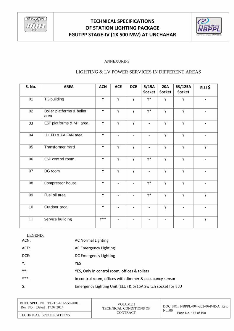
TECHNICAL SPECIFICATIONS OF STATION LIGHTING PACKAGE
FGUTPP STAGE‐IV (1X 500 MW) AT UNCHAHAR
BHEL SPEC. NO. :PE-TS-401-558-e001 Rev. No.: Dated : 17.07.2014
VOLUME:I TECHNICAL CONDITIONS OF
CONTRACT
DOC. NO.: NBPPL-004-202-06-P4E-A Rev. No.:00
TECHNICAL SPECIFICATIONS
ANNEXURE-3
LIGHTING & LV POWER SERVICES IN DIFFERENT AREAS
S. No. AREA ACN ACE DCE 5/15ASocket
20A Socket
63/125A Socket
ELU $
01 TG building Y Y Y Y* Y Y ‐
02 Boiler platforms & boiler area
Y Y Y Y* Y Y ‐
03 ESP platforms & Mill area Y Y Y ‐ Y Y ‐
04 ID, FD & PA FAN area Y ‐ ‐ ‐ Y Y ‐
05 Transformer Yard Y Y Y ‐ Y Y Y
06 ESP control room Y Y Y Y* Y Y ‐
07 DG room Y Y Y ‐ Y Y ‐
08 Compressor house Y ‐ ‐ Y* Y Y ‐
09 Fuel oil area Y ‐ ‐ Y* Y Y Y
10 Outdoor area Y ‐ ‐ ‐ Y ‐ ‐
11 Service building Y** ‐ ‐ ‐ ‐ ‐ Y
LEGEND:
ACN: AC Normal Lighting
ACE: AC Emergency Lighting
DCE: DC Emergency Lighting
Y: YES
Y*: YES, Only in control room, offices & toilets
Y**: In control room, offices with dimmer & occupancy sensor
$: Emergency Lighting Unit (ELU) & 5/15A Switch socket for ELU
Page No. 113 of 190
TECHNICAL SPECIFICATIONS OF STATION LIGHTING PACKAGE
FGUTPP STAGE‐IV (1X 500 MW) AT UNCHAHAR
BHEL SPEC. NO. :PE-TS-401-558-e001 Rev. No.: Dated : 17.07.2014
VOLUME:I TECHNICAL CONDITIONS OF
CONTRACT
DOC. NO.: NBPPL-004-202-06-P4E-A Rev. No.:00
TECHNICAL SPECIFICATIONS
Note: The plants/areas as per the contract will be considered for lighting.
ANNEXURE-4
LUMINAIRE DETAILS LUMINAIRE CODING SCHEME 1.0 Code Structure A A NN (no. x W) Number of lamps x Wattage of each lamp Classified Serial Number (Numeric) Luminaire type (Alpha) Lamp type (Alpha) 2.0 Lamp types a) F - Fluorescent b) M - Mercury Vapour c) S - Sodium Vapour d) T - Tungsten e) H - Halogen 3.0 Luminaire types a) C - Channel Mounted (Fluorescent) b) B - Bay Mounted c) W - Well Glass d) S - Street Lighting e) F - Flood Lighting f) H - Bulk Head g) P - Post Top Lantern h) E - Emergency Lighting i) X - Others 4.0 Serial Numbers a) 01 - 20 General Purpose ( Industrial) b) 21 - 40 Decorative c) 41 - 50 Vapour Proof d) 51 - 60 Dust Proof e) 61 - 70 Drip Proof f) 81 - 90 Corrosion Proof g) 91 - 99 Flame Proof
NOTES : 1. Flood lighting luminaires to have non-integral control gearbox.
Page No. 114 of 190
TECHNICAL SPECIFICATIONS OF STATION LIGHTING PACKAGE
FGUTPP STAGE‐IV (1X 500 MW) AT UNCHAHAR
BHEL SPEC. NO. :PE-TS-401-558-e001 Rev. No.: Dated : 17.07.2014
VOLUME:I TECHNICAL CONDITIONS OF
CONTRACT
DOC. NO.: NBPPL-004-202-06-P4E-A Rev. No.:00
TECHNICAL SPECIFICATIONS
2. All other luminaires shall have integral control gearbox, unless specifically mentioned
otherwise in enclosed sheets. 3. For more details of each luminaire, refer specification.
1.0 Fluorescent Lamp Luminaires 1.1 FC01 1 x 40 Fluorescent, industrial box type base without any cover. 1.2 FC02 2 x 40 Fluorescent, industrial box type base without any cover. 1.3 FC03 1 x 40 Fluorescent, industrial box type base and stove enamelled side reflectors. 1.4 FC04 2 x 40 Fluorescent, industrial box type base and stove enamelled side reflectors. 1.5 FC05 1 x 40 Fluorescent, industrial box type base and vitreous enamelled side reflectors. 1.6 FC06 2 x 40 Fluorescent, industrial box type base and vitreous enamelled side reflectors. 1.7 FC21 1 x 40 Fluorescent, decorative with 3 side perspex acrylic diffuser. 1.8 FC22 2 x 40 Fluorescent, decorative with 3 side perspex acrylic diffuser. 1.9 FC23 1 x 40 Fluorescent, decorative, recessed type with perspex acrylic diffuser. 1.10 FC24 2 x 40 Fluorescent, decorative, recessed type with perspex acrylic diffuser. 1.11 FC25 1 x 40 Fluorescent, decorative, recessed type with mirror optic reflector. 1.12 FC26 2 x 40 Fluorescent, decorative, recessed type with mirror optic reflector. 1.13 FC27 2 x 40 Fluorescent, decorative with opal polystyrene louvers. 1.14 FC28 2 x 40 Fluorescent, decorative, recessed type with opal polystyrene louvers. 1.15 FC29 2 x 40 Fluorescent, decorative with vertical metallic louvers. 1.16 FC30 4 x 20 Fluorescent, decorative, recessed type, 600 x 600 size with perspex acrylic
diffuser. 1.17 FC31 4 x 20 Fluorescent, decorative, recessed type, 600 x 600 size with opal polystyrene
louvers. 1.18 FC32 2 x 20 Fluorescent, decorative, surface mounted with mirror optic reflector. 1.19 FC41 2 x 40 Fluorescent, vapour proof with end boxes and controlgear box of cast Al.
Page No. 115 of 190
TECHNICAL SPECIFICATIONS OF STATION LIGHTING PACKAGE
FGUTPP STAGE‐IV (1X 500 MW) AT UNCHAHAR
BHEL SPEC. NO. :PE-TS-401-558-e001 Rev. No.: Dated : 17.07.2014
VOLUME:I TECHNICAL CONDITIONS OF
CONTRACT
DOC. NO.: NBPPL-004-202-06-P4E-A Rev. No.:00
TECHNICAL SPECIFICATIONS
1.20 FC51 2 x 40 Fluorescent, dust proof, totally enclosed type with sheet steel housing. 1.21 FC61 1 x 40 Fluorescent, street light with sheet aluminium canopy and ribbed acrylic cover. 1.22 FC62 2 x 40 Fluorescent, street light with sheet aluminium canopy and ribbed acrylic cover. 1.23 FC81 2 x 40 Fluorescent, corrosion proof, totally enclosed type with sheet aluminium housing. 2.0 High Pressure Mercury Vapour (HPMV) Lamp Luminaire 2.1 MB01 1 x 250 Mercury, high bay, industrial type. 2.2 MB02 1 x 400 Mercury, high bay, industrial type. 2.3 MB03 1 x 1000 Mercury, high bay, industrial type. 2.4 MB04 1 x 250 Mercury, high bay, totally enclosed industrial type. 2.5 MB05 1 x 400 Mercury, high bay, totally enclosed industrial type. 2.6 MB06 1 x 250 Mercury, high bay with non-integral controlgear box. 2.7 MB07 1 x 400 Mercury, high bay with non-integral controlgear box. 2.8 MB11 1 x 250 Mercury, medium bay, industrial type. 2.9 MB12 1 x 400 Mercury, medium bay, industrial type. 2.10 MB13 1 x 250 Mercury, medium bay, totally enclosed industrial type. 2.11 MB14 1 x 400 Mercury, medium bay, totally enclosed industrial type. 2.12 MB17 1 x 80 Mercury, low bay, industrial type. 2.13 MB18 1 x 125 Mercury, low bay, industrial type. 2.14 MB19 1 x 80 Mercury, low bay, totally enclosed industrial type. 2.15 MB20 1 x 125 Mercury, low bay, totally enclosed industrial type. 2.16 MW41 1 x 80 Mercury, well glass, vapour proof with vitreous enamelled reflector. 2.17 MW42 1 x 125 Mercury, well glass, vapour proof with vitreous enamelled reflector. 2.18 MW51 1 x 80 Mercury, well glass, dust proof with vitreous enamelled reflector. 2.19 MW52 1 x 125 Mercury, well glass, dust proof with vitreous enamelled reflector.
Page No. 116 of 190
TECHNICAL SPECIFICATIONS OF STATION LIGHTING PACKAGE
FGUTPP STAGE‐IV (1X 500 MW) AT UNCHAHAR
BHEL SPEC. NO. :PE-TS-401-558-e001 Rev. No.: Dated : 17.07.2014
VOLUME:I TECHNICAL CONDITIONS OF
CONTRACT
DOC. NO.: NBPPL-004-202-06-P4E-A Rev. No.:00
TECHNICAL SPECIFICATIONS
2.20 MW91 1 x 80 Mercury, well glass, flame proof with vitreous enamelled reflector and cast aluminium housing.
2.21 MW92 1 x 125 Mercury, well glass, flame proof with vitreous enamelled reflector
and cast aluminium housing. 2.22 MW93 1 x 80 Mercury, well glass, flame proof with vitreous enamelled reflector
and cast iron housing. 2.23 MW94 1 x 125 Mercury, well glass, flame proof with vitreous enamelled reflector
and cast iron housing. 2.24 MW95 1 x 80 Mercury, well glass, flame proof increased safety luminaire
with vitreous enamelled reflector and cast iron housing for Div.-2 areas. 2.25 MW96 1 x 125 Mercury, well glass, flame proof increased safety luminaire with vitreous
enamelled reflector and cast iron housing for Div. 2 areas. 2.25a MW98 1 x 125 Mercury, well glass, flame proof increased safety luminaire with vitreous
enamelled reflector and cast iron housing for Div. 2, Group-IIC areas. 2.26 MS61 1 x 125 Mercury, street light with one piece cast aluminium body. 2.27 MS62 1 x 250 Mercury, street light with two piece cast aluminium body. 2.28 MS63 1 x 400 Mercury, street light with two piece cast aluminium body. 2.29 MF61 1 x 250 Mercury, flood light, general purpose. 2.30 MF62 1 x 400 Mercury, flood light, heavy duty type. 2.31 MF63 2 x 400 Mercury, flood light, heavy duty type. 2.32 MP21 1 x 80 Mercury, post top lantern 2.33 MP22 1 x 125 Mercury, post top lantern 3.0 High Pressure Sodium Vapour (HPSV) Lamp Luminaire 3.1 SB01 1 x 150 Sodium, high bay, industrial type. 3.2 SB02 1 x 250 Sodium, high bay, industrial type. 3.3 SB03 1 x 400 Sodium, high bay, industrial type. 3.4 SB04 1 x 150 Sodium, high bay, totally enclosed industrial type. 3.5 SB05 1 x 250 Sodium, high bay, totally enclosed industrial type.
Page No. 117 of 190
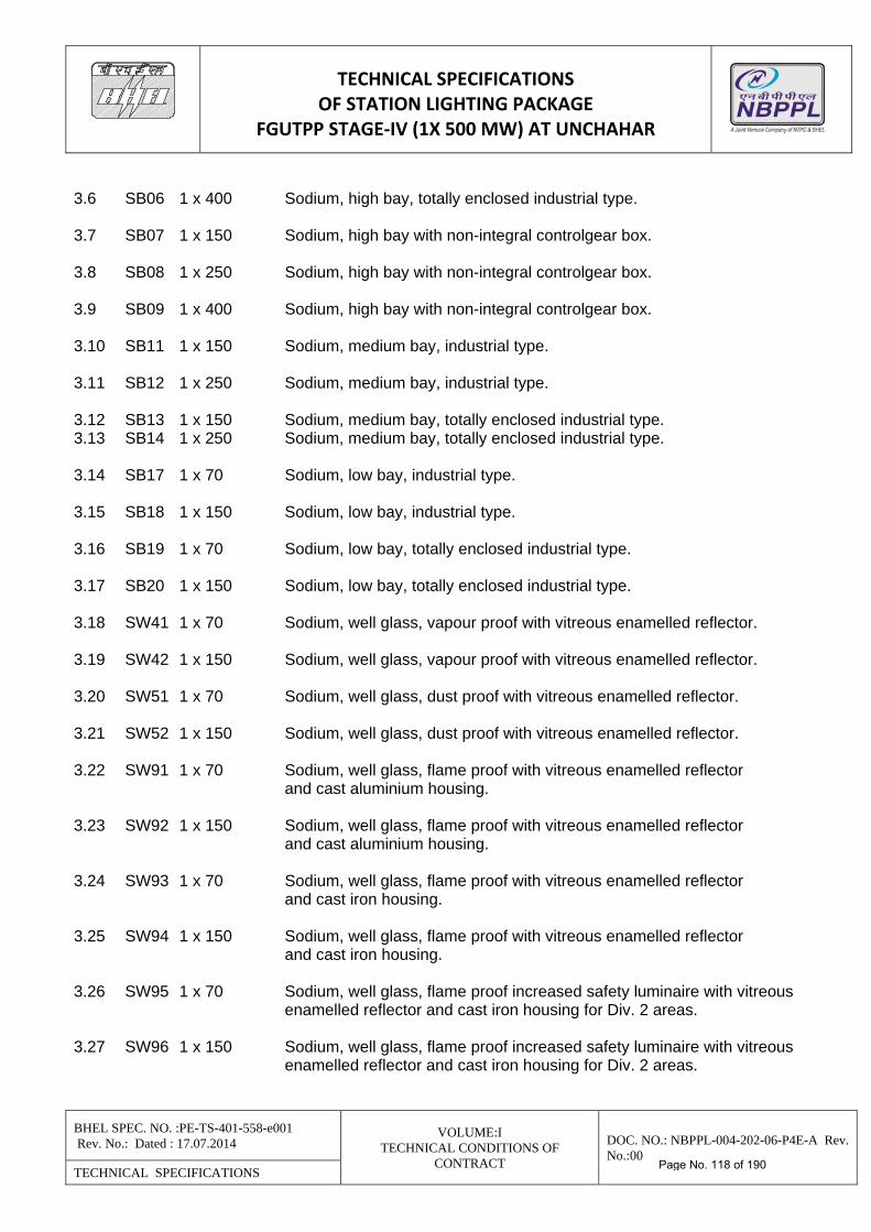
TECHNICAL SPECIFICATIONS OF STATION LIGHTING PACKAGE
FGUTPP STAGE‐IV (1X 500 MW) AT UNCHAHAR
BHEL SPEC. NO. :PE-TS-401-558-e001 Rev. No.: Dated : 17.07.2014
VOLUME:I TECHNICAL CONDITIONS OF
CONTRACT
DOC. NO.: NBPPL-004-202-06-P4E-A Rev. No.:00
TECHNICAL SPECIFICATIONS
3.6 SB06 1 x 400 Sodium, high bay, totally enclosed industrial type. 3.7 SB07 1 x 150 Sodium, high bay with non-integral controlgear box. 3.8 SB08 1 x 250 Sodium, high bay with non-integral controlgear box. 3.9 SB09 1 x 400 Sodium, high bay with non-integral controlgear box. 3.10 SB11 1 x 150 Sodium, medium bay, industrial type. 3.11 SB12 1 x 250 Sodium, medium bay, industrial type. 3.12 SB13 1 x 150 Sodium, medium bay, totally enclosed industrial type. 3.13 SB14 1 x 250 Sodium, medium bay, totally enclosed industrial type. 3.14 SB17 1 x 70 Sodium, low bay, industrial type. 3.15 SB18 1 x 150 Sodium, low bay, industrial type. 3.16 SB19 1 x 70 Sodium, low bay, totally enclosed industrial type. 3.17 SB20 1 x 150 Sodium, low bay, totally enclosed industrial type. 3.18 SW41 1 x 70 Sodium, well glass, vapour proof with vitreous enamelled reflector. 3.19 SW42 1 x 150 Sodium, well glass, vapour proof with vitreous enamelled reflector. 3.20 SW51 1 x 70 Sodium, well glass, dust proof with vitreous enamelled reflector. 3.21 SW52 1 x 150 Sodium, well glass, dust proof with vitreous enamelled reflector. 3.22 SW91 1 x 70 Sodium, well glass, flame proof with vitreous enamelled reflector
and cast aluminium housing. 3.23 SW92 1 x 150 Sodium, well glass, flame proof with vitreous enamelled reflector
and cast aluminium housing. 3.24 SW93 1 x 70 Sodium, well glass, flame proof with vitreous enamelled reflector
and cast iron housing. 3.25 SW94 1 x 150 Sodium, well glass, flame proof with vitreous enamelled reflector
and cast iron housing. 3.26 SW95 1 x 70 Sodium, well glass, flame proof increased safety luminaire with vitreous
enamelled reflector and cast iron housing for Div. 2 areas. 3.27 SW96 1 x 150 Sodium, well glass, flame proof increased safety luminaire with vitreous
enamelled reflector and cast iron housing for Div. 2 areas.
Page No. 118 of 190
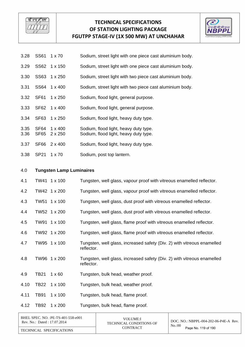
TECHNICAL SPECIFICATIONS OF STATION LIGHTING PACKAGE
FGUTPP STAGE‐IV (1X 500 MW) AT UNCHAHAR
BHEL SPEC. NO. :PE-TS-401-558-e001 Rev. No.: Dated : 17.07.2014
VOLUME:I TECHNICAL CONDITIONS OF
CONTRACT
DOC. NO.: NBPPL-004-202-06-P4E-A Rev. No.:00
TECHNICAL SPECIFICATIONS
3.28 SS61 1 x 70 Sodium, street light with one piece cast aluminium body. 3.29 SS62 1 x 150 Sodium, street light with one piece cast aluminium body. 3.30 SS63 1 x 250 Sodium, street light with two piece cast aluminium body. 3.31 SS64 1 x 400 Sodium, street light with two piece cast aluminium body. 3.32 SF61 1 x 250 Sodium, flood light, general purpose. 3.33 SF62 1 x 400 Sodium, flood light, general purpose. 3.34 SF63 1 x 250 Sodium, flood light, heavy duty type. 3.35 SF64 1 x 400 Sodium, flood light, heavy duty type. 3.36 SF65 2 x 250 Sodium, flood light, heavy duty type. 3.37 SF66 2 x 400 Sodium, flood light, heavy duty type. 3.38 SP21 1 x 70 Sodium, post top lantern. 4.0 Tungsten Lamp Luminaires 4.1 TW41 1 x 100 Tungsten, well glass, vapour proof with vitreous enamelled reflector. 4.2 TW42 1 x 200 Tungsten, well glass, vapour proof with vitreous enamelled reflector. 4.3 TW51 1 x 100 Tungsten, well glass, dust proof with vitreous enamelled reflector. 4.4 TW52 1 x 200 Tungsten, well glass, dust proof with vitreous enamelled reflector. 4.5 TW91 1 x 100 Tungsten, well glass, flame proof with vitreous enamelled reflector. 4.6 TW92 1 x 200 Tungsten, well glass, flame proof with vitreous enamelled reflector. 4.7 TW95 1 x 100 Tungsten, well glass, increased safety (Div. 2) with vitreous enamelled
reflector. 4.8 TW96 1 x 200 Tungsten, well glass, increased safety (Div. 2) with vitreous enamelled
reflector. 4.9 TB21 1 x 60 Tungsten, bulk head, weather proof. 4.10 TB22 1 x 100 Tungsten, bulk head, weather proof. 4.11 TB91 1 x 100 Tungsten, bulk head, flame proof. 4.12 TB92 1 x 200 Tungsten, bulk head, flame proof.
Page No. 119 of 190
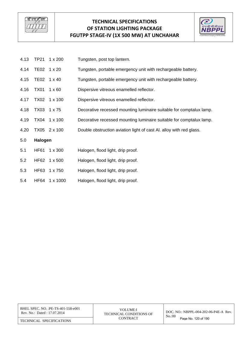
TECHNICAL SPECIFICATIONS OF STATION LIGHTING PACKAGE
FGUTPP STAGE‐IV (1X 500 MW) AT UNCHAHAR
BHEL SPEC. NO. :PE-TS-401-558-e001 Rev. No.: Dated : 17.07.2014
VOLUME:I TECHNICAL CONDITIONS OF
CONTRACT
DOC. NO.: NBPPL-004-202-06-P4E-A Rev. No.:00
TECHNICAL SPECIFICATIONS
4.13 TP21 1 x 200 Tungsten, post top lantern. 4.14 TE02 1 x 20 Tungsten, portable emergency unit with rechargeable battery. 4.15 TE02 1 x 40 Tungsten, portable emergency unit with rechargeable battery. 4.16 TX01 1 x 60 Dispersive vitreous enamelled reflector. 4.17 TX02 1 x 100 Dispersive vitreous enamelled reflector. 4.18 TX03 1 x 75 Decorative recessed mounting luminaire suitable for comptalux lamp. 4.19 TX04 1 x 100 Decorative recessed mounting luminaire suitable for comptalux lamp. 4.20 TX05 2 x 100 Double obstruction aviation light of cast Al. alloy with red glass. 5.0 Halogen 5.1 HF61 1 x 300 Halogen, flood light, drip proof. 5.2 HF62 1 x 500 Halogen, flood light, drip proof. 5.3 HF63 1 x 750 Halogen, flood light, drip proof. 5.4 HF64 1 x 1000 Halogen, flood light, drip proof.
Page No. 120 of 190
TECHNICAL SPECIFICATIONS OF STATION LIGHTING PACKAGE
FGUTPP STAGE‐IV (1X 500 MW) AT UNCHAHAR
BHEL SPEC. NO. :PE-TS-401-558-e001 Rev. No.: Dated : 17.07.2014
VOLUME:I TECHNICAL CONDITIONS OF
CONTRACT
DOC. NO.: NBPPL-004-202-06-P4E-A Rev. No.:00
TECHNICAL SPECIFICATIONS
1. ADDITIONAL TECHNICAL REQUIREMENT- INSTALLATION
1.1 SCOPE OF WORK The scope of installation work of the complete lighting and low voltage power services
equipment shall be as follows: Receipt at site, unloading, handling, unpacking, storing and preservation of all lighting
equipment specified under technical specification (Supply) of Section-C and all other materials required for completion of this package.
The above scope of LV services also include arrangement like conduiting and wiring for power supply for LIE/LIR, Propellor fans, exhaust fans, Computer UPS, etc.
1.2 Erection, testing and commissioning of complete lighting and low voltage power services for
the power station. 1.3 The contractor’s scope shall also be deemed to include all such other equipment/materials and
services required for the completeness of the job, but not listed above, as applicable and shall be quoted for accordingly.
1.4 Supply & erection of consumable like conduit accessories & fittings, conduit boxes, saddles,
clamps, flexible conduit, junction boxes, fixing hardwares, anchors, wedges, nuts & bolts, concrete inserts, materials required for mounting the fixtures, consumable and other incidental materials required to complete the installation testing & commissioning of complete lighting system for successful operation, & to the satisfaction of purchaser/ customer. Supply scope of these items shall form part of the installation rates quoted for the item.
Minor civil works Plumbing/Grouting/Foundation required to complete the lighting installation
are covered under the scope of this contract and form part of the item installation cost and are not payable separately.
1.5 Power cables from lighting distribution boards LDBs to lighting panels (LPs), LDBs to street
lighting panel, street lighting panels to poles and control cables from LDBs to remote street lighting control panel will be supplied by purchaser as free issue item to contractor, Laying & termination of these cables are to be done by the bidder.
1.6 Supply & Erection of supporting structural steel i.e. angles, channels etc. are to be quoted on
tonnage basis. During contract stage contractors has to furnish total requirement for structural steel.
1.7 All tools & tackles, ladders, testing equipment etc. required for erection, testing &
commissioning of complete lighting system are to be arranged by the contractors. 1.8 The entire work shall be carried out in accordance with specified installation instruction,
manufacturer’s recommendations, purchaser’s approved drawings and/or as directed by the purchaser. Manufacturer’ drawings and instructions shall be correctly followed in handling setting, testing and commissioning of all equipment and care shall be taken in handling to
Page No. 121 of 190
TECHNICAL SPECIFICATIONS OF STATION LIGHTING PACKAGE
FGUTPP STAGE‐IV (1X 500 MW) AT UNCHAHAR
BHEL SPEC. NO. :PE-TS-401-558-e001 Rev. No.: Dated : 17.07.2014
VOLUME:I TECHNICAL CONDITIONS OF
CONTRACT
DOC. NO.: NBPPL-004-202-06-P4E-A Rev. No.:00
TECHNICAL SPECIFICATIONS
avoid distortion to structures, marring of finished surface, damage to delicate instruments etc. The equipment shall be installed in a neat work-manship like manner.
1.9 The erection work shall conform to latest applicable Indian standards, codes and practices,
Electricity rules, fire insurance regulations and safety regulations of the locality where the equipment will be installed. All apparatus, wiring and connections shall be designed so as to minimise risk of fire or any damage which will be caused in the event of fire. Contractor to furnish the installation drawings of all equipment for purchaser’s approval.
2.0 VOID. 3.0 GUIDELINES FOR LIGHTING SYSTEM ERECTION WORK. 3.1 The contractor shall work in co-ordination with civil, air-conditioning, ventilation & switchgear
vendors. Where holes or openings in walls and floors are required for routing the conduits, the contractor shall provide the same. Cut-outs in false ceiling shall be provided by false ceiling contractor.
3.2 The contractor shall be responsible if any parts of lighting fixtures, LDBs, LPs are lost or
damaged and lamps are broken during installation. All damage and thefts shall be made good by the contractor till the installation is handed over to the customer.
3.3 The contractor shall note that for any change in the location of lighting panels, lighting fixtures,
switch boxes/receptacles, no extra charges will be paid so long as the modifications are indicated to the contractor before commencement of the work on that particular equipment or circuit.
3.4 The contractor shall have a separate cleaning gang to clean all equipment under erection as
well as the work area and the project site at regular intervals to the satisfaction of Engineer-in-charge. In case this is not done, the purchaser will have the right to carry out the cleaning operation and any expenditure incurred in this regard will be to the contractor account.
3.5 Except as specifically approved by the Engineer-in-Charge, installation of exposed conduits,
mounting of lighting fixtures, etc. shall be taken up only after other services such as piping, air ducting, cable tray/bus duct hangers, structural bracing’s etc. in a particular area have been installed
3.6 After installation of lighting fixtures/receptacles, panel number and circuit number shall be
painted on them at a suitable place 3.14 Earthing of Lighting system 3.14.1 All junction boxes, receptacles, switch boxes, lighting fixtures, conduit etc. shall be earthed in
compliance with the provision of I.E. rules and applicable Indian Standard amended upto date. 3.14.2 A continuous earth conductor of 14 SWG G.I. wire shall be run all along each conduit run and
bonded at every 600 mm by not less than two turns of the same size of wires. This conductor
Page No. 122 of 190
TECHNICAL SPECIFICATIONS OF STATION LIGHTING PACKAGE
FGUTPP STAGE‐IV (1X 500 MW) AT UNCHAHAR
BHEL SPEC. NO. :PE-TS-401-558-e001 Rev. No.: Dated : 17.07.2014
VOLUME:I TECHNICAL CONDITIONS OF
CONTRACT
DOC. NO.: NBPPL-004-202-06-P4E-A Rev. No.:00
TECHNICAL SPECIFICATIONS
shall be connected to the earth bus of lighting panel from which the conduits originate. All junction boxes, receptacles, lighting fixtures etc. shall be connected to this 14 SWG GI earth conductor. All lighting panels and LDBs shall be earthed by GI flats to the purchasers earthing bus. The supply of GI flat and erection shall be in contractor’s scope and rates of the same shall be included in the erection rates of the respective LDB/LP.
3.15 Ceiling Fans and Regulators (If Applicable) 3.15.1 The contractor shall install the ceiling fans and regulators at the locations shown in the relev-
ant drawings. The exact location will however, be decided at site in consultation with engineer-in-charge.
3.15.2 The fan regulators shall be flush mounted on the lighting control switch boxes provided in that
area. 3.15.3 Hook alongwith rubber bush shall be supplied and grouted by contractor in ceiling for mounting
the fan. All necessary material and hard wares for installation shall be supplied by contractor. 3.16 Foundation & Civil Works 3.16.1 Equipment foundations, for street lighting Poles/Flood Lighting Poles,lighting mast, street
lighting panel and other panels mounting foundation and other civil work including supply of cement, steel and other materials as per relevant drawings and specification clauses shall be provided by the contractor. Cost of foundation works , including supply of necessary material is to be quoted as part of E & C rates for these items.
3.16.2 All foundation drawings shall be subject to the purchaser’s approval. However, it shall be the
responsibility of the contractor to check these foundations before commencement of erection to ensure their suitability.
3.16.3 Al final adjustment of foundation levels, chipping and dressing of foundation surfaces, setting and grouting of anchor bolts, sills, inserts and fastening devices shall be carried out by the contractor including minor modification of civil work as may be required for erection.
3.16.4 Any cutting of masonry/concrete work, which is necessary, shall be done by the contractor at
his own cost and shall be made good to match the original work. The contractor shall obtain approval of the purchaser before proceeding with any cutting of masonry/concrete work.
3.16.5 The contractor shall perform all excavation and backfilling as required for ground connections
and casting foundations. 3.16.6 Excavation shall be performed upto the required depth. Such measures shall be taken as may
be necessary for protection of the wall. 3.16.7 The contractor shall make use of his own arrangements for pumping out any water that may be
accumulated in the excavation. 3.16.8 All excavation, supply & erection of sand bed, brick covering, etc, back filling shall be in
Bidder’s scope
Page No. 123 of 190
TECHNICAL SPECIFICATIONS OF STATION LIGHTING PACKAGE
FGUTPP STAGE‐IV (1X 500 MW) AT UNCHAHAR
BHEL SPEC. NO. :PE-TS-401-558-e001 Rev. No.: Dated : 17.07.2014
VOLUME:I TECHNICAL CONDITIONS OF
CONTRACT
DOC. NO.: NBPPL-004-202-06-P4E-A Rev. No.:00
TECHNICAL SPECIFICATIONS
3.17 Cabling work: 3.17.1 The owner will supply necessary cables required for the system as per the specification & the
bidder shall have to lay & terminate the same. This shall include all clamping, fixing, drilling, cutting, glanding, luging, connecting to terminal blocks, grounding etc. as required to complete the job. Cost of all consumable materials required for cable laying & cable termination shall be included in the erection rate to be quoted by the bidder.
3.17.2 Bidder shall supply all necessary glands & lugs required for cable termination carried out by
him. Size of glands & lugs shall be as per the size of the cables selected during detailed engg. 3.17.3 Cable glands shall be double compression type & made of tin plated heavy duty brass casting
and machine finished. Glands shall be of robust construction capable of clamping cable & cable armour firmly without injury to the cable. Thickness of tin coating shall not be less than 10 microns. All washers and hardwares shall be made of brass & tinned. Rubber components used in the glands shall be made of neoprene of tested quality.
3.17.4 Cable lugs shall be tinned copper, solderless crimping type, conforming to IS:8309 suitable for
Al or Cu conductors. Crimping of terminals shall be done by using corrosion inhibitory compound.
3.17.5 All cable entry points shall be sealed & made vermin & dust proof. Unused opening shall be
effectively closed. 3.17.6 Cables shall be laid in owner's trays wherever available. In areas, where owners trays are not
available, cable shall be clamped to the structures or laid in conduit or buried depending on the area.
3.17.7 Each cable shall be tagged with the cable no. as per cable schedule. The tag shall be of
rectangular shape & attached to the cable by not less than two turns of 20 SWG GI wire. Cable tag shall be provided at each end of the cable before entering the equipment enclosure, on both sides of wall or floor crossing and every 30 meter of cable runs.
3.17.8 Minimum bending radius for the cables shall not be less than 12D, where D is the overall dia of the cable.
3.18 Steel Fabrication 3.18.1 The steel structures supplied and fabricated by the contractor shall be made from standard
quality steel sections/flats/plates. The steel fabricated structures shall be free from defects, cleaned of rust, grease, oil etc,. and sharp edges shall be removed.
3.18.2 The welds shall be wire brushed or cleaned otherwise. The holes shall be touched up with
metal primer. 3.18.3 All steel fabrications shall be painted with two coats of metal primer (lead oxide and zinc
chromate in synthetic medium) followed by two coats of aluminium paint. The welds to galvanised steel shall be touched up with galvanised weld rod applied in accordance with manufacturer’s instruction.
Page No. 124 of 190
TECHNICAL SPECIFICATIONS OF STATION LIGHTING PACKAGE
FGUTPP STAGE‐IV (1X 500 MW) AT UNCHAHAR
BHEL SPEC. NO. :PE-TS-401-558-e001 Rev. No.: Dated : 17.07.2014
VOLUME:I TECHNICAL CONDITIONS OF
CONTRACT
DOC. NO.: NBPPL-004-202-06-P4E-A Rev. No.:00
TECHNICAL SPECIFICATIONS
3.19 Cutting & wastage allowances: 3.19.1 Contractor shall carefully plan cutting schedule of each cable drum, conduit, lighting wires, GI
wires such that wastage’s are minimised and any resultant short length can be used where appropriate route length are available. The following wastage’s allowances are permissible for various materials.
3.19.2 Power cables, and control cables, Cutting & wastage’s allowance shall be computed on the
length actually measured, used & accepted. Break up of above 3% wastage allowances are given below :
a) 1% unaccountable wastage. b) 2% accountable wastage. Note: Usable length to be returned to purchaser. Minimum wastage length is to be decided in
consultant with site engineers. 3.19.3 The contractor shall take-back the unused installation materials which has not been entered in
the measurement records by the purchaser after completion of job. 3.20 Quantity measurement: 3.20.1 For all payment purpose, measurement shall be made on physical measurements. Physical
measurements shall be made by the contractor in the presence of the site engineer/purchaser. 3.20.2 The measurement of cable laying shall be made on the basis of length actually laid from lug to
lug including that of loops provided. 3.20.3 In the measurement of conduits, the accessories will not be include GI wire / GI strip. 3.20.4 The E & C cost of of lighting wires and earthing wires shall be included in the E & C cost of
conduits. No separate cost of erection of lighting wires and earthing wires shall be paid. 3.20.5 The accountable wastage to be returned to purchaser’s store in good condition and as directed
by site engineer. 3.20.6 Any wastage granted by the vendor in excess of the allowable percentage shall be charged at
the panel rates decided by the site engineer whose decision shall be final and binding on the vendor.
3.21 Contractor to make a protocol in consultation with site engineer and customer’s representative
for erection, testing & commissioning of all lighting equipment. 4.0 TESTING & INSPECTION AT CONTRACTOR’S WORKS 4.1 Standard quality plan (QP) for lighting equipment is enclosed. Bidder to confirm compliance to
this QP by signing every page of it.
Page No. 125 of 190
TECHNICAL SPECIFICATIONS OF STATION LIGHTING PACKAGE
FGUTPP STAGE‐IV (1X 500 MW) AT UNCHAHAR
BHEL SPEC. NO. :PE-TS-401-558-e001 Rev. No.: Dated : 17.07.2014
VOLUME:I TECHNICAL CONDITIONS OF
CONTRACT
DOC. NO.: NBPPL-004-202-06-P4E-A Rev. No.:00
TECHNICAL SPECIFICATIONS
4.2 All accessories shall be subject to routine and type tests in accordance with requirement of appropriate IS in the presence of purchaser’s representative.
4.3 Samples selected by the purchaser of all galvanising material shall be subjected to galvanising
tests. All fittings, fabrications, hardwares etc. as specified shall be inspected & tested in accordance with IS recommendation. Type test certificates from National Test House or from reputed agency shall be considered.
4.4 Field quality plan for quality checks to be observed at site during erection, testing & commis-
sioning shall also be furnished by contractor alongwith offers as per standard format. 4.5 Testing and commissioning 4.5.1 On completion of erection work, the contractor shall request the site engineer for inspection
and test. 4.5.2 The site engineer shall arrange for joint inspection of the installation by purchaser’s and
customers representative for completeness and correctness of the work. Any defect pointed out during such inspection shall be promptly rectified by the contractor.
4.5.3 The installation shall be then tested and commissioned in presence of the site Engineer &
customer’s representative 4.5.4 The contractor shall provide all men, material and equipment required to carry out the tests. 4.5.5 All rectification’s, repairs or adjustment work found necessary during inspection, testing and
commissioning shall be carried out by the contractor without nay extra cost. The handing over of the lighting installation shall be effected only after the receipt of written instruction from the site engineers/ customer.
4.5.6 The testing shall be done in accordance with the applicable Indian standards and codes of
practice. The following tests shall be specifically carried out for all lighting installation. i. Insulation resistance ii. Testing of earth continuity path iii Polarity test of single phase switches. 4.5.7 The lighting circuits shall be tested in the following manner.
i. All switches ON and consuming devices in circuit, both poles connected together, to obtain resistance to earth.
ii. Insulation resistance between poles with lamps and other consuming devices removed and
switches ON 5.0 DRAWINGS/ DOCUMENTS REFER VARIOUS CLAUSES OF ELSEWHERE
Page No. 126 of 190
TECHNICAL SPECIFICATIONS OF STATION LIGHTING PACKAGE
FGUTPP STAGE‐IV (1X 500 MW) AT UNCHAHAR
BHEL SPEC. NO. :PE-TS-401-558-e001 Rev. No.: Dated : 17.07.2014
VOLUME:I TECHNICAL CONDITIONS OF
CONTRACT
DOC. NO.: NBPPL-004-202-06-P4E-A Rev. No.:00
TECHNICAL SPECIFICATIONS
VOLUME-II
Page No. 127 of 190
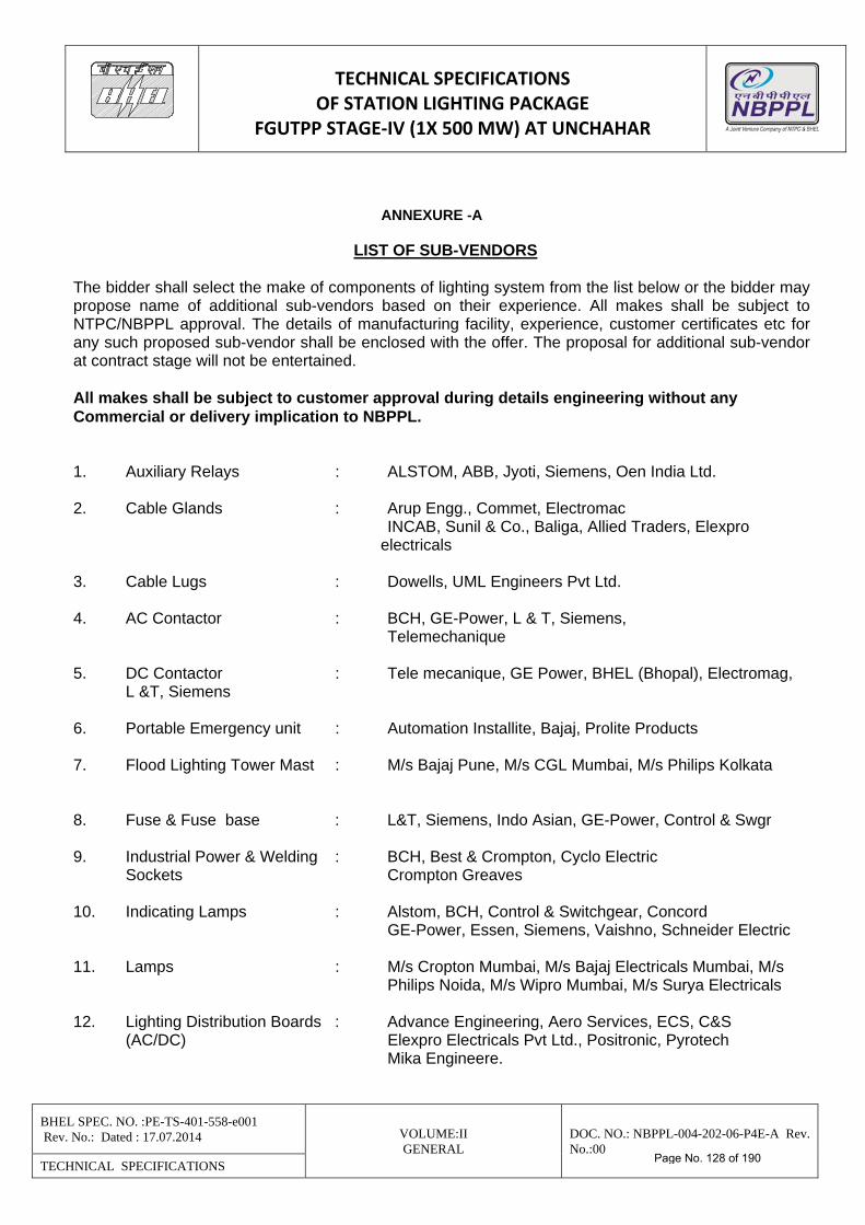
TECHNICAL SPECIFICATIONS OF STATION LIGHTING PACKAGE
FGUTPP STAGE‐IV (1X 500 MW) AT UNCHAHAR
BHEL SPEC. NO. :PE-TS-401-558-e001 Rev. No.: Dated : 17.07.2014 VOLUME:II
GENERAL DOC. NO.: NBPPL-004-202-06-P4E-A Rev. No.:00
TECHNICAL SPECIFICATIONS
ANNEXURE -A
LIST OF SUB-VENDORS
The bidder shall select the make of components of lighting system from the list below or the bidder may propose name of additional sub-vendors based on their experience. All makes shall be subject to NTPC/NBPPL approval. The details of manufacturing facility, experience, customer certificates etc for any such proposed sub-vendor shall be enclosed with the offer. The proposal for additional sub-vendor at contract stage will not be entertained. All makes shall be subject to customer approval during details engineering without any Commercial or delivery implication to NBPPL. 1. Auxiliary Relays : ALSTOM, ABB, Jyoti, Siemens, Oen India Ltd. 2. Cable Glands : Arup Engg., Commet, Electromac INCAB, Sunil & Co., Baliga, Allied Traders, Elexpro electricals 3. Cable Lugs : Dowells, UML Engineers Pvt Ltd. 4. AC Contactor : BCH, GE-Power, L & T, Siemens, Telemechanique 5. DC Contactor : Tele mecanique, GE Power, BHEL (Bhopal), Electromag,
L &T, Siemens 6. Portable Emergency unit : Automation Installite, Bajaj, Prolite Products 7. Flood Lighting Tower Mast : M/s Bajaj Pune, M/s CGL Mumbai, M/s Philips Kolkata 8. Fuse & Fuse base : L&T, Siemens, Indo Asian, GE-Power, Control & Swgr 9. Industrial Power & Welding : BCH, Best & Crompton, Cyclo Electric Sockets Crompton Greaves 10. Indicating Lamps : Alstom, BCH, Control & Switchgear, Concord GE-Power, Essen, Siemens, Vaishno, Schneider Electric 11. Lamps : M/s Cropton Mumbai, M/s Bajaj Electricals Mumbai, M/s Philips Noida, M/s Wipro Mumbai, M/s Surya Electricals 12. Lighting Distribution Boards : Advance Engineering, Aero Services, ECS, C&S (AC/DC) Elexpro Electricals Pvt Ltd., Positronic, Pyrotech Mika Engineere.
Page No. 128 of 190
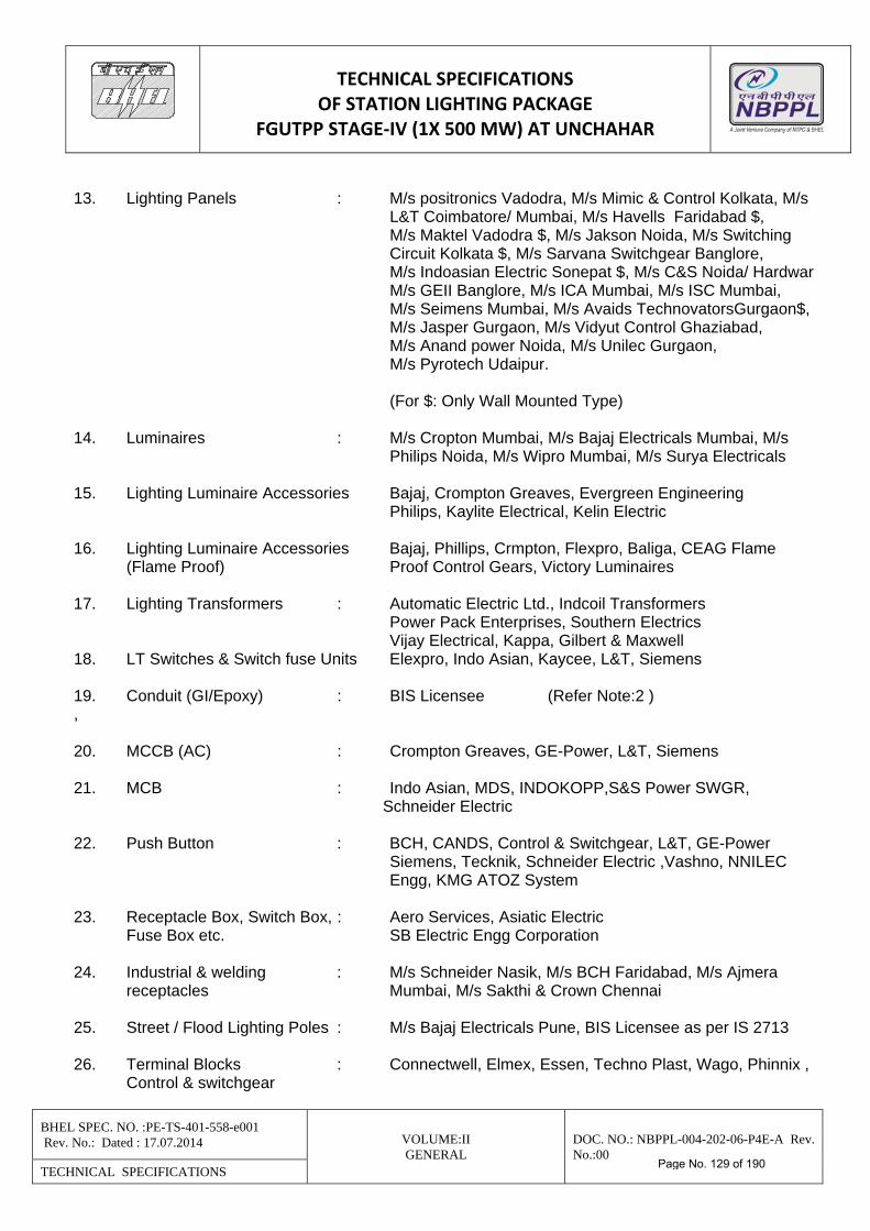
TECHNICAL SPECIFICATIONS OF STATION LIGHTING PACKAGE
FGUTPP STAGE‐IV (1X 500 MW) AT UNCHAHAR
BHEL SPEC. NO. :PE-TS-401-558-e001 Rev. No.: Dated : 17.07.2014 VOLUME:II
GENERAL DOC. NO.: NBPPL-004-202-06-P4E-A Rev. No.:00
TECHNICAL SPECIFICATIONS
13. Lighting Panels : M/s positronics Vadodra, M/s Mimic & Control Kolkata, M/s L&T Coimbatore/ Mumbai, M/s Havells Faridabad $, M/s Maktel Vadodra $, M/s Jakson Noida, M/s Switching Circuit Kolkata $, M/s Sarvana Switchgear Banglore, M/s Indoasian Electric Sonepat $, M/s C&S Noida/ Hardwar M/s GEII Banglore, M/s ICA Mumbai, M/s ISC Mumbai, M/s Seimens Mumbai, M/s Avaids TechnovatorsGurgaon$, M/s Jasper Gurgaon, M/s Vidyut Control Ghaziabad, M/s Anand power Noida, M/s Unilec Gurgaon, M/s Pyrotech Udaipur. (For $: Only Wall Mounted Type) 14. Luminaires : M/s Cropton Mumbai, M/s Bajaj Electricals Mumbai, M/s Philips Noida, M/s Wipro Mumbai, M/s Surya Electricals 15. Lighting Luminaire Accessories Bajaj, Crompton Greaves, Evergreen Engineering Philips, Kaylite Electrical, Kelin Electric 16. Lighting Luminaire Accessories Bajaj, Phillips, Crmpton, Flexpro, Baliga, CEAG Flame (Flame Proof) Proof Control Gears, Victory Luminaires 17. Lighting Transformers : Automatic Electric Ltd., Indcoil Transformers Power Pack Enterprises, Southern Electrics Vijay Electrical, Kappa, Gilbert & Maxwell 18. LT Switches & Switch fuse Units Elexpro, Indo Asian, Kaycee, L&T, Siemens 19. Conduit (GI/Epoxy) : BIS Licensee (Refer Note:2 ) , 20. MCCB (AC) : Crompton Greaves, GE-Power, L&T, Siemens 21. MCB : Indo Asian, MDS, INDOKOPP,S&S Power SWGR, Schneider Electric 22. Push Button : BCH, CANDS, Control & Switchgear, L&T, GE-Power Siemens, Tecknik, Schneider Electric ,Vashno, NNILEC
Engg, KMG ATOZ System 23. Receptacle Box, Switch Box, : Aero Services, Asiatic Electric Fuse Box etc. SB Electric Engg Corporation 24. Industrial & welding : M/s Schneider Nasik, M/s BCH Faridabad, M/s Ajmera receptacles Mumbai, M/s Sakthi & Crown Chennai 25. Street / Flood Lighting Poles : M/s Bajaj Electricals Pune, BIS Licensee as per IS 2713 26. Terminal Blocks : Connectwell, Elmex, Essen, Techno Plast, Wago, Phinnix ,
Control & switchgear
Page No. 129 of 190
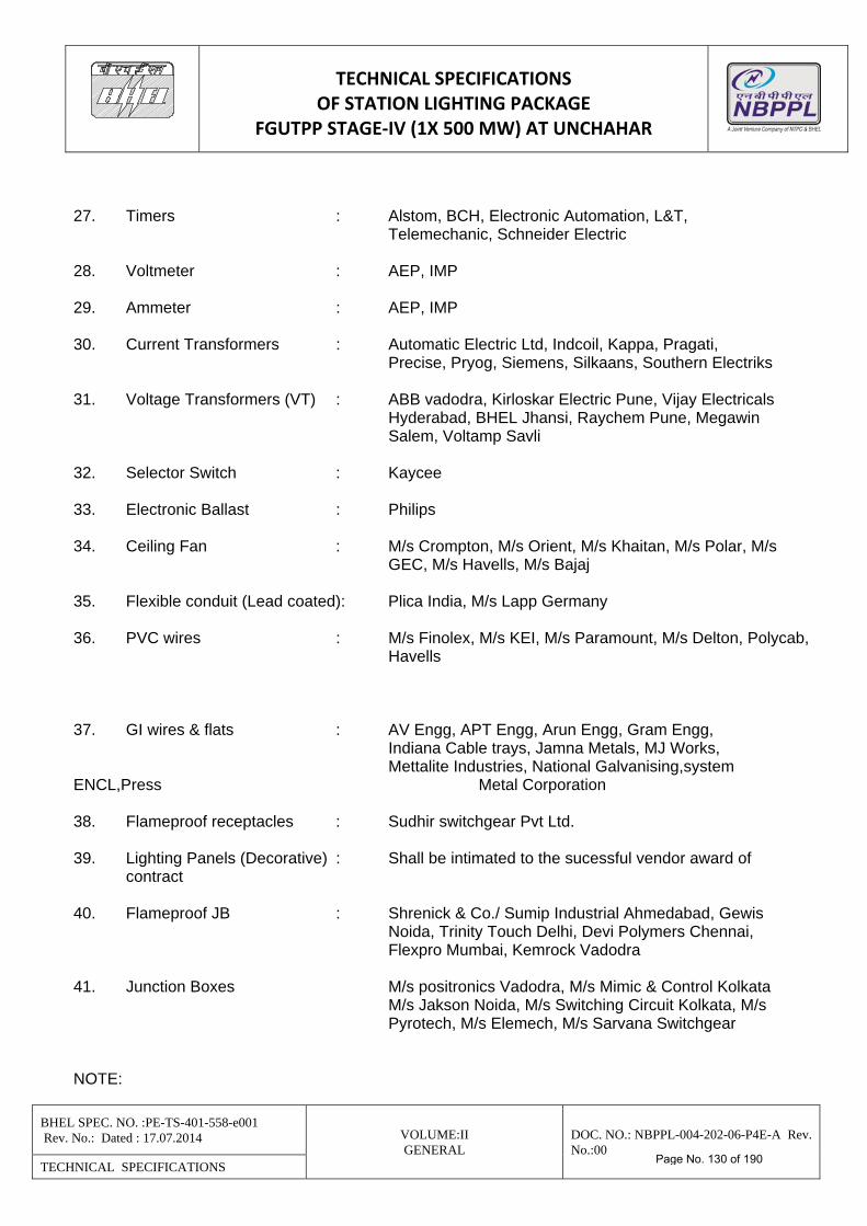
TECHNICAL SPECIFICATIONS OF STATION LIGHTING PACKAGE
FGUTPP STAGE‐IV (1X 500 MW) AT UNCHAHAR
BHEL SPEC. NO. :PE-TS-401-558-e001 Rev. No.: Dated : 17.07.2014 VOLUME:II
GENERAL DOC. NO.: NBPPL-004-202-06-P4E-A Rev. No.:00
TECHNICAL SPECIFICATIONS
27. Timers : Alstom, BCH, Electronic Automation, L&T, Telemechanic, Schneider Electric 28. Voltmeter : AEP, IMP 29. Ammeter : AEP, IMP 30. Current Transformers : Automatic Electric Ltd, Indcoil, Kappa, Pragati, Precise, Pryog, Siemens, Silkaans, Southern Electriks 31. Voltage Transformers (VT) : ABB vadodra, Kirloskar Electric Pune, Vijay Electricals Hyderabad, BHEL Jhansi, Raychem Pune, Megawin Salem, Voltamp Savli 32. Selector Switch : Kaycee 33. Electronic Ballast : Philips 34. Ceiling Fan : M/s Crompton, M/s Orient, M/s Khaitan, M/s Polar, M/s GEC, M/s Havells, M/s Bajaj 35. Flexible conduit (Lead coated): Plica India, M/s Lapp Germany 36. PVC wires : M/s Finolex, M/s KEI, M/s Paramount, M/s Delton, Polycab, Havells 37. GI wires & flats : AV Engg, APT Engg, Arun Engg, Gram Engg, Indiana Cable trays, Jamna Metals, MJ Works, Mettalite Industries, National Galvanising,system ENCL,Press Metal Corporation 38. Flameproof receptacles : Sudhir switchgear Pvt Ltd. 39. Lighting Panels (Decorative) : Shall be intimated to the sucessful vendor award of
contract 40. Flameproof JB : Shrenick & Co./ Sumip Industrial Ahmedabad, Gewis Noida, Trinity Touch Delhi, Devi Polymers Chennai, Flexpro Mumbai, Kemrock Vadodra 41. Junction Boxes M/s positronics Vadodra, M/s Mimic & Control Kolkata M/s Jakson Noida, M/s Switching Circuit Kolkata, M/s Pyrotech, M/s Elemech, M/s Sarvana Switchgear
NOTE:
Page No. 130 of 190
TECHNICAL SPECIFICATIONS OF STATION LIGHTING PACKAGE
FGUTPP STAGE‐IV (1X 500 MW) AT UNCHAHAR
BHEL SPEC. NO. :PE-TS-401-558-e001 Rev. No.: Dated : 17.07.2014 VOLUME:II
GENERAL DOC. NO.: NBPPL-004-202-06-P4E-A Rev. No.:00
TECHNICAL SPECIFICATIONS
1. Main Contractor will ensure that a copy of Valid BIS licence of the manufacturer for the particular
item is enclosed along with inspection call/ COC issued by Main contractor for NBPPL information & record.
Page No. 131 of 190
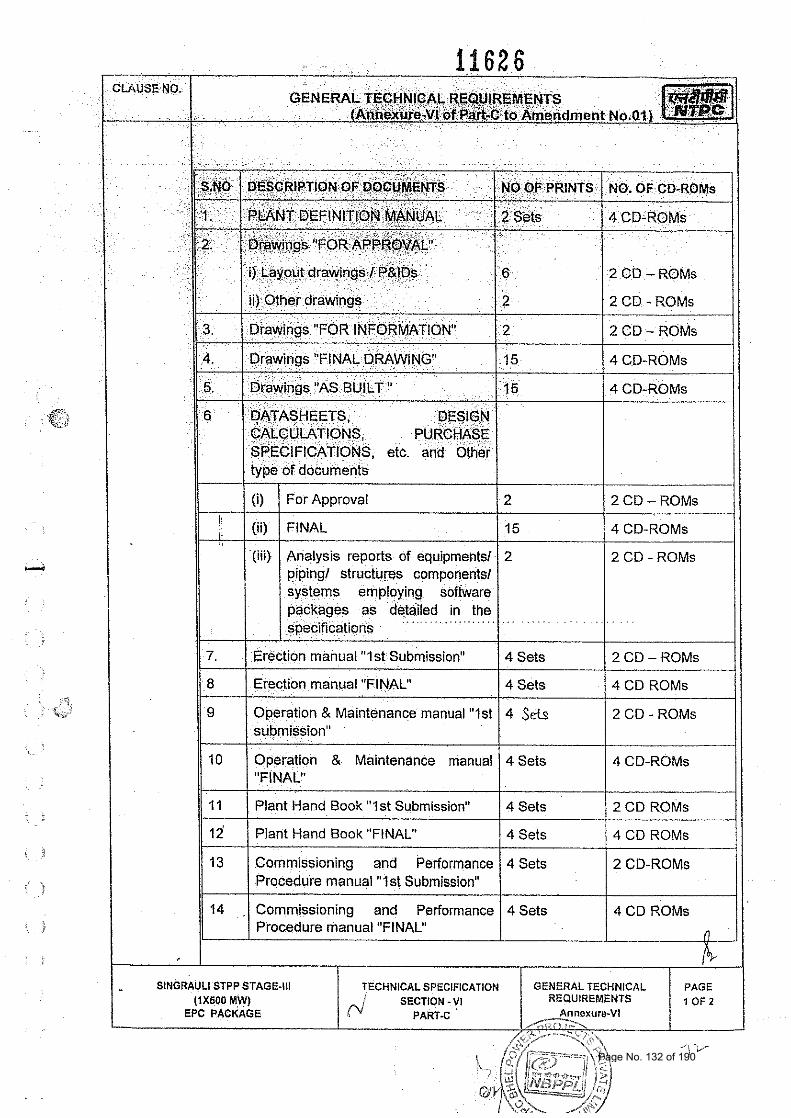
, (i) For Approval 2 2 CD - ROMs
/ (ii) FINAL 15
- 4 CD-ROMs
(iiif Analysis reports of equiprnentsl 2 2 CD - ROMs piping1 structures components1 systems employing software packages as detailed in the specifications
7. Erect~on manual "1st Submission" 4 Sets 2 CD - ROMs
8 Erection manual "FINAL" 4 Sets 4 CD ROMs
9 Operation & Maintenance manual "?st 4 Sets 2 CD - ROMs submission"
10 Operation & Maintenance manual 4 Sets 4 CD-ROMs "FINAL"
11 Plant Hand Book "1st Submission" 4 Sets 2 CD ROMs
12 Plant Hand Book "FINAL" 4 Sets 4 CD ROMs
13 Commissioning and Performance 4 Sets 2 CD-ROMs Procedure manual "1st Submission"
14 Commissioning and Performance 4 Sets 4 CD ROMs Procedure manual "FINAL" A
- SlNGRAULl STPP STAGE-111 TECHNICAL SPECIFICATION GENERAL TECHNICAL PAGE (1x600 M:W) SECTION - VI REQUIREMENTS $ O F 2
EPC PACKAGE PARS< Annsxure-VI
Page No. 132 of 190
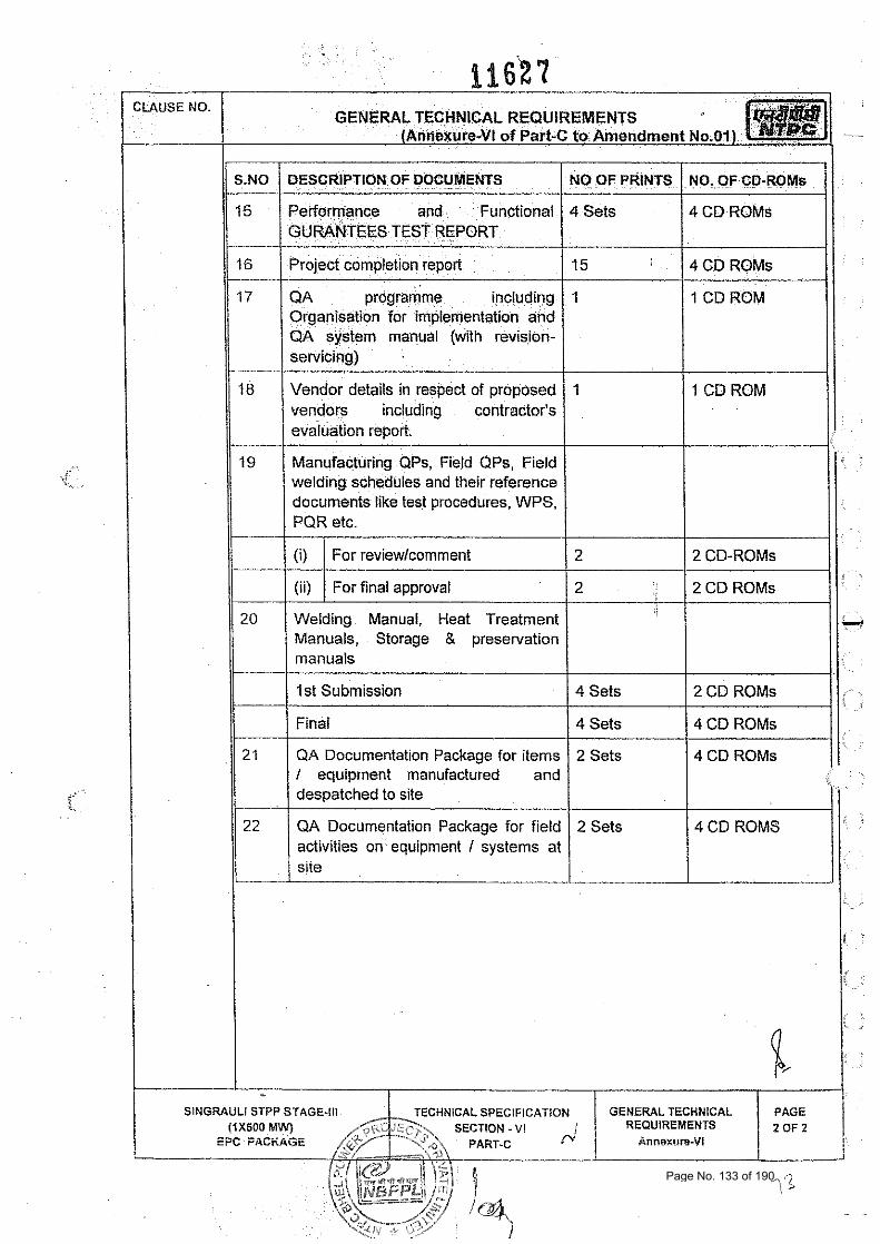
11 S.NO / DESCRIPTION OF DOCUMENTS I NO OF PRINTS I NO. OF CD-ROMs 1 1 Performance and Functional
TEST REPORT
16 -
17
'18
19
-.
4 Sets
20
SINGRAULI STPP STAGE-Ill CHNICAL SPECIFICATION GENERAL TECHNICAL REQUIREMENTS
.~ .
4 CD ROMs
Welding Manual, Heat Treatment Manuals, Storage & preservation manuals
21
-- 22
Project completion report.
QA programme including Organisation for implementation and QA system manual (with revision- servicing)
Vendor details in respect of proposed vendors including contractor's evaluation report.
Manufacturing QPs, Field QPs, Field welding schedules and their reference documents like test procedures. WPS, PQR etc.
15
1
1
2
2
(I)
(ii)
1st Submission
Finai
ai\ Documentation Package for items I equipment manufactured and despatched to s~te
QA Documentation Package for field activities on equipment I systems at slie
4 CD ROMs
1 CD ROM
1 CD ROM
2 CD-ROMs
2 CD ROMs
For reviewlcomment
For final approval
4 Sets
4 Sets
2 Sets
2 Sets
2 CD ROMs
4 CD ROMs
4 CD ROMs
4 CD ROMS
Page No. 133 of 190
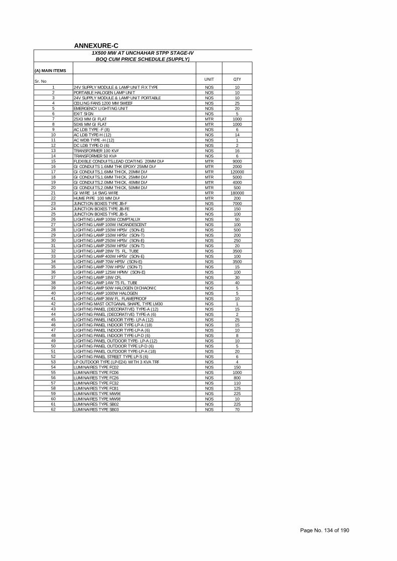
(A) MAIN ITEMS
Sr. No UNIT QTY
1 24V SUPPLY MODULE & LAMP UNIT FIX TYPE NOS 102 PORTABLE HALOGEN LAMP UNIT NOS 103 24V SUPPLY MODULE & LAMP UNIT PORTABLE NOS 104 CEILING FANS 1200 MM SWEEP NOS 255 EMERGENCY LIGHTING UNIT NOS 206 EXIT SIGN NOS 57 25X3 MM GI FLAT MTR 10008 50X6 MM GI FLAT MTR 10009 AC LDB TYPE -F (8) NOS 6
10 AC LDB TYPE-H (12) NOS 1411 AC WDB TYPE -H (12) NOS 112 DC LDB TYPE-D (6) NOS 213 TRANSFORMER 100 KVA NOS 1614 TRANSFORMER 50 KVA NOS 615 FLEXIBLE CONDUITS,LEAD COATING 20MM DIA MTR 900016 GI CONDUITS 1.6MM THK EPOXY 25MM DIA MTR 200017 GI CONDUITS,1.6MM THICK, 20MM DIA MTR 12000018 GI CONDUITS,1.6MM THICK, 25MM DIA MTR 500019 GI CONDUITS,2.0MM THICK, 40MM DIA MTR 400020 GI CONDUITS,2.0MM THICK, 50MM DIA MTR 50021 GI WIRE 14 SWG WIRE MTR 18000022 HUME PIPE 100 MM DIA MTR 20023 JUNCTION BOXES TYPE JB-F NOS 700024 JUNCTION BOXES TYPE JB-FE NOS 15025 JUNCTION BOXES TYPE JB-S NOS 10026 LIGHTING LAMP 100W COMPTALUX NOS 5027 LIGHTING LAMP 100W INCANDESCENT NOS 10028 LIGHTING LAMP 150W HPSV (SON-E) NOS 50029 LIGHTING LAMP 150W HPSV (SON-T) NOS 20030 LIGHTING LAMP 250W HPSV (SON-E) NOS 25031 LIGHTING LAMP 250W HPSV (SON-T) NOS 2032 LIGHTING LAMP 28W T5 FL. TUBE NOS 350033 LIGHTING LAMP 400W HPSV (SON-E) NOS 10034 LIGHTING LAMP 70W HPSV (SON-E) NOS 350035 LIGHTING LAMP 70W HPSV (SON-T) NOS 1536 LIGHTING LAMP 125W HPMV (SON-E) NOS 10037 LIGHTING LAMP 18W CFL NOS 3038 LIGHTING LAMP 14W T5 FL. TUBE NOS 4039 LIGHTING LAMP 50W HALOGEN DICHAONIC NOS 540 LIGHTING LAMP 1000W HALOGEN NOS 541 LIGHTING LAMP 36W FL. FLAMEPROOF NOS 1042 LIGHTING MAST OCTGANAL SHAPE, TYPE LM30 NOS 143 LIGHTING PANEL (DECORATIVE) TYPE-A (12) NOS 1544 LIGHTING PANEL (DECORATIVE) TYPE-A (6) NOS 245 LIGHTING PANEL INDOOR TYPE- LP-A (12) NOS 2546 LIGHTING PANEL INDOOR TYPE-LP-A (18) NOS 1547 LIGHTING PANEL INDOOR TYPE-LP-A (6) NOS 1048 LIGHTING PANEL INDOOR TYPE-LP-D (6) NOS 849 LIGHTING PANEL OUTDOOR TYPE- LP-A (12) NOS 1050 LIGHTING PANEL OUTDOOR TYPE LP-D (6) NOS 551 LIGHTING PANEL OUTDOOR TYPE-LP-A (18) NOS 2052 LIGHTING PANEL STREET TYPE LP-S (6) NOS 653 LP OUTDOOR TYPE (LP-E24) WITH 3 KVA TRF NOS 454 LUMINAIRES TYPE FC02 NOS 15055 LUMINAIRES TYPE FC06 NOS 100056 LUMINAIRES TYPE FC26 NOS 80057 LUMINAIRES TYPE FC32 NOS 11058 LUMINAIRES TYPE FC81 NOS 12559 LUMINAIRES TYPE MW96 NOS 22560 LUMINAIRES TYPE MW98 NOS 1061 LUMINAIRES TYPE SB02 NOS 22562 LUMINAIRES TYPE SB03 NOS 70
ANNEXURE-C1X500 MW AT UNCHAHAR STPP STAGE-IV
BOQ CUM PRICE SCHEDULE (SUPPLY)
Page No. 134 of 190
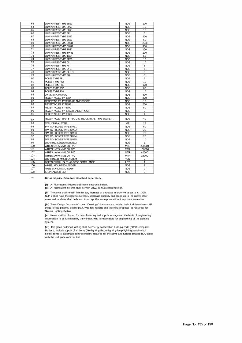
63 LUMINAIRES TYPE SB11 NOS 10064 LUMINAIRES TYPE SF63 NOS 1065 LUMINAIRES TYPE SF66 NOS 1066 LUMINAIRES TYPE SF1 NOS 567 LUMINAIRES TYPE SS62 NOS 20068 LUMINAIRES TYPE SS63 NOS 5069 LUMINAIRES TYPE SW41 NOS 350070 LUMINAIRES TYPE SW42 NOS 35071 LUMINAIRES TYPE TB22 NOS 10072 LUMINAIRES TYPE TW41 NOS 10073 LUMINAIRES TYPE TX04 NOS 5074 LUMINAIRES TYPE FR2S NOS 1075 LUMINAIRES TYPE CLI NOS 1076 LUMINAIRES TYPE HF NOS 577 LUMINAIRES TYPE DH1 NOS 578 LUMINAIRES TYPE CL1-D NOS 579 LUMINAIRES TYPE FH NOS 580 POLES TYPE PF1 NOS 581 POLES TYPE PF2 NOS 1082 POLES TYPE PS1 NOS 12083 POLES TYPE PS2 NOS 8084 POLES TYPE PS4 NOS 1085 20 MM DIA MS ROD NOS 30086 RECEPTACLES TYPE RA NOS 22087 RECEPTACLES TYPE RA (FLAME PROOF) NOS 1588 RECEPTACLES TYPE RB NOS 20089 RECEPTACLES TYPE RC NOS 5090 RECEPTACLES TYPE RC (FLAME PROOF) NOS 291 RECEPTACLES TYPE RD NOS 4
92 RECEPTACLE TYPE RF (5A, 24V INDUSTRIAL TYPE SOCKET ) NOS 40
93 STRUCTURAL STEEL MT 2594 SWITCH BOXES TYPE SWB1 NOS 6095 SWITCH BOXES TYPE SWB2 NOS 2096 SWITCH BOXES TYPE SWB3 NOS 7097 SWITCH BOXES TYPE SWB4 NOS 2098 SWITCH BOXES TYPE SWB5 NOS 1099 LIGHTING SENSOR SYSTEM NOS 5100 WIRES 1X1.5 MM2 CU PVC MTR 200000101 WIRES 1X2.5 MM2 CU PVC MTR 100000102 WIRES 1X4.0 MM2 CU PVC MTR 40000103 WIRES 1X6.0 MM2 CU PVC MTR 15000104 LIGHTING DIMMER SYSTEM NOS. 2105 GREEN BLDG LIGHTING-ECBC COMPLIANCE LOT 1106 WHEEL MOUNTED LADDER NOS 1107 FREE STANDING LADDER NOS 2108 STEP LADDER-SL2 NOS 2
** Detailed price Schedule attached saperately.
(i) All Fluorescent fixtures shall have electronic ballast.(ii) All fluorescent fixtures shall be with 28W, T5 fluorescent fittings.
(iii) The price shall remain firm for any increase or decrease in order value up to +/- 30%. NBPPL shall have the right to increase / decrease quantity and scope up to the above order value and tenderer shall be bound to accept the same price without any price escalation
(iv) 'Basic Design Documents' cover: Drawings/ documents schedule, technical data sheets, GA dwgs. of equipments, quality plan, type test reports and type test proposal (as required) for Station Lighting System.
(v) Items shall be cleared for manufacturing and supply in stages on the basis of engineering information to be furnished by the vendor, who is responsible for engineering of the Lighting system.
(vi) For green building Lighting shall be Energy consevation building code (ECBC) compliant. Bidder to include supply of all items (like lighting fixture,lighting lamp,lighting panel,switch boxes, sensors, automatic control system) required for the same and furnish detailed BOQ along with the unit price with the bid.
Page No. 135 of 190
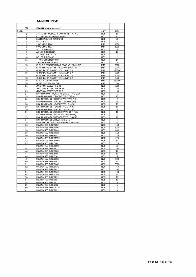
(B)
Sr. No UNIT QTY1 24V SUPPLY MODULE & LAMP UNIT FIX TYPE NOS 102 CEILING FANS 1200 MM SWEEP NOS 253 EMERGENCY LIGHTING UNIT NOS 204 EXIT SIGN NOS 55 25X3 MM GI FLAT MTR 10006 50X6 MM GI FLAT MTR 10007 AC LDB TYPE -F (8) NOS 58 AC LDB TYPE-H (12) NOS 139 AC WDB TYPE -H (12) NOS 110 DC LDB TYPE-D (6) NOS 211 TRANSFORMER 100 KVA NOS 1412 TRANSFORMER 50 KVA NOS 513 FLEXIBLE CONDUITS,LEAD COATING 20MM DIA MTR 900014 GI CONDUITS 1.6MM THK EPOXY 25MM DIA MTR 200015 GI CONDUITS,1.6MM THICK, 20MM DIA MTR 12000016 GI CONDUITS,1.6MM THICK, 25MM DIA MTR 500017 GI CONDUITS,2.0MM THICK, 40MM DIA MTR 400018 GI CONDUITS,2.0MM THICK, 50MM DIA MTR 50019 GI WIRE 14 SWG WIRE MTR 18000020 HUME PIPE 100 MM DIA MTR 20021 JUNCTION BOXES TYPE JB-F NOS 700022 JUNCTION BOXES TYPE JB-FE NOS 15023 JUNCTION BOXES TYPE JB-S NOS 10024 LIGHTING MAST OCTGANAL SHAPE, TYPE LM30 NOS 125 LIGHTING PANEL (DECORATIVE) TYPE-A (12) NOS 1526 LIGHTING PANEL (DECORATIVE) TYPE-A (6) NOS 227 LIGHTING PANEL INDOOR TYPE- LP-A (12) NOS 2528 LIGHTING PANEL INDOOR TYPE-LP-A (18) NOS 1529 LIGHTING PANEL INDOOR TYPE-LP-A (6) NOS 1030 LIGHTING PANEL INDOOR TYPE-LP-D (6) NOS 831 LIGHTING PANEL OUTDOOR TYPE- LP-A (12) NOS 1032 LIGHTING PANEL OUTDOOR TYPE LP-D (6) NOS 533 LIGHTING PANEL OUTDOOR TYPE-LP-A (18) NOS 2034 LIGHTING PANEL STREET TYPE LP-S (6) NOS 635 LP OUTDOOR TYPE (LP-E24) WITH 3 KVA TRF NOS 436 LUMINAIRES TYPE FC02 NOS 15037 LUMINAIRES TYPE FC06 NOS 100038 LUMINAIRES TYPE FC26 NOS 80039 LUMINAIRES TYPE FC32 NOS 11040 LUMINAIRES TYPE FC81 NOS 12541 LUMINAIRES TYPE MW96 NOS 22542 LUMINAIRES TYPE MW98 NOS 1043 LUMINAIRES TYPE SB02 NOS 22544 LUMINAIRES TYPE SB03 NOS 7045 LUMINAIRES TYPE SB11 NOS 10046 LUMINAIRES TYPE SF63 NOS 1047 LUMINAIRES TYPE SF66 NOS 1048 LUMINAIRES TYPE SS61 NOS 549 LUMINAIRES TYPE SS62 NOS 20050 LUMINAIRES TYPE SS63 NOS 5051 LUMINAIRES TYPE SW41 NOS 350052 LUMINAIRES TYPE SW42 NOS 35053 LUMINAIRES TYPE TB22 NOS 10054 LUMINAIRES TYPE TW41 NOS 10055 LUMINAIRES TYPE TX04 NOS 5056 LUMINAIRES TYPE FR2S NOS 1057 LUMINAIRES TYPE CLI NOS 1058 LUMINAIRES TYPE HF NOS 559 LUMINAIRES TYPE DH1 NOS 560 LUMINAIRES TYPE CL1-D NOS 561 LUMINAIRES TYPE FH NOS 5
E&C ITEMS ( Annexure-D )
ANNEXURE-D
Page No. 136 of 190
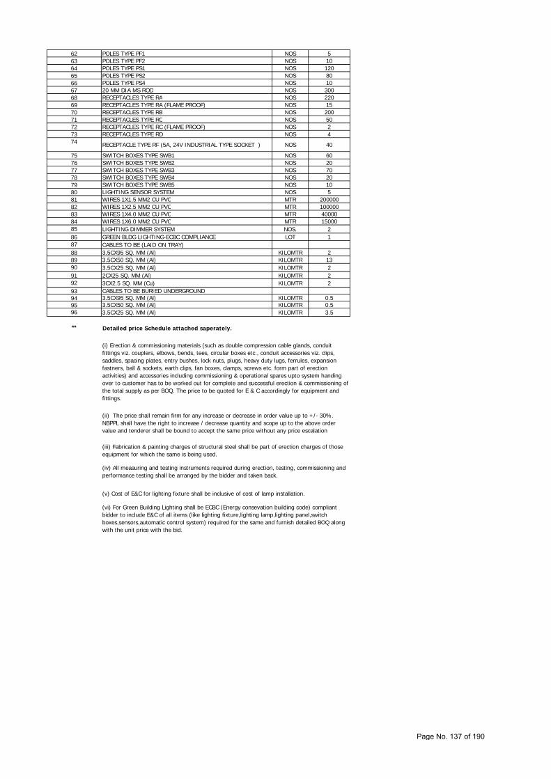
62 POLES TYPE PF1 NOS 563 POLES TYPE PF2 NOS 1064 POLES TYPE PS1 NOS 12065 POLES TYPE PS2 NOS 8066 POLES TYPE PS4 NOS 1067 20 MM DIA MS ROD NOS 30068 RECEPTACLES TYPE RA NOS 22069 RECEPTACLES TYPE RA (FLAME PROOF) NOS 1570 RECEPTACLES TYPE RB NOS 20071 RECEPTACLES TYPE RC NOS 5072 RECEPTACLES TYPE RC (FLAME PROOF) NOS 273 RECEPTACLES TYPE RD NOS 474 RECEPTACLE TYPE RF (5A, 24V INDUSTRIAL TYPE SOCKET ) NOS 40
75 SWITCH BOXES TYPE SWB1 NOS 6076 SWITCH BOXES TYPE SWB2 NOS 2077 SWITCH BOXES TYPE SWB3 NOS 7078 SWITCH BOXES TYPE SWB4 NOS 2079 SWITCH BOXES TYPE SWB5 NOS 1080 LIGHTING SENSOR SYSTEM NOS 581 WIRES 1X1.5 MM2 CU PVC MTR 20000082 WIRES 1X2.5 MM2 CU PVC MTR 10000083 WIRES 1X4.0 MM2 CU PVC MTR 4000084 WIRES 1X6.0 MM2 CU PVC MTR 1500085 LIGHTING DIMMER SYSTEM NOS. 286 GREEN BLDG LIGHTING-ECBC COMPLIANCE LOT 187 CABLES TO BE (LAID ON TRAY)88 3.5CX95 SQ. MM (Al) KILOMTR 289 3.5CX50 SQ. MM (Al) KILOMTR 1390 3.5CX25 SQ. MM (Al) KILOMTR 291 2CX25 SQ. MM (Al) KILOMTR 292 3CX2.5 SQ. MM (Cu) KILOMTR 293 CABLES TO BE BURIED UNDERGROUND94 3.5CX95 SQ. MM (Al) KILOMTR 0.595 3.5CX50 SQ. MM (Al) KILOMTR 0.596 3.5CX25 SQ. MM (Al) KILOMTR 3.5
** Detailed price Schedule attached saperately.
(i) Erection & commissioning materials (such as double compression cable glands, conduit fittings viz. couplers, elbows, bends, tees, circular boxes etc., conduit accessories viz. clips, saddles, spacing plates, entry bushes, lock nuts, plugs, heavy duty lugs, ferrules, expansion fastners, ball & sockets, earth clips, fan boxes, clamps, screws etc. form part of erection activities) and accessories including commissioning & operational spares upto system handing over to customer has to be worked out for complete and successful erection & commissioning of the total supply as per BOQ. The price to be quoted for E & C accordingly for equipment and fittings.
(ii) The price shall remain firm for any increase or decrease in order value up to +/- 30%. NBPPL shall have the right to increase / decrease quantity and scope up to the above order value and tenderer shall be bound to accept the same price without any price escalation
(vi) For Green Building Lighting shall be ECBC (Energy consevation building code) compliant bidder to include E&C of all items (like lighting fixture,lighting lamp,lighting panel,switch boxes,sensors,automatic control system) required for the same and furnish detailed BOQ along with the unit price with the bid.
(iii) Fabrication & painting charges of structural steel shall be part of erection charges of those equipment for which the same is being used.
(iv) All measuring and testing instruments required during erection, testing, commissioning and performance testing shall be arranged by the bidder and taken back.
(v) Cost of E&C for lighting fixture shall be inclusive of cost of lamp installation.
Page No. 137 of 190
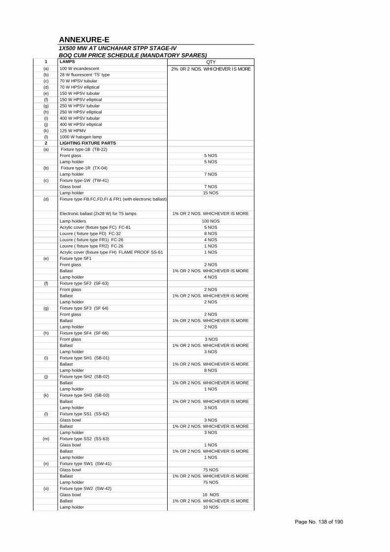
ANNEXURE-E
1 LAMPS QTY (a) 100 W incandescent
(b) 28 W fluorescent ‘T5’ type
(c) 70 W HPSV tubular
(d) 70 W HPSV elliptical
(e) 150 W HPSV tubular
(f) 150 W HPSV elliptical
(g) 250 W HPSV tubular
(h) 250 W HPSV elliptical
(i) 400 W HPSV tubular
(j) 400 W HPSV elliptical
(k) 125 W HPMV
(l) 1000 W halogen lamp
2 LIGHTING FIXTURE PARTS
(a) Fixture type-1B (TB-22)
Front glass 5 NOS
Lamp holder 5 NOS
(b) Fixture type-1R (TX-04)
Lamp holder 7 NOS
(c) Fixture type-1W (TW-41)
Glass bowl 7 NOS
Lamp holder 15 NOS
(d) Fixture type FB,FC,FD,FI & FR1 (with electronic ballast)
Electronic ballast (2x28 W) for T5 lamps 1% OR 2 NOS. WHICHEVER IS MORE
Lamp holders 100 NOS
Acrylic cover (fixture type FC) FC-81 5 NOS
Louvre ( fixture type FD) FC-32 8 NOS
Louvre ( fixture type FR1) FC-26 4 NOS
Louvre ( fixture type FR2) FC-26 1 NOS
Acrylic cover (fixture type FH) FLAME PROOF SS-61 1 NOS
(e) Fixture type SF1
Front glass 2 NOS
Ballast 1% OR 2 NOS. WHICHEVER IS MORE
Lamp holder 4 NOS
(f) Fixture type SF2 (SF-63)
Front glass 2 NOS
Ballast 1% OR 2 NOS. WHICHEVER IS MORE
Lamp holder 2 NOS
(g) Fixture type SF3 (SF 64)
Front glass 2 NOS
Ballast 1% OR 2 NOS. WHICHEVER IS MORE
Lamp holder 2 NOS
(h) Fixture type SF4 (SF-66)
Front glass 3 NOS
Ballast 1% OR 2 NOS. WHICHEVER IS MORE
Lamp holder 3 NOS
(i) Fixture type SH1 (SB-01)
Ballast 1% OR 2 NOS. WHICHEVER IS MORE
Lamp holder 8 NOS
(j) Fixture type SH2 (SB-02)
Ballast 1% OR 2 NOS. WHICHEVER IS MORE
Lamp holder 1 NOS
(k) Fixture type SH3 (SB-03)
Ballast 1% OR 2 NOS. WHICHEVER IS MORE
Lamp holder 3 NOS
(l) Fixture type SS1 (SS-62)
Glass bowl 3 NOS
Ballast 1% OR 2 NOS. WHICHEVER IS MORE
Lamp holder 3 NOS
(m) Fixture type SS2 (SS-63)
Glass bowl 1 NOS
Ballast 1% OR 2 NOS. WHICHEVER IS MORE
Lamp holder 1 NOS
(n) Fixture type SW1 (SW-41)
Glass bowl 75 NOS
Ballast 1% OR 2 NOS. WHICHEVER IS MORE
Lamp holder 75 NOS
(o) Fixture type SW2 (SW-42)
Glass bowl 10 NOS
Ballast 1% OR 2 NOS. WHICHEVER IS MORE
Lamp holder 10 NOS
1X500 MW AT UNCHAHAR STPP STAGE-IVBOQ CUM PRICE SCHEDULE (MANDATORY SPARES)
2% 0R 2 NOS. WHICHEVER IS MORE
Page No. 138 of 190
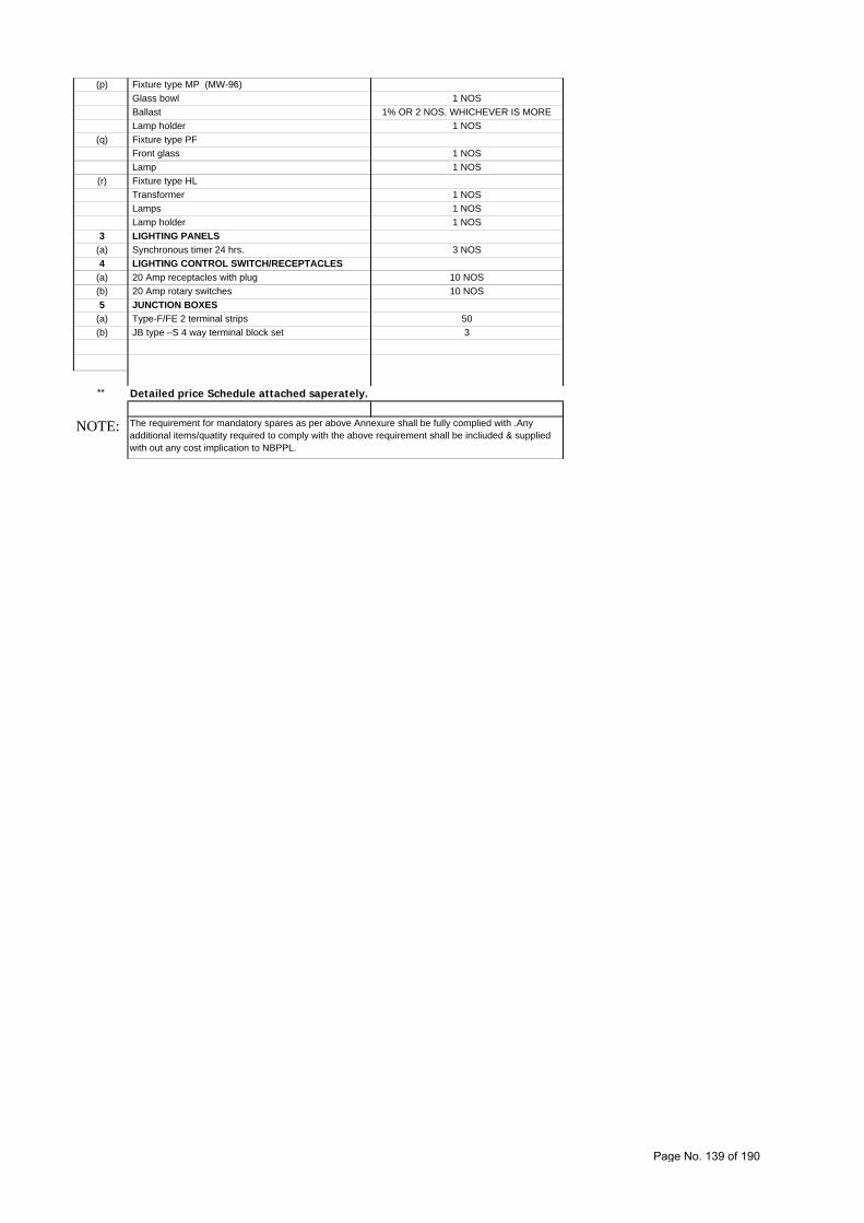
(p) Fixture type MP (MW-96)
Glass bowl 1 NOS
Ballast 1% OR 2 NOS. WHICHEVER IS MORE
Lamp holder 1 NOS
(q) Fixture type PF
Front glass 1 NOS
Lamp 1 NOS
(r) Fixture type HL
Transformer 1 NOS
Lamps 1 NOS
Lamp holder 1 NOS
3 LIGHTING PANELS
(a) Synchronous timer 24 hrs. 3 NOS
4 LIGHTING CONTROL SWITCH/RECEPTACLES
(a) 20 Amp receptacles with plug 10 NOS
(b) 20 Amp rotary switches 10 NOS
5 JUNCTION BOXES
(a) Type-F/FE 2 terminal strips 50
(b) JB type –S 4 way terminal block set 3
**
NOTE: The requirement for mandatory spares as per above Annexure shall be fully complied with .Any additional items/quatity required to comply with the above requirement shall be incliuded & supplied with out any cost implication to NBPPL.
Detailed price Schedule attached saperately.
Page No. 139 of 190
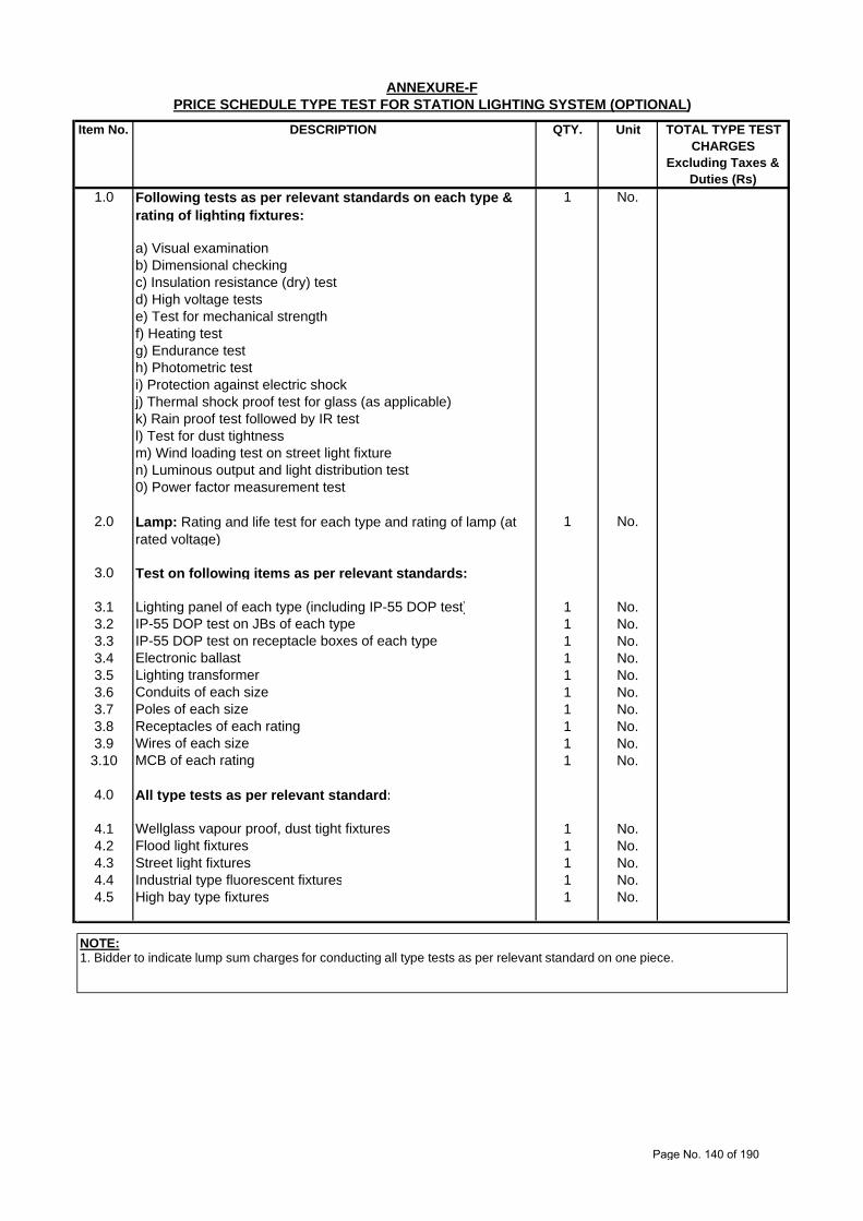
Item No. DESCRIPTION QTY. Unit
1.0 Following tests as per relevant standards on each type & rating of lighting fixtures:
1 No.
a) Visual examinationb) Dimensional checkingc) Insulation resistance (dry) testd) High voltage testse) Test for mechanical strengthf) Heating testg) Endurance testh) Photometric testi) Protection against electric shockj) Thermal shock proof test for glass (as applicable)k) Rain proof test followed by IR testl) Test for dust tightnessm) Wind loading test on street light fixturen) Luminous output and light distribution test0) Power factor measurement test
2.0 Lamp: Rating and life test for each type and rating of lamp (at rated voltage)
1 No.
3.0 Test on following items as per relevant standards:
3.1 Lighting panel of each type (including IP-55 DOP test) 1 No.3.2 IP-55 DOP test on JBs of each type 1 No.3.3 IP-55 DOP test on receptacle boxes of each type 1 No.3.4 Electronic ballast 1 No.3.5 Lighting transformer 1 No.3.6 Conduits of each size 1 No.3.7 Poles of each size 1 No.3.8 Receptacles of each rating 1 No.3.9 Wires of each size 1 No.3.10 MCB of each rating 1 No.
4.0 All type tests as per relevant standard:
4.1 Wellglass vapour proof, dust tight fixtures 1 No.4.2 Flood light fixtures 1 No.4.3 Street light fixtures 1 No.4.4 Industrial type fluorescent fixtures 1 No.4.5 High bay type fixtures 1 No.
ANNEXURE-FPRICE SCHEDULE TYPE TEST FOR STATION LIGHTING SYSTEM (OPTIONAL)
TOTAL TYPE TEST CHARGES
Excluding Taxes & Duties (Rs)
NOTE:1. Bidder to indicate lump sum charges for conducting all type tests as per relevant standard on one piece.
Page No. 140 of 190
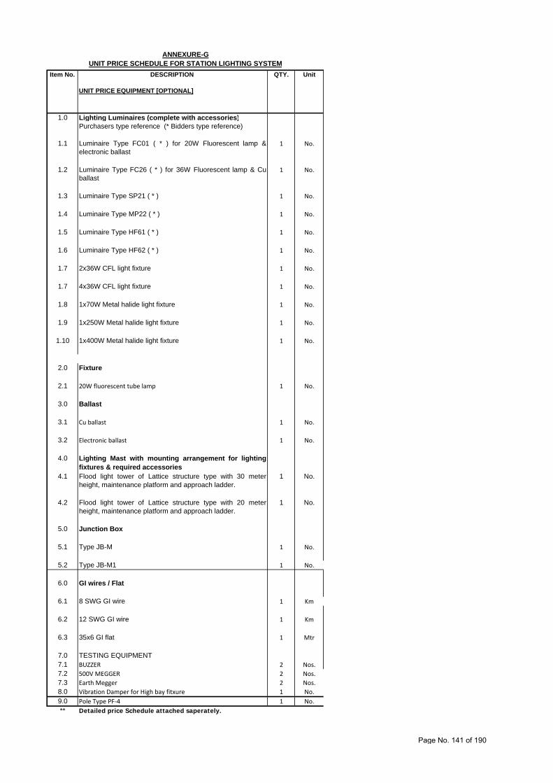
Item No. DESCRIPTION QTY. Unit
UNIT PRICE EQUIPMENT [OPTIONAL]
1.0 Lighting Luminaires (complete with accessories)Purchasers type reference (* Bidders type reference)
1.1 Luminaire Type FC01 ( * ) for 20W Fluorescent lamp &electronic ballast
1 No.
1.2 Luminaire Type FC26 ( * ) for 36W Fluorescent lamp & Cuballast
1 No.
1.3 Luminaire Type SP21 ( * ) 1 No.
1.4 Luminaire Type MP22 ( * ) 1 No.
1.5 Luminaire Type HF61 ( * ) 1 No.
1.6 Luminaire Type HF62 ( * ) 1 No.
1.7 2x36W CFL light fixture 1 No.
1.7 4x36W CFL light fixture 1 No.
1.8 1x70W Metal halide light fixture 1 No.
1.9 1x250W Metal halide light fixture 1 No.
1.10 1x400W Metal halide light fixture 1 No.
2.0 Fixture
2.1 20W fluorescent tube lamp 1 No.
3.0 Ballast
3.1 Cu ballast 1 No.
3.2 Electronic ballast 1 No.
4.0 Lighting Mast with mounting arrangement for lightingfixtures & required accessories
4.1 Flood light tower of Lattice structure type with 30 meterheight, maintenance platform and approach ladder.
1 No.
4.2 Flood light tower of Lattice structure type with 20 meterheight, maintenance platform and approach ladder.
1 No.
5.0 Junction Box
5.1 Type JB-M 1 No.
5.2 Type JB-M1 1 No.
6.0 GI wires / Flat
6.1 8 SWG GI wire 1 Km
6.2 12 SWG GI wire 1 Km
6.3 35x6 GI flat 1 Mtr
7.0 TESTING EQUIPMENT7.1 BUZZER 2 Nos.
7.2 500V MEGGER 2 Nos.
7.3 Earth Megger 2 Nos.
8.0 Vibration Damper for High bay fitxure 1 No.
9.0 Pole Type PF‐4 1 No.
**
ANNEXURE-GUNIT PRICE SCHEDULE FOR STATION LIGHTING SYSTEM
Detailed price Schedule attached saperately.
Page No. 141 of 190
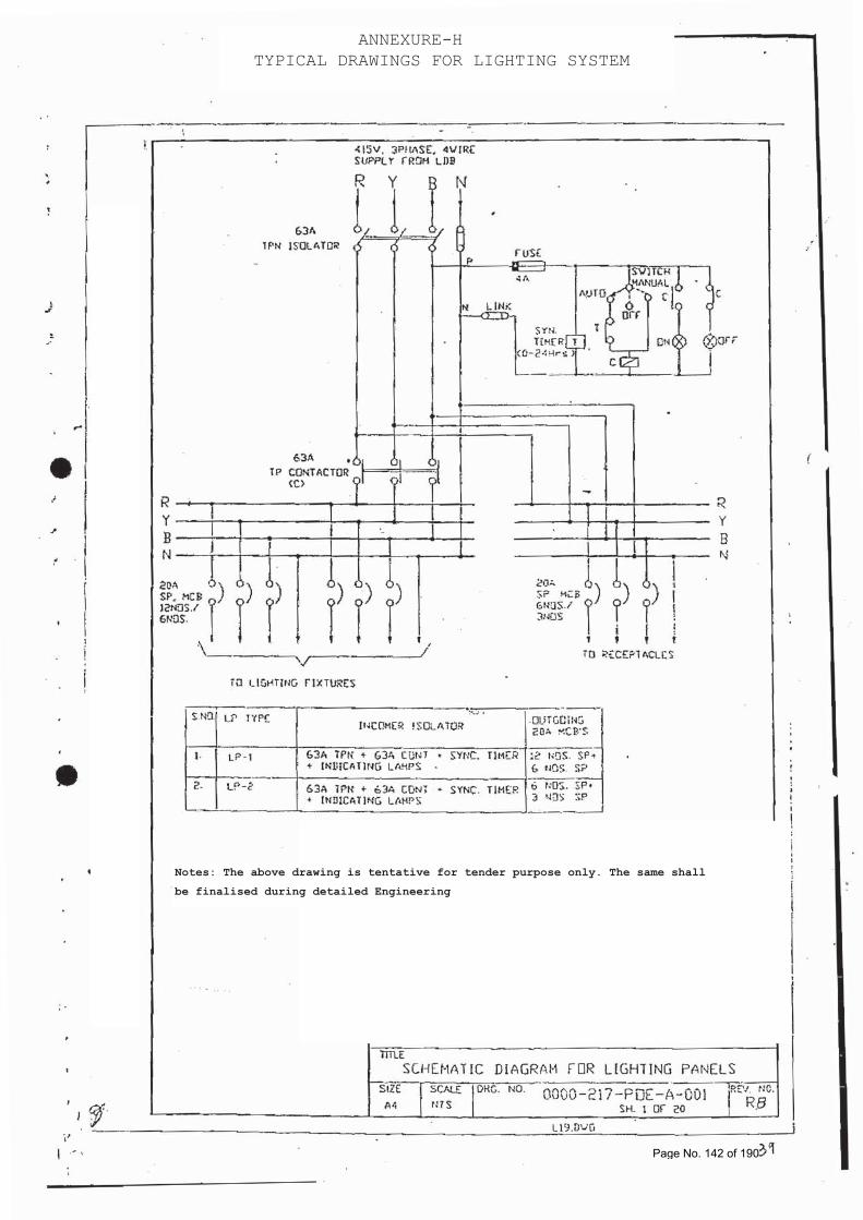
ANNEXURE-H TYPICAL DRAWINGS FOR LIGHTING SYSTEM
Notes: The above drawing is tentative for tender purpose only. The same shall
be finalised during detailed Engineering
Page No. 142 of 190
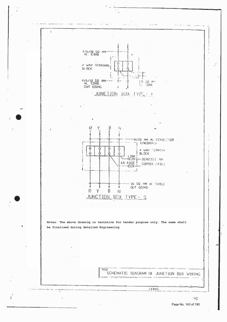
Notes: The above drawing is tentative for tender purpose only. The same shall
be finalised during detailed Engineering
Page No. 143 of 190
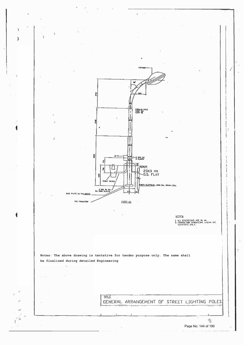
Notes: The above drawing is tentative for tender purpose only. The same shall
be finalised during detailed Engineering
Page No. 144 of 190
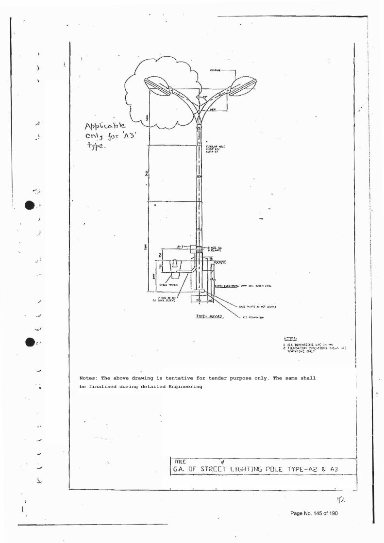
Notes: The above drawing is tentative for tender purpose only. The same shall
be finalised during detailed Engineering
Page No. 145 of 190
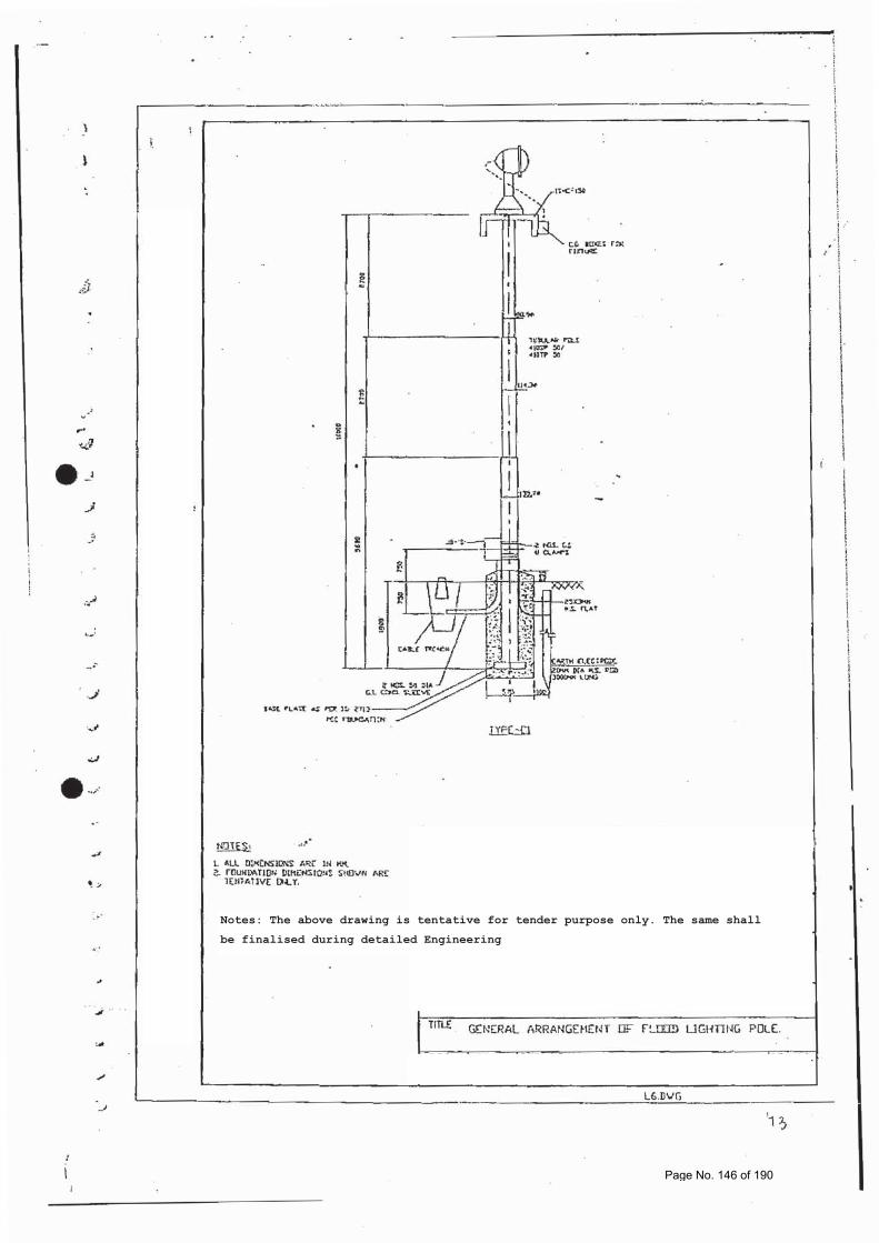
Notes: The above drawing is tentative for tender purpose only. The same shall
be finalised during detailed Engineering
Page No. 146 of 190
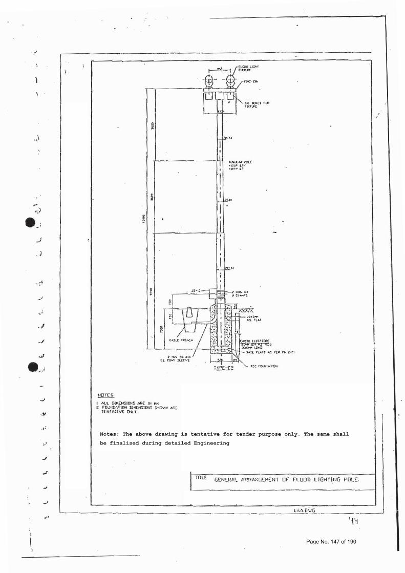
Notes: The above drawing is tentative for tender purpose only. The same shall
be finalised during detailed Engineering
Page No. 147 of 190
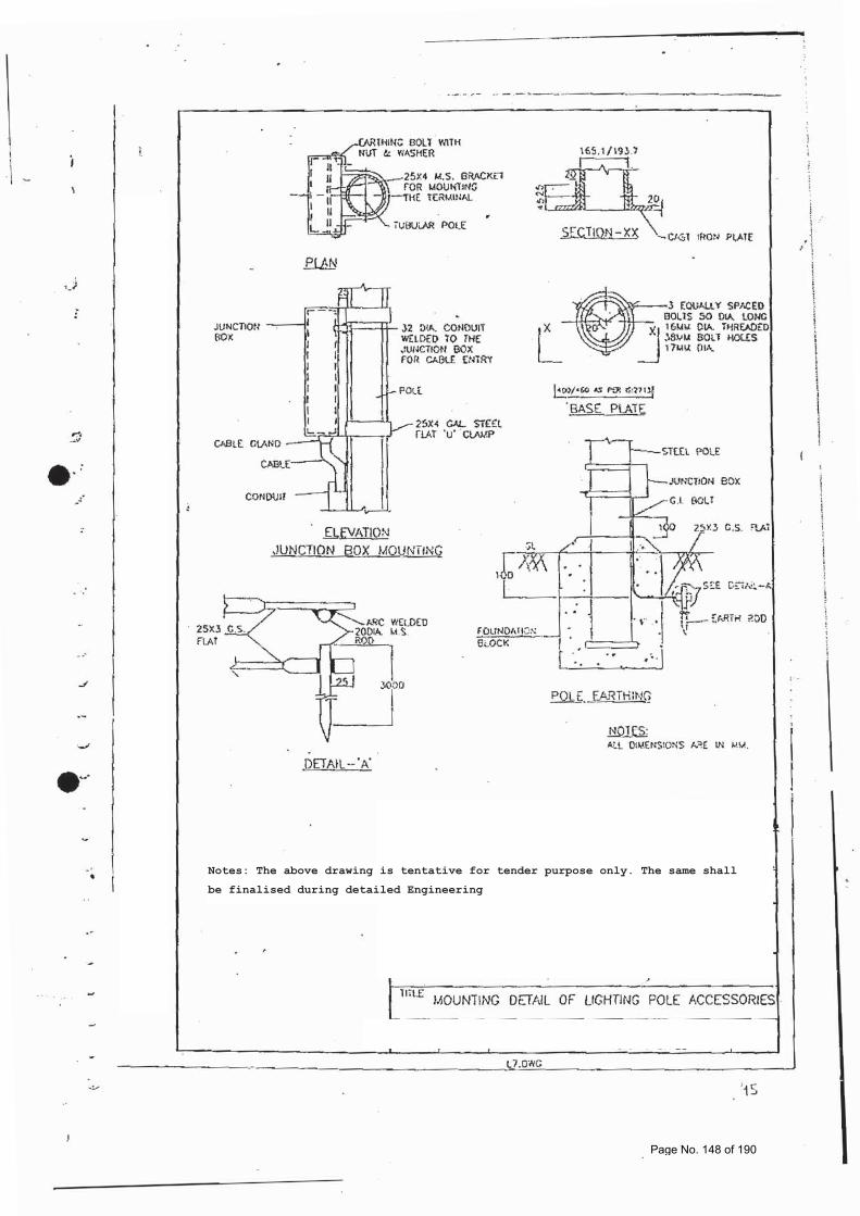
Notes: The above drawing is tentative for tender purpose only. The same shall
be finalised during detailed Engineering
Page No. 148 of 190
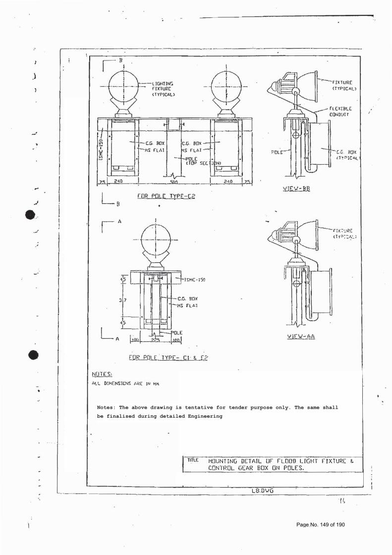
Notes: The above drawing is tentative for tender purpose only. The same shall
be finalised during detailed Engineering
Page No. 149 of 190
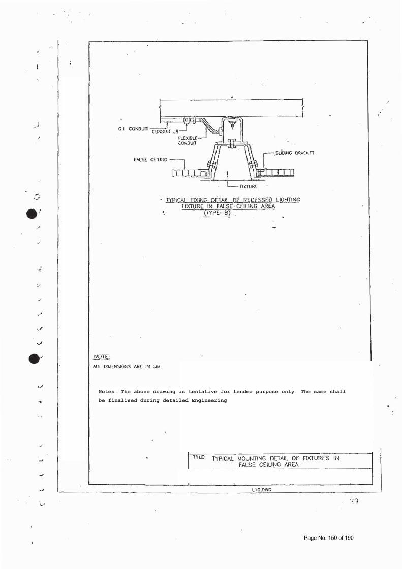
Notes: The above drawing is tentative for tender purpose only. The same shall
be finalised during detailed Engineering
Page No. 150 of 190
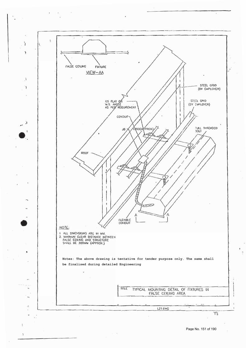
Notes: The above drawing is tentative for tender purpose only. The same shall
be finalised during detailed Engineering
Page No. 151 of 190
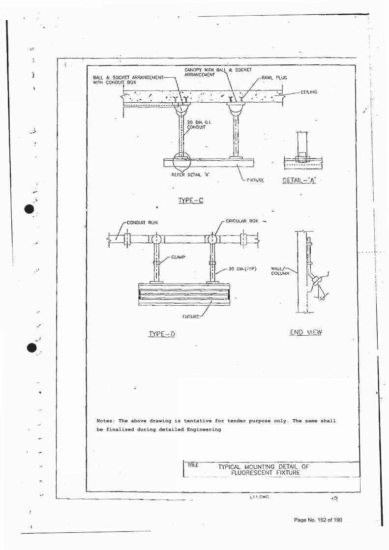
Notes: The above drawing is tentative for tender purpose only. The same shall
be finalised during detailed Engineering
Page No. 152 of 190
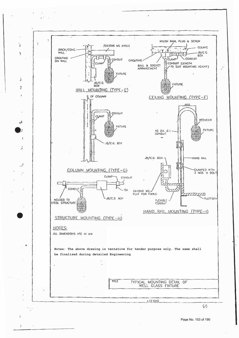
Notes: The above drawing is tentative for tender purpose only. The same shall
be finalised during detailed Engineering
Page No. 153 of 190
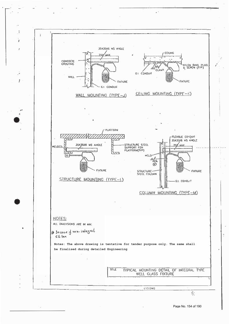
Notes: The above drawing is tentative for tender purpose only. The same shall
be finalised during detailed Engineering
Page No. 154 of 190
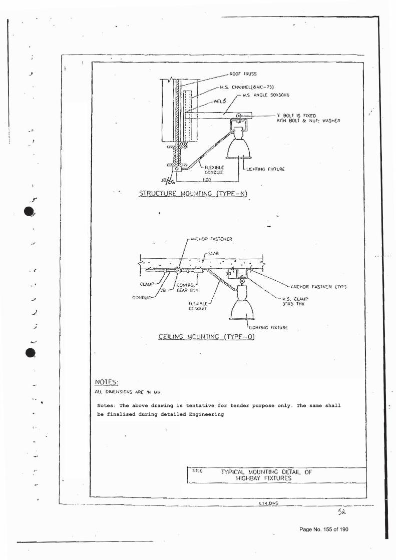
Notes: The above drawing is tentative for tender purpose only. The same shall
be finalised during detailed Engineering
Page No. 155 of 190
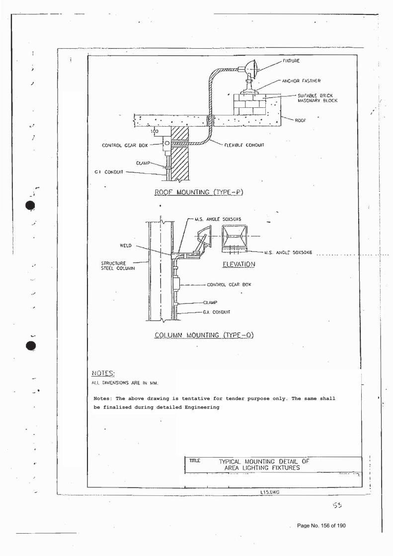
Notes: The above drawing is tentative for tender purpose only. The same shall
be finalised during detailed Engineering
Page No. 156 of 190
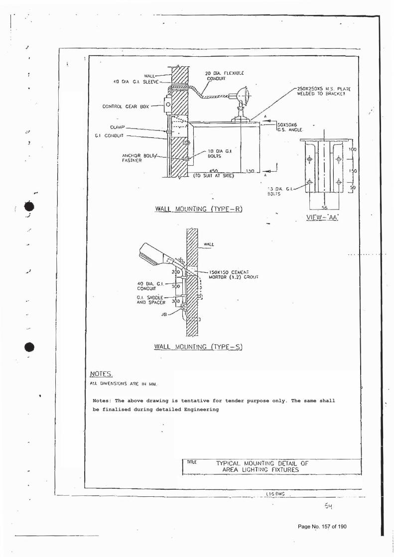
Notes: The above drawing is tentative for tender purpose only. The same shall
be finalised during detailed Engineering
Page No. 157 of 190
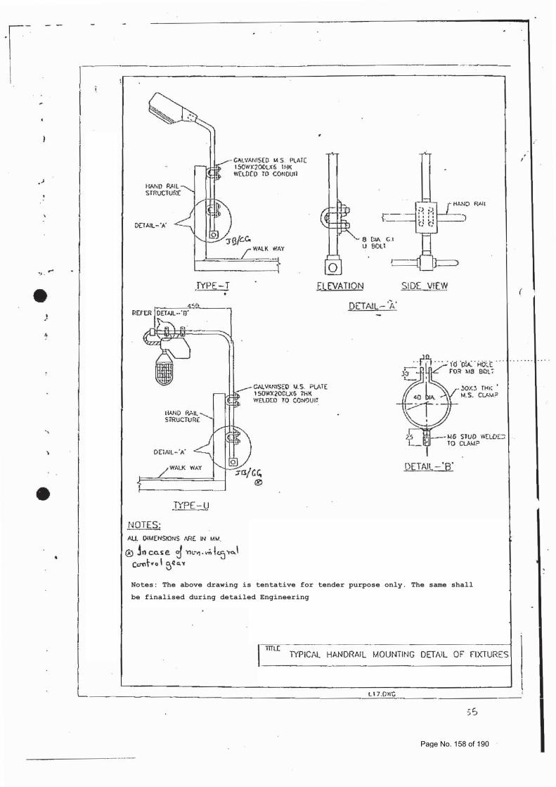
Notes: The above drawing is tentative for tender purpose only. The same shall
be finalised during detailed Engineering
Page No. 158 of 190
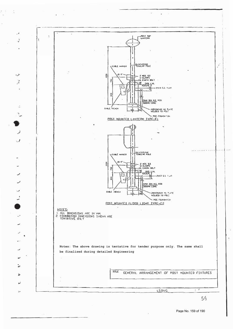
Notes: The above drawing is tentative for tender purpose only. The same shall
be finalised during detailed Engineering
Page No. 159 of 190
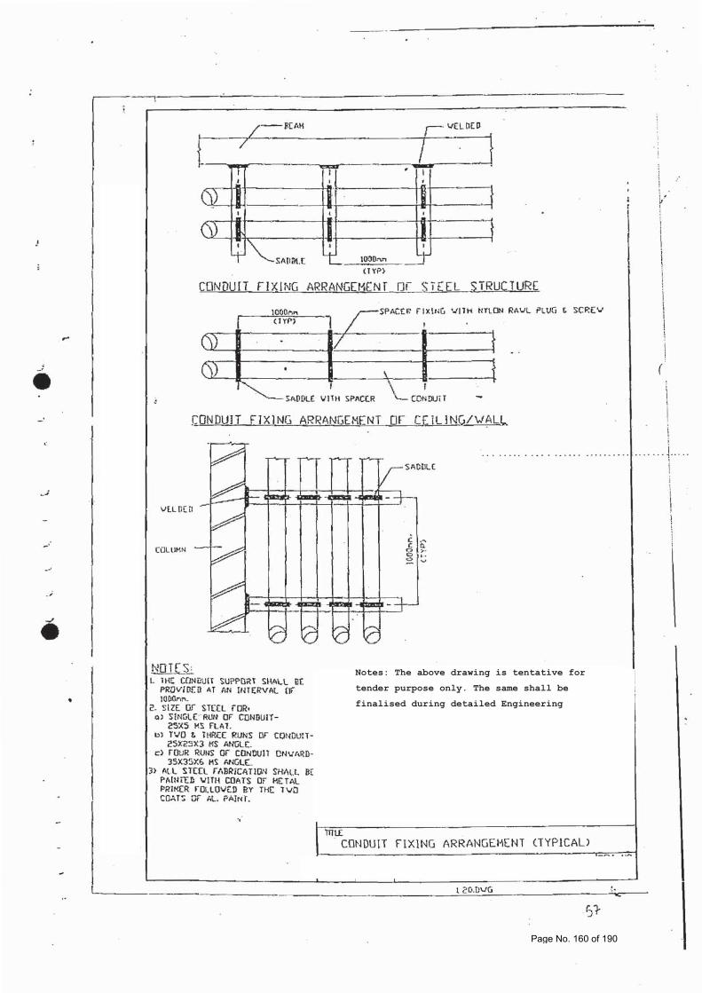
Notes: The above drawing is tentative for
tender purpose only. The same shall be
finalised during detailed Engineering
Page No. 160 of 190
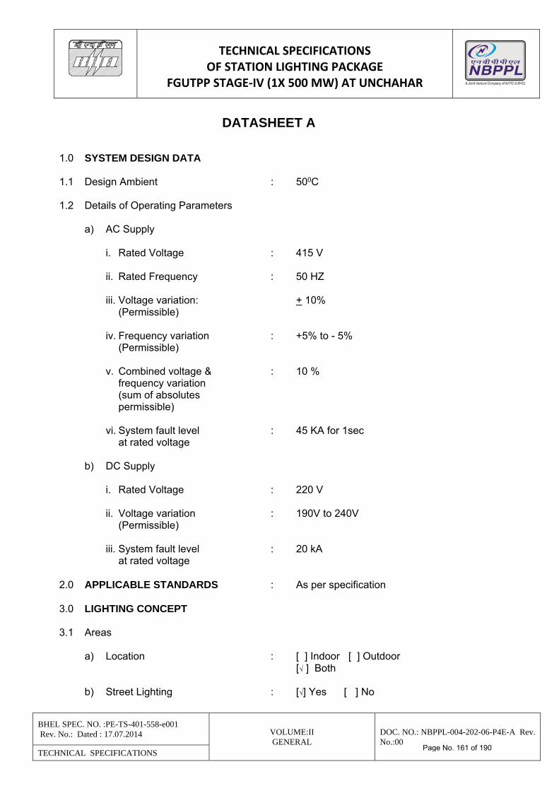
TECHNICAL SPECIFICATIONS OF STATION LIGHTING PACKAGE
FGUTPP STAGE‐IV (1X 500 MW) AT UNCHAHAR
BHEL SPEC. NO. :PE-TS-401-558-e001 Rev. No.: Dated : 17.07.2014 VOLUME:II
GENERAL DOC. NO.: NBPPL-004-202-06-P4E-A Rev. No.:00
TECHNICAL SPECIFICATIONS
DATASHEET A 1.0 SYSTEM DESIGN DATA 1.1 Design Ambient : 500C 1.2 Details of Operating Parameters a) AC Supply i. Rated Voltage : 415 V ii. Rated Frequency : 50 HZ iii. Voltage variation: + 10% (Permissible) iv. Frequency variation : +5% to - 5% (Permissible) v. Combined voltage & : 10 % frequency variation (sum of absolutes permissible) vi. System fault level : 45 KA for 1sec at rated voltage b) DC Supply i. Rated Voltage : 220 V ii. Voltage variation : 190V to 240V (Permissible) iii. System fault level : 20 kA at rated voltage 2.0 APPLICABLE STANDARDS : As per specification 3.0 LIGHTING CONCEPT 3.1 Areas a) Location : [ ] Indoor [ ] Outdoor [√ ] Both b) Street Lighting : [√] Yes [ ] No
Page No. 161 of 190
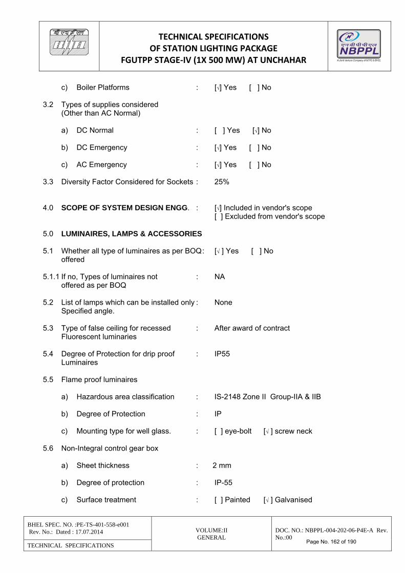
TECHNICAL SPECIFICATIONS OF STATION LIGHTING PACKAGE
FGUTPP STAGE‐IV (1X 500 MW) AT UNCHAHAR
BHEL SPEC. NO. :PE-TS-401-558-e001 Rev. No.: Dated : 17.07.2014 VOLUME:II
GENERAL DOC. NO.: NBPPL-004-202-06-P4E-A Rev. No.:00
TECHNICAL SPECIFICATIONS
c) Boiler Platforms : [√] Yes [ ] No 3.2 Types of supplies considered (Other than AC Normal) a) DC Normal : [ ] Yes [√] No b) DC Emergency : [√] Yes [ ] No c) AC Emergency : [√] Yes [ ] No 3.3 Diversity Factor Considered for Sockets : 25% 4.0 SCOPE OF SYSTEM DESIGN ENGG. : [√] Included in vendor's scope [ ] Excluded from vendor's scope 5.0 LUMINAIRES, LAMPS & ACCESSORIES 5.1 Whether all type of luminaires as per BOQ : [√ ] Yes [ ] No offered 5.1.1 If no, Types of luminaires not : NA offered as per BOQ 5.2 List of lamps which can be installed only : None Specified angle. 5.3 Type of false ceiling for recessed : After award of contract Fluorescent luminaries 5.4 Degree of Protection for drip proof : IP55 Luminaires 5.5 Flame proof luminaires a) Hazardous area classification : IS-2148 Zone II Group-IIA & IIB b) Degree of Protection : IP c) Mounting type for well glass. : [ ] eye-bolt [√ ] screw neck 5.6 Non-Integral control gear box a) Sheet thickness : 2 mm b) Degree of protection : IP-55 c) Surface treatment : [ ] Painted [√ ] Galvanised
Page No. 162 of 190
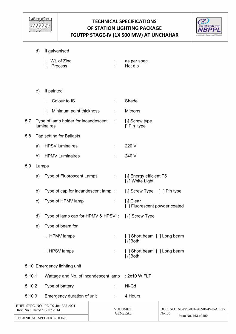
TECHNICAL SPECIFICATIONS OF STATION LIGHTING PACKAGE
FGUTPP STAGE‐IV (1X 500 MW) AT UNCHAHAR
BHEL SPEC. NO. :PE-TS-401-558-e001 Rev. No.: Dated : 17.07.2014 VOLUME:II
GENERAL DOC. NO.: NBPPL-004-202-06-P4E-A Rev. No.:00
TECHNICAL SPECIFICATIONS
d) If galvanised i. Wt. of Zinc : as per spec. ii. Process : Hot dip e) If painted i. Colour to IS : Shade ii. Minimum paint thickness : Microns 5.7 Type of lamp holder for incandescent : [√] Screw type luminaires [] Pin type 5.8 Tap setting for Ballasts a) HPSV luminaires : 220 V b) HPMV Luminaires : 240 V 5.9 Lamps a) Type of Fluoroscent Lamps : [√] Energy efficient T5 [√ ] White Light b) Type of cap for incandescent lamp : [√] Screw Type [ ] Pin type c) Type of HPMV lamp : [√] Clear [ ] Fluorescent powder coated d) Type of lamp cap for HPMV & HPSV : [√ ] Screw Type e) Type of beam for i. HPMV lamps : [ ] Short beam [ ] Long beam [√ ]Both ii. HPSV lamps : [ ] Short beam [ ] Long beam [√ ]Both 5.10 Emergency lighting unit 5.10.1 Wattage and No. of incandescent lamp : 2x10 W FLT 5.10.2 Type of battery : Ni-Cd 5.10.3 Emergency duration of unit : 4 Hours
Page No. 163 of 190
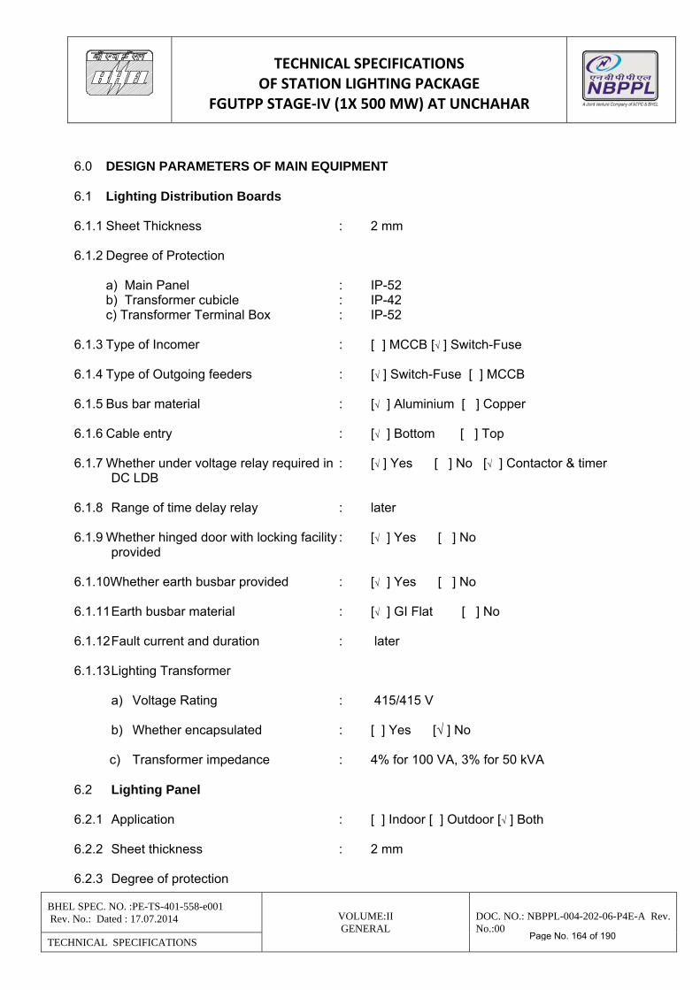
TECHNICAL SPECIFICATIONS OF STATION LIGHTING PACKAGE
FGUTPP STAGE‐IV (1X 500 MW) AT UNCHAHAR
BHEL SPEC. NO. :PE-TS-401-558-e001 Rev. No.: Dated : 17.07.2014 VOLUME:II
GENERAL DOC. NO.: NBPPL-004-202-06-P4E-A Rev. No.:00
TECHNICAL SPECIFICATIONS
6.0 DESIGN PARAMETERS OF MAIN EQUIPMENT 6.1 Lighting Distribution Boards 6.1.1 Sheet Thickness : 2 mm 6.1.2 Degree of Protection a) Main Panel : IP-52 b) Transformer cubicle : IP-42 c) Transformer Terminal Box : IP-52 6.1.3 Type of Incomer : [ ] MCCB [√ ] Switch-Fuse 6.1.4 Type of Outgoing feeders : [√ ] Switch-Fuse [ ] MCCB 6.1.5 Bus bar material : [√ ] Aluminium [ ] Copper 6.1.6 Cable entry : [√ ] Bottom [ ] Top 6.1.7 Whether under voltage relay required in : [√ ] Yes [ ] No [√ ] Contactor & timer DC LDB 6.1.8 Range of time delay relay : later 6.1.9 Whether hinged door with locking facility : [√ ] Yes [ ] No provided 6.1.10Whether earth busbar provided : [√ ] Yes [ ] No 6.1.11 Earth busbar material : [√ ] GI Flat [ ] No 6.1.12 Fault current and duration : later 6.1.13 Lighting Transformer a) Voltage Rating : 415/415 V b) Whether encapsulated : [ ] Yes [√ ] No c) Transformer impedance : 4% for 100 VA, 3% for 50 kVA 6.2 Lighting Panel 6.2.1 Application : [ ] Indoor [ ] Outdoor [√ ] Both 6.2.2 Sheet thickness : 2 mm 6.2.3 Degree of protection
Page No. 164 of 190
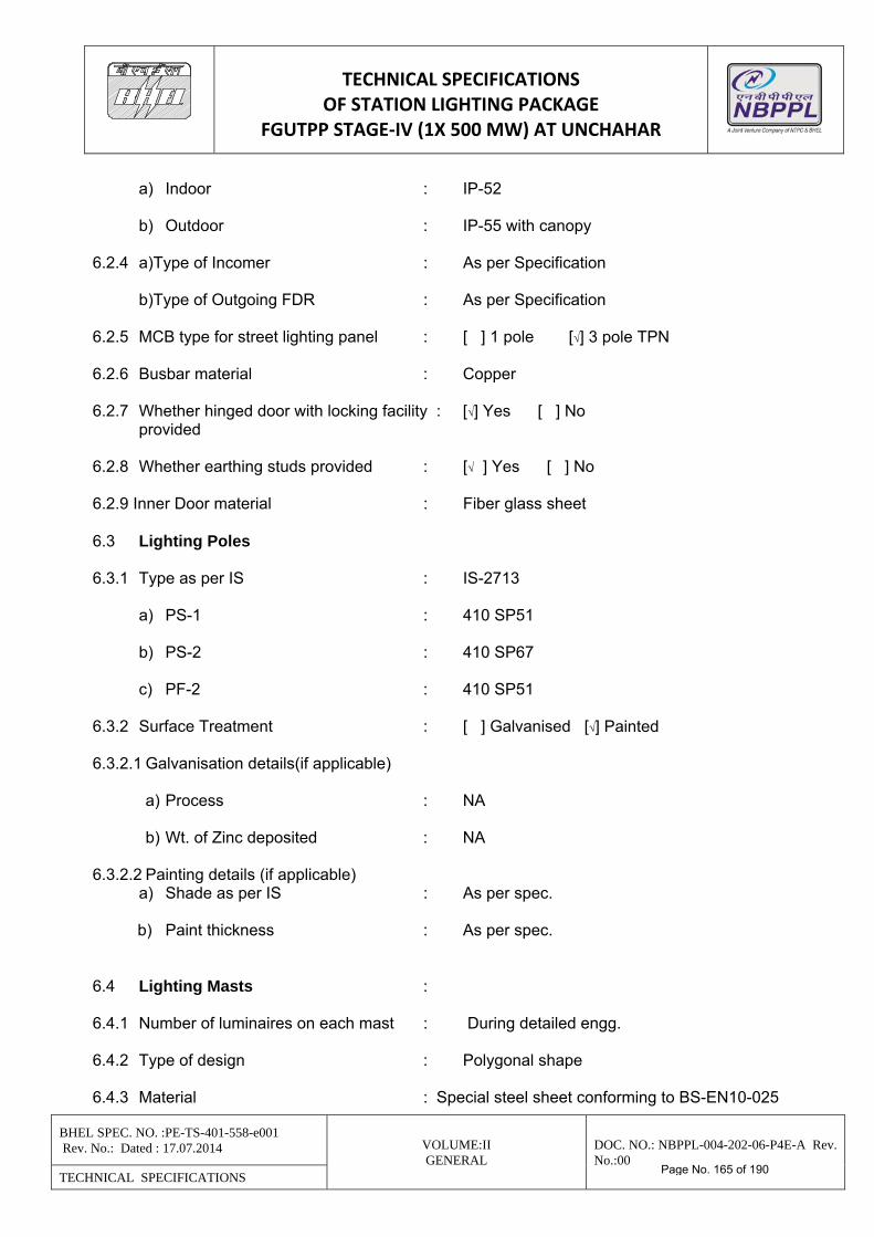
TECHNICAL SPECIFICATIONS OF STATION LIGHTING PACKAGE
FGUTPP STAGE‐IV (1X 500 MW) AT UNCHAHAR
BHEL SPEC. NO. :PE-TS-401-558-e001 Rev. No.: Dated : 17.07.2014 VOLUME:II
GENERAL DOC. NO.: NBPPL-004-202-06-P4E-A Rev. No.:00
TECHNICAL SPECIFICATIONS
a) Indoor : IP-52 b) Outdoor : IP-55 with canopy 6.2.4 a)Type of Incomer : As per Specification
b)Type of Outgoing FDR : As per Specification 6.2.5 MCB type for street lighting panel : [ ] 1 pole [√] 3 pole TPN 6.2.6 Busbar material : Copper 6.2.7 Whether hinged door with locking facility : [√] Yes [ ] No provided 6.2.8 Whether earthing studs provided : [√ ] Yes [ ] No 6.2.9 Inner Door material : Fiber glass sheet 6.3 Lighting Poles 6.3.1 Type as per IS : IS-2713 a) PS-1 : 410 SP51 b) PS-2 : 410 SP67 c) PF-2 : 410 SP51 6.3.2 Surface Treatment : [ ] Galvanised [√] Painted 6.3.2.1 Galvanisation details(if applicable) a) Process : NA b) Wt. of Zinc deposited : NA 6.3.2.2 Painting details (if applicable) a) Shade as per IS : As per spec. b) Paint thickness : As per spec. 6.4 Lighting Masts : 6.4.1 Number of luminaires on each mast : During detailed engg. 6.4.2 Type of design : Polygonal shape 6.4.3 Material : Special steel sheet conforming to BS-EN10-025
Page No. 165 of 190
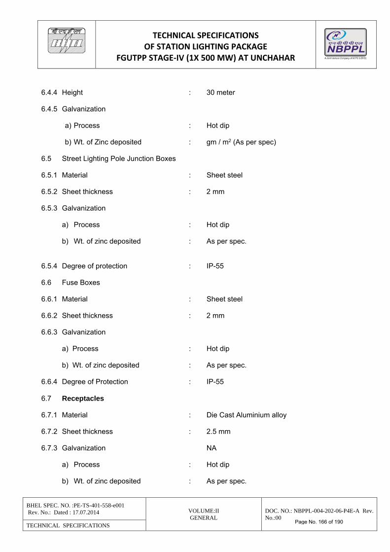
TECHNICAL SPECIFICATIONS OF STATION LIGHTING PACKAGE
FGUTPP STAGE‐IV (1X 500 MW) AT UNCHAHAR
BHEL SPEC. NO. :PE-TS-401-558-e001 Rev. No.: Dated : 17.07.2014 VOLUME:II
GENERAL DOC. NO.: NBPPL-004-202-06-P4E-A Rev. No.:00
TECHNICAL SPECIFICATIONS
6.4.4 Height : 30 meter 6.4.5 Galvanization a) Process : Hot dip b) Wt. of Zinc deposited : gm / m2 (As per spec) 6.5 Street Lighting Pole Junction Boxes 6.5.1 Material : Sheet steel 6.5.2 Sheet thickness : 2 mm 6.5.3 Galvanization a) Process : Hot dip b) Wt. of zinc deposited : As per spec. 6.5.4 Degree of protection : IP-55 6.6 Fuse Boxes 6.6.1 Material : Sheet steel 6.6.2 Sheet thickness : 2 mm 6.6.3 Galvanization a) Process : Hot dip b) Wt. of zinc deposited : As per spec. 6.6.4 Degree of Protection : IP-55 6.7 Receptacles 6.7.1 Material : Die Cast Aluminium alloy 6.7.2 Sheet thickness : 2.5 mm 6.7.3 Galvanization NA a) Process : Hot dip b) Wt. of zinc deposited : As per spec.
Page No. 166 of 190
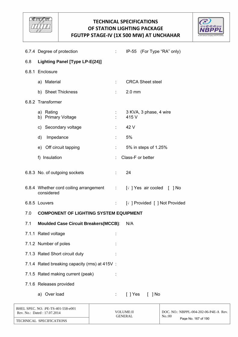
TECHNICAL SPECIFICATIONS OF STATION LIGHTING PACKAGE
FGUTPP STAGE‐IV (1X 500 MW) AT UNCHAHAR
BHEL SPEC. NO. :PE-TS-401-558-e001 Rev. No.: Dated : 17.07.2014 VOLUME:II
GENERAL DOC. NO.: NBPPL-004-202-06-P4E-A Rev. No.:00
TECHNICAL SPECIFICATIONS
6.7.4 Degree of protection : IP-55 (For Type “RA” only) 6.8 Lighting Panel [Type LP-E(24)] 6.8.1 Enclosure a) Material : CRCA Sheet steel b) Sheet Thickness : 2.0 mm 6.8.2 Transformer a) Rating : 3 KVA, 3 phase, 4 wire b) Primary Voltage : 415 V c) Secondary voltage : 42 V d) Impedance : 5% e) Off circuit tapping : 5% in steps of 1.25% f) Insulation : Class-F or better 6.8.3 No. of outgoing sockets : 24 6.8.4 Whether cord coiling arrangement : [√ ] Yes air cooled [ ] No considered 6.8.5 Louvers : [√ ] Provided [ ] Not Provided 7.0 COMPONENT OF LIGHTING SYSTEM EQUIPMENT 7.1 Moulded Case Circuit Breakers(MCCB): N/A 7.1.1 Rated voltage : 7.1.2 Number of poles : 7.1.3 Rated Short circuit duty : 7.1.4 Rated breaking capacity (rms) at 415V : 7.1.5 Rated making current (peak) : 7.1.6 Releases provided a) Over load : [ ] Yes [ ] No
Page No. 167 of 190
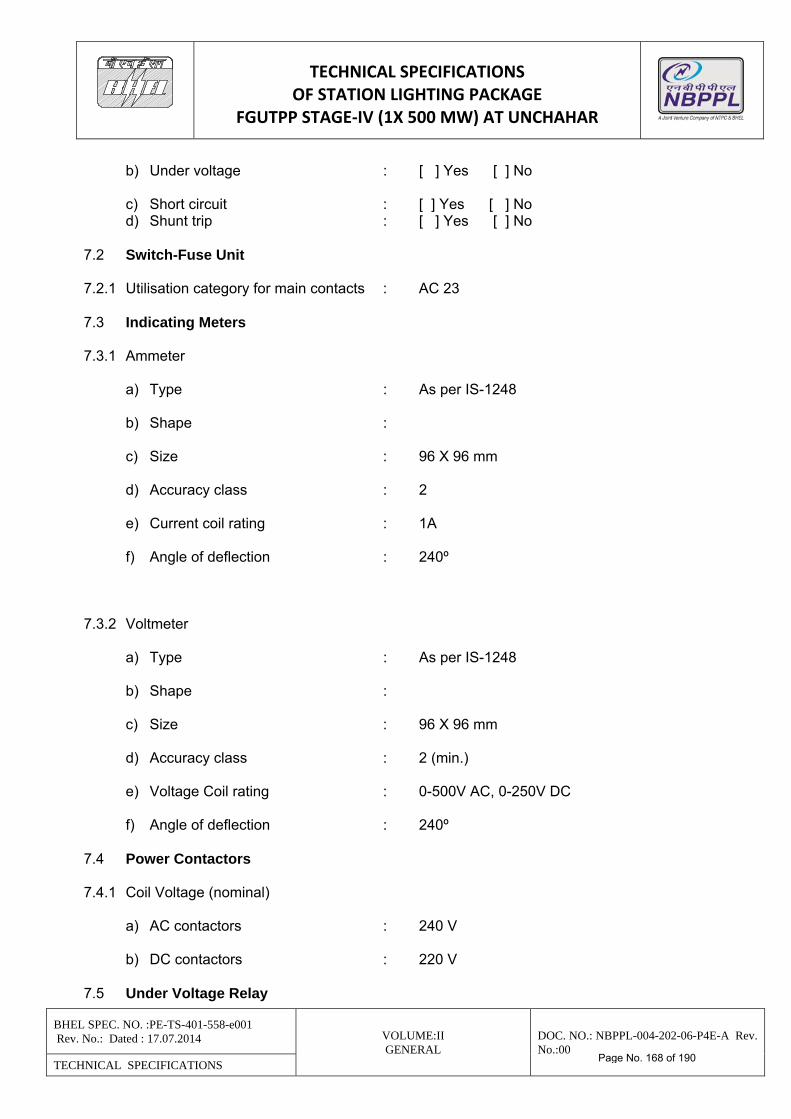
TECHNICAL SPECIFICATIONS OF STATION LIGHTING PACKAGE
FGUTPP STAGE‐IV (1X 500 MW) AT UNCHAHAR
BHEL SPEC. NO. :PE-TS-401-558-e001 Rev. No.: Dated : 17.07.2014 VOLUME:II
GENERAL DOC. NO.: NBPPL-004-202-06-P4E-A Rev. No.:00
TECHNICAL SPECIFICATIONS
b) Under voltage : [ ] Yes [ ] No c) Short circuit : [ ] Yes [ ] No d) Shunt trip : [ ] Yes [ ] No 7.2 Switch-Fuse Unit 7.2.1 Utilisation category for main contacts : AC 23 7.3 Indicating Meters 7.3.1 Ammeter a) Type : As per IS-1248 b) Shape : c) Size : 96 X 96 mm d) Accuracy class : 2 e) Current coil rating : 1A f) Angle of deflection : 240º 7.3.2 Voltmeter a) Type : As per IS-1248 b) Shape : c) Size : 96 X 96 mm d) Accuracy class : 2 (min.) e) Voltage Coil rating : 0-500V AC, 0-250V DC f) Angle of deflection : 240º 7.4 Power Contactors 7.4.1 Coil Voltage (nominal) a) AC contactors : 240 V b) DC contactors : 220 V 7.5 Under Voltage Relay
Page No. 168 of 190
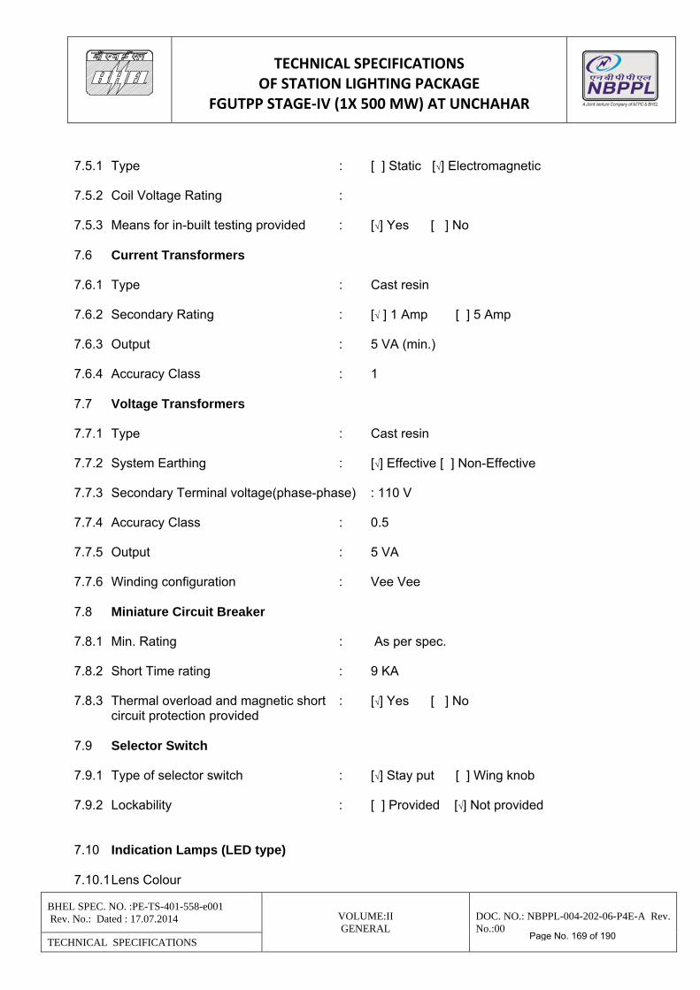
TECHNICAL SPECIFICATIONS OF STATION LIGHTING PACKAGE
FGUTPP STAGE‐IV (1X 500 MW) AT UNCHAHAR
BHEL SPEC. NO. :PE-TS-401-558-e001 Rev. No.: Dated : 17.07.2014 VOLUME:II
GENERAL DOC. NO.: NBPPL-004-202-06-P4E-A Rev. No.:00
TECHNICAL SPECIFICATIONS
7.5.1 Type : [ ] Static [√] Electromagnetic 7.5.2 Coil Voltage Rating : 7.5.3 Means for in-built testing provided : [√] Yes [ ] No 7.6 Current Transformers 7.6.1 Type : Cast resin 7.6.2 Secondary Rating : [√ ] 1 Amp [ ] 5 Amp 7.6.3 Output : 5 VA (min.) 7.6.4 Accuracy Class : 1 7.7 Voltage Transformers 7.7.1 Type : Cast resin 7.7.2 System Earthing : [√] Effective [ ] Non-Effective 7.7.3 Secondary Terminal voltage(phase-phase) : 110 V 7.7.4 Accuracy Class : 0.5 7.7.5 Output : 5 VA 7.7.6 Winding configuration : Vee Vee 7.8 Miniature Circuit Breaker 7.8.1 Min. Rating : As per spec. 7.8.2 Short Time rating : 9 KA 7.8.3 Thermal overload and magnetic short : [√] Yes [ ] No circuit protection provided 7.9 Selector Switch 7.9.1 Type of selector switch : [√] Stay put [ ] Wing knob 7.9.2 Lockability : [ ] Provided [√] Not provided 7.10 Indication Lamps (LED type) 7.10.1 Lens Colour
Page No. 169 of 190
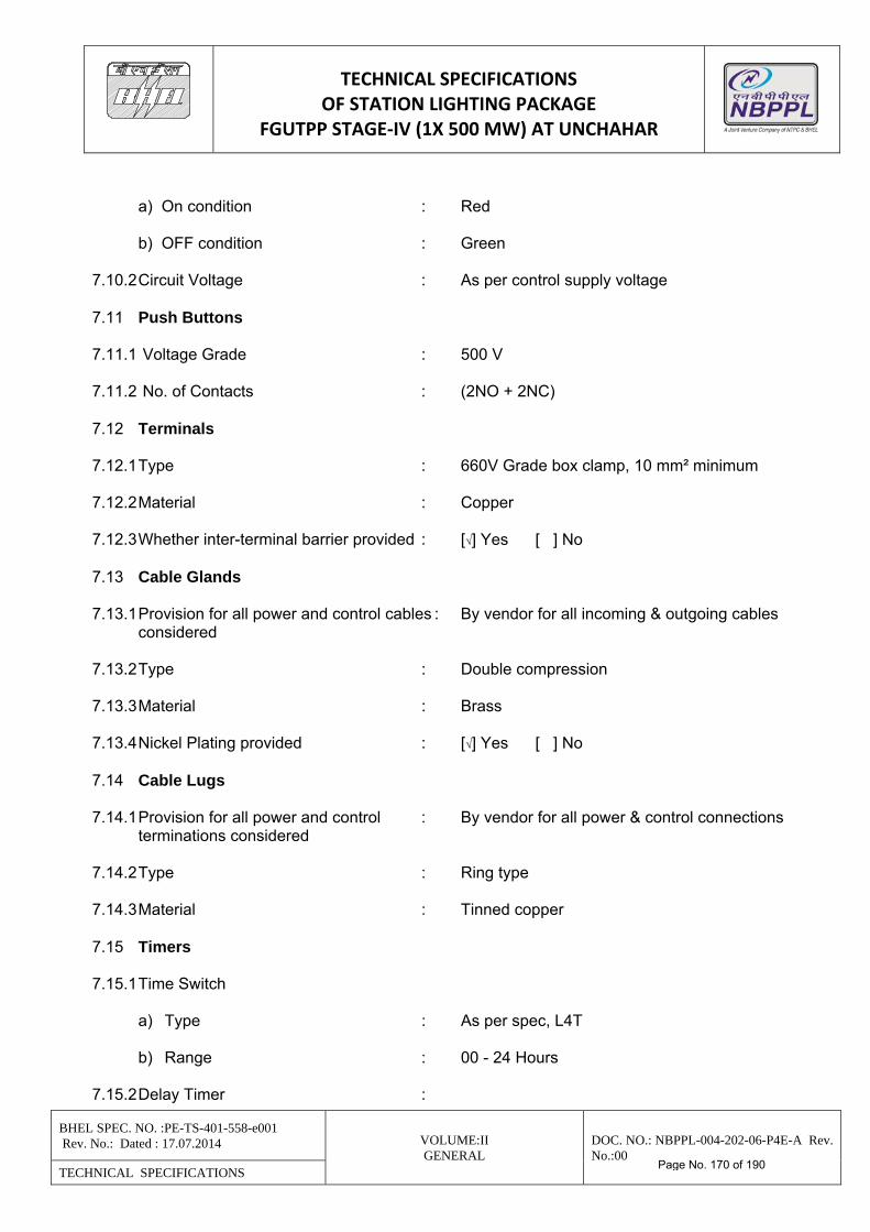
TECHNICAL SPECIFICATIONS OF STATION LIGHTING PACKAGE
FGUTPP STAGE‐IV (1X 500 MW) AT UNCHAHAR
BHEL SPEC. NO. :PE-TS-401-558-e001 Rev. No.: Dated : 17.07.2014 VOLUME:II
GENERAL DOC. NO.: NBPPL-004-202-06-P4E-A Rev. No.:00
TECHNICAL SPECIFICATIONS
a) On condition : Red b) OFF condition : Green 7.10.2 Circuit Voltage : As per control supply voltage 7.11 Push Buttons 7.11.1 Voltage Grade : 500 V 7.11.2 No. of Contacts : (2NO + 2NC) 7.12 Terminals 7.12.1 Type : 660V Grade box clamp, 10 mm² minimum 7.12.2 Material : Copper 7.12.3 Whether inter-terminal barrier provided : [√] Yes [ ] No 7.13 Cable Glands 7.13.1 Provision for all power and control cables : By vendor for all incoming & outgoing cables considered 7.13.2 Type : Double compression 7.13.3 Material : Brass 7.13.4 Nickel Plating provided : [√] Yes [ ] No 7.14 Cable Lugs 7.14.1 Provision for all power and control : By vendor for all power & control connections terminations considered 7.14.2 Type : Ring type 7.14.3 Material : Tinned copper 7.15 Timers 7.15.1 Time Switch a) Type : As per spec, L4T b) Range : 00 - 24 Hours 7.15.2 Delay Timer :
Page No. 170 of 190
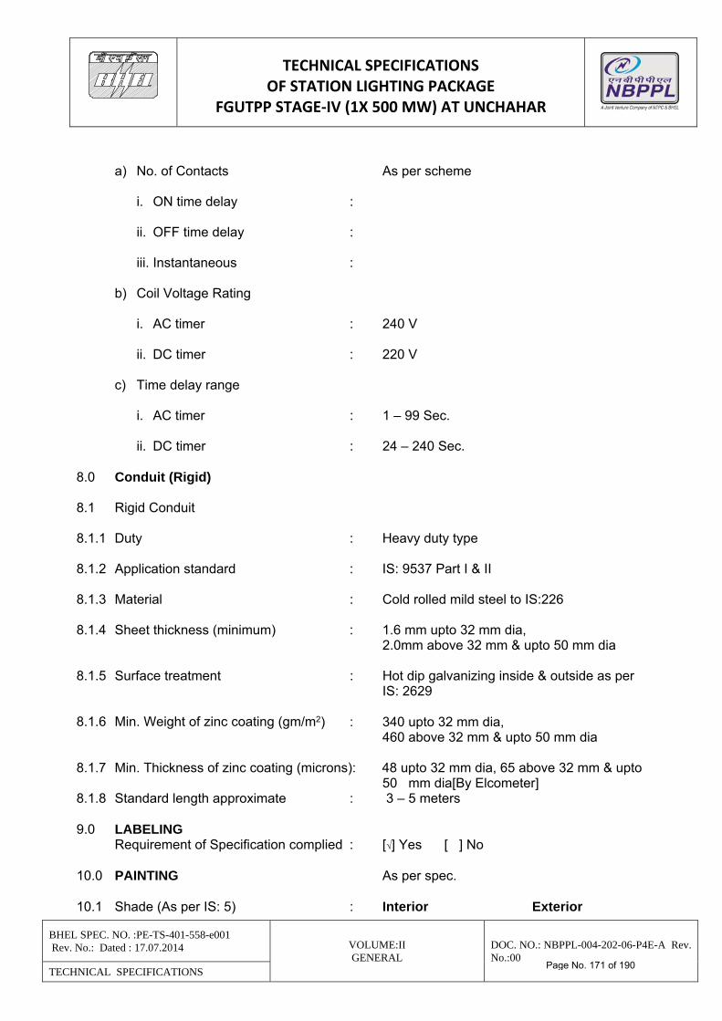
TECHNICAL SPECIFICATIONS OF STATION LIGHTING PACKAGE
FGUTPP STAGE‐IV (1X 500 MW) AT UNCHAHAR
BHEL SPEC. NO. :PE-TS-401-558-e001 Rev. No.: Dated : 17.07.2014 VOLUME:II
GENERAL DOC. NO.: NBPPL-004-202-06-P4E-A Rev. No.:00
TECHNICAL SPECIFICATIONS
a) No. of Contacts As per scheme i. ON time delay : ii. OFF time delay : iii. Instantaneous : b) Coil Voltage Rating i. AC timer : 240 V ii. DC timer : 220 V c) Time delay range i. AC timer : 1 – 99 Sec. ii. DC timer : 24 – 240 Sec. 8.0 Conduit (Rigid) 8.1 Rigid Conduit 8.1.1 Duty : Heavy duty type 8.1.2 Application standard : IS: 9537 Part I & II 8.1.3 Material : Cold rolled mild steel to IS:226 8.1.4 Sheet thickness (minimum) : 1.6 mm upto 32 mm dia, 2.0mm above 32 mm & upto 50 mm dia 8.1.5 Surface treatment : Hot dip galvanizing inside & outside as per
IS: 2629
8.1.6 Min. Weight of zinc coating (gm/m2) : 340 upto 32 mm dia, 460 above 32 mm & upto 50 mm dia 8.1.7 Min. Thickness of zinc coating (microns): 48 upto 32 mm dia, 65 above 32 mm & upto 50 mm dia[By Elcometer] 8.1.8 Standard length approximate : 3 – 5 meters 9.0 LABELING Requirement of Specification complied : [√] Yes [ ] No 10.0 PAINTING As per spec. 10.1 Shade (As per IS: 5) : Interior Exterior
Page No. 171 of 190
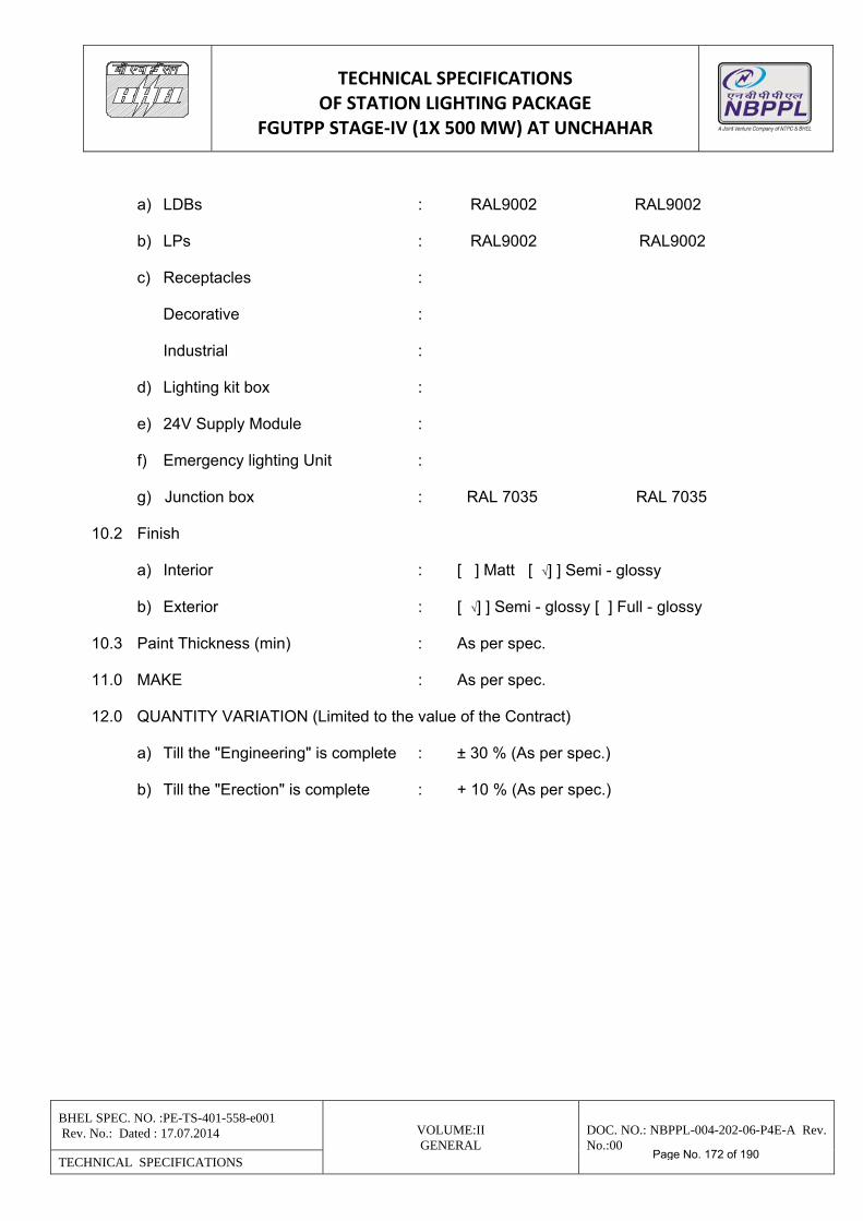
TECHNICAL SPECIFICATIONS OF STATION LIGHTING PACKAGE
FGUTPP STAGE‐IV (1X 500 MW) AT UNCHAHAR
BHEL SPEC. NO. :PE-TS-401-558-e001 Rev. No.: Dated : 17.07.2014 VOLUME:II
GENERAL DOC. NO.: NBPPL-004-202-06-P4E-A Rev. No.:00
TECHNICAL SPECIFICATIONS
a) LDBs : RAL9002 RAL9002 b) LPs : RAL9002 RAL9002 c) Receptacles : Decorative : Industrial : d) Lighting kit box : e) 24V Supply Module : f) Emergency lighting Unit : g) Junction box : RAL 7035 RAL 7035 10.2 Finish a) Interior : [ ] Matt [ √] ] Semi - glossy b) Exterior : [ √] ] Semi - glossy [ ] Full - glossy 10.3 Paint Thickness (min) : As per spec. 11.0 MAKE : As per spec. 12.0 QUANTITY VARIATION (Limited to the value of the Contract) a) Till the "Engineering" is complete : ± 30 % (As per spec.) b) Till the "Erection" is complete : + 10 % (As per spec.)
Page No. 172 of 190
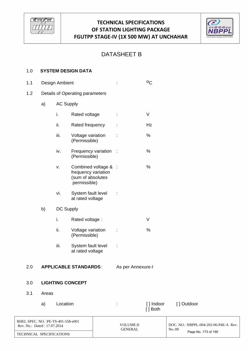
TECHNICAL SPECIFICATIONS OF STATION LIGHTING PACKAGE
FGUTPP STAGE‐IV (1X 500 MW) AT UNCHAHAR
BHEL SPEC. NO. :PE-TS-401-558-e001 Rev. No.: Dated : 17.07.2014 VOLUME:II
GENERAL DOC. NO.: NBPPL-004-202-06-P4E-A Rev. No.:00
TECHNICAL SPECIFICATIONS
DATASHEET B 1.0 SYSTEM DESIGN DATA
1.1 Design Ambient : oC 1.2 Details of Operating parameters a) AC Supply i. Rated voltage : V ii. Rated frequency : Hz iii. Voltage variation : % (Permissible) iv. Frequency variation : % (Permissible) v. Combined voltage & : % frequency variation (sum of absolutes permissible) vi. System fault level : at rated voltage b) DC Supply i. Rated voltage : V ii. Voltage variation : % (Permissible) iii. System fault level : at rated voltage 2.0 APPLICABLE STANDARDS : As per Annexure-I 3.0 LIGHTING CONCEPT 3.1 Areas a) Location : [ ] Indoor [ ] Outdoor [ ] Both
Page No. 173 of 190
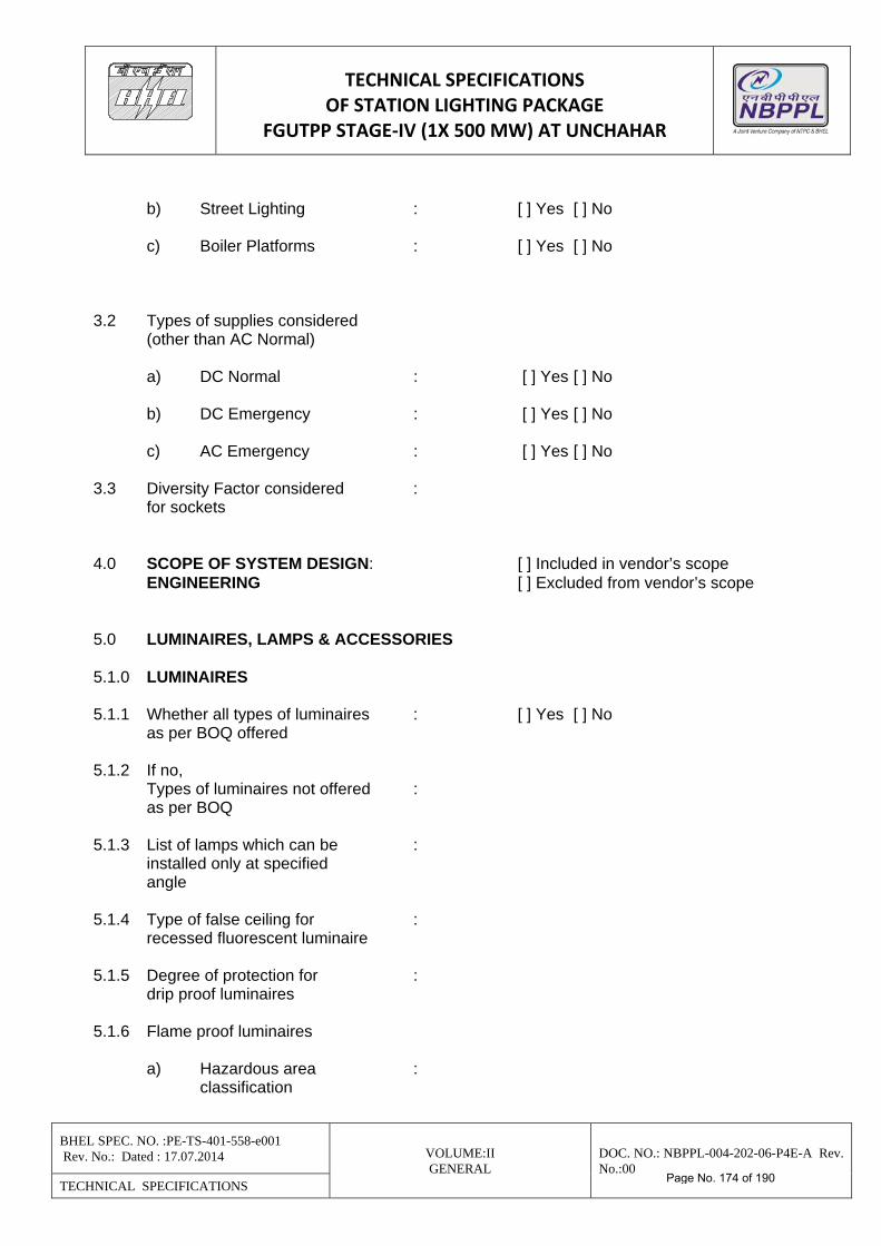
TECHNICAL SPECIFICATIONS OF STATION LIGHTING PACKAGE
FGUTPP STAGE‐IV (1X 500 MW) AT UNCHAHAR
BHEL SPEC. NO. :PE-TS-401-558-e001 Rev. No.: Dated : 17.07.2014 VOLUME:II
GENERAL DOC. NO.: NBPPL-004-202-06-P4E-A Rev. No.:00
TECHNICAL SPECIFICATIONS
b) Street Lighting : [ ] Yes [ ] No
c) Boiler Platforms : [ ] Yes [ ] No
3.2 Types of supplies considered (other than AC Normal) a) DC Normal : [ ] Yes [ ] No b) DC Emergency : [ ] Yes [ ] No c) AC Emergency : [ ] Yes [ ] No 3.3 Diversity Factor considered : for sockets 4.0 SCOPE OF SYSTEM DESIGN: [ ] Included in vendor’s scope ENGINEERING [ ] Excluded from vendor’s scope 5.0 LUMINAIRES, LAMPS & ACCESSORIES 5.1.0 LUMINAIRES 5.1.1 Whether all types of luminaires : [ ] Yes [ ] No as per BOQ offered 5.1.2 If no, Types of luminaires not offered : as per BOQ 5.1.3 List of lamps which can be : installed only at specified angle 5.1.4 Type of false ceiling for : recessed fluorescent luminaire 5.1.5 Degree of protection for : drip proof luminaires 5.1.6 Flame proof luminaires a) Hazardous area : classification
Page No. 174 of 190
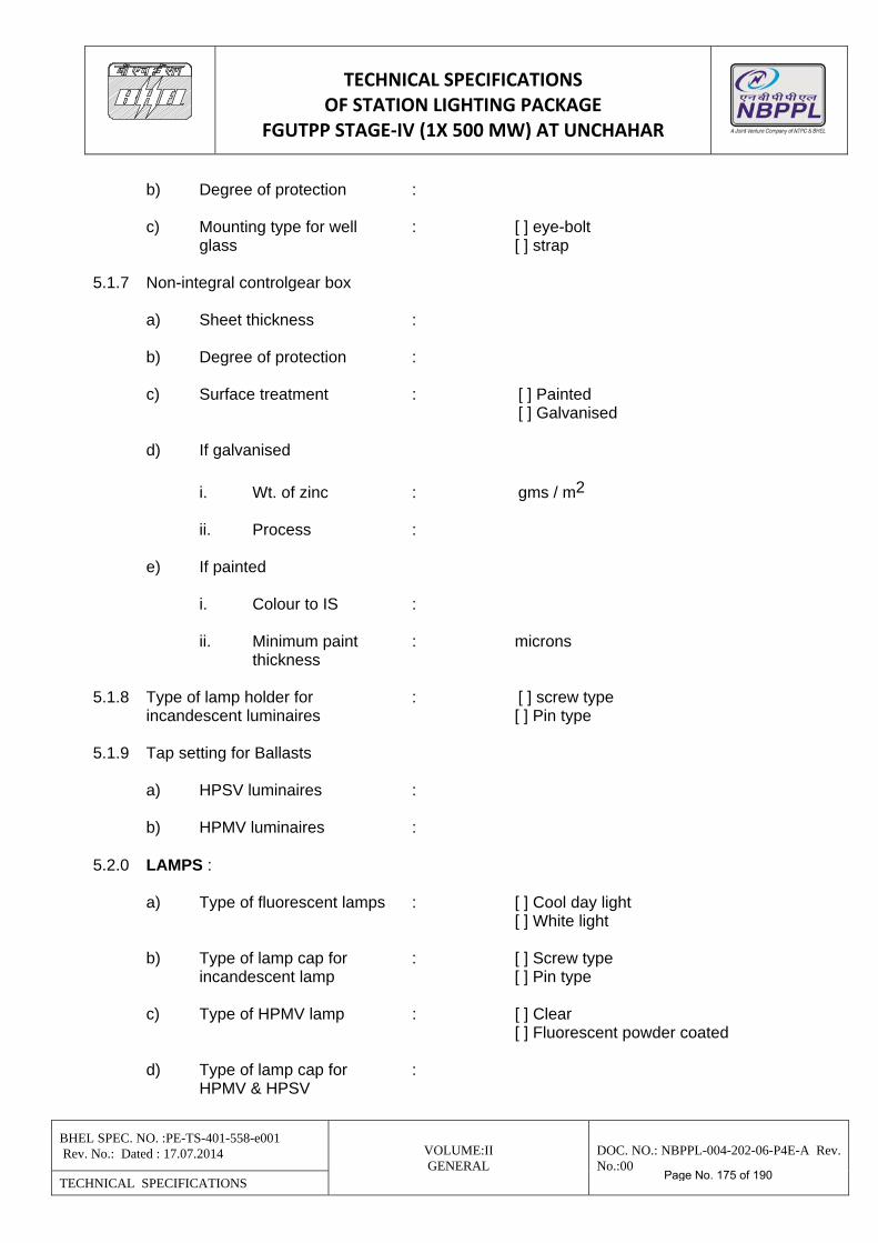
TECHNICAL SPECIFICATIONS OF STATION LIGHTING PACKAGE
FGUTPP STAGE‐IV (1X 500 MW) AT UNCHAHAR
BHEL SPEC. NO. :PE-TS-401-558-e001 Rev. No.: Dated : 17.07.2014 VOLUME:II
GENERAL DOC. NO.: NBPPL-004-202-06-P4E-A Rev. No.:00
TECHNICAL SPECIFICATIONS
b) Degree of protection : c) Mounting type for well : [ ] eye-bolt glass [ ] strap 5.1.7 Non-integral controlgear box a) Sheet thickness : b) Degree of protection : c) Surface treatment : [ ] Painted [ ] Galvanised d) If galvanised
i. Wt. of zinc : gms / m2 ii. Process : e) If painted i. Colour to IS : ii. Minimum paint : microns thickness 5.1.8 Type of lamp holder for : [ ] screw type incandescent luminaires [ ] Pin type 5.1.9 Tap setting for Ballasts a) HPSV luminaires : b) HPMV luminaires : 5.2.0 LAMPS : a) Type of fluorescent lamps : [ ] Cool day light [ ] White light b) Type of lamp cap for : [ ] Screw type incandescent lamp [ ] Pin type c) Type of HPMV lamp : [ ] Clear [ ] Fluorescent powder coated d) Type of lamp cap for : HPMV & HPSV
Page No. 175 of 190
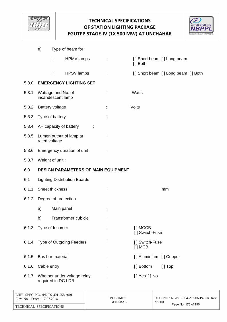
TECHNICAL SPECIFICATIONS OF STATION LIGHTING PACKAGE
FGUTPP STAGE‐IV (1X 500 MW) AT UNCHAHAR
BHEL SPEC. NO. :PE-TS-401-558-e001 Rev. No.: Dated : 17.07.2014 VOLUME:II
GENERAL DOC. NO.: NBPPL-004-202-06-P4E-A Rev. No.:00
TECHNICAL SPECIFICATIONS
e) Type of beam for i. HPMV lamps : [ ] Short beam [ ] Long beam [ ] Both ii. HPSV lamps : [ ] Short beam [ ] Long beam [ ] Both 5.3.0 EMERGENCY LIGHTING SET 5.3.1 Wattage and No. of : Watts incandescent lamp 5.3.2 Battery voltage : Volts 5.3.3 Type of battery : 5.3.4 AH capacity of battery : 5.3.5 Lumen output of lamp at : rated voltage 5.3.6 Emergency duration of unit : 5.3.7 Weight of unit : 6.0 DESIGN PARAMETERS OF MAIN EQUIPMENT 6.1 Lighting Distribution Boards 6.1.1 Sheet thickness : mm 6.1.2 Degree of protection a) Main panel : b) Transformer cubicle : 6.1.3 Type of Incomer : [ ] MCCB [ ] Switch-Fuse 6.1.4 Type of Outgoing Feeders : [ ] Switch-Fuse [ ] MCB 6.1.5 Bus bar material : [ ] Aluminium [ ] Copper 6.1.6 Cable entry : [ ] Bottom [ ] Top 6.1.7 Whether under voltage relay : [ ] Yes [ ] No required in DC LDB
Page No. 176 of 190
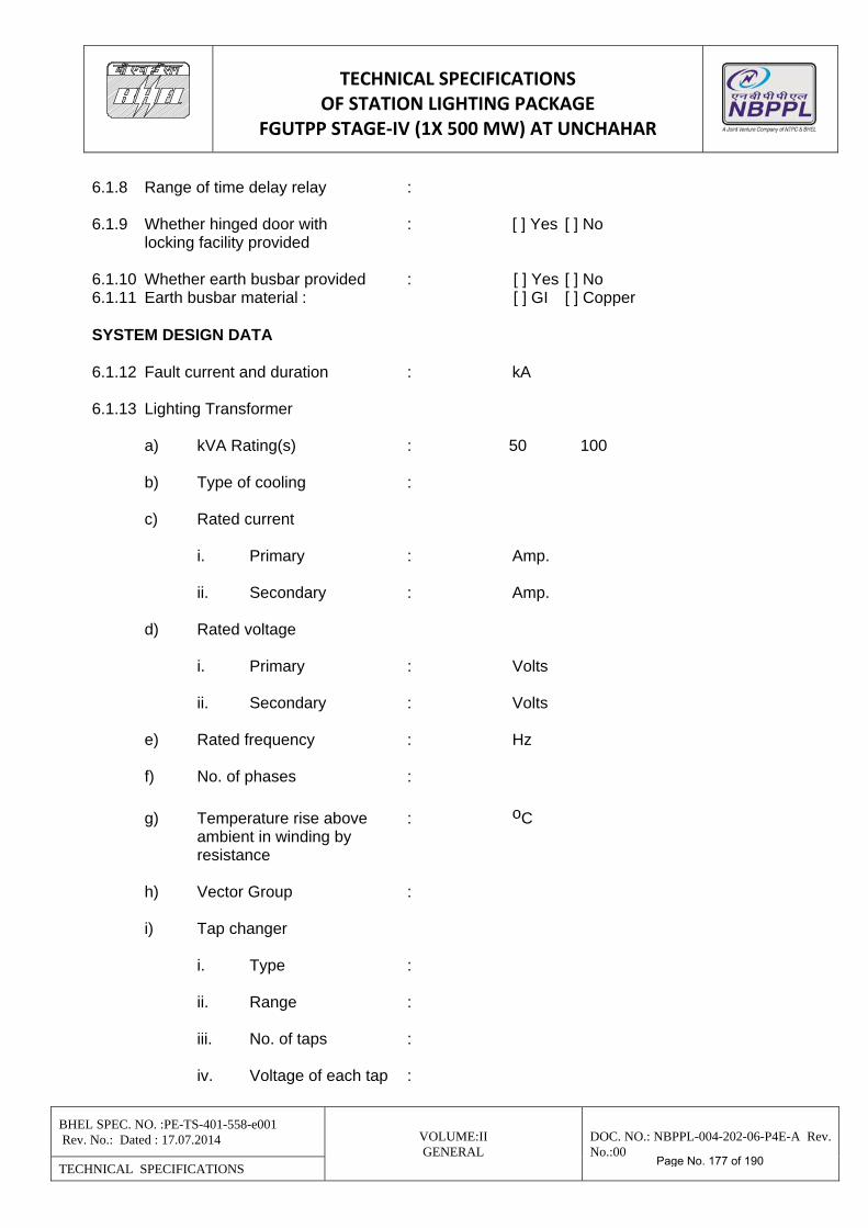
TECHNICAL SPECIFICATIONS OF STATION LIGHTING PACKAGE
FGUTPP STAGE‐IV (1X 500 MW) AT UNCHAHAR
BHEL SPEC. NO. :PE-TS-401-558-e001 Rev. No.: Dated : 17.07.2014 VOLUME:II
GENERAL DOC. NO.: NBPPL-004-202-06-P4E-A Rev. No.:00
TECHNICAL SPECIFICATIONS
6.1.8 Range of time delay relay : 6.1.9 Whether hinged door with : [ ] Yes [ ] No locking facility provided 6.1.10 Whether earth busbar provided : [ ] Yes [ ] No 6.1.11 Earth busbar material : [ ] GI [ ] Copper SYSTEM DESIGN DATA 6.1.12 Fault current and duration : kA 6.1.13 Lighting Transformer a) kVA Rating(s) : 50 100 b) Type of cooling : c) Rated current i. Primary : Amp. ii. Secondary : Amp. d) Rated voltage i. Primary : Volts ii. Secondary : Volts e) Rated frequency : Hz f) No. of phases :
g) Temperature rise above : oC ambient in winding by resistance h) Vector Group : i) Tap changer i. Type : ii. Range : iii. No. of taps : iv. Voltage of each tap :
Page No. 177 of 190
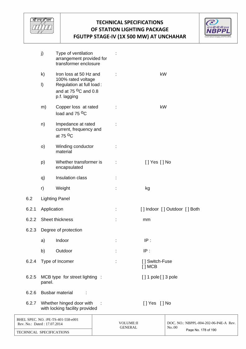
TECHNICAL SPECIFICATIONS OF STATION LIGHTING PACKAGE
FGUTPP STAGE‐IV (1X 500 MW) AT UNCHAHAR
BHEL SPEC. NO. :PE-TS-401-558-e001 Rev. No.: Dated : 17.07.2014 VOLUME:II
GENERAL DOC. NO.: NBPPL-004-202-06-P4E-A Rev. No.:00
TECHNICAL SPECIFICATIONS
j) Type of ventilation : arrangement provided for transformer enclosure k) Iron loss at 50 Hz and : kW 100% rated voltage l) Regulation at full load :
and at 75 oC and 0.8 p.f. lagging m) Copper loss at rated : kW
load and 75 oC n) Impedance at rated : current, frequency and
at 75 oC o) Winding conductor : material p) Whether transformer is : [ ] Yes [ ] No encapsulated q) Insulation class : r) Weight : kg 6.2 Lighting Panel 6.2.1 Application : [ ] Indoor [ ] Outdoor [ ] Both 6.2.2 Sheet thickness : mm 6.2.3 Degree of protection a) Indoor : IP : b) Outdoor : IP : 6.2.4 Type of Incomer : [ ] Switch-Fuse [ ] MCB 6.2.5 MCB type for street lighting : [ ] 1 pole [ ] 3 pole panel. 6.2.6 Busbar material : 6.2.7 Whether hinged door with : [ ] Yes [ ] No with locking facility provided
Page No. 178 of 190
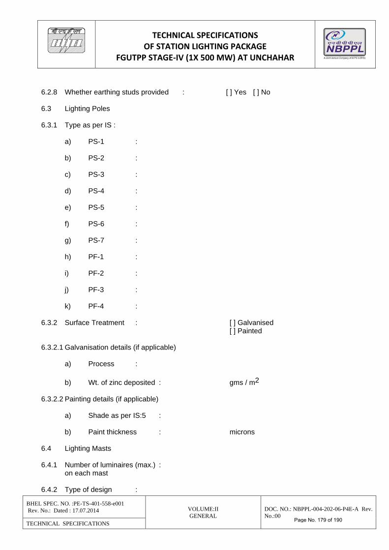
TECHNICAL SPECIFICATIONS OF STATION LIGHTING PACKAGE
FGUTPP STAGE‐IV (1X 500 MW) AT UNCHAHAR
BHEL SPEC. NO. :PE-TS-401-558-e001 Rev. No.: Dated : 17.07.2014 VOLUME:II
GENERAL DOC. NO.: NBPPL-004-202-06-P4E-A Rev. No.:00
TECHNICAL SPECIFICATIONS
6.2.8 Whether earthing studs provided : [ ] Yes [ ] No 6.3 Lighting Poles 6.3.1 Type as per IS : a) PS-1 : b) PS-2 : c) PS-3 : d) PS-4 : e) PS-5 : f) PS-6 : g) PS-7 : h) PF-1 : i) PF-2 : j) PF-3 : k) PF-4 : 6.3.2 Surface Treatment : [ ] Galvanised [ ] Painted 6.3.2.1 Galvanisation details (if applicable) a) Process :
b) Wt. of zinc deposited : gms / m2 6.3.2.2 Painting details (if applicable) a) Shade as per IS:5 : b) Paint thickness : microns 6.4 Lighting Masts 6.4.1 Number of luminaires (max.) : on each mast 6.4.2 Type of design :
Page No. 179 of 190
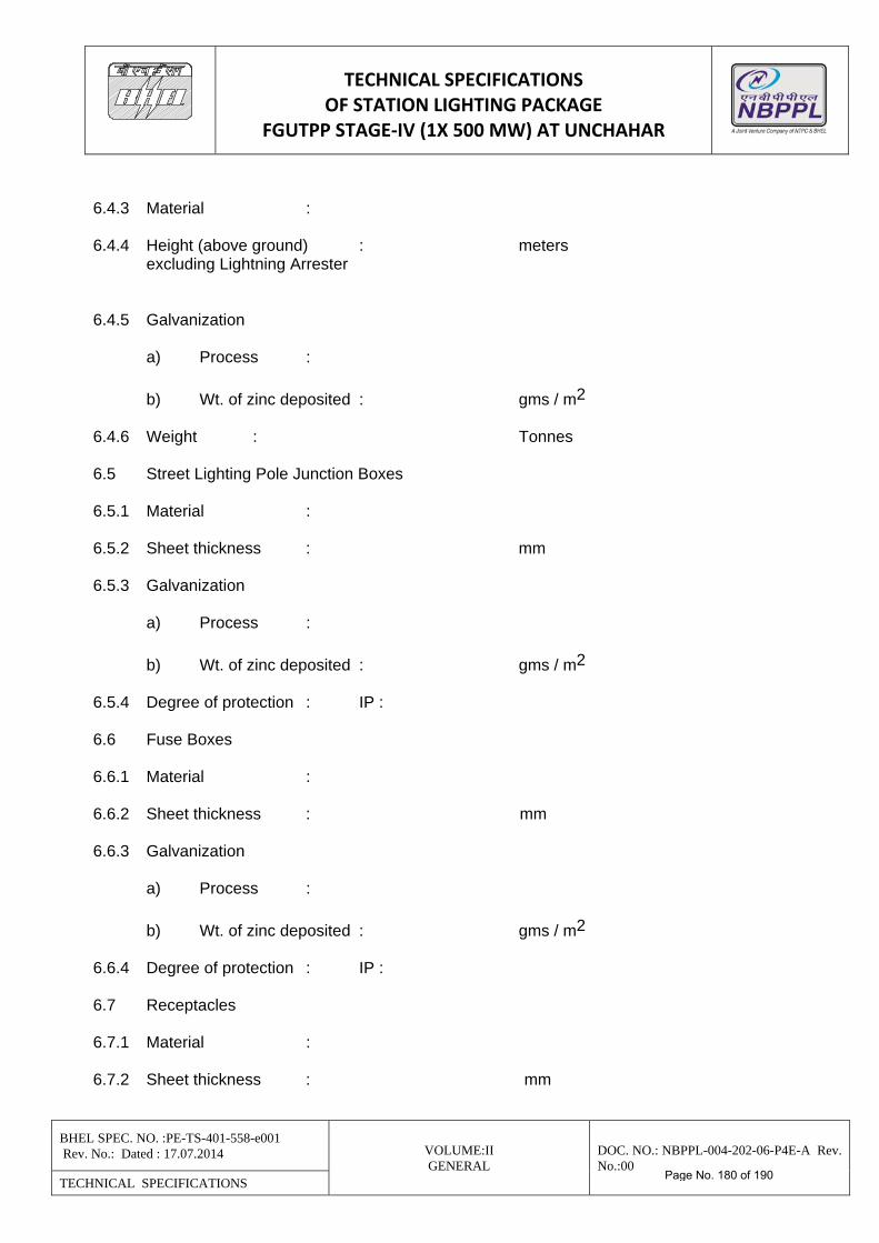
TECHNICAL SPECIFICATIONS OF STATION LIGHTING PACKAGE
FGUTPP STAGE‐IV (1X 500 MW) AT UNCHAHAR
BHEL SPEC. NO. :PE-TS-401-558-e001 Rev. No.: Dated : 17.07.2014 VOLUME:II
GENERAL DOC. NO.: NBPPL-004-202-06-P4E-A Rev. No.:00
TECHNICAL SPECIFICATIONS
6.4.3 Material : 6.4.4 Height (above ground) : meters excluding Lightning Arrester 6.4.5 Galvanization a) Process :
b) Wt. of zinc deposited : gms / m2 6.4.6 Weight : Tonnes 6.5 Street Lighting Pole Junction Boxes 6.5.1 Material : 6.5.2 Sheet thickness : mm 6.5.3 Galvanization a) Process :
b) Wt. of zinc deposited : gms / m2 6.5.4 Degree of protection : IP : 6.6 Fuse Boxes 6.6.1 Material : 6.6.2 Sheet thickness : mm 6.6.3 Galvanization a) Process :
b) Wt. of zinc deposited : gms / m2 6.6.4 Degree of protection : IP : 6.7 Receptacles 6.7.1 Material : 6.7.2 Sheet thickness : mm
Page No. 180 of 190
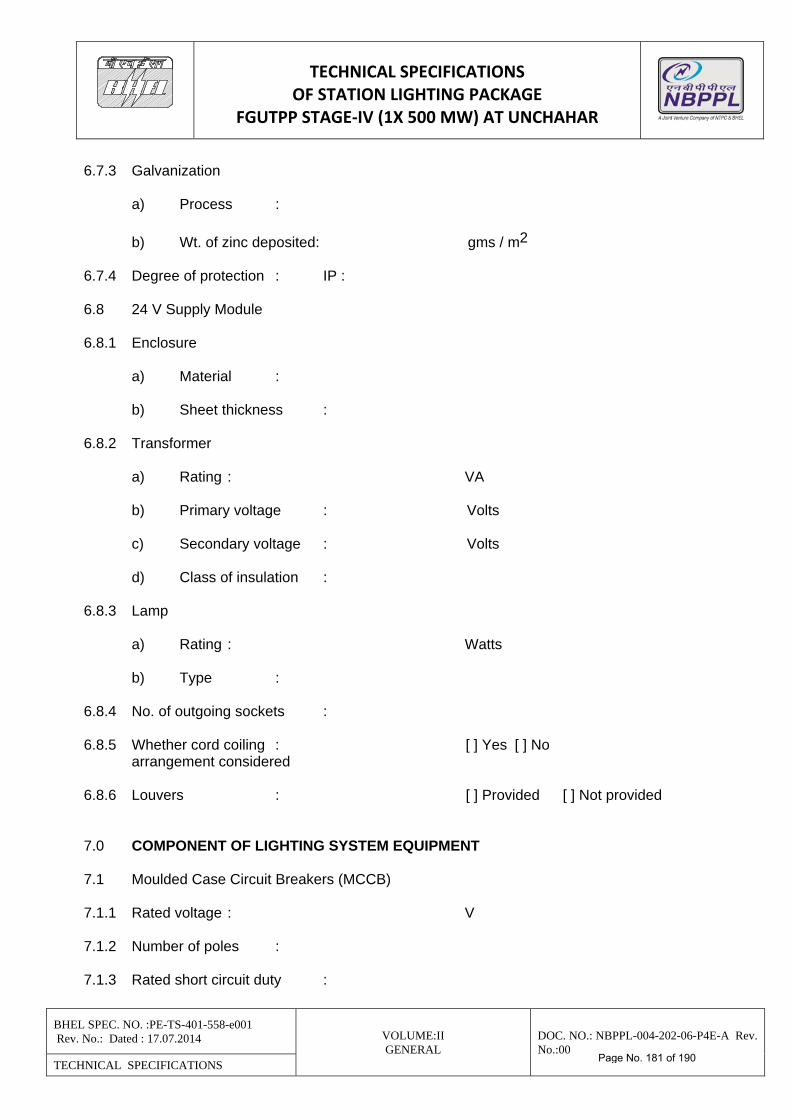
TECHNICAL SPECIFICATIONS OF STATION LIGHTING PACKAGE
FGUTPP STAGE‐IV (1X 500 MW) AT UNCHAHAR
BHEL SPEC. NO. :PE-TS-401-558-e001 Rev. No.: Dated : 17.07.2014 VOLUME:II
GENERAL DOC. NO.: NBPPL-004-202-06-P4E-A Rev. No.:00
TECHNICAL SPECIFICATIONS
6.7.3 Galvanization a) Process :
b) Wt. of zinc deposited: gms / m2 6.7.4 Degree of protection : IP : 6.8 24 V Supply Module 6.8.1 Enclosure a) Material : b) Sheet thickness : 6.8.2 Transformer a) Rating : VA b) Primary voltage : Volts c) Secondary voltage : Volts d) Class of insulation : 6.8.3 Lamp a) Rating : Watts b) Type : 6.8.4 No. of outgoing sockets : 6.8.5 Whether cord coiling : [ ] Yes [ ] No arrangement considered 6.8.6 Louvers : [ ] Provided [ ] Not provided 7.0 COMPONENT OF LIGHTING SYSTEM EQUIPMENT 7.1 Moulded Case Circuit Breakers (MCCB) 7.1.1 Rated voltage : V 7.1.2 Number of poles : 7.1.3 Rated short circuit duty :
Page No. 181 of 190
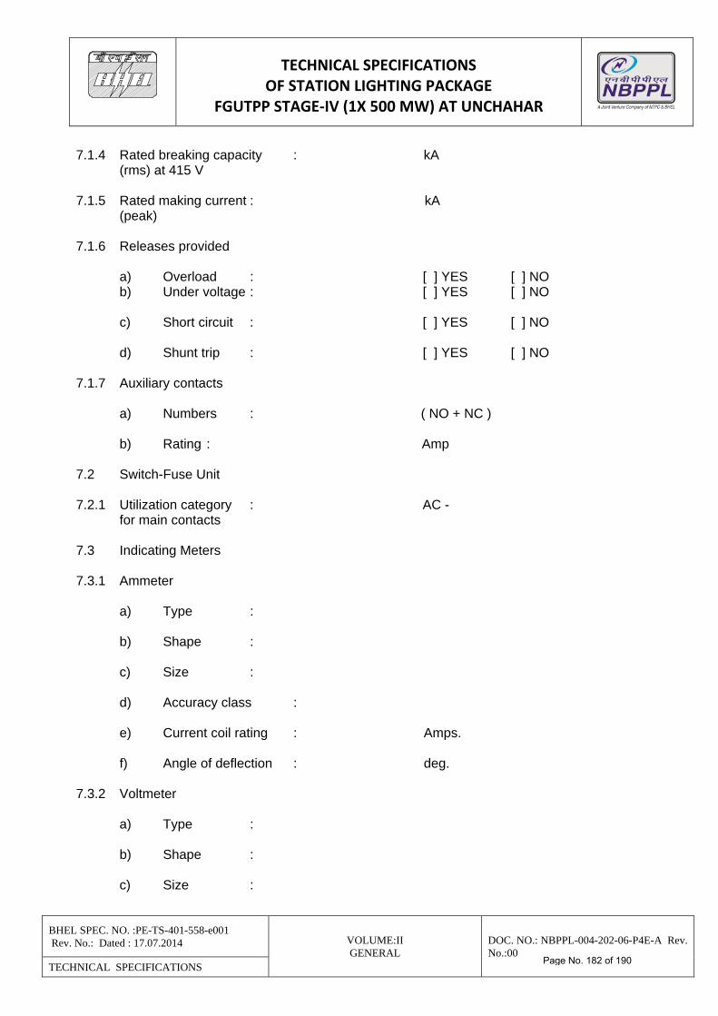
TECHNICAL SPECIFICATIONS OF STATION LIGHTING PACKAGE
FGUTPP STAGE‐IV (1X 500 MW) AT UNCHAHAR
BHEL SPEC. NO. :PE-TS-401-558-e001 Rev. No.: Dated : 17.07.2014 VOLUME:II
GENERAL DOC. NO.: NBPPL-004-202-06-P4E-A Rev. No.:00
TECHNICAL SPECIFICATIONS
7.1.4 Rated breaking capacity : kA (rms) at 415 V 7.1.5 Rated making current : kA (peak) 7.1.6 Releases provided a) Overload : [ ] YES [ ] NO b) Under voltage : [ ] YES [ ] NO c) Short circuit : [ ] YES [ ] NO d) Shunt trip : [ ] YES [ ] NO 7.1.7 Auxiliary contacts a) Numbers : ( NO + NC ) b) Rating : Amp 7.2 Switch-Fuse Unit 7.2.1 Utilization category : AC - for main contacts 7.3 Indicating Meters 7.3.1 Ammeter a) Type : b) Shape : c) Size : d) Accuracy class : e) Current coil rating : Amps. f) Angle of deflection : deg. 7.3.2 Voltmeter a) Type : b) Shape : c) Size :
Page No. 182 of 190
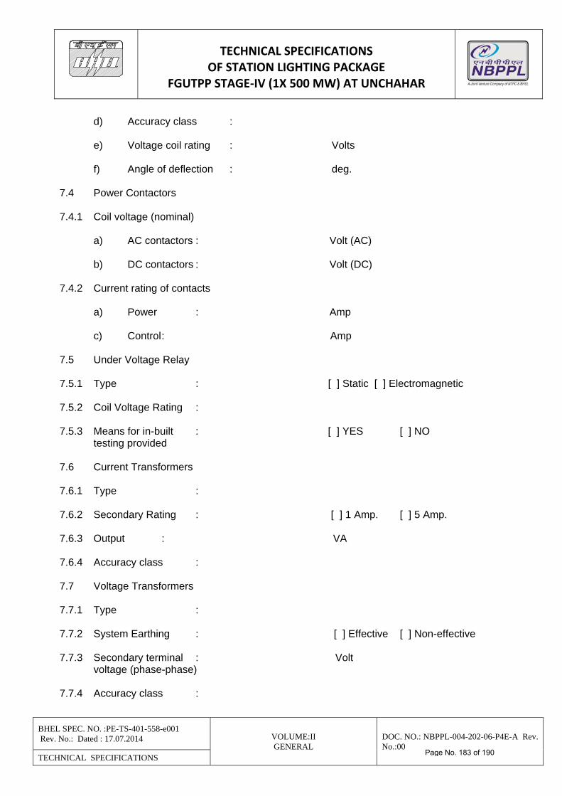
TECHNICAL SPECIFICATIONS OF STATION LIGHTING PACKAGE
FGUTPP STAGE‐IV (1X 500 MW) AT UNCHAHAR
BHEL SPEC. NO. :PE-TS-401-558-e001 Rev. No.: Dated : 17.07.2014 VOLUME:II
GENERAL DOC. NO.: NBPPL-004-202-06-P4E-A Rev. No.:00
TECHNICAL SPECIFICATIONS
d) Accuracy class : e) Voltage coil rating : Volts f) Angle of deflection : deg. 7.4 Power Contactors 7.4.1 Coil voltage (nominal) a) AC contactors : Volt (AC) b) DC contactors : Volt (DC) 7.4.2 Current rating of contacts a) Power : Amp c) Control : Amp 7.5 Under Voltage Relay 7.5.1 Type : [ ] Static [ ] Electromagnetic 7.5.2 Coil Voltage Rating : 7.5.3 Means for in-built : [ ] YES [ ] NO testing provided 7.6 Current Transformers 7.6.1 Type : 7.6.2 Secondary Rating : [ ] 1 Amp. [ ] 5 Amp. 7.6.3 Output : VA 7.6.4 Accuracy class : 7.7 Voltage Transformers 7.7.1 Type : 7.7.2 System Earthing : [ ] Effective [ ] Non-effective 7.7.3 Secondary terminal : Volt voltage (phase-phase) 7.7.4 Accuracy class :
Page No. 183 of 190
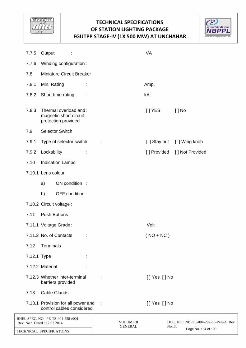
TECHNICAL SPECIFICATIONS OF STATION LIGHTING PACKAGE
FGUTPP STAGE‐IV (1X 500 MW) AT UNCHAHAR
BHEL SPEC. NO. :PE-TS-401-558-e001 Rev. No.: Dated : 17.07.2014 VOLUME:II
GENERAL DOC. NO.: NBPPL-004-202-06-P4E-A Rev. No.:00
TECHNICAL SPECIFICATIONS
7.7.5 Output : VA 7.7.6 Winding configuration : 7.8 Miniature Circuit Breaker 7.8.1 Min. Rating : Amp. 7.8.2 Short time rating : kA 7.8.3 Thermal overload and : [ ] YES [ ] No magnetic short circuit protection provided 7.9 Selector Switch 7.9.1 Type of selector switch : [ ] Stay put [ ] Wing knob 7.9.2 Lockability : [ ] Provided [ ] Not Provided 7.10 Indication Lamps 7.10.1 Lens colour a) ON condition : b) OFF condition : 7.10.2 Circuit voltage : 7.11 Push Buttons 7.11.1 Voltage Grade : Volt 7.11.2 No. of Contacts : ( NO + NC ) 7.12 Terminals 7.12.1 Type : 7.12.2 Material : 7.12.3 Whether inter-terminal : [ ] Yes [ ] No barriers provided 7.13 Cable Glands 7.13.1 Provision for all power and : [ ] Yes [ ] No control cables considered
Page No. 184 of 190
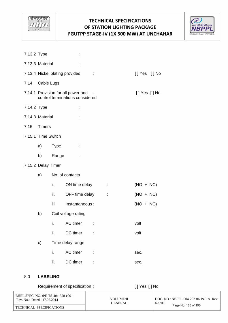
TECHNICAL SPECIFICATIONS OF STATION LIGHTING PACKAGE
FGUTPP STAGE‐IV (1X 500 MW) AT UNCHAHAR
BHEL SPEC. NO. :PE-TS-401-558-e001 Rev. No.: Dated : 17.07.2014 VOLUME:II
GENERAL DOC. NO.: NBPPL-004-202-06-P4E-A Rev. No.:00
TECHNICAL SPECIFICATIONS
7.13.2 Type : 7.13.3 Material : 7.13.4 Nickel plating provided : [ ] Yes [ ] No 7.14 Cable Lugs 7.14.1 Provision for all power and : [ ] Yes [ ] No control terminations considered 7.14.2 Type : 7.14.3 Material : 7.15 Timers 7.15.1 Time Switch a) Type : b) Range : 7.15.2 Delay Timer a) No. of contacts i. ON time delay : (NO + NC) ii. OFF time delay : (NO + NC) iii. Instantaneous : (NO + NC) b) Coil voltage rating i. AC timer : volt ii. DC timer : volt c) Time delay range i. AC timer : sec. ii. DC timer : sec. 8.0 LABELING Requirement of specification : [ ] Yes [ ] No
Page No. 185 of 190
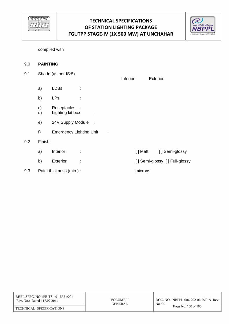
TECHNICAL SPECIFICATIONS OF STATION LIGHTING PACKAGE
FGUTPP STAGE‐IV (1X 500 MW) AT UNCHAHAR
BHEL SPEC. NO. :PE-TS-401-558-e001 Rev. No.: Dated : 17.07.2014 VOLUME:II
GENERAL DOC. NO.: NBPPL-004-202-06-P4E-A Rev. No.:00
TECHNICAL SPECIFICATIONS
complied with 9.0 PAINTING 9.1 Shade (as per IS:5) Interior Exterior a) LDBs : b) LPs : c) Receptacles : d) Lighting kit box : e) 24V Supply Module : f) Emergency Lighting Unit : 9.2 Finish a) Interior : [ ] Matt [ ] Semi-glossy b) Exterior : [ ] Semi-glossy [ ] Full-glossy 9.3 Paint thickness (min.) : microns
Page No. 186 of 190
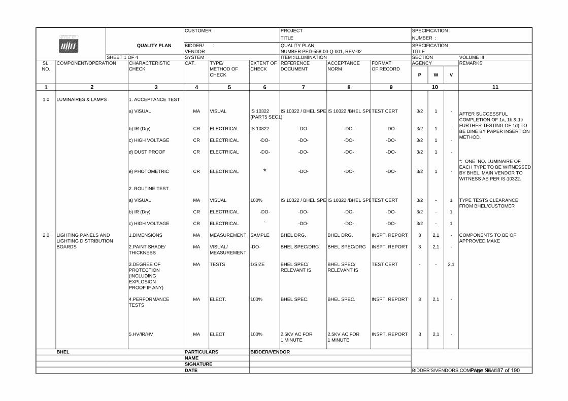
CUSTOMER : PROJECT SPECIFICATION :
TITLE NUMBER :
QUALITY PLAN BIDDER/ : QUALITY PLAN SPECIFICATION : VENDOR NUMBER PED-558-00-Q-001, REV-02 TITLE
SHEET 1 OF 4 SYSTEM ITEM :ILLUMINATION SECTION VOLUME IIISL. COMPONENT/OPERATION CHARACTERISTIC CAT. TYPE/ EXTENT OF REFERENCE ACCEPTANCE FORMAT AGENCY REMARKSNO. CHECK METHOD OF CHECK DOCUMENT NORM OF RECORD
CHECK P W V
1 3 4 5 6 7 8 9
1.0 LUMINAIRES & LAMPS 1. ACCEPTANCE TEST
a) VISUAL MA VISUAL IS 10322 IS 10322 / BHEL SPECIS 10322 /BHEL SPETEST CERT 3/2 1 -(PART5 SEC1)
b) IR (Dry) CR ELECTRICAL IS 10322 -DO- -DO- -DO- 3/2 1 -
c) HIGH VOLTAGE CR ELECTRICAL -DO- -DO- -DO- -DO- 3/2 1 -
d) DUST PROOF CR ELECTRICAL -DO- -DO- -DO- -DO- 3/2 1 -
e) PHOTOMETRIC CR ELECTRICAL * -DO- -DO- -DO- 3/2 1 -
2. ROUTINE TEST
a) VISUAL MA VISUAL 100% IS 10322 / BHEL SPECIS 10322 /BHEL SPETEST CERT 3/2 - 1 TYPE TESTS CLEARANCEFROM BHEL/CUSTOMER
b) IR (Dry) CR ELECTRICAL -DO- -DO- -DO- -DO- 3/2 - 1
c) HIGH VOLTAGE CR ELECTRICAL ` -DO- -DO- -DO- 3/2 - 1
2.0 LIGHTING PANELS AND 1.DIMENSIONS MA MEASUREMENT SAMPLE BHEL DRG. BHEL DRG. INSPT. REPORT 3 2,1 - COMPONENTS TO BE OFLIGHTING DISTRIBUTION APPROVED MAKEBOARDS 2.PAINT SHADE/ MA VISUAL/ -DO- BHEL SPEC/DRG BHEL SPEC/DRG INSPT. REPORT 3 2,1 -
THICKNESS MEASUREMENT
3.DEGREE OF MA TESTS 1/SIZE BHEL SPEC/ BHEL SPEC/ TEST CERT - - 2,1PROTECTION RELEVANT IS RELEVANT IS(INCLUDINGEXPLOSIONPROOF IF ANY)
4.PERFORMANCE MA ELECT. 100% BHEL SPEC. BHEL SPEC. INSPT. REPORT 3 2,1 -TESTS
5.HV/IR/HV MA ELECT 100% 2.5KV AC FOR 2.5KV AC FOR INSPT. REPORT 3 2,1 -1 MINUTE 1 MINUTE
BHEL PARTICULARS BIDDER/VENDORNAMESIGNATUREDATE BIDDER'S/VENDORS COMPANY SEAL
112 10
*: ONE NO. LUMINAIRE OF EACH TYPE TO BE WITNESSED BY BHEL. MAIN VENDOR TO WITNESS AS PER IS-10322.
AFTER SUCCESSFUL COMPLETION OF 1a, 1b & 1c FURTHER TESTING OF 1d) TO BE DINE BY PAPER INSERTION METHOD.
Page No. 187 of 190
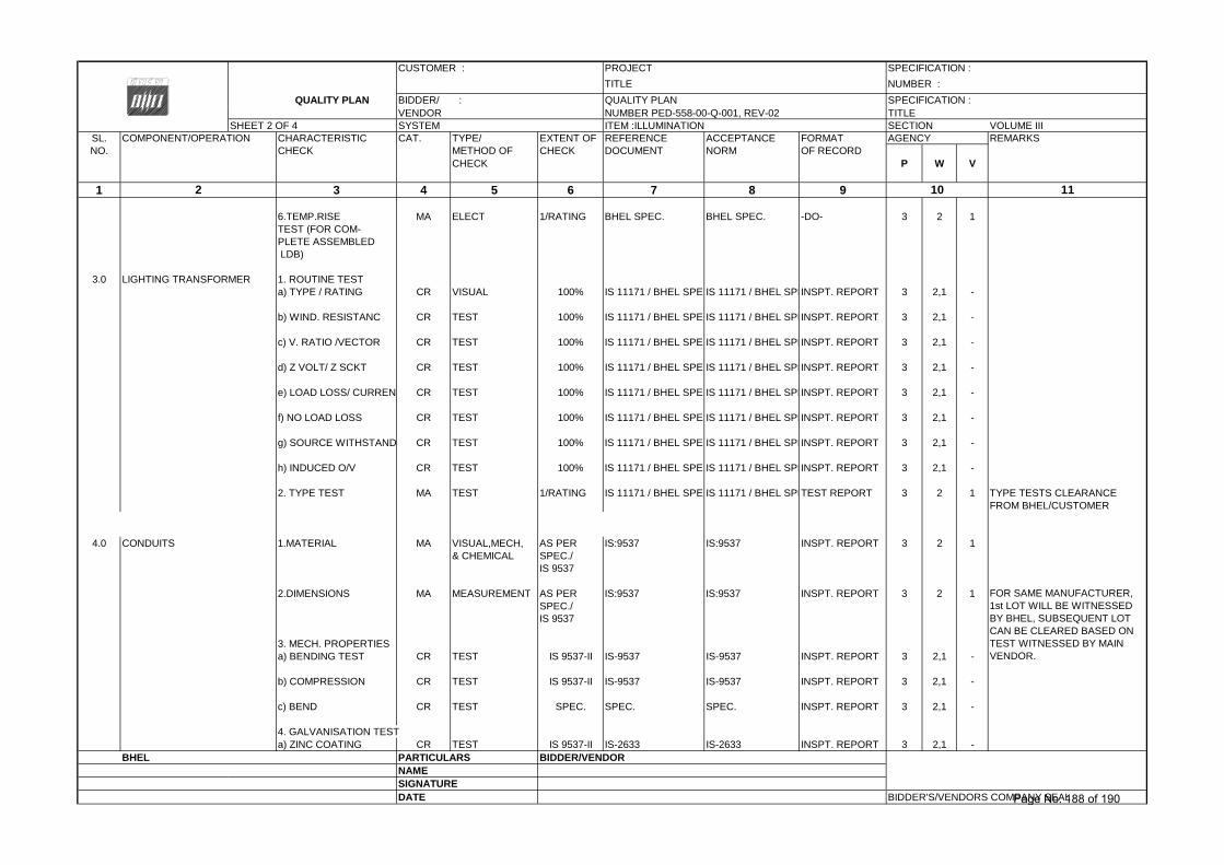
CUSTOMER : PROJECT SPECIFICATION :
TITLE NUMBER :
QUALITY PLAN BIDDER/ : QUALITY PLAN SPECIFICATION : VENDOR NUMBER PED-558-00-Q-001, REV-02 TITLE
SHEET 2 OF 4 SYSTEM ITEM :ILLUMINATION SECTION VOLUME IIISL. COMPONENT/OPERATION CHARACTERISTIC CAT. TYPE/ EXTENT OF REFERENCE ACCEPTANCE FORMAT AGENCY REMARKSNO. CHECK METHOD OF CHECK DOCUMENT NORM OF RECORD
CHECK P W V
1 3 4 5 6 7 8 9
6.TEMP.RISE MA ELECT 1/RATING BHEL SPEC. BHEL SPEC. -DO- 3 2 1TEST (FOR COM-PLETE ASSEMBLED LDB)
3.0 LIGHTING TRANSFORMER 1. ROUTINE TESTa) TYPE / RATING CR VISUAL 100% IS 11171 / BHEL SPECIS 11171 / BHEL SPEINSPT. REPORT 3 2,1 -
b) WIND. RESISTANC CR TEST 100% IS 11171 / BHEL SPECIS 11171 / BHEL SPEINSPT. REPORT 3 2,1 -
c) V. RATIO /VECTOR CR TEST 100% IS 11171 / BHEL SPECIS 11171 / BHEL SPEINSPT. REPORT 3 2,1 -
d) Z VOLT/ Z SCKT CR TEST 100% IS 11171 / BHEL SPECIS 11171 / BHEL SPEINSPT. REPORT 3 2,1 -
e) LOAD LOSS/ CURREN CR TEST 100% IS 11171 / BHEL SPECIS 11171 / BHEL SPEINSPT. REPORT 3 2,1 -
f) NO LOAD LOSS CR TEST 100% IS 11171 / BHEL SPECIS 11171 / BHEL SPEINSPT. REPORT 3 2,1 -
g) SOURCE WITHSTAND CR TEST 100% IS 11171 / BHEL SPECIS 11171 / BHEL SPEINSPT. REPORT 3 2,1 -
h) INDUCED O/V CR TEST 100% IS 11171 / BHEL SPECIS 11171 / BHEL SPEINSPT. REPORT 3 2,1 -
2. TYPE TEST MA TEST 1/RATING IS 11171 / BHEL SPECIS 11171 / BHEL SPETEST REPORT 3 2 1 TYPE TESTS CLEARANCEFROM BHEL/CUSTOMER
4.0 CONDUITS 1.MATERIAL MA VISUAL,MECH, AS PER IS:9537 IS:9537 INSPT. REPORT 3 2 1& CHEMICAL SPEC./
IS 9537
2.DIMENSIONS MA MEASUREMENT AS PER IS:9537 IS:9537 INSPT. REPORT 3 2 1SPEC./IS 9537
3. MECH. PROPERTIESa) BENDING TEST CR TEST IS 9537-II IS-9537 IS-9537 INSPT. REPORT 3 2,1 -
b) COMPRESSION CR TEST IS 9537-II IS-9537 IS-9537 INSPT. REPORT 3 2,1 -
c) BEND CR TEST SPEC. SPEC. SPEC. INSPT. REPORT 3 2,1 -
4. GALVANISATION TESTa) ZINC COATING CR TEST IS 9537-II IS-2633 IS-2633 INSPT. REPORT 3 2,1 -
BHEL PARTICULARS BIDDER/VENDORNAMESIGNATUREDATE BIDDER'S/VENDORS COMPANY SEAL
FOR SAME MANUFACTURER, 1st LOT WILL BE WITNESSED BY BHEL, SUBSEQUENT LOT CAN BE CLEARED BASED ON TEST WITNESSED BY MAIN VENDOR.
2 10 11
Page No. 188 of 190
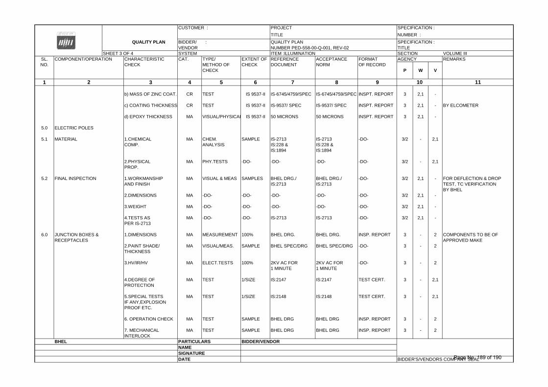
CUSTOMER : PROJECT SPECIFICATION :
TITLE NUMBER :
QUALITY PLAN BIDDER/ : QUALITY PLAN SPECIFICATION : VENDOR NUMBER PED-558-00-Q-001, REV-02 TITLE
SHEET 3 OF 4 SYSTEM ITEM :ILLUMINATION SECTION VOLUME IIISL. COMPONENT/OPERATION CHARACTERISTIC CAT. TYPE/ EXTENT OF REFERENCE ACCEPTANCE FORMAT AGENCY REMARKSNO. CHECK METHOD OF CHECK DOCUMENT NORM OF RECORD
CHECK P W V
1 3 4 5 6 7 8 9
b) MASS OF ZINC COAT. CR TEST IS 9537-II IS-6745/4759/SPEC IS-6745/4759/SPEC INSPT. REPORT 3 2,1 -
c) COATING THICKNESS CR TEST IS 9537-II IS-9537/ SPEC IS-9537/ SPEC INSPT. REPORT 3 2,1 - BY ELCOMETER
d) EPOXY THICKNESS MA VISUAL/PHYSICAL IS 9537-II 50 MICRONS 50 MICRONS INSPT. REPORT 3 2,1 -
5.0 ELECTRIC POLES
5.1 MATERIAL 1.CHEMICAL MA CHEM. SAMPLE IS-2713 IS-2713 -DO- 3/2 - 2,1COMP. ANALYSIS IS:228 & IS:228 &
IS:1894 IS:1894
2.PHYSICAL MA PHY.TESTS -DO- -DO- -DO- -DO- 3/2 - 2,1PROP.
5.2 FINAL INSPECTION 1.WORKMANSHIP MA VISUAL & MEAS SAMPLES BHEL DRG./ BHEL DRG./ -DO- 3/2 2,1 - FOR DEFLECTION & DROPAND FINISH IS:2713 IS:2713 TEST, TC VERIFICATION
BY BHEL2.DIMENSIONS MA -DO- -DO- -DO- -DO- -DO- 3/2 2,1 -
3.WEIGHT MA -DO- -DO- -DO- -DO- -DO- 3/2 2,1 -
4.TESTS AS MA -DO- -DO- IS-2713 IS-2713 -DO- 3/2 2,1 -PER IS-2713
6.0 JUNCTION BOXES & 1.DIMENSIONS MA MEASUREMENT 100% BHEL DRG. BHEL DRG. INSP. REPORT 3 - 2 COMPONENTS TO BE OFRECEPTACLES APPROVED MAKE
2.PAINT SHADE/ MA VISUAL/MEAS. SAMPLE BHEL SPEC/DRG BHEL SPEC/DRG -DO- 3 - 2THICKNESS
3.HV/IR/HV MA ELECT.TESTS 100% 2KV AC FOR 2KV AC FOR -DO- 3 - 21 MINUTE 1 MINUTE
4.DEGREE OF MA TEST 1/SIZE IS:2147 IS:2147 TEST CERT. 3 - 2,1PROTECTION
5.SPECIAL TESTS MA TEST 1/SIZE IS:2148 IS:2148 TEST CERT. 3 - 2,1IF ANY,EXPLOSIONPROOF ETC.
6. OPERATION CHECK MA TEST SAMPLE BHEL DRG BHEL DRG INSP. REPORT 3 - 2
7. MECHANICAL MA TEST SAMPLE BHEL DRG BHEL DRG INSP. REPORT 3 - 2INTERLOCK
BHEL PARTICULARS BIDDER/VENDORNAMESIGNATUREDATE BIDDER'S/VENDORS COMPANY SEAL
2 10 11
Page No. 189 of 190
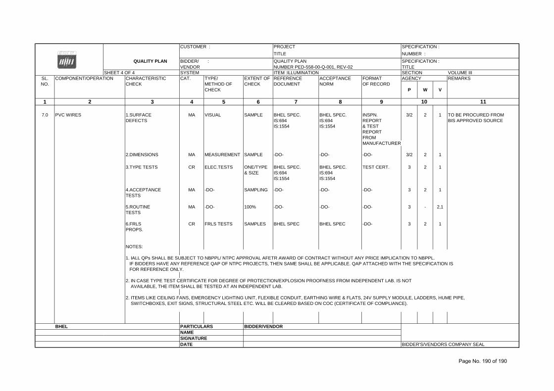
CUSTOMER : PROJECT SPECIFICATION :
TITLE NUMBER :
QUALITY PLAN BIDDER/ : QUALITY PLAN SPECIFICATION : VENDOR NUMBER PED-558-00-Q-001, REV-02 TITLE
SHEET 4 OF 4 SYSTEM ITEM :ILLUMINATION SECTION VOLUME IIISL. COMPONENT/OPERATION CHARACTERISTIC CAT. TYPE/ EXTENT OF REFERENCE ACCEPTANCE FORMAT AGENCY REMARKSNO. CHECK METHOD OF CHECK DOCUMENT NORM OF RECORD
CHECK P W V
1 3 4 5 6 7 8 9
7.0 PVC WIRES 1.SURFACE MA VISUAL SAMPLE BHEL SPEC. BHEL SPEC. INSPN. 3/2 2 1 TO BE PROCURED FROMDEFECTS IS:694 IS:694 REPORT BIS APPROVED SOURCE
IS:1554 IS:1554 & TEST REPORTFROM MANUFACTURER
2.DIMENSIONS MA MEASUREMENT SAMPLE -DO- -DO- -DO- 3/2 2 1
3.TYPE TESTS CR ELEC.TESTS ONE/TYPE BHEL SPEC. BHEL SPEC. TEST CERT. 3 2 1& SIZE IS:694 IS:694
IS:1554 IS:1554
4.ACCEPTANCE MA -DO- SAMPLING -DO- -DO- -DO- 3 2 1TESTS
5.ROUTINE MA -DO- 100% -DO- -DO- -DO- 3 - 2,1TESTS
6.FRLS CR FRLS TESTS SAMPLES BHEL SPEC BHEL SPEC -DO- 3 2 1PROPS.
NOTES:
1. IALL QPs SHALL BE SUBJECT TO NBPPL/ NTPC APPROVAL AFETR AWARD OF CONTRACT WITHOUT ANY PRICE IMPLICATION TO NBPPL. IF BIDDERS HAVE ANY REFERENCE QAP OF NTPC PROJECTS, THEN SAME SHALL BE APPLICABLE. QAP ATTACHED WITH THE SPECIFICATION IS FOR REFERENCE ONLY.
2. IN CASE TYPE TEST CERTIFICATE FOR DEGREE OF PROTECTION/EXPLOSION PROOFNESS FROM INDEPENDENT LAB. IS NOT AVAILABLE, THE ITEM SHALL BE TESTED AT AN INDEPENDENT LAB.
2. ITEMS LIKE CEILING FANS, EMERGENCY LIGHTING UNIT, FLEXIBLE CONDUIT, EARTHING WIRE & FLATS, 24V SUPPLY MODULE, LADDERS, HUME PIPE, SWITCHBOXES, EXIT SIGNS, STRUCTURAL STEEL ETC. WILL BE CLEARED BASED ON COC (CERTIFICATE OF COMPLIANCE).
BHEL PARTICULARS BIDDER/VENDORNAMESIGNATUREDATE BIDDER'S/VENDORS COMPANY SEAL
2 10 11
Page No. 190 of 190