novel five-level anpc bidirectional converter for power
TRANSCRIPT
energies
Article
Novel Five-Level ANPC Bidirectional Converter for PowerQuality Enhancement during G2V/V2G Operation of CascadedEV Charger
Jorge Lara 1,* , Lesedi Masisi 2 , Concepcion Hernandez 1, Marco A. Arjona 1 and Ambrish Chandra 3
Citation: Lara, J.; Masisi, L.;
Hernandez, C.; Arjona, M.A.;
Chandra, A. Novel Five-Level ANPC
Bidirectional Converter for Power
Quality Enhancement during
G2V/V2G Operation of Cascaded EV
Charger. Energies 2021, 14, 2650.
https://doi.org/10.3390/en14092650
Academic Editor: Sekyung Han
Received: 24 March 2021
Accepted: 27 April 2021
Published: 5 May 2021
Publisher’s Note: MDPI stays neutral
with regard to jurisdictional claims in
published maps and institutional affil-
iations.
Copyright: © 2021 by the authors.
Licensee MDPI, Basel, Switzerland.
This article is an open access article
distributed under the terms and
conditions of the Creative Commons
Attribution (CC BY) license (https://
creativecommons.org/licenses/by/
4.0/).
1 División de Estudios de Posgrado e Investigación, TNM Instituto Tecnológico de La Laguna,Torreón 27000, Mexico; [email protected] (C.H.); [email protected] (M.A.A.)
2 School of Electrical and Information Engineering, University of the Witwatersrand,Johannesburg 2000, South Africa; [email protected]
3 Department of Electrical Engineering, École de Technologie Supérieure (ÉTS), Montreal, QC H3C 1K3, Canada;[email protected]
* Correspondence: [email protected]
Abstract: This paper presents a novel single-phase (SP) active-neutral point clamped (ANPC) five-level bidirectional converter (FLBC) for enhancing the power quality (PQ) during the grid-to-vehicle(G2V) and vehicle-to-grid (V2G) operation of an electric vehicle (EV) charger connected in series. ThisEV charger is based on a dual-active half-bridge DC-DC converter (DAHBC) with a high frequencyisolation transformer. Unlike the comparable ANPC topologies found in literature, the proposed onehas two more switches, i.e., ten instead of eight. However, with the addition of these components,the proposed multilevel converter not only becomes capable of properly balancing the voltage of theDC-link split capacitors under various step-changing conditions but it achieves a better efficiency, alower stress of the switching devices and a more even distribution of the power losses. The resultinggrid-tied ANPC-SPFLBC and DAHBC are accurately controlled with a cascaded control strategyand a single-phase shift (SPS) control technique, respectively. The simulation results obtained withMATLAB-SimPowerSystems as well as the experimental results obtained in laboratory validate theproposed ANPC-SPFLBC for a set of exhaustive tests in both V2G and G2V modes. A detailedpower quality analysis carried out with a Fluke 43B alike demonstrates the good performance of theproposed topology.
Keywords: single-phase five-level converter; ANPC topology; DC-link split capacitors voltagebalancing; power quality enhancement; electric vehicle charger; G2V/V2G operation modes
1. Introduction
The detrimental environment pollution due to the use of conventional sources ofenergy, the continuous increases in the price of oil and the expected eventual exhaustion offossil fuels have fostered the rapid development of electric vehicles, both battery-based(BEV), hybrid (HEV), plug-in (PEV) and fuel cell-based (FCEV) [1,2]. Some Europeancountries, such as Norway and Sweden have scheduled banning all petrol-powered carsin the next 3–4 decades. The EVs inherently linking the transport and the electricitysectors have given rise to emerging technologies such as superchargers (G2V) and grid-support (V2G) [3–5]. These EVs are grid-connected through a power converter, hencerequiring of advanced power conversion and control techniques and a deep analysisof the grid impact, the converter behavior, the stability, the harmonic emission and theelectromagnetic interference (EMI) [6]. There exists a wide variety of EV battery chargertopologies [7]. The dual active full bridge (DAFB) and the dual active half bridge (DAHB)DC-DC topologies are especially practical because they include a higher frequency (HF)transformer in between that provides a galvanic isolation for safely connecting the EV
Energies 2021, 14, 2650. https://doi.org/10.3390/en14092650 https://www.mdpi.com/journal/energies
Energies 2021, 14, 2650 2 of 19
batteries with the mains through the grid-tied power converter [8,9]. Furthermore, bearingin mind that the physical size and in turn the weight of the required transformer reduceswith the increasing of the operating frequency [10], this topology is fairly attractive for EVapplications where space and burden constraints are critical. Despite the fact that in theDAHB topology only the SPS control technique can be applied, it is widely utilized dueto its low cost, volume and weight as well as its global reduction in switches, drivers andcooling system [11].
The interaction of modern power converters with the smart grid is a main issueregarding power quality aspects [12]. The use of multilevel power converters (ML) isincreasingly preferred since they provide a high-quality output voltage with a lowerharmonic content, a lower dV/dt, a lower switching frequency and consequently a higherefficiency [13]. The cascaded H-bridge (CHB), the flying capacitor (FC) and the neutral-point-clamped (NPC) including its subtopology of active-NPC (ANPC) are the maintypes of conventional multilevel topologies [14]. The NPC-based configurations have theadvantage of requiring only one isolated DC source but also the inconvenient that itsDC-link split capacitors undergo the voltage unbalance phenomenon and consequentlythey need implementing balancing compensation techniques [15–18]. It is possible to getrid of this unbalancing issue by using two independent DC voltage sources instead ofcapacitors but at the expense of a higher cost and a bigger system complexity [19] or wellin certain photovoltaic (PV) applications [20].
Over the last years various topologies of single-phase ANPC five-level (FL) convertershave been devised. In [21], authors propose a single-phase hybrid Si/SiC ANPC FL inverterwith an improved modulation scheme for reducing the conduction losses. Although theinherent voltage unbalancing problem is not mentioned, its undesirable effect is present butit could have been reduced by considerably increasing the capacitance of the electrolyticsplit capacitors. Due to the absence of redundant vectors for the states that output halfof the DC bus voltage, the voltage balancing in this topology is simply not possible.In [22], authors propose a single-phase ANPC FL inverter and its three-phase version.The modulation strategy is based on an unipolar pulse-width modulation (PWM) forthe high-frequency switches and on the polarity of the modulating signal for the low-frequency switches. Owing to the consecutive alternation of the redundant switching statesfor the high-frequency switches, the split capacitors are equally charge and discharge ateach switching period, thus accurately maintaining a zero average neutral current andconsequently achieving a fairly good voltage unbalancing compensation. Nevertheless, thealternation of the redundant states at twice the switching frequency increases the powerlosses and the stress of the high frequency switches, thus reducing the overall efficiency.
In comparison with [21,22], the single-phase (SP) ANPC-FL converter proposed in thispaper is based on a novel topology consisting of ten switches instead of eight. However,with the addition of these two switches, it not only becomes capable of properly balancingthe voltage of the DC-link split capacitors under different step-changing conditions butit achieves a better efficiency, a lower stress of the switching devices and a more evendistribution of the power losses. Thanks to this voltage balancing, the power qualityof the proposed ANPC-FL converter output voltage and in turn of the grid current areconsiderably enhanced during the G2V and V2G operation of the cascaded DAHB converterworking as a bidirectional EV charger.
This paper is organized as follows: Section 2 describes the topology details of theproposed ANPC SPFLBC, its current flowing paths and its voltage balancing strategy.Section 3 examines the cascaded control strategy for the proposed grid-tied SPFLBC whileanalyzes the DAHB converter and its SPS control technique. Section 4 shows the transientand steady state simulation results obtained with MATLAB-SimPowerSystems whereasthe experimental results obtained in laboratory are presented in Section 5. For this, severaltests and measurements under different conditions have been carried out including also thepower quality and power losses distribution analyses. Section 6 provides the discussion.Finally, the conclusion and some important remarks are given in Section 7.
Energies 2021, 14, 2650 3 of 19
2. Proposed Single-Phase ANPC Five-Level Bidirectional Converter
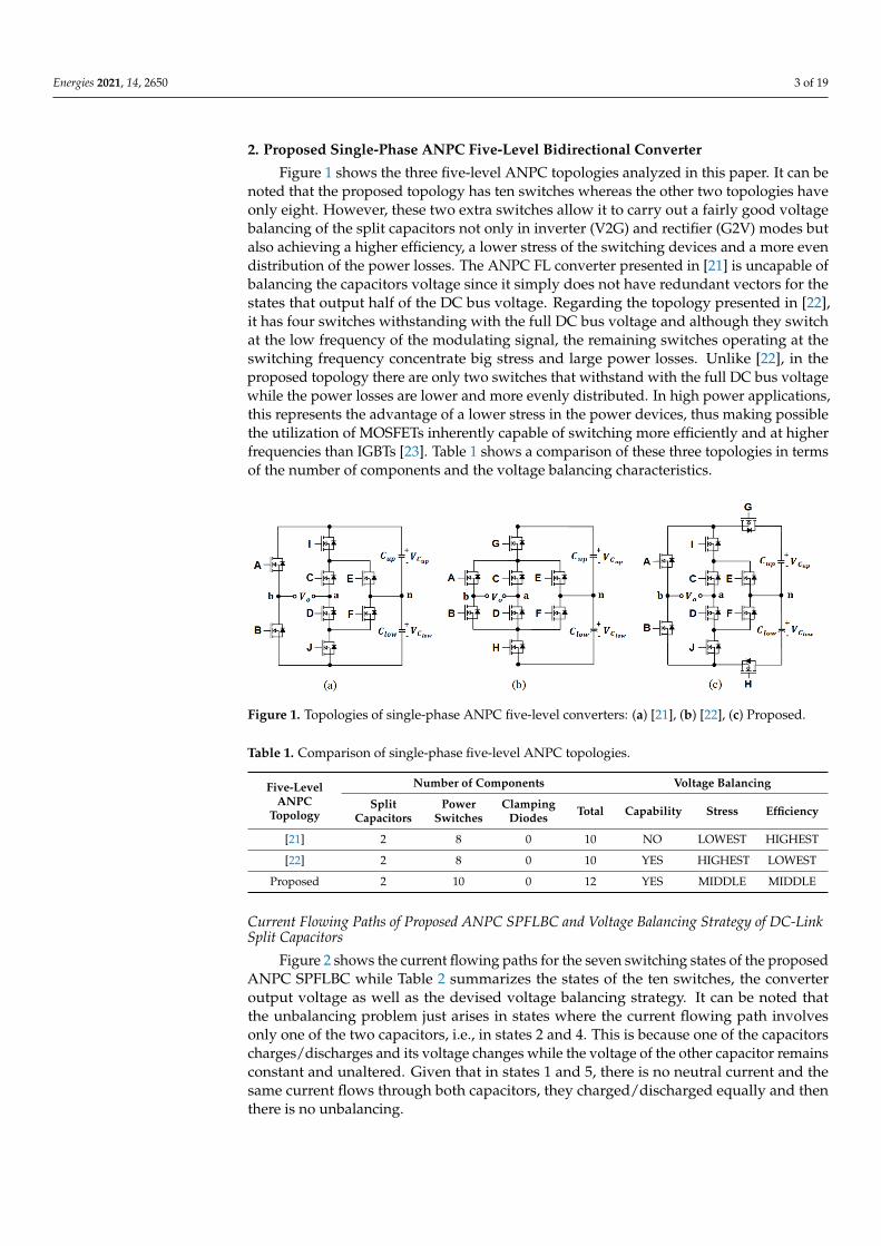
Figure 1 shows the three five-level ANPC topologies analyzed in this paper. It can benoted that the proposed topology has ten switches whereas the other two topologies haveonly eight. However, these two extra switches allow it to carry out a fairly good voltagebalancing of the split capacitors not only in inverter (V2G) and rectifier (G2V) modes butalso achieving a higher efficiency, a lower stress of the switching devices and a more evendistribution of the power losses. The ANPC FL converter presented in [21] is uncapable ofbalancing the capacitors voltage since it simply does not have redundant vectors for thestates that output half of the DC bus voltage. Regarding the topology presented in [22],it has four switches withstanding with the full DC bus voltage and although they switchat the low frequency of the modulating signal, the remaining switches operating at theswitching frequency concentrate big stress and large power losses. Unlike [22], in theproposed topology there are only two switches that withstand with the full DC bus voltagewhile the power losses are lower and more evenly distributed. In high power applications,this represents the advantage of a lower stress in the power devices, thus making possiblethe utilization of MOSFETs inherently capable of switching more efficiently and at higherfrequencies than IGBTs [23]. Table 1 shows a comparison of these three topologies in termsof the number of components and the voltage balancing characteristics.
Figure 1. Topologies of single-phase ANPC five-level converters: (a) [21], (b) [22], (c) Proposed.
Table 1. Comparison of single-phase five-level ANPC topologies.
Five-LevelANPC
Topology
Number of Components Voltage Balancing
SplitCapacitors
PowerSwitches
ClampingDiodes Total Capability Stress Efficiency
[21] 2 8 0 10 NO LOWEST HIGHEST
[22] 2 8 0 10 YES HIGHEST LOWEST
Proposed 2 10 0 12 YES MIDDLE MIDDLE
Current Flowing Paths of Proposed ANPC SPFLBC and Voltage Balancing Strategy of DC-LinkSplit Capacitors
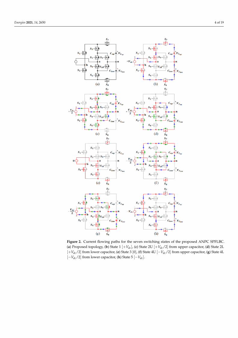
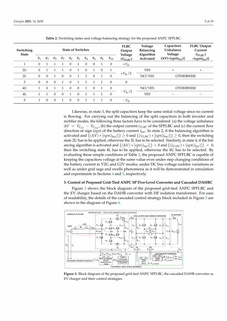
Figure 2 shows the current flowing paths for the seven switching states of the proposedANPC SPFLBC while Table 2 summarizes the states of the ten switches, the converteroutput voltage as well as the devised voltage balancing strategy. It can be noted thatthe unbalancing problem just arises in states where the current flowing path involvesonly one of the two capacitors, i.e., in states 2 and 4. This is because one of the capacitorscharges/discharges and its voltage changes while the voltage of the other capacitor remainsconstant and unaltered. Given that in states 1 and 5, there is no neutral current and thesame current flows through both capacitors, they charged/discharged equally and thenthere is no unbalancing.
Energies 2021, 14, 2650 4 of 19
Figure 2. Current flowing paths for the seven switching states of the proposed ANPC SPFLBC.(a) Proposed topology, (b) State 1 [+Vdc], (c) State 2U [+Vdc/2] from upper capacitor, (d) State 2L[+Vdc/2] from lower capacitor, (e) State 3 [0], (f) State 4U [−Vdc/2] from upper capacitor, (g) State 4L[−Vdc/2] from lower capacitor, (h) State 5 [−Vdc].
Energies 2021, 14, 2650 5 of 19
Table 2. Switching states and voltage balancing strategy for the proposed ANPC SPFLBC.
SwitchingState
State of SwitchesFLBC
OutputVoltage(VFLBC)
VoltageBalancingAlgorithmActivated
CapacitorsUnbalance
Voltage(∆V)∗[sgn(ibat)]
FLBC OutputCurrent(iFLBC)∗[sgn(ibat)]S1 S3 S5 S7 S9 S2 S4 S6 S8 S10
1 0 1 1 1 0 1 0 0 1 0 +Vdc
2U 0 1 1 1 0 1 0 1 0 1+Vdc/2
YES + +
2L 0 0 1 0 0 1 1 0 1 0 NO/YES OTHERWISE
3 0 0 0 1 0 1 1 1 1 0 0
4U 1 0 1 1 0 0 1 0 1 0−Vdc/2
NO/YES OTHERWISE
4L 1 1 0 0 1 0 1 1 1 0 YES − −5 1 0 0 1 0 0 1 1 1 0 −Vdc
Likewise, in state 3, the split capacitors keep the same initial voltage since no currentis flowing. For carrying out the balancing of the split capacitors in both inverter andrectifier modes, the following three factors have to be considered: (a) the voltage unbalance∆V = VCup − VClow , (b) the output current iFLBC of the SPFLBC and (c) the current flowdirection or sign (sgn) of the battery current ibat. In state 2, if the balancing algorithm isactivated and (∆V) ∗ [sgn(ibat)] ≥ 0 and (iFLBC) ∗ [sgn(ibat)] ≥ 0, then the switchingstate 2U has to be applied, otherwise the 2L has to be selected. Similarly, in state 4, if the bal-ancing algorithm is activated and (∆V) ∗ [sgn(ibat)] < 0 and (iFLBC) ∗ [sgn(ibat)] < 0,then the switching state 4L has to be applied, otherwise the 4U has to be selected. Byevaluating these simple conditions of Table 2, the proposed ANPC SPFLBC is capable ofkeeping the capacitors voltage at the same value even under step changing conditions ofthe battery current in V2G and G2V modes, under DC bus voltage sudden variations aswell as under grid sags and swells phenomena as it will be demonstrated in simulationand experiments in Sections 4 and 5, respectively.
3. Control of Proposed Grid-Tied ANPC SP Five-Level Converter and Cascaded DAHBC
Figure 3 shows the block diagram of the proposed grid-tied ANPC SPFLBC andthe EV charger based on the DAHB converter with HF isolation transformer. For easeof readability, the details of the cascaded control strategy block included in Figure 3 areshown in the diagram of Figure 4.
Figure 3. Block diagram of the proposed grid-tied ANPC SPFLBC, the cascaded DAHB converter asEV charger and their control strategies.
Energies 2021, 14, 2650 6 of 19
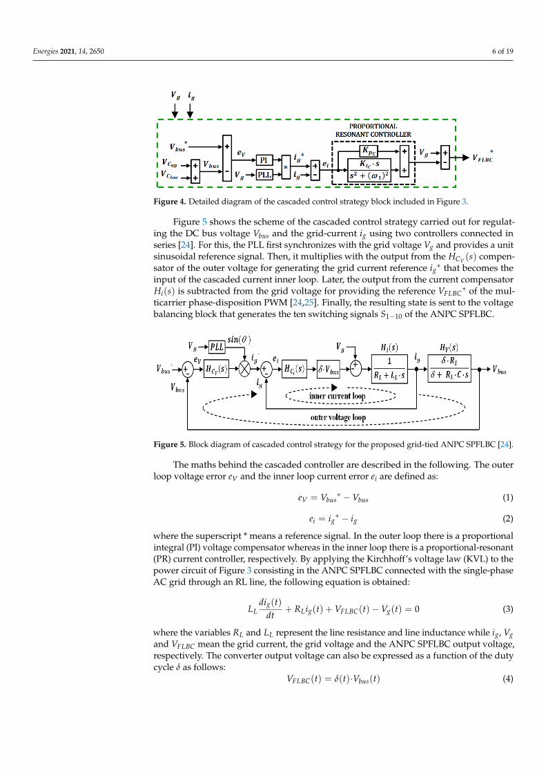
Figure 4. Detailed diagram of the cascaded control strategy block included in Figure 3.
Figure 5 shows the scheme of the cascaded control strategy carried out for regulat-ing the DC bus voltage Vbus and the grid-current ig using two controllers connected inseries [24]. For this, the PLL first synchronizes with the grid voltage Vg and provides a unitsinusoidal reference signal. Then, it multiplies with the output from the HCV (s) compen-sator of the outer voltage for generating the grid current reference ig
∗ that becomes theinput of the cascaded current inner loop. Later, the output from the current compensatorHi(s) is subtracted from the grid voltage for providing the reference VFLBC
∗ of the mul-ticarrier phase-disposition PWM [24,25]. Finally, the resulting state is sent to the voltagebalancing block that generates the ten switching signals S1−10 of the ANPC SPFLBC.
Figure 5. Block diagram of cascaded control strategy for the proposed grid-tied ANPC SPFLBC [24].
The maths behind the cascaded controller are described in the following. The outerloop voltage error eV and the inner loop current error ei are defined as:
eV = Vbus∗ −Vbus (1)
ei = ig∗ − ig (2)
where the superscript * means a reference signal. In the outer loop there is a proportionalintegral (PI) voltage compensator whereas in the inner loop there is a proportional-resonant(PR) current controller, respectively. By applying the Kirchhoff’s voltage law (KVL) to thepower circuit of Figure 3 consisting in the ANPC SPFLBC connected with the single-phaseAC grid through an RL line, the following equation is obtained:
LLdig(t)
dt+ RLig(t) + VFLBC(t)−Vg(t) = 0 (3)
where the variables RL and LL represent the line resistance and line inductance while ig, Vgand VFLBC mean the grid current, the grid voltage and the ANPC SPFLBC output voltage,respectively. The converter output voltage can also be expressed as a function of the dutycycle δ as follows:
VFLBC(t) = δ(t)·Vbus(t) (4)
Energies 2021, 14, 2650 7 of 19
By substituting (4) in (3) and assuming an average value for the grid current and therespective duty cycle, the small signal model of the grid current is given by:
ig(s) =Vg(s)− δ·Vbus(s)
[RL + LL·s](5)
Assuming that the inner current loop is ten times faster than the outer voltage loop,Vg is seen as a constant value that does not vary with time and consequenlty Vg(s) = 0.Hence, the transfer function Hi(s) for the inner current loop is written as:
Hi(s) =ig(s)
δ=−Vbus(s)[RL + LL·s]
(6)
Bearing in mind that the inner loop deals with the grid current that is an ac quantity,thus a proportional-resonant controller with a zero-steady state error and a theoreticalinfinite gain at the resonance frequency has been used [26]. The transfer function HCi (s) ofthis current controller is given by:
HCi (s) = kpC +kiC ·s
s2 + ω12 (7)
After applying the Kirchhoff’s current law (KCL) at the node P in the power circuit ofFigure 3, the following equations are obtained:
ibus(t)− icap(t)− iFLBC(t) = 0 (8)
ibus(t) = δ(t)·ig(t) (9)
icap(t) = C·d[Vbus(t)]dt
(10)
iFLBC(t) =VFLBC(t)−Vg(t)
RL(11)
where icap is the split capacitors current and C = Cup/2 = Clow/2. By substituting (4) into(11) and the resulting (9)–(11) into (8) while assuming an average value for the grid currentand the duty cycle, the small signal model that links up the dc bus voltage with the gridcurrent is found as:
δ·RL·ig(s)− [RL·C·Vbus(s)]·s−VFLBC(s) + Vg(s) = 0 (12)
By considering in (12) the same assumption as in the inner loop, i.e., Vg(s) = 0, thetransfer function HV(s) for the outer voltage loop is derived as:
HV(s) =Vbus(s)
ig(s)=
δ·RL
[δ + RL·C·s](13)
Bearing in mind that the outer loop deals with the bus voltage that is a dc quantity,thus a classical proportional-integral controller has been used. The transfer function HCV (s)of this voltage controller is given by:
HCV (s) = kpV +kiVs
(14)
By programming the transfer functions of the plants (6), (13) and the compensators(7), (14) in MATLAB code and using the single-input single-output (SISO) design tool, thegains of the controller have been accurately tuned until obtaining a good response [24].
Energies 2021, 14, 2650 8 of 19
Dual Active Half-Bridge DC-DC Converter
The EV bidirectional charger studied in this paper is based on the dual-active half-bridge DC-DC converter which has an advantageous isolation high-frequency transformerin between. As shown in Figure 3, the EV battery bank is connected on the low-voltageside of the DAHBC whereas the proposed ANPC SPFLBC is connected on the high-voltageside. The topology of this DAHB converter consists of one arm with two switches andanother arm with two split capacitors. The set of these two arms are found at either sideof the HF transformer [27]. The DAHBC can either increase or decrease the voltage fromeither side, thereby it is capable of working as a bidirectional Boost/Buck voltage converter.The direction and magnitude of the power flow is controlled by shifting the relative phasebetween the voltages on either side of the HF transformer. In comparison with the dualactive full bridge converter (DAFBC), the DAHBC replaces four of its switches with fourcapacitors. This reduction in the number of power switches represents a limitation in termsof the available degrees of liberty for controlling the power flow. However, it becomesan important advantage regarding the inherent lower switching and conduction losses.Furthermore, in the DAHBC the unique four power switches available also experiment alower stress since they have to endure only half of the DC bus voltage. Another advantageof this simplified topology is that in steady state, the magnetizing current of the HFtransformer does not contain any dc component, thereby not increasing the core losses orgiving rise to flux saturation [28].
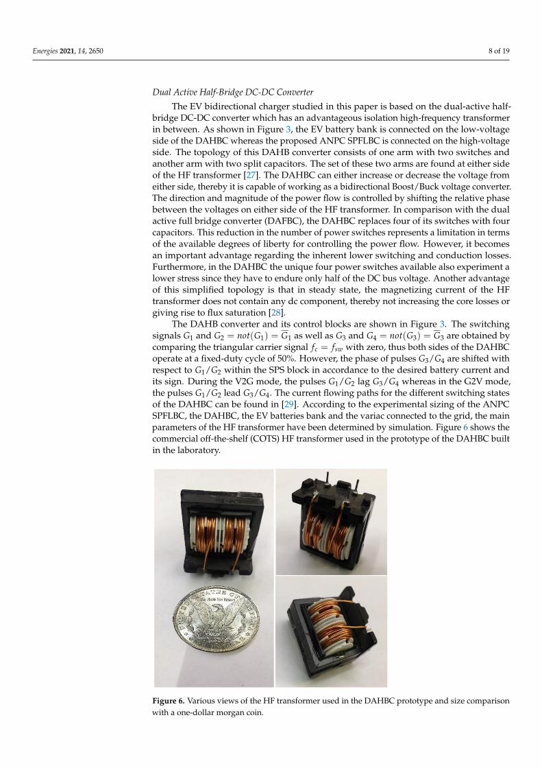
The DAHB converter and its control blocks are shown in Figure 3. The switchingsignals G1 and G2 = not(G1) = G1 as well as G3 and G4 = not(G3) = G3 are obtained bycomparing the triangular carrier signal fc = fsw with zero, thus both sides of the DAHBCoperate at a fixed-duty cycle of 50%. However, the phase of pulses G3/G4 are shifted withrespect to G1/G2 within the SPS block in accordance to the desired battery current andits sign. During the V2G mode, the pulses G1/G2 lag G3/G4 whereas in the G2V mode,the pulses G1/G2 lead G3/G4. The current flowing paths for the different switching statesof the DAHBC can be found in [29]. According to the experimental sizing of the ANPCSPFLBC, the DAHBC, the EV batteries bank and the variac connected to the grid, the mainparameters of the HF transformer have been determined by simulation. Figure 6 shows thecommercial off-the-shelf (COTS) HF transformer used in the prototype of the DAHBC builtin the laboratory.
Figure 6. Various views of the HF transformer used in the DAHBC prototype and size comparisonwith a one-dollar morgan coin.
Energies 2021, 14, 2650 9 of 19
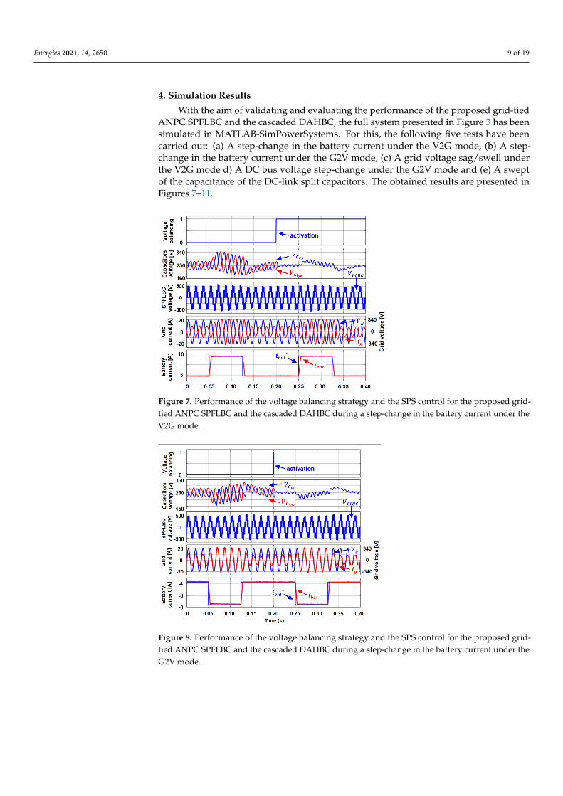
4. Simulation Results
With the aim of validating and evaluating the performance of the proposed grid-tiedANPC SPFLBC and the cascaded DAHBC, the full system presented in Figure 3 has beensimulated in MATLAB-SimPowerSystems. For this, the following five tests have beencarried out: (a) A step-change in the battery current under the V2G mode, (b) A step-change in the battery current under the G2V mode, (c) A grid voltage sag/swell underthe V2G mode d) A DC bus voltage step-change under the G2V mode and (e) A sweptof the capacitance of the DC-link split capacitors. The obtained results are presented inFigures 7–11.
Figure 7. Performance of the voltage balancing strategy and the SPS control for the proposed grid-tied ANPC SPFLBC and the cascaded DAHBC during a step-change in the battery current under theV2G mode.
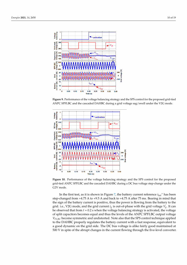
Figure 8. Performance of the voltage balancing strategy and the SPS control for the proposed grid-tied ANPC SPFLBC and the cascaded DAHBC during a step-change in the battery current under theG2V mode.
Energies 2021, 14, 2650 10 of 19
Figure 9. Performance of the voltage balancing strategy and the SPS control for the proposed grid-tiedANPC SPFLBC and the cascaded DAHBC during a grid voltage sag/swell under the V2G mode.
Figure 10. Performance of the voltage balancing strategy and the SPS control for the proposedgrid-tied ANPC SPFLBC and the cascaded DAHBC during a DC bus voltage step-change under theG2V mode.
In the first test, as it is shown in Figure 7, the battery current reference ibat∗ has been
step-changed from +4.75 A to +9.5 A and back to +4.75 A after 75 ms. Bearing in mind thatthe sign of the battery current is positive, thus the power is flowing from the battery to thegrid. i.e., V2G mode, and the grid current ig is out-of-phase with the grid voltage Vg. It canbe observed that from t = 0.2 s when the voltage balancing strategy is activated, the voltageof split capacitors becomes equal and thus the levels of the ANPC SPFLBC output voltageVFLBC become symmetric and undistorted. Note also that the SPS control technique appliedto the DAHBC properly regulates the battery current with a fast response, equivalent toa good dynamic on the grid side. The DC bus voltage is alike fairly good maintained at500 V in spite of the abrupt changes in the current flowing through the five-level converter.
Energies 2021, 14, 2650 11 of 19
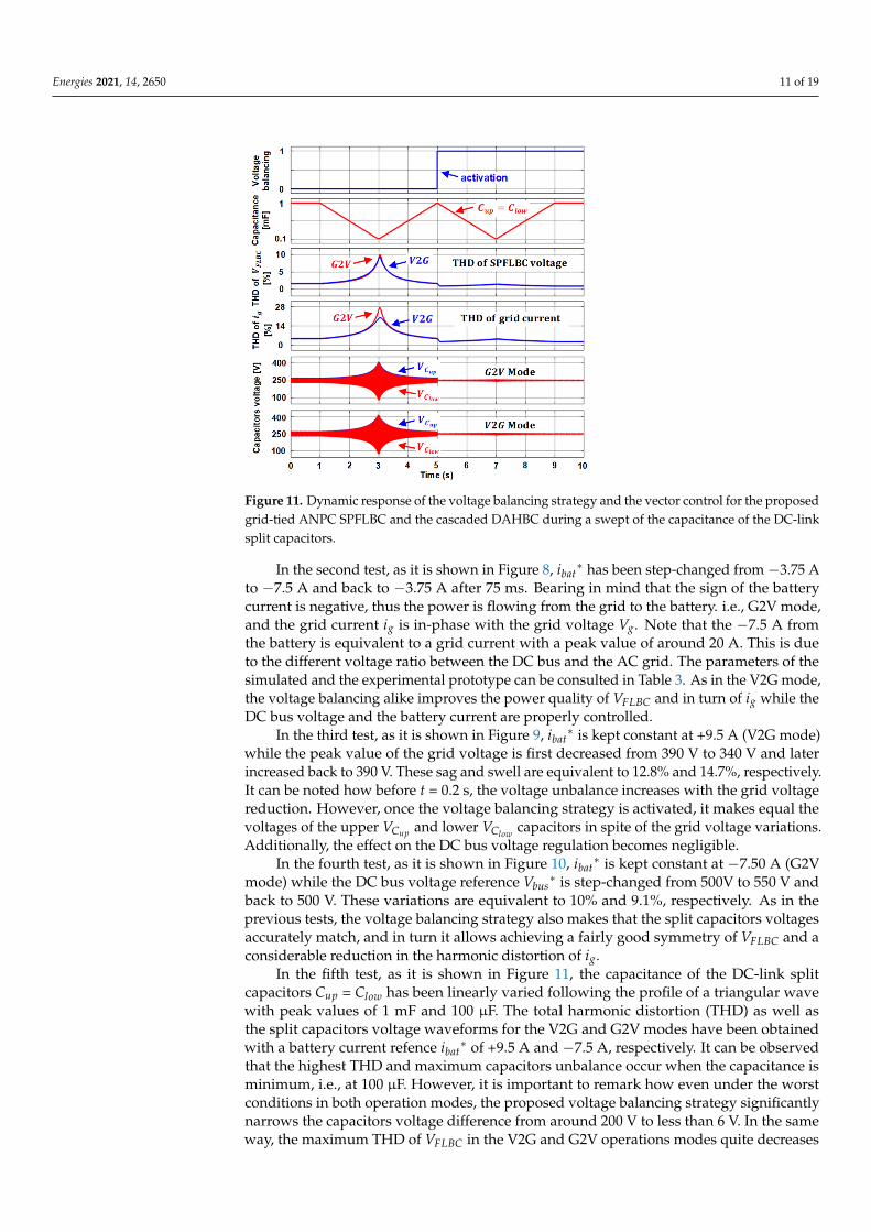
Figure 11. Dynamic response of the voltage balancing strategy and the vector control for the proposedgrid-tied ANPC SPFLBC and the cascaded DAHBC during a swept of the capacitance of the DC-linksplit capacitors.
In the second test, as it is shown in Figure 8, ibat∗ has been step-changed from −3.75 A
to −7.5 A and back to −3.75 A after 75 ms. Bearing in mind that the sign of the batterycurrent is negative, thus the power is flowing from the grid to the battery. i.e., G2V mode,and the grid current ig is in-phase with the grid voltage Vg. Note that the −7.5 A fromthe battery is equivalent to a grid current with a peak value of around 20 A. This is dueto the different voltage ratio between the DC bus and the AC grid. The parameters of thesimulated and the experimental prototype can be consulted in Table 3. As in the V2G mode,the voltage balancing alike improves the power quality of VFLBC and in turn of ig while theDC bus voltage and the battery current are properly controlled.
In the third test, as it is shown in Figure 9, ibat∗ is kept constant at +9.5 A (V2G mode)
while the peak value of the grid voltage is first decreased from 390 V to 340 V and laterincreased back to 390 V. These sag and swell are equivalent to 12.8% and 14.7%, respectively.It can be noted how before t = 0.2 s, the voltage unbalance increases with the grid voltagereduction. However, once the voltage balancing strategy is activated, it makes equal thevoltages of the upper VCup and lower VClow capacitors in spite of the grid voltage variations.Additionally, the effect on the DC bus voltage regulation becomes negligible.
In the fourth test, as it is shown in Figure 10, ibat∗ is kept constant at −7.50 A (G2V
mode) while the DC bus voltage reference Vbus∗ is step-changed from 500V to 550 V and
back to 500 V. These variations are equivalent to 10% and 9.1%, respectively. As in theprevious tests, the voltage balancing strategy also makes that the split capacitors voltagesaccurately match, and in turn it allows achieving a fairly good symmetry of VFLBC and aconsiderable reduction in the harmonic distortion of ig.
In the fifth test, as it is shown in Figure 11, the capacitance of the DC-link splitcapacitors Cup = Clow has been linearly varied following the profile of a triangular wavewith peak values of 1 mF and 100 µF. The total harmonic distortion (THD) as well asthe split capacitors voltage waveforms for the V2G and G2V modes have been obtainedwith a battery current refence ibat
∗ of +9.5 A and −7.5 A, respectively. It can be observedthat the highest THD and maximum capacitors unbalance occur when the capacitance isminimum, i.e., at 100 µF. However, it is important to remark how even under the worstconditions in both operation modes, the proposed voltage balancing strategy significantlynarrows the capacitors voltage difference from around 200 V to less than 6 V. In the sameway, the maximum THD of VFLBC in the V2G and G2V operations modes quite decreases
Energies 2021, 14, 2650 12 of 19
from 9.4% and 10.0% to around 1.5% in both cases. Likewise, the highest THD of ig inthe V2G and G2V operation modes fairly reduces from 19.9% and 27.4% to only 4.3% and4.5%, respectively.
Table 3. Parameters of simulation and experimental grid-tied ANPC SPFLBC and cascaded DAHBC.
Parameter SymbolValue
UnitsSimulation Experimental
Switching frequency of FLBC fsw/FLBC 5 5kHzSwitching frequency of DAHB fsw/DAHB 50 10
Line resistance RL 0.1 0.1 ΩLine inductance LL 5 2.5
mHHF transformer magnetization inductance Lm 10 8.3
HF transformer leakage inductances L1T , L2T 0.01 0.082Inductance of the battery inductor Lb 50 5
Grid voltage (peak) Vg 340 21 | 7 *VDC bus voltage Vbus 500 24
Battery nominal voltage Vbat/nom 360 22Battery rated current capacity Ibat/Ah 66 120 Ah
Grid frequency fg 60 60 HzCapacitance of FLBC split capacitors Cup, Clow 350 128
µFCapacitance of DAHB split capacitors C1, C2 350 680C3, C4 10 165
Capacitance of battery side capacitor Cb 1 100Sampling time/Time-step Ts 20 100 µs
* Note: The grid voltage Vg is 21V in the G2V mode and 7V in the V2G mode, respectively.
5. Experimental Results
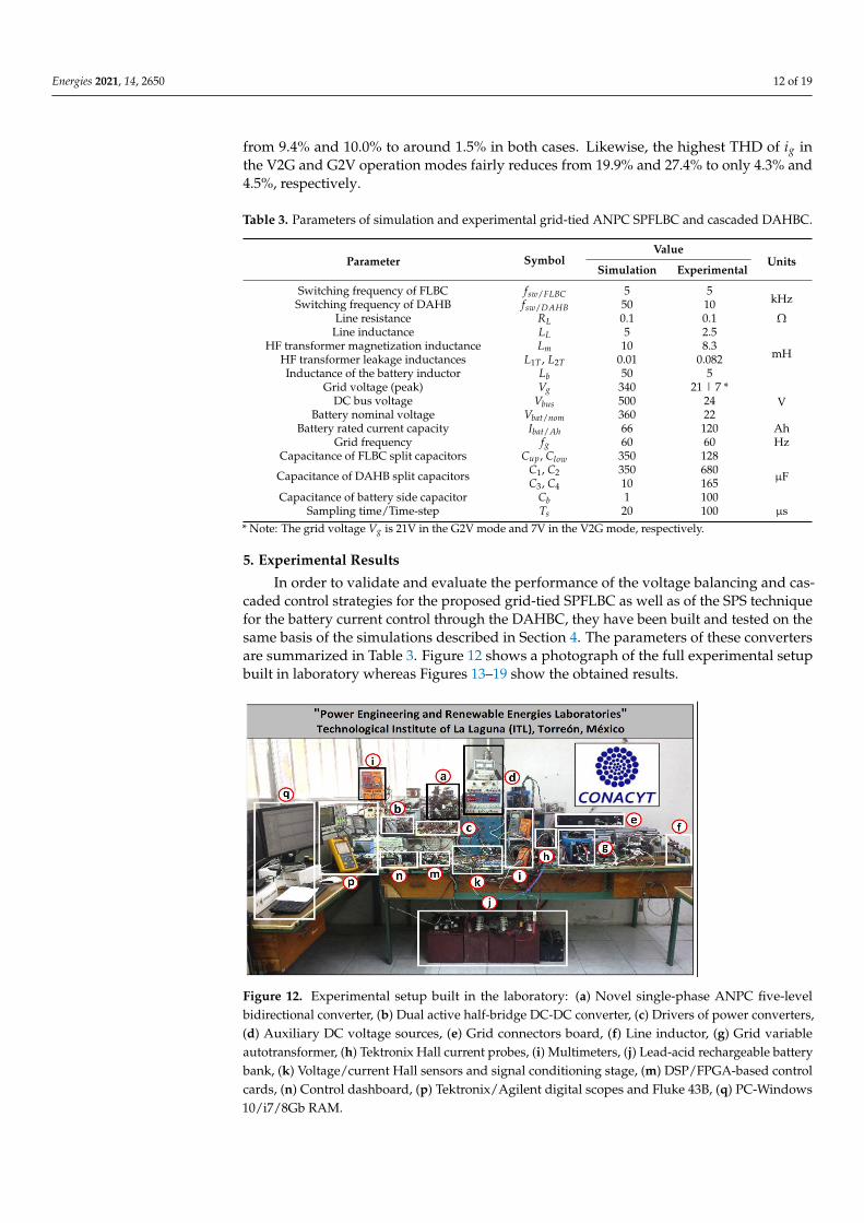
In order to validate and evaluate the performance of the voltage balancing and cas-caded control strategies for the proposed grid-tied SPFLBC as well as of the SPS techniquefor the battery current control through the DAHBC, they have been built and tested on thesame basis of the simulations described in Section 4. The parameters of these convertersare summarized in Table 3. Figure 12 shows a photograph of the full experimental setupbuilt in laboratory whereas Figures 13–19 show the obtained results.
Figure 12. Experimental setup built in the laboratory: (a) Novel single-phase ANPC five-levelbidirectional converter, (b) Dual active half-bridge DC-DC converter, (c) Drivers of power converters,(d) Auxiliary DC voltage sources, (e) Grid connectors board, (f) Line inductor, (g) Grid variableautotransformer, (h) Tektronix Hall current probes, (i) Multimeters, (j) Lead-acid rechargeable batterybank, (k) Voltage/current Hall sensors and signal conditioning stage, (m) DSP/FPGA-based controlcards, (n) Control dashboard, (p) Tektronix/Agilent digital scopes and Fluke 43B, (q) PC-Windows10/i7/8Gb RAM.
Energies 2021, 14, 2650 13 of 19
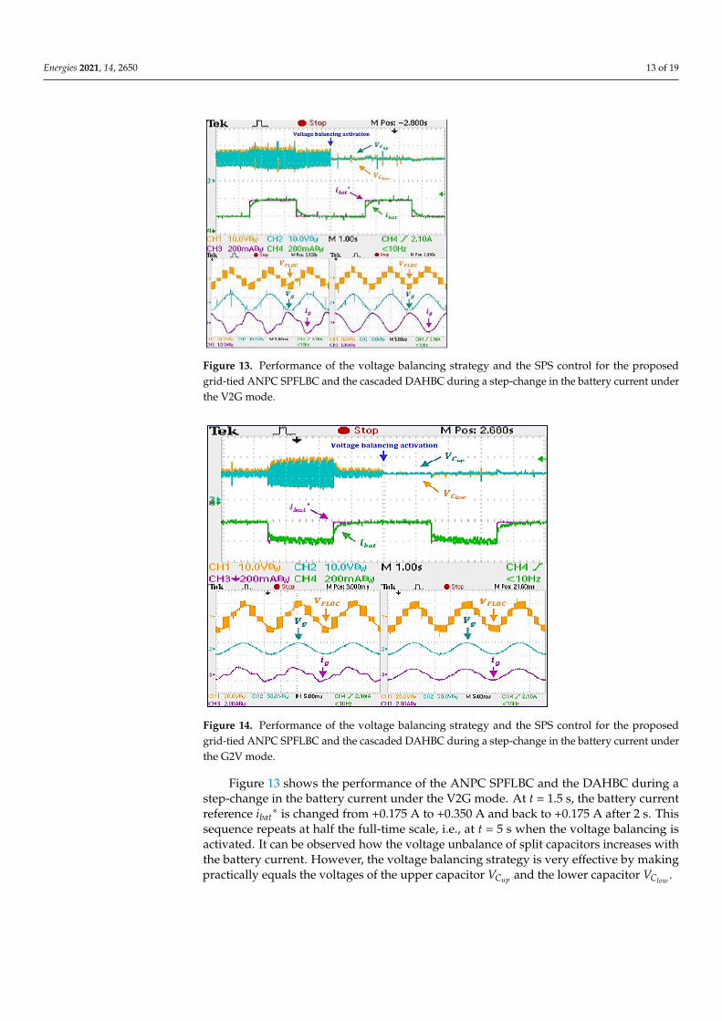
Figure 13. Performance of the voltage balancing strategy and the SPS control for the proposedgrid-tied ANPC SPFLBC and the cascaded DAHBC during a step-change in the battery current underthe V2G mode.
Figure 14. Performance of the voltage balancing strategy and the SPS control for the proposedgrid-tied ANPC SPFLBC and the cascaded DAHBC during a step-change in the battery current underthe G2V mode.
Figure 13 shows the performance of the ANPC SPFLBC and the DAHBC during astep-change in the battery current under the V2G mode. At t = 1.5 s, the battery currentreference ibat
∗ is changed from +0.175 A to +0.350 A and back to +0.175 A after 2 s. Thissequence repeats at half the full-time scale, i.e., at t = 5 s when the voltage balancing isactivated. It can be observed how the voltage unbalance of split capacitors increases withthe battery current. However, the voltage balancing strategy is very effective by makingpractically equals the voltages of the upper capacitor VCup and the lower capacitor VClow .
Energies 2021, 14, 2650 14 of 19
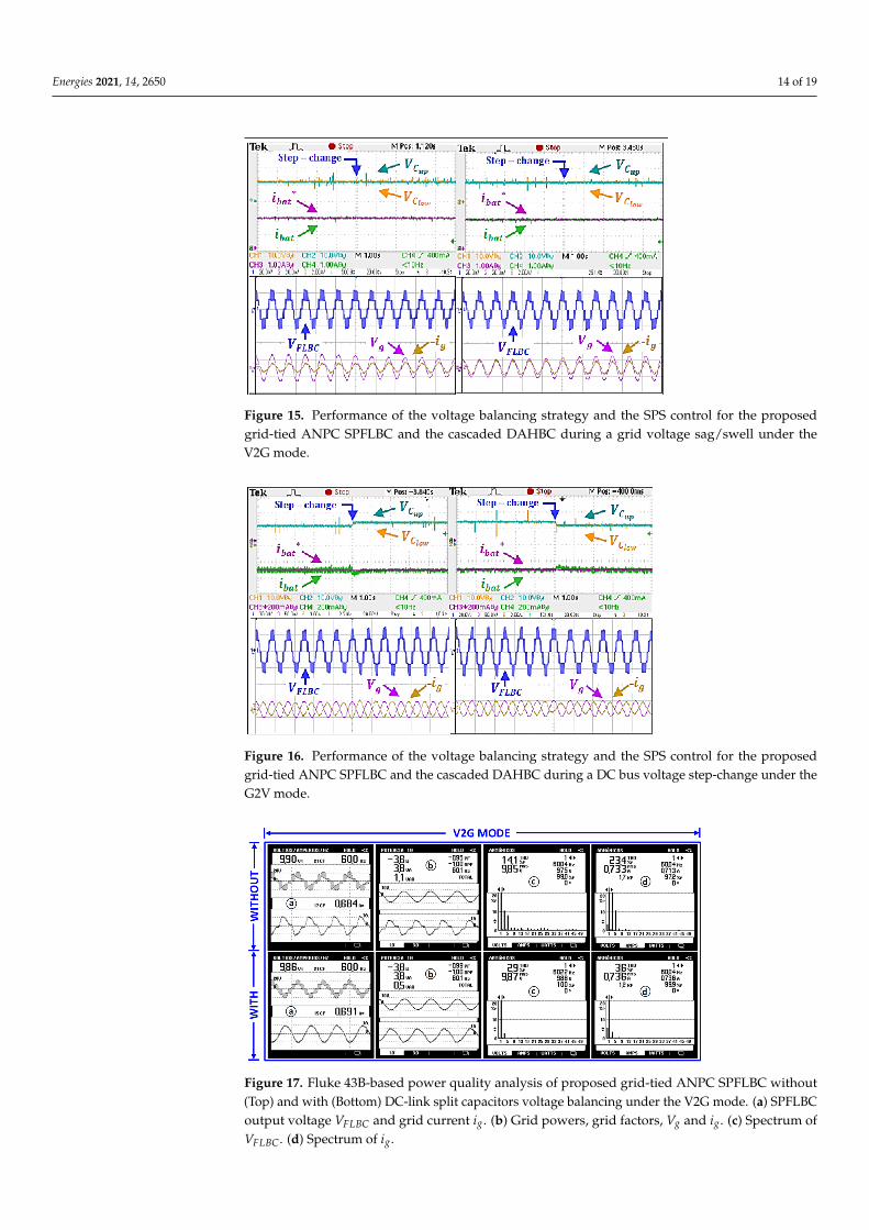
Figure 15. Performance of the voltage balancing strategy and the SPS control for the proposedgrid-tied ANPC SPFLBC and the cascaded DAHBC during a grid voltage sag/swell under theV2G mode.
Figure 16. Performance of the voltage balancing strategy and the SPS control for the proposedgrid-tied ANPC SPFLBC and the cascaded DAHBC during a DC bus voltage step-change under theG2V mode.
Figure 17. Fluke 43B-based power quality analysis of proposed grid-tied ANPC SPFLBC without(Top) and with (Bottom) DC-link split capacitors voltage balancing under the V2G mode. (a) SPFLBCoutput voltage VFLBC and grid current ig. (b) Grid powers, grid factors, Vg and ig. (c) Spectrum ofVFLBC. (d) Spectrum of ig.
Energies 2021, 14, 2650 15 of 19
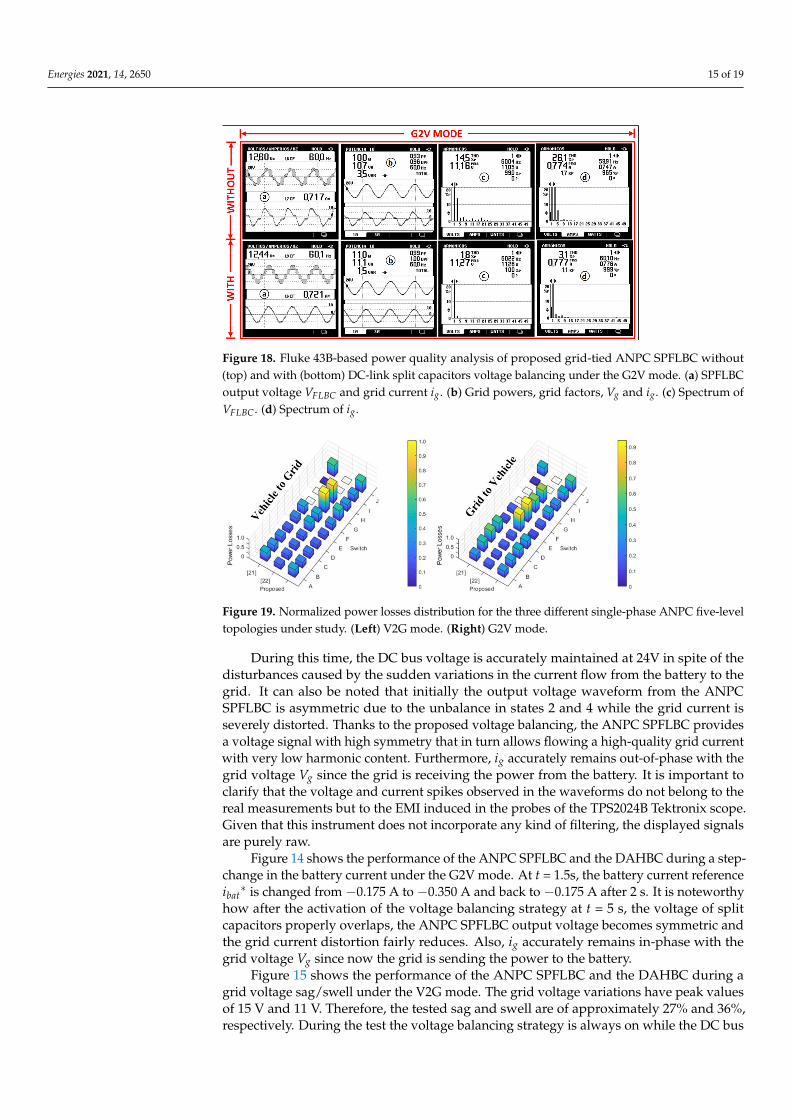
Figure 18. Fluke 43B-based power quality analysis of proposed grid-tied ANPC SPFLBC without(top) and with (bottom) DC-link split capacitors voltage balancing under the G2V mode. (a) SPFLBCoutput voltage VFLBC and grid current ig. (b) Grid powers, grid factors, Vg and ig. (c) Spectrum ofVFLBC. (d) Spectrum of ig.
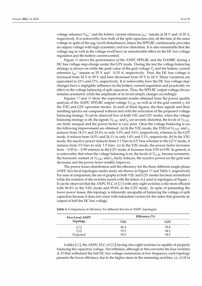
Figure 19. Normalized power losses distribution for the three different single-phase ANPC five-leveltopologies under study. (Left) V2G mode. (Right) G2V mode.
During this time, the DC bus voltage is accurately maintained at 24V in spite of thedisturbances caused by the sudden variations in the current flow from the battery to thegrid. It can also be noted that initially the output voltage waveform from the ANPCSPFLBC is asymmetric due to the unbalance in states 2 and 4 while the grid current isseverely distorted. Thanks to the proposed voltage balancing, the ANPC SPFLBC providesa voltage signal with high symmetry that in turn allows flowing a high-quality grid currentwith very low harmonic content. Furthermore, ig accurately remains out-of-phase with thegrid voltage Vg since the grid is receiving the power from the battery. It is important toclarify that the voltage and current spikes observed in the waveforms do not belong to thereal measurements but to the EMI induced in the probes of the TPS2024B Tektronix scope.Given that this instrument does not incorporate any kind of filtering, the displayed signalsare purely raw.
Figure 14 shows the performance of the ANPC SPFLBC and the DAHBC during a step-change in the battery current under the G2V mode. At t = 1.5s, the battery current referenceibat∗ is changed from −0.175 A to −0.350 A and back to −0.175 A after 2 s. It is noteworthy
how after the activation of the voltage balancing strategy at t = 5 s, the voltage of splitcapacitors properly overlaps, the ANPC SPFLBC output voltage becomes symmetric andthe grid current distortion fairly reduces. Also, ig accurately remains in-phase with thegrid voltage Vg since now the grid is sending the power to the battery.
Figure 15 shows the performance of the ANPC SPFLBC and the DAHBC during agrid voltage sag/swell under the V2G mode. The grid voltage variations have peak valuesof 15 V and 11 V. Therefore, the tested sag and swell are of approximately 27% and 36%,respectively. During the test the voltage balancing strategy is always on while the DC bus
Energies 2021, 14, 2650 16 of 19
voltage reference Vbus∗ and the battery current reference ibat
∗ remain at 24 V and +0.35 A,respectively. It is noteworthy how both of the split capacitors stay all the time at the samevoltage in spite of the sag/swell disturbances, hence the SPFLBC continuously providesan output voltage with high symmetry and low distortion. It is also remarkable that thevoltage sag as well as the voltage swell have an unnoticeable effect on the DC bus voltageregulation and the battery current control.
Figure 16 shows the performance of the ANPC SPFLBC and the DAHBC during aDC bus voltage step-change under the G2V mode. During the test the voltage balancingstrategy is always on while the peak value of the grid voltage Vg and the battery currentreference ibat
∗ remain at 25 V and −0.35 A, respectively. First, the DC bus voltage isincreased from 24 V to 29 V and later decreased from 29 V to 24 V. These variations areequivalent to 21% and 17%, respectively. It is noteworthy how the DC bus voltage step-changes have a negligible influence on the battery current regulation and practically noeffect on the voltage balancing of split capacitors. Thus, the SPFLBC output voltage alwaysremains symmetric while the amplitude of its levels simply changes accordingly.
Figures 17 and 18 show the experimental results obtained from the power qualityanalysis of the ANPC SPFLBC output voltage VFLBC as well as of the grid current ig forthe V2G and G2V operation modes. In each of these figures, the time signals and theirresulting spectra are compared without and with the activation of the proposed voltagebalancing strategy. It can be observed how in both V2G and G2V modes, when the voltagebalancing strategy is off, the signals VFLBC and ig are severely distorted, the levels of VFLBCare fairly unequal and the power factor is very poor. Once the voltage balancing is on,the following improvement are obtained: (a) In the V2G mode, the THD of VFLBC and igreduces from 14.1% and 23.4% to only 2.9% and 3.6%, respectively, whereas in the G2Vmode, it reduces from 14.5% and 26.1% to only 1.8% and 3.1%, respectively. (b) In the V2Gmode, the reactive power reduces from 1.1 Vars to 0.5 Vars whereas in the G2 V mode, itreduces from 3.5 Vars to only 1.5 Vars. (c) In the V2G mode, the power factor increasesfrom −0.95 to −0.99 whereas in the G2V mode, it increases from 0.93 to 0.99. In general, itis noteworthy that when the voltage balancing is on, the levels of VFLBC become symmetric,the harmonic content of VFLBC and ig fairly reduces, the reactive power on the grid sidedecreases and the power factor notably improves.
The power losses distribution and the efficiency for the three different single-phaseANPC five-level topologies under study are shown in Figure 19 and Table 4, respectively.For ease of comparison, the set of graphs in both V2G and G2V modes has been normalizedwhile the notation of the switches match with the letters A-J used in topologies of Figure 1.It can be observed that the ANPC-FLC of [21] with only eight switches is the more efficientwith 96.4% in the V2G mode and 95.8% in the G2V mode. In spite of presenting thelower power losses, this topology is inherently uncapable of balancing the voltage of splitcapacitors because it does not count with redundant vectors for the states that generate anoutput of half the DC bus voltage.
Table 4. Comparison of efficiency for different five-level ANPC topologies.
Five-Level ANPCTopology
Efficiency (%)
V2G G2V
[21] 96.4 95.8[22] 93.5 94.1
Proposed 95.0 94.5
Unlike [21], the ANPC-FLC of [22] having also eight switches is capable of properlybalancing the capacitors voltage. Nevertheless, although in this converter the four switchesA–D that withstand the full DC bus voltage commutate at low frequency, such topologypresents the lower efficiency due to the higher stress in the remaining switches, i.e., G-H in
Energies 2021, 14, 2650 17 of 19
the V2G mode and E-F in the G2V mode. According to Table 4, its efficiency in the V2Gand G2V modes is 93.5% and 94.1%, respectively.
In comparison with [21,22], the proposed ANPC-FLBC has two more switches, i.e., atotal of ten. However, unlike [21] it is capable of balancing the capacitors voltage whereas incontrast with [22], it not only achieves a better efficiency but a lower stress of the switchingdevices and a more even distribution of the power losses. The efficiency of the proposedtopology is 95.0% in the V2G mode and 94.5% in the G2V mode.
6. Discussion
In comparison with the conventional two-level converters, the multilevel convertersare characterized for providing a lower distortion voltage signal and achieve it with lowerswitching frequencies. These are two big advantages in terms of a lower cost and volumeof the required output passive filter as well as a switching losses reduction. Thus, with theaim of increasing the efficiency of multilevel converters, the switching frequency must bekept low but not too much because it can deteriorate the fundamental output signal usedfor control purposes and compromise the performance of the converter application. In thepresent work, the switching frequency fsw/FLBC of the FLBC has been set to 5 kHz in bothsimulation and experiments. The results shown in Sections 4 and 5 validate the selectionof this frequency by obtaining a good control performance and an efficiency even higherthan with the topology proposed in [22]. A summary of the parameters for the proposedgrid-tied ANPC SPFLBC is shown in Table 3. The selection of fsw/FLBC is also based on [24].This research works deals with a single-phase five-level converter that implements thesame multicarrier phase disposition method used in the present paper.
The parameter discrepancies and drifts due to temperature and aging of the inductiveand capacitive components in the power system shown in Figure 3 do not have an influenceon the accuracy and performance of the proposed voltage balancing strategy. Nevertheless,the gain and offset of the Hall-effect voltage sensors used for measuring the voltage ofthe upper and lower capacitors have a significant effect on the voltage balancing. In thesame way, the parameter variations due to temperature in the resistors connected to theoperational amplifiers in turn contained within the signal conditioning stage that interfacesthe Hall-effect voltage sensors with the analog-to-digital converters of the DSP alike affectthe voltage balancing.
With the aim of providing accurate voltage measurements of the split capacitors to thevoltage balancing control loop, a digital calibration curve that compensates the nonlinearityand gain mismatch from the voltage sensors as well as an automatic routine that digitallyremoves their initial voltage offsets have been programmed within the DSP. It importantto remark that before taking the initial voltage measurements, the split capacitors are firstdischarged through a resistor. In spite that the experimental results presented in Section 5were obtained at various times in different days as well as under different conditionsand scenarios, they exhibited repeatability since the initialization routine has been alwaysperformed before starting up the ANPC SPFLBC. Thanks to the nonlinearity, gain mismatchand offset compensations carried out on the voltage sensors, the remaining parametersvariations undergone by the full power system during the days of tests have been minorand practically unnoticeable.
7. Conclusions
A novel single-phase ANPC SPFLBC that enhances the power quality during theG2V and V2G operation of a cascaded EV charger has been presented in this paper. Thesimulation and experimental results obtained from a set of exhaustive tests validate thegood performance of the developed balancing strategy for keeping equal the split capacitorsvoltages even under step-changing disturbances. In the same way, the cascaded controland the SPS control strategies implemented with a DSP/FPGA for controlling in real-timethe grid-tied ANPC SPFLBC and the DAHBC have alike shown a good performance. Ithas been also demonstrated that the proposed grid-tied ANPC SPFLBC not only is capable
Energies 2021, 14, 2650 18 of 19
of achieving a very low THD of the grid current but a higher efficiency, a lower stress ofthe switching devices and a more even distribution of the power losses in both V2G andG2V modes.
Author Contributions: Conceptualization, J.L., L.M., C.H., M.A.A. and A.C.; Formal analysis, J.L.,L.M., C.H., M.A.A. and A.C.; Investigation, J.L., L.M., C.H., M.A.A. and A.C.; Methodology, J.L., L.M.,C.H., M.A.A. and A.C.; Validation, J.L., L.M., C.H., M.A.A. and A.C.; Writing—review & editing,J.L., L.M., C.H., M.A.A. and A.C. All authors have read and agreed to the published version ofthe manuscript.
Funding: This work was funded by the National Council of Science and Technology of Mexico(CONACYT) through its “Postdoctoral Fellowship Program” under grants 2019-000006-01NACV-00062 and 2020-000022-01NACV-00108.
Institutional Review Board Statement: Not Applicable.
Informed Consent Statement: Not Applicable.
Data Availability Statement: Not Applicable.
Acknowledgments: Authors would like to thank TNM Instituto Tecnológico de La Laguna for itspartial support in this research.
Conflicts of Interest: Authors declare no conflicts of interest.
References1. Cheng, M.; Tong, M. Development status and trend of electric vehicles in China. Chin. J. Electr. Eng. 2017, 3, 1–13.2. Falahi, M.; Chou, H.-M.; Ehsani, M.; Xie, L.; Butler-Purry, K.L. Potential Power Quality Benefits of Electric Vehicles. IEEE Trans.
Sustain. Energy 2013, 4, 1–8. [CrossRef]3. Mude, K.N. Battery charging method for electric vehicles: From wired to on-road wireless charging. Chin. J. Electr. Eng. 2018, 4,
1–15. [CrossRef]4. Kwon, M.; Jung, S.; Choi, S. A high efficiency bi-directional EV charger with seamless mode transfer for V2G and V2H ap-plication.
In Proceedings of the IEEE Energy Conversion Congress and Exposition (ECCE), Montreal, QC, Canada, 20–24 September 2015;pp. 5394–5399.
5. Zgheib, R.; Al-Haddad, K.; Kamwa, I. V2G, G2V and active filter operation of a bidirectional battery charger for electric vehicles.In Proceedings of the 2016 IEEE International Conference on Industrial Technology (ICIT), Taipei, Taiwan, 14–17 March 2016;pp. 1260–1265.
6. Verma, A.; Singh, B. AFF-SOGI-DRC Control of Renewable Energy Based Grid Interactive Charging Station for EV with PowerQuality Improvement. IEEE Trans. Ind. Appl. 2021, 57, 588–597. [CrossRef]
7. Yilmaz, M.; Krein, P.T. Review of Battery Charger Topologies, Charging Power Levels, and Infrastructure for Plug-In Electric andHybrid Vehicles. IEEE Trans. Power Electron. 2013, 28, 2151–2169. [CrossRef]
8. Tian, Q.; Bai, K. Widen the zero-voltage-switching range and secure grid power quality for an ev charger using variable-switching-frequency single-dual-phase-shift control. Chin. J. Electr. Eng. 2018, 4, 11–19.
9. Sha, D.; Xu, G.; Xu, Y. Utility Direct Interfaced Charger/Discharger Employing Unified Voltage Balance Control for CascadedH-Bridge Units and Decentralized Control for CF-DAB Modules. IEEE Trans. Ind. Electron. 2017, 64, 7831–7841. [CrossRef]
10. Zhao, B.; Song, Q.; Liu, W.; Sun, Y. Overview of Dual-Active-Bridge Isolated Bidirectional DC–DC Converter for High-Frequency-Link Power-Conversion System. IEEE Trans. Power Electron. 2013, 29, 4091–4106. [CrossRef]
11. He, P.; Khaligh, A. Comprehensive Analyses and Comparison of 1 kW Isolated DC–DC Converters for Bidirectional EV ChargingSystems. IEEE Trans. Transp. Electrif. 2017, 3, 147–156. [CrossRef]
12. Brenna, M.; Foiadelli, F.; Longo, M. The Exploitation of Vehicle-to-Grid Function for Power Quality Improvement in a Smart Grid.IEEE Trans. Intell. Transp. Syst. 2014, 15, 2169–2177. [CrossRef]
13. Fard, M.T.; Abarzadeh, M.; Noghani, K.A.; He, J.; Al-Haddad, K. Si/SiC hybrid 5-level active NPC inverter for electric air-craftpropulsion drive applications. Chin. J. Electr. Eng. 2020, 6, 63–76. [CrossRef]
14. Abarzadeh, M.; Vahedi, H.; Al-Haddad, K. Fast sensor-less voltage balancing and capacitor size reduction in PUC5 converterusing novel modulation method. IEEE Trans. Ind. Inform. 2019, 15, 4394–4406. [CrossRef]
15. Onar, O.C.; Kobayashi, J.; Erb, D.C.; Khaligh, A. A bidirectional high-power-quality grid interface with a novel bidirectionalnoninverted buck–boost converter for PHEVs. IEEE Trans. Veh. Technol. 2012, 61, 2018–2032. [CrossRef]
16. Awal, M.A.; Bipu, R.H.; Montes, O.A.; Feng, H.; Husain, I.; Yu, W.; Lukic, S. Capacitor Voltage Balancing for Neutral PointClamped Dual Active Bridge Converters. IEEE Trans. Power Electron. 2020, 35, 11267–11276. [CrossRef]
17. Filba-Martinez, A.; Busquets-Monge, S.; Bordonau, J. Modulation and Capacitor Voltage Balancing Control of Multilevel NPCDual Active Bridge DC–DC Converters. IEEE Trans. Ind. Electron. 2019, 67, 2499–2510. [CrossRef]
Energies 2021, 14, 2650 19 of 19
18. Moonem, M.; Duman, T.; Krishnaswami, H. Capacitor voltage balancing in a neutral-point clamped multilevel dc-dc dual activebridge converter. In Proceedings of the 2017 IEEE 8th International Symposium on Power Electronics for Distributed GenerationSystems (PEDG), Florianopolis, Brazil, 17–20 April 2017; pp. 1–7.
19. Khan, S.A.; Islam, R.; Guo, Y.; Zhu, J. An Amorphous Alloy Magnetic-Bus-Based SiC NPC Converter with Inherent VoltageBalancing for Grid-Connected Renewable Energy Systems. IEEE Trans. Appl. Supercond. 2018, 29, 1–8. [CrossRef]
20. Sivakumar, K. A Fault-Tolerant Single-Phase Five-Level Inverter for Grid-Independent PV Systems. IEEE Trans. Ind. Electron.2015, 62, 7569–7577. [CrossRef]
21. Zhang, L.; Zheng, Z.; Li, C.; Ju, P.; Wu, F.; Gu, Y.; Chen, G. A Si/SiC hybrid five-level active NPC inverter with improvedmodulation scheme. IEEE Trans. Power Electron. 2020, 35, 4835–4846. [CrossRef]
22. Ruiz-Caballero, D.A.; Ramos-Astudillo, R.M.; Mussa, S.A.; Heldwein, M.L. Symmetrical hybrid multilevel DC–AC converterswith reduced number of insulated DC supplies. IEEE Trans. Ind. Electron. 2010, 57, 2307–2314. [CrossRef]
23. Buticchi, G.; Lorenzani, E.; Franceschini, G. A Five-Level Single-Phase Grid-Connected Converter for Renewable DistributedSystems. IEEE Trans. Ind. Electron. 2013, 60, 906–918. [CrossRef]
24. Vahedi, H.; Shojaei, A.A.; Chandra, A.; Al-Haddad, K. Five-Level Reduced-Switch-Count Boost PFC Rectifier with MulticarrierPWM. IEEE Trans. Ind. Appl. 2016, 52, 4201–4207. [CrossRef]
25. Calais, M.; Borle, L.J.; Agelidis, V.G. Analysis of multicarrier PWM methods for a single-phase five level inverter. In Proceedingsof the 2001 IEEE 32nd Annual Power Electronics Specialists Conference (IEEE Cat. No.01CH37230), Vancouver, BC, Canada,17–21 June 2001; pp. 1351–1356.
26. Teodorescu, R.; Blaabjerg, F.; Liserre, M.; Loh, P.C. Proportional-resonant controllers and filters for grid-connected voltage-sourceconverters. IEE Proc. Electr. Power Appl. 2006, 153, 750–762. [CrossRef]
27. Fan, H.; Li, H. High-Frequency Transformer Isolated Bidirectional DC–DC Converter Modules with High Efficiency over WideLoad Range for 20 kVA Solid-State Transformer. IEEE Trans. Power Electron. 2011, 26, 3599–3608. [CrossRef]
28. Chakraborty, S.; Chattopadhyay, S. Minimum-RMS-Current Operation of Asymmetric Dual Active Half-Bridge Converters withand Without ZVS. IEEE Trans. Power Electron. 2016, 32, 5132–5145. [CrossRef]
29. Ngo, T.; Won, J.; Nam, K. A single-phase bidirectional dual active half-bridge converter. In Proceedings of the 2012 Twenty-Seventh Annual IEEE Applied Power Electronics Conference and Exposition (APEC), Orlando, FL, USA, 5–9 February 2012;pp. 1127–1133.

Reproduced with permission of copyright owner. Further reproductionprohibited without permission.