novel chemical surface modification to enhance hydrophobicity of polyamide-imide (pai) hollow fiber...
TRANSCRIPT
No
Ya
b
c
a
ARRAA
KPmHMM
1
mpcc
emamar
NT
0d
Journal of Membrane Science 380 (2011) 241– 250
Contents lists available at ScienceDirect
Journal of Membrane Science
jo u rn al hom epa ge: www.elsev ier .com/ locate /memsci
ovel chemical surface modification to enhance hydrophobicityf polyamide-imide (PAI) hollow fiber membranes
uan Zhanga,b, Rong Wanga,b,∗, Shouliang Yia,b, Laurentia Setiawana,b, Xiao Hub,c, Anthony G. Fanea,b
School of Civil and Environmental Engineering, Nanyang Technological University, 639798 Singapore, SingaporeSingapore Membrane Technology Centre, Nanyang Technological University, 639798 Singapore, SingaporeSchool of Material Science and Engineering, Nanyang Technological University, 639798 Singapore, Singapore
r t i c l e i n f o
rticle history:eceived 9 May 2011eceived in revised form 2 July 2011ccepted 6 July 2011vailable online 14 July 2011
eywords:olyamide-imide (PAI) hollow fiberembraneydrophobic surface modificationembrane characterizationembrane contactor
a b s t r a c t
Membrane wetting is a major concern for the application of membrane contactors. In order to develop anovel hydrophobic membrane that can be used in membrane contactors, a hydrophobic surface modifica-tion method for Torlon® polyamide-imide (PAI) membrane was explored, which has not been reportedpreviously. Asymmetric microporous hollow fiber membranes were fabricated using PAI material fol-lowed by a simple surface modification using a silane coupling agent, 3-aminopropyltrimethoxysilane(APTMS), and a perfluro-compound (Fluorolink S10) to produce PAI hollow fiber membranes with ahydrophobic surface. The reactions between PAI and the modification reagents have been confirmed byexperiments.
Optimal modification conditions were investigated by varying the modification parameters, such asAPTMS treatment temperature, APTMS concentration, APTMS treatment time, and Fluorolink S10 treat-ment time. The modified PAI membranes were, subsequently, characterized by a series of standardprotocols in terms of membrane morphology, chemical structure, contact angle, porosity and criticalwater entry pressure. A preliminary study of using the modified membranes in a membrane contac-
tor for CO2 absorption was also carried out. The newly developed PAI hollow fiber membranes showedmuch higher hydrophobicity, the contact angle was improved from 76◦ to 108–117◦ and the criticalwater entry pressure was improved from 0.7–0.8 bar to 2.1–4.0 bar. Moreover, the modified PAI hollowfiber membranes showed reasonably high CO2 flux by using water as a physical absorption liquid. Theresults indicate that the modified PAI membranes have great potential to be used in membrane contactorapplications.. Introduction
Microporous hollow fiber membrane is a core element in theembrane contactor device, in which the membrane acts as a
hysical support and provides a large interfacial area between theontacting phases without phase dispersion, thus the two phasesan be manipulated independently.
However, one drawback of the membrane contactor is the pres-nce of membrane itself which introduces an extra resistance to theass transfer process. The membrane used should have a high over-
ll porosity to minimize the membrane resistance. In addition, the
embrane must be highly wetting resistant. If the membrane poresre filled or even partially filled by the liquid, the mass transferesistance will increase significantly due to the additional resis-
∗ Corresponding author at: School of Civil and Environmental Engineering,anyang Technological University, 639798 Singapore, Singapore.el.: +65 6790 5327; fax: +65 6791 0676.
E-mail address: [email protected] (R. Wang).
376-7388/$ – see front matter © 2011 Elsevier B.V. All rights reserved.oi:10.1016/j.memsci.2011.07.016
© 2011 Elsevier B.V. All rights reserved.
tance brought by the stagnant liquid phase inside the pores. Thus,in order to ensure an efficient mass transfer process, membranewetting has to be avoided. The breakthrough pressure or liquid pen-etrating pressure is used to characterize the membrane in terms ofwetting resistance, above which the liquid can penetrate into themembrane pores, as estimated by the Laplace-Young equation [1]:
�p = −4�l cos �
dmax(1)
where �l is the liquid surface tension, � is the contact angle betweenthe liquid and membrane surface, and dmax is the maximum porediameter in the membrane. As can be seen from Eq. (1), in orderto obtain a high breakthrough pressure, the membrane materialhas to be hydrophobic with a contact angle as high as possible andthe membrane should have a well tailored surface pore structure,
i.e., a relatively small maximum pore size and a narrow pore sizedistribution.Among various hydrophobic materials, polypropylene (PP) andpolytetrafluoroethylene (PTFE) are the most popular materials that
2 bran
hPtriplitbwt[bmmmacLfloamiwgn
gWiobibomteeRPsctsf[wbt1p1wdasetm1m
b
42 Y. Zhang et al. / Journal of Mem
ave been used in membrane contactor processes [2–8]. However,TFE and PP membranes are usually produced by stretching orhermal methods due to their insolubility in common solvents,esulting in a relatively low porosity that restricts the attain-ng of a high mass transfer flux. Another hydrophobic polymer,olyvinylidene fluoride (PVDF), is also widely used to fabricate hol-
ow fiber membranes for membrane contactor processes due tots good chemical and thermal resistance, and processibility viahe phase-inversion method. However, microporous PVDF mem-ranes still cannot maintain long-term performance due to theetting problem. One of possible reasons responsible for this is
hat the hydrophobicity of PVDF membrane is not sufficiently high9,10]. Therefore, it is necessary to seek new highly hydropho-ic membranes that can be processed using the phase inversionethod to meet the application requirement. Two approaches areainly used. The first one is to use new hydrophobic membraneaterials for membranes fabrication. Feng et al. [11,12] fabricated
n asymmetric hydrophobic microporous membrane by using theopolymer of tetrafluoroethylene and vinylidene fluoride (F2.4).ater, Shi et al. [13–15] reported the fabrication of poly(vinylideneuoride-co-hexafluropropylene) (PVDF-HFP) asymmetric microp-rous hollow fiber membranes with different additives. The secondpproach is to make composite membranes by applying an evenore hydrophobic surface coating/modification layer on the exist-
ng hydrophobic membranes to protect the surface pores frometting. This approach seems to be more feasible and efficient,
iven the availability of a variety of surface modification tech-iques.
A number of surface modification studies have been investi-ated to increase the hydrophobicity for different membranes.u et al. [16] modified a hydrophilic cellulose acetate membrane
nto the hydrophobic membrane by radiation graft polymerizationf styrene. Kong et al. [17] treated a cellulose nitrate membraney plasma polymerization of octafluorocyclobutane to increase
ts hydrophobicity and to reach the membrane distillation mem-rane characteristics. Jin et al. modified [18] the top surfacef poly(phthalazine ether sulfone ketone) (PPESK) hollow fiberembrane by coating with silicon rubber and with sol–gel poly-
rifluoropropysiloxane. The modified membrane showed greatlynhanced contact angle and liquid entry pressure due to the pres-nce of the hydrophobic layer on the surface of PPESK membranes.ecently, Lv et al. [19] successfully fabricated a superhydrophobicP hollow fiber membrane by depositing a rough layer of dis-olved granulated polypropylene on the membrane surface. Theontact angle increased from 122◦ to 158◦ after the modifica-ion. Different membranes were modified by blending fluorinatedurface modifying macromolecule (SMM), such as polyethersul-one (PES) [20], PVDF [21] and polyetherimide (PEI) membranes22], and a serious of porous hydrophobic composite membranesere obtained. Gugliuzza et al. [23] fabricated a superhydropho-
ic PVDF membrane simply by surface coating of a thin layer ofetra-fluoroethylene (TFE) and 2,2,4-trifluoro-5-tri-fluorometoxy-,3-dioxole (TIT) (Hyflon AD 60X). The resultant membraneresented strong hydrophobicity with contact angle as high as47◦. Zheng et al. [24] reported a surperhydrophobic PVDF filmhich was fabricated by alkali treatment enhancing chemical batheposition method. The modified membrane showed water contactngle and sliding angle of 157◦ and 1◦, respectively, indicating theuperhydrophobic and self-cleaning property. Very recently, Yangt al. [25] modified PVDF membrane by two methods, e.g. plasmareatment and chemical treatment by a perfluoro-compound. The
odified PVDF membranes showed the contact angle of 105◦ and
15◦, respectively. The long term membrane distillation perfor-ance by using the modified PVDF membrane was improved.Poly(amie-imide) (PAI), commercially known as Torlon®, haveeen used to make membranes for vapor permeation and per-
e Science 380 (2011) 241– 250
vaporation [26,27], and gas separation [28,29]. Recently, thepolyelectrolyte modified PAI membranes were used in forwardosmosis process and have been demonstrated their superior per-formance [30]. PAI is a copolymer of amide and imide, it possessesunique characteristic properties of both polyamide and polyimide.It has exceptional mechanical, thermal and chemical resistant prop-erties.
However, so far no any study is available using PAI membranesin membrane contactor applications because this polymer mate-rial is less hydrophobic in nature with the contact angle of ∼76◦
and can be wetted easily. Therefore, to make PAI membranessuitable for membrane contactor applications, a surface hydropho-bic modification method for PAI membrane has to be developed.The present work explores a simple approach to make highlyhydrophobic PAI hollow fiber membranes by utilizing the uniquefeature of PAI. That is, the imide group in PAI can react with anamine-functionalized silane coupling agent and hence to impartthe hydroxyl (OH−) groups on the PAI membrane surface, whichmakes the resultant membrane being activated to further reactwith a perfluoro-compound. To the best of our knowledge, there isno similar method reported previously to obtain hydrophobic PAImembranes. The chemical modification mechanism will be exam-ined by Attenuated total reflectance-Fourier transform infraredspectroscopy (ATR-FTIR), and modified membranes will be charac-terized in terms of contact angle, mechanical strength, membraneporosity and critical water entry pressure (CEPw). A preliminarytest of modified membrane used in the membrane contactor forCO2 absorption will be evaluated.
2. Methodology
2.1. Membrane materials and chemicals
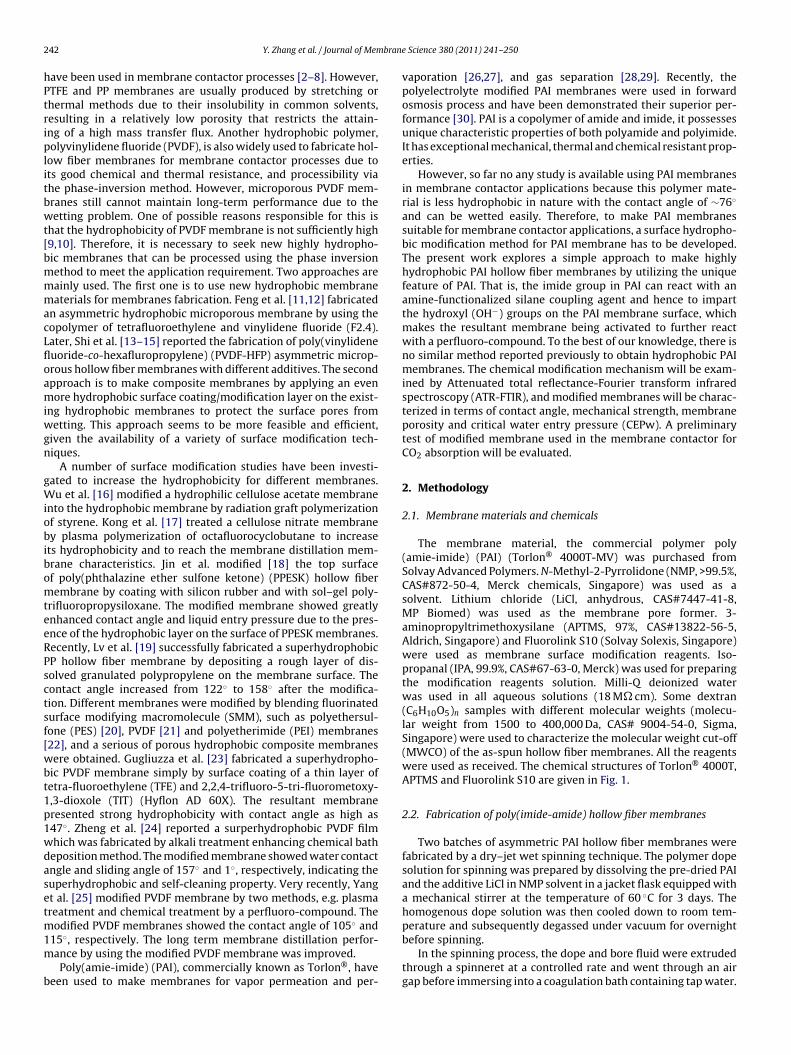
The membrane material, the commercial polymer poly(amie-imide) (PAI) (Torlon® 4000T-MV) was purchased fromSolvay Advanced Polymers. N-Methyl-2-Pyrrolidone (NMP, >99.5%,CAS#872-50-4, Merck chemicals, Singapore) was used as asolvent. Lithium chloride (LiCl, anhydrous, CAS#7447-41-8,MP Biomed) was used as the membrane pore former. 3-aminopropyltrimethoxysilane (APTMS, 97%, CAS#13822-56-5,Aldrich, Singapore) and Fluorolink S10 (Solvay Solexis, Singapore)were used as membrane surface modification reagents. Iso-propanal (IPA, 99.9%, CAS#67-63-0, Merck) was used for preparingthe modification reagents solution. Milli-Q deionized waterwas used in all aqueous solutions (18 M� cm). Some dextran(C6H10O5)n samples with different molecular weights (molecu-lar weight from 1500 to 400,000 Da, CAS# 9004-54-0, Sigma,Singapore) were used to characterize the molecular weight cut-off(MWCO) of the as-spun hollow fiber membranes. All the reagentswere used as received. The chemical structures of Torlon® 4000T,APTMS and Fluorolink S10 are given in Fig. 1.
2.2. Fabrication of poly(imide-amide) hollow fiber membranes
Two batches of asymmetric PAI hollow fiber membranes werefabricated by a dry–jet wet spinning technique. The polymer dopesolution for spinning was prepared by dissolving the pre-dried PAIand the additive LiCl in NMP solvent in a jacket flask equipped witha mechanical stirrer at the temperature of 60 ◦C for 3 days. Thehomogenous dope solution was then cooled down to room tem-perature and subsequently degassed under vacuum for overnight
before spinning.In the spinning process, the dope and bore fluid were extrudedthrough a spinneret at a controlled rate and went through an airgap before immersing into a coagulation bath containing tap water.
Y. Zhang et al. / Journal of Membrane Science 380 (2011) 241– 250 243
a
b c
Si
OCH
H3CO
OCH3NH2
O
N
O
NH
O
O
N
O
NH
0.3n0.7nO
O
PFPE Si OC2H5
OC2H5
on® 4
Tstr
2h
malw
((Tm
isamTmmAt
2fi
2
t
TS
3
Fig. 1. Chemical structure of (a) Torl
he nascent hollow fibers were collected at free-falling take-uppeed and subsequently stored in a water bath for at least 2 dayso remove residual solvent. The spinning conditions were summa-ized in Table 1.
.3. Surface hydrophobic modification of poly(imide-amide)ollow fiber membranes
The chemical modification involved the hydroxylation of the PAIembrane by a silane coupling agent APTMS followed by grafting
nd crosslinking of the perfluoro-compound containing ethoxysi-ane terminal groups, e.g. Fluorolink S10. The reactions mechanisms
ere confirmed by the ATR-FTIR.Firstly, the as-spun PAI membranes were immersed into a 2%
wt./vol.) APTMS solution in a mixture of IPA and distilled watervol. 1:1) at 50–70 ◦C for varied times ranging from 0 to 120 min.he membranes were then rinsed several times by the IPA and DIixture solution (vol. 1:1).After the APTMS treatment step, the membranes were
mmersed into the Fluorolink S10 solution at 60 ◦C for 120 min. Theolution was prepared by dissolving 4 wt.% distilled water, 1 wt.%cetic acid and 1 wt.% Fluorolink S10 in 94 wt.% IPA. The modifiedembranes were then rinsed with 300 ml IPA, and dried in vacuum.
he dried membranes were cured at 100◦ for 30 min. The opti-al modification conditions were determined by varying differentodification parameters, such as APTMS treatment temperature,PTMS concentration, APTMS treatment time, and Fluorolink S10
reatment time.
.4. Characterization of the unmodified and modified PAI hollowber membranes
.4.1. SEM observationTo observe the morphologies of PAI hollow fiber membranes,
he membrane samples were broken in liquid nitrogen and then
able 1pinning conditions of fabricating PAI hollow fiber membranes.
Parameters PAI-A PAI-B
Dope composition (PAI/LiCl/NMP) (wt.%) 12/3/85 14/3/83Dope flow rate (g/min) 6.0 6.0Bore fluid (NMP/H2O) (vol.%) 0/100 25/75Bore fluid flow rate (ml/min) 7.0 7.0Air gap (cm) 15 5.0Take up speed free fall free fallExternal coagulant tap water tap waterSpinning temperature (◦C) 23 23Spinneret diameter (mm) 1.50 1.50ID of bore fluid needle (mm) 0.70 0.70
OC2H5
000T; (b) APTMS; (c) Fluorolink S10.
sputtered with a thin layer of gold using EMITECH SC7620 sput-ter coater. The cross-section and outer surface of the hollow fibermembranes were examined using a Zeiss EVO 50 Scanning Elec-tron Microscope (SEM). Images were obtained using an acceleratingvoltage 20 kV.
2.4.2. Pure water permeability (PWP) and molecular weightcut-off (MWCO)
Pure water permeability (PWP) and molecular weight cut-off(MWCO) were performed to characterize the as-spun PAI mem-branes. Two glass hollow fiber modules were made. Every moduleconsisted of four fibers with an effective length of 25 cm. Theexperiment was carried out in a cross flow filtration set up. Mili-Q ultrapure water was circulated to test the pure water flux at aconstant pressure of 14.7 psi (1 bar). PWP was measured after 1 hof starting the test to eliminate the influence of membrane com-paction on flux measurement.
The membrane pore size was assessed by MWCO. It was testedusing a 2000 ppm dextran aqueous solution with molecular weightranging from 1500 to 400,000 Da. The gel permeation chromatogra-phy (GPC) on a Polymer Laboratories-GPC 50 plus system was usedto determine the dextran molecular weight distribution in feed andpermeate solutions. The MWCO of asymmetric hollow fiber mem-branes is defined as the molecular weight at 90% rejection. Thedetailed procedure was described elsewhere [13].
2.4.3. PorosityThe membrane porosity, εm, is defined as the volume of the pores
divided by the total volume of the membrane. It is usually deter-mined by gravimetric method, measuring the weight of isopropylalcohol (IPA, analytical grade from VWR Co Ltd) contained in themembrane pores:
εm = (ω1 − ω2)/Di
(ω1 − ω2)/Di + ω2/Dp(2)
where ω1 is the weight of the wet membrane; ω2 is the weight ofthe dry membrane; Di is the isopropyl alcohol density; Dp is thepolymer density.
2.4.4. ATR-FTIR measurementThe mechanism of chemical modification was confirmed by
ATR-FTIR. ATR-FTIR spectra were collected at room temperature
over a scanning range of 650–4000 cm−1 with a resolution of4.0 cm−1, using an IR Presitige-21 FT-IR (Shimadzu, Japan). Thespectrometer was installed with a deuterated triglycine sulphatedoped with l-analine (DLATGS) detector and KBr beamsplitter.
2 brane Science 380 (2011) 241– 250
SS
2m
fhpieb
vsimbcr
ttwoat
2m
aaCm
tptlafbinTbpa1sout
TC
Table 3Properties of in-house made PAI membranes.
Properties PAI-A PAI-B
Fiber OD (mm) 1.38 1.43Fiber ID (mm) 1.05 1.10Fiber wall thickness (�m) 165 165
2
44 Y. Zhang et al. / Journal of Mem
pectral analysis was performed using FT-IR software (IR Solution,himadzu).
.5. Measurement of dynamic contact angle, mechanical strength,embrane porosity and critical water entry pressure (CEPw)
A tensiometer (DCAT11 Dataphysics, Germany) was used to per-orm the dynamic contact angle measurement to determine theydrophobic properties of the fibers. A sample fixed by the sam-le holder was hung from the arm of an electro-balance, and then
t experienced a cycle of immersion into DI water and successivemersion. The contact angle was calculated from the wetting forceased on the Wihelmy method.
Mechanical strength test was measured by a Zwick 0.5 kN Uni-ersal testing machine to investigate the membrane mechanicaltability. The sample was clamped at the both ends and pulledn tension at constant elongation velocity of 50 mm/min. Tensile
odulus and strain at break were measured to indicate the mem-rane’s mechanical strength and the degree of deformation thatould be expected under a given load. The test was carried out atoom temperature and 75% humidity.
Critical entry pressure of water (CEPw) was tested to measurehe membrane wetting resistance. Distilled water was pumped tohe lumen side of the dried hollow fiber membrane and the pressureas increased gradually. The pressure at which the first droplet
f water appears on the outer surface of membrane was recordeds CEPw, which is the minimum pressure required to drive waterhrough the membrane pore.
.6. Preliminary study of the modified PAI hollow fiberembranes in membrane contactors for CO2 absorption
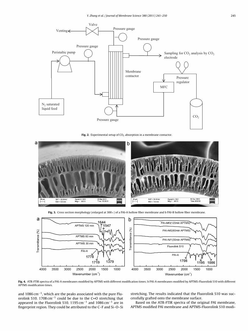
The modified PAI hollow fiber membranes were subjected to preliminary study in a gas-liquid membrane contactor for CO2bsorption. A membrane contactor module was made to test theO2 flux of the modified PAI membranes. The characteristics of theembrane contactor modules are given in Table 2.Pure CO2 was employed as the feed gas and water was used as
he liquid absorbent in order to measure the CO2 flux. The liquidassed through the shell side and the gas flowed counter-currentlyhrough the lumen side of the hollow fibers, as the hydrophobicayers of the modified membranes were in the outer surfaces. In
typical experiment, the feed gas was introduced into the systemrom a compressed gas cylinder and the flow rate was adjustedy mass flow controllers (Cole-Parmer). The gas pressures were
ndicated by the pressure gauges at the lumen inlet and outlet. Aeedle valve at the outlet was used to regulate the gas pressures.he gas volume flow rates at the inlet and the outlet were measuredy digital bubble meters (BioDefense 510L). A digital variable floweristaltic pump (MasterFlex) was used to control the liquid flownd pumped the liquid into the shell side of the hollow fibers from a0L container. The pressures at the inlet and the outlet of the shell
ide were recorded. The liquid flow rate was also checked at theutlet at regular intervals. The CO2 concentration of the outlet liq-id was measured by a CO2 electrode (Thermo Orion Model 95-02)o verify the mass balance via the gas analysis. The measurementable 2haracteristics of the membrane contactor module.
Module ID (mm) 6.4Module length (mm) 25Fiber OD (mm) 1.4Fiber ID (mm) 1.1Effective fiber length (cm) 17Effective membrane area (cm2) 15Number of fibers 2
Pure water flux (L/m h bar) 125 90MWCO (kDa) 34 20Porosity (%) 85 83
range of the electrode was 4.4–440 ppm CO2 with a reproducibil-ity of ±2%. Experimental data were recorded after the contactorsystem was stabilized. The system is schematically shown in Fig. 2.
3. Results and discussion
3.1. Characterization of the as-spun PAI hollow fiber membranes
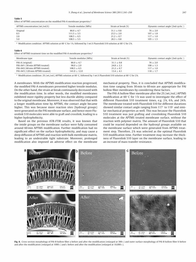
The cross section morphologies of the as-spun PAI-A and PAI-Bhollow fiber membranes are shown in Fig. 3. It can be seen thatboth PAI-A and PAI-B hollow fibers exhibited finger-like struc-tures which were developed simultaneously beneath the inner andouter surfaces of the fibers. The properties of PAI hollow fiber sub-strates in terms of dimension, PWP, MWCO and porosity are listedin Table 3. It shows that both the PAI-A and PAI-B membranes fall inthe category of UF membranes. These two hollow fiber membranesexhibited high water flux and small MWCO which suggested a nar-row pore size distribution, as compared to the other UF membranesreported in literature that were used in membrane contactors[15,31]. A higher polymer concentration was used for fabricat-ing PAI-B membranes. Increasing in polymer concentration wouldresult in a higher viscosity of the dope solution [13], and tendedto delay the dope precipitation rate by slowing down the solvent-nonsolvent exchange process, leading to a denser and thicker skinlayer [32]. Therefore, it was observed that PAI-B showed a lowerflux and smaller MWCO as compared to PAI-A. On the other hand,both PAI-A and PAI-B exhibited a high porosity larger than 80%,which was favourable for reducing the mass transfer resistance ofthe membranes when they were used in the membrane contac-tor after surface modification. The PAI-A was used as the modelsubstrate for the surface modification to identify the optimal mod-ification conditions, which will be discussed later.
3.2. Reaction mechanisms of the surface modification
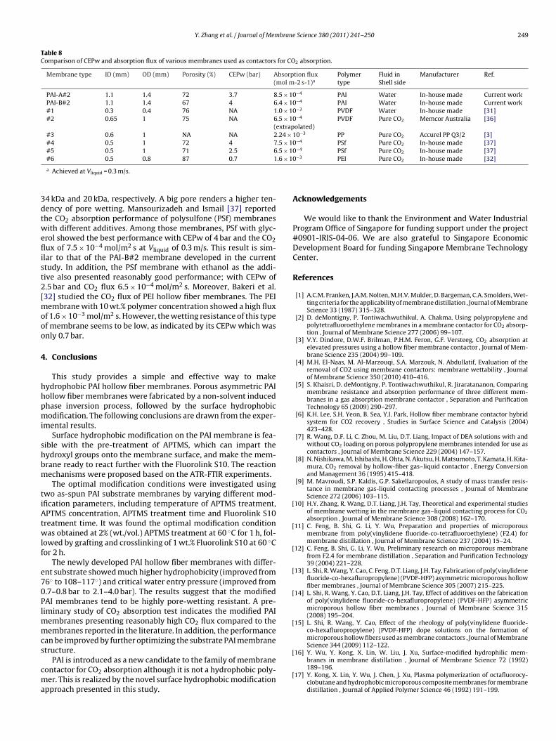
The chemical structures of the original PAI-A membrane beforeand after the first step of APTMS modification were examined byATR-FTIR, as illustrated in Fig. 4(a). For the original membrane,the typical imide transmission bands were observed at 1778 cm−1
(symmetric C–O stretching), 1719 cm−1 (asymmetric C–O stretch-ing) and 1379 cm−1 (C–N–C stretching). As the chemical reactionprogressed, the transmission peaks of the imide bands graduallydiminished. The peaks of the 1778 cm−1 and 1719 cm−1 disap-peared altogether after 1 h APTMS modification. On the otherhand, the amide peaks 1644 cm−1 (C O stretching) and 1547 cm−1
(C–N stretching) became stronger gradually. This indicated that theimide rings were opened and transformed into amide bonds, whichconfirmed that the modification reaction by APTMS had taken placeeffectively. Moreover, the peaks due to O–H stretching variationsoccurred in the regions of 3200 cm−1 to 3600 cm−1 became boarderwith the increase of APTMS treatment time, which suggested thesuccessful imparting of hydroxyl groups onto the PAI surface.
Fig. 4(b) shows the typical transmission bands of the originalPAI, Fluorolink S10 and APTMS-Fluorolink S10 modified PAI mem-branes. It can be observed that APTMS-Fluorolink S10 modifiedmembranes showed transmission bands at 1708 cm−1, 1195 cm−1
Y. Zhang et al. / Journal of Membrane Science 380 (2011) 241– 250 245
Sampli ng for CO2 anal ysis by CO2electrode
N2 sat urated liquid feed
CO2
MFC
Membrane contact or
Pressu re gauge
Pressu re gauge
Pressu re gauge
Press ure gauge
Peristaltic pump
Pressu re regulat or
Venti ng
Valve
Fig. 2. Experimental setup of CO2 absorption in a membrane contactor.
Fig. 3. Cross section morphology (enlarged at 300×) of a PAI-A hollow fiber membrane and b PAI-B hollow fiber membrane.
F odificA
aoafi
ig. 4. ATR-FTIR spectra of a PAI-A membranes modified by APTMS with different mPTMS modification times.
nd 1086 cm−1, which are the peaks associated with the pure Flu-rolink S10. 1708 cm−1 could be due to the C O stretching thatppeared in the Fluorolink S10. 1195 cm−1 and 1086 cm−1 are inngerprint region. They could be attributed to the C–F and Si–O–Si
ation times; b PAI-A membranes modified by APTMS-Fluorolink S10 with different
stretching. The results indicated that the Fluorolink S10 was suc-cessfully grafted onto the membrane surface.
Based on the ATR-FTIR spectra of the original PAI membrane,APTMS modified PAI membrane and APTMS-Fluorolink S10 modi-

246 Y. Zhang et al. / Journal of Membrane Science 380 (2011) 241– 250
a
b
c3H2O 3R'OH
RSi(OR')3
RSi(OH)3
2RSi(OH)3 3H2O
HO Si O
R
OH
Si O
OH
R
Si
R
OH
OH
R=H2N(CH2)3
R'=CH3
C
C
O
N Si
OH
(CH2)3
NH2
C
C
O
NH
O
NH
(CH2)3
Si
OH
C
C
O
NH
O
NH
(CH2)3
Si
OH
PFPE Si OC2H5
OC2H5
OC2H5
C
C
O
NH
O
NH
(CH2)3
Si O
O
Si O
PFPE
Cross link
Si
Si
tween
fircw[itPtthspttF
3
blcwcimmpo
TE
O
Fig. 5. Reaction mechanism of the a hydrolysis of APTMS; b reaction be
ed PAI membrane, the possible mechanisms of PAI membraneseacting with APTMS, and further reacting with Fluorolink S10ould be deduced. As shown in Fig. 5(a), the APTMS compoundas hydrolyzed first in the aqueous solution to form polysiloxane
33]. The hydrolyzed APTMS have a chemical structure compris-ng both primary amine and hydroxyl functional groups, in whichhe amine functional group can react with the imide group fromAI. Fig. 5(b) shows the chemical reaction between the PAI andhe hydrolyzed APTMS, which is confirmed by the ATR-FTIR spec-ra shown in Fig. 4(a). It could be seen that after the reaction, theydroxyl functional groups were imparted onto the membraneurface, which made the secondary treatment by Fluorolink S10ossible. Fluorolink S10 molecules were apt to chemically bond tohe hydroxyl sites [25]. The proposed reaction mechanism betweenhe APTMS treated PAI membrane and Fluorolink S10 is shown inig. 5(c).
.3. Optimal conditions for the surface modification
The optimal APTMS treatment temperature was determinedy varying the temperature from 50◦ to 70◦ using the PAI-A hol-
ow fiber membranes as the model substrate while the ATPMSoncentration was fixed at 2% (wt./vol.) and the treatment timeas controlled at 1 h, followed by the Fluorolink S10 grafting and
rosslinking at 60◦ for 2 h. The temperature effect on the mechan-cal property and surface hydrophobicity of the modified PAI-A
embrane were listed in Table 4. It can be seen that the tensileodulus of the membrane increased significantly with the tem-
erature increased. A high tensile modulus suggests a high rigidityf the membrane. The strain at break (ductile behavior) of the mem-
able 4ffect of APTMS treatment temperature on the modified PAI-A membrane properties.a
APTMS treatment temperature (◦C) Tensile modulus (MPa)
Original 86.0 ± 4.7
50 97.7 ± 0.5
60 108.5 ± 6.5
70 101.1 ± 7.9
a Modification condition: 2% (wt./vol.) APTMS solution for 1 h, followed by 1 wt.% Fluor
PAI and hydrolyzed APTMS; c Fluorolink S10 grafting and crosslinking.
brane dropped continuously. When the temperature increased to70◦, the strain at break was very low, indicating the membranebecame very brittle due to the harsh reaction condition. On theother hand, the contact angle increased dramatically from orig-inal 76◦ to 112◦ at 50 ◦C APTMS treatment. It increased furtherto 117◦ when the temperature increased to 60 ◦C. The increase incontact angle was because of the layer of the perfluoro-compoundFluorolink S10 on the membrane surface. In addition, the contactangle of the modified membrane at 60◦ was similar with that of themembrane treated at 70◦. Therefore, the APTMS treatment temper-ature of 60 ◦C was selected as an optimal condition applied for thetreatment of PAI hollow fiber substrates.
In order to determine the optimal APTMS concentration, threeAPTMS solutions with APTMS 0.5%, 2% and 5% (wt./vol.) in a mixtureof IPA/DI water (vol. 1:1) were prepared. The results of modi-fied PAI-A membrane are showed in Table 5. As observed, thetensile modulus increased after the modification, indicating themodified membrane became more rigid, while the stain at breakdecreased with the increase in APTMS concentration. The contactangle increased considerably after the modification. Surprisinglyat 5% (wt./vol.) APTMS, the contact angle was even less than thatof 0.5% and 2% (wt./vol.) treated membranes. This was possiblybecause of the self condensation of APTMS in the aqueous solu-tion due to the high concentration, which may hinder the reactionbetween the amine group and PAI. Therefore, the APTMS solutionwith 2% (wt./vol.) was selected for the modification.
Optimal APTMS modification time was determined by usingthe as-spun PAI-A hollow fibers under the treatment of APTMSfor varied period of time. Table 6 shows the effect of differentAPTMS modification times on the properties of the modified PAI-
Strain at break (%) Dynamic contact angle (2nd cycle,◦)
31.1 ± 0.8 76 ± 2.027.1 ± 0.5 112 ± 1.221.2 ± 0.7 117 ± 1.012.1 ± 1.8 118 ± 1.3
olink S10 solution at 60 ◦C for 2 h.
Y. Zhang et al. / Journal of Membrane Science 380 (2011) 241– 250 247
Table 5Effect of APTMS concentration on the modified PAI-A membrane properties.a
APTMS concentration (wt./vol.%) Tensile modulus (MPa) Strain at break (%) Dynamic contact angle (2nd cycle,◦)
Original 86.0 ± 4.7 31.1 ± 0.8 76 ± 2.00.5 111.5 ± 3.5 23.3 ± 2.0 107 ± 1.82.0 108.5 ± 6.5 21.2 ± 0.7 117 ± 1.05.0 108.5 ± 5.5 28.3 ± 0.8 105 ± 1.5
a Modification condition: APTMS solution at 60 ◦C for 1 h, followed by 1 wt.% Fluorolink S10 solution at 60 ◦C for 2 h.
Table 6Effect of APTMS treatment time on the modified PAI-A membrane properties.a
Membrane type Tensile modulus (MPa) Strain at break (%) Dynamic contact angle (2nd cycle,◦)
PAI-A (original) 86.0 ± 4.7 31.1 ± 0.8 76 ± 2.0PAI-A#1 (30 min APTMS treated) 98.0 ± 2.0 24.8 ± 2.3 108 ± 1.3PAI-A#2 (60 min APTMS treated) 108.5 ± 6.5 21.2 ± 0.7 117 ± 1.0
.% Fluo
AtOtetahwoh
tasdlm
Fa
PAI-A#3 (120 min APTMS treated) 141.0 ± 12.0
a Modification condition: 2% (wt./vol.) APTMS solution at 60 ◦C, followed by 1 wt
membranes. With the APTMS modification reaction progressed,he modified PAI-A membranes presented higher tensile modulus.n the other hand, the strain at break continuously decreased with
he modification time. In other words, the modified membranesxhibited more rigidity property but less ductile ability comparedo the original membrane. Moreover, it was observed that that with
longer modification time by APTMS, the contact angle becameigher. This was because more reaction sites (hydroxyl groups)ere generated on the PAI membrane surface, and hence more Flu-
rolink S10 molecules were able to graft and crosslink, leading to aigher hydrophobicity.
Based on the previous ATR-FTIR results, it was known thathe imide groups on the membrane surface were fully consumedround 60 min APTMS modification. Further modification had no
ignificant effect on the surface hydrophobicity, and may cause aeep diffusion of APTMS and reaction with bulk membrane matrix,eading to an undesirable tight substrate. Moreover, prolongedodification also imposed an adverse effect on the membrane
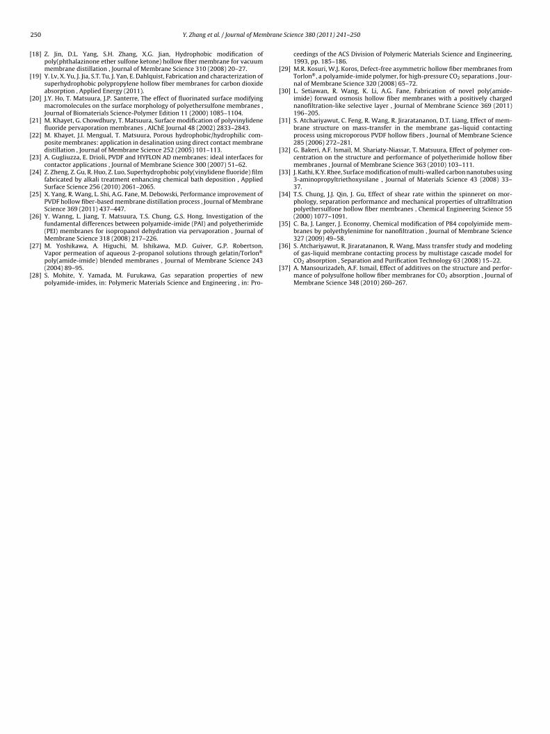
ig. 6. Cross section morphology of PAI-B hollow fiber a before and after the modificationd after the modification (enlarged at 1000×) and c before and after the modification (e
13.4 ± 4.1 118 ± 1.7
rolink S10 solution at 60 ◦C for 2 h.
mechanical property. Thus, it is concluded that APTMS modifica-tion time ranging from 30 min to 60 min are appropriate for PAIhollow fiber membranes by considering these factors.
The PAI-A hollow fiber membrane after the 2% (wt./vol.) APTMSmodification at 60 ◦C for 1 h was used to investigate the effect ofdifferent Fluorolink S10 treatment times, e.g. 2 h, 6 h, and 24 h.The membrane treated with Fluorolink S10 for different durationsshowed similar contact angle ranging from 117◦ to 119◦ and simi-lar mechanical properties as well. This was because the FluorolinkS10 treatment was just grafting and crosslinking Fluorolink S10molecules at the APTMS treated membrane surface, without thereaction with polymer matrix. The amount of Fluorolink S10 thatcould be reacted depended on the hydroxyl groups available onthe membrane surface which were generated from APTMS treat-
ment step. Therefore, 2 h was selected as the optimal FluorolinkS10 modification time. Further treatment may increase the thick-ness of Fluorolink S10 layer on the membrane surface, leading toan increase of mass transfer resistance.n (enlarged at 300×) and outer surface morphology of PAI-B hollow fiber b beforenlarged at 10,000×).

248 Y. Zhang et al. / Journal of Membrane Science 380 (2011) 241– 250
Table 7Mechanical properties, porosity and critical water entry pressure (CEPw) of APTMS-Fluorolink S10 modified membranes.
Membrane type Tensile modulus (MPa) Strain at break (%) Porosity (%) Dynamic contact angle (2nd cycle,◦) CEPw (bar)
PAI-A (original) 86 ± 4.7 31.1 ± 0.8 85 76 ± 2.0 0.7PAI-A#1 (30 min APTMS treated) 98 ± 2.0 24.8 ± 2.3 78 108 ± 1.3 2.1PAI-A#2 (60 min APTMS treated) 108.5 ± 6.5 21.2 ± 0.7 72 117 ± 1.0 3.7PAI-B (original) 182 ± 4.0 28.6 ± 0.3 83 76 ± 2.0 0.8PAI-B#1 (30 min APTMS treated) 199 ± 15 24.5 ± 0.2 73 110 ± 1.4 2.7
3
psPimlcbisbAme
oirtmhPiidsitAfowrhBhtpte
3u
trwwbll
PAI-A#2 and PAI-B#2. This could be attributed to its large poresize of around 0.2 �m, which is in the category of MF membranes,whereas the PAI-A and PAI-B are UF membranes with a MWCO of
0.0E+00
2.0E-04
4.0E-04
6.0E-04
8.0E-04
1.0E-03
1.2E-03
1.4E-03
1.6E-03
1.8E-03
CO
2flu
x(m
ol/m
2s)
PAI-A#1
PAI-A#2
PAI-B#1
PAI-B#2
PAI-B#2 (60 min APTMS treated) 259 ± 7.0 22.4 ± 1.9
.4. PAI membrane properties after the surface modification
The modified membranes were observed by SEM. Fig. 6 dis-lays the morphology observations of the cross-section and outerurface of the original and the APTMS & Fluorolink S10 modifiedAI-B membrane based on 60 min APTMS modification. The mod-fied PAI-B with 30 min APTMs modification showed the similar
orphology. In addition, the SEM images of the modified PAI-Aook similar. It can be seen that there is no visible difference on theross-section morphology for the modified and unmodified mem-ranes. The porous structures under the dense skin layer remained
ntegrity after modification. However, the difference in the outerurface morphology for modified and unmodified membranes cane observed. The original membrane surface was very smooth.fter modification, the surface morphology was altered and becameuch rougher. It was possible that the membrane surface was cov-
red by a thin layer of APTMS and Fluorolink S10.The mechanical properties, porosity, contact angle and CEPw
f the modified PAI-A and PAI-B membranes are summarizedn Table 7. Overall, the modified membranes showed enhancedigidity but weaker ductile properties with the modificationime. Nevertheless, the modified membranes exhibited excellent
echanical properties compared to PES membranes [34], and muchigher rigidity but relatively lower ductile property compared toVDF membranes [25]. It is worth mentioning that although theres no significant difference on cross section structure from SEMmage shown in Fig. 6, the change in mechanical property could beue to the diffusion of the modification regents into the membraneubstrate and reacted with the bulk matrix. The membrane poros-ty decreased after the surface modification. A longer modificationime rendered a lower porosity. This was due to the introduction ofPTMS and Fluorolink S10 macromolecules to the membrane sur-
aces that had restricted some of the big pores and blocked off somef the small pores due to their diffusion and anchoring onto the porealls during the modification process. Similar phenomenon was
eported elsewhere [35]. PAI-A#2 and PAI-B#2 presented a muchigher CEPw than PAI-A#1 and PAI-B#1, because PAI-A#2 and PAI-#2 experienced longer modification times, which led to higherydrophobicity and denser skink layers. As a result, it is expectedhat PAI-A#2 and PAI-B#2 membranes would be less vulnerable toore-wetting but have correspondingly lower CO2 flux as comparedo PAI-A#1 and PAI-B#1 membranes in the membrane contactorxperiments.
.5. Preliminary study of modified PAI hollow fiber membranessed in membrane contactors for CO2 absorption
The modified membranes were subjected to a preliminary studyhat used as a membrane contactor for CO2 absorption, and theesults are shown in Fig. 7. It can be seen that the CO2 flux increasedith the increase in liquid velocity. This was because when water
as supplied at a higher speed, the consumed water was replacedy more fresh water, resulting in a lower CO2 concentration in theiquid phase. Thus, the driving force for CO2 transfer was increased,eading to a higher CO2 flux. This is a well-recognized behavior
67 117 ± 1.6 4.0
of membrane contactors, which implies the mass transfer resis-tance mainly exists on the liquid side in the case of physical CO2absorption.
It was observed that the CO2 absorption performance was insequence of the modified PAI-A > modified PAI-B (PAI-A#1 > PAI-B#1; PAI-A#2 > PAI-B#2) with respect to the same order of waterpermeation flux and MWCO of the as-spun PAI-A and PAI-Bmembranes. Membranes prepared with different dope solutionsand spinning conditions showed different substrate performances,would turn out to affect CO2 absorption performance of the modi-fied membranes. In addition, although the modified PAI-B showedsmaller CO2 flux, they exhibited stronger anti-wetting resistancewhich was reflected by CEPw values. Furthermore, the CO2 flux ofPAI-A#1 was obviously higher than that of PAI-A#2, and this wasbecause PAI-A#2 experienced a longer modification time, whichresulted in higher hydrophobicity and a denser top layer. This resultwas consistent with the change in CEPw as discussed in Table 7.In addition, PAI-B#1 and PAI-B#2 membranes showed the similartrend.
Table 8 shows the comparison of CEPw and CO2 flux of thecurrent modified PAI-A#2 and PAI-B#2 with the membranesreported by different groups in literature at the liquid velocityof 0.3 m/s. At liquid velocity of 0.3 m/s, PAI-A#2 showed a highCO2 flux of 8.5 × 10⁻⁴ mol/m2 s, while PAI-B#2 showed a flux of6.4 × 10−4mol/m2 s. Atchariyawut et al. tested both in-house madePVDF membranes [31] and commercial PVDF membranes [36] forthe absorption of pure CO2 with water. The absorption results ofboth PVDF hollow fibers were similar to that of the PAI-A#2 andPAI-B#2 membranes, respectively. Dindore et al. [3] reported theabsorption flux of the commercial PP hollow fibers which was usedfor the absorption of pure CO2 in water. The CO2 flux at Vliquidof 0.3 m/s was 2.24 × 10⁻³ mol/m2 s, which was higher than both
0.05 0.1 0.15 0.2 0.25 0.3 0.35 0.4Liquid velocity (m/s)
Fig. 7. Effect of absorbent flow rate on the CO2 flux of the modified PAI hollow fibermembranes (pure CO2–water system).
Y. Zhang et al. / Journal of Membrane Science 380 (2011) 241– 250 249
Table 8Comparison of CEPw and absorption flux of various membranes used as contactors for CO2 absorption.
Membrane type ID (mm) OD (mm) Porosity (%) CEPw (bar) Absorption flux(mol m-2 s-1)a
Polymertype
Fluid inShell side
Manufacturer Ref.
PAI-A#2 1.1 1.4 72 3.7 8.5 × 10⁻⁴ PAI Water In-house made Current workPAI-B#2 1.1 1.4 67 4 6.4 × 10⁻⁴ PAI Water In-house made Current work#1 0.3 0.4 76 NA 1.0 × 10⁻³ PVDF Water In-house made [31]#2 0.65 1 75 NA 6.5 × 10⁻⁴
(extrapolated)PVDF Pure CO2 Memcor Australia [36]
#3 0.6 1 NA NA 2.24 × 10⁻³ PP Pure CO2 Accurel PP Q3/2 [3]#4 0.5 1 72 4 7.5 × 10⁻⁴ PSf Pure CO2 In-house made [37]#5 0.5 1 71 2.5 6.5 × 10⁻⁴ PSf Pure CO2 In-house made [37]
.6 × 10−3
3dtweflist2[mooo
4
hhpmi
shbm
tiAtwlf
e70Plmmcs
cma
[
[
[
[
[
[
[
#6 0.5 0.8 87 0.7 1
a Achieved at Vliquid = 0.3 m/s.
4 kDa and 20 kDa, respectively. A big pore renders a higher ten-ency of pore wetting. Mansourizadeh and Ismail [37] reportedhe CO2 absorption performance of polysulfone (PSf) membranesith different additives. Among those membranes, PSf with glyc-
rol showed the best performance with CEPw of 4 bar and the CO2ux of 7.5 × 10⁻⁴ mol/m2 s at Vliquid of 0.3 m/s. This result is sim-
lar to that of the PAI-B#2 membrane developed in the currenttudy. In addition, the PSf membrane with ethanol as the addi-ive also presented reasonably good performance; with CEPw of.5 bar and CO2 flux 6.5 × 10−4 mol/m2 s. Moreover, Bakeri et al.32] studied the CO2 flux of PEI hollow fiber membranes. The PEI
embrane with 10 wt.% polymer concentration showed a high fluxf 1.6 × 10⁻³ mol/m2 s. However, the wetting resistance of this typef membrane seems to be low, as indicated by its CEPw which wasnly 0.7 bar.
. Conclusions
This study provides a simple and effective way to makeydrophobic PAI hollow fiber membranes. Porous asymmetric PAIollow fiber membranes were fabricated by a non-solvent inducedhase inversion process, followed by the surface hydrophobicodification. The following conclusions are drawn from the exper-
mental results.Surface hydrophobic modification on the PAI membrane is fea-
ible with the pre-treatment of APTMS, which can impart theydroxyl groups onto the membrane surface, and make the mem-rane ready to react further with the Fluorolink S10. The reactionechanisms were proposed based on the ATR-FTIR experiments.The optimal modification conditions were investigated using
wo as-spun PAI substrate membranes by varying different mod-fication parameters, including temperature of APTMS treatment,PTMS concentration, APTMS treatment time and Fluorolink S10
reatment time. It was found the optimal modification conditionas obtained at 2% (wt./vol.) APTMS treatment at 60 ◦C for 1 h, fol-
owed by grafting and crosslinking of 1 wt.% Fluorolink S10 at 60 ◦Cor 2 h.
The newly developed PAI hollow fiber membranes with differ-nt substrate showed much higher hydrophobicity (improved from6◦ to 108–117◦) and critical water entry pressure (improved from.7–0.8 bar to 2.1–4.0 bar). The results suggest that the modifiedAI membranes tend to be highly pore-wetting resistant. A pre-iminary study of CO2 absorption test indicates the modified PAI
embranes presenting reasonably high CO2 flux compared to theembranes reported in the literature. In addition, the performance
an be improved by further optimizing the substrate PAI membranetructure.
PAI is introduced as a new candidate to the family of membraneontactor for CO2 absorption although it is not a hydrophobic poly-er. This is realized by the novel surface hydrophobic modification
pproach presented in this study.
[
PEI Pure CO2 In-house made [32]
Acknowledgements
We would like to thank the Environment and Water IndustrialProgram Office of Singapore for funding support under the project#0901-IRIS-04-06. We are also grateful to Singapore EconomicDevelopment Board for funding Singapore Membrane TechnologyCenter.
References
[1] A.C.M. Franken, J.A.M. Nolten, M.H.V. Mulder, D. Bargeman, C.A. Smolders, Wet-ting criteria for the applicability of membrane distillation , Journal of MembraneScience 33 (1987) 315–328.
[2] D. deMontigny, P. Tontiwachwuthikul, A. Chakma, Using polypropylene andpolytetrafluoroethylene membranes in a membrane contactor for CO2 absorp-tion , Journal of Membrane Science 277 (2006) 99–107.
[3] V.Y. Dindore, D.W.F. Brilman, P.H.M. Feron, G.F. Versteeg, CO2 absorption atelevated pressures using a hollow fiber membrane contactor , Journal of Mem-brane Science 235 (2004) 99–109.
[4] M.H. El-Naas, M. Al-Marzouqi, S.A. Marzouk, N. Abdullatif, Evaluation of theremoval of CO2 using membrane contactors: membrane wettability , Journalof Membrane Science 350 (2010) 410–416.
[5] S. Khaisri, D. deMontigny, P. Tontiwachwuthikul, R. Jiraratananon, Comparingmembrane resistance and absorption performance of three different mem-branes in a gas absorption membrane contactor , Separation and PurificationTechnology 65 (2009) 290–297.
[6] K.H. Lee, S.H. Yeon, B. Sea, Y.I. Park, Hollow fiber membrane contactor hybridsystem for CO2 recovery , Studies in Surface Science and Catalysis (2004)423–428.
[7] R. Wang, D.F. Li, C. Zhou, M. Liu, D.T. Liang, Impact of DEA solutions with andwithout CO2 loading on porous polypropylene membranes intended for use ascontactors , Journal of Membrane Science 229 (2004) 147–157.
[8] N. Nishikawa, M. Ishibashi, H. Ohta, N. Akutsu, H. Matsumoto, T. Kamata, H. Kita-mura, CO2 removal by hollow-fiber gas–liquid contactor , Energy Conversionand Management 36 (1995) 415–418.
[9] M. Mavroudi, S.P. Kaldis, G.P. Sakellaropoulos, A study of mass transfer resis-tance in membrane gas-liquid contacting processes , Journal of MembraneScience 272 (2006) 103–115.
10] H.Y. Zhang, R. Wang, D.T. Liang, J.H. Tay, Theoretical and experimental studiesof membrane wetting in the membrane gas–liquid contacting process for CO2
absorption , Journal of Membrane Science 308 (2008) 162–170.11] C. Feng, B. Shi, G. Li, Y. Wu, Preparation and properties of microporous
membrane from poly(vinylidene fluoride-co-tetrafluoroethylene) (F2.4) formembrane distillation , Journal of Membrane Science 237 (2004) 15–24.
12] C. Feng, B. Shi, G. Li, Y. Wu, Preliminary research on microporous membranefrom F2.4 for membrane distillation , Separation and Purification Technology39 (2004) 221–228.
13] L. Shi, R. Wang, Y. Cao, C. Feng, D.T. Liang, J.H. Tay, Fabrication of poly(vinylidenefluoride-co-hexafluropropylene) (PVDF-HFP) asymmetric microporous hollowfiber membranes , Journal of Membrane Science 305 (2007) 215–225.
14] L. Shi, R. Wang, Y. Cao, D.T. Liang, J.H. Tay, Effect of additives on the fabricationof poly(vinylidene fluoride-co-hexafluropropylene) (PVDF-HFP) asymmetricmicroporous hollow fiber membranes , Journal of Membrane Science 315(2008) 195–204.
15] L. Shi, R. Wang, Y. Cao, Effect of the rheology of poly(vinylidene fluoride-co-hexafluropropylene) (PVDF-HFP) dope solutions on the formation ofmicroporous hollow fibers used as membrane contactors , Journal of MembraneScience 344 (2009) 112–122.
16] Y. Wu, Y. Kong, X. Lin, W. Liu, J. Xu, Surface-modified hydrophilic mem-
branes in membrane distillation , Journal of Membrane Science 72 (1992)189–196.17] Y. Kong, X. Lin, Y. Wu, J. Chen, J. Xu, Plasma polymerization of octafluorocy-clobutane and hydrophobic microporous composite membranes for membranedistillation , Journal of Applied Polymer Science 46 (1992) 191–199.
2 bran
[
[
[
[
[
[
[
[
[
[
[
[
[
[
[
[
[
[
[
50 Y. Zhang et al. / Journal of Mem
18] Z. Jin, D.L. Yang, S.H. Zhang, X.G. Jian, Hydrophobic modification ofpoly(phthalazinone ether sulfone ketone) hollow fiber membrane for vacuummembrane distillation , Journal of Membrane Science 310 (2008) 20–27.
19] Y. Lv, X. Yu, J. Jia, S.T. Tu, J. Yan, E. Dahlquist, Fabrication and characterization ofsuperhydrophobic polypropylene hollow fiber membranes for carbon dioxideabsorption , Applied Energy (2011).
20] J.Y. Ho, T. Matsuura, J.P. Santerre, The effect of fluorinated surface modifyingmacromolecules on the surface morphology of polyethersulfone membranes ,Journal of Biomaterials Science-Polymer Edition 11 (2000) 1085–1104.
21] M. Khayet, G. Chowdhury, T. Matsuura, Surface modification of polyvinylidenefluoride pervaporation membranes , AIChE Journal 48 (2002) 2833–2843.
22] M. Khayet, J.I. Mengual, T. Matsuura, Porous hydrophobic/hydrophilic com-posite membranes: application in desalination using direct contact membranedistillation , Journal of Membrane Science 252 (2005) 101–113.
23] A. Gugliuzza, E. Drioli, PVDF and HYFLON AD membranes: ideal interfaces forcontactor applications , Journal of Membrane Science 300 (2007) 51–62.
24] Z. Zheng, Z. Gu, R. Huo, Z. Luo, Superhydrophobic poly(vinylidene fluoride) filmfabricated by alkali treatment enhancing chemical bath deposition , AppliedSurface Science 256 (2010) 2061–2065.
25] X. Yang, R. Wang, L. Shi, A.G. Fane, M. Debowski, Performance improvement ofPVDF hollow fiber-based membrane distillation process , Journal of MembraneScience 369 (2011) 437–447.
26] Y. Wanng, L. Jiang, T. Matsuura, T.S. Chung, G.S. Hong, Investigation of thefundamental differences between polyamide-imide (PAI) and polyetherimide(PEI) membranes for isopropanol dehydration via pervaporation , Journal ofMembrane Science 318 (2008) 217–226.
27] M. Yoshikawa, A. Higuchi, M. Ishikawa, M.D. Guiver, G.P. Robertson,
Vapor permeation of aqueous 2-propanol solutions through gelatin/Torlon®poly(amide-imide) blended membranes , Journal of Membrane Science 243(2004) 89–95.
28] S. Mohite, Y. Yamada, M. Furukawa, Gas separation properties of newpolyamide-imides, in: Polymeric Materials Science and Engineering , in: Pro-
[
e Science 380 (2011) 241– 250
ceedings of the ACS Division of Polymeric Materials Science and Engineering,1993, pp. 185–186.
29] M.R. Kosuri, W.J. Koros, Defect-free asymmetric hollow fiber membranes fromTorlon® , a polyamide-imide polymer, for high-pressure CO2 separations , Jour-nal of Membrane Science 320 (2008) 65–72.
30] L. Setiawan, R. Wang, K. Li, A.G. Fane, Fabrication of novel poly(amide-imide) forward osmosis hollow fiber membranes with a positively chargednanofiltration-like selective layer , Journal of Membrane Science 369 (2011)196–205.
31] S. Atchariyawut, C. Feng, R. Wang, R. Jiraratananon, D.T. Liang, Effect of mem-brane structure on mass-transfer in the membrane gas–liquid contactingprocess using microporous PVDF hollow fibers , Journal of Membrane Science285 (2006) 272–281.
32] G. Bakeri, A.F. Ismail, M. Shariaty-Niassar, T. Matsuura, Effect of polymer con-centration on the structure and performance of polyetherimide hollow fibermembranes , Journal of Membrane Science 363 (2010) 103–111.
33] J. Kathi, K.Y. Rhee, Surface modification of multi-walled carbon nanotubes using3-aminopropyltriethoxysilane , Journal of Materials Science 43 (2008) 33–37.
34] T.S. Chung, J.J. Qin, J. Gu, Effect of shear rate within the spinneret on mor-phology, separation performance and mechanical properties of ultrafiltrationpolyethersulfone hollow fiber membranes , Chemical Engineering Science 55(2000) 1077–1091.
35] C. Ba, J. Langer, J. Economy, Chemical modification of P84 copolyimide mem-branes by polyethylenimine for nanofiltration , Journal of Membrane Science327 (2009) 49–58.
36] S. Atchariyawut, R. Jiraratananon, R. Wang, Mass transfer study and modeling
of gas-liquid membrane contacting process by multistage cascade model forCO2 absorption , Separation and Purification Technology 63 (2008) 15–22.37] A. Mansourizadeh, A.F. Ismail, Effect of additives on the structure and perfor-mance of polysulfone hollow fiber membranes for CO2 absorption , Journal ofMembrane Science 348 (2010) 260–267.