noida metro rail corporation (nmrc) limited
TRANSCRIPT
RFP for Shopping Complex,
Addition and Alteration of Hall (3rd Floor) and Proposed Entrance for NMRC Office at Ganga Sector 29, Noida
NOIDA METRO RAIL CORPORATION
(NMRC) LIMITED
REQUEST FOR PROPOSAL (RFP)
E tender No. NMRC/Office-connectivity/50/2018
For Addition and Alteration of Hall (3rd Floor) and Proposed Entrance
for NMRC Office at Ganga Shopping Complex, Sector 29, Noida
November 2018
Issued by:
Noida Metro Rail Corporation (NMRC) Limited
Block-III, 3rd Floor,
Ganga Shopping Complex, Sector-29, Noida -201301,
District Gautam Budh Nagar, Uttar Pradesh, India

RFP for Addition and Alteration of Hall (3rd Floor) and Proposed Entrance for NMRC Office at Ganga Shopping Complex, Sector 29, Noida
Page 2 of 170
Disclaimer
This Request for Proposal (RFP) Document (or ―E-Tender‖ or ―E-Bid‖) for ―Addition and Alteration of
Hall (3rd Floor) and Proposed Entrance for NMRC Office at Ganga Shopping Complex, Sector 29, Noida‖
contains brief information about the scope of work and selection process for the Bidder (‗the Contractor‖
or ―the Tenderer‖). The purpose of the Document is to provide the Bidders with information to assist the
formulation of their Bidding Documents.
While all efforts have been made to ensure the accuracy of information contained in this RFP Document,
this Document does not purport to contain all the information required by the Bidders. The Bidders should
conduct their own independent assessment, investigations and analysis and should check the reliability,
accuracy and completeness of the information at their end and obtain independent advice from relevant
sources as required before submission of their Bid/s. Noida Metro Rail Corporation Ltd. (―NMRC‖ or ―the
Corporation‖) or any of its employees or advisors shall incur no liability under any law, statute, rules or
regulations as to the accuracy or completeness of the RFP Document.
NMRC reserves the right to change any or all conditions/information set in this RFP Document by way of
revision, deletion, updating or annulment through issuance of appropriate addendum as NMRC may deem
fit without assigning any reason thereof.
NMRC reserves the right to accept or reject any or all Bids without giving any reasons thereof. NMRC will
not entertain or be liable for any claim for costs and expenses in relation to the preparation of the Bid/s to
be submitted in terms of this RFP Document.
RFP for Addition and Alteration of Hall (3rd Floor) and Proposed Entrance for NMRC Office at Ganga Shopping Complex, Sector 29, Noida
Page 3 of 170
Glossary a) ―Addendum / Amendment‖ means any written amendment / addendum /corrigendum to this RFP,
from time to time issued by NMRC to the prospective bidders b) “Agreement” means the Contract Agreement to be executed between NMRC and the Selected
Bidder
c) “Applicable Laws” means all the laws including local, state, national or other laws, brought into
force and effect by Govt. of India, State Governments, local bodies, statutory agencies and any other,
and rules / regulations / notifications issued by them from time to time. It also include judgments,
decrees, injunctions, writs and orders of any court or judicial authority as may be in force and effected
from time to time d) “Bidder” or “Tenderer” means any entity which is a sole proprietorship firm, a partnership firm or a
company, in title and assigns which is submitting its bid pursuant to RFP Documents e) “Bid Due Date” means Bid Submission end date and time given in the E-tender f) “e-Bid Security / Earnest Money Deposit (EMD)” means the refundable amount to be submitted by
the Bidder along with RFP documents to NMRC g) “Performance Bank Guarantee/ Security Deposit” means interest free amount to be deposited by
the Contractor with NMRC as per terms and conditions of Contract Agreement as a security against
the performance of the Contract agreement
h) “NMRC” means Noida Metro Rail Corporation Limited ( or ―Corporation‖ or ―Purchaser‖ or
―Employer‖) i) “Party” means Contractor or Corporation (together they are called “Parties”) j) “Permits” shall mean and include all applicable statutory, environmental or regulatory Contracts,
authorization, permits, consents, approvals, registrations and franchises from concerned authorities k) “Re. or Rs. or INR” means Indian Rupee
l) “Revenue Operations Date (ROD)” means the date of operation of Metro
m) “Selected Bidder” means the bidder who has been selected by NMRC, pursuant to the bidding
process for award of Contract n) ―Work" means all the work specified or set forth and required in and by the said specifications,
hereto annexed or to be implied there from or incidental thereto, or to be hereafter specified or
required in such explanatory instructions and drawings (being in conformity with the said original
specifications)
The words and expressions beginning with capital letters and defined in this document shall, unless
repugnant to the context, have the meaning ascribed thereto hereinabove.
Data Sheet
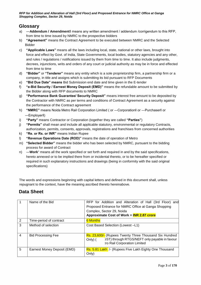
1 Name of the Bid RFP for Addition and Alteration of Hall (3rd Floor) and
Proposed Entrance for NMRC Office at Ganga Shopping Complex, Sector 29, Noida Approximate Cost of Work = INR 2.87 crore
2 Time-period of contract 6 Months 3
Method of selection Cost Based Selection (Lowest –L1)
4 Bid Processing Fee Rs. 23,600/- (Rupees Twenty Three Thousand Six Hundred inclusive of GST) through RTGS/NEFT only payable in favour of Noida Metro Rail Corporation Limited Only) (
5 Earnest Money Deposit (EMD) Rs. 5.81 Lakh /- (Rupees Five Lakh Eighty One Thousand Only)
RFP for Addition and Alteration of Hall (3rd Floor) and Proposed Entrance for NMRC Office at Ganga Shopping Complex, Sector 29, Noida
Page 4 of 170
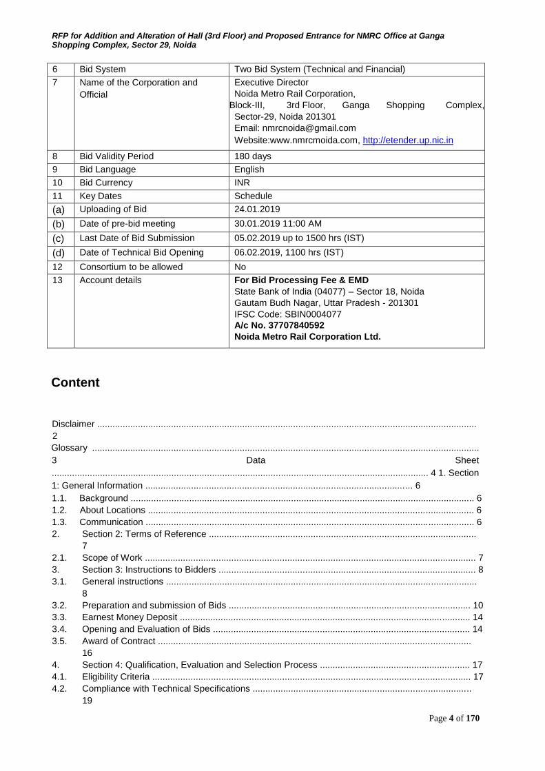
6 Bid System Two Bid System (Technical and Financial)
7 Name of the Corporation and Official
Executive Director Noida Metro Rail Corporation,
Block-III, 3rd Floor, Ganga Shopping Complex, Sector-29, Noida 201301 Email: [email protected] Website:www.nmrcmoida.com, http://etender.up.nic.in
8 Bid Validity Period 180 days
9 Bid Language English
10 Bid Currency INR
11 Key Dates Schedule
(a) Uploading of Bid 24.01.2019
(b) Date of pre-bid meeting 30.01.2019 11:00 AM
(c) Last Date of Bid Submission 05.02.2019 up to 1500 hrs (IST)
(d) Date of Technical Bid Opening 06.02.2019, 1100 hrs (IST)
12 Consortium to be allowed No
13 Account details For Bid Processing Fee & EMD State Bank of India (04077) – Sector 18, Noida Gautam Budh Nagar, Uttar Pradesh - 201301 IFSC Code: SBIN0004077 A/c No. 37707840592 Noida Metro Rail Corporation Ltd.
Content
Disclaimer .....................................................................................................................................................
2 Glossary ........................................................................................................................................................
3 Data Sheet
.................................................................................................................................................... 4 1. Section
1: General Information ......................................................................................................... 6 1.1. Background ....................................................................................................................................... 6 1.2. About Locations ................................................................................................................................ 6 1.3. Communication ................................................................................................................................. 6 2. Section 2: Terms of Reference .........................................................................................................
7 2.1. Scope of Work .................................................................................................................................. 7 3. Section 3: Instructions to Bidders ..................................................................................................... 8 3.1. General instructions ..........................................................................................................................
8 3.2. Preparation and submission of Bids ............................................................................................... 10 3.3. Earnest Money Deposit .................................................................................................................. 14 3.4. Opening and Evaluation of Bids ..................................................................................................... 14 3.5. Award of Contract ...........................................................................................................................
16 4. Section 4: Qualification, Evaluation and Selection Process ........................................................... 17 4.1. Eligibility Criteria ............................................................................................................................. 17 4.2. Compliance with Technical Specifications ......................................................................................
19
RFP for Addition and Alteration of Hall (3rd Floor) and Proposed Entrance for NMRC Office at Ganga Shopping Complex, Sector 29, Noida
Page 5 of 170
4.3. Information of the Technical and Financial Proposal ..................................................................... 19 4.4. Selection of Bidder ..........................................................................................................................
19 4.5. Notice of Award and Execution of Contract Agreement ................................................................. 20 4.6. Performance Bank Guarantee / Security Deposit........................................................................... 20 4.7. Contract during Proposal Evaluation .............................................................................................. 20 4.8. Other Instruction ............................................................................................................................. 21 5. Section 5: Special Conditions of Contract (SCC) ........................................................................... 22 5.1. Conditions Governing the Contract ................................................................................................ 22 5.2. Time for Completion of Work ..........................................................................................................
25 6. Section 6: Technical Specifications ................................................................................................ 26 6.1. Specifications for Civil Works ............................................................................................................... 26
6.2. Specifications of Plumbing works.........................................................................................................
26 6.3. Specifications of Electrical and other works
....................................................................................... 31 6.4. Specifications for Manually Operated Fire Detection and Alarm System ......................................
71 6.5. Specifications for HVAC ........................................................................................................................ 72 7. Section 7: Draft Contract Agreement ..............................................................................................
99 8. Section 8: Appendix to Form of Tender and Forms ..................................................................... 101 8.1. Appendix 1: Metro Alignment ....................................................................................................... 101
8.2. Appendix 2: List of makes
............................................................................................................. 103 8.3. Form 1: Letter of Proposal Submission
............................................................................................. 110 8.4. Form 2: Firm Details
.................................................................................................................... 111 8.5. Form
3: Capability Statement
....................................................................................................... 112 8.6. Form 4:
Work Experience ............................................................................................................
114
8.7. Form 5: Financial Capability Details ............................................................................................. 115 8.8. Form 6: Memorandum .................................................................................................................. 117 8.9. Form 7: Undertaking - 1 ................................................................................................................
118 8.10. Form 8: Power of Attorney
............................................................................................................ 119 8.11. Form 9: Banker‘s Solvency Certificate ......................................................................................... 121 8.12. Form 10: General Guidelines for Fixing Requirement of Technical Staff for Work ...................... 122 8.13. Form 11: Proforma for Equipment available .................................................................................
124 8.14. Form 12: Salable Form for Tender Document ..............................................................................
125 8.15. Form 13: Declaration of Refund of Earnest Money ...................................................................... 126
8.16. Form 14: Bid Offer/ BOQ (Format)
............................................................................................... 127 8.17. Form 15 : Bid Details .................................................................................................................... 170

RFP for Addition and Alteration of Hall (3rd Floor) and Proposed Entrance for NMRC Office at Ganga Shopping Complex, Sector 29, Noida
Page 6 of 170
1. Section 1: General Information
1.1. Background
a. Noida and Greater Noida are being developed as the satellite towns to New Delhi and more and
more people from Delhi and other areas are shifting to these towns in search of fresh air,
greenery and better infrastructure. There is a need of providing an efficient, reliable and
comfortable transportation system for the population intending to settle in these towns and also
the public coming to these areas for education, service and business.
b. Noida Metro Rail Corporation is a Special Purpose Vehicle (SPV) formed by Noida and Greater
Noida Authorities for planning and executing urban transport projects in Noida, Greater Noida
regions. The Corporation desires to provide a world-class Public Transportation System with
state-of-the-art technology. As such, the overarching criterion for setting up of the Corporation is
to help create an efficient, safe, reliable, economical and affordable public transport system.
c. An elevated metro line between Noida and Greater Noida is already under advanced stages of
testing.
d. NMRC invites E-Bids for selection of Contractor for Addition and Alteration of Hall (3rd Floor) and Proposed Entrance for NMRC Office at Ganga Shopping Complex, Sector 29, Noida
e. In this regard, the Corporation now invites the interested Bidder/s to submit their proposals as per
provisions of this RFP Document.
f. NMRC will shortlist the Bidders on the basis of evaluation criteria mentioned in this RFP
Document. On the basis of the minimum evaluation criteria, qualified Bidders will be shortlisted
and Financial proposal of only qualified Bidders will be opened.
1.2. About Locations
The metro corridor is 29.7 km long in first phase and is known as Noida Greater Noida Metro Rail Corridor.
It comprises 21 metro stations starting from Noida Sector 51 in Noida and ends up at Depot Station in
Greater Noida. The map is in Appendix 1: Metro Alignment.
1.3. Communication
All communications should be addressed to -
Executive Director Noida Metro Rail Corporation (NMRC) Limited
Block-III, 3rd Floor, Ganga Shopping Complex, Sector-29, Noida -201301 District Gautam Budh Nagar, Uttar Pradesh
Email: [email protected]
2. Section 2: Terms of Reference

RFP for Addition and Alteration of Hall (3rd Floor) and Proposed Entrance for NMRC Office at Ganga Shopping Complex, Sector 29, Noida
Page 7 of 170
2.1. Scope of Work
a. The work covered in the tender includes below mentioned location
Entrance and Hall (3rd Floor), Ganga Shopping Complex, Sector 29, Noida
b. The technical specifications is set forth in Section 6 of this RFP.
RFP for Addition and Alteration of Hall (3rd Floor) and Proposed Entrance for NMRC Office at Ganga Shopping Complex, Sector 29, Noida
Page 8 of 170
3. Section 3: Instructions to Bidders 3.1. General instructions
a. A Bidder is eligible to submit only one Tender for the Project. A Bidder applying shall not be entitled
to submit another Tender, as the case may be. Any Bidder, which submits or participates in more
than one tender/proposal would be disqualified.
b. The Bidder shall initiate, and actively pursue and involve itself in all investigations and enquiries,
Corporation feedbacks, information, convening of and attendance at meetings, and in any other
activities as are or may be necessary for producing high quality work as per the requirements.
c. The Bidder shall carry out the services in compliance with the provisions of this Agreement. Any
and all changes necessary to ensure that the Bidder's documents conform to the intent and
purpose set out in the Agreement, shall be made at the Bidder's own expense. The Bidder
represents that it is a professional and experienced company providing services related to tender,
and hereby agrees to bear full responsibility for the correctness and technical merit of the services
performed.
d. Bidders shall be evaluated on the basis of the Evaluation Criteria specified in this document.
Bidders shall be deemed to have understood and agreed that no explanation or justification for any
aspect of the Selection Process will be given and that NMRC‘s decisions are without any right of
appeal whatsoever.
e. Any entity which has been barred by the Central/State Government in India or by any entity
controlled by them, from participating in any project, and the bar subsists as on the date of Bid,
would not be eligible to submit an e - Bid.
f. An Bidder should have, during the last five years, neither failed to perform on any agreement, as
evidenced by imposition of a penalty by an arbitral or judicial authority or a judicial pronouncement
or arbitration award against the Bidder, nor been expelled from any project or agreement nor have
had any agreement terminated for breach by such Bidder.
g. Bidders are encouraged to inform themselves fully about the assignment and the local conditions
before submitting the e-Bid by paying a visit to the Corporation and/or by sending written queries
to NMRC before the last date for receiving queries/clarifications.
h. NMRC shall not be liable for any omission, mistake or error on the part of the Bidder in respect of
any of the above or on account of any matter or thing arising out of or concerning or relating to e-
Bid or the Selection Process, including any error or mistake therein or in any information or data
given by NMRC.
i. Any new taxes or any statutory variation [which comes into effect after the last date of submission
of Bid on any item] during the contractual completion shall be to the Employer‘s account for which
the Bidder shall furnish the documentary evidence in support of their claims. However, any
increase in cost due to new taxes or change in existing taxes introduced during extended
contractual period due to Bidder‘s fault shall be to his account.
j. The currency for the purpose of the Proposal shall be the Indian Rupee (INR).
3.1.1. Cost of Bid Document / e-Tender processing Fee
a. The tenderer shall bear all costs associated with the preparation and submission of its e-Bid and
Noida Metro Rail Corporation Ltd. (―NMRC‖ or ―the Corporation‖), will in no case be
responsible or liable for these costs, regardless of the conduct or outcome of the e-Bid process.
b. This tender document is available on the web site http://etender.up.nic.in or on NMRC website
(www.nmrcnoida.com) to enable the tenderers to view, download the e-Bid document and submit
e-Bids online up to the last date and time mentioned in e-Tender notice/e-tender document

RFP for Addition and Alteration of Hall (3rd Floor) and Proposed Entrance for NMRC Office at Ganga Shopping Complex, Sector 29, Noida
Page 9 of 170
against this e-Tender. The tenderers shall have to pay cost of bid document/ eTender processing
fee of as mentioned in Data Sheet through RTGS/NEFT only payable in favour of Noida Metro
Rail Corporation Limited in the A/c No. mentioned in Data Sheet. The scanned copy of
RTGS/NEFT receipt with transaction Id certified by the same bank must be enclosed along with
the e-Bid. This cost of bid document/ e-Tender processing fee as mentioned in Data Sheet will
be non-refundable. Tender without cost of bid document/ e-Tender processing fee in the
prescribed form, will not be accepted.
3.1.2. Acknowledgement by Bidder
It shall be deemed that by submitting the e-Bid, the Bidder has:
a. made a complete and careful examination of the e-Bid;
b. received all relevant information requested from NMRC;
c. acknowledged and accepted the risk of inadequacy, error or mistake in the information provided in
the e-Bid or furnished by or on behalf of NMRC;
d. satisfied itself about all matters, things and information, necessary and required for submitting an
informed Application and performance of all of its obligations thereunder;
e. acknowledged that it does not have a Conflict of Interest; and
f. agreed to be bound by the undertaking provided by it under and in terms hereof.
3.1.3. Availability of Bid Document
This Bid document is available on the web site http://etender.up.nic.in and on Noida Metro website
www.nmrcnoida.com to enable the Bidders to view, download the e-Bid document and submit e-Bids online
up to the last date and time mentioned in e-Bidder notice/ e-Bid document. The Bidder`s shall have to pay
e-Bid document fee and EMD as mentioned in Data sheet through RTGS/NEFT on addresses given in data
sheet. The scanned copy of RTGS/NEFT with transaction ID certified by the same bank must be enclosed
along with the e-Bid. This e-Bid document fee will be non-refundable. Bid without Bid fee in the prescribe
form will not be accepted.
3.1.4. Clarifications of e-Bid
a. During evaluation of e-Bid, NMRC may, at its discretion, ask the Bidder for a clarification of
his/her e-Bid. The request for clarification shall be in writing.
b. Any queries or request for additional information concerning this RFP shall be submitted in
writing or by fax and e-mail to the Executive Director, NMRC only within seven days of issuance
of tender. The envelopes/ communication shall clearly bear the following identification/ title:
"Queries/ Request for Additional Information: RFP for Addition and Alteration of Hall (3rd
Floor) and Proposed Entrance for NMRC Office at Ganga Shopping Complex, Sector 29,
Noida ". The responses will be posted to all such queries on the official Website
www.nmrcnoida.com. NMRC reserves the right not to respond to any questions or provide any
clarifications, in its sole discretion, and nothing in this Clause shall be taken or read as compelling
or requiring NMRC to respond to any question or to provide any clarification.
c. In case the Bidder seeks for any queries, he shall send letter or e-mail to the correspondence
address given in Data Sheet.
d. However, NMRC shall not entertain any correspondence from the Bidders during the period of
eBid opening to selection of the successful Bidder. Any wrong practice shall be dealt in
accordance with the Section of this e-Bid document under Fraud and Corrupt Practices.
3.1.5. Amendment of e-Bid Document

RFP for Addition and Alteration of Hall (3rd Floor) and Proposed Entrance for NMRC Office at Ganga Shopping Complex, Sector 29, Noida
Page 10 of 170
a. At any time prior to the deadline for submission of e-Bid, NMRC may, for any reason, whether at
its on in iterative or in response to a clarification requested by a prospective Bidder, modify the e-
Bid document by amendments. Such amendments shall be uploaded on the e-

RFP for Addition and Alteration of Hall (3rd Floor) and Proposed Entrance for NMRC Office at Ganga Shopping Complex, Sector 29, Noida
Page 11 of 170
procurement website http://etender.up.nic.in. The relevant clauses of the e-Bid document shall
be treated as amended accordingly.
b. It shall be the sole responsibility of the prospective Bidder to check the web site
http//etender.up.nic.in or NMRC‘s website www.nmrcnoida.com from time to time for any
amendment in the e-Bid documents. In case of failure to get the amendments, if any, NMRC shall
not be responsible for it.
c. In order to allow prospective e-Bids a reasonable time to take the amendment into account in
preparing their e-Bids, NMRC, at the discretion, may extend the deadline for the submission of
e-Bids. Such extensions shall be uploaded on the e-procurement website http://etender.up.nic.in
or NMRC‘s website www.nmrcnoida.com.
3.2. Preparation and submission of Bids
3.2.1. Language of e-Bid
The e-Bid prepared by the Bidder, as well as all correspondence and documents relating to the e-Bid
exchanged by the Bidder and NMRC shall be written in English language. Only English numerals shall be
used in the e-Bid. The correspondence and documents in any other language must be accompanied by
transcripts verified by the Embassy of Home Country or equivalent.
3.2.2. Documents constituting the e-Bid
The e-Bid prepared by the Bidder shall comprise the following components: a.
Technical e-Bid- Technical e-Bid will comprise of -
i. Fee details - Details of Bid processing fee and prescribed EMD
ii. Eligibility details - Includes copies of required documents in PDF format justifying that
the Bidder is qualified to perform the contract if his/her bid is accepted and the Bidder
has financial & technical capability necessary to perform the contract and meets the
criteria outlined in the Qualification requirement and technical specification and fulfill all
the conditions of the contract.
iii. Technical evaluation - Details of all documents needed for Technical evaluation as
mentioned in this RFP
b. Financial e-Bid -
i. Price bid – Bill of Quantities in XLS format to be filled in after downloading from the
eProcurement website for this e-tender. There shall be a single quote.
3.2.3. Documents establishing Bidder's Qualification
a. The Bidder shall furnish, as part of its technical e-Bid, documents establishing the Bidder's
qualification to perform the contract if its e-Bid is accepted. The documentary evidence should
be submitted by the Bidder electronically in the PDF format.
b. The documentary evidence of Bidder's qualification to perform the contract if its e-Bid is
accepted shall be as per qualification requirements specified in e-Bid document.
3.2.4. E-Bid form
The Bidder shall complete the e-Bid form and the appropriate price schedule/BOQ furnished in the
e-Bid document. Financial Quote shall comprise of the rate of Total Price for RFP for Addition and
Alteration of Hall (3rd Floor) and Proposed Entrance for NMRC Office at Ganga Shopping
Complex, Sector 29, Noida in the Bid form in figures.
3.2.5. E-Bid Currency
Prices shall be quoted in Indian Rupees only.

RFP for Addition and Alteration of Hall (3rd Floor) and Proposed Entrance for NMRC Office at Ganga Shopping Complex, Sector 29, Noida
Page 12 of 170
3.2.6. Formats and Signing of e-Bid
a. The Bidder shall prepare one electronic copy of the technical e-Bid and financial e-Bid separately.
b. The e-Bid document shall be digitally signed, at the time of uploading, by the Bidder or a person
or persons duly authorized to bind the Bidder to the contract. The later authorization shall be
indicated by a scanned copy of written power-of attorney accompanying the e-Bid. All the
pages/documents of the e-Bid that are to be uploaded shall be digitally signed by the person
authorized to sign the e-Bid.
c. Bidders should provide all the information as per the RFP and in the specified formats. NMRC
reserves the rights to reject any proposal that is not in the specified formats.
d. In case the Bidders intends to provide additional information for which specified space in the
given format is not sufficient, it can be furnished in duly stamped and signed PDFs.
3.2.7. Deadline for submission of e-Bid
E-Bid (Technical and financial) must be submitted by the Bidder at e-procurement website
http://etender.up.nic.in not later than the time specified on the prescribed date (as the server time
displayed in the e-procurement website). NMRC may, at its discretion, extend this deadline for
submission of e-Bid by amending the e-Bid document, in which case all rights and obligations of
NMRC and Bidders previously subject to the deadline will thereafter be subject to the deadline as
extended.
3.2.8. Submission of e-Bid
a. The bid submission module of e-procurement website http://etender.up.nic.in enables the Bidders
to submit the e-Bid online in response to this e-Bid published by NMRC.
b. Bid submission can be done only from the bid submission start date and time till the bid
submission end date and time given in the e-Bid. Bidders should start the bid submission process
well in advance so that they can submit their e-Bid in time.
c. The Bidder should submit their e-Bid considering the server time displayed in the e- procurement
website. This server time is the time by which the e-Bid submission activity will be allowed till the
permissible time on the last/end date of submission indicated in the e-Bid schedule.
d. Once the e-Bid submission date and time is over, the Bidders cannot submit their e-Bid. For
delay in submission of e-Bid due to any reasons, the Bidders shall only be held responsible.
The Bidders have to follow the following instructions for submission of their e-Bid:
a. For participating in e-Bid through the e-Biding system it is necessary for the Bidders to be
the registered users of the e-procurement website http://etender.up.nic.in. The Bidders
must obtain a user login Id and password by registering themselves with U.P. Electronics
Corporation Ltd., Lucknow if they have not done so previously for registration.
b. In addition to the normal registration, the Bidder has to register with his/her digital signature
certificate (DSC) in the e-Biding system and subsequently he/she will be allowed to carry
out his/her e-Bid submission activities. Registering the digital signature certificate (DSC) is
a one-time activity. Before proceeding to register his/her DSC, the Bidder should first log
on to the e-Biding system using the user login option on the home page with the login Id
and password with which he/she has registered.
For successful registration of DSC on e-procurement website http://etender.up.nic.in the
Bidder must ensure that he/she should possess class-2/class-3 DSC issued by any
certifying authorities approved by controller of certifying authorities, Government of India,
as the e-procurement website http://etender.up.nic.in is presently accepting DSC issued by
these authorities only. The Bidder can obtain user login Id and perform DSC registration

RFP for Addition and Alteration of Hall (3rd Floor) and Proposed Entrance for NMRC Office at Ganga Shopping Complex, Sector 29, Noida
Page 13 of 170
exercise given above even before the e-Bid submission date starts. NMRC shall not be held
responsible if the Bidder tries to submit his/her e-Bid at the moment before end date of
submission but could not submit due to DSC registration problem.
c. The Bidder can search for active Bids through "search active tenders" link, select a Bid in
which he/she is interested in and then move it to 'My Tenders' folder using the options
available in the e-Bid submission menu. After selecting and the Bid, for which the Bidder
intends to e-Bid, from "My tenders" folder, the Bidder can place his/her e-Bid by clicking
"pay offline" option available at the end of the view Bid details form. Before this, the Bidder
should download the e-Bid document and price schedule/bill of quantity (BOQ) and study
them carefully. The Bidder should keep all the documents ready as per the requirements of
e-Bid document in the PDF format except the price schedule /bill of quantity (BOQ) which
should be in the XLS format (excel sheet).
d. After clicking the 'pay offline' option, the Bidder will be redirected to terms and conditions
page. The Bidder should read the terms & conditions before proceeding to fill in the Bid fee
and EMD offline payment details. After entering and saving the Bid fee and EMD details
form so that "bid document preparation and submission" window appears to upload the
documents as per technical (fee details, qualification details, e-Bid form and technical
specification details) and financial (e-Bid form and price schedule/BOQ) schedules/packets
given in the Bid details. The details of the RTGS/NEFT should tally with the details available
in the scanned copy and the date entered during e-Bid submission time otherwise the e-Bid
submitted will not be accepted.
e. Next the Bidder should upload the technical e-Bid documents for fee details (e-Bid fee and
EMD), Qualification details. Before uploading, the Bidder has to select the relevant digital
signature certificate. He may be prompted to enter the digital signature certificate password,
if necessary. For uploading, the Bidder should click "browse" button against each document
label in technical and financial schedules/packets and then upload the relevant PDF/XLS
files already prepared and stored in the Bidder's computer. The required documents for
each document label of technical ( fee details, qualification details, e-Bid form and technical
specification details) and financial ( e-Bid form and price schedule/BOQ) schedules/packets
can be clubbed together to make single different files for each label.
f. The Bidder should click "Encrypt" next for successfully encrypting and uploading of required
documents. during the above process, the e-Bid document are digitally signed using the
DSC of the Bidder and then the documents are encrypted/locked electronically with the
DSC's of the bid openers to ensure that the e-Bid documents are protected, stored and
opened by concerned bid openers only.
g. After successful submission of e-Bid document, a page giving the summary of e-Bid
submission will be displayed confirming end of e-Bid submission process. The Bidder can
take a printout of the bid summary using the "print" option available in the window as an
acknowledgement for future reference.
h. NMRC reserves the right to cancel any or all e-Bids without assigning any reason.
3.2.9. Late e-Bid
a. Bids received by NMRC after the specified time on the Bid Due Date shall not be eligible for
consideration and shall be summarily rejected.
b. The server time indicated in the bid management window on the e- procurement website
http://etender.up.nic.in will be the time by which the e-Bid submission activity will be allowed till the
permissible date and time scheduled in the e-Bid.

RFP for Addition and Alteration of Hall (3rd Floor) and Proposed Entrance for NMRC Office at Ganga Shopping Complex, Sector 29, Noida
Page 14 of 170
c. Once the e-Bid submission date and time is over, the Bidder cannot submit his/her e-Bid. Bidder
has to start the bid submission well in advance so that the submission process passes off smoothly.
The Bidder will only be held responsible if his/her e-Bid is not submitted in time due to any of his/her
problems/faults, for whatsoever reason, during e-Bid submission process.
3.2.10. Withdrawal and resubmission of e-Bid
a. At any point of time, a Bidder can withdraw his/her e-Bid submitted online before the bid submission
end date and time. For withdrawing the Bidder should first log in using his/her login id and password
and subsequently by his/her digital signature certificate on the e-procurement website
http://etender.up.nic.in. The Bidder should then select "My bids" option in the bid submission menu.
The page listing all the bids submitted by the Bidder will be displayed. Click "View" to see the details
of the bid to be withdrawn. After selecting the "bid withdrawal" option the Bidder has to click "Yes"
to the message "Do you want to withdraw this bid?" displayed in the bid information window for the
selected bid. The Bidder also has to enter the bid withdrawing reasons and upload the letter giving
the reasons for withdrawing before clicking the "Submit" button. The Bidder has to confirm again
by pressing "OK" button before finally withdrawing his/her selected e-Bid.
b. No e-Bid may be withdrawn in the interval between the deadline for submission of e-Bids and the
expiration of period of e- bid validity. Withdrawal of an e-Bid during this interval may result in the
forfeiting of Bidder's e-Bid security.
c. The Bidder can re-submit his/her e-Bid as when required till the e-Bid submission end date and
time. The e-Bid submitted earlier will be replaced by the new one. The payment made by the Bidder
earlier will be used for revised e-Bid and the new e-Bid submission summary generated after the
successful submission of the revised e-Bid will considered for evaluation purposes. For
resubmission, the Bidder should first log in using his/her login Id and password and subsequently
by his/her digital signature certificate on the e-procurement website http://etender.up.nic.in. The
Bidder should then select "My bids" option in the bid submission menu. The page listing all the bids
submitted by the Bidder will be displayed. Click "View" to see the detail of the e-Bid to be
resubmitted. After selecting the "bid resubmission" option, click "Encrypt & upload" to upload the
revised e-Bids documents.
d. The Bidder can submit their revised e-Bids as many times as possible by uploading their e-Bid
documents within the scheduled date & time for submission of e-Bids.
e. No e-Bid can be resubmitted subsequently after the deadline for submission of e-Bids.
3.2.11. NMRC's right to accept any e-Bid and to reject any or all e-Bids.
a. Notwithstanding anything contained in this e-Bid, NMRC reserves the right to accept or reject any
Bid and to annul the Selection Process and reject all Bids, at any time without any liability or any
obligation for such acceptance, rejection or annulment, and without assigning any reasons thereof.
b. NMRC reserves the right to reject any Bid if:
• At any time, a material misrepresentation is made or uncovered, or
• The Bidder does not provide, within the time specified by NMRC, the supplemental
information sought by NMRC for evaluation of the e-Bid.
c. Such misrepresentation/ improper response may lead to the disqualification of the Bidder. If such
disqualification /rejection occurs after the e-Bid have been opened and the highest ranking Bidder
gets disqualified / rejected, then the NMRC reserves the right to consider the next best Bidder, or
take any other measure as may be deemed fit in the sole discretion of NMRC, including annulment
of the Selection Process.
3.2.12. Period of validity of e-Bid

RFP for Addition and Alteration of Hall (3rd Floor) and Proposed Entrance for NMRC Office at Ganga Shopping Complex, Sector 29, Noida
Page 15 of 170
a. e-Bid shall remain valid for 180 days after the date of e-Bid opening prescribed by NMRC. An
eBid valid for a shorter period shall be rejected by NMRC as non-responsive.
b. In exceptional circumstances, NMRC may solicit the Bidder's consent to an extension of the
period of e-Bid validity. The request and the response thereto shall be made in writing.
3.2.13. Correspondence with the Bidder
a. Save and except as provided in this e-Bid, NMRC shall not entertain any correspondence with
any Bidder or its Technical Partners in relation to acceptance or rejection of any e-Bid.
b. Subject to Clause 3.4.5 no Bidders or its Technical Partners shall contact NMRC on any matter
relating to his e-Bid from the time of Bid opening to the time contract is awarded.
c. Any effort by the Bidder or by its Technical Partners to influence NMRC in the Bid evaluation, Bid
comparison or contract award decisions, may result in the rejection of his Bid.
3.3. Earnest Money Deposit
3.3.1. Earnest money deposit (EMD)
a. The tenderer shall furnish, as part of its e-Bid, an e-Bid security/ EMD as stated in Data Sheet in
form of RTGS/NEFT only in favour Noida Metro Rail Corporation Limited in the A/c No.
mentioned in Data Sheet. The scanned copy of RTGS/NEFT receipt of Security/ EMD with
transaction Id certified by the same bank must be enclosed along with the e-Bid. Tender without
Earnest Money in the prescribed form, will not be accepted.
b. Any e-Bid not secured in accordance with above shall be treated as non-responsive and rejected
by NMRC.
c. Unsuccessful Bidder's EMD will be returned promptly as possible after opening of the Price Bid.
d. No interest will be paid by the Purchaser on the Earnest Money Deposit.
e. The successful Bidder's e-Bid EMD will be adjusted with Performance Bank Guarantee, if
applicable, to be submitted by the Bidder upon signing the contract.
f. The EMD may be forfeited:
i. If Bidder (a) withdraws its e-Bid during the period of e-Bid validity specified by the Bidder
on the e- bid form: or (b) does not accept the correction of errors or (c) modifies its e-Bid
price during the period of e-Bid validity specified by the Bidder on the form.
ii. In case of a successful Bidder, if the Bidder fails to sign the contract with the Corporation.
3.4. Opening and Evaluation of Bids
3.4.1. Opening of technical e-Bid by NMRC
a. NMRC will open all technical e-Bids, in the presence of Bidder`s representatives who choose to
attend on the prescribed date of opening at NMRC Office. The Bidder's representatives who are
present shall sign a register evidencing their attendance. In the event of the specified date e-Bid
opening being declared a holiday for the Corporation, the e –bids shall be opened at the appointed
time and place on the next working day.
b. The Bidder who is participating in e-Bid should ensure that the RTGS/NEFT of Bid Processing Fee
and EMD must be submitted in the prescribed account of NMRC within the duration (strictly within
opening & closing date and time of individual e-Bid) of the work as mentioned in Bid notice,
otherwise, in any case, e-Bid shall be rejected.
c. The Bidders names and the presence or absence of requisite e-Bid security and such other details
as NMRC at its discretion may consider appropriate, will be announced at the opening.
3.4.2. Opening of financial e-Bid

RFP for Addition and Alteration of Hall (3rd Floor) and Proposed Entrance for NMRC Office at Ganga Shopping Complex, Sector 29, Noida
Page 16 of 170
a. After evaluation of technical e-Bid, through the evaluation committee NMRC shall notify those
Bidders whose technical e-Bids were considered non-responsive to the conditions of the contract
and not meeting the technical specifications and qualification requirements indicating that their
financial e-Bids will not be opened.
b. NMRC will simultaneously notify the Bidders, whose technical e-Bids were considered acceptable
to the Corporation. The notification may sent by e-mail provided by Bidder.
c. The financial e-Bids of technically qualified Bidders shall be opened in the presence of technically
qualified bidders who choose to attend. The date and time for opening of financial bids will be
communicated to the technically qualified Bidders subsequently after completion of technical bids
evaluation through e-mail provided by the Bidder. The name of Bidders, percentage price quoted
for various items etc. will be announced at the meeting.
3.4.3. Correction of Errors
a. Financial Bids determined to be responsive will be checked by NMRC for any arithmetic errors.
Where there is a discrepancy between the rate quoted in the Financial Bid, in figures and in words,
the amount in words will prevail over the amounts in figures, to the extent of such discrepancy.
b. The amount stated in the Financial Bid will be adjusted by NMRC in accordance with the above
procedure for the correction of errors and shall be considered as binding upon the Bidder. If the
Bidder does not accept the corrected quoted rate of e-Bid, his e-Bid will be rejected, and his Bid
Security shall be liable for forfeiture in accordance with Clause 3.3.1f
3.4.4. Examination of e-Bid document
a. The NMRC will examine the e-Bid to determine if:
i. They are complete;
ii. They meet all the conditions of the contract;
iii. The required e-Bid Processing fee, EMD and other required documents have been
furnished;
iv. The documents have been properly digitally signed; and
v. The e-Bids are in order.
b. Any e-Bid or e-Bids not fulfilling these requirements shall be rejected.
3.4.5. Contacting NMRC
a. No Bidder shall contact NMRC on any matter relating to his/her e-Bid, from the time of the e-Bid
opening to the time the contract is awarded. If the Bidder wishes to bring additional information to
the notice of NMRC, he/she can do so in writing.
b. Any effort by a Bidder to influence NMRC in its decisions on e-Bid evaluation, e- bid comparison
or contract award may result in rejection of the Bidder's e-Bid.
c. In the event of any information furnished by the Bidder is found false or fabricated, the minimum
punishment shall be debarring /blacklisting from Noida Metro works and legal proceeding can also
be initiated. EMD of such bidders will be forfeited.
3.4.6. Confidentiality
a. Information relating to the examination, clarification, evaluation, and recommendation for the
Bidders shall not be disclosed to any person who is not officially concerned with the process or is
not a retained professional advisor advising NMRC in relation to or matters arising out of, or
concerning the Bidding Process. Any effort by a Bidder to exert undue or unfair influence in the

RFP for Addition and Alteration of Hall (3rd Floor) and Proposed Entrance for NMRC Office at Ganga Shopping Complex, Sector 29, Noida
Page 17 of 170
process of examination, clarification, evaluation and comparison of Proposal shall result in outright
rejection of the offer, made by the said Bidder.
b. NMRC shall treat all information, submitted as part of Bid, in confidence and shall require all those
who have access to such material to treat the same in confidence. NMRC may not divulge any
such information unless it is directed to do so by any statutory entity that has the power under law
to require its disclosure or is to enforce or assert any right or privilege of the statutory entity and/
or NMRC or as may be required by law or in connection with any legal process.
3.5. Award of Contract
3.5.1. Award Criteria
a. NMRC will award the contract as per evaluation criteria stated in the RFP Document.
b. NMRC will award the contract to the successful Bidder whose bid has been determined to be
responsive to all the conditions of the contract and meeting the eligibility requirement of the
bidding document.
3.5.2. Notice of Award (NOA)
a. Prior to the expiration of the period of e-Bid validity, NMRC will notify the successful Bidder in
writing, by letter/e-mail/fax, that its e-Bid has been accepted.
b. The acceptance of NOA will constitute the formation of the contract.
3.5.3. Contract
a. This contract is for the supply, install, commissioning, training and maintenance of the equipment
of the description, specifications and drawings, and in the quantities set forth in the contract on the
date or dates specified therein. All equipment must be brand new and unused. Unpacking/seal
opening has to be done in presence of NMRC.
b. The whole contract is to be executed in the most approved, substantial and workmanship manner,
to the entire satisfaction of the Purchaser or his nominee, who, both personally and may his
deputies, shall have full power, at every stage of progress, to inspect the equipment at such times
as he may deem fit and to reject any of the equipment which he may disapprove.
3.5.4. Signing of contract
At the same time as NMRC notifies the successful Bidder that it‘s e-Bid has been accepted, the successful
Bidder shall have to sign the contract agreement with relevant document as mentioned in the RFP. The
agreement draft along with other related terms and conditions will be same as furnished in this e-Bid. Any
refusal will not be allowed. The Bidder need not download and submit in hard copies of these documents.
3.5.5. NMRC’s right to accept any e-Bid and to reject any or all e-Bids
NMRC reserves the right to accept or reject any e-Bid, and to annul the e-Bid process and reject all eBids
at any time prior to contract award, without thereby incurring any liability to the affected tenderer or
tenderers.
4. Section 4: Qualification, Evaluation and Selection
Process
4.1. Eligibility Criteria
The Bidder‘s competence and capability is proposed to be established by the following parameters. The
Bidder should meet all the criteria given in this section.

RFP for Addition and Alteration of Hall (3rd Floor) and Proposed Entrance for NMRC Office at Ganga Shopping Complex, Sector 29, Noida
Page 18 of 170
a. The Bidder should be Sole proprietorship/ partnership firm/ public limited company/ private limited
company.
b. The Bidder should have successfully completed in India during last 7 (seven) years period ending
last day of month previous to the one in which the bids are invited with Govt./ Semi Govt./ PSU
only should be either of the following:
i. One order of similar nature of value not less than Rs. 2.33 crore (Rupees Two crore Thirty Three Lakh only) or ii. Two orders of similar nature of value not less than Rs. 1.75
crore (Rupees One crore
Seventy Five lakh only) each or iii. Three orders of similar nature of value not less than
Rs. 1.17 crore (Rupees One crore Seventeen lakh only) each
Definition of Similar Works – Experience in only building construction inclusive of civil work,
Electrical work and HVAC, Firefighting work and landscaping work will be acceptable.
c. The Bidder should submit the solvency certificate issued by Nationalized / Scheduled bank (issued
within a period of minimum six months) and it should not be less than Rs. 1.17 crore (Rupees One
crore Seventeen lakh only)
d. The Bidder should have minimum average annual turnover from construction works of Rs. 2.33
crore (Rupees Two crore Thirty Three Lakh only) in the last 3 (three) Financial Years (20152016,
2016-17, 2017-18) preceding the Bid Due Date.
e. The Bidder should have positive profit before tax in the last 3 (three) Financial Years (2015-2016,
2016-17, 2017-18) preceding Bid Due Date.
f. The Bidder requires to provide proof of employment of technical staff, which will consist of a
declaration by the Bidder as perForm 10: General Guidelines for Fixing Requirement of Technical
Staff for Work.
g. The Bidder shall submit affidavit duly verified by Notary for having arrangement of required
machinery, tools & plants, centering & shuttering, etc.
The minimum requirement of T&P possessed by the firm shall be as follows:
S.No. Particulars Quantity
1 Road Roller NIL
2 Vibratory Road Roller NIL
3 Truck/ Tipper 1
4 Water Tanker 1
5 Water Pumps 1
S.No. Particulars Quantity
6 Hot Mix Plant & Paver (Hiring of hot mix plant shall not be
permitted in case the cost of DBM/ BM/ BC/ SDC work is more
than one crore. Bidder will have to submit the purchase bill of
plant as a proof).
The bituminous work of DBM/ BM/ BC/ SDC will have to be done by hot mix plant and paver only.
NIL

RFP for Addition and Alteration of Hall (3rd Floor) and Proposed Entrance for NMRC Office at Ganga Shopping Complex, Sector 29, Noida
Page 19 of 170
7 Excavator NIL
8 Concrete Mixture with hopper 1
9 Vibrator
a Needle Vibrator 1
b Surface Vibrator 1
10 Concrete Batch Mix Plant of Capacity 15 Cum/Hr. NIL
h. The Bidder shall submit the Character certificate issued by District Magistrate in the names of
partners in case it is partnership firm, proprietor, in case it is proprietorship firm, directors in case
it is company.
i. The Bidder should submit the notarized affidavit that the bidder has not been blacklisted by any
state/ central government/ organization in last 7 (seven) financial years.
NMRC, if required, may seek clarifications from bidders during the technical evaluation. The
Bidder shall also furnish the following:
a. For above criteria 4.1a i. Statutory proof of existence as the legal entity ii. Power of attorney as inForm 8: Power of Attorney
iii. Memorandum and Articles of Association showing the objectives of the company/ firm
(as per applicability)
b. For above criteria 4.1b
i. A statement as in Form 4: Work Experience with documentary proof
c. For above criteria 4.1c i. Solvency certificate should be issued within a period of minimum 6 months of
nationalized/ Schedule Bank. In case it is issued more than 6 months, it should be
revalidated after 6 months In case of firm, proof of solvency of the bidder will consist of a certificate signed by the
District Magistrate or Manager of the Bank as per Form 9: Banker‘s Solvency Certificate
regarding the cash assets of the bidder.
In case of company, the proof of the company solvency will be its last balance sheet
audited and certificate by the Chartered Accountant or certificate/ reference of a Bank.
d. For above criteria 4.1d and 4.1e i. Form 5: Financial Capability Details
ii. A copy of the Annual Reports (Profit and Loss Account and Balance Sheet) for the last 3
(three) Financial Years of Bidder A copy of the Audited balance sheets and Profit and Loss Statements for the last 3
(three) financial years. In case the Financial Statements for the latest financial year are not audited and therefore
the Bidder cannot make it available, the Bidder shall give an undertaking to this effect and
the statutory auditor/charted accountant shall certify the same. In such a case, the Bidder
shall provide the Audited Financial Statements for 2 (two) years preceding the year for

RFP for Addition and Alteration of Hall (3rd Floor) and Proposed Entrance for NMRC Office at Ganga Shopping Complex, Sector 29, Noida
Page 20 of 170
which the Audited Financial Statement is not being provided. Also, pertaining to latest
financial year, the bidder shall submit an affidavit certifying that ―The Annual Accounts
have not been audited so far. We are submitting the CA certified provisional accounts,
which shall be substantiated by the Audited Accounts, when prepared.‖ iii. A self-attested copy of current valid ITR iv. A self-attested copy of PAN, GST registration
e. For above criteria 4.1f i. Form 10: General Guidelines for Fixing Requirement of Technical Staff for Work
f. For above criteria 4.1g i. Form 11: Proforma for Equipment available
g. For above criteria 4.1i ii. Form 7: Undertaking - 1
4.2. Compliance with Technical Specifications
The equipment offered by the bidders must comply with the stipulated technical specifications as
mentioned in the tender documents.
4.3. Information of the Technical and Financial Proposal
a. The Bidder satisfying technical and financial eligibility criteria under Clause 4.1 shall be
considered as technically and financially qualified.
b. The financial proposal of only technically qualified Bidders shall be opened for evaluation.
c. The Bidder with the lowest quoted price for ―Addition and Alteration of Hall (3rd Floor) and
Proposed Entrance for NMRC Office at Ganga Shopping Complex, Sector 29, Noida " in the
financial quote (L1 bidder) shall be selected for the award of contract.
4.4. Selection of Bidder
After the above evaluation process, the Technically Qualified Bidder, who is declared as L1 (lowest
quoted price) may be declared as the selected Bidder (―Selected Bidder‖) for the Project.
a. In case, two or more technically qualified bidders quote the same percentage in the Bid, and
become Lowest (i.e. L-1), then the tender would be awarded to the bidder who has the highest /
higher Average Annual Turnover from ‗Similar Works‘ (as per Minimum Eligibility Criteria defined
in Section 4 under ―Definition of Similar Work‖) during the last 3 years ending on the last day of
the month preceding the month in which the tender has been floated.
b. Prior to the expiry of the period of bid validity, NMRC will notify the successful bidder in writing,
either through Notice of Award (NOA), that his bid has been accepted.
c. The NOA would be sent in duplicate to the successful bidder, who will return one copy to NMRC
duly acknowledged, signed and stamped by the authorized signatory of the bidder, as an
unconditional acceptance of the NOA, within 10 (ten) days from the date of issue of NOA.
d. No correspondence will be entertained by NMRC from the unsuccessful bidders.
4.5. Notice of Award and Execution of Contract Agreement
a. NMRC will notify the Successful Bidder by a NOA that its bid has been accepted.
b. The Selected Bidder shall, within 10 (ten) days of the receipt of the NOA, sign and return the
duplicate copy of the NOA in acknowledgement thereof along with letter of acceptance of NOA. In
the event, the duplicate copy of the NOA duly signed by the Selected Bidder and letter of
acceptance of NOA is not received by the stipulated date, NMRC may, unless it consents to

RFP for Addition and Alteration of Hall (3rd Floor) and Proposed Entrance for NMRC Office at Ganga Shopping Complex, Sector 29, Noida
Page 21 of 170
extension of time for submission thereof, appropriate the Bid Security of such Bidder as mutually
agreed genuine pre-estimated loss and damage suffered by NMRC on account of failure of the
Selected Bidder to acknowledge the NOA.
c. The Successful Bidder shall execute the Contract Agreement within 30 (thirty) days of the letter of
acceptance of NOA or such extended period as may be decided by the Corporation.
d. Failure of the Successful Bidder to comply with the requirement of acknowledgement of NOA
shall constitute sufficient grounds for the annulment of the NOA, and forfeiture of the bid security.
4.6. Performance Bank Guarantee / Security Deposit
a. Contractor has to deposit additional performance guarantee/ Security in the shape of FDR/ CDR/
Bank Guarantee/ NSC in case rate quoted below of Bill of Quantity (BOQ) at 0.5% per one percent
up to 10% below rate and 1% per one percent on rate quoted beyond 10% below rate, valid for the
complete contract period by the Contractor before entering in to the contract bond.
b. A Contract agreement will have to be signed by the Contractor at his cost on proper stamp paper.
Without performance guarantee by Contractor, Contract agreement shall not be signed.
c. NMRC reserves the right for deduction of NMRC dues from Contractor‘s Performance Bank
Guarantee/ Security Deposit (interest free) for – Any penalty imposed by NMRC for violation of any
terms and conditions of agreement committed by the Contractor.
i. Any amount which NMRC becomes liable to the Government/Third party due to any
default of the Contractor or any of his director/ employees/ representatives/ servant/
agent, etc.
ii. Any payment/ fine made under the order/judgment of any court/consumer forum or law
enforcing Contractor or any person duly empowered in his behalf.
iii. Any outstanding payment/ claims of NMRC remained due after completion of relevant
actions as per agreement.
d. Once the amount under above Clause is debited, the Contractor shall replenish the Security
Deposit/ Performance Bank Guarantee to the extent the amount is debited within 15 days period,
failing which, it shall be treated as Contractor Event of Default and will entitle NMRC to deal with
the matter as per the provisions of RFP and Contract Agreement.
4.7. Contract during Proposal Evaluation
a. Proposals shall be deemed to be under consideration immediately after they are opened and until
such time NMRC makes official intimation of award/ rejection to the Bidders. While the Proposals
are under consideration, Bidders and/ or their representatives or other interested parties are
advised to refrain from contacting by any means, NMRC and/ or their employees/ representatives
on matters related to the Proposals under consideration till the time Contract is awarded.
b. Any effort by a Bidder to influence NMRC in its decisions on e-Bid evaluation, e-Bid comparison or
contract award may result in rejection of the Bidder‘s e-Bid.
c. In the event of any information furnished by the Contractor is found false or fabricated the minimum
punishment shall be debarred/ blacklisting and the legal proceeding may also be initiated.
d. If the Bidder wishes to bring additional information to the notice of NMRC, he/she can do so in
writing. All correspondence/ enquiry should be submitted to the following in writing by fax/
post/courier:
Executive Director Noida Metro Rail Corporation (NMRC) Limited Block-III, 3rd Floor, Ganga Shopping Complex, Sector-29, Noida -201301
RFP for Addition and Alteration of Hall (3rd Floor) and Proposed Entrance for NMRC Office at Ganga Shopping Complex, Sector 29, Noida
Page 22 of 170
District Gautam Budh Nagar, Uttar Pradesh
Email: [email protected]
e. No interpretation, revision, or other communication from NMRC regarding this solicitation is valid
unless in writing and signed by the competent authority from NMRC.
4.8. Other Instruction
a. Canvassing in connection with the tenders is strictly prohibited and the tenders, submitted by
Bidder, who resort to canvassing, are liable to be rejected. EMD will be forfeited of those tenders
who will be found non serious and if it is felt by the tender committee that the Bidders submitted
their tender only to influence the tendering process.
b. On acceptance of the tender, the name of the accredited representative of the Contractor, who
would be responsible for taking instructions from the NMRC or the official deputed by NMRC, shall
be communicated to the NMRC or the official deputed by NMRC in writing.
RFP for Shopping Complex,
Addition and Alteration of Hall (3rd Floor) and Proposed Entrance for NMRC Office at Ganga Sector 29, Noida
5. Section 5: Special Conditions of Contract (SCC)
5.1. Conditions Governing the Contract
The special conditions of contract contained herein shall be supplemented to the general conditions of the
contract and in event of any conflict or inconsistency between them; Special conditions of the contract will
supersede the General conditions of the contract.
a. The Bidders are advised before bidding to see carefully the site of work & study architectural &
structural drawings for the buildings/ roads to be constructed under the scope of this tender.
b. In giving their rates, the Bidders should take into account all fluctuations of market construction rates
of materials, as no claim shall be entertained on this account during the acceptance of the tender and
the currency of the contract.
c. The tendered rates shall be for all completed items of the work and shall include all quarry royalties,
testing, screening, tools & plants, railways freight, carriage of materials to site, stacking, removal
charge of any rejected material, etc. labour cess and all other taxes in force from time to time.
d. Within fifteen days of the signing of Agreement, the contractor shall have to notify in writing the name
of his two authorized representatives one of them will always be available at the site of work to receive
the orders / instructions by Engineer in charge and the other for issue of materials and other
miscellaneous works. The contractor shall be fully responsible for the orders / instructions received by
his representatives regarding quality, progress and materials from the Engineer-in-charge or any higher
officer of NMRC.
e. Contractor shall have to make their own arrangement of water and electricity for construction work at
site. All the building material for the work shall be arranged by the contractor at his own cost.
f. The contractor shall be fully responsible for setting out the works and for the correctness of the
positions, levels, dimensions and alignments strictly according to the plan / architectural and structural
drawings (shall be provided without any charge) and all necessary instruments, pegs poles and other
material required for the purpose, failing which the contractor will be penalized as applicable.
g. A Cement consumption register shall be maintained at the site by the department for material brought
by contractor as per CPWD Manual/Specification. The contractor or his authorized representative /
agent shall have to sign the register daily in token of the consumption of material consumed daily at
work site.
h. The contractor (in self) shall give sufficient supervision to the work using his best skill and attention.
He shall provide necessary qualified staff to supervise the execution of the work. The contractor or a
competent authorized agent or representative should be got approved in writing by the Engineer-
incharge (whose approval at any time can be withdrawn or changed) for supervising the work and to
receive directions and instructions from Engineer-in-charge of the work on the behalf of the contractor.
The supervisory staff of the contractor will not be changed without the approval of Engineer-in-charge.
i. The contractor shall be responsible for the damage to any property or any injury to person whatsoever
caused by him or anybody in his employment or caused in consequence of his work. He will indemnify
and keep the Government un-indemnified against all claims, demands, proceedings, charges and
expenses and compensation, whatsoever, in respect of the or in relation to any such injuries or
damages. The contractor shall take all necessary precautions for the safety of his employees on the

RFP for Addition and Alteration of Hall (3rd Floor) and Proposed Entrance for NMRC Office at Ganga Shopping Complex, Sector 29, Noida
Page 24 of 170
work site and shall comply with all applicable provisions of safety law and building codes to prevent
accident or injuries to person on the work site.
j. The contractor shall keep at his own, whole of the excavated area free from water; however, if
excavation is filled with water the contractor shall provide all pumping equipment temporary drain and
such cuts / excavation shall be made good at the completion of work at his own cost.
k. The contractor shall at all times keep the premise free from accumulated waste material or rubbish
caused by his employees on the work and on completion of the work he shall clear away whole site
from such material and fill up the borrow pits / cuts dug by him. He will leave whole of the site and work
clear in a workman like. Nothing extra shall be paid to contractor for this clearing up.
l. The contractor shall maintain and keep the area in agreed sanitary condition for the use of men
engaged in the work by him and shall remove and clear all structures etc. which may have been setup
by the contractor for accommodating his staff / labour on the completion of work to the satisfaction of
the Engineer in charge.
m. All the material and workmanship and its working procedure shall be strictly as per specification of
described in the contract and in case not covered in the contract then in accordance with the Engineer
in charge / ISI code. Instructions shall be issued from time to time to tests the material as the Engineer
in charge may direct at places of manufacture, at the work site. Contractor shall provide conveyance,
labour and material required for examining, measuring and testing for the work and quality of material
used. Contractor shall supply sample of the material get them approved before using in the work. The
cost of such, like conveyance, labour and material provide for testing purpose and for examining the
work and for proper completion of the same shall be borne by the contractor and no extra payment
shall be made for the same. In addition to above, the contractor shall establish a field laboratory to
carry out day to day tests of all material at his own cost. The contractor shall submit a list of the all the
laboratory equipment's, quality control Engineer of the contractor who will work under direction and
control of Engineer-in-charge.
n. The contractors shall have to make their own arrangements of water for construction work, for
temporary accommodations for the office staff and for the labourers' residence at the site of work. The
water should be fit for drinking. In case the water is supplied by the department, the contractor shall
have to bear charges at rates fixed by the authority.
o. The contractor will have to follow all existing rules and regulations of the Government & labour
department or as amended from time to time regarding the labour employed by him without entitling
him for any extra claim on this account.
p. Works to be open to inspection : All works under or in course of execution or executed in pursuance of
the contractor shall at time be opened to the inspection and supervision of the Engineer-in-charge and
other corporation‘s officials and the contractor shall present at work site at all times during the
inspection and usual working hours. At all other times, notice for the inspection of site by the Engineer-
in-charge or any other official is given to the contractor, contractor should either himself be present to
receive orders and instructions of a responsible authorized agent be present for the purpose. Orders
given to the contractor's agent shall be considered to have the same force as if they had been given to
the contractor himself. The contractor shall also provide all facilities necessary for inspection of the
work by the Engineer-in-charge or other officials for which no payment shall be made to the contractor.
q. The contractor will arrange the water for consolidation of stone ballast and compaction of earth and
nothing extra will be paid for the same.
RFP for Addition and Alteration of Hall (3rd Floor) and Proposed Entrance for NMRC Office at Ganga Shopping Complex, Sector 29, Noida
Page 25 of 170
r. The contractor is to stack the metal at the road berms first according to the size of template with stack
number as decided by the Engineer in charge and no metal shall be stocked on road embankment.
The metal shall be only allowed to spread for consolidation after recording measurements and taken
into road metal account register.
s. The quantity measured in stacks shall be final & binding on the contractor and no claim will be
entertained thereafter.
t. A deduction of 7.5% (for voids) shall be made after stack measurements of stone aggregate for
payment.
u. Deduction shall be made for earthwork in filling without compaction up to 95% proctor density as per C.P.W.D. specification.
v. The stone ballast and grit will be blue textured and free from soft stone pieces. The size / gauge of the
ballast shall be as per detailed specification of C.P.W.D.
w. In case of earth work in filling is being done in layers of 20cm thickness, the compaction must be done
with heavy machinery such as road roller of 8 tonne or above capacity at the optimum moisture content.
The dry density must be achieved to the extent or not less than 95% of proctor's density. In this area
when the compaction is achieved to the desired density no deduction shall be made from the measured
cubical content.
x. In case of earth work in filling is being done in layers of 20cm thickness, the compaction must be done
with heavy machinery such as road roller of 8 tonne or above capacity at the optimum moisture content.
The dry density must be achieved to the extent or not less than 95% of proctor's density. In this area
when the compaction is achieved to the desired density no deduction shall be made from the measured
cubical content.
In case of patries (shoulder of road) the compaction should be done with road roller of 8 tonne capacity.
However, 95% proctor's density at optimum moisture contents is not necessary. The deduction of this
area must be made 10% on the measured cubical content of compacted earth.
y. For cement storage at work site, double lock system will have to be followed.
z. The dust emissions from the construction site should be completely controlled and all precautions taken
in that behalf.
aa. Every worker working on the construction site and involved in loading, unloading and carriage of
construction material and construction debris shall be provided with mask to prevent inhalation of dust
particles.
bb. Every Project proponent shall be under obligation to provide all medical help, investigation and
treatment to the workers involved in the construction of building and carry of construction material and
debris relatable to dust emission.
cc. All builders/owners should take appropriate measures and strictly comply with by fixing sprinklers and
creations of green air barriers on construction site.
dd. Compulsory use of wet-jet in grinding and stone cutting.
ee. Wind breaking walls around construction site and proper maintenance of greenbelt should be
answered.
ff. All builders shall ensure that C&D waste is transported and disposed to the C&D waste site only and
due record in that behalf shall be maintained by the builders and transporters.
RFP for Addition and Alteration of Hall (3rd Floor) and Proposed Entrance for NMRC Office at Ganga Shopping Complex, Sector 29, Noida
Page 26 of 170
gg. It shall be the responsibility of every builder that all the construction material and debris shall be carried
in the trucks or other vehicles which are fully covered and protected so as to ensure that the
construction debris or the construction material does not get dispersed into the air or atmosphere, in
any form whatsoever.
hh. The vehicles carrying construction material and construction debris of any kind should be cleared
before it is permitted to ply on the road after unloading of such material.
ii. The entry and exit points design is very important as it should not disturb the existing traffic. This clear
demarcation of entry and exit points is important.
jj. Fitness certification is a statutory requirement for commercial vehicles and public transport vehicles.
Periodicity for certification is once in a Year.
kk. Pollution-Under-Control (PUC) certificates are required to be obtained every three months for all
categories of vehicles and Life of vehicle should be inspected to avoid further air pollution.
ll. Viable emission control technologies exist to reduce diesel exhaust emissions designed to control
particulate matter (PM) should be installed/used such as Diesel oxidation catalysts (DOCs), Diesel
particulate filters (DPFs), Exhaust gas recirculation (EGR), Selective catalytic reduction (SCR), Lean
NOx catalysts (LNCs), Lean Nox traps (LNTs).
mm. The Vehicles carrying garbage should be covered with polythene/Tripal otherwise contractor will
be suitably penalized. nn. Garbage, dry leafs burning is a serious offence. If it is found at site, respective
contractor will be suitably penalized.
5.2. Time for Completion of Work
The Work needs to be completed within a period of 6 (six) months from the date of acceptance of NOA.
RFP for Addition and Alteration of Hall (3rd Floor) and Proposed Entrance for NMRC Office at Ganga Shopping Complex, Sector 29, Noida
Page 27 of 170
6. Section 6: Technical Specifications
6.1. Specifications for Civil Works
6.1.1. Puf Panel Insulated Roof Fixing of Puff Panel Roofing shell be constructed of 60+30 mm thick PUF (Poly Urethane Foam) & density
of 40 + 2 kg/m3 laminated with 0.5mm Pre-coated GI outside and 0.5mm inside of roof. Over the perlin
over main trusss as / structure. The roofing panel shall have overlap joinery systems. The top coat of the
panels shall preferably be AWT color & Bottom AWT. Complete in all respect.
6.1.2. Polycarbonate Sheet Fixing of Polycarbonate sheet (4 mm thick) inserted in 50 mm Aluminium Extrusion standard tightened with
EPDM RUBBER GASKET with SDS screws and fasteners over steel structure as / drawing complete in all
respect. Transparent silicone 789 shall be used to fill the joints.
6.1.3. Terrace Garden Laying of grass Selection No 1 over Growing Medium Soil (200 mm thick) over 0.8 to 0.9 mm thick
Geotextile of GSM 140 (+-5%) of Quality Code ST-14 over Drainage Board 8 to 9 mm thick of GSM 400
(+-5%) Quality Code DB-04 over 1 mm APP membrane over RCC slab complete in all respect.
6.2. Specifications of Plumbing works
6.2.1. Section-I: Internal Rain Water Drainage
6.2.1.1. Scope of Work The scope of work under this section comprises the supply, installation, testing and commissioning of
internal drainage services. This shall consist of furnishing all labor, materials, equipment and appliances
necessary and required to completely install rainwater pipes and fittings as required by the drawings, and
given in the schedule of quantities.
6.2.1.2. Piping System Rain water pipes in shafts, ducts and in concealed areas etc. shall consist of uPVC pipes confirming to IS
to IS 4985 (class C) & fittings as called for.
The rain water pipes shall be circular with a minimum diameter of 150mm. Pipes shall be fixed by means
of galvanized steel clamps in two sections, bolted together, built into the walls, wedged and neatly jointed
as directed and approved by the Owner‘s site representative. All bends, branches, swan neck and other
parts shall conform to the requirement and standards as described for the pipes. Pipes shall be rested
against the walls on suitable wooden cradles. Local authority regulations applicable to the installations shall
be strictly followed.
Access doors for fittings and clean outs shall be so located that they are easily accessible for repair and
maintenance. Any access panel required in the civil structure, false ceiling or marble cladding etc. shall be
clearly reported to the Owner in the form of shop drawings so that other agencies are instructed to provide
the same.
6.2.1.3. Piping Materials UPVC
Pipes and Fittings
1. The pipes shall be round and shall be supplied in straight lengths with socketed ends. The
internal and external surfaces of pipes shall be smooth, clean, and free from grooving‘s and other
defects. The ends shall be cleanly cut and square with the axis of the pipe. The pipes shall be
designed by external diameter and shall conform to IS: 4985-1981. The pipes shall be of ClassIII;
6 kg/sqm pressure rating.
2. Fittings shall be of the same make as that of pipes, injection moulded and shall conform to Indian
Standard.
RFP for Addition and Alteration of Hall (3rd Floor) and Proposed Entrance for NMRC Office at Ganga Shopping Complex, Sector 29, Noida
Page 28 of 170
Supports
3. UPVC pipes require supports at close intervals. Recommended support spacing for unplasticised
PVC pipes is 1400 mm for pipes 50 mm dia and above. Pipes shall be aligned properly before
fixing them on the wooden plugs with clamps. Even if the wooden plugs are fixed using a plumb
line, pipe shall also be checked for its alignment before clamping, piping shall be properly
supported on, or suspended from clamps, hangers as specified and as required. The Contractor
shall adequately design all the brackets, saddles, anchors, clamps and hangers and be
responsible for their structural sufficiency. Pipe supports shall be primer coated with rust
preventive paint.
Laying and Jointing
4. The pipes shall be laid and clamped to wooden plugs fixed above the surface of the wall.
Alternatively plastic clamps of suitable designs shall be preferred. Provision shall be made for the
effect of thermal movement by not gripping or disturbing the pipe at supports between the
anchors for suspended pipes. The supports shall allow the repeated movements to take place
without abrasion.
5. Jointing for UPVC pipes shall be made by means of solvent cement for horizontal lines and ‗O‘
rubber ring for vertical line. The type of joint shall be used as per site conditions / direction of the
Owner‘s site representative. Where UPVC pipes are to be used for rain water pipes, the pipe
shall be finished with GI adopter for insertion in the RCC slab for a water proof joint complete as
directed by Owner‘s site representative.
6. All open terraces shall be drained by rain water down takes.
7. Rainwater down takes are separate and independent of the soil and waste system and will
discharge into the underground storm water drainage system of the complex.
8. Rainwater in open area shall be collected in catch basins and connected to the Storm Water
manhole.
6.2.1.4. Testing
1. Testing shall be done in accordance with IS: 1172 and IS: 5329 except as may be modified
herein under.
2. Before use at site all uPVC pipes shall be tested by filling up with water for at least 30 minutes.
After filling, pipes shall be struck with a hammer and inspected for blow holes and cracks. All
defective pipes shall be rejected and removed from the site within 48 hours. Pipes with minor
sweating may be accepted at the discretion of the Project Manager.
3. Entire drainage system shall be tested for water tightness and smoke tightness during and after
completion of the installation. No portion of the system shall remain untested. Contractor must
have adequate number of expandable rubber bellow plugs, manometers, smoke testing
machines, pipe and fitting work tests. All materials obtained and used on site must have
manufacturer‘s hydraulic test certificate for each batch of materials used on the site.
6.2.2. Section-II: External Drainage (Storm Water Disposal)
6.2.2.1. Scope of Work
The scope under this section comprises the supply, installation, testing and commissioning of external
storm drainage services.
The drainage system shall include: Storm water drainage, earth works for excavation, disposal, backfilling
and compaction, pipe lines, manholes, catch basins and connections to the existing municipal storm water
drain.
RFP for Addition and Alteration of Hall (3rd Floor) and Proposed Entrance for NMRC Office at Ganga Shopping Complex, Sector 29, Noida
Page 29 of 170
All materials shall be new and of quality conforming to specifications and subject to the approval of the
Owner‘s site representative.
Drainage lines and open drains shall be laid to the required gradients and profiles. All drainage work shall
be done in accordance with the local municipal bye-laws.
Contractor shall obtain necessary approval and permission for the drainage system from the municipal or
any other competent authority.
Location of all manholes, etc. shall be got confirmed by the Project Manager before the actual execution of
work at site. As far as possible, no drains shall be laid in the middle of road unless otherwise specifically
shown on the drawings or directed by the Project Manager in writing.
All materials shall be rust proofed; materials in direct or indirect contact shall be compatible to prevent
electrolytic or chemical (bimetallic) corrosion.
6.2.2.2. Pipe and Drain Trench
Alignment
1. The storm water drainage pipes shall be carefully laid to levels and gradients shown in the plans
and sections but subject to modifications as shall be approved by the Architects from time to time
to meet the requirements of the works. Great care shall be taken to prevent sand etc. from
entering the pipes. The pipes between two manholes shall be laid truly in straight lines without
vertical or horizontal undulations. The body of the pipes shall rest on an even bed in the trench
for its length and places shall be excavated to receive collar for the purpose of jointing. No
deviations from the lines, depths of cuttings or gradients as called for on the drawings shall be
permitted without the written approval of the Architect. All pipes shall be laid at least 45cms below
the finished ground level or as called for on the drawings. Trenches Setting Out
2. The contractor shall set out all trenches including widths, manholes, chambers and such other
works to true grades and alignments as called for. All trenches shall be laid to true grade and in
straight lines and as shown on the drawings. Trench Excavation
3. The trenches for the pipes shall be excavated with bottoms formed to level and gradients as
shown on the drawings. In soft and filled in ground, the Project Manager may require the
trenches to be excavated to a greater depth than the shown on the drawings and to fill up such
additional excavation with concrete (1:4:8) consolidated to bring the excavation to the required
levels as shown on the drawings.
4. All excavations shall be properly protected where necessary by suitable timbering, piling and
sheeting as approved by the Project Manager. All timbering and sheeting when withdrawn shall
be done gradually to avoid falls. All cavities be adequately filled and consolidated. No blasting
shall be allowed without prior approval in writing from the Architect. It shall be carried out under
thorough and competent supervision, with the written permission of the appropriate authorities
taking full precautions connected with the blasting operations. All excavated earth shall be kept
clear of the trenches to a distance equal to 75 cms. Trench Back Filling
5. Refilling of the trenches shall not be commenced until the length of pipes therein has been tested
and approved. All timbering which may be withdrawn safely shall be removed as filling proceeds.
Where the pipes are unprotected by concrete hunching, selected fine material shall be carefully
hand-packed around the lower half of the pipes so as to buttress them to the sides of the trench.
Width of trench
6. Recommended width of trenches at the bottom shall be as follows:-
100 mm dia pipe 55 cms
150 mm dia pipe 55 cms
225-250 cms dia pipe 60 cms

RFP for Addition and Alteration of Hall (3rd Floor) and Proposed Entrance for NMRC Office at Ganga Shopping Complex, Sector 29, Noida
Page 30 of 170
7. Maximum width of the bed concrete shall also be as above. Should the contractor excavate the
trenches to width greater that specified above, no additional payment will be admissible for
widths greater than specified. The contractor shall also fill the cement concrete for the pipe to the
full width of the excavated trench with any extra cost.
6.2.2.3. Piping Material
RCC pipes
1. All pipes shall be centrifugally spun RCC pipes NP3. Pipes shall be true and straight with uniform
bore throughout. Cracked, warped pipes shall not be used on the work. All pipes shall be tested
by the manufacturer and the Contractor shall produce, prior to use on site, a certificate to that
effect from the manufacturer. The pipes shall be with or without reinforcement as required and of
the class as specified. These shall conform to IS: 458-1971.
2. All pipes shall be true to shape, straight, perfectly sound and free from cracks and flaws. The
external and internal surface of the pipes shall be smooth and hard. The pipes shall be free from
defects resulting from imperfect grading of the aggregate mixing or moulding. Pipe Laying
3. RCC spun pipes shall be laid on cement concrete bed of cradles as specified and shown on the
detailed drawings. The cradles may be precast and sufficiently cured to prevent cracks and
breakage in handling. The invert of the cradles shall be left 12 mm below the invert level of the
pipe and properly placed on the soil to prevent any disturbance. The pipe shall then be placed on
`the bed concrete or cradles and set for the line and gradient by means of sight rails and boning
rods, etc. Cradles or concrete bed may be omitted, if directed by the Project Manager. Pipe
Jointing
4. Semi flexible type collar joint. Hemp rope soaked in neat cement wash shall be passed round the
joint and inserted in it by means of caulking tool. More skein of yarn shall be added and rammed
home. Cement mortar with one part of cement and two part of sand and with minimum water
content but on no account soft or sloppy, shall be carefully inserted, punched and caulked into
the collar and more cement mortar added until the space of the collar has been filled completely
with tightly caulked mortar. Provision of rubber sealing ring in the collar joint shall also be made.
The joint shall then be finished off neatly outside the socket at an angle of 45 deg.
5. The joint shall be cured for at least seven days. Refilling at joints will be permitted only on
satisfactory completion of curing period.
6. Cement Concrete for Pipe Supports:
a. Pipes may be supported on brick masonry or precast RCC or in situ cradles. Cradles
shall be as shown on the drawings.
up to 1.5 m depth
up to 3 m depth
beyond 3 m depth
1 RCC or SW in sub soil water
All round (1:3:6)
In Haunches (1:3:6)
In Haunches (1:3:6)
b. Unless otherwise directed by the Project Manager cement concrete for bed, all round or
in haunches shall be as follows:
c. Pipes in loose soil or above ground shall be supported on brick or stone masonry pillars
as shown on the drawings.
7. Measurement:
a. Measurement for excavation of pipes trenches shall be made per linear meter.
b. Trenches shall be measurement between outside walls of manholes at top and the depth
shall be the average depth between the two ends to the nearest cm. The rate quoted
shall be for a depth up to 1.5 metre or as identified in the Schedule of Quantities.

RFP for Addition and Alteration of Hall (3rd Floor) and Proposed Entrance for NMRC Office at Ganga Shopping Complex, Sector 29, Noida
Page 31 of 170
c. RCC pipes shall be measured for length of the pipe line per linear meter. Length
between manholes shall be recorded from inside of one manhole or inside of other
manhole.
6.2.2.4. Construction of Manhole
1. Based on approved drawings, manholes are to be constructed, the excavation, filling back and
ramming, disposal of surplus earth, preparation of bottom and sides etc. shall be carried out as
described earlier under trench excavation.
2. The manhole shall be built on a base concrete 1:3:6 of 150mm thickness for manholes up to
1500mm depth and 250mm thickness for manholes from 1500 to 2500mm depth and 300mm
thickness manholes of depth greater than 2500mm. Reinforcement as shown shall be provided in
the base slabs.
3. The walls shall be of brick work of thickness as shown in drawings built in cement mortar 1:5. The
joints of brick work shall be raked and plastered internally in cement mortar 1:3 and finish with a
coat of neat cement, external plaster shall be rough plaster in 1:3, PCC benching & semicircular
channels of the same diameter as the pipes shall be provided and finished with neat cement
coating.
4. All manholes shall be provided with poly propylene coated steel reinforced foot rest. The
polypropylene shall confirm to ASTM D-4101 specification, injection moulded around 12 mm dia
IS-1786 grade FE-415 steel reinforcing bar. These rungs shall be set at 30cms interval in two
vertical runs at 380mm apart horizontally. The top rung shall be 450mm below the manhole
cover.
Measurements
5. Manhole shall be measured in numbers as indicated in the Bill of Quantity. The depth of manhole
shall be measured from invert of channel to the top of manhole cover.
6. Manhole with depth greater than specified under the main item shall be paid for under `Extra
Depth‘ and shall include all items as given for manholes depth will be measured to the nearest
cm. Depth of the manholes shall be measured from top of the manhole cover to bottom of
channel. The following shall be inclusive in the quoted para of manhole
7. Bed concrete Brick work.
a. Inside & Outside Plastering
b. R C C top slab, benching and channelling including drop connections.
c. Supply and fix foot rests.
d. De-watering of chambers
e. Excavation, refilling, necessary de-watering and disposing off surplus soil
f. Cost of angle frame and embedding the frame in concrete bed. Road Gully
Chambers
8. The chamber shall be of brick masonry with Bricks of class designation 75 in cement mortar 1:5 (1cement : 5 coarse sand) and shall have a PCC/SFRC/D.I dully grating with frame fixed in
150mm thick cement concrete 1:2:4 (1cement : 2 coarse sand : 4 hard stone ballast 20mm
nominal size) on top. The size of the chamber shall be taken as the clear internal dimension as
specified in the schedule of quantities. The brick walls on the top of the bed concrete 1:4:8
(1cement: 4 coarse sand: 8 hard stone ballast 40mm and down gauge) of the chamber shall be
plastered with 12mm thick cement plaster 1:3 (1cement: 3 coarse sand) internally and externally
and finished with a floating coat of neat cement. The excavation shall be done true to dimension
and level shown in the drawing.

RFP for Addition and Alteration of Hall (3rd Floor) and Proposed Entrance for NMRC Office at Ganga Shopping Complex, Sector 29, Noida
Page 32 of 170
6.2.2.5. Testing
1. All storm water lines shall be carefully tested for water tightness by means of water pressure
maintained for not less than 30 minutes. Testing shall be carried out from manhole to manhole.
All pipes shall be subject to a test pressure of 1.5 meter head of water. The test pressure will
however, not exceed 6 meters head at any point. The pipes shall be plugged preferably with
standard design plugs or with rubber plugs on both sides, the upper end shall, however, be
connected to a pipe for filling with water and getting the required head poured at one time.
2. Sewer lines shall be tested for straightness by:
a. The contractor shall give a smoke test to the drain and sewer at his own expense and
charges, if directed by the Owner‘s site representative.
b. A test register shall be maintained which shall be signed and dated by contractor and
Owner‘s site representative.
c. Means of a mirror at one end a lamp at the other end. If the pipe is straight the full circle
of light will be seen otherwise obstructions or deviations will be apparent.
d. Inserting a smooth ball 12 mm less than the internal diameter of the pipe. In the absence
of obstructions such as yarn or mortar projecting at the joints the ball shall roll down the
invert of the pipe and emerge at the lower end.
6.3. Specifications of Electrical and other works
6.3.1. Section - I Lt Distribution Boards
6.3.1.1. Scope
This section covers specification of Distribution Boards (DBs) suitable for operation on 415 V 3 Phase 4
wire 50 Hz supply feeding final lighting and power sub circuits.
6.3.1.2. Standards And Codes Updated and current Indian Standard Specifications and Codes of Practice will apply to the equipment and
the work covered by the scope of this contract. In addition the relevant clauses of the Indian Electricity Act
2003, Indian Electricity Rules 1956, National Building Code 1997, National Electric Code
1985, Code of Practice for Fire Safety of Building (general): General Principal and Fire Grading – IS 1641
- 1988 as amended up to date shall also apply. Wherever appropriate Indian Standards are not available,
relevant British and/or IEC Standards shall be applicable.
• Miniature Circuit Breakers for AC circuits IS 8828 : 1996 & IEC 947
• Residual current operated Circuit Breakers IS 12640 : 1988
• Low voltage switchgear and control gear Part II IS 13947 : 1993
• Degrees of Protection provided by enclosures for low voltage switchgear IS 2147 : 1962
• Code of Practice for installation and maintenance of switchgear not exceeding 1000 volts IS
10118 : 1982
• General requirements for switchgear and control gear for voltages not exceeding 1000 volts IS
4237 : 1982
• Specification for Low-voltages switchgear & control gear assembly (Part-1,2 & 3) IS 8623 : 1993
6.3.1.3. Miniature Circuit Breakers

RFP for Addition and Alteration of Hall (3rd Floor) and Proposed Entrance for NMRC Office at Ganga Shopping Complex, Sector 29, Noida
Page 33 of 170
The MCB's shall be of the completely moulded design suitable for operation at 240/415 Volts 50 Hz system.
The MCB's shall have a rupturing capacity of 10 KA Ics. The MCB's shall have inverse time delayed thermal
overload and instantaneous magnetic short circuit protection. The MCB time current characteristic shall
coordinate with PVC cable characteristic. Watt loss per pole of MCB shall confirm to value specified in IS
8828 – 1996. Type test certificates from independent authorities shall be submitted with the tender or before
approval.
6.3.1.4. Residual Current Circuit Breakers (RCCB) RCCBs shall comply with IS 12640 – 1988 and shall be of the current operated type. The RCCB shall be
designed to trip within 20 mili sec at a current sensitivity of 30 mA. The RCCB shall be of 2 pole construction
for single phase and 4 pole construction for 3 phase. All RCCB shall be complete with test buttons. RCCB
shall have a minimum life expectancy of 10,000 operations.
6.3.1.5. Distribution Boards
1. DBs shall be wall mounting, recessed/surfaced type, totally enclosed,16 SWG, dust and vermin
proof and shall comprise of miniature isolator, miniature circuit breakers, earth leakage circuit
breakers, busbars, neutral link etc. as required, of ratings detailed in the schedule of quantities.
2. DBs shall be double door type. Access to the wiring shall be possible without removing the outer
hinged door. The door shall be earthed with insulated copper braded flexible wires.
3. Components forming a part of the DBs shall comply with the relevant Standards and Codes of
the Bureau of Indian Standards.
4. As a general practice only prewired MCB type DBs shall be used, on account of their superior
technical features, compared to conventional DBs, which don‘t allow for proper wiring space and
wiring terminations. Rewirable fuse type DBs shall not be used.
5. Prewired DBs shall have following features :
a. Recess / surface type with integral loose wire box
b. Phase / neutral / earth terminal blocks for termination of incoming and outgoing wires.
c. Din channel for mounting MCBs
d. Arrangement for mounting incomer MCB/RCCB/RCBO/MCCB as required. e. Copper
bus bar
f. Earthing terminals
g. Wiring from MCB‘s to phase terminal block
h. Interconnection between terminal block/incoming switch / bus bar/neutral terminal block /
earth terminal connector with specified size of FRLS pre-insulated copper conductor
cable duly fitted with copper lugs / thimbles
i. Terminal blocks should be suitable for termination of conductor / cable of required size
but minimum rated cross section of the terminal blocks should be 6 sq mm
j. Terminal block shall be made of flame retardant polymide material
k. Colored terminal blocks and FRLS wires for easy identification of RYB phases, neutral
and earth
l. Prewired DB shall be provided with a detachable cassette for safe removal of MCBs,
RCCBs. Terminal connectors from the DB without loosening the internal cable
connections of phase and neutral circuits (This is an optional feature).
m. The prewired DB shall have peel able poly layer on the cover for protection from cement,
plaster, paints etc. during the construction period.

RFP for Addition and Alteration of Hall (3rd Floor) and Proposed Entrance for NMRC Office at Ganga Shopping Complex, Sector 29, Noida
Page 34 of 170
n. Detachable plate with Knock out holes shall be provided at the top/bottom of board.
Complete board shall be factory fabricated and prewired in factory ready for installation
at site. The box and cover shall be fabricated from 1.6 mm sheet steel, properly
pretreated, phosphatized with powder coated finish.
Where specified it shall be out double door construction provided with hinged cover in the front.
6.3.1.6. Name Plates and Labels Suitable engraved white on black name plates and identification labels of metal for all Switchboards
and Circuits shall be provided. These shall indicate the feeder number and feeder designation.
6.3.2. Section - II Cable Tray/Raceway
6.3.2.1. Cable Trays
1. Ladder type Cable tray – for Power Cables only
a. Cable trays shall be ladder type fabricated out of mild steel/slotted angles and flats of
required width as per design.
b. Bends shall be prefabricated. The cable tray shall be hot dip galvanized or primed and
painted with powder coating as asked for in BoQ or as approved by Owner/Consultant.
c. The minimum weight of the zinc coating shall be 460 gm/sq.m and minimum thickness of
coating shall not be less than 75 microns.
2. Perforated Cable tray – for Cables for Low current service only
a. The perforated cable trays are fabricated out of 2.0 mm thick CRCA sheet steel having
minimum 50mm depth or as called for in BOQ, hot dip galvanized or epoxy coated of
approved shade.
b. Perforations are maximum 10mm spaced at maximum 20mm distance. The cables shall
be tied with the cable tray with nylon strip/aluminium clamps/M.S. clamps as per
requirements.
c. Suitable provision shall be made where a tray crosses expansion joints. The width of the
tray shall allow for a suitable separation between cables the design shall allow for
adequate bending radius for the sizes of cables.
d. No sharp bend to be allowed in cable tray. Joints between sections shall be bolted.
e. The tray shall be suspended from the surface of the concrete slab by means of approved
steel hangers spaced at a distance of not more than 125cms. Suitable bushes shall be
provided where cables pass through apertures in the tray.
f. Cables must be securely fixed to the tray with clamps or cable ties. In routing necessary
barrier and spacing shall be maintained for cables of different voltages in case they lie
side by side.
g. Telephone cables shall cross the power cables only at about right angle and these two
shall not run in close proximity.
h. Full details of the tray shall be approved by the Consultant/Site Engineer before
fabrication. Earth continuity shall be maintained between each section of cable tray and
each total run of tray shall be effectively bonded to the nearest earth continuity 0
conductor.
i. All nuts and bolts used shall be of galvanised steel.
j. Depending on the size of cable trays space of 20-33% has to be maintained for future
expansion.

RFP for Addition and Alteration of Hall (3rd Floor) and Proposed Entrance for NMRC Office at Ganga Shopping Complex, Sector 29, Noida
Page 35 of 170
k. Cable tray is manufactured to comply with the specifications of National Electrical Code
(NEC) and National Electrical Manufacturer‘s Association (NEMA).
6.3.2.2. Hot Dip Galvanizing Process for Mild Steel Used for Earthing, Cable Trays or Junction Boxes
for Electrical Installation.
GENERAL REQUIREMENTS
1. Quality of Zinc: Zinc to be used shall conform to minimum Zn 98 grade as per requirement of IS:
209-1992.
2. Coating Requirement
a. Minimum weight of zinc coating for mild steel flats with thickness up to 6 mm in
accordance with IS:6745-1972 shall be 400 g/sqm.
b. The weight of coating expressed in grams per square metre shall be calculated by
dividing the total weight of Zinc by total area (both sides) of the coated surface.
c. The Zinc coating shall be uniform, smooth and free from imperfections as flux, ash and
dross inclusions, bare patches black spots, pimples, lumpiness, runs, rust stains bulky
white deposits, blisters.
d. Mild steel flats / wires shall undergo a process of degreasing pickling in acid, cold rinsing
and then galvanizing.
6.3.2.3. Fire Retardant Cable Paint & Fire Barrier:
1. The fire retardant paint / barrier shall be listed by independent test agencies such as UL, FM or
OPL and be tested to, and pass the criteria of ASTM E 814 ( UL1479) standard test method for
fire test through- penetration fire stops and ASTM E 1996 ( UL 2079) standard test method for
fire resistive joint system/
Fire retardant cable Paint
a. The Fire resistant cable coating / painting shall be intumescent / ablative, water based
compound, and the coating shall expand up to 10 times, supplied in a manufacturer seal
container indicating manufacturing and expiry dates. The coating material shall be
nontoxic, asbestos free, & halogen free and shall have good mechanical strength. The
colour of paint shall be white and density of coating shall be 1.3kg/ltr, coating shall have
a snap time of 30 minutes, the expansion shall begin at 230 deg.C and it shall have an
oxygen index of 41%.
b. Coating shall be applied by ordinary paint brush after cleaning the cables of dust and oil
deposition. A minimum textured finish of 3 mm wet film thickness shall be achieved by
applying the material in 2-3 layers leaving intervals of 2 to 8 hours depending upon the
moisture and thickness, moisture and temperature hours between each coat.
Fire Barrier sheet for floor and wall sealing
c. The framing & fixing part of fire barrier sheet shall be very simple & directly fixed around
walls & floors by help of anchored bolts & washer. For 2 hour fire rating the fire barrier
sheet shall be minimum 7.62 mm thick and shall be cut as per the profile of penetration
and opening. The small gap left around the penetration shall be closed with fire rated soft
& mouldable putty. Fire barrier must be design on the intumescent technology to seal
larger penetration through the fire rated walls & floors. Fire barrier must be a composite
construction with the quality incorporated with organic/ inorganic fire resistive elastomeric
sheet with specific gravity of 1.6 gm/ cubic centimeter.
6.3.2.4. Testing of Cables

RFP for Addition and Alteration of Hall (3rd Floor) and Proposed Entrance for NMRC Office at Ganga Shopping Complex, Sector 29, Noida
Page 36 of 170
1. Cables shall be tested at works for the following tests before being dispatched to site by the
project team.
a. Insulation Resistance Test.
b. Continuity resistance test.
c. Sheathing continuity test.
d. Earth test.(in armoured cables)
e. Hi Pot Test.
2. Test shall also be conducted at site for insulation between phases and between phase and earth
for each length of cable, before and after jointing. On completion of cable laying work, the
following tests shall be conducted in the presence of the Owner‘s site representative.
a. Insulation Resistance Test( Sectional and overall)
b. Continuity resistance test.
c. Sheathing continuity test.
d. Earth test.
3. All tests shall be carried out in accordance with relevant Standard Code of Practice and
Electricity Rules. The Contractor shall provide necessary instruments, equipment and labour
for conducting the above tests and shall bear all expenses in connection with such tests. All
tests shall be carried out in the presence of the Owner‘s site representative.
6.3.2.5. Floor Cable Trunking
1. General
a. Trunking and fittings shall comply with BS 2989 or Indian Standard of IS277 with a GI
coating thickness of 275GSM.
b. Trunking shall be top accessed. Inverted trunking is not acceptable.
c. All multi-compartment trunking systems shall maintain the stated segregation throughout,
including all accessories.
d. Trunking shall be manufactured using pregalvanised sheet steel. Trunking shall be spot
welded & arc welded throughout its length for better impact resistant and to prevent
concrete seepage during installation. The trunking shall normally be supplied in 2500mm
lengths with a material thickness of 1.6mm. Lengths of trunking, shall be coupled
together by means of joint sleeves, made of pre galvanized GI with 275 GSM GI coating.
At each joint in the trunking, continuity shall be maintained by means of copper links, not
less than 25 x 3 mm to achieve an acceptable earth loop impedance level in compliance
with BS 2989, fixed with brass nuts, bolts and serrated washers. Removal of any lid no
matter how it is fitted shall not affect the earth continuity of the trunking. LSZH copper
cable link with cable lugs may be used, if the proper connection method is provided to
avoid long term corrosion and electrolytic action. The LSZH cable shall have an
equivalent cross sectional area to the copper links. Bonding link shall be fixed on
external surfaces.
e. Manufacturer‘s standard fittings shall be used for all connections and changes of
direction. All vertical bends, Crossover boxes, access outlets, and junction boxes shall
be of the same manufacturer as the trunking. Trunking shall not be cut or bent to form
bends, flanges or attachments. Gusset bends shall be used wherever necessary to
provide sufficient bending radius for the cables. Site fabricated items shall not be
accepted.

RFP for Addition and Alteration of Hall (3rd Floor) and Proposed Entrance for NMRC Office at Ganga Shopping Complex, Sector 29, Noida
Page 37 of 170
2. The minimum size shall be 50mm by 40mm with single compartment. The maximum
recommended size for the trunking is up to 300mm by 40mm with triple compartments.
3. All inside edges of trunking shall be smooth and provision shall be made to prevent abrasion at
bends.
4. Cable retaining straps supplied by the trunking manufacturer shall be fitted at intervals not
exceeding 1m. Where trunking passes through walls, floors and ceilings, proprietary fire barriers
shall be installed in the trunking. The fire barrier shall have a rating not less than that of the
original construction of the opening.
5. Trunking shall be adequately supported throughout its length. Trunking support and channel shall
be quick-fixing type and shall be such as to space the trunking a minimum of 13mm from any part
of the wall or bulkhead.
6. A minimum of two fixings shall be provided between joints in the trunking except where the
distance between is less than the maximum spacing.
7. Where trunking is cut or drilled, the cut edges of the trunking shall be smoothed to prevent
abrasion of the cables and shall be painted with anti-corrosion paint like aluminium coating, to the
same colour as the adjacent surfaces, such painting to be carried out as the work proceeds. In no
circumstances will rough screw edges and nuts be allowed in the interior of the trunking.
8. Flush or buried trunking and under floor metal ducts shall comply with BS 2989.
9. The space factor for cables installed in trunking shall not exceed 35% as per IEE regulations.
10. All lengths of vertical run trunking in excess of 3000mm shall contain cable supports made of
insulating, non-hygroscopic, non-combustible material. The spacing between such supports shall
not exceed 1800mm.
11. An additional support shall be provided at the top of all vertical runs exceeding 3000mm, to
support the weight of the cable and distribute the cables within the trunking to prevent undue
compression of the installation.
12. Where trunking crosses expansion joints, a trunking fitting shall be used which shall allow for
expansion and maintain earth continuity.
13. Suitable cutout on underfloor trunking at ticket barriers shall be provided to suit Automatic Fare
Collection System Contractor‘s requirement. The cutout shall not have a sharp edge or abrasive
effect on cables. The location and route for the cutout and under floor trunking shall be according
to Working Drawings.
14. Trunking installed externally shall be manufactured from galvanized sheet steel in accordance
with BS 2989 protection Class 3, or other international standards. Trunking installed internally
shall be of Class 2.
15. Partitions or dividers shall be of the same material and finish as the trunking. The method of
fixing shall not cause any long-term corrosion or electrolytic action.
16. Connections to multiple boxes, switchgear and distribution boards shall be made with multi
compartment vertical access boxes. Expansion joints in long continuous runs shall be provided
as recommended by the manufacturer.
6.3.2.6. Access Outlets
1. Access Outlets are made of very high quality materials to withstand heavy load and corrosion.
2. Manufactured from high-pressure die cast material for strength &durability.

RFP for Addition and Alteration of Hall (3rd Floor) and Proposed Entrance for NMRC Office at Ganga Shopping Complex, Sector 29, Noida
Page 38 of 170
3. The trap frame & trap are made of flame retardant Engineering Plastic - ABS & Polyamide ratchet
for strength & durability.
4. The Trap Frame can be easily removed by pulling either one of the Nylon Bars to detach &
remove the unit for servicing or installation of accessories to save installation & servicing time.
5. Patented screw less ratchet bar level adjusting system to match with screed / floor height. The
trap lid is self-adjustable to any floor finish thickness.
6. Trap cover must be reinforced with a 2.5mm thick pre-galvanized steel plate to provide rigidity &
added strength. Trap lid to have a screw less knob-hinged design for quick mounting on to the
frame requiring minimum maintenance.
7. The Trap cover must have 8 mm recessed for installation of carpet and tiles.
8. Trap trim design to protect carpet from damages and give the floor area added aesthetics.
9. Trap lid should be made of Electrostatic Polyester Epoxy Coating to provide excellent and
enhanced protection on visible parts against chemical or saline corrosion.
10. Strong and durable trap lifting handle on the trap cover is made of similar color material and has
special design for easy lifting, even with large fingers.
11. Cables are guided by Cable Retainers through generous cable outlet which open automatically
and lock into position when cables are present.
12. Trap cover of Access box should be retained by Cable Grommets with high quality durable foam
to prevent the cable damage from exit position & also prevent ingress of dust when closed.
13. Access Outlet should carry service plates for providing services i.e.: Power, Data & Telecom. The
Access outlets must accommodate to have three compartments to run Mains Voltage & Extra
Low Voltage cables.
14. The system must have Positive Double Earthing connections.
15. Earth wire connector should be provided in all the boxes, and complies with the requirement of
current IEE regulation.
16. Access outlets are tested to a load bearing of 2 tons on the trap lid for heavy traffic areas
17. Four side blanks are made with removable perforations to suit ducts installation.
18. Standards & Approvals – The system must comply with the relevant specification & IEC 61084
standards.
6.3.2.7. Crossovers/Junction Boxes
1. Cross Overs/Junction boxes are made of very high quality materials to withstand heavy load and
corrosion.
2. Manufactured from high-pressure die cast material for strength &durability.
3. The trap lid is self-adjustable to any floor finish thickness using the levelling screws on all the four
corners.
4. The Trap cover is made of 2.5mm thick pre-galvanized steel plate to provide rigidity & added
strength.
5. The Trap covers to have flexibility for quick mounting on to the base box requiring minimum
maintenance.
6. The Trap cover must have 8mm recessed for installation of carpet and tiles.

RFP for Addition and Alteration of Hall (3rd Floor) and Proposed Entrance for NMRC Office at Ganga Shopping Complex, Sector 29, Noida
Page 39 of 170
7. The Flyover units, trap frame and traps should be made of Electrostatic Polyester Epoxy Coating
to provide excellent and enhanced protection on visible parts against chemical or saline
corrosion.
8. The Cross Overs should carry fly-over made of Electrostatic Polyester Epoxy Coating for cables
passage to ensure segregation of service
9. Crossovers are tested to a load bearing of 3.6 tons on the trap lid for heavy traffic areas. The
Cross Overs should have provision to Power, Data & Telecom services.
10. The system must accommodate to run Mains Voltage & Extra Low Voltage cables.
11. The trap cover screws must be made from Stainless Steel for extra protection.
12. The system must have Positive Double Earthing connections.
13. Earth wire connector should be provided in all the boxes, and complies with the requirement of
current IEE regulation.
14. The complete system must have excellent protection against rust.
15. Four side blanks are made with removable perforations to suit ducts installation of up to 38-mm
height.
16. The one-piece base frame design ensures minimum openings to prevent concrete seepage into
the box during casting of concrete or screeding.
17. Standards & Approvals – The system must comply with the relevant specification & IEC 61084
standards.
6.3.2.8. Vertical Access Boxes
1. Vertical access boxes are made of very high quality materials to withstand heavy load and
corrosion.
2. Vertical access boxes facilitate the connectivity of floor raceways to the equipment on the wall
like the distribution boards, so the product should be designed as ―L‖ shaped
3. The Vertical access boxes should have provision to carry Power, Data & Telecom services
4. The vertical access boxes should have the duct entry knockouts of up to 38mm and also
provision for carrying the conduits to the wall
5. The vertical access boxes are made of electrostatic polyester epoxy coating to prevent the rust
accumulation.
6.3.3. Section III- Light Fixtures
6.3.3.1. Light Fittings
Technical parameters to be followed by all light fixtures unless specified in:
1. Efficacy of the fixture must be minimum 95 lumen/Watt,
2. Service Life of the fixture should be minimum 50,000 burning hours,
3. The LED used should be of following makes- Nichia/Cree/Philips-Lumiled/Osram/Sharp/Seoul.
4. The CRI of the fixture should be minimum 80 for indoor applications and 70 for outdoor
applications,
5. The THD should be less than 10%.
6. The housing of the indoor fixtures should be extruded aluminum/standard alloy housing,
7. For outdoor fixtures the housing shall be of high pressure die cast aluminium housing,

RFP for Addition and Alteration of Hall (3rd Floor) and Proposed Entrance for NMRC Office at Ganga Shopping Complex, Sector 29, Noida
Page 40 of 170
8. The IP category should be IP20 or higher for indoor applications and IP65 or higher for outdoor
applications,
9. The Surge Protection to be provided conforming to relevant IS standards/IEC 61643-II Class-2 &
EN 61643-II Type-2,
10. The manufacturers name/logo should be engraved/embossed on the housing/body or Name/Logo on aluminium plate labels or Name/logo printed on housing/body,
11. The warranty period on complete luminaire including driver/control gear, LED, all accessories
should be 5 years from the actual date of completion of work.
12. The Power factor should be 0.95 or higher,
13. The total power consumption of the fitting should not be more than 110% of rated capacity of
LED light.
6.3.3.2. Lighting Fixtures & Accessories The light fixtures and fittings shall be assembled and installed in position complete and ready for service,
in accordance with details, drawings, manufacturer‘s instructions and to the satisfaction of the Engineerin-
Charge.
1. Scope: Scope of work under this section shall include inspection at suppliers/ manufacturer‘s
premises at site up to satisfaction of Engineer-in-Charge or authorized representative. Light
fixture can only be supplied after getting approval from Engineer-in Charge. Supplying at site,
receiving at site, safe storage, transportation from point of storage to point of erection, erection
and commissioning of light fittings, fixtures and accessories including all necessary supports,
brackets, down rods and painting etc. as required as per .
2. Standards: The lighting and their associated accessories such as reflectors, housings, drivers
etc., shall comply with the latest applicable standards, more specifically the following:
Light Fittings-General Requirements:
3. Fittings shall be designed for continuous trouble free operation under atmospheric conditions
without reduction in lamp life or without deterioration of materials and internal wiring. Degree of
protection of enclosure shall be IP-65 or above and as per for outdoor fittings.
4. Fittings shall be so designed as to facilitate easy maintenance including cleaning, replacement of
drivers.
5. Outdoor type fittings shall be provided with weather proof junction boxes (IP-55) and IP-54
Control gear boxes. All Medium bay and high bay fixtures shall be supplied with junction box as
per site requirement and as per.
6. Each fitting shall have a terminal block suitable for loop-out connection by 1100 V PVC insulated
copper conductor wires up to 4 sq.mm. The internal wiring should be completed by the
manufacturer by means of standard copper wire and terminated on the terminal block.
7. All hardware used in the fitting shall be suitably plated or anodized and passivated.
8. Earthing: Each lighting fitting shall be provided with an earthing terminal. All metal or metal
enclosed parts of the housing shall be bonded and connected to the earthing terminal so as to
ensure satisfactory earthing continuity throughout the fixture.
9. Painting/Finish: All surfaces of the fittings shall be thoroughly cleaned and degreased and the
fittings shall be free from scale, rust, sharp-edges, and burns.
10. The housing shall be powder coated as required and as per. The surface shall be scratch
resistant.

RFP for Addition and Alteration of Hall (3rd Floor) and Proposed Entrance for NMRC Office at Ganga Shopping Complex, Sector 29, Noida
Page 41 of 170
11. Luminaire shall have dual optics with primary optics distribution of 120 degree or higher and
secondary optics as per site/ requirement.
12. Luminaire shall be designed to operate continuously for minimum 12 hours without deviation in
the output parameters.
13. All the luminaires shall have LM-79, LM-80 and certificates from NABL accredited lab.
14. Luminaires and driver both shall be BIS certified individually.
15. Metal used in BODY of lighting fixtures shall be not less than 22 SWG or heavier if so required to
comply with specification of standards. Sheet steel reflectors shall have a thickness of not less
than 20 SWG. The metal parts of the fixtures shall be completely free from burns and tool marks.
Solder shall not be used as mechanical fastening device on any part of the fixture.
16. Luminaire should be covered with suitable Glass or diffuser with High Transitivity. Outdoor
luminaire shall be with clear toughened glass or clear polycarbonate cover.
17. Heat sink used should be extruded Aluminium or Pressure Die-Cast Aluminium having high
conductivity preferably ADC 12 or LM 6.
18. Lighting fixtures and accessories shall be designed for continuous trouble free operation of
minimum of 12 hrs under diverse atmospheric conditions without deterioration of materials.
19. Gasket: An extruded silicon loop gasket shall be provided in the lantern body to ensure a weather
proof seal between the cover and the metal housing to exclude the entry of dust, water, insects,
etc. Luminaire should conform to degree of protection of IP 65 or above. Felt gasket will not be
accepted. This point is applicable only for highbays and outdoor type lumianires.
20. The fixture shall be suitable to work under following ambient conditions. Maximum ambient air
temperature of 45 deg C (For Indoor products) Maximum ambient air temperature of 35 deg C
(For Outdoor products).
21. For outdoor type luminaire it shall consist of separate optical and control gear compartment.
Driver should be easily replaceable in the field conditions. Driver shall be integrated inside the
luminaire and should not be kept behind light engine.
22. The Luminaire should be compliant to the following standards:
• IEC 60529 - Classification of degree of protections provided by enclosures
• 16103(Part 1) : 2012 Led Modules for General Lighting- Safety Requirements
• 16103(Part 2) : 2012 Led Modules For General Lighting Part 2 Performance
Requirements
• IS 16107 (Part 1) : 2012 Luminaires Performance Part 1 General Requirements
• IS 16107 (Part 2) : 2012 Luminaires Performance Part 2 Particular Requirements Section
1 LED Luminaire
• IS 16104 : 2012 - d.c. or a.c. Supplied Electronic Control Gear for LED Modules -
Performance Requirements
• IS 16105 : 2012 Method of Measurement of Lumen Maintenance of Solid - State Light
LED Sources
• IS 16106 : 2012 - Method of Electrical and Photometric Measurements of Solid-State
Lighting (Led) Products
• IES LM-79-08 - Electrical and Photometric Measurements for Solid State Lighting
Products
RFP for Addition and Alteration of Hall (3rd Floor) and Proposed Entrance for NMRC Office at Ganga Shopping Complex, Sector 29, Noida
Page 42 of 170
• IES LM-80-08 - Measuring Lumen Maintenance of LED Light Sources
• IEC 60598-1 - General requirement and tests
• IEC 60068-2-38 - Specification for Permitted Humidity Test
Immunity to interference EN 61547
Safety EN 60928 / IEC 928 / IS 13021 (Part I)
Performance EN 60929 / IEC 929 / IS 13021 (Part II)
Vibrations & Bump tests IEC 68-2-6 FC / IEC 9001
Quality Standard ISO 9001
• Environmental Standard ISO 14001
• DC Operation EN 60924
• Emergency Lighting Operation VDE 0108
6.3.3.3. Electronic driver Driver shall comply with the following:
• EN 6 1000-3-2 – Harmonics
• EMI – Confirming to CISPR-15
• No Stroboscopic Effect
• Constant Wattage / Light output between 240 V ± 10%.
• Circuit protection for surge current and inrush current.
• Short circuits, open lamp protection
• RFI < 30 MHz EN 55015
• RFI > 30 MHz EN 55022
• Total Harmonic Distortion (THD) 10%
• Output voltage ripple should be within 3%
• Full Load Efficiency of the driver ≥ 90%
• Current waveform should meet EN 61000-3-2
6.3.3.4. Installation
1. Fixtures shall be installed at mounting heights as detailed on the Drawings or as instructed on
site by the Engineer.
2. Pendent fixtures within the same room or area, shall be installed plumb and at a uniform height
from the finished floor. Adjustment of height shall be made during installation. Flush mounted
recessed fixtures, shall be installed so as to completely eliminate leakage of light within the
fixture and between the fixture and adjacent finish.
3. Fixtures mounted outlet boxes shall be rigidly secured to a fixture stud in the outlet box. Hickeys
or extension pieces shall be installed where required to facilitate proper installation.
4. Fixtures located on the exterior of the building shall be installed with non-ferrous metal screws
finished to match the fixtures.
5. All light fittings shall be supported with appropriate fixing accessories such as clips, supporting
brackets, suspension sets, nuts, washers, screws etc. for their proper installation on different
types of ceiling panels. Suspension sets shall be of adjustable type suitable to carry the weight of
the lighting fittings unless otherwise stated or indicated on drawings.

RFP for Addition and Alteration of Hall (3rd Floor) and Proposed Entrance for NMRC Office at Ganga Shopping Complex, Sector 29, Noida
Page 43 of 170
6.3.3.5. Testing of installations: After all lighting fixtures are installed and are connected their respective switches, test all fixtures to ensure
operation on their correct switch in the presence of the Engineer. All un-operating fixtures or ones
connected to the wrong or inconveniently located switch shall be correctly connected as directed by the
Engineer.
6.3.4. Section IV- Earthing
6.3.4.1. Scope
1. This section covers specifications for earthing systems comprising of earth electrodes, earth
leads and loop earthing conductors.
2. Separate earthing systems shall be provided for neutral earthing (of transformers and generators)
and body earthing.
3. All the non-current carrying metal parts of electrical installations including metal conduits,
trunkings, cable armour, switchboards, DBs, light fittings and all other non-current carrying parts
made of metal shall be bonded together and connected by means of specified earthing
conductors to an efficient earthing system.
4. All three phase equipment shall have two separate and distinct body earths and single phase
equipment shall have a single body earth.
5. Separate earth leads of appropriate size shall be provided for.
a. Main switchboards
b. UPS system earth bus
c. Computer system earth bus
d. Telephone system earth bus
Wherever so specified the earth lead shall be PVC sheathed to provide a ―clean‖ earth.
6. All metallic components and pipes within bathrooms, toilets and kitchens shall be connected to
the earthing system by means of minimum 4 sq mm PVC insulated (green/yellow) copper
conductor wires.
6.3.4.2. Standards The earthing system shall be carried out in conformity with the updated and current edition of IS 3043:
1987. In addition, relevant clauses of Indian Electricity Act 2003, India Electricity Rules 1956 and IEE Wiring
Regulations (16th edition), as amended up-to-date, shall also be applicable.
6.3.4.3. Earth Electrodes
1. Plate Earth Electrodes: The plate electrodes shall be of copper or GI as called for in the schedule
of quantities. Minimum dimensions of the electrodes shall be 600 mm x 600 mm. Thickness of
copper electrodes shall not be less than 3 mm and of GI electrodes not less than 6 mm.
2. Pipe Earth Electrode: Pipe electrode shall be fabricated from a 40 mm dia 4500 mm long class B
(medium) GI pipe. The GI pipe shall be tapered at the bottom and shall be provided with 12 mm
dia holes drilled at every 75 mm.
3. Galvanizing: Galvanizing of Earth Electrodes and Earthing Conductors shall conform to class – IV
of IS 4736: 1986.
6.3.4.4. Earth Pit
1. For plate electrodes: Plate electrode shall be buried in ground with its face vertical and top not
less than 500 mm below ground level. The depth shall be increased if required so that
permanently moist soil level is reached. The electrode shall be surrounded by alternate layers of

RFP for Addition and Alteration of Hall (3rd Floor) and Proposed Entrance for NMRC Office at Ganga Shopping Complex, Sector 29, Noida
Page 44 of 170
charcoal and salt. A 20 mm dia class B GI pipe shall be provided for watering of the soil
surrounding the electrode. The watering pipe shall have a watering funnel attachment with a wire
mesh which shall be housed in the masonry inspection chamber. Main earth lead shall be
securely terminated at the electrode by means of 2 bolts, nuts, checknuts and spring washers.
The earth lead from the electrode up to the test link in masonry chamber shall be drawn in a
suitable diameter class B GI pipe for mechanical protection. The GI pipe shall be provided with a
coat of bituminous paint or bituminized jute wrapping for additional corrosion protection. The lead
shall terminate in a test link provided in the inspection chamber to enable the earth electrode to
be isolated for measuring earth resistance.
2. For pipe electrodes: Pipe electrode shall be installed with its stop not less than 200 mm below
ground level. The top shall be provided with a 40 mm x 20 mm reducer to fix watering funnel with
mesh on top. The entire length of pipe below the inspection chamber shall be surrounded by
alternate layers of charcoal and sand. Earth lead shall be provided as for plate electrode and
shall be terminated using a though bolt, nuts, check nuts, spring washers etc.
3. Masonry inspection chamber: The watering funnel arrangement as also earth test links shall be
accessible and shall be housed in a 400 mm x 400 mm x 400 mm deep masonry inspection
chamber having a lockable 10 mm thick cast iron hinged cover plate attached to a galvanized
steel frame work embedded in the chamber walls. The hinged cover shall be suitably marked on
top so that it is conspicuously identifiable as an earth station.
4. Location of earth electrodes: Location of earth electrodes shall be based on following guidelines.
a. Minimum distance between any electrode and building structure shall be 1.5 m.
b. Minimum distance between two adjacent electrodes shall be 2 m.
c. Electrodes shall be located in accessible locations. Entrances, pavements and roads
shall not be used for locating earth electrodes.
6.3.4.5. Earthing Conductor Main
Earth Lead
1. Interconnections between earth bus provided on the main switchboard inside the building for
body earthing / neutral terminals of transformers / generators for neutral earthing and test link
provided in the earth electrode inspection chamber shall be laid at minimum 300 mm depth below
ground (minimum 600 mm below road crossings and paved pavements).
2. For small installations where this lead is by means of GI / copper wire, the earth lead shall be
drawn in a 15 mm dia class B GI pipe. For larger installations the GI pipe size shall be suitable for
drawing the earth strip. GI pipe shall be provided with a coat of bituminous paint on the outside
for minimizing corrosion. In locations where GI pipe protection cannot be provided, the earth
conductor shall be wrapped with bituminous jute wrapping. Earthing conductors
3. Earthing conductors shall be connected to form the earthing network throughout the installation
for earthing of all non-carrying metal parts as below. Materials and sizes shall be as per schedule
of quantities
a. Main earthing conductors shall be taken from the earth connections at the main
switchboards to all other switchboards in the network.
b. Sub-mains earthing conductors shall run from the main switchboard to the sub
distribution boards and to the final distribution boards.
c. Loop earthing conductors shall run from the distribution boards and shall be connected to
any point on the main/sub-main earthing conductor, or its distribution board or to an earth
leakage circuit breaker.
RFP for Addition and Alteration of Hall (3rd Floor) and Proposed Entrance for NMRC Office at Ganga Shopping Complex, Sector 29, Noida
Page 45 of 170
d. Conduiting systems and cable armouring shall be earthed at the ends adjacent to
switchboards at which they originate, or otherwise at the commencement of the run by
separate loop earthing conductors in effective electrical contact with cable armour, switch
boxes, accessories, lighting fitting etc.
Installation and Jointing of earthing conductors
4. Earthing conductors shall be provided in longest possible unbroken length to minimize jointing of
the conductors in between terminations.
5. Strip conductors shall be secured to the building walls etc. with appropriate size of saddles at
intervals not exceeding 900 mm. The saddle shall be gun metal for copper and GI for GI strips.
6. Copper earth strips shall be joined by butt welding /brazing or the mating surfaces shall be
tinned, riveted and soldered.
7. GI earth strips shall be joined by GI bolts, nuts, checknuts and spring washers of appropriate
size.
8. All exposed joints shall be provided with 2 coats of anti-corrosive paint.
9. Wires shall be joined by means of lugs of appropriate size connected by bolts, nuts, checknuts
and washers. If the connection is on a painted surface, the paint shall be thoroughly removed and
the metal exposed for making effective electrical contact. Lugs and bolts shall be of brass for
copper wires and for GI wires.
6.3.4.6. Prohibited Connections Neutral conductor, sprinkler pipes, or pipes conveying gas, water, or inflammable liquid, structural steel
work, metallic enclosures, metallic conduits and lighting protection system conductors shall not be used as
a means of earthing an installation or even as a link in an earthing system.
6.3.4.7. Resistance To Earth
1. No earth electrode shall have a greater ohmic resistance than 3 ohms as measured by an
approved earth testing apparatus. In rocky soil the resistance may be up to 5 ohms.
2. The electrical resistance measured between earth connection at the main switchboard and any
other point on the completed installation shall be low enough to permit the passage of current
necessary to operate circuit breakers, and shall not exceed 1 ohm.
6.3.4.8. Maintenance Free Earthing Electrode System/ Chemical Earthing
1. In maintenance free earthing copper bonded earthing rod electrode shall be of minimum 14.35
mm in diameter and 3 meter length. The rod shall be placed in a 150 mm dia an augured hole in
the ground and then surrounded by ground enhancement material in either a dry form or pre
mixed in a slurry. Once set, ground enhancement material becomes hard and as such holds
positively to the rod as well as surrounding ground. Earth rod offered shall have passed the test
required of BS7430/ ANSI/ UL467 and confirm to the adhesion of the copper coating to the steel
core (Design feature that prevents the ingress of moister and subsequently the integrity of the
rod.
2. Minimum 0.25 mm thickness of copper shall be deposited over the steel core as per BS 7430/ UL
467. Average life of the ground rod shall be 30 years in most soil.
3. Ground enhancement material shall be as per IEEE-80 clause 14.5d with a resistivity of less than
0.12 ohm-meter. The ground enhancement material shall be permanent and not leach any
chemicals in to the ground.
4. Minimum 30 Kg of ground enhancement material shall be provided for each earth electrode.
RFP for Addition and Alteration of Hall (3rd Floor) and Proposed Entrance for NMRC Office at Ganga Shopping Complex, Sector 29, Noida
Page 46 of 170
5. Inspection chamber shall be of 400 x 500 mm with concrete base CI manhole cover with frame
painted with bitumastic paint. 2 Nos. of 50 x 6 mm cross section & 300 mm long copper strip to
be clamped with copper claded rod electrode have sufficient nos (But not less than 4 Nos.) of
s for connection to the equipment / interconnection to the other pits to
form equi-potential bonding.
6.3.4.9. Testing At Site
1. Testing Of Earth Continuity Path: The earth continuity conductor including metal conduits and
metallic envelopes of cable in all cases shall be tested for electric continuity and the electrical
resistance of the same along with the earthing lead but excluding any added resistance of earth
leakage circuit breaker measured from the connection with the earth electrode to any point in the
earth continuity conductor in the completed installation shall not exceed one ohm.
2. Earth Resistivity Test: Earth resistivity test shall be carried out in accordance with IS Code of
Practice for earthing IS 3043.
6.3.5. Section V- Wiring
6.3.5.1. General
1. Technical Specifications in this section cover the Internal Wiring Installation in concealed/surface
conduit/raceways pertaining to:
a. Lights and fans
b. Convenience socket outlets
c. Submain wiring
6.3.5.2. Standards and codes
2. Updated and current Indian Standard Specifications and Codes of Practice as stipulated below
shall apply to the equipment and the work covered in this section. In addition the relevant clauses
of the Indian Electricity Act 1910, Indian Electricity Rules 1956, National Building Code 1994,
National Electric Code 1985, Code of Practice for Fire Safety of Building (general) : General
Principal and Fire Grading – IS 1641 and IEE wiring regulation 16th edition as amended up to
date shall also apply. Wherever appropriate Indian Standards are not available, relevant British
and/or IEC Standards shall be applicable.
a. 660/1100 V grade FRLS PVC insulated wires. IS 694 : 1990
b. MS conduits for electrical wiring. IS 9537 : Part I 1980
IS 9537: Part II 1981
c. Accessories for rigid steel conduits IS 3837 : 1990
d. Flexible steel conduits for electrical wiring IS 3480 : 1990
e. Switch socket outlets IS 4615 : 1990
f. 3 pin plugs and socket outlets up to 250 volts IS 1293 : 1988
g. General and safety requirements for fluorescent lamps luminaries IS 1913 : 1978
h. Switches for domestic and similar purposes IS 3854 : 1997
i. Boxes for the enclosure of electrical accessories IS 5133 : Parts I &II 1969
j. Danger notice plates IS 2551 : 1982
k. Code of practice for personal hazard fire safety of buildings IS 1644: 1998

RFP for Addition and Alteration of Hall (3rd Floor) and Proposed Entrance for NMRC Office at Ganga Shopping Complex, Sector 29, Noida
Page 47 of 170
l. Code of practice for electrical installation fire safety of buildings IS 1646 :
1997
m. Code of practice for electrical wiring installations IS 732 : 1989
n. Code of practice of fire safety buildings (General- Electrical installations) IS 1646 : 1982
o. Guide for safety procedure and practices in electrical works IS 5216 :
1982
6.3.5.3. Materials (conduits & accessories)
1. MS Conduits
All conduits shall be of heavy gauge solid drawn ERW welded manufactured out of 16 (1.6mm)
gauge MS Sheet up to 32mm dia and of 14 (2 mm) gauge for sizes higher than this. Both inner and
outer surfaces shall be smooth without burrs, dents and kinks. Conduits shall be black stove
enameled inside and outside. The cross section of conduit shall be uniform throughout. The welding
shall be uniform such that welded joints do not yield when subjected to flattening test. Welded joint
shall not break when threaded or bent at an angle. Conduit shall conform to specifications of IS:
9537 (Part-II) and the capacity of conduits shall be in accordance with the standards and shall never
be exceeded. The minimum size of the conduit shall be 20mm dia. Care shall be taken to ensure that
all conduits are adequately protected while stored at site prior to erection and no damaged conduit
shall be used.
2. Joints All jointing shall be subject to the approval of the Owner‘s site representative. The
threads and sockets shall be free from grease and oil, Connections between screwed conduit
and GI boxes shall be by means of hexagon brass check nut, fixed outside and brass bush from
inside the box. The joints in conduits shall be free of burrs to avoid damage to insulation of
conductors while pulling them through the conduits.
3. Recessed or Exposed conduit
All conduits shall be as per Schedule of Quantities.
4. Flexible Conduit
Wiring for short extensions to outlets in hung ceiling or to vibrating equipment, motors etc. shall be
installed in flexible conduits. Flexible conduits shall be formed from a continuous length of spirally
wound interlocked wire steel with a fused zinc coating on both sides. The conduit shall be provided
with approved type adaptor. A separate and accessible earth connection shall bond across the
flexible conduit.
5. Conduit Accessories.
a. Standard accessories
Heavy duty black enamel painted / galvanized standard conduit fittings and accessories
like standard/extra-deep circular boxes, looping in boxes, junction boxes, solid
/inspection elbows , solid/inspection tees, couplers, nipples, saddles, check nuts, earth
clips, ball socket joints, bushes etc. shall be of superior quality and of approved makes.
Heavy duty covers screwed with approved quality screws shall be used. Samples of all
conduits fittings and accessories shall be got approved by Engineer-in-Charge before
use.
b. Fabricated accessories
Wherever required, outlet/junction boxes of required sizes shall be fabricated from 1.6
mm thick MS sheets excepting ceiling fan outlet boxes which shall be fabricated from
minimum 3 mm thick sheets. The outlet boxes shall be of approved quality, finish and

RFP for Addition and Alteration of Hall (3rd Floor) and Proposed Entrance for NMRC Office at Ganga Shopping Complex, Sector 29, Noida
Page 48 of 170
manufacture. Suitable means of fixing connectors etc., if required, shall be provided in
the boxes.
The boxes shall be protected from rust by zinc phosphate primer process. Boxes shall be
finished with minimum 2 coats of enamel paint of approved colour. A screwed brass stud
shall be provided in all boxes as earthing terminal.
c. Outlet Boxes for Light Fittings.
These shall be minimum 75mm x 75mm x 50mm deep and provided with required
number of threaded collars for conduit entry. For ceiling mounted florescent fittings, the
boxes shall be provided 300 mm off centre for a 1200 mm fitting and 150 mm off centre
for a 600 mm fitting so that the wiring is taken directly to the down rod. 3 mm thick
perspex/hylam sheet cover of matching colour shall be provided.
d. Outlet Boxes For Ceiling Fans
Outlet boxes for ceiling fans shall be fabricated from minimum 3 mm thick MS sheet
steel. The boxes shall be hexagonal in shape of minimum 100 mm depth and 60 mm
sides. Each box shall be provided with a recessed fan hook in the form of one 'U' shaped
15 mm dia rod welded to the box and securely tied to the top reinforcement of the
concrete slab for a length of minimum 150 mm on either side. 3 mm thick Perspex/hylam
sheet cover of matching colour shall be provided.
6. PVC Conduit and Accessories
Conduits and accessories shall conform to latest edition of IS-9537 part 3 and shall be heavy
duty with minimum wall thickness of 2.0 mm rigid tubes which are unscrewed without coupling
and with plain ends. All sections of conduit and relevant boxes shall be properly cleaned and
glued by using epoxy resin glue and the proper connecting pieces. All conduits used shall be
ISImarked and shall not be less than 20 mm diameter.
a. PVC conduit shall be used for all concealed / embedded installation.
b. PVC Conduit Accessories
c. Accessories used for conduit shall be of an approved brand and type complying with
relevant IS code.
d. All accessories used shall be of standard white or black colour, identical to conduit used.
e. Plain conduits shall be joined by slip type of couplers with manufacturer‘s standard
sealing cement.
f. All conduit entries to outlet boxes, trunking and switchgear are to be made with adaptors
female thread and screwed male bushes.
g. PVC-switch and socket boxes with round knockouts are to be used. The colours of these
boxes and the conduits shall be the same.
h. Standard PVC circular junction boxes are to be used with conduits for intersection,
Teejunction, angle-junction and terminal. For the drawing-in of cables, standard circular
through boxes shall be used.
i. Samples of accessories shall be submitted for approval prior to installation.
j. All jointing of PVC conduits shall be by means of adhesive jointing. Adequate expansion
joints shall be allowed to take up the expansion of PVC conduits.
7. Bends in Conduit
Where necessary, bends or diversions may be achieved by means of bends and / or circular cast
iron inspection boxes with adequate and suitable inlet and outlet screwed joints. In case of

RFP for Addition and Alteration of Hall (3rd Floor) and Proposed Entrance for NMRC Office at Ganga Shopping Complex, Sector 29, Noida
Page 49 of 170
recessed system each junction box shall be provided with a cover properly secured and flush
with the finished wall surface.
No bends shall have radius less than 7.5 cms or three times the outside diameter of the conduits.
No run of conduit shall have more than four right angle bends from outlet to outlet. Bends in multi
runs of conduits shall be parallel to each other and neat in appearance, maintaining the same
distance as between straight runs of conduits.
8. Conduit Installation
a. System
The whole conduit system shall be installed to comply fully with relevant provision in
Indian Standard Specifications, Indian Electricity Rules and IE wiring regulations.
Conduits shall be laid either recessed in walls and ceilings or on surface on walls and
ceilings or partly recessed and partly on surface, as required. Same rate shall apply for
recessed and surface conduiting in this contract. Stranded copper conductor insulated
wire of size as per schedule of quantities shall be provided in entire conduiting for loop
earthing. Steel wire of suitable size to serve as a fish wire shall be left in all conduit runs
to facilitate drawing of wires after completion of conduiting.
b. Installation
Conduits shall be laid before casting in the upper portion of a slab or otherwise, as may
be instructed or in accordance with approved drawings, so as to conceal the entire run of
conduits and ceiling outlet boxes. Vertical drops shall be buried in columns or walls.
Wherever necessary, chases will be cut by the contractor with the help of chase cutting
m/c or by hand. Nothing extra shall be paid to the contractor on this account. In case of
exposed brick/ rubble masonry work special care shall be taken to fix the conduit and
accessories in position along with the building work. Sufficient depth of the chases will be
made to accommodate the required number of conduits. The chase will be filled with
cement, coarse sand mortar (1:3) and properly cured by watering for one week.
c. If a chase is cut in an already finished surface the contractor shall fill the chase and finish
it to match the existing finish. Contractor must not cut any iron bars to fix conduits.
Conduits shall be kept at a minimum distance of 100mm from the pipes of other
nonelectrical services. Where the conduit is to be embedded in a concrete member it
shall be adequately tied to the reinforcement to prevent displacement during casting,
conduits in chases shall be held by steel hooks of approved design at maximum of 100
cm centres. The embedding of conduits in walls shall be so arranged as to allow at least
12mm plaster cover the same. All threaded joints of conduit pipes shall be treated with
some approved ‗preservative compound‘ to secure protection against rust.
d. Suitable expansion joints fittings of approved make and design shall be provided at all
the points where the conduit crosses the expansion joint in the building.
Separate conduit shall be used for:
i. Normal light, fan call bell
ii. 16 A power outlets
iii. Emergency Light Point
iv. Fire alarm System
v. Computer Outlets
vi. P.A System
vii. Telephone system

RFP for Addition and Alteration of Hall (3rd Floor) and Proposed Entrance for NMRC Office at Ganga Shopping Complex, Sector 29, Noida
Page 50 of 170
viii. TV Network
ix. Or any other services not mentioned here.
e. Conduit runs on surfaces shall be supported with metal 1.2 mm thick saddles, which in
turn are properly secured on to GI spacer to the wall or ceiling. Fixing screws shall be
with round or cheese head and of rust proof materials. Exposed conduits shall be neatly
run parallel or at right angles to the walls of the building and shall be painted in color
matching the adjoining area.
Cross cover of conduits shall be minimum and entire conduit installation shall be clean
and with good appearance. For surface work, the boxes shall be raised back pattern
type, designed for use with distance saddles to give clearance of 6mm between the back
of conduit and the fixing surface.
f. Where conduits are run on steel work, they will be fixed by means of purpose made GI
Caddy clips in manner meeting with the approval of the Engineer prior to the installation
being carried out. Other methods of fixing may be agreed in special circumstances, but
approval must first be obtained from the site engineer.
g. The spacing of saddles shall be not more than 600mm centers for up to 32mm diameter
conduits and at 750mm for conduit sizes of 40mm diameter and above in case of MS
conduit and not more than 600 mm for PVC conduit. In addition, saddles shall be fixed at
each side of any bend/Tee, or set at a distance of 200mm from the bend/Tee.
h. Suitable size of boxes shall be provided a minimum of 2 adjustable fixing lugs on vertical
sides. Suitable earth terminal inside each box shall be provided. All fixing lugs shall be
threaded to receive standard machined chromium plated brass screws. Sufficient number
of knockouts shall be provided for conduit entry. Conduits carrying wires of different
circuit can terminate in common J.B having metal compartments. Necessary GI pull wires
shall be inserted into the conduit for drawings wires. In case conduit pipe is required to
cross any RCC beam special adopter boxes shall be provided for crossing & nothing
shall be paid extra.
i. Particular care shall be taken during the progress of the work to prevent the ingress of
dirt and rubbish such as plaster droppings into erected conduits. Conduit which has
become so clogged shall be entirely freed from these accumulations or will be replaced.
Screwed plastic or metal caps or turned wooden plugs shall be employed to protect all
open ends. Plugs of waste wood, paper, cotton or other fibrous matter shall not be used.
All unused conduit entries shall be blanked off in an approved manner and where
conduits terminate in adaptable boxes, all removable box covers shall be firmly secured
to provide complete enclosure.
j. All conduit installations must be completed and erected in their totality before they are
wired and must be fully rewireable from outlets to distribution boards or trunking systems
etc. to which they connect. No wiring of any part of the installation shall be commenced
until instructions are received to do so by the Engineer-in-charge at such time as he is
satisfied that the wiring will not be damaged due to building operations.
k. Conduits shall be installed so that they are self draining in the event of ingress of
moisture due to condensation or any other reason. A suitable drainage hole shall be
drilled at the bottom of the lowest conduit box in every 9-meter of horizontal run.
l. PVC bush of good quality shall be used in each conduit termination in a switch box, draw
box, lighting fixtures and circular junction boxes.
m. Exposed conduits running above false ceilings shall be suitably clamped independently
along with the dropped ceiling. Perforated straphangers or twisted attachment shall not
be acceptable. In no case shall raceways be supported or fastened to other pipe for

RFP for Addition and Alteration of Hall (3rd Floor) and Proposed Entrance for NMRC Office at Ganga Shopping Complex, Sector 29, Noida
Page 51 of 170
repair and maintenance. They shall be arranged symmetrically and in the cost compact
design, in no way unduly criss-crossing each other. Proper spacing shall be maintained
when two or more conduits run side by side. The layout of the pipes shall be coordinated
with other services if any. The junction boxes and conduits used in hazardous areas shall
be flameproof type with cast iron construction complete with threaded covers.
n. The conduit of each circuit or section shall be completed before conductors are drawn in.
The entire system of conduit after erection shall be tested for mechanical and electrical
continuity throughout and permanently connected to earth conforming to the
requirements by means of special approved type of earthing clamp efficiently fastened to
conduit pipe in a workman like manner for a perfect continuity between the earth and
conduit.
o. The conduit system shall be so laid out that it will obviate the use of tees, elbows and
sharp bends. No length of conduit shall have more than the equivalent of two-quarter
bends from inlet to outlet. The conduit itself being given required smooth bend with
radius of bends suiting to the site conditions but not less than 6 times overall diameter.
p. Outlet boxes shall be of heavy-duty sheet steel installed as to maintain continuity
throughout. These shall be so protected at the time of laying that no mortar finds its way
inside during concrete filling or plastering. For fluorescent fittings, the outlet boxes heavy
duty shall be provided 300mm off centre for a 1200mm fitting and 150mm off centre for a
600mm fittings or as per B.O.Q.
q. Draw boxes of ample dimensions shall be provided at convenient points to facilitate
pulling of long runs of cables. They shall be completely concealed with MS covers flush
with plasterwork painted to match the wall.
6.3.5.4. Wiring capacity of conduits
1. Maximum number of PVC insulated 650/1100 V grade/copper conductor cable
conforming to IS: 694-1990.
Conduit size 20mm 25mm 32mm 40mm 50mm 60mm
Wire size in sq.mm.
S B S B S B S B S B S B
1.5 7 5 12 10 20 14 - - - - - -
2.5 6 5 10 8 18 12 - - - - - -
4 4 3 7 6 12 10 - - - - - -
6 3 2 6 5 10 8 - - - - - -
10 2 - 4 3 6 5 8 6 - - - -
16 - - 2 - 4 3 7 6 - - - -
25 - - - - 3 2 5 4 8 6 9 7
RFP for Addition and Alteration of Hall (3rd Floor) and Proposed Entrance for NMRC Office at Ganga Shopping Complex, Sector 29, Noida
Page 52 of 170
2. Notes:
a. The above table shows the maximum capacity of conduits for a
simultaneous drawing in of cables.
b. The columns heads ‗S‘-Straight - apply to runs of conduits which have
distance not exceeding 4.25 m between draw in boxes and which do not
deflect from the straight by an angle of more than 15 degrees. The
columns heads ‗B‘- Bends - apply to runs of conduit which deflect from
the straight by an angle of more than 15 degrees.
c. Conduit sizes are the nominal external diameters.
6.3.5.5. Switch outlets and junction boxes All outlet boxes for switches, sockets and other receptacles shall be rust proof and shall be of 2 mm thick
mild steel sheets with HOT dipped galvanizing (or as specified in BOQ), having smooth external and
internal surfaces to true finish. All outlet boxes for receiving plug sockets and switches shall be fabricated
to approved sizes. All boxes shall have adequate number of knock out holes of required diameter and
earthing terminal screws. Outlet boxes shall be of a maximum depth of 65 mm.
6.3.5.6. Inspection boxes
Inspection boxes of 50 mm dia of cast iron shall have smooth external and internal finish to facilitate
removal and replacement of wires, where required.
6.3.5.7. Fish wire For drawing of wires in the conduit, GI fish wires of 2.0 mm (14 SWG) shall be provided along with the
laying of recessed conduit.
6.3.5.8. Conductors
PVC insulated, Flame Retardant Low Smoke (FRLS) wires shall be single core unsheathed in voltage
grade 1100 V as per IS 694 – 1990 with 99.97% pure electrolytic grade bright annealed stranded bare
copper conductors. Special parameters of FRLS PVC insulation like critical oxygen index, temperature
index, smoke density and flammability test shall conform to relevant IEC and ASTM Standards. Coil packing
shall be ISI marked as stipulated in IS 694
6.3.5.9. Bunching of wires Wires carrying current shall be so bunched that the outgoing and return wires are drawn into the
same conduit. Wires originating from two different phases shall not run in the same conduit. All wires
shall have ferrules for identification. Lighting and power circuits shall be separate.
6.3.5.10. Drawing conductors
1. The drawing and jointing of PVC insulated copper conductor wires shall be executed with due
regard to the following precautions. While drawing wires through conduits, care shall be taken to
avoid scratches and kinks which may cause breakage of conductors. There shall be no sharp
bends. Wire reel stands to be used for pulling of wires to avoid kinks.
2. Insulation shall be removed by insulation stripper only. Strands of wires shall not be cut for
connecting terminals. The terminals shall have sufficient cross sectional area to take all strands
and connecting brass screws shall have flats ends. All looped joints shall be connected through
terminal block/connectors. The pressure applied to tighten terminal screws shall be just
adequate, neither too much nor too less. All light points shall be terminated through a connector.
3. All light points will terminated through a connector. Conductors having nominal cross sectional
areas exceeding 10 sq.mm shall always be provided with cable sockets. At all bolted terminals
brass flat washer of large area and approved steel spring washer shall be used. Brass nuts and
bolts shall be used for all connections.
RFP for Addition and Alteration of Hall (3rd Floor) and Proposed Entrance for NMRC Office at Ganga Shopping Complex, Sector 29, Noida
Page 53 of 170
4. Only licensed wiremen (Before doing the work or before appointing him on site contractor has to
submit his wiring license to Owner) and cable jointers shall be employed to do jointing work. All
wires and cables shall bear the manufacturer‘s label and shall be brought to site in original
packing.
5. For all internal wiring. PVC insulated wires of 1100 volts grade shall be used. The sub-circuit
wiring for point shall be carried out in loop system and no joints shall be allowed in the length of
the conductors. No wire shall be drawn into any conduit until all work of any nature that may
cause injury to wire is completed. Care shall be taken while pulling out the wires so that no
damage occurs to conduits/wire itself, the conduits shall be thoroughly cleaned of moisture, dust,
dirt or any other obstruction. The minimum size of PVC insulated copper conductor wires for all
sub-circuit wiring for light points shall be minimum 2.5 sq.mm copper Separate neutral to be
pulled for each circuit.
6.3.5.11. Joints
All joints shall be made at main switches, distribution boards, socket outlets, lighting outlets and switches
boxes only. No joints shall be made in conduits and in junction boxes. Conductors shall be continuous
from outlet to inlet.
6.3.5.12. Load balancing
Balancing of circuits in three phase installation shall be planned by the Consultants and shall be checked
by the contractor before the commencement of wiring and shall be strictly adhered to.
6.3.5.13. Colour code of conductors
1. Colour code for normal supply – Red, Yellow, Blue for three Phases, Black for Neutral and
Green for Earth – shall be maintained for the electrical wiring installation
2. Colour code for UPS supply – Red/white, Yellow/white, Blue/white for three Phases, white for
Neutral and Green/yellow for Earth
6.3.5.14. Switches, receptacles (modular)
1. SWITCHES
All switches shall be enclosed type flush mounted suitable for 240 volts AC. All switches shall be
fixed inside the switch boxes on adjustable flat M S strips/plates with tapped holes and brass
machine screws, leaving ample space at the back and sides for accommodating wires. Switch
controlling the light point shall be connected to the phase wire of the circuit and not more than
ten lights shall be connected on one circuit and load shall be restricted to 800 watts. All wiring
accessories shall be BIS approved.
2. WALL SOCKET OUTLET
Wall socket outlets shall be of the three pin. The switch controlling the socket outlet shall be on
the phase wire of the circuit and not more than two socket outlets of 16 amps shall be connected
on one circuit. An earth wire shall be provided along with the circuit wires and shall be
connected to earthing screw inside the box. The earth terminal of the socket shall be connected
to the earth terminal provided inside the box. All sockets shall be shuttered type.
a. Every socket outlet shall be controlled by an individual switch unless mentioned
otherwise.
b. The switch controlling the socket outlet shall be on the `Live‘ side of the line.
c. 6 amps and 16 amps socket outlet shall normally be fixed at any convenient height
above the floor level based on request of Architect/Interior designer. The switch for 6 and
16 amps, socket outlet shall be kept along with the socket outlet.
RFP for Addition and Alteration of Hall (3rd Floor) and Proposed Entrance for NMRC Office at Ganga Shopping Complex, Sector 29, Noida
Page 54 of 170
16 amps socket outlet in the kitchen of the residential or commercial buildings shall be
fixed at any convenient height above working platform or as specified in drawings /
schedule of equipment.
In a room containing a fixed bath or shower, there shall be no socket outlet and there
shall be no provision for connecting a portable appliance. Any stationary appliance
connected permanently in the bath room shall be controlled by an isolator switch or
circuit breaker having outlets at such location where water / moisture does not effect.
d. Where socket outlets are placed at lower level, they shall be enclosed in
a suitable metallic box with the system of wiring adopted or shutter type
sockets shall be provided as specified.
e. In an earthed system of supply, a socket outlet and plug shall be of three
pin type, the third terminal shall be connected to earth.
f. Conductors connecting electrical appliance with socket outlet shall be
flexible twin cord with an earthing cord which shall be secured by
connecting between the earth terminal of plug and the metallic body of
the electrical appliance.
g. Where use of shutter type of interlocking type of socket is required for
any special installation, the items should be separately and specifically
listed in the Schedule of Quantities of that particular work.
6.3.5.15. Measurement of wiring
1. Wiring for lights, fans and convenience socket outlets shall be measured and paid for on Point
Basis as itemized schedule of quantities and as elaborated as below (unless otherwise stated).
2. Average wiring Length.
a. The point wiring basis for wiring for lights, fans and convenience socket outlets shall
assume average wiring length and average conduiting length per point based on
parameters stipulated in below. The average wiring length and average conduiting length
forming the basis of point wiring payment, shall take the electrical layouts of the entire
project into consideration.
b. Tenderers are advised to seek clarifications, if they so desire, on this aspect before
submitting their tenders. No claim for extra payment on account of electrical layouts in
part or whole of the project requiring larger average wiring and conduiting length per
point, whether specifically shown in tender drawings or not, shall be entertained after the
award of contract.
3. Point wiring for Lights – Primary and Secondary Light Points.
In respect of group control of lights (more than one light controlled by one switch or MCB), wiring
up to the first light in the group shall be measured and paid for as a primary light point. Wiring for
other lights looped in one group for switch controlled as also MCB controlled lights shall be
measured and paid for as secondary light points. Primary light points for switch controlled lights
shall include the cost of control switch whereas primary light points controlled by MCBs shall not
include the switch cost. The cost of MCB controlling such lights shall not be included in the
primary light point rate since the MCB shall be paid for in the item of DB. Primary light points
shall include the cost of circuit wiring (wiring from DB terminal to the first switch in the sub circuit)
4. Design Parameters
Wiring shall be carried out as per following design parameters in recessed/ surface
conduit/conduit cum raceway system.
RFP for Addition and Alteration of Hall (3rd Floor) and Proposed Entrance for NMRC Office at Ganga Shopping Complex, Sector 29, Noida
Page 55 of 170
a. Only looping system of wiring shall be adopted throughout. No joints excepting at wiring
terminals shall be permitted.
b. All accessories shall be flush type unless otherwise stated.
c. For estimation of load, following loads per point shall be assumed.
Light points 60/100 Watts.
6 amps socket outlet points 100 Watts.
Fan points 60 Watts.
Exhaust fan points 100 Watts unless otherwise specified.
16 amp socket outlet points 500/1000 Watts. Unless otherwise specified
d. Light and fan points shall be wired on a common final sub-circuit. Each sub circuit shall
not have more than a total of 10 nos. lights and fans or a load of 800 watts whichever is
lesser unless specifically stipulated otherwise. Wiring shall be carried out in MS
conduiting system.
5. Scope of Point Wiring
Wiring for Lights
a. Primary Light Points : Wiring for Primary light points, as defined above, shall
commence at the DB terminals and shall terminate at the ceiling rose/connector in ceiling
box/lamp holder via the control switch (for switch controlled lights). Rates for Primary
light point wiring shall be deemed to be inclusive of the cost of entire material and labour
require for completion of Primary light point thus defined including : .
b. Recessed/surface conduiting system with all accessories, junction/draw/inspection
boxes, bushes, check nuts etc. complete as required,
c. Wiring with stranded copper conductor FRLS PVC insulated 660/1000 volt grade wires
including terminations etc. complete as required.
d. Control switch with switch box and cover plate of specified type including fixing screws,
earth terminal etc. complete as required. Cost of this switch is applicable only for switch
controlled points. This cost shall not be applicable for DB controlled Primary light points.
e. Loop earthing with insulated copper wires.
6. Secondary Light points :
Secondary light points shall cover the cost of interconnection wiring between group controlled
light fittings and shall be deemed to be inclusive of the cost of entire materials and labour
required for completion of the secondary light point thus defined including
a. Recessed / surface conduiting system with all accessories, junction/draw/inspection
boxes, bushes, check nuts etc. complete as required,
b. Wiring with stranded copper conductor FRLS PVC insulated 660/1000 volt grade wires
including terminations etc. complete as required.
c. Loop earthing with insulated copper wires.
7. Wiring for Ceiling Fans
Wiring for ceiling fan points shall be same as for Primary light points and shall, in addition,
include ceiling outlet box with recessed fan hooks and installation of fan regulator.
8. Wiring for Exhaust Fans
RFP for Addition and Alteration of Hall (3rd Floor) and Proposed Entrance for NMRC Office at Ganga Shopping Complex, Sector 29, Noida
Page 56 of 170
Wiring for exhaust fan points shall be same as for Primary light points and shall in addition
include the cost of providing a 3/5 pin 6 amp socket outlet near the fan along with plug top and a
separate 6 amp control switch.
9. Wiring for Convenience Socket Outlets
Wiring for 6 amps socket outlets on work tables shall be carried out partly in MS conduits and
partly in MS raceways as indicated in electrical layout drawings. Wiring for socket outlets (6
amps as well as 16 amps) in locations other than workstations shall be carried out in MS
conduits only.
10. Point wiring for 3 pin 6 amps convenience socket outlets
Point wiring for 3 pin 6 amps socket outlets on point wiring basis shall be the same as Primary
light points defined in para 3.17.4.1 and shall in addition include 3 pin 6 amp socket outlet with 6
amp control switch in GI box with cover. Including loop earthing of the third pin complete as
required and as itemized in scheduled of quantities.
11. Point wiring for 3 pin 16 amps convenience socket outlets
Point wiring for 3 pin 16 amps socket outlets on point wiring basis shall be the same as Primary
light point defined in para 3.17.4.1 and shall in addition include 3 pin 16 amp socket outlet with
16 amp control switch in MS box with cover. Including loop earthing of the third pin complete as
required and as itemized in scheduled of quantities.
12. Sub-mains Wiring
Sub-mains wiring shall be measured and paid for on linear basis as per the length of conduit
actually installed between terminations. This shall include conduit system with all accessories,
wires and insulated loop earthing conductors as itemised in schedule of quantities. The quoted
rates shall include termination of wiring at either end. Cost of wires only without conduits at
either end required for end terminations and taken inside switchboards etc. shall be deemed to
be included in the liner running meter rate of Submain wiring in conduit and no extra shall be paid
for such additional wiring without conduit.
6.3.5.16. Routine and completion tests
1. Installation Completion Tests
At the completion of the work, the entire installation shall be subject to the following
tests: i. Wiring continuity test ii. Insulation resistance test iii. Earth continuity test iv.
Earth resistivity test
2. Besides the above, any other test specified by the local authority shall also be carried out. All
tested and calibrated instruments for testing, labour, materials and incidentals necessary to
conduct the above tests shall be provided by the contractor at his own cost.
3. Wiring Continuity Test
All wiring systems shall be tested for continuity of circuits, short circuits, and earthing after wiring
is completed and before installation is energized.
4. Insulation Resistance Test
The insulation resistance shall be measured between earth and the whole system conductors, or
any section thereof with all protection in place and all switches closed and except in concentric
wiring all lamps in position of both poles of the installation otherwise electrically connected
together, a direct current pressure of not less than twice the working pressure provided that it does
not exceed 1100 volts for LT circuits. Where the supply is derived from AC three phase system,
RFP for Addition and Alteration of Hall (3rd Floor) and Proposed Entrance for NMRC Office at Ganga Shopping Complex, Sector 29, Noida
Page 57 of 170
the neutral pole of which is connected to earth, either direct or through added resistance, pressure
shall be deemed to be that which is maintained between the phase conductor and the neutral.
5. The insulation resistance measured as above shall not be less than 50 megohms divided by the
number of points provided on the circuit the whole installation shall not have an insulation
resistance lower than one megohm.
6. The insulation resistance shall also be measured between all conductors connected to one phase
conductor of the supply and shall be carried out after removing all metallic connections between
the two poles of the installation and in those circumstances the insulation shall not be less than
that specified above.
7. The insulation resistance between the frame work of housing of power appliances and all live
parts of each appliance shall not be less than that specified in the relevant Standard specification
or where there is no such specification, shall not be less than half a megohm or when PVC
insulated cables are used for wiring 12.5 megohms divided by the number of outlets. Where a
whole installation is being tested a lower value than that given by the above formula subject to a
minimum of 1 Megohms is acceptable.
6.3.5.17. Testing of earth continuity path
The earth continuity conductor including metal conduits and metallic envelopes of cable in all cases shall
be tested for electric continuity and the electrical resistance of the same along with the earthing lead but
excluding any added resistance of earth leakage circuit breaker measured from the connection with the
earth electrode to any point in the earth continuity conductor in the completed installation shall not exceed
one ohm.
6.3.5.18. Testing of polarity of non-linked single pole switches In a two wire installation a test shall be made to verify that all non-linked single pole switches have been
connected to the same conductor throughout, and such conductor shall be labelled or marked for
connection to an outer or phase conductor or to the non-earthed conductor of the supply. In the three of
four wire installation, a test shall be made to verify that every non-linked single pole switch is fitted to one
of the outer or phase conductor of the supply. The entire electrical installation shall be subject to the final
acceptance of the Engineer-in-Charge as well as the local authorities.
6.3.5.19. Earth resistivity test
Earth resistivity test shall be carried out in accordance with IS Code of Practice for earthing IS 3043.
6.3.5.20. Performance Should the above tests not comply with the limits and requirements as above the contractor shall rectify
the faults until the required results are obtained. The contractor shall be responsible for providing the
necessary instruments and subsidiary earths for carrying out the tests. The above tests are to be carried
out by the contractor without any extra charge.
6.3.5.21. Tests and test reports The Contractor shall furnish test reports and preliminary drawings for the equipment to the Engineer-
inCharge for approval before commencing supply of the equipment. The Contractor should intimate with
the tender the equipment intended to be supplied with its technical particulars. Any test certificates etc.,
required by the local Inspectors or any other Authorities would be supplied by the Contractor without any
extra charge. All test reports shall be approved by the Engineer-in-Charge prior to energizing of installation.
6.3.6. Section – VI: Cabling For Voice, Data System
6.3.6.1. Scope This document defines the cabling system and subsystem components to include cable, termination
hardware, supporting hardware, and miscellany required to furnish, and to install a complete cabling
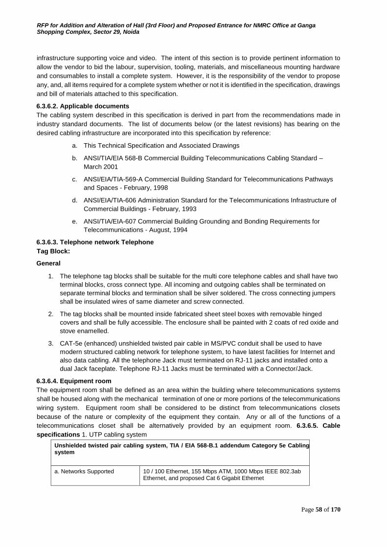
RFP for Addition and Alteration of Hall (3rd Floor) and Proposed Entrance for NMRC Office at Ganga Shopping Complex, Sector 29, Noida
Page 58 of 170
infrastructure supporting voice and video. The intent of this section is to provide pertinent information to
allow the vendor to bid the labour, supervision, tooling, materials, and miscellaneous mounting hardware
and consumables to install a complete system. However, it is the responsibility of the vendor to propose
any, and, all items required for a complete system whether or not it is identified in the specification, drawings
and bill of materials attached to this specification.
6.3.6.2. Applicable documents The cabling system described in this specification is derived in part from the recommendations made in
industry standard documents. The list of documents below (or the latest revisions) has bearing on the
desired cabling infrastructure are incorporated into this specification by reference:
a. This Technical Specification and Associated Drawings
b. ANSI/TIA/EIA 568-B Commercial Building Telecommunications Cabling Standard – March 2001
c. ANSI/EIA/TIA-569-A Commercial Building Standard for Telecommunications Pathways
and Spaces - February, 1998
d. ANSI/EIA/TIA-606 Administration Standard for the Telecommunications Infrastructure of Commercial Buildings - February, 1993
e. ANSI/TIA/EIA-607 Commercial Building Grounding and Bonding Requirements for
Telecommunications - August, 1994
6.3.6.3. Telephone network Telephone
Tag Block:
General
1. The telephone tag blocks shall be suitable for the multi core telephone cables and shall have two
terminal blocks, cross connect type. All incoming and outgoing cables shall be terminated on
separate terminal blocks and termination shall be silver soldered. The cross connecting jumpers
shall be insulated wires of same diameter and screw connected.
2. The tag blocks shall be mounted inside fabricated sheet steel boxes with removable hinged
covers and shall be fully accessible. The enclosure shall be painted with 2 coats of red oxide and
stove enamelled.
3. CAT-5e (enhanced) unshielded twisted pair cable in MS/PVC conduit shall be used to have
modern structured cabling network for telephone system, to have latest facilities for Internet and
also data cabling. All the telephone Jack must terminated on RJ-11 jacks and installed onto a
dual Jack faceplate. Telephone RJ-11 Jacks must be terminated with a Connector/Jack.
6.3.6.4. Equipment room The equipment room shall be defined as an area within the building where telecommunications systems
shall be housed along with the mechanical termination of one or more portions of the telecommunications
wiring system. Equipment room shall be considered to be distinct from telecommunications closets
because of the nature or complexity of the equipment they contain. Any or all of the functions of a
telecommunications closet shall be alternatively provided by an equipment room. 6.3.6.5. Cable
specifications 1. UTP cabling system
Unshielded twisted pair cabling system, TIA / EIA 568-B.1 addendum Category 5e Cabling system
a. Networks Supported 10 / 100 Ethernet, 155 Mbps ATM, 1000 Mbps IEEE 802.3ab Ethernet, and proposed Cat 6 Gigabit Ethernet
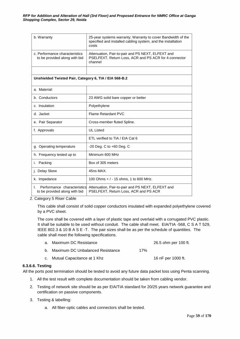
RFP for Addition and Alteration of Hall (3rd Floor) and Proposed Entrance for NMRC Office at Ganga Shopping Complex, Sector 29, Noida
Page 59 of 170
b. Warranty 25-year systems warranty; Warranty to cover Bandwidth of the specified and installed cabling system, and the installation costs
c. Performance characteristics to be provided along with bid
Attenuation, Pair-to-pair and PS NEXT, ELFEXT and PSELFEXT, Return Loss, ACR and PS ACR for 4-connector channel
Unshielded Twisted Pair, Category 6, TIA / EIA 568-B.2
a. Material:
b. Conductors 23 AWG solid bare copper or better
c. Insulation Polyethylene
d. Jacket Flame Retardant PVC
e. Pair Separator Cross-member fluted Spline.
f. Approvals UL Listed
ETL verified to TIA / EIA Cat 6
g. Operating temperature -20 Deg. C to +60 Deg. C
h. Frequency tested up to Minimum 600 MHz
i. Packing Box of 305 meters
j. Delay Skew 45ns MAX.
k. Impedance 100 Ohms + / - 15 ohms, 1 to 600 MHz.
l. Performance characteristics to be provided along with bid
Attenuation, Pair-to-pair and PS NEXT, ELFEXT and PSELFEXT, Return Loss, ACR and PS ACR
2. Category 5 Riser Cable
This cable shall consist of solid copper conductors insulated with expanded polyethylene covered
by a PVC sheet.
The core shall be covered with a layer of plastic tape and overlaid with a corrugated PVC plastic.
It shall be suitable to be used without conduit. The cable shall meet. EIA/TIA -568, C S A T 529,
IEEE 802.3 & 10 B A S E -T. The pair sizes shall be as per the schedule of quantities. The
cable shall meet the following specifications.
a. Maximum DC Resistance 26.5 ohm per 100 ft.
b. Maximum DC Unbalanced Resistance 17%
c. Mutual Capacitance at 1 Khz 16 nF per 1000 ft.
6.3.6.6. Testing All the ports post termination should be tested to avoid any future data packet loss using Penta scanning.
1. All the test result with complete documentation should be taken from cabling vendor.
2. Testing of network site should be as per EIA/TIA standard for 20/25 years network guarantee and
certification on passive components.
3. Testing & labelling:
a. All fiber-optic cables and connectors shall be tested.

RFP for Addition and Alteration of Hall (3rd Floor) and Proposed Entrance for NMRC Office at Ganga Shopping Complex, Sector 29, Noida
Page 60 of 170
b. All voice cables and connectors shall be tested for continuity and pin-out as well as live
circuit operation.
c. All date cables, connectors and patch cables shall be tested to EIA /TIA *568
specification using a Penta Scanner.
d. All Cables, racks, enclosures, patch panels, blocks and faceplate shall be professionally
and clearly labelled using an electronic labelling devise in accordance with planned
network labelling scheme.
6.3.6.7. Warranty Owner seeks warranty for the installed cable plant from the OEM equipment supplier. Bidder shall ensure
that the OEM norms for supply, installation, testing and documentation as specified by the OEM supplier
shall be adhered to, provided those are in line with TIA / EIA standards and Owner requirement
specifications. The warranty shall be provided by the OEM vendor to Owner and shall be administered in
India. The duration of the warranty shall be for a minimum of 25 years and shall cover the system
performance, application assurance and the costs of the supply of components and installation. 6.3.7.
Section –VII: Cabling For Data System
6.3.7.1. Scope This document defines the cabling system and subsystem components to include cable, termination
hardware, supporting hardware, and miscellany required to furnish, and to install a complete cabling
infrastructure supporting data and video. The intent of this section is to provide pertinent information to
allow the vendor to bid the labour, supervision, tooling, materials, and miscellaneous mounting hardware
and consumables to install a complete system. However, it is the responsibility of the vendor to propose
any, and, all items required for a complete system whether or not it is identified in the specification, drawings
and bill of materials attached to this specification.
6.3.7.2. Applicable documents The cabling system described in this specification is derived in part from the recommendations made in
industry standard documents. The list of documents below (or the latest revisions) has bearing on the
desired cabling infrastructure are incorporated into this specification by reference:
1. This Technical Specification and Associated Drawings
2. ANSI/TIA/EIA 568-B Commercial Building Telecommunications Cabling Standard – March 2001
3. ANSI/EIA/TIA-569-A Commercial Building Standard for Telecommunications Pathways and
Spaces - February, 1998
4. ANSI/EIA/TIA-606 Administration Standard for the Telecommunications Infrastructure of
Commercial Buildings - February, 1993
5. ANSI/TIA/EIA-607 Commercial Building Grounding and Bonding Requirements for
Telecommunications - August, 1994
6.3.7.3. Cabling system and component specifications
1. UTP Cabling System
Unshielded twisted pair cabling system, TIA / EIA 568-B.1 addendum Category 6 Cabling system
Networks Supported 1000 Ethernet, 155 Mbps ATM, 1000 Mbps IEEE 802.3ab Ethernet, and proposed Cat 6 Gigabit Ethernet
Warranty 25-year systems warranty; Warranty to cover Bandwidth of the specified and installed cabling system, and the installation costs
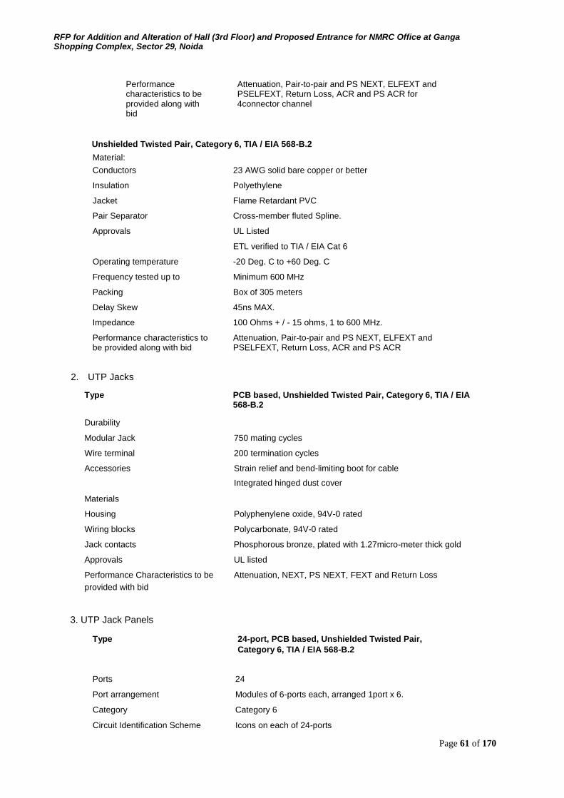
RFP for Addition and Alteration of Hall (3rd Floor) and Proposed Entrance for NMRC Office at Ganga Shopping Complex, Sector 29, Noida
Page 61 of 170
Performance characteristics to be provided along with bid
Attenuation, Pair-to-pair and PS NEXT, ELFEXT and PSELFEXT, Return Loss, ACR and PS ACR for 4connector channel
Unshielded Twisted Pair, Category 6, TIA / EIA 568-B.2
Material: Conductors 23 AWG solid bare copper or better
Insulation Polyethylene
Jacket Flame Retardant PVC
Pair Separator Cross-member fluted Spline.
Approvals UL Listed
ETL verified to TIA / EIA Cat 6
Operating temperature -20 Deg. C to +60 Deg. C
Frequency tested up to Minimum 600 MHz
Packing Box of 305 meters
Delay Skew 45ns MAX.
Impedance 100 Ohms + / - 15 ohms, 1 to 600 MHz.
Performance characteristics to be provided along with bid
Attenuation, Pair-to-pair and PS NEXT, ELFEXT and PSELFEXT, Return Loss, ACR and PS ACR
2. UTP Jacks
Type PCB based, Unshielded Twisted Pair, Category 6, TIA / EIA 568-B.2
Durability
Modular Jack 750 mating cycles
Wire terminal 200 termination cycles
Accessories Strain relief and bend-limiting boot for cable
Integrated hinged dust cover
Materials
Housing Polyphenylene oxide, 94V-0 rated
Wiring blocks Polycarbonate, 94V-0 rated
Jack contacts Phosphorous bronze, plated with 1.27micro-meter thick gold
Approvals UL listed
Performance Characteristics to be Attenuation, NEXT, PS NEXT, FEXT and Return Loss provided with bid
3. UTP Jack Panels
Type 24-port, PCB based, Unshielded Twisted Pair, Category 6, TIA / EIA 568-B.2
Ports 24
Port arrangement Modules of 6-ports each, arranged 1port x 6.
Category Category 6
Circuit Identification Scheme Icons on each of 24-ports
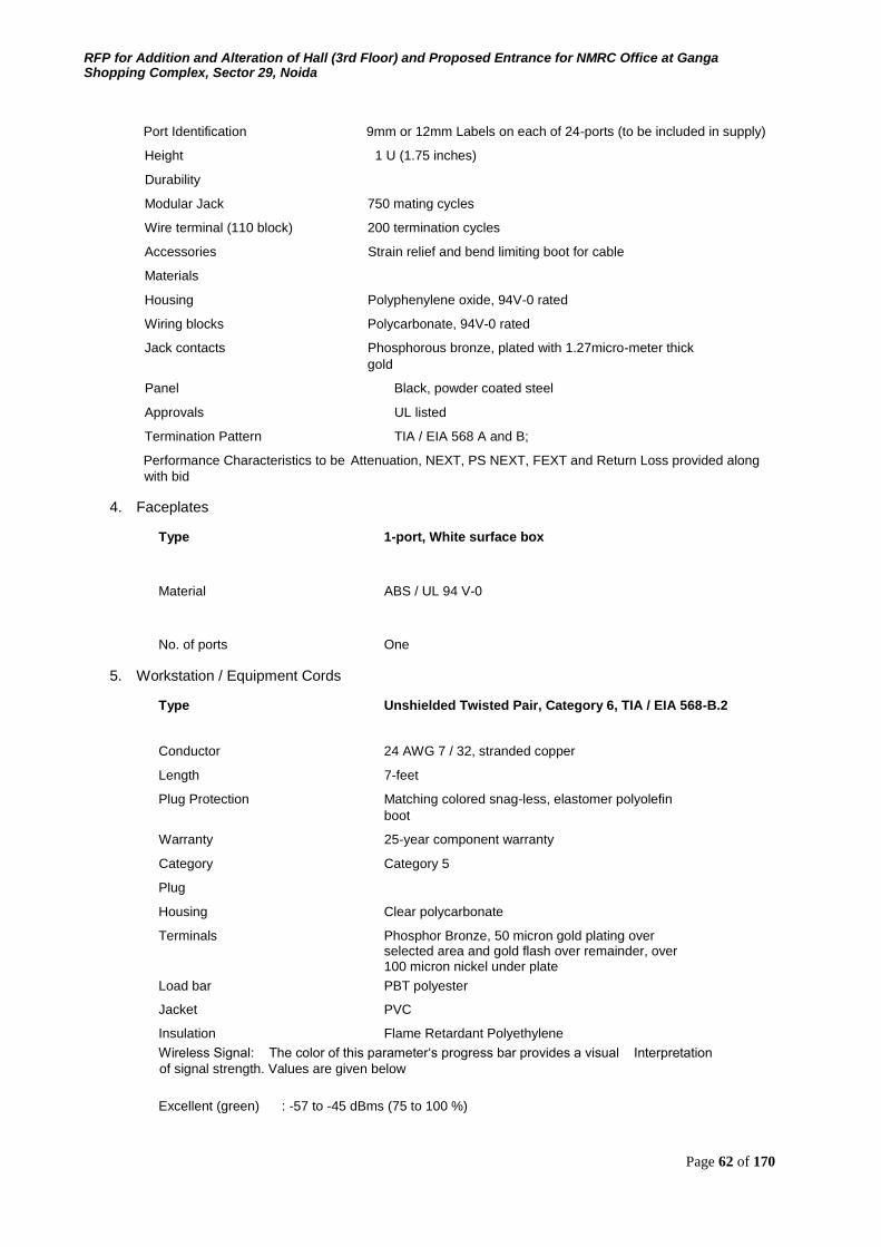
RFP for Addition and Alteration of Hall (3rd Floor) and Proposed Entrance for NMRC Office at Ganga Shopping Complex, Sector 29, Noida
Page 62 of 170
Port Identification 9mm or 12mm Labels on each of 24-ports (to be included in supply)
Height 1 U (1.75 inches)
Durability
Modular Jack 750 mating cycles
Wire terminal (110 block) 200 termination cycles
Accessories Strain relief and bend limiting boot for cable
Materials
Housing Polyphenylene oxide, 94V-0 rated
Wiring blocks Polycarbonate, 94V-0 rated
Jack contacts Phosphorous bronze, plated with 1.27micro-meter thick gold
Panel Black, powder coated steel
Approvals UL listed
Termination Pattern TIA / EIA 568 A and B;
Performance Characteristics to be Attenuation, NEXT, PS NEXT, FEXT and Return Loss provided along
with bid
4. Faceplates
Type 1-port, White surface box
Material ABS / UL 94 V-0
No. of ports One
5. Workstation / Equipment Cords
Type Unshielded Twisted Pair, Category 6, TIA / EIA 568-B.2
Conductor 24 AWG 7 / 32, stranded copper
Length 7-feet
Plug Protection Matching colored snag-less, elastomer polyolefin boot
Warranty 25-year component warranty
Category Category 5
Plug
Housing Clear polycarbonate
Terminals Phosphor Bronze, 50 micron gold plating over selected area and gold flash over remainder, over 100 micron nickel under plate
Load bar PBT polyester
Jacket PVC
Insulation Flame Retardant Polyethylene Wireless Signal: The color of this parameter‘s progress bar provides a visual Interpretation
of signal strength. Values are given below Excellent (green) : -57 to -45 dBms (75 to 100 %)
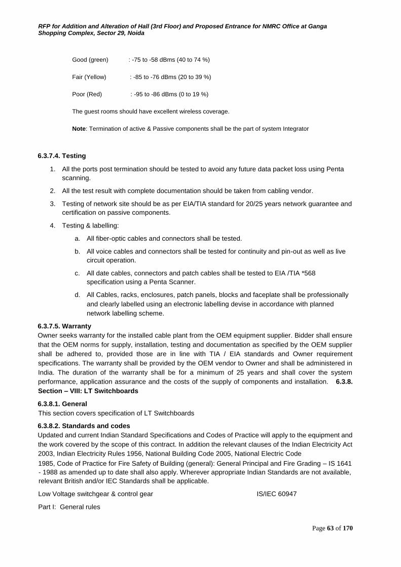
RFP for Addition and Alteration of Hall (3rd Floor) and Proposed Entrance for NMRC Office at Ganga Shopping Complex, Sector 29, Noida
Page 63 of 170
Good (green) : -75 to -58 dBms (40 to 74 %) Fair (Yellow) : -85 to -76 dBms (20 to 39 %) Poor (Red) : -95 to -86 dBms (0 to 19 %) The guest rooms should have excellent wireless coverage. Note: Termination of active & Passive components shall be the part of system Integrator
6.3.7.4. Testing
1. All the ports post termination should be tested to avoid any future data packet loss using Penta
scanning.
2. All the test result with complete documentation should be taken from cabling vendor.
3. Testing of network site should be as per EIA/TIA standard for 20/25 years network guarantee and
certification on passive components.
4. Testing & labelling:
a. All fiber-optic cables and connectors shall be tested.
b. All voice cables and connectors shall be tested for continuity and pin-out as well as live
circuit operation.
c. All date cables, connectors and patch cables shall be tested to EIA /TIA *568
specification using a Penta Scanner.
d. All Cables, racks, enclosures, patch panels, blocks and faceplate shall be professionally
and clearly labelled using an electronic labelling devise in accordance with planned
network labelling scheme.
6.3.7.5. Warranty Owner seeks warranty for the installed cable plant from the OEM equipment supplier. Bidder shall ensure
that the OEM norms for supply, installation, testing and documentation as specified by the OEM supplier
shall be adhered to, provided those are in line with TIA / EIA standards and Owner requirement
specifications. The warranty shall be provided by the OEM vendor to Owner and shall be administered in
India. The duration of the warranty shall be for a minimum of 25 years and shall cover the system
performance, application assurance and the costs of the supply of components and installation. 6.3.8.
Section – VIII: LT Switchboards
6.3.8.1. General
This section covers specification of LT Switchboards
6.3.8.2. Standards and codes Updated and current Indian Standard Specifications and Codes of Practice will apply to the equipment and
the work covered by the scope of this contract. In addition the relevant clauses of the Indian Electricity Act
2003, Indian Electricity Rules 1956, National Building Code 2005, National Electric Code
1985, Code of Practice for Fire Safety of Building (general): General Principal and Fire Grading – IS 1641
- 1988 as amended up to date shall also apply. Wherever appropriate Indian Standards are not available,
relevant British and/or IEC Standards shall be applicable.
Low Voltage switchgear & control gear IS/IEC 60947
Part I: General rules
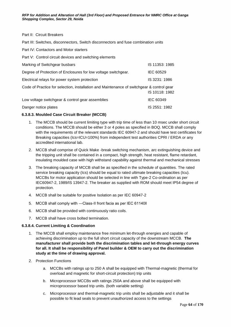
RFP for Addition and Alteration of Hall (3rd Floor) and Proposed Entrance for NMRC Office at Ganga Shopping Complex, Sector 29, Noida
Page 64 of 170
Part II: Circuit Breakers
Part III: Switches, disconnectors, Switch disconnectors and fuse combination units
Part IV: Contactors and Motor starters
Part V: Control circuit devices and switching elements
Marking of Switchgear busbars IS 11353: 1985
Degree of Protection of Enclosures for low voltage switchgear. IEC 60529
Electrical relays for power system protection IS 3231: 1986
Code of Practice for selection, installation and Maintenance of switchgear & control gear IS 10118: 1982
Low voltage switchgear & control gear assemblies IEC 60349
Danger notice plates IS 2551: 1982
6.3.8.3. Moulded Case Circuit Breaker (MCCB)
1. The MCCB should be current limiting type with trip time of less than 10 msec under short circuit
conditions. The MCCB should be either 3 or 4 poles as specified in BOQ. MCCB shall comply
with the requirements of the relevant standards IEC 60947-2 and should have test certificates for
Breaking capacities (Ics=ICU=100%) from independent test authorities CPRI / ERDA or any
accredited international lab.
2. MCCB shall comprise of Quick Make -break switching mechanism, arc extinguishing device and
the tripping unit shall be contained in a compact, high strength, heat resistant, flame retardant,
insulating moulded case with high withstand capability against thermal and mechanical stresses
3. The breaking capacity of MCCB shall be as specified in the schedule of quantities. The rated
service breaking capacity (Ics) should be equal to rated ultimate breaking capacities (Icu).
MCCBs for motor application should be selected in line with Type-2 Co-ordination as per
IEC60947-2, 1989/IS 13947-2. The breaker as supplied with ROM should meet IP54 degree of
protection.
4. MCCB shall be suitable for positive Isolation as per IEC 60947-2
5. MCCB shall comply with ―Class-II front facia as per IEC 61140‖
6. MCCB shall be provided with continuously ratio coils.
7. MCCB shall have cross bolted termination.
6.3.8.4. Current Limiting & Coordination
1. The MCCB shall employ maintenance free minimum let-through energies and capable of
achieving discrimination up to the full short circuit capacity of the downstream MCCB. The
manufacturer shall provide both the discrimination tables and let-through energy curves
for all. It shall be responsibility of Panel builder & OEM to carry out the discrimination
study at the time of drawing approval.
2. Protection Functions
a. MCCBs with ratings up to 250 A shall be equipped with Thermal-magnetic (thermal for
overload and magnetic for short-circuit protection) trip units
b. Microprocessor MCCBs with ratings 250A and above shall be equipped with
microprocessor based trip units. (both variable setting)
c. Microprocessor and thermal-magnetic trip units shall be adjustable and it shall be
possible to fit lead seals to prevent unauthorized access to the settings
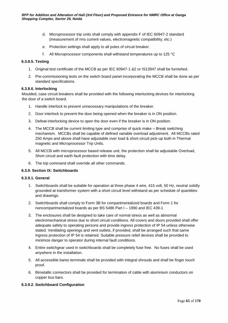
RFP for Addition and Alteration of Hall (3rd Floor) and Proposed Entrance for NMRC Office at Ganga Shopping Complex, Sector 29, Noida
Page 65 of 170
d. Microprocessor trip units shall comply with appendix F of IEC 60947-2 standard (measurement of rms current values, electromagnetic compatibility, etc.)
e. Protection settings shall apply to all poles of circuit breaker.
f. All Microprocessor components shall withstand temperatures up to 125 °C
6.3.8.5. Testing
1. Original test certificate of the MCCB as per IEC 60947-1 &2 or IS13947 shall be furnished.
2. Pre-commissioning tests on the switch board panel incorporating the MCCB shall be done as per
standard specifications.
6.3.8.6. Interlocking
Moulded, case circuit breakers shall be provided with the following interlocking devices for interlocking
the door of a switch board.
1. Handle interlock to prevent unnecessary manipulations of the breaker.
2. Door interlock to prevent the door being opened when the breaker is in ON position.
3. Defeat-interlocking device to open the door even if the breaker is in ON position.
4. The MCCB shall be current limiting type and comprise of quick make – Break switching
mechanism. MCCBs shall be capable of defined variable overload adjustment. All MCCBs rated
250 Amps and above shall have adjustable over load & short circuit pick-up both in Thermal
magnetic and Microprocessor Trip Units.
5. All MCCB with microprocessor based release unit, the protection shall be adjustable Overload,
Short circuit and earth fault protection with time delay.
6. The trip command shall override all other commands.
6.3.9. Section IX: Switchboards
6.3.9.1. General
1. Switchboards shall be suitable for operation at three phase 4 wire, 415 volt, 50 Hz, neutral solidly
grounded at transformer system with a short circuit level withstand as per schedule of quantities
and drawings.
2. Switchboards shall comply to Form 3B for compartmentalized boards and Form 1 for
noncompartmentalized boards as per BS 5486 Part I – 1990 and IEC 439-1
3. The enclosures shall be designed to take care of normal stress as well as abnormal
electromechanical stress due to short circuit conditions. All covers and doors provided shall offer
adequate safety to operating persons and provide ingress protection of IP 54 unless otherwise
stated. Ventilating openings and vent outlets, if provided, shall be arranged such that same
ingress protection of IP 54 is retained. Suitable pressure relief devices shall be provided to
minimize danger to operator during internal fault conditions.
4. Entire switchgear used in switchboards shall be completely fuse free. No fuses shall be used
anywhere in the installation.
5. All accessible bares terminals shall be provided with integral shrouds and shall be finger touch
proof.
6. Bimetallic connectors shall be provided for termination of cable with aluminium conductors on
copper bus bars.
6.3.9.2. Switchboard Configuration
RFP for Addition and Alteration of Hall (3rd Floor) and Proposed Entrance for NMRC Office at Ganga Shopping Complex, Sector 29, Noida
Page 66 of 170
1. The Switchboard shall be configured with Air Circuit Breakers, MCCB's, and other equipment as
called for in the schedule of quantities.
2. The MCCB's shall be arranged in multi-tier formation whereas the Air Circuit Breakers shall be
arranged in Single or Double tier formation only to facilitate operation and maintenance.
3. The Switchboards shall be of adequate size with a provision of 25% spare space to
accommodate possible future additional switch gear.
6.3.9.3. Equipment Specifications All equipment used to configure the Switchboard shall comply with the relevant Standards and Codes of
the Bureau of Indian Standards and to the detailed technical specifications as included in this tender
document.
6.3.9.4. Constructional Features
1. The Switchboards shall be metal clad totally enclosed, floor mounted free standing type of
modular extensible design suitable for indoor mounting. The Switchboards shall be designed for
a temperature rise restricted to 40 Deg C above ambient of 45 Deg C
2. Switchboards shall be either compartmentalized or non-compartmentalized as stipulated in
schedule of quantities.
3. Switchboards shall be made up of requisite vertical sections, which when coupled together, shall
for continuous dead front switchboards.
4. Switchboard shall be readily extensible on both sides by addition of vertical sections after
removal of the end covers.
5. The switchboards shall be designed for use in high ambient temperature and humid tropical
conditions as specified. Ease of inspections, cleaning and repairs while maintaining continuity of
operation shall be provided in the design.
6. Metal based neoprene gaskets between all adjacent units and beneath all covers shall be
provided to render the joints dust and vermin proof to provide a degree of protection of IP 54 as
stipulated in schedule of quantities.
7. ‗U‘ Channels forming switchboard frames shall be fabricated from 2.5 mm thick electro
galvanized MS sheets. All joints shall be neatly formed and finished flush with adjacent surfaces
by grinding. No joints shall be located in corners. Bare edges shall be lipped. Structural
members and bracings where ever required shall be welded or bolted to the frame. The frame
shall be of modular design and extensible.
8. All doors and covers shall also be fully gasketed with metal based neoprene gaskets with
fastners designed to ensure proper compression of the gaskets. The hinged door shall open a
maximum of 1500. All hinged doors shall have earth braid connected to the cubicle. Good quality
door handles fitted with toggles to operate rods to latch with suitable slots in both top and bottom
of switchboards shall be provided. Latching rods and associated brackets shall be cadmium
plated.
9. Each vertical section shall be provided with a rear side cable chamber housing the cable end
connections and power/control cable terminations. There should be generous availability of
space for ease of installation and maintenance with adequate safety for working in one vertical
section without coming into contract with any liver parts.
10. Switchboard panels and cubicles shall be fabricated with CRCA Sheet Steel of thickness not less
than 2.0 mm and shall be folded and braced as necessary to provide a rigid support for all
components. The doors and covers shall be fabricated from CRCA sheet steel of thickness not
less than 1.6 mm. Joints of any kind in sheet metal shall be seam welded and all welding slag
ground off and welding pits wiped smooth with plumber metal.
RFP for Addition and Alteration of Hall (3rd Floor) and Proposed Entrance for NMRC Office at Ganga Shopping Complex, Sector 29, Noida
Page 67 of 170
11. All panels and covers shall be properly fitted and square with the frame. The holes in the panel
shall be correctly positioned.
12. Fixing screws shall enter holes tapped into an adequate thickness of metal or provided with hank
nuts. Self-threading screws shall not be used in switchboards.
13. All electrical contacts between dissimilar metals (e.g.. aluminium conductor of cables connected
to copper terminals of breakers etc..) shall be through bimetallic connection
6.3.9.5. Switchboard Dimensional Limitations
1. A base channel 75 mm x 5 mm thick shall be provided at the bottom.
2. A minimum of 200 mm blank space between the floor of switchboard and bottom most unit shall
be provided.
3. The overall height of the switchboard shall be limited to 2300 mm unless otherwise stipulated.
4. The height of the operating handle, push buttons etc. shall be restricted between 300 mm and
2000 mm from finished floor level.
6.3.9.6. Switchboard Compartmentalization
1. For compartmentalized switchboards, separate totally enclosed compartments shall be provided
for horizontal busbars, vertical busbars, ACBs, MCCBs and cable alleys.
2. Earthed metal or insulated shutters shall be provided between drawout and fixed portion of the
switchgear such that no live parts are accessible with equipment drawn out. Degree of protection
within compartments shall be at least IP 4X.
3. Sheet steel hinged lockable doors for each separate compartment shall be provided and duly
interlocked with the breaker in "ON" and "OFF" position.
4. For all Circuit Breakers separate and adequate compartments shall be provided for
accommodating instruments, indicating lamps, control contactors and control MCB etc. These
shall be accessible for testing and maintenance without any danger of accidental contact with live
parts of the circuit breaker, busbars and connections.
5. Each switchgear cubicles shall be fitted with label in front and back identifying the circuit,
switchgear type, rating and duty. All operating device shall be located in front of switchgear only.
Minimum height from floor level for any device mounted on panel cover shall be 250 mm.
6. A horizontal wire way with screwed cover shall be provided at the top to take interconnecting
control wiring between vertical sections.
7. Separate cable compartments running the height of the switchboard in the case of front access
boards shall be provided for incoming and outgoing cables.
8. Cable compartments shall be of adequate size for easy termination of all incoming and outgoing
cables entering from bottom or top.
9. Adequate and proper support shall be provided in cable compartments to support cables.
6.3.9.7. Spare Provision 25% spare cubicles/space shall be provided in all switchboards to cater for future use.
6.3.9.8. Switchboard Bus Bars
1. Busbars shall be made of high conductivity, high strength aluminium alloy, complying with
requirements of grade E 91E of IS 5082 – 1981. Design of busbar system shall comply to IS
5578 and IS 11353. Busbars shall be of rectangular cross sections suitable for full load current
for phase bus bars as also neutral bus bar. The maximum current density shall be 1 amp per Sq.
RFP for Addition and Alteration of Hall (3rd Floor) and Proposed Entrance for NMRC Office at Ganga Shopping Complex, Sector 29, Noida
Page 68 of 170
mm. Busbar shall be suitable to withstand the stresses of fault level as specified in schedule of
quantities.
2. Bus bars shall be insulted with heat shrunk PVC sleeving of 1.1 kV grade and bus bar joints
provided with clip-on shrouds.
3. The bus bars shall be extensible on either side of the switchboard.
4. The bus bars shall be supported on non-breakable, non-hygroscopic epoxy resin or glass fiber
reinforced polymer insulated supports able to withstand operating temperature of 110O C at
regular intervals, to withstand the forces arising from a fault level of 31 MVA at 415 volts for 1
second or as stipulated in schedule of quantities.
5. All bus bars shall be colour coded.
6. Auxiliary buses for control power supply, space heater power supply or any other specified
service shall be provided. These buses shall be insulated, adequately supported and sized to
suit specific requirement. The material for auxiliary supply bus will be electrolytic copper.
7. Additional cross sectional area to be added to the bus bar to compensate for the holes.
6.3.9.9. Switchboard Interconnection
1. All connection and tap offs shall be through adequately sized connectors appropriate for fault
level at location. This shall include tap off to feeders and instrument/control transformers.
Alternatively current limiters of approved make and type shall be used.
2. For unit ratings up to 100 amps, PVC insulated copper conductor wires of adequate size to carry
full load current shall be used. The terminations of such interconnections shall be crimped. Solid
connections shall be used for all rating of 100 amps and above.
3. All connections, tappings, clamping, shall be made in an approved manner to ensure minimum
contact resistance. All connections shall be firmly bolted and clamp with .even tension. Before
assembly joint surfaces shall be filed or finished to remove burrs, dents and oxides and silvered
to maintain good continuity at all joints. All screws, bolts, washers shall be cadmium plated.
4. Approved spring washers shall be used with cadmium plated high tensile steel bolts with BSF
threads.
5. All connectivity and tap offs shall have bimetallic connectors as required, finger touch proof
terminals & integral switchgear shrouds.
6.3.9.10. Drawout Features
1. Air Circuit Breakers shall be provided in fully drawout cubicles, unless otherwise stated. These
cubicles shall be such that drawout is possible without disconnection of the wires and cables. The
power and control circuits shall have self-aligning and self-isolating contacts.
2. The fixed and moving contacts shall be easily accessible for operation and maintenance.
Mechanical interlocks shall be provided on the drawout cubicles to ensure safety and compliance
to relevant Standards. The MCCB's shall be provided in fixed type cubicles.
6.3.9.11. Instrument Accommodation
1. Instruments and indicating lamps shall not be mounted on the Circuit Breaker Compartment door
for which a separate and adequate compartment shall be provided and the instrumentation shall
be accessible for testing and maintenance without danger of accidental contact with live parts of
the Switchboard.
2. For MCCB's instruments and indicating lamps can be provided on the compartment doors.
3. The current transformers for metering and for protection shall be mounted on the solid
copper/aluminium busbars with proper supports.
RFP for Addition and Alteration of Hall (3rd Floor) and Proposed Entrance for NMRC Office at Ganga Shopping Complex, Sector 29, Noida
Page 69 of 170
6.3.9.12. Wiring
1. All wiring for relays and meters shall be with PVC insulated copper conductor wires. The wiring
shall be coded and labelled with approved ferrules for identification. The minimum size of copper
conductor control wires shall be 2.5 sq. mm.
2. Wiring shall be terminated with ferrules on terminal block. CTs shall be provided with shorting facilities
6.3.9.13. Cable Terminations
1. Knockout holes of appropriate size and number shall be provided in the Switchboard in
conformity with the location of incoming and outgoing conduits/cables.
2. The cable terminations of the Circuit Breakers shall be brought out to terminal cable sockets
suitably located in the cable chamber
3. The cable terminations for the MCCB's shall be brought out to the rear in the case of rear access
switchboards or in the cable compartment in the case of front access Switchboards.
4. The Switchboards shall be complete with tinned brass cable sockets, tinned brass compression
glands, gland plates, supporting clamps and brackets etc. for termination of 1100 volt grade
aluminium conductor XLPE cables.
5. Removable gland plates shall be provided for power and control cables. The gland plates shall be
3 mm thick and for single core cables shall be of non-magnetic material.
6.3.9.14. Space Heaters Anti- condensation heaters shall be fitted in each cubicle together with an ON/OFF isolating switch suitable
for electrical operation at 230 volts A.C 50 Hz single phase of sufficient capacity to raise the internal ambient
temperature by 5O C. The electrical apparatus so protected shall be designed so that the maximum
permitted rise in temperature is not exceeded if the heaters are energized while the switchboard is in
operation. As a general rule, the heaters shall be placed at the bottom of the cubicle.
6.3.9.15. Ventilation Fans
The Switchboard shall be provided with panel mounting type ventilation fans in each panel with switchgear
rated for 2500 amp and above. The fan shall be interlocked with switchgear operation. If ventilation fans
cannot be provided for maintaining the required degree of ingress protection, the design of switch board
cubical shall incorporate suitable measures like decreasing current density of conductors, increasing
cubical volume for effective heat dissipation etc. in order to restrict temperature rise to within the required
limit.
6.3.9.16. Earthing Continuous internal copper earth bus sized for prospective fault current to be provided with arrangement
for connecting to station earth at two points. Hinged doors / frames to be connected to earth through
adequately sized flexible braids.
6.3.9.17. Sheet Steel Treatment And Painting
Sheet steel used in the fabrication of switchboards shall undergo a rigorous cleaning and surface treatment
seven tank process comprising of alkaline degreasing, descaling in dilute sulphuric acid and a recognised
phosphating process after which a coat of primer paint compactively with the final paint shall be applied
over the treated surface. Final paint coat of oven baked powder coating, of minimum 50 micron thickness,
of sheet approved by Architects/Owners shall then be provided.
6.3.9.18. Name Plates And Labels
Suitable engraved white on black name plates and identification labels of metal for all Switchboards and
Circuits shall be provided. These shall indicate the feeder number and feeder designation.
RFP for Addition and Alteration of Hall (3rd Floor) and Proposed Entrance for NMRC Office at Ganga Shopping Complex, Sector 29, Noida
Page 70 of 170
6.3.9.19. 19 Local Authorities Requirement
All other requirements by the local Authority that are imposed in course of execution of the work,
particularly those listed below shall be provided.
a) Danger Signs b) Rubber floor mat of 10 m thickness and 1 m width provided for the full length of the switchboard. c) A dry chemical type fire extinguisher of 9 kg capacity with approved label d) Framed single line diagram with minimum A1 size e) First Aid Demonstration sign.
6.3.9.20. CPRI Testing
Switchboard configurations offered shall be CPRI tested. Copies of the CPRI test certificates shall be
submitted with the tender.
6.3.9.21. Testing at works
Copies of type test carried out at ACB/MCCB manufacturers works and routine tests carried out at the
switchboard fabricators shop shall be furnished along with the delivery of the switchboards.
Architects/Owners reserves the right to get the switchboard inspected by their representative at fabricators
works prior to dispatch to site to witness the routine tests
6.3.9.22. Installation
1. The foundations prepared as per the manufacturers drawings shall be levelled, checked for
accuracy and the Switchboard installed. All bus bar connections shall be checked with a feeler
gauge after installation. The cable end boxes shall be sealed to prevent entry of moisture. The
main earth bar shall be connected to the sub-station earths.
2. Antistatic rubber matting of approved make conforming to IS 5424 – 1983, of minimum 1000 mm
width 10 mm thickness shall be provided in front of and along the full length of the Switchboard.
The rubber mat shall withstand 15 KV for 1 minute and leakage current shall not exceed 160
mA/sq. metre.
3. After installation the Switchboard shall be tested as required prior to commissioning.
6.3.9.23. Testing At Site
Pre-commissioning tests as required and as per manufacturers recommendations shall be carried out on
each switchboards at site before energizing the switchboards including but not restricted to the following.
a) Physical checking of the switchboards including checking alignment of panels, interconnection of
Bus bars, tightness of bolts/connections and evidence of damage/cracks in any components. b) Physical checking and inspections of Inter panel wiring c) Checking free movement of ACBs/MCCBs/SFUs d) Checking of operation of breakers e) Insulation tests of bus bar supports and control wiring etc. with 1.1 kV megger. f) Primary & secondary injection tests of relays and CTs. g) Checking of Interlocking function.
6.3.10. Section – X: Metering Equipment
6.3.10.1. General
This section covers specifications for Protection and Control Relays for breakers, Instrument Transformers,
Measuring Instruments, Push Buttons, and Indicating Lamps etc. required in LT and HT switchboards.
6.3.10.2. Standards and codes
Updated and current Indian Standard Specifications and Codes of Practice will apply to the equipment and
the work covered by the scope of this contract. In addition the relevant clauses of the Indian Electricity Act
2003, Indian Electricity Rules 1956, National Building Code 1994, National Electric Code
RFP for Addition and Alteration of Hall (3rd Floor) and Proposed Entrance for NMRC Office at Ganga Shopping Complex, Sector 29, Noida
Page 71 of 170
1985, Code of Practice for Fire Safety of Building (general) :General Principal and Fire Grading – IS 1641
as amended up to date shall also apply. Wherever appropriate Indian Standards are not available, relevant
British and/or IEC Standards shall be applicable.
Application guide for Current Transformers IS 4201:
Application guide for Voltage Transformers IS 4140:
Application guide for Relays IS 3842:
Electromagnetic Relays IS 5051
6.3.10.3. Protection and control relays
1. The Circuit Breaker shall have protection and control relays as specified in the schedule of
quantities. Relays shall be approved types complying with relevant ISS and having approved
characteristic. Relays shall be flush mounted in dust proof cases. Relays shall be arranged so
that adjustments, testing and replacement can be affected with minimum of time and labour.
2. In case of C.T. operated thermal overload and magnetic instantaneous short circuit release, the
overload releases shall be such that each phase can be individually set depending on the phase
unbalanced currents. The releases shall have inverse time current characteristics and the
magnetic release shall be time delayed with a minimum setting of 25 ms varying up to 300 ms for
discrimination without effecting the breaking current capacity of the ACB.
6.3.10.4. Current transformers
1. Separate sets of CTs shall be provided for metering and protection. C/Ts shall confirm to IS 2705
(part -I, II and III) in all respects. All C/Ts used for medium voltage application shall be rated for 1
kV. C/Ts shall have rated primary current, rated burden and class of accuracy as specified in
Schedule of Quantities/drawings. Rated secondary current shall be 5A unless otherwise stated. Minimum acceptable class for measurement shall be class 0.5 to 1 and for protection class 5P10.
C/Ts shall be capable of withstanding magnetic and thermal stresses due to short circuit faults as
applicable. Terminals of C/Ts shall be paired permanently for easy identification of poles. C/Ts
shall be provided with earthing terminals for earthing chassis, frame work and fixed part of metal
casing (if any). Each C/T shall be provided with rating plate indicating:
a. Name and make
b. Serial number
c. Transformation ratio
d. Rated burden
e. Rated voltage
f. Accuracy class
2. CTs shall be mounded such that they are easily accessible for inspection, maintenance and
replacement. Wiring for CT shall be with copper conductor FRLS PVC insulated wires with proper
termination works and wiring shall be bunched with cable straps and fixed to the panel structure
in a neat manner. Facilities for shorting terminal shall be provided.
6.3.10.5. Potential transformer
PT‘s shall conform to IS 3156 (Part I, II and III) in all respects. Primary and secondary circuit wiring star
connected and voltage ratio shall be 11 kV / 3/110/ 3 or 415/ 3/110/ 3 as specified in Schedule of
Quantities. Class of accuracy shall be 1.0. Over voltage factor shall be 1.2
6.3.10.6. Measuring instruments
RFP for Addition and Alteration of Hall (3rd Floor) and Proposed Entrance for NMRC Office at Ganga Shopping Complex, Sector 29, Noida
Page 72 of 170
1. Direct reading electrical instruments shall conform to IS 1248 or in all respects. Accuracy of direct
reading shall be 1.0 of voltmeter and 1.0 for ammeters. Other instruments shall have accuracy of
1.0. Meters shall be suitable for continuous operation between -10o C and +450C. Meters shall be
flush mounting and shall be enclosed in dust tight housing. The housing shall be of steel or
phenolic mould. Design and manufacture of meters shall ensure prevention of fogging of
instrument glass. Pointer shall be black in colour and shall have Zero position adjustment device
operable from outside. Direction of deflection shall be from left to right. Suitable selector switches shall
be provided for ammeters and volt meters used in three phase system unless otherwise stipulated, 96
mm x 96 mm instrument shall be used. The rating type and quantity of meters, instruments and
protective device shall be as per Schedule of Quantities /drawings. Ammeter on motor circuit shall be
provided with suppressed scales to take care of shorting surges. 2. Ammeters
Digital type Ammeter of specified range to class 1.0 accuracy with necessary selector switches.
Ammeters shall be manufacture and calibrated as per IS 1248. Ammeters shall normally be
suitable for 5 A secondary of current transformers. Ammeters shall be capable of carrying
substantial over loads during fault conditions. Ammeters of motor circuits shall be provided with
suppressed scale to cater for starting current.
3. Voltmeters
Voltmeters shall be digital type range of 3 phase 415 volt voltmeters shall be 0-500. Volt meters
shall be provided with protection MCB.
4. Watt meter
Wattmeter shall be of 3 phase digital type and shall be provided with a maximum demand
indicator if required.
5. Power factor meters
3 phase power factor meters shall be digital type with current and potential coils suitable for
operation with current and potential transformers provided in the panel. Scale shall be calibrated
for 50% lag - 100% - 50% readings. Phase angle accuracy shall be +40.
6. Energy and reactive power meters
Trivector meters shall be two element, integrating type, KWH, KVA, KVARH meters. Meters shall
confirm to IEC 170 in all respects. Energy meters, KVA, and KVARH meters shall be provided
with integrating registers. The registers shall be able to record energy consumption of 500 hours
corresponding to maximum current at rated voltage and unity power factor. Meters shall be
suitable for operation with current and potential transformers available in the panel.
6.3.10.7. Indicating lamps
Cluster LED type indicating lamps shall be provided for indication of phases and Breaker position as
required in the schedule of quantities. Lamps shall be easily removed and replaced from the front of the
panel by manual means not requiring the use of extractors.
6.3.10.8. Push buttons
Push buttons shall be of non-hygroscopic material, non-swelling and fitted to avoid any possibility of
sticking. Contacts shall be of adequate strength and have a positive whipping action when in operation
6.4. Specifications for Manually Operated Fire Detection and Alarm System
General description:
6.4.1. Scope This specification covers the supply, installation, testing and commissioning of the Fire Alarm Systems
and generally comprise
1. Provision of Manual Call Points
RFP for Addition and Alteration of Hall (3rd Floor) and Proposed Entrance for NMRC Office at Ganga Shopping Complex, Sector 29, Noida
Page 73 of 170
2. Provision of Hooters
3. Local Control Unit for the System
4. Wiring between MCP, Hooter and Control Units to make the complete System
6.4.2. Standards and codes All equipment and the installation shall be as per the relevant Indian Standards Specifications. Where these
Standards do not exist, the relevant British Standards or any other internationally accepted Standard shall
apply.
6.4.3. Manual call points Manual Call Points shall consist of a push button switch housed in a dust tight sheet steel enclosure of 1.5
mm thick sheet to manually initiate audio visual alarms. The front shall be sealed with a breakable glass
cover fixed in such a way that the actuating push button is kept depressed as long as the glass is intact
and released automatically when the glass is broken. The front face of the Manual Call Box shall have an
area not less than 5000 sq mm and the element shall have an exposed area of not less than 1600 sq mm
in the shape of a square or a rectangle.
A small steel hammer shall be attached to the assembly with a steel chain to facilitate breaking of the glass
front. The Manual Call Box shall be suitable for surface or recessed mounting as required. The words "IN
CASE OF FIRE BREAK GLASS" 5 mm high shall be painted in red on the front face.
6.4.4. Hooter Electronic audio alarm sirens shall be suitable for operation on the DC supply of the System and will be
actuated from the Main Control Panel in the event of a fire. These shall have a two tone modulated alarm
signal for continuous service with an output of 89 dB at a distance of 3 meters.
6.4.5. Main control panel
6.4.5.1. General
The Main Control Panel (MCP) shall be located at entrance and shall form the nerve centre of the total
System.
6.4.5.2. Constructional features
The MCP shall be metal enclosed, sheet steel cubicle pattern, dead front, floor/wall mounting type as
required and suitable for indoor mounting.
The MCP shall be dust and vermin proof. Synthetic rubber gaskets shall be provided on all covers and
doors to render the joints dust and vermin proof. All doors shall be lockable.
The MCP shall be fabricated from 2.0 mm CRCA thick sheet steel and shall be folded and braced to
provide a rigid support. Joints shall be seam welded.
6.4.5.3. Internal wiring All internal wiring shall be with 1.5 sq mm PVC insulated copper conductor wires colour coded and labelled
with ferrules for easy identification. The wiring shall be properly bunched and harnessed. The wiring shall
be done in a manner such that it is readily accessible from the front for maintenance.
6.4.5.4. Sheet steel treatment and painting Sheet steel materials used in the construction of the Panels should have undergone a rigorous rust proofing
process comprising of alkaline degreasing, descaling in dilute sulphuric acid and a recognized phosphating
process. The steel work shall then receive two coats of filler oxide primer before final painting.
All sheet steel shall after metal treatment be spray or powder painted with two coats of shade 692 to IS 5
on the outside and white on the inside. Each coat of paint shall be properly stoved and the paint thickness
shall not be less than 50 microns.
6.4.6. Test certificates
RFP for Addition and Alteration of Hall (3rd Floor) and Proposed Entrance for NMRC Office at Ganga Shopping Complex, Sector 29, Noida
Page 74 of 170
Type test certificates from a recognized independent agency shall be furnished for all the equipment. The
equipment shall comply with the requirements of the Indian, International Standards, Fire Insurance
Authorities and all National and Local Regulations in force.
6.5. Specifications for HVAC
6.5.1. Section - I: Air Handling Units (Suitable For Working With VRV/VRF )
6.5.1.1. Scope It includes the supply, erection, testing and commissioning of double skin type air handling units, conforming
to these Specifications and as detailed in the Schedule of Quantities and approved shop drawings.
6.5.1.2. Type The air handling units shall be double skin construction, horizontal or vertical type through blow though
type comprising of various sections i.e. filter section/s coil section/s and fan section. Mixing box (with
dampers), (wherever the return air, or and fresh air are ducted) as included in schedule of quantities and
shown in shop drawings.
6.5.1.3. Capacity The air handling capacities in terms of air delivery, maximum motor horse power and static pressure shall
be as identified in Schedule of Quantities and in shop drawings.
6.5.1.4. Casing
1. Double skinned panels of AHUs shall be 23mm thick for recirculation type AHUs & 46 mm thick
for TFA AHUs & outdoor type AHUs. These shall be made of galvanized steel, pressure injected
with foam insulation (density 40 kg/m3) These panels shall be fixed to minimum 1.5 mm thick
aluminium alloy structural framework with stainless steel screws. Outer sheet of double
skinned panels shall be made of pre-plasticized galvanized sheet, and inner sheet of plain G.I.
Sheet, both inner & out shafts shall be of 24 gauge.
2. The entire framework shall be mounted on an aluminium alloy or galvanized steel channel base
as per manufacturer‘s design. Sealing of panels to the frame work shall be through heavy duty
`O‘ ring gaskets held captive in the framed extrusion. All panels shall be detachable or hinged.
Handles for panels shall be made of hard nylon and shall be operational from both inside and
outside of the unit. Units supplied with various sections shall be suitable for onsite assembly
gaskets shall be continuous & concealed.
3. AHU shall have hinged, access door in the fan section and also in filter section where filters are
not accessible from outside. Access doors shall be part of double skinned panels.
4. AHU shall have 18 gauge stainless steel sheet condensate drain pan. It shall be isolated from
bottom floor panel through insulation as per manufacturer‘s standards.
6.5.1.5. Mixing Box
Mixing box shall be provided to AHUs specified in Schedule of Quantities and shall be along with fresh air
and return air dampers.
6.5.1.6. Thermal Break Profile
TFA AHUs & AHUs with mixing box having ducted return air, shall be provided with thermal break profile
whatever or not indicated in schedule of quantities.
6.5.1.7. Dampers Dampers provided at supply air inlet, return air & fresh air intake shall be opposed blade type made of
double skinned aerofoil aluminium sections, assembled within a rigid extruded aluminium alloy frame work
with gasket. All linkages shall be made of aluminium or nylon, having Teflon bushes. Dampers shall be
provided with a Bakelite knob for locking the damper blades in position. Linkages shall be extended
wherever specified for motorized operation. Damper frames shall be manufacturer in such a way that
RFP for Addition and Alteration of Hall (3rd Floor) and Proposed Entrance for NMRC Office at Ganga Shopping Complex, Sector 29, Noida
Page 75 of 170
blades never wrap. Air leakage in the closed position of dampers shall not exceed 1.5% of the total flow
rate at the maximum design air total pressure.
6.5.1.8. Motor and Drive AHU fan motors shall be energy (TEFC) efficient (IE-2) suitable for 415±10% volts, 50 cycles, three phase,
supply motor shall be totally enclosed fan-cooled class F, with IP-55 protection. Motors shall be designed
for quiet operation and motor speed shall not exceed 1440 rpm. Drive forwarded to fan shall be provided
through pulley belt-drive arrangement. Belts shall be oil-resistant type.
6.5.1.9. Fan
1. AHU fans as per schedule of quantities either be forward inclined blades (suitable for static
pressure up to 70 mm Wg) or backward inclined blades (for static pressure above 70 mm Wg).
AHU fan motor driven by variable frequency drive shall have backward inclined irrespective of
static pressure casing of fan shall be made of galvanized steel sheet. Fans shall be selected for
minimum efficiency of 75%. Fan wheels shall be made of galvanized steel. Fan shaft shall be of
carbon steel, supported in self-aligning plummer block, grease lubricated bearings. Fan wheels
be tested and balanced dynamically. Fan motor assembly shall be statically and dynamically
balanced as per relevant ISO/AMCA standard. Computerized fan selection print outs shall be
submitted along with the offer/ technical submittal.
2. Motors shall be totally enclosed, fan cooled, to be class `F‘ insulation. It shall be mounted inside
the AHU casing on slide rails for easy belt tensioning. Motors drive shall be heavy duty V-belt,
having constant pitch, suitably selected for rated motor horsepower. Both fan and motors
assemblies shall be mounted on aluminium alloy or galvanized steel base frame, as per the
manufacturer‘s standard.
3. Anti-vibration manuals consisting of spring & rubber combinations shall be provided for isolating
the unit casing against vibration transmission. Flame retardant, waterproof silicone rubber
impregnated flexible connection shall be provided at the fan discharge.
6.5.1.10. DX Coil
1. The Dx coil section shall have 9.5 mm dia copper tubes minimum of 30 G thick & .43 mm inner
groove tube and 0.15 mm thick aluminium fins firmly bonded to copper tubes assembled in zinc
coated steel frame. Face and surface area shall be such as to ensure rated capacity from each
unit and such that air velocity across each coil shall not exceed 2.54 M/sec. An appropriate
panel of the coil section shall incorporate factory made openings for coil inlet & outlet
connections. The coils shall be mounted over an adequately sized condensate drain pan.
Particular, care shall be taken to ensure that condensate is drained totally without leaving any
stagnant pools anywhere in the unit. Each coil shall be factory tested with 500-600 Psi. Tube
shall be mechanical expanded for minimum thermal contact resistance with fins Fin spacing shall
be 11 to 12 fins per inch. Flanges of resilient isolation material shall be provided both at the inlet
and outlet connections of all Dx coils with necessary bushes of similar material to minimize
transmission of vibration to connected piping. Coil shall have automatic air vents, the vent outlets
being piped to the drain pan with copper pipe. Coil performance shall be rated in accordance with
ARI standard 410.
2. The casing/frame of coil shall be heavy duty Stainless Steel. Coil shall be design with intertwined
type if the multiple outdoor connected to single coil. Expansion kit & outdoor unit from
manufacturer.
6.5.1.11. Filters
Each AHU shall be supplied with a factory assembled filter section. This shall be provided with washable
synthetic type air filters having anodized aluminium frame. The filters shall have minimum 90% efficiency
down to 10 microns. The media shall be supported with HDP mesh on one side and aluminium mesh on
RFP for Addition and Alteration of Hall (3rd Floor) and Proposed Entrance for NMRC Office at Ganga Shopping Complex, Sector 29, Noida
Page 76 of 170
other side. Filter banks shall be easily accessible and designed for easy withdrawal and renewal of filter
cells. Filter framework shall be and constructed from aluminium alloy and should be fully sealed.
6.5.1.12. Isolators
Vibration isolators shall be provided with all air handling units as per manufacturer‘s recommendation.
Vibration isolators shall be cushy foot mounting type. Else these shall be of neoplane pads 2 Nos. each
having minimum thickness of 25mm sandwiched in GI sheet. Minimum vibration isolation efficiency shall
be 90%.
6.5.1.13. Fresh Air Intakes
Anodized extruded aluminium construction fresh air louvers with bird screen pre filters and dampers shall
be provided in the external masonry walls of the air handling unit rooms. Fresh air dampers shall be of the
interlocking, opposed-blade louver type. Blades shall be made of extruded aluminium construction and
shall be rattle-free. Dampers shall be similar to those specified in ―Air Distribution‖. Fresh air fans and
fresh air intakes shall be as per the requirements of Schedule of Quantities.
6.5.1.14. Performance Data AHU selection shall be for the lowest operating noise level. Fan performance curve and power consumption
data, with operating point indicated shall be submitted in technical submittals which shall be verified at the
time of testing and commissioning of the installation.
6.5.1.15. Painting
Shop coats of paint that have become marred during shipment or erection shall be cleaned off with
mineral spirits, wire brushed and spot primed over the affected areas, then coated with paint to match
the finish over the adjoining shop painted surface.
6.5.1.16. Testing
Cooling / heating capacity of each air handling unit shall be computed from the measurements of air
flow and dry and wet bulb temperatures of air entering and leaving the coil. Flow measurements shall be
by voltmeter anemometer and temperature measurements by accurately calibrated mercury-inglass
thermometer. Computed results shall conform to the specified capacities and quoted ratings. Power
consumption shall be measured from w.r.t incoming voltage and input current.
6.5.2. Section – II: Ventilation Fans
6.5.2.1. Inline & Propeller Fans Scope
1. The scope of this section comprises the supply, installation, testing and commissioning of
centrifugal and inline fans conforming to these specifications and in accordance with the
requirement of drawings and as per BOQ. Type
2. Centrifugal and inline fans shall be of type as indicated in drawings and as per BOQ. Inline Fans
3. Inline fan shall incorporate DIDW direct driven centrifugal fan with TEFC (IP-21/44) motor or as
per OEM. It should be preferably AMCA certified. The Fan RPM should not be exceed 1440. The
fan assembly shall be enclosed in a sheet metal housing of 22 gauge GSS and with necessary
inspection cover with proper gasket assembly. The fan material shall be galvanized sheet steel.
Flanges shall be provided on both sides of inline fan to facilitate easy connection. Flexible
antivibration joints shall be provided to arrest vibration being transferred to other Equipment
connected to inline fan. Motor shall be single phase/three phase as per duty conditions.
4. All single-phase fans shall be provided with speed regulators while all three phase fans shall be
provided with opposed blade dampers in GSS construction at fan outlet for air balancing.
Propeller Fans
5. Propeller fans shall be direct driven, three or four blade type mounted on a steel mounting plate
with orifice ring.
RFP for Addition and Alteration of Hall (3rd Floor) and Proposed Entrance for NMRC Office at Ganga Shopping Complex, Sector 29, Noida
Page 77 of 170
6. Mounting plate shall be of steel construction, square with streamlined venturi inlet coated with
baked enamel paint. Mounting plate shall be of standard size, constructed of 12 to 16 gauge steel
sheet depending upon the fan size. Orifice ring shall be correctly formed by spinning or stamping
to provide easy passage of air without turbulence and to direct the air stream.
7. Fan blades shall be constructed of aluminium or glass reinforced polypropylene. Fan hub shall be
of heavy welded steel construction with blades bolted to the hub fan blades and assembly shall
be statically and dynamically balanced
8. Shaft shall be of steel accurately ground and shall not pass through first critical speed through
entire range of specified fan speed.
9. Motor shall be standard permanent split capacitor of shaded pole for small sizes, totally enclosed
with pre-lubricated sleeve or ball bearings, designed for a quiet operation with a maximum speed
of 1000 RPM for fans 60 cm dia. or larger and 1440 RPM for fans 45 cm dia. and smaller. Motors
for larger fans shall be suitable for 415 ± 6% volts. 50 cycle 3-phase power supply and for smaller
fans shall be suitable for 220 ± 6% volts, 50 cycles single-phase power supply. Motors shall be
suitable for horizontal or vertical service as indicated in drawings and as per requirements.
10. Propeller fans shall be provided with following accessories: -
a. Wire guard and bird-screen
b. Gravity louvers at outlet
c. Regulator for controlling fan speed for single-phase fan motor.
d. Single-phase preventors for 3 phase fans.
e. Wiring between regulator and fan motor including termination at both ends.
Performance Data
11. All fans shall be selected for the lowest operating noise level. Capacity rating, power
consumption with operating points clearly indicated shall be submitted and verified at the time of
testing and commissioning of installation. Testing
12. Capacity of all fans shall be measured by an anemometer. Measured airflow capacities shall
conform to the specified capacities and quoted ratings, power consumption shall be computed
from measurements of incoming voltage and incoming current.
13. The Fans shall be preferably AMCA certified. Also, it should be UL & FM/EN approved.
6.5.2.2. Centrifugal Fan Sections (AMCA certified) Scope
1. The scope of this section comprises the supply, installation, testing and commissioning of
ventilation fan sections conforming to these specifications and in accordance with the
requirement of drawings and DPR. Fan Outlet velocity shall not exceed 610 meters per minute.
Type
2. Ventilation fan sections shall be complete with Centrifugal Fans, belt driven fans complete with
motor drive and housing with weatherproof cowl.
Unit construction
Housing
3. The housing shall be fabricated out of 16 gauge steel sheet and shall have flange to be
connected to duct. The discharge cowl shall be hinged along one edge for easy access to motor
and drive, for inspection and maintenance. The entire assembly shall be weatherproof and
RFP for Addition and Alteration of Hall (3rd Floor) and Proposed Entrance for NMRC Office at Ganga Shopping Complex, Sector 29, Noida
Page 78 of 170
provided with 18 gauge galvanized steel mesh bird screen of 6 mm size on all discharge cowls
around the outlet areas. Shaft shall be constructed of steel, turned, ground & polished. Fan
4. Fan shall be forward / backward inclined wheel type designed for maximum efficiency, minimum
turbulence and quiet operation. Fan shall be statically and dynamically balanced. Fan shall
conform to specifications as given in specification No.SPC/CF – PF/01 Motor
5. Motors shall be suitable for 415 +- 10% volts, 50 CPS, 3 Phase AC supply totally enclosed fan
cooled motor provided with class ‗F‘ insulation& IE-3 class efficiency. Motor shall be designed
for quiet operation and motor speed shall not exceed 1440 RPM. Drive to fan shall be through
belts. Back draft Damper
6. Where called for in BOQ, the ventilation fan section shall be provided with a rattle free back draft
damper to prevent air from re-entering the fan when fan is not in operation, thus sealing
completely in closed position. Damper shall be chatterproof under all conditions. Vibration
isolation
7. The motor and fan assembly shall be isolated from base through Dunlop/Resistoflex vibration
isolators.
Performance data
8. All fans shall be selected for the lowest operating noise level. Capacity rating, power
consumption with operating points clearly indicated shall be submitted and verified at the time of
testing and commissioning of installation. Testing
9. Capacity of all fans shall be measured by an anemometer. Measured airflow capacities shall
conform to the specified capacities and quoted ratings, power consumption shall be computed
from measurements of incoming voltage and incoming current.
10. The Fans shall be AMCA certified. Also, it should be UL & FM/EN approved. Sound attenuators
with/without baffles to reduce noise generated at source itself wherever feasible. 6.5.2.3. Axial
flow fan sections (AMCA certified) Scope
1. This section covers the technical requirements for manufacture, testing at works, delivery at site,
testing after installation, commissioning of axial flow fan equipment for ventilation and exhaust
system. Their location shall be as given in DPR and drawings.
2. The fans shall be complete with all the accessories required for proper installation and
performance consisting mainly of the following: -
3. Suction and discharge side flanges and counter flanges suitably drilled, complete with bolts &
nuts, direct driving electric motor, suspension hangers (for ceiling hung fans only) for vibration
isolation (rubber in shear type). Any structural steel and hardware required for assembly,
installation, supporting of fan or accessories. 2 mm thick flexible connectors, fire resistant type at
suction and discharge end, Foundation bolts and vibration isolators (in case of floor mounting
only).Gravity louvers
Applicable specifications standards and codes.
4. Documents listed below should be read along with the technical data given in the BOQ and shall
be applicable to the material, manufacture, testing and installation of axial flow fans and
accessories.
a. I.S.S.: 3588 – 1986; specifications for electric axial flow fans.
b. ANSI/ASHRAE: standard 51
RFP for Addition and Alteration of Hall (3rd Floor) and Proposed Entrance for NMRC Office at Ganga Shopping Complex, Sector 29, Noida
Page 79 of 170
c. ANSI/AMCA: standard 210 & 300 for preparing performance curves, charts and testing of
fans for air and sound performance
d. IS-2312 – Propeller type A.C ventilation fans
e. BS – 848/ ACMA Tested – Methods of performance test for fans
Design & manufacturing
Fan and Components
5. The fan shall be designed to handle the quantity of air against the static pressure and at
conditions indicated in the technical data. The fan shall have 70% efficiency at operating
conditions and shall have performance characteristics to match the approved performance
curves.
6. The unit shall be factory built to the highest standards to ensure rigidity, maximum mechanical
and electrical reliability, quite, stable and vibration free operation at the prescribed conditions of
flow, static and speed.
7. The casing shall be fabricated from heavy gauge sheet steel with suction and discharge ends
flanged and complete with counter flanges, G.I. nuts and bolts. The flanges and counter flanges
shall be matched and drilled suitably to receive flexible PVC connections. An inspection door
with handle and neoprene gaskets shall be provided. Support brackets for ceiling suspension
shall be bolted to the casing for connection to hanger bolts. Impeller & Blades
8. The impeller shall be cast aluminium; aerofoil type with well-balanced blades made from cast
aluminium alloy or cast steel construction. Drive
9. The fan hub and blades shall be directly mounted on the shaft of a totally enclosed motor, rotor of
fan motor shall be well balanced. The motor shall be TEFC, squirrel cage, IP 55 0– class H/F as
per use, IE-3 class efficiency preferably and suitable for 415 +- 10% V, 50 HZ 3 phase AC power
supply. The motor shall be dual speed wherever called for as per BOQ. The maximum motor
speed shall be limited to 1450 RPM. Motor conduit box shall be mounted on exterior of fan
casing and lead wires from motor to conduit box shall be protected from air stream by enclosing
in a flexible metal conduit.
10. Technical Specifications: The firm shall submit the technical data and performance
characteristics with operating points duly marked for approval prior to fabrication. The supplier
shall supply the test certificates of all the fans.
11. General Requirements Static, dynamic balancing and vibration: the individual fan impeller,
blades, motor shall be statically and dynamically balanced independently. After assembly the
entire fan motor unit shall not give rise to any vibrations. The balancing shall be as per ISO:
1940 GR 6.3.
12. Noise Level: The tendered shall indicate the noise level generated by the fan/motor unit in terms
of decibel units to be measured at 3M from the unit. This shall fall in line with best engineering
standard and shall not be more than 80 db. Painting
13. All fans and their accessories shall be painted with two coats of suitable enamel paint after one
coat of Red Oxide primer. Packing
14. The fans shall be dispatched in packed condition to avoid damage during transportation to site.
Transit insurance for the fans shall be included in this offer. Inspection & testing
RFP for Addition and Alteration of Hall (3rd Floor) and Proposed Entrance for NMRC Office at Ganga Shopping Complex, Sector 29, Noida
Page 80 of 170
15. All fans shall be subjected to inspection and testing requirements as given below. The contactor
shall be responsible for providing all inspection facilities and for conducting all tests at works and
at site after erection.
16. The performance of the fan motor unit shall be tested by operating at design conditions. The
following parameters will be tested vis-à-vis the approved performance curves.
17. Airflow capacity, Static head developed, BHP requirement, Vibration and noise level. The Fans
shall be AMCA certified. Also, it should be UL & FM/EN approved. Sound attenuators
with/without baffles to reduce noise generated at source itself wherever feasible.
6.5.3. Section – III: Air Distribution Alternate: I
(For Ducts Fabricated In Factory as Per “SMANCA” Standards)
6.5.3.1. Scope The scope of this section comprises supply fabrication, installation and testing of all sheet metal / aluminium
ducts, supply, and installation, testing and balancing of all grilles, registers and diffusers. All to be in
accordance with these specifications and the general arrangement shown on the Drawings.
6.5.3.2. Duct materials
1. Raw materials: Galvanizing shall be Class VII – light coating of zinc, nominal 120gm/sq. m
surface area and Lock Forming Quality prime material along with mill test certificates. In addition,
if deemed necessary, samples of raw material, selected at random by owner‘s site representative
shall be subject to approval and tested for thickness and zinc coating at contractor's expense.
2. Gauges, bracing by size of ducts: All ducts shall be factory fabricated from galvanized steel /
aluminium of the following thickness, as indicated as below :
a. 2.2.1 For Ducts with external SP up to 250 Pa ( ESP up to 25mmWg)
Rectangular Ducts G. S.
Pressure 250 Pa Duct Section Length 1.2 m (4 ft.)
Maximum Duct Size
Gauge Joint Type Bracing Spacing
1–500 mm 26 C&S Connector Nil
501 – 750 mm 26 C&S Connector Nil
751 – 900 mm 26 TDF Flange Nil
901 – 1200 mm 24 TDF Flange Nil
1201 – 1500 mm 22 TDF Flange Nil
1501 – 1800 mm 22 TDF Flange JTR or ZEE BAR
1801 – 2100 mm 20 TDF Flange JTR or ZEE
BAR
2101 – above 18 TDF Flange JTR or ZEE BAR
OR
b. For Ducts with External SP up to 500 Pa (50mmWg)
Rectangular Ducts G. S.
External Pressure 500 Pa Duct Section Length 1.2 m (4 ft.)
Maximum Duct Size
Gauge Joint Type Bracing Spacing
1–400 mm 26 C&S Connector Nil
RFP for Addition and Alteration of Hall (3rd Floor) and Proposed Entrance for NMRC Office at Ganga Shopping Complex, Sector 29, Noida
Page 81 of 170
401-700 mm 24 C&S Connector Nil
701-900 mm 24 TDF Flange Nil
901-1000 mm 22 TDF Flange Nil
1001-1200 mm 22 TDF Flange JTR or ZEE BAR
1201-2100 mm 20 TDF Flange JTR or ZEE BAR
2101-above 18 TDF Flange JTR or ZEE BAR
*Distance of reinforcement/bracing from each joint. Bracing material to be same as of material used for
joining of duct sections.
For Aluminium Ducts Material Shall Be One Commercial Gauge Higher With 22 GAs Minimum 3.
For Round Ducts
Duct diameter mm
up to 50 mm Wg static pressure (+ve)
51 – 250 mm Wg static pressure (+ve)
Upto 50 mm Wg static pressure (-ve)
Spiral seam gauge
Longitudinal seam gauge
Spiral seam gauge
Longitudinal seam gauge
Spiral seam gauge
Longitudinal seam gauge
up to 650 26 24 24 22 24 22
651-900 24 22 22 20 22 20
901 – 1250 22 20 20 20 20 18
1251 – 1500 20 18 18 18 18 16
1501 – 2100 18 16 18 16 16 14
6.5.3.3. Fabrication standards & equipment
1. All duct construction and installation shall be in accordance with SMACNA standards. In addition
ducts shall be factory fabricated utilizing the following machines to provide the requisite quality of
ducts.
a. Coil (Sheet metal in Roll Form) lines to facilitate location of longitudinal seams at
corners/folded edges only, for required duct rigidity and leakage free characteristics. No
longitudinal seams permitted along any face side of the duct.
b. All ducts, transformation pieces and fittings to be made on CNC profile cutter for requisite
accuracy of dimensions, location and dimensions of notches at the folding lines.
c. All edges to be machine treated using lockformers, flangers and rollers for turning up
edges.
d. Kitchen exhaust ducting shall be with 16 G MS welded construction. Suitable access
doors shall be provided at every 3m. Provision shall be made for firefighting agency to
install duct mounted sprinklers at every 3m. Generally exhaust ducts shall have slope
towards kitchen hood.
6.5.3.4. Duct construction
RFP for Addition and Alteration of Hall (3rd Floor) and Proposed Entrance for NMRC Office at Ganga Shopping Complex, Sector 29, Noida
Page 82 of 170
1. All ducts shall be fabricated and installed in workmanlike manner, conforming to relevant SMACNA
codes.
a. Ducts so identified on the Drawings shall be acoustically lined and insulated from outside
as described in the section ―Insulation‖ and as indicated in schedule of Quantities.
Duct dimensions shown on drawings, are overall sheet metal dimensions inclusive of the
acoustic lining where required and indicated in Schedule of quantities. The fabricated
duct dimensions should be as per approved drawings and care should be taken to
ensure that all connecting sections are dimensionally matched to avoid any gaps.
b. Ducts shall be straight and smooth on the inside with longitudinal seams shall be airtight
and at corners only which shall be either Pittsburgh or snap button as per SMACNA
practice, to ensure air tightness.
c. All ducts up to 75cms width within conditioned spaces shall have C&S connector. The
internal ends of slip joints shall be in the direction of airflow. Care should be taken to
ensure that Cleats are mounted on the longer side of the duct and Cleats on the shorter
side. Ducts and accessories within ceiling spaces, visible from air-conditioned areas shall
be provided with two coats of mat black finish paint.
d. Changes in dimensions and shape of ducts shall be gradual (between 1:4 and 1:7).
Airturns (vanes) shall be installed in all bends and duct collars designed to permit the air
to make the turn without appreciable turbulence.
e. Ducts shall be fabricated as per details shown on Drawings. All ducts shall be rigid and
shall be adequately supported and braced where required with standing seams, tees, or
angles, of ample size to keep the ducts true to shape and to prevent buckling, vibration
or breathing.
f. All sheet metal connection, partitions and plenums, required to confine the flow of air to
and through the filters and fans, shall be constructed of 18 gauge GSS / 16gauge
aluminium, thoroughly stiffened with 25mm x 25mm x 3mm galvanized steel angle
braces and fitted with all necessary inspection doors as required, to give access to all
parts of the apparatus. Access doors shall be not less than 45cm x 45cm in size.
g. Plenums shall be shop/factory fabricated panel type and assembled at site. Fixing of
galvanized angle flanges on duct pieces shall be with rivets heads inside i.e. towards GS
sheet and riveting shall be done from outside.
h. Self-adhesive Neoprene rubber / UV resistant PVC foam lining 5mm nominal thickness
instead of felt, shall be used between duct flanges and between duct supports in all
ducting installation.
6.5.3.5. Pre-insulated ducts (if indicated in Schedule of Quantities) Pre-Insulated Ducting shall be fabricated from 20 mm thickness air duct panel sheet having dimensions of
3000 (Length) mm by 1200 (Width) mm and produced and Sandwiched with Polyisocyanurate (PIR) first
quality insulating Foam having 35 Kg / m3 density. The Ducting Sheet shall have Lacquered & Embossed
Aluminium facing on both sides.
Insulating foam material shall be Expanded Rigid Polyisocyanurate foam having closed cell content not
less than 95%, CFC/ HCFC free, Non Toxic, Non-combustible, zero ozone depletion, Zero Global Warming
Potential and Non ignitable.
Ducting panels shall comply with following or equivalent standards and manufacturer should produce M1
& F1 certification for Fire & Toxicity test results.
1. BS 476: PART 6--Fire Propagation for Products
2. BS 476: PART 7--- Surface Flame Spread (Class 1)
RFP for Addition and Alteration of Hall (3rd Floor) and Proposed Entrance for NMRC Office at Ganga Shopping Complex, Sector 29, Noida
Page 83 of 170
3. Class O Fire Rating as per Building Regulation requirements.
4. Thermal Conductivity Coefficient at 100C--0.022 W/m. K
5. Smoke Opacity Index—less than 10
6. Rigidity class: 200000 Nm m2/mm
7. Water vapour permeability of laminations = 0
All required accessories; Connecting Flanges, Invisible Bayonet, Adhesive, Sealant, Duct Supports shall
be part of ducting work for fabrication of the HVAC ducting in Square, rectangle, radius, offset construction
etc., appropriate sizes of Aluminium flanges with self-adhesive good quality gasket shall be provided as a
joinery or connection of duct pieces.
Excellent quality Silicon Neutral Sealant of Approved make along with fire rated PVC corners shall be
used for sealing of all joints & corners.
Complete ducting shall be installed incorporating duct supports such as galvanized angles, threaded
rods, self-adhesive brackets, Etc. Panel Specifications: --
Description Internal Areas External Areas of Building
Dimensions of panel 3000 x 1200 mm 3000 x 1200 mm
Thickness of panel 20 mm 20/30 mm
Thickness of aluminum Laminations
60/60 microns 60/200 microns
Density of the foam 35 kg/m3 35 kg/m3
Surface finish Embossed/Embossed Embossed/Embossed
Anti-rust lacquer 2 gm/m2 both sides 2 gm/m2 both sides
6.5.3.6. Installation practice
All ducts shall be installed generally as per tender drawings, and in strict accordance with approved shop
drawings to be prepared by the Contractor:
1. The Contractor shall provide and neatly erect all sheet metal work as may be required to carry
out the intent of these Specifications and Drawings. The work shall meet with the approval of
Owner‘s site representative in all its parts and details
2. All necessary allowances and provisions shall be made by the Contractor for beams, pipes, or
other obstructions in the building, whether or not the same are shown on the drawings. Where
necessary to avoid beams or other structural work, plumbing or other pipes, and conduits, the
ducts shall be transformed, divided or curved to one side (the required area being maintained) all
as per the site requirements.
3. If a duct cannot be run as shown on the drawings, the contractor shall install the duct between
the required points by any path available in accordance with other services and as per approval
of owner‘s site representative.
4. All ductwork shall be independently supported from building construction. All horizontal ducts
shall be rigidly and securely supported, in an approved manner, with hangers formed of
galvanized steel wire ropes (as per clause 16.12) and galvanized steel angle/channel or a pair of
brackets, connected by galvanized steel wire hangers under ducts, rigid supports may be
provided at certain interval if need be. The spacing between supports should be not greater than
RFP for Addition and Alteration of Hall (3rd Floor) and Proposed Entrance for NMRC Office at Ganga Shopping Complex, Sector 29, Noida
Page 84 of 170
2.4 meter. All vertical ductwork shall be supported by structural members on each floor slab.
Duct supports may be through galvanized steel insert plates or Toggle end wire fixing left in slab
at the time of slab casting. Galvanized steel cleat with a hole for passing the wire rope hanger
shall be welded to the plates. Trapeze hanger formed of galvanized steel wire rope using Gripple
shall be hung through these cleats. Wherever use of metal insert plates is not feasible, duct
support shall be through dash/anchor fastener driven into the concrete slab by electrically
operated gun. Wire rope supports shall hang through the cleats or wire rope threaded studs can
be screwed into the anchor fasteners.
5. Alternatively, if mentioned in the BoQ, all ductwork shall be independently supported from
building construction. All horizontal ducts shall be rigidly and securely supported, in an approved
manner, with trapeze hangers formed of galvanized steel rods and galvanized steel
angle/channel or a pair of brackets, connected by galvanized steel rod under ducts. The spacing
between supports should be not greater than 2.0 meter. All vertical ductwork shall be supported
by structural members on each floor slab. Duct supports may be through galvanized steel insert
plates left in slab at the time of slab casting. Galvanized steel cleat with a hole for passing the
hanger rods shall be welded to the plates. Trapeze hanger formed of galvanized steel rods shall
be hung through these cleats. Wherever use of metal insert plates is not feasible, duct support
shall be through dash/anchor fastener driven into the concrete slab by electrically operated gun.
Hanger rods shall then hang through the cleats or fully threaded galvanized rods can be screwed
into the anchor fasteners.
6. Ducting over furred ceiling shall be supported from the slab above, or from beams after obtaining
approval of Owner‘s site representative. In no case shall any duct be supported from false ceiling
hangers or be permitted to rest on false ceiling. All metal work in dead or furred down spaces
shall be erected in time to occasion no delay to other contractor‘s work in the building.
7. Where ducts pass through brick or masonry openings, it shall be provided with 25mm thick
insulation around the duct and totally covered with fire barrier mortar for complete sealing.
8. All ducts shall be totally free from vibration under all conditions of operation. Whenever ductwork
is connected to fans, air handling units or blower coil units that may cause vibration in the ducts,
ducts shall be provided with a flexible connection, located at the unit discharge. Flexible
connections shall be constructed of fire retarding flexible heavy canvas sleeve at least 10cm long
securely bonded and bolted on both sides. Sleeve shall be made smooth and the connecting
ductwork rigidly held by independent supports on both sides of the flexible connection. The
flexible connection shall be suitable for pressure at the point of installation.
9. Duct shall not rest on false ceiling and shall be in level from bottom. Taper pieces shall taper
from top.
6.5.3.7. Dampers
1. Dampers: All duct dampers shall be opposed blade louver dampers of robust 16 G GSS
construction and tight fitting. The design, method of handling and control shall be suitable for the
location and service required.
2. Dampers shall be provided with suitable links levers and quadrants as required for their proper
operation. Control or setting device shall be made robust, easily operable and accessible through
suitable access door in the duct. Every damper shall have an indicating device clearly showing
the damper position at all times.
3. Dampers shall be placed in ducts at every branch supply or return air duct connection, whether
or not indicated on the Drawings, for the proper volume control and balancing of the air
distribution system.
RFP for Addition and Alteration of Hall (3rd Floor) and Proposed Entrance for NMRC Office at Ganga Shopping Complex, Sector 29, Noida
Page 85 of 170
4. Pressure relief dampers: Pressure relief dampers shall be constructed with 18G Aluminium
construction with parallel blade construction. Leafs shall be 100% air tight upon closure. Leafs
shall be loaded with spring pressure of stiffness (k value) corresponding to set point pressure.
5. Non return damper (Back draft damper): Non return damper shall be constructed out of 16G
GSS. Blades shall ensure 100% air leak proof performance on closure. Design shall ensure that
no rattling noise is produced at design duty.
6.5.3.8. Fire & smoke dampers
1. All supply and return air ducts at AHU room crossings and at all floor crossings or as indicated in
the drawings shall be provided with Motor operated Fire & smoke damper of at least 90 minutes
rating. These shall be of multi-leaf type and provided with Spring Return electrical actuator having
its own thermal trip for ambient air temperature outside the duct and air temperature inside the
duct. Actuator shall have Form fit type of mounting, metal enclosure and guaranteed long life
span. The dampers shall meet the requirements of NFPA90A, 92A and 92B. Dampers shall have
a fire rating of 1.5 Hrs. in accordance with latest edition of UL555 and shall be classified as
Leakage Class 2 smoke damper in accordance with latest version of UL555S. Each fire/smoke
damper shall be AMCA licensed and bear the AMCA seal for air Performance. Pressure drop
shall not exceed 7.5Pa when tested at 300m/min face velocity on 600x600mm size damper.
Actuator shall be UL listed.
2. Each damper shall be supplied with factory mounted sleeve of galvanized steel of thickness as
per SMACNA and of minimum 500mm long or as specified in schedule of quantities depending
up on the wall thickness. The damper shall be fitted in to sleeve either using welding or
selftapping screws. All welded joints shall be finished using heat resistance steel paint. UL listed
and approved Silicon sealant shall be applied at all corners as well as at joints between damper
frame and sleeve. Damper Frame shall be a roll formed structural hat channel, reinforced at
corners, formed from a single piece of 1.6mm galvanized steel. Damper blades shall be air foil
shaped (equivalent to 2.3mm thickness strength) roll formed using 0.8mm thick single piece of
galvanized sheet. Bearings shall be of stainless steel fitted in an extruded hole in the damper
frame. Blade edge seals shall be silicone rubber and galvanized steel mechanically locked in to
the blade edge (adhesive type seals are not acceptable). Side Jam seals of stainless steel and
Top and bottom seals of galvanized steel shall be provided. All galvanized steel used shall be
with minimum 180GSM Zinc coating bigger size Dampers shall be supplied in multiple modules
of sizes not exceeding in dimensions of certified module, jack shafted together. Multiple actuators
shall be provided for large dampers with higher torque requirements as prescribed in UL.
3. The electric actuator shall be energized either upon receiving a signal from smoke detector
installed in AHU room supply air duct / return air duct. Electric Actuator of suitable Torque
and as approved by UL shall be factory mounted and tested. The actuator shall be suitable for
24V AC supply. In addition actuator shall have elevated temperature rating of 250 deg.F. Electric
Actuator shall have been energized hold open tested for a period of at least one year with no
spring return failure. Each fire/smoke damper shall be equipped with a heat actuated release
device which shall allow controlled closure of damper rather than instantaneous to prevent
accident. (Electrical fusible link).The EFL shall allow the damper to reopen automatically after a
test, smoke detection or power failure condition. The damper shall be equipped with a device to
indicate OPEN and CLOSE position of Damper blades through a link mounted on the damper
blade.
4. Each damper shall be provided with its own control panel, mounted on the wall and suitable for
240 VAC supply. This control panel shall be suitable for spring return actuator and shall have at
least the following features:
a. Potential free contacts for AHU fan ON/ Off and remote alarm indication.
RFP for Addition and Alteration of Hall (3rd Floor) and Proposed Entrance for NMRC Office at Ganga Shopping Complex, Sector 29, Noida
Page 86 of 170
b. Accept signal from external smoke / fire detection system for tripping the electrical
actuator.
c. Test and reset facility.
d. Indicating lights / contacts to indicate the following status:
e. Power Supply On
f. Alarm
g. Damper open and close position
5. Actuators shall be mounted on the sleeve by the damper supplier in his shop and shall furnish
test certificate for satisfactory operation of each Motor Operated Damper in conjunction with its
control panel. Control panel shall be wall mounted type.
6. It shall be HVAC Contractor‘s responsibility to co-ordinate with the Fire Alarm System Contractor
for correctly hooking up the Motor Operated Damper to Fire Detection / Fire Management
System. All necessary materials for hooking up shall be supplied and installed by HVAC
Contractor under close co-ordination with the fire protection system contractor.
7. HVAC Contractor shall demonstrate the testing of all Dampers and its control panel after
necessary hook up with the fire protection / fire management system is carried out by energising
all the smoke detectors with the help of smoke.
8. HVAC Contractor shall provide Fire retardant cables wherever required for satisfactory operation
and control of the Damper.
9. HVAC Contractor shall strictly follow the instructions of the Damper Supplier or avail his services
at site before carrying out testing and installation at site.
10. Fire/smoke damper shall be provided with factory fitted sleeves; however, access doors shall be
provided in the ducts within AHU room in accordance with the manufacturer‘s
recommendations.
11. The Contractor shall also furnish to the Owner, the necessary additional spare actuators
and temperature sensor (a minimum of 5% of the total number installed) at the time of
commissioning of the installation.
6.5.3.9. Fire dampers
1. Whenever a supply/return duct crosses from one fire zone to another, it shall be provided with
approved fire damper of at least 1½ hour fire rating as per UL555/1995 tested by CBRI. This shall
be curtain type fire damper.
2. Fire damper blades shall be one piece folded high strength 16 gage galvanised steel
construction. In normal position, these blades shall be gathered and stacked at the frame head
providing maximum air passage and preventing passing air currents from creating noise or
chatter. The blades shall be held in position through fusible link of temp 70o C. The HVAC
contractor shall supply UL classified Fire Dampers meeting or exceeding the specifications. Fire
Dampers shall be furnished and installed at locations shown in Drawings and as described in
Schedule of quantities. Fire Dampers shall have a fire rating of 1.5/3 Hrs.as specified in BOQ, in
accordance with latest edition of UL555. Each Fire damper shall be AMCA licenced and shall
bear the AMCA seal for air performance.
Damper shall be equipped with UL labelled Fusible Link with Temperature setting 165 or 212deg.
F or as specified in Bill of quantities. Fire dampers shall have been tested to close under dynamic
air flow conditions with pressure up to 1000 pa and velocities up to 10.2 m /sec. Fire damper
shall be approved for Horizontal or vertical installation as may be required by the location shown
in the drawings.
RFP for Addition and Alteration of Hall (3rd Floor) and Proposed Entrance for NMRC Office at Ganga Shopping Complex, Sector 29, Noida
Page 87 of 170
Damper Frame shall be a roll formed structural hat channel, reinforced at corners, formed from a
single piece of 1.6mm galvanized steel. Damper blades shall be roll formed 3-v groove
(1.6mmthick) or airfoil shaped in case of 3 Hrs. fire rating (equivalent to 2.3mm thickness
strength) roll formed using 0.8mm thick single piece of galvanized sheet. Bearings shall be of
stainless steel fitted in an extruded hole in the damper frame. All galvanized steel used shall be
with minimum 180GSM Zinc coating bigger size Dampers shall be supplied in multiple modules
of sizes not exceeding in dimensions of certified module jack shafted together.
Fire damper shall be equipped with an electric limit switch to indicate open and close position of
the damper blades.
Fire Damper shall be installed in wall or floor opening using galvanized steel sleeve of minimum
435mm length of sheet thickness as per SMACNA and as per Installation instruction of
Manufacturer.
3. In case of fire, the intrinsic energy of the folded blades shall be utilized to close the opening. The
thrust of the suddenly released tension shall instantly drive the blades down and keep it down
without the use of springs, weights or other devices subject to failure.
4. Fire damper sleeves and access doors shall be provided within the duct in accordance with the
manufacturer‘s recommendation.
5. The contractor shall also furnish to the Owner, the necessary additional fusible links (spares), as
recommended by the manufacturer, at the time of commissioning of the installation.
6.5.3.10. Supply and return air registers Supply & return air registers shall be of either steel or aluminium sections as specified in schedule of
quantities. Steel construction registers shall have primer Coat finish whereas extruded aluminium registers
shall be either Anodised or Powder Coated as specified in Schedule of Quantities. These registers shall
have individually adjustable louvers both horizontal and vertical. Supply air registers shall be provided with
key operated opposed blade extruded aluminium volume control damper anodised in matt black shade.
The registers shall be suitable for fixing arrangement having concealed screws as approved by Architect.
Linear continuous supply cum return air register shall be extruded aluminium construction with fixed
horizontal bars at 15 Deg. inclination & flange on both sides only (none on top & bottom). The thickness of
the fixed bar louvers shall be minimum 5.5 mm in front and 3.8 mm in rear with rounded edges. Flanges
on the two sides shall be 20 mm/30 mm wide as approved by Architect. The grilles shall be suitable for
concealed fixing. Volume control dampers of extruded aluminium anodised in black color shall be
provided in supply air duct collars. For fan coil units horizontal fixed bar grilles as described above shall
be provided with flanges on four sides, and the core shall be & suitable for clip fixing, permitting its removal
without disturbing the flanges.
1. All registers shall be selected in consultation with the Architect. Different spaces shall require
horizontal or vertical face bars, and different width of margin frames. These shall be procured
only after obtaining written approval from Architect for each type of register.
2. All registers shall have a soft continuous rubber/foam gasket between the periphery of the
register and the surface on which it has to be mounted. The effective area of the registers for air
flow shall not be less than 66 percent of gross face area.
3. Registers specified with individually adjustable bars shall have adjustable pattern as each grille
bar shall be pivotable to provide pattern with 0 to +45 degree horizontal arc and up to 30
degree deflection downwards. Bars shall hold deflection settings under all conditions of velocity
and pressure.
4. Bar longer than 45 cm shall be reinforced by set-back vertical members of approved thickness.
5. All volume control dampers shall be anodised aluminium in mat black shade.
RFP for Addition and Alteration of Hall (3rd Floor) and Proposed Entrance for NMRC Office at Ganga Shopping Complex, Sector 29, Noida
Page 88 of 170
6.5.3.11. Supply and return air diffusers
Supply and return air diffusers shall be as shown on the Drawings and indicated in Schedule of Quantities.
Mild steel diffusers/dampers shall be factory coated with rust-resistant primer. Aluminium diffusers shall
be powder coated & made from extruded aluminium section as specified in schedule of quantities.
1. Rectangular Diffusers shall be steel/ extruded aluminium construction, square & rectangular
diffusers with flush fixed pattern for different spaces as per schedule of quantities These shall
be selected in consultation with the Architect. These shall be procured only after obtaining
written approval from Architect for each type of diffuser.
2. Supply air diffusers shall be equipped with fixed air distribution grids, removable key-operated
volume control dampers, and anti-smudge rings as required in specific applications, and as
per requirements of schedule of quantities. All extruded aluminium diffusers shall be provided
with removable central core and concealed key operation for volume control damper.
3. Linear Diffuser shall be extruded aluminium construction with removable core, one or two way
blow type. Supply air diffusers shall be provided with volume control/ balancing dampers within
the supply air collar. Diffusers for different spaces shall be selected in consultation with the
Architect, and provided as per requirements of schedule of quantities. All diffusers shall have
volume control dampers of extruded aluminium construction anodised in mat black shade.
4. Slot Diffuser shall be extruded aluminium construction multislot type with air pattern controller
provided in each slot. Supply air diffusers shall be provided with Hit & Miss volume control
dampers in each slot of the supply air diffusers. Diffusers for different spaces shall be selected in
consultation with the Architect and provided as per requirement of Schedule of Quantities.
5. Data centers shall be provided with floor grilles. Grilles shall be of nominal size of 600mm x
600mm and shall be fitted in floor tile of false floor. Grille shall be with dampers for flow control.
Grill shall be heavy duty 16G Aluminium and shall take care of human traffic load. Damper shall
be operable in situ without requirement of removal of grille.
6.5.3.12. Fire rated ductwork
Ducting for kitchen exhaust & fire evacuation shall be fire rated as per following specifications.
1. All fire rated ductwork constructed for mechanical or dual ventilation/pressurization/basement car
park/smoke extract systems and kitchen exhaust shall be fabricated from Lock Forming Quality
grade prime Galvanized Steel Sheet, constructed to enhanced SMACNA American/DW144
European standard to either low, medium or high velocity/ pressure.
2. Test requirement of fire rated ductwork should be tested to BS476: Part 24 [1987] and ISO 6944
providing required fire rating for Stability and Integrity.
3. Stability: the ability of a duct, ductwork & the support system to remain intact & fulfill their
intended function for a specified period of time, when tested to the requirements of BS476: Part
24 and ISO 6944.
4. Integrity: the ability of a duct or ductwork to remain free of cracks, holes or openings outside the
compartment in which the fire is present for a specified period of time, when tested to the
requirements of BS476 Part 24 ISO 6944.
5. Insulation: the ability of a duct or ductwork to maintain its separating function without developing
temperatures on its external surface outside the compartment in which the fire is present, which
exceeds, (i) 140OC as an average value above ambient & or, (ii) 180OC as maximum value above
ambient at any point, when tested for a specified period of time to the requirements of BS476:
Part 24 ISO 6944.
6. It‘s important that the fire rated ductwork has a smooth internal surface in order to minimize the
pressure loss within the fire rated ductwork system thereby reduce the power requirements.
RFP for Addition and Alteration of Hall (3rd Floor) and Proposed Entrance for NMRC Office at Ganga Shopping Complex, Sector 29, Noida
Page 89 of 170
7. All fire rated ducts for Smoke Extract Duct shall have Stability / Integrity and Insulation for smoke
temperatures up to 300OC up to 1.5 hrs. restriction of the duct due to twisting or buckling after the
fire test shall not cause 25% or more reduction in cross sectional area proven by certification
from an independent test house.
8. Each duct shall have fire rated coating. Fire rated coating compound used for construction of fire
rated ductwork shall be protected with minimum 0.7mm to 1mm nominal thickness tested to
properties as per the requirements of BS 476: 6 & 7, including non-combustibility Class O and fire
propagation - Class 1 surface spread of flame & materials in accordance with Building
Regulations.
9. Fire duct to be tested / assessed to BS476: Part 24 for all sizes up to 25 meters x 3 meters cross-
sectional area and fully certified to vertical and horizontal plane.
10. Fire rated duct fabricated to Method 3 of BS 5588: Part 9, factory produced. The coating
compound shall be applied either offsite or onsite on the ground, dried and cured.
11. Fire duct expansion under fire conditions shall not exceed following,
- At 430OC an expansion of 0.006106mm per mm -
At 600OC an expansion of 0.00852mm per mm
- At 1100OC an expansion of 0.01562mm per mm.
6.5.3.13. Braided ( wire) rope support
Braided (Wire) Hangers shall be used to suspend all static mechanical, electrical and HVAC services.
Braided (Wire) Rope Hangers shall consist of a pre-formed wire rope sling with either a ferruled loop,
permanently fixed threaded M8 stud, or permanently fixed nipple end with toggle, at one end or hook or
eyelet or any other end fixture type or size as per manufacturer‘s recommendation. The end fixings and
the wire must be of the same manufacturer. The system is secured and tensioned with a wire rope Hanger
self-locking grip at the other end.
Only wire and/or supports supplied and/or approved, shall be used with the system.
1. Braided (Wire) Rope Hangers have been independently tested by Lloyds Register. APAVE,
TUV, UL, CSA and SMACNA, approved by ULC and CSA and comply with the requirements of
DW/144 and BSRIA – wire Rope Suspension systems. Wire rope is manufactured to BSEN
12385: 2002.
2. The contractor shall select the correct specification of wire Hanger to use for supporting each
particular service from table 1 below. Each size is designated with a maximum safe working
load limit.
The correct specification of Braided (Wire) Rope Hanger required is determined using the following
formula.
Weight per meter of object suspended (kg) X distance between suspension points (m) = weight
loading per Braided (Wire) Rope Hanger suspension point (kg).
The contractor shall select the correct length of Braided (Wire) Rope required to support the service.
Lengths from 1-10m lengths. No in–line joints should be made in the rope.
Table. 1
size
minimum breaking load of Braided (Wire)
Rope
Braided (Wire) Rope construction
tensile strength(Nmm2)
working load limit (kg/lbs)
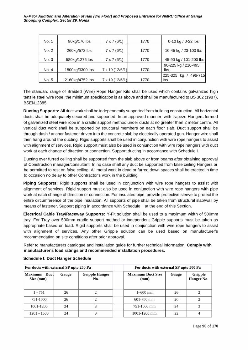
RFP for Addition and Alteration of Hall (3rd Floor) and Proposed Entrance for NMRC Office at Ganga Shopping Complex, Sector 29, Noida
Page 90 of 170
No. 1 80kg/176 lbs 7 x 7 (6/1) 1770 0-10 kg / 0-22 lbs
No. 2 260kg/572 lbs 7 x 7 (6/1) 1770 10-45 kg / 23-100 lbs
No. 3 580kg/1276 lbs 7 x 7 (6/1) 1770 45-90 kg / 101-200 lbs
No. 4 1500kg/3300 lbs 7 x 19 (12/6/1) 1770 90-225 kg / 210-495 lbs
No. 5 2160kg/4752 lbs 7 x 19 (12/6/1) 1770 225-325 kg / 496-715 lbs
The standard range of Braided (Wire) Rope Hanger Kits shall be used which contains galvanized high
tensile steel wire rope, the minimum specification is as above and shall be manufactured to BS 302 (1987),
BSEN12385.
Ducting Supports: All duct work shall be independently supported from building construction. All horizontal
ducts shall be adequately secured and supported. In an approved manner, with trapeze Hangers formed
of galvanized steel wire rope in a cradle support method under ducts at no greater than 2 meter centre. All
vertical duct work shall be supported by structural members on each floor slab. Duct support shall be
through dash / anchor fastener driven into the concrete slab by electrically operated gun. Hanger wire shall
then hang around the ducting. Rigid supports shall be used in conjunction with wire rope hangers to assist
with alignment of services. Rigid support must also be used in conjunction with wire rope hangers with duct
work at each change of direction or connection. Support ducting in accordance with Schedule I.
Ducting over furred ceiling shall be supported from the slab above or from beams after obtaining approval
of Construction manager/consultant. In no case shall any duct be supported from false ceiling Hangers or
be permitted to rest on false ceiling. All metal work in dead or furred down spaces shall be erected in time
to occasion no delay to other Contractor‘s work in the building.
Piping Supports: Rigid supports shall be used in conjunction with wire rope hangers to assist with
alignment of services. Rigid support must also be used in conjunction with wire rope hangers with pipe
work at each change of direction or connection. For insulated pipe, provide protective sleeve to protect the
entire circumference of the pipe insulation. All supports of pipe shall be taken from structural slab/wall by
means of fastener. Support piping in accordance with Schedule II at the end of this Section.
Electrical Cable Tray/Raceway Supports: Y-Fit solution shall be used to a maximum width of 500mm
tray. For Tray over 500mm cradle support method or independent Gripple supports must be taken as
appropriate based on load. Rigid supports shall be used in conjunction with wire rope hangers to assist
with alignment of services. Any other Gripple solution can be used based on manufacturer‘s
recommendation on site conditions after prior approval.
Refer to manufacturers catalogue and installation guide for further technical information. Comply with
manufacturer's load ratings and recommended installation procedures.
Schedule I: Duct Hanger Schedule
For ducts with external SP upto 250 Pa For ducts with external SP upto 500 Pa
Maximum Duct
Size (mm) Gauge Gripple Hanger
No. Maximum Duct Size
(mm) Gauge Gripple
Hanger No.
1 - 751 26 2 1–600 mm 26 2
751-1000 26 2 601-750 mm 26 2
1001-1200 24 3 751-1000 mm 24 3
1201 - 1500 24 3 1001-1200 mm 22 4
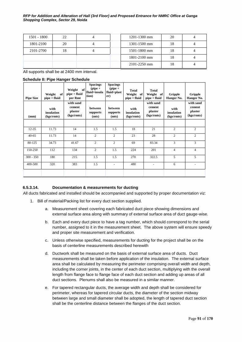
RFP for Addition and Alteration of Hall (3rd Floor) and Proposed Entrance for NMRC Office at Ganga Shopping Complex, Sector 29, Noida
Page 91 of 170
1501 - 1800 22 4 1201-1300 mm 20 4
1801-2100 20 4 1301-1500 mm 18 4
2101-2700 18 4 1501-1800 mm 18 4
1801-2100 mm 18 4
2101-2250 mm 18 4
All supports shall be at 2400 mm interval.
Schedule II: Pipe Hanger Schedule
Pipe Size Weight of
pipe + fluid
Weight of
pipe + fluid per Rmt
Spacings (pipe +
fluid+insula
tion)
Spacings (pipe +
fluid+plast
er) Total
Weight of
pipe + fluid
Total Weight of
pipe + fluid Gripple
Hanger No. Gripple
Hanger No.
(mm)
with insulation (kgs/rmts)
with sand
cement
plaster (kgs/rmts)
between
supports (mts)
between
supports (mts)
with insulation (kgs/rmts)
with sand
cement
plaster (kgs/rmts)
with insulation (kgs/rmts)
with sand
cement
plaster (kgs/rmts)
12-35 11.73 14 1.5 1.5 18 21 2 2
40-65 11.73 14 2 2 23 28 2 2
80-125 34.73 41.67 2 2 69 83.34 3 3
150-250 112 134 2 1.5 224 201 4 4
300 - 350 180 215 1.5 1.5 270 322.5 5 5
400-500 320 383 1.5 - 480 - 6 -
6.5.3.14. Documentation & measurements for ducting
All ducts fabricated and installed should be accompanied and supported by proper documentation viz:
1. Bill of material/Packing list for every duct section supplied.
a. Measurement sheet covering each fabricated duct piece showing dimensions and
external surface area along with summary of external surface area of duct gauge-wise.
b. Each and every duct piece to have a tag number, which should correspond to the serial
number, assigned to it in the measurement sheet. The above system will ensure speedy
and proper site measurement and verification.
c. Unless otherwise specified, measurements for ducting for the project shall be on the
basis of centerline measurements described herewith
d. Ductwork shall be measured on the basis of external surface area of ducts. Duct
measurements shall be taken before application of the insulation. The external surface
area shall be calculated by measuring the perimeter comprising overall width and depth,
including the corner joints, in the center of each duct section, multiplying with the overall
length from flange face to flange face of each duct section and adding up areas of all
duct sections. Plenums shall also be measured in a similar manner.
e. For tapered rectangular ducts, the average width and depth shall be considered for
perimeter, whereas for tapered circular ducts, the diameter of the section midway
between large and small diameter shall be adopted, the length of tapered duct section
shall be the centerline distance between the flanges of the duct section.
RFP for Addition and Alteration of Hall (3rd Floor) and Proposed Entrance for NMRC Office at Ganga Shopping Complex, Sector 29, Noida
Page 92 of 170
f. For special pieces like bends, tees, reducers, branches and collars, mode of
measurement shall be identical to that described above using the length along the
centerline.
g. The quoted unit rate for external surface of ducts shall include all wastage allowances,
flanges and gaskets for joints, nuts and bolts, hangers and angles with double nuts for
supports, rubber strip 5mm thick between duct and support, vibration isolator suspension
where specified or required, inspection chamber/access panel, splitter damper with
quadrant and lever for position indication, turning vanes, straightening vanes, and all
other accessories required to complete the duct installation as per the specifications.
These accessories shall NOT be separately measured nor paid for.
2. Special Items for Air Distribution shall be measured by the cross-section area perpendicular to
air flow, as identified herewith :
a. Grilles and registers - width multiplied by height, excluding flanges. Volume control
dampers shall form part of the unit rate for registers and shall not be separately
accounted.
b. Diffusers - cross section area for air flow at discharge area, excluding flanges. Volume
control dampers shall form part of unit rate for supply air diffusers and shall not be
separately accounted.
c. Linear diffusers - shall be measured by cross-sectional areas and shall exclude flanges
for mounting of linear diffusers. The supply air plenum for linear diffusers shall be
measured with ducting as described earlier.
d. Fire dampers - shall be measured by their cross sectional area perpendicular to the
direction of air flow. Quoted rates shall include the necessary collars and flanges for
mounting, inspection pieces with access door, electrical actuators and panel. No special
allowance shall be payable for extension of cross section outside the air stream.
e. Flexible connection - shall be measured by their cross sectional area perpendicular to
the direction of air flow. Quoted rates shall include the necessary mounting
arrangement, flanges, nuts and bolts and treated-for-fire requisite length of canvas
cloth.
f. Kitchen Hoods - shall be measured by their cross sectional area at the capture point
of fumes, parallel to the surface of kitchen equipment. Quoted rates shall include
the grease filters, provision for hood light, suspension arrangement for the hood,
profile to direct the air to ventilation ducts and provision for removable drip tray.
6.5.3.15. Underfloor air distribution system
1. Round Floor Turbulent Flow Diffuser
a. Each diffuser shall produce a high induction turbulent vertical flow resulting in rapid temp
erature equalization within the occupied zone.
b. The discharge airflow shall be adjustable from the face of the diffuser. Minimum flow limit
shall be adjustable from 0% to 50% of maximum flow using a mechanical stop.
c. The adjustable diffuser face shall have a positive interlock with the mounting hardware to
reduce the chance of accidental adjustment due to foot traffic.
d. The diffuser core shall consist of multiple radial slots with an incline angle of 30 degrees.
The 8‖ core shall be constructed of UL2043 Fire Rated Polyamide with permeating
colour able to withstand maximum mechanical loading of 1300 lbs.
RFP for Addition and Alteration of Hall (3rd Floor) and Proposed Entrance for NMRC Office at Ganga Shopping Complex, Sector 29, Noida
Page 93 of 170
e. Round floor diffusers shall be installed with Ring Nut / fastening and shall include tamper
protection to prevent unauthorized removal of the diffuser. Assembly shall include black
polycarbonate distributor Basket with Damper device.
2. Round Floor Displacement Diffuser
a. Each diffuser shall produce a low induction horizontal flowresulting in a stratified zone te
mperature distribution within the occupied zone.
b. The discharge airflow shall be adjustable from the face of the diffuser. Minimum flow limit
shall be adjustable from 0% to 50% of maximum flow using a mechanical stop.
c. The adjustable diffuser face shall have a positive interlock with the mounting hardware to
reduce the chance of accidental adjustment due to foot traffic. The 8‖ core shall be const
ructed of UL2043 Fire Rated Polyamide with permeating color able to withstand maximu
m mechanical loading of 1300 lbs.
d. Round floor diffusers shall be installed with Ring Nut fastening and shall include tamper p
rotection to prevent unauthorized removal of the diffuser. Assembly shall include black p
olycarbonate distributor Basket with Damper device.
3. Round Floor Inclined Diffuser
a. Each diffuser shall produce a high induction turbulent flow by utilizing radial and circular
discharge slots to create a discharge of 30 degrees to vertical resulting in rapid temperat
ure equalization within the occupied zone.
b. The diffuser core shall consist of multiple radial slots and circular slots with an incline ang
le of 30 degrees. The 8‖ core shall be constructed of aluminum able to withstand maximu
m mechanical loading of 2600 lbs. Round floor diffusers shall be installed with Ring Pres
s Fit / Ring Claw fasteners and shall include tamper protection to prevent unauthorized re
moval of the round diffuser.
c. Assembly shall include black polyamide distributor Basket with Damper device / Short Ba
sket / Extra Short Basket with Damper Device. Round Floor diffusers shall be supplied wi
th an RFB / RFBV boot mounted to the underside of the floor tile constructed of galvaniz
ed steel.
6.5.3.16. Flexible Duct: Insulated flexible duct should be UL 181 CLASS I AIR DUCT LISTED AND LABELLED WITH NFPA 90A
& 90B ANDSEAL OF AIR DIFFUSION COUNCIL with double lamination of tough polyester which
encapsulates steel helix wire forms the air tight inner core, double layer core wrapped in a multiple
thickness of fiberglass wool with R Value 4.2, Green guard certification of fiberglass wool must. ,
Reinforced and sheathed in a rugged and durable tridirectionally reinforced matlized polyester jacket.
Flexible duct connections should be made as per UL181 listing procedure with proper flexible right forming
brace connection allowing right connections for flexible duct into energy efficient. And Strapping the flexible
duct connections with flexible duct strap ties.
6.5.3.17. Testing and balancing
After the installation of the entire air distribution system is completed in all respects, all ducts shall be
tested for air leaks by visual inspection.
The entire air distribution system shall be balanced using an anemometer. Measured air quantities at fan
discharge and at various outlets shall be identical to or less/excess than 5 percent in excess of those
specified and quoted. Branch duct adjustments shall be permanently marked after air balancing is
completed so that these can be restored to their correct position if disturbed at any time. Complete air
balance report shall be submitted for scrutiny and approval, and four copies of the approved balance report
shall be provided with completion documents.
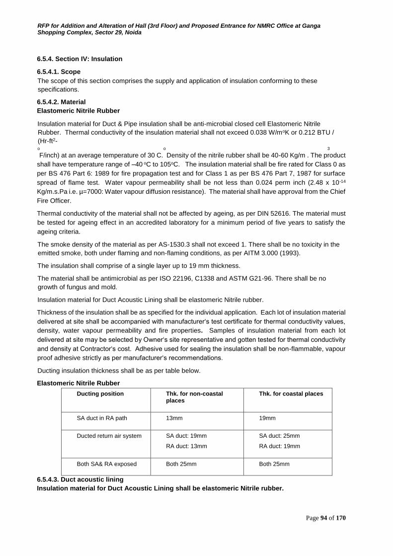
RFP for Addition and Alteration of Hall (3rd Floor) and Proposed Entrance for NMRC Office at Ganga Shopping Complex, Sector 29, Noida
Page 94 of 170
6.5.4. Section IV: Insulation
6.5.4.1. Scope The scope of this section comprises the supply and application of insulation conforming to these
specifications.
6.5.4.2. Material Elastomeric Nitrile Rubber
Insulation material for Duct & Pipe insulation shall be anti-microbial closed cell Elastomeric Nitrile
Rubber. Thermal conductivity of the insulation material shall not exceed 0.038 W/moK or 0.212 BTU /
(Hr-ft2- o o 3 F/inch) at an average temperature of 30 C. Density of the nitrile rubber shall be 40-60 Kg/m . The product
shall have temperature range of –40 oC to 105oC. The insulation material shall be fire rated for Class 0 as
per BS 476 Part 6: 1989 for fire propagation test and for Class 1 as per BS 476 Part 7, 1987 for surface
spread of flame test. Water vapour permeability shall be not less than 0.024 perm inch (2.48 x 10⁻¹⁴
Kg/m.s.Pa i.e. µ=7000: Water vapour diffusion resistance). The material shall have approval from the Chief
Fire Officer.
Thermal conductivity of the material shall not be affected by ageing, as per DIN 52616. The material must
be tested for ageing effect in an accredited laboratory for a minimum period of five years to satisfy the
ageing criteria.
The smoke density of the material as per AS-1530.3 shall not exceed 1. There shall be no toxicity in the
emitted smoke, both under flaming and non-flaming conditions, as per AITM 3.000 (1993).
The insulation shall comprise of a single layer up to 19 mm thickness.
The material shall be antimicrobial as per ISO 22196, C1338 and ASTM G21-96. There shall be no
growth of fungus and mold.
Insulation material for Duct Acoustic Lining shall be elastomeric Nitrile rubber.
Thickness of the insulation shall be as specified for the individual application. Each lot of insulation material
delivered at site shall be accompanied with manufacturer‘s test certificate for thermal conductivity values,
density, water vapour permeability and fire properties. Samples of insulation material from each lot
delivered at site may be selected by Owner‘s site representative and gotten tested for thermal conductivity
and density at Contractor‘s cost. Adhesive used for sealing the insulation shall be non-flammable, vapour
proof adhesive strictly as per manufacturer‘s recommendations.
Ducting insulation thickness shall be as per table below.
Elastomeric Nitrile Rubber
Ducting position Thk. for non-coastal places
Thk. for coastal places
SA duct in RA path 13mm 19mm
Ducted return air system SA duct: 19mm
RA duct: 13mm
SA duct: 25mm
RA duct: 19mm
Both SA& RA exposed Both 25mm Both 25mm
6.5.4.3. Duct acoustic lining Insulation material for Duct Acoustic Lining shall be elastomeric Nitrile rubber.

RFP for Addition and Alteration of Hall (3rd Floor) and Proposed Entrance for NMRC Office at Ganga Shopping Complex, Sector 29, Noida
Page 95 of 170
Material shall be engineered Nitrile Rubber open cell foam. The material should be fibre free. The density
of the same shall be within 140-180 Kg/m3. It should have antimicrobial product protection, and should
pass Fungi Resistance as per ASTM G 21 and Bacterial Resistance as per ASTM E 2180. The material
should have a thermal conductivity not exceeding 0.047 W/m.K @ 20 Deg. C . The material should
withstand maximum surface temperature of +850C and minimum surface temperature of -200C. The
material should conform to Class 1 rating for surface spread of Flame in accordance to BS 476 Part 7 &
UL 94 (HBF, HF 1 & HF 2) in accordance to UL 94, 1996. The insulation should pass Air Erosion Resistance
Test in accordance to ASTM Standard C 1071-05 (section 12.7). Thickness of the material shall be as
specified for the individual application. The insulation should be installed as per manufacturer‘s
recommendation. The adhesive shall be specially formulated for the Duct insulation application and
supplied by insulation manufacturer. The adhesive shall be Solvent based rubber insulation adhesive, free
from benzene. Ducts so identified and marked on Drawings and included in Schedule of Quantities shall
be provided with acoustic lining of thermal insulation material for a distance of minimum 5 meters (or 30%
of the duct length whichever is more).
Installation Procedure
The inside surface for the ducts shall be covered with adhesive recommended by the manufacturer. Cut
Foamed sheets into required sizes apply adhesive on the foam and stick it to the duct surface
6.5.4.4. Duct insulation External thermal insulation shall be provided as follows:
The thickness of nitrile rubber shall be as shown on drawing or identified in the schedule of quantity.
Following procedure shall be adhered to:
Duct surfaces shall be cleaned to remove all grease, oil, dirt, etc. prior to carrying out insulation work.
Measurement of surface dimensions shall be taken properly to cut closed cell elastomeric rubber sheets to
size with sufficient allowance in dimension. Cutting of nitrile rubber sheets shall be done with adjustable
blade to make 900 cut in thickness of nitrile rubber sheet. Hacksaw or blades are not acceptable tools for
cutting the insulation.
Material shall be fitted under compression and no stretching of material shall be permitted. A thin film of
adhesive shall be applied on the back of the insulating material sheet and then on to the metal surface.
When adhesive is tack dry, insulating material sheet shall be placed in position and pressed firmly to
achieve a good bond. All longitudinal and transverse joints shall be sealed by providing 6 mm thick 50 mm
wide nitrile rubber tape. The adhesive shall be strictly as recommended by the manufacturer.
6.5.4.5. Piping insulation All chilled water, refrigerant, and condensate drain piping shall be insulated in the manner specified herein.
Before applying insulation, all pipes shall be brushed and cleaned. All MS pipes shall be provided with a
coat of zinc chromate primer. Thermal insulation shall be applied as follows or as specified in drawings or
schedule of quantity:
Pipe nominal bore Thk. for non-coastal places Thk. for coastal places
15mm – 25mm 19mm 25mm
32mm – 80mm 25mm 32mm
100mm – 400mm 32mm 38mm
Above 400mm 45mm 45mm
RFP for Addition and Alteration of Hall (3rd Floor) and Proposed Entrance for NMRC Office at Ganga Shopping Complex, Sector 29, Noida
Page 96 of 170
Insulating material in tube form shall be sleeved on the pipes. On piping, slit opened tube from insulating
material shall be placed over the pipe and adhesive shall be applied as suggested by the manufacturer.
Adhesive must be allowed to tack dry and then press surface firmly together starting from butt end and
working towards center. Wherever flat sheets shall be used it shall be cut out in correct dimension using
correct tools. Scissors or Hacksaw-blade shall not be allowed. All longitudinal and transverse joints shall
be sealed as per manufacturer recommendations. All longitudinal and transverse joints shall be sealed by
providing 6 mm thick, 50 mm wide nitrile rubber tape. The adhesive shall be strictly as recommended by
the manufacturer. The insulation shall be continuous over the entire run of piping, fittings and valves. All
valves, fittings, joints, strainers etc. in chilled water piping shall be insulated to the same thickness as
specified for the main run of piping and application shall be same as above.
Valves bonnet, yokes and spindles shall be insulated in such a manner as not to cause damage to insulation
when the valve is used or serviced. Manufacturer‘s installation manual shall be submitted and followed for
full compliance. All insulation work shall be carried out by skilled workmen specially trained in this kind of
work. All insulated pipes shall be labeled (S.R. or R.R.) and provided with 300 mm wide band of paint
along circumference at every 1200 mm for colour coding. Direction of fluid shall also be marked. Un-
insulated MS pipes shall be painted throughout and direction of fluid marked. All painting shall be as per
relevant BIS codes.
6.5.4.6. Protective coating over insulation To provide mechanical strength and protection from damage all pipe / duct insulated with nitrile rubber as
indicated in BOQ shall be covered All insulated chilled water piping shall be with 7mil woven fiber glass
cloth to provide complete seal against air and moisture/resistance against mechanical impact, scratch and
weather resistance.
6.5.4.7. Overdeck insulation
Overdeck insulation shall be done with 75 mm thick extruded polystyrene of density 45-48 kg/cm3 & thermal
conductivity of 0.21 Btu in / ft2 hroF (at 24oC as per ASTM C – 518). Minimum compressive strength as per
ASTM D-2842 shall be 570 kPa water absorption as per ASTM D-2842 shall not be more than 1%.
Method of Application
1. Clean RCC slab and make it free from dust and other laitance matter.
2. Lay cement based water proofing on roof with a minimum slope of 1:100 and average thickness
of 110 mm using brickbats of appropriate size and shape suitable to achieve the required slope
laid over 15 mm thick waterproof c3ement mortar 1:4 and finished with 20 mm thick waterproof
plaster wing cement mortar 1:4 and making false squares of 300 mm size including rounding off
the junction of roof and parapet walls for a height of 300 mm with brickbats and 20 mm thick
waterproof plaster and conducting necessary leakage / dampers tests, etc.
3. Lay 65 mm thick extruded polystyrene boards over prepared surface fixing with adhesive.
Adhesive shall be strictly as per recommendations from manufacturer. 4. Lay 80 gsm geotextile
fabric over insulation board
5. Lay 40 x 40 x 4 cm precast paver blocks.
(Note: If contractor is awarded work of waterproofing + overdeck insulation, follow all steps from (a) to (e).
if contractor is awarded work of only overdeck insulation follow step (c) and (d). Rest will be done by
Civil Contractor).
6.5.4.8. Underdeck insulation
Underdeck insulation shall be 50mm thick TF Quality expanded polystyrene (32 Kg/m3) or 30mm thick
phenotherm. Underdeck surface of ceiling shall be cleaned and made dirt free. Insulation panels shall be
pasted on this surface with black CPRX compound. 28g wire net shall be tightened around insulation so
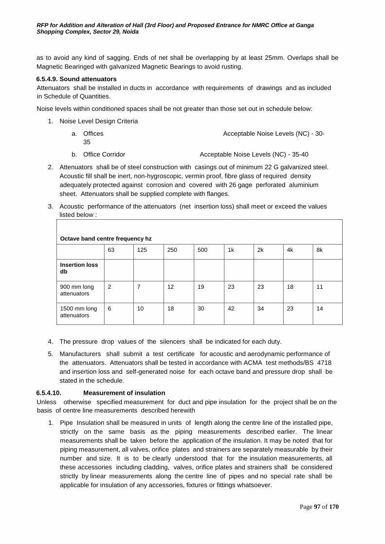
RFP for Addition and Alteration of Hall (3rd Floor) and Proposed Entrance for NMRC Office at Ganga Shopping Complex, Sector 29, Noida
Page 97 of 170
as to avoid any kind of sagging. Ends of net shall be overlapping by at least 25mm. Overlaps shall be
Magnetic Bearinged with galvanized Magnetic Bearings to avoid rusting.
6.5.4.9. Sound attenuators Attenuators shall be installed in ducts in accordance with requirements of drawings and as included
in Schedule of Quantities.
Noise levels within conditioned spaces shall be not greater than those set out in schedule below:
1. Noise Level Design Criteria
a. Offices Acceptable Noise Levels (NC) - 30-
35
b. Office Corridor Acceptable Noise Levels (NC) - 35-40
2. Attenuators shall be of steel construction with casings out of minimum 22 G galvanized steel.
Acoustic fill shall be inert, non-hygroscopic, vermin proof, fibre glass of required density
adequately protected against corrosion and covered with 26 gage perforated aluminium
sheet. Attenuators shall be supplied complete with flanges.
3. Acoustic performance of the attenuators (net insertion loss) shall meet or exceed the values
listed below :
Octave band centre frequency hz
63 125 250 500 1k 2k 4k 8k
Insertion loss db
900 mm long attenuators
2 7 12 19 23 23 18 11
1500 mm long attenuators
6 10 18 30 42 34 23 14
4. The pressure drop values of the silencers shall be indicated for each duty.
5. Manufacturers shall submit a test certificate for acoustic and aerodynamic performance of
the attenuators. Attenuators shall be tested in accordance with ACMA test methods/BS 4718
and insertion loss and self-generated noise for each octave band and pressure drop shall be
stated in the schedule.
6.5.4.10. Measurement of insulation
Unless otherwise specified measurement for duct and pipe insulation for the project shall be on the
basis of centre line measurements described herewith
1. Pipe Insulation shall be measured in units of length along the centre line of the installed pipe,
strictly on the same basis as the piping measurements described earlier. The linear
measurements shall be taken before the application of the insulation. It may be noted that for
piping measurement, all valves, orifice plates and strainers are separately measurable by their
number and size. It is to be clearly understood that for the insulation measurements, all
these accessories including cladding, valves, orifice plates and strainers shall be considered
strictly by linear measurements along the centre line of pipes and no special rate shall be
applicable for insulation of any accessories, fixtures or fittings whatsoever.
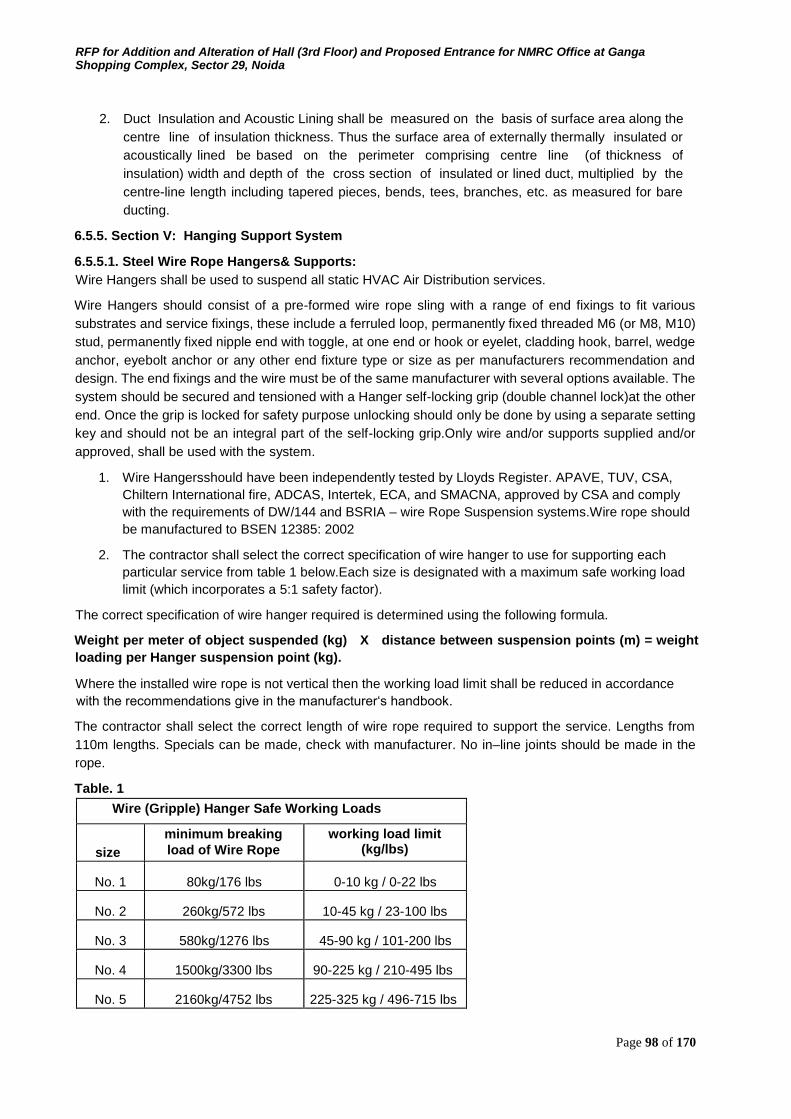
RFP for Addition and Alteration of Hall (3rd Floor) and Proposed Entrance for NMRC Office at Ganga Shopping Complex, Sector 29, Noida
Page 98 of 170
2. Duct Insulation and Acoustic Lining shall be measured on the basis of surface area along the
centre line of insulation thickness. Thus the surface area of externally thermally insulated or
acoustically lined be based on the perimeter comprising centre line (of thickness of
insulation) width and depth of the cross section of insulated or lined duct, multiplied by the
centre-line length including tapered pieces, bends, tees, branches, etc. as measured for bare
ducting.
6.5.5. Section V: Hanging Support System
6.5.5.1. Steel Wire Rope Hangers& Supports: Wire Hangers shall be used to suspend all static HVAC Air Distribution services.
Wire Hangers should consist of a pre-formed wire rope sling with a range of end fixings to fit various
substrates and service fixings, these include a ferruled loop, permanently fixed threaded M6 (or M8, M10)
stud, permanently fixed nipple end with toggle, at one end or hook or eyelet, cladding hook, barrel, wedge
anchor, eyebolt anchor or any other end fixture type or size as per manufacturers recommendation and
design. The end fixings and the wire must be of the same manufacturer with several options available. The
system should be secured and tensioned with a Hanger self-locking grip (double channel lock)at the other
end. Once the grip is locked for safety purpose unlocking should only be done by using a separate setting
key and should not be an integral part of the self-locking grip.Only wire and/or supports supplied and/or
approved, shall be used with the system.
1. Wire Hangersshould have been independently tested by Lloyds Register. APAVE, TUV, CSA,
Chiltern International fire, ADCAS, Intertek, ECA, and SMACNA, approved by CSA and comply
with the requirements of DW/144 and BSRIA – wire Rope Suspension systems.Wire rope should
be manufactured to BSEN 12385: 2002
2. The contractor shall select the correct specification of wire hanger to use for supporting each
particular service from table 1 below.Each size is designated with a maximum safe working load
limit (which incorporates a 5:1 safety factor).
The correct specification of wire hanger required is determined using the following formula.
Weight per meter of object suspended (kg) X distance between suspension points (m) = weight
loading per Hanger suspension point (kg).
Where the installed wire rope is not vertical then the working load limit shall be reduced in accordance
with the recommendations give in the manufacturer‘s handbook.
The contractor shall select the correct length of wire rope required to support the service. Lengths from
110m lengths. Specials can be made, check with manufacturer. No in–line joints should be made in the
rope.
Table. 1
Wire (Gripple) Hanger Safe Working Loads
size
minimum breaking load of Wire Rope
working load limit (kg/lbs)
No. 1 80kg/176 lbs 0-10 kg / 0-22 lbs
No. 2 260kg/572 lbs 10-45 kg / 23-100 lbs
No. 3 580kg/1276 lbs 45-90 kg / 101-200 lbs
No. 4 1500kg/3300 lbs 90-225 kg / 210-495 lbs
No. 5 2160kg/4752 lbs 225-325 kg / 496-715 lbs
RFP for Addition and Alteration of Hall (3rd Floor) and Proposed Entrance for NMRC Office at Ganga Shopping Complex, Sector 29, Noida
Page 99 of 170
No. 6 2500kg/5500 lbs 325-500 kg / 715-1100 lbs The standard range of Hanger Kits should contain galvanized high tensile steel wire rope or stainless steel
wire rope as per the application, the minimum specification is as above and should be manufactured to BS
302 (1987), BSEN12385. Comply with manufacturer's load ratings and recommended installation
procedures.Note the testing is done to the minimum breaking load of the wire thus giving a minimum
safety factor of 5: 1.
6.5.5.2. HVAC Supports Gripple Hanger Supports are suitable for: Rectangular duct, Spiral Duct, Oval Duct, Fabric Duct,
Desertification fans, Air Conditioning Units, Plenum Boxes, Fan Coil Units & Diffusers
1. Ducting Supports:
All ductwork shall be independently supported from building construction. All horizontal ducts
shall be rigidly and securely supported, in an approved manner, with hangers formed of
galvanized steel wire ropes and galvanized steel angle/channel or a pair of brackets, connected
by galvanized steel wire hangers under ducts, rigid supports may be provided at certain interval if
need be. The spacing between supports should be not greater than 2.4 meter. All vertical
ductwork shall be supported by structural members on each floor slab. Duct supports may be
through galvanized steel insert plates or Toggle end wire fixing left in slab at the time of slab
casting. Galvanized steel cleat with a hole for passing the wire rope hanger shall be welded to
the plates. Trapeze hanger formed of galvanized steel wire rope using Gripple shall be hung
through these cleats. Wherever use of metal insert plates is not feasible, duct support shall be
through dash/anchor fastener driven into the concrete slab by electrically operated gun. Wire
rope supports shall hang through the cleats or wire rope threaded studs can be screwed into the
anchor fasteners. In case of PEB structure Loop and Catenary system can be used based on the
site conditions as per approved suspension system drawings.
2. All horizontal ducts shall be adequately secured and supported. In an approved manner, with
trapeze Hangers formed of galvanized steel wire rope in a cradle support method (refer to typical
drawings) under ducts at no greater than 3000mmcentre, for 3001mm-above appropriate size
angle along with neoprene pad in between the duct & MS angleshould be used with prior
approval. All vertical duct work shall be supported by structural members on each floor slab. Duct
support shall be through dash / anchor fastener driven into the concrete slab by electrically
operated gun. Hanger wires shall then hang around the ducting.Rigid supports shall be used in
conjunction with wire rope hangers to assist with alignment of services where recommended for
by the manufacturer. Rigid support must also be used in conjunction with wire rope hangers with
duct work at each change of direction or connectionor as per approved drawings. Support ducting
in accordance with Schedule I at the end of this Section.Any other Gripple solution can be used
based on manufacturer‘s recommendation on site conditions after prior approval. In cases of
Spiral ducting the wire can be wrapped directly around the ducting without the need for a spiral
ducting clamp for sizes above 1100 a cradle support should be provided, refer to manufacturer‘s
recommendations.
3. Ducting over furred ceiling shall be supported from the slab above or from beams after obtaining
approval of Construction manager/consultant. In no case shall any duct be supported from false
ceiling Hangers or be permitted to rest on false ceiling. All metal work in dead or furred down
spaces shall be erected in time to occasion no delay to other Contractor‘s work in the building. All
supports of pipe shall be taken from structural slab/wall by means of fastener.
Catenary Supports: Refer to manufacturer‘s recommendations on Catenary supports with Cclip,
special care should be taken with tensioning of the wire and angles at which the installation of
services are made.
RFP for Addition and Alteration of Hall (3rd Floor) and Proposed Entrance for NMRC Office at Ganga Shopping Complex, Sector 29, Noida
Page 100 of 170
4. Stainless Steel Supports should be available for food, chemical and High Corrosion areas near
coastlines.
Refer to manufacturers catalogue and installation guide for further technical information.Comply
with manufacturer's load ratings and recommended installation procedures. Schedule I:
Duct Hanger Schedule
For ducts with external SP upto 250 Pa For ducts with external SP upto 500 Pa
Maximum Duct Size (mm)
Gauge Gripple Hanger No.
Maximum Duct Size (mm)
Gauge Gripple Hanger No.
1 - 750 26 1 or 2 1–600 mm 26 1 or 2
751-1000 26 2 601-750 mm 26 2
1001-1200 24 2 or 3 751-1000 mm 24 2 or 3
1201 - 1500 24 3 1001-1200 mm 22 3 or 4
1501 - 1800 22 3 or 4 1201-1300 mm 20 3 or 4
1801-2100 20 3 or 4 1301-1500 mm 18 4
2101-2700 18 4 1501-1800 mm 18 4
1801-2100 mm 18 4
2101-2250 mm 18 4 or 5
2251-2400 mm 18 4 or 5
2401-2700 mm 18 4 or 5
Notes: All supports are considered at 2400 mm interval in above table and may vary as per the design
but should not be greater than 2400mm.
5. Desertification fans, Air Conditioning Units, Plenum Boxes, Radiant Panels, Heaters, Fan Coil
Units, Diffusers, Cassette units.
All units shall be adequately secured and supported in an approved manner using wire hanger
suspension Y fit solution as per manufacturers‘ recommendation with prior approval.
Rigid Supports:
Rigid supports if required in conjunction with wire hangers shall be of steel, adjustable for height
and Zinc chromate primer coated and finish coated black. Where supports and clamps are of
dissimilar materials, a gasket shall be provided in between. If the MS angle at the bottom if
required as per design should be as per following table:
Longer size of Duct Type of Joints
Up to 750 25x25x3 mm L angle with M8 nuts & bolts
751-1000 25x25x3 mm L angle with M8 nuts & bolts
1001-1500 40x40x5 mm L angle with M8 nuts & bolts
1501-2250 50x50x5 mm L angle with M10 nuts & bolts
2251 & above 50x50x6 mm L angle with M10 nuts & bolts
All the supporting system should be supplied from same manufacturer.
RFP for Addition and Alteration of Hall (3rd Floor) and Proposed Entrance for NMRC Office at Ganga Shopping Complex, Sector 29, Noida
Page 101 of 170
7. Section 7: Draft Contract Agreement
THIS AGREEMENT made on the ………….day of ………….. 2018 at Noida, District Gautam Budh Nagar,
Uttar Pradesh Between Noida Metro Rail Corporation Limited (Hereafter referred to as ―NMRC‖), a
company incorporated under Companies Act 2013, vide corporate identification Number: U60231UP2014SGC066849 and having its registered office at Block-III, 3rd Floor, Ganga Shopping
Complex, Sector-29, Noida -201301, District Gautam Budh Nagar, Uttar Pradesh, India represented
by ……………………………………. of the company, by virtue of his designation and authorization by Shri
…………………….., Managing Director, NMRC (hereinafter called as the ―Purchaser"), which
expression shall unless excluded by or repugnant to the context or meaning thereof be deemed to include
its successors and permitted assigns) of the one part,
AND
………………………………………………………………….……………….. having its registered office at
………………………………………………………………, represented by ………………………………….
(herein after called the “Contractor", which expression shall unless excluded by or repugnant to the
context or meaning thereof be deemed to include its successors and permitted assigns) of the other part. WHEREAS the Purchaser desires that the Works known as the
“………………………………………………………………………………………………….” should be
executed by the Contractor, and has accepted a contract by the Contractor for the execution and
completion of these Works.
The Purchaser and the Contractor agree as follows:
1. In this Agreement words and expressions shall have the same meanings as are respectively
assigned to them in the Contract documents referred to.
2. The following documents shall be deemed to form and be read and construed as part of this
Agreement -
Reference:
(i) Tender No. ………………………… Dated ………………..
(ii) Bid Documents duly accepted and submitted by …………………………… dated ……………..
(iii) The Bidding Documents which include all the Sections specified below: a. Section 1: General Information b. Section 2: Terms of Reference c. Section 3: Instructions to Bidders d. Section 4: Qualification, Evaluation and Selection Process e. Section 5: Special Conditions of Contract f. Section 6: Technical Specifications g. Section 7: Draft Contract Agreement h. Section 8: Appendix to Form of Tender and Forms i. General Conditions to Contract (GCC) j. Condition of Contract on Safety, Health & Environment Management k. Amendment/ Modification, if any
(iv) Notice of Award (………………….) issued by NMRC
(v) Letter of Acceptance of NOA (…………………………….) given by ………….. to NMRC (vi)
Any other admitted correspondence documents between NMRC and the Bidder.

RFP for Addition and Alteration of Hall (3rd Floor) and Proposed Entrance for NMRC Office at Ganga Shopping Complex, Sector 29, Noida
Page 102 of 170
3. Price Schedule NMRC shall be as quoted by the contractor as part of financial bid i.e. INR ________________.
As per letter of acceptance no ______________ dt ___________.
RFP for Addition and Alteration of Hall (3rd Floor) and Proposed Entrance for NMRC Office at Ganga Shopping Complex, Sector 29, Noida
Page 103 of 170
4. The courts at District Gautam Budh Nagar, Uttar Pradesh shall have the exclusive jurisdiction to try
all disputes arising out of this agreement between the parties.
5. In consideration of the payments to be made by the Purchaser to the Contractor as specified in this
Agreement, the Contractor hereby covenants with the Purchaser to execute the Works and to
remedy defects therein in conformity in all respects with the provisions of the Contract and Notice
of Award issued. ―Any conditions, deviation, assumption, exclusion, suggestion of
alternative clauses, request of amendments in conditions & specifications of work
submitted by bidders along with his Technical Bid or Financial bid, which is different from
the Tender Document, Corrigendum, Addendum uploaded by NMRC on the E-Tender Portal
(http://etender.up.nic.in) and any other correspondence in this regard, shall not be treated
as a part of the contract Agreement & shall not be binding upon NMRC in anyway
whatsoever at any stage of work during execution or thereafter."
6. The Purchaser hereby covenants to pay the Contractor in consideration of the execution and
completion of the Works, the Contract Price or such other sum as may become payable under the
provisions of the Contract at the times and in the manner prescribed by the Contract and NOA.
IN WITNESS where of the parties hereto have caused this Agreement to be executed in accordance with
the laws of India on the day, month and year specified above.
For and on behalf of the Contractor For and on behalf of the Purchaser Signature of the authorized official Signature of the authorized official
Name of the official Name of the official
Stamp/Seal of the contractor Stamp/Seal of the Purchaser
In the presence of:
In the presence of:
Sign of Witness 1________________
Sign of Witness 1________________
Name________________________
Name________________________
Address______________________
Address______________________
_____________________________
_____________________________
Sign of Witness 2________________
Sign of Witness 2________________
Name________________________
Name________________________
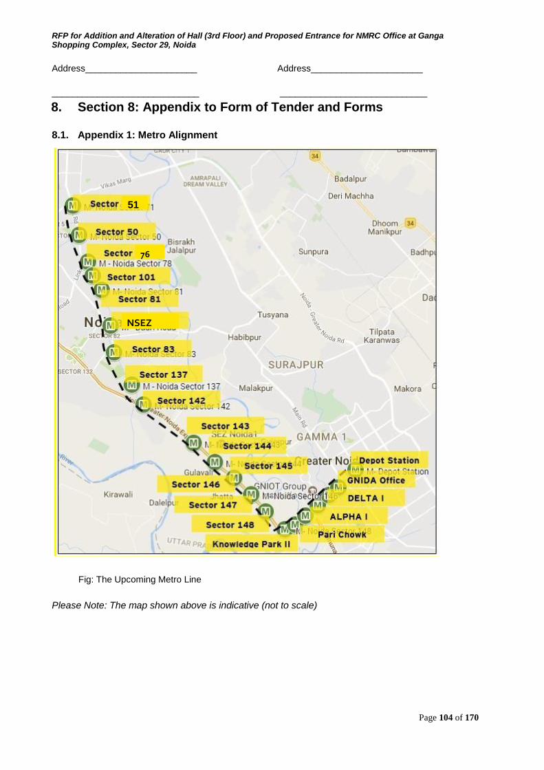
RFP for Addition and Alteration of Hall (3rd Floor) and Proposed Entrance for NMRC Office at Ganga Shopping Complex, Sector 29, Noida
Page 104 of 170
Address______________________
Address______________________
_____________________________ _____________________________
8. Section 8: Appendix to Form of Tender and Forms
Fig: The Upcoming Metro Line
Please Note: The map shown above is indicative (not to scale)
8.1. Appendix 1: Metro Alignment
51
76
NSEZ
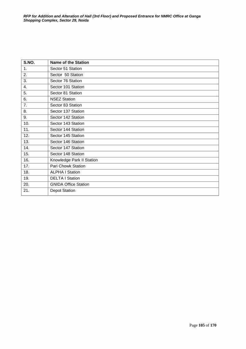
RFP for Addition and Alteration of Hall (3rd Floor) and Proposed Entrance for NMRC Office at Ganga Shopping Complex, Sector 29, Noida
Page 105 of 170
S.NO. Name of the Station
1. Sector 51 Station
2. Sector 50 Station
3. Sector 76 Station
4. Sector 101 Station
5. Sector 81 Station
6. NSEZ Station
7. Sector 83 Station
8. Sector 137 Station
9. Sector 142 Station
10. Sector 143 Station
11. Sector 144 Station
12. Sector 145 Station
13. Sector 146 Station
14. Sector 147 Station
15. Sector 148 Station
16. Knowledge Park II Station
17. Pari Chowk Station
18. ALPHA I Station
19. DELTA I Station
20. GNIDA Office Station
21. Depot Station
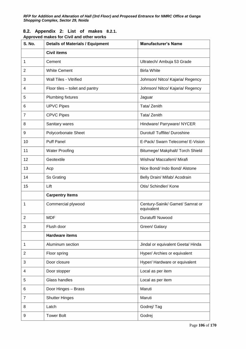
RFP for Addition and Alteration of Hall (3rd Floor) and Proposed Entrance for NMRC Office at Ganga Shopping Complex, Sector 29, Noida
Page 106 of 170
8.2. Appendix 2: List of makes 8.2.1.
Approved makes for Civil and other works
S. No. Details of Materials / Equipment Manufacturer’s Name
Civil items
1 Cement Ultratech/ Ambuja 53 Grade
2 White Cement Birla White
3 Wall Tiles - Vitrified Johnson/ Nitco/ Kajaria/ Regency
4 Floor tiles – toilet and pantry Johnson/ Nitco/ Kajaria/ Regency
5 Plumbing fixtures Jaguar
6 UPVC Pipes Tata/ Zenith
7 CPVC Pipes Tata/ Zenith
8 Sanitary wares Hindware/ Parryware/ NYCER
9 Polycorbonate Sheet Durotuf/ Tufflite/ Duroshine
10 Puff Panel E-Pack/ Swarn Telecome/ E-Vision
11 Water Proofing Bitumege/ Makphalt/ Torch Shield
12 Geotextile Wishva/ Maccaferri/ Mirafi
13 Acp Nice Bond/ Indo Bond/ Alstone
14 Ss Grating Belly Drain/ Mifab/ Acodrain
15 Lift Otis/ Schindler/ Kone
Carpentry Items
1 Commercial plywood Century-Sainik/ Gamet/ Samrat or equivalent
2 MDF Duratuff/ Nuwood
3 Flush door Green/ Galaxy
Hardware items
1 Aluminum section Jindal or equivalent Geeta/ Hinda
2 Floor spring Hyper/ Archies or equivalent
3 Door closure Hyper/ Hardware or equivalent
4 Door stopper Local as per item
5 Glass handles Local as per item
6 Door Hinges – Brass Maruti
7 Shutter Hinges Maruti
8 Latch Godrej/ Tag
9 Tower Bolt Godrej
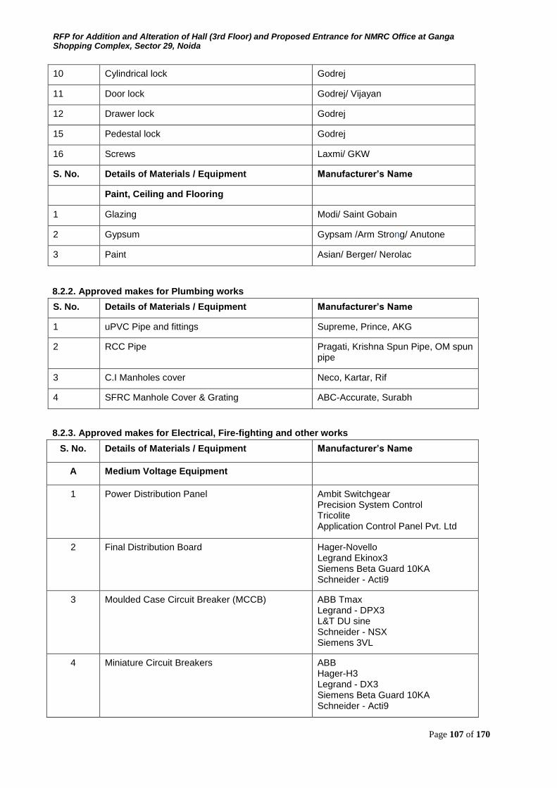
RFP for Addition and Alteration of Hall (3rd Floor) and Proposed Entrance for NMRC Office at Ganga Shopping Complex, Sector 29, Noida
Page 107 of 170
10 Cylindrical lock Godrej
11 Door lock Godrej/ Vijayan
12 Drawer lock Godrej
15 Pedestal lock Godrej
16 Screws Laxmi/ GKW
S. No. Details of Materials / Equipment Manufacturer’s Name
Paint, Ceiling and Flooring
1 Glazing Modi/ Saint Gobain
2 Gypsum Gypsam /Arm Strong/ Anutone
3 Paint Asian/ Berger/ Nerolac
8.2.2. Approved makes for Plumbing works
S. No. Details of Materials / Equipment Manufacturer’s Name
1 uPVC Pipe and fittings Supreme, Prince, AKG
2 RCC Pipe Pragati, Krishna Spun Pipe, OM spun pipe
3 C.I Manholes cover Neco, Kartar, Rif
4 SFRC Manhole Cover & Grating ABC-Accurate, Surabh
8.2.3. Approved makes for Electrical, Fire-fighting and other works
S. No. Details of Materials / Equipment Manufacturer’s Name
A Medium Voltage Equipment
1 Power Distribution Panel Ambit Switchgear Precision System Control Tricolite Application Control Panel Pvt. Ltd
2 Final Distribution Board Hager-Novello Legrand Ekinox3 Siemens Beta Guard 10KA Schneider - Acti9
3 Moulded Case Circuit Breaker (MCCB) ABB Tmax Legrand - DPX3 L&T DU sine Schneider - NSX Siemens 3VL
4 Miniature Circuit Breakers ABB Hager-H3 Legrand - DX3 Siemens Beta Guard 10KA Schneider - Acti9
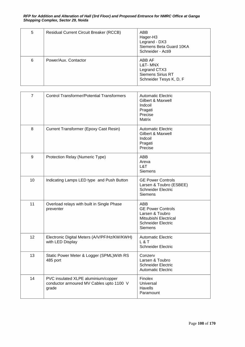
RFP for Addition and Alteration of Hall (3rd Floor) and Proposed Entrance for NMRC Office at Ganga Shopping Complex, Sector 29, Noida
Page 108 of 170
5 Residual Current Circuit Breaker (RCCB) ABB Hager-H3 Legrand - DX3 Siemens Beta Guard 10KA Schneider - Acti9
6 Power/Aux. Contactor ABB AF L&T- MNX Legrand CTX3 Siemens Sirius RT Schneider Tesys K, D, F
7 Control Transformer/Potential Transformers Automatic Electric Gilbert & Maxwell Indcoil Pragati Precise Matrix
8 Current Transformer (Epoxy Cast Resin) Automatic Electric Gilbert & Maxwell Indcoil Pragati Precise
9 Protection Relay (Numeric Type) ABB Areva L&T Siemens
10 Indicating Lamps LED type and Push Button GE Power Controls Larsen & Toubro (ESBEE) Schneider Electric Siemens
11 Overload relays with built in Single Phase preventer
ABB GE Power Controls Larsen & Toubro Mitsubishi Electrical Schneider Electric Siemens
12 Electronic Digital Meters (A/V/PF/Hz/KW/KWH) with LED Display
Automatic Electric L & T Schneider Electric
13 Static Power Meter & Logger (SPML)With RS 485 port
Conzerv Larsen & Toubro Schneider Electric Automatic Electric
14 PVC insulated XLPE aluminium/copper conductor armoured MV Cables upto 1100 V grade
Finolex Universal Havells Paramount
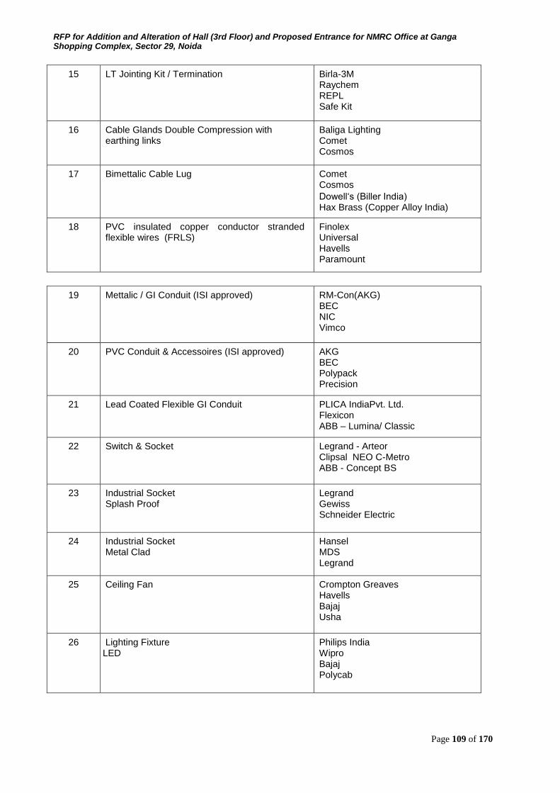
RFP for Addition and Alteration of Hall (3rd Floor) and Proposed Entrance for NMRC Office at Ganga Shopping Complex, Sector 29, Noida
Page 109 of 170
15 LT Jointing Kit / Termination Birla-3M Raychem REPL Safe Kit
16 Cable Glands Double Compression with earthing links
Baliga Lighting Comet Cosmos
17 Bimettalic Cable Lug Comet Cosmos Dowell‘s (Biller India) Hax Brass (Copper Alloy India)
18 PVC insulated copper conductor stranded flexible wires (FRLS)
Finolex Universal Havells Paramount
19 Mettalic / GI Conduit (ISI approved) RM-Con(AKG) BEC NIC Vimco
20 PVC Conduit & Accessoires (ISI approved) AKG BEC Polypack Precision
21 Lead Coated Flexible GI Conduit PLICA IndiaPvt. Ltd. Flexicon ABB – Lumina/ Classic
22 Switch & Socket Legrand - Arteor Clipsal NEO C-Metro ABB - Concept BS
23 Industrial Socket Splash Proof
Legrand Gewiss Schneider Electric
24 Industrial Socket Metal Clad
Hansel MDS Legrand
25 Ceiling Fan Crompton Greaves Havells Bajaj Usha
26 Lighting Fixture LED
Philips India Wipro Bajaj Polycab
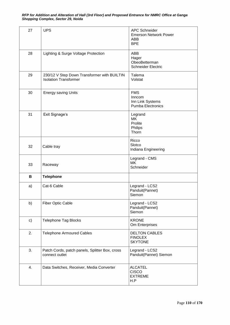
RFP for Addition and Alteration of Hall (3rd Floor) and Proposed Entrance for NMRC Office at Ganga Shopping Complex, Sector 29, Noida
Page 110 of 170
27 UPS APC Schneider Emerson Network Power ABB BPE
28 Lighting & Surge Voltage Protection ABB Hager ObeoBetterman Schneider Electric
29 230/12 V Step Down Transformer with BUILTIN Isolation Transformer
Talema Volstat
30 Energy saving Units FMS Inncom Inn Link Systems Pumba Electronics
31 Exit Signage‘s Legrand MK Prolite Philips Thorn
32 Cable tray
Ricco Slotco Indiana Engineering
33 Raceway
Legrand - CMS MK Schneider
B Telephone
a) Cat-6 Cable Legrand - LCS2 Panduit(Pannet) Siemon
b) Fiber Optic Cable Legrand - LCS2 Panduit(Pannet) Siemon
c) Telephone Tag Blocks KRONE Om Enterprises
2. Telephone Armoured Cables DELTON CABLES FINOLEX SKYTONE
3. Patch Cords, patch panels, Splitter Box, cross connect outlet
Legrand - LCS2 Panduit(Pannet) Siemon
4. Data Switches, Receiver, Media Converter ALCATEL CISCO EXTREME H.P
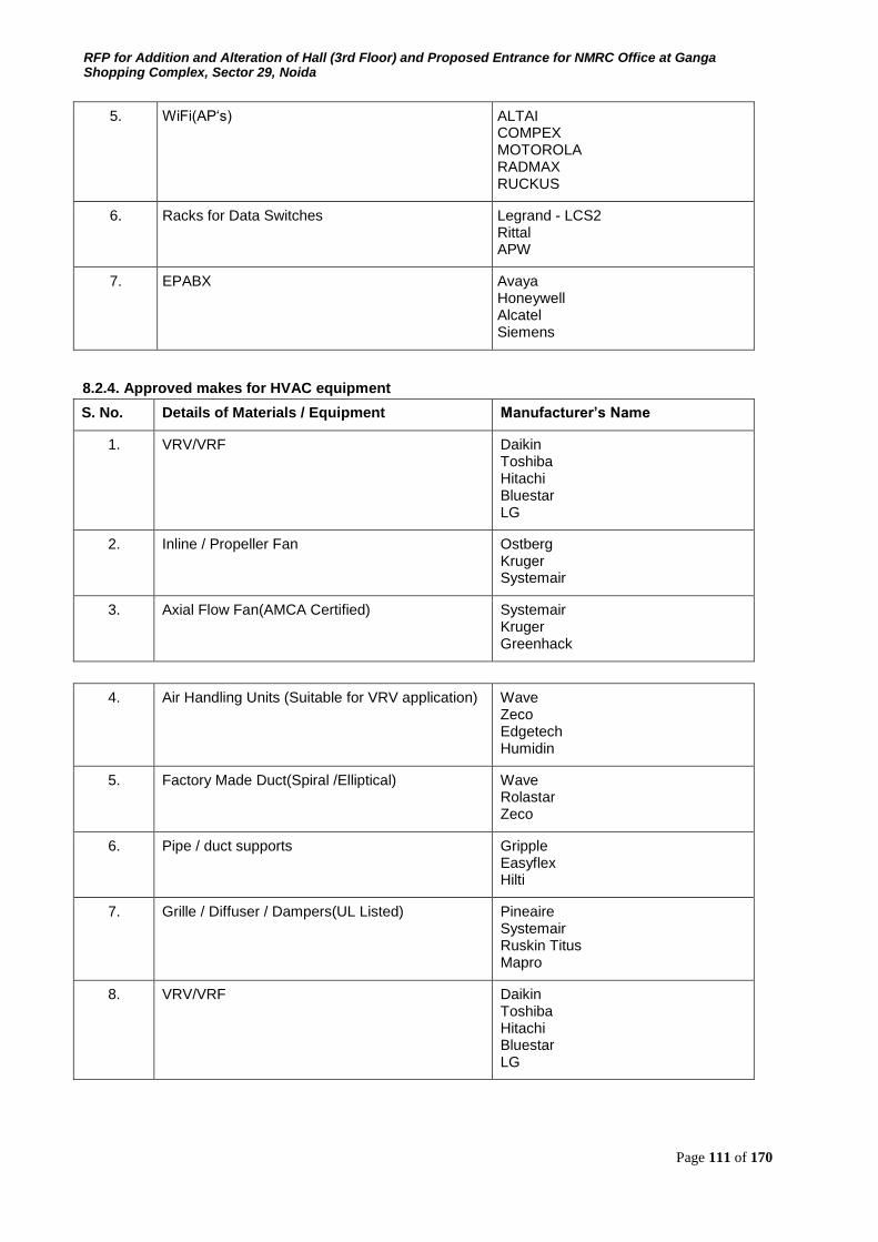
RFP for Addition and Alteration of Hall (3rd Floor) and Proposed Entrance for NMRC Office at Ganga Shopping Complex, Sector 29, Noida
Page 111 of 170
5. WiFi(AP‘s) ALTAI COMPEX MOTOROLA RADMAX RUCKUS
6. Racks for Data Switches Legrand - LCS2 Rittal APW
7. EPABX Avaya Honeywell Alcatel Siemens
8.2.4. Approved makes for HVAC equipment
S. No. Details of Materials / Equipment Manufacturer’s Name
1. VRV/VRF Daikin Toshiba Hitachi Bluestar LG
2. Inline / Propeller Fan Ostberg Kruger Systemair
3. Axial Flow Fan(AMCA Certified) Systemair Kruger Greenhack
4. Air Handling Units (Suitable for VRV application)
Wave Zeco Edgetech Humidin
5. Factory Made Duct(Spiral /Elliptical) Wave Rolastar Zeco
6. Pipe / duct supports
Gripple Easyflex Hilti
7. Grille / Diffuser / Dampers(UL Listed) Pineaire Systemair Ruskin Titus Mapro
8. VRV/VRF Daikin Toshiba Hitachi Bluestar LG
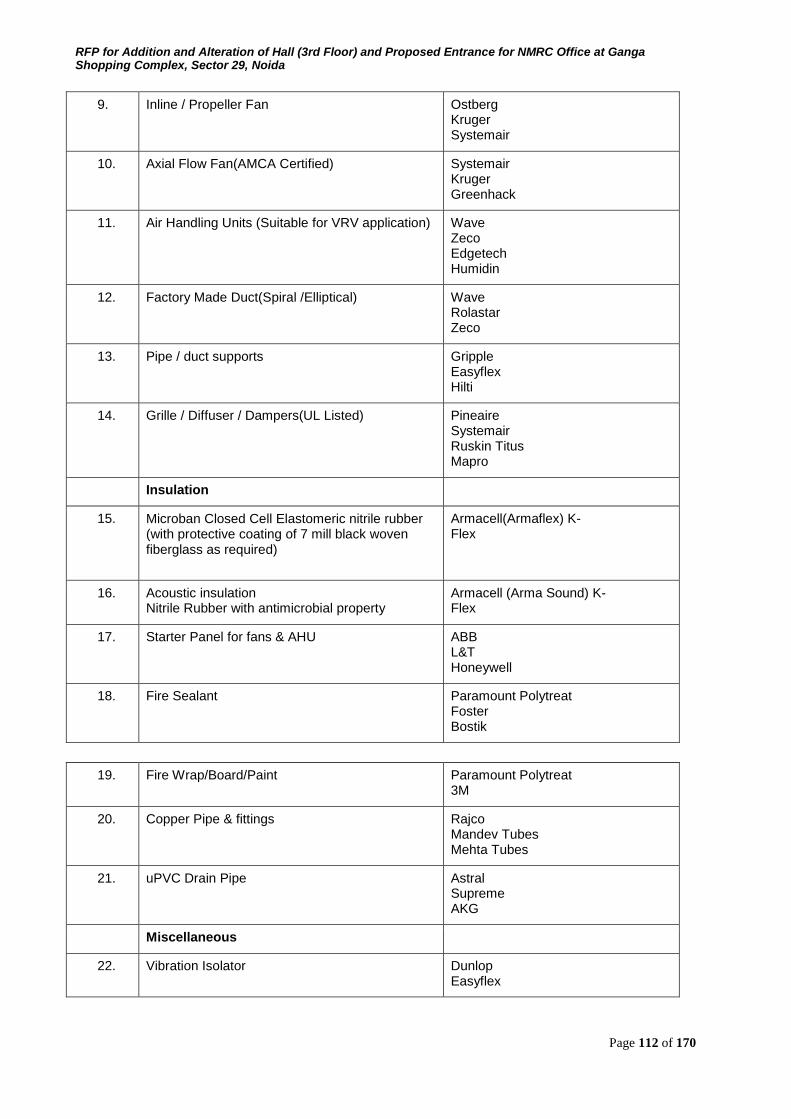
RFP for Addition and Alteration of Hall (3rd Floor) and Proposed Entrance for NMRC Office at Ganga Shopping Complex, Sector 29, Noida
Page 112 of 170
9. Inline / Propeller Fan Ostberg Kruger Systemair
10. Axial Flow Fan(AMCA Certified) Systemair Kruger Greenhack
11. Air Handling Units (Suitable for VRV application) Wave Zeco Edgetech Humidin
12. Factory Made Duct(Spiral /Elliptical) Wave Rolastar Zeco
13. Pipe / duct supports Gripple Easyflex Hilti
14. Grille / Diffuser / Dampers(UL Listed) Pineaire Systemair Ruskin Titus Mapro
Insulation
15. Microban Closed Cell Elastomeric nitrile rubber (with protective coating of 7 mill black woven fiberglass as required)
Armacell(Armaflex) K-Flex
16. Acoustic insulation Nitrile Rubber with antimicrobial property
Armacell (Arma Sound) K-Flex
17. Starter Panel for fans & AHU ABB L&T Honeywell
18. Fire Sealant
Paramount Polytreat Foster Bostik
19. Fire Wrap/Board/Paint Paramount Polytreat 3M
20. Copper Pipe & fittings Rajco Mandev Tubes Mehta Tubes
21. uPVC Drain Pipe Astral Supreme AKG
Miscellaneous
22. Vibration Isolator Dunlop Easyflex

RFP for Addition and Alteration of Hall (3rd Floor) and Proposed Entrance for NMRC Office at Ganga Shopping Complex, Sector 29, Noida
Page 113 of 170
23. Flexible Pipe Connection
Easyflex Pineair
24. Flexible duct connector Pineair Easyflex Ruskin Titus
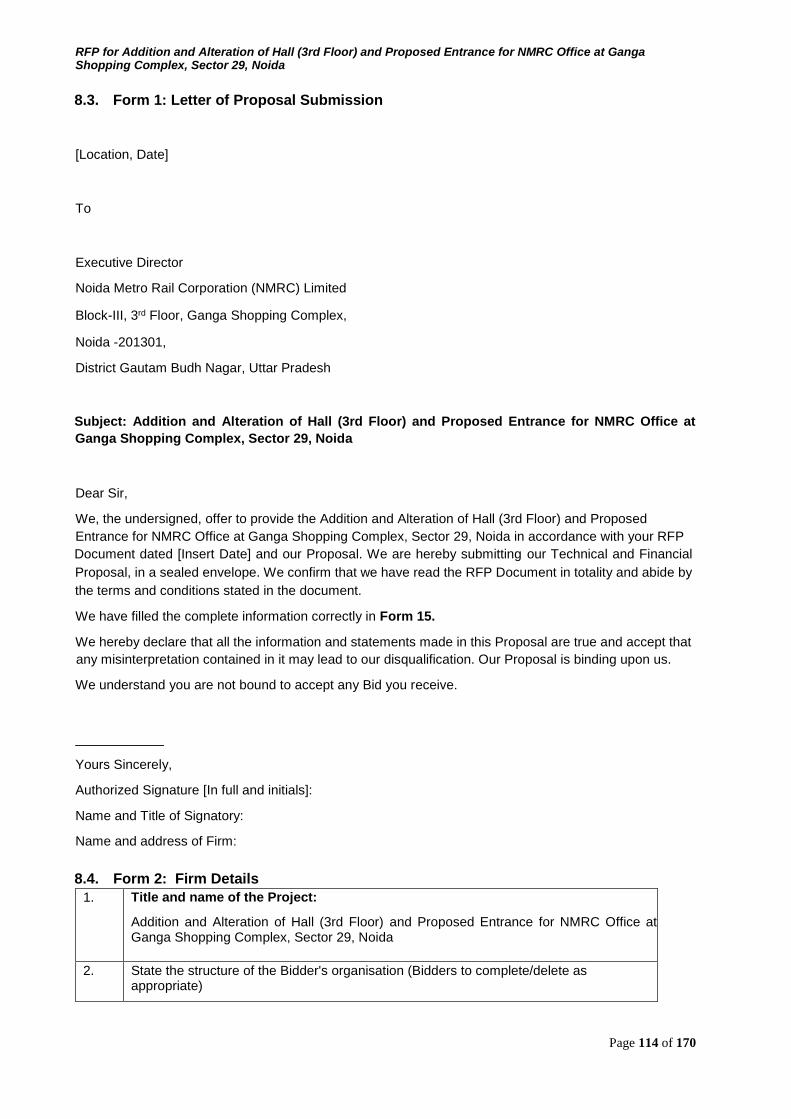
RFP for Addition and Alteration of Hall (3rd Floor) and Proposed Entrance for NMRC Office at Ganga Shopping Complex, Sector 29, Noida
Page 114 of 170
8.3. Form 1: Letter of Proposal Submission
[Location, Date]
To
Executive Director
Noida Metro Rail Corporation (NMRC) Limited
Block-III, 3rd Floor, Ganga Shopping Complex,
Noida -201301,
District Gautam Budh Nagar, Uttar Pradesh
Subject: Addition and Alteration of Hall (3rd Floor) and Proposed Entrance for NMRC Office at
Ganga Shopping Complex, Sector 29, Noida
Dear Sir,
We, the undersigned, offer to provide the Addition and Alteration of Hall (3rd Floor) and Proposed Entrance for NMRC Office at Ganga Shopping Complex, Sector 29, Noida in accordance with your RFP Document dated [Insert Date] and our Proposal. We are hereby submitting our Technical and Financial
Proposal, in a sealed envelope. We confirm that we have read the RFP Document in totality and abide by
the terms and conditions stated in the document.
We have filled the complete information correctly in Form 15.
We hereby declare that all the information and statements made in this Proposal are true and accept that
any misinterpretation contained in it may lead to our disqualification. Our Proposal is binding upon us.
We understand you are not bound to accept any Bid you receive.
____________
Yours Sincerely,
Authorized Signature [In full and initials]:
Name and Title of Signatory:
Name and address of Firm:
8.4. Form 2: Firm Details
1. Title and name of the Project:
Addition and Alteration of Hall (3rd Floor) and Proposed Entrance for NMRC Office at Ganga Shopping Complex, Sector 29, Noida
2. State the structure of the Bidder's organisation (Bidders to complete/delete as appropriate)
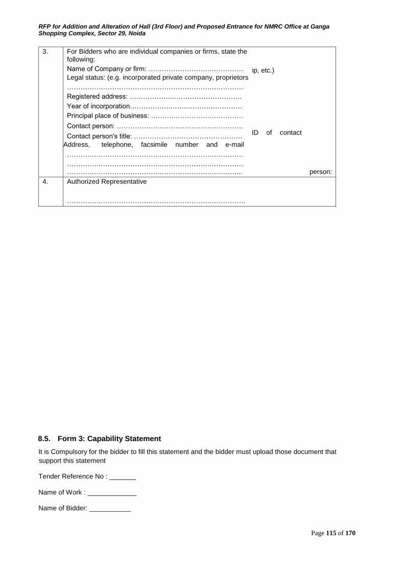
RFP for Addition and Alteration of Hall (3rd Floor) and Proposed Entrance for NMRC Office at Ganga Shopping Complex, Sector 29, Noida
Page 115 of 170
3. For Bidders who are individual companies or firms, state the following:
Name of Company or firm: …………………………………… Legal status: (e.g. incorporated private company, proprietors
……………………………………………………………………
Registered address: ………………..…………………………
Year of incorporation……………….…….……………………
Principal place of business: ……….………………………….
Contact person: ………………………………………………..
Contact person's title: ………………………………………… Address, telephone, facsimile number and e-mail
……………………………………………………………………
…………………………………………………………………… …………………………………………………………………...
hip, etc.)
ID of contact
person:
4. Authorized Representative
…………………………………………………………………….
8.5. Form 3: Capability Statement
It is Compulsory for the bidder to fill this statement and the bidder must upload those document that
support this statement
Tender Reference No : _______
Name of Work : _____________
Name of Bidder: ___________
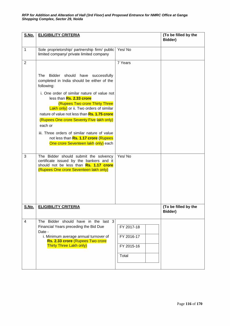
RFP for Addition and Alteration of Hall (3rd Floor) and Proposed Entrance for NMRC Office at Ganga Shopping Complex, Sector 29, Noida
Page 116 of 170
S.No. ELIGIBILITY CRITERIA (To be filled by the Bidder)
1 Sole proprietorship/ partnership firm/ public limited company/ private limited company
Yes/ No
2
The Bidder should have successfully
completed in India should be either of the
following:
i. One order of similar nature of value not
less than Rs. 2.33 crore (Rupees Two crore Thirty Three
Lakh only) or ii. Two orders of similar
nature of value not less than Rs. 1.75 crore
(Rupees One crore Seventy Five lakh only)
each or
iii. Three orders of similar nature of value
not less than Rs. 1.17 crore (Rupees
One crore Seventeen lakh only) each
7 Years
3 The Bidder should submit the solvency certificate issued by the bankers and it should not be less than Rs. 1.17 crore (Rupees One crore Seventeen lakh only)
Yes/ No
S.No. ELIGIBILITY CRITERIA (To be filled by the Bidder)
4 The Bidder should have in the last 3
Financial Years preceding the Bid Due Date -
i. Minimum average annual turnover of Rs. 2.33 crore (Rupees Two crore Thirty Three Lakh only)
FY 2017-18
FY 2016-17
FY 2015-16
Total
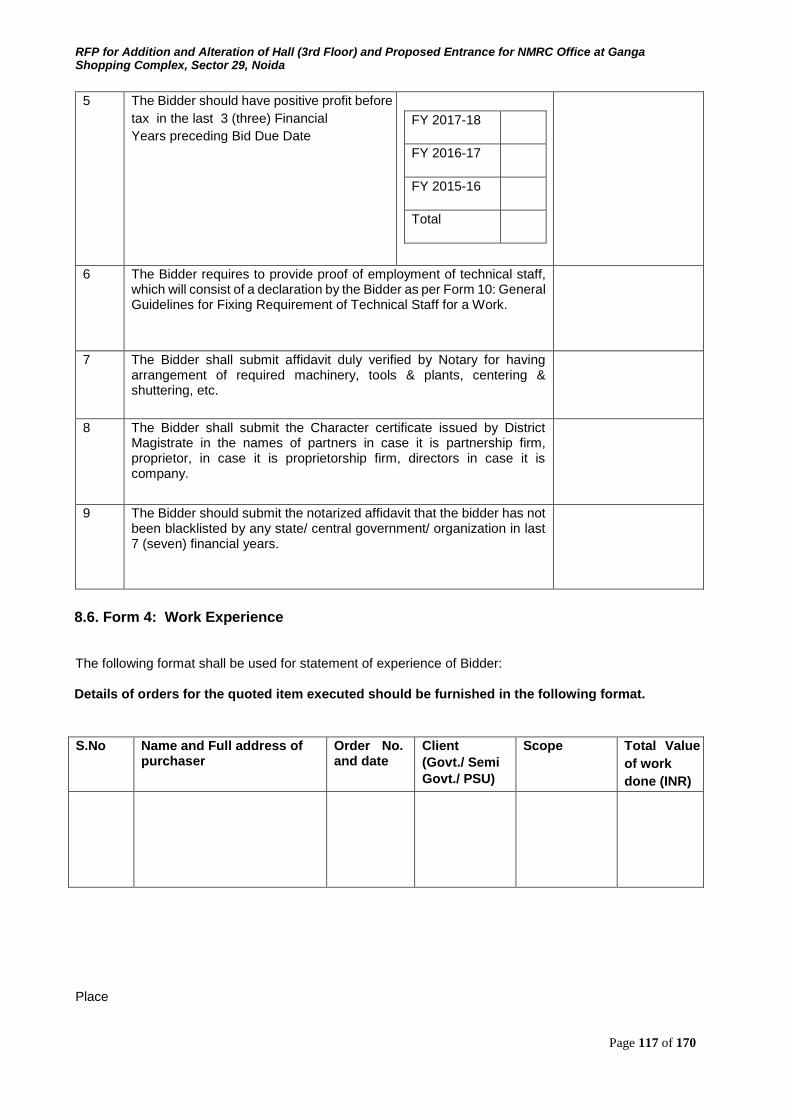
RFP for Addition and Alteration of Hall (3rd Floor) and Proposed Entrance for NMRC Office at Ganga Shopping Complex, Sector 29, Noida
Page 117 of 170
5 The Bidder should have positive profit before
tax in the last 3 (three) Financial Years preceding Bid Due Date
FY 2017-18
FY 2016-17
FY 2015-16
Total
6 The Bidder requires to provide proof of employment of technical staff, which will consist of a declaration by the Bidder as per Form 10: General Guidelines for Fixing Requirement of Technical Staff for a Work.
7 The Bidder shall submit affidavit duly verified by Notary for having arrangement of required machinery, tools & plants, centering & shuttering, etc.
8 The Bidder shall submit the Character certificate issued by District Magistrate in the names of partners in case it is partnership firm, proprietor, in case it is proprietorship firm, directors in case it is company.
9 The Bidder should submit the notarized affidavit that the bidder has not been blacklisted by any state/ central government/ organization in last 7 (seven) financial years.
8.6. Form 4: Work Experience
The following format shall be used for statement of experience of Bidder:
Details of orders for the quoted item executed should be furnished in the following format.
S.No Name and Full address of purchaser
Order No. and date
Client (Govt./ Semi Govt./ PSU)
Scope Total Value
of work done (INR)
Place
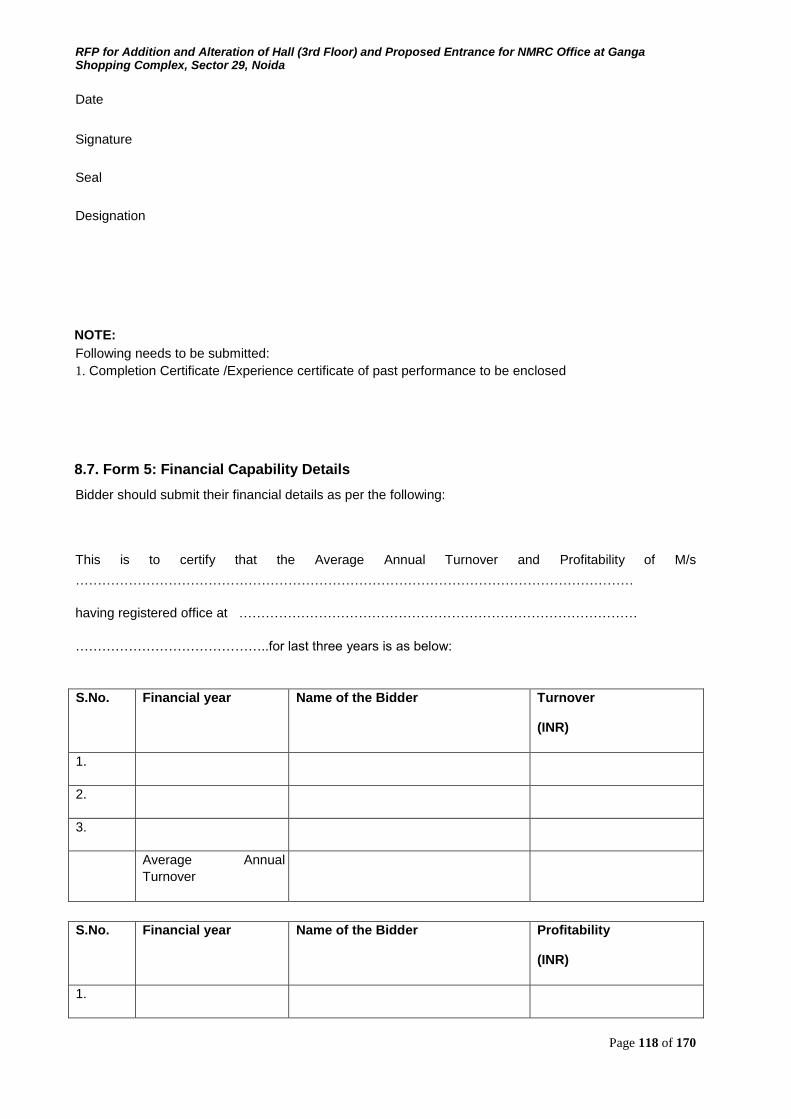
RFP for Addition and Alteration of Hall (3rd Floor) and Proposed Entrance for NMRC Office at Ganga Shopping Complex, Sector 29, Noida
Page 118 of 170
Date
Signature
Seal
Designation
NOTE:
Following needs to be submitted: 1. Completion Certificate /Experience certificate of past performance to be enclosed
8.7. Form 5: Financial Capability Details
Bidder should submit their financial details as per the following:
This is to certify that the Average Annual Turnover and Profitability of M/s
………………………………………………………………………………………………………………
having registered office at ………………………………………………………………………………
……………………………………..for last three years is as below:
S.No. Financial year Name of the Bidder Turnover
(INR)
1.
2.
3.
Average Annual Turnover
S.No. Financial year Name of the Bidder Profitability
(INR)
1.
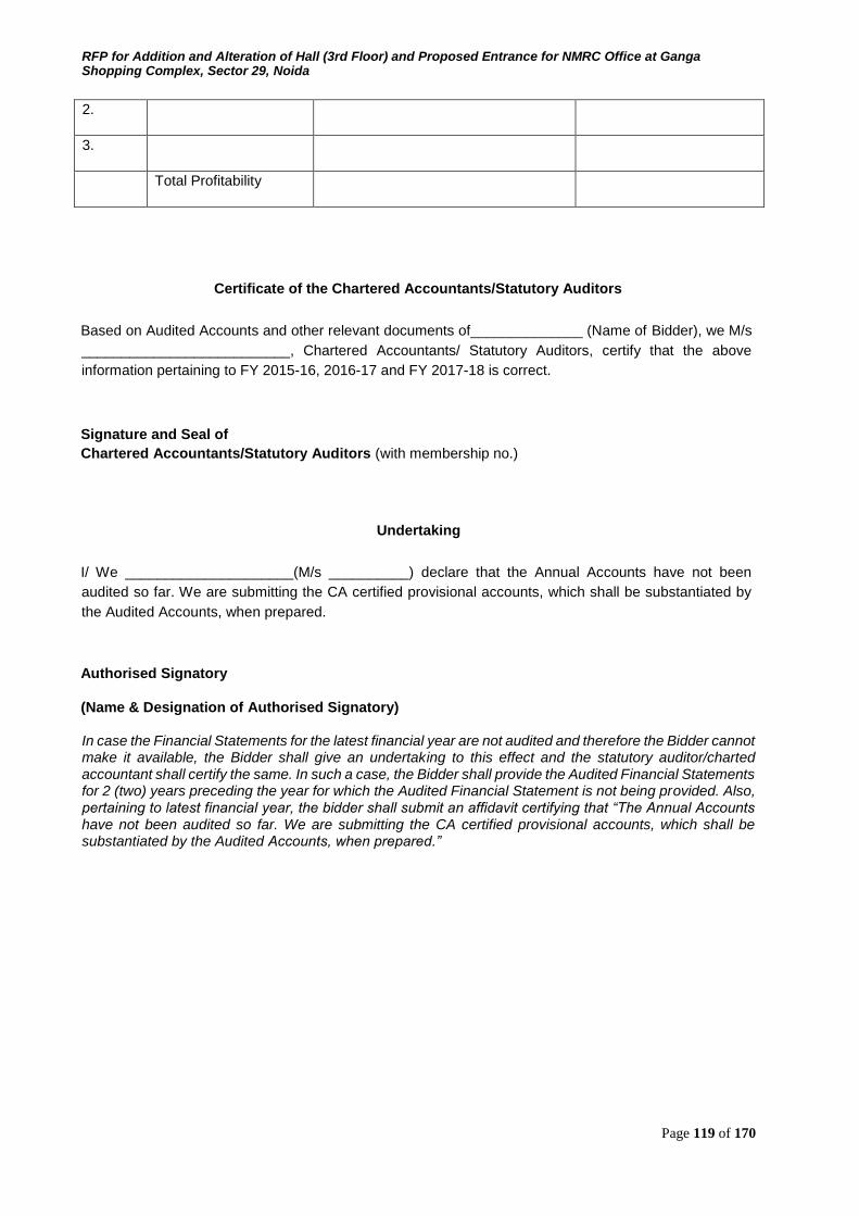
RFP for Addition and Alteration of Hall (3rd Floor) and Proposed Entrance for NMRC Office at Ganga Shopping Complex, Sector 29, Noida
Page 119 of 170
2.
3.
Total Profitability
Certificate of the Chartered Accountants/Statutory Auditors
Based on Audited Accounts and other relevant documents of______________ (Name of Bidder), we M/s
__________________________, Chartered Accountants/ Statutory Auditors, certify that the above
information pertaining to FY 2015-16, 2016-17 and FY 2017-18 is correct.
Signature and Seal of Chartered Accountants/Statutory Auditors (with membership no.)
Undertaking
I/ We _____________________(M/s __________) declare that the Annual Accounts have not been
audited so far. We are submitting the CA certified provisional accounts, which shall be substantiated by
the Audited Accounts, when prepared.
Authorised Signatory
(Name & Designation of Authorised Signatory)
In case the Financial Statements for the latest financial year are not audited and therefore the Bidder cannot make it available, the Bidder shall give an undertaking to this effect and the statutory auditor/charted accountant shall certify the same. In such a case, the Bidder shall provide the Audited Financial Statements for 2 (two) years preceding the year for which the Audited Financial Statement is not being provided. Also, pertaining to latest financial year, the bidder shall submit an affidavit certifying that “The Annual Accounts have not been audited so far. We are submitting the CA certified provisional accounts, which shall be substantiated by the Audited Accounts, when prepared.”
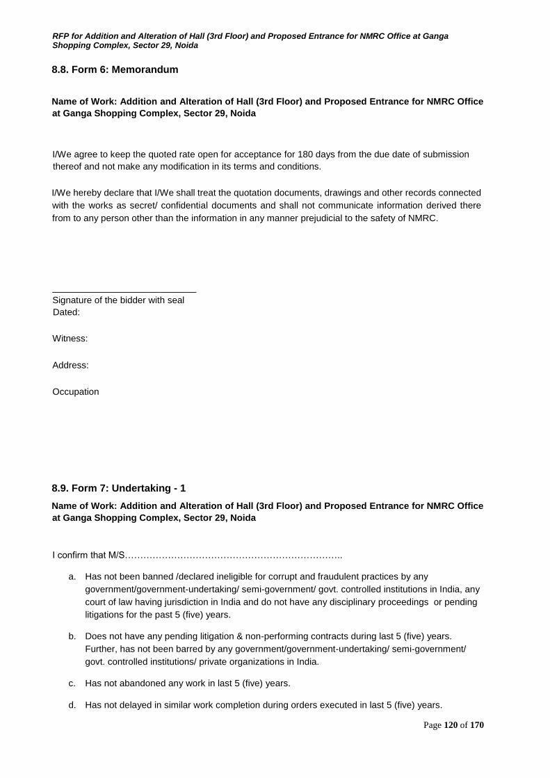
RFP for Addition and Alteration of Hall (3rd Floor) and Proposed Entrance for NMRC Office at Ganga Shopping Complex, Sector 29, Noida
Page 120 of 170
8.8. Form 6: Memorandum
Name of Work: Addition and Alteration of Hall (3rd Floor) and Proposed Entrance for NMRC Office
at Ganga Shopping Complex, Sector 29, Noida
I/We agree to keep the quoted rate open for acceptance for 180 days from the due date of submission
thereof and not make any modification in its terms and conditions.
I/We hereby declare that I/We shall treat the quotation documents, drawings and other records connected
with the works as secret/ confidential documents and shall not communicate information derived there
from to any person other than the information in any manner prejudicial to the safety of NMRC.
____________________________ Signature of the bidder with seal
Dated:
Witness:
Address:
Occupation
8.9. Form 7: Undertaking - 1
Name of Work: Addition and Alteration of Hall (3rd Floor) and Proposed Entrance for NMRC Office
at Ganga Shopping Complex, Sector 29, Noida
I confirm that M/S……………………………………………………………..
a. Has not been banned /declared ineligible for corrupt and fraudulent practices by any
government/government-undertaking/ semi-government/ govt. controlled institutions in India, any
court of law having jurisdiction in India and do not have any disciplinary proceedings or pending
litigations for the past 5 (five) years.
b. Does not have any pending litigation & non-performing contracts during last 5 (five) years.
Further, has not been barred by any government/government-undertaking/ semi-government/
govt. controlled institutions/ private organizations in India.
c. Has not abandoned any work in last 5 (five) years.
d. Has not delayed in similar work completion during orders executed in last 5 (five) years.
RFP for Addition and Alteration of Hall (3rd Floor) and Proposed Entrance for NMRC Office at Ganga Shopping Complex, Sector 29, Noida
Page 121 of 170
e. Does not ever been terminated due to poor performance.
f. Has not suffered Bankruptcy/ insolvency in last 5 (five) years.
g. Has not been blacklisted by any organization.
h. Has not submitted any misleading information in the Bid.
i. Is financially sound to perform the work.
____________________________
Signature of the bidder with seal Dated:
Witness:
Address:
Occupation
8.10. Form 8: Power of Attorney
(To be on non-judicial stamp paper of appropriate value as per Stamp Act relevant to place of
execution.) Power of Attorney to be provided by the Bidding Company in favour of its representative as
evidence of authorized signatory’s authority.
Know all men by these presents, We …………………………………………….(name and address of the
registered office of the Bidding Company) do hereby constitute, appoint and authorize Mr./Ms…………………………………………………(name and residential address) who is presently
employed with us and holding the position of ______, as our Attorney to do in our name and our behalf all
or any of the acts, deeds or things necessary or incidental to submission of our Bid for Addition and
Alteration of Hall (3rd Floor) and Proposed Entrance for NMRC Office at Ganga Shopping Complex,
Sector 29, Noida in response to the RFP Document dated ______ issued by Noida Metro Rail Corporation
(―NMRC‖ or ―the Corporation‖), including signing and submission of the Bid and all other documents
related to the Bid, including but not limited to undertakings, letters, certificates, acceptances, clarifications,
guarantees or any other document which the Corporation may require us to submit. The aforesaid Attorney
is further authorized for making representations to the NMRC or any other authority, and providing
information / responses to the NMRC, representing us in all matters before the NMRC, and generally
dealing with the Corporation in all matters in connection with our Bid till the completion of the bidding
process as per the terms of the RFP Document and further till the Contract is entered into with the NMRC
and thereafter till the expiry of the Contract.
RFP for Addition and Alteration of Hall (3rd Floor) and Proposed Entrance for NMRC Office at Ganga Shopping Complex, Sector 29, Noida
Page 122 of 170
We hereby agree to ratify all acts, deeds and things done by our said attorney pursuant to this Power of
Attorney and that all acts, deeds and things done by our aforesaid attorney shall be binding on us and
shall always be deemed to have been done by us.
All the terms used herein but not defined shall have the meaning ascribed to such terms under the RFP
Document.
Signed by the within named ...........................................[Insert the name of the executant company] through
the hand of
Mr. ………………………………………. duly authorized by the Board to issue such Power of Attorney
Dated this ………………………. day of ………
Accepted
……………………………… Signature of Attorney (Name, designation and address of the Attorney)
Attested
………………………………… (Signature of the executant) (Name, designation and address of the executant)
…………………………………… Signature and stamp of Notary of the place of execution
Common seal of ……………… has been affixed in my/our presence pursuant to Board of Director‘s
Resolution dated…… WITNESS
1. ……………………………………………….
(Signature)
Name ………………………………….
Designation...........…………………..
2. ………………………………………………. (Signature)
Name ………………………………….
Designation...........………………….. Notes:
(1) The mode of execution of the power of attorney should be in accordance with the procedure, if any,
laid down by the applicable law and the charter documents of the executant(s) and the same should
be under common seal of the executant affixed in accordance with the applicable procedure. Further,
the person whose signatures are to be provided on the power of attorney shall be duly authorized by
the executant(s) in this regard.
RFP for Addition and Alteration of Hall (3rd Floor) and Proposed Entrance for NMRC Office at Ganga Shopping Complex, Sector 29, Noida
Page 123 of 170
(2) In the event, power of attorney has been executed outside India, the same needs to be duly notarized
by a notary public of the jurisdiction where it is executed.
(3) Also, wherever required, the executant(s) should submit for verification the extract of the charter
documents and documents such as a board resolution / power of attorney, in favour of the person
executing this power of attorney for delegation of power hereunder on behalf of the executant(s).
8.11. Form 9: Banker’s Solvency Certificate
To
Executive Director
Noida Metro Rail Corporation (NMRC) Limited
Block-III, 3rd Floor, Ganga Shopping Complex,
Noida -201301,
District Gautam Budh Nagar, Uttar Pradesh
SOLVENCY CERTIFICATE
This is to certify that to the best of our knowledge and information M/s. ………………… …………………………………………………………. having a registered office at ………….
…………………………………………………………………………, a customer of our Bank is has been
dealing with us for last ………… years and can be treated solvent up to a limit of INR
……………………………. (Rupees ……………………………………………….), as disclosed by the
information and record which are made available to the Bank.
It is clarified that this information is furnished without any risk and responsibility on our part, or any of
its officials in any respect whatsoever more particularly as a Guarantor or otherwise.
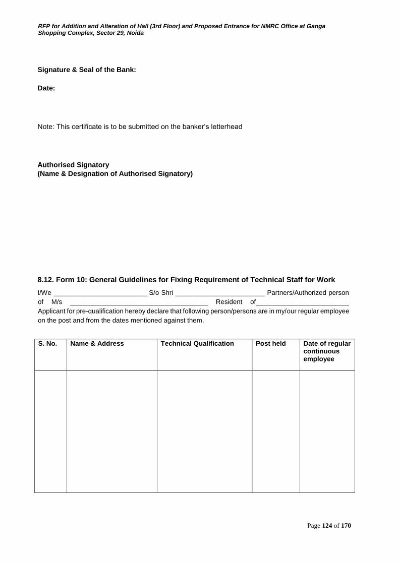
RFP for Addition and Alteration of Hall (3rd Floor) and Proposed Entrance for NMRC Office at Ganga Shopping Complex, Sector 29, Noida
Page 124 of 170
Signature & Seal of the Bank: Date:
Note: This certificate is to be submitted on the banker‘s letterhead
Authorised Signatory (Name & Designation of Authorised Signatory)
8.12. Form 10: General Guidelines for Fixing Requirement of Technical Staff for Work
I/We _________________________ S/o Shri ________________________ Partners/Authorized person
of M/s _____________________________________ Resident of_________________________
Applicant for pre-qualification hereby declare that following person/persons are in my/our regular employee
on the post and from the dates mentioned against them.
S. No. Name & Address Technical Qualification Post held Date of regular continuous employee
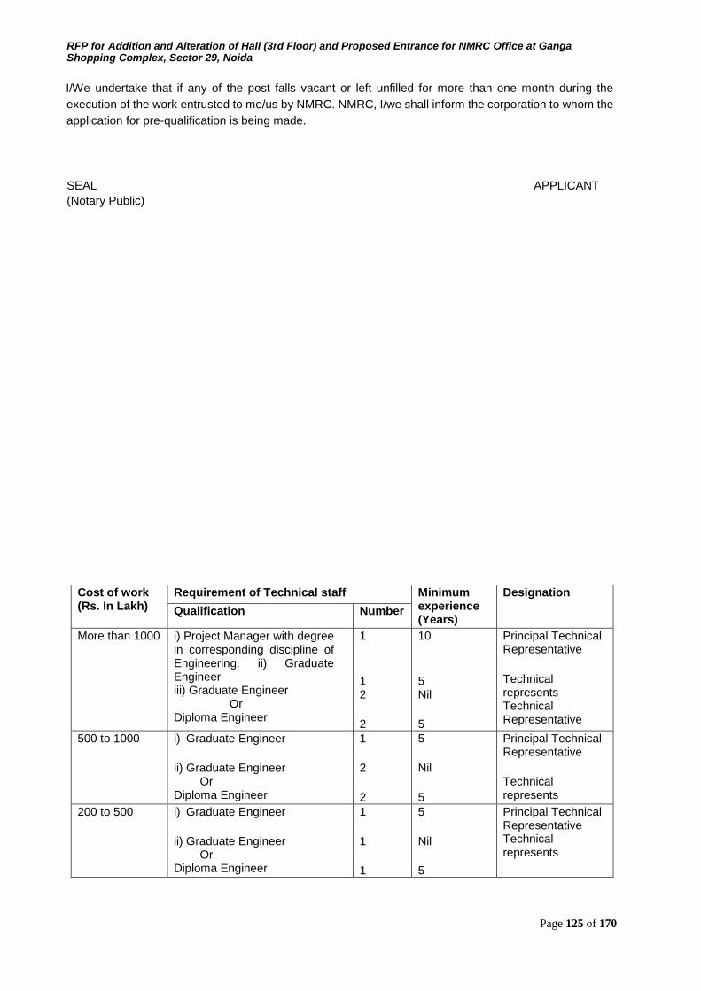
RFP for Addition and Alteration of Hall (3rd Floor) and Proposed Entrance for NMRC Office at Ganga Shopping Complex, Sector 29, Noida
Page 125 of 170
I/We undertake that if any of the post falls vacant or left unfilled for more than one month during the
execution of the work entrusted to me/us by NMRC. NMRC, I/we shall inform the corporation to whom the
application for pre-qualification is being made.
SEAL APPLICANT (Notary Public)
Cost of work (Rs. In Lakh)
Requirement of Technical staff Minimum experience (Years)
Designation
Qualification Number
More than 1000 i) Project Manager with degree in corresponding discipline of Engineering. ii) Graduate Engineer iii) Graduate Engineer Or Diploma Engineer
1 1 2 2
10 5 Nil 5
Principal Technical Representative Technical represents Technical Representative
500 to 1000 i) Graduate Engineer ii) Graduate Engineer Or Diploma Engineer
1 2 2
5 Nil 5
Principal Technical Representative Technical represents
200 to 500 i) Graduate Engineer ii) Graduate Engineer Or Diploma Engineer
1 1 1
5 Nil 5
Principal Technical Representative Technical represents
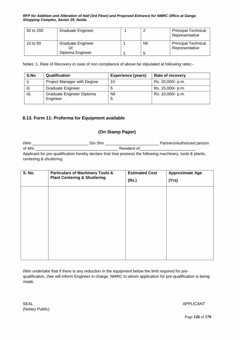
RFP for Addition and Alteration of Hall (3rd Floor) and Proposed Entrance for NMRC Office at Ganga Shopping Complex, Sector 29, Noida
Page 126 of 170
50 to 200 Graduate Engineer 1 2 Principal Technical Representative
10 to 50 Graduate Engineer Or Diploma Engineer
1 1
Nil 5
Principal Technical Representative
Notes: 1. Rate of Recovery in case of non compliance of above be stipulated at following rates:-
S.No Qualification Experience (years) Rate of recovery
i) Project Manager with Degree 10 Rs. 20,000/- p.m.
ii) Graduate Engineer 5 Rs. 15,000/- p.m.
iii) Graduate Engineer Diploma Engineer
Nil 5
Rs. 10,000/- p.m.
8.13. Form 11: Proforma for Equipment available
(On Stamp Paper)
I/We _________________________ S/o Shri ________________________ Partners/Authorized person
of M/s _____________________________________ Resident of_________________________ Applicant for pre-qualification hereby declare that I/we possess the following machinery, tools & plants,
centering & shuttering.
S. No. Particulars of Machinery Tools & Plant Centering & Shuttering
Estimated Cost
(Rs.)
Approximate Age
(Yrs)
I/We undertake that if there is any reduction in the equipment below the limit required for pre-
qualification, I/we will inform Engineer in charge, NMRC to whom application for pre-qualification is being
made.
SEAL APPLICANT (Notary Public)
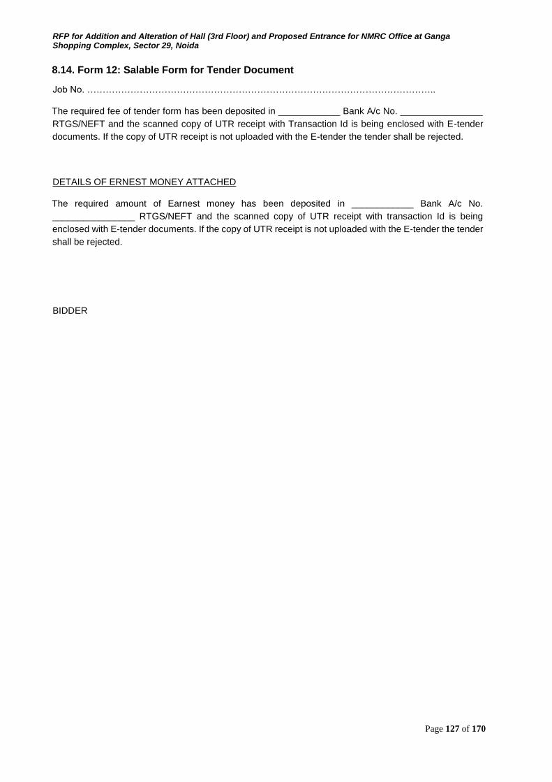
RFP for Addition and Alteration of Hall (3rd Floor) and Proposed Entrance for NMRC Office at Ganga Shopping Complex, Sector 29, Noida
Page 127 of 170
8.14. Form 12: Salable Form for Tender Document
Job No. …………………………………………………………………………………………………..
The required fee of tender form has been deposited in ____________ Bank A/c No. ________________
RTGS/NEFT and the scanned copy of UTR receipt with Transaction Id is being enclosed with E-tender
documents. If the copy of UTR receipt is not uploaded with the E-tender the tender shall be rejected.
DETAILS OF ERNEST MONEY ATTACHED
The required amount of Earnest money has been deposited in ____________ Bank A/c No.
________________ RTGS/NEFT and the scanned copy of UTR receipt with transaction Id is being
enclosed with E-tender documents. If the copy of UTR receipt is not uploaded with the E-tender the tender
shall be rejected.
BIDDER
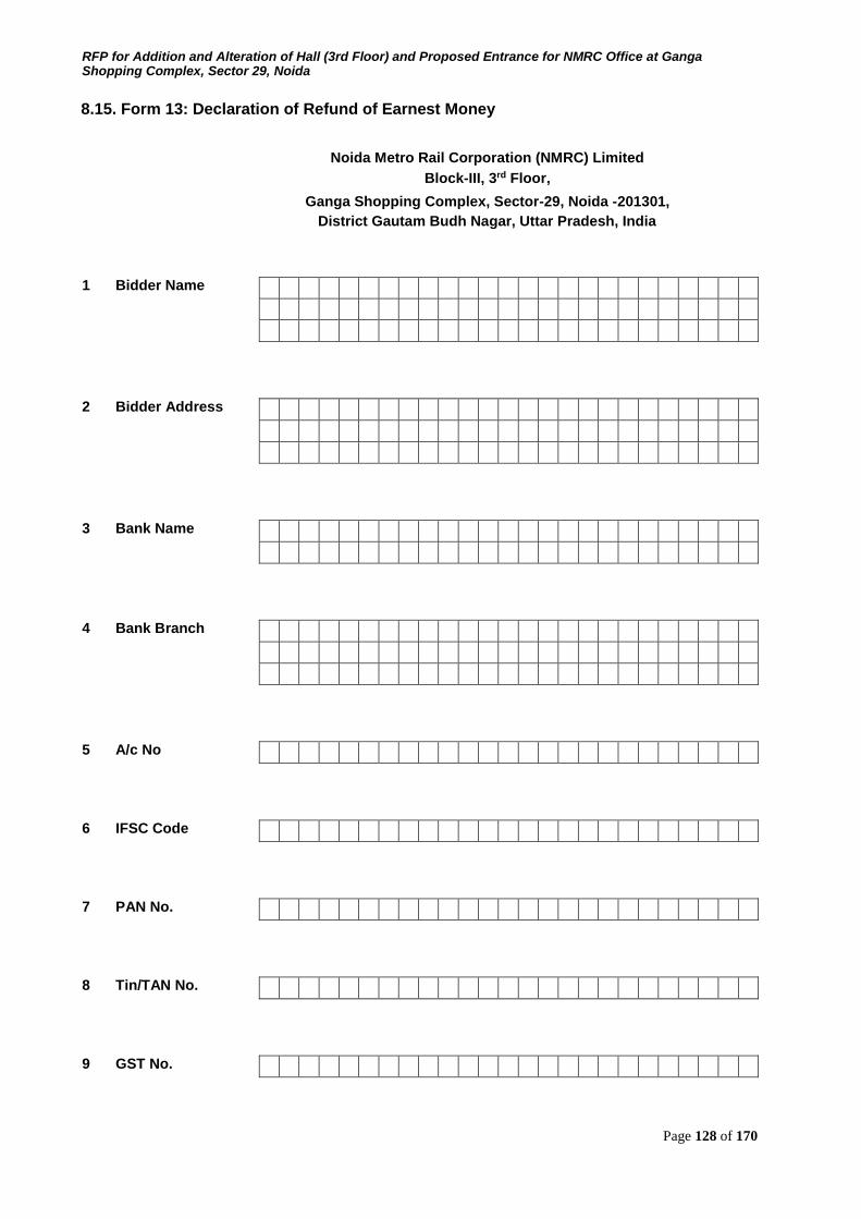
RFP for Addition and Alteration of Hall (3rd Floor) and Proposed Entrance for NMRC Office at Ganga Shopping Complex, Sector 29, Noida
Page 128 of 170
8.15. Form 13: Declaration of Refund of Earnest Money
Noida Metro Rail Corporation (NMRC) Limited
Block-III, 3rd Floor,
Ganga Shopping Complex, Sector-29, Noida -201301, District Gautam Budh Nagar, Uttar Pradesh, India
1 Bidder Name
2 Bidder Address
3 Bank Name
4 Bank Branch
5 A/c No
6 IFSC Code
7 PAN No.
8 Tin/TAN No.
9 GST No.
RFP for Addition and Alteration of Hall (3rd Floor) and Proposed Entrance for NMRC Office at Ganga Shopping Complex, Sector 29, Noida
Page 129 of 170
10 Phone No.
11 Mobile No.
12 Email-Id
For Office Use Only 13 Party Unique Id
The above provided information is true to the best of my knowledge.
Date: Signature with Stamp/Seal
8.16. Form 14: Bid Offer/ BOQ (Format)
To
Executive Director
Noida Metro Rail Corporation (NMRC) Limited
Block-III, 3rd Floor, Ganga Shopping Complex
Noida -201301,
District Gautam Budh Nagar, Uttar Pradesh
THIS FORM IS NOT TO BE FILLED. THE BIDDERS ARE REQUIRED TO FILL THE FINANCIAL PROPOSAL IN XLS FORMAT AFTER DOWNLOADING THE FORM FROM THE E-PROCUREMENT
WEBSITE FOR THIS TENDER DOCUMENT
Sub: Addition and Alteration of Hall (3rd Floor) and Proposed Entrance for NMRC Office at Ganga
Shopping Complex, Sector 29, Noida
Dear Sir,
I/we have read and examined the RFP document, general terms and conditions.
I/we hereby quote for the Total Price for Addition and Alteration of Hall (3rd Floor) and Proposed
Entrance for NMRC Office at Ganga Shopping Complex, Sector 29, Noida as specified below, payable
by NMRC.

RFP for Addition and Alteration of Hall (3rd Floor) and Proposed Entrance for NMRC Office at Ganga Shopping Complex, Sector 29, Noida
Page 130 of 170
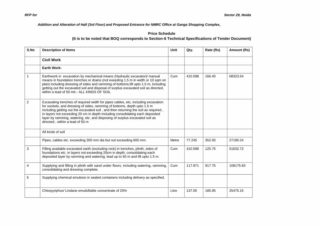
RFP for Sector 29, Noida
Addition and Alteration of Hall (3rd Floor) and Proposed Entrance for NMRC Office at Ganga Shopping Complex,
Price Schedule (It is to be noted that BOQ corresponds to Section-6 Technical Specifications of Tender Document)
S.No Description of Items Unit Qty. Rate (Rs) Amount (Rs)
Civil Work
Earth Work-
1 Earthwork in excavation by mechanical means (Hydraulic excavator)/ manual means in foundation trenches or drains (not exeeding 1.5 m in width or 10 sqm on plan) including dressing of sides and ramming of bottoms,lift upto 1.5 m, including getting out the excavated soil and disposal of surplus excavated soil as directed, within a lead of 50 mtr.- ALL KINDS OF SOIL
Cum 410.598 166.40 68323.54
2 Excavating trenches of required width for pipes cables, etc, including excavation for sockets, and dressing of sides, ramming of bottoms, depth upto 1.5 m including getting out the excavated soil , and then returning the soil as required , in layers not exceeding 20 cm in depth including consolidating each deposited layer by ramming, watering, etc. and disposing of surplus excavated soil as directed , within a lead of 50 m
All kinds of soil
Pipes, cables etc. exceeding 300 mm dia but not exceeding 600 mm. Metre 77.245 352.00 27190.24
3 Filling available excavated earth (excluding rock) in trenches, plinth, sides of foundations etc. in layers not exceeding 20cm in depth, consolidating each deposited layer by ramming and watering, lead up to 50 m and lift upto 1.5 m.
Cum 410.598 125.75 51632.72
4 Supplying and filling in plinth with sand under floors, including watering, ramming, consolidating and dressing complete.
Cum 117.871 917.75 108175.83
5 Supplying chemical emulsion in sealed containers including delivery as specified.
Chlorpyriphos/ Lindane emulsifiable concentrate of 20% Litre 137.00 185.95 25475.15
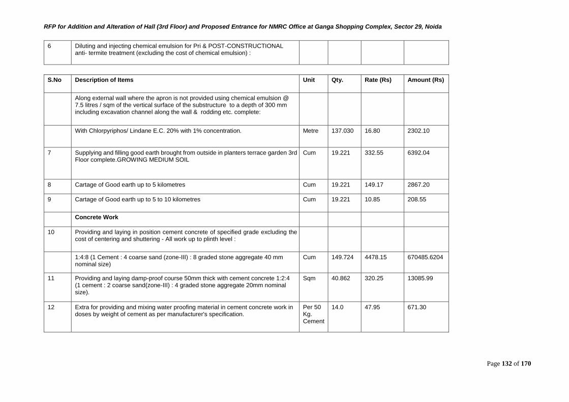
RFP for Addition and Alteration of Hall (3rd Floor) and Proposed Entrance for NMRC Office at Ganga Shopping Complex, Sector 29, Noida
Page 132 of 170
6 Diluting and injecting chemical emulsion for Pri & POST-CONSTRUCTIONAL anti- termite treatment (excluding the cost of chemical emulsion) :
S.No Description of Items Unit Qty. Rate (Rs) Amount (Rs)
Along external wall where the apron is not provided using chemical emulsion @ 7.5 litres / sqm of the vertical surface of the substructure to a depth of 300 mm including excavation channel along the wall & rodding etc. complete:
With Chlorpyriphos/ Lindane E.C. 20% with 1% concentration. Metre 137.030 16.80 2302.10
7 Supplying and filling good earth brought from outside in planters terrace garden 3rd Floor complete.GROWING MEDIUM SOIL
Cum 19.221 332.55 6392.04
8 Cartage of Good earth up to 5 kilometres Cum 19.221 149.17 2867.20
9 Cartage of Good earth up to 5 to 10 kilometres Cum 19.221 10.85 208.55
Concrete Work
10 Providing and laying in position cement concrete of specified grade excluding the cost of centering and shuttering - All work up to plinth level :
1:4:8 (1 Cement : 4 coarse sand (zone-III) : 8 graded stone aggregate 40 mm nominal size)
Cum 149.724 4478.15 670485.6204
11 Providing and laying damp-proof course 50mm thick with cement concrete 1:2:4 (1 cement : 2 coarse sand(zone-III) : 4 graded stone aggregate 20mm nominal size).
Sqm 40.862 320.25 13085.99
12 Extra for providing and mixing water proofing material in cement concrete work in doses by weight of cement as per manufacturer's specification.
Per 50 Kg. Cement
14.0 47.95 671.30
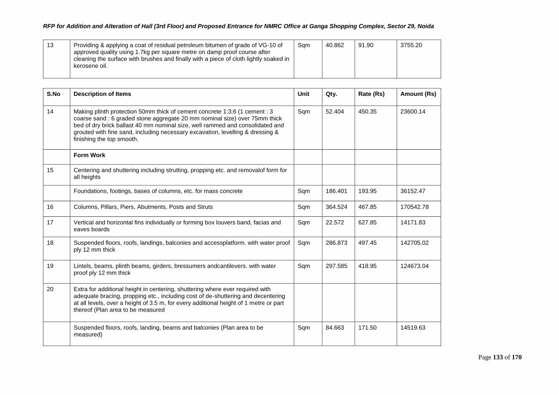
RFP for Addition and Alteration of Hall (3rd Floor) and Proposed Entrance for NMRC Office at Ganga Shopping Complex, Sector 29, Noida
Page 133 of 170
13 Providing & applying a coat of residual petroleum bitumen of grade of VG-10 of approved quality using 1.7kg per square metre on damp proof course after cleaning the surface with brushes and finally with a piece of cloth lightly soaked in kerosene oil.
Sqm 40.862 91.90 3755.20
S.No Description of Items Unit Qty. Rate (Rs) Amount (Rs)
14 Making plinth protection 50mm thick of cement concrete 1:3:6 (1 cement : 3 coarse sand : 6 graded stone aggregate 20 mm nominal size) over 75mm thick bed of dry brick ballast 40 mm nominal size, well rammed and consolidated and grouted with fine sand, including necessary excavation, levelling & dressing & finishing the top smooth.
Sqm 52.404 450.35 23600.14
Form Work
15 Centering and shuttering including strutting, propping etc. and removalof form for all heights
Foundations, footings, bases of columns, etc. for mass concrete Sqm 186.401 193.95 36152.47
16 Columns, Pillars, Piers, Abutments, Posts and Struts Sqm 364.524 467.85 170542.78
17 Vertical and horizontal fins individually or forming box louvers band, facias and eaves boards
Sqm 22.572 627.85 14171.83
18 Suspended floors, roofs, landings, balconies and accessplatform. with water proof ply 12 mm thick
Sqm 286.873 497.45 142705.02
19 Lintels, beams, plinth beams, girders, bressumers andcantilevers. with water proof ply 12 mm thick
Sqm 297.585 418.95 124673.04
20 Extra for additional height in centering, shuttering where ever required with adequate bracing, propping etc., including cost of de-shuttering and decentering at all levels, over a height of 3.5 m, for every additional height of 1 metre or part thereof (Plan area to be measured
Suspended floors, roofs, landing, beams and balconies (Plan area to be measured)
Sqm 84.663 171.50 14519.63
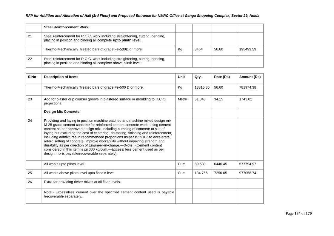
RFP for Addition and Alteration of Hall (3rd Floor) and Proposed Entrance for NMRC Office at Ganga Shopping Complex, Sector 29, Noida
Page 134 of 170
Steel Reinforcement Work.
21 Steel reinforcement for R.C.C. work including straightening, cutting, bending, placing in position and binding all complete upto plinth level.
Thermo-Mechanically Treated bars of grade Fe-500D or more. Kg 3454 56.60 195493.59
22 Steel reinforcement for R.C.C. work including straightening, cutting, bending, placing in position and binding all complete above plinth level.
S.No Description of Items Unit Qty. Rate (Rs) Amount (Rs)
Thermo-Mechanically Treated bars of grade Fe-500 D or more. Kg 13815.80 56.60 781974.38
23 Add for plaster drip course/ groove in plastered surface or moulding to R.C.C. projections.
Metre 51.040 34.15 1743.02
Design Mix Concrete.
24 Providing and laying in position machine batched and machine mixed design mix M-25 grade cement concrete for reinforced cement concrete work, using cement content as per approved design mix, including pumping of concrete to site of laying but excluding the cost of centering, shuttering, finishing and reinforcement, including admixtures in recommended proportions as per IS: 9103 to accelerate, retard setting of concrete, improve workability without impairing strength and durability as per direction of Engineer-in-charge.―(Note :- Cement content considered in this item is @ 330 kg/cum.―Excess/ less cement used as per design mix is payable/recoverable separately).
All works upto plinth level Cum 89.630 6446.45 577794.97
25 All works above plinth level upto floor V level Cum 134.766 7250.05 977058.74
26 Extra for providing richer mixes at all floor levels.
Note:- Excess/less cement over the specified cement content used is payable /recoverable separately.
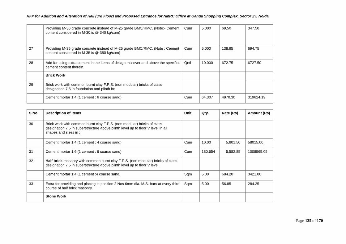
RFP for Addition and Alteration of Hall (3rd Floor) and Proposed Entrance for NMRC Office at Ganga Shopping Complex, Sector 29, Noida
Page 135 of 170
Providing M-30 grade concrete instead of M-25 grade BMC/RMC. (Note:- Cement content considered in M-30 is @ 340 kg/cum)
Cum 5.000 69.50 347.50
27 Providing M-35 grade concrete instead of M-25 grade BMC/RMC. (Note : Cement content considered in M-35 is @ 350 kg/cum)
Cum 5.000 138.95 694.75
28 Add for using extra cement in the items of design mix over and above the specified cement content therein.
Qntl 10.000 672.75 6727.50
Brick Work
29 Brick work with common burnt clay F.P.S. (non modular) bricks of class designation 7.5 in foundation and plinth in:
Cement mortar 1:4 (1 cement : 6 coarse sand) Cum 64.307 4970.30 319624.19
S.No Description of Items Unit Qty. Rate (Rs) Amount (Rs)
30 Brick work with common burnt clay F.P.S. (non modular) bricks of class designation 7.5 in superstructure above plinth level up to floor V level in all shapes and sizes in :
Cement mortar 1:4 (1 cement : 4 coarse sand) Cum 10.00 5,801.50 58015.00
31 Cement mortar 1:6 (1 cement : 6 coarse sand) Cum 180.654 5,582.85 1008565.05
32 Half brick masonry with common burnt clay F.P.S. (non modular) bricks of class
designation 7.5 in superstructure above plinth level up to floor V level.
Cement mortar 1:4 (1 cement :4 coarse sand) Sqm 5.00 684.20 3421.00
33 Extra for providing and placing in position 2 Nos 6mm dia. M.S. bars at every third course of half brick masonry.
Sqm 5.00 56.85 284.25
Stone Work
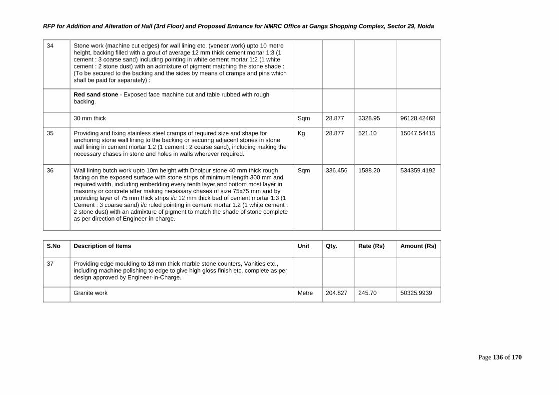
RFP for Addition and Alteration of Hall (3rd Floor) and Proposed Entrance for NMRC Office at Ganga Shopping Complex, Sector 29, Noida
Page 136 of 170
34 Stone work (machine cut edges) for wall lining etc. (veneer work) upto 10 metre height, backing filled with a grout of average 12 mm thick cement mortar 1:3 (1 cement : 3 coarse sand) including pointing in white cement mortar 1:2 (1 white cement : 2 stone dust) with an admixture of pigment matching the stone shade : (To be secured to the backing and the sides by means of cramps and pins which shall be paid for separately) :
Red sand stone - Exposed face machine cut and table rubbed with rough
backing.
30 mm thick Sqm 28.877 3328.95 96128.42468
35 Providing and fixing stainless steel cramps of required size and shape for anchoring stone wall lining to the backing or securing adjacent stones in stone wall lining in cement mortar 1:2 (1 cement : 2 coarse sand), including making the necessary chases in stone and holes in walls wherever required.
Kg 28.877 521.10 15047.54415
36 Wall lining butch work upto 10m height with Dholpur stone 40 mm thick rough facing on the exposed surface with stone strips of minimum length 300 mm and required width, including embedding every tenth layer and bottom most layer in masonry or concrete after making necessary chases of size 75x75 mm and by providing layer of 75 mm thick strips i/c 12 mm thick bed of cement mortar 1:3 (1 Cement : 3 coarse sand) i/c ruled pointing in cement mortar 1:2 (1 white cement : 2 stone dust) with an admixture of pigment to match the shade of stone complete as per direction of Engineer-in-charge.
Sqm 336.456 1588.20 534359.4192
S.No Description of Items Unit Qty. Rate (Rs) Amount (Rs)
37 Providing edge moulding to 18 mm thick marble stone counters, Vanities etc., including machine polishing to edge to give high gloss finish etc. complete as per design approved by Engineer-in-Charge.
Granite work Metre 204.827 245.70 50325.9939
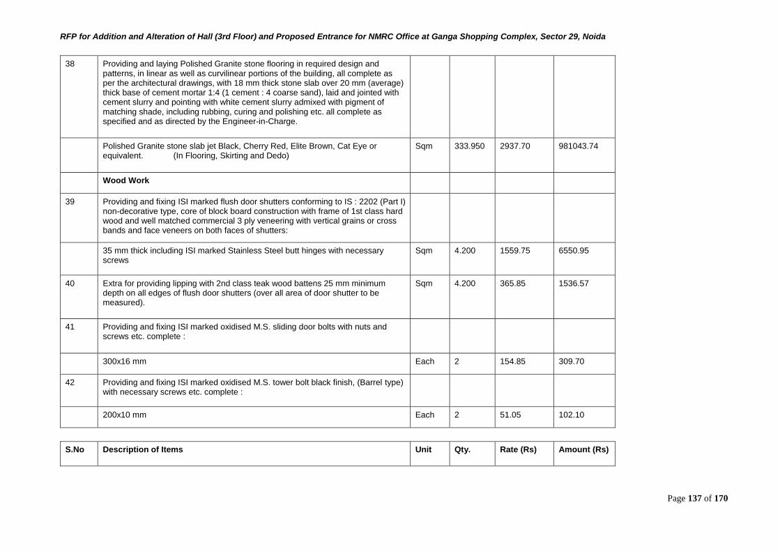
RFP for Addition and Alteration of Hall (3rd Floor) and Proposed Entrance for NMRC Office at Ganga Shopping Complex, Sector 29, Noida
Page 137 of 170
38 Providing and laying Polished Granite stone flooring in required design and patterns, in linear as well as curvilinear portions of the building, all complete as per the architectural drawings, with 18 mm thick stone slab over 20 mm (average) thick base of cement mortar 1:4 (1 cement : 4 coarse sand), laid and jointed with cement slurry and pointing with white cement slurry admixed with pigment of matching shade, including rubbing, curing and polishing etc. all complete as specified and as directed by the Engineer-in-Charge.
Polished Granite stone slab jet Black, Cherry Red, Elite Brown, Cat Eye or equivalent. (In Flooring, Skirting and Dedo)
Sqm 333.950 2937.70 981043.74
Wood Work
39 Providing and fixing ISI marked flush door shutters conforming to IS : 2202 (Part I) non-decorative type, core of block board construction with frame of 1st class hard wood and well matched commercial 3 ply veneering with vertical grains or cross bands and face veneers on both faces of shutters:
35 mm thick including ISI marked Stainless Steel butt hinges with necessary screws
Sqm 4.200 1559.75 6550.95
40 Extra for providing lipping with 2nd class teak wood battens 25 mm minimum depth on all edges of flush door shutters (over all area of door shutter to be measured).
Sqm 4.200 365.85 1536.57
41 Providing and fixing ISI marked oxidised M.S. sliding door bolts with nuts and screws etc. complete :
300x16 mm Each 2 154.85 309.70
42 Providing and fixing ISI marked oxidised M.S. tower bolt black finish, (Barrel type) with necessary screws etc. complete :
200x10 mm Each 2 51.05 102.10
S.No Description of Items Unit Qty. Rate (Rs) Amount (Rs)
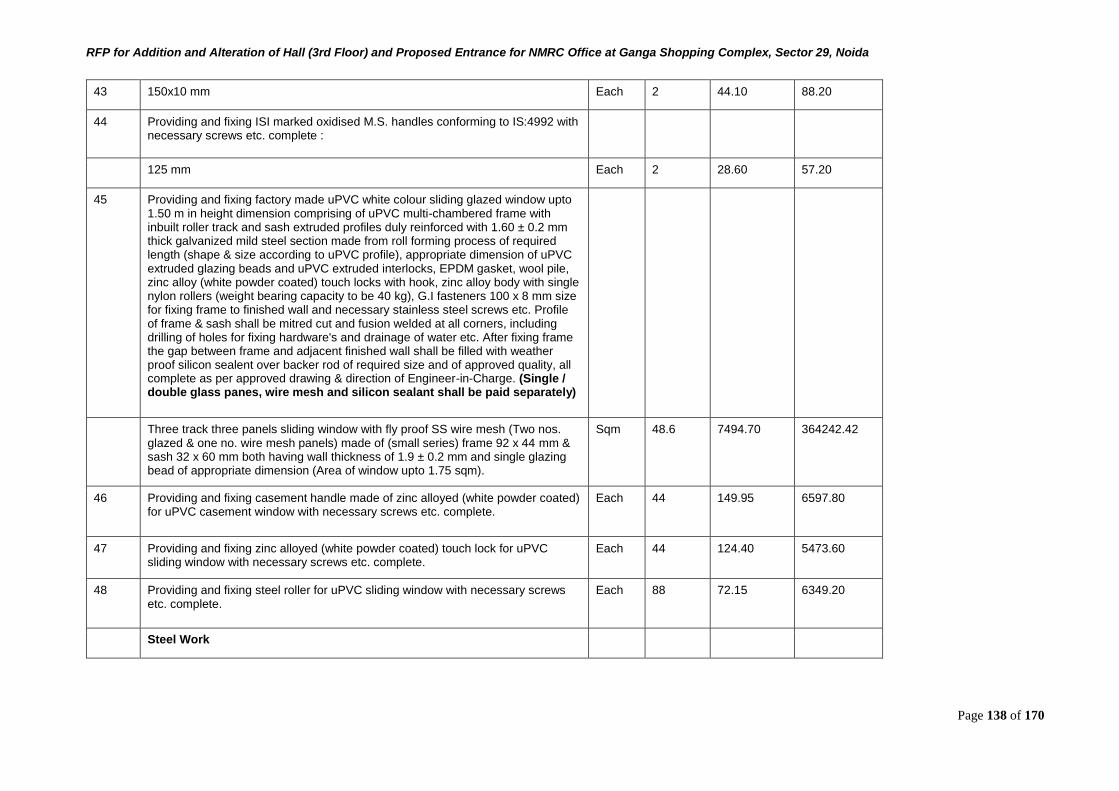
RFP for Addition and Alteration of Hall (3rd Floor) and Proposed Entrance for NMRC Office at Ganga Shopping Complex, Sector 29, Noida
Page 138 of 170
43 150x10 mm Each 2 44.10 88.20
44 Providing and fixing ISI marked oxidised M.S. handles conforming to IS:4992 with necessary screws etc. complete :
125 mm Each 2 28.60 57.20
45 Providing and fixing factory made uPVC white colour sliding glazed window upto 1.50 m in height dimension comprising of uPVC multi-chambered frame with inbuilt roller track and sash extruded profiles duly reinforced with 1.60 ± 0.2 mm thick galvanized mild steel section made from roll forming process of required length (shape & size according to uPVC profile), appropriate dimension of uPVC extruded glazing beads and uPVC extruded interlocks, EPDM gasket, wool pile, zinc alloy (white powder coated) touch locks with hook, zinc alloy body with single nylon rollers (weight bearing capacity to be 40 kg), G.I fasteners 100 x 8 mm size for fixing frame to finished wall and necessary stainless steel screws etc. Profile of frame & sash shall be mitred cut and fusion welded at all corners, including drilling of holes for fixing hardware's and drainage of water etc. After fixing frame the gap between frame and adjacent finished wall shall be filled with weather proof silicon sealent over backer rod of required size and of approved quality, all complete as per approved drawing & direction of Engineer-in-Charge. (Single / double glass panes, wire mesh and silicon sealant shall be paid separately)
Three track three panels sliding window with fly proof SS wire mesh (Two nos. glazed & one no. wire mesh panels) made of (small series) frame 92 x 44 mm & sash 32 x 60 mm both having wall thickness of 1.9 ± 0.2 mm and single glazing bead of appropriate dimension (Area of window upto 1.75 sqm).
Sqm 48.6 7494.70 364242.42
46 Providing and fixing casement handle made of zinc alloyed (white powder coated) for uPVC casement window with necessary screws etc. complete.
Each 44 149.95 6597.80
47 Providing and fixing zinc alloyed (white powder coated) touch lock for uPVC sliding window with necessary screws etc. complete.
Each 44 124.40 5473.60
48 Providing and fixing steel roller for uPVC sliding window with necessary screws etc. complete.
Each 88 72.15 6349.20
Steel Work
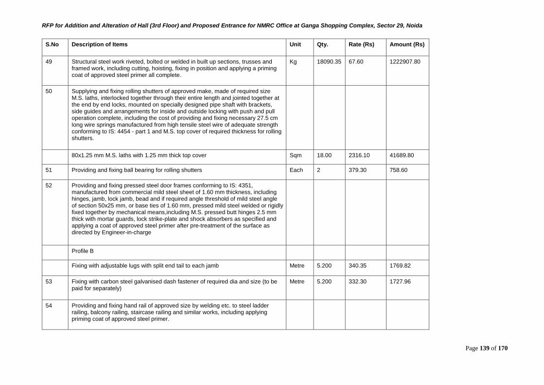
RFP for Addition and Alteration of Hall (3rd Floor) and Proposed Entrance for NMRC Office at Ganga Shopping Complex, Sector 29, Noida
Page 139 of 170
S.No Description of Items Unit Qty. Rate (Rs) Amount (Rs)
49 Structural steel work riveted, bolted or welded in built up sections, trusses and framed work, including cutting, hoisting, fixing in position and applying a priming coat of approved steel primer all complete.
Kg 18090.35 67.60 1222907.80
50 Supplying and fixing rolling shutters of approved make, made of required size M.S. laths, interlocked together through their entire length and jointed together at the end by end locks, mounted on specially designed pipe shaft with brackets, side guides and arrangements for inside and outside locking with push and pull operation complete, including the cost of providing and fixing necessary 27.5 cm long wire springs manufactured from high tensile steel wire of adequate strength conforming to IS: 4454 - part 1 and M.S. top cover of required thickness for rolling shutters.
80x1.25 mm M.S. laths with 1.25 mm thick top cover Sqm 18.00 2316.10 41689.80
51 Providing and fixing ball bearing for rolling shutters Each 2 379.30 758.60
52 Providing and fixing pressed steel door frames conforming to IS: 4351, manufactured from commercial mild steel sheet of 1.60 mm thickness, including hinges, jamb, lock jamb, bead and if required angle threshold of mild steel angle of section 50x25 mm, or base ties of 1.60 mm, pressed mild steel welded or rigidly fixed together by mechanical means,including M.S. pressed butt hinges 2.5 mm thick with mortar guards, lock strike-plate and shock absorbers as specified and applying a coat of approved steel primer after pre-treatment of the surface as directed by Engineer-in-charge
Profile B
Fixing with adjustable lugs with split end tail to each jamb Metre 5.200 340.35 1769.82
53 Fixing with carbon steel galvanised dash fastener of required dia and size (to be paid for separately)
Metre 5.200 332.30 1727.96
54 Providing and fixing hand rail of approved size by welding etc. to steel ladder railing, balcony railing, staircase railing and similar works, including applying priming coat of approved steel primer.
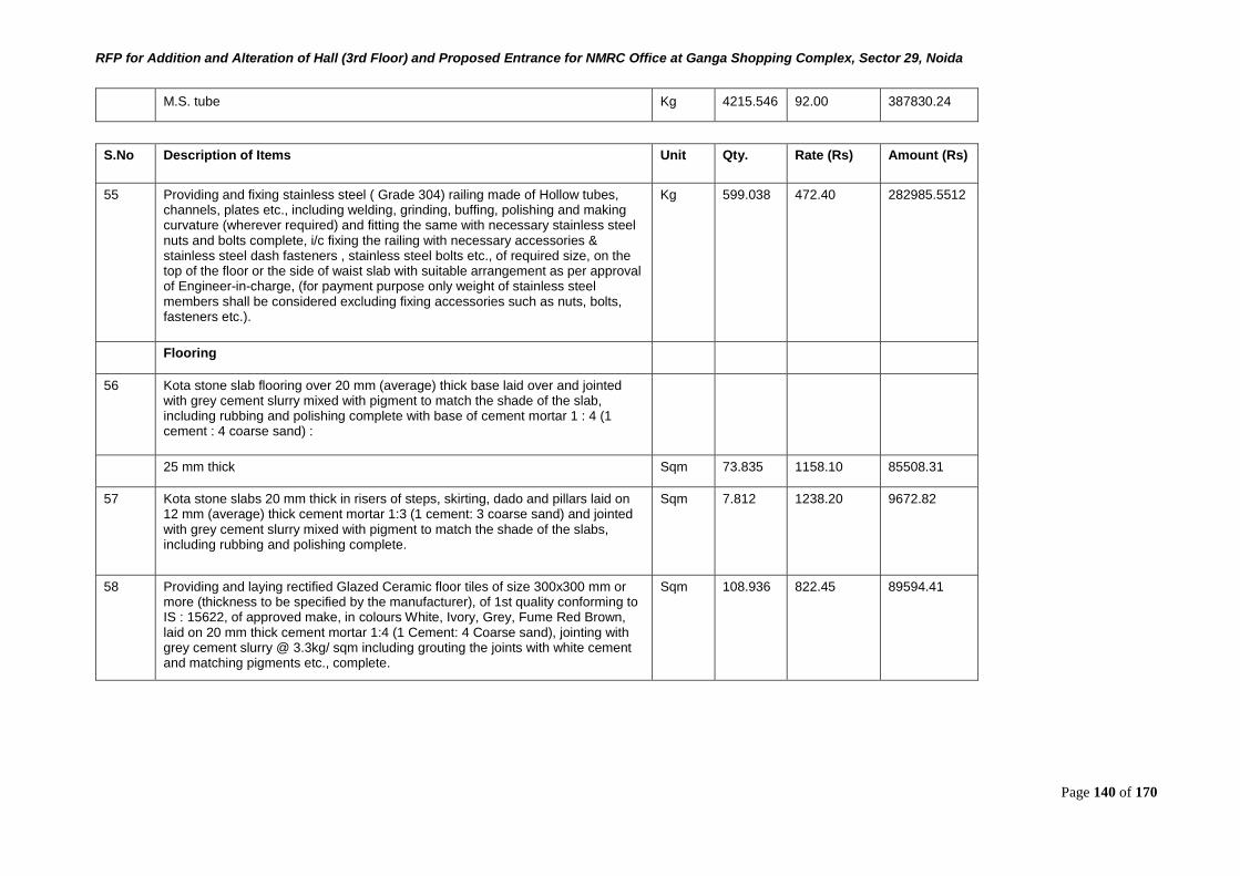
RFP for Addition and Alteration of Hall (3rd Floor) and Proposed Entrance for NMRC Office at Ganga Shopping Complex, Sector 29, Noida
Page 140 of 170
M.S. tube Kg 4215.546 92.00 387830.24
S.No Description of Items Unit Qty. Rate (Rs) Amount (Rs)
55 Providing and fixing stainless steel ( Grade 304) railing made of Hollow tubes, channels, plates etc., including welding, grinding, buffing, polishing and making curvature (wherever required) and fitting the same with necessary stainless steel nuts and bolts complete, i/c fixing the railing with necessary accessories & stainless steel dash fasteners , stainless steel bolts etc., of required size, on the top of the floor or the side of waist slab with suitable arrangement as per approval of Engineer-in-charge, (for payment purpose only weight of stainless steel members shall be considered excluding fixing accessories such as nuts, bolts, fasteners etc.).
Kg 599.038 472.40 282985.5512
Flooring
56 Kota stone slab flooring over 20 mm (average) thick base laid over and jointed with grey cement slurry mixed with pigment to match the shade of the slab, including rubbing and polishing complete with base of cement mortar 1 : 4 (1 cement : 4 coarse sand) :
25 mm thick Sqm 73.835 1158.10 85508.31
57 Kota stone slabs 20 mm thick in risers of steps, skirting, dado and pillars laid on 12 mm (average) thick cement mortar 1:3 (1 cement: 3 coarse sand) and jointed with grey cement slurry mixed with pigment to match the shade of the slabs, including rubbing and polishing complete.
Sqm 7.812 1238.20 9672.82
58 Providing and laying rectified Glazed Ceramic floor tiles of size 300x300 mm or more (thickness to be specified by the manufacturer), of 1st quality conforming to IS : 15622, of approved make, in colours White, Ivory, Grey, Fume Red Brown, laid on 20 mm thick cement mortar 1:4 (1 Cement: 4 Coarse sand), jointing with grey cement slurry @ 3.3kg/ sqm including grouting the joints with white cement and matching pigments etc., complete.
Sqm 108.936 822.45 89594.41
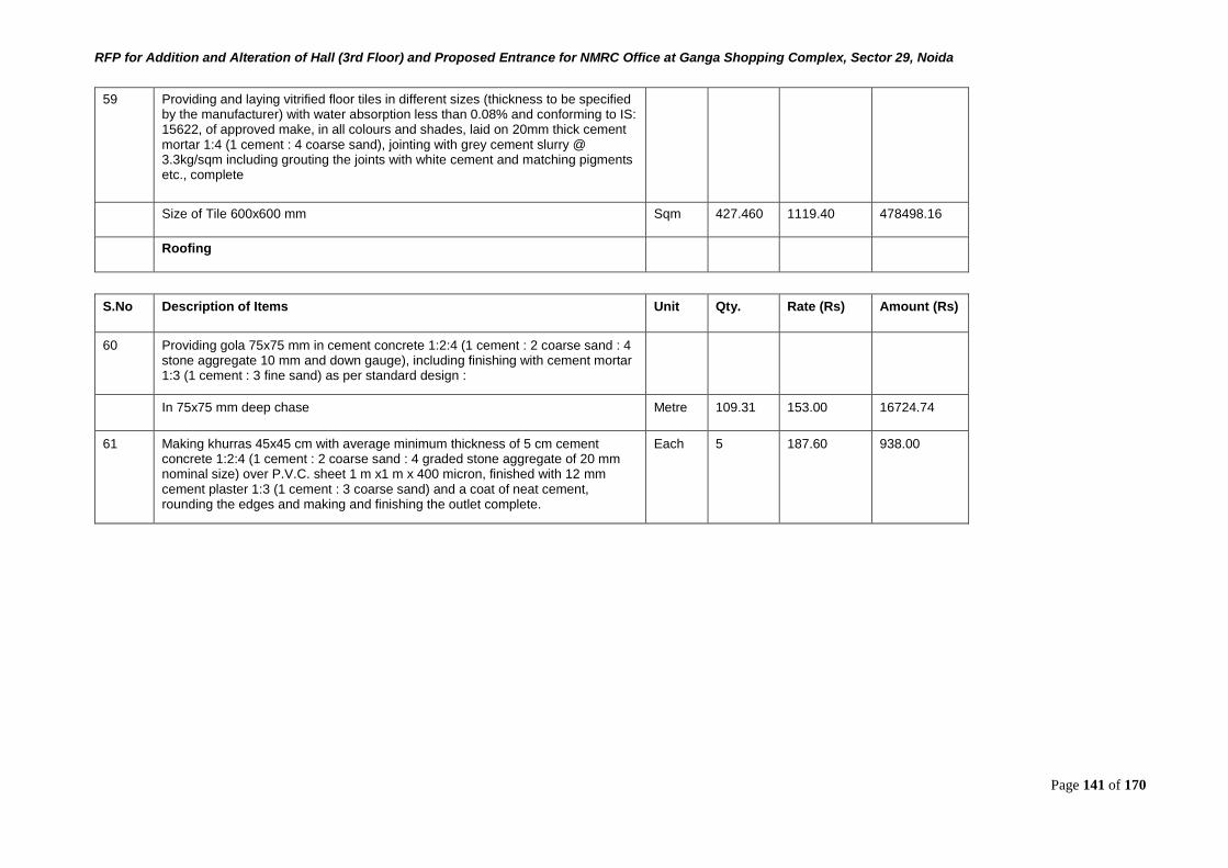
RFP for Addition and Alteration of Hall (3rd Floor) and Proposed Entrance for NMRC Office at Ganga Shopping Complex, Sector 29, Noida
Page 141 of 170
59 Providing and laying vitrified floor tiles in different sizes (thickness to be specified by the manufacturer) with water absorption less than 0.08% and conforming to IS: 15622, of approved make, in all colours and shades, laid on 20mm thick cement mortar 1:4 (1 cement : 4 coarse sand), jointing with grey cement slurry @ 3.3kg/sqm including grouting the joints with white cement and matching pigments etc., complete
Size of Tile 600x600 mm Sqm 427.460 1119.40 478498.16
Roofing
S.No Description of Items Unit Qty. Rate (Rs) Amount (Rs)
60 Providing gola 75x75 mm in cement concrete 1:2:4 (1 cement : 2 coarse sand : 4 stone aggregate 10 mm and down gauge), including finishing with cement mortar 1:3 (1 cement : 3 fine sand) as per standard design :
In 75x75 mm deep chase Metre 109.31 153.00 16724.74
61 Making khurras 45x45 cm with average minimum thickness of 5 cm cement concrete 1:2:4 (1 cement : 2 coarse sand : 4 graded stone aggregate of 20 mm nominal size) over P.V.C. sheet 1 m x1 m x 400 micron, finished with 12 mm cement plaster 1:3 (1 cement : 3 coarse sand) and a coat of neat cement, rounding the edges and making and finishing the outlet complete.
Each 5 187.60 938.00
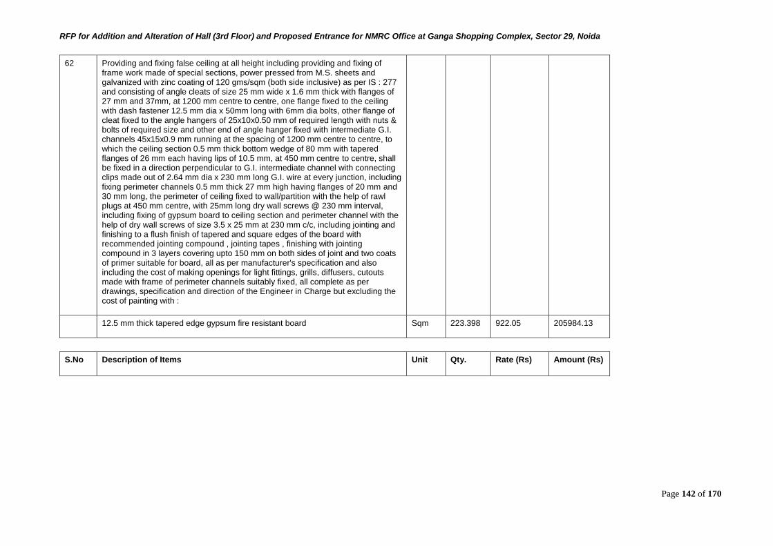
RFP for Addition and Alteration of Hall (3rd Floor) and Proposed Entrance for NMRC Office at Ganga Shopping Complex, Sector 29, Noida
Page 142 of 170
62 Providing and fixing false ceiling at all height including providing and fixing of frame work made of special sections, power pressed from M.S. sheets and galvanized with zinc coating of 120 gms/sqm (both side inclusive) as per IS : 277 and consisting of angle cleats of size 25 mm wide x 1.6 mm thick with flanges of 27 mm and 37mm, at 1200 mm centre to centre, one flange fixed to the ceiling with dash fastener 12.5 mm dia x 50mm long with 6mm dia bolts, other flange of cleat fixed to the angle hangers of 25x10x0.50 mm of required length with nuts & bolts of required size and other end of angle hanger fixed with intermediate G.I. channels 45x15x0.9 mm running at the spacing of 1200 mm centre to centre, to which the ceiling section 0.5 mm thick bottom wedge of 80 mm with tapered flanges of 26 mm each having lips of 10.5 mm, at 450 mm centre to centre, shall be fixed in a direction perpendicular to G.I. intermediate channel with connecting clips made out of 2.64 mm dia x 230 mm long G.I. wire at every junction, including fixing perimeter channels 0.5 mm thick 27 mm high having flanges of 20 mm and 30 mm long, the perimeter of ceiling fixed to wall/partition with the help of rawl plugs at 450 mm centre, with 25mm long dry wall screws @ 230 mm interval, including fixing of gypsum board to ceiling section and perimeter channel with the help of dry wall screws of size 3.5 x 25 mm at 230 mm c/c, including jointing and finishing to a flush finish of tapered and square edges of the board with recommended jointing compound , jointing tapes , finishing with jointing compound in 3 layers covering upto 150 mm on both sides of joint and two coats of primer suitable for board, all as per manufacturer's specification and also including the cost of making openings for light fittings, grills, diffusers, cutouts made with frame of perimeter channels suitably fixed, all complete as per drawings, specification and direction of the Engineer in Charge but excluding the cost of painting with :
12.5 mm thick tapered edge gypsum fire resistant board Sqm 223.398 922.05 205984.13
S.No Description of Items Unit Qty. Rate (Rs) Amount (Rs)
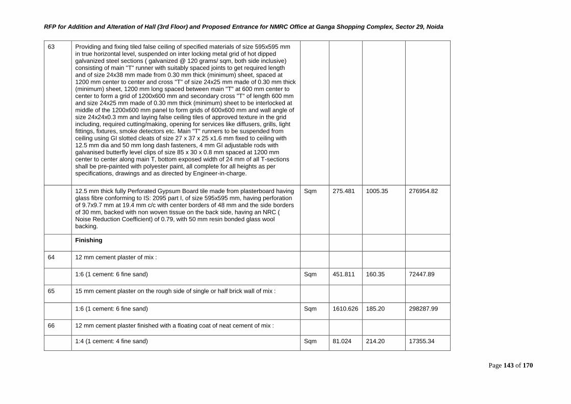
RFP for Addition and Alteration of Hall (3rd Floor) and Proposed Entrance for NMRC Office at Ganga Shopping Complex, Sector 29, Noida
Page 143 of 170
63 Providing and fixing tiled false ceiling of specified materials of size 595x595 mm in true horizontal level, suspended on inter locking metal grid of hot dipped galvanized steel sections ( galvanized @ 120 grams/ sqm, both side inclusive) consisting of main "T" runner with suitably spaced joints to get required length and of size 24x38 mm made from 0.30 mm thick (minimum) sheet, spaced at 1200 mm center to center and cross "T" of size 24x25 mm made of 0.30 mm thick (minimum) sheet, 1200 mm long spaced between main "T" at 600 mm center to center to form a grid of 1200x600 mm and secondary cross "T" of length 600 mm and size 24x25 mm made of 0.30 mm thick (minimum) sheet to be interlocked at middle of the 1200x600 mm panel to form grids of 600x600 mm and wall angle of size 24x24x0.3 mm and laying false ceiling tiles of approved texture in the grid including, required cutting/making, opening for services like diffusers, grills, light fittings, fixtures, smoke detectors etc. Main "T" runners to be suspended from ceiling using GI slotted cleats of size 27 x 37 x 25 x1.6 mm fixed to ceiling with 12.5 mm dia and 50 mm long dash fasteners, 4 mm GI adjustable rods with galvanised butterfly level clips of size 85 x 30 x 0.8 mm spaced at 1200 mm center to center along main T, bottom exposed width of 24 mm of all T-sections shall be pre-painted with polyester paint, all complete for all heights as per specifications, drawings and as directed by Engineer-in-charge.
12.5 mm thick fully Perforated Gypsum Board tile made from plasterboard having glass fibre conforming to IS: 2095 part I, of size 595x595 mm, having perforation of 9.7x9.7 mm at 19.4 mm c/c with center borders of 48 mm and the side borders of 30 mm, backed with non woven tissue on the back side, having an NRC ( Noise Reduction Coefficient) of 0.79, with 50 mm resin bonded glass wool backing.
Sqm 275.481 1005.35 276954.82
Finishing
64 12 mm cement plaster of mix :
1:6 (1 cement: 6 fine sand) Sqm 451.811 160.35 72447.89
65 15 mm cement plaster on the rough side of single or half brick wall of mix :
1:6 (1 cement: 6 fine sand) Sqm 1610.626 185.20 298287.99
66 12 mm cement plaster finished with a floating coat of neat cement of mix :
1:4 (1 cement: 4 fine sand) Sqm 81.024 214.20 17355.34
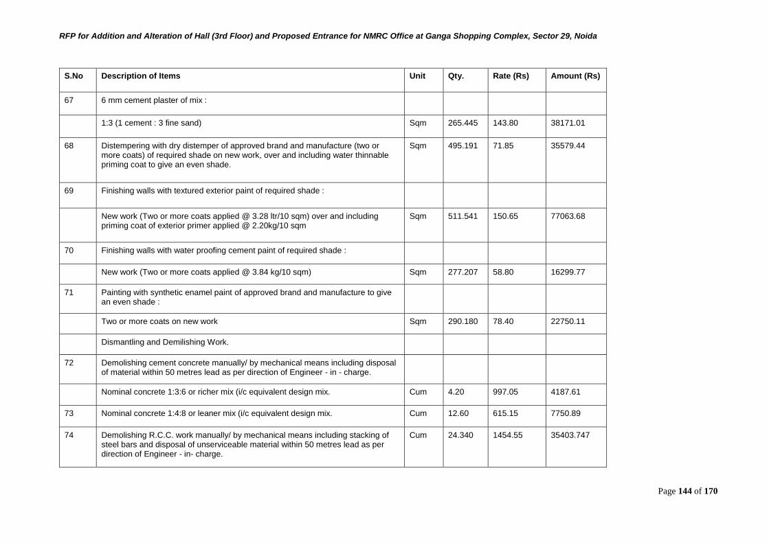
RFP for Addition and Alteration of Hall (3rd Floor) and Proposed Entrance for NMRC Office at Ganga Shopping Complex, Sector 29, Noida
Page 144 of 170
S.No Description of Items Unit Qty. Rate (Rs) Amount (Rs)
67 6 mm cement plaster of mix :
1:3 (1 cement : 3 fine sand) Sqm 265.445 143.80 38171.01
68 Distempering with dry distemper of approved brand and manufacture (two or more coats) of required shade on new work, over and including water thinnable priming coat to give an even shade.
Sqm 495.191 71.85 35579.44
69 Finishing walls with textured exterior paint of required shade :
New work (Two or more coats applied @ 3.28 ltr/10 sqm) over and including priming coat of exterior primer applied @ 2.20kg/10 sqm
Sqm 511.541 150.65 77063.68
70 Finishing walls with water proofing cement paint of required shade :
New work (Two or more coats applied @ 3.84 kg/10 sqm) Sqm 277.207 58.80 16299.77
71 Painting with synthetic enamel paint of approved brand and manufacture to give an even shade :
Two or more coats on new work Sqm 290.180 78.40 22750.11
Dismantling and Demilishing Work.
72 Demolishing cement concrete manually/ by mechanical means including disposal of material within 50 metres lead as per direction of Engineer - in - charge.
Nominal concrete 1:3:6 or richer mix (i/c equivalent design mix. Cum 4.20 997.05 4187.61
73 Nominal concrete 1:4:8 or leaner mix (i/c equivalent design mix. Cum 12.60 615.15 7750.89
74 Demolishing R.C.C. work manually/ by mechanical means including stacking of steel bars and disposal of unserviceable material within 50 metres lead as per direction of Engineer - in- charge.
Cum 24.340 1454.55 35403.747
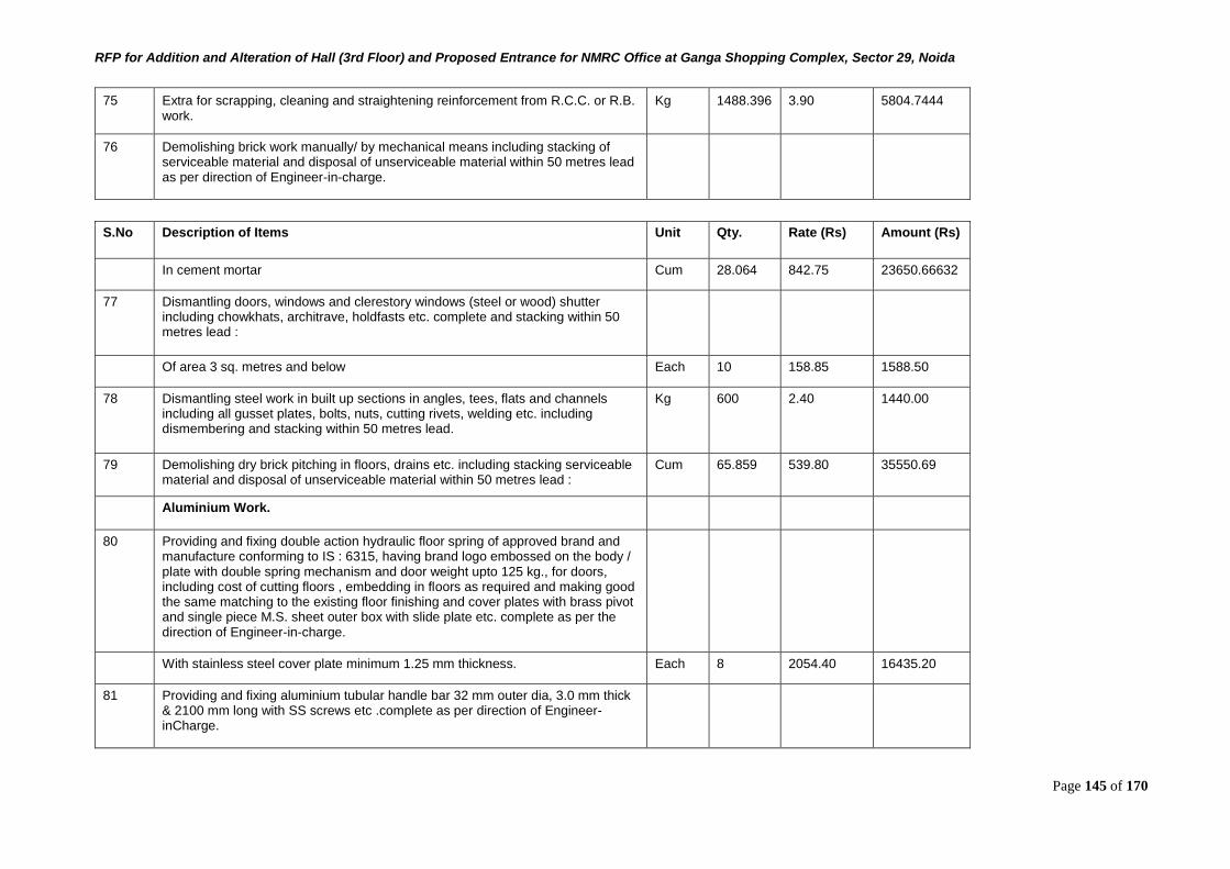
RFP for Addition and Alteration of Hall (3rd Floor) and Proposed Entrance for NMRC Office at Ganga Shopping Complex, Sector 29, Noida
Page 145 of 170
75 Extra for scrapping, cleaning and straightening reinforcement from R.C.C. or R.B. work.
Kg 1488.396 3.90 5804.7444
76 Demolishing brick work manually/ by mechanical means including stacking of serviceable material and disposal of unserviceable material within 50 metres lead as per direction of Engineer-in-charge.
S.No Description of Items Unit Qty. Rate (Rs) Amount (Rs)
In cement mortar Cum 28.064 842.75 23650.66632
77 Dismantling doors, windows and clerestory windows (steel or wood) shutter including chowkhats, architrave, holdfasts etc. complete and stacking within 50 metres lead :
Of area 3 sq. metres and below Each 10 158.85 1588.50
78 Dismantling steel work in built up sections in angles, tees, flats and channels including all gusset plates, bolts, nuts, cutting rivets, welding etc. including dismembering and stacking within 50 metres lead.
Kg 600 2.40 1440.00
79 Demolishing dry brick pitching in floors, drains etc. including stacking serviceable material and disposal of unserviceable material within 50 metres lead :
Cum 65.859 539.80 35550.69
Aluminium Work.
80 Providing and fixing double action hydraulic floor spring of approved brand and manufacture conforming to IS : 6315, having brand logo embossed on the body / plate with double spring mechanism and door weight upto 125 kg., for doors, including cost of cutting floors , embedding in floors as required and making good the same matching to the existing floor finishing and cover plates with brass pivot and single piece M.S. sheet outer box with slide plate etc. complete as per the direction of Engineer-in-charge.
With stainless steel cover plate minimum 1.25 mm thickness. Each 8 2054.40 16435.20
81 Providing and fixing aluminium tubular handle bar 32 mm outer dia, 3.0 mm thick & 2100 mm long with SS screws etc .complete as per direction of Engineer-inCharge.
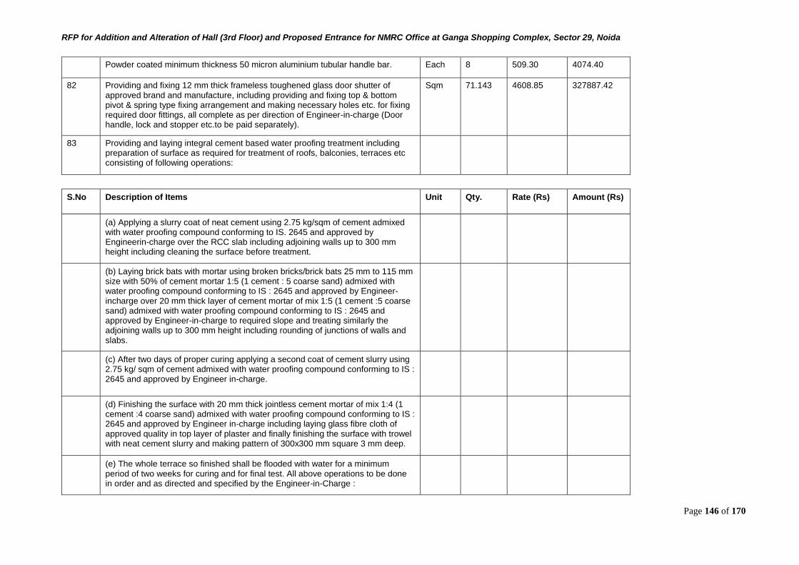
RFP for Addition and Alteration of Hall (3rd Floor) and Proposed Entrance for NMRC Office at Ganga Shopping Complex, Sector 29, Noida
Page 146 of 170
Powder coated minimum thickness 50 micron aluminium tubular handle bar. Each 8 509.30 4074.40
82 Providing and fixing 12 mm thick frameless toughened glass door shutter of approved brand and manufacture, including providing and fixing top & bottom pivot & spring type fixing arrangement and making necessary holes etc. for fixing required door fittings, all complete as per direction of Engineer-in-charge (Door handle, lock and stopper etc.to be paid separately).
Sqm 71.143 4608.85 327887.42
83 Providing and laying integral cement based water proofing treatment including preparation of surface as required for treatment of roofs, balconies, terraces etc consisting of following operations:
S.No Description of Items Unit Qty. Rate (Rs) Amount (Rs)
(a) Applying a slurry coat of neat cement using 2.75 kg/sqm of cement admixed with water proofing compound conforming to IS. 2645 and approved by Engineerin-charge over the RCC slab including adjoining walls up to 300 mm height including cleaning the surface before treatment.
(b) Laying brick bats with mortar using broken bricks/brick bats 25 mm to 115 mm size with 50% of cement mortar 1:5 (1 cement : 5 coarse sand) admixed with water proofing compound conforming to IS : 2645 and approved by Engineer-incharge over 20 mm thick layer of cement mortar of mix 1:5 (1 cement :5 coarse sand) admixed with water proofing compound conforming to IS : 2645 and approved by Engineer-in-charge to required slope and treating similarly the adjoining walls up to 300 mm height including rounding of junctions of walls and slabs.
(c) After two days of proper curing applying a second coat of cement slurry using 2.75 kg/ sqm of cement admixed with water proofing compound conforming to IS : 2645 and approved by Engineer in-charge.
(d) Finishing the surface with 20 mm thick jointless cement mortar of mix 1:4 (1 cement :4 coarse sand) admixed with water proofing compound conforming to IS : 2645 and approved by Engineer in-charge including laying glass fibre cloth of approved quality in top layer of plaster and finally finishing the surface with trowel with neat cement slurry and making pattern of 300x300 mm square 3 mm deep.
(e) The whole terrace so finished shall be flooded with water for a minimum period of two weeks for curing and for final test. All above operations to be done in order and as directed and specified by the Engineer-in-Charge :
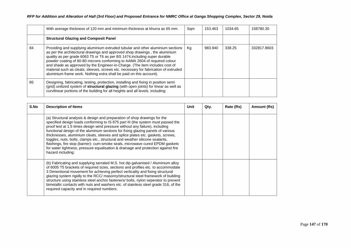
RFP for Addition and Alteration of Hall (3rd Floor) and Proposed Entrance for NMRC Office at Ganga Shopping Complex, Sector 29, Noida
Page 147 of 170
With average thickness of 120 mm and minimum thickness at khurra as 65 mm. Sqm 153.463 1034.65 158780.30
Structural Glazing and Composit Panel
84 Providing and supplying aluminium extruded tubular and other aluminium sections as per the architectural drawings and approved shop drawings , the aluminium quality as per grade 6063 T5 or T6 as per BS 1474,including super durable powder coating of 60-80 microns conforming to AAMA 2604 of required colour and shade as approved by the Engineer-in-Charge. (The item includes cost of material such as cleats, sleeves, screws etc. necessary for fabrication of extruded aluminium frame work. Nothing extra shall be paid on this account).
Kg 983.940 338.25 332817.8603
85 Designing, fabricating, testing, protection, installing and fixing in position semi (grid) unitized system of structural glazing (with open joints) for linear as well as
curvilinear portions of the building for all heights and all levels, including:
S.No Description of Items Unit Qty. Rate (Rs) Amount (Rs)
(a) Structural analysis & design and preparation of shop drawings for the specified design loads conforming to IS 875 part III (the system must passed the proof test at 1.5 times design wind pressure without any failure), including functional design of the aluminum sections for fixing glazing panels of various thicknesses, aluminium cleats, sleeves and splice plates etc. gaskets, screws, toggles, nuts, bolts, clamps etc., structural and weather silicone sealants, flashings, fire stop (barrier)- cum-smoke seals, microwave cured EPDM gaskets for water tightness, pressure equalisation & drainage and protection against fire hazard including:
(b) Fabricating and supplying serrated M.S. hot dip galvanised / Aluminium alloy of 6005 T5 brackets of required sizes, sections and profiles etc. to accommodate 3 Dimentional movement for achieving perfect verticality and fixing structural glazing system rigidly to the RCC/ masonry/structural steel framework of building structure using stainless steel anchor fasteners/ bolts, nylon seperator to prevent bimetallic contacts with nuts and washers etc. of stainless steel grade 316, of the required capacity and in required numbers.
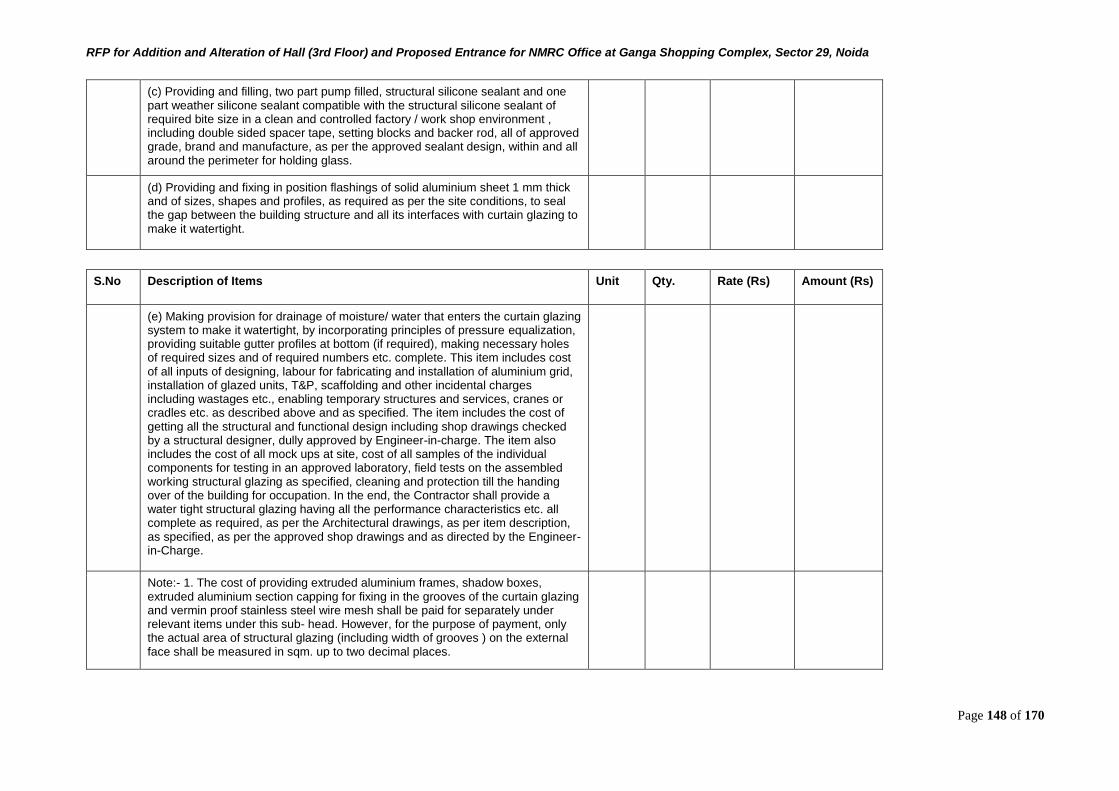
RFP for Addition and Alteration of Hall (3rd Floor) and Proposed Entrance for NMRC Office at Ganga Shopping Complex, Sector 29, Noida
Page 148 of 170
(c) Providing and filling, two part pump filled, structural silicone sealant and one part weather silicone sealant compatible with the structural silicone sealant of required bite size in a clean and controlled factory / work shop environment , including double sided spacer tape, setting blocks and backer rod, all of approved grade, brand and manufacture, as per the approved sealant design, within and all around the perimeter for holding glass.
(d) Providing and fixing in position flashings of solid aluminium sheet 1 mm thick and of sizes, shapes and profiles, as required as per the site conditions, to seal the gap between the building structure and all its interfaces with curtain glazing to make it watertight.
S.No Description of Items Unit Qty. Rate (Rs) Amount (Rs)
(e) Making provision for drainage of moisture/ water that enters the curtain glazing system to make it watertight, by incorporating principles of pressure equalization, providing suitable gutter profiles at bottom (if required), making necessary holes of required sizes and of required numbers etc. complete. This item includes cost of all inputs of designing, labour for fabricating and installation of aluminium grid, installation of glazed units, T&P, scaffolding and other incidental charges including wastages etc., enabling temporary structures and services, cranes or cradles etc. as described above and as specified. The item includes the cost of getting all the structural and functional design including shop drawings checked by a structural designer, dully approved by Engineer-in-charge. The item also includes the cost of all mock ups at site, cost of all samples of the individual components for testing in an approved laboratory, field tests on the assembled working structural glazing as specified, cleaning and protection till the handing over of the building for occupation. In the end, the Contractor shall provide a water tight structural glazing having all the performance characteristics etc. all complete as required, as per the Architectural drawings, as per item description, as specified, as per the approved shop drawings and as directed by the Engineer- in-Charge.
Note:- 1. The cost of providing extruded aluminium frames, shadow boxes, extruded aluminium section capping for fixing in the grooves of the curtain glazing and vermin proof stainless steel wire mesh shall be paid for separately under relevant items under this sub- head. However, for the purpose of payment, only the actual area of structural glazing (including width of grooves ) on the external face shall be measured in sqm. up to two decimal places.
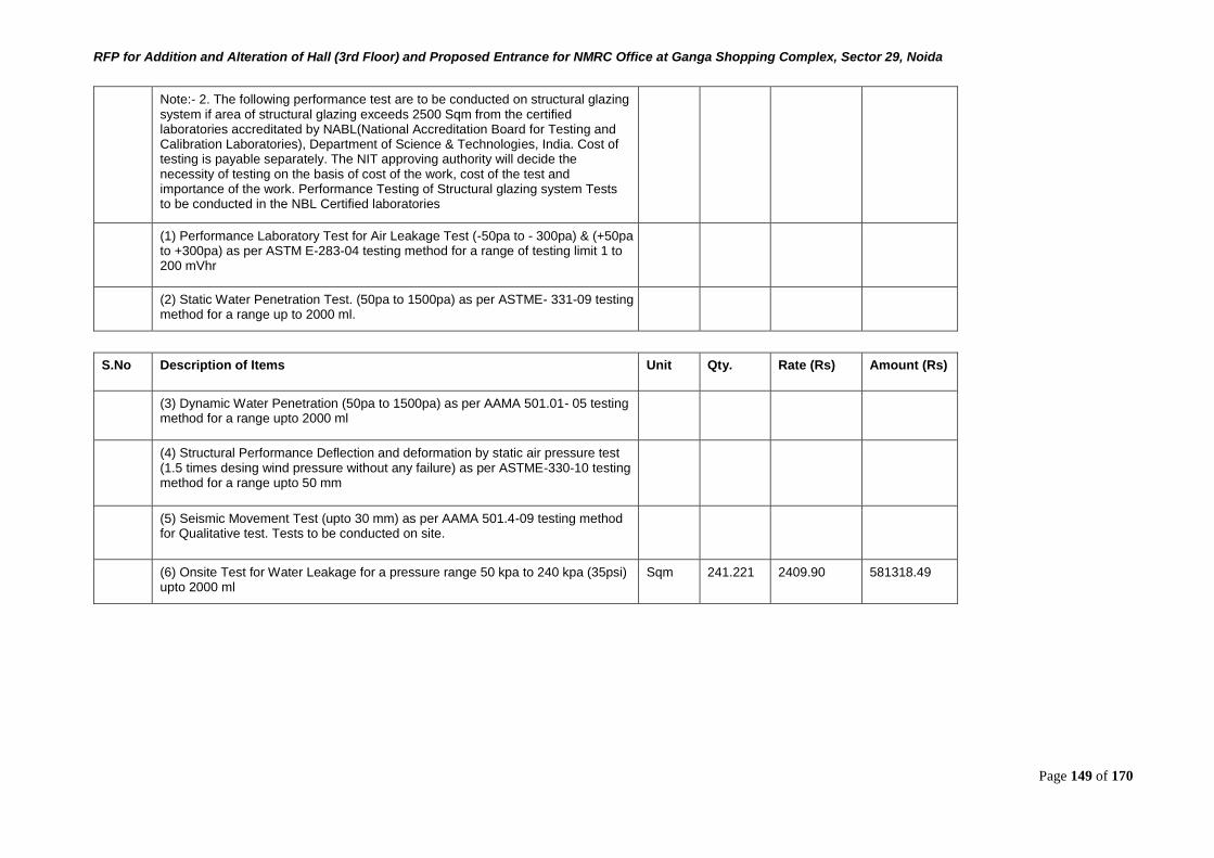
RFP for Addition and Alteration of Hall (3rd Floor) and Proposed Entrance for NMRC Office at Ganga Shopping Complex, Sector 29, Noida
Page 149 of 170
Note:- 2. The following performance test are to be conducted on structural glazing system if area of structural glazing exceeds 2500 Sqm from the certified laboratories accreditated by NABL(National Accreditation Board for Testing and Calibration Laboratories), Department of Science & Technologies, India. Cost of testing is payable separately. The NIT approving authority will decide the necessity of testing on the basis of cost of the work, cost of the test and importance of the work. Performance Testing of Structural glazing system Tests to be conducted in the NBL Certified laboratories
(1) Performance Laboratory Test for Air Leakage Test (-50pa to - 300pa) & (+50pa to +300pa) as per ASTM E-283-04 testing method for a range of testing limit 1 to 200 mVhr
(2) Static Water Penetration Test. (50pa to 1500pa) as per ASTME- 331-09 testing method for a range up to 2000 ml.
S.No Description of Items Unit Qty. Rate (Rs) Amount (Rs)
(3) Dynamic Water Penetration (50pa to 1500pa) as per AAMA 501.01- 05 testing method for a range upto 2000 ml
(4) Structural Performance Deflection and deformation by static air pressure test (1.5 times desing wind pressure without any failure) as per ASTME-330-10 testing method for a range upto 50 mm
(5) Seismic Movement Test (upto 30 mm) as per AAMA 501.4-09 testing method for Qualitative test. Tests to be conducted on site.
(6) Onsite Test for Water Leakage for a pressure range 50 kpa to 240 kpa (35psi) upto 2000 ml
Sqm 241.221 2409.90 581318.49
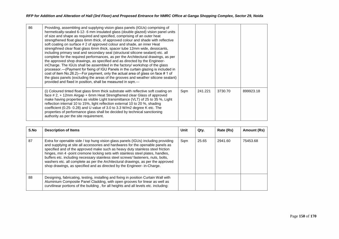
RFP for Addition and Alteration of Hall (3rd Floor) and Proposed Entrance for NMRC Office at Ganga Shopping Complex, Sector 29, Noida
Page 150 of 170
86 Providing, assembling and supplying vision glass panels (IGUs) comprising of hermetically-sealed 6-12- 6 mm insulated glass (double glazed) vision panel units of size and shape as required and specified, comprising of an outer heat strengthened float glass 6mm thick, of approved colour and shade with reflective soft coating on surface # 2 of approved colour and shade, an inner Heat strengthned clear float glass 6mm thick, spacer tube 12mm wide, dessicants, including primary seal and secondary seal (structural silicone sealant) etc. all complete for the required performances, as per the Architectural drawings, as per the approved shop drawings, as specified and as directed by the Engineer-inCharge. The IGUs shall be assembled in the factory/ workshop of the glass processor.―(Payment for fixing of IGU Panels in the curtain glazing is included in cost of item No.26.2)―For payment, only the actual area of glass on face # 1 of the glass panels (excluding the areas of the grooves and weather silicone sealant) provided and fixed in position, shall be measured in sqm.―
(i) Coloured tinted float glass 6mm thick substrate with reflective soft coating on face # 2, + 12mm Airgap + 6mm Heat Strengthened clear Glass of approved make having properties as visible Light transmittance (VLT) of 25 to 35 %, Light reflection internal 10 to 15%, light reflection external 10 to 20 %, shading coefficient (0.25- 0.28) and U value of 3.0 to 3.3 W/m2 degree K etc. The properties of performance glass shall be decided by technical sanctioning authority as per the site requirement.
Sqm 241.221 3730.70 899923.18
S.No Description of Items Unit Qty. Rate (Rs) Amount (Rs)
87 Extra for openable side / top hung vision glass panels (IGUs) including providing and supplying at site all accessories and hardwares for the openable panels as specified and of the approved make such as heavy duty stainless steel friction hinges, min 4 -point cremone locking sets with stainless steel plates, handles, buffers etc. including necessary stainless steel screws/ fasteners, nuts, bolts, washers etc. all complete as per the Architectural drawings, as per the approved shop drawings, as specified and as directed by the Engineer- in-Charge.
Sqm 25.65 2941.60 75453.68
88 Designing, fabricating, testing, installing and fixing in position Curtain Wall with Aluminium Composite Panel Cladding, with open grooves for linear as well as curvilinear portions of the building , for all heights and all levels etc. including:
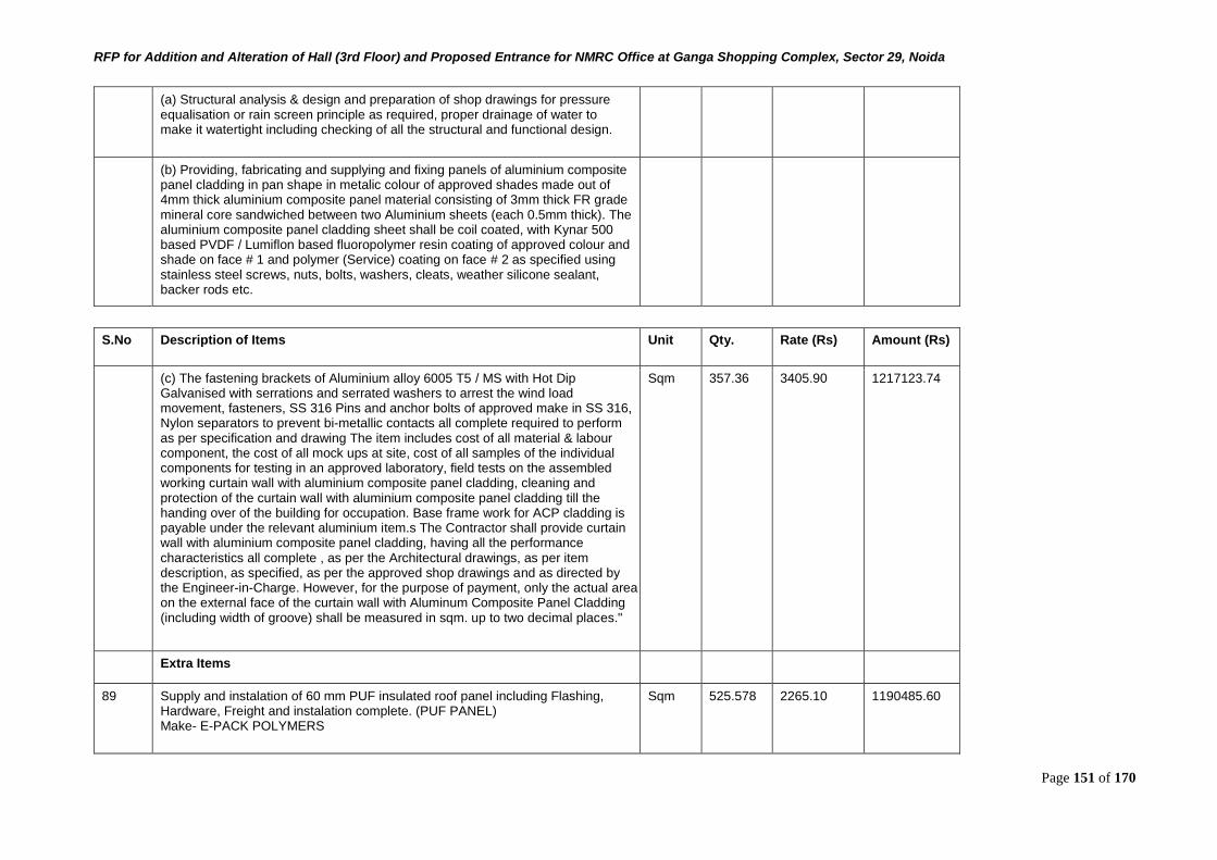
RFP for Addition and Alteration of Hall (3rd Floor) and Proposed Entrance for NMRC Office at Ganga Shopping Complex, Sector 29, Noida
Page 151 of 170
(a) Structural analysis & design and preparation of shop drawings for pressure equalisation or rain screen principle as required, proper drainage of water to make it watertight including checking of all the structural and functional design.
(b) Providing, fabricating and supplying and fixing panels of aluminium composite panel cladding in pan shape in metalic colour of approved shades made out of 4mm thick aluminium composite panel material consisting of 3mm thick FR grade mineral core sandwiched between two Aluminium sheets (each 0.5mm thick). The aluminium composite panel cladding sheet shall be coil coated, with Kynar 500 based PVDF / Lumiflon based fluoropolymer resin coating of approved colour and shade on face # 1 and polymer (Service) coating on face # 2 as specified using stainless steel screws, nuts, bolts, washers, cleats, weather silicone sealant, backer rods etc.
S.No Description of Items Unit Qty. Rate (Rs) Amount (Rs)
(c) The fastening brackets of Aluminium alloy 6005 T5 / MS with Hot Dip Galvanised with serrations and serrated washers to arrest the wind load movement, fasteners, SS 316 Pins and anchor bolts of approved make in SS 316, Nylon separators to prevent bi-metallic contacts all complete required to perform as per specification and drawing The item includes cost of all material & labour component, the cost of all mock ups at site, cost of all samples of the individual components for testing in an approved laboratory, field tests on the assembled working curtain wall with aluminium composite panel cladding, cleaning and protection of the curtain wall with aluminium composite panel cladding till the handing over of the building for occupation. Base frame work for ACP cladding is payable under the relevant aluminium item.s The Contractor shall provide curtain wall with aluminium composite panel cladding, having all the performance characteristics all complete , as per the Architectural drawings, as per item description, as specified, as per the approved shop drawings and as directed by the Engineer-in-Charge. However, for the purpose of payment, only the actual area on the external face of the curtain wall with Aluminum Composite Panel Cladding (including width of groove) shall be measured in sqm. up to two decimal places."
Sqm 357.36 3405.90 1217123.74
Extra Items
89 Supply and instalation of 60 mm PUF insulated roof panel including Flashing, Hardware, Freight and instalation complete. (PUF PANEL) Make- E-PACK POLYMERS
Sqm 525.578 2265.10 1190485.60
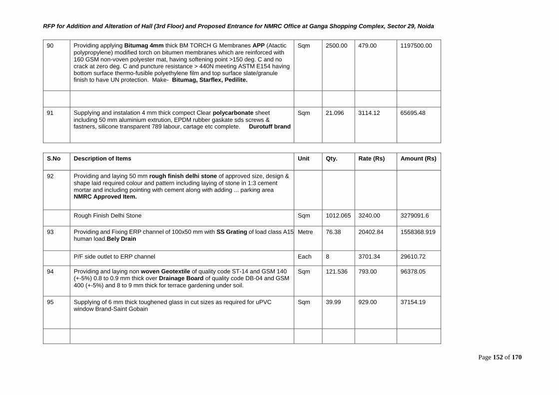
RFP for Addition and Alteration of Hall (3rd Floor) and Proposed Entrance for NMRC Office at Ganga Shopping Complex, Sector 29, Noida
Page 152 of 170
90 Providing applying Bitumag 4mm thick BM TORCH G Membranes APP (Atactic
polypropylene) modified torch on bitumen membranes which are reinforced with 160 GSM non-voven polyester mat, having softening point >150 deg. C and no crack at zero deg. C and puncture resistance > 440N meeting ASTM E154 having bottom surface thermo-fusible polyethylene film and top surface slate/granule finish to have UN protection. Make- Bitumag, Starflex, Pedilite.
Sqm 2500.00 479.00 1197500.00
91 Supplying and instalation 4 mm thick compect Clear polycarbonate sheet
including 50 mm aluminium extrution, EPDM rubber gaskate sds screws & fastners, silicone transparent 789 labour, cartage etc complete. Durotuff brand
Sqm 21.096 3114.12 65695.48
S.No Description of Items Unit Qty. Rate (Rs) Amount (Rs)
92 Providing and laying 50 mm rough finish delhi stone of approved size, design &
shape laid required colour and pattern including laying of stone in 1:3 cement mortar and including pointing with cement along with adding ... parking area NMRC Approved Item.
Rough Finish Delhi Stone Sqm 1012.065 3240.00 3279091.6
93 Providing and Fixing ERP channel of 100x50 mm with SS Grating of load class A15 human load.Bely Drain
Metre 76.38 20402.84 1558368.919
P/F side outlet to ERP channel Each 8 3701.34 29610.72
94 Providing and laying non woven Geotextile of quality code ST-14 and GSM 140 (+-5%) 0.8 to 0.9 mm thick over Drainage Board of quality code DB-04 and GSM
400 (+-5%) and 8 to 9 mm thick for terrace gardening under soil.
Sqm 121.536 793.00 96378.05
95 Supplying of 6 mm thick toughened glass in cut sizes as required for uPVC window Brand-Saint Gobain
Sqm 39.99 929.00 37154.19
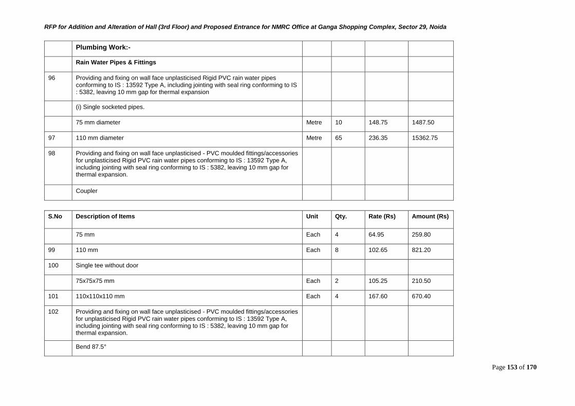
RFP for Addition and Alteration of Hall (3rd Floor) and Proposed Entrance for NMRC Office at Ganga Shopping Complex, Sector 29, Noida
Page 153 of 170
Plumbing Work:-
Rain Water Pipes & Fittings
96 Providing and fixing on wall face unplasticised Rigid PVC rain water pipes conforming to IS : 13592 Type A, including jointing with seal ring conforming to IS : 5382, leaving 10 mm gap for thermal expansion
(i) Single socketed pipes.
75 mm diameter Metre 10 148.75 1487.50
97 110 mm diameter Metre 65 236.35 15362.75
98 Providing and fixing on wall face unplasticised - PVC moulded fittings/accessories for unplasticised Rigid PVC rain water pipes conforming to IS : 13592 Type A, including jointing with seal ring conforming to IS : 5382, leaving 10 mm gap for thermal expansion.
Coupler
S.No Description of Items Unit Qty. Rate (Rs) Amount (Rs)
75 mm Each 4 64.95 259.80
99 110 mm Each 8 102.65 821.20
100 Single tee without door
75x75x75 mm Each 2 105.25 210.50
101 110x110x110 mm Each 4 167.60 670.40
102 Providing and fixing on wall face unplasticised - PVC moulded fittings/accessories for unplasticised Rigid PVC rain water pipes conforming to IS : 13592 Type A, including jointing with seal ring conforming to IS : 5382, leaving 10 mm gap for thermal expansion.
Bend 87.5°
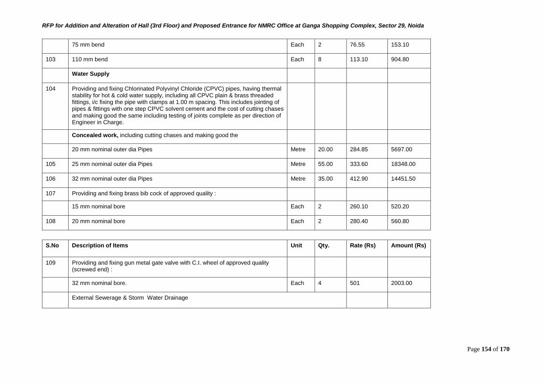
RFP for Addition and Alteration of Hall (3rd Floor) and Proposed Entrance for NMRC Office at Ganga Shopping Complex, Sector 29, Noida
Page 154 of 170
75 mm bend Each 2 76.55 153.10
103 110 mm bend Each 8 113.10 904.80
Water Supply
104 Providing and fixing Chlorinated Polyvinyl Chloride (CPVC) pipes, having thermal stability for hot & cold water supply, including all CPVC plain & brass threaded fittings, i/c fixing the pipe with clamps at 1.00 m spacing. This includes jointing of pipes & fittings with one step CPVC solvent cement and the cost of cutting chases and making good the same including testing of joints complete as per direction of Engineer in Charge.
Concealed work, including cutting chases and making good the
20 mm nominal outer dia Pipes Metre 20.00 284.85 5697.00
105 25 mm nominal outer dia Pipes Metre 55.00 333.60 18348.00
106 32 mm nominal outer dia Pipes Metre 35.00 412.90 14451.50
107 Providing and fixing brass bib cock of approved quality :
15 mm nominal bore Each 2 260.10 520.20
108 20 mm nominal bore Each 2 280.40 560.80
S.No Description of Items Unit Qty. Rate (Rs) Amount (Rs)
109 Providing and fixing gun metal gate valve with C.I. wheel of approved quality (screwed end) :
32 mm nominal bore. Each 4 501 2003.00
External Sewerage & Storm Water Drainage
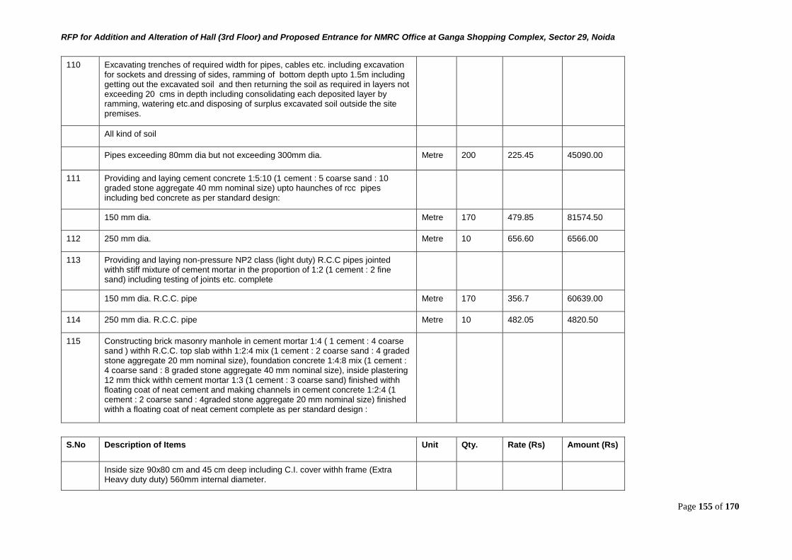
RFP for Addition and Alteration of Hall (3rd Floor) and Proposed Entrance for NMRC Office at Ganga Shopping Complex, Sector 29, Noida
Page 155 of 170
110 Excavating trenches of required width for pipes, cables etc. including excavation for sockets and dressing of sides, ramming of bottom depth upto 1.5m including getting out the excavated soil and then returning the soil as required in layers not exceeding 20 cms in depth including consolidating each deposited layer by ramming, watering etc.and disposing of surplus excavated soil outside the site premises.
All kind of soil
Pipes exceeding 80mm dia but not exceeding 300mm dia. Metre 200 225.45 45090.00
111 Providing and laying cement concrete 1:5:10 (1 cement : 5 coarse sand : 10 graded stone aggregate 40 mm nominal size) upto haunches of rcc pipes including bed concrete as per standard design:
150 mm dia. Metre 170 479.85 81574.50
112 250 mm dia. Metre 10 656.60 6566.00
113 Providing and laying non-pressure NP2 class (light duty) R.C.C pipes jointed withh stiff mixture of cement mortar in the proportion of 1:2 (1 cement : 2 fine sand) including testing of joints etc. complete
150 mm dia. R.C.C. pipe Metre 170 356.7 60639.00
114 250 mm dia. R.C.C. pipe Metre 10 482.05 4820.50
115 Constructing brick masonry manhole in cement mortar 1:4 ( 1 cement : 4 coarse sand ) withh R.C.C. top slab withh 1:2:4 mix (1 cement : 2 coarse sand : 4 graded stone aggregate 20 mm nominal size), foundation concrete 1:4:8 mix (1 cement : 4 coarse sand : 8 graded stone aggregate 40 mm nominal size), inside plastering 12 mm thick withh cement mortar 1:3 (1 cement : 3 coarse sand) finished withh floating coat of neat cement and making channels in cement concrete 1:2:4 (1 cement : 2 coarse sand : 4graded stone aggregate 20 mm nominal size) finished withh a floating coat of neat cement complete as per standard design :
S.No Description of Items Unit Qty. Rate (Rs) Amount (Rs)
Inside size 90x80 cm and 45 cm deep including C.I. cover withh frame (Extra Heavy duty duty) 560mm internal diameter.
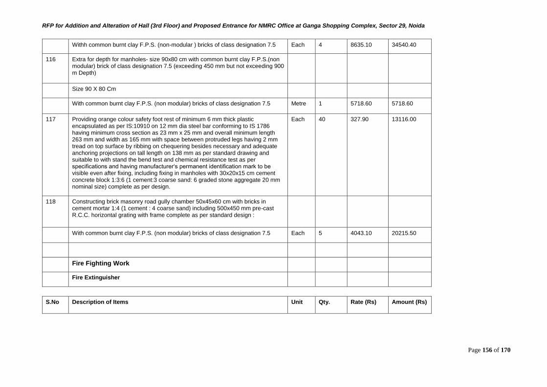
RFP for Addition and Alteration of Hall (3rd Floor) and Proposed Entrance for NMRC Office at Ganga Shopping Complex, Sector 29, Noida
Page 156 of 170
Withh common burnt clay F.P.S. (non-modular ) bricks of class designation 7.5 Each 4 8635.10 34540.40
116 Extra for depth for manholes- size 90x80 cm with common burnt clay F.P.S.(non modular) brick of class designation 7.5 (exceeding 450 mm but not exceeding 900 m Depth)
Size 90 X 80 Cm
With common burnt clay F.P.S. (non modular) bricks of class designation 7.5 Metre 1 5718.60 5718.60
117 Providing orange colour safety foot rest of minimum 6 mm thick plastic encapsulated as per IS:10910 on 12 mm dia steel bar conforming to IS 1786 having minimum cross section as 23 mm x 25 mm and overall minimum length 263 mm and width as 165 mm with space between protruded legs having 2 mm tread on top surface by ribbing on chequering besides necessary and adequate anchoring projections on tall length on 138 mm as per standard drawing and suitable to with stand the bend test and chemical resistance test as per specifications and having manufacturer‘s permanent identification mark to be visible even after fixing, including fixing in manholes with 30x20x15 cm cement concrete block 1:3:6 (1 cement:3 coarse sand: 6 graded stone aggregate 20 mm nominal size) complete as per design.
Each 40 327.90 13116.00
118 Constructing brick masonry road gully chamber 50x45x60 cm with bricks in cement mortar 1:4 (1 cement : 4 coarse sand) including 500x450 mm pre-cast R.C.C. horizontal grating with frame complete as per standard design :
With common burnt clay F.P.S. (non modular) bricks of class designation 7.5 Each 5 4043.10 20215.50
Fire Fighting Work
Fire Extinguisher
S.No Description of Items Unit Qty. Rate (Rs) Amount (Rs)
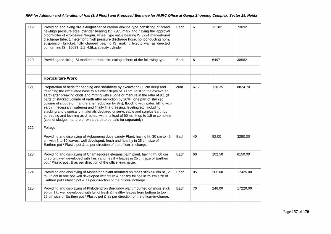
RFP for Addition and Alteration of Hall (3rd Floor) and Proposed Entrance for NMRC Office at Ganga Shopping Complex, Sector 29, Noida
Page 157 of 170
119 Providing and fixing fire extinguisher of carbon dioxide type consisting of brand newhigh pressure steel cylinder bearing IS: 7285 mark and having the approval ofcontroller of explosives Nagpur, wheel type valve bearing IS:3224 markinternal discharge tube, 1 meter long high pressure discharge hose, nonconducting horn, suspension bracket, fully charged bearing IS: making fixedto wall as directed conforming IS : 15683 1.1 4.5kgcapacity cylinder
Each 6 12182 73092
120 Providingand fixing ISI marked portable fire extinguishers of the following type. Each 6 6497 38982
Horticulture Work
121 Preparation of beds for hedging and shrubbery by excavating 60 cm deep and trenching the excavated base to a further depth of 30 cm, refilling the excavated earth after breaking clods and mixing with sludge or manure in the ratio of 8:1 (8 parts of stacked volume of earth after reduction by 20% : one part of stacked volume of sludge or manure after reduction by 8%), flooding with water, filling with earth if necessary, watering and finally fine dressing, leveling etc. including stacking and disposal of materials declared unserviceable and surplus earth by spreading and leveling as directed, within a lead of 50 m, lift up to 1.5 m complete (cost of sludge, manure or extra earth to be paid for separately)
cum 67.7 130.35 8824.70
122 Foliage
Providing and displaying of Aglaonema dove variety Plant, having ht. 30 cm to 45 cm with 8 to 10 leaves, well developed, fresh and healthy in 25 cm size of Earthen pot / Plastic pot & as per direction of the officer-in-charge.
Each 40 82.00 3280.00
123 Providing and displaying of Chamaedorea elegans palm plant, having ht. 60 cm to 75 cm, well developed with fresh and healthy leaves in 25 cm size of Earthen pot / Plastic pot . & as per direction of the officer-in-charge.
Each 60 102.50 6150.00
124 Providing and displaying of Monestaria plant mounted on moss stick 90 cm ht., 2 to 3 plant in one pot well developed with fresh & healthy foliage in 25 cm size of Earthen pot / Plastic pot & as per direction of the officer-incharge.
Each 85 205.00 17425.00
125 Providing and displaying of Philodendron Burgundy plant mounted on moss stick 90 cm ht., well developed with full of fresh & healthy leaves from bottom to top in 25 cm size of Earthen pot / Plastic pot & as per direction of the officer-in-charge.
Each 70 246.00 17220.00
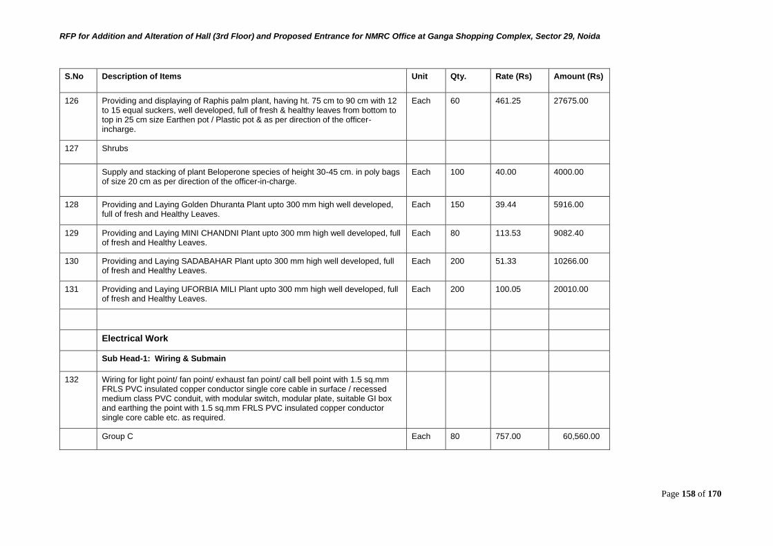
RFP for Addition and Alteration of Hall (3rd Floor) and Proposed Entrance for NMRC Office at Ganga Shopping Complex, Sector 29, Noida
Page 158 of 170
S.No Description of Items Unit Qty. Rate (Rs) Amount (Rs)
126 Providing and displaying of Raphis palm plant, having ht. 75 cm to 90 cm with 12 to 15 equal suckers, well developed, full of fresh & healthy leaves from bottom to top in 25 cm size Earthen pot / Plastic pot & as per direction of the officer-incharge.
Each 60 461.25 27675.00
127 Shrubs
Supply and stacking of plant Beloperone species of height 30-45 cm. in poly bags of size 20 cm as per direction of the officer-in-charge.
Each 100 40.00 4000.00
128 Providing and Laying Golden Dhuranta Plant upto 300 mm high well developed, full of fresh and Healthy Leaves.
Each 150 39.44 5916.00
129 Providing and Laying MINI CHANDNI Plant upto 300 mm high well developed, full of fresh and Healthy Leaves.
Each 80 113.53 9082.40
130 Providing and Laying SADABAHAR Plant upto 300 mm high well developed, full of fresh and Healthy Leaves.
Each 200 51.33 10266.00
131 Providing and Laying UFORBIA MILI Plant upto 300 mm high well developed, full of fresh and Healthy Leaves.
Each 200 100.05 20010.00
Electrical Work
Sub Head-1: Wiring & Submain
132 Wiring for light point/ fan point/ exhaust fan point/ call bell point with 1.5 sq.mm FRLS PVC insulated copper conductor single core cable in surface / recessed medium class PVC conduit, with modular switch, modular plate, suitable GI box and earthing the point with 1.5 sq.mm FRLS PVC insulated copper conductor single core cable etc. as required.
Group C Each 80 757.00 60,560.00
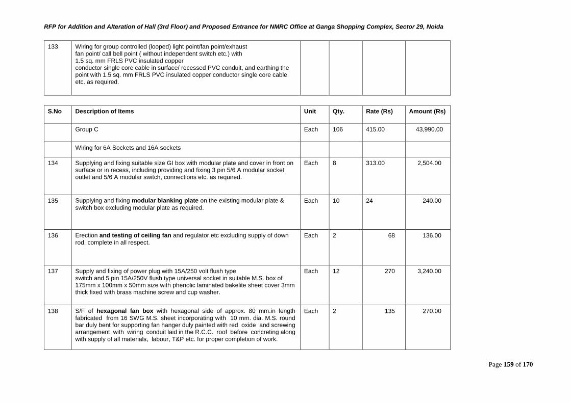
RFP for Addition and Alteration of Hall (3rd Floor) and Proposed Entrance for NMRC Office at Ganga Shopping Complex, Sector 29, Noida
Page 159 of 170
133 Wiring for group controlled (looped) light point/fan point/exhaust fan point/ call bell point ( without independent switch etc.) with 1.5 sq. mm FRLS PVC insulated copper conductor single core cable in surface/ recessed PVC conduit, and earthing the point with 1.5 sq. mm FRLS PVC insulated copper conductor single core cable etc. as required.
S.No Description of Items Unit Qty. Rate (Rs) Amount (Rs)
Group C Each 106 415.00 43,990.00
Wiring for 6A Sockets and 16A sockets
134 Supplying and fixing suitable size GI box with modular plate and cover in front on surface or in recess, including providing and fixing 3 pin 5/6 A modular socket outlet and 5/6 A modular switch, connections etc. as required.
Each 8 313.00 2,504.00
135 Supplying and fixing modular blanking plate on the existing modular plate &
switch box excluding modular plate as required. Each 10 24 240.00
136 Erection and testing of ceiling fan and regulator etc excluding supply of down
rod, complete in all respect. Each 2 68 136.00
137 Supply and fixing of power plug with 15A/250 volt flush type switch and 5 pin 15A/250V flush type universal socket in suitable M.S. box of 175mm x 100mm x 50mm size with phenolic laminated bakelite sheet cover 3mm thick fixed with brass machine screw and cup washer.
Each 12 270 3,240.00
138 S/F of hexagonal fan box with hexagonal side of approx. 80 mm.in length
fabricated from 16 SWG M.S. sheet incorporating with 10 mm. dia. M.S. round bar duly bent for supporting fan hanger duly painted with red oxide and screwing arrangement with wiring conduit laid in the R.C.C. roof before concreting along with supply of all materials, labour, T&P etc. for proper completion of work.
Each 2 135 270.00
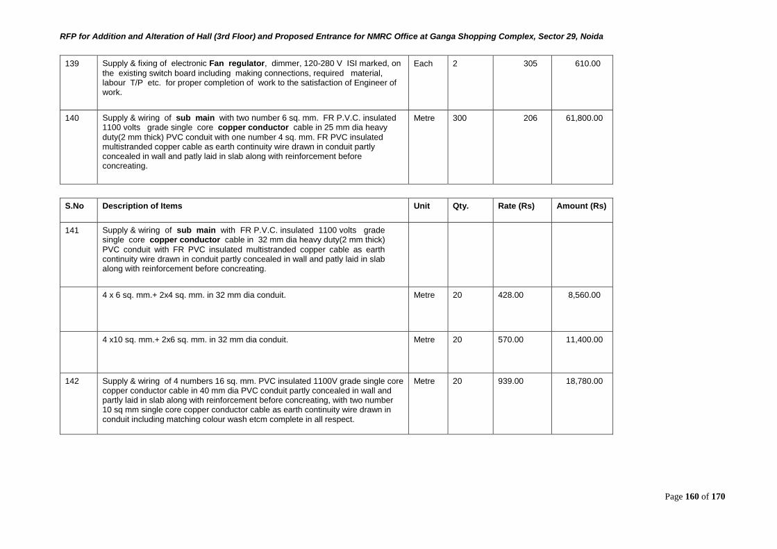
RFP for Addition and Alteration of Hall (3rd Floor) and Proposed Entrance for NMRC Office at Ganga Shopping Complex, Sector 29, Noida
Page 160 of 170
139 Supply & fixing of electronic Fan regulator, dimmer, 120-280 V ISI marked, on
the existing switch board including making connections, required material, labour T/P etc. for proper completion of work to the satisfaction of Engineer of work.
Each 2 305 610.00
140 Supply & wiring of sub main with two number 6 sq. mm. FR P.V.C. insulated 1100 volts grade single core copper conductor cable in 25 mm dia heavy
duty(2 mm thick) PVC conduit with one number 4 sq. mm. FR PVC insulated multistranded copper cable as earth continuity wire drawn in conduit partly concealed in wall and patly laid in slab along with reinforcement before concreating.
Metre 300 206 61,800.00
S.No Description of Items Unit Qty. Rate (Rs) Amount (Rs)
141 Supply & wiring of sub main with FR P.V.C. insulated 1100 volts grade single core copper conductor cable in 32 mm dia heavy duty(2 mm thick)
PVC conduit with FR PVC insulated multistranded copper cable as earth continuity wire drawn in conduit partly concealed in wall and patly laid in slab along with reinforcement before concreating.
4 x 6 sq. mm.+ 2x4 sq. mm. in 32 mm dia conduit. Metre 20 428.00 8,560.00
4 x10 sq. mm.+ 2x6 sq. mm. in 32 mm dia conduit. Metre 20 570.00 11,400.00
142 Supply & wiring of 4 numbers 16 sq. mm. PVC insulated 1100V grade single core copper conductor cable in 40 mm dia PVC conduit partly concealed in wall and partly laid in slab along with reinforcement before concreating, with two number 10 sq mm single core copper conductor cable as earth continuity wire drawn in conduit including matching colour wash etcm complete in all respect.
Metre 20 939.00 18,780.00
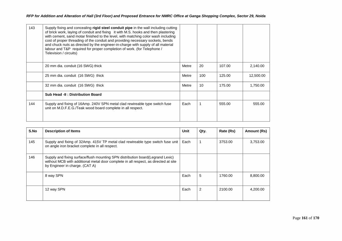
RFP for Addition and Alteration of Hall (3rd Floor) and Proposed Entrance for NMRC Office at Ganga Shopping Complex, Sector 29, Noida
Page 161 of 170
143 Supply fixing and concealing rigid steel conduit pipe in the wall including cutting
of brick work, laying of conduit and fixing it with M.S. hooks and then plastering with cement, sand motar finished to the level, with matching color wash including cost of proper threading of the conduit and providing necessary sockets, bends and chuck nuts as directed by the engineer-in-charge with supply of all material labour and T&P required for proper completion of work. (for Telephone / Television / circuits)
20 mm dia. conduit (16 SWG) thick Metre 20 107.00 2,140.00
25 mm dia. conduit (16 SWG) thick Metre 100 125.00 12,500.00
32 mm dia. conduit (16 SWG) thick Metre 10 175.00 1,750.00
Sub Head -II : Distribution Board
144 Supply and fixing of 16Amp. 240V SPN metal clad rewireable type switch fuse unit on M.D.F.E.G./Teak wood board complete in all respect.
Each 1 555.00 555.00
S.No Description of Items Unit Qty. Rate (Rs) Amount (Rs)
145 Supply and fixing of 32Amp. 415V TP metal clad rewireable type switch fuse unit on angle iron bracket complete in all respect.
Each 1 3753.00 3,753.00
146 Supply and fixing surface/flush mounting SPN distribution board(Legrand Lexic) without MCB with additional metal door complete in all respect, as directed at site by Engineer in charge. (CAT A)
8 way SPN Each 5 1760.00 8,800.00
12 way SPN Each 2 2100.00 4,200.00
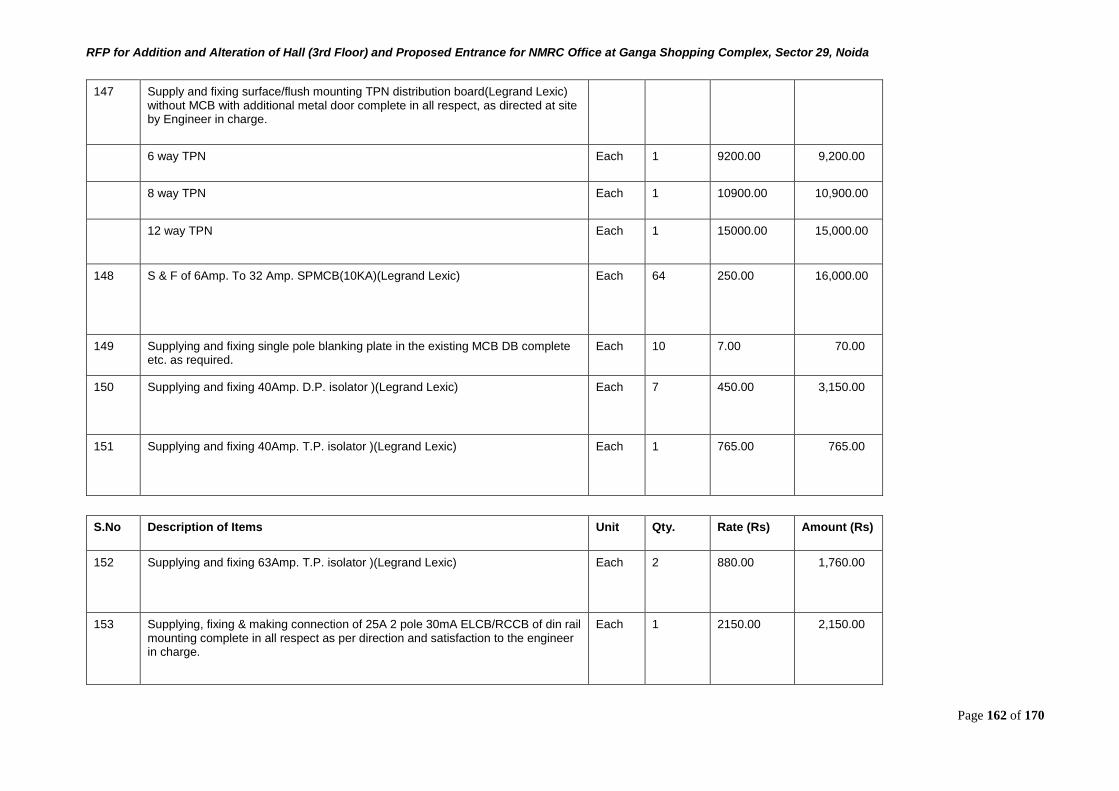
RFP for Addition and Alteration of Hall (3rd Floor) and Proposed Entrance for NMRC Office at Ganga Shopping Complex, Sector 29, Noida
Page 162 of 170
147 Supply and fixing surface/flush mounting TPN distribution board(Legrand Lexic) without MCB with additional metal door complete in all respect, as directed at site by Engineer in charge.
6 way TPN Each 1 9200.00 9,200.00
8 way TPN Each 1 10900.00 10,900.00
12 way TPN Each 1 15000.00 15,000.00
148 S & F of 6Amp. To 32 Amp. SPMCB(10KA)(Legrand Lexic) Each 64 250.00 16,000.00
149 Supplying and fixing single pole blanking plate in the existing MCB DB complete etc. as required.
Each 10 7.00 70.00
150 Supplying and fixing 40Amp. D.P. isolator )(Legrand Lexic) Each 7 450.00 3,150.00
151 Supplying and fixing 40Amp. T.P. isolator )(Legrand Lexic) Each 1 765.00 765.00
S.No Description of Items Unit Qty. Rate (Rs) Amount (Rs)
152 Supplying and fixing 63Amp. T.P. isolator )(Legrand Lexic) Each 2 880.00 1,760.00
153 Supplying, fixing & making connection of 25A 2 pole 30mA ELCB/RCCB of din rail mounting complete in all respect as per direction and satisfaction to the engineer in charge.
Each 1 2150.00 2,150.00
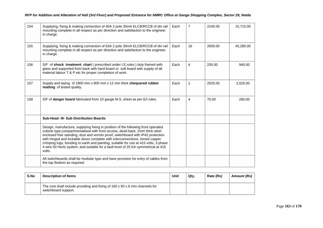
RFP for Addition and Alteration of Hall (3rd Floor) and Proposed Entrance for NMRC Office at Ganga Shopping Complex, Sector 29, Noida
Page 163 of 170
154 Supplying, fixing & making connection of 40A 2 pole 30mA ELCB/RCCB of din rail mounting complete in all respect as per direction and satisfaction to the engineer in charge.
Each 7 2245.00 15,715.00
155 Supplying, fixing & making connection of 63A 2 pole 30mA ELCB/RCCB of din rail mounting complete in all respect as per direction and satisfaction to the engineer in charge.
Each 16 2830.00 45,280.00
156 S/F of shock treatment chart ( prescribed under I.E.rules ) duly framed with
glass and supported from back with hard board or soft board with supply of all material labour T & P etc for proper completion of work.
Each 4 235.00 940.00
157 Supply and laying of 1800 mm x 900 mm x 12 mm thick chequered rubber matting of tested quality.
Each 1 2525.00 2,525.00
158 S/F of danger board fabricated from 10 gauge M.S. sheet as per E/I rules. Each 4 70.00 280.00
Sub-Head -III- Sub Distribution Boards
Design, manufacture, supplying fixing in position of the following front operated cubicle type,compartmentalised with front access, dead back, 2mm thick steel enclosed free standing, dust and vermin proof, switchboard with IP42 protection with hinged and lockable doors complete with interconnections, tinned copper crimping lugs, bonding to earth and painting, suitable for use at 415 volts, 3 phase 4 wire 50 Hertz system, and suitable for a fault level of 25 KA symmetrical at 415 volts.
All switchboards shall be modular type and have provision for entry of cables from the top /bottom as required.
S.No Description of Items Unit Qty. Rate (Rs) Amount (Rs)
The cost shall include providing and fixing of 100 x 50 x 6 mm channels for switchboard support.
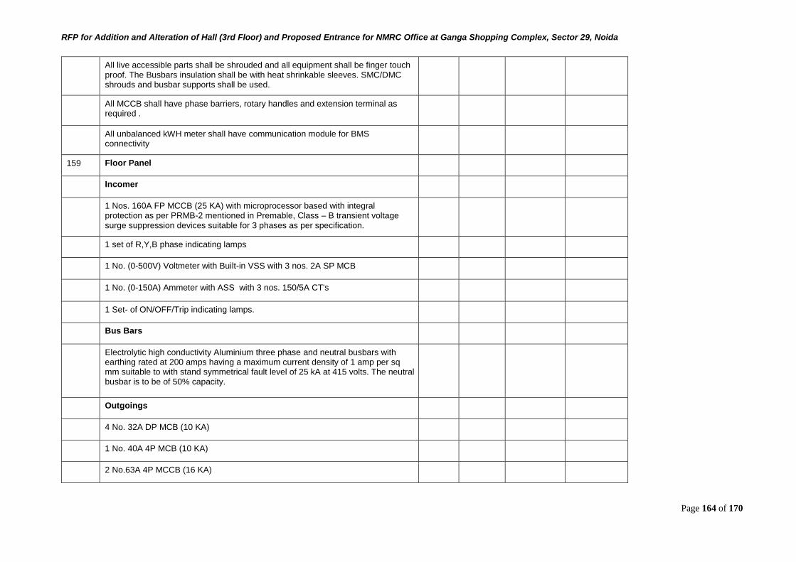
RFP for Addition and Alteration of Hall (3rd Floor) and Proposed Entrance for NMRC Office at Ganga Shopping Complex, Sector 29, Noida
Page 164 of 170
All live accessible parts shall be shrouded and all equipment shall be finger touch proof. The Busbars insulation shall be with heat shrinkable sleeves. SMC/DMC shrouds and busbar supports shall be used.
All MCCB shall have phase barriers, rotary handles and extension terminal as required .
All unbalanced kWH meter shall have communication module for BMS connectivity
159 Floor Panel
Incomer
1 Nos. 160A FP MCCB (25 KA) with microprocessor based with integral protection as per PRMB-2 mentioned in Premable, Class – B transient voltage surge suppression devices suitable for 3 phases as per specification.
1 set of R,Y,B phase indicating lamps
1 No. (0-500V) Voltmeter with Built-in VSS with 3 nos. 2A SP MCB
1 No. (0-150A) Ammeter with ASS with 3 nos. 150/5A CT's
1 Set- of ON/OFF/Trip indicating lamps.
Bus Bars
Electrolytic high conductivity Aluminium three phase and neutral busbars with earthing rated at 200 amps having a maximum current density of 1 amp per sq mm suitable to with stand symmetrical fault level of 25 kA at 415 volts. The neutral busbar is to be of 50% capacity.
Outgoings
4 No. 32A DP MCB (10 KA)
1 No. 40A 4P MCB (10 KA)
2 No.63A 4P MCCB (16 KA)
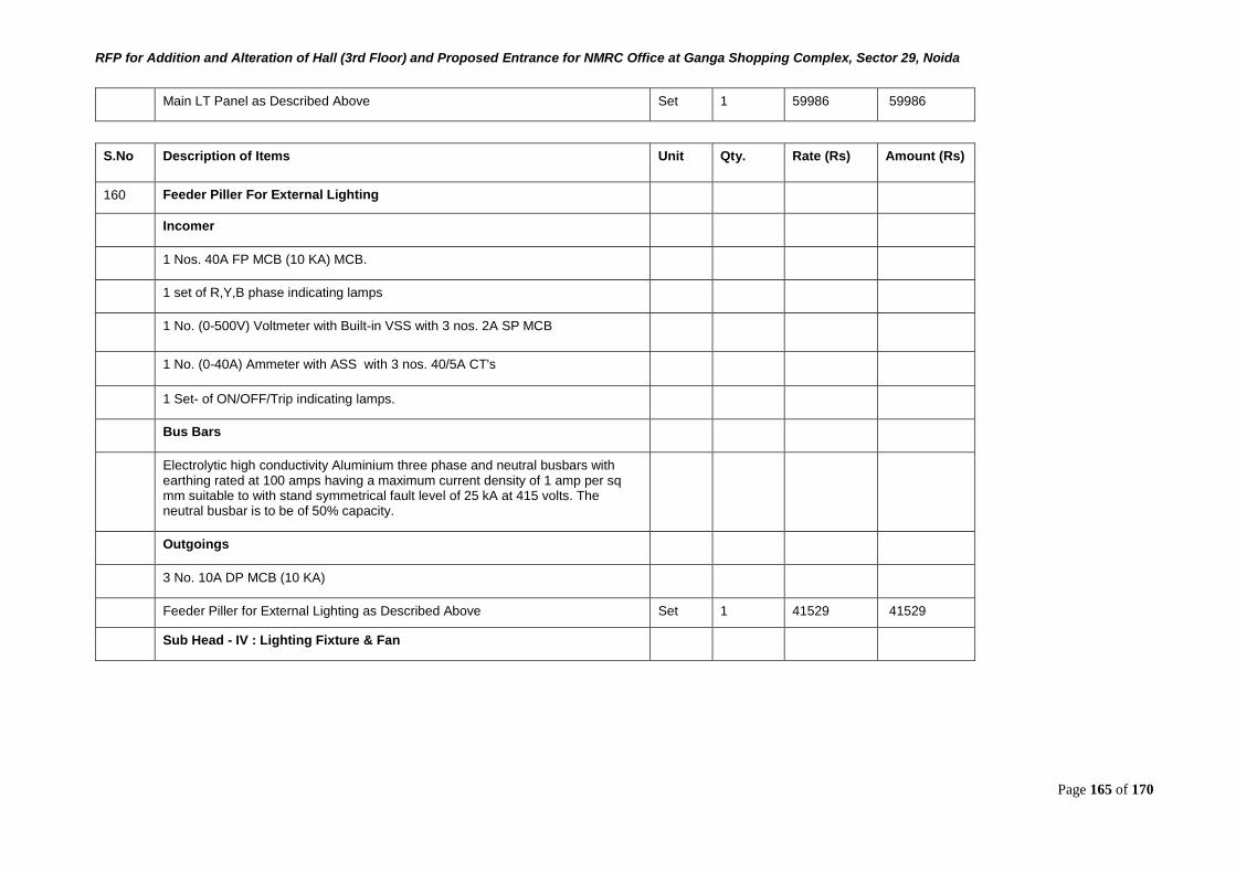
RFP for Addition and Alteration of Hall (3rd Floor) and Proposed Entrance for NMRC Office at Ganga Shopping Complex, Sector 29, Noida
Page 165 of 170
Main LT Panel as Described Above Set 1 59986 59986
S.No Description of Items Unit Qty. Rate (Rs) Amount (Rs)
160 Feeder Piller For External Lighting
Incomer
1 Nos. 40A FP MCB (10 KA) MCB.
1 set of R,Y,B phase indicating lamps
1 No. (0-500V) Voltmeter with Built-in VSS with 3 nos. 2A SP MCB
1 No. (0-40A) Ammeter with ASS with 3 nos. 40/5A CT's
1 Set- of ON/OFF/Trip indicating lamps.
Bus Bars
Electrolytic high conductivity Aluminium three phase and neutral busbars with earthing rated at 100 amps having a maximum current density of 1 amp per sq mm suitable to with stand symmetrical fault level of 25 kA at 415 volts. The neutral busbar is to be of 50% capacity.
Outgoings
3 No. 10A DP MCB (10 KA)
Feeder Piller for External Lighting as Described Above Set 1 41529 41529
Sub Head - IV : Lighting Fixture & Fan
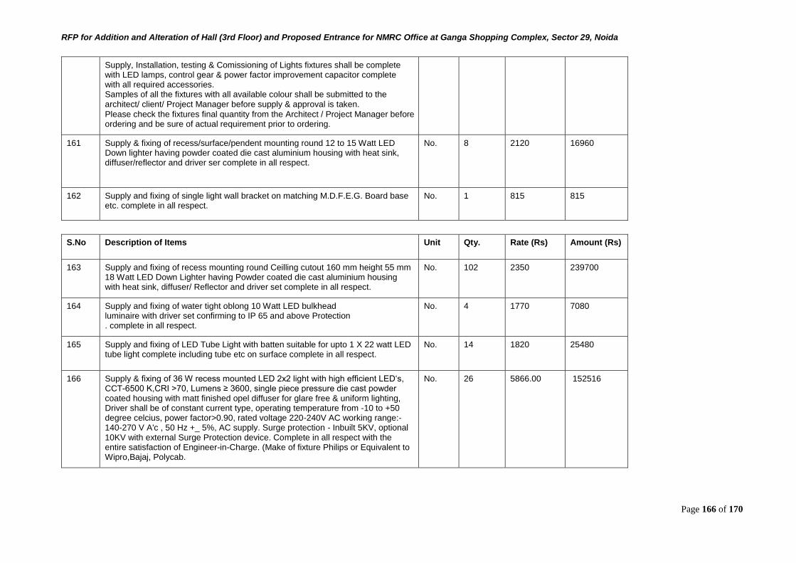
RFP for Addition and Alteration of Hall (3rd Floor) and Proposed Entrance for NMRC Office at Ganga Shopping Complex, Sector 29, Noida
Page 166 of 170
Supply, Installation, testing & Comissioning of Lights fixtures shall be complete with LED lamps, control gear & power factor improvement capacitor complete with all required accessories. Samples of all the fixtures with all available colour shall be submitted to the architect/ client/ Project Manager before supply & approval is taken. Please check the fixtures final quantity from the Architect / Project Manager before ordering and be sure of actual requirement prior to ordering.
161 Supply & fixing of recess/surface/pendent mounting round 12 to 15 Watt LED Down lighter having powder coated die cast aluminium housing with heat sink, diffuser/reflector and driver ser complete in all respect.
No. 8 2120 16960
162 Supply and fixing of single light wall bracket on matching M.D.F.E.G. Board base etc. complete in all respect.
No. 1 815 815
S.No Description of Items Unit Qty. Rate (Rs) Amount (Rs)
163 Supply and fixing of recess mounting round Ceilling cutout 160 mm height 55 mm 18 Watt LED Down Lighter having Powder coated die cast aluminium housing with heat sink, diffuser/ Reflector and driver set complete in all respect.
No. 102 2350 239700
164 Supply and fixing of water tight oblong 10 Watt LED bulkhead luminaire with driver set confirming to IP 65 and above Protection . complete in all respect.
No. 4 1770 7080
165 Supply and fixing of LED Tube Light with batten suitable for upto 1 X 22 watt LED tube light complete including tube etc on surface complete in all respect.
No. 14 1820 25480
166 Supply & fixing of 36 W recess mounted LED 2x2 light with high efficient LED‘s, CCT-6500 K,CRI >70, Lumens ≥ 3600, single piece pressure die cast powder coated housing with matt finished opel diffuser for glare free & uniform lighting, Driver shall be of constant current type, operating temperature from -10 to +50 degree celcius, power factor>0.90, rated voltage 220-240V AC working range:- 140-270 V A'c , 50 Hz +_ 5%, AC supply. Surge protection - Inbuilt 5KV, optional 10KV with external Surge Protection device. Complete in all respect with the entire satisfaction of Engineer-in-Charge. (Make of fixture Philips or Equivalent to Wipro,Bajaj, Polycab.
No. 26 5866.00 152516
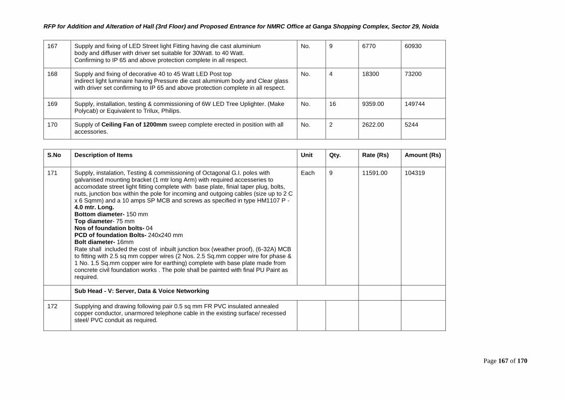
RFP for Addition and Alteration of Hall (3rd Floor) and Proposed Entrance for NMRC Office at Ganga Shopping Complex, Sector 29, Noida
Page 167 of 170
167 Supply and fixing of LED Street light Fitting having die cast aluminium body and diffuser with driver set suitable for 30Watt. to 40 Watt. Confirming to IP 65 and above protection complete in all respect.
No. 9 6770 60930
168 Supply and fixing of decorative 40 to 45 Watt LED Post top indirect light luminaire having Pressure die cast aluminium body and Clear glass with driver set confirming to IP 65 and above protection complete in all respect.
No. 4 18300 73200
169 Supply, installation, testing & commissioning of 6W LED Tree Uplighter. (Make Polycab) or Equivalent to Trilux, Philips.
No. 16 9359.00 149744
170 Supply of Ceiling Fan of 1200mm sweep complete erected in position with all
accessories. No. 2 2622.00 5244
S.No Description of Items Unit Qty. Rate (Rs) Amount (Rs)
171 Supply, instalation, Testing & commissioning of Octagonal G.I. poles with galvanised mounting bracket (1 mtr long Arm) with required accesseries to accomodate street light fitting complete with base plate, finial taper plug, bolts, nuts, junction box within the pole for incoming and outgoing cables (size up to 2 C x 6 Sqmm) and a 10 amps SP MCB and screws as specified in type HM1107 P - 4.0 mtr. Long. Bottom diameter- 150 mm Top diameter- 75 mm Nos of foundation bolts- 04 PCD of foundation Bolts- 240x240 mm Bolt diameter- 16mm Rate shall included the cost of inbuilt junction box (weather proof), (6-32A) MCB to fitting with 2.5 sq mm copper wires (2 Nos. 2.5 Sq.mm copper wire for phase & 1 No. 1.5 Sq.mm copper wire for earthing) complete with base plate made from concrete civil foundation works . The pole shall be painted with final PU Paint as required.
Each 9 11591.00 104319
Sub Head - V: Server, Data & Voice Networking
172 Supplying and drawing following pair 0.5 sq mm FR PVC insulated annealed copper conductor, unarmored telephone cable in the existing surface/ recessed steel/ PVC conduit as required.
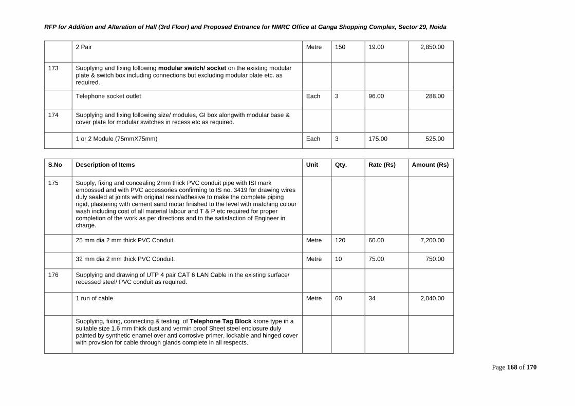
RFP for Addition and Alteration of Hall (3rd Floor) and Proposed Entrance for NMRC Office at Ganga Shopping Complex, Sector 29, Noida
Page 168 of 170
2 Pair Metre 150 19.00 2,850.00
173 Supplying and fixing following modular switch/ socket on the existing modular
plate & switch box including connections but excluding modular plate etc. as required.
Telephone socket outlet Each 3 96.00 288.00
174 Supplying and fixing following size/ modules, GI box alongwith modular base & cover plate for modular switches in recess etc as required.
1 or 2 Module (75mmX75mm) Each 3 175.00 525.00
S.No Description of Items Unit Qty. Rate (Rs) Amount (Rs)
175 Supply, fixing and concealing 2mm thick PVC conduit pipe with ISI mark embossed and with PVC accessories confirming to IS no. 3419 for drawing wires duly sealed at joints with original resin/adhesive to make the complete piping rigid, plastering with cement sand motar finished to the level with matching colour wash including cost of all material labour and T & P etc required for proper completion of the work as per directions and to the satisfaction of Engineer in charge.
25 mm dia 2 mm thick PVC Conduit. Metre 120 60.00 7,200.00
32 mm dia 2 mm thick PVC Conduit. Metre 10 75.00 750.00
176 Supplying and drawing of UTP 4 pair CAT 6 LAN Cable in the existing surface/ recessed steel/ PVC conduit as required.
1 run of cable Metre 60 34 2,040.00
Supplying, fixing, connecting & testing of Telephone Tag Block krone type in a
suitable size 1.6 mm thick dust and vermin proof Sheet steel enclosure duly painted by synthetic enamel over anti corrosive primer, lockable and hinged cover with provision for cable through glands complete in all respects.
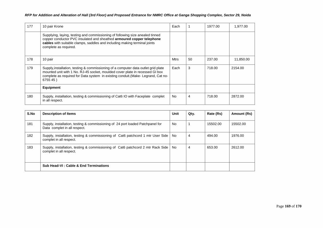
RFP for Addition and Alteration of Hall (3rd Floor) and Proposed Entrance for NMRC Office at Ganga Shopping Complex, Sector 29, Noida
Page 169 of 170
177 10 pair Krone Each 1 1977.00 1,977.00
Supplying, laying, testing and commissioning of following size anealed tinned copper conductor PVC insulated and sheathed armoured copper telephone cables with suitable clamps, saddles and including making terminal joints
complete as required.
178 10 pair Mtrs 50 237.00 11,850.00
179 Supply,installation, testing & commissioning of a computer data outlet grid plate mounted unit with 1 No. RJ-45 socket, moulded cover plate in recessed GI box complete as required for Data system in existing conduit.(Make- Legrand, Cat no- 6755 45 )
Each 3 718.00 2154.00
Equipment
180 Supply, installation, testing & commissioning of Cat6 IO with Faceplate complet in all respect.
No 4 718.00 2872.00
S.No Description of Items Unit Qty. Rate (Rs) Amount (Rs)
181 Supply, installation, testing & commissioning of 24 port loaded Patchpanel for Data complet in all respect.
No 1 15502.00 15502.00
182 Supply, installation, testing & commissioning of Cat6 patchcord 1 mtr User Side complet in all respect.
No 4 494.00 1976.00
183 Supply, installation, testing & commissioning of Cat6 patchcord 2 mtr Rack Side complet in all respect.
No 4 653.00 2612.00
Sub Head-VI : Cable & End Terminations

RFP for Addition and Alteration of Hall (3rd Floor) and Proposed Entrance for NMRC Office at Ganga Shopping Complex, Sector 29, Noida
Page 170 of 170
184 Supplying and laying of aluminium conductor PVC insulated armoured served sheathed cable 1100V grade at a depth of 750mm below ground level over a cushion of 75mm thick sand all around the protected with burnt bricks on sides and on top.On surface/ cable tray the cable run shall be fix on M.S. clamps etc. of suitable size or as directed by engineer incharge, complete in all respect. The armouring of the cable shall be properly connected with the earth conductor by clamp etc.
2 core 6 sq. mm Metre 250 263.00 65,750.00
4 core 6 sq. mm Metre 100 295.00 29,500.00
4 core 10 sq. mm Metre 20 325.00 6,500.00
3.5 core 35 sq. mm Metre 100 448.00 44,800.00
185 Supplying and laying of brass nickle plated compression gland for PVC insulated & armourd served sheathed, under ground cable including rubber ring etc. complete in all respect. The armouring of the cable shall be properly connected with the earth as per direction of ingineer in charge.
2 core 6 sq. mm Each 10 72 720.00
4 core 6 sq. mm Each 2 72 144.00
4 core 10 sq. mm Each 2 80 160.00
3.5 core 35 sq. mm Each 2 152.00 304.00
S.No Description of Items Unit Qty. Rate (Rs) Amount (Rs)
186 Supplying and fixing of plain orpin type copper tin plated cable socket (Lug) to the cable leads, insulating with tape & making connection etc. complete in all respect as per direction of the Engineer Incharge.
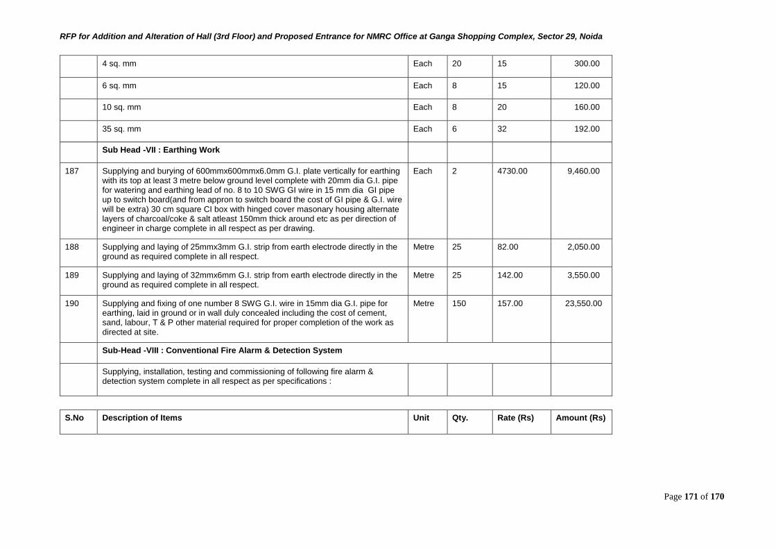
RFP for Addition and Alteration of Hall (3rd Floor) and Proposed Entrance for NMRC Office at Ganga Shopping Complex, Sector 29, Noida
Page 171 of 170
4 sq. mm Each 20 15 300.00
6 sq. mm Each 8 15 120.00
10 sq. mm Each 8 20 160.00
35 sq. mm Each 6 32 192.00
Sub Head -VII : Earthing Work
187 Supplying and burying of 600mmx600mmx6.0mm G.I. plate vertically for earthing with its top at least 3 metre below ground level complete with 20mm dia G.I. pipe for watering and earthing lead of no. 8 to 10 SWG GI wire in 15 mm dia GI pipe up to switch board(and from appron to switch board the cost of GI pipe & G.I. wire will be extra) 30 cm square CI box with hinged cover masonary housing alternate layers of charcoal/coke & salt atleast 150mm thick around etc as per direction of engineer in charge complete in all respect as per drawing.
Each 2 4730.00 9,460.00
188 Supplying and laying of 25mmx3mm G.I. strip from earth electrode directly in the ground as required complete in all respect.
Metre 25 82.00 2,050.00
189 Supplying and laying of 32mmx6mm G.I. strip from earth electrode directly in the ground as required complete in all respect.
Metre 25 142.00 3,550.00
190 Supplying and fixing of one number 8 SWG G.I. wire in 15mm dia G.I. pipe for earthing, laid in ground or in wall duly concealed including the cost of cement, sand, labour, T & P other material required for proper completion of the work as directed at site.
Metre 150 157.00 23,550.00
Sub-Head -VIII : Conventional Fire Alarm & Detection System
Supplying, installation, testing and commissioning of following fire alarm & detection system complete in all respect as per specifications :
S.No Description of Items Unit Qty. Rate (Rs) Amount (Rs)
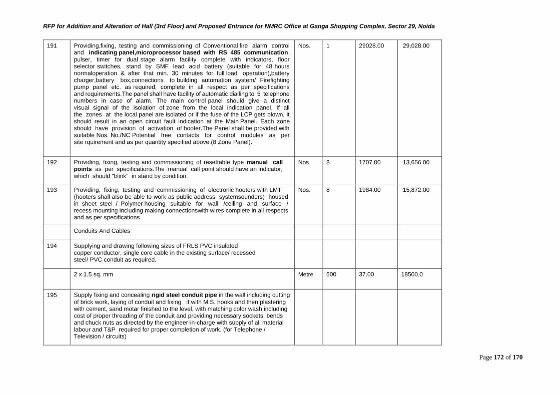
RFP for Addition and Alteration of Hall (3rd Floor) and Proposed Entrance for NMRC Office at Ganga Shopping Complex, Sector 29, Noida
Page 172 of 170
191 Providing,fixing, testing and commissioning of Conventional fire alarm control and indicating panel,microprocessor based with RS 485 communication,
pulser, timer for dual stage alarm facility complete with indicators, floor selector switches, stand by SMF lead acid battery (suitable for 48 hours normaloperation & after that min. 30 minutes for full load operation),battery charger,battery box,connections to building automation system/ Firefighting pump panel etc. as required, complete in all respect as per specifications and requirements.The panel shall have facility of automatic dialling to 5 telephone numbers in case of alarm. The main control panel should give a distinct visual signal of the isolation of zone from the local indication panel. If all the zones at the local panel are isolated or if the fuse of the LCP gets blown, it should result in an open circuit fault indication at the Main Panel. Each zone should have provision of activation of hooter.The Panel shall be provided with suitable Nos. No./NC Potential free contacts for control modules as per site rquirement and as per quantity specified above.(8 Zone Panel).
Nos. 1 29028.00 29,028.00
192 Providing, fixing, testing and commissioning of resettable type manual call points as per specifications.The manual call point should have an indicator,
which should "blink" in stand by condition.
Nos. 8 1707.00 13,656.00
193 Providing, fixing, testing and commissioning of electronic hooters with LMT (hooters shall also be able to work as public address systemsounders) housed in sheet steel / Polymer housing suitable for wall /ceiling and surface / recess mounting including making connectionswith wires complete in all respects and as per specifications.
Nos. 8 1984.00 15,872.00
Conduits And Cables
194 Supplying and drawing following sizes of FRLS PVC insulated copper conductor, single core cable in the existing surface/ recessed steel/ PVC conduit as required.
2 x 1.5 sq. mm Metre 500 37.00 18500.0
195 Supply fixing and concealing rigid steel conduit pipe in the wall including cutting
of brick work, laying of conduit and fixing it with M.S. hooks and then plastering with cement, sand motar finished to the level, with matching color wash including cost of proper threading of the conduit and providing necessary sockets, bends and chuck nuts as directed by the engineer-in-charge with supply of all material labour and T&P required for proper completion of work. (for Telephone / Television / circuits)
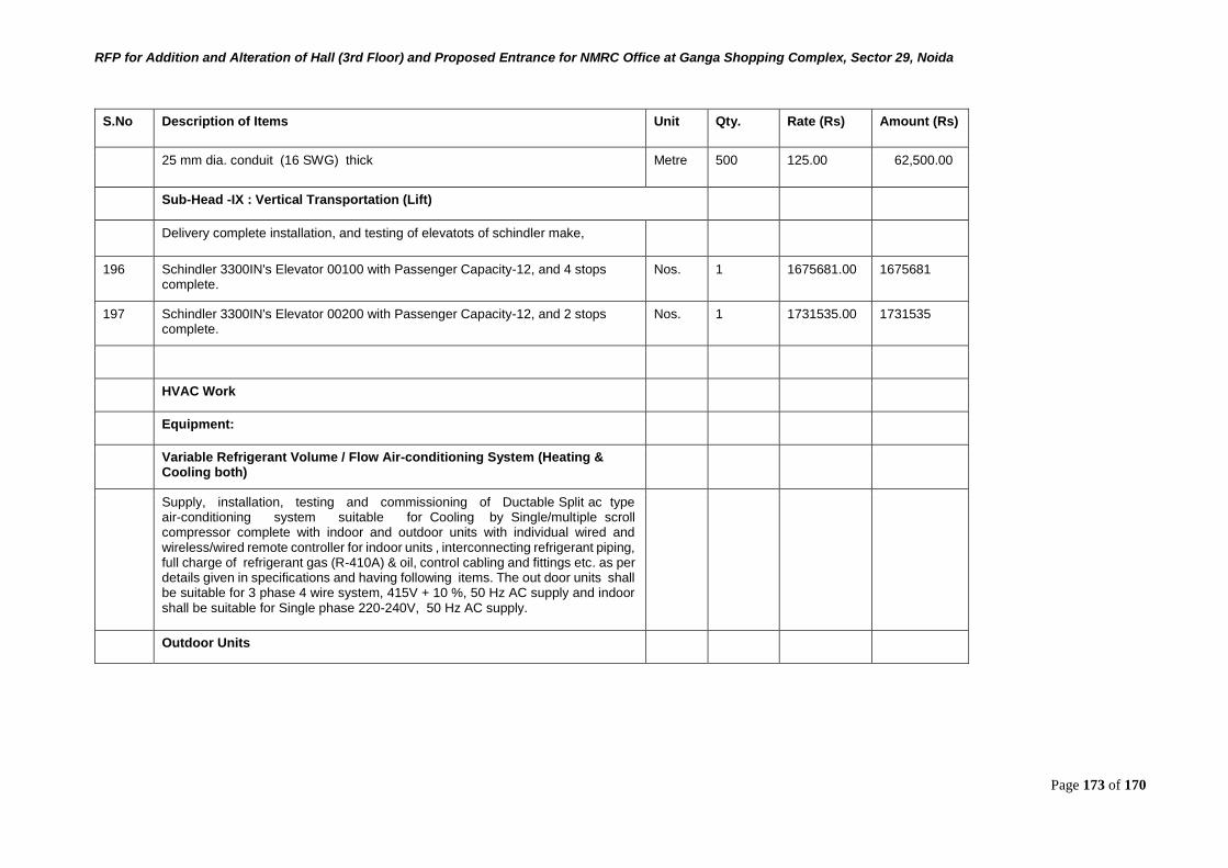
RFP for Addition and Alteration of Hall (3rd Floor) and Proposed Entrance for NMRC Office at Ganga Shopping Complex, Sector 29, Noida
Page 173 of 170
S.No Description of Items Unit Qty. Rate (Rs) Amount (Rs)
25 mm dia. conduit (16 SWG) thick Metre 500 125.00 62,500.00
Sub-Head -IX : Vertical Transportation (Lift)
Delivery complete installation, and testing of elevatots of schindler make,
196 Schindler 3300IN's Elevator 00100 with Passenger Capacity-12, and 4 stops complete.
Nos. 1 1675681.00 1675681
197 Schindler 3300IN's Elevator 00200 with Passenger Capacity-12, and 2 stops complete.
Nos. 1 1731535.00 1731535
HVAC Work
Equipment:
Variable Refrigerant Volume / Flow Air-conditioning System (Heating & Cooling both)
Supply, installation, testing and commissioning of Ductable Split ac type air-conditioning system suitable for Cooling by Single/multiple scroll compressor complete with indoor and outdoor units with individual wired and wireless/wired remote controller for indoor units , interconnecting refrigerant piping, full charge of refrigerant gas (R-410A) & oil, control cabling and fittings etc. as per details given in specifications and having following items. The out door units shall be suitable for 3 phase 4 wire system, 415V + 10 %, 50 Hz AC supply and indoor shall be suitable for Single phase 220-240V, 50 Hz AC supply.
Outdoor Units
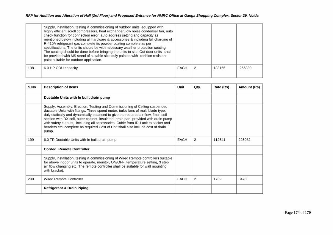
RFP for Addition and Alteration of Hall (3rd Floor) and Proposed Entrance for NMRC Office at Ganga Shopping Complex, Sector 29, Noida
Page 174 of 170
Supply, installation, testing & commissioning of outdoor units equipped with highly efficient scroll compressors, heat exchanger, low noise condenser fan, auto check function for connection error, auto address setting and capacity as mentioned below including all hardware & accessories & including full charging of R-410A refrigerant gas complete i/c powder coating complete as per specifications. The units should be with necessary weather protection coating. The coating should be done before bringing the units to site. Out door units shall be provided with MS stand of suitable size duly painted with corision resistant paint suitable for outdoor application.
198 6.0 HP ODU capacity EACH 2 133165 266330
S.No Description of Items Unit Qty. Rate (Rs) Amount (Rs)
Ductable Units with In built drain pump
Supply, Assembly, Erection, Testing and Commissioning of Ceiling suspended ductable Units with fittings. Three speed motor, turbo fans of multi blade type, duly statically and dynamically balanced to give the required air flow, filter, coil section with DX coil, outer cabinet, insulated drain pan, provided with drain pump with safety cutouts, including all accessories. Cable from IDU unit to socket and headers etc. complete as required.Cost of Unit shall also include cost of drain pump.
199 6.0 TR Ductable Units with In built drain pump EACH 2 112541 225082
Corded Remote Controller
Supply, installation, testing & commissioning of Wired Remote controllers suitable for above indoor units to operate, monitor, ON/OFF, temperature setting, 3 step air flow changing etc. The remote controller shall be suitable for wall mounting with bracket.
200 Wired Remote Controller EACH 2 1739 3478
Refrigerant & Drain Piping:
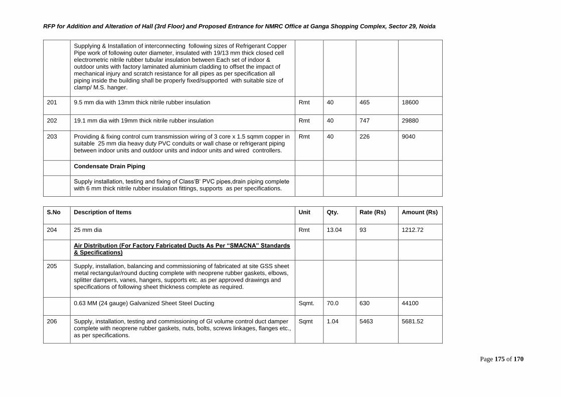
RFP for Addition and Alteration of Hall (3rd Floor) and Proposed Entrance for NMRC Office at Ganga Shopping Complex, Sector 29, Noida
Page 175 of 170
Supplying & Installation of interconnecting following sizes of Refrigerant Copper Pipe work of following outer diameter, insulated with 19/13 mm thick closed cell electrometric nitrile rubber tubular insulation between Each set of indoor & outdoor units with factory laminated aluminium cladding to offset the impact of mechanical injury and scratch resistance for all pipes as per specification all piping inside the building shall be properly fixed/supported with suitable size of clamp/ M.S. hanger.
201 9.5 mm dia with 13mm thick nitrile rubber insulation Rmt 40 465 18600
202 19.1 mm dia with 19mm thick nitrile rubber insulation Rmt 40 747 29880
203 Providing & fixing control cum transmission wiring of 3 core x 1.5 sqmm copper in suitable 25 mm dia heavy duty PVC conduits or wall chase or refrigerant piping between indoor units and outdoor units and indoor units and wired controllers.
Rmt 40 226 9040
Condensate Drain Piping
Supply installation, testing and fixing of Class‘B‘ PVC pipes,drain piping complete with 6 mm thick nitrile rubber insulation fittings, supports as per specifications.
S.No Description of Items Unit Qty. Rate (Rs) Amount (Rs)
204 25 mm dia Rmt 13.04 93 1212.72
Air Distribution (For Factory Fabricated Ducts As Per “SMACNA” Standards & Specifications)
205 Supply, installation, balancing and commissioning of fabricated at site GSS sheet metal rectangular/round ducting complete with neoprene rubber gaskets, elbows, splitter dampers, vanes, hangers, supports etc. as per approved drawings and specifications of following sheet thickness complete as required.
0.63 MM (24 gauge) Galvanized Sheet Steel Ducting Sqmt. 70.0 630 44100
206 Supply, installation, testing and commissioning of GI volume control duct damper complete with neoprene rubber gaskets, nuts, bolts, screws linkages, flanges etc., as per specifications.
Sqmt 1.04 5463 5681.52
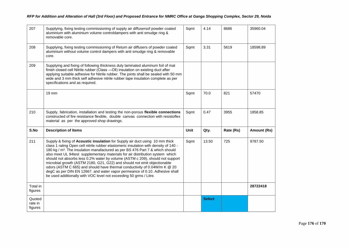
RFP for Addition and Alteration of Hall (3rd Floor) and Proposed Entrance for NMRC Office at Ganga Shopping Complex, Sector 29, Noida
Page 176 of 170
207 Supplying, fixing testing commissioning of supply air diffusersof powder coated aluminium with aluminium volume controldampers with anti smudge ring & removable core.
Sqmt 4.14 8686 35960.04
208 Supplying, fixing testing commissioning of Return air diffusers of powder coated aluminium without volume control dampers with anti smudge ring & removable core.
Sqmt 3.31 5619 18598.89
209 Supplying and fixing of following thickness duly laminated aluminum foil of mat finish closed cell Nitrile rubber (Class ―O‖) insulation on existing duct after applying suitable adhesive for Nitrile rubber. The joints shall be sealed with 50 mm wide and 3 mm thick self adhesive nitrile rubber tape insulation complete as per specifications and as required.
19 mm Sqmt 70.0 821 57470
210 Supply, fabrication, installation and testing the non-porous flexible connections
constructed of fire resistance flexible, double canvas connection with resistoflex material as per the approved shop drawings.
Sqmt 0.47 3955 1858.85
S.No Description of Items Unit Qty. Rate (Rs) Amount (Rs)
211 Supply & fixing of Acoustic insulation for Supply air duct using 10 mm thick
class 1 rating Open cell nitrile rubber elastomeric insulation with density of 140 - 180 kg / m³. The insulation manafactured as per BS 476 Part 7 & which should also meet UL 94test supplementary materials for air distribution system which should not absorbs less 0.2% water by volume (ASTM c 209), should not support microbial growth (ASTM 2180, G21, G22) and should not emit objectionable odors (ASTM C 665) and should have thermal conductivity of 0.04W/m K @ 20 degC as per DIN EN 12667. and water vapor permeance of 0.10. Adhesive shall be used additionally with VOC level not exceeding 50 grms / Litre.
Sqmt 13.50 725 9787.50
Total in figures
28722418
Quoted rate in figures
Select
RFP for Addition and Alteration of Hall (3rd Floor) and Proposed Entrance for NMRC Office at Ganga Shopping Complex, Sector 29, Noida
Page 177 of 170
Quoted rate in words
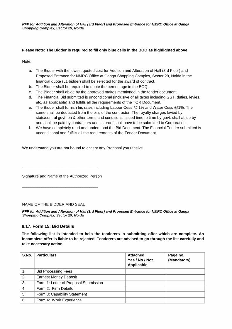
RFP for Addition and Alteration of Hall (3rd Floor) and Proposed Entrance for NMRC Office at Ganga Shopping Complex, Sector 29, Noida
Please Note: The Bidder is required to fill only blue cells in the BOQ as highlighted above
Note:
a. The Bidder with the lowest quoted cost for Addition and Alteration of Hall (3rd Floor) and
Proposed Entrance for NMRC Office at Ganga Shopping Complex, Sector 29, Noida in the
financial quote (L1 bidder) shall be selected for the award of contract. b. The Bidder shall be required to quote the percentage in the BOQ. c. The Bidder shall abide by the approved makes mentioned in the tender document. d. The Financial Bid submitted is unconditional (inclusive of all taxes including GST, duties, levies,
etc. as applicable) and fulfills all the requirements of the TOR Document. e. The Bidder shall furnish his rates including Labour Cess @ 1% and Water Cess @1%. The
same shall be deducted from the bills of the contractor. The royalty charges levied by
stats/central govt. on & other terms and conditions issued time to time by govt. shall abide by
and shall be paid by contractors and its proof shall have to be submitted to Corporation. f. We have completely read and understood the Bid Document. The Financial Tender submitted is
unconditional and fulfills all the requirements of the Tender Document.
We understand you are not bound to accept any Proposal you receive.
___________________________________
Signature and Name of the Authorized Person
___________________________________
NAME OF THE BIDDER AND SEAL
RFP for Addition and Alteration of Hall (3rd Floor) and Proposed Entrance for NMRC Office at Ganga Shopping Complex, Sector 29, Noida
8.17. Form 15: Bid Details
The following list is intended to help the tenderers in submitting offer which are complete. An
incomplete offer is liable to be rejected. Tenderers are advised to go through the list carefully and
take necessary action.
S.No. Particulars Attached Yes / No / Not Applicable
Page no. (Mandatory)
1 Bid Processing Fees 2 Earnest Money Deposit 3 Form 1: Letter of Proposal Submission 4 Form 2: Firm Details 5 Form 3: Capability Statement 6 Form 4: Work Experience
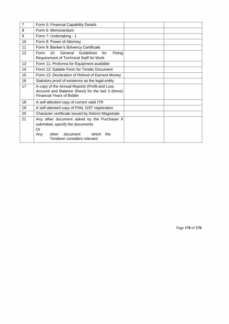
7 Form 5: Financial Capability Details 8 Form 6: Memorandum 9 Form 7: Undertaking - 1 10 Form 8: Power of Attorney 11 Form 9: Banker‘s Solvency Certificate 12 Form 10: General Guidelines for Fixing
Requirement of Technical Staff for Work
13 Form 11: Proforma for Equipment available 14 Form 12: Salable Form for Tender Document 15 Form 13: Declaration of Refund of Earnest Money 16 Statutory proof of existence as the legal entity 17 A copy of the Annual Reports (Profit and Loss
Account and Balance Sheet) for the last 3 (three) Financial Years of Bidder
18 A self-attested copy of current valid ITR 19 A self-attested copy of PAN, GST registration 20 Character certificate issued by District Magistrate 21 Any other document asked by the Purchaser if
submitted, specify the documents Or Any other document which the Tenderer considers relevant
Page 170 of 170
1
NOIDA METRO RAIL CORPORATION LTD.
(A joint venture of Govt. of India and Govt. of U.P.)
GENERAL CONDITIONS OF CONTRACT
(July 2018)
NOIDA METRO RAIL CORPORATION LTD. Block – III, 3rd Floor, Ganga Shopping Complex,
Sector-29, Noida – 201 301,
District Gautam Budh Nagar, Uttar Pradesh, India
General Conditions of Contract
2
Content
1. Definitions and interpretations ..................................................................................................... 7
1.1. Definitions ................................................................................................................. .............. 7
1.2. Interpretation ......................................................................................................................... 13
1.3. Law and Language ............................................................................................................ .... 14
1.4. Contract Agreement............................................................................................................... 14
1.5. Priority of Documents ....................................................................................................... ..... 14
1.6. Care of Supply of Construction and/or Manufacture Documents ............................................. 14
1.7. Communications .............................................................................................................. ...... 15
1.8. Employer’s Use of Contractor’s Documents ........................................................................... 15
1.9. Contractor’s Use of Employer’s Documents ........................................................................... 15
1.10. Compliance with Statutes, Regulations and Laws .................................................................. 15
1.11. Joint and Several Liability ................................................................................................. ..... 16
2. The Employer ............................................................................................................................ 17
2.1. General Obligations ......................................................................................................... ...... 17
2.2. Access to and Possession of the Site..................................................................................... 17
2.3. Permits, Licences or Approvals .............................................................................................. 17
2.4. Assignment by Employer ....................................................................................................... 17
3. The Engineer................................................................................................................. ............ 18
3.1. Appointment of Engineer ..................................................................................................... .. 18
3.2. Duties and Authorities of Engineer ........................................................................................ . 18
3.3. Engineer’s Authority to Delegate ............................................................................................ 18
3.4. Engineer’s Instructions................................................................................................... ........ 19
3.5. Engineer to Attempt Agreement ............................................................................................. 19
4. The Contractor ...................................................................................................... .................... 20
4.1. General Obligations ......................................................................................................... ...... 20
4.2. Performance security ............................................................................................................. 21
4.3. Representation on Works ..................................................................................................... . 23
4.4. Facilities for and co-ordination with Others. ............................................................................ 23
4.5. Sub-contractors ................................................................................................................. .... 25
4.6. Assignment of Contractor’s and Sub-contractor’s Obligations ................................................. 27
4.7. Compensation for Breach ..................................................................................................... . 27
4.8. Setting Out ............................................................................................................................ 27
4.9. Site Data ................................................................................................................... ............ 28
4.10. Sufficiency of accepted Contract Amount ............................................................................... 28
4.11. Access Route ................................................................................................................ ........ 28
4.12. Rights of way and Facilities................................................................................................. ... 29
4.13. Programmes ....................................................................................................... ................... 29
General Conditions of Contract
3
4.14. Progress Reports ............................................................................................................ ....... 30
4.15. Contractor's Equipment ......................................................................................................... 30
4.16. Safety of Works ............................................................................................................. ........ 30
4.17. Protection of the Environment ................................................................................................ 31
4.18. Electricity Water and Gas ................................................................................................... ... 31
4.19. Tools, Plants And Equipment Supplied By The Employer ....................................................... 31
4.20. Employer’s Materials & Excavated Materials .......................................................................... 32
4.21. Sheds, Stores, Yards ............................................................................................................. 32
4.22. Temporary Works ............................................................................................................. ..... 32
4.23. Unforeseeable Physical Conditions ........................................................................................ 32
4.24. Access for Engineer.......................................................................................................... ..... 33
4.25. Access Road and Way Leaves .............................................................................................. 33
4.26. Contractor to keep Site Clear ............................................................................................... .. 33
4.27. Security of the Site ........................................................................................................ ........ 34
4.28. Contractor's Operations on Site ....................................................................................... ...... 34
4.29. Discoveries ................................................................................................................. ........... 34
4.30. Publicity ................................................................................................ ................................. 34
4.31. Disclosure Of Relationship .................................................................................................. ... 34
4.32. Use Of Explosives ................................................................................................................. 35
4.33. Corrupt or fraudulent practices ............................................................................................. .. 35
5. Design....................................................................................................................................... 36
5.1. General Obligations ......................................................................................................... ...... 36
5.2. Contractor’s warranty of design.............................................................................................. 36
5.3. Construction and/or Manufacture Documents......................................................................... 37
5.4. Technical Standards and Regulations .................................................................................... 38
5.5. Samples ..................................................................................................................... ........... 39
5.6. As-Built Drawings and Documents ......................................................................................... 39
5.7. Operation and Maintenance Manuals ..................................................................................... 39
5.8. Intellectual Property Rights and Royalties .............................................................................. 40
6. Staff and Labour ............................................................................................................ ............ 42
6.1. Engagement of Staff and Labour ........................................................................................... 42
6.2. Rates of Wages and Conditions of Labour ............................................................................. 42
6.3. Persons in the service/ retired of Employer/ Engineer ............................................................ 42
6.4. Labour Laws ................................................................................................................. ......... 43
6.5. Working Hours ....................................................................................................................... 43
6.6. Facilities for Staff and Labour ............................................................................................. ... 44
6.7. Health and Safety .................................................................................................................. 44
6.8. Contractor's Superintendence ................................................................................................ 44
General Conditions of Contract
4
6.9. Provision Of Efficient And Competent Staff ............................................................................ 44
6.10. Preservation of Peace and orderly conduct ............................................................................ 45
6.11. Labour to be Contractor’s Employee ...................................................................................... 45
6.12. Report Of Accidents To Labour .............................................................................................. 45
6.13. Claim` on account of violation of Labour laws......................................................................... 46
7. Quality Control ............................................................................................................. ............. 47
7.1. Manner of Execution .............................................................................................................. 47
7.2. Source of material .......................................................................................................... ....... 47
7.3. Delivery to Site ............................................................................................................. ......... 47
7.4. Inspection ........................................................................................................... ................... 47
7.5. Testing ..................................................................................................................... ............. 47
7.6. Rejection ............................................................................................................................... 48
7.7. Liability after Inspection and Testing ...................................................................................... 49
7.8. Ownership of Plant and Materials .......................................................................................... 49
7.9. Cost of Employer’s Attendance Including Travel .................................................................... 49
7.10. Covering up of Works .................................................................. .......................................... 49
7.11. Tests after Completion ...................................................................................................... ..... 50
7.12. Integrated testing and system commissioning ........................................................................ 51
8. Time Management ............................................................................................................. ....... 53
8.1. Commencement of Works ..................................................................................................... 53
8.2. Time for Completion ......................................................................................................... ..... 53
8.3. Delay ..................................................................................................................................... 53
8.4. Extension of Time for Completion ...................................................................................... .... 53
8.5. Liquidated Damages for Delay ............................................................................................... 55
8.6. Rate of Progress........................................................................................................ ............ 56
8.7. Suspension of Work........................................................................................................... .... 56
8.8. Consequences of Suspension ................................................................................ ............... 56
8.9. Resumption of Work .......................................................................................................... .... 57
9. Employer’s Taking Over ................................................................................. ........................... 58
9.1. Taking Over Certificate ..................................................................................................... ..... 58
9.2. Taking over of Parts of the Works ......................................................... ................................. 58
10. Defects Liability ........................................................................................................... .............. 59
10.1. Completion of Outstanding Work and Remedying Defects ..................................................... 59
10.2. Cost of Remedying Defects ................................................................................................... 59
10.3. Extension of Contract Period ................................................................ ................................. 59
10.4. Failure to Remedy Defects.................................................................................................... . 60
10.5. Removal of Defective Work.................................................................................................... 60
10.6. Further Tests ............................................................................................................... .......... 60
General Conditions of Contract
5
10.7. Right of Access...................................................................................................................... 60
10.8. Contractor to Search ........................................................................................................ ...... 61
10.9. Performance Certificate ......................................................................................................... 61
10.10. Unfulfilled Obligations ..................................................................................................... ... 61
10.11. Emergency defect rectification ........................................................................................... 61
11. Contract Price and Payment .................................................................................................. .... 62
11.1. The Contract Price ................................................................................................................. 62
11.2. Advances .................................................................................................................... .......... 63
11.3. Provisional Payment Against Material at Site ......................................................................... 65
11.4. Application for Interim Payment Certificates ........................................................................... 65
11.5. Issue of Interim Payment Certificates ..................................................................................... 66
11.6. Payment- Interim and Final .................................................................................................... 67
11.7. Statement at Completion ....................................................................................................... 68
11.8. Application for Final Payment Certificate ................................................................................ 68
11.9. Discharge .......................................................................................................................... .... 68
11.10. Issue of Final Payment Certificate ...................................................................................... 69
11.11. Cessation of Employer's Liability ........................................................................................ 69
11.12. Calculation of Payments in Foreign Currency ..................................................................... 69
11.13. Round off ........................................................................................................................... 69
11.14. Payment By Cheque and E-Payment ................................................................................. 69
11.15. Tax Deduction at Source.................................................................................................... 69
11.16. Production of Vouchers ...................................................................................................... 70
11.17. Withholding And Lien For Sums Claimed ........................................................................... 70
11.18. Signature On Receipts For Payments ................................................................................ 70
11.19. Post Payment Audit ........................................................................................................... 71
11.20. Recovery of money due to the Employer ............................................................................ 71
12. Variations .................................................................................................................................. 72
12.1. Right to Vary............................................................................................................. ............. 72
12.2. Contractor’s Variations...................................................................................................... ..... 72
12.3. Employer’s Variations ............................................................................................................ 73
12.4. Variation Procedure ......................................................................................................... ...... 74
12.5. Variation in the Bill of Quantities ............................................................................................ 74
12.6. Payment in Applicable Currencies.......................................................................................... 75
13. Termination of the Contract ....................................................................................................... 76
13.1. Notice to Contractor ........................................................................................................ ....... 76
13.2. Termination Of Contract Due To Contractor’s Default ............................................................. 76
13.3. Default of Employer ......................................................................................................... ...... 78
14. Risk and Responsibility ..................................................................................................... ........ 81
General Conditions of Contract
6
14.1. Indemnity.......................................................................................................... ..................... 81
14.2. Contractor’s Care of the Works .............................................................................................. 81
14.3. Employer’s Risks ..................................................................................... .............................. 82
14.4. Consequences of Employer’s ................................................................................................ 82
14.5. Contractor’s Risks ................................................................................................................. 83
14.6. Limitation of Liability ..................................................................................................... ......... 83
15. Insurance .................................................................................................................................. 84
15.1. Professional Indemnity Insurance .......................................................................................... 84
15.2. Insurance for Works and Contractor’s Equipment................................................................... 84
15.3. Insurance against injury to Persons and Damage to Property ................................................. 84
15.4. Insurance for Workers ................................................................... ........................................ 85
15.5. General Requirements for Insurances .................................................................................... 85
16. Force Majeure ........................................................................................................................... 87
16.1. Definition of Force Majeure ................................................................................................. ... 87
16.2. Effect of Force Majeure Event ............................................................................................... . 87
16.3. Contractor’s Responsibility................................................................................................ ..... 87
16.4. Employer’s Responsibility ................................................................................................... ... 87
16.5. Payment to Contractor ............................................................................................. .............. 87
16.6. Resumption of Work .......................................................................................................... .... 87
16.7. Optional Termination, Payment and Release ......................................................................... 88
16.8. Release from Performance Under the Law ............................................................................. 88
17. Claims, Disputes, Conciliation And Arbitration............................................................................ 89
17.1. Procedure for Claims ........................................................................................................ ..... 89
17.2. Payment for Claims ................................................................................................... ............ 89
17.3. No legal action till Dispute Settlement Procedure is exhausted ............................................... 89
17.4. Notice of Dispute ........................................................................................................... ........ 89
17.5. Two Stages for Dispute Resolution ........................................................................................ 90
17.6. Conciliation .......................................................................................................... .................. 90
17.7. Conciliation Procedure ...................................................................................................... ..... 90
17.8. Termination of Conciliation Proceedings ............................................................ .................... 91
17.9. Arbitration ................................................................................................................. ............. 91
17.10. Interest on Arbitration Award .............................................................................................. 92
17.11. Cost of Arbitration ......................................................................................................... ..... 92
17.12. Jurisdiction of Courts ......................................................................................................... 92
17.13. Suspension of Work on Account of Arbitration .................................................................... 92
18. Service of Notices ..................................................................................................................... 94
18.1. Notice to Contractor ........................................................................................................ ....... 94
18.2. Notice to Employer and Engineer ........................................................................................... 94
General Conditions of Contract
7
18.3. Change of Address ........................................................................................................... ..... 94
1. Definitions and interpretations
1.1. Definitions In the contract (as defined below) the words and expressions defined below shall have the meanings
assigned to them, except where the context requires otherwise. Words
indicating persons or parties include corporations and other legal entities
except where the context requires otherwise.
1.1.1. Documents
“Appendix to Form of Tender” means the completed pages in title Appendix,
which are appended to and form part of the Tender.
“Bill of Quantity” means a document containing various items of payment and
contains schedule of Payment also.
“Construction and/or Manufacture Documents” means all drawings, calculations,
computer software (programs), samples, patterns, models, operation and
maintenance manuals, and other manuals and information of a similar nature,
to be submitted by the Contractor.
“Contract” means the Contract Agreement, the Notice of Award, the letter of
tender, General Conditions of Contract, Special Conditions of Contract, the Employer’s Requirements, the Tender, the Notice Inviting
Tender, Instructions to Tenderers, the Contractor’s Proposal, the Schedules,
and such further documents which are listed in the Notice of Award or
Contract Agreement (if completed).
“Contract Agreement” means the contract agreement referred to in Sub-Clause 1.4.
It shall also include all subsequent modifications/ amendments to the Contract
as a result of the communications or negotiation proceedings between the
parties.
“Contractor’s Proposal” means the proposal submitted by the Contractor with the
Tender, as modified and accepted by the Employer and included in the
Contract. Such documents may include the Contractor’s preliminary design.
“Contractor’s Document” means the calculations, computer programme and other
software, drawings, manuals and other documents of a technical nature (if
any) supplied by the Contractor under the Contract.
“Design Data” means all specifications, plans, drawings, details, graphs, sketches,
models, levels, setting-out dimensions, calculations duly checked by the
Contractor and other documents relating to the design of the Works prepared
or to be prepared by or on behalf of the Contractor.
“Drawings” means the Employer’s Drawings and the Drawings submitted by the
Contractor and any modification of such drawings as any, from time to time,
be furnished or for which the Engineer has issued a Notice of No Objection.
General Conditions of Contract
8
“Employer’s Requirements” means the description of the scope, standard, design
criteria, specifications, drawings, programme of work, indigenisation
programme (where applicable) as included in the Contract, and any alterations
and modifications thereto in accordance with the Contract.
“Interim Payment Schedule” means the schedule included for each Cost Centre
in the Pricing Document and accepted by the Employer to be used for interim
payments in relation to achievement of milestones under that Cost Centre, as
the same may be revised from time to time in accordance with Clause 11.
“Notice of Award” means the written notice issued by NMRC to the
Selected Bidder(s) intimating the acceptance of Selected Bidder's Proposal for
the award of Contract
“Notice to Proceed” means the notice issued by the Employer to the Contractor
communicating the date on which the Works are to be commenced.
"Letter of Tender” means the document entitled letter of tender, which was
completed by the Contractor and includes the signed offer to the Employer for
the Works.
“Safety, Health and Environmental (SHE) Manual” means the Employer’s
manual containing the requirements and conditions to be met during the
execution of the Works by the Contractor.
“Schedules” means the information and data submitted with the Tender, as
included in the Contract.
“Tender” means the Contractor’s priced offer to the Employer for the designing
where ever applicable, execution, manufacture, and completion of the whole
of Works, testing and commissioning (including Integrated Testing and
Commissioning where ever applicable) and remedying of any defects therein,
as accepted by the Letter of Acceptance.
“Schedule of Milestones” means the schedule included in each Cost Centre in the
Pricing Document, describing the Milestones and stipulating dates by which
the Milestones are to be achieved under that Cost Centre in order to maintain
interim payments by the Employer to the Contractor in accordance with the
Interim Payment Schedule for that Cost Centre, as the same may be revised
from time to time in accordance with the Contract.
“Schedule of Payment” means the schedule included in the Bill of Quantity for
payment in various stages on part of the works.
“Special Conditions of Contract” means any special conditions of contract issued
by the Employer prior to submission of the Tender or negotiated and agreed
in writing by the Employer and the Contractor prior to and conditional upon
acceptance of the Tender.
General Conditions of Contract
9
“Works Programme” means the programme showing the sequence, method and
timing of investigations, design, issue of No Objection Notices, execution,
manufacture, delivery to site, erection, installation, testing, commissioning of
the Works (including Integrated Testing and Commissioning), indigenisation
(where applicable) and related activities in the form and content prescribed by
the Employer’s Requirements, or any amended or varied version thereof, as
submitted by the Contractor and for which the Engineer has issued a Notice
of No Objection.
1.1.2. Persons
“Party” means the Employer or the Contractor as the context requires “Tenderer or
Bidder” means the person submitting a bid/Tender.
“Contractor” means the person whose Tender has been accepted by the Employer
and the legal successors in title to such person, but not (except with the consent
of the Employer) any assignee of such person.
“Contractor’s Representative” shall mean a person named by the Contractor in
the Contract or appointed from time to time by the Contractor under Sub-clause
4.3 to act on behalf of Contractor.
"Designated Contractors" means any of the following whose activities or the
works they are engaged to carry out, affect or are affected by the Works, in any
way or at any time:
a. Contractors, design consultants and utility authorities engagedon the
Project from time to time by the Employer;
b. Sub-contractors of any tier of the contractors above; providedthat the
definition shall exclude the Contractor and his subcontractors of any
tier in relation to the Works.
“Other Contractor” means a person employed by or having Contract directly or
indirectly with the Employer otherwise than through the Contractor.
“Designer” means the Contractor, or part of the group forming the contractor,
person, firm or company or group of companies, or any replacement, carrying out
the Design of Works or part thereof.
“Employer” means NOIDA METRO RAIL CORPORATION LIMITED
(NMRC), its legal successors and assignees.
General Conditions of Contract
10
“Engineer” means any person nominated or appointed from time to time by the
Employer to act as the Engineer for the purposes of the Contract and notified as
such in writing to the Contractor.
“Engineer’s Representative” means any Assistant of the Engineer appointed
from time to time by the Engineer under Sub-clause 3.3.
“Sub-contractor” means any person named in the Contract as a subcontractor,
manufacturer or supplier for a part of the Works or any person to whom a part
of the Works has been sub-contracted with the consent of the Employer and the legal
successors in title to such person, but not any assignee of such person.
1.1.3. Dates, Times and
Periods
“Commencement Date” means the date on which the Contractor shall commence
the Works on the written instructions of the Employer contained in the Notice to
Proceed.
“Contract Period” means the period from the Commencement Date to the end of
Defects Liability Period including Integrated Testing and Commissioning and as
certified by the Engineer under Clause 7.11 (or as extended under Sub-Clause 10.3).
“Day” means a calendar day, “Week” means 7 calendar days, and “Month” means
a calendar month and “Year” means 365 days.
“Effective Date” means the date on which the Contract comes into force and
effect
“Gazetted Holiday” means every holiday which is observed by Noida Metro Rail
Corporation Limited as a gazetted holiday as well as a weekly holiday.
“General Holiday” means Sunday.
“Key Date” means a date identified as such in the Contract.
“Milestone” means the completion of a part of the Works or the occurrence of an
event identified as such in the Schedule of Milestones.
“Milestone Date” means the date prescribed in the Schedule of Milestone by
which a Milestone is to be achieved if Interim Payments for the Cost Centre in
which the Milestone is included are not to be suspended.
“Stage” means level of progress of the works identified as such and more
particularly described in the Employer’s Requirements for which a Key Date
for the achievement thereof is stipulated in the Contract.
“Time for Completion” means the time for completing the Works or a section
or a part thereof (as the case may be), and passing the Tests on Completion,
General Conditions of Contract
11
including Integrated Testing and Commissioning, as stated in the contract, calculated from
the Commencement Date.
1.1.4. Tests and Completion
“Factory Tests” means the tests required to be carried out in the factory premises
on components, equipment, subsystem, system, etc. during and/or after
manufacture in the factory.
“Integrated Testing” in the contracts where applicable means the programme of
tests performed by the Contractor at the direction of the Engineer following
satisfactory completion of Contractor’s tests on his equipment, sub-systems or system to
verify and confirm the compatibility and compliant performance of his equipment/
subsystem/ system with the equipment/ sub-system/ system provided by others.
“Milestone Certificate” means the certificate to be issued by the Engineer in
relation to the achievement or otherwise of Milestones.
“Performance Certificate” means the certificate issued by the Engineer under
Sub-Clause 10.9.
“Taking Over Certificate” means a certificate issued under Clause 9.1.
“Tests on Completion” means the tests specified in the Contract and designated
as such, including Integrated Testing where applicable and any other such tests
as may be agreed by the Engineer and the Contractor, or instructed as a Variation, which are
to be carried out before the Works, or any Section are taken over by the Employer.
1.1.5. Money and Payments
“Contract Price” means the sum stated in the Notice of Award as payable to the
Contractor, subject to such additions thereto or deductions therefrom as may be
made under the provisions of the Contract.
“Cost” means all expenditure properly incurred (or to be incurred) by the
Contractor, whether on or off the Site.
“Cost Centre Amount” means the amount apportioned to a Cost Centre as set out
in the Pricing Document, as the same may be revised from time to time in
accordance with the Contract.
“Final Payment Certificate” means the payment certificate issued by the Engineer
under Sub-Clause 11.9.
“Final Statement” means the agreed statement defined in SubClause 11.10.
“Foreign Currency” means a freely convertible international trading currency in
which part of the Contract Price is payable, but not the Local Currency.
General Conditions of Contract
12
“Interim Payment Certificate” means any payment certificate issued by the
Engineer under Sub-Clause 11.5, other than the Final Payment Certificate.
“Local Currency” means Indian Rupees.
1.1.6. Other Definitions
“Approval or Approved” means Approval in writing including subsequent
written confirmation of previous verbal approval.
“Contractor’s Equipment” means all machinery, apparatus, appliances, other
things of whatsoever nature required for purpose of the Contract, including
without limitation, Contractor’s Plant and Equipment, or Materials to or from the Site, but
does not include Plant, or Materials intended to form or forming part of the Permanent
Works.
“Cost Centre” means a group of activities and/ or items of work identified as such
in the Pricing Document.
“Materials” means things of all kinds (other than Plant) to be provided and
incorporated in the Permanent Works by the Contractor, including the supply-
only items (if any), which are to be supplied by the Contractor as specified in the Contract.
“Plant” means the machinery, equipment, and apparatus and the likes, intended
to form or forming part of the Permanent Works, including the supply-only items
(if any), which are to be supplied by the Contractor as specified in the Contract.
“Section” means a part of the Works specifically designated in the Appendix to
Form of Tender as a Section (if any).
“Site” means the places provided by the Employer where the Works are to be
executed and to which Plant, Rolling Stock and Materials are to be delivered, and
any other place as may be specifically designated in the Contract as forming part of the Site.
Site includes Depot, where Rolling Stock will be delivered, tested and commissioned as
provided in the Contract.
“Scheduled Bank” means a bank included in the second schedule to the Reserve
Bank of India Act, 1934, or modifications thereto.
“Specification” means the Specification referred to in the contract and any
modification thereof or addition thereto, as may from time to time be furnished
or approved in writing by the Engineer.
“Test” means such Tests as are prescribed in the Specifications or by the
Engineer or Engineer’s Representative, whether performed by the Contractor or
by the Engineer or his Representative or any agency acting under the direction of the
Engineer.
General Conditions of Contract
13
“Variation” means any alteration and/ or modification to the Employer’s
Requirements, which is instructed by the Engineer or approved as a variation by
the Engineer, in accordance with Clause 12.
“Works” means the work, both permanent and temporary, or services to be
carried out, designed, manufactured, fabricated, delivered to Site, erected,
installed, completed, tested, commissioned, (including Integrated Testing and
Commissioning) and remedying of any defects, and/ or supplied in accordance with the
Contract and include Plant, Rolling Stock and Materials and their accessories.
“Permanent Works” means the permanent works to be designed and executed
in accordance with the Contract.
“Temporary Works” means all temporary works of every kind (other than
Contractor’s Equipment) required for the execution and completion of the
Works, and the remedying of any defects.
“Project” means Noida – Greater Noida Metro Corridor project
In the Contract except where the context requires otherwise 1.2. Interpretation
a. words indicating one gender include all genders;
b. words indicating the singular also include the plural and
wordsindicating the plural also include the singular and
c. “written” or “in writing” means hand-written, type written,printed or
electronically made and resulting in a permanent record.
The marginal words and other headings shall not be taken into consideration
in the interpretation of these condition.
Terms and expressions not herein defined” shall have the meanings assigned
to them in the “Indian General Clauses Act, 1897” or the Indian Contract Act
or the Indian Sale of Goods Act or any other applicable Indian Law, as the
case may be.
1.3. Law Language and The contract shall be governed by the Acts and Laws of India, the rules,
regulations and bye-laws of the concerned public bodies and authorities.
Language of the Contract shall be English.
1.4. Contract
Agreement
The Employer and the Contractor shall execute a Contract Agreement, with
such modifications as may be necessary to record the Contract. The costs of
stamp duties and similar charges imposed by law shall be borne by the
Contractor.
1.5. Priority Documents
of The documents forming the Contract are to be taken as mutually explanatory
of one another. If there is an ambiguity or discrepancy in the documents, the
Engineer shall issue any necessary clarification or
1.6. Care of Supply of Construction and/or Manufacture
General Conditions of Contract
14
Documents instruction to the
Contractor, and the priority
of the documents shall be
as follows:
a. The Contract
Agreement
b. The Notice of
Award
c. Pre and Post bid
proceeds
d. Form of Tender
e. BOQ/Payment
schedule
f. NIT
g. ITT
h. The Outline
Design
Specifications (Design Criteria) and Outline Construction Specifications; or any other specification
i. Drawings
j. The Employer’s Requirements
k. The Special Conditions of Contract;
l. The General Conditions of Contract;
m. The Contractor’s Proposal; and
n. Any other document forming part of the Contract.
The Construction and/or Manufacture Documents shall be in the custody and
care of the Contractor during the Contract. Unless otherwise stated in the
Employer’s Requirements, the Contractor shall provide three copies for the
use of the Engineer and assistants (as referred to in Sub-Clause 5.3).
The Contractor shall keep on Site one complete set of the documents forming
the Contract, the Construction and/or Manufacture Documents, Variations,
other communications given or issued from time to time and the
documents/samples mentioned in Sub-Clause 5.3. The Employer, the
Engineer and their assistants (as referred to in Sub-
Clause 3.3) shall have the right to access these documents all reasonable
times.
On discovery of any technical error or defect in a document intended to be
used for the purpose of Contract, the Contractor shall promptly give notice to
the Engineer of such error or defect.
1.7. Communications Communications between parties, unless otherwise specified shall be
effective only when made in writing. A notice will be effective only when
delivered.
General Conditions of Contract
15
1.8. Employer’s Use of Contractor’s Documents As between the Parties, the Contractor shall retain the copyright and other
intellectual property rights in the Contractor's Documents and other design
documents made by (or on behalf of) the Contractor.
The Contractor shall be deemed (by signing the Contract) to give to the
Employer a non-terminable transferable non-exclusive royalty-free licence to
copy, use and communicate the Contractor's Documents, including making
and using modifications of them. This licence shall:
a. apply throughout the actual or intended working life (whicheveris
longer) of the relevant parts of the Works,
b. entitle any person in proper possession of the relevant part ofthe
Works to copy, use and communicate the Contractor's Documents
for the purposes of completing, operating, maintaining, altering,
adjusting, repairing and demolishing the Works, and
c. In the case of Contractor's Documents which are in the formof
computer programs and other software, permit their use on any
computer on the Site and other places as envisaged by the Contract,
including replacements of any computers supplied by the Contractor.
1.9. Contractor’s Use of
Employer’s Documents
As between the Parties, the Employer shall retain the copyright and other
intellectual property rights in the Employer's Requirements and other
documents made by (or on behalf of) the Employer. The Contractor may, at
his cost, copy, use, and obtain communication of these documents for the
purposes of the Contract.
They shall not, without the Employer's consent, be copied, used or
communicated to a third party by the Contractor, except as necessary for the
purposes of the Contract.
1.10. Compliance with
Statutes,
Regulations and
Laws
The Contractor shall familiarise themselves and conform in all aspects with:
a. the provision of any enactment in India as applicable from time to time
b. the regulations or bye-laws of any local body and utilities.
c. The Contractor shall be bound to give all notices required
bystatute, regulations or by-laws, as aforesaid and to pay all fees
and bills payable in respect thereof. The Contractor will
arrange necessary clearances and approvals before the Work is
taken up.
Ignorance of Rules, Regulations and Bylaws shall not constitute a basis for
any claim at any stage of work
The Contractor shall indemnify the Employer against all penalties and
liabilities of every kind of breach of any such enactment, laws, regulations,
bye-laws or rules.
1.11. Joint and Several Liability
If the Contractor is (under applicable Laws) a joint venture, consortium, or
other incorporated grouping of two or more Persons:

General Conditions of Contract
16
a. these Persons shall be deemed to be jointly and severallyliable to the
Employer for the performance of the Contract;
b. these Persons shall notify the Employer of their leader whoshall have
authority to bind the Contractor and each of these persons; and
c. the Contractor shall not alter its composition or legal statuswithout
the prior consent of the Employer.
General Conditions of Contract
17
2. The Employer
2.1. General Obligations
The Employer shall provide the Site/area of works and shall pay the Contractor
in accordance with the Contract.
2.2. Access to and
Possession of the Site
The Employer shall grant the Contractor right of access to, and or possession
of, the Site progressively for the completion of Works. Such right and
possession may not be exclusive to the Contractor. The Contractor will
draw/modify the schedule for completion of Works according to progressive
possession/right of such sites.
If the Contractor suffers delay from failure on the part of the Employer to grant
right of access to, or possession of the Site, the Contractor shall give notice to
the Engineer in a period of 28 days of such occurrence. After receipt of such
notice the Engineer shall proceed to determine any extension of time to which
the Contractor is entitled and shall notify the Contractor accordingly.
For any such delay in handing over of site, Contractors will be entitled to only
reasonable extension of time and no monetary claims whatsoever shall be paid
or entertained on this account.
2.3. Permits, Licences or
Approvals It shall be Contractor’s exclusive responsibility to get approvals, permits or
license required for the Contract. However, the Employer may (where he is in
a position to do so) provide reasonable assistance to Contractor at the request
and cost of the Contractor in getting Permits, License or Approvals required
during the Contract.
The rendering of such assistance by the Employer shall not be interpreted as a
pretext by the Contractor as condoning of any delay or non-performance of any
of the Contractors obligations. The following-up of all such applications shall
be the responsibility of the Contractor.
2.4. Assignment by Employer The Employer shall be fully entitled without the consent of the Contractor, to
assign the benefit of the part thereof and any interest therein or there under to
any third party. 3. The Engineer
3.1. Appointment Engineer
of The Employer shall notify the Contractor in writing of the appointment and
identity of the Engineer and of any replacement from time to time.
General Conditions of Contract
18
3.2. Duties
Authorities Engineer
and of The Engineer shall carry out the duties specified in the Contract. The Engineer
shall have no authority to amend the Contract.
The Engineer may exercise the authority specified in, or necessarily to be
implied from the Contract. If the Engineer is required to obtain the specific
approval of the Employer before exercising such authority, such requirements
shall be as stated in Special Conditions of Contract. Any requisite approval shall
be deemed to have been given by the Employer for any such authority exercised
by the Engineer.
The Engineer shall have no authority to relieve the Contractor of any of his
duties, obligations, or responsibilities under the Contract. Any proposal,
inspection, examination, testing, consent, approval or similar act by the
Engineer (including absence of disapproval) shall not relieve the Contractor
from any responsibility, including responsibility for his errors, omissions,
discrepancies, and non-compliance with Sub-Clause 5.4.
The Engineer shall copy to the Employer all communications given or received
by him in accordance with the Contract.
3.3. Engineer’s
Authority Delegate
to
The Engineer, may from time to time assign and delegate authority to
Engineer’s representatives/assistants and may also revoke such assignments
and delegations. The delegation or revocation shall be in writing and shall be
applicable only after same has been notified in writing to the Contractor. Each Assistant to whom duties have been assigned or authority has been
delegated, shall be authorized to issue instructions to the Contractor to the
extent defined by the delegation. Any determination, approval, check,
certificate, consent, examination, inspection, instruction, notice, proposal,
request, test or similar act by an assistance shall have the same effect as though
the act had been an act of the Engineer. However:
a. Any failure to disapprove any Plant, Goods, Material, designand
workmanship shall not prejudice the right of the Engineer to reject
such Plant, Goods, Material, design and workmanship;
b. if the Contractor questions any determination or instruction ofan
assistant of the Engineer, the Contractor may refer the matter to the
Engineer within three days of such decision having been given, who
shall confirm, reverse or vary such determination or instruction.
3.4. Engineer’s
Instructions The Contractor shall comply with instructions given by the Engineer in
accordance with the Contract.
The Contractor shall give reasonable notice to the Engineer of any instruction,
which he considers necessary for the execution of the Works, to enable the
Engineer to issue the instruction so that progress of the Works is not delayed.
The Engineer shall not, however, be bound to issue any instruction which, in
his opinion, is unnecessary.
No act or omission by the Engineer or the assistants to the Engineer in the
performance of any of the Engineer’s duties or the exercise of any of the
Engineer’s powers under the Contract shall, in any way, operate to relieve the
Contractor of any of the duties, responsibilities, obligations or liabilities
imposed upon the Contractor by any of the provisions of the Contract.

General Conditions of Contract
19
3.5. Engineer Attempt Agreement
to When the Engineer is required to determine value, cost or extension of time, he
shall consult with the Contractor and the Employer in an endeavour to reach
agreement. If agreement is not achieved, the Engineer shall determine the
matter fairly, reasonably and in accordance with the Contract, with the approval
of Employer.
General Conditions of Contract
20
4. The Contractor
4.1. General Obligations
The Works as completed by the Contractor shall be wholly in accordance with
the Contract and fit for the purposes for which they are intended, as defined in
the Contract. The Works shall include any work which is necessary to satisfy the
Employer's Requirements, the Contractor's Proposal and Schedules, or is implied
by the Contract, or arises from any obligation of the Contractor, and all works
not mentioned in the Contract but which may be inferred to be necessary for
stability, or completion, or the safe, reliable and efficient operation of the Works.
The Contractor shall design, if in the scope of work, manufacture, execute,
install, complete, test (including Integrated Testing in case of rolling stock and
signaling contracts) and commission, the Works, including providing
Construction and/or Manufacture Documents, within the Time for Completion
and shall remedy any defects within the Contract Period. The Contractor shall
provide all superintendence, labour, Plant, Materials, Contractor’s Equipment,
Temporary Works and all other things, whether of a temporary or permanent
nature, required in and for such design, works and remedying of defects.
Before commencing design, if in the scope of the contract, the Contractor shall
satisfy himself regarding the Employer's Requirements (including design criteria
and calculations, if any) and the items of reference mentioned in Sub-Clause 4.8.
The Contractor shall give notice to the Engineer of any error, fault or other defect
in the Employer's Requirements or such items of reference. After receipt of such
notice, the Engineer shall determine whether Clause 12 shall be applied and shall
notify the Contractor accordingly.
The Contractor shall take full responsibility for the adequacy, stability and safety
of all Site operations, of all methods of construction, manufacture, and of all the
Works, irrespective of any approval or consent by the Engineer.
The Contractor shall be deemed to have satisfied himself before submitting his
tender as to the correctness and sufficiency of his Tender to cover all his risks,
liabilities and obligations set out in or implied by the Contract and all matters
and things necessary for the proper design, manufacture, execution, installation,
completion, testing, Integrated Testing whichever is in the scope of the contract,
commissioning of the Works and remedying of the Defects.
The Contractor acknowledges responsibility for ascertaining and securing at his
own cost:
a. conditions bearing upon the proper transportation, disposal,handling
and storage of materials (including but not limited to hazardous toxic
substances and excavated materials);
b. availability of electricity, water and gas;
c. availability of skilled manpower;
d. the character of equipment and facilities needed preliminary toand
during the manufacture, installation, execution, testing, Integrated
Testing, and commissioning of the Works and remedying of any
defects;
e. the protection of the environment and adjacent structures whichwill be
necessary preliminary to and during the manufacture, installation,
execution, testing, Integrated Testing, and commissioning of the Works
and remedying of any defects;
General Conditions of Contract
21
f. the location of and the authorisation required for and the means of
diversion of any services and facilities required for the purposes of the
Works.
The Contractor shall whenever required by the Engineer, submit details of the
arrangement and methods which the Contractor proposed to adopt for the
execution of the Works. No alteration to these arrangements or methods shall be
made without the approval of the Engineer.
4.2. Performance security
4.2.1. Amount Within 30 days of receipt of the Notice of Award, the successful Tenderer shall furnish Performance
Security in the form of a bank guarantee from a branch in India of a scheduled foreign bank or from a scheduled
commercial bank in India acceptable to the Employer for an amount of ten per cent of the Contract value in types
and proportions of currencies in which the Contract Price is payable The approved form provided in the
“Instructions to Tenderers documents or any other form approved by the Employer shall be used for Bank
Guarantee. The Bank Guarantee shall be valid up to 6 months beyond the Defect Liability Period. In case the
contract value exceeds beyond 25% of the original contract value, the contractor shall have to submit additional
performance security.
4.2.2. Forfeiture Failure of the successful Tenderer to furnish the required Performance Security shall be a ground for the annulment of the award of Contract and
forfeiture of the tender security.
4.2.3. Release The whole of the Performance Security amount shall be liable to be forfeited by the Employer at the discretion of the Employer, in the event of any
breach of contract on the part of the Contractor.
i. On completion of the entire work, one half of the Performance
Security shall be refunded to the Contractor, on issue of
Taking over Certificate by the Engineer, in accordance with
Sub-Clause 9.1 and 9.2 of these conditions. This shall not
relieve the Contractor from his obligations and liabilities, to
make good that may be detected during the Defects Liability
Period. ii. The balance amount shall become due and shall be paid to the
on Contractor on signing of the Performance Certificate after
the expiry of the final Defects Liability Period as per Clause
10.9 of these conditions.
4.2.4. Guarantees and Warranties
Within 30 days of the date of Notice of Award of the Tender, the Contractor shall
submit to the Employer: a. An Undertaking in the approved format from a parent company,the
identity of which shall have been submitted in writing to the Employer
prior to acceptance of the Tender and against which the Employer shall
have raised no objection.
b. A written Guarantee in the approved format from a parentcompany, the
identity of which shall have been submitted in writing to the Employer
prior to acceptance of the Tender and against which the Employer shall
have raised no objection.
c. A warrantee in the approved format from the Contractor.

General Conditions of Contract
22
In the event that the Contractor shall comprise two or more members,
corporations acting in partnership, joint venture, consortium or otherwise each
such member or corporation shall submit a parent company Undertaking and
Guarantee.
Notwithstanding any other provision of the Contract:
a. submission by the Contractor of the requisite Performancesecurity,
parent company Undertakings and written Guarantees shall be
condition precedent to the Contractor's entitlement to any payment,
under the Contract; and
b. failure by the Contractor to provide a Performance security orparent
company Undertakings or parent company Guarantees shall entitle the
Employer either to suspend the Works or to terminate the Contract
forthwith by notice in writing to that effect, notwithstanding that the
Contractor may have been permitted to proceed with the Works, and the
Contractor shall not be entitled to any compensation whatsoever as a
consequence of such suspension or termination.
4.3. Representation on Works
Unless the Contractor's Representative is named in the Contract, the Contractor shall, within 14 days of Notice to Proceed, submit to the
4.4. Facilities for andco-
ordination with
Others. Engineer for consent the
name and particulars of the
person the Contractor
proposes to appoint. The
Contractor shall not revoke
the appointment of the
Contractor's
Representative without the
prior consent of the
Engineer. The
Contractor’s
Representative so
nominated shall have full
authority to act on behalf of
the Contractor. The
Contractor's
Representative shall give
his whole time to directing
the preparation of the
Construction and/or
Manufacture Documents
and the execution of the
Works. The Contractor's
Representative shall
receive (on behalf of the
Contractor) all notices,
instructions, consents, no
objection certificate
approvals, certificates,
determinations and other
communications under the
Contract. Whenever the Contractor's Representative is to be absent from the Site,
a suitable replacement person shall be appointed, with prior consent of Engineer
Failure on part of the Contractor to comply with these provisions shall constitute
a breach of Contract leading to action under Sub-Clause 13.2
The Contractor's Representative may delegate any of his powers, functions and
authorities to any competent person, and may at any time revoke any such
delegation. Any such delegation or revocation shall be in writing and shall not
take effect until the Engineer has given prior consent thereto. The Contractor’s
Representative and such persons shall be fluent in the language of day to day
communication and the Contractor shall be bound by and fully liable for the acts
or omissions of the Contractor’s Representatives or any of his employees and/or
delegates, agents or nominees.
The Contractor shall not impede and shall afford all necessary facilities, access
and/or services to the Employer, Engineer, Designated Contractors, utility
undertakings, other relevant authorities and other contractors (whether
employed by the Employer or not) who are carrying out on, or in the vicinity
of, the Site, works not included in the Contract but forming part of the Project:
a. The Contractor shall take all
reasonable steps to ensure
that theWorks are co-
ordinated and integrated with
the design, manufacture,
installation execution and
testing of such other works
and shall in particular (but
without limitation). i. complies with any direction which the Engineer may give for
the integration of the design of the Works with the design of
any other part of the Project; ii. consult, liaise and co-operate with those responsible for
carrying out such other works, including where necessary, in
the preparation of the respective designs, the preparation of
General Conditions of Contract
23
co-
ordinate
d
program
mes,
method
stateme
nts, co-ordination drawings and specifications together with
arrangements of service priorities and zoning; iii. participate in Integrated Testing and Commissioning of the
system with Designated Contractors and demonstrate to the
satisfaction of the Engineer that the Works have been
designed and constructed in a manner compatible with the
works of Designated Contractors.
b. The Contractor shall undertake design co-ordination with
othercontractors who are carrying out works forming part of the Project
as described in the Employer's Requirements. At the end of each such
co-ordination period, the Contractor and the other contractor with
whose works the interface period refers shall jointly state in writing that
their design co-ordination activities are complete and that their
respective designs are integrated and can be finalised without
interference with each other's designs or the designs with which their
designs have already been integrated. A copy of this joint written
statement shall be provided to the Engineer within 7 days of the end of
the said design co-ordination period. Unless and until copies of all
relevant and necessary design co-ordination statements have been
submitted to the Engineer, the Engineer shall be entitled to suspend any
review or further review of the Contractor's or the other contractor's
design submissions. Such suspension shall not be grounds for the
Contractor to claim nor shall be entitled to receive an extension of time
or additional payments.
The Contractor shall provide within the Site, staging, storage and
unloading areas for the use of Designated Contractors, if any, who are
undertaking track work, fare collection system, supply, testing and
commissioning of Rolling Stock, escalators, lifts, signaling and
telecommunications and traction power installation works, etc.
Separate locations shall be provided for each such contractor. The exact
size and location of these staging, storage and unloading areas, and the
commencement date shall be coordinated and agreed during the design
interface period with each Designated Contractor.
c. Any other contract which depends for its execution on theContract or
upon which the Contract is dependent for its own execution shall be
identified by the Engineer as a "Designated Contract". The Contractor
shall provide attendance on Designated Contractors in accordance with
the Employer's Requirements and as instructed by the Engineer. The
identity of the contractor for a Designated Contract may not be known
before the execution of the Contract but this shall not be a ground for
the Contractor to object to the subsequent appointment of a Designated
Contractor.
The Contractor shall in accordance with the requirements of the
Engineer co-ordinate his own Works with that of Designated
Contractors through Co-ordinated Installation Programme (CIP) stated
in the Employer's Requirements, or as the Engineer may require, and
shall afford the Designated Contractors all reasonable opportunities for
carrying out their works.
d. The Contractor shall afford all reasonable opportunities, forcarrying out
their work, to other contractors employed by the Employer and their
workmen respectively and the workmen of the Employer who may be
General Conditions of Contract
24
engaged on or near the Site of any work, ancillary to the Works, but,
not included in the Contract and shall not cause them inconvenience.
e. If the Contractor shall suffer delay by reason of failure by
anyDesignated Contractor to meet the specified installation interfacing
and co-ordination, completion dates, which delay shall be caused
otherwise than by fault of the Contractor, or, if compliance with sub-
clause (f) herein shall involve the Contractor in delay beyond that which
could be reasonably foreseen by an experienced contractor at the time
of tender, then the Engineer shall take such delay into account in
determining any extension of time to which the Contractor is entitled
under the Contract.
f. It shall be the responsibility of the Contractor to ensure that the full
extent of the Works under the Contract and the works to be carried out
by Designated Contractors within the Works or, in, on, under, through
and over the Site are co-ordinated and integrated in their design,
manufacture, installation and construction. Such responsibility shall
neither be mitigated nor in any other way affected by virtue of similar
responsibilities being placed on other contractors.
The Contractor shall be deemed to have made adequate allowance in the Contract
Price and in the Works Programme in respect of these obligations.
If any act or omission of the Contractor whether directly or indirectly results in
the delay in the execution of the works of a Designated Contractor, the
Contractor, in addition to his liability in respect of liquidated damages if they
become due, shall pay to the Employer, or the Engineer may deduct from Interim
Payment Certificates such amount as the Engineer shall have certified in respect
of additional payments or costs to the Designated Contractor in respect of such
delay.
4.5. Sub-contractors
The Contractor shall not sub-contract the whole of the Works. 4.5.1.
4.5.2. Unless otherwise stated in the Special Conditions of Contract:
a. the Contractor shall not be required to obtain consent forpurchases of
Materials which are in accordance with the makes specified in the
Contract or provisions of labour or for the subcontracts for which the
Sub-contractor is named in the Contract;
b. the prior consent of the Engineer shall be obtained for otherproposed
Sub-contractors;
c. not less than 28 days before the intended date of each Sub-contractor
commencing work, the Contractor shall notify the Engineer of such
intention; and the Contractor shall give fair and reasonable opportunity
for contractors in India to be appointed as Sub-contractors.
4.5.3. The Contractor shall be responsible for observance by all Subcontractors of all
the provisions of the Contract. The Contractor shall be responsible for the acts
or defaults of any Sub-contractor, his representatives or employees, as fully as if
they were the acts or defaults of the Contractor, his representatives or employees
and nothing contained in Sub-clause (a) of clause 4.5 shall constitute a waiver of
the Contractor’s obligations under this contract. The Contractor shall provide to
General Conditions of Contract
25
the Engineer of all the Sub Contracts including terms, conditions and pricing.
The Contractor shall endeavor to resolve all matters and payments amicable and
speedily with the sub-contractors.
4.5.4. The contractor shall ensure that their sub-contractors, material/equipment
suppliers, consultants and other agencies deployed by them in connection with
execution of the contract do not make any claim or raise any dispute before
NMRC. For this, necessary provision is to be made in the agreement between
contractor and their subcontractors/consultants/other agencies. Similarly, the
agreement should also incorporate the provision of dispute resolution. An
undertaking in the following format shall be submitted by contractor in respect
of each such agency: -
“Name of work……………………………………………………………………………... In connection with above work, M/s…………………………, Contractor has/is
engaging M/s………………………………, as sub-contractor (or consultant or
material/equipment supplier or service provider). For this, the terms and
conditions of agreement include necessary provisions for resolution of dispute if
any arising between contractor and sub-contractor.
It is confirmed by the sub-contractor that any claim/dispute arising out of the
above work shall be resolved in terms of agreement and shall not be raised before
NMRC and also shall not make any claim against NMRC before any
forum/court.
Signature of Contractor
General Conditions of Contract
26
4.6. Assignment of Contractor’s and Sub-contractor’s Obligations
The Contractor shall not assign a right or benefit under the Contract without first
obtaining Employer’s prior written consent, otherwise than by:
a. a charge in favour of the Contractor’s bankers of any money dueor to
become due under the Contract, or
b. assignment to the Contractor’s insurers (in cases where theinsurers have
discharged the Contractor’s loss or liability) of the Contractor’s right to
obtain relief against any other party liable.
If a Subcontractor’s obligations extend beyond the expiry date of Defects
Liability Period then the Contractor shall assign the benefits of such obligations
to the Employer. In the event that a sub-contractor of any tier provides to the
Contractor or any other sub-contractor a warranty in respect of Plant, Materials
or services supplied in connection with the Works, or undertakes a continuing
obligation of any nature whatsoever in relation to such Plant, Materials or
services (including without limitation an obligation to maintain stocks of spare
parts) extending for a period exceeding that of the Defects Liability Period or
where there is more than one Defects Liability Period exceeding that of the latest
Defects Liability Period, and if the Engineer so directs in writing within 21 days
of the expiry of the Defects Liability Period or the latest Defects Liability Period
(as the case may be), the Contractor shall immediately assign or obtain the
assignment of the benefit of such warranty or obligation to the Employer or at
the direction of the Employer, to any third party referred to in Sub-Clause 2.4.
4.7. Compensation for Breach
4.8. Setting Out
Any breach of Sub-clauses 4.5 to 4.6 shall entitle the Employer to rescind the
contract under Clause 13.2 of these conditions and also render the Contractor
liable for loss or damage arising due to such cancellation.
4.8.1. Accurate Setting Out
The Contractor shall be responsible for
a. the accurate setting out of the Works in relation to the originalpoints,
lines and levels of reference given by the Engineer in writing
b. the correctness of position, levels, dimensions and alignments ofall
parts of the Works
c. the provisions of all necessary instruments, equipment,apparatus and
labour in connection with the foregoing responsibilities
d. Carefully protecting and preserving all bench marks, sight rails,pegs
and other things used in setting out the Works
The checking of any setting-out or of any line or level by the Engineer shall not
in any way relieve the Contractor of his responsibility for the accuracy or
correctness thereof and the Contractor shall carefully protect and preserve all
bench-marks, sight-rails, pegs and other things used in setting out the Works.
General Conditions of Contract
27
4.8.2. Errors in Setting out If at any time during the execution of the Work, an error appears in the positions, levels, dimensions or alignment of any part of the Works, the Contractor on being required to do so by the Engineer shall, at Contractor’s cost,
rectify such error to the satisfaction of the Engineer.
4.9. Site Data The Employer shall have made available to the Contractor with the Tender
documents such relevant data in Employer’s possession on hydrological and sub-
surface conditions. The accuracy or reliability of the data/studies/reports and of
any other information supplied at any time by the Employer or Engineer is not
warranted with respect to the viability of his design and execution of Works and
the Contractor shall be responsible for interpreting all such data. The Contractor
shall conduct further investigations considered necessary by him at his own cost
and any error, discrepancies if found in Employer’s data at any stage will not
constitute ground for any claim for extra time and costs.
The Contractor shall be deemed to have obtained all necessary information as to
risks, contingencies and other circumstances which may influence or affect the
Tender or Works.
The Contractor shall also be deemed to have inspected and examined the Site,
its surroundings, the above data and other available information with respect to
the viability of his design and execution of Works and to have satisfied himself
before submitting the Tender, as to all the relevant matters including without
limitation:
a. the form and nature of the Site, including the sub-surfaceconditions;
b. the hydrological and climatic conditions;
c. the extent and nature of the work, Plant, and Materials necessaryfor
the execution and completion of the Works and the remedying of any
defects;
d. the applicable laws, procedures and labour practices
e. The Contractor’s requirement for access, accommodation,facilities,
personnel, power, transport and other services.
f. the risk of injury or damage to property adjacent to the Site and to the
occupiers of such property or any other risk.
4.10. Sufficiency of
The Contractor shall be deemed to have satisfied himself as to the correctness
and sufficiency of the Contract Price. Unless otherwise stated in the Contract,
the Contract Price shall cover all his obligations under the Contract and all things
necessary for the proper design, execution and completion of the Works, testing
and commissioning (including Integrated Testing and Commissioning) and
remedying of any defects.
accepted Contract Amount
4.11. Access Route
The Contractor shall be deemed to have satisfied himself as to the suitability and
availability of the access routes he chooses to use. The Contractor shall (as
between the parties) be responsible for the maintenance of access routes. The
Contractor shall provide at his cost signs or directions, which he may consider
necessary or as instructed by Engineer for the guidance of his staff, labour and
others. The Contractor shall obtain any permission concessions and related
easement right that
General Conditions of Contract
28
4.12. Rights of way and
Facilities may be required from the
relevant authorities for the
use of such routes, signs
and directions.
The Employer will not be responsible for any claims which may arise from the
use or otherwise of any access route. The Employer does not guarantee the
suitability or availability of any particular access route and will not entertain any
claim for any non-suitability or non-availability for continuous use during
construction of any such route.
The Employer will acquire and provide land for Permanent Works and right of
way (within NMRC’s land) for access thereto over routes
established by the Contractor. The Contractor shall bear all cost and charges for
special or temporary rights of way which he may require including those for
access to the Site. The Contractor shall also obtain, at his risk and cost, any
additional facility outside the Site which he may require for the purpose of the
Works the Employer reserves the right to make use of these service roads/rights
of way for itself or for other Contractors working in the area, as and when
necessary without any payment to the Contractor.
4.13. Programmes The Contractor shall submit a detailed programme to the Engineer after receipt of the Notice of Award
not later than 28 days from the date of receipt of Notice of Award. The Contractor
shall also submit a revised programme whenever the Engineer finds that the
previous programme is inconsistent with actual progress or with the Contractor’s
obligations.
Each programme shall include the following:
a. the order in which the Contractor proposes to carry out the
Works(including each stage of design, procurement, manufacture,
delivery to Site, construction, erection, testing and commissioning),
b. all major events and activities in the production of Constructionor
Manufacture Documents; and
c. the sequence of all tests specified in the Contract includingIntegrated
Testing and Commissioning.
Unless otherwise stated in the Contract, the programmes shall be developed
using precedence networking techniques, showing early start, late start, early
finish and late finish dates.
No significant alteration to the programmes, or to such arrangements and
methods, shall be made without obtaining consent of the Engineer. If the
progress of the Works does not conform to the programmes, the Engineer may
instruct the Contractor to revise the programmes, showing the modifications
necessary to achieve completion within the Time for Completion.
Consent by the Engineer to Programmes shall not relieve the Contractor of any
of his responsibilities or obligations under the Contract. If the Programmes
indicate that a Key Date has not, or will not be met, it shall not, by itself entitle
the Contractor to an extension of time in relation to such Key Date.
4.14. Progress The Contractor shall submit to the Engineer by the end of each calendar Reports month his Monthly
Progress Report which shall, amongst other things, highlight actual or potential departures from the Works
Programmes and/or the Design Submission Programme and state the measures which the Contractor proposes to
take in order to make good or reduce any delay.
If requested by the Engineer, the Contractor shall submit to the Engineer, at
weekly intervals, a written report as to the progress of off-Site manufacture of
Plant, Rolling Stock and Materials.
General Conditions of Contract
29
The Contractor shall also submit to the Engineer such other reports as may
reasonably be required by him or any relevant authority or public body.
4.15. Contractor's 4.15.1. All Contractor’s Equipment and Temporary Works provided by the
Equipment Contractor shall, when brought on to the site, be deemed to be exclusively intended for execution of the
Works and not be removed without the consent in writing of the Engineer. Such
consent shall not be unreasonably withheld or delayed.
4.15.2. Upon completion of the Works the Contractor shall remove from the Site all the
said Constructional Plant and his unused materials.
4.15.3. The Employer shall not, at any time, be liable for the loss or damage to any of
the Constructional Plant, Temporary Works or materials save as mentioned in
Clauses 14.1
4.15.4. In respect of any Constructional Plant which the Contractor shall have imported
for the purpose of the Works, the Employer may assist the Contractor, where
required, in procuring any necessary Government consent for re-export of the
same after the completion of the Works.
4.15.5. The Employer may assist (but is not obligated to) the Contractor, where required,
in obtaining clearance through the Customs of Constructional Plant, materials
and other things required for the Works.
4.16. Safety of The Contractor shall throughout the execution of the Works including the
Works carrying out of any testing, commissioning (including Integrated Testing and Commissioning), or remedying
of any defect:
a. take full responsibility for the adequacy, stability, safety andsecurity of
the Works, Plant, Rolling Stock, Contractor's Equipment, Temporary
Works, operations on Site and methods of manufacture, installation,
construction and transportation;
b. have full regard for the safety of all persons on or in the vicinityof the
Site (including without limitation persons to whom access to the Site
has been allowed by the Contractor), comply with all relevant safety
regulations, including provision of safety gear, and insofar as the
Contractor is in occupation or otherwise is using areas of the Site, keep
the Site and the Works (so far as the same are not completed and
occupied by the Employer) in an orderly state appropriate to the
avoidance of injury to all persons and shall keep the Employer
indemnified against all injuries to such persons.
c. provide and maintain all lights, guards, fences and warning signsand
watchmen when and where necessary or required by the Engineer or by
laws or by any relevant authority for the protection of the Works and
for the safety and convenience of the public and all persons on or in the
vicinity of the Site; and
where any work would otherwise be carried out in darkness, ensure that
all parts of the Site where work is being carried out are so lighted as to
ensure the safety of all persons on or in the vicinity of the Site and of
such work.
Contractor is required to take note of all the necessary provisions in Employer’s
Safety, Health and Environment Manual (SHE Manual) and the Contractor’s
price shall be inclusive of all the necessary costs to meet the prescribed safety
General Conditions of Contract
30
standards. In the case, the Contractor fails in the above, the Employer may
provide the necessary arrangements and recover the costs from the Contractor.
4.17. Protection of
the Environment The Contractor shall take all reasonable steps to protect the environment (both
on and off the Site) and to avoid injury, damage and nuisance to people and
property resulting from pollution, noise and other results of his operations. The
Contractor shall ensure that air emissions, surface discharges and effluent from
the Site during the Contract Period shall not exceed the values indicated in the
Employer's Requirements and shall not exceed the values prescribed by law. The
Contractor shall conform to the Employer’s Requirements and shall indemnify
the Employer against any liability or damages or claims arising out of his
operations. The Contractor shall be responsible and liable for any stoppage,
closure or suspension of the works due to any contravention of statutory
requirements relating to the protection of the environment and shall indemnify
and keep indemnified the Employer in this regard.
The Contractor's Site Environmental Plan shall be developed from his
Employer’s Safety. Health and Environmental Manual (SHE Manual), as per the
Employer's Requirements and Special Conditions of Contract. Nothing extra
shall be payable to the Contractor on this account and his Tender price shall be
inclusive of expenditure required to be incurred for working as per SHE Manual.
4.18. Electricity The Contractor shall be responsible for making his own arrangements at his own
cost to obtain supply of water, electricity or gas for the Works. The Employer
where feasible may at its discretion assist the Contractor in this respect.
Water and Gas
4.19. Tools, Plants And
Equipment Supplied
By The Employer
Except for any specific item mentioned in the Special Conditions of Contract or
in Employer’s Requirements, the Contractor shall provide all tools, plants and
equipment for the Works. In respect of such exceptional tools, plants or
equipment committed to be provided by the Employer under terms and
conditions specified in the Special Conditions of Contract, the Contractor shall
take all reasonable care and shall be responsible for all damages or loss caused
by him, his representatives, sub-contractors or his workmen or others while they
are in his charge. On completion of the Works, the Contractor shall hand over the unused balance
of the tools, plants and equipment to the Employer in good order and repair, fair
wear and tear expected, and shall be responsible for any failure to account for
the same or any damage done thereto.
The decision of the Engineer as to the amount recoverable from the Contractor
on this account shall be final and binding.
General Conditions of Contract
31
4.20. Employer’s Materials &
Excavated Materials
i. Except for items mentioned in the Special Conditions of
Contract, the Contractor shall provide all materials for the
Works. Material if any, to be provided by Employer will be
done only in a phased manner as per pre-approved program,
against a Bank Guarantee for the value of the Material and at
terms and conditions for issue, upkeep, usage, return and
recovery of such Materials as specified in Special Conditions
of Contract. ii. Unless otherwise specified, the Contractor shall not sell or
remove, except for the purpose of this Contract, sand, stone,
clay, ballast, earth, rock or other materials obtained from the
work Site and these shall be the property of the Employer and
will be disposed off only in the manner instructed by him.
4.21. Sheds, Stores, Yards It shall be the responsibility of the Contractor to provide at his own expense the
required sheds, store houses, and yards for both Permanent and Temporary
Works and provide free access to the Engineer and the Engineer’s Representative
who will have right of inspection including that of instructing the Contractor to
remove a particular material from the stores and not to use the same on the
Works.
4.22. Temporary Works
All temporary works necessary for the proper execution of the works shall be
provided and maintained by the Contractor at his cost and subject to the consent
of the Engineer shall be removed by Contractor at his own expense when they
are no longer required and in such manner as the Engineer shall direct. In case
the Contractor fails to remove the temporary works on completion the Engineer
is authorized to get the same removed and recover the cost there of from the
Contractor.
4.23. Unforeseeable Physical Conditions
In this Clause “physical conditions” means natural physical conditions, which
the Contractor encounters at Site while executing the Works excluding climatic
conditions. If, during the execution of the Works, the Contractor shall encounter physical
conditions, which, in his opinion, could not have been reasonably foreseen by an
experienced Contractor, the Contractor shall forthwith give written notice
thereof to the Engineer and if, in the opinion of the Engineer, such conditions
could not have been reasonably foreseen by an experienced Contractor, then the
Engineer shall certify and the Employer shall pay reasonable additional cost to
which the Contractor shall have been put by reason of such conditions in the
following cases:
a. for complying with any instruction which the Engineer may issueto the
Contractor in connection therewith, and
b. for any proper and reasonable measures approved by theEngineer which
the Contractor may take in the absence of specific instructions from the
Engineer, as a result of such conditions or obstructions being
encountered.
The decision of the Engineer as to the additional cost shall be final and binding.
General Conditions of Contract
32
4.24. Access for Engineer
The Contractor shall allow the Engineer or the Engineer’s Representative or any
other person authorised by him, at all times access to the Site, and to any place
where work in connection with the Contract is being carried out or is intended to
be carried out and to any place where materials or plant are being manufactured,
fabricated and/or assembled for the Works. The Contractor shall ensure that sub
contracts if any shall contain provisions entitling the Engineer or any person
authorised by him to have such access.
4.25. Access Road and
Way Leaves Providing access roads/ way leaves to the site will be Contractor’s
responsibility.
4.26. Contractor to
keep Site Clear
During the execution of the Works, the Contractor shall keep the Site free from
all unnecessary obstruction, and shall store or dispose of any Contractor’s
Equipment or surplus materials. The Contractor shall clear away and remove
from the Site any wreckage, rubbish or Temporary Works no longer required. On completion of the works, the Contractor shall clear away and remove from
site all Constructional Plant, surplus material and Temporary Works. He should
leave the whole of the site and Works in a clean, tidy and workman like condition
to the satisfaction of the Engineer.
On completion of Work the Contractor shall also clear away the labour camps,
hutments and other related installations and restore the land to its original
condition to the satisfaction of the Engineer within 45 days of the physical
completion of Work. The cost on account of delay in return of land and
reinstatement of original condition within the stipulated time as determined by
Engineer will be recovered from the Contractor’s dues.
No final payment in settlement of the accounts for Works shall be made or held
to be due to the Contractor, till, in addition to any other condition necessary for
such final payment, site clearance and clearances of labour camps etc. shall have
been effected by him. Such clearance may be made by the Engineer through any
other agency at the expense of the Contractor in the event of the Contractor’s
failure to comply with this provision within 7 days after receiving notice to that
effect from the Engineer. All expenses on such removal / clearance shall be
debitable to the Contractor as loans due from the Contractor to the Employer,
and the Employer shall be competent to recover the same from Contractor’s
onaccount or final bills, or from Performance Security amount or from any other
amount payable to the Contractor in any other Contract.
4.27. Security of the
Site The Contractor shall be wholly responsible for security of site and Works. Unless otherwise stated in Special Conditions of Contract
a. the Contractor shall be responsible for keeping unauthorisedpersons off
the Site; and
b. Authorized persons shall be limited to the Employees of theContractor,
Subcontractor or persons authorized by the Engineer.
General Conditions of Contract
33
4.28. Contractor's Operations on Site
The Contractor shall confine his operations to the Site, and to any additional area
which may be provided to the Contractor and agreed by the Engineer as working
areas. The Contractor shall take all necessary precautions to keep his personnel
and equipment within the Site and such additional areas, and to keep and prohibit
them from encroaching on adjacent land.
4.29. Discoveries
All fossils, coins, articles of value or antiquity and structures and other remains
or things of geological or archaeological interest, in addition to oil and other
minerals discovered on the Site shall be the absolute property of the Government
of India and the Contractor shall take all the necessary precautions to prevent its
workmen or its sub-contractors' workmen or any other person from removing or
damaging any such article or thing and shall immediately upon discovery
thereof, acquaint the Engineer of such discovery and carry out the instructions
of the Engineer
4.30. Publicity The Contractor shall not publish or otherwise circulate alone or in conjunction
with any other person, any articles, photographs or other materials relating to the
Contract, the Site, the Works, the Project or any part thereof, nor impart to the
Press, or any radio or television network any information relating thereto, nor
allow any representative of the media access to the Site, Contractor's Works
Areas, or off-Site place of manufacture, or storage except with the permission,
in writing, of the Employer. The Contractor shall ensure that his sub-contractors
of any tier shall be bound by a like obligation and shall, if so required by the Employer, enforce the same at his own expense. The provisions of this Sub-
Clause shall not exempt the Contractor from complying with any statutory
provision in regard to the taking and publication of photographs.
4.31. Disclosure Of
If the Contractor or any partner of the Contractor or Director of the Contractor’s
company is closely related to any of the Officers of the Employer or the
Engineer, or alternatively, if any close relative of an officer of the Employer or
the Engineer has financial interest / stake in the Contractor’s firm, the same shall
be disclosed by the Contractor at the time of filing his tender. Any failure to
disclose the interest involved, shall entitle the Employer to rescind the Contract,
without payment of any compensation to the Contractor. The Contractor shall
note that he is prohibited from developing such interest during the Contract
period.
Relationship
4.32. Use Of Explosives if required on the Work shall be used by Contractor only with
Explosives prior Approval of the Engineer and in the manner and to the extent permitted by him. The Contractor
shall be responsible for safe upkeep of such explosives in a special magazine as
per the law on explosives as well as for taking all the precautions in the usage of
the explosives with proper license and at Contractor’s cost, sole risk and
responsibility. The Contractor shall hold the Employer harmless and indemnify
for the above.
4.33. Corrupt or
fraudulent practices
General Conditions of Contract
34
4.33.1. Definition The Employer requires that the Bidders/Contractors, their designated contractors and/or their agents
observe the highest standards of ethics during Tendering and execution of this
Contract. In pursuance with this policy, the Employer:
a. defines, for the purpose of these provisions, the terms set forthbelow as
follows: i. “corrupt practice” means the offering, giving, receiving or
soliciting of anything of value to Employer, Engineer or any
of their employees, influence in the procurement process or in
Contract execution; and ii. “fraudulent practice” means a concealment or
misrepresentation of facts in order to influence a procurement
process or the execution of a Contract to the detriment of the
Employer and includes collusive practice among Bidders
(prior to or after bid submission) designed to establish bid
prices at artificial noncompetitive levels and to deprive the
Employer of the benefits of free and open competition.
iii. Breach of any of the contract condition during execution.
b. Will reject the Tender for the Work or rescind the Contract if
theEmployer determines that the Bidder/Contractor has engaged in
corrupt or fraudulent practices.
c. Will declare a Contractor ineligible, either indefinitely or for astated
period of time, to be awarded a Contract/s if he at any time determines
that the Contractor has engaged in corrupt or fraudulent practices in
competing for, or in executing the Contract.
d. The successful Bidders/Contractors shall apprise through
ChiefVigilance Officer, NMRC of any fraud/suspected fraud as soon as
it comes to their notice.
4.33.2. Compensation In the event of rescission of Contract under Sub-clause 4.33.1, the to Contractor on Contractor shall
not be entitled to any compensation whatsoever, except rescission of Contract for the work done up to the date of rescission.
5. Design
The clauses under the head ’Design’ are applicable only in ‘Design & Build’ contracts and in case of ‘Part Design &
Build’ contracts, these are applicable only to part of the contract in which the design is the responsibility of the
contractor.
5.1. General Obligations
The Contractor shall design and provide all necessary specifications for the
Works in accordance with the site plans and Employer’s requirements. Any
design detail, plan, drawing, specifications, notes, annotations, and information
required shall be provided in such sufficient format, details, extent, size and
scale and within such time as may be required to ensure effective execution of
Works and/or as otherwise required by the Engineer.
The Contractor holds himself, and his designers as having the experience and
capability necessary for the design. The Contractor undertakes that the
designers shall be available to attend discussions with the Engineer at all
reasonable times during the Contract Period.
The designer shall be the same entity as proposed by the Contractor at the time
of pre-qualification, unless otherwise approved by the Employer. The
Contractor shall furnish Designer’s Warranty in the format approved by the
Employer.
General Conditions of Contract
35
5.2. Contractor’s warranty of
design a. The Contractor shall be fully responsible, for the suitability, adequacy,
integrity, durability and practicality of the Contractor’s proposal. b. The Contractor warrants that the Contractor’s Proposals meetthe
Employer’s Requirements and is fit for the purpose thereof. Where
there is any inadequacy, insufficiency, impracticality or unsuitability
in or of the Employer’s Requirements or any part thereof, the
Contractor’s Proposal shall take into account, address or rectify such
inadequacy, insufficiency, impracticality or unsuitability at
Contractor’s own cost.
c. The Contractor warrants that the Works have been or will
bedesigned, manufactured, installed and otherwise constructed and to
the highest standards available using proven up-to-date good practice
d. The Contractor warrants that the Works will, when
completed,comply with enactments and regulations relevant to the
Works
e. The Contractor warrants that the design of the Works and
themanufacture of plant have taken or will have taken full account of
the effects of the intended manufacturing and installation methods,
Temporary Works and Contractor’s Equipment
f. The Contractor shall also provide a guarantee from the Designer for
the design for suitability, adequacy, practicality of design for Employer’s Requirements
g. The Contractor shall indemnify the Employer against anydamage,
expense, liability, loss or claim, which the Employer might incur,
sustain or be subject to arising from any breach of the Contractor’s
design responsibility and/or warranty set out in this Clause.
h. The Contractor further specifies and is deemed to have checkedand
accepted full responsibility ‘for the Contractor’ s Proposal and
warrants absolutely that the same meets the Employer’s
Requirements: i. Notwithstanding that such design may be or have been prepared,
developed or issued by the Employer, any of Contractor’s
consultants, his sub-contractors and/or his qualified
personnel/persons or cause to be prepared, developed or issued by
others. ii. Notwithstanding any warranties, guaranties and/or indemnities
that may be or may have been submitted by any other person. iii.
Notwithstanding that the same have been accepted by the Engineer
The Contractor shall be fully responsible for the Plants, Materials, goods,
workmanship, preparing, developing and coordinating all design Works to
enable that part of the Works to be constructed and/or to be fully operational in
accordance with the Contract’s requirements.
Apart from the Contractor, the above warranty shall also be applicable for his
designer. This warranty shall be a part of his sub contract with the designer and
should be made available at the time of signing of the Agreement.
No claim for additional payment or extension of time shall be entertained and/or
the Contractor shall not be relieved from any obligation/liability under the
Contract, for any delay, suspension, impediment to or adverse effect upon the
progress of the Works due to any mistake, inaccuracy, discrepancy or omission
General Conditions of Contract
36
in or between the Contractor’s, the Definitive Design and the final design, or
any failure by the Contractor to prepare any Design Data or submit the same to
the Engineer in due time and the Contractor shall promptly make good any such
defect at his own cost.
5.3. Construction and/or
Manufacture Documents
The Manufacture Documents shall comprise the technical documents specified
in the Employer’s Requirements, documents required to satisfy all regulatory
approvals, documents described in Sub Clause 5.6 (As Built Document), and
Sub Clause 5.7 (Operations and Maintenance Manuals). The Contractor shall
prepare all Manufacture Documents in sufficient detail and shall also prepare
any other document necessary to instruct the Contractor’s personnel. The
Engineer shall have the right to inspect the preparation of all these documents
wherever they are being prepared.
Each of the Construction and/or Manufacture Documents shall, when
considered ready for use, be submitted to the Engineer for preconstruction or
pre-manufacture review. Unless otherwise stated in Employer’s Requirements,
each review by the Engineer shall not exceed 21 days, calculated from the date
on which the Engineer receives the Manufacture Document.
The Engineer may during the review period, give notice to the Contractor that
a Manufacture Document fails (to the extent stated) to comply with the
Employer's Requirements, it shall be rectified, resubmitted and reviewed (and
if specified, approved) in accordance with this SubClause, at the Contractor's
cost.
For each part of the Works, and except to the extent that the prior consent of the
Engineer shall have been obtained:
a. In the case of a Construction and/or Manufacture Documentwhich has
(as specified) been submitted for the Engineer’s approval i. The Engineer shall give notice to the Contractor that the
Construction and/or Manufacture Document is provided with
no objection, with or without comments, or that it fails (to
the extent stated) to comply with the Contract ii. Execution of such part of the Works shall not commence
until the Engineer has provided with no objection the
Construction and/or Manufacture Document; and iii. The Engineer shall be deemed to have
provided with no objection the Construction and/or Manufacture
Document upon the expiry of the review periods for all the
Construction and/or Manufacture Documents which are relevant to
the design and execution of such parts, unless the Engineer has
previously notified otherwise in accordance with sub-paragraph (i)
b. Construction and/or manufacture of such part of the Works shallnot
commence prior to the expiry of the review of the Construction and/or
Manufacture Documents which are relevant to its design and
execution;
c. Construction and/or manufacture shall be in accordance withsuch
reviewed (and if specified, approved) Construction and/or Manufacture Documents; and
d. If the Contractor wishes to modify any design or documentwhich has
previously been submitted for such pre-construction and/or pre-
manufacture review, the Contractor shall immediately notify the
Engineer, and based on Engineer’s approval shall subsequently submit
General Conditions of Contract
37
revised documents to the Engineer in accordance with the above
procedure.
If the Engineer instructs that further Construction and/or Manufacture
Documents are necessary for carrying out the Works, the Contractor shall
promptly and at Contractor’s cost prepare such documents,
Errors omissions, ambiguities, inconsistencies, inadequacies and other defects
if found at any stage in construction or any operations manufacture documents,
then shall be rectified by the Contractor at his own cost and any approval or
consent or review (under this sub-clause or otherwise) by the
Employer/Engineer of the Manufacture and Construction Documents under this
Sub-clause shall not relieve the Contractor from any obligations or
responsibility under the Contract.
5.4. Technical
Standards Regulations
and The design, the Construction and/or Manufacture Documents, the execution and
the completed Works (including remedying of defects therein) shall comply
with the specifications, technical standards, building construction, safety and
environmental regulations and other standards specified in the Employer’s
Requirements applicable to the Works or defined by the applicable laws and regulations
5.5. Samples The Contractor shall submit at his own cost the following samples and relevant
information to the Engineer for pre-construction and/or premanufacture review
in accordance with the procedure for Construction and/or Manufacture
Documents described in Sub-Clause 5.3:
a. manufacturer's standard samples of Materials,
b. samples (if any) specified in the Employer's Requirements.
Each sample shall be labelled as to origin and intended use in the Works.
5.6. As-Built Drawings and
Documents
This clause is applicable for ‘Build’ part of contract also. The Contractor shall
prepare, and keep up-to-date, a complete set of "as-built" records of the
execution of the Works, showing the exact "as-built" locations, sizes and details
of the Works as executed, with cross references to relevant specifications and
data sheets. These records shall be kept on the Site and shall be used exclusively
for the purposes of this SubClause. Six copies shall be submitted to the Engineer
prior to the commencement of the Tests on Completion.
In addition, the Contractor shall prepare and submit to the Engineer "asbuilt
drawings" of the Works, showing all Works as executed. The drawings shall be
prepared as the Works proceed and shall be submitted to the Engineer for his
inspection. The Contractor shall obtain the consent of the Engineer as to their
size, the referencing system, and other pertinent details.
Prior to the issue of any Taking Over Certificate, the Contractor shall submit to
the Engineer one microfiche copy, one full-size original copy and six printed
copies of the relevant "as-built drawings", and any further Construction and/or
Manufacture Documents specified in the Employer's Requirements. The Works
shall not be considered to be completed for the purposes of Taking Over under
Sub-Clause 9.1 until such documents have been submitted to the Engineer.
General Conditions of Contract
38
5.7. Operation
Maintenance
Manuals
and
Prior to commencement of the Tests on Completion, the Contractor shall
prepare, and submit to the Engineer, Operation and Maintenance Manuals in
accordance with the Employer's Requirements and in sufficient detail for the
Employer to operate, maintain, dismantle, reassemble, adjust and repair the
Works. The Works shall not be considered to be completed for the purposes of
Taking Over under SubClause 9.1 until such Operation and Maintenance
Manuals have been submitted to the Engineer and received his consent. 5.8. Intellectual
Property Rights and
Royalties
The Contractor shall indemnify the Employer and the Engineer from and
against all claims and proceedings on account of infringement (or alleged
infringement) of any patent rights, registered designs, copyright, design,
trademark, trade name, know-how or other intellectual property rights in respect
of the Works, Contractor's Equipment, machines, work method, or Plant, or
Materials, or anything whatsoever required for the Works and from and against
all claims, demands, proceedings, damages, costs, charges and expenses
whatsoever in respect thereof or in relation thereto. The Contractor shall pay all
traffic surcharges and other royalties, licence fees, rent and other payments or
compensation, if any, for getting stone, sand, gravel, clay or other materials,
machine, process, systems, work methods, or Contractor’s Equipment required
for the Works. The Contractor shall, in the event of infringement of Intellectual
Property Rights, rectify, modify or replace at his own cost the Works, Plant or
materials or anything whatsoever required for the Works so that infringement
no more exist or in the alternative shall procure necessary rights/license so that
there is no infringement of Intellectual Property Rights.
The Contractor shall be promptly notified of any claim under this SubClause
made against the Employer. The Contractor shall, at his cost, conduct
negotiations for the settlement of such claim, and any litigation or arbitration
that may arise from it. The Employer or the Engineer shall not make any
admission which might be prejudicial to the Contractor, unless the Contractor
has failed to take over the conduct of the negotiations, litigation or arbitration
within a reasonable time after having been so requested. In the event of
Contractor failing to act at Engineer’s notice, the Employer shall be at full
liberty to deduct any such amount of pending claim from any amount due to the
Contractor under this Contract or any other Contract.
Insofar as the patent, copyright or other intellectual property rights in any Plant,
Design Data, plans, calculations, drawings, documents, Materials, know-how
and information relating to the Works shall be vested in the Contractor, the
Contractor shall grant to the Employer, his successors and assignees a royalty-
free, non-exclusive and irrevocable licence (carrying the right to grant sub-
licences) to use and reproduce any of the works, designs or inventions
incorporated and referred to in such Plant, documents or Materials and any such
know-how and information for all purposes relating to the Works (including
without limitation the design, manufacture, installation, reconstruction, Testing,
commissioning, completion, reinstatement, extension, repair and operation of
the Works).
If any patent, registered design or software is developed by the Contractor
specifically for the Works, the title thereto shall vest in the Employer and the
Contractor shall grant to the Employer a non-exclusive irrevocable and royalty-
free licence (carrying the right to grant sublicense) to use, repair, copy, modify,
enhance, adapt and translate in any form such Software for his own use.
General Conditions of Contract
39
If the Contractor uses proprietary software for the purpose of storing or utilising
records the Contractor shall obtain at his own expense the grant of a licence or
sub-licence to use such software in favour of the Employer and shall pay such
licence fee or other payment as the grantor of such licence may require provided
that the use of such software under the licence may be restricted to use relating
to the design, construction, reconstruction, manufacture, completion,
reinstatement, extension, repair and operation of the Works or any part thereof.
The Contractor's permission referred to above shall be given, inter alia, to
enable the Employer to disclose (under conditions of confidentiality
satisfactory to the Contractor) programmes and documentation for a third party
to undertake the performance of services for the Employer in respect of such
programmes and documentation.
If any software is developed under the Contract or used by the Contractor for
the purposes of storing or utilising records over which the Contractor or a third
party holds title or other rights, the Contractor shall permit or obtain for the
Employer (as the case may require) the right to use and apply that Software free
of additional charge (together with any modifications, improvements and
developments thereof) for the purpose of the design, manufacture, installation,
reconstruction, testing, commissioning, completion, reinstatement, extension,
repair, modification or operation of the Works, or any part thereof, or for the
purpose of any Dispute.
The Employer reserves the right to use other Software on or in connection with
the Works.
6. Staff and Labour
6.1. Engagement of
Staff and Labour The Contractor shall make his own arrangements for the engagement of staff
and labour at his own cost.
6.2. Rates of Wages and Conditions of
Labour
Full compliance of statutory requirements apart, the Contractor shall pay
rates of wages and observe conditions of labour not less favourable than
those established for the trade or the industry where
6.3. Persons in
the service/ retired
of Employer/ Engineer the work is carried out.
The Contractor shall make
himself aware of all labour
regulations and their impact
on the cost and build up the
same in the Contract Price.
During the Contract Period
no extra amount in this
regard shall be payable to the
Contractor, for whatsoever
reason including any revision
of rates payable to the labour
due to revision of rates
payable in Minimum Wages
Act.
Labour provided by the
Contractor, either directly or
through subcontractors, for
the exclusive use of the
Employer or the Engineer, shall, for the purpose of this Sub-Clause, be
deemed to be employed by the Contractor.
In the event of default being made in the payment of any money in respect
of wages of any person employed by the Contractor or any of its sub-
contractors of any tier in and for carrying out of this Contract and if a claim
therefor is filed in the office of the Labour Authorities and proof thereof is
furnished to the satisfaction of the Labour Authorities, the Employer may,
failing payment of the said money by the Contractor, make payment of such
claim on behalf of the Contractor to the said Labour Authorities and any
sums so paid shall be recoverable by the Employer from the Contractor.
a. The Contractor shall not recruit or attempt to recruit, staff
andlabour from amongst the Employer and the Engineer’s
personnel.
b. The Contractor either at the tendering stage or duringconstruction
stage will not employ any retired employee of Employer or
Engineer of the Employer in any capacity unless such employee
has completed at least two years post retirement period or has
obtained the no-objection certificate from Employer for being
employed with the Contractor. It will be responsibility of the
Contractor to collect the Employer’s no objection certification
General Conditions of Contract
40
from such retired
employee and
submit the same
back to the
Employer.
In case of non-compliance of above, in addition to any or several of the
courses, referred in Sub-clauses 13.2 being adopted by the Employer the
Contractor on Termination of the Contract for the aforesaid reasons will
have no claim whatsoever against the Employer except for actual value of
the Work executed till the time of Termination.
6.4. Labour Laws a. In dealing with labour and employees, the Contractor and his Sub-Contractors (including piece rate
and petty Contractors) shall comply fully with all laws and
statutory regulations pertaining to engagement, payment and
upkeep of the labour in India.
b. The Contractor shall have a Labour Welfare Organisationwhich
shall be responsible for labour welfare and compliance with
prevalent labour laws, statutes and guidelines. In this context the
Contractor is also required to familiarize himself with NMRC’s
Labour Welfare Fund Rules as specified in Special Conditions of
Contract or elsewhere in the contract and comply with the same.
c. The Contractor shall prepare and submit compliance reportsof
adherence to labour laws as and when desired by the Engineer.
d. The Contractor will ensure to open bank accounts for eachworker
employed by him and his subcontractors and all the payments to
workers will be released through bank accounts.
e. The violation of Labour Laws viz. Contract Labour(Regulation and
Abolition) Act, 1970 & Central Rules, 1971 made there under or
other applicable Labour Laws under the jurisdiction shall attract
following penalties in addition to the penalties imposed by
Statutory Authorities in terms of applicable Act/ Rules:
a) Delay in payment of dues
to any workmen
: INR 100 per day per
workman
b)
Non-compliance of any
other provision of labour
laws, pointed out by
Employer/Engineer or
their representative
: INR 500 for each non
compliance informed
in writing under the
contract
The decision of Engineer with regard to the merits of imposition of
penalty, determination of non-compliance and amount of penalty
shall be final and binding on Contractor. The ‘Contract’ under this
sub-clause shall include any workmen employed by contractor
working within premises of Work at Employer’s establishment
whether directly or through Sub-Contractor etc.
f. The contractor shall ensure the registration of all his eligible
workers (inclusive of sub-contractors and petty contractors) with
BOCW Board.
6.5. Working Hours The Contractor, if required, shall carry out work during night hours or in shifts, unless specifically
provided otherwise in the Contract. No increase in rates or extra payments
shall be admissible for night work.
The Contractor shall provide adequate lighting and safety arrangements.
General Conditions of Contract
41
6.6. Facilities for Staff and
Labour The Contractor shall provide and maintain at his own expense, all necessary
accommodation and welfare facilities as per prevailing labour & welfare
laws for his (and his Sub- contractor’s) staff and labour. This includes good
practices like provision of temporary crèche (Bal Mandir) where 50 or more
women are employed at a time. All accommodation shall be maintained in
a clean and sanitary condition, by the Contractor at his cost.
6.7. Health and Safety
Precaution shall be taken by the Contractor to ensure the health and safety
of his staff and labour. The Contractor shall, in collaboration with and to the
requirements of the local health authorities, ensure that medical staff, first
aid facilities, sick bay and ambulance service are available at the
accommodation and on the Site at all times, and that suitable arrangements
are made for all necessary welfare and hygiene requirements and for the
prevention of epidemics. The Contractor shall maintain records and make
reports concerning health, safety and welfare of persons, and damage to
property, as per the Engineer’s requirement and will ensure complete
compliance with relevant clauses of Employer’s Health, Safety and
Environment Manual (SHE Manual).
The Contractor's Site Safety Plan shall be developed from his Outline
Safety Plan as per Employer's Requirements and SHE Manual of the
Employer.
The Contractor shall appoint a member of his staff at the Site to be
responsible for maintaining the safety, and protection against accidents, of
personnel on the Site. This person shall be qualified for his work and shall
have the authority to issue instructions and take protective measures to
prevent accidents.
6.8. Contractor's Superintendence
The Contractor shall provide all necessary superintendence during the
design and execution of the Works, and as long thereafter as the Engineer
may consider necessary for the proper fulfilling of the Contractor's
obligations under the Contract. Such superintendence shall be provided by
sufficient persons having adequate knowledge of the operations to be carried
out (including the methods and techniques required, the hazards likely to be
encountered and methods of preventing accidents) for the satisfactory and
safe execution of the Works
6.9. Provision Of Efficient
And Competent Staff
The Contractor shall employ (or cause to be employed) only persons who
are careful and appropriately qualified, skilled and experienced in their
respective trades or occupations. The Engineer may require the Contractor
to remove (or cause to be removed) any person employed on the Site or
Works, including the Contractor's Representative, who in the opinion of the
Engineer: a. persists in any misconduct,
b. is incompetent or negligent in the performance of his duties,
c. fails to conform with any provisions of the Contract, orpersists in any conduct which
is prejudicial to safety, health, or the protection of the environment.
6.10. Preservation of Peace
and orderly conduct
General Conditions of Contract
42
6.10.1. The Contractor shall be responsible for preservation of peace and orderly
conduct at the site and its neighbourhood by Contractor’s employees,
Representatives, petty contractors, Sub Contractors etc. In case, deployment
of a Special Police Force, becomes necessary at or near Site, during the
tenure of Works, the expenses for the same shall be borne by the Contractor.
6.10.2. The Contractor shall at all times take all reasonable precautions which will
include that no labour or employee is permitted to work at site in an
intoxicated state or under influence of drugs, to prevent any unlawful,
riotous or disorderly conduct by or amongst his staff and labour, and to
preserve peace and protection of persons and property in the neighbourhood
of the Works against such conduct.
6.11. Labour to
be
If, the Contractor directly or through petty contractors or SubContractors
supplies any labour to be used wholly or partly under the direct orders and
control of the Engineer or the Employer, whether in connection with any
work being executed by the Contractor or otherwise for the purposes of the
Employer, such labour shall, for the purpose of this clause, be deemed to be
persons employed by the Contractor.
Contractor’s Employee
6.12. Report
Accidents Labour Of To
The Contractor shall be responsible for safety of all employees, employed
by him on Works, directly or through petty contractors or Sub-Contractors,
and shall report accidents to any of them, however, and wherever occurring
on Works, to the Engineer or the Engineer’s Representative, and shall make
every arrangement to render all possible assistance and to provide prompt
and proper medical attention. The compensation for affected Workers or
their relatives shall be paid by the Contractor in such cases with utmost
expeditious in accordance with the Workmen’s Compensation Act.

General Conditions of Contract
43
6.13. Claim` on account of
violation of Labour laws The Contractor shall be solely accountable for violation of any labour law
by it, its petty contractors or Sub Contractors and will pay any such
claim/damage to the authorities forthwith on demand. If any moneys shall,
as a result of any instructions, directions or decisions from the Authorities
or claim or application made under any of the labour laws or regulations, be
directed to be paid by the Employer, such moneys shall be deemed to be
moneys payable to the Employer by the Contractor and he will pay the same
to the Employer forthwith on demand, without demur and without asking
for any reasons/explanations from the Employer. On failure of the
Contractor to repay the Employer any moneys paid or to be paid by it as
aforesaid within seven days after the same shall have been demanded, the
Employer shall be entitled to recover the amount from any moneys due or
accruing to the Contractor under this or any other Contract with the
Employer.
General Conditions of Contract
44
7. Quality Control
7.1. Manner of Execution
All Plant, goods, and Materials to be supplied shall be manufactured,
and all work to be done shall be executed, in the manner set out in the
Contract. Where the manner of manufacture and execution is not set out
in the Contract, the work shall be executed in a proper, workmanlike
and careful manner, with properly equipped facilities and non-
hazardous Materials, and in accordance with modern recognized good
practice.
7.2. Source of material Sources of Materials being supplied shall be intimated to the Engineer
and are subject to his approval. Materials that are not specified in the
Contract document shall conform to the relevant Indian Standards or in
their absence conform to any International Standard approved by the
Engineer.
Save as otherwise expressly provided in the contract, samples shall be
supplied by the Contractor at his own cost.
7.3. Delivery to Site
The Contractor shall be responsible for procurement, transport,
receiving, unloading and safe keeping of all Plant, Rolling Stock,
Construction Materials, Contractor's Equipment and other things
required for the completion of the Works. 7.4. Inspection
The Employer and the Engineer shall at all reasonable times
a. have full access to all parts of the Site and to all placesfrom
which natural materials are being obtained, and
b. during production, manufacture, fabrication and construction
(at the site and elsewhere) be entitled to inspect, examine,
measure and test the materials and workmanship, and to
checkthe progress of manufacture, of all Plant, goods,
construction and Materials to be supplied under the Contract.
The Contractor shall give the Engineer full opportunity to carry out
these activities including providing access, facilities, permissions and
safety equipment. No such activity/inspection shall relieve the
Contractor from any obligation or responsibility.
7.5. Testing This sub clause shall apply to all tests specified in the Contract, other
than the Tests after Completion. The Contractor shall provide all documents and other information
necessary for all types of testing and such assistance, labour, materials,
electricity, fuel, stores, apparatus and instruments as are necessary to
carry out such tests efficiently.
The Contractor shall agree, with the Engineer, the timeand place for the
testing of any Plant, goods, Materials and other parts of the Works as
specified in the Contract. The employer/Engineer may instruct the
contractor for any additional test, at employer’s cost.
The Engineer shall give the Contractor not less than 24 hours' notice of his
intention to attend the tests.
General Conditions of Contract
45
If the Engineer does not attend at the time and place agreed, or if the
Contractor and the Engineer agree that the Engineer shall not attend,
the Contractor may proceed with the tests, unless the Engineer instructs
the Contractor otherwise. Such tests shall be deemed to have been made
in the Engineer's presence.
The Contractor shall promptly forward to the Engineer duly certified
reports of the tests. If the Engineer has not attended the tests, he shall
accept the readings as accurate. When the specified tests have been
passed, the Engineer shall endorse the Contractor's test certificate, or
issue a certificate to him, to that effect.
The expense of conducting such Tests shall be borne by the Contractor.
No such testing shall relieve the Contractor from any obligation or
responsibility.
i. If, as a result of inspection, examination or testing, any 7.6. Rejection Plant, goods, Material, design or workmanship is found to be
defective or otherwise not in accordance with the Contract, the
Engineer may reject the same and by giving notice to the Contractor
with reasons. The Contractor shall then promptly make good the defect
and ensure that the rejected item after rectification complies with the
Contract. ii. If the Engineer requires such Plant, goods, Material,
design or workmanship to be retested, the tests shall be repeated under
the same terms and conditions. If such rejection and retesting cause the
Employer to incur additional costs, such costs shall be recoverable
from the Contractor by the Employer and may be deducted by the
Employer from any sum due, or to become due, to the Contractor.
iii. Notwithstanding any previous Test or certification, the Engineer
shall have the authority to instruct the Contractor: -
a. To remove from the Site and replace any plant orMaterials
which is not in accordance with the Contract.
b. To remove and re-execute any other work which is notin
accordance with the Contract.
c. Execute any work which is urgently required for thesafety of the
Works, whether because of an accident, unforeseeable event or
otherwise. iv. In case of default on the part of the Contractor in carrying out
such order, the Employer shall be entitled to employ and pay
other parties, to carry out the same, and all expenses consequent
thereof or incidental thereto, shall be recoverable from the
Contractor or may be deducted by the Employer from any sum
which may be due to the Contractor..
General Conditions of Contract
46
Cost of uncovering the work
already covered up
Representative.
7.10.2. The Contractor shall
uncover any part
or parts of the
Works, or make
openings in or
through the
same, as the
Engineer may
from time to
time direct, and
shall reinstate
and make good such part or parts, to the satisfaction of the Engineer. If
any such part or parts have been covered up, or put out of view after
compliance with the requirement of Sub-clause 7.11.4 and the Works
are found to be executed in accordance with the Contract, the expenses
of uncovering, making openings in or through, reinstating and making
good the same, shall be borne by the Employer, but if the Works are
found to be defective, costs shall be borne by the Contractor.
In case after completion of a part of the Work, the part of Work is not
fully consistent with the Employer’s Requirements and there is no way
to change the same, in that case, the same (provided it has no
implication on safety and operation) shall be accepted only at a
Contractor’s deemed variation at lower negotiated price.
The decision of the Engineer in this regard shall be final and binding on
the Contractor.
7.11. Tests after Completion
Contractor’s Obligations 7.11.1. The Contractor shall carry out the Tests on Completion at his own cost in
accordance with the Contract after providing the documents in
accordance with Sub-Clauses 5.4 and 5.5. The Contractor shall give, to
the Engineer, 21 days' notice of the date after which the Contractor will
be ready to carry out the Tests on Completion. Unless otherwise agreed,
such Tests shall be carried out within 14 days after this date, on such
day or days as the Engineer shall instruct.
Unless otherwise stated in Special Conditions of Contract, the Tests on
Completion shall be carried out in the following sequence
a. pre-commissioning test, which shall include
appropriateinstructions and (“dry” or “cold”) functional tests
to demonstrate that each item of the Plant, goods and Work
can safely undertake the next stage
7.7. Liability after Inspection
and Testing
The Contractor shall not be released from any liability or obligation
under the Contract by reason of any such inspection or testing or
witnessing of testing, or by the submission of reports of inspection or
testing to the Engineer.
7.8. Ownership of Plant and
Materials
Each item of Plant, goods, and Material shall become the property of
the Employer, when it is delivered to Site or payment thereof, either in
part or full, has been made. The Contractor shall however continue to
bear the risk in respect of such items which continue to remain in his
custody.
7.9. Cost of Employer’s
Attendance Including Travel
7.10. Covering up of Works
The Employer shall bear the costs of attendance including travel by the
Employer or his Representative for the purposes of SubClauses 7.4 and
7.5 above. The cost of attendance including travel by the Employer,
Engineer or his Representative for the purpose of Sub-clause 7.6 shall
be borne by the Contractor.
Examination of work before covering up
7.10.1. No work or part of work shall be covered up or put out of view, without
the prior approval of the Engineer or the Engineer’s
General Conditions of Contract
47
b. Commissioning Test shall include the specifiedoperational
tests to demonstrate Works or Sections can operated safely and
as specified under all available operating condition
c. trial operation which shall demonstrate that the Works
orSection perform reliably and in accordance with the
Contract
The Contractor at his cost shall arrange all tools, equipment, gadgets,
facilities or as deemed necessary by the Engineer for such tests, in
considering the results of the Tests on Completion, the Engineer shall
make allowances for the effect of any use of the Works by the Employer
on the performance or other characteristics of the Works. As soon as
the Works, or a Section, have passed the Tests on Completion described
in subparagraphs (a), (b) or (c), the Contractor shall provide the
Engineer and the Employer with a certified report of the results of all
such Tests.
Delayed Tests 7.11.2. If the Engineer opines that Tests on Completion are being unduly delayed by the Contractor,
the Engineer may by notice require the Contractor to carry out such
Tests within 21 days after the receipt of the notice. The Contractor shall
carry out such Tests on such day or days as the Contractor may fix and
of which he shall give notice to the Engineer.
If the Contractor fails to carry out the Tests on Completion within 21
days, the Engineer may proceed with such Tests at the risk and cost of
the Contractor. The Tests on Completion then shall be deemed to have
been carried out in the presence of the Contractor and the results of such
Tests shall be accepted as accurate.
Retesting 7.11.3. If the Works, or a part thereof, or a Section, fail to pass the Tests on
Completion, Sub-Clause 7.6 “Rejection” shall apply, and the Engineer
or the employer may require such failed Tests, and the Tests on
Completion on any related work, to be repeated under the same terms
and conditions.
Failure to Pass Tests on Completion
7.11.4. If the Works, or a part thereof, or a Section, fail to pass the Tests
on Completion repeated under Sub-Clause 7.11.4, the Engineer shall
be entitled to:
a. order further repetition of Tests on Completion under Sub-Clause 7.11.4;
b. reject the Works, or a part thereof, or a Section (as thecase
may be), in which event the Employer shall have the same
remedies against the Contractor as are provided under Clause
13; or
c. issue a Taking Over Certificate, if the Employer sorequires.
The Contract Price shall then be reduced by such amount
asdetermined by the Engineer and as shall be appropriate to
cover the reduced value to the Employer as a result of this
failure. The Contractor shall then proceed in accordance with
his other obligations under the Contract.
7.12. Integrated
General Conditions of Contract
48
testing and system
commissioning
Integrated Testing 7.12.1.
Tests on Completion shall also include Integrated Testing where
applicable as per the contract conditions. The Contractor shall,
following satisfactory completion of tests on his works, equipment,
sub-systems or system, perform, at the direction of the Engineer,
programme of tests to verify and confirm the compatibility and
complete performance of his works, equipment, sub-systems or system
with the works, equipment, sub-systems or system provided by others.
Compilation of Test Results
7.12.2. The results of the Integrated Testing and Commissioning shall be
compiled and evaluated by the Engineer and the Contractor.
Retesting 7.12.3. If the Works, or a part thereof, or a Section, fail to pass the Integrated
Testing and Commissioning, the Engineer shall require such failed
Tests, to be repeated under the same terms and conditions. If such
failure and retesting result from a default of the Contractor and cause
the Employer to incur additional costs, the same shall be recoverable
from the Contractor by the Employer, and may be deducted by the
Employer from any monies due, or to become due, to the Contractor.
Failure to Pass Test
7.12.4. If theWorks, or a part thereof, or a Section, fail to pass Integrated Testing
and Commissioning and the Contractor in consequence proposes to
make any adjustment or modification to the Works or a part thereof, or
a section, the Engineer may, with the approval of the Employer, instruct
the Contractor to carry out such adjustment or modification, at his own
cost and to satisfy the requirements of Integrated Testing and
Commissioning within such time as the Employer / Engineer may deem
to be reasonable.
Statutory Requirements 7.12.5. The Contractor along with others shall carry out all statutory tests and trials,
under the supervision of the Engineer, necessary for obtaining sanction
of the competent authority for opening the system for public carriage of
passengers.
General Conditions of Contract
49
8. Time Management
8.1. Commencement of The Contractor shall commence the Works on the date specified
Works in the Notice of Award or if no date is specified in the Notice of Award, on the date specified in an instruction in writing to that effect from
the Engineer (Notice to Proceed). Thereafter the Contractor shall proceed
with due diligence, without delay, and in accordance with the programme
or any revised or modified programme of the Works. Time will be the
essence of Contract and time for Completion shall run from the date the
Contractor is to commence the Works under this Clause.
The Contractor shall not commence the construction, manufacture or
installation of the Works or of any part of the Works unless and until the
Engineer has endorsed the relevant Working Drawings in accordance
with the Employer's Requirements.
8.2. Time for Time is the essence of Contract and will remain so at all times Completion during the pendency of
the Contract including the extended period of Contract. The Contractor shall ensure defect free completion
and have passed the tests on the completion, including integrated testing where ever in the scope of work and
commissioning of the whole of the Works and/or parts thereof before the same is taken over by the Employer.
8.3. Delay In case of delay on the part of the Contractor, the Contractor shall be liable to pay liquidated damages
and any other compensation for the damages suffered by the Employer as
per clause 8.5. This is without prejudice to the right of the Employer to
rescind the Contract.
Failure or delay by the Employer or the Engineer, to hand over to the
Contractor the Site necessary for execution of Works, or any part of the
Works, or to give necessary notice to commence the Works, or to provide
necessary Drawings or instructions or clarifications or to supply any
material, plant or machinery, which under the Contract, is the
responsibility of the Employer, shall in no way affect or vitiate the
Contract or alter the character thereof; or entitle the Contractor to
damages or compensation thereof but in any such case, the Engineer shall
extend the time period for the completion of the Contract, as in his
opinion is / are reasonable.
8.4. Extension of Time for
Completion
Extension of Time 8.4.1. The Contractor may apply for an extension of the Time for Completion if the Work is or will be delayed either before or after the
Time for Completion by any of the following causes:
a. “Force Majeure” referred to in Clause 16
b. The Contractor’s work held up for not being givenpossession of
or access to the Site in accordance with the Contract
c. Instruction of the Engineer to suspend the Works and
theContractor not being in default as to reasons of suspension.
General Conditions of Contract
50
d. Acts or omissions of other Designated Contractors inexecuting
work not forming part of this Contract and on whose
performance, the performance of the Contractor necessarily
depends.
e. Any act of prevention or Breach of Contract by the Employer and not mentioned in this Clause
f. Any order of Court restraining the performance of the Contract in full or in any part thereof
g. Any other event or occurrence which, according to theEmployer
is not due to the Contractor’s failure or fault and is beyond his
control without Employer being responsible for the same.
h. An Employer’s Variation
However, the Contractor shall not be entitled to any extension of time
where the instructions or acts of the Employer or the Engineer are
necessitated by or intended to cure any default of or breach of Contract by the Contractor or where any delay is due to
a. the failure of sub-contractor, to commence or to carry outwork
in due time,
b. non-availability, or shortage of Contractor’s equipment,labour,
utility services, Plant and Materials,
c. inclement weather conditions, and
d. the Contractor not fulfilling his obligations under Sub-Clause
4.4.
If the Contractor considers himself to be entitled to an extension of time
for Completion, he shall give notice to the Engineer of such intention as
soon as possible and in any event within 28 days of the start of the event
giving rise to the delay and full and final supporting details of his
application within 21 days of the last day of delay, together with any
notice required by the Contract and relevant to such Clause.
The Engineer shall proceed in accordance with Sub-Clause 3.5 to agree
or determine either prospectively or retrospectively such extension of the
Time for Completion as may be due. The Engineer shall notify the
Contractor accordingly. The extension of time including that of key date
shall not entitle the contractor to retain the advance which shall be
governed by Clause 11.2.
Extension of time for
completion for other reasons 8.4.2. The Contractor shall not be entitled to an extension of time by reason of
any delay to any activity in the carrying out of the Works unless in the
opinion of the Engineer such delay results in or may be expected to result
in a delay to completion of the Works, or achievement of any Stage by
the relevant Key Date. Whether or not the Contractor fails to achieve any
Milestone by reason of any delay shall not by itself be material to the
Contractor's entitlement to an extension of time.
Any extension to a Key Date shall not by itself entitle the Contractor to
an extension to any other Key Date.
General Conditions of Contract
51
Extension of time for delays
due to Contractor 8.4.3.
If the delay in the completion of the whole Works or a portion of the
Works, for which an earlier completion period is stipulated, is due to the
Contractor’s failure or fault, and the Engineer is of the view that the
remaining Works or the portions of Works can be completed by the
Contractor in a reasonable and acceptable short time, then, the Engineer
may allow the Contractor extension or further extension of time at its
discretion with or without liquidated damages, for completion, as he may
decide.
8.5. Liquidated Damages for Delay
Time is the essence of the Contract. Appendix to the Form of Tender shall
include in respect of the Works and in respect of any Stage, a percentage
of the total contract value which will be recoverable from the Contractor
as liquidated damages for delay in completion of the Works or in
achievement of a stage by a particular Key Date. The total amount of
liquidated damages in respect of the Works in all stages shall, however,
not exceed the limit of liquidated damages stated in the Appendix to the
Form of Tender. The aforesaid liquidated damages do not, however,
include the sums payable by the Employer to Designated Contractors on
account of delay caused by the Contractor to Designated Contractors
which sums shall be recoverable from the Contractor in addition to any
liquidated damages payable under this clause, the total ceiling limit of
which is 15% of the contract value including liquidated damages levied
under the provision of Appendix to the Form of Tender. The liquidated damages are recovered by the Employer from the
Contractor for delay and not as penalty.
The Employer may, without prejudice to any other method of recovery,
deduct the amount of such damages from any sum due, or to become due,
to the Contractor. In the event of an extension of time being granted under
Sub- Clause 8.3, the amount due under this Sub-Clause shall be
recalculated accordingly, and any over-payment refunded. The payment
or deduction of such damages shall not relieve the Contractor from his
obligations to complete the Works, or from any other of his duties,
obligations or responsibilities under the Contract.
The Contractor shall use and continue to use his best endeavours to avoid
or reduce further delay to the Works, or any relevant Stages.
At any time after the Employer has become entitled to liquidated
damages, the Engineer may give notice to the Contractor under Sub-
Clause 13.1, requiring the Contractor to complete the Works within a
specified reasonable time. Such action shall not prejudice the Employer's
entitlements to recovery of liquidated damages, under this Sub-Clause
and to terminate under Sub- Clause 13.2.
The decision of the Engineer as to the compensation payable by the
Contractor under this Clause shall be final and binding.
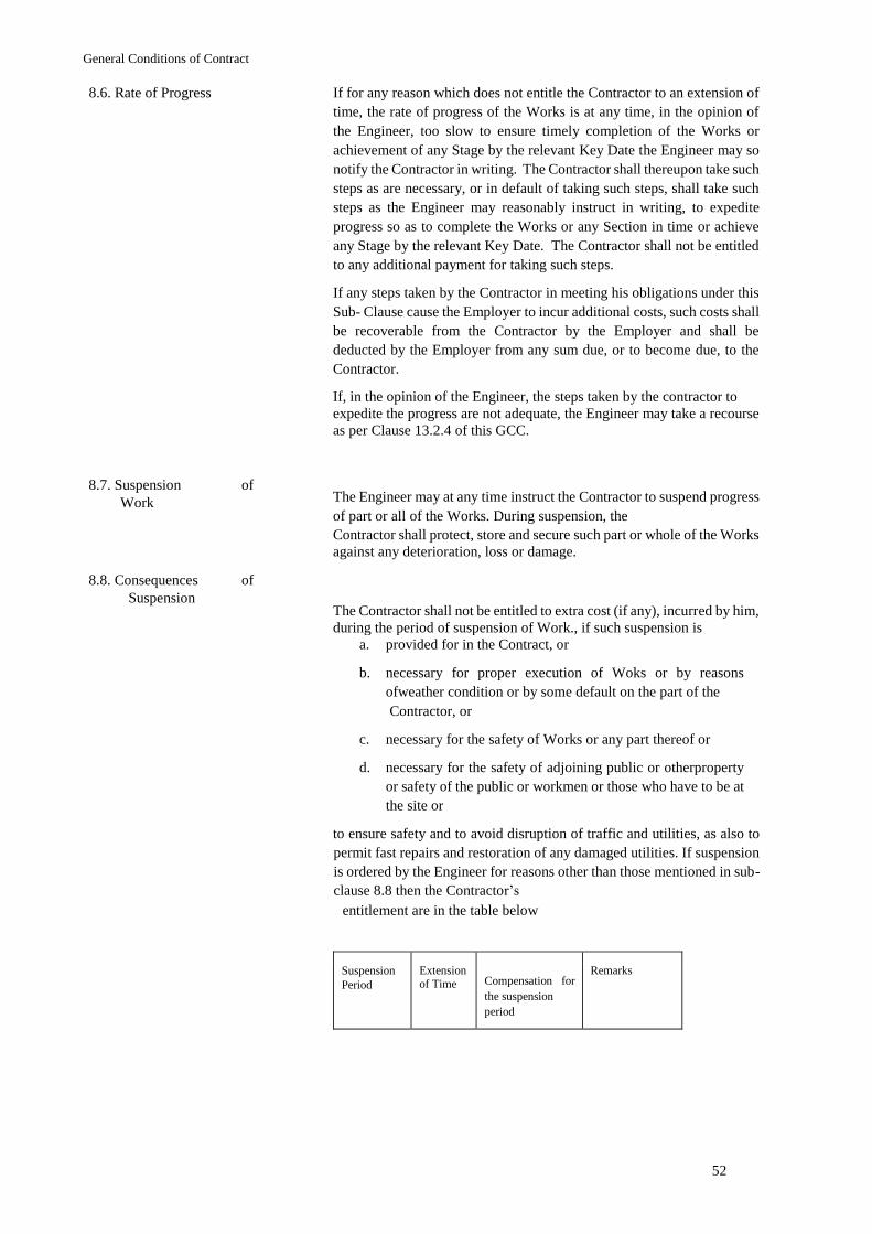
General Conditions of Contract
52
8.6. Rate of Progress If for any reason which does not entitle the Contractor to an extension of
time, the rate of progress of the Works is at any time, in the opinion of
the Engineer, too slow to ensure timely completion of the Works or
achievement of any Stage by the relevant Key Date the Engineer may so
notify the Contractor in writing. The Contractor shall thereupon take such
steps as are necessary, or in default of taking such steps, shall take such
steps as the Engineer may reasonably instruct in writing, to expedite
progress so as to complete the Works or any Section in time or achieve
any Stage by the relevant Key Date. The Contractor shall not be entitled
to any additional payment for taking such steps.
If any steps taken by the Contractor in meeting his obligations under this
Sub- Clause cause the Employer to incur additional costs, such costs shall
be recoverable from the Contractor by the Employer and shall be
deducted by the Employer from any sum due, or to become due, to the
Contractor.
If, in the opinion of the Engineer, the steps taken by the contractor to
expedite the progress are not adequate, the Engineer may take a recourse
as per Clause 13.2.4 of this GCC.
8.7. Suspension Work
of The Engineer may at any time instruct the Contractor to suspend progress
of part or all of the Works. During suspension, the Contractor shall protect, store and secure such part or whole of the Works
against any deterioration, loss or damage.
8.8. Consequences Suspension
of
The Contractor shall not be entitled to extra cost (if any), incurred by him,
during the period of suspension of Work., if such suspension is a. provided for in the Contract, or
b. necessary for proper execution of Woks or by reasons
ofweather condition or by some default on the part of the Contractor, or
c. necessary for the safety of Works or any part thereof or
d. necessary for the safety of adjoining public or otherproperty
or safety of the public or workmen or those who have to be at
the site or
to ensure safety and to avoid disruption of traffic and utilities, as also to
permit fast repairs and restoration of any damaged utilities. If suspension
is ordered by the Engineer for reasons other than those mentioned in sub-
clause 8.8 then the Contractor’s entitlement are in the table below
Suspension Period
Extension
of Time Compensation for
the suspension period
Remarks
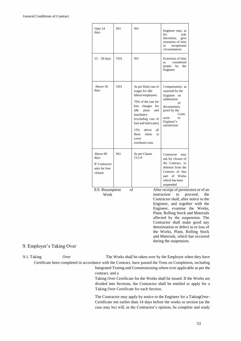
General Conditions of Contract
53
Upto 14
days NO NO
Engineer may, at
his sole discretion, give
extension of time
in exceptional circumstances
15 – 30 days YES NO Extension of time
as considered
proper by the Engineer
Above 30 days
YES As per Daily rate of
wages for idle labour/employees
70% of the rate for
hire charges for
idle plant and
machinery
(excluding cost of
fuel and lubricants)
15% above all
these items to
cover overhead costs
Compensation as
assessed by the Engineer on submission
of
documentary proof by the
Contr
actor to Engineer’s
satisfaction
Above 90
days
If Contractor
asks for fore closure
NO As per Clause
13.3.4 Contractor may
ask for closure of
the Contract, or
deletion from the
Contract of that
part of Works
which has been suspended
8.9. Resumption Work
of After receipt of permission or of an
instruction to proceed, the
Contractor shall, after notice to the
Engineer, and together with the
Engineer, examine the Works,
Plant, Rolling Stock and Materials
affected by the suspension. The
Contractor shall make good any
deterioration or defect in or loss of
the Works, Plant, Rolling Stock
and Materials, which has occurred
during the suspension. 9. Employer’s Taking Over
9.1. Taking Over The Works shall be taken over by the Employer when they have
Certificate been completed in accordance with the Contract, have passed the Tests on Completion, including
Integrated Testing and Commissioning where ever applicable as per the
contract, and a Taking Over Certificate for the Works shall be issued. If the Works are
divided into Sections, the Contractor shall be entitled to apply for a
Taking Over Certificate for each Section.
The Contractor may apply by notice to the Engineer for a TakingOver-
Certificate not earlier than 14 days before the works or section (as the
case may be) will, in the Contractor’s opinion, be complete and ready
General Conditions of Contract
54
for taking over. The Engineer shall, within 28 days after the receipt of
the Contractor’s application shall conduct a complete joint survey of the
works including carrying out any tests prescribed in the contract and
prepare a list of defects and outstanding works and:
a. issue the Taking Over Certificate to the Contractor,stating the
date on which the Works or Section were completed, including
the Tests on Completion and Integrated Testing and
Commissioning where ever applicable as per the contract in
accordance with the Contract if defects and/or outstanding
works are minor that does not affect the use and safety of the
Works or Section for their intended purposes The list of such
works along with the target date of completion for each work
shall be enclosed with the taking over certificate and
completion of all these works /rectification of defects within
the stipulated time shall be the responsibility of the contractor
and any failure in it may be considered a reason by the
Engineer to cancel the taking over certificate issued earlier; or
b. reject the application, giving his reasons and specifyingthe
work required to be done by the Contractor to enable the
Taking Over Certificate to be issued. The Contractor shall then
complete such work before issuing a further notice under this
Sub-Clause.
9.2. Taking over of The Engineer may, at the sole discretion of the Employer issue a
Parts of the Works Taking Over Certificate for any part of the Permanent Works by following the procedure
stipulated in Clause 9.1 above if:
a. the Employer uses that part of the Works for revenue service
before the Taking Over Certificate is issued for the entire
work.
b. the balance part is not completed not due to default ofthe
contractor and contractual date of completion for the
completed part is over.
10. Defects Liability
10.1. Completion of
Outstanding Work and
Remedying Defects
“Defects Liability Period” shall mean the defects liability period stated
in the Special Conditions of Contract calculated from the date of taking
over of the Works. Provided that, if any part of the Works or sub-
systems or component of that part has been replaced, renewed or
repaired except minor repair, the “Defects Liability Period” in respect
of that part or sub-system or components of that part shall start from the
date such replacement, renewal or repair has been completed to the
satisfaction of the Engineer.
In order that the Construction and/or Manufacture Documents and the
Works shall be in the condition required by the Contract (fair wear and
tear excepted) at, or as soon as practicable after the expiry of the
Contract Period, the Contractor shall execute all such work of
amendment, reconstruction, and remedying defects or damage, as may
be instructed in writing by the Employer or the Engineer during the
Defect Liability Period.
General Conditions of Contract
55
10.2. Cost of Remedying Defects
All work referred to in Sub-Clause 10.1shall be executed by the
Contractor at his own cost, if the necessity for such work is due to:
a. the design of the Works;
b. Plant, Rolling Stock, Materials or workmanship not beingin
accordance with the Contract; or
c. failure by the Contractor to comply with any of his
otherobligations. If in the opinion of the Engineer, such
necessity is due to any other cause, he shall determine an
adjustment to the Contract Price, with the approval of the
Employer, and shall notify the Contractor accordingly. In this
event, Sub-Clause 12.3 shall apply to such work.
10.3. Extension Contract Period
of The Contract Period shall be extended by a period, after the Works are
taken over, during which the Works or any Section or item of Plant,
Rolling Stock, cannot be used, for the purposes for which they are
intended, by reason of a defect or damage. When delivery of Plant, Rolling Stock, and/or Materials, or erection of
Plant, or installation of Materials, has been suspended under Sub-
Clause 8.7, the Contractor's obligations under this Sub-Clause shall not
apply to any defects or damage occurring more than three years after
the Plant, Rolling Stock and/or Materials would otherwise have been
delivered, erected and taken over.
10.4. Failure to
Remedy Defects If the Contractor fails to remedy any defect or damage within such time
as the Employer / Engineer may deem to be reasonable, the Employer
or the Engineer may fix a date on or by which to remedy the defect or
damage and givethe Contractor reasonable notice of such date. If the
Contractor fails to remedy the defect or damage by such date and the
necessity for such work is due to a cause stated in Sub-Clause 10.2(a),
(b) or (c), the Employer may (at his sole discretion):
a. carry out the work himself or by others, in a reasonablemanner
and at the Contractor's risk and cost, but the Contractor shall
have no responsibility for such work: the costs incurred by the
Employer in remedying the defect or damage shall be
recoverable from the Contractor by the Employer
b. require the Engineer to determine and certify a reasonable
reduction in the Contract Price; or
c. if the defect or damage is such that the Employer hasbeen
deprived of substantially the whole of the benefit of the Works
or parts of the Works, terminate the Contract in respect of such
parts of the Works as cannot be put to the intended use, the
Employer shall then be entitled to recover all sums paid for
such parts of the Works together with the cost of dismantling
the same, clearing the Site and returning Plant, Rolling Stock
and Materials to the Contractor, and Sub-Clause 13 shall not
apply.
10.5. Removal of
General Conditions of Contract
56
Defective Work If the defect or damage is such that it cannot be remedied expeditiously
on the Site and if the Employer gives consent, the Contractor may,
remove from the Site for the purposes of repair any part of the Works,
which is defective or damaged. This consent may require the Contractor
to increase the amount of Performance Security by the full replacement
cost of these items or to provide other appropriate security acceptable
to the Employer.
10.6. Further Tests If the remedying of any defect or damage is such that it may affect the
performance of the Works, the Engineer may require that Tests on
Completion, including Integrated Testing, be repeated to the extent
necessary. The requirement shall be made by notice within 28 days after
the defect or damage is remedied. Such Tests shall be carried out in
accordance with Clause 7.11
10.7. Right of Access
Until the Performance Certificate has been issued, the Contractor shall have the right of access to all parts of the Works and
to records of the working and performance of the Works, except as may
be inconsistent with any reasonable security restrictions by the
organisation responsible for operating the Works.
10.8. Contractor Search
to The Contractor shall, if required by the Engineer, search for the cause
of any defect, under the direction of the Engineer. Unless the defect is
one for which the Contractor is liable, the Cost of such search shall be
added to the Contract Price.
10.9. Performance Certificate
The Contract shall not be considered to be completed until the
Performance Certificate has been signed by the Engineer and delivered
to the Contractor at the end of ‘Defect Liability Period, stating the date
on which the Contractor completed his obligations related to completion of works and rectification of defects
during Defect Liability Period. to the Engineer's satisfaction. Only the
Performance Certificate shall be deemed to constitute approval of the
Works.
10.10. Unfulfilled Obligations
After the Performance Certificate has been issued, the Contractor and the Employer shall remain liable for the fulfillment of
any obligation, which remains unperformed at that lime. For the
purposes of determining the nature and extent of any such obligation,
the Contract shall be deemed to remain in force.
10.11. Emergency If any defect or damage is one requiring immediate attention from
safety, environmental or operational viewpoint, the Engineer has the
authority to proceed with rectification in any manner suitable and
deduct such sums from the Contract Price.
defect rectification
General Conditions of Contract
57
11. Contract Price and Payment
11.1. The Contract Price
Inclusions / Exclusions 11.1.1. i. Unless otherwise stated in the Special Conditions of Contract
the Contract Price, subject any to any adjustment thereto in
accordance with the Contract shall be all inclusive (including
all taxes, duties, royalties etc.)
ii. Nothing extra shall be payable over the quoted rates,
notwithstanding any provision to the contrary in any law for
the time being in force, save and except what is specifically
provided in General or Special Conditions of Contract.
iii. The reimbursement (as per this Sub-clause) of whatsoever
nature shall be provided only for Permanent Works. No
reimbursement (as per this Sub-clause) shall be provided for
Temporary Works and fuel.
Maintaining Records and Availing Exemptions
11.1.2. i. In the event of exemption of custom duties, excise duties, GST
(CGST/SGST/IGST etc.) or any other cess/levy being granted
by the Government in respect of the Works, the benefit of the
same shall be passed on to Employer. The Contractor shall
therefore maintain meticulous records of all the taxes and duties
paid and provide the same as and when required by the
Employer, so that the Employer is able to avail the
reimbursement for which NMRC may issue a procedure order
separately. Alternatively, the Employer may direct the Contractor to get the
reimbursements based on exemption certificates / government’s
order and it shall be obligatory on part of the Contractor to get
the reimbursements from the statutory authorities and pass on
the benefit to NMRC.
ii. In case of Contractor’s failure in availing the exemptions as
stipulated above, the recovery of equivalent amount will be
made from Contractor’s dues.
Adjust in Contract Price 11.1.3. Adjustment in contract price on account of inflation shall be done only
if a “Price Variation Formula” is given in the special conditions of
contract otherwise it will be a fixed price contract.
Change in Taxes/Duty 11.1.4.
The Contract Price shall not be adjusted to take into account any
increase or decrease in cost resulting from any change in taxes, duties,
levies from the last date of submission of the Tender to the completion
date including the date of the extended period of Contract unless a
contrary provision exists in Special Conditions of Contract. 11.2. Advances
General Conditions of Contract
58
Mobilisation Advance 11.2.1. Mobilisation advance shall be generally 5% of original contract value
payable in two equal instalments or as mentioned in the Special
Conditions of Contract. The first instalment shall be paid after
mobilisation has started and next instalment shall be paid after
satisfactory utilization of earlier instalment.
Mobilisation advance shall be paid interest free against acceptable Bank
Guarantee from a scheduled commercial bank in India. The value of
Bank Guarantee taken towards security of “Mobilization Advance”
shall be 110% of the advance taken by the Contractor. The Contractor,
once the 50% of mobilisation advance has been recovered, shall have a
one-time option to reduce the Bank Guarantee for the mobilisation
advance by the amount recovered
Advance against and
Machinery Plant 11.2.2.
Plant and machinery advance shall generally be 5% of original contract
value or as specified in Special Conditions of Contract.
This advance is payable against plant, equipment and machinery,
provided the same have reached the site or in the case of new items
meant specifically for the work firm purchase order has been placed and
the invoices received. The advance will be given only if the
plant/machinery has been purchased for this contract and not for those
which are already in the books of the contractor. The plant and
machinery shall be valued by the Engineer as follows:
a. New Items: 80% of purchase price
b. Second hand items in working order: 80% of thedepreciated
value as assessed by Engineer
c. Items valued at less than Rs.5,00,000 per unit: Not to
beconsidered
The total advance for Plant and Machinery shall be limited to 5%. This advance shall be paid interest free against acceptable Bank
Guarantee from a scheduled commercial bank in India. The value of
Bank Guarantee taken towards security of “Plant and Machinery
advance” shall be 110% of the advance taken by the Contractor. The
Contractor, once the 50% of the Plant and Machinery advance has been
recovered, shall have a one-time option to reduce the Bank Guarantee
for the Plant and Machinery advance by the amount recovered.
Written Request for 11.2.3.
Advances as admissible, shall be payable only on Contractor’s written
request to the Employer. Advances
General Conditions of Contract
59
Recovery of Advances 11.2.4. a. The recovery of Advances shall commence when 20%of the
original contract value of the work has been paid and it will be
completed by the time 85% of the Original Contract Value has
been paid or the original completion date whichever is earlier.
As far as possible the recovery of advances shall be limited to
30% of an account bill.
b. No advance shall be given after 40% of the originalcontract
amount has been paid.
c. The contractor shall always have the option to have
therecoveries commenced and / or completed earlier, and / or
to have recoveries affected in installments of higher amounts
and also repay part or whole of the advance by direct payment
rather than through On-account Bills.
d. In case the Contract is terminated due to default of
thecontractor or rescinded/foreclosed due to any other reason,
the contractor shall return the unrecovered amount of all
advances within 15 days of issue of notice of termination/
rescission/ foreclosure of the contract and if the Contractor
fails to do so due to any reason whatsoever, then interest at an
interest rate equal to State Bank of India’s Marginal Cost of
fund based Lending Rate (MCLR) applicable for the tenure of
01 year prevailing on the date of issue of notice of termination/
rescission/ foreclosure plus 3% Penal Interest per annum shall
be charged on the unrecovered amount of such advances from
16th day onwards compounded quarterly till the same is
returned by the contractor.
Interest in Case of Delay in
Repayment of
Advances
11.2.5. Should there be delay in the progress and completion of work, as a
result of which it is not possible to recover the advance and interest
thereon, before the date of completion stipulated in the Contract, then
the interest to be charged from the Contractor on the remaining portion
of the advance beyond the original completion date specified in the
Contract, shall be the State Bank of India Marginal Cost of fund based
Lending Rate (MCLR) applicable for the tenure of 01 year prevailing
on the original completion date specified in the Contract plus 3% Penal
Interest per annum.
Advances to be Used only for
This Work. 11.2.6.
The advances shall be used by the Contractor strictly for the purpose of
the Contract, and for the purpose for which they are paid. Under no
circumstances, shall the advances be diverted for other purposes. Any
such diversion shall be construed as a breach of the Contract and the
Contractor shall be asked to return the advance at once and pay interest
at 15% per annum till the advance is recovered back from him. The
Contractor shall return the advance and pay the interest in one go
without demur. Employer retains the right for any other remedy prescribed for breach
of Contract in this regard.
The Contractor, if required by the Engineer shall provide the details of
utilisation of Mobilization advance.
General Conditions of Contract
60
11.3. Provisional Payment
Against Material at Site
Provisional Payment Against Material at Site
11.3.1.
A provisional payment on account of main contraction materials
required for the Permanent Works, shall be paid on request of the
Contractor after these materials are brought to Site, against an
Indemnity Bond in a form acceptable to Employer is duly executed. The
payment shall be limited to 80% of the actual value or assessed value
of these materials and the total of such provisional payment on account
of construction materials at a time shall be limited to three percent of
original contract value or likely average consumption of such materials
for three months, whichever is less and at any time the total outstanding
provisional payment against material at site shall not exceed four
percent of the original control value. The valuation of the average
consumption of such main construction materials shall be approved by
the Engineer, whose decision shall be final. Materials which are of
perishable nature should be adequately insured.
Written Request for 11.3.2. Advances and provisional payments as admissible, shall be payable only
on Contractor’s written request to the Employer/Engineer. Advances/Provisional Payment against material at
site
Recovery of Advances/Provisional Payment
11.3.3. a. The recovery of Advances shall commence when 20% of the original
Contract Value of the work has been paid and it will be
completed by the time of original Date of Completion. As far
as possible the recovery of advances shall be limited to 30%
of an account bill. b. No advance shall be given after 40% of the originalcontract
amount has been paid. However, provisional payment against
material at site will continue to be paid as stipulated in Clause
11.3. till end of the contract period.
c. In case of provisional payment against Materials, theamount
consumed every month shall be recovered from the next
months on account bill and completing the recovery in 3
monthly instalments. In case recovery could not be made due
to any reason, interest will be charged as per Clause 11.2.5.
11.4. Application for
Interim Payment Certificates
General Conditions of Contract
61
11.4.1. In case of ‘Lump Sum’ contract with cost centre and Milestone
payment, the fixed Lump Sum Price shall be apportioned by the
Contractor amongst the various Cost Centres. The amount thus
apportioned under each Cost Centre will be further apportioned
amongst various Milestones with the approval of the Employer. The
Contractor shall be entitled to submit to the Engineer requests for
interim payments only upon the achievement of one or more of the
Milestones described in the Cost Centre.
At the beginning of each month, the Engineer shall issue to the
Contractor certificate in respect of each Milestone due to be achieved
in the preceding month stating:
a. the date on which the Milestone was achieved; or
b. the non-achievement of the Milestone.
The Contractor shall submit a statement in three copies to the Engineer
at the beginning of each month, in a form approved by the Engineer,
showing the amounts to which the Contractor is entitled, together with
supporting documents, including Milestone Certificates. The statement
shall include the following items, as applicable, which shall be
expressed in the various currencies in which the Contract Price is
payable, in the sequence listed:
a. the amount due in respect of Milestones certifiedachieved by
the Engineer under each Cost Centre;
b. any amounts to be added and deducted for the
advancepayments and recovery thereof;
c. any other additions or deductions is due and approvedby the
Engineer in accordance with the Contract; and
the deduction of the amounts certified in all previous Interim
Payment Certificates.
The Contractor shall not submit more than one request for interim
payment per month.
If any Milestone is not achieved by the end of the month in which it is
scheduled to be achieved, the Engineer shall suspend the payment
relating to the Cost Centre in which the Milestone is included.
Payments suspended under this Clause shall be resumed by being
included in the next application for interim payment made after the
Milestone is achieved.
11.4.2. In case of ‘Lump Sum’ or Item rate’ contracts with payment schedule,
the contractor shall be entitled to be paid from time to time, normally
once in a calendar month, by way of ‘on account’ bill as per the payment
schedule indicated in Bill of Quantity (BOQ) or as finally approved by
the Engineer.
11.5. Issue of Interim No amount will be certified or paid until the Employer has received,
and approved, the Performance security and the parent Company
Undertakings and Guarantees in accordance with Sub-Clause 4.2.
Thereafter, the Engineer shall, within 21 days of receiving a statement
and supporting documents, deliver to the
Payment Certificates
General Conditions of Contract
62
Employer, with a copy to the Contractor, an Interim Payment
Certificate showing the amount which the Engineer considers to be due;
if no payment is considered to be due, the Engineer shall promptly
notify the Contractor accordingly.
Where only a part of the payment applied for is disputed, payment
certificate shall be issued for the undisputed amount.
The Engineer shall have the power to omit from any of the contractor’s
requests for payment the value of any work executed or Materials
supplied or services rendered, with which he may for the time being be
dissatisfied and for that purpose and for any other reason which to him
may seem proper, may delete, correct or modify the sum(s) previously
certified by him as being due to the Contractor.
11.6. Payment- Interim and Final
Unless otherwise stated in Special Conditions of Contract,
a. After preliminary scrutiny and certification by theEngineer,
payment of 80% of the certified interim amount shall be made
by the Employer within 07 days. The amount certified shall
account for all deductions, including statutory deductions,
recoveries for advances and any amounts due from the
Contractor. The balance 20% shall be paid within 28 days,
from the date of the preliminary certification of the bill by the
Engineer.
b. Next 80% interim payment shall be made only after100%
payment of preceding interim payment certified has been
completed.
c. Any such payment made to contractor by Employer,shall not
constitute any acceptance of the measurements or bill of
quantities by the Employer and the classification entered in the
measurement books or bills. The employer shall have right to
recover any excess payment made in either 80% interim
payment of bill or earlier bill from balance 20% bill or
subsequent bill respectively. However, if such excess payment
exceeds the balance 20% bill or subsequent bill respectively,
the contractor shall on demand from the Engineer or Employer
immediately refund the extra amount to the employer within 7
days, failing which the contractor shall have to pay interest at
the rate equal to State Bank of India’s Marginal Cost of fund
based Lending Rate (MLCR) applicable for the tenure of 01
year prevailing on date plus 3% Penal interest per annum with
monthly rest till the said extra amount is paid back by the
Contractor.
d. The Employer shall pay the amount certified in the
FinalPayment Certificate within 56 days from the date of issue
of the Certificate.
Payments shall be made into a bank account, nominated by the
Contractor in Indian rupees in a bank in India unless otherwise
permitted in Special Conditions of Contract. If payments are to be made
in more than one currency, separate bank accounts may be nominated
by the Contractor for each currency, and payments shall be made by the
Employer accordingly.
General Conditions of Contract
63
11.7. Statement Completion
at Not later than 60 days after the issue of the Taking Over Certificate for
the whole of Works, the Contractor shall submit, to the Engineer, three
copies of a statement at completion with supporting documents,
showing in detail, in the form approved by the Engineer under Sub-
Clause 11.4.:
a. the final value of all work done in accordance with
theContract, up to the date stated in such Taking Over Certificate,
b. any further sums which the Contractor considers to bedue, and
c. an estimate of amounts which the Contractor considerswill
become due to him under the Contract.
The estimated amounts shall be shown separately in such statement at
completion. The Engineer shall certify payment under Sub-Clause 11.5
11.8. Application for
Not later than 56 days after the issue of the Performance Certificate, the
Contractor shall submit to the Engineer three copies of a draft final
statement with supporting documents showing in detail, in a form
approved by the Engineer:
a. the value of all work done in accordance with the Contract, and
b. any further sums which the Contractor considers to bedue to
him under the Contract or otherwise.
If the Engineer disagrees with or cannot verify any part of the draft final
statement, the Contractor shall submit such further information as the
Engineer may reasonably require and shall make changes in the draft as
may be agreed between them. The Contractor shall then prepare and
submit to the Engineer the Final Statement as agreed.
If, following discussions between the Engineer and the Contractor and
any changes to the draft final statement which may be agreed between
them, it becomes evident that a dispute exists, the Employer shall pay
those parts of the draft final statement as certified by the Engineer as
not being in dispute. The remainder of the dispute may then be resolved
under Clause 17, in which case the Contractor shall then prepare and
submit to the Engineer a Final Statement in accordance with the
outcome of the dispute.
Final Payment Certificate
11.9. Discharge When submitting the final statement, the Contractor shall submit a
written discharge which confirms that the total of the Final Statement
represents full and final settlement of all monies due to the Contractor
under the Contract. Such discharge may state that it shall become
effective only after payment due under the Final Payment Certificate has been made and the Performance security referred to in Sub-Clause 4.2 has been returned to the
Contractor.
General Conditions of Contract
64
11.10. Issue of Final Payment Certificate
The Engineer shall issue to the Employer, with a copy to the Contractor,
the Final Payment Certificate within 28 days after receiving the Final
Statement and written discharge in accordance with Sub-Clause 11.7
and 11.8, stating:
a. the amount which is finally due, and
b. after giving credit to the Employer for all amountspreviously
paid by the Employer and for all sums to which the Employer
is entitled, the balance, if any, due from the Employer to the
Contractor or from the Contractor to the Employer, as the
case may be
If the Contractor has not applied for a Final Payment Certificate in
accordance with Sub-Clauses 11.8 and 11.9, the Engineer shall request
the Contractor to do so. If the Contractor fails to make such an
application within a period of 28 days, the Engineer shall issue the Final
Payment Certificate for such amount as he considers to be due.
11.11. Cessation of In respect of any matter or thing arising out of (or in connection with)
the contract or execution of the Works before the issue of the Taking
Over Certificate for the whole of the Works, the Employer shall not be
liable to the Contractor unless the Contractor shall have included a claim for it in his Statement at
Completion described in Sub-Clause 11.7. For any such matter or thing
arising after the issue of the Taking Over Certificate for the whole of
the Works, the Employer shall not be liable to the Contractor unless the
Contractor shall have included a claim for it in his Final Statement.
Employer's Liability
11.12. Calculation of Payments in
Foreign Currency All payments made by the Employer pursuant to the terms of the
Contract shall be in the currency or currencies specified in the Contract.
Wherever any sum in a foreign currency has to be converted into Indian
Rupees for any purpose, the exchange rate to be employed for such
conversion shall be the selling rate of exchange at the close of business
of the State Bank of India 28 days before the latest date of submission
of Tenders.
11.13. Round off In every payment to the Contractor, sums of less than fifty paise shall
be omitted and sums of fifty paise and more up to one rupee shall be
reckoned as one rupee.
11.14. Payment By Cheque
and E-
Payment
All payments to the Contractor will be made by cheque or “EPayment”
as desired by the Employer.
11.15. Tax Deduction at Source Tax deductions will be made at source as per statutory requirement from
every payment made to the Contractor at rates notified from time to
time.
General Conditions of Contract
65
11.16. Production Vouchers
of i. The Contractor shall, whenever required by the Engineer, produce
or cause to be produced for examination by the Engineer, any
quotation, invoice, cost or other account books, vouchers, receipts,
letters, memoranda or any copy of or extract from any such
documents and also furnish information and returns, as may be
required, relating to the execution of this Contract or relevant for
verifying or ascertaining the cost of execution of this Contract or
ascertaining the Materials supplied by the Contractor are in
accordance with the Specifications laid down in the Contract. The
Engineer’s decision on the question of relevancy of any
documents, information or returns shall be final and binding on the
parties.
ii. If any part or item of the work is allowed to be carried out by a
sub-Contractor, assignee or any subsidiary or allied firm, the
Engineer shall have power to secure the books of such sub-
Contractor, assignee or any subsidiary or allied firm through the
Contractor and shall have power to examine and inspect the same.
The above obligations are without prejudice to the obligations of
the Contractor under any statute, rules or orders
11.17. Withholding And i. The Employer shall have lien over all or any moneys that may
become due and payable to the Contractor under the Contract, and
/ or over the deposit of Performance Security or other amount or
amounts made under the Contract and which may become payable
to the Contractor.
Lien For Claimed
Sums
ii. And further, unless the Contractor pays and clears immediately on
demand any claim of the Employer, the Employer shall at all times
be entitled to deduct the amount of the said claim from the moneys,
securities and / or deposits which may have become or will
become payable to the Contractor under these presents, or under
any other Contract or transaction whatsoever between the
Employer and the Contractor even if the matter stands referred to
Arbitration. The Contractor shall have no claim for any interest or
damage whatsoever in respect of any amounts withheld or treated
as withheld under the lien referred to above and duly notified as
such to the Contractor
11.18. Signature Receipts Payments
On For
Every receipt of payment to Contractor including refund of the
Performance Security shall be signed by the person authorized to do so
on his behalf. In the event of death of any of the Contractor’s partners
in case the Contractor is a partnership firm, during the currency of the
Contract, it is hereby expressly agreed that every receipt by any one of
surviving Contractor’s partners, shall, if so signed as aforesaid, be a
good and sufficient discharge as aforesaid, provided that nothing in this
Clause shall be deemed to prejudice or affect any claim, which the
Employer may hereafter have against the legal representatives of any
Contractor’s partner so dying, for or in respect of breach of any of the
conditions of the Contract. Provided also that nothing contained in this
clause shall be deemed to prejudice or affect the respective rights and
obligations of the Contractor’s partners,
General Conditions of Contract
66
or of the legal heirs / representatives of any deceased Contractor /
partner interest.
11.19. Post Audit
Payment It is an agreed term of the Contract, that the Employer reserves to
himself the right to carry out a post payment audit and / or
11.20. Recovery of money
due to the Employer technical examination of the
Works, and the Final bill
including all supporting
vouchers, abstracts, etc., and
to make a claim on the
Contractor for the refund of
any excess amount paid to
him, if as a result of such
examination, any over-
payment to him is discovered
to have been made in respect
of any work done or alleged
to have been done by the
Contractor, under the
Contract. If any under-
payment is discovered, the
same shall be paid by the Employer to the Contractor. Such payments
or recoveries, however, shall not carry any interest.
All damages (including, without limitation, liquidated damages), costs,
charges, expenses, debts, or sums for which the Contractor is liable to
the Employer under any provision of the Contract may be deducted by
the Employer from monies due to the Contractor under the Contract
including, without limitation, and the Employer shall have the power to
recover any balance not so deducted from monies due to the Contractor
under any other contract between the Employer and the Contractor.
When the Contractor has assigned to a third party the right to receive
monies due, or, to become due, under the Contract to the Contractor or
charged such monies in favour of a third party, the Employer's right to
deduct damages (including without limitation liquidated damages),
costs, charges, expenses, debts or sums for which the Contractor is
liable to the Employer from monies due to the Contractor under the
Contract shall be limited to the right expressed above.
12. Variations
12.1. Right to Vary All Variations shall be recorded in a written instruction from the Engineer
either as a Contractor's Variation or as an Employer's Variation and shall
not be implemented by the Contractor without such an instruction in
writing from the Engineer. No Variation shall in any way vitiate or
invalidate the Contract. The Contractor shall not make any alteration
and/or modification of the Works, unless and until the Engineer instructs
or gives consent to a Variation. If the Construction and/or Manufacture
Documents or Works are not in accordance with the Contract, the
rectification shall not constitute a Variation.
12.2. Contractor’s Variations
Value Engineering or Innovation
General Conditions of Contract
67
Value Proposals
Engineering 12.2.1.
The Contractor may submit to the Employer, in writing at its own cost,
value engineering proposals for modifying the Employer’s Requirements,
provision of additional land, access or feasibility over and above that is
provided in the Contract for the purpose of saving in time, construction or
manufacture costs. The value engineering proposal shall not impair the
essential character, functions or characteristics or the Work, including
service life, economy of operation, ease of maintenance, desired
appearance, or design and safety standards.
The Contractor shall provide his value engineering proposal in a time limit
prescribed by the Engineer. The Engineer’s decision in this regard shall be
communicated to the Contractor within a reasonable period of time. If by
any reason the time limit specified by the Engineer is exceeded, the
proposal may not be considered.
The decision of the Engineer in this regard shall be final and binding.
Value Engineering 12.2.2.
If the Employer requires or accepts it, and if the Contractor wants to
proceed with the proposal, the Contractor must provide (at no cost to the
Employer) a detailed report prepared by a consultant acceptable to the
Employer and which shall include:
Proposals – Contents
a. general description of the original Contract requirementsfor the
Works and the proposed changes
b. detail of all the proposed modifications to the drawings
andspecifications
c. detail of all Work and goods affected by the valueengineering
proposal
d. detailed estimate of the construction cost based on theoriginal
Contract requirements and based on the proposed changes
e. any resultant time extensions or reductions for the Contract
f. statement to the extent of minimum saving expected. The
Contractor’s cost of preparing value engineering proposal shall
be excluded in determining the estimated net savings in
construction costs. Value Engineering 12.2.3. The Employer may in his sole discretion, accept or reject the value
engineering proposal or any part thereof and determine the estimated net
saving in the construction cost. The Employer shall not be liable for delays
or damages to the Contractor due to any failure of the Employer to accept
or act upon any value engineering proposal submitted pursuant to this
Clause. If the submitted value engineering proposal is similar to a change
/ variation already under consideration by the Employer, the Employer
may make such changes without respect to the value engineering proposal.
Once, the Employer or the Engineer rejects the value engineering during
proposition due to any reason, it shall not be pursued by Contractor in any
other form.
Proposals- Review
Employer
General Conditions of Contract
68
Amendments- Issuance
Employer 12.2.4.
If the value engineering proposal is acceptable to the Employer in whole
or in parts, it will accept by execution of an amendment. Such amendment
shall identify all the changes in the specifications, Contract Period etc,
shall specify net savings on construction costs and shall provide that the
Contractor be paid 30% of saved net savings amount based on the
difference between the amount contained in the Contract and the estimated
net savings both as determined by the Employer.
Contractor’s Acceptance and
Payment 12.2.5. The Contractor shall either accept or reject any proposed amendment executed
by the Engineer pursuant to this section within 5 working days of its
receipt date from the Employer. If the Contractor does not reject the same
in the period stipulated above, the amendments shall be deemed to be
accepted by the Contractor and shall become a variation to the Contract.
The Contractor’s acceptance shall be unconditional and compensation of
30% of the value shall constitute the full compensation. The Contractor
will be paid this 30% or less but not more at the time of final payment on
Engineer’s certification that the net savings as intended by value
engineering have been achieved.
12.3. Employer’s Variations
If the Engineer requests a proposal, prior to instructing a Variation, the
Contractor shall submit at his own cost within 14 days or such period as
the Engineer may allow of the receipt of such request of the Engineer a. a description of the proposed design and/or work to beperformed
and a programme for its execution,
b. the Contractor's proposal for any necessary modificationsto the
programme according to Sub-Clause 4. 13, and
c. the Contractor's proposal for adjustment to the ContractPrice,
Time for Completion and/or modifications to the Contract.
12.5. Variation in the
Bill of Quantities approval,
rejection or comments.
If the Engineer instructs or
approves a Variation, he
shall proceed in accordance
with Sub-Clause 3.5 to agree
or determine adjustments to
the Contract Price, Time for
Completion and Schedule of
Payments.
After receipt of proposal, it
will be the prerogative of the
Employer, whether to
Instruct and proceed ahead
with the variation or drop the
proposal in part or full. In
that case, no cost of preparing and submitting the proposal will be payable
to Contractor. In case, the design part of variation has been completed on
submission of same to the Engineer, the Employer decides to abandon the
variation, only cost for design to the extent of work done will be paid to
the Contractor.
i. i) The quantities of items shown in the Bill of Quantities are
approximate, and liable to vary during the actual execution of the work.
Some items/group of items may have to be altered, added or omitted.
The Contractor shall be bound to carry out and complete the stipulated
work as instructed by the Engineer, irrespective of the magnitude of
variations including additions, alterations or omissions in the Bill of
Quantities, individual items or group of items, specified in the Bill of
Quantities. ii. Such variations shall be paid as follows:
a. At the accepted rates of the Contract for Positive variationin
quantities to the extent of 25%, except in the case of foundation
works. Unless otherwise specifically for in the Bill of Quantities
or elsewhere in the Contract, the variation of 25% shall be
12.4. Variation Procedure
The Engineer shall, as soon as practicable after receipt of proposals under
sub-clauses 12.2 and / or 12.3, respond with
General Conditions of Contract
69
applicable to a
group of items
mentioned therein
and not to
individual items. In
case of variation in
quantities on minus
side, contract rates
will be payable for
executed quantities.
b. In case of
foundation work, no
variation limit
applies
andContractor shall
carry out the Work, at rates stipulated in the Contract irrespective
of any variation.
c. In case of earth work, the aforesaid variation limit of 25%shall
apply to the gross quantity of earth work and variation in the
quantity of individual classifications of soil will not be subject to
this limit where any variation can take place.
d. For items against which the quantity given in the Bills
ofQuantities is “if or as required”, there shall be no
increase/decrease of rates whatever be the quantity finally
executed.
e. Variation in the quantity of items individually costing upto1% of
the total contract value, shall be payable at the rates stated in the
Contract. Notwithstanding the magnitude of variation upto 2% of
the original Contract Value for each item.
f. In case the variation in individual items or the group of items as stipulated above, is more than 25% on plus
side, the rate for the varied quantity beyond 25% shall be negotiated between the Engineer and the
Contractor and mutually agreed rates arrived at before actual execution of the extra quantity.
g. In case Engineer introduces an item for which the Contractdoes not contain any rates or prices applicable
to the varied Works, the rate of such items shall be derived, wherever possible, from rate for similar items
available in the Bill of Quantities of the accepted Tender. In case this is not possible, the rate may be
decided on the following basis: i. Cost of Materials at current market price, as actually utilised
in the final finished Permanent Works, including a
reasonable percentage for wastage and transportation. ii. Cost of enabling works if any (unless provided for
separately) worked out on the above basis but with less
stringent quality. Specifications minus salvage value of
serviceable material released after completion of work and
cost of material released as scrap. iii. Cost of labour actually used at the site of work at rates under
Payment of Minimum Wages Act for the area of work for
each category of worker, further enhanced by a percentage
of 10% of the aforesaid rates to account for labour not
directly utilised at Site and other ancillary and incidental
expenses on labour.
iv. Hire charges for Plant * Machinery, scaffolding, shuttering, forms, etc., required to be used at the site of the
work. The tools used by the various trades shall not be
counted as Plant & Machinery for this purpose. v. An amount of 20% of items (i), (ii), (iii) and (iv) above to
allow for Contractor’s overheads, profits and corporate
taxes. This percentage shall also apply to estimated cost of
Materials supplied free to the Contractor. vi. In all cases
where extra items of work are involved, for which there are
no rates in the accepted Bill of Quantities the Contractor shall
give a notice to the Engineer, of at least 7 days before the
need for their execution arises.
General Conditions of Contract
70
12.6. Payment
Applicable Currencies
in If the Contract provides for payment of the Contract Price in more than
one currency, and an adjustment is agreed or fixed as stated above, the
amount payable in each of the applicable currencies shall be specified
when the adjustment is agreed or fixed. In specifying the amount in each
currency, the Contractor and the Engineer (or, failing agreement, the
Engineer) shall take account of the actual or expected currency
proportions of the Cost of the varied work, without being bound by the
proportions of various currencies specified for payment of the Contract
Price.
13. Termination of the Contract
13.1. Notice to
Contractor
If the Contractor fails to carry out any of his obligations, or if the Contractor is not executing the Works in accordance with the
Contract Due To Contractor’s Default
Conditions Leading To 13.2.1. Termination Of Contract
The Employer shall be entitled to
terminate the Contract if the Contractor or any one of its constituents,
a. fails to comply with a notice
under Sub clause 13.1
b. abandons or repudiates the
Contract
c. without reasonable excuse
acceptable to the Engineer
failsto commence the Works in
accordance with the Contract
d. sub contracts the whole of the
Works or assigns the Contract without approval of the
Employer
e. becomes bankrupt or insolvent or goes into liquidationexcept
voluntary liquidation for the purpose of amalgamation or
reconstruction
f. persistently disregards instructions of the Engineer or
contravenes any provisions of the Contract, or
g. fails to adhere to the agreed programme of work by marginof
10% of the stipulated period or 21 days, whichever is earlier, or
fails to complete the Works or parts of the Works within the
stipulated or extended period of completion, or is unlikely to
complete the whole Work or part thereof within time because of
poor record of progress; or
h. fails to remove materials from the Site, or pull down andreplace
work, after receiving notice from the Engineer to the effect that
the said materials or Works have been condemned or rejected, or
i. fails to take steps to employ competent and/or additional staff and
labour, or
j. fails to afford the Engineer or his representative proper facilities
for inspecting the Works or any part thereof, or
k. indulges in corrupt or fraudulent practices as explained in Clause 4.33
13.2.2. In any one of these events or circumstances, the Employer may upon giving
14 days notice to the Contractor, terminate the Contract and expel the
Contractor from the Site. However, in case of subparagraph (e) or (k), the
Employer may by notice of 7 days terminate the Contract immediately.
Contract, the Engineer may give notice to the Contractor requiring him to
make good such failure and remedy the same within such time as the
Employer / Engineer may deem to be reasonable.
13.2. Termination Of
General Conditions of Contract
71
13.2.3. For the purpose of sub para (c) above, this clause, reasonable excuse shall be
one, which in the opinion of the Engineer has resulted from Circumstance
which
a. is beyond the employer’s or contractor’s control and
b. made the failure unavoidable and it is evidenced by theContractor
to the satisfaction of the Engineer that the failure was remedied
without unreasonable delay once that obstacle was out of the
way.
13.2.4. In case of sub para(g), the Engineer at its sole discretion may terminate
only part of the contract also by taking out some part of the total scope of
work and may complete or arrange for any other entity through the process
of open/limited/single tender or by calling quotations, to do so at the risk
and cost of the contractor.
13.2.5. The Employer’s decision to terminate the Contract shall not prejudice any
other rights of the Employer under the Contract.
13.2.6. On termination of contract due to contractor’s default theperformance
security shall be forfeited by encashing the bank guarantee and the balance
work shall be got done independently without risk and cost of the failed
contractor. The failed contractor shall be debarred from participating in
the tender for executing the balance work. If the failed contractor is a JV
or a partnership firm, then every member/partner of such JV or partnership
firm shall be debarred from participating in the tender for the balance work
either in his/her individual capacity or as a partner of any other
JV/partnership firm.
13.2.7. The Engineer shall not make a claim under the Performance Security
except for amounts to which the NMRC is entitled under the contract (Not
withstanding and/or without prejudice to any other provisions in the
contract agreement) in the event of:
i. Failure by the contractor to extend the validity of the
Performance Security as described herein above, in
which event the Engineer may claim the full amount of
the Performance Security. ii. Failure by the contractor to pay NMRC any amount
due, either as agreed by the contractor or determined
under any or the Clauses/Conditions of the agreement,
within 30 days of the service of notice to this effect by
Engineer. iii. The contractor being determined or rescinded under
provision of the GCC the Performance Security shall be
forfeited in full and shall be absolutely at the disposal
of the NMRC.
Valuation at the date of Termination
13.2.8. The Engineer shall, as soon as possible after termination under Sub-Clause
13.2.1, determine and advise the Contractor of the value of the
Construction and/or Manufacture Documents, Plant, Rolling Stock,
Materials, Contractor's Equipment and works and all sums then due to the
Contractor as at the date of termination.
General Conditions of Contract
72
Payment after Termination 13.2.9.
After termination under Sub-Clause 13.2.1, the Employer shall not be
liable to make any further payments to the Contractor until the costs of
design, manufacture, execution, completion and remedying of any defects,
damages for delay in completion (if any), and all other costs incurred by
the Employer, have been established.
The Employer shall be entitled to recover from the Contractor the extra
costs, if any, of completing the Works after allowing for any sum due to
the Contractor under Sub-Clause 13.2.8. If there are no such extra costs,
the Employer shall pay any balance to the Contractor. Non-exercise of power not 13.2.10.
Provided always that in case any of the powers conferred upon the
Employer by Sub-clause 13.1 and Sub-clause 13.2.1 above, shall have
become exercisable, and the same may not have been exercised, the non-
exercise thereof shall not constitute waiver of any of the conditions
thereof.
to constitute waiver
13.3. Default Employer
of
Notice by Contractor 13.3.1. In the event of the Employer:
a. failing to pay the Contractor, without reasonable cause,
theamount due under any certificate of the Engineer within 56
days after the expiry of the time stated in Sub-Clause 11.5 within
which payment has to be made, subject to any deduction that the
Employer is entitled to make under the Contract, or
b. becoming bankrupt or, being a company, going intoliquidation,
other than for the purpose of a scheme of reconstruction or
amalgamation,
Then, the Contractor may give notice requiring the Employer to remedy
the default within 28 days after receipt of the notice. If the Employer fails
to remedy the default or fails to propose steps reasonably acceptable to the
Contractor to do so and in that case, the Contractor may terminate the
Contract after issue of 14 days notice to the Employer with a copy to the
Engineer. In this case, the Contractor shall be compensated as per Sub
clause 13.3.4.
The Engineer’s decision on the amount payable on this account shall be
final and binding.
Contractor’s Entitlement to Suspend the Work
13.3.2. The Contractor may, if the Employer fails to pay the Contractor the
amount due under any certificate of the Engineer within 56 days after the
expiry of the time stated in Sub-Clause 11.6, within which payment is to
be made, subject to any deduction that the Employer is entitled to make under the Contract, after giving 28 days’ prior notice to
the Employer, with a copy to the Engineer, suspend work or reduce the
rate of work.
If the Contractor suspends work or reduces the rate of work in accordance
with the provisions of this Sub-Clause and thereby suffers delay or incurs
General Conditions of Contract
73
costs the Engineer shall, after due consultation with the Employer and the
Contractor, determine:
a. any extension of time to which the Contractor is entitledunder
sub-clause-8.4, and
b. the amount of such costs, which shall be added to theContract
Price, and shall notify the Contractor accordingly, with a copy to
the Employer.
Cessation of Work by 13.3.3. After termination under Sub-13.3.1, the Contractor shall: Contractor
a. cease all further work, except for such work as may benecessary
and instructed by the Engineer for the purpose of making safe or
protecting those parts of the Works already executed, and any
Work required to leave the Site in a clean and safe condition,
b. hand over all Construction and/or Manufacture Documents,Plant,
Rolling stock, and Materials for which the Contractor has
received payment,
c. hand over those parts of other Works executed by the Contractor up to the date of termination, and
d. remove all Contractor's Equipment which is on the Site
andrepatriate all his staff and labour from the Site.
Any such termination shall be without prejudice to any other right of the
Contractor under the Contract.
Payment on Termination 13.3.4.
After termination under Sub-Clause 13.3.1 the Employer shall return the
Performance security, and shall pay the Contractor an amount calculated
and certified in accordance with the following conditions:
a. The value of approved materials actually brought to the siteand
reasonably required to execute the works during next three
months, as per approved programme, and
b. Value of work completed up to date by the contractor atrates
specified in the Contract, after taking into account any
deductions, retentions, set-off.
c. In addition, a sum not exceeding 2% (two percent) of thevalue of
the work remaining incomplete on the date of Termination notice
taking effect.
The payment as above shall be full compensation for termination under
this clause and the Contractor has no claim for damages or other
entitlements whether under the contract or otherwise.
13.3.5. In case termination/foreclosure of the Contract under whatsoever
circumstances, any remaining tools, plants, equipments and surplus
materials of Employer with contractor will be returned to the Employer in good condition at Employer’s depot at Contractor’s cost. In
case of the failure of the contractor to do so, the Employer will be entitled
to recover their cost from the contractor from the amount becoming due
to the contractor or from any other money due in any other contracts. The
decision of the Engineer of the amount to be recovered will be final

General Conditions of Contract
74
decision and full credit at rates initially charged to the contractor shall be
allowed for such materials. Similarly, the Employer shall be entitled to
recover the cost of the unreturned material, plant equipment and tools from
the contractor where such material have been supplied free of cost and
plant, equipment and tools free of cost or on lease basis to the contractor
as stipulated in the Conditions of Contract.
General Conditions of Contract
75
14. Risk and Responsibility
14.1. Indemnity The Contractor shall indemnify and hold harmless the Employer, the Engineer, the Designated
Contractors, representatives and employees from and against all actions,
sits, proceedings, claims, damages, losses, expenses and demands of every
nature and description, by reasons of any act or omissions of the
Contractor, his representative or his employees in the execution of the
Works, including professional services provided by the Contractor or in
the guarding the same.
These indemnification obligations shall include but not be limited to
claims, damages, losses, damage proceedings, charges and expenses
which are attributable to:
a. sickness, or disease, or death of, or injury to any person;and
b. loss of, or damage to, or destruction of any property (otherthan
the Works) including consequential loss of use; and
c. loss, damage or costs arising from the carriage of Plant,Rolling
Stock and Materials and/or ownership or chartering of marine
vessels by the Contractor, or any sub-contractor of any tier.
The Contractor shall also indemnify and save harmless the Employer from
and against all claims and proceedings on account of infringements of
patents rights, design, trademark name etc as detailed out in clause 5.8.
All sums payable by way of compensation under these conditions shall be
considered reasonable compensation payable to the Employer, without
reference to the actual loss or damage sustained, and whether or not any
damage shall have been sustained. The decision of the Engineer as to
compensation claimed shall be final and binding.
14.2. Contractor’s The Contractor shall take full responsibility for the care of the
Care of the Works Works, or any part thereof, including full responsibility for the care of any work being
manufactured, or stored off-Site for inclusion in the Works, or in the
course of transportation to the Site, and for the care of Contractor's
Equipment, Temporary Works, Plant, Rolling Stock, and any other
Material, whatsoever, on the Site or delivered to or placed on the Site in
connection with, or for the purpose of the Works.
The Contractor shall take this responsibility from the Commencement
Date until the date of issue of the Taking Over Certificate, when responsibility shall pass to the Employer. If the Engineer
issues a Taking Over Certificate for any Section or part of the Works, the
Contractor shall cease to be responsible for the care of that Section or part
from the date of issue of such Taking Over Certificate when responsibility
shall pass to the Employer.
The Contractor shall take responsibility for the care of any outstanding
work which is required to be completed prior to the expiry of the Contract
Period, until the Engineer confirms in writing that such outstanding work
has been completed.
If any loss or damage happens to the Works, any other property or person,
arising from any cause other than the Employer's risks listedin Sub-Clause
14.3, duringthe period for which the Contractor is responsible, the
Contractor shall rectify such loss or damage, at his cost, so that the Works
conform with the Contract or at the
General Conditions of Contract
76
option of the Employer, will pay or allow to the Employer the cost of
rectifying such loss or damage. Notwithstanding such loss or damage, the
Contractor shall proceed with the execution of works in all respects in
accordance with the contract and the Engineer's instructions. The
Contractor shall also be liable for any loss or damage to the Works caused
by any operations carried out by the Contractor after the date of issue of
the Taking Over Certificate.
14.3. Employer’s Risks
The Employer's risks of loss or damage to physical property in India and
of death and personal injury occurring in India in consequence of the
performance of obligations under the Contract are:
a. war, hostilities (whether war be declared or not), invasion,act of
foreign enemies,
b. rebellion, revolution, insurrection, or military or usurpedpower,
or civil war, within India,
c. riot, commotion or disorder by persons unless solelyrestricted to
or caused by employees of Contractor or of sub-contractors
currently or formerly engaged in the Works,
d. Ionising radiations, or contamination by radio-activity fromany
nuclear fuel, or from any nuclear waste from the combustion of
nuclear fuel, radio-active toxic explosive, or other hazardous
properties of any explosive nuclear assembly or nuclear
component of such an assembly, except to the extent to which the
Contractor may be responsible for the use of any radio-active
material,
e. pressure waves caused by aircraft or other aerial devices travelling at sonic or supersonic speeds, and
f. use or occupation by the Employer of any part of the Works,
except as may be specified in the Contract.
14.4. Consequences If an Employer's risk results in loss or damage, the Contractor shall
promptly notify the Engineer and shall rectify this loss or damage to the
extent required by the Engineer. of Employer’s
If the Contractor suffers delay and/or incurs cost from rectifying this loss
or damage, the Contractor shall give notice to the Engineer and shall be
entitled to claim:
a. extension of time for any such delay, if completion is or willbe
delayed, under Sub-Clause 8.4, and
b. amount of such cost, which shall be included in the Contract Price.
14.5. Contractor’s Risks
The Contractor's risks are all risks other than the Employer's risks given
in sub- clause14.3.
General Conditions of Contract
77
14.6. Limitation Liability
of
Except as provided otherwise in these Conditions, neither party shall be
liable to the other party for loss of use of any Works, loss of profit, loss of
any Contract or any other indirect or consequential loss or damage which
may be suffered by the other party in connection with the Contract. The
total liability of the Contractor to the Employer under the Contract shall
not exceed the Contract Price. Except that this Sub-Clause shall not limit
the liability of the Contractor: a. under Sub-Clauses 4.18, 4.19, 5.7, 8.6, and Clauses 7.10and 7.11
b. under any other provisions of the Contract which
expresslyimpose a greater liability,
c. in cases of fraud, wilful misconduct or illegal or unlawfulacts, or
d. in cases of acts or omissions of the Contractor which arecontrary
to the most elementary rules of diligence which a conscientious
Contractor would have followed in similar circumstances.
General Conditions of Contract
78
15. Insurance
15.1. Professional Indemnity Insurance
The Contractor shall affect and maintain professional indemnity
insurance, preferably in the name of NMRC, for the amount in Indian
Rupees stipulated in Appendix to the Form of Tender in respect of any
design of the Works to be carried out by, or on behalf of the Contractor.
This insurance, which shall ensure the Contractor’s liability by reason of
professional negligence and errors in the design of the works, shall be
valid from the date of commencement of Works, until 5 years after the
date of issue of Performance Certificate. Alternatively, the Contractor
shall redeem the insurance before the expiry of the Yearly Insurance in
such a way that the entire validity period is covered.
The Engineer will not issue Final Payment Certificate until the Contractor
has produced evidence that coverage of the professional indemnity
insurance has been provided for the aforesaid period.
15.2. Insurance
Works Contractor’s Equipment
for and
The Contractor shall insure the Plant, Rolling stock, Materials and Works
in the joint names of the Employer, the Contractor and Subcontractors
(wherever applicable) against all loss or damage. This insurance shall
cover loss or damage from any cause other than the Employer's risks listed
in Sub-Clause 14.3 sub paragraphs (a), (b), (d) and (e). Such insurance
shall be for a limit of not less than the full replacement cost (including
profit) and shall also cover the costs of demolition and removal of debris.
Such insurance shall be in such a manner that the Employer and the
Contractor are covered from the commencement date until the date of
issue of the Taking Over Certificate for the whole of Works. The
Contractor shall extend such insurance to provide cover until the date of
issue of the Performance Certificate, for loss or damage for which the
Contractor is liable arising from a cause occurring prior to the issue of the
Taking Over Certificate, and for loss or damage occasioned by the
Contractor or Sub-contractors in the course of any other operations
(including Clauses 7.10, 7.11 and 10).
The Contractor shall insure the Contractor's Equipment against all risks in
the joint names of the Employer, the Contractor and Subcontractors,
(wherever applicable) against all loss or damage. This insurance shall
cover loss or damage from any cause other than the Employer's risks listed
in Sub-Clause 14.3 sub-paragraphs (a), (b), (d) and (e). Such insurance
shall be for a limit of not less than the full replacement value (including
delivery to Site). Such insurance shall be in such a manner that each item
of equipment is insured while it is being transported to the Site and
throughout the period it is on or near the Site.
15.3. Insurance
to and
The Contractor shall insure against liability to third parties in the joint
names of the Employer, the Contractor and Sub-contractors, (wherever
applicable) for any loss, damage, death or bodily injury which may occur
to any physical property (except things insured under Sub-Clause 15.2) or
to any person (except persons insured under Sub-Clause 15.4), which may
arise out of the performance of the Contract and occurring before the issue
of the Performance
against injury Persons
Damage to Property
General Conditions of Contract
79
Certificate. Such insurance shall be at least for the amount specified in the
Appendix to Form of Tender.
15.4. Insurance Workers
for The Contractor shall affect and maintain insurance against losses and
claims arising from the death or injury to any person employed by the
Contractor or any Sub-contractor (wherever applicable) in such a manner
that the Employer and the Engineer are indemnified under the policy of
insurance. For Sub-contractor’s employees (wherever applicable), such
insurance may be affected by the Subcontractor, but the Contractor shall
be responsible for compliance with this Clause.
15.5. General
Requirements Insurances for
The Contractor shall, within the respective periods stated in the Appendix
to Form of Tender (calculated from the Commencement Date), submit to
the Employer: a. Evidence that the insurances described in this Clause
havebeen affected, with an Indian Insurance Company,
and
b. Copies of the policies for the above said insurances.
When each premium has been paid, the contractor shall submit copy of
receipts to the employer. The contractor shall also, when providing such
evidence, policies and receipts to the employer, notify the engineer of so
doing.
The contractor shall affect all insurances for which he is responsible with
insurers and in terms approved by the employer. Each policy insuring
against loss or damage shall provide for payments to be made in the
currencies required to rectify such loss or damage. Payments received
from insurers shall be used for the rectification of such loss or damage.
The contractor (and, if appropriate, the employer) shall comply with the
conditions stipulated in each of the insurance policies. The contractor shall
make no material alteration to the terms of any insurance without the prior
approval of the employer. If an insurer makes (or purports to make) any
such alteration, the contractor shall notify the employer immediately.
If the contractor fails to effect and keep in force any of the insurances
required under the contract, or fails to provide satisfactory evidence,
policies and receipts in accordance with this sub-clause, the employer
may, without prejudice to any other right or remedy, effect insurance for
the coverage relevant to such default, and pay the premiumsdue. In such
cases the premium paid by the employer plus overheads (equal to 50% of
the premium paid) shall be recoverable from the contractor by the
employer and may be deducted by the employer from any monies due, or
to become due, to the contractor or recover the same as debt due from the
contractor. The contractor shall not dispute the amount of premium paid
by the employer or the overhead charges thereon.
Nothing in this clause limits the obligations, liabilities or responsibilities
of the contractor or the employer, under the other terms of the contract or
otherwise. Any amount not insured or not recovered from the insurers
shall be borne by the contractor.
The Contractor shall submit to the Engineer, the details of all claims made
with the insurer and claims accepted by the insurer or any other details as
required by the Engineer on monthly basis.
General Conditions of Contract
80
16. Force Majeure
16.1. Definition Force Majeure
of In this Clause, "force majeure " means an event beyond the control of the
Employer and the Contractor, which makes it impossible or illegal for a
party to perform, including but not limited to:
a. act of God;
b. war, hostilities (whether war be declared or not), invasion,act of
foreign enemies, mobilization, requisition, or embargo;
c. rebellion, revolution, insurrection, or military or usurpedpower,
or civil war;
d. contamination by radio-activity from any nuclear fuel, orfrom
any nuclear waste from the combustion of nuclear fuel, radio-
active toxic explosive, or other hazardous properties of any
explosive nuclear assembly or nuclear component of such an
assembly;
e. riot, commotion or disorder, unless solely restricted toemployees
of the Contractor or of his Sub-contractors currently or formerly
engaged on the Works.
If a party considers that it may be affected by Force Majeure, the party
shall promptly notify the other party and Engineer of such Force Majeure
within 21 days of such occurrence. If neither party issues any notice
regarding the event within 21 days of its occurrence, the said event shall
be deemed not to have occurred and the Contract shall continue to have
effect as such.
16.2. Effect of Force Majeure Event Neither the Employer nor the Contractor shall be considered in default or
in contractual breach to the extent that performance of obligations is
prevented by a Force Majeure event which arises after the date of Notice
to Proceed Upon the occurrence of such Force Majeure, the affected party
shall endeavour to continue to perform its obligations as far as reasonably
practicable.
16.3. Contractor’s Responsibility If affected by such Force Majeure, the Contractor shall promptly notify
the Engineer of any proposals for overcoming the consequences of the
Force Majeure, including any reasonable alternative means for
performance, but shall not carry out these proposals without the consent
of the Engineer.
16.4. Employer’s Responsibility If affected by such Force Majeure, the Employer shall promptly notify the
Engineer and the Contractor of any proposals for overcoming the
consequences of the Force Majeure.
16.5. Payment to Contractor If theWorks shall sufferloss or damage due to such Force Majeure, the
Contractor shall be entitled to have included, in an Interim Payment
Certificate, the Cost of work executed in accordance with the Contract.
16.6. Resumption of Work
The obligations under the Contract shall be resumed as soon as practicable
after the event has come to an end or ceased to exist.
General Conditions of Contract
81
In case of doubt or dispute, whether a particular occurrence should be
considered an “event” as defined under this clause, the decision of the
Engineer shall be final and binding.
Works that have already been measured shall be paid for by the Employer
even if the same is subsequently destroyed or damaged as a result of the
event. The cost of rebuilding or replacing any work that has been
measured shall be borne by the Employer.
16.7. Optional
Termination, Payment Release
and Irrespective of any extension of time, if a Force Majeure occurs and its
effect continues for a period of 6 months, after notice has been given under
Sub-Clause 16.1, either party may give to the other party a notice of
termination of the Contract which shall take effect in 28 days after the
notice is given. Unless at the end of 28 days period the effect of the Force
Majeure has ceased, the Contract shall terminate upon that date.
Otherwise, the Contract shall remain in effect.
The Contractor shall be paid fully for the work done under the Contract,
but not for any defective work or work done which has been destroyed or
damaged before its measurement. The Employer shall have the option to take over any Plant, Rolling Stock and
Materials lying at site, at rates provided for in the Contract, failing that, as
per rates, which are determined to be fair and reasonable by the Engineer.
16.8. Release from
If under the law of the Contract the Employer and the Contractor are
released from further performance, the sum payable by the Employer to
the Contractor shall be the same as would have been payable under Sub-
Clause 16.7 if the Contract had been terminated under that Sub-Clause.
Performance Under the
Law
General Conditions of Contract
82
17. Claims, Disputes, Conciliation And Arbitration
17.1. Procedure Claims
for If the Contractor intends to claim any additional payment under any clause
of these Conditions or otherwise, the Contractor shall give notice to the
Engineer as soon as possible and in any event within 28 days of the start
of the event giving rise to the claim.
The Contractor shall keep such contemporary records as may be necessary
to substantiate any claim, either on the Site or at any other location
acceptable to the Engineer. Without admitting the Employer’s liability, the
Engineer shall, on receipt of such notice, inspect such records and may
instruct the Contractor to keep further contemporary records. The
Contractor shall permit the Engineer to inspect all such records and shall
(if instructed) submit copies to the Engineer.
Within 28 days of such notice, or such other time as may be agreed by the
Engineer, the Contractor shall send to the Engineer a fully detailed claim
which includes full supporting particulars of the basis of the claim and
additional payment claimed. If the event or circumstance giving rise to the
claim has a continuing effect:
a. This fully detailed claim shall be considered as interim
b. The Contractor shall send further interim claims at
monthlyintervals giving the accumulated amount of the claim
and any further particulars and such further particulars as the Engineer may reasonably require; and
c. The Contractor shall send a final account within 28 days ofthe
end of the effects resulting from the event
If the Contractor fails to comply with this Sub-Clause, he shall not be
entitled to claim any additional payment.
17.2. Payment for
The Contractor shall be entitled to have included in any Interim Payment
Certificate such amount for any claim as the Engineer considers due, after
taking approval from the Employer. If the particulars supplied are
insufficient to substantiate the whole of the claim, the Contractor shall be
entitled to payment for such part of the claim as has been substantiated.
Claims
17.3. No legal action till
Dispute Settlement
Procedure is
exhausted
Any and all Disputes shall be settled in accordance with the provisions of
Clause 17. No action at law concerning or arising out of any Dispute shall
be commenced unless and until all applicable Dispute resolution
procedures set out in Clause 17 shall have been finally exhausted in
relation to that Dispute or any Dispute out of which that Dispute shall have
arisen with which it may be or may have been connected.
17.4. Notice of Dispute
For the purpose of Sub-Clause 17.5, a Dispute shall be deemed to arise
when one party serves on the other party a notice in writing (hereinafter
called a "Notice of Dispute") stating the nature of the Dispute provided
that no such notice shall be served later than 28 days after the date of issue
of Performance Certificate by the Engineer.
General Conditions of Contract
83
17.5. Two Stages for Dispute Resolution
Disputes shall be settled through two stages:
a. Conciliation procedures as established by “The Arbitrationand
Conciliation Act-1996” (as amended from time to time) and in
accordance with this Clause. In the event this procedure fails to
resolve the Dispute then;
b. Arbitration procedures undertaken as provided by
“TheArbitration and Conciliation Act -1996” (as amended from
time to time) and in accordance with this Clause.
17.6. Conciliation Within 60 days of receipt of Notice of Dispute, either party shall refer the
matter in dispute to conciliation.
Conciliation proceedings shall be initiated within 30 days of one party
inviting the other in writing to Conciliation. Conciliation shall commence
when the other party accepts in writing this invitation. If the invitation is
not accepted then Conciliation shall not take place. If the party initiating
conciliation does not receive a reply within 30 days from the date on which
he sends the invitation he may elect to treat this as a rejection of the
invitation to conciliate and inform the other party accordingly.
The Conciliation shall be undertaken by one Conciliator selected from a
panel of Conciliators maintained by the Employer. The Conciliator shall
assist the parties to reach an amicable settlement in an independent and
impartial manner.
17.7. Conciliation
The Employer shall maintain a panel of Conciliators with requisite
qualifications and professional experience who shall be from serving or
retired engineers of Government Departments, or of Public Sector
Undertakings. Out of this panel, a list of three Conciliators shall be sent to
the Contractor who shall choose one of them to act as Conciliator and
conduct conciliation proceedings in accordance with “The Arbitration and
Conciliation Act, 1996”, of India. The party serving notice of dispute on
the other party shall also serve such notice on the Conciliator chosen as
per this Clause. The Employer at the time of offering the panel of
Conciliator(s) to be appointed as Conciliator shall also supply the
information with regard to the qualifications of the said Conciliator
nominated in the panel along with their professional experience, phone
nos. and addresses to the contractor.
Procedure
The Employer and the Contractor shall in good faith co-operate with the
Conciliator and, in particular, shall endeavour to comply with requests by
the Conciliator to submit written materials, provide evidence and attend
meetings. Each party may, on his own initiative or at the invitation of the
Conciliator, submit to the Conciliator suggestions for the settlement of the
dispute.
When it appears to the Conciliator that there exist elements of a settlement
which may be acceptable to the parties, he shall formulate the terms of a
possible settlement and submit them to the parties for their observations.
After receiving the observations of the parties, the Conciliator may
reformulate the terms of a possible settlement in the light of such
observations.
If the parties reach agreement on a settlement of the dispute, they may
draw up and sign a written settlement agreement. If requested by the
General Conditions of Contract
84
parties, the Conciliator may draw up, or assist the parties in drawing up,
the settlement agreement.
When the parties sign the settlement agreement, it shall be final and
binding on the parties and persons claiming under them respectively.
The Conciliator shall authenticate the settlement agreement and furnish a
copy thereof to each of the parties
As far as possible, the conciliation proceedings should be completed
within 60 days of the receipt of notice by the Conciliator.
The parties shall not initiate, during the conciliation proceedings, any
arbitral or judicial proceedings in respect of a dispute that is the subject
matter of the conciliation proceedings.
17.8. Termination
Conciliation Proceedings
of The conciliation proceedings shall be terminated:
a. by the signing of the settlement agreement by the partieson the
date of agreement; or
b. by written declaration of the conciliator, after consultationwith
the parties, to the effect further efforts at conciliation are no
longer justified, on the date of declaration; or
c. by a written declaration of the parties to the conciliator tothe
effect that the conciliation proceedings are terminated, on the
date of declaration; or
d. by a written declaration of a party to the other party and
theconciliator, if appointed, to the effect that the conciliation
proceedings are terminated, on the date of declaration.
Upon termination of the conciliation proceedings, the conciliator shall fix
the costs of the conciliation and give written notice thereof to the parties.
The costs shall be borne equally by the parties unless settlement agreement
provides for a different apportionment. All other expenses incurred by a
party shall be borne by that party.
17.9. Arbitration
If the efforts to resolve all or any of the disputes through conciliation fails,
then such disputes or differences, whatsoever arising between the parties,
arising out of touching or relating to construction/ manufacture, measuring
operation or effect of the Contract or the breach thereof shall be referred
to Arbitration in accordance with the following provisions: a. Matters to be arbitrated upon shall be referred to a soleArbitrator
if the total value of the claim is up to Rs.50 lakh and to a panel of
three Arbitrators if total value of claims is more than Rs.50 lakh.
b. NMRC shall provide a panel of three Arbitrators for theclaims up
to Rs.50 Lakh and a panel of five Arbitrators for claims of more
than Rs.50 Lakh which may also include NMRC officers. The
Contractor shall have to choose the sole Arbitrator from the panel
of three and / or one Arbitrator from the panel of five in case three
Arbitrators are
to be appointed. NMRC shall also choose one Arbitrator from
this panel of five and the two so chosen will choose the third
Arbitrator from the panel only as the presiding arbitrator. The
Arbitrator(s) shall be appointed within a period of 30 days from
date of receipt of written notice / demand of appointment of
General Conditions of Contract
85
Arbitrator from either party. Neither party shall be limited in the
proceedings before such arbitrator(s) to the evidence or
arguments put before the Engineer for the purpose fo obtaining
his decision. No decision given by the Engineer in accordance
with the foregoing provisions shall disqualify him from being call
as a witness and giving evidence before the arbitrator(s) on any
matter whatsoever, relevant to dispute or difference referred to
the arbitrators. The arbitration proceedings shall be held in Noida
only. The language of the proceedings, that of documents and
communication shall be English.
c. The Employer at the time of offering the panel of Arbitrator(s) to be appointed as Arbitrator shall also supply the
Information with regard to the qualifications of the said
Arbitrator nominated in the panel along with their professional
experience, phone nos. and addresses to the Contractor.
d. The Arbitration Proceedings shall be governed by
IndianArbitration and Conciliation Act 1996, as amended from
time to time including provisions in force at the time the
references made. During the pendency of arbitration proceedings,
the Contractor shall continue to perform and make due payments
to NMRC as per the Contract Agreement
e. The award of the sole Arbitrator or the award by majority ofthree
Arbitrators as the case may be shall be binding on all parties. 17.10. Interest on
Arbitration Award Where the arbitral award is for the payment of money, no interest shall be
payable on whole or any part of the money for any period, till the date on
which the award is made.
17.11. Cost of Arbitration The cost of arbitration shall be borne by the respective parties. The cost
shall, inter alia, include the fees of the Arbitrator(s) as per rates fixed by
the Employer from time to time.
17.12. Jurisdiction of Courts With respect to any dispute arising out of or related to this Contract, the
parties consent to the exclusive jurisdiction of, and venue in, the District
Court located in Gautam Budh Nagar, Uttar Pradesh, India
17.13. Suspension of Work
on Account of Arbitration
The reference to Conciliation / Arbitration shall proceed not withstanding
that the Works shall not then be or be alleged to be complete, provided
always that the obligations of the Employer, Engineer and the Contractor
shall not be altered by reasons of arbitration being conducted during the
progress of the Works. Neither party shall be entitled to suspend the work
or part of the work to which the dispute relates on account of arbitration
and payments to the Contractor shall continue to be made in terms of the
Contract.
General Conditions of Contract
86
18. Service of Notices
18.1. Notice to a. All notices to the Contractor, shall be served by post or
Contractor telex or telefax or by hand to the Contractor or his authorized representatives. In case of notices
delivered by post, they will be deemed to have been delivered
after 7 days of dispatch.
b. The Contractor shall, on award of the Contract, furnish to the
Engineer, the name, designation, address and telephone, telex and
telefax numbers and e-mail address of his representative referred
to in Clause 4.3.
18.2. Notice to All notices to the Employer or Engineer shall be served by post or
Employer and telex or telefax, or by delivering by hand to the address nominated
Engineer for the purpose.
18.3. Change of Parties to the Contract may change the nominated address by Address Employer with a notice to all
concerned.
1
NOIDA METRO RAIL CORPORATION LTD.
(A joint venture of Govt. of India and Govt. of U.P.)
CONDITIONS OF CONTRACT ON
SAFETY, HEALTH AND ENVIRONMENT MANAGEMENT
(July 2018)
NOIDA METRO RAIL CORPORATION LTD. Block – III, 3rd Floor, Ganga Shopping Complex,
Sector-29, Noida – 201 301,
District Gautam Budh Nagar, Uttar Pradesh, India
Safety, Health and Environment Management Manual
2
Content Part – I: Safety Health & Environment Management ........................................................................... 3
1. General ..................................................................................................................... .................. 3
2. ‘SHE’ Targets and Goals ..................................................................................................... ........ 3
3. Compliance ................................................................................................. ................................ 4
4. ID Card and first day at work; SHE orientation training ................................................................. 4
5. Safety and Health Training ...................................................................... .................................... 4
6. Safety and Health Inspection ................................................................................................ ....... 4
7. Safety Communication ................................................................................................................ 4
8. Accident reporting and investigation ........................................................................................ .... 5 9. Emergency
preparedness plan .................................................................................................... 6 Part – II: Safety
...................................................................................................................................... 7
10. Housekeeping ............................................................................................................................. 7 11. Working at
Height ...................................................................................................................... .. 8
12. Slipping, Tripping, Cutting and Falling Hazards ............................................................................ 9
13. Work place machinery ........................................................................................................ ......... 9
14. Machine and General Area Guarding ......................................................................................... 10
15. Manual lifting and carrying of excessive weight ......................................................................... . 10
16. Work place Electricity ...................................................................................................... .......... 10
17. Work on or near live conductors ................................................................................ ................ 10 18. Hand Tools and
Power Tools ..................................................................................................... 10
19. Fire prevention, protection and fighting system .................................................... ...................... 11
20. Corrosive substances ........................................................................................................ ........ 11 21. Work Permit
system .................................................................................................................. 11
22. Work to adjacent track .................................................................................................. ............. 11 23. Personal
Protective Equipments (PPEs) .................................................................................... 11 Part – III: Occupational
Health and Welfare ....................................................................................... 12
24. Physical fitness of workmen....................................................................................................... 12
25. Medical Facilities .......................................................................................................... ............. 12 26. Welfare
measures for workers ................................................................................................... 12
Part – IV: Penalty and Awards ...................................................................................................... ...... 13
27. Charges to be recovered from contractor for unsafe act or condition .......................................... 13
28. Stoppage of unsafe activity by contractor ................................................................................... 13 29. Awards
...................................................................................................................................... 13 Par t – V:
Environment Management .................................................................................................. 14
30. Indian statutory requirements ............................................................................................... ..... 14
31. Procurement of materials ................................................................................................ ........... 14
32. Waste Management ............................................................................................................ ...... 14
33. Collection ............................................................................................... ................................... 15
34. Segregation ................................................................................................................. .............. 15 35. Storage and disposal
Mechanism .............................................................................................. 15
Appendix– 1: Topics for First Day at Work SHE Orientation Training of Workmen......................... 16 36. Hazard Identification Procedure ................................................................................................. 16
37. Personal Protective Equipment ............................................................................................... ... 16
38. Health ....................................................................................................................................... 16
39. Duties of the contractor .................................................................................................... ......... 16 40. Employee's Duties
..................................................................................................................... 16 Appendix – 2: ID Card Format
............................................................................................................ 17 Appendix – 3: Safety and Health Posters
.......................................................................................... 18 Appendix – 4: Sample Accident Occurrence Form ...................................................................... ..... 19
Part – I: Safety Health & Environment Management
Safety, Health and Environment Management Manual
3
1. General
1.1. Scope This document defines the principal requirements of the Employer on Safety, Health & Environment associated with the contracts to be practiced in
Housekeeping works of O&M wing.
1.2. Definition / In this document: languages
a. The use of ‘shall’ indicates a mandatory requirement.
b. The use of ‘should’ indicates a guideline that is stronglyrecommended.
c. The use of ‘may’ indicates a guideline that is to be considered.
d. ‘S & H’ means Safety and Health.
e. Employer means Noida Metro Rail Corporation Ltd., (NMRC).
f. BOCWA means Building and Other Construction Workers (Regulation of Employment and Conditions of Service) Act, 1996
g. BOCWR means Building and Other Construction Workers(Regulation of
Employment and Conditions of Service) Central Rules, 1998
h. DG means Director General of Ministry of Labour, Govt. of India
i. CIIBC means Chief Inspector of Inspection of Building and Other construction
1.3. Application of This document applies to all aspects of the contractor’s scope of work, this document including all
aspects conducted by sub-contractors and all other
agencies. There shall be no activity associated to the contract, which is exempted from
the purview of this document.
1.4. Purpose of this The objective of these guidelines is to ensure that adequate precautions document are taken to avoid
accidents, occupational illness and harmful effects on the environment during housekeeping work.
2. ‘SHE’ Targets The SHE targets, goals and aim for the Works are to achieve:
and Goals a. Zero total recordable injuries.
b. Zero reportable environmental incidents
c. All personnel inducted in accordance with the approvedcontractor SHE plan.
d. Total compliance of conducting inspections and audits as perapproved SHE
plan
e. 100% incident recording and reporting
f. 100% adherence of usage of appropriate PPEs at work.
g. Executing housekeeping work with least disturbance to theenvironment,
adjoining road users and traffic
3. Compliance
3.1. NMRC’s Safety The Housekeeping works shall be undertaken in accordance with and Health NMRC’s Safety and
Health Policy and Management Systems as Policy and amended from time to time provided in Safety and Health
Manual.
Management Systems
Safety, Health and Environment Management Manual
4
3.2. Indian statutory Contractor shall develop thorough understanding about Building and requirements Other construction
Workers (Regulation of Employment and Conditions of Service) Act 1996, Central Rules 1998, Building and Other
construction workers Welfare Cess Act, 1996 and Central Rules, 1998 and Uttar Pradesh Building Workers’
Welfare Board Rules, not only to satisfy the Inspectors’ perspective but the use of legislation as the strong tool for
effective SHE management at work place work places. Contractor is strongly advised to practice the principle of
voluntary compliance.
4. ID Card and Identity card to each housekeeping staff shall be issued by the Chief first day at Security Commissioner
office of NMRC on payment of requisite fee for police verification and cost of card. The contractor should submit work;
SHE
application for this in the prescribed format clearly providing basic details
orientation affixing photographs and finger prints of the concerned staff. In the training absence of valid identity card,
the housekeeping staff shall not be
permitted to enter into the station premises.
The Contractor shall ensure that all personnel working at the housekeeping work
places receive an induction Safety and Health training explaining the nature of
the work, the hazards that may be encountered during the work place work and
the particular hazards attached to their own function within the operation.
5. Safety and Team leader, Manager and supervisors employed for cleaning and Health housekeeping works should be
trained and certified by BICS (British
Institute of Cleaning Science, Gurgaon) or Forbes Pro Academy of Training Eureka Forbes. They shall in turn train their other Housekeeping Personnel under
them. Certificate of training of Team Leader, Manager and Supervisor should be
produced before start of work.
On-the spot practical skill development training on height safety shall also be
conducted to all foremen/ workmen who were associated to the concerned jobs.
6. Safety and The contractor shall prepare required inspection checklist for all activity Health operations and equipment.
Checklists will be prepared based on the
Indian standards, rules and regulations and Employer’s requirements.
Inspection
All records will be properly kept and filed for record purpose.
7. Safety The contractor shall take every effort to communicate the Safety and Communicati Occupational health
management measures through posters campaigns /billboards /banners /glow signs being displayed
around the on housekeeping work places as part of the effort to raise safety awareness amongst the work force. Posters should be in Hindi, English and other suitable language as deemed appropriate.
8. Accident reporting and investigation
8.1. Reporting to All accidents and dangerous occurrences shall immediately be informed Employer verbally to the
employer. Reports of all accidents (fatal / injury) and dangerous occurrences shall also be sent within 24 hours as
per format provided.
No accident/ dangerous occurrence is exempted from reporting to the employer.
Any wilful delay in verbal and written reporting to the Employer shall be
penalised.
8.2. Reporting to In addition to the above verbal and written reporting to the Employer, a Govt. notice of any accident to
a worker at the building or work place that organisations causes loss of life; or disables a worker from working for
a period of 48 hours or more immediately following the accident;
Safety, Health and Environment Management Manual
5
shall forthwith be sent by telephone, fax, email or similar other means including
special messenger within 24 hours in case of fatal accidents and not later than 72
hours in case of other accidents to:
a. Regional Labour Commissioner (central), wherein the contractor has
registered the firm/work
b. the board with which the worker involved was registered as abeneficiary;
c. Director General and
d. the next of kin or other relative of the worker involved in theaccident;
8.3. Notice of Further, notice of accident shall be sent in respect of an accident which
Accident causes loss of life; or disables the injured worker from work for more 10 days to
a. the officer-in-charge of the nearest police station;
b. the District Magistrate or, if the District Magistrate by order sodesires, to
c. the Sub-Divisional Magistrate
8.4. Notice of death Where any accident causing disablement that subsequently results in death, notice in writing of
such death, shall be sent to the authorities mentioned above as soon as possible within 24 hrs and maximum 72
hours of such death.
8.5. Reporting of All cases of dangerous occurrences shall be reported to the Inspector dangerous having jurisdiction,
whether or not any disablement or death caused to occurrences the worker. The same shall also be immediately
reported to the employer.
8.6. Accident Investigations should be conducted in an open and positive atmosphere investigation that encourages the
witnesses to talk freely. The primary objective is to ascertain the facts with a view to prevent future and possibly
more serious occurrences.
8.7. Employers’ In case of fatal / dangerous occurrence the Employer shall also conduct independent independent
investigation. Contractor and his staff shall extend incident necessary co-operation and testify about the
accident.
investigation
9. Emergency preparedness plan
9.1. The Contractor shall prepare an Emergency Response Plan for all work places. Arrangements shall be made for
emergency medical treatment and evacuation of the victim in the event of an
accident or dangerous incident occurring, the chain of command and the
responsible persons of the contractor with their telephone numbers and addresses
for quick communication shall be adequately publicized and conspicuously
displayed in the workplace.
9.2. Contractors shall require to tie-up with the hospitals located in the neighbourhood for
attending to the casualties promptly.
9.3. Contractor shall participate in on-work-place emergency mock drill for all his
housekeeping staff along with Mock drill being conducted by NMRC.
Safety, Health and Environment Management Manual
6
Part – II: Safety
10. Housekeeping a. Contractor shall understand and accept that improper housekeeping is the primary hazard in any work
place and ensure that a high degree of housekeeping is always maintained.
b. General Housekeeping shall be carried out by the contractor and ensuredat all times
at Work place, Stores and Offices.
c. All stairways, passageways and gangways shall be maintained withoutany blockages
or obstructions. All emergency exits passageways, exits fire doors, break glass alarm
points, firefighting equipment, first aid stations, and other emergency stations shall
be kept clean, unobstructed and in good working order.
d. Water logging on work places shall not be allowed.
e. Proper and safe stacking of material needs to be ensured.
f. All wooden scrap and other combustible packing materials shall be removed from
work place to identified location(s).
Do’s and Don’ts for Housekeeping Staff
Do’s i. In case of fire / anything unusual on electric traction equipment or wires, inform
the station controller/Manager. ii. Extinguish fire by special extinguishers (carbon tetrachloride or carbon dioxide
type, if available.
iii. Ensure no water jet to be directed at the fire under any circumstances. iv. Before taking up the work on a line running parallel to 25 KV AC lines, the line
shall be earthed on both sides. Ensure that the distance between the two earths
used for protection does not exceed 1km. v. Keep clear of the track and avoid contact with the rails when electric train within
250m. vi. Special care should be taken to carry long pipes, poles or ladders so that it should
not come in contact with or within 2 meters of live OHE. vii. Cleaning work other than that of surface (i.e. of beam, pillars etc.) should be
done during block period only. viii. Whenever washing or cleaning using water jets is done, take appropriate power
block. ix. Cases of electric shock arising out of contact with 25 KV A.C traction
equipment shall be reported immediately to TPC.
Don’ts i. Do not approach within 2 meters of any traction wires or live EHV equipment. ii. Do not work on or near traction wires or any live equipment unless they are
made dead, earthed and shut down notices/ permit to work obtained. iii. Do not enter any switching station or remote control centre unless specially
permitted. iv. Do not touch a person in contact with live traction wires. Remove body only
after power supply is switched off & earthed. v. Do not touch any traction wire hanging from the mast or fallen on the ground
and do not allow anyone else to touch it.
vi. Cleaning work with conducting materials like Aluminum/ Steel rods
should be avoided at all times when power block is not availed.
vii. Do not lift or raise your tools towards traction wires. viii. Do not damage the plinth continuity, connection to BEC, OPC and handrail
continuity.
Safety, Health and Environment Management Manual
7
ix. Do not use steel tape or metallic tape or tape with woven metal reinforcement
in electrified area. x. Do not forget to give artificial respiration to the victim as per the prescribed
procedure laid down at shock treatment charts.
xi. Metallic telescopic rods are prohibited for use in the NMRC station. xii.
Do not throw garbage in haste. Dispose it properly at designated place.
11. Working at
Height
The contractor shall ensure that work at height is
a. properly planned for any emergencies and rescue
b. appropriately supervised; and
c. carried out in a manner, which is reasonably practicable safe.
11.1. Falling objects a. The contractor shall, where necessary to prevent injury to any person, takesuitable
and sufficient steps to prevent, so far as is reasonably practicable, the fall of any
material or object.
b. Every contractor shall take suitable and sufficient steps to prevent anyperson being
struck by any falling material or object which is liable to cause personal injury.
c. The contractor shall ensure that no material or object is thrown or tippedfrom height
in circumstances where it is liable to cause injury to any person.
d. Every contractor shall ensure that, every workplace where chances of fallof material
or other risk exist, shall be properly barricaded or provided with suitable safety net
as fall catch arrestors etc.
11.2. Danger areas Every contractor shall ensure that
a. where a workplace contains an area in which, owing to the nature of the work, there
is a risk of any person at work i. falling a distance; or ii. being struck by a falling object
which is liable to cause personal injury, the workplace be so far as is reasonably
practicable, equipped with devices preventing unauthorised persons from entering such
area; and such area is clearly indicated
11.3. Inspection of work
equipment The contractor shall ensure that, all work equipment used at work place and exposed to
conditions causing deterioration shall be inspected regularly and recorded.
11.4. Requirements for all
Working Platforms
Every contractor shall ensure that whenever necessary proper, safe and adequate to the
working requirement, working platforms is provided.
11.5. Requirements for fall protection
Every contractor shall ensure that fall protection measures are provided for safe means
of access as well as safe working
Safety, Health and Environment Management Manual
8
11.6. Requirements for
Ladders Every contractor shall ensure that a ladder is used for work at height only if a risk
assessment has demonstrated that the use of more suitable work equipment is not
justified because of the low risk.
a. Only metal ladders shall be allowed. Bamboo ladders are prohibited
b. Any surface upon which a ladder rests shall be stable, firm, of sufficientstrength
and of suitable composition safely to support the ladder so that its rungs or steps
remain horizontal, and any loading intended to be placed on it.
c. A ladder shall be so positioned as to ensure its stability during use.
d. A portable ladder shall be prevented from slipping during use by –
e. a. securing the stiles at or near their upper or lower ends;
f. b. an effective anti-slip or other effective stability device; or
g. c. any other arrangement of equivalent effectiveness
h. A ladder used for access shall be long enough to protrude sufficientlyabove the
place of landing to which it provides access unless other measures have been
taken to ensure a firm handhold.
i. No interlocking or extension ladder shall be used unless its sections are
prevented from moving relative to each other while in use.
j. A mobile ladder shall be prevented from moving before it is stepped on.
k. Where a ladder or run of ladders raises a vertical distance of 9 metres ormore
above its base, there shall, where reasonably practicable, be provided at suitable
intervals sufficient safe landing areas or rest platforms.
l. Every ladder shall be used in such a way that i. a secure handhold and secure support are always available to theuser; and ii. the user can maintain a safe handhold when carrying a load unless,in the case
of a step ladder, the maintenance of a handhold is not practicable when a load
is carried, and a risk assessment has demonstrated that the use of a stepladder
is justified because of iii. the low risk; andiv. the short duration of use.
12. Slipping, Tripping,
Cutting and
Falling
Hazards
a. All places should be free from dust, debris or similar materials. Sharpprojections or
any protruding nails or similar objects shall be suitably guarded or shall even be
avoided to make the place safe to work.
b. Open side or opening where worker, equipment, vehicle or lifting appliancemay fall
at a building or outside shall be guarded suitably except in places of free access by
reasons of nature of work.
c. Suitable safety net shall be provided at places of material / man falling ispossible in
accordance with national standards.
13. Work place machinery Every work place equipment shall be in sound mechanical working condition and
certified by either competent person under Factories Act or manufacturers’ warranty in
case of brand new equipments or authorized persons / firms approved by Employer
before induction to any work place.
Safety, Health and Environment Management Manual
9
14. Machine and General
Area Guarding
The contractor shall ensure at the work place all dangerous and moving parts of
housekeeping machines are securely fenced or legged. The fencing of dangerous part of
machinery is not removed while such machinery is in motion or in use.
15. Manual lifting and
carrying of
excessive
The contractor shall ensure at his work place no housekeeping staff lifts by hand or
carries overhead or over his back or shoulders any material, article, tool or appliances
exceeding in weight as said below, unless aided by another housekeeping staff or device.
weight
16. Work place
Electricity
a. Every contractor shall ensure safe usage practices of power supply as wellas safe
electrical equipments fitted with protection devices.
b. Cables shall be selected after full consideration of the condition to whichthey shall
be exposed and the duties for which they are required.
c. The contractor shall ensure plugs, socket-outlets, and couplers available inthe work
place as per IS/applicable standard.
d. Every joint and connection in a system shall be mechanically andelectrically suitable
for use to prevent danger. Proper cable connectors as per standards shall only be
used to connect cables.
e. No loose connections or tapped joints shall be allowed anywhere in thework place,
office area, stores and other areas.
17. Work on or
near live conductors
a. For working near OHE & other Electrical installation, the rules/measuresprovided
in the Safety Circular – 2 of O&M wing shall be followed.
b. No person shall be engaged in any work activity on or so near any liveconductor
(other than one suitably covered with insulating material so as to prevent danger)
that danger may arise unless-
c. a. Suitable precautions (including where necessary the provision ofsuitable
protective equipment) are taken to prevent injury.
17.1. Inspection and Maintenance
All electrical equipment should be permanently numbered and a record kept of the date
of issue, date of last inspection and recommended inspection period.
18. Hand Tools and
Power
Tools a. The contractor is wholly responsible for the safe condition of Housekeeping plant and
equipment used by his employees and that of his subcontractors. b. Use of short / damaged hand tools shall be avoided and the contractorshall ensure all
his hand tools used at his work place are safe to work with or stored and shall also
train his employees (including his sub-contractors) for proper use thereby.
c. All hand tools and power tools shall be duly inspected before use for safeoperation.
d. The contractor shall ensure that power tools (electric) are properlygrounded or / and
double insulated.
19. Fire a. The contractor shall ensure that storage area is provided with fire prevention, extinguishing equipment sufficient
to extinguish any small fire at work place. protection and fighting b. Recharging of fire extinguishers and their proper
maintenance should be system ensured and as a minimum should meet Indian National Standards.
Person Maximum weight in kg
Adult man 55
Adult woman 30
Safety, Health and Environment Management Manual
10
c. Combustible scrap and other work place debris should be disposed off on a regular
basis.
20. Corrosive Corrosive substances including alkalis and acids shall be stored and used by a substances person dealing
with such substances at a building / work place in a manner that it does not endanger the worker and suitable PPE shall be
provided by the contractor to the worker during such handling and work. In case of spillage of such substances on worker,
the contractor shall take immediate remedial measures.
21. Work Permit system
The Contractor’s site staff shall abide by Work Permit system of NMRC, used to control
certain types of work that are potentially hazardous.
A permit is needed when work place work can only be carried out if normal safeguards
are dropped or when new hazards are introduced by the work. Examples of high-risk
activities include but are not limited to:
a. Entry into confined spaces
b. Work in close proximity to overhead power lines and telecommunicationcables.
c. Work with electrical equipment and operations closer to live power line.
d. Working on track & operation rooms.
A Work Permit authorisation form shall be completed with the maximum duration period
not exceeding one shift.
A copy of each Permit to Work shall be displayed, during its validity, in a conspicuous
location in close proximity to the actual works location to which it applies.
22. Work to Whenever work is to be conducted in close proximity to the live track then the adjacent track following
measures shall need to be addressed:
a. The rules/measures provided in the Safety Circular – 2 of O&M manualshall be
followed.
b. No persons are allowed to work onto the track unless specific authority hasbeen
given by NMRC. Adequate protection in accordance with the O&M requirements
shall be followed.
c. All persons shall wear high visibility clothing at all times.
d. Any induction training requirements of the Track shall be strictly observed.
23. Personal The contractor shall provide required PPEs to workmen to protect against Protective safety and / or health
hazards. Primarily PPEs are required for the following protection:
Equipment
(PPEs) a. A. Height Work i. Safety Helmet
ii. Full body Safety harness
b. B. Electrical Operation Room
i. Shoes with insulated sole/Rubber Gum
boots
ii. Electrically insulated Gloves
c. C. Chemical Handling i. Eye protection i.e. Safety goggles ii.
Chemical Gloves for hand protection Part – III: Occupational Health and Welfare
Safety, Health and Environment Management Manual
11
24. Physicalfitness of
workmen
25. Medical Facilities
The contractor shall ensure that his employees/workmen subject themselves to such
medical examination as required under the law or under the contract provision and keep
a record of the same.
The contractor shall not permit any employee/workmen to enter the work area under the
influence of alcohol or any drugs.
25.1. Medical Examination As per BOCW relevant rules, the contractor shall arrange a medical examination of all
his employees including his sub-contractor employees employed before employing, after
illness or injury, if it appears that the illness or injury might have affected his fitness.
25.2. Ambulance van The contractor shall ensure that an arrangement is made with a nearby hospital for
providing such ambulance van for transportation of serious cases of accident or sickness
of workers to hospital promptly.
25.3. First-aid boxes
The contractor shall ensure at a work place one First-aid box provided and maintained
for providing First-aid to the workers. Every First-aid box is distinctly marked “First
aid” and is equipped with the articles specified in BOCWR.
26. Welfare measures for workers
26.1. Toilets and Generally, facilities are available at Metro Station, Depots & other work places
Urinals and maintained by agencies engaged by NMRC. Contractors workers may utilised these facilities on payment basis.
26.2. Drinking water As per relevant section of BOCWA the contractor shall make in every work place, effective arrangements
to provide sufficient supply of wholesome drinking water with minimum quantity of 5
litres per workman per day. Quality of the drinking water shall conform to the
requirements of national standards on Public Health.
Part – IV: Penalty and Awards
27. Charges to be
recovered from
contractor for
unsafe act or
condition
NMRC has built an image of safety conscious organisation meticulously over a long
period of operation. Any reportable accident (fatality / injury) results in loss of life and/or
property damage. These accidents not only result in loss of life but also damage the
reputation of NMRC. Most of the accidents are avoidable and caused preliminary due to
contractors’ negligence. Hence NMRC shall recover the cost of damages from the
contractors for every reportable incident (fatality / injury).
In addition, sometimes our activities are exposed to public scrutiny as the work is
executed on public places. Any unsafe act / unsafe condition observed by public further
damage our reputation. Without limiting to the unsafe acts and or conditions, the
Employer shall have the right to deduct charges for any other unsafe act and or condition
depending upon the gravity of the situation on a case-to-case basis.
Safety, Health and Environment Management Manual
12
28. Stoppage of
unsafe activity
by contractor
a. The Employer shall have the right to stop the work at his sole discretion, ifin his
opinion the work is being carried out in such a way that it may cause accidents and
endanger the safety of the persons and / or property, and / or equipment at specific
work place.
b. The contractor shall not proceed with the work until he has complied witheach
direction to the satisfaction of Employer.
c. The Contractor shall not be entitled for any damages / compensation forstoppage of
work, due to safety reasons.
29. Awards The following categories will be considered for awards as per the scheme in practice of
Employer
a. Zero fatality contracts.
b. 100% adherence to voluntary reporting of all accidents throughout
thecurrency of contract.
c. Safest Contractor of the year.
Part – V: Environment Management
30. Indian statutory
requirements
The Housekeeping works shall be undertaken in accordance with all applicable
legislation and Indian statutory requirements listed below but not limiting to:
a. Environment Protection Act, 1986 and Rules 1986
b. Air (Prevention and control of Pollution) Act, 1981
c. Water (Prevention and Control of Pollution) Act, 1974
d. The Noise Pollution (Regulation & Control) Rules, 2000
e. Notification on Control of Noise from Diesel Generator (DG) sets, 2002
f. Solid Waste Management Rules, 2016
g. Hazardous and Other Wastes (Management and Trans boundary Movement) Rules, 2016
h. e-waste (Management) Rules, 2016
i. Batteries (Management & Handling) Rules, 2001 and amendment 2010
j. Plastic Waste Management Rules, 2016
k. Bio-Medical Waste Management Rules, 2016
31. Procurement
of materials
Cleaning products shall be bio-based, non-toxic, fragrance free, have a pH between 4
and 9, and have low levels of volatile organic compounds (VOCs). Products may not
contain: carcinogens, mutagens, teratogens, ozonedepleting compounds, greenhouse
gasses, dyes, petroleum distillates, endocrine modifiers, alkyl phenyl ethoxylates,
dibutyl phthalate, heavy metals, more than 0.5% phosphorous, chlorinated solvents, or
contribute to petrochemical smog or poor indoor air quality.
In addition, concentrated products are used and properly diluted to reduce impacts to
human health and the environment.
Re-usable/washable rags and mops should be used, which are effective and do not shed
fibers.
Products used should degrade rapidly, should not harm human health, should not pollute
the air or water supply, and should present an economically sound cost of usage.
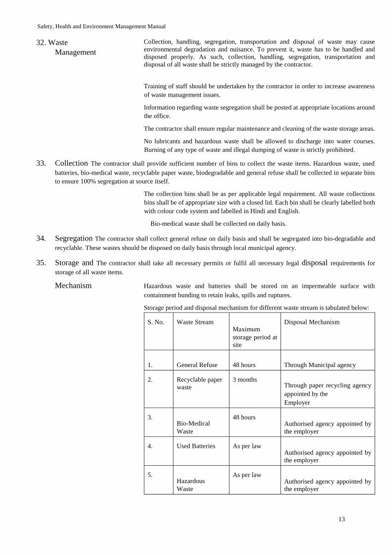
Safety, Health and Environment Management Manual
13
32. Waste
Management
Collection, handling, segregation, transportation and disposal of waste may cause
environmental degradation and nuisance. To prevent it, waste has to be handled and
disposed properly. As such, collection, handling, segregation, transportation and
disposal of all waste shall be strictly managed by the contractor.
Training of staff should be undertaken by the contractor in order to increase awareness
of waste management issues.
Information regarding waste segregation shall be posted at appropriate locations around
the office.
The contractor shall ensure regular maintenance and cleaning of the waste storage areas.
No lubricants and hazardous waste shall be allowed to discharge into water courses.
Burning of any type of waste and illegal dumping of waste is strictly prohibited.
33. Collection The contractor shall provide sufficient number of bins to collect the waste items. Hazardous waste, used
batteries, bio-medical waste, recyclable paper waste, biodegradable and general refuse shall be collected in separate bins
to ensure 100% segregation at source itself.
The collection bins shall be as per applicable legal requirement. All waste collections
bins shall be of appropriate size with a closed lid. Each bin shall be clearly labelled both
with colour code system and labelled in Hindi and English.
Bio-medical waste shall be collected on daily basis.
34. Segregation The contractor shall collect general refuse on daily basis and shall be segregated into bio-degradable and
recyclable. These wastes should be disposed on daily basis through local municipal agency.
35. Storage and The contractor shall take all necessary permits or fulfil all necessary legal disposal requirements for
storage of all waste items.
Mechanism Hazardous waste and batteries shall be stored on an impermeable surface with
containment bunding to retain leaks, spills and ruptures.
Storage period and disposal mechanism for different waste stream is tabulated below:
S. No. Waste Stream Maximum storage period at
site
Disposal Mechanism
1. General Refuse 48 hours Through Municipal agency
2. Recyclable paper
waste 3 months
Through paper recycling agency
appointed by the Employer
3. Bio-Medical Waste
48 hours Authorised agency appointed by
the employer
4. Used Batteries As per law Authorised agency appointed by
the employer
5. Hazardous Waste
As per law Authorised agency appointed by
the employer
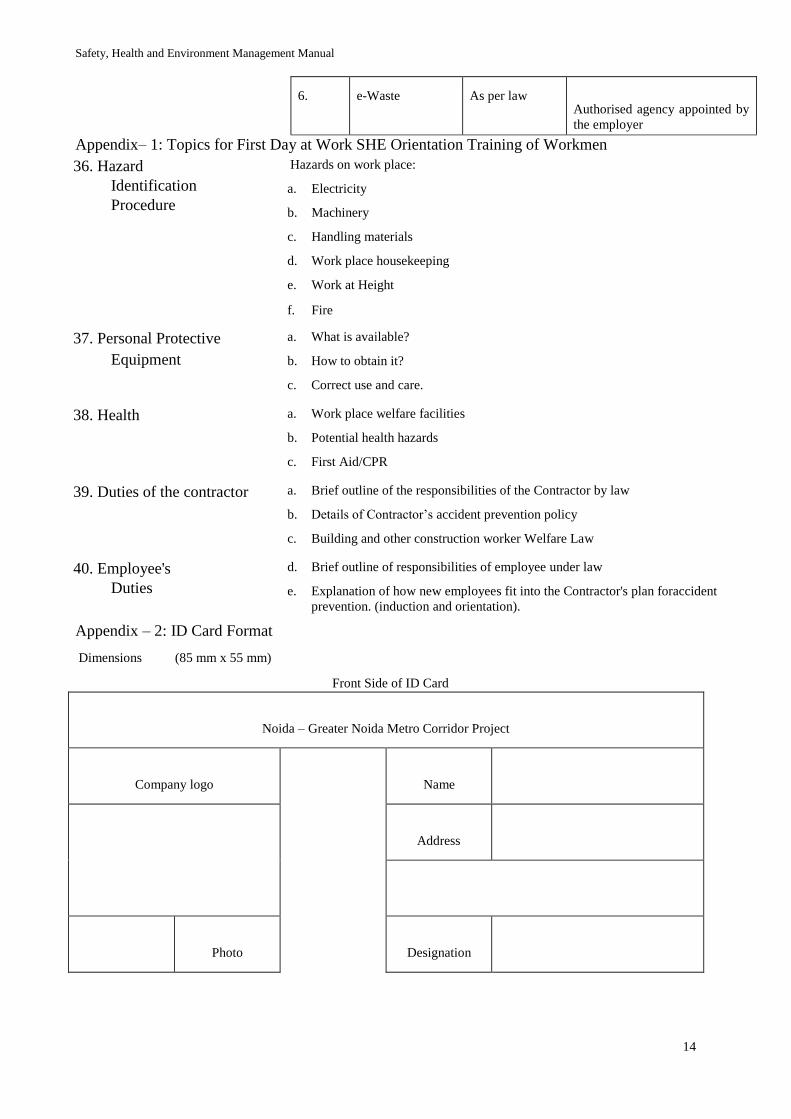
Safety, Health and Environment Management Manual
14
6. e-Waste As per law Authorised agency appointed by
the employer
Appendix– 1: Topics for First Day at Work SHE Orientation Training of Workmen
36. Hazard
Identification
Procedure
Hazards on work place:
a. Electricity
b. Machinery
c. Handling materials
d. Work place housekeeping
e. Work at Height
f. Fire
37. Personal Protective
Equipment
a. What is available?
b. How to obtain it?
c. Correct use and care.
38. Health a. Work place welfare facilities
b. Potential health hazards
c. First Aid/CPR
39. Duties of the contractor a. Brief outline of the responsibilities of the Contractor by law
b. Details of Contractor’s accident prevention policy
c. Building and other construction worker Welfare Law
40. Employee's
Duties
d. Brief outline of responsibilities of employee under law
e. Explanation of how new employees fit into the Contractor's plan foraccident
prevention. (induction and orientation).
Appendix – 2: ID Card Format
Dimensions (85 mm x 55 mm)
Front Side of ID Card
Noida – Greater Noida Metro Corridor Project
Company logo
Name
Address
Photo Designation
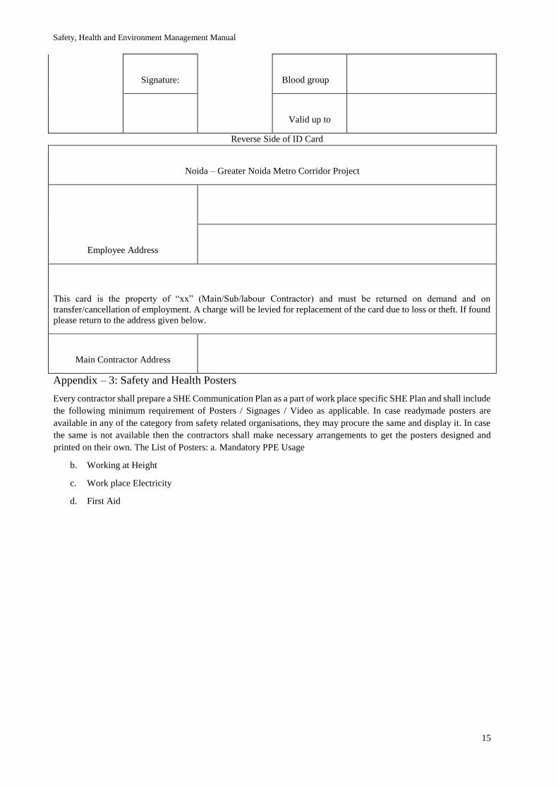
Safety, Health and Environment Management Manual
15
Signature: Blood group
Valid up to
Reverse Side of ID Card
Noida – Greater Noida Metro Corridor Project
Employee Address
This card is the property of “xx” (Main/Sub/labour Contractor) and must be returned on demand and on
transfer/cancellation of employment. A charge will be levied for replacement of the card due to loss or theft. If found
please return to the address given below.
Main Contractor Address
Appendix – 3: Safety and Health Posters
Every contractor shall prepare a SHE Communication Plan as a part of work place specific SHE Plan and shall include
the following minimum requirement of Posters / Signages / Video as applicable. In case readymade posters are
available in any of the category from safety related organisations, they may procure the same and display it. In case
the same is not available then the contractors shall make necessary arrangements to get the posters designed and
printed on their own. The List of Posters: a. Mandatory PPE Usage
b. Working at Height
c. Work place Electricity
d. First Aid
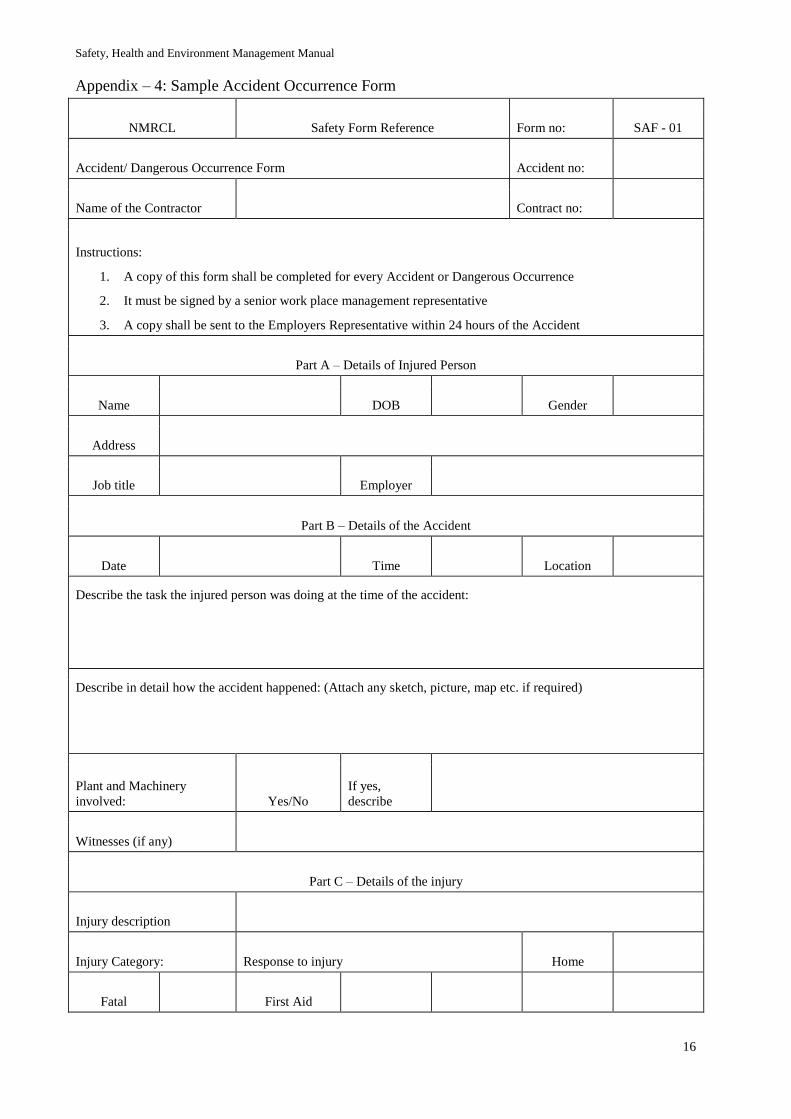
Safety, Health and Environment Management Manual
16
Appendix – 4: Sample Accident Occurrence Form
NMRCL Safety Form Reference Form no: SAF - 01
Accident/ Dangerous Occurrence Form Accident no:
Name of the Contractor
Contract no:
Instructions:
1. A copy of this form shall be completed for every Accident or Dangerous Occurrence
2. It must be signed by a senior work place management representative
3. A copy shall be sent to the Employers Representative within 24 hours of the Accident
Part A – Details of Injured Person
Name
DOB
Gender
Address
Job title
Employer
Part B – Details of the Accident
Date
Time
Location
Describe the task the injured person was doing at the time of the accident:
Describe in detail how the accident happened: (Attach any sketch, picture, map etc. if required)
Plant and Machinery
involved: Yes/No If yes,
describe
Witnesses (if any)
Part C – Details of the injury
Injury description
Injury Category: Response to injury Home
Fatal
First Aid

Safety, Health and Environment Management Manual
17
Major
Doctor
Minor
Hospital
Part D - Certification
I have checked the above information and can confirm that it is a true record of the accident
Signed
In-charge
name
Date