ni 40-41_technical reference manual - baixardoc
TRANSCRIPT
User’s manual and Technical description
Document No 1MDV07203-YN:
Issued: July 2007
Version A
NI 40/41
Numerical Three phase Over current
and Earth Fault Relay
Data subject to change without notice
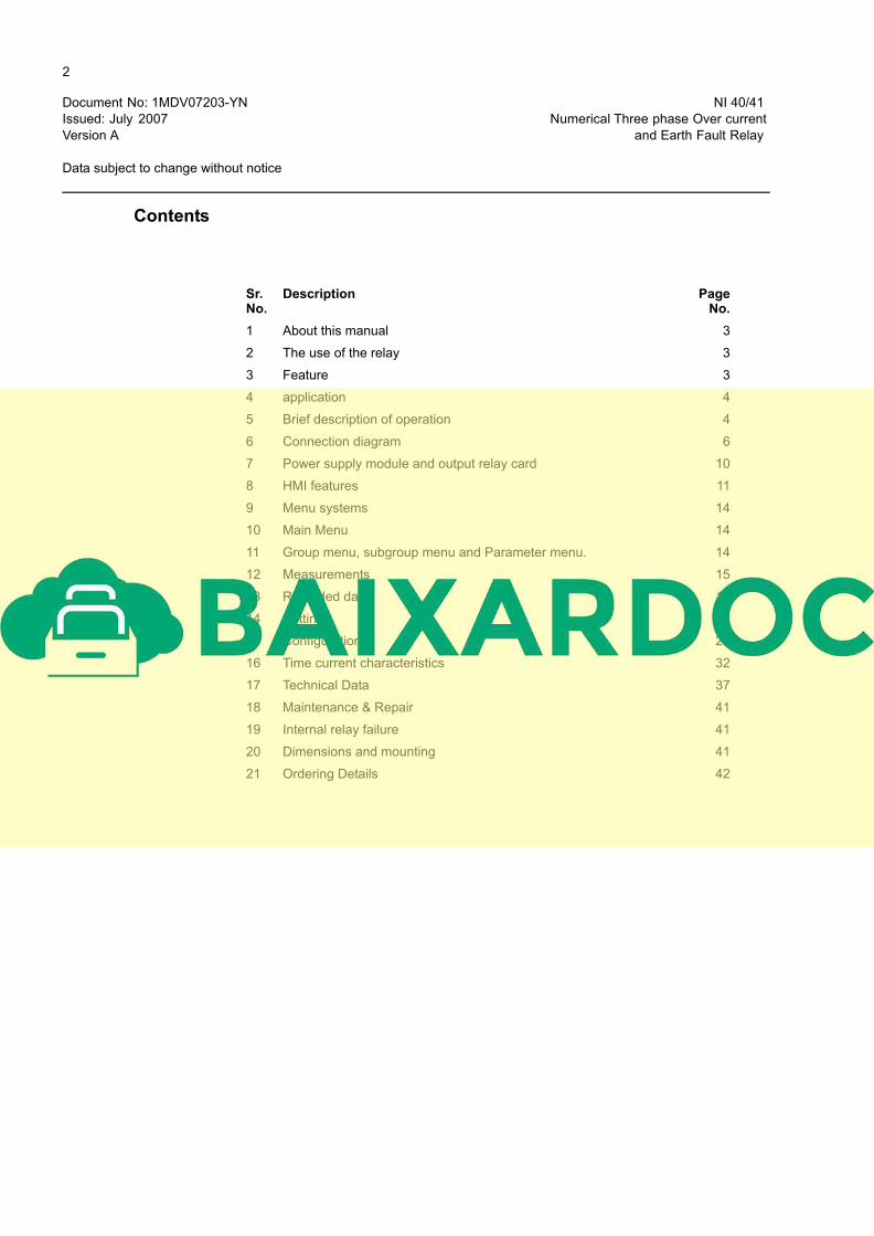
Contents
Sr. Description PageNo. No.
1 About this manual 3
2 The use of the relay 3
3 Feature 3
4 application 4
5 Brief description of operation 4
6 Connection diagram 6
7 Power supply module and output relay card 10
8 HMI features 11
9 Menu systems 14
10 Main Menu 14
11 Group menu, subgroup menu and Parameter menu. 14
12 Measurements 15
13 Recorded data 17
14 Settings 22
15 Configuration 27
16 Time current characteristics 32
17 Technical Data 37
18 Maintenance & Repair 41
19 Internal relay failure 41
20 Dimensions and mounting 41
21 Ordering Details 42
2
3
1 About this manual
This manual provides information on the protection relay NI 40/41 and its applications, focusing on giving a technical description of the relay. The manual also provides basic information on the protection relay NI 40/41 and presents detailed instructions on how to use the Human-Machine Interface (HMI) of the relay, also known as the Man-Machine Interface (MMI).
2 The use of the relay
NI 40/41 is a versatile protection relay mainly designed to protect incoming and outgoing feeders in a wide range of feeder applications. NI 40/41 is based on a microprocessor environment. A self supervision system continuously monitors the operation of the relay. The HMI has a Liquid Crystal Display (LCD) which makes the local use of the relay
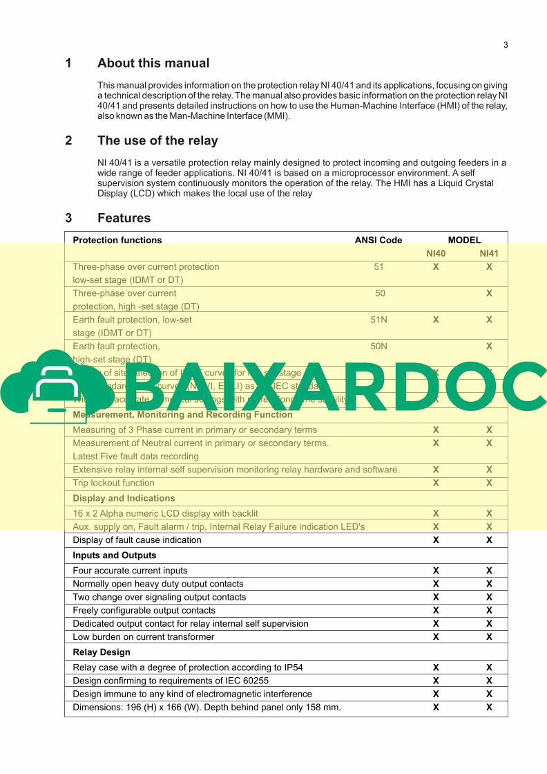
3 Features
Protection functions ANSI Code MODEL
NI40 NI41
Three-phase over current protection 51 X X
low-set stage (IDMT or DT)
Three-phase over current 50 X
protection, high -set stage (DT)
Earth fault protection, low-set 51N X X
stage (IDMT or DT)
Earth fault protection, 50N X
high-set stage (DT)
Facility of site selection of IDMT curves for low set stage X X
Four standard IDMT curves (NI, VI, EI, LI) as per IEC standard. X X
Wide and accurate numerical settings with perfect long time stability. X X
Measurement, Monitoring and Recording Function
Measuring of 3 Phase current in primary or secondary terms X X
Measurement of Neutral current in primary or secondary terms. X X
Latest Five fault data recording
Extensive relay internal self supervision monitoring relay hardware and software. X X
Trip lockout function X X
Display and Indications
16 x 2 Alpha numeric LCD display with backlit X X
Aux. supply on, Fault alarm / trip, Internal Relay Failure indication LED's X X
Display of fault cause indication X X
Inputs and Outputs
Four accurate current inputs X X
Normally open heavy duty output contacts X X
Two change over signaling output contacts X X
Freely configurable output contacts X X
Dedicated output contact for relay internal self supervision X X
Low burden on current transformer X X
Relay Design
Relay case with a degree of protection according to IP54 X X
Design confirming to requirements of IEC 60255 X X
Design immune to any kind of electromagnetic interference X X
Dimensions: 196 (H) x 166 (W). Depth behind panel only 158 mm. X X
4
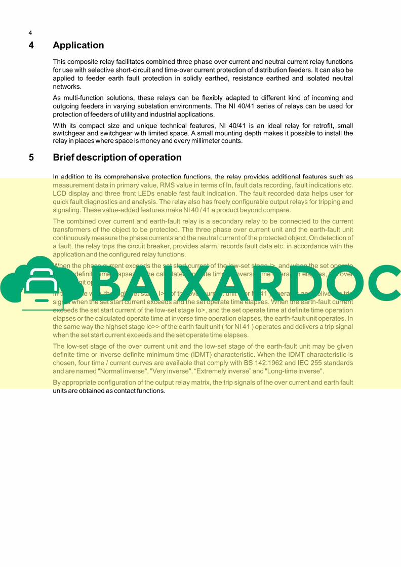
4 Application
This composite relay facilitates combined three phase over current and neutral current relay functions
for use with selective short-circuit and time-over current protection of distribution feeders. It can also be
applied to feeder earth fault protection in solidly earthed, resistance earthed and isolated neutral
networks.
As multi-function solutions, these relays can be flexibly adapted to different kind of incoming and
outgoing feeders in varying substation environments. The NI 40/41 series of relays can be used for
protection of feeders of utility and industrial applications.
With its compact size and unique technical features, NI 40/41 is an ideal relay for retrofit, small switchgear and switchgear with limited space. A small mounting depth makes it possible to install the relay in places where space is money and every millimeter counts.
5 Brief description of operation
In addition to its comprehensive protection functions, the relay provides additional features such as
measurement data in primary value, RMS value in terms of In, fault data recording, fault indications etc.
LCD display and three front LEDs enable fast fault indication. The fault recorded data helps user for
quick fault diagnostics and analysis. The relay also has freely configurable output relays for tripping and
signaling. These value-added features make NI 40 / 41 a product beyond compare.
The combined over current and earth-fault relay is a secondary relay to be connected to the current
transformers of the object to be protected. The three phase over current unit and the earth-fault unit
continuously measure the phase currents and the neutral current of the protected object. On detection of
a fault, the relay trips the circuit breaker, provides alarm, records fault data etc. in accordance with the
application and the configured relay functions.
When the phase current exceeds the set start current of the low-set stage I>, and when the set operate
time at definite time elapses or the calculated operate time at inverse time operation elapses, the over
current unit operates.
In the same way, the high-set stage I>> of the over current unit ( for NI 41 ) operates and delivers a trip
signal when the set start current exceeds and the set operate time elapses. When the earth-fault current
exceeds the set start current of the low-set stage Io>, and the set operate time at definite time operation
elapses or the calculated operate time at inverse time operation elapses, the earth-fault unit operates. In
the same way the highset stage Io>> of the earth fault unit ( for NI 41 ) operates and delivers a trip signal
when the set start current exceeds and the set operate time elapses.
The low-set stage of the over current unit and the low-set stage of the earth-fault unit may be given
definite time or inverse definite minimum time (IDMT) characteristic. When the IDMT characteristic is
chosen, four time / current curves are available that comply with BS 142:1962 and IEC 255 standards
and are named "Normal inverse", "Very inverse", “Extremely inverse” and "Long-time inverse".
By appropriate configuration of the output relay matrix, the trip signals of the over current and earth fault
units are obtained as contact functions.
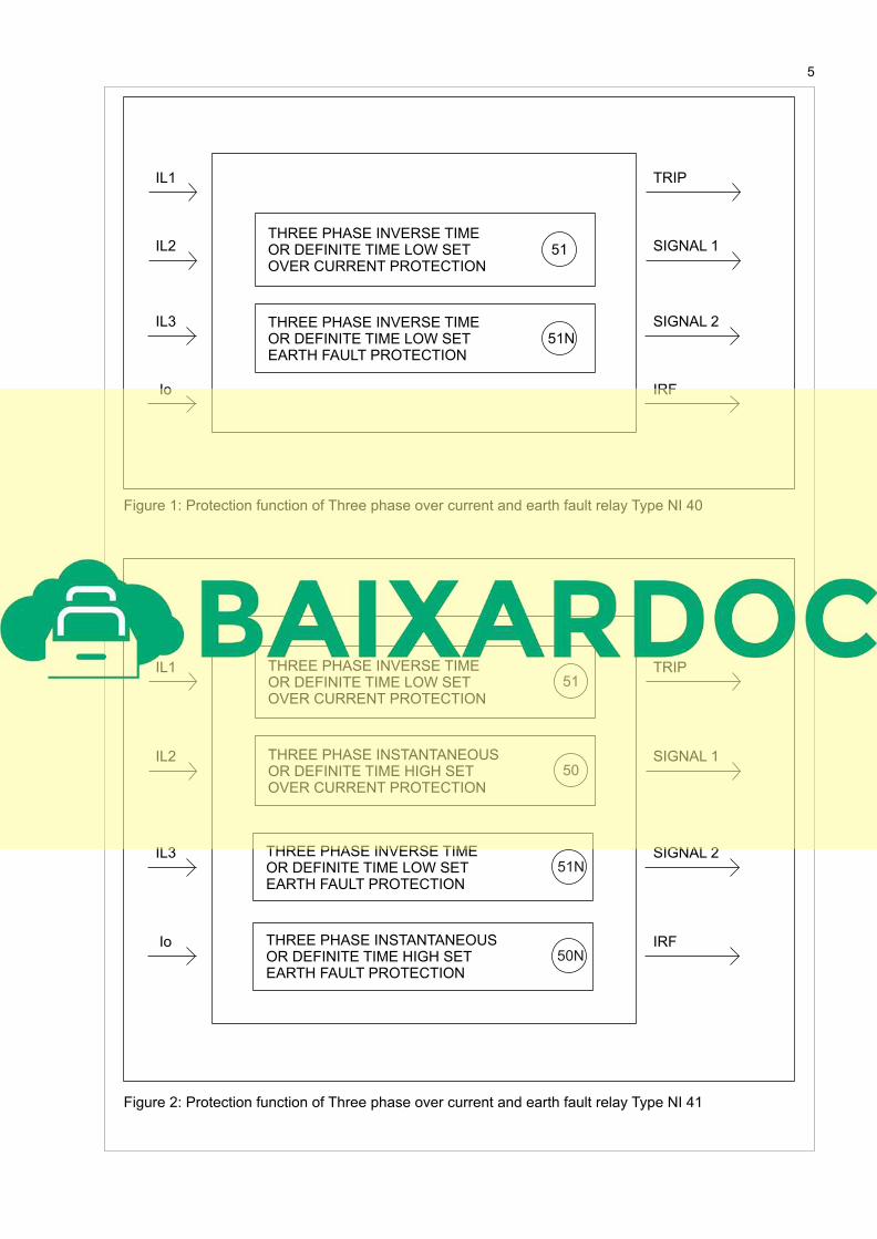
Figure 1: Protection function of Three phase over current and earth fault relay Type NI 40
Figure 2: Protection function of Three phase over current and earth fault relay Type NI 41
THREE PHASE INVERSE TIME OR DEFINITE TIME LOW SET OVER CURRENT PROTECTION
51
THREE PHASE INVERSE TIMEOR DEFINITE TIME LOW SET EARTH FAULT PROTECTION
51N
THREE PHASE INVERSE TIME OR DEFINITE TIME LOW SET OVER CURRENT PROTECTION
51
THREE PHASE INSTANTANEOUS OR DEFINITE TIME HIGH SET OVER CURRENT PROTECTION
50
THREE PHASE INSTANTANEOUS OR DEFINITE TIME HIGH SET EARTH FAULT PROTECTION
THREE PHASE INVERSE TIMEOR DEFINITE TIME LOW SET EARTH FAULT PROTECTION
51N
50N
IL1
IL2
IL3
Io IRF
TRIP
SIGNAL 1
SIGNAL 2
5
IL1
IL2
IL3
Io IRF
TRIP
SIGNAL 1
SIGNAL 2
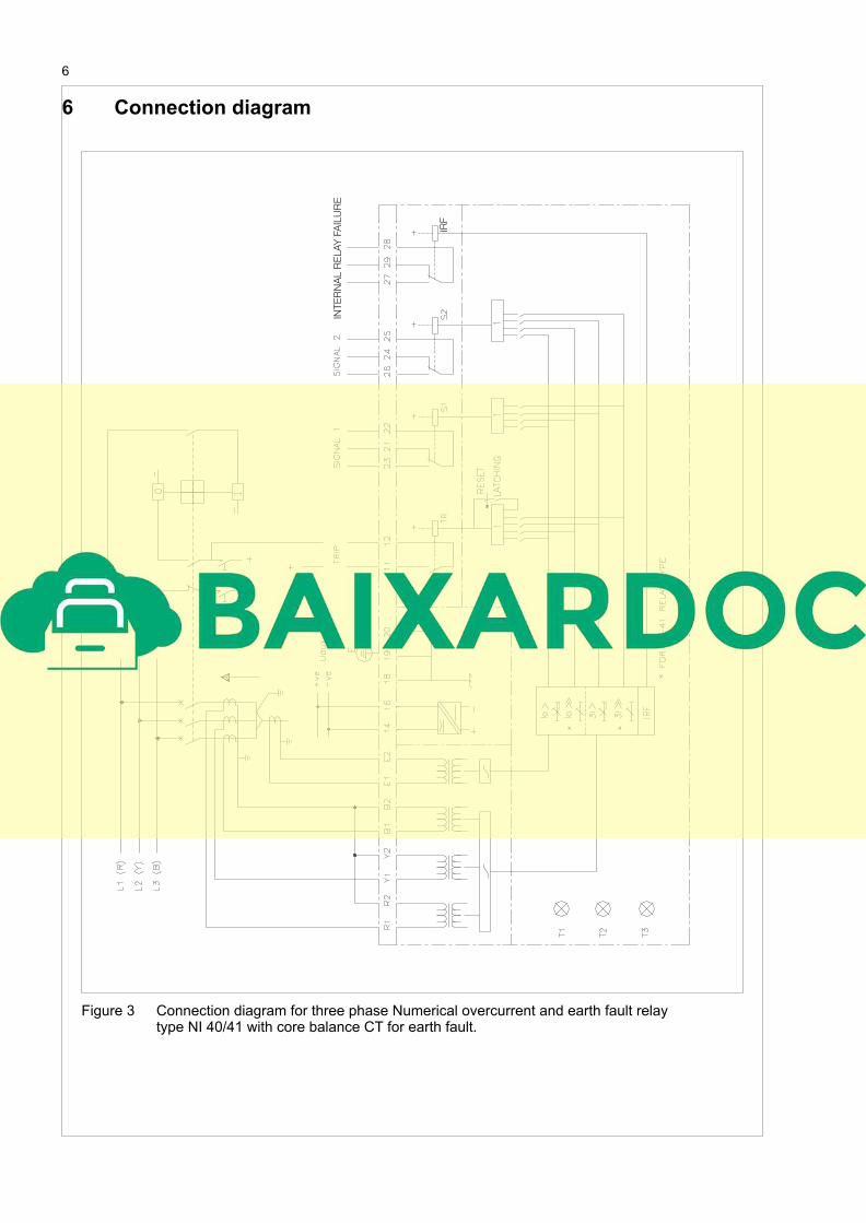
6 Connection diagram
Figure 3 Connection diagram for three phase Numerical overcurrent and earth fault relaytype NI 40/41 with core balance CT for earth fault.
6
IRF
INT
ER
NA
L R
ELA
Y F
AIL
UR
E
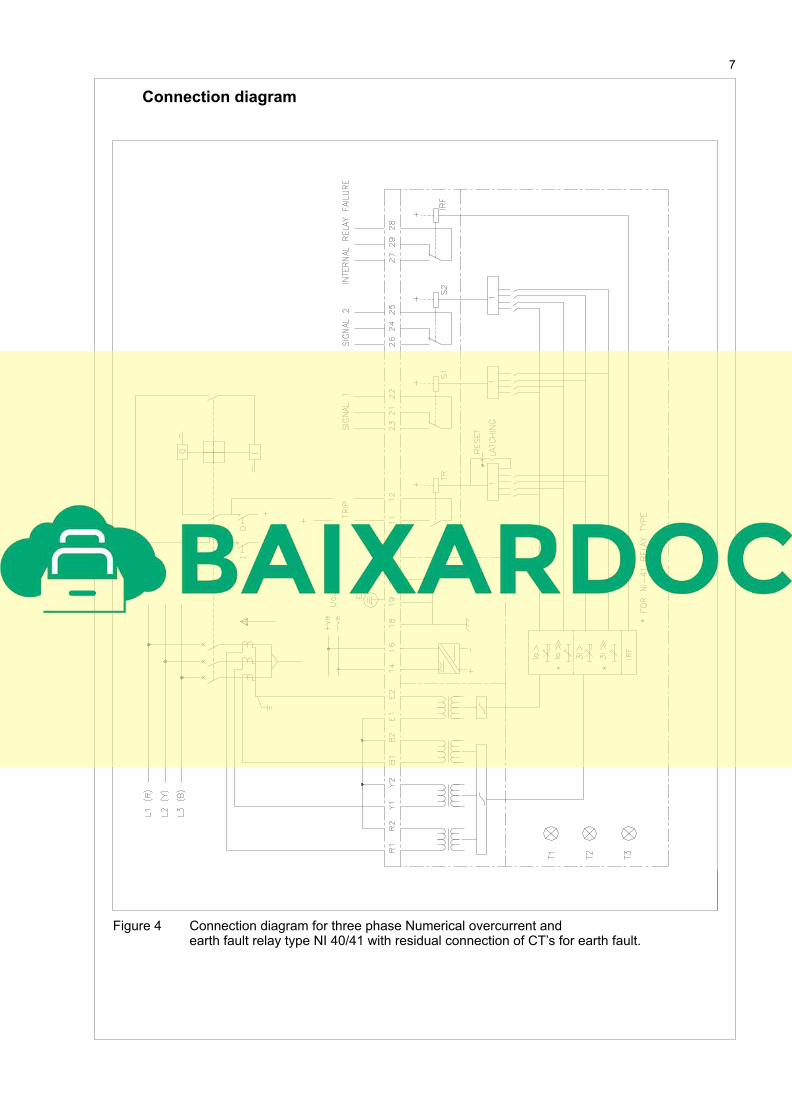
Connection diagram
Figure 4 Connection diagram for three phase Numerical overcurrent and earth fault relay type NI 40/41 with residual connection of CT’s for earth fault.
7
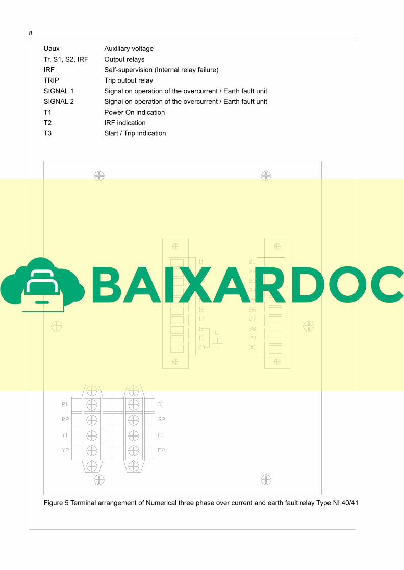
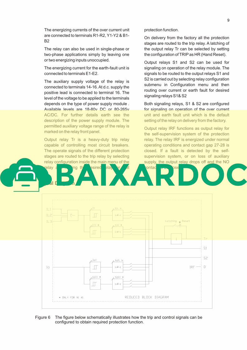
Uaux Auxiliary voltage
Tr, S1, S2, IRF Output relays
IRF Self-supervision (Internal relay failure)
TRIP Trip output relay
SIGNAL 1 Signal on operation of the overcurrent / Earth fault unit
SIGNAL 2 Signal on operation of the overcurrent / Earth fault unit
T1 Power On indication
T2 IRF indication
T3 Start / Trip Indication
Figure 5 Terminal arrangement of Numerical three phase over current and earth fault relay Type NI 40/41
8
Signal Diagram
The energizing currents of the over current unit
are connected to terminals R1-R2, Y1-Y2 & B1-
B2
The relay can also be used in single-phase or
two-phase applications simply by leaving one
or two energizing inputs unoccupied.
The energizing current for the earth-fault unit is
connected to terminals E1-E2.
The auxiliary supply voltage of the relay is
connected to terminals 14-16. At d.c. supply the
positive lead is connected to terminal 16. The
level of the voltage to be applied to the terminals
depends on the type of power supply module .
Available levels are 18-80v DC or 80-265v
AC/DC. For further details earth see the
description of the power supply module. The
permitted auxiliary voltage range of the relay is
marked on the relay front panel.
Output relay Tr is a heavy-duty trip relay
capable of controlling most circuit breakers.
The operate signals of the different protection
stages are routed to the trip relay by selecting
relay configuration inside the main menu of the
relay and routing the desired relay for that
protection function.
On delivery from the factory all the protection
stages are routed to the trip relay. A latching of
the output relay Tr can be selected by setting
the configuration of TRIP as HR (Hand Reset).
Output relays S1 and S2 can be used for
signaling on operation of the relay module. The
signals to be routed to the output relays S1 and
S2 is carried out by selecting relay configuration
submenu in Configuration menu and then
routing over current or earth fault for desired
signaling relays S1& S2
Both signaling relays, S1 & S2 are configured
for signaling on operation of the over current
unit and earth fault unit which is the default
setting of the relay on delivery from the factory.
Output relay IRF functions as output relay for
the self-supervision system of the protection
relay. The relay IRF is energized under normal
operating conditions and contact gap 27-28 is
closed. If a fault is detected by the self-
supervision system, or on loss of auxiliary
supply, the output relay drops off and the NO
contact 28-29 closes.
Figure 6 The figure below schematically illustrates how the trip and control signals can be configured to obtain required protection function.
9
Signal IL1, IL2, IL3
Abbreviation Io
Tr
S1
S2
IRF
Energizing current of phase L1, L2 & L3
Neutral Current (Residual Current)
Trip relay
Signal Relay 1
Signal Relay 2
Internal relay Failure
7. Power Supply Module and Output relay Card
To be able to operate the relay needs a secured
auxiliary voltage supply. The power supply
module forms the voltages required by the
protection relay cards and the auxiliary relays.
The power supply module contains the power
supply unit and the control circuits of the output
relays. Output relay card contains trip and
signal output relays.
The primary side of the power supply module is
protected with a fuse, F1, located on the PCB of
the module. The fuse size is 1 A (slow).
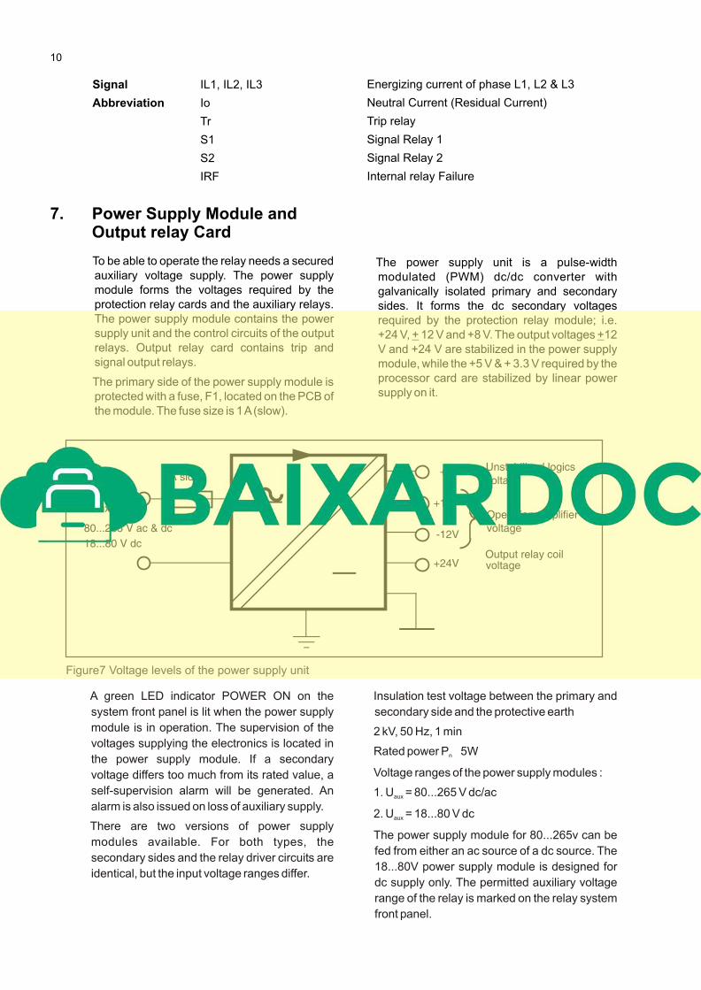
The power supply unit is a pulse-width
modulated (PWM) dc/dc converter with
galvanically isolated primary and secondary
sides. It forms the dc secondary voltages
required by the protection relay module; i.e.
+24 V, + 12 V and +8 V. The output voltages +12
V and +24 V are stabilized in the power supply
module, while the +5 V & + 3.3 V required by the
processor card are stabilized by linear power
supply on it.
A green LED indicator POWER ON on the
system front panel is lit when the power supply
module is in operation. The supervision of the
voltages supplying the electronics is located in
the power supply module. If a secondary
voltage differs too much from its rated value, a
self-supervision alarm will be generated. An
alarm is also issued on loss of auxiliary supply.
There are two versions of power supply
modules available. For both types, the
secondary sides and the relay driver circuits are
identical, but the input voltage ranges differ.
Insulation test voltage between the primary and
secondary side and the protective earth
2 kV, 50 Hz, 1 min
Rated power P 5Wn
Voltage ranges of the power supply modules :
1. U = 80...265 V dc/acaux
2. U = 18...80 V dcaux
The power supply module for 80...265v can be
fed from either an ac source of a dc source. The
18...80V power supply module is designed for
dc supply only. The permitted auxiliary voltage
range of the relay is marked on the relay system
front panel.
10