naval structures integrity under blast loading
TRANSCRIPT
Naval Structures Integrity under Blast Loading Bertrand Langrand1, Aude Menegazzi2 and Thierry Millot3
Key-words—Explosion; Welded Panel Abstract—The paper deals with numerical methodologies to model and study the structural resistance of ship hull against explosions, where fluid and solid phenomena interact. It is proposed to study those problems, based on Explosion Crack Starter Tests, using an explicit FE code that solves Fluid/Structure (F/S) interactions within the same computation. Numerical results are compared to the corresponding explosion tests (ECST) performed by DGA (French Ministry of Defence).
1 Introduction Bulge Explosion Tests (BET) and Explosion Crack Starter Tests (ECST) are usual to study the strength of naval structures under blast loading conditions. Several shots (two at the minimum) are undertaken to assess the plastic strain capability of structural metallic materials and welded assemblies. Tests may be also performed at different temperatures to define the Fracture Transition for Plastic loading (FTP). Based on ECST tests, the presented paper concerns the assessment of the simulation capability of explicit Finite Element (FE) codes to model the behaviour of metallic welded structures under explosion pressure wave loading conditions. Developed numerical methods focus only on the ductile behaviour of experimented plates (Continuous Damage Mechanics and not Fracture Mechanics).
Metallic samples are experimented to study the strain rate sensitivity of the Fusion Zone (FZ) and Base Metal (BM) materials, and to identify the parameters of viscoplastic models (homogeneous) used in FE computations. A first explosion simulation is computed until complete dynamic relaxation. Numerical methodologies are then developed (1) to capture the deformed shape of the metallic plate and (2) to measure the residual plastic strain and stress fields in all 3D FE of the metallic plate. The deformed shape (including fluid domain local re-meshing for F/S interaction) and the residual properties (plastic strain and stress tensor components) of the metallic plate are then introduced as initial state of a second explosion computation. Numerical results are compared to the corresponding explosion tests (ECST) performed by DGA.
1 ONERA/DMSE, Lille, France (E-Mail address: [email protected]). 2 DGA/SPN, Paris, France. 3 DCN/CESMAN, Nantes, France.

2 Characterisation of welded “materials” viscoplastic behaviour Based on micro hardness diagram, to locate the fusion zone and the average heat affected zone, metallic tensile test specimens (Fig. 1) are extracted from a welded flat panel. The specimen geometry is adapted to static, hydraulic jack and Hopkinson bars tests [3]. The sample material is considered homogeneous (for BM, FZ and HAZ) due to the small size of specimens.
Experiments are undertaken at ambient temperature and –5°C (flat panel temperature for the explosion tests considered in the paper). Pre-test FE simulations are performed to assess the flat panel strain rate range during the explosion test. Maximum strain rate levels are thus found to be up 400s–1. Tensile tests are performed on a hydraulic jack, using a specific experimental device [3], at several velocities for each specimen temperature. The force is measured with a piezoelectric cell (Kistler) and the global strain with an optical extensometer (Zimmer).
Figure 1. Tensile test specimen (all dimensions in mm – 1mm thick).
The experimental analysis shows that mechanical behaviours are very close for both HAZ and BM materials whatever the strain rate or temperature (Fig. 2). Consequently, the explosion FE model could be simplified by neglecting the influence of the HAZ material. The influence of temperature (–5°C) may be also neglected during the identification procedure of material constitutive models if necessary. Fig. 3 presents raw (unfiltered) engineering stress/strain diagrams.
500
625
750
875
1000
1125
1250
0,001 0,01 0,1 1 10 100 1000
Strain Rate [1/s]
Yie
ld S
tres
s [M
Pa] BM +20°C
HAZ +20°CFZ +20°CBM -5°CHAZ -5°CFZ -5°C
500
625
750
875
1000
1125
1250
0,001 0,01 0,1 1 10 100 1000
Strain Rate [1/s]
Max
Str
ess
[MP
a] BM +20°CHAZ +20°CFZ +20°CBM -5°CHAZ -5°CFZ -5°C
Figure 2. Stain rate and temperature effects on welded materials.

Figure 3. Measured engineering stress/strain diagram.
3 Explosion Crack Starter Tests FE simulations Explosion Crack Starter Tests were developed in 1949 to 1950 and have been used extensively to investigate the factors, which determine the performance of weldments, particularly in submarine structure, and other large welded structures [1,2]. This explosion test is principally used to qualify prospective products wherein a flat test plate specimen is explosively loaded into a circular test die. A deposited and notched defect (or crack starter4 bead) is machined on the flat panel (Fig. 4). The flat panel thickness governs the explosion test parameters. For a 50mm thick flat panel, the dimensions are: flat panel length: 600mm square, test die internal diameter: 400mm, stand-off-distance: 350mm, charge diameter/weight: 400mm/10kg. The crack starter geometrical characteristics are as follow: length: 75mm, width: 12mm, overall thickness: 8mm, distance crack tip/test plate: 5mm.
Figure 4. Explosion test configuration and FE model.
The metallic panel has an “initial” flatness defect due to the welding process (8mm deflection measured at the panel centre). A digitalisation of the specimen is therefore
4 Brittle weld metal deposited on the weldment to present a sharp crack front to the weld or HAZ or base metal for the purpose of assessing the resistance to cracking of the material being tested.
performed to define the panel meshing and to investigate the effects of the flatness defect on its behaviour. Consequently, no symmetry boundary condition can be considered for FE simplification, and complete 3D FE models must be computed. The size of the FE mesh is about 10mm and 5mm in the fluid and solid domains respectively. It is not possible to consider the influence of the crack starter (the distance between the crack tip and the test plate surface is 5mm only). In such conditions, the number of FE is about 435 000, including 360 000 FE for the fluid area and 75 000 FE for solid area. Another consequence concerns the material failure, which is not considered with this FE mesh scale.
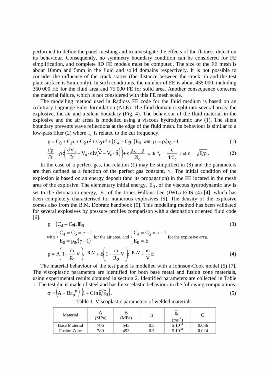
The modelling method used in Radioss FE code for the fluid medium is based on an Arbitrary Lagrange Euler formulation (ALE). The fluid domain is split into several areas: the explosive, the air and a silent boundary (Fig. 4). The behaviour of the fluid material in the explosive and the air areas is modelled using a viscous hydrodynamic law (1). The silent boundary prevents wave reflections at the edge of the fluid mesh. Its behaviour is similar to a low-pass filter (2) where cl is related to the cut frequency.
0543
32
210 ECCCCCCp with 10 . (1)
c
nnn
l2pp
cnVVdivVt
Vc
tp
with c
c l4
cf
and Ec . (2)
In the case of a perfect gas, the relation (1) may be simplified in (3) and the parameters are then defined as a function of the perfect gas constant, . The initial condition of the explosion is based on an energy deposit (and its propagation) in the FE located in the mesh area of the explosive. The elementary initial energy, 0E , of the viscous hydrodynamic law is
set to the detonation energy, E , of the Jones-Wilkins-Lee (JWL) EOS (4) [4], which has been completely characterised for numerous explosives [5]. The density of the explosive comes also from the B.M. Dobratz handbook [5]. This modelling method has been validated for several explosives by pressure profiles comparison with a detonation oriented fluid code [6].
054 ECCp (3)
with
1pE
1CC
00
54 for the air area, and
EE
1CC
0
54 for the explosive area.
EV
eVR
1BeVR
1Ap VR
2
VR
121
(4)
The material behaviour of the test panel is modelled with a Johnson-Cook model (5) [7]. The viscoplastic parameters are identified for both base metal and fusion zone materials, using experimental results obtained in section 2. Identified parameters are collected in Table 1. The test die is made of steel and has linear elastic behaviour in the following computations.
0n
p lnC1BA . (5)
Table 1. Viscoplastic parameters of welded materials.
Material A (MPa)
B (MPa)
n 0
(ms–1) C
Base Material 706 545 0.5 5 10–4 0.036 Fusion Zone 780 493 0.5 5 10–4 0.024

3.1 First ECST computation First ECST FE simulation consists in two computations. During computation n°1
(0 < T < 1ms), the complete fluid/structure interaction problem is solved until the flat panel starts its spring-back (detected by numerical strain gauges). At the test plate centre, peak overpressure is about 10 000bars and maximum acceleration is about 250 000g (Butterworth –4db filter).
Computation n°2 (1ms < T < 2ms) consists in a dynamic relaxation computation to define residual properties of the flat panel (plastic strain and stress tensor in each FE, maximum deflexion and thickness reduction). Fluid FE are deleted in this second simulation to save computational cost. The residual properties will initialise the second ECST FE simulation: (1) geometry of the deformed flat panel and (2) stress tensor and plastic strain of all 3D FE of the test plate.
At the end of the computation, thickness reduction is about 3.7% and residual plastic strain is about 17% at the centre of the test plate. Compared to material percentage elongation (15% and 14% for BM and ZF respectively), failure could appear and propagate, all the more as the crack starter effects are not taken into account in the current FE computation. Maximum defection is about 40mm.
DGA performs the corresponding explosion test. Residual strain measurement is carried out using electro-erosion marked grid located on the test plate. Residual strain distribution is measured using image digitalisation and stereo correlation (for 3D measurements) systems [8]. Comparison of strain distributions shows a good agreement between FE and experimental results (Fig. 5). Thickness reduction is about 4.2% and maximum defection is about 45mm.
Another FE computation is performed using a test plate FE model not considering the initial flatness defect. Pressure and acceleration fields are close whatever the presence or not of the initial flatness defect. However, strains decrease a little in the case of the flat panel.
Figure 5. Residual strain distribution after ECST test n°1.

3.2 Second ECST computation In-house developed programs are implemented to capture, from the last state of the first ECST computation, the residual deformed shape of the test plate. The deformed test plate is then interfaced with the test die and the fluid mesh is locally modified for Fluid/Structure interaction (modelled using a specific tied interface). Other programs developed to handle ASCII output files from Radioss are implemented to initialise all test plate FE with plastic strain and stress tensor from the residual state of the first ECST computation. When this modelling process is completed, the second ECST computation is launched in two steps as presented in section 3.1 and resumed in Fig. 6. Material EOS and parameters are identical to the first explosion simulation (§3).
Figure 6. Methodology for second ECST simulation.
Pressure fields measured for both explosions are very close. Only the arrival time of the blasting wave has increased in the second ECST computation due to the initial deformation of the test plate (initial defection: 40mm). So, Fluid/Structure coupling effects are very low in that case. To save computational cost, it is then possible to measure the pressure field distribution with a preliminary computation (a fluid code if considering rigid test plate), and to apply this pressure fields for other structural computations (fluid FE can be deleted for structural computations in such conditions).
However, acceleration measured at the test plate centre reaches 300 000g at the maximum. Shock spectrum analysis [9] shows that the second explosion test is more severe in the high frequency range (f > 100kHz, Fig. 7). Residual plastic strain introduced in the second explosion computation could explain that difference. Material is harder (weaker plastic damping) in the second explosion computation. It still has to be investigated by a parametric sensitivity study.
Figure 7. Shock spectrum analysis
Strain distribution is localised at the test plate centre and near the test plate/test die interface (Fig. 8). Tests plate «corners» influence the strain distribution in the hold-on region

(more localised plastic strain following the diagonal direction). Strain gradient between initial and final state of the computation is more important in hold-on region. Strains have not increased so much in the bulge region (17% at T0 and 22% at Tf). Experimental and numerical strain distributions are close (Fig. 8).
Figure 8. Residual strain distribution after ECST test n°2.
The thickness reduction due to the second explosion is about 4.7%. For overall explosion computations, thickness reduction is about 8% (9% measured after two experimental shots). The maximum deflection measured at the end of the computation is 66mm (67mm measured experimentally).
4 Conclusion The paper deals with numerical methodologies (based on explicit FE codes) to model and study the structural resistance of ship hull against several explosions. Numerical results, obtained for Explosion Crack Starter Tests, are close to experiments in terms of global residual deflection, thickness reduction or local residual strain distribution. FE results show an influence of the weldment on the strain distribution, and therefore the interest in taking into account the material behaviour of the Fusion Zone in the FE computations. This influence can be investigated in further researches by performing a parametric FE study. Another interesting parametric study could consist in analysing the influence of residual plastic strain or stress tensor (introduced in all test plate FE) in the second ECST computation.
The numerical methods, developed to model the effects of a second explosion, can be reiterated to study the effects of repetitive explosions on a ship hull. FE model could be simplified by applying equivalent loading conditions to save computation cost (numerous FE of the fluid domain can be deleted for structural computations in such conditions).
A perspective in this study consists in considering the influence crack starter in FE computations. Based on material dynamic tensile tests, failure criterion from Continuous Damage Mechanics Theory (e.g. a critical plastic strain or damage) could be characterised for a specific mesh size using inverse method. Another solution could consist in applying

Extended Finite Element Method, and therefore failure criterion from Fracture Mechanics Theory (e.g. static and/or dynamic stress intensity factors), once plasticity implemented (and validated) in X-FEM codes.
Acknowledgements—This work have been grant-aided by the French Ministry of Defence (DGA/SPN) and the French military shipyard (DCN).
References [1] W.S. Pellini. Principals of structural integrity technology. Naval Research Laboratory,
Washington DC 20375, 1976. [2] Department of Defense. Test Method Standard, Standard procedures for explosion testing ferrous
and non-ferrous metallic materials and weldments. MIL-STD-2149A(SH), 2 February 1990. [3] G. Haugou, E. Markiewicz, and J. Fabis. On the use of the non direct tensile loading on a classical
split Hopkinson bar apparatus dedicated to sheet metal specimen characterisation. Int. J. of Impact Engineering, 32:778–798, 2006.
[4] E.L. Lee, M. Finger, and W. Collins. JWL equation of state coefficients for high explosives. Lawrence Livermore Laboratory, University of California, Report n° UCID-16189, 1973.
[5] B.M. Dobratz. LLNL explosive handbook – Properties of chemical explosives and explosives simulants. Lawrence Livermore Laboratory, University of California, Report n° UCRL-52997, 1981.
[6] B. Langrand, E. Deletombe, et al. Armoured vehicles subject to mine explosions – An analysis method for operationability and survivability. J. Phys. IV, 110:621–626, 2003.
[7] G.R. Johnson, and W.H. Cook. A constitutive model and data for metal subjected to large strains, high strain rates and high temperatures. In Proc. of 7th Symp. on ballistics, pages 541–547, The Hague, The Nederlands, 1983.
[8] GOM Atos and Aramis theory and user manual, 2006. [9] C. Lalanne. Chocs mécaniques – Tome 2. HERMES Science Publication, 1st Edn., 1999.