multi factor authentication access control
TRANSCRIPT
i
MULTI FACTOR AUTHENTICATION ACCESS
CONTROL FOR STUDENT AND STAFF BASED ON
RFID, BARCODE AND GIS
BY
Simukali Moono Consuela
A Dissertation submitted to the University of Zambia in partial fulfilment of the
requirements of the degree in Masters of Engineering in ICT Security
UNIVERSITY OF ZAMBIA
LUSAKA
2019
ii
COPYRIGHT
All rights reserved. No part of this dissertation may be reproduced, stored in any retrieval system,
or transmitted in any form or by any means, electronic, mechanical photocopying, recording,
scanning or otherwise without the prior written permission of the author or the University of
Zambia.
© Consuela Moono Simukali, 2019
i
DECLARATION
I, Consuela Moono Simukali, the undersigned, declare that this has not previously been submitted
in candidature for any degree. The dissertation is the result of my own work and investigations,
except where otherwise stated. Other sources are acknowledged by given explicit references. A
complete list of references is appended.
Signature: ...............................................
Date: .......................................................

ii
CERTIFICATE OF APPROVAL
This dissertation by Consuela Moono Simukali has been approved as fulfilling the requirements
for the award of the degree of Masters of Engineering in ICT Security by the University of
Zambia.
Examiner 1……………………………......…….... Signature: ………………………Date………
Examiner 2……………………………......….........Signature: ………………………Date………
Examiner 3……………………………......………. Signature: ………………………Date………
Board of Examiners Chairperson……………...........Signature…….…………………. Date….
Supervisor…………………………………………...Signature…………………………Date……
iii
ABSTRACT
University of Zambia like most Public Universities and Higher Learning Institutions in Zambia
have a challenge preventing unauthorized access into their campus environment. There is no
automatic identification of all who enter or exit the campus facilities. No audit trail or record is
kept for visitors who enter the campus. This makes it a challenge to protect the organisations’
assets such as information, personal property, staff and students. Members of Staff, Students and
Visitors of the University have lost and continue to lose belongings such as laptops and cars. This
study proposes an Access Control and Visitor Real Time Tracking System to improve the level of
security on the campus. A baseline study was conducted to measure the level of security at the
University using questionnaires that were designed based on ISO 27002 Standard for Physical and
Environmental Security. The results of this baseline study show that the University’s security is
porous. The findings also revealed that more than ninety percent of the respondents were victims
of theft or have known of a victim of theft whilst on campus. Data was collected from 200 students,
120 members of staff ten of which are from the University of Zambia’s (UNZA) security office.
Based on the results from the baseline study a model Access Control and Real Time Tracking
system was to designed to control all who enter and exit the campus. The designed model was
based on RFID, Biometrics, Barcode and GIS. The RFID, Biometrics, and Barcode Technologies
are designed as an identification and authentication mechanism of people entering and exiting the
campus. The study focused on developing a real time visitor tracking system using GIS and GPS
Results from the real time tracking system show that a visitor’s movement and geographical
location was known. A record of past visits could also be reviewed. This research is expected to
allow the University have control of who accesses the University premises and ensure visitors are
recorded and access only facilities they are allowed to.
Keywords: Security and Access Control, Authentication, RFID, ISO 27002, GIS

iv
ACKNOWLEDGEMENT
First and above all, I thank the Lord Almighty to whom I owe my very existence for providing
me this opportunity and granting me the capability to proceed successfully. I am grateful for the
joy, good health and grace for growth that have been bestowed upon me during this research work,
and indeed, throughout my life: "I can do everything through Him (God) who gives me strength."
Secondly, I would like to thank my research Supervisor Dr. Jackson Phiri of the School of Natural
Sciences at the University of Zambia. The door to Dr. Jackson Phiri’s office was always open
whenever I ran into a trouble spot or had a question about my research or writing. He consistently
allowed this study to be my own work, but steered me in the right direction whenever he thought
I needed it.
I would also like to thank the UNZA Students and Staff who participated in the baseline survey
for this research project, without their participation and input, the validation survey could not have
been successfully conducted.
I would also like to acknowledge Mr. Stephen Namukolo of the School of Engineering at the
University of Zambia as the Co-Supervisor to this study. I am gratefully indebted to his valuable
guidance especially at the beginning of this research.
I would also like to thank Ella Kasanda and Siphiwe Chihana for their unique encouragement.
Finally, I must express my very profound gratitude to my husband Benson Mwembeshi and
children Besa Luumuno, Mwila and Langila for providing me with unfailing support and
continuous encouragent throughout my years of study and through the process of researching and
writing this thesis. This accomplishment would not have been possible without them.
v
TABLE OF CONTENTS
COPYRIGHT .................................................................................................................................. ii
DECLARATION ............................................................................................................................. i
ABSTRACT ................................................................................................................................... iii
ACKNOWLEDGEMENT ............................................................................................................. iv
TABLE OF CONTENTS ................................................................................................................ v
LIST OF TABLES ......................................................................................................................... ix
LIST OF FIGURES ........................................................................................................................ x
LIST OF APPENDICES .............................................................................................................. xiii
ACRONYMS ............................................................................................................................... xiv
CHAPTER 1: INTRODUCTION ................................................................................................... 1
1.1 Background to the study ........................................................................................................... 1
1.2 Related Work ............................................................................................................................ 2
1.3 Problem Statement .................................................................................................................... 3
1.4 Aim 4
1.5 Objectives ................................................................................................................................. 4
1.6 Research Questions ................................................................................................................... 4
1.7 Motivation and Significance of the Study ................................................................................ 5
1.8 Scope ......................................................................................................................................... 5
1.9 Research Contributions ............................................................................................................. 5
10.0 Organization of the Dissertation ............................................................................................. 5
11.0 Summary ................................................................................................................................. 6
CHAPTER 2: LITERATURE REVIEW ........................................................................................ 7
2.1 Introduction ............................................................................................................................... 7
2.2 Physical Security and Access Control ...................................................................................... 7
2.2.1 Physical Controls ................................................................................................................... 7
2.2.2 Technical controls .................................................................................................................. 9
2.3 International information security standards. ......................................................................... 11
2.3.1 Physical and Environmental Security .................................................................................. 13
vi
2.3.2 Role of ISO 27002 Standard ................................................................................................ 13
2.4 Multifactor Authentication ...................................................................................................... 14
2.4.1 The Five Different Authentication Factors .......................................................................... 15
2.5 Barcodes .................................................................................................................................. 19
2.5.1 One Dimensional (1D) Barcode........................................................................................... 20
2.5.2 Two-Dimensional (2D) Barcode.......................................................................................... 23
2.5.3 Barcode Readers .................................................................................................................. 25
2.5.4 Structure of Barcode ............................................................................................................ 28
2.6 Biometrics ............................................................................................................................... 29
2.6.1 Fingerprint Authentication ................................................................................................... 30
2.6.2 Voice Authentication ........................................................................................................... 31
2.6.3 Retina Authentication .......................................................................................................... 33
2.6.4 Face Authentication ............................................................................................................. 33
2.6.5 Quick Response Code .......................................................................................................... 34
2.7 RFID identification ................................................................................................................. 34
2.7.1 RFID Tags ............................................................................................................................ 37
2.7.2 RFID Reader ........................................................................................................................ 38
2.7.3 RFID Antennas .................................................................................................................... 39
2.8 Central Node Computer System (Database Server/ Middleware) rewrite .............................. 41
2.9 Data Security and Confidentiality ........................................................................................... 44
2.9.1 Deployment of RFID Tags and Readers .............................................................................. 44
a) Deployment of Tags.................................................................................................................. 44
2.10.1 Traditional methodology and object-oriented methodology .............................................. 46
2.11 Methodology for Object-Oriented System Development ..................................................... 46
2.11.1 Advantages of Developing Object-Oriented Systems ....................................................... 47
2.11.2 Uniform Modeling Language ............................................................................................ 47
2.11.3 Object-oriented system development: A case-based approach .......................................... 48
2.12 Geographical Information Systems (GIS) and Geographical Positioning Systems(GPS).... 49
2.12.1 What is Geographical Information Systems (GIS) ............................................................ 49
2.12.2 Global Positioning System (GPS) ...................................................................................... 52
2.12.3 Various Navigation Systems .............................................................................................. 53
2.13 Related Works ....................................................................................................................... 54
vii
2.13.1 Access Control through People Identification ................................................................... 54
2.13.2 Access Control through Multifactor Authentication.......................................................... 58
2.13.4 Location Tracking .............................................................................................................. 64
2.14 Summary ............................................................................................................................... 69
3.1 Introduction ............................................................................................................................. 70
3.1.1 System Design Methodology ............................................................................................... 70
3.1.2 Sampling .............................................................................................................................. 71
3.1.3 Data Processing and Analysis .............................................................................................. 71
3.1.4 Ethnical Consideration ......................................................................................................... 71
3.1.5 Limitations of the Baseline Study ........................................................................................ 71
3.1.6 Presentation of Findings ...................................................................................................... 71
3.2 Baseline Study ........................................................................................................................ 72
3.3 System Automation ................................................................................................................. 76
3.4. Visitor Tracking ..................................................................................................................... 77
3.5 System Requirements Specifications ...................................................................................... 80
3.5.1 System Modeling and Design .............................................................................................. 83
3.6 Summary ................................................................................................................................. 96
CHAPTER 4: RESULTS .............................................................................................................. 97
4.1 Introduction ............................................................................................................................. 97
4.1.1 Baseline Line Study ............................................................................................................. 97
4.1.2 Visitor Tracking System Implementation and Testing ...................................................... 106
4.1.3 System Hardware Setup. .................................................................................................... 112
4.1.4 Real Time Visitor Position Information ............................................................................ 114
4.2 Chapter Summary ................................................................................................................. 115
CHAPTER 5: DISCUSSION AND CONCLUSION ................................................................. 116
5.1 Introduction ........................................................................................................................... 116
5.2 Discussion ............................................................................................................................. 116
5.2.1 Baseline Study ................................................................................................................... 116
5.2.2 Security Model Design ...................................................................................................... 117
5.2.3 Visitor Tracking Module.................................................................................................... 117
viii
5.3 Recommendations ................................................................................................................. 119
5.4 Conclusion: ........................................................................................................................... 119
5.5 Future Works ........................................................................................................................ 120
5.6 Chapter Summary ................................................................................................................. 120
REFERENCES ........................................................................................................................... 121
APPENDICES ............................................................................................................................ 130
ix
LIST OF TABLES
Table 1: International Security Standards, Years 2001 – 2013 ................................................................... 12
Table 2: Barcode vs RFID .......................................................................................................................... 36
Table 3:Active vs Passive vs Semi-passive ................................................................................................ 38
Table 4: Tag frequencies, advantages and disadvantages ........................................................................... 40
Table 5: Shows the three main GNSS technologies.................................................................................... 54
Table 6: Details the functional requirements required for application processes. ...................................... 81
Table 7: Shows the performance, serviceability and security requirements the system ............................. 82
Table 8: Visitor monitoring actor description ............................................................................................. 83
Table 9: Visitor monitoring Use Case description ..................................................................................... 86
Table 10: Communication and sequence diagram symbols ........................................................................ 87
x
LIST OF FIGURES
Figure 1: Multifactor Authentication System .............................................................................. 15
Figure 2: Conceptual Authentication examples ............................................................................ 18
Figure 3: UPC Barcode ................................................................................................................. 20
Figure 4:: EAN -13 barcode image ............................................................................................... 21
Figure 5: Code 39 image ............................................................................................................... 22
Figure 6: Code 128 image ............................................................................................................. 22
Figure 7: QR code Versions image ............................................................................................... 23
Figure 8: Symbols of PDF 417 image........................................................................................... 24
Figure 9: Pen like reader ............................................................................................................... 26
Figure 10: Laser scanner image .................................................................................................... 27
Figure 11: Camera based image .................................................................................................... 28
Figure 12: Image of barcode ......................................................................................................... 28
Figure 13: Fingerprint image sample ............................................................................................ 30
Figure 14: Fingerprint features ..................................................................................................... 30
Figure 15: showing a voice pattern .............................................................................................. 32
Figure 16: Basic components of RFID system ............................................................................ 36
Figure 17: RFID tag image ........................................................................................................... 37
Figure 18: Antenna ....................................................................................................................... 41
Figure 19: EPC example image .................................................................................................... 42
Figure 20: Cloud configuration ..................................................................................................... 45
Figure 21: Basic GPS system ........................................................................................................ 50
Figure 22: Shows the Student Authentication and Verification System using Barcode Scanner . 55
Figure 23: An RFID based security access control system with GSM technology. .................... 56
Figure 24: Automatic Access Control prototype using Arduino and RFID ................................ 57
Figure 25: Automatic Access Control prototype using Arduino and RFID System Block .......... 58
Figure 26: Block diagram showing system Operation ................................................................. 59
Figure 27: Sequence of actions during the authentication process .............................................. 60
Figure 28: Broad overview of the proposed system ..................................................................... 63
Figure 29: RFID based two-fold authentication ........................................................................... 63
xi
Figure 30: systems structure Tracking using wireless communication ....................................... 64
Figure 31: NFC based personnel location tracking [18] .............................................................. 67
Figure 32: Proposed system architecture [19] .............................................................................. 68
Figure 33: Methodology Flow Chart…………………………………………………………………………………………………73
Figure 34: ISO 27002 Structure and Format................................................................................. 74
Figure 35: Current Business Process of Student access into UNZA ............................................ 75
Figure 36 : Current Business Process of Staff access into UNZA ................................................ 75
Figure 37: Proposed Access Control Business Model ................................................................. 77
Figure 38: Arduino Uno r3 ........................................................................................................... 79
Figure 39: GPS Antenna ............................................................................................................... 79
Figure 40: Battery ........................................................................................................................ 80
Figure 41: Visitor Monitoring Use Case diagram........................................................................ 85
Figure 42: Login communication diagram ................................................................................... 88
Figure 43: Communication Diagram ............................................................................................ 88
Figure 44: Get directions communication diagram ...................................................................... 90
Figure 45: Get directions sequence diagram ................................................................................. 91
Figure 46: Monitoring dashboard communication diagram ....................................................... 912
Figure 47: Monitoring dashboard sequence diagram.................................................................. 913
Figure 48: Object that constitute system and their relationships ................................................ 914
Figure 49: Secure entranced.......................................................................................................... 99
Figure 50: Events of uncontrolled Access into UNZA hostel or Premises.............................. 9900
Figure 51: Number of keys per room ....................................................................................... 1001
Figure 52: Theft Victims on Campus.......................................................................................... 100
Figure 53: Perimeter Definition .................................................................................................. 101
Figure 54: perimeter Coverage ................................................................................................. 1023
Figure 55: Existing Entrance Points ........................................................................................... 102
Figure 56: Guarded Entrances .................................................................................................... 103
Figure 57: Employed Access Control Systems ........................................................................... 104
Figure 58: Visitor and contractor identification .......................................................................... 105
Figure 59: Visitors audit trail ...................................................................................................... 105
Figure 63: Access Control Systems ............................................................................................ 106
xii
Figure 61: University Online Visitor Monitoring System Home Page....................................... 107
Figure 62: Visitor tracking Home page ...................................................................................... 108
Figure 63: Perimeter gate addition .............................................................................................. 109
Figure 64: Addition of visitor information ................................................................................. 110
Figure 65: Visitor added successfully ......................................................................................... 111
Figure 66: Movements Check Option ......................................................................................... 111
Figure 67: Hardware system set up image ................................................................................. 113
Figure 68: Visitor Tracking in Real Time................................................................................... 114
Figure 69: Visitor information date and time. ............................................................................ 115
xiii
LIST OF APPENDICES
Appendix 1 Journal Paper publication IJACSA….................................................................123
Appendix 2 Sample Visitor Tracking Code.............................................................................124
Appendix 3 Sample Student Questionnaire..............................................................................140
Appendix 4 Sample Staff Questionnaire……...........................................................................144
Appendix.5 Sample Security Questionnaire…….....................................................................149
xiv
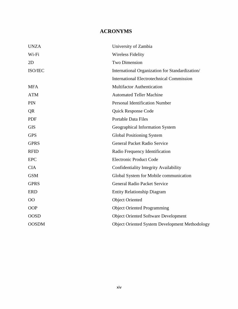
ACRONYMS
UNZA University of Zambia
Wi-Fi Wireless Fidelity
2D Two Dimension
ISO/IEC International Organization for Standardization/
International Electrotechnical Commission
MFA Multifactor Authentication
ATM Automated Teller Machine
PIN Personal Identification Number
QR Quick Response Code
PDF Portable Data Files
GIS Geographical Information System
GPS Global Positioning System
GPRS General Packet Radio Service
RFID Radio Frequency Identification
EPC Electronic Product Code
CIA Confidentiality Integrity Availability
GSM Global System for Mobile communication
GPRS General Radio Packet Service
ERD Entity Relationship Diagram
OO Object Oriented
OOP Object Oriented Programming
OOSD Object Oriented Software Development
OOSDM Object Oriented System Development Methodology
1
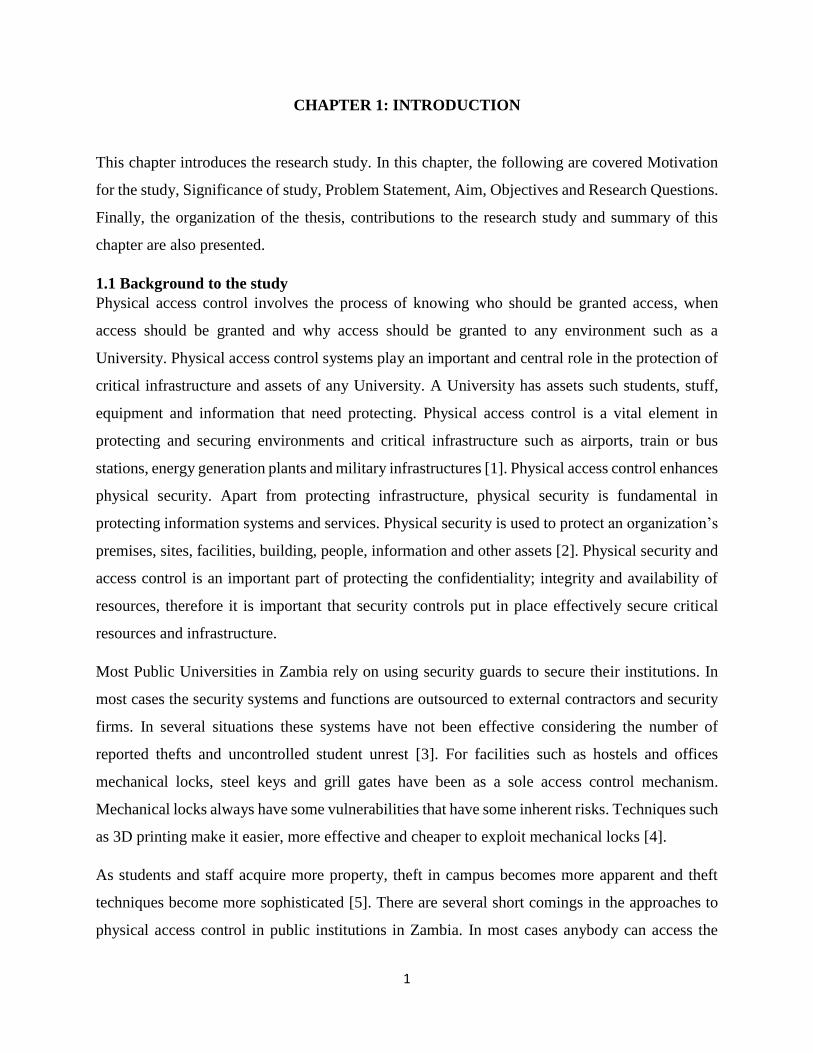
CHAPTER 1: INTRODUCTION
This chapter introduces the research study. In this chapter, the following are covered Motivation
for the study, Significance of study, Problem Statement, Aim, Objectives and Research Questions.
Finally, the organization of the thesis, contributions to the research study and summary of this
chapter are also presented.
1.1 Background to the study
Physical access control involves the process of knowing who should be granted access, when
access should be granted and why access should be granted to any environment such as a
University. Physical access control systems play an important and central role in the protection of
critical infrastructure and assets of any University. A University has assets such students, stuff,
equipment and information that need protecting. Physical access control is a vital element in
protecting and securing environments and critical infrastructure such as airports, train or bus
stations, energy generation plants and military infrastructures [1]. Physical access control enhances
physical security. Apart from protecting infrastructure, physical security is fundamental in
protecting information systems and services. Physical security is used to protect an organization’s
premises, sites, facilities, building, people, information and other assets [2]. Physical security and
access control is an important part of protecting the confidentiality; integrity and availability of
resources, therefore it is important that security controls put in place effectively secure critical
resources and infrastructure.
Most Public Universities in Zambia rely on using security guards to secure their institutions. In
most cases the security systems and functions are outsourced to external contractors and security
firms. In several situations these systems have not been effective considering the number of
reported thefts and uncontrolled student unrest [3]. For facilities such as hostels and offices
mechanical locks, steel keys and grill gates have been as a sole access control mechanism.
Mechanical locks always have some vulnerabilities that have some inherent risks. Techniques such
as 3D printing make it easier, more effective and cheaper to exploit mechanical locks [4].
As students and staff acquire more property, theft in campus becomes more apparent and theft
techniques become more sophisticated [5]. There are several short comings in the approaches to
physical access control in public institutions in Zambia. In most cases anybody can access the
2
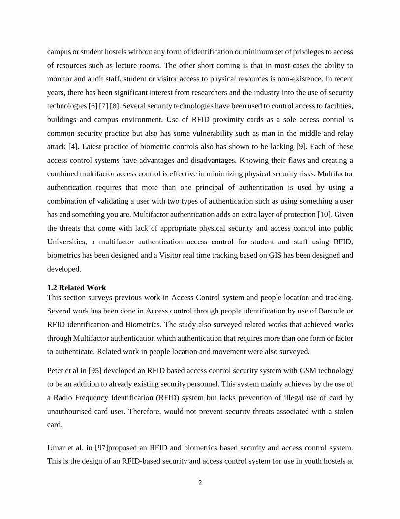
campus or student hostels without any form of identification or minimum set of privileges to access
of resources such as lecture rooms. The other short coming is that in most cases the ability to
monitor and audit staff, student or visitor access to physical resources is non-existence. In recent
years, there has been significant interest from researchers and the industry into the use of security
technologies [6] [7] [8]. Several security technologies have been used to control access to facilities,
buildings and campus environment. Use of RFID proximity cards as a sole access control is
common security practice but also has some vulnerability such as man in the middle and relay
attack [4]. Latest practice of biometric controls also has shown to be lacking [9]. Each of these
access control systems have advantages and disadvantages. Knowing their flaws and creating a
combined multifactor access control is effective in minimizing physical security risks. Multifactor
authentication requires that more than one principal of authentication is used by using a
combination of validating a user with two types of authentication such as using something a user
has and something you are. Multifactor authentication adds an extra layer of protection [10]. Given
the threats that come with lack of appropriate physical security and access control into public
Universities, a multifactor authentication access control for student and staff using RFID,
biometrics has been designed and a Visitor real time tracking based on GIS has been designed and
developed.
1.2 Related Work
This section surveys previous work in Access Control system and people location and tracking.
Several work has been done in Access control through people identification by use of Barcode or
RFID identification and Biometrics. The study also surveyed related works that achieved works
through Multifactor authentication which authentication that requires more than one form or factor
to authenticate. Related work in people location and movement were also surveyed.
Peter et al in [95] developed an RFID based access control security system with GSM technology
to be an addition to already existing security personnel. This system mainly achieves by the use of
a Radio Frequency Identification (RFID) system but lacks prevention of illegal use of card by
unauthourised card user. Therefore, would not prevent security threats associated with a stolen
card.
Umar et al. in [97]proposed an RFID and biometrics based security and access control system.
This is the design of an RFID-based security and access control system for use in youth hostels at
3
Punjab University. The system combines RFID technology and biometrics to perform the required
task. Although the developed system is useful for reducing threats to the safety of hostels, the
response time of the system can be further improved by using dedicated processors that are
dedicated to the task as is proposed in this study.
In [108] personnel location tracking is achieved through use of Near field Communication (NFC).
Near Field Communication (NFC) is an automatic identification method that remotely stores and
retrieves data using devices called NFC tags or transponders. The main goal of the system is to
give employees a real-time location in the company's business premises. In addition to the location,
the employee's physical location, the system also captures the date and time the employee accessed
the system. However, the system is very expensive to implement and may not be suitable for
government organizations. Therefore, this study proposes a much cheaper real time tracking and
movement locator.
1.3 Problem Statement
The University of Zambia has limited control of who accesses the University campus, offices and
student hostels and this has posed to be a threat to the protection of UNZA’s assets namely
students, staff and information. The University of Zambia’s security is porous.
Student and staff have lost and continue to lose personal belongings from offices, hostels and cars
whilst parked in the campus car parks. Common belongings that are mostly lost include media
such as mobile phones, laptops, IPads and personal belongings such as clothes have been stolen
while on the clothes line. Handbags have also been commonly stolen from offices.
UNZA’s access control measures are limited. The access control measures that have been put in
place do not conform to any standard. There are no written down procedures of how the access
into the university should be controlled. There are no specific identification measures put in place
to identify students or staff from visitors. Visitors, students and staff can access the University
campus freely and at any time. The University has employed security personnel and also contracted
a Security Firm but these personnel put together is not sufficient especially in time of student
unrest.
UNZA experiences student unrest regularly. Controlling these riots has been a big challenge and
has sometimes led to serious injuries and death. There are no security measures to quarantine
4
students in the hostels so that students do not run to places such as Road Side to break public
property such as cars.
UNZA has no procedure written down to record visitors if any procedures, most personnel
concerned are not aware of such procedures. Visitor date and time of visit to the UNZAs’ facilities
are not recorded. There is no audit trail to show visitors whereabouts while on campus nor a record
to show they visited the intended place.
1.4 Aim
The main aim of this study was to design and develop a Multifactor Student and Staff access
control system to improve security at UNZA and keep an audit trail of all visitors that come to
UNZA.
1.5 Objectives
This research was guided by the following objectives,
1. Carry out a baseline study to establish the level of Security at the University of Zambia
student hostel and staff offices.
2. Design a security model based on Radio Frequency Identification, Biometrics, barcode
and GIS technology to address challenges in objective (i).
3. Build a prototype based on the model in objective (ii)
1.6 Research Questions
This research was guided by the following research questions,
1. What is the level of security in the Student hostels and Staff Offices based on ISO
27002?
2. What security model based on Multifactor Authentication can be used to address
challenges in (2)?
3. Is it possible to build a prototype based on the model in (2) to address challenges in
(1)?
5
1.7 Motivation and Significance of the Study
Physical security and access control are vital and play a central role in protecting any organization
assets such as information, people, equipment and infrastructure. Implementing an extra layer of
security through the use of multifactor authentication of users and control who enter and how they
enter can greatly improve security in any organization. The findings of this research were
published in International Journal of Advanced Computer Science and Applications (IJACSA) 1
1.8 Scope
The research investigated the level of security at the University of Zambia based on ISO 27002;
Physical and Environment Security model. Multifactor Authentication based on RFID and
Biometrics authentication and real time visitor tracking based on GIS was designed and developed
in this research. A detailed literature review of GIS, RFID, Biometrics and Barcode technologies
in authentication and access control was conducted to determine the most effective and appropriate
method to implement the system. Site visits were also conducted. The outcomes of this research
were analysed from survey conducted with students, staff and security personnel at the University
of Zambia and a prototype designed.
1.9 Research Contributions
This research was focused on multifactor authentication access control of students and staff into
the University of Zambia Campus, student hostels, offices and Visitor real time tracking. The
major contribution in this research was the baseline study on measuring the level of security at the
University of Zambia. The level of security was measured against the ISO 270002 Physical and
Environmental Security Model.
10.0 Organization of the Dissertation
This research is divided into five chapters.
Chapter 1 is the introduction to the research and gives an overview of the work. The Aim,
Significance of Study and Problem Statement are presented. This chapter concludes with
presenting the thesis outline.
1 Simukali C. M., & Phiri, J. (2018). Multifactor Authentication for Student and Staff Control.
International Journal of Advanced Computer Science and Applications, IJACSA, issue 1, Vol 10.
6
Chapter 2 discusses more in detail the literature reviewed on RFID, biometric, barcode and GIS.
Related works regarding multifactor authentication and access control is presented.
Chapter 3 outlines the research methodology. The methods used to conduct the baseline study and
to design and develop the prototype are presented.
Chapter 4 gives the research findings of the baseline study and system design and implementation.
Finally, chapter 5 presents the discussion and conclusion.
11.0 Summary
In this chapter, an introduction of the work in this thesis was given. A review of the area being
studied and current information surrounding access control was presented. The current methods
being used at the institution were also evaluated. The chapter closed with an outline of the thesis.
7
CHAPTER 2: LITERATURE REVIEW
2.1 Introduction
In this chapter, the literature reviewed and works related to this research study are reviewed. An
extensive review of technologies that are related to the access control, identification and real time
tracking are reviewed. These include Barcode Technologies, Radio Frequency Identification
(RFID), Biometrics, GIS and GPS. The chapter also reviews Physical Security and multifactor
authentication as factors that are applied in access control. Also, a brief review of International
Organisation Standards (ISO) and how they relate to security are included in this chapter.
2.2 Physical Security and Access Control
Physical security is fundamental in protecting information systems and services. Physical security
is used to protect a company’s premises, sites, facilities, buildings, people, information, and other
assets [1]. It is an important part of protecting the confidentiality, integrity and availability of
resources. It is vital to develop physical security in a way that can effectively secure critical
resources, infrastructure and systems. The ‘CIA triad’ consists of confidentiality, integrity and
availability. Security controls are designed to protect these aspects of information systems.
Properly designed and maintained access controls are the cornerstone of securing and controlling
organizations assets. They control how resources are accessed, and reduce the risk of unauthorized
modification or disclosure [2].
2.2.1 Physical Controls
Facilities require physical access controls that control, monitor and manage access. Different levels
of access control are required to limit the areas that users must enter, depending on how they are
identified. There are many mechanisms for controlling and isolating access permissions. These
mechanisms should prevent and detect unauthorized access.
2.2.1.1 Perimeter Security
Mantraps, doors, fences and turnstiles are used outside the facility to provide additional security
before entering the building. Fences clearly distinguish the boundaries between protected areas
and public areas. The materials used to make fences vary in type and thickness. The protected
8
facilities determine the necessary security levels of the fences. Types of fences include electric
wires, barbed wire, thermal, motion or laser detection, concrete and floor-painted strips [11].
Doors or gates are entrances and exits through a fence. To be effectively deterrent, barriers must
provide the same level of protection as fences. Otherwise, attackers have the opportunity to bypass
the fence and use the gate as a point of attack. The door construction should consist of hardened
hinges, locking mechanisms and locking devices. The number of doors must be limited to
consolidate the resources required for backup. Dogs or surveillance cameras have to be used to
watch the doors that may have no guards.
Turnstiles are a kind of door through which a person can enter. They must offer the same protection
as the fence to which they are connected. Turnstiles work by turning as a revolving door in one
direction and a person can simultaneously exit or enter the building [2].
Mantraps are small parts that prevent people from entering. Only one person can participate in the
Mantrap design at a time. The idea is to block the person attempting to access them by locking
them in until the proof of identity is confirmed. If the person has permission to enter, the inner
door opens to allow access. This is a security surveillance measure that delays the access of
unauthorized persons to the facility until the arrival of security forces or the police.
2.2.1.2 Badge
A proof of identity is required to verify that a person is an employee or a visitor. These cards come
in the form of name badges, name badges and identity cards. ID cards can also be chip cards that
are integrated into access control systems. Images, RFID tags, tapes, computer chips, and
employee information are often included to assist employees with security testing.
2.2.1.3 Motion Detector
Motion detectors offer different technology options as needed. They are used as intrusion detectors
and work together with alarm systems. Infrared motion detectors observe changes in the infrared
light patterns. Heat-based motion detectors detect changes in heat levels. Wave pattern motion
detectors use ultrasonic or microwave control changes in the reflected patterns. Capacity motion
9
detectors monitor changes in electrical or magnetic fields. Photoelectric motion detectors look for
changes in light and are used in dimly lit rooms. Passive motion detectors hear unusual noises.
2.2.1.4 Intrusion alarm
The alarms monitor various sensors and detectors. These devices are door and window contacts,
window break detectors, motion detectors, water sensors, etc. Changes in the status of the devices
trigger the alarm. In hardwired systems, alarms detect that the device status changes by creating a
short circuit. The types of alerts are deterrent, repulsive and notifications.
Deterrence alarms attempt to prevent attackers from gaining access to key resources by closing
doors and activating locks.
Rejecting alarms use sirens and bright lights to force attackers to leave the site.
Notification alerts send alerts via modems
2.2.2 Technical controls
Technical controls focus primarily on access control as it is one of the most vulnerable security
domains [12]. Smart cards are a technical control that provides physical access to a building or
secure room, as well as a secure connection to corporate networks and computers. In the event of
an overlap, multiple layers of defense are required to protect attackers with direct access to
corporate resources. Burglar alarm systems are essential technical controls as they detect intrusion.
Detection is important because the security event is notified. By knowing the event, the
organization can respond to the incident and narrow it down. Audit trails and access logs must be
continuously monitored. They allow the organization to identify where and how often violations
occur. This information helps the security team reduce vulnerabilities.
2.2.2.1 Smart Card
Token cards include chips and integrated circuits that are embedded in the cards that process the
data. Microchips and integrated circuits allow the chip card to be authenticated according to two
factors. This authentication check prevents hackers or unauthorized employees from accessing
10
rooms where they are not authorized. Employee information is stored on-chip for easy
identification and authentication. Two-factor authentication protects computers, servers and data
centers from unauthorized persons. The evaluation is not granted with the possession of the card
alone. To unlock the card, you must enter a biometric form (whatever you are) or a PIN or
password (something you know) to authenticate the user.
There are two types of access to the chip card: contact and contactless. Contact smart cards have
a contact on the front of the card for data transfer. When the card is inserted, the device's fingers
connect to the contact points of the chip. The connection to the chip provides power and allows
communication with the host device. Contactless smart cards use an antenna that communicates
with electromagnetic waves. The electromagnetic signal feeds the chip card and communicates
with the card readers.
Access token cards are considered insensitive to manipulation methods. These cards are not
foolproof though. Security offers the complexity of the smart token. The smart token reads the
card only after entering the correct PIN. Encryption methods prevent attackers from capturing data
in the microchips. Smart cards also have the option to delete the data stored there. The card detects
fake.
The cost is a disadvantage of smart card technology. Creating smart cards and buying card readers
is expensive. Smart cards are essentially small computers and carry the same risk. As technology
advances, storage capacity and the ability to separate "critical security computations" [13] into
smart cards becomes more and more important. Smart cards can store keys used with encryption
systems, which contributes to security. Due to the autonomous circuits and memory, the card can
use encryption algorithms. Encryption algorithms provide secure permissions that can be applied
across the enterprise.
2.2.2.2 Proximity reader and RFID
Access control systems use proximity readers to scan cards and determine if they are authourised
to enter the facility or zone. Access control systems evaluate the permissions stored in the chip,
which are sent via the radio identification RFID. This technology uses transmitters (for sending)
and answering machines (for receiving).
11
Physical access control uses the use of proximity readers and access control cards with passive
tags. The passive tags are powered by the proximity readers via an electromagnetic field generated
by the card reader. When you drag a card, a signal is sent to the reader. The door will be unlocked
once the signal has been received and verified.
Active tags contain batteries for the self-sufficiency of the RFID tag. Active tags have an integrated
power source that allows them to transmit signals further than passive tags. However, their costs
are considerably higher and their life is limited due to the life of the battery. These are generally
used to track items of great value. Readers can track movements and find items when connected
to the network and recognition system. When an asset is removed from specific areas, the
organization may ask the access control system to trigger an alert.
2.2.2.3 Intrusion Detection, Guards and CCTV
If the device is moved without authorization, Intrusion Detection Systems (IDS) can monitor and
notify unauthorized entries. SDIs are security-relevant because systems can send a warning when
a specific event occurs or at an unusual time an access attempt was made.
Protectors are an important part of an intrusion detection system because they are more adaptable
than other security aspects. Security officers can be stationed in one location or on patrol to patrol
the campus.
2.3 International information security standards.
International standards and guidelines are available to help and support organisations with
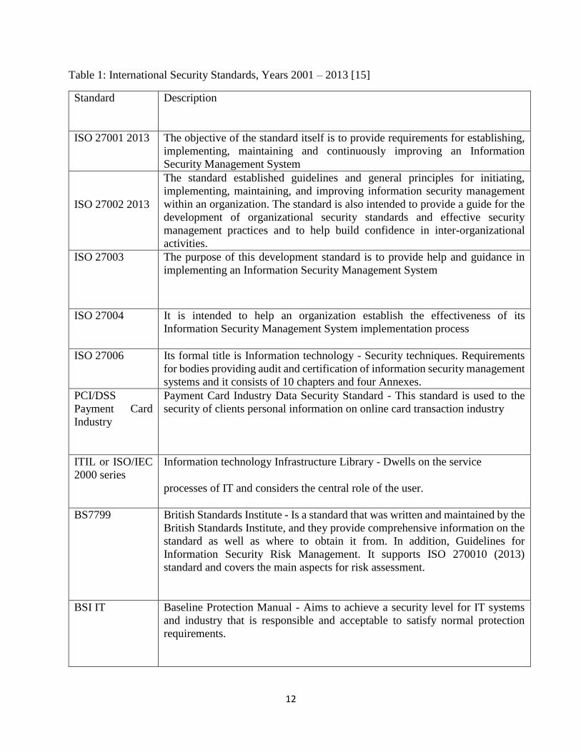
management of Information Security, by established rules and regulations. The Table 1 shows
some international Security Standards established between the period 2001-2013. Moore [15]
observes that without standards that provide objective criteria for organsational security choices,
the people
12
Table 1: International Security Standards, Years 2001 – 2013 [15]
Standard
Description
ISO 27001 2013
The objective of the standard itself is to provide requirements for establishing,
implementing, maintaining and continuously improving an Information
Security Management System
ISO 27002 2013
The standard established guidelines and general principles for initiating,
implementing, maintaining, and improving information security management
within an organization. The standard is also intended to provide a guide for the
development of organizational security standards and effective security
management practices and to help build confidence in inter-organizational
activities.
ISO 27003 The purpose of this development standard is to provide help and guidance in
implementing an Information Security Management System
ISO 27004
It is intended to help an organization establish the effectiveness of its
Information Security Management System implementation process
ISO 27006
Its formal title is Information technology - Security techniques. Requirements
for bodies providing audit and certification of information security management
systems and it consists of 10 chapters and four Annexes.
PCI/DSS
Payment Card
Industry
Payment Card Industry Data Security Standard - This standard is used to the
security of clients personal information on online card transaction industry
ITIL or ISO/IEC
2000 series
Information technology Infrastructure Library - Dwells on the service
processes of IT and considers the central role of the user.
BS7799
British Standards Institute - Is a standard that was written and maintained by the
British Standards Institute, and they provide comprehensive information on the
standard as well as where to obtain it from. In addition, Guidelines for
Information Security Risk Management. It supports ISO 270010 (2013)
standard and covers the main aspects for risk assessment.
BSI IT
Baseline Protection Manual - Aims to achieve a security level for IT systems
and industry that is responsible and acceptable to satisfy normal protection
requirements.
13
responsible with making these choices can make them based on undeserved aspects that might
include lack of knowledge, supposed constraints, inappropriate confidence and personal
motivations.
2.3.1 Physical and Environmental Security
Based on the ISO 27002 (2013) standard, the objective of the Physical and Environmental Security
is to avoid unapproved access, loss and conflicts to organisation facilities and secure areas.
Critical or sensitive business assets and information processing must be in protected areas, secured
by a clear security limit with appropriate security barriers and entry controls. The safeguard
delivered must be matching with the acknowledged risks. Additional procedures in order to adopt
secure physical security can be implemented [14]
2.3.2 Role of ISO 27002 Standard
The ISO/IEC 27002 Code of Practice for Information Security Management establishes guidelines
and general principles for organizations to initiate, implement, maintain, and improve information
security management. The objectives that are outlined provide general guidance on the commonly
accepted goals of information security management. ISO/IEC 27002 contains best practices of
control objectives and controls in the following areas of information security management [15]:
i. Information security policy;
ii. Organizational security;
iii. Asset classification and control;
iv. Physical and environmental security;
v. Communication and operation management;
vi. Aspects of business continuity management;
vii. Compliance with the legal requirements;
viii. Internal information security.
14
2.4 Multifactor Authentication
Digitalisation decisively penetrates all the sides of the modern society today. The continuous
growth of digitally based systems such as in online payments, communications, access right
management etc. has also brought with it an ascent in security concerns [14]. One of the key
enablers to maintain these systems secure is authentication. Authentication is the process of
identifying an individual by using a factor such as something they know (password), something
they have (Identification card), something they are (biometrics) and so on. Authentication merely
ensures that the individual is who he or she claims to be. In [16], authentication is a process where
a “user identifies himself by sending x to the system; the system authenticates his identity by
computing a result F ( x ) and checking that it equals the stored value y”. This definition has not
changed significantly over time despite the fact that a simple password is no longer the only factor
for validating the user from the information technology perspective [17]. Authentication by one
factor such as use of a password only or ID card only is the weakest level of authentication because
by either sharing the password or using a stolen ID card can compromise a transaction. Further, it
was realised that authentication with just a single factor is not reliable to provide adequate
protection due to a number of security threats [18]. Multifactor authentication (MFA) is a security
system in which more than one form of authentication is implemented to verify the legitimacy of
a transaction. MFA has several categories for defining factors of authentication and these are
knowledge factor (ID/Password, PIN, Challenge-Response), Possession factor (Security Token,
Smart Card, Smart Phone, ID OTP Token), Inherence factor (retina scans, iris scan, fingerprint
scans, voice recognition, hand geometry, earlobe geometry), Location factor (GPS) and time factor
[19].The goal of MFA is to make a layered hindrance and make it more difficult for an unapproved
individual to get to a focus, for instance, a physical zone, figuring contraption, framework or
database. In case one part is exchanged off or broken, the attacker still has no short of what one
more impediment to break before viably breaking into the target. The multifactor method demands
various reactions to test request and recoups 'such as something you have' or 'something you are'
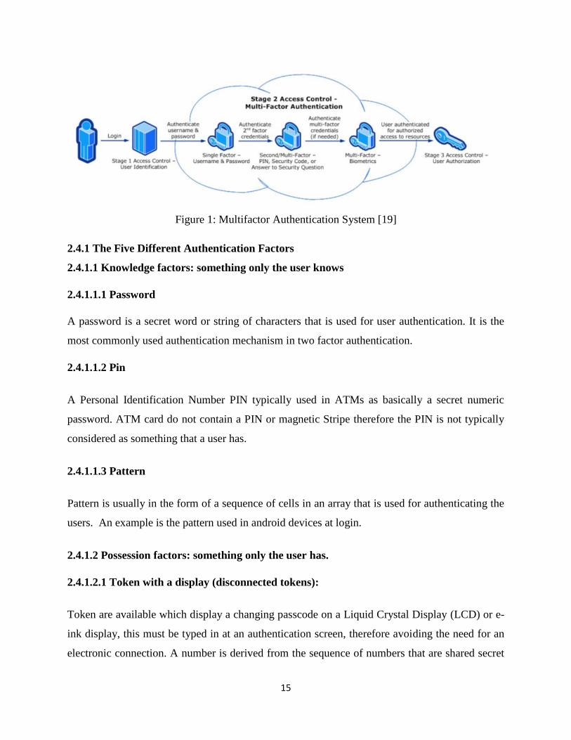
[20]. In the Figure 1 below a sample process of two stage Multifactor Authentication is shown.
15
Figure 1: Multifactor Authentication System [19]
2.4.1 The Five Different Authentication Factors
2.4.1.1 Knowledge factors: something only the user knows
2.4.1.1.1 Password
A password is a secret word or string of characters that is used for user authentication. It is the
most commonly used authentication mechanism in two factor authentication.
2.4.1.1.2 Pin
A Personal Identification Number PIN typically used in ATMs as basically a secret numeric
password. ATM card do not contain a PIN or magnetic Stripe therefore the PIN is not typically
considered as something that a user has.
2.4.1.1.3 Pattern
Pattern is usually in the form of a sequence of cells in an array that is used for authenticating the
users. An example is the pattern used in android devices at login.
2.4.1.2 Possession factors: something only the user has.
2.4.1.2.1 Token with a display (disconnected tokens):
Token are available which display a changing passcode on a Liquid Crystal Display (LCD) or e-
ink display, this must be typed in at an authentication screen, therefore avoiding the need for an
electronic connection. A number is derived from the sequence of numbers that are shared secret
16
by a cryptographic process. This process makes it infeasible to work out the secret from the
sequence of numbers.
2.4.1.2.2 Magnetic Strip Cards
Magnetic stripe cards examples being Credit cards, Debit cards, ATM cards, Loyalty cards, Gift
cards, etc. are easily cloned and so are being or have been replaced in various regions by smart
cards, particularly in banking.
2.4.1.2.3 Smart Cards
Smart cards are usually the same size as a credit card and in some cases are used to perform several
functions of a proximity card physical access device, network authentication or Identification
badge. Users can be authenticated into a facility such as a building via proximity detection and
then insert the card into their PC to produce network logon credentials.
2.4.1.2.4 Wireless
Available in this category are RFID-based tokens, Bluetooth-based tokens and Contactless smart
cards which are a wireless version of the traditional smartcard.
2.4.1.2.5 USB Tokens
A Universal Serial Board (USB) port is standard equipment to most modern computers. USB
tokens generally have a large storage capacity for logon credentials as well as for data storage.
However, they may be relatively costly to deploy and support. They are also prone to theft and
fraud for example nothing can stop a stored secret X.509 certificate stored on the USB Token from
being copied.
2.4.1.2.6 Mobile phones
There are available Two factor authentication tools that transforms the PC user's mobile phone
into a token device using SMS messaging, an interactive telephone call, or via downloadable
application to a Smart phone.
17
2.4.1.3 Inherence factors: something only the user is.
This is achieved through Biometrics technology; a living persons’ identification can be
automatically verified or recognized based on a physiological or behavioral characteristic.
2.4.1.3.1 Types of Biometrics
There are available various biometric methods that have been introduced and the following are
what has gained acceptance;
2.4.1.3.2 Typing patterns.
These are similar to signature dynamics but extended to the keyboard, recognizing not just a
password that is typed in but the intervals between characters and the overall speeds and pattern.
2.4.1.3.3 Eye scans.
This can involve two parts of the eye the retina or iris. This technologies hardware is expensive
and specialized, and using it is slow and inconvenient and may make users uneasy.
2.4.1.3.4 Fingerprint recognition.
Fingerprints are unique to every individual. They are also readily accessible and require little
physical space either for the reading hardware or the stored data.
2.4.1.3.5 Ear biometrics.
This will be the most important biometrics identification factor in the near future because of
qualities such as the fact the seven features on human ear that recognition is based on remain
permanent over the course of the human life and are unique. Additionally, the acquisition of ear
images does not necessarily require person's cooperation though considered to be non-intrusive by
most people. Because of these qualities, the interest in ear recognition systems has grown
significantly in recent years.
18
2.4.1.3.6 Hand or Palm geometry.
This factor involves reading the individual entire hand instead of just fingerprints. The reading
devices depend on measuring the length and angles of individual fingers. Although more user-
friendly than retinal scans it is quite a cumbersome technology.
2.4.1.3.7 Voice recognition.
Requires that the individual is recognized by matching the individual’s speech to a stored voice
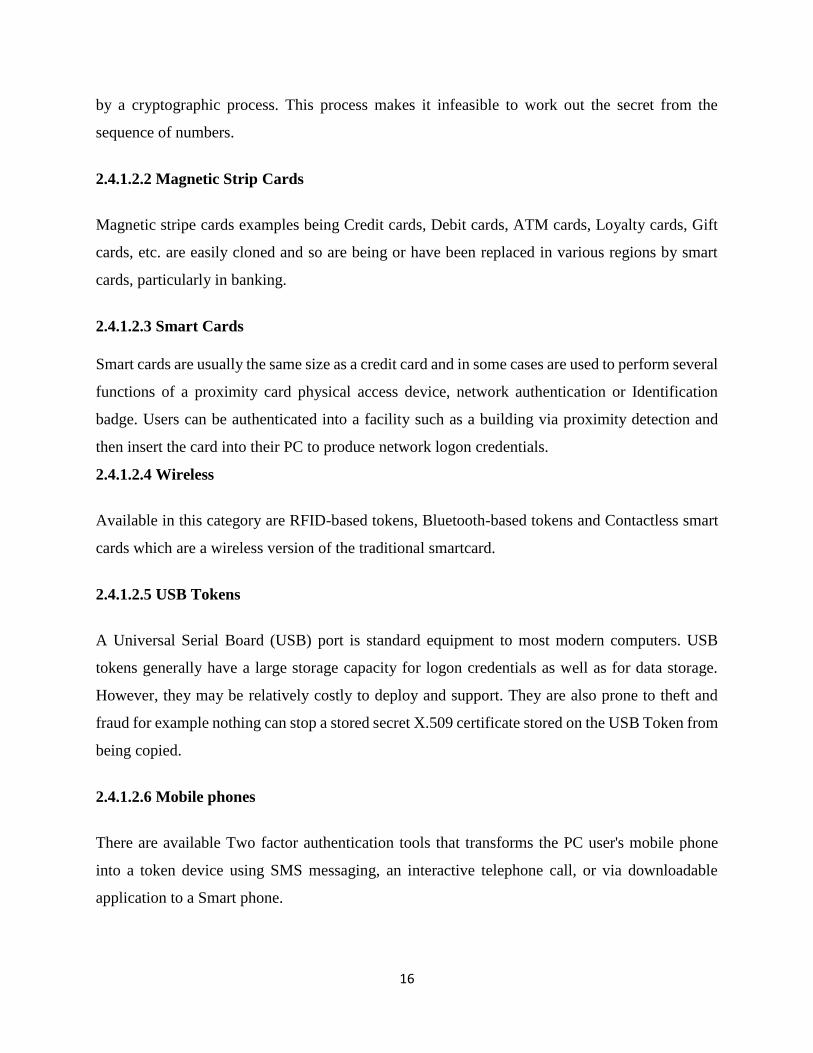
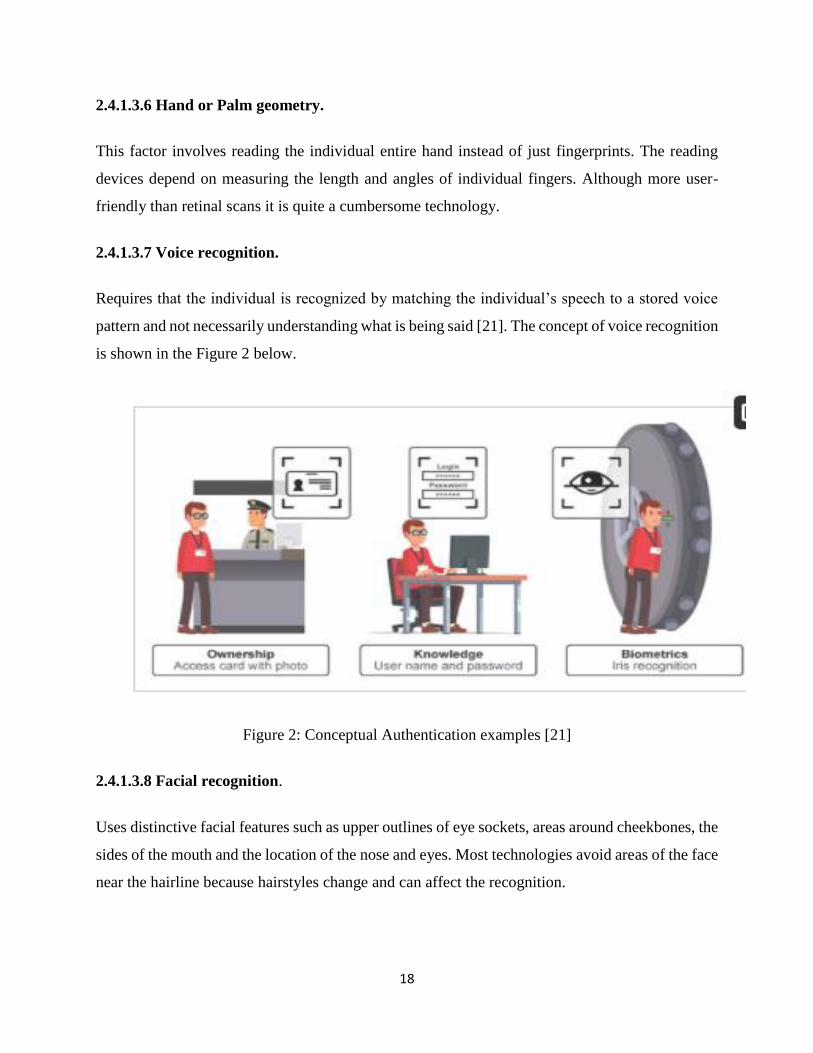
pattern and not necessarily understanding what is being said [21]. The concept of voice recognition
is shown in the Figure 2 below.
Figure 2: Conceptual Authentication examples [21]
2.4.1.3.8 Facial recognition.
Uses distinctive facial features such as upper outlines of eye sockets, areas around cheekbones, the
sides of the mouth and the location of the nose and eyes. Most technologies avoid areas of the face
near the hairline because hairstyles change and can affect the recognition.
19
2.4.1.4 Fingerprint or Face Detection have some disadvantages like:
Quality of the fingerprint scan may be affected by an individual’s age, or how much grease
is on the fingers. Other factors such as their occupation or lifestyle may affect the
fingerprint.
Elastic distortion of the skin of the finger due to touch sensing methods and potential
problems with cleanliness of the sensor and public hygiene.
In some cases, where people have no fingers or maybe without a full set, these people
cannot be fingerprinted.
2.5 Barcodes
Barcodes are part of every product that we buy and has become the ubiquitous standard for
identifying and tracking product. Barcodes have been used as automate-identification systems
using the two dimensional system of barcoding which allows barcodes to hold more data.
Barcoding dates back to 1950’s when Bernard silver and Norman woodland patented printing
patterns called the bulls-eye printing pattern. By the 1959 an automatic car identification system
was developed by David Collins which became the first commercial use of a linear barcode [21].
IBM also developed the uniform grocery product code (UPC) in 1973. This was adopted by the
national association of good chains.
A barcode is a machine readable representation of information in a visual format. A barcode
comprises of a series of parallel, adjacent bars and spaces. Different alphanumeric symbols,
numbers, characters, colon and others can be used to represent information.
Barcode have in recent past used in many areas such as market production, electronic devices or
people identification cards.
The lines on the barcodes represent the product referencing number. These are different types of
barcodes with the barcode symbol defining the technical details of a particular type of barcode.
The barcode types can be classified into four categories which are numeric-only barcode, alpha-
numeric barcode, 2D barcode and industry standard for barcode and labels. There are three basic
types of bar code readers namely fixed, portable batch and portable RF [22]
20
Barcodes are categorized into two: one dimensional (1D) barcode and the two dimensional (2D)
barcode.
2.5.1 One Dimensional (1D) Barcode.
One dimensional barcodes have a linear representation of data and its represented systematically
by varying sizes of spaces (width) in between the parallel lines in the barcodes, examples of linear
barcodes include Universal product code UPC and International Article Number (also known as
European Article Number or EAN) codes.
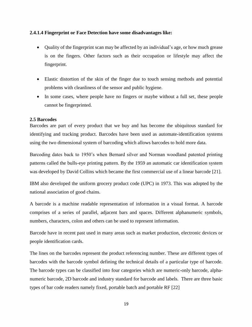
a) Universal Product Code (UPC)
This is the most used barcode worldwide. It labels and scans customer products at the checkout
points. The UPC has two variations: UPC-A which encodes 12 numeric digits and the UPC-E
which encodes 6 numeric digits.
In the UPC code the first 6 to 9 digits are referred to as the “company prefix”. These digits are
assigned by GIS US formerly known as the Uniform code council. This company prefix number
does not change on the company product range. The next range of digits known as Product
numbers uniquely identify individual items of a company. While the company prefix is assigned
by GIS, the product number are assigned arbitrarily by each particular company. The twelfth
character or number used is called “check digit” and is calculated based on first 11 digits of the
UPC code [23]. Figure 3 below shows an example of UPC Barcode.
Figure 3: UPC Barcode [23]
21
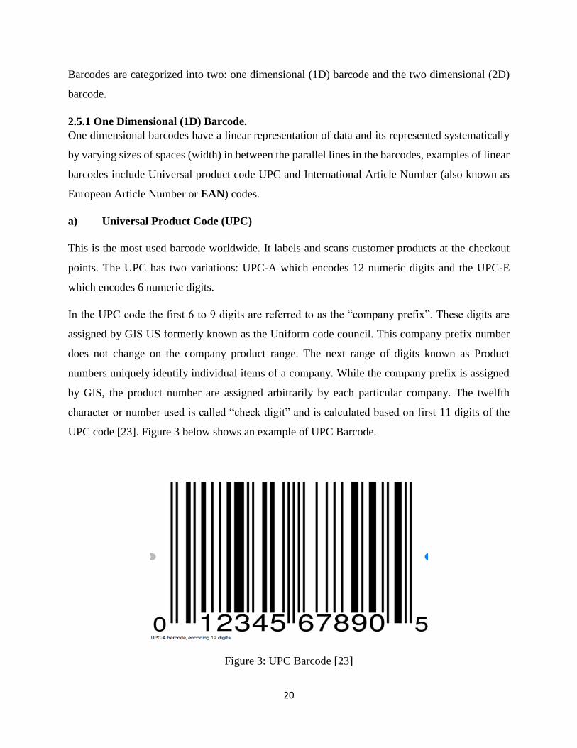
b) EAN code
The EAN codes are basically used in Europe to label and scan products at the point of sale. They
are numeric only barcode used for identification of retail products, the EAN codes are not so
different from UPC except for the geographical application. There are two types of the EAN code:
EAN-13 and EAN -8. The EAN- 8 uses 8 digits and is mostly used in situations where space is
limited.
The EAN-13 as in Figure 4 is mostly used as default form factor and like the code is written it has
13 digits [24].
Figure 4:: EAN -13 barcode image [24]
Examples of one dimensional codes
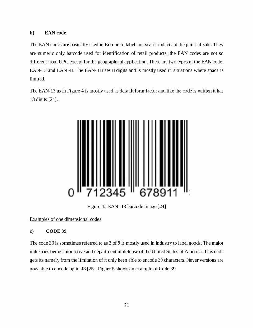
c) CODE 39
The code 39 is sometimes referred to as 3 of 9 is mostly used in industry to label goods. The major
industries being automotive and department of defense of the United States of America. This code
gets its namely from the limitation of it only been able to encode 39 characters. Never versions are
now able to encode up to 43 [25]. Figure 5 shows an example of Code 39.
22
Figure 5: Code 39 image [25]
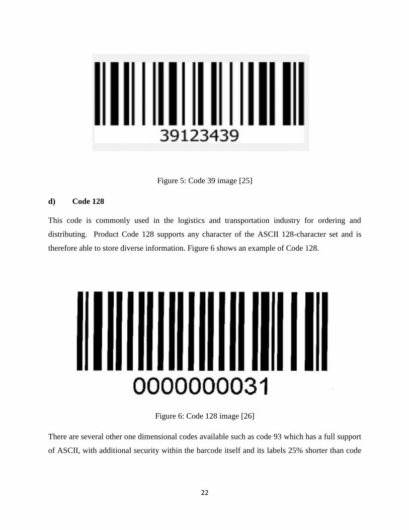
d) Code 128
This code is commonly used in the logistics and transportation industry for ordering and
distributing. Product Code 128 supports any character of the ASCII 128-character set and is
therefore able to store diverse information. Figure 6 shows an example of Code 128.
Figure 6: Code 128 image [26]
There are several other one dimensional codes available such as code 93 which has a full support
of ASCII, with additional security within the barcode itself and its labels 25% shorter than code
23
39% [26]. Another type is the CODA BAR, which has an advantage of ease of print. The Coda bar
is a discrete self-checking symbol and is capable of encoding up to 16 different character [27].
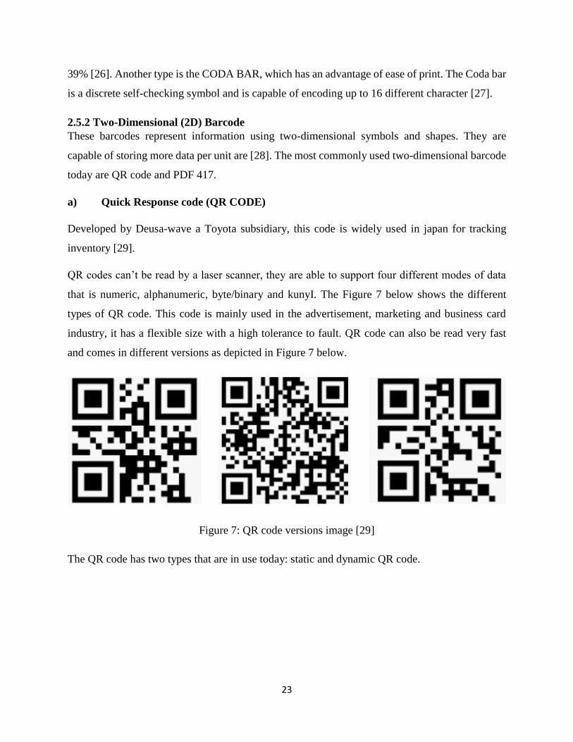
2.5.2 Two-Dimensional (2D) Barcode These barcodes represent information using two-dimensional symbols and shapes. They are
capable of storing more data per unit are [28]. The most commonly used two-dimensional barcode
today are QR code and PDF 417.
a) Quick Response code (QR CODE)
Developed by Deusa-wave a Toyota subsidiary, this code is widely used in japan for tracking
inventory [29].
QR codes can’t be read by a laser scanner, they are able to support four different modes of data
that is numeric, alphanumeric, byte/binary and kunyI. The Figure 7 below shows the different
types of QR code. This code is mainly used in the advertisement, marketing and business card
industry, it has a flexible size with a high tolerance to fault. QR code can also be read very fast
and comes in different versions as depicted in Figure 7 below.
Figure 7: QR code versions image [29]
The QR code has two types that are in use today: static and dynamic QR code.
24
b) Static QR code
is the most commonly used to disseminate information to the public. It’s especially used in
adverting and marketing. It’s possible to track information about the number of times a static QR
code has been scammed as well as the associated action taken with each scan. Information such as
the operating system of the device that scanned the code can also be traced.
c) Dynamic QR code
Also referred to as unique code has more added functionalities than the static code such as ability
to track specific information examples include scanners names, email address and the number of
times that code may have been scanned. Their typical use is in retail, entertainment and adverting.
Figure 7 retail [28]
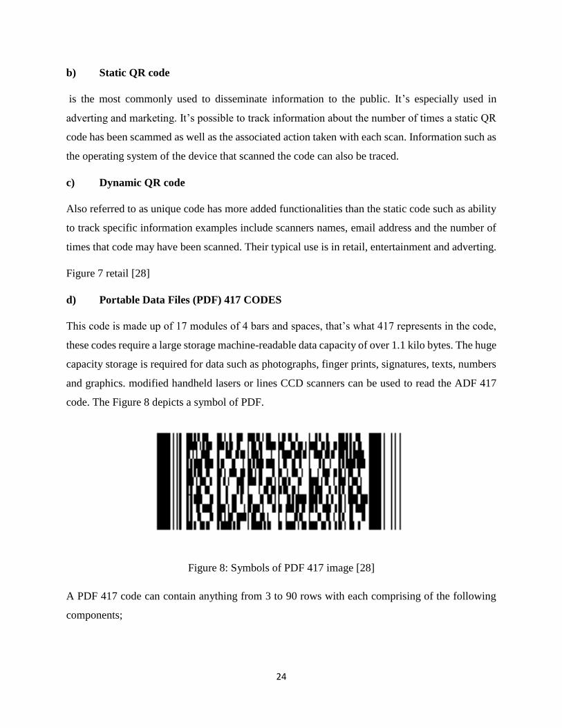
d) Portable Data Files (PDF) 417 CODES
This code is made up of 17 modules of 4 bars and spaces, that’s what 417 represents in the code,
these codes require a large storage machine-readable data capacity of over 1.1 kilo bytes. The huge
capacity storage is required for data such as photographs, finger prints, signatures, texts, numbers
and graphics. modified handheld lasers or lines CCD scanners can be used to read the ADF 417
code. The Figure 8 depicts a symbol of PDF.
Figure 8: Symbols of PDF 417 image [28]
A PDF 417 code can contain anything from 3 to 90 rows with each comprising of the following
components;
25
Leading quiet zone
Start pattern
Left row indicator
Right row indicator symbol character
Stop pattern
Trailing quiet zone
Figure 8 above shows PDF 147 used in logistics industry
2.5.3 Barcode Readers
Barcode reader has four types of technology in use today. The four categories of the bar code
readers are pen type, laser scanners, Charge Coupled Device readers and camera based readers.
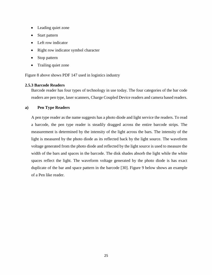
a) Pen Type Readers
A pen type reader as the name suggests has a photo diode and light service the readers. To read
a barcode, the pen type reader is steadily dragged across the entire barcode strips. The
measurement is determined by the intensity of the light across the bars. The intensity of the
light is measured by the photo diode as its reflected back by the light source. The waveform
voltage generated from the photo diode and reflected by the light source is used to measure the
width of the bars and spaces in the barcode. The disk shades absorb the light while the white
spaces reflect the light. The waveform voltage generated by the photo diode is has exact
duplicate of the bar and space pattern in the barcode [30]. Figure 9 below shows an example
of a Pen like reader.
26
Figure 9: Pen like reader [29]
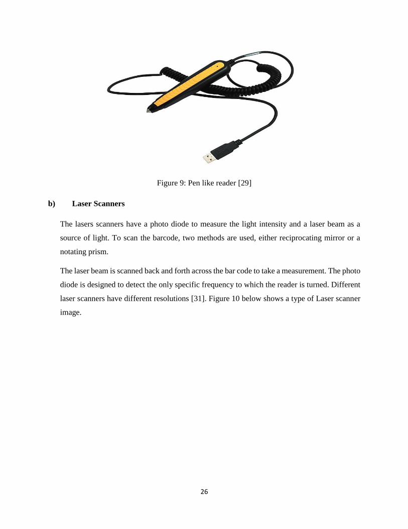
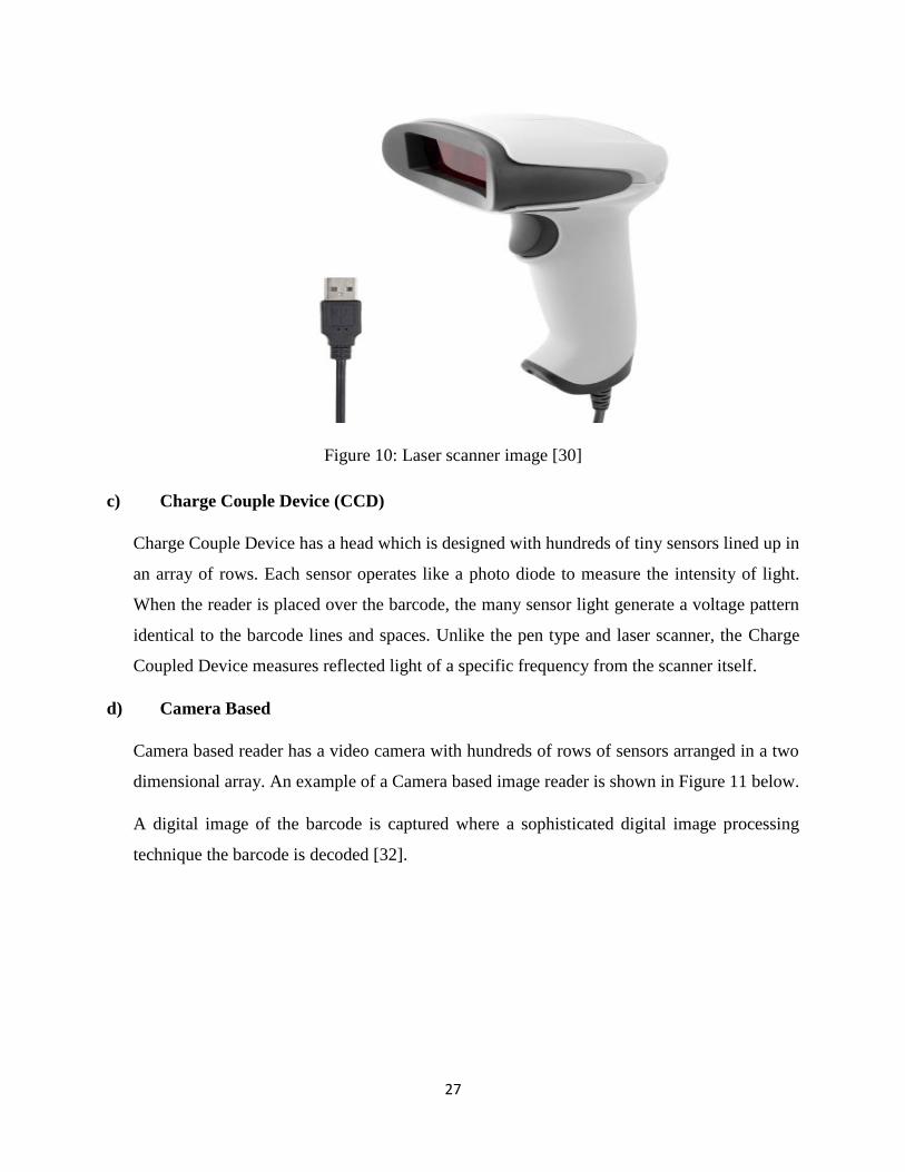
b) Laser Scanners
The lasers scanners have a photo diode to measure the light intensity and a laser beam as a
source of light. To scan the barcode, two methods are used, either reciprocating mirror or a
notating prism.
The laser beam is scanned back and forth across the bar code to take a measurement. The photo
diode is designed to detect the only specific frequency to which the reader is turned. Different
laser scanners have different resolutions [31]. Figure 10 below shows a type of Laser scanner
image.
27
Figure 10: Laser scanner image [30]
c) Charge Couple Device (CCD)
Charge Couple Device has a head which is designed with hundreds of tiny sensors lined up in
an array of rows. Each sensor operates like a photo diode to measure the intensity of light.
When the reader is placed over the barcode, the many sensor light generate a voltage pattern
identical to the barcode lines and spaces. Unlike the pen type and laser scanner, the Charge
Coupled Device measures reflected light of a specific frequency from the scanner itself.
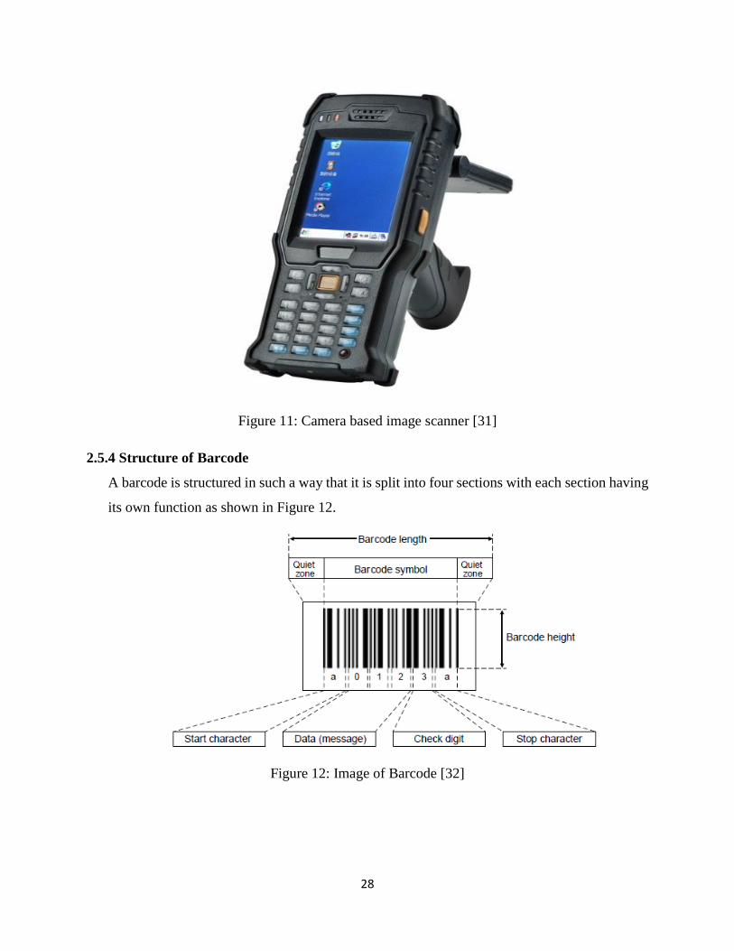
d) Camera Based
Camera based reader has a video camera with hundreds of rows of sensors arranged in a two
dimensional array. An example of a Camera based image reader is shown in Figure 11 below.
A digital image of the barcode is captured where a sophisticated digital image processing
technique the barcode is decoded [32].
28
Figure 11: Camera based image scanner [31]
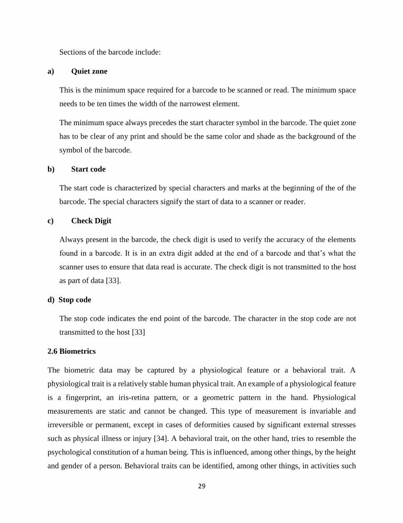
2.5.4 Structure of Barcode
A barcode is structured in such a way that it is split into four sections with each section having
its own function as shown in Figure 12.
Figure 12: Image of Barcode [32]
29
Sections of the barcode include:
a) Quiet zone
This is the minimum space required for a barcode to be scanned or read. The minimum space
needs to be ten times the width of the narrowest element.
The minimum space always precedes the start character symbol in the barcode. The quiet zone
has to be clear of any print and should be the same color and shade as the background of the
symbol of the barcode.
b) Start code
The start code is characterized by special characters and marks at the beginning of the of the
barcode. The special characters signify the start of data to a scanner or reader.
c) Check Digit
Always present in the barcode, the check digit is used to verify the accuracy of the elements
found in a barcode. It is in an extra digit added at the end of a barcode and that’s what the
scanner uses to ensure that data read is accurate. The check digit is not transmitted to the host
as part of data [33].
d) Stop code
The stop code indicates the end point of the barcode. The character in the stop code are not
transmitted to the host [33]
2.6 Biometrics
The biometric data may be captured by a physiological feature or a behavioral trait. A
physiological trait is a relatively stable human physical trait. An example of a physiological feature
is a fingerprint, an iris-retina pattern, or a geometric pattern in the hand. Physiological
measurements are static and cannot be changed. This type of measurement is invariable and
irreversible or permanent, except in cases of deformities caused by significant external stresses
such as physical illness or injury [34]. A behavioral trait, on the other hand, tries to resemble the
psychological constitution of a human being. This is influenced, among other things, by the height
and gender of a person. Behavioral traits can be identified, among other things, in activities such
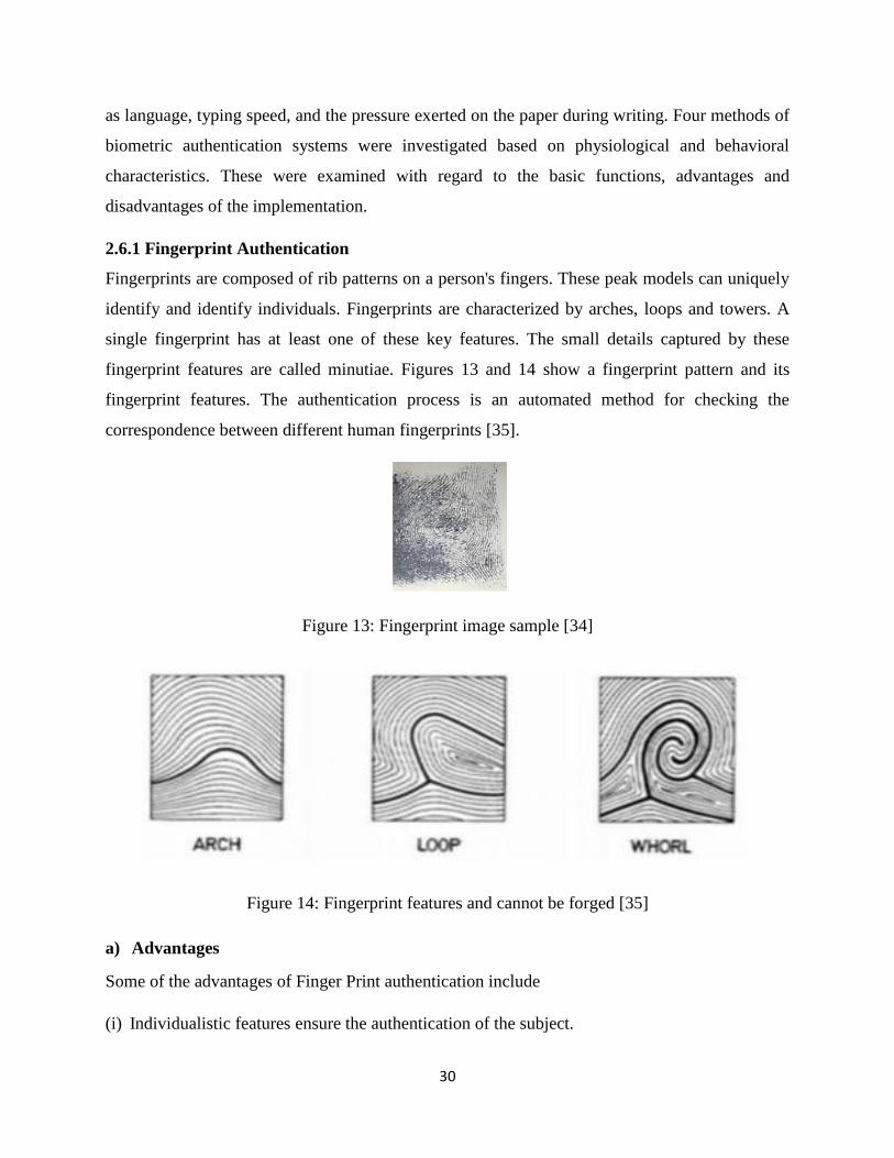
30
as language, typing speed, and the pressure exerted on the paper during writing. Four methods of
biometric authentication systems were investigated based on physiological and behavioral
characteristics. These were examined with regard to the basic functions, advantages and
disadvantages of the implementation.
2.6.1 Fingerprint Authentication
Fingerprints are composed of rib patterns on a person's fingers. These peak models can uniquely
identify and identify individuals. Fingerprints are characterized by arches, loops and towers. A
single fingerprint has at least one of these key features. The small details captured by these
fingerprint features are called minutiae. Figures 13 and 14 show a fingerprint pattern and its
fingerprint features. The authentication process is an automated method for checking the
correspondence between different human fingerprints [35].
Figure 13: Fingerprint image sample [34]
Figure 14: Fingerprint features and cannot be forged [35]
a) Advantages
Some of the advantages of Finger Print authentication include
(i) Individualistic features ensure the authentication of the subject.
31
(ii) Systems are relatively cheap to buy and install
(iii) After use, the user no longer needs to access that password storage because fingerprint
authentication guarantees access
(iv) A fingerprint identification point cannot be forged
(v) Different even in identical twins
(vi) Very specific with unique structure throughout the life of the subject.
(vii) The wearing of glasses or contact lenses does NOT function as a method of contraception
with technological precision.
(viii) High accuracy and high processing speed [34] [36].
b) Disadvantages
Some Disadvantages include
(i) Injury or eye disease can render can render this biometric system ineffective
(ii) Injury or eye disease can render this biometric system ineffective.
(iii) Intrusive technology that may not be well received by many people.
(iv) Lighting may affect the accuracy of the reader.
(v) Quite expensive to acquire compared to other biometric systems.
2.6.2 Voice Authentication
This technology allows the conversion of voices or sounds of a human voice into an electrical
signal that can be encoded. The speech recognition software is designed to identify a person via
their unique voiceprint. Voice prints are generated from the physical characteristics of an
individual's throat associated with his mouth. Research has shown that there are no two identical
voices. Voice biometrics therefore offers a rare opportunity to use one's voice to authenticate or
identify people [36]. An example of a voice pattern is shown in Figure 15 below.
32
Figure 15: Showing a voice pattern [36]
a) Advantages
Some advantages of Voice Authentication
(i) No need for training, users can simply speak in the biometric voice reader
(ii) Voice communication is a natural activity for human beings
(iii) Voice communications eliminate the need to learn Keyboard operations (and thus helps to
narrow the gap between valid people and those with limited abilities in hand-motion activities,
such as writing). By eliminating learning, the voice eliminates the need to learn
(iv) This eliminates the need to be precise in written declarations as is the case for password
authentication.
(v) Since the voice is used, the speed of operation is improved. People usually speaker faster than
they are able to write [36].
b) Disadvantages
Some disadvantages of Voice Authentication
(i) The catch limit is reduced to an individual finger with additional limitation of the capture
reduced to a section or part of that finger only and not to the whole finger.
(ii) Susceptible of FAR (false acceptance error) while a wrong subject is registered access is
allowed.
(iii) Injuries to the hands (including the fingers), chemical work and work (such as brick-laying or
metal) have intrapersonal variations that make reading and capture difficult fingerprints.
(iv) Washing with soap or dipping a finger in the water for about 30 minutes serves as a means of
contraception for fingerprint readers, which may prevent readers from capturing or recording
fingerprint until that the finger returns to its original position, the original form in which it
was found during capture or inscription [37].
33
2.6.3 Retina Authentication
This is one of two forms of ocular biometrics; the other being the recognition of the iris. This form
of biometrics is one of the most secure authentication systems in the world. The installed
technology requires that the fingerprint of a retina pattern is taken and stored. The authentication
process involves assessing the retina of a subject with a stored version (recorded impression) of
that subject's retina. Retinal recognition has a low acceptance error (FAR) and a low rejection rate
[38].
c) Disadvantages
Some disadvantages of Voice Authentication include:
(i) Impulse noise can affect the accuracy of the voice report and render the system ineffective.
(ii) The proximity of the microphone must be accurate for the system to work properly.
(iii) A prerecorded sound may bypass this system
(iv) A person may speak different languages which may affect the accuracy of the device if that
person uses a different language or dialect.
(v) Some words have a homonym feature, which can affect the accuracy of the device.
(vi) The learning curve of the system can be long because it is formed by voice.
(vii) Most voice-activated biometric data are expensive.
2.6.4 Face Authentication
Facial biometrics is divided into two aspects, facial recognition and recognition programs. Face
recognition extracts a face from a given image, while face recognition compares a captured face
to registered faces to match the face. The whole process is executed by a series of complex
algorithms. One of the options of facial recognition is to select the characteristics of a face and to
match them to a face. Facial features or the dataset are normally stored in a database. In ideal
situations, this database must be encrypted to obtain sufficient security [39].
(a) Advantages
Some advantages of face authentication include
(i) Non-intrusive technology and can be realized sneaking without the subject knowing is
revealed, therefore ideal for investigation purposes.
(ii) Some algorithms can be adjusted to analyse a large scale of a population and this technology
is therefore ideal in overcrowded environments.
34
(iii) Ideal for tracking people and reporting incidents
(iv) User friendly because there is no need for complex training for topics to grasp.
(v) Can be developed and run from a basic camera without having to buy other tools. This proves
to be one of the major benefits and reduces the cost of this technology exponentially.
(vi) Some pre-trained and easy-to-install facial calibration tools are available. This further reduces
installation costs.
(vii) Biometric face algorithms have a person inside calculation of the variation capable of
detecting aging and basic facial deformity and reducing a face to a known variable [40].
(b) Disadvantages
(i) Some algorithms may not work correctly on black
2.6.5 Quick Response Code
QR code is a machine readable imprint consisting of a set of black and white squares that normally
incorporate certain information into the print. The QR codes were developed by a Japanese
company called Denso Wave for the purpose of monitoring manufacturing processes. However,
QR codes can authenticate and identify an entity. In this way, QR codes can be used as an
additional security feature, especially when connecting to networks. Networks can be designed to
read QR codes, verify data, and offer or deny access to an entity. Because QR code information is
not human readable, it is a basic form of information hidden from view (encryption). This hidden
information can then be transmitted. When used with geolocation, QR codes can be used to
determine the location status of an entity [41].
2.7 RFID identification
RFID is an automated technology that uses wireless technology to uniquely identify and track
tagged objects as a unique serial number [42] [43] [44]. The identification and tracking of objects
takes place without human intervention [45]. RFID technology collects data about an object
without having to touch or display the data carrier. This is done by inductive coupling or
electromagnetic waves [46]. Ruiz-Garcia and Lunadei [47] point out that RFID technology is well-
suited to collecting multiple data on people, animals and objects in order to track and count them
in the different environment.
RFID is one of a broad category of technologies known as Auto-ID technologies [44]. According
to Wyld and Budden [48], automatic identification technologies provide fast and reliable object
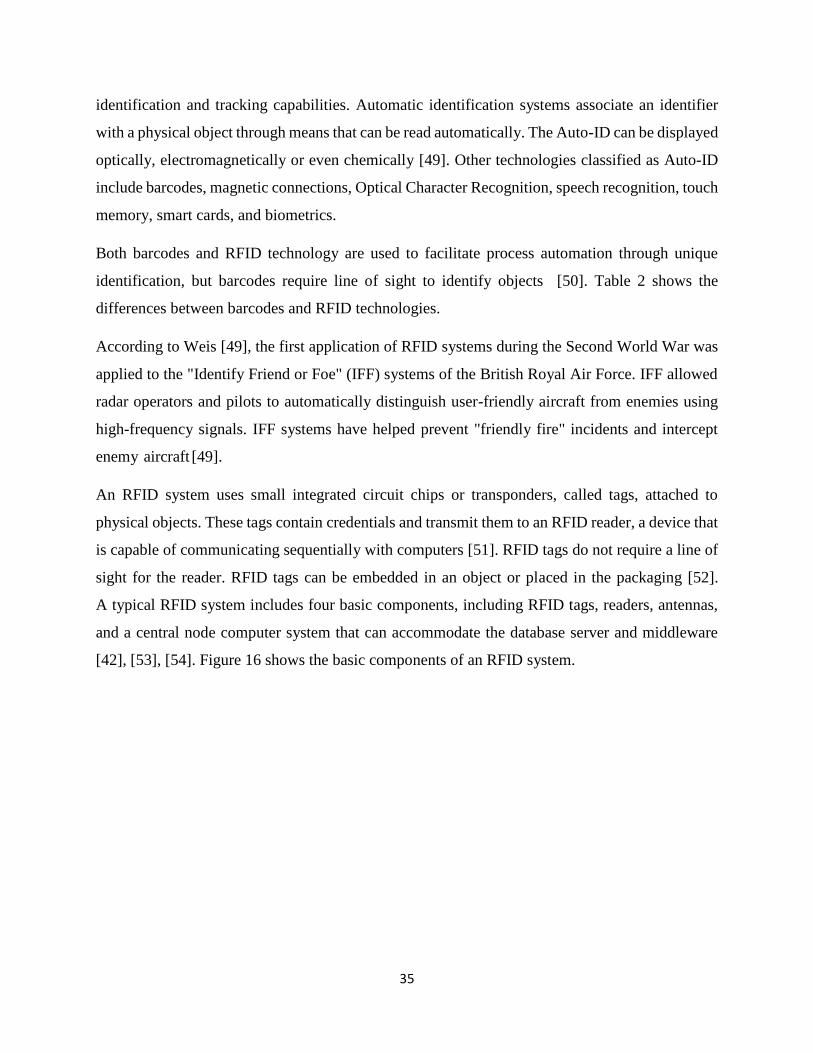
35
identification and tracking capabilities. Automatic identification systems associate an identifier
with a physical object through means that can be read automatically. The Auto-ID can be displayed
optically, electromagnetically or even chemically [49]. Other technologies classified as Auto-ID
include barcodes, magnetic connections, Optical Character Recognition, speech recognition, touch
memory, smart cards, and biometrics.
Both barcodes and RFID technology are used to facilitate process automation through unique
identification, but barcodes require line of sight to identify objects [50]. Table 2 shows the
differences between barcodes and RFID technologies.
According to Weis [49], the first application of RFID systems during the Second World War was
applied to the "Identify Friend or Foe" (IFF) systems of the British Royal Air Force. IFF allowed
radar operators and pilots to automatically distinguish user-friendly aircraft from enemies using
high-frequency signals. IFF systems have helped prevent "friendly fire" incidents and intercept
enemy aircraft [49].
An RFID system uses small integrated circuit chips or transponders, called tags, attached to
physical objects. These tags contain credentials and transmit them to an RFID reader, a device that
is capable of communicating sequentially with computers [51]. RFID tags do not require a line of
sight for the reader. RFID tags can be embedded in an object or placed in the packaging [52].
A typical RFID system includes four basic components, including RFID tags, readers, antennas,
and a central node computer system that can accommodate the database server and middleware
[42], [53], [54]. Figure 16 shows the basic components of an RFID system.
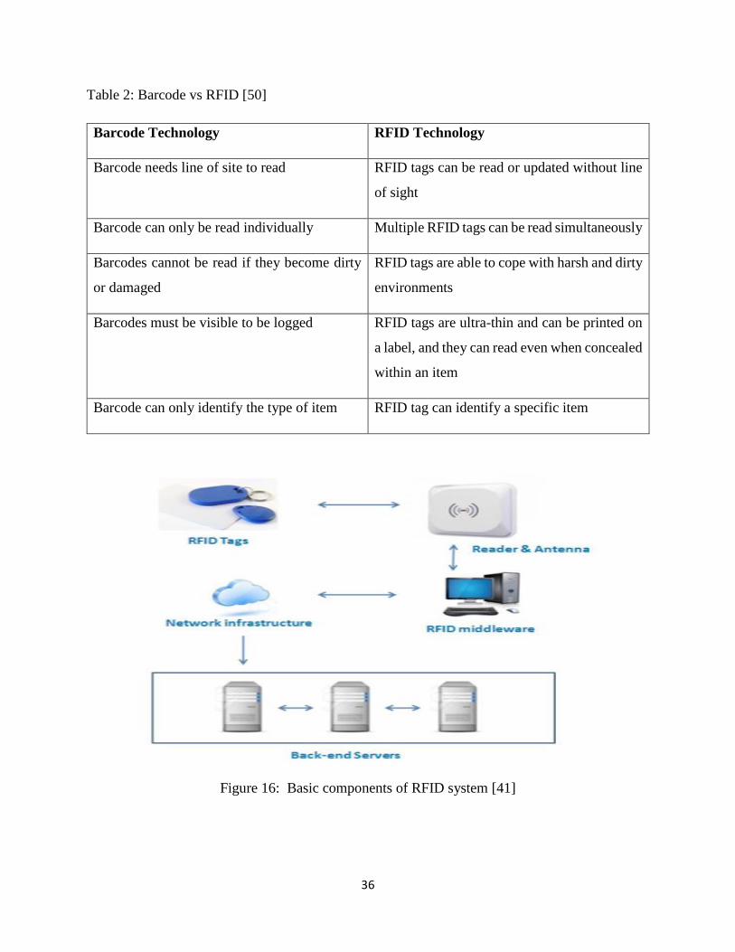
36
Table 2: Barcode vs RFID [50]
Barcode Technology RFID Technology
Barcode needs line of site to read RFID tags can be read or updated without line
of sight
Barcode can only be read individually Multiple RFID tags can be read simultaneously
Barcodes cannot be read if they become dirty
or damaged
RFID tags are able to cope with harsh and dirty
environments
Barcodes must be visible to be logged RFID tags are ultra-thin and can be printed on
a label, and they can read even when concealed
within an item
Barcode can only identify the type of item RFID tag can identify a specific item
Figure 16: Basic components of RFID system [41]
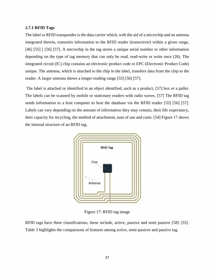
37
2.7.1 RFID Tags
The label or RFID transponder is the data carrier which, with the aid of a microchip and an antenna
integrated therein, transmits information to the RFID reader (transceiver) within a given range,
[46] [55] [ [56] [57]. A microchip in the tag stores a unique serial number or other information
depending on the type of tag memory that can only be read, read-write or write once (26). The
integrated circuit (IC) chip contains an electronic product code or EPC (Electronic Product Code)
unique. The antenna, which is attached to the chip in the label, transfers data from the chip to the
reader. A larger antenna shows a longer reading range [55] [56] [57].
The label is attached or identified in an object identified, such as a product, [57] box or a pallet.
The labels can be scanned by mobile or stationary readers with radio waves. [57] The RFID tag
sends information to a host computer to host the database via the RFID reader [55] [56] [57].
Labels can vary depending on the amount of information they may contain, their life expectancy,
their capacity for recycling, the method of attachment, ease of use and costs. [54] Figure 17 shows
the internal structure of an RFID tag.
Figure 17: RFID tag image
RFID tags have three classifications, these include, active, passive and semi passive [58] [55].
Table 3 highlights the comparisons of features among active, semi-passive and passive tag.
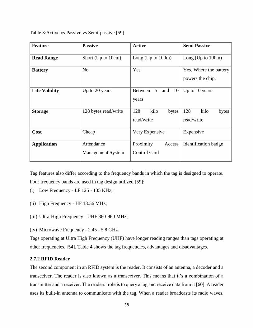
38
Table 3:Active vs Passive vs Semi-passive [59]
Feature Passive Active Semi Passive
Read Range Short (Up to 10cm) Long (Up to 100m) Long (Up to 100m)
Battery No Yes Yes. Where the battery
powers the chip.
Life Validity Up to 20 years Between 5 and 10
years
Up to 10 years
Storage 128 bytes read/write 128 kilo bytes
read/write
128 kilo bytes
read/write
Cost Cheap Very Expensive Expensive
Application Attendance
Management System
Proximity Access
Control Card
Identification badge
Tag features also differ according to the frequency bands in which the tag is designed to operate.
Four frequency bands are used in tag design utilized [59]:
(i) Low Frequency - LF 125 - 135 KHz;
(ii) High Frequency - HF 13.56 MHz;
(iii) Ultra-High Frequency - UHF 860-960 MHz;
(iv) Microwave Frequency - 2.45 - 5.8 GHz.
Tags operating at Ultra High Frequency (UHF) have longer reading ranges than tags operating at
other frequencies. [54]. Table 4 shows the tag frequencies, advantages and disadvantages.
2.7.2 RFID Reader
The second component in an RFID system is the reader. It consists of an antenna, a decoder and a
transceiver. The reader is also known as a transceiver. This means that it’s a combination of a
transmitter and a receiver. The readers’ role is to query a tag and receive data from it [60]. A reader
uses its built-in antenna to communicate with the tag. When a reader broadcasts its radio waves,
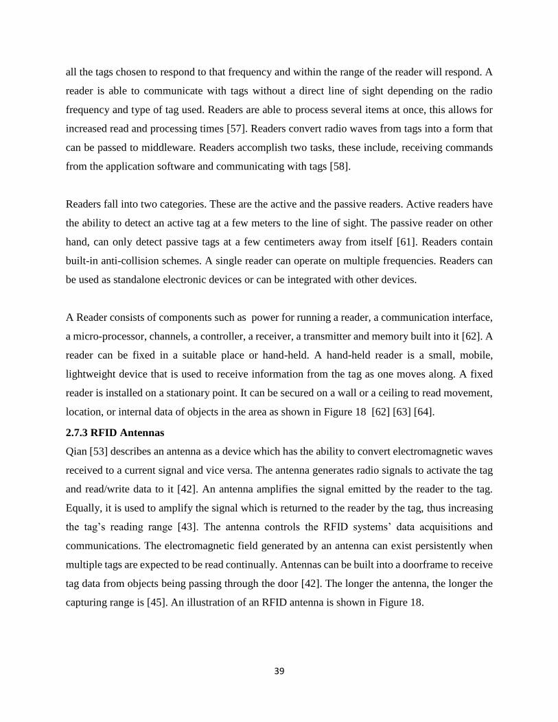
39
all the tags chosen to respond to that frequency and within the range of the reader will respond. A
reader is able to communicate with tags without a direct line of sight depending on the radio
frequency and type of tag used. Readers are able to process several items at once, this allows for
increased read and processing times [57]. Readers convert radio waves from tags into a form that
can be passed to middleware. Readers accomplish two tasks, these include, receiving commands
from the application software and communicating with tags [58].
Readers fall into two categories. These are the active and the passive readers. Active readers have
the ability to detect an active tag at a few meters to the line of sight. The passive reader on other
hand, can only detect passive tags at a few centimeters away from itself [61]. Readers contain
built-in anti-collision schemes. A single reader can operate on multiple frequencies. Readers can
be used as standalone electronic devices or can be integrated with other devices.
A Reader consists of components such as power for running a reader, a communication interface,
a micro-processor, channels, a controller, a receiver, a transmitter and memory built into it [62]. A
reader can be fixed in a suitable place or hand-held. A hand-held reader is a small, mobile,
lightweight device that is used to receive information from the tag as one moves along. A fixed
reader is installed on a stationary point. It can be secured on a wall or a ceiling to read movement,
location, or internal data of objects in the area as shown in Figure 18 [62] [63] [64].
2.7.3 RFID Antennas
Qian [53] describes an antenna as a device which has the ability to convert electromagnetic waves
received to a current signal and vice versa. The antenna generates radio signals to activate the tag
and read/write data to it [42]. An antenna amplifies the signal emitted by the reader to the tag.
Equally, it is used to amplify the signal which is returned to the reader by the tag, thus increasing
the tag’s reading range [43]. The antenna controls the RFID systems’ data acquisitions and
communications. The electromagnetic field generated by an antenna can exist persistently when
multiple tags are expected to be read continually. Antennas can be built into a doorframe to receive
tag data from objects being passing through the door [42]. The longer the antenna, the longer the
capturing range is [45]. An illustration of an RFID antenna is shown in Figure 18.
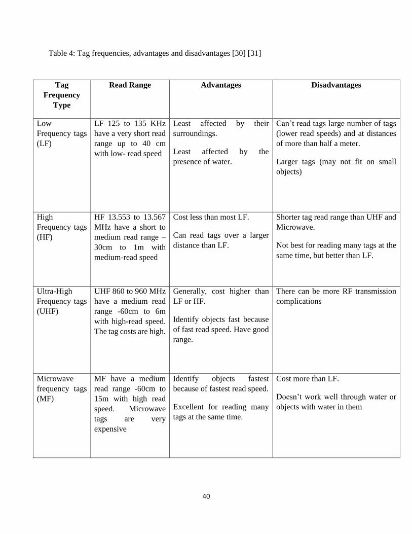
40
Table 4: Tag frequencies, advantages and disadvantages [30] [31]
Tag
Frequency
Type
Read Range
Advantages
Disadvantages
Low
Frequency tags
(LF)
LF 125 to 135 KHz
have a very short read
range up to 40 cm
with low- read speed
Least affected by their
surroundings.
Least affected by the
presence of water.
Can’t read tags large number of tags
(lower read speeds) and at distances
of more than half a meter.
Larger tags (may not fit on small
objects)
High
Frequency tags
(HF)
HF 13.553 to 13.567
MHz have a short to
medium read range –
30cm to 1m with
medium-read speed
Cost less than most LF.
Can read tags over a larger
distance than LF.
Shorter tag read range than UHF and
Microwave.
Not best for reading many tags at the
same time, but better than LF.
Ultra-High
Frequency tags
(UHF)
UHF 860 to 960 MHz
have a medium read
range -60cm to 6m
with high-read speed.
The tag costs are high.
Generally, cost higher than
LF or HF.
Identify objects fast because
of fast read speed. Have good
range.
There can be more RF transmission
complications
Microwave
frequency tags
(MF)
MF have a medium
read range -60cm to
15m with high read
speed. Microwave
tags are very
expensive
Identify objects fastest
because of fastest read speed.
Excellent for reading many
tags at the same time.
Cost more than LF.
Doesn’t work well through water or
objects with water in them
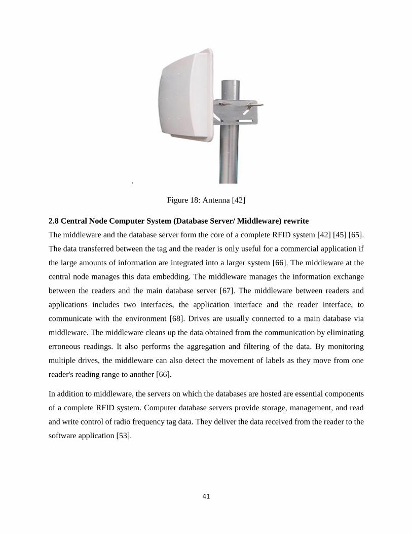
41
.
Figure 18: Antenna [42]
2.8 Central Node Computer System (Database Server/ Middleware) rewrite
The middleware and the database server form the core of a complete RFID system [42] [45] [65].
The data transferred between the tag and the reader is only useful for a commercial application if
the large amounts of information are integrated into a larger system [66]. The middleware at the
central node manages this data embedding. The middleware manages the information exchange
between the readers and the main database server [67]. The middleware between readers and
applications includes two interfaces, the application interface and the reader interface, to
communicate with the environment [68]. Drives are usually connected to a main database via
middleware. The middleware cleans up the data obtained from the communication by eliminating
erroneous readings. It also performs the aggregation and filtering of the data. By monitoring
multiple drives, the middleware can also detect the movement of labels as they move from one
reader's reading range to another [66].
In addition to middleware, the servers on which the databases are hosted are essential components
of a complete RFID system. Computer database servers provide storage, management, and read
and write control of radio frequency tag data. They deliver the data received from the reader to the
software application [53].

42
I) Other RFID Attributes
a) Electronic Product Code
The Electronic Product Code (EPC) is the code that is used for automatic and unique identification
of objects such as parts, products, pallets, locations and so on. It is a standard product coding
structure for item management applications [68]. EPC is the - 16 - standard designed to allocate a
unique identifier to each object. EPC comprises four sequences of binary digits, these include [69]:
(i) an eight-bit header,
(ii) the EPC manager (28 bits),
(iii) the product type (24 bits) and,
(iv) Serial number of the product (36 bits).
The EPC global Inc. oversees the development of the EPC Standard [69]. An example of an EPC
code is shown as an image in Figure 19. The development of the Electronic Product Codes (EPC)
was initiated by the auto ID center in 1999 [70].
Figure 19: EPC example image [70]
II) RFID Limitations
a) RFID Standards
MuzaffarIqbal and Singh [45] indicate that standards for radio interface protocols (radio frequency,
data signal strength, communication protocols, for example), tag encoding format (writing and
blocking data) are essential. , Encryption) and information about the service infrastructure (e.g.
data structure for supply chain applications). Information coding models and information
processing software vary from provider to provider. When switching systems from one provider
43
to another, all items must be redrawn or the software changed. Therefore, it is important to develop
common RFID standards that should be accepted by all [42]. Scattered standards leave much
freedom in the communication protocols, formats and choice of information store. Current
standards focus on radio interface protocols, data content and application of technology. According
to Samadi [70], the International Organization for Standardization (ISO) has created some
standards necessary for RFID technology. Some of the basic standards established by ISO include
[70]:
(i) ISO 11784 for the monitoring of RFID cattle.
(ii) ISO 11785 for the interface protocol.
(iii) ISO 14443 for the use of smart cards in payment transactions and
(iv) ISO 15693 for neighbourhood maps.
Standardisation is a crucial factor that must not be ignored in RFID technology
(b)Costs
The cost is another major obstacle to the introduction of RFID [42] [52] [71]. The drives, antennas
and tags used in this technology require large sums of money. Additional system costs include
attaching labels to items, buying and installing drives, implementing system application solutions,
redesigning work processes, and training and education personnel [42], [71]. In [72] the author
indicates that the cost of a fully functional RFID system can range from $ 20,000 to $ 1 million,
depending on the size of the application and the application. Recovery times are usually too long
[73].
Depending on the type of system and uses, the initial installation and operating costs may be too
high [71]. In [56] points out that the initial implementation of an RFID system is very expensive,
but the benefits in most cases outweigh the original costs. The cost is another major obstacle to the
introduction of RFID [42] [52] [71]. The drives, antennas and tags used in this technology require
large sums of money. Additional system costs include attaching labels to items, buying and
installing drives, implementing system application solutions, redesigning work processes, and
training and education personnel [42] [71]. The author in [72] indicates that the cost of a fully
functional RFID system can range from $ 20,000 to $ 1 million, depending on the size of the
application. Recovery times are usually too long [74]. Depending on the type of system and uses,
the initial installation and operating costs may be too high [71]. Hashemipour [74] and Sharma et
44
al. [56] point out that the initial implementation of an RFID system is very expensive, but the
benefits in most cases outweigh the original costs.
2.9 Data Security and Confidentiality
Kuar et al. [44] argued that, depending on the scope and, in some cases, the law, it may be
indispensable to prevent unauthorized persons from reading or writing data stored or transmitted
there from labels. Therefore, encryption (data encryption) must be ensured at all interfaces where
data can be intercepted or transmitted. This can be done both on the medium itself and on the
communication reader of tags or reader host.
2.9.1 Deployment of RFID Tags and Readers
a) Deployment of Tags
Dolgui and Proth [69] suggest that tags can be deployed by introducing them at the object level,
i.e. each object is tagged. Consequently, each object is tracked to ensure that any element that
disappears from the system is recognized immediately [69]. Ruiz-Garcia and Lunadei [52] also
suggest that labels can also be inserted into an object or placed in the packaging.
b) Deployment of Readers
RFID reader can be deployed in two ways namely fixed or hand-held. The RFID reader can be
fixed in an adequate place or hand-held [62] [63] [75]. A hand-held reader is a lightweight device
that can be carried around [62] [63] [75]. A fixed reader is installed on a stationary point, for
example, on a wall or a ceiling. [62] [63] [75]. Antennas can be built into a doorframe to receive
tag data from objects being passing through the door [42].
c) RFID and Cloud Computing
Data collected by RFID readers can be processed and stored either on local servers or in servers
hosted in the cloud [76]. Cloud Computing is a computing paradigm where real-time scalable
resources such as files, data, programs, and hardware can be shared with users over the Internet
[76]. Cloud computing should be the solution that solves the problem of processing large amounts
of data [77]. Using cloud computing significantly reduces the cost of deploying software and data
storage solutions. Cloud solutions have desirable features such as high scalability, agility, high
availability and reliability, and multi-sharing [77]. Clouds offer a variety of service models,
including: software, platform, platform and infrastructure as a service [77]. In the IaaS service
model (Infrastructure as a Service), vendors offer physical or virtual machines that can meet
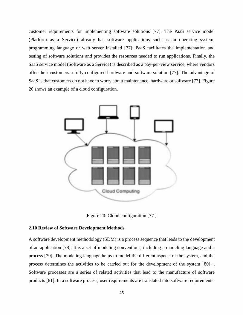
45
customer requirements for implementing software solutions [77]. The PaaS service model
(Platform as a Service) already has software applications such as an operating system,
programming language or web server installed [77]. PaaS facilitates the implementation and
testing of software solutions and provides the resources needed to run applications. Finally, the
SaaS service model (Software as a Service) is described as a pay-per-view service, where vendors
offer their customers a fully configured hardware and software solution [77]. The advantage of
SaaS is that customers do not have to worry about maintenance, hardware or software [77]. Figure
20 shows an example of a cloud configuration.
Figure 20: Cloud configuration [77 ]
2.10 Review of Software Development Methods
A software development methodology (SDM) is a process sequence that leads to the development
of an application [78]. It is a set of modeling conventions, including a modeling language and a
process [79]. The modeling language helps to model the different aspects of the system, and the
process determines the activities to be carried out for the development of the system [80]. ,
Software processes are a series of related activities that lead to the manufacture of software
products [81]. In a software process, user requirements are translated into software requirements.
46
The requirements are then translated into designs, the designs are implemented, and the
implementation is tested. Software processes can overlap or iteratively execute [78]. An SDM can
be classified into two classes, a conventional SDM and an object-oriented SDM (OOSDM).
2.10.1 Traditional methodology and object-oriented methodology
Traditional approaches to system development consider software as a set of programs or functions
and isolated data. Algorithms and data structures form a program. A structured method based on
the waterfall model [82] [83] [84] is an example of a traditional approach to system development.
The Cascade Model takes a very formal approach to the phases and activities of the System
Development Life Cycle (SDLC). The activities of one phase must be completed before you can
move on to another phase. An iteration is not allowed model [82] [83] [84]. The SDLC OO
approach, on the other hand, pursues an iterative and incremental approach to system development.
In OO, the SDLC is visualized as a series of increments or phases. Everyone from SDLC phases
are interactively visited until the developer is satisfied with model [83] [84] [85]. The main
difference between traditional system development methods and OOSDMs depends on their main
purpose. The traditional approach focuses on the functions of the system. The OOSD approach
focuses on the object that combines data and functionality model [82] [83] [84]. The development
phases of a system, ie planning-analysis-design-implementation, do not change. The only change,
however, is the way they are performed. The structured approach focuses on understanding a
problem using a model called the Data Flow Diagram (DFD). Consequently, all system
components are derived from DFD model [82] [83] [84] On the contrary, the OO approach uses
use cases. There are many models that need to be dealt with in the OO approach, and there are no
clear steps so that the design of system components logically follows from a single model [82]
[83] [84].
2.11 Methodology for Object-Oriented System Development
An object-oriented system development methodology (OOSDM) can be defined as a system of
principles and procedures applied to the development of object-oriented software (OOSD) [85].
OOSD provides a way to develop software by creating standalone modules or objects that are easy
to replace, modify, and reuse. Object Orientation (OO) is a means of visualizing and modeling the
world or system as a set of interacting and correlating objects [86]. An object can be a physical or
immaterial physical entity. Examples of objects are an agency, a job, a place, or a person [86].
47
2.11.1 Advantages of Developing Object-Oriented Systems
The advantages of an OOSD approach to system development as opposed to a traditional approach
are [83] [84]:
(a) The orientation object (OO) offers a higher level of abstraction at the object level. Objects
encapsulate data and functions and thus their higher level of abstraction. Development can be
continued at the object level, ignoring the rest of the system for as long as necessary. This
facilitates the design, coding, testing and maintenance of the system.
(b) OO ensures a seamless transition between the different phases of software development. OO
uses the same language to talk about analysis, design, programming, and database design. This
transparent approach significantly reduces complexity and redundancy. This allows a clearer and
more robust system development. On the other hand, traditional approaches to system
development require different styles and methods for each stage of the development process.
c) OO promotes reusability. Objects are reusable because they are modeled directly from a real
problem domain. Each object stands alone or in a circle of other objects.
2.11.2 Uniform Modeling Language
The modeling language used in an object-oriented SDM is the Unified Modeling Language
(UML). UML is a set of diagram techniques [84]. UML uses graphical notation to express the
design of software developments [80]. Examples of design artifacts include requirements,
architecture, design, source code, test cases, prototypes, etc. [86] [87]. The modeling provides a
representation or simplification of reality. It provides a plan of the system. UML supports
independent specifications for specific programming languages, technologies and development
processes [86] [87]. The underlying assumption of UML is that no diagram can capture all the
different elements of a system [80]. UML consists of three basic elements, namely elements,
relationships, and charts. The elements are the main components of the model, while the
relationships link them. Finally, diagrams provide mechanisms for grouping collections of
elements and relationships. Examples of elements in UML include [86] [87]:
a) Structure: is the static part of the model, which is a conceptual element.
Examples of structural elements are classes, use cases, collaboration and components.
b) Behavior: represents behavior in time and space. Interaction and state describe behavioral
elements.
48
The UML is characterized by nine main diagrams. A diagram is a graphical representation of a
group of elements and relationships in which node elements and edge relationships are. The nine
main diagrams are: class, object, use case, order, collaboration, status table, activity, component,
and deployment [86], [87].
2.11.3 Object-oriented system development: A case-based approach
A use case is an interaction between a user and a system that captures the goals and needs of the
user [81], [87]. The main advantage of a case-based OOSD approach is that all design decisions
can be tracked directly according to user needs [88]. OOSDMs consist of an object-oriented system
development cycle (OOSDLC). The OOSDLC file contains three macro processes, namely Object
Oriented Analysis (OOA), Object Oriented Design (OOD), and Object Oriented Implementation
(OOI). The OOSDLC macro processes can be broken down into the following phases [86] [87]
[89]:
a) Object-oriented analysis (OOA phase): The requirements of the users are modeled, what the
future system has to do. OOA helps to understand the needs of the company and to process the
requirements. OOA focuses on developing an object-oriented model of the problem domain. OOA
answers the question of what the system should do. The result of this phase is a conceptual model
consisting of two results, namely requirement models and object models.
b) Object-Oriented Design (OOD Phase): OOD provides the ability to develop object-oriented
software / system models to implement the OOA-determined requirements. The result of OOD is
a plan that shows how the system meets the requirements analysis model requirements. OOD
answers the question of how the system will do this.
2.11.3.1 Object-oriented Languages
The OOP languages include Java, Cis-C (C #), and C-Plus Plus (C ++). Java is a portable OOP
language introduced by Sun Microsystems [90] [91]. C # is a C ++ and C ++ based OOP language
and was developed specifically for the Microsoft .NET platform. Microsoft's .NET platform
provides developers with the capabilities they need to build and run computer applications that run
on computers on the Internet. C ++ is an extension of the language "C". C ++ offers functions for
OOP. C ++ was developed by Bjarne Stroustrup at Bell Laboratories [91].
49
The use of The use of an OOP language offers some advantages over a non-OOP language such
as [90]:
a) Improved productivity in software development: OOP has a modular structure; i.e. it allows
the separation of tasks in the development of object-based programs. It is extensible because
objects with new attributes and behavior can be extended. In OOP, objects can be reused in and
between applications. Because of these three factors - scalability, scalability, and reusability -
object-oriented programming improves the productivity of software development over traditional
procedural programming techniques.
b) Software Maintenance Function: For the above reasons, maintaining object-oriented software
is easier. Due to the modular nature of the system, part of the system can be updated in the event
of problems without requiring extensive changes.
c) Faster development: Reusability allows for faster development. OOP languages come with
extensive object libraries. Code developed during the projects can also be reused in future projects.
d) Reduced development costs: Reusing software reduces development costs. Typically, object-
oriented analysis and design (OOAD) requires more effort, which reduces the overall cost of
development.
e) Better Software: The faster development of software and its development costs reduce the time
and resources required for software verification. OOP tends to lead to better software.
2.12 Geographical Information Systems (GIS) and Geographical Positioning Systems(GPS)
For centuries, geographic information in the form of paper maps has been a driving force for the
progress of our society. Just a few decades ago, the manipulation, synthesis and presentation of
geographic information on paper maps was limited to tasks that were limited to manual and non-
interactive processes. The exponential improvement in the performance of computer technologies
and the increasing demand for interactive manipulation and analysis of geographic information
have led to a need for Geographic Information systems (GIS)
2.12.1 What is Geographical Information Systems (GIS) Geographical Information Systems (GIS) can generally be described as purpose computer-based
technologies basically used for handling geographical data in digital form in order to capture, store,
manipulate, analyse and visualize information, where part of the information is sets of spatial or
geo-referenced data [95]. Geographic Information Systems are a special class of information
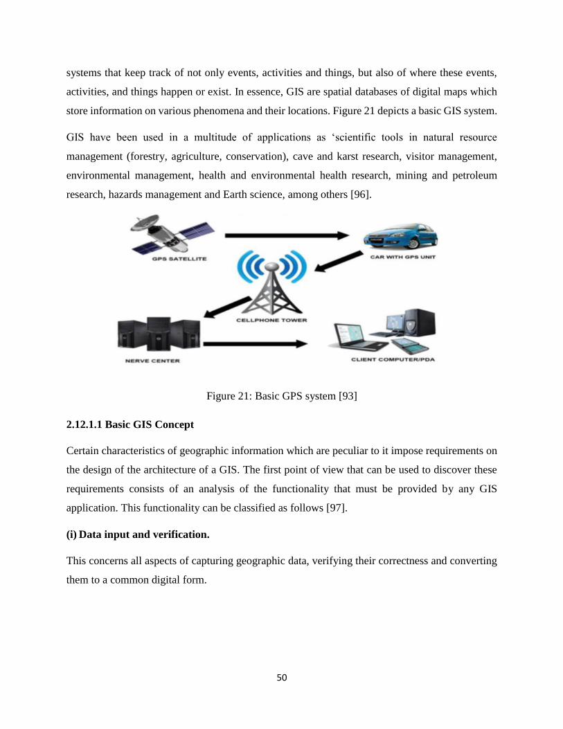
50
systems that keep track of not only events, activities and things, but also of where these events,
activities, and things happen or exist. In essence, GIS are spatial databases of digital maps which
store information on various phenomena and their locations. Figure 21 depicts a basic GIS system.
GIS have been used in a multitude of applications as ‘scientific tools in natural resource
management (forestry, agriculture, conservation), cave and karst research, visitor management,
environmental management, health and environmental health research, mining and petroleum
research, hazards management and Earth science, among others [96].
Figure 21: Basic GPS system [93]
2.12.1.1 Basic GIS Concept
Certain characteristics of geographic information which are peculiar to it impose requirements on
the design of the architecture of a GIS. The first point of view that can be used to discover these
requirements consists of an analysis of the functionality that must be provided by any GIS
application. This functionality can be classified as follows [97].
(i) Data input and verification.
This concerns all aspects of capturing geographic data, verifying their correctness and converting
them to a common digital form.
51
(ii) Data storage and management.
It covers the structure and organization of geographic information both in terms of the way in
which it is perceived by the user (i.e. Conceptual model) and the way in which it is handled in the
computer (i.e., logical model and physical model).
(iii) Data transformation and analysis.
This functionality consists of the processes of editing the information to keep it up to date or to
remove errors. Data analysis is one of the main tasks of GIS, and concerns the application of
analysis methods to the information to achieve answers to the questions asked to the GIS.
Data output and presentation.
The functionality of producing maps and map-based material is a highly distinctive feature of GIS
compared with a general-purpose information system. Together with the analysis techniques, this
is the aspect that differs the most from traditional information systems.
2.12.1.2 GIS as a decision making tool
GIS has a wide range of areas where it can be applied. Some examples include urban planning,
forestry, climate science, military use, emergency management, public health, epidemiology,
location tracking etc.
GIS can use spatially referenced data, make detailed location based analysis, and keep track of
events on an area over extended period of time to see how things are changing with time. A
university may require to make complex decisions about its environment but sometimes decisions
are made with incomplete information. GIS enables to build a model that helps to make decisions
easier in a complex environment. Visually depicted data is far easier to understand than just the
raw data itself. In addition to that, GIS makes the interaction between various factors that the data
represents to be easily recognized. For example, in University Access Control one might need to
know the number of people accessing the university premise, their exact location, the number of
the undeserved people and the accessibility to the existing facilities. The acquired data on its own
might not be easy to understand or make sense at all to take a comprehensive action. Especially,
in the case of spatially referenced data such as location, it is virtually impossible to conceive
without the help of a map. Therefore, maps are a key in turning raw data and experience into usable
information.
52
A large amount of different data becomes more conceivable and easier to understand when
processed into required information.
Geographical Information Systems (GIS) have been integrated with other technologies to build
systems such as fleet tracking system. An example is GIS, GPS, GPRS and Web – based
Framework for Fleet Tracking [102]. Real time location information of the fleet is collected via
GPS. This information is transferred continuously through the General Packet Radio Service
(GPRS) to a central database. The users are able to view the current location of each of the vehicles
in the fleet via a web-based GIS application.
Visitor location can be tracked in any University Via GPS and viewed and displayed via GIS
through a server.
2.12.2 Global Positioning System (GPS)
GPS is a modern technology [92]. The importance of GPS in our daily lives is undeniable. This is
because GPS applications are growing rapidly in today's dynamic world. The main objective is to
facilitate the execution of tasks and to solve many of humanity's problems. It's very important in
health, crime, transportation and communications, and its applications have been expanded [92].
The Global Positioning System (GPS) is a space navigation system that provides location and time
information in all weather conditions, whether it is on or near Earth, where four or more are more
than four GPS satellites in sight [92]. The Global Positioning System (GPS) shows you where you
are on Earth. A related study [92] notes that this is a navigation technology that provides accurate
locations and information. GPS is a space satellite system that allows you to contact any GPS
compatible receiver. GPS (Global Positioning System) technology is an essential tool for the
management of agricultural and natural resources. [92] adds that the Global Positioning System
(GPS) is a system of Navigation system based on a network of 24 satellites in orbit. The system
provides vital information to military, civil and commercial users worldwide and is freely
accessible to anyone with a GPS receiver. GPS works in all weather conditions around the world.
The Global Positioning System (GPS) is a space-based satellite navigation system that provides
location and time information anywhere, regardless of weather conditions, on or near Earth, where
there is an unobstructed line gives. With four or more GPS satellites, GPS satellites rotate around
the earth twice a day in a specific orbit. These satellites send information about the signals to earth.
This signal information is received by the GPS receiver to measure the correct position of the user.
53
The GPS receiver compares the time at which a satellite transmits the signal with the time at which
the signal is received. The calculated time difference allows us to determine the distance of the
satellite. By measuring the distance of some additional satellites, the position of the user can be
checked and displayed on the electronics board of the device. GPS is a satellite and ground based
radio navigation and location system that allows the user to determine very precise positions on
the earth's surface. Remote Sensing: Remote sensing technologies are used to collect information
from the Earth's surface from a remote platform, usually a satellite or air sensor. Most remote
sensing data used for mapping and spatial analysis are collected as reflected electromagnetic
radiation and converted into a digital image that can be superimposed on other spatial data.
According to [93], GPS technology and its application can be designed using all three GPS
components. Its three components are: The Room Segment: which consists satellites and
transmitted signals. THE CONTROL SEGMENT: consists of ground stations (worldwide), which
ensure the proper functioning of the satellites. THE USER SEGMENT: consists of receivers which
you can hold by hand or get into your car.
2.12.3 Various Navigation Systems
Currently, navigation systems are available and people use them to track each object. GNSS
(Global Navigation Satellite System) includes three main satellite navigation systems. These are
GPS (Global Positioning System), GLONASS and Galileo. Other navigation systems include GPS
NAVSTAR navigation timing and Satellite Telemetry, the world's most fully functional US
navigation system in the world, the BEIDOU regional system of the People's Republic of China,
which is currently limited to Asia and the US. West Pacific, the global system of COMPASS
People's Republic of China, is expected to be operational by 2020 [92], IRNSS - Indian regional
navigation satellite system, India's regional navigation system covering India and India the north
of the Indian Ocean. QZSS - Japanese regional system for Asia and Oceania [92].
Table 5 shows the three main GNSS technologies from which it can be seen that GLONASS and
Galileo provide more precise location than GPS but they are costly. GPS (Global Positioning
System) is highly available GNSS technology.
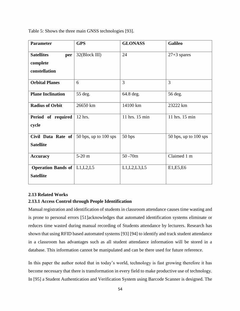
54
Table 5: Shows the three main GNSS technologies [93].
Parameter GPS GLONASS Galileo
Satellites per
complete
constellation
32(Block III) 24 27+3 spares
Orbital Planes 6 3 3
Plane Inclination 55 deg. 64.8 deg. 56 deg.
Radius of Orbit 26650 km 14100 km 23222 km
Period of required
cycle
12 hrs. 11 hrs. 15 min 11 hrs. 15 min
Civil Data Rate of
Satellite
50 bps, up to 100 sps 50 bps 50 bps, up to 100 sps
Accuracy 5-20 m 50 -70m Claimed 1 m
Operation Bands of
Satellite
L1,L2,L5 L1,L2,L3,L5 E1,E5,E6
2.13 Related Works
2.13.1 Access Control through People Identification
Manual registration and identification of students in classroom attendance causes time wasting and
is prone to personal errors [51]acknowledges that automated identification systems eliminate or
reduces time wasted during manual recording of Students attendance by lecturers. Research has
shown that using RFID based automated systems [93] [94] to identify and track student attendance
in a classroom has advantages such as all student attendance information will be stored in a
database. This information cannot be manipulated and can be there used for future reference.
In this paper the author noted that in today’s world, technology is fast growing therefore it has
become necessary that there is transformation in every field to make productive use of technology.
In [95] a Student Authentication and Verification System using Barcode Scanner is designed. The
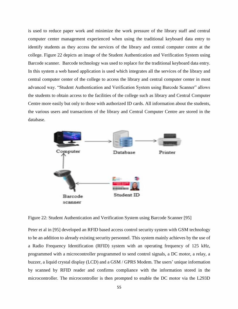
55
is used to reduce paper work and minimize the work pressure of the library staff and central
computer center management experienced when using the traditional keyboard data entry to
identify students as they access the services of the library and central computer centre at the
college. Figure 22 depicts an image of the Student Authentication and Verification System using
Barcode scanner. Barcode technology was used to replace for the traditional keyboard data entry.
In this system a web based application is used which integrates all the services of the library and
central computer center of the college to access the library and central computer center in most
advanced way. “Student Authentication and Verification System using Barcode Scanner” allows
the students to obtain access to the facilities of the college such as library and Central Computer
Centre more easily but only to those with authorized ID cards. All information about the students,
the various users and transactions of the library and Central Computer Centre are stored in the
database.
Figure 22: Student Authentication and Verification System using Barcode Scanner [95]
Peter et al in [95] developed an RFID based access control security system with GSM technology
to be an addition to already existing security personnel. This system mainly achieves by the use of
a Radio Frequency Identification (RFID) system with an operating frequency of 125 kHz,
programmed with a microcontroller programmed to send control signals, a DC motor, a relay, a
buzzer, a liquid crystal display (LCD) and a GSM / GPRS Modem. The users’ unique information
by scanned by RFID reader and confirms compliance with the information stored in the
microcontroller. The microcontroller is then prompted to enable the DC motor via the L293D
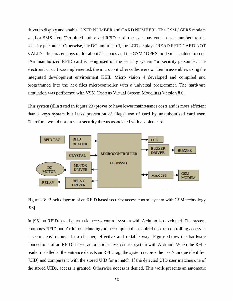
56
driver to display and enable "USER NUMBER and CARD NUMBER". The GSM / GPRS modem
sends a SMS alert "Permitted authorized RFID card, the user may enter a user number" to the
security personnel. Otherwise, the DC motor is off, the LCD displays "READ RFID CARD NOT
VALID", the buzzer stays on for about 5 seconds and the GSM / GPRS modem is enabled to send
"An unauthorized RFID card is being used on the security system "on security personnel. The
electronic circuit was implemented, the microcontroller codes were written in assembler, using the
integrated development environment KEIL Micro vision 4 developed and compiled and
programmed into the hex files microcontroller with a universal programmer. The hardware
simulation was performed with VSM (Proteus Virtual System Modeling) Version 8.0.
This system (illustrated in Figure 23) proves to have lower maintenance costs and is more efficient
than a keys system but lacks prevention of illegal use of card by unauthourised card user.
Therefore, would not prevent security threats associated with a stolen card.
Figure 23: Block diagram of an RFID based security access control system with GSM technology
[96]
In [96] an RFID-based automatic access control system with Arduino is developed. The system
combines RFID and Arduino technology to accomplish the required task of controlling access in
a secure environment in a cheaper, effective and reliable way. Figure shows the hardware
connections of an RFID- based automatic access control system with Arduino. When the RFID
reader installed at the entrance detects an RFID tag, the system records the user's unique identifier
(UID) and compares it with the stored UID for a match. If the detected UID user matches one of
the stored UIDs, access is granted. Otherwise access is denied. This work presents an automatic
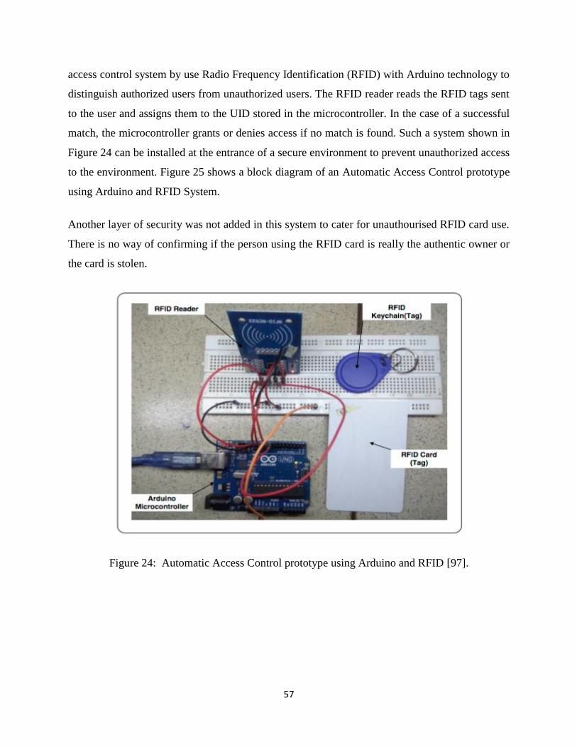
57
access control system by use Radio Frequency Identification (RFID) with Arduino technology to
distinguish authorized users from unauthorized users. The RFID reader reads the RFID tags sent
to the user and assigns them to the UID stored in the microcontroller. In the case of a successful
match, the microcontroller grants or denies access if no match is found. Such a system shown in
Figure 24 can be installed at the entrance of a secure environment to prevent unauthorized access
to the environment. Figure 25 shows a block diagram of an Automatic Access Control prototype
using Arduino and RFID System.
Another layer of security was not added in this system to cater for unauthourised RFID card use.
There is no way of confirming if the person using the RFID card is really the authentic owner or
the card is stolen.
Figure 24: Automatic Access Control prototype using Arduino and RFID [97].
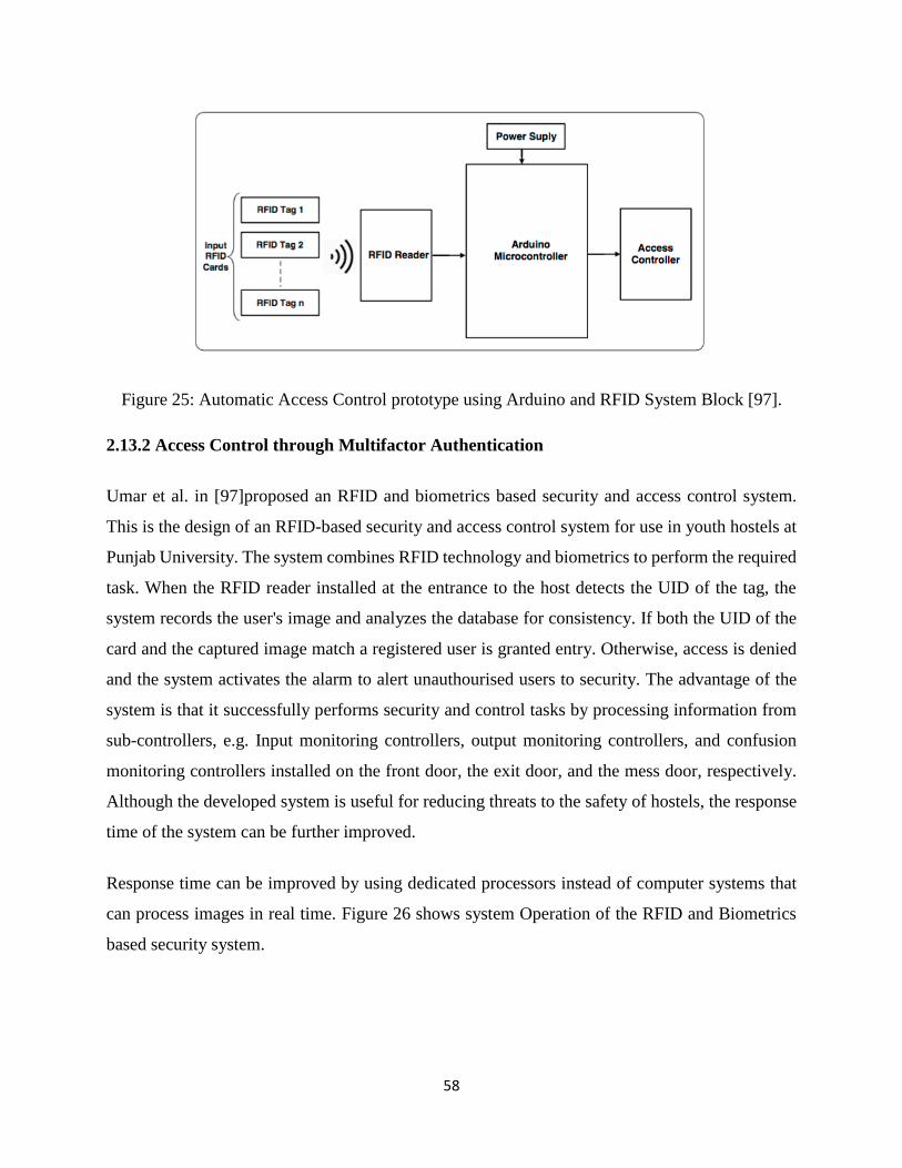
58
Figure 25: Automatic Access Control prototype using Arduino and RFID System Block [97].
2.13.2 Access Control through Multifactor Authentication
Umar et al. in [97]proposed an RFID and biometrics based security and access control system.
This is the design of an RFID-based security and access control system for use in youth hostels at
Punjab University. The system combines RFID technology and biometrics to perform the required
task. When the RFID reader installed at the entrance to the host detects the UID of the tag, the
system records the user's image and analyzes the database for consistency. If both the UID of the
card and the captured image match a registered user is granted entry. Otherwise, access is denied
and the system activates the alarm to alert unauthourised users to security. The advantage of the
system is that it successfully performs security and control tasks by processing information from
sub-controllers, e.g. Input monitoring controllers, output monitoring controllers, and confusion
monitoring controllers installed on the front door, the exit door, and the mess door, respectively.
Although the developed system is useful for reducing threats to the safety of hostels, the response
time of the system can be further improved.
Response time can be improved by using dedicated processors instead of computer systems that
can process images in real time. Figure 26 shows system Operation of the RFID and Biometrics
based security system.
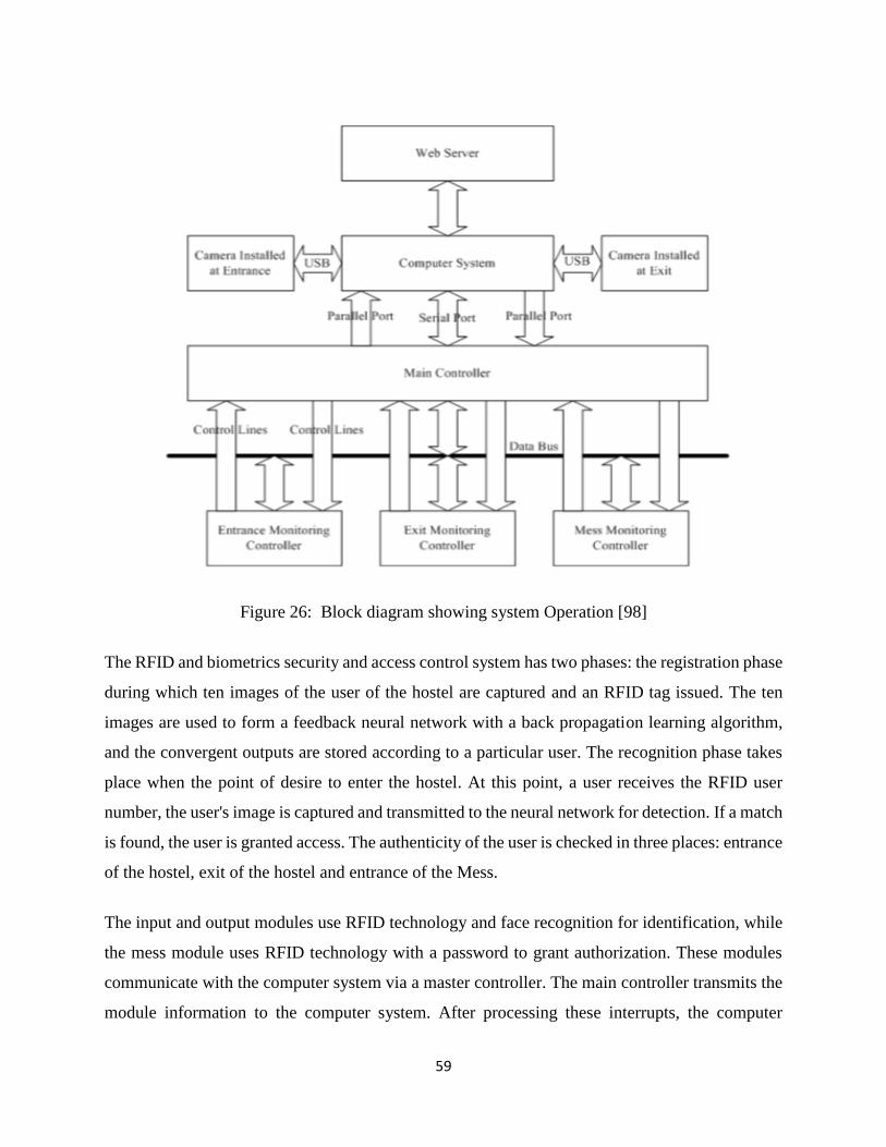
59
Figure 26: Block diagram showing system Operation [98]
The RFID and biometrics security and access control system has two phases: the registration phase
during which ten images of the user of the hostel are captured and an RFID tag issued. The ten
images are used to form a feedback neural network with a back propagation learning algorithm,
and the convergent outputs are stored according to a particular user. The recognition phase takes
place when the point of desire to enter the hostel. At this point, a user receives the RFID user
number, the user's image is captured and transmitted to the neural network for detection. If a match
is found, the user is granted access. The authenticity of the user is checked in three places: entrance
of the hostel, exit of the hostel and entrance of the Mess.
The input and output modules use RFID technology and face recognition for identification, while
the mess module uses RFID technology with a password to grant authorization. These modules
communicate with the computer system via a master controller. The main controller transmits the
module information to the computer system. After processing these interrupts, the computer
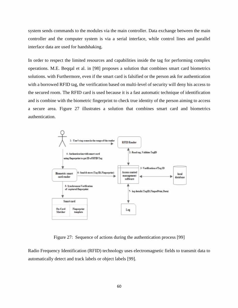
60
system sends commands to the modules via the main controller. Data exchange between the main
controller and the computer system is via a serial interface, while control lines and parallel
interface data are used for handshaking.
In order to respect the limited resources and capabilities inside the tag for performing complex
operations. M.E. Beqqal et al. in [98] proposes a solution that combines smart card biometrics
solutions. with Furthermore, even if the smart card is falsified or the person ask for authentication
with a borrowed RFID tag, the verification based on multi-level of security will deny his access to
the secured room. The RFID card is used because it is a fast automatic technique of identification
and is combine with the biometric fingerprint to check true identity of the person aiming to access
a secure area. Figure 27 illustrates a solution that combines smart card and biometrics
authentication.
Figure 27: Sequence of actions during the authentication process [99]
Radio Frequency Identification (RFID) technology uses electromagnetic fields to transmit data to
automatically detect and track labels or object labels [99].
61
The author notes that it offers opportunities for designing and implementing relatively inexpensive
systems, especially for security aspects. In this system a digital access control system is proposed,
that can be used in a secure area where only individuals with authenticated authentication
information can enter. The system was implemented in the server room of an educational
institution in Bangladesh to test its efficiency and spending. The implemented system includes a
digital door lock that can be unlocked in real-time to provide secure access indicating activation,
authentication, and user verification before the RFID card is brought closer to the reader. To ensure
and maintain the overall integrity of the system is connected to a central client-server subsystem.
The visitor registration status based on the key identity information is logged and managed by the
associated subsystem. The systems rightfully generate a report for all visits but lacks the facility
to authenticate the card holder.
Filipe [100] notes that researchers have utilized RFID technology in developing access control
system. The author has developed an RFID based monitoring and access control system consisting
of RFID terminal, camera, server and an alert device. Upon detecting an RFID tag, the terminal
captures a photo and transmits the data including the TAG’s UID and photo to the server through
TCP/IP connection. The database server is searched for this particular query and sends the results
back to the terminal to allow or deny the access. Illicit acts such as a person trying to enter when
the door is open without completion of authentication process causes the web application to turn
on the alert device using web services. The performance of the system is tested by installing RFID
kits with antennas covering a range of 10cm and satisfactory results are obtained.
Xiang-Lei Meng [101] has developed an RFID based embedded security authentication system
with novel face recognition structure. The system comprises of two phases first phase is the
registration in which ten pictures of user face with different emotions are collected and eigen
information is obtained with an extraction algorithm. The information form the registration phase
along with a UID is written on RFID tag. In recognition phase, a camera tracks the face and an
extraction algorithm returns Eigen information of the face in the picture. This information is then
matched with the information already stored on the tag for authentication. The entire processing
of this system is on the embedded ARM11 processor. Instead of a computer terminal/server a
S3C6410 is used which has resulted in faster response time, about 57ms with an authentication
62
accuracy up to 86.5%. The performance of the system is compared with the existing database
systems and is found to have far better response time with the same authentication accuracy.
In [102] Dong-Liang Wu has experimented and implemented a system that can improve the
security of RFID access control. The system is based on RFID in conjunction with face recognition
and based on neural network. The system recognizes the face of person holding RFID card and
denies the access if person is found to be unauthorized. Radial basis function neural network
(RBFNN) has been used for learning the face of authorized persons. For extracting the features
from the image, Principal component analysis (PCA) has been used and linear discriminant
analysis (LDA) has been used for refining these features. The network is trained with localized
generalization error model (L-GEM) for enhancing its generalization capabilities.
According to [103] RFID has become a reliable solution for automatically identifying and tracking
labels associated with real objects. The author notes that it can be used to integrate physical and
digital worlds. In this RFID-based security in an intelligent building is examined. In the Smart
Building case study, people (physical objects) carry RFID tags that help them to participate in the
calculations. The tag reader checks the information of the tag which is worn by the person. The
systems involve a two-stage authentication process which aims to protect the smart building from
unauthorized access using RFID-based mechanisms. Two algorithms have been proposed for this
purpose. The first ACTIA algorithm performs the verification of the non-collision RFID tag
information, while the second IMA algorithm uses the biometric metric known as the face-image
match. If authentication fails with ACTIA, image matching is not required because it can be
concluded that unauthorized persons are trying to compromise security. The DAISY descriptor, is
used by the IMA algorithm which is more accurate compared to SIFT and SURF. The performance
of the three algorithms is evaluated in terms of average accuracy, average execution time,
accuracy, and retrieval. The results revealed through standard AT & T image data experiments
showed that the proposed biometric authentication based on Radio Frequency Identification
(RFID) methodology is effective in protecting the smart building with secure access control. Fully
automatic trust management in critical RFID applications is yet to be implemented. Figure 28
shows a security solution that can be used in a smart building and Figure 29 shows the flow chart
of how the system achieves its function.
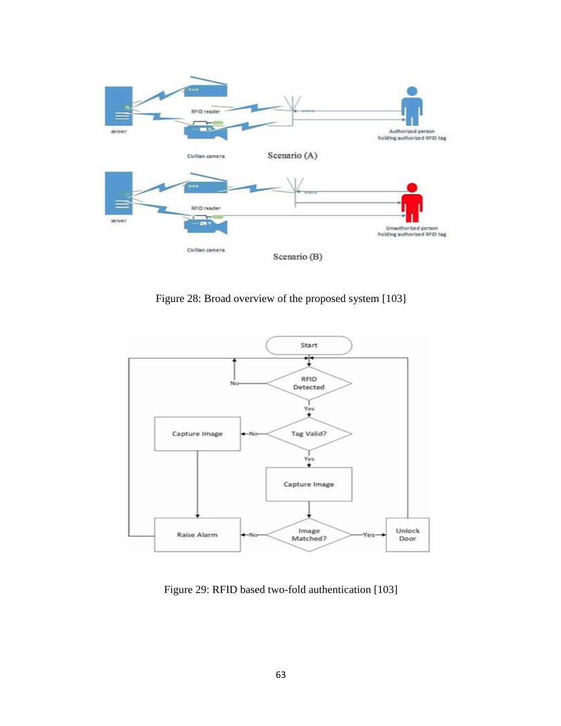
63
Figure 28: Broad overview of the proposed system [103]
Figure 29: RFID based two-fold authentication [103]
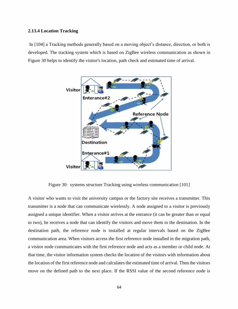
64
2.13.4 Location Tracking
In [104] a Tracking methods generally based on a moving object’s distance, direction, or both is
developed. The tracking system which is based on ZigBee wireless communication as shown in
Figure 30 helps to identify the visitor's location, path check and estimated time of arrival.
Figure 30: systems structure Tracking using wireless communication [101]
A visitor who wants to visit the university campus or the factory site receives a transmitter. This
transmitter is a node that can communicate wirelessly. A node assigned to a visitor is previously
assigned a unique identifier. When a visitor arrives at the entrance (it can be greater than or equal
to two), he receives a node that can identify the visitors and move them to the destination. In the
destination path, the reference node is installed at regular intervals based on the ZigBee
communication area. When visitors access the first reference node installed in the migration path,
a visitor node communicates with the first reference node and acts as a member or child node. At
that time, the visitor information system checks the location of the visitors with information about
the location of the first reference node and calculates the estimated time of arrival. Then the visitors
move on the defined path to the next place. If the RSSI value of the second reference node is
65
greater than that of the first one, the visitor node is replaced by a child node of the second reference
node. The visitor information system displays information about visitor movements and the
estimated time of arrival has changed. Finally, as visitors approach the final reference node of the
destination, the parent-child relationship changes according to the strength of the signal in the
RSSI values and indicates the estimated time of arrival based on the average distance traveled. to
the buildings. The location and the path of the visitor are monitored, but real-time physical site
capture is active.
In [105]a new upcoming model of real time location system (RTLS) to focus and track the exact
location of real time objects in vicinity is proposed. Overcoming the limitations of size, power,
attenuation of GPS & DGPS system, the active RFID tags can be easily affixed with objects. The
TIA approach of distance calculation will minimize the errors occurred in RSSI method.
Geographically fixed matrix of RFID readers at 50 m to 1 km apart, will monitor, track, and
calculate the exact position of tagged-object by communicating with the tag and other co-readers.
One 48 MHz PLL enabled 8-bit CPU in RFID reader is enough to calculate the TIA with an
accuracy of 3.3 m distance. One active tag with 100 mAh cell can respond many thousands of
times using IEEE802.15.4 standard which makes it globally acceptable. DSSS and GFSK used in
the tag for more reliable data communication. One central server is enough to store, filter, and
handle the calculated data flowing from the matrix net of RFID readers.
In [106] the author notes that apart from the importance of tracking the target in wireless sensor
networks in an area of application, communication consumption and the lowest energy source must
also be considered. The author also further notes that wireless sensor networks are more focused
on tracking individual targets for quantitative monitoring methodology. In this study a new method
based on quantitative multi-target tracking is introduced. To meet the demand for wireless sensor
networks, nodes must first save power and reduce power consumption. A new combination of
common probability data using the Innovation Mark (SOI-JPDA) is applied. This algorithm allows
for minimal power consumption, and the performance and complexity are very close to the data
association algorithm. normal ordinary probability. An SOI-JPDA based multi-target distributed
tracking algorithm in wireless sensor networks is proposed. The results of the simulation show that
this algorithm can successfully track multiple targets with minimal power consumption in wireless
sensor networks.
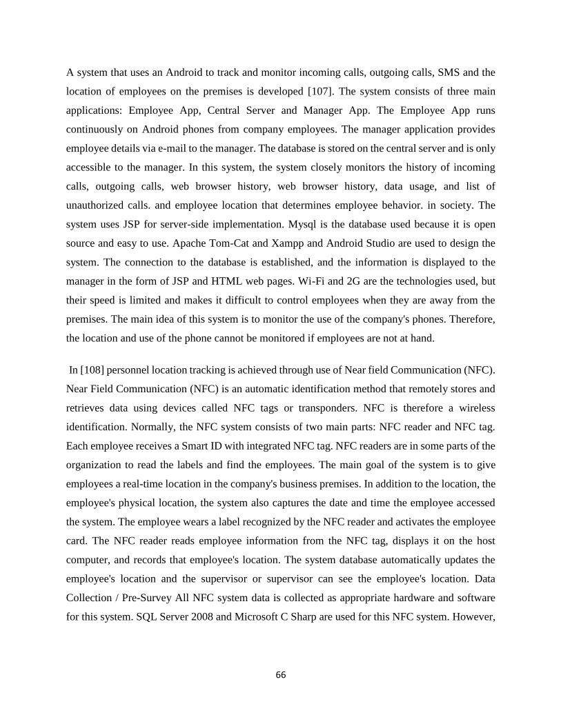
66
A system that uses an Android to track and monitor incoming calls, outgoing calls, SMS and the
location of employees on the premises is developed [107]. The system consists of three main
applications: Employee App, Central Server and Manager App. The Employee App runs
continuously on Android phones from company employees. The manager application provides
employee details via e-mail to the manager. The database is stored on the central server and is only
accessible to the manager. In this system, the system closely monitors the history of incoming
calls, outgoing calls, web browser history, web browser history, data usage, and list of
unauthorized calls. and employee location that determines employee behavior. in society. The
system uses JSP for server-side implementation. Mysql is the database used because it is open
source and easy to use. Apache Tom-Cat and Xampp and Android Studio are used to design the
system. The connection to the database is established, and the information is displayed to the
manager in the form of JSP and HTML web pages. Wi-Fi and 2G are the technologies used, but
their speed is limited and makes it difficult to control employees when they are away from the
premises. The main idea of this system is to monitor the use of the company's phones. Therefore,
the location and use of the phone cannot be monitored if employees are not at hand.
In [108] personnel location tracking is achieved through use of Near field Communication (NFC).
Near Field Communication (NFC) is an automatic identification method that remotely stores and
retrieves data using devices called NFC tags or transponders. NFC is therefore a wireless
identification. Normally, the NFC system consists of two main parts: NFC reader and NFC tag.
Each employee receives a Smart ID with integrated NFC tag. NFC readers are in some parts of the
organization to read the labels and find the employees. The main goal of the system is to give
employees a real-time location in the company's business premises. In addition to the location, the
employee's physical location, the system also captures the date and time the employee accessed
the system. The employee wears a label recognized by the NFC reader and activates the employee
card. The NFC reader reads employee information from the NFC tag, displays it on the host
computer, and records that employee's location. The system database automatically updates the
employee's location and the supervisor or supervisor can see the employee's location. Data
Collection / Pre-Survey All NFC system data is collected as appropriate hardware and software
for this system. SQL Server 2008 and Microsoft C Sharp are used for this NFC system. However,
67
the system is very expensive to implement and may not be suitable for government organizations.
The following diagram, Figure 31 shows the proposed NFC-based monitoring system.
Figure 31: NFC based personnel location tracking [105]
In proposed system [109] an employee’s office cell phone usage and location of employee while
at work is tracked. The overall behavior of the employee is also tracked, using K-means algorithm.
The system uses a Telephony manager to store subscriber id, SIM serial no, etc. All the details like
call log, SMS history, Data usage history, web browsing history, location are tracked and recorded.
Location of employee is traced by using Global Positioning System. GPS and can also give
location of employee at outside the corporate area. The features of this system as shown in Figure
32 are record of incoming and outgoing calls. text and multimedia Messages, browser history, data
usage, current location of employee, alerts to Managers, unauthorized call list and behavior of
Employee
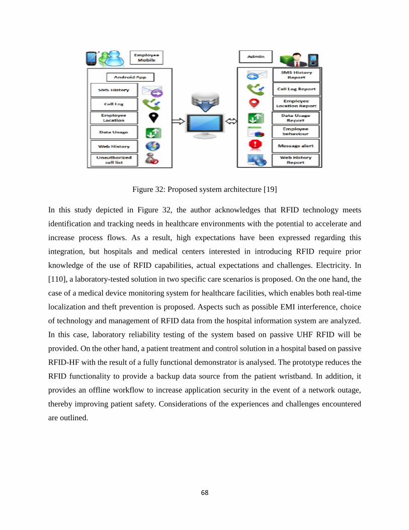
68
Figure 32: Proposed system architecture [19]
In this study depicted in Figure 32, the author acknowledges that RFID technology meets
identification and tracking needs in healthcare environments with the potential to accelerate and
increase process flows. As a result, high expectations have been expressed regarding this
integration, but hospitals and medical centers interested in introducing RFID require prior
knowledge of the use of RFID capabilities, actual expectations and challenges. Electricity. In
[110], a laboratory-tested solution in two specific care scenarios is proposed. On the one hand, the
case of a medical device monitoring system for healthcare facilities, which enables both real-time
localization and theft prevention is proposed. Aspects such as possible EMI interference, choice
of technology and management of RFID data from the hospital information system are analyzed.
In this case, laboratory reliability testing of the system based on passive UHF RFID will be
provided. On the other hand, a patient treatment and control solution in a hospital based on passive
RFID-HF with the result of a fully functional demonstrator is analysed. The prototype reduces the
RFID functionality to provide a backup data source from the patient wristband. In addition, it
provides an offline workflow to increase application security in the event of a network outage,
thereby improving patient safety. Considerations of the experiences and challenges encountered
are outlined.
69
2.14 Summary
In this chapter detailed overview of the background theory identification technologies such as
Biometrics, Barcode and RFID and some examples of related works to use of these identification
technologies have been given. Applications of multifactor authentication by combining biometrics
and RFID are many and in various systems of access control and identification. They have been
commonly used in various organization such as education, healthcare, supply chain for tracking,
monitoring and identification. Tracking of object or personnel has also been successfully
implemented by use of GPS.
70
CHAPTER 3: METHODOLOGY
3.1 Introduction
This chapter presents the research design, the material and methods used to conduct research. The
proposed business process to control access by identification and multifactor authentication to
control access into the university is outlined. The Chapter also defines the methodology used to
design and develop the prototypes for access control and people real time tracking.
3.1.1 System Design Methodology
A mixed method approach was used in this study; qualitative and quantitative. For quantitative
data, three questionnaires were designed based on ISO 27002 standard with focus on Physical and
Environmental Security, best practice and guidelines. Questionnaires were distributed to 150
students, 120 members of staff (Academicians and Support Staff) and 10 Security personnel. The
study focused on four controls of the ISO 27002 Physical and Environmental Security controls.
The overview of the current business processes was learnt through on-site walk-throughs and
random interviews with students, security personnel and members of staff. The site walk through
was done by entering the University Perimeter as a motorist and as pedestrian. Entering and
checking access control available to facilities such offices, hostels and lecture rooms was also done
to understand the current business process.
Object-Oriented Systems Development Methodology (OOSDM) was used to analyse, design and
develop the software prototype system. Some of the diagrammatic representations that are used in
Unified Modeling Language were used to visualise how the system would operate from different
perspectives. Object-Oriented System Development Life Cycle (OOSDLC) was used for the
systems development in this research study.
The third research question was achieved through an experiment and tests with the prototype. The
experiment was done to validate the model by actually testing a person’s location in real time. The
testing was done to have a deeper understanding of how visitors’ location in real time can be
tracked to allow visitors to be identified and only allow them to access areas they are allowed to.
71
3.1.2 Sampling
The research population was purposely sampled using the homogenous purposive sampling
because the researcher’s focus was on specific population characteristics that would adequately
answer the research questions which are related to their environment. Data was collected from
answered questionnaires. The researcher also took time to visit sites and access the university using
different modes as pedestrian or motorist over a period of one month. Random interviews were
also done with different people found on campus. Interviews were also conducted from the testers
of the prototype to get reviews of the working model.
3.1.3 Data Processing and Analysis
A computer based software called IBM Statistical Package for Social Science [SPSS] was used to
process and analyze the data collected from the questionnaires. The data from the questionnaires
was presented in the form of charts and narrations. The study also validated results from the
prototype by allow it to be tested by independent testers.
3.1.4 Ethnical Consideration
All the respondents to the questionnaires were assured of confidentiality as no identity was
required to be revealed as they answered the questionnaire.
3.1.5 Limitations of the Baseline Study
The study faced a lot of apathy from the respondents. It was not easy to collect the questionnaires
back on time causing delays in data processing and analysis.
3.1.6 Presentation of Findings
The analyzed data was summarized and presented in the form of pie charts, figures and tables.
3.1.7 Flow of the Methodology
The study followed steps as described in the flow chart Figure 33 below
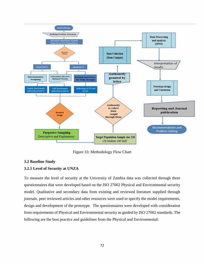
72
Figure 33: Methodology Flow Chart
3.2 Baseline Study
3.2.1 Level of Security at UNZA
To measure the level of security at the University of Zambia data was collected through three
questionnaires that were developed based on the ISO 27002 Physical and Environmental security
model. Qualitative and secondary data from existing and reviewed literature supplied through
journals, peer reviewed articles and other resources were used to specify the model requirements,
design and development of the prototype. The questionnaires were developed with consideration
from requirements of Physical and Environmental security as guided by ISO 27002 standards. The
following are the best practice and guidelines from the Physical and Environmental:
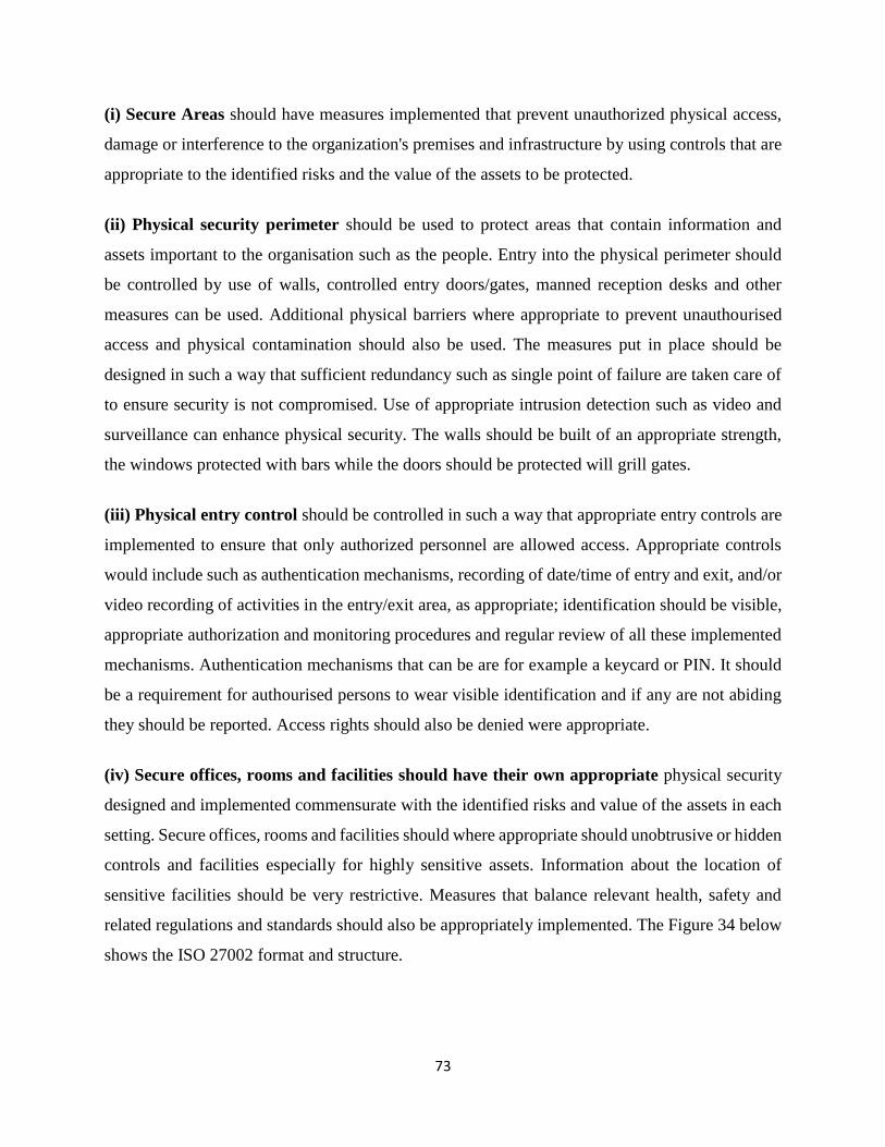
73
(i) Secure Areas should have measures implemented that prevent unauthorized physical access,
damage or interference to the organization's premises and infrastructure by using controls that are
appropriate to the identified risks and the value of the assets to be protected.
(ii) Physical security perimeter should be used to protect areas that contain information and
assets important to the organisation such as the people. Entry into the physical perimeter should
be controlled by use of walls, controlled entry doors/gates, manned reception desks and other
measures can be used. Additional physical barriers where appropriate to prevent unauthourised
access and physical contamination should also be used. The measures put in place should be
designed in such a way that sufficient redundancy such as single point of failure are taken care of
to ensure security is not compromised. Use of appropriate intrusion detection such as video and
surveillance can enhance physical security. The walls should be built of an appropriate strength,
the windows protected with bars while the doors should be protected will grill gates.
(iii) Physical entry control should be controlled in such a way that appropriate entry controls are
implemented to ensure that only authorized personnel are allowed access. Appropriate controls
would include such as authentication mechanisms, recording of date/time of entry and exit, and/or
video recording of activities in the entry/exit area, as appropriate; identification should be visible,
appropriate authorization and monitoring procedures and regular review of all these implemented
mechanisms. Authentication mechanisms that can be are for example a keycard or PIN. It should
be a requirement for authourised persons to wear visible identification and if any are not abiding
they should be reported. Access rights should also be denied were appropriate.
(iv) Secure offices, rooms and facilities should have their own appropriate physical security
designed and implemented commensurate with the identified risks and value of the assets in each
setting. Secure offices, rooms and facilities should where appropriate should unobtrusive or hidden
controls and facilities especially for highly sensitive assets. Information about the location of
sensitive facilities should be very restrictive. Measures that balance relevant health, safety and
related regulations and standards should also be appropriately implemented. The Figure 34 below
shows the ISO 27002 format and structure.
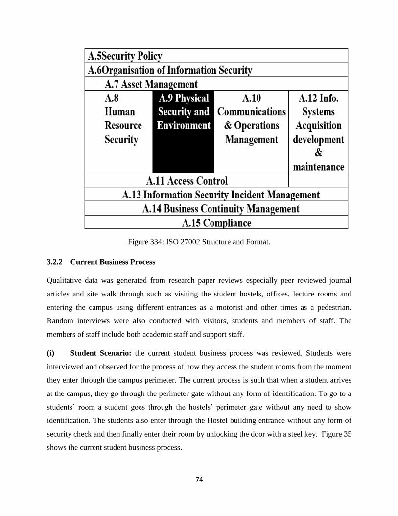
74
Figure 334: ISO 27002 Structure and Format.
3.2.2 Current Business Process
Qualitative data was generated from research paper reviews especially peer reviewed journal
articles and site walk through such as visiting the student hostels, offices, lecture rooms and
entering the campus using different entrances as a motorist and other times as a pedestrian.
Random interviews were also conducted with visitors, students and members of staff. The
members of staff include both academic staff and support staff.
(i) Student Scenario: the current student business process was reviewed. Students were
interviewed and observed for the process of how they access the student rooms from the moment
they enter through the campus perimeter. The current process is such that when a student arrives
at the campus, they go through the perimeter gate without any form of identification. To go to a
students’ room a student goes through the hostels’ perimeter gate without any need to show
identification. The students also enter through the Hostel building entrance without any form of
security check and then finally enter their room by unlocking the door with a steel key. Figure 35
shows the current student business process.
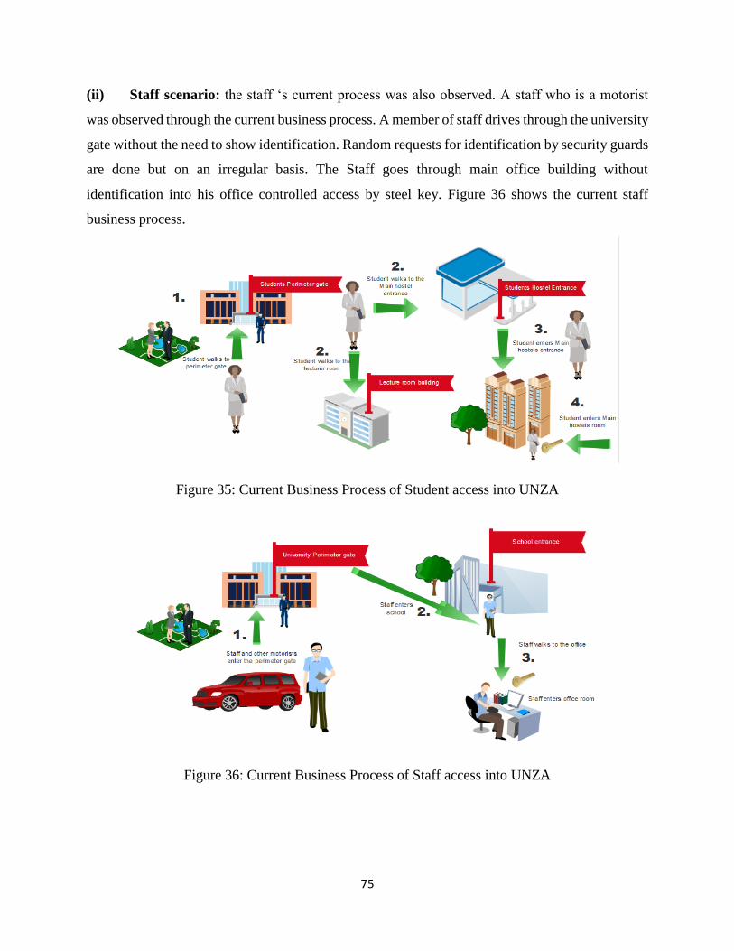
75
(ii) Staff scenario: the staff ‘s current process was also observed. A staff who is a motorist
was observed through the current business process. A member of staff drives through the university
gate without the need to show identification. Random requests for identification by security guards
are done but on an irregular basis. The Staff goes through main office building without
identification into his office controlled access by steel key. Figure 36 shows the current staff
business process.
Figure 35: Current Business Process of Student access into UNZA
Figure 36: Current Business Process of Staff access into UNZA
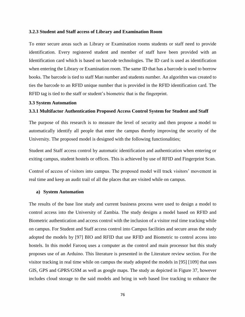
76
3.2.3 Student and Staff access of Library and Examination Room
To enter secure areas such as Library or Examination rooms students or staff need to provide
identification. Every registered student and member of staff have been provided with an
Identification card which is based on barcode technologies. The ID card is used as identification
when entering the Library or Examination room. The same ID that has a barcode is used to borrow
books. The barcode is tied to staff Man number and students number. An algorithm was created to
ties the barcode to an RFID unique number that is provided in the RFID identification card. The
RFID tag is tied to the staff or student’s biometric that is the fingerprint.
3.3 System Automation
3.3.1 Multifactor Authentication Proposed Access Control System for Student and Staff
The purpose of this research is to measure the level of security and then propose a model to
automatically identify all people that enter the campus thereby improving the security of the
University. The proposed model is designed with the following functionalities;
Student and Staff access control by automatic identification and authentication when entering or
exiting campus, student hostels or offices. This is achieved by use of RFID and Fingerprint Scan.
Control of access of visitors into campus. The proposed model will track visitors’ movement in
real time and keep an audit trail of all the places that are visited while on campus.
a) System Automation
The results of the base line study and current business process were used to design a model to
control access into the University of Zambia. The study designs a model based on RFID and
Biometric authentication and access control with the inclusion of a visitor real time tracking while
on campus. For Student and Staff access control into Campus facilities and secure areas the study
adopted the models by [97] BIO and RFID that use RFID and Biometric to control access into
hostels. In this model Farooq uses a computer as the control and main processor but this study
proposes use of an Arduino. This literature is presented in the Literature review section. For the
visitor tracking in real time while on campus the study adopted the models in [95] [109] that uses
GIS, GPS and GPRS/GSM as well as google maps. The study as depicted in Figure 37, however
includes cloud storage to the said models and bring in web based live tracking to enhance the
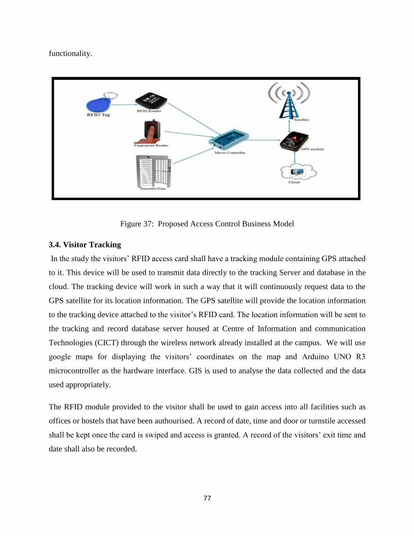
77
functionality.
Figure 37: Proposed Access Control Business Model
3.4. Visitor Tracking
In the study the visitors’ RFID access card shall have a tracking module containing GPS attached
to it. This device will be used to transmit data directly to the tracking Server and database in the
cloud. The tracking device will work in such a way that it will continuously request data to the
GPS satellite for its location information. The GPS satellite will provide the location information
to the tracking device attached to the visitor’s RFID card. The location information will be sent to
the tracking and record database server housed at Centre of Information and communication
Technologies (CICT) through the wireless network already installed at the campus. We will use
google maps for displaying the visitors’ coordinates on the map and Arduino UNO R3
microcontroller as the hardware interface. GIS is used to analyse the data collected and the data
used appropriately.
The RFID module provided to the visitor shall be used to gain access into all facilities such as
offices or hostels that have been authourised. A record of date, time and door or turnstile accessed
shall be kept once the card is swiped and access is granted. A record of the visitors’ exit time and
date shall also be recorded.
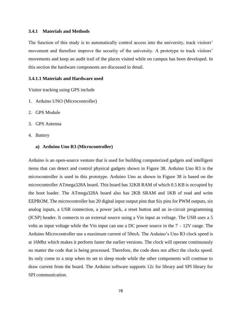
78
3.4.1 Materials and Methods
The function of this study is to automatically control access into the university, track visitors’
movement and therefore improve the security of the university. A prototype to track visitors’
movements and keep an audit trail of the places visited while on campus has been developed. In
this section the hardware components are discussed in detail.
3.4.1.1 Materials and Hardware used
Visitor tracking using GPS include
1. Arduino UNO (Microcontroller)
2. GPS Module
3. GPS Antenna
4. Battery
a) Arduino Uno R3 (Microcontroller)
Arduino is an open-source venture that is used for building computerized gadgets and intelligent
items that can detect and control physical gadgets shown in Figure 38. Arduino Uno R3 is the
microcontroller is used in this prototype. Arduino Uno as shown in Figure 38 is based on the
microcontroller ATmega328A board. This board has 32KB RAM of which 0.5 KB is occupied by
the boot loader. The ATmega328A board also has 2KB SRAM and 1KB of read and write
EEPROM. The microcontroller has 20 digital input output pins that Six pins for PWM outputs, six
analog inputs, a USB connection, a power jack, a reset button and an in-circuit programming
(ICSP) header. It connects to an external source using a Vin input as voltage. The USB uses a 5
volts as input voltage while the Vin input can use a DC power source in the 7 – 12V range. The
Arduino Microcontroller use a maximum current of 50mA. The Arduino’s Uno R3 clock speed is
at 16Mhz which makes it perform faster the earlier versions. The clock will operate continuously
no matter the code that is being processed. Therefore, the code does not affect the clocks speed.
Its only come to a stop when its set to sleep mode while the other components will continue to
draw current from the board. The Arduino software supports 12c for library and SPI library for
SPI communication.
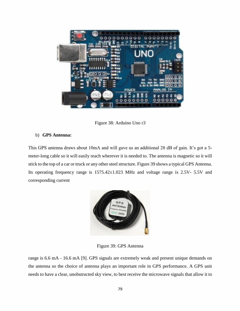
79
Figure 38: Arduino Uno r3
b) GPS Antenna:
This GPS antenna draws about 10mA and will gave us an additional 28 dB of gain. It’s got a 5-
meter-long cable so it will easily reach wherever it is needed to. The antenna is magnetic so it will
stick to the top of a car or truck or any other steel structure. Figure 39 shows a typical GPS Antenna.
Its operating frequency range is 1575.42±1.023 MHz and voltage range is 2.5V- 5.5V and
corresponding current
Figure 39: GPS Antenna
range is 6.6 mA - 16.6 mA [9]. GPS signals are extremely weak and present unique demands on
the antenna so the choice of antenna plays an important role in GPS performance. A GPS unit
needs to have a clear, unobstructed sky view, to best receive the microwave signals that allow it to
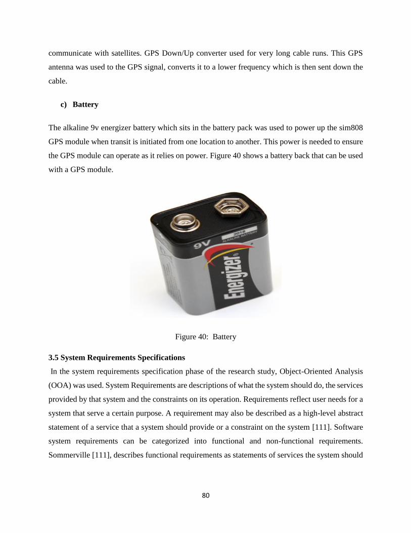
80
communicate with satellites. GPS Down/Up converter used for very long cable runs. This GPS
antenna was used to the GPS signal, converts it to a lower frequency which is then sent down the
cable.
c) Battery
The alkaline 9v energizer battery which sits in the battery pack was used to power up the sim808
GPS module when transit is initiated from one location to another. This power is needed to ensure
the GPS module can operate as it relies on power. Figure 40 shows a battery back that can be used
with a GPS module.
Figure 40: Battery
3.5 System Requirements Specifications
In the system requirements specification phase of the research study, Object-Oriented Analysis
(OOA) was used. System Requirements are descriptions of what the system should do, the services
provided by that system and the constraints on its operation. Requirements reflect user needs for a
system that serve a certain purpose. A requirement may also be described as a high-level abstract
statement of a service that a system should provide or a constraint on the system [111]. Software
system requirements can be categorized into functional and non-functional requirements.
Sommerville [111], describes functional requirements as statements of services the system should
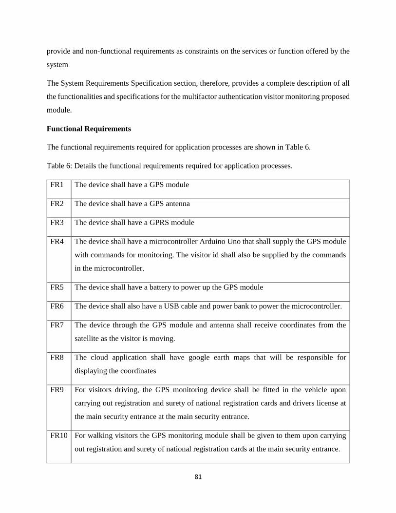
81
provide and non-functional requirements as constraints on the services or function offered by the
system
The System Requirements Specification section, therefore, provides a complete description of all
the functionalities and specifications for the multifactor authentication visitor monitoring proposed
module.
Functional Requirements
The functional requirements required for application processes are shown in Table 6.
Table 6: Details the functional requirements required for application processes.
FR1 The device shall have a GPS module
FR2 The device shall have a GPS antenna
FR3 The device shall have a GPRS module
FR4 The device shall have a microcontroller Arduino Uno that shall supply the GPS module
with commands for monitoring. The visitor id shall also be supplied by the commands
in the microcontroller.
FR5 The device shall have a battery to power up the GPS module
FR6 The device shall also have a USB cable and power bank to power the microcontroller.
FR7 The device through the GPS module and antenna shall receive coordinates from the
satellite as the visitor is moving.
FR8 The cloud application shall have google earth maps that will be responsible for
displaying the coordinates
FR9 For visitors driving, the GPS monitoring device shall be fitted in the vehicle upon
carrying out registration and surety of national registration cards and drivers license at
the main security entrance at the main security entrance.
FR10 For walking visitors the GPS monitoring module shall be given to them upon carrying
out registration and surety of national registration cards at the main security entrance.
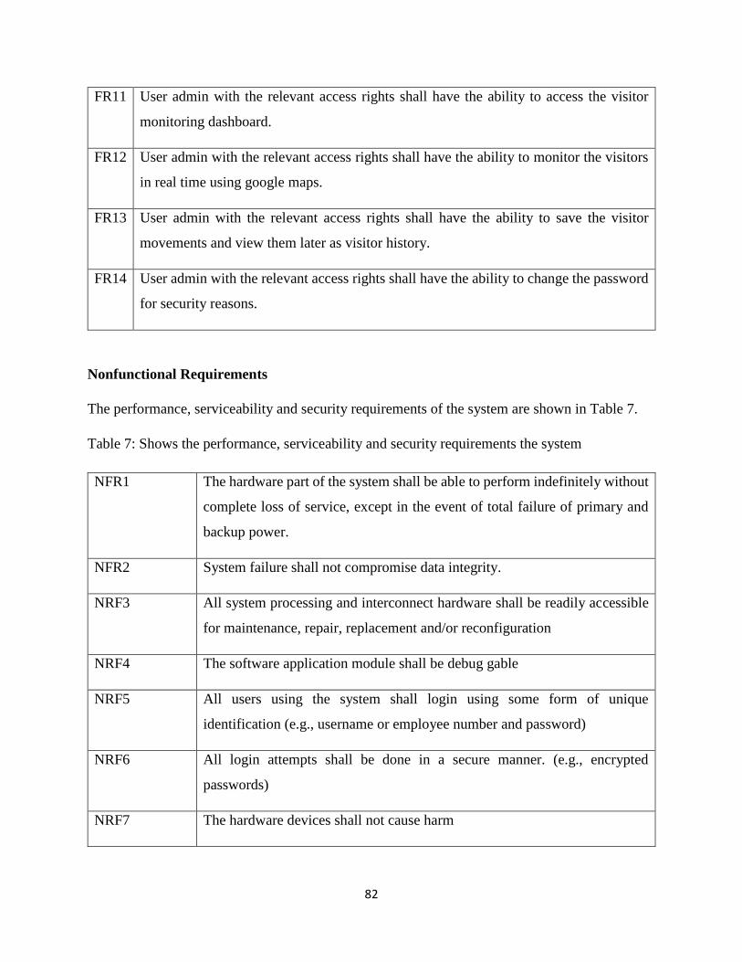
82
FR11 User admin with the relevant access rights shall have the ability to access the visitor
monitoring dashboard.
FR12 User admin with the relevant access rights shall have the ability to monitor the visitors
in real time using google maps.
FR13 User admin with the relevant access rights shall have the ability to save the visitor
movements and view them later as visitor history.
FR14 User admin with the relevant access rights shall have the ability to change the password
for security reasons.
Nonfunctional Requirements
The performance, serviceability and security requirements of the system are shown in Table 7.
Table 7: Shows the performance, serviceability and security requirements the system
NFR1 The hardware part of the system shall be able to perform indefinitely without
complete loss of service, except in the event of total failure of primary and
backup power.
NFR2 System failure shall not compromise data integrity.
NRF3 All system processing and interconnect hardware shall be readily accessible
for maintenance, repair, replacement and/or reconfiguration
NRF4 The software application module shall be debug gable
NRF5 All users using the system shall login using some form of unique
identification (e.g., username or employee number and password)
NRF6 All login attempts shall be done in a secure manner. (e.g., encrypted
passwords)
NRF7 The hardware devices shall not cause harm
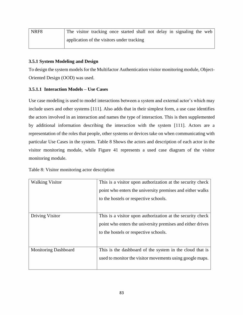
83
NRF8 The visitor tracking once started shall not delay in signaling the web
application of the visitors under tracking
3.5.1 System Modeling and Design
To design the system models for the Multifactor Authentication visitor monitoring module, Object-
Oriented Design (OOD) was used.
3.5.1.1 Interaction Models – Use Cases
Use case modeling is used to model interactions between a system and external actor’s which may
include users and other systems [111]. Also adds that in their simplest form, a use case identifies
the actors involved in an interaction and names the type of interaction. This is then supplemented
by additional information describing the interaction with the system [111]. Actors are a
representation of the roles that people, other systems or devices take on when communicating with
particular Use Cases in the system. Table 8 Shows the actors and description of each actor in the
visitor monitoring module, while Figure 41 represents a used case diagram of the visitor
monitoring module.
Table 8: Visitor monitoring actor description
Walking Visitor This is a visitor upon authorization at the security check
point who enters the university premises and either walks
to the hostels or respective schools.
Driving Visitor This is a visitor upon authorization at the security check
point who enters the university premises and either drives
to the hostels or respective schools.
Monitoring Dashboard This is the dashboard of the system in the cloud that is
used to monitor the visitor movements using google maps.
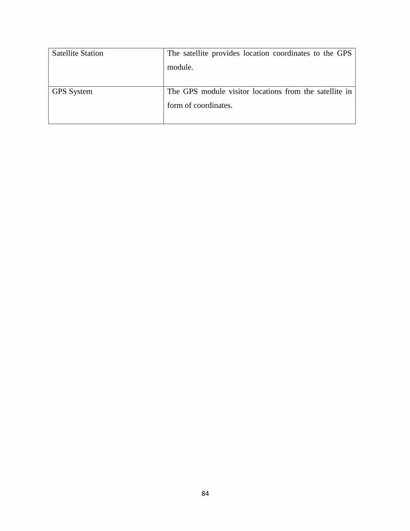
84
Satellite Station The satellite provides location coordinates to the GPS
module.
GPS System The GPS module visitor locations from the satellite in
form of coordinates.
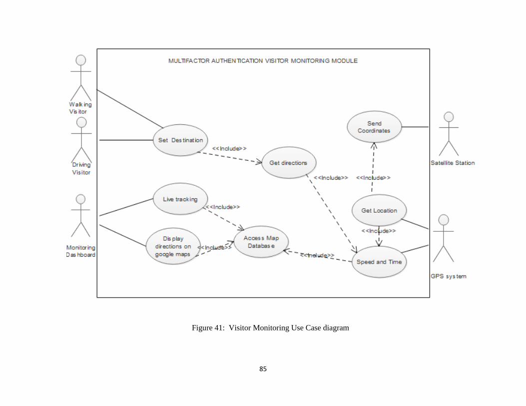
85
Figure 41: Visitor Monitoring Use Case diagram
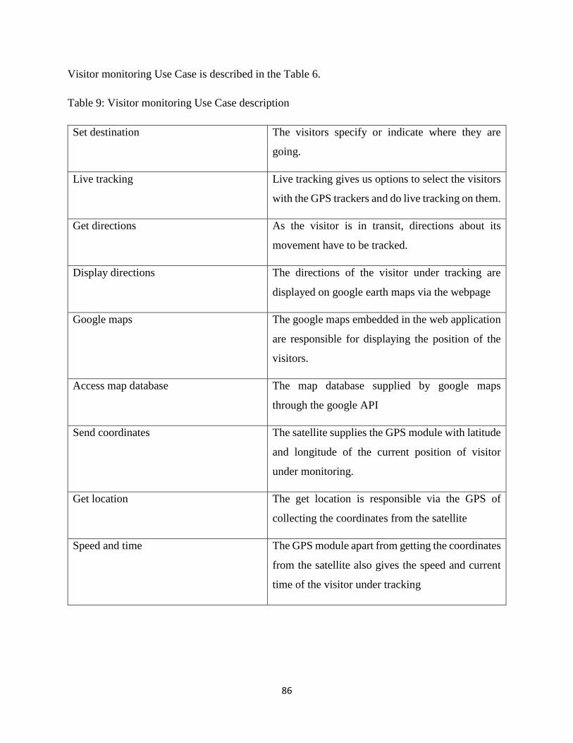
86
Visitor monitoring Use Case is described in the Table 6.
Table 9: Visitor monitoring Use Case description
Set destination The visitors specify or indicate where they are
going.
Live tracking Live tracking gives us options to select the visitors
with the GPS trackers and do live tracking on them.
Get directions As the visitor is in transit, directions about its
movement have to be tracked.
Display directions The directions of the visitor under tracking are
displayed on google earth maps via the webpage
Google maps The google maps embedded in the web application
are responsible for displaying the position of the
visitors.
Access map database The map database supplied by google maps
through the google API
Send coordinates The satellite supplies the GPS module with latitude
and longitude of the current position of visitor
under monitoring.
Get location The get location is responsible via the GPS of
collecting the coordinates from the satellite
Speed and time The GPS module apart from getting the coordinates
from the satellite also gives the speed and current
time of the visitor under tracking
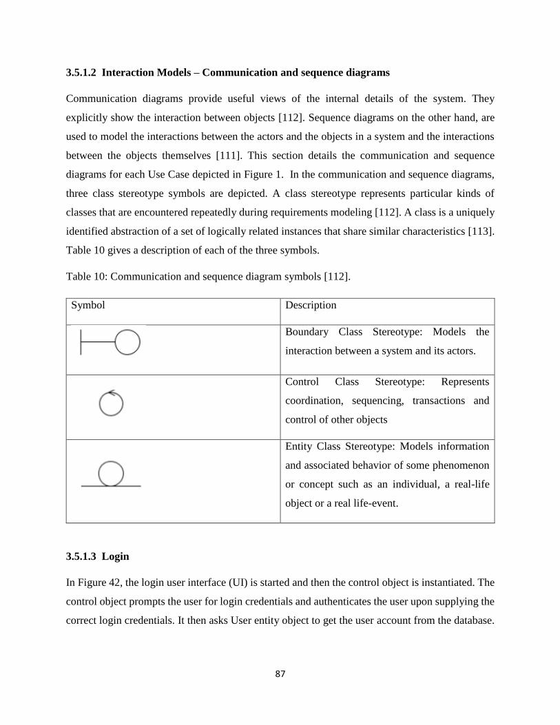
87
3.5.1.2 Interaction Models – Communication and sequence diagrams
Communication diagrams provide useful views of the internal details of the system. They
explicitly show the interaction between objects [112]. Sequence diagrams on the other hand, are
used to model the interactions between the actors and the objects in a system and the interactions
between the objects themselves [111]. This section details the communication and sequence
diagrams for each Use Case depicted in Figure 1. In the communication and sequence diagrams,
three class stereotype symbols are depicted. A class stereotype represents particular kinds of
classes that are encountered repeatedly during requirements modeling [112]. A class is a uniquely
identified abstraction of a set of logically related instances that share similar characteristics [113].
Table 10 gives a description of each of the three symbols.
Table 10: Communication and sequence diagram symbols [112].
Symbol Description
Boundary Class Stereotype: Models the
interaction between a system and its actors.
Control Class Stereotype: Represents
coordination, sequencing, transactions and
control of other objects
Entity Class Stereotype: Models information
and associated behavior of some phenomenon
or concept such as an individual, a real-life
object or a real life-event.
3.5.1.3 Login
In Figure 42, the login user interface (UI) is started and then the control object is instantiated. The
control object prompts the user for login credentials and authenticates the user upon supplying the
correct login credentials. It then asks User entity object to get the user account from the database.
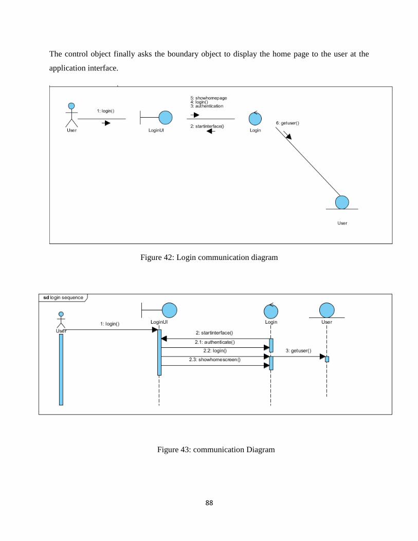
88
The control object finally asks the boundary object to display the home page to the user at the
application interface.
Figure 42: Login communication diagram
Figure 43: communication Diagram
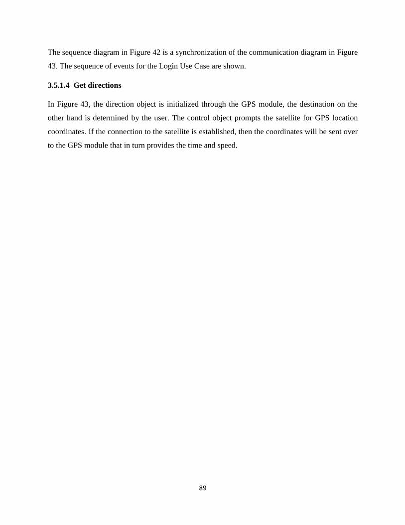
89
The sequence diagram in Figure 42 is a synchronization of the communication diagram in Figure
43. The sequence of events for the Login Use Case are shown.
3.5.1.4 Get directions
In Figure 43, the direction object is initialized through the GPS module, the destination on the
other hand is determined by the user. The control object prompts the satellite for GPS location
coordinates. If the connection to the satellite is established, then the coordinates will be sent over
to the GPS module that in turn provides the time and speed.
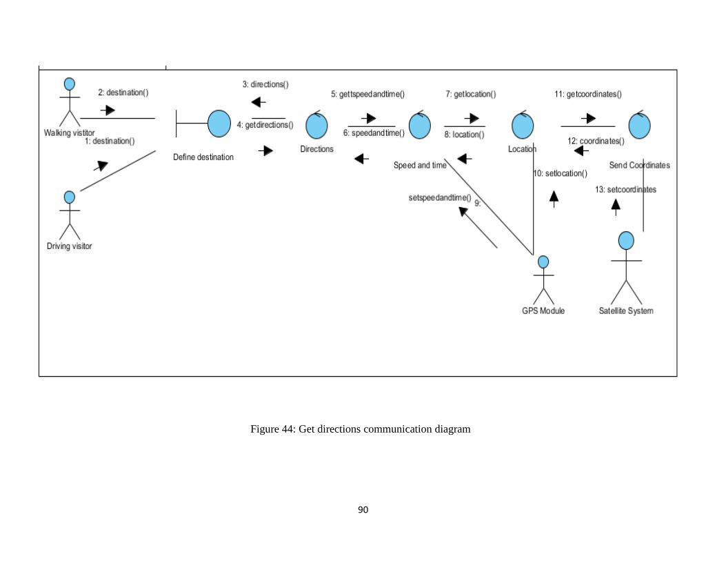
90
Figure 44: Get directions communication diagram
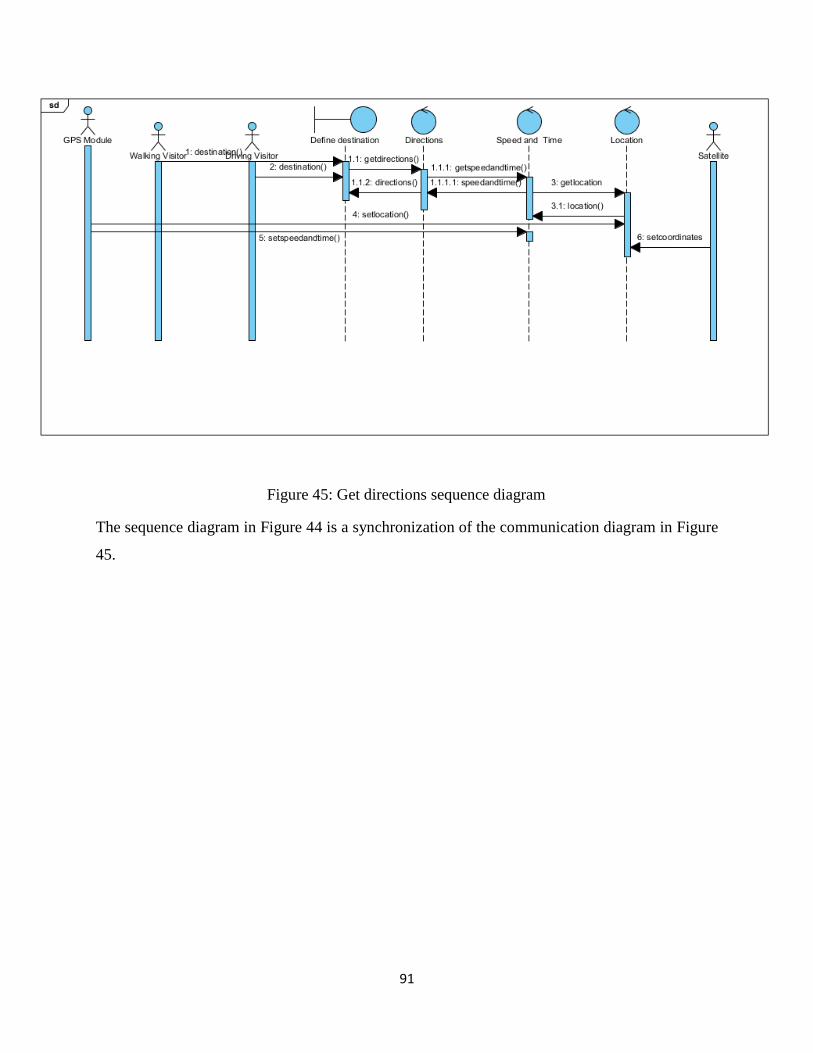
91
The sequence diagram in Figure 44 is a synchronization of the communication diagram in Figure
45.
Figure 34: Get directions sequence diagram
Figure 35: Get directions sequence diagram
Figure 36: Get directions sequence diagram
Figure 37: Get directions sequence diagram
Figure 38: Get directions sequence diagram
Figure 39: Get directions sequence diagram
Figure 40: Get directions sequence diagram
Figure 45: Get directions sequence diagram
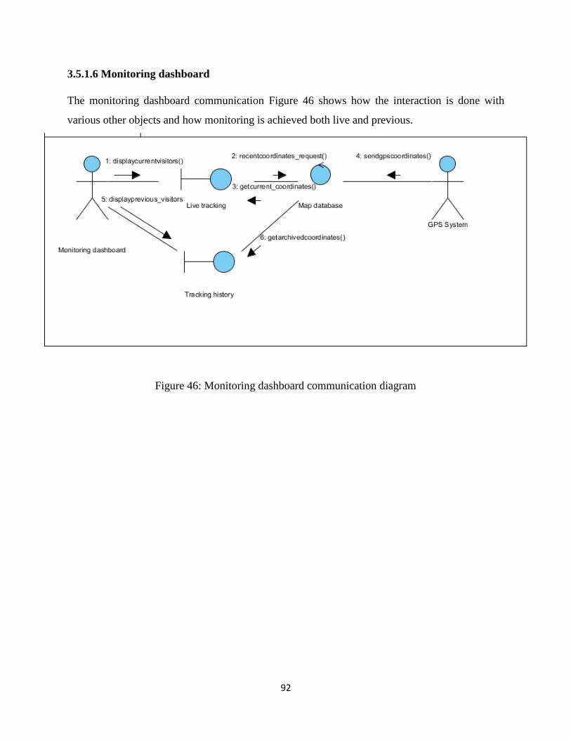
92
3.5.1.6 Monitoring dashboard
The monitoring dashboard communication Figure 46 shows how the interaction is done with
various other objects and how monitoring is achieved both live and previous.
Figure 46: Monitoring dashboard communication diagram
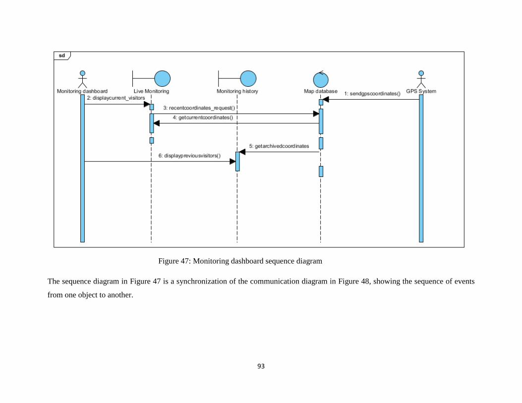
93
Figure 47: Monitoring dashboard sequence diagram
The sequence diagram in Figure 47 is a synchronization of the communication diagram in Figure 48, showing the sequence of events
from one object to another.
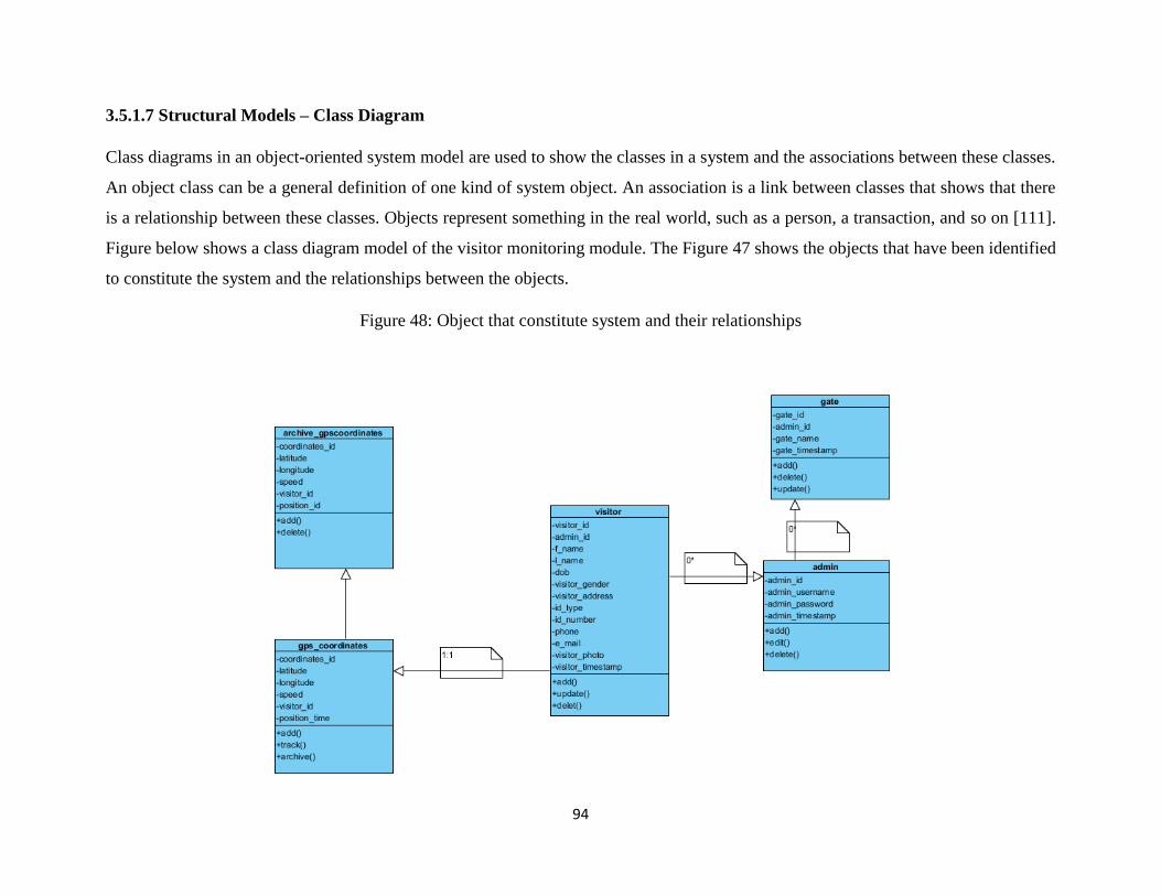
94
3.5.1.7 Structural Models – Class Diagram
Class diagrams in an object-oriented system model are used to show the classes in a system and the associations between these classes.
An object class can be a general definition of one kind of system object. An association is a link between classes that shows that there
is a relationship between these classes. Objects represent something in the real world, such as a person, a transaction, and so on [111].
Figure below shows a class diagram model of the visitor monitoring module. The Figure 47 shows the objects that have been identified
to constitute the system and the relationships between the objects.
Figure 48: Object that constitute system and their relationships
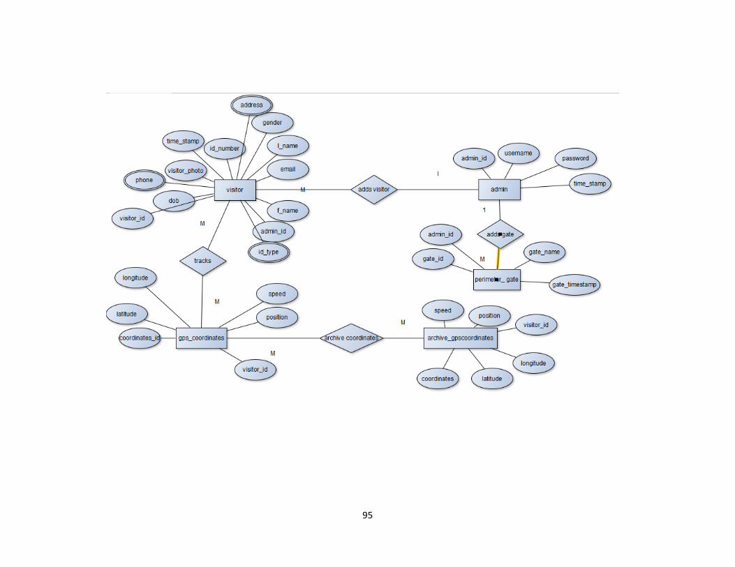
95

96
3.6 Summary
This chapter looked at the approach and methodology used to conduct and collect the baseline
study, model design and prototype development. A mixed methods approach of qualitative and
quantitative approached was used in this study. This chapter also looked at the functional
specifications, system design and implementation and lastly the hardware, developmental tools
and languages were also looked at.
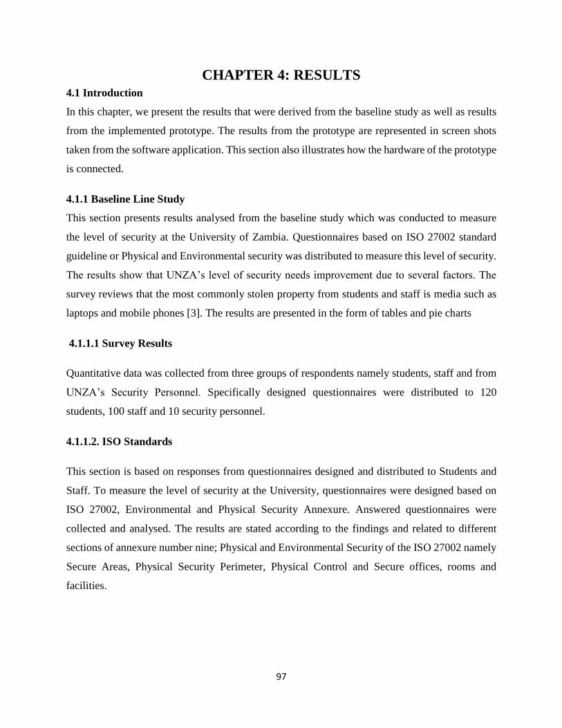
97
CHAPTER 4: RESULTS
4.1 Introduction
In this chapter, we present the results that were derived from the baseline study as well as results
from the implemented prototype. The results from the prototype are represented in screen shots
taken from the software application. This section also illustrates how the hardware of the prototype
is connected.
4.1.1 Baseline Line Study
This section presents results analysed from the baseline study which was conducted to measure
the level of security at the University of Zambia. Questionnaires based on ISO 27002 standard
guideline or Physical and Environmental security was distributed to measure this level of security.
The results show that UNZA’s level of security needs improvement due to several factors. The
survey reviews that the most commonly stolen property from students and staff is media such as
laptops and mobile phones [3]. The results are presented in the form of tables and pie charts
4.1.1.1 Survey Results
Quantitative data was collected from three groups of respondents namely students, staff and from
UNZA’s Security Personnel. Specifically designed questionnaires were distributed to 120
students, 100 staff and 10 security personnel.
4.1.1.2. ISO Standards
This section is based on responses from questionnaires designed and distributed to Students and
Staff. To measure the level of security at the University, questionnaires were designed based on
ISO 27002, Environmental and Physical Security Annexure. Answered questionnaires were
collected and analysed. The results are stated according to the findings and related to different
sections of annexure number nine; Physical and Environmental Security of the ISO 27002 namely
Secure Areas, Physical Security Perimeter, Physical Control and Secure offices, rooms and
facilities.
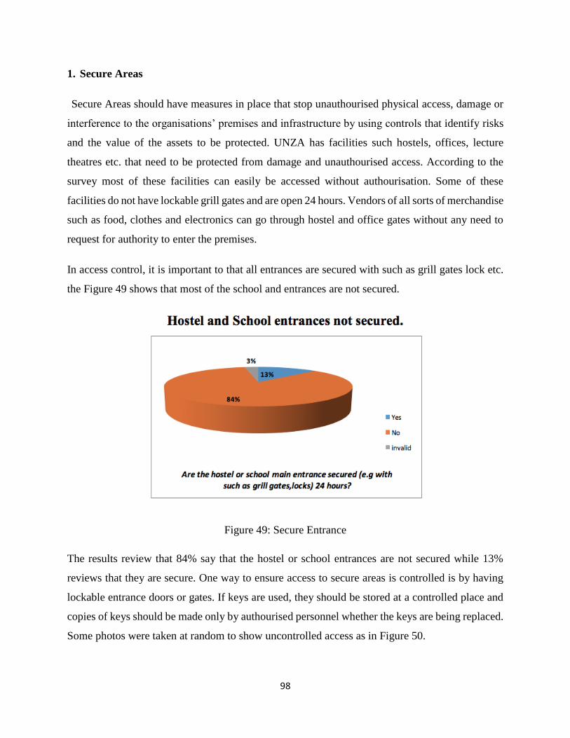
98
1. Secure Areas
Secure Areas should have measures in place that stop unauthourised physical access, damage or
interference to the organisations’ premises and infrastructure by using controls that identify risks
and the value of the assets to be protected. UNZA has facilities such hostels, offices, lecture
theatres etc. that need to be protected from damage and unauthourised access. According to the
survey most of these facilities can easily be accessed without authourisation. Some of these
facilities do not have lockable grill gates and are open 24 hours. Vendors of all sorts of merchandise
such as food, clothes and electronics can go through hostel and office gates without any need to
request for authority to enter the premises.
In access control, it is important to that all entrances are secured with such as grill gates lock etc.
the Figure 49 shows that most of the school and entrances are not secured.
Figure 49: Secure Entrance
The results review that 84% say that the hostel or school entrances are not secured while 13%
reviews that they are secure. One way to ensure access to secure areas is controlled is by having
lockable entrance doors or gates. If keys are used, they should be stored at a controlled place and
copies of keys should be made only by authourised personnel whether the keys are being replaced.
Some photos were taken at random to show uncontrolled access as in Figure 50.
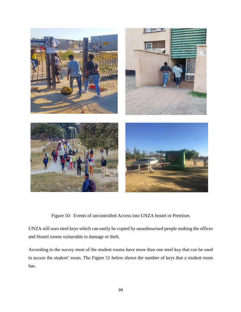
99
Figure 50: Events of uncontrolled Access into UNZA hostel or Premises
UNZA still uses steel keys which can easily be copied by unauthourised people making the offices
and Hostel rooms vulnerable to damage or theft.
According to the survey most of the student rooms have more than one steel key that can be used
to access the student’ room. The Figure 51 below shows the number of keys that a student room
has.
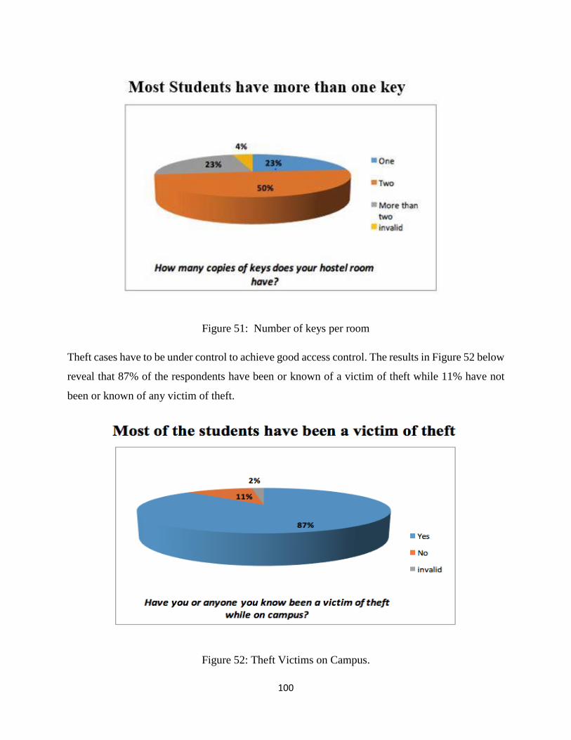
100
Figure 51: Number of keys per room
Theft cases have to be under control to achieve good access control. The results in Figure 52 below
reveal that 87% of the respondents have been or known of a victim of theft while 11% have not
been or known of any victim of theft.
Figure 52: Theft Victims on Campus.
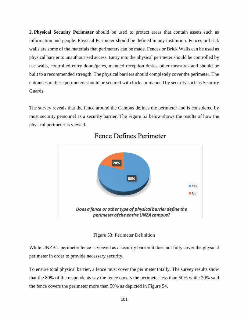
101
2. Physical Security Perimeter should be used to protect areas that contain assets such as
information and people. Physical Perimeter should be defined in any institution. Fences or brick
walls are some of the materials that perimeters can be made. Fences or Brick Walls can be used as
physical barrier to unauthourised access. Entry into the physical perimeter should be controlled by
use walls, controlled entry doors/gates, manned reception desks, other measures and should be
built to a recommended strength. The physical barriers should completely cover the perimeter. The
entrances in these perimeters should be secured with locks or manned by security such as Security
Guards.
The survey reveals that the fence around the Campus defines the perimeter and is considered by
most security personnel as a security barrier. The Figure 53 below shows the results of how the
physical perimeter is viewed.
Figure 53: Perimeter Definition
While UNZA’s perimeter fence is viewed as a security barrier it does not fully cover the physical
perimeter in order to provide necessary security.
To ensure total physical barrier, a fence must cover the perimeter totally. The survey results show
that the 80% of the respondents say the fence covers the perimeter less than 50% while 20% said
the fence covers the perimeter more than 50% as depicted in Figure 54.
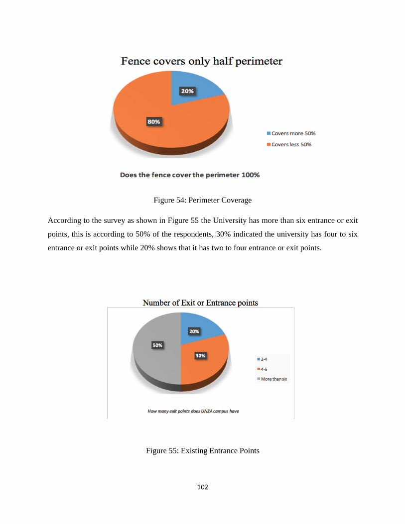
102
Figure 54: Perimeter Coverage
According to the survey as shown in Figure 55 the University has more than six entrance or exit
points, this is according to 50% of the respondents, 30% indicated the university has four to six
entrance or exit points while 20% shows that it has two to four entrance or exit points.
Figure 55: Existing Entrance Points
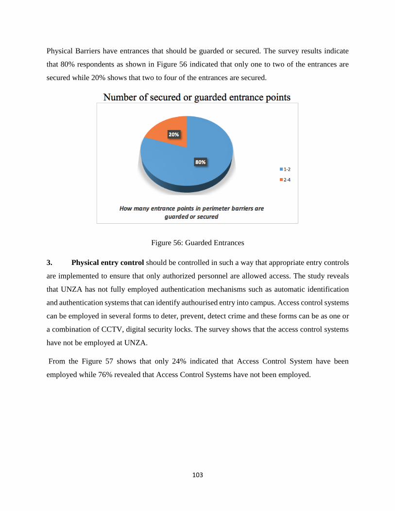
103
Physical Barriers have entrances that should be guarded or secured. The survey results indicate
that 80% respondents as shown in Figure 56 indicated that only one to two of the entrances are
secured while 20% shows that two to four of the entrances are secured.
Figure 56: Guarded Entrances
3. Physical entry control should be controlled in such a way that appropriate entry controls
are implemented to ensure that only authorized personnel are allowed access. The study reveals
that UNZA has not fully employed authentication mechanisms such as automatic identification
and authentication systems that can identify authourised entry into campus. Access control systems
can be employed in several forms to deter, prevent, detect crime and these forms can be as one or
a combination of CCTV, digital security locks. The survey shows that the access control systems
have not be employed at UNZA.
From the Figure 57 shows that only 24% indicated that Access Control System have been
employed while 76% revealed that Access Control Systems have not been employed.
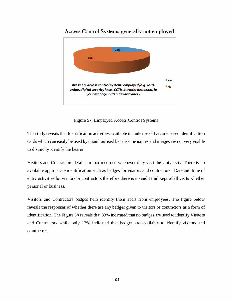
104
Figure 57: Employed Access Control Systems
The study reveals that Identification activities available include use of barcode based identification
cards which can easily be used by unauthourised because the names and images are not very visible
to distinctly identify the bearer.
Visitors and Contractors details are not recorded whenever they visit the University. There is no
available appropriate identification such as badges for visitors and contractors. Date and time of
entry activities for visitors or contractors therefore there is no audit trail kept of all visits whether
personal or business.
Visitors and Contractors badges help identify them apart from employees. The figure below
reveals the responses of whether there are any badges given to visitors or contractors as a form of
identification. The Figure 58 reveals that 83% indicated that no badges are used to identify Visitors
and Contractors while only 17% indicated that badges are available to identify visitors and
contractors.
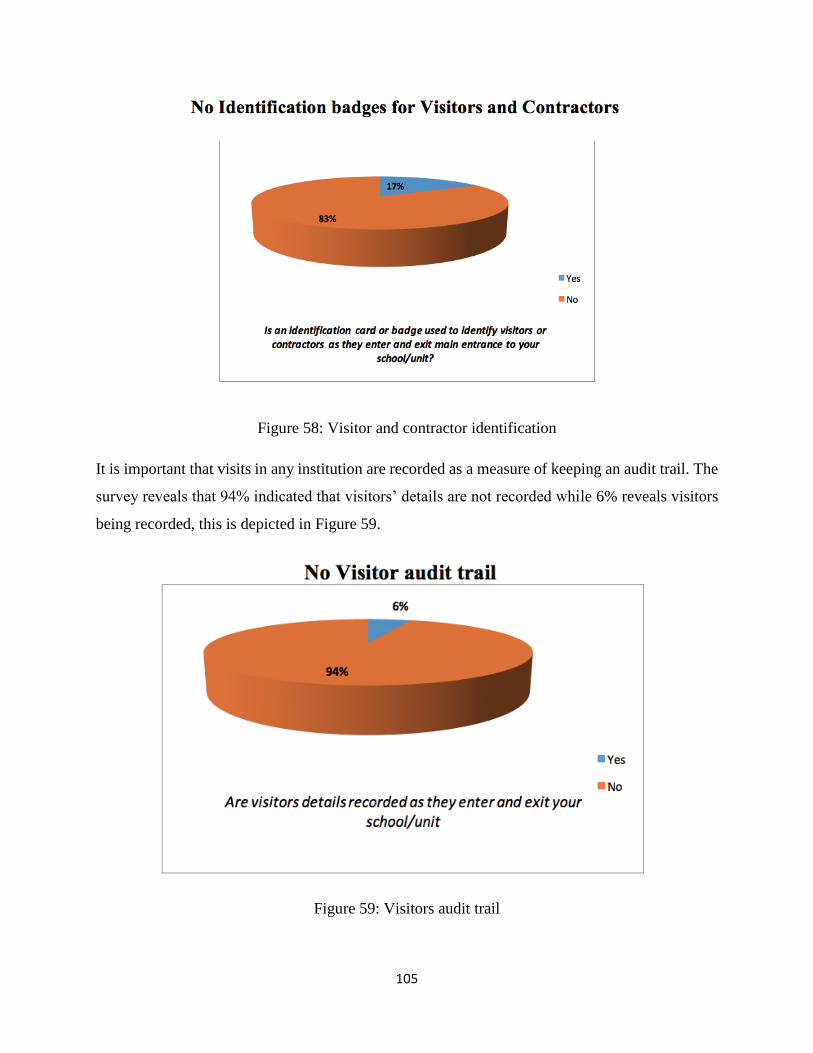
105
Figure 58: Visitor and contractor identification
It is important that visits in any institution are recorded as a measure of keeping an audit trail. The
survey reveals that 94% indicated that visitors’ details are not recorded while 6% reveals visitors
being recorded, this is depicted in Figure 59.
Figure 59: Visitors audit trail
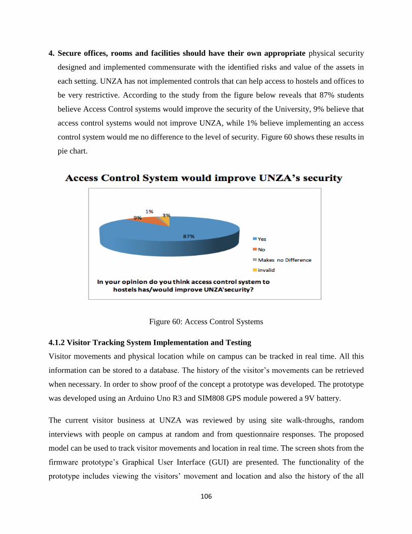
106
4. Secure offices, rooms and facilities should have their own appropriate physical security
designed and implemented commensurate with the identified risks and value of the assets in
each setting. UNZA has not implemented controls that can help access to hostels and offices to
be very restrictive. According to the study from the figure below reveals that 87% students
believe Access Control systems would improve the security of the University, 9% believe that
access control systems would not improve UNZA, while 1% believe implementing an access
control system would me no difference to the level of security. Figure 60 shows these results in
pie chart.
Figure 60: Access Control Systems
4.1.2 Visitor Tracking System Implementation and Testing
Visitor movements and physical location while on campus can be tracked in real time. All this
information can be stored to a database. The history of the visitor’s movements can be retrieved
when necessary. In order to show proof of the concept a prototype was developed. The prototype
was developed using an Arduino Uno R3 and SIM808 GPS module powered a 9V battery.
The current visitor business at UNZA was reviewed by using site walk-throughs, random
interviews with people on campus at random and from questionnaire responses. The proposed
model can be used to track visitor movements and location in real time. The screen shots from the
firmware prototype’s Graphical User Interface (GUI) are presented. The functionality of the
prototype includes viewing the visitors’ movement and location and also the history of the all
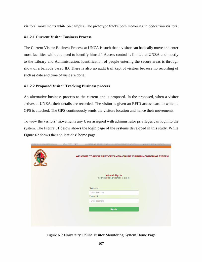
107
visitors’ movements while on campus. The prototype tracks both motorist and pedestrian visitors.
4.1.2.1 Current Visitor Business Process
The Current Visitor Business Process at UNZA is such that a visitor can basically move and enter
most facilities without a need to identify himself. Access control is limited at UNZA and mostly
to the Library and Administration. Identification of people entering the secure areas is through
show of a barcode based ID. There is also no audit trail kept of visitors because no recording of
such as date and time of visit are done.
4.1.2.2 Proposed Visitor Tracking Business process
An alternative business process to the current one is proposed. In the proposed, when a visitor
arrives at UNZA, their details are recorded. The visitor is given an RFID access card to which a
GPS is attached. The GPS continuously sends the visitors location and hence their movements.
To view the visitors’ movements any User assigned with administrator privileges can log into the
system. The Figure 61 below shows the login page of the systems developed in this study. While
Figure 62 shows the applications’ home page.
Figure 61: University Online Visitor Monitoring System Home Page
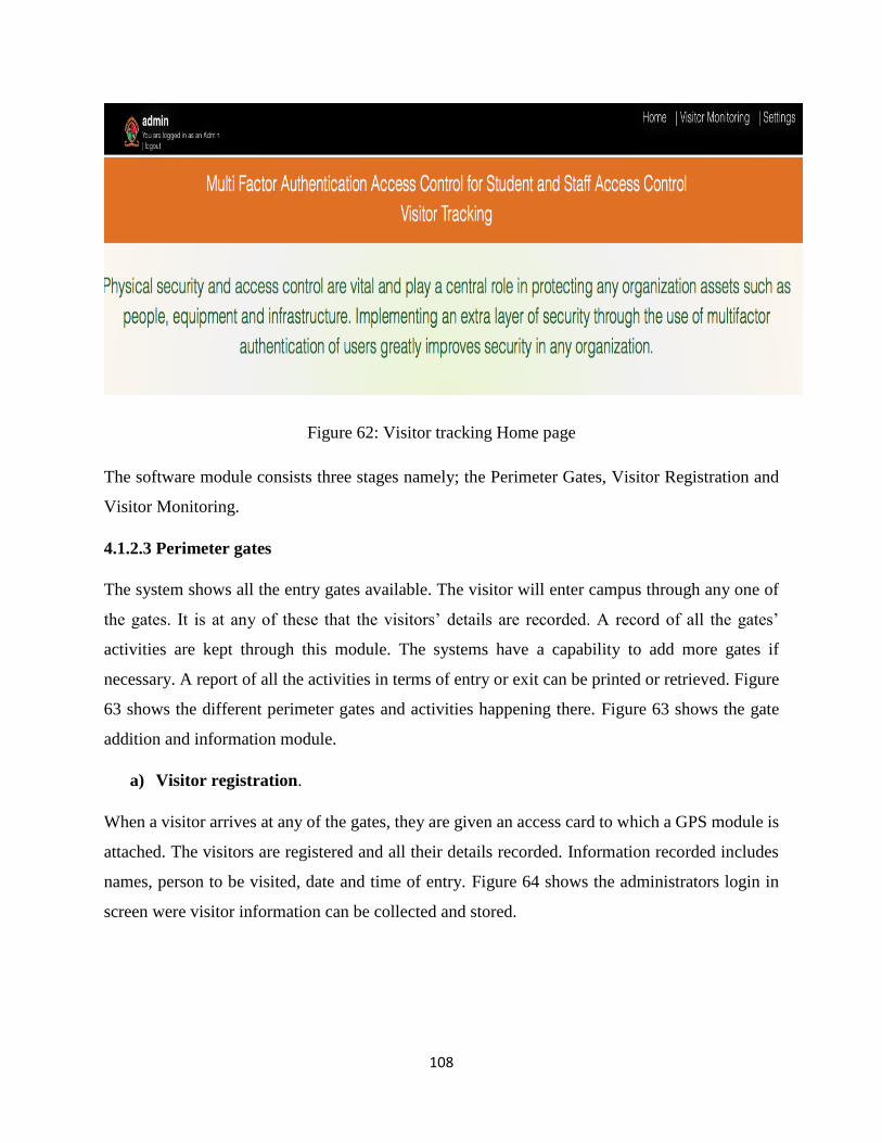
108
Figure 62: Visitor tracking Home page
The software module consists three stages namely; the Perimeter Gates, Visitor Registration and
Visitor Monitoring.
4.1.2.3 Perimeter gates
The system shows all the entry gates available. The visitor will enter campus through any one of
the gates. It is at any of these that the visitors’ details are recorded. A record of all the gates’
activities are kept through this module. The systems have a capability to add more gates if
necessary. A report of all the activities in terms of entry or exit can be printed or retrieved. Figure
63 shows the different perimeter gates and activities happening there. Figure 63 shows the gate
addition and information module.
a) Visitor registration.
When a visitor arrives at any of the gates, they are given an access card to which a GPS module is
attached. The visitors are registered and all their details recorded. Information recorded includes
names, person to be visited, date and time of entry. Figure 64 shows the administrators login in
screen were visitor information can be collected and stored.
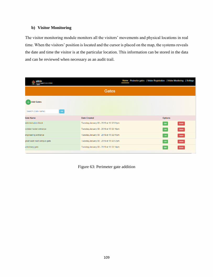
109
b) Visitor Monitoring
The visitor monitoring module monitors all the visitors’ movements and physical locations in real
time. When the visitors’ position is located and the cursor is placed on the map, the systems reveals
the date and time the visitor is at the particular location. This information can be stored in the data
and can be reviewed when necessary as an audit trail.
Figure 63: Perimeter gate addition
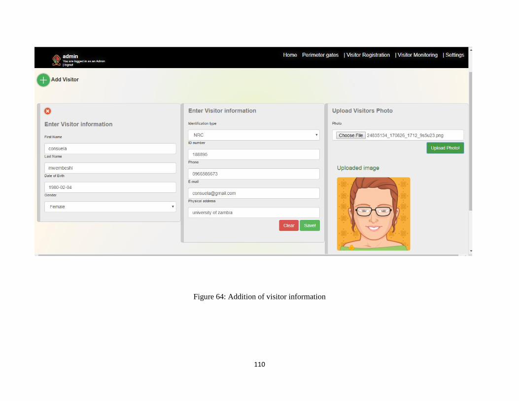
110
Figure 64: Addition of visitor information
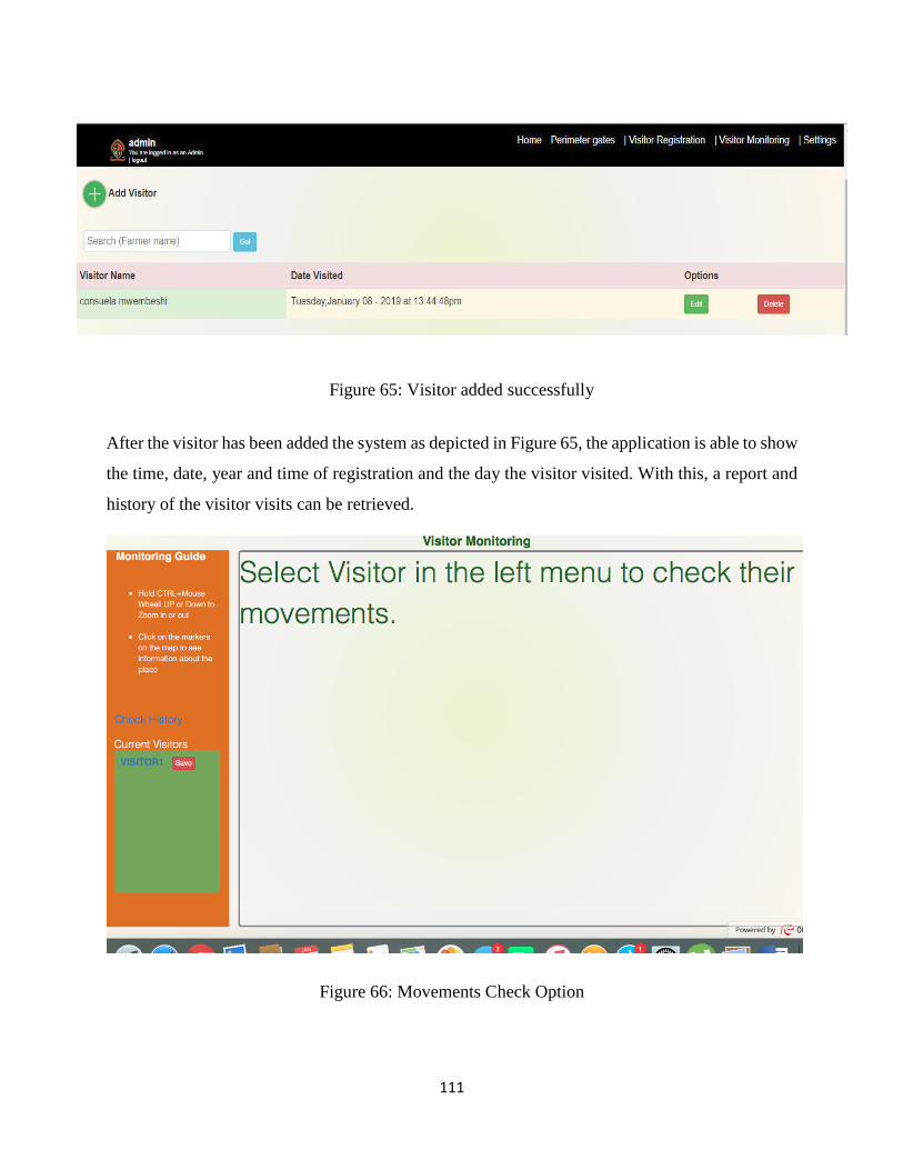
111
After the visitor has been added the system as depicted in Figure 65, the application is able to show
the time, date, year and time of registration and the day the visitor visited. With this, a report and
history of the visitor visits can be retrieved.
Figure 66: Movements Check Option
Figure 65: Visitor added successfully
112
The main function of the systems is to track visitor movements and track their physical location in
real time. From visitor monitoring menu Figure 66 a visitors’ movements and location can be
traced.
4.1.3 System Hardware Setup.
The visitor tracking device consists of an Arduino Uno R3 module SIM808, which includes a
GPS/GSM module with on board antenna, power pack and a USB cable. The heart of the tracking
system is the Arduino Uno microcontroller. The geographical location of a visitor can be detected
by a GPS receiver and this data is transmitted to the web server using GSM technology. This data
is stored in a database. The SIM808 module is initialized to begin acquiring geographical location
data through satellites. Using AT commands the deice which includes GPS and GSM modules is
initialized. The GPS is turned on and put into reset mode. As soon as the module is ready to receive
the coordinates of the satellite, the GPRS is then activated. The process includes the GPRS start,
the definition of the service provider APN, initiates the start of the HTTP protocol and the
definition of the protocol method (Get method). The device initialization process can take up to a
minute to clear the position and calculate the exact position. If the network is unavailable, the
acquired GPS coordinates and other data such as time and speed are buffered until the network is
ready for use. Then, the stored coordinates are time stamped. An external power supply of 9V is
used to ensure that the device is continuously powered during the process.
The GPS antenna and the GSM antenna are connected to the SIM808 module connector. The
module and the Arduino have a common base. A program written in the C ++ programming
language is loaded into the Arduino microcontroller using the Arduino IDE software.
4.1.3.1 Visitor Tracking
To monitor the motorist visitor, the device was placed on the vehicle’s dash board. To monitor the
movements of the pedestrian visitor, the module is carried round as the go around campus. The
Arduino as connected to a USB power pack through the USB cable. The GPS/GSM module was
powered using the energizer 9V battery. The GPS/GSM module was then connected to the Arduino
module. The Figure 67 below shows the hardware connection of the device.
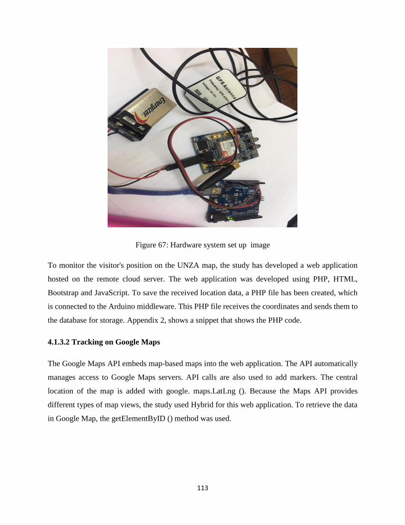
113
Figure 67: Hardware system set up image
To monitor the visitor's position on the UNZA map, the study has developed a web application
hosted on the remote cloud server. The web application was developed using PHP, HTML,
Bootstrap and JavaScript. To save the received location data, a PHP file has been created, which
is connected to the Arduino middleware. This PHP file receives the coordinates and sends them to
the database for storage. Appendix 2, shows a snippet that shows the PHP code.
4.1.3.2 Tracking on Google Maps
The Google Maps API embeds map-based maps into the web application. The API automatically
manages access to Google Maps servers. API calls are also used to add markers. The central
location of the map is added with google. maps.LatLng (). Because the Maps API provides
different types of map views, the study used Hybrid for this web application. To retrieve the data
in Google Map, the getElementByID () method was used.
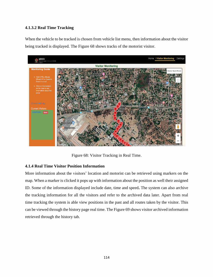
114
4.1.3.2 Real Time Tracking
When the vehicle to be tracked is chosen from vehicle list menu, then information about the visitor
being tracked is displayed. The Figure 68 shows tracks of the motorist visitor.
Figure 68: Visitor Tracking in Real Time.
4.1.4 Real Time Visitor Position Information
More information about the visitors’ location and motorist can be retrieved using markers on the
map. When a marker is clicked it pops up with information about the position as well their assigned
ID. Some of the information displayed include date, time and speed. The system can also archive
the tracking information for all the visitors and refer to the archived data later. Apart from real
time tracking the system is able view positions in the past and all routes taken by the visitor. This
can be viewed through the history page real time. The Figure 69 shows visitor archived information
retrieved through the history tab.
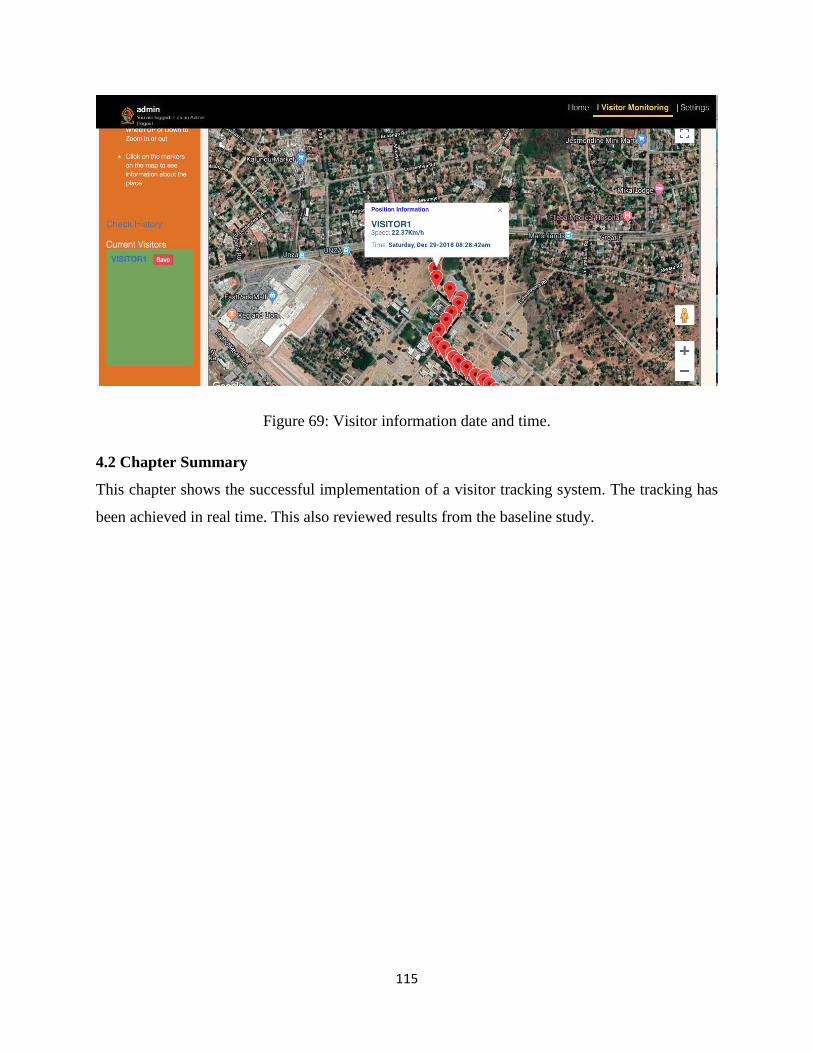
115
Figure 69: Visitor information date and time.
4.2 Chapter Summary
This chapter shows the successful implementation of a visitor tracking system. The tracking has
been achieved in real time. This also reviewed results from the baseline study.
116
CHAPTER 5: DISCUSSION AND CONCLUSION
5.1 Introduction
In this chapter, the main findings with regard the research questions are given in summary. General
conclusions based on the findings of the study are also presented. Furthermore, limitations of this
study are considered and recommendations are given.
5.2 Discussion
5.2.1 Baseline Study
A baseline study was conducted to measure the level of physical security at the University of
Zambia. The study reveals that University of Zambia has limited or no control of who enters or
visits campus. Analysis of the survey data identifies key points in the level of security and access
control at the University of Zambia. It strongly shows that security at UNZA is porous. Access
Control of who enters or exits the campus and what time is limited. The survey shows that the
University Security Personnel are understaffed to man all the entry and exit points. The University
does not have a system to automatically identify students, staff and visitors as is revealed from the
baseline study conducted that more than 83% have no identification badges. This implies that
anyone can access UNZA facilities such as offices and hostels without having the need to show
identification. The survey shows that 84 % of office or hostels entrances are not secured by such
as grill gates or automatic identification and access control system. Any institution that has no
control of who accesses its premises is vulnerable to thefts and damage of property. The study
revealed that University Staff and Students have been victims of theft or experienced a lot of thefts,
the most common lost items being media such as laptop. The security department reports a total
of 40 laptops belonging to staff, students and visitors stolen in the month of June alone.
According to the survey results the fence which is considered to be security perimeter only covers
the University perimeter less than 50 % showing that unidentified people can enter, exit or trespass
the campus premise without and need for permission. The results to the study also noted that about
83% show that there is no record kept of anyone who visits UNZA and at what time. Contractors
deliver different supplies to the University but no audit record is kept of such visits. It is also not
possible to ascertain whether the visitors only visited the intended and authourised place.
117
The baseline study conducted based on the ISO 27002 helped to measure the level of security at
the campus. According to the survey the university does not have not have any written down
procedures for security personnel to follow or reference to.
From the results as shown in results section 4.2, a prototype was designed and proposed to
improve access control through automatic identification and authentication of all who enter
campus. A prototype to track visitors’ movements was also designed to ensure visitors can be
tracked and an audit trail kept.
5.2.2 Security Model Design
Based on the results from the baseline study, a security model based on multifactor authentication
access control was designed. This model based on RFID and Fingerprint was designed to improve
security and control access to the university facilities. During registration a registered student and
employed staff are registered into the system. The person’s ID and finger print are matched in the
system. The model also includes a module to monitor visitor physical location and movements in
real time. The Visitor tracking module was designed, developed and implemented.
5.2.3 Visitor Tracking Module
The research implemented a visitor tracking module which gives required requests in real time.
The visitor tracking device was designed, developed and validated through testing. Information
such as date and time of entry and real time physical location and movements could be seen
through the web application. This information is also stored on the cloud server. The tracking
device which consists of GPS and GSM fetches the visitors’ location and movements and then
sends this information at regular intervals in this case was set to 4s intervals and is sent to the cloud
server to ensure that the information is current. The system user or administrator can monitor the
visitor’s movements by logging into the systems’ web application. The visitor information can be
analysed through GIS.
The tracking device brings with it some benefits for UNZA. Since the visitor is notified or warned
about the tracking, it works as a deterrent to visitors’ who might want to visit unauthourised places.
The devices keep a history of the past movements and locations, therefore it can also be used to
keep a record and an audit trail of the visitor.
118
However, the tracking module has some limitations. For example, as was noticed during the testing
phase, there was a skip in the visitor location results in places around campus where there are tall
trees and buildings. The same was experienced during cloudy days, it was noticed that a multipath
error was created leading to some errors in the results. The device had to be iniatialised several
times in order to start reading again.
5.2.2 System Prototype Implementation
The study focused on developing the visitor tracking module, to which the basic functionalities
were implemented on the basis of the use cases as indicated in the methodology Chapter 3 of the
thesis document. To achieve this goal in this study, the proposed visitor tracking model was
developed and a prototype system was implemented, demonstrating the concept of prototype
operation. First, information was collected, analyzed and formulated as useful system requirements
(methodology Chapter 3). The system requirements were derived from observing the current
UNZA business process of Visitors hosting. The prototype of the system was developed in PHP
and MySQL databases. The prototype has been successfully developed and shows how visitor
movements can be tracked. The development tools used are available for free as they are all open
source. The tools introduced in Chapter 4 were: Apache Web Server, MySQL, PHP, Bootstrap
CSS, and JavaScript. The prototype demonstrates how data can be centrally managed and received
in real time as they come from a variety of sources, most notably tracking people movements and
physical locations. Cloud technologies like cloud storage and web application hosting making it
possible for database storage. It can be concluded that cloud technologies are a better way to
manage information from multiple sources. Storage in cloud databases also makes it possible to
manage sensor data that is generated in large quantities, such as in people tracking. Based on the
web application testing and validation, it has been experienced that the application provides easy
and effective management and accessibility. The application was also reported as user friendly and
easy to learn. The system also eliminates the need for paper records and accountability. All records
are stored electronically in the cloud and are accessible to anyone with permission anywhere in the
university.
119
5.3 Recommendations
The aim of the study was to design and develop a system to improve security at UNZA by
controlling access and keeping an audit trail of visitors into the University. UNZA can greatly
benefit in employing a visitor tracking system in so many ways. The study put forward the
following recommendations:
(i) Visitor tracking at UNZA will allow to take control over who has access to UNZA
premises and when.
(ii) The same visitor tracking system can be used for employee attendance tracking, giving
an extensive overview of who is in, out or expected at the premises.
(iii) An audit trail date and time will be kept of all Visitors that come to the University.
(iv) Visitor tracking improves security; visitor control reduces the risk of theft taking place
as where theft occurs it can help to identify the culprits.
(v) A Visitor tracking systems will allow authourised users of the systems to have full
control over who has access to specific areas of the premises. Example would be during
students’ unrest; the students can be denied access out of the campus.
5.4 Conclusion:
In this thesis, the problem of limited control of access to the UNZA is addressed. The study
designed a Multi Factor Authentication model for student and staff access control to UNZA based
on RFID and Biometrics. One of the main contributions of this work is to improve identification
and authentication of student and staff in comparison to what is currently being used which is
identification with barcode based IDs. It is not easy to authenticate whether the person carrying
the ID is actually the authourised owner. This work also measured the level of security at the
University based ISO27002 physical and environmental security. According to the survey
UNZA’s security is porous. The institution can be accessed so easily by anyone, as has been
revealed that only half the perimeter is fenced and not all entrances to hostels or offices are secured.
No automated access control systems have been implemented.
The main focus of the thesis was to design and develop a prototype to monitor visitors’ physical
location and movements in real time. The prototype has been designed and developed and as seen
from the testing and validation UNZA can greatly benefit from such an implementation.
120
5.5 Future Works
The student and staff access control will be developed and implemented to improve UNZAs’
security. The Visitors module will be developed into a full-fledged system instead of just a
prototype. Future implementations of the access control systems should include the use of a more
intelligent and higher storage capacity micro controller such as Raspberry pi.
5.6 Chapter Summary
This chapter discussed the baseline study, system model design and visitor tracking. The study
recommendations, conclusion and future works are also presented.
121
REFERENCES
[1] Fernandez, E. B. J. D.-D. A. L.-P. M. "Security Patterns for Physical Access Control Systems.," Data
and Applications Security. LNCS, , Vols. vol. 4602,, p. pp. 259–274., 2007.
[2] Perry M, " Effective Physical Security (Fourth Edition), Fourth. Elsevier Inc.," , 2013..
[3] U. Security, Interviewee, Theft Records. [Interview].
[4] Brown F. and Shubham S., RFIDiggity: Pentester Guide to Hacking HF/NFC and UHF RFID in Defcon
23 Archive,, 2015.
[5] "Sophisticated from power point presentation".
[6] Balfanz, D. D. G. G. R. S. D. "In search of usable security: Five lessons from the field.," in IEEE
Security and Privacy 2(5, 2004, p. 19–24.
[7] Botta, D. W. R. G. A. B. K. I. L. F. S. F. B. "Proceedings of the 3rd Symposium on Usable Privacy and
Security, SOUPS," in Towards understanding it security professionals and their tools., New Y,
ACM,, 2007, p. pp. 100–111.
[8] Garfinkel S, Design principles and patterns for computer systems that are simultaneously secure
and usable, 2005.
[9] Cao K, Jain A. K, "Hacking Mobile Phones Using 2D Printed Fingerprints," Vols. vol. 16, no. 2,, no.
MSU Tech. Rep. MSU-CSE-16-2, 2016..
[10] S. M. B. D. C. R. Ph.D., "Physical Security and Cybersecurity: Reducing Risk by Enhancing Physical
Security Posture through Multi-Factor Authentication and other Techniques International Journal
for Information Security Research (IJISR)," vol. Volume 6, no. Issue 2, 2016.
[11] Stewart J. C. M. &. G. D., Physical Security Requirements, 6th ed ed., Indianapolis, USA: Wiley,
2012, pp. pp. 572- 597,745-774.
[12] Harris S., " CISSP Exam Guide," in Information Security Governance and Risk Management,
McGraw-Hill, 2013, pp. (6th ed., pp. 21-141).
[13] S. Harris, in ALL IN ONE CISSP EXAM GUIDE, , McGraw-Hill,, 2013. , p. Sixth Edit..
[14] Aleksandr O., S. B. N. M. S. A. T. M. Y. K. Multi-Factor Authentication, 2018.
[15] "http://www.iso27001security.com/html/27002.html," accessed 29/11/18.
[16] Lamport L., "Password authentication with insecure communication.," ACM , 1981, , pp. 24, 770–
772..
122
[17] Benarous L., Kadri B. and Bouridane A., "A Survey on Cyber Security Evolution and Threats:
Biometric Authentication Solutions.," in Biometric Security and Privacy, Springer: Berlin, Germany,
2017, p. pp. 371–411..
[18] Gunson N., Marshall D., H. Morton and M. Jack, "User perceptions of security and usability of
single-factor and two-factor authentication in automated telephone banking," 2011, pp. 30, 208–
220..
[19] Sajjan R. &. G. V. &. D. M. 2. E.-I.-2.Z, "Multi-factor Authentication as a Service for Cloud Data
Security," International Journal of Computer Sciences and Engineering, Vols. . Volume-4, , no.
Special issue-4,, 2016.
[20] Alireza Pirayesh Sabzevar A. S., "Proceedings of the 2008 IEEE International Conference on Signal
Image Technology and Internet Based Systems.," in Universal Multi-Factor Authentication Using
Graphical Passwords, 2008., pp. pp. 625-632,.
[21] Kato H., "Barcodes for mobile devices,," in Barcodes for mobile devices , Cambridge University
Press, 2010, pp. pp 11-20.
[22] Akshatha M., "Student Authentication and Verification System using Barcode Scanner,"
International Journal of Internet of Things 2017, pp. 71-74.
[23] "“UPC Symbols.” gtin.info," [Online]. Available: http://www.gtin.info.upc gtin.info, “UPC
Symbols.” gtin.info.
[24] "Terrapin Solutions Limited. “barcode services and specifications,," Terrapin Solutions Limited
[online]. , [Online]. Available: Available http://www.terrapin.co.uk/sevices bapecean13.html [.
[Accessed Accessed 2018].
[25] "World barcodes 2018 [online].," Barcodes Limited, “World Barcodes,” , [Online]. Available:
Available https://worldbarcodes.com/code-18-code-39/. [Accessed Accessed 19 October, 2018].
[26] "LEADTOOLS Barcode, www.leadtools.com,," LEADTOOLS Barcode, [online]., [Online]. Available:
Available https://www.leadtools.com/helpv/leadtools/v19/dhtoleadtools.topic.barcode-
ba.topics/miscellaneousbarcodeinleadtools.html . [Accessed accessed October 2018].
[27] "Phil Peretz,," ID Barcode Formats , 17 December 2011. [Online]. Available: Available
https://www.nationalwidebarcode/id-barcode-format/ . [Accessed October 2018].
[28] "scandit “types-barcodes-choosing-right-barcode"," [Online]. Available:
http://www.scandit.com/2015/01/27/ types-barcodes-choosing-right-barcode . [Accessed
October 2018].
[29] "“flick2know,"," flick2know, , [Online]. Available: ”[Online] Available http://www.
flick2know.com/QRcode.
123
[30] "wasp barcode technologies, “wasp barcode technologies,”," wasp barcode technologies, 10
March 2016. [Online]. Available: http://www.waspbarcode.com. [Accessed 2018].
[31] "Barcode Scanners – Redefining Technology with Human Touch,," “Barcode Scanners –
Redefining Technology with Human Touch,”, [Online]. Available:
http://www.products.indianbarcode.in/barcode-scanner/ . [Accessed June 2018].
[32] "“Microscan Mobile Hawk Scanner,” barcodes inc,," [Online]. Available:
https://www.barcodesine.com/article/view1339..
[33] Trupti Lotlikar, R.K.A.P., "Comparative study of Barcode, QR-code and RFID systems,”," Vols.
IJCTA vol,04. No. 05, , 2013, pp. pp. 817-821.
[34] T.-J. Z. H. C. Z. a. J. M. Phiri J., "Using Artificial Intelligence Techniques to Implement a Multifactor
Authentication System,," Vols. vol. 4, no. 4,, pp. pp. 420-430,, 2011.
[35] Saini R. and Rana N., "International Journal of Advances in Science and Technology,," in
COMPARISON OF VARIOUS BIOMETRIC METHODS,, Vols. vol. Vol 2, no. I,, 2014, pp. pp. 1-7,.
[36] Ferguson, B. S. a. T. K. N., "Cryptography Engineering: Design Principles and Practical
Applications," 2010.
[37] Martin K., "Everyday Cryptography: Fundamental Principles & Applications," New York, Oxford
University Press, 2012.
[38] Stewart E. T. M. C. J. M., in Certified Information Systems Security Proffesional, , Canada, Wiley,
2008.
[39] Alonso-Fernandez J. F. a. J. O.-G. F., "Quality Measures in Biometric Systems,," 2011.
[40] Lanitis A., " Problems and Challenges for ArtificialProblems and Challenges for Artificial in AIAI-
2009 Workshops Proceedings," in Facial Biometric Templates and Aging, 2014.
[41] Mehta A., "QR Code Recognition from Image," in International Journal of Advanced Research in
Computer Science and Software Engineering,, Vols. vol. 5, no. 12, , 2015, pp. pp. 781-785,.
[42] Mamdapur U. and Rajgoli I., "Implementing radio frequency identification technology in libraries:
Advantages and disadvantages," International Journal of Library and Information Science,, Vols.
vol. 3, , no. no. 3,, pp. pp. pp. 46-57,, 2011.
[43] G. O. S. S. D. V. M. L. J. H. B. T. a. S. O. Vestnik S., "Implementation of Automatic Identification
Technology in a Process of Fixture".
[44] M. S. N. M. a. S. P. S. Kaur M., "RFID Technology Principles, Advantages, Limitations & Its
Applications," International Journal of Computer and Electrical Engineering,," Vols. vol. 3, no. 1,,
2011, pp. pp. 1793-8163,.
124
[45] MuzaffarIqbal M. and Singh V. P., " Radio Frequency identification (RFID) Technology in Libraries,"
in An Introduction," Research Directions,, Vols. vol. 2, no. 2, , 2014, pp. pp. 1-7.
[46] Z. K. P. E. a. L. M. E. Ilie-Zudor, " The RFID Technology and its Current Applications," in In
proceedings ofThe Modern Information Technology in the Innovation Processes of the Industrial
Enterprises-MITIP," 2006..
[47] L. R.-G. a. Lunadei L., "The role of RFID in agriculture: Applications, limitations and challenges," in
Computers and Electronics in Agriculture, Vols. vol. 75, no. 1, , 2011, pp. pp. 42-50.
[48] Wyld C. D. and Budden C. M., "Upping the Ante: Using Rfids a Competitive Weapon to Fight
Shoplifting and Improve Business Intelligence," The International Journal of Managing
Information Technology (IJMIT), Vols. vol. 1, no. 1,, pp. pp. 1-10,, 2009..
[49] Weis S. A., "RFID (Radio Frequency Identification): Principles and Applications," Massachusetts:
MIT,, 2006.
[50] T. C. a. T. L. M. Evic G., "RFID and Supply Chain Management for Manufacturing Digital
Enterprise,," in Supply Chain Management- New Perspectives, 2011.
[51] A. O. O. A. F. a. O. M. O. ". Arulogun O. T., "RFID-Based Students Attendance Management
System,," International Journal of Scientific & Engineering Research,, Vols. vol. 4, no. 2, p. 1,,
2013.
[52] Ruiz-Garcia ,. L. and Lunadei L., "The role of RFID in agriculture: Applications, limitations and
challenges,," Computers and Electronics in Agriculture, Vols. vol. 75, no. 1, , pp. pp. 42-50,, 2011.
[53] Qian Z. L. a. X. X. J., "Design and Application of RFID Technology in Container Port,," Scientific
Journal of Information Engineering,, Vols. vol. 4, no. 2, , pp. pp. 26-37,, 2014..
[54] Sardroud M. J., "Influence of RFID technology on automated management of construction
materials and components," Vols. vol. 19, no. 3, , pp. p. 381– 392,.
[55] J. T. P. a. C. J. Visich R. J. K., " Empirical applications of RFID in the manufacturing environemnt,"
Radio Frequency Identification Technology and Applications,, 2009..
[56] S. L. S. a. S. Sharma C. S., "Radio Frequency Identification (RFID) Based Employee Monitoring
System (EMS),," International Journal of Current Engineering and Technology, Vols. vol. 4, no. 5, ,
pp. pp. 1-5, , 2014. .
[57] P. M. K. D. a. Salunke J. D. P., "Automated Toll Collection System Using RFID," IOSR Journal of
Computer Engineering (IOSR-JCE), Vols. vol. 9, no. 2, , pp. pp. 61-66, , 2013..
[58] G. S. R. B. D. T. K. a. R. P. S. Singh B. K. A., "Application of Radio Frequency Identification (RFID)
Technology in Dairy Herd Management," International Journal of Livestock Research,, Vols. vol. 4,
no. 1,, pp. pp. 10- 18,, 2014..
125
[59] Cristea A. R. a. L., "RFID- Application in Info-Documentary Systems," Designing and Deploying
RFID Applications, InTech, , 2011.
[60] Mahajan K. N. S. a. P., "Application of RFID Technology in Libraries,," International Journal of
Library and Information Studies, , Vols. vol. 4, no. 2, , pp. pp. 1-9,, 2014..
[61] Yadav R. and Nainan S., "Design of RFID Based Student Attendance System with Notification to
Parents Using GSM,," International Journal of Engineering Research & Technology (IJERT), Vols.
vol. 3, no. 2, 2014..
[62] Ravi H. G. V. T. V. a. P. P. S. K., "RFID Based Security System,," International Journal of Innovative
Technology and Exploring Engineering (IJITEE), , Vols. vol. 2, no. 5, , 2013.
[63] Motorola, Motorola Fixed RFID Reader Antennas, [Online]. Available:
http://www.fieldtechnologiesonline.com/doc/motorola-fixed-rfid-reader- antennas-0001..
[Accessed 15 September 2015].
[64] All Barcode Systems, "RFID Readers,," All Barcode Systems,, [Online]. Available:
https://www.allbarcodesystems.com/products/rfid-products/readers/.. [Accessed 15 September
2015].
[65] Mahajan K. N. S. a. P, "Application of RFID Technology in Libraries,," International Journal of
Library and Information Studies, Vols. vol. 4, no. 2,, pp. pp. 1-9, , 2014.
[66] Hamilton P. and Sankaranarayanan S., "Intelligent Agent Based RFID System for on Demand Bus
Scheduling and Ticketing,," International Journal of Future Computer and Communication,, Vols.
vol. 2, no. 5,, pp. pp. 399-406, , 2013.
[67] Singh K. N. and Mahajan P., "Application of RFID Technology in Libraries,"," International Journal
of Library and Information Studies, Vols. vol. 4, no. 2, , pp. pp. 1-9, , 2014.
[68] Evic T. C. a. T. L. M. G., "RFID and Supply Chain Management for Manufacturing Digital
Enterprise,," Supply Chain Management- New Perspectives, InTech,, 2011.
[69] Dolgui A. and Proth M. J., "RFID Technology in Supply Chain Management: State of the Art and
Perspectives,," in Proceedings of the 17th World Congress The International Federation of
Automatic Control,, Seoul, , 2008.
[70] Samadi S., "Applications and Opportunities for Radio Frequency Identification (RFID) Technology
in Intelligent Transportation Systems: A Case Study,," International Journal of Information and
Electronics Engineering,, Vols. vol. 3, no. 3,, pp. pp. 341-345,, 2013.
[71] S. C. E. C. K. O. a. M. Cho R. J., "Use of RFID in Healthcare Industry,," Colorado State University,
Pueblo, , 2012.
[72] E. H. R. H. S. V. C. O.-N. a. H. J. d. V. Vilamovska K. A., "Study on the requirements and options for
RFID application in healthcare,", United Kingdom,, 2009..
126
[73] Prasad N. K. R. S. and A. Rajesh, "RFID-Based Hospital Real Time Patient," p. 143.
[74] M. Hashemipour, "Assessing and Monitoring Student Participation in Engineering Laboratory
using Radio Frequency Identification (RFID) – Satisfying ABET EC2000 Outcome 3b," in
Proceedings of the World Congress on Engineering,, London, , 2015. .
[75] "All Barcode Systems," [Online]. Available: https://www.allbarcodesystems.com/products/rfid-
products/readers/. [Accessed 15 September 2015]. .
[76] Shawish A. and Salama M., ""Cloud Computing: Paradigms and Technologies,"," in Inter-
cooperative Collective Intelligence: Techniques and Applications, , Berlin, Springer, , 2014,, pp. pp.
39-67..
[77] Tole A. A., ""Cloud Computing and Business Intelligence,"," Database Systems Journal,, Vols. vol.
5, no. 4, ,, pp. pp. 49-58, 2014.
[78] IEEE, IEEE Standard Glossary of Software Engineering Terminology,, 1990. .
[79] A. I. A.-B. a. K. G. Khan A. U., "Object-Oriented Software Methodologies: Roadmap to the
Future," in IJCSI International Journal of Computer Science Issues,, Vols. vol. 8, no. 5,, 2011, pp.
pp. 392-396,.
[80] A. I. A.-B. a. K. G. Khan A. U., ""Object-Oriented Software Methodologies: Roadmap to the
Future,"," in IJCSI International Journal of Computer Science Issues,, Vols. vol. 8, no. 5, , 2011, pp.
pp. 392-396,.
[81] Sommerville I., in Software Engineering, 9th ed., , Boston, Addison-Wesley, , 2011. .
[82] Norman R., "Object-Oriented System Analysis and Design,," Pentice Hall, , 1996. .
[83] Brahmi A., "Object-Oriented System Development.".
[84] Mohammad R. A., ""Issues of Structured vs. Object-Oriented Methodology of Systems Analysis
and Design,"," in Issues in Information Systems,, Vols. vol. 5, no. 1, , 2004, pp. pp. 275-280.
[85] Liu Z., "Object-Oriented Software Development with UML,," Macau, United Nations University
International Institue for Software Technology, , p. 2002.
[86] Ojo A. and Estevez E., "Object-Oriented Analysis with UML," 2005.
[87] Bennett S. M. a. R. F. S., Object-Oriented Systems Analysis and Design using UML, 3rd ed.,,
McGraw Hill, , 2006.
[88] Jacobson G. B. a. J. R. I., "The Unified Software Development Process,," Boston, Addison-Wesley, ,
1999..
[89] Brown W. D., Objects and UML in Plain English,, Wiley,, 2002..
127
[90] Gosling B. J. G. S. a. G. B. J., Java (TM) Language Specification, Addison-Wesley.
[91] Deitel P. J. and Deitel H. M., Java How to Program, 7th ed.,, New Jersey: Prentice Hall, 2006..
[92] Hoque M. Z., " Basic Concept of GPS and Its Applications IOSR Journal Of Humanities And Social
Science (IOSR-JHSS)," Vols. Volume 21, , no. Issue 3, , pp. PP 31-37, 2016.
[93] J. S. a. D. Chandrashekar M. R., "Importance and Analysis of RFID in Attendance System,,"
International Journal of Emerging Science and Engineering (IJESE),, Vols. vol. 1, no. 9,, 2013.
[94] B. Y. D. S. P. K. M. G. a. H. C. S. Murthy K. K. K., ""Advanced College Surveillance System,","
International Journal of Scientific and Research Publications,, Vols. vol. 4, no. 6, 2014.
[95] J. M. M. a. Peter Adole G. A. I., ""RFID Based Security Access Control System with GSM
Technology",," American Journal of Engineering Research (AJER), Vols. Volume-5, , no. Issue-7,,
pp. pp-236-242., 2016.
[96] O. C. N. EZ*, "UI Automatic Access Control System using Arduino and RFID Orji Journal of
Scientific and Engineering Research,," pp. 333-340 5(4):, 2018.
[97] M. u. H. M. A. A. H. a. M. Umar Farooq U. A., ""RFID Based Security and Access Control System","
IACSIT International Journal of Engineering and Technology, , Vols. Vol. 6, No. 4, 2014. .
[98] Beqqal M., Advances in Science, Technology and Engineering Systems Journal , Vols. Vol. 2, No. 6,
, pp. 194-202 , 2017.
[99] Meera Mathew R. S. D., ""Super secure door lock system for critical zones",," Networks &
Advances in Computational Technologies (NetACT) 2017 International Conference on, pp. pp. 242-
245, , 2017.
[100] Lorenzo C. A. F., "RFID based Monitoring and Control System," INFORUM, 2009.
[101] Z. S. X. Meng L. X.L, "RFID- Based security Ayuthentication System based on a Novel Face
Recognition Structure," WASE International Conference on information Engineering, pp. pp 97-
100, 2010.
[102] W. W. Wu D.L, "Access Control and RFID and face recognition based on Neural Network,"
International Conference on machine learning and Cybernatics, pp. 675-680, July 11=14, 2010.
[103] Ahmed Raad W. Z., "Dectecting Unauthorised RFID Tag Carrier for Secure Access Control to a
Smart Building," International Journal of Applied Engineering Research, vol. 13, no. 1, pp. 749-
760, 2018.
[104] YShin-Hyeong Choi Sun-Yeob Kim .-C. R., "A Study on Visitors Tracking Method Using Wireless
Communication," 2013 .
128
[105] Behera ,. A. S. and Maity C., ""Active RFID tag in Real Time Location System,"," in 5th
International Multi-Conference on Systems, Signals and Devices, 2008, pp. pp. 1-7..
[106] Z. &. L. J. &. H. S. &. Zhang Z. Q., in Multi-target tracking using the sign of innovations in wireless
sensor networks. , 2012.
[107] Sonal Kasliwal S. K. H., " Employee Tracking and Monitoring System Using Android," International
Journal of Innovative Research in Advanced Engineering (IJIRAE) , vol. Volume 3, no. Issue 03, ,
2016.
[108] Awais Mulla U. A. S. K. E., "Tracking System Using NFC," International Research Journal of
Engineering and Technology (IRJET), vol. Volume: 05, no. Issue: 02, 2018.
[109] Sabale R., "Employee Monitoring System Using Android Smartphone," (IJCSIT) International
Journal of Computer Science and Information Technologies, Vols. Vol. 6 (6) , , pp. 5130-5132,
2015.
[110] Roman P. N. J. L. R, Journal of Network and Computer Applications, Vols. Volume 34, Issue 3, May,
pp. Pages 980-989, 2011.
[111] Summervile I., Sofware Engineering, 9 ed., New York: Addison-Wesley, 2011.
[112] Farmer B. S, S. and McRobb R., Object-Oriented Systems Analysis and Design using UML, 3 ed.,
McGraw Hill, 2006.
[113] O. A and E. E, Object-Oriented Analysis with UML, e-Marcao, 2005.
[114] Perry M., in Effective Physical Security (Fourth Edition), Fourth. , Elsevier Inc., , 2013. .
[115] C. G. L. B. a. D. C. R. “. C. a. 3. L. –.Doyle B., "How 3D Printing can Defeat Physical Security,”," in
Proceedings of the 2015 ASEE Annual Conference and Exposition, , 2015..
[116] S. M. a. J. Conrad F. E., "Eleventh Hour CISSP,," Syngress, , p. 3rd Edition. , 2016..
[117] Owens M., "“Biometrics and User Authentication,”," 2002. .
[118] Hancke G. P., "“Security of Proximity Identification Systems,” Univ. Cambridge Comput. Lab.,," no.
no. 752,, 2009..
[119] Samuel Moses D. C. R., " Physical Security and Cybersecurity: Reducing Risk by Enhancing Physical
Security Posture through Multi-Factor Authentication and other Techniques," international
Journal for Information Security Research (IJISR), , Vols. Volume 6,.
[120] [Online]. Available: http://www.iso.org/iso/.
[121] last visited in December 2018. [Online]. Available: http://www.iso.org/iso/.
129
[122] Wyld C. D. and Budden C. M., "Upping the Ante: Using Rfids a Competitive Weapon to Fight
Shoplifting and Improve Business Intelligence," in The International Journal of Managing
Information Technology (IJMIT), Vols. vol. 1, no. 1, , 2009, pp. pp. 1-10,.
[123] A. O. O. A. F. a. O. M. Arulogun O. T., "RFID-Based Students Attendance Management System,,"
International Journal of Scientific & Engineering Research,, Vols. vol. 4, no. 2,, pp. p. 1,, 2013.
[124] B. L. A. A. a. M. Y. Ahmed Raad Al-SudaniWanlei Zhou, International Journal of Applied
Engineering Research , Vols. Volume 13, Number 1 , pp. pp. 749-760, (2018).
130
APPENDICES
APENDIX A
A.1 Sample code
GPS C++ Code listing
#include <SoftwareSerial.h>
SoftwareSerial ss(10,11); //RX TX
#define GSM_PORT ss
#include "sim808.h"
#define JOURNEY "vr978rye7R"
void setup() {
// setup code here, to run once:
ss.begin(9600);
Serial.begin(115200);
Serial.println("Starting...");
sim808_setup();
}
void sendPositionReport(unsigned long now) {
GSM_PORT.print("AT+HTTPPARA=\"URL\",\"unzavisitor.000webhostapp.com/gpsReceiver.p
hp?");
GSM_PORT.print("&vid=VISITOR1");
GSM_PORT.print("&jn=");
GSM_PORT.print(JOURNEY);
GSM_PORT.print("&tm=");
131
GSM_PORT.print( utc );
GSM_PORT.print("&fx=");
GSM_PORT.print(fixStatus);
GSM_PORT.print("<=");
GSM_PORT.print(lat);
// Serial.print("Latitude=");
// Serial.print(lat);
GSM_PORT.print("&ln=");
GSM_PORT.print(lon);
GSM_PORT.print("&sv=");
GSM_PORT.print(sats);
GSM_PORT.print("&ha=");
GSM_PORT.print(hdop);
GSM_PORT.print("&gs=");
GSM_PORT.print(sog);
GSM_PORT.print("&hd=");
GSM_PORT.print(cog);
GSM_PORT.println("\"");
flushGSM(now);
delay(500);
sendGSM("AT+HTTPACTION=0");
}
void loop() {
unsigned long now = millis();
boolean gotGPS = false;
132
if ( actionState == AS_IDLE ) {
if ( fixStatus > 0 && now > lastActionTime + 10000 ) {
sendPositionReport(now);
lastActionTime = now;
httpResult = 0;
actionState = AS_WAITING_FOR_RESPONSE;
}
}
else {
// waiting on response - abort if taking too long
if ( now > lastActionTime + 15000 ) {
actionState = AS_IDLE;
parseState = PS_DETECT_MSG_TYPE;
resetBuffer();
}
}
sim808_loop();
}
PHP Web application code listing: Tracking page
<?php
include('db_server.php');
include('class_lib/class_lib_inc.php');
if(!warehousesExist($conn) && !visitorsExist($conn)){
header('location:manager_home.php'); die;
}
$trackingObj = new Visitor_Tracking($conn);
?>
133
<!--DOCTYPE html-->
<html lang="en">
<head>
<meta charset="UTF-8"/>
<meta name="viewport" content="width=device-width, initial-scale=1"/>
<title>Admin | Maps |</title>
<link rel="shortcut icon" href="images/logo.svg" type="image/x-icon">
<link rel="stylesheet" href="js/bootstrap.min.css"/>
<link rel="stylesheet" href="css/style.css"/>
<link rel="stylesheet" href="css/typeheadAndMapStyles.css"/>
<script src="js/jquery.min.js"></script>
<script src="js/bootstrap.min.js"></script>
<script src="js/myscript.js"></script>
<script src="js/prefixfree.min.js"></script>
<script src="managerWarehouse.js"></script>
<?php include('mapsProcessorTracking.php') ?>
<style type="text/css">
#addUserIcon:hover,#addUserIconClose:hover{
box-shadow: 0 0 7px #222 ;
border-radius:20px;
}
#addUserIconClose,#addUserIcon{
box-shadow: 0 0 5px #444 ;
border-radius:20px;
}
</style>
</head>
<body>
<?php
134
//process header inclusion based on user settings
if(isset($_SESSION['sysAdmin_pwd_crypt'])){
include('sysAdmin_header.php');
}else if(isset($_SESSION['admin_pwd_crypt'])){
include('manager_header.php');
}
?>
<div class="main">
<div class="page" id="mission">
<div class="content container-fluid">
<div class="row">
<div class="col-lg-12 col-md-12 col-sm-12 col-xsm-12" style="height:relative;color:#fff;text-
align:center;">
<b style="font-size:1.3em;color:#296122">Visitor Monitoring</b>
</div>
<div class="col-lg-12">
<div class="col-lg-2" style="background-color:#DF7401;height:84%;color:#fff">
<h4 style="padding-left:3px;"><b>Monitoring Guide</b></h4>
<br/><br/>
<ul style="font-size: 0.8em;">
<li>Hold CTRL+Mouse Wheell UP or Down to Zoom in or out</li><br/>
<li>Click on the markers on the map to see information about the place</li><br/>
<br/><br/>
<!-- Rounded switch -->
</ul>
<a href="manager_arch_tracking.php"><h4>Check History</h4></a><br/>
<?php
$trackingObj->getVisitorList("gps_coordinate");
?>
</div>
135
<div class="col-md-10 col-sm-10 col-xsm-10" >
<div id="map" style="width:100%;height: 84%; border: 3px solid #838186; border-radius: 5px;
">
<p style="color:296122; font-size: 3em;">Select Visitor in the left menu to check their
movements.<br/>
</p>
</div><!-- Map-->
<div id="infowindow-content">
<img src="" width="16" height="16" id="place-icon">
<span id="place-name" class="title"></span><br>
<span id="place-address"></span>
</div>
</div>
</div><!--Whole form-->
</div><!-- row -->
</div><!-- content container -->
</div><!-- add program -->
</div><!--main-->
<?php include('manager_footer.php')?>
<script async defer
src='https://maps.googleapis.com/maps/api/js?key=AIzaSyBwiqodRbtEX-U-
b3vXlwahF1QlOMw1fug&libraries=places&callback=initMap'>
</script>
<script src="mapGoefenceControls.js" type="text/javaScript"></script>
</body>
</html>
136
PHP Class Visitor_Tracking
<?php
class Visitor_Tracking{
private $dbConnection = NULL;
public function __construct($conVar){ $this->dbConnection = $conVar; }
//get paths
function buildPath($vIDVal,$tbl){
$returnStr = "[";
$getCord = mysqli_query($this->dbConnection,"SELECT * FROM $tbl
WHERE visitor_id='".$vIDVal."'");
if(mysqli_num_rows($getCord)>0){
while($coordInfo = mysqli_fetch_assoc($getCord)){
$returnStr .=
"{lat:".$coordInfo['latitude'].",lng:".$coordInfo['longitude']."},";
}
$returnStr .= "]";
$strWithoutLastComa = substr($returnStr,0,strlen($returnStr)-2);
return $strWithoutLastComa."]";
}else{
return "[{lat:-15.3875259,lng:28.3228165}]";
}
}
//get center point
public function getCenterPoint($vIDVal,$tbl){
$getCord = mysqli_query($this->dbConnection,"SELECT * FROM $tbl
137
WHERE coordinates_id=(SELECT MIN(coordinates_id) FROM $tbl WHERE
visitor_id='".$vIDVal."')
");
if(mysqli_num_rows($getCord)>0){
$point = mysqli_fetch_assoc($getCord);
$coordinatesObj =
"{lat:".$point['latitude'].",lng:".$point['longitude']."}";
return $coordinatesObj;
}else{
$coordinatesObj = "{lat:-15.3875259,lng:28.3228165}";
return $coordinatesObj;
}
}
public function getCenterPointMap($vIDVal,$tbl){
$retArr = array();
$getCord = mysqli_query($this->dbConnection,"SELECT * FROM $tbl
WHERE coordinates_id=(SELECT MAX(coordinates_id) FROM $tbl WHERE
visitor_id='".$vIDVal."')
");
if(mysqli_num_rows($getCord)>0){
$point = mysqli_fetch_assoc($getCord);
$retArr['latitude'] = $point['latitude'];
$retArr['longitude'] = $point['longitude'];
return $retArr;
138
}else{
$retArr['latitude'] = "-15.3875259";
$retArr['longitude'] = "28.3228165";
return $retArr;
}
}
//get Route for specific visitor
public function getRoute($vIDVal,$tbl){
$getCord = mysqli_query($this->dbConnection,"SELECT * FROM $tbl
WHERE visitor_id='".$vIDVal."'");
return $getCord;
}
//get Route for specific visitor
public function getRouteFilter($vIDVal,$tbl,$start,$end){
$getCord = mysqli_query($this->dbConnection,"SELECT * FROM $tbl
WHERE visitor_id='".$vIDVal."'
AND position_time BETWEEN '".$start."' AND '".$end."'
");
return $getCord;
}
//get visitor list
public function getvisitorList($tbl){
$getCord = mysqli_query($this->dbConnection,"SELECT
DISTINCT(visitor_id) AS vid_item FROM $tbl");
139
if(mysqli_num_rows($getCord)>0){
echo '<h4>Current Visitors</h4>';
echo '';
echo '<p style="height:38%;overflow:auto;background-
color:#76a651;border-radius:7px;padding:10px;">';
while($vID = mysqli_fetch_assoc($getCord)){
echo '<a
href="manager_tracking.php?vid='.$vID['vid_item'].'"><b>'.$vID['vid_item'].'</b><a/>';
echo '   <a
href="archiveTrackingInfo.php?vid='.$vID['vid_item'].'"><button class="btn btn-xs btn-
danger">Archive</button><a/><br/><br/>';
}
echo '</p>';
}
}
//get center point
public function getvisitorListArch($tbl){
$getCord = mysqli_query($this->dbConnection,"SELECT
DISTINCT(visitor_id) AS vid_item FROM $tbl");
if(mysqli_num_rows($getCord)>0){
echo '<h4>Visitor list</h4>';
echo '';
140
echo '<pstyle="height:38%;overflow:auto;background-
color:#76a651;border-radius:7px;padding:10px;">';
while($vID = mysqli_fetch_assoc($getCord)){
echo '<a
href="manager_arch_tracking.php?vid='.$vID['vid_item'].'"><b>'.$vID['vid_item'].'</b><a/>';
echo '   <a
href="restoreTrackingInfo.php?vid='.$vID['vid_item'].'"><button class="btn btn-xs btn-
success">Restore</button><a/><br/><br/>';
}
echo '</p>';
}
}
?>
Perimeter gates page code listing
<!--DOCTYPE html-->
<html lang="en">
<head>
<meta charset="UTF-8"/>
<meta name="viewport" content="width=device-width, initial-scale=1"/>
<title>Admin | Gates |</title>
<link rel="shortcut icon" href="images/logo.ico" type="image/x-icon">
<link rel="stylesheet" href="js/bootstrap.min.css"/>
<link rel="stylesheet" href="css/style.css"/>
<script src="js/jquery.min.js"></script>
<script src="js/bootstrap.min.js"></script>
<script src="js/myscript.js"></script>
<script src="js/prefixfree.min.js"></script>
141
<script src="managergatess.js"></script>
<style type="text/css">
#addUserIcon:hover,#addUserIconClose:hover{
box-shadow: 0 0 7px #222 ;
border-radius:20px;
}
#addUserIconClose,#addUserIcon{
box-shadow: 0 0 5px #444 ;
border-radius:20px;
}
</style>
</head>
<body>
<?php
//process header inclusion based on user settings
if(isset($_SESSION['sysAdmin_pwd_crypt'])){
include('sysAdmin_header.php');
}else if(isset($_SESSION['admin_pwd_crypt'])){
include('manager_header.php');
}
include('db_server.php');
include('class_lib/class_lib_inc.php');
$gatesObj = new gates($conn);
?>
<div class="main">
<div class="page" id="mission">
142
<div class="content container-fluid">
<div class="row">
<div class="col-md-12" style="background-color:#DF7401; padding:1%;"><!-- blue band -->
<div class="col-lg-12 col-md-12 col-sm-12 col-xsm-12" style="height:relative;color:#fff;font-
size:2em;text-align:center;">
Gates
</div>
</div><!-- blue band -->
<div class="col-lg-12" style="margin-top:30px;padding-left:2%;">
<span>
<img class="icon" id="addUserIcon" src="images/plusgreen.png" height="40"/>
<b>Add Gates</b>
</span><br/><br/>
</div>
<div class="col-lg-12" id="userDiv" style="margin-top:30px;padding-left:2%;">
<div class="col-sm-4 col-xsm-4" style="padding: 1%; border: solid 1px #ccc; border-left: solid
10px #ccc;border-radius:6px;" id="formPanel">
<img id="addUserIconClose" src="images/cancelflat.png" height="20"/><br/><br/>
<form id="userForm" name="userForm" method="POST" action="" >
<h4 style="color:#777;"><strong>Enter Gate Information</strong></h4><br/>
<label for="d_name">Gate Name</label>
<input class="form-control" type="text" name="p_name" id="p_name" style="margin-top:6px;"
value="" placeholder="Gate name" max-length="60" autocomplete="off" />
<div align="right">
<input class="btn btn-danger" type="reset" style="margin-top: 6px;" value="Clear"/>
<input class="btn btn-success" type="submit" name="send" style="margin-top: 6px;"
value="Save!"/>
</div>
</form>
<div class="col-md-12" id="mainserverResponseSignup" style="margin-top:5%;">
143
</div>
</div>
</div><!--Whole form-->
<div class="col-md-12" style="padding:1%;"><!-- blue band -->
<div class="col-md-6">
<form method="POST" action="">
<input id="searchField" name="sKey" placeholder="Search (Gate name)"/>
<input class="btn btn-info btn-sm" type="submit" name="search" value="Go!">
</form>
<?php
if(isset($_POST['sKey']) && $_POST['sKey']!==""){
$sKey = mysqli_real_escape_string($conn,strip_tags($_POST['sKey']));
$districtRes = $gatesObj->searchgatessByName($sKey,$ADMIN_ID);
echo '<h4 style="color:green;">Search results for : <b>
'.$_POST['sKey'].'</b></h4><br/>';
echo '<a href="manager_gatess.php"><img src="images/reload.png" height="40"/> Show
everything</a><br/><br/>';
}else if(isset($_POST['sKey']) && $_POST['sKey']==""){
echo '<h4 style="color:red;"><b>Enter Gate name to search</b></h4><br/>';
$gateRes = $gatesObj->getgatess($ADMIN_ID);
}else{
$gateRes = $gatesObj->getgatess($ADMIN_ID);
}
?>
</div>
<?php
if(!$districtRes){
echo '<p class="alert alert-info"> <img src="images/info.png" height="40"/> There is no gate to
show, Add gates to get started!</p>';
}else{
144
echo'<table class="table table-compact table-hover">
<tr class="danger">
<th>Gate Name</th>
<th>Date Created</th><th colspan="3">Options</th>';
echo'</tr>';
while($propertiInfo = mysqli_fetch_assoc($districtRes)){
$date = date_create($propertiInfo['gates_timestamp']);
$dateOut = date_format($date,'l,F d - Y').' at '.date_format($date,'H:i:sa');
$pID = $propertiInfo['gates_id'];
$pNameDisp = $propertiInfo['gates_name'];
echo '
<tr>
<td class="success">'.$pNameDisp.'</td>
<td class="warning">'.$dateOut.'</td>';
//check user status for shared access, show options if user is managerAddRoomAJAXProc
echo'<td class="warning">
<button class="btn btn-success btn-sm" data-toggle="modal" data-
productname="'.$pNameDisp.'" data-href="'.$pID.'" data-
target="#EditModal">Edit</button></td>
<td class="warning">
<button class="btn btn-danger btn-sm" data-toggle="modal" data-productname="'.$pNameDisp.'"
data-href="processgates.php?del_pID='.$pID.'" data-target="#DeleteModal">Delete</button>
</td>';
//show options ends here
echo'</tr>';
}
}
echo '</table>';
?>
</div><!-- blue band -->
145
</div><!-- row -->
</div><!-- content container -->
</div><!-- add program -->
</div><!--main-->
<div class="modal fade" id="DeleteModal" tabindex="-1" role="dialog" aria-
labelledby="myModalLabel" aria-hidden="true">
<div class="modal-dialog alert alert-danger">
<div class="modal-content">
<div class="modal-header alert alert-danger">
<button type="button" class="close" data-dismiss="modal" aria-
hidden="true">×</button>
<h4 class="modal-title" id="myModalLabel"><b>Confirm
Delete gate</b></h4>
</div>
<div class="modal-body alert-danger">
<!-- confirm modal dynamic contetn-->
</div>
<div class="modal-footer alert-danger">
<button type="button" class="btn btn-default" data-
dismiss="modal">Cancel</button>
<a class="btn btn-danger btn-ok">Delete</a>
</div>
</div>
</div>
</div>
<div class="modal fade" id="EditModal" tabindex="-1" role="dialog" aria-
labelledby="myModalLabel" aria-hidden="true">
146
<div class="modal-dialog alert alert-success">
<div class="modal-content">
<div class="modal-header alert alert-success">
<button type="button" class="close" data-dismiss="modal" aria-
hidden="true">×</button>
<h4 class="modal-title" id="myModalLabel"><b>Update gate
Information</b></h4>
</div>
<div class="modal-body alert-success">
<!-- confirm modal dynamic contetn-->
</div>
<div class="modal-footer alert-success">
<button type="button" class="btn btn-default" data-
dismiss="modal">Cancel</button>
<!--<a class="btn btn-success btn-ok">Ok</a>-->
</div>
</div>
</div>
</div>
PHP Class Visitor Registration code Listing
<?php
class visitor_registration{
private $dbConnection = NULL;
public function __construct($conVar){ $this->dbConnection = $conVar; } //construct with
connection
147
public function
addvisitor($fName,$lName,$dob,$gend,$Addr,$idType,$idNum,$phn,$eMail,$photo,$uID){
$setD = mysqli_query($this->dbConnection,"INSERT INTO
visitor(`f_name`,`l_name`,`dob`,`visitor_gender`,`visitor_address`,
`id_type`,`id_number`,`phone`,`e_mail`,`visitor_photo`,`admin_id`)
VALUES('".$fName."','".$lName."','".$dob."','".$gend."','".$Addr."','".$idType."',
'".$idNum."','".$phn."','".$eMail."','".$photo."','".$uID."'
)
");
if(!$setD){
return false;
}else{
return true;
}
}
//update visitor record
public function
updatevisitor($fName,$lName,$dob,$gend,$Addr,$idType,$idNum,$phn,$eMail,$photo,$fID){
$setD = mysqli_query($this->dbConnection,"UPDATE visitor SET
`f_name`='".$fName."',
`l_name`='".$lName."',
`dob`='".$dob."',
148
`visitor_gender`='".$gend."',
`visitor_address`='".$Addr."',
`id_type`='".$idType."',
`id_number`='".$idNum."',
`phone`='".$phn."',
`e_mail`='".$eMail."',
`visitor_photo`='".$photo."'
WHERE visitor_id='".$fID."'
");
if(!$setD){
return false;
}else{
return true;
}
}
//get visitors
public function getvisitors($uID){
$setD = mysqli_query($this->dbConnection,"SELECT * FROM visitor
WHERE admin_id='".$uID."' ORDER BY f_name ASC
");
if(mysqli_num_rows($setD)>0){
149
return $setD;
}else{
return false;
}
}
//search visitors by name
public function searchvisitorsByName($sKey,$uID){
$setD = mysqli_query($this->dbConnection,"SELECT * FROM visitor
WHERE f_name LIKE '%".$sKey."%' OR id_number LIKE '%".$sKey."%'
OR phone LIKE '%".$sKey."%' OR e_mail LIKE '%".$sKey."%'
AND admin_id='".$uID."'
ORDER BY f_name ASC
");
if(mysqli_num_rows($setD)>0){
return $setD;
}else{
return false;
}
}
//visitor exists on update
public function visitorIDExistsOnUpdate($idNum,$fID){
150
$setD = mysqli_query($this->dbConnection,"SELECT * FROM visitor
WHERE id_number='".$idNum."' AND visitor_id<>'".$fID."'
");
if(mysqli_num_rows($setD)>0){
return $setD;
}else{
return false;
}
}
public function visitorPhoneExistsOnUpdate($phn,$fID){
$setD = mysqli_query($this->dbConnection,"SELECT * FROM visitor
WHERE phone='".$phn."' AND visitor_id<>'".$fID."'
");
if(mysqli_num_rows($setD)>0){
return $setD;
}else{
return false;
}
}
public function visitorEmailExistsOnUpdate($eMail,$fID){
$setD = mysqli_query($this->dbConnection,"SELECT * FROM visitor
WHERE e_mail='".$eMail."' AND visitor_id<>'".$fID."'
");
if(mysqli_num_rows($setD)>0){
return $setD;
151
}else{
return false;
}
}
//delete visitor
public function deletevisitor($fID){
$setD = mysqli_query($this->dbConnection,"DELETE FROM visitor
WHERE visitor_id='".$fID."'
");
if($setD){
return true;
}else{
return false;
}
}
public function getvisitorsMenu(){
$getH = mysqli_query($this->dbConnection,"SELECT * FROM visitor
ORDER BY f_name ASC");
$outContent = '';
if(mysqli_num_rows($getH)>0){
while($rTypeInfo = mysqli_fetch_assoc($getH)){
$outContent .= '<option
value='.$rTypeInfo['visitor_id'].'>'.$rTypeInfo['f_name'].' '.$rTypeInfo['l_name'].'</option>';
}
}else{
152
$outContent .= '<option value="">There is no visitors at the
moment!</option>';
}
echo $outContent;
}
public function __destruct(){}
}
?>

153
The University of Zambia
School of Engineering
______________________________________________________________________________
Multi-factor Authentication for Student and Staff Access Control based on Radio Frequency
Identification and Barcode Technologies and Global Information System
______________________________________________________________________________
By Consuela Simukali (2016145977)
Master of Engineering – ICT Security
For further details or any queries, kindly get in touch on 0977 676 706
154
Dear Respondent,
I am a final year Master of Engineering – ICT Security student at the University of Zambia. As
partial fulfillment for the award of a Master’s degree, I am conducting a baseline study on: “Multi-
factor Authentication for Student and Staff Access Control based on Artificial Intelligence,
Radio Frequency Identification and Barcode Technologies”.
You have been purposively sampled to provide information for the topic indicated above. The
information being collected is purely for academic purposes as such, it will be treated with
maximum confidentiality. Subsequently, you are not supposed to indicate your name or any
personal information that can lead to revealing of your identity.
Your co-operation will be greatly appreciated.
For more information queries in relation to the survey, you may wish to contact the following:
Research Supervisor: Dr. Jackson Phiri on [email protected]
Assistant Dean: Dr. Mwanaumo on [email protected]
155
A.2 Student Questionnaire
__________________________________________________________
Part A: Bio Data - Please tick in the box as appropriate
1) Sex: (a) Male (b) Female
2) Age in years:
(a) 18-22 (d) 30-34
(b) 22-26 (e) 30-40
(c) 26-30 (f) 40 and above
3) Marital Status
(a) Single (e) Separated
(b) Married (f) Divorce
(c) Widowed
4) Please indicate the program you are enrolled in:
(a) Certificate/Diploma (e) Doctorate
(b) Undergraduate (f) Other
(c) Post Graduate
Other specify …………………………
156
5) Are you accommodated by UNZA?
(a) Yes
(b) No
Please specify your hostel block? .................................................
Part B Access Control and Security (Tick the correct answer)
1) How many copies of keys does your hostel room have?
(a) One
(b) Two
(c) More than two
2) Have you ever lost or replaced your hostel room key?
(a) Yes
(b) No
3) If your answer to question (2) yes was the padlock changed?
(a) Yes
(b) No
4) Are the hostels or school main entrances secured (e.g. with such as grill gates, locks)
at night?
(a) Yes
(b) No
5) Are the hostels or school main entrances guarded by security guards 24/7?
(a) Yes
(b) No
6) Is there an identification system for students at the hostel entrances?
157
(a) Yes
(b) No
7) Is there an identification system for visitors at the hostel entrances?
(a) Yes
(b) No
8) How safe are your belongings in your hostel?
(a) Extremely safe (d) Somewhat safe
(b) Very safe (e) Not safe
9) Is the place where you hang your washing (clothes) safe?
(a) Extremely safe (d) Somewhat safe
(b) Very safe (e) Not safe
(c) safe
10) Have you or anyone you know been a victim of theft while on campus?
(a) Yes
(b) No
If answer to question (10) is yes please specify what was stolen:
…….……………………………………….
11) Are there Access Control Systems employed (e.g. card-swipe, security locks, CCTV,
intruder detection)
(a) Yes
(b) No
If answer to question 11 is yes please specify: ………………………………………….
158
12) Would you like to be notified via sms or any other means when someone enters your
room without your knowledge?
(a) Yes
(b) No
13) In your opinion do you think Access Control System to Hostels has/would improve
UNZA’s security?
(a) Yes
(b) No
(c) Makes no Difference
159
A.3 Staff Questionnaire
Part A: Bio Data - Please tick in the box as appropriate
6) Sex: (a) Male (b) Female
7) Age in years:
(a) 18-22 (d) 30-34
(b) 22-26 (e) 30-40
(c) 26-30 (f) 40 and above
8) Marital Status
(a) Single (e) Separated
(b) Married (f) Divorce
(c) Widowed
(4) Level of Education
(a) Certificate (d) Postgraduate
(b) Diploma (e) PhD
(c) Degree (f) Other………………………….
Please specify your specialisation……………………………………….
160
(5) Please indicate the school or unit you belong to:
(a) Education (j) Engineering
(b) Mines (k) Natural Sciences
(c) Medicine (l) Humanities and Social Sciences
(d) Graduate Studies (m) Veterinary Medicine
(e) Law (n) Agricultural Sciences
(f) Library (o) CICT
(g) Dean of Students (p) UNZA Printer
(h) TDAU (q) Administration
(i) Clinic (r) Purchasing
Part B Access Control and Security (Tick the correct answer)
1) How many copies of keys does your office have?
(d) One
(e) Two
(f) More than two
2) Have you ever lost or replaced your Office key?
(a) No
(b) Yes
3) If your answer to question (2) yes was the padlock changed?
(a) No
(b) Yes
161
4) Is your School/Unit’s main entrances secured (e.g. with such as grill gates, locks,)?
(a) Yes
(b) No
5) Are your school/unit’s main entrances guarded by security guards?
(a) Everyday 24/7
(b) During working hours
(c) After working hours
(d) No Security Guards
6) Is there a central receptionist?
a) Yes
b) No
7) Does the receptionist perform functions of identifying people that enter through the main
entrance?
a) Yes
b) No
c) No receptionist
8) Is an identification card or badge used to identify members of staff as they enter and exit
main entrances to your school/Unit?
a) Yes
b) No
9) Is an identification card or badge used to identify students as they enter and exit main
entrances to your school/Unit?
a) Yes
162
b) No
10) Is an identification card or badge used to identify visitors or contractors as they enter and
exit main entrances to your school/Unit?
a) Yes
b) No
11) Are there written down procedures for the method of identification members of staff (e.g.
date, time,) at the time of entering and leaving the office?
a) Yes
b) No
12) Are there written procedures relative to lost, damaged and/or forgotten identity cards or
badges?
a) Yes
b) No
c) Don’t know
13) Are vendors, tradesmen, utility servicemen etc. issued a special or distinctive type of
visitor badge?
d) Yes
e) No
163
14) Are visitors’ details recorded as they enter and exit your school/unit?
a) Yes
b) No
15) Are there procedures that insure the return of identification badges or cards upon
termination of employment or school for staff and students?
a) Yes
b) No
c) Don’t know
16) How safe are your belongings in your office?
(a) Extremely safe (b) Very safe
(c) Somewhat safe (d) Not safe
17) Have you or anyone you know been a victim of theft while on campus?
(a) Yes
(b) No
18) If answer to question (17) is yes please specify what was stolen:
What was stolen………………………………Year of theft ……...
19) Are there Access Control Systems employed (e.g. card-swipe, digital security locks,
CCTV, intruder detection) in your school/Unit’s main entrance?
(a) Yes
(b) No
164
20) If answer to question 11 is yes please specify:
………………………………………………………….
21) In your opinion do you think Access Control Systems has/would improve school/unit’s
security?
(a) Yes
(b) No
(c) Makes no Difference
165
A.4 Security Department
This part to be filled by UNZA security Personnel
Part A: Bio Data - Please tick in the box as appropriate
9) Sex: (a) Male (b) Female
10) Age in years:
(a) 18-22 (d) 30-34
(b) 22-26 (e) 30-40
(c) 26-30 (f) 40 and above
11) Marital Status
(a) Single (e) Separated
(b) Married (f) Divorce
(c) Widowed
(4) Level of Education
(a) Certificate (d) Postgraduate
(b) Diploma (e) PhD
(c) Degree (f) Other………………………….
Please specify your specialisation……………………………………….
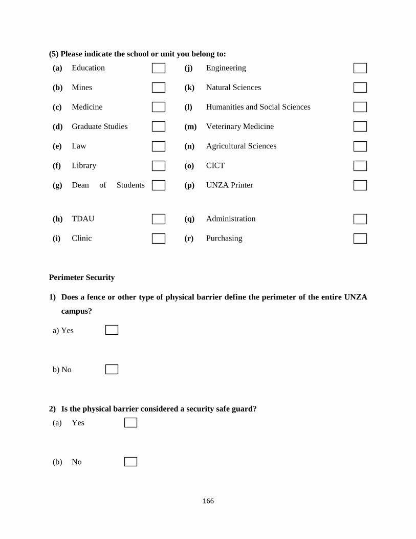
166
(5) Please indicate the school or unit you belong to:
(a) Education (j) Engineering
(b) Mines (k) Natural Sciences
(c) Medicine (l) Humanities and Social Sciences
(d) Graduate Studies (m) Veterinary Medicine
(e) Law (n) Agricultural Sciences
(f) Library (o) CICT
(g) Dean of Students
(p) UNZA Printer
(h) TDAU (q) Administration
(i) Clinic (r) Purchasing
Perimeter Security
1) Does a fence or other type of physical barrier define the perimeter of the entire UNZA
campus?
a) Yes
b) No
2) Is the physical barrier considered a security safe guard?
(a) Yes
(b) No
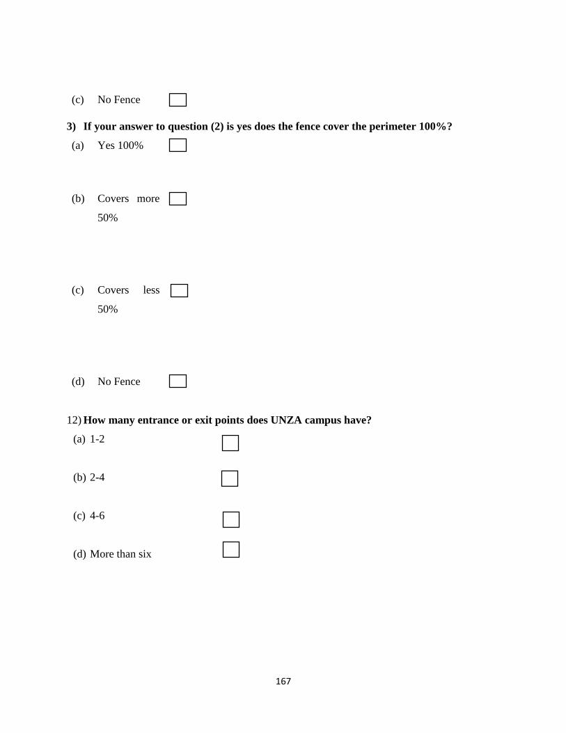
167
(c) No Fence
3) If your answer to question (2) is yes does the fence cover the perimeter 100%?
(a) Yes 100%
(b) Covers more
50%
(c) Covers less
50%
(d) No Fence
12) How many entrance or exit points does UNZA campus have?
(a) 1-2
(b) 2-4
(c) 4-6
(d) More than six
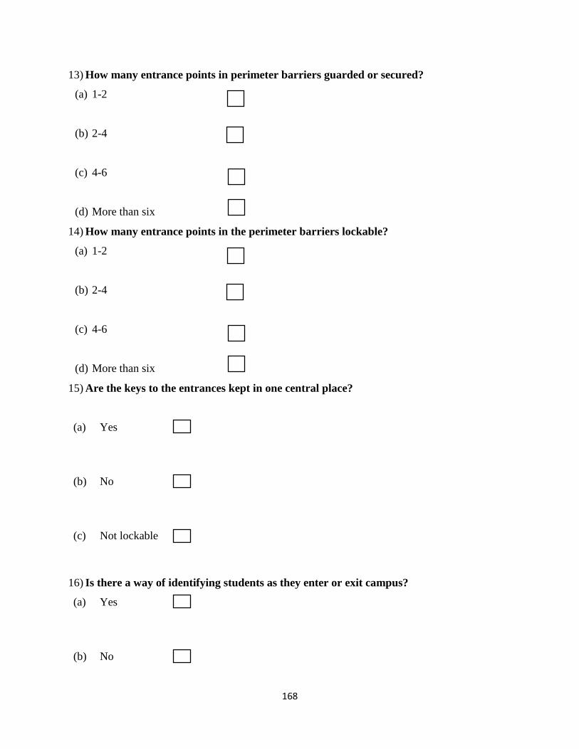
168
13) How many entrance points in perimeter barriers guarded or secured?
(a) 1-2
(b) 2-4
(c) 4-6
(d) More than six
14) How many entrance points in the perimeter barriers lockable?
(a) 1-2
(b) 2-4
(c) 4-6
(d) More than six
15) Are the keys to the entrances kept in one central place?
(a) Yes
(b) No
(c) Not lockable
16) Is there a way of identifying students as they enter or exit campus?
(a) Yes
(b) No
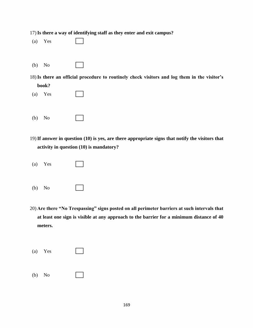
169
17) Is there a way of identifying staff as they enter and exit campus?
(a) Yes
(b) No
18) Is there an official procedure to routinely check visitors and log them in the visitor’s
book?
(a) Yes
(b) No
19) If answer in question (10) is yes, are there appropriate signs that notify the visitors that
activity in question (10) is mandatory?
(a) Yes
(b) No
20) Are there “No Trespassing” signs posted on all perimeter barriers at such intervals that
at least one sign is visible at any approach to the barrier for a minimum distance of 40
meters.
(a) Yes
(b) No
170
21) Are all normally used pedestrian and vehicle gates lighted to allow proper identification
and examination of interiors of vehicles?
(a) Yes
(b) No
(c) Some
22) Are the lighting sources at theses entrances provided with dependable source of power?
(a) Yes
(b) No
(c) No lighting
23) Are there Security communications equipment exclusive for security personnel?
(a) Yes
(b) No
171
24) Is there a written down procedure to report crime?
(a) Yes
(b) No
25) Is the university of Zambia community availed with a number to call the Security in case
of an emergency.
(a) Yes
(b) No
26) Is there a record of reported thefts?
(a) Yes
(b) No

172