ms ma - wdm - fibrolan cee gmbh
TRANSCRIPT

MSMARS
WDMWDM
...THE COMPANY
Established in 1996, has been continuously building up it’s expertise in the area of Fiber-Optic Networking.
In our first years we have been providing mainly FO connectivity solutions, targeting the Enterprise and Government markets.
Early this century, our forces began its shift towards Carrier Access solutions. With our MetroStarTM system and the MA technology, we turned out to be one of the first vendors to provide (already in 2002) fully integrated Ethernet Access Systems with advanced and comprehensive IP-less OAM. Continuously keeping open mind and ears to carriers’ needs and wishes, our technology expanded to include 2.5G and 10G transmission, extremely fast link protected devices, PDH integration (Ethernet over PDH and PDH over FE/GBE), affordable WDM and other features. Our new gigabit product-family named FALCON, is probably the most attractive NTU available in the market, offering very high data-throughput, PDH integration and Synchronous Ethernet.
With a wide-ranging suit of products - combined with state of the art technology, competitive pricing, record high product reliability, willingness to adapt to specific requirements and dedicated customer support - no wonder that dozens of tier 1-2-3 carriers made FibroLAN their choice, some of them deploying our solutions for the fifth year in row.
FibroLAN’s successful positioning in the markets has resulted in the restructuring of our channels: we currently have OEM/reselling agreements with some of the world’s most prominent Telecommunications equipment vendors, increasing further our exposure to carriers. Based on its outstanding business performance, FibroLANbecame - in March 2006 - a public company, successfully traded in TASE - the Tel Aviv Stock Exchange (symbol: FIBR). Funds raised (followed by more private equity investments) provide us with a solid financial basis required to meet the challenges of accelerated technology and business growth.
FibroLAN thrives to become a key player in the Access market. Carriers will seriously consider our technology offering before deciding on the most advatageous way to implement the Access layer of their legacy and NG networks.
FibroLAN
Version 2009/01, Copyright 2009 by FibroLAN CEE GmbH, Leobersdorferstr. 42, 2560 Berndorf, AustriaDisclaimer: FibroLAN continuously enhances its products, therefore this catalogue may not correctly represent all currently available devices and parts. Product specifications can change without notice. FibroLAN does not accept liability for errors or changes in the stated specifications. For current availabili-ty, detailed specifications and warranty information, please contact your regional sales person.
...CONTENTS
Management....................................................... Functional Description
FibroLAN MA™ enabled Product Line
MA™ Function Set
MetroView..........................................................
MetroStarTM........................................................ Chassis
Modules
WDM Solutions...................................................
Converters.......................................................... F.CON
H.CON
S.CON
U.CON
GSM
DLA
GA10
Aggregators........................................................ LTA
FALCON
Any-to-Any Redundant Link Access Device....... ATARA100
ATARA1000
Extender........................................................... FC
SFP/Accessories for all products........................ 155Mbps
1Gbps
CWDM, 1,25Gbps
2,5Gbps
CWDM, 2,5Gbps
DWDM, 1,25Gbps
DWDM, 2,5Gbps
RS
4
7
9
47
57
93
107
117
123
MA
MS
WDM
...THE COMPANY
FibroLAN
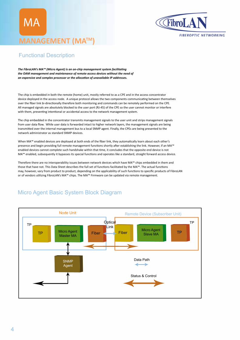
The FibroLAN‘s MA™ (Micro Agent) is an on-chip management system facilitating the OAM management and maintenance of remote access devices without the need of an expensive and complex processor or the allocation of unavailable IP addresses.
The chip is embedded in both the remote (home) unit, mostly referred to as a CPE and in the access concentrator device deployed in the access node. A unique protocol allows the two components communicating between themselves over the fiber link bi-directionally therefore both monitoring and commands can be remotely performed on the CPE.All managed signals are absolutely blocked to the user port (RJ-45) of the CPE so the user cannot monitor or interfere with them, preventing intentional or accidental access to the network management system.
The chip embedded in the concentrator transmits management signals to the user unit and strips management signals from user data flow. While user data is forwarded intact to higher network layers, the management signals are being transmitted over the internal management bus to a local SNMP agent. Finally, the CPEs are being presented to the network administrator as standard SNMP devices.
When MA™ enabled devices are deployed at both ends of the fiber link, they automatically learn about each other’s presence and begin providing full remote management functions shortly after establishing the link. However, if an MA™ enabled devices cannot complete such handshake within that time, it concludes that the opposite end device is not MA™ enabled, subsequently it bypasses its special functions and operates like a standard, straight forward access device.
Therefore there are no interoperability issues between network devices which have MA™ chips embedded in them and those that have not. This Data Sheet describes the full set of functions facilitated by the MA™. The actual functions may, however, vary from product to product, depending on the applicability of such functions to specific products of FibroLAN or of vendors utilizing FibroLAN’s MA™ chips. The MA™ Firmware can be updated via remote management.
MANAGEMENT (MATM)
Functional Description
Micro Agent Basic System Block Diagram
TP Micro AgentMaster MA
Fiber Fiber TPMicro AgentSlave MA
SNMPAgent
Data Path
Status & Control
TP TP
SNMPAgent
Remote Device (Subscriber Unit)Node Unit
OpticalLink
MA
4
MANAGEMENT (MATM)
MA
FibroLAN MATM enabled Product Line
All 100/1000 Mbps MetroStarTM system modules:
MCM100, MCM110, ACM110MCM100-1E1/2E1/4E1, MCM100-1T1/2/1/4T1PCM110-4/8E1, PCM110-4/8T1MCM100-RL, MCM1000T, MCM1000S, MCM1000XMCM1000-XRL, MCM1000-XRL-4E1, MCM1000-XRL-4T1
S.CON1M/MA, GSM1000M, GSM1010MH.CON/MA, LTA41/MAF.CON1/MA, F.CON1F/MAATARA1000-RMGSM1000/MA, GSM1010/MAGSM1000x
Following are the management (maintenance) functions available for an MATM enabled
remote device (CPE) through an MATM enabled and SNMP managed Access Concentrator
F/O Link Status:The incoming path as seen by the CPE. Every change
(link down to up and vice versa) generates an alarm to the manager.
T/P Link Status: Integrity of user connection. Every change (link down to up and vice versa)
generates an alarm to the manager.
Fiber Link Integrity:Continuous (every 10ms) verification of the fiber link.
Fault Propagation:when activated, a CPE MA device sensing a loss of its F/O link, will automatically
cuts its TP port link. MetroStarTM modules incorporate bi-directional Fault Propagation mechanism (FO>TP, TP>FO)
Link Segmentation Test (LST):FibroLAN GBE devices are equipped with this powerful link status alert
and link testing mechanism
Subscriber Link Emulation (SLE):A most advanced Fault Propagation mechanism propagates failure of the subscriber (connected to FibroLAN’s CPE) all the way to the Access switch respective port
(and vice-versa) without affecting the fiber link connecting the 2 sites (CPE remains under full control)
Loop-Back:A special test pattern transmitted to the CPE is looped back as close as possible to the USER port, and positively verified at the access concentrator, confirming the good condition of the CPE and the link. This function is performed upon request. This function tests more than 90% of the CPE’s active parts.
The LB test is performed without disruption of user traffic thus may be used as a basic preventive maintenance operation.
Extended Loop-Back (ELB):Activating this function initiates a series of individual Loop-Back tests providing a precise
measurement of the entire link quality. The length of this test is user definable.
MATM Function Set
MANAGEMENT (MATM)
Functional Description
Micro Agent Basic System Block Diagram
5

Signal Detect:presence of a valid analog optical signal at the receive port of the CPE. This indication – together
with the F/O Link as above – provides a powerful diagnostics tool for the optical link integrity and troubleshooting.
Power On:CPE Power On; equivalent to CPE’s log-into the network.
Set A/N Mode:CPE’s TP port may be set to Auto-Negotiation or non A/N mode.
This function is not applicable to non-buffered CPEs (F.CON series).
Set 10/100:when CPE set to A/N disable mode, this function allows forcing 10 or 100Mbps onto the TP port.
This function is not applicable to non-buffered CPEs (F.CON series).
Set Duplex Mode:when CPE set to A/N disable mode, this function allows forcing HDX or FDX onto the TP port.
This function is not applicable to non-buffered CPEs (F.CON series).
Port enable/disable: all modes
VLAN and QoS:CPEs operation profile (e.g. for multi media applications) can be set or changed remotely by changing VLAN and QoS settings.
Port Priority: per port priority, 802.1p and DSCP port priority Applicable to CPE models supporting all these features.
Statistics:provide information regarding the overall traffic through the LTA41/MA device
(error packet counters, good packet counters, refresh/clear counters)
Last Gasp:Upon occurrence of a supply power failure, which may result from a local failure or any failure in the supply network (apartment, building, block etc), the CPE alerts the NOC– using last “drops” of energy left. This will automatically be followed by a Link-Loss alert from the concentrator. Both alerts combined allow
the NOC take the right decision regarding action to be taken.
Rate Limiting:A robust layer 1 algorithm allows providing users with a partial bandwidth out of the nominal rate of 100Mbps or 1000Mbps to facilitate SLA, mainly in MTUs. Consequently, available bandwidth in the network can be utilized to the fullest, maximizing revenues and profits of the service provider. Bandwidth can be set in more than 100 steps starting from 256Kbps both symmetrically and asymmetrically up and down stream. The applicability of this function depends on the architecture and implementation of
upper layers of the network
Reset Device and Restore factory default parameters
Specifications are subject to change without prior notice
MANAGEMENT (MATM)
MA
MATM Function Set
6
The MetroView™ platform provides a comprehensive high level management of FibroLAN MetroStarTM
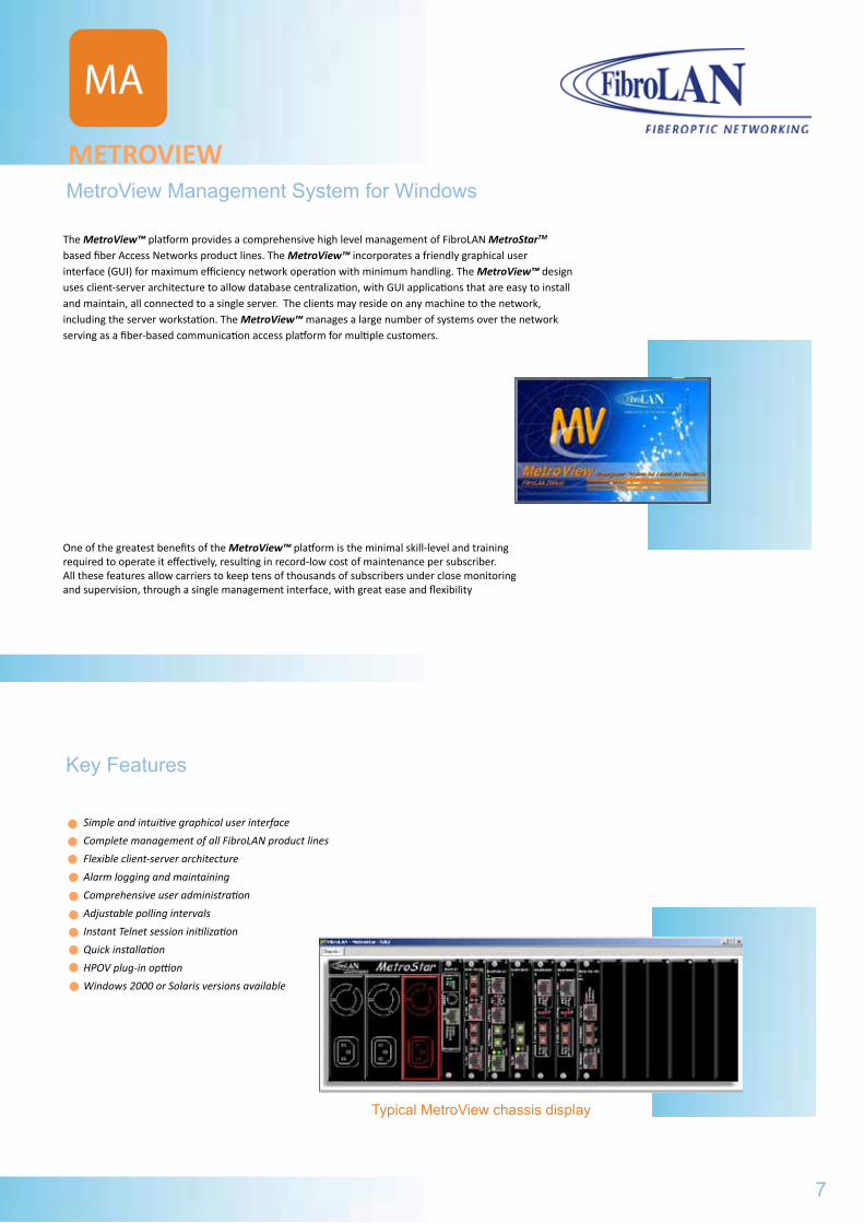
based fiber Access Networks product lines. The MetroView™ incorporates a friendly graphical user interface (GUI) for maximum efficiency network operation with minimum handling. The MetroView™ design uses client-server architecture to allow database centralization, with GUI applications that are easy to install and maintain, all connected to a single server. The clients may reside on any machine to the network, including the server workstation. The MetroView™ manages a large number of systems over the network serving as a fiber-based communication access platform for multiple customers.
One of the greatest benefits of the MetroView™ platform is the minimal skill-level and training required to operate it effectively, resulting in record-low cost of maintenance per subscriber. All these features allow carriers to keep tens of thousands of subscribers under close monitoring and supervision, through a single management interface, with great ease and flexibility
METROVIEW
MA
MetroView Management System for Windows
Key Features
Simple and intuitive graphical user interface
Complete management of all FibroLAN product lines
Flexible client-server architecture
Alarm logging and maintaining
Comprehensive user administration
Adjustable polling intervals
Instant Telnet session initilization
Quick installation
HPOV plug-in opttion
Windows 2000 or Solaris versions available
Typical MetroView chassis display
7
MANAGEMENT (MATM)MATM Function Set
MA
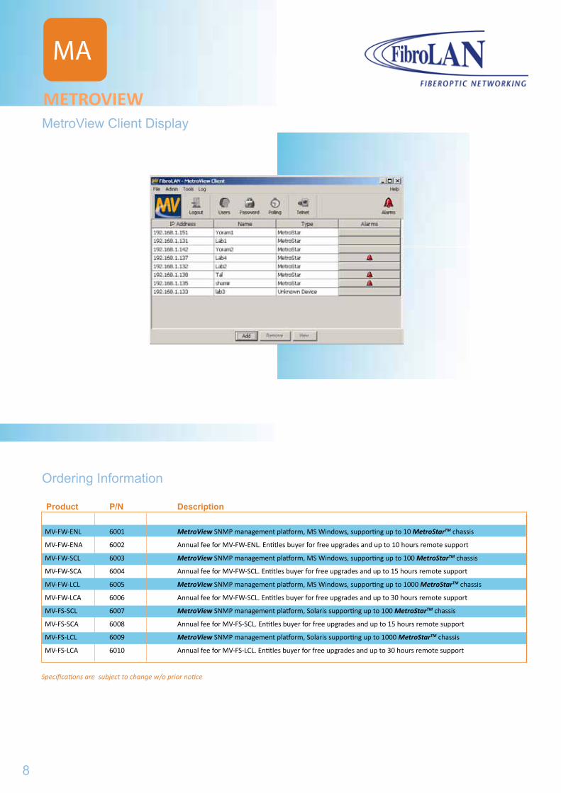
MetroView Client Display
Ordering Information
Product P/N Description
MV-FW-ENL 6001 MetroView SNMP management platform, MS Windows, supporting up to 10 MetroStarTM chassis
MV-FW-ENA 6002 Annual fee for MV-FW-ENL. Entitles buyer for free upgrades and up to 10 hours remote support
MV-FW-SCL 6003 MetroView SNMP management platform, MS Windows, supporting up to 100 MetroStarTM chassis
MV-FW-SCA 6004 Annual fee for MV-FW-SCL. Entitles buyer for free upgrades and up to 15 hours remote support
MV-FW-LCL 6005 MetroView SNMP management platform, MS Windows, supporting up to 1000 MetroStarTM chassis
MV-FW-LCA 6006 Annual fee for MV-FW-SCL. Entitles buyer for free upgrades and up to 30 hours remote support
MV-FS-SCL 6007 MetroView SNMP management platform, Solaris supporting up to 100 MetroStarTM chassis
MV-FS-SCA 6008 Annual fee for MV-FS-SCL. Entitles buyer for free upgrades and up to 15 hours remote support
MV-FS-LCL 6009 MetroView SNMP management platform, Solaris supporting up to 1000 MetroStarTM chassis
MV-FS-LCA 6010 Annual fee for MV-FS-LCL. Entitles buyer for free upgrades and up to 30 hours remote support
Specifications are subject to change w/o prior notice
METROVIEW
8
MS
...METROSTAR
Chassis.....................................11
MS
Modules
MMMMMM-01........................................
MCM100........................................MCM100RL....................................MCM1000XRL...............................MCM100-E1/T1.............................MCM110........................................MCM1000T....................................MCM1000S/L.................................MCM1000X....................................
MCM
PCM110....................................
MSM100U.................................MSM622U.................................MSM2500U...............................
ACM110....................................
MDX-41....................................MDX-81....................................
15
1719212527293135
9
MetroView Client Display
Ordering Information
Product P/N Description
MV-FW-ENL 6001 MetroView SNMP management platform, MS Windows, supporting up to 10 MetroStarTM chassis
MV-FW-ENA 6002 Annual fee for MV-FW-ENL. Entitles buyer for free upgrades and up to 10 hours remote support
MV-FW-SCL 6003 MetroView SNMP management platform, MS Windows, supporting up to 100 MetroStarTM chassis
MV-FW-SCA 6004 Annual fee for MV-FW-SCL. Entitles buyer for free upgrades and up to 15 hours remote support
MV-FW-LCL 6005 MetroView SNMP management platform, MS Windows, supporting up to 1000 MetroStarTM chassis
MV-FW-LCA 6006 Annual fee for MV-FW-SCL. Entitles buyer for free upgrades and up to 30 hours remote support
MV-FS-SCL 6007 MetroView SNMP management platform, Solaris supporting up to 100 MetroStarTM chassis
MV-FS-SCA 6008 Annual fee for MV-FS-SCL. Entitles buyer for free upgrades and up to 15 hours remote support
MV-FS-LCL 6009 MetroView SNMP management platform, Solaris supporting up to 1000 MetroStarTM chassis
MV-FS-LCA 6010 Annual fee for MV-FS-LCL. Entitles buyer for free upgrades and up to 30 hours remote support
Specifications are subject to change w/o prior notice
METROVIEW
37
394143
45
5153

MS10
37
394143
45
5153
PCM
MSM
ACM
MDX
All these result in record high MTBF and virtually zero MTTR. Most of the modules are equipped with FibroLAN’s MATM technology, which allows low cost OAM of the link partners. SNMP management is provided either by a single management module or by a combination of Master and Slave modules which allow the stacking of up to 8 devices, providing full management of hundrets of users by a single SNMP agent. The optional cable organizer facilitates neat and safe deployment even in the densest configurations.
The MetroStarTM provides a comprehensive range of services for access, aggregation, transmission and extension of IP traffic (10/100/1000/2500Mbps), with integrated TDM/PDH, and SONET/SDH support. All these features make MetroStarTM the industry’s most efficient Access Platform for FTTx applications, as well as for miscellaneous transmission scenarios.
Carrier Access PlatformMETROSTAR
Key Features
Demaraction point between Service Providers‘ and Users‘ Networks
Ethernet Service OAM to quarantee SLAs
Versatile carrier Ethernet Services
Supported protocols: TDM/PDH, Ethernet, Fast Ethernet, ATM, Gigabit
Ethernet, SAN (Fibre Channel and Escon), SONET/SDH and 10GE
Multi-purpose customer and network interfaces.
Carrier Class - redundant PS, -48VDC PS, all modules (including fans) are
hot-swappable. All modules and indicators are - front loaded, no active
components on back-plane and comprehensive alarming.
Cost effective CWDM
PDH (E1/T1-E3/T3) over Ethernet support for backhauling wireless base
stations
Management - Stand Alone, redundant or stackable
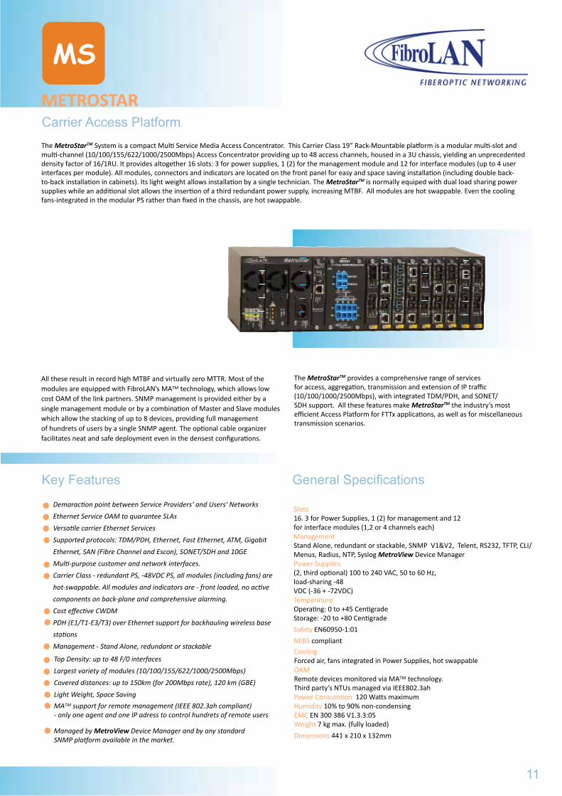
The MetroStarTM System is a compact Multi Service Media Access Concentrator. This Carrier Class 19” Rack-Mountable platform is a modular multi-slot and multi-channel (10/100/155/622/1000/2500Mbps) Access Concentrator providing up to 48 access channels, housed in a 3U chassis, yielding an unprecedented density factor of 16/1RU. It provides altogether 16 slots: 3 for power supplies, 1 (2) for the management module and 12 for interface modules (up to 4 user interfaces per module). All modules, connectors and indicators are located on the front panel for easy and space saving installation (including double back-to-back installation in cabinets). Its light weight allows installation by a single technician. The MetroStarTM is normally equiped with dual load sharing power supplies while an additional slot allows the insertion of a third redundant power supply, increasing MTBF. All modules are hot swappable. Even the cooling fans-integrated in the modular PS rather than fixed in the chassis, are hot swappable.
MS
Top Density: up to 48 F/0 interfaces
Largest variety of modules (10/100/155/622/1000/2500Mbps)
Covered distances: up to 150km (for 200Mbps rate), 120 km (GBE)
Light Weight, Space Saving
MATM support for remote management (IEEE 802.3ah compliant)- only one agent and one IP adress to control hundrets of remote users
Managed by MetroView Device Manager and by any standard SNMP platform available in the market.
General Specifications
Slots 16. 3 for Power Supplies, 1 (2) for management and 12 for interface modules (1,2 or 4 channels each)Management Stand Alone, redundant or stackable, SNMP V1&V2, Telent, RS232, TFTP, CLI/Menus, Radius, NTP, Syslog MetroView Device ManagerPower Supplies (2, third optional) 100 to 240 VAC, 50 to 60 Hz, load-sharing -48 VDC (-36 + -72VDC)Temperature Operating: 0 to +45 Centigrade Storage: -20 to +80 Centigrade
Safety EN60950-1:01
NEBS compliantCooling Forced air, fans integrated in Power Supplies, hot swappableOAM Remote devices monitored via MATM technology. Third party’s NTUs managed via IEEE802.3ahPower Consumtion 120 Watts maximumHumidity 10% to 90% non-condensingEMC EN 300 386 V1.3.3:05Weight 7 kg max. (fully loaded)
Dimensions 441 x 210 x 132mm
11
METROSTAR
MS
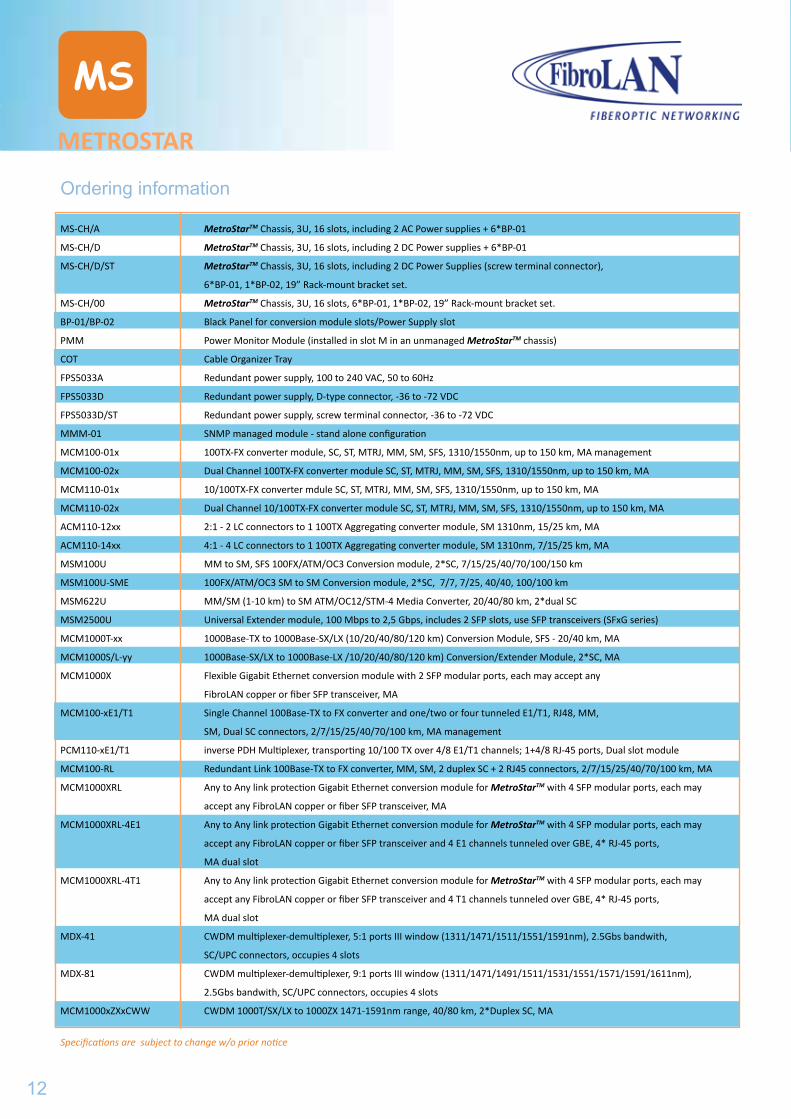
Ordering information
MS-CH/A MetroStarTM Chassis, 3U, 16 slots, including 2 AC Power supplies + 6*BP-01
MS-CH/D MetroStarTM Chassis, 3U, 16 slots, including 2 DC Power supplies + 6*BP-01
MS-CH/D/ST MetroStarTM Chassis, 3U, 16 slots, including 2 DC Power Supplies (screw terminal connector),
6*BP-01, 1*BP-02, 19” Rack-mount bracket set.
MS-CH/00 MetroStarTM Chassis, 3U, 16 slots, 6*BP-01, 1*BP-02, 19” Rack-mount bracket set.
BP-01/BP-02 Black Panel for conversion module slots/Power Supply slot
PMM Power Monitor Module (installed in slot M in an unmanaged MetroStarTM chassis)
COT Cable Organizer Tray
FPS5033A Redundant power supply, 100 to 240 VAC, 50 to 60Hz
FPS5033D Redundant power supply, D-type connector, -36 to -72 VDC
FPS5033D/ST Redundant power supply, screw terminal connector, -36 to -72 VDC
MMM-01 SNMP managed module - stand alone configuration
MCM100-01x 100TX-FX converter module, SC, ST, MTRJ, MM, SM, SFS, 1310/1550nm, up to 150 km, MA management
MCM100-02x Dual Channel 100TX-FX converter module SC, ST, MTRJ, MM, SM, SFS, 1310/1550nm, up to 150 km, MA
MCM110-01x 10/100TX-FX converter mdule SC, ST, MTRJ, MM, SM, SFS, 1310/1550nm, up to 150 km, MA
MCM110-02x Dual Channel 10/100TX-FX converter module SC, ST, MTRJ, MM, SM, SFS, 1310/1550nm, up to 150 km, MA
ACM110-12xx 2:1 - 2 LC connectors to 1 100TX Aggregating converter module, SM 1310nm, 15/25 km, MA
ACM110-14xx 4:1 - 4 LC connectors to 1 100TX Aggregating converter module, SM 1310nm, 7/15/25 km, MA
MSM100U MM to SM, SFS 100FX/ATM/OC3 Conversion module, 2*SC, 7/15/25/40/70/100/150 km
MSM100U-SME 100FX/ATM/OC3 SM to SM Conversion module, 2*SC, 7/7, 7/25, 40/40, 100/100 km
MSM622U MM/SM (1-10 km) to SM ATM/OC12/STM-4 Media Converter, 20/40/80 km, 2*dual SC
MSM2500U Universal Extender module, 100 Mbps to 2,5 Gbps, includes 2 SFP slots, use SFP transceivers (SFxG series)
MCM1000T-xx 1000Base-TX to 1000Base-SX/LX (10/20/40/80/120 km) Conversion Module, SFS - 20/40 km, MA
MCM1000S/L-yy 1000Base-SX/LX to 1000Base-LX /10/20/40/80/120 km) Conversion/Extender Module, 2*SC, MA
MCM1000X Flexible Gigabit Ethernet conversion module with 2 SFP modular ports, each may accept any
FibroLAN copper or fiber SFP transceiver, MA
MCM100-xE1/T1 Single Channel 100Base-TX to FX converter and one/two or four tunneled E1/T1, RJ48, MM,
SM, Dual SC connectors, 2/7/15/25/40/70/100 km, MA management
PCM110-xE1/T1 inverse PDH Multiplexer, transporting 10/100 TX over 4/8 E1/T1 channels; 1+4/8 RJ-45 ports, Dual slot module
MCM100-RL Redundant Link 100Base-TX to FX converter, MM, SM, 2 duplex SC + 2 RJ45 connectors, 2/7/15/25/40/70/100 km, MA
MCM1000XRL Any to Any link protection Gigabit Ethernet conversion module for MetroStarTM with 4 SFP modular ports, each may
accept any FibroLAN copper or fiber SFP transceiver, MA
MCM1000XRL-4E1 Any to Any link protection Gigabit Ethernet conversion module for MetroStarTM with 4 SFP modular ports, each may
accept any FibroLAN copper or fiber SFP transceiver and 4 E1 channels tunneled over GBE, 4* RJ-45 ports,
MA dual slot
MCM1000XRL-4T1 Any to Any link protection Gigabit Ethernet conversion module for MetroStarTM with 4 SFP modular ports, each may
accept any FibroLAN copper or fiber SFP transceiver and 4 T1 channels tunneled over GBE, 4* RJ-45 ports,
MA dual slot
MDX-41 CWDM multiplexer-demultiplexer, 5:1 ports III window (1311/1471/1511/1551/1591nm), 2.5Gbs bandwith,
SC/UPC connectors, occupies 4 slots
MDX-81 CWDM multiplexer-demultiplexer, 9:1 ports III window (1311/1471/1491/1511/1531/1551/1571/1591/1611nm),
2.5Gbs bandwith, SC/UPC connectors, occupies 4 slots
MCM1000xZXxCWW CWDM 1000T/SX/LX to 1000ZX 1471-1591nm range, 40/80 km, 2*Duplex SC, MA
Specifications are subject to change w/o prior notice
12
METROSTAR
MS
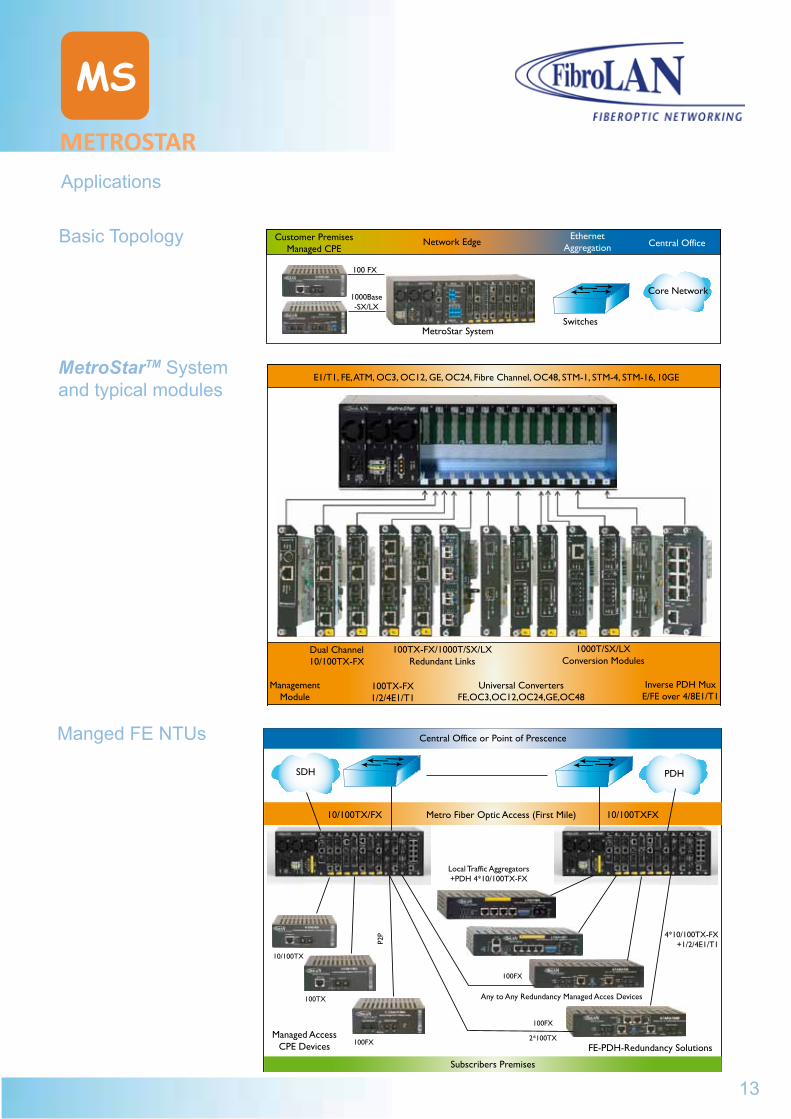
Applications
Customer PremisesManaged CPE
Network EdgeEthernet
Aggregation Central Office
Core Network
SwitchesMetroStar System
E1/T1, FE, ATM, OC3, OC12, GE, OC24, Fibre Channel, OC48, STM-1, STM-4, STM-16, 10GE
Management Module
Dual Channel10/100TX-FX
100TX-FX1/2/4E1/T1
100TX-FX/1000T/SX/LXRedundant Links
Universal ConvertersFE,OC3,OC12,OC24,GE,OC48
1000T/SX/LXConversion Modules
Inverse PDH MuxE/FE over 4/8E1/T1
100 FX
1000Base-SX/LX
Central Office or Point of Prescence
SDH PDH
10/100TX/FX Metro Fiber Optic Access (First Mile) 10/100TXFX
10/100TX
100TX
100FX
Subscribers Premises
Managed AccessCPE Devices
Local Traffic Aggregators+PDH 4*10/100TX-FX
FE-PDH-Redundancy Solutions
Any to Any Redundancy Managed Acces Devices
4*10/100TX-FX+1/2/4E1/T1
100FX
100FX
2*100TX
Basic Topology
MetroStarTM System and typical modules
Manged FE NTUs
13
METROSTAR
Ordering information
METROSTAR
MS
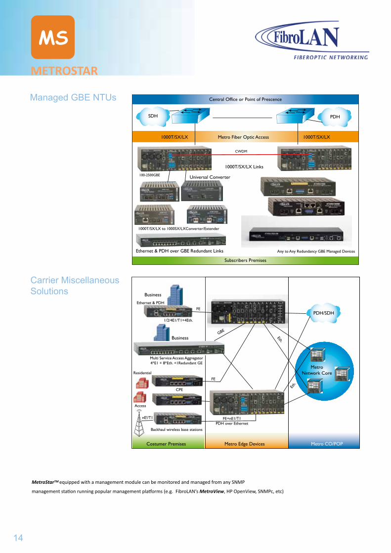
Managed GBE NTUs
Carrier Miscellaneous Solutions
Central Office or Point of Prescence
SDH PDH
1000T/SX/LX Metro Fiber Optic Access 1000T/SX/LX
100-2500GBE
Subscribers Premises
Ethernet & PDH over GBE Redundant Links
1000T/SX/LX to 1000SX/LXConverter/Extender
Any to Any Redundancy GBE Managed Devices
1000T/SX/LX Links
CWDM
Universal Converter
Costumer Premises Metro Edge Devices Metro CO/POP
PDH/SDH
MetroNetwork Core
Business
Ethernet & PDH
1/2/4E1/T1+4Eth.
Business
Multi Service Access Aggregator4*E1 + 8*Eth. +1Redundant GE
CPE
Backhaul wireless base stations
nE!/T1
Residential
Access
FE
FE
FE+nE1/T1PDH over Ethernet
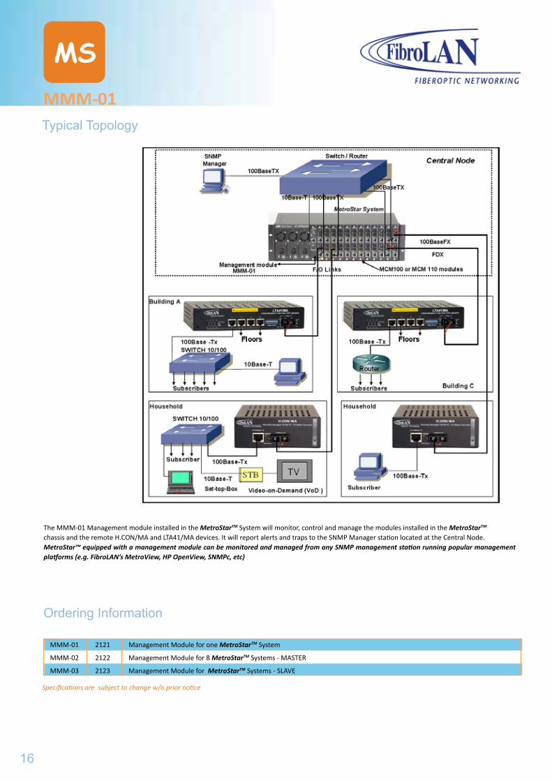
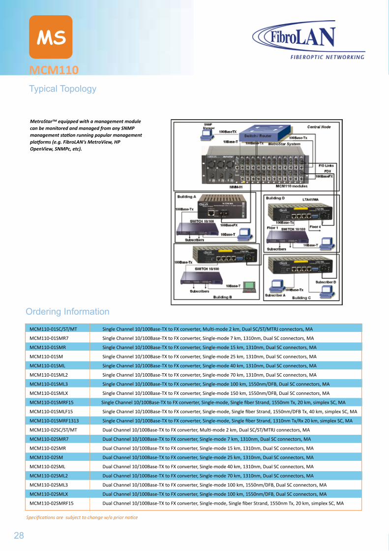
MetroStarTM equipped with a management module can be monitored and managed from any SNMP
management station running popular management platforms (e.g. FibroLAN‘s MetroView, HP OpenView, SNMPc, etc)
14
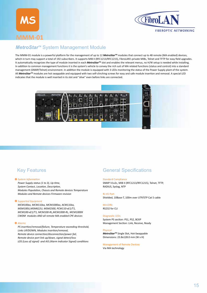
MMM-01
MS
MetroStarTM System Management ModuleThe MMM-01 module is a powerful platform for the management of up to 12 MetroStarTM modules that connect up to 48 remote (MA enabled) devices, which in turn may support a total of 192 subscribers. It supports MIB II (RFC1213/RFC1215), FibroLAN’s private MIBs, Telnet and TFTP for easy field upgrades.It automatically recognizes the type of module inserted in each MetroStarTM slot and enables the relevant menus, no H/W setup is needed while installing. In addition to common management functions it is the system’s vehicle to convey the rich suit of MA related functions (status and control) into a standard management (SNMP/Telnet) environment. In addition the module is equipped with 3 LEDs monitoring the status of the Power Supply plant of the system. All MetroStarTM modules are hot swappable and equipped with two self-clinching screws for easy and safe module insertion and removal. A special LED indicates that the module is well inserted in its slot and “alive” even before links are connected.
Key Features
System InformationPower Supply status (1 to 3), Up time, System Contact, Location, Description, Modules Population, Chassis and Remote devices TemperatureModules and Remote devices Firmware revision
Supported EquipmentMCM100xx, MCM110xx, MCM1000xx, ACM110xx,MSM100U,MSM622U, MSM2500, PCM110-xE1/T1,MCM100-xE1/T1, MCM100-RL,MCM1000-RL, MCM1000XCWDM modules AND all remote MA enabled CPE devices
AlarmsPS insertion/removal/failure, Temperature exceeding threshold,Links UP/DOWN, Modules insertion/removal, Remote device connection/disconnection/power fail,Remote device port link up/down, signal detect/lossLOS (Loss of signal) and AIS (Alarm Indicator Signal) conditions
General Specifications
Standard Compliance SNMP V1v2c, MIB II (RFC1213/RFC1215), Telnet, TFTP, RADIUS, Syslog, NTP
RJ-45 Port Shielded, 10Base-T, 100m over UTP/STP Cat 5 cable
MiniDIN: RS232 for CLI
Diagnostic LEDs System PS section: PS1, PS2, BCKPManagement Section: Link, Receive, Ready
Physical MetroStarTM Single Slot, Hot-SwappableDimensions: 23.8x128.0 mm (W x H)
Management of Remote Devices Via MA technology
15
METROSTAR
Managed GBE NTUs
Carrier Miscellaneous Solutions
MMM-01
MS
Typical Topology
The MMM-01 Management module installed in the MetroStarTM System will monitor, control and manage the modules installed in the MetroStarTM chassis and the remote H.CON/MA and LTA41/MA devices. It will report alerts and traps to the SNMP Manager station located at the Central Node.MetroStar™ equipped with a management module can be monitored and managed from any SNMP management station running popular management platforms (e.g. FibroLAN’s MetroView, HP OpenView, SNMPc, etc)
Ordering Information
MMM-01 2121 Management Module for one MetroStarTM System
MMM-02 2122 Management Module for 8 MetroStarTM Systems - MASTER
MMM-03 2123 Management Module for MetroStarTM Systems - SLAVE
www
Specifications are subject to change w/o prior notice
16
MCM100
MS
100Base-TX to 100Base-FX Converter ModuleThis module provides one or two direct and independent 100Base-TX to 100Base-FX conversion channels. As a layer one converter, it is independent from frame size. The module is offered in a large variety of optical interfaces, both dual and single fiber strand, allowing the extension of the network up to 150 km. The bi-directional Fault Propagation (FP) allows the network redundancy (provided that he switch/router to which it is connected is properly set to activate an alternate path). The TEST switch disables FP function and it is used for diagnostics purposes. Its RJ-45 port is Auto-Cross compliant, making installation fault free. The Subscriber Link Emulation (SLE) - when link partner is an MATM enabled device - allows real time notification of the remote user failure while maintaining the fiber link active. The rate limiting mechanism provides the carrier with a platform to ensure SLAs along with high over-subscription rates. Like other MetroStarTM modules, the MCM100 is fully SNMP managed.
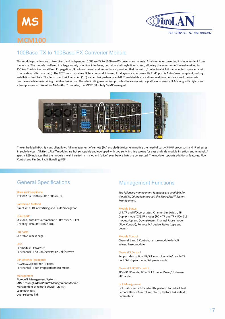
The embedded MA chip controllerallows full management of remote (MA enabled) devices eliminating the need of costly SNMP processors and IP adresses in such devices. All MetroStarTM modules are hot swappable and equipped with two self-clinching screws for easy and safe module insertion and removal. A special LED indicates that the module is well inserted in its slot and “alive” even before links are connected. The module supports additional features: Flow Control and Far End Fault Signaling (FEF).
General Specifications
Standard ComplianceIEEE 802.3u, 100Base-TX, 100Base-FX.
Conversion MethodDirect with FDX advertising and Fault Propagation
RJ-45 portsShielded, Auto Cross compliant, 100m over STP Cat 5 cabling. Default: 100Mb FDX
F/O portsSee table in next page
LEDsPer module - Power ONPer channel - F/O Link/Activity, TP Link/Activity
DIP switches (on board)HDX/FDX Selector for TP portsPer channel - Fault Propagation/Test mode
ManagementFibroLAN Management SystemSNMP through MetroStarTM Management ModuleManagement of remote device: via MALoop Back TestOver selected link
Management Functions
The following management functions are available for the MCM100 module through the MetroStarTM System Management:
Module StatusLink TP and F/O port status, Channel bandwidth, TP Duplex mode (DX), FP modes (FO>>TP and TP>>FO), SLE modes, (Up and Downstream), Channel Pause mode (Flow Control), Remote MA device Status (type and power)
Module ControlChannel 1 and 2 Controls, restore module default values, Reset module
Channel X ControlSet port description, FP/SLE control, enable/disable TP port, Set duplex mode, Set pause mode
Channel X FP/SLE control:TP>>FO FP mode, FO>>TP FP mode, Down/Upstream SLE mode
Link ManagementLink status, set link bandwidth, perform Loop-back test, Remote Device Control and Status, Restore link default parameters.
17
MMM-01Typical Topology
Ordering Information
MCM100
MS
Typical Topology
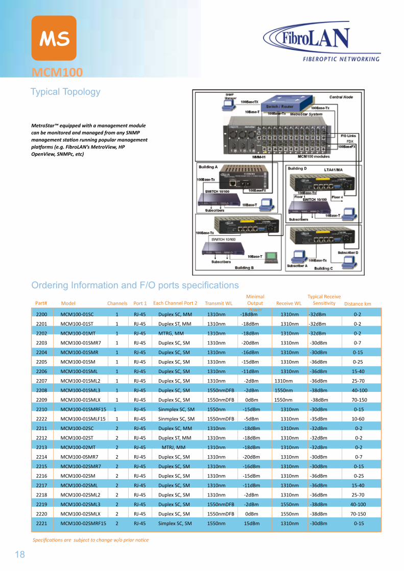
MetroStar™ equipped with a management module can be monitored and managed from any SNMP management station running popular management platforms (e.g. FibroLAN’s MetroView, HP OpenView, SNMPc, etc)
Ordering Information and F/O ports specifications
Part# Model Channels Port 1 Each Channel Port 2 Transmit WLMinimal OutputPower
Receive WLTypical Receive
Sensitivity Distance km
2200 MCM100-01SC 1 RJ-45 Duplex SC, MM 1310nm -18dBm 1310nm -32dBm 0-2
2201 MCM100-01ST 1 RJ-45 Duplex ST, MM 1310nm -18dBm 1310nm -32dBm 0-2
2202 MCM100-01MT 1 RJ-45 MTRG, MM 1310nm -18dBm 1310nm -32dBm 0-2
2203 MCM100-01SMR7 1 RJ-45 Duplex SC, SM 1310nm -20dBm 1310nm -30dBm 0-7
2204 MCM100-01SMR 1 RJ-45 Duplex SC, SM 1310nm -16dBm 1310nm -30dBm 0-15
2205 MCM100-01SM 1 RJ-45 Duplex SC, SM 1310nm -15dBm 1310nm -36dBm 0-25
2206 MCM100-01SML 1 RJ-45 Duplex SC, SM 1310nm -11dBm 1310nm -36dBm 15-40
2207 MCM100-01SML2 1 RJ-45 Duplex SC, SM 1310nm -2dBm 1310nm -36dBm 25-70
2208 MCM100-01SML3 1 RJ-45 Duplex SC, SM 1550nmDFB -2dBm 1550nm -38dBm 40-100
2209 MCM100-01SMLX 1 RJ-45 Duplex SC, SM 1550nmDFB 0dBm 1550nm -38dBm 70-150
2210 MCM100-01SMRF15 1 RJ-45 Sinmplex SC, SM 1550nm -15dBm 1310nm -30dBm 0-15
2222 MCM100-01SMLF15 1 RJ-45 Sinmplex SC, SM 1550nmDFB -5dBm 1310nm -35dBm 10-60
2211 MCM100-02SC 2 RJ-45 Duplex SC, MM 1310nm -18dBm 1310nm -32dBm 0-2
2212 MCM100-02ST 2 RJ-45 Duplex ST, MM 1310nm -18dBm 1310nm -32dBm 0-2
2213 MCM100-02MT 2 RJ-45 MTRJ, MM 1310nm -18dBm 1310nm -32dBm 0-2
2214 MCM100-0SMR7 2 RJ-45 Duplex SC, SM 1310nm -20dBm 1310nm -30dBm 0-7
2215 MCM100-02SMR7 2 RJ-45 Duplex SC, SM 1310nm -16dBm 1310nm -30dBm 0-15
2216 MCM100-02SM 2 RJ-45 Duplex SC, SM 1310nm -15dBm 1310nm -36dBm 0-25
2217 MCM100-02SML 2 RJ-45 Duplex SC, SM 1310nm -11dBm 1310nm -36dBm 15-40
2218 MCM100-02SML2 2 RJ-45 Duplex SC, SM 1310nm -2dBm 1310nm -36dBm 25-70
2219 MCM100-02SML3 2 RJ-45 Duplex SC, SM 1550nmDFB -2dBm 1550nm -38dBm 40-100
2220 MCM100-02SMLX 2 RJ-45 Duplex SC, SM 1550nmDFB 0dBm 1550nm -38dBm 70-150
2221 MCM100-02SMRF15 2 RJ-45 Simplex SC, SM 1550nm 15dBm 1310nm -30dBm 0-15
Specifications are subject to change w/o prior notice
18
MCM100-RL
MS
100Base-TX to 100Base-FX Redundant Links - Converter ModuleThe MCM100-RL is an “Any To any” 100TX to 100FX Redundant Link Conversion module for the MetroStarTM chassis. It automatically selects the active port on each F/O and TP sides (with priority to “MAIN” ports) and interconnects them. It has two TP and two F/O connectors. This way, end-to-end path and device redundancy is achieved disregarding the type of the remote device, catering to various network resilience scenarios. Upon failure of a MAIN port, the module switches traffic within less than 10μsecs to the Backup port and alerts the network manager. When the MAIN link is restored, the traffic will automatically or manually switch back to it, providing operational consistency and easy tracing of the active path. The switch-back occurs immediately after link restoration or following a tunable delay (via the management systems) to avoid network instability during the repair process. Inactive Ports (normally Backup) are continuously monitored for link integrity, providing the network manager with valuable information of his system’s readiness.
Using an on-board switch (or via management), the Redundant Links mode may be disabled. In such case, the module functions exactly like a dual channel converter, each 2 adjacent ports forming a channel. As a layer 1 converter, it is independent from frame size. The module is offered in a large variety of optical interfaces, both dual and single fiber strand, allowing the extension of the network up to 150km. Selective Fault Propagation (FP) from the F/O port to the TP or vice-versa provides link status forwarding. The TEST switch disables the Fault Propagation and allows link failure detection. The RJ-45 ports are Auto-Cross compliant, making installation fail free. The Subscriber Link Emulation (SLE) - when link partner is an MA enabled device – allows real time notification of the remote user failure while maintaining the fiber link active.
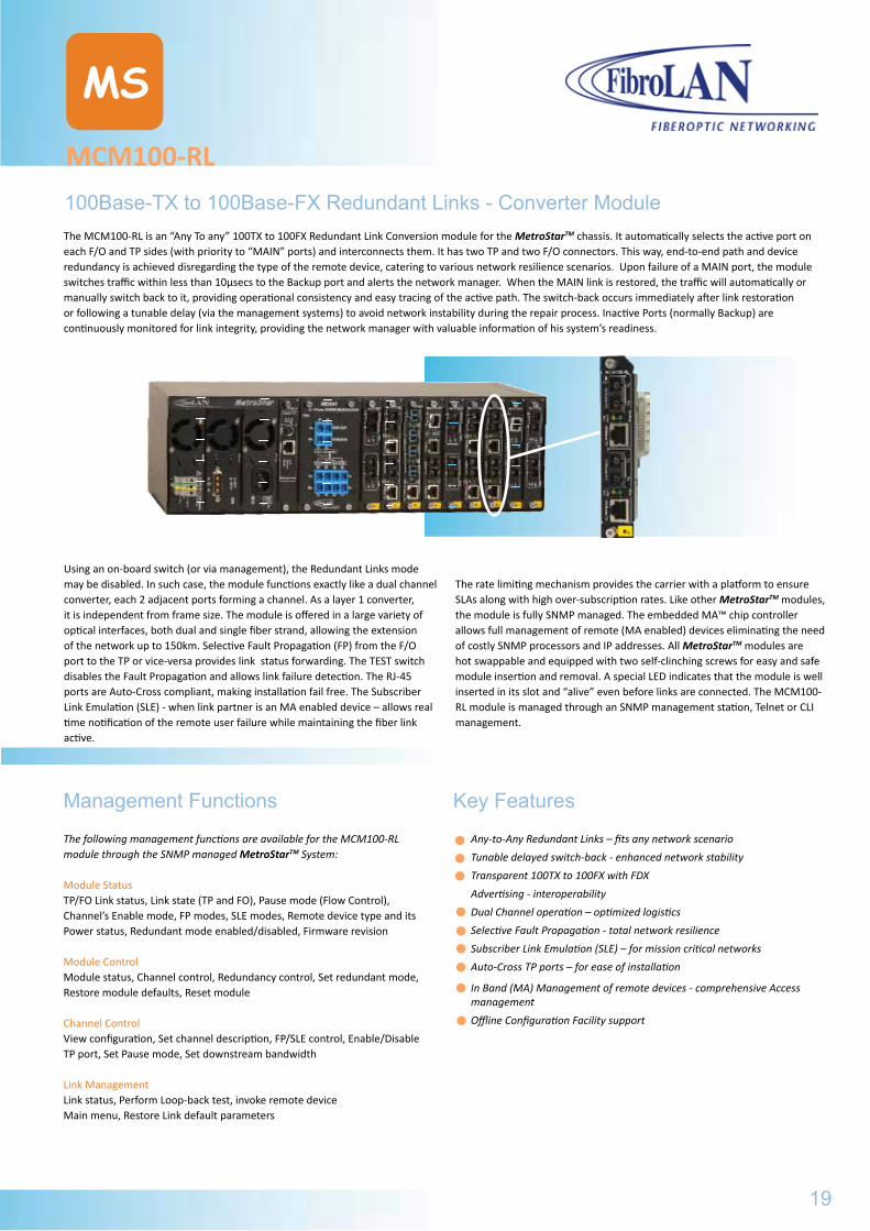
The rate limiting mechanism provides the carrier with a platform to ensure SLAs along with high over-subscription rates. Like other MetroStarTM modules, the module is fully SNMP managed. The embedded MA™ chip controller allows full management of remote (MA enabled) devices eliminating the need of costly SNMP processors and IP addresses. All MetroStarTM modules are hot swappable and equipped with two self-clinching screws for easy and safe module insertion and removal. A special LED indicates that the module is well inserted in its slot and “alive” even before links are connected. The MCM100-RL module is managed through an SNMP management station, Telnet or CLI management.
Key Features
Any-to-Any Redundant Links – fits any network scenario
Tunable delayed switch-back - enhanced network stability
Transparent 100TX to 100FX with FDX
Advertising - interoperability
Dual Channel operation – optimized logistics
Selective Fault Propagation - total network resilience
Subscriber Link Emulation (SLE) – for mission critical networks
Auto-Cross TP ports – for ease of installation
In Band (MA) Management of remote devices - comprehensive Access management
Offline Configuration Facility support
Management Functions
The following management functions are available for the MCM100-RL module through the SNMP managed MetroStarTM System:
Module StatusTP/FO Link status, Link state (TP and FO), Pause mode (Flow Control), Channel’s Enable mode, FP modes, SLE modes, Remote device type and its Power status, Redundant mode enabled/disabled, Firmware revision
Module ControlModule status, Channel control, Redundancy control, Set redundant mode, Restore module defaults, Reset module
Channel ControlView configuration, Set channel description, FP/SLE control, Enable/Disable TP port, Set Pause mode, Set downstream bandwidth
Link ManagementLink status, Perform Loop-back test, invoke remote deviceMain menu, Restore Link default parameters
19
MCM100Typical Topology
Ordering Information and F/O ports specifications
MCM100-RL
MS
General Specifications
Standard ComplianceIEEE802.3u, 100Base-TX, 100Base-FX
Conversion MethodDirect with FDX advertising
RJ-45 Ports (x2)Shielded, Auto-Cross, 100m over STP Cat 5 cabling
F/O Ports (x2)Simplex and Duplex SC connectors
MAIN to Backup switchover10 µsec max. from link fail detection
Backup to MAIN switchoverTunable to 0/5/10/20/ sec or manually
Diagnostic LEDsPower ONLink/activity MAIN F/O, Link/activity MAIN TPLink/activity Backup F/O, Link/activity Backup TP
DIP switches (on board)Mode (Redundant Links/ Dual Channel Converter)Fault Propagation: FO>>TP ON/OFF, TP>>FO ON/OFFManagement overrides DIP switches setting
Management:
FibroLAN MetroView Device ManagerSNMP , Telnet and CLI
Management of Remote Devicesvia MA™ Technology
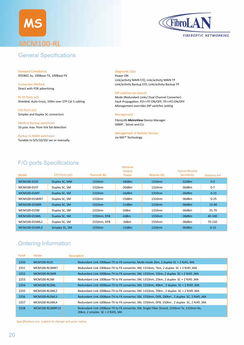
F/O ports Specifications
Model F/O Ports (x2) Transmit WL
Minimal OutputPower Receive WL
Typical Receive Sensitivity Distance km
Specifications are subject to change w/o prior notice
MCM100-01SC Duplex SC, MM 1310nm -18dBm 1310nm -32dBm 0-2
MCM100-01ST Duplex SC, SM 1310nm -20dBm 1310nm -30dBm 0-7
MCM100-01MT Duplex SC, SM 1310nm -16dBm 1310nm -30dBm 0-15
MCM100-01SMR7 Duplex SC, SM 1310nm -15dBm 1310nm -36dBm 0-25
MCM100-01SMR Duplex SC, SM 1310nm -11dBm 1310nm -36dBm 15-40
MCM100-01SM Duplex SC, SM 1310nm -2dBm 1310nm -36dBm 25-70
MCM100-01SML Duplex SC, SM 1550nm, DFB -2dBm 1550nm -38dBm 40-100
MCM100-01SML2 Duplex SC, SM 1550nm, DFB 0dBm 1550nm -38dBm 70-150
MCM100-01SML3 Simplex SC, SM 1550nm -15dBm 1310nm -30dBm 0-15
Ordering Information
ModelPart# Description
2250 MCM100-RLSC Redundant Link 100Base-TX to FX converter, Multi-mode 2km, 2 duplex SC + 2 RJ45, MA
2251 MCM100-RLSMR7 Redundant Link 100Base-TX to FX converter, SM, 1310nm, 7km, 2 duplex SC + 2 RJ45 ,MA
2252 MCM100-RLSMR Redundant Link 100Base-TX to FX converter, SM, 1310nm, 15km, 2 duplex SC + 2 RJ45 ,MA
2253 MCM100-RLSM Redundant Link 100Base-TX to FX converter, SM, 1310nm, 25km, 2 duplex SC + 2 RJ45 ,MA
2254 MCM100-RLSML Redundant Link 100Base-TX to FX converter, SM, 1310nm, 40km , 2 duplex SC + 2 RJ45 ,MA
2255 MCM100-RLSML2 Redundant Link 100Base-TX to FX converter, SM, 1310nm, 70km , 2 duplex SC + 2 RJ45 ,MA
2256 MCM100-RLSML3 Redundant Link 100Base-TX to FX converter, SM, 1550nm, DFB, 100km , 2 duplex SC, 2 RJ45 ,MA
2257 MCM100-RLSMLX Redundant Link 100Base-TX to FX converter, SM, 1550nm, DFB, 150km , 2 duplex SC, 2 RJ45 ,MA
2258 MCM100-RLSMRF15 Redundant Link 100Base-TX to FX converter, SM, Single Fiber Strand, 1550nm Tx, 1310nm Rx, 20km, 2 simplex SC + 2 RJ45, MA
20
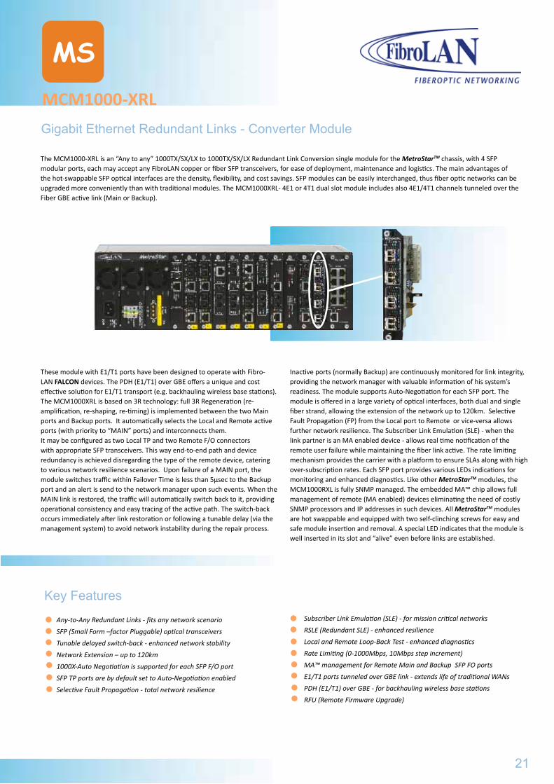
MCM1000-XRL
MS
Gigabit Ethernet Redundant Links - Converter Module
The MCM1000-XRL is an “Any to any” 1000TX/SX/LX to 1000TX/SX/LX Redundant Link Conversion single module for the MetroStarTM chassis, with 4 SFP modular ports, each may accept any FibroLAN copper or fiber SFP transceivers, for ease of deployment, maintenance and logistics. The main advantages of the hot-swappable SFP optical interfaces are the density, flexibility, and cost savings. SFP modules can be easily interchanged, thus fiber optic networks can be upgraded more conveniently than with traditional modules. The MCM1000XRL- 4E1 or 4T1 dual slot module includes also 4E1/4T1 channels tunneled over the Fiber GBE active link (Main or Backup).
These module with E1/T1 ports have been designed to operate with Fibro-LAN FALCON devices. The PDH (E1/T1) over GBE offers a unique and cost effective solution for E1/T1 transport (e.g. backhauling wireless base stations). The MCM1000XRL is based on 3R technology: full 3R Regeneration (re-amplification, re-shaping, re-timing) is implemented between the two Main ports and Backup ports. It automatically selects the Local and Remote active ports (with priority to “MAIN” ports) and interconnects them. It may be configured as two Local TP and two Remote F/O connectors with appropriate SFP transceivers. This way end-to-end path and device redundancy is achieved disregarding the type of the remote device, catering to various network resilience scenarios. Upon failure of a MAIN port, the module switches traffic within Failover Time is less than 5µsec to the Backup port and an alert is send to the network manager upon such events. When the MAIN link is restored, the traffic will automatically switch back to it, providing operational consistency and easy tracing of the active path. The switch-back occurs immediately after link restoration or following a tunable delay (via the management system) to avoid network instability during the repair process.
Inactive ports (normally Backup) are continuously monitored for link integrity, providing the network manager with valuable information of his system’s readiness. The module supports Auto-Negotiation for each SFP port. The module is offered in a large variety of optical interfaces, both dual and single fiber strand, allowing the extension of the network up to 120km. Selective Fault Propagation (FP) from the Local port to Remote or vice-versa allows further network resilience. The Subscriber Link Emulation (SLE) - when the link partner is an MA enabled device - allows real time notification of the remote user failure while maintaining the fiber link active. The rate limiting mechanism provides the carrier with a platform to ensure SLAs along with high over-subscription rates. Each SFP port provides various LEDs indications for monitoring and enhanced diagnostics. Like other MetroStarTM modules, the MCM1000RXL is fully SNMP managed. The embedded MA™ chip allows full management of remote (MA enabled) devices eliminating the need of costly SNMP processors and IP addresses in such devices. All MetroStarTM modules are hot swappable and equipped with two self-clinching screws for easy and safe module insertion and removal. A special LED indicates that the module is well inserted in its slot and “alive” even before links are established.
Key Features
Any-to-Any Redundant Links - fits any network scenario
SFP (Small Form –factor Pluggable) optical transceivers
Tunable delayed switch-back - enhanced network stability
Network Extension – up to 120km
1000X-Auto Negotiation is supported for each SFP F/O port
SFP TP ports are by default set to Auto-Negotiation enabled
Selective Fault Propagation - total network resilience
Subscriber Link Emulation (SLE) - for mission critical networks
RSLE (Redundant SLE) - enhanced resilience
Local and Remote Loop-Back Test - enhanced diagnostics
Rate Limiting (0-1000Mbps, 10Mbps step increment)
MA™ management for Remote Main and Backup SFP FO ports
E1/T1 ports tunneled over GBE link - extends life of traditional WANs
PDH (E1/T1) over GBE - for backhauling wireless base stations
RFU (Remote Firmware Upgrade)
21
MCM100-RLGeneral Specifications
F/O ports Specifications
Ordering Information
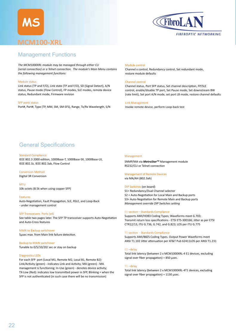
Management Functions
The MCM1000XRL module may be managed through either CLI (serial connection) or a Telnet connection. The module‘s Main Menu contains the following management functions:
Module statusLink status (TP and F/O), Link state (TP and F/O), SD (Signal Detect), A/N status, Pause mode (Flow Control), FP modes, SLE modes, remote device status, Redundant mode, Firmware revision
SFP ports statusPort#, Part#, Type (TP, MM, SM, SM-SFS), Range, Tx/Rx Wavelength, S/N
MCM100-XRL
MS
General Specifications
Standard ComplianceIEEE 802.3 2000 edition, 1000Base-T, 1000Base-SX, 1000Base-LX, IEEE 802.3z, IEEE 802.3ab, Flow Control
Conversion MethodDigital 3R Conversion
MTU10k octets (8.5k when using copper SFP)
FeaturesAuto-Negotiation, Fault Propagation, SLE, RSLE, and Loop-Back- under management control
SFP Transceivers Ports (x4)See table two pages later. The SFP TP transceiver supports Auto-Negotiation and Auto-Cross features
MAIN to Backup switchover5µsec max. from Main link failure detection.
Backup to MAIN switchoverTunable to 0/5/10/20/ sec or stay on backup
Diagnostics LEDsFor each SFP port (Local M1, Remote M2, Local B1, Remote B2): Link/Activity (green) - indicates Link and Activity; MA (green) - MA management is functioning; In-Use (green) - denotes device activity;TX-Low (Red): indicates low transmitted power in SFP, Blinking = when the SFP is not authenticated (in such case there will be no transmission)
Management
SNMP/MA via MetroStarTM Management module RS232/CLI or Telnet connection
Management of Remote Devicesvia MA/AH (802.3ah)
DIP Switches (on board)S1= Redundancy/Dual Channel selectorS2 = Auto-Negotiation for Local Main and Backup portsS3= Auto-Negotiation for Remote Main and Backup portsManagement override DIP Switches setting
E1 section – Standards ComplianceSupports AMI/HDB3 Coding Types; Waveforms meet G.703; Transmit return loss specifications - ETSI ETS-300166; Jitter as per ETSI CTR12/13, ITU G.736, G.742, and G.823; LOS per ITU G.775
T1 section - Standards ComplianceSupports AMI/B8ZS Coding Types. Output Power Waveforms meet ANSI T1.102 Jitter attenuation per AT&T Pub 62411LOS per ANSI T1.231
E1 –delayTotal link latency (between 2 x MCM1000XRL-4 E1 devices, excluding signal over fiber propagation) = 850 μsec.
T1 –delayTotal link latency (between 2 x MCM1000XRL-4T1 devices, excluding signal over fiber propagation) = 1130 μsec.
Module control Channel x control, Redundancy control, Set redundant mode, restore module defaults
Channel controlChannel status, Port SFP status, Set channel description, FP/SLE control, enable/disable TP port, Set Pause mode, Set downstream BW (rate limit), Set port A/N mode, set port LB mode, restore channel defaults
Link ManagementInvoke remote device, perform Loop-back test
22
MCM100-XRL
MS
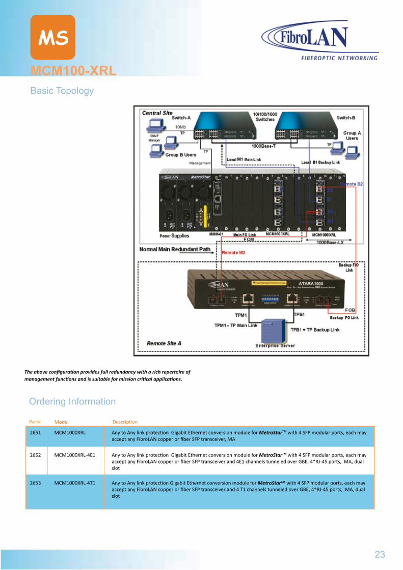
Basic Topology
Ordering Information
ModelPart# Description
The above configuration provides full redundancy with a rich repertoire of management functions and is suitable for mission critical applications.
2651 MCM1000XRL Any to Any link protection Gigabit Ethernet conversion module for MetroStarTM with 4 SFP modular ports, each may accept any FibroLAN copper or fiber SFP transceiver, MA
2652 MCM1000XRL-4E1 Any to Any link protection Gigabit Ethernet conversion module for MetroStarTM with 4 SFP modular ports, each may accept any FibroLAN copper or fiber SFP transceiver and 4E1 channels tunneled over GBE, 4*RJ-45 ports, MA, dual slot
2653 MCM1000XRL-4T1 Any to Any link protection Gigabit Ethernet conversion module for MetroStarTM with 4 SFP modular ports, each may accept any FibroLAN copper or fiber SFP transceiver and 4 T1 channels tunneled over GBE, 4*RJ-45 ports, MA, dual slot
23
MCM100-XRL
Management
SNMP/MA via MetroStarTM Management module RS232/CLI or Telnet connection
Management of Remote Devicesvia MA/AH (802.3ah)
DIP Switches (on board)S1= Redundancy/Dual Channel selectorS2 = Auto-Negotiation for Local Main and Backup portsS3= Auto-Negotiation for Remote Main and Backup portsManagement override DIP Switches setting
E1 section – Standards ComplianceSupports AMI/HDB3 Coding Types; Waveforms meet G.703; Transmit return loss specifications - ETSI ETS-300166; Jitter as per ETSI CTR12/13, ITU G.736, G.742, and G.823; LOS per ITU G.775
T1 section - Standards ComplianceSupports AMI/B8ZS Coding Types. Output Power Waveforms meet ANSI T1.102 Jitter attenuation per AT&T Pub 62411LOS per ANSI T1.231
E1 –delayTotal link latency (between 2 x MCM1000XRL-4 E1 devices, excluding signal over fiber propagation) = 850 μsec.
T1 –delayTotal link latency (between 2 x MCM1000XRL-4T1 devices, excluding signal over fiber propagation) = 1130 μsec.
Module control Channel x control, Redundancy control, Set redundant mode, restore module defaults
Channel controlChannel status, Port SFP status, Set channel description, FP/SLE control, enable/disable TP port, Set Pause mode, Set downstream BW (rate limit), Set port A/N mode, set port LB mode, restore channel defaults
Link ManagementInvoke remote device, perform Loop-back test
Specifications are subject to change w/o prior notice
MCM100-XRL
MS
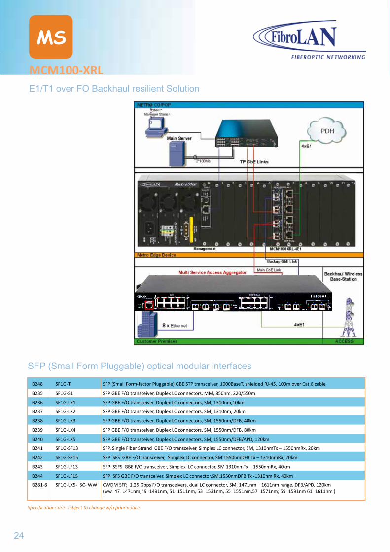
E1/T1 over FO Backhaul resilient Solution
SFP (Small Form Pluggable) optical modular interfaces
B248 SF1G-T SFP (Small Form-factor Pluggable) GBE STP transceiver, 1000BaseT, shielded RJ-45, 100m over Cat.6 cable
B235 SF1G-S1 SFP GBE F/O transceiver, Duplex LC connectors, MM, 850nm, 220/550m
B236 SF1G-LX1 SFP GBE F/O transceiver, Duplex LC connectors, SM, 1310nm,10km
B237 SF1G-LX2 SFP GBE F/O transceiver, Duplex LC connectors, SM, 1310nm, 20km
B238 SF1G-LX3 SFP GBE F/O transceiver, Duplex LC connectors, SM, 1550nm/DFB, 40km
B239 SF1G-LX4 SFP GBE F/O transceiver, Duplex LC connectors, SM, 1550nm/DFB, 80km
B240 SF1G-LX5 SFP GBE F/O transceiver, Duplex LC connectors, SM, 1550nm/DFB/APD, 120km
B241 SF1G-SF13 SFP, Single Fiber Strand GBE F/O transceiver, Simplex LC connector, SM, 1310nmTx – 1550nmRx, 20km
B242 SF1G-SF15 SFP SFS GBE F/O transceiver, Simplex LC connector, SM 1550nmDFB Tx – 1310nmRx, 20km
B243 SF1G-LF13 SFP SSFS GBE F/O transceiver, Simplex LC connector, SM 1310nmTx – 1550nmRx, 40km
B244 SF1G-LF15 SFP SFS GBE F/O transceiver, Simplex LC connector,SM,1550nmDFB Tx -1310nm Rx, 40km
B281-8 SF1G-LX5- 5C- WW CWDM SFP, 1.25 Gbps F/O transceivers, dual LC connector, SM, 1471nm – 1611nm range, DFB/APD, 120km (ww=47=1471nm,49=1491nm, 51=1511nm, 53=1531nm, 55=1551nm,57=1571nm; 59=1591nm 61=1611nm )
24
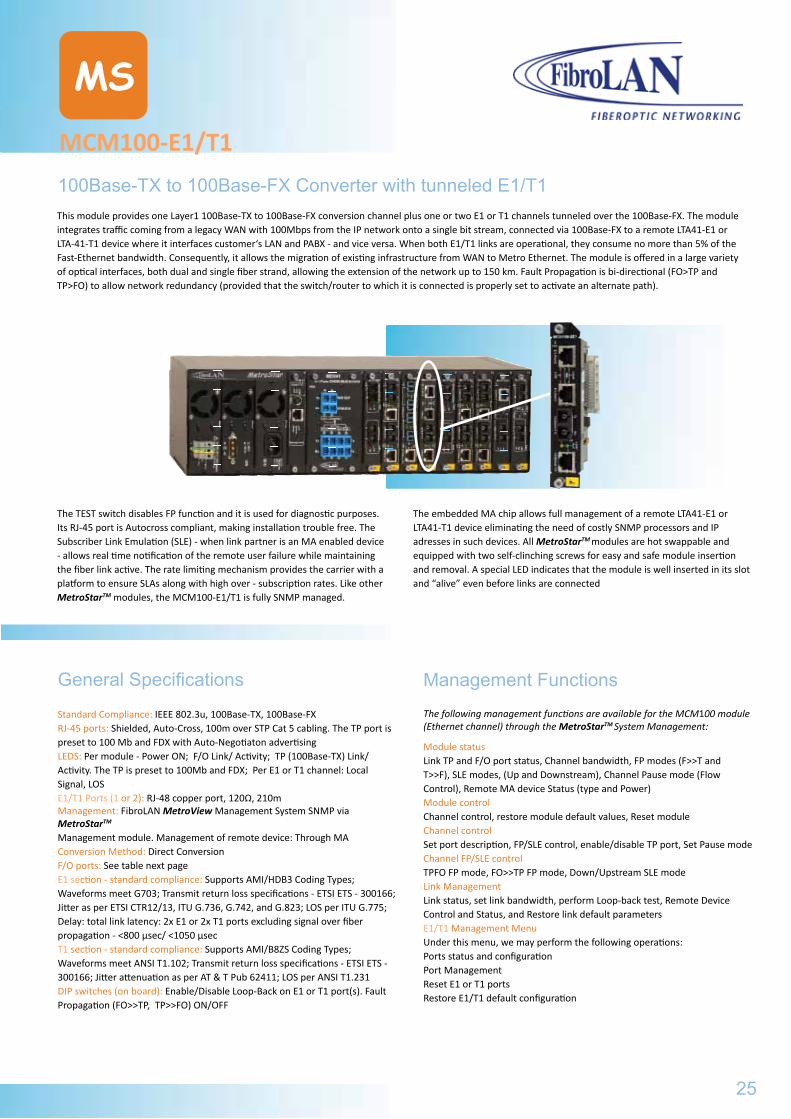
MCM100-E1/T1
MS
100Base-TX to 100Base-FX Converter with tunneled E1/T1This module provides one Layer1 100Base-TX to 100Base-FX conversion channel plus one or two E1 or T1 channels tunneled over the 100Base-FX. The module integrates traffic coming from a legacy WAN with 100Mbps from the IP network onto a single bit stream, connected via 100Base-FX to a remote LTA41-E1 or LTA-41-T1 device where it interfaces customer‘s LAN and PABX - and vice versa. When both E1/T1 links are operational, they consume no more than 5% of the Fast-Ethernet bandwidth. Consequently, it allows the migration of existing infrastructure from WAN to Metro Ethernet. The module is offered in a large variety of optical interfaces, both dual and single fiber strand, allowing the extension of the network up to 150 km. Fault Propagation is bi-directional (FO>TP and TP>FO) to allow network redundancy (provided that the switch/router to which it is connected is properly set to activate an alternate path).
The TEST switch disables FP function and it is used for diagnostic purposes. Its RJ-45 port is Autocross compliant, making installation trouble free. The Subscriber Link Emulation (SLE) - when link partner is an MA enabled device - allows real time notification of the remote user failure while maintaining the fiber link active. The rate limiting mechanism provides the carrier with a platform to ensure SLAs along with high over - subscription rates. Like other MetroStarTM modules, the MCM100-E1/T1 is fully SNMP managed.
The embedded MA chip allows full management of a remote LTA41-E1 or LTA41-T1 device eliminating the need of costly SNMP processors and IP adresses in such devices. All MetroStarTM modules are hot swappable and equipped with two self-clinching screws for easy and safe module insertion and removal. A special LED indicates that the module is well inserted in its slot and “alive” even before links are connected
Management FunctionsThe following management functions are available for the MCM100 module (Ethernet channel) through the MetroStarTM System Management:
Module statusLink TP and F/O port status, Channel bandwidth, FP modes (F>>T and T>>F), SLE modes, (Up and Downstream), Channel Pause mode (Flow Control), Remote MA device Status (type and Power)Module controlChannel control, restore module default values, Reset moduleChannel controlSet port description, FP/SLE control, enable/disable TP port, Set Pause modeChannel FP/SLE controlTPFO FP mode, FO>>TP FP mode, Down/Upstream SLE modeLink ManagementLink status, set link bandwidth, perform Loop-back test, Remote Device Control and Status, and Restore link default parametersE1/T1 Management MenuUnder this menu, we may perform the following operations:Ports status and configurationPort ManagementReset E1 or T1 portsRestore E1/T1 default configuration
General Specifications
Standard Compliance: IEEE 802.3u, 100Base-TX, 100Base-FXRJ-45 ports: Shielded, Auto-Cross, 100m over STP Cat 5 cabling. The TP port is preset to 100 Mb and FDX with Auto-Negotiaton advertisingLEDS: Per module - Power ON; F/O Link/ Activity; TP (100Base-TX) Link/ Activity. The TP is preset to 100Mb and FDX; Per E1 or T1 channel: LocalSignal, LOS E1/T1 Ports (1 or 2): RJ-48 copper port, 120Ω, 210mManagement: FibroLAN MetroView Management System SNMP via MetroStarTM Management module. Management of remote device: Through MAConversion Method: Direct ConversionF/O ports: See table next pageE1 section - standard compliance: Supports AMI/HDB3 Coding Types; Waveforms meet G703; Transmit return loss specifications - ETSI ETS - 300166; Jitter as per ETSI CTR12/13, ITU G.736, G.742, and G.823; LOS per ITU G.775; Delay: total link latency: 2x E1 or 2x T1 ports excluding signal over fiber propagation - <800 µsec/ <1050 µsecT1 section - standard compliance: Supports AMI/B8ZS Coding Types; Waveforms meet ANSI T1.102; Transmit return loss specifications - ETSI ETS - 300166; Jitter attenuation as per AT & T Pub 62411; LOS per ANSI T1.231DIP switches (on board): Enable/Disable Loop-Back on E1 or T1 port(s). Fault Propagation (FO>>TP, TP>>FO) ON/OFF
25
MCM100-XRLE1/T1 over FO Backhaul resilient Solution
SFP (Small Form Pluggable) optical modular interfaces
Specifications are subject to change w/o prior notice
MCM100-E1/T1
MS
Typical Network
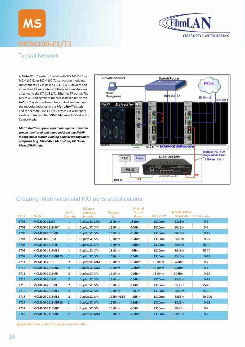
A MetroStarTM system, loaded with 12x MCM-E1 or MCM100-E1 or MCM100-T1 conversion modules, can connect 12 x installed LTA41-E1/T1 devices and more than 48 subscribers (if Hubs and switches are attached to the LTA41-E1/T1 Ethernet TP ports). The MMM-01 Management module installed in the Me-troStarTM system will monitor, control and manage the modules installed in the MetroStarTM chassis and the remote LTA41-E1/T1 devices. It will report alerts and traps to the SNMP Manager located in the Central Node.
MetroStarTM equipped with a management module can be monitored and managed from any SNMP management station running popular management platforms (e.g. FibroLAN‘s MetroView, HP Open-View, SNMPc, etc)
Part# ModelE1/T1
Channels
F/O port Connector & mode
Transmit WL
Minimal OutputPower Receive WL
Typical Receive Sensitivity Distance km
2701 MCM100-1E1SC 1 Duplex SC, MM 1310nm -18dBm 1310nm -32dBm 0-2
2702 MCM100-1E1SMR7 1 Duplex SC, SM 1310nm -20dBm 1310nm -30dBm 0-7
2703 MCM100-1E1SMR 1 Duplex SC, SM 1310nm -16dBm 1310nm -30dBm 0-15
2704 MCM100-1E1SM 1 Duplex SC, SM 1310nm -15dBm 1310nm -36dBm 0-25
2705 MCM100-1E1SML 1 Duplex SC, SM 1310nm -11dBm 1310nm -36dBm 15-40
2706 MCM100-1E1SML2 1 Duplex SC, SM 1310nm -2dBm 1310nm -36dBm 25-70
2707 MCM100-1E1SMRF15 1 Duplex SC, SM 1550nm -15dBm 1310nm -35dBm 0-15
2711 MCM100-2E1SC 2 Duplex SC, MM 1310nm -18dBm 1310nm -32dBm 0-2
2712 MCM100-2E1SMR7 2 Duplex SC, MM 1310nm -20dBm 1310nm -30dBm 0-7
2713 MCM100-2E1SMR 2 Duplex SC, SM 1310nm -16dBm 1310nm -30dBm 0-15
2714 MCM100-2E1SM 2 Duplex SC, SM 1310nm -15dBm 1310nm -36dBm 0-25
2715 MCM100-2E1SML 2 Duplex SC, SM 1310nm -11dBm 1310nm -36dBm 15-40
2716 MCM100-2E1SML2 2 Duplex SC, SM 1310nm -2dBm 1310nm -36dBm 25-70
2718 MCM100-2E1SML3 2 Duplex SC, SM 1550nmDFB -5dBm 1310nm -38dBm 40-100
2717 MCM100-2E1SMRF15 2 Duplex SC, SM 1550nm -15dBm 1310nm -35dBm 0-15
2752 MCM100-1T1SMR7 1 Duplex SC, SM 1310nm -20dBm 1310nm -30dBm 0-7
2762 MCM100-2T1SMR7 2 Duplex SC, MM 1310nm -20dBm 1310nm -30dBm 0-7
Ordering Information and F/O ports specifications
26
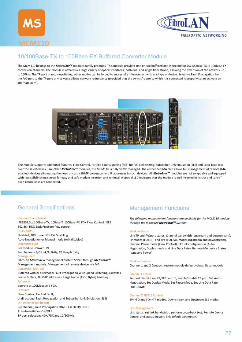
MCM110
MS
10/100Base-TX to 100Base-FX Buffered Converter ModuleThe MCM110 belongs to the MetroStarTM modules family products. This module provides one or two buffered and independent 10/100Base-TX to 100Base-FX conversion channels. The module is offered in a large variety of optical interfaces, both dual and single fiber strand, allowing the extension of the network up to 150km. The TP port is auto-negotiating; other modes can be forced to succesfully interconnect with any type of device. Selective Fault Propagation from the F/O port to the TP port or vice versa allows network redundancy (provided that the switch/router to which it is connected is properly set to activate an alternate path).
Management Functions
The following management functions are available for the MCM110 module through the managed MetroStarTM System:
Module Status Link TP and F/Oport status, Channel bandwidth (upstream and downstream), FP modes (FO>>TP and TP>>FO), SLE modes (upstream and downstream), Channel Pause mode (Flow Control), TP Link configuration (Auto-Negotiation, Duplex mode and Line Data Rate), Remote MA device Status (type and Power)
Module ControlChannel 1 and 2 Controls, restore module default values, Reset module
Channel Control Set port description, FP/SLE control, enable/disable TP port, Set Auto-Negotiation, Set Duplex Mode, Set Pause Mode, Set Line Data Rate (10/100Mb).
Channel X FP/SLE Control TP>>FO and FO>>TP modes, Downstream and Upstream SLE modes
Link Management Link status, set link bandwidth, perform Loop-back test, Remote Device Control and status, Restore link default parameters.
General Specifications
Standard ComplianceIEEE802.3u, 100Base-TX, 10Base-T, 100Base-FX, FDX Flow Control (IEEE 802.3x), HDX Back Pressure flow controlRJ-45 portsShielded, 100m over STP Cat 5 cabling Auto-Negotiation or Manual mode (A/N disabled)Diagnostic LEDsPer module - Power ONPer channel - F/O Link/Activity, TP Link/ActivityManagementFibroLan MetroView management System SNMP through MetroStarTM
Management module. Management of remote device: via MAConversion MethodBuffered with bi-directional Fault Propagation Wire Speed Switching, 64kbytes Frame Buffers, 1k MAC addresses, Large frame (1536 Bytes) handlingF/O portsoperate at 100Mbps and FDX. FeaturesFlow Control, Far End Fault, bi-directional Fault Propagation and Subscriber Link Emulation (SLE)DIP switches (on board)Per channel; Fault Propagation ON/OFF (FO>TP,TP>FO)Auto-Negotiation ON/OFFTP port selection: HDX/FDX and 10/100Mb
The module supports additional features: Flow Control, Far End Fault Signaling (FEF) for F/O Link testing, Subscriber Link Emulation (SLE) and Loop-back test over the selected link. Like other MetroStarTM modules, the MCM110 is fully SNMP managed. The embedded MA chip allows full management of remote (MA enabled) devices eliminating the need of costly SNMP processors and IP addresses in such devices. All MetroStarTM modules are hot swappable and equipped with two selfclinching screws for easy and safe module insertion and removal. A special LED indicates that the module is well inserted in its slot and „alive“ even before links are connected.
27
MCM100-E1/T1Typical Network
Specifications are subject to change w/o prior notice
MCM110
MS
Typical Topology
MetroStarTM equipped with a management module can be monitored and managed from any SNMP management station running popular management platforms (e.g. FibroLAN‘s MetroView, HP OpenView, SNMPc, etc).
Ordering Information
MCM110-01SC/ST/MT Single Channel 10/100Base-TX to FX converter, Multi-mode 2 km, Dual SC/ST/MTRJ connectors, MA
MCM110-01SMR7 Single Channel 10/100Base-TX to FX converter, Single-mode 7 km, 1310nm, Dual SC connectors, MA
MCM110-01SMR Single Channel 10/100Base-TX to FX converter, Single-mode 15 km, 1310nm, Dual SC connectors, MA
MCM110-01SM Single Channel 10/100Base-TX to FX converter, Single-mode 25 km, 1310nm, Dual SC connectors, MA
MCM110-01SML Single Channel 10/100Base-TX to FX converter, Single-mode 40 km, 1310nm, Dual SC connectors, MA
MCM110-01SML2 Single Channel 10/100Base-TX to FX converter, Single-mode 70 km, 1310nm, Dual SC connectors, MA
MCM110-01SML3 Single Channel 10/100Base-TX to FX converter, Single-mode 100 km, 1550nm/DFB, Dual SC connectors, MA
MCM110-01SMLX Single Channel 10/100Base-TX to FX converter, Single-mode 150 km, 1550nm/DFB, Dual SC connectors, MA
MCM110-01SMRF15 Single Channel 10/100Base-TX to FX converter, Single-mode, Single fiber Strand, 1550nm Tx, 20 km, simplex SC, MA
MCM110-01SMLF15 Single Channel 10/100Base-TX to FX converter, Single-mode, Single fiber Strand, 1550nm/DFB Tx, 40 km, simplex SC, MA
MCM110-01SMRF1313 Single Channel 10/100Base-TX to FX converter, Single-mode, Single fiber Strand, 1310nm Tx/Rx 20 km, simplex SC, MA
MCM110-02SC/ST/MT Dual Channel 10/100Base-TX to FX converter, Multi-mode 2 km, Dual SC/ST/MTRJ connectors, MA
MCM110-02SMR7 Dual Channel 10/100Base-TX to FX converter, Single-mode 7 km, 1310nm, Dual SC connectors, MA
MCM110-02SMR Dual Channel 10/100Base-TX to FX converter, Single-mode 15 km, 1310nm, Dual SC connectors, MA
MCM110-02SM Dual Channel 10/100Base-TX to FX converter, Single-mode 25 km, 1310nm, Dual SC connectors, MA
MCM110-02SML Dual Channel 10/100Base-TX to FX converter, Single-mode 40 km, 1310nm, Dual SC connectors, MA
MCM110-02SML2 Dual Channel 10/100Base-TX to FX converter, Single-mode 70 km, 1310nm, Dual SC connectors, MA
MCM110-02SML3 Dual Channel 10/100Base-TX to FX converter, Single-mode 100 km, 1550nm/DFB, Dual SC connectors, MA
MCM110-02SMLX Dual Channel 10/100Base-TX to FX converter, Single-mode 100 km, 1550nm/DFB, Dual SC connectors, MA
MCM110-02SMRF15 Dual Channel 10/100Base-TX to FX converter, Single-mode, Single fiber Strand, 1550nm Tx, 20 km, simplex SC, MA
28
MCM1000T
MS
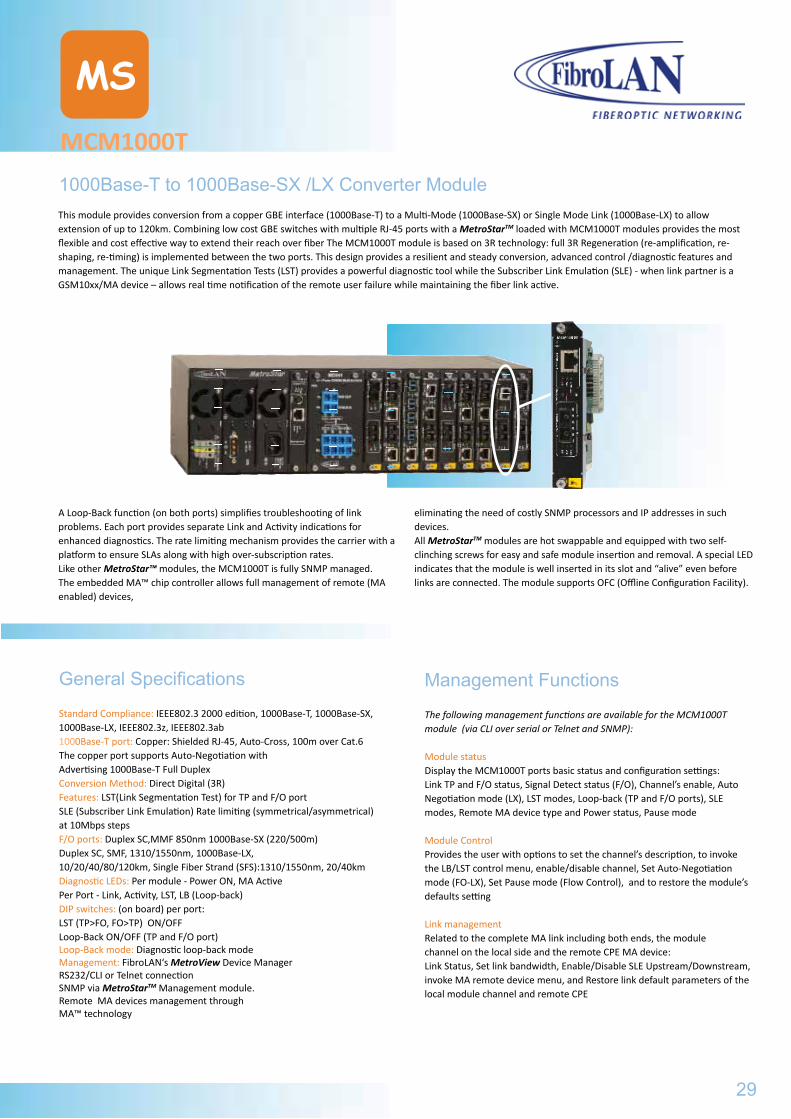
1000Base-T to 1000Base-SX /LX Converter ModuleThis module provides conversion from a copper GBE interface (1000Base-T) to a Multi-Mode (1000Base-SX) or Single Mode Link (1000Base-LX) to allow extension of up to 120km. Combining low cost GBE switches with multiple RJ-45 ports with a MetroStarTM loaded with MCM1000T modules provides the most flexible and cost effective way to extend their reach over fiber The MCM1000T module is based on 3R technology: full 3R Regeneration (re-amplification, re-shaping, re-timing) is implemented between the two ports. This design provides a resilient and steady conversion, advanced control /diagnostic features and management. The unique Link Segmentation Tests (LST) provides a powerful diagnostic tool while the Subscriber Link Emulation (SLE) - when link partner is a GSM10xx/MA device – allows real time notification of the remote user failure while maintaining the fiber link active.
A Loop-Back function (on both ports) simplifies troubleshooting of link problems. Each port provides separate Link and Activity indications for enhanced diagnostics. The rate limiting mechanism provides the carrier with a platform to ensure SLAs along with high over-subscription rates. Like other MetroStar™ modules, the MCM1000T is fully SNMP managed. The embedded MA™ chip controller allows full management of remote (MA enabled) devices,
eliminating the need of costly SNMP processors and IP addresses in such devices. All MetroStarTM modules are hot swappable and equipped with two self-clinching screws for easy and safe module insertion and removal. A special LED indicates that the module is well inserted in its slot and “alive” even before links are connected. The module supports OFC (Offline Configuration Facility).
Management Functions
The following management functions are available for the MCM1000T module (via CLI over serial or Telnet and SNMP): Module statusDisplay the MCM1000T ports basic status and configuration settings: Link TP and F/O status, Signal Detect status (F/O), Channel’s enable, Auto Negotiation mode (LX), LST modes, Loop-back (TP and F/O ports), SLE modes, Remote MA device type and Power status, Pause mode Module Control Provides the user with options to set the channel’s description, to invoke the LB/LST control menu, enable/disable channel, Set Auto-Negotiation mode (FO-LX), Set Pause mode (Flow Control), and to restore the module’s defaults setting Link managementRelated to the complete MA link including both ends, the modulechannel on the local side and the remote CPE MA device:Link Status, Set link bandwidth, Enable/Disable SLE Upstream/Downstream, invoke MA remote device menu, and Restore link default parameters of the local module channel and remote CPE
General Specifications
Standard Compliance: IEEE802.3 2000 edition, 1000Base-T, 1000Base-SX, 1000Base-LX, IEEE802.3z, IEEE802.3ab 1000Base-T port: Copper: Shielded RJ-45, Auto-Cross, 100m over Cat.6The copper port supports Auto-Negotiation with Advertising 1000Base-T Full Duplex Conversion Method: Direct Digital (3R) Features: LST(Link Segmentation Test) for TP and F/O portSLE (Subscriber Link Emulation) Rate limiting (symmetrical/asymmetrical) at 10Mbps steps F/O ports: Duplex SC,MMF 850nm 1000Base-SX (220/500m)Duplex SC, SMF, 1310/1550nm, 1000Base-LX, 10/20/40/80/120km, Single Fiber Strand (SFS):1310/1550nm, 20/40km Diagnostic LEDs: Per module - Power ON, MA ActivePer Port - Link, Activity, LST, LB (Loop-back) DIP switches: (on board) per port:LST (TP>FO, FO>TP) ON/OFFLoop-Back ON/OFF (TP and F/O port)Loop-Back mode: Diagnostic loop-back mode Management: FibroLAN‘s MetroView Device ManagerRS232/CLI or Telnet connection SNMP via MetroStarTM Management module. Remote MA devices management throughMA™ technology
29
MCM110Typical Topology
Specifications are subject to change w/o prior notice
MCM1000T
MS
Typical Topology
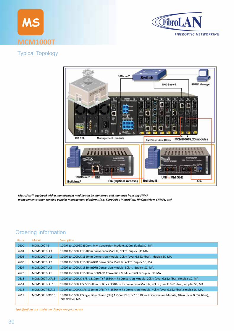
MetroStarTM equipped with a management module can be monitored and managed from any SNMP management station running popular management platforms (e.g. FibroLAN‘s MetroView, HP OpenView, SNMPc, etc)
Part# Model Description
2600 MCM1000T-S 1000T to 1000SX 850nm, MM Conversion Module, 220m duplex SC, MA
2601 MCM1000T-LX1 1000T to 1000LX 1310nm Conversion Module, 10km. duplex SC, MA
2602 MCM1000T-LX2 1000T to 1000LX 1310nm Conversion Module, 20km (over G.652 fiber). duplex SC, MA
2603 MCM1000T-LX3 1000T to 1000LX 1550nmDFB Conversion Module, 40km. duplex SC, MA
2604 MCM1000T-LX4 1000T to 1000LX 1550nmDFB Conversion Module, 80km. duplex SC, MA
2623 MCM1000T-LX5 1000T to 1000LX 1550nm DFB/APD Conversion Module, 120km.duplex SC, MA
2613 MCM1000T-LXF13 1000T to 1000LX, SFS, 1310nm Tx / 1550nm Rx Conversion Module, 20km (over G.652 fiber) simplex SC, MA
2614 MCM1000T-LXF15 1000T to 1000LX SFS 1550nm DFB Tx / 1310nm Rx Conversion Module, 20km (over G.652 fiber), simplex SC, MA
2618 MCM1000T-ZXF13 1000T to 1000LX SFS 1310nm DFB Tx / 1550nm Rx Conversion Module, 40km (over G.652 fiber).simplex SC, MA
2619 MCM1000T-ZXF15 1000T to 1000LX Single Fiber Strand (SFS) 1550nmDFB Tx / 1310nm Rx Conversion Module, 40km (over G.652 fiber), simplex SC, MA
Ordering Information
30
MCM1000S/L
MS
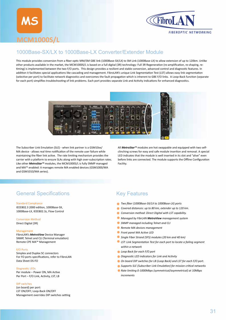
1000Base-SX/LX to 1000Base-LX Converter/Extender ModuleThis module provides conversion from a fiber-optic MM/SM GBE link (1000Base-SX/LX) to SM Link (1000Base-LX) to allow extension of up to 120km. Unlike other products available in the market, the MCM1000S/L is based on a full digital (3R) technology: Full 3R Regeneration (re-amplification, re-shaping, re-timing) is implemented between the two F/O ports. This design provides a resilient and stable conversion, advanced control and diagnostic features. In addition it facilitates special applications like cascading and management. FibroLAN’s unique Link Segmentation Test (LST) allows easy link segmentation (selective per port) to facilitate network diagnostics and overcomes the fault propagation which is inherent to GBE F/O links. A Loop-Back function (separate for each port) simplifies troubleshooting of link problems. Each port provides separate Link and Activity indications for enhanced diagnostics.
The Subscriber Link Emulation (SLE) - when link partner is a GSM10xx/MA device - allows real time notification of the remote user failure while maintaining the fiber link active. The rate limiting mechanism provides the carrier with a platform to ensure SLAs along with high over-subscription rates. Like other MetroStar™ modules, the MCM1000S/L is fully SNMP managed and MA™ enabled: it manages remote MA enabled devices (GSM1000/MA and GSM1010/MA series).
All MetroStar™ modules are hot swappable and equipped with two self-clinching screws for easy and safe module insertion and removal. A special LED indicates that the module is well inserted in its slot and “alive” even before links are connected. The module supports the Offline Configuration Facility.
General Specifications
Standard ComplianceIEEE802.3 2000 edition, 1000Base-SX,1000Base-LX, IEEE802.3z, Flow Control
Conversion MethodDirect Digital (3R)
ManagementFibroLAN’s MetroView Device ManagerSNMP, Telnet and CLI (Terminal emulation)Remote CPE MA™ Management
F/O PortsSimplex and Duplex SC connectorsFor FO ports specifications, refer to FibroLANData Sheet DS-FO
Diagnostic LEDs Per module – Power ON, MA ActivePer Port – F/O Link, Activity, LST, LB
DIP switches(on board) per port:LST ON/OFF; Loop-Back ON/OFFManagement overrides DIP switches setting
Key Features
Two fiber (1000Base-SX/LX to 1000Base-LX) ports
Covered distances: up to 80 km, extender up to 120 km.
Conversion method: Direct Digital with LST capability.
Managed by FibrLAN MetroView management system
SNMP managed including Telnet and CLI
Remote MA devices management
Front panel MA Active LED
Single Fiber Strand (SFS) modules (20 km and 40 km)
LST: Link Segmentation Test for each port to locate a failing segment
within a network
Loop Back for each F/O port
Diagnostic LED indicators for Link and Activity
On board DIP switches for LB (Loop Back) and LST for each F/O port.
Supports SLE (Subscriber Link Emulation) for mission critical networks
Rate limiting 0-1000Mbps (symmetrical/asymmetrical) at 10Mbps
increments
31
MCM1000TTypical Topology
Specifications are subject to change w/o prior notice
MCM1000S/L
MS
Management Functions
Part# Model Description
Ordering Information
The following management functions are available for the MCM1000S/L module through an MA™ enabled and SNMP managed MetroStarTM:
Module status Shows the MCM1000S/L ports basic status and configuration settings: Link status, Signal Detect status, Channel’s enable, LST modes, Loop-back mode (SX and LX), SLE modes, Pause mode, Remote MA device type and Power status. Module Control Provides the user with options to set the channel’s description, set Auto-Nego mode(FO-LX,SX),to invoke the LB/LST menu, enable/disable channel, set Pause mode, and to restore the module’s defaults setting.Link management Related to the complete MA link including both ends, the module channel on the local side and the remote CPE MA device (if connected):Link Status, Set link bandwidth, Enable/disable Downstream/Upstream SLE, invoke MA remote device menu, and Restore link default parameters of the local module channel and the remote device’s channel.
2605 MCM1000S-LX1 1000SX multi-mode 850nm, 220m, to 1000LX single mode 1310nm Conversion Module, 10km, 2*Duplex SC, MA
2606 MCM1000S-LX2 1000SX multi-mode 850nm, 220m, to 1000LX single mode 1310nm Conversion Module, 20km (over G.652 fiber), 2*Duplex SC, MA
2607 MCM1000S-LX3 1000SX multi-mode 850nm, 220m, to 1000LX single mode 1550nmDFB Conversion Module, 40km, 2*Duplex SC, MA
2608 MCM1000S-LX4 1000SX multi-mode 850nm, 220m, to 1000LX single mode 1550nmDFB Conversion Module, 80km, 2*Duplex SC, MA
2609 MCM1000S-LXF13 1000SX multi-mode 850nm, 220m, to 1000LX Single Fiber Strand, 1310nmTx/1550nmRx, Conversion Module, 20km (over G.652 fiber), 1xduplex/1xsimplex SC, MA
2610 MCM1000S-LXF15 1000SX multi-mode 850nm, 220m, to 1000LX Single Fiber Strand, 1550nmTxDFB/1310nmRx, Conversion Module, 20km (over G.652 fiber), 1xduplex/1xsimplex SC, MA
2620 MCM1000S-ZXF13 1000SX multi-mode 850nm, 220m, to 1000LX Single Fiber Strand, 1310nmTxDFB/1550nmRx, Conversion Module, 40km (over G.652 fiber), 1x duplex/1x simplex SC, MA
2621 MCM1000S-ZXF15 1000SX multi-mode 850nm, 220m, to 1000LX Single Fiber Strand, 1550nmTxDFB/1310nmRx, Conversion Module, 40km (over G.652 fiber), 1xduplex/1xsimplex SC, MA
2617 MCM1000L-LX1-2 1000LX single-mode 1310nm, 10km to 1000LX single-mode 1310nm Extender module 20km (over G.652 fiber), 2*Duplex SC, MA
2611 MCM1000L-LX1-3 1000LX single-mode 1310nm, 10km to 1000LX single-mode 1550nm DFB Extender module 40km, 2*Duplex SC, MA
2612 MCM1000L-LX1-4 1000LX single-mode 1310nm, 10km to 1000LX single-mode 1550nm DFB Extender module 80km, 2*Duplex SC, MA
2615 MCM1000L-LX3-3 1000LX single-mode 1550nm DFB, 40km to 1000LX single-mode 1550nm DFB Extender module 40km, 2*Duplex SC, MA
2616 MCM1000L-LX4-4 1000LX single-mode 1550nm DFB, 80km to 1000LX single-mode 1550nm DFB Extender module 80km, 2*Duplex SC, MA
2622 MCM1000L-LX4-5 1000LX single-mode 1550nm DFB, 80km to 1000LX single-mode 1550nm DFB/APD 120km Extender module, 2*Duplex SC, MA
32
Specifications are subject to change w/o prior notice
MCM1000S/L
MS
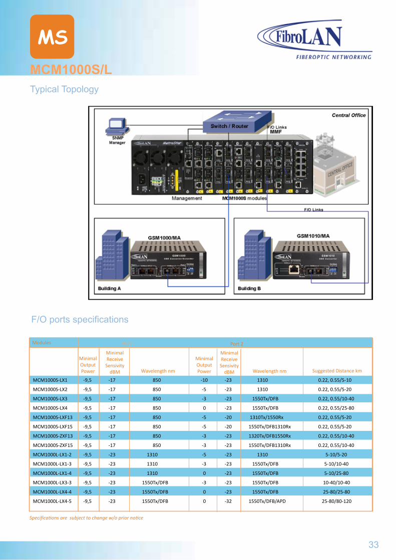
Typical Topology
Modules
Minimal Output Power
Minimal Receive
Sensivity dBM
F/O ports specifications
Wavelength nm
Minimal Output Power
Minimal Receive
Sensivity dBM Wavelength nm Suggested Distance km
Port 1 Port 2
MCM1000S-LX1 -9,5 -17 850 -10 -23 1310 0.22, 0.55/5-10
MCM1000S-LX2 -9,5 -17 850 -5 -23 1310 0.22, 0.55/5-20
MCM1000S-LX3 -9,5 -17 850 -3 -23 1550Tx/DFB 0.22, 0.55/10-40
MCM1000S-LX4 -9,5 -17 850 0 -23 1550Tx/DFB 0.22, 0.55/25-80
MCM1000S-LXF13 -9,5 -17 850 -5 -20 1310Tx/1550Rx 0.22, 0.55/5-20
MCM1000S-LXF15 -9,5 -17 850 -5 -20 1550Tx/DFB1310Rx 0.22, 0.55/5-20
MCM1000S-ZXF13 -9,5 -17 850 -3 -23 1320Tx/DFB1550Rx 0.22, 0.55/10-40
MCM1000S-ZXF15 -9,5 -17 850 -3 -23 1550Tx/DFB1310Rx 0.22, 0.55/10-40
MCM1000L-LX1-2 -9,5 -23 1310 -5 -23 1310 5-10/5-20
MCM1000L-LX1-3 -9,5 -23 1310 -3 -23 1550Tx/DFB 5-10/10-40
MCM1000L-LX1-4 -9,5 -23 1310 0 -23 1550Tx/DFB 5-10/25-80
MCM1000L-LX3-3 -9,5 -23 1550Tx/DFB -3 -23 1550Tx/DFB 10-40/10-40
MCM1000L-LX4-4 -9,5 -23 1550Tx/DFB 0 -23 1550Tx/DFB 25-80/25-80
MCM1000L-LX4-5 -9,5 -23 1550Tx/DFB 0 -32 1550Tx/DFB/APD 25-80/80-120
33
MCM1000S/LManagement Functions

MS34
MCM1000X
MS
Managed SFP 1000Base-T/SX/LX Module ConverterThe MCM1000X module provides conversion from a 1000Base-T, Multi-Mode 1000Base-SX or Single Mode 1000Base-LX GBE link to 1000Base-T/1000Base-SX/LX GBE link, allowing extension of up to 120km. The MCM1000X is based on the 3R technology: optical signals from one port are converted to digital electrical signals, fully retimed, repeated, reshaped and then converted again to the second SFP port. The module is designed for use with SFP (Small Factor-factor Pluggable) optical modular transceivers. The power of the hot-swappable SFP is in the density, flexibility and cost-savings. SFP modules can be easily interchanged; therefore fiber optic networks can be upgraded and maintained more conveniently. The MCM1000X provides reliable and robust conversion, advanced control /diagnostic features and management.
Selective Fault Propagation from port 1 to port 2 and vice-versa allows link status forwarding. Each port provides separate and various LED indications for monitoring and enhanced diagnostics.The device supports SLE (Subscriber Link Emulation) to enhance network resilience. When the link remote partner is a GSM1000X (enabled MA device), the SLE feature allows real time notification of the remote user failure while maintaining the fiber link and the MA management is maintained active and operational. The MA™ (Micro Agent) is an on chip management system enabling the management of remote access devices eliminating the need of an SNMP agent and IP address.
When the MCM1000X is connected through a F/O link to a remote device that is MA™ enabled, a comprehensive set of monitoring and controlling functions are implemented on the remote device. The module has MA management capability (or IEEE 802.3ah) for each port separately, thus each port may be connected to a remote CPE. Like other MetroStarTM modules, the MCM1000X is fully SNMP managed and MA enabled or IEEE 802.3ah management: it manages remote enabled devices. All MetroStarTM modules are hot swappable and equipped with two self-clinching screws for easy and safe module insertion and removal. A special LED indicates that the module is well inserted in its slot and “alive” even before links are connected.
Management Functions
Module status Port type, Link and Signal Detect (SD) status, Port‘s enable/disable, A/N On/Off, Pause (Flow Control) On/Off, Loop back On/Off (P1, P2), SLE (Up/Down) On/Off, BW (Up/Downstream), End to End SLE modes, FP modes (P1>P2 and P2>P1) and Remote device SFP modules status( Port #, Part #, Type, Range, Tx-WL, Rx-WL, S/N) SFP module digital diagnostics status (Rx/Tx optical power, temperature, Tx bias current) Module control Display Module status, Port1/Port2 control, Enable/Disable End to End SLE, Enable/Disable Fault Propagation, Restore module defaultsLink management Loop-back test, invoke Remote device menuPort control Display port status, SFP status, enable/disable port, Set Pause/LB (loop-back) mode, Set SLE (upstream/downstream), set bandwidth and restore port defaults, and set Management module (MA or IEEE 802.3ah)
Key Features
Versatility- different interfaces (1000Base-T/SX/LX) on both ports
SFP (Small Form-factor Pluggable) optical interfaces
MA™ or IEEE 802.3ah OAM management for each SFP port
Feasible installation – desktop, shelf or wall-mount
1000X –Auto-Negotiation is supported for each F/O port
Fault Propagation-total network resilience
Local and Remote Loop-Back Test – enhanced diagnostics
SLE for enhancing network resilience
Rate Limiting ( 0-1000Mbps- 10Mbps step increment)
RFU (Remote Firmware Upgrade) and OFC (Offline Configuration Facility)
35
Standard ComplianceIEEE802.3 2000 edition, 1000Base-T,1000Base-SX, 1000Base-LX, IEEE802.3z, IEEEE802.3ab, 1000base-ZX, Flow control Conversion MethodDigital 3R conversionFeatures Auto-Negotiation, Fault Propagation, SLE and Loop-BackManagementRS232/CLI or Telnet connectionMA™ /IEEE 802.3ah OAM managementFibroLAN MetroView (V2) Device Manager Ports Simplex and Duplex LC connectorsSFP (Small Form -factor Pluggable) MSA and SFF-8472 compliant
Specifications are subject to change w/o prior notice
MCM1000X
MS
General Specifications
Part#
Ordering Information
Diagnostic LEDsSystem LEDs: PWR-Power On (green)MA1(green) MA port 1FP (yellow) (P1>P2, P2>P1)MA2 (green) MA port 2SFP port 1 and 2 LEDs:Link/Act (green) - Link and ActivityTX-LO(red)-lit = low power TX in SFP, blinking when not authenticatedLB (red) - loop-back for designated port DIP switches (on board)Loop-Back (LB P1, LB P2) enable/disableFault Propagation ON/OFF (FO port 1>2 (FO port 2>1)Auto-Negotiation for Port 1 and Port 2 (enable/disable)Management commands override DIP switches setting
Model Description
SFP optical modular interfaces
2650 MCM1000X Flexible Gigabit Ethernet conversion module for MetroStarTM with 2 SFP modular ports, each may accept any FibroLAN copper or fiber SFP transceiver, MA or IEEE 802.3ah management
B248 SF1G-T SFP (Small Form-factor Pluggable) GBE STP transceiver, 1000BaseT, shielded RJ-45, 100m over Cat.6 cable
B235 SF1G-S1 SFP GBE F/O transceiver, Duplex LC connectors, MM, 850nm, 220/550m
B136 SF1G-LX1 SFP GBE F/O transceiver, Duplex LC connectors, SM, 1310nm,10km
B237 SF1G-LX2 SFP GBE F/O transceiver, Duplex LC connectors, SM, 1310nm, 20km
B238 SF1G-LX3 SFP GBE F/O transceiver, Duplex LC connectors, SM, 1550nm/DFB, 40km
B239 SF1G-LX4 SFP GBE F/O transceiver, Duplex LC connectors, SM, 1550nm/DFB, 80km
B240 SF1G-LX5 SFP GBE F/O transceiver, Duplex LC connectors, SM, 1550nm/DFB/APD, 120km
B241 SF1G-SF13 SFP, Single Fiber Strand GBE F/O transceiver, Simplex LC connector, SM, 1310nmTx - 1550nmRx, 20km
B242 SF1G-SF15 SFP Single Fiber Strand GBE F/O transceiver, Simplex LC connector, SM 1550nmDFB Tx - 1310nmRx, 20km
B243 SF1G-LF13 SFP Single Fiber Strand GBE F/O transceiver, Simplex LC connector, SM 1310nmTx - 1550nmRx, 40km
B244 SF1G-LF15 SFP Single Fiber Strand GBE F/O transceiver, Simplex LC connector, SM, 1550nmDFB Tx - 1310nm Rx, 40km
B269 SF1G-ZF49 SFP Single Fiber Strand GBE F/O transceiver, Simplex LC connector, SM, 1490nmDFB Tx -1570nm Rx, 80km
B270 SF1G-ZF57 SFP Single Fiber Strand GBE F/O transceiver, Simplex LC connector, SM, 1570nmDFB Tx – 1490nm Rx, 80km
36
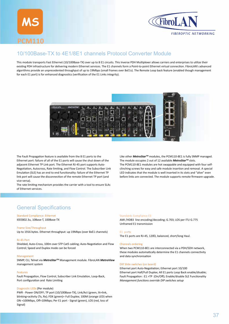
PCM110
MS
10/100Base-TX to 4E1/8E1 channels Protocol Converter ModuleThis module transports Fast Ethernet (10/100Base-TX) over up to 8 E1 circuits. This Inverse PDH Multiplexer allows carriers and enterprises to utilize their existing PDH infrastructure for delivering modern Ethernet services. The E1 channels form a Point-to-point Ethernet virtual connection. FibroLAN’s advanced algorithms provide an unprecedented throughput of up to 19Mbps (small frames over 8xE1s). The Remote Loop back feature (enabled though management for each E1 port) is for enhanced diagnostics (verification of the E1 Links integrity).
The Fault Propagation feature is available from the 8 E1 ports to the Ethernet port: failure of all of the E1 ports will cause the shut down of the adjacent Ethernet TP Link port. The Ethernet RJ-45 port supports Auto-Negotiation, Autocross, Rate limiting, and Flow Control. The Subscriber Link Emulation (SLE) has an end to end functionality: failure of the Ethernet TP link port will cause the disconnection of the remote Ethernet TP port (and vice-versa).The rate limiting mechanism provides the carrier with a tool to ensure SLAs of Ethernet services.
Like other MetroStarTM modules, the PCM110-8E1 is fully SNMP managed. The module occupies 2 out of 12 available MetroStarTM slots.The PCM110-8E1 modules are hot swappable and equipped with four self-clinching screws for easy and safe module insertion and removal. A special LED indicates that the module is well inserted in its slots and “alive” even before links are connected. The module supports remote firmware upgrade.
General SpecificationsStandard Compliance: Ethernet IEEE802.3u, 10Base-T, 100Base-TX
Frame Size/ThroughputUp to 1916 bytes. Ethernet throughput: up 19Mbps (over 8xE1 channels)
RJ-45 PortShielded, Auto-Cross, 100m over STP Cat5 cabling; Auto-Negotiation and Flow Control; Speed and Duplex mode can be forced
ManagementSNMP, CLI, Telnet via MetroStarTM Management module. FibroLAN MetroView management system
FeaturesFault Propagation, Flow Control, Subscriber Link Emulation, Loop-Back, Port configuration and Rate Limiting
Diagnostic LEDs (Per module) PWR - Power ON/OFF; TP port (10/100Base-TX), Link/Act (green, lit=link, blinking=activity (Tx, Rx); FDX (green)= Full Duplex; 100M (orange LED) when ON =100Mbps, Off=10Mbps; Per E1 port - Signal (green), LOS (red, loss of Signal)
Standards Compliance E1AMI /HDB3 line encoding/decoding; G.703; LOS per ITU G.775Unframed E1 transmission
E1 portsThe E1 ports are RJ-45, 120Ώ, balanced, short/long Haul.
Channels orderingWhen two PCM110-8E1 are interconnected via a PDH/SDH network, these modules automatically determine the E1 channels connectivity and data synchronisation
DIP Slide switches (on board)Ethernet port Auto-Negotiation; Ethernet port 10/100Ethernet port Half/Full Duplex; All E1 ports Loop Back enable/disable;Fault Propagation : E1 >TP (On/Off); Enable/disable SLE FunctionalityManagement functions override DIP switches setup
37
MCM1000XGeneral Specifications
2650 MCM1000X Flexible Gigabit Ethernet conversion module for MetroStarTM with 2 SFP modular ports, each may accept any FibroLAN copper or fiber SFP transceiver, MA or IEEE 802.3ah management
B248 SF1G-T SFP (Small Form-factor Pluggable) GBE STP transceiver, 1000BaseT, shielded RJ-45, 100m over Cat.6 cable
B235 SF1G-S1 SFP GBE F/O transceiver, Duplex LC connectors, MM, 850nm, 220/550m
B136 SF1G-LX1 SFP GBE F/O transceiver, Duplex LC connectors, SM, 1310nm,10km
B237 SF1G-LX2 SFP GBE F/O transceiver, Duplex LC connectors, SM, 1310nm, 20km
B238 SF1G-LX3 SFP GBE F/O transceiver, Duplex LC connectors, SM, 1550nm/DFB, 40km
B239 SF1G-LX4 SFP GBE F/O transceiver, Duplex LC connectors, SM, 1550nm/DFB, 80km
B240 SF1G-LX5 SFP GBE F/O transceiver, Duplex LC connectors, SM, 1550nm/DFB/APD, 120km
B241 SF1G-SF13 SFP, Single Fiber Strand GBE F/O transceiver, Simplex LC connector, SM, 1310nmTx - 1550nmRx, 20km
B242 SF1G-SF15 SFP Single Fiber Strand GBE F/O transceiver, Simplex LC connector, SM 1550nmDFB Tx - 1310nmRx, 20km
B243 SF1G-LF13 SFP Single Fiber Strand GBE F/O transceiver, Simplex LC connector, SM 1310nmTx - 1550nmRx, 40km
B244 SF1G-LF15 SFP Single Fiber Strand GBE F/O transceiver, Simplex LC connector, SM, 1550nmDFB Tx - 1310nm Rx, 40km
B269 SF1G-ZF49 SFP Single Fiber Strand GBE F/O transceiver, Simplex LC connector, SM, 1490nmDFB Tx -1570nm Rx, 80km
B270 SF1G-ZF57 SFP Single Fiber Strand GBE F/O transceiver, Simplex LC connector, SM, 1570nmDFB Tx – 1490nm Rx, 80km
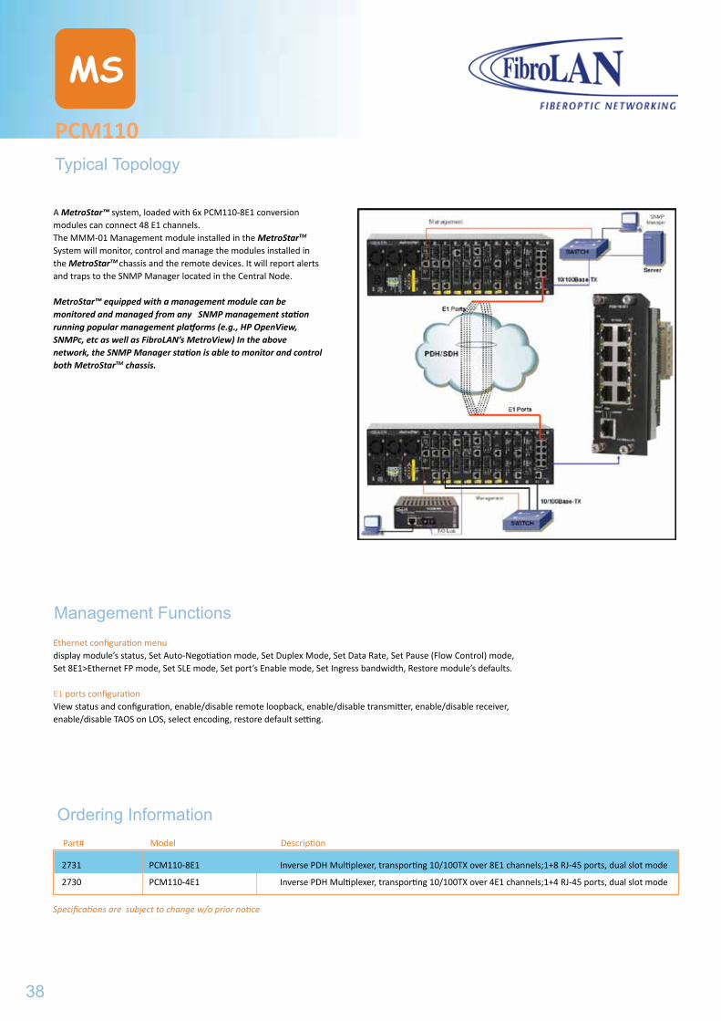
PCM110
MS
Typical Topology
Part#
Ordering InformationModel Description
2731 PCM110-8E1 Inverse PDH Multiplexer, transporting 10/100TX over 8E1 channels;1+8 RJ-45 ports, dual slot mode
2730 PCM110-4E1 Inverse PDH Multiplexer, transporting 10/100TX over 4E1 channels;1+4 RJ-45 ports, dual slot mode
Specifications are subject to change w/o prior notice
Management FunctionsEthernet configuration menudisplay module’s status, Set Auto-Negotiation mode, Set Duplex Mode, Set Data Rate, Set Pause (Flow Control) mode, Set 8E1>Ethernet FP mode, Set SLE mode, Set port’s Enable mode, Set Ingress bandwidth, Restore module’s defaults.
E1 ports configurationView status and configuration, enable/disable remote loopback, enable/disable transmitter, enable/disable receiver, enable/disable TAOS on LOS, select encoding, restore default setting.
A MetroStar™ system, loaded with 6x PCM110-8E1 conversion modules can connect 48 E1 channels.The MMM-01 Management module installed in the MetroStarTM System will monitor, control and manage the modules installed in the MetroStarTM chassis and the remote devices. It will report alerts and traps to the SNMP Manager located in the Central Node.
MetroStar™ equipped with a management module can be monitored and managed from any SNMP management station running popular management platforms (e.g., HP OpenView, SNMPc, etc as well as FibroLAN’s MetroView) In the above network, the SNMP Manager station is able to monitor and control both MetroStarTM chassis.
38
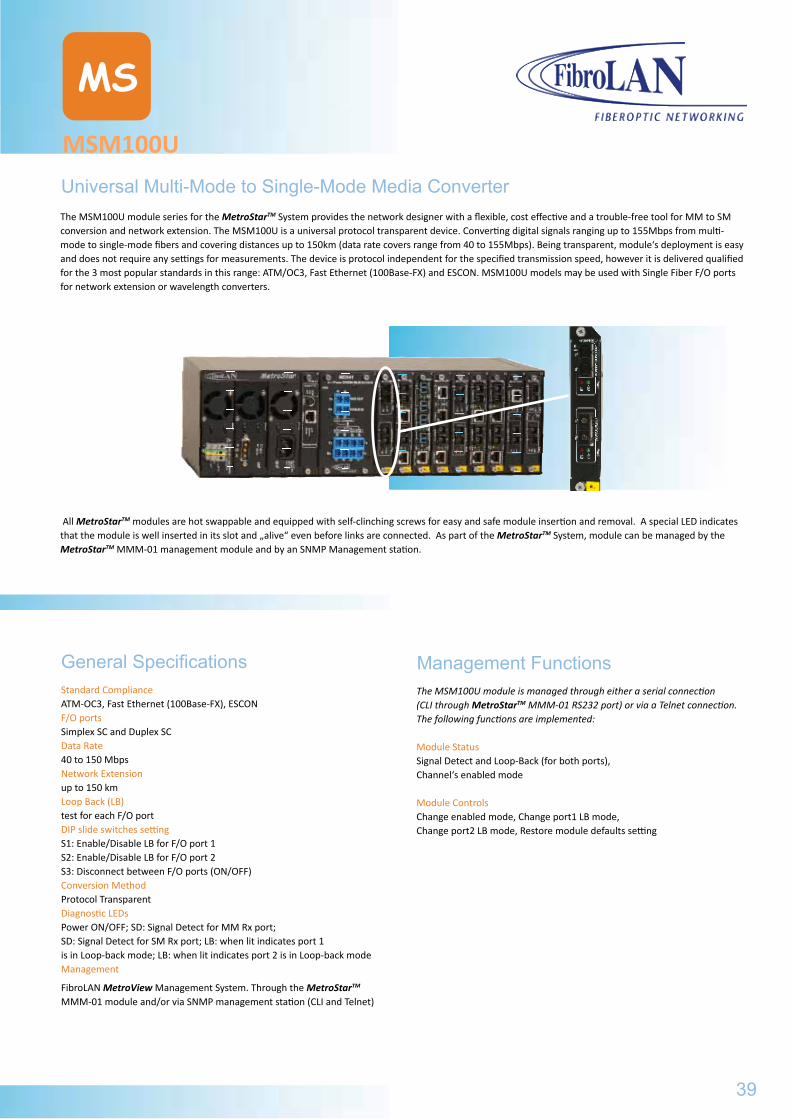
MSM100U
MS
Universal Multi-Mode to Single-Mode Media ConverterThe MSM100U module series for the MetroStarTM System provides the network designer with a flexible, cost effective and a trouble-free tool for MM to SM conversion and network extension. The MSM100U is a universal protocol transparent device. Converting digital signals ranging up to 155Mbps from multi-mode to single-mode fibers and covering distances up to 150km (data rate covers range from 40 to 155Mbps). Being transparent, module‘s deployment is easy and does not require any settings for measurements. The device is protocol independent for the specified transmission speed, however it is delivered qualified for the 3 most popular standards in this range: ATM/OC3, Fast Ethernet (100Base-FX) and ESCON. MSM100U models may be used with Single Fiber F/O ports for network extension or wavelength converters.
General SpecificationsStandard ComplianceATM-OC3, Fast Ethernet (100Base-FX), ESCONF/O portsSimplex SC and Duplex SCData Rate40 to 150 MbpsNetwork Extension up to 150 kmLoop Back (LB) test for each F/O port DIP slide switches settingS1: Enable/Disable LB for F/O port 1S2: Enable/Disable LB for F/O port 2S3: Disconnect between F/O ports (ON/OFF)Conversion MethodProtocol TransparentDiagnostic LEDsPower ON/OFF; SD: Signal Detect for MM Rx port; SD: Signal Detect for SM Rx port; LB: when lit indicates port 1 is in Loop-back mode; LB: when lit indicates port 2 is in Loop-back modeManagement
FibroLAN MetroView Management System. Through the MetroStarTM MMM-01 module and/or via SNMP management station (CLI and Telnet)
The MSM100U module is managed through either a serial connection (CLI through MetroStarTM MMM-01 RS232 port) or via a Telnet connection. The following functions are implemented:
Module StatusSignal Detect and Loop-Back (for both ports), Channel‘s enabled mode
Module Controls Change enabled mode, Change port1 LB mode, Change port2 LB mode, Restore module defaults setting
All MetroStarTM modules are hot swappable and equipped with self-clinching screws for easy and safe module insertion and removal. A special LED indicates that the module is well inserted in its slot and „alive“ even before links are connected. As part of the MetroStarTM System, module can be managed by the MetroStarTM MMM-01 management module and by an SNMP Management station.
Management Functions
39
PCM110Typical Topology
2731 PCM110-8E1 Inverse PDH Multiplexer, transporting 10/100TX over 8E1 channels;1+8 RJ-45 ports, dual slot mode
2730 PCM110-4E1 Inverse PDH Multiplexer, transporting 10/100TX over 4E1 channels;1+4 RJ-45 ports, dual slot mode
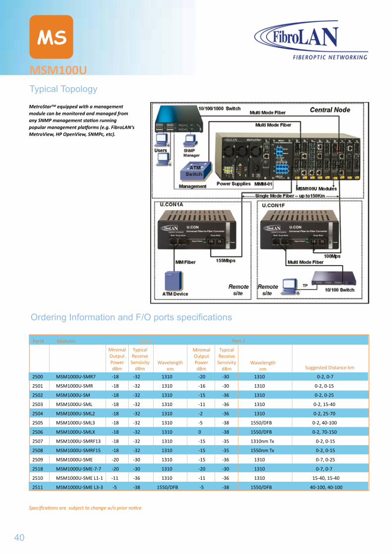
Specifications are subject to change w/o prior notice
MSM100U
MS
Typical Topology
Modules
Minimal Output PowerdBm
Typical Receive
Sensivity dBm
Ordering Information and F/O ports specifications
Wavelength nm
Minimal Output PowerdBm
Typical Receive
Sensivity dBm
Wavelength nm Suggested Distance km
Port 1 Port 2
MetroStarTM equipped with a management module can be monitored and managed from any SNMP management station running popular management platforms (e.g. FibroLAN‘s MetroView, HP OpenView, SNMPc, etc).
Part#
2500 MSM1000U-SMR7 -18 -32 1310 -20 -30 1310 0-2, 0-7
2501 MSM1000U-SMR -18 -32 1310 -16 -30 1310 0-2, 0-15
2502 MSM1000U-SM -18 -32 1310 -15 -36 1310 0-2, 0-25
2503 MSM1000U-SML -18 -32 1310 -11 -36 1310 0-2, 15-40
2504 MSM1000U-SML2 -18 -32 1310 -2 -36 1310 0-2, 25-70
2505 MSM1000U-SML3 -18 -32 1310 -5 -38 1550/DFB 0-2, 40-100
2506 MSM1000U-SMLX -18 -32 1310 0 -38 1550/DFB 0-2, 70-150
2507 MSM1000U-SMRF13 -18 -32 1310 -15 -35 1310nm Tx 0-2, 0-15
2508 MSM1000U-SMRF15 -18 -32 1310 -15 -35 1550nm Tx 0-2, 0-15
2509 MSM1000U-SME -20 -30 1310 -15 -36 1310 0-7, 0-25
2518 MSM1000U-SME-7-7 -20 -30 1310 -20 -30 1310 0-7, 0-7
2510 MSM1000U-SME L1-1 -11 -36 1310 -11 -36 1310 15-40, 15-40
2511 MSM1000U-SME L3-3 -5 -38 1550/DFB -5 -38 1550/DFB 40-100, 40-100
40
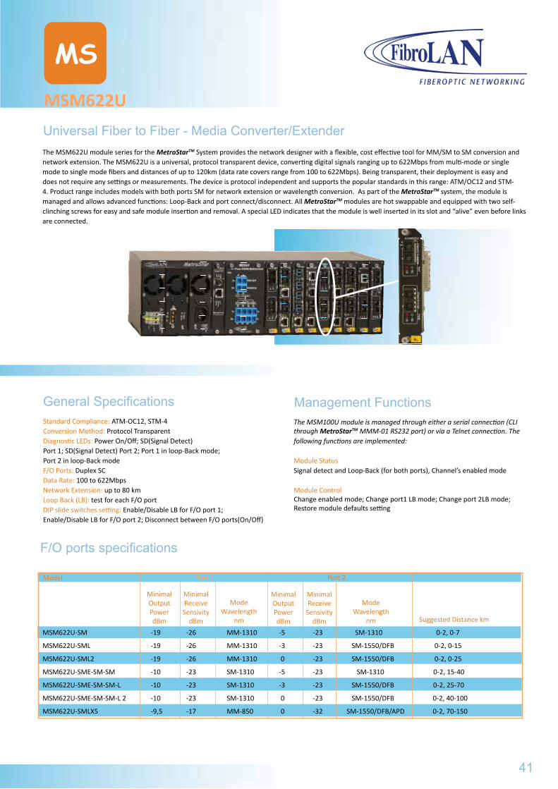
MSM622U
MS
Universal Fiber to Fiber - Media Converter/ExtenderThe MSM622U module series for the MetroStarTM System provides the network designer with a flexible, cost effective tool for MM/SM to SM conversion and network extension. The MSM622U is a universal, protocol transparent device, converting digital signals ranging up to 622Mbps from multi-mode or single mode to single mode fibers and distances of up to 120km (data rate covers range from 100 to 622Mbps). Being transparent, their deployment is easy and does not require any settings or measurements. The device is protocol independent and supports the popular standards in this range: ATM/OC12 and STM-4. Product range includes models with both ports SM for network extension or wavelength conversion. As part of the MetroStarTM system, the module is managed and allows advanced functions: Loop-Back and port connect/disconnect. All MetroStarTM modules are hot swappable and equipped with two self-clinching screws for easy and safe module insertion and removal. A special LED indicates that the module is well inserted in its slot and “alive” even before links are connected.
General SpecificationsStandard Compliance: ATM-OC12, STM-4 Conversion Method: Protocol Transparent Diagnostic LEDs: Power On/Off; SD(Signal Detect) Port 1; SD(Signal Detect) Port 2; Port 1 in loop-Back mode; Port 2 in loop-Back mode F/O Ports: Duplex SCData Rate: 100 to 622MbpsNetwork Extension: up to 80 kmLoop Back (LB): test for each F/O portDIP slide switches setting: Enable/Disable LB for F/O port 1;Enable/Disable LB for F/O port 2; Disconnect between F/O ports(On/Off)
The MSM100U module is managed through either a serial connection (CLI through MetroStarTM MMM-01 RS232 port) or via a Telnet connection. The following functions are implemented:
Module StatusSignal detect and Loop-Back (for both ports), Channel’s enabled mode
Module Control Change enabled mode; Change port1 LB mode; Change port 2LB mode;Restore module defaults setting
Management Functions
Model
Minimal Output PowerdBm
Minimal Receive
Sensivity dBm
F/O ports specifications
ModeWavelength
nm
Minimal Output PowerdBm
MinimalReceive
Sensivity dBm
ModeWavelength
nm Suggested Distance km
Port 1 Port 2
MSM622U-SM -19 -26 MM-1310 -5 -23 SM-1310 0-2, 0-7
MSM622U-SML -19 -26 MM-1310 -3 -23 SM-1550/DFB 0-2, 0-15
MSM622U-SML2 -19 -26 MM-1310 0 -23 SM-1550/DFB 0-2, 0-25
MSM622U-SME-SM-SM -10 -23 SM-1310 -5 -23 SM-1310 0-2, 15-40
MSM622U-SME-SM-SM-L -10 -23 SM-1310 -3 -23 SM-1550/DFB 0-2, 25-70
MSM622U-SME-SM-SM-L 2 -10 -23 SM-1310 0 -23 SM-1550/DFB 0-2, 40-100
MSM622U-SMLX5 -9,5 -17 MM-850 0 -32 SM-1550/DFB/APD 0-2, 70-150
41
MSM100UTypical Topology
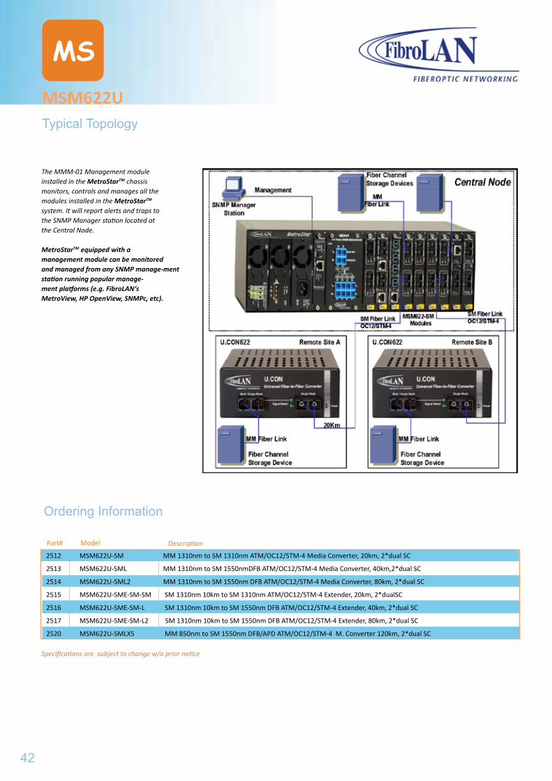
Specifications are subject to change w/o prior notice
MSM622U
MS
Typical Topology
Model
Ordering Information
Description
The MMM-01 Management module installed in the MetroStarTM chassis monitors, controls and manages all the modules installed in the MetroStarTM system. It will report alerts and traps to the SNMP Manager station located at the Central Node.
MetroStarTM equipped with a management module can be monitored and managed from any SNMP manage-ment station running popular manage-ment platforms (e.g. FibroLAN‘s MetroView, HP OpenView, SNMPc, etc).
Part#
2512 MSM622U-SM MM 1310nm to SM 1310nm ATM/OC12/STM-4 Media Converter, 20km, 2*dual SC
2513 MSM622U-SML MM 1310nm to SM 1550nmDFB ATM/OC12/STM-4 Media Converter, 40km,2*dual SC
2514 MSM622U-SML2 MM 1310nm to SM 1550nm DFB ATM/OC12/STM-4 Media Converter, 80km, 2*dual SC
2515 MSM622U-SME-SM-SM SM 1310nm 10km to SM 1310nm ATM/OC12/STM-4 Extender, 20km, 2*dualSC
2516 MSM622U-SME-SM-L SM 1310nm 10km to SM 1550nm DFB ATM/OC12/STM-4 Extender, 40km, 2*dual SC
2517 MSM622U-SME-SM-L2 SM 1310nm 10km to SM 1550nm DFB ATM/OC12/STM-4 Extender, 80km, 2*dual SC
2520 MSM622U-SMLX5 MM 850nm to SM 1550nm DFB/APD ATM/OC12/STM-4 M. Converter 120km, 2*dual SC
42
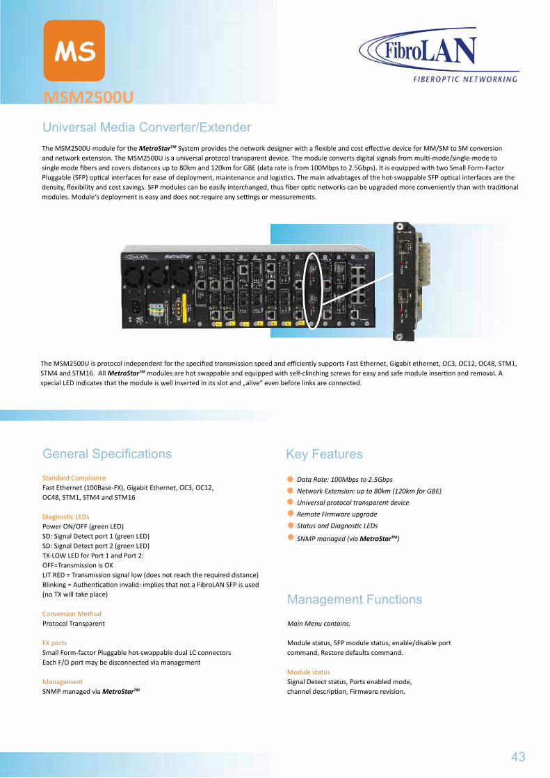
MSM2500U
MS
Universal Media Converter/ExtenderThe MSM2500U module for the MetroStarTM System provides the network designer with a flexible and cost effective device for MM/SM to SM conversion and network extension. The MSM2500U is a universal protocol transparent device. The module converts digital signals from multi-mode/single-mode to single mode fibers and covers distances up to 80km and 120km for GBE (data rate is from 100Mbps to 2.5Gbps). It is equipped with two Small Form-Factor Pluggable (SFP) optical interfaces for ease of deployment, maintenance and logistics. The main advabtages of the hot-swappable SFP optical interfaces are the density, flexibility and cost savings. SFP modules can be easily interchanged, thus fiber optic networks can be upgraded more conveniently than with traditional modules. Module‘s deployment is easy and does not require any settings or measurements.
General Specifications
Standard ComplianceFast Ethernet (100Base-FX), Gigabit Ethernet, OC3, OC12, OC48, STM1, STM4 and STM16
Diagnostic LEDsPower ON/OFF (green LED)SD: Signal Detect port 1 (green LED)SD: Signal Detect port 2 (green LED)TX-LOW LED for Port 1 and Port 2:OFF=Transmission is OKLIT RED = Transmission signal low (does not reach the required distance)Blinking = Authentication invalid: implies that not a FibroLAN SFP is used (no TX will take place)
Conversion MethodProtocol Transparent
FX portsSmall Form-factor Pluggable hot-swappable dual LC connectorsEach F/O port may be disconnected via management
ManagementSNMP managed via MetroStarTM
Key Features
Data Rate: 100Mbps to 2.5Gbps
Network Extension: up to 80km (120km for GBE)
Universal protocol transparent device
Remote Firmware upgrade
Status and Diagnostic LEDs
SNMP managed (via MetroStarTM)
The MSM2500U is protocol independent for the specified transmission speed and efficiently supports Fast Ethernet, Gigabit ethernet, OC3, OC12, OC48, STM1, STM4 and STM16. All MetroStarTM modules are hot swappable and equipped with self-clinching screws for easy and safe module insertion and removal. A special LED indicates that the module is well inserted in its slot and „alive“ even before links are connected.
Management Functions
Main Menu contains:
Module status, SFP module status, enable/disable port command, Restore defaults command.
Module status Signal Detect status, Ports enabled mode, channel description, Firmware revision.
43
MSM622UTypical Topology
MSM2500U
MS
Ordering information
Specifications are subject to change w/o prior notice
2519 MSM2500U Universal Extender module, 100Mbps to 2.5Gbps, includes 2 SFP slots, uses SFP optical transceivers
B289 SF155 - SMRF15 SFP (Small Form Pluggable) OC3,Single Fiber Strand (SFS),F/O transceiver, LC connector,SM S1550nmTX/1310nmRx,15km
B290 SF155 - SMRF13 SFP OC3, SFS F/O transceiver, LC connector, SM 1310nmTx/1550nmRx, 15km
B235 SF1G-S1 SFP module, GBE F/O transceiver, dual LC connector, MM 850nm, 220/550m
B236 SF1G-LX1 SFP module, GBE F/O transceiver, dual LC connector, SM 1310nm, 10km
B237 SF1G-LX2 SFP module, GBE F/O transceiver, dual LC connector, SM 1310nm, 20km
B238 SF1G-LX3 SFP module, GBE F/O transceiver, dual LC connector, SM 1550nm/DFB, 40km
B239 SF1G-LX4 SFP module, GBE F/O transceiver, dual LC connector, SM 1550nm/DFB, 80km
B240 SF1G-LX5 SFP module, GBE F/O transceiver, dual LC connector, SM 1550nm/DFB/APD, 120km
B241 SF1G-SF13 SFP module, SFS, GBE F/O transceiver, 1*LC, SM 1310nmTx/1550nmRx, 20km
B242 SF1G-SF15 SFP module, SFS, GBE F/O transceiver, 1*LC, SM 1550nmDFB Tx/1310nmRx, 20km
B243 SF1G-LF13 SFP module, SFS, GBE F/O transceiver, 1*LC, SM 1310nmDFB Tx/1550nmRx, 40km
B244 SF1G-LF15 SFP module, SFS, GBE F/O transceiver, 1*LC, SM 1550nmDFB Tx/1310nmRx, 40km
B269 SF1G-ZF49 SFP, SFS, GBE F/O transceiver, LC connector, SM 1490nmDFB Tx/1550nm Rx, 80km
B270 SF1G-ZF57 SFP, SFS, GBE F/O transceiver, LC connector, SM 1550nmDFB Tx/1490nm Rx, 80km
B281 SF1G-LX5-5C-47 CWDM SFP, 1,25Gbps F/O transceiver, duall LC connector, SM 1471nm DFB/APD, 120km
B282 SF1G-LX5-5C-49 CWDM SFP, 1,25Gbps F/O transceiver, duall LC connector, SM 1491nm DFB/APD, 120km
B283 SF1G-LX5-5C-51 CWDM SFP, 1,25Gbps F/O transceiver, duall LC connector, SM 1511nm DFB/APD, 120km
B284 SF1G-LX5-5C-53 CWDM SFP, 1,25Gbps F/O transceiver, duall LC connector, SM 1531nm DFB/APD, 120km
B285 SF1G-LX5-5C-55 CWDM SFP, 1,25Gbps F/O transceiver, duall LC connector, SM 1551nm DFB/APD, 120km
B286 SF1G-LX5-5C-57 CWDM SFP, 1,25Gbps F/O transceiver, duall LC connector, SM 1571nm DFB/APD, 120km
B287 SF1G-LX5-5C-59 CWDM SFP, 1,25Gbps F/O transceiver, duall LC connector, SM 1591nm DFB/APD, 120km
B288 SF1G-LX5-5C-61 CWDM SFP, 1,25Gbps F/O transceiver, duall LC connector, SM 1611nm DFB/APD, 120km
B268 SF2G-S1 SFP module, 2,5Gbps F/O transceiver, dual LC connector, MM 850nm, 300/400m
B249 SF2G-S2 SFP module, 2,5Gbps F/O transceiver, dual LC connector, SM 1310nm, 2km
B250 SF2G-LX2-3 SFP module, 2,5Gbps F/O transceiver, dual LC connector, SM 1310nm DFB, 15km
B251 SF2G-LX2-5 SFP module, 2,5Gbps F/O transceiver, dual LC connector, SM 1550nm DFB, 15km
B252 SF2G-LX3-3 SFP module, 2,5Gbps F/O transceiver, dual LC connector, SM 1310nm DFB/APD, 40km
B253 SF2G-LX3-5 SFP module, 2,5Gbps F/O transceiver, dual LC connector, SM 1550nm DFB, 40km
B254 SF2G-LX4-5 SFP module, 2,5Gbps F/O transceiver, dual LC connector, SM 1550nm DFB/APD, 80km
B271 SF2G-LX3-5C-47 CWDM, SFP, 2,5Gbps F/O transceiver, dual LC connector, SM1471nm DFB, 40km
B272 SF2G-LX3-5C-49 CWDM, SFP, 2,5Gbps F/O transceiver, dual LC connector, SM1491nm DFB, 40km
B273 SF2G-LX3-5C-51 CWDM, SFP, 2,5Gbps F/O transceiver, dual LC connector, SM1511nm DFB, 40km
B274 SF2G-LX3-5C-53 CWDM, SFP, 2,5Gbps F/O transceiver, dual LC connector, SM1531nm DFB, 40km
B275 SF2G-LX3-5C-55 CWDM, SFP, 2,5Gbps F/O transceiver, dual LC connector, SM1551nm DFB, 40km
B276 SF2G-LX3-5C-57 CWDM, SFP, 2,5Gbps F/O transceiver, dual LC connector, SM1571nm DFB, 40km
B277 SF2G-LX3-5C-59 CWDM, SFP, 2,5Gbps F/O transceiver, dual LC connector, SM1591nm DFB, 40km
B278 SF2G-LX3-5C-61 CWDM, SFP, 2,5Gbps F/O transceiver, dual LC connector, SM1611nm DFB, 40km
B258 SF2G-LX4-5C-47 CWDM, SFP, 2,5Gbps F/O transceiver, dual LC connector, SM1471nm DFB/APD, 80km
B259 SF2G-LX4-5C-49 CWDM, SFP, 2,5Gbps F/O transceiver, dual LC connector, SM1491nm DFB/APD, 80km
B260 SF2G-LX4-5C-51 CWDM, SFP, 2,5Gbps F/O transceiver, dual LC connector, SM1511nm DFB/APD, 80km
B261 SF2G-LX4-5C-53 CWDM, SFP, 2,5Gbps F/O transceiver, dual LC connector, SM1531nm DFB/APD, 80km
B262 SF2G-LX4-5C-55 CWDM, SFP, 2,5Gbps F/O transceiver, dual LC connector, SM1551nm DFB/APD, 80km
B263 SF2G-LX4-5C-57 CWDM, SFP, 2,5Gbps F/O transceiver, dual LC connector, SM1571nm DFB/APD, 80km
B264 SF2G-LX4-5C-59 CWDM, SFP, 2,5Gbps F/O transceiver, dual LC connector, SM1591nm DFB/APD, 80km
B265 SF2G-LX4-5C-61 CWDM, SFP, 2,5Gbps F/O transceiver, dual LC connector, SM1611nm DFB/APD, 80km
The SFP transceivers from SF155-SMRF15 through SF2G-LX4-5C-61 are used in the following FibroLAN equipment: MetroStarTM module MSM2500U and U.CON2500 device. All recommended distances for CWDM active components assume direct point-to-point connection between them. If these are passing thru passive Mux/Demuxes, the additional attenuation introduced by such devices must be considered when assessing the actual distance.
44
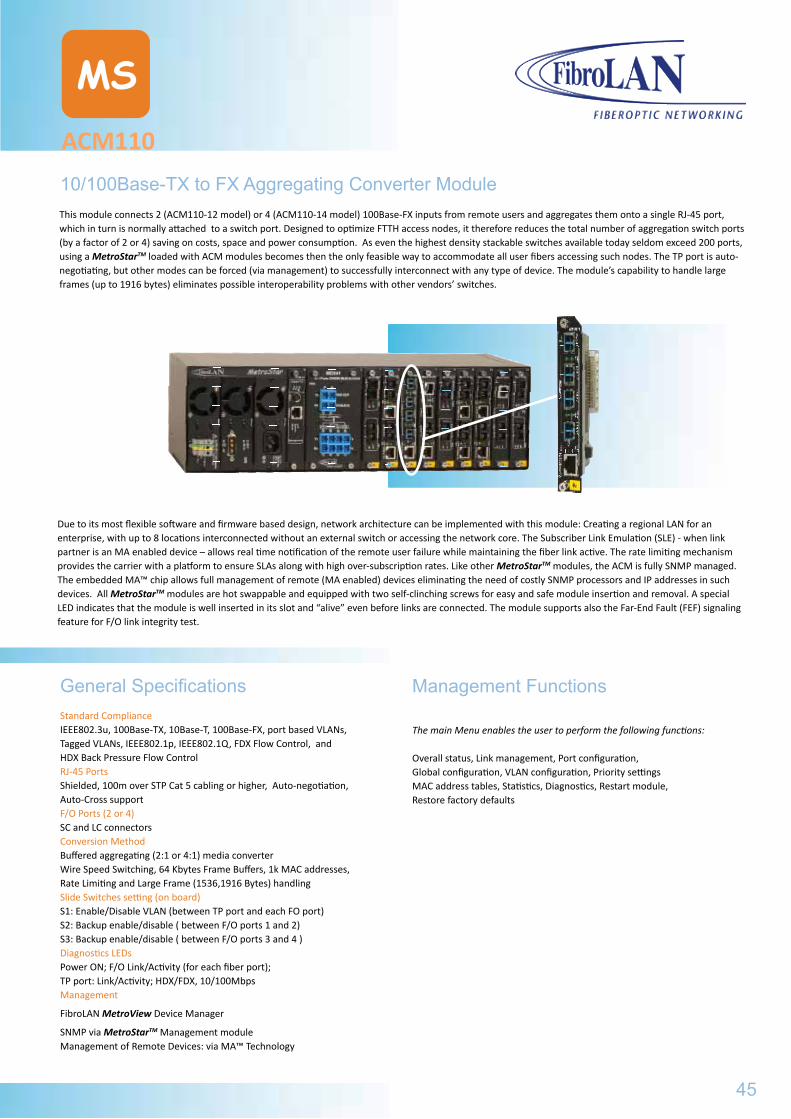
ACM110
MS
10/100Base-TX to FX Aggregating Converter ModuleThis module connects 2 (ACM110-12 model) or 4 (ACM110-14 model) 100Base-FX inputs from remote users and aggregates them onto a single RJ-45 port, which in turn is normally attached to a switch port. Designed to optimize FTTH access nodes, it therefore reduces the total number of aggregation switch ports (by a factor of 2 or 4) saving on costs, space and power consumption. As even the highest density stackable switches available today seldom exceed 200 ports, using a MetroStarTM loaded with ACM modules becomes then the only feasible way to accommodate all user fibers accessing such nodes. The TP port is auto-negotiating, but other modes can be forced (via management) to successfully interconnect with any type of device. The module’s capability to handle large frames (up to 1916 bytes) eliminates possible interoperability problems with other vendors’ switches.
General SpecificationsStandard ComplianceIEEE802.3u, 100Base-TX, 10Base-T, 100Base-FX, port based VLANs, Tagged VLANs, IEEE802.1p, IEEE802.1Q, FDX Flow Control, and HDX Back Pressure Flow Control RJ-45 PortsShielded, 100m over STP Cat 5 cabling or higher, Auto-negotiation, Auto-Cross supportF/O Ports (2 or 4) SC and LC connectorsConversion MethodBuffered aggregating (2:1 or 4:1) media converterWire Speed Switching, 64 Kbytes Frame Buffers, 1k MAC addresses,Rate Limiting and Large Frame (1536,1916 Bytes) handling Slide Switches setting (on board)S1: Enable/Disable VLAN (between TP port and each FO port)S2: Backup enable/disable ( between F/O ports 1 and 2)S3: Backup enable/disable ( between F/O ports 3 and 4 )Diagnostics LEDsPower ON; F/O Link/Activity (for each fiber port);TP port: Link/Activity; HDX/FDX, 10/100Mbps Management
FibroLAN MetroView Device Manager
SNMP via MetroStarTM Management moduleManagement of Remote Devices: via MA™ Technology
Due to its most flexible software and firmware based design, network architecture can be implemented with this module: Creating a regional LAN for an enterprise, with up to 8 locations interconnected without an external switch or accessing the network core. The Subscriber Link Emulation (SLE) - when link partner is an MA enabled device – allows real time notification of the remote user failure while maintaining the fiber link active. The rate limiting mechanism provides the carrier with a platform to ensure SLAs along with high over-subscription rates. Like other MetroStarTM modules, the ACM is fully SNMP managed. The embedded MA™ chip allows full management of remote (MA enabled) devices eliminating the need of costly SNMP processors and IP addresses in such devices. All MetroStarTM modules are hot swappable and equipped with two self-clinching screws for easy and safe module insertion and removal. A special LED indicates that the module is well inserted in its slot and “alive” even before links are connected. The module supports also the Far-End Fault (FEF) signaling feature for F/O link integrity test.
Management Functions
The main Menu enables the user to perform the following functions:
Overall status, Link management, Port configuration, Global configuration, VLAN configuration, Priority settingsMAC address tables, Statistics, Diagnostics, Restart module, Restore factory defaults
45
MSM2500U
Ordering information
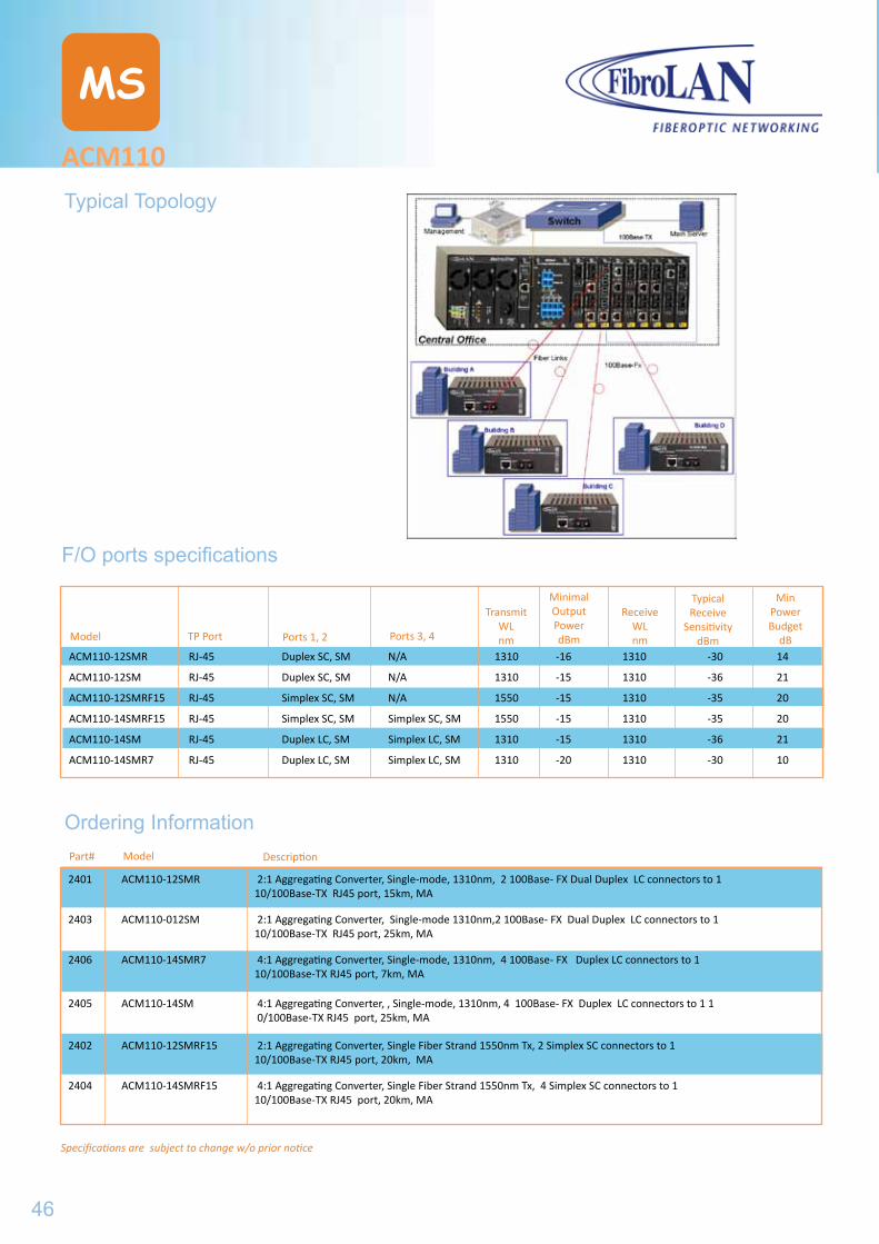
Specifications are subject to change w/o prior notice
ACM110
MS
F/O ports specifications
Model
Ordering InformationDescriptionPart#
TP Port Ports 1, 2Model Ports 3, 4
TransmitWLnm
MinimalOutput PowerdBm
ReceiveWLnm
TypicalReceive
SensitivitydBm
MinPowerBudget
dBACM110-12SMR RJ-45 Duplex SC, SM N/A 1310 -16 1310 -30 14
ACM110-12SM RJ-45 Duplex SC, SM N/A 1310 -15 1310 -36 21
ACM110-12SMRF15 RJ-45 Simplex SC, SM N/A 1550 -15 1310 -35 20
ACM110-14SMRF15 RJ-45 Simplex SC, SM Simplex SC, SM 1550 -15 1310 -35 20
ACM110-14SM RJ-45 Duplex LC, SM Simplex LC, SM 1310 -15 1310 -36 21
ACM110-14SMR7 RJ-45 Duplex LC, SM Simplex LC, SM 1310 -20 1310 -30 10
2401 ACM110-12SMR 2:1 Aggregating Converter, Single-mode, 1310nm, 2 100Base- FX Dual Duplex LC connectors to 1 10/100Base-TX RJ45 port, 15km, MA
2403 ACM110-012SM 2:1 Aggregating Converter, Single-mode 1310nm,2 100Base- FX Dual Duplex LC connectors to 1 10/100Base-TX RJ45 port, 25km, MA
2406 ACM110-14SMR7 4:1 Aggregating Converter, Single-mode, 1310nm, 4 100Base- FX Duplex LC connectors to 1 10/100Base-TX RJ45 port, 7km, MA
2405 ACM110-14SM 4:1 Aggregating Converter, , Single-mode, 1310nm, 4 100Base- FX Duplex LC connectors to 1 1 0/100Base-TX RJ45 port, 25km, MA
2402 ACM110-12SMRF15 2:1 Aggregating Converter, Single Fiber Strand 1550nm Tx, 2 Simplex SC connectors to 1 10/100Base-TX RJ45 port, 20km, MA
2404 ACM110-14SMRF15 4:1 Aggregating Converter, Single Fiber Strand 1550nm Tx, 4 Simplex SC connectors to 1 10/100Base-TX RJ45 port, 20km, MA
Typical Topology
46
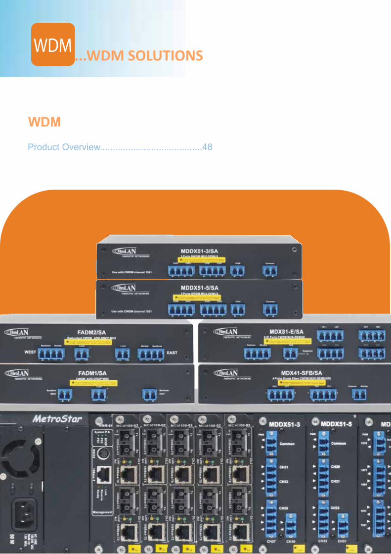
WDM
...WDM SOLUTIONS
WDM
Product Overview........................................48
WDMACM110
F/O ports specifications
Typical Topology
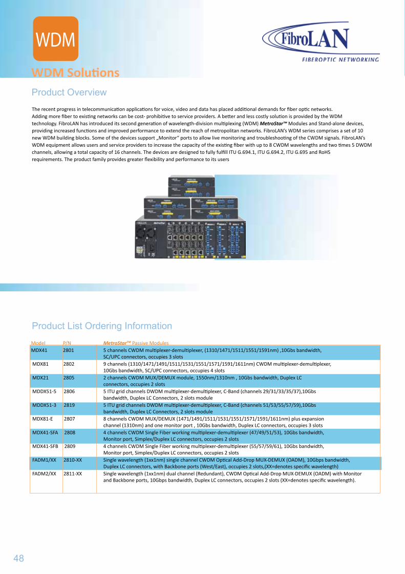
Product Overview
WDM Solutions
Product List Ordering Information
The recent progress in telecommunication applications for voice, video and data has placed additional demands for fiber optic networks.Adding more fiber to existing networks can be cost- prohibitive to service providers. A better and less costly solution is provided by the WDMtechnology. FibroLAN has introduced its second generation of wavelength-division multiplexing (WDM) MetroStar™ Modules and Stand-alone devices,providing increased functions and improved performance to extend the reach of metropolitan networks. FibroLAN’s WDM series comprises a set of 10new WDM building blocks. Some of the devices support „Monitor“ ports to allow live monitoring and troubleshooting of the CWDM signals. FibroLAN’sWDM equipment allows users and service providers to increase the capacity of the existing fiber with up to 8 CWDM wavelengths and two times 5 DWDM channels, allowing a total capacity of 16 channels. The devices are designed to fully fulfill ITU G.694.1, ITU G.694.2, ITU G.695 and RoHSrequirements. The product family provides greater flexibility and performance to its users
Model P/N MetroStarTM Passive Modules MDX41 2801 5 channels CWDM multiplexer-demultiplexer, (1310/1471/1511/1551/1591nm) ,10Gbs bandwidth, SC/UPC connectors, occupies 3 slots MDX81 2802 9 channels (1310/1471/1491/1511/1531/1551/1571/1591/1611nm) CWDM multiplexer-demultiplexer, 10Gbs bandwidth, SC/UPC connectors, occupies 4 slots MDX21 2805 2 channels CWDM MUX/DEMUX module, 1550nm/1310nm , 10Gbs bandwidth, Duplex LC connectors, occupies 2 slots MDDX51-5 2806 5 ITU grid channels DWDM multiplexer-demultiplexer, C-Band (channels 29/31/33/35/37),10Gbs bandwidth, Duplex LC Connectors, 2 slots module MDDX51-3 2819 5 ITU grid channels DWDM multiplexer-demultiplexer, C-Band (channels 51/53/55/57/59),10Gbs bandwidth, Duplex LC Connectors, 2 slots module MDX81-E 2807 8 channels CWDM MUX/DEMUX (1471/1491/1511/1531/1551/1571/1591/1611nm) plus expansion channel (1310nm) and one monitor port , 10Gbs bandwidth, Duplex LC connectors, occupies 3 slots MDX41-SFA 2808 4 channels CWDM Single Fiber working multiplexer-demultiplexer (47/49/51/53), 10Gbs bandwidth, Monitor port, Simplex/Duplex LC connectors, occupies 2 slots MDX41-SFB 2809 4 channels CWDM Single Fiber working multiplexer-demultiplexer (55/57/59/61), 10Gbs bandwidth, Monitor port, Simplex/Duplex LC connectors, occupies 2 slots FADM1/XX 2810-XX Single wavelength (1xx1nm) single channel CWDM Optical Add-Drop MUX-DEMUX (OADM), 10Gbps bandwidth, Duplex LC connectors, with Backbone ports (West/East), occupies 2 slots,(XX=denotes specific wavelength) FADM2/XX 2811-XX Single wavelength (1xx1nm) dual channel (Redundant), CWDM Optical Add-Drop MUX-DEMUX (OADM) with Monitor and Backbone ports, 10Gbps bandwidth, Duplex LC connectors, occupies 2 slots (XX=denotes specific wavelength).
48
WDM
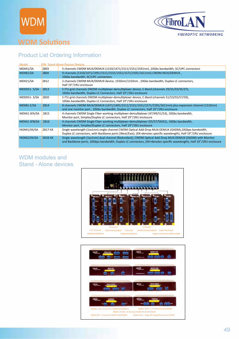
Product List Ordering Information
WDM Solutions
WDM modules and Stand - Alone devices
Model P/N Stand-Alone Passive Devices MDX41/SA 2803 5 channels CWDM MUX/DEMUX (1310/1471/1511/1551/1591nm) ,10Gbs bandwidth, SC/UPC connectors MDX81/SA 2804 9 channels (1310/1471/1491/1511/1531/1551/1571/1591/1611nm) CWDM MUX/DEMUX , 10Gbs bandwidth, SC/UPC connectors MDX21/SA 2812 2 channels CWDM MUX/DEMUX device, 1550nm/1310nm , 10Gbs bandwidth, Duplex LC connectors, Half 19”/1RU enclosure MDDX51- 5/SA 2813 5 ITU grid channels DWDM multiplexer-demultiplexer device, C-Band (channels 29/31/33/35/37), 10Gbs bandwidth, Duplex LC Connectors, Half 19”/1RU enclosure MDDX51- 3/SA 2820 5 ITU grid channels DWDM multiplexer-demultiplexer device, C-Band (channels 51/53/55/57/59), 10Gbs bandwidth, Duplex LC Connectors, Half 19”/1RU enclosure MDX81-E/SA 2814 8 channels CWDM MUX/DEMUX (1471/1491/1511/1531/1551/1571/1591/1611nm) plus expansion channel (1310nm) and one monitor port , 10Gbs bandwidth, Duplex LC connectors, Half 19”/1RU enclosure MDX41-SFA/SA 2815 4 channels CWDM Single Fiber working multiplexer-demultiplexer (47/49/51/53), 10Gbs bandwidth, Monitor port, Simplex/Duplex LC connectors, Half 19”/1RU enclosure MDX41-SFB/SA 2816 4 channels CWDM Single Fiber working multiplexer-demultiplexer (55/57/59/61), 10Gbs bandwidth, Monitor port, Simplex/Duplex LC connectors, Half 19”/1RU enclosure FADM1/XX/SA 2817-XX Single wavelength (1xx1nm) single channel CWDM Optical Add-Drop MUX-DEMUX (OADM),10Gbps bandwidth, Duplex LC connectors, with Backbone ports (West/East), (XX=denotes specific wavelength), Half 19”/1RU enclosure FADM2/XX/SA 2818-XX Single wavelength (1xx1nm) dual channel (Redundant), CWDM Optical Add-Drop MUX-DEMUX (OADM) with Monitor and Backbone ports, 10Gbps bandwidth, Duplex LC connectors, (XX=denotes specific wavelength), Half 19”/1RU enclosure
49
5 ITU Channels
DWDM MUX/DEMUX
8 Channels
CWDM MUX/DEMUX 2 Channels
CWDM MUX/DEMUX
4 Channels
CWDM SFS MUX/DEMUX Single Wavelength
Single/Dual Channel CWDM OADM
MDX81-E/SA = 8 channels CWDM MUX/DEMUX MDX51-X/SA = 5 ITU Grid channels DWDM
MDX41-SFX/SA = 4 channels CWDM SFS MUX/DEMUX
MDX21/SA = 2 channels CWDM MUX/DEMUX FADM1/2/xx = Single WV Single/Dual channel OADM
WDM
Product Overview
WDM Solutions
Product List Ordering Information Model P/N MetroStarTM Passive Modules MDX41 2801 5 channels CWDM multiplexer-demultiplexer, (1310/1471/1511/1551/1591nm) ,10Gbs bandwidth, SC/UPC connectors, occupies 3 slots MDX81 2802 9 channels (1310/1471/1491/1511/1531/1551/1571/1591/1611nm) CWDM multiplexer-demultiplexer, 10Gbs bandwidth, SC/UPC connectors, occupies 4 slots MDX21 2805 2 channels CWDM MUX/DEMUX module, 1550nm/1310nm , 10Gbs bandwidth, Duplex LC connectors, occupies 2 slots MDDX51-5 2806 5 ITU grid channels DWDM multiplexer-demultiplexer, C-Band (channels 29/31/33/35/37),10Gbs bandwidth, Duplex LC Connectors, 2 slots module MDDX51-3 2819 5 ITU grid channels DWDM multiplexer-demultiplexer, C-Band (channels 51/53/55/57/59),10Gbs bandwidth, Duplex LC Connectors, 2 slots module MDX81-E 2807 8 channels CWDM MUX/DEMUX (1471/1491/1511/1531/1551/1571/1591/1611nm) plus expansion channel (1310nm) and one monitor port , 10Gbs bandwidth, Duplex LC connectors, occupies 3 slots MDX41-SFA 2808 4 channels CWDM Single Fiber working multiplexer-demultiplexer (47/49/51/53), 10Gbs bandwidth, Monitor port, Simplex/Duplex LC connectors, occupies 2 slots MDX41-SFB 2809 4 channels CWDM Single Fiber working multiplexer-demultiplexer (55/57/59/61), 10Gbs bandwidth, Monitor port, Simplex/Duplex LC connectors, occupies 2 slots FADM1/XX 2810-XX Single wavelength (1xx1nm) single channel CWDM Optical Add-Drop MUX-DEMUX (OADM), 10Gbps bandwidth, Duplex LC connectors, with Backbone ports (West/East), occupies 2 slots,(XX=denotes specific wavelength) FADM2/XX 2811-XX Single wavelength (1xx1nm) dual channel (Redundant), CWDM Optical Add-Drop MUX-DEMUX (OADM) with Monitor and Backbone ports, 10Gbps bandwidth, Duplex LC connectors, occupies 2 slots (XX=denotes specific wavelength).

WDM50
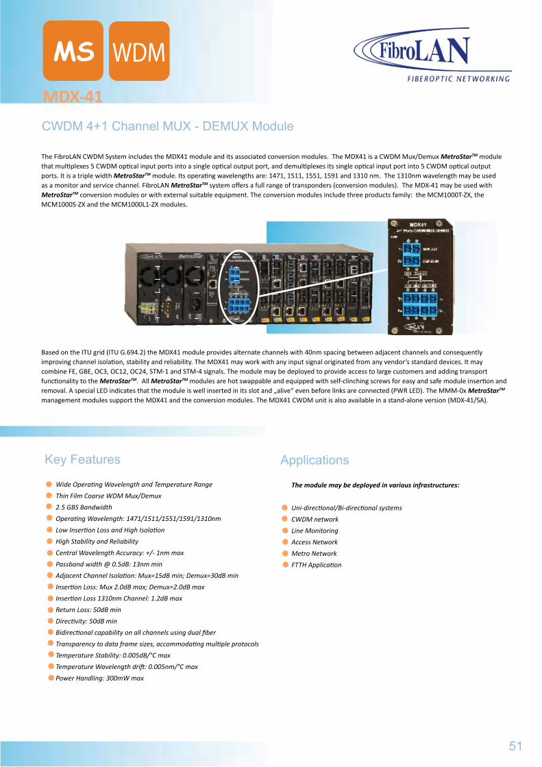
MDX-41
MS
CWDM 4+1 Channel MUX - DEMUX Module
The FibroLAN CWDM System includes the MDX41 module and its associated conversion modules. The MDX41 is a CWDM Mux/Demux MetroStarTM module that multiplexes 5 CWDM optical input ports into a single optical output port, and demultiplexes its single optical input port into 5 CWDM optical output ports. It is a triple width MetroStarTM module. Its operating wavelengths are: 1471, 1511, 1551, 1591 and 1310 nm. The 1310nm wavelength may be used as a monitor and service channel. FibroLAN MetroStarTM system offers a full range of transponders (conversion modules). The MDX-41 may be used with MetroStarTM conversion modules or with external suitable equipment. The conversion modules include three products family: the MCM1000T-ZX, the MCM1000S-ZX and the MCM1000L1-ZX modules.
Based on the ITU grid (ITU G.694.2) the MDX41 module provides alternate channels with 40nm spacing between adjacent channels and consequently improving channel isolation, stability and reliability. The MDX41 may work with any input signal originated from any vendor‘s standard devices. It may combine FE, GBE, OC3, OC12, OC24, STM-1 and STM-4 signals. The module may be deployed to provide access to large customers and adding transport functionality to the MetroStarTM. All MetroStarTM modules are hot swappable and equipped with self-clinching screws for easy and safe module insertion and removal. A special LED indicates that the module is well inserted in its slot and „alive“ even before links are connected (PWR LED). The MMM-0x MetroStarTM management modules support the MDX41 and the conversion modules. The MDX41 CWDM unit is also available in a stand-alone version (MDX-41/SA).
Key Features
Wide Operating Wavelength and Temperature Range
Thin Film Coarse WDM Mux/Demux
2.5 GBS Bandwidth
Operating Wavelength: 1471/1511/1551/1591/1310nm
Low Insertion Loss and High Isolation
High Stability and Reliability
Central Wavelength Accuracy: +/- 1nm max
Passband width @ 0.5dB: 13nm min
Adjacent Channel Isolation: Mux=15dB min; Demux=30dB min
Insertion Loss: Mux 2.0dB max; Demux=2.0dB max
Insertion Loss 1310nm Channel: 1.2dB max
Return Loss: 50dB min
Directivity: 50dB min
Bidirectional capability on all channels using dual fiber
Transparency to data frame sizes, accommodating multiple protocols
Temperature Stability: 0.005dB/°C max
Temperature Wavelength drift: 0.005nm/°C max
Power Handling: 300mW max
Applications
The module may be deployed in various infrastructures:
Uni-directional/Bi-directional systems
CWDM network
Line Monitoring
Access Network
Metro Network
FTTH Application
51
WDM
WDM
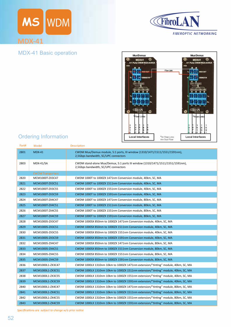
Specifications are subject to change w/o prior notice
MDX-41
MS
Model
Ordering InformationDescriptionPart#
MDX-41 Basic operation
2801 MDX-41 CWDM Mux/Demux module, 5:1 ports, III window (1310/1471/1511/1551/1591nm), 2,5Gbps bandwidth, SC/UPC connectors
2803 MDX-41/SA CWDM stand-alone Mux/Demux, 5:1 ports III window (1310/1471/1511/1551/1591nm), 2,5Gbps bandwidth, SC/UPC connectors
2820 MCM1000T-ZX3C47 CWDM 1000T to 1000ZX 1471nm Conversion module, 40km, SC, MA
2821 MCM1000T-ZX3C51 CWDM 1000T to 1000ZX 1511nm Conversion module, 40km, SC, MA
2822 MCM1000T-ZX3C55 CWDM 1000T to 1000ZX 1551nm Conversion module, 40km, SC, MA
2823 MCM1000T-ZX3C59 CWDM 1000T to 1000ZX 1591nm Conversion module, 40km, SC, MA
2824 MCM1000T-ZX4C47 CWDM 1000T to 1000ZX 1471nm Conversion module, 80km, SC, MA
2825 MCM1000T-ZX4C51 CWDM 1000T to 1000ZX 1511nm Conversion module, 80km, SC, MA
2826 MCM1000T-ZX4C55 CWDM 1000T to 1000ZX 1551nm Conversion module, 80km, SC, MA
2827 MCM1000T-ZX4C59 CWDM 1000T to 1000ZX 1591nm Conversion module, 80km, SC, MA
2828 MCM1000S-ZX3C47 CWDM 1000SX 850nm to 1000ZX 1471nm Conversion module, 40km, SC, MA
2829 MCM1000S-ZX3C51 CWDM 1000SX 850nm to 1000ZX 1511nm Conversion module, 40km, SC, MA
2830 MCM1000S-ZX3C55 CWDM 1000SX 850nm to 1000ZX 1551nm Conversion module, 40km, SC, MA
2831 MCM1000S-ZX3C59 CWDM 1000SX 850nm to 1000ZX 1591nm Conversion module, 40km, SC, MA
2832 MCM1000S-ZX4C47 CWDM 1000SX 850nm to 1000ZX 1471nm Conversion module, 80km, SC, MA
2833 MCM1000S-ZX4C51 CWDM 1000SX 850nm to 1000ZX 1511nm Conversion module, 80km, SC, MA
2834 MCM1000S-ZX4C55 CWDM 1000SX 850nm to 1000ZX 1551nm Conversion module, 80km, SC, MA
2835 MCM1000S-ZX4C59 CWDM 1000SX 850nm to 1000ZX 1591nm Conversion module, 80km, SC, MA
2836 MCM1000L1-ZX3C47 CWDM 1000LX 1310nm 10km to 1000ZX 1471nm extension/”tinting” module, 40km, SC, MA
2837 MCM1000L1-ZX3C51 CWDM 1000LX 1310nm 10km to 1000ZX 1511nm extension/”tinting” module, 40km, SC, MA
2838 MCM1000L1-ZX3C55 CWDM 1000LX 1310nm 10km to 1000ZX 1551nm extension/”tinting” module, 40km, SC, MA
2839 MCM1000L1-ZX3C59 CWDM 1000LX 1310nm 10km to 1000ZX 1591nm extension/”tinting” module, 40km, SC, MA
2840 MCM1000L1-ZX4C47 CWDM 1000LX 1310nm 10km to 1000ZX 1471nm extension/”tinting” module, 80km, SC, MA
2841 MCM1000L1-ZX4C51 CWDM 1000LX 1310nm 10km to 1000ZX 1511nm extension/”tinting” module, 80km, SC, MA
2842 MCM1000L1-ZX4C55 CWDM 1000LX 1310nm 10km to 1000ZX 1551nm extension/”tinting” module, 80km, SC, MA
2843 MCM1000L1-ZX4C59 CWDM 1000LX 1310nm 10km to 1000ZX 1591nm extension/”tinting” module, 80km, SC, MA
CWDM Transporters
52
WDM
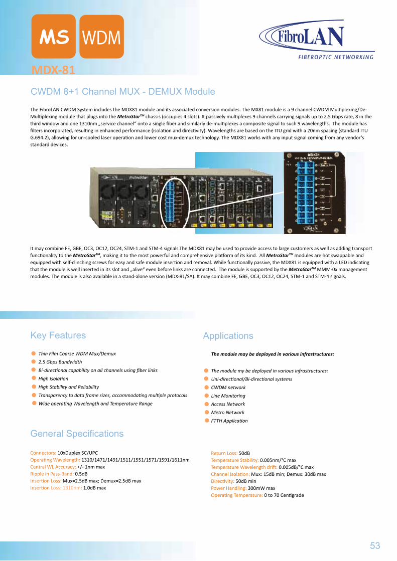
MDX-81
MS
CWDM 8+1 Channel MUX - DEMUX Module
The FibroLAN CWDM System includes the MDX81 module and its associated conversion modules. The MX81 module is a 9 channel CWDM Multiplexing/De-Multiplexing module that plugs into the MetroStarTM chassis (occupies 4 slots). It passively multiplexes 9 channels carrying signals up to 2.5 Gbps rate, 8 in the third window and one 1310nm „service channel“ onto a single fiber and similarly de-multiplexes a composite signal to such 9 wavelengths. The module has filters incorporated, resulting in enhanced performance (isolation and directivity). Wavelengths are based on the ITU grid with a 20nm spacing (standard ITU G.694.2), allowing for un-cooled laser operation and lower cost mux-demux technology. The MDX81 works with any input signal coming from any vendor‘s standard devices.
Key Features
Thin Film Coarse WDM Mux/Demux
2.5 Gbps Bandwidth
Bi-directional capability on all channels using fiber links
High Isolation
High Stability and Reliability
Transparency to data frame sizes, accommodating multiple protocols
Wide operating Wavelength and Temperature Range
Applications
The module may be deployed in various infrastructures:
The module my be deployed in various infrastructures:
Uni-directional/Bi-directional systems
CWDM network
Line Monitoring
Access Network
Metro Network
FTTH Application
It may combine FE, GBE, OC3, OC12, OC24, STM-1 and STM-4 signals.The MDX81 may be used to provide access to large customers as well as adding transport functionality to the MetroStarTM, making it to the most powerful and comprehensive platform of its kind. All MetroStarTM modules are hot swappable and equipped with self-clinching screws for easy and safe module insertion and removal. While functionally passive, the MDX81 is equipped with a LED indicating that the module is well inserted in its slot and „alive“ even before links are connected. The module is supported by the MetroStarTM MMM-0x management modules. The module is also available in a stand-alone version (MDX-81/SA). It may combine FE, GBE, OC3, OC12, OC24, STM-1 and STM-4 signals.
General Specifications
Connectors: 10xDuplex SC/UPCOperating Wavelength: 1310/1471/1491/1511/1551/1571/1591/1611nmCentral WL Accuracy: +/- 1nm maxRipple in Pass-Band: 0.5dBInsertion Loss: Mux=2.5dB max; Demux=2.5dB maxInsertion Loss: 1310nm: 1.0dB max
Return Loss: 50dBTemperature Stability: 0.005nm/°C maxTemperature Wavelength drift: 0.005dB/°C maxChannel Isolation: Mux: 15dB min; Demux: 30dB maxDirectivity: 50dB minPower Handling: 300mW maxOperating Temperature: 0 to 70 Centigrade
53
WDM
MDX-41MDX-41 Basic operation
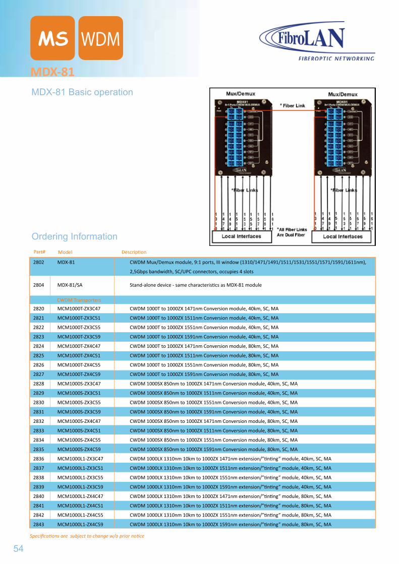
Specifications are subject to change w/o prior notice
MDX-81
MS
Model
Ordering InformationDescriptionPart#
MDX-81 Basic operation
2802 MDX-81 CWDM Mux/Demux module, 9:1 ports, III window (1310/1471/1491/1511/1531/1551/1571/1591/1611nm),
2,5Gbps bandwidth, SC/UPC connectors, occupies 4 slots
2804 MDX-81/SA Stand-alone device - same characteristics as MDX-81 module
2820 MCM1000T-ZX3C47 CWDM 1000T to 1000ZX 1471nm Conversion module, 40km, SC, MA
2821 MCM1000T-ZX3C51 CWDM 1000T to 1000ZX 1511nm Conversion module, 40km, SC, MA
2822 MCM1000T-ZX3C55 CWDM 1000T to 1000ZX 1551nm Conversion module, 40km, SC, MA
2823 MCM1000T-ZX3C59 CWDM 1000T to 1000ZX 1591nm Conversion module, 40km, SC, MA
2824 MCM1000T-ZX4C47 CWDM 1000T to 1000ZX 1471nm Conversion module, 80km, SC, MA
2825 MCM1000T-ZX4C51 CWDM 1000T to 1000ZX 1511nm Conversion module, 80km, SC, MA
2826 MCM1000T-ZX4C55 CWDM 1000T to 1000ZX 1551nm Conversion module, 80km, SC, MA
2827 MCM1000T-ZX4C59 CWDM 1000T to 1000ZX 1591nm Conversion module, 80km, SC, MA
2828 MCM1000S-ZX3C47 CWDM 1000SX 850nm to 1000ZX 1471nm Conversion module, 40km, SC, MA
2829 MCM1000S-ZX3C51 CWDM 1000SX 850nm to 1000ZX 1511nm Conversion module, 40km, SC, MA
2830 MCM1000S-ZX3C55 CWDM 1000SX 850nm to 1000ZX 1551nm Conversion module, 40km, SC, MA
2831 MCM1000S-ZX3C59 CWDM 1000SX 850nm to 1000ZX 1591nm Conversion module, 40km, SC, MA
2832 MCM1000S-ZX4C47 CWDM 1000SX 850nm to 1000ZX 1471nm Conversion module, 80km, SC, MA
2833 MCM1000S-ZX4C51 CWDM 1000SX 850nm to 1000ZX 1511nm Conversion module, 80km, SC, MA
2834 MCM1000S-ZX4C55 CWDM 1000SX 850nm to 1000ZX 1551nm Conversion module, 80km, SC, MA
2835 MCM1000S-ZX4C59 CWDM 1000SX 850nm to 1000ZX 1591nm Conversion module, 80km, SC, MA
2836 MCM1000L1-ZX3C47 CWDM 1000LX 1310nm 10km to 1000ZX 1471nm extension/”tinting” module, 40km, SC, MA
2837 MCM1000L1-ZX3C51 CWDM 1000LX 1310nm 10km to 1000ZX 1511nm extension/”tinting” module, 40km, SC, MA
2838 MCM1000L1-ZX3C55 CWDM 1000LX 1310nm 10km to 1000ZX 1551nm extension/”tinting” module, 40km, SC, MA
2839 MCM1000L1-ZX3C59 CWDM 1000LX 1310nm 10km to 1000ZX 1591nm extension/”tinting” module, 40km, SC, MA
2840 MCM1000L1-ZX4C47 CWDM 1000LX 1310nm 10km to 1000ZX 1471nm extension/”tinting” module, 80km, SC, MA
2841 MCM1000L1-ZX4C51 CWDM 1000LX 1310nm 10km to 1000ZX 1511nm extension/”tinting” module, 80km, SC, MA
2842 MCM1000L1-ZX4C55 CWDM 1000LX 1310nm 10km to 1000ZX 1551nm extension/”tinting” module, 80km, SC, MA
2843 MCM1000L1-ZX4C59 CWDM 1000LX 1310nm 10km to 1000ZX 1591nm extension/”tinting” module, 80km, SC, MA
CWDM Transporters
54
WDM
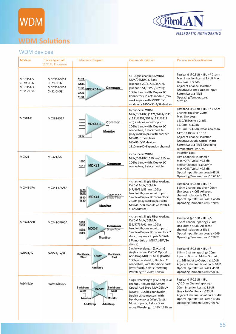
WDM devices
WDM Solutions
Modules Device type Half Schematic Diagram General description Performance Specifications 19“/1RU Enclosure
MDDX51-5CH29-CH37MDDX51-3CH51-CH59
MDX81-E
MDX21
MDX41-SFA
MDX41-SFB
FADM1/xx
FADM2/xx
MDDX51-5/SACH29-CH37MDDX51-3/SACH51-CH59
MDX81-E/SA
MDX21/SA
MDX41-SFA/SA
MDX41-SFB/SA
FADM1/xx/SA
FADM2/xx/SA
5 ITU grid channels DWDMMUX/DEMUX, C-Band (channels 29/31/33/35/37), (channels 51/53/55/57/59); 10Gbs bandwidth, Duplex LC Connectors, 2 slots module (may work in pair with MDDX51-5 module or MDDX51-5/SA device)
8 channels CWDMMUX/DEMUX, (1471/1491/1511/1531/1551/1571/1591/1611nm) and one monitor port, 10Gbs bandwidth, Duplex LCconnectors, 3 slots module(may work in pair with anotherMDX81-E module or MDX81-E/SA device) 1310nm±40=Expansion channel
2 channels CWDMMUX/DEMUX 1550nm/1310nm , 10Gbs bandwidth, Duplex LCconnectors, 2 slots module
4 channels Single Fiber workingCWDM MUX/DEMUX (47/49/51/53nm), 10Gbs bandwidth, one monitor port, Simplex/Duplex LC connectors, 2 slots (may work in pair with MDX41- SFB module or MDX41-SFB/SAdevice)
4 channels Single Fiber workingCWDM MUX/DEMUX (55/57/59/61nm), 10Gbs bandwidth, one monitor port, Simplex/Duplex LC connectors, 2 slots (may work in pair MDX41- SFA mo-dule or MDX41-SFA/SA device)Single wavelength (1xx1nm) single channel CWDM Optical Add-Drop MUX-DEMUX (OADM), 10Gbps bandwidth, Duplex LC connectors, with Backbone ports (West/East), 2 slots Operating Wavelength:1260~1620nm
Single wavelength (1xx1nm) Dual channel, Redundant, CWDM Optical Add-Drop MUXDEMUX(OADM), 10Gbps bandwidth, Duplex LC connectors, with Backbone ports (West/East), Monitor ports, 2 slots Ope-rating Wavelength:1460~1620nm
Passband @0.5dB = ITU +/-0.1nm Max. Insertion Loss: ≤ 2.4dB Max. Link Loss: ≤ 3.5dBAdjacent Channel Isolation(DEMUX): ≥ 30dB Optical Input Return Loss: ≥ 45dBOperating Temperature: 0~70 ºC
Passband @0.5dB = ITU +/-6.5nmChannel spacing= 20nm Max. Link Loss:1530/1550nm: ≤ 2.3dB 1570nm: ≤ 3.0dB 1310nm: ≤ 3.6dB-Expansion chan. 1470-1610nm: ≤ 5.1dBAdjacent Channel Isolation(DEMUX): ≥30dB Optical Input Return Loss: ≥ 45dB Operating Temperature: 0~70 ºCInsertion Loss:Pass Channel (1550nm) =Max.=0.7, Typical =0.5.dBReflect Channel (1310nm)=Max.=0,5, Typical =0,3.dBOptical Input Return Loss:≥ 45dBOperating Temperature: 0 ~ 65 ºC
Passband @0.5dB = ITU +/-6.5nm Channel spacing = 20nmLink Loss: ≤ 4.0dB Adjacent channel isolation: ≥ 35dBOptical Input Return Loss: ≥ 45dBOperating Temperature: 0 ~70 ºC
Passband @0.5dB = ITU +/-6.5nm Channel spacing= 20nmLink Loss: ≤ 4.0dB Adjacent channel isolation: ≥ 35dBOptical Input Return Loss: ≥ 45dBOperating Temperature: 0 ~70 ºC
Passband @0.5dB = ITU +/-6.5nm Channel spacing= 20nmInput to Drop or Add to Output:≤ 1.2dB Input to Output: ≤ 1.0dBAdjacent channel isolation: ≥ 30dBOptical Input Return Loss:≥ 45dBOperating Temperature: 0~70 ºC
Passband @0.5dB = ITU +/-6.5nm Channel spacing= 20nm Insertion Loss: ≤ 1.6dB Line x to Monitor x = ≤ 23dB Adjacent channel isolation:≥ 30dBOptical Input Return Loss: ≥ 45dBOperating Temperature: 0~70 ºC
55
WDM
MDX-81MDX-81 Basic operation
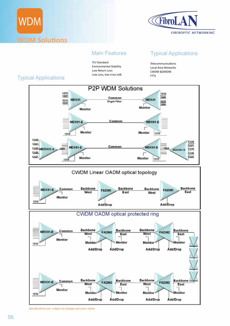
WDM Solutions
Main Features Typical ApplicationsITU StandardEnvironmental StabilityLow Return LossLow Loss, low cross talk
TelecommunicationsLocal Area NetworksCWDM &DWDMFTTxTypical Applications
Specifications are subject to change w/o prior notice
56
WDM
...CONVERTERS
F.CONF.CON1............................................F.CON1/MA.....................................F.CON1F/MA...................................
H.CON.............................................H.CON/MA.......................................
S.CON1............................................S.CON1M.........................................mS.CON2.........................................
U.CON.............................................U.CON2500.....................................
GSM1000.........................................GSM1000/MA.....................................GSM1000X.......................................GSM1010..........................................GSM1010/MA...................................
DLA22/22M......................................
GA10...............................................
H.CON
S.CON
U.CON
GSM
DLA
GA10
596163
6567
697173
7577
7981838587
89
91
57
WDM Solutions
Typical Applications
TelecommunicationsLocal Area NetworksCWDM &DWDMFTTxTypical Applications

58
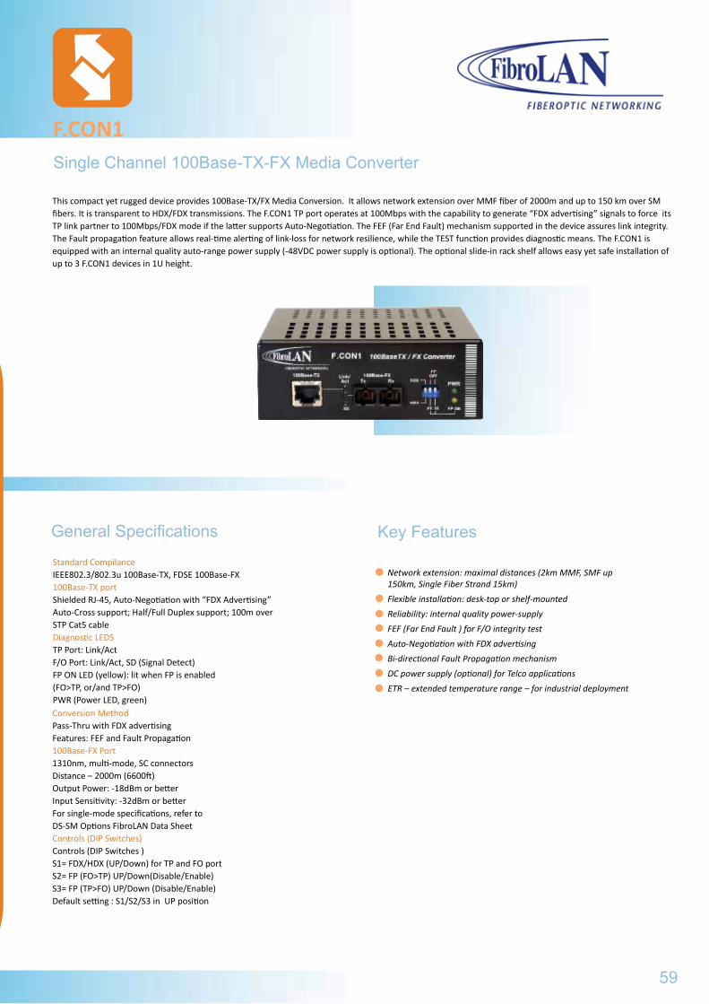
Network extension: maximal distances (2km MMF, SMF up 150km, Single Fiber Strand 15km)
Flexible installation: desk-top or shelf-mounted
Reliability: internal quality power-supply
FEF (Far End Fault ) for F/O integrity test
Auto-Negotiation with FDX advertising
Bi-directional Fault Propagation mechanism
DC power supply (optional) for Telco applications
ETR – extended temperature range – for industrial deployment
Single Channel 100Base-TX-FX Media Converter
F.CON1
Standard CompilanceIEEE802.3/802.3u 100Base-TX, FDSE 100Base-FX100Base-TX portShielded RJ-45, Auto-Negotiation with “FDX Advertising” Auto-Cross support; Half/Full Duplex support; 100m over STP Cat5 cableDiagnostic LEDSTP Port: Link/ActF/O Port: Link/Act, SD (Signal Detect)FP ON LED (yellow): lit when FP is enabled(FO>TP, or/and TP>FO)PWR (Power LED, green)
General Specifications
Conversion MethodPass-Thru with FDX advertisingFeatures: FEF and Fault Propagation100Base-FX Port1310nm, multi-mode, SC connectorsDistance – 2000m (6600ft)Output Power: -18dBm or betterInput Sensitivity: -32dBm or betterFor single-mode specifications, refer toDS-SM Options FibroLAN Data SheetControls (DIP Switches)Controls (DIP Switches )S1= FDX/HDX (UP/Down) for TP and FO portS2= FP (FO>TP) UP/Down(Disable/Enable)S3= FP (TP>FO) UP/Down (Disable/Enable)Default setting : S1/S2/S3 in UP position
This compact yet rugged device provides 100Base-TX/FX Media Conversion. It allows network extension over MMF fiber of 2000m and up to 150 km over SM fibers. It is transparent to HDX/FDX transmissions. The F.CON1 TP port operates at 100Mbps with the capability to generate “FDX advertising” signals to force its TP link partner to 100Mbps/FDX mode if the latter supports Auto-Negotiation. The FEF (Far End Fault) mechanism supported in the device assures link integrity. The Fault propagation feature allows real-time alerting of link-loss for network resilience, while the TEST function provides diagnostic means. The F.CON1 is equipped with an internal quality auto-range power supply (-48VDC power supply is optional). The optional slide-in rack shelf allows easy yet safe installation of up to 3 F.CON1 devices in 1U height.
59
Key Features
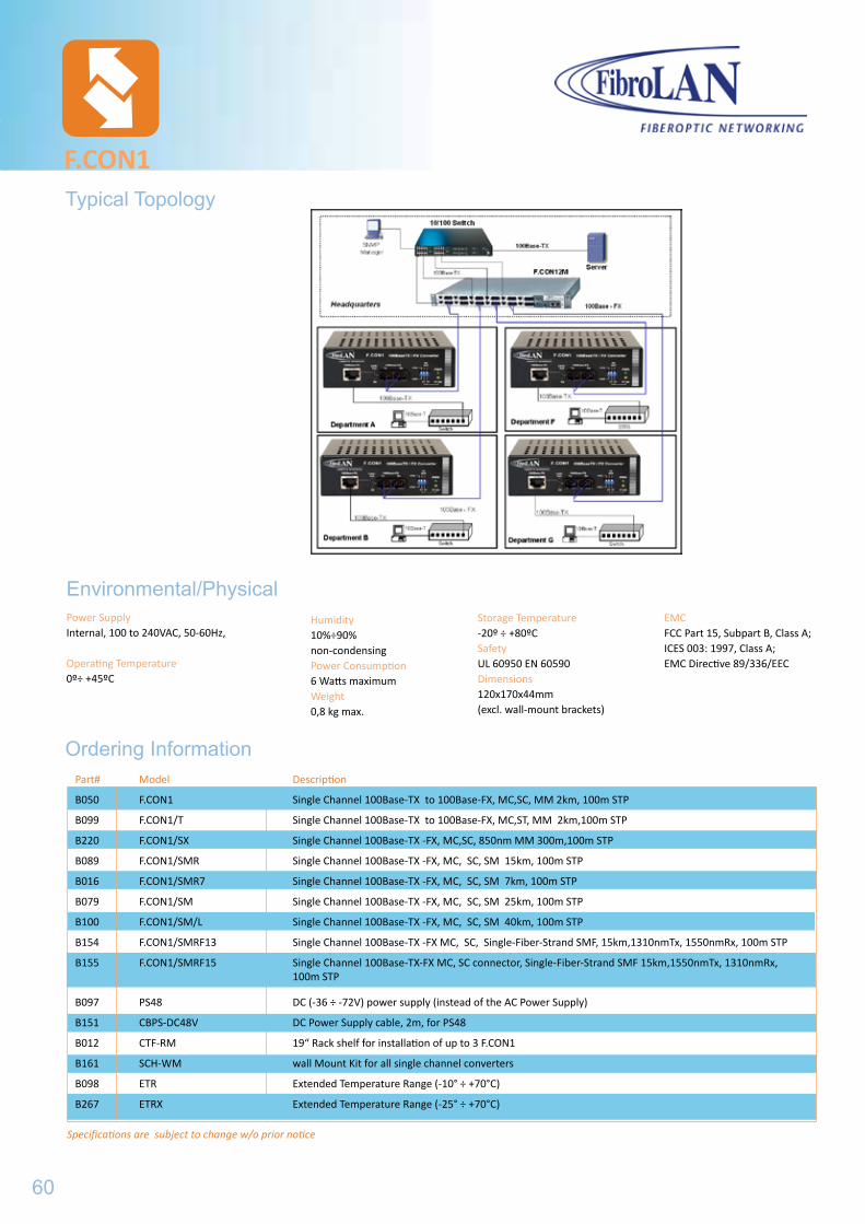
Power SupplyInternal, 100 to 240VAC, 50-60Hz,
Operating Temperature0º÷ +45ºC
Humidity10%÷90% non-condensingPower Consumption6 Watts maximumWeight0,8 kg max.
Environmental/Physical
Ordering Information
F.CON1
Storage Temperature-20º ÷ +80ºC SafetyUL 60950 EN 60590Dimensions120x170x44mm(excl. wall-mount brackets)
EMCFCC Part 15, Subpart B, Class A; ICES 003: 1997, Class A; EMC Directive 89/336/EEC
Typical Topology
Specifications are subject to change w/o prior notice
Part# Model Description
B050 F.CON1 Single Channel 100Base-TX to 100Base-FX, MC,SC, MM 2km, 100m STP
B099 F.CON1/T Single Channel 100Base-TX to 100Base-FX, MC,ST, MM 2km,100m STP
B220 F.CON1/SX Single Channel 100Base-TX -FX, MC,SC, 850nm MM 300m,100m STP
B089 F.CON1/SMR Single Channel 100Base-TX -FX, MC, SC, SM 15km, 100m STP
B016 F.CON1/SMR7 Single Channel 100Base-TX -FX, MC, SC, SM 7km, 100m STP
B079 F.CON1/SM Single Channel 100Base-TX -FX, MC, SC, SM 25km, 100m STP
B100 F.CON1/SM/L Single Channel 100Base-TX -FX, MC, SC, SM 40km, 100m STP
B154 F.CON1/SMRF13 Single Channel 100Base-TX -FX MC, SC, Single-Fiber-Strand SMF, 15km,1310nmTx, 1550nmRx, 100m STP
B155 F.CON1/SMRF15 Single Channel 100Base-TX-FX MC, SC connector, Single-Fiber-Strand SMF 15km,1550nmTx, 1310nmRx, 100m STP
B097 PS48 DC (-36 ÷ -72V) power supply (instead of the AC Power Supply)
B151 CBPS-DC48V DC Power Supply cable, 2m, for PS48
B012 CTF-RM 19“ Rack shelf for installation of up to 3 F.CON1
B161 SCH-WM wall Mount Kit for all single channel converters
B098 ETR Extended Temperature Range (-10° ÷ +70°C)
B267 ETRX Extended Temperature Range (-25° ÷ +70°C)
60
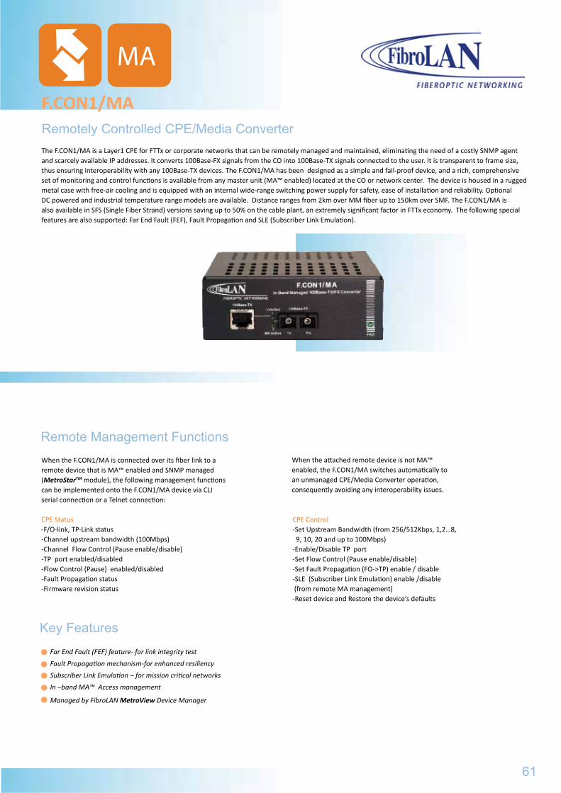
Remotely Controlled CPE/Media Converter
F.CON1/MA
When the F.CON1/MA is connected over its fiber link to a remote device that is MA™ enabled and SNMP managed (MetroStarTM module), the following management functions can be implemented onto the F.CON1/MA device via CLI serial connection or a Telnet connection:
CPE Status-F/O-link, TP-Link status-Channel upstream bandwidth (100Mbps)-Channel Flow Control (Pause enable/disable)-TP port enabled/disabled-Flow Control (Pause) enabled/disabled -Fault Propagation status-Firmware revision status
Remote Management Functions
Key Features
When the attached remote device is not MA™ enabled, the F.CON1/MA switches automatically to an unmanaged CPE/Media Converter operation, consequently avoiding any interoperability issues.
CPE Control-Set Upstream Bandwidth (from 256/512Kbps, 1,2…8, 9, 10, 20 and up to 100Mbps)-Enable/Disable TP port-Set Flow Control (Pause enable/disable)-Set Fault Propagation (FO->TP) enable / disable-SLE (Subscriber Link Emulation) enable /disable (from remote MA management)-Reset device and Restore the device’s defaults
MA
The F.CON1/MA is a Layer1 CPE for FTTx or corporate networks that can be remotely managed and maintained, eliminating the need of a costly SNMP agent and scarcely available IP addresses. It converts 100Base-FX signals from the CO into 100Base-TX signals connected to the user. It is transparent to frame size, thus ensuring interoperability with any 100Base-TX devices. The F.CON1/MA has been designed as a simple and fail-proof device, and a rich, comprehensive set of monitoring and control functions is available from any master unit (MA™ enabled) located at the CO or network center. The device is housed in a rugged metal case with free-air cooling and is equipped with an internal wide-range switching power supply for safety, ease of installation and reliability. Optional DC powered and industrial temperature range models are available. Distance ranges from 2km over MM fiber up to 150km over SMF. The F.CON1/MA is also available in SFS (Single Fiber Strand) versions saving up to 50% on the cable plant, an extremely significant factor in FTTx economy. The following special features are also supported: Far End Fault (FEF), Fault Propagation and SLE (Subscriber Link Emulation).
61
Far End Fault (FEF) feature- for link integrity test
Fault Propagation mechanism-for enhanced resiliency
Subscriber Link Emulation – for mission critical networks
In –band MA™ Access management
Managed by FibroLAN MetroView Device Manager
F.CON1
EMCFCC Part 15, Subpart B, Class A; ICES 003: 1997, Class A; EMC Directive 89/336/EEC
F.CON1/MAGeneral Specifications
Power SupplyInternal, 100 to 240VAC, 50-60Hz, IEC Connector. -48VDC power supply (-36 to -72VDC) Optional DC power Suppply (PS 48)SafetyUL 60950; EN60950
Humidity10% ÷ 90% non-condensingPower Consumption4 Watts maximumWeight400g
Environmental/Physical
Ordering Information
TemperatureOperating:0ºC ÷ +45ºC Industrial Extended Temperature Range OptionStorage: -20ºC ÷ +80ºC Dimensions120x170x44mm
EMCFCC part 15, SubpartB, ClassA EMC Directive 89/336EEC
Specifications are subject to change w/o prior notice
Standard CompilanceIEEE 802.3u 100Base-TX, 10Base-FX
TP PortShielded RJ-45, Auto-Cross, 100m over STP Cat. 5 cabling or better.Factors affecting the TP port: Fault Propagation and SLE
Diagnostic LEDSPower ON, TP Link/Activity, F/O Link/Activity, MA Active
Conversion MethodLayer1 transparent conversion with FDX advertising, MA™ managed
FX portDuplex SC or ST, FDX, MM 1310nm; output power -18dBm min., Sensitivity -32dBm or better. For SM fiber specifications, refer to FibroLAN Data Sheet DS-FO.SFS: 1310Tx/1550nmRx or 1550Tx/1310nmRx
ManagementRemote MA™ based Managed by FibroLAN MetroView Device Manager
Part# Model Description
3401 F.CON1/MA 100TX-FX Converter/Access device, Duplex SC connectors, MMF, 2km, 1310nm, MA managed
3402 F.CON1/MA/T 100TX-FX Converter/Access device, Duplex ST, MMF, 2km, 1310nm, MA managed
3404 F.CON1/MA/SMR7 100TX-FX Converter/Access device, Duplex SC, SMF, 7km, 1310nm, MA managed
3403 F.CON1/MA/SMR 100TX-FX Converter/Access device, Duplex SC, SMF, 15km, 1310nm, MA managed
3405 F.CON1/MA/SM 100TX-FX Converter/Access device, Duplex SC, SMF, 25km, 1310nm, MA managed
3406 F.CON1/MA/SM/L 100TX-FX Converter/Access device, Duplex SC, SMF 40km, 1310nm, MA managed
B097 PS48 DC (-36 ÷ -72VDC ) PS instead of AC
B216 PS24 DC (-18 ÷ -36VDC ) PS instead of AC
B151 CBPS-DC48V DC Power Suplly cable (for PS24 and PS48), 2m
B098 ETR Extended Temperature Range (-10° ÷ +70°C) option
B012 CTF-RM 19“ Rack shelf for installation of up to 3 F.CON1/MA
B161 SCH-WM Wall mount kit
62
MA
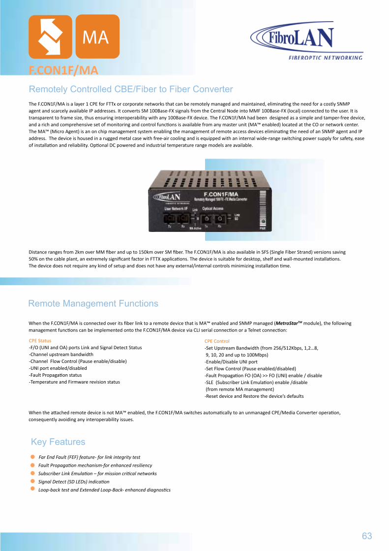
Remotely Controlled CBE/Fiber to Fiber Converter
F.CON1F/MA
When the F.CON1F/MA is connected over its fiber link to a remote device that is MA™ enabled and SNMP managed (MetroStarTM module), the following management functions can be implemented onto the F.CON1F/MA device via CLI serial connection or a Telnet connection:
When the attached remote device is not MA™ enabled, the F.CON1F/MA switches automatically to an unmanaged CPE/Media Converter operation, consequently avoiding any interoperability issues.
Remote Management Functions
Key Features Far End Fault (FEF) feature- for link integrity test
Fault Propagation mechanism-for enhanced resiliency
Subscriber Link Emulation – for mission critical networks
Signal Detect (SD LEDs) indication
Loop-back test and Extended Loop-Back- enhanced diagnostics
CPE Control-Set Upstream Bandwidth (from 256/512Kbps, 1,2…8, 9, 10, 20 and up to 100Mbps)-Enable/Disable UNI port-Set Flow Control (Pause enabled/disabled)-Fault Propagation FO (OA) >> FO (UNI) enable / disable-SLE (Subscriber Link Emulation) enable /disable (from remote MA management)-Reset device and Restore the device’s defaults
CPE Status-F/O (UNI and OA) ports Link and Signal Detect Status-Channel upstream bandwidth-Channel Flow Control (Pause enable/disable) -UNI port enabled/disabled-Fault Propagation status-Temperature and Firmware revision status
MA
The F.CON1F/MA is a layer 1 CPE for FTTx or corporate networks that can be remotely managed and maintained, eliminating the need for a costly SNMP agent and scarcely available IP addresses. It converts SM 100Base-FX signals from the Central Node into MMF 100Base-FX (local) connected to the user. It is transparent to frame size, thus ensuring interoperability with any 100Base-FX device. The F.CON1F/MA had been designed as a simple and tamper-free device, and a rich and comprehensive set of monitoring and control functions is available from any master unit (MA™ enabled) located at the CO or network center.The MA™ (Micro Agent) is an on chip management system enabling the management of remote access devices eliminating the need of an SNMP agent and IP address. The device is housed in a rugged metal case with free-air cooling and is equipped with an internal wide-range switching power supply for safety, ease of installation and reliability. Optional DC powered and industrial temperature range models are available.
Distance ranges from 2km over MM fiber and up to 150km over SM fiber. The F.CON1F/MA is also available in SFS (Single Fiber Strand) versions saving 50% on the cable plant, an extremely significant factor in FTTX applications. The device is suitable for desktop, shelf and wall-mounted installations.The device does not require any kind of setup and does not have any external/internal controls minimizing installation time.
63
F.CON1/MA
EMCFCC part 15, SubpartB, ClassA EMC Directive 89/336EEC
Part# Model Description
3401 F.CON1/MA 100TX-FX Converter/Access device, Duplex SC connectors, MMF, 2km, 1310nm, MA managed
3402 F.CON1/MA/T 100TX-FX Converter/Access device, Duplex ST, MMF, 2km, 1310nm, MA managed
3404 F.CON1/MA/SMR7 100TX-FX Converter/Access device, Duplex SC, SMF, 7km, 1310nm, MA managed
3403 F.CON1/MA/SMR 100TX-FX Converter/Access device, Duplex SC, SMF, 15km, 1310nm, MA managed
3405 F.CON1/MA/SM 100TX-FX Converter/Access device, Duplex SC, SMF, 25km, 1310nm, MA managed
3406 F.CON1/MA/SM/L 100TX-FX Converter/Access device, Duplex SC, SMF 40km, 1310nm, MA managed
B097 PS48 DC (-36 ÷ -72VDC ) PS instead of AC
B216 PS24 DC (-18 ÷ -36VDC ) PS instead of AC
B151 CBPS-DC48V DC Power Suplly cable (for PS24 and PS48), 2m
B098 ETR Extended Temperature Range (-10° ÷ +70°C) option
B012 CTF-RM 19“ Rack shelf for installation of up to 3 F.CON1/MA
B161 SCH-WM Wall mount kit
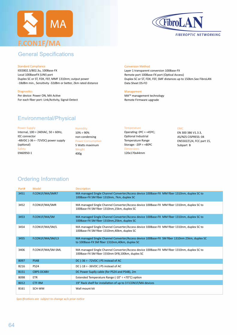
F.CON1F/MAGeneral Specifications
Power SupplyInternal, 100 ÷ 240VAC, 50 ÷ 60Hz, IEC connector-48VDC (-36 ÷ -72VDC) power supply (optional)SafetyEN60950-1
Humidity10% ÷ 90% non-condensingPower Consumption5 Watts maximumWeight400g
Environmental/Physical
Ordering Information
TemperatureOperating: 0ºC ÷ +45ºC;Optional Industrial Temperature Range Storage: -20º ÷ +80ºCDimensions120x170x44mm
EMCEN 300 386 V1.3.3, AS/NZS CISPRESS: 04EN55022\24, FCC part 15, Subpart B
Specifications are subject to change w/o prior notice
Standard Compliance IEEE802.3/802.3u, 100Base-FXLocal 100BaseFX (UNI) portDuplex SC or ST, FDX, FEF, MMF 1310nm; output power -18dBm min., Sensitivity -32dBm or better, 2km rated distance
Diagnostics Per device: Power ON, MA ActiveFor each fiber port: Link/Activity, Signal-Detect
Conversion MethodLayer 1 transparent conversion 100Base-FX Remote port 100Base-FX port (Optical Access) Duplex SC or ST, FDX, FEF, SMF distances up to 150km.See FibroLAN Data Sheet DS-FO
Management MA™ management technology Remote Firmware upgrade
MA
Part# Model Description
3451 F.CON1F/MA/SMR7 MA managed Single Channel Converter/Access device 100Base-FX MM fiber 1310nm, duplex SC to 100Base-FX SM fiber 1310nm, 7km, duplex SC
3452 F.CON1F/MA/SMR MA managed Single Channel Converter/Access device 100Base-FX MM fiber 1310nm, duplex SC to 100Base-FX SM fiber 1310nm,15km, duplex SC
3453 F.CON1F/MA/SM MA managed Single Channel Converter/Access device 100Base-FX MM fiber 1310nm, duplex SC to 100Base-FX SM fiber 1310nm,25km, duplex SC
3454 F.CON1F/MA/SM/L MA managed Single Channel Converter/Access device 100Base-FX MM fiber 1310nm, duplex SC to 100Base-FX SM fiber 1310nm,40km, duplex SC
3455 F.CON1F/MA/SM/L3 MA managed Single Channel Converter/Access device 100Base-FX SM fiber 1310nm 25km, duplex SC to 100Base-FX SM fiber 1310nm,40km, duplex SC
3406 F.CON1F/MA/SM-SML MA managed Single Channel Converter/Access device 100Base-FX MM fiber 1310nm, duplex SC to 100Base-FX SM fiber 1550nm DFB,100km, duplex SC
B097 PS48 DC (-36 ÷ -72VDC ) PS instead of AC
B216 PS24 DC (-18 ÷ -36VDC ) PS instead of AC
B151 CBPS-DC48V DC Power Suplly cable (for PS24 and PS48), 2m
B098 ETR Extended Temperature Range (-10° ÷ +70°C) option
B012 CTF-RM 19“ Rack shelf for installation of up to 3 F.CON1F/MA devices
B161 SCH-WM Wall mount kit
64
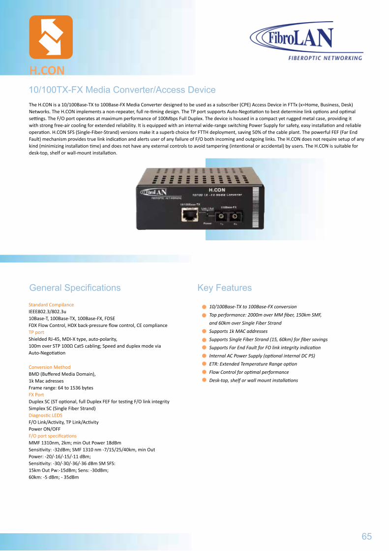
10/100TX-FX Media Converter/Access Device
H.CON
Standard CompilanceIEEE802.3/802.3u10Base-T, 100Base-TX, 100Base-FX, FDSEFDX Flow Control, HDX back-pressure flow control, CE complianceTP port Shielded RJ-45, MDI-X type, auto-polarity, 100m over STP 100Ω Cat5 cabling; Speed and duplex mode via Auto-Negotiation
General Specifications
Conversion MethodBMD (Buffered Media Domain),1k Mac adressesFrame range: 64 to 1536 bytesFX PortDuplex SC (ST optional, full Duplex FEF for testing F/O link integrity Simplex SC (Single Fiber Strand)Diagnostic LEDSF/O Link/Activity, TP Link/ActivityPower ON/OFFF/O port specificationsMMF 1310nm, 2km; min Out Power 18dBmSensitivity: -32dBm; SMF 1310 nm -7/15/25/40km, min Out Power: -20/-16/-15/-11 dBm;Sensitivity: -30/-30/-36/-36 dBm SM SFS: 15km Out Pw:-15dBm; Sens: -30dBm;60km: -5 dBm; - 35dBm
10/100Base-TX to 100Base-FX conversion
Top performance: 2000m over MM fiber, 150km SMF,
and 60km over Single Fiber Strand
Supports 1k MAC addresses
Supports Single Fiber Strand (15, 60km) for fiber savings
Supports Far End Fault for FO link integrity indication
Internal AC Power Supply (optional internal DC PS)
ETR: Extended Temperature Range option
Flow Control for optimal performance
Desk-top, shelf or wall mount installations
The H.CON is a 10/100Base-TX to 100Base-FX Media Converter designed to be used as a subscriber (CPE) Access Device in FTTx (x=Home, Business, Desk) Networks. The H.CON implements a non-repeater, full re-timing design. The TP port supports Auto-Negotiation to best determine link options and optimal settings. The F/O port operates at maximum performance of 100Mbps Full Duplex. The device is housed in a compact yet rugged metal case, providing it with strong free-air cooling for extended reliability. It is equipped with an internal wide-range switching Power Supply for safety, easy installation and reliable operation. H.CON SFS (Single-Fiber-Strand) versions make it a superb choice for FTTH deployment, saving 50% of the cable plant. The powerful FEF (Far End Fault) mechanism provides true link indication and alerts user of any failure of F/O both incoming and outgoing links. The H.CON does not require setup of any kind (minimizing installation time) and does not have any external controls to avoid tampering (intentional or accidental) by users. The H.CON is suitable for desk-top, shelf or wall-mount installation.
65
Key Features
F.CON1F/MA
EMCEN 300 386 V1.3.3, AS/NZS CISPRESS: 04EN55022\24, FCC part 15, Subpart B
Part# Model Description
3451 F.CON1F/MA/SMR7 MA managed Single Channel Converter/Access device 100Base-FX MM fiber 1310nm, duplex SC to 100Base-FX SM fiber 1310nm, 7km, duplex SC
3452 F.CON1F/MA/SMR MA managed Single Channel Converter/Access device 100Base-FX MM fiber 1310nm, duplex SC to 100Base-FX SM fiber 1310nm,15km, duplex SC
3453 F.CON1F/MA/SM MA managed Single Channel Converter/Access device 100Base-FX MM fiber 1310nm, duplex SC to 100Base-FX SM fiber 1310nm,25km, duplex SC
3454 F.CON1F/MA/SM/L MA managed Single Channel Converter/Access device 100Base-FX MM fiber 1310nm, duplex SC to 100Base-FX SM fiber 1310nm,40km, duplex SC
3455 F.CON1F/MA/SM/L3 MA managed Single Channel Converter/Access device 100Base-FX SM fiber 1310nm 25km, duplex SC to 100Base-FX SM fiber 1310nm,40km, duplex SC
3406 F.CON1F/MA/SM-SML MA managed Single Channel Converter/Access device 100Base-FX MM fiber 1310nm, duplex SC to 100Base-FX SM fiber 1550nm DFB,100km, duplex SC
B097 PS48 DC (-36 ÷ -72VDC ) PS instead of AC
B216 PS24 DC (-18 ÷ -36VDC ) PS instead of AC
B151 CBPS-DC48V DC Power Suplly cable (for PS24 and PS48), 2m
B098 ETR Extended Temperature Range (-10° ÷ +70°C) option
B012 CTF-RM 19“ Rack shelf for installation of up to 3 F.CON1F/MA devices
B161 SCH-WM Wall mount kit
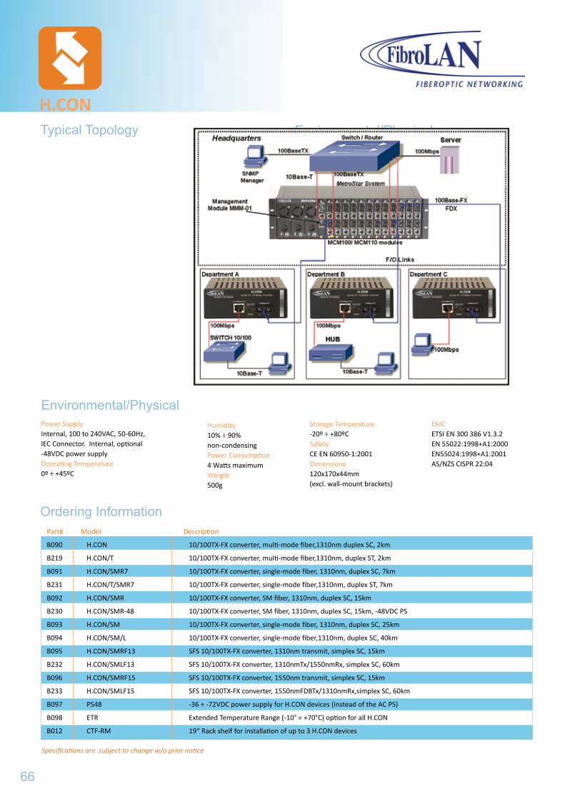
Environmental/Physical
Power SupplyInternal, 100 to 240VAC, 50-60Hz, IEC Connector. Internal, optional -48VDC power supplyOperating Temperature0º ÷ +45ºC
Humidity10% ÷ 90% non-condensingPower Consumption4 Watts maximumWeight500g
Environmental/Physical
Ordering Information
H.CON
Storage Temperature-20º ÷ +80ºC SafetyCE EN 60950-1:2001Dimensions120x170x44mm(excl. wall-mount brackets)
EMCETSI EN 300 386 V1.3.2EN 55022:1998+A1:2000EN55024:1998+A1:2001AS/NZS CISPR 22:04
Typical Topology
Specifications are subject to change w/o prior notice
Part# Model Description
B090 H.CON 10/100TX-FX converter, multi-mode fiber,1310nm duplex SC, 2km
B219 H.CON/T 10/100TX-FX converter, multi-mode fiber,1310nm, duplex ST, 2km
B091 H.CON/SMR7 10/100TX-FX converter, single-mode fiber, 1310nm, duplex SC, 7km
B231 H.CON/T/SMR7 10/100TX-FX converter, single-mode fiber,1310nm, duplex ST, 7km
B092 H.CON/SMR 10/100TX-FX converter, SM fiber, 1310nm, duplex SC, 15km
B230 H.CON/SMR-48 10/100TX-FX converter, SM fiber, 1310nm, duplex SC, 15km, -48VDC PS
B093 H.CON/SM 10/100TX-FX converter, single-mode fiber, 1310nm, duplex SC, 25km
B094 H.CON/SM/L 10/100TX-FX converter, single-mode fiber,1310nm, duplex SC, 40km
B095 H.CON/SMRF13 SFS 10/100TX-FX converter, 1310nm transmit, simplex SC, 15km
B232 H.CON/SMLF13 SFS 10/100TX-FX converter, 1310nmTx/1550nmRx, simplex SC, 60km
B096 H.CON/SMRF15 SFS 10/100TX-FX converter, 1550nm transmit, simplex SC, 15km
B233 H.CON/SMLF15 SFS 10/100TX-FX converter, 1550nmFDBTx/1310nmRx,simplex SC, 60km
B097 PS48 -36 ÷ -72VDC power supply for H.CON devices (instead of the AC PS)
B098 ETR Extended Temperature Range (-10° ÷ +70°C) option for all H.CON
B012 CTF-RM 19“ Rack shelf for installation of up to 3 H.CON devices
66
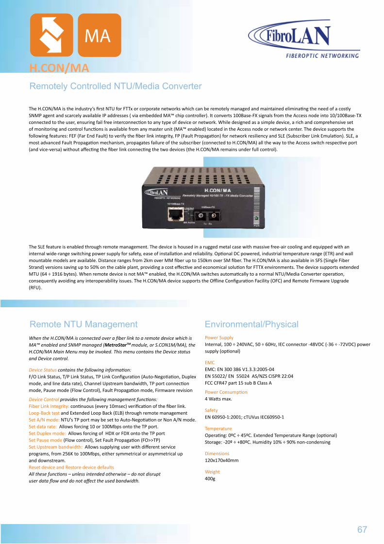
Remotely Controlled NTU/Media Converter
H.CON/MA
When the H.CON/MA is connected over a fiber link to a remote device which is MA™ enabled and SNMP managed (MetroStarTM module, or S.CON1M/MA), the H.CON/MA Main Menu may be invoked. This menu contains the Device status and Device control.
Device Status contains the following information: F/O Link Status, T/P Link Status, TP Link Configuration (Auto-Negotiation, Duplex mode, and line data rate), Channel Upstream bandwidth, TP port connection mode, Pause mode (Flow Control), Fault Propagation mode, Firmware revision
Device Control provides the following management functions: Fiber Link Integrity: continuous (every 10msec) verification of the fiber link.Loop-Back test and Extended Loop Back (ELB) through remote management Set A/N mode: NTU’s TP port may be set to Auto-Negotiation or Non A/N mode. Set data rate: Allows forcing 10 or 100Mbps onto the TP port. Set Duplex mode: Allows forcing of HDX or FDX onto the TP port Set Pause mode (Flow control), Set Fault Propagation (FO>>TP) Set Upstream bandwidth: Allows supplying user with different service programs, from 256K to 100Mbps, either symmetrical or asymmetrical up and downstream.Reset device and Restore device defaults All these functions – unless intended otherwise – do not disrupt user data flow and do not affect the used bandwidth.
Remote NTU Management Environmental/Physical
The H.CON/MA is the industry’s first NTU for FTTx or corporate networks which can be remotely managed and maintained eliminating the need of a costly SNMP agent and scarcely available IP addresses ( via embedded MA™ chip controller). It converts 100Base-FX signals from the Access node into 10/100Base-TX connected to the user, ensuring fail free interconnection to any type of device or network. While designed as a simple device, a rich and comprehensive set of monitoring and control functions is available from any master unit (MA™ enabled) located in the Access node or network center. The device supports the following features: FEF (Far End Fault) to verify the fiber link integrity, FP (Fault Propagation) for network resiliency and SLE (Subscriber Link Emulation). SLE, a most advanced Fault Propagation mechanism, propagates failure of the subscriber (connected to H.CON/MA) all the way to the Access switch respective port (and vice-versa) without affecting the fiber link connecting the two devices (the H.CON/MA remains under full control).
The SLE feature is enabled through remote management. The device is housed in a rugged metal case with massive free-air cooling and equipped with an internal wide-range switching power supply for safety, ease of installation and reliability. Optional DC powered, industrial temperature range (ETR) and wall mountable models are available. Distance ranges from 2km over MM fiber up to 150km over SM fiber. The H.CON/MA is also available in SFS (Single Fiber Strand) versions saving up to 50% on the cable plant, providing a cost effective and economical solution for FTTX environments. The device supports extended MTU (64 ÷ 1916 bytes). When remote device is not MA™ enabled, the H.CON/MA switches automatically to a normal NTU/Media Converter operation, consequently avoiding any interoperability issues. The H.CON/MA device supports the Offline Configuration Facility (OFC) and Remote Firmware Upgrade (RFU).
MA
Power SupplyInternal, 100 ÷ 240VAC, 50 ÷ 60Hz, IEC connector -48VDC (-36 ÷ -72VDC) power supply (optional)
EMCEMC: EN 300 386 V1.3.3:2005-04 EN 55022/ EN 55024 AS/NZS CISPR 22:04 FCC CFR47 part 15 sub B Class A
Power Consumption4 Watts max.
SafetyEN 60950-1:2001; cTUVus IEC60950-1
TemperatureOperating: 0ºC ÷ 45ºC. Extended Temperature Range (optional)Storage: -20º ÷ +80ºC. Humidity 10% ÷ 90% non-condensing
Dimensions120x170x40mm
Weight400g
Environmental/Physical
67
H.CON
EMCETSI EN 300 386 V1.3.2EN 55022:1998+A1:2000EN55024:1998+A1:2001AS/NZS CISPR 22:04
Ordering Information
Specifications are subject to change w/o prior notice
Standard ComplianceIEEE802.3/802.3u, 10Base-T, 100Base-TX, 100Base-FX, FDSEFrame length range: 64 ÷ 1916 bytesSupports 1k MAC addresses Conversion MethodBuffered Media Domain, FDX Flow Control (IEEE 802.3X), HDX Back Pressure, Auto Negotiation, MA™ managed;Far End Fault (FEF) and FP are supportedTP PortShielded RJ-45, MDI-X, 100m over STP Cat. 5 cabling; Auto-Negotiation or forced mode (10/100 and FDX/HDX) via management; Fault Propagation through SLE feature
H.CON/MA
General Specifications
MA
FX PortDuplex SC or ST, FDX, FEF, MM fiber 1310nm; output power -20dBm min., Sensitivity -30dBm or better; For SM: refer to Data Sheet DS-FO; SFS: 1310/1550nm or 1550/1310nmDiagnostics4 LEDs/6 functions: Power ON, TP Link/Activity, F/O Link/Activity, MA ActiveManagementRemote, MA™ (Micro Agent) based technology Managed by FibroLAN‘s MetroView Device Manager
Part# Model Description
3101 H.CON/MA 10/100TX-FX Converter/Access device, duplex SC, MM, 2km, 1310nm, MA
3118 H.CON/MA/T 10/100TX-FX Converter/Access device, duplex ST, MM, 2km, 1310nm, MA
3102 H.CON/MA/SMR7 10/100TX-FX Converter/Access device, duplex SC, SM, 7km, 1310nm, MA
3103 H.CON/MA/SMR 10/100TX-FX Converter/Access device, duplex SC, SM, 15km 1310nm, MA
3119 H.CON/MA/SMR/T 10/100TX-FX Converter/Access device, duplex SC, SM, 15km 1310nm, MA
3104 H.CON/MA/SM 10/100TX-FX Converter/Access device, duplex ST, SM, 25km, 1310nm, MA
3111 H.CON/MA/SM-TL 10/100TX-FX Converter/Access device, wall mountable, extended MTU support, duplex SC, SM, 25km, 1310nm, MA 3115 H.CON/MA/SM-TL-48 10/100TX-FX Converter/Access device, wall mountable, extended MTU support, duplex SC, SM, 25km, 1310nm, -48VDC PS, including 3m power cable, MA
3105 H.CO N/MA/SM/L 10/100TX-FX Converter/Access device, SC, SM, 40km, 1310nm, MA
3108 H.CON/MA/SM/L2 10/100TX-FX Converter/Access device, SC, SM, 70km, 1310nm, MA
3109 H.CON/MA/SM/L3 10/100TX-FX Converter/Access device, SC, SM, 100km, 1550nmDFB, MA
3110 H.CON/MA/SM/LX 10/100TX-FX Converter/Access device, SC, SM, 100km, 1550nmDFB, MA
3106 H.CON/MA/SMRF13 10/100TX-FX Converter/Access device, simplex SC, SM, Single Fiber Strand (SFS), 20km, 1310nm Tx/1550nm Rx, MA
3107 H.CON/MA/SMRF15 10/100TX-FX Converter/Access device, simplex SC, 20km, SFS, 1550nm Tx/1310nm Rx, MA
3112 H.CON/MA/SMRF13-TL 10/100TX-FX Converter/Access device, wall mountable, extended MTU support, simplex SC, SM, 20km, SFS, 1310nm Tx/1550nmRx, MA 3113 H.CON/MA/SMLF13-TL 10/100TX-FX Converter/Access device, wall mountable, extended MTU support, simplex SC, SM, 40km, SFS, 1310nm Tx/1550nmRx, MA 3117 H.CON/MA/SMXF13-TL 10/100TX-FX Converter/Access device, wall mountable, extended MTU support, simplex SC, SM, 80km, SFS, 1310nm Tx/1550nmRx, MA
3116 H.CON/MA/SMRF1313 10/100TX-FX Converter/Access device, simplex SC, SM, 20km, SFS, 1310nm Tx/1310nm Rx, MA
3114 H.CON/MA/ETRX/SMLF13 MA managed 10/100 TX-FX converter/Access device, SC connector, SM Single fiber strand, 1310nmTx/1550nmRx, 40km, Extended temperature range -25C to +70C, -48DC power supply
B097 PS48 DC (-36÷-72VDC) PS instead of AC PS
68
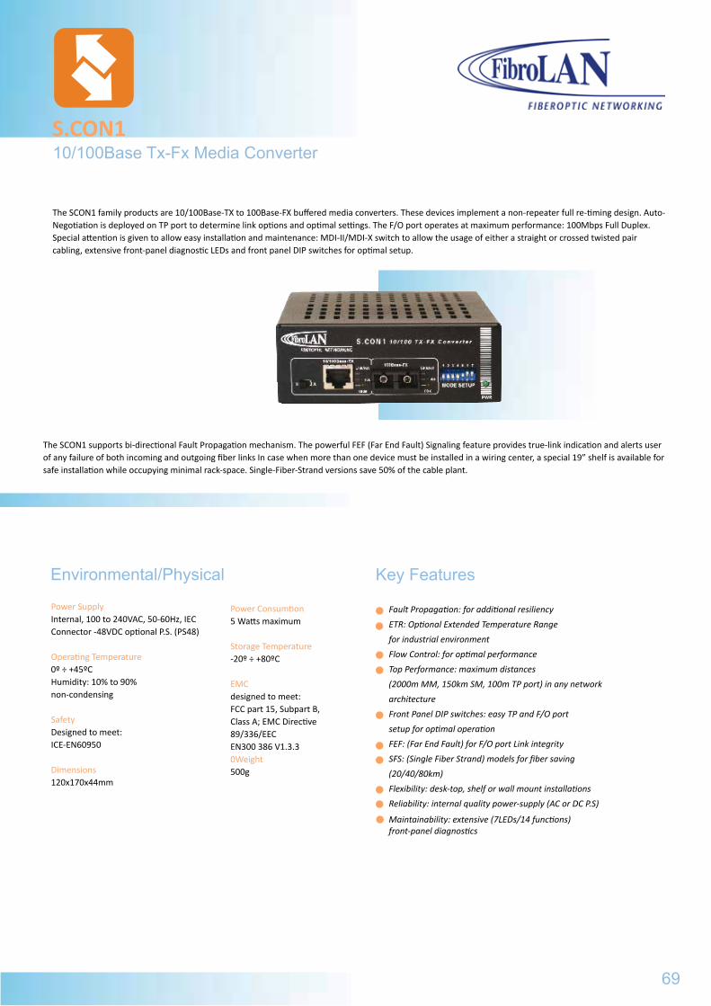
Power SupplyInternal, 100 to 240VAC, 50-60Hz, IEC Connector -48VDC optional P.S. (PS48)
Operating Temperature0º ÷ +45ºCHumidity: 10% to 90%non-condensing
SafetyDesigned to meet: ICE-EN60950
Dimensions120x170x44mm
Power Consumtion5 Watts maximum
Storage Temperature-20º ÷ +80ºC
EMCdesigned to meet:FCC part 15, Subpart B, Class A; EMC Directive 89/336/EECEN300 386 V1.3.30Weight500g
Fault Propagation: for additional resiliency
ETR: Optional Extended Temperature Range
for industrial environment
Flow Control: for optimal performance
Top Performance: maximum distances
(2000m MM, 150km SM, 100m TP port) in any network
architecture
Front Panel DIP switches: easy TP and F/O port
setup for optimal operation
FEF: (Far End Fault) for F/O port Link integrity
SFS: (Single Fiber Strand) models for fiber saving
(20/40/80km)
Flexibility: desk-top, shelf or wall mount installations
Reliability: internal quality power-supply (AC or DC P.S)
Maintainability: extensive (7LEDs/14 functions) front-panel diagnostics
10/100Base Tx-Fx Media ConverterS.CON1
Environmental/Physical Key Features
The SCON1 family products are 10/100Base-TX to 100Base-FX buffered media converters. These devices implement a non-repeater full re-timing design. Auto-Negotiation is deployed on TP port to determine link options and optimal settings. The F/O port operates at maximum performance: 100Mbps Full Duplex. Special attention is given to allow easy installation and maintenance: MDI-II/MDI-X switch to allow the usage of either a straight or crossed twisted pair cabling, extensive front-panel diagnostic LEDs and front panel DIP switches for optimal setup.
69
The SCON1 supports bi-directional Fault Propagation mechanism. The powerful FEF (Far End Fault) Signaling feature provides true-link indication and alerts user of any failure of both incoming and outgoing fiber links In case when more than one device must be installed in a wiring center, a special 19” shelf is available for safe installation while occupying minimal rack-space. Single-Fiber-Strand versions save 50% of the cable plant.
H.CON/MA
General Specifications
Part# Model Description
3101 H.CON/MA 10/100TX-FX Converter/Access device, duplex SC, MM, 2km, 1310nm, MA
3118 H.CON/MA/T 10/100TX-FX Converter/Access device, duplex ST, MM, 2km, 1310nm, MA
3102 H.CON/MA/SMR7 10/100TX-FX Converter/Access device, duplex SC, SM, 7km, 1310nm, MA
3103 H.CON/MA/SMR 10/100TX-FX Converter/Access device, duplex SC, SM, 15km 1310nm, MA
3119 H.CON/MA/SMR/T 10/100TX-FX Converter/Access device, duplex SC, SM, 15km 1310nm, MA
3104 H.CON/MA/SM 10/100TX-FX Converter/Access device, duplex ST, SM, 25km, 1310nm, MA
3111 H.CON/MA/SM-TL 10/100TX-FX Converter/Access device, wall mountable, extended MTU support, duplex SC, SM, 25km, 1310nm, MA 3115 H.CON/MA/SM-TL-48 10/100TX-FX Converter/Access device, wall mountable, extended MTU support, duplex SC, SM, 25km, 1310nm, -48VDC PS, including 3m power cable, MA
3105 H.CO N/MA/SM/L 10/100TX-FX Converter/Access device, SC, SM, 40km, 1310nm, MA
3108 H.CON/MA/SM/L2 10/100TX-FX Converter/Access device, SC, SM, 70km, 1310nm, MA
3109 H.CON/MA/SM/L3 10/100TX-FX Converter/Access device, SC, SM, 100km, 1550nmDFB, MA
3110 H.CON/MA/SM/LX 10/100TX-FX Converter/Access device, SC, SM, 100km, 1550nmDFB, MA
3106 H.CON/MA/SMRF13 10/100TX-FX Converter/Access device, simplex SC, SM, Single Fiber Strand (SFS), 20km, 1310nm Tx/1550nm Rx, MA
3107 H.CON/MA/SMRF15 10/100TX-FX Converter/Access device, simplex SC, 20km, SFS, 1550nm Tx/1310nm Rx, MA
3112 H.CON/MA/SMRF13-TL 10/100TX-FX Converter/Access device, wall mountable, extended MTU support, simplex SC, SM, 20km, SFS, 1310nm Tx/1550nmRx, MA 3113 H.CON/MA/SMLF13-TL 10/100TX-FX Converter/Access device, wall mountable, extended MTU support, simplex SC, SM, 40km, SFS, 1310nm Tx/1550nmRx, MA 3117 H.CON/MA/SMXF13-TL 10/100TX-FX Converter/Access device, wall mountable, extended MTU support, simplex SC, SM, 80km, SFS, 1310nm Tx/1550nmRx, MA
3116 H.CON/MA/SMRF1313 10/100TX-FX Converter/Access device, simplex SC, SM, 20km, SFS, 1310nm Tx/1310nm Rx, MA
3114 H.CON/MA/ETRX/SMLF13 MA managed 10/100 TX-FX converter/Access device, SC connector, SM Single fiber strand, 1310nmTx/1550nmRx, 40km, Extended temperature range -25C to +70C, -48DC power supply
B097 PS48 DC (-36÷-72VDC) PS instead of AC PS
Ordering Information
Specifications are subject to change w/o prior notice
Standard CompilanceIEEE 802.3u100Base-TX, 10Base-T, FDSE 100Base-FX
10/100Base-TX ports Shielded RJ-45, Speed and Half/Full Duplex support via Auto-Negotiation or forced (DIP switches) 100m over STP Cat5 cableAuto-Polarity correction MDI-II/MDI-X selection (front panel switch) 10/100Base-TX support via auto-negotiation or forced (DIP switches)
Controls (Front panel DIP switches)FX port: FDX/HDX selectionTX port: 10/100, FDX/HDXAuto-Negotiation enable/disableEnable/Disable Fault Propagation (F>T, T>F)Reset device
S.CON1
General Specifications
Conversion MethodBMD (Buffered Media Domain), FDX flow control, HDX back-pressure flow control 1k Mac addresses, Frames: 64 to 1518 bytes
100Base-FX PortFEF SignalingHalf for Full Duplex (DIP switch selectable)1310nm, multi-mode, Duplex SC/STDistance - 2000mOutput Power: -18dBm or betterInput Sensitivity: -32dBm or betterSingle Mode 7/15/25/40/70/100/150 kmSingle-Fiber Strand 20/40/80kmRefer to FibroLAN F/O Specs DS (DS-FO)
Diagnostic LEDsF/O port: Link/Activity, Signal Detect, FDX TP port: Link/Activity, FDX, 100MbpsPower On/Off
Part# Model Description
B017 S.CON1 Single Channel 10/100TX-FX converter, BMD, duplex SC, MM, 2km
B019 S.CON1/T Single Channel 10/100TX-FX converter, BMD, ST connectors, MM, 2km
B060 S.CON1-48 Single Channel 10/100TX-FX converter, BMD, duplex SC, MM, 2km, -48VDC PS
B015 S.CON1/SMR7 Single Channel 10/100TX-FX converter, BMD, duplex SC, SM, 7km, 1310nm
B059 S.CON1/SMR Single Channel 10/100TX-FX converter, BMD, duplex SC, SM, 15km, 1310nm
B061 S.CON1/SM Single Channel 10/100TX-FX converter, BMD, duplex SC, SM, 25km, 1310nm
B027 S.CON1/SM/L Single Channel 10/100TX-FX converter, BMD, duplex SC, SM, 40km, 1310nm
B028 S.CON1/SM/L2 Single Channel 10/100TX-FX converter, BMD, duplex SC, SM, 70km, 1310nm
B147 S.CON1/SM/L3 Single Channel 10/100TX-FX converter, BMD, duplex SC, SM, 100km, CFB 1550nm
B029 S.CON1/SM/LX Single Channel 10/100TX-FX converter, BMD, 2* SC, SM, 150km, 1550nm DFB
B034 S.CON1/SMRF15 Single Channel 10/100TX-FX converter, BMD, simplexSC, Single Fiber Strand, SM,
20km, 1550nmTX/ 1310nmRX
B030 S.CON1/SMRF13 Single Channel 10/100TX-FX converter, BMD, simplexSC, Single Fiber Strand, SM, 20km, 1310nmTX/ 1550nmRX
B294 S.CON1/SMXF15 Single Channel 10/100Base-TX to 100Base-FX converter, BMD (Buffered Media Domain), simplex SC connector, single-mode-80km,1550nmTX DFB/1310nmRX, Single Fiber Strand
B295 S.CON1/SMXF13 Single Channel 10/100Base-TX to 100Base-FX converter, BMD (Buffered Media Domain), simplex SC connector, single-mode-80km,1310nmTX/1550nmRX, Single Fiber Strand
B097 PS48 Optional Power Supply (-36 to -72 VDC) instead of AC PS
B151 CBPS-DC48V DC PS Cable, 2m for PS48
B098 ETR Extended Temperature Range (-10 ºC to *70ºC) option for all S.CON devices
B012 CTF-RM 19” Rack shelf for installation of up to 3 S.CON1 devices
B161 SCH-WM Wall mount kit
70
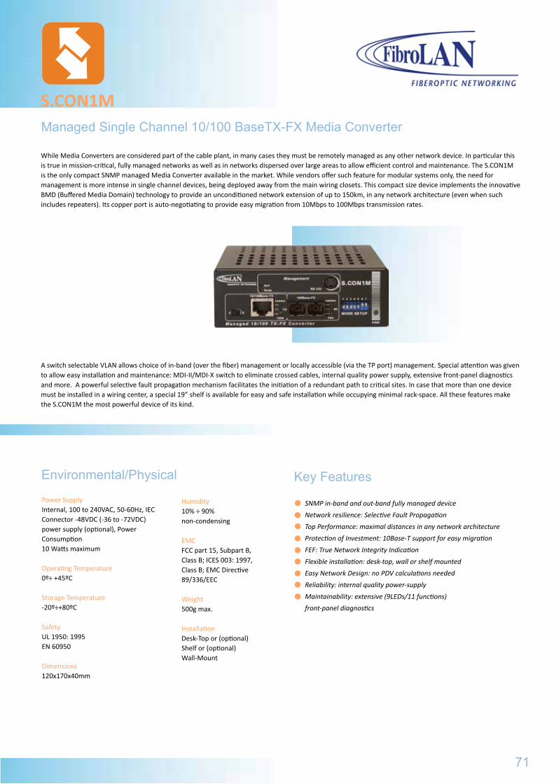
Managed Single Channel 10/100 BaseTX-FX Media Converter
S.CON1M
Humidity10% ÷ 90% non-condensing
EMCFCC part 15, Subpart B, Class B; ICES 003: 1997,Class B; EMC Directive 89/336/EEC
Weight500g max.
InstallationDesk-Top or (optional) Shelf or (optional)Wall-Mount
SNMP in-band and out-band fully managed device
Network resilience: Selective Fault Propagation
Top Performance: maximal distances in any network architecture
Protection of Investment: 10Base-T support for easy migration
FEF: True Network Integrity Indication
Flexible installation: desk-top, wall or shelf mounted
Easy Network Design: no PDV calculations needed
Reliability: internal quality power-supply
Maintainability: extensive (9LEDs/11 functions)
front-panel diagnostics
Environmental/Physical
Power SupplyInternal, 100 to 240VAC, 50-60Hz, IEC Connector -48VDC (-36 to -72VDC) power supply (optional), Power Consumption10 Watts maximum
Operating Temperature0º÷ +45ºC
Storage Temperature-20º÷+80ºC
SafetyUL 1950: 1995EN 60950
Dimensions120x170x40mm
Key Features
While Media Converters are considered part of the cable plant, in many cases they must be remotely managed as any other network device. In particular this is true in mission-critical, fully managed networks as well as in networks dispersed over large areas to allow efficient control and maintenance. The S.CON1M is the only compact SNMP managed Media Converter available in the market. While vendors offer such feature for modular systems only, the need for management is more intense in single channel devices, being deployed away from the main wiring closets. This compact size device implements the innovative BMD (Buffered Media Domain) technology to provide an unconditioned network extension of up to 150km, in any network architecture (even when such includes repeaters). Its copper port is auto-negotiating to provide easy migration from 10Mbps to 100Mbps transmission rates.
A switch selectable VLAN allows choice of in-band (over the fiber) management or locally accessible (via the TP port) management. Special attention was given to allow easy installation and maintenance: MDI-II/MDI-X switch to eliminate crossed cables, internal quality power supply, extensive front-panel diagnostics and more. A powerful selective fault propagation mechanism facilitates the initiation of a redundant path to critical sites. In case that more than one device must be installed in a wiring center, a special 19” shelf is available for easy and safe installation while occupying minimal rack-space. All these features make the S.CON1M the most powerful device of its kind.
71
S.CON1
General Specifications
Part# Model Description
B017 S.CON1 Single Channel 10/100TX-FX converter, BMD, duplex SC, MM, 2km
B019 S.CON1/T Single Channel 10/100TX-FX converter, BMD, ST connectors, MM, 2km
B060 S.CON1-48 Single Channel 10/100TX-FX converter, BMD, duplex SC, MM, 2km, -48VDC PS
B015 S.CON1/SMR7 Single Channel 10/100TX-FX converter, BMD, duplex SC, SM, 7km, 1310nm
B059 S.CON1/SMR Single Channel 10/100TX-FX converter, BMD, duplex SC, SM, 15km, 1310nm
B061 S.CON1/SM Single Channel 10/100TX-FX converter, BMD, duplex SC, SM, 25km, 1310nm
B027 S.CON1/SM/L Single Channel 10/100TX-FX converter, BMD, duplex SC, SM, 40km, 1310nm
B028 S.CON1/SM/L2 Single Channel 10/100TX-FX converter, BMD, duplex SC, SM, 70km, 1310nm
B147 S.CON1/SM/L3 Single Channel 10/100TX-FX converter, BMD, duplex SC, SM, 100km, CFB 1550nm
B029 S.CON1/SM/LX Single Channel 10/100TX-FX converter, BMD, 2* SC, SM, 150km, 1550nm DFB
B034 S.CON1/SMRF15 Single Channel 10/100TX-FX converter, BMD, simplexSC, Single Fiber Strand, SM,
20km, 1550nmTX/ 1310nmRX
B030 S.CON1/SMRF13 Single Channel 10/100TX-FX converter, BMD, simplexSC, Single Fiber Strand, SM, 20km, 1310nmTX/ 1550nmRX
B294 S.CON1/SMXF15 Single Channel 10/100Base-TX to 100Base-FX converter, BMD (Buffered Media Domain), simplex SC connector, single-mode-80km,1550nmTX DFB/1310nmRX, Single Fiber Strand
B295 S.CON1/SMXF13 Single Channel 10/100Base-TX to 100Base-FX converter, BMD (Buffered Media Domain), simplex SC connector, single-mode-80km,1310nmTX/1550nmRX, Single Fiber Strand
B097 PS48 Optional Power Supply (-36 to -72 VDC) instead of AC PS
B151 CBPS-DC48V DC PS Cable, 2m for PS48
B098 ETR Extended Temperature Range (-10 ºC to *70ºC) option for all S.CON devices
B012 CTF-RM 19” Rack shelf for installation of up to 3 S.CON1 devices
B161 SCH-WM Wall mount kit
Ordering Information
Specifications are subject to change w/o prior notice
Standard CompilanceIEEE 802.3u100Base-TX, 10Base-T, FDSE 100Base-FX
10/100Base-TX ports Shielded RJ-45, Half/Full Duplex support via Auto-Sensing or manual (DIP switch), 100m over UTP/STP Cat5 cableAuto-Polarity correction MDI-II/MDI-X selection 10Base-T support via auto-sensing or manual (DIP switch)
Controls (DIP switches)TX po: 10/100 FDX/HDX Auto-Negotiation enable/disableVLAN enable/disableFault Propagation (F>T, T>F)
Management FunctionsAll diagnostic functions (see above)All control functions (see above)Device Temperature, Alerts of device’sany operational changesSystem status
S.CON1MGeneral Specifications
Conversion MethodBMD (Buffered Media Domain), Selective Fault Propagation
100Base-FX Port1310nm, multi-mode, SCconnectorsDistance - 2000m (660 ft)Half or Full Duplex (DIP switch selectable)Output Power: -18dBm or betterInput Sensitivity: -32dBm or betterFor Single Mode specifications see DS-SM
DiagnosticsFull Duplex, Link/Activity, SD-F/O portFull Duplex, Link/Activity, 100Mbps-TP portPower
Management Physical InterfaceminiDIN connector (RS232) for setup and diagnostics 2 status LEDs (Activity, Readiness)
Management StandardsSNMP (V1 & V2), MIB II (RFC 1213)FibroLAN private MIB extensionsTelnet, TFTP
Part# Model Description
B017 S.CON1 Single Channel 10/100TX-FX converter, BMD, duplex SC, MM, 2km
B019 S.CON1/T Single Channel 10/100TX-FX converter, BMD, ST connectors, MM, 2km
B060 S.CON1-48 Single Channel 10/100TX-FX converter, BMD, duplex SC, MM, 2km, -48VDC PS
B015 S.CON1/SMR7 Single Channel 10/100TX-FX converter, BMD, duplex SC, SM, 7km, 1310nm
B059 S.CON1/SMR Single Channel 10/100TX-FX converter, BMD, duplex SC, SM, 15km, 1310nm
B061 S.CON1/SM Single Channel 10/100TX-FX converter, BMD, duplex SC, SM, 25km, 1310nm
B027 S.CON1/SM/L Single Channel 10/100TX-FX converter, BMD, duplex SC, SM, 40km, 1310nm
B028 S.CON1/SM/L2 Single Channel 10/100TX-FX converter, BMD, duplex SC, SM, 70km, 1310nm
B147 S.CON1/SM/L3 Single Channel 10/100TX-FX converter, BMD, duplex SC, SM, 100km, CFB 1550nm
B029 S.CON1/SM/LX Single Channel 10/100TX-FX converter, BMD, 2* SC, SM, 150km, 1550nm DFB
B034 S.CON1/SMRF15 Single Channel 10/100TX-FX converter, BMD, simplexSC, Single Fiber Strand, SM,
20km, 1550nmTX/ 1310nmRX
B030 S.CON1/SMRF13 Single Channel 10/100TX-FX converter, BMD, simplexSC, Single Fiber Strand, SM, 20km, 1310nmTX/ 1550nmRX B294 S.CON1/SMXF15 Single Channel 10/100Base-TX to 100Base-FX converter, BMD (Buffered Media Domain), simplex SC connector, single-mode-80km,1550nmTX DFB/1310nmRX, Single Fiber Strand B295 S.CON1/SMXF13 Single Channel 10/100Base-TX to 100Base-FX converter, BMD (Buffered Media Domain), simplex SC connector, single-mode-80km,1310nmTX/1550nmRX, Single Fiber Strand
B097 PS48 Optional Power Supply (-36 to -72 VDC) instead of AC PS
B151 CBPS-DC48V DC PS Cable, 2m for PS48
B098 ETR Extended Temperature Range (-10 ºC to *70ºC) option for all S.CON devices
B012 CTF-RM 19” Rack shelf for installation of up to 3 S.CON1 devices
B161 SCH-WM Wall mount kit
72
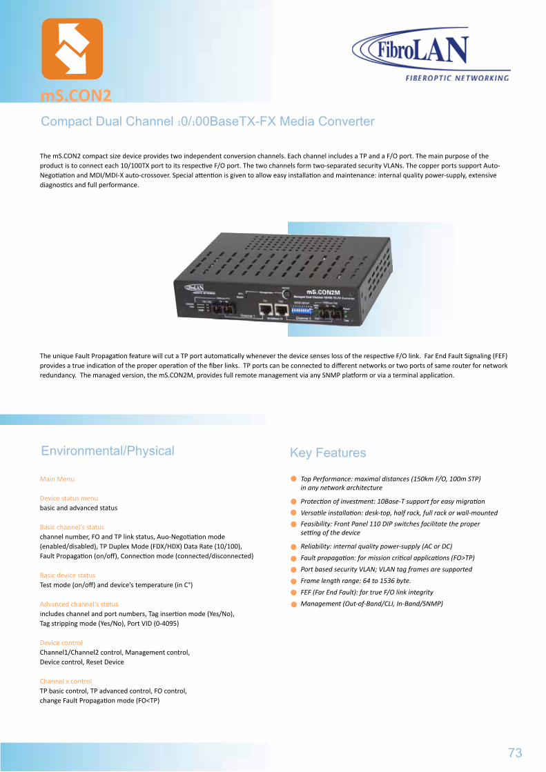
Compact Dual Channel 10/100BaseTX-FX Media Converter
mS.CON2
Main Menu
Device status menubasic and advanced status
Basic channel‘s statuschannel number, FO and TP link status, Auo-Negotiation mode (enabled/disabled), TP Duplex Mode (FDX/HDX) Data Rate (10/100), Fault Propagation (on/off), Connection mode (connected/disconnected)
Basic device statusTest mode (on/off) and device‘s temperature (in C°)
Advanced channel‘s statusincludes channel and port numbers, Tag insertion mode (Yes/No), Tag stripping mode (Yes/No), Port VID (0-4095)
Device controlChannel1/Channel2 control, Management control,Device control, Reset Device
Channel x controlTP basic control, TP advanced control, FO control, change Fault Propagation mode (FO<TP)
Top Performance: maximal distances (150km F/O, 100m STP) in any network architecture
Protection of investment: 10Base-T support for easy migration
Versatile installation: desk-top, half rack, full rack or wall-mounted
Feasibility: Front Panel 110 DIP switches facilitate the proper setting of the device
Reliability: internal quality power-supply (AC or DC)
Fault propagation: for mission critical applications (FO>TP)
Port based security VLAN; VLAN tag frames are supported
Frame length range: 64 to 1536 byte.
FEF (Far End Fault): for true F/O link integrity
Management (Out-of-Band/CLI, In-Band/SNMP)
Environmental/Physical Key Features
The mS.CON2 compact size device provides two independent conversion channels. Each channel includes a TP and a F/O port. The main purpose of the product is to connect each 10/100TX port to its respective F/O port. The two channels form two-separated security VLANs. The copper ports support Auto-Negotiation and MDI/MDI-X auto-crossover. Special attention is given to allow easy installation and maintenance: internal quality power-supply, extensive diagnostics and full performance.
The unique Fault Propagation feature will cut a TP port automatically whenever the device senses loss of the respective F/O link. Far End Fault Signaling (FEF) provides a true indication of the proper operation of the fiber links. TP ports can be connected to different networks or two ports of same router for network redundancy. The managed version, the mS.CON2M, provides full remote management via any SNMP platform or via a terminal application.
73
S.CON1MGeneral Specifications
Part# Model Description
B017 S.CON1 Single Channel 10/100TX-FX converter, BMD, duplex SC, MM, 2km
B019 S.CON1/T Single Channel 10/100TX-FX converter, BMD, ST connectors, MM, 2km
B060 S.CON1-48 Single Channel 10/100TX-FX converter, BMD, duplex SC, MM, 2km, -48VDC PS
B015 S.CON1/SMR7 Single Channel 10/100TX-FX converter, BMD, duplex SC, SM, 7km, 1310nm
B059 S.CON1/SMR Single Channel 10/100TX-FX converter, BMD, duplex SC, SM, 15km, 1310nm
B061 S.CON1/SM Single Channel 10/100TX-FX converter, BMD, duplex SC, SM, 25km, 1310nm
B027 S.CON1/SM/L Single Channel 10/100TX-FX converter, BMD, duplex SC, SM, 40km, 1310nm
B028 S.CON1/SM/L2 Single Channel 10/100TX-FX converter, BMD, duplex SC, SM, 70km, 1310nm
B147 S.CON1/SM/L3 Single Channel 10/100TX-FX converter, BMD, duplex SC, SM, 100km, CFB 1550nm
B029 S.CON1/SM/LX Single Channel 10/100TX-FX converter, BMD, 2* SC, SM, 150km, 1550nm DFB
B034 S.CON1/SMRF15 Single Channel 10/100TX-FX converter, BMD, simplexSC, Single Fiber Strand, SM,
20km, 1550nmTX/ 1310nmRX
B030 S.CON1/SMRF13 Single Channel 10/100TX-FX converter, BMD, simplexSC, Single Fiber Strand, SM, 20km, 1310nmTX/ 1550nmRX B294 S.CON1/SMXF15 Single Channel 10/100Base-TX to 100Base-FX converter, BMD (Buffered Media Domain), simplex SC connector, single-mode-80km,1550nmTX DFB/1310nmRX, Single Fiber Strand B295 S.CON1/SMXF13 Single Channel 10/100Base-TX to 100Base-FX converter, BMD (Buffered Media Domain), simplex SC connector, single-mode-80km,1310nmTX/1550nmRX, Single Fiber Strand
B097 PS48 Optional Power Supply (-36 to -72 VDC) instead of AC PS
B151 CBPS-DC48V DC PS Cable, 2m for PS48
B098 ETR Extended Temperature Range (-10 ºC to *70ºC) option for all S.CON devices
B012 CTF-RM 19” Rack shelf for installation of up to 3 S.CON1 devices
B161 SCH-WM Wall mount kit
Ordering Information
Specifications are subject to change w/o prior notice
Standard CompilanceIEEE 802.3u100Base-TX, 10Base-T, FDSE 100Base-FX
10/100Base-TX ports (2) Shielded RJ-45, Half/Full Duplex support via Auto-Negotiation or forced; 100m over STP Cat5 cableAuto-Cross Support
Diagnostic LEDsPower, F/O Link/Activity, TP Link/Activity 10/100M Test Mode ON (disables Far End Fault and Fault Propagation for both channels)
Conversion MethodeBMD (Buffered Media Domain) with Fault Propagation (FO>>TP)
100Base-FX ports (2)Multi Mode Fiber: Output Power -18dBm min. Sensivity -32dBm or better; Single mode and SFS (Single Fiber Strand) - Refer to FibroLAN Datasheet - SM options
Controls (Front Panel DIP switches)Per Channel: FP enable/disable, A/N enable/disable, 10/100Mbps, HDX/FDX. Per Device: Reset, FEF enable/disable
ms.CON2
General Specifications
Power - SupplyInternal, 100 to 240 VAC, 50-60Hz; IEC connector -48VDC optional PS
TemperatureOperating: 0° to +45°C; Storage: -20° to +80°CHumidity: 10% to 90% non-condensing
SafetyUL 60950, EN 60950
Dimensions/WeightMax - 223x150x44nm/1kg maxPower Consumption15 Watts maximumEMCETSI EN 300 386 V1.3.2; EN55022:1988+A1:2000EN55024:1998+A1:2001; AN/NZS CISPR 22:04ManagementOut-of-Band (RS232/CLI); In-Band (SNMP management platforms:SNMPc, HP OpenView, FibroLAN’s MetroView Management System, etc...)
Part# Model Description
B013 mS.CON2 Compact Dual channel, 10/100Base-TX to 100BaseFX, BMD, Duplex SC, Multi Mode, 2km, 1310nm
B014 mS.CON2M Compact Dual channel, 10/100Base-TX to 100BaseFX, BMD, Duplex SC, Multi Mode, 2km, 1310nm, SNMP managed
B156 mS.CON2/SMR Compact Dual channel, 10/100Base-TX to 100BaseFX, BMD, Duplex SC, Multi Mode, 15km, 1310nm
B157 mS.CON2M/SMR Compact Dual channel, 10/100Base-TX to 100BaseFX, BMD, Duplex SC, Multi Mode, 15km, 1310nm
B158 mS.CON2M/SMRF13 Compact Dual channel, 10/100Base-TX to 100BaseFX, BMD, Simplex SC, Single Fiber Strand Single Mode,
15km, 1310nm Tx/1550nm Rx B159 mS.CON2M/SMRF15 Compact Dual channel, 10/100Base-TX to 100BaseFX, BMD, Simplex SC, Single Fiber Strand Single Mode, 15km, 1550nm Tx/1310nm Rx
B160 RM2 19” Rack shelf for mounting up to 2 mS.CON2 devices
B098 ETR Extended Temperature Range (-10°C to +70°C)
B097 PS48 DC (-36VDC to -72VDC) power supply instead of AC PS
74
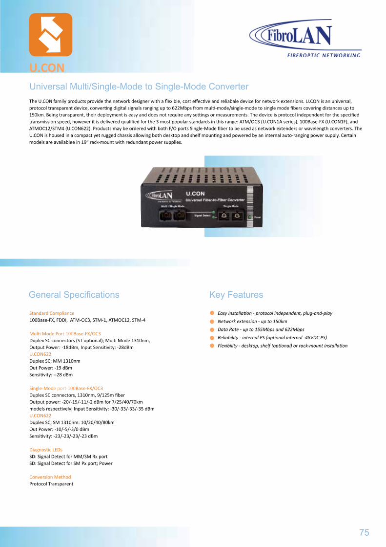
Universal Multi/Single-Mode to Single-Mode Converter
U.CON
General Specifications
Easy Installation - protocol independent, plug-and-play
Network extension - up to 150km
Data Rate - up to 155Mbps and 622Mbps
Reliability - internal PS (optional internal -48VDC PS)
Flexibility - desktop, shelf (optional) or rack-mount installation
Standard Compliance100Base-FX, FDDI, ATM-OC3, STM-1, ATMOC12, STM-4
Multi Mode Port 100Base-FX/OC3Duplex SC connectors (ST optional); Multi Mode 1310nm,Output Power: -18dBm, Input Sensitivity: -28dBmU.CON622Duplex SC; MM 1310nmOut Power: -19 dBmSensitivity: --28 dBm
Single-Mode port-100Base-FX/OC3Duplex SC connectors, 1310nm, 9/125m fiberOutput power: -20/-15/-11/-2 dBm for 7/25/40/70kmmodels respectively; Input Sensitivity: -30/-33/-33/-35 dBmU.CON622Duplex SC; SM 1310nm: 10/20/40/80kmOut Power: -10/-5/-3/0 dBmSensitivity: -23/-23/-23/-23 dBm
Diagnostic LEDsSD: Signal Detect for MM/SM Rx portSD: Signal Detect for SM Px port; Power
Conversion MethodProtocol Transparent
The U.CON family products provide the network designer with a flexible, cost effective and reliabale device for network extensions. U.CON is an universal, protocol transparent device, converting digital signals ranging up to 622Mbps from multi-mode/single-mode to single mode fibers covering distances up to 150km. Being transparent, their deployment is easy and does not require any settings or measurements. The device is protocol independent for the specified transmission speed, however it is delivered qualified for the 3 most popular standards in this range: ATM/OC3 (U.CON1A series), 100Base-FX (U.CON1F), and ATMOC12/STM4 (U.CON622). Products may be ordered with both F/O ports Single-Mode fiber to be used as network extenders or wavelength converters. The U.CON is housed in a compact yet rugged chassis allowing both desktop and shelf mounting and powered by an internal auto-ranging power supply. Certain models are availablee in 19” rack-mount with redundant power supplies.
75
Key Features
ms.CON2
General Specifications
Part# Model Description
B013 mS.CON2 Compact Dual channel, 10/100Base-TX to 100BaseFX, BMD, Duplex SC, Multi Mode, 2km, 1310nm
B014 mS.CON2M Compact Dual channel, 10/100Base-TX to 100BaseFX, BMD, Duplex SC, Multi Mode, 2km, 1310nm, SNMP managed
B156 mS.CON2/SMR Compact Dual channel, 10/100Base-TX to 100BaseFX, BMD, Duplex SC, Multi Mode, 15km, 1310nm
B157 mS.CON2M/SMR Compact Dual channel, 10/100Base-TX to 100BaseFX, BMD, Duplex SC, Multi Mode, 15km, 1310nm
B158 mS.CON2M/SMRF13 Compact Dual channel, 10/100Base-TX to 100BaseFX, BMD, Simplex SC, Single Fiber Strand Single Mode,
15km, 1310nm Tx/1550nm Rx B159 mS.CON2M/SMRF15 Compact Dual channel, 10/100Base-TX to 100BaseFX, BMD, Simplex SC, Single Fiber Strand Single Mode, 15km, 1550nm Tx/1310nm Rx
B160 RM2 19” Rack shelf for mounting up to 2 mS.CON2 devices
B098 ETR Extended Temperature Range (-10°C to +70°C)
B097 PS48 DC (-36VDC to -72VDC) power supply instead of AC PS
Environmental/Physical
Power SupplyInternal, 100 to 240 VAC, 50-60 Hz
TemperatureOperating: 0° to +45°C; Storage: -20° to +80°CHumidity: 10% to 90% non-condensing
SafetyUL 60950, EN 60950
U.CON
Ordering Information
Specifications are subject to change w/o prior notice
Part# Model Description
B152 U.CON1A/SMR7 MM to SM 1310nm ATM/OC3 Media Converter, 7km, 2*duplex SC
B080 U.CON1A MM to SM 1310nm ATM/OC3 Media Converter, 25km, 2*duplex SC
B153 U.CON1F/SMR7 MM to SM 1310nm Fast Ethernet Media Converter, 7km, 2*duplex SC
B081 U.CON1F MM to SM 1310nm Fast Ethernet Media Converter, 25km, 2*duplex SC
B082 U.CON1A-48 MM to SM 1310nm ATM/OC3, MC, 25km, 2*duplex SC, internal -48VDC PS
B083 U.CON1F-48 MM to SM 1310nm Fast Ethernet, MC, 25km, 2*duplex SC, internal -48VDC PS
B084 U.CON1A/L MM to SM 1310nm ATM/OC3 Media Converter, 40km, 2*duplex SC
B085 U.CON1F/L MM to SM 1310nm Fast Ethernet Media Converter, 40km, 2*duplex SC
B086 U.CON1A/L2 MM to SM 1310nm ATM/OC3 Media Converter, 70km, 2*duplex SC
B087 U.CON1F/L2 MM to SM 1310nmFast Ethernet Media Converter, 40km, 2*duplex SC
B149 U.CON1A2AC/SMR7LX SM fiber 7km 1310nm to SM fiber 150km 1550nm converter ATM/OC3, 2*duplex SC, 19” 1U, dual redundant PS
B150 U.CON2A2AC/SMR7LX Dual Channel SM 7km 1310nm to SM fiber 150km 1550nm converter ATM/OC3, 2*duplex SC, 19” 1U, dual redundant PS
B224 U.CON622 MM 1310nm to SM 1310nm ATM/OC12/STM-4 Media Converter, 2*duplex SC, 20km
B225 U.CON622/SML MM 1310nm to SM 1550nm DFB ATM/OC12/STM-4 Media Converter, 2*duplex SC, 40km
B226 U.CON622/SML2 MM 1310nm to SM 1550nm DFB ATM/OC12/STM-4 Media Converter, 2*duplex SC, 80km
B227 U.CON622/SM-SM SM 1310nm 10km to SM 1310nm ATM/OC12/STM-4 Extender, 2*duplex SC, 20km
B228 U.CON622/SM-SML SM 1310nm 10km to SM 1550nm DFB ATM/OC12/STM-4 Extender, 2*duplex SC, 40km
B229 U.CON622/SM-SML2 SM 1310nm 10km to SM 1550nm DFB ATM/OC12/STM-4 Extender, 2*duplex SC, 80km
76
Dimensions, Weight120x170x44 mm; 500 g
Power Consumption5 Watts maximum
EMCFCC part 15, Subpart B, Class A; VCCI Class A; ICES 003:1997, Class A; EMC Directive 89/336/EEC
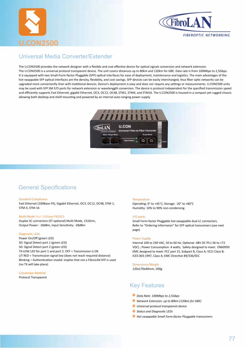
Universal Media Converter/Extender
U.CON2500
General Specifications
Data Rate: 100Mbps to 2,5Gbps
Network Extension: up to 80km (120km for GBE)
Universal protocol transparent device
Status and Diagnostic LEDs
Hot swappable Small Form-factor Pluggable transceivers
Standard ComplianceFast Ethernet (100Base-FX), Gigabit Ethernet, OC3, OC12, OC48, STM-1, STM-4, STM-16
Multi Mode Port 100Base-FX/OC3Duplex SC connectors (ST optional) Multi Mode, 1310nm,Output Power: -18dBm, Input Sensitivity: -28dBm
Diagnostic LEDsPower On/Off (green LED)SD: Signal Detect port 1 (green LED)SD: Signal Detect port 2 (green LED)TX-LOW LED for port 1 and port 2: OFF = Transmission is OKLIT RED = Transmission signal low (does not reach required distance)Blinking = Authentication invalid: implies that not a FibroLAN SFP is used(no TX will take place)
Conversion MethodProtocol Transparent
The U.CON2500 provides the network designer with a flexible and cost effective device for optical signals conversion and network extension. The U.CON2500 is a universal protocol transparent device. The unit covers distances up to 80km and 120km for GBE. Data rate is from 100Mbps to 2,5Gbps. It is equipped with two Small-Form-factor Pluggable (SFP) optical interfaces for ease of deployment, maintenance and logistics. The main advantages of the hot-swappable SFP optical interfaces are the density, flexibility, and cost savings. SFP devices can be easily interchanged, thus fiber optic networks can be upgraded more conveniently than with traditional devices. Device’s deployment is easy and does nor require any settings or measurements. U.CON2500 units may be used with SFP SM F/O ports for network extension or wavelenggth conversion. The device is protocol independent for the specified transmission speed and efficiently supports Fast Ethernet, gigabit Ethernet, OC3, OC12, OC48, STM1, STM4, and STM16. The U.CON2500 is housed in a compact yet rugged chassis allowing both desktop and shelf-mounting and powered by an internal auto-ranging power supply.
TemperatureOperating: 0° to +45°C; Storage: -20° to +80°CHumidity: 10% to 90% non-condensing
F/O portsSmall Form-factor Pluggable hot-swappable dual LC connectors. Refer to “Ordering Informaion” for SFP optical transceivers (see next page)
Power SupplyInternal 100 to 240 VAC, 50 to 60 Hz; Optional -48V DC PS (-36 to +72 VDC) ; Power Consumption: 4 watts; Safety designed to meet: EN60950EMC designed to meet: FCC part 15, Subpart B, Class A; VCCI Class B; ICES 003:1997, Class A; EMC Directive 89/336/EEC
Dimensions/Weight120x170x40mm, 500g
Key Features
77
Environmental/Physical
U.CON
Part# Model Description
B152 U.CON1A/SMR7 MM to SM 1310nm ATM/OC3 Media Converter, 7km, 2*duplex SC
B080 U.CON1A MM to SM 1310nm ATM/OC3 Media Converter, 25km, 2*duplex SC
B153 U.CON1F/SMR7 MM to SM 1310nm Fast Ethernet Media Converter, 7km, 2*duplex SC
B081 U.CON1F MM to SM 1310nm Fast Ethernet Media Converter, 25km, 2*duplex SC
B082 U.CON1A-48 MM to SM 1310nm ATM/OC3, MC, 25km, 2*duplex SC, internal -48VDC PS
B083 U.CON1F-48 MM to SM 1310nm Fast Ethernet, MC, 25km, 2*duplex SC, internal -48VDC PS
B084 U.CON1A/L MM to SM 1310nm ATM/OC3 Media Converter, 40km, 2*duplex SC
B085 U.CON1F/L MM to SM 1310nm Fast Ethernet Media Converter, 40km, 2*duplex SC
B086 U.CON1A/L2 MM to SM 1310nm ATM/OC3 Media Converter, 70km, 2*duplex SC
B087 U.CON1F/L2 MM to SM 1310nmFast Ethernet Media Converter, 40km, 2*duplex SC
B149 U.CON1A2AC/SMR7LX SM fiber 7km 1310nm to SM fiber 150km 1550nm converter ATM/OC3, 2*duplex SC, 19” 1U, dual redundant PS
B150 U.CON2A2AC/SMR7LX Dual Channel SM 7km 1310nm to SM fiber 150km 1550nm converter ATM/OC3, 2*duplex SC, 19” 1U, dual redundant PS
B224 U.CON622 MM 1310nm to SM 1310nm ATM/OC12/STM-4 Media Converter, 2*duplex SC, 20km
B225 U.CON622/SML MM 1310nm to SM 1550nm DFB ATM/OC12/STM-4 Media Converter, 2*duplex SC, 40km
B226 U.CON622/SML2 MM 1310nm to SM 1550nm DFB ATM/OC12/STM-4 Media Converter, 2*duplex SC, 80km
B227 U.CON622/SM-SM SM 1310nm 10km to SM 1310nm ATM/OC12/STM-4 Extender, 2*duplex SC, 20km
B228 U.CON622/SM-SML SM 1310nm 10km to SM 1550nm DFB ATM/OC12/STM-4 Extender, 2*duplex SC, 40km
B229 U.CON622/SM-SML2 SM 1310nm 10km to SM 1550nm DFB ATM/OC12/STM-4 Extender, 2*duplex SC, 80km
U.CON2500Ordering Information
Specifications are subject to change w/o prior notice
Part# Model Description
B266 U.CON2500 Universal Extender module, 100Mbps to 2,5Gbps, includes 2 SFP slots, uses SFP optical transceivers
B289 SF155-SMRF15 SFP OC3, Single Fiber Strand (SFS), F/O transceiver, LC connector, SM, 1550nmTx/1310nmRx, 15km
B290 SF155-SMRF13 SFP, OC3, SFS F/O transceiver, LC connector, SM 1310nmTx/1550nmRx, 15km
B235 SF1G-S1 SFP module, GBE F/O transceiver, dual LC connector, MM 850nm, 220/550m
B236 SF1G-LX1 SFP module, GBE F/O transceiver, dual LC connector, SM 1310nm, 10km
B237 SF1G-LX2 SFP module, GBE F/O transceiver, dual LC connector, SM 1310nm, 20km
B238 SF1G-LX3 SFP module, GBE F/O transceiver, dual LC connector, SM 1550nm/DFB, 40km
B239 SF1G-LX4 SFP module, GBE F/O transceiver, dual LC connector, SM 1550nm/DFB, 80km
B240 SF1G-LX5 SFP module, GBE F/O transceiver, dual LC connector, SM 1550nm/DFB/APD 120km
B241 SF1G-SF13 SFP module, SFS, GBE F/O transceiver, 1*LC, SM 1310nmTx/1550nmRx, 20km
B242 SF1G-SF15 SFP module, SFS, GBE F/O transceiver, 1*LC, SM 1550nmDFB Tx/1310nmRx, 20km
B243 SF1G-LF13 SFP module, SFS, GBE F/O transceiver, 1*LC, SM 1310nmDFB Tx/1550nmRx, 40km
B244 SF1G-LF15 SFP module, SFS, GBE F/O transceiver, 1*LC, SM 1550nmDFB Tx/1310nmRx, 40km
B269 SF1G-ZF49 SFP, SFS, GBE F/O transceiver, LC connector, SM, 1490nmDFB Tx/1550nm Rx, 80km
B270 SF1G-ZF57 SFP, SFS, GBE F/O transceiver, LC connector, SM, 1550nmDFB Tx/1490nm Rx, 80km
B281 SF1G-LX5-5C-47 CWDM SFP, 1,25Gbps F/O transceiver, dual LC connector, SM 1471nmDFB/APD, 120km
B282 SF1G-LX5-5C-49 CWDM SFP, 1,25Gbps F/O transceiver, dual LC connector, SM 1491nmDFB/APD, 120km
B283 SF1G-LX5-5C-51 CWDM SFP, 1,25Gbps F/O transceiver, dual LC connector, SM 1511nmDFB/APD, 120km
B284 SF1G-LX5-5C-53 CWDM SFP, 1,25Gbps F/O transceiver, dual LC connector, SM 1531nmDFB/APD, 120km
B285 SF1G-LX5-5C-55 CWDM SFP, 1,25Gbps F/O transceiver, dual LC connector, SM 1551nmDFB/APD, 120km
B286 SF1G-LX5-5C-57 CWDM SFP, 1,25Gbps F/O transceiver, dual LC connector, SM 1571nmDFB/APD, 120km
B287 SF1G-LX5-5C-59 CWDM SFP, 1,25Gbps F/O transceiver, dual LC connector, SM 1591nmDFB/APD, 120 km
B288 SF1G-LX5-5C-61 CWDM SFP, 1,25Gbps F/O transceiver, dual LC connector, SM 1611nmDFB/APD, 120km
B268 SF2G-S1 SFP module, 2,5Gbps F/O transceiver, dual LC connector, MM 850nm, 300/400 m
B249 SF2G-S2 SFP module, 2,5Gbps F/O transceiver, dual LC connector, SM 1310nm, 2km
B250 SF2G-LX2-3 SFP module, 2,5Gbps F/O transceiver, dual LC connector, SM 1310nmDFB, 15km
B251 SF2G-LX2-5 SFP module, 2,5Gbps F/O transceiver, dual LC connector, SM 1550nmDFB, 15km
B252 SF2G-LX3-3 SFP module, 2,5Gbps F/O transceiver, dual LC connector, SM 1310nmDFB/APD, 40km
B253 SF2G-LX3-5 SFP module, 2,5Gbps F/O transceiver, dual LC connector, SM 1550nmDFB, 40km
B254 SF2G-LX4-5 SFP module, 2,5Gbps F/O transceiver, dual LC connector, SM 1310nmDFB/APD, 80km
B271 SF2G-LX3-5C-47 CWDM, SFP, 2,5Gbps F/O transceiver, dual LC connector, SM 1471nm DFB, 40km
B272 SF2G-LX3-5C-49 CWDM, SFP, 2,5Gbps F/O transceiver, dual LC connector, SM 1491nm DFB, 40km
B273 SF2G-LX3-5C-51 CWDM, SFP, 2,5Gbps F/O transceiver, dual LC connector, SM 1511nm DFB, 40km
B274 SF2G-LX3-5C-53 CWDM, SFP, 2,5Gbps F/O transceiver, dual LC connector, SM 1531nm DFB, 40km
B275 SF2G-LX3-5C-55 CWDM, SFP, 2,5Gbps F/O transceiver, dual LC connector, SM 1551nm DFB, 40km
B276 SF2G-LX3-5C-57 CWDM, SFP, 2,5Gbps F/O transceiver, dual LC connector, SM 1571nm DFB, 40km
B277 SF2G-LX3-5C-59 CWDM, SFP, 2,5Gbps F/O transceiver, dual LC connector, SM 1591nm DFB, 40km
B278 SF2G-LX3-5C-61 CWDM, SFP, 2,5Gbps F/O transceiver, dual LC connector, SM 1611nm DFB, 40km
B258 SF2G-LX4-5C-47 CWDM, SFP, 2,5Gbps F/O transceiver, dual LC connector, SM 1471nm DFB/APD, 80km
B259 SF2G-LX4-5C-49 CWDM, SFP, 2,5Gbps F/O transceiver, dual LC connector, SM 1491nm DFB/APD, 80km
B260 SF2G-LX4-5C-51 CWDM, SFP, 2,5Gbps F/O transceiver, dual LC connector, SM 1511nm DFB/APD, 80km
B261 SF2G-LX4-5C-53 CWDM, SFP, 2,5Gbps F/O transceiver, dual LC connector, SM 1531nm DFB/APD, 80km
B262 SF2G-LX4-5C-55 CWDM, SFP, 2,5Gbps F/O transceiver, dual LC connector, SM 1551nm DFB/APD, 80km
B263 SF2G-LX4-5C-57 CWDM, SFP, 2,5Gbps F/O transceiver, dual LC connector, SM 1571nm DFB/APD, 80km
B264 SF2G-LX4-5C-59 CWDM, SFP, 2,5Gbps F/O transceiver, dual LC connector, SM 1591nm DFB/APD, 80km
B265 SF2G-LX4-5C-61 CWDM, SFP, 2,5Gbps F/O transceiver, dual LC connector, SM 1611nm DFB/APD, 80km
The SFP transceivers from SF155-SMRF15 through SF2G-LX4-5C-61 are used in the following FibroLAN equipment: MetroStarTM module MSM2500U und U.CON2500 devices. All recommended distances for CWDM active components assume direct point-to-point connection between them. If these are passing thru passive Mux/demuxes, the additional attenduation introduced by such devices must be considered when assessing the actual distance.
78
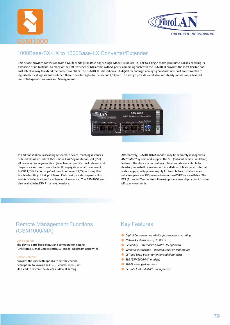
In addition it allows cascading of several devices, reaching distances of hundrets of km. FibroLAN’s unique Link Segmentation Test (LST) allows easy link segmentation (selective per port) to facilitate network diagnostics and overcomes the fault propagation which is inherent to GBE F/O links. A Loop-Back function on each F/O port simplifies troubleshooting of link problems. Each port provides separate Link and Activity indications for enhanced diagnostics. The GSM1000 are also available in SNMP managed versions.
Alternatively, GSM1000/MA models may be remotely managed via MetroStarTM system and support the SLE (Subscriber Link Emulation) feature. The device is housed in a robust metal case suitable for desktop, rack-shelf or wall-mount installation. It features an internal, wide-range, quality power supply for trouble free installation and reliable operation. DC powered versions (-48VDC) are available. The ETR (Extended Temperature Range) option allows deployment in non-office environments
1000Base-SX-LX to 1000Base-LX Converter/Extender
GSM1000
Device status: The device ports basic status and configuration setting (Link status, Signal Detect status, LST mode, Upstream Bandwith)
Device Control: provides the user with options to set the channel description, to invoke the LB/LST control menu, set SLEe and to restore the devices’s default setting
Remote Management Functions (GSM1000/MA)
Digital Conversion – stability, feature rich, cascading
Network extension – up to 80km
Reliability – internal PS (-48VDC PS optional)
Versatile installation – desktop, shelf or wall-mount
LST and Loop-Back– for enhanced diagnostics
SLE (GSM1000/MA models)
SNMP managed versions
Remote In-Band MA™ management
Key Features
This device provides conversion from a Multi-Mode (1000Base-SX) or Single Mode (1000Base-LX) link to a single-mode (1000Base-LX) link allowing its extension of up to 80km. As many of the GBE switches or NICs come with SX ports, combining such with the GSM1000 provides the most flexible and cost effective way to extend their reach over fiber. The GSM1000 is based on a full digital technology: analog signals from one port are converted to digital electrical signals, fully retimed then converted again to the second F/O port. This design provides a reliable and steady conversion, advanced control/diagnostic features and Management.
79
U.CON2500
Part# Model Description
B266 U.CON2500 Universal Extender module, 100Mbps to 2,5Gbps, includes 2 SFP slots, uses SFP optical transceivers
B289 SF155-SMRF15 SFP OC3, Single Fiber Strand (SFS), F/O transceiver, LC connector, SM, 1550nmTx/1310nmRx, 15km
B290 SF155-SMRF13 SFP, OC3, SFS F/O transceiver, LC connector, SM 1310nmTx/1550nmRx, 15km
B235 SF1G-S1 SFP module, GBE F/O transceiver, dual LC connector, MM 850nm, 220/550m
B236 SF1G-LX1 SFP module, GBE F/O transceiver, dual LC connector, SM 1310nm, 10km
B237 SF1G-LX2 SFP module, GBE F/O transceiver, dual LC connector, SM 1310nm, 20km
B238 SF1G-LX3 SFP module, GBE F/O transceiver, dual LC connector, SM 1550nm/DFB, 40km
B239 SF1G-LX4 SFP module, GBE F/O transceiver, dual LC connector, SM 1550nm/DFB, 80km
B240 SF1G-LX5 SFP module, GBE F/O transceiver, dual LC connector, SM 1550nm/DFB/APD 120km
B241 SF1G-SF13 SFP module, SFS, GBE F/O transceiver, 1*LC, SM 1310nmTx/1550nmRx, 20km
B242 SF1G-SF15 SFP module, SFS, GBE F/O transceiver, 1*LC, SM 1550nmDFB Tx/1310nmRx, 20km
B243 SF1G-LF13 SFP module, SFS, GBE F/O transceiver, 1*LC, SM 1310nmDFB Tx/1550nmRx, 40km
B244 SF1G-LF15 SFP module, SFS, GBE F/O transceiver, 1*LC, SM 1550nmDFB Tx/1310nmRx, 40km
B269 SF1G-ZF49 SFP, SFS, GBE F/O transceiver, LC connector, SM, 1490nmDFB Tx/1550nm Rx, 80km
B270 SF1G-ZF57 SFP, SFS, GBE F/O transceiver, LC connector, SM, 1550nmDFB Tx/1490nm Rx, 80km
B281 SF1G-LX5-5C-47 CWDM SFP, 1,25Gbps F/O transceiver, dual LC connector, SM 1471nmDFB/APD, 120km
B282 SF1G-LX5-5C-49 CWDM SFP, 1,25Gbps F/O transceiver, dual LC connector, SM 1491nmDFB/APD, 120km
B283 SF1G-LX5-5C-51 CWDM SFP, 1,25Gbps F/O transceiver, dual LC connector, SM 1511nmDFB/APD, 120km
B284 SF1G-LX5-5C-53 CWDM SFP, 1,25Gbps F/O transceiver, dual LC connector, SM 1531nmDFB/APD, 120km
B285 SF1G-LX5-5C-55 CWDM SFP, 1,25Gbps F/O transceiver, dual LC connector, SM 1551nmDFB/APD, 120km
B286 SF1G-LX5-5C-57 CWDM SFP, 1,25Gbps F/O transceiver, dual LC connector, SM 1571nmDFB/APD, 120km
B287 SF1G-LX5-5C-59 CWDM SFP, 1,25Gbps F/O transceiver, dual LC connector, SM 1591nmDFB/APD, 120 km
B288 SF1G-LX5-5C-61 CWDM SFP, 1,25Gbps F/O transceiver, dual LC connector, SM 1611nmDFB/APD, 120km
B268 SF2G-S1 SFP module, 2,5Gbps F/O transceiver, dual LC connector, MM 850nm, 300/400 m
B249 SF2G-S2 SFP module, 2,5Gbps F/O transceiver, dual LC connector, SM 1310nm, 2km
B250 SF2G-LX2-3 SFP module, 2,5Gbps F/O transceiver, dual LC connector, SM 1310nmDFB, 15km
B251 SF2G-LX2-5 SFP module, 2,5Gbps F/O transceiver, dual LC connector, SM 1550nmDFB, 15km
B252 SF2G-LX3-3 SFP module, 2,5Gbps F/O transceiver, dual LC connector, SM 1310nmDFB/APD, 40km
B253 SF2G-LX3-5 SFP module, 2,5Gbps F/O transceiver, dual LC connector, SM 1550nmDFB, 40km
B254 SF2G-LX4-5 SFP module, 2,5Gbps F/O transceiver, dual LC connector, SM 1310nmDFB/APD, 80km
B271 SF2G-LX3-5C-47 CWDM, SFP, 2,5Gbps F/O transceiver, dual LC connector, SM 1471nm DFB, 40km
B272 SF2G-LX3-5C-49 CWDM, SFP, 2,5Gbps F/O transceiver, dual LC connector, SM 1491nm DFB, 40km
B273 SF2G-LX3-5C-51 CWDM, SFP, 2,5Gbps F/O transceiver, dual LC connector, SM 1511nm DFB, 40km
B274 SF2G-LX3-5C-53 CWDM, SFP, 2,5Gbps F/O transceiver, dual LC connector, SM 1531nm DFB, 40km
B275 SF2G-LX3-5C-55 CWDM, SFP, 2,5Gbps F/O transceiver, dual LC connector, SM 1551nm DFB, 40km
B276 SF2G-LX3-5C-57 CWDM, SFP, 2,5Gbps F/O transceiver, dual LC connector, SM 1571nm DFB, 40km
B277 SF2G-LX3-5C-59 CWDM, SFP, 2,5Gbps F/O transceiver, dual LC connector, SM 1591nm DFB, 40km
B278 SF2G-LX3-5C-61 CWDM, SFP, 2,5Gbps F/O transceiver, dual LC connector, SM 1611nm DFB, 40km
B258 SF2G-LX4-5C-47 CWDM, SFP, 2,5Gbps F/O transceiver, dual LC connector, SM 1471nm DFB/APD, 80km
B259 SF2G-LX4-5C-49 CWDM, SFP, 2,5Gbps F/O transceiver, dual LC connector, SM 1491nm DFB/APD, 80km
B260 SF2G-LX4-5C-51 CWDM, SFP, 2,5Gbps F/O transceiver, dual LC connector, SM 1511nm DFB/APD, 80km
B261 SF2G-LX4-5C-53 CWDM, SFP, 2,5Gbps F/O transceiver, dual LC connector, SM 1531nm DFB/APD, 80km
B262 SF2G-LX4-5C-55 CWDM, SFP, 2,5Gbps F/O transceiver, dual LC connector, SM 1551nm DFB/APD, 80km
B263 SF2G-LX4-5C-57 CWDM, SFP, 2,5Gbps F/O transceiver, dual LC connector, SM 1571nm DFB/APD, 80km
B264 SF2G-LX4-5C-59 CWDM, SFP, 2,5Gbps F/O transceiver, dual LC connector, SM 1591nm DFB/APD, 80km
B265 SF2G-LX4-5C-61 CWDM, SFP, 2,5Gbps F/O transceiver, dual LC connector, SM 1611nm DFB/APD, 80km
Standard Compilance IEEE802.3 2000 edition1000Base-SX, 1000Base-LX, IEEE802.3zConversion Method Digital with Link Segmentation Test and Loop-BackLED’s Power ON, MA Active (GSM1000/MA models) Per Port: Link Activity, LST, Loop BackManagement GSM1000MSNMP versions 1&2, Telnet, RS232GSM1000/MA
Remote In-Band MATM via MetroStarTM
Ports 2x Dual SC ports except in SFS models (see specifications below)DIP switches (front panel) per port:LST ON/OFFLoop-Back ON/OFF
GSM1000
General Specifications Environmental/PhysicalPower SupplyInternal, 100 to 240VAC,50-60Hz Optional DC PS.
Operating Temperature0º÷ +45ºC
Storage Temperature-20º÷+80ºC
SafetyDesigned to meet UL60950,EN 60950
Dimensions120x170x44mm
Power Consumption5 Watts Maximum
Humidity10%÷90% non-condensing
EMCFCC part 15, Subpart B, Class A ICES 003: 1997,Class A EMC Directive
Weight400g
Ordering Information and F/O port Specifications
Minimal Output Power
Typical Receive
Sensitivity
Wavelength
Part# Model Port1
Minimal Output Power
Typical Receive
Sensitivity
Wavelength
Port2
SuggestedDistance
GSM1000/MA
GSM1000
M
GSM1000
Options
Specifications are subject to change w/o prior notice
B097 PS48 DC (-36 ÷ -72VDC) option (instead of AC PS) for all GSM models
B098 ETR Extended Temperature Range (-10ºC ÷ +70ºC) option for all GSM models
B012 CTF-RM 19” rack shelf for installation of up to 3 GSM devices
B161 SCH-WM Wall Mount kit for all GSM models
B222 MCP5 Mode Conditioned Patch cord, Simplex, 50micron, SC/SC, 2m, for GBE 1310nm over Multimode links
B223 MCP6 Mode Conditioned Patch cord, Simplex, 62,5micron, SC/SC, 2m, for GBE 1310nm over Mm links
3701 B195 B162 GSM1000 -9,5dBm -17dBm 850nm -13dBm -20dBm 1310nm 0-10
3702 B196 B163 GSM1001 -9,5dBm -17dBm 850nm -5dBm -20dBm 1310nm 5-20
3703 B197 B164 GSM1002 -9,5dBm -17dBm 850nm -8dBm -23dBm 1550nm/DFB 10-40
3704 B198 B165 GSM1003 -9,5dBm -17dBm 850nm 0dBm -24dBm 1550nm/DFB 25-80
3705 B299 B177 GSM1004 -13dBm -20dBm 1310nm -13dBm -20dBm 1310nm 0-10/0-10
3706 B200 B178 GSM1005 -5dBm -20dBm 1310nm -5dBm -20dBm 1310nm 5-20/5-20
3707 B201 B179 GSM1006 -8dBm -23dBm 1550nm/DFB -8dBm -23dBm 1550nm/DFB 10-40/10-40
3708 B202 B180 GSM1007 0dBm -24dBm 1550nm/DFB 0dBm -24dBm 1550nm/DFB 25-80/25-80
3720 B214 B212 GSM1008 -13dBm -20dBm 1310nm -8dBm -23dBm 1550nm/DFB 0-10/10-40
N/A B215 B213 GSM1009 -13dBm -20dBm 1310nm 0dBm -24dBm 1550nm/DFB 0-10/25-80
3709 B203 B191 GSM1000F13 -9,5dBm -17dBm 850nm -5dBm -20dBm 1310Tx/1550Rx 0-20/SFS
3710 B204 B192 GSM1000F15 -9,5dBm -17dBm 850nm -5dBm -20dBm 1550TX/1310RX 0-20/SFS
80
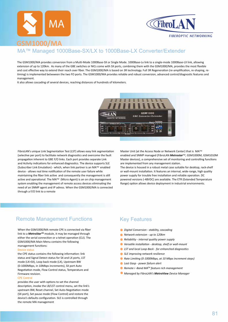
MA™ Managed 1000Base-SX/LX to 1000Base-LX Converter/ExtenderGSM1000/MA
FibroLAN’s unique Link Segmentation Test (LST) allows easy link segmentation (selective per port) to facilitate network diagnostics and overcome the fault propagation inherent to GBE F/O links. Each port provides separate Link and Activity indications for enhanced diagnostics. The device supports SLE (Subscriber Link Emulation) - which, when link partner is an MATM enabled device - allows real time notification of the remote user failure while maintaining the fiber link active and consequently the management is still active and operational. The MATM (Micro Agent) is an on chip management system enabling the management of remote access devices eliminating the need of an SNMP agent and IP adress. When the GSM1000/MA is connected through a F/O link to a remote
Master Unit (at the Access Node or Network Center) that is MATM
enabled and SNMP managed (FibroLAN MetrostarTM, GSM1000M, GSM1010M Master devices), a comprehensive set of monitoring and controlling functions are implemented from any management station. The device is housed in a robust metal case suitable for desktop, rack-shelf or wall-mount installation. It features an internal, wide-range, high quality power supply for trouble free installation and reliable operation. DCpowered versions (-48VDC) are available. The ETR (Extended Temperature Range) option allows device deployment in industrial environments.
When the GSM1000/MA remote CPE is connected via fiber link to a MetroStarTM module, it may be managed through either the serial connection or a telnet operation (CLI). The GSM1000/MA Main Menu contains the following management functions:Device status the CPE status contains the following information: link status and Signal Detect status for SX and LX ports, LST mode (LX>SX), Loop back mode (LX), Upstream BW (0-1000Mbps, in 10Mbps increments), SX port Auto Negotiation mode, Flow Control status, Temperature and Firmware revision.CPE Controlprovides the user with options to set the channel description, invoke the LB/LST control menu, set the link’supstream BW, Reset channel, Set Auto-Negotiation mode (SX port), Set pause mode (Flow Control) and restore the device’s defaults configuration. SLE is controlled through the remote MA management
Remote Management Functions
Digital Conversion - stability, cascading
Network extension - up to 120km
Reliability - internal quality power supply
Versatile installation - desktop, shelf or wall-mount
LST and local Loop-Back - for enhanched diagnostics
SLE improving network resilience
Rate Limiting (0-1000Mbps, at 10 Mbps increment steps)
Last Gasp - power failure alert
Remote i -Band MATM feature rich management
Managed by FibroLAN‘s MetroView Device Manager
MA
The GSM1000/MA provides conversion from a Multi-Mode 1000Base-SX or Single Mode. 1000Base-Lx link to a single-mode 1000Base-LX link, allowing extension of up to 120km. As many of the GBE switches or NICs come with SX ports, combining them with the GSM1000/MA, provides the most flexible and cost effective way to extend their reach over fiber. The GSM1000/MA is based on 3R technology. Full 3R Regeneration (re-amplification, re-shaping, re-timing) is implemented betwween the two FO ports. The GSM1000/MA provides reliable and robust conversion, advanced control/diagnostic features and management. It also allows cascading of several devices, reaching distances of hundreds of kilometers.
Key Features
81
GSM1000
General Specifications
Power Consumption5 Watts Maximum
Humidity10%÷90% non-condensing
EMCFCC part 15, Subpart B, Class A ICES 003: 1997,Class A EMC Directive
Weight400g
B097 PS48 DC (-36 ÷ -72VDC) option (instead of AC PS) for all GSM models
B098 ETR Extended Temperature Range (-10ºC ÷ +70ºC) option for all GSM models
B012 CTF-RM 19” rack shelf for installation of up to 3 GSM devices
B161 SCH-WM Wall Mount kit for all GSM models
B222 MCP5 Mode Conditioned Patch cord, Simplex, 50micron, SC/SC, 2m, for GBE 1310nm over Multimode links
B223 MCP6 Mode Conditioned Patch cord, Simplex, 62,5micron, SC/SC, 2m, for GBE 1310nm over Mm links
3701 B195 B162 GSM1000 -9,5dBm -17dBm 850nm -13dBm -20dBm 1310nm 0-10
3702 B196 B163 GSM1001 -9,5dBm -17dBm 850nm -5dBm -20dBm 1310nm 5-20
3703 B197 B164 GSM1002 -9,5dBm -17dBm 850nm -8dBm -23dBm 1550nm/DFB 10-40
3704 B198 B165 GSM1003 -9,5dBm -17dBm 850nm 0dBm -24dBm 1550nm/DFB 25-80
3705 B299 B177 GSM1004 -13dBm -20dBm 1310nm -13dBm -20dBm 1310nm 0-10/0-10
3706 B200 B178 GSM1005 -5dBm -20dBm 1310nm -5dBm -20dBm 1310nm 5-20/5-20
3707 B201 B179 GSM1006 -8dBm -23dBm 1550nm/DFB -8dBm -23dBm 1550nm/DFB 10-40/10-40
3708 B202 B180 GSM1007 0dBm -24dBm 1550nm/DFB 0dBm -24dBm 1550nm/DFB 25-80/25-80
3720 B214 B212 GSM1008 -13dBm -20dBm 1310nm -8dBm -23dBm 1550nm/DFB 0-10/10-40
N/A B215 B213 GSM1009 -13dBm -20dBm 1310nm 0dBm -24dBm 1550nm/DFB 0-10/25-80
3709 B203 B191 GSM1000F13 -9,5dBm -17dBm 850nm -5dBm -20dBm 1310Tx/1550Rx 0-20/SFS
3710 B204 B192 GSM1000F15 -9,5dBm -17dBm 850nm -5dBm -20dBm 1550TX/1310RX 0-20/SFS
Standard CompilanceIEEE802.3 2000 edition1000Base-SX, 1000Base-LX, IEEE802.3z, Diagnostic LedsPower ON, MA ActiveFor each FO Port - Link, Activity, LST, Loop-BackManagementRemote In-Band MATM via MetroStarTM System or GSM1000M/GSM1010M Master devices; Managed by FibroLAN MetroView Device Manager
GSM1000/MAGeneral Specifications Environmental/Physical
Power SupplyInternal, 100 to 240VAC, 50-60HzOptional DC P.S. (-36÷ -72VDC) -PS48
Operating Temperature0º ÷ +45ºC
Storage Temperature-20º÷+80ºC
SafetyEN 60950-1
Dimensions120x170x44mm
Conversion MethodDigital based on 3R TechnologyPorts2x Dual SC ports, see F/O specifications below MM, SM and SFS (Single Fiber Strand)DPI switches(front panel) for each port LST ON/OFF, LB (Loop Back) ON/OFF
Ordering Information and F/O Specifications
Minimal Output Power
Minimal Receive
Senitivity
Wavelength
Part# Model Port1
Minimal Output Power
Minimal Receive
Senitivity
Wavelength
Port2
SuggestedDistance
km
Power Consumptionca. 40W
Humidity10% ÷ 90% non-condensing
EMCFCC CFR 47 part 15 Subpart B, Class AEN 300 386 V1.3.3, AS/NZS CISPRESS:04, EN55022/24
Weight400g
Options
Specifications are subject to change w/o prior notice
MA
3701 GSM1000/MA -9,5dBm -17dBm 850nm -10dBm -23dBm 1310nm 0,2-0,5/0-10
3702 GSM1001/MA -9,5dBm -17dBm 850nm -5dBm -23dBm 1310nm 0,2-0,5/5-20
3703 GSM1002/MA -9,5dBm -17dBm 850nm -3dBm -23dBm 1550nm/DFB 0,2-0,5/10-40
3704 GSM1003/MA -9,5dBm -17dBm 850nm 0dBm -23dBm 1550nm/DFB 0,2-0,5/25-80
3728 GSM1020/MA -9,5dBm -17dBm 850nm 0dBm -32dBm 1550nm/DFB -APD 0,2-0,5/80-120
3705 GSM1004/MA -10dBm -23dBm 1310nm -10dBm -23dBm 1310nm 0-10/0-10
3706 GSM1005/MA -5dBm -23dBm 1310nm -5dBm -23dBm 1310nm 5-20/5-20
3707 GSM1006/MA -3dBm -23dBm 1550nm/DFB -3dBm -23dBm 1550nm/DFB 10-40/10-40
3708 GSM1007/MA 0dBm -23dBm 1550nm/DFB 0dBm -23dBm 1550nm/DFB 25-80/25-80
3734 GSM1021/MA 0dBm -32dBm 1550nm/DFB -APD 0dBm -23dBm 1550nm/DFB 80-120/25-80
3726 GSM1018/MA 0dBm -32dBm 1550nm/DFB -APD 0dBm -32dBm 1550nm/DFB -APD 80-120/80-120
3720 GSM1008/MA -10dBm -23dBm 1310nm -3dBm -23dBm 1550nm/DFB 0-10/10-40
3718 GSM1009/MA -10dBm -23dBm 1310nm -5dBm -23dBm 1310nm 0-10/5-20
3721 GSM1016/MA -10dBm -23dBm 1310nm 0dBm -23dBm 1550nm/DFB 0-10/25-80
3709 GSM1000 F13/MA -9,5dBm -17dBm 850nm -5dBm -20dBm 1310Tx/1550Rx 0,2-0,5/5-20
3710 GSM1000 F15/MA -9,5dBm -17dBm 850nm -5dBm -20dBm 1550DFBTx/1310Rx 0,2-0,5/5-20
3722 GSM1000 F13L/MA -9,5dBm -17dBm 850nm -3dBm -23dBm 1310DFBTx/1550Rx 0,2-0,5/10-40
3723 GSM1000 F15L/MA -9,5dBm -17dBm 850nm -3dBm -23dBm 1550DFBTx/1310Rx 0,2-0,5/10-40
B097 PS48 Optional DC PS (-36 ÷ -72VDC) instead of AC PS
B151 CBPS-DC48V DC Power Supply cable, 2m for PS48
B098 ETR Extended Temperature Range (-10ºC ÷ +70ºC) option for all GSM1000/MA models
B012 CTF-RM 19” rack shelf for installation of up to 3 GSM1000/MA devices
B161 SCH-WM Wall Mount kit for all GSM1000/MA models
82
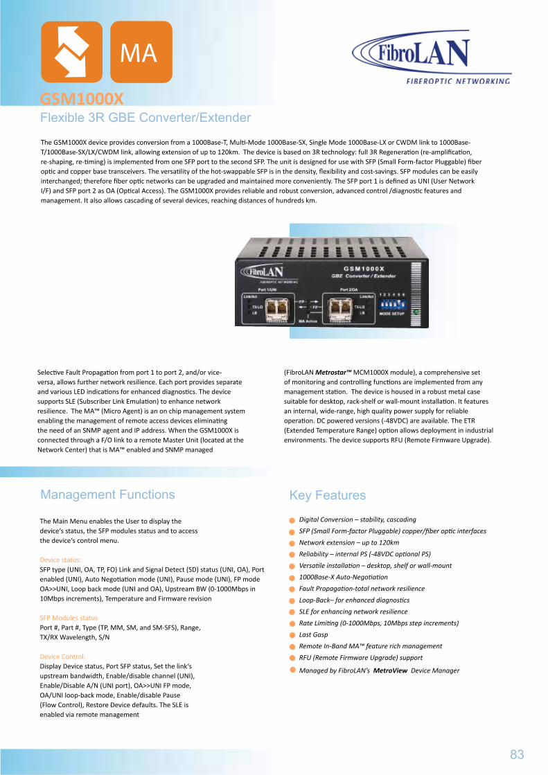
The Main Menu enables the User to display the device‘s status, the SFP modules status and to accessthe device‘s control menu.
Device status: SFP type (UNI, OA, TP, FO) Link and Signal Detect (SD) status (UNI, OA), Port enabled (UNI), Auto Negotiation mode (UNI), Pause mode (UNI), FP mode OA>>UNI, Loop back mode (UNI and OA), Upstream BW (0-1000Mbps in 10Mbps increments), Temperature and Firmware revision
SFP Modules statusPort #, Part #, Type (TP, MM, SM, and SM-SFS), Range, TX/RX Wavelength, S/N
Device Control: Display Device status, Port SFP status, Set the link‘s upstream bandwidth, Enable/disable channel (UNI), Enable/Disable A/N (UNI port), OA>>UNI FP mode, OA/UNI loop-back mode, Enable/disable Pause (Flow Control), Restore Device defaults. The SLE is enabled via remote management
Digital Conversion – stability, cascading
SFP (Small Form-factor Pluggable) copper/fiber optic interfaces
Network extension – up to 120km
Reliability – internal PS (-48VDC optional PS)
Versatile installation – desktop, shelf or wall-mount
1000Base-X Auto-Negotiation
Fault Propagation-total network resilience
Loop-Back– for enhanced diagnostics
SLE for enhancing network resilience
Rate Limiting (0-1000Mbps, 10Mbps step increments)
Last Gasp
Remote In-Band MA™ feature rich management
RFU (Remote Firmware Upgrade) support
Managed by FibroLAN’s MetroView Device Manager
Selective Fault Propagation from port 1 to port 2, and/or vice-versa, allows further network resilience. Each port provides separate and various LED indications for enhanced diagnostics. The device supports SLE (Subscriber Link Emulation) to enhance network resilience. The MA™ (Micro Agent) is an on chip management system enabling the management of remote access devices eliminating the need of an SNMP agent and IP address. When the GSM1000X is connected through a F/O link to a remote Master Unit (located at the Network Center) that is MA™ enabled and SNMP managed
(FibroLAN Metrostar™ MCM1000X module), a comprehensive set of monitoring and controlling functions are implemented from any management station. The device is housed in a robust metal case suitable for desktop, rack-shelf or wall-mount installation. It features an internal, wide-range, high quality power supply for reliable operation. DC powered versions (-48VDC) are available. The ETR (Extended Temperature Range) option allows deployment in industrial environments. The device supports RFU (Remote Firmware Upgrade).
Flexible 3R GBE Converter/ExtenderGSM1000X
Management Functions Key Features
The GSM1000X device provides conversion from a 1000Base-T, Multi-Mode 1000Base-SX, Single Mode 1000Base-LX or CWDM link to 1000Base-T/1000Base-SX/LX/CWDM link, allowing extension of up to 120km. The device is based on 3R technology: full 3R Regeneration (re-amplification, re-shaping, re-timing) is implemented from one SFP port to the second SFP. The unit is designed for use with SFP (Small Form-factor Pluggable) fiber optic and copper base transceivers. The versatility of the hot-swappable SFP is in the density, flexibility and cost-savings. SFP modules can be easily interchanged; therefore fiber optic networks can be upgraded and maintained more conveniently. The SFP port 1 is defined as UNI (User Network I/F) and SFP port 2 as OA (Optical Access). The GSM1000X provides reliable and robust conversion, advanced control /diagnostic features and management. It also allows cascading of several devices, reaching distances of hundreds km.
83
MA
GSM1000/MAGeneral Specifications
Power Consumptionca. 40W
Humidity10% ÷ 90% non-condensing
EMCFCC CFR 47 part 15 Subpart B, Class AEN 300 386 V1.3.3, AS/NZS CISPRESS:04, EN55022/24
Weight400g
3701 GSM1000/MA -9,5dBm -17dBm 850nm -10dBm -23dBm 1310nm 0,2-0,5/0-10
3702 GSM1001/MA -9,5dBm -17dBm 850nm -5dBm -23dBm 1310nm 0,2-0,5/5-20
3703 GSM1002/MA -9,5dBm -17dBm 850nm -3dBm -23dBm 1550nm/DFB 0,2-0,5/10-40
3704 GSM1003/MA -9,5dBm -17dBm 850nm 0dBm -23dBm 1550nm/DFB 0,2-0,5/25-80
3728 GSM1020/MA -9,5dBm -17dBm 850nm 0dBm -32dBm 1550nm/DFB -APD 0,2-0,5/80-120
3705 GSM1004/MA -10dBm -23dBm 1310nm -10dBm -23dBm 1310nm 0-10/0-10
3706 GSM1005/MA -5dBm -23dBm 1310nm -5dBm -23dBm 1310nm 5-20/5-20
3707 GSM1006/MA -3dBm -23dBm 1550nm/DFB -3dBm -23dBm 1550nm/DFB 10-40/10-40
3708 GSM1007/MA 0dBm -23dBm 1550nm/DFB 0dBm -23dBm 1550nm/DFB 25-80/25-80
3734 GSM1021/MA 0dBm -32dBm 1550nm/DFB -APD 0dBm -23dBm 1550nm/DFB 80-120/25-80
3726 GSM1018/MA 0dBm -32dBm 1550nm/DFB -APD 0dBm -32dBm 1550nm/DFB -APD 80-120/80-120
3720 GSM1008/MA -10dBm -23dBm 1310nm -3dBm -23dBm 1550nm/DFB 0-10/10-40
3718 GSM1009/MA -10dBm -23dBm 1310nm -5dBm -23dBm 1310nm 0-10/5-20
3721 GSM1016/MA -10dBm -23dBm 1310nm 0dBm -23dBm 1550nm/DFB 0-10/25-80
3709 GSM1000 F13/MA -9,5dBm -17dBm 850nm -5dBm -20dBm 1310Tx/1550Rx 0,2-0,5/5-20
3710 GSM1000 F15/MA -9,5dBm -17dBm 850nm -5dBm -20dBm 1550DFBTx/1310Rx 0,2-0,5/5-20
3722 GSM1000 F13L/MA -9,5dBm -17dBm 850nm -3dBm -23dBm 1310DFBTx/1550Rx 0,2-0,5/10-40
3723 GSM1000 F15L/MA -9,5dBm -17dBm 850nm -3dBm -23dBm 1550DFBTx/1310Rx 0,2-0,5/10-40
B097 PS48 Optional DC PS (-36 ÷ -72VDC) instead of AC PS
B151 CBPS-DC48V DC Power Supply cable, 2m for PS48
B098 ETR Extended Temperature Range (-10ºC ÷ +70ºC) option for all GSM1000/MA models
B012 CTF-RM 19” rack shelf for installation of up to 3 GSM1000/MA devices
B161 SCH-WM Wall Mount kit for all GSM1000/MA models
Standard Compilance: IEEE802.3 2000 edition1000Base-T, 1000Base-SX, 1000Base-LX IEEE802.3z, Flow ControlConversion Method: Digital 3R conversionLED’s: Power ON (green), MA Active (green)FP (yellow LED’s): upper (UNI>OA), Middle (OA>UNI) F/O SFP Port: Link/Act (green), TX-LO (red) = Low Transmission in SFP, Blinking = when not authenticated; LB (red): Loop - Back for each port.
Management: Remote In-Band MATM via MetroStarTM System
FibroLAN’s MetroView Device ManagerPorts: Simplex and Duplex LC connectors (Small Form-factor Pluggable) - See table belowDIP switches (front panel):Loop-Back (LB UNI, LB OA) enable/disable; Fault Porpagation ON/OFF (UNI>OA, OA>UNI); Auto Negotiation for Port1 and Port2 (enable/disable; Management commands override DIP switsches setup
GSM1000XGeneral Specifications Environmental/Physical
Power SupplyInternal, 100 to 240VAC, 50-60Hz DC P.S. range (-36 ÷ -72 VDC)
Operating Temperature0º÷ +45ºC
Storage Temperature-20º ÷ +80ºC
SafetyEN 60950-1
Dimensions120x170x44mm
Power Consumption5 Watts Maximum
Humidity10%÷90% non-condensing
EMCEN 300 386 V1.3.3, AS/NZS CISPRESS:04, EN55022/24, FCC part 15, Subpart B
Weight400g
Ordering Information and F/O Specifications
SFP optical modular interfaces
Specifications are subject to change w/o prior notice
Part# Model Description
3750 GSM1000X MATM Managed Gigabit Ethernet converter/access device/extender with 2 SFP modular ports, each may accept any FibroLAN copper or fiber SFP transceiver. Internal AC power Supply
3751 GSM1000X-48 MA Managed Ethernet converter/access device/extender with 2SFP modular ports, each may accept any FibroLAN copper or fiber SFP transceiver. Internal -48DC power Supply (PS48)
B098 ETR Extended Temperature Range option (-10ºC ÷ +70ºC)
B012 CTF - RM 19“ Rack Shelf for installation of up to 3 GSM1000X devices
B151 CBPS - DC48V DC Power Supply cable for PS48, 2m
B161 SCH - WM Wall mount kit
Part# Model Description
B248 SF1G-T SFP (Small Form Pluggable) GBE STP transceiver, 1000BaseT, shielded RJ-45, 100m over Cat.6 cable
B235 SF1G-S1 SFP GBE F/O transceiver, Duplex LC connectors, MM, 850nm, 220/550m
B236 SF1G-LX1 SFP GBE F/O transceiver, Duplex LC connectors, SM, 1310nm,10km
B237 SF1G-LX2 SFP GBE F/O transceiver, Duplex LC connectors, SM, 1310nm, 20km
B238 SF1G-LX3 SFP GBE F/O transceiver, Duplex LC connectors, SM, 1550nm/DFB, 40km
B239 SF1G-LX4 SFP GBE F/O transceiver, Duplex LC connectors, SM, 1550nm/DFB, 80km
B240 SF1G-LX5 SFP GBE F/O transceiver, Duplex LC connectors, SM, 1550nm/DFB/APD, 120km
B241 SF1G-SF13 SFP, Single Fiber Strand (SFS),GBE F/O transceiver, Simplex LC connector, SM, 1310nmTx -1550nmRx, 20km
B242 SF1G-SF15 SFP Single Fiber Strand,GBE F/O transceiver, Simplex LC connector, SM, 1550nmDFB Tx - 1310nmRx, 20km
B243 SF1G-LF13 SFP Single Fiber Strand, GBE F/O transceiver, Simplex LC connector, SM, 1310nmTx - 1550nmRx, 40km
B244 SF1G-LF15 SFP Single Fiber Strand,GBE F/O transceiver,Simplex LC connector, SM,1550nmDFB Tx - 1310nm Rx, 40km
B269 SF1G-ZF49 SFP, SFS, GBE F/O transceiver, LC connector, SM, 1490nmDFBTx/ 1550nmRx, 80km
B270 SF1G-ZF57 SFP, SFS, GBE F/O transceiver, LC connector, SM, 1550nmDFBTx/1490nmRx, 80km
B281-8 SF1G-LX5-5C-WW CWDM SFP, 1.25Gbps F/O transceiver, dual LC connector, SM, 1471nm – 1611nm range, DFB/APD, 120km
84
MA
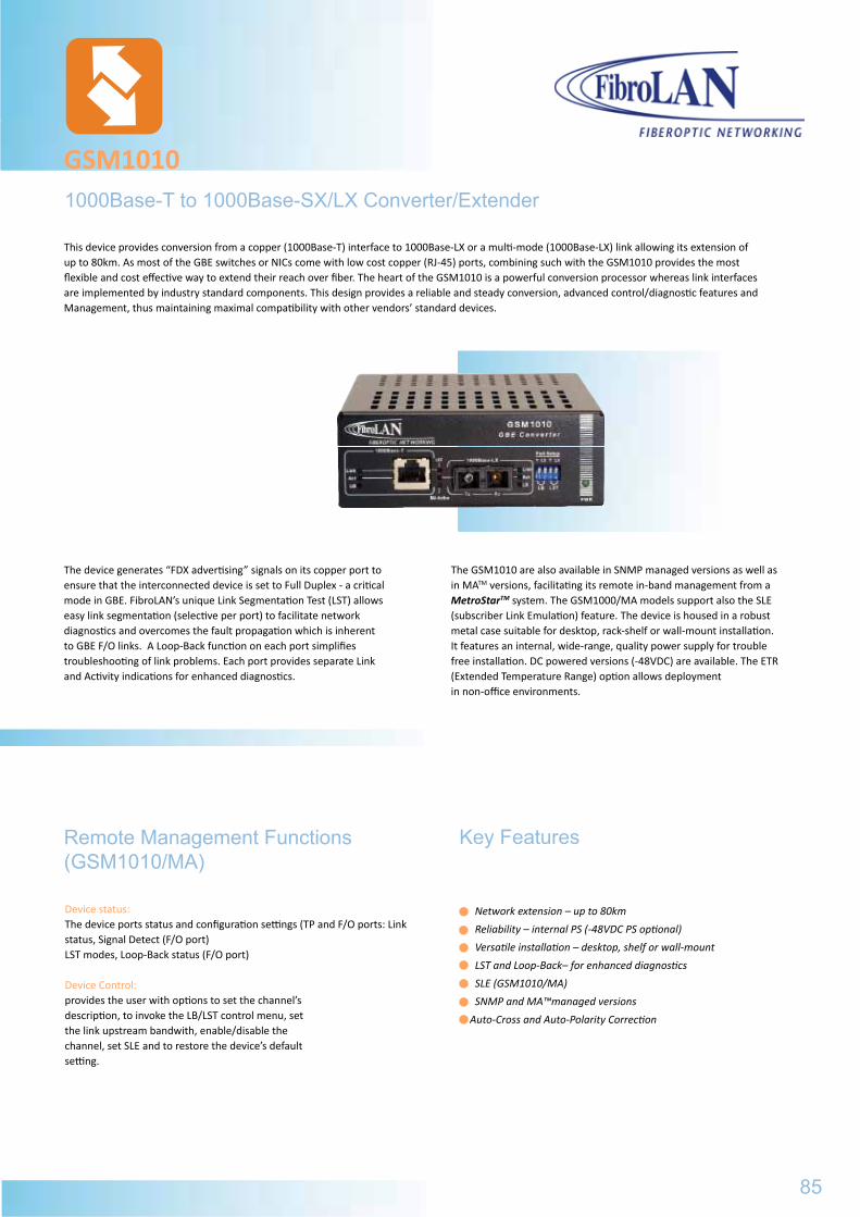
The device generates “FDX advertising” signals on its copper port to ensure that the interconnected device is set to Full Duplex - a critical mode in GBE. FibroLAN’s unique Link Segmentation Test (LST) allows easy link segmentation (selective per port) to facilitate network diagnostics and overcomes the fault propagation which is inherent to GBE F/O links. A Loop-Back function on each port simplifies troubleshooting of link problems. Each port provides separate Link and Activity indications for enhanced diagnostics.
The GSM1010 are also available in SNMP managed versions as well as in MATM versions, facilitating its remote in-band management from a MetroStarTM system. The GSM1000/MA models support also the SLE (subscriber Link Emulation) feature. The device is housed in a robust metal case suitable for desktop, rack-shelf or wall-mount installation. It features an internal, wide-range, quality power supply for trouble free installation. DC powered versions (-48VDC) are available. The ETR (Extended Temperature Range) option allows deployment in non-office environments.
Device status: The device ports status and configuration settings (TP and F/O ports: Link status, Signal Detect (F/O port)LST modes, Loop-Back status (F/O port)
Device Control: provides the user with options to set the channel’s description, to invoke the LB/LST control menu, set the link upstream bandwith, enable/disable the channel, set SLE and to restore the device’s default setting.
1000Base-T to 1000Base-SX/LX Converter/Extender
GSM1010
Network extension – up to 80km
Reliability – internal PS (-48VDC PS optional)
Versatile installation – desktop, shelf or wall-mount
LST and Loop-Back– for enhanced diagnostics
SLE (GSM1010/MA)
SNMP and MA™managed versions
Auto-Cross and Auto-Polarity Correction
Remote Management Functions (GSM1010/MA)
Key Features
This device provides conversion from a copper (1000Base-T) interface to 1000Base-LX or a multi-mode (1000Base-LX) link allowing its extension of up to 80km. As most of the GBE switches or NICs come with low cost copper (RJ-45) ports, combining such with the GSM1010 provides the most flexible and cost effective way to extend their reach over fiber. The heart of the GSM1010 is a powerful conversion processor whereas link interfaces are implemented by industry standard components. This design provides a reliable and steady conversion, advanced control/diagnostic features and Management, thus maintaining maximal compatibility with other vendors’ standard devices.
85
GSM1000XGeneral Specifications
Power Consumption5 Watts Maximum
Humidity10%÷90% non-condensing
EMCEN 300 386 V1.3.3, AS/NZS CISPRESS:04, EN55022/24, FCC part 15, Subpart B
Weight400g
3750 GSM1000X MATM Managed Gigabit Ethernet converter/access device/extender with 2 SFP modular ports, each may accept any FibroLAN copper or fiber SFP transceiver. Internal AC power Supply
3751 GSM1000X-48 MA Managed Ethernet converter/access device/extender with 2SFP modular ports, each may accept any FibroLAN copper or fiber SFP transceiver. Internal -48DC power Supply (PS48)
B098 ETR Extended Temperature Range option (-10ºC ÷ +70ºC)
B012 CTF - RM 19“ Rack Shelf for installation of up to 3 GSM1000X devices
B151 CBPS - DC48V DC Power Supply cable for PS48, 2m
B161 SCH - WM Wall mount kit
Part# Model Description
B248 SF1G-T SFP (Small Form Pluggable) GBE STP transceiver, 1000BaseT, shielded RJ-45, 100m over Cat.6 cable
B235 SF1G-S1 SFP GBE F/O transceiver, Duplex LC connectors, MM, 850nm, 220/550m
B236 SF1G-LX1 SFP GBE F/O transceiver, Duplex LC connectors, SM, 1310nm,10km
B237 SF1G-LX2 SFP GBE F/O transceiver, Duplex LC connectors, SM, 1310nm, 20km
B238 SF1G-LX3 SFP GBE F/O transceiver, Duplex LC connectors, SM, 1550nm/DFB, 40km
B239 SF1G-LX4 SFP GBE F/O transceiver, Duplex LC connectors, SM, 1550nm/DFB, 80km
B240 SF1G-LX5 SFP GBE F/O transceiver, Duplex LC connectors, SM, 1550nm/DFB/APD, 120km
B241 SF1G-SF13 SFP, Single Fiber Strand (SFS),GBE F/O transceiver, Simplex LC connector, SM, 1310nmTx -1550nmRx, 20km
B242 SF1G-SF15 SFP Single Fiber Strand,GBE F/O transceiver, Simplex LC connector, SM, 1550nmDFB Tx - 1310nmRx, 20km
B243 SF1G-LF13 SFP Single Fiber Strand, GBE F/O transceiver, Simplex LC connector, SM, 1310nmTx - 1550nmRx, 40km
B244 SF1G-LF15 SFP Single Fiber Strand,GBE F/O transceiver,Simplex LC connector, SM,1550nmDFB Tx - 1310nm Rx, 40km
B269 SF1G-ZF49 SFP, SFS, GBE F/O transceiver, LC connector, SM, 1490nmDFBTx/ 1550nmRx, 80km
B270 SF1G-ZF57 SFP, SFS, GBE F/O transceiver, LC connector, SM, 1550nmDFBTx/1490nmRx, 80km
B281-8 SF1G-LX5-5C-WW CWDM SFP, 1.25Gbps F/O transceiver, dual LC connector, SM, 1471nm – 1611nm range, DFB/APD, 120km
Standard Compilance: IEEE802.3 2000 edition1000Base-SX, 1000Base-LX, IEEE802.3z IEEE802.abConversion Method: Digital with FDX Advertising, Link Segmentation Test and Loop-BackLED’s: Power ON, MA Active (GSM1010/MA models) Per Port: Link Activity, LST, Loop BackManagement: SNMP versions 1&2, Telnet, RS232(GSM1010M) Remote via MetroStarTM
system (GSM1010/MA)F/O Port: Dual SC except in SFS models (see specifications below)TP Port: Shielded RJ-45, Auto-Cross, Auto Polarity CorrectionDIP switches (front panel) per port:LST ON/OFFLoop-Back ON/OFF
GSM1010General Specifications Environmental/Physical
Power SupplyInternal, 100 to 240VAC, 50-60Hz Optional DC PS.
Operating Temperature0º÷ +45ºC
Storage Temperature-20º÷+80ºC
SafetyDesigned to meet UL60950,EN 60950
Dimensions120x170x44mm
Power Consumption5 Watts Maximum
Humidity10%÷90% non-condensing
EMCFCC part 15, Subpart B, Class A ICES 003: 1997,Class A EMC Directive 89/336/EEC
Weight400g
Ordering Information and F/O port Specifications
Minimal Output Power
Typical Receive
Sensitivity
Wavelength
Part# Model F/O Port
SuggestedDistance
GSM1010/MA
GSM1000
M
GSM1000
Options
Specifications are subject to change w/o prior notice
B097 PS48 DC (-36 ÷ -72VDC) option (instead of AC PS) for all GSM models
B098 ETR Extended Temperature Range (-10ºC ÷ +70ºC) option for all GSM models
B012 CTF-RM 19” rack shelf for installation of up to 3 GSM devices
B161 SCH-WM Wall Mount kit for all GSM models
B222 MCP5 Mode Conditioned Patch cord, Simplex, 50micron, SC/SC, 2m, for GBE 1310nm over Multimode links
B223 MCP6 Mode Conditioned Patch cord, Simplex, 62,5micron, SC/SC, 2m, for GBE 1310nm over Mm links
Fiber
3712 B206 B166 GSM1010 S/M -9,5dBm -17dBm 850nm 0-10
3713 B207 B167 GSM1011 S/M -9,5dBm -17dBm 850nm 5-20
3714 B208 B168 GSM1012 S/M -9,5dBm -17dBm 850nm 10-40
3715 B209 B169 GSM1013 S/M -9,5dBm -17dBm 850nm 25-80
3711 B205 B186 GSM1014 M/M -13dBm -20dBm 1310nm 0-10/0-10
3716 B210 B193 GSM1010F13 SM/SFS -5dBm -20dBm 1310nm 5-20/5-20
3717 B211 B194 GSM1010F15 SM/SFS -8dBm -23dBm 1550nm/DFB 10-40/10-40
86
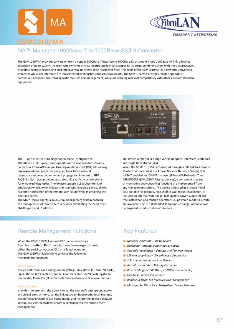
MA™ Managed 1000Base-T to 1000Base-SX/LX Converter GSM1010/MA
The TP port is set to Auto-Negotiation mode (configured to 1000Base-T Full Duplex), and supports Auto-Cross and Auto-Polarity correction. FibroLAN’s unique Link Segmentation Test (LST) allows easy link segmentation (selective per port) to facilitate network diagnostics and overcome the fault propagation inherent to GBE F/O links. Each port provides separate Link and Activity indications for enhanced diagnostics. The device supports SLE (Subscriber Link Emulation) which, when link partner is an MA™enabled device, allows real time notification of the remote user failure while maintaining the fiber link active. The MA™ (Micro Agent) is an on chip management system enabling the management of remote access devices eliminating the need of an SNMP agent and IP address.
The device is offered in a large variety of optical interfaces, both dual and single fiber strand (SFS). When the GSM1010/MA is connected through a F/O link to a remote Master Unit (located at the Access Node or Network Center) that is MA™ enabled and SNMP managed (FibroLAN Metrostar™, or GSM1000M, GSM1010M Master devices), a comprehensive set of monitoring and controlling functions are implemented from any management station. The device is housed in a robust metal case suitable for desktop, rack-shelf or wall-mount installation. It features an internal,wide-range, high quality power supply for fail free installation and reliable operation. DC powered models (-48VDC) are available. The ETR (Extended Temperature Range) option allows deployment in industrial environments.
When the GSM1010/MA remote CPE is connected via a fiber link to a MetroStarTM module, it may be managed through either the serial connection (CLI) or a Telnet operation. The GSM1010/MA Main Menu contains the following management functions:
Device status: device ports status and configuration settings: Link status (TP and F/O ports), Signal Detect (F/O port), LST mode, Loop-back status (F/O port), upstream bandwidth, Pause On (Flow Control), Temperature and Firmware revision
Device Control: provides the user with the options to set the channel’s description, invoke the LB/LST control menu, set the link upstream bandwidth, Reset channel, enable/disable Channel, Set Pause mode, and restore the device’s defaults setting. SLE upstream/downstream is controlled via the remote MATM management
Remote Management FunctionsNetwork extension – up to 120km
Reliability – internal quality power supply
Versatile installation – desktop, shelf or wall-mount
LST and Loop-Back – for enhanced diagnostics
SLE to enhance network resilience
Auto-Cross and Auto Polarity Correction
Rate Limiting (0-1000Mbps, at 10Mbps increments)
Last Gasp- power failure alert
Remote In-Band MA™ feature rich management
Managed by FibroLAN’s MetroView Device Manager
Key Features
MA
The GSM1010/MA provides conversion from a copper 1000Base-T interface to 1000Base-LX or a multi-mode 1000Base-SX link, allowing extension of up to 120km. As most GBE switches or NICs incorporate low cost copper RJ-45 ports, combining them with the GSM1010/MA provides the most flexible and cost effective way to extend their reach over fiber. The heart of the GSM1010/MA is a powerful conversion processor while link interfaces are implemented by industry standard components. The GSM1010/MA provides reliable and robust conversion, advanced control/diagnostic features and management, while maintaining maximal compatibility with other vendors’ standard equipment.
87
GSM1010General Specifications
Power Consumption5 Watts Maximum
Humidity10%÷90% non-condensing
EMCFCC part 15, Subpart B, Class A ICES 003: 1997,Class A EMC Directive 89/336/EEC
Weight400g
B097 PS48 DC (-36 ÷ -72VDC) option (instead of AC PS) for all GSM models
B098 ETR Extended Temperature Range (-10ºC ÷ +70ºC) option for all GSM models
B012 CTF-RM 19” rack shelf for installation of up to 3 GSM devices
B161 SCH-WM Wall Mount kit for all GSM models
B222 MCP5 Mode Conditioned Patch cord, Simplex, 50micron, SC/SC, 2m, for GBE 1310nm over Multimode links
B223 MCP6 Mode Conditioned Patch cord, Simplex, 62,5micron, SC/SC, 2m, for GBE 1310nm over Mm links
3712 B206 B166 GSM1010 S/M -9,5dBm -17dBm 850nm 0-10
3713 B207 B167 GSM1011 S/M -9,5dBm -17dBm 850nm 5-20
3714 B208 B168 GSM1012 S/M -9,5dBm -17dBm 850nm 10-40
3715 B209 B169 GSM1013 S/M -9,5dBm -17dBm 850nm 25-80
3711 B205 B186 GSM1014 M/M -13dBm -20dBm 1310nm 0-10/0-10
3716 B210 B193 GSM1010F13 SM/SFS -5dBm -20dBm 1310nm 5-20/5-20
3717 B211 B194 GSM1010F15 SM/SFS -8dBm -23dBm 1550nm/DFB 10-40/10-40
-Main Menu: Device status, Device control and Software version control-VLAN Tagging support (VLAN tag insertion and stripping)-Per port based priority, 802.1p and TOS based priority schemes-Broadcast storm protection (25%, 12%, 6%, 3%)-Telnet support-In-Band management-Out-of-Band with any terminal emulation program (RS232 port, front panel)-The firmware for the DLA22M can be downloaded through TFTP routine-The DLA22M devices may be managed from any management station
running popular management platforms (FibroLAN’s MetroView, HP OPV, SNMPc, etc)
GSM1010/MA
General SpecificationsStandard CompilanceIEEE802.3 2000 edition1000Base-SX, 1000Base-LX, IEEE802.3zIEEE802.3ab, Diagnostic LedsPower ON, MA ActiveFor each FO Port - Link, Activity, LST, Loop-BackManagementRemote In-Band MATM via MetroStarTM System or GSM1000M/GSM1010M Master devices Conversion MethodDigital with FDX Advertising, Link Segmentation Test and Loop-BackTP PortShielded RJ-45, 100m over Cat6 STP cabling Auto-Cross supportDIP switches (front panel) per port:LST ON/OFF Loop-Back ON/OFF Active MA overrides DIP switches settingsSNMP ManagementFibroLAN MetroView Device Manager
Environmental/PhysicalPower SupplyInternal, 100 to 240VAC, 50-60Hz Optional DC P.S. (PS48)
Operating Temperature0º ÷ +45ºC
Storage Temperature-20º ÷ +80ºC
SafetyEN 60950-1
Dimensions
120x170x44mm
Power Consumption5 Watts Maximum
Humidity10% ÷ 90% non-condensing
EMCFCC CFR 47 part 15, Subpart B, Class AEN 300 386 V1.3.3, AS/NZS CISPRESS:04, EN55022/24
Weight400g
Ordering Information and F/O Specifications
Minimal Output Power
Minimal Receive
Senitivity
Wavelengthnm
Part# Model F/O Ports
Fiber SuggestedDistance
km
Options
Specifications are subject to change w/o prior notice
B097 PS48 Optional DC PS (-36 ÷ -72VDC) instead of AC PS
B151 CBPS-DC48V DC Power Supply cable, 2m for PS48
B098 ETR Extended Temperature Range (-10ºC ÷ +70ºC) option for all GSM1010/MA models
B012 CTF-RM 19” rack shelf for installation of up to 3 GSM1010/MA devices
B161 SCH-WM Wall Mount kit for all GSM1010/MA models
MA
3711 GSM1014/MA MM -9,5dBm -17dBm 850 220/500m
3712 GSM1010/MA SM -10dBm -23dBm 1310 5-10
3713 GSM1011/MA SM -5dBm -23dBm 1310 5-20
3731 GSM1011/MA-48 SM -5dBm -23dBm 1310 5-20
3714 GSM1012/MA SM -3dBm -23dBm 1550/DFB 10-40
3715 GSM1013/MA SM 0dBm -23dBm 1550/DFB 25-80
3727 GSM1019/MA SM 0dBm -32dBm 1550/DFB-APD 80-120
3716 GSM1010F13/MA SM/SFS -5dBm -20dBm 1310Tx/1550Rx 5-20
3717 GSM1010F15/MA SM/SFS -5dBm -20dBm 1550DFB-Tx/1310Rx 5-20
3724 GSM1010F13L/MA SM/SFS -3dBm -23dBm 1310DFB-Tx/1550Rx 10-40
3725 GSM1010F15L/MA SM/SFS -3dBm -23dBm 1550DFB-Tx/1310Rx 10-40
88
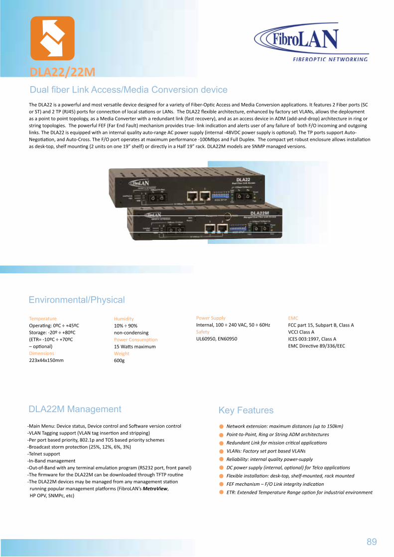
Dual fiber Link Access/Media Conversion device
DLA22/22M
-Main Menu: Device status, Device control and Software version control-VLAN Tagging support (VLAN tag insertion and stripping)-Per port based priority, 802.1p and TOS based priority schemes-Broadcast storm protection (25%, 12%, 6%, 3%)-Telnet support-In-Band management-Out-of-Band with any terminal emulation program (RS232 port, front panel)-The firmware for the DLA22M can be downloaded through TFTP routine-The DLA22M devices may be managed from any management station
running popular management platforms (FibroLAN’s MetroView, HP OPV, SNMPc, etc)
DLA22M Management
The DLA22 is a powerful and most versatile device designed for a variety of Fiber-Optic Access and Media Conversion applications. It features 2 Fiber ports (SC or ST) and 2 TP (RJ45) ports for connection of local stations or LANs. The DLA22 flexible architecture, enhanced by factory set VLANs, allows the deployment as a point to point topology, as a Media Converter with a redundant link (fast recovery), and as an access device in ADM (add-and-drop) architecture in ring or string topologies. The powerful FEF (Far End Fault) mechanism provides true- link indication and alerts user of any failure of both F/O incoming and outgoing links. The DLA22 is equipped with an internal quality auto-range AC power supply (internal -48VDC power supply is optional). The TP ports support Auto-Negotiation, and Auto-Cross. The F/O port operates at maximum performance -100Mbps and Full Duplex. The compact yet robust enclosure allows installation as desk-top, shelf mounting (2 units on one 19” shelf) or directly in a Half 19” rack. DLA22M models are SNMP managed versions.
TemperatureOperating: 0ºC ÷ +45ºCStorage: -20º ÷ +80ºC(ETR= -10ºC ÷ +70ºC – optional)Dimensions223x44x150mm
Power SupplyInternal, 100 ÷ 240 VAC, 50 ÷ 60HzSafetyUL60950, EN60950
Humidity10% ÷ 90% non-condensingPower Consumption15 Watts maximumWeight600g
Environmental/Physical
EMCFCC part 15, Subpart B, Class AVCCI Class AICES 003:1997, Class AEMC Directive 89/336/EEC
89
Key FeaturesNetwork extension: maximum distances (up to 150km)
Point-to-Point, Ring or String ADM architectures
Redundant Link for mission critical applications
VLANs: Factory set port based VLANs
Reliability: internal quality power-supply
DC power supply (internal, optional) for Telco applications
Flexible installation: desk-top, shelf-mounted, rack mounted
FEF mechanism – F/O Link integrity indication
ETR: Extended Temperature Range option for industrial environment
GSM1010/MA
General SpecificationsPower Consumption5 Watts Maximum
Humidity10% ÷ 90% non-condensing
EMCFCC CFR 47 part 15, Subpart B, Class AEN 300 386 V1.3.3, AS/NZS CISPRESS:04, EN55022/24
Weight400g
B097 PS48 Optional DC PS (-36 ÷ -72VDC) instead of AC PS
B151 CBPS-DC48V DC Power Supply cable, 2m for PS48
B098 ETR Extended Temperature Range (-10ºC ÷ +70ºC) option for all GSM1010/MA models
B012 CTF-RM 19” rack shelf for installation of up to 3 GSM1010/MA devices
B161 SCH-WM Wall Mount kit for all GSM1010/MA models
3711 GSM1014/MA MM -9,5dBm -17dBm 850 220/500m
3712 GSM1010/MA SM -10dBm -23dBm 1310 5-10
3713 GSM1011/MA SM -5dBm -23dBm 1310 5-20
3731 GSM1011/MA-48 SM -5dBm -23dBm 1310 5-20
3714 GSM1012/MA SM -3dBm -23dBm 1550/DFB 10-40
3715 GSM1013/MA SM 0dBm -23dBm 1550/DFB 25-80
3727 GSM1019/MA SM 0dBm -32dBm 1550/DFB-APD 80-120
3716 GSM1010F13/MA SM/SFS -5dBm -20dBm 1310Tx/1550Rx 5-20
3717 GSM1010F15/MA SM/SFS -5dBm -20dBm 1550DFB-Tx/1310Rx 5-20
3724 GSM1010F13L/MA SM/SFS -3dBm -23dBm 1310DFB-Tx/1550Rx 10-40
3725 GSM1010F15L/MA SM/SFS -3dBm -23dBm 1550DFB-Tx/1310Rx 10-40
Standard Compliance IEEE 802.3u, 10Base-T,100Base-TX, 100Base-FX, VLAN per portVLAN Tagging, DSCP (RFC2474) DLA22M100BaseTX ports (2x)Shielded RJ-45 Half/Full Duplex support 10Base-T and 100Base-TX100m over STP Cat5 cableFull Auto-Negotiation with optional manual setting (DIP switch selectable) Auto Cross supports Diagnostic LedsF/O ports: FDX, Link/ActivityCopper ports: FDX, Link/Activity, 100MPower Test mode (lit when FEF is enabled)Management Section (DLA22M)RS232 (miniDIN) terminal connectorLEDs: RCV, Ready
DLA22/22MGeneral Specifications
Ordering Information
Specifications are subject to change w/o prior notice
Conversion MethodBMD™ (Buffered Media Domain), Full wire speed, 1000 MAC addresses, FDX flow-control (IEEE.802.3x) HDX back-pressure flow controlFrame range: 64 ÷ 1536 bytes 100Base-FX ports (2)1310nm, multi-mode, SC connectors, 2000mOutput Power: -18dBm ; Input Sensitivity: -32dBm SM fiber 1310nm distances: 7/15/25/40/70kmMin. Out Power: -20/-16/-15/-11/-2 dBmTypical Sensitivity: -30/-30/-33/-33/-35 dBmSingle-Fiber-Strand: 15km, 60kmMin. Out Power: -15/-5 dBm; Sensitivity: -30/-35 dBmControls (Front Panel Dip switches)FDX/HDX (F/O ports) selectionAuto-Negotiation enable/disableTP ports forced to 10Mbps/FDX (A/N disabled)Back-Up mode/Topology selectionFEF enable/disable. VLAN enable/disable (port based security VLANs)Reset device
Part# Model Description
B106 DLA22 Versatile 10/100TX-FX, Dual F/O link, duplex SC, Multi-Mode, 2km
B125 DLA22/T Versatile 10/100TX-FX, Dual F/O link, ST connectors, Multi-Mode, 2km
B218 DLA22/T/SMR7 Versatile 10/100TX-FX, Dual F/O link, ST connectors, Single-Mode 7km
B120 DLA22/SMR7 Versatile 10/100TX-FX, Dual F/O link, duplex SC, Single-Mode 7km
B121 DLA22/SMR Versatile 10/100TX-FX, Dual F/O link, duplex SC, Single-Mode 15km
B122 DLA22//SM Versatile 10/100TX-FX, Dual F/O link, duplex SC, Single-Mode 25km
B123 DLA22/SM/L Versatile 10/100TX-FX, Dual F/O link, duplex SC, Single-Mode 40km
B221 DLA22/SM/L2 Versatile 10/100TX-FX, Dual F/O link, duplex SC, Single-Mode 70km
B124 DLA22/SMRF135 Versatile 10/100TX-FX, Dual F/O link, SC, Single-Mode 15km, Single Fiber strand, One port 1310nm Tx/1550nmRx, Second port 1550nmTx/1310nmRx
B234 DLA22/SMLF135 Versatile 10/100TX-FX, Dual F/O link, 2*simplex SC, SM, 60km, Single Fiber strand, One port 1310nm Tx/1550nmRx, Second port 1550DFBnmTx/1310nmRx
B107 DLA22M Versatile 10/100TX-FX, Dual F/O link, duplex SC, Multi-Mode, SNMP managed
B126 DLA22M/T Versatile 10/100TX-FX, Dual F/O link, dual ST, Multi-Mode, SNMP managed
B127 DLA22M/SMR7 Versatile 10/100TX-FX, Dual F/O link, duplex SC, SM 7 km, SNMP managed
B128 DLA22M/SMR Versatile 10/100TX-FX, Dual F/O link, duplex SC, SM 15 km, SNMP managed
B129 DLA22M/SM Versatile 10/100TX-FX, Dual F/O link, duplex SC, SM 25km, SNMP managed
B130 DLA22M/SM/L Versatile 10/100TX-FX, Dual F/O link, duplex SC, SM 40km, SNMP managed
B131 DLA22M/SMRF135 Versatile 10/100TX-FX, Dual F/O link, 2*simplex SC, SM 15km, single Fiber strand, One port 1310nm
Tx/1550nmRx, Second port 1550nmTx/ 1310nmRx, SNMP
B097 PS48 -36÷ - 72VDC power supply for DLAxxx (instead of the 100÷240VAC,50÷60Hz PS)
B098 ETR Extended Temperature Range option of up to 2 x DLAxxx (-10° ÷ +70°C)
B160 RM2 19” Rack Shelf for installation of up to 2x DLA22/22M devices
90
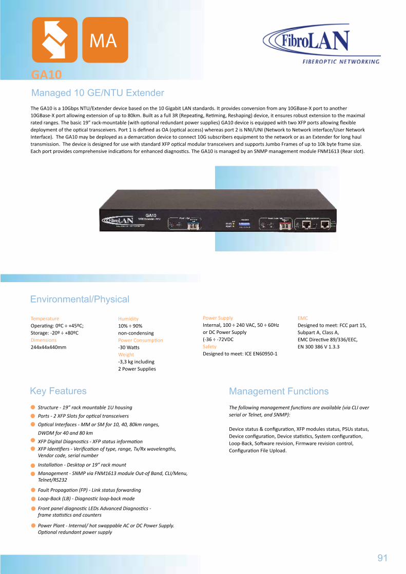
Managed 10 GE/NTU Extender
GA10
The following management functions are available (via CLI over serial or Telnet, and SNMP):
Device status & configuration, XFP modules status, PSUs status, Device configuration, Device statistics, System configuration, Loop-Back, Software revision, Firmware revision control, Configuration File Upload.
Key FeaturesStructure - 19” rack mountable 1U housing
Ports - 2 XFP Slots for optical transceivers
Optical Interfaces - MM or SM for 10, 40, 80km ranges,
DWDM for 40 and 80 km
XFP Digital Diagnostics - XFP status information
XFP Identifiers - Verification of type, range, Tx/Rx wavelengths, Vendor code, serial number
Installation - Desktop or 19” rack mount
Management - SNMP via FNM1613 module Out-of Band, CLI/Menu, Telnet/RS232
Fault Propagation (FP) - Link status forwarding
Loop-Back (LB) - Diagnostic loop-back mode
Front panel diagnostic LEDs Advanced Diagnostics - frame statistics and counters
Power Plant - Internal/ hot swappable AC or DC Power Supply. Optional redundant power supply
The GA10 is a 10Gbps NTU/Extender device based on the 10 Gigabit LAN standards. It provides conversion from any 10GBase-X port to another10GBase-X port allowing extension of up to 80km. Built as a full 3R (Repeating, Retiming, Reshaping) device, it ensures robust extension to the maximal rated ranges. The basic 19” rack-mountable (with optional redundant power supplies) GA10 device is equipped with two XFP ports allowing flexible deployment of the optical transceivers. Port 1 is defined as OA (optical access) whereas port 2 is NNI/UNI (Network to Network interface/User Network Interface). The GA10 may be deployed as a demarcation device to connect 10G subscribers equipment to the network or as an Extender for long haul transmission. The device is designed for use with standard XFP optical modular transceivers and supports Jumbo Frames of up to 10k byte frame size. Each port provides comprehensive indications for enhanced diagnostics. The GA10 is managed by an SNMP management module FNM1613 (Rear slot).
TemperatureOperating: 0ºC ÷ +45ºC;Storage: -20º ÷ +80ºCDimensions244x44x440mm
Power SupplyInternal, 100 ÷ 240 VAC, 50 ÷ 60Hzor DC Power Supply (-36 ÷ -72VDCSafetyDesigned to meet: ICE EN60950-1
Humidity10% ÷ 90% non-condensingPower Consumption-30 Watts Weight-3,3 kg including 2 Power Supplies
Environmental/Physical
EMCDesigned to meet: FCC part 15, Subpart A, Class A,EMC Directive 89/336/EEC, EN 300 386 V 1.3.3
91
Management Functions
MA
DLA22/22M
Part# Model Description
B106 DLA22 Versatile 10/100TX-FX, Dual F/O link, duplex SC, Multi-Mode, 2km
B125 DLA22/T Versatile 10/100TX-FX, Dual F/O link, ST connectors, Multi-Mode, 2km
B218 DLA22/T/SMR7 Versatile 10/100TX-FX, Dual F/O link, ST connectors, Single-Mode 7km
B120 DLA22/SMR7 Versatile 10/100TX-FX, Dual F/O link, duplex SC, Single-Mode 7km
B121 DLA22/SMR Versatile 10/100TX-FX, Dual F/O link, duplex SC, Single-Mode 15km
B122 DLA22//SM Versatile 10/100TX-FX, Dual F/O link, duplex SC, Single-Mode 25km
B123 DLA22/SM/L Versatile 10/100TX-FX, Dual F/O link, duplex SC, Single-Mode 40km
B221 DLA22/SM/L2 Versatile 10/100TX-FX, Dual F/O link, duplex SC, Single-Mode 70km
B124 DLA22/SMRF135 Versatile 10/100TX-FX, Dual F/O link, SC, Single-Mode 15km, Single Fiber strand, One port 1310nm Tx/1550nmRx, Second port 1550nmTx/1310nmRx
B234 DLA22/SMLF135 Versatile 10/100TX-FX, Dual F/O link, 2*simplex SC, SM, 60km, Single Fiber strand, One port 1310nm Tx/1550nmRx, Second port 1550DFBnmTx/1310nmRx
B107 DLA22M Versatile 10/100TX-FX, Dual F/O link, duplex SC, Multi-Mode, SNMP managed
B126 DLA22M/T Versatile 10/100TX-FX, Dual F/O link, dual ST, Multi-Mode, SNMP managed
B127 DLA22M/SMR7 Versatile 10/100TX-FX, Dual F/O link, duplex SC, SM 7 km, SNMP managed
B128 DLA22M/SMR Versatile 10/100TX-FX, Dual F/O link, duplex SC, SM 15 km, SNMP managed
B129 DLA22M/SM Versatile 10/100TX-FX, Dual F/O link, duplex SC, SM 25km, SNMP managed
B130 DLA22M/SM/L Versatile 10/100TX-FX, Dual F/O link, duplex SC, SM 40km, SNMP managed
B131 DLA22M/SMRF135 Versatile 10/100TX-FX, Dual F/O link, 2*simplex SC, SM 15km, single Fiber strand, One port 1310nm
Tx/1550nmRx, Second port 1550nmTx/ 1310nmRx, SNMP
B097 PS48 -36÷ - 72VDC power supply for DLAxxx (instead of the 100÷240VAC,50÷60Hz PS)
B098 ETR Extended Temperature Range option of up to 2 x DLAxxx (-10° ÷ +70°C)
B160 RM2 19” Rack Shelf for installation of up to 2x DLA22/22M devices
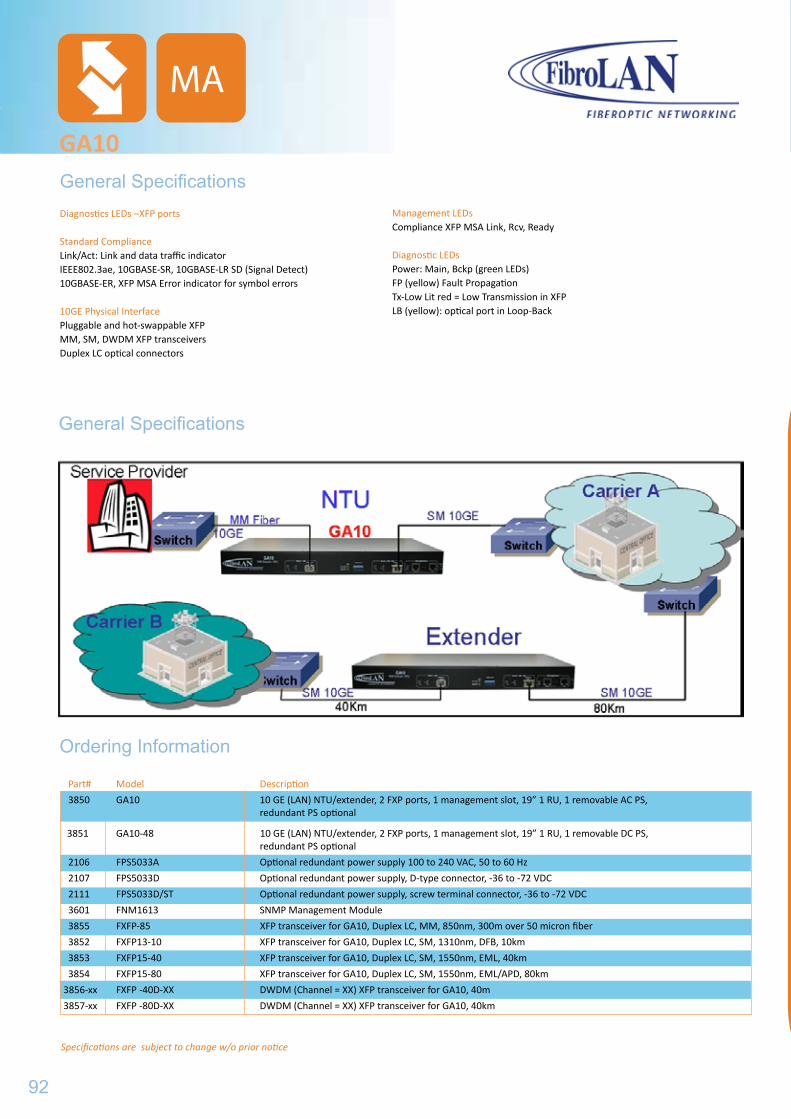
Diagnostics LEDs –XFP ports
Standard Compliance Link/Act: Link and data traffic indicator IEEE802.3ae, 10GBASE-SR, 10GBASE-LR SD (Signal Detect) 10GBASE-ER, XFP MSA Error indicator for symbol errors
10GE Physical Interface Pluggable and hot-swappable XFPMM, SM, DWDM XFP transceivers Duplex LC optical connectors
GA10General Specifications
Ordering Information
Specifications are subject to change w/o prior notice
Part# Model Description
3850 GA10 10 GE (LAN) NTU/extender, 2 FXP ports, 1 management slot, 19” 1 RU, 1 removable AC PS, redundant PS optional
3851 GA10-48 10 GE (LAN) NTU/extender, 2 FXP ports, 1 management slot, 19” 1 RU, 1 removable DC PS, redundant PS optional
2106 FPS5033A Optional redundant power supply 100 to 240 VAC, 50 to 60 Hz
2107 FPS5033D Optional redundant power supply, D-type connector, -36 to -72 VDC
2111 FPS5033D/ST Optional redundant power supply, screw terminal connector, -36 to -72 VDC
3601 FNM1613 SNMP Management Module
3855 FXFP-85 XFP transceiver for GA10, Duplex LC, MM, 850nm, 300m over 50 micron fiber
3852 FXFP13-10 XFP transceiver for GA10, Duplex LC, SM, 1310nm, DFB, 10km
3853 FXFP15-40 XFP transceiver for GA10, Duplex LC, SM, 1550nm, EML, 40km
3854 FXFP15-80 XFP transceiver for GA10, Duplex LC, SM, 1550nm, EML/APD, 80km
3856-xx FXFP -40D-XX DWDM (Channel = XX) XFP transceiver for GA10, 40m
3857-xx FXFP -80D-XX DWDM (Channel = XX) XFP transceiver for GA10, 40km
Management LEDs Compliance XFP MSA Link, Rcv, Ready
Diagnostic LEDs Power: Main, Bckp (green LEDs) FP (yellow) Fault Propagation Tx-Low Lit red = Low Transmission in XFP LB (yellow): optical port in Loop-Back
General Specifications
92
MA
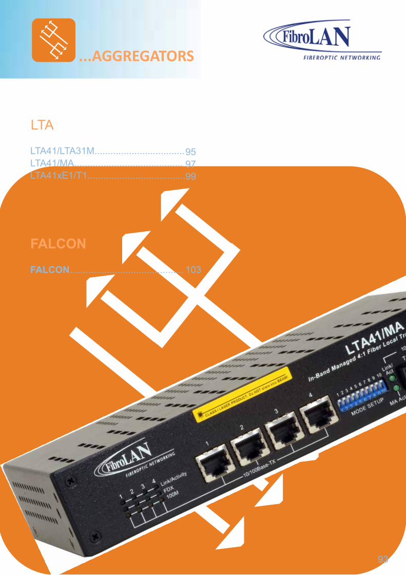
...AGGREGATORS
LTA
LTA41/LTA31M..................................LTA41/MA.........................................LTA41xE1/T1.....................................
FALCON
FALCON...........................................
93
959799
103
GA10
Part# Model Description
3850 GA10 10 GE (LAN) NTU/extender, 2 FXP ports, 1 management slot, 19” 1 RU, 1 removable AC PS, redundant PS optional
3851 GA10-48 10 GE (LAN) NTU/extender, 2 FXP ports, 1 management slot, 19” 1 RU, 1 removable DC PS, redundant PS optional
2106 FPS5033A Optional redundant power supply 100 to 240 VAC, 50 to 60 Hz
2107 FPS5033D Optional redundant power supply, D-type connector, -36 to -72 VDC
2111 FPS5033D/ST Optional redundant power supply, screw terminal connector, -36 to -72 VDC
3601 FNM1613 SNMP Management Module
3855 FXFP-85 XFP transceiver for GA10, Duplex LC, MM, 850nm, 300m over 50 micron fiber
3852 FXFP13-10 XFP transceiver for GA10, Duplex LC, SM, 1310nm, DFB, 10km
3853 FXFP15-40 XFP transceiver for GA10, Duplex LC, SM, 1550nm, EML, 40km
3854 FXFP15-80 XFP transceiver for GA10, Duplex LC, SM, 1550nm, EML/APD, 80km
3856-xx FXFP -40D-XX DWDM (Channel = XX) XFP transceiver for GA10, 40m
3857-xx FXFP -80D-XX DWDM (Channel = XX) XFP transceiver for GA10, 40km

94
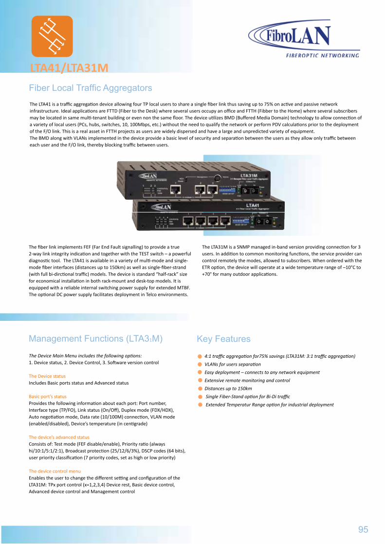
Fiber Local Traffic Aggregators
LTA41/LTA31M
The LTA41 is a traffic aggregation device allowing four TP local users to share a single fiber link thus saving up to 75% on active and passive network infrastructure. Ideal applications are FTTD (Fiber to the Desk) where several users occupy an office and FTTH (Fibber to the Home) where several subscribers may be located in same multi-tenant building or even non the same floor. The device utilizes BMD (Buffered Media Domain) technology to allow connection of a variety of local users (PCs, hubs, switches, 10, 100Mbps, etc.) without the need to qualify the network or perform PDV calculations prior to the deployment of the F/O link. This is a real asset in FTTH projects as users are widely dispersed and have a large and unpredicted variety of equipment.The BMD along with VLANs implemented in the device provide a basic level of security and separation between the users as they allow only traffic between each user and the F/O link, thereby blocking traffic between users.
The fiber link implements FEF (Far End Fault signalling) to provide a true 2-way link integrity indication and together with the TEST switch – a powerful diagnostic tool. The LTA41 is available in a variety of multi-mode and single-mode fiber interfaces (distances up to 150km) as well as single-fiber-strand (with full bi-dirctional traffic) models. The device is standard “half-rack” size for economical installation in both rack-mount and desk-top models. It is equipped with a reliable internal switching power supply for extended MTBF. The optional DC power supply facilitates deployment in Telco environments.
The LTA31M is a SNMP managed in-band version providing connection for 3 users. In addition to common monitoring functions, the service provider can control remotely the modes, allowed to subscribers. When ordered with the ETR option, the device will operate at a wide temperature range of –10°C to +70° for many outdoor applications.
The Device Main Menu includes the following options: 1. Device status, 2. Device Control, 3. Software version control
The Device status Includes Basic ports status and Advanced status
Basic port’s status Provides the following information about each port: Port number, Interface type (TP/FO), Link status (On/Off), Duplex mode (FDX/HDX), Auto negotiation mode, Data rate (10/100M) connection, VLAN mode (enabled/disabled), Device’s temperature (in centigrade)
The device’s advanced status Consists of: Test mode (FEF disable/enable), Priority ratio (always hi/10:1/5:1/2:1), Broadcast protection (25/12/6/3%), DSCP codes (64 bits), user priority classification (7 priority codes, set as high or low priority)
The device control menu Enables the user to change the different setting and configuration of the LTA31M: TPx port control (x=1,2,3,4) Device rest, Basic device control, Advanced device control and Management control
Management Functions (LTA31M) Key Features
4:1 traffic aggregation for75% savings (LTA31M: 3:1 traffic aggregation)
VLANs for users separation
Easy deployment – connects to any network equipment
Extensive remote monitoring and control
Distances up to 150km
Single Fiber-Stand option for Bi-Di traffic
Extended Temperatur Range option for industrial deployment
95
LTA41/LTA31MGeneral Specifications
Environmental/Physical
Power-SupplyInternal, 100 to 240VAC, 50 to 60HzOptional DC PS (-36 to -72VDC)
Operating Temperature0° to 45°C; ETR = -10° to +70°C optional
Humidity10% to 90% non-cndensing
SafetyUL 60950, EN 60950
EMCFCC part 15, Subpart A, Class B, VCCI Class AINCES 003:1997, Class A, EMC Directive 89/336/EEC
Power Consumption15W max.
Storage Temperature-20° to +80°C
Weight 600g
Dimensions223x44x150mm (WxHxD)
Management (LTA31M only)Out-of band (RS232 Port, terminal emulation)In band SNMP management and Telnet
Standard ComplianceIEEE802.3u, 100Base-TX, 10 Base-T, 100Base-Fx, VLAN per port
10/100Base-TX Ports 1 to 4 (1 to 3 in LTA31M)Shielded RJ-45, Auto-Cross, auto-polarity 100m over STP Cat5 or higher cable. HDX/FDX via auto negotiation or forced (DIP)
Diagnostics LEDs per PortFX port: Link/Activity, FDXTX ports (each): Link/activity, FDX, 100M
Diagnostics per SystemPower, Link Test
Management (LTA31M)RS232 (miniDIN) terminal connector. LEDs: RCV, Ready
Conversion MethodBMD (Buffered Media Domain), Full wire speed, 1000 MAC addresses, FDX flow control, HDX back-pressure flow control
100Base-Fx PortDuplex SC connector (ST optional)Far End Fault Signaling; HDX/FDX selection1310nm multi-mode -18 dBm min. output power, -32dBm or better sensibility. Optional single-mode for 7/15//25/40/70/100/150km Single Fiber Strand (SMRF1x) models
Controls (DIP switches)FX port: FDX/HDX, Far End Fault enable/ disableTX port #4:10/100, FDX/HDX, A/N enable-disableTX ports 1 to 3: Auto-negotiation/ forced FDX-10MbitVLAN ports enable/disableReset device
Ordering Information Part# Model Description
B104 LTA41 4x10/100Base-TX to 100Base-Fx, MM, 2km 1310nm, 4xRJ45 ports (switched, VLAN) and Duplex SC
B174 LTA41/T 4x10/100Base-TX to 100Base-Fx, MM, 2km 1310nm, 4xRJ45 ports (switched, VLAN) and Duplex ST
B108 LTA41/SMR7 4x10/100Base-TX to 100Base-Fx, SM, 7km 1310nm, 4xRJ45 ports (switched, VLAN) and Duplex SC
B109 LTA41/SMR 4x10/100Base-TX to 100Base-Fx, SM, 15km 1310nm, 4xRJ45 ports (switched, VLAN) and Duplex SC
B110 LTA41/SM 4x10/100Base-TX to 100Base-Fx, SM, 25km 1310nm, 4xRJ45 ports (switched, VLAN) and Duplex SC
B111 LTA41/SM/L 4x10/100Base-TX to 100Base-Fx, SM, 40km 1310nm, 4xRJ45 ports (switched, VLAN) and Duplex SC
B112 LTA41/SM/L2 4x10/100Base-TX to 100Base-Fx, SM, 70km 1310nm, 4xRJ45 ports (switched, VLAN) and Duplex SC
B113 LTA41/SMRF13 4x10/100Base-TX to 100Base-Fx, SM, SFS 15km 1310nm Tx/ 1550nm Rx, 4x RJ45 ports (switched, VLAN), and single SC connector
B105 LTA31M 3x10/100Base-TX to 100Base-Fx, MM, 2km 1310nm, 4xRJ45 ports (switched, VLAN), and Duplex SC, SNMP managed
Specifications are subject to change w/o prior notice
96
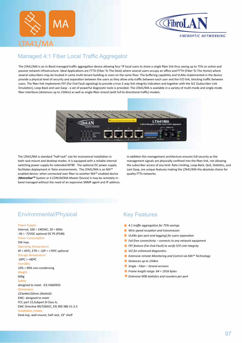
Managed 4:1 Fiber Local Traffic Aggregator
LTA41/MA
The LTA41/MA is an In-Band managed traffic aggregation device allowing four TP local users to share a single fiber link thus saving up to 75% on active and passive network infrastructure. Ideal Applications are FTTD (Fiber To The Desk) where several users occupy an office and FTTH (Fiber To The Home) where several subscribers may be located in same multi-tenant building or even on the same floor. The buffering capability and VLANs implemented in the device provide a physical level of security and separation between the users as they allow only traffic between each user and the F/O link, blocking traffic between users. The fiber link implements FEF (Far End Fault signaling) to provide a true 2-way link integrity indication and together with the SLE (Subscriber Link Emulation), Loop-Back and Last Gasp - a set of powerful diagnostic tools is provided. The LTA41/MA is available in a variety of multi-mode and single-mode fiber interfaces (distances up to 150km) as well as single-fiber-strand (with full bi-directional traffic) models.
The LTA41/MA is standard “half-rack” size for economical installation in both rack-mount and desktop modes. It is equipped with a reliable internal switching power supply for extended MTBF. The optional DC power supply facilitates deployment in Telco environments. The LTA41/MA is an MA™ enabled device: when connected over fiber to another MA™ enabled device (MetroStarTM System or S.CON1M/MA Master Device) it may be remotely in-band managed without the need of an expensive SNMP agent and IP address.
In addition this management architecture ensures full security as the management signals are physically confined into the fiber-link, not allowing the subscriber access of any kind. Rate Limiting, Loop-Back, QoS, Statistics, and Last Gasp, are unique features making the LTA41/MA the absolute choice for quality FTTx networks.
Power-SupplyInternal, 100 ÷ 240VAC, 50 ÷ 60Hz-36 ÷ -72VDC optional DC PS (PS48) Power Consumption5W max.Operating Temperature0º ÷ 45ºC, ETR = -10º ÷ +70ºC optional Storage Temperature-20ºC ÷ +80ºC Humidity10% ÷ 90% non-condensing Weight600gSafetydesigned to meet: ICE-EN60950 Dimensions223x44x150mm (WxHxD)EMC- designed to meet:FCC part 15,Subpart B Class A, EMC Directive 89/336EEC, EN 300 386 V1.3.3 Installation modesDesk-top, wall-mount, half rack, 19” shelf
Environmental/Physical Key Features
4:1 traffic aggregation for 75% savings
Wire speed reception and transmission
VLANs (per port and tagging) for users separation
Fail-free connectivity – connects to any network equipment
FEF feature (Far-End-Fault) to verify F/O Link integrity
SLE for enhanced diagnostics
Extensive remote Monitoring and Control via MA™ Technology
Distances up to 150km
Single - Fiber – Strand versions
Frame length range: 64 ÷ 1916 bytes
Extensive MIB statistics and counters per port
97
MA
LTA41/LTA31MGeneral Specifications
Part# Model Description
B104 LTA41 4x10/100Base-TX to 100Base-Fx, MM, 2km 1310nm, 4xRJ45 ports (switched, VLAN) and Duplex SC
B174 LTA41/T 4x10/100Base-TX to 100Base-Fx, MM, 2km 1310nm, 4xRJ45 ports (switched, VLAN) and Duplex ST
B108 LTA41/SMR7 4x10/100Base-TX to 100Base-Fx, SM, 7km 1310nm, 4xRJ45 ports (switched, VLAN) and Duplex SC
B109 LTA41/SMR 4x10/100Base-TX to 100Base-Fx, SM, 15km 1310nm, 4xRJ45 ports (switched, VLAN) and Duplex SC
B110 LTA41/SM 4x10/100Base-TX to 100Base-Fx, SM, 25km 1310nm, 4xRJ45 ports (switched, VLAN) and Duplex SC
B111 LTA41/SM/L 4x10/100Base-TX to 100Base-Fx, SM, 40km 1310nm, 4xRJ45 ports (switched, VLAN) and Duplex SC
B112 LTA41/SM/L2 4x10/100Base-TX to 100Base-Fx, SM, 70km 1310nm, 4xRJ45 ports (switched, VLAN) and Duplex SC
B113 LTA41/SMRF13 4x10/100Base-TX to 100Base-Fx, SM, SFS 15km 1310nm Tx/ 1550nm Rx, 4x RJ45 ports (switched, VLAN), and single SC connector
B105 LTA31M 3x10/100Base-TX to 100Base-Fx, MM, 2km 1310nm, 4xRJ45 ports (switched, VLAN), and Duplex SC, SNMP managed
Specifications are subject to change w/o prior notice
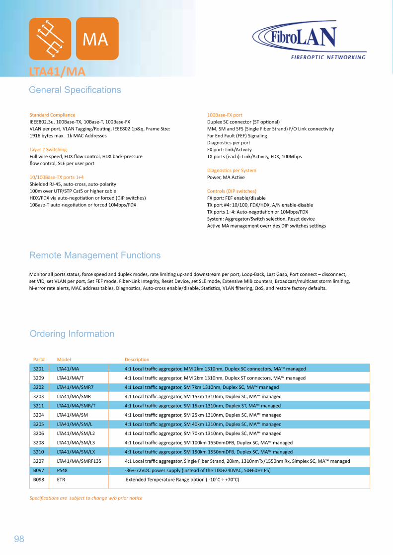
LTA41/MAGeneral Specifications
Standard ComplianceIEEE802.3u, 100Base-TX, 10Base-T, 100Base-FXVLAN per port, VLAN Tagging/Routing, IEEE802.1p&q, Frame Size: 1916 bytes max. 1k MAC Addresses
Layer 2 SwitchingFull wire speed, FDX flow control, HDX back-pressure flow control, SLE per user port
10/100Base-TX ports 1÷4 Shielded RJ-45, auto-cross, auto-polarity100m over UTP/STP Cat5 or higher cableHDX/FDX via auto-negotiation or forced (DIP switches)10Base-T auto-negotiation or forced 10Mbps/FDX
Ordering Information
100Base-FX portDuplex SC connector (ST optional)MM, SM and SFS (Single Fiber Strand) F/O Link connectivityFar End Fault (FEF) Signaling Diagnostics per portFX port: Link/ActivityTX ports (each): Link/Activity, FDX, 100Mbps
Diagnostics per System Power, MA Active
Controls (DIP switches)FX port: FEF enable/disableTX port #4: 10/100, FDX/HDX, A/N enable-disableTX ports 1÷4: Auto-negotiation or 10Mbps/FDXSystem: Aggregator/Switch selection, Reset deviceActive MA management overrides DIP switches settings
Part# Model Description
3201 LTA41/MA 4:1 Local traffic aggregator, MM 2km 1310nm, Duplex SC connectors, MA™ managed
3209 LTA41/MA/T 4:1 Local traffic aggregator, MM 2km 1310nm, Duplex ST connectors, MA™ managed
3202 LTA41/MA/SMR7 4:1 Local traffic aggregator, SM 7km 1310nm, Duplex SC, MA™ managed
3203 LTA41/MA/SMR 4:1 Local traffic aggregator, SM 15km 1310nm, Duplex SC, MA™ managed
3211 LTA41/MA/SMR/T 4:1 Local traffic aggregator, SM 15km 1310nm, Duplex ST, MA™ managed
3204 LTA41/MA/SM 4:1 Local traffic aggregator, SM 25km 1310nm, Duplex SC, MA™ managed
3205 LTA41/MA/SM/L 4:1 Local traffic aggregator, SM 40km 1310nm, Duplex SC, MA™ managed
3206 LTA41/MA/SM/L2 4:1 Local traffic aggregator, SM 70km 1310nm, Duplex SC, MA™ managed
3208 LTA41/MA/SM/L3 4:1 Local traffic aggregator, SM 100km 1550nmDFB, Duplex SC, MA™ managed
3210 LTA41/MA/SM/LX 4:1 Local traffic aggregator, SM 150km 1550nmDFB, Duplex SC, MA™ managed
3207 LTA41/MA/SMRF13S 4:1 Local traffic aggregator, Single Fiber Strand, 20km, 1310nmTx/1550nm Rx, Simplex SC, MA™ managed
B097 PS48 -36÷-72VDC power supply (instead of the 100÷240VAC, 50÷60Hz PS)
B098 ETR Extended Temperature Range option ( -10°C ÷ +70°C)
Specifications are subject to change w/o prior notice
Remote Management Functions
Monitor all ports status, force speed and duplex modes, rate limiting up-and downstream per port, Loop-Back, Last Gasp, Port connect – disconnect, set VID, set VLAN per port, Set FEF mode, Fiber-Link Integrity, Reset Device, set SLE mode, Extensive MIB counters, Broadcast/multicast storm limiting, hi-error rate alerts, MAC address tables, Diagnostics, Auto-cross enable/disable, Statistics, VLAN filtering, QoS, and restore factory defaults.
98
MA
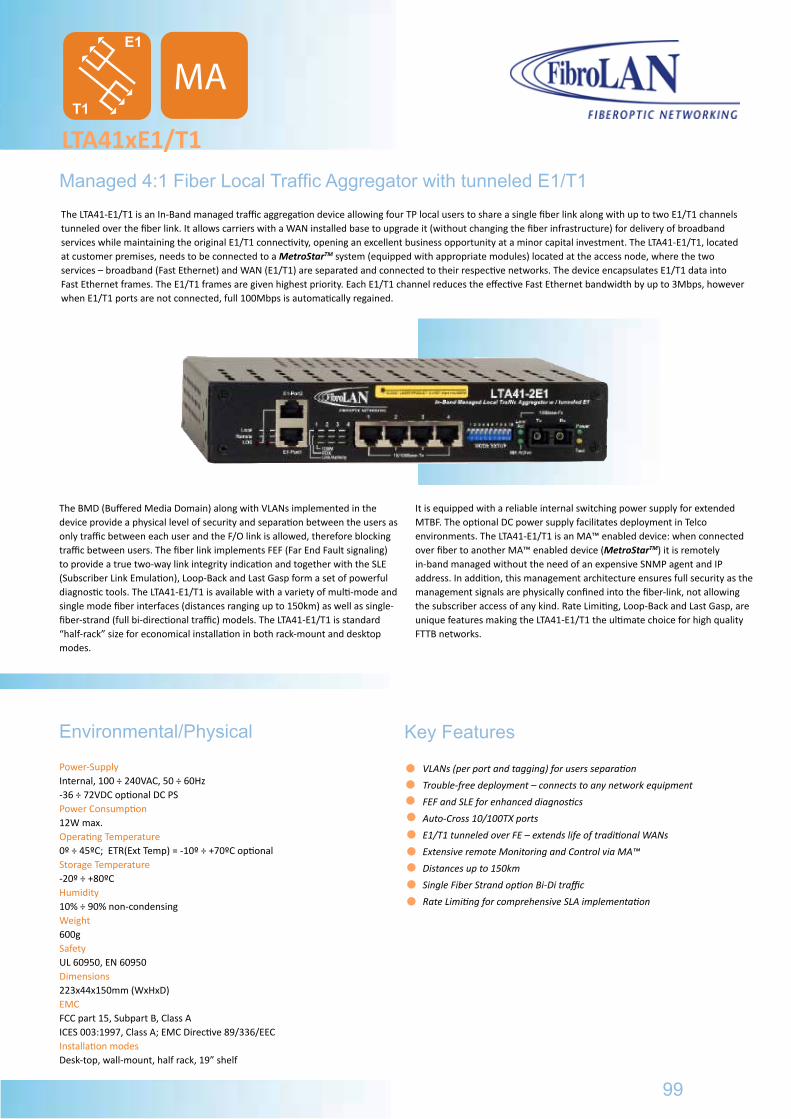
Managed 4:1 Fiber Local Traffic Aggregator with tunneled E1/T1
LTA41xE1/T1
The LTA41-E1/T1 is an In-Band managed traffic aggregation device allowing four TP local users to share a single fiber link along with up to two E1/T1 channels tunneled over the fiber link. It allows carriers with a WAN installed base to upgrade it (without changing the fiber infrastructure) for delivery of broadband services while maintaining the original E1/T1 connectivity, opening an excellent business opportunity at a minor capital investment. The LTA41-E1/T1, located at customer premises, needs to be connected to a MetroStarTM system (equipped with appropriate modules) located at the access node, where the two services – broadband (Fast Ethernet) and WAN (E1/T1) are separated and connected to their respective networks. The device encapsulates E1/T1 data into Fast Ethernet frames. The E1/T1 frames are given highest priority. Each E1/T1 channel reduces the effective Fast Ethernet bandwidth by up to 3Mbps, however when E1/T1 ports are not connected, full 100Mbps is automatically regained.
The BMD (Buffered Media Domain) along with VLANs implemented in the device provide a physical level of security and separation between the users as only traffic between each user and the F/O link is allowed, therefore blocking traffic between users. The fiber link implements FEF (Far End Fault signaling) to provide a true two-way link integrity indication and together with the SLE (Subscriber Link Emulation), Loop-Back and Last Gasp form a set of powerful diagnostic tools. The LTA41-E1/T1 is available with a variety of multi-mode and single mode fiber interfaces (distances ranging up to 150km) as well as single-fiber-strand (full bi-directional traffic) models. The LTA41-E1/T1 is standard “half-rack” size for economical installation in both rack-mount and desktop modes.
It is equipped with a reliable internal switching power supply for extended MTBF. The optional DC power supply facilitates deployment in Telco environments. The LTA41-E1/T1 is an MA™ enabled device: when connected over fiber to another MA™ enabled device (MetroStarTM) it is remotely in-band managed without the need of an expensive SNMP agent and IP address. In addition, this management architecture ensures full security as the management signals are physically confined into the fiber-link, not allowing the subscriber access of any kind. Rate Limiting, Loop-Back and Last Gasp, are unique features making the LTA41-E1/T1 the ultimate choice for high quality FTTB networks.
Power-SupplyInternal, 100 ÷ 240VAC, 50 ÷ 60Hz-36 ÷ 72VDC optional DC PS Power Consumption12W max.Operating Temperature0º ÷ 45ºC; ETR(Ext Temp) = -10º ÷ +70ºC optional Storage Temperature-20º ÷ +80ºCHumidity10% ÷ 90% non-condensing Weight600gSafety UL 60950, EN 60950 Dimensions 223x44x150mm (WxHxD)EMCFCC part 15, Subpart B, Class AICES 003:1997, Class A; EMC Directive 89/336/EEC Installation modesDesk-top, wall-mount, half rack, 19” shelf
Environmental/Physical Key Features
VLANs (per port and tagging) for users separation
Trouble-free deployment – connects to any network equipment
FEF and SLE for enhanced diagnostics
Auto-Cross 10/100TX ports
E1/T1 tunneled over FE – extends life of traditional WANs
Extensive remote Monitoring and Control via MA™
Distances up to 150km
Single Fiber Strand option Bi-Di traffic
Rate Limiting for comprehensive SLA implementation
E1
T1
99
MA
LTA41/MAGeneral Specifications
Part# Model Description
3201 LTA41/MA 4:1 Local traffic aggregator, MM 2km 1310nm, Duplex SC connectors, MA™ managed
3209 LTA41/MA/T 4:1 Local traffic aggregator, MM 2km 1310nm, Duplex ST connectors, MA™ managed
3202 LTA41/MA/SMR7 4:1 Local traffic aggregator, SM 7km 1310nm, Duplex SC, MA™ managed
3203 LTA41/MA/SMR 4:1 Local traffic aggregator, SM 15km 1310nm, Duplex SC, MA™ managed
3211 LTA41/MA/SMR/T 4:1 Local traffic aggregator, SM 15km 1310nm, Duplex ST, MA™ managed
3204 LTA41/MA/SM 4:1 Local traffic aggregator, SM 25km 1310nm, Duplex SC, MA™ managed
3205 LTA41/MA/SM/L 4:1 Local traffic aggregator, SM 40km 1310nm, Duplex SC, MA™ managed
3206 LTA41/MA/SM/L2 4:1 Local traffic aggregator, SM 70km 1310nm, Duplex SC, MA™ managed
3208 LTA41/MA/SM/L3 4:1 Local traffic aggregator, SM 100km 1550nmDFB, Duplex SC, MA™ managed
3210 LTA41/MA/SM/LX 4:1 Local traffic aggregator, SM 150km 1550nmDFB, Duplex SC, MA™ managed
3207 LTA41/MA/SMRF13S 4:1 Local traffic aggregator, Single Fiber Strand, 20km, 1310nmTx/1550nm Rx, Simplex SC, MA™ managed
B097 PS48 -36÷-72VDC power supply (instead of the 100÷240VAC, 50÷60Hz PS)
B098 ETR Extended Temperature Range option ( -10°C ÷ +70°C)
Specifications are subject to change w/o prior notice
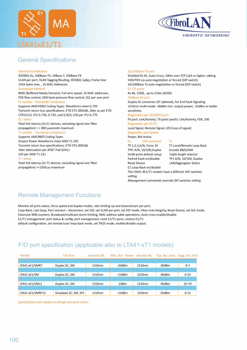
LTA41xE1/T1
General Specifications
Standard ComplianceIEEE802.3u, 100Base-TX, 10Base-T, 100Base-FXVLAN per port, VLAN Tagging/Routing, IEEE802.1p&q, Frame Size: 1916 bytes max. , 1k MAC Addresses Conversion MethodBMD (Buffered Media Domain), Full wire speed, 1k MAC addresses, FDX flow control, HDX back-pressure flow control, SLE per user portE1 section – Standards ComplianceSupports AMI/HDB3 Coding Types. Waveforms meet G.703 Transmit return loss specifications: ETSI ETS-300166, Jitter as per ETSI CTR12/13, ITU G.736, G.742, and G.823; LOS per ITU G.775 E1 –delayTotal link latency (2x E1 devices, excluding signal over fiber propagation) = < 800 µseconds maximumT1 section - Standards ComplianceSupports AMI/B8ZS Coding TypesOutput Power Waveforms meet ANSI T1.102Transmit return loss specifications: ETSI ETS-300166Jitter attenuation per AT&T Pub 62411LOS per ANSI T1.231T1 –delayTotal link latency (2x T1 devices, excluding signal over fiber propagation) =<1050 µs maximum
F/O port specification (applicable also to LTA41-xT1 models)
10/100Base-TX portShielded RJ-45, Auto-Cross; 100m over STP Cat5 or higher cablingHDX/FDX via auto-negotiation or forced (DIP switch)10/100Base-Tx auto-negotiation or forced (DIP switch)E1 /T1 portsRJ-48, 120, up to 210m (655ft) 100Base-FX portDuplex SC connector (ST optional), Far End Fault Signaling 1310nm multi-mode -18dBm min. output power, -32dBm or better sensitivity.Diagnostics per 10/100TX portFX port: Link/Activity; TX ports (each): Link/Activity, FDX, 100Diagnostics per E1/T1Local Signal, Remote Signal, LOS (Loss of signal)Diagnostics per System Power, MA Active E1 (DIP switches) T1TP 1,2,3,A/N, Force 10 T1 Local/Remote Loop-BackTP4: A/N, 10/100,Duplex Encode B8ZS/AMIVLAN ports default setup Cable length selectorFarEnd-Fault en/disable TP1 A/N, 10/100, DuplexReset Device LAN/Aggregator SelectE1 Loop-Back en/disable The LTA41-4E1/T1 models have a different DIP switchessettingManagement commands override DIP switches setting
Remote Management Functions
Monitor all ports status, force speed and duplex modes, rate limiting up-and downstream per port, Loop-Back, Last Gasp, Port connect – disconnect, set VID, set VLAN per port, set FEF mode, Fiber-Link Integrity, Reset Device, set SLE mode, Extensive MIB counters, Broadcast/multicast storm limiting, MAC address table operations, Auto-cross enable/disable.E1/T1 management: port status & config, port management, reset E1/T1 ports, restore E1/T1 default configuration, set remote/user loop-back mode, set TAOS mode, enable/disable output.
Model F/O Port Transmit WL Min. Out - Power Receive WL Typ. Rec. Sens. Sugg. Dis. (km)
LTA41-xE1 Duplex SC, MM 1310nm -18dBm 1310nm -32dBm 0-2 LTA41-xE1/SMR7 Duplex SC, SM 1310nm -20dBm 1310nm -30dBm 0-7 LTA41-xE1/SMR Duplex SC, SM 1310nm -16dBm 1310nm -30dBm 0-15 LTA41-xE1/SM Duplex SC, SM 1310nm -15dBm 1310nm -36dBm 0-25 LTA41-xE1/SML Duplex SC, SM 1310nm -11dBm 1310nm -36dBm 15-40 LTA41-xE1/SML2 Duplex SC, SM 1310nm -2dBm 1310nm -36dBm 25-70 LTA41-xE1/SML3 Duplex SC, SM 1550nm DFB -3dBm 1550nm -36dBm 40-100 LTA41-xE1/SMRF13 Simplwex SC, SM, SFS 1310nm -15dBm 1550nm -35dBm 0-15
Specifications are subject to change w/o prior notice
E1
T1
100
MA
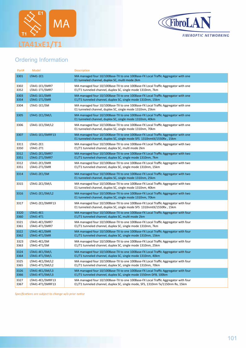
Part# Model Description
3301 LTA41-1E1 MA managed four 10/100Base-TX to one 100Base-FX Local Traffic Aggregator with one E1 tunneled channel, duplex SC, multi mode 2km
3302 LTA41-1E1/SMR7 MA managed four 10/100Base-TX to one 100Base-FX Local Traffic Aggregator with one 3352 LTA41-1T1/SMR7 E1/T1 tunneled channel, duplex SC, single mode 1310nm, 7km
3303 LTA41-1E1/SMR MA managed four 10/100Base-TX to one 100Base-FX Local Traffic Aggregator with one 3354 LTA41-1T1/SMR E1/T1 tunneled channel, duplex SC, single mode 1310nm, 15km
3304 LTA41-1E1/SM MA managed four 10/100Base-TX to one 100Base-FX Local Traffic Aggregator with one E1 tunneled channel, duplex SC, single mode 1310nm, 25km
3305 LTA41-1E1/SM/L MA managed four 10/100Base-TX to one 100Base-FX Local Traffic Aggregator with one E1 tunneled channel, duplex SC, single mode 1310nm, 40km
3306 LTA41-1E1/SM/L2 MA managed four 10/100Base-TX to one 100Base-FX Local Traffic Aggregator with one E1 tunneled channel, duplex SC, single mode 1310nm, 70km
3307 LTA41-1E1/SMRF13 MA managed four 10/100Base-TX to one 100Base-FX Local Traffic Aggregator with one E1 tunneled channel, duplex SC, single mode SFS 1310nmtX/1550Rx , 15km
3311 LTA41-2E1 MA managed four 10/100Base-TX to one 100Base-FX Local Traffic Aggregator with two 3350 LTA41-2T1 E1/T1 tunneled channel, duplex SC, multi mode 2km
3312 LTA41-2E1/SMR7 MA managed four 10/100Base-TX to one 100Base-FX Local Traffic Aggregator with two 3351 LTA41-2T1/SMR7 E1/T1 tunneled channel, duplex SC, single mode 1310nm, 7km
3312 LTA41-2E1/SMR MA managed four 10/100Base-TX to one 100Base-FX Local Traffic Aggregator with two 3351 LTA41-2T1/SMR E1/T1 tunneled channel, duplex SC, single mode 1310nm, 15km
3314 LTA41-2E1/SM MA managed four 10/100Base-TX to one 100Base-FX Local Traffic Aggregator with two E1 tunneled channel, duplex SC, single mode 1310nm, 25km
3315 LTA41-2E1/SM/L MA managed four 10/100Base-TX to one 100Base-FX Local Traffic Aggregator with two E1 tunneled channel, duplex SC, single mode 1310nm, 40km
3316 LTA41-2E1/SM/L2 MA managed four 10/100Base-TX to one 100Base-FX Local Traffic Aggregator with two E1 tunneled channel, duplex SC, single mode 1310nm, 70km
3317 LTA41-2E1/SMRF13 MA managed four 10/100Base-TX to one 100Base-FX Local Traffic Aggregator with four E1 tunneled channel, duplex SC, single mode SFS 1310nmtX/1550Rx , 15km
3320 LTA41-4E1 MA managed four 10/100Base-TX to one 100Base-FX Local Traffic Aggregator with four 3360 LTA41-4T1 E1/T1 tunneled channel, duplex SC, multi mode 2km
3321 LTA41-4E1/SMR7 MA managed four 10/100Base-TX to one 100Base-FX Local Traffic Aggregator with four 3361 LTA41-4T1/SMR7 E1/T1 tunneled channel, duplex SC, single mode 1310nm, 7km
3322 LTA41-4E1/SMR MA managed four 10/100Base-TX to one 100Base-FX Local Traffic Aggregator with four 3362 LTA41-4T1/SMR E1/T1 tunneled channel, duplex SC, single mode 1310nm, 15km
3323 LTA41-4E1/SM MA managed four 10/100Base-TX to one 100Base-FX Local Traffic Aggregator with four 3363 LTA41-4T1/SM E1/T1 tunneled channel, duplex SC, single mode 1310nm, 25km
3324 LTA41-4E1/SM/L MA managed four 10/100Base-TX to one 100Base-FX Local Traffic Aggregator with four 3364 LTA41-4T1/SM/L E1/T1 tunneled channel, duplex SC, single mode 1310nm, 40km
3325 LTA41-4E1/SM/L2 MA managed four 10/100Base-TX to one 100Base-FX Local Traffic Aggregator with four 3365 LTA41-4T1/SM/L2 E1/T1 tunneled channel, duplex SC, single mode 1310nm, 70km
3326 LTA41-4E1/SM/L3 MA managed four 10/100Base-TX to one 100Base-FX Local Traffic Aggregator with four 3366 LTA41-4T1/SM/L3 E1/T1 tunneled channel, duplex SC, single mode 1550nm DFB, 100km
3327 LTA41-4E1/SMRF13 MA managed four 10/100Base-TX to one 100Base-FX Local Traffic Aggregator with four 3367 LTA41-4T1/SMRF13 E1/T1 tunneled channel, duplex SC, single mode, SFS, 1310nm Tx/1150nm Rx, 15km
Specifications are subject to change w/o prior notice
LTA41xE1/T1
E1
T1
MA
Ordering Information
101
LTA41xE1/T1
General Specifications

102
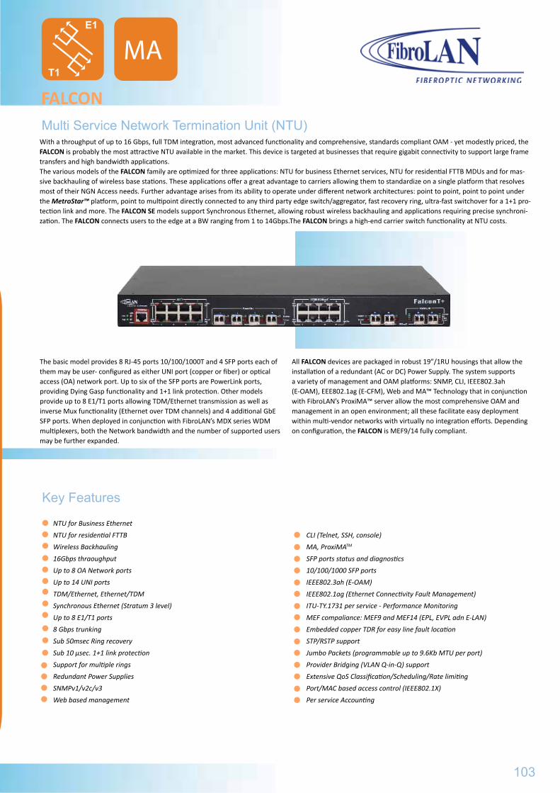
The basic model provides 8 RJ-45 ports 10/100/1000T and 4 SFP ports each of them may be user- configured as either UNI port (copper or fiber) or optical access (OA) network port. Up to six of the SFP ports are PowerLink ports, providing Dying Gasp functionality and 1+1 link protection. Other models provide up to 8 E1/T1 ports allowing TDM/Ethernet transmission as well as inverse Mux functionality (Ethernet over TDM channels) and 4 additional GbE SFP ports. When deployed in conjunction with FibroLAN’s MDX series WDM multiplexers, both the Network bandwidth and the number of supported users may be further expanded.
All FALCON devices are packaged in robust 19”/1RU housings that allow the installation of a redundant (AC or DC) Power Supply. The system supports a variety of management and OAM platforms: SNMP, CLI, IEEE802.3ah (E-OAM), EEE802.1ag (E-CFM), Web and MA™ Technology that in conjunction with FibroLAN’s ProxiMA™ server allow the most comprehensive OAM and management in an open environment; all these facilitate easy deployment within multi-vendor networks with virtually no integration efforts. Depending on configuration, the FALCON is MEF9/14 fully compliant.
Multi Service Network Termination Unit (NTU)
FALCON
Key Features
NTU for Business Ethernet
NTU for residential FTTB
Wireless Backhauling
16Gbps thraoughput
Up to 8 OA Network ports
Up to 14 UNI ports
TDM/Ethernet, Ethernet/TDM
Synchronous Ethernet (Stratum 3 level)
Up to 8 E1/T1 ports
8 Gbps trunking
Sub 50msec Ring recovery
Sub 10 μsec. 1+1 link protection
Support for multiple rings
Redundant Power Supplies
SNMPv1/v2c/v3
Web based management
CLI (Telnet, SSH, console)
MA, ProxiMATM
SFP ports status and diagnostics
10/100/1000 SFP ports
IEEE802.3ah (E-OAM)
IEEE802.1ag (Ethernet Connectivity Fault Management)
ITU-TY.1731 per service - Performance Monitoring
MEF compaliance: MEF9 and MEF14 (EPL, EVPL adn E-LAN)
Embedded copper TDR for easy line fault location
STP/RSTP support
Jumbo Packets (programmable up to 9.6Kb MTU per port)
Provider Bridging (VLAN Q-in-Q) support
Extensive QoS Classification/Scheduling/Rate limiting
Port/MAC based access control (IEEE802.1X)
Per service Accounting
103
MA
With a throughput of up to 16 Gbps, full TDM integration, most advanced functionality and comprehensive, standards compliant OAM - yet modestly priced, the FALCON is probably the most attractive NTU available in the market. This device is targeted at businesses that require gigabit connectivity to support large frame transfers and high bandwidth applications.The various models of the FALCON family are optimized for three applications: NTU for business Ethernet services, NTU for residential FTTB MDUs and for mas-sive backhauling of wireless base stations. These applications offer a great advantage to carriers allowing them to standardize on a single platform that resolves most of their NGN Access needs. Further advantage arises from its ability to operate under different network architectures: point to point, point to point under the MetroStar™ platform, point to multipoint directly connected to any third party edge switch/aggregator, fast recovery ring, ultra-fast switchover for a 1+1 pro-tection link and more. The FALCON SE models support Synchronous Ethernet, allowing robust wireless backhauling and applications requiring precise synchroni-zation. The FALCON connects users to the edge at a BW ranging from 1 to 14Gbps.The FALCON brings a high-end carrier switch functionality at NTU costs.
E1
T1
IEEE802.3z/ab, 10/100/1000TX, 100Base-SX, 1000Base-LX, 100 Base-ZX, single Fiber strand
IGMP snooping
Port mirroring
Spanning Tree: STP, RSTP, sub 50msec ring recovery
Loop-Back: port based (per port) and ACL based (per flow)
Remote Device Temperature reading, overheat alarm
S/W and F/W remote upgrade: support for future standards and tailored applications
Dying Gasp (802.3ah or SNMP trap)
Alarms: user definable filters
Cascading, non p-t-p features maintained
SFP ports (4 or 8)Copper 10/100/1000Fiber 100/1000 MM, SM, SFS, WDM transceiversSimplex and Duplex LC connectorsT1 Standard ComplianceAMI/B8ZS CodingOutput Power Waveforms meets ANSI T1.102Jitter as per AT&T Pub 62411, ITU G.824LOS per ANSI T1.231 Diagnostic LEDs-SFPLink/Act ON = Link Blinking=activityTx Low ON = Tx power lowBlinking = not a FibroLAN SFPIn-Use (Uplink ports) On/Off= port in use/not in use(relevant in 1+1 redundancy mode)MA(Uplink ports) ON= MA active (In-band management)
IEEE802.3ah, IEEE802.1ag MTU: from 1522 to 9600 bytes, user settableVLAN: per IEEE802.1q, 4K entries, private VLANQ-in-Q: per IEEE802.1adPriority: per IEEE802.1p, 5 ingress queue, 5 egress queuesAddress table: 8K MAC addresses per port adjustable agingRate Limiting: single and dual leaky bucket (TrTCM) (ingress/egress) policing and shapingQoS: QCL for flexible wire-speed QoS classification based on all L2, L3 and L4 informationStorm Control: Unicast, Broadcast, Muticast rate limitationLink Aggregation: user definable groups, up to 8 ports each1+1 Link protection (PowerLink ports): 10 μsec SwitchoverComprehensive SFP diagnostics
The FALCON can be remotely managed via a variety of mechanisms/platforms at virtually no integration efforts:
IP Based (in-band): SNMP (v1/v2/v3), Telnet, SSH, Web (HTTP).Console: RJ-45, RS-232 (9600Bd) - CLI (Cisco like).ProxiMA: allows an MA like feature rich management for thousands of NUTs disregarding third party devices or topology – maximal performance at full flexibility.OAM/MA: when connected via FibroLAN’s MetroStarTM MAC at the edge.OAM/IEEE802.3ah: when connected to third party edge switch that support the standard.Other Standards: NPT, Syslog, Radius, DHCP, IGMP, LACP, LLDP.
Management
Technical Specifications
FALCONSystem Features and Standard Compliance
10/100/1000Base-TX ports (8)Shields RJ-45, 100m over STP 5/6 cable, Auto-Negotiation and Auto-Cross, Copper TDR. Per port configuration: speed, Duplex, A/N, Flow-Control, MTUE1/T1ports (8)RJ45/48 connectors, 120Ω/100Ω respectively E1 Standard ComplianceAMI/HDB3 Coding TypeG.703 compliance Transmit return loss specifications-ETSI ETS-300166Jitter as per ETSI CTR12/13, ITU G.736 and G.823LOS per ITU G.775Diagnostic LEDsSystem: PS1, PS2, CPU Status, System AlarmCopper port: Link/Act, speed (10/100/1000)E1/T1 LEDs: Signal (present /AIS), LOS (LOS, Remote LOS)Signal= ON: signal present; blinking=AIS signal receivedLOS ON= Loss of local signal; Blinking RLOS= Loss of remote signal
Environmental/PhysicalPower Plant: Internal, 100 - 240VAC, 50 - 60Hz or –36 to –72VDC Power Supplies, hot swappable, integrated cooling fan, Optional redundant PSU (Load Sharing Operation)Operating Temperature: -10 to 50ºCHumidity: 10% to 90% non-condensingSafety: ICE EN60950-1: 2005 cTUVusPower Consumption: up to 40W
EMC:EN 300 386 V1.3.3; 05, AS/NZS CISPR22:06,FCC CFR 47 part 15, Subpart B, Class AStorage Temperature: -20°÷+80°CWeight: ~3,5Kg with 2 Power SuppliesDimensions: 244x44x440mm (WxHxD)Installation: 19” Rack Mountable, 1U, brackets included
104
MAE1
T1
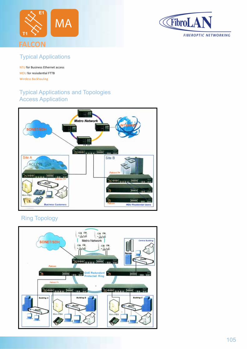
NTU for Business Ethernet access
MDU for resisdential FTTB
Wireless Backhauling
Typical Applications and TopologiesAccess Application
FALCONTypical Applications
Ring Topology
IEEE802.3z/ab, 10/100/1000TX, 100Base-SX, 1000Base-LX, 100 Base-ZX, single Fiber strand
IGMP snooping
Port mirroring
Spanning Tree: STP, RSTP, sub 50msec ring recovery
Loop-Back: port based (per port) and ACL based (per flow)
Remote Device Temperature reading, overheat alarm
S/W and F/W remote upgrade: support for future standards and tailored applications
Dying Gasp (802.3ah or SNMP trap)
Alarms: user definable filters
Cascading, non p-t-p features maintained
SFP ports (4 or 8)Copper 10/100/1000Fiber 100/1000 MM, SM, SFS, WDM transceiversSimplex and Duplex LC connectorsT1 Standard ComplianceAMI/B8ZS CodingOutput Power Waveforms meets ANSI T1.102Jitter as per AT&T Pub 62411, ITU G.824LOS per ANSI T1.231 Diagnostic LEDs-SFPLink/Act ON = Link Blinking=activityTx Low ON = Tx power lowBlinking = not a FibroLAN SFPIn-Use (Uplink ports) On/Off= port in use/not in use(relevant in 1+1 redundancy mode)MA(Uplink ports) ON= MA active (In-band management)
105
MAE1
T1
FALCON
Power Plant: Internal, 100 - 240VAC, 50 - 60Hz or –36 to –72VDC Power Supplies, hot swappable, integrated cooling fan, Optional redundant PSU (Load Sharing Operation)Operating Temperature: -10 to 50ºCHumidity: 10% to 90% non-condensingSafety: ICE EN60950-1: 2005 cTUVusPower Consumption: up to 40W
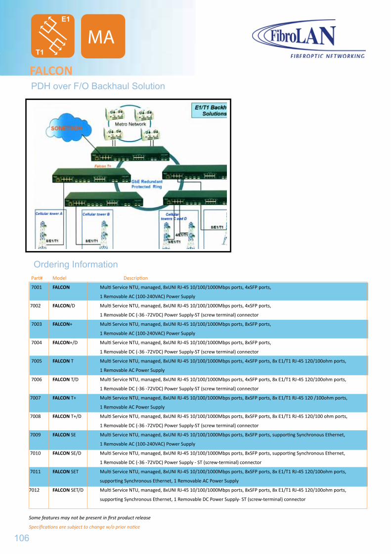
FALCONPDH over F/O Backhaul Solution
Ordering Information
106
MA
Part# Model Description
7001 FALCON Multi Service NTU, managed, 8xUNI RJ-45 10/100/1000Mbps ports, 4xSFP ports,
1 Removable AC (100-240VAC) Power Supply
7002 FALCON/D Multi Service NTU, managed, 8xUNI RJ-45 10/100/1000Mbps ports, 4xSFP ports,
1 Removable DC (-36 -72VDC) Power Supply-ST (screw terminal) connector
7003 FALCON+ Multi Service NTU, managed, 8xUNI RJ-45 10/100/1000Mbps ports, 8xSFP ports,
1 Removable AC (100-240VAC) Power Supply
7004 FALCON+/D Multi Service NTU, managed, 8xUNI RJ-45 10/100/1000Mbps ports, 8xSFP ports,
1 Removable DC (-36 -72VDC) Power Supply-ST (screw terminal) connector
7005 FALCON T Multi Service NTU, managed, 8xUNI RJ-45 10/100/1000Mbps ports, 4xSFP ports, 8x E1/T1 RJ-45 120/100ohm ports,
1 Removable AC Power Supply
7006 FALCON T/D Multi Service NTU, managed, 8xUNI RJ-45 10/100/1000Mbps ports, 4xSFP ports, 8x E1/T1 RJ-45 120/100ohm ports,
1 Removable DC (-36 -72VDC) Power Supply-ST (screw terminal) connector
7007 FALCON T+ Multi Service NTU, managed, 8xUNI RJ-45 10/100/1000Mbps ports, 8xSFP ports, 8x E1/T1 RJ-45 120 /100ohm ports,
1 Removable AC Power Supply
7008 FALCON T+/D Multi Service NTU, managed, 8xUNI RJ-45 10/100/1000Mbps ports, 8xSFP ports, 8x E1/T1 RJ-45 120/100 ohm ports,
1 Removable DC (-36 -72VDC) Power Supply-ST (screw terminal) connector
7009 FALCON SE Multi Service NTU, managed, 8xUNI RJ-45 10/100/1000Mbps ports, 8xSFP ports, supporting Synchronous Ethernet,
1 Removable AC (100-240VAC) Power Supply
7010 FALCON SE/D Multi Service NTU, managed, 8xUNI RJ-45 10/100/1000Mbps ports, 8xSFP ports, supporting Synchronous Ethernet,
1 Removable DC (-36 -72VDC) Power Supply - ST (screw-terminal) connector
7011 FALCON SET Multi Service NTU, managed, 8xUNI RJ-45 10/100/1000Mbps ports, 8xSFP ports, 8x E1/T1 RJ-45 120/100ohm ports,
supporting Synchronous Ethernet, 1 Removable AC Power Supply
7012 FALCON SET/D Multi Service NTU, managed, 8xUNI RJ-45 10/100/1000Mbps ports, 8xSFP ports, 8x E1/T1 RJ-45 120/100ohm ports,
supporting Synchronous Ethernet, 1 Removable DC Power Supply- ST (screw-terminal) connector
Some features may not be present in first product release
Specifications are subject to change w/o prior notice
E1
T1
...ANY - TO - ANY REDUNDANT LINK ACCESS DEVICE
ATARA
Fast Ethernet
ATARA100........................................ATARA100M.....................................
Gigabit Ethernet
ATARA1000......................................ATARA1000M...................................
107
109 111
113115
FALCON
Part# Model Description
7001 FALCON Multi Service NTU, managed, 8xUNI RJ-45 10/100/1000Mbps ports, 4xSFP ports,
1 Removable AC (100-240VAC) Power Supply
7002 FALCON/D Multi Service NTU, managed, 8xUNI RJ-45 10/100/1000Mbps ports, 4xSFP ports,
1 Removable DC (-36 -72VDC) Power Supply-ST (screw terminal) connector
7003 FALCON+ Multi Service NTU, managed, 8xUNI RJ-45 10/100/1000Mbps ports, 8xSFP ports,
1 Removable AC (100-240VAC) Power Supply
7004 FALCON+/D Multi Service NTU, managed, 8xUNI RJ-45 10/100/1000Mbps ports, 8xSFP ports,
1 Removable DC (-36 -72VDC) Power Supply-ST (screw terminal) connector
7005 FALCON T Multi Service NTU, managed, 8xUNI RJ-45 10/100/1000Mbps ports, 4xSFP ports, 8x E1/T1 RJ-45 120/100ohm ports,
1 Removable AC Power Supply
7006 FALCON T/D Multi Service NTU, managed, 8xUNI RJ-45 10/100/1000Mbps ports, 4xSFP ports, 8x E1/T1 RJ-45 120/100ohm ports,
1 Removable DC (-36 -72VDC) Power Supply-ST (screw terminal) connector
7007 FALCON T+ Multi Service NTU, managed, 8xUNI RJ-45 10/100/1000Mbps ports, 8xSFP ports, 8x E1/T1 RJ-45 120 /100ohm ports,
1 Removable AC Power Supply
7008 FALCON T+/D Multi Service NTU, managed, 8xUNI RJ-45 10/100/1000Mbps ports, 8xSFP ports, 8x E1/T1 RJ-45 120/100 ohm ports,
1 Removable DC (-36 -72VDC) Power Supply-ST (screw terminal) connector
7009 FALCON SE Multi Service NTU, managed, 8xUNI RJ-45 10/100/1000Mbps ports, 8xSFP ports, supporting Synchronous Ethernet,
1 Removable AC (100-240VAC) Power Supply
7010 FALCON SE/D Multi Service NTU, managed, 8xUNI RJ-45 10/100/1000Mbps ports, 8xSFP ports, supporting Synchronous Ethernet,
1 Removable DC (-36 -72VDC) Power Supply - ST (screw-terminal) connector
7011 FALCON SET Multi Service NTU, managed, 8xUNI RJ-45 10/100/1000Mbps ports, 8xSFP ports, 8x E1/T1 RJ-45 120/100ohm ports,
supporting Synchronous Ethernet, 1 Removable AC Power Supply
7012 FALCON SET/D Multi Service NTU, managed, 8xUNI RJ-45 10/100/1000Mbps ports, 8xSFP ports, 8x E1/T1 RJ-45 120/100ohm ports,
supporting Synchronous Ethernet, 1 Removable DC Power Supply- ST (screw-terminal) connector
Some features may not be present in first product release
Specifications are subject to change w/o prior notice

108
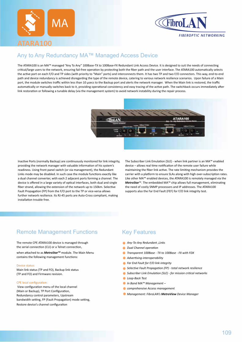
Inactive Ports (normally Backup) are continuously monitored for link integrity, providing the network manager with valuable information of his system’s readiness. Using front panel switch (or via management), the Redundant Links mode may be disabled. In such case the module functions exactly like a dual channel converter, with each 2 adjacent ports forming a channel. The device is offered in a large variety of optical interfaces, both dual and single fiber strand, allowing the extension of the network up to 150km. Selective Fault Propagation (FP) from the F/O port to the TP or vice-versa allows further network resilience. Its RJ-45 ports are Auto-Cross compliant, making installation trouble free.
The Subscriber Link Emulation (SLE) - when link partner is an MA™ enabled device – allows real time notification of the remote user failure while maintaining the fiber link active. The rate limiting mechanism provides the carrier with a platform to ensure SLAs along with high over-subscription rates. Like other MA™ enabled devices, the ATARA100 is remotely managed via the MetroStar™. The embedded MA™ chip allows full management, eliminating the need of costly SNMP processors and IP addresses. The ATARA100 supports also the Far End Fault (FEF) for F/O link integrity test.
The remote CPE ATARA100 device is managed through the serial connection (CLI) or a Telnet connection,
when attached to as MetroStarTM module. The Main Menu contains the following management functions:
Device status: Main link status (TP and FO), Backup link status (TP and FO) and Firmware revision.
CPE local configuration: View configuration menu of the local channel (Main or Backup), TP Port Configuration,Redundancy control parameters, Upstream bandwidth setting, FP (Fault Propagation) mode setting,
Restore device’s channel configuration
Any to Any Redundancy MA™ Managed Access Device
ATARA100
Remote Management Functions Key Features
Any-To-Any Redundant ‚Links
Dual Channel operation
Transparent 100Base - TX to 100Base - FX with FDX
Advertising-interoperability
Far End Fault for F/O link integrity
Selective Fault Propagation (FP) - total network resilience
Subscriber Link Emulation (SLE) - for mission critical networks
Loop-Back Test
In Band MA™ Management –
comprehensive Access management
Management: FibroLAN’s MetroView Device Manager
The ATARA100 is an MA™ managed “Any To Any” 100Base-TX to 100Base-FX Redundant Link Access Device. It is designed to suit the needs of connecting critical/large users to the network, ensuring fail-free operation by protecting both the fiber path and the user interface. The ATARA100 automatically selects the active port on each F/O and TP sides (with priority to “Main” ports) and interconnects them. It has two TP and two F/O connectors. This way, end-to-end path and device redundancy is achieved disregarding the type of the remote device, catering to various network resilience scenarios. Upon failure of a Main port, the module switches traffic within less than 10 μsecs to the Backup port and alerts the network manager. When the Main link is restored, the traffic automatically or manually switches back to it, providing operational consistency and easy tracing of the active path. The switchback occurs immediately after link restoration or following a tunable delay (via the management system) to avoid network instability during the repair process.
109
MA
ATARA100
General Specifications
Environmental/Physical
Power SupplyInternal, 100 ÷ 240VAC, 50 ÷ 60Hz, -36 ÷ -72VDC (optional PS48)Operating Temperature0º ÷ 45ºC, ETR = -10º ÷ +70ºC optionalHumidity10% ÷ 90% non-condensingSafetydesigned to meet: EN 60950EMCdesigned to meet: FCC part 15, Subpart B Class A,
Directive 89/366/EEC
Power Consumption 5W max.Storage Temperature-20ºC ÷ + 80ºC Weight600gDimensions223x44x150mm (WxHxD)Installation modes
Desk-top, wall-mount, half rack, 19” shelf
Standard CompilanceIEEE802.3u, 100Base-TX, 100Base-FX100Base-TX ports (x2)Shielded RJ-45, Auto-cross, auto-polarity100m over STP Cat5 or higher cabling Preset to 100Base-TX and FDXMain to Backup switchover – 10 μsec. maxDiagnostic LEDsMain: F/O-Link/activity, In-Use, MA Backup: F/O - Link/activity, In-Use, MA Main: TP-Link/activity, In-Use Backup: TP-Link/activity,In-Use PowerLocal ManagementFibroLAN MA™ Technology
Conversion MethodLayer 1, between any FX to any TX port100Base-FX ports (x2)Dual Duplex SC connectors (ST optional) Far End Fault Signaling and Loop-Back test 1310nm multi-mode -18dBm min. output power, -32dBm or better sensitivity. For SM and SFS versions see FibroLAN Datasheet DS-SMBackup to Main switchback tunable to 0/5/10/20 sec, or manually controlledControls (DIP switches)Mode (Redundant Links/Dual Channel Converter) FO>>TP Fault propagation ON/OFF. TP>>FO Fault propagation ON/OFF(for Main and Backup channels)Management FibroLAN MetroView Device Manager
Ordering Information
Part# Model Description
3900 ATARA 100 100TX to 100FX Redundant Link Access Device, MM, 2km 1310nm, 2*Duplex SC,MA™ managed
3901 ATARA100/SMR7 100TX to 100FX Redundant Link Access Device, SM 7km 1310nm, 2*Duplex SC, MA™ managed
3902 ATARA 100/SMR 100TX to 100FX Redundant Link Access Device, SM 15km 1310nm, 2*Duplex SC, MA™ managed
3904 ATARA 100/SM 100TX to 100FX Redundant Link Access Device, SM 25km 1310nm, 2*Duplex SC, MA™ managed
3902 ATARA 100/SM/L 100TX to 100FX Redundant Link Access Device, SM 40km 1310nm, 2*Duplex SC, MA™ managed
3905 ATARA 100/SM/L/2 100TX to 100FX Redundant Link Access Device, SM 70km 1310nm, 2*Duplex SC, MA™ managed
3906 ATARA 100/SM/L/3 100TX to 100FX Redundant Link Access Device, SM 100km 1550nm, DFB, 2*Duplex SC, MA™ managed
3907 ATARA 100/SMRF13 100TX to 100FX Redundant Link Access Device, SM, Single Fiber Strand, 15km 1310nm Transmit/ 1550nm Receive, 2* simplex SC, MA™ managed
B097 PS48 -36÷-72VDC power supply (instead of the 100÷240VAC, 50÷60Hz PS)
B151 CBPS-DC48V DC Power Supply cable for PS48, 2m
B098 ETR Extended Temperature Range option (-10ºC ÷ +70ºC)
B160 RM2 19” Rack shelf for installation of up to two ATARA100 devices
B218 MBR Set (pair) of rack-mounting brackets
Specifications are subject to change w/o prior notice
110
MA
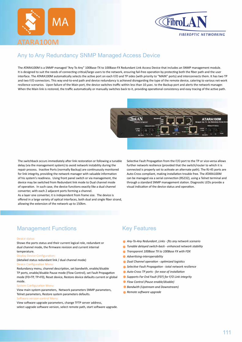
The switchback occurs immediately after link restoration or following a tunable delay (via the management system) to avoid network instability during the repair process. Inactive Ports (normally Backup) are continuously monitored for link integrity, providing the network manager with valuable information of his system’s readiness. Using front panel switch or via management, the device may be switched from Redundant link mode to Dual channel mode of operation. In such case, the device functions exactly like a dual channel converter, with each 2 adjacent ports forming a channel. As a layer one converter, it is independent from frame size. The device is offered in a large variety of optical interfaces, both dual and single fiber strand, allowing the extension of the network up to 150km.
Selective Fault Propagation from the F/O port to the TP or vice-versa allows further network resilience (provided that the switch/router to which it is connected is properly set to activate an alternate path). The RJ-45 ports are Auto-Cross compliant, making installation trouble free. The ATARA100M can be managed via a serial connection (RS232), using a Telnet terminal and through a standard SNMP management station. Diagnostic LEDs provide a visual indication of the device status and operation.
Key Features
Any-To-Any Redundant ‚Links - fits any network scenario
Tunable delayed switch-back - enhanced network stability
Transparent 100Base TX to 100Base FX with FDX
Advertising-interoperability
Dual Channel operation - optimized logistics
Selective Fault Propagation - total network resilience
Auto-Cross TP ports - for ease of installation
Supports Far End Fault (FEF) for F/O Link integrity
Flow Control (Pause enable/disable)
Bandwith (Upstream and Downstream)
Remote software upgrade
Any to Any Redundancy SNMP Managed Access Device
ATARA100M
Management FunctionsDevice status: Shows the ports status and their current logical role, redundant or dual channel mode, the firmware revision and current internal temperature. Display Device Configuration: (detailed status redundant link / dual channel mode)Device Configuration Menu: Redundancy menu, channel description, set bandwith, enable/disable TP ports, enable/disable Pause mode (Flow Control), set Fault Propagation mode (F0>TP, TP>F0), Reset device, Restore device defaults current or global mode.System Configuration Menu: View main system parameters, Network parameters SNMP parameters, Telnet parameters, Restore system parameters defaults.Software version control Menu: View software upgrade parameters, change TFTP server address, select upgrade software version, select remote path, start software upgrade.
The ATARA100M is a SNMP managed “Any To Any” 100Base-TX to 100Base-FX Redundant Link Access Device that includes an SNMP management module. It is designed to suit the needs of connecting critical/large users to the network, ensuring fail-free operation by protecting both the fiber path and the user interface. The ATARA100M automatically selects the active port on each F/O and TP sides (with priority to “MAIN” ports) and interconnects them. It has two TP and two F/O connectors. This way end-to-end path and device redundancy is achieved disregarding the type of the remote device, catering to various net-work resilience scenarios. Upon failure of the Main port, the device switches traffic within less than 10 μsec. to the Backup port and alerts the network manager. When the Main link is restored, the traffic automatically or manually switches back to it, providing operational consistency and easy tracing of the active path.
111
MA
ATARA100
General Specifications
Part# Model Description
3900 ATARA 100 100TX to 100FX Redundant Link Access Device, MM, 2km 1310nm, 2*Duplex SC,MA™ managed
3901 ATARA100/SMR7 100TX to 100FX Redundant Link Access Device, SM 7km 1310nm, 2*Duplex SC, MA™ managed
3902 ATARA 100/SMR 100TX to 100FX Redundant Link Access Device, SM 15km 1310nm, 2*Duplex SC, MA™ managed
3904 ATARA 100/SM 100TX to 100FX Redundant Link Access Device, SM 25km 1310nm, 2*Duplex SC, MA™ managed
3902 ATARA 100/SM/L 100TX to 100FX Redundant Link Access Device, SM 40km 1310nm, 2*Duplex SC, MA™ managed
3905 ATARA 100/SM/L/2 100TX to 100FX Redundant Link Access Device, SM 70km 1310nm, 2*Duplex SC, MA™ managed
3906 ATARA 100/SM/L/3 100TX to 100FX Redundant Link Access Device, SM 100km 1550nm, DFB, 2*Duplex SC, MA™ managed
3907 ATARA 100/SMRF13 100TX to 100FX Redundant Link Access Device, SM, Single Fiber Strand, 15km 1310nm Transmit/ 1550nm Receive, 2* simplex SC, MA™ managed
B097 PS48 -36÷-72VDC power supply (instead of the 100÷240VAC, 50÷60Hz PS)
B151 CBPS-DC48V DC Power Supply cable for PS48, 2m
B098 ETR Extended Temperature Range option (-10ºC ÷ +70ºC)
B160 RM2 19” Rack shelf for installation of up to two ATARA100 devices
B218 MBR Set (pair) of rack-mounting brackets
Specifications are subject to change w/o prior notice
ATARA100MGeneral Specifications
Environmental/Physical
Power SupplyInternal, 100 ÷ 240VAC, 50 ÷ 60Hz-36 ÷ -72VDC optional Operating Temperature0º ÷ 45ºC, ETR = -10º ÷ +70ºC optionalHumidity10% ÷ 90% non-condensingSafetydesigned to meet: EN 60950EMCdesigned to meet: FCC part 15, Subpart B Class A, Directive 89/366/EEC
Power Consumption5W max.Storage Temperature-20º ÷ +80ºC Weight650gDimensions223x44x150mm (WxHxD)Installation modes
Desk-top, wall-mount, half rack, 19” shelf
Standard CompilanceIEEE802.3u, 100Base-TX, 100Base-FX100Base-TX ports (x2)Shielded RJ-45, Auto-cross, auto-polarity100m over STP Cat5 or higher cablingPreset to 100Base-TX and FDXMain to Backup switchover <10 μsec. maxManagementSNMP, Telnet, CLI (RS232)Diagnostic LEDsMain: F/O-Link/activity, In-Use, MABackup: F/O-Link/activity, In-Use, MA(MA Active LED not in use)Main: TP-Link/activity, In-UseBackup: TP-Link/activity, In-UsePower LED
Conversion MethodLayer 1, between any F/O to any TP port100Base-FX ports (x2)Dual Duplex SC connectors (ST optional)Far End Fault SignalingFlow Control Backup to Main switchover tunable to 0/5/10/20 sec, or manually controlledFrontal panel ManagementPorts: 2x RJ45 10Base-T, RS232 (mini - Din)LEDs: RDY, RCV, LinkControls (DIP switches)Redundant Links/Dual Channel modeFO>>TP Fault propagation ON/OFF
TP>>FO Fault propagation ON/OFF
Ordering Information
Part# Model Description
3908 ATARA 100M 100Base-TX to 100Base-FX Redundant Link Access Device, MM 2km 1310nm, 2*Duplex SC,SNMP managed
3909 ATARA100M/SMR7 100Base-TX to 100Base-FX Redundant Link Access Device, SM 7km 1310nm, 2*Duplex SC,SNMP managed
3910 ATARA 100M/SMR 100Base-TX to 100Base-FX Redundant Link Access Device, SM 15km 1310nm, 2*Duplex SC,SNMP managed
3911 ATARA 100M/SM 100Base-TX to 100Base-FX Redundant Link Access Device, SM 25km 1310nm, 2*Duplex SC,SNMP managed
3912 ATARA 100M/SM/L 100Base-TX to 100Base-FX Redundant Link Access Device, SM 40km 1310nm, 2*Duplex SC,SNMP managed
3913 ATARA 100M/SM/L/2 100Base-TX to 100Base-FX Redundant Link Access Device, SM 70km 1310nm, 2*Duplex SC,SNMP managed
3914 ATARA 100M/SM/L/3 100Base-TX to 100Base-FX Redundant Link Access Device, SM 100km 1550nm, DFB, 2*Duplex SC, SNMP managed
3915 ATARA 100M/SMRF13 100Base-TX to 100Base-FX Redundant Link Access Device, SM 15km 1310nm Transmit/ 1550nm Receive, 2* simplex SC, SNMP managed
B097 PS48 -36÷-72VDC power supply (instead of the 100÷240VAC, 50÷60Hz PS)
B098 ETR Extended Temperature Range option (-10ºC ÷ +70ºC)
B151 CBPS-DC48V DC Power Supply cable for PS48, 2m
B160 RM2 19” Rack shelf for installation of up to two ATARA100 devices
B218 MBR Set (pair) of rack-mounting brackets
Specifications are subject to change w/o prior notice
112
MA
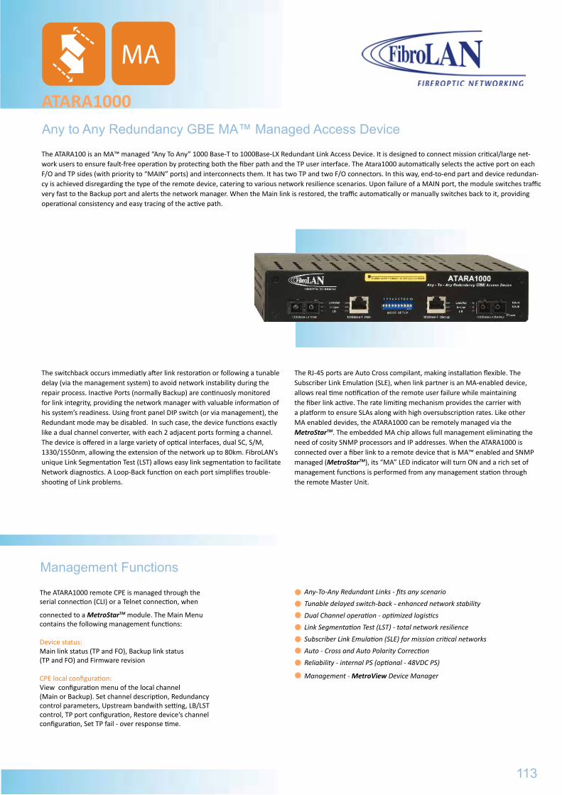
The switchback occurs immediatly after link restoration or following a tunable delay (via the management system) to avoid network instability during the repair process. Inactive Ports (normally Backup) are continuosly monitored for link integrity, providing the network manager with valuable information of his system’s readiness. Using front panel DIP switch (or via management), the Redundant mode may be disabled. In such case, the device functions exactly like a dual channel converter, with each 2 adjacent ports forming a channel. The device is offered in a large variety of optical interfaces, dual SC, S/M, 1330/1550nm, allowing the extension of the network up to 80km. FibroLAN’s unique Link Segmentation Test (LST) allows easy link segmentation to facilitate Network diagnostics. A Loop-Back function on each port simplifies trouble-shooting of Link problems.
The RJ-45 ports are Auto Cross compilant, making installation flexible. The Subscriber Link Emulation (SLE), when link partner is an MA-enabled device, allows real time notification of the remote user failure while maintaining the fiber link active. The rate limiting mechanism provides the carrier with a platform to ensure SLAs along with high oversubscription rates. Like other MA enabled devides, the ATARA1000 can be remotely managed via the MetroStarTM. The embedded MA chip allows full management eliminating the need of cosity SNMP processors and IP addresses. When the ATARA1000 is connected over a fiber link to a remote device that is MA™ enabled and SNMP managed (MetroStarTM), its “MA” LED indicator will turn ON and a rich set of management functions is performed from any management station through the remote Master Unit.
The ATARA1000 remote CPE is managed through the serial connection (CLI) or a Telnet connection, when
connected to a MetroStarTM module. The Main Menu contains the following management functions:
Device status:Main link status (TP and FO), Backup link status (TP and FO) and Firmware revision
CPE local configuration:View configuration menu of the local channel (Main or Backup). Set channel description, Redundancy control parameters, Upstream bandwith setting, LB/LST control, TP port configuration, Restore device‘s channel configuration, Set TP fail - over response time.
Any to Any Redundancy GBE MA™ Managed Access Device
ATARA1000
Management Functions
Any-To-Any Redundant Links - fits any scenario
Tunable delayed switch-back - enhanced network stability
Dual Channel operation - optimized logistics
Link Segmentation Test (LST) - total network resilience
Subscriber Link Emulation (SLE) for mission critical networks
Auto - Cross and Auto Polarity Correction
Reliability - internal PS (optional - 48VDC PS)
Management - MetroView Device Manager
The ATARA100 is an MA™ managed “Any To Any” 1000 Base-T to 1000Base-LX Redundant Link Access Device. It is designed to connect mission critical/large net-work users to ensure fault-free operation by protecting both the fiber path and the TP user interface. The Atara1000 automatically selects the active port on each F/O and TP sides (with priority to “MAIN” ports) and interconnects them. It has two TP and two F/O connectors. In this way, end-to-end part and device redundan-cy is achieved disregarding the type of the remote device, catering to various network resilience scenarios. Upon failure of a MAIN port, the module switches traffic very fast to the Backup port and alerts the network manager. When the Main link is restored, the traffic automatically or manually switches back to it, providing operational consistency and easy tracing of the active path.
113
MA
ATARA100MGeneral Specifications
Part# Model Description
3908 ATARA 100M 100Base-TX to 100Base-FX Redundant Link Access Device, MM 2km 1310nm, 2*Duplex SC,SNMP managed
3909 ATARA100M/SMR7 100Base-TX to 100Base-FX Redundant Link Access Device, SM 7km 1310nm, 2*Duplex SC,SNMP managed
3910 ATARA 100M/SMR 100Base-TX to 100Base-FX Redundant Link Access Device, SM 15km 1310nm, 2*Duplex SC,SNMP managed
3911 ATARA 100M/SM 100Base-TX to 100Base-FX Redundant Link Access Device, SM 25km 1310nm, 2*Duplex SC,SNMP managed
3912 ATARA 100M/SM/L 100Base-TX to 100Base-FX Redundant Link Access Device, SM 40km 1310nm, 2*Duplex SC,SNMP managed
3913 ATARA 100M/SM/L/2 100Base-TX to 100Base-FX Redundant Link Access Device, SM 70km 1310nm, 2*Duplex SC,SNMP managed
3914 ATARA 100M/SM/L/3 100Base-TX to 100Base-FX Redundant Link Access Device, SM 100km 1550nm, DFB, 2*Duplex SC, SNMP managed
3915 ATARA 100M/SMRF13 100Base-TX to 100Base-FX Redundant Link Access Device, SM 15km 1310nm Transmit/ 1550nm Receive, 2* simplex SC, SNMP managed
B097 PS48 -36÷-72VDC power supply (instead of the 100÷240VAC, 50÷60Hz PS)
B098 ETR Extended Temperature Range option (-10ºC ÷ +70ºC)
B151 CBPS-DC48V DC Power Supply cable for PS48, 2m
B160 RM2 19” Rack shelf for installation of up to two ATARA100 devices
B218 MBR Set (pair) of rack-mounting brackets
Specifications are subject to change w/o prior notice
Key Features
ATARA1000General Specifications
Environmental/Physical
Power SupplyInternal, 100 ÷ 240VAC, 50 ÷ 60Hz-36 ÷ -72VDC optional (PS48)Operating Temperature0º ÷ 45ºC, ETR = -10º ÷ +70ºC optionalHumidity10% ÷ 90% non-condensingSafetydesigned to meet: EN 60950EMCFCC part 15, Subpart A Class A, EN 300 386 V1.3.3
Power Consumption 5W max.Storage Temperature-20º÷+80ºC Weight600gDimensions223x44x150mm (WxHxD)Installation modesDesk-top, wall-mount, 19” Rack shelf
Standard CompilanceIEEE802.3 2000 edition1000Base-T, 1000Base-LX, IEEE802.3z, IEEE802.3ab100Base-T ports (x2)Shielded RJ-45, auto-polarity correction Automatic MDI/MDIX Crossover100m over Cat6 STP cablingMain to Backup switchover <10 μsec.Diagnostic LEDsF/O - Link/activity, Port in-Use, LB (Loop Back)TP- Link/activity, Port in-Use, LB (Loop Back)Power, MA-M, MA-B (Main and Backup MA indicators)Management
MetroView device Manager
Conversion MethodLayer 1, between any Fiber to any TP port100Base-LX ports (x2)Dual Duplex SC connectorsFor SM and SFS (Single Fiber Strand) F/O specifications, refer to Fibro-LAN Data Sheet (DS-FO)Backup to Main switchback – tunable to 0/5/10/20 sec, or manually via managementControls (DIP switches)Mode (Redundant Links/Dual Channel Converter)LST ON/OFFLoop-Back ON/OFFLocal ManagementFibroLAN MA™ (Micro Agent) Technology
Ordering Information
Part# Model Description
3950 ATARA1000-LX1 1000T to 1000LX Redundant Link Access Device, SM, 10km 1310nm, 2*Duplex SC,MA™ managed
3951 ATARA1000-LX2 1000T to 1000LX Redundant Link Access Device, SM 20km 1310nm, 2*Duplex SC, MA™ managed
3952 ATARA1000-LX3 1000T to 1000LX Redundant Link Access Device, SM 40km 1550nm, DFB, 2*Duplex SC, MA™ managed
3953 ATARA1000-LX4 1000T to 1000LX Redundant Link Access Device, SM 80km 1550nm, DFB, 2*Duplex SC, MA™ managed
3958 ATARA1000-F13L 1000T to 1000LX Redundant Link Access Device, SM 40km Single Fiber Strand 1310nm, DFB Tx / 1550nm Rx, 2x Simplex SC, MA™ managed
B097 PS48 DC (-36÷-72VDC) Power Supply (instead of the AC Power Supply)
B098 ETR Extended Temperature Range option (-10ºC ÷ +70ºC)
B160 RM2 19” Rack shelf for installation of up to two ATARA1000 devices
B218 MBR Set (pair) of rack-mounting brackets
Specifications are subject to change w/o prior notice
114
MA
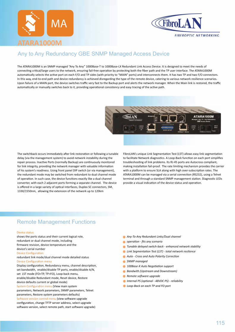
The switchback occurs immediately after link restoration or following a tunable delay (via the management system) to avoid network instability during the repair process. Inactive Ports (normally Backup) are continuously monitored for link integrity, providing the network manager with valuable information of his system’s readiness. Using front panel DIP switch (or via management), the redundant mode may be switched from redundant to dual channel mode of operation. In such case, the device functions exactly like a dual channel converter, with each 2 adjacent ports forming a separate channel. The device is offered in a large variety of optical interfaces, Duplex SC connectors, SM, 1330/1550nm, allowing the extension of the network up to 120km
FibroLAN’s unique Link Segmentation Test (LST) allows easy link segmentation to facilitate Network diagnostics. A Loop-Back function on each port simplifies troubleshooting of link problems. Its RJ-45 ports are Autocross compliant, making installation fail-proof. The rate limiting mechanism provides the carrier with a platform to ensure SLA along with high over-subscription rates. The ATARA1000M can be managed via a serial connection (RS232), using a Telnet terminal and through a standard SNMP management station. Diagnostic LEDs provide a visual indication of the device status and operation.
Device status shows the ports status and their current logical role, redundant or dual channel mode, including firmware revision, device temperature and the device’s serial numberDevice Configuration redundant link mode/dual channel mode detailed statusDevice Configuration menu Display configuration, Redundancy menu, channel description, set bandwidth, enable/disable TP ports, enable/disable A/N, set LST mode (FO>TP, TP>FO), Loop-back menu, enable/disable Redundant mode, Reset device, Restore device defaults current or global mode)System Configuration menu (View main system parameters, Network parameters, SNMP parameters, Telnetparameters, Restore system parameters defaults)Software version control menu (view software upgrade configuration, change TFTP server address, select upgrade software version, select remote path, start software upgrade)
Any to Any Redundancy GBE SNMP Managed Access Device
ATARA1000M
Remote Management Functions
Any-To-Any Redundant Links/Dual channel
operation - fits any scenario
Tunable delayed switch-back - enhanced network stability
Link Segmentation Test (LST) - total network resilience
Auto - Cross and Auto Polarity Correction
SNMP managed
100Base-X Auto Negotiation support
Bandwith (Upstream and Downstream)
Remote software upgrade
Internal PS (optional - 48VDC PS) - reliability
Loop-Back on each TP and FO port
The ATARA1000M is an SNMP managed “Any To Any” 1000Base-T to 1000Base-LX Redundant Link Access Device. It is designed to meet the needs of connecting critical/large users to the network, ensuring fail-free operation by protecting both the fiber path and the TP user interface. The ATARA1000M automatically selects the active port on each F/O and TP sides (with priority to “MAIN” ports) and interconnects them. It has two TP and two F/O connectors. In this way, end-to-end path and device redundancy is achieved disregarding the type of the remote device, catering to various network resilience scenarios. Upon failure of a MAIN port, the device switches traffic very fast to the Backup port and alerts the network manager. When the Main link is restored, the traffic automatically or manually switches back to it, providing operational consistency and easy tracing of the active path.
115
MA
ATARA1000General Specifications
Part# Model Description
3950 ATARA1000-LX1 1000T to 1000LX Redundant Link Access Device, SM, 10km 1310nm, 2*Duplex SC,MA™ managed
3951 ATARA1000-LX2 1000T to 1000LX Redundant Link Access Device, SM 20km 1310nm, 2*Duplex SC, MA™ managed
3952 ATARA1000-LX3 1000T to 1000LX Redundant Link Access Device, SM 40km 1550nm, DFB, 2*Duplex SC, MA™ managed
3953 ATARA1000-LX4 1000T to 1000LX Redundant Link Access Device, SM 80km 1550nm, DFB, 2*Duplex SC, MA™ managed
3958 ATARA1000-F13L 1000T to 1000LX Redundant Link Access Device, SM 40km Single Fiber Strand 1310nm, DFB Tx / 1550nm Rx, 2x Simplex SC, MA™ managed
B097 PS48 DC (-36÷-72VDC) Power Supply (instead of the AC Power Supply)
B098 ETR Extended Temperature Range option (-10ºC ÷ +70ºC)
B160 RM2 19” Rack shelf for installation of up to two ATARA1000 devices
B218 MBR Set (pair) of rack-mounting brackets
Specifications are subject to change w/o prior notice
Key Features
ATARA1000MGeneral Specifications
Environmental/Physical
Power SupplyInternal, 100 ÷ 240VAC, 50 ÷ 60Hz-36 ÷ -72VDC optional DC P.S.Operating Temperature0º ÷ 45ºC, ETR = -10º ÷ +70ºC optionalHumidity10% ÷ 90% non-condensingSafetyUL 60950, EN 60950EMCFCC part 15, Subpart A, Class A, ICES 003:1997, Class A, EMC Directive 89/336/EEC
Power Consumption 15W max.Storage Temperature-20º÷+80ºC Weight600gDimensions223x44x150mm (WxHxD)Installation modesDesk-top, wall-mount, 19” Rack shelf
Standard CompilanceIEEE802.3 2000 edition1000Base-T, 1000Base-LX, IEEE802.3z, IEEE802.3abConversion MethodDigital with “FDX Advertising” and 1000Base-X Auto Negotiation100Base-T ports (x2)Shielded RJ-45, auto-polarity correction Automatic MDI/MDIX Crossover100m over STP Cat6 cabling100Base-LX ports (x2)Dual Duplex SC connectorsMain to Backup switchover
5 μsec. max
Backup to Main switchover tunable to 0/5/10/20 sec, or manually via managementDiagnostic LEDsF/O - Link/activity, Port in-Use, LB (Loop Back)TP- Link/activity, Port in-Use, LB (Loop Back)Power, MA-M, MA-B (Main and Backup MA indicators)ManagementSNMP, Telnet, CLIControls (DIP switches)Mode (Redundant Links/Dual Channel Converter)LST ON/OFF, Loop-Back ON/OFF (for each port)Enable Disable 1000Base-X Auto Neotiation and FEF (Far End Fault) feature. DIP switches configuration or Management enabled selection
(via DIP switch 10)
Ordering Information
Part# Model Description
3954 ATARA1000M-LX1 1000T to 1000LX Redundant Link Access Device, SM, 10km 1310nm, dual SC, SNMP managed
3955 ATARA1000-LX2 1000T to 1000LX Redundant Link Access Device, SM 20km 1310nm, dual SC, SNMP managed
3956 ATARA1000-LX3 1000T to 1000LX Redundant Link Access Device, SM 40km 1550nm, DFB, dual SC, SNMP managed
3957 ATARA1000-LX4 1000T to 1000LX Redundant Link Access Device, SM 80km 1550nm, DFB, dual SC, SNMP managed
B097 PS48 DC( -36÷-72VDC) Power Supply (instead of the AC Power Supply)
B098 ETR Extended Temperature Range option (-10ºC ÷ +70ºC): allows employment in industrial environments
B160 RM2 19” Rack shelf for installation of up to two ATARA1000M devices
Specifications are subject to change w/o prior notice
116
MA
...EXTENDER
FCFC32.........................FC42.........................
RS
117
119121
RS
ATARA1000MGeneral Specifications
Part# Model Description
3954 ATARA1000M-LX1 1000T to 1000LX Redundant Link Access Device, SM, 10km 1310nm, dual SC, SNMP managed
3955 ATARA1000-LX2 1000T to 1000LX Redundant Link Access Device, SM 20km 1310nm, dual SC, SNMP managed
3956 ATARA1000-LX3 1000T to 1000LX Redundant Link Access Device, SM 40km 1550nm, DFB, dual SC, SNMP managed
3957 ATARA1000-LX4 1000T to 1000LX Redundant Link Access Device, SM 80km 1550nm, DFB, dual SC, SNMP managed
B097 PS48 DC( -36÷-72VDC) Power Supply (instead of the AC Power Supply)
B098 ETR Extended Temperature Range option (-10ºC ÷ +70ºC): allows employment in industrial environments
B160 RM2 19” Rack shelf for installation of up to two ATARA1000M devices
Specifications are subject to change w/o prior notice

RS
118
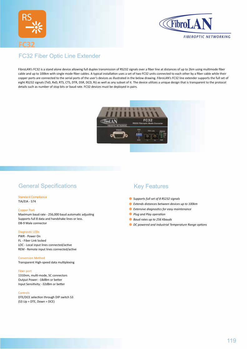
Standard ComplianceTIA/EIA - 574
Copper PortMaximum baud rate - 256,000 baud automatic adjusting Supports full 8 data and handshake lines or less. DB-9 Male connector
Diagnostic LEDsPWR - Power OnFL - Fiber Link lockedLOC - Local input lines connected/activeREM - Remote input lines connected/active
Conversion MethodTransparent High-speed data multiplexing
Fiber port1310nm, multi-mode, SC connectorsOutput Power: -18dBm or betterInput Sensitivity: -32dBm or better
ControlsDTE/DCE selection through DIP switch S3(S3 Up = DTE, Down = DCE)
FC32 Fiber Optic Line Extender
FC32
General Specifications
Supports full set of 8 RS232 signals
Extends distances between devices up to 100km
Extensive diagnostics for easy maintenance
Plug and Play operation
Baud rates up to 256 Kbauds
DC powered and Industrial Temperature Range options
FibroLAN’s FC32 is a stand alone device allowing full duplex transmission of RS232 signals over a fiber line at distances of up to 2km using multimode fiber cable and up to 100km with single mode fiber cables. A typical installation uses a set of two FC32 units connected to each other by a fiber cable while their copper ports are connected to the serial ports of the user’s devices as illustrated in the below drawing. FibroLAN’s FC32 line extender supports the full set of eight RS232 signals (TxD, RxD, RTS, CTS, DTR, DSR, DCD, Ri) as well as any subset of it. The device utilizes a unique design that is transparent to the protocol details such as number of stop bits or baud rate. FC32 devices must be deployed in pairs.
RS
119
Key Features
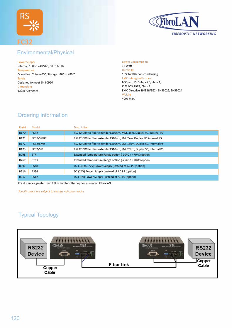
Power SupplyInternal, 100 to 240 VAC, 50 to 60 HzTemperatureOperating: 0° to +45°C; Storage: -20° to +80°CSafetyDesigned to meet EN 60950Dimensions120x170x40mm
FC32Environmental/Physical
power Consumption13 WattHumidity10% to 90% non-condensingEMC - designed to meetFCC part 15, Subpart B, class A; ICES 003:1997, Class AEMC Directive 89/336/EEC - EN55022, EN55024Weight400g max.
Ordering Information
RS
B097 PS48 DC (-36 to -72V) Power Supply (instead of AC PS (option)
B216 PS24 DC (24V) Power Supply (instead of AC PS (option)
B217 PS12 DC (12V) Power Supply (instead of AC PS (option)
Part# Model Description
B170 FC32 RS232 DB9 to fiber extender1310nm, MM, 3km, Duplex SC, internal PS
B171 FC32/SMR7 RS232 DB9 to fiber extender1310nm, SM, 7km, Duplex SC, internal PS
B172 FC32/SMR RS232 DB9 to fiber extender1310nm, SM, 15km, Duplex SC, internal PS
B173 FC32/SM RS232 DB9 to fiber extender1310nm, SM, 25km, Duplex SC, internal PS
B098 ETR Extended Temperature Range option (-10ºC ÷ +70ºC) option
B267 ETRX Extended Temperature Range option (-25ºC ÷ +70ºC) option
For distances greater than 25km and for other options - contact FibroLAN
Specifications are subject to change w/o prior notice
Typical Topology
120
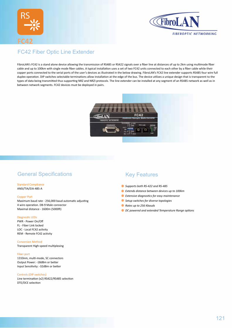
Standard ComplianceANSI/TIA/EIA-485-A
Copper PortMaximum baud rate - 256,000 baud automatic adjusting 4 wire operation. DB-9 Male connectorMaximal distance - 1600m (5000ft)
Diagnostic LEDsPWR - Power On/OffFL - Fiber Link lockedLOC - Local FC42 activityREM - Remote FC42 activity
Conversion MethodTransparent High-speed multiplexing
Fiber port1310nm, multi-mode, SC connectorsOutput Power: -18dBm or betterInput Sensitivity: -32dBm or better
Controls (DIP switches)Line termination (x2) RS422/RS485 selectionDTE/DCE selection
FC42 Fiber Optic Line Extender
FC42
General Specifications
Supports both RS-422 and RS-485
Extends distance between devices up to 100km
Extensive diagnostics for easy maintenance
Setup switches for diverse topologies
Rates up to 256 Kbauds
DC powered and extended Temperature Range options
FibroLAN’s FC42 is a stand alone device allowing the transmission of RS485 or RS422 signals over a fiber line at distances of up to 2km using multimode fiber cable and up to 100km with single mode fiber cables. A typical installation uses a set of two FC42 units connected to each other by a fiber cable while their copper ports connected to the serial ports of the user’s devices as illustrated in the below drawing. FibroLAN’s FC42 line extender supports RS485 four wire full duplex operation. DIP switches selectable terminations allow installation at the edge of the bus. The device utilizes a unique design that is transparent to the types of data being transmitted thus supporting NRZ and NRZI protocols. The line extender can be installed at any segment of an RS485 network as well as in between network segments. FC42 devices must be deployed in pairs.
RS
121
Key Features
FC32Environmental/Physical
B097 PS48 DC (-36 to -72V) Power Supply (instead of AC PS (option)
B216 PS24 DC (24V) Power Supply (instead of AC PS (option)
B217 PS12 DC (12V) Power Supply (instead of AC PS (option)
Part# Model Description
B170 FC32 RS232 DB9 to fiber extender1310nm, MM, 3km, Duplex SC, internal PS
B171 FC32/SMR7 RS232 DB9 to fiber extender1310nm, SM, 7km, Duplex SC, internal PS
B172 FC32/SMR RS232 DB9 to fiber extender1310nm, SM, 15km, Duplex SC, internal PS
B173 FC32/SM RS232 DB9 to fiber extender1310nm, SM, 25km, Duplex SC, internal PS
B098 ETR Extended Temperature Range option (-10ºC ÷ +70ºC) option
B267 ETRX Extended Temperature Range option (-25ºC ÷ +70ºC) option
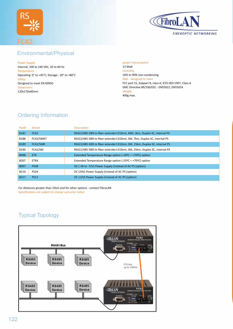
Power SupplyInternal, 100 to 240 VAC, 50 to 60 HzTemperatureOperating: 0° to +45°C; Storage: -20° to +80°CSafetyDesigned to meet EN 60950Dimensions120x170x40mm
FC42Environmental/Physical
power Consumption13 WattHumidity10% to 90% non-condensingEMC - designed to meetFCC part 15, Subpart B, class A; ICES 003:1997, Class AEMC Directive 89/336/EEC - EN55022, EN55024Weight400g max.
Ordering Information
RS
B097 PS48 DC (-36 to -72V) Power Supply (instead of AC PS (option)
B216 PS24 DC (24V) Power Supply (instead of AC PS (option)
B217 PS12 DC (12V) Power Supply (instead of AC PS (option)
Part# Model Description
B187 FC42 RS422/485 DB9 to fiber extender1310nm, MM, 3km, Duplex SC, internal PS
B188 FC42/SMR7 RS422/485 DB9 to fiber extender1310nm, SM, 7km, Duplex SC, internal PS
B189 FC42/SMR RS422/485 DB9 to fiber extender1310nm, SM, 15km, Duplex SC, internal PS
B190 FC42/SM RS422/485 DB9 to fiber extender1310nm, SM, 25km, Duplex SC, internal PS
B098 ETR Extended Temperature Range option (-10ºC ÷ +70ºC) option
B267 ETRX Extended Temperature Range option (-25ºC ÷ +70ºC) option
For distances greater than 25km and for other options - contact FibroLANSpecifications are subject to change w/o prior notice
Typical Topology
122
...ACCESSORIES FOR ALL PRODUCTS
SFP Transceivers
SFxG Series.........................
123
125
FC42Environmental/Physical
B097 PS48 DC (-36 to -72V) Power Supply (instead of AC PS (option)
B216 PS24 DC (24V) Power Supply (instead of AC PS (option)
B217 PS12 DC (12V) Power Supply (instead of AC PS (option)
Part# Model Description
B187 FC42 RS422/485 DB9 to fiber extender1310nm, MM, 3km, Duplex SC, internal PS
B188 FC42/SMR7 RS422/485 DB9 to fiber extender1310nm, SM, 7km, Duplex SC, internal PS
B189 FC42/SMR RS422/485 DB9 to fiber extender1310nm, SM, 15km, Duplex SC, internal PS
B190 FC42/SM RS422/485 DB9 to fiber extender1310nm, SM, 25km, Duplex SC, internal PS
B098 ETR Extended Temperature Range option (-10ºC ÷ +70ºC) option
B267 ETRX Extended Temperature Range option (-25ºC ÷ +70ºC) option

124
Standard Compliance Fast Ethernet (100Base-FX), Gigabit Ethernet, Fiber Channel , OC3, OC12, OC48, STM-1, STM-4, STM-16 Conversion Method Universal protocol transparent device CWDMF/O Ports Simplex and Duplex LC connectorsEach F/O port may be disconnected via managementTemperature Operating: 0º÷ +70ºC; Storage: -40°÷ +85°CManagement SNMP managed via MetroStarTM (MSM2500U) MA™ management (MCM1000X,GSM1000x) Diagnostic LED (FibroLAN devices that support SFP) TX-LOW LED for Port 1 and Port 2 OFF = Transmission is OKLIT Red = Transmission signal low (does not reach the required distance)Blinking = Transmission signal low (does not reach the required distance)
Small Form Factor Pluggable Transceivers
SFP TRANSCEIVERS
Compliant with SFP and SFF-8472
Data Rate: 100Mbps to 2.5Gbps
Hot Pluggable SFP transceivers
Compliant to full ICE825 and CDRH class 1 eye safety
Digital diagnostic monitoring
Metal enclosure for lower EMI
Network Extension: up to 80km (120km for GBE)
Pull de-latch mechanism for easy deployment
CWDM DFB Laser
Spectral width (-20dB) = 1nm
Side Mode Suppression ratio: 30dB
Extinction Ratio: Min 8.2dB
Receiver Optical Return Loss: Max = 27dB
Output Eye Diagram: compliant with ITU-G957
Qualified to meet Bellcore reliability practices
General Specifications
ManagementThe SFP transceivers have status screens, which can be displayed via the menu of FibroLAN devices that support SFP (MCM1000X, GSM1000X and MSM2500U):
SFP modules status
Port# Part# Type Range Tx-WL S/N
1 SF1G-SF15 SM-SFS 20000m 1310nm FibroLAN-SER#1
2 SF2G-LX4-5C-61 SM 80000m 1611nm FibroLAN-SER#100
The SFP port status contains the same info and a Tx Power indicator(Normal, Low, N/A=SFP unplugged)
The FibroLAN 1.25/2.5 Gpbs Small Form Factor Pluggable (SFP) Optical Transceivers are Multi-Source Agreement (MSA) compliant and provide high performance duplex data links for bi-directional communication over Multi-mode and Single mode fiber. The SFP SF1G series are designed for Gigabit Ethernet data links and are deployed in FibroLAN‘s MCM1000X MetroStarTM Module, GSM1000X remote Access device. The SF2X series are designed to operate from 100Mbps to 2.5Gbps and are deployed in FibroLAN‘s MSM2500U MetroStarTM module and in MCM2500 remote Extender device. These FibroLAN devices are protocol independent for the specified transmission speed and efficiently support Fast Ethernet, Fiber Channel, Gigabit Ethernet, OC3, OC12, OC48, STM1, STM4, and STM16. The SF2G/C family transceivers are designed for CWDM data links and may be installed also in MSM2500U and MCM2500 devices. Small Form-factor Pluggable optical interfaces are suitable for ease of deployment, maintenance and logistics, and do not require any settings or measurements. The main advantages of the hot-swappable SFP optical interfaces are the density, flexibility, and cost savings. SFP modules can be easily interchanged, thus fiber optic networks can be upgraded more conveniently than with traditional modules. The SFP transceivers provide status information (SFP modules status and SFP port status). The key features are common to all SFP series.
125
Ordering Information
SFP TRANSCEIVERS
The SFP transceivers from SF1G-T (B248) through SF1G-LX-SC-61 (B288) are deployed in the following FibroLAN equipment: MetroStarTM module MCM 1000X, CPE device GSM1000X and GTAxx00 series. The SFP transceivers from SF155-SMRF15 (except SF1G-T) through SF2G-LX4-5C-61 are used in the following Fibro-LAN equipment: MetroStarTM module MSM2500U and U.CON2500 devices Note: All recommended distances for CWDM active components assume direct point-to-point connection between them. If these are passing thru passive MUX/Demuxes, the additional attenduation introduced by such devices must be considered when assessing the actual distances.
Part# Model Description
B289 SF155-SMRF15 SFP (Small Form Pluggable) OC3 Single Fiber Strand F/O transceiver, LC connector, SM 1550nmTx/1310nmRx, 15km
B290 SF155-SMRF13 SFP (Small Form Pluggable) OC3 Single Fiber Strand F/O transceiver, LC connector, SM 1310nmTx/1550nmRx, 15km
B248 SF1G-T SFP module, GBE F/O transceiver, 1000Base-T, shielded RJ45, 100m over Cat.6 cable
B235 SF1G-S1 SFP module, GBE F/O transceiver,, dual LC connector, MM 850nm, 220/550m
B236 SF1G-LX1 SFP module, GBE F/O transceiver, dual LC connector, SM1310nm, 10km
B237 SF1G-LX2 SFP module, GBE F/O transceiver, dual LC connector, SM1310nm, 20km
B238 SF1G-LX3 SFP module, GBE F/O transceiver, dual LC connector, SM1550nm/DFB, 40km
B239 SF1G-LX4 SFP module, GBE F/O transceiver, dual LC connector, SM1550nm/DFB, 80km
B240 SF1G-LX5 SFP module, GBE F/O transceiver, dual LC connector, SM1550nm/DFB,/APD, 120km
B241 SF1G--SF13 SFP module, Single Fiber Strand GBE F/O transceiver, 1* LC, SM 1310nm Tx/ 1550nm Rx, 20km
B242 SF1G-SF15 SFP module, SFS, GBE F/O transceiver, 1* LC, SM 1550nmDFB Tx/ 1310nm Rx, 20km
B243 SF1G-LF13 SFP module, Single Fiber Strand GBE F/O transceiver, 1* LC, SM 1310nmDFB Tx/ 1550nm Rx, 40km
B244 SF1G-LF15 SFP module, SFS, GBE F/O transceiver, 1* LC, SM 1550nmDFB Tx/ 1310nm Rx, 40km
B269 SF1G-ZF49 SFP , SFS, GBE F/O transceiver, LC connector, SM 1490nm Tx/ 1570nm Rx, 80km
B270 SF1G-ZF57 SFP , SFS, GBE F/O transceiver, LC connector, SM 1570nm Tx/ 1490nm Rx, 80km
B281 SF1G-LX5-5C-47 CWDM SFP, 1.25Gbps F/O transceiver, dual LC connector, SM 1471nm DFB/APD, 120km
B282 SF1G-LX5-5C-49 CWDM SFP, 1.25Gbps F/O transceiver, dual LC connector, SM 1491nm DFB/APD, 120km
B283 SF1G-LX5-5C-51 CWDM SFP, 1.25Gbps F/O transceiver, dual LC connector, SM 1511nm DFB/APD, 120km
B284 SF1G-LX5-5C-53 CWDM SFP, 1.25Gbps F/O transceiver, dual LC connector, SM 1531nm DFB/APD, 120km
B285 SF1G-LX5-5C-55 CWDM SFP, 1.25Gbps F/O transceiver, dual LC connector, SM 1551nm DFB/APD, 120km
B286 SF1G-LX5-5C-57 CWDM SFP, 1.25Gbps F/O transceiver, dual LC connector, SM 1571nm DFB/APD, 120km
B287 SF1G-LX5-5C-59 CWDM SFP, 1.25Gbps F/O transceiver, dual LC connector, SM 1591nm DFB/APD, 120km
B288 SF1G-LX5-5C-61 CWDM SFP, 1.25Gbps F/O transceiver, dual LC connector, SM 1611nm DFB/APD, 120km
B268 SF2G-S1 SFP module, 2.5Gbps F/O transceiver, dual LC connector, MM 850nm, 300/400m
B249 SF2G-S2 SFP module, 2.5Gbps F/O transceiver, dual LC connector, SM 1310nm, 2km
B250 SF2G-LX2-3 SFP module, 2.5Gbps F/O transceiver, dual LC connector, SM 1310nm, DFB, 15km
B251 SF2G-LX2-5 SFP module, 2.5Gbps F/O transceiver, dual LC connector, SM 1550nm, DFB, 15km
B252 SF2G-LX3-3 SFP module, 2.5Gbps F/O transceiver, dual LC connector, SM 1310nm, DFB/APD 40km
B253 SF2G-LX3-5 SFP module, 2.5Gbps F/O transceiver, dual LC connector, SM 1550nm, DFB, 40km
B254 SF2G-LX4-5 SFP module, 2.5Gbps F/O transceiver, dual LC connector, SM 1550nm, DFB/APD 80km
B271 SF2G-LX3-5C-47 CWDM, SFP 2.5Gbps F/O transceiver, dual LC connector, SM 1471nm DFB, 40km
B272 SF2G-LX3-5C-49 CWDM, SFP 2.5Gbps F/O transceiver, dual LC connector, SM 1491nm DFB, 40km
B273 SF2G-LX3-5C-51 CWDM, SFP 2.5Gbps F/O transceiver, dual LC connector, SM 1511nm DFB, 40km
B274 SF2G-LX3-5C-53 CWDM, SFP 2.5Gbps F/O transceiver, dual LC connector, SM 1531nm DFB, 40km
B275 SF2G-LX3-5C-55 CWDM, SFP 2.5Gbps F/O transceiver, dual LC connector, SM 1551nm DFB, 40km
B276 SF2G-LX3-5C-57 CWDM, SFP 2.5Gbps F/O transceiver, dual LC connector, SM 1571nm DFB, 40km
B277 SF2G-LX3-5C-59 CWDM, SFP 2.5Gbps F/O transceiver, dual LC connector, SM 1591nm DFB, 40km
B278 SF2G-LX3-5C-61 CWDM, SFP 2.5Gbps F/O transceiver, dual LC connector, SM 1611nm DFB, 40km
B258 SF2G-LX4-5C-47 CWDM, SFP 2.5Gbps F/O transceiver, dual LC connector, SM 1471nm DFB/APD 80km
B259 SF2G-LX4-5C-49 CWDM, SFP 2.5Gbps F/O transceiver, dual LC connector, SM 1491nm DFB/APD 80km
B260 SF2G-LX4-5C-51 CWDM, SFP 2.5Gbps F/O transceiver, dual LC connector, SM 1511nm DFB/APD 80km
B261 SF2G-LX4-5C-53 CWDM, SFP 2.5Gbps F/O transceiver, dual LC connector, SM 1531nm DFB/APD 80km
B262 SF2G-LX4-5C-55 CWDM, SFP 2.5Gbps F/O transceiver, dual LC connector, SM 1551nm DFB/APD 80km
B263 SF2G-LX4-5C-57 CWDM, SFP 2.5Gbps F/O transceiver, dual LC connector, SM 1571nm DFB/APD 80km
B264 SF2G-LX4-5C-59 CWDM, SFP 2.5Gbps F/O transceiver, dual LC connector, SM 1591nm DFB/APD 80km
B265 SF2G-LX4-5C-61 CWDM, SFP 2.5Gbps F/O transceiver, dual LC connector, SM 1611nm DFB/APD 80km
126
Key Features
CWDM SFP
Single-Mode for Fast Ethernet products
FibroLAN Products Fiber Optic Specifications
B047 SM1/LX 1550nm/DFB Duplex SC 0 -38 38 70-150
Part# Model Wavelength ConnectorsMin.Output
Power (dBm)
TypicalReceive
SensitivitydBm
Min.PowerBudget, dB
Typical distance
km B057 SMR7-1 1310nm Duplex SC -20 -30 10 0-7
B058 SMR1 1310nm Duplex SC -16 -30 14 0-15
B022 SM1 1310nm Duplex SC -15 -36 21 0-25
B024 SM1/L 1310nm Duplex SC -11 -36 25 15-40
B045 SM1/L2 1310nm Duplex SC -2 -36 34 25-70
B146 SM1/L3 1550nm/DFB Duplex SC -2 -38 36 40-100
Gigabit Ethernet products
Link Type
ReceiveWavelength
nm RX
TransmitWavelength
nm TX
Min. TransmitOutputPower
(dBm)
Min.Receive
SensitivitydBm
Min.PowerBudget, dBm
Typical distance
km Connectors 1000Base-SX 850 850 -17 -9,5 7,5 0,22-0,55 Duplex SC
1000Base-LX1 1310 1310 -23 -10 13 5-10 Duplex SC
1000Base-LX2 1310 1310 -23 -5 18 5-20* Duplex SC
1000Base-LX3 1550 1550/DFB -23 -3 20 10-40 Duplex SC
1000Base-LX4 1550 1550/DFB -23 0 23 25-80 Duplex SC
1000Base-LX5 155 1550/DFB/APD -32 0 32 80-120 Duplex SC
1000Base-LXF13 1550 1310 -20 -5 15 5-20* Simplex SC
1000Base-LXF15 1310 1550/DFB -20 -5 15 5-20* Simplex SC
1000Base-ZXF13 1550 1310/DFB -23 -3 20 10-40 Simplex SC
1000Base-ZXF15 1310 1550/DFB -23 -3 20 10-40 Simplex SC
Single Fiber Strand (SFS) products
Fast Ethernetdevices
ReceiveWavelength
nm RX
TransmitWavelength
nm TX
Min. TransmitOutputPower
(dBm)
Min.Receive
SensitivitydBm
Min.PowerBudget, dBm
Typical distance
km Xxx/SM/F1 1310 1310SC/APD -30 -15 15 20
Xxx/SMRF13 1550 1310 -35 -15 20 0-15
Xxx/SMRF15 1310 1550 -35 -15 20 0-15
Xxx/SMLF13 1550 1310 -35 -5 30 10-60
Xxx/SMLF15 1310 1550/DFB -35 -5 30 10-60
Gigabit Ethernet devices GSM10xxF13, MCM1000x-LXF13 1550 1310 -20 -5 15 1-20
GSM10xxF15, MCM1000x-LXF15 1310 1550/DFB -20 -5 15 1-20
GSM10xxF13L, MCM1000x-ZXF13 1550 1310/DFB -23 -3 20 10-40
GSM10xxF15L, MCM1000x-ZXF15 1310 1550/DFB -23 -3 20 10-40
(GSM1000, GSM1010, GSM10X0M, GSM10X0/MA, MCM1000T, MCM1000SL, ATARA1000, ATARA1000M, ATARA1000RM) *Over G. 652 fiber
*Actual distances depend on the parameters of the cable plant (attenduantions, number and quality of splices, connectors/patch panels etc.) and on performance of the remote-end fiber optic interface. In cases of 1550nm transmission MAKE SURE that your fiber plant supports this (third window) transmission. Be aware that most of the fibers manufactured before 1992 do not support 1550nm transmission. Make sure fiber complies with ITU-T-G651/652
127
SFP TRANSCEIVERS
Part# Model Description
B289 SF155-SMRF15 SFP (Small Form Pluggable) OC3 Single Fiber Strand F/O transceiver, LC connector, SM 1550nmTx/1310nmRx, 15km
B290 SF155-SMRF13 SFP (Small Form Pluggable) OC3 Single Fiber Strand F/O transceiver, LC connector, SM 1310nmTx/1550nmRx, 15km
B248 SF1G-T SFP module, GBE F/O transceiver, 1000Base-T, shielded RJ45, 100m over Cat.6 cable
B235 SF1G-S1 SFP module, GBE F/O transceiver,, dual LC connector, MM 850nm, 220/550m
B236 SF1G-LX1 SFP module, GBE F/O transceiver, dual LC connector, SM1310nm, 10km
B237 SF1G-LX2 SFP module, GBE F/O transceiver, dual LC connector, SM1310nm, 20km
B238 SF1G-LX3 SFP module, GBE F/O transceiver, dual LC connector, SM1550nm/DFB, 40km
B239 SF1G-LX4 SFP module, GBE F/O transceiver, dual LC connector, SM1550nm/DFB, 80km
B240 SF1G-LX5 SFP module, GBE F/O transceiver, dual LC connector, SM1550nm/DFB,/APD, 120km
B241 SF1G--SF13 SFP module, Single Fiber Strand GBE F/O transceiver, 1* LC, SM 1310nm Tx/ 1550nm Rx, 20km
B242 SF1G-SF15 SFP module, SFS, GBE F/O transceiver, 1* LC, SM 1550nmDFB Tx/ 1310nm Rx, 20km
B243 SF1G-LF13 SFP module, Single Fiber Strand GBE F/O transceiver, 1* LC, SM 1310nmDFB Tx/ 1550nm Rx, 40km
B244 SF1G-LF15 SFP module, SFS, GBE F/O transceiver, 1* LC, SM 1550nmDFB Tx/ 1310nm Rx, 40km
B269 SF1G-ZF49 SFP , SFS, GBE F/O transceiver, LC connector, SM 1490nm Tx/ 1570nm Rx, 80km
B270 SF1G-ZF57 SFP , SFS, GBE F/O transceiver, LC connector, SM 1570nm Tx/ 1490nm Rx, 80km
B281 SF1G-LX5-5C-47 CWDM SFP, 1.25Gbps F/O transceiver, dual LC connector, SM 1471nm DFB/APD, 120km
B282 SF1G-LX5-5C-49 CWDM SFP, 1.25Gbps F/O transceiver, dual LC connector, SM 1491nm DFB/APD, 120km
B283 SF1G-LX5-5C-51 CWDM SFP, 1.25Gbps F/O transceiver, dual LC connector, SM 1511nm DFB/APD, 120km
B284 SF1G-LX5-5C-53 CWDM SFP, 1.25Gbps F/O transceiver, dual LC connector, SM 1531nm DFB/APD, 120km
B285 SF1G-LX5-5C-55 CWDM SFP, 1.25Gbps F/O transceiver, dual LC connector, SM 1551nm DFB/APD, 120km
B286 SF1G-LX5-5C-57 CWDM SFP, 1.25Gbps F/O transceiver, dual LC connector, SM 1571nm DFB/APD, 120km
B287 SF1G-LX5-5C-59 CWDM SFP, 1.25Gbps F/O transceiver, dual LC connector, SM 1591nm DFB/APD, 120km
B288 SF1G-LX5-5C-61 CWDM SFP, 1.25Gbps F/O transceiver, dual LC connector, SM 1611nm DFB/APD, 120km
B268 SF2G-S1 SFP module, 2.5Gbps F/O transceiver, dual LC connector, MM 850nm, 300/400m
B249 SF2G-S2 SFP module, 2.5Gbps F/O transceiver, dual LC connector, SM 1310nm, 2km
B250 SF2G-LX2-3 SFP module, 2.5Gbps F/O transceiver, dual LC connector, SM 1310nm, DFB, 15km
B251 SF2G-LX2-5 SFP module, 2.5Gbps F/O transceiver, dual LC connector, SM 1550nm, DFB, 15km
B252 SF2G-LX3-3 SFP module, 2.5Gbps F/O transceiver, dual LC connector, SM 1310nm, DFB/APD 40km
B253 SF2G-LX3-5 SFP module, 2.5Gbps F/O transceiver, dual LC connector, SM 1550nm, DFB, 40km
B254 SF2G-LX4-5 SFP module, 2.5Gbps F/O transceiver, dual LC connector, SM 1550nm, DFB/APD 80km
B271 SF2G-LX3-5C-47 CWDM, SFP 2.5Gbps F/O transceiver, dual LC connector, SM 1471nm DFB, 40km
B272 SF2G-LX3-5C-49 CWDM, SFP 2.5Gbps F/O transceiver, dual LC connector, SM 1491nm DFB, 40km
B273 SF2G-LX3-5C-51 CWDM, SFP 2.5Gbps F/O transceiver, dual LC connector, SM 1511nm DFB, 40km
B274 SF2G-LX3-5C-53 CWDM, SFP 2.5Gbps F/O transceiver, dual LC connector, SM 1531nm DFB, 40km
B275 SF2G-LX3-5C-55 CWDM, SFP 2.5Gbps F/O transceiver, dual LC connector, SM 1551nm DFB, 40km
B276 SF2G-LX3-5C-57 CWDM, SFP 2.5Gbps F/O transceiver, dual LC connector, SM 1571nm DFB, 40km
B277 SF2G-LX3-5C-59 CWDM, SFP 2.5Gbps F/O transceiver, dual LC connector, SM 1591nm DFB, 40km
B278 SF2G-LX3-5C-61 CWDM, SFP 2.5Gbps F/O transceiver, dual LC connector, SM 1611nm DFB, 40km
B258 SF2G-LX4-5C-47 CWDM, SFP 2.5Gbps F/O transceiver, dual LC connector, SM 1471nm DFB/APD 80km
B259 SF2G-LX4-5C-49 CWDM, SFP 2.5Gbps F/O transceiver, dual LC connector, SM 1491nm DFB/APD 80km
B260 SF2G-LX4-5C-51 CWDM, SFP 2.5Gbps F/O transceiver, dual LC connector, SM 1511nm DFB/APD 80km
B261 SF2G-LX4-5C-53 CWDM, SFP 2.5Gbps F/O transceiver, dual LC connector, SM 1531nm DFB/APD 80km
B262 SF2G-LX4-5C-55 CWDM, SFP 2.5Gbps F/O transceiver, dual LC connector, SM 1551nm DFB/APD 80km
B263 SF2G-LX4-5C-57 CWDM, SFP 2.5Gbps F/O transceiver, dual LC connector, SM 1571nm DFB/APD 80km
B264 SF2G-LX4-5C-59 CWDM, SFP 2.5Gbps F/O transceiver, dual LC connector, SM 1591nm DFB/APD 80km
B265 SF2G-LX4-5C-61 CWDM, SFP 2.5Gbps F/O transceiver, dual LC connector, SM 1611nm DFB/APD 80km
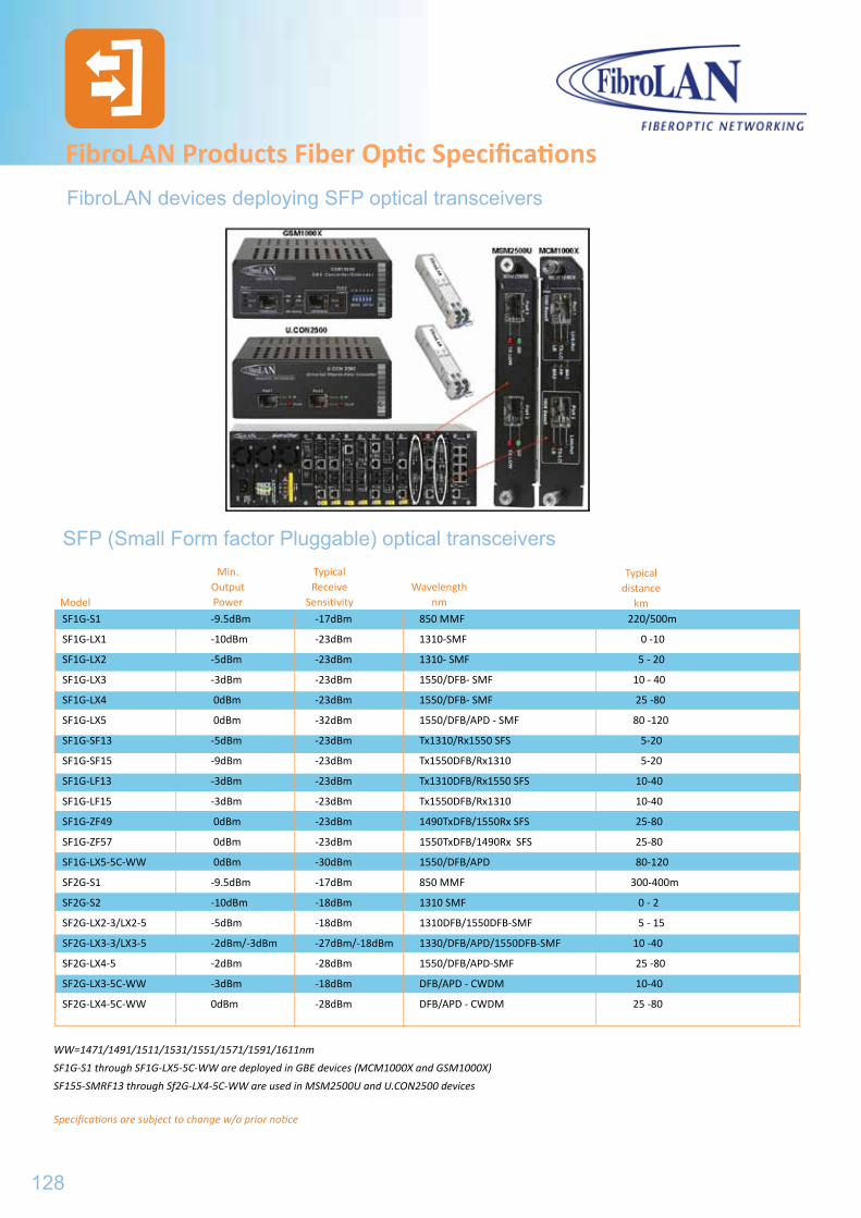
FibroLAN Products Fiber Optic Specifications
SFP (Small Form factor Pluggable) optical transceivers
ModelWavelength
nm
Min. OutputPower
TypicalReceive
Sensitivity
Typical distance
km
WW=1471/1491/1511/1531/1551/1571/1591/1611nm
SF1G-S1 through SF1G-LX5-5C-WW are deployed in GBE devices (MCM1000X and GSM1000X)
SF155-SMRF13 through Sf2G-LX4-5C-WW are used in MSM2500U and U.CON2500 devices
Specifications are subject to change w/o prior notice
FibroLAN devices deploying SFP optical transceivers
SF1G-S1 -9.5dBm -17dBm 850 MMF 220/500m
SF1G-LX1 -10dBm -23dBm 1310-SMF 0 -10
SF1G-LX2 -5dBm -23dBm 1310- SMF 5 - 20
SF1G-LX3 -3dBm -23dBm 1550/DFB- SMF 10 - 40
SF1G-LX4 0dBm -23dBm 1550/DFB- SMF 25 -80
SF1G-LX5 0dBm -32dBm 1550/DFB/APD - SMF 80 -120
SF1G-SF13 -5dBm -23dBm Tx1310/Rx1550 SFS 5-20
SF1G-SF15 -9dBm -23dBm Tx1550DFB/Rx1310 5-20
SF1G-LF13 -3dBm -23dBm Tx1310DFB/Rx1550 SFS 10-40
SF1G-LF15 -3dBm -23dBm Tx1550DFB/Rx1310 10-40
SF1G-ZF49 0dBm -23dBm 1490TxDFB/1550Rx SFS 25-80
SF1G-ZF57 0dBm -23dBm 1550TxDFB/1490Rx SFS 25-80
SF1G-LX5-5C-WW 0dBm -30dBm 1550/DFB/APD 80-120
SF2G-S1 -9.5dBm -17dBm 850 MMF 300-400m
SF2G-S2 -10dBm -18dBm 1310 SMF 0 - 2
SF2G-LX2-3/LX2-5 -5dBm -18dBm 1310DFB/1550DFB-SMF 5 - 15
SF2G-LX3-3/LX3-5 -2dBm/-3dBm -27dBm/-18dBm 1330/DFB/APD/1550DFB-SMF 10 -40
SF2G-LX4-5 -2dBm -28dBm 1550/DFB/APD-SMF 25 -80
SF2G-LX3-5C-WW -3dBm -18dBm DFB/APD - CWDM 10-40
SF2G-LX4-5C-WW 0dBm -28dBm DFB/APD - CWDM 25 -80
128
FibroLAN Products Fiber Optic Specifications
WW=1471/1491/1511/1531/1551/1571/1591/1611nm
SF1G-S1 through SF1G-LX5-5C-WW are deployed in GBE devices (MCM1000X and GSM1000X)
SF155-SMRF13 through Sf2G-LX4-5C-WW are used in MSM2500U and U.CON2500 devices
Specifications are subject to change w/o prior notice
FibroLAN CEE GmbH.Leobersdorferstraße 42
2560 BerndorfAUSTRIA
Tel.: +43 2672 81975 6940Fax: +43 2672 81975 6904
eMail: [email protected]
http://www.fibrolan.at