mr and ct arthrography of the hip - dmc-diagnostico
TRANSCRIPT

MR and CT Arthrography of the HipEva Llopis, M.D. 1 Ernesto Fernandez, Ph.D. 2 Luis Cerezal, M.D. 3
1Department of Radiology, Hospital de la Ribera, Alzira, Spain.2Department of Orthopedics, Hospital de la Ribera, Alzira, Spain.3Department of Radiology, Diagnostico Medico Cantabria (DMC),Santander, Spain.
Semin Musculoskelet Radiol 2012;16:42–56.
Address for correspondence and reprint requests Eva Llopis, M.D.,Department of Radiology, Hospital de la Ribera, Carretera de Corberakm1, 46600 Alzira, Valencia, Spain (e-mail: [email protected]).
The hip joint is deeply located and surrounded by a thickcapsule and large muscles; its cartilage is thin with thecartilage surfaces of the femoral head and acetabulum closelyopposed. These anatomical factors have limited its access forhigh-resolution images and arthroscopy. In the past 10 years,improvements in arthroscopy together with many advancesof imaging have changed the diagnosis and treatment algo-rithms and approaches to intra-articular hip lesions. Indica-tions of arthroscopy are still expanding. However, althoughMR arthrography (MRa) with or without traction, 3T, newcoil, or CT arthrography (CTa) have been proposed as goodtechniques for intra-articular evaluation, for true imaging themethod of choice is still under somedebate. Their accuracy fordetecting intra-articular lesions and labral pathology is vari-able, but the detection and characterization of cartilagelesions remains challenging. Intraobserver variability hasbeen related to the degree of training. There is a lack ofuniformity in describing lesion location and characterization,and there are many different classification systems withoutconsensus.1–3 Significant controversy regards the relevanceof hip impaction syndromes with the early development ofhip osteoarthritis and therefore the need to treat suchsyndromes.
Arthrography Technique
Arthrography can be performed using anatomical landmarks,ultrasound (US), CT, or, most commonly, fluoroscopic guid-ance. The advantage of fluoroscopic guidance is that if the tipof the needle is not correctly located, it can be easily adjusted;the volume of injected contrast can also be controlled. Wemark femoral vessels with US to avoid accidental punctureduring the procedure. The patient is placed on the table in thesupine position with the leg in neutral or slightly internalrotation to increase visualization of the femoral neck. Theprocedure is done under the usual strict sterile conditions.
The dilution is different depending on whether CTa, MRa,or combined CT-MR arthrography will subsequently be per-formed. The dilution of saline, gadolinium, iodine contrast,and local anesthetic has been reported safe worldwide,although the Food and Drug Administration has not yetapproved gadopentetate dimeglumine (Gd-DPTA) for intra-articular use.4 The dilution of Gd-DPTA with iodinated con-trast material is safe because there is no release of freegadolinium and therefore no increase in its systemic or jointtoxicity effect.5 A decrease of signal intensity on T1-weightedimages is seen after a mixture of iodine contrast media and
Keywords
► hip arthrography► CT arthrography► MR arthrography► labral tear► cartilage► femoroacetabular
impingement
Abstract CT arthrography (CTa) and MR arthrography (MRa) are useful tools for the investigationof intra-articular hip disease. They are minimally invasive techniques with a very low rateof complications and can be performed safely. CTa or MRa can be performed after anintra-articular injection of diluted contrast, but both techniques can also be performedafter a single injection. As radiologists we should be able to address the surgeon’squestions and work together to standardize terminology and classifications systems foraccurate reporting. This update emphasizes radiological findings with a clinicalperspective. CTa and MRa allow the precise diagnosis of labral tears, loose bodies,and intra-articular ligaments (capsular and ligamentum teres). The use of carefultechnique and a tailored protocol has improved our ability to detect and describecartilage lesions. This is essential because knowledge of the status of the cartilage maydictate a specific surgical approach, and when cartilage lesions are extensive, they are anegative prognostic indicator for arthroscopic treatment.
Issue Theme Current Concepts in MRand CT Arthrography; Guest Editor, AraKassarjian, M.D., F.R.C.P.C.
Copyright © 2012 by Thieme MedicalPublishers, Inc., 333 Seventh Avenue,New York, NY 10001, USA.Tel: +1(212) 584-4662.
DOI http://dx.doi.org/10.1055/s-0032-1304300.ISSN 1089-7860.
42
Dow
nloa
ded
by: H
OS
PIT
AL
"12
de O
CT
UB
RE
". C
opyr
ight
ed m
ater
ial.
Gd-DPTA when the concentration of iodine is >25%; thisshould be kept in mind if combined CT-MR arthrography isperformed. However, in our experience, 30 to 40% of iodine inthe dilution allows high-quality images on T1 as well as high-quality CT images, and, as such, this is the concentration weuse to perform combined CTa and MRa. When MR is per-formed after intra-articular injection, the Gd-DPTA concen-tration should remain between 0.5 and 2 mmol/L. Localanesthetic injection can decrease pain related to the patient’sdisease and increase the tolerance for joint injection. We uselidocaine as the local anesthetic. Although not used in ourpractice, if a delay between injection and MR is anticipated,epinephrine can be added to the mixture.6,7
For combined CTa-MRa, the dilution is 1 mL of Gd-DTPAmixed in 100mL of saline; 8mL of thismixture is then dilutedwith 7 mL of iodine solution (340 mg/cc) and 3 mL oflidocaine 2%. CTa dilution is made combining 10 mL of iodineand 5 mL of lidocaine. The volume injected varies from 10 to20 mL, with a mean of 15 mL. The injection is stopped whenthe patient reports pain and feels resistance. However, oneshould keep in mind that hip arthrography is performedresistance, unlike shoulder, ankle, or wrist arthrography.The hip joint needs pressure to be distended.
We use a 22-gauge (G) 9-cm needle unless there issignificant hip osteoarthritis in which case we use a 20Gneedle. In rare instances and with exceptionally large pa-tients, we may have to use 15-cm-long needle.
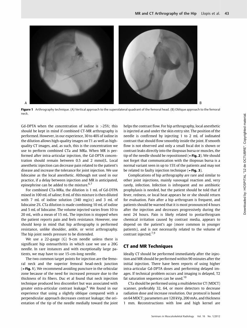
The two common target points for injection are the femo-ral neck and the superior femoral head-neck junction(►Fig. 1). We recommend avoiding puncture in the orbicularzone because of the need for increased pressure due to thethickness of its fibers. Duc et al found that neck injectiontechnique produced less discomfort but was associated withgreater extra-articular contrast leakage.8 We found in ourexperience that using a slightly oblique compared with aperpendicular approach decreases contrast leakage; the ori-entation of the tip of the needle medially toward the joint
helps the contrast flow. For hip arthrography, local anestheticis injected at and under the skin entry site. The position of theneedle is confirmed by injecting 1 to 2 mL of iodinatedcontrast that should flow smoothly inside the joint. If smoothflow is not observed and only a small focal dot is shown orcontrast leaks directly into the iliopsoas bursa or muscles, thetip of the needle should be repositioned (►Fig. 2). We shouldnot forget that communication with the iliopsoas bursa is anormal variant seen in up to 15% of the patients and may notbe related to faulty injection technique (►Fig. 3).
Complications of hip arthrography are rare and similar toother joint injections, mainly vasovagal reaction and, veryrarely, infection. Infection is infrequent and no antibioticprophylaxis is needed, but the patient should be told that iffever, redness, or local heat appears he or she should returnfor evaluation. Pain after a hip arthrogram is frequent, andpatients should bewarned that it is most pronounced 4 hoursafter the injection and decreases progressively during thenext 24 hours. Pain is likely related to postarthrogramchemical irritation caused by contrast media, appears todepend on the patient’s age (more common in youngerpatients), and is not necessarily related to the volume ofcontrast injected.7,9
CT and MR Techniques
Ideally CT should be performed immediately after the injec-tion andMR should be performedwithin 90minutes after theinitial injection. There have been reports of using higherintra-articular Gd-DPTA doses and performing delayed im-ages. If technical problem occurs and imaging is delayed, T2fat saturation sequences can be used.10
CTa should be performed using amultidetector CT (MDCT)scanner, preferably 32, 64, or more detectors to decreaseradiation dose and increase resolution. Our protocol is basedon 64MDCT; parameters are 120 kVp, 200mAs, and thickness1 mm. Reconstructions with low and high kernel are
Figure 1 Arthrography technique. (A) Vertical approach to the superolateral quadrant of the femoral head. (B) Oblique approach to the femoralneck.
Seminars in Musculoskeletal Radiology Vol. 16 No. 1/2012
MR and CT Arthrography of the Hip Llopis et al. 43
Dow
nloa
ded
by: H
OS
PIT
AL
"12
de O
CT
UB
RE
". C
opyr
ight
ed m
ater
ial.

Figure 3 Normal communication with iliopsoas muscle bursa. (A) Arthrography contrast injection is performed in the femoral neck (arrows), andcontrast communication is seen with the iliopsoas bursa (arrowhead). (B) CTa and (C) MRa demonstrate the puncture site (arrows) and theextension into the iliopsoas bursa (arrowheads).
Figure 2 Arthrography. (A) Technical error with intramuscular contrast leakage. (B) Needle tip was changed and the intra-articular position was confirmed.
Seminars in Musculoskeletal Radiology Vol. 16 No. 1/2012
MR and CT Arthrography of the Hip Llopis et al.44
Dow
nloa
ded
by: H
OS
PIT
AL
"12
de O
CT
UB
RE
". C
opyr
ight
ed m
ater
ial.
important to allow bone and soft tissue reconstructions.Multiplanar reformats in coronal, oblique axial (followingfemoral neck axis), and sagittal images allow assessment ofcartilage, labrum, and bones. In addition, volume renderingcan aid in assessing the bones.11
MRa should be performed on a high field magnet, usingcoronal, sagittal, axial, and oblique sagittal planes, and com-bining T1, fat-suppressed T1, and at least one fluid-sensitivesequence. Our fat-saturated T1-weighted MR sequence pro-tocol is TR/TE 450/15; matrix size, 256 � 512; sectionthickness, 3 mm; interslice gap, 0.3 mm; number of signalsper data line acquired, 3; field of view, 16 cm2. New volumet-ric fast spin-echo techniques are promising and should allowmultiplanar reconstructions without losing quality.
The hip is a ball-and-socket joint. This morphology togeth-er with the sealant effect of the labrum explains why contrasthas difficulty reaching the central compartment, thusmakingit hard to distinguish the cartilage surfaces of the femoralhead and acetabulum as distinct structures. Therefore westrongly recommend manual traction to allow the fluid toenter into the central compartment for CTa followed by 6 to9 kg continuous traction (depending on the patient) for MRabecause of the length of the procedure. A small amount ofcontrast is enough to delineate cartilage surfaces.3,12
Performing CT and MR after a single intra-articular injec-tion increases the length, radiation dose, and cost of theprocedure, and there is no long-term evidence that it im-proves diagnostic capability and patient outcome; However,if logistically possible we recommend it because thesetechniques are complementary for the evaluation of somestructures and offer additional value. CT is better for theevaluation of bone deformities including calcification of theacetabulum. MR is better for soft tissue structures such asligaments and labrum (especially intrasubstance changes).Cartilage imaging is still the cornerstone for intra-articularimaging. CTa is in general slightly better than MRa formorphological abnormalities, but having both techniquesincreases our confidence in cartilage evaluation. If thereare technical problems such as movement artifacts on MR,CTa acts as a backup.
Femoroacetabular Impingement
In the past 10 years, controversy has arisen about theassociation of femoroacetabular impingement (FAI) withearly osteoarthritis and whether FAI truly represents a path-ological condition or is a borderline normal anatomicalfeature. FAI is defined as an abnormal contact between thefemoral head and the acetabulum that limits normal range ofmotion. Although two types were defined (pincer when focalor general acetabular overcoverage occurs and cam whenthere is an abnormal contact between the femoral head-neckjunction and the anterior acetabulum), most patients havemixed types (►Figs. 4, 5, and 6).13,14 The cam type has beenreported as a complication after femoral neck malunion,slipped capital femoral epiphysis, and Perthes disease, butit is also secondary to repetitive impact in some sports. Pincerimpingement is related to anterosuperior overcoverage, coxaprofunda, protrusio acetabuli, and acetabular retroversion.
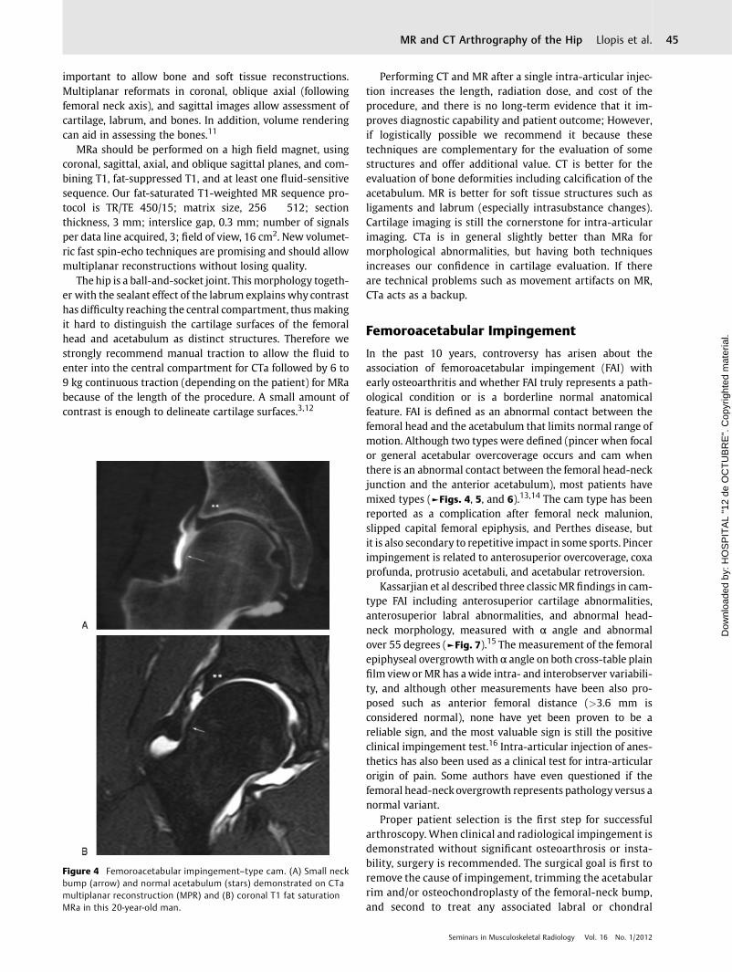
Kassarjian et al described three classicMR findings in cam-type FAI including anterosuperior cartilage abnormalities,anterosuperior labral abnormalities, and abnormal head-neck morphology, measured with α angle and abnormalover 55 degrees (►Fig. 7).15 The measurement of the femoralepiphyseal overgrowthwith α angle on both cross-table plainfilm view or MR has awide intra- and interobserver variabili-ty, and although other measurements have been also pro-posed such as anterior femoral distance (>3.6 mm isconsidered normal), none have yet been proven to be areliable sign, and the most valuable sign is still the positiveclinical impingement test.16 Intra-articular injection of anes-thetics has also been used as a clinical test for intra-articularorigin of pain. Some authors have even questioned if thefemoral head-neckovergrowth represents pathology versus anormal variant.
Proper patient selection is the first step for successfularthroscopy. When clinical and radiological impingement isdemonstrated without significant osteoarthrosis or insta-bility, surgery is recommended. The surgical goal is first toremove the cause of impingement, trimming the acetabularrim and/or osteochondroplasty of the femoral-neck bump,and second to treat any associated labral or chondral
Figure 4 Femoroacetabular impingement–type cam. (A) Small neckbump (arrow) and normal acetabulum (stars) demonstrated on CTamultiplanar reconstruction (MPR) and (B) coronal T1 fat saturationMRa in this 20-year-old man.
Seminars in Musculoskeletal Radiology Vol. 16 No. 1/2012
MR and CT Arthrography of the Hip Llopis et al. 45
Dow
nloa
ded
by: H
OS
PIT
AL
"12
de O
CT
UB
RE
". C
opyr
ight
ed m
ater
ial.

lesions.14 The method for addressing these pathologicallesions depends on location and size of the impingementlesion, the underlying pathology, and the degree of labraldamage. Incomplete reshaping of the FAI deformity is themost frequent indication for hip arthroscopic revision.17
Osteochondroplasty should try to recreate the anatomicalsphericity of the femoral head, and precaution must be takento avoid injury to the lateral retinacular vessels that perforatethrough the lateral femoral neck at its capsular insertion.Management of pincer lesions includes detaching the labrumattachment, bony removal of the acetabular rim overgrowth,and reattachment of the viable labrum. A center-edge angle<20 degrees is a contraindication for rim trimming because itmay lead to instability.2
CTa is a useful tool to provide a multiplanar view of theosseous deformity. Standard measurements have not yetbeen validated for CT (►Fig. 8).18 Some surgeons routinelyuse MDCT to plan surgery. The advantage of CTa is thattogether with the bone deformity (femoral and acetabular)we have information regarding the cartilage and labrum.
Overresection of the femoral neck is a concern especiallywith arthroscopic techniques. To avoid femoral neck frac-tures, resection should be limited to <30% because resectionof 30% of resection has been shown to decrease the amount ofenergy necessary to produce a fracture by 20%.17 The acetab-ular morphology is much better depicted with CT than MR.
Labrum
The labrum is a fibrocartilaginous triangular-shaped incom-plete ring that surrounds the bony acetabulum and blendsinferiorly with the transverse ligament. The labrum increasesthe depth of the acetabulum, thereby assisting hip stabilityand distributing hip load. It also seals the hip joint, helping tomaintain synovial fluid within the central compartment andbecoming a mechanical stabilizer.2,3 The labrum is thinneranteriorly and thicker posteriorly. Although the labrum ismost frequently triangular, its shape changes with aging and
Figure 5 Femoroacetabular impingement–type pincer. (A) Plain filmshows acetabular retroversion with a crossover sign (arrowheads) andischial spine prominence (long arrow). (B) MR shows acetabularovercoverage and labral degenerative changes (white arrow).
Figure 6 Mixed femoroacetabular impingement. (A) Coronal multi-planar reconstruction CTa and (B) proton-density-weighted MRa showfemoral head-neck junction bump and acetabular component (arrows)with full-thickness chondral lesion on the acetabulum (arrowheads)and femoral chondral lesion (star).
Seminars in Musculoskeletal Radiology Vol. 16 No. 1/2012
MR and CT Arthrography of the Hip Llopis et al.46
Dow
nloa
ded
by: H
OS
PIT
AL
"12
de O
CT
UB
RE
". C
opyr
ight
ed m
ater
ial.

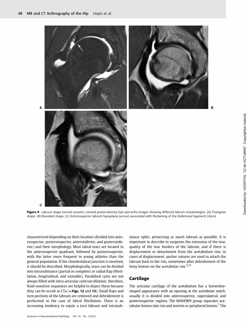
maybecomemore rounded (►Fig. 9). Although absence of thelabrum has been described in up to 16% of the population, inour experience this percentage is much lower. We have foundagenesia very infrequently with the occasional association ofanterior labral hypoplasia with thickening of the iliofemoralligament, especially in patients with pincer-type FAI. Wethink it could be a biomechanical adaptation. Labral tearsmay contribute to the progression of hip osteoarthritis; theyare closely related to cartilage lesions, especially those at thechondrolabral junction. The transition zone with acetabularhyaline cartilage is a difficult area to image and should becarefully analyzed to avoid under- or overdiagnosing labrumtears or cartilage defects because this is a frequent startingpoint for delaminating cartilage injuries. Fluid in the labraltear might furrow under the cartilage creating a carpet-likelesion or extend along the subchondral bone resulting in asubchondral cyst.1
It is important to become familiar with normal labralrecesses. The posteroinferior labrum has a frequent grooveor recess; however, there is still no consensus on the rele-vance of a sublabral recess located along the superior labrum.
Labral tearsmay be traumatic or secondary to entities suchas femoroacetabular impingement, hip dysplasia, instability,and degenerative change. Traumatic injuries can be acute orassociated with repetitive traumas, especially related tosports that require excessive rotation or kicking such as socceror martial arts.19
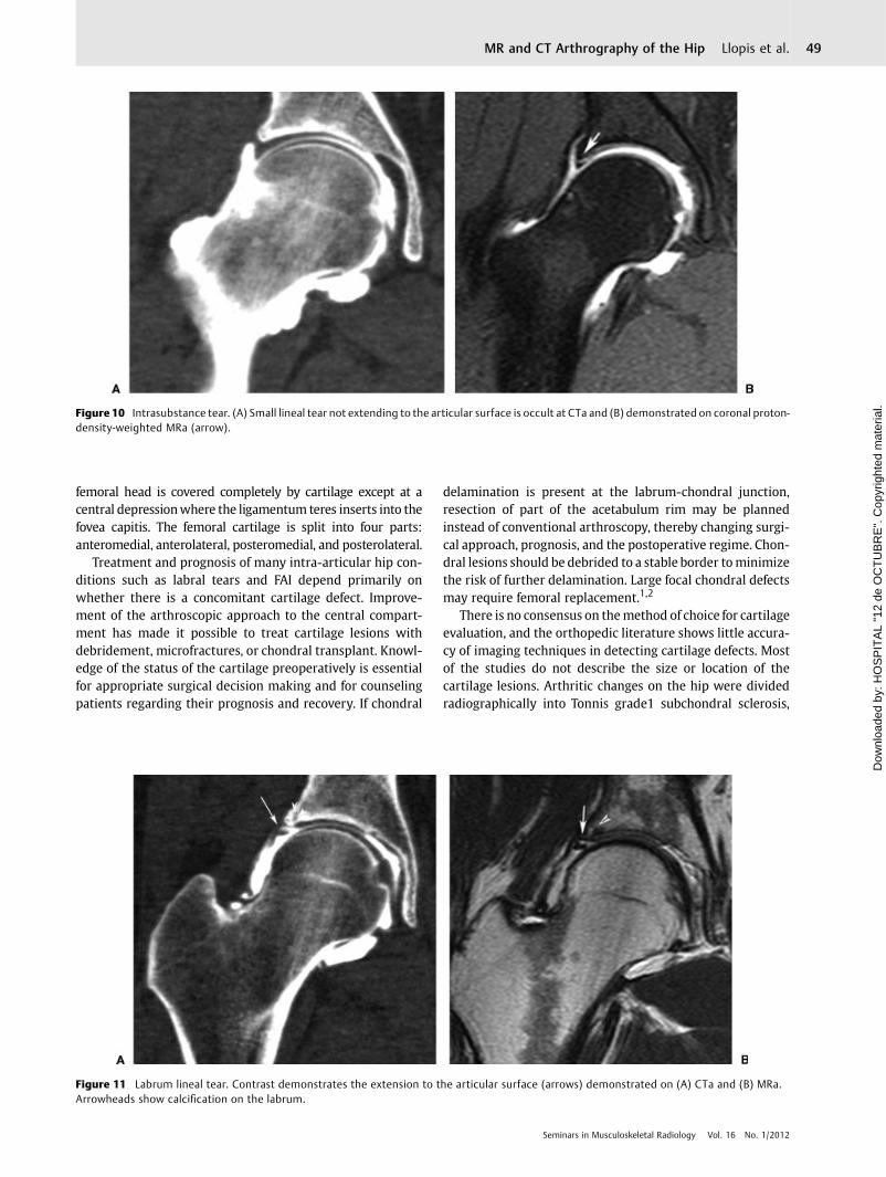
The diagnosis of a labral tear ismade on CTa andMRawhencontrast fluid gets inside the labrum. Fluid-sensitive sequen-ces are needed on MRa to detect intrasubstance labrum
changes, especially those that do not extend to the articularsurface. Unless calcified, these changes are missed on CTa(►Fig. 10). The best imaging planes for detecting labral tearsare the coronal and oblique sagittal images planes. Because ofthe obliquity of the anterosuperior and posterosuperioraspects of the labrum, some tears in these regions are missedon conventional planes. No additional value has been dem-onstrated with radial sequences. CTa has the option formultiplanar reconstruction without loss of image quality(►Figs. 11 and 12).20,21
The multicenter Arthroscopic Hip Outcomes ResearchNetwork (MAHORN) recently proposed a classification sys-tem for labral tears and chondral lesions (acetabular rim andacetabulum except the rim).1 Labral tears should be
Figure 7 The α angle is the angle between the femoral neck axis and aline connecting the center of the femoral head with the point ofbeginning asphericity of the head neck contour. An angle >55 degreesis an indicator of an abnormal femoral head neck contour.
Figure 8 Multidetector CT. (A) Coronal and (B) oblique sagittalreformats give precise images and information about bone deformity(arrows) and about cartilage defects such as this chondral lesion in thefemoral head (arrowheads).
Seminars in Musculoskeletal Radiology Vol. 16 No. 1/2012
MR and CT Arthrography of the Hip Llopis et al. 47
Dow
nloa
ded
by: H
OS
PIT
AL
"12
de O
CT
UB
RE
". C
opyr
ight
ed m
ater
ial.
characterized depending on their location (divided into ante-rosuperior, posterosuperior, anteroinferior, and posteroinfe-rior) and their morphology. Most labral tears are located inthe anterosuperior quadrant, followed by posterosuperior,with the latter more frequent in young athletes than thegeneral population. If the chondrolabral junction is involved,it should be described. Morphologically, tears can be dividedinto intrasubstance (partial or complete) or radial flap (fibril-lation, longitudinal, and unstable). Paralabral cysts are notalways filled with intra-articular contrast dilution; therefore,fluid-sensitive sequences are helpful to depict them becausethey can be occult at CTa (►Figs. 12 and 13). Small flaps andtorn portions of the labrum are removed and debridement isperformed in the case of labral fibrillation. There is anincreasing tendency to repair a torn labrum and intrasub-
stance splits, preserving as much labrum as possible. It isimportant to describe to surgeons the extension of the tear,quality of the tear borders of the labrum, and if there isdisplacement or detachment from the acetabulum rim; incases of displacement, anchor sutures are used to attach thelabrum back to the rim, sometimes after debridement of thebony lesions on the acetabular rim.2,21
Cartilage
The articular cartilage of the acetabulum has a horseshoe-shaped appearance with an opening at the acetabular notch;usually it is divided into anterosuperior, superolateral, andposterosuperior regions. The MAHORN group separates ace-tabular lesions into rim and nonrim or peripheral lesions.1 The
Figure 9 Labrum shape normal variants: coronal proton-density fast spin-echo images showing different labrum morphologies. (A) Triangularshape. (B) Rounded shape. (C) Anterosuperior labrum hypoplasia (arrow) associated with thickening of the iliofemoral ligament (stars).
Seminars in Musculoskeletal Radiology Vol. 16 No. 1/2012
MR and CT Arthrography of the Hip Llopis et al.48
Dow
nloa
ded
by: H
OS
PIT
AL
"12
de O
CT
UB
RE
". C
opyr
ight
ed m
ater
ial.
femoral head is covered completely by cartilage except at acentral depressionwhere the ligamentum teres inserts into thefovea capitis. The femoral cartilage is split into four parts:anteromedial, anterolateral, posteromedial, and posterolateral.
Treatment and prognosis of many intra-articular hip con-ditions such as labral tears and FAI depend primarily onwhether there is a concomitant cartilage defect. Improve-ment of the arthroscopic approach to the central compart-ment has made it possible to treat cartilage lesions withdebridement, microfractures, or chondral transplant. Knowl-edge of the status of the cartilage preoperatively is essentialfor appropriate surgical decision making and for counselingpatients regarding their prognosis and recovery. If chondral
delamination is present at the labrum-chondral junction,resection of part of the acetabulum rim may be plannedinstead of conventional arthroscopy, thereby changing surgi-cal approach, prognosis, and the postoperative regime. Chon-dral lesions should be debrided to a stable border tominimizethe risk of further delamination. Large focal chondral defectsmay require femoral replacement.1,2
There is no consensus on themethod of choice for cartilageevaluation, and the orthopedic literature shows little accura-cy of imaging techniques in detecting cartilage defects. Mostof the studies do not describe the size or location of thecartilage lesions. Arthritic changes on the hip were dividedradiographically into Tonnis grade1 subchondral sclerosis,
Figure 10 Intrasubstance tear. (A) Small lineal tear not extending to the articular surface is occult at CTa and (B) demonstrated on coronal proton-density-weighted MRa (arrow).
Figure 11 Labrum lineal tear. Contrast demonstrates the extension to the articular surface (arrows) demonstrated on (A) CTa and (B) MRa.Arrowheads show calcification on the labrum.
Seminars in Musculoskeletal Radiology Vol. 16 No. 1/2012
MR and CT Arthrography of the Hip Llopis et al. 49
Dow
nloa
ded
by: H
OS
PIT
AL
"12
de O
CT
UB
RE
". C
opyr
ight
ed m
ater
ial.
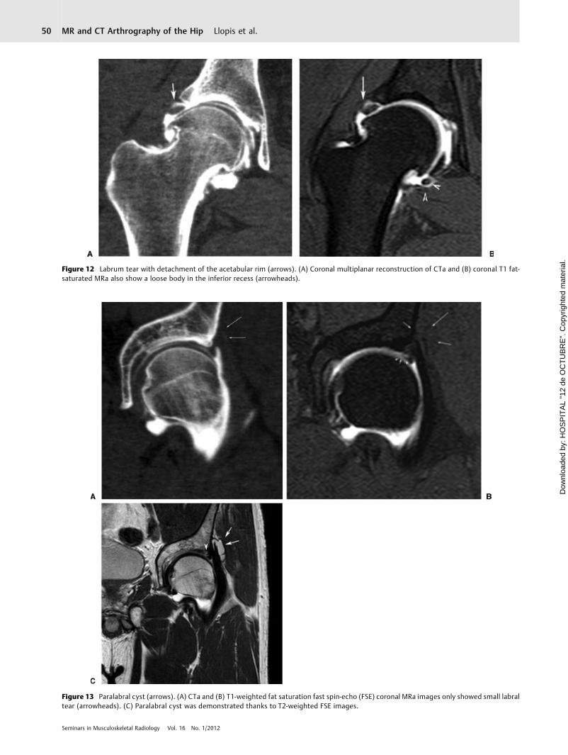
Figure 12 Labrum tear with detachment of the acetabular rim (arrows). (A) Coronal multiplanar reconstruction of CTa and (B) coronal T1 fat-saturated MRa also show a loose body in the inferior recess (arrowheads).
Figure 13 Paralabral cyst (arrows). (A) CTa and (B) T1-weighted fat saturation fast spin-echo (FSE) coronal MRa images only showed small labraltear (arrowheads). (C) Paralabral cyst was demonstrated thanks to T2-weighted FSE images.
Seminars in Musculoskeletal Radiology Vol. 16 No. 1/2012
MR and CT Arthrography of the Hip Llopis et al.50
Dow
nloa
ded
by: H
OS
PIT
AL
"12
de O
CT
UB
RE
". C
opyr
ight
ed m
ater
ial.
Tonnis grade 2 partial joint space narrowing, and Tonnis grade3 complete joint narrowing. However, this grading systemonly shows late changes, and imaging techniques for earlierdepiction of cartilage lesions are needed (►Fig. 14). Delami-nation cysts have been described as an indirect radiologicalsign related to an underlying cartilage defect, evidenced by anacetabulum cyst or a subchondral crack in the acetabulum.These cysts are better visualized on CT, especially on CTawhere the cartilage is outlined (►Fig. 15).22
Cartilage defects are frequently classified arthroscopi-cally using the Outerbridge staging system. This system isuseful for femoral head and nonrim acetabulum but notvalid for acetabulum rim lesions. The MAHORN system hasbeen accepted by the International Cartilage Repair Societyfor a rim and nonrim staging system.1 A modified Outer-
bridge classification can be used on MR (grade 0, normal; 1,abnormal signal intensity and surface slightly irregular; 2,<50% focal or diffuse chondral loss; 3, excessive cartilagedefects) or simplified by dividing defects into completedefect (>50%), partial defect (<50%), fissures, and fibrilla-tion (►Figs. 16, 17, and 18). However, reports should includeextent of the chondral lesion, thickness, if chondrolabraljunction is or is not affected, its detachment from subchon-dral bone, and if there is an associated flap. MRa and CTahave adopted the same staging system. Adding traction tothe arthrography procedure allows contrast to extend be-tween acetabular and femoral surfaces in 70% of the cases,thereby improving the ability to depict lesions.12 CTa hasbeen demonstrated in other joints as a valuable tool forcartilage detection due to its excellent spatial resolution and
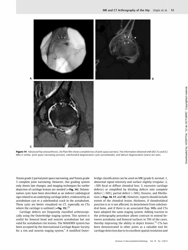
Figure 14 Advanced hip osteoarthrosis. (A) Plain film shows complete loss of joint space (arrows). The information obtained with (B) CTa and (C)MRa is similar. Joint space narrowing (arrows), subchondral degenerative cysts (arrowheads), and labrum degeneration (stars) are seen.
Seminars in Musculoskeletal Radiology Vol. 16 No. 1/2012
MR and CT Arthrography of the Hip Llopis et al. 51
Dow
nloa
ded
by: H
OS
PIT
AL
"12
de O
CT
UB
RE
". C
opyr
ight
ed m
ater
ial.
contrast resolution. The higher signal intensity variabilityon MR with artifacts due to magnetic field inhomogeneitiesand partial imbibition of the contrast by the cartilage makeit more difficult to depict small cartilage lesions at MR.23 Aslightly higher resolution of CTa compared with MRa hasbeen published, and this is consistent with our experiencebecause defects are better detected at CTa and also smalldelamination cysts are better seen, increasing our confi-dence in the diagnosis.6
Delaminating chondral lesions are a common abnormalityassociated with FAI, especially with the cam type (►Fig. 19).Acetabular overcoverage might be protective against delami-nation.24 Hypointense areas in the acetabular cartilage seenon intermediate-weighted fat-saturated or T1-weighted im-ages have been described as a reliable radiological sign ofdelamination.25 Careful attention should be directed at thechondrolabral junction. Sometimes, especially after traction,fluid separates the femoral and acetabular cartilage and helpsto delineate these lesions.12
Instability
Hip instability is unusual due to the strong capsular andmuscular support of the hip joint. The capsule is reinforcedby three longitudinal ligaments—iliofemoral, pubofemoral,and ischiofemoral—and circumferentially by the zona orbi-cularis. Instability can be traumatic or atraumatic, traumaticsecondary to dislocation or subluxation of the femoral headproduced by high energy, or atraumatic as a result of overuseor hyperlaxity. Overuse is usually focal and rotational inpatients requiring great flexion movements such as in mar-tial arts or in sports with excessive rotation maneuvers suchas golf. Recently concern was raised over postcapsulotomyinstability secondary to iliofemoral ligament injury.2 If cap-sular ligaments are injured, excessive load is placed on the
dynamic stabilizers such as the iliopsoas and abductorstendons.26
Ligamentum Teres
The ligamentum teres has only recently been appreciated as acause of hip pain. Its biomechanical function is not yetcompletely clear. Gray and Villar divided tears into type Icomplete (associated with traumas that frequently havelabrum and chondral injuries); type II partial, and type IIIdegenerative. CTa and especially MRa are superior to con-ventional MR for detecting and grading ligamentum terestears. The oblique axial plane is particularly useful because ofits normal orientation. Chronic injuries show granulationtissue with increased signal intensity and irregular contourof the ligament. Thickening of the proximal ligamentum teressecondary to degeneration and partial ruptures might causemechanical impingement (►Fig. 20).26,27
Synovial Plica
Synovial plicae are remnants of the synovial membranes andcommonly located at the interface of articular surfaces andderived from mesenchymal tissue. Two morphological var-iants have been reported: flat (leaflike) and villous. Theirfunction includes synovial fluid production, transmission ofneurovascular structures, and joint stabilization. Dependingon their location they are divided into superior, middle, andinferior, and recently new ones have been described: neckplicae, ligamentous plicae, and labral plicae. Labral plicae arelocated between the acetabulum labrum and the anteriorjoint capsule, and they can be flat or villous with the latterincreasingwith aging andmainly located along the transverseligament. They have been associated with entrapment duringmedial rotation of the thigh. A neck plica is a linear
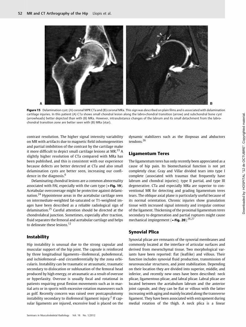
Figure 15 Delamination cyst: (A) coronal MPR CTa and (B) coronal MRa. This sign was described on plain films and is associated with delaminationcartilage injuries. In this patient (A) CTa shows small chondral lesion along the labro-chondral transition (arrow) and subchondral bone cyst(arrowheads) better depicted than with (B) MRa. However, intrasubstance changes of the labrum and its small detachment from the labro-chondral transition zone are better seen with (B) MRa (star).
Seminars in Musculoskeletal Radiology Vol. 16 No. 1/2012
MR and CT Arthrography of the Hip Llopis et al.52
Dow
nloa
ded
by: H
OS
PIT
AL
"12
de O
CT
UB
RE
". C
opyr
ight
ed m
ater
ial.

hypointense structure that extends from the anterior aspectof the intertrochanteric area, along the anterior aspect of thefemoral neck to the articular margin of the femoral head. Thepectinofoveal fold is a subtype of medial or neck plica fromthe lesser trochanter to the fovea capitis of the femur(►Fig. 21). The ligament plica extends parallel to the liga-mentum teres from its base at the acetabular fossa and shouldnot be mistaken for ligament teres split tears (►Fig. 20).28
Figure 17 Small chondral lesion in the labro-chondral junction (arrow). (A) CTa better outlines the chondral defect than the MRa (B).
Figure 18 Coronal T1 fat saturation fast spin-echo MRa image showsirregularities on the acetabulum surface (arrowheads) and a smallchondral flap with contrast extending through the subchondral-chondral junction (arrows).
Figure 16 Chondral flap. (A) Coronal multiplanar reconstruction CTand (B) coronal T1-weighted fast spin-echo fat-saturated MRa showcontrast at the labral-chondral junction and extending to the sub-chondral labral transition (arrows) creating a flap lesion.
Seminars in Musculoskeletal Radiology Vol. 16 No. 1/2012
MR and CT Arthrography of the Hip Llopis et al. 53
Dow
nloa
ded
by: H
OS
PIT
AL
"12
de O
CT
UB
RE
". C
opyr
ight
ed m
ater
ial.
Folds and normal plicae should not be confused withsymptomatic plicae. Ligament plicae can thicken and causemechanical painwith clicking and popping in young athletes.There are only a few cases described in the literature, and allhave plicae thicker than 4 mm.29
Loose Bodies
Intra-articular loose bodies are defined as rounded oroblong filling defects completely or nearly completely
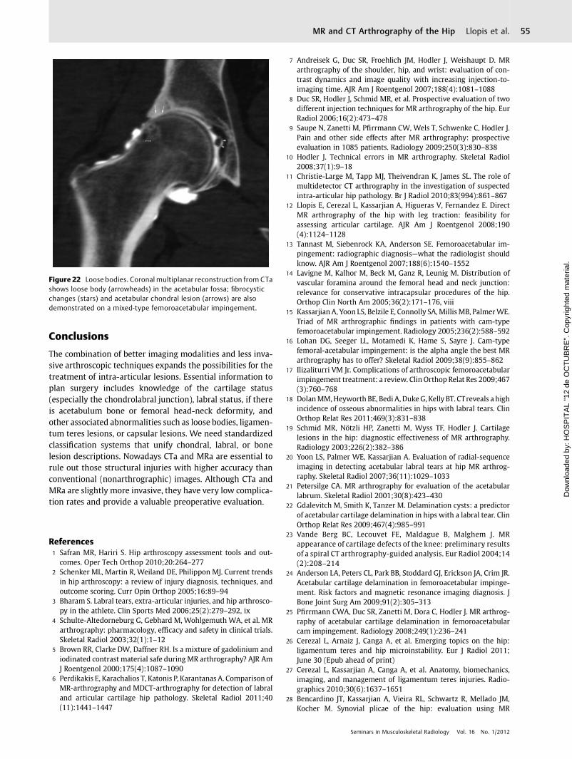
surrounded by contrast material. They can be cartilagi-nous, osseous, or mixed. If the defect is more elongated andconnected with the capsule or plica, it is usually a synovialfold or synovitis. The most frequent locations for loosebodies are the fovea and inferior recess. Loose bodies maybe secondary to acute or chronic trauma, fragments asso-ciated with osteoarthrosis, osteochondritis dissecans,and primary osteochondromatosis. The sensitivity ofMRa has been reported as 50% and specificity as 96%(►Fig. 22).30
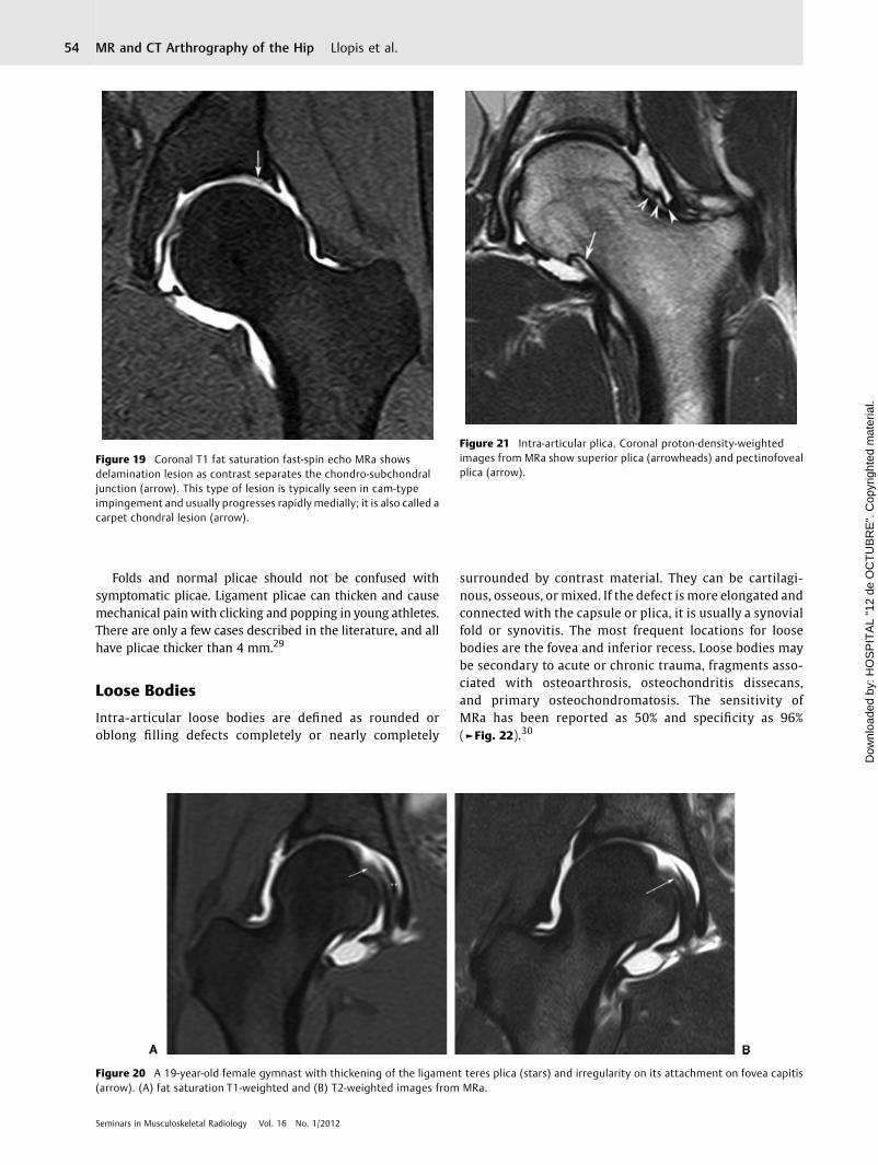
Figure 19 Coronal T1 fat saturation fast-spin echo MRa showsdelamination lesion as contrast separates the chondro-subchondraljunction (arrow). This type of lesion is typically seen in cam-typeimpingement and usually progresses rapidly medially; it is also called acarpet chondral lesion (arrow).
Figure 20 A 19-year-old female gymnast with thickening of the ligament teres plica (stars) and irregularity on its attachment on fovea capitis(arrow). (A) fat saturation T1-weighted and (B) T2-weighted images from MRa.
Figure 21 Intra-articular plica. Coronal proton-density-weightedimages from MRa show superior plica (arrowheads) and pectinofovealplica (arrow).
Seminars in Musculoskeletal Radiology Vol. 16 No. 1/2012
MR and CT Arthrography of the Hip Llopis et al.54
Dow
nloa
ded
by: H
OS
PIT
AL
"12
de O
CT
UB
RE
". C
opyr
ight
ed m
ater
ial.
Conclusions
The combination of better imaging modalities and less inva-sive arthroscopic techniques expands the possibilities for thetreatment of intra-articular lesions. Essential information toplan surgery includes knowledge of the cartilage status(especially the chondrolabral junction), labral status, if thereis acetabulum bone or femoral head-neck deformity, andother associated abnormalities such as loose bodies, ligamen-tum teres lesions, or capsular lesions. We need standardizedclassification systems that unify chondral, labral, or bonelesion descriptions. Nowadays CTa and MRa are essential torule out those structural injuries with higher accuracy thanconventional (nonarthrographic) images. Although CTa andMRa are slightly more invasive, they have very low complica-tion rates and provide a valuable preoperative evaluation.
References1 Safran MR, Hariri S. Hip arthroscopy assessment tools and out-
comes. Oper Tech Orthop 2010;20:264–2772 Schenker ML, Martin R, Weiland DE, Philippon MJ. Current trends
in hip arthroscopy: a review of injury diagnosis, techniques, andoutcome scoring. Curr Opin Orthop 2005;16:89–94
3 Bharam S. Labral tears, extra-articular injuries, and hip arthrosco-py in the athlete. Clin Sports Med 2006;25(2):279–292, ix
4 Schulte-Altedorneburg G, Gebhard M, Wohlgemuth WA, et al. MRarthrography: pharmacology, efficacy and safety in clinical trials.Skeletal Radiol 2003;32(1):1–12
5 Brown RR, Clarke DW, Daffner RH. Is a mixture of gadolinium andiodinated contrast material safe during MR arthrography? AJR AmJ Roentgenol 2000;175(4):1087–1090
6 Perdikakis E, Karachalios T, Katonis P, Karantanas A. Comparison ofMR-arthrography and MDCT-arthrography for detection of labraland articular cartilage hip pathology. Skeletal Radiol 2011;40(11):1441–1447
7 Andreisek G, Duc SR, Froehlich JM, Hodler J, Weishaupt D. MRarthrography of the shoulder, hip, and wrist: evaluation of con-trast dynamics and image quality with increasing injection-to-imaging time. AJR Am J Roentgenol 2007;188(4):1081–1088
8 Duc SR, Hodler J, Schmid MR, et al. Prospective evaluation of twodifferent injection techniques for MR arthrography of the hip. EurRadiol 2006;16(2):473–478
9 Saupe N, Zanetti M, Pfirrmann CW, Wels T, Schwenke C, Hodler J.Pain and other side effects after MR arthrography: prospectiveevaluation in 1085 patients. Radiology 2009;250(3):830–838
10 Hodler J. Technical errors in MR arthrography. Skeletal Radiol2008;37(1):9–18
11 Christie-Large M, Tapp MJ, Theivendran K, James SL. The role ofmultidetector CT arthrography in the investigation of suspectedintra-articular hip pathology. Br J Radiol 2010;83(994):861–867
12 Llopis E, Cerezal L, Kassarjian A, Higueras V, Fernandez E. DirectMR arthrography of the hip with leg traction: feasibility forassessing articular cartilage. AJR Am J Roentgenol 2008;190(4):1124–1128
13 Tannast M, Siebenrock KA, Anderson SE. Femoroacetabular im-pingement: radiographic diagnosis—what the radiologist shouldknow. AJR Am J Roentgenol 2007;188(6):1540–1552
14 Lavigne M, Kalhor M, Beck M, Ganz R, Leunig M. Distribution ofvascular foramina around the femoral head and neck junction:relevance for conservative intracapsular procedures of the hip.Orthop Clin North Am 2005;36(2):171–176, viii
15 Kassarjian A, Yoon LS, Belzile E, Connolly SA,Millis MB, PalmerWE.Triad of MR arthrographic findings in patients with cam-typefemoroacetabular impingement. Radiology 2005;236(2):588–592
16 Lohan DG, Seeger LL, Motamedi K, Hame S, Sayre J. Cam-typefemoral-acetabular impingement: is the alpha angle the best MRarthrography has to offer? Skeletal Radiol 2009;38(9):855–862
17 Ilizaliturri VM Jr. Complications of arthroscopic femoroacetabularimpingement treatment: a review. Clin Orthop Relat Res 2009;467(3):760–768
18 DolanMM,Heyworth BE, Bedi A, DukeG, Kelly BT. CTreveals a highincidence of osseous abnormalities in hips with labral tears. ClinOrthop Relat Res 2011;469(3):831–838
19 Schmid MR, Nötzli HP, Zanetti M, Wyss TF, Hodler J. Cartilagelesions in the hip: diagnostic effectiveness of MR arthrography.Radiology 2003;226(2):382–386
20 Yoon LS, Palmer WE, Kassarjian A. Evaluation of radial-sequenceimaging in detecting acetabular labral tears at hip MR arthrog-raphy. Skeletal Radiol 2007;36(11):1029–1033
21 Petersilge CA. MR arthrography for evaluation of the acetabularlabrum. Skeletal Radiol 2001;30(8):423–430
22 Gdalevitch M, Smith K, Tanzer M. Delamination cysts: a predictorof acetabular cartilage delamination in hips with a labral tear. ClinOrthop Relat Res 2009;467(4):985–991
23 Vande Berg BC, Lecouvet FE, Maldague B, Malghem J. MRappearance of cartilage defects of the knee: preliminary resultsof a spiral CT arthrography-guided analysis. Eur Radiol 2004;14(2):208–214
24 Anderson LA, Peters CL, Park BB, Stoddard GJ, Erickson JA, Crim JR.Acetabular cartilage delamination in femoroacetabular impinge-ment. Risk factors and magnetic resonance imaging diagnosis. JBone Joint Surg Am 2009;91(2):305–313
25 Pfirrmann CWA, Duc SR, Zanetti M, Dora C, Hodler J. MR arthrog-raphy of acetabular cartilage delamination in femoroacetabularcam impingement. Radiology 2008;249(1):236–241
26 Cerezal L, Arnaiz J, Canga A, et al. Emerging topics on the hip:ligamentum teres and hip microinstability. Eur J Radiol 2011;June 30 (Epub ahead of print)
27 Cerezal L, Kassarjian A, Canga A, et al. Anatomy, biomechanics,imaging, and management of ligamentum teres injuries. Radio-graphics 2010;30(6):1637–1651
28 Bencardino JT, Kassarjian A, Vieira RL, Schwartz R, Mellado JM,Kocher M. Synovial plicae of the hip: evaluation using MR
Figure 22 Loose bodies. Coronal multiplanar reconstruction from CTashows loose body (arrowheads) in the acetabular fossa; fibrocysticchanges (stars) and acetabular chondral lesion (arrows) are alsodemonstrated on a mixed-type femoroacetabular impingement.
Seminars in Musculoskeletal Radiology Vol. 16 No. 1/2012
MR and CT Arthrography of the Hip Llopis et al. 55
Dow
nloa
ded
by: H
OS
PIT
AL
"12
de O
CT
UB
RE
". C
opyr
ight
ed m
ater
ial.

arthrography in patients with hip pain. Skeletal Radiol 2011;40(4):415–421
29 Katz LD, Haims A, Medvecky M, McCallum J. Symptomatic hipplica: MR arthrographic and arthroscopic correlation. SkeletalRadiol 2010;39(12):1255–1258
30 Neckers AC, Polster JM, Winalski CS, Krebs VE, Sundaram M.Comparison of MR arthrography with arthroscopy of the hip forthe assessment of intra-articular loose bodies. Skeletal Radiol2007;36(10):963–967
Seminars in Musculoskeletal Radiology Vol. 16 No. 1/2012
MR and CT Arthrography of the Hip Llopis et al.56
Dow
nloa
ded
by: H
OS
PIT
AL
"12
de O
CT
UB
RE
". C
opyr
ight
ed m
ater
ial.