modelling and analysis of a romanesque church under earthquake loading: assessment of seismic...
TRANSCRIPT
Engineering Structures 30 (2008) 352–367www.elsevier.com/locate/engstruct
Modelling and analysis of a Romanesque church under earthquake loading:Assessment of seismic resistance
Michele Betti∗, Andrea Vignoli1
Department of Civil and Environmental Engineering, University of Florence, I-50139 Florence, Italy
Received 17 November 2005; received in revised form 13 March 2007; accepted 14 March 2007Available online 21 May 2007
Abstract
In this paper a Romanesque masonry church is analysed in order to assess its structural behaviour and its seismic vulnerability with respectto the actual state of conservation. Starting from a specific case study, a contribution to the issue of modelling and analysis of monumentalmasonry buildings under seismic action is provided. A finite element methodology for the static and dynamic nonlinear analysis of historicalmasonry structures is described and applied to the case study. A quasi-static approach (the seismic coefficient method) for the evaluation of theseismic loads has been used (as indeed is common in many analyses of the seismic behaviour of masonry structures). The comparison demand vs.capacity confirms the susceptibility of this type of building to extensive damage and possibly to collapse, as frequently observed. Moreover theactual efficiency of current techniques for repairing and strengthening are analyzed in order to evaluate their benefits. The analysis of repairing andstrengthening techniques show the effectiveness of the usual structural reinforcement in terms of increased seismic capacity. The paper advocatesthat significant information can be obtained from advanced numerical analysis, namely with respect to the understanding of existing damage andto the minimum and adequate design of strengthening. A clear understanding of the structural behaviour and reliable strengthening, based onsophisticated tools of structural analysis, can therefore reduce the extent of the remedial measures in the restoration of ancient structures.c© 2007 Elsevier Ltd. All rights reserved.
Keywords: Romanesque church buildings; Earthquake loading; Nonlinear analysis; FE modelling; Seismic vulnerability; Strengthening techniques
1. Introduction
A large portion of the Italian cultural heritage is providedby Church masonry building. These historical buildings havedemonstrated during the past to be particularly susceptible todamage, and prone to partial or total collapse, under earthquakeloads, sometimes due to non-respectful restoration [1,2]. As amatter of fact repairs and retrofitting techniques should alwaysrespect the original existence; any intervention not respectful ofit could also create incompatibility with the original structuralbehaviour.
Masonry buildings are generally able to carry the verticalloads in a very safe and stable way, while they are rathersensitive, from a structural point of view, to horizontal loads.
∗ Corresponding author. Tel.: +39 055 4796 326; fax: +39 055 495 333.E-mail addresses: [email protected] (M. Betti), [email protected]
(A. Vignoli).1 Tel.: +39 055 4796 214; fax: +39 055 495 433.
0141-0296/$ - see front matter c© 2007 Elsevier Ltd. All rights reserved.doi:10.1016/j.engstruct.2007.03.027
The high seismic vulnerability of this type of building is dueboth to the particular configuration (often characterized by openspace, slender walls, lack of effective connections among thestructural elements) and to the mechanical properties of themasonry material (highly nonlinear behaviour and very smalltensile strength). If in principle, the prediction of the structuralresponse of monumental buildings is not different from that ofother constructed facilities (e.g. a bridge) it is an even morechallenging task for several reasons [3–5].
Each monumental building is by definition a unique buildingcharacterised by its own history, often resulting in a compositemixture of added or substituted structural elements, stronglyinteracting; the dynamic (and static, for that matter) behaviourof ancient buildings is normally too complicated to beinterpreted by simple mechanical models. In particular tryingto extrapolate analytical procedures specifically developed formodern buildings is in most cases inadequate, since the staticdiagram is substantially different from the one of modernstructures made of trusses and frames. Moreover it is quite
M. Betti, A. Vignoli / Engineering Structures 30 (2008) 352–367 353
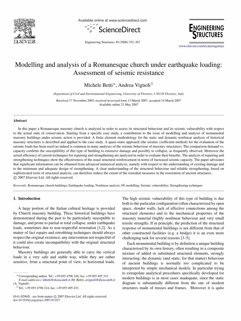
Fig. 1. Aerial view of the Farneta abbey.
difficult to perform reliable quantitative strength evaluations,due to the difficulty of gathering experimental data on theresistance of the structural elements and even on the mechanicalproperties of the materials on site [6–8]. Restrictions in thepossibility to inspect the construction, or difficulties on theremoval of specimens in buildings of historical value (as well asthe high costs involved in inspection and diagnosis) often resultin limited information about the internal constructive system orthe properties of existing materials. Moreover, another aspectthat it’s important to take into account, is that structuralresistance of material decreases in time due to deterioration,and this degradation is frequently accelerated by neglect orcarelessness.
In brief, monumental historical buildings are by definitionbuildings that it’s difficult to reduce to any standard structuralscheme because of the uncertainties that affect the structuralbehaviour and mechanical properties. The above considerationsexplain the need of specific modelling and analysis strategiesfor historic masonry constructions.
In this paper, starting from a single case study, a contributionto the issue of modelling and analysis of Romanesque churchesunder seismic action is provided: a relevant case studythat demonstrates the careful use of numerical analyses toface practical engineering problems in the field of historicalconstruction is presented.
An evaluation of the capacity of the church to withstandlateral loads together with the expected demands from seismicactions is also given. The effects of the current techniques forrepairing and strengthening are then investigated in order toevaluate the effectiveness of the usual retrofitting techniques.
2. The object of study
2.1. Description of the structure
This paper addresses the concern of seismic analysis andvulnerability of Romanesque churches with respect to a specificcase study: the Farneta abbey (see Fig. 1). This church islocated in Val di Chiana (Cortona, Italy). The plan view showsthe typical basilica layout with the main nave, the clerestorytransept and a triple apse (see Fig. 2). The main dimensionswere a maximum length of about 26.5 m, a maximum widthof 21.5 m and a wall height of about 11.0 m. The masonry
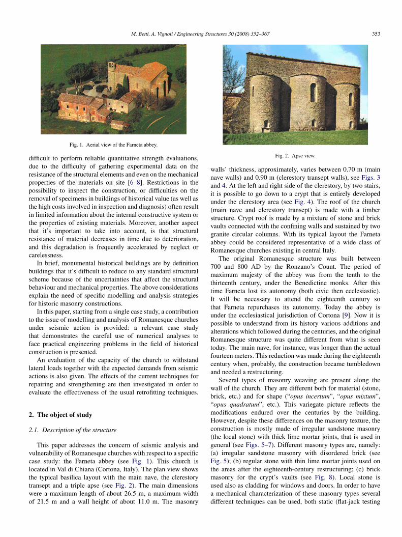
Fig. 2. Apse view.
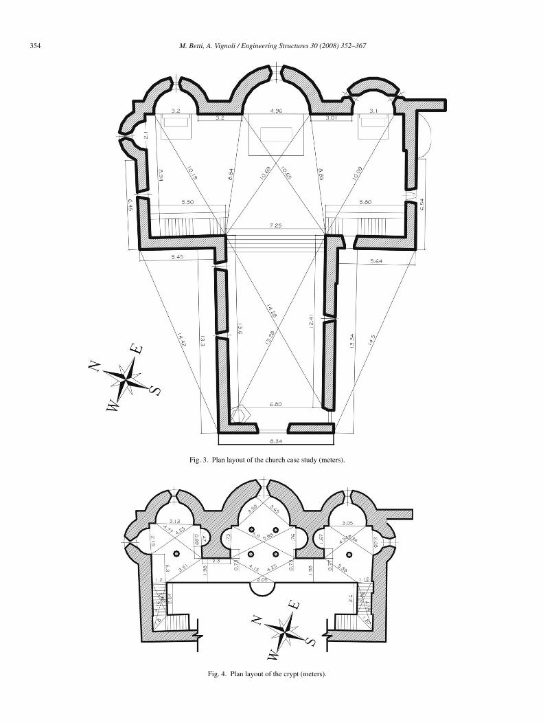
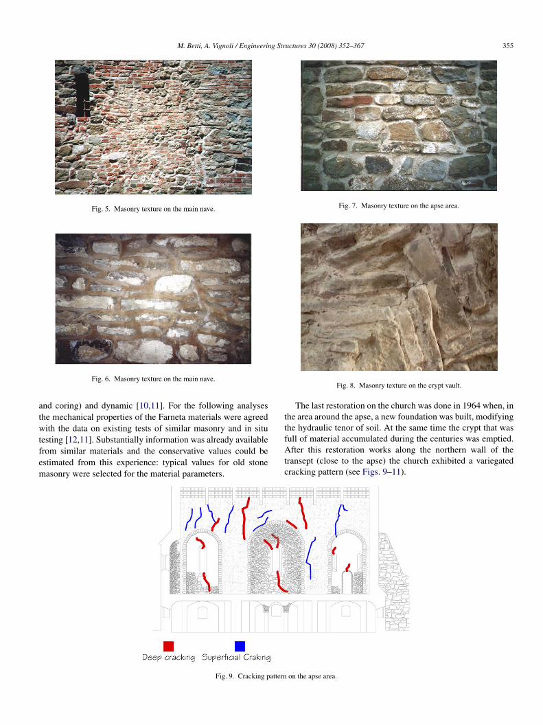
walls’ thickness, approximately, varies between 0.70 m (mainnave walls) and 0.90 m (clerestory transept walls), see Figs. 3and 4. At the left and right side of the clerestory, by two stairs,it is possible to go down to a crypt that is entirely developedunder the clerestory area (see Fig. 4). The roof of the church(main nave and clerestory transept) is made with a timberstructure. Crypt roof is made by a mixture of stone and brickvaults connected with the confining walls and sustained by twogranite circular columns. With its typical layout the Farnetaabbey could be considered representative of a wide class ofRomanesque churches existing in central Italy.
The original Romanesque structure was built between700 and 800 AD by the Ronzano’s Count. The period ofmaximum majesty of the abbey was from the tenth to thethirteenth century, under the Benedictine monks. After thistime Farneta lost its autonomy (both civic then ecclesiastic).It will be necessary to attend the eighteenth century sothat Farneta repurchases its autonomy. Today the abbey isunder the ecclesiastical jurisdiction of Cortona [9]. Now it ispossible to understand from its history various additions andalterations which followed during the centuries, and the originalRomanesque structure was quite different from what is seentoday. The main nave, for instance, was longer than the actualfourteen meters. This reduction was made during the eighteenthcentury when, probably, the construction became tumbledownand needed a restructuring.
Several types of masonry weaving are present along thewall of the church. They are different both for material (stone,brick, etc.) and for shape (“opus incertum”, “opus mixtum”,“opus quadratum”, etc.). This variegate picture reflects themodifications endured over the centuries by the building.However, despite these differences on the masonry texture, theconstruction is mostly made of irregular sandstone masonry(the local stone) with thick lime mortar joints, that is used ingeneral (see Figs. 5–7). Different masonry types are, namely:(a) irregular sandstone masonry with disordered brick (seeFig. 5); (b) regular stone with thin lime mortar joints used onthe areas after the eighteenth-century restructuring; (c) brickmasonry for the crypt’s vaults (see Fig. 8). Local stone isused also as cladding for windows and doors. In order to havea mechanical characterization of these masonry types severaldifferent techniques can be used, both static (flat-jack testing
354 M. Betti, A. Vignoli / Engineering Structures 30 (2008) 352–367
Fig. 3. Plan layout of the church case study (meters).
Fig. 4. Plan layout of the crypt (meters).
M. Betti, A. Vignoli / Engineering Structures 30 (2008) 352–367 355
Fig. 5. Masonry texture on the main nave.
Fig. 6. Masonry texture on the main nave.
and coring) and dynamic [10,11]. For the following analysesthe mechanical properties of the Farneta materials were agreedwith the data on existing tests of similar masonry and in situtesting [12,11]. Substantially information was already availablefrom similar materials and the conservative values could beestimated from this experience: typical values for old stonemasonry were selected for the material parameters.
Fig. 7. Masonry texture on the apse area.
Fig. 8. Masonry texture on the crypt vault.
The last restoration on the church was done in 1964 when, inthe area around the apse, a new foundation was built, modifyingthe hydraulic tenor of soil. At the same time the crypt that wasfull of material accumulated during the centuries was emptied.After this restoration works along the northern wall of thetransept (close to the apse) the church exhibited a variegatedcracking pattern (see Figs. 9–11).
Fig. 9. Cracking pattern on the apse area.
356 M. Betti, A. Vignoli / Engineering Structures 30 (2008) 352–367
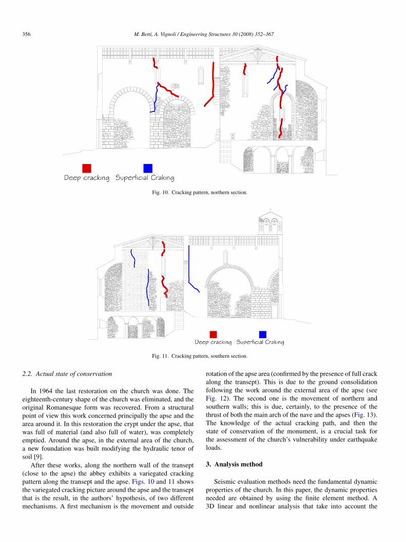
Fig. 10. Cracking pattern, northern section.
Fig. 11. Cracking pattern, southern section.
2.2. Actual state of conservation
In 1964 the last restoration on the church was done. Theeighteenth-century shape of the church was eliminated, and theoriginal Romanesque form was recovered. From a structuralpoint of view this work concerned principally the apse and thearea around it. In this restoration the crypt under the apse, thatwas full of material (and also full of water), was completelyemptied. Around the apse, in the external area of the church,a new foundation was built modifying the hydraulic tenor ofsoil [9].
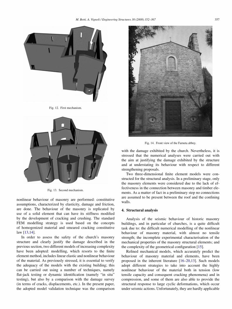
After these works, along the northern wall of the transept(close to the apse) the abbey exhibits a variegated crackingpattern along the transept and the apse. Figs. 10 and 11 showsthe variegated cracking picture around the apse and the transeptthat is the result, in the authors’ hypothesis, of two differentmechanisms. A first mechanism is the movement and outside
rotation of the apse area (confirmed by the presence of full crackalong the transept). This is due to the ground consolidationfollowing the work around the external area of the apse (seeFig. 12). The second one is the movement of northern andsouthern walls; this is due, certainly, to the presence of thethrust of both the main arch of the nave and the apses (Fig. 13).The knowledge of the actual cracking path, and then thestate of conservation of the monument, is a crucial task forthe assessment of the church’s vulnerability under earthquakeloads.
3. Analysis method
Seismic evaluation methods need the fundamental dynamicproperties of the church. In this paper, the dynamic propertiesneeded are obtained by using the finite element method. A3D linear and nonlinear analysis that take into account the
M. Betti, A. Vignoli / Engineering Structures 30 (2008) 352–367 357
Fig. 12. First mechanism.
Fig. 13. Second mechanism.
nonlinear behaviour of masonry are performed: constitutiveassumptions, characterized by elasticity, damage and friction,are done. The behaviour of the masonry is replicated byuse of a solid element that can have its stiffness modifiedby the development of cracking and crushing. The standardFEM modelling strategy is used based on the conceptsof homogenized material and smeared cracking constitutivelaw [13,14].
In order to assess the safety of the church’s masonrystructure and clearly justify the damage described in theprevious section, two different models of increasing complexityhave been adopted: modelling, which resorts to the finiteelement method, includes linear elastic and nonlinear behaviourof the material. As previously stressed, it is essential to verifythe adequacy of the models with the existing building; thiscan be carried out using a number of techniques, namelyflat-jack testing or dynamic identification (namely “in situ”testing), but also by a comparison with the damage survey(in terms of cracks, displacements, etc.). In the present paper,the adopted model validation technique was the comparison
Fig. 14. Front view of the Farneta abbey.
with the damage exhibited by the church. Nevertheless, it isstressed that the numerical analyses were carried out withthe aim at justifying the damage exhibited by the structureand at understating its behaviour with respect to differentstrengthening proposals.
Two three-dimensional finite element models were con-structed for the structural analysis. In a preliminary stage, onlythe masonry elements were considered due to the lack of ef-fectiveness in the connection between masonry and timber ele-ments. As a matter of fact in a preliminary step no connectionsare assumed to be present between the roof and the confiningwalls.
4. Structural analysis
Analysis of the seismic behaviour of historic masonrybuildings, and in particular of churches, is a quite difficulttask due to: the difficult numerical modelling of the nonlinearbehaviour of masonry material, with almost no tensilestrength; the incomplete experimental characterisation of themechanical properties of the masonry structural elements; andthe complexity of the geometrical configuration [15].
Refined mechanical models, which accurately predict thebehaviour of masonry material and elements, have beenproposed in the inherent literature [16–20,13]. Such modelsadopt different strategies to take into account the highlynonlinear behaviour of the material both in tension (lowtensile capacity and consequent cracking phenomena) and incompression, and some of them are also able to provide thestructural response to large cyclic deformations, which occurunder seismic actions. Unfortunately, they are hardly applicable
358 M. Betti, A. Vignoli / Engineering Structures 30 (2008) 352–367
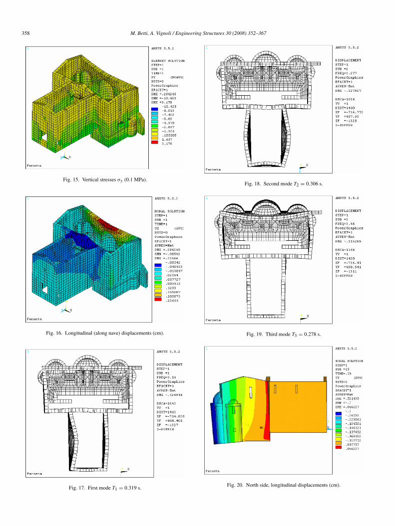
Fig. 15. Vertical stresses σy (0.1 MPa).
Fig. 16. Longitudinal (along nave) displacements (cm).
Fig. 17. First mode T1 = 0.319 s.
Fig. 18. Second mode T2 = 0.306 s.
Fig. 19. Third mode T3 = 0.278 s.
Fig. 20. North side, longitudinal displacements (cm).
M. Betti, A. Vignoli / Engineering Structures 30 (2008) 352–367 359
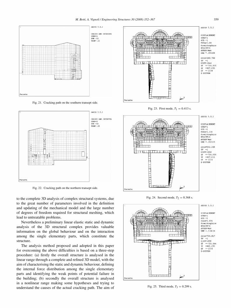
Fig. 21. Cracking path on the southern transept side.
Fig. 22. Cracking path on the northern transept side.
to the complete 3D analysis of complex structural systems, dueto the great number of parameters involved in the definitionand updating of the mechanical model and the large numberof degrees of freedom required for structural meshing, whichlead to untreatable problems.
Nevertheless a preliminary linear elastic static and dynamicanalysis of the 3D structural complex provides valuableinformation on the global behaviour and on the interactionamong the single elementary parts, which constitute thestructure.
The analysis method proposed and adopted in this paperfor overcoming the above difficulties is based on a three-stepprocedure: (a) firstly the overall structure is analysed in thelinear range through a complete and refined 3D model, with theaim of characterising the static and dynamic behaviour, definingthe internal force distribution among the single elementaryparts and identifying the weak points of potential failure inthe building; (b) secondly the overall structure is analysedin a nonlinear range making some hypotheses and trying tounderstand the causes of the actual cracking path. The aim of
Fig. 23. First mode, T1 = 0.413 s.
Fig. 24. Second mode, T2 = 0.368 s.
Fig. 25. Third mode, T3 = 0.299 s.

360 M. Betti, A. Vignoli / Engineering Structures 30 (2008) 352–367
Fig. 26. Comparison of the main period for “as is” building and identified one.
Fig. 27. Modal effective mass for “as is” building and identified one for longitudinal direction.
this step is twofold: to understand the origin of the crackingand to obtain, from a numerical point of view, the actual stateof conservation of the church; (c) thirdly the nonlinear modelof the church previously identified is used for a simplifiedassessment of the seismic behaviour of the whole building.
The comparison between the strength capacity of the single3D model of the church delivers an estimate of the seismicsafety level of the building, and gives an indication of the typesand locations for the required restoration interventions.
4.1. Linear static analysis
As stressed before, a preliminary linear analysis of themasonry building is done in order to obtain some basicinformation on the global behaviour of the building. Althoughthe hypothesis of elastic behaviour of masonry material is notstrictly correct, this preliminary step is able, in the authors’opinion, to offer some basic results concerning the internalforce distribution among the single elementary parts and alsoto identify the weak points of potential failure in the building.A preliminary linear analysis is also significant in order to havea feedback with the following nonlinear analyses.
Static and dynamic analyses have been carried out on the 3Dmodel of the church structural complex using the FE computer
code ANSYS [21]. The masonry walls have been modelledby means of solid45 elements (eight node isoparametric linearelastic elements). The final 3D model consists of 10 620 jointsand 5963 3D solid45 elements. For the masonry brick elementsthe hypothesis of linear elastic behaviour has been adopted,and a smeared model with homogenized properties has beenused where the masonry is modelled as a isotropic continuum.The problem of using smeared models lies in the calibration ofthe material parameters, [22]. Values concerning the physicalproperties of masonry material have been established onstatistical analysis of test data found in the literature [2,11].Particularly, the mechanical properties were agreed based onexisting tests of similar masonry and in situ testing; thereforeconservative values are estimated from this experience. Valuesassumed in this research are: Young’s modulus E equal to 2000MPa, Poisson modulus ν equal to 0.25 and own weight W equalto 22 kN/m3. The structural elements have been analysed underconstant vertical loads, deriving from its own weight and fromthe roof loads. Timber trusses have not been modelled and theirself-weight has been applied to the model as vertical load actingon the top level of masonry wall. In the analysis of the “as is”state of the church no connections are assumed to be presentbetween the timber roof and the confining walls due to the
M. Betti, A. Vignoli / Engineering Structures 30 (2008) 352–367 361
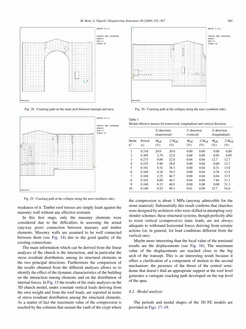
Fig. 28. Cracking path on the main arch between transept and nave.
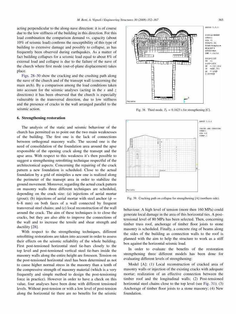
Fig. 29. Cracking path at the collapse along the nave (northern side).
weakness of it. Timber roof trusses are simply leant against themasonry wall without any effective restraint.
In this first stage, only the masonry elements wereconsidered due to the difficulties in assessing the actual(anyway poor) connection between masonry and timberelements. Masonry walls are assumed to be well connectedbetween them (see Fig. 14) due to the good quality of theexisting connections.
The main information which can be derived from the linearanalyses of the church is the interaction, and in particular thestress resultant distribution, among its structural elements inthe two principal directions. Furthermore the comparison ofthe results obtained from the different analyses allows us toidentify the effect of the dynamic characteristics of the buildingon the interaction among elements and on the distribution ofinternal forces. In Fig. 15 the results of the static analyses on the3D church model, under constant vertical loads deriving fromthe own weight and from the roof loads, are reported in termsof stress resultant distribution among the structural elements.As a matter of fact the maximum value of the compression isreached by the columns that sustain the vault of the crypt where
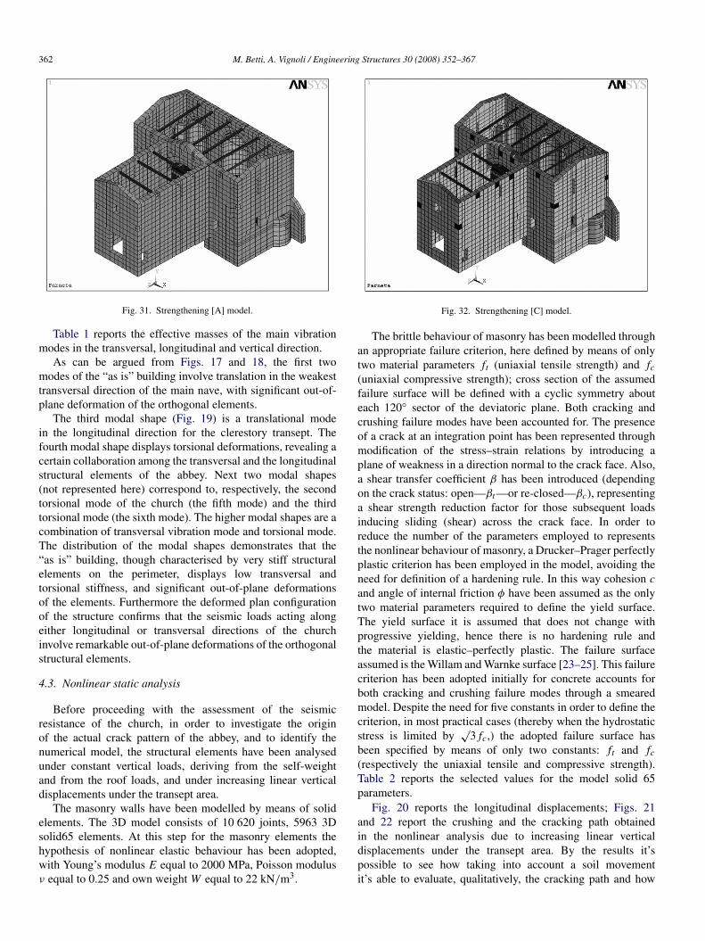
Fig. 30. Cracking path at the collapse along the nave (southern side).
Table 1Modal effective masses for transversal, longitudinal and vertical direction
X -direction(transversal)
Y -direction(vertical)
Z -direction(longitudinal)
Moden◦
Period(s)
Meff(%)
Σ Meff(%)
Meff(%)
Σ Meff(%)
Meff(%)
Σ Meff(%)
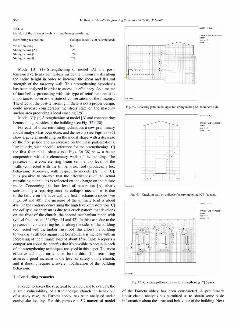
1 0.318 20.0 20.0 0.00 0.00 0.00 0.002 0.305 2.79 22.8 0.00 0.00 0.05 0.053 0.273 0.00 22.8 0.04 0.04 12.7 12.74 0.225 5.96 28.8 0.00 0.04 0.00 12.75 0.181 9.52 38.3 0.00 0.04 0.31 13.06 0.169 0.18 38.5 0.00 0.04 0.38 13.57 0.168 2.25 40.7 0.00 0.04 0.04 13.58 0.162 0.00 40.7 0.04 0.08 7.84 21.39 0.160 8.13 48.9 0.00 0.08 0.00 21.3
10 0.140 0.23 49.1 0.01 0.09 32.7 54.0
the compression is about 1 MPa (anyway admissible for thestone material). Substantially this result confirms that churcheswere designed by architects who were skilled in attempting veryslender schemes; these structural systems, though perfectly ableto resist vertical (compressive) static loads, are not alwaysadequate to withstand horizontal forces deriving from seismicactions (or, in general, for load conditions different from thevertical one).
Maybe more interesting than the local value of the tensionalresults are the displacements (see Fig. 16). The maximumvalue of the displacements are reached close to the bigarch of the transept. This is an interesting result because itoffers a clarification of a component of motion to the secondmechanism: the presence of the thrust of the central semi-dome that doesn’t find an appropriate support at the roof levelgenerates a variegate cracking path developed on the top levelof the apse.
4.2. Modal analysis
The periods and modal shapes of the 3D FE models areprovided in Figs. 17–19.
362 M. Betti, A. Vignoli / Engineering Structures 30 (2008) 352–367
Fig. 31. Strengthening [A] model.
Table 1 reports the effective masses of the main vibrationmodes in the transversal, longitudinal and vertical direction.
As can be argued from Figs. 17 and 18, the first twomodes of the “as is” building involve translation in the weakesttransversal direction of the main nave, with significant out-of-plane deformation of the orthogonal elements.
The third modal shape (Fig. 19) is a translational modein the longitudinal direction for the clerestory transept. Thefourth modal shape displays torsional deformations, revealing acertain collaboration among the transversal and the longitudinalstructural elements of the abbey. Next two modal shapes(not represented here) correspond to, respectively, the secondtorsional mode of the church (the fifth mode) and the thirdtorsional mode (the sixth mode). The higher modal shapes are acombination of transversal vibration mode and torsional mode.The distribution of the modal shapes demonstrates that the“as is” building, though characterised by very stiff structuralelements on the perimeter, displays low transversal andtorsional stiffness, and significant out-of-plane deformationsof the elements. Furthermore the deformed plan configurationof the structure confirms that the seismic loads acting alongeither longitudinal or transversal directions of the churchinvolve remarkable out-of-plane deformations of the orthogonalstructural elements.
4.3. Nonlinear static analysis
Before proceeding with the assessment of the seismicresistance of the church, in order to investigate the originof the actual crack pattern of the abbey, and to identify thenumerical model, the structural elements have been analysedunder constant vertical loads, deriving from the self-weightand from the roof loads, and under increasing linear verticaldisplacements under the transept area.
The masonry walls have been modelled by means of solidelements. The 3D model consists of 10 620 joints, 5963 3Dsolid65 elements. At this step for the masonry elements thehypothesis of nonlinear elastic behaviour has been adopted,with Young’s modulus E equal to 2000 MPa, Poisson modulusν equal to 0.25 and own weight W equal to 22 kN/m3.
Fig. 32. Strengthening [C] model.
The brittle behaviour of masonry has been modelled throughan appropriate failure criterion, here defined by means of onlytwo material parameters ft (uniaxial tensile strength) and fc(uniaxial compressive strength); cross section of the assumedfailure surface will be defined with a cyclic symmetry abouteach 120◦ sector of the deviatoric plane. Both cracking andcrushing failure modes have been accounted for. The presenceof a crack at an integration point has been represented throughmodification of the stress–strain relations by introducing aplane of weakness in a direction normal to the crack face. Also,a shear transfer coefficient β has been introduced (dependingon the crack status: open—βt —or re-closed—βc), representinga shear strength reduction factor for those subsequent loadsinducing sliding (shear) across the crack face. In order toreduce the number of the parameters employed to representsthe nonlinear behaviour of masonry, a Drucker–Prager perfectlyplastic criterion has been employed in the model, avoiding theneed for definition of a hardening rule. In this way cohesion cand angle of internal friction φ have been assumed as the onlytwo material parameters required to define the yield surface.The yield surface it is assumed that does not change withprogressive yielding, hence there is no hardening rule andthe material is elastic–perfectly plastic. The failure surfaceassumed is the Willam and Warnke surface [23–25]. This failurecriterion has been adopted initially for concrete accounts forboth cracking and crushing failure modes through a smearedmodel. Despite the need for five constants in order to define thecriterion, in most practical cases (thereby when the hydrostaticstress is limited by
√3 fc,) the adopted failure surface has
been specified by means of only two constants: ft and fc(respectively the uniaxial tensile and compressive strength).Table 2 reports the selected values for the model solid 65parameters.
Fig. 20 reports the longitudinal displacements; Figs. 21and 22 report the crushing and the cracking path obtainedin the nonlinear analysis due to increasing linear verticaldisplacements under the transept area. By the results it’spossible to see how taking into account a soil movementit’s able to evaluate, qualitatively, the cracking path and how

M. Betti, A. Vignoli / Engineering Structures 30 (2008) 352–367 363
Fig. 33. Comparison of the main periods.
Fig. 34. Modal effective mass (longitudinal direction).
Fig. 35. Modal effective mass (transversal direction).

364 M. Betti, A. Vignoli / Engineering Structures 30 (2008) 352–367
Table 2Yield criterion and failure surface parameters
Yield Drucker–Prager criterion William and Warnkesurface
c 0.09 MPa fc 4 MPaη 15◦ ft 0.1 MPaϕ 38◦ βc 0.75
βt 0.15
the cracking path is close to the effective one: the crackingcollapse reconstructs the actual behaviour of the Farnetaabbey. Moreover collapse increases after a maximum basedisplacement of 0.32 cm: this means that a very small valuecould generate a sensible cracking pattern on the church. Thisconfirms that the main cause of the damage of the transeptand the apse of the abbey is due to the modifying in thehydraulic tenor of the soil occurring during the last restoration.Cracking fissures take place in the weakest wall of the church(window area). Crack pattern is present where there is aweakness of the building (along the wall with windows orsection reduction).
The soil under the abbey is a clay ground particularlysensitive to change in the water level. The last restoration thathas modified the hydraulic tenor of soil, with the correspondingreduction of the water level, could be considered one of themajor concerns for the cracking on the transept.
5. Seismic analysis
In order to simulate the behaviour of the abbey under seismicloads the church was subjected to an equivalent static analysisthrough the application of horizontal forces perpendicular toone another (allowed by several national standards in manycountries and by EC8 too [26]). In particular these forces, notacting simultaneously, are evaluated upon the Italian rule [27].Adopting the static approach inertia forces acting on the wallscan be approximately evaluated considering a force distributionaccording to the first vibration mode of the building with linearassumption.
A preliminary new modal analysis is done where theeffective actual cracking path is taken into account. In orderto reduce the computational effort the previously described FEmodel of the church has been updated posing gap elements(namely contact52 elements) around the areas where cracks arepresent.
Results concerning this preliminary step are reported inFigs. 23–25. Due to the crack pattern it’s possible to observean increase on the main periods (see Fig. 26) and a reductionon the mass participation factor for each mode (see Fig. 27).Table 3 reports the periods of the main vibration modes for the“as is” model and the identified one.
The seismic analyses carried out on the identified nonlinear3D FE model has permitted us to evaluate the ultimate strengthcapacity of the church (with respect to the Italian rules). Someload combinations have been carried out for all transversaland longitudinal seismic directions allowing a direct, thoughapproximate, assessment of the seismic safety level of the
Fig. 36. First mode T1 = 0.2454 s for strengthening [C].
Fig. 37. Second mode, T2 = 0.1894 s for strengthening [C].
Table 3Comparison of the main period for “as is” building and identified one
Farneta abbey (“as is”) Farneta abbey (nonlinear analysis)
Mode n◦ Period (s) Period (s)
1 0.318 0.4792 0.305 0.4283 0.273 0.3504 0.225 0.3155 0.181 0.2926 0.169 0.2557 0.169 0.2528 0.162 0.2469 0.160 0.218
10 0.141 0.203
church. Square root of sum of squares (SRSS) technique hasbeen used for the load combination. The most severe loadcombination for the building turns out to be the seismic load
M. Betti, A. Vignoli / Engineering Structures 30 (2008) 352–367 365
acting perpendicular to the along-nave direction: it is of coursedue to the low stiffness of the building in this direction. For thisload combination the comparison demand vs. capacity (about10% of seismic load) confirms the susceptibility of this type ofbuilding to extensive damage and possibly to collapse, as hasfrequently been observed during earthquakes. As a matter offact building collapses for a seismic load equal to about 8% ofexternal load and collapse is due to the failure of the nave ofthe church where first mode (out-of-plane displacement) takesplace.
Figs. 28–30 show the cracking and the crushing path alongthe nave of the church and of the transept wall (concerning themain arch). By a comparison among the load conditions takeninto account for the seismic analyses (acting in the x and zdirections) it has been observed that the church is especiallyvulnerable in the transversal direction, due to low stiffnessand the presence of cracks in the wall arranged parallel to theseismic action.
6. Strengthening restoration
The analysis of the static and seismic behaviour of thechurch has permitted us to point out the two main weaknessesof the building. The first one is the lack of connectionsbetween orthogonal masonry walls. The second one is theneed of consolidation of the foundation area around the apseresponsible of the opening crack along the transept and theapse area. With respect to this weakness it’s then possible tosuggest a strengthening retrofitting technique respectful of thearchitectonical aspects. Concerning the repairing of the crackpattern a new foundation is scheduled. Close to the actualfoundation by a grid of minipiles a new one is realized alongthe perimeter of the transept area in order to stabilize theground movement. Moreover, regarding the actual crack patternon masonry walls three different techniques are scheduled,depending on the crack size: (a) injections of aerial mortar(grout); (b) injections of aerial mortar with steel anchor (φ =
6–8 mm) on both faces of a wall connected by frequenttransversal steel chains; and (c) local reconstruction of the wallaround the crack. The aim of these techniques is to close thecracks, but they are also able to improve the connections ofthe wall and to increase the tensile and shear strength andductility [28].
With respect to the strengthening techniques, differentretrofitting restorations are taken into account in order to assesstheir effects on the seismic reliability of the whole building.First post-tensioned horizontal steel tie-bars closely to thetop level and post-tensioned vertical steel tie-bars inside themasonry walls along the entire height are foreseen. Tension onthe post-tensioned horizontal steel has been determined as notto cause higher normal stress in the masonry than a tenth ofthe compressive strength of masonry material (which is a veryfrequently and simple method to design the post-tensioningforce in practice). However in order to have a check on thisvalue, four analyses have been done with different tensionedlevels. Without post-tension or with a low level of post-tensionalong the horizontal tie there are no benefits for the seismic
Fig. 38. Third mode, T3 = 0.1623 s for strengthening [C].
Fig. 39. Cracking path on collapse for strengthening [A] (northern side).
behaviour. A high level of tension (more then 160 MPa) couldgenerate local damage in the area of this horizontal ties. A post-tensional level of 80 MPa has been selected. Then, concerningtimber truss roof, anchorage of timber floor joists to stonemasonry is scheduled. Finally, a concrete ring of beams alongthe sides of the building as connection walls to the roof isplanned with the aim to help the structure to work as a stiffbox against the horizontal seismic load.
In order to evaluate the benefits of the restorationstrengthening three different models has been done forevaluating different levels of strengthening:
Model [A]: (1) Local reconstruction of cracked area ofmasonry walls or injection of the existing cracks with adequatemortar; realization of an effective connection between thetimber roof and the longitudinal walls; (2) Post-tensionedhorizontal steel chains close to the top level (see Fig. 31); (3)Anchorage of timber floor joists to a stone masonry; (4) Newfoundation.
366 M. Betti, A. Vignoli / Engineering Structures 30 (2008) 352–367
Table 4Benefits of the different levels of strengthening retrofitting
Retrofitting restorations Collapse loads (% of seismic load)
“as is” building 8%Strengthening [A] 12%Strengthening [B] 15%Strengthening [C] 23%
Model [B]: (1) Strengthening of model [A] and post-tensioned vertical steel tie-bars inside the masonry walls alongthe entire height in order to increase the shear and flexuralstrength of the masonry wall. This strengthening hypothesishas been analyzed in order to assess its efficiency. As a matterof fact before proceeding with this type of reinforcement it isimportant to observe the state of conservation of the masonry.The effect of the post-tensioning, if there is not a proper design,could increase considerably the stress state on the masonryanchor area producing a local crashing [29].
Model [C]: (1) Strengthening of model [A] and concrete ringbeams along the sides of the building (see Fig. 32) [20].
For each of these retrofitting techniques a new preliminarymodal analysis has been done, and the results (see Figs. 33–35)show a general modifying on the modal shape with a decreaseof the first period and an increase on the mass participations.Particularly, with specific reference for the strengthening [C]the first four modal shapes (see Figs. 36–38) show a bettercooperation with the elementary walls of the building. Thepresence of a concrete ring beam on the top level of thewalls (connected with the timber truss roof) produces a boxbehaviour. Moreover, with respect to models [A] and [C],it is possible to observe that the effectiveness of the actualretrofitting techniques is reflected on the change on the failuremode. Concerning the low level of restoration [A] (that’ssubstantially a repairing one) the collapse mechanism is dueto the failure on the nave walls: a first mechanism mode (seeFigs. 39 and 40). The increase of the ultimate load is about4%. On the contrary concerning the high level of restoration [C]the collapse mechanism is due to a crack pattern that developson the front of the church: the second mechanism mode withtypical fracture on 45◦ (Figs. 41 and 42). In this case, due to thepresence of concrete ring beams along the sides of the building(connected with the timber truss roof) this allows the buildingto work as a stiff box against the horizontal seismic load with anincreasing of the ultimate load of about 15%. Table 4 reports acomparison about the benefits that it’s possible to obtain in eachof the strengthening techniques analysed in this paper. The mosteffective technique turns out to be the third. This retrofittingassures a good increase in the level of safety of the church,and it doesn’t require a severe modification of the buildingbehaviour.
7. Concluding remarks
In order to assess the structural behaviour, and to evaluate theseismic vulnerability, of a Romanesque church the behaviourof a study case, the Farneta abbey, has been analysed underearthquake loading. For this purpose a 3D numerical model
Fig. 40. Cracking path on collapse for strengthening [A] (southern side).
Fig. 41. Cracking path on collapse for strengthening [C] (facade).
Fig. 42. Cracking path on collapse for strengthening [C] (apse).
of the Farneta abbey has been constructed. A preliminarylinear elastic analysis has permitted us to obtain some basicinformation about the structural behaviour of the building. Next
M. Betti, A. Vignoli / Engineering Structures 30 (2008) 352–367 367
some nonlinear analyses have been made in order to assessthe seismic vulnerability. A crucial task in masonry buildingmodelling is the evaluation of the mechanical properties. Inthis work, concerning this step, conservative values alreadyavailable from similar experience are assumed. In order togain an understanding of the actual deterioration state of thestructure the model has been identified taking into account theactual cracking path. By this procedure it has been possibleto obtain a proof of the configuration of the cracks, whichwas found to depend primarily on the change on the hydraulictenor of the soil, i.e. the large sensibility of this building toground movements. Next the church is subjected to a seismicstatic analysis, with respect to the Italian rules, through theapplication of horizontal forces perpendicular to one anothernot acting simultaneously.
By a comparison between the stresses and the strainsdue to the seismic shocks acting in the horizontal x and zdirections, respectively, it was observed that the church isespecially vulnerable in the along-nave longitudinal x direction,due to low stiffness and the presence of cracks in the wallarranged parallel to the seismic action (the wall responsiblefor counteracting the seismic loads). The comparison demand(seismic loads) vs. capacity (material and topology strength)confirms the susceptibility of this type of building to extensivedamage and possibly to collapse, as frequently observed.
Also, the efficiency of current techniques for repairingand strengthening have been analysed in order to evaluatetheir benefits. Three different levels of restoration have beeninvestigated, and the analysis of repairing and strengtheningtechniques shows the effectiveness of the usual structuralreinforcement in terms of increased seismic capacity. It isbelieved that the results and the conclusions obtained withrespect to the seismic assessment of this case study couldbe extrapolated to the wide variety of historical Romanesquechurches, and generalized for a wide masonry buildingcategory.
References
[1] Ramos LF, Lourenco PB. Modeling and vulnerability of historical citycenters in seismic areas: A case study in Lisbon. Engineering Structures2004;26:1295–310.
[2] Borri A, Corradi M, Vignoli A. Il comportamento strutturale dellamuratura nelle zone terremotate dell’Umbria: Alcune sperimentazioni.Ingegneria Sismica 2000;XVII(3):23–33 [in Italian].
[3] Betti M, Vignoli A. L’utilizzo del codice ad elementi finiti ANSYS perl’analisi strutturale di edifici monumentali in muratura. Analisi & Calcolo2005;VI(21):27–31 [in Italian].
[4] Del Piero G. Le costruzioni in muratura. NJ: Springer-Verlag; 1984.[5] Carpinteri A, Invernizzi S, Lacidogna G. In situ damage assessment and
nonlinear modelling of a historical masonry tower. Engineering Structures2005;27:387–95.
[6] Corradi M, Borri A, Vignoli A. Experimental study on the determinationof strength of masonry walls. Construction and Building Materials 2002;17(5):325–37.
[7] Corradi M, Borri A, Vignoli A. Strengthening techniques testedon masonry structures struck by the Umbria–Marche earthquake of1997–1998. Construction and Building Materials 2002;16(4):229–39.
[8] Binda L, Saisi A, Tiraboschi C. Investigation procedures for the diagnosis
of historic masonries. Construction and Building Materials 2000;14:199–233.
[9] Sante F. L’abbazia di Farneta in Val di Chiana. Arezzo: Tipografie riunite;1985 [in Italian].
[10] Chiostrini S, Foraboschi P, Vignoli A. Structural analysis and damageevaluation of existing masonry building by dynamic experimentation andnumerical modelling damage. In: Proceedings of tenth world conferenceon earthquake engineering. 1992. p. 3481–86.
[11] Chiostrini S, Galano L, Vignoli A. In situ tests and numericalsimulations on structural behaviour of ancient masonry. In: Proceedings of“Monument-98, workshop on seismic performance of monuments”. 1998.p. 197–206.
[12] Chiostrini S, Galano L, Vignoli A. Mechanical characterization ofstone masonry panels and effectiveness of strengthening techniques. In:Proceeding of fourth international symposium on computer methods instructural masonry. 1997. p. 128–35.
[13] Grimaldi A, Luciano R, Sacco E. Nonlinear dynamic analysis of masonrystructures via FEM. In: Computing methods in applied sciences andengineering. Nova Science Publishers; 1992. p. 373–82.
[14] Luciano R, Sacco E. Homogenization technique and damage model forold masonry material. International Journal of Solids and Structures 1997;34(24):3191–208.
[15] Augusti G, Ciampoli M, Giovenale P. Seismic vulnerability ofmonumental buildings. Structural Safety 2001;23:253–74.
[16] Mele E, De Luca A. Behaviour and modelling of masonry churchbuildings in seismic regions. In: Proceedings second internationalsymposium on earthquake resistant engineering structures. 1999.
[17] Ronca P, Castiglioni L. lo strumento dell’analisi numerica nelle fasi didiagnosi e di scelte progettuali per il consolidamento conservativo divecchie strutture. In: Atti IV Convegno ASSI.R.C.CO. 1997. p. 591–601[in Italian].
[18] Genna F, Di Pasqua M, Veroli M. Numerical analysis comparison modelsbuildings: A constitutive of old masonry among constitutive models.Engineering Structures 1998;20(1–2):37–53.
[19] Facchini L, Betti M, Biagini P, Vignoli A. RBF — Galerkin approachfor the dynamics of simple disordered masonry structures. In: Atti XVIICongresso Nazionale AIMETA di Meccanica Teorica ed Applicata. 2005[in Italian].
[20] Betti M, Orlando M, Vignoli A. Modelling and analysis of an ItalianMedieval Castle under earthquake loading: Diagnosis and strengthening.In: Proceedings of VI international conference on structural analysis ofhistorical constructions. 2006. p. 1529–36.
[21] ANSYS. Users’s manual (Rev. 5.0). Swason analysis systems, Inc. 1992.[22] Anthoine A. Derivation of the in-plane characteristic of masonry thought
homogenization theory. International Journal of Solid and Structures1995;32(2):137–63.
[23] William KJ, Warnke ED. Constitutive model for the triaxial behaviour ofconcrete. In: Proc. int. ass. for bridge and struct. engng. 1975. p. 174–86.
[24] Salari MR, Saeb S, Willam KJ, Patchet SJ, Carrasco RC. A coupled elasto-plastic damage model for geo-materials. Computer Methods in AppliedMechanics and Engineering 2004;193(27–29):2625–43.
[25] Hansen E, William K, Carol I. A two-surface anisotropic dam-age/plasticity model for plain concrete. In: Proceedings of Framcos-4 con-ference. 2001. p. 549–56.
[26] CEN. Eurocode 8. Design provisions for earthquake resistance ofstructures. Part 1-4: General rules — Strengthening and repair ofbuildings. ENV 1998-1-4: 1996.
[27] Ministero dei Lavori Pubblici. DM 16/01/1996: Norme tecniche per lecostruzioni in zone sismiche. Gazzetta Ufficiale 05.02.1996, n◦29 [inItalian].
[28] Modena C, Zavarise G, Valluzzi MR. Modelling of stone masonrywalls strengthened by r.c. jackets. In: Proceedings fourth internationalsymposium on computer methods in structural masonry. 1997.
[29] Gucci N, Simonelli F. Conferimento di sismoresistenza a edifici storici: ilcaso della Pieve di S.Stefano di Sorano. L’edilizia 2001. XV(4):24–33 [inItalian].