modèle mrs 97 - chauvin arnoux group
TRANSCRIPT
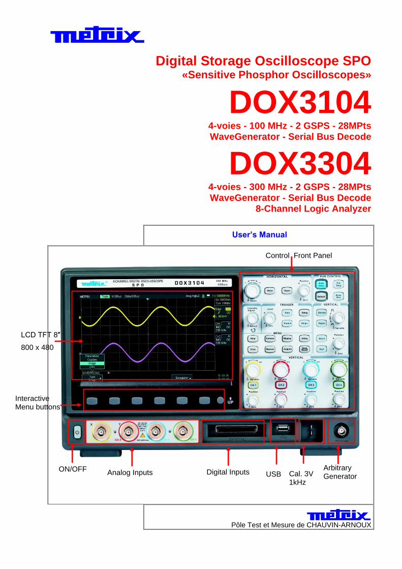
Digital Storage Oscilloscope SPO «Sensitive Phosphor Oscilloscopes»
DOX3104 4-voies - 100 MHz - 2 GSPS - 28MPts WaveGenerator - Serial Bus Decode
DOX3304
4-voies - 300 MHz - 2 GSPS - 28MPts WaveGenerator - Serial Bus Decode
8-Channel Logic Analyzer
User’s Manual
Pôle Test et Mesure de CHAUVIN-ARNOUX
Analog Inputs Digital Inputs Arbitrary Generator
Output
Interactive Menu buttons
LCD TFT 8″
800 x 480
USB host
Cal. 3V 1kHz
Control Front Panel
ON/OFF
Content
2 4-Channel SPO Digital Oscilloscopes
Content
General Instructions Introduction .............................................................................. 6 Precautions and safety measures ............................................. 6 Symbols on instrument ............................................................. 7 Guarantee, Repair, Servicing .................................................... 7
Instrument Description Front panel ............................................................................... 8
Rear panel ................................................................................ 9 User display interface ............................................................. 10 Menu and Control buttons ...................................................... 11 Front panel Inputs and Ouputs................................................ 13 Rear panel Connectors .......................................................... 13 Universal knob ........................................................................ 13
Getting Started Function Checking .................................................................. 14 Probe ...................................................................................... 15 Probe compensation .............................................................. 16
Function Description
AUTO Config/Default Config .................................................................................................... 17
Auto Setup .............................................................................. 17 Default Configuration ............................................................. 18
I - Vertical System .................................................................................................................... 19
Channels CH1 - CH2 - CH3 - CH4 ............................................. 19 Channel configuration ............................................................ 20 Input coupling ........................................................................ 21 Bandwidth Limit ...................................................................... 21 Vertical Sensitivity .................................................................. 22
Probe Factor ........................................................................... 23 Invert function ........................................................................ 23 Input impedance ..................................................................... 24 Vertical Unit ............................................................................ 25
Vertical knobs ............................................................................................................... 26 Vertical Position knob ............................................................. 26 Vertical Sensitivity knob ......................................................... 26
Storing and Displaying Reference waveforms ............................................................... 27 REF Menu ............................................................................... 27
Mathematical Funstions ................................................................................................ 28 MATH Menu ............................................................................ 28
Mathematical operations ..................................................... 28 Fast Fourier Transform FFT .................................................... 29 FFT Menu ............................................................................ 29 How to use the FFT ............................................................. 29 Displaying the FFT spectrum .............................................. 30 Selecting the FFT window ................................................... 31
FFT : Vertical and Horizontal scales .................................. 32
Vertical and Horizontal Position .......................................... 32 Cursors Measurements ....................................................... 32 Amplitude .......................................................................... 32 Frequency .......................................................................... 33 FFT of « Cal 3V 1kHz » signal ............................................. 34

Content
4-Channel SPO Digital Oscilloscopes 3
II - HORIZONTAL System ......................................................................................................... 35
Horizontal menu ..................................................................... 35 HORIZONTAL Pad ................................................................... 36
Horizontal Position ................................................................ 37 Time Base Coefficient S/div ................................................... 37
Horizontal Zoom .................................................................... 37
III - TRIGGER System ............................................................................................................... 38
Trigger Menu .......................................................................... 38 Tigger Source ......................................................................... 39 Trigger Type ........................................................................... 40 Edge .................................................................................. 40 Pulse ................................................................................. 41 Video ................................................................................ 43 Slope .................................................................................. 44 Window ............................................................................... 46 Interval ............................................................................... 47 DropOut .............................................................................. 48 Runt .................................................................................... 49 Pattern ................................................................................ 50 Serial 1-2 ............................................................................ 53 I2C ................................................................................... 53 SPI ................................................................................... 54 UART/RS232 .................................................................... 55 CAN ................................................................................. 56 LIN ................................................................................... 57 Trigger Coupling .................................................................... 58 Horizontal Position ................................................................. 58 Slope&Level ........................................................................... 58 Holdoff .................................................................................... 59
IV - ACQUISITION System ........................................................................................................ 61
Acquisition menu .................................................................... 61 Acquisition Configuration ................................................ 62 Acquisition modes .................................................................. 63 Normal ................................................................................ 63 Peak detect ........................................................................ 63 Average ............................................................................. 64 High Res ............................................................................ 64 Sequence ............................................................................ 65 Memory Depth setting ......................................................... 67 Time Base ............................................................................... 68 Under-Sampling - Aliasing ...................................................... 68 Sequence Mode ...................................................................... 70 Run/Stop, Single, Auto, Normal ............................................... 71

Content
4 4-Channel SPO Digital Oscilloscopes
Content (cont’d)
V - Display System .................................................................................................................. 72
Display ................................................................................... 72 SPO : Color ON - Color Off ...................................................... 73 X-Y Format .............................................................................. 75
VI - Measurement System ........................................................................................................ 77
Scale measurements ............................................................... 78 Cursors measurement ............................................................ 77 Manual Cursors .......................... 77 Track Mode .......................... 79 Automatic measurements ....................................................... 81 Automatic Measurements menu .......................... 81 Voltage Measurements .......................... 81 Time Measurements .......................... 81 Delay Measurements ......................... 81 All Measurements .......................... 82 Measurement Types .......................... 83
VII - SAVE/RECALL System ..................................................................................................... 87
Save/Recall ........................................................................... 87 Saving Setup files in Internal and External memory ......................... 89 Recall a Setup file ......................... 90 Rename a Setup file .......................... 91 Delete » a Setup file .......................... 91 Save/Recall Waveforms ......................................................... 92 Save/Recall Picture ............................................................... 95 Save .CSV file ....................................................................... 96 Recall Default Setup .............................................................. 98
VIII - UTILITY System ............................................................................................................. 101
Utility Menu ........................................................................... 101 Utility page 1/3 ................................................................... 102 Utility page 2/3 ................................................................... 103 Utility page 3/3 ................................................................... 105 System Status ...................................................................... 107
Language ............................................................................. 107 Print ...................................................................................... 108 Do Self Cal ........................................................................... 111 Do Self Test ......................................................................... 111
Screen Test ....................................................................... 111 Keyboard Test ................................................................... 112 LED Test .................................................................................... 112
Firmware Update .................................................................. 113 Pass/Fail .............................................................................. 113 History ................................................................................. 119
Options .......................................................................................... 122 Date/Time ............................................................................. 124 I/O ......................................................................................... 125

Content
4-Channel SPO Digital Oscilloscopes 5
IX - Arbitrary Waveform Generator ............................................................................................. 126
Creating an arbitrary waveform with EasyWave ..................... 126 Auto-Calibrating the arbitrary waveform generator ............... 129
X - DECODE option for Decoding Serial Bus .............................................................................. 130 I2C serial bus ....................................................................... 130 Setting I2C Trigger .............................................................. 131 Decoding I2C ...................................................................... 134 Reading I2C decoding ......................................................... 135 SPI serial bus ....................................................................... 136 Setting SPI Trigger .............................................................. 138 Decoding SPI ...................................................................... 139 Reading SPI decoding ......................................................... 140 UART/RS232 serial bus ........................................................ 141 Setting UART/RS232 Trigger ............................................... 142 Decoding UART/RS232 ....................................................... 144 Reading UART/RS232 decoding .......................................... 145 CAN serial bus .................................................................... 146 Setting CAN Trigger ............................................................ 151 Decoding CAN .................................................................... 157 Reading CAN decoding ....................................................... 158 LIN serial bus ....................................................................... 157 Setting LIN Trigger ............................................................. 158 Decoding LIN ...................................................................... 159 Reading LIN decoding ......................................................... 160 XI - DIGITAL Option Logic Analyzer…………………………………………………………………………160
XII - Power Analysis Option.............…………………………………………………………………………167
XIII - Remote Control .......................…………………………………………………………………………172
Messages ...................................................................................................................................... 178 Help ..................................................................................... 178 Messages ............................................................................. 179 Diagnostic ............................................................................ 180
Technical Specifications ................................................................................................................ 181
Appendix ...................................................................................................................................... 188

General Instructions
6 4-Channel SPO Digital Oscilloscopes
General Instructions
Introduction
You have just acquired a 4-channel SPO Digital oscilloscope:
DOX3104, 4-channel, 100 MHz, 2 GSPS, 28Mpts, Arbitrary Waveform Generator, Serial Bus Decode or
DOX3304, 4-channel, 300 MHz, 2 GSPS, 28 Mpts, Arbitrary Waveform Generator, Serial Bus Decode, 8-channel Logic Analyzer.
This 2-4-channel oscilloscope provides a set of powerful features for a wide range of applications such as production, education, maintenance, service, research and development.
Congratulations for your choice and thank you for your trust in the quality of our products.
This instrument conforms to safety standard NF EN 61010-1, single insulation, and relative to electronic measurement instruments. This is a class 1 device which must be connected to the protective earth by its power cord.
To obtain optimum service, read these instructions with care and comply with the precautions for use.
Failure to comply with these warnings and/or user instructions is liable to cause damage to equipment to the equipment and/or components. This could be dangerous to the user.
Précautions and safety measures
This instrument has been designed for use: - indoors, - in a pollution degree 2 environment, - at an altitude of less than 2000 m, - at a temperature in the range of 0°C to 40°C - at a relative humidity below 80 % up to 31°C.
It can be used for measurements on 300V CAT I circuits and can be powered by a 300V CAT II network.
Définition of installation categories
Overvoltage Category l : Is applicable to instruments and equipment which are not intended to be connected to the mains supply. Because the available energy is very limited this category is normally not marked on the equipment. CAT I is for connection to circuits in which measures are taken to limit transient over-voltages to an appropriately low level. Examples: Protected electronic circuits. Overvoltage Category ll : is for equipment intended to be supplied from building wiring. It applies to both equipments plug-connected or permanently connected. E.g.:Measurements on the network circuits of household appliances, portables tools and other similar appliances.
Overvoltage Category lll : is for equipment intended to be incorporated into the building wiring. Such equipment includes socket outlets, fuse panels, and some mains installation control equipment. E.g.: Measurements on distribution panels (including secondary meters) circuits breakers, cabling including cables, busbars, junction boxes, disconnecting switches, power outlets in the fixed installation, and industrial appliances and other equipment, such as motors permanently connected to the fixed installation.
La catégorie de surtension lV : is for equipment installed at or near the origin of electrical supply to a building, between the building entrance and the main distribution board. Such equipment may include electricity tariff meters and primary overcurrent protection devices. E.g.: Measurements on systems installed before the main fuse or the circuit breaker of the building’s installation.
before use Comply with environment and storage conditions.
during use
Read carefully all the notes preceded by the symbol .
Connect the instrument to an outlet with a protective ground pin.
Be sure not to obstruct the aeration points.
As a safety measure, use only suitable cords and accessories supplied with the instrument or type approved by the manufacturer.
When the instrument is connected to the measurement circuits, never touch an unused terminal.

General Instructions
4-Channel SPO Digital Oscilloscopes 7
General Instructions (cont’d)
Symbols on instrument
Warning: Risk of danger. Refer to the operating manual to find out the nature of the potential hazards and the action necessary to avoid such hazards.
Selective sorting of waste for recycling electric and electronic materials. In accordance with the WEEE 2002/96/CE directive: must not be treated as household waste.
Earth symbol
On/Off switch
LAN symbol
USB symbol
Fuse symbol
European Conformity
Hazardous voltage
Alternative Current
Guarantee
This equipment is guaranteed for 3 years against any material defect or manufacturing faults, in conformity with the general conditions of sale. During this period, only the manufacturer may repair the equipment and it reserves the rigth to carry out repair or replacement of all or part of the equipment. If the equipment is returned to the manufacturer, forward transport is at the expense of the customer. The guarantee does not apply in the event of : Improper use of the equipment or by association with incompatible equipment Modification of the equipment without the explicit authorization of the manufacturer technical services Equipment repaired by a person not authorized by the manufacturer Equipment used in a particular application not suitable for the device or not described in the user manual Shock, fall or flooding.
Repair
For repairs under or out off warranty, please contact our nearest « CHAUVIN-ARNOUX » sales office or our “ MANUMESURE” regional technical center , which will establish a feedback file and will communicate the procedure to be followed.
Contact information on our website : http://www.chauvin-arnoux.com or by phone at the following numbers: 02 31 64 51 43 (MANUMESURE Technical Center) 01 44 85 44 85 (Chauvin Arnoux). For repairs outside metropolitan France, return the instrument to our “Chauvin-Arnoux” local agency or distributor.
Servicing Turn the instrument off. Clean it with a damp cloth and soap. Never use abrasive products or solvents. Dry it before any further use.

Instrument Description
8 4-Channel SPO Digital Oscilloscopes
Instrument Description
Front Panel
No. Description No. Description
1 Universal Knob 12 Trigger Control
2 Horizontal Controls 13 Common Functions Keys
3 Auto Setup 14 Vertical Controls
4 « Default » Configuration 15 Six menu buttons
5 Run/Stop 16 «Up » Menu button
6 Generator set button « Wave Gen »
17 On/Off button
7 « DECODE » set button 18 Analog Inputs BNCs
8 « Digital » set button 19 Logic Analyzer Inputs
9 « Math » set button 20 « USB Host » connector
10 « Ref» set button 21 Probe Adjust Output
11 Vertical Controls for
(Decode/Digital/Math/Ref) 22 Arbitrary Waveform Generator Output
17 18 19 20 21 22
1 2 3 4 5 6 7
7
8
11 9
10
14

Instrument Description
4-Channel SPO Digital Oscilloscopes 9
Instrument Description (cont’d)
Rear Panel
1. Handle
To transport the oscilloscope turn the handle uprigth. 2. EXT TRIG
External trig input BNC “EXT TRIG”. 3. « PASS/FAIL » output or trigger output « TRIG OUT » :
The oscilloscope delivers either a square signal whose frequency is the number of waveforms acquired per second (Aux Output=Trig Out) or the number of “Fail” tests (Aux Output = Pass/Fail).
4. LAN RJ45 connector for a remote control of the oscilloscope (VXI11).
5. USB Device USB connector for « PictBridge » printer (printer) or PC control (USBTMC).
6. Kensington Lock The Kensington cable is not supplied with the unit
7. Power cord connector The supply voltage range is 100-240 Vac, 45-440 Hz. Use the power cord supplied with the unit.
8. Fuse Slow blow fuse 5x20mm 250V, 1.25A.
Instrument Description
10 4-Channel SPO Digital Oscilloscopes
Instrument Description (cont’d)
User display interface
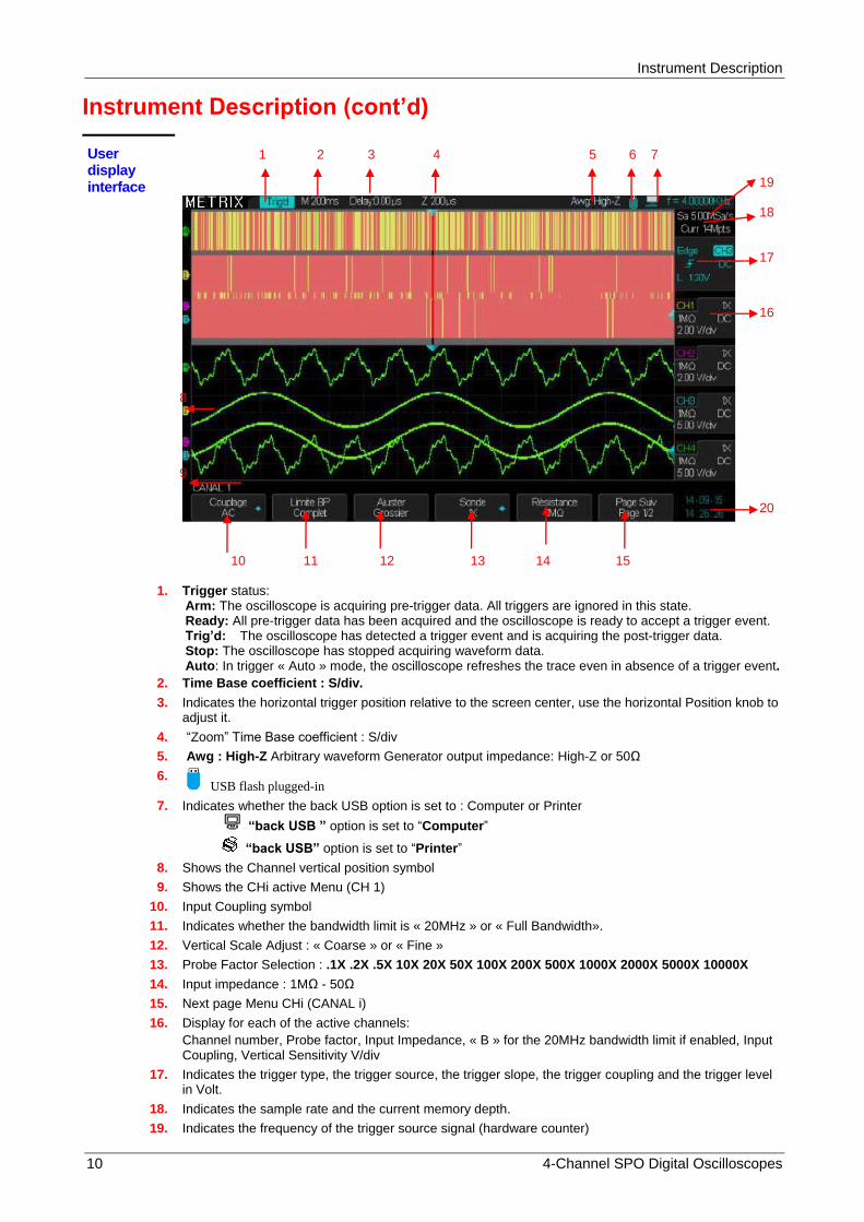
1. Trigger status:
Arm: The oscilloscope is acquiring pre-trigger data. All triggers are ignored in this state. Ready: All pre-trigger data has been acquired and the oscilloscope is ready to accept a trigger event. Trig’d: The oscilloscope has detected a trigger event and is acquiring the post-trigger data. Stop: The oscilloscope has stopped acquiring waveform data. Auto: In trigger « Auto » mode, the oscilloscope refreshes the trace even in absence of a trigger event.
2. Time Base coefficient : S/div.
3. Indicates the horizontal trigger position relative to the screen center, use the horizontal Position knob to adjust it.
4. “Zoom” Time Base coefficient : S/div
5. Awg : High-Z Arbitrary waveform Generator output impedance: High-Z or 50Ω
6. USB flash plugged-in
7. Indicates whether the back USB option is set to : Computer or Printer
“back USB ” option is set to “Computer”
“back USB” option is set to “Printer”
8. Shows the Channel vertical position symbol
9. Shows the CHi active Menu (CH 1)
10. Input Coupling symbol
11. Indicates whether the bandwidth limit is « 20MHz » or « Full Bandwidth».
12. Vertical Scale Adjust : « Coarse » or « Fine »
13. Probe Factor Selection : .1X .2X .5X 10X 20X 50X 100X 200X 500X 1000X 2000X 5000X 10000X
14. Input impedance : 1MΩ - 50Ω
15. Next page Menu CHi (CANAL i)
16. Display for each of the active channels:
Channel number, Probe factor, Input Impedance, « B » for the 20MHz bandwidth limit if enabled, Input Coupling, Vertical Sensitivity V/div
17. Indicates the trigger type, the trigger source, the trigger slope, the trigger coupling and the trigger level in Volt.
18. Indicates the sample rate and the current memory depth.
19. Indicates the frequency of the trigger source signal (hardware counter)
1 2 3 4 5 6 7
8
9
19 18 17
16 20
10 11 12 13 14 15

Instrument Description
4-Channel SPO Digital Oscilloscopes 11
20. Indicates the date and time
Instrument Description (cont’d)
Menu and Control buttons and knobs
Channel buttons
CH1, CH2, CH3, CH4
Press the CH1 (or CH2 or CH3 or CH4) button to enable (ON) or disable (OFF) the channel and to open the CHi configuration menu. When the channel is “On” the button is lit.
Run/Stop Run : The traces are refreshed continuously, Stop: acquisition is Stopped.
Note: In « Stop », use the S/div knob to zoom or compress the trace.
Auto Setup Automatically sets the oscilloscope controls to produce a suitable display of the input signals.
Wave Gen Press this button to enable the « Arbitrary Waveform Generator »
Horizontal Control
Trigger Control
Common Menu buttons
Vertical Control
Advanced
Functions
Arbitrary
Generator
Submenu buttons

Instrument Description
12 4-Channel SPO Digital Oscilloscopes
Default Press this button to reset the oscilloscope settings to the « Default » configuration
Decode Press this button to enable and configure the serial bus « Decode » option
Math Press this button to enable and configure the « MATH » function.
Digital Press this button to enable and configure the 8 channel « Digital » bus option
Ref Press this button to open the REF WAVE menu. Use this menu to Save or Recall reference waveforms (REFA REFB REFC REFD) in the internal memory. When a reference waveform is displayed the “Ref” button is lit.
Horiz Press this button to open the horizontal menu to select the horizontal format : YT, XY or Roll.
Setup TRIG Press this button to open the TRIGGER menu to select the trigger type : Edge, Slope, Pulse, Video, Window, Interval, DropOut, Runt, Pattern, Serial1, Serial 2 and to configure it.
50% Push the « Level » knob to obtain a stable trace. The oscilloscope automatically sets the trigger level to be halfway between the minimum and maximum voltage level of the trigger source signal. This is particularly useful when the trigger source is a “non displayed” signal like “EXT TRIG”.
« Auto » Press this button to enable the Auto mode. In this mode the traces are refreshed in the presence or absence of a trigger event.
Normal Press this button to enable the Normal mode. In this mode the traces are refreshed only in the presence of a trigger event.
Single Press this button to enable the « Single » mode trigger. In this mode the oscilloscope performs a single acquisition and then « STOP ».
Utility Press this button to open the « Utility » menu. The utility menu allows to configure the oscilloscope options such as: Sound, Language, Printer, Date/Hour etc. The Utility menu allows to display the « System Status » and to update the firmware.
Display Press this button to open the « Display » menu. The display menu allows to configure the display Type, Color, Grid, Persistence, Intensity, Brightness, etc..
Cursors Press this button to open the « CURSORS » menu. Use the « Universal » knob to position the active cursor. The sliders are displayed after leaving the « CURSORS » menu (exept if mode = Off) but can not be adjusted.
Help Press this button to open the access to the internal Help.
Print Press this button to open the « Print » menu. The back USB connector must be set on « Printer ».
Measure Press this button to open the « MEASURE » menu.
Acquire Press this button to open the « Acquire » menu. The Acquire menu allows to configure the sampling mode : Normal, Peak Detect, Average, High Resolution.
Save / Recall
Press this button to open the « Save/Recall » menu. This menu allows to Save (or Recall) “Setups” in the internal or external memory and “Pictures”, “Waveforms”, “CSV files” in external memory.
Soft Keys Six soft keys and the « Up » key provide access to submenus.
Instrument Description
4-Channel SPO Digital Oscilloscopes 13
Instrument Description (cont’d)
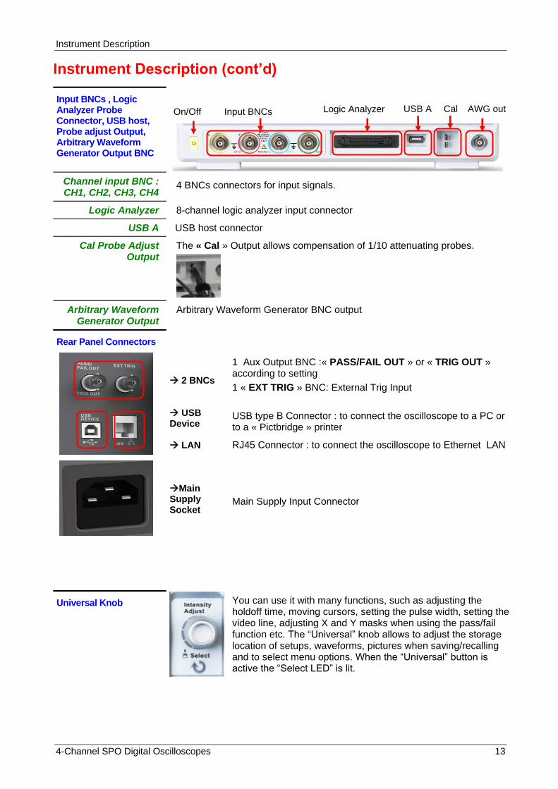
Input BNCs , Logic Analyzer Probe Connector, USB host, Probe adjust Output, Arbitrary Waveform Generator Output BNC
Channel input BNC : CH1, CH2, CH3, CH4
4 BNCs connectors for input signals.
Logic Analyzer 8-channel logic analyzer input connector
USB A USB host connector
Cal Probe Adjust Output
The « Cal » Output allows compensation of 1/10 attenuating probes.
Arbitrary Waveform Generator Output
Arbitrary Waveform Generator BNC output
Rear Panel Connectors
2 BNCs USB Device LAN Main Supply Socket
1 Aux Output BNC :« PASS/FAIL OUT » or « TRIG OUT » according to setting
1 « EXT TRIG » BNC: External Trig Input
USB type B Connector : to connect the oscilloscope to a PC or to a « Pictbridge » printer
RJ45 Connector : to connect the oscilloscope to Ethernet LAN
Main Supply Input Connector
Universal Knob
You can use it with many functions, such as adjusting the holdoff time, moving cursors, setting the pulse width, setting the video line, adjusting X and Y masks when using the pass/fail function etc. The “Universal” knob allows to adjust the storage location of setups, waveforms, pictures when saving/recalling and to select menu options. When the “Universal” button is active the “Select LED” is lit.
Input BNCs Logic Analyzer USB A Cal AWG out On/Off
Getting started
14 4-Channel SPO Digital Oscilloscopes
Getting started
Verification of instrument operation
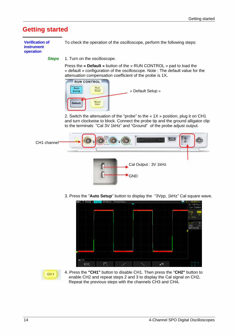
To check the operation of the oscilloscope, perform the following steps:
Steps 1. Turn on the oscilloscope.
Press the « Default » button of the « RUN CONTROL » pad to load the « default » configuration of the oscilloscope. Note : The default value for the attenuation compensation coefficient of the probe is 1X.
2. Switch the attenuation of the “probe” to the « 1X » position, plug it on CH1 and turn clockwise to block. Connect the probe tip and the ground alligator clip to the terminals “Cal 3V 1kHz” and “Ground” of the probe adjust output.
3. Press the "Auto Setup" button to display the “3Vpp, 1kHz” Cal square wave.
4. Press the "CH1" button to disable CH1. Then press the "CH2" button to enable CH2 and repeat steps 2 and 3 to display the Cal signal on CH2. Repeat the previous steps with the channels CH3 and CH4.
Cal Output : 3V 1kHz
GND
CH1 channel
« Default Setup »
Getting started
4-Channel SPO Digital Oscilloscopes 15
Getting started (cont’d)
Oscilloscope Probe
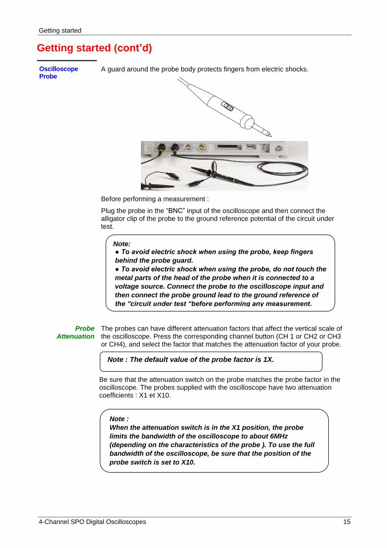
A guard around the probe body protects fingers from electric shocks.
Before performing a measurement :
Plug the probe in the “BNC” input of the oscilloscope and then connect the alligator clip of the probe to the ground reference potential of the circuit under test.
Probe Attenuation
The probes can have different attenuation factors that affect the vertical scale of the oscilloscope. Press the corresponding channel button (CH 1 or CH2 or CH3 or CH4), and select the factor that matches the attenuation factor of your probe.
Be sure that the attenuation switch on the probe matches the probe factor in the oscilloscope. The probes supplied with the oscilloscope have two attenuation coefficients : X1 et X10.
Note: To avoid electric shock when using the probe, keep fingers
behind the probe guard.
To avoid electric shock when using the probe, do not touch the
metal parts of the head of the probe when it is connected to a
voltage source. Connect the probe to the oscilloscope input and
then connect the probe ground lead to the ground reference of
the “circuit under test “before performing any measurement.
Note : The default value of the probe factor is 1X.
Note :
When the attenuation switch is in the X1 position, the probe
limits the bandwidth of the oscilloscope to about 6MHz
(depending on the characteristics of the probe ). To use the full
bandwidth of the oscilloscope, be sure that the position of the
probe switch is set to X10.
Getting started
16 4-Channel SPO Digital Oscilloscopes
Getting Started (cont’d)
Probe Adjust Warning : The DOX3000 series have a switchable input impedance: 1MΩ - 50Ω. When using a « 1/10 » probe of 10MΩ input impedance (= 9MΩ for the probe + 1MΩ oscilloscope input) it is imperative to set the oscilloscope input impedance to 1MΩ. If we visualize the « Cal 3V 1kHz » signal with a 1/10 probe and the oscilloscope input impedance is set to 50Ω, we will see on the screen a near zero amplitude signal because instead of having an attenuation of 1/10, we have an attenuation of 1/180000 (50/9000050).
Manual method of compensating the frequency response of a « 1/10 » probe connected to one channel of the oscilloscope.
Operation Steps 1. Open the CH1 menu and set the Probe attenuation factor to 10X and the oscilloscope input impedance to 1MΩ. Set the probe switch to X10 and connect the probe to CH1. If you use the probe hook-tip, insure a proper connection by firmly inserting the tip onto the probe.
2. Attach the probe tip to the “Cal 3V 1kHz” output and the reference lead to the GND connector. Set CH1 « On » (button lit) and then press the "Auto Setup" button.
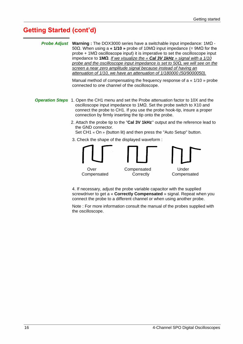
3. Check the shape of the displayed waveform :
Over Compensated Under Compensated Correctly Compensated
4. If necessary, adjust the probe variable capacitor with the supplied screwdriver to get a « Correctly Compensated » signal. Repeat when you connect the probe to a different channel or when using another probe.
Note : For more information consult the manual of the probes supplied with the oscilloscope.

Functional Description
4-Channel SPO Digital Oscilloscopes 17
Functional Description AUTO SETUP
Auto Setup
« Auto Setup » button on « RUN CONTROL” block
DOX3000 digital oscilloscopes have an « Auto Setup » function that configures automatically the device to produce a display adapted to the signals at the channel inputs.
After launching an “Auto Setup”, select, if necessary, the type of signal displayed among the four proposed : Several periods, One period, Rising or Falling edge at the center of the screen.
Auto Setup Function
Option Description
Multi-cycle Autoset and displays several cycle signal.
Single-cycle Autoset and displays single cycle signal.
Rising edge Autoset and displays the Rising edge.
Falling edge Autoset and displays the Falling edge.
Undo config. The oscilloscope recalls the previous Setup.
The “Auto Setup” sets the trigger source and displays the channels according to the following criteria : If multiple channels have an input signal, channel with the lowest frequency signal has the priority.
If no channel is « On » and no signal is found, no channels are displayed.
If one or more channels are « On » and no signal is found, only the « On » channels remains active.

Functional Description
18 4-Channel SPO Digital Oscilloscopes
Functional Description AUTO SETUP (cont’d)
« Auto setup » function
Function Value
Sampling Mode unchanged
Display Format Y-T
Display Type Vectors
Input Coupling AC
Bandwidth limit Unchanged
V/div Set
V/div adjust Coarse (séquence 1 2 5)
Invert Signal unchanged
Horizontal Position Centered
S/div Set
Trigger Type Edge
Trigger Source Auto detection of the signals on the input channels and selection of the proper trigger source.
Trigger Slope Rising
Trigger Mode Auto
Trigger Coupling DC
Holdoff unchanged
Trigger Level Adjusted to 50%
« Default » Setup
The oscilloscope is set up for normal operation when it is shipped from the factory. This is the « Default Setup ». To recall this setup, press the « Default » button. Settings may change for options, buttons and controls when you press the « Default » button, refer to appendix B.
The « Default » setup does not change the following settings :
Language option
Saved reference waveform files
Saved setup files
Display settings
Calibration data

Functional Description
4-Channel SPO Digital Oscilloscopes 19
Functional Description I - VERTICAL System
Vertical knobs and buttons allow to display waveforms and to modify sensitivity and vertical position.
Channels: CH1 CH2 CH3 CH4
page 1 Option Value Description
Coupling DC AC GND
DC: passes the AC and DC components of the input signal. AC: blocks the DC component of the input signal and attenuates AC components below 10Hz. GND: disconnects the input signal.
Bandwidth limit
ON OFF
Limits the channel bandwidth to 20 MHz and reduces high frequency noise. Full bandwidth
Volts/Div Coarse Fine
Selects the resolution of the Volts/div knob : « Coarse » : defines a 1-2-5 sequence. « Fine » : small steps continuous adjustement.
Probe .1x, .2x, .5x,1x , 5x, 10x, 20x, 50x,100x, 200x, 500x, 1000x, 2000x, 5000x,10000x
Set to match the attenuation of the probe you are using to ensure correct vertical readouts.
Input Impedance
1MΩ 50Ω
Selects the channel input impedance. « 1MΩ » : for use with 10MΩ input impedance «1/10» probes. « 50Ω » : for use with 50Ω cable and 50Ω output impedance Generator to preserve impedance matching which is necessary when working with high frequency signals.
Next Page Page 1/2 To access page 2/2
page 2 Option Values Description
Unit V A
Vertical unit : Volts or Ampères.
Invert ON OFF
To invert the channel. To disable inversion.
Next Page Page 2/2 To access page 1/2.
CH1 CH2 CH3 CH4 buttons to open vertical menu and set channels
“on”
CH1 CH2 CH3 CH4
« Volt/div » knobs
CH1 CH2 CH3 CH4
Vertical « Position » knobs
Functional Description
20 4-Channel SPO Digital Oscilloscopes
Functional Description
I - VERTICAL System (cont’d)
Setting up: CH1,CH2, CH3, CH4 channels
Press the CH1 (CH2, CH3 or CH4) button to open the corresponding channel menu.
Selecting the channel Input
Coupling
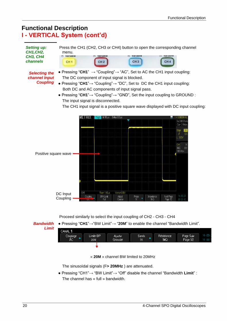
Pressing “CH1” → “Coupling”→ “AC”, Set to AC the CH1 input coupling:
The DC component of input signal is blocked.
Pressing “CH1”→ “Coupling”→ “DC”, Set to DC the CH1 input coupling:
Both DC and AC components of input signal pass.
Pressing “CH1”→ “Coupling”→ “GND”, Set the input coupling to GROUND :
The input signal is disconnected.
The CH1 input signal is a positive square wave displayed with DC input coupling:
Proceed similarly to select the input coupling of CH2 - CH3 - CH4
Bandwidth Limit
Pressing “CH1”→“BW Limit”→ “20M” to enable the channel “Bandwidth Limit”.
The sinusoïdal signals (F> 20MHz ) are attenuated.
Pressing “CH1”→ “BW Limit”→ “Off” disable the channel “Bandwidth Limit” :
The channel has « full » bandwidth.
DC Input Coupling
Positive square wave
« 20M » channel BW limited to 20MHz

Functional Description
4-Channel SPO Digital Oscilloscopes 21
Injecting a “<1ns” rise time “1MHz” square wave on channels CH1 and CH2 .
The picture below shows a “1MHz” square wave displayed with the bandwidth limit "20M" on CH2 and with the “full” bandwidth on CH1:
The measured rise time is 1.8ns on CH1 and 17.20ns on CH2, the presence of the « bandwidth limit » on CH2 leads to a slower rise time.

Functional Description
22 4-Channel SPO Digital Oscilloscopes
Functional Description
I - VERTICAL System (cont’d)
Adjusting vertical
sensitivity V/div
Vertical scale adjusting has « Coarse » and « Fine » mode, vertical sensitivity range is 2mV/div to 10V/div.
For example, for CH1:
Pressing “CH1”→ “Volts/Div”→ “Coarse” sets “V/div” adjust to “coarse” default value.
Vertical sensitivity can be adjusted in a 1-2-5 sequence from 2mV/div, 5mV/div, 10mV/div to 10V/div.
Pressing “CH1”→“Volts/Div”→ “Fine” sets “V/div” adjust to “fine” This setting allows a continuous adjustement of the vertical sensitivity between coarse steps.
Note : Pressing the vertical sensitivity button also toggles the setting from « Coarse » to « Fine ».
For example : Use the « Fine » vertical sensitivity adjust to determine the channel bandwidth when the bandwidth limit is « On »:
1° Set the bandwidth limit to 20MHz on CH2 and “Full” bandwidth on CH1
2° Inject on CH1 and CH2 the same “300mVpp, 1kHz” sinusoïdal signal
3° Adjust the CH1 vertical sensitivity to 50mV/div (coarse) and CH2 (Fine) to 35mV/div (35mV= 0.7x50mV).
Fine adjust sensitivity
Bandwidth Limit
« 20M » on CH2
21.6MHz
50mV/div
35mV/div

Functional Description
4-Channel SPO Digital Oscilloscopes 23
4° Increase the frequency of the generator to obtain a « 6 divisions amplitude » signal on both channels, the frequency measured by the oscilloscope (21.6MHz in our example) is the CH2 cutoff frequency with the bandwidth limit to 20M.
Probe attenuation
factor
In the CHi menu, select the probe « factor » that matches the attenuation coefficient of the probe used.
To compensate an attenuation coefficient of 1/10, the probe factor must be set to 10X to integrate the attenuation coefficient of the probe in the vertical sensitivity.
For example if you are using a « 1/100 » probe, the probe factor must be set to 100X :
Press “CH1”→ “Probe” → and select the “100X” factor
Then the vertical sensitivity range will cover : 200mV/div to 1kV/div
Probe Factor “100X” to compensate a “1/100” probe
Maximum sensitivity 1kV/div

Functional Description
24 4-Channel SPO Digital Oscilloscopes
Functional Description
I - VERTICAL System (cont’d)
Inverting Waveforms
For example, on CH1:
Press “CH1”→ ″Page Suiv″ (″Next Page“) ″page 2/2” →“Invert”→“On”:
We show below, the same positive square wave on CH1 with invert « On » and on CH2 with invert « Off »
Input Impedance
Press “CH1”→ «Impedance »→ and select the channel input impedance « 1MΩ » or « 50Ω ».
1MΩ input impedance is necessary when using 1/10 probes:
The “1MΩ” impedance allows to compensate the « 1/10 » probes by adjusting its variable capacitor :« 9MΩ//Var. Cap ».
The « 1MΩ » impedance is particularly well suited to « low frequency » and “high voltage” signals.
« 50Ω » impedance : for use with 50Ω cable and 50Ω output impedance Generators to preserve impedance matching .
“50Ω » impedance is particularly well suited to « High Frequency » and « Low voltage » signals.
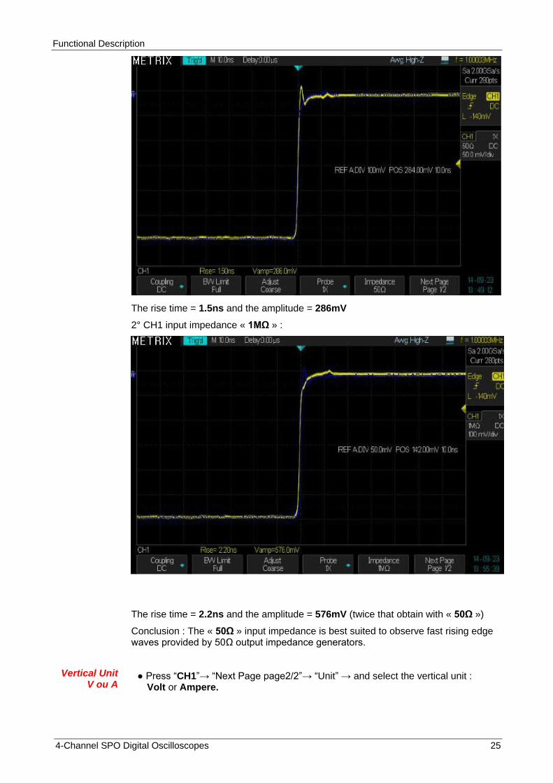
In the example below we show a fast rising edge (<1ns) square wave on CH1 with an impedance of 50Ω and 1MΩ
1° CH1 input impedance « 50Ω » :
Functional Description
4-Channel SPO Digital Oscilloscopes 25
The rise time = 1.5ns and the amplitude = 286mV
2° CH1 input impedance « 1MΩ » :
The rise time = 2.2ns and the amplitude = 576mV (twice that obtain with « 50Ω »)
Conclusion : The « 50Ω » input impedance is best suited to observe fast rising edge waves provided by 50Ω output impedance generators.
Vertical Unit V ou A
Press “CH1”→ “Next Page page2/2”→ “Unit” → and select the vertical unit : Volt or Ampere.

Functional Description
26 4-Channel SPO Digital Oscilloscopes
Functional Description I - VERTICAL System (cont’d)
2. Vertical Knobs
Vertical Position knobs
1. Use the vertical "Position" knobs to move traces up and down the screen. The vertical position variation range is :
+ /- 1V for vertical sensitivities from 2mV/div to 100mV/div
+/- 10V for vertical sensitivities from 102mV/div to 1V/div
+/- 100V for vertical sensitivities from 1.02V/div to 10V/div
2. While you adjust the trace vertical position the ″Volts Pos=″ value is displayed on the screen.
3. Push the vertical “Position” knob to set the vertical position to zero (= screen center).
Vertical Sensitivity
Volts/div
1. Use the “Volt/div” knob to adjust the vertical sensitivity. When you turn clockwise or counter-clockwise the sensitivity increases or decreases.
2. Push the “Volt/div” knob, to toogle between Coarse and Fine adjust.
″Coarse″ Vertical sensitivity can be adjusted in a 1-2-5 sequence from 2mV/div, 5mV/div, 10mV/div to 10V/div (12 steps).
″Fine″ a continuous adjustement of the vertical sensitivity from 2mV/div to 10V/div.
3. Save and Recall
Reference Waveform
The REF menu allows to save (or recall) reference waveforms in four internal memorie locations : REFA - REFB - REFC and REFD.
Press the « Ref » button to open the REF menu :
Functional Description
4-Channel SPO Digital Oscilloscopes 27
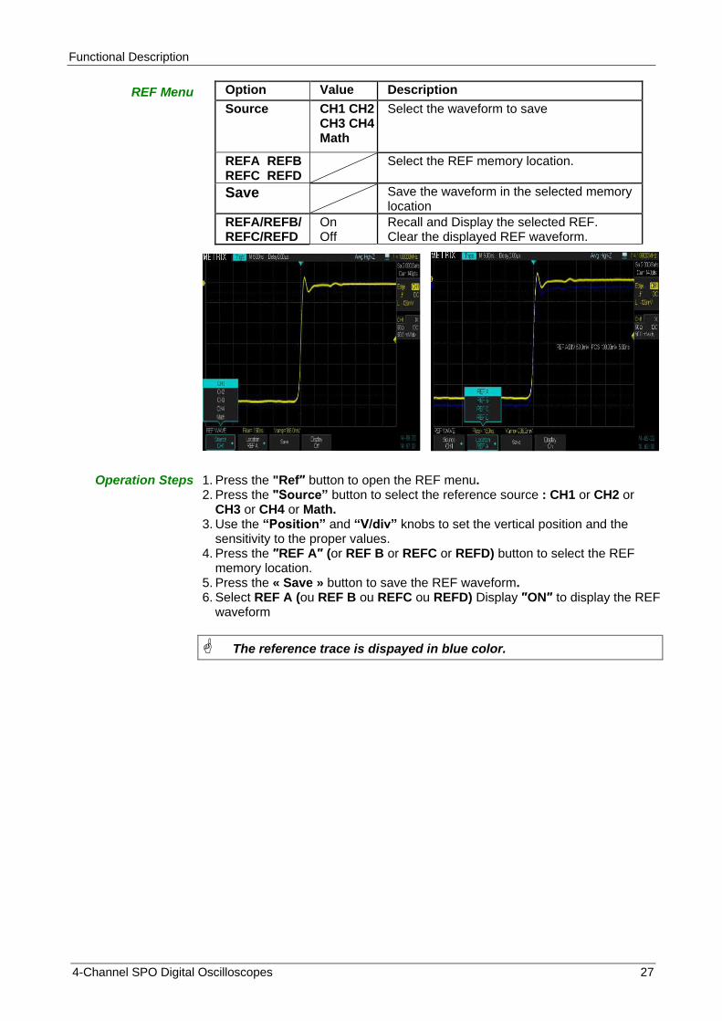
REF Menu Option Value Description
Source CH1 CH2 CH3 CH4 Math
Select the waveform to save
REFA REFB REFC REFD
Select the REF memory location.
Save Save the waveform in the selected memory location
REFA/REFB/REFC/REFD
On Off
Recall and Display the selected REF. Clear the displayed REF waveform.
Operation Steps 1. Press the "Ref″ button to open the REF menu. 2. Press the "Source” button to select the reference source : CH1 or CH2 or
CH3 or CH4 or Math. 3. Use the “Position” and “V/div” knobs to set the vertical position and the
sensitivity to the proper values. 4. Press the ″REF A″ (or REF B or REFC or REFD) button to select the REF
memory location. 5. Press the « Save » button to save the REF waveform. 6. Select REF A (ou REF B ou REFC ou REFD) Display ″ON″ to display the REF
waveform
The reference trace is dispayed in blue color.

Functional Description
28 4-Channel SPO Digital Oscilloscopes
Functional Description I - VERTICAL System / MATH Functions
Menu MATH The « MATH » menu displays the results of mathematicals operations: +, -, *, /, FFT, d/dt, ∫dt and √ on channels CH1, CH2, CH3, CH4 and REFA, REFB, REFC, REFD waveforms.
Press the « Math » button to open the MATH menu.
MATH Menu Fonction Value Description
Operation +, -, *, FFT, d/dt, ∫dt and √
Select the mathematical function.
Source A Source B
CH1, CH2, CH3, CH4, REFA, REFB, REFC, REFD
Select the Math source
Invert On Off
Invert the MATH waveform. “Invert” is disable.
Vertical Position
Use the vertical « Position » knob to adjust the MATH waveform vertical position.
Vertical Scale
Use the « Variable » knob to adjust the MATH vertical scale.
Mathematical
operations
Opération Value Description
+ CHi+CHj CHi added to CHj.
- CHi-CHj CHj subtracted from CHi.
* CHi*CHj CHi multiplied by CHj.
/ CHi/CHj CHi divided by CHj.
FFT Fast Fourier Transform.
d/dt Derivative
∫dt Integral
√ Square Root
Example of Math function:
CH1+CH2

Functional Description
4-Channel SPO Digital Oscilloscopes 29
Functional Description I - VERTICAL System / MATH Funtion (Cont’d)
« Fast Fourier Transform »
The “Fast Fourier Transform « FFT » process” mathematically converts à time domain signal into its components in the frequency domain.
Two measurements are available on the FFT spectrum : Magnitude (in Vrms or dBVrms) and Frequency (in Hz).
Menu FFT
FFT Option Setting Description
Operation FFT
Source CH1, CH2, CH3, CH4, REFA, REFB, REFC, REFD
Select the FFT source channel.
Window Hanning, Hamming Rectangulaire Blackman
Select the FFT window type.
FFT ZOOM 1X, 2X 5X,10X
Changes the horizontal magnification of FFT display.
Vertical « Scale »
Vrms, dBVrms FFT vertical scale
FFT « Display »
Split Full Screen
Displays the FFT spectrum on half screen Displays the FFT spectrum on full screen
How to use FFT To use the FFT Math function, select the time domain signal source Y(t):
Press « Auto Setup» button to display the Y(t) signal and select Multi cycles.
Push the vertical “Position” knob to reset the vertical position to zero divisions (screen center).
Use the horizontal “Position” knob to position the Y(t) signal portion to be analyzed with the FFT, in the center of the screen.
The oscilloscope calculates the FFT spectrum using the center 1024 points of the time-domain waveform.
Turn the “V/div” knob to ensure that the entire waveform remains on the screen.
Turn the “S/div” knob to provide the resolution you want in the FFT spectrum.
Operation Sequence
To display the FFT correctly:
1. Push the "Math" button.
2. Set the "Opération" option to « FFT ».
3. Press the "Source" button and select the channel "CH1" or "CH2" or "CH3" or "CH4" or "REFA" or "REFB" or "REFC" or "REFD".
4. To comply with the Nyquist-Shanon theorem turn the "S/div" knob to adjust the sampling rate (displayed on top rigth of the screen) at least twice the frequency of the input signal.
5. To determine the appropriate value for the “S/div” coefficient, compare the FFT horizontal scale to the frequency displayed by the hardware counter, on the top rigth of the screen.

Functional Description
30 4-Channel SPO Digital Oscilloscopes
Functional Description I - VERTICAL System / MATH Function (cont’d)
2) Displaying the
FFT Spectrum
Press the « Math » button to display the MATH menu. Use the options to select: the Source channel, the Window, and the FFT Zoom Factor. You can display only one FFT spectrum at a time. You can select ″Full Screen" or "Split" in the Display option to display the waveform and its FFT spectrum on full screen, or the waveform and the FFT on half screen at a time.
With « Split » display and « Cursors » Off, you can display simultaneously: The entire Waveform, a Zoom portion and the FFT spectrum.
FFT Menu: Source - Window - FFT Zoom - Scale - Display
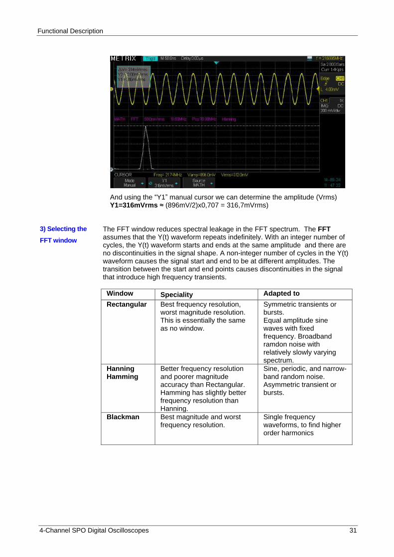
We inject on CH1 a sine wave: frequency = 21.7MHz and amplitude=896mVpp
We will use the « Hanning » window to calculate the FFT, to determine the frequency and the amplitude of the fundamental :
Using the “X1” manual cursor we can determine the frequency (X1=21.8MHz) of the fundamental
Functional Description
4-Channel SPO Digital Oscilloscopes 31
And using the “Y1” manual cursor we can determine the amplitude (Vrms) Y1=316mVrms ≈ (896mV/2)x0,707 = 316,7mVrms)
3) Selecting the
FFT window
The FFT window reduces spectral leakage in the FFT spectrum. The FFT assumes that the Y(t) waveform repeats indefinitely. With an integer number of cycles, the Y(t) waveform starts and ends at the same amplitude and there are no discontinuities in the signal shape. A non-integer number of cycles in the Y(t) waveform causes the signal start and end to be at different amplitudes. The transition between the start and end points causes discontinuities in the signal that introduce high frequency transients.
Window Speciality Adapted to
Rectangular
Best frequency resolution, worst magnitude resolution. This is essentially the same as no window.
Symmetric transients or bursts. Equal amplitude sine waves with fixed frequency. Broadband ramdon noise with relatively slowly varying spectrum.
Hanning Hamming
Better frequency resolution and poorer magnitude accuracy than Rectangular. Hamming has slightly better frequency resolution than Hanning.
Sine, periodic, and narrow-band random noise. Asymmetric transient or bursts.
Blackman Best magnitude and worst frequency resolution.
Single frequency waveforms, to find higher order harmonics

Functional Description
32 4-Channel SPO Digital Oscilloscopes
Functional Description I - VERTICAL System/ MATH Function (cont’d)
FFT:Vertical and Horizontal Scale, Vertical and Horizontal Position
You can magnify and use cursors to take measurements on the FFT spectrum.
The oscilloscope includes an "FFT Zoom" option to magnify horizontally, press this button to select : "1X", "2X", "5X", or "10X".
The FFT spectrum can be moved horizontally using the horizontal « Position » knob.
The FFT spectrum can be moved vertically using the Math « Vertical » knob.
The Math « Variable » knob allows to adjust the FFT vertical scale.
5) Measuring the FFT spectrum with Cursors
Two types of measurements are possible on the FFT spectrum :
Amplitude : in dBVrms or Vrms and
Frequency : in Hz
Amplitude
1. Input a sine wave to CH1 and press the "Auto Setup" button then select the “Multi cycles” option.
2. Press the "Math" button to open the "MATH" menu.
3. Press the "Opération" button and select "FFT"
4. Press the "Source" button and select "CH1"
5. Press the “CH1” button to open the CH1 menu.
6. Turn the "S/div" knob to adjust the sample rate (at least the double than the input signal frequency).
7. If the FFT display is on full screen, press CH1 button again to remove CH1 waveform from display.
8. Press the "Cursors" button to open the CURSORS menu.
9. Press the cursor “Mode” button and select “Manual”.
10. Select the « Yi » cursor type
11. Press the "Source" button and select "MATH"
12. Select the "Y1" cursor, and use the "Universal" knob to move “Y1” to the highest amplitude component of the FFT spectrum.
13. Select the "Y2" cursor, and use the "Universal" knob to move “Y2” to the lowest amplitude component of FFT spectrum.
14. The amplitude (∆V) displays on the top left of the screen.
In the following example we will consider a composite periodic signal : fundamental frequency 5MHz and 20MHz - 35.6MHz spectral components
The FFT displays the fundamental (F=5MHz Amplitude =2.66 Vrms) and two spectral components at 20MHz and 35.6MHz of Amplitude=0.4Vrms
Using Yi horizontal cursors to measure the amplitude of spectral components

Functional Description
4-Channel SPO Digital Oscilloscopes 33
Functional Description I - MATH Function (cont’d)
Measure frequency with « Xi » Vertical
Cursors
1. Press the « Cursors » button
2. Press cursor “Mode” button and select “Manual”.
3. Select "Xi" vertical cursor type
4. Press the "Source" button and select "MATH".
5. Select the "X1" cursor, and use the "Universal" knob to move “X1” to the highest amplitude component of the FFT spectrum.
6. The value ″X1=5.00MHz″ displayed on the top left of the screen is the frequency of the fundamental of the CH1 input signal.
Use vertical cursors to measure the frequency of the spectral components
Fundamental frequency X1=5MHz and the harmonic X2=35.6MHz
Frequency of the two harmonics: X1=20MHz and X2=35.6MHz

Functional Description
34 4-Channel SPO Digital Oscilloscopes
FFT of « Cal 3V 1kHz »
1° Enter the « CAL 3V 1kHz » signal on CH4 with a 1/1 probe
2° Channel CH4 coupling = DC
3° Select 1.4Mpts memory depth and a 500ms/div Time Base
4° Select the FFT Math function with a « Blackman » window (highest amplitude resolution) and FFT Zoom = « X10 » so that the horizontal scale is 1kHz/div.
5° Set the FFT vertical scale to Vrms
6° Use the manual cursors to measure the amplitude of the fundamental (1kHz) and the first harmonic (3kHz) :
The fundamental (1kHz) amplitude is Y1=1.12Vrms (close to 1.06Vrms = 1.5V /1.414)
Note : The « Cal 3V 1kHz » output provides a positive square wave, if the input coupling is « DC » we observe a DC component in the FFT spectrum.
Set the input coupling to « AC » to block the DC component of the « CAL 3V 1kHz » signal to obtain a FFT spectrum without DC component :
Warning : The presence of a DC component can hinder the observation of low-frequency components of the signal.
With FFT math function, the use of AC input coupling is recommended.

Functional Description
4-Channel SPO Digital Oscilloscopes 35
Functional Description II - HORIZONTAL System
HORIZONTAL
Menu
The ″HORIZONTAL″ pad contains two buttons (Horiz and Zoom) and two knobs (S/div and Horizontal Position).
HORIZONTAL Menu « Horiz » button of the HORIZONTAL pad
Option Setting Description
Format YT
XY
ROLL
«YT» : Displays the voltage (on the vertical axis) versus time
(on the horizontal axis).
«XY» : To display in « XY » mode the two channel couples
[CH1(X), CH2(Y)] and [CH3(X), CH4(Y)]
Time Base coefficient >100ms. The traces scroll from the right
to the left of the screen as in a recorder, the “Roll” format is
suitable for slow signals.
In « ROLL » there is no trigger or horizontal position control.
Warning : When working with very low frequency signals (<10Hz) the DC input coupling is not recommended.
ROLL mode
example
Note : The hardware frequency counter does not work for frequencies <10Hz
S/div knob
Horiz and Zoom menu buttons
Horizontal Positon knob

Functional Description
36 4-Channel SPO Digital Oscilloscopes
Functional Description II - HORIZONTAL System (cont’d)
HORIZONTAL pad
The “HORIZONTAL pad” knobs allow to adjust the Time Base coefficient « S/div » and the traces horizontal Position.
The two buttons allow to open the HORIZONTAL menu (“Horiz”) and to activate the “Zoom” function.
Horizontal "POSITION" knob
1. Adjusts the trace horizontal position (the trigger position relative to the center of the screen). The time resolution of this command depends on the selected Time Base coefficient.
2. To reset to zero the horizontal position, push the ″Position″ knob.
S/div knob
1. Adjusts the Time Base coefficient. When the acquisition is stopped ( with “RUN/STOP” button or in “SINGLE” mode), turn the « S/div » knob to expand or compress the waveform.
2. « S/div » knob adjusts the coefficient of the « Main » or « Zoom » Time Bases. In Zoom mode, changing the Time Base coefficient (S/div) modifies the width of the « Zoom » window.
Horizontal Zoom
Use the horizontal “Zoom” function to define the portion of the waveform to be observed in details. The slowest « zoom » time base coefficient may not be lower than the “main” time base coefficient. Use the horizontal « Position » knob to move the « zoom window » position and the « S/div » knob to magnify or compress the “zoom window”.
"M" stands for « Main » time base, "Z" stands for “Zoom” time base.
The vertical « blue » arrows indicate the horizontal position of the trigger event in the Main time base and in the “Zoom” window.
The horizontal « yellow » arrow indicate the vertical position of the trigger level. Note: The display of the « Trigger Position » symbol in the “zoomed window” is only possible if the position of the “zoomed window” includes the trigger event.
If the trigger event is outside the “zoomed window” the horizontal blue arrow indicates the direction in which to move the “zoomed window” to display the trigger.

Functional Description
4-Channel SPO Digital Oscilloscopes 37
Operation Steps To display in details a portion of the waveform:
1. Press the "Horiz" button to open the HORIZONTAL menu.
2. Turn the "S/div" knob to adjust the main timebase.
3. Press the « Zoom » button to activate the horizontal Zoom.
4. Turn the « S/div » knob to adjust the “Zoom” time base.
5. Turn the horizontal "Position" knob to move the zoom window.
In the example below, we display in « Zoom » mode, a detail (a 0.24µs wide window with a resolution of 0.5ns situated at 235µs from the trig event) of a signal acquired at 2GSPS sample rate with a memory depth of 28Mpoints. The oscilloscope has recorded the evolution of the signal during a lapse of time of 14ms with an elementary time step of 0.5ns :
The arrows indicates the delay value (Delay=235µs) relative to the trigger event and the signal value for this delay :
We can « Stop » the trace refresh (« Run/Stop » button) to observe it in detail.
For example we can determine the value that the signal has 74ns before the trigger event by moving the zoomed window (Horizontal « Position » knob):
The red arrows indicate the value of the signal at the trigger event and 74ns before :
Functional Description
38 4-Channel SPO Digital Oscilloscopes
Functional Description III - Trigger System
TRIGGER Menu The DOX3000 oscilloscope series have a digital trigger system that has the following advantages: Precise Trigger - Low « Jitter » - High Sensitivity Precise Trigger timing < 1ns - Configurable noise reject High stability with temperature A hardware counter allows to display the frequency of the trigger source signal
in the top right of the screen
The « Setup » button gives access to the « Trigger » setting menu.
The trigger symbol indicates when the “trigger event” has occurred. The “trigger event” divides the acquisition memory in two parts:
- The « Pre-Trig Buffer » before the trigger event and - The « Post-Trig Buffer » after the trigger event
The DOX3000 oscilloscope series have eleven trigger modes: Edge, Slope, Pulse, Video (HDTV), Window, Interval, Dropout, Runt, Pattern, Serial 1, Serial 2 (Serial bus: I2C, UART, SPI, CAN, LIN)
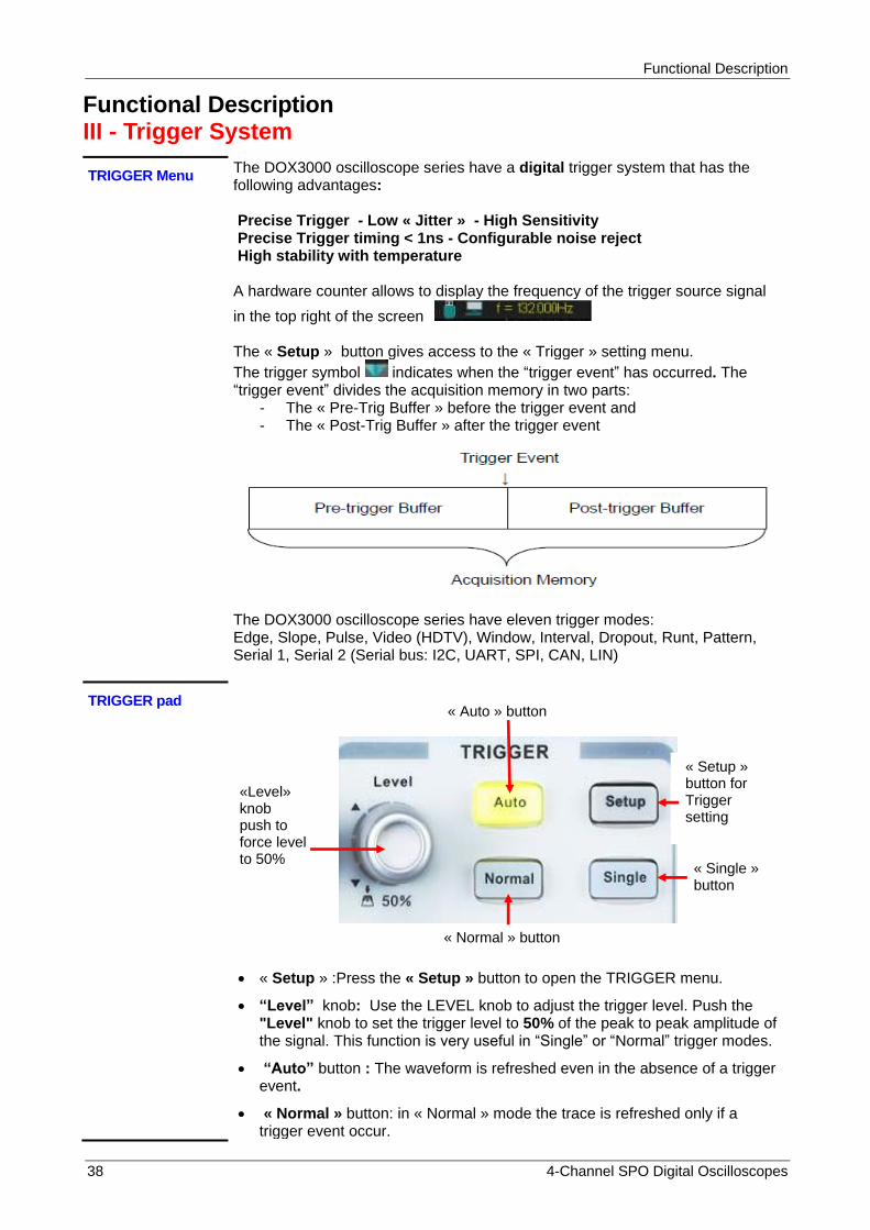
TRIGGER pad
« Setup » :Press the « Setup » button to open the TRIGGER menu.
“Level” knob: Use the LEVEL knob to adjust the trigger level. Push the "Level" knob to set the trigger level to 50% of the peak to peak amplitude of the signal. This function is very useful in “Single” or “Normal” trigger modes.
“Auto” button : The waveform is refreshed even in the absence of a trigger event.
« Normal » button: in « Normal » mode the trace is refreshed only if a trigger event occur.
«Level» knob push to force level to 50%
« Setup » button for Trigger setting
« Single » button
« Auto » button
« Normal » button

Functional Description
4-Channel SPO Digital Oscilloscopes 39
"Single” button: Press the "Single" button to activate the SINGLE mode. In this mode only one acquisition is allowed at a time.
Pre-trig/Post-trig/Trig-Delay: Datas before and after the trigger event . If
the trigger symbol is at the center of the screen, the portion of the traces corresponding to the first 7 divisions represent the pre-trig and the 7 following divisions the post-trig. This function is very useful because you can observe the samples that occur before and after the trigger event. Everithing that is to the right of the trigger event corresponds to the post-trig.
Trigger SOURCE In « Edge » mode : the trigger source may be the signal to the following inputs : CH1, CH2, CH3, CH4, EXT, EXT/5 or AC line.
For the other trigger modes (Slope, Pulse, Vidéo, Window, Interval, DropOut, Runt, Pattern and Serial 1 & 2) the 4 possible trigger sources are: CH1, CH2, CH3 and CH4.
Functional Description
40 4-Channel SPO Digital Oscilloscopes
Functional Description III - TRIGGER System (cont’d)
1. Edge
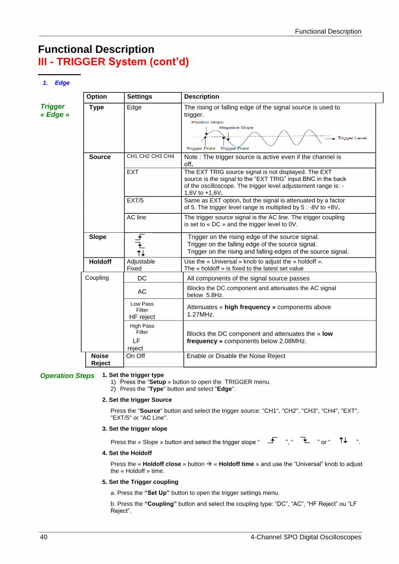
Trigger « Edge »
Option Settings Description
Type Edge The rising or falling edge of the signal source is used to trigger.
Source
CH1 CH2 CH3 CH4 Note : The trigger source is active even if the channel is off.
EXT The EXT TRIG source signal is not displayed. The EXT source is the signal to the “EXT TRIG” input BNC in the back of the oscilloscope. The trigger level adjustement range is: -1,6V to +1,6V.
EXT/5 Same as EXT option, but the signal is attenuated by a factor of 5. The trigger level range is multiplied by 5 : -8V to +8V.
AC line The trigger source signal is the AC line. The trigger coupling is set to « DC » and the trigger level to 0V.
Slope
Trigger on the rising edge of the source signal. Trigger on the falling edge of the source signal. Trigger on the rising and falling edges of the source signal.
Holdoff Adjustable Fixed
Use the « Universal » knob to adjust the « holdoff ». The « holdoff » is fixed to the latest set value
Coupling DC All components of the signal source passes
AC Blocks the DC component and attenuates the AC signal below 5.8Hz.
Low Pass Filter
HF reject
Attenuates « high frequency » components above 1.27MHz.
High Pass Filter
LF reject
Blocks the DC component and attenuates the « low frequency » components below 2.08MHz.
Noise Reject
On Off Enable or Disable the Noise Reject
Operation Steps 1. Set the trigger type 1) Press the “Setup » button to open the TRIGGER menu. 2) Press the "Type" button and select "Edge".
2. Set the trigger Source
Press the "Source" button and select the trigger source: "CH1", "CH2", "CH3", "CH4", "EXT", "EXT/5" or "AC Line".
3. Set the trigger slope
Press the « Slope » button and select the trigger slope “ ”, “ ” or “ ”.
4. Set the Holdoff
Press the « Holdoff close » button « Holdoff time » and use the “Universal” knob to adjust the « Holdoff » time.
5. Set the Trigger coupling
a. Press the “Set Up” button to open the trigger settings menu.
b. Press the “Coupling” button and select the coupling type: “DC”, “AC”, “HF Reject” ou “LF Reject”.
Functional Description
4-Channel SPO Digital Oscilloscopes 41
Functional Description III - TRIGGER System (cont’d)
2. «Pulse»
Pulse
Trigger
page 1
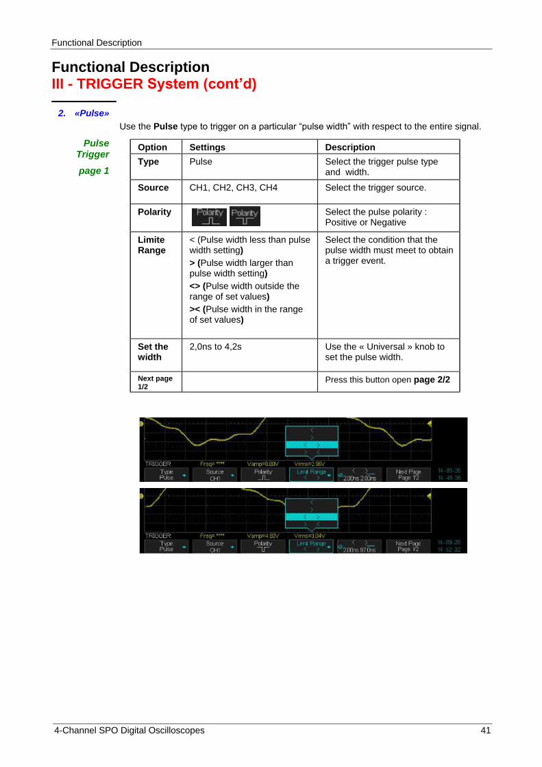
Use the Pulse type to trigger on a particular “pulse width” with respect to the entire signal.
Option Settings Description
Type Pulse Select the trigger pulse type and width.
Source CH1, CH2, CH3, CH4 Select the trigger source.
Polarity
Select the pulse polarity : Positive or Negative
Limite Range
< (Pulse width less than pulse width setting)
> (Pulse width larger than pulse width setting)
<> (Pulse width outside the range of set values)
>< (Pulse width in the range of set values)
Select the condition that the pulse width must meet to obtain a trigger event.
Set the width
2,0ns to 4,2s Use the « Universal » knob to set the pulse width.
Next page 1/2
Press this button open page 2/2
Functional Description
42 4-Channel SPO Digital Oscilloscopes
Functional Description III - TRIGGER System (cont’d)
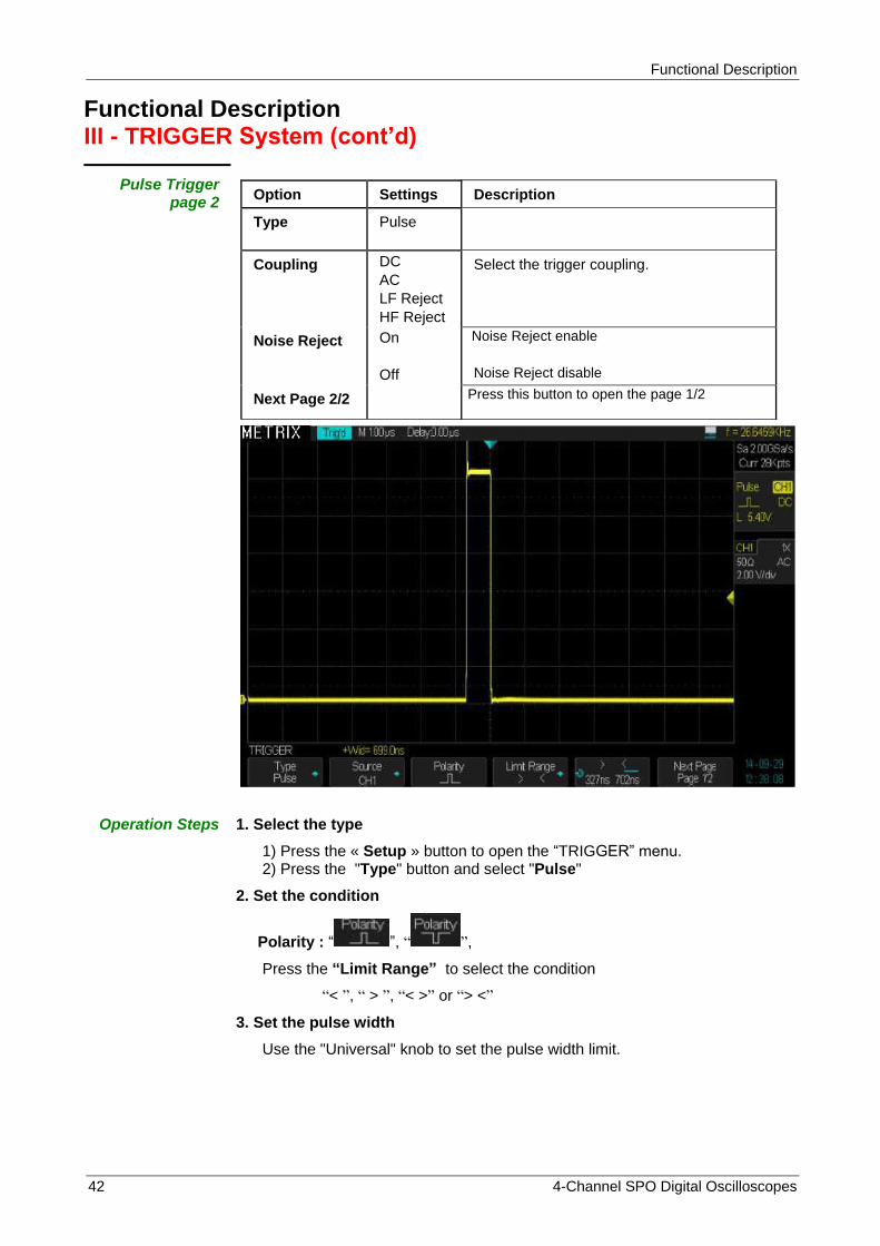
Pulse Trigger page 2
Option Settings Description
Type Pulse
Coupling DC
AC
LF Reject
HF Reject
Select the trigger coupling.
Noise Reject On
Off
Noise Reject enable
Noise Reject disable
Next Page 2/2 Press this button to open the page 1/2
Operation Steps 1. Select the type
1) Press the « Setup » button to open the “TRIGGER” menu. 2) Press the "Type" button and select "Pulse"
2. Set the condition
Polarity : “ ”, “ ”,
Press the “Limit Range” to select the condition
“< ”, “ > ”, “< >” or “> <”
3. Set the pulse width
Use the "Universal" knob to set the pulse width limit.
Functional Description
4-Channel SPO Digital Oscilloscopes 43
Functional Description III - TRIGGER System (cont’d)
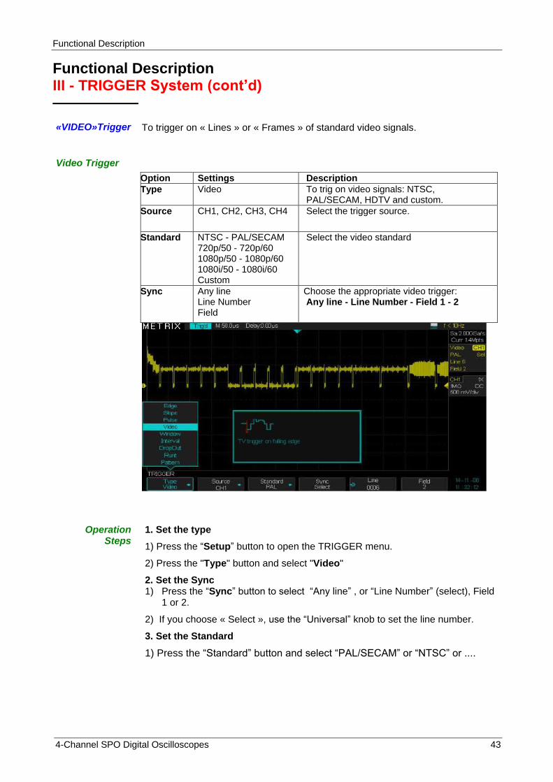
«VIDEO»Trigger
To trigger on « Lines » or « Frames » of standard video signals.
Video Trigger
Option Settings Description
Type Video To trig on video signals: NTSC, PAL/SECAM, HDTV and custom.
Source CH1, CH2, CH3, CH4 Select the trigger source.
Standard NTSC - PAL/SECAM 720p/50 - 720p/60 1080p/50 - 1080p/60 1080i/50 - 1080i/60 Custom
Select the video standard
Sync
Any line Line Number Field
Choose the appropriate video trigger: Any line - Line Number - Field 1 - 2
Operation Steps
1. Set the type
1) Press the “Setup” button to open the TRIGGER menu.
2) Press the "Type" button and select "Video"
2. Set the Sync 1) Press the “Sync” button to select “Any line” , or “Line Number” (select), Field
1 or 2.
2) If you choose « Select », use the “Universal” knob to set the line number.
3. Set the Standard
1) Press the “Standard” button and select “PAL/SECAM” or “NTSC” or ....

Functional Description
44 4-Channel SPO Digital Oscilloscopes
Functional Description III - TRIGGER System (cont’d)
« Slope » Trigger on a positive or negative slope whose duration is specified.
« Slope » Trigger
page 1
Option Settings Description
Type Slope Trigger on a positive or negative slope of specific duration.
Source CH1, CH2 CH3, CH4
Select the trigger source.
Slope
Positive slope Negative slope
Limit Range
< , > < > > <
Select the trigger condition on slope duration.
< Less than > Greater than
< > Outside the limited range > < Inside the limited range
Duration
Use the "Universal" knob to adjust the slope duration in the range: 2 ns to 4.20s.
Next Page 1/2

Functional Description
4-Channel SPO Digital Oscilloscopes 45
Functional Description III - TRIGGER System (cont’d)
Slope Trigger
page 2
Option Settings Description
Type Slope
Level Lower Upper
Select the level (L1 or L2) to adjust with the trigger "Level" knob. You can adjust the two levels 'L1' & "L 2" that define the slope.
Coupling DC - AC LF Reject HF Reject
Select the trigger coupling
Noise Reject
On Off
NextPage Page 2/2 Press this button to open page 1/2
Operation Steps
1. Enter the signal on CH1 or CH2 or CH3 or CH4.
2. Press the “Auto” button.
3. Press the “Setup” button to open the “Trigger Menu”.
4. Press the “Type” button and select "Slope".
5. Press the “Source” button and select “CH1” or “CH2” or “CH3” or “CH4”.
6. Press the “Limit Range” button and select the condition: “<”, “>”, “<>”, “><”.
7. Press the “Time” button and use the “Universal” knob to adjust the slope duration.
8. Press the “Next Page” button to open page 2/2.
9. Press the “Lower Upper” button to select the level to adjust L1 or L2.
10. Use the “Level” knob to adjust L1 or L2.
Functional Description
46 4-Channel SPO Digital Oscilloscopes
Functional Description III - TRIGGER System (cont’d)
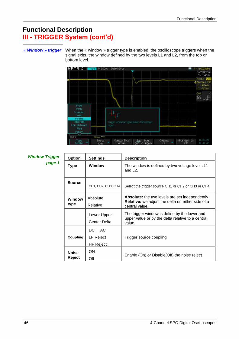
« Window » trigger When the « window » trigger type is enabled, the oscilloscope triggers when the signal exits, the window defined by the two levels L1 and L2, from the top or bottom level.
Window Trigger
page 1 Option Settings Description
Type Window The window is defined by two voltage levels L1 and L2.
Source
CH1, CH2, CH3, CH4 Select the trigger source CH1 or CH2 or CH3 or CH4
Window type
Absolute
Relative
Absolute: the two levels are set independently Relative: we adjust the delta on either side of a central value.
Lower Upper
Center Delta
The trigger window is define by the lower and upper value or by the delta relative to a central value.
Coupling
DC AC
LF Reject
HF Reject
Trigger source coupling
Noise Reject
ON
Off Enable (On) or Disable(Off) the noise reject
Functional Description
4-Channel SPO Digital Oscilloscopes 47
Functional Description III - TRIGGER System (cont’d)
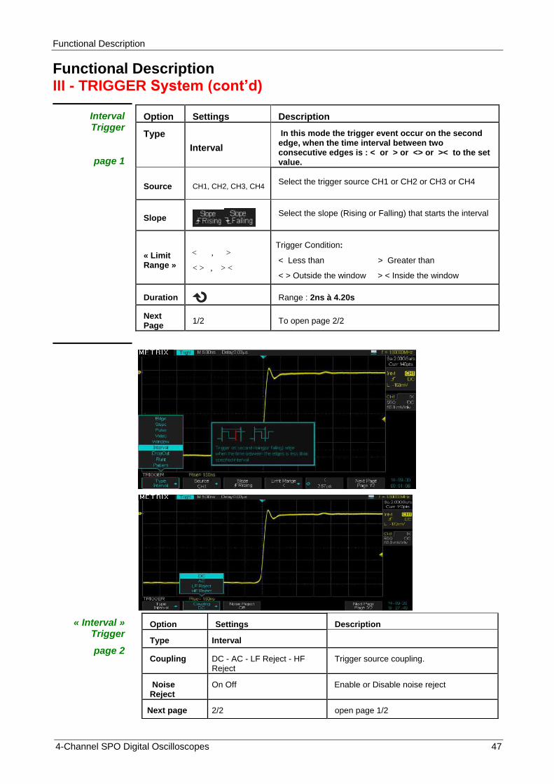
Interval Trigger
page 1
Option Settings Description
Type
Interval
In this mode the trigger event occur on the second edge, when the time interval between two consecutive edges is : < or > or <> or >< to the set value.
Source CH1, CH2, CH3, CH4 Select the trigger source CH1 or CH2 or CH3 or CH4
Slope
Select the slope (Rising or Falling) that starts the interval
« Limit Range »
< , >
< > , > <
Trigger Condition:
< Less than > Greater than
< > Outside the window > < Inside the window
Duration Range : 2ns à 4.20s
Next Page
1/2 To open page 2/2
« Interval » Trigger
page 2
Option Settings Description
Type Interval
Coupling DC - AC - LF Reject - HF Reject
Trigger source coupling.
Noise Reject
On Off Enable or Disable noise reject
Next page 2/2 open page 1/2

Functional Description
48 4-Channel SPO Digital Oscilloscopes
Functional Description III - TRIGGER System (Cont’d)
« DropOut »
trigger
page 1
Option Settings Description
Type DropOut
A trigger event occurs if the signal disappears for a time longer than the specified « DropOut » duration.
Source CH1, CH2
CH3, CH4
Select the trigger source CH1 or CH2 or CH3 or CH4
Slope
Select the edge (state) that reset the dropout duration.
Over Time type
Edge
State
Duration « DropOut » duration range : 2ns to 4.20s
Next Page 1/2 open page 2/2
« DropOut »
page 2
Option Settings Description
Type DropOut
Coupling DC AC
LF Reject HF Reject
Trigger source coupling.
Noise reject On Off Enable or disable noise reject.
Next Page 2/2 Open page 1/2
Functional Description
4-Channel SPO Digital Oscilloscopes 49
Functional Description III - TRIGGER System (cont’d)
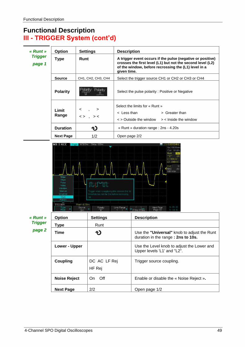
« Runt » Trigger
page 1
Option Settings Description
Type Runt A trigger event occurs if the pulse (negative or positive) crosses the first level (L1) but not the second level (L2) of the window, before recrossing the (L1) level in a given time.
Source CH1, CH2, CH3, CH4 Select the trigger source CH1 or CH2 or CH3 or CH4
Polarity
Select the pulse polarity : Positive or Negative
Limit Range
< , >
< > , > <
Select the limits for « Runt »
< Less than > Greater than
< > Outside the window > < Inside the window
Duration « Runt » duration range : 2ns - 4.20s
Next Page 1/2 Open page 2/2
« Runt » Trigger
page 2
Option Settings Description
Type Runt
Time Use the "Universal" knob to adjust the Runt duration in the range : 2ns to 10s.
Lower - Upper
Use the Level knob to adjust the Lower and Upper levels 'L1' and "L2".
Coupling DC AC LF Rej
HF Rej
Trigger source coupling.
Noise Reject On Off Enable or disable the « Noise Reject ».
Next Page 2/2 Open page 1/2

Functional Description
50 4-Channel SPO Digital Oscilloscopes
Functional Description III - TRIGGER System (cont’d)
« Pattern » Trigger
without the « Digital » option
page 1
Option Settings Description
Type Pattern Triggers when the «pattern» condition goes from false to true.
We can also adjust the time duration of the pattern “true” condition.
Note : Input coupling must be : DC.
Inputs CHi CH1 CH2
CH3 CH4
Select the Pattern inputs and the active level : Low High Invalid
Next Page Page 1/2 Open page 2/2
Trigger type « Pattern »
Without the Digital option
page 2
Option Settings Description
Type Pattern
Logic AND, OR
NAND, NOR
Fonction
Limit Range < >
< > > <
« True » pattern durantion condition limit
Duration
Use the "Universal" knob to adjust the duration of the pattern « true » condition in the range: 2 ns to 4.20s.
HoldOff Time Setting range : 100ns to 1.50s.
« Next page » 2/2 open page 1/2
Functional Description
4-Channel SPO Digital Oscilloscopes 51
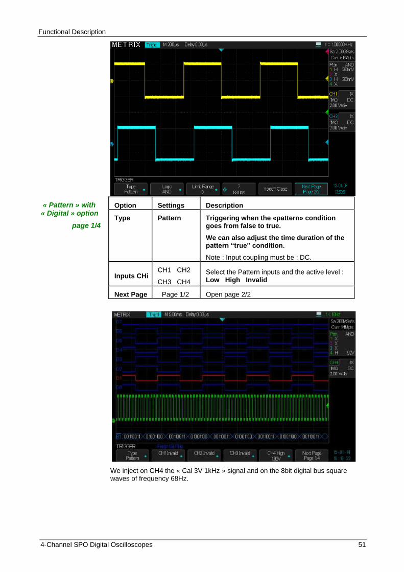
« Pattern » with « Digital » option
page 1/4
Option Settings Description
Type Pattern Triggering when the «pattern» condition goes from false to true.
We can also adjust the time duration of the pattern “true” condition.
Note : Input coupling must be : DC.
Inputs CHi CH1 CH2
CH3 CH4
Select the Pattern inputs and the active level : Low High Invalid
Next Page Page 1/2 Open page 2/2
We inject on CH4 the « Cal 3V 1kHz » signal and on the 8bit digital bus square waves of frequency 68Hz.

Functional Description
52 4-Channel SPO Digital Oscilloscopes
« Pattern » with « Digital » option
page 2/4
Option Settings Description
Type Pattern Digital inputs : select the logic type to set automatically the threshold :
TTL - CMOS - LVCMOS3.3 - LVCMOS2.5 or Custom
Di Inputs D0 D1
D2 D3
Select the pattern inputs and the active level:
Low High Invalid
Next Page Page 2/4 Open page 3/4
Pattern with the Digital option
page 3/4
Option Valeurs Instruction
Type Pattern Digital inputs : select the logic type to set automatically the threshold :
TTL - CMOS - LVCMOS3.3 - LVCMOS2.5 or Custom
Di Inputs D4 D5
D6 D7
Select the pattern inputs and the active level:
Low High Invalid
Next Page Page 3/4 Open page 4/4
Pattern with the Digital option
page 4/4
Option Settings Description
Type Pattern
Logic AND, OR
NAND, NOR
Function
Limit Range < , >
< > , > <
True pattern duration limit
Durée
Use the "Universal" knob to adjust the « true » pattern duration within the range : 2 ns à 4.20s.
HoldOff Setting range : 100ns to 1.50s.
Next page 4/4 Open page 1/4
More details § XI - DIGITAL, option.
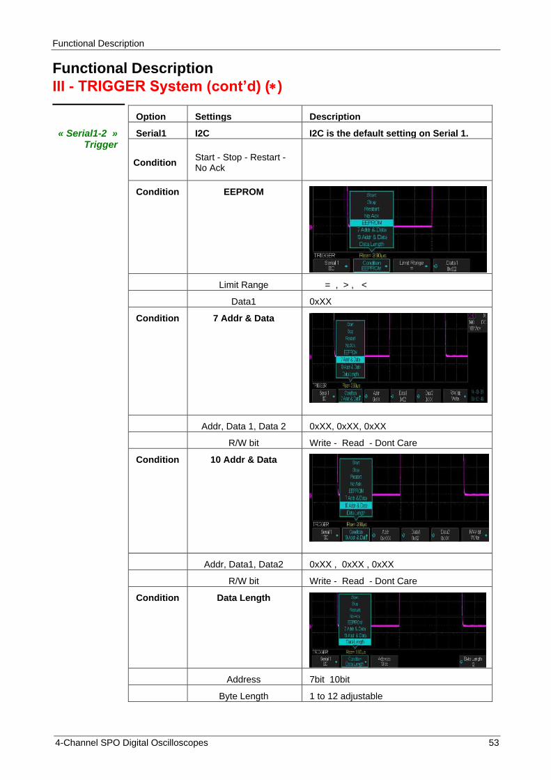
Functional Description
4-Channel SPO Digital Oscilloscopes 53
Functional Description
III - TRIGGER System (cont’d) ()
« Serial1-2 » Trigger
Option Settings Description
Serial1 I2C I2C is the default setting on Serial 1.
Condition Start - Stop - Restart - No Ack
Condition EEPROM
Limit Range = , > , <
Data1 0xXX
Condition 7 Addr & Data
Addr, Data 1, Data 2 0xXX, 0xXX, 0xXX
R/W bit Write - Read - Dont Care
Condition 10 Addr & Data
Addr, Data1, Data2 0xXX , 0xXX , 0xXX
R/W bit Write - Read - Dont Care
Condition Data Length
Address 7bit 10bit
Byte Length 1 to 12 adjustable

Functional Description
54 4-Channel SPO Digital Oscilloscopes
Functional Description
III - TRIGGER System (cont’d) ()
Trigger « Serial 2 »
Option Settings Description
Serial 2 SPI SPI is the default setting on Serial 2
Trigger Setting
SPI Trigger Setting
Trigger type MOSI MISO
Data Length
4 to 96 ajustable
Bit Roll
0 to 95
Bit Value 0 1 X
All Same 0 1 X
Bit Order MSB LSB
() Further informations : § DECODE : Decode bus SPI/I2C/UART/LIN/CAN

Functional Description
4-Channel SPO Digital Oscilloscopes 55
Functional Description III - TRIGGER System (cont’d)
Trigger « Serial1-2 »
Option Settings Description
Serial1 UART/RS232 Trigger on UART/RS232 serial bus.
Trigger Setting
Source Type RX TX
Condition Start - Stop - Data - Parity error
Bus Configure
Baud 600-1200-2400-4800-9600-19200-38400-57600-115200-Custom
Data Length 5 - 6 - 7 - 8
Parity Check None - Odd - Even
Stop Bit 1 - 1.5 - 2
Idle Level Low - High
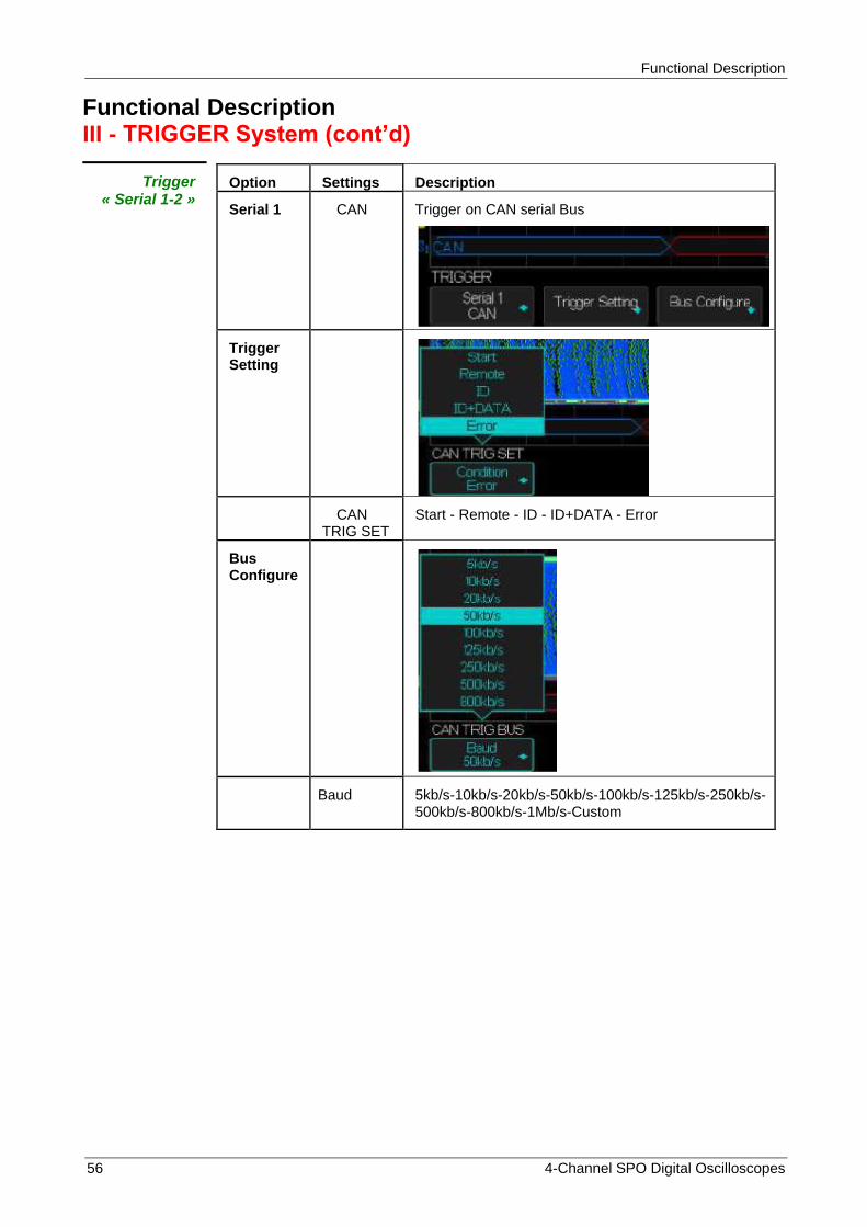
Functional Description
56 4-Channel SPO Digital Oscilloscopes
Functional Description III - TRIGGER System (cont’d)
Trigger « Serial 1-2 »
Option Settings Description
Serial 1 CAN Trigger on CAN serial Bus
Trigger Setting
CAN TRIG SET
Start - Remote - ID - ID+DATA - Error
Bus Configure
Baud
5kb/s-10kb/s-20kb/s-50kb/s-100kb/s-125kb/s-250kb/s-500kb/s-800kb/s-1Mb/s-Custom
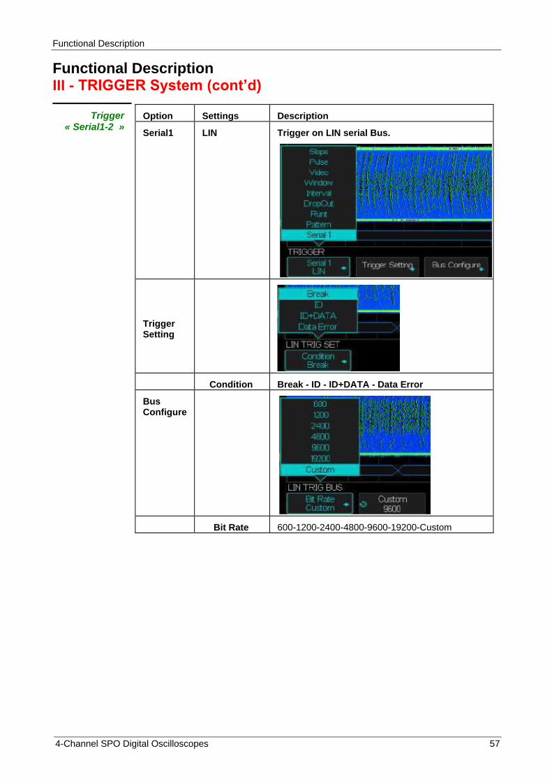
Functional Description
4-Channel SPO Digital Oscilloscopes 57
Functional Description III - TRIGGER System (cont’d)
Trigger « Serial1-2 »
Option Settings Description
Serial1 LIN Trigger on LIN serial Bus.
Trigger Setting
Condition Break - ID - ID+DATA - Data Error
Bus Configure
Bit Rate 600-1200-2400-4800-9600-19200-Custom
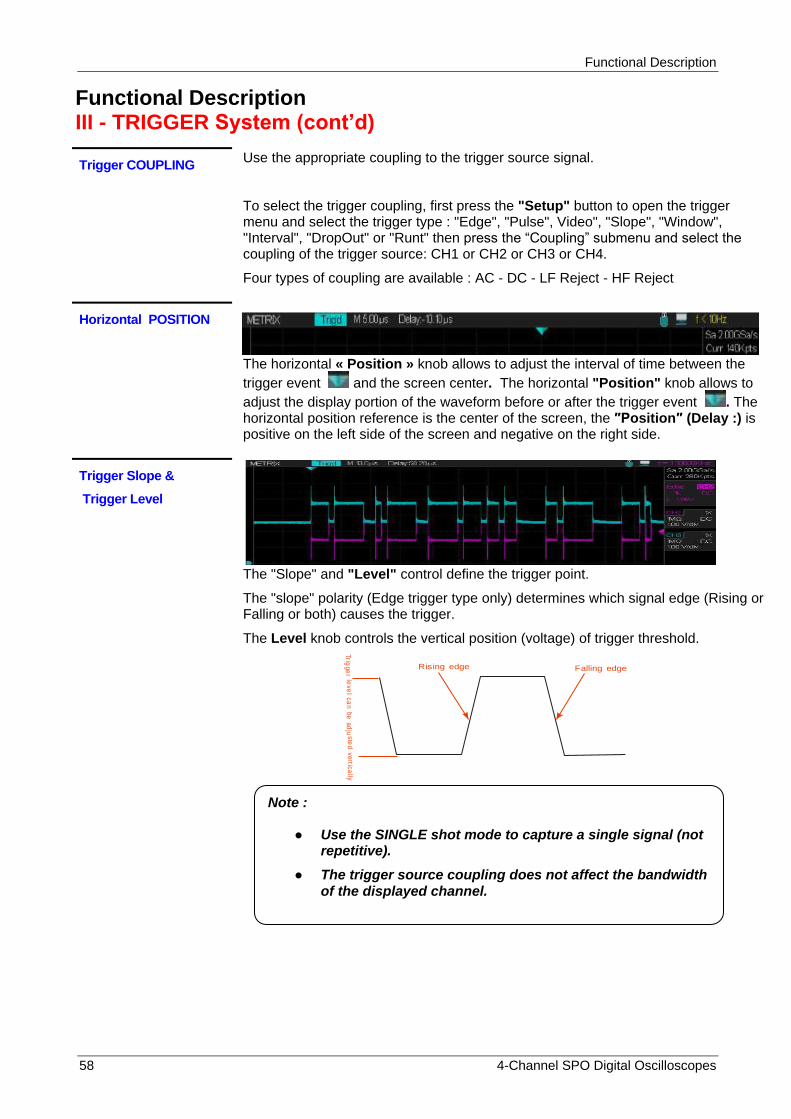
Functional Description
58 4-Channel SPO Digital Oscilloscopes
Functional Description III - TRIGGER System (cont’d)
Trigger COUPLING Use the appropriate coupling to the trigger source signal.
To select the trigger coupling, first press the "Setup" button to open the trigger menu and select the trigger type : "Edge", "Pulse", Video", "Slope", "Window", "Interval", "DropOut" or "Runt" then press the “Coupling” submenu and select the coupling of the trigger source: CH1 or CH2 or CH3 or CH4.
Four types of coupling are available : AC - DC - LF Reject - HF Reject
Horizontal POSITION
The horizontal « Position » knob allows to adjust the interval of time between the
trigger event and the screen center. The horizontal "Position" knob allows to
adjust the display portion of the waveform before or after the trigger event . The horizontal position reference is the center of the screen, the ″Position″ (Delay :) is positive on the left side of the screen and negative on the right side.
Trigger Slope &
Trigger Level
The "Slope" and "Level" control define the trigger point.
The "slope" polarity (Edge trigger type only) determines which signal edge (Rising or Falling or both) causes the trigger.
The Level knob controls the vertical position (voltage) of trigger threshold.
Falling edgeRising edge
Trig
ge
rle
ve
lc
an
be
ad
jus
ted
ve
rtica
lly
Note :
Use the SINGLE shot mode to capture a single signal (not repetitive).
The trigger source coupling does not affect the bandwidth
of the displayed channel.

Functional Description
4-Channel SPO Digital Oscilloscopes 59
Functional Description III - TRIGGER System (cont’d)
HOLDOFF Triggering Inhibition time
Use the « Holdoff » to obtain a stable display in the case of complex signals such as pulse bursts. The “HoldOff” represents the time interval between the detection of a valid trigger event and the moment when the oscilloscope is ready to detect a new trigger event. The oscilloscope will not trigger during the Holdoff time, because the trigger circuit is inhibited. With "pulse bursts", set the Holdoff equal to the burst length, so that the oscilloscope will trigger on the first pulse of the burst masking the other pulses.
Holdoff time
Trigger position
Trigger level
Operation Steps
To set the Hold-Off :
1. Press the “Setup” button to open the TRIGGER Menu.
2. Press the “Type” button and select the trigger type.
3. Press the “Holdoff” button and use the ″Universal″ knob to adjust the Holdoff.
4. Set the HoldOff time to obtain a stable waveform.
Note : With periodic complex waveforms use the « Holdoff » to stabilize the display.
Example : We display on CH3 with the option Color « On » a periodic signal (generated by the DOX3304 AWG) having two rising edges separated by 392µs (measured with the manual cursors ΔT= X2-X1= 390µs - (-2µs) = 392µs).
Color : is « On » (Color grading: Red corresponds to frequent points and Blue to rare points) and the “Edge” trigger type.
If the holdoff is less than 392µs we observe double triggers instability : The most frequent triggering is on the first rising edge (Red trace) and rarely on the second rising edge (Blue trace).
If the holdoff is greater than 392µs the trigger event is always on the same edge the oscilloscope displays only a red trace.
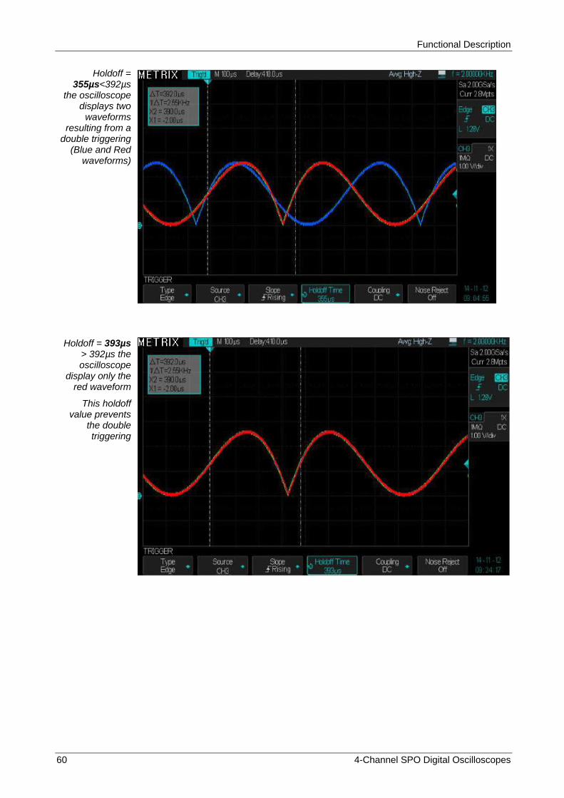
Functional Description
60 4-Channel SPO Digital Oscilloscopes
Holdoff =
355µs<392µs the oscilloscope
displays two waveforms
resulting from a double triggering
(Blue and Red waveforms)
Holdoff = 393µs > 392µs the oscilloscope
display only the red waveform
This holdoff value prevents
the double triggering

Functional Description
4-Channel SPO Digital Oscilloscopes 61
Functional Description IV - ACQUISITION System
Acquisition menu « ACQUIRE »
When acquiring an analog signal, the oscilloscope converts it into digital format and displays a waveform. The acquisition mode defines how the signal is digitized. The time base setting multiplied by the number of horizontal divisions of the screen determines the duration of the recording in seconds (“S/div” x 14div), and the elementary step of acquisition is given by the sampling period. The Memory Depth, the Sample Rate and the Waveform Recorded Length are related by the following formula: Memory Depth (Nb Recorded Samples) = Sampling rate ( Samples/sec) x Waveform Recorded Length (in sec) The oscilloscope adjusts the current memory depth according to the the selected time base coefficient : For example we set the maximum memory depth to “14Mpts” (Menu «Acquire» Sub-menu « Memory Depth ») and the channel CH1 “On” (all other channels are Off), the oscilloscope will adjust the “Current” memory depth according to the selected Time Base coefficient:
S/div Sample Rate Memory depth (Samples)
1ns 2GSPS 28 Samples
2ns 2GSPS 56 Sa
5ns 2GSPS 140 Sa
10ns 2GSPS 280 Sa
20ns 2GSPS 560 Sa
50ns 2GSPS 1.4k Sa
100ns 2GSPS 2.8k Sa
200ns 2GSPS 5.6k Sa
500ns 2GSPS 14k Sa
1µs 2GSPS 28k Sa
2µs 2GSPS 56k Sa
5µs 2GSPS 140k Sa
10µs 2GSPS 280k Sa
20µs 2GSPS 560k Sa
50µs 2GSPS 1.40M Sa
100µs 2GSPS 2.80M Sa
200µs 2GSPS 5.60M Sa
500µs 2GSPS 14.0M Sa
1ms 2GSPS 28.0M Sa
2ms 1GSPS 28.0M Sa
5ms 0.4GSPS 28.0M Sa
10ms 200MSPS 28.0M Sa
20ms 100MSPS 28.0M Sa
50ms 40MSPS 28.0M Sa
100ms 20MSPS 28.0M Sa
200ms 10MSPS 28.0M Sa
500ms 4MSPS 28.0M Sa
1s 2MSPS 28.0M Sa
2s 1MSPS 28.0M Sa
5s 400KSPS 28.0M Sa
10s 200KSPS 28.0M Sa
20s 100KSPS 28.0M Sa
50s 40KSPS 28.0M Sa

Functional Description
62 4-Channel SPO Digital Oscilloscopes
Functional Description IV - ACQUISITION System (cont‟d)
« Acquire » Press the "Acquire" button to open the acquisition menu.
Acquisition Settings
Option Settings Description
Acquisition
Normal This mode is used for an accurate sampling and display of most signals.
Peak Detect This mode is used to display noise and to reduce aliasing.
High Res To increase the vertical resolution and to reduce random noise.
Average To reduce the random noise on displayed waveforms. Average: 4, 16, 32, 64,128, 256, 512, 1024
Sinx/x Sinx
X
Sinusoidal Interpolation "Sinx" Linear Interpolation "x"
Sequence
Acq Mode Off Normal Single
Display Mode
Overlay Waterfall
Frame Set Setting range : 1 to 80000 (The max value depends on the time base coefficient “S/div” and the number of active channels)
Mem Depth
7k - 14k - 70k - 140k - 700k - 1.4M - 7M - 14M
Select the maximum Memory Depth value

Functional Description
4-Channel SPO Digital Oscilloscopes 63
Functional Description IV - ACQUISITION System (cont‟d)
Sampling Modes The oscilloscope has the following sampling modes:
Normal - Peak Detect - Average - High Resolution
Normal The oscilloscope samples the signal at regular intervals to build the digital waveform. In general this mode is a true representation of the signal.
Advantage It is the most common sampling mode. This mode reduces the random noise.
Disadvantage The "Normal" mode does not capture fast signal changes that may occur between to successive samples. An aliasing phenomenon can result and the short pulses may not be detected. In the presence of short pulses (glitch) you must use the Peak Detect mode.
« Peak Detect »
The « Peak Detect » mode capture the minimum and maximum values of the signal (Oversampled waveform) between two successive samples and displays two Waveforms, one with the Low values and the other with the High values.
Advantage In this mode, the oscilloscope can capture fine pulses (glitch) which have not been detected by the "Normal" mode.
Disadvantage The trace thickness (noise) will be higher in this mode.
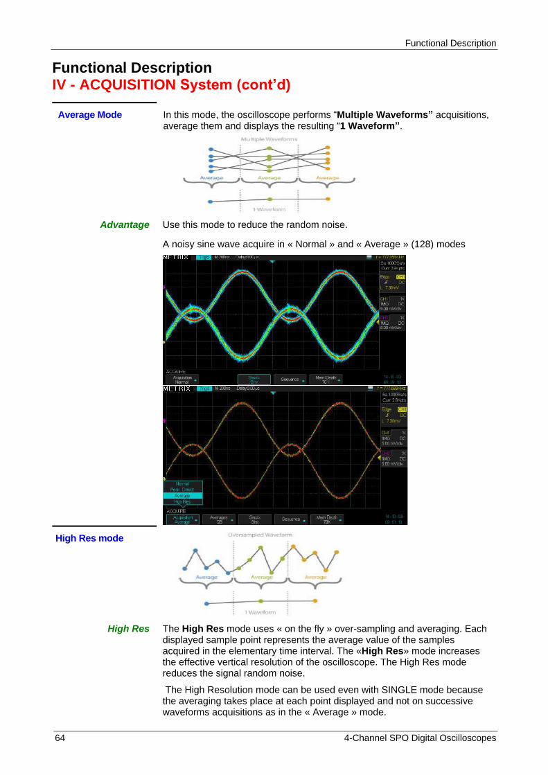
Functional Description
64 4-Channel SPO Digital Oscilloscopes
Functional Description IV - ACQUISITION System (cont‟d)
Average Mode In this mode, the oscilloscope performs “Multiple Waveforms” acquisitions, average them and displays the resulting “1 Waveform”.
Advantage Use this mode to reduce the random noise.
A noisy sine wave acquire in « Normal » and « Average » (128) modes
High Res mode
High Res The High Res mode uses « on the fly » over-sampling and averaging. Each displayed sample point represents the average value of the samples acquired in the elementary time interval. The «High Res» mode increases the effective vertical resolution of the oscilloscope. The High Res mode reduces the signal random noise.
The High Resolution mode can be used even with SINGLE mode because the averaging takes place at each point displayed and not on successive waveforms acquisitions as in the « Average » mode.
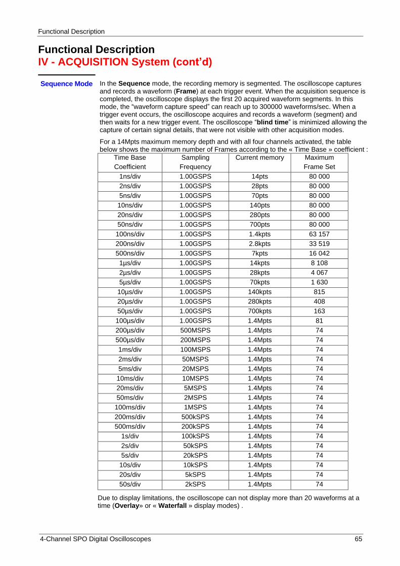
Functional Description
4-Channel SPO Digital Oscilloscopes 65
Functional Description IV - ACQUISITION System (cont‟d)
Sequence Mode
In the Sequence mode, the recording memory is segmented. The oscilloscope captures and records a waveform (Frame) at each trigger event. When the acquisition sequence is completed, the oscilloscope displays the first 20 acquired waveform segments. In this mode, the “waveform capture speed” can reach up to 300000 waveforms/sec. When a trigger event occurs, the oscilloscope acquires and records a waveform (segment) and then waits for a new trigger event. The oscilloscope “blind time” is minimized allowing the capture of certain signal details, that were not visible with other acquisition modes.
For a 14Mpts maximum memory depth and with all four channels activated, the table below shows the maximum number of Frames according to the « Time Base » coefficient :
Time Base
Coefficient
Sampling
Frequency
Current memory Maximum
Frame Set
1ns/div 1.00GSPS 14pts 80 000
2ns/div 1.00GSPS 28pts 80 000
5ns/div 1.00GSPS 70pts 80 000
10ns/div 1.00GSPS 140pts 80 000
20ns/div 1.00GSPS 280pts 80 000
50ns/div 1.00GSPS 700pts 80 000
100ns/div 1.00GSPS 1.4kpts 63 157
200ns/div 1.00GSPS 2.8kpts 33 519
500ns/div 1.00GSPS 7kpts 16 042
1µs/div 1.00GSPS 14kpts 8 108
2µs/div 1.00GSPS 28kpts 4 067
5µs/div 1.00GSPS 70kpts 1 630
10µs/div 1.00GSPS 140kpts 815
20µs/div 1.00GSPS 280kpts 408
50µs/div 1.00GSPS 700kpts 163
100µs/div 1.00GSPS 1.4Mpts 81
200µs/div 500MSPS 1.4Mpts 74
500µs/div 200MSPS 1.4Mpts 74
1ms/div 100MSPS 1.4Mpts 74
2ms/div 50MSPS 1.4Mpts 74
5ms/div 20MSPS 1.4Mpts 74
10ms/div 10MSPS 1.4Mpts 74
20ms/div 5MSPS 1.4Mpts 74
50ms/div 2MSPS 1.4Mpts 74
100ms/div 1MSPS 1.4Mpts 74
200ms/div 500kSPS 1.4Mpts 74
500ms/div 200kSPS 1.4Mpts 74
1s/div 100kSPS 1.4Mpts 74
2s/div 50kSPS 1.4Mpts 74
5s/div 20kSPS 1.4Mpts 74
10s/div 10kSPS 1.4Mpts 74
20s/div 5kSPS 1.4Mpts 74
50s/div 2kSPS 1.4Mpts 74
Due to display limitations, the oscilloscope can not display more than 20 waveforms at a time (Overlay» or « Waterfall » display modes) .
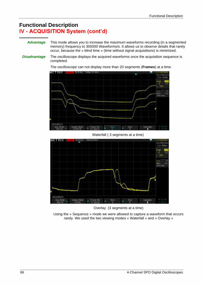
Functional Description
66 4-Channel SPO Digital Oscilloscopes
Functional Description IV - ACQUISITION System (cont‟d)
Advantage This mode allows you to increase the maximum waveforms recording (in a segmented memory) frequency to 300000 Waveforms/s. It allows us to observe details that rarely occur, because the « blind time » (time without signal acquisitions) is minimized.
Disadvantage The oscilloscope displays the acquired waveforms once the acquisition sequence is completed.
The oscilloscope can not display more than 20 segments (Frames) at a time.
Waterfall ( 3 segments at a time)
Overlay (3 segments at a time)
Using the « Sequence » mode we were allowed to capture a waveform that occurs rarely. We used the two viewing modes « Waterfall » and « Overlay »

Functional Description
4-Channel SPO Digital Oscilloscopes 67
Functional Description IV - ACQUISITION System (cont‟d)
Memory Depth
Advantage A deep memory allows to record the signal evolution over a long period of time, and then analyze it in detail with a very fine elementary pitch. For example with a 28Mpoints memory depth we can record the evolution of a signal for 14ms with an elementary pitch of 0.5ns.
Disadvantage We have to search in the long recording memory, the waveform portion to observe in details.
Using the x50000 Zoom mode to display simultaneously the overall waveform and a detail
Using x1000000 Zoom coefficient to analyze in detail the detail
Using a “28Mpoints” memory depth, we were able to record “14ms” of signal evolution at a sampling rate of 2GSPS (=0.5ns elementary pitch). We then used two Zoom factors : x50000 (to display a 280ns portion of 14ms) and x1000000 (to display a 14ns portion of 14ms) to observe an elementary portion of the recorded waveform in “RUN” or “STOP”. We can move the Zoom window in the entire memory depth by using the horizontal « Position » knob.

Functional Description
68 4-Channel SPO Digital Oscilloscopes
Functional Description IV - ACQUISITION System (cont‟d)
Time Base The oscilloscope digitizes the waveform by sampling the input signal at a regular time interval. The Time Base coefficient and the Memory Depth set the sampling frequency.
Use the "S/div" knob to set the “Time Base” coefficient.
Open the « Acquire » menu to set the suitable memory depth.
Under-Sampling Aliasing
Example of «aliasing»
observed with a 160MHz sinusoïdal
signal sampled at 100MSa/s : the
hardware counter frequency is :
« f=160.66MHz » the automatic
frequency measurement is
« Freq=667.8kHz » Comparing the two different frequency
values we can highligth the presence of «aliasing»
The aliasing occurs when the oscilloscope sampling rate is not fast enough to precisely reconstruct the digital waveform. The oscilloscope displays a lower frequency waveform, or an unstable waveform.
Sampled points
Apparent low-frequencywaveform due to aliasing
Actual high-frequency waveform
The real high frequency signal
The displayed low-frequency signal resulting from aliasing
Sample points
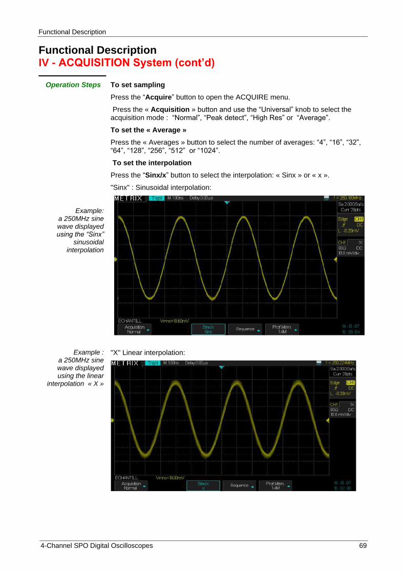
Functional Description
4-Channel SPO Digital Oscilloscopes 69
Functional Description IV - ACQUISITION System (cont‟d)
Operation Steps
Example: a 250MHz sine wave displayed using the “Sinx”
sinusoidal interpolation
To set sampling
Press the “Acquire” button to open the ACQUIRE menu.
Press the « Acquisition » button and use the “Universal” knob to select the acquisition mode : “Normal”, “Peak detect”, “High Res” or “Average”.
To set the « Average »
Press the « Averages » button to select the number of averages: “4”, “16”, “32”, “64”, “128”, “256”, “512” or “1024”.
To set the interpolation
Press the “Sinx/x” button to select the interpolation: « Sinx » or « x ».
"Sinx" : Sinusoidal interpolation:
Example : a 250MHz sine wave displayed using the linear
interpolation « X »
"X" Linear interpolation:

Functional Description
70 4-Channel SPO Digital Oscilloscopes
Functional Description IV - ACQUISITION System (cont‟d)
SEQUENCE Mode In the « Sequence » mode, the oscilloscope is ready to display waveforms, once the acquisitions are completed. In this mode, the maximum number of acquisitions per second can reach 300000. For each trigger event, the oscilloscope fills a segment of the recording memory and continues until the memory is completely filled. Once completed, the oscilloscope displays the acquired segments up to 20 segments at a time.
To use the « Sequence » the Horizontal format must be: “YT”.
To set the Sequence mode :
1° Press the « Acquire » button to open the ACQUIRE menu
2° Press the "Sequence" button to open the SEQUENCE menu
3° Press the « Acq. Mode » button to disable or enable the Acquisition « Off - On » (Off is the default value).
4° Press the « Display Mode » button to select the display mode :
Overlay - Waterfall
5° Press the « Frame set » button and use the « Universal” knob to set the displayed « Frame set »
6° Press the «Run/Stop» button to start recording the sequence
7° When the acquisition sequence is completed and the oscilloscope displays the first 20 segments, press the « Run/Stop » button
8° Manually scroll the acquired segments using the « Start », « End » buttons and the « Universal » knob
9° or Press the « Operation » button to automatically scroll the acquired segments.
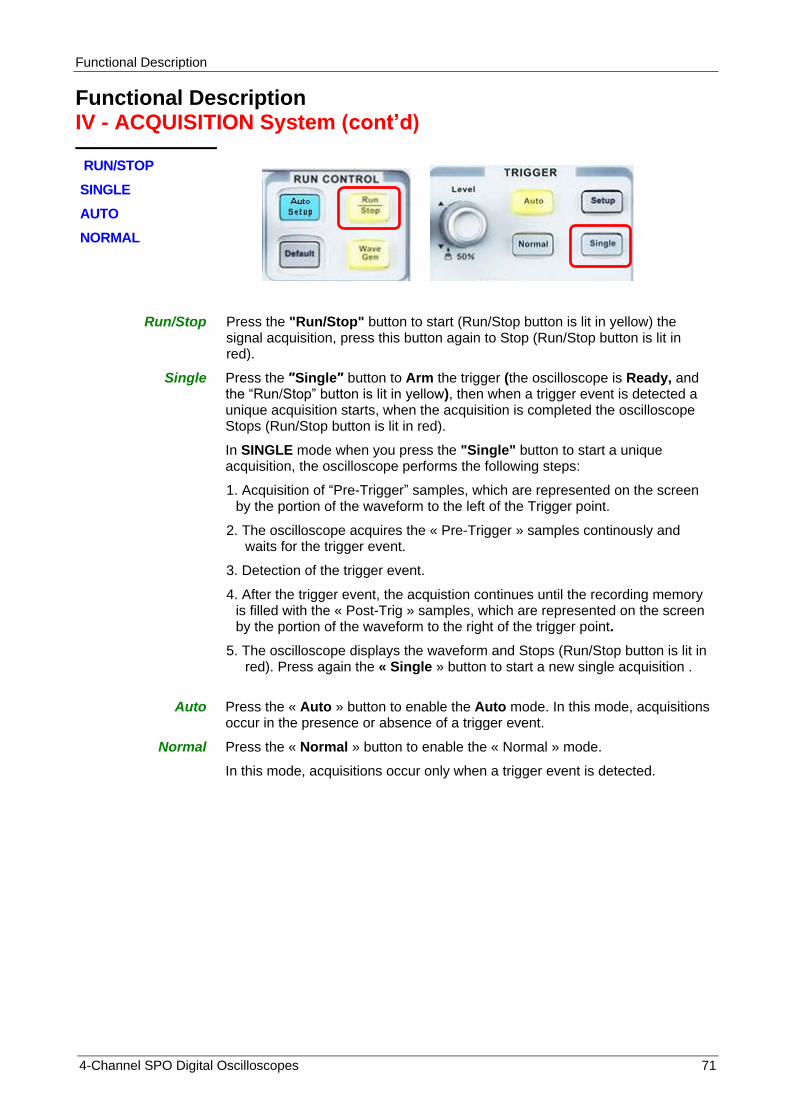
Functional Description
4-Channel SPO Digital Oscilloscopes 71
Functional Description IV - ACQUISITION System (cont‟d)
RUN/STOP
SINGLE
AUTO
NORMAL
Run/Stop Press the "Run/Stop" button to start (Run/Stop button is lit in yellow) the
signal acquisition, press this button again to Stop (Run/Stop button is lit in red).
Single
Press the ″Single″ button to Arm the trigger (the oscilloscope is Ready, and the “Run/Stop” button is lit in yellow), then when a trigger event is detected a unique acquisition starts, when the acquisition is completed the oscilloscope Stops (Run/Stop button is lit in red).
In SINGLE mode when you press the "Single" button to start a unique acquisition, the oscilloscope performs the following steps:
1. Acquisition of “Pre-Trigger” samples, which are represented on the screen by the portion of the waveform to the left of the Trigger point.
2. The oscilloscope acquires the « Pre-Trigger » samples continously and waits for the trigger event.
3. Detection of the trigger event.
4. After the trigger event, the acquistion continues until the recording memory is filled with the « Post-Trig » samples, which are represented on the screen by the portion of the waveform to the right of the trigger point.
5. The oscilloscope displays the waveform and Stops (Run/Stop button is lit in red). Press again the « Single » button to start a new single acquisition .
Auto Press the « Auto » button to enable the Auto mode. In this mode, acquisitions occur in the presence or absence of a trigger event.
Normal
Press the « Normal » button to enable the « Normal » mode.
In this mode, acquisitions occur only when a trigger event is detected.
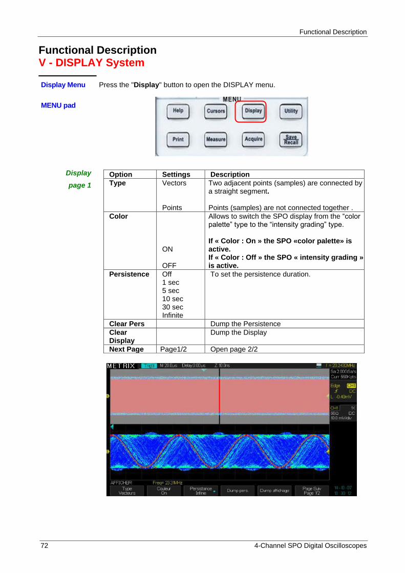
Functional Description
72 4-Channel SPO Digital Oscilloscopes
Functional Description V - DISPLAY System
Display Menu Press the "Display" button to open the DISPLAY menu.
MENU pad
Display
page 1
Option Settings Description
Type Vectors Points
Two adjacent points (samples) are connected by a straight segment. Points (samples) are not connected together .
Color ON OFF
Allows to switch the SPO display from the “color palette” type to the “intensity grading” type. If « Color : On » the SPO «color palette» is active. If « Color : Off » the SPO « intensity grading » is active.
Persistence
Off 1 sec 5 sec 10 sec 30 sec Infinite
To set the persistence duration.
Clear Pers Dump the Persistence
Clear Display
Dump the Display
Next Page Page1/2 Open page 2/2
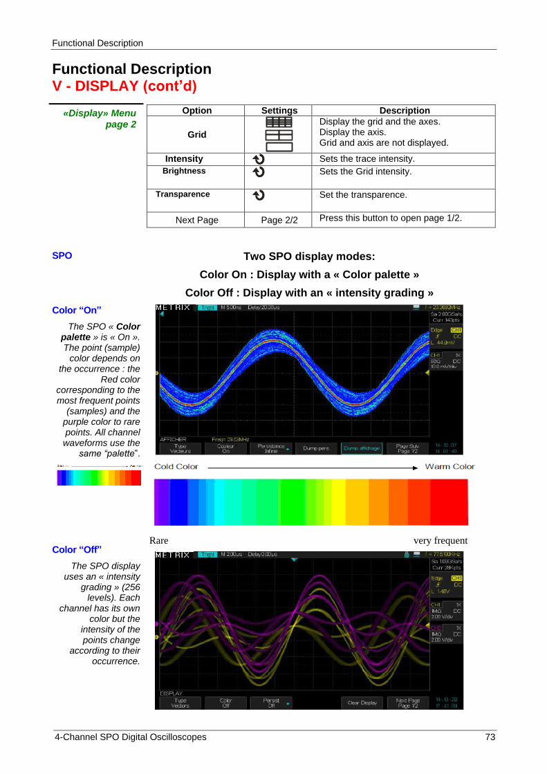
Functional Description
4-Channel SPO Digital Oscilloscopes 73
Functional Description V - DISPLAY (cont‟d)
«Display» Menu page 2
Option Settings Description
Grid
Display the grid and the axes. Display the axis. Grid and axis are not displayed.
Intensity Sets the trace intensity.
Brightness
Sets the Grid intensity.
Transparence
Set the transparence.
Next Page Page 2/2 Press this button to open page 1/2.
SPO Two SPO display modes:
Color On : Display with a « Color palette »
Color Off : Display with an « intensity grading »
Color “On”
The SPO « Color palette » is « On ». The point (sample)
color depends on the occurrence : the
Red color corresponding to the most frequent points
(samples) and the purple color to rare points. All channel waveforms use the
same “palette”.
Color “Off”
The SPO display uses an « intensity
grading » (256 levels). Each
channel has its own color but the
intensity of the points change
according to their occurrence.
Rare very frequent

Functional Description
74 4-Channel SPO Digital Oscilloscopes
Functional Description V - DYSPLAY System (cont‟d)
Operation Steps
1. To set the display type 1) Press the "Display" button to open the DISPLAY menu. 2) Press the "Type" button and select "Vectors" or "Points".
2. To set the Color Press the "Color″ button and set "ON" or "Off" : Off : Each Channel is displayed with its own color and an intensity grading : CH1 yellow, CH2 red, CH3 blue and CH4 green ON : All channels are displayed using the same « color palette » (Red Yellow Green Blue Purple) 3. To set the Persistance
Press the "Persistance" button and select "Off", "1 Sec", "5 Sec", "10 Sec", "30 Sec", or "Infinite". This option is used to view, for example, the drift of a signal over time.
4. «Clear» Persistence Press this button to dump the persistence 5. «Clear» Display Press this button to dump the Display 6. Next page button Press this button to open page 2/2 7. To set the Grid
Press the “Grid” button and select the grid type “ ”, “ ” or “
” 8. To set the Intensity
Press the “Intensity” button and use the “Universal” knob to set the trace Intensity.
9. To set the « Brightness » Press the “Brightness” button and use the “Universal” knob to set the grid Brightness.
10. To set the transparence Press the “Transparence” button and use the « Universal » knob to set the transparence. 11. Next Page
Press this button to open page 1/2.
Caution in XY mode, the «Persistence»
and the «Color» are «Off» and the “Dots”
display type is imposed

Functional Description
4-Channel SPO Digital Oscilloscopes 75
Functional Description V - DISPLAY System (cont‟d)
X-Y Format
The XY format is used to analyze the phase difference between signals using the Lissajous figures. In « XY » mode, channel CH1 (CH3) is the X axis and channel CH2 (CH4) the Y axis. The oscilloscope uses an acquisition mode without trigger and displays XY datas in the form of points, each XY point corresponds to a simultaneous acquisition on CH1(X) and CH2(Y) : X= CH1 sample (or CH3), Y= CH2 sample (or CH4).
The "XY" mode accepts sampling frequencies from 20Sa/s to 1GSa/s (1-2-5 sequence). If we visualize, in XY mode, two sinusoidal signals with the same frequency but phase shifted by an angle θ :
We will have : Sin(θ)=A/B or C/D θ=± arcsin(A/B) or ± arcsin(C/D)
Two sine waves with same frequency but phase shifted by 40° :

Functional Description
76 4-Channel SPO Digital Oscilloscopes
Operation Steps
Channel CH1 (or CH3) X axis, the corresponding “V/div” and vertical “Position” knobs allows to adjust the horizontal scale and position.
Channel CH2 (or CH4) Y axis, The corresponding “V/div” and vertical “Position” knobs allows to adjust the vertical scale and position.
Turn the “S/div” knob to set the sampling rate
The following functions are not available in “XY” mode:
- XY between a Real waveform and a Math waveform
- Cursor
- Trigger Control
- Horizontal position knob
- Vector display type
Note : The « Auto setup » function resets automatically to YT format.

Functional Description
4-Channel SPO Digital Oscilloscopes 77
Functional Description VI - MEASURE System
MEASUREMENTS The oscilloscope displays the waveform, that is to say the variation of the signal amplitude (voltage or current) as a function of time. The oscilloscope displays : the vertical and horizontal scales and the automatic and cursors measurements values.
The oscilloscope has a « hardware » frequency counter on the signal of the active trigger source channel.
Scale measurements This method allows a quick visual estimate of the amplitude or the period of the signal. For example, you can observe the signal amplitude and roughly determine it is slightly higher than 100 mV. You can estimate the amplitude by simple measurements by counting the number of major and minor divisions and multiplying by the vertical sensitivity. For example, if you count five major divisions between the minimum and maximum values of a signal, and if the vertical sensitivity is 100mV/div, then it is easy to calculate the peak-to-peak amplitude: 5 div x 100 mV/div = 500 mV.
Cursors measurements
Three modes : Manual, Track (cursors attached to the trace) and Off Press the "Cursors" button to open the cursors menu.
1. Manual Cursors Option Settings Description
Mode Manual For measurements using manual cursors.
Type Voltage Time
Use the cursors to measure the signal amplitude : voltage ∆V. Use the cursors to measure the period (or the frequency) of the signal : ∆T et 1/∆T.
Source CH1 - CH2 CH3 - CH4 MATH REFA - REFB REFC - REFD
Select the reference source for measurements.
Cur X1
Select X1 cursor and use the "Universal" knob to adjust.
Cur X2
Select X2 cursor and use the "Universal" knob to adjust.
Cur X1-X2
Select X1-X2 cursors pair and use the "Universal" knob to adjust.
Cur Y1
Select Y1 cursor and use the "Universal" knob to adjust.
Cur Y2
Select Y2 cursor and use the "Universal" knob to adjust.
Cur Y1-Y2
Select Y1-Y2 cursors pair and use the "Universal" knob to adjust.

Functional Description
78 4-Channel SPO Digital Oscilloscopes
Functional Description VI - MEASURE Sytem (cont‟d)
Examples :
Use of X and Y cursors to measure
the period (or frequency) and the amplitude of a sine
wave
When the « Manual Cursors » are active, the display shows two horizontal or vertical parallel cursors to measure voltage (Y cursors) or time (X cursors). Use the "Universal" knob to move the cursors. Select the appropriated reference source for cursors measurements.
Voltage cursor (Y cursors) : The voltage cursors materialized on the screen in the form of horizontal lines. The cursor position is in Volt.
Time Cursor (X cursors) : The time cursors materialized on the screen in the form of vertical lines. The cursor position is in second.
Moving the cursors : Select the cursor (X or Y) and use the "Universal" knob to move it. When you move the cursor the value corresponding to the vertical and(or) horizontal position of the cursor is displayed in the top left of the screen.
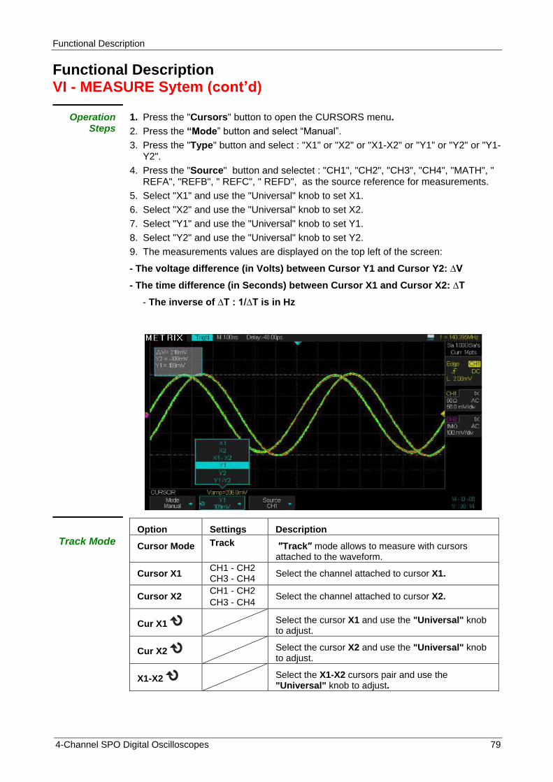
Functional Description
4-Channel SPO Digital Oscilloscopes 79
Functional Description VI - MEASURE Sytem (cont‟d)
Operation Steps
1. Press the "Cursors" button to open the CURSORS menu.
2. Press the “Mode” button and select “Manual”.
3. Press the "Type" button and select : "X1" or "X2" or "X1-X2" or "Y1" or "Y2" or "Y1-Y2".
4. Press the "Source" button and selectet : "CH1", "CH2", "CH3", "CH4", "MATH", " REFA", "REFB", " REFC", " REFD", as the source reference for measurements.
5. Select "X1" and use the "Universal" knob to set X1.
6. Select "X2" and use the "Universal" knob to set X2.
7. Select "Y1" and use the "Universal" knob to set Y1.
8. Select "Y2" and use the "Universal" knob to set Y2.
9. The measurements values are displayed on the top left of the screen:
- The voltage difference (in Volts) between Cursor Y1 and Cursor Y2: ∆V
- The time difference (in Seconds) between Cursor X1 and Cursor X2: ∆T
- The inverse of ∆T : 1/∆T is in Hz
Track Mode
Option Settings Description
Cursor Mode Track ″Track″ mode allows to measure with cursors attached to the waveform.
Cursor X1 CH1 - CH2 CH3 - CH4
Select the channel attached to cursor X1.
Cursor X2 CH1 - CH2
CH3 - CH4 Select the channel attached to cursor X2.
Cur X1 Select the cursor X1 and use the "Universal" knob to adjust.
Cur X2 Select the cursor X2 and use the "Universal" knob to adjust.
X1-X2 Select the X1-X2 cursors pair and use the "Universal" knob to adjust.

Functional Description
80 4-Channel SPO Digital Oscilloscopes
The « Track » mode displays two cross cursors attached to the trace. With the “Universal” knob, you can only adjust the horizontal position of the selected cross cursor. The oscilloscope displays the ∆V and ∆T values.
Operation Steps
1. Press the "Cursors" button to open the CURSORS menu.
2. Press the “Mode” button and select "Track".
3. Press the "X1 source” button and select the attached channel.
4. Press the "X2 source” button and select the attached channel.
5. Select “X1” and use the “Universal” knob to move horizontally the X1 cross
cursor.
6. Select “X2” and use the “Universal” knob to move horizontally the X2 cross
cursor.
7. The measured values are displayed on the top left of the screen:
X1→T: The horizontal position of X1 Cursor (Time Cursor).
Y1→V: The vertical position of Y1 Cursor (Voltage Cursor).
X2→T: The horizontal position of X2 Cursor (Time Cursor).
Y2→V: The vertical position of Y2 Cursor (Voltage Cursor).
∆T : The time interval between X1 and X2 cursors.
1/∆T : The inverse of the time interval between X1 and X2 cursors in Hz.
∆V : The voltage difference between Y1 and Y2 cursors.
Example : Measuring the amplitude and the frequency
of a 1MHz square wave
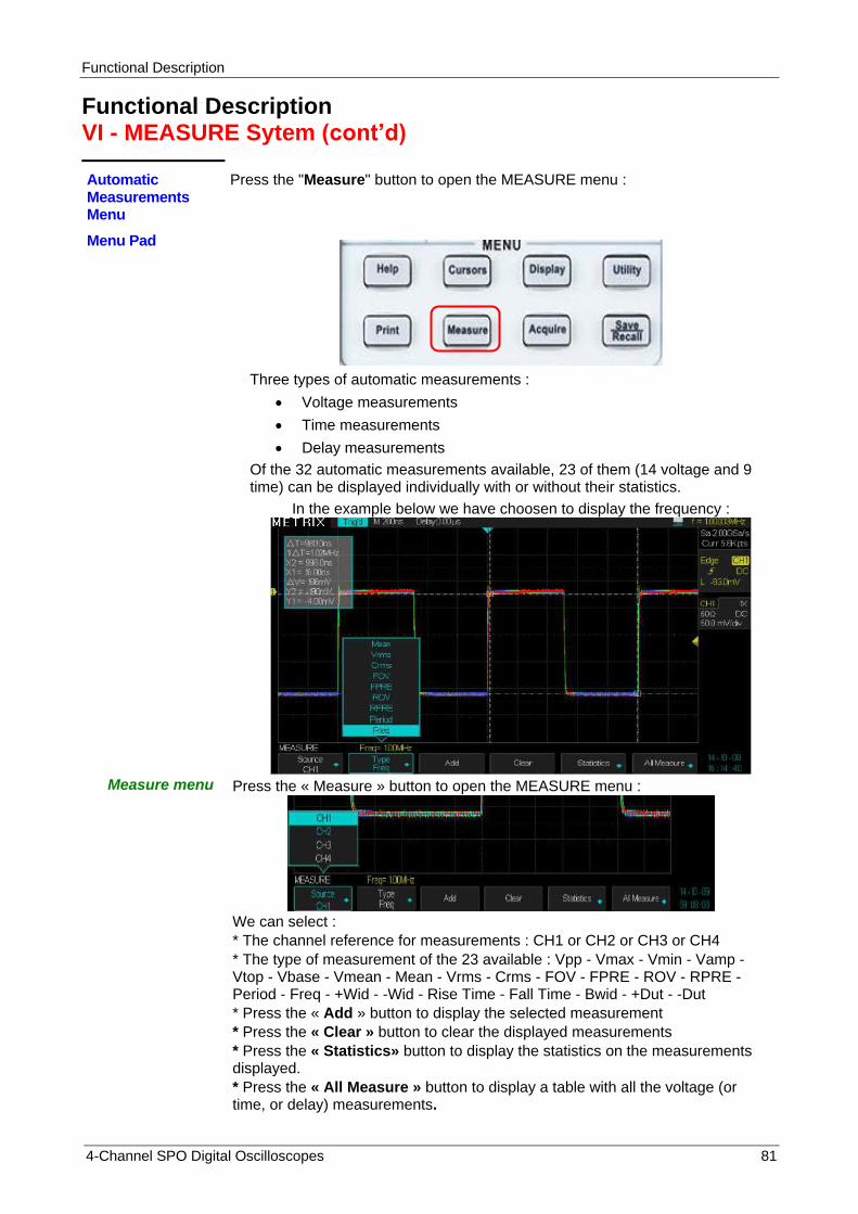
Functional Description
4-Channel SPO Digital Oscilloscopes 81
Functional Description VI - MEASURE Sytem (cont‟d)
Automatic Measurements Menu
Press the "Measure" button to open the MEASURE menu :
Menu Pad
Three types of automatic measurements :
Voltage measurements
Time measurements
Delay measurements
Of the 32 automatic measurements available, 23 of them (14 voltage and 9 time) can be displayed individually with or without their statistics.
In the example below we have choosen to display the frequency :
Measure menu Press the « Measure » button to open the MEASURE menu :
We can select :
* The channel reference for measurements : CH1 or CH2 or CH3 or CH4
* The type of measurement of the 23 available : Vpp - Vmax - Vmin - Vamp - Vtop - Vbase - Vmean - Mean - Vrms - Crms - FOV - FPRE - ROV - RPRE - Period - Freq - +Wid - -Wid - Rise Time - Fall Time - Bwid - +Dut - -Dut
* Press the « Add » button to display the selected measurement
* Press the « Clear » button to clear the displayed measurements
* Press the « Statistics» button to display the statistics on the measurements displayed.
* Press the « All Measure » button to display a table with all the voltage (or time, or delay) measurements.
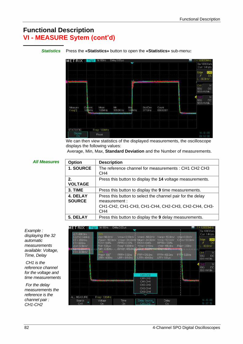
Functional Description
82 4-Channel SPO Digital Oscilloscopes
Functional Description VI - MEASURE Sytem (cont‟d)
Statistics Press the «Statistics» button to open the «Statistics» sub-menu:
We can then view statistics of the displayed measurements, the oscilloscope displays the following values:
Average, Min, Max, Standard Deviation and the Number of measurements.
All Measures Option Description
1. SOURCE The reference channel for measurements : CH1 CH2 CH3 CH4
2. VOLTAGE
Press this button to display the 14 voltage measurements.
3. TIME Press this button to display the 9 time measurements.
4. DELAY SOURCE
Press this button to select the channel pair for the delay measurement :
CH1-CH2, CH1-CH3, CH1-CH4, CH2-CH3, CH2-CH4, CH3-CH4
5. DELAY Press this button to display the 9 delay measurements.
Example : displaying the 32 automatic measurements available: Voltage, Time, Delay
CH1 is the reference channel for the voltage and time measurements
For the delay measurements the reference is the channel pair : CH1-CH2
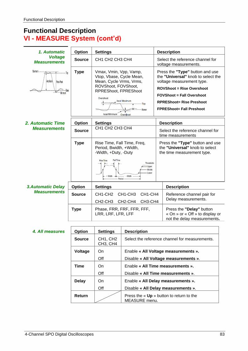
Functional Description
4-Channel SPO Digital Oscilloscopes 83
Functional Description VI - MEASURE System (cont‟d)
1. Automatic Voltage
Measurements
Option Settings Description
Source CH1 CH2 CH3 CH4 Select the reference channel for voltage measurements.
Type Vmax, Vmin, Vpp, Vamp, Vtop, Vbase, Cycle Mean, Mean, Cycle Vrms, Vrms, ROVShoot, FOVShoot, RPREShoot, FPREShoot
Press the "Type" button and use the "Universal" knob to select the voltage measurement type.
ROVShoot = Rise Overshoot
FOVShoot = Fall Overshoot
RPREShoot= Rise Preshoot
FPREShoot= Fall Preshoot
2. Automatic Time Measurements
Option Settings Description
Source CH1 CH2 CH3 CH4
Select the reference channel for time measurements
Type Rise Time, Fall Time, Freq, Period, Bwidth, +Width, -Width, +Duty, -Duty
Press the "Type" button and use the "Universal" knob to select the time measurement type.
3.Automatic Delay Measurements
Option Settings Description
Source CH1-CH2 CH1-CH3 CH1-CH4
CH2-CH3 CH2-CH4 CH3-CH4
Reference channel pair for Delay measurements.
Type Phase, FRR, FRF, FFR, FFF, LRR, LRF, LFR, LFF
Press the "Delay" button « On » or « Off » to display or not the delay measurements.
4. All measures Option Settings Description
Source CH1, CH2 CH3, CH4
Select the reference channel for measurements.
Voltage On
Off
Enable « All Voltage measurements ».
Disable « All Voltage measurements ».
Time On
Off
Enable « All Time measurements ».
Disable « All Time measurements ».
Delay On
Off
Enable « All Delay measurements ».
Disable « All Delay measurements ».
Return Press the « Up » button to return to the MEASURE menu.
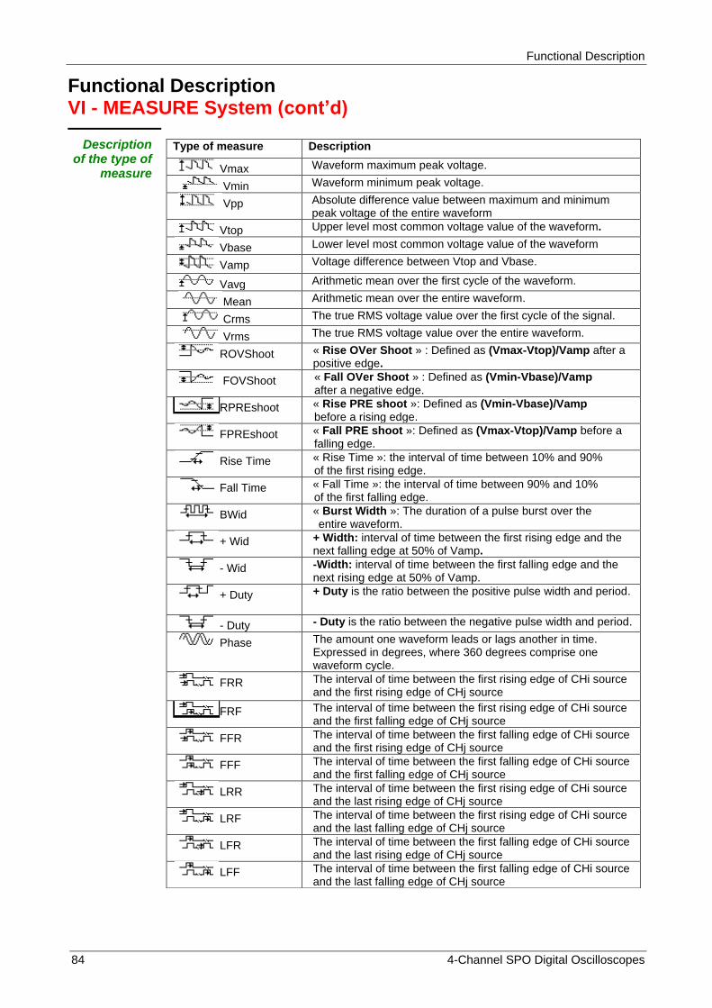
Functional Description
84 4-Channel SPO Digital Oscilloscopes
Functional Description VI - MEASURE System (cont‟d)
Description of the type of
measure
Type of measure Description
Vmax Waveform maximum peak voltage.
Vmin Waveform minimum peak voltage.
Vpp Absolute difference value between maximum and minimum peak voltage of the entire waveform
Vtop Upper level most common voltage value of the waveform.
Vbase Lower level most common voltage value of the waveform
Vamp Voltage difference between Vtop and Vbase.
Vavg Arithmetic mean over the first cycle of the waveform.
Mean Arithmetic mean over the entire waveform.
Crms The true RMS voltage value over the first cycle of the signal.
Vrms The true RMS voltage value over the entire waveform.
ROVShoot « Rise OVer Shoot » : Defined as (Vmax-Vtop)/Vamp after a positive edge.
FOVShoot « Fall OVer Shoot » : Defined as (Vmin-Vbase)/Vamp after a negative edge.
RPREshoot « Rise PRE shoot »: Defined as (Vmin-Vbase)/Vamp before a rising edge.
FPREshoot « Fall PRE shoot »: Defined as (Vmax-Vtop)/Vamp before a falling edge.
Rise Time « Rise Time »: the interval of time between 10% and 90% of the first rising edge.
Fall Time « Fall Time »: the interval of time between 90% and 10% of the first falling edge.
BWid « Burst Width »: The duration of a pulse burst over the entire waveform.
+ Wid + Width: interval of time between the first rising edge and the next falling edge at 50% of Vamp.
- Wid -Width: interval of time between the first falling edge and the next rising edge at 50% of Vamp.
+ Duty
+ Duty is the ratio between the positive pulse width and period.
- Duty - Duty is the ratio between the negative pulse width and period.
Phase The amount one waveform leads or lags another in time. Expressed in degrees, where 360 degrees comprise one waveform cycle.
FRR The interval of time between the first rising edge of CHi source and the first rising edge of CHj source
FRF The interval of time between the first rising edge of CHi source and the first falling edge of CHj source
FFR The interval of time between the first falling edge of CHi source and the first rising edge of CHj source
FFF The interval of time between the first falling edge of CHi source and the first falling edge of CHj source
LRR The interval of time between the first rising edge of CHi source and the last rising edge of CHj source
LRF The interval of time between the first rising edge of CHi source and the last falling edge of CHj source
LFR The interval of time between the first falling edge of CHi source and the last rising edge of CHj source
LFF The interval of time between the first falling edge of CHi source and the last falling edge of CHj source
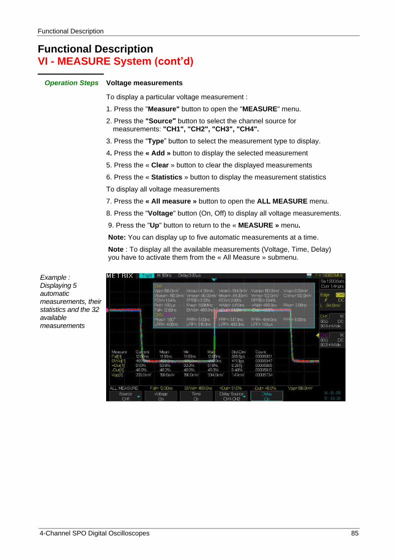
Functional Description
4-Channel SPO Digital Oscilloscopes 85
Functional Description VI - MEASURE System (cont‟d)
Operation Steps Voltage measurements
To display a particular voltage measurement :
1. Press the "Measure" button to open the "MEASURE" menu.
2. Press the "Source″ button to select the channel source for measurements: "CH1", "CH2", "CH3", "CH4".
3. Press the “Type” button to select the measurement type to display.
4. Press the « Add » button to display the selected measurement
5. Press the « Clear » button to clear the displayed measurements
6. Press the « Statistics » button to display the measurement statistics
To display all voltage measurements
7. Press the « All measure » button to open the ALL MEASURE menu.
8. Press the "Voltage" button (On, Off) to display all voltage measurements.
9. Press the "Up" button to return to the « MEASURE » menu.
Note: You can display up to five automatic measurements at a time.
Note : To display all the available measurements (Voltage, Time, Delay) you have to activate them from the « All Measure » submenu.
Example : Displaying 5 automatic measurements, their statistics and the 32 available measurements

Functional Description
86 4-Channel SPO Digital Oscilloscopes
Functional Description VI - MEASURE System (cont‟d)
Operation Steps Time measurements
To display a particular time measurement :
1. Press the "Measure" button to open the "MEASURE" menu
2. Press the "Source″ button to select the channel source for measurements: "CH1", "CH2", "CH3", "CH4".
3. Press the “Type” button to select the measurement type to display.
4. Press the « Add » button to display the selected measurement
5. Press the « Clear » button to clear the displayed measurements
6. Press the « Statistics » button to display the measurement statistics
To display all time measurements
7. Press the « All measure » button to open the ALL MEASURE menu.
8. Press the "Time" button (On, Off) to display all time measurements.
9. Press the "Up" button to return to the « MEASURE » menu.

Functional Description
4-Channel SPO Digital Oscilloscopes 87
Functional Description VII - SAVE/RECALL System
Save/Recall Press the “Save/Recall” button to open the SAVE/RECALL menu. This menu allows to Save/Recall : Setups, Waveforms, Picture, .CSV files.
4 data types can be saved : - Setups - Waveforms - Pictures - .CSV files
The «Setups» files can be saved in internal (the oscilloscope) or external (USB memory device plugged in the “USB host” front panel connector) memories. You can save up to 20 Setups in the internal memory. The Waveforms, the Pictures, and the .CSV files must be saved in external memories. The setups and the waveforms can be recalled and displayed on the oscilloscope. The pictures and the .CSV files can not be recalled or displayed on the oscilloscope, this files can be open on a PC.
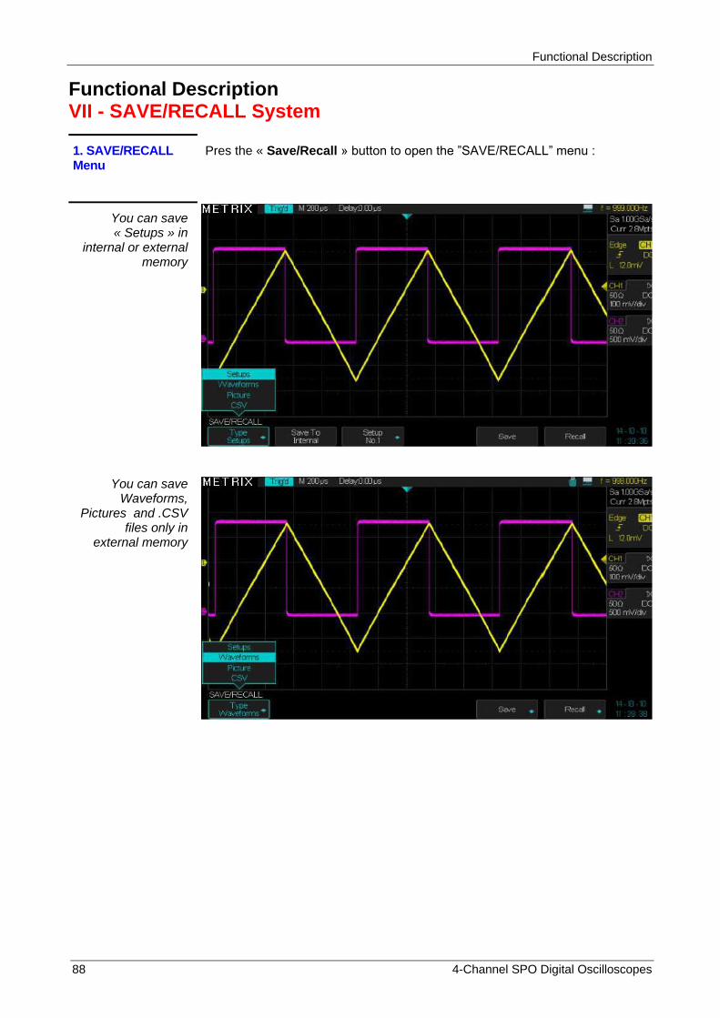
Functional Description
88 4-Channel SPO Digital Oscilloscopes
Functional Description VII - SAVE/RECALL System
1. SAVE/RECALL Menu
Pres the « Save/Recall » button to open the ”SAVE/RECALL” menu :
You can save « Setups » in
internal or external memory
You can save Waveforms,
Pictures and .CSV files only in
external memory

Functional Description
4-Channel SPO Digital Oscilloscopes 89
Functional Description VII - SAVE/RECALL System (cont‟d)
Saving « Setups » in Internal or
External memory
To save a «Setup» file in the oscilloscope internal memory :
1° Press the « Save/Recall » button to open the SAVE/RECALL menu.
2° Press the « Type » button and select « Setups »
3° Select Save to « Internal »
4° Select a Setup N° location among the 20 available
5° Press the «Save» button to save the current Setup
To save a setup file in an external memory (USB memory device plugged in the « USB host » front panel connector) :
1° Press the « Save/Recall » button to open the SAVE/RECALL menu
2° Press the « Type » button and select « Setups »
3° Select Save to « External »
4° Plug the USB device in the « USB host » front panel connector and wait
for the USB icon appears and the following “Popup” message : « USB Flash Drive Plugged in ! » is displayed.
5° Press the « Save » button and set the « save » function, wait for the file directory of the “USB memory device” is displayed.
Note : If the USB device is not plugged in and we press the «Save» button, the following message is displayed : « USB Flash Drive isn‟t connected !»
6° Press the « New » button, to enter from the keyboard (shift to keyboard) the name of the new setup file to save, the maximum width allowed is 8 characters
Example : To enter the name « dox3302s » select one by one the characters (using the Universal knob or the buttons “→” and “←”) and press the « Enter » button for each selected character.
7° Press the «Switch to keyboard» button to switch to «Switch to Name»
8° Press the « Enter » button to save the Setup file: “dox3302S”

Functional Description
90 4-Channel SPO Digital Oscilloscopes
9° The Setup file « dox3302s » is saved in the USB memory device as dox3302s.SET
To Recall a Setup file We can « recall » a setup file from an internal or an external memory.
To Recall a Setup file from an internal or external memory
To Recall a Setup file from the oscilloscope internal memory
1° Press the « Save/Recall » button to open the SAVE/RECALL menu.
2° Press the « Type » button and select « Setups »
3° Select Save to «Internal»
4° Select a Setup N° location among the 20 available
5° Press the « Recall » button to recall the selected Setup file;
wait for the message «Read Data success»
Note : If the selected « setup N° » corresponds to an empty location the following message is displayed : « Location Empty ! »
To Recall a Setup file from an external memory (USB memory device plugged in the « USB host » front panel connector) :
1° Press the « Save/Recall » button to open the SAVE/RECALL menu
2° Press the « Type » button and select « Setups »
3° Select Save to « External »
4° Plug the USB memory device in the USB host connector and wait for the
USB device icon and the Popup message « USB Flash Drive Plugged in ! ».
5° Press the « Recall » button and wait for the file directory of the “USB memory device” is displayed.
6° Use the Universal knob to select the .SET file to recall
7° Press the « Load » button to recall the selected setup file and wait for the message «Read Data success» .

Functional Description
4-Channel SPO Digital Oscilloscopes 91
Functional Description VII - SAVE/RECALL System (cont‟d)
Rename We can Rename an existing Setup file
1° Press the « Save/Recall » button to open the SAVE/RECALL menu
2° Press the « Type » button and select « Setups »
3° Select Save to « External »
4° Plug the USB memory device in the USB host connector and wait for the
USB device icon and the Popup message « USB Flash Drive Plugged
in ! ».
5° Press the « Recall » button and wait for the file directory of the “USB
memory device” is displayed
6° Select the file to Rename
7° Press « Next Page » button
8° Press the « Rename » button
9° Modify the file name using the buttons and the Universal knob: « Switch
to Name », « Universal knob», « Delete », « switch to keyboard »,
« Universal knob », « Enter », « Switch to Name », « Enter »,
« Confirm » or « Cancel »
Delete We can delete a file in a directory:
1° Press the « Save/Recall » button to open the SAVE/RECALL menu
2° Press the « Type » button and select « Setups »
3° Select Save to « External »
4° Plug the USB memory device in the USB host connector and wait for the
USB device icon and the Popup message « USB Flash Drive Plugged
in ! ».
5° Press the « Recall » button and wait for the file directory of the “USB
memory device” is displayed
6° Select the file to Delete
7° Press the Delete button
8° Press the « Confirm » or « Cancel » button to delete or not the selected
file.
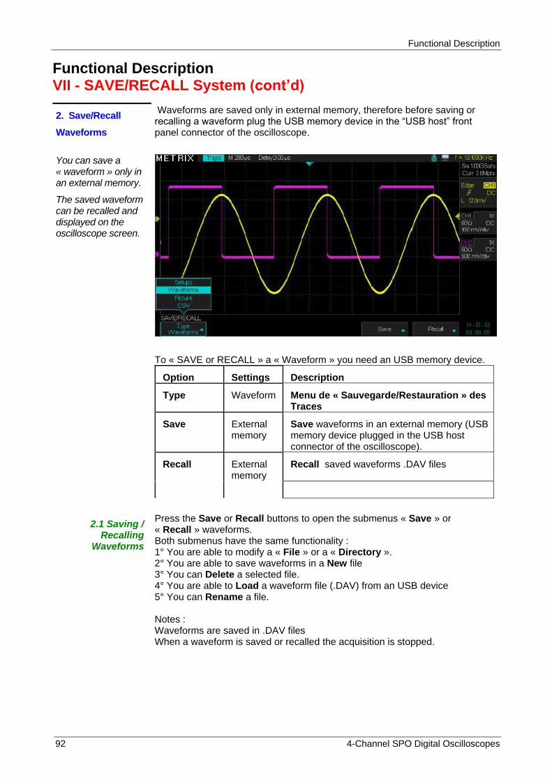
Functional Description
92 4-Channel SPO Digital Oscilloscopes
Functional Description VII - SAVE/RECALL System (cont‟d)
2. Save/Recall
Waveforms
Waveforms are saved only in external memory, therefore before saving or recalling a waveform plug the USB memory device in the “USB host” front panel connector of the oscilloscope.
You can save a « waveform » only in an external memory.
The saved waveform can be recalled and displayed on the oscilloscope screen.
To « SAVE or RECALL » a « Waveform » you need an USB memory device.
Option Settings Description
Type Waveform Menu de « Sauvegarde/Restauration » des Traces
Save External memory
Save waveforms in an external memory (USB memory device plugged in the USB host connector of the oscilloscope).
Recall External memory
Recall saved waveforms .DAV files
2.1 Saving / Recalling
Waveforms
Press the Save or Recall buttons to open the submenus « Save » or « Recall » waveforms. Both submenus have the same functionality : 1° You are able to modify a « File » or a « Directory ». 2° You are able to save waveforms in a New file 3° You can Delete a selected file. 4° You are able to Load a waveform file (.DAV) from an USB device 5° You can Rename a file. Notes : Waveforms are saved in .DAV files When a waveform is saved or recalled the acquisition is stopped.
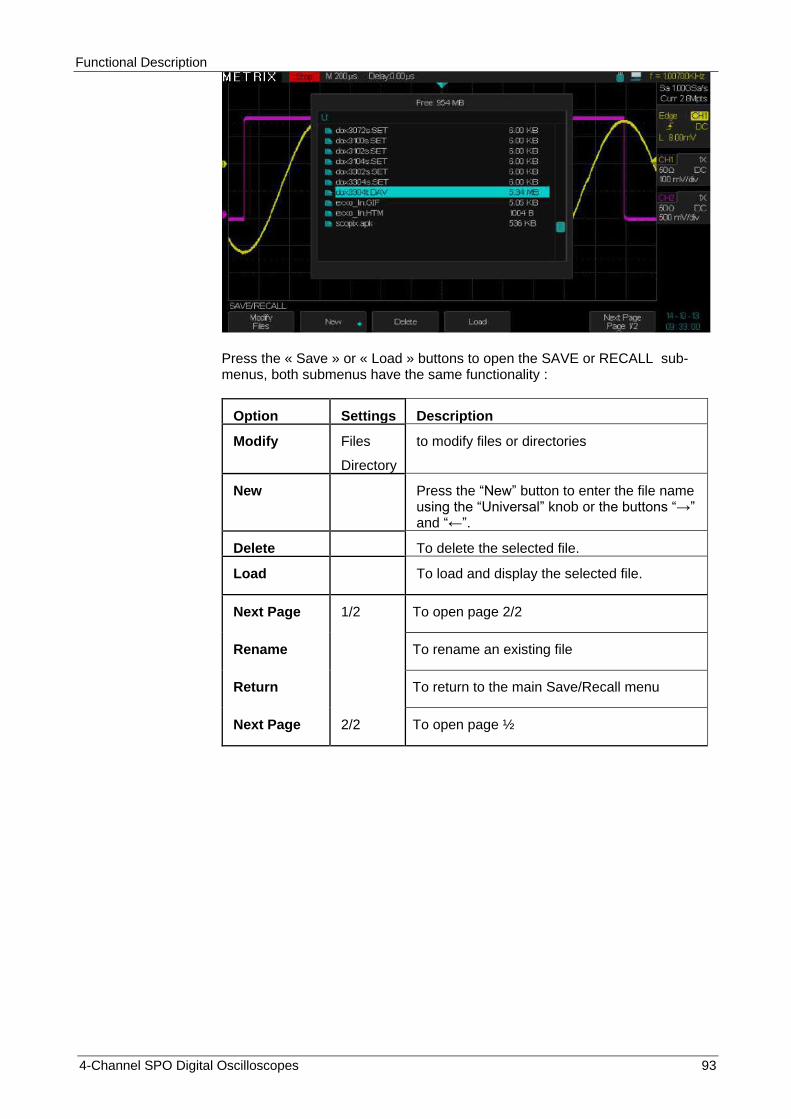
Functional Description
4-Channel SPO Digital Oscilloscopes 93
Press the « Save » or « Load » buttons to open the SAVE or RECALL sub-menus, both submenus have the same functionality :
Option Settings Description
Modify Files
Directory
to modify files or directories
New Press the “New” button to enter the file name using the “Universal” knob or the buttons “→” and “←”.
Delete To delete the selected file.
Load To load and display the selected file.
Next Page 1/2 To open page 2/2
Rename To rename an existing file
Return To return to the main Save/Recall menu
Next Page 2/2 To open page ½
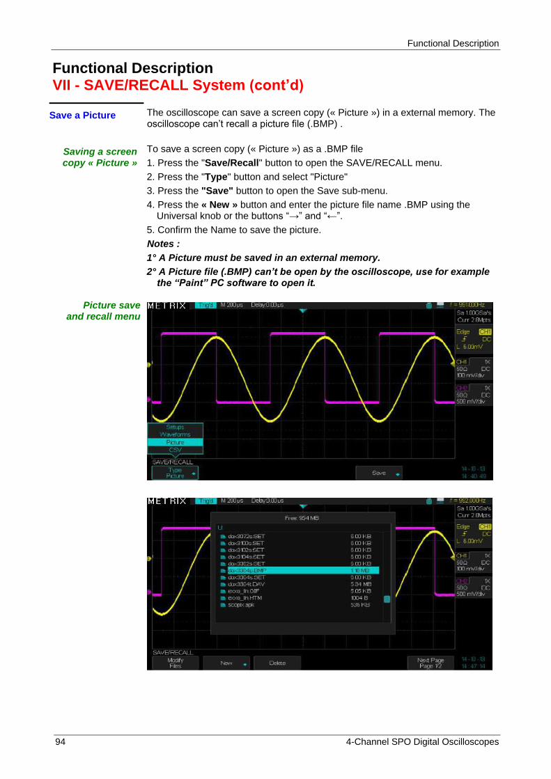
Functional Description
94 4-Channel SPO Digital Oscilloscopes
Functional Description VII - SAVE/RECALL System (cont‟d)
Save a Picture The oscilloscope can save a screen copy (« Picture ») in a external memory. The oscilloscope can’t recall a picture file (.BMP) .
Saving a screen copy « Picture »
To save a screen copy (« Picture ») as a .BMP file
1. Press the "Save/Recall" button to open the SAVE/RECALL menu.
2. Press the "Type" button and select "Picture"
3. Press the "Save" button to open the Save sub-menu.
4. Press the « New » button and enter the picture file name .BMP using the Universal knob or the buttons “→” and “←”.
5. Confirm the Name to save the picture.
Notes :
1° A Picture must be saved in an external memory.
2° A Picture file (.BMP) can’t be open by the oscilloscope, use for example the “Paint” PC software to open it.
Picture save and recall menu

Functional Description
4-Channel SPO Digital Oscilloscopes 95
Functional Description VII - SAVE/RECALL System (cont‟d)
2.2 Saving a screen copy
(Picture)
To save a screen copy in an external memory :
Open the SAVE/RECALL menu and select the Picture type, press the «Save» button to open the Save submenu to save a screen copy .BMP.
Option Settings Description
Type Picture Save a « Picture» file.
Save Press the « Save » button to open the save menu.
Submenu « Save » « Picture »
Option Settings Description
Modify File
Directory
To modify a file or a directory
New
To create a new screen copy (picture) file press the « New » button to open the New file submenu. Enter the file name (.BMP) using the Universal knob or the buttons “→” and “←”.
Delete Press this button to delete the selected file
Next page 1/2 Press this button to open page 2/2
Rename Press this button to rename an existing file
Return To return to the main menu
Next Page 2/2 To open page ½
To enter the picture file name first press the « Switch to Keyboard » button (to “switch to name”) and then press the “Enter” button
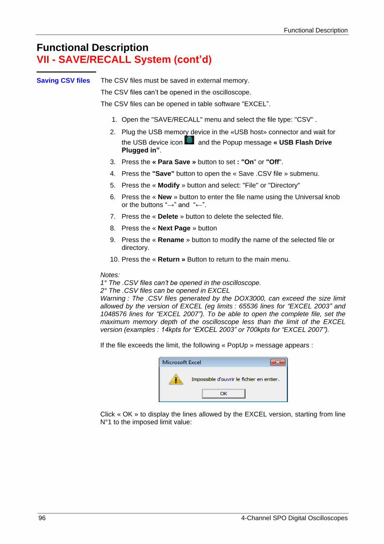
Functional Description
96 4-Channel SPO Digital Oscilloscopes
Functional Description VII - SAVE/RECALL System (cont‟d)
Saving CSV files The CSV files must be saved in external memory.
The CSV files can’t be opened in the oscilloscope.
The CSV files can be opened in table software “EXCEL”.
1. Open the "SAVE/RECALL" menu and select the file type: "CSV" .
2. Plug the USB memory device in the «USB host» connector and wait for
the USB device icon and the Popup message « USB Flash Drive Plugged in”.
3. Press the « Para Save » button to set : "On" or "Off".
4. Press the "Save" button to open the « Save .CSV file » submenu.
5. Press the « Modify » button and select: "File" or "Directory"
6. Press the « New » button to enter the file name using the Universal knob or the buttons “→” and “←”.
7. Press the « Delete » button to delete the selected file.
8. Press the « Next Page » button
9. Press the « Rename » button to modify the name of the selected file or directory.
10. Press the « Return » Button to return to the main menu. Notes: 1° The .CSV files can‟t be opened in the oscilloscope. 2° The .CSV files can be opened in EXCEL Warning : The .CSV files generated by the DOX3000, can exceed the size limit allowed by the version of EXCEL (eg limits : 65536 lines for “EXCEL 2003” and 1048576 lines for “EXCEL 2007”). To be able to open the complete file, set the maximum memory depth of the oscilloscope less than the limit of the EXCEL version (examples : 14kpts for “EXCEL 2003” or 700kpts for “EXCEL 2007”). If the file exceeds the limit, the following « PopUp » message appears :
Click « OK » to display the lines allowed by the EXCEL version, starting from line N°1 to the imposed limit value:
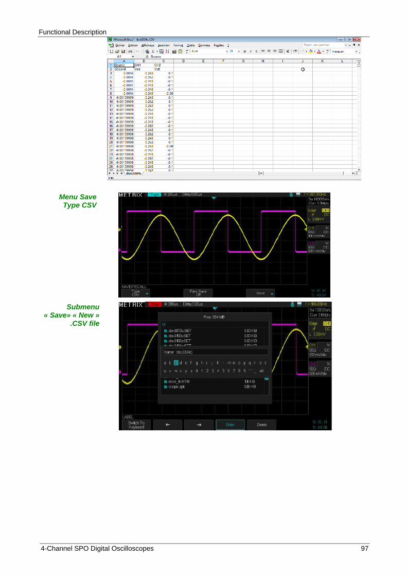
Functional Description
4-Channel SPO Digital Oscilloscopes 97
Menu Save Type CSV
Submenu « Save» « New »
.CSV file
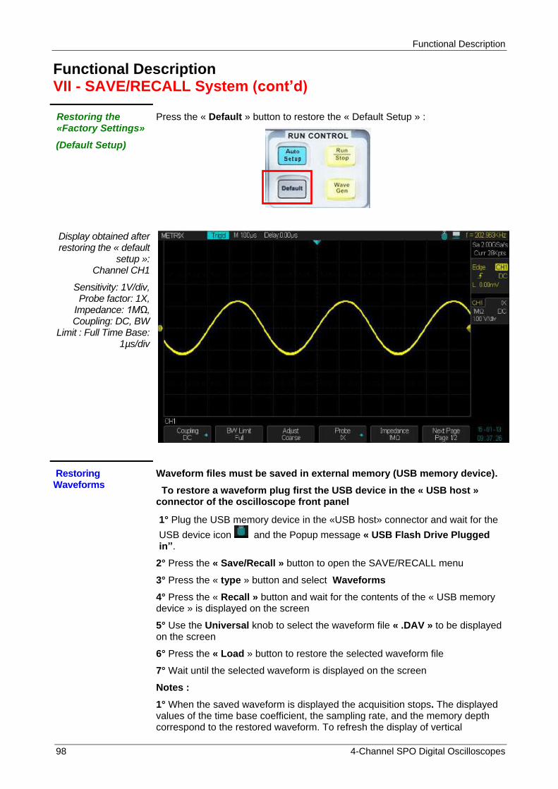
Functional Description
98 4-Channel SPO Digital Oscilloscopes
Functional Description VII - SAVE/RECALL System (cont‟d)
Restoring the «Factory Settings»
(Default Setup)
Press the « Default » button to restore the « Default Setup » :
Display obtained after restoring the « default
setup »: Channel CH1
Sensitivity: 1V/div, Probe factor: 1X,
Impedance: 1MΩ, Coupling: DC, BW
Limit : Full Time Base: 1µs/div
Restoring Waveforms
Waveform files must be saved in external memory (USB memory device).
To restore a waveform plug first the USB device in the « USB host » connector of the oscilloscope front panel
1° Plug the USB memory device in the «USB host» connector and wait for the
USB device icon and the Popup message « USB Flash Drive Plugged in”.
2° Press the « Save/Recall » button to open the SAVE/RECALL menu
3° Press the « type » button and select Waveforms
4° Press the « Recall » button and wait for the contents of the « USB memory device » is displayed on the screen
5° Use the Universal knob to select the waveform file « .DAV » to be displayed on the screen
6° Press the « Load » button to restore the selected waveform file
7° Wait until the selected waveform is displayed on the screen
Notes :
1° When the saved waveform is displayed the acquisition stops. The displayed values of the time base coefficient, the sampling rate, and the memory depth correspond to the restored waveform. To refresh the display of vertical
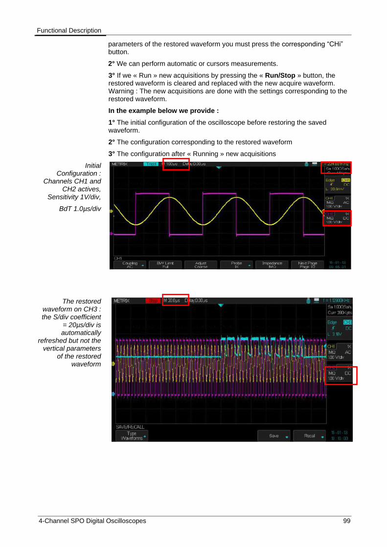
Functional Description
4-Channel SPO Digital Oscilloscopes 99
parameters of the restored waveform you must press the corresponding “CHi” button.
2° We can perform automatic or cursors measurements.
3° If we « Run » new acquisitions by pressing the « Run/Stop » button, the restored waveform is cleared and replaced with the new acquire waveform. Warning : The new acquisitions are done with the settings corresponding to the restored waveform.
In the example below we provide :
1° The initial configuration of the oscilloscope before restoring the saved waveform.
2° The configuration corresponding to the restored waveform
3° The configuration after « Running » new acquisitions
Initial Configuration :
Channels CH1 and CH2 actives,
Sensitivity 1V/div,
BdT 1.0µs/div
The restored waveform on CH3 : the S/div coefficient
= 20µs/div is automatically
refreshed but not the vertical parameters
of the restored waveform

Functional Description
100 4-Channel SPO Digital Oscilloscopes
To refreshed the vertical parameters of
the restored (CH3) waveform you must
press a « CHi » button.
If we « Run » new acquisitions by
pressing the « Run/Stop » button,
the restored waveform is cleared
and replaced with the new acquire
waveform. The new acquisitions are done
with the settings corresponding to the
restored waveform.
(The initial configuration is lost)
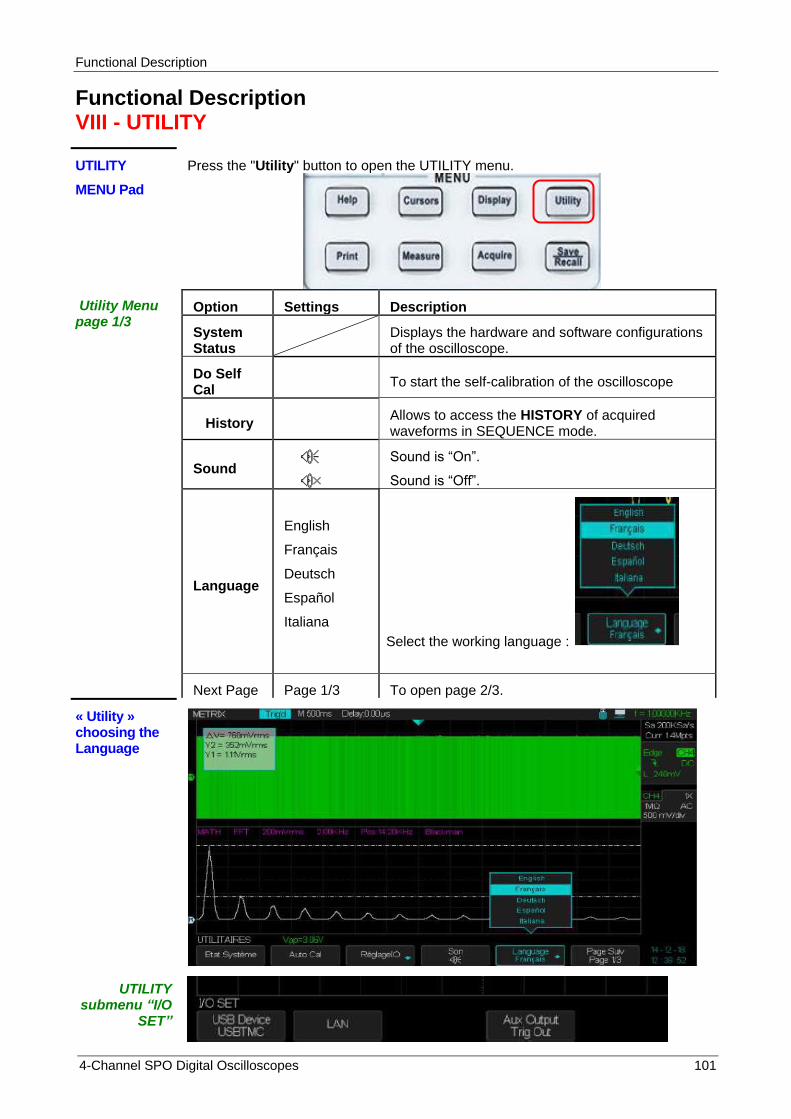
Functional Description
4-Channel SPO Digital Oscilloscopes 101
Functional Description VIII - UTILITY
UTILITY Press the "Utility" button to open the UTILITY menu.
MENU Pad
Utility Menu page 1/3
Option Settings Description
System Status
Displays the hardware and software configurations of the oscilloscope.
Do Self Cal
To start the self-calibration of the oscilloscope
History Allows to access the HISTORY of acquired waveforms in SEQUENCE mode.
Sound
Sound is “On”.
Sound is “Off”.
Language
English
Français
Deutsch
Español
Italiana
Select the working language :
Next Page Page 1/3 To open page 2/3.
« Utility » choosing the Language
UTILITY submenu “I/O
SET”

Functional Description
102 4-Channel SPO Digital Oscilloscopes
UTILITY do self Cal
Press “Single” to begin
When “Do self Call” ends
“Press Run/Stop to
Exit”
UTILITY submenu
System Status

Functional Description
4-Channel SPO Digital Oscilloscopes 103
Functional Description VIII - UTILITY (cont‟d)
« Utility » page 2/3
Option Valeurs Instructions
Pass/Fail To open the Pass-Fail menu
I/O
USB
LAN
Aux Output
To set the Input/Output interfaces
Power Analyze
To enable the « Power Analyzer » option, when the option is installed. Otherwise the following message appears :
Setup
Ink Saver
Layout
Paper Size
Image Size
ID Print
Print Key
To set up printer
Quick Cal
ON
OFF
If «Quick-Cal» is «ON» and the vertical sensitivity is set to 2mV or 5mV/div, a quick-cal routine starts automatically when the oscilloscope is switched “On” or when the ambiant temperature varies by more than 2°C.
Next Page
2/3 To open page 3/3
USB Device (Back USB)
Printer
The « Printer » is connected to the oscilloscope with an USB cable. Before printing, select the "Printer" option. The
Printer icon is displayed on the top right of the screen.
USBTMC (PC)
The oscilloscope is connected to the PC with an USB cable. When working with "EasyScopeX" PC software select "USBTMC". The PC icon is displayed on the top
right of the screen.
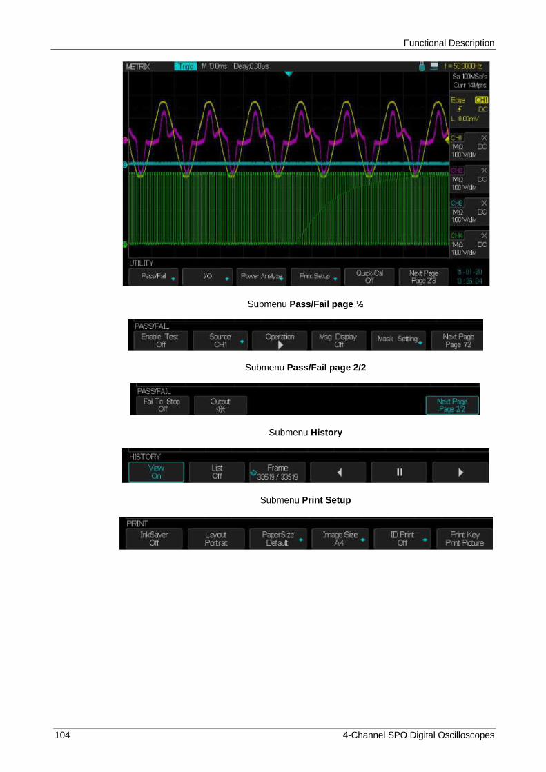
Functional Description
104 4-Channel SPO Digital Oscilloscopes
Submenu Pass/Fail page ½
Submenu Pass/Fail page 2/2
Submenu History
Submenu Print Setup
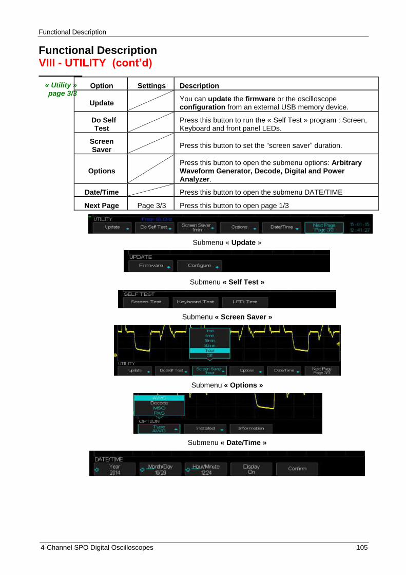
Functional Description
4-Channel SPO Digital Oscilloscopes 105
Functional Description VIII - UTILITY (cont‟d)
« Utility » page 3/3
Option Settings Description
Update You can update the firmware or the oscilloscope configuration from an external USB memory device.
Do Self Test
Press this button to run the « Self Test » program : Screen, Keyboard and front panel LEDs.
Screen Saver
Press this button to set the “screen saver” duration.
Options Press this button to open the submenu options: Arbitrary Waveform Generator, Decode, Digital and Power Analyzer.
Date/Time Press this button to open the submenu DATE/TIME
Next Page Page 3/3 Press this button to open page 1/3
Submenu « Update »
Submenu « Self Test »
Submenu « Screen Saver »
Submenu « Options »
Submenu « Date/Time »
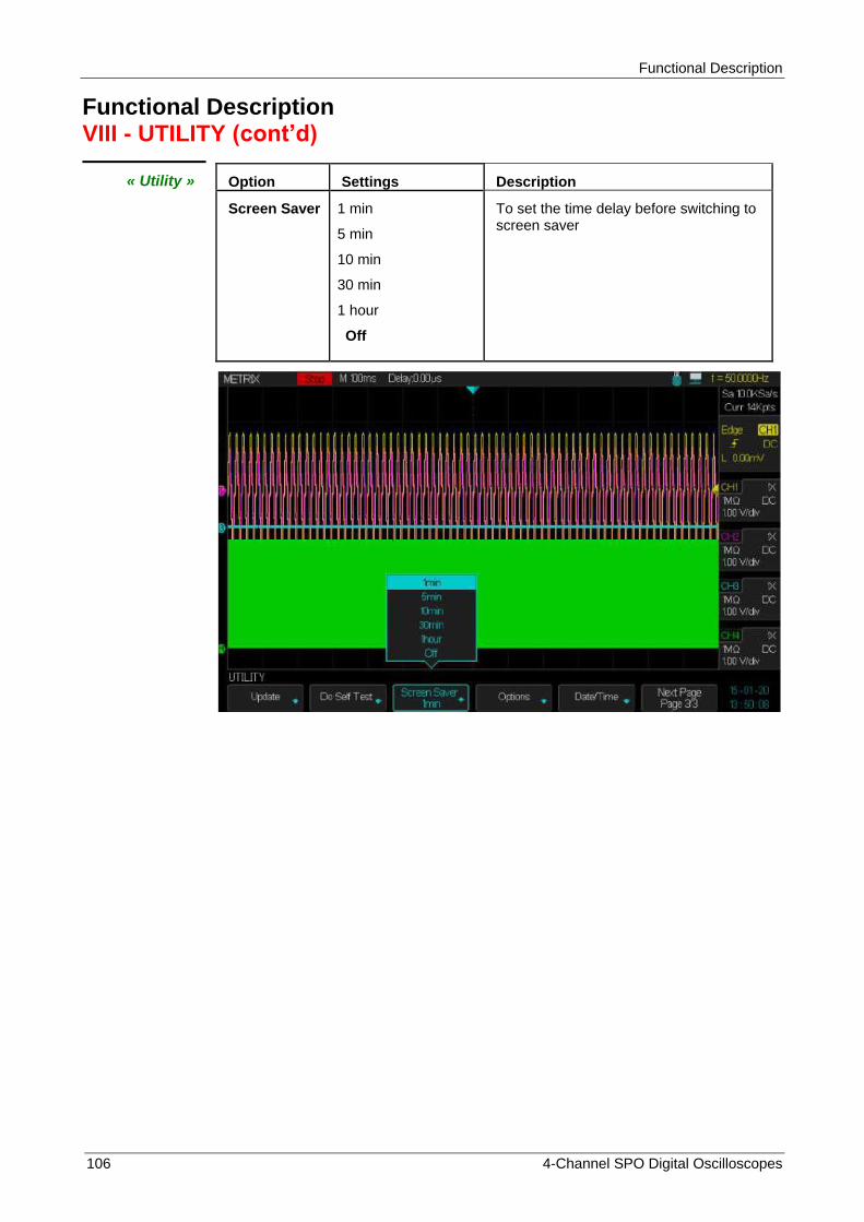
Functional Description
106 4-Channel SPO Digital Oscilloscopes
Functional Description VIII - UTILITY (cont‟d)
« Utility » Option Settings Description
Screen Saver 1 min
5 min
10 min
30 min
1 hour
Off
To set the time delay before switching to screen saver
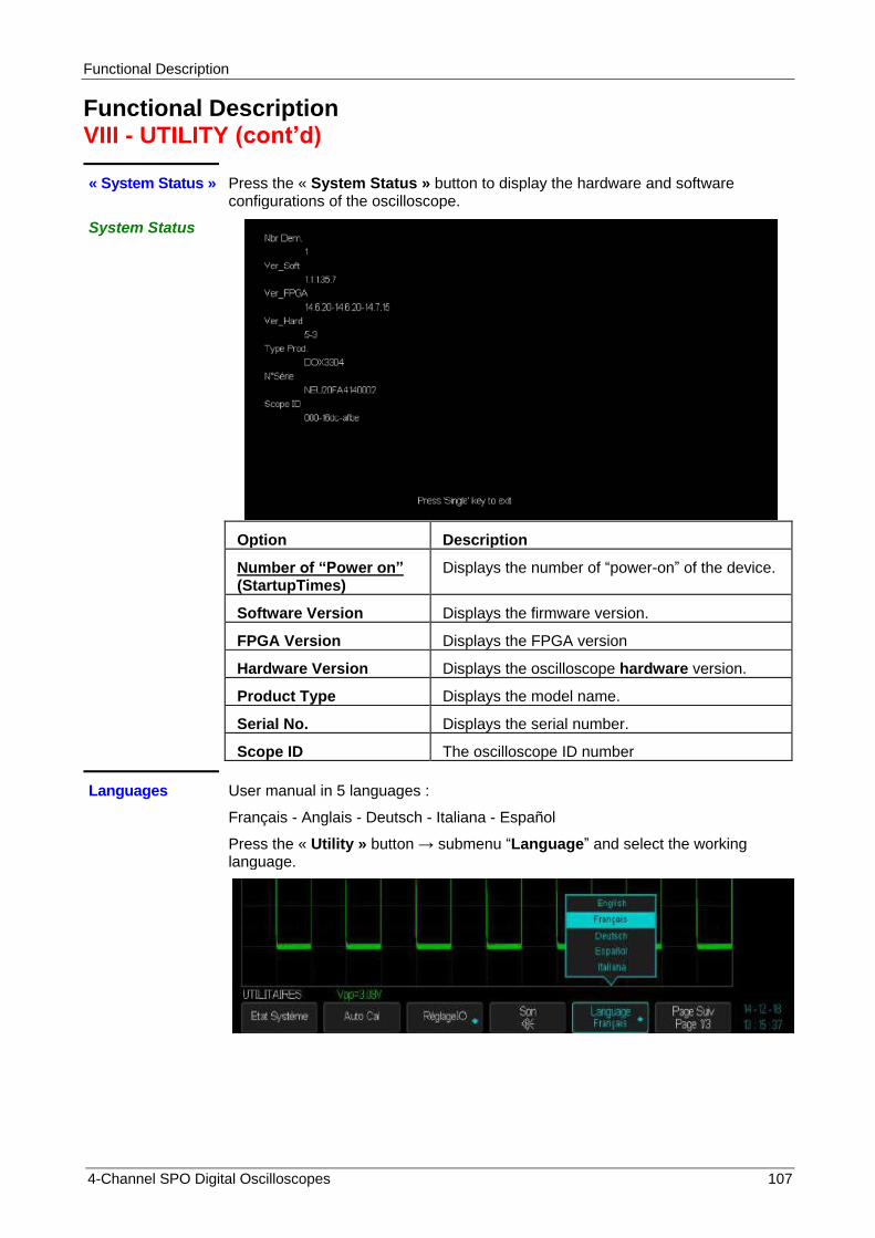
Functional Description
4-Channel SPO Digital Oscilloscopes 107
Functional Description VIII - UTILITY (cont‟d)
« System Status » Press the « System Status » button to display the hardware and software configurations of the oscilloscope.
System Status
Option Description
Number of “Power on” (StartupTimes)
Displays the number of “power-on” of the device.
Software Version Displays the firmware version.
FPGA Version Displays the FPGA version
Hardware Version Displays the oscilloscope hardware version.
Product Type Displays the model name.
Serial No. Displays the serial number.
Scope ID The oscilloscope ID number
Languages User manual in 5 languages :
Français - Anglais - Deutsch - Italiana - Español
Press the « Utility » button → submenu “Language” and select the working language.

Functional Description
108 4-Channel SPO Digital Oscilloscopes
Functional Description VIII - UTILITY (cont‟d)
« Print Setup » Set the « USB device » interface to « Printer » (Utility submenu « I/O ») and connect a ″Pict Bridge″ printer to the “USB Device” connector of the rear panel of the oscilloscope.
Open the submenu « Print Setup » submenu to setup the printer.
Press the « Print » button to print.
Printer Settings
Option Settings Instructions
Ink Saver On Off
To print a screen copy on a white background. To print the screen copy as it is.
Layout Portrait Landscape
To select the desired layout.
Paper Size Default, A4, Letter Displays the available settings with your compatible USB "PictBridge" printer.
Image Size Default, A4, Letter
ID Print ON OFF
To print the oscilloscope ID
Print Key Print Picture Save Picture
Select the option «Print Picture» when the oscilloscope is connected to a Printer. Select "Save Picture" to save the screen copy in a USB memory device.
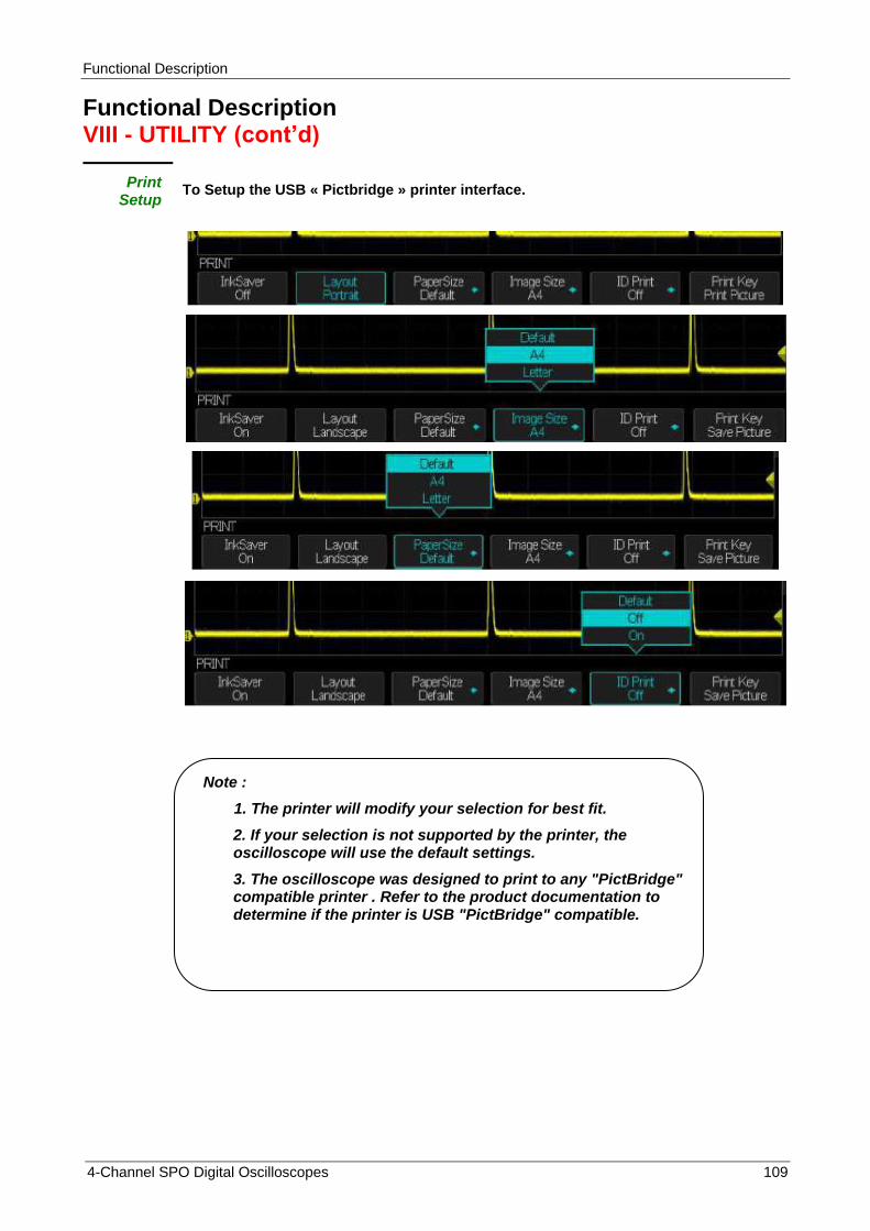
Functional Description
4-Channel SPO Digital Oscilloscopes 109
Functional Description VIII - UTILITY (cont‟d)
Print Setup
To Setup the USB « Pictbridge » printer interface.
Note :
1. The printer will modify your selection for best fit.
2. If your selection is not supported by the printer, the oscilloscope will use the default settings.
3. The oscilloscope was designed to print to any "PictBridge" compatible printer . Refer to the product documentation to determine if the printer is USB "PictBridge" compatible.

Functional Description
110 4-Channel SPO Digital Oscilloscopes
Functional Description VIII - UTILITY (cont‟d)
Print a screen copy
Operation Steps 1. To connect the oscilloscope to a "PictBridge" compatible printer .
1) Plug the USB cable in the "USB Device" connector of the oscilloscope.
2) Plug the other end of the USB cable in the printer ″USB Pictbridge″ connector.
2. To print a screen copy
1) Power on the oscilloscope and the printer. (The printer recognizes the oscilloscope only when the printer is powered on).
2) Press the “Utility” button to open the "UTILITY” menu.
3) Press the “I/O” button to set the “USB Device” interface.
4) Press the “USB Device” button to select “Printer”
5) Press the « Next Page 1/3 » button to open the page 2/3
6) Press the « Print Setup » button to open the « Print setup » menu.
7) Set up the print setup according to your need . The oscilloscope queries the printer, and only displays options and values that the printer supports.
If you are not sure which setting to choose, select "Default" for each option.
8) Press the « Print Key » button to select “Print Picture”.
9) Press the “Print” button to print a screen copy.
Note : If the «Pictbridge» printer is not connected the following message is displayed : « Printer isn‟t connected »
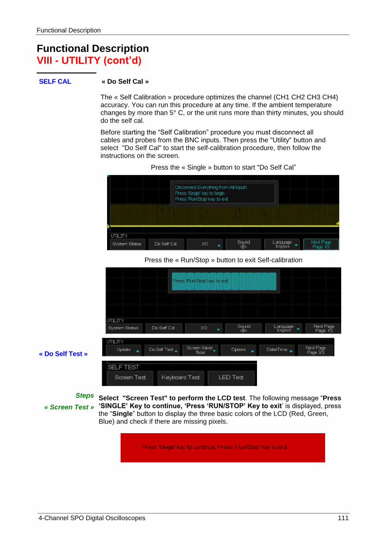
Functional Description
4-Channel SPO Digital Oscilloscopes 111
Functional Description VIII - UTILITY (cont‟d)
SELF CAL « Do Self Cal »
The « Self Calibration » procedure optimizes the channel (CH1 CH2 CH3 CH4) accuracy. You can run this procedure at any time. If the ambient temperature changes by more than 5° C, or the unit runs more than thirty minutes, you should do the self cal.
Before starting the “Self Calibration” procedure you must disconnect all cables and probes from the BNC inputs. Then press the "Utility" button and select "Do Self Cal" to start the self-calibration procedure, then follow the instructions on the screen.
Press the « Single » button to start “Do Self Cal”
Press the « Run/Stop » button to exit Self-calibration
« Do Self Test »
Steps
« Screen Test »
Select "Screen Test" to perform the LCD test. The following message “Press „SINGLE‟ Key to continue, „Press „RUN/STOP‟ Key to exit’ is displayed, press the “Single” button to display the three basic colors of the LCD (Red, Green, Blue) and check if there are missing pixels.
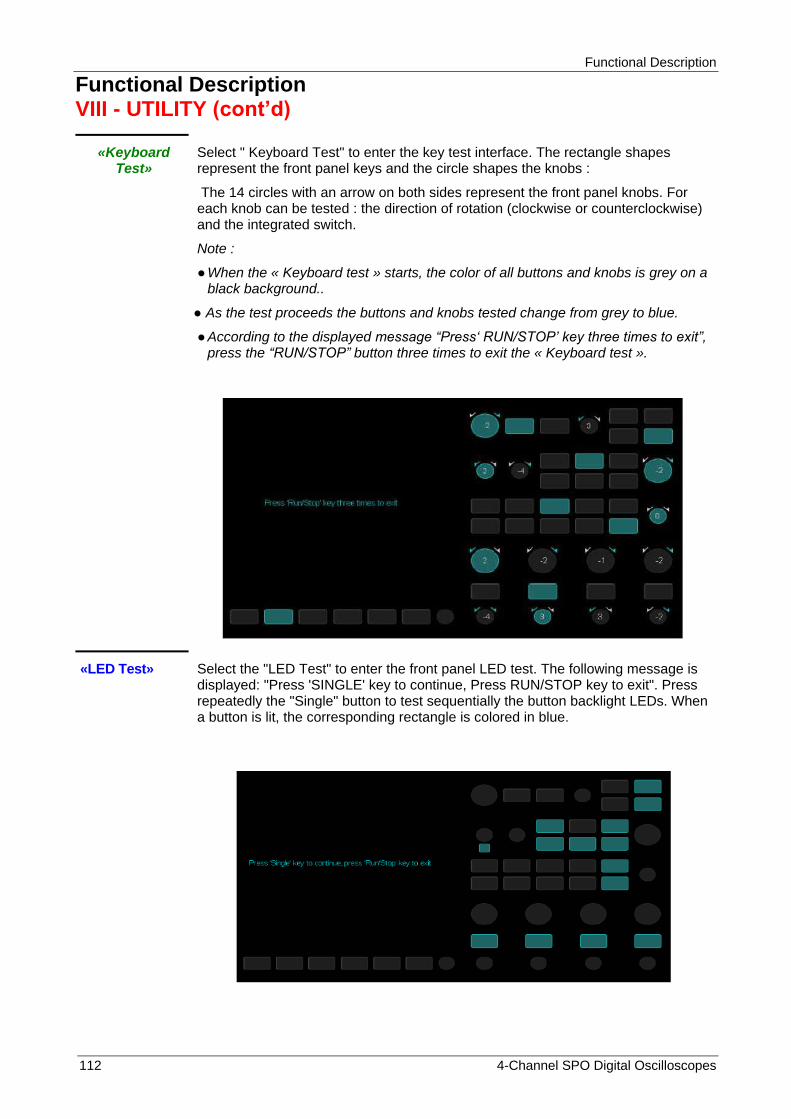
Functional Description
112 4-Channel SPO Digital Oscilloscopes
Functional Description VIII - UTILITY (cont‟d)
«Keyboard Test»
Select " Keyboard Test" to enter the key test interface. The rectangle shapes represent the front panel keys and the circle shapes the knobs :
The 14 circles with an arrow on both sides represent the front panel knobs. For each knob can be tested : the direction of rotation (clockwise or counterclockwise) and the integrated switch.
Note :
When the « Keyboard test » starts, the color of all buttons and knobs is grey on a black background..
As the test proceeds the buttons and knobs tested change from grey to blue.
According to the displayed message “Press„ RUN/STOP‟ key three times to exit”, press the “RUN/STOP” button three times to exit the « Keyboard test ».
«LED Test» Select the "LED Test" to enter the front panel LED test. The following message is displayed: "Press 'SINGLE' key to continue, Press RUN/STOP key to exit". Press repeatedly the "Single" button to test sequentially the button backlight LEDs. When a button is lit, the corresponding rectangle is colored in blue.

Functional Description
4-Channel SPO Digital Oscilloscopes 113
Functional Description VIII - UTILITY (cont‟d)
«Firmware Update»
Update the « Firmware » from a USB memory device.
The embedded software of the oscilloscope can be updated directly from a USB memory device.
Operation Steps
1. Plug the USB memory device with the new « firmware » version in the USB host
connector of the oscilloscope front panel and wait for the USB is displayed on the top
right of the screen.
2. Press the «Utility» button to open the UTILITY menu.
3. Press the "Next Page” button to enter the page 3/3 of the UTILITY menu.
4. Press the « Update » button and select the firmware update procedure .
5. Press the “Single” button to start updating the embedded software, follow the instructions displayed on the screen.
6. Turn « off » the oscilloscope and back « on » and make sure the « firmware » has been updated. After updating the firmware you must perform a “Do Self Cal”.
Note : Don’t cut off the power while the oscilloscope is updating.
« Pass/Fail »
The ″Pass/Fail″ function allows to compare the evolution of the real-time signal to a mask. Within the mask limits, the real-time signal « Pass » the test, outside the mask limits the test “Fail”.
Utility Pass/Fail
PASS/FAIL page 1/2
PASS/FAIL page 2/2

Functional Description
114 4-Channel SPO Digital Oscilloscopes
Pass/Fail Menu
page 1
Option Settings Description
Enable Test On
Off
Enable the Pass/Fail test
Disable the Pass/Fail test
Source CH1 CH2
CH3 CH4
Select the channel Source for pass Pass/Fail test.
Operation
Press to run the Pass/Fail test.
Press to stop the Pass/Fail test.
Msg Display
On
Off
Enable the display of the number of tests that Pass or Fail.
Disable the display of the number of Pass/Fail tests.
Mask Setting To set the mask limits
Next Page Page 1/2 Press this button to open page 2/2.
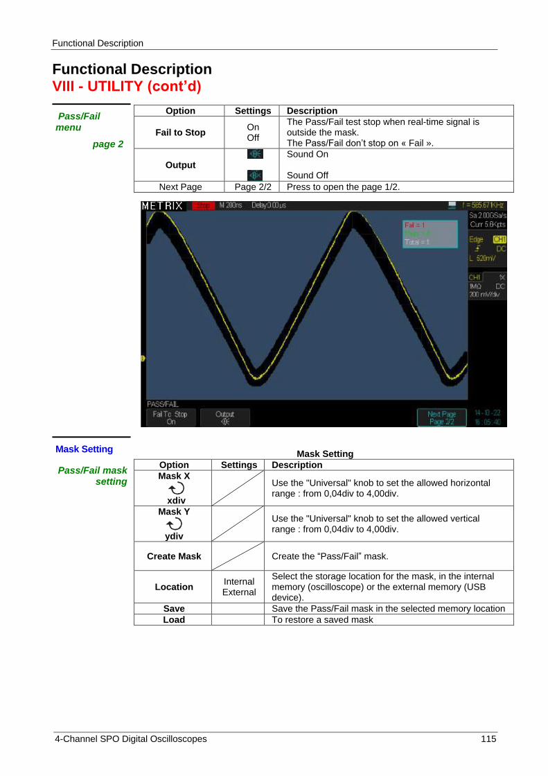
Functional Description
4-Channel SPO Digital Oscilloscopes 115
Functional Description VIII - UTILITY (cont‟d)
Pass/Fail menu
page 2
Option Settings Description
Fail to Stop On Off
The Pass/Fail test stop when real-time signal is outside the mask. The Pass/Fail don’t stop on « Fail ».
Output
Sound On Sound Off
Next Page Page 2/2 Press to open the page 1/2.
Mask Setting
Mask Setting
Pass/Fail mask setting
Option Settings Description
Mask X
xdiv
Use the "Universal" knob to set the allowed horizontal range : from 0,04div to 4,00div.
Mask Y
ydiv
Use the "Universal" knob to set the allowed vertical range : from 0,04div to 4,00div.
Create Mask Create the “Pass/Fail” mask.
Location Internal External
Select the storage location for the mask, in the internal memory (oscilloscope) or the external memory (USB device).
Save Save the Pass/Fail mask in the selected memory location
Load To restore a saved mask

Functional Description
116 4-Channel SPO Digital Oscilloscopes
X Mask set
Y Mask set
Create Mask
To save the created Mask in the external memory select the External Location:
Plug the USB device, press the « Save » button and wait for the oscilloscope displays the contents of the USB memory device :
Press the « New » button to enter the name of the mask file (Example dox3304m) :
Press the « Switch to Keyboard » button to switch to « Switch to Name »
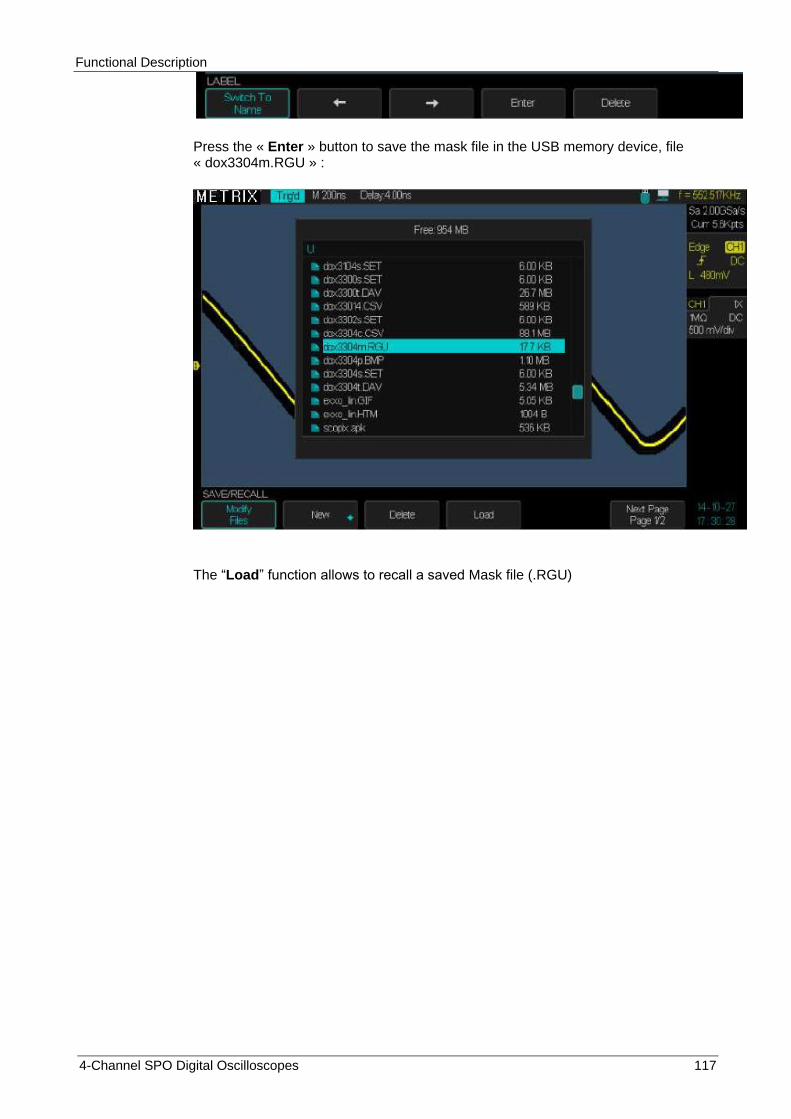
Functional Description
4-Channel SPO Digital Oscilloscopes 117
Press the « Enter » button to save the mask file in the USB memory device, file « dox3304m.RGU » :
The “Load” function allows to recall a saved Mask file (.RGU)
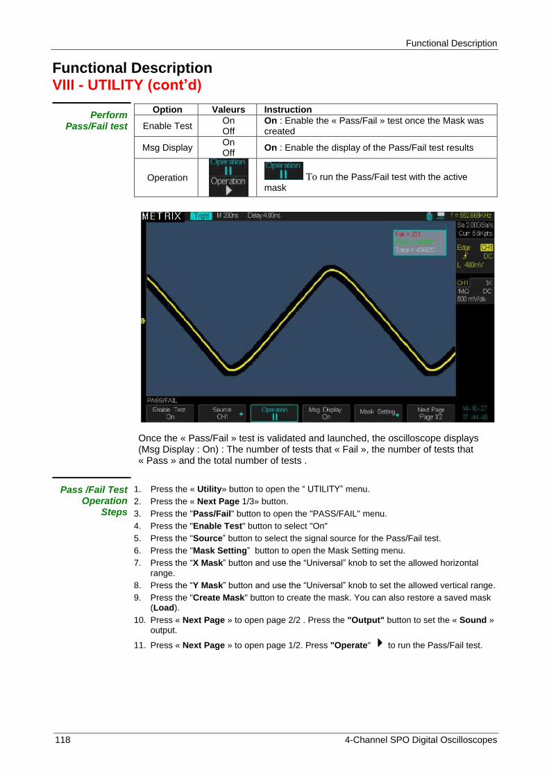
Functional Description
118 4-Channel SPO Digital Oscilloscopes
Functional Description VIII - UTILITY (cont‟d)
Perform Pass/Fail test
Option Valeurs Instruction
Enable Test On Off
On : Enable the « Pass/Fail » test once the Mask was created
Msg Display On Off
On : Enable the display of the Pass/Fail test results
Operation
To run the Pass/Fail test with the active mask
Once the « Pass/Fail » test is validated and launched, the oscilloscope displays (Msg Display : On) : The number of tests that « Fail », the number of tests that « Pass » and the total number of tests .
Pass /Fail Test Operation
Steps
1. Press the « Utility» button to open the “ UTILITY” menu.
2. Press the « Next Page 1/3» button.
3. Press the "Pass/Fail" button to open the "PASS/FAIL" menu.
4. Press the "Enable Test" button to select "On"
5. Press the "Source” button to select the signal source for the Pass/Fail test.
6. Press the "Mask Setting” button to open the Mask Setting menu.
7. Press the “X Mask” button and use the “Universal” knob to set the allowed horizontal range.
8. Press the “Y Mask” button and use the “Universal” knob to set the allowed vertical range.
9. Press the "Create Mask" button to create the mask. You can also restore a saved mask (Load).
10. Press « Next Page » to open page 2/2 . Press the "Output" button to set the « Sound » output.
11. Press « Next Page » to open page 1/2. Press "Operate" to run the Pass/Fail test.

Functional Description
4-Channel SPO Digital Oscilloscopes 119
Functional Description VIII - UTILITY (cont‟d)
« History »
The « History » function allows to record and display a history of the last waveforms corresponding to the channels: CH1 CH2 CH3 CH4. In « RUN » the oscilloscope continuously records the signals present at the inputs of the channels : CH1 CH2 CH3 CH4, in the form of a sequence of memory segments « Frames ». When the recording memory is full (ie the number maximum of segments is reached) the oscilloscope continues recording by replacing the frames previously recorded by the new segments. The oscilloscope stores the « History » of the last recorded frames. Open the submenu « History » and select « View On » to display the « History », the acquisition automatically stops, allowing to scroll the history of the latest recorded segments. The maximum number of recorded frames and the segment size depends on the sample rate and the current memory depth :
« Sample Rate » Current memory depth (pts)
Maximum Number of « Frames »
2GSa/s < ou = 560 > 50000
1,4k 48000
2,8k 32432
5,6k 16997
14k 8075
28k 4067
56k 2037
140k 815
280k 408
560k 204
1,4M 81
2,8M 40
5,6M 18
14M 7
< ou = 2GSa/s 28M 3
1GSa/s < ou = 700 80000
1,4k 63157
2,8k 36585
7k 16043
14k 8108
28k 4067
70k 1630
140k 815
280k 408
700k 163
1,4M 81
2,8M 37
7M 14
< ou = 1GSa/s 14M 7
The « History » function can be used in the following modes : Normal, Sequence, and Pass/Fail
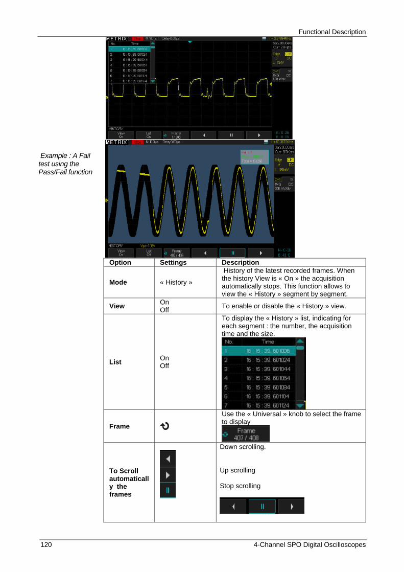
Functional Description
120 4-Channel SPO Digital Oscilloscopes
Example : A Fail test using the Pass/Fail function
Option Settings Description
Mode « History »
History of the latest recorded frames. When the history View is « On » the acquisition automatically stops. This function allows to view the « History » segment by segment.
View On Off
To enable or disable the « History » view.
List On Off
To display the « History » list, indicating for each segment : the number, the acquisition time and the size.
Frame
Use the « Universal » knob to select the frame to display
To Scroll automatically the frames
Down scrolling. Up scrolling Stop scrolling

Functional Description
4-Channel SPO Digital Oscilloscopes 121
Operation Steps 1. Press the «Utility» button to open the “UTILITY” menu. 2. Press the "Next Page” button to open page 2/2. 3. Press the “History” button to open the ″HISTORY" submenu. 4. Press the “View Off” button to set the “View On”, the acquisitions are stopped
to allow to view the “History”. 5. Press the "List” button to display (On) or not (Off) the frames list of the
“History”. 6. Press the « Frame » button and use the Universal knob to select the frame to
display.
7. Press the button to automatically scroll down the frames of the history
8. Press the button to stop scrolling
9. Press the button to automatically scroll up the frames of the history.
Notes :
1° The automatic up scrolling stops when the maximum frame number “N°” is reached.
2° The automatic down scrolling stops when the frame N°1 is reached

Functional Description
122 4-Channel SPO Digital Oscilloscopes
Functional Description VIII - UTILITY (cont‟d)
« Options » The « Options » submenu allows to manage the oscilloscope options: DECODE - ARBITRARY WAVEFORM GENERATOR - MSO LOGIC ANALYZER - POWER ANALYZER
For each option the oscilloscope indicates whether it is installed or not and the type of license.
If the hardware does not allow the installation of the « MSO Logic Analyzer », this option is not present in the « Information » window and can not be installed.
If the option can be installed, such as « PAS » option, press the « Install » button and enter the code :

Functional Description
4-Channel SPO Digital Oscilloscopes 123
Functional Description VIII - UTILITY (cont‟d)
« Options »
Option Description
Options The « Options » submenu allows to manage the oscilloscope options
Type
4 options types are available : The are 3 software options: (DECODE - WAVE GENERATOR integrated) - PAS (contact us) The « Digital » option needs a software and a special hardware « MSO-DOX3LA » (Logic Analyzer Probe). If the hardware is not suitable, it is not possible to install the « MSO » option when pressing the “Install” button.
Install Installed
«Install» : Press the « Install » button and enter the code to install the option. «Installed» : indicates that the option is already installed.
Information
Press this button to access information about the options : Name, License type and remaining time
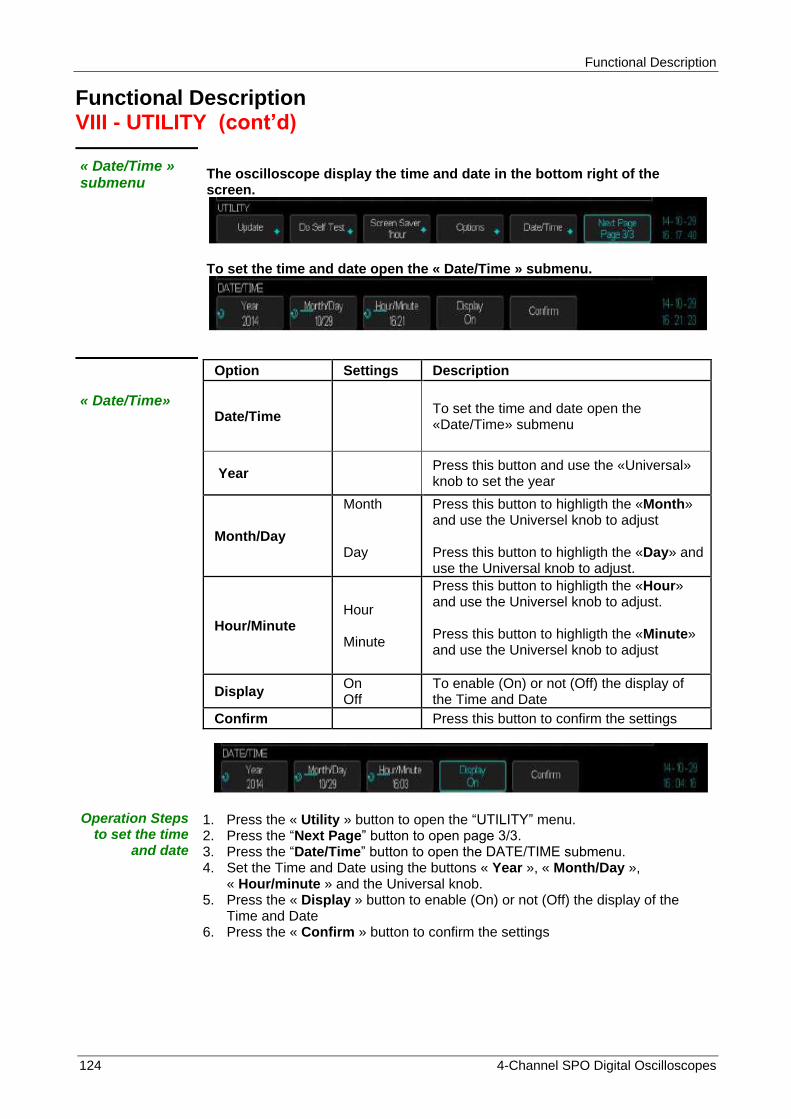
Functional Description
124 4-Channel SPO Digital Oscilloscopes
Functional Description VIII - UTILITY (cont‟d)
« Date/Time » submenu
The oscilloscope display the time and date in the bottom right of the screen.
To set the time and date open the « Date/Time » submenu.
« Date/Time»
Option Settings Description
Date/Time To set the time and date open the «Date/Time» submenu
Year Press this button and use the «Universal» knob to set the year
Month/Day
Month Day
Press this button to highligth the «Month» and use the Universel knob to adjust Press this button to highligth the «Day» and use the Universal knob to adjust.
Hour/Minute Hour Minute
Press this button to highligth the «Hour» and use the Universel knob to adjust. Press this button to highligth the «Minute» and use the Universel knob to adjust
Display On Off
To enable (On) or not (Off) the display of the Time and Date
Confirm Press this button to confirm the settings
Operation Steps to set the time
and date
1. Press the « Utility » button to open the “UTILITY” menu. 2. Press the “Next Page” button to open page 3/3. 3. Press the “Date/Time” button to open the DATE/TIME submenu. 4. Set the Time and Date using the buttons « Year », « Month/Day »,
« Hour/minute » and the Universal knob. 5. Press the « Display » button to enable (On) or not (Off) the display of the
Time and Date 6. Press the « Confirm » button to confirm the settings
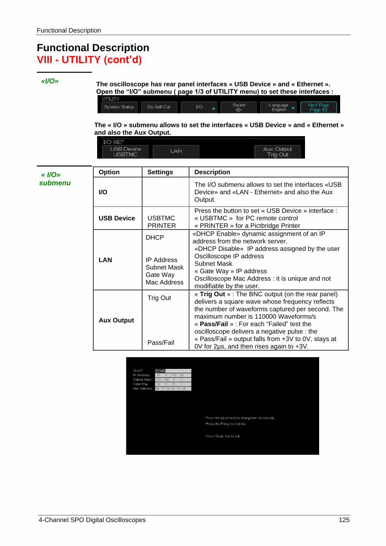
Functional Description
4-Channel SPO Digital Oscilloscopes 125
Functional Description VIII - UTILITY (cont‟d)
«I/O»
The oscilloscope has rear panel interfaces « USB Device » and « Ethernet ». Open the “I/O” submenu ( page 1/3 of UTILITY menu) to set these interfaces :
The « I/O » submenu allows to set the interfaces « USB Device » and « Ethernet » and also the Aux Output.
« I/O» submenu
Option Settings Description
I/O The I/O submenu allows to set the interfaces «USB Device» and «LAN - Ethernet» and also the Aux Output.
USB Device USBTMC PRINTER
Press the button to set « USB Device » interface : « USBTMC » for PC remote control « PRINTER » for a Pictbridge Printer
LAN
DHCP
IP Address Subnet Mask Gate Way Mac Address
«DHCP Enable» dynamic assignment of an IP address from the network server. «DHCP Disable» IP address assigned by the user Oscilloscope IP address Subnet Mask « Gate Way » IP address Oscilloscope Mac Address : it is unique and not modifiable by the user.
Aux Output
Trig Out Pass/Fail
« Trig Out » : The BNC output (on the rear panel) delivers a square wave whose frequency reflects the number of waveforms captured per second. The maximum number is 110000 Waveforms/s « Pass/Fail » : For each “Failed” test the oscilloscope delivers a negative pulse : the « Pass/Fail » output falls from +3V to 0V, stays at 0V for 2µs, and then rises again to +3V.

Functional Description
126 4-Channel SPO Digital Oscilloscopes
IX - « Arbitrary Waveform Generator » (AWG) option
The DOX3000 oscilloscope series come with an Arbitrary Waveform Generators (AWG) that can generate 10 types of pre-defined waveforms (Sine, Square, Ramp, Pulse, DC, Noise, Cardiac, Gauss Pulse, Exponential Rise and Exponential Fall) and 4 arbitrary user defined waveforms (Arb 1, Arb 2, Arb 3, Arb 4).
To set the waveform parameters :
1° Press the « WaveGen » button to open the WAVEFORM menu to set the Waveform Generator (the « Wave Gen » button is lit).
2° Press the « Wave Type » button and use the « Universal » knob to select the waveform type to generate, then press the “Confirm” button.
3° Press the « Frequency » button and use the « Universal » knob to adjust the signal frequency
4° Press the « Amplitude » button and use the « Universal » knob to adjust the signal amplitude
5° Press the « Offset » button and use the « Universal » knob to adjust the signal offset
« Wave Type » « Frequency Range »
Peak to Peak Amplitude Range Vpp
« High-Z »
Offset range
« High-Z »
Sine 1µHz to 25MHz 4mV to 6V ± 3V
Square 1µHz to 10MHz 4mV to 6V ± 3V
Ramp 1µHz to 300kHz 4mV to 6V ± 3V
Pulse 1µHz to 10MHz 4mV to 6V ± 3V
DC ± 3V
Noise
Cardiac Pulse 1µHz to 5MHz 4mV to 6V ± 3V
Gauss Pulse 1µHz to 5MHz 4mV to 6V ± 3V
Exponential Rise 1µHz to 5MHz 4mV to 6V ± 3V
Exponential Fall 1µHz to 5MHz 4mV to 6V ± 3V
Arb 1, 2, 3, 4
Notes:
1° The total amplitude (Peak to Peak amplitude + offset) of the waveform provided by the AWG can not exceed +3V or -3V, for example when programming a 6Vpp sine wave the offset is automatically set to 0V.
2° When the generator output is loaded by a “50Ω” instead of a “High-Z” impedance the signal amplitude is divided by two.

Functional Description
4-Channel SPO Digital Oscilloscopes 127
IX - « Arbitrary Waveform Generator » (AWG) option (cont‟d)
Create an arbitrary waveform with the « EasyWave » software and load it into the l‟oscilloscope AWG (Arbitrary Waveform Generator)
1° Press the « Wave Gen » button to open the WAVEFORM generator menu
2° Connect the DOX3000 oscilloscope to a PC (USB cable plug in the rear panel « USB Device » connector) where the « EasyWave » software is installed
3° Run « EasyWave »
4° Create an arbitrary waveform or Select an already created waveform file :
5° Click the « Send wave » button, select the “Store Location” and click the “Send” button to send it to the oscilloscope
Click the « Send » button to transfer the waveform « wave1 » from the PC to the “Arb 2” location of the Oscilloscope Arbitrary Waveform Generator.
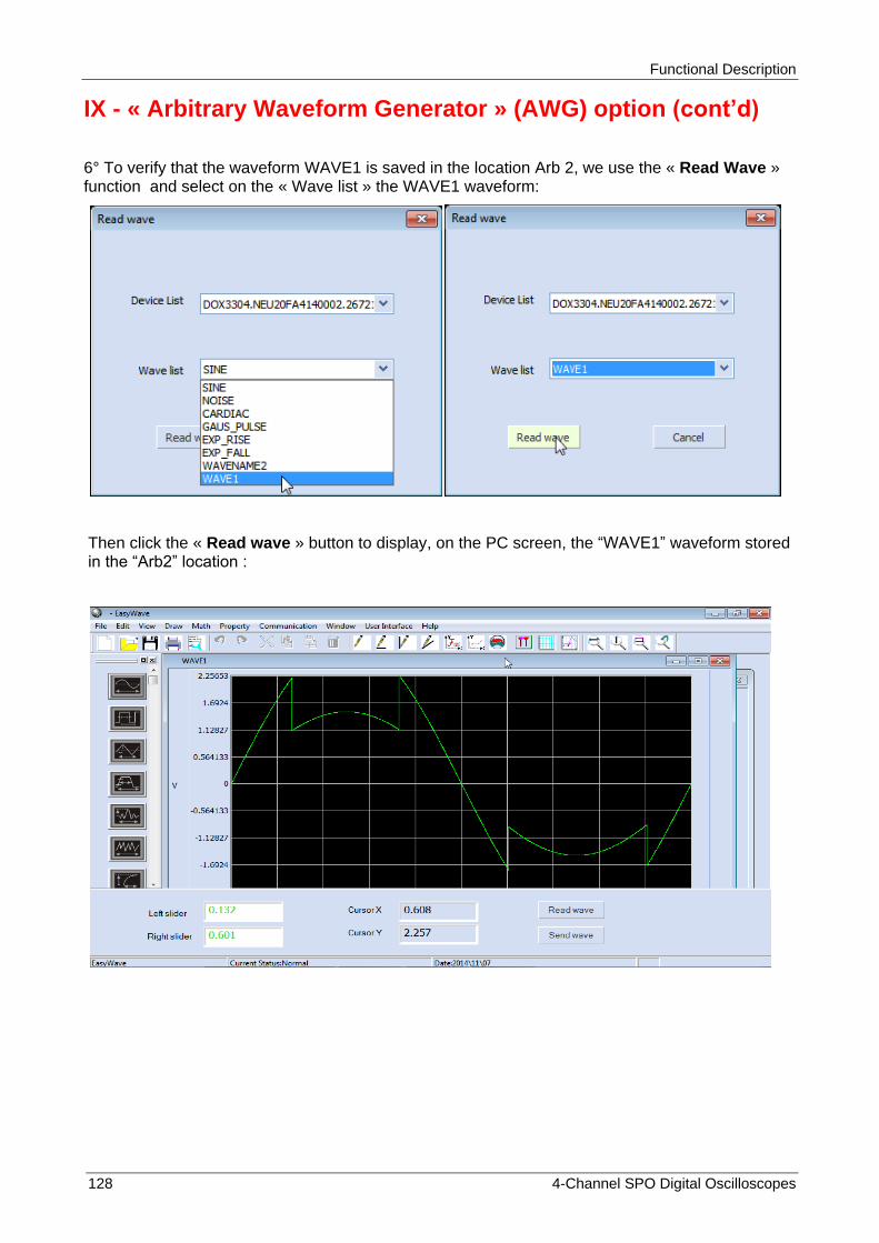
Functional Description
128 4-Channel SPO Digital Oscilloscopes
IX - « Arbitrary Waveform Generator » (AWG) option (cont‟d)
6° To verify that the waveform WAVE1 is saved in the location Arb 2, we use the « Read Wave » function and select on the « Wave list » the WAVE1 waveform:
Then click the « Read wave » button to display, on the PC screen, the “WAVE1” waveform stored in the “Arb2” location :

Functional Description
4-Channel SPO Digital Oscilloscopes 129
IX - « Arbitrary Waveform Generator » (AWG) option (cont‟d)
Automatic Calibration of the « Arbitrary Waveform Generator»
If the ambient temperature varies by more than 5°C and the instrument was left « On » for more than 30 minutes you can start an automatic calibration of the generator output.
1° Press the « Wave Gen » button to open the WAVEFORM menu
2° Press the « Setting » button to open the SETTING submenu
3° Press the « AWG Self Cal » button to launch the automatic calibration.
4° Press the « Run/Stop » button to exit the AWG self Cal
We can also set the generator output impedance (Output Load) : High-Z or 50Ω
To set the generator default values (Sine, 1kHz, 4Vpp, 0Vdc) press the « Default » button.
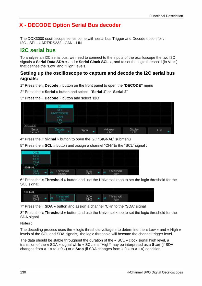
Functional Description
130 4-Channel SPO Digital Oscilloscopes
X - DECODE Option Serial Bus decoder
The DOX3000 oscilloscope series come with serial bus Trigger and Decode option for : I2C - SPI - UART/RS232 - CAN - LIN
I2C serial bus
To analyse an I2C serial bus, we need to connect to the inputs of the oscilloscope the two I2C signals « Serial Data SDA » and « Serial Clock SCL », and to set the logic threshold (in Volts) that defines the “Low” and “High” levels.
Setting up the oscilloscope to capture and decode the I2C serial bus signals:
1° Press the « Decode » button on the front panel to open the “DECODE” menu
2° Press the « Serial » button and select: “Serial 1” or “Serial 2”
3° Press the « Decode » button and select ”I2C”
4° Press the « Signal » button to open the I2C “SIGNAL” submenu
5° Press the « SCL » button and assign a channel “CHi” to the “SCL” signal :
6° Press the « Threshold » button and use the Universal knob to set the logic threshold for the SCL signal:
7° Press the « SDA » button and assign a channel “CHj” to the “SDA” signal
8° Press the « Threshold » button and use the Universel knob to set the logic threshold for the SDA signal
Notes :
The decoding process uses the « logic threshold voltage » to determine the « Low » and « High » levels of the SCL and SDA signals, the logic threshold will become the channel trigger level.
The data should be stable throughout the duration of the « SCL » clock signal high level, a transition of the « SDA » signal while « SCL » is “High” may be interpreted as a Start (if SDA changes from « 1 » to « 0 ») or a Stop (if SDA changes from « 0 » to « 1 ») condition.

Functional Description
4-Channel SPO Digital Oscilloscopes 131
X - DECODE I2C Serial Bus Decode (cont‟d)
Trigger conditions on an I2C bus can be :
A « Start/Stop » condition, a « Restart », a missing «Acknowledge», an EEPROM data read, a « Read/Write » frame with a specific device address and data value or a “Data Length”.
Setting the I2C bus trigger
1° Press the « Setup » button to open the “TRIGGER” menu.
2° Press the « Type » button and use the Universal knob to select « Serial 1 or Serial 2 »
3° Press the « Condition » button and us the universal knob to select the trigger condition: Start, Stop, Restart, No Ack, EEPROM, 7 Addr&Data, 10 Addr&Data, Data Length:
Start Condition:
The oscilloscope triggers when the « SDA » signal changes from « 1 » to « 0 » while SCL is « 1 ».
Note : for the trigger a « Restart » is equivalent to a « Start » condition
Stop Condition:
The oscilloscope triggers when the « SDA » signal changes from « 0 » to « 1 » while SCL is « 1 ».
ReStart:
The oscilloscope triggers if: after a « Start condition », a new « Start Condition » occurs before a « Stop Condition ».
Missing Acknowledge :
The oscilloscope triggers if « SDA » is « high » during any “Ack SCL” clock bit.
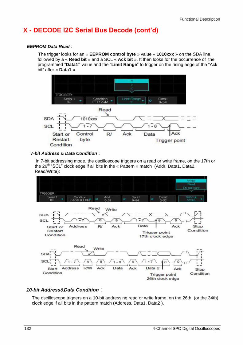
Functional Description
132 4-Channel SPO Digital Oscilloscopes
X - DECODE I2C Serial Bus Decode (cont‟d)
EEPROM Data Read :
The trigger looks for an « EEPROM control byte » value « 1010xxx » on the SDA line, followed by a « Read bit » and a SCL « Ack bit ». It then looks for the occurrence of the programmed “Data1” value and the “Limit Range” to trigger on the rising edge of the “Ack bit” after « Data1 ».
7-bit Address & Data Condition :
In 7-bit addressing mode, the oscilloscope triggers on a read or write frame, on the 17th or the 26th “SCL” clock edge if all bits in the « Pattern » match (Addr, Data1, Data2, Read/Write):
10-bit Address&Data Condition :
The oscilloscope triggers on a 10-bit addressing read or write frame, on the 26th (or the 34th) clock edge if all bits in the pattern match (Address, Data1, Data2 ).

Functional Description
4-Channel SPO Digital Oscilloscopes 133
X - DECODE I2C Serial Bus Decode (cont‟d)
The 26th clock edge front trigger occurs for the following frame format :
(Start :Address byte 1 :Write :Address byte 2 : Ack : Data)
Data2 set to « 0xXX »
The 34th clock edge trigger occurs for the following frame format :
(Start :Address byte 1 :Write :Address byte 2 : Ack : Data: Ack: Data)
Data2 must have a value other than « 0xXX », such as « 0x02 »
Data Length :
The oscilloscope triggers when the data lentgh is equal to the set « Byte Length » value:
4° If you have selected the « EEPROM Data Read » condition :
Press the « Limit Range » button to set the oscilloscope to trigger when data is = (equal), < (less than), or > (greater than) the « Data1 » value.
5° If you have selected the « 7-bit Address&Data » or « 10-bit Address&Data » condition:
a) Press the « Address » button and use the « Universal » knob to select the device address length range : 7-bit (from 0x00 to 0x7F hexadecimal) or 10-bit (from 0x00 to 0x3FF). The oscilloscope will trigger on a Write or Read frame if the set frame [Start, Address, Read/Write, Acknowledge and Data] occurs.
Note : If don’t care is selected 0xXX (7-bit Address) or 0xXXX (10-bit Address), the adrress will be ignored. The trigger will always occur on the 17th clock edge (7-bit Address) or the 26th clock edge (10-bit Address).
b) Press the « Data1 » or « Data2 » button and use the « Universal » knob to set the 8-bit data byte value (from 0x00 to 0xFF). The oscilloscope will trigger if the set frame [Start, Address, Read/Write, Acknowledge and Data] occurs.
c) If don’t care « 0xXX » is selected, the data will be ignored. The trigger will always occur on the 17th clock adge (7-bit Address) or the 26th clock edge (10-bit Address).

Functional Description
134 4-Channel SPO Digital Oscilloscopes
X - DECODE I2C Serial Bus Decode (cont‟d)
Note : If you have selected a 3 bytes trigger, press the « Data2 » button and use the Universal knob to set the 8-bit value.
6° If you have selected the « Data Length » condition :
Press the « Address » button to select the address length: 7-bit or 10-bit
Press the « Byte Length » button and use the Universal knob to set the byte length value (1 to 12).
Setting the I2C Bus Decode
1° Press the « Decode » button to open the « DECODE » menu.
2° Press the « Address » button to select the address length: 7-bit or 10-bit
3° Press the « Display » button to set Display « On » to display the decode lines.
4° Press the « List » button to open the LIST menu
5° Press the « Display » button to set display « On » to display the list
6° Press the « Scroll » and the « Lines » buttons and use the Universal knob to set the cursor position and the number of lines (from 1 to 7).

Functional Description
4-Channel SPO Digital Oscilloscopes 135
X - DECODE I2C Serial Bus Decode (cont‟d)
Interpreting I2C Decode line
1° The transition lines indicate an active bus (inside a packet/frame)
2° Mid-level blue lines indicate an idle bus
3° Decoded hexadecimal data:
Address values appear at the start of a frame
Write addresses are displayed in « dark green » along with the « W » character
Read addresses are displayed in « yellow » along with the « R » character
Data values are displayed in « white »
« A » indicates Ack (low) et « A » indicates No Ack (high)
Decoded text is truncated at the end of the associated frame when the space within frame boundaries is insufficient.
4° The blue vertical bars indicate that you need to expand the “S/div” horizontal scale (and run again) to see the decode information
5° The red dots in the decode line indicate that more data can be displayed. Scroll or expand the horizontal scale to view the data.
Interpreting the decoded List
The « List » display includes the following columns :
No - Frame number from left to rigth
Time - Standard Time
Address - colored « blue » for Writes and « yellow » for Reads
R/W - yellow « R » for Reads, dark green «W» for Writes, and “X” for Missing
Data - data bytes
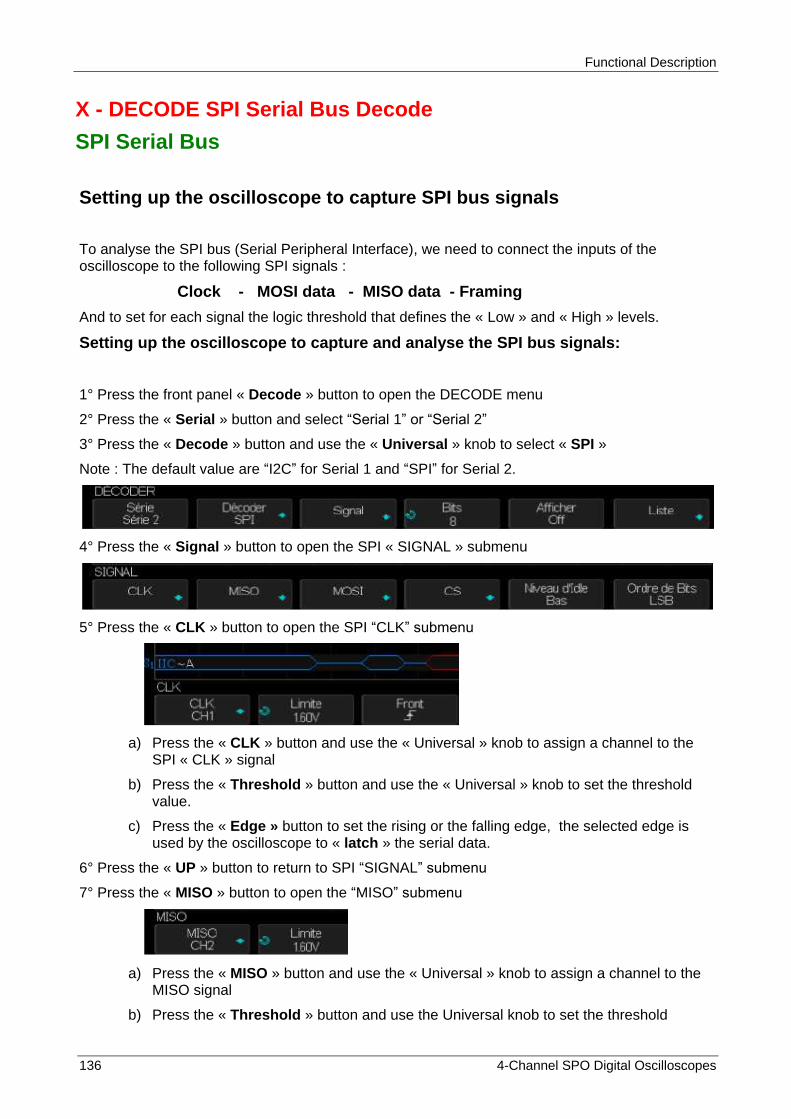
Functional Description
136 4-Channel SPO Digital Oscilloscopes
X - DECODE SPI Serial Bus Decode
SPI Serial Bus
Setting up the oscilloscope to capture SPI bus signals
To analyse the SPI bus (Serial Peripheral Interface), we need to connect the inputs of the oscilloscope to the following SPI signals :
Clock - MOSI data - MISO data - Framing
And to set for each signal the logic threshold that defines the « Low » and « High » levels.
Setting up the oscilloscope to capture and analyse the SPI bus signals:
1° Press the front panel « Decode » button to open the DECODE menu
2° Press the « Serial » button and select “Serial 1” or “Serial 2”
3° Press the « Decode » button and use the « Universal » knob to select « SPI »
Note : The default value are “I2C” for Serial 1 and “SPI” for Serial 2.
4° Press the « Signal » button to open the SPI « SIGNAL » submenu
5° Press the « CLK » button to open the SPI “CLK” submenu
a) Press the « CLK » button and use the « Universal » knob to assign a channel to the SPI « CLK » signal
b) Press the « Threshold » button and use the « Universal » knob to set the threshold value.
c) Press the « Edge » button to set the rising or the falling edge, the selected edge is used by the oscilloscope to « latch » the serial data.
6° Press the « UP » button to return to SPI “SIGNAL” submenu
7° Press the « MISO » button to open the “MISO” submenu
a) Press the « MISO » button and use the « Universal » knob to assign a channel to the
MISO signal
b) Press the « Threshold » button and use the Universal knob to set the threshold
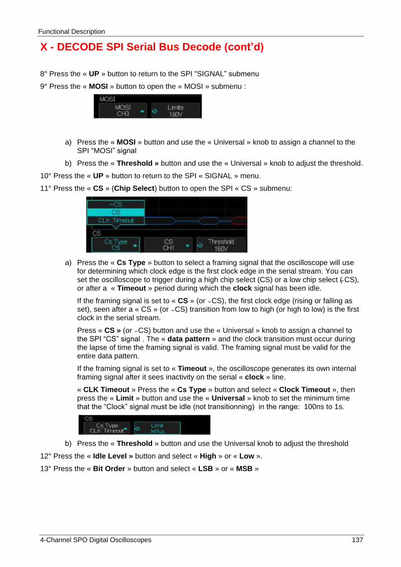
Functional Description
4-Channel SPO Digital Oscilloscopes 137
X - DECODE SPI Serial Bus Decode (cont‟d)
8° Press the « UP » button to return to the SPI “SIGNAL” submenu
9° Press the « MOSI » button to open the « MOSI » submenu :
a) Press the « MOSI » button and use the « Universal » knob to assign a channel to the SPI “MOSI” signal
b) Press the « Threshold » button and use the « Universal » knob to adjust the threshold.
10° Press the « UP » button to return to the SPI « SIGNAL » menu.
11° Press the « CS » (Chip Select) button to open the SPI « CS » submenu:
a) Press the « Cs Type » button to select a framing signal that the oscilloscope will use
for determining which clock edge is the first clock edge in the serial stream. You can set the oscilloscope to trigger during a high chip select (CS) or a low chip select ( CS), or after a « Timeout » period during which the clock signal has been idle.
If the framing signal is set to « CS » (or CS), the first clock edge (rising or falling as set), seen after a « CS » (or CS) transition from low to high (or high to low) is the first clock in the serial stream.
Press « CS » (or CS) button and use the « Universal » knob to assign a channel to the SPI “CS” signal . The « data pattern » and the clock transition must occur during the lapse of time the framing signal is valid. The framing signal must be valid for the entire data pattern.
If the framing signal is set to « Timeout », the oscilloscope generates its own internal framing signal after it sees inactivity on the serial « clock » line.
« CLK Timeout » Press the « Cs Type » button and select « Clock Timeout », then press the « Limit » button and use the « Universal » knob to set the minimum time that the “Clock” signal must be idle (not transitionning) in the range: 100ns to 1s.
b) Press the « Threshold » button and use the Universal knob to adjust the threshold
12° Press the « Idle Level » button and select « High » or « Low ».
13° Press the « Bit Order » button and select « LSB » or « MSB »
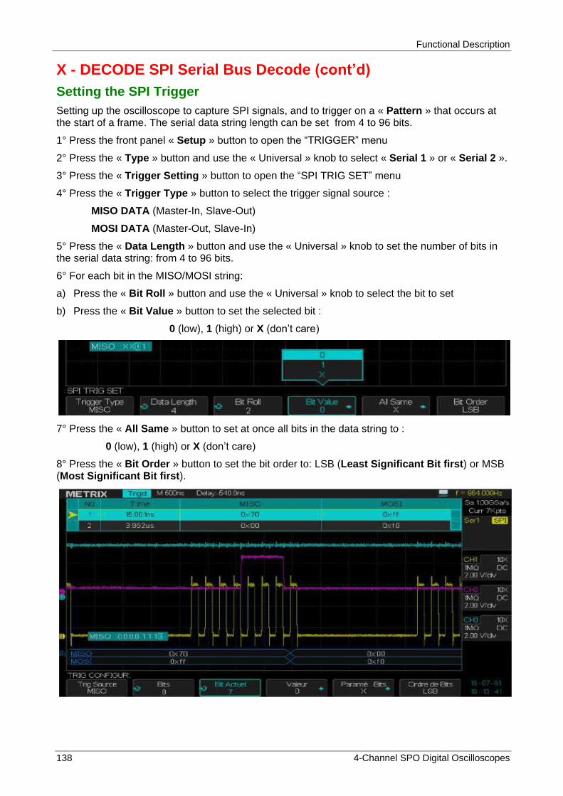
Functional Description
138 4-Channel SPO Digital Oscilloscopes
X - DECODE SPI Serial Bus Decode (cont‟d)
Setting the SPI Trigger
Setting up the oscilloscope to capture SPI signals, and to trigger on a « Pattern » that occurs at the start of a frame. The serial data string length can be set from 4 to 96 bits.
1° Press the front panel « Setup » button to open the “TRIGGER” menu
2° Press the « Type » button and use the « Universal » knob to select « Serial 1 » or « Serial 2 ».
3° Press the « Trigger Setting » button to open the “SPI TRIG SET” menu
4° Press the « Trigger Type » button to select the trigger signal source :
MISO DATA (Master-In, Slave-Out)
MOSI DATA (Master-Out, Slave-In)
5° Press the « Data Length » button and use the « Universal » knob to set the number of bits in the serial data string: from 4 to 96 bits.
6° For each bit in the MISO/MOSI string:
a) Press the « Bit Roll » button and use the « Universal » knob to select the bit to set
b) Press the « Bit Value » button to set the selected bit :
0 (low), 1 (high) or X (don’t care)
7° Press the « All Same » button to set at once all bits in the data string to :
0 (low), 1 (high) or X (don’t care)
8° Press the « Bit Order » button to set the bit order to: LSB (Least Significant Bit first) or MSB (Most Significant Bit first).
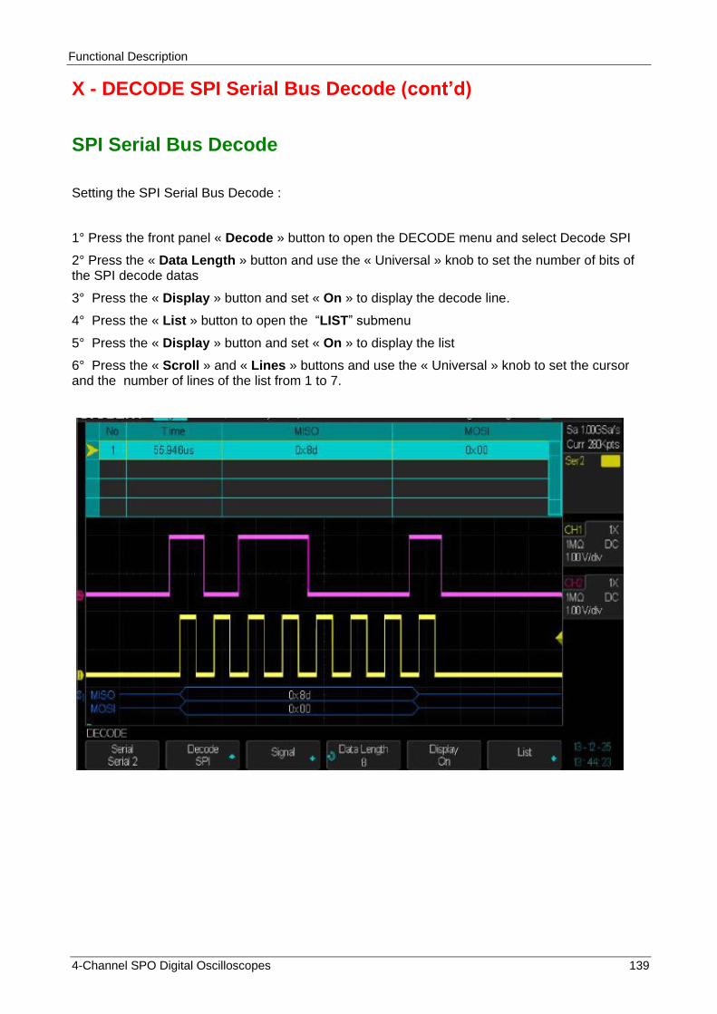
Functional Description
4-Channel SPO Digital Oscilloscopes 139
X - DECODE SPI Serial Bus Decode (cont‟d)
SPI Serial Bus Decode
Setting the SPI Serial Bus Decode :
1° Press the front panel « Decode » button to open the DECODE menu and select Decode SPI
2° Press the « Data Length » button and use the « Universal » knob to set the number of bits of the SPI decode datas
3° Press the « Display » button and set « On » to display the decode line.
4° Press the « List » button to open the “LIST” submenu
5° Press the « Display » button and set « On » to display the list
6° Press the « Scroll » and « Lines » buttons and use the « Universal » knob to set the cursor and the number of lines of the list from 1 to 7.
Functional Description
140 4-Channel SPO Digital Oscilloscopes
X - DECODE SPI Serial Bus Decode (cont‟d)
Interpreting SPI Decode
Transition lines indicate an active bus
Mid-level blue lines indicate an iddle bus
The number of clocks in a frame are displayed in ligth-blue above the frame on the right
Decoded hexadecimel values are displayed in « White »
Decoded text is truncated at the end of the associated frame when the space between the frame boundaries is insufficient.
Pink vertical bars indicate that you need to expand the horizontal scale (and Run again) to see the decode information.
Red dots indicate that there is data not been displayed.
Aliased bus values (undersampled or indeterminate) are drawn in pink
Unknown bus values (undefined or error conditions) are drawn in red
Interpreting the SPI List
The SPI List has the following columns :
No - Frame Number from left to right
MISO - Datas for MISO decode
MOSI - Datas for MOSI decode
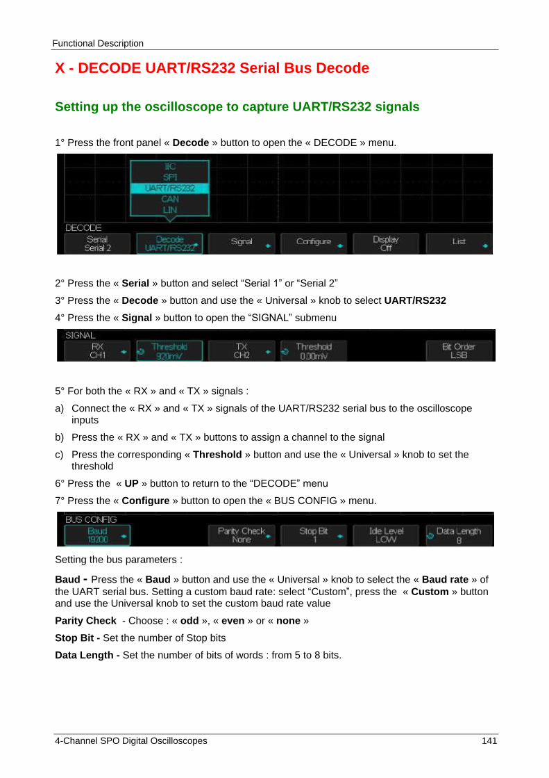
Functional Description
4-Channel SPO Digital Oscilloscopes 141
X - DECODE UART/RS232 Serial Bus Decode
Setting up the oscilloscope to capture UART/RS232 signals
1° Press the front panel « Decode » button to open the « DECODE » menu.
2° Press the « Serial » button and select “Serial 1” or “Serial 2”
3° Press the « Decode » button and use the « Universal » knob to select UART/RS232
4° Press the « Signal » button to open the “SIGNAL” submenu
5° For both the « RX » and « TX » signals :
a) Connect the « RX » and « TX » signals of the UART/RS232 serial bus to the oscilloscope inputs
b) Press the « RX » and « TX » buttons to assign a channel to the signal
c) Press the corresponding « Threshold » button and use the « Universal » knob to set the threshold
6° Press the « UP » button to return to the “DECODE” menu
7° Press the « Configure » button to open the « BUS CONFIG » menu.
Setting the bus parameters :
Baud - Press the « Baud » button and use the « Universal » knob to select the « Baud rate » of
the UART serial bus. Setting a custom baud rate: select “Custom”, press the « Custom » button and use the Universal knob to set the custom baud rate value
Parity Check - Choose : « odd », « even » or « none »
Stop Bit - Set the number of Stop bits
Data Length - Set the number of bits of words : from 5 to 8 bits.

Functional Description
142 4-Channel SPO Digital Oscilloscopes
X - DECODE UART/RS232 Serial Bus Decode (cont‟d)
Setting up the UART/RS232 Trigger
To trigger on a UART (Universal Asynchronous Receiver/Transmitter) signal, connect the oscilloscope channels to the « RX » and « TX » lines and set up a trigger condition. RS232 (Recommended Standard 232) is one example of UART protocole.
1° Press the front panel « Setup » button to open the “TRIGGER” menu.
2° Press the « Type » button and use the « Universal » knob to select Serial 1 (or Serial 2) according with the Decode selection.
3° Press the « Trigger Setting» button to open the « UART TRIG SET » submenu :
4° Press the « Condition » button and select the trigger condition:
Start - The oscilloscope triggers when a « Start bit » occurs
Stop - The oscilloscope triggers when a « Stop bit » occurs
Data - The oscilloscope triggers when a set « data byte » occurs.
a) Press the « Compare type » button and set the « qualifier » condition :
You can choose one of the following 3 conditions : = (equal), > (greater than) or < (less than)
b) Press the « Value » button and set the « qualifier » value in the range: 0x00 to 0xff

Functional Description
4-Channel SPO Digital Oscilloscopes 143
X - DECODE UART/RS232 Serial Bus Decode (cont‟d)
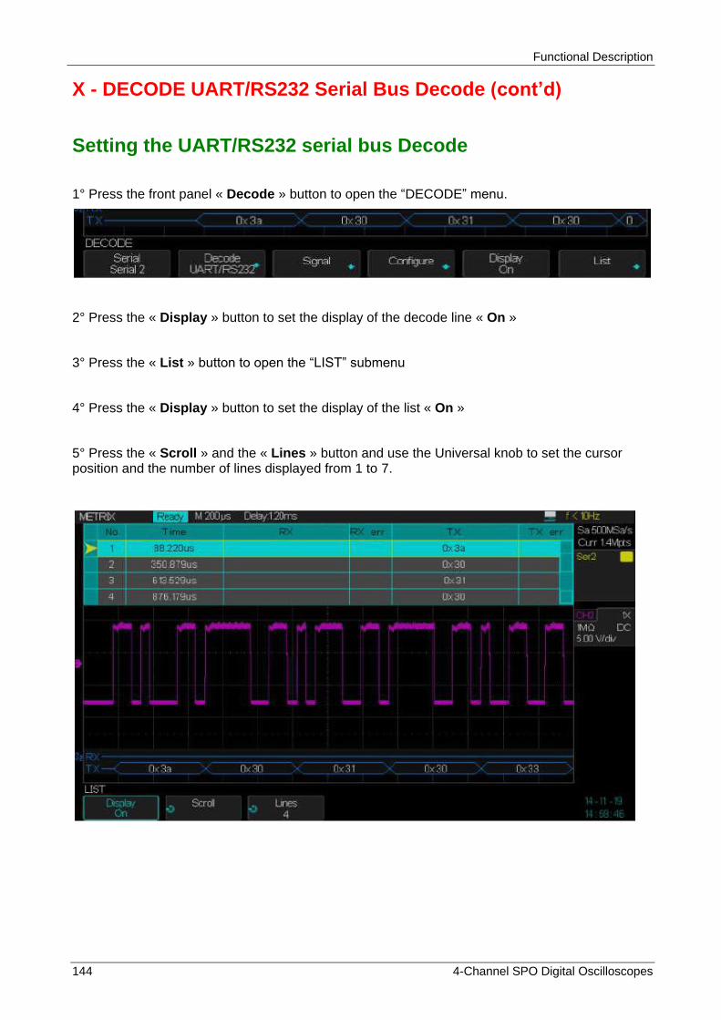
Functional Description
144 4-Channel SPO Digital Oscilloscopes
X - DECODE UART/RS232 Serial Bus Decode (cont‟d)
Setting the UART/RS232 serial bus Decode
1° Press the front panel « Decode » button to open the “DECODE” menu.
2° Press the « Display » button to set the display of the decode line « On »
3° Press the « List » button to open the “LIST” submenu
4° Press the « Display » button to set the display of the list « On »
5° Press the « Scroll » and the « Lines » button and use the Universal knob to set the cursor position and the number of lines displayed from 1 to 7.
Functional Description
4-Channel SPO Digital Oscilloscopes 145
X - DECODE UART/RS232 Serial Bus Decode (cont‟d)
Interpreting the UART/RS232 Decode
The transition lines indicate an active bus (inside a packet/frame)
The mid-level blue lines indicate an iddle bus
The mid-level red lines indicate that the idle level is wrong
The decoded data are displayed in white
The decoded text is truncated at the end of the associated frame when the space between the frame boundaries is insufficient
The vertical blue bars indicate that you need to expand the horizontal scale (and run again) to see the decode data
When the horizontal scale setting (S/div) does not allow to display all available decode data, red dots will appear to mark the location of hidden decoded data. Expand the horizontal scale to display them.
An unknown (undefined) bus is shown in red
Interpreting the UART/RS232 List
The “UART/RS232” List has the following columns :
No - Line number
Time -
RX - Receive Data
TX - Transmit Data
Rx err - Parity error or unknown error in the Received data
Tx err - Parity error or unknown error in the Transmitted data

Functional Description
146 4-Channel SPO Digital Oscilloscopes
X - DECODE CAN Serial Bus Decode
Setting up the oscilloscope to capture the CAN bus signals
To capture and analyse the CAN bus connect the CAN-H and CAN-L bus signals to the oscilloscope inputs and open the CAN bus “SIGNAL” and “Configure” submenus to set the : decode Source, Threshold, Baud rate.
1° Press the front panel « Decode » button to open the DECODE menu.
2° Press the « Serial » button and select “Serial 1” or “Serial 2”
3° Press the « Decode » button and use the « Universal » knob to select « CAN »
4° Press the « Signal » button to open the “SIGNAL” submenu
5° Press the « CAN-H » (or « CAN-L ») button to assign a channel to this signal.
6° Press the « Threshold » button and use the « Universal » knob to set the threshold.
7° Press the « UP » button to return to the DECODE menu
8° Press the « Configure » button to open the « BUS CONFIG » submenu
9° Press the « Baud » button and use the « Universal » knob to select the « baud rate » (500kb/s for the CAN High Speed ) from 5kb/s to 1Mb/s or “Custom” from 1b/s to 1Mb/s.
10° Press the « Decode Source » button to select the CAN decode source :
CAN_H - source is the CAN_H signal of the differential CAN bus
CAN_L - source is the CAN_L signal of the differential CAN bus
CAN_H - CAN_L - source is the differential signal: CAN_H-CAN_L. Use a differential probe to capture the CAN differential signal (CAN-H on positive lead and CAN-L on negative lead)

Functional Description
4-Channel SPO Digital Oscilloscopes 147
X - DECODE CAN Serial Bus Decode (cont‟d)
Triggering on ID 0x0105
Triggering on ID 0x0108
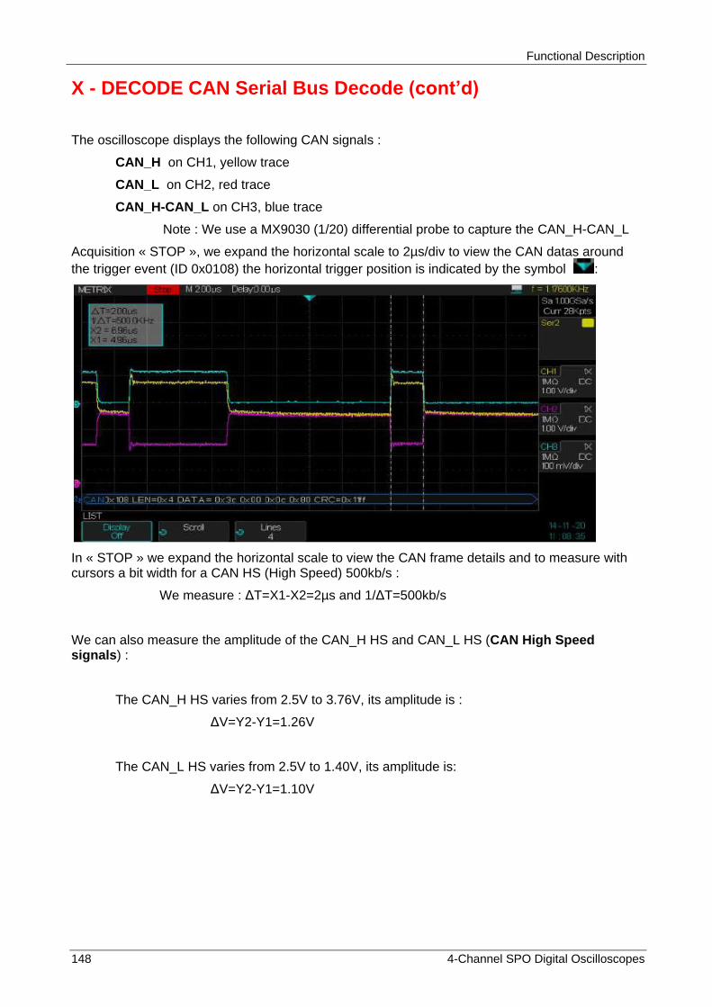
Functional Description
148 4-Channel SPO Digital Oscilloscopes
X - DECODE CAN Serial Bus Decode (cont‟d)
The oscilloscope displays the following CAN signals :
CAN_H on CH1, yellow trace
CAN_L on CH2, red trace
CAN_H-CAN_L on CH3, blue trace
Note : We use a MX9030 (1/20) differential probe to capture the CAN_H-CAN_L
Acquisition « STOP », we expand the horizontal scale to 2µs/div to view the CAN datas around
the trigger event (ID 0x0108) the horizontal trigger position is indicated by the symbol :
In « STOP » we expand the horizontal scale to view the CAN frame details and to measure with cursors a bit width for a CAN HS (High Speed) 500kb/s :
We measure : ΔT=X1-X2=2µs and 1/ΔT=500kb/s
We can also measure the amplitude of the CAN_H HS and CAN_L HS (CAN High Speed signals) :
The CAN_H HS varies from 2.5V to 3.76V, its amplitude is :
ΔV=Y2-Y1=1.26V
The CAN_L HS varies from 2.5V to 1.40V, its amplitude is:
ΔV=Y2-Y1=1.10V
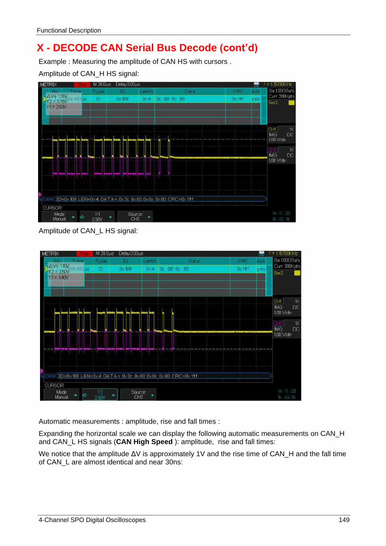
Functional Description
4-Channel SPO Digital Oscilloscopes 149
X - DECODE CAN Serial Bus Decode (cont‟d)
Example : Measuring the amplitude of CAN HS with cursors .
Amplitude of CAN_H HS signal:
Amplitude of CAN_L HS signal:
Automatic measurements : amplitude, rise and fall times :
Expanding the horizontal scale we can display the following automatic measurements on CAN_H and CAN_L HS signals (CAN High Speed ): amplitude, rise and fall times:
We notice that the amplitude ΔV is approximately 1V and the rise time of CAN_H and the fall time of CAN_L are almost identical and near 30ns:

Functional Description
150 4-Channel SPO Digital Oscilloscopes
X - DECODE CAN Serial Bus Decode (cont‟d)
In our example, the measured amplitude of the CAN_H and CAN_L signals is 1.12V, close to the 1V nominal value of the “CAN High Speed”:
CAN High Speed Nominal bus levels
CAN HS nominal values
CAN_H HS varies from 2.5V to 3.5V amplitude 1V
CAN_L HS varies from 1.5V to 2.5V amplitude 1V
CAN_H - CAN_L varies from 0V (Recessive) to 2V (Dominant)
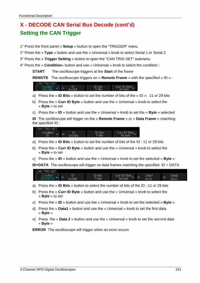
Functional Description
4-Channel SPO Digital Oscilloscopes 151
X - DECODE CAN Serial Bus Decode (cont‟d)
Setting the CAN Trigger
1° Press the front panel « Setup » button to open the “TRIGGER” menu
2° Press the « Type » button and use the « Universal » knob to select Serial 1 or Serial 2
3° Press the « Trigger Setting » button to open the “CAN TRIG SET” submenu
4° Press the « Condition» button and use « Universal » knob to select the condition :
START The oscilloscope triggers at the Start of the frame
REMOTE The oscilloscope triggers on « Remote Frame » with the specified « ID » :
a) Press the « ID Bits » button to set the number of bits of the « ID »: 11 or 29 bits
b) Press the « Curr ID Byte » button and use the « Universal » knob to select the « Byte » to set
c) Press the « ID » button and use the « Universal » knob to set the « Byte » selected
ID The oscilloscope will trigger on the « Remote Frame » or « Data Frame » matching the specified ID :
a) Press the « ID Bits » button to set the number of bits of the ID : 11 or 29 bits
b) Press the « Curr ID Byte » button and use the « Universal » knob to select the « Byte » to set
c) Press the « ID » button and use the « Universal » knob to set the selected « Byte »
ID+DATA The oscilloscope will trigger on data frames matching the specified ID + DATA
a) Press the « ID Bits » button to select the number of bits of the ID : 11 or 29 bits
b) Press the « Curr ID Byte » button and use the « Universal » knob to select the « Byte » to set
c) Press the « ID » button and use the « Universal » knob to set the selected « Byte »
d) Press the « Data1 » button and use the « Universal » knob to set the first data « Byte »
e) Press the « Data 2 » button and use the « Universal » knob to set the second data « Byte »
ERROR The oscilloscope will trigger when an error occurs

Functional Description
152 4-Channel SPO Digital Oscilloscopes
X - DECODE CAN Serial Bus Decode (cont‟d)
Triggering on a bus « CAN Low Speed » 125kb/s on the IDentifier 0x03b6 :
We stop the acquisition and expand the horizontal scale to view in detail the « CAN Low Speed » (125kb/s) data flow, we use the cursors to determine the bit width :
The « CAN Low Speed » signals (CAN_H varies from 0V to 3.6V and CAN_L varies from 5V to 1.4V)
ΔVcan = Vcan_H - Vcan_L varies from -5V to +2.2V

Functional Description
4-Channel SPO Digital Oscilloscopes 153
X - DECODE CAN Serial Bus Decode (cont‟d)
Set the List display « Off » :
We measure : ΔT=X1-X2=8µs to 1/ΔT=125kb/s
Measuring the amplitude of the CAN LS signals
Amplitude of the CAN_H LS (CAN Low Speed) :
The « CAN_H LS » signal varies from 0 to 4V, with the cursors we measure
ΔV=Y2-Y1=4.04V
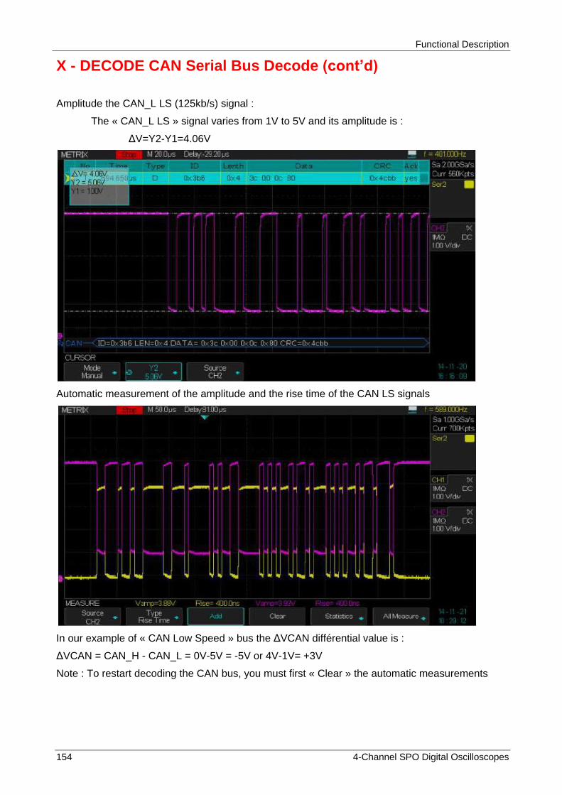
Functional Description
154 4-Channel SPO Digital Oscilloscopes
X - DECODE CAN Serial Bus Decode (cont‟d)
Amplitude the CAN_L LS (125kb/s) signal :
The « CAN_L LS » signal varies from 1V to 5V and its amplitude is :
ΔV=Y2-Y1=4.06V
Automatic measurement of the amplitude and the rise time of the CAN LS signals
In our example of « CAN Low Speed » bus the ΔVCAN différential value is :
ΔVCAN = CAN_H - CAN_L = 0V-5V = -5V or 4V-1V= +3V
Note : To restart decoding the CAN bus, you must first « Clear » the automatic measurements

Functional Description
4-Channel SPO Digital Oscilloscopes 155
X - DECODE CAN Serial Bus Decode (cont‟d)
Setting the CAN Bus DECODE
1° Press the front panel « Decode » button to open the “DECODE” menu
2° Press the « Display » button to set the display of the decoded line « On »
3° Press the « List » button to open the LIST submenu
4° Press the « Display » button to set the display of the List « On »
5° Press the « Scroll » and « Lines » buttons and use the « Universal » knob to set the cursor position and the number of lines displayed.
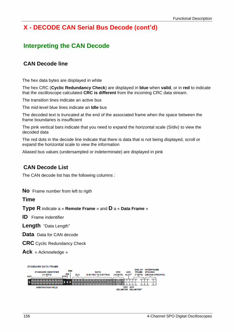
Functional Description
156 4-Channel SPO Digital Oscilloscopes
X - DECODE CAN Serial Bus Decode (cont‟d)
Interpreting the CAN Decode
CAN Decode line
The hex data bytes are displayed in white
The hex CRC (Cyclic Redundancy Check) are displayed in blue when valid, or in red to indicate that the oscilloscope calculated CRC is different from the incoming CRC data stream.
The transition lines indicate an active bus
The mid-level blue lines indicate an Idle bus
The decoded text is truncated at the end of the associated frame when the space between the frame boundaries is insufficient
The pink vertical bars indicate that you need to expand the horizontal scale (S/div) to view the decoded data
The red dots in the decode line indicate that there is data that is not being displayed, scroll or expand the horizontal scale to view the information
Aliased bus values (undersampled or indeterminate) are displayed in pink
CAN Decode List
The CAN decode list has the following columns :
No Frame number from left to rigth
Time
Type R indicate a « Remote Frame » and D a « Data Frame »
ID Frame indentifier
Length “Data Length”
Data Data for CAN decode
CRC Cyclic Redundancy Check
Ack « Acknowledge »
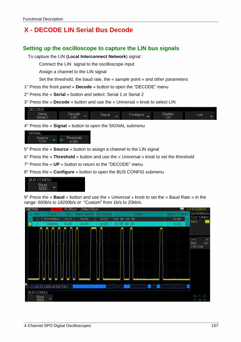
Functional Description
4-Channel SPO Digital Oscilloscopes 157
X - DECODE LIN Serial Bus Decode
Setting up the oscilloscope to capture the LIN bus signals
To capture the LIN (Local Interconnect Network) signal :
Connect the LIN signal to the oscilloscope input
Assign a channel to the LIN signal
Set the threshold, the baud rate, the « sample point » and other parameters
1° Press the front panel « Decode » button to open the “DECODE” menu
2° Press the « Serial » button and select: Serial 1 or Serial 2
3° Press the « Decode » button and use the « Universal » knob to select LIN
4° Press the « Signal » button to open the SIGNAL submenu
5° Press the « Source » button to assign a channel to the LIN signal
6° Press the « Threshold » button and use the « Universal » knob to set the threshold
7° Press the « UP » button to return to the “DECODE” menu
8° Press the « Configure » button to open the BUS CONFIG submenu
9° Press the « Baud » button and use the « Universal » knob to set the « Baud Rate » in the range: 600b/s to 19200b/s or “Custom” from 1b/s to 20kb/s.
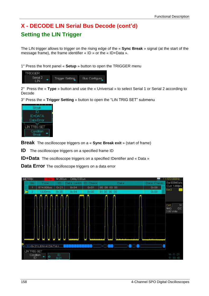
Functional Description
158 4-Channel SPO Digital Oscilloscopes
X - DECODE LIN Serial Bus Decode (cont‟d)
Setting the LIN Trigger
The LIN trigger allows to trigger on the rising edge of the « Sync Break » signal (at the start of the message frame), the frame identifier « ID » or the « ID+Data ».
1° Press the front panel « Setup » button to open the TRIGGER menu
2° Press the « Type » button and use the « Universal » to select Serial 1 or Serial 2 according to Decode
3° Press the « Trigger Setting » button to open the “LIN TRIG SET” submenu
Break The oscilloscope triggers on a « Sync Break exit » (start of frame)
ID The oscilloscope triggers on a specified frame ID
ID+Data The oscilloscope triggers on a specified IDentifier and « Data »
Data Error The oscilloscope triggers on a data error
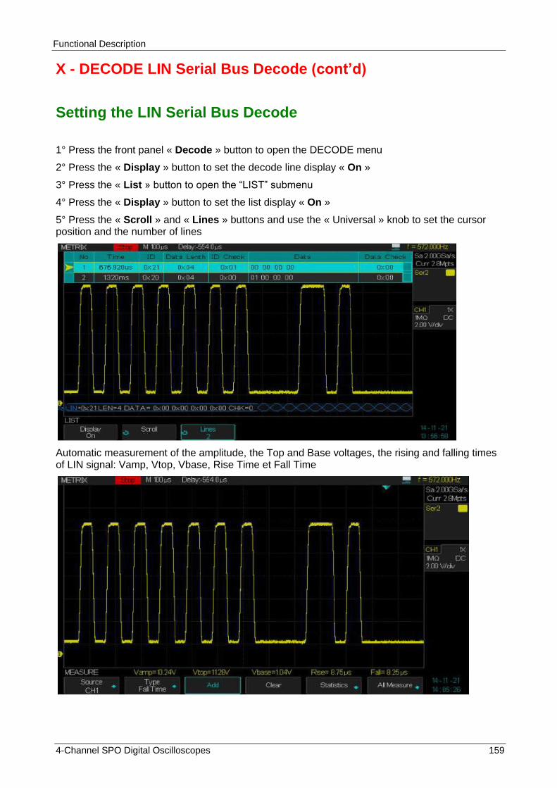
Functional Description
4-Channel SPO Digital Oscilloscopes 159
X - DECODE LIN Serial Bus Decode (cont‟d)
Setting the LIN Serial Bus Decode
1° Press the front panel « Decode » button to open the DECODE menu
2° Press the « Display » button to set the decode line display « On »
3° Press the « List » button to open the “LIST” submenu
4° Press the « Display » button to set the list display « On »
5° Press the « Scroll » and « Lines » buttons and use the « Universal » knob to set the cursor position and the number of lines
Automatic measurement of the amplitude, the Top and Base voltages, the rising and falling times of LIN signal: Vamp, Vtop, Vbase, Rise Time et Fall Time

Functional Description
160 4-Channel SPO Digital Oscilloscopes
X - DECODE LIN Serial Bus Decode (cont‟d)
Interpreting the LIN decode line
The transition lines indicate an active bus
The mid-level blue lines indicate an Idle bus
The identifier ID (hexadecimal) and the parity bit (if enabled) are in yellow or in red if a parity error is detected.
The decoded hex data values are in white
The decoded text is truncated at the end of the associated frame when the space between the frame boundaries is insufficient
The pink vertical bars indicate that you need to expand the horizontal scale to see the decoded information
The red dots indicate that there is data that is not being displayed . Scroll or Expand the horizontal scale to display them
The unknown bus values (undefined or error conditions) are displayed in red
Interpreting the LIN decode List
The LIN decode list has the following columns :
No Frame number from left to right
Time
ID Frame Indentifier
Data Data bytes
Data Length Length of data
ID Check ID parity error
Data Check data error check
LIN Message Frame :
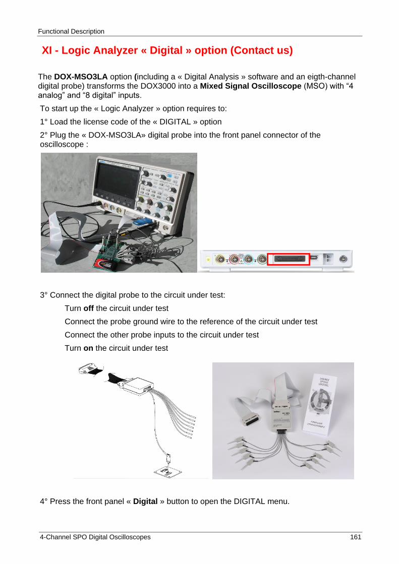
Functional Description
4-Channel SPO Digital Oscilloscopes 161
XI - Logic Analyzer « Digital » option (Contact us)
The DOX-MSO3LA option (including a « Digital Analysis » software and an eigth-channel digital probe) transforms the DOX3000 into a Mixed Signal Oscilloscope (MSO) with “4 analog” and “8 digital” inputs.
To start up the « Logic Analyzer » option requires to:
1° Load the license code of the « DIGITAL » option
2° Plug the « DOX-MSO3LA» digital probe into the front panel connector of the oscilloscope :
3° Connect the digital probe to the circuit under test:
Turn off the circuit under test
Connect the probe ground wire to the reference of the circuit under test
Connect the other probe inputs to the circuit under test
Turn on the circuit under test
4° Press the front panel « Digital » button to open the DIGITAL menu.

Functional Description
162 4-Channel SPO Digital Oscilloscopes
XI - Logic Analyzer « Digital » option (cont‟d)
Press the « Channel High » button to select the display type, to vertically expand (High) or compress (Low) the 8 digital channels display.
Press the « Channel Control» button and use the Universal knob to select the digital channel
Press the « Di » button to switch “On” or “Off” the selected channel
Press the « D0-D7 » button to switch “On” or “Off” all the digital channels :
Press the « Threshold » button to open the THRESHOLD menu
Press the “D0-D7” button and use the Universal knob to select a logic family : TTL - CMOS - LVCMOS3.3 - LVCMOS2.5 - Autodéfini
Note : The selected threshold applies to all digital channels
Select « Custom » and use the Universal knob to adjust the threshold voltage in the range: -3V to +3V
Press the « Digital Bus» button to open the DIGITAL BUS menu to set the Bus 1 or 2 :
Bus width : 1 to 8bits
Bus format : Hexadecimal or Binary
Display : « On » or « Off »
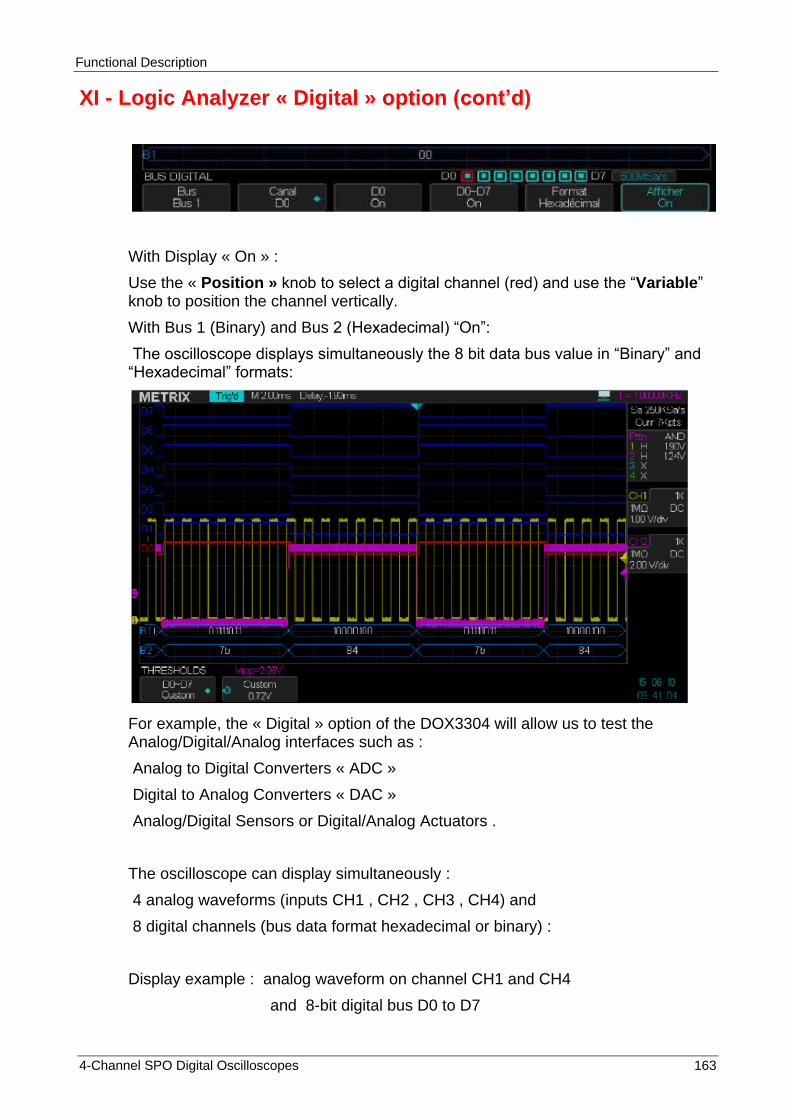
Functional Description
4-Channel SPO Digital Oscilloscopes 163
XI - Logic Analyzer « Digital » option (cont‟d)
With Display « On » :
Use the « Position » knob to select a digital channel (red) and use the “Variable” knob to position the channel vertically.
With Bus 1 (Binary) and Bus 2 (Hexadecimal) “On”:
The oscilloscope displays simultaneously the 8 bit data bus value in “Binary” and “Hexadecimal” formats:
For example, the « Digital » option of the DOX3304 will allow us to test the Analog/Digital/Analog interfaces such as :
Analog to Digital Converters « ADC »
Digital to Analog Converters « DAC »
Analog/Digital Sensors or Digital/Analog Actuators .
The oscilloscope can display simultaneously :
4 analog waveforms (inputs CH1 , CH2 , CH3 , CH4) and
8 digital channels (bus data format hexadecimal or binary) :
Display example : analog waveform on channel CH1 and CH4
and 8-bit digital bus D0 to D7

Functional Description
164 4-Channel SPO Digital Oscilloscopes
XI - Logic Analyzer « Digital » option (cont‟d)
The DOX3304 will allow us to make:
1° Cursor measurements (Voltage, Time) on all channels CH1 CH2 CH3 CH4
2° Automatic measurements on all analog channels CH1 - CH2 - CH3 - CH4 and on the 8 digital channels D0 to D7 :

Functional Description
4-Channel SPO Digital Oscilloscopes 165
XI - Logic Analyzer « Digital » option (cont‟d)
The DOX3304 will display statistics on the active measurements (our example 5 active measurements on: D0, CH1 and CH4) :
The DOX3304 also displays all « Time » and « Voltage » measurements on a channel CHi :
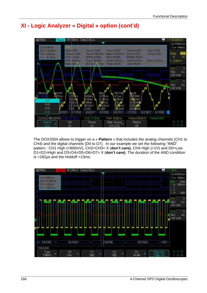
Functional Description
166 4-Channel SPO Digital Oscilloscopes
XI - Logic Analyzer « Digital » option (cont‟d)
The DOX3304 allows to trigger on a « Pattern » that includes the analog channels (CH1 to CH4) and the digital channels (D0 to D7). In our example we set the following “AND” pattern : CH1 High (>900mV), CH2=CH3= X (don‟t care), CH4 High (>1V) and D0=Low D1=D2=High and D3=D4=D5=D6=D7= X (don‟t care). The duration of the AND condition is >182µs and the Holdoff =13ms:
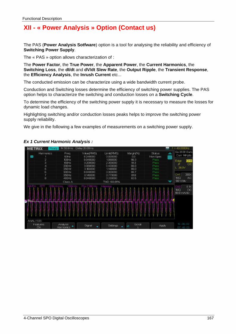
Functional Description
4-Channel SPO Digital Oscilloscopes 167
XII - « Power Analysis » Option (Contact us)
The PAS (Power Analysis Sotfware) option is a tool for analysing the reliability and efficiency of Switching Power Supply.
The « PAS » option allows characterization of :
The Power Factor, the True Power, the Apparent Power, the Current Harmonics, the Switching Loss, the dI/dt and dV/dt Slew Rate, the Output Ripple, the Transient Response, the Efficiency Analysis, the Inrush Current etc...
The conducted emission can be characterize using a wide bandwidth current probe.
Conduction and Switching losses determine the efficiency of switching power supplies. The PAS option helps to characterize the switching and conduction losses on a Switching Cycle.
To determine the efficiency of the switching power supply it is necessary to measure the losses for dynamic load changes.
Highlighting switching and/or conduction losses peaks helps to improve the switching power supply reliability.
We give in the following a few examples of measurements on a switching power supply.
Ex 1 Current Harmonic Analysis :

Functional Description
168 4-Channel SPO Digital Oscilloscopes
XII - « Power Analysis » Option (cont‟d)
Ex 2 Inrush current :
Ex 3 Output Ripple (Input coupling DC) :
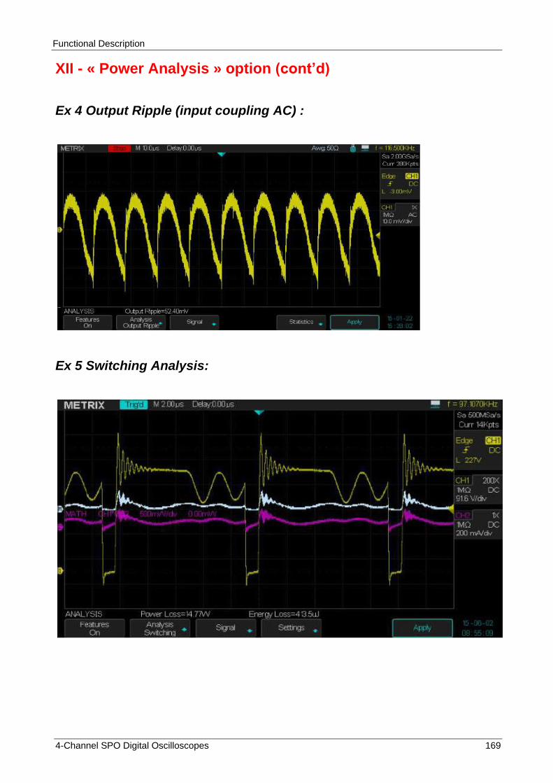
Functional Description
4-Channel SPO Digital Oscilloscopes 169
XII - « Power Analysis » option (cont‟d)
Ex 4 Output Ripple (input coupling AC) :
Ex 5 Switching Analysis:
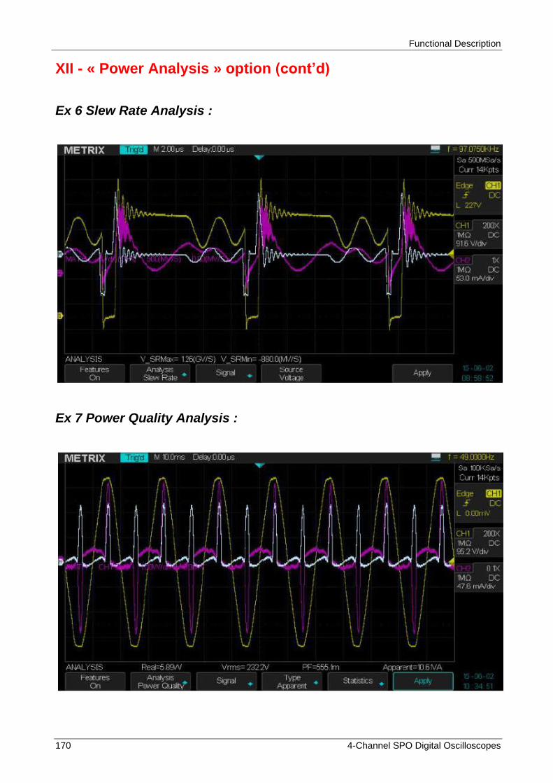
Functional Description
170 4-Channel SPO Digital Oscilloscopes
XII - « Power Analysis » option (cont‟d)
Ex 6 Slew Rate Analysis :
Ex 7 Power Quality Analysis :

Functional Description
4-Channel SPO Digital Oscilloscopes 171
XII - « Power Analysis » option (cont‟d)
Ex 8 Turn On Analysis :
Ex 9 Turn Off Analysis :

Functional Description
172 4-Channel SPO Digital Oscilloscopes
XIII - Remote Control of the Oscilloscope
Remote Control There are two methods to remotely control the oscilloscope:
using SCPI commands or using the specialized PC software « EasyScopeX »
User-defined programming
User can control the oscilloscope by programming through standard SCPI (Standard Commands for Programmable Instruments) commands. For more details about commands and programming, please refer to the « Programming Manual ». User can remotely control the oscilloscope through the specialized PC software « EasyScopeX ».
Using the PC software « EasyScopeX »
The oscilloscope can communicate with a PC through its « USB Device » port (USB B connector) or through its « LAN Ethernet » interface (RJ45 connector). These connectors are located on the rear panel of the unit. This section describes how to use the « EasyScopeX » PC software to remotely control a DOX3000 oscilloscope through its USB or LAN interface.
Control through USB Use a USB cable to connect the oscilloscope (USB Device connector) to a PC
(USB host connector) with EasyScopeX installed.
Installing the USBTMC interface in
the DOX3000
Through the I/O submenu of the UTILITY menu set the « USB Device » interface to USBTMC. If you have installed the EasyScopeX software, the PC will display pop-up dialogue boxes when you connect the oscilloscope to the PC for the first time. Please follow the prompting messages to install the "USB Test and Measurement Device" . Below are the steps:

Functional Description
4-Channel SPO Digital Oscilloscopes 173
XIII - Remote Control (cont‟d)

Functional Description
174 4-Channel SPO Digital Oscilloscopes
Connecting Devices
Open « EasyScopeX » software, click "Add Device" to start the search, the following dialog box appears:
Click the communication interface to use USBTMC (USB) or VXI11 (Ethernet).
If the instrument is connected through USBTMC interface, select the instrument to open and click the « Add » button :

Functional Description
4-Channel SPO Digital Oscilloscopes 175
If the active communication interface is VXI11, the following window appears:
Enter the oscilloscope IP address (example 14.3.212.25) and click OK to remotely control the oscilloscope through « Ethernet ».
Check lnstrument
Resource
The informations about the instrument « added » are displayed. See the examples below. The device “Serial Number” and the informations about the USB communication interface (or Ethernet) are displayed.

Functional Description
176 4-Channel SPO Digital Oscilloscopes
Testing the communication
interface
Send Command
Click "Send Command" button and enter (keyboard) the SCPI command : « *IDN? », press the « Enter » button to send the command. The « EasyScopeX » software sends the command to the oscilloscope, accepts the instrument datas and displays the instrument identification:
Send Command
To send SCPI commands to the oscilloscope
Traces
WaveTrace
To retreive the waveforms from the oscilloscope (all acquired samples)

Functional Description
4-Channel SPO Digital Oscilloscopes 177
Screen Capture
To perform a screen capture (displayed waveforms)
Scope Configuration
To Control the oscilloscope through a virtual panel
Virtual Panel By activating the virtual panel it is possible to remotely control the oscilloscope by acting on the softkeys and virtual knobs of the « Virtual Panel ». The “virtual screen” will react interactively to the actions on the “Virtual Panel”:
For more details, please consult the « EasyScopeX » help file.

Messages
178 4-Channel SPO Digital Oscilloscopes
Messages / Help
« Help »
The oscilloscope has an embedded help function that supplies multi-language Help information ( English , French, German). To access help:
Press the front panel "Help" button to activate the help, then press every button to display the corresponding help information.
Note : To display the help information corresponding to the « Single » or « Run/Stop» buttons, press these buttons immediately after you press the « Help » button. Otherwise the « Single » button is used to display the next page of the displayed help and the “Run/Stop” button the previous page, when the help information exceeds one page.
All submenus of every main menus have their own help information. Note : If you want to display help information of next page submenus, first press the « Help » button to exit the help status and switch to next page menu then press the « Help » button to enter the help status again and press the submenu option buttons to display the corresponding help information.

Messages
4-Channel SPO Digital Oscilloscopes 179
Messages (cont‟d)
Messages
Trig level at limit! : Indicates that the adjustable trigger level is at its limit.
Horizon position at limit! : Indicates that the adjustable horizontal position is at its limit.
Volts/Div at limit! : Indicates that the vertical scale “V/div” has reached the minimum “2mV/div” or the maximum “10V/div”.
Volts position at limit! : Indicates that the vertical position is at its limit.
Sec/Div at limit! : Indicates that the Time Base coefficient “S/div” is at its limit.
Hold-off time at limit! : Indicates that the adjustable « Holdoff » is at its limit.
Function isn‟t useable! : Indicates that the function is not compatible with the operating mode.
No signal! : This message is output by the Autoset in the absence of signal.
Adjust at limit! : This message is displayed when the pulse width adjustement (Universal knob) reaches the limits min “2,0ns” or max “10,0s”.
Location Empty! : This message is displayed when you press the « Recall » button and the location is empty (no waveform or setup).
USB Flash Drive Plug In! : This message is displayed when you plug a USB Flash Drive in the USB host connector.
USB Flash Drive Pull Out! : This message is displayed when you pull out the USB flash drive.
Store Data Success! : This message indicates a « Successfull Save » of the Setup, the Waveform or the Picture in the internal memory of the oscilloscope or the USB flash drive.
Read Data Success! : This message indicates a « Successfull Recall » of the Setup or the Waveform from the internal memory of the oscilloscope or the USB flash drive.
Please set Back USB to printer! : This message is displayed if you press the front panel “Print” button with the “Back USB connector” set to “USBTMC”.
USB Flash Drive isn‟t connected! : This message is displayed when the USB flash drive is not plugged in the « USB host connector » and you press the “Save” button to save a “File” or to "Print" a “Picture” in the external memory.
Record Wave Success!: This message is displayed when a waveform is successfully saved.

Messages
180 4-Channel SPO Digital Oscilloscopes
Messages (cont‟d)
Troubleshooting
Operation Steps 1. After the oscilloscope is powered "ON", the LCD screen remains dark, please proceed as follow:
- Check the power cord connection. - Check the Power On button backligth (“On/Off” button lighting is variable). - Ensure the power On/Off switch is turned On (“On/Off” button lighting is fixed On) . - After the inspections above, restart the oscilloscope. - If the oscilloscope is still not usable after the checking, contact METRIX division CHAUVIN-ARNOUX (support area). 2. If the oscilloscope does not display any waveform with signals on
input channels: (1) Check the input probe. (2) Check the input cable. (3) Check the probe with the front panel « Cal 3V 1kHz» output. (4) Check that the unit under test generates the signal or not. (5) Press the « Auto setup » button. 3. The displayed voltage value is 10 times higher/lower than the real one,
please proceed as follow : Check that the channel probe factor matches the probe attenuation coefficient. 4. The displayed signal is unstable : (1) Check that the selected trigger source matches the displayed
signal channel. (2) Check that the selected trigger mode is well suited to the type of
signal displayed (ie for video signal use the “Video” trigger mode). (3) Set the « HF reject » or « LF reject » trigger coupling, to
suppress the high/low frequency noise that eventually disturbs the trigger . (4) Use the “Noise Reject” option, to prevent signal noise to disturb
the trigger 5. You press the "Run/Stop" button but nothing is displayed. Check whether the trigger mode is set to “Normal” or “Single”, and check that the trigger level is within the max and min peaks of the signal. Press the « Level » knob to set the « Level to 50% » , or press « Auto » button to set the Auto Trig mode or press the “Auto Setup” button to perform an automatic set up. 6. The waveform refreshes slowly after setting the acquire "Average"
mode or the "The display Persistence time" is set too long. It is normal with this settings 7. The signal is displayed as a « ladder like » waveform (1) This phenomenon is normal. If the Time Base is too slow,
turn the “S/div” knob to improve the display. (2) If the display type is set to “Vectors”, set it to “Dots”.

Characteristics
4-Channel SPO Digital Oscilloscopes 181
Technical Specifications
Inputs DOX3104 DOX3304
Channels 4 4
Input Coupling AC, DC, GND
Input Impedance 1 MΩ ± 2 % || 20 pF ± 4 pF or 50 Ω ± 2 %
Maximum input voltage 300 V (DC+AC Pk = 300 Vmax) CATI (1 MΩ) or ≤5Vrms (50 Ω)
Channel to Channel isolation
(Same sensitivity V/div on both channels)
> 100:1 at 50 MHz > 100:1 at 150 MHz
Probe Attenuation 1X, 10X
Probe compensation factor
.1X, .2X, .5X, 1X, 2X, 5X, 10X, 20X, 50X, 100X, 200X, 500X, 1000X, 2000X, 5000X, 10000X
Vertical System DOX3104 DOX3304
Vertical Sensitivity 2 mV/div to 10V/div (sequence 1-2-5)
Vertical Position Range
2mV/div to 100mV/div : ± 1V
102 mV/div to 1V/div : ± 1V 1.02V/div to 10V/div : ± 100V
Vertical Resolution 8 bit
Number of Channels 4 4
Analog Bandwidth 100 MHz 300 MHz
Single Shot Bandwidth 100 MHz 300 MHz
Bandwidth Flatness at BNC input
DC - 10 % of nominal Bandwidth : ± 1 dB 10 % - 50 % of nominal Bandwidth: ± 2 dB
50 % - 100 % of nominal Bandwidth: + 2 dB / - 3 dB
Low frequency cutoff (-3dB) AC input coupling
≤ 10 Hz
Noise: Pk-Pk
≤ 0,6 div. 10 Pk-Pk values average, calibres 2mV to 10V/div
≤ 1,0 div. 10 Pk-Pk values average, (152mV/div ~ 198mV/div, 1.52V/div ~1,98V/div)
≤ 0,7 div. 10 Pk-Pk values average, fine vertical sensitivity adjust
SFDR including harmonics (measure with FFT)
≥ 35 dB (≥ 10mV/div) ; ≥ 30 dB (< 10mV /div)
DC gain precision for a 6 div amplitude signal.
± 3.0 % : 5 mV/div. to 10 V/div. Fixe sensitivities ± 4.0 % : 2 mV/div. Fine adjust sensitivity
DC measurements precision all Sensitivities : ≤ 100mV/div.
± [3 % * (|measure| + |offset|) + 1 % * |offset| + 0,2 div. + 2 mV]
DC measurements precison all sensitivities :
>100mV/div. ± [3 % * (|mesure| + |offset|) + 1 % * |offset| + 0,2 div. + 100 mV]
Rise Time < 3.5ns < 1.2ns
Overshoot (Typical) (pulse tr = 500ps)
< 10 % (with 50 Ohm internal input impedance)
Skew between channels (same sensitivity V/div)
< 200ps < 200ps
Math +, - , *, /, FFT, d/dt, ∫dt, √
FFT Window Type : Hanning, Hamming, Blackman, Rectangular
Number of samples : 1024
Bandwidth Limit 20 MHz ± 40 %
(Note : The Bandwidth limit is less than 10 MHz when using a X1 probe)
The oscilloscope must have been operating continuously for thirty minutes within the specified temperature. You must perform the « Do Self Cal » operation through the “Utility” menu, if the operating temperature changes by more than 5°C. The oscilloscope must be within the calibration interval. All specifications are guaranteed unless note "typical"

Characteristics
182 4-Channel SPO Digital Oscilloscopes
Technical Specifications (cont‟d)
Horizontal and Sampling system
DOX3104 DOX3304
Real time sampling frequency
Dual Channel [CH1 CH3] or [CH2 CH4] : 2GSa/s
3 or 4 Channel : 1GSa/s (For Time Base
coefficients faster than 1ms/div and 14Mpts memory depth)
Dual Channel [CH1 CH3] or [CH2 CH4]: 2GSa/s
3 or 4 Channel: 1GSa/s (For Time Base
coefficients faster than 1ms/div and 14Mpts memory depth)
Memory depth
14Mpts max per channel
Adjustable: 7kpts 14kpts 70kpts 140kpts 700kpts 1.4Mpts 7Mpts
14Mpts max per channel
Adjustable: 7kpts 14kpts 70kpts 140kpts 700kpts 1.4Mpts 7Mpts
Acquisition Normal, Peak Detect, Average, High Resolution
“Averages” 4, 16, 32, 64, 128, 256, 512, 1024
Time base accuracy
± 25 ppm
Time Base coefficients range
1ns/div. - 50s/div. 1ns/div. - 50s/div.
Maximum number of capture
waveforms per second
110000 Waveforms/s
SPO Intensity grading
256 levels
Display Format Y(t), Zoom, Roll, X-Y
Roll mode Roll : 100ms/div. - 50s/div. (sequence 1-2-5)
Trigger System
Trigger Digital Trigger on CH1, CH2, CH3 and CH4 sources
Trigger Types Edge, Pulse, Video, Slope, Window, Interval, Dropout, Runt, Pattern, Serial Trigger
Trigger Sources CH1, CH2, CH3, CH4, EXT, EXT/5, AC Line
Trigger Modes Auto, Normal, Single-Shot
« Roll » Mode for Time Base coefficients : from 100ms/div to 50s/div
Trigger Coupling
AC, DC, LF rej, HF rej
DC: All components of the signal passes
AC : Blocks the DC component and attenuates low frequency signals <5.8Hz
LF rej : Blocks the DC component and attenuates low frequency signals <2.08MHz
HF rej : Attenuates high frequency signals >1.27MHz
Holdoff Adjustement range : 100ns - 1,5s
Trigger level range CH1, CH2, CH3, CH4: ± 4.5 divisions from the center of the screen
EXT : ± 1,2V EXT/5 : ± 6V
Trigger position Pre-trigger : 7 divisions
Post trigger Max : 10s to 1000000000s depending on the Time Base coefficient.
Trigger Level accuracy (Typical)
± 0,2 div
Trigger Sensitivity CH1 CH2 CH3 CH4 ( 2mV to 10V/div sequence 1-2-5) : 0.5 div
EXT : 200mVpp DC - 10 MHz 300mVpp 10MHz - max. BW
EXT/5 : 1Vpp DC - 10 MHz 1,5Vpp 10MHz - max. BW
« Edge » Trigger Pente : Positive, Negative, Positive&Negative
Source : CH1 CH2 CH3 CH4 EXT EXT/5 Line
« Slope » Trigger
Slope : Rising, Falling
Limit : <, >, < >, > <
Source : CH1 CH2 CH3 CH4
Adjustement range: 2ns to 4,2s Resolution : 1ns

Characteristics
4-Channel SPO Digital Oscilloscopes 183
« Pulse Trigger »
Polarity : +wid, -wid
Limit : <, >, < >, > <
Source : CH1 CH2 CH3 CH4
Adjustement Range: 2ns to 4,2s Resolution : 1ns
« Window Trigger» Window Type : Absolute, Relative
Source : CH1 CH2 CH3 CH4
« Video Trigger »
Supported Standards : PAL/SECAM, NTSC, 720p/50, 720p/60, 1080p/50, 1080p/60, 1080i/50, 1080i/60, Custom
Source : CH1 CH2 CH3 CH4
Sync: All, Selection
“Interval Trigger”
Slope : Rising, Falling
Limit : <, >, < >, > <
Source : CH1 CH2 CH3 CH4
Adjustement range : 2ns to 4,2s Resolution : 1ns
« Dropout Trigger »
Timeout type : Edge, State
Source : CH1 CH2 CH3 CH4
Slope : Rising, Falling
Adjustement range : 2ns to 4,2s Resolution : 1ns
« Runt Trigger »
Polarity : +wid -wid
Limit : <, >, < >, > <
Source : CH1 CH2 CH3 CH4
Adjustement Range : 2ns to 4,2s Resolution : 1ns
Pattern Trigger
State : don’t care, Low, High
Logic : AND, OR, NAND, NOR
Source : CH1 CH2 CH3 CH4
Limit: <, >, < >, > <
Adjustement Range : 2ns to 4,2s Resolution : 1ns
Serial Bus Trigger
« I2C Trigger » Condition : Start, Stop, Restart, No Ack, EEPROM, 7bits Address&Data
« SPI Trigger »
Trigger Source : MOSI, MISO
Data length: 4 to 96bits
Value: 0, 1, X
Bit Order: LSB, MSB
« RS232/UART Trigger”
“Trigger Setting”
Trigger Source: RX, TX
Condition: Start, Stop, Data, Check Error
“Bus Configure”
Baud: 600/1200/2400/4800/9600/19200/38400/57600/115200/Custom
Data Length: 5bits, 6bits, 7bits, 8bits
Parity Check: No, Odd, Even
Idle Level: Low, High
“CAN Trigger”
“Trigger Setting”
Condition: Start, Remote Frame, Data Frame, ID&DATA
“Bus Configure”
Baud: 5kb/s, 10kb/s, 20kb/s, 50kb/s, 100kb/s, 125kb/s, 250kb/s, 500kb/s, 800kb/s, 1Mb/s, Custom
“LIN Trigger
“Trigger Setting”
Condition: Start, ID, ID&DATA, Error
“Bus Configure”
Baud: 600/1200/2400/4800/9600/19200/Custom

Characteristics
184 4-Channel SPO Digital Oscilloscopes
“Serial Decode”
Bus I2C
Signal : SCL, SDA
Address: 7bits, 10bits
List : 1 to 7 lines
SPI bus
Signal : CLK, MISO, MOSI, CS
Slope select : Rising, Falling
Idle Level : Low, High
Ordre des Bits : MSB, LSB
Data Length : 4 to 96bits
Liste : 1 to 7 lines
RS232/UART Bus
Signal : RX, TX
Configuration
Baud: 600/1200/2400/4800/9600/19200/38400/57600/115200/Custom
“Parity Check”: No, Odd, Even
Bit Stop: 1, 1.5 , 2
Idle Level: Low, High
Data Length: 5bits, 6bits, 7bits, 8bits
List: 1 to 7 lines
CAN bus
Signal : CAN_H, CAN_L
Configure
Baud: 5kb/s, 10kb/s, 20kb/s, 50kb/s, 100kb/s, 125kb/s, 250kb/s, 500kb/s, 800kb/s, 1Mb/s, Custom
Decode Source: CAN_H, CAN_L, CAN_H - CAN_L
List: 1 to 7 lines
LIN Bus
Configure
Baud: Baud: 600/1200/2400/4800/9600/19200/Custom
List: 1 to 7 lines
X-Y Format
X-Y Inputs [CH1 (X) CH2 (Y)] or/and [CH3(X) CH4(Y)]
Phase Error ± 3 degrees
XY Sampling frequency range
XY mode Sampling frequency range : 20Sa/s to 1GSa/s
Hardware Frequency Counter
Reading Resolution 6 Digits
Precision ± 0,01% @ 1kHz
Frequency range DC Input coupling : frequency measurement range from 10Hz to the maximum bandwidth frequency .
Signal Type All the source signals that generate a trigger event.
Measurement system
Automatic Measurements (32 Types)
Vpp, Vmax, Vmin, Vamp, Vtop, Vbase, Vavg, Mean, Crms, Vrms, ROVShoot, FOVShoot, RPREShoot, FPREShoot, Rise time, Fall time, Freq, Period, +Wid, -Wid, +Dut, -Dut, BWid, Phase, FRR, FRF, FFR, FFF, LRR, LRF, LFR, LFF
Cursor Measurements Modes : Manual, Track
Time : (X1,X2), (X1X2) Voltage: (Y1, Y2), (Y1Y2)
Statistics Current, Mean, Min, Max, Std-Dev, Count
Interfaces Entrée/Sortie I/O
Ports Standards USB Host, USB Device, LAN, Pass/Fail, Sortie Trigger
Bon/Mauvais (Pass/Fail) 3.3V TTL Output
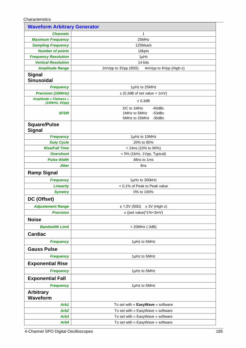
Characteristics
4-Channel SPO Digital Oscilloscopes 185
Waveform Arbitrary Generator
Channels 1
Maximum Frequency 25MHz
Sampling Frequency 125Msa/s
Number of points 16kpts
Frequency Resolution 1µHz
Vertical Resolution 14 bits
Amplitude Range 2mVpp to 3Vpp (50Ω) 4mVpp to 6Vpp (High-z)
Signal Sinusoidal
Frequency 1µHz to 25MHz
Precision (100kHz) ± (0,3dB of set value + 1mV)
Amplitude « Flatness » (100kHz, 5Vpp)
± 0,3dB
SFDR
DC to 1MHz -60dBc
1MHz to 5MHz -53dBc
5MHz to 25MHz -35dBc
Square/Pulse Signal
Frequency 1µHz to 10MHz
Duty Cycle 20% to 80%
Rise/Fall Time < 24ns (10% to 90%)
Overshoot < 5% (1kHz, 1Vpp, Typical)
Pulse Width 48ns to 1ms
Jitter 8ns
Ramp Signal
Frequency 1µHz to 300kHz
Linearity < 0,1% of Peak to Peak value
Symetry 0% to 100%
DC (Offset)
Adjustement Range ± 1,5V (50Ω) ± 3V (High-z)
Precision ± (|set value|*1%+3mV)
Noise
Bandwidth Limit > 20MHz (-3dB)
Cardiac
Frequency 1µHz to 5MHz
Gauss Pulse
Frequency 1µHz to 5MHz
Exponential Rise
Frequency 1µHz to 5MHz
Exponential Fall
Frequency 1µHz to 5MHz
Arbitrary Waveform
Arb1 To set with « EasyWave » software
Arb2 To set with « EasyWave » software
Arb3 To set with « EasyWave » software
Arb4 To set with « EasyWave » software

Characteristics
186 4-Channel SPO Digital Oscilloscopes
Technical Specifications (cont‟d)
Display System
LCD screen 8 inch TFT Color LCD (203,2 mm diagonal )
Resolution 800 pixels (horizontal) x 480 pixels (vertical)
Colors 24 bit
Display Contrast 500:1 (typical)
Backligth Intensity 300nit (typical)
Waveform display 8 x 14 div.
Display Modes Points, Vectors
Persistence Off, 1 sec, 5 sec, 10 sec, 30s, Infinite
Screen Saver Off, 1mn, 5mn, 10mn, 30mn, 1h
Interpolation Sin(x) , x
SPO color Mode On , Off
Language English, Français, Deutsch, Español, Italiana
Environment
Temperature Range
Reference : 18°C to 28°C Operating : 0°C to +40°C
Non-operating : -20°C to +60°C For indoor use
Cooling Fan
Humidity Operating : < 80 % HR, up to 31°C
Non-operating : < 80 % HR, up to 31°C
Altitude Operating : < 2000 m
Non-operating : < 12.000 m
Power Supply
Input voltage range nominal 100 - 240 VAC Auto selection
Frequency 50 Hz to 400 Hz
Power Consumption 80W max.
Fuse T 1,25 A / 250 V 5x20mm
Power Cord Removable
Security Compliant with NF EN 61010-1
Insulation Classe 1
Pollution Index 2
Power Supply Surge Category
300V CATII
Inputs surge Category 300V CATI

Characteristics
4-Channel SPO Digital Oscilloscopes 187
Technical Specifications (cont‟d)
EMC
Th appliance has been designed in compliance with the applicable EMC standards and its compatibility has been tested in compliance with standard NF EN 61326-1.
European Directives CE
The CE marking indicates compliance with « Low Voltage » , "EMC", "DEEE" and "RoHS" European Directives.
Mechanical
Dimensions
Length 352 mm
Width 112 mm
Height 224 mm
Weigth 3,6 kg DOX3104 & DOX3304 models
Materials ABS VO (auto extinguishing)
Sealing IP20
Packaging
Dimensions 430 x 240 x 365 mm
Parts Accessories
Shipped User Manual on USB memory device
« EasyScopeX » PC software
« Easywave » PC software
Getting started guide
Safety instructions
Power supply cord
USB A/B cable
4 Probes (DOX3104, DOX3304)
options Differential Probes :
- single MX 9030 - dual MTX 1032 (consult us)
Remote Programing
Manual Contact us.

Characteristics
188 4-Channel SPO Digital Oscilloscopes
Appendix : Default Setup
Menu or system Default setup
Horizontal T/div 1µs/div
Delay 0 s
Zoom Off
Format Y(t)
Vertical Channel On/Off CH1
V/div 1V/div
Vertical Position 0V
Input Coupling DC
BW Limit Full
V/div adjust Coarse 1 2 5
Probe Factor X1
Input Impedance 1MΩ
Vertical Unit V
Invert Off
Acquisition « Acquire »
Acquisition mode Normal
SinX/X X
Memory Depth 14Mpts
« Trigger » Type Edge
Source CH1
Slope Rising
Holdoff Fixed (Close)
Coupling DC
Noise Reject Off
Mode Auto
« Display » Type Vectors
Color Off
Persistance Off
Grid
Intensity 50%
Brightness 40%
Transparence 50%
« Cursors » Mode Off
Type X1
Source CH1
X1 -3,5µs
X2 3,5µs
« Save/Recall » Type Setups
« UTILITY » I/O Set
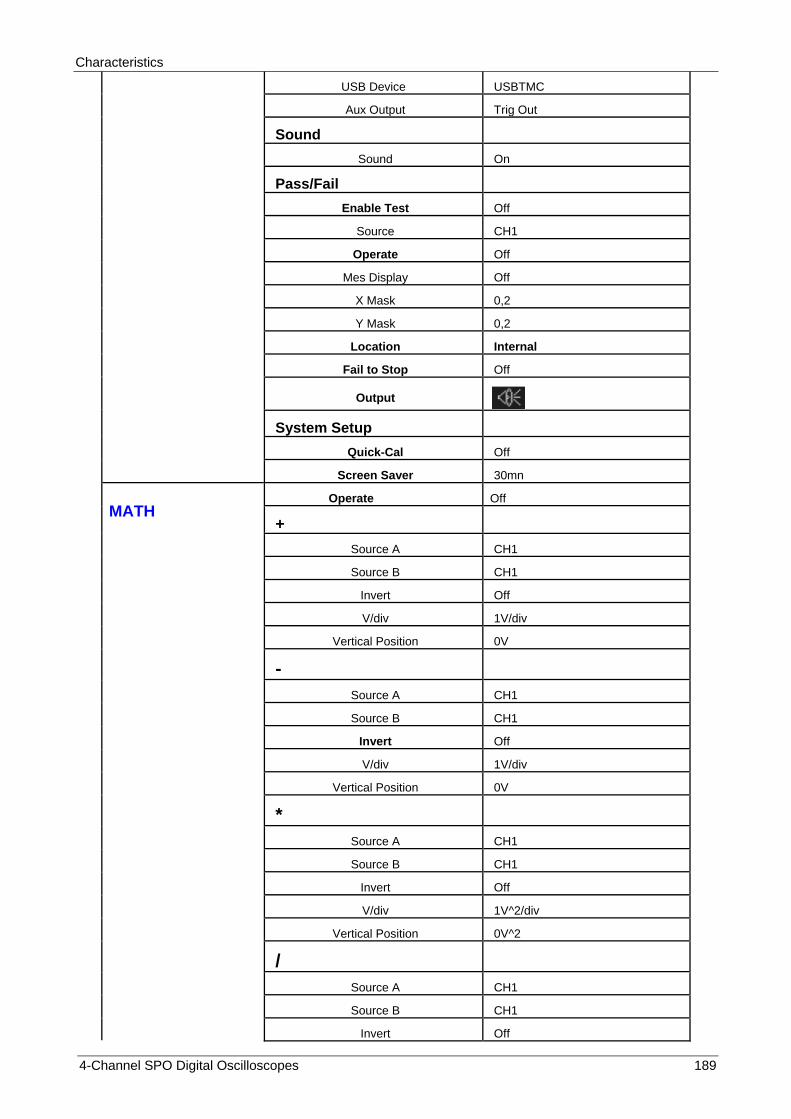
Characteristics
4-Channel SPO Digital Oscilloscopes 189
USB Device USBTMC
Aux Output Trig Out
Sound
Sound On
Pass/Fail
Enable Test Off
Source CH1
Operate Off
Mes Display Off
X Mask 0,2
Y Mask 0,2
Location Internal
Fail to Stop Off
Output
System Setup
Quick-Cal Off
Screen Saver 30mn
MATH
Operate Off
+
Source A CH1
Source B CH1
Invert Off
V/div 1V/div
Vertical Position 0V
-
Source A CH1
Source B CH1
Invert Off
V/div 1V/div
Vertical Position 0V
*
Source A CH1
Source B CH1
Invert Off
V/div 1V^2/div
Vertical Position 0V^2
/
Source A CH1
Source B CH1
Invert Off

Characteristics
190 4-Channel SPO Digital Oscilloscopes
V/div 1V/div
Vertical Position 0
FFT
Source CH1
Window Hanning
FFT Zoom 1X
Vertical Scale 20dBVrms
Display Split
Horizontal Scale 100MHz
d/dt (dy/dx)
Source CH1
Vertical Scale (1MV/s)/div = (1V/µs)/div
Vertical position 0
dx 0.2div
∫dt
Source CH1
offset 0
Vertical Scale 1µVs/div
Vertical position 0
√
Source CH1
Vertical Scale 1V½div
Vertical position 0
REF Source CH1
Location REF A
Display Off
DECODE
Serial 1
Serial I2C
Display Off
List Off
Serial 2
Serial SPI
Display Off
List Off
I2C
SCK CH1
Threshold 1,6V
SDK CH2
Threshold 1,6V
Adresse (Address) 7 bit
SPI
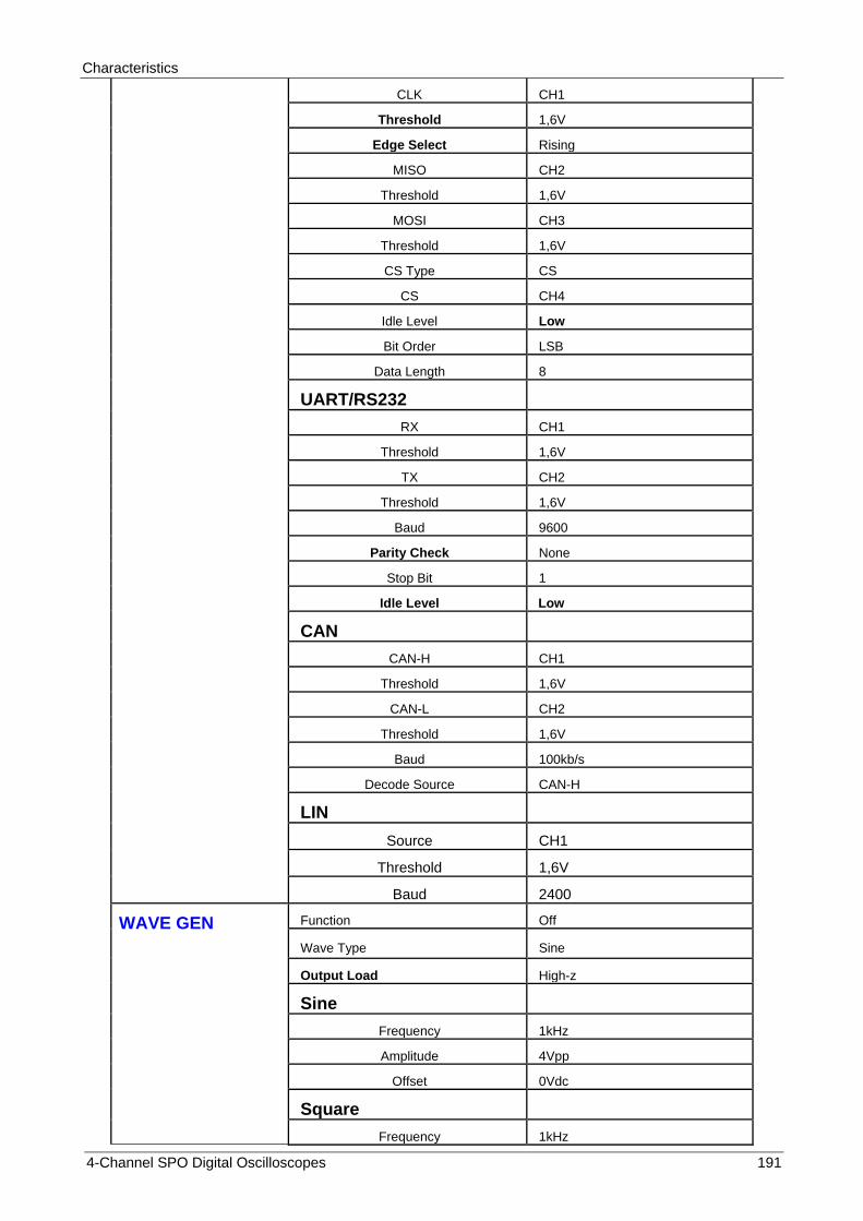
Characteristics
4-Channel SPO Digital Oscilloscopes 191
CLK CH1
Threshold 1,6V
Edge Select Rising
MISO CH2
Threshold 1,6V
MOSI CH3
Threshold 1,6V
CS Type CS
CS CH4
Idle Level Low
Bit Order LSB
Data Length 8
UART/RS232
RX CH1
Threshold 1,6V
TX CH2
Threshold 1,6V
Baud 9600
Parity Check None
Stop Bit 1
Idle Level Low
CAN
CAN-H CH1
Threshold 1,6V
CAN-L CH2
Threshold 1,6V
Baud 100kb/s
Decode Source CAN-H
LIN
Source CH1
Threshold 1,6V
Baud 2400
WAVE GEN Function Off
Wave Type Sine
Output Load High-z
Sine
Frequency 1kHz
Amplitude 4Vpp
Offset 0Vdc
Square
Frequency 1kHz

Characteristics
192 4-Channel SPO Digital Oscilloscopes
Amplitude 4Vpp
Offset 0Vdc
Duty Cycle 50%
Ramp
Frequency 1kHz
Amplitude 4Vpp
Offset 0Vdc
Symmetry 50%
Pulse
Frequency 1kHz
Amplitude 4Vpp
Offset 0Vdc
Width 200µs
DC
Offset 0mVdc
Noise
St dev 300mV
Mean 0mV
Cardiac
Frequency 1kHz
Amplitude 4Vpp
Offset 0Vdc
Gauss Pulse
Frequency 1kHz
Amplitude 4Vpp
Offset 0Vdc
Exponential Rise
Frequency 1kHz
Amplitude 4Vpp
Offset 0Vdc
Exponential Fall
Frequency 1kHz
Amplitude 4Vpp
Offset 0Vdc

07 - 2015
X04249A02 - Ed. 01
DEUTSCHLAND - Chauvin Arnoux GmbH
Straßburger Str. 34 - 77694 Kehl / Rhein
Tel: (07851) 99 26-0 - Fax: (07851) 99 26-60
SCHWEIZ - Chauvin Arnoux AG
Moosacherstrasse 15 - 8804 AU / ZH
Tel: 044 727 75 55 - Fax: 044 727 75 56
UNITED KINGDOM - Chauvin Arnoux Ltd
Unit 1 Nelson Ct - Flagship Sq - Shaw Cross Business Pk
Dewsbury, West Yorkshire - WF12 7TH
Tel: 01924 460 494 - Fax: 01924 455 328
CHINA - Shanghai Pujiang Enerdis Instruments Co. Ltd
3 Floor, Building 1 - N° 381 Xiang De Road
Hongkou District - 200081 SHANGHAI
Tel: +86 21 65 21 51 96 - Fax: +86 21 65 21 61 07
中国 – 上海浦江埃纳迪斯仪表有限公司
上海市虹口区祥德路381号3号楼3楼
Tel: +86 21 65 21 51 96 - Fax: +86 21 65 21 61 07
ITALIA - Amra SpA
Via Sant’Ambrogio, 23/25 - 20846 Macherio (MB)
Tel: 039 245 75 45 - Fax: 039 481 561
ESPAÑA - Chauvin Arnoux Ibérica S.A.
C/ Roger de Flor, 293 - 1a Planta - 08025 Barcelona
Tel: 902 20 22 26 - Fax: 934 59 14 43
ÖSTERREICH - Chauvin Arnoux Ges.m.b.H
Slamastrasse 29/2/4 - 1230 Wien
Tel: 01 61 61 9 61-0 - Fax: 01 61 61 9 61-61
MIDDLE EAST - Chauvin Arnoux Middle East
P.O. BOX 60-154 - 1241 2020 JAL EL DIB (Beirut) - LEBANON
Tel: (01) 890 425 - Fax: (01) 890 424
SCANDINAVIA - CA Mätsystem AB
Sjöflygvägen 35 - SE 18304 TÄBY
Tel: +46 8 50 52 68 00 - Fax: +46 8 50 52 68 10
USA - Chauvin Arnoux Inc - d.b.a AEMC Instruments
200 Foxborough Blvd. - Foxborough - MA 02035
Tel: (508) 698-2115 - Fax: (508) 698-2118
http://www.chauvin-arnoux.com
190, rue Championnet - 75876 PARIS Cedex 18 - FRANCE
Tél. : +33 1 44 85 44 85 - Fax : +33 1 46 27 73 89 - [email protected]
Export : Tél. : +33 1 44 85 44 38 - Fax : +33 1 46 27 95 59 - [email protected]