model driven atchitecture in to support of software product line
TRANSCRIPT
MODEL DRIVEN ATCHITECTURE IN TO SUPPORT OFSOFTWARE PRODUCT LINE
Ahmed Mohammed Elsawi1*, Shamsul Sahibuddin2
1 Faculty of Computing, University Teknologi Malaysia, Johor Bahru, Malaysia,Sudanese.2 Dean of Advance Informatics School, University Teknologi Malaysia, Kuala Lumpur, Malaysia.3 The third author’s current affiliation and address.
* Corresponding author. Tel.: +249926100000; email: [email protected] submitted January 10, 2014; accepted March 8, 2014.doi: Software engineering , Model Driven Architecture
Abstract: Product management is focusing on variation description; ascurrent and future possible market positioning, acceptable limitations,business opportunity, etc. On the other hand, the Architectural Modeling isconcentrating on creation and description of software platform and how itextends and evolves to deliver and support all or any of these productmanagement and product line scenarios. In product line engineering softwarefeatures are always defined by the variability model. While therequirements specifications, architectural, design, implementation andtesting are normally captured by the solution space. In this work we areutilizing the architectural modeling concept of the Model DrivenArchitecture (MDA) as a complementary of the software product lineconcerning the solution space part. Aiming to improve software quality andproductivity the MDA principles has been adopt. We explicitly employed thePlatform Model (PM) designed by the Entity-Attribute-Value (EAV) concept, toprovision the transformation between Platform Specific Models (PSM) to thetargeted platforms from side, and to manage the platforms diversity andvolatility from other side. A case study presented to demonstrate thesoftware productivity under the orthogonal relationship between the MDA andthe SPL at the later solution space side.
Key words: Model Driven Architecture, Software Product Line, Platform Model,EAV, MDA, .
1. IntroductionThe dynamic change in technologies drags the enterprises to a frantic race
to keep up with this technology evolution. Consequently, modern softwareapplications are regularly required to come in multiple platform supportfeature. But the software size and their development process are growing toocomplex. The thing that reflected on the quality and software framesprofitability and productivity. Different software methodologies adoptedsoftware reusability to reduce the cost and time to market along with thefocus on platforms diversity. The Software Product Line (SPL) and ModelDriven Architecture (MDA) are examples of these methodologies, that handlingthe above targets each of its way. While the SPL focusing on not reinventingsoftware applications by seeking commonalities in applications to bedeveloped once and reused in upcoming releases in a specific domain[1], TheMDA adopted the separation of concern and employed models as a keystone insoftware development productivity process[2].The development process of the SPL focusing on reusability of the software
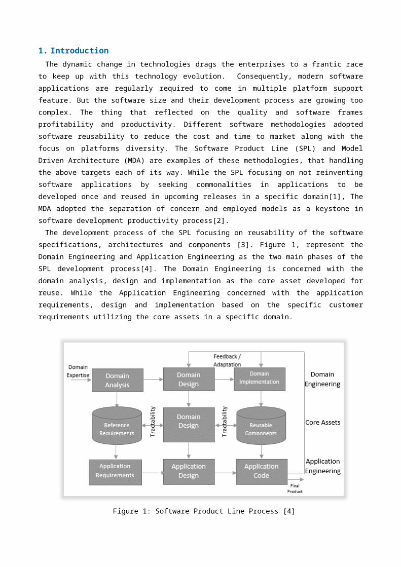
specifications, architectures and components [3]. Figure 1, represent theDomain Engineering and Application Engineering as the two main phases of theSPL development process[4]. The Domain Engineering is concerned with thedomain analysis, design and implementation as the core asset developed forreuse. While the Application Engineering concerned with the applicationrequirements, design and implementation based on the specific customerrequirements utilizing the core assets in a specific domain.
Figure 1: Software Product Line Process [4]
The application requirements captured by the Reference Requirementsdefined by the Domain Analysis. While the Application structure captured bythe Reference Architecture that defined by the Domain Design. The reusablecomponents are reused to code application. Future change and updates aremanaged by the bidirectional reusability[5]. From the above we can say that the Domain Engineering provide the product
line scope, core asset for reuse, and a plan for software productivity .These component based assets of the SPL considered as an advantage as wellas a main drawback approach as its software in a specific domain, produceapplications for a specific platform. In other word, to reproduce a productto work in a different environment need a huge redevelopment and coding,since the asset components designed in the first place to address specificplatforms. The model based development lifecycle in MDA is somehow overcome this
limitation of SPL, since the focus here in Architectural Modeling theconcern of the business requirement is separated from the technicalimplementation and platform requirements. The model driven developmentapproach divided to platform independent model (PIM) and platform specificmodels (PSM). Both models are working in different level of abstractions[2]. UML/MOF are a common OMG standard tools that normally used in modeldriven development to design models and metamodels [6, 7]. Modeltransformation is one of the main activity in model driven software thatserve in transform high level models to low level models using modeltransformation tools such as Query-View-Transformation (QVT), AtlasTransformation Language (ATL) and Eclipse Model Framework (EMF). The adoption of separation of concern and models along with model
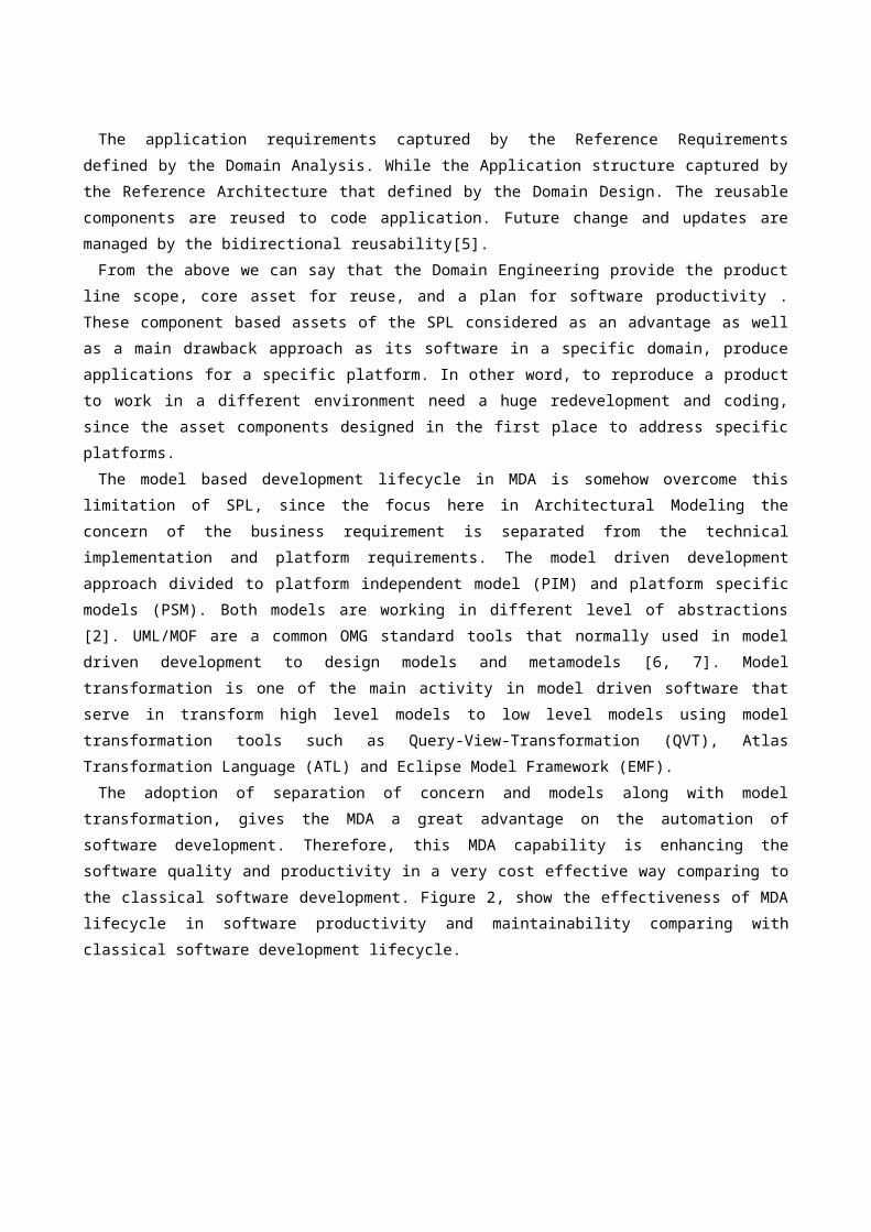
transformation, gives the MDA a great advantage on the automation ofsoftware development. Therefore, this MDA capability is enhancing thesoftware quality and productivity in a very cost effective way comparing tothe classical software development. Figure 2, show the effectiveness of MDAlifecycle in software productivity and maintainability comparing withclassical software development lifecycle.
Figure 2: Classical software development lifecycle vs. MDA lifecycle
Figure 2 (a) represent the classical software development process.Practically, any possible automation is taking place from the coding leveldownward. Consequently, changes in coding doesn’t reflected to the toplevels, and updates on the top levels above the coding on the other handmeans a considerable effort of recoding. This is due to the fact the textand diagrams in the above layers are normally used for documentation andcommunication purposes[8]. The MDA process shown in Figure 2 (b), present anautomated closed loop of between levels. Where, changes in the abstract toplevels can automatically be propagated to the lower ones, with minimaleffort, time and cost. On the other hand, changes on the lower abstractlevels can be reflected to the upper ones, by reversing the transformationfrom lower level of abstractions code/artifacts to the upper layers withhigher level of abstraction models[9]. Similar to classical software development process, the SPL process in
Figure 1, is lacking the automation flexibility between the different levelsof the development process. Where the bottom-up and top-down changes arelimited cannot be propagated upward or downward respectively. For exampleany change in the domain engineering area require a manual update on thecore asset and consequence the application engineering. This is due to thefact that the diagrams and charts adopted to descript the domain engineeringdoesn’t exceed the documentation and communication purpose. In this work we motivate for the MDA capabilities in to support of the
software product line concept. We also illustrated how to address theplatform diversity and volatility by an explicit employment of platformmodels. This explicit platform model inspired by the Entity-Attribute-Valueconcept. It was designed to support the transformation from platformspecific model to targeted platform code. Next, is section 2 we introducingthe related works, and initiatives that focused on the collaborationsbetween software product line and mode driven architecture. This is besidethe work that address the issues of platform diversity in the MDA context.Section 3 show the capability of EAV in modelling a computer platform andhow we utilize it to design an explicit platform model to support the modeltransformation from PSM models to targeted computer platform. A case studypresented in Section 4. The discussion and results shown in Section 5.While the conclusion and future work provided in Section 6.
2. Related WorkThe work in [10] proposed an End to End Development Engineering (E2EDE) to
bridge the transformation gap between PIM and PSM. The author relied on thenotion of variability in SPL to support model design decisions in PSM. Inreverse, the collaboration between the two methodologies presented in [11],as they introduced an automation configuration process created on SPL, andproposed an integration of MDA platform model in a software developmentprocess. This work is closely related to ours. Where the authors suggest anexplicit use of an ontology based platform model to address the platformdependencies of the model transformations and their validity to specificplatforms. Using the ontology to represent the platform model comes with thelimitations. In general, the automation of handling big ontology isimpossible due to the number of classes an instances. This is beside thefact that the time consumed in a manual construction of ontologies isgrowing more complex upon the diversity and platform’s data volume rapidincrease. Consequently, this is reflected in the number of ontologiesrequired to cope with this technology volatility. Although some ambitiousontology automation[12, 13] works on reducing the time and complexity,however, it is not yet mature enough to be adopted. Putting in to accountthat the current ontology automation methods are failing to merge differentontologies to produce new mature one[14, 15]. Another ontology platformrepresentation limitation, is it lack flexible validators that capable tovalidate all different type of platform ontologies. Especially when it comesto complex inheritance relationship. On the other hand the OWL language thatadopted to create the platform ontologies is also draw some limitation on
ontology creation. Since, the OWL doesn’t stand on a backend database duringthe ontology creation. Nevertheless, is following some of their steps as we also explicitly
employed the platform model. However, we used the EAV model to address theplatform representation issues and to equip the model transformation withthe necessary technical details required by the targeted platforms that wedesigned and store it in EAV designed platform model. In SPL terminology the platform model here can be described as a core
assets that can be utilized by model transformations to address differentplatforms. In the next section we highlight EAV capabilities in knowledge
representation and specifically in representing computer platforms modelsand metamodels along with the design of the explicit Platform Model.
3. Modelling of Computer Platform Using Entity-Attribute-Value Aiming to describe platform and platform’s dependencies and constrains we
employed the Entity-Attribute-Value (EAV). EAV is widely used in the medicaland clinical information system as a general purpose means of knowledgerepresentation. The Attribute-value pairs concept are an esteemed way ofrepresenting information on an object, originated on 1950s on the LISPassociation lists[16]. An example of attribute-value pairs showing aparticular student information would be:
((IndexNo A3) (Program CS101) (GPA 3.1) (Year 2012) (Status Active))
Relational databases are traditionally designed using at least firstnormal form (all values are atomic, with no repeating groups), and soattribute-value pairs become triples with the entity (the thing beingdescribed, identified with a unique identifier of some sort) repeating ineach row of a table.Extensible Markup Language (XML) [17] syntax is related to attribute-value
pairs. XML elements, delimited within open- and close-tags for ease andaccuracy of parsing, can represent either entities or attributes. They cancontain sub-elements nested to arbitrary levels; sub-elements may beregarded as attributes with complex structure. For convenience, atomic datadescribing an entity may also be represented within an element's open-tag asattribute-value pairs, each component of a pair being separated by an equalsign.
3.1.EAV Representation for Model and Metamodels
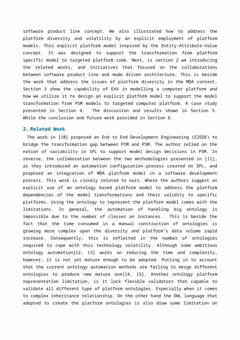
In this part we are presenting how we represents models and metamodels inEAV format. Figure 3 show our instance model that we designed by a simpleState Machine design language for an application in which Passengers buytickets at the time they obtain reservations. At check-in time they obtainboarding cards if there are still seats available. Due to over booking offlights they may be rescheduled on later flights.
Figure 3: A State Machine model For Airline Passenger
Some of the information in the Airline Passenger model is implicit. Inthis situation, we need to interpret the graphical objects in the diagram,which we do by consulting the documentation of the State Machine modelinglanguage and its particular representation in this case.Here, there are three types of object:• States, represented by ovals, each of which has a name, represented by
the text contained in the oval.• Transitions, represented by arrows. A transition is from a source state
(represented by the plain end of the arrow) to a target state (representedby the end of the arrow with an arrowhead).Events, each of which is associated with a transition. An event is
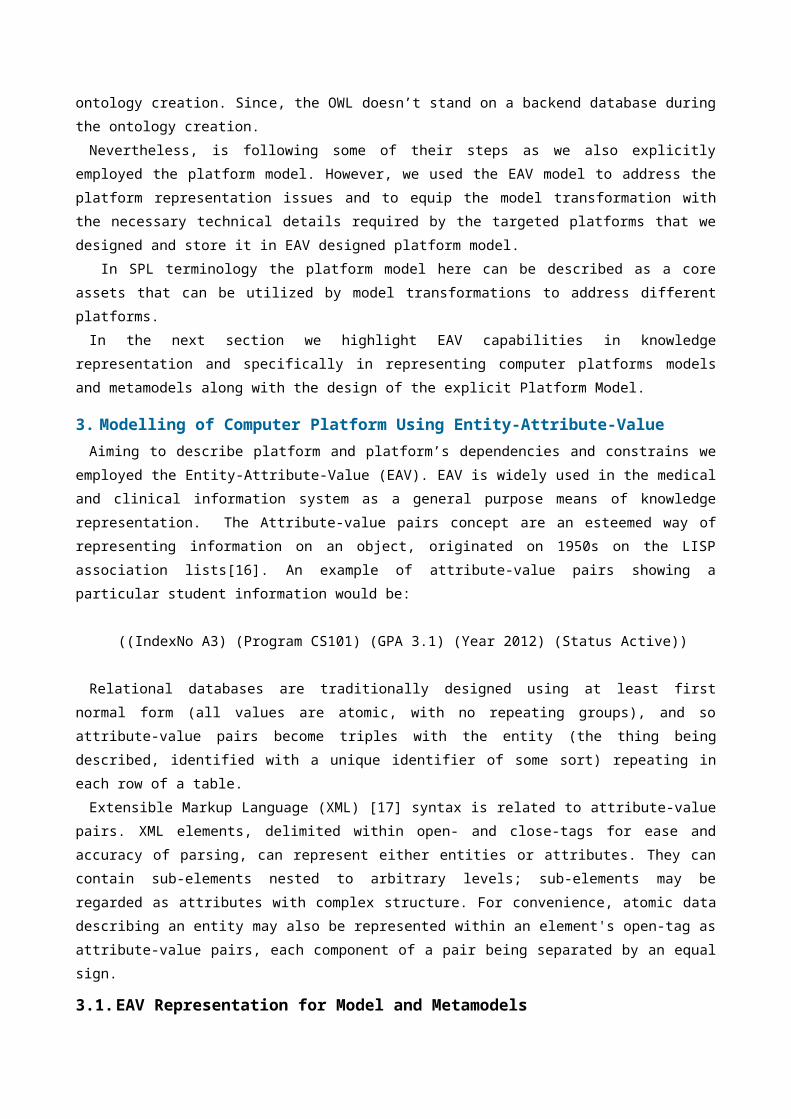
represented by a name near the arrow representing the associated transition.The diagram contains five instances of State: PassengerA metamodel representing the concept in Figure 3 is shown in Figure 4,
represented as a UML Classes diagram. Note that the instances in the diagramof Figure 3 do not appear in the metamodel of Figure 4. Note also themetaclass NamedElement, which is a superclass of the metaclasses State andEvent. The states and events of Figure 3 are all named. The metaclassNamedElement supplies an attribute name to its subclasses.
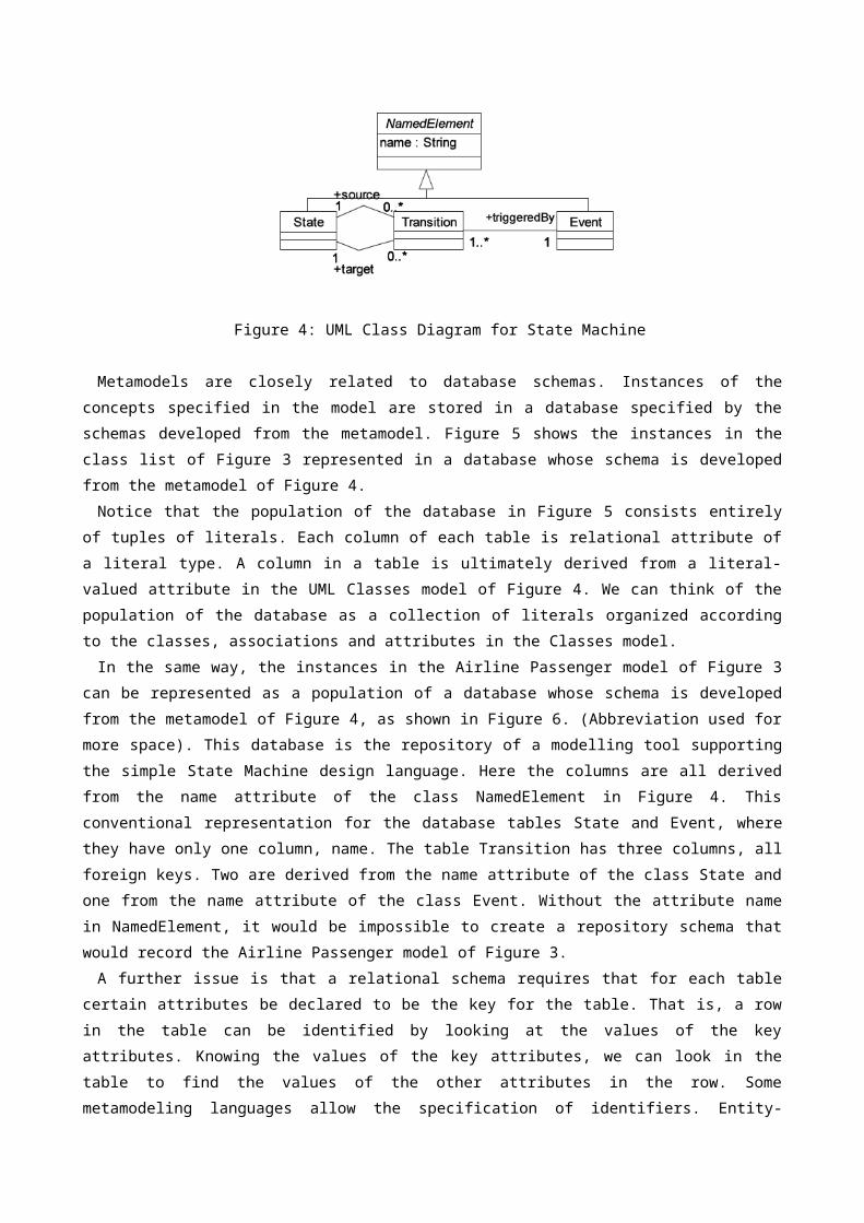
Figure 4: UML Class Diagram for State Machine
Metamodels are closely related to database schemas. Instances of theconcepts specified in the model are stored in a database specified by theschemas developed from the metamodel. Figure 5 shows the instances in theclass list of Figure 3 represented in a database whose schema is developedfrom the metamodel of Figure 4.Notice that the population of the database in Figure 5 consists entirely
of tuples of literals. Each column of each table is relational attribute ofa literal type. A column in a table is ultimately derived from a literal-valued attribute in the UML Classes model of Figure 4. We can think of thepopulation of the database as a collection of literals organized accordingto the classes, associations and attributes in the Classes model.In the same way, the instances in the Airline Passenger model of Figure 3
can be represented as a population of a database whose schema is developedfrom the metamodel of Figure 4, as shown in Figure 6. (Abbreviation used formore space). This database is the repository of a modelling tool supportingthe simple State Machine design language. Here the columns are all derivedfrom the name attribute of the class NamedElement in Figure 4. Thisconventional representation for the database tables State and Event, wherethey have only one column, name. The table Transition has three columns, allforeign keys. Two are derived from the name attribute of the class State andone from the name attribute of the class Event. Without the attribute namein NamedElement, it would be impossible to create a repository schema thatwould record the Airline Passenger model of Figure 3. A further issue is that a relational schema requires that for each table
certain attributes be declared to be the key for the table. That is, a rowin the table can be identified by looking at the values of the keyattributes. Knowing the values of the key attributes, we can look in thetable to find the values of the other attributes in the row. Somemetamodeling languages allow the specification of identifiers. Entity-
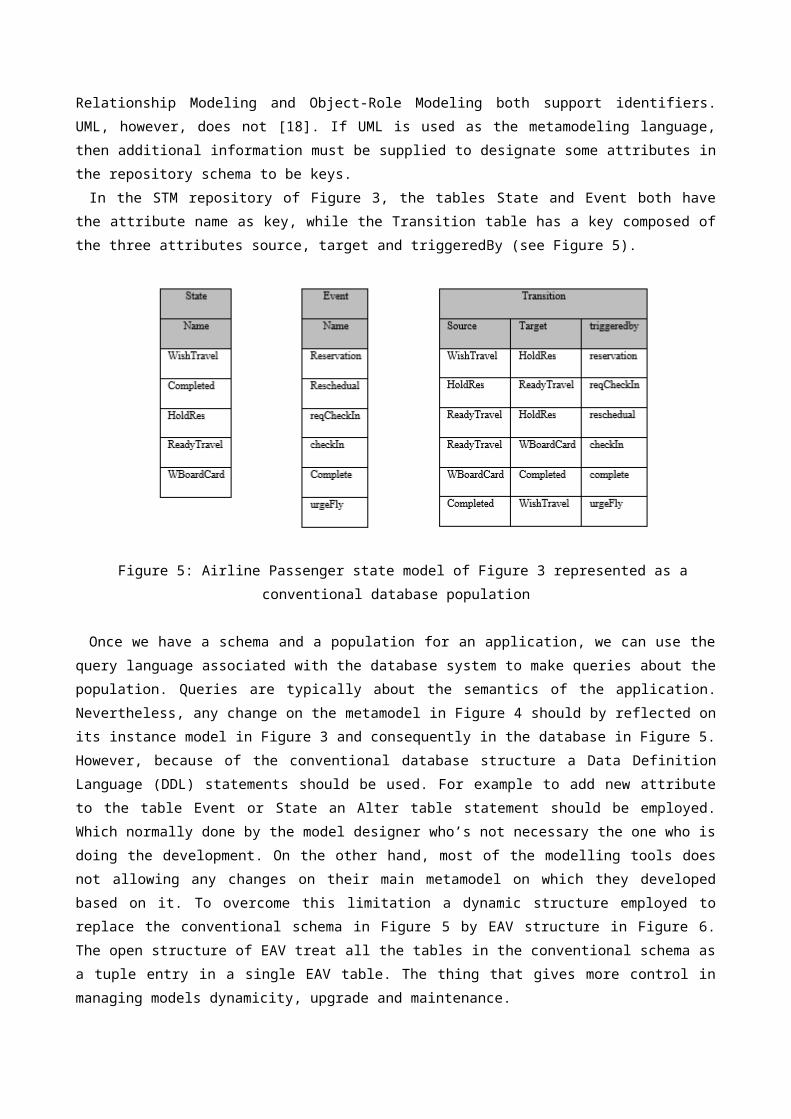
Relationship Modeling and Object-Role Modeling both support identifiers.UML, however, does not [18]. If UML is used as the metamodeling language,then additional information must be supplied to designate some attributes inthe repository schema to be keys.In the STM repository of Figure 3, the tables State and Event both have
the attribute name as key, while the Transition table has a key composed ofthe three attributes source, target and triggeredBy (see Figure 5).
Figure 5: Airline Passenger state model of Figure 3 represented as aconventional database population
Once we have a schema and a population for an application, we can use thequery language associated with the database system to make queries about thepopulation. Queries are typically about the semantics of the application.Nevertheless, any change on the metamodel in Figure 4 should by reflected onits instance model in Figure 3 and consequently in the database in Figure 5.However, because of the conventional database structure a Data DefinitionLanguage (DDL) statements should be used. For example to add new attributeto the table Event or State an Alter table statement should be employed.Which normally done by the model designer who’s not necessary the one who isdoing the development. On the other hand, most of the modelling tools doesnot allowing any changes on their main metamodel on which they developedbased on it. To overcome this limitation a dynamic structure employed toreplace the conventional schema in Figure 5 by EAV structure in Figure 6.The open structure of EAV treat all the tables in the conventional schema asa tuple entry in a single EAV table. The thing that gives more control inmanaging models dynamicity, upgrade and maintenance.
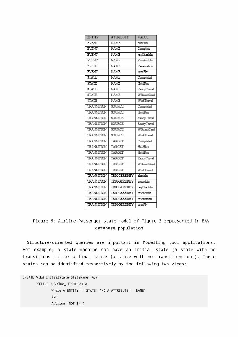
Figure 6: Airline Passenger state model of Figure 3 represented in EAVdatabase population
Structure-oriented queries are important in Modelling tool applications.For example, a state machine can have an initial state (a state with notransitions in) or a final state (a state with no transitions out). Thesestates can be identified respectively by the following two views:
CREATE VIEW InitialState(StateName) AS(
SELECT A.Value_ FROM EAV A
Where A.ENTITY = 'STATE' AND A.ATTRIBUTE = 'NAME'
AND
A.Value_ NOT IN (
SELECT B.Value_ FROM EAV B
WHERE
B.ENTITY = 'TRANSITION'
AND
B.ATTRIBUTE = 'TARGET'))
CREATE VIEW FinalState(StateName) AS(
SELECT A.Value_ FROM EAV A
Where A.ENTITY = 'STATE' AND A.ATTRIBUTE = 'NAME'
AND
A.Value_ NOT IN (
SELECT B.Value_ FROM EAV B
WHERE
B.ENTITY = 'TRANSITION'
AND
B.ATTRIBUTE = SOURCE))
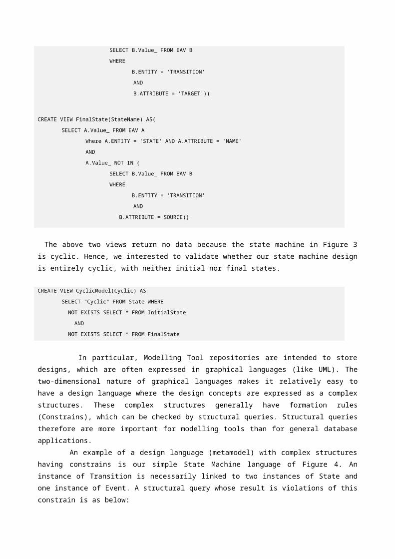
The above two views return no data because the state machine in Figure 3is cyclic. Hence, we interested to validate whether our state machine designis entirely cyclic, with neither initial nor final states.
CREATE VIEW CyclicModel(Cyclic) AS
SELECT "Cyclic" FROM State WHERE
NOT EXISTS SELECT * FROM InitialState
AND
NOT EXISTS SELECT * FROM FinalState
In particular, Modelling Tool repositories are intended to storedesigns, which are often expressed in graphical languages (like UML). Thetwo-dimensional nature of graphical languages makes it relatively easy tohave a design language where the design concepts are expressed as a complexstructures. These complex structures generally have formation rules(Constrains), which can be checked by structural queries. Structural queriestherefore are more important for modelling tools than for general databaseapplications. An example of a design language (metamodel) with complex structures
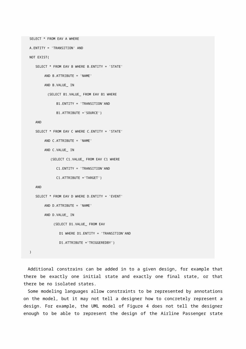
having constrains is our simple State Machine language of Figure 4. Aninstance of Transition is necessarily linked to two instances of State andone instance of Event. A structural query whose result is violations of thisconstrain is as below:
SELECT * FROM EAV A WHERE
A.ENTITY = 'TRANSITION' AND
NOT EXIST(
SELECT * FROM EAV B WHERE B.ENTITY = 'STATE'
AND B.ATTRIBUTE = 'NAME'
AND B.VALUE_ IN
(SELECT B1.VALUE_ FROM EAV B1 WHERE
B1.ENTITY = 'TRANSITION'AND
B1.ATTRIBUTE ='SOURCE')
AND
SELECT * FROM EAV C WHERE C.ENTITY = 'STATE'
AND C.ATTRIBUTE = 'NAME'
AND C.VALUE_ IN
(SELECT C1.VALUE_ FROM EAV C1 WHERE
C1.ENTITY = 'TRANSITION'AND
C1.ATTRIBUTE ='TARGET')
AND
SELECT * FROM EAV D WHERE D.ENTITY = 'EVENT'
AND D.ATTRIBUTE = 'NAME'
AND D.VALUE_ IN
(SELECT D1.VALUE_ FROM EAV
D1 WHERE D1.ENTITY = 'TRANSITION'AND
D1.ATTRIBUTE ='TRIGGEREDBY')
)
Additional constrains can be added in to a given design, for example thatthere be exactly one initial state and exactly one final state, or thatthere be no isolated states. Some modeling languages allow constraints to be represented by annotations
on the model, but it may not tell a designer how to concretely represent adesign. For example, the UML model of Figure 4 does not tell the designerenough to be able to represent the design of the Airline Passenger state
model so that it looks like Figure 3. To do this, the conceptual model mustbe augmented by some rendering conventions. However, we are implementingthis by joining both, model and metamodel presented in Figure 3 and Figure 4respectively in a single EAV structure, that we introduced in[19] as a novelopen source metamodel concept.In the next part we presented an EAV representation for a computer
platform and a platform model designed by EAV.
3.2.EAV Representation for Computer PlatformIn section 3.1 we show EAV capabilities in representation of models and
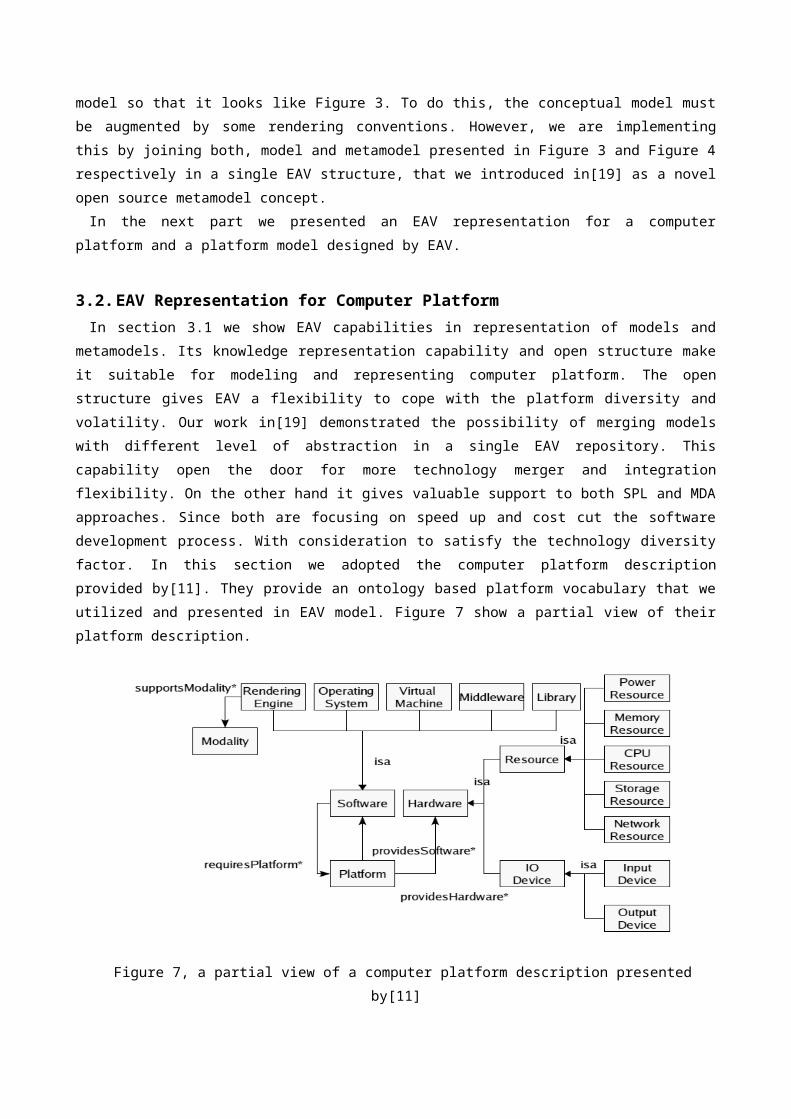
metamodels. Its knowledge representation capability and open structure makeit suitable for modeling and representing computer platform. The openstructure gives EAV a flexibility to cope with the platform diversity andvolatility. Our work in[19] demonstrated the possibility of merging modelswith different level of abstraction in a single EAV repository. Thiscapability open the door for more technology merger and integrationflexibility. On the other hand it gives valuable support to both SPL and MDAapproaches. Since both are focusing on speed up and cost cut the softwaredevelopment process. With consideration to satisfy the technology diversityfactor. In this section we adopted the computer platform descriptionprovided by[11]. They provide an ontology based platform vocabulary that weutilized and presented in EAV model. Figure 7 show a partial view of theirplatform description.
Figure 7, a partial view of a computer platform description presentedby[11]
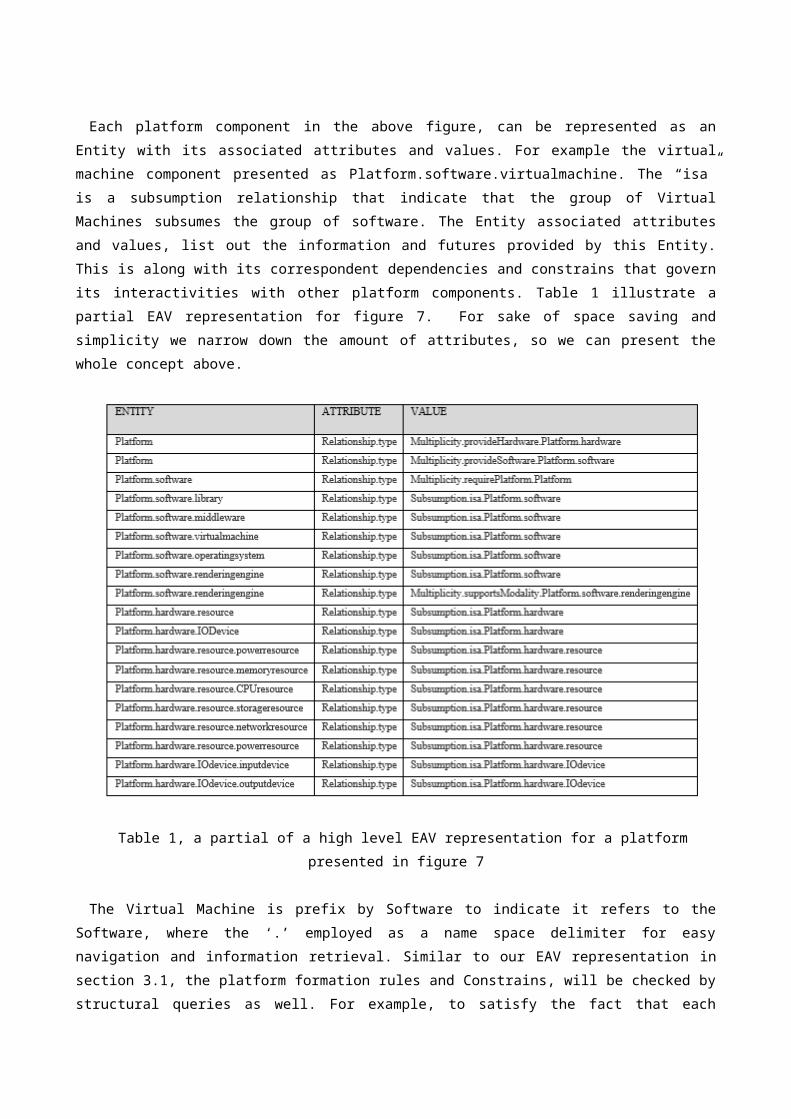
Each platform component in the above figure, can be represented as anEntity with its associated attributes and values. For example the virtualmachine component presented as Platform.software.virtualmachine. The “isa”is a subsumption relationship that indicate that the group of VirtualMachines subsumes the group of software. The Entity associated attributesand values, list out the information and futures provided by this Entity.This is along with its correspondent dependencies and constrains that governits interactivities with other platform components. Table 1 illustrate apartial EAV representation for figure 7. For sake of space saving andsimplicity we narrow down the amount of attributes, so we can present thewhole concept above.
Table 1, a partial of a high level EAV representation for a platformpresented in figure 7
The Virtual Machine is prefix by Software to indicate it refers to theSoftware, where the ‘.’ employed as a name space delimiter for easynavigation and information retrieval. Similar to our EAV representation insection 3.1, the platform formation rules and Constrains, will be checked bystructural queries as well. For example, to satisfy the fact that each
software platform is in a cyclical relationship with software and hardwareplatform.
SELECT * FROM EAV_PM AS B
WHERE
B.ENTITY IN (SELECT SUBSTR( A.VALUE_ , -8, 8 ) FROM EAV_PM AS A
WHERE
B.ENTITY = SUBSTR( A.VALUE_ , -8, 8 )
)
The highlighted output results in the below XML format illustrated thatfor each software platform there are multiple hardware and software platforminvolved. Having the constrains among other EAV PM results on XML, open thedoor for more integration possibilities with different tools in differentbranch streams concerned with model and software development automation andcode generation.
<database name="test">
<!-- Table eav_pm -->
<table name="eav_pm">
<column name="ENTITY">Platform</column>
<column name="ATTRIBUTE">Relationship.type</column>
<column name="VALUE_">Multiplicity.provideHardware.Platform.hardware</column>
</table>
<table name="eav_pm">
<column name="ENTITY">Platform</column>
<column name="ATTRIBUTE">Relationship.type</column>
<column name="VALUE_">Multiplicity.provideSoftware.Platform.software</column>
</table>
</database>
The high abstract level platform representation in figure 7, can beextended to detailed lower levels of abstraction. For example the JavaRuntime Environment (JRE) in figure 8 come with Java Virtual Machine.
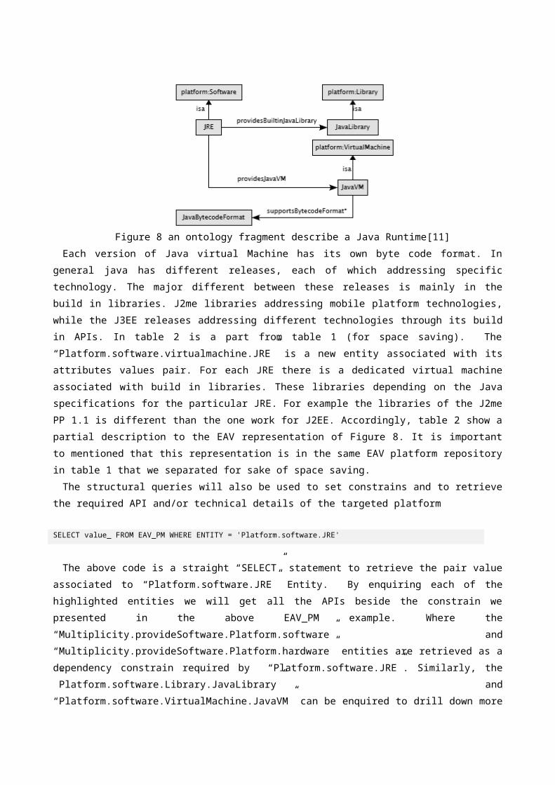
Figure 8 an ontology fragment describe a Java Runtime[11]Each version of Java virtual Machine has its own byte code format. In
general java has different releases, each of which addressing specifictechnology. The major different between these releases is mainly in thebuild in libraries. J2me libraries addressing mobile platform technologies,while the J3EE releases addressing different technologies through its buildin APIs. In table 2 is a part from table 1 (for space saving). The“Platform.software.virtualmachine.JRE” is a new entity associated with itsattributes values pair. For each JRE there is a dedicated virtual machineassociated with build in libraries. These libraries depending on the Javaspecifications for the particular JRE. For example the libraries of the J2mePP 1.1 is different than the one work for J2EE. Accordingly, table 2 show apartial description to the EAV representation of Figure 8. It is importantto mentioned that this representation is in the same EAV platform repositoryin table 1 that we separated for sake of space saving.The structural queries will also be used to set constrains and to retrieve
the required API and/or technical details of the targeted platform
SELECT value_ FROM EAV_PM WHERE ENTITY = 'Platform.software.JRE'
The above code is a straight “SELECT” statement to retrieve the pair valueassociated to “Platform.software.JRE” Entity. By enquiring each of thehighlighted entities we will get all the APIs beside the constrain wepresented in the above EAV_PM example. Where the“Multiplicity.provideSoftware.Platform.software” and“Multiplicity.provideSoftware.Platform.hardware” entities are retrieved as adependency constrain required by “Platform.software.JRE”. Similarly, the”Platform.software.Library.JavaLibrary” and“Platform.software.VirtualMachine.JavaVM” can be enquired to drill down more
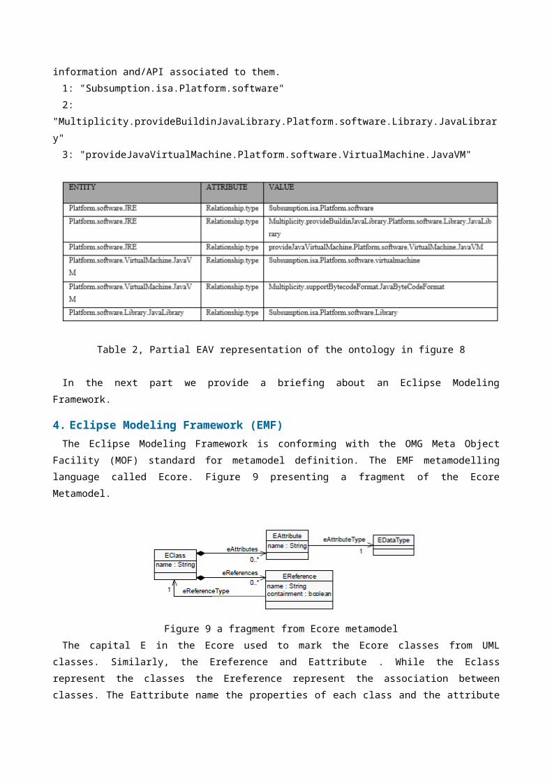
information and/API associated to them.1: "Subsumption.isa.Platform.software"2:
"Multiplicity.provideBuildinJavaLibrary.Platform.software.Library.JavaLibrary"3: "provideJavaVirtualMachine.Platform.software.VirtualMachine.JavaVM"
Table 2, Partial EAV representation of the ontology in figure 8
In the next part we provide a briefing about an Eclipse ModelingFramework.
4. Eclipse Modeling Framework (EMF)The Eclipse Modeling Framework is conforming with the OMG Meta Object
Facility (MOF) standard for metamodel definition. The EMF metamodellinglanguage called Ecore. Figure 9 presenting a fragment of the EcoreMetamodel.
Figure 9 a fragment from Ecore metamodelThe capital E in the Ecore used to mark the Ecore classes from UML
classes. Similarly, the Ereference and Eattribute . While the Eclassrepresent the classes the Ereference represent the association betweenclasses. The Eattribute name the properties of each class and the attribute
type address by the Etype. Beside the Ecore, the EMF has another metamodel called Genmodel. While the
Ecore handle the information about the defined classes. The Genmodel,provide the necessary information required from code generation. Among other transformation tools we adopted the RMF for its modelling
capability where a domain model is visibly established. This is beside thenotification feature the EMF provided upon model modification. Also, the EMFmanaging changes in models upon object creation through its notificationfeature. Consequently, applications will be immune from discrete classes’employment. On the other hand, the targeted code (Java code) can begenerated when desired from the source model.In the next part a case study introduced to demonstrate the MDA
capabilities in software productivity and to show the transformation fromPSM to Java code utilizing the explicit EAV platform model. The EMF versionadopted to implement this case study is Eclipse Juno Service Release 21.
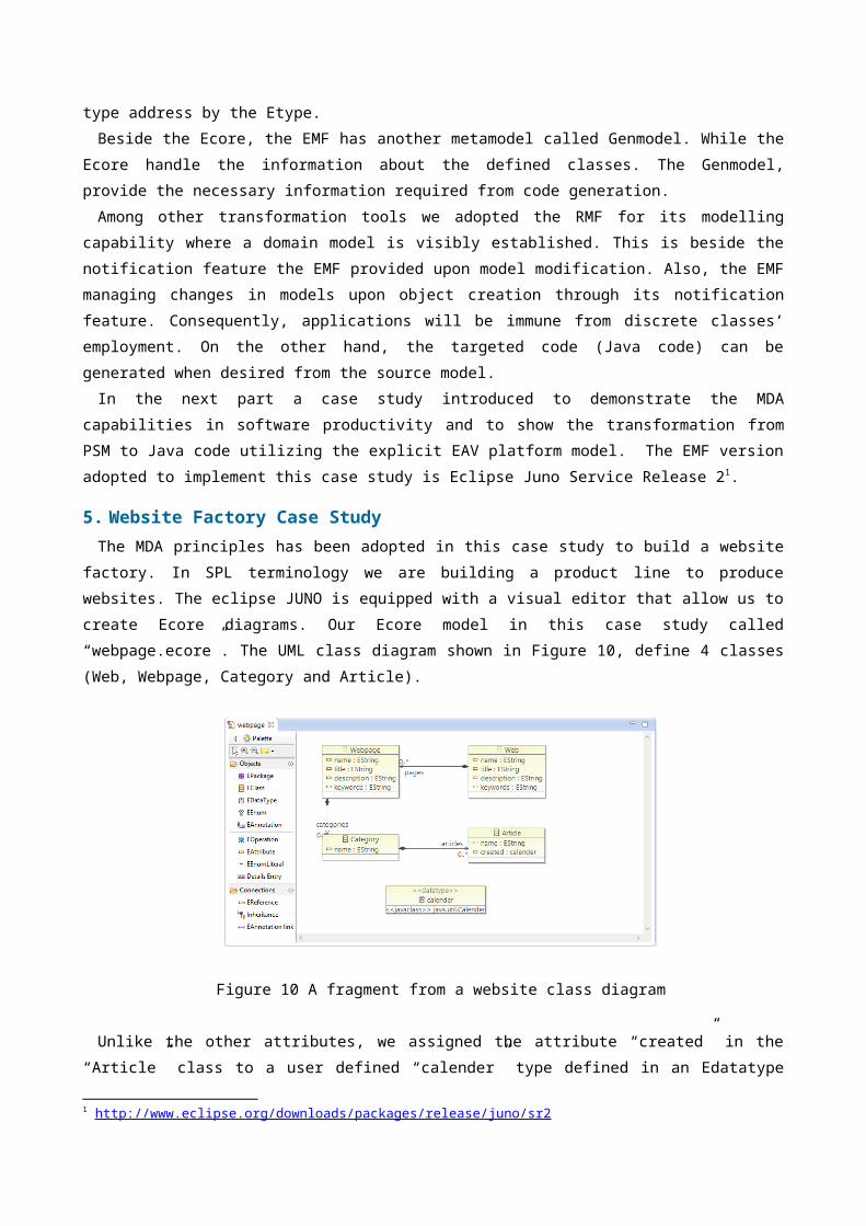
5. Website Factory Case Study The MDA principles has been adopted in this case study to build a website
factory. In SPL terminology we are building a product line to producewebsites. The eclipse JUNO is equipped with a visual editor that allow us tocreate Ecore diagrams. Our Ecore model in this case study called“webpage.ecore”. The UML class diagram shown in Figure 10, define 4 classes(Web, Webpage, Category and Article).
Figure 10 A fragment from a website class diagram Unlike the other attributes, we assigned the attribute “created” in the
“Article” class to a user defined “calender” type defined in an Edatatype
1 http://www.eclipse.org/downloads/packages/release/juno/sr2
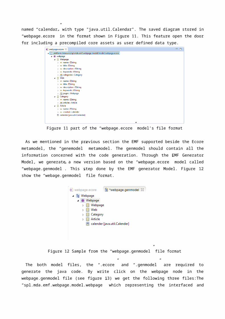
named “calendar” with type "java.util.Calendar". The saved diagram stored in“webpage.ecore” in the format shown in Figure 11. This feature open the doorfor including a precompiled core assets as user defined data type.
Figure 11 part of the “webpage.ecore” model’s file format
As we mentioned in the previous section the EMF supported beside the Ecoremetamodel, the “genemodel” metamodel. The genmodel should contain all theinformation concerned with the code generation. Through the EMF GeneratorModel, we generate a new version based on the “webpage.ecore” model called“webpage.genmodel”. This step done by the EMF generator Model. Figure 12show the “webage.genmodel” file format.
Figure 12 Sample from the “webpage.genmodel” file format
The both model files, the “.ecore” and “.genmodel” are required togenerate the java code. By write click on the webpage node in thewebpage.genmodel file (see figure 13) we get the following three files:The“spl.mda.emf.webpage.model.webpage” which representing the interfaced and
the factory to great the Java classes. While the second is the“spl.mda.emf.webpage.model.webpage.impl” which holding the concrete code ofthe webpage model. The last is file is the“spl.mda.emf.webpage.model.webpage.util” which act as the adaptor factory.
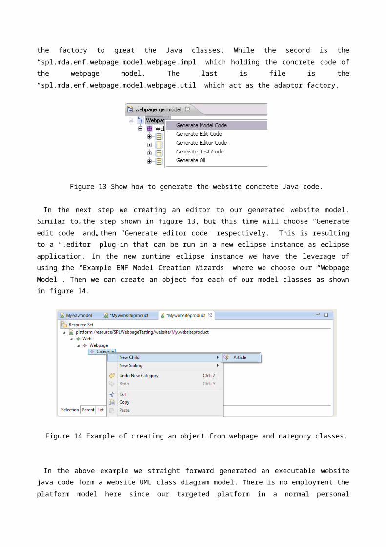
Figure 13 Show how to generate the website concrete Java code.
In the next step we creating an editor to our generated website model.Similar to the step shown in figure 13, but this time will choose “Generateedit code” and then “Generate editor code” respectively. This is resultingto a “.editor” plug-in that can be run in a new eclipse instance as eclipseapplication. In the new runtime eclipse instance we have the leverage ofusing the “Example EMF Model Creation Wizards” where we choose our “WebpageModel”. Then we can create an object for each of our model classes as shownin figure 14.
Figure 14 Example of creating an object from webpage and category classes.
In the above example we straight forward generated an executable websitejava code form a website UML class diagram model. There is no employment theplatform model here since our targeted platform in a normal personal
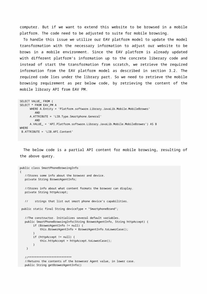
computer. But if we want to extend this website to be browsed in a mobileplatform. The code need to be adjusted to suite for mobile browsing. To handle this issue we utilize our EAV platform model to update the model
transformation with the necessary information to adjust our website to bebrows in a mobile environment. Since the EAV platform is already updatedwith different platform’s information up to the concrete liberary code andinstead of start the transformation from scratch, we retrieve the requiredinformation from the EAV platform model as described in section 3.2. Therequired code lies under the library part. So we need to retrieve the mobilebrowsing requirement as per below code, by retrieving the content of themobile library API from EAV PM.
SELECT VALUE_ FROM (SELECT * FROM EAV_PM A WHERE A.Entity = ‘Platform.software.Library.JavaLib.Mobile.MobileBrowes’ AND A.ATTRIBUTE = ‘LIB.Type.Smartphone.General’ AND A.VALUE_ = ‘API.Platform.software.Library.JavaLib.Mobile.MobileBrowes’) AS BWHERE B.ATTRIBUTE = ‘LIB.API.Content’
The below code is a partial API content for mobile browsing, resulting ofthe above query.
public class SmartPhoneBrowsingInfo{ //Stores some info about the browser and device. private String BrowerAgentInfo;
//Stores info about what content formats the browser can display. private String httpAccept;
// strings that list out smart phone device’s capabilities.
public static final String deviceType = "SmartphoneBrand";
//The constructor. Initializes several default variables. public SmartPhoneBrowsingInfo(String BrowerAgentInfo, String httpAccept) { if (BrowerAgentInfo != null) { this.BrowerAgentInfo = BrowerAgentInfo.toLowerCase(); } if (httpAccept != null) { this.httpAccept = httpAccept.toLowerCase(); } }
//************************** //Returns the contents of the broweser Agent value, in lower case. public String getBrowerAgentInfo()
{ return BrowerAgentInfo; }
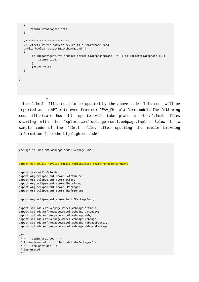
//************************** // Detects if the current device is a SmartphoneBrand. public boolean detectSmartphoneBrand () { if (BrowerAgentInfo.indexOf(device SmartphoneBrand) != -1 && !detectsmartphone()) { return true; } return false; }
}
The “.Impl” files need to be updated by the above code. This code will beimported as an API retrieved from our “EAV_PM” platform model. The followingcode illustrate how this update will take place in the “.Impl” filesstarting with the “spl.mda.emf.webpage.model.webpage.impl”. Below is asample code of the “.Impl” file, after updating the mobile browsinginformation (see the highlighted code).
package spl.mda.emf.webpage.model.webpage.impl;
import eav_pm.lib.javalib.mobile.mobilebrowse.SmartPhoneBrowsingInfo
import java.util.Calender;import org.eclipse.emf.ecore.EAttribute;import org.eclipse.emf.ecore.EClass;import org.eclipse.emf.ecore.EDataType;import org.eclipse.emf.ecore.EPackage;import org.eclipse.emf.ecore.EReference;
import org.eclipse.emf.ecore.impl.EPackageImpl;
import spl.mda.emf.webpage.model.webpage.Article;import spl.mda.emf.webpage.model.webpage.Category;import spl.mda.emf.webpage.model.webpage.Web;import spl.mda.emf.webpage.model.webpage.Webpage;import spl.mda.emf.webpage.model.webpage.WebpageFactory;import spl.mda.emf.webpage.model.webpage.WebpagePackage;
/** * <!-- begin-user-doc --> * An implementation of the model <b>Package</b>. * <!-- end-user-doc --> * @generated */
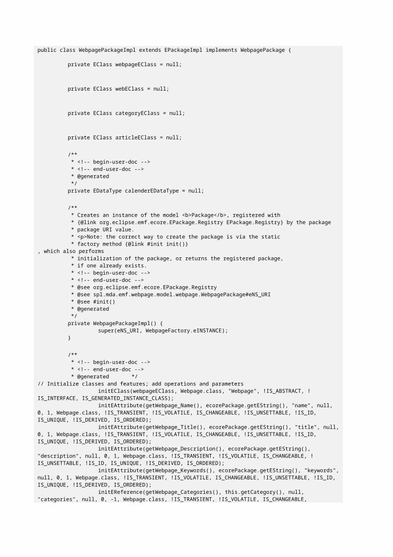
public class WebpagePackageImpl extends EPackageImpl implements WebpagePackage {
private EClass webpageEClass = null;
private EClass webEClass = null;
private EClass categoryEClass = null;
private EClass articleEClass = null;
/** * <!-- begin-user-doc --> * <!-- end-user-doc --> * @generated */private EDataType calenderEDataType = null;
/** * Creates an instance of the model <b>Package</b>, registered with * {@link org.eclipse.emf.ecore.EPackage.Registry EPackage.Registry} by the package * package URI value. * <p>Note: the correct way to create the package is via the static * factory method {@link #init init()}
, which also performs * initialization of the package, or returns the registered package, * if one already exists. * <!-- begin-user-doc --> * <!-- end-user-doc --> * @see org.eclipse.emf.ecore.EPackage.Registry * @see spl.mda.emf.webpage.model.webpage.WebpagePackage#eNS_URI * @see #init() * @generated */private WebpagePackageImpl() {
super(eNS_URI, WebpageFactory.eINSTANCE);}
/** * <!-- begin-user-doc --> * <!-- end-user-doc --> * @generated */
// Initialize classes and features; add operations and parametersinitEClass(webpageEClass, Webpage.class, "Webpage", !IS_ABSTRACT, !
IS_INTERFACE, IS_GENERATED_INSTANCE_CLASS);initEAttribute(getWebpage_Name(), ecorePackage.getEString(), "name", null,
0, 1, Webpage.class, !IS_TRANSIENT, !IS_VOLATILE, IS_CHANGEABLE, !IS_UNSETTABLE, !IS_ID, IS_UNIQUE, !IS_DERIVED, IS_ORDERED);
initEAttribute(getWebpage_Title(), ecorePackage.getEString(), "title", null,0, 1, Webpage.class, !IS_TRANSIENT, !IS_VOLATILE, IS_CHANGEABLE, !IS_UNSETTABLE, !IS_ID, IS_UNIQUE, !IS_DERIVED, IS_ORDERED);
initEAttribute(getWebpage_Description(), ecorePackage.getEString(), "description", null, 0, 1, Webpage.class, !IS_TRANSIENT, !IS_VOLATILE, IS_CHANGEABLE, !IS_UNSETTABLE, !IS_ID, IS_UNIQUE, !IS_DERIVED, IS_ORDERED);
initEAttribute(getWebpage_Keywords(), ecorePackage.getEString(), "keywords",null, 0, 1, Webpage.class, !IS_TRANSIENT, !IS_VOLATILE, IS_CHANGEABLE, !IS_UNSETTABLE, !IS_ID, IS_UNIQUE, !IS_DERIVED, IS_ORDERED);
initEReference(getWebpage_Categories(), this.getCategory(), null, "categories", null, 0, -1, Webpage.class, !IS_TRANSIENT, !IS_VOLATILE, IS_CHANGEABLE,
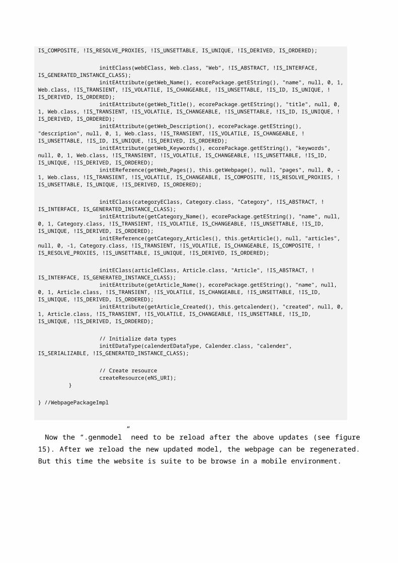
IS_COMPOSITE, !IS_RESOLVE_PROXIES, !IS_UNSETTABLE, IS_UNIQUE, !IS_DERIVED, IS_ORDERED);
initEClass(webEClass, Web.class, "Web", !IS_ABSTRACT, !IS_INTERFACE, IS_GENERATED_INSTANCE_CLASS);
initEAttribute(getWeb_Name(), ecorePackage.getEString(), "name", null, 0, 1,Web.class, !IS_TRANSIENT, !IS_VOLATILE, IS_CHANGEABLE, !IS_UNSETTABLE, !IS_ID, IS_UNIQUE, !IS_DERIVED, IS_ORDERED);
initEAttribute(getWeb_Title(), ecorePackage.getEString(), "title", null, 0, 1, Web.class, !IS_TRANSIENT, !IS_VOLATILE, IS_CHANGEABLE, !IS_UNSETTABLE, !IS_ID, IS_UNIQUE, !IS_DERIVED, IS_ORDERED);
initEAttribute(getWeb_Description(), ecorePackage.getEString(), "description", null, 0, 1, Web.class, !IS_TRANSIENT, !IS_VOLATILE, IS_CHANGEABLE, !IS_UNSETTABLE, !IS_ID, IS_UNIQUE, !IS_DERIVED, IS_ORDERED);
initEAttribute(getWeb_Keywords(), ecorePackage.getEString(), "keywords", null, 0, 1, Web.class, !IS_TRANSIENT, !IS_VOLATILE, IS_CHANGEABLE, !IS_UNSETTABLE, !IS_ID, IS_UNIQUE, !IS_DERIVED, IS_ORDERED);
initEReference(getWeb_Pages(), this.getWebpage(), null, "pages", null, 0, -1, Web.class, !IS_TRANSIENT, !IS_VOLATILE, IS_CHANGEABLE, IS_COMPOSITE, !IS_RESOLVE_PROXIES, !IS_UNSETTABLE, IS_UNIQUE, !IS_DERIVED, IS_ORDERED);
initEClass(categoryEClass, Category.class, "Category", !IS_ABSTRACT, !IS_INTERFACE, IS_GENERATED_INSTANCE_CLASS);
initEAttribute(getCategory_Name(), ecorePackage.getEString(), "name", null, 0, 1, Category.class, !IS_TRANSIENT, !IS_VOLATILE, IS_CHANGEABLE, !IS_UNSETTABLE, !IS_ID, IS_UNIQUE, !IS_DERIVED, IS_ORDERED);
initEReference(getCategory_Articles(), this.getArticle(), null, "articles", null, 0, -1, Category.class, !IS_TRANSIENT, !IS_VOLATILE, IS_CHANGEABLE, IS_COMPOSITE, !IS_RESOLVE_PROXIES, !IS_UNSETTABLE, IS_UNIQUE, !IS_DERIVED, IS_ORDERED);
initEClass(articleEClass, Article.class, "Article", !IS_ABSTRACT, !IS_INTERFACE, IS_GENERATED_INSTANCE_CLASS);
initEAttribute(getArticle_Name(), ecorePackage.getEString(), "name", null, 0, 1, Article.class, !IS_TRANSIENT, !IS_VOLATILE, IS_CHANGEABLE, !IS_UNSETTABLE, !IS_ID, IS_UNIQUE, !IS_DERIVED, IS_ORDERED);
initEAttribute(getArticle_Created(), this.getcalender(), "created", null, 0,1, Article.class, !IS_TRANSIENT, !IS_VOLATILE, IS_CHANGEABLE, !IS_UNSETTABLE, !IS_ID, IS_UNIQUE, !IS_DERIVED, IS_ORDERED);
// Initialize data typesinitEDataType(calenderEDataType, Calender.class, "calender",
IS_SERIALIZABLE, !IS_GENERATED_INSTANCE_CLASS);
// Create resourcecreateResource(eNS_URI);
}
} //WebpagePackageImpl
Now the “.genmodel” need to be reload after the above updates (see figure15). After we reload the new updated model, the webpage can be regenerated.But this time the website is suite to be browse in a mobile environment.
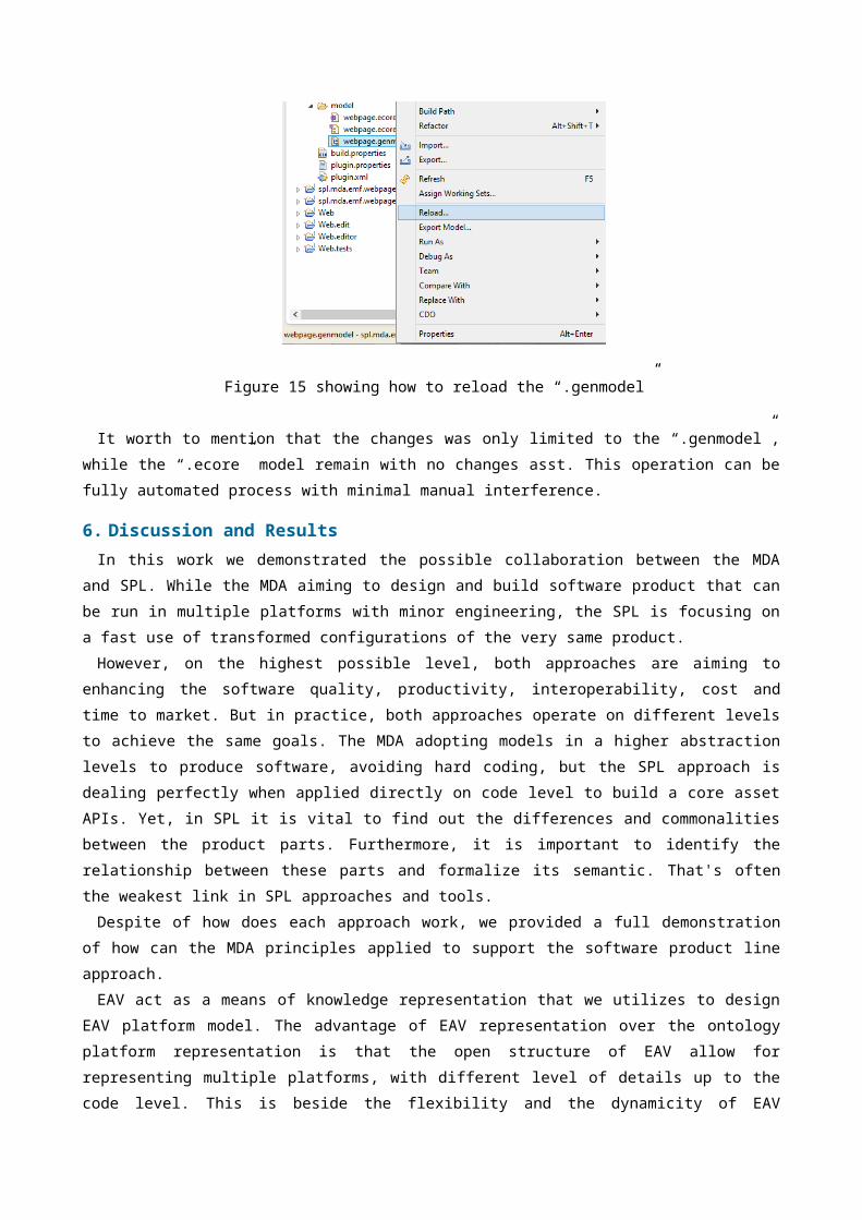
Figure 15 showing how to reload the “.genmodel”
It worth to mention that the changes was only limited to the “.genmodel”,while the “.ecore” model remain with no changes asst. This operation can befully automated process with minimal manual interference.
6. Discussion and ResultsIn this work we demonstrated the possible collaboration between the MDA
and SPL. While the MDA aiming to design and build software product that canbe run in multiple platforms with minor engineering, the SPL is focusing ona fast use of transformed configurations of the very same product.However, on the highest possible level, both approaches are aiming to
enhancing the software quality, productivity, interoperability, cost andtime to market. But in practice, both approaches operate on different levelsto achieve the same goals. The MDA adopting models in a higher abstractionlevels to produce software, avoiding hard coding, but the SPL approach isdealing perfectly when applied directly on code level to build a core assetAPIs. Yet, in SPL it is vital to find out the differences and commonalitiesbetween the product parts. Furthermore, it is important to identify therelationship between these parts and formalize its semantic. That's oftenthe weakest link in SPL approaches and tools. Despite of how does each approach work, we provided a full demonstration
of how can the MDA principles applied to support the software product lineapproach. EAV act as a means of knowledge representation that we utilizes to design
EAV platform model. The advantage of EAV representation over the ontologyplatform representation is that the open structure of EAV allow forrepresenting multiple platforms, with different level of details up to thecode level. This is beside the flexibility and the dynamicity of EAV
structure in defining and representing any upcoming new platform ormodifying the current one. On the other hand, the possibility of presenting EAV platform model in XML
format is giving an integration room with different systems, tools andapproaches. For example EAV platform can be used as a core asset repositoryin any software product line. The platform information and APIs can bestored and retrieved from it. Consequently, Both MDA and SPL can share thisplatform model as a centric area of collaboration, integration andinformation exchange. The SPL core assets can be stored in the EAV Platformmodel adopting the same semantic presented in this work. This willpositively reflected on the number of platforms that the modeltransformation can support. This collaboration between the two approacheswill complement each other and will enhance the quality and productivity ofsoftware. From other prospective the possibility of EAV platform XML formatcan be updated by the platform vendor’s website feeds (RSS). This way theplatform model will be up to day with new platform releases or versions.Consequently, the software productivity will rapidly increase supporting agreat number of platform with minimal changes and cost effective. While thecoding effort can be shifted in more architectural and design work toimprove the software quality. On top of the above, the explicit employment of EAV platform model a great
support to the model evolution: with proper mechanisms and tools like theEMF in place, there is a flexibility to ensure that models will work, openin editors, produce the code etc. with the newer metamodel too (e.g. updatesautomatically the models to the new metamodel).There are also other advantages like faster metamodel/language
development, easier management, possibility to couple various generatorsbased on the metamodel together, etc. The think that support softwareproduct line productivity as well. The limitation of the EAV Platform model is inherited from EAV
representation drawbacks. Where a considerable up-front programming isneeded to do many tasks that a conventional architecture would doautomatically. Moreover, such programming needs to be done only once, andavailability of generic EAV tools could remove this limitation. Also, forbulk retrieval EAV design is considered less ef cient than a conventionalfistructure. Consequently, performing complex attribute-centric queries, whichare based on values of attributes, and returning a set of objects is bothsigni cantly less ef cient as well as technically more dif cult.fi fi fi
7. Conclusion and Future workComputer platforms are combining a set of features and component that
allow to formally control different functions and contexts(Hardware/software activities) that normally limited to a particular streamof technology. Having a capability of representing multiple platforms fordifferent technologies in different levels of abstraction, in a single EAVrepository, is dramatically increasing the quality and the productivity ofthe software development process. In other word we show how the MDAprinciples can contribute positively in software quality and productivity ingeneral, and in particular how the collaboration between the MDA and SPL canbe useful for both approaches. The EAV platform introduced in this work as a novel approach that
explicitly employed to support the transformation from PSM models to javacode. The EMF used for modeling, transformation and code generation. TheWebsite factory case study presented to show the MDA capability in producingend to end software product. The website designed for desktop browsing.However, we put the EAV platform in action to update the modeltransformation by retrieving the mobile browsing information from EAVplatform model. The model reloaded and regenerated in a mobile browsefriendly version with minimal interference and modification. In the near future the focus will be on the automatic update of the EAV
platform. Where the Domain Specific Language will be explored as a solutionto produce a user friendly interface that allow easy update to EAV platformmodel. Also, we intend to create a plug-in to automatically update EAVplatform model from the vendor’s website feeds. More case studies will be implemented to target different platforms other
than java for more testing and to generalization.
AcknowledgmentThe authors would like to express their deepest gratitude to Universiti
Teknologi Malaysia (UTM) for their financial support under ResearchUniversity Grant Scheme.
References
[1] K. Pohl, G. Böckle, and F. Van Der Linden, Software product line engineering:foundations, principles, and techniques: Springer, 2005.
[2] D. S. Frankel, MODEL DRIVEN ARCHITECTURE APPLYING MDA: Wiley. com, 2003.[3] P. Clements and L. Northrop, Software product lines: Addison-Wesley Boston,
2002.
[4] L. M. Northrop, "SEI's software product line tenets," Software, IEEE, vol.19, pp. 32-40, 2002.
[5] P. HEYMANS, J.-C. TRIGAUX, and F. E. Objectif, "Software productlines: State of the art," 2003.
[6] OMG Document: formal/01-11-02, "OMG: Meta Object Facility (MOF)v1.3.1," in OMG Document: formal, ed, 2001.
[7] O. D. formal/01-09-67, "OMG: Unified Modeling Language v1.4. OMGDocument: formal/01-09-67, Sept.
2001.," ed, 2001.[8] B. Dobing and J. Parsons, "Dimensions of UML diagram use: a survey of
practitioners," Journal of Database Management ( JDM), vol. 19, pp. 1-18, 2008.[9] K. Czarnecki and S. Helsen, "Classification of model transformation
approaches," in Proceedings of the 2nd OOPSLA Workshop on Generative Techniques inthe Context of the Model Driven Architecture, 2003, pp. 1-17.
[10] A. Hamed and R. M. Colomb, "End to End Development Engineering," JSEA,vol. 4, pp. 195-216, 2011.
[11] D. Wagelaar and R. Van Der Straeten, "Platform ontologies for themodel-driven architecture," European Journal of Information Systems, vol. 16,pp. 362-373, 2007.
[12] N. F. Noy and M. A. Musen, "Algorithm and tool for automated ontologymerging and alignment," in Proceedings of the 17th National Conference on ArtificialIntelligence (AAAI-00). Available as SMI technical report SMI-2000-0831, 2000.
[13] O. Corcho, M. Fernández-López, and A. Gómez-Pérez, "Methodologies,tools and languages for building ontologies. Where is their meetingpoint?," Data & knowledge engineering, vol. 46, pp. 41-64, 2003.
[14] P. Kremen, M. Smid, and Z. Kouba, "OWLDiff: A practical tool forcomparison and merge of OWL ontologies," in Database and Expert SystemsApplications (DEXA), 2011 22nd International Workshop on, 2011, pp. 229-233.
[15] A. Flahive, D. Taniar, and W. Rahayu, "Ontology as a service (OaaS): acase for sub-ontology merging on the cloud," The Journal of Supercomputing,vol. 65, pp. 185-216, 2013.
[16] V. Dinu and P. Nadkarni, "Guidelines for the effective use of entity-attribute-value modeling for biomedical databases," International journal ofmedical informatics, vol. 76, p. 769, 2007.
[17] T. Kiefer and M. M. Nicola, "Generating structured querylanguage/extensible markup language (SQL/XML) statements," ed: GooglePatents, 2012.
[18] R. M. Colomb, "Metamodelling and Model-Driven Architecture," Faculty ofComputer Science and Information Systems
University of Technology Malaysia, vol. 1, 2009 2009.[19] A. M. ELSAWI, S. SAHIBULDIN, and A. ABDELHADI, "INTRODUCING THE OPEN
SOURCE METAMODEL CONCEPT," Journal of Theoretical & Applied Information Technology,vol. 57, 2013.
Mr. Elsawi received the degree in computer science &information Technology from Computer Man College for ComputerStudies, in 2000. His master degree in Computer Science as well(2002). Currently, he is pursuing with a PhD in the field ofModel Driven Architecture at Universiti Teknologi Malaysia –Kuala Lumpur, Malaysia.
Ahmed is experienced business Intelligence and enterprise architectureproffessional. He is a ITIL certified who worked in different mobilecompanies in Sudan, South Sudan and Afghanistan.
Prof. Dr. Shamsul Sahibuddin is the Professor and Dean of theAdvanced Informatics School (AIS) at Universiti TeknologiMalaysia (UTM) Kuala Lumpur, Malaysia. His research interest isSoftware Process, Software Quality, and Software Modeling.