model 458-lm-a2-18
TRANSCRIPT
“Results You Can Count On”
Model 458-LM-A2-18 Local Loop Simulator
0315-0352 Rev. - Date of Publication: 12/03/04
Customer Support
Thank you for your purchase of the Telebyte Model 458-LM-A2-18 Local Loop Simulator, featuring 2 channels that simulate 24 and 26 AWG PIC as specified in T1.417. Contact Information: Telephone E-mail/Internet General: 631-423-3232 [email protected] Technical support: 800-835-3298 [email protected] Fax: 631-385-8184 www.telebytebroadband.com Mail Telebyte, Inc. 270 Pulaski Road Greenlawn, NY 11740
Warranty
Included With Your Purchase
One-year Warranty
• Telebyte will furnish parts and labor for the repair or replacement of products found by Telebyte to be defective
in material or workmanship during the warranty period.1
One-year Calibration (where applicable)
• One N.I.S.T. traceable calibration on the first-year anniversary of the product ship date.2
• Calibration report to ensure traceability.
Extended Customer Care
There are two options available. Our three-year extended warranty extends the original warranty by an additional 36 months and the three-year calibration contract provides 36 additional months of calibration.
Three-Year Extended Warranty
You can extend the original two-year warranty that comes with your product by purchasing the Three-Year
Extended Warranty.3
Features:
· Telebyte will furnish parts and labor for the repair or replacement of products found by Telebyte to be defective in material or workmanship during the
warranty period.1
Three-Year Calibration Contract (where applicable)
Extended calibration is available through the Three-Year
Calibration Contract.4
Features:
· Yearly N.I.S.T. traceable calibrations, each on the
second, third and fourth anniversary of the ship date.2
· Report to ensure traceability.
· Automatic notification when calibration of your product is due.
Disclaimer of Warranties and Other Terms and Conditions 1 TELEBYTE, INC. warrants its broadband simulation equipment to be free from defects in material and workmanship, under normal and proper use and in its unmodified condition, for 12-months, starting on the date it is delivered for use. TELEBYTE’S sole obligation under this warranty shall be to furnish parts and labor for the repair or replacement of products found by TELEBYTE to be defective in material or workmanship during the warranty period. Warranty repairs will be performed at the point of manufacture. Equipment approved for return for warranty service shall be returned F.O.B. TELEBYTE factory and will be redelivered by TELEBYTE freight prepaid, except for non-continental U.S.A. locations. These deliveries will be sent COD freight and import/export charges. 2 The customer is responsible for freight and customs charges when shipping products to and from Telebyte for calibration services. 3 You must purchase the extended warranty at the time of purchase or during the initial warranty period. 4 You must purchase the calibration contract at the time of purchase or during the initial warranty period. The above warranty is in lieu of all other warranties, expressed or implied, statutory or otherwise, including any implied warranty of merchantability or fitness for a particular purpose. TELEBYTE shall not be liable for any damages sustained by reseller or any other party arising from or relating to any equipment failure, including but not limited to consequential damages, nor shall TELEBYTE have any liability for delays in replacement or repair of equipment.

Equipment Returns
Out of warranty equipment may be returned, prepaid, to the Greenlawn, N.Y. customer service facility. Return shipping charges will be billed to the customer. The repaired unit will have a 90-day warranty. In those cases where "no trouble" is found, a reduced charge will be billed to cover handling, testing, and packaging. Whether in or out of warranty, a Return Material Authorization number (RMA) is required and may be obtained by: Calling customer service at 631-423-3232 or 800-835-3298 Sending a request via Fax at 631-385-8184 E-mailing us at [email protected] Please be sure to reference the RMA number on the outside container.
Table of Contents
1.0 Introduction .................................................................................................................................. 1-1 2.0 Specifications ............................................................................................................................... 2-2
2.1 458-LM-A2-18........................................................................................................................ 2-2 2.2 458-2SL ................................................................................................................................. 2-2 2.3 458-CM.................................................................................................................................. 2-3
3.0 Connections.................................................................................................................................. 3-1
3.1 458-LM-A2-18 ........................................................................................................................ 3-1 3.2 458-2SL/458-CM.................................................................................................................... 3-2 3.2.2 Connections 458-CM/458-2SL IEEE488 Control............................................................... 3-3
4.0 Control .......................................................................................................................................... 4-1
4.1.1 RS-232 (Serial Port) Remote Commands .......................................................................... 4-1 4.1.2 IEEE 488 (GPIB) Remote Commands............................................................................... 4-4 4.2 Graphical User Interface ....................................................................................................... 4-8 4.3 LCD Display (458-2SL) .......................................................................................................... 4-9
Model 458-LM-A2-18 Local Loop Simulator Rev - Page 1-1
1.0 Introduction
The Model 458-LM-A2-18 Local Loop Simulator simulates 24 and 26 AWG PIC as specified in T1.417. This plug and play line module provides two channels with loop lengths from 0 to 16,000 ft, in 100-ft increments. Other features include: - Bandwidth to 18 MHz - Accurately simulates attenuation and impedance - 2 channels per line module (one 24 and one 26 AWG) - Plugs into our 458-CC (16-slot chassis) or 458-2SL (2-slot chassis) - Independent control of each channel - Ability to open loop at either end of any channel - MAE <1 dB
Figure 1: Front View of Model 458-LM-A2-18. Both the front and rear of the line module have 4 RJ-45 connectors.
Model 458-LM-A2-18 Local Loop Simulator Rev - Page 2-1
2.0 Specifications
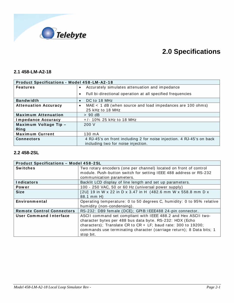
2.1 458-LM-A2-18 Product Specifications - Model 458-LM-A2-18 Features • Accurately simulates attenuation and impedance
• Full bi-directional operation at all specified frequencies
Bandwidth • DC to 18 MHz Attenuation Accuracy • MAE < 1 dB (when source and load impedances are 100 ohms)
25 kHz to 18 MHz Maximum Attenuation > 90 dB Impedance Accuracy +/- 10% 25 kHz to 18 MHz Maximum Voltage Tip –Ring
200 V
Maximum Current 130 mA Connectors 4 RJ-45’s on front including 2 for noise injection. 4 RJ-45’s on back
including two for noise injection.
2.2 458-2SL Product Specifications – Model 458-2SL Switches Two rotary encoders (one per channel) located on front of control
module. Push-button switch for setting IEEE 488 address or RS-232 communication parameters.
Indicators Backlit LCD display of line length and set up parameters. Power 100 - 250 VAC, 50 or 60 Hz (universal power supply) Size [2U] 19 in W x 22 in D x 3.47 in H (482.6 mm W x 558.8 mm D x
88.1 mm H) Environmental Operating temperature: 0 to 50 degrees C, humidity: 0 to 95% relative
humidity (non-condensing). Remote Control Connectors RS-232: DB9 female (DCE); GPIB:IEEE488 24-pin connector. User Command Interface ASCII command set compliant with IEEE 488.2 and Hex ASCII two-
character bytes per 488 bus data byte. RS-232: HDX (Echo characters); Translate CR to CR + LF; baud rate: 300 to 19200; commands use terminating character (carriage return); 8 Data bits; 1 stop bit.
Model 458-LM-A2-18 Local Loop Simulator Rev - Page 2-2
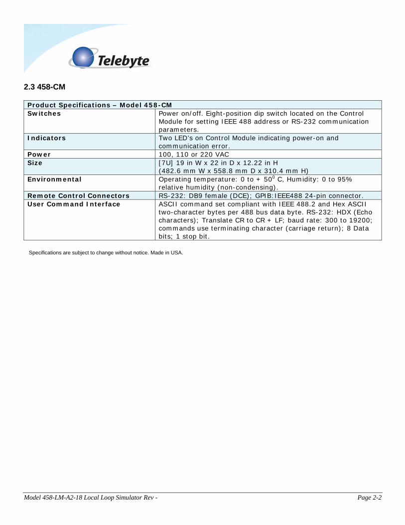
2.3 458-CM Product Specifications – Model 458-CM Switches Power on/off. Eight-position dip switch located on the Control
Module for setting IEEE 488 address or RS-232 communication parameters.
Indicators Two LED’s on Control Module indicating power-on and communication error.
Power 100, 110 or 220 VAC Size [7U] 19 in W x 22 in D x 12.22 in H
(482.6 mm W x 558.8 mm D x 310.4 mm H) Environmental Operating temperature: 0 to + 500 C, Humidity: 0 to 95%
relative humidity (non-condensing). Remote Control Connectors RS-232: DB9 female (DCE); GPIB:IEEE488 24-pin connector. User Command Interface ASCII command set compliant with IEEE 488.2 and Hex ASCII
two-character bytes per 488 bus data byte. RS-232: HDX (Echo characters); Translate CR to CR + LF; baud rate: 300 to 19200; commands use terminating character (carriage return); 8 Data bits; 1 stop bit.
Specifications are subject to change without notice. Made in USA.
Model 458-LM-A2-18 Local Loop Simulator Rev - Page 3-1
3.0 Connections
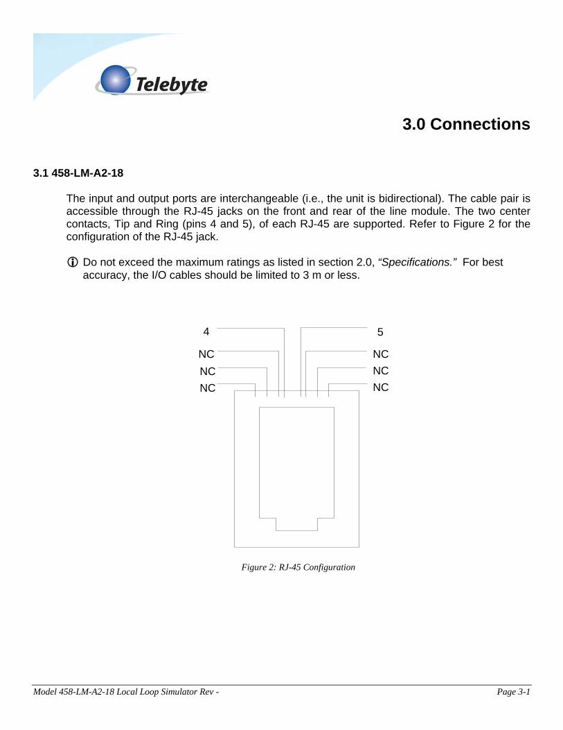
3.1 458-LM-A2-18 The input and output ports are interchangeable (i.e., the unit is bidirectional). The cable pair is accessible through the RJ-45 jacks on the front and rear of the line module. The two center contacts, Tip and Ring (pins 4 and 5), of each RJ-45 are supported. Refer to Figure 2 for the configuration of the RJ-45 jack.
Do not exceed the maximum ratings as listed in section 2.0, “Specifications.” For best accuracy, the I/O cables should be limited to 3 m or less.
NC NC NC
NCNCNC
4 5
Figure 2: RJ-45 Configuration
Model 458-LM-A2-18 Local Loop Simulator Rev - Page 3-2
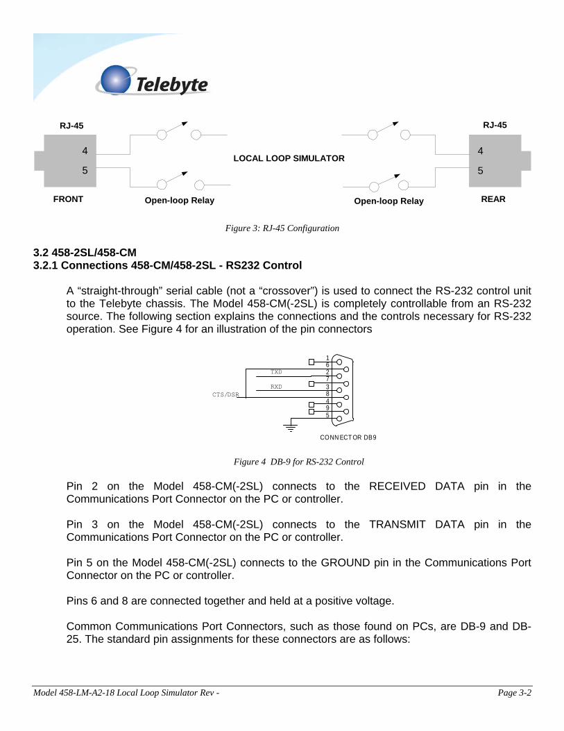
4
5
4
5
RJ-45 RJ-45
LOCAL LOOP SIMULATOR
FRONT REAROpen-loop Relay Open-loop Relay
Figure 3: RJ-45 Configuration
3.2 458-2SL/458-CM 3.2.1 Connections 458-CM/458-2SL - RS232 Control
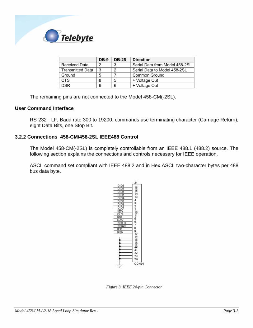
A “straight-through” serial cable (not a “crossover”) is used to connect the RS-232 control unit to the Telebyte chassis. The Model 458-CM(-2SL) is completely controllable from an RS-232 source. The following section explains the connections and the controls necessary for RS-232 operation. See Figure 4 for an illustration of the pin connectors
CONN ECT OR DB9
5 9 4
8 3 7 2 6 1
RXD
TXD
CTS/DSR
Figure 4 DB-9 for RS-232 Control
Pin 2 on the Model 458-CM(-2SL) connects to the RECEIVED DATA pin in the Communications Port Connector on the PC or controller. Pin 3 on the Model 458-CM(-2SL) connects to the TRANSMIT DATA pin in the Communications Port Connector on the PC or controller. Pin 5 on the Model 458-CM(-2SL) connects to the GROUND pin in the Communications Port Connector on the PC or controller. Pins 6 and 8 are connected together and held at a positive voltage. Common Communications Port Connectors, such as those found on PCs, are DB-9 and DB-25. The standard pin assignments for these connectors are as follows:
Model 458-LM-A2-18 Local Loop Simulator Rev - Page 3-3
DB-9 DB-25 Direction Received Data 2 3 Serial Data from Model 458-2SL Transmitted Data 3 2 Serial Data to Model 458-2SL Ground 5 7 Common Ground CTS 8 5 + Voltage Out DSR 6 6 + Voltage Out
The remaining pins are not connected to the Model 458-CM(-2SL).
User Command Interface
RS-232 - LF, Baud rate 300 to 19200, commands use terminating character (Carriage Return), eight Data Bits, one Stop Bit.
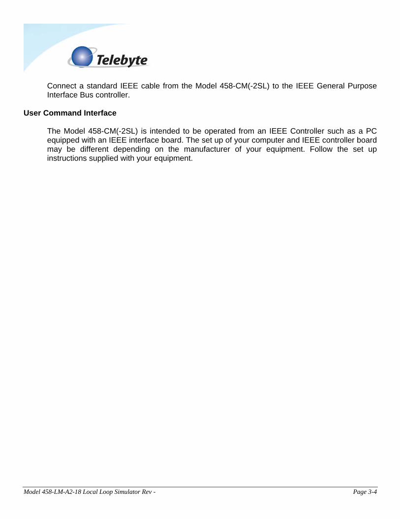
3.2.2 Connections 458-CM/458-2SL IEEE488 Control The Model 458-CM(-2SL) is completely controllable from an IEEE 488.1 (488.2) source. The following section explains the connections and controls necessary for IEEE operation. ASCII command set compliant with IEEE 488.2 and in Hex ASCII two-character bytes per 488 bus data byte.
Figure 3 IEEE 24-pin Connector
Model 458-LM-A2-18 Local Loop Simulator Rev - Page 3-4
Connect a standard IEEE cable from the Model 458-CM(-2SL) to the IEEE General Purpose Interface Bus controller.
User Command Interface
The Model 458-CM(-2SL) is intended to be operated from an IEEE Controller such as a PC equipped with an IEEE interface board. The set up of your computer and IEEE controller board may be different depending on the manufacturer of your equipment. Follow the set up instructions supplied with your equipment.
Model 458-LM-A2-18 Local Loop Simulator Rev - Page 4-1
4.0 Control
The Model 458-LM-A2-18 can be controlled three ways: Via RS-232 and IEEE488 Remote Commands, our GUI interface or the LCD display on the front panel of our 458-2SL.
4.1 Remote Commands
4.1.1 RS-232 (Serial Port) Remote Commands
md Disable manual control disable manual setting of lengths or configuration (used in 458-2SL only) me Enable manual control enable manual setting of lengths or configuration (used in 458-2SL only) id Identify model no. and rev. read model no. and software revision code re Read last error read description of last error ee Echo enable echo all inputs and format output for terminal display
Model 458-LM-A2-18 Local Loop Simulator Rev - Page 4-2
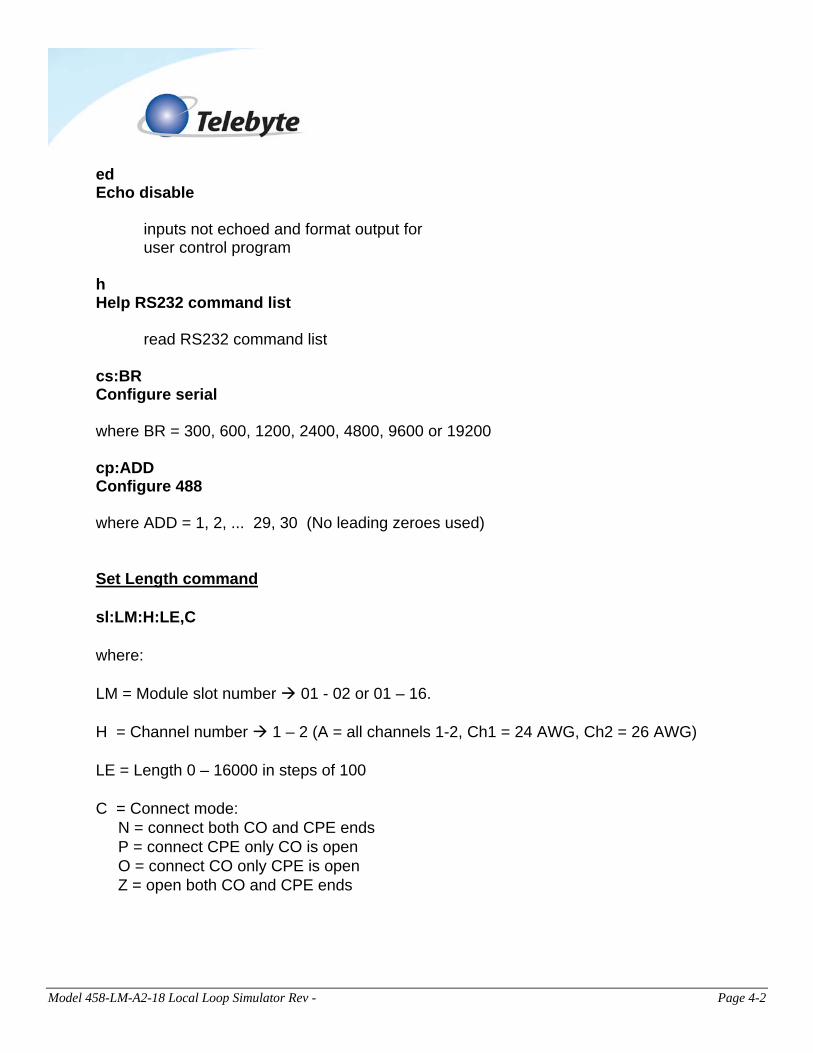
ed Echo disable inputs not echoed and format output for user control program h Help RS232 command list read RS232 command list cs:BR Configure serial where BR = 300, 600, 1200, 2400, 4800, 9600 or 19200 cp:ADD Configure 488 where ADD = 1, 2, ... 29, 30 (No leading zeroes used) Set Length command sl:LM:H:LE,C where: LM = Module slot number 01 - 02 or 01 – 16. H = Channel number 1 – 2 (A = all channels 1-2, Ch1 = 24 AWG, Ch2 = 26 AWG) LE = Length 0 – 16000 in steps of 100 C = Connect mode: N = connect both CO and CPE ends P = connect CPE only CO is open O = connect CO only CPE is open Z = open both CO and CPE ends
Model 458-LM-A2-18 Local Loop Simulator Rev - Page 4-3
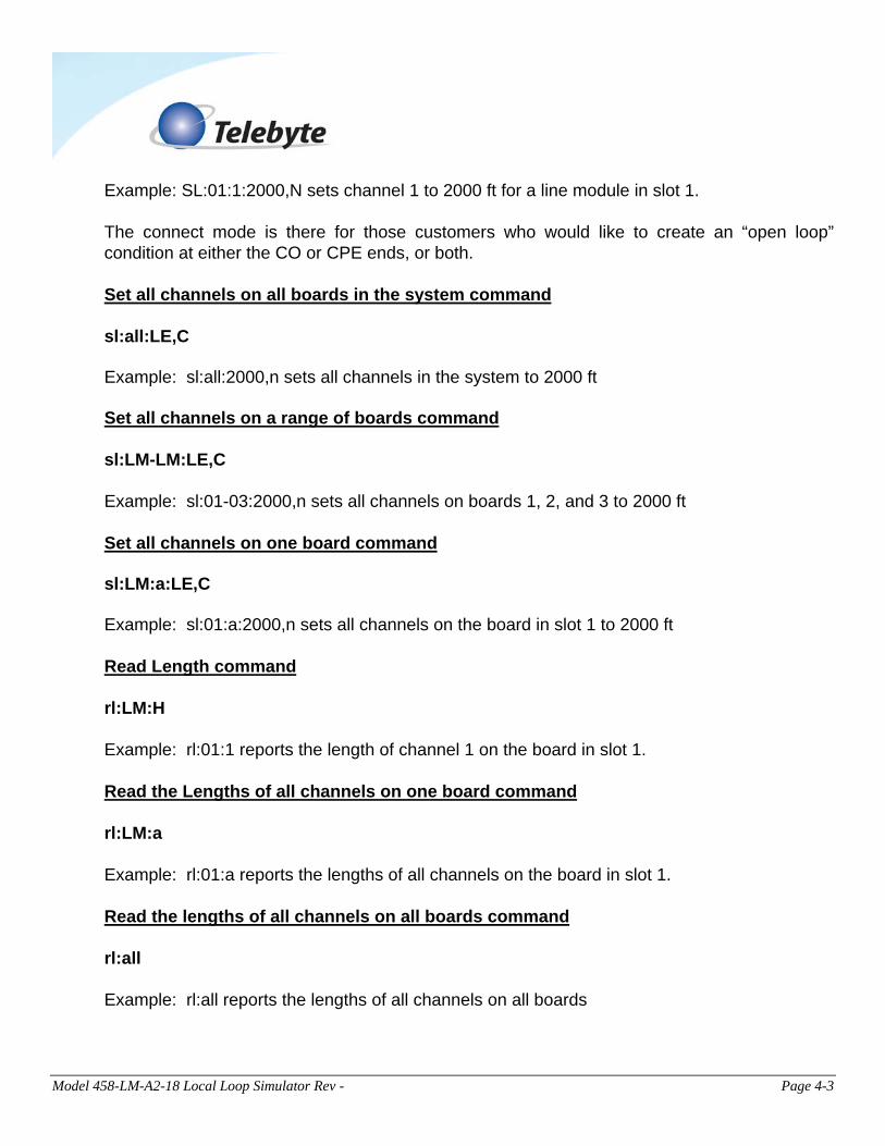
Example: SL:01:1:2000,N sets channel 1 to 2000 ft for a line module in slot 1. The connect mode is there for those customers who would like to create an “open loop” condition at either the CO or CPE ends, or both. Set all channels on all boards in the system command sl:all:LE,C Example: sl:all:2000,n sets all channels in the system to 2000 ft Set all channels on a range of boards command sl:LM-LM:LE,C Example: sl:01-03:2000,n sets all channels on boards 1, 2, and 3 to 2000 ft Set all channels on one board command sl:LM:a:LE,C Example: sl:01:a:2000,n sets all channels on the board in slot 1 to 2000 ft Read Length command rl:LM:H Example: rl:01:1 reports the length of channel 1 on the board in slot 1. Read the Lengths of all channels on one board command rl:LM:a Example: rl:01:a reports the lengths of all channels on the board in slot 1. Read the lengths of all channels on all boards command rl:all Example: rl:all reports the lengths of all channels on all boards
Model 458-LM-A2-18 Local Loop Simulator Rev - Page 4-4
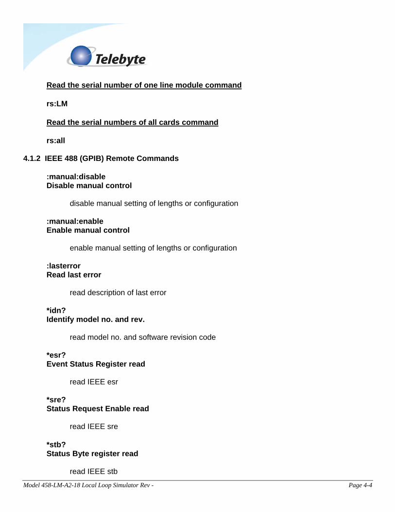
Read the serial number of one line module command rs:LM Read the serial numbers of all cards command rs:all
4.1.2 IEEE 488 (GPIB) Remote Commands
:manual:disable Disable manual control disable manual setting of lengths or configuration :manual:enable Enable manual control enable manual setting of lengths or configuration :lasterror Read last error read description of last error *idn? Identify model no. and rev. read model no. and software revision code *esr? Event Status Register read read IEEE esr *sre? Status Request Enable read read IEEE sre
*stb? Status Byte register read read IEEE stb
Model 458-LM-A2-18 Local Loop Simulator Rev - Page 4-5
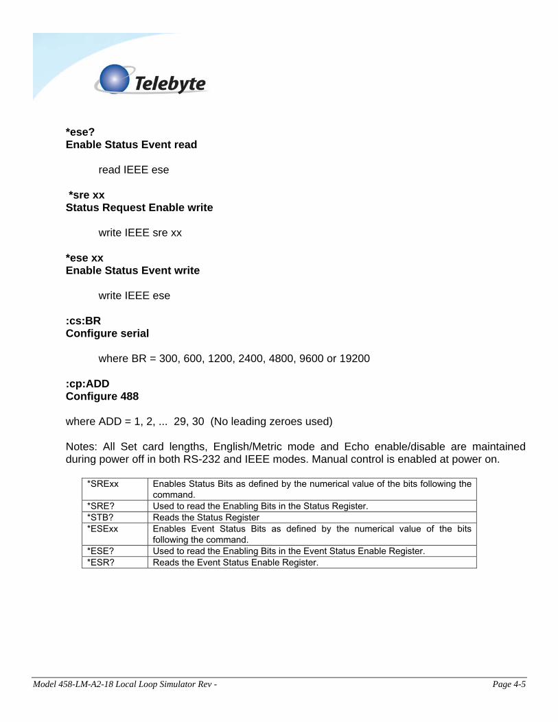
*ese? Enable Status Event read read IEEE ese *sre xx Status Request Enable write write IEEE sre xx *ese xx Enable Status Event write write IEEE ese :cs:BR Configure serial where BR = 300, 600, 1200, 2400, 4800, 9600 or 19200 :cp:ADD Configure 488 where ADD = 1, 2, ... 29, 30 (No leading zeroes used) Notes: All Set card lengths, English/Metric mode and Echo enable/disable are maintained during power off in both RS-232 and IEEE modes. Manual control is enabled at power on.
*SRExx Enables Status Bits as defined by the numerical value of the bits following the command.
*SRE? Used to read the Enabling Bits in the Status Register. *STB? Reads the Status Register *ESExx Enables Event Status Bits as defined by the numerical value of the bits
following the command. *ESE? Used to read the Enabling Bits in the Event Status Enable Register. *ESR? Reads the Event Status Enable Register.
Model 458-LM-A2-18 Local Loop Simulator Rev - Page 4-6
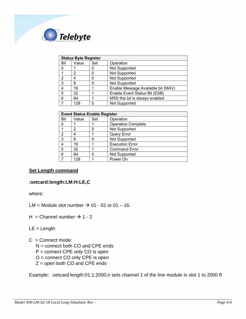
Status Byte Register Bit Value Set Operation 0 1 0 Not Supported 1 2 0 Not Supported 2 4 0 Not Supported 3 8 0 Not Supported 4 16 1 Enable Message Available bit (MAV) 5 32 1 Enable Event Status Bit (ESB) 6 64 1 MSS this bit is always enabled 7 128 0 Not Supported
Event Status Enable Register Bit Value Set Operation 0 1 1 Operation Complete 1 2 0 Not Supported 2 4 1 Query Error 3 8 0 Not Supported 4 16 1 Execution Error 5 32 1 Command Error 6 64 0 Not Supported 7 128 1 Power On
Set Length command :setcard:length:LM:H:LE,C where: LM = Module slot number 01 - 02 or 01 – 16. H = Channel number 1 - 2 LE = Length C = Connect mode: N = connect both CO and CPE ends P = connect CPE only CO is open O = connect CO only CPE is open Z = open both CO and CPE ends Example: :setcard:length:01:1:2000,n sets channel 1 of the line module in slot 1 to 2000 ft
Model 458-LM-A2-18 Local Loop Simulator Rev - Page 4-7
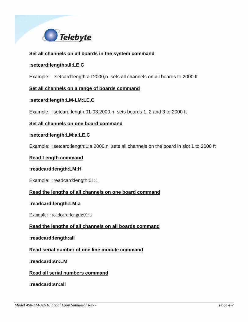
Set all channels on all boards in the system command :setcard:length:all:LE,C Example: :setcard:length:all:2000,n sets all channels on all boards to 2000 ft Set all channels on a range of boards command :setcard:length:LM-LM:LE,C Example: :setcard:length:01-03:2000,n sets boards 1, 2 and 3 to 2000 ft Set all channels on one board command :setcard:length:LM:a:LE,C Example: :setcard:length:1:a:2000,n sets all channels on the board in slot 1 to 2000 ft Read Length command :readcard:length:LM:H Example: :readcard:length:01:1 Read the lengths of all channels on one board command :readcard:length:LM:a Example: :readcard:length:01:a Read the lengths of all channels on all boards command :readcard:length:all Read serial number of one line module command :readcard:sn:LM Read all serial numbers command :readcard:sn:all
Model 458-LM-A2-18 Local Loop Simulator Rev - Page 4-8
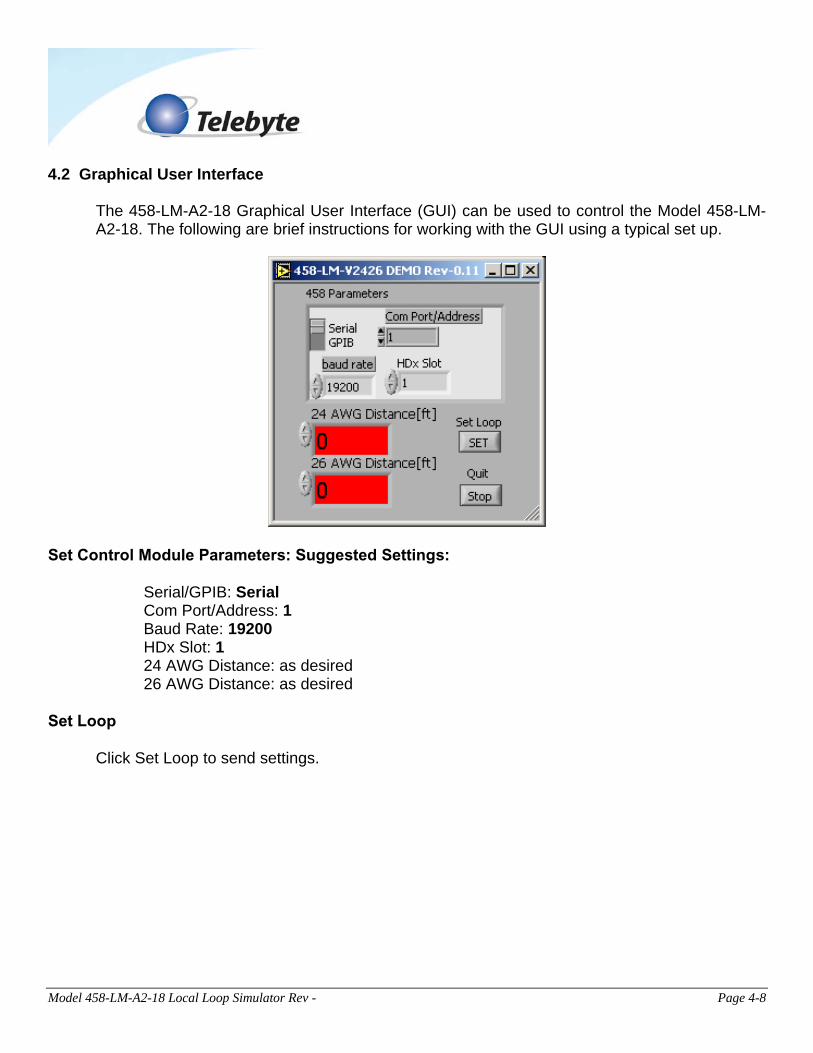
4.2 Graphical User Interface The 458-LM-A2-18 Graphical User Interface (GUI) can be used to control the Model 458-LM-A2-18. The following are brief instructions for working with the GUI using a typical set up.
Set Control Module Parameters: Suggested Settings: Serial/GPIB: Serial Com Port/Address: 1 Baud Rate: 19200 HDx Slot: 1 24 AWG Distance: as desired 26 AWG Distance: as desired
Set Loop Click Set Loop to send settings.
Model 458-LM-A2-18 Local Loop Simulator Rev - Page 4-9
4.3 LCD Display (458-2SL) Top encoder selects module number and channel. Bottom encoder selects length. Top display line shows module number and channel. Bottom display line shows line length and connect mode. The Config button is used to access a second menu on the front panel. The bottom of the LCD will display the Communication settings used. The bottom knob on the 458-2SL will adjust this value between GPIB address 1 - GPIB address 30 as well as RS-232 baud rates 19200,9600,4800,2400,1200 and 600.
Allowable lengths (feet)
All Channels: 0 to 16,000 ft in 100-ft increments.
Model 458-LM-A2-18 Local Loop Simulator Rev - Page 4-10
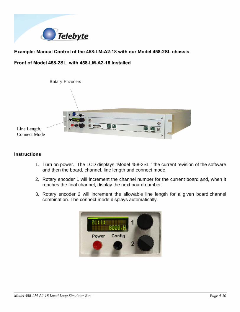
Example: Manual Control of the 458-LM-A2-18 with our Model 458-2SL chassis Front of Model 458-2SL, with 458-LM-A2-18 Installed
Rotary Encoders
Line Length, Connect Mode
Instructions
1. Turn on power. The LCD displays “Model 458-2SL,” the current revision of the software and then the board, channel, line length and connect mode.
2. Rotary encoder 1 will increment the channel number for the current board and, when it reaches the final channel, display the next board number.
3. Rotary encoder 2 will increment the allowable line length for a given board:channel combination. The connect mode displays automatically.