mineralogy and chemistry of proterozoic magnesite ores from south australia
TRANSCRIPT

MINERALOGY AND CHEMISTRY OF PROTEROZOICMAGNESITE ORES FROM SOUTH AUSTRALIA
J.L. Keeling1
, S.G. McClure2 and M.D. Raven2
1 Primary Industries and Resources, South Australia2 CSIRO Land and Water
_______________________________________________________________________________________________________________
This report on characterisation of magnesite was prepared as a collaborative investigation with Primary Industries and Resources, SouthAustralia. It is not intended for, nor does CSIRO accept any responsibility for its, use by any third party. CSIRO has not made any and herebyexcludes all warranties, terms, conditions or undertakings, whether express or implied, written or oral, statutory or otherwise including anyimplied warranty of merchantability or of fitness for a particular purpose in respect of the Services. To the full extent permitted by the laws of theCommonwealth of Australia or of any State or territory of Australia having jurisdiction, all conditions or warranties imposed by such legislationare hereby excluded. Insofar as liability under or pursuant to such legislation may not be excluded, such liability is limited, at the exclusiveoption of CSIRO, to:(i) the re-performance of the Service; or(ii) the payment of the cost of having the Services performed again.CSIRO shall retain ownership and exclusive rights of use of all research expertise, research skills and research techniques developed in thepreparation of results for this report.
CSIRO gives no warranty and makes no representation, whether express or implied, that this report is error free. CSIRO will accept noresponsibility for any interpretation, opinion or conclusion that any person may form as a result of examining this report._______________________________________________________________________________________________________________
Technical Report 7/98

CONTENTS Page
ABSTRACT 1
1.0 INTRODUCTION 2
2.0 SAMPLES 2
3.0 METHODS 43.1 Scanning Electron Microscopy 43.2 X-ray Diffraction 43.3 Chemical Analyses 4
4.0 RESULTS 54.1 Scanning Electron Microscopy 5
4.1.1 Balcanoona Magnesite 54.1.2 Magnesite interbeds in Skillogalee Dolomite 5
4.2 X-Ray Diffraction 74.3 Chemical Analyses 8
5.0 DISSCUSSION 115.1 Balcanoona 115.2 Magnesite interbeds in Skillogalee Dolomite 11
6.0 REFERENCES 13
APPENDIX A: ELECTRON MICROSCOPY AND EDX ANALYSES A1-A54
TABLES
1. Summary of magnesite samples 32. Quantitative mineralogy by Rietveld analysis of XRD results 73. Bulk magnesite samples; chemical analyses of major oxides and trace elements 94. Calculated mineralogy of magnesite and dolomite samples 105. Mineral compositions used for calculations 10

CSIRO LAND and WATER TECHNICAL REPORT NO. 7/98
NOT FOR PUBLICATION
The material contained herein has
not been refereed. It may be quoted
as a personal communication following
the written consent of the author.
MINERALOGY AND CHEMISTRY OF PROTEROZOICMAGNESITE ORES FROM SOUTH AUSTRALIA
J.L. Keeling1, S.G. McClure and M.D. Raven
ABSTRACT
The chemistry and mineralogy of samples from six Proterozoic magnesite prospects in thenorthern Flinders Ranges and Willouran Ranges, South Australia were investigated usingICP, quantitative XRD and SEM. The samples represent two different styles of magnesitedeposit namely: 1) sedimentary - replacement and 2) sedimentary - chemical with reworkedclastic deposits.
The Balcanoona prospect is a sedimentary - replacement deposit and forms irregular bodiesof coarse, crystalline sparry magnesite replacing pre-existing sedimentary dolomite ofBalcanoona Formation. Magnesite crystals range in size from 2 to 30 mm. Balcanoonamagnesite ore has an average Fe2O3 content of 1.5% and a CaO content of 1.7%. Both Feand Ca are present and substitute for Mg in magnesite. Chlorite is the dominant minormineral phase with accessory quartz, apatite and trace amounts of pyrite. Non-carbonatemineral phases form mainly along magnesite crystal boundaries. Fe, P and Mn contents arehigher than for sedimentary-chemical magnesite ores but CaO content is lower. Comparedwith sedimentary-chemical magnesite ores, trace element chemistry in Balcanoonamagnesite shows lower concentrations of Sr and B and slightly higher Zr and Th. Traces oforganic substance were recorded in one sample.
Samples from Screechowl Creek, Witchelina, Termination Hill, Myrtle Springs and MountHutton are all sedimentary -chemical deposits formed as shallow marine or marginalmarine deposits. The original layered chemical sediments have often been reworked toform coarse clastic deposits that are thinly interbedded with dolomite. Magnesite is presentpredominantly as cryptocrystalline particles 1-5 µm in size. Iron content is comparativelylow, ranging from Fe2O3 0.08% at Witchelina to 0.39% at Myrtle Springs. Calcium contentis relatively high ranging from CaO 2% at Mount Hutton to 4.5% at Screechowl Creek.Calcium is present as dolomite or magnesian calcite usually as a slightly coarser crystallinephase mostly in the matrix around magnesite clasts, and as veinlets. In bedded chemicalsediments the composition of individual layers may change from dominantly magnesitic todolomitic. Cryptocrystalline magnesite contains persistent but low levels of Ca and Si. Talcis the dominant minor phase; quartz is present in minor to trace amounts mainly as finesand grains; other phases include trace amounts of albite, K-feldspar and organic matter.
1.0 INTRODUCTION 1 Primary Industries and Resources, South Australia.
CSIRO LAND and WATER TECHNICAL REPORT 7/98 2
Magnesite (MgCO3), as a minor component, is widely associated with Proterozoic sedimentary dolomite
units throughout the Mount Lofty, Flinders and Willouran Ranges of South Australia (Forbes & Priess,
1987). Potential economic resources of magnesite are known from the northern Flinders Ranges and
Willouran Ranges where magnesite is found as thinly bedded conglomerates and layered chemical
sediments in Skillogalee Dolomite, and as coarsely crystalline aggregates replacing dolomite in
Balcanoona Formation (Crettenden, 1985).
During April - May 1997, samples of magnesite ore were collected by J.L. Keeling, A.M. Pain and
W.V. Priess (Primary Industries and Resources, South Australia) from six magnesite prospects as part
of an assessment of these resources for use as feedstock for magnesium metal production. The resource
assessment is part a pre-feasibility study for the proposed development of a magnesium metal
production facility in the northern Spencer Gulf region of South Australia.
Quantitative mineralogy and chemistry of bulk composite ore samples from each of the prospects were
determined using X-ray diffraction and ICP analysis. Selected samples were examined by electron
microscopy to characterise the mineralogy of the magnesite and associated mineral phases.
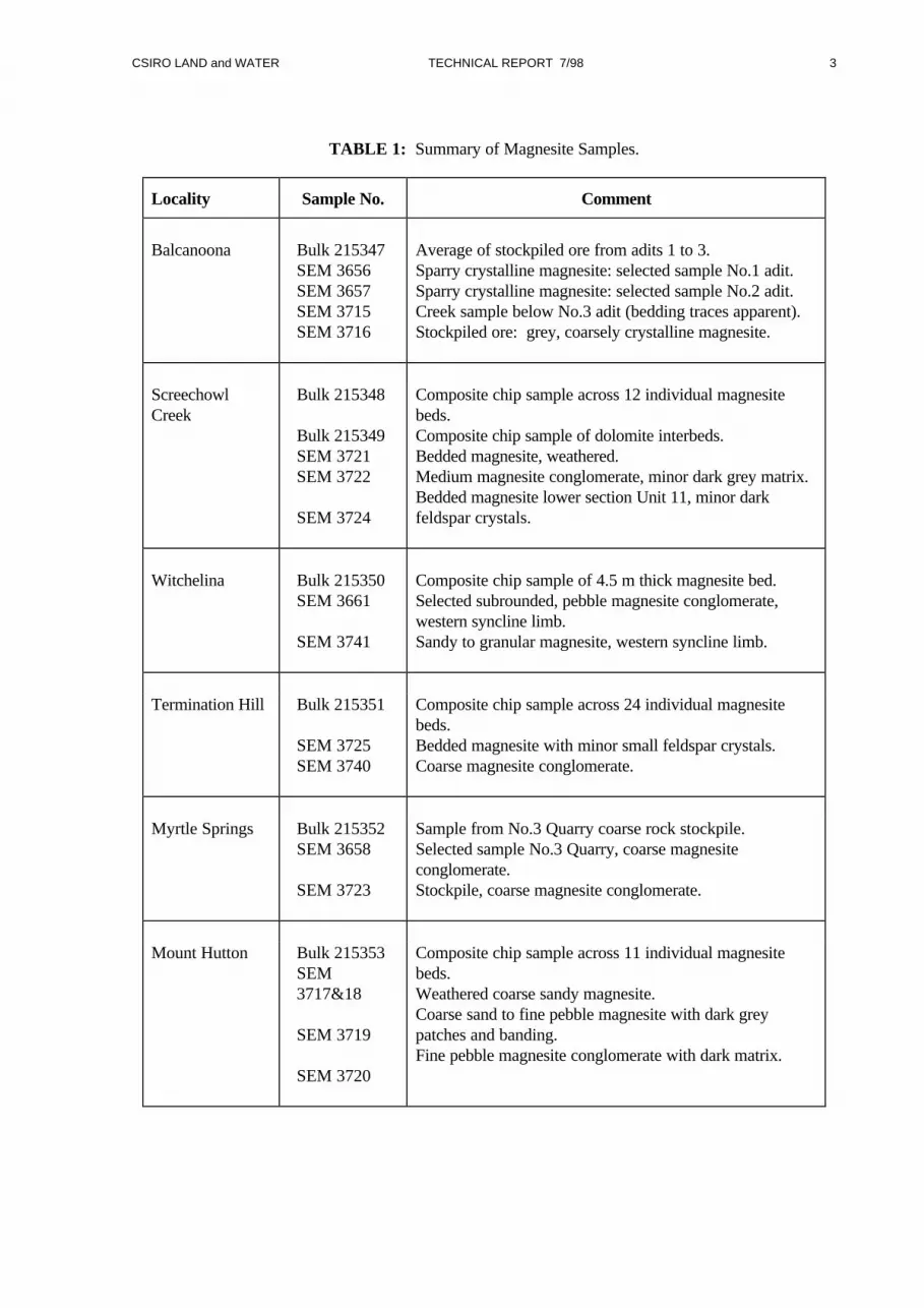
2.0 SAMPLES
Representative bulk magnesite samples (215347, 215348, 215350-53) from 6 magnesite prospects were
collected in the field either by subsampling existing ore stockpiles or by chip sampling across individual
magnesite beds as summarised in Table 1. In addition, one bulk sample representative of interbedded
dolomite (sample 215349) was collected from the Screechowl Creek Prospect. Bulk samples were
crushed at Australian Mineral Development Laboratories (AMDEL) Ltd to <2 mm size from which
further subsamples were taken for chemical analyses, X-ray diffraction and preliminary acid leach tests.
For electron microscope and petrographic studies, selected samples were collected in the field as
representative of individual magnesite beds or were chosen from stockpiled ore. These were
supplemented with samples collected from previous investigations (Crettenden, 1985). Petrographic
studies were undertaken by Mason Geoscience Pty Ltd with results reported in Mason (1997).
CSIRO LAND and WATER TECHNICAL REPORT 7/98 3
TABLE 1: Summary of Magnesite Samples.
Locality Sample No. Comment
Balcanoona Bulk 215347SEM 3656SEM 3657SEM 3715SEM 3716
Average of stockpiled ore from adits 1 to 3.Sparry crystalline magnesite: selected sample No.1 adit.Sparry crystalline magnesite: selected sample No.2 adit.Creek sample below No.3 adit (bedding traces apparent).Stockpiled ore: grey, coarsely crystalline magnesite.
ScreechowlCreek
Bulk 215348
Bulk 215349SEM 3721SEM 3722
SEM 3724
Composite chip sample across 12 individual magnesitebeds.Composite chip sample of dolomite interbeds.Bedded magnesite, weathered.Medium magnesite conglomerate, minor dark grey matrix.Bedded magnesite lower section Unit 11, minor darkfeldspar crystals.
Witchelina Bulk 215350SEM 3661
SEM 3741
Composite chip sample of 4.5 m thick magnesite bed.Selected subrounded, pebble magnesite conglomerate,western syncline limb.Sandy to granular magnesite, western syncline limb.
Termination Hill Bulk 215351
SEM 3725SEM 3740
Composite chip sample across 24 individual magnesitebeds.Bedded magnesite with minor small feldspar crystals.Coarse magnesite conglomerate.
Myrtle Springs Bulk 215352SEM 3658
SEM 3723
Sample from No.3 Quarry coarse rock stockpile.Selected sample No.3 Quarry, coarse magnesiteconglomerate.Stockpile, coarse magnesite conglomerate.
Mount Hutton Bulk 215353SEM3717&18
SEM 3719
SEM 3720
Composite chip sample across 11 individual magnesitebeds.Weathered coarse sandy magnesite.Coarse sand to fine pebble magnesite with dark greypatches and banding.Fine pebble magnesite conglomerate with dark matrix.
CSIRO LAND and WATER TECHNICAL REPORT 7/98 4
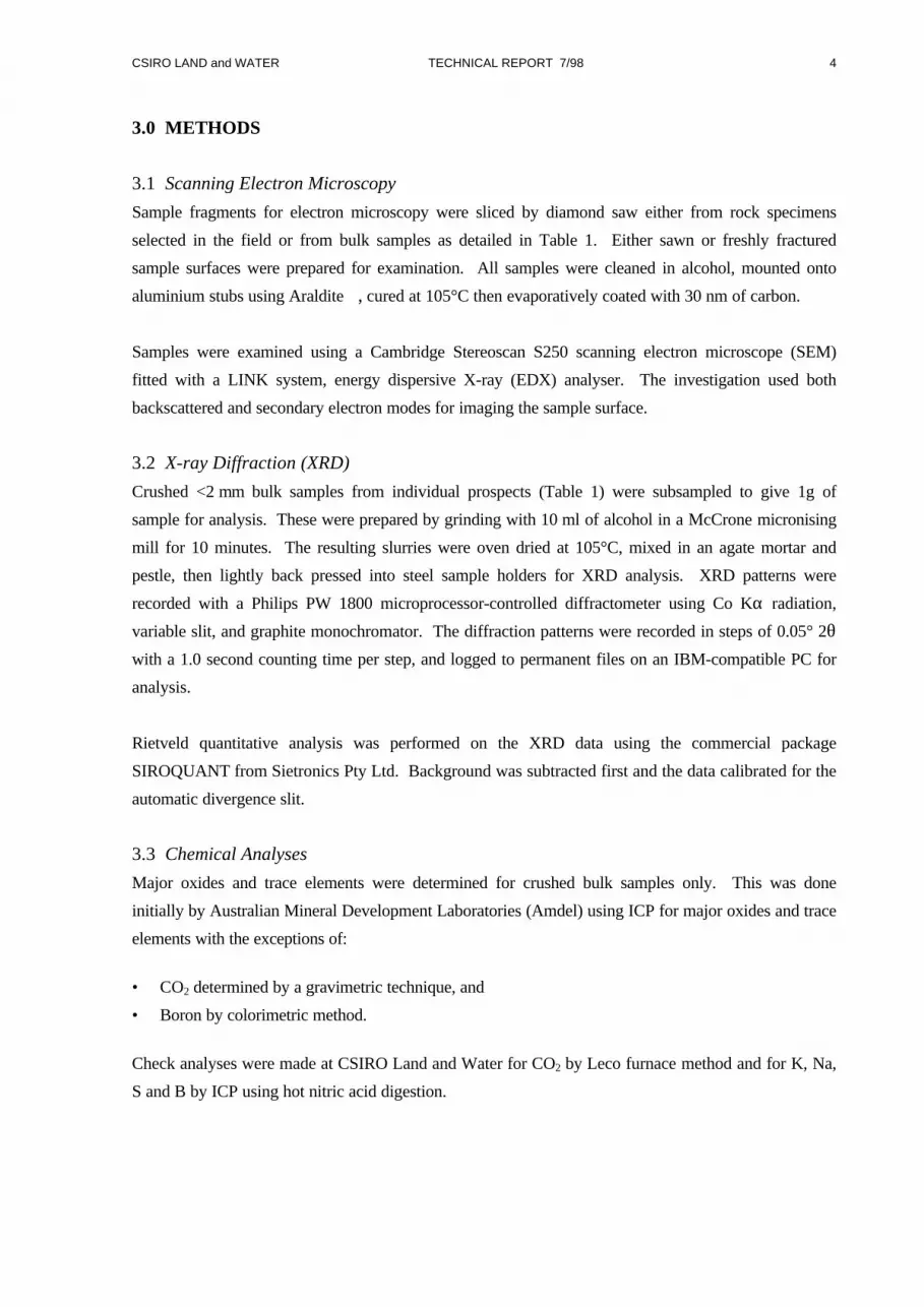
3.0 METHODS
3.1 Scanning Electron Microscopy
Sample fragments for electron microscopy were sliced by diamond saw either from rock specimens
selected in the field or from bulk samples as detailed in Table 1. Either sawn or freshly fractured
sample surfaces were prepared for examination. All samples were cleaned in alcohol, mounted onto
aluminium stubs using Araldite, cured at 105°C then evaporatively coated with 30 nm of carbon.
Samples were examined using a Cambridge Stereoscan S250 scanning electron microscope (SEM)
fitted with a LINK system, energy dispersive X-ray (EDX) analyser. The investigation used both
backscattered and secondary electron modes for imaging the sample surface.
3.2 X-ray Diffraction (XRD)
Crushed <2 mm bulk samples from individual prospects (Table 1) were subsampled to give 1g of
sample for analysis. These were prepared by grinding with 10 ml of alcohol in a McCrone micronising
mill for 10 minutes. The resulting slurries were oven dried at 105°C, mixed in an agate mortar and
pestle, then lightly back pressed into steel sample holders for XRD analysis. XRD patterns were
recorded with a Philips PW 1800 microprocessor-controlled diffractometer using Co Kα radiation,
variable slit, and graphite monochromator. The diffraction patterns were recorded in steps of 0.05° 2θwith a 1.0 second counting time per step, and logged to permanent files on an IBM-compatible PC for
analysis.
Rietveld quantitative analysis was performed on the XRD data using the commercial package
SIROQUANT from Sietronics Pty Ltd. Background was subtracted first and the data calibrated for the
automatic divergence slit.
3.3 Chemical Analyses
Major oxides and trace elements were determined for crushed bulk samples only. This was done
initially by Australian Mineral Development Laboratories (Amdel) using ICP for major oxides and trace
elements with the exceptions of:
• CO2 determined by a gravimetric technique, and
• Boron by colorimetric method.
Check analyses were made at CSIRO Land and Water for CO2 by Leco furnace method and for K, Na,
S and B by ICP using hot nitric acid digestion.

CSIRO LAND and WATER TECHNICAL REPORT 7/98 5
4.0 RESULTS
4.1. Scanning Electron Microscopy
Electron micrographs and EDX analyses are presented in full in Appendix A. A summary of the results
is given below.
4.1.1 Balcanoona Magnesite
• Magnesite: Cleavage planes of coarse magnesite crystals were characterised by the presence of
numerous small voids (fluid inclusions?) mainly as negative crystals, typically <10 µm across
(Plates 1 & 2). Magnesite also contains patches where calcium dominates over magnesium. These
were not common, and varied in size from <15 µm to several 100 µm (Plates 2 & 10). The
presence of a trace of cerium phosphate was recorded in a calcium-rich area in one sample (Plate
2). EDX analyses of magnesite showed Fe in the magnesite crystal structure (Figs A1, A3-8).
Other mineral phases were concentrated mainly along magnesite crystal boundaries and included:
• Chlorite as curved thin flakes from 10-200 µm across (Plates 3 & 4). Composition of chlorite was
Mg rich but always with some Fe present.
• Apatite as irregular grains and granular masses 2-100 µm diameter (Plates 3, 4, 7) and rarely as
euhedral crystals (S1, Plate 4).
• Dolomite and Mg-calcite as minor granular particles with chlorite and apatite (Plate 7) as well as
discrete areas within individual magnesite crystals as described above.
• Pyrite as rare euhedral pyriohedral crystals (Plate 9).
• Fe and Ti oxides as small inclusions in chlorite-rich areas (Plate 8).
• Gypsum was recorded with chlorite in one sample (Plates 5 & 6).
4.1.2 Magnesite interbeds in Skillogalee Dolomite
Samples from Screechowl Creek, Witchelina, Termination Hill, Myrtle Springs and Mount Hutton are
all included in this group and have many characteristics in common. Magnesite sedimentary rocks from
these prospects include finely laminated chemical sediments which may be locally disrupted to produce
intraformational conglomerate, or reworked and deposited as coarse sand, granule and pebble
conglomerate. Pebble conglomerate was common at all prospects; bedded magnesite was much less
common and was best represented at Screechowl Creek and Termination Hill prospects; sandy and
granular magnesite beds were more significant at Myrtle Springs and Mount Hutton prospects.
• Magnesite: The magnesite in all samples was predominantly cryptocrystalline as irregular
rhombohedral crystallites 1 µm to 8 µm in size (Plates 14, 15, 35, 40). Individual crystals were
partly fused together but also appeared to enclose numerous voids of size range similar to that of
the crystallites. Cryptocrystalline magnesite invariably included some calcium (Ca) and silica (Si)
(Figs A8, A10, A12-15, A18-20, A22, A23, A25-30). At Termination Hill, fine dark laminae in
bedded magnesite corresponded with more dolomitic composition and the presence of some organic

CSIRO LAND and WATER TECHNICAL REPORT 7/98 6
matter (Plates 30, 33, Fig. A18). In other samples darker grey patches or bands were magnesite of
identical composition to light grey and white areas (Plates 12-15, Fig. A8; Plate 34, Fig. A19).
Minor recrystallised, microcrystalline to sparry, magnesite was also present in most samples as a
component of either thin veinlets or of the matrix between magnesite clasts in conglomerates.
Recrystallised magnesite formed granular particles and aggregates with individual grains 5-50 µm
diameter (Plates 28, 29, 36, 37, 39, 55). These were generally pure with little or no detectable silica
or calcium but occassionally with some iron (Figs A15, A16(S1), A20(S6), A21, A30(S9)). In the
majority of cases, recrystallised magnesite grains were invariably intermixed with dolomite, Mg-
calcite or talc of similar grainsize.
Non-magnesite phases included:
• Dolomite and Mg-calcite were present mostly as recrystallised, microcrystalline grains either
forming the matrix around magnesite clasts (Plates 20, 28, 29, 48) or as thin veinlets that cut across
bedding and magnesite clasts (Plates 17, 23, 37, 39). Pure calcite was rarely present, but the
distinction between areas of Mg-calcite and dolomite was difficult from EDX data because Mg X-
rays are of lower energy which makes them more susceptible to absorption. The relative intensity
of Mg to Ca, as recorded, can therefore be suspect, particularly when working with samples with
rough surfaces. Dolomite was observed in sample 3725 from Termination Hill (Plates 30 & 33) as
cryptocrystalline particles in thin laminae within bedded magnesite. The cryptocrystalline dolomite
layers also contained some organic matter (Fig. A18). While variation in composition of primary
sediment from magnesite to dolomite was rarely observed at the microscopic scale this was
suspected from field mapping to be a characteristic of bedded magnesite. Within individual
magnesite clasts, irregular patches of dolomite alteration were occasionally observed (Plates 41 &
42) and confirm larger scale replacements of magnesite by dolomite observed in the field. In veins
of sparry Mg-calcite, strontium (Sr) was sometimes recorded (Figs A20 & A21), indicating that
trace amounts of Sr are mainly present as carbonate where Sr substitutes for Ca in late stage veins.
• Talc was the most common silicate phase in many of the samples as flakes from 5µm to 100 µm
across and mostly scattered throughout the dolomitic matrix (Plates 16, 44, 47, 50). Talc was also
present as flakes or veinlets in magnesite clasts (Plates 21, 23, 39, 40, 42) and as elongate crystal
laths on the margins of clasts (Plates 24 & 25). Talc composition was usually pure magnesium
silicate (Fig. A14) although occasionally intimately mixed with K-feldspar (Figs B12, B13). The
presence of silica in cryptocrystalline magnesite is due largely to the presence of submicron size talc
particles partly coating the surface of magnesite crystallites (pers comm. P Self from preliminary
TEM investigations of Screechowl Creek magnesite).
• Quartz was observed as fine-grained sand particles of around 100 µm diameter in the matrix
between magnesite clasts in sample 3740 from Termination Hill (Plate 37). Free quartz was not
observed in any other samples but was recorded from optical microscopy as rare sand grains and
associated with recrystallised dolomite veins (Mason, 1997).
• Albite feldspar was common as small (0.2-0.5 mm long), euhedral, black crystals with random
orientation in bedded magnesite from Screechowl Creek and Termination Hill (Plates 22, 23, 30,
CSIRO LAND and WATER TECHNICAL REPORT 7/98 7
31, 32). EDX analyses indicate that euhedral crystals of albite are relatively pure (Figs A13, A17).
Albite crystals were rare in reworked magnesite and appear to have not been formed prior to
reworking or were in part destroyed during dolomitisation of the enclosing matrix (see Mason,
1997).
• K-feldspar was not observed directly but is inferred from EDX analyses to be present as fine-
grained particles occurring with talc in matrix and veins (Plates 21, 23; Figs A12, A13).
• Barite was located in one sample from Screechowl Creek as a discrete mineral phase of grain size
up to 100 x 20 µm across, together with Mg-calcite in a veinlet (Plate 17).
• Organic matter was rare but suspected to be present with primary dolomite from Termination Hill
based on the presence of S, P and Cl in EDX analyses (Fig. A18), and was observed in
microcrystalline dolomitic matrix in Witchelina sample 3741 (Plate 29; Fig. A16).
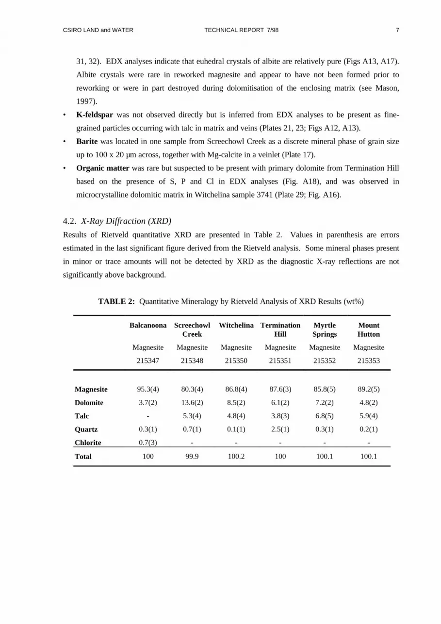
4.2. X-Ray Diffraction (XRD)
Results of Rietveld quantitative XRD are presented in Table 2. Values in parenthesis are errors
estimated in the last significant figure derived from the Rietveld analysis. Some mineral phases present
in minor or trace amounts will not be detected by XRD as the diagnostic X-ray reflections are not
significantly above background.
TABLE 2: Quantitative Mineralogy by Rietveld Analysis of XRD Results (wt%)
Balcanoona Screechowl Witchelina Termination Myrtle Mount
Magnesite
Creek
Magnesite Magnesite
Hill
Magnesite
Springs
Magnesite
Hutton
Magnesite
215347 215348 215350 215351 215352 215353
Magnesite 95.3(4) 80.3(4) 86.8(4) 87.6(3) 85.8(5) 89.2(5)
Dolomite 3.7(2) 13.6(2) 8.5(2) 6.1(2) 7.2(2) 4.8(2)
Talc - 5.3(4) 4.8(4) 3.8(3) 6.8(5) 5.9(4)
Quartz 0.3(1) 0.7(1) 0.1(1) 2.5(1) 0.3(1) 0.2(1)
Chlorite 0.7(3) - - - - -
Total 100 99.9 100.2 100 100.1 100.1

CSIRO LAND and WATER TECHNICAL REPORT 7/98 8
4.3 Chemical Analyses
Results of full chemical analyses for major oxides and trace elements are given in Table 3. Using these
results, together with data from SEM and XRD, the percentages of mineral phases present in each
sample were calculated by a process of rational analysis (Table 4). The procedure adopted was as
follows:
• For sample 215347, all P2O5 was allocated to apatite.
• Residual Ca in sample 215347 and all Ca in samples 215348-215353 was allocated to dolomite.
• Residual CO2 was allocated to magnesite.
• All Na2O was allocated to albite (except for sample 215347).
• All K2O was allocated to orthoclase.
• Quartz content was estimated from XRD.
• In sample 215347, residual Al2O3 was allocated to Chlorite.
• Residual silica was allocated to talc.
• In samples 215348-215353, SO4 was allocated to barite, for sample 215347, S was allocated to
pyrite.
• Residual Fe2O3 is reported for sample 215347 but not assigned to a mineral phase. In this sample,
significant amounts of Fe substitute for Mg in magnesite but is also present as both goethite and
hematite.
• All samples show residual MgO. Where mineralogical totals were below 100%, a proportion of
this residual was used to increase the magnesite content. Increase in magnesite content, from
allocation of residual MgO, was ≤1%.
Mineral compositions used for calculations are given in Table 5. Compositions are for “ideal” minerals
or were modified based on energy dispersive X-ray (EDX) analyses from electron microscope
investigations. In particular, EDX showed the close to ideal composition for albite and talc in the
sedimentary magnesite samples and confirmed a low Fe content in chlorite in Balcanoona samples.

CSIRO LAND and WATER TECHNICAL REPORT 7/98 9
TABLE 3: Bulk Magnesite Samples; Chemical Analyses of Major Oxides (%) and Trace Elements(mg/kg) (modified from Amdel Report N831000G/97).
Balcanoona ScreechowlCreek
ScreechowlCreek
Witchelina Termination Hill
MyrtleSprings
MountHutton
Magnesite Magnesite Dolomite Magnesite Magnesite Magnesite Magnesite
215347 215348 215349 215350 215351 215352 215353
MgO 46.1 44.3 21.1 46.5 45.1 45.9 46.3
CaO 1.67 4.42 19.9 3.05 2.36 2.27 1.92
SiO2 1.01 3.40 20.3 1.75 4.49 3.77 3.53
Fe2O3 1.48 0.15 0.29 0.08 0.21 0.39 0.29
Al2O3 0.50 0.17 1.34 0.13 0.19 0.20 0.20
Na2O* 0.045 0.027 0.49 0.023 0.027 0.027 0.031
K2O* 0.014 0.011 0.36 0.01 0.019 0.016 0.044
MnO 0.09 <0.01 0.01 <0.01 0.01 0.02 0.01
P2O5 0.11 0.03 0.03 0.04 0.03 0.03 0.03
TiO2 0.03 <0.01 0.04 <0.01 <0.01 <0.01 <0.01
CO2* 49.9 48.4 34.7 49.9 48.4 48.4 48.8
SO4* 0.10 0.11 nd 0.07 0.06 0.05 0.05
Total 101.05 101.02 98.51 101.55 100.89 101.05 101.19
Trace Elements mg/kg (ppm)
As 16 16 14 22 14 16 14B* 34 105 350 97 166 133 142Ba 80 150 320 50 140 50 160Be <2 <2 <2 <2 <2 <2 <2Ce 100 <100 100 200 <100 100 150Cd <20 <20 <20 <20 <20 <20 <20Co <20 <20 <20 <20 <20 <20 <20Cr <20 <20 30 <20 <20 <20 <20Cu 13 19 <2 13 17 <2 <2La <50 <50 <50 100 <50 <50 50Mo <50 <50 <50 <50 <50 <50 <50Nb <50 <50 <50 <50 <50 <50 <50Ni 16 13 15 18 12 12 11Pb <5 5 <5 <5 <5 5 <5S* 332 362 nd 221 197 172 155Sn 100 100 50 100 100 100 100Sc <5 <5 <5 <5 <5 <5 <5Sr <20 110 750 60 100 70 50Ta 50 50 <50 50 50 50 50Th 0.77 0.33 1.65 0.17 0.18 0.22 0.22U 0.20 0.20 0.50 0.17 0.18 0.19 0.17V 30 20 30 20 20 20 20Y 10 <10 <10 <10 <10 <10 <10Zn 9 11 22 13 24 12 9Zr 7.5 2.5 16.5 1.5 1.5 2.0 1.5
* CSIRO analysis

CSIRO LAND and WATER TECHNICAL REPORT 7/98 10
TABLE 4: Calculated Mineralogy of Magnesite and Dolomite Samples.
Balcanoona Screechowl Screechowl Witchelina Termination Myrtle Mount
Magnesite
Creek
Magnesite
Creek
Dolomite Magnesite
Hill
Magnesite
Springs
Magnesite
Hutton
Magnesite
215347 215348 215349 215350 215351 215352 215353
Magnesite 91.0 80.5 11.4 87.3 86.6 86.8 88.2
Dolomite 5.0 14.5 65.5 10.0 7.8 7.5 6.3
Talc 4.0 1.7 2.3 2.8 5.1 4.7
Quartz (XRD) 0.3 0.7 15.0 0.1 2.5 0.3 0.2
Albite 0.2 4.2 0.2 0.2 0.2 0.3
K-feldspar 0.1 0.1 2.1 0.1 0.1 0.1 0.3
Barite 0.03 0.05 0.01 0.02 0.01 0.03
Chlorite 2.3
Apatite 0.3
Pyrite 0.1
Fe2O3 1.3
Total 100.4 100.0 100.0 100.0 100.0 100.0 100.0
Residual MgO 0.81 1.37 0.84 1.81 1.58 1.13 1.25
TABLE 5: Mineral Compositions Used for Calculations in Table 4 (wt%)
SiO2 Al2O3 Na2O K2O MgO FeO CaO CO2 H2O
Magnesite 47.81 52.19
Dolomite 21.82 30.42 47.75
Talc 63.40 31.83 4.75
Quartz 100
Chlorite 31.54 17.84 31.83 6.28 12.61
Albite 68.74 19.44 11.81
K-feldspar 64.76 18.31 16.92

CSIRO LAND and WATER TECHNICAL REPORT 7/98 11
5.0 DISCUSSION
5.1 Balcanoona
Balcanoona magnesite ore is sparry, coarsely crystalline magnesite formed by replacement of original
sedimentary dolomite. Magnesite crystals form radiating clusters that are intergrown and vary in size
from 2 mm to 30 mm. In samples 3656 and 3715, magnesite crystals were arranged in bands which
roughly parallel bedding in adjacent dolomite. Crystal growth was at approximately 90° to bedding
trendlines. Field evidence suggests metasomatic alteration of dolomite by Mg-rich fluids migrating
along bedding plane weaknesses followed by recrystallisation as magnesite.
Examination of magnesite cleavage fragments showed the presence of small fluid inclusions generally
<10 µm across, persistent Fe in the crystal lattice, and minor calcium-rich zones. Granular magnesite
was also present in irregular patches of matrix concentrated along crystal boundaries, together with
dolomite/Mg-calcite, chlorite and apatite. Minerals forming the matrix were generally <200 µm across
and typically between 20 µm and 80 µm in size. Quartz was not observed during SEM investigations
but was reported in XRD. Any beneficiation to remove non-magnesite phases would require initial
crushing of the ore to <100 µm. Beneficiated magnesite would still contain Fe and Ca in the magnesite
crystal lattice. Substitution of Mg by Fe and Ca in magnesite is the principal cause of discrepancy
between average magnesite percentages determined from XRD (MgCO3=95%) and that determined by
rational analysis of chemical data (MgCO3=91%).
Compared with the sedimentary magnesite from the Skillogalee Dolomite member, Balcanoona
magnesite has higher Fe2O3 (1.48%), MnO (0.09%) and P2O5 (0.11%) but lower CaO (1.67%). For
trace elements, Balcanoona magnesite is characterised by low boron (B=34 ppm) and strontium
(Sr=<20 ppm) and slightly higher thorium (Th=0.77 ppm) and zirconium (Zr=7.5 ppm). The low B and
Sr values are consistent with the magnesite not being having formed under marine conditions.
5.2 Magnesite Interbeds in Skillogalee Dolomite
Magnesite samples from Screechowl Creek, Witchelina, Termination Hill, Myrtle Springs and Mount
Hutton all show similar physical and chemical properties and probably formed as shallow marine or
marginal marine chemical precipitates and are classed here as sedimentary-chemical deposits that
include abundant reworked magnesite as coarse clastic sediments. Direct chemical precipitation rather
than diagenetic growth of magnesite is supported by the fine grain size of the magnesite, typically 1-
5 µm, and the observation that it may be interbedded with dolomite of similar grain size. The fine grain
size of the magnesite particles and poor packing suggest rapid crystallisation and sedimentation,
possibly under agitated conditions. Recrystallisation and growth of sparry magnesite may have been
restricted by the co-precipitation of silica or Mg-rich clay, and very low metamorphic grade. A marine
environment is inferred from the nature of the interbedded dolomites, which include stromatolite and
cherty layers, and by the elevated levels of boron (B=97-142 ppm) and strontium (Sr=50-110 ppm).

CSIRO LAND and WATER TECHNICAL REPORT 7/98 12
Early diagenetic changes included consolidation through desiccation and in many cases, break up of the
magnesite sediment leading to formation of intraformational conglomerate or, more often, reworking of
the disrupted sediment to form pebble conglomerate and in some areas, coarse magnesite sand. Albite
crystals, to 1 mm length, formed during early stages of diagenesis and are the principal repository of
aluminium and sodium in the magnesite ore. In conglomerate, microcrystalline dolomite and magnesite
form the cementing matrix. Minor to trace amounts of fine-grained quartz sand were observed in the
matrix of samples from Termination Hill. Quartz was apparently unstable in the sedimentary
environment and displays severe replacement around the margins by dolomite, leaving small angular
kernels (Mason, 1997). This may also be indicative of the alkaline conditions at the time of
sedimentation and later diagenesis.
Later diagenetic changes include the formation of talc and cross-cutting veinlets that comprise mostly
sparry carbonate or rarely talc. Talc is present in a wide range of sizes from sub-micron particles,
associated with cryptocrystalline magnesite, to millimetre sized, lath-shaped crystals growing out from
the margin of magnesite clasts. Talc flakes are found in both magnesite clasts and matrix and, less
commonly, as late-stage veinlets with fine-grained K-feldspar. Talc flakes in samples from Witchelina,
Myrtle Springs and Mount Hutton were generally coarser grained than those from Screechowl Creek
and Termination Hill. Talc formed probably during late-stage diagenesis or very low grade
metamorphism either by reaction of colloidal silica with magnesite or through recrystallisation of Mg
clays such as sepiolite or stevensite (Noack et al., 1989) that may have been deposited together with the
magnesite. With the exception of samples from Termination Hill, the majority of SiO2 present in
sedimentary magnesite samples was in the form of talc. Carbonate veinlets comprised coarsely
crystalline dolomite, Mg-calcite or magnesite. Strontium and barium were reported in veinlets with Sr
substituting for Ca in Mg-calcite, and Ba as barium sulphate.
The cryptocrystalline character of the sedimentary-chemical magnesites and the present of voids
between individual crystallites gives these samples a high surface area and potentially a higher reactivity
to acid at lower temperatures than would be expected for the more coarsely crystalline Balcanoona ore.
27 February 1998

CSIRO LAND and WATER TECHNICAL REPORT 7/98 13
6.0 REFERENCES
Crettenden, P.P., 1985. Magnesite in South Australia: a historical review 1915 - 1984. South
Australia. Department of Mines and Energy Report 85/62.
Forbes, B.G. and Priess, W.V., 1987. Stratigraphy of the Burra Group. In Priess, W.V. (compiler),
1987. The Adelaide Geosyncline - late Proterozoic stratigraphy, sedimentation,
palaeontology and tectonics. South Australia. Bulletin Geological Survey South
Australia, 53: 73-123.
Mason D.R., 1997. Petrographic descriptions for fourteen magnesite rock samples (Skillogalee
Dolomite, Flinders Ranges, South Australia). Mason Geoscience Report 2343
(unpublished).
Noack, Y., Decarreau, A., Boudzoumou, F. and Trompette, R., 1988. Low-temperature oolitic talc in
Upper Proterozoic rocks, Congo. Journal of Sedimentary Petrology 59: 717-723.

APPENDIX A
ELECTRON MICROSCOPY AND EDX ANALYSES
CSIRO LAND and WATER TECHNICAL REPORT 7/98 A1
BALCANOONA
Four samples were examined, 2 from the walls of adits 1 and 2, one from outcrop, and the fourth from
stockpiled magnesite ore.
3656: BHP exploratory Adit 1: Sparry magnesite as white to pale grey coarse crystals 2-15 mm long
as slightly radiating growths in weakly defined bands 10 mm to 15 mm thick. Minor pale green chlorite
concentrated mainly at the junction of magnesite bands. Trace of yellow brown Fe oxides on sample
surface. SEM examination of a freshly fractured surface (P.P. Crettenden sample, collected 1983).
3657: BHP exploratory Adit 2: Sparry magnesite as white to very pale grey, interlocking aggregates of
radiating crystals 5-30 mm long. Minor, pale grey to greenish grey patches of probable fine-grained
chlorite mainly along crystal boundaries. SEM examination of a freshly fractured surface (P.P.
Crettenden sample, collected 1983).
3715: Creek sample: Comprises white opaque to slightly translucent magnesite crystals 4 mm to
10 mm in length arranged as intergrown radiating aggregates from subparallel lineations which appear
to be continuous with bedding traces apparent in adjacent dolomite. Pale greenish-grey chlorite is
concentrated along the traces and at the base of the radiating magnesite crystals. Sample collected from
outcrop in the creek below Adit 3 (1997). SEM examination of a freshly fractured surface.
3716: Stockpile sample: Pale grey to opaque white, coarsely crystalline magnesite showing regular
mosaic of interlocking crystals 3 - 8 mm length by 3 - 4 mm width. Minor pale yellow-orange iron
oxide staining mainly on boundaries between individual crystals. SEM examination of a sawn face.

CSIRO LAND and WATER TECHNICAL REPORT 7/98 A2
Plate 1: Balcanoona Magnesite, Adit 1: Detail of the surface of a cleavage plane in a single magnesite crystalshowing the presence of small voids (fluid inclusions?) and some lighter areas indicating high calciumcontent (see Plate 2 for detail). Photo no. 56-3552, scale bar 20 µm.
Plate 2: Balcanoona Magnesite, Adit 1: Detail of Fig. 1 (top centre) of an area with high calcium substitutionfor magnesium. Minor cerium phosphate (very bright spot, S4) is also present in the high calcium area.Photo no. 56-3553, scale bar 4 µm. EDX analyses for spot sites are given in Fig. A1.
CSIRO LAND and WATER TECHNICAL REPORT 7/98 A3
0 1 2 3 4 5 6 7 8 9Energy (KeV)
0
1000
2000
3000
4000
5000
6000
7000
8000
9000
10000Intensity
3656 s1 mg355.2 matrix
Mg
Fe
S1: Magnesite
1 2 3 4 5 6 7 8 9 10Energy (KeV)
0
1000
2000
3000
4000
5000
6000
7000
8000Intensity
Mg
Ca
S2
S3
S2, S3: Mg-Calcite
1 2 3 4 5 6 7 8 9 10Energy (KeV)
0
100
200
300
400
500
600
700
800
900
1000Intensity
3656 s4 mg355.3 sml bb rhs
Fe
CeCe
Ca
Cl
P
Mg
Ce
S4: Ce Phosphate
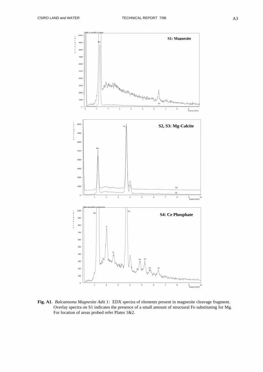
Fig. A1. Balcanoona Magnesite Adit 1: EDX spectra of elements present in magnesite cleavage fragment.Overlay spectra on S1 indicates the presence of a small amount of structural Fe substituting for Mg.For location of areas probed refer Plates 1&2.

CSIRO LAND and WATER TECHNICAL REPORT 7/98 A4
Plate 3: Balcanoona Magnesite, Adit 1: Boundary between coarse magnesite crystals comprisingpredominantly chlorite (Ch) flakes (S6) to 100 µm across, and bright apatite grains (S5, S7) mixedtogether with smaller magnesite (Mg) fragments. Photo no. 56-3554, scale bar 100 µm.
0 2 4 6 8 10 12 14 16 18 20Energy (KeV)
0
1000
2000
3000
4000
5000
6000
7000Intensity
3656 s5 mg355.4Ca
P
Si
AlMg
S5: Apatite and chlorite
1 2 3 4 5 6 7 8 9Energy (KeV)
0
200
400
600
800
1000
1200
1400
1600
1800
2000Intensity
3656 s6 mg355.4
Mg
Al
Si
Fe
S6: Chlorite
1 2 3 4 5 6 7 8 9Energy (KeV)
0
2000
4000
6000
8000
10000
12000
14000
Intensity
3656 s7 mg355.4 bb inCa
P
Mg
S7: Apatite
Fig. A2. Balcanoona Magnesite Adit 1: EDX spectra of apatite and chlorite shown in Plate 3. Note relativelow Fe content in chlorite (S6).

CSIRO LAND and WATER TECHNICAL REPORT 7/98 A5
Plate 4: Balcanoona Magnesite, Adit 2: Boundary between coarse bladed magnesite crystals (S1) occupied bycurved chlorite flakes (S3) and apatite grains (S4). Note euhedral apatite crystal, middle right,penetrating into magnesite (S2). Photo no. 57-3555, scale bar 200 µm.
1 2 3 4 5 6 7 8 9Energy (KeV)
0
1000
2000
3000
4000
5000
6000
7000
8000Intensity
3657 s1 mg355.5 magnesiteMg
Fe
Cl
S1: Magnesite
1 2 3 4 5 6 7 8 9Energy (KeV)
0
2000
4000
6000
8000
10000
12000
14000
16000Intensity
3657 s2 & s4 mg355.5
S4
S2
P
Ca
S2, S4: Apatite
1 2 3 4 5 6 7 8 9Energy (KeV)
0
500
1000
1500
2000
2500
3000
3500
4000
4500
5000
5500Intensity
3657 s3 mg355.5 chlorite
Fe
Si
Al
Mg
S3: Chlorite
Fig. A3: Balcanoona Magnesite; Adit 2: EDX spectra of magnesite, apatite and chlorite shown in Plate 4.Note structural Fe present in magnesite and chlorite.

CSIRO LAND and WATER TECHNICAL REPORT 7/98 A6
Plate 5: Balcanoona Magnesite, Adit 2: Boundary between two coarse magnesite crystals marked by thepresence of chlorite and apatite. Composition of magnesite recorded (S5, S6) and small aggregate ofsecondary gypsum (S7). Photo no. 57-3557, scale bar 200 µm.
Plate 6: Balcanoona Magnesite, Adit 2: Detail of Plate 5 showing secondary gypsum mixed with chlorite onthe surface of a magnesite cleavage fragment. Photo no. 57-3558, scale bar 40 µm.
CSIRO LAND and WATER TECHNICAL REPORT 7/98 A7
1 2 3 4 5 6 7 8 9Energy (KeV)
0
1000
2000
3000
4000
5000
6000
7000
8000
9000
Intensity
3657 s5 m355.7 magnesite
Ca
Fe
Mg
Cl
S5: Magnesite
1 2 3 4 5 6 7 8 9Energy (KeV)
0
1000
2000
3000
4000
5000
6000
7000
8000
Intensity
3657 s6 mg355.7 magnesite
Ca
Fe
Mg
S6: Magnesite
1 2 3 4 5 6 7 8 9Energy (KeV)
0
1000
2000
3000
4000
5000
6000
7000
8000
Intensity
3657 s7 mg355.8 top of bb
S
K
Ca
Ca
Fe
Si
Al
Mg
P
S7: Gypsum and Chlorite
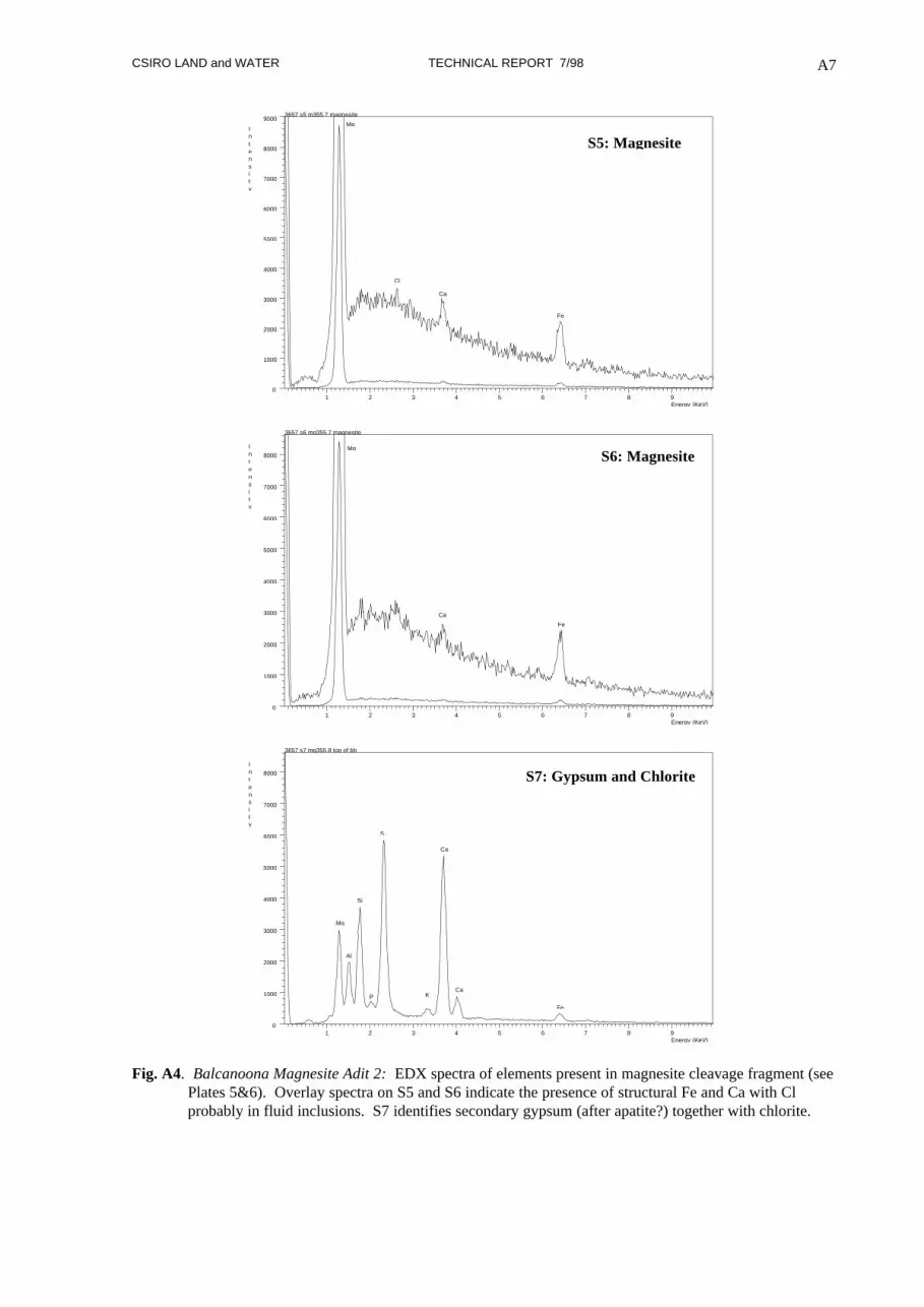
Fig. A4. Balcanoona Magnesite Adit 2: EDX spectra of elements present in magnesite cleavage fragment (seePlates 5&6). Overlay spectra on S5 and S6 indicate the presence of structural Fe and Ca with Clprobably in fluid inclusions. S7 identifies secondary gypsum (after apatite?) together with chlorite.

CSIRO LAND and WATER TECHNICAL REPORT 7/98 A8
Plate 7: Balcanoona Magnesite, Adit 2: Detail of Plate 5 (bottom centre) showing mixture of finer grainedchlorite (S10), apatite (S11), magnesian calcite (S12) and magnesite (S13) along boundary with coarsemagnesite crystals. Photo no. 57-3561, scale bar 40 µm.
Fig. A5. Balcanoona Magnesite Adit 2: EDX spectra of minerals phases included between coarse magnesitecrystals shown in Plate 7.
1 2 3 4 5 6 7 8 9Energy (KeV)
0
1000
2000
3000
4000
5000
6000
7000
8000Intensity
3657 s10 mg356.1 lhs
Fe
Si
Al
Mg
S10: Chlorite
1 2 3 4 5 6 7 8 9Energy (KeV)
0
2000
4000
6000
8000
10000
12000
14000
16000Intensity
3657 s11 mg356.1 apatite
Ca
Ca
P
S11: Apatite
1 2 3 4 5 6 7 8 9Energy (KeV)
0
1000
2000
3000
4000
5000
6000
7000
Intensity
3657 s12 mg356.1 bm-lhs ^Mg-
Ca
Ca
Mg
Fe
S12: Mg-Calcite
1 2 3 4 5 6 7 8 9Energy (KeV)
0
1000
2000
3000
4000
5000
6000
7000
8000
Intensity
3657 s13 mg356.1 b-lh
Fe
Mg
S13: Magnesite

CSIRO LAND and WATER TECHNICAL REPORT 7/98 A9
Plate 8: Balcanoona Magnesite, Creek Sample: Micrograph of a boundary zone (centre-left to right) betweentwo radiating magnesite crystals. Zone contains minor inclusions of chlorite (S8) and clacite/apatite(S10) and some Fe and Ti oxides (S9). Photo no. 15-3583, scale bar 200 µm.
Fig. A6. Balcanoona Magnesite Creek Sample: EDX spectra of magnesite and minor mineral phases betweencoarse magnesite crystals. For location of spectra refer Plate 8.
1 2 3 4 5 6 7 8 9Energy (KeV)
0
200
400
600
800
1000
1200
1400
1600
1800
2000Intensity
3715 s7 mg358.3
Mg
Fe
S7: Magnesite
1 2 3 4 5 6 7 8 9Energy (KeV)
0
500
1000
1500
2000
2500
Intensity
3715 s8 mg358.3 bighter
Fe
Mg
Al
Si
S8: Chlorite
1 2 3 4 5 6 7 8 9Energy (KeV)
0
500
1000
1500
2000
2500
3000
3500
4000
4500
Intensity
3715 s9 mg358.3
MgAl
SiTi
Ti
Fe
Fe
S9: Fe and Ti oxides
1 2 3 4 5 6 7 8 9Energy (KeV)
0
500
1000
1500
2000
2500
3000
3500
4000
4500
Intensity
3715 s10 mg358.3 bright matrixCa
Ca
P
S10: Calcite and minor Apatite

CSIRO LAND and WATER TECHNICAL REPORT 7/98 A10
Plate 9: Balcanoona Magnesite, Creek Sample: Margin of a coarse magnesite crystal marked by finer grainedapatite (S14) and chlorite (S18) lower left. Note inclusion of chlorite in magnesite, S18 upper left, andeuhedral pyrite, bright grain S12. Photo no. 15-3585, scale bar 100 µm.
Fig. A7. Balcanoona Magnesite, Creek Sample: EDX spectra of pyrite (S12) and chlorite (S18) inclusions inmagnesite and chlorite (S18) and apatite (S14) along magnesite crystal boundary. For location ofspectra refer Plate 9.
1 2 3 4 5 6 7 8 9Energy (KeV)
0
1000
2000
3000
4000
5000
6000
7000
8000Intensity
3715 s12 mg 358.5
Fe
S
S12: Pyrite
1 2 3 4 5 6 7 8 9Energy (KeV)
0
1000
2000
3000
4000
5000
6000
7000
8000Intensity
3517 s14 mg358.5 b inclusion
Ca
Ca
P
S14: Apatite
1 2 3 4 5 6 7 8 9Energy (KeV)
0
500
1000
1500
2000
2500
3000
3500
4000
Intensity
3715 s17 mg358.5 matrix nxt
Mg
P
Ca
Fe
S17: Magnesite
1 2 3 4 5 6 7 8 9Energy (KeV)
0
500
1000
1500
2000
2500
3000
3500
4000
Intensity
3715 s18 mg358.5 matrix
Mg
Al
Si
Fe
S18: Chlorite

CSIRO LAND and WATER TECHNICAL REPORT 7/98 A11
Plate 10: Balcanoona Magnesite, Stockpiled ore sample: Sawn surface through interlocking coarse magnesitecrystals. Composition variation in magnesite is recorded in spectra from sites S1-S5 (see Fig. A8).Bright areas are Mg-calcite. Photo no. 16-3587, scale bar 400 µm.
Plate 11: Balcanoona Magnesite, Stockpiled ore sample: Sawn surface in magnesite showing the presence of asmall rounded, 20 µm diameter, inclusion of organic material (lower centre, arrowed). Photo no. 16-3591, scale bar 20 µm.

CSIRO LAND and WATER TECHNICAL REPORT 7/98 A12
1 2 3 4 5 6 7 8 9Energy (KeV)
0
500
1000
1500
2000
2500
3000
3500
4000
Intensity
3716 s1-5 mg358.7
Mg Ca
Ca
Fe
S1
S2
S3
S4
S5
Si
Fig. A8. Balcanoona Magnesite, Stockpiled Ore Sample: EDX spectra showing variation in magnesitecomposition due mainly to iron (Fe) and calcium (Ca) substitution for magnesium (Mg). Silica (Si) inspectra S4 is due to the presence of nearby chlorite inclusions. Locations of analysed sites are shownin Plate 10.
CSIRO LAND and WATER TECHNICAL REPORT 7/98 A13
SCREECHOWL CREEK
Three samples were examined, all from outcrop in creek section and selected during the bulk sampling
program in April 1997.
3721: Fine-grained, massive, mid-grey bedded magnesite showing some disruption of layers to form
elongate pebble intraformational conglomerate bands with slightly coarser grained and darker crystalline
matrix. Within some areas of bedded magnesite, and in clasts, there are abundant equant dark grey
albite crystals grown in random orientation. Thin veinlets of crystalline carbonate run parallel to and
cut across bedding. The sample has a white, weathered surface with irregular patches of white to pale
grey magnesite extending into the body of the rock preferentially within areas of bedded magnesite and
clasts leaving the matrix darker grey. In weathered areas, traces of orange-brown staining were
observed preferentially within the more coarsely crystalline matrix and around the margins of the clasts
(sample SC8). SEM examination of a freshly fractured surface.
3722: Massive, regular pebble magnesite conglomerate with very pale grey magnesite as rounded
subspherical granules 2-5 mm diameter partly fused together or surrounded by a medium to dark grey
carbonate matrix. SEM examination of a freshly fractured surface.
3724: Massive, fine-grained, very pale grey bedded magnesite with slightly curved and truncated
bedding planes outlined by thin, slightly darker magnesite bands. Bedding crosscut at almost 90° by
occasional thin veinlets of slightly darker grey and slightly coarser crystalline carbonate. Traces of dark
grey, equant albite crystals to about 1 mm length, showing random growth orientation (Sample
169.7 m). SEM examination of a sawn surface.

CSIRO LAND and WATER TECHNICAL REPORT 7/98 A14
Plate 12: Screechowl Creek Magnesite, Sample 3721: Bedded, fine-grained magnesite containing somecoarser crystalline matrix between bedding planes. Evidence of partial desiccation and disruption tosome beds (centre right). Patchy white areas result from weathering with the weathering progressingfrom right to left. Photo no. 3721, width of sample is 20 mm.
Plate 13: Screechowl Creek Magnesite, Sample 3721: Backscattered electron micrograph of portion of Plate12 showing fine-grained magnesite with thin bands of recrystallised matrix (lighter grey) that roughlyparallel bedding. Enlargements are shown in Plates 14-16. Photo no. 21-3617, scale bar 1 mm.
CSIRO LAND and WATER TECHNICAL REPORT 7/98 A15
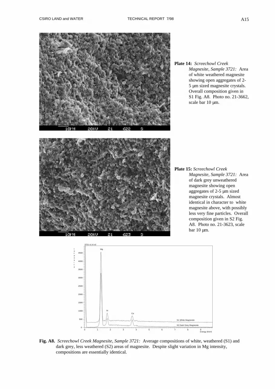
Plate 14: Screechowl CreekMagnesite, Sample 3721: Areaof white weathered magnesiteshowing open aggregates of 2-5 µm sized magnesite crystals.Overall composition given inS1 Fig. A8. Photo no. 21-3662,scale bar 10 µm.
Plate 15: Screechowl CreekMagnesite, Sample 3721: Areaof dark grey unweatheredmagnesite showing openaggregates of 2-5 µm sizedmagnesite crystals. Almostidentical in character to whitemagnesite above, with possiblyless very fine particles. Overallcomposition given in S2 Fig.A8. Photo no. 21-3623, scalebar 10 µm.
0 1 2 3 4 5 6 7 8 9Energy (KeV)
0
500
1000
1500
2000
2500
3000
3500
4000
4500
Intensity
3721 s1 & s2
S1 White Magnesite
S2 Dark Grey Magnesite
Mg
Si
Ca
Fig. A8. Screechowl Creek Magnesite, Sample 3721: Average compositions of white, weathered (S1) anddark grey, less weathered (S2) areas of magnesite. Despite slight variation in Mg intensity,compositions are essentially identical.

CSIRO LAND and WATER TECHNICAL REPORT 7/98 A16
Plate 16: Screechowl Creek Magnesite, Sample 3721: Detail of more coarsely crystalline layers between fine-grained magnesite. These layers are composed of a mixture of fine and coarser crystalline magnesite(S3), dolomite (S7), talc (S5, S6) and magnesian calcite (S4). Photo no. 21-3624, scale bar 40 µm.
0 1 2 3 4 5 6 7 8 9Energy (KeV)
0
500
1000
1500
2000
2500
3000
3500
4000
4500Intensity
3721 s3, s4, s7 mg326.3
Mg
Si
Ca
Ca
S3
S7
S4
Coarser crystalline carbonates
0 1 2 3 4 5 6 7 8 9Energy (KeV)
0
500
1000
1500
2000
2500
3000
3500
4000
4500Intensity
3721 s5 & s6 mg362.4
Fe
Ca
Si
Mg
S5
S6
Talc and Fe oxides
Fig. A9. Screechowl Creek Magnesite, Sample 3721: Composition of recrystallised magnesite and dolomite(S3, S4, S7) and talc (S5, S6). See Plate 16 for locations.

CSIRO LAND and WATER TECHNICAL REPORT 7/98 A17
Plate 17: Screechowl Creek Magnesite, Sample 3721: Thin veinlet of magnesian calcite (S9) with patches ofbarite (BaSO4) (S8) in very fine-grained magnesite (S10). Photo no. 21-3625, scale bar 20 µm.
1 2 3 4 5 6 7 8 9Energy (KeV)
0
100
200
300
400
500
600
700
800
900
1000
1100Intensity
3721 s8 mg362.5
S Ba
Ba
Ba
Ba
S8: Barite
1 2 3 4 5 6 7 8 9Energy (KeV)
0
200
400
600
800
1000
1200
1400
Intensity
3721 s9 mg362.5 bm mid
Mg
Ca
Ca
S9: Mg-Calcite
1 2 3 4 5 6 7 8 9Energy (KeV)
0
500
1000
1500
2000
Intensity
3721s10 mg362.5 top lh
Mg
SiCa
S10: Magnesite
Fig. A10. Screechowl Creek Magnesite, Sample 3721: Composition of Mg-calcite (S9) veinlet with barite (S8)crosscutting fine-grained magnesite (S10). See Plate 17 for locations.

CSIRO LAND and WATER TECHNICAL REPORT 7/98 A18
Plate 18: Screechowl Creek Magnesite, Sample3722: Pebble magnesite conglomerate comprising fine-grainedmagnesite granules 2-5 mm across in a carbonate matrix. Photo no. 22-3627, scale bar 1 mm.
Plate 19: Screechowl Creek Magnesite, Sample 3722: Detail of Plate 18, lower centre, showing the contactbetween magnesite clasts and carbonate cement. Photo no. 22-3626, scale bar 200 µm.
CSIRO LAND and WATER TECHNICAL REPORT 7/98 A19
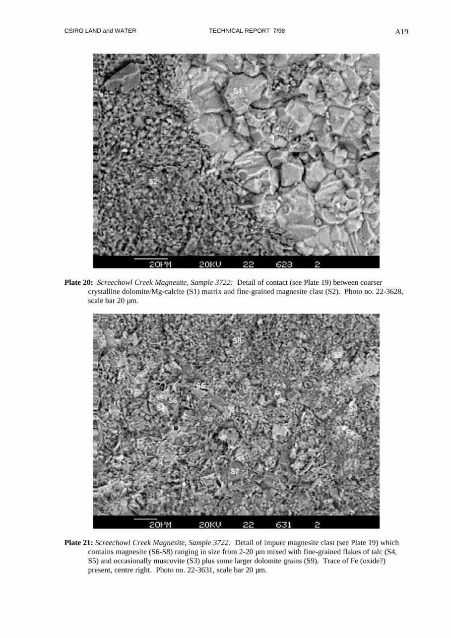
Plate 20: Screechowl Creek Magnesite, Sample 3722: Detail of contact (see Plate 19) between coarsercrystalline dolomite/Mg-calcite (S1) matrix and fine-grained magnesite clast (S2). Photo no. 22-3628,scale bar 20 µm.
Plate 21: Screechowl Creek Magnesite, Sample 3722: Detail of impure magnesite clast (see Plate 19) whichcontains magnesite (S6-S8) ranging in size from 2-20 µm mixed with fine-grained flakes of talc (S4,S5) and occasionally muscovite (S3) plus some larger dolomite grains (S9). Trace of Fe (oxide?)present, centre right. Photo no. 22-3631, scale bar 20 µm.

CSIRO LAND and WATER TECHNICAL REPORT 7/98 A20
1 2 3 4 5 6 7 8 9Energy (KeV)
0
1000
2000
3000
4000
5000
6000
7000
8000Intensity
3722 s1 mg362.8 large grain
MgCa
Ca
S2
S1
S1: Mg-calciteS2: Magnesite
Fig. A11. Screechowl Creek Magnesite, Sample 3722: Comparison of composition of crystalline matrix andfiner grained magnesite making up individual clasts. Note no apparent Si and Ca associated withmagnesite in the particular clast examined (refer Plate 20).
1 2 3 4 5 6 7 8 9Energy (KeV)
0
200
400
600
800
1000
1200
1400
1600
1800
2000
2200Intensity
3722 s3 mg363.2 flat bb rhs mid
Mg
Si
Al K Ca
S3
S4
S5
S3: Talc and K-feldsparS4-S5: Talc
1 2 3 4 5 6 7 8 9Energy (KeV)
0
100
200
300
400
500
600
700
Intensity
3722 s6-s8 mg363.1
Ca
Si
Mg
S6
S7
S8
S6-S7: Magnesite with variable Si and Ca
Fig. A12. Screechowl Creek Magnesite, Sample 3722: Variation in composition of a single impure magnesiteclast due to the presence of other fine-grained mineral phases (Plate 21).

CSIRO LAND and WATER TECHNICAL REPORT 7/98 A21
Plate 22: Screechowl Creek Magnesite, Sample 3724: Fine-grained bedded magnesite with crosscuttingcarbonate veinlets and random black, euhedral albite crystals. Photo no. 3724, specimen width 12 mm.
Plate 23: Screechowl Creek Magnesite, Sample 3724: Euhedral albite crystals to 0.6 x 0.2 mm (S2, S4, S6) infine-grained magnesite (S12). Crosscutting veinlets comprise Mg-calcite (S8) offset by later veinlets oftalc and K-feldspar (S10). Photo no. 24-3673, scale bar 400 µm.

CSIRO LAND and WATER TECHNICAL REPORT 7/98 A22
1 2 3 4 5 6 7 8 9Energy (KeV)
0
1000
2000
3000
4000
5000
6000
7000
8000
Intensity
3724 s2,s4,s6 mg363.7
Na
Al
Si
S2
S4
S6
S2, S4, S6: Albite crystals
1 2 3 4 5 6 7 8 9Energy (KeV)
0
1000
2000
3000
4000
5000
6000
7000
8000Intensity
3724 s8, s10 mg363.7 veins
Si
Al
Mg
K
S8
S10
Ca
Ca
VeinletsS8: Mg-calciteS10: K-feldspar/talc
1 2 3 4 5 6 7 8 9Energy (KeV)
0
1000
2000
3000
4000
5000
6000
7000
8000Intensity
3724 s12 fine gr magnesite
Mg
Si
Ca
Fe
S12: Magnesite with trace Si, Ca and Fe
Fig. A13. Screechowl Creek Magnesite, Sample 3724: Composition of diagenetic albite crystals (S2, S4, S6),dolomitic calcite (S8) and talc/K-feldspar veinlets, (S10), and bedded magnesite (S12) (Plate 23).
CSIRO LAND and WATER TECHNICAL REPORT 7/98 A23
WITCHELINA
Two samples were examined, both from outcrop of the main magnesite bed on the western syncline
limb.
3661: White to very pale grey magnesite pebble conglomerate with magnesite as rounded, subspherical
to elongate clasts 1 mm to 15 mm diameter in a white, pale grey to grey fine-grained carbonate matrix.
Numerous rounded clasts show a white border, usually <1 mm wide, which has a high (talc). SEM
examination of a freshly fractured surface. Sample from P P Crettenden collection (sample 6437 RS2,
collected 1983).
3741: Massive, white to pale grey coarse magnesite sand to fine granule conglomerate with
subspherical, rounded, magnesite clasts 0.5-1 mm grading to rounded, subspherical to elongate clasts to
4 mm. Clasts are fused together or cemented by a slightly more crystalline darker grey carbonate
matrix. SEM examination of a freshly fractured surface.

CSIRO LAND and WATER TECHNICAL REPORT 7/98 A24
Plate 24: Witchelina Magnesite, Sample 3661: Contact between fine-grained magnesite clast (S2), right, andmatrix of elongate subparallel talc crystals (S1). Photo no. 61-3565, scale bar 40 µm.
Plate 25: Witchelina Magnesite, Sample 3661: Detail of subparallel talc crystals (S4) with interspersedcoarser crystalline magnesite particles (S3) at contact with fine-grained magnesite (right). Photo no.61-3566, scale bar 40 µm.

CSIRO LAND and WATER TECHNICAL REPORT 7/98 A25
1 2 3 4 5 6 7 8 9Energy (KeV)
0
2000
4000
6000
8000
10000
12000Intensity
3661s1 mg356.5 talc
Mg
Si
S1: Talc
1 2 3 4 5 6 7 8 9Energy (KeV)
0
1000
2000
3000
4000
5000
6000
7000
Intensity
3661 s2 mg356.5 magnesite
Mg
Si
Ca
S2: Magnesite with trace Si and Ca
1 2 3 4 5 6 7 8 9Energy (KeV)
0
500
1000
1500
2000
2500
3000
3500
4000
4500
5000
Intensity
3661 s3 mg356.6 magnesite xtals
Mg
Si
S3: Magnesite
1 2 3 4 5 6 7 8 9Energy (KeV)
0
2000
4000
6000
8000
10000
12000Intensity
3661 s4 mg356.6 talc
Si
Mg
S4: Talc
Fig. A14. Witchelina Magnesite, Sample 3661: Composition of fine-grained magnesite clast (S2) andrecrystallised matrix of talc (S1, S4) and coarser grained magnesite (S3) (Plates 24&25).

CSIRO LAND and WATER TECHNICAL REPORT 7/98 A26
Plate 26: Witchelina Magnesite, Sample 3661: Detail of magnesite clast comprising anhedral, fine-grainedmagnesite particles 2-5 µm across arranged in an open porous network. Photo no. 61-3568, scale bar10 µm.
Plate 27: Witchelina Magnesite, Sample 3741: Low magnification view showing coarse rounded clasts offine-grained magnesite (mid-grey) cemented by a matrix of slightly coarser crystalline carbonate (lightgrey). Photo no. 41-3676, scale bar 200 µm.

CSIRO LAND and WATER TECHNICAL REPORT 7/98 A27
Plate 28: : Witchelina Magnesite, Sample 3641: Detail of Plate 27 showing boundary between fine-grainedmagnesite clast (lower right) and coarser grained matrix of magnesite (S6) and calcite (S7). Photo no.41-3677, scale bar 40 µm.
1 2 3 4 5 6 7 8 9Energy (KeV)
0
500
1000
1500
2000
2500
3000
3500Intensity
3741 s5 mg367.7
Mg
Si Ca
S5: Magnesite
1 2 3 4 5 6 7 8 9Energy (KeV)
0
500
1000
1500
2000
2500
3000Intensity
3741 s6 mg367.7 coarseMg
Ca
S6: Magnesite - coarser matrix
1 2 3 4 5 6 7 8 9Energy (KeV)
0
500
1000
1500
2000
2500
3000
3500
4000Intensity
3741 s7 mg367.7 finer
Mg
Ca
Ca
S7: Mg-calcite
Fig. A15. Witchelina Magnesite, Sample 3741: Composition of fine-grained magnesite clast (S5) andrecrystallised matrix of magnesite (S6) and dolomitic calcite(S7) (Plate 28).

CSIRO LAND and WATER TECHNICAL REPORT 7/98 A28
Plate 29: : Witchelina Magnesite, Sample 3741: Detail of crystalline matrix composed of magnesite (S1),dolomite (S4) and Mg-calcite (S3) with rare patches of organic inclusions (fuzzy dark patches) (S2, S8).Photo no. 41-3681, scale bar 40 µm.
1 2 3 4 5 6 7 8 9Energy (KeV)
0
200
400
600
800
1000
1200
1400
1600
1800Intensity
3741 s1,s3,s4 mg368.1
S1
S3
S4
Mg
Ca
Ca
S1, S3, S4: Carbonate matrix composition
1 2 3 4 5 6 7 8 9Energy (KeV)
0
100
200
300
400
500
600
700
800Intensity
3741 s2,s8 mg368.1 dark area
S2
S8
Ca
Fe
Si
Al
Mg S Cl
K
Ca
S2, S8: Organic inclusions
Fig. A16. Witchelina Magnesite, Sample 3741: Composition of recrystallised matrix (S1, S3, S4) and organicinclusions (characterised by high sulphur and chlorine) (S2, S8) (Plate 29).
CSIRO LAND and WATER TECHNICAL REPORT 7/98 A29
TERMINATION HILL
Two samples were examined, both from outcrop in creek section and selected during the bulk sampling
program in April 1997.
3725: Massive, very pale grey, extremely fine-grained, bedded magnesite with minor inclusions of
randomly orientated dark grey to black albite crystals to 1.5 mm length. SEM examination of a freshly
fractured surface.
3740: Magnesite conglomerate with very pale grey clasts, 2 mm to >20 mm across, in pale to dark
grey, fine to medium-grained matrix. Both clasts and matrix cut by minor carbonate veinlets. SEM
examination of a freshly fractured surface.

CSIRO LAND and WATER TECHNICAL REPORT 7/98 A30
Plate 30: Termination Hill Magnesite, Sample 3725: Pale grey, fine-grained, bedded magnesite with blackalbite crystals and thin carbonate veins. Photo no. 3725a, sample width 15 mm.
Plate 31: Termination Hill Magnesite, Sample 3725: Sodium feldspar (albite) crystal (S1), 250x400 µm size,in fine-grained magnesite. Photo no. 25-3641, scale bar 100 µm.

CSIRO LAND and WATER TECHNICAL REPORT 7/98 A31
Plate 32: Termination Hill Magnesite, Sample 3725: Sodium feldspar (albite) crystal (S4), in fine-grainedmagnesite. Photo no. 25-3641, scale bar 200 µm.
1 2 3 4 5 6 7 8 9Energy (KeV)
0
2000
4000
6000
8000
10000
12000
14000
Intensity
3725 s1, s4 mg364.1, mg 365.1 Feldspar
Ca
Si
Al
Mg
Na
S1
S4
S1, S4: Albite crystals
Fig. A17. Termination Hill Magnesite, Sample 3725: EDX spectra of albite crystals in fine-grained magnesite(see Plates 31 & 32). Presence of dolomite in S4 may indicate some later stage replacement ofearlier formed albite.

CSIRO LAND and WATER TECHNICAL REPORT 7/98 A32
Plate 33: Termination Hill Magnesite, Sample 3725: Thin dolomite vein, centre, cuts at right angles acrossmagnesite bedding which varies in composition from dolomite (S5) to magnesite (S6). Thin darkbands, visible in Plate 30, are more dolomitic (and organic?). Photo no. 25-3653, scale bar 400 µm.
1 2 3 4 5 6 7 8 9Energy (KeV)
0
500
1000
1500
2000
2500
3000
3500
4000Intensity
3725 s5 mg365.3 dark vein avg.
Mg
Ca
Si
S ClPCa
S5: Dark band
1 2 3 4 5 6 7 8 9Energy (KeV)
0
1000
2000
3000
4000
5000
6000
7000Intensity
3725 s6 mg365.3 nxt to s5Mg
Si
Ca
Cl
Ca
S6: Light band
Fig. A18. Termination Hill Magnesite, Sample 3725: Composition of dark and light bands in beddedmagnesite. Dark bands are dolomitic and the presence of P, S & Cl suggest some organic matter.Light bands are magnesite with some silica and calcium. (see Plates 30 & 33).

CSIRO LAND and WATER TECHNICAL REPORT 7/98 A33
Plate 34: Termination Hill Magnesite, Sample 3740: Coarse magnesite conglomerate with large clasts of fine-grained magnesite in a matrix of magnesite and dark grey dolomite. Composition of clast S1 ispredominantly magnesite with traces of Si and Ca (Fig. A19) Photo no. 3740a, sample width 18 mm.
1 2 3 4 5 6 7 8 9Energy (KeV)
0
500
1000
1500
2000
2500
3000
3500
4000
4500Intensity
3740 s1 mg365.5 uniform grain
Mg
Si
Ca
S1: Magnesite
Fig. A19. Termination Hill Magnesite, Sample 3740: Average composition of magnesite clast (S1) showingtraces of silica and calcium (Plate 34).
CSIRO LAND and WATER TECHNICAL REPORT 7/98 A34
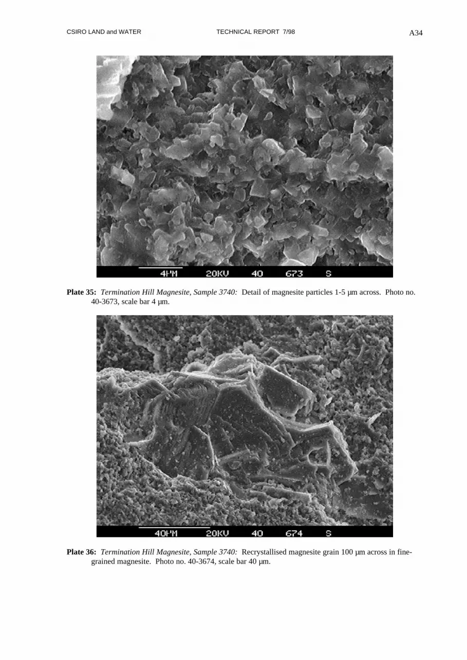
Plate 35: Termination Hill Magnesite, Sample 3740: Detail of magnesite particles 1-5 µm across. Photo no.40-3673, scale bar 4 µm.
Plate 36: Termination Hill Magnesite, Sample 3740: Recrystallised magnesite grain 100 µm across in fine-grained magnesite. Photo no. 40-3674, scale bar 40 µm.

CSIRO LAND and WATER TECHNICAL REPORT 7/98 A35
Plate 37: Termination Hill Magnesite, Sample 3740: Matrix zone between magnesite clasts comprisingmainly fine-grained magnesite (S7) with dolomitic patches (S4). Thin cross-cutting vein is largely Mg-calcite (S5) with segments of magnesite (S6) and rare quartz grain (S2). Photo no. 40-3675, scale bar200 µm.
Fig. A20. Termination Hill Magnesite, Sample 3740: EDX spectra of magnesite (S7), dolomitic patches (S4),vein material (S5, S6) and quartz grain (S2) (Plate 37).
1 2 3 4 5 6 7 8 9Energy (KeV)
0
500
1000
1500
2000
2500
3000
3500
4000
4500Intensity
3740 s4 mg367.5 large
Mg
Ca
Ca
S4: Mg-calcite
1 2 3 4 5 6 7 8 9Energy (KeV)
0
500
1000
1500
2000
2500
3000
3500
4000
4500Intensity
3740 s5, s6 mg367.5 bb vein up
MgCa
Ca
Sr
S5
S6
S5, S6: Vein
1 2 3 4 5 6 7 8 9Energy (KeV)
0
500
1000
1500
2000
2500Intensity
3740 s7 mg367.5 matrix mid
Si
Ca
S7: Magnesite
1 2 3 4 5 6 7 8 9Energy (KeV)
0
2000
4000
6000
8000
10000
12000
14000
16000Intensity
3740 s2 mg367.5
Si
S2: Quartz

CSIRO LAND and WATER TECHNICAL REPORT 7/98 A36
MYRTLE SPRINGS
Two samples were examined, one from bedded magnesite in the quarry face and the other from the
crushed lump ore stockpile.
3658: Coarse magnesite conglomerate comprising rounded magnesite pebble clasts in a matrix of
coarse sandy magnesite. SEM of a freshly fractured surface focused on a single clast with cross cutting
thin carbonate veinlets.
3723: Massive, coarse, pale grey, poorly sorted magnesite pebble conglomerate comprising rounded,
elongate 10 to 50 mm sized clasts of very fine-grained magnesite in a coarse sandy to fine granule
magnesite matrix with carbonate cement. Minor cross cutting veinlets of pale grey carbonate are
present. SEM examination of sawn face.

CSIRO LAND and WATER TECHNICAL REPORT 7/98 A37
Plate 38: Myrtle Springs Magnesite, Sample 3658: Fine-grained magnesite with inclusions of talc flakes andcut by recrystallised carbonate vein. Photo no. 58-3562, scale bar 100 µm.
Plate 39: : Myrtle Springs Magnesite, Sample 3658: Detail of Plate 38 showing distribution of talc flakes inmagnesite and variation in the composition of the carbonate vein (right). Photo no. 58-3562, scale bar40 µm.

CSIRO LAND and WATER TECHNICAL REPORT 7/98 A38
1 2 3 4 5 6 7 8 9Energy (KeV)
0
1000
2000
3000
4000
5000
6000
7000
8000
9000
10000Intensity
3658 s1 mg356.3 large flat grain
Mg
Ca
Fe
S1: Magnesite (darker grain)
1 2 3 4 5 6 7 8 9Energy (KeV)
0
1000
2000
3000
4000
5000
6000
7000
8000
9000
10000Intensity
3658 s2, s3, s4 mg356.3 Mg-calcite + Sr
Mg
Ca
Ca
Sr
S2
S3
S4
S2, S3, S4: Mg-calcite +Sr
Fig. A21: Myrtle Springs Magnesite, Sample 3658: Variation in composition of recrystallised vein materialwhere darker grains are magnesite with traces of Ca and Fe (S1) and lighter grains are Mg-calcite withsome Sr substituting for Ca (S2, S3, S4) (Plate 39).

CSIRO LAND and WATER TECHNICAL REPORT 7/98 A39
Plate 40: Myrtle Springs Magnesite, Sample 3658: Detail of magnesite particles to 5 µm across (S6), togetherwith coarser flakes of talc (S5). Photo no. 58-3564, scale bar 10 µm.
1 2 3 4 5 6 7 8 9Energy (KeV)
0
500
1000
1500
2000
2500
3000
3500
4000
4500
5000Intensity
3658 s5 mg356.4 talc
Mg
Si
S5: Talc
1 2 3 4 5 6 7 8 9Energy (KeV)
0
1000
2000
3000
4000
5000
6000
7000
8000
9000Intensity
3658 s6 mg356.4 magnesite
Mg
SiCa
S6: Magnesite
Fig. A22: Myrtle Springs Magnesite, Sample 3658: Composition of talc (S5) associated with fine-grainedmagnesite (S6) (Plate 40).

CSIRO LAND and WATER TECHNICAL REPORT 7/98 A40
Plate 41: Myrtle Springs Magnesite, Sample 3723: Sawn surface of a coarse magnesite conglomerate showingareas examined: 23-3633 interior of a coarse clast; 23-3635 area of finer clasts with dolomitic matrix.Photo no. 23-3634, scale bar 1 mm.
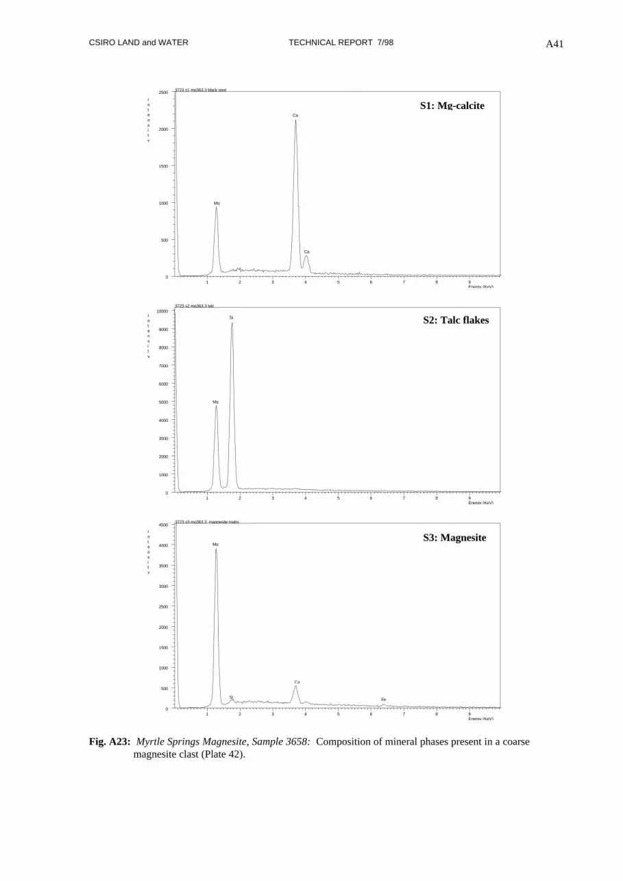
Plate 42: Myrtle Springs Magnesite, Sample 3723: Detail of interior of a coarse magnesite clast comprisingfine-grained magnesite (S3) with clusters of talc flakes (S2) and dolomitic patches (S1). Photo no. 23-3633, scale bar 40 µm.
CSIRO LAND and WATER TECHNICAL REPORT 7/98 A41
1 2 3 4 5 6 7 8 9Energy (KeV)
0
500
1000
1500
2000
2500
Intensity
3723 s1 mg363.3 black spot
Mg
Ca
Ca
S1: Mg-calcite
1 2 3 4 5 6 7 8 9Energy (KeV)
0
1000
2000
3000
4000
5000
6000
7000
8000
9000
10000Intensity
3723 s2 mg363.3 talc
Mg
Si S2: Talc flakes
1 2 3 4 5 6 7 8 9Energy (KeV)
0
500
1000
1500
2000
2500
3000
3500
4000
4500
Intensity
3723 s3 mg363.3 magnesite matrx
Mg
Si
Ca
Fe
S3: Magnesite
Fig. A23: Myrtle Springs Magnesite, Sample 3658: Composition of mineral phases present in a coarsemagnesite clast (Plate 42).

CSIRO LAND and WATER TECHNICAL REPORT 7/98 A42
Plate 43: Myrtle Springs Magnesite, Sample 3723: Irregular-shaped, subangular magnesite clasts (mid-grey)in a matrix of Mg-calcite, talc (light grey) and magnesite . Photo no. 23-3635, scale bar 400 µm.
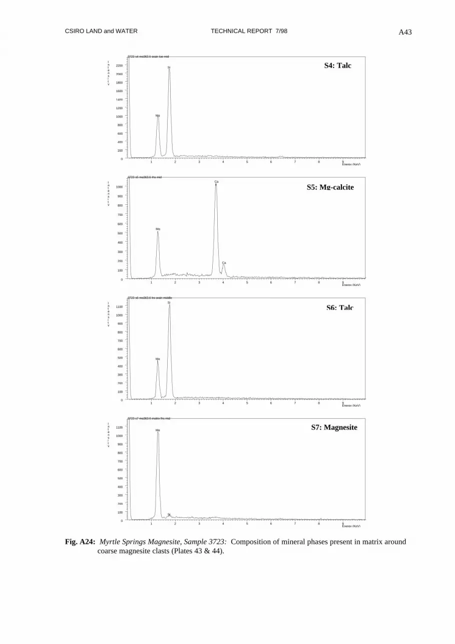
Plate 44: Myrtle Springs Magnesite, Sample 3723: Detail of Plate 43 showing fine-grained magnesite (S7)with patches of talc (S4, S6) and Mg-calcite (S5). Photo no. 23-3636, scale bar 20 µm.
CSIRO LAND and WATER TECHNICAL REPORT 7/98 A43
1 2 3 4 5 6 7 8 9Energy (KeV)
0
200
400
600
800
1000
1200
1400
1600
1800
2000
2200Intensity
3723 s4 mg363.6 grain top mid
Mg
Si S4: Talc
1 2 3 4 5 6 7 8 9Energy (KeV)
0
100
200
300
400
500
600
700
800
900
1000Intensity
3723 s5 mg363.6 rhs mid
Mg
Ca
Ca
S5: Mg-calcite
1 2 3 4 5 6 7 8 9Energy (KeV)
0
100
200
300
400
500
600
700
800
900
1000
1100Intensity
3723 s6 mg363.6 lrg grain middle
Mg
Si
S6: Talc
1 2 3 4 5 6 7 8 9Energy (KeV)
0
100
200
300
400
500
600
700
800
900
1000
1100Intensity
3723 s7 mg363.6 matrix lhs mid
Mg
Si
S7: Magnesite
Fig. A24: Myrtle Springs Magnesite, Sample 3723: Composition of mineral phases present in matrix aroundcoarse magnesite clasts (Plates 43 & 44).

CSIRO LAND and WATER TECHNICAL REPORT 7/98 A44
MOUNT HUTTON
Four samples were examined, all selected from the bulk sample taken from creek outcrop during the
sampling program in April 1997.
3717: Weathered, white, coarse grained magnesite sandstone comprising white to pale grey, rounded,
subspherical magnesite clasts in a white carbonate matrix. SEM of a freshly fractured surface.
3718: Sample as for 3717. SEM of a sawn face.
3719: Massive, coarse sand to fine pebble magnesite conglomerate comprising rounded magnesite
clasts 1 to 5 mm diameter in a recrystallised carbonate cement. Colour varies from white to dark grey
in streaky patches that cut across individual clasts. Other clasts are pale grey surrounded by white
matrix. The rock has a distinct mottled texture and shows evidence of graded bedding. SEM of freshly
fractured surface.
3720: Pale grey, magnesite pebble conglomerate comprising rounded, oval, fine-grained magnesite
clasts 1 to 10 mm across in a matrix of slightly darker grey recrystallised carbonate matrix. Minor thin
irregular crystalline carbonate veinlets cut across clasts and matrix. SEM of a sawn face.

CSIRO LAND and WATER TECHNICAL REPORT 7/98 A45
Plate 45: Mount Hutton Magnesite, Sample 3717: Coarse magnesite sand comprising 1-2 mm detritalmagnesite in a carbonate matrix. Sample appears white and moderately weathered. Photo no. 17-3592,scale bar 1 mm.
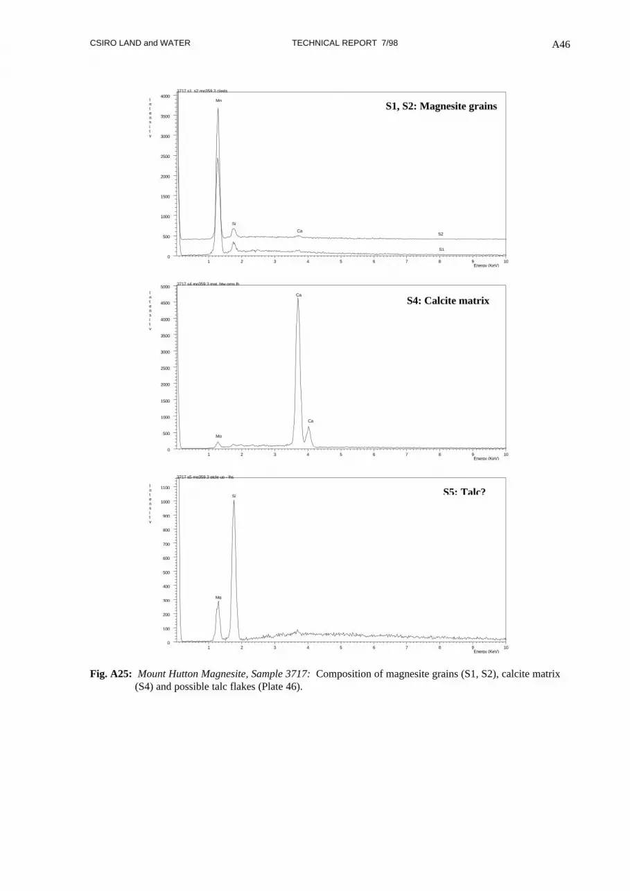
Plate 46: Mount Hutton Magnesite, Sample 3717: Detail of Plate 45 showing subrounded magnesite grains(S1, S2) with talc flakes (S5) in an open matrix that includes areas of high calcium content (S4). Photono. 17-3593, scale bar 200 µm.
CSIRO LAND and WATER TECHNICAL REPORT 7/98 A46
1 2 3 4 5 6 7 8 9 10Energy (KeV)
0
500
1000
1500
2000
2500
3000
3500
4000Intensity
3717 s1, s2 mg359.3 clasts
Mg
Si
Ca
S1
S2
S1, S2: Magnesite grains
1 2 3 4 5 6 7 8 9 10Energy (KeV)
0
500
1000
1500
2000
2500
3000
3500
4000
4500
5000Intensity
3717 s4 mg359.3 mat. btw grns lh
Ca
Ca
Mg
S4: Calcite matrix
1 2 3 4 5 6 7 8 9 10Energy (KeV)
0
100
200
300
400
500
600
700
800
900
1000
1100Intensity
3717 s5 mg359.3 ptcle up - lhs
Si
Mg
S5: Talc?
Fig. A25: Mount Hutton Magnesite, Sample 3717: Composition of magnesite grains (S1, S2), calcite matrix(S4) and possible talc flakes (Plate 46).
CSIRO LAND and WATER TECHNICAL REPORT 7/98 A47
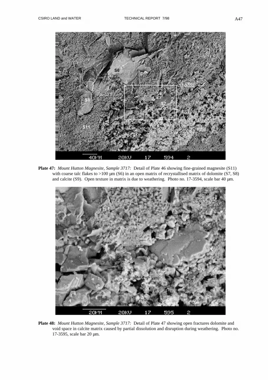
Plate 47: Mount Hutton Magnesite, Sample 3717: Detail of Plate 46 showing fine-grained magnesite (S11)with coarse talc flakes to >100 µm (S6) in an open matrix of recrystallised matrix of dolomite (S7, S8)and calcite (S9). Open texture in matrix is due to weathering. Photo no. 17-3594, scale bar 40 µm.
Plate 48: Mount Hutton Magnesite, Sample 3717: Detail of Plate 47 showing open fractures dolomite andvoid space in calcite matrix caused by partial dissolution and disruption during weathering. Photo no.17-3595, scale bar 20 µm.

CSIRO LAND and WATER TECHNICAL REPORT 7/98 A48
1 2 3 4 5 6 7 8 9 10Energy (KeV)
0
500
1000
1500
2000
2500
3000
3500
4000
4500
5000Intensity
3717 s6 mg359.4 flakes
Mg
Si S6: Talc
1 2 3 4 5 6 7 8 9 10Energy (KeV)
0
500
1000
1500
2000
2500
3000
3500
4000
4500
Intensity
3717 s7, s8, s9 mg359.4 recrystallised matrix
Mg
Si
Ca
Ca
S7
S8
S9
S7, S8, S9: Dolomite/calcite matrix
1 2 3 4 5 6 7 8 9 10Energy (KeV)
0
200
400
600
800
1000
1200
1400
1600
1800Intensity
3717 s11 mg359.4 lower lhs matrix
Mg
Si
Ca
S11: Magnesite
Fig. A26: Mount Hutton Magnesite, Sample 3717: Probable talc flakes (S6) with low Mg possibly due topreferential absorption of Mg X-rays resulting from sample position relative to the X-ray detector.Similarly, matrix composition is probably dolomitic (S7, S8) with some finer grained vughy calcite(S9). Fine-grained magnesite, typical of the sand-sized clasts, contains a trace of silica and calcium(S11). For location of sites analysed refer Plate 47.

CSIRO LAND and WATER TECHNICAL REPORT 7/98 A49
Plate 49: Mount Hutton Magnesite, Sample 3718: Rounded, coarse sandy magnesite clasts in a carbonatematrix, sawn sample face. Photo no. 3718a, sample width 12 mm.
1 2 3 4 5 6 7 8 9 10Energy (KeV)
0
500
1000
1500
2000
2500
3000
3500
4000Intensity
3718 s1 mg359.7 mid grain
Mg
SiCa
S1: Magnesite
1 2 3 4 5 6 7 8 9 10Energy (KeV)
0
500
1000
1500
2000
2500
3000
3500
4000Intensity
3718 s2 mg359.7 matrx btw grains
Si
Ca
Mg S2: Talc with magnesite and dolomite
Fig. A27: Mount Hutton Magnesite, Sample 3718: EDX spectra of the centre of a coarse magnesite clast (S1)and the matrix between clasts (S2) (see Plate 49).

CSIRO LAND and WATER TECHNICAL REPORT 7/98 A50
Plate 50: Mount Hutton Magnesite, Sample 3718: Detail of Plate 49 showing matrix between magnesite claststo comprise mainly talc flakes and fine-grained magnesite. Photo no. 18-3602, scale bar 20 µm.
1 2 3 4 5 6 7 8 9Energy (KeV)
0
500
1000
1500
2000
2500
3000
3500
4000
4500Intensity
3718 s7, s8 mg360.2
Mg
Si
S7
S8
S7, S8: Talc
1 2 3 4 5 6 7 8 9Energy (KeV)
0
500
1000
1500
2000
2500
3000Intensity
3718 s10 mg360.2 fine matrix
Mg
Si
Ca
S10: Magnesite
Fig. A28: Mount Hutton Magnesite, Sample 3718: EDX spectra of talc flakes (S7, S8) and fine-grainedmagnesite (S10) in the matrix (see Plate 50).

CSIRO LAND and WATER TECHNICAL REPORT 7/98 A51
Plate 51: Mount Hutton Magnesite, Sample 3719: Massive coarse sandy to pebbly magnesite with distinctcolour mottling from dark grey (centre) to pale grey to white. Analyses S1-S3 record the magnesitecomposition in different coloured areas, S4 on a grain margin shows the presence of talc and iron oxidewith magnesite (see Fig. A29). Photo no. 3719a, Sample width 10 mm.
1 2 3 4 5 6 7 8 9Energy (KeV)
0
200
400
600
800
1000
1200
1400Intensity
3719 s1, s2, s3 mg360.3
CaSi
Mg
S1 - White magnesite
S3 - Pale grey magnesite
S2 - Dark grey magnesite
S1-S3: Magnesite
1 2 3 4 5 6 7 8 9Energy (KeV)
0
100
200
300
400
500
600
700
800
900Intensity
3719 s4 mg360.3 bb top lhs
Mg
Si
Fe
FeCa
S4: Fe oxide Talc Magnesite
Fig. A29: Mount Hutton Magnesite, Sample 3719: EDX spectra of individual magnesite clasts in areas ofwhite (S1), dark grey (S2) and pale grey (S3) mottling. Results confirm that magnesite compositionis consistent across colour variation. Some talc and rare Fe oxide present in matrix (S4) (see Plate51).

CSIRO LAND and WATER TECHNICAL REPORT 7/98 A52
Plate 52: Mount Hutton Magnesite, Sample 3720: Magnesite pebble conglomerate cut by a thin carbonateveinlet (lower centre), sawn face. Enlargements focus on clasts and matrix (20-3611) and compositionof the vein and adjacent clast (20-3614). Photo no. 3720b, Sample width 16 mm.
Plate 53: Mount Hutton Magnesite, Sample 3720: Backscattered electron micrograph highlighting thedifference in composition between areas of pale matrix comprising mainly dolomite with minor talc andthe darker grey magnesite in clasts and matrix. Photo no. 20-3611, scale bar 1 mm.

CSIRO LAND and WATER TECHNICAL REPORT 7/98 A53
Plate 54: Mount Hutton Magnesite, Sample 3720: Detail of Plate 52 showing the intersection of twocarbonate veinlets which cut through the centre of a large magnesite pebble clast Photo no. 20-3614,scale bar 40 µm.
Plate 55: Mount Hutton Magnesite, Sample 3720: Enlargement of Plate 54 showing sites probe to determinedifferences in composition between the recrystallised magnesite vein and fine-grained magnesite of thepebble clast. Photo no. 20-3616, scale bar 20 µm.

CSIRO LAND and WATER TECHNICAL REPORT 7/98 A54
1 2 3 4 5 6 7 8 9Energy (KeV)
0
100
200
300
400
500
600
700
800
900
1000Intensity
3720 s9, s10 mg361.6 magnesite
Mg
SiCa
S9 - Magnesite vein
S10 - Magnesite clast
S9, S10: Magnesite in vein and clast
Fig. A30: Mount Hutton Magnesite, Sample 3720: Comparison of the composition of recrystallised veinmagnesite (S9) and fine-grained magnesite (S10) in the pebble clasts. Si and Ca are ubiquitous inoriginal clasts but not in recrystallised magnesite. For location of probed sites refer Plate 55.