microstructure constitutive equation for discotic nematic liquid crystalline materials
TRANSCRIPT
Arvinder P. SinghAlejandro D. Rey
Microstructure constitutive equation fordiscotic nematic liquid crystalline materials
Part I: Selection procedure and shear flow predictions
Received: 8 May 1997Accepted: 15 September 1997
A.P. Singh · A.D. Rey (✉)Department of Chemical EngineeringMcGill University3610 University StreetMontreal, Quebec, H3A 2B2Canadae-mail: [email protected]
Abstract Four different microstruc-ture constitutive equations (CEs) fordiscotic nematic liquid crystalsbased on Doi’s modified nematody-namics theory are formulated. Theirdynamic and steady state responsesunder simple shear flows are com-puted and analyzed in terms of thetensor order parameterQ, the orien-tation director triad (n, m, l), andthe uniaxialS and biaxialP align-ments. A unit sphere description ofthe director triad is used to charac-terize and classify the various pre-dicted stable orientation states, andto discuss and analyze their multi-stabilities as a function of dimen-sionles shear rate. Various attractors,steady and periodic, are also identi-fied and their stability is discussedin detail for all the CEs. A valida-tion procedure based on the pre-dicted microstructural responsealong with bifurcation diagrams of
the individual CE and representativeexperimental observations as well astheoretical results is implemented,and used to select the most appro-priate CE. The selected CE predicts,under shear, the simultaneous pres-ence of stable in-plane (steady andperiodic) states and out-of-planesteady state, and the classical transi-tion among the in-plane periodicand steady states with increasingshear rate. The excellent perfor-mance of the selected CE in shearflows strongly suggests that it is areliable contribution towards the for-mulation of a process model for me-sophase pitch spinning.
Key words Mesophase pitches –discotic nematic liquid crystals –simple shear flow of nematics –constitutive equations for discoticnematic liquid crystals – mesophasecarbon fibers
Introduction
Carbonaceous mesophases or mesophase pitches are ob-tained from natural (petroleum or coal tar pitches) orsynthetic feed stock (naphthalene), and are used in themanufacture of high-performance mesophase pitch-based carbon fibers (Zimmer and White, 1982; Singer,1985; McHugh and Edie, 1996). The mesophase carbonfibers show outstanding stiffness and thermal transportproperties due to their ability to develop extended gra-phitic structures. The physical properties of high perfor-mance fibers are mainly due to the molecular orienta-
tion developed during the spinning process (McHugh,1994).
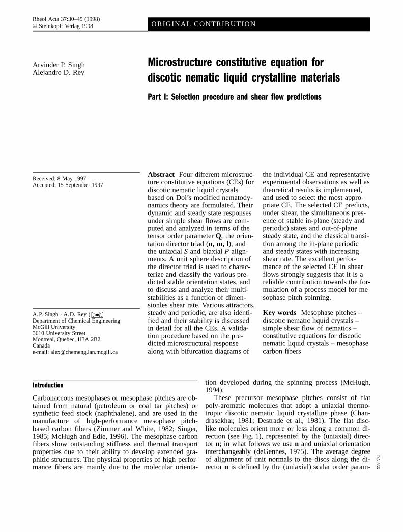
These precursor mesophase pitches consist of flatpoly-aromatic molecules that adopt a uniaxial thermo-tropic discotic nematic liquid crystalline phase (Chan-drasekhar, 1981; Destrade et al., 1981). The flat disc-like molecules orient more or less along a common di-rection (see Fig. 1), represented by the (uniaxial) direc-tor n; in what follows we usen and uniaxial orientationinterchangeably (deGennes, 1975). The average degreeof alignment of unit normals to the discs along the di-rectorn is defined by the (uniaxial) scalar order param-
Rheol Acta 37:30–45 (1998)© Steinkopff Verlag 1998 ORIGINAL CONTRIBUTION
RA
866
eterS; in what follows useS and uniaxial alignment in-terchangeably. The inherent nature of liquid crystallinematerials to acquire a preferred orientation in the pres-ence of flow provides a natural advantage to these ma-terials to be used as precursors for the manufacturing ofhigh performance fibers (e.g. mesophase pitch-basedcarbon fibers, Kevlar). In the spinning of mesophasecarbon fibers the preferred orientation is achieved as theprecursor material passes through the spin-pack whereit is subjected to non-homogeneous mixed shear andextensional flows. The extensional flows during fiberdrawing only accentuates the already attained orienta-tion in the spinneret in a plane normal to the fiber axis(McHugh, 1994).
The preferred orientation and degree of alignment ofthe disk-like molecules, and the average crystallite sizeare expected to have a predominant effect on all me-chanical and thermal properties. The optimization andcontrol of preferred orientation hence is of practical im-portance. Unfortunately, the fundamental understandingof the factors that affect the development of preferredorientation in mesophase carbon fibers is currently lack-ing, and is hindering their further development. Onecost-effective way to develop this understanding isthrough the use of modeling and simulation by adopt-ing the well developed theories for liquid crystallinepolymers (LCPs). The transfer of knowledge by adopt-ing the theories for conventional rod-like nematics todiscotic nematics is successfully demonstrated by Far-houdi and Rey (1993a), Rey (1995a), and Singh andRey (1994, 1995a, 1995b).
The classical theories for describing the rheology ofLCPs are the Leslie-Ericksen (L-E) continuum theoryand Doi’s molecular theory for mono-domain LCPs.Doi’s theory has fewer parameters and is shown to pre-dict satisfactorily the steady state shear and extensionalrheology (Doi and Sridhar, 1994). There exists a lot oftheoretical work, based on the above-mentioned the-ories, on modeling the flows of conventional rod-likenematics (Doi and Edwards, 1986; Larson, 1988; Mar-rucci and Greco, 1993; Beris and Edwards, 1994).However, these theories have not been used in a signifi-
cant way to model discotic nematic flows, and currentlythere is no appropriate constitutive equation that can de-scribe the flow-induced microstructure of discotic ne-matics in general, and that of mesophase pitches in par-ticular. In the present work we will adopt the well es-tablished Doi’s mesoscopic theory as a starting pointand modify it to establish the most suitable constitutiveequation for mesophase pitches. Next we present a sum-mary of the theoretical work performed in modeling themicrostructural response of discotics along with the es-sential features that are used to transfer the theoreticalknowledge from rod-like nematics to discotic nematics.
The previous work of Volovik (1980), Carlsson(1982, 1983), Baals and Hess (1988), and Ho and Rey(1991) on the rheology and flow-induced orientation ofuniaxial discotic nematics (DNs) assumed that thescalar order parameterS remains unaffected by the in-duced flow. The validity of this assumption for low mo-lecular weight materials justifies the use of Leslie-Erick-sen (L-E) theory (Leslie, 1979; deGennes, 1975; Chan-drasekhar, 1992) for uniaxial nematics with the propervalues of the materials parameters. The important differ-ence in sign and magnitude of the material parameterscorresponding to the uniaxial rod-like and discotic ne-matics arises from the fact that the rod-like nematicsorient their longest molecular dimension along the di-rector, whereas discotic nematics orient their shortest di-mension along the director. The orienting properties ofthe uniaxial nematics subjected to shear flows are gov-erned by the sign and magnitude of the uniaxial tum-bling (reactive) parameterk such that for aligning (non-aligning) rods k > 1 �0 < k < 1�, and for aligning(non-aligning) discsk < ÿ1 �ÿ1 < k < 0�. The uniax-ial tumbling parameterk is given by the negative ratioof the irrotational torque coefficient�c2� and the rota-tional viscosity�c1�, and represents the ratio of strain tothe vorticity torques acting on the uniaxial directorn(deGennes, 1975). Previous works by Carlsson (1982,1983) focus on the orienting properties of the aligninguniaxial discotic nematics in shear, and that of Ho andRey (1991) on Hamel flows. In these works, it wasfound that shear orients the director in the shear planeand at a steady anglehn, lying in the 908≤hn≤1358 sec-tor with respect to the flow direction, while extensionorients the director anywhere in a plane normal to theflow direction. Farhoudi and Rey (1993a) focused onthe orienting properties of non-aligning uniaxial discoticnematics in steady simple shear flows in which theyshowed that the uniaxial directorn tumbles, oscillatesor aligns according to the strength of the applied shear;the existence and transition between the various re-gimes is shown to be similar to that predicted by mo-lecular theories of the rod-like nematics. In steady uni-axial extensional flows, the orienting behavior of uniax-ial nematics is again determined by the sign ofk: whenk > 0 the director aligns along the stretching direction,
31A.P. Singh and A.D. ReyConstitutive equation for discotic nematics
Fig. 1 Definition of uniaxial directorn orientation of a discotic ne-matic liquid crystalline material. The uniaxial directorn is the aver-age orientation of the unit normals to the disc-like molecules
and whenk < 0 the director aligns somewhere in thecompression plane, orthogonal to the stretching direc-tion (Ho and Rey, 1991; Singh and Rey, 1994, 1995a,1995b). In a previous work (Singh and Rey, 1994) theauthors developed, from variational principles, a modelfor discotic nematics that takes into account variablealignment, and applied the model to a series of exten-sional flows such as uniaxial, equi-biaxial and planarextensional flows. It was found that the director alignsanywhere in a plane perpendicular to the extension di-rection (i.e., anywhere in the plane of uniform compres-sion) under uniaxial extensional flows, along compres-sion direction in biaxial, and planar extensional flows,and the director trajectories and steady states exhibitstrong sensitivity with the initial director orientation(Singh and Rey, 1994, 1995a).
The main objective of this work is to develop a con-stitutive equation for the idealized uniaxial discotic ne-matics that is consistent with the existing predictions ofmolecular and macroscopic theories for the rod-like ne-matics, and that is in qualitative agreement with the ex-perimental observations. The particular objectives ofthis paper are:
1) To formulate a set of generic constitutive equations(CEs) for discotic nematics;
2) To characterize the main microstructure features pre-dicted by the various proposed CEs in terms of uni-axial orientation dynamics;
3) To identify the various multi-stabilities of uniaxialorientation dynamics predicted by various CEs undershear flows;
4) To select the most suitable CE based on the com-puted microstructure behavior that reproduces withsufficient accuracy the experimentally observed be-havior of representative discotics, and that is consis-tent with previous theoretical predictions.
The organization of this paper is as follows. In thefollowing section we present the selection criteria forestablishing the most suitable CE for mesophasepitches. Then we define the coordinate system, the statevariables, the shear flow, and briefly present the ele-ments of unit sphere description used to characterize thebifurcation and dynamic results. In the same section,we present representative schematics of the main micro-structure phenomena in terms of uniaxial directorn thatare used to characterize the predicted bifurcational anddynamical phenomena, followed by the various pro-posed CEs and a brief description of the solution meth-ods employed to solve them. Next, we present the com-puted bifurcation results for each CE and employ thevalidation and selection criteria to select the mostappropriate microstructure CE. Subsequently, the mainfeatures of dynamic results of orientation and alignment(uniaxial and biaxial) are presented and summarized.Finally, the conclusions are given.
Selection procedure
As mentioned before in the present study we adopt thewell established theories for rod-like nematics and mod-ify them for discotic nematics. In this paper we proposeand select a CE using an iterative selection process thatstarts with a series of CEs and ends with the selectionof the one that meets a set of criteria. The criteria arebased on: 1) consistency with previous theoretical re-sults; 2) consistency with experimental data; and 3)simplicity. In this iterative process we propose a CE, in-vestigate the predicted orientation (microstructure) phe-nomena under simple shear flows, validate the com-puted results with the existing classical theoretical andexperimental results available in the literature, and se-lect the CE that best meets the criteria. If the simulatedresults of the proposed CE fail to satisfy the criteria itis then modified and tested again. In this iterative pro-cess we start with the simplest available CE for disco-tics which is derived from Doi’s mesoscopic theory andwas investigated by Rey (1995a) for extensional flows.
The theoretical results of classical molecular, andmacroscopic theories for conventional rod-like nematicsare employed to check the consistency of the CEs. Thesimulated results of modified macroscopic theories forDNs (Farhoudi and Rey, 1993a) are also used to checkthe validity of the simulated results of the proposedCEs. It is well established that the necessary uniaxialdirector n orientation features of the non-aligning ne-matics under shear rate: rotation ofn in the shear planeor in-plane tumbling (ITO), oscillation ofn in the shearplane or in-plane wagging (IWO), and stationary orien-tation of n in the shear plane or in-plane steady states(ISS); along with the smooth transition ITO?IWS?ISS with increasing shear rate (Larson and Ottinger,1991; Farhoudi and Rey, 1993a,b).
The experimental results for representative discoticnematics and mesophase pitches are used to test thepredicted simulation results of CEs. Hammouda et al.(1995) showed that the disc-like molecules of discoticnematics, subjected to shear flows, orient their unit nor-mals along the velocity gradient or the vorticity direc-tions. In a recent study on the development of micro-structure of mesophase pitches in narrow channels,McHugh and Edie (1996) reported that very close tothe channel walls the preferred orientation of discoticmesophase pitches is along the vorticity axis (seeFigs. 4, 9 of McHugh and Edie, 1996).
The mesophase carbon fibers derived from the disco-tic mesophase pitches show a spectrum of textures as afunction of materials properties, processing conditions,and/or geometry which are consistent with the ISS,LRS (in whichn aligns along the neutral/vorticity direc-tion) and ITO orientation modes. The consistency be-tween fiber textures and the predicted orientation modeswill be explained thoroughly in part II of this two-paper
32 Rheologica Acta, Vol. 37, No. 1 (1998)© Steinkopff Verlag 1998
series. Therefore the most suitable microstructure CEfor discotic mesophase pitches should predict, whensubjected to shear flows, all the essential orientationfeatures (ITO, ISS, and LRS) over an appropriate rangeof parameters. Moreover, there exists multiplicity in tex-tures of mesophase pitch-based carbon fibers for thesame set of processing conditions (see Otani and Oya,1986). Hence an essential requirement for a CE that canbe used to describe the microstructure features in meso-phase pitches is prediction of multi-stabilities. One wayto capture and characterize the multi-stabilities of thesimulated microstructures and their transitions isthrough bifurcation methods, as is explained and em-ployed in nematic flows by Farhoudi and Rey (1993b),Rey (1995a,b) and Maffettone and Crescitelli (1995).Thus the most appropriate CE equation for mesophasepitches must show the bifurcation phenomena that is re-ported in the real spinning process that is used to manu-facture mesophase-based carbon fibers.
Theory and governing equations
Definition of coordinates, kinematics, orientationand alignment
In this paper we study the spatially uniform microstruc-tural response (dynamic and steady state) of model uni-axial discotic nematics (DNs) subjected to a steady sim-ple shear flow, of known and constant shear rate_c. Themicrostructure of the DNs is characterized by a secondorder tensor, known generally as tensor order parameterQ:
Q � S
�nnÿ 1
3d
�� 1
3P�nmÿ ll� �1a�
where the following restrictions apply:
Q � QT ; tr�Q� � 0 ; ÿ 1
2� S � 1 ;ÿ 3
2� P � 3
2
�1b; c; d; e�
n � n � m �m � l � l �1 ; nn�mm� ll
� d �1 0 0
0 1 0
0 0 1
264375 �1f ; g�
The uniaxial directorn corresponds to the maximumeigenvalue2
3 S, the biaxial directorm corresponds thesecond largest eigenvalueÿ 1
3 �S ÿ P�, and the secondbiaxial director l (=n×m) corresponds to the smallesteigenvalueÿ 1
3 �S � P�. The orientation is defined com-pletely by the orthogonal director triad (n, m, l). Themagnitude of the uniaxial scalar order parameterS is a
measure of the molecular alignment along the uniaxialdirectorn, and is given asS � 2
3 �n �Q � n�. The magni-tude of the biaxial scalar order parameterP is a mea-sure of the molecular alignment in a plane perpendicu-lar to the direction of uniaxial directorn, and is givenby P � 3
2 �m �Q �mÿ l �Q � l�. On the principal axes,the tensor order parameterQ is represented as
Q �ÿ 1
3 �S ÿ P� 0 00 ÿ 1
3 �S � P� 00 0 2
3S
24 35 �2�
Details on uniaxial and biaxial scalar order parametersand their interrelations are given in (Singh and Rey,1995b). BothS and P are positive for normal disc-likeuniaxial nematic liquid crystals, and this study is re-stricted to normal discotic nematics.
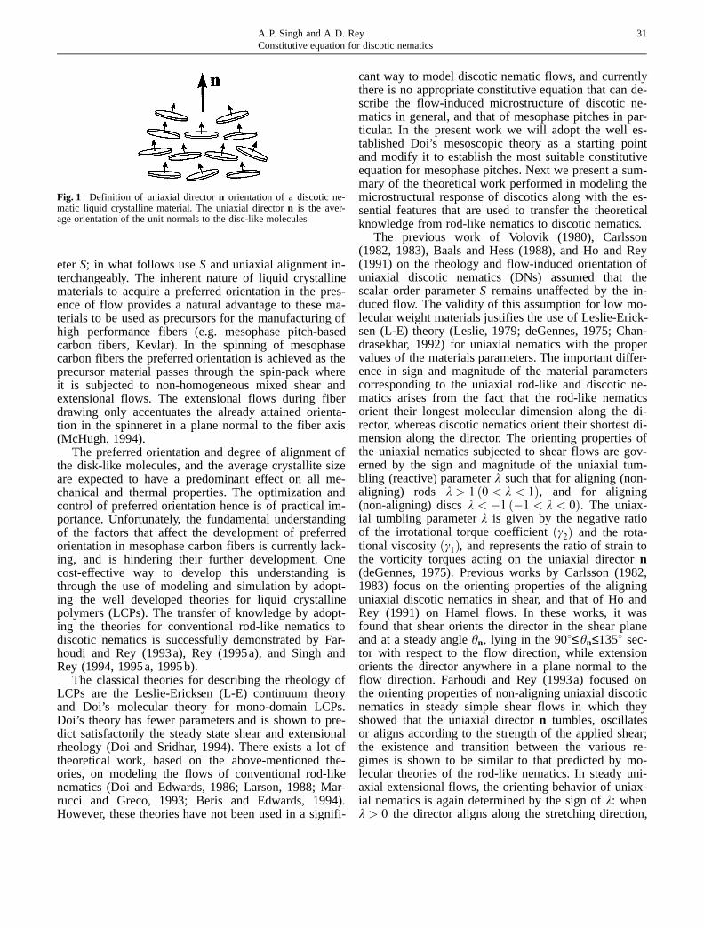
Figure 2a is the schematic representation of thesteady shear flow. The flow direction is along the x-axis, the velocity gradient direction is along the y-axis,and the vorticity axis (neutral axis) is along thez-axis. To visualize and analyze the individual director(n, m, l) behavior, we parametrize them as follows (seeFig. 2b):
33A.P. Singh and A.D. ReyConstitutive equation for discotic nematics
Fig. 2 a) Definition of rectilinear shear flow deformation, b) coordi-nate system. a) x-axis is the flow direction, y-axis is the velocitygradient direction, and z-axis (normal outwards to the plane of paper)is the neutral (vorticity) direction. b) Unit vector angle and unitsphere description: unit vectora is completely defined by the azi-muthal angleha�0 � ha � 2p� and polar angle�a�0 � �a � p�. Interms of unit vector angles, the equator lies in the shear plane and isgiven as�ha; �a� � ��0; 2p�; �p=2�, and the north pole and the southpole are located on the vorticity axis and are given as�a � 0 and�a � p respectively
(a)
(b)
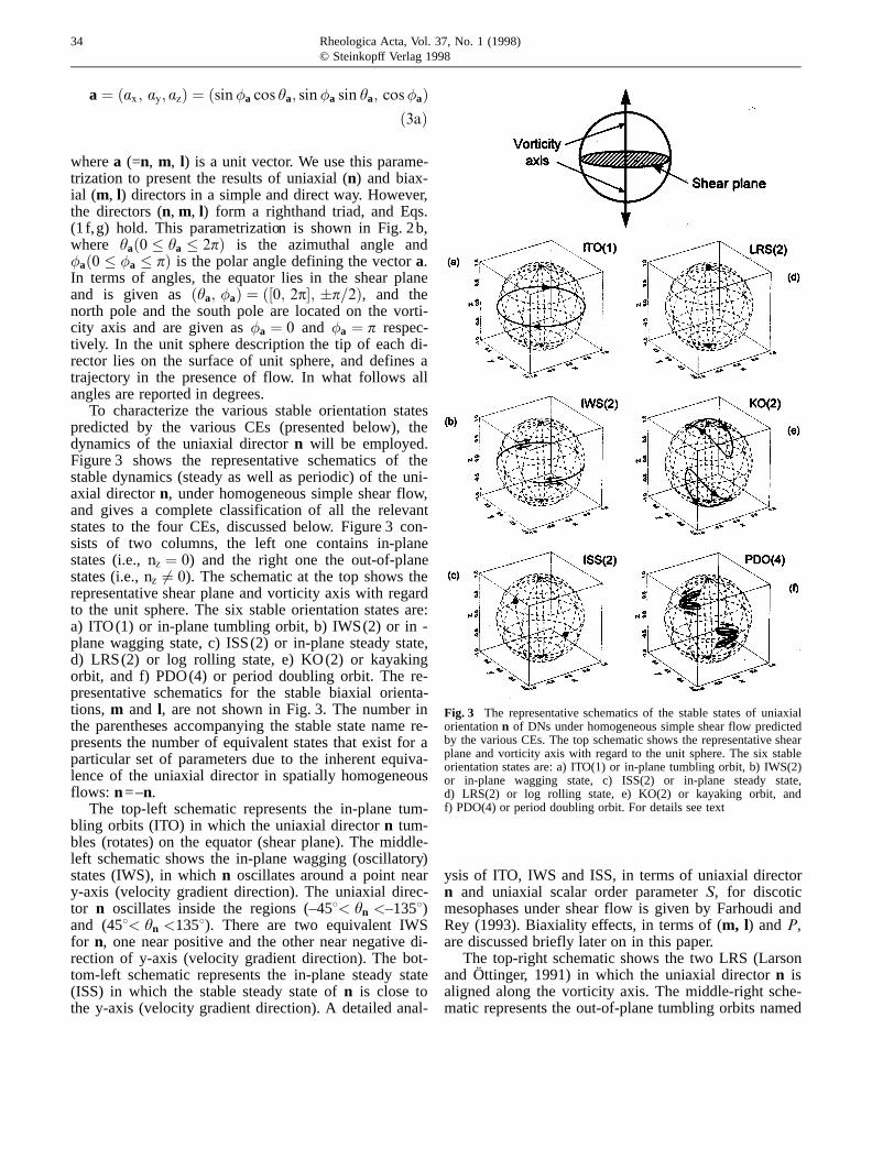
a� �ax ; ay; az� � �sin�a cos ha; sin�a sin ha; cos�a��3a�
wherea (=n, m, l) is a unit vector. We use this parame-trization to present the results of uniaxial (n) and biax-ial (m, l) directors in a simple and direct way. However,the directors (n, m, l) form a righthand triad, and Eqs.(1 f,g) hold. This parametrization is shown in Fig. 2b,where ha�0 � ha � 2p� is the azimuthal angle and�a�0 � �a � p� is the polar angle defining the vectora.In terms of angles, the equator lies in the shear planeand is given as�ha; �a� � ��0; 2p�; �p=2�, and thenorth pole and the south pole are located on the vorti-city axis and are given as�a � 0 and �a � p respec-tively. In the unit sphere description the tip of each di-rector lies on the surface of unit sphere, and defines atrajectory in the presence of flow. In what follows allangles are reported in degrees.
To characterize the various stable orientation statespredicted by the various CEs (presented below), thedynamics of the uniaxial directorn will be employed.Figure 3 shows the representative schematics of thestable dynamics (steady as well as periodic) of the uni-axial directorn, under homogeneous simple shear flow,and gives a complete classification of all the relevantstates to the four CEs, discussed below. Figure 3 con-sists of two columns, the left one contains in-planestates (i.e.,nz � 0) and the right one the out-of-planestates (i.e.,nz 6� 0). The schematic at the top shows therepresentative shear plane and vorticity axis with regardto the unit sphere. The six stable orientation states are:a) ITO(1) or in-plane tumbling orbit, b) IWS(2) or in -plane wagging state, c) ISS(2) or in-plane steady state,d) LRS(2) or log rolling state, e) KO(2) or kayakingorbit, and f) PDO(4) or period doubling orbit. The re-presentative schematics for the stable biaxial orienta-tions, m and l, are not shown in Fig. 3. The number inthe parentheses accompanying the stable state name re-presents the number of equivalent states that exist for aparticular set of parameters due to the inherent equiva-lence of the uniaxial director in spatially homogeneousflows: n=–n.
The top-left schematic represents the in-plane tum-bling orbits (ITO) in which the uniaxial directorn tum-bles (rotates) on the equator (shear plane). The middle-left schematic shows the in-plane wagging (oscillatory)states (IWS), in whichn oscillates around a point neary-axis (velocity gradient direction). The uniaxial direc-tor n oscillates inside the regions (–458< hn <–1358)and (458< hn <1358). There are two equivalent IWSfor n, one near positive and the other near negative di-rection of y-axis (velocity gradient direction). The bot-tom-left schematic represents the in-plane steady state(ISS) in which the stable steady state ofn is close tothe y-axis (velocity gradient direction). A detailed anal-
ysis of ITO, IWS and ISS, in terms of uniaxial directorn and uniaxial scalar order parameterS, for discoticmesophases under shear flow is given by Farhoudi andRey (1993). Biaxiality effects, in terms of (m, l) andP,are discussed briefly later on in this paper.
The top-right schematic shows the two LRS (Larsonand Öttinger, 1991) in which the uniaxial directorn isaligned along the vorticity axis. The middle-right sche-matic represents the out-of-plane tumbling orbits named
34 Rheologica Acta, Vol. 37, No. 1 (1998)© Steinkopff Verlag 1998
Fig. 3 The representative schematics of the stable states of uniaxialorientationn of DNs under homogeneous simple shear flow predictedby the various CEs. The top schematic shows the representative shearplane and vorticity axis with regard to the unit sphere. The six stableorientation states are: a) ITO(1) or in-plane tumbling orbit, b) IWS(2)or in-plane wagging state, c) ISS(2) or in-plane steady state,d) LRS(2) or log rolling state, e) KO(2) or kayaking orbit, andf) PDO(4) or period doubling orbit. For details see text
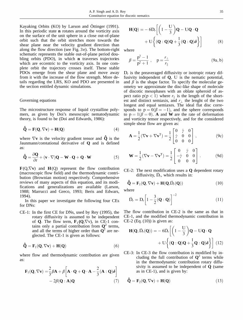
Kayaking Orbits (KO) by Larson and Öttinger (1991).In this periodic staten rotates around the vorticity axison the surface of the unit sphere in a close out-of-planeorbit such that the orbit stretches more towards theshear plane near the velocity gradient direction thanalong the flow direction (see Fig. 3e). The bottom-rightschematic represents the stable out-of-plane period dou-bling orbits (PDO), in whichn traverses trajectorieswhich are eccentric to the vorticity axis. In one com-plete orbit the trajectory crosses itself. These stablePDOs emerge from the shear plane and move awayfrom it with the increase of the flow strength. More de-tails regarding the LRS, KO and PDO are presented inthe section entitled dynamic simulations.
Governing equations
The microstructure response of liquid crystalline poly-mers, as given by Doi’s mesoscopic nematodynamictheory, is found to be (Doi and Edwards, 1986):
Q̂ � F�Q;rv� � H�Q� �4�whererv is the velocity gradient tensor and̂Q is theJaunmann/corotational derivative ofQ and is definedas:
Q̂ � @Q@t� �v � r�QÿW �Q�Q �W �5�
F (Q,rv) and H (Q) represent the flow contribution(macroscopic flow field) and the thermodynamic contri-bution (Brownian motion) respectively. Comprehensivereviews of many aspects of this equation, and its modi-fications and generalizations are available (Larson,1988; Marrucci and Greco, 1993; Beris and Edwars,1994).
In this paper we investigate the following four CEsfor DNs:
CE-1: In the first CE for DNs, used by Rey (1995), therotary diffusivity is assumed to be independentof Q. The flow term,F1(Q,rv), in CE-1 con-tains only a partial contribution fromQ2 terms,and all the terms of higher order thanQ2 are ne-glected. The CE-1 is given as follows:
Q̂ � F1�Q;rv� � H�Q� �6�where flow and thermodynamic contribution are givenas:
F1�Q;rv� � 2
3bA � b
�A �Q�Q � A ÿ 2
3�A : Q�d
�ÿ 2b�Q : A�Q �7�
H�Q� � ÿ 6Dr
��1ÿU
3
�QÿUQ �Q
�U
��Q : Q�Q� 1
3�Q : Q�d
���8�
where
b � p2 ÿ 1
p2 � 1; p� r?
rk�9a; b�
Dr is the preaveraged diffusivity or isotropic rotary dif-fusivity independent ofQ, U is the nematic potential,and b is the shape factor. To specify the molecular ge-ometry we approximate the disc-like shape of moleculeof discotic mesophases with an oblate spheroid of as-pect ratiop�p< 1� whererk is the length of the short-est and distinct semiaxis, andr? the lenght of the twolongest and equal semiaxes. The ideal flat disc corre-sponds top� 0�b � ÿ1�, and the sphere correspondsto p� 1�b � 0�. A and W are the rate of deformationand vorticity tensor respectively, and for the consideredsimple shear flow are given as:
A � 1
2�rv�rvT� � 1
2
0 _c 0_c 0 00 0 0
24 35 ; �9c�
W � 1
2�rvÿrvT� � 1
2
0 _c 0ÿ_c 0 00 0 0
24 35 : �9d�
CE-2: The next modification uses aQ dependent rotarydiffusivity, �Dr, which results in:
Q̂ � F1�Q;rv� � H�Q; �Dr�Q�� �10�where
�Dr � Dr
�1ÿ 3
2�Q : Q�
�ÿ2
�11�
The flow contribution in CE-2 is the same as that inCE-1, and the modified thermodynamic contribution inCE-2 (Eq. (10)) is given as:
H�Q; �Dr�Q�� � ÿ 6 �Dr
��1ÿU
3
�QÿUQ �Q
�U
��Q : Q�Q� 1
3Q : Q�d
���12�
CE-3: In CE-3 the flow contribution is modified by in-cluding the full contribution ofQ2 terms whilein the thermodynamic contribution rotary diffu-sivity is assumed to be independent ofQ (sameas in CE-1), and is given by:
Q̂ � F2�Q;rv� � H�Q� �13�
35A.P. Singh and A.D. ReyConstitutive equation for discotic nematics
where the modified flow contribution is:
F2�Q;rv� � 2
3bA � b
�A �Q�Q � A ÿ 2
3�A : Q�d
�ÿ b
2��A : Q�Q� A �Q �Q�Q � A �Q
�Q �Q � A ÿ f�Q �Q� : Agd� �14�CE-4: The fourth and final CE is similar to CE-3, how-
ever, the rotary diffusivity is assumed to a func-tion of Q. The CE-4 comprises the flow term asdoes that in CE-3 and the thermodynamic termas in CE-2, and is given as:
Q̂ � F2�Q;rv� � H�Q; �Dr�Q�� �15�The flow contribution is not modified further to in-
clude higher order terms thanQ2 as the original Doi’stheory does not contain terms which would yield, onquadratic closure approximation, terms with orderhigher thanQ2. Also, the curvature elastic effects (i.e.,Frank elasticity) are neglected in the present investiga-tion.
The CEs in the non-dimensional form along with thedimensionless parameters are given in Appendix A.
In this paper we analyze and evaluate the CEs usingbifurcation analysis as employed by Farhoudi and Rey(1993b) and Rey (1995a,b). For bifurcation analysis ofthe CEs we use AUTO94, a software for continuationand bifurcation analysis for ordinary differential equa-tions (Doedel et al., 1996). The equations solved are aset of five nonlinear coupled algebraic equations givenby the righthand side of the ODEs (A.1 to A.4). Thelong time dynamic response (steady or periodic) wasused for the continuation of stable branch(es), the un-stable branches were traced by the subsequent continua-tion of the bifurcation points. For continuation the di-mensionless shear rate or Peclet number,Pe, is used asthe free parameter. The outputs from AUTO94 are thecomponents of the steady state tensor order parameterQss(Pe) which is transformed to principal form to deter-mine its eigenvalues (to evaluate steady state align-mentsSss and Pss) and eigenvectors or steady state or-ientations (nss, mss, lss). As AUTO94 was unable toconfirm the stability and sometimes the existence ofsome branches (periodic or steady), dynamic simula-tions are used to augment and confirm the bifurcationresults obtained from AUTO94. For dynamic simula-tions the set of time-dependent dimensionless equations(presented in Appedix A) are integrated using an impli-cit predictor-corrector first order Euler integration meth-od with adaptable time step. The implicit predictor cor-rector method transforms the set of coupled nonlinearordinary differential equations into a set of couplednonlinear algebraic equations. The resulting algebraicequations are solved using the Newton-Raphson itera-
tion scheme; the predictor step generates a first guessfor iteration which forms the corrector step itself. Theadopted convergence criteria is that the length of thedifference vector between the calculated solution vec-tors corresponding to two successive iterations is lessthan 10–8. The transient solution vector resulting fromthe numerical solutions consists of a set of five inde-pendent components of the tensor order parameterQ�t�� as a function of dimensionless timet� �j 6Dr j t.The numerically obtained tensor order parameterQ�t��is subsequently transformed into the principal form, giv-en by Eq. (2), to evaluate its eigenvalues and eigenvec-tors.
To compute the dynamic response of CEs, the modeldiscotic nematics are assumed to be uniaxial�P � 0,and m, l?undefined; Singh and Rey, 1995b) prior tothe imposition of the shear flow, and the initial condi-tions in the eigenvalue-eigenvector form are given as:
t � 0 : n � n0 ; S � S0 � Seq�U� �16�whereSeq�U� is the equilibrium uniaxial alignment ofnormal �S > 0� uniaxial nematic phase, given by Doiand Edwards (1986):
Seq � 1
4� 3
4
������������������������1ÿ 8
3U
�s�17�
For U < 8=3 the stable phase is isotropic, for8=3 � U � 3 there is biphasic equilibrium, and for thehigher values of uniaxial nematic potentialU the phaseis uniaxial nematic. Higher values ofU correspond tostronger uniaxial alignment. In this paper we use thefollowing values of the parameters:U � 6:0, andb � ÿ0:8. The range of initial uniaxial director orienta-tion, n0, for the dynamic simulations performed in thiswork is: 08� hn0 �3608, 58� �n0 �858.
Results and discussion
This section describes and discusses the bifurcation anddynamic simulation results for the four CEs. This sec-tion is divided into two major subsections: bifurcationphenomena, and dynamic simulations; the former isfurther subdivided into four parts, one for each CE. Ineach part we present the computed bifurcation diagramsof the tensor order parameterQss as a function ofPe.To facilitate the discussion the eigenvalues and eigen-vectors of theQss are computed; the eigenvalues ofQssare used to calculateSss and Pss and the eigenvectors(nss, mss, lss) are used to distinguish between the var-ious stable states predicted by the bifurcation computa-tions for each CE. The following conventions are usedto plot the bifurcation results: solid lines for stablesteady state branch intervals, dot-dash lines for stable
36 Rheologica Acta, Vol. 37, No. 1 (1998)© Steinkopff Verlag 1998
periodic branch intervals, short-dash lines for unstable(steady or periodic) branch intervals, empty squares tomark the bifurcation points, and filled squares for Hopfbifurcation points. While showing the bifurcation dia-grams for various CEs, the maxima/minima correspond-ing to the periodic (or oscillatory) states are not plottedas a function of the continuation parameterPe. At theHopf bifurcation point, the steady state branch ex-changes stability with the periodic branch. Locally,close to the Hopf bifurcation point, the stable periodicorbits encircle an unstable steady state solution branch,and the unstable periodic orbits encircle a stable steadystate solution branch. In both cases, the stable or un-stable steady state part of the branch does not necessari-ly represent the mean values of the periodic oscillia-tions. Thus the variable values represented by dot-dashlines (for stable oscillatory/periodic states) do not neces-sarily correspond to mean values of the oscillatory dy-namic response. In the following discussion the solutionbranch means the plotted solution vector (computedcomponents ofQss, or the calculatedSss or Pss) as afunction of Pe. The solution branches are classified intotwo main categories: in-plane branches (such as IP-1,IP-2) and out-of-plane branches (OP-1, OP-2, OP-3),such that the latter always have a non-zero z-compo-nent of n (i.e., nz 6� 0). The numbers associated withthe branch categories (i.e., 1, 2, with IP and 1, 2, 3with OP) are used merely to differentiate the differentbranches belonging to the same category. The two in-trinsic changes that may occur in different intervals ofthe same solution branch are changes in the stabilityand in the nature of the attractor. For example if the at-tractor loses stability in an interval ofPe, the corre-sponding solution branch will also become unstable inthe same interval, and if the nature of the attractorchanges in an interval then the corresponding orienta-tion state represented by the solution branch will alsochange. The orientation state or simply the state meansthe corresponding uniaxial director dynamics, as shownin Fig. 3, represented by a particular solution branch. Inwhat follows we discuss only the stable steady andstable periodic states represented by various solutionbranches.
Bifurcation phenomena
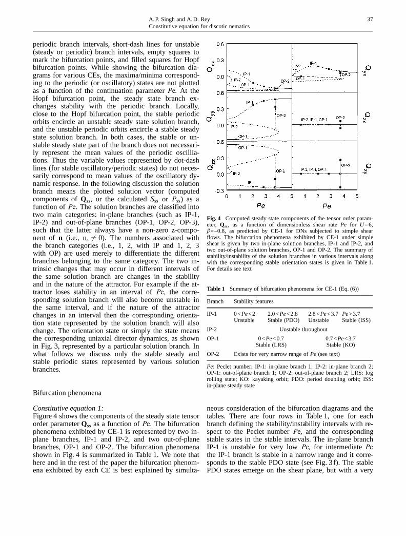
Constitutive equation 1:Figure 4 shows the components of the steady state tensororder parameterQss as a function ofPe. The bifurcationphenomena exhibited by CE-1 is represented by two in-plane branches, IP-1 and IP-2, and two out-of-planebranches, OP-1 and OP-2. The bifurcation phenomenashown in Fig. 4 is summarized in Table 1. We note thathere and in the rest of the paper the bifurcation phenom-ena exhibited by each CE is best explained by simulta-
neous consideration of the bifurcation diagrams and thetables. There are four rows in Table 1, one for eachbranch defining the stability/instability intervals with re-spect to the Peclet numberPe, and the correspondingstable states in the stable intervals. The in-plane branchIP-1 is unstable for very lowPe, for intermediatePethe IP-1 branch is stable in a narrow range and it corre-sponds to the stable PDO state (see Fig. 3 f). The stablePDO states emerge on the shear plane, but with a very
37A.P. Singh and A.D. ReyConstitutive equation for discotic nematics
Fig. 4 Computed steady state components of the tensor order param-eter, Qss, as a function of dimensionless shear ratePe for U=6,b=–0.8, as predicted by CE-1 for DNs subjected to simple shearflows. The bifurcation phenomena exhibited by CE-1 under simpleshear is given by two in-plane solution branches, IP-1 and IP-2, andtwo out-of-plane solution branches, OP-1 and OP-2. The summary ofstability/instability of the solution branches in various intervals alongwith the corresponding stable orientation states is given in Table 1.For details see text
Table 1 Summary of bifurcation phenomena for CE-1 (Eq. (6))
Branch Stability features
IP-1 0<Pe<2 2.0<Pe<2.8 2.8<Pe<3.7 Pe>3.7Unstable Stable (PDO) Unstable Stable (ISS)
IP-2 Unstable throughout
OP-1 0<Pe<0.7 0.7<Pe<3.7Stable (LRS) Stable (KO)
OP-2 Exists for very narrow range ofPe (see text)
Pe: Peclet number; IP-1: in-plane branch 1; IP-2: in-plane branch 2;OP-1: out-of-plane branch 1; OP-2: out-of-plane branch 2; LRS: logrolling state; KO: kayaking orbit; PDO: period doubling orbit; ISS:in-plane steady state
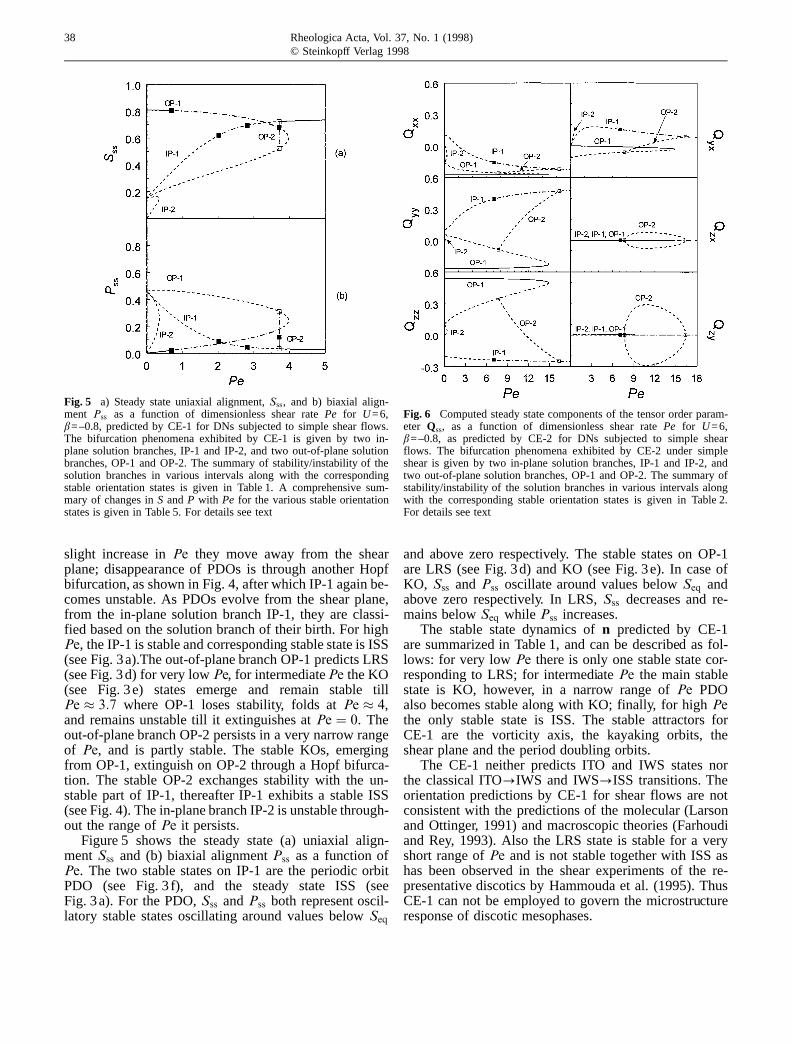
slight increase inPe they move away from the shearplane; disappearance of PDOs is through another Hopfbifurcation, as shown in Fig. 4, after which IP-1 again be-comes unstable. As PDOs evolve from the shear plane,from the in-plane solution branch IP-1, they are classi-fied based on the solution branch of their birth. For highPe, the IP-1 is stable and corresponding stable state is ISS(see Fig. 3a).The out-of-plane branch OP-1 predicts LRS(see Fig. 3d) for very lowPe, for intermediatePe the KO(see Fig. 3e) states emerge and remain stable tillPe � 3:7 where OP-1 loses stability, folds atPe � 4,and remains unstable till it extinguishes atPe � 0. Theout-of-plane branch OP-2 persists in a very narrow rangeof Pe, and is partly stable. The stable KOs, emergingfrom OP-1, extinguish on OP-2 through a Hopf bifurca-tion. The stable OP-2 exchanges stability with the un-stable part of IP-1, thereafter IP-1 exhibits a stable ISS(see Fig. 4). The in-plane branch IP-2 is unstable through-out the range ofPe it persists.
Figure 5 shows the steady state (a) uniaxial align-ment Sss and (b) biaxial alignmentPss as a function ofPe. The two stable states on IP-1 are the periodic orbitPDO (see Fig. 3 f), and the steady state ISS (seeFig. 3a). For the PDO,Sss andPss both represent oscil-latory stable states oscillating around values belowSeq
and above zero respectively. The stable states on OP-1are LRS (see Fig. 3d) and KO (see Fig. 3e). In case ofKO, Sss and Pss oscillate around values belowSeq andabove zero respectively. In LRS,Sss decreases and re-mains belowSeq while Pss increases.
The stable state dynamics ofn predicted by CE-1are summarized in Table 1, and can be described as fol-lows: for very lowPe there is only one stable state cor-responding to LRS; for intermediatePe the main stablestate is KO, however, in a narrow range ofPe PDOalso becomes stable along with KO; finally, for highPethe only stable state is ISS. The stable attractors forCE-1 are the vorticity axis, the kayaking orbits, theshear plane and the period doubling orbits.
The CE-1 neither predicts ITO and IWS states northe classical ITO?IWS and IWS?ISS transitions. Theorientation predictions by CE-1 for shear flows are notconsistent with the predictions of the molecular (Larsonand Ottinger, 1991) and macroscopic theories (Farhoudiand Rey, 1993). Also the LRS state is stable for a veryshort range ofPe and is not stable together with ISS ashas been observed in the shear experiments of the re-presentative discotics by Hammouda et al. (1995). ThusCE-1 can not be employed to govern the microstructureresponse of discotic mesophases.
38 Rheologica Acta, Vol. 37, No. 1 (1998)© Steinkopff Verlag 1998
Fig. 5 a) Steady state uniaxial alignment,Sss, and b) biaxial align-ment Pss as a function of dimensionless shear ratePe for U=6,b=–0.8, predicted by CE-1 for DNs subjected to simple shear flows.The bifurcation phenomena exhibited by CE-1 is given by two in-plane solution branches, IP-1 and IP-2, and two out-of-plane solutionbranches, OP-1 and OP-2. The summary of stability/instability of thesolution branches in various intervals along with the correspondingstable orientation states is given in Table 1. A comprehensive sum-mary of changes inS andP with Pe for the various stable orientationstates is given in Table 5. For details see text
Fig. 6 Computed steady state components of the tensor order param-eter Qss, as a function of dimensionless shear ratePe for U=6,b=–0.8, as predicted by CE-2 for DNs subjected to simple shearflows. The bifurcation phenomena exhibited by CE-2 under simpleshear is given by two in-plane solution branches, IP-1 and IP-2, andtwo out-of-plane solution branches, OP-1 and OP-2. The summary ofstability/instability of the solution branches in various intervals alongwith the corresponding stable orientation states is given in Table 2.For details see text
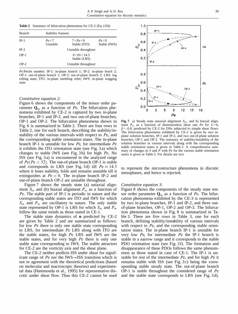
Constitutive equation 2:Figure 6 shows the components of the tensor order pa-rameterQss as a function ofPe. The bifurcation phe-nomena exhibited by CE-2 is captured by two in-planebranches, IP-1 and IP-2, and two out-of-plane branches,OP-1 and OP-2. The bifurcation phenomena shown inFig. 6 is summarized in Table 2. There are four rows inTable 2, one for each branch, describing the stability/in-stability of the various intervals with respect toPe, andthe corresponding stable orientation states. The in-planebranch IP-1 is unstable for lowPe, for intermediatePeit exhibits the ITO orientation state (see Fig. 3a) whichchanges to stable IWS (see Fig. 3b) for highPe. NoISS (see Fig. 3a) is encountered in the analyzed rangeof Pe�Pe < 52�. The out-of-plane branch OP-1 is stableand corresponds to LRS (see Fig. 3d) tillPe � 14:3where it loses stability, folds and remains unstable till itextinguishes atPe � 0. The in-plane branch IP-2 andout-of-plane branch OP-2 are unstable throughout.
Figure 7 shows the steady state (a) uniaxial align-ment Sss and (b) biaxial alignmentPss as a function ofPe. The stable part of IP-1 is periodic in nature and thecorresponding stable states are ITO and IWS for whichSss and Pss are oscillatory in nature. The only stablestate represented by OP-1 is LRS for whichSss andPss
follow the same trends as those stated in CE-1.The stable state dynamics ofn predicted by CE-2
are given by Table 2 and are summarized as follows:for low Pe there is only one stable state correspondingto LRS, for intermediatePe LRS along with ITO arethe stable states, for highPe LRS and IWS are thestable states, and for very highPe there is only onestable state corresponding to IWS. The stable attractorsfor CE-2 are the vorticity axis and the shear plane.
The CE-2 neither predicts ISS under shear for signif-icant range ofPe nor the IWS?ISS transition which isnot in agreement with the theoretical predictions (basedon molecular and macroscopic theories) and experimen-tal data (Hammouda et al., 1995) for representative dis-cotic under shear flow. Thus this CE-2 cannot be used
to represent the microstructure phenomena in discoticmesophases, and hence is rejected.
Constitutive equation 3:Figure 8 shows the components of the steady state ten-sor order parameterQss as a function ofPe. The bifur-cation phenomena exhibited by the CE-3 is representedby two in-plane branches, IP-1 and IP-2, and three out-of-plane branches, OP-1, OP-2 and OP-3. The bifurca-tion phenomena shown in Fig. 8 is summarized in Ta-ble 3. There are five rows in Table 3, one for eachbranch, defining stability/instability of various intervalswith respect toPe, and the corresponding stable orien-tation states. The in-plane branch IP-1 is unstable forvery low Pe, for intermediatePe the IP-1 branch isstable in a narrow range and it corresponds to the stablePDO orientation state (see Fig. 3 f). The formation anddisappearance of these PDOs follows the same phenom-enon as those stated in case of CE-1. The IP-1 is un-stable for rest of the intermediatePe, and for highPe itremains stable with ISS (see Fig. 3c) being the corre-sponding stable steady state. The out-of-plane branchOP-1 is stable throughout the considered range ofPeand the stable state corresponds to LRS (see Fig. 3d).
39A.P. Singh and A.D. ReyConstitutive equation for discotic nematics
Table 2 Summary of bifurcation phenomena for CE-2 (Eq. (10))
Branch Stability features
IP-1 Pe<7 7<Pe<9 Pe>9Unstable Stable (ITO) Stable (IWS)
IP-2 Unstable throughout
OP-1 0<Pe<14.3Stable (LRS)
OP-2 Unstable throughout
Pe:Peclet number; IP-1: in-plane branch 1; IP-2: in-plane brach 2;OP-1: out-of-plane branch 1; OP-2: out-of-plane branch 2; LRS: logrolling state; ITO: in-plane tumbling orbit; IWS: in-plane waggingstate
Fig. 7 a) Steady state uniaxial alignmentSss, and b) biaxial align-ment Pss as a function of dimensionless shear ratePe for U=6,b=–0.8, predicted by CE-2 for DNs subjected to simple shear flows.The bifurcation phenomena exhibited by CE-2 is given by two in-plane solution branches, IP-1 and IP-2, and two out-of-plane solutionbranches, OP-1 and OP-2. The summary of stability/instability of thesolution branches in various intervals along with the correspondingstable orientation states is given in Table 2. A comprehensive sum-mary of changes inS andP with Pe for the various stable orientationstates is given in Table 5. For details see text
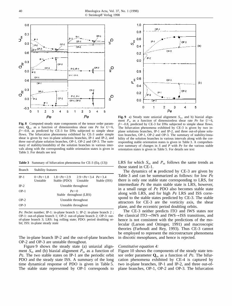
The in-plane branch IP-2 and the out-of-plane branchesOP-2 and OP-3 are unstable throughout.
Figure 9 shows the steady state (a) uniaxial align-ment Sss and (b) biaxial alignmentPss as a function ofPe. The two stable states on IP-1 are the periodic orbitPDO and the steady state ISS. A summary of the longtime dynamical response of PDO is given in Table 5.The stable state represented by OP-1 corresponds to
LRS for which Sss and Pss follows the same trends asthose stated in CE-1.
The dynamics ofn predicted by CE-3 are given byTable 3 and can be summarized as follows: for lowPethere is only one stable state corresponding to LRS, forintermediatePe the main stable state is LRS, however,in a small range ofPe PDO also becomes stable statealong with LRS, and for highPe LRS and ISS corre-spond to the stable states predicted by CE-3. The stableattractors for CE-3 are the vorticity axis, the shearplane, and the eccentric period doubling orbits.
The CE-3 neither predicts ITO and IWS states northe classical ITO?IWS and IWS?ISS transitions, andhence is not consistent with the predictions of the mo-lecular (Larson and Ottinger, 1991) and macroscopictheories (Farhoudi and Rey, 1993). Thus CE-3 cannotbe employed to represent the microstructure phenomenain discotic mesophases, and hence is rejected.
Constitutive equation 4:Figure 10 shows the components of the steady state ten-sor order parameterQss as a function ofPe. The bifur-cation phenomena exhibited by CE-4 is captured bytwo in-plane branches, IP-1 and IP-2, and three out-of-plane branches, OP-1, OP-2 and OP-3. The bifurcation
40 Rheologica Acta, Vol. 37, No. 1 (1998)© Steinkopff Verlag 1998
Fig. 8 Computed steady state components of the tensor order param-eter, Qss, as a function of dimensionless shear ratePe for U=6,b=–0.8, as predicted by CE-3 for DNs subjected to simple shearflows. The bifurcation phenomena exhibited by CE-3 under simpleshear is given by two in-plane solutions branches, IP-1 and IP-2, andthree out-of-plane solution branches, OP-1, OP-2 and OP-3. The sum-mary of stability/instability of the solution branches in various inter-vals along with the corresponding stable orientation states is given inTable 3. For details see text
Table 3 Summary of bifurcation phenomena for CE-3 (Eq. (13))
Branch Stability features
IP-1 0<Pe<1.8 1.8<Pe<2.9 2.9<Pe<3.4 Pe>3.4Unstable Stable (PDO) Unstable Stable (ISS)
IP-2 Unstable throughout
OP-1 Pe>0Stable throughout (LRS)
OP-2 Unstable throughout
OP-3 Unstable throughout
Pe: Peclet number; IP-1: in-plane branch 1; IP-2: in-plane branch 2 ;OP-1: out-of-plane branch 1; OP-2: out-of-plane branch 2; OP-3: out-of-plane branch 3; LRS: log rolling state; PDO: period doubling or-bit; ISS: in-plane steady state
Fig. 9 a) Steady state uniaxial alignmentSss, and b) biaxial align-ment Pss as a function of dimensionless shear ratePe for U=6,b=–0.8, predicted by CE-3 for DNs subjected to simple shear flows.The bifurcation phenomena exhibited by CE-3 is given by two in-plane solutions branches, IP-1 and IP-2, and three out-of-plane solu-tion branches, OP-1, OP-2 and OP-3. The summary of stability/insta-bility of the solution branches in various intervals along with the cor-responding stable orientation states is given in Table 3. A comprehen-sive summary of changes inS and P with Pe for the various stableorientation states is given in Table 5. For details see text
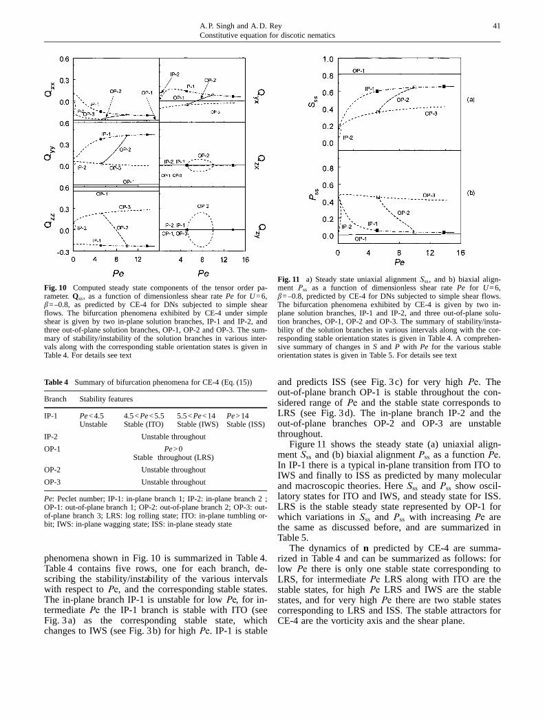
phenomena shown in Fig. 10 is summarized in Table 4.Table 4 contains five rows, one for each branch, de-scribing the stability/instability of the various intervalswith respect toPe, and the corresponding stable states.The in-plane branch IP-1 is unstable for lowPe, for in-termediatePe the IP-1 branch is stable with ITO (seeFig. 3a) as the corresponding stable state, whichchanges to IWS (see Fig. 3b) for highPe. IP-1 is stable
and predicts ISS (see Fig. 3c) for very highPe. Theout-of-plane branch OP-1 is stable throughout the con-sidered range ofPe and the stable state corresponds toLRS (see Fig. 3d). The in-plane branch IP-2 and theout-of-plane branches OP-2 and OP-3 are unstablethroughout.
Figure 11 shows the steady state (a) uniaxial align-mentSss and (b) biaxial alignmentPss as a functionPe.In IP-1 there is a typical in-plane transition from ITO toIWS and finally to ISS as predicted by many molecularand macroscopic theories. HereSss and Pss show oscil-latory states for ITO and IWS, and steady state for ISS.LRS is the stable steady state represented by OP-1 forwhich variations inSss and Pss with increasingPe arethe same as discussed before, and are summarized inTable 5.
The dynamics ofn predicted by CE-4 are summa-rized in Table 4 and can be summarized as follows: forlow Pe there is only one stable state corresponding toLRS, for intermediatePe LRS along with ITO are thestable states, for highPe LRS and IWS are the stablestates, and for very highPe there are two stable statescorresponding to LRS and ISS. The stable attractors forCE-4 are the vorticity axis and the shear plane.
41A.P. Singh and A.D. ReyConstitutive equation for discotic nematics
Fig. 10 Computed steady state components of the tensor order pa-rameter.Qss, as a function of dimensionless shear ratePe for U=6,b=–0.8, as predicted by CE-4 for DNs subjected to simple shearflows. The bifurcation phenomena exhibited by CE-4 under simpleshear is given by two in-plane solution branches, IP-1 and IP-2, andthree out-of-plane solution branches, OP-1, OP-2 and OP-3. The sum-mary of stability/instability of the solution branches in various inter-vals along with the corresponding stable orientation states is given inTable 4. For details see text
Table 4 Summary of bifurcation phenomena for CE-4 (Eq. (15))
Branch Stability features
IP-1 Pe<4.5 4.5<Pe<5.5 5.5<Pe<14 Pe>14Unstable Stable (ITO) Stable (IWS) Stable (ISS)
IP-2 Unstable throughout
OP-1 Pe>0Stable throughout (LRS)
OP-2 Unstable throughout
OP-3 Unstable throughout
Pe: Peclet number; IP-1: in-plane branch 1; IP-2: in-plane branch 2 ;OP-1: out-of-plane branch 1; OP-2: out-of-plane branch 2; OP-3: out-of-plane branch 3; LRS: log rolling state; ITO: in-plane tumbling or-bit; IWS: in-plane wagging state; ISS: in-plane steady state
Fig. 11 a) Steady state uniaxial alignmentSss, and b) biaxial align-ment Pss as a function of dimensionless shear ratePe for U=6,b=–0.8, predicted by CE-4 for DNs subjected to simple shear flows.The bifurcation phenomena exhibited by CE-4 is given by two in-plane solution branches, IP-1 and IP-2, and three out-of-plane solu-tion branches, OP-1, OP-2 and OP-3. The summary of stability/insta-bility of the solution branches in various intervals along with the cor-responding stable orientation states is given in Table 4. A comprehen-sive summary of changes inS and P with Pe for the various stableorientation states is given in Table 5. For details see text
The CE-4 predicts the major and essential stablesteady and periodic states along with the classicalITO?IWS and IWS?ISS transitions as predicted bymacroscopic (Farhoudi and Rey, 1993) and moleculartheories (Larson and Ottinger, 1991). The multi-stabili-ties of the various stable states and their phase diagramsare qualitatively the same as those shown by Larsonand Ottinger (1991). Moreover, the simulations resultsof CE-4 under shear are consistent with the experimen-tal results on representative discotics under shear(Hammouda et al., 1995). Also, as mentioned in the in-troduction, the preferred orientation of the disc-likemolecules (close to the walls of slit) of discotic meso-phase pitches, flowing in a thin rectangular channel,corresponds to LRS. Thus CE-4 can be considered asthe most appropriate choice for describing the micro-structural response of the discotic mesophases. The rele-vance of the predicted microstructure response in disco-tic mesophase pitches in explaing some of the observedmicrostructural features in mesophase carbon fibers willbe established in future work.
Dynamic simulations
As mentioned above the dynamic simulations were em-ployed to confirm the stability of the various branches
obtained by bifurcation analysis of the various CEs un-der shear flows. The results of the bifurcation analysisare organized and classified in terms of the uniaxial di-rectorn dynamcis, given in Fig. 3, but a more completecharacterization must include the remaining two eigen-vectors. Moreover, the maxima/minima correspondingto the periodic states are not plotted either in terms ofdirector triad (n, m, l) or in terms of alignmentsS andP. Hence to further understand the long time dynamicresponse of periodic states in terms of either directortriad (n, m, l) or alignmentsS and P, dynamic simula-tions were performed.
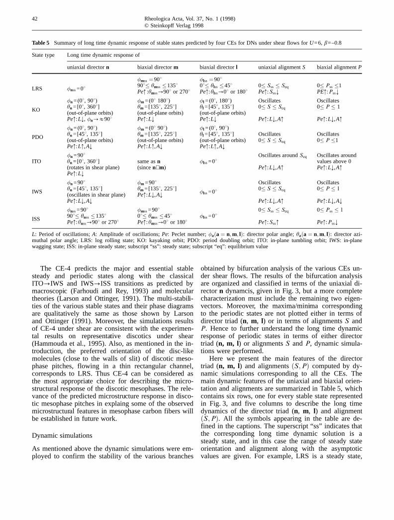
Here we present the main features of the directortriad (n, m, l) and alignments�S;P� computed by dy-namic simulations corresponding to all the CEs. Themain dynamic features of the uniaxial and biaxial orien-tation and alignments are summarized in Table 5, whichcontains six rows, one for every stable state representedin Fig. 3, and five columns to describe the long timedynamics of the director triad (n, m, l) and alignment�S ;P�. All the symbols appearing in the table are de-fined in the captions. The superscript “ss” indicates thatthe corresponding long time dynamic solution is asteady state, and in this case the range of steady stateorientation and alignment along with the asymptoticvalues are given. For example, LRS is a steady state,
42 Rheologica Acta, Vol. 37, No. 1 (1998)© Steinkopff Verlag 1998
Table 5 Summary of long time dynamic response of stable states predicted by four CEs for DNs under shear flows forU=6, b=–0.8
State type Long time dynamic response of
uniaxial directorn biaxial directorm biaxial directorl uniaxial alignmentS biaxial alignmentP
�mss �908 �lss �908908� hmss �1358 08� hlss �458 0� Sss � Seq 0� Pss �1LRS �nss =08 Pe: :hmss?908 or 2708 Pe::hlss?08 or 1808 Pe::Sss; PE::Pss;
�n =(08, 908) �m =(08 1808) �l =(08, 1808) Oscillates Oscillateshn =[08, 3608] hm =[1358, 2258] hl =[458, 1358] 0� S � Seq 0� P � 1KO (out-of-plane orbits) (out-of-plane orbits) (out-of-plane orbits)Pe::L;, �n?&908 Pe::L; Pe::L; Pe::L;,A: Pe::L;,A:
�n =(08, 908) �m =(08 908) �l =(08, 908)hn =[458, 1358] hm =[1358, 2258] hl =[458, 1358] Oscillates OscillatesPDO (out-of-plane orbits) (out-of-plane orbits) (out-of-plane orbits) 0� S � Seq 0� P �1Pe::L:,A; Pe::L:,A; Pe::L:,A;
�n =908 Oscillates aroundSeq Oscillates aroundITO hn =[08, 3608] same asn �lss =08 values above 0
(rotates in shear plane) (sincen⊥m) Pe::L;,A: Pe::L;,A:Pe::L;
�n =908 �m =908 Oscillates Oscillateshn =[458, 1358] hm =[1358, 2258] 0� S � Seq 0� P � 1IWS �lss =08(oscillates in shear plane) Pe::L;,A;Pe::L;,A; Pe::L;,A: Pe::L;,A;
�nss =908 �mss =908 0� Sss � Seq 0� Pss � 1908� hnss �1358 08� hmss �458 �lss =08ISSPe::hnss?908 or 2708 Pe::hmss?08 or 1808 Pe::Sss: Pe::Pss;
L: Period of oscillations;A: Amplitude of oscillations;Pe: Peclet number;�a�a� n;m; l�: director polar angle;ha�a� n;m; l�: director azi-muthal polar angle; LRS: log rolling state; KO: kayaking orbit; PDO: period doubling orbit; ITO: in-plane tumbling orbit; IWS: in-planewagging state; ISS: in-plane steady state; subscript “ss”: steady state; subscript “eq”: equilibrium value
the uniaxial directorn aligns along the vorticity axis�hnss =08), the biaxial directorm aligns in the region(908� hmss �1358) in the shear plane (�mss =908), andfor very high Pe it approaches its asymptotic orienta-tion (hmss?908). For periodic states (ITO, IWS, KOand PDO) the range of oscillation along with changesin amplitude,A, and period of oscillations,L, with in-creasingPe is given. For example, IWS the uniaxial di-rector oscillates in the shear plane (�n =90), the ampli-tude of oscillations is within the regions (hn =[458,1358]), and asPe increase the amplitude as well asperiod of oscillations decreases;Pe::L;,A;. In partialsummary, Table 5 gives a comprehensive data base ofall the characteristics of all the stable states predictedby all the CEs, investigated in this paper, under forshear flow at any arbitrary shear rate for a nematic dis-cotic phase composed of molecules with a shape factorof b=–0.8. Although not discussed in the paper, it wasfound that as the shape factorb increases the tendencyof DNs to tumble increases.
Conclusions
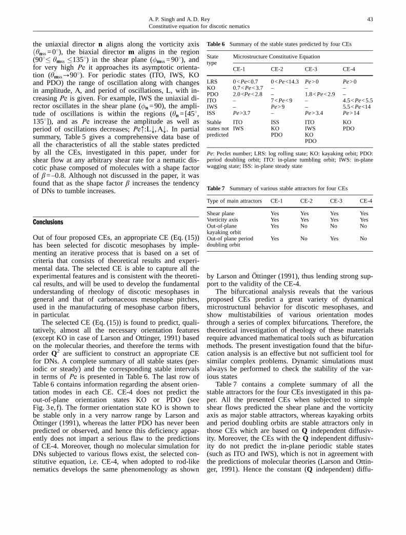
Out of four proposed CEs, an appropriate CE (Eq. (15))has been selected for discotic mesophases by imple-menting an iterative process that is based on a set ofcriteria that consists of theoretical results and experi-mental data. The selected CE is able to capture all theexperimental features and is consistent with the theoreti-cal results, and will be used to develop the fundamentalunderstanding of rheology of discotic mesophases ingeneral and that of carbonaceous mesophase pitches,used in the manufacturing of mesophase carbon fibers,in particular.
The selected CE (Eq. (15)) is found to predict, quali-tatively, almost all the necessary orientation features(except KO in case of Larson and Ottinger, 1991) basedon the molecular theories, and therefore the terms withorder Q2 are sufficient to construct an appropriate CEfor DNs. A complete summary of all stable states (per-iodic or steady) and the corresponding stable intervalsin terms ofPe is presented in Table 6. The last row ofTable 6 contains information regarding the absent orien-tation modes in each CE. CE-4 does not predict theout-of-plane orientation states KO or PDO (seeFig. 3e, f). The former orientation state KO is shown tobe stable only in a very narrow range by Larson andÖttinger (1991), whereas the latter PDO has never beenpredicted or observed, and hence this deficiency appar-ently does not impart a serious flaw to the predictionsof CE-4. Moreover, though no molecular simulation forDNs subjected to various flows exist, the selected con-stitutive equation, i.e. CE-4, when adopted to rod-likenematics develops the same phenomenology as shown
by Larson and Öttinger (1991), thus lending strong sup-port to the validity of the CE-4.
The bifurcational analysis reveals that the variousproposed CEs predict a great variety of dynamicalmicrostructural behavior for discotic mesophases, andshow multistabilities of various orientation modesthrough a series of complex bifurcations. Therefore, thetheoretical investigation of rheology of these materialsrequire advanced mathematical tools such as bifurcationmethods. The present investigation found that the bifur-cation analysis is an effective but not sufficient tool forsimilar complex problems. Dynamic simulations mustalways be performed to check the stability of the var-ious states
Table 7 contains a complete summary of all thestable attractors for the four CEs investigated in this pa-per. All the presented CEs when subjected to simpleshear flows predicted the shear plane and the vorticityaxis as major stable attractors, whereas kayaking orbitsand period doubling orbits are stable attractors only inthose CEs which are based onQ independent diffusiv-ity. Moreover, the CEs with theQ independent diffusiv-ity do not predict the in-plane periodic stable states(such as ITO and IWS), which is not in agreement withthe predictions of molecular theories (Larson and Ottin-ger, 1991). Hence the constant (Q independent) diffu-
43A.P. Singh and A.D. ReyConstitutive equation for discotic nematics
Table 6 Summary of the stable states predicted by four CEs
State Microstructure Constitutive Equationtype
CE-1 CE-2 CE-3 CE-4
LRS 0<Pe<0.7 0<Pe<14.3 Pe>0 Pe>0KO 0.7<Pe<3.7 – – –PDO 2.0<Pe<2.8 – 1.8<Pe<2.9 –ITO – 7<Pe<9 – 4.5<Pe<5.5IWS – Pe>9 – 5.5<Pe<14ISS Pe>3.7 – Pe>3.4 Pe>14
Stable ITO ISS ITO KOstates not IWS KO IWS PDOpredicted PDO KO
PDO
Pe: Peclet number; LRS: log rolling state; KO: kayaking orbit; PDO:period doubling orbit; ITO: in-plane tumbling orbit; IWS: in-planewagging state; ISS: in-plane steady state
Table 7 Summary of various stable attractors for four CEs
Type of main attractors CE-1 CE-2 CE-3 CE-4
Shear plane Yes Yes Yes YesVorticity axis Yes Yes Yes YesOut-of-planekayaking orbit
Yes No No No
Out-of plane perioddoubling orbit
Yes No Yes No
sivity is not an appropriate assumption while selecting aCE for nematics.
Acknowledgments This work is supported by the Natural Scienceand Engineering Research Council of Canada (NSERC). Acknowl-edgment is made to the donors of the Petroleum Research Fund,administered by the American Chemical Society, for partial support ofthis research. We thankfully acknowledge the help of Prof. Doedel foruseful discussion, and tutorial and supply of AUTO94.
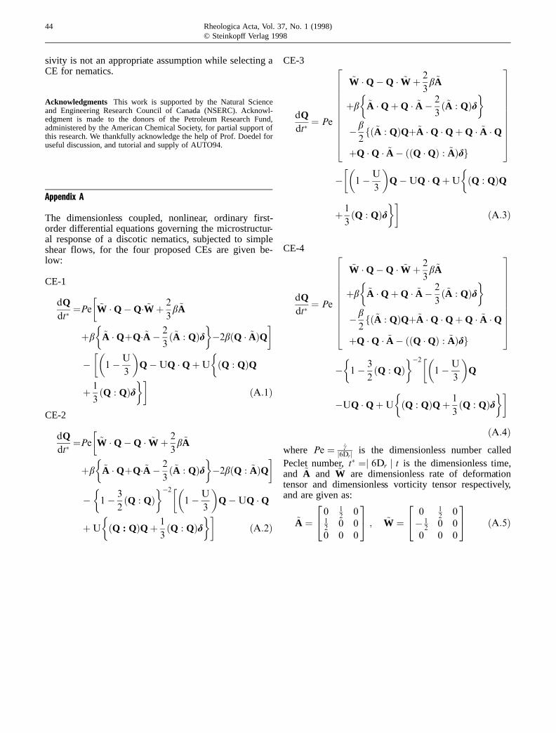
Appendix A
The dimensionless coupled, nonlinear, ordinary first-order differential equations governing the microstructur-al response of a discotic nematics, subjected to simpleshear flows, for the four proposed CEs are given be-low:
CE-1
dQdt��Pe
�~W �QÿQ� ~W � 2
3b~A
�b�
~A �Q�Q�~A ÿ 2
3�~A : Q�d
�ÿ2b�Q � ~A�Q
�ÿ��
1ÿU
3
�QÿUQ �Q�U
��Q : Q�Q
� 1
3�Q : Q�d
���A:1�
CE-2
dQdt��Pe
�~W �QÿQ � ~W � 2
3b~A
�b�
~A �Q�Q�~A ÿ 2
3�~A : Q�d
�ÿ2b�Q : ~A�Q
�ÿ�
1ÿ 3
2�Q : Q�
�ÿ2��1ÿU
3
�QÿUQ �Q
�U
��Q : Q�Q� 1
3�Q : Q�d
���A:2�
CE-3
~W �QÿQ � ~W � 2
3b~A
�b�
~A �Q�Q � ~A ÿ 2
3�~A : Q�d
�ÿ b
2f�~A : Q�Q�~A �Q �Q�Q � ~A �Q
�Q �Q � ~A ÿ ��Q �Q� : ~A�dg
éêêêêêêêë
ùúúúúúúúû
dQdt�� Pe
ÿ��
1ÿU
3
�QÿUQ �Q�U
��Q : Q�Q
� 1
3�Q : Q�d
���A:3�
CE-4
~W �QÿQ � ~W � 2
3b~A
�b�
~A �Q�Q � ~A ÿ 2
3�~A : Q�d
�ÿ b
2f�~A : Q�Q�~A �Q �Q�Q � ~A �Q
�Q �Q � ~A ÿ ��Q �Q� : ~A�dg
éêêêêêêêë
ùúúúúúúúû
dQdt�� Pe
ÿ�
1ÿ 3
2�Q : Q�
�ÿ2��1ÿU
3
�Q
ÿUQ �Q�U
��Q : Q�Q� 1
3�Q : Q�d
���A:4�
where Pe � _cj6Drj is the dimensionless number called
Peclet number,t� �j 6Dr j t is the dimensionless time,and ~A and ~W are dimensionless rate of deformationtensor and dimensionless vorticity tensor respectively,and are given as:
~A �0 1
2 012
0 00 0 0
24 35 ; ~W �0 1
2 0ÿ 1
20 0
0 0 0
24 35 �A:5�
44 Rheologica Acta, Vol. 37, No. 1 (1998)© Steinkopff Verlag 1998
45A.P. Singh and A.D. ReyConstitutive equation for discotic nematics
References
Andrews NC, Edwards BJ, McHugh AJ(1995) Continuum dynamic behavior ofhomogeneous liquid-crystalline polymersunder the imposition of shear and mag-netic fields. J Rheo 39:1161–1181
Baals H, Hess S (1988) The viscosity coeffi-cients of oriented nematics and nematicdiscotic liquids crystals: affine transfor-mation model. Z Naturforsch 43A:662–670
Beris AN, Edwards BJ (1994) Thermody-namics of flowing systems: with internalmicrostructure. Oxford University Press,New York
Carlsson T (1982) The possibility of the exis-tence of a positive Leslie viscositya2-proposed flow behavior of a disk-like ne-matic liquid crystals. Mol Cryst Liq Cryst89:57–66
Carlsson T (1983) Remarks on the flowalignment of disk like nematics. J Physi-que 44:909–911
Chandrasekhar S (1981) Liquid crystals ofdisc-like molecules. Mol Cryst Liq Cryst63:171–179
Chandrasekhar S (1992) Liquid crystals.Cambridge University Press, Cambridge
deGennes PG (1975) The physics of liquidcrystals. Oxford University Press, London
Destrade C, Tinh NH, Gasparoux H, Mal-thete J, Levelut AM (1981) Disc-likemesogen: A classification. Mol Cryst LiqCryst 71:111–135
Doedel EJ, Wang XJ, Fairgrieve TF (1995)AUTO94: Software for continuation andbifurcation problems in ordinary differen-tial equations. Applied MathematicsReport, California Institute of Technol-ogy, Pasadena
Doi M, Edwards SF (1986) The theory ofpolymer dynamics. Oxford UniversityPress, New York, pp 358–362
Farhoudi Y, Rey AD (1993a) Ordering ef-fects in shear flows of discotic polymers.Rheol Acta 32:207–217
Farhoudi Y, Rey AD (1993b) Shear flow ofnematic polymers. Part I. Orientingmodes, bifurcations and steady rheologi-cal predictions. J Rheo 37:289–314
Hammouda B, Mang J, Kumar S (1995)Shear-indued orientational effects in dis-cotic-liquid-crystal micelles. Phys Rev E51:6282–6285
Ho ASK, Rey AD (1991) Orienting propertiesof discotic nematic liquid crystals in Jef-frey-Hamel flows. Rheo Acta 30:77–88
Larson RG (1988) Constitutive equations forpolymer melts and solutions. Butter-worths, Boston
Larson RG, Öttinger HC (1991) Effect ofmolecular elasticity on out-of-plane orien-tations in shearing flows of liquid-crystal-line polymers. Macromolecules 24:6270–6282
Leslie FM (1979) Theory of flow phenomenain liquid crystals. In: Brown HG (ed) Ad-vances in Liquid Crystals, vol. 4. Aca-demic Press, New York, p 1–81
Maffettone PL, Crescitelli S (1995) Bifurca-tion analysis of a molecular model fornematic polymers in shear flows. JNNFM59:73–91
Marrucci G, Greco F (1993) Flow behaviorof liquid crystalline polymers. Adv ChemPhys 86:331–404
McHugh JJ (1994) The development of ori-entation in mesophase pitch during fiberformation. PhD thesis, Clemson Univer-sity, Clemson, SC, USA
McHugh JJ, Edie DD (1996) The orientationof mesophase pitch during fully devel-oped channel flow. Carbon 34:1315–1322
Ooi YW, Sridhar T (1994) Uniaxial exten-sional of a lyotropic liquid crystallinepolymer solution. Ind Eng Chem Res33:2368–2373
Otani S, Oya A (1986) Progress of pitch-based carbon fibers in Japan, in petro-leum derived carbons. In: Bacha JD,Newman JW, White JL (eds) ACS SympSer No. 303, American Chemical Society,Washington DC, p 322
Phillips TJ, Minter V (1996) On the observa-tion of flow-induced order in the isotro-pic phase of a nematic discogen. LiqCryst 20:243–245
Rey AD (1995a) Bifurcational analysis ofthe isotropic-discotic nematic phase tran-sition in the presence of extensional flow.Liq Cryst 19:325–331
Rey AD (1995b) Bifurcational analysis ofthe isotropic-nematic phase transition ofrigid rod polymers subjected to biaxialstretching flow. Macro Theo Sim 4:857–873
Singer LS (1985) The mesophase in carbo-naceous pitches. Faraday Discuss ChemSoc 79:265–272
Singh AP, Rey AD (1994) Extensional dy-namics of discotic nematics of variableorder: geodesic flow and viscoelastic re-laxation. J Phys II France 4:645–665
Singh AP, Rey AD (1995a) Computer simu-lation of dynamics and morphology ofdiscotic mesophases in extensional flows.Liq Cryst 18:219–230
Singh AP, Rey AD (1995b) Theory and sim-ulation of extensional flow-induced biaxi-ality in discotic mesophases. J Phys IIFrance 5:1321–1348
Volovik GE (1980) Relationship betweenmolecule shape and hydrodynamics in anematic substance. JETP Lett 31:273–275
Zimmer JE, White JL (1982) Disclinationsstructures in the carbonaceous meso-phase. In: Brown HG (ed) Advances inLiquid Crystals, vol. 5. Academic Press,New York