microbubble generation using fiber optic tips coated with nanoparticles
TRANSCRIPT

Microbubble generation using fiber optic tips coated with nanoparticles
Reinher Pimentel-Domínguez, Juan Hernández-Cordero,* and Roberto Zenit
Instituto de Investigaciones en Materiales, UNAM, A.P. 70-360 Circuito Exterior, Cd. Universitaria, México, D. F.,
04510, México *[email protected]
Abstract: We show that fiber optic tips can be used as microbubble
generators in liquid media. Using standard single-mode silica fibers
incorporating nanoparticles (carbon nanoparticles and metallic powders),
bubbles can be generated with low optical powers owing to the enhanced
photothermal effects of the coating materials. We provide details about the
hydrodynamic effects generated in the vicinity of the fiber tip during the
coating process, bubble generation and growth. Flow visualization
techniques show that thermal effects lead to bubble formation on the tip of
the fibers, and coating optimization is crucial for optimal performance of
the probes.
©2012 Optical Society of America
OCIS codes: (060.2310) Fiber optics; (140.0140) Lasers and laser optics; (350.5340)
Photothermal effects; (140.6810) Thermal effects.
References and links
1. A. Katzir, Lasers and Optical Fibers in Medicine (Academic Press, 1993).
2. A. Leung, P. M. Shankar, and R. Mutharasan, “A review of fiber-optic biosensors,” Sens. Act. B 125(2), 688–
703 (2007).
3. C. J. de Lima, L. M. Moreira, J. P. Lyon, A. B. Villaverde, and M. T. T. Pacheco, “Catheters: instrumental
advancements in biomedical applications of optical fibers,” Lasers Med. Sci. 24(4), 621–626 (2009).
4. A. Ashkin, “History of optical trapping and manipulation of small-neutral particles, atoms and molecules,” IEEE
J. Sel. Top. Quantum Electron. 6(6), 841–856 (2000).
5. D. G. Grier, “A revolution in optical manipulation,” Nature 424(6950), 810–816 (2003).
6. V. I. Yusupov, V. M. Chudnovskii, and V. N. Bagratashvili, “Laser-induced hydrodynamics in water-saturated
biotissues: 1. Generation of bubbles in liquid,” Laser Phys. 20(7), 1641–1646 (2010).
7. V. I. Yusupov, V. M. Chudnovskii, and V. N. Bagratashvili, “Laser-induced hydrodynamics in water-saturated
biotissues: 2. Effect on delivery fiber,” Laser Phys. 21(7), 1230–1234 (2011).
8. K. F. MacDonald, V. A. Fedotov, S. Pochon, B. F. Soares, N. I. Zheludev, C. Guignard, A. Mihaescu, and P.
Besnard, “Oscillating bubbles at the tips of optical fibers in liquid nitrogen,” Phys. Rev. E Stat. Nonlin. Soft
Matter Phys. 68(2), 027301 (2003).
9. R. S. Taylor and C. Hnatovsky, “Growth and decay dynamics of a stable microbubble produced at the end of a
near-field scanning optical microscopy fiber probe,” J. Appl. Phys. 95(12), 8444–8449 (2004).
10. J. C. Ramirez-San-Juan, E. Rodriguez-Aboytes, A. E. Martinez-Canton, O. Baldovino-Pantaleon, A. Robledo-
Martinez, N. Korneev, and R. Ramos-Garcia, “Time-resolved analysis of cavitation induced by CW lasers in
absorbing liquids,” Opt. Express 18(9), 8735–8742 (2010).
11. J. W. Nicholson, R. S. Windeler, and D. J. Digiovanni, “Optically driven deposition of single-walled carbon-
nanotube saturable absorbers on optical fiber end-faces,” Opt. Express 15(15), 9176–9183 (2007).
12. K. Kashiwagi, S. Yamashita, and S. Y. Set, “Optically manipulated deposition of carbon nanotubes onto optical
fiber end,” Jpn. J. Appl. Phys. 46(40), L988–L990 (2007).
13. R. Pimentel-Domínguez, N. Cuando-Espitia, and J. Hernández-Cordero, “Optically driven deposition of
nanostructures on optical fiber end faces,” Proc. SPIE 7839, 78391X, 78391X-4 (2010).
14. D. W. Berry, N. R. Heckenberg, and H. Rubinsztein-Dunlop, “Effects associated with bubble formation in
optical trapping,” J. Mod. Opt. 47, 1575–1585 (2000).
15. H. Ramachandran, A. K. Dharmadhikari, K. Bambardekar, H. Basu, J. A. Dharmadhikari, S. Sharma, and D.
Mathur, “Optical-tweezer-induced microbubbles as scavengers of carbon nanotubes,” Nanotechnology 21(24),
245102 (2010).
16. K. Mizuno, J. Ishii, H. Kishida, Y. Hayamizu, S. Yasuda, D. N. Futaba, M. Yumura, and K. Hata, “A black body
absorber from vertically aligned single-walled carbon nanotubes,” Proc. Natl. Acad. Sci. U.S.A. 106(15), 6044–
6047 (2009).
#163183 - $15.00 USD Received 16 Feb 2012; revised 21 Mar 2012; accepted 21 Mar 2012; published 30 Mar 2012(C) 2012 OSA 9 April 2012 / Vol. 20, No. 8 / OPTICS EXPRESS 8732

1. Introduction
Optical fibers have been widely used for sensors and laser delivery in biomedical applications
[1–3]. Laser surgery and noncontact manipulation of microparticles, as well as biological
materials using optical traps, are two applications in which optical fibers have also played a
key role [1, 4, 5]. Recently, laser delivery through optical fibers has shown to yield
hydrodynamic effects that may be relevant for medical procedures involving water-saturated
tissues [6]. In particular, it has been shown that moderate laser powers can lead to bubble
formation and explosion resulting in tissue damage and degradation of the end surface of the
delivery fiber [7]. In general, bubbles at the micron and nano-scale have attracted interest in
scientific research and in industry because their properties are very different from those of
macroscopic bubbles. Suitable methods for bubble generation and control at those scales are
therefore of interest for a wide variety of applications.
Bubble generation on the tip of optical fibers immersed in liquid media has been
demonstrated under different experimental conditions [7–9]. In contrast to continuous-wave
(CW) laser-induced cavitation effects that can produce bubbles in liquids [10], bubble
formation using optical fibers usually requires moderate laser power and does not rely on
absorbing solutions. The mechanism for bubble formation is mainly driven by optical
absorption in the vicinity of the fiber tip, which leads to thermal effects yielding gas-vapor
bubbles. Fiber optic tips for micron-sized bubble generation have been based on metallic
coatings as well as on carbon layers on the fiber end-face. While metallic coated fibers
typically require elaborated fabrication methods and/or specialty fibers [8, 9], carbon coatings
have been obtained upon placing a quartz fiber in contact with wood [6, 7]. The latter
approach is simple and apparently reproducible enough so as to yield bubbles in water with
laser powers ranging from 1 to 5 W. However, there are other methods upon which carbon
coatings may be incorporated on the tips of optical fibers, thereby providing further options
for developing fiber tips for microbubble generation.
In this paper we demonstrate a simple means to fabricate fiber optic tips for microbubble
generation in liquids using a laser diode. The tips are based on standard single-mode silica
fibers coated with carbon nanoparticles and metallic powders. Such materials provide
enhanced optical absorption compared to metallic and carbon coatings, and the thermal effects
required for bubble formation in liquids can be obtained with low laser power (tens of mW).
Bubbles can be readily generated upon immersing the coated fibers in liquids such as water
and methanol and their maximum size depends on the coating features. We provide details
about the fabrication procedure of the probes and the hydrodynamic effects generated in the
vicinity of the fiber tip during bubble generation and growth. Using flow visualization
techniques we also show experimental evidence of the thermal effects leading to bubble
formation on the tip of the fiber probes. The performance of the probes is demonstrated under
different experimental conditions, showing that the coating process has a significant impact
on the capabilities of the probes for bubble generation.
2. Fabrication of fiber tips and experiments
Nanoparticles can be readily incorporated onto optical fibers using a simple technique
originally demonstrated with carbon nanotubes [11, 12]. This is based on immersing the tip of
an optical fiber in a solution of nanotubes dispersed in ethanol and launching a laser beam
through the waveguide. The output beam irradiating the solution generates thermophoresis
and pressure gradients leading to deposition of the carbon nanotubes onto the fiber end-face.
We have shown that this optically driven deposition technique can be also used with other
materials such as graphite, iron and iron-graphite particles [13]. In addition, we have also
verified that deposition occurs using either single- or multimode optical fibers.
The experimental setup used for optically driven deposition of materials onto optical
fibers has been described previously [11–13]. As illustrated in Fig. 1(a), the main components
#163183 - $15.00 USD Received 16 Feb 2012; revised 21 Mar 2012; accepted 21 Mar 2012; published 30 Mar 2012(C) 2012 OSA 9 April 2012 / Vol. 20, No. 8 / OPTICS EXPRESS 8733

are a laser diode, an optical fiber for guiding the laser light and the nanostructures to be
deposited on the fiber. The nanostructures are dissolved in a liquid that must be chosen so as
to avoid optical absorption at the laser wavelength. In our experiments, the nanostructures
were dissolved in ethanol and a CW fiber-coupled laser diode (Thorlabs, 975 nm, 300 mW
max. output power) is used as the light source. The fiber tips are based on standard single-
mode optical fiber (SMF-28e), which is used for laser guiding and as the deposition target.
Prior to being immersed in the solution, the fibers are cleaved to obtain a flat end-face. The
results shown in this paper were obtained using graphite nanoparticles, multi-walled carbon
nanotubes (carbon >95%, O.D. × L 6-9 nm × 5 µm, Sigma-Aldrich, 724769), carbon
nanopowder (<50 nm particle size, Sigma-Aldrich, 633100) and silver nanopowder (<100 nm
particle size, Sigma-Aldrich, 576832).
Fig. 1. (a) Experimental setup for nanoparticle deposition onto optical fibers. (b) Arrangement
for visualization of bubble generation.
For visualizing bubble generation and growth, we used a high-speed camera (Redlike,
1108-0014) with a zoom-imaging lens (TECHSPEC® VZM, 1000i). The fiber tip was
illuminated with a high intensity white LED spot lamp (Fig. 1(b)). Additionally, we used a
shadowgraph system for monitoring thermal gradients around the location of the fiber end-
faces. This included a laser light source (633 nm, 17 mW) and a microscope objective (0.55,
35X) for expanding the beam. Finally, a standard CCD camera was used for recording the
shadowgraph images.
Deposition of nanoparticles is achieved after immersing the fibers in the liquid solution
and turning the laser on. The time required for successful deposition on the fiber tip depends
on the laser power as well as on the concentration and size of the nanoparticles. For our
experiments, the nanoparticles were dissolved in ethanol using a concentration of 2.35 mg/ml
for the silver nanoparticles and 0.235 mg/ml for the carbon nanotubes. All the solutions were
sonicated for 10 minutes prior deposition. Three sets of tips were fabricated upon immersing
the fibers during 30 seconds using three different power settings for the laser diode (57, 120
and 182 mW). Subsequent observations of the fiber end-faces with a scanning electron
microscope (SEM) were also performed to verify the successful deposition of nanoparticles.
3. Hydrodynamic effects during nanoparticle deposition
The mechanisms leading to optically driven deposition of nanoparticles start when the laser
diode is turned on. Laser light emerging from the optical fiber generates a gradient force
driving the nanostructures towards the tip of the fiber [11, 12]; thus, flow patterns are
induced. The fluid motion can thus be registered by means of the high-speed camera. Figure
2(a) shows a sequence of images that illustrate the initial motion of the nanoparticles, which is
#163183 - $15.00 USD Received 16 Feb 2012; revised 21 Mar 2012; accepted 21 Mar 2012; published 30 Mar 2012(C) 2012 OSA 9 April 2012 / Vol. 20, No. 8 / OPTICS EXPRESS 8734
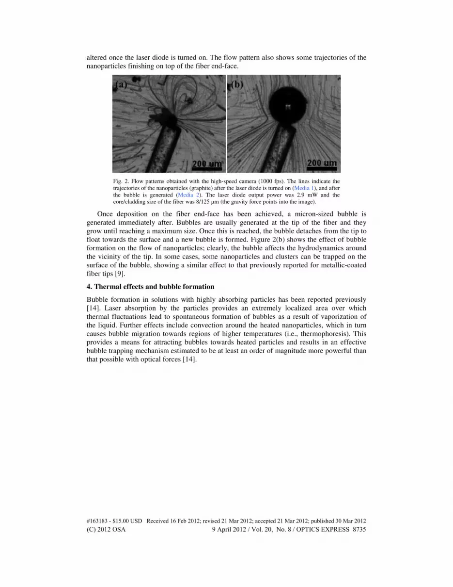
altered once the laser diode is turned on. The flow pattern also shows some trajectories of the
nanoparticles finishing on top of the fiber end-face.
Fig. 2. Flow patterns obtained with the high-speed camera (1000 fps). The lines indicate the
trajectories of the nanoparticles (graphite) after the laser diode is turned on (Media 1), and after
the bubble is generated (Media 2). The laser diode output power was 2.9 mW and the
core/cladding size of the fiber was 8/125 µm (the gravity force points into the image).
Once deposition on the fiber end-face has been achieved, a micron-sized bubble is
generated immediately after. Bubbles are usually generated at the tip of the fiber and they
grow until reaching a maximum size. Once this is reached, the bubble detaches from the tip to
float towards the surface and a new bubble is formed. Figure 2(b) shows the effect of bubble
formation on the flow of nanoparticles; clearly, the bubble affects the hydrodynamics around
the vicinity of the tip. In some cases, some nanoparticles and clusters can be trapped on the
surface of the bubble, showing a similar effect to that previously reported for metallic-coated
fiber tips [9].
4. Thermal effects and bubble formation
Bubble formation in solutions with highly absorbing particles has been reported previously
[14]. Laser absorption by the particles provides an extremely localized area over which
thermal fluctuations lead to spontaneous formation of bubbles as a result of vaporization of
the liquid. Further effects include convection around the heated nanoparticles, which in turn
causes bubble migration towards regions of higher temperatures (i.e., thermophoresis). This
provides a means for attracting bubbles towards heated particles and results in an effective
bubble trapping mechanism estimated to be at least an order of magnitude more powerful than
that possible with optical forces [14].
#163183 - $15.00 USD Received 16 Feb 2012; revised 21 Mar 2012; accepted 21 Mar 2012; published 30 Mar 2012(C) 2012 OSA 9 April 2012 / Vol. 20, No. 8 / OPTICS EXPRESS 8735

Fig. 3. Shadowgraph images (left) obtained during bubble growth (right). The fiber probe is
coated with carbon nanotubes and immersed in clean methanol (optical power during
deposition: 57.5 mW, laser diode output power: 180 mW). After reaching a maximum size, the
bubble detaches from the probe and another bubble is formed immediately after (Media 3). In
these experiments the gravity force points downwards (same direction as the fiber).
Using the shadowgraph setup we were able to obtain experimental evidence of the thermal
effects associated with bubble formation. For these experiments, the nanoparticle coated fiber
probes were immersed in clean methanol and/or water. Bubbles were readily generated once
the laser diode was turned on, and refractive index changes in the vicinity of the fiber tip were
evident in the shadowgraph image. As shown in Fig. 3, a bubble starts forming immediately
after the laser diode is turned on and kept at a constant output power. The bubble reaches a
maximum size and then detaches from the fiber tip; subsequently, another bubble starts
growing and the process repeats itself. Similar effects were observed for the different
nanoparticles used in our experiments, although the optical power required for bubble
formation varied for each case.
The shadowgraph images show that thermal effects arise near the fiber tip owing to optical
absorption of the nanostructures. This is consistent with previous observations of bubble
formation in carbon nanotube clusters due to photothermal effects in optical tweezers
experiments [14, 15]. In our case, clusters are formed on the tips of the fibers during
deposition of the nanoparticles, thus providing a preferential site for optical absorption and
hence bubble formation and growth. In the image sequence (Fig. 3), the intensity gradients
observed around the bubble indicate that there are temperature gradients around the tip of the
fiber. It is particularly interesting to note that, when the bubble detaches and a new one is
formed, the temperature gradients in the vicinity of the tip are more pronounced. This is a
clear indication that when the bubble is being formed, most of the thermal energy is being
used to convert liquid into vapor (latent heat). As it is well known, this process is isothermal;
therefore, weak temperature gradients are observed, as shown in Media 3. When the bubble
detaches, the heat is no longer used to transform liquid into vapor and a fast temperature
change in the fluid is observed, again, as clearly shown in the image sequence.
Bubble growth and lifetime were evaluated for the different fiber tips. For each case, the
optical power launched into the fiber was increased and the maximum size of the bubbles was
measured from the video images. As seen in Fig. 4(a), each of the tested tips has a different
bubble formation threshold, which depends on the optical power used for nanoparticle
deposition. Above this power threshold, the bubbles grow to the same maximum size,
although this also depends on the deposition conditions. The largest bubbles are obtained with
#163183 - $15.00 USD Received 16 Feb 2012; revised 21 Mar 2012; accepted 21 Mar 2012; published 30 Mar 2012(C) 2012 OSA 9 April 2012 / Vol. 20, No. 8 / OPTICS EXPRESS 8736

the tip fabricated using the lowest laser power (57.5 mW). For comparison, we also include
data obtained using a fiber coated with silver nanoparticles, showing that bubbles can only be
generated for a small range of optical power. Furthermore, the maximum size attained with
this tip is smaller than those obtained with fibers coated with carbon nanostructures. Notice
that in spite of using a larger concentration of silver nanoparticles in the solutions, only one of
the tips effectively generated bubbles that could be useful for comparing with the carbon
nanotube coated fibers. This seems to suggest that thermal effects due to optical absorption of
the nanostructures play an important role during the deposition process.
Fig. 4. Bubble size (a) and lifetime (b) for the different fiber tips fabricated for our
experiments. Each fiber tip was fabricated using different optical powers for nanoparticle
deposition (MWCNT-multi-wall carbon nanotubes, SNP-silver nanoparticles). Also shown in
(b) is the lifetime as a function of energy as obtained from the force and mass balances (green
line, see Eq. (8)).
The deposition conditions of the nanoparticles also affect the lifetime of the bubbles. We
define the lifetime as the time taken for a bubble to reach its maximum size and detach from
#163183 - $15.00 USD Received 16 Feb 2012; revised 21 Mar 2012; accepted 21 Mar 2012; published 30 Mar 2012(C) 2012 OSA 9 April 2012 / Vol. 20, No. 8 / OPTICS EXPRESS 8737

the tip of the fiber. As seen in Fig. 4(b), the maximum lifetime is achieved with a tip
fabricated with low optical powers during deposition. However, it is interesting to notice that
regardless of the deposition conditions, the bubbles generated with carbon nanostructure
coatings seem to reach a similar lifetime at higher laser diode powers. In contrast, the fibers
with coatings based on silver nanoparticles show only a small variation in lifetime, albeit
being smaller than those obtained with the carbon nanostructures.
Previous reports using carbon deposits on fibers have required a few watts of optical
power for bubble generation [6]. In contrast, our coated tips can produce bubbles with optical
powers as low as 20 mW, owing to the increased photothermal effects provided by the carbon
nanotubes. Notice that our deposition technique does not yield a preferential alignment for the
nanotubes and may favor clustering of nanoparticles on the fiber tips. Both, random
orientation and clustering of carbon nanotubes have been pointed out as factors for the
enhanced optical absorption observed in these materials [14–16]; thus, this may be a reason
for the improved power efficiency observed with our fiber tips. Metallic coated fiber optic tips
have shown to require even lower optical powers for bubble generation [9]; however, as
pointed out earlier, their fabrication process involves more elaborated procedures than those
required for depositing carbon nanoparticles on fiber optic end-faces.
The carbon nanotube coatings do not seem to degrade after bubbles detach from the fiber
tip. Owing to the low optical powers used in our experiments, cavitation effects and explosion
of the bubbles (as reported in [6]) are not apparent. A different scenario is obtained with silver
nanoparticle coatings, which do degrade after generating one or two bubbles in subsequent
experiments as observed in SEM images of the fiber tips. Nonetheless, further
characterization of the fiber coatings is required in order to fully assess the lifetime of the
fiber tips.
5. Discussion
The conditions for bubble detachment from the tip of the coated fiber can be estimated upon
considering the forces acting upon the bubble. For a bubble of maximum radius RBmax, the
balance between the buoyancy force and the “attachment” force yields:
( )3
v
42
3Bmax F
R g Rπ
ρ σ π= (1)
where ρv is the density and g is the acceleration of gravity. The term on the right hand side
involves the surface tension (σ) and the wetted perimeter RF represents the effective size of
the area covered by nanoparticles onto which the bubble is being formed. Under these
conditions, the maximum radius of the bubble is thus:
3
v
3
2Bmax FR R
g
σρ
= (2)
If RF is independent of the laser power, RBmax should not show a dependence on it, as
shown in Fig. 4(a). Notice also that features of the nanoparticle coating such as deposition
quality and photothermal properties are also considered in RF. This is also shown in Fig. 4(a),
since RBmax indeed changes for different deposition conditions and different nanoparticles (i.e.,
different RF values).
Let us consider now the bubble lifetime; the bubble is growing due to mass transfer from
liquid to vapor as a result of heating. A simple mass balance for a bubble of radius R, volume
V and constant density (ρv) yields:
2
v v
1 14
V Rm R
t tπ
ρ ρ
• ∂ ∂ = = ∂ ∂ (3)
#163183 - $15.00 USD Received 16 Feb 2012; revised 21 Mar 2012; accepted 21 Mar 2012; published 30 Mar 2012(C) 2012 OSA 9 April 2012 / Vol. 20, No. 8 / OPTICS EXPRESS 8738

The mass flow rate can be calculated from the latent heat of the liquid (L), which, from
dimensional analysis, can be shown to be:
Q mL= (4)
The power is then:
Q m L• •
= (5)
which can be combined with Eq. (3) to obtain:
2
v
1 14
RQ R
L tπ
ρ
• ∂ = ∂ (6)
This shows that the bubble growth rate depends directly on the amount of power being
injected into the system. Upon integrating Eq. (6), we can calculate the lifetime of the bubble
(T) assuming that the energy and the fluid properties (ρv, L) are constant. Thus:
3
max
v
4 1
3B
LT R
Q
πρ •
= (7)
Further, using Eq. (2) we can obtain the lifetime as:
2
v
2 FRLT
gQ
π σρ •
= (8)
Notice that this expression states that bubble lifetime is inversely proportional to the
energy injected to the system. This is what is shown in Fig. 4(b); thus, our assumptions are
consistent with our experimental results. Also, as shown in the figure, the lifetime depends on
RF.
It is clear from our results that bubble features such as maximum size and lifetime depend
on the coatings of the optical fibers. As demonstrated previously, deposition of the
nanostructures depends on the optical power used during fabrication [11–13]. In general, low
powers yield more uniform coatings on the fiber tips, thus providing a better surface for
bubble formation and growth. This is confirmed in our results, since the threshold for bubble
formation is smaller for the fiber tips fabricated with lower optical powers during deposition
of the nanoparticles. Similarly, the simple models considered above show that an improved RF
(i.e., coating area) would yield larger bubbles. It is interesting to notice that bubbles smaller
than the fiber diameter can remain attached to the tip, while larger bubbles always detach and
float to the surface. Although the buoyancy force and other thermal effects in the vicinity of
the bubble play an important role in the lifetime of the bubble [9], the fact that bubbles detach
from the probes further suggests that the uniformity of the coating is also critical for holding
the bubbles on the fiber. The large bubble lifetimes achieved with the tips fabricated at low
optical powers seems to confirm this suggestion as well. Clearly, further experiments are
required to optimize the coating process in order to fully exploit the photothermal effects
generated in the fiber tips.
Conclusions
We have demonstrated a simple technique for fabricating fiber optic tips for microbubble
generation in liquids using low optical powers. The fiber tips are based on standard single-
mode silica fibers incorporating carbon nanoparticles and metallic powders deposited on the
fiber end-faces. Bubbles can be generated in different liquids using low optical powers owing
to the enhanced photo-thermal effects of the nanoparticles used for coating the fibers. Our
experiments show that microbubbles are generated through thermal effects arising from
optical absorption by the nanostructures, thus leading to bubble formation on the tip of the
#163183 - $15.00 USD Received 16 Feb 2012; revised 21 Mar 2012; accepted 21 Mar 2012; published 30 Mar 2012(C) 2012 OSA 9 April 2012 / Vol. 20, No. 8 / OPTICS EXPRESS 8739

fibers. The maximum bubble size was shown to depend on the type and size of the coating,
while the bubble lifetime was shown to depend inversely on the optical power. Although
optimization of the coatings is still required, we have shown that standard single-mode optical
fibers and carbon nanoparticles can be used as an enabling technology for localized heating
generation. This might be of interest for biomedical applications.
Acknowledgments
We thank Mathieu Hautefeuille for useful discussions. Technical support from Omar Novelo
is duly appreciated. This work was supported in part by DGAPA-UNAM through grant
PAPIIT-IN102112, and by Conacyt through grant 154464.
#163183 - $15.00 USD Received 16 Feb 2012; revised 21 Mar 2012; accepted 21 Mar 2012; published 30 Mar 2012(C) 2012 OSA 9 April 2012 / Vol. 20, No. 8 / OPTICS EXPRESS 8740