mercedes-benz e-class 2008 estate owner's manual pdf
TRANSCRIPT
Disclaimer
Das folgende PDF-Dokument für dieses Fahrzeugmodell bezieht sich in allen Sprachversionen nur auf die Fahrzeuge, die für den deutschen Markt bestimmt sind und die den deutschen Vorschriften entsprechen. Bitte wenden Sie sich an Ihren autorisierten Mercedes-Benz Servicestützpunkt, um ein gedrucktes Exemplar für andere Fahrzeugmodelle und Fahrzeugmodelljahre zu erhalten.
Dieses PDF-Dokument stellt die aktuelle Version dar. Mögliche Abweichungen zu Ihrem konkreten Fahrzeug könnten nicht berücksichtigt sein, da Mercedes-Benz seine Fahrzeuge ständig dem neuesten Stand der Technik anpasst, sowie Änderungen in Form und Ausstattung vornimmt. Bitte beachten Sie daher, dass dieses PDF-Dokument in keinem Fall das gedruckte Exemplar ersetzt, das mit dem Fahrzeug ausgeliefert wurde.
Internal use only
Disclaimer
All language versions of the following PDF document for this vehicle model relate solely to vehicles intended for sale on the German market and which correspond to German regulations.
Please contact your authorised Mercedes-Benz Service Centre to obtain a printed version for other vehicle models and vehicle model years. This PDF document is the latest version. Possible variations to your vehicle may not be taken into account as Mercedes-Benz constantly updates their vehicles to the state of the art and introduces changes in design and equipment. Please therefore note that this PDF document in no way replaces the printed version which was delivered with your vehicle.
Internal use only
Disclaimer
The following version of the Owner‘s Manual describes all models, series and special equipment of your vehicle. Country-specific language variations are possible. Please note that your vehicle might not be equipped with all the described functions. This also affects safety-relevant systems and functions. Please contact your authorised Mercedes-Benz dealership if you would like to receive a printed Owner‘s Manual for other vehicle models and vehicle model years.
The online Owner‘s Manual is the current and valid version. It is possible that deviations affecting your specific vehicle could not be taken into account as Mercedes-Benz constantly adapts its vehicles according to the latest technology and makes changes to the form and the equipment.
Please also read the printed Owner‘s Manual, supplementary documents and the digital Owner‘s Manual in the vehicle.
CopyrightAll rights reserved. All texts, images and graphics are subject to copyright and other laws for the protection of intellectual property. They may not be copied or changed for any commercial use or for the purpose of being passed on nor used on other webistes.

Thank you for choosing Mercedes-Benz.Before you drive off, familiarise yourself withyour vehicle and read the Operating Instruc-tions. This will help you to obtain the maxi-mum pleasure from your vehicle and to avoidendangering yourself and others.Items of optional equipment are marked withan asterisk *.The equipment in your vehicle may vary,depending on the model, the ordered items,the country specifications and availability.The illustrations in this manual show a left-hand-drive vehicle. The arrangement of theswitches, levers, stowage compartments,etc. will differ accordingly in a right-hand-drive vehicle.Mercedes-Benz is constantly updating itsvehicles to the state of the art and thereforereserves the right to introduce changes indesign, equipment and technical features atany time. You cannot, therefore, base anyclaims on the data, illustrations or descrip-tions in this manual.Please consult a Mercedes-Benz ServiceCentre if you have any questions.The Owner’s Manual, Brief Instructions,Service Booklet and supplements specific tovehicle equipment belong with the vehicle.You should always keep them in the vehicle
and pass them on to the new owner if you sellthe vehicle.The technical documentation team atDaimler AG wishes you safe and pleasantmotoring.
i You can get to know the important fea-tures of your vehicle in German and inEnglish in the interactive Owner's Manualon the Internet at:www.mercedes-benz.de/betriebsanlei-tung
211_AKB; 2; 5, en-GBmkalafa, Version: 2.9.4
2008-02-29T16:57:07+01:00 - Seite 1
Dateiname: 6515_3416_02_buchblock.pdf; preflight
2
Index . . . . . . . . . . . . . . . . . . . . . . . . . . . . 3
Introduction . . . . . . . . . . . . . . . . . . . . . 16
At a glance . . . . . . . . . . . . . . . . . . . . . . 19
Safety . . . . . . . . . . . . . . . . . . . . . . . . . . 39
Controls . . . . . . . . . . . . . . . . . . . . . . . . 65
Operation . . . . . . . . . . . . . . . . . . . . . . 217
Practical advice . . . . . . . . . . . . . . . . . 251
Technical data . . . . . . . . . . . . . . . . . . 343
Contents
211_AKB; 2; 5, en-GBmkalafa, Version: 2.9.4
2008-02-29T16:57:07+01:00 - Seite 2
Dateiname: 6515_3416_02_buchblock.pdf; preflight
3
1, 2, 3 ...4MATIC (permanent four-wheeldrive) . . . . . . . . . . . . . . . . . . . . . . . . . . 1587G–TRONIC . . . . . . . . . . . . . . . . . . . . . 116
AABS (Anti-lock Braking System) . . . . . 58
Display message . . . . . . . . . . 258, 269Warning lamp . . . . . . . . . . . . . . . . . 285
AccelerationTechnical data . . . . . . . . . . . . . . . . 354
AccidentNotes . . . . . . . . . . . . . . . . . . . . . . . 293
Active Service Systemsee ASSYST PLUS
ADAPTIVE BRAKE . . . . . . . . . . . . . . . . . 61Adaptive brake lamps . . . . . . . . . . . . . 59Adaptive damping system
see ADSADS . . . . . . . . . . . . . . . . . . . . . . . . . . . 157Airbag
Activation . . . . . . . . . . . . . . . . . . . . . 41Control unit . . . . . . . . . . . . . . . . . . . 41Driver's . . . . . . . . . . . . . . . . . . . . . . . 44Front . . . . . . . . . . . . . . . . . . . . . . . . 44Front passenger . . . . . . . . . . . . . . . . 44PASSENGER AIRBAGOFFwarninglamp . . . . . . . . . . . . . . . . . . . . . . . 283Sidebags . . . . . . . . . . . . . . . . . . . . . 45
System . . . . . . . . . . . . . . . . . . . . . . . 43Windowbags . . . . . . . . . . . . . . . . . . . 46
Air cleanerDisplay message . . . . . . . . . . . . . . 276
Air conditioning2-zone Thermatic . . . . . . . . . . . . . . 1644-zone Thermotronic . . . . . . . . . . . 166Activating/deactivating . . . . . . . . . 169Activating/deactivating air-recir-culation mode . . . . . . . . . . . . . . . . 175Air-recirculation mode with con-venience opening/closing feature . 176Auxiliary heating/ventilation . . . . . 177Controlling automatically . . . . . . . . 170Cooling with air dehumidification . . 169Demisting the windscreen . . . . . . . 174Malfunction indicator lamp . . . . . . 283Misted-up windows . . . . . . . . . . . . 175Rear compartment . . . . . . . . . . . . . 169Rear window heating . . . . . . . . . . . 175Setting the air distribution . . . . . . . 173Setting the airflow . . . . . . . . . . . . . 174Setting the air vents . . . . . . . . . . . . 171Setting the temperature . . . . . . . . . 170Setting the temperature (rearcompartment) . . . . . . . . . . . . . . . . 171Switching the residual heat func-tion on/off . . . . . . . . . . . . . . . . . . . 176see Climate control
Airmatic DC (Dual Control) . . . . . . . . 156
Air pump, electric . . . . . . . . . . . . . . . 255Ambient lighting
Setting (on-board computer) . . . . . 136Antifreeze concentration . . . . . 389, 390Anti-lock braking system
see ABSAnti-theft alarm system
see ATAAnti-theft systems . . . . . . . . . . . . . . . . 62Ashtray . . . . . . . . . . . . . . . . . . . . . . . . 209ASSYST PLUS . . . . . . . . . . . . . . . . . . . 243ATA (anti-theft alarm system) . . . . . . 62
Switching off the alarm . . . . . . . . . . 62Audible warning signal . . . . . . . . . . . 292AUTO lights
Display message . . . . . . . . . . . . . . 273Automatic car wash . . . . . . . . . . . . . 245Automatic transmission
Changing gear yourself . . . . . . . . . 116Display in the speedometer . . . . . . 115Driving tips . . . . . . . . . . . . . . . . . . . 117Emergency running mode . . . . . . . 297Malfunction . . . . . . . . . . . . . . . . . . 297One-touch gearshifting . . . . . . . . . 116Program selector button . . . . . . . . 117Releasing the parking lock man-ually . . . . . . . . . . . . . . . . . . . . . . . . 309Selector lever positions . . . . . . . . . 115Shift ranges . . . . . . . . . . . . . . . . . . 116Trailer towing . . . . . . . . . . . . . . . . . 117
Index
211_AKB; 2; 5, en-GBmkalafa, Version: 2.9.4
2008-02-29T16:57:07+01:00 - Seite 3
Dateiname: 6515_3416_02_buchblock.pdf; preflight
4
Automatic transmission Displaymessage . . . . . . . . . . . . . . . . . . . . . . . 261Auxiliary heating . . . . . . . . . . . . 177, 304
Display message . . . . . . . . . . . . . . 280Remote control . . . . . . . . . . . . . . . 178Setting (on-board computer) . . . . . 133
Auxiliary ventilation . . . . . . . . . . . . . 177Axle load, maximum permissible. . . . . . . . . . . . . . 370, 371, 372, 373, 374
BBall coupling
Folding in . . . . . . . . . . . . . . . . . . . . 241Folding out . . . . . . . . . . . . . . . . . . . 239
BAS (Brake Assist) . . . . . . . . . . . . . . . . 59Battery
Changing (auxiliary heatingremote control) . . . . . . . . . . . . . . . 311Changing (key) . . . . . . . . . . . . . . . . 310Changing (KEYLESS GO key) . . . . . 310Charging . . . . . . . . . . . . . . . . . . . . . 332Checking (key) . . . . . . . . . . . . . . . . 310Checking (KEYLESS GO key) . . . . . 310Check lamp (key) . . . . . . . . . . . . . . 310Check lamp (KEYLESS GO key). . . . . . . . . . . . . . . . . . . . . . . . . 69, 310Disconnecting . . . . . . . . . . . . . . . . 331Display message . . . . . . . . . . . . . . 266Maintenance (vehicle) . . . . . . . . . . 329Reconnecting . . . . . . . . . . . . . . . . . 333
Removing/fitting . . . . . . . . . . . . . . 332Vehicle battery . . . . . . . . . . . . . . . . 329Voltage (on-board computer) . . . . . 127
Belt force limitersActivation . . . . . . . . . . . . . . . . . . . . . 41
Belt height adjustment . . . . . . . . . . . . 97Belt reel (Easy-Pack fix kit) . . . . . . . . 203Belt tensioners
Activation . . . . . . . . . . . . . . . . . . . . . 41Belt warning . . . . . . . . . . . . . . . . . . . . . 97Bonnet
Bonnet catch . . . . . . . . . . . . . . . . . 223Display message . . . . . . . . . . . . . . 267Opening/closing . . . . . . . . . . . . . . 222
Bonnet release leverRelease lever . . . . . . . . . . . . . . . . . 222
BootEmergency release . . . . . . . . . . . . . 307Locking separately . . . . . . . . . . . . . . 72Opening/closing (manually) . . . . . . . 70
Boot/luggage compartmentOpening/closing (automatically) . . . 73
Boot lidDisplay message . . . . . . . . . . . . . . 266
BrakeWarning lamp . . . . . . . . . . . . . . . . . 286
Brake Assistsee BAS
Brake fluid . . . . . . . . . . . . . . . . . . . . . 390Display message . . . . . . . . . . . . . . 270
Brake lampsAdaptive . . . . . . . . . . . . . . . . . . . . . . 59Display message . . . . . . . . . . . . . . 274
Brake systemDisplay message . . . . . . . . . . 268, 269Parking brake . . . . . . . . . . . . . . . . . 113
BulbChanging . . . . . . . . . . . . . . . . 314, 315Dipped-beam headlamps . . . . . . . . 314Licence plate lamp . . . . . . . . . . . . . 315Main-beam headlamps . . . . . . . . . . 314Parking lamp . . . . . . . . . . . . . . . . . 314Side lamp . . . . . . . . . . . . . . . . . . . . 314Turn signal lamp . . . . . . . . . . . . . . . 314see Lamp
BulbsOverview . . . . . . . . . . . . . . . . . . . . 312
CCalling up a malfunction
see Message memory menuCare . . . . . . . . . . . . . . . . . . . . . . . . . . . 244
Automatic car wash . . . . . . . . . . . . 245Distronic . . . . . . . . . . . . . . . . . . . . 248Headlamps . . . . . . . . . . . . . . . . . . . 246High-pressure cleaners . . . . . . . . . 245Parktronic . . . . . . . . . . . . . . . . . . . 248Plastic trim . . . . . . . . . . . . . . . . . . . 247Rear window . . . . . . . . . . . . . . . . . 246Side windows . . . . . . . . . . . . . . . . . 246
Index
211_AKB; 2; 5, en-GBmkalafa, Version: 2.9.4
2008-02-29T16:57:07+01:00 - Seite 4
Dateiname: 6515_3416_02_buchblock.pdf; preflight
5
Tail pipes (AMG vehicles) . . . . . . . . 247Trailer tow hitch . . . . . . . . . . . . . . . 248
CD player/CD changerOperating (on-board computer) . . . 129
Central lockingAutomatic locking (on-board com-puter) . . . . . . . . . . . . . . . . . . . . . . . 137From the luggage compartment(outside) . . . . . . . . . . . . . . . . . . . . . . 69Key . . . . . . . . . . . . . . . . . . . . . . . . . . 66KEYLESS GO . . . . . . . . . . . . . . . 68, 69
Central locking/unlocking button . . . 70Central unlocking
Key . . . . . . . . . . . . . . . . . . . . . . . . . . 66KEYLESS GO . . . . . . . . . . . . . . . 68, 69
Centre consoleLower section . . . . . . . . . . . . . . . . . . 31Upper section . . . . . . . . . . . . . . . . . . 32
Changing a wheelsee Flat tyre
Child-proof locksRear doors . . . . . . . . . . . . . . . . . . . . 56Side windows (rear) . . . . . . . . . . . . . 57Tailgate . . . . . . . . . . . . . . . . . . . . . . 57
ChildrenFastening seat belts . . . . . . . . . . . . . 56in the vehicle . . . . . . . . . . . . . . . . . . 47Restraint systems . . . . . . . . . . . . . . 48
Child seatAutomatic recognition . . . . . . . . . . . 49Automatic recognition (malfunc-tion) . . . . . . . . . . . . . . . . . . . . . . . . 284Integrated . . . . . . . . . . . . . . . . . . . . 55ISOFIX . . . . . . . . . . . . . . . . . . . . . . . 54Recommendations . . . . . . . . . . . . . . 53Suitable positions . . . . . . . . . . . . . . 51
Cigarette lighter . . . . . . . . . . . . . . . . 209Cockpit
Overview . . . . . . . . . . . . . . . . . . . . . 22Collapsible wheel
Pumping up . . . . . . . . . . . . . . . . . . 326Storage location . . . . . . . . . . . . . . . 255Technical data . . . . . . . . . . . . . . . . 365
COMAND . . . . . . . . . . . . . . . . . . . . . . . 124On-board computer . . . . . . . . . . . . 124see separate operating instructions
Constant headlamp modeSetting (on-board computer) . . . . . 135
Consumption statistics (on-boardcomputer) . . . . . . . . . . . . . . . . . . . . . . 140Convenience closing . . . . . . . . . . . . . 109Coolant . . . . . . . . . . . . . . . . . . . . . . . . 225
Checking the level . . . . . . . . . . . . . 226Display message . . . . . . . . . . 267, 271Mixture ratio . . . . . . . . . . . . . . . . . 388Temperature gauge . . . . . . . . . . . . 120Warning lamp . . . . . . . . . . . . . . . . . 287
Cornering lightDisplay message . . . . . . . . . . . . . . 272
Cruise control . . . . . . . . . . . . . . . . . . 143Display message . . . . . . . . . . . . . . 265
Cup holder . . . . . . . . . . . . . . . . . . . . . 186
DDashboard
see Cockpitsee Instrument cluster
DateSetting (on-board computer) . . . . . 134
Daytime driving lightssee Constant headlamp mode
Delayed switch-offExterior lighting (on-board com-puter) . . . . . . . . . . . . . . . . . . . . . . . 136Interior lighting (on-board com-puter) . . . . . . . . . . . . . . . . . . . . . . . 136
DieselLow outside temperatures . . . . . . . 221
Diesel engineWinter driving . . . . . . . . . . . . . . . . . 221
Digital speedometer . . . . . . . . . . . . . 126Dipped-beam headlamps
Display message . . . . . . . . . . . . . . 272Symmetrical . . . . . . . . . . . . . . . . . . 238
Display message . . . . . . . . . . . . . . . . 257Displaying . . . . . . . . . . . . . . . . . . . 131
Index
211_AKB; 2; 5, en-GBmkalafa, Version: 2.9.4
2008-02-29T16:57:07+01:00 - Seite 5
Dateiname: 6515_3416_02_buchblock.pdf; preflight
6
Service display . . . . . . . . . . . . . . . . 243Symbol messages . . . . . . . . . . . . . 266Text messages . . . . . . . . . . . . . . . . 258up (AMG menu) . . . . . . . . . . . . . . . 126
Distance warning function . . . . . . . . 149Distance warning lamp . . . . . . . . . . . 149Distronic . . . . . . . . . . . . . . . . . . . . . . . 145
Cleaning the sensors . . . . . . . . . . . 248Cover . . . . . . . . . . . . . . . . . . . . . . . 248Display message . . . . . . . . . . . . . . 259Distance warning function . . . . . . . 149Driving tips . . . . . . . . . . . . . . . . . . . 151Warning lamp . . . . . . . . . . . . . . . . . 286
DoorAutomatic locking . . . . . . . . . . . . . . 70Display message . . . . . . . . . . . . . . 267Emergency locking . . . . . . . . . . . . . 307Emergency unlocking . . . . . . . . . . . 306Opening (from the inside) . . . . . . . . 69
Door control panelOverview . . . . . . . . . . . . . . . . . . . . . 35
Drinks holdersee Cup holder
Driver's airbag . . . . . . . . . . . . . . . . . . . 44Driver's door
Unlocking (KEYLESS GO) . . . . . . . . . 69Driver's seat position . . . . . . . . . . . . . 97Driving abroad . . . . . . . . . . . . . . . . . . 238Driving safety system . . . . . . . . . . . . . 58
ABS . . . . . . . . . . . . . . . . . . . . . . . . . 58
ADAPTIVE BRAKE . . . . . . . . . . . . . . . 61Adaptive brake lamps . . . . . . . . . . . 59BAS . . . . . . . . . . . . . . . . . . . . . . . . . 59EBV . . . . . . . . . . . . . . . . . . . . . . . . . 61ESP® . . . . . . . . . . . . . . . . . . . . . . . . 60
Driving system . . . . . . . . . . . . . . . . . . 1424MATIC . . . . . . . . . . . . . . . . . . . . . 158Airmatic DC . . . . . . . . . . . . . . . . . . 156Cruise control . . . . . . . . . . . . . . . . 143Distronic . . . . . . . . . . . . . . . . . . . . 145HOLD . . . . . . . . . . . . . . . . . . . . . . . 155Parktronic . . . . . . . . . . . . . . . . . . . 158Speedtronic . . . . . . . . . . . . . . . . . . 152
Driving tipBraking . . . . . . . . . . . . . . . . . . . . . . 236Distronic . . . . . . . . . . . . . . . . . . . . 151Driving abroad . . . . . . . . . . . . . . . . 238Driving on flooded roads . . . . . . . . 238Driving on wet roads . . . . . . . . . . . 238Trailer towing . . . . . . . . . . . . . . . . . 240Winter . . . . . . . . . . . . . . . . . . . . . . 235
DVD audioOperating (on-board computer) . . . 129
DVD videoOperating (on-board computer) . . . 130
Dynamic driving seat . . . . . . . . . . . . . 84Selecting seat adjustment (on-board computer) . . . . . . . . . . . . . . 139
EEasy-entry/exit feature
Activating/deactivating (on-board computer) . . . . . . . . . . . . . . 138
Easy-entry feature . . . . . . . . . . . . . . . . 90Easy-exit feature . . . . . . . . . . . . . . . . . 90Easy-Pack fix kit . . . . . . . . . . . . . . . . 202Easy-Pack stowage box . . . . . . . . . . 204Easy-Pack system . . . . . . . . . . . . . . . 202EBV (electronic brake-power distri-bution) . . . . . . . . . . . . . . . . . . . . . . . . . 61
Display message . . . . . . . . . . . . . . 269Electrical/electronic equipment
Retrofitting . . . . . . . . . . . . . . . . . . . 345Electronic brake-power distribution
see EBVElectronic Stability Program
see ESP®e mark . . . . . . . . . . . . . . . . . . . . . . . . . 345Emergency engine starting . . . . . . . 339Emergency key element
Lost . . . . . . . . . . . . . . . . . . . . . . . . 301Emergency locking
Vehicle . . . . . . . . . . . . . . . . . . . . . . 307Emergency running mode
Automatic transmission . . . . . . . . . 297
Index
211_AKB; 2; 5, en-GBmkalafa, Version: 2.9.4
2008-02-29T16:57:07+01:00 - Seite 6
Dateiname: 6515_3416_02_buchblock.pdf; preflight
7
Emergency unlockingBoot . . . . . . . . . . . . . . . . . . . . . . . . 307Tailgate . . . . . . . . . . . . . . . . . . . . . 308Vehicle . . . . . . . . . . . . . . . . . . . . . . 306
EngineDisplay message . . . . . . . . . . . . . . 278Running irregularly . . . . . . . . . . . . . 296Starting problems . . . . . . . . . . . . . 295Starting with KEYLESS GO . . . . . . . 111Starting with the key . . . . . . . . . . . 110Technical data . . . . . . . . . . . . . . . . 348
Engine diagnostic warning lamp . . . 288Engine electronics . . . . . . . . . . . . . . . 345
Malfunction . . . . . . . . . . . . . . . . . . 295Engine number . . . . . . . . . . . . . . . . . . 347Engine oil . . . . . . . . . . . . . . . . . . . . . . 385
Capacities . . . . . . . . . . . . . . . . . . . 224Checking the oil level (dipstick) . . . 224Checking the oil level (on-boardcomputer) . . . . . . . . . . . . . . . . . . . 223Consumption . . . . . . . . . . . . . . . . . 223Display message . . . . . . . . . . 224, 277Filler neck . . . . . . . . . . . . . . . . . . . 225Temperature display (on-boardcomputer) . . . . . . . . . . . . . . . . . . . 126Topping up . . . . . . . . . . . . . . . . . . . 225
ESP® (Electronic Stability Program) . 60Activating/deactivating . . . . . . . . . . 60Display message . . . . . . . . . . 260, 269Warning lamp . . . . . . . . . . . . . . 60, 285
Exterior lightingDelayed switch-off (on-boardcomputer) . . . . . . . . . . . . . . . . . . . 136
Exterior mirror parking positionStoring . . . . . . . . . . . . . . . . . . . . 92, 94
Exterior mirrorsAdjusting . . . . . . . . . . . . . . . . . . . . . 91Anti-dazzle mode (automatic) . . . . . 92Folding in/out (automatically) . . . . . 92Folding in/out (electrically) . . . . . . . 91Folding in when locking (on-boardcomputer) . . . . . . . . . . . . . . . . . . . 139Malfunction . . . . . . . . . . . . . . . . . . 300Parking position . . . . . . . . . . . . . 92, 94Resetting . . . . . . . . . . . . . . . . . . . . . 92Storing settings . . . . . . . . . . . . . . . . 93
Exterior viewOverview . . . . . . . . . . . . . . . . . . . . . 20
FFastening seat belts
Children . . . . . . . . . . . . . . . . . . . . . . 56Fire extinguisher . . . . . . . . . . . . . . . . 253First-aid kit . . . . . . . . . . . . . . . . . . . . . 253Flat tyre
MOExtended run-flat system . . . . . 328Preparing the vehicle . . . . . . . . . . . 317TIREFIT kit . . . . . . . . . . . . . . . . . . . 318
Floormat . . . . . . . . . . . . . . . . . . . . . . . 216
FoglampsDisplay message . . . . . . . . . . . . . . 275
Folding bench seat . . . . . . . . . . . . . . . 86Folding out/folding back . . . . . . . . . 87
Fording . . . . . . . . . . . . . . . . . . . . . . . . 238Frequencies
Garage door opener . . . . . . . . . . . . 391Telephone . . . . . . . . . . . . . . . . . . . 346
Front airbag . . . . . . . . . . . . . . . . . . . . . 44Front-passenger airbag . . . . . . . . . . . . 44Fuel . . . . . . . . . . . . . . . . . . . . . . . . . . . 377
Diesel . . . . . . . . . . . . . . . . . . . . . . . 220Display message . . . . . . . . . . . . . . 270Loss . . . . . . . . . . . . . . . . . . . . . . . . 294Petrol . . . . . . . . . . . . . . . . . . . . . . . 219
Fuel consumption . . . . . . . . . . . 379, 380Fuel filler flap
Opening/closing . . . . . . . . . . . . . . 218Fuel line
Malfunction . . . . . . . . . . . . . . . . . . 294Fuel tank
Malfunction . . . . . . . . . . . . . . . . . . 294Range (on-board computer) . . . . . . 140
Fuse allocation chart . . . . . . . . . . . . 340Fuse box
Boot/luggage compartment . . . . . 341Dashboard . . . . . . . . . . . . . . . . . . . 341
Fuses . . . . . . . . . . . . . . . . . . . . . . . . . . 340
Index
211_AKB; 2; 5, en-GBmkalafa, Version: 2.9.4
2008-02-29T16:57:07+01:00 - Seite 7
Dateiname: 6515_3416_02_buchblock.pdf; preflight
8
GGarage door
Opening/closing (with the remotecontrol) . . . . . . . . . . . . . . . . . . . . . 215
Garage door opener . . . . . . . . . . . . . . 214Clearing the memory . . . . . . . . . . . 216Frequencies . . . . . . . . . . . . . . . . . . 391Programming the remote control . . 214
Gear indicator (on-board computer) 126Gearshift program
Manual . . . . . . . . . . . . . . . . . . . . . . 118Genuine Mercedes-Benz parts . . . . . 344Glove compartment . . . . . . . . . . . . . . 205Gross vehicle weight, maximumpermissible . . . . 369, 371, 372, 373, 374
HHeadlamp
Misting up . . . . . . . . . . . . . . . . . . . 299Headlamps
Cleaning . . . . . . . . . . . . . . . . . . . . . 246Cleaning system . . . . . . . . . . . . . . . 103
Headlamps delayed switch-offsee Exterior lighting delayed switch-off
Head restraintAdjusting (front) . . . . . . . . . . . . . 79, 80Adjusting (rear) . . . . . . . . . . . . . . . . 81Luxury . . . . . . . . . . . . . . . . . . . . 79, 81
NECK-PRO . . . . . . . . . . . . . . . . . . . . 47Removing (rear) . . . . . . . . . . . . . . . . 83
Head restraintsResetting triggered NECK-PROhead restraints . . . . . . . . . . . . . . . . 309
Heatingsee Air conditioning
High-pressure cleaners . . . . . . . . . . . 245HOLD . . . . . . . . . . . . . . . . . . . . . . . . . . 155
Display message . . . . . . . . . . . . . . 264HomeLink®
see Garage door opener
IImmobiliser . . . . . . . . . . . . . . . . . . . . . 62Indicator and warning lamp
Brakes (red) . . . . . . . . . . . . . . . . . . 286Coolant . . . . . . . . . . . . . . . . . . . . . 287Distronic (red) . . . . . . . . . . . . 149, 286Engine diagnostic . . . . . . . . . . . . . . 288ESP® . . . . . . . . . . . . . . . . . . . . 60, 285PASSENGER AIRBAG OFF . . . . 49, 283Reserve fuel . . . . . . . . . . . . . . . . . . 291Seat belt . . . . . . . . . . . . . . . . . . . . . 290SRS . . . . . . . . . . . . . . . . . . . . . 41, 289Tyre pressure monitor . . . . . . . . . . 289
Indicator and warning lamps . . . . . . 285Indicator lamp
see Indicator and warning lamp
Instrument cluster . . . . . . . . . . . . . . 120Overview . . . . . . . . . . . . . . . . . . 26, 28Selecting the language (on-boardcomputer) . . . . . . . . . . . . . . . . . . . 133
Instrument lighting . . . . . . . . . . . . . . 120Integrated child seat . . . . . . . . . . . . . . 55Intelligent Light System . . . . . . . . . . 103
Display message . . . . . . . . . . . . . . 274Menu (on-board computer) . . . . . . 137
Interior lighting . . . . . . . . . . . . . . . . . 104Ambient (on-board computer) . . . . 136Automatic control . . . . . . . . . . . . . 105Delayed switch-off (on-boardcomputer) . . . . . . . . . . . . . . . . . . . 136Manual control . . . . . . . . . . . . . . . . 105Reading lamp . . . . . . . . . . . . . . . . . 105
Interior motion sensor . . . . . . . . . . . . 63ISOFIX child seat securing system . . 54
JJack
Operation . . . . . . . . . . . . . . . . . . . . 324Storage location . . . . . . . . . . . . . . . 254
Jump-starting . . . . . . . . . . . . . . . . . . . 333Jump leads . . . . . . . . . . . . . . . . . . . 333
KKey . . . . . . . . . . . . . . . . . . . . . . . . . . . . 66
Changing the battery . . . . . . . . . . . 310
Index
211_AKB; 2; 5, en-GBmkalafa, Version: 2.9.4
2008-02-29T16:57:07+01:00 - Seite 8
Dateiname: 6515_3416_02_buchblock.pdf; preflight
9
Checking the battery . . . . . . . . . . . 310Convenience closing . . . . . . . . . . . 110Display message . . . . . . . . . . . . . . 279Factory setting . . . . . . . . . . . . . . 66, 67Loss . . . . . . . . . . . . . . . . . . . . . . . . 301Malfunction . . . . . . . . . . . . . . . . . . 301Modifying the programming . . . . . . . 66
KEYLESS GO . . . . . . . . . . . . . . . . . . . . . 67Button . . . . . . . . . . . . . . . . . . . . . . . 77Changing the battery . . . . . . . . . . . 310Checking the battery . . . . . . . . . . . 310Closing the boot lid automatically . . 74Convenience closing . . . . . . . . . . . 110Factory settings . . . . . . . . . . . . . . . . 68Losing the key . . . . . . . . . . . . . . . . 304Malfunction . . . . . . . . . . . . . . . . . . 303Modifying the programming . . . . . . . 68Starting the engine . . . . . . . . . . . . 111
Key positionsKey . . . . . . . . . . . . . . . . . . . . . . . . . . 76KEYLESS GO . . . . . . . . . . . . . . . . . . 77
Kickdown . . . . . . . . . . . . . . . . . . 117, 119
LLamp
Display message . . . . . . . . . . . . . . 272Lamps
see Indicator and warning lampLanguage
Selecting (on-board computer) . . . 133
Lashing eyelets . . . . . . . . . . . . . . . . . 191Licence plate lighting
Display message . . . . . . . . . . . . . . 275Lighting
see LightsLights
Active light function . . . . . . . . . . . . 103Automatic headlamp mode . . . . . . 100Constant headlamp mode . . . . . . . . 99Cornering light function . . . . . . . . . 103Dipped-beam headlamps . . . . . . . . . 99Display message . . . . . . . . . . . . . . 272Fog lights . . . . . . . . . . . . . . . . 100, 104Hazard warning lamps . . . . . . . . . . 102Headlamp flasher . . . . . . . . . . . . . . 101Headlamp range . . . . . . . . . . . . . . . 102Light switch . . . . . . . . . . . . . . . . . . . 99Main-beam headlamps . . . . . . . . . . 101Motorway mode . . . . . . . . . . . . . . . 104Rear foglamp . . . . . . . . . . . . . . . . . 100Switching off (display message) . . . 275Turn signals . . . . . . . . . . . . . . . . . . 101
LIM indicator lampCruise control . . . . . . . . . . . . . . . . 143Distronic . . . . . . . . . . . . . . . . . . . . 146Variable Speedtronic . . . . . . . . . . . 152
Loadcompartment load,maximum. . . . . . . . . . . . . . 370, 371, 372, 373, 374Loading guidelines . . . . . . . . . . . . . . 190
LockingAutomatic . . . . . . . . . . . . . . . . . . . . . 70Emergency locking . . . . . . . . . . . . . 307From the inside (central lockingbutton) . . . . . . . . . . . . . . . . . . . . . . . 70
Luggage compartment enlarge-ment . . . . . . . . . . . . . . . . . . . . . . . . . . 198Luggage compartment floor
extending . . . . . . . . . . . . . . . . . . . . 194opening/closing . . . . . . . . . . 193, 195removing . . . . . . . . . . . . . . . . . . . . 194stowage well, under . . . . . . . . . . . . 192
Luggage cover . . . . . . . . . . . . . . . . . . 201Luggage net
Front-passenger footwell . . . . . . . . 190Luggage well
Removing/fitting . . . . . . . . . . . . . . 256Lumbar support
see Lumbar supportLuxury head restraint . . . . . . . . . . 79, 81
MMain-beam headlamps
Display message . . . . . . . . . . . . . . 274Main fuse box . . . . . . . . . . . . . . . . . . . 341Maintenance
Battery . . . . . . . . . . . . . . . . . . . . . . 329Malfunction memory
see Message memory menu
Index
211_AKB; 2; 5, en-GBmkalafa, Version: 2.9.4
2008-02-29T16:57:07+01:00 - Seite 9
Dateiname: 6515_3416_02_buchblock.pdf; preflight
10
Manual gearshift program . . . . . . . . 118Manual transmission . . . . . . . . . . . . . 115Massage function (PULSE) . . . . . . . . . 85Maximum speed
Technical data . . . . . . . . . . . . . . . . 352Memory card . . . . . . . . . . . . . . . . . . . 129
Operating (on-board computer) . . . 129see separate operating instructions
Memory function . . . . . . . . . . . . . . . . . 93Menu (on-board computer) . . . . . . . . 124
AMG . . . . . . . . . . . . . . . . . . . . . . . . 126Audio . . . . . . . . . . . . . . . . . . . . . . . 129Distronic . . . . . . . . . . . . . . . . . . . . 149DVD . . . . . . . . . . . . . . . . . . . . . . . . 130Message memory . . . . . . . . . . . . . . 131Navigation . . . . . . . . . . . . . . . . . . . 130Resetting to factory settings . . . . . 132Settings . . . . . . . . . . . . . . . . . . . . . 131Standard display . . . . . . . . . . . . . . 125Submenu overview . . . . . . . . . . . . . 132Telephone . . . . . . . . . . . . . . . . . . . 141Trip computer . . . . . . . . . . . . . . . . 139TV . . . . . . . . . . . . . . . . . . . . . . . . . . 130
Messagesee Display messagesee Indicator and warning lampsee Message memory menu
Minispare emergency spare wheelStorage location . . . . . . . . . . . . . . . 255Technical data . . . . . . . . . . . . . . . . 365
MirrorSun visor . . . . . . . . . . . . . . . . . . . . 208see Exterior or rear-view mirror
Mobile phone . . . . . . . . . . . . . . . . . . . 211Bracket . . . . . . . . . . . . . . . . . . . . . 211Display message . . . . . . . . . . . . . . 281Installation . . . . . . . . . . . . . . . . . . . 345Own number sending . . . . . . . . . . . 212Run-on time . . . . . . . . . . . . . . . . . . 212Stowage compartment . . . . . . . . . . 206Telephone menu (on-board com-puter) . . . . . . . . . . . . . . . . . . . . . . . 141
Modifying the programmingKey . . . . . . . . . . . . . . . . . . . . . . . . . . 66KEYLESS GO key . . . . . . . . . . . . . . . 68
MOExtended run-flat system* . 229, 328MP3 . . . . . . . . . . . . . . . . . . . . . . . . . . . 129
Operation (on-board computer) . . . 129see separate operating instructions
Multi-contour seat . . . . . . . . . . . . . . . . 84Multi-function display . . . . . . . . 120, 123Multi-function steering wheel . . . . . 122
Overview . . . . . . . . . . . . . . . . . . . . . 30
NNavigation . . . . . . . . . . . . . . . . . . . . . 130
Navigation menu (on-board com-puter) . . . . . . . . . . . . . . . . . . . . . . . 130see separate operating instructions
NECK-PRO head restraint . . . . . . . . . . 47Resetting triggered NECK-PROhead restraints . . . . . . . . . . . . . . . . 309
OOil
Consumption . . . . . . . . . . . . . . . . . 223Topping up . . . . . . . . . . . . . . . . . . . 225
Oil levelChecking (dipstick) . . . . . . . . . . . . 224Checking (on-board computer) . . . 223
On-board computer . . . . . . . . . . . . . . 121AMG menu . . . . . . . . . . . . . . . . . . . 126Audio menu . . . . . . . . . . . . . . . . . . 129Convenience submenu . . . . . . . . . . 133Display messages . . . . . . . . . . . . . 257Distronic menu . . . . . . . . . . . . . . . . 149DVD menu . . . . . . . . . . . . . . . . . . . 130Dynamic driving seat submenu . . . 139Factory settings . . . . . . . . . . . . . . . 132Heating submenu . . . . . . . . . . . . . . 133Instrument cluster submenu . . . . . 132Lighting submenu . . . . . . . . . . . . . 133Message memory menu . . . . . . . . . 131
Index
211_AKB; 2; 5, en-GBmkalafa, Version: 2.9.4
2008-02-29T16:57:07+01:00 - Seite 10
Dateiname: 6515_3416_02_buchblock.pdf; preflight
11
Navigation menu . . . . . . . . . . . . . . 130Settings menu . . . . . . . . . . . . . . . . 131Standard display menu . . . . . . . . . 125Telephone menu . . . . . . . . . . . . . . 141Time/date submenu . . . . . . . . . . . 132Trip computer menu . . . . . . . . . . . . 139TV menu . . . . . . . . . . . . . . . . . . . . . 130Vehicle submenu . . . . . . . . . . . . . . 133
One-touch gearshifting . . . . . . . . . . . 116Operating system
see On-board computerOutside temperature display . . . . . . 121
On-board computer . . . . . . . . . . . . 126Overhead control panel
Overview . . . . . . . . . . . . . . . . . . . . . 34Own number sending (mobilephone) . . . . . . . . . . . . . . . . . . . . . . . . . 212
PPaint code number . . . . . . . . . . . . . . 346Panorama sliding sunroof . . . . . . . . . 183
Opening/closing . . . . . . . . . . . . . . 183Raising/lowering . . . . . . . . . . . . . . 184Resetting . . . . . . . . . . . . . . . . . . . . 185
Parking . . . . . . . . . . . . . . . . . . . . . . . . 113Parking aid . . . . . . . . . . . . . . . . . . . . . . 92
Parktronic . . . . . . . . . . . . . . . . . . . 158Parking brake . . . . . . . . . . . . . . . . . . . 113
Display message . . . . . . . . . . . . . . 270
Parking lampsDisplay message . . . . . . . . . . . . . . 276
Parking lockReleasing manually (automatictransmission) . . . . . . . . . . . . . . . . . 309
Parking positionExterior mirror . . . . . . . . . . . . . . . . . 92
Parktronic . . . . . . . . . . . . . . . . . . . . . . 158Activating/deactivating . . . . . . . . . 160Malfunction . . . . . . . . . . . . . . . . . . 298Range of the sensors . . . . . . . . . . . 159Trailer towing . . . . . . . . . . . . . . . . . 161Warning display . . . . . . . . . . . . . . . 160
PASSENGER AIRBAG OFF warninglamp . . . . . . . . . . . . . . . . . . . . . . . 49, 283Performance . . . . . . . . . . . . . . . . . . . 352Permanent four-wheel drive
see 4MATICPermanent Speedtronic . . . . . . . . . . 154Petrol
Minimum grade . . . . . . . . . . . . . . . 219Plastic hooks . . . . . . . . . . . . . . . . . . . 191Plastic trim
Cleaning . . . . . . . . . . . . . . . . . . . . . 247Power supply (trailer) . . . . . . . . . . . . 242Power windows
see Side windowPre-emptive occupant safety system
see PRE-SAFE®PRE-SAFE® system . . . . . . . . . . . . . . . . 46
PRE-SAFE® SystemDisplay message . . . . . . . . . . . . . . 262
Program selector buttonAutomatic transmission . . . . . . . . . 117
Pulling away . . . . . . . . . . . . . . . . . . . . 112
RRACETIMER (on-board computer) . . 127Radio
Changing a station (on-boardcomputer) . . . . . . . . . . . . . . . . . . . 129see separate operating instructions
Radio-controlled equipmentInstallation . . . . . . . . . . . . . . . . . . . 214
Rain closing featureSliding/tilting sunroof . . . . . . . . . . 182
Rain sensorWindscreen wipers . . . . . . . . . . . . . 106
Range (on-board computer) . . . . . . . 140R button
see Reset buttonRear bench seat
Folding forward/back . . . . . . 195, 198Rear foglamp
Display message . . . . . . . . . . . . . . 275Rear seat backrest
Display message . . . . . . . . . . . . . . 270
Index
211_AKB; 2; 5, en-GBmkalafa, Version: 2.9.4
2008-02-29T16:57:07+01:00 - Seite 11
Dateiname: 6515_3416_02_buchblock.pdf; preflight
12
Rear-view mirrorAdjusting . . . . . . . . . . . . . . . . . . . . . 91Anti-dazzle (manual) . . . . . . . . . . . . . 91Anti-dazzle mode (automatic) . . . . . 92
Rear windowCleaning . . . . . . . . . . . . . . . . . . . . . 246
Rear window blind . . . . . . . . . . . . . . . 208Rear window heating . . . . . . . . . . . . 175
Malfunction indicator lamp . . . . . . 283Rear window wiper . . . . . . . . . . . . . . 106
Replacing the wiper blade . . . . . . . 316Refuelling . . . . . . . . . . . . . . . . . . . . . . 218Remote control
Auxiliary heating . . . . . . . . . . . . . . 178Changing the batteries (auxiliaryheating) . . . . . . . . . . . . . . . . . . . . . 311Garage door opener . . . . . . . . . . . . 214Programming (garage dooropener) . . . . . . . . . . . . . . . . . . . . . . 214
Replacing the wiper blades . . . . . . . 315Reserve
Display message . . . . . . . . . . . . . . 281Reserve fuel . . . . . . . . . . . . . . . . . . . . 378
Display message . . . . . . . . . . . . . . 281Fuel tank . . . . . . . . . . . . . . . . . . . . 378Warning lamp . . . . . . . . . . . . . . . . . 291
Reset button . . . . . . . . . . . . . . . . . . . 120Restraint system
Display message . . . . . . . . . . . . . . 265
Restraint Systemsee SRS
Restraint systemsFor children . . . . . . . . . . . . . . . . . . . 48
Retaining hooks (boot) . . . . . . . . . . . 195Rev counter . . . . . . . . . . . . . . . . . . . . 121Reverse gear
Engaging (automatic transmission) 115Engaging (manual transmission) . . 115
Reversing lampDisplay message . . . . . . . . . . . . . . 276
Roller sunblindOpening/closing . . . . . . . . . . . . . . 184Rear side window . . . . . . . . . . . . . . 208Rear window . . . . . . . . . . . . . . . . . 208
Roof load, maximum. . . . . . . . . . . . . . 370, 371, 372, 373, 374Roof rack . . . . . . . . . . . . . . . . . . . . . . 187Run-on time (mobile phone) . . . . . . . 212
SSafety net . . . . . . . . . . . . . . . . . . . . . . 201Seat
Adjusting . . . . . . . . . . . . . . . 77, 78, 80Correct driver's seat position . . . . . . 97Storing settings . . . . . . . . . . . . . . . . 93
Seat beltAdjusting the height . . . . . . . . . . . . . 97Fastening . . . . . . . . . . . . . . . . . . . . . 95Warning lamp . . . . . . . . . . . . . . 97, 290
Seat cushionRemoving (rear bench seat) . . 197, 200
Seat heating . . . . . . . . . . . . . . . . . . . . . 85Seat ventilation . . . . . . . . . . . . . . . . . . 85
Malfunction indicator lamp . . . . . . 282Securing a load . . . . . . . . . . . . . . . . . 191Selector lever
Display message . . . . . . . . . . . . . . 261Positions . . . . . . . . . . . . . . . . . . . . 115
ServiceDisplay message . . . . . . . . . . . . . . 243
Service displaysee ASSYST PLUS
Service indicatorsee ASSYST PLUS
Service products . . . . . . . . . . . . . . . . 377Brake fluid . . . . . . . . . . . . . . . . . . . 390Coolant . . . . . . . . . . . . . . . . . . . . . 388Windscreen washer fluid . . . . . . . . 390
SettingsCalling up a stored setting . . . . . . . . 94Factory (key) . . . . . . . . . . . . . . . 66, 67Factory (KEYLESS GO) . . . . . . . . . . . 68Factory (on-board computer) . . . . . 132
Index
211_AKB; 2; 5, en-GBmkalafa, Version: 2.9.4
2008-02-29T16:57:07+01:00 - Seite 12
Dateiname: 6515_3416_02_buchblock.pdf; preflight
13
Shift rangesAutomatic transmission . . . . . . . . . 116Display in the speedometer . . . . . . 115
Sidebags . . . . . . . . . . . . . . . . . . . . . . . . 45Side window
Fault . . . . . . . . . . . . . . . . . . . . . . . . 300Opening/closing . . . . . . . . . . . . . . 107Resetting . . . . . . . . . . . . . . . . . . . . 108
Side windowsCleaning . . . . . . . . . . . . . . . . . . . . . 246
Skibag . . . . . . . . . . . . . . . . . . . . . . . . . 188Sliding/tilting sunroof . . . . . . . . . . . 180
Rain closing feature . . . . . . . . . . . . 182Resetting . . . . . . . . . . . . . . . . . . . . 182
Sliding sunroofsee Panorama sliding/tilting sunroofsee Sliding/tilting sunroof
Snow chains . . . . . . . . . . . . . . . . . . . . 235Socket
Cockpit . . . . . . . . . . . . . . . . . . . . . . 210Rear compartment . . . . . . . . . . . . . 210
Spare wheelFitting . . . . . . . . . . . . . . . . . . . . . . . 323Storage location . . . . . . . . . . . . . . . 254Technical data . . . . . . . . . . . . . . . . 365
Spectacles compartment . . . . . . . . . 206Speed
Technical data . . . . . . . . . . . . . . . . 352Speed limiter
Speedtronic . . . . . . . . . . . . . . . . . . 152
SpeedometerDigital speedometer (on-boardcomputer) . . . . . . . . . . . . . . . . . . . 126Segments . . . . . . . . . . . . . . . . . . . . 121Setting the unit (on-board com-puter) . . . . . . . . . . . . . . . . . . . . . . . 133
Speedtronic . . . . . . . . . . . . . . . . . . . . 152Display message . . . . . . . . . . . . . . 265Permanent . . . . . . . . . . . . . . . . . . . 154Variable . . . . . . . . . . . . . . . . . . . . . 152
SRS (Supplemental Restraint Sys-tem) . . . . . . . . . . . . . . . . . . . . . . . . . . . . 41
Warning lamp . . . . . . . . . . . . . . . . . . 41Standard display (on-board com-puter) . . . . . . . . . . . . . . . . . . . . . . . . . 125
Selecting the display . . . . . . . . . . . 134Station
see RadioStatus line (on-board computer) . . . 123
Selecting the display . . . . . . . . . . . 134Steering wheel
Adjusting . . . . . . . . . . . . . . . . . . . . . 89Buttons (on-board computer) . . . . . 122Storing settings . . . . . . . . . . . . . . . . 93
Steering wheel gearshift paddles . . 118Steering wheel heating . . . . . . . . . . . . 90
Malfunction indicator lamp . . . . . . 283Stowage compartment . . . . . . . . . . . 205
Armrest (in front) . . . . . . . . . . . . . . 206Armrest (under) . . . . . . . . . . . . . . . 206
Centre console . . . . . . . . . . . . . . . . 206Centre console (rear) . . . . . . . . . . . 207Glove compartment . . . . . . . . . . . . 205Rear seat armrest . . . . . . . . . . . . . 207
Stowage compartmentsOverview . . . . . . . . . . . . . . . . . . . . . 36
Stowage spaceCup holder . . . . . . . . . . . . . . . . . . . 186
Stowage wellBoot floor (underneath) . . . . . . . . . 192underneath luggage compart-ment floor . . . . . . . . . . . . . . . . . . . 192
Submenu (on-board computer) . . . . 132Convenience . . . . . . . . . . . . . . . . . 133Dynamic driving seat . . . . . . . . . . . 139Heating . . . . . . . . . . . . . . . . . . . . . 133Instrument cluster . . . . . . . . . . . . . 132Lighting . . . . . . . . . . . . . . . . . . . . . 133Time/date . . . . . . . . . . . . . . . . . . . 132Vehicle . . . . . . . . . . . . . . . . . . . . . . 133
Summer opening . . . . . . . . . . . . . . . . 109Sun visor . . . . . . . . . . . . . . . . . . . . . . . 207Supplemental Restraint System
see SRSSupplemental Restraint System (SRS)
Display message . . . . . . . . . . . . . . 265Warning lamp . . . . . . . . . . . . . . . . . 289
Surround lightingSwitching on/off (on-board com-puter) . . . . . . . . . . . . . . . . . . . . . . . 135
Index
211_AKB; 2; 5, en-GBmkalafa, Version: 2.9.4
2008-02-29T16:57:07+01:00 - Seite 13
Dateiname: 6515_3416_02_buchblock.pdf; preflight
14
Switching off the alarmATA . . . . . . . . . . . . . . . . . . . . . . . . . . 62
TTailgate
Display message . . . . . . . . . . . . . . 266Emergency unlocking . . . . . . . . . . . 308Limiting the opening angle . . . . . . . . 76Opening/closing (manually) . . . . . . . 70
Tail lampsDisplay message . . . . . . . . . . . . . . 276
Tank capacity . . . . . . . . . . . . . . . . . . . 377Technical data
Acceleration . . . . . . . . . . . . . . . . . . 354Engine . . . . . . . . . . . . . . . . . . . . . . 348Speed . . . . . . . . . . . . . . . . . . . . . . . 352Trailer loads . . . . . . . . . . . . . . . . . . 376Tyres . . . . . . . . . . . . . . . . . . . . . . . 357Vehicle dimensions . . . . . . . . . . . . 366Vehicle weights . . . . . . . . . . . . . . . 369Wheels . . . . . . . . . . . . . . . . . . . . . . 357
Telephonesee Mobile phone
Telescopic lever . . . . . . . . . . . . . . . . . 239Telescopic rod (Easy-Pack fix kit) . . 204Temperature
Engine oil (on-board computer) . . . 126Outside temperature . . . . . . . . . . . 121
ThermaticMalfunction indicator lamp . . . . . . 283
ThermotronicMalfunction indicator lamp . . . . . . 283
Third brake lampDisplay message . . . . . . . . . . . . . . 274
Through-loading feature . . . . . . . . . . 195Tightening torque . . . . . . . . . . . . . . . 327Time
Lap time (on-board computer) . . . . 127Setting (on-board computer) . . . . . 134Setting the time (on-board com-puter) . . . . . . . . . . . . . . . . . . . . . . . 134
Timer (on-board computer) . . . . . . . 127TIREFIT kit
Storage location . . . . . . . . . . . . . . . 255Using . . . . . . . . . . . . . . . . . . . . . . . 318
Total distance recorder. . . . . . . . . . . . . . . . . . . . . . . . . . . . . 27, 29
Resetting the trip meter . . . . . . . . . 121Tow-away protection . . . . . . . . . . . . . . 63Towing . . . . . . . . . . . . . . . . . . . . . . . . 339Towing eye
Fitting . . . . . . . . . . . . . . . . . . . . . . . 338Removing . . . . . . . . . . . . . . . . . . . . 339
Tow-starting . . . . . . . . . . . . . . . . . . . . 339Trailer
7-pin connector . . . . . . . . . . . . . . . 242Display message . . . . . . 268, 272, 273Power supply . . . . . . . . . . . . . . . . . 242
Trailer loadsTechnical data . . . . . . . . . . . . . . . . 376
Trailer tow hitch . . . . . . . . . . . . . . . . 239Notes on care . . . . . . . . . . . . . . . . 248
Trailer towingDriving tips . . . . . . . . . . . . . . . . . . . 240Mounting dimensions . . . . . . . . . . . 375Parktronic . . . . . . . . . . . . . . . . . . . 161
Transmission output (maximum)Telephone/two-way radio . . . . . . . 345
Transport (vehicle) . . . . . . . . . . . . . . 340Trip computer
Menu (on-board computer) . . . . . . 139Trip meter . . . . . . . . . . . . . . . . . . . . . . 125
Resetting . . . . . . . . . . . . . . . . . . . . 121Turn signal lamps
Display message . . . . . . . . . . 273, 274TV
Operating (on-board computer) . . . 130Two-way radio
Installation . . . . . . . . . . . . . . . . . . . 345Tyre grip . . . . . . . . . . . . . . . . . . . . . . . 237Tyre pressure . . . . . . . . . . . . . . . . . . . 229
Calling up (on-board computer) . . 232Display message . . . . . . . . . . 262, 278Table (see Fuel filler flap) . . . . . . . . 219see Tyre pressure
Tyre pressure loss warning system 230Tyre pressure monitor
Warning lamp . . . . . . . . . . . . . . . . . 289
Index
211_AKB; 2; 5, en-GBmkalafa, Version: 2.9.4
2008-02-29T16:57:07+01:00 - Seite 14
Dateiname: 6515_3416_02_buchblock.pdf; preflight
15
Tyre pressuresTable . . . . . . . . . . . . . . . . . . . . . . . 356
TyresDirection of rotation . . . . . . . . . . . . 229General notes . . . . . . . . . . . . . . . . . 227Technical data . . . . . . . . . . . . . . . . 357
Tyre tread . . . . . . . . . . . . . . . . . . . . . . 229
UUnit for distance
Setting (on-board computer) . . . . . 133Unladen weight. . . . . . . . . . . . . . 369, 370, 372, 373, 374Unlocking
Emergency unlocking . . . . . . . . . . . 306From the inside (central unlockingbutton) . . . . . . . . . . . . . . . . . . . . . . . 70
Up (display message) . . . . . . . . . . . . 126
VVariable Speedtronic . . . . . . . . . . . . . 152Vehicle
Emergency unlocking . . . . . . . 306, 307Individual settings (on-board com-puter) . . . . . . . . . . . . . . . . . . . . . . . 131Leaving parked up . . . . . . . . . . . . . 305Towing . . . . . . . . . . . . . . . . . . . . . . 339Tow-starting . . . . . . . . . . . . . . . . . . 339Transporting . . . . . . . . . . . . . . . . . . 340
Vehicle battery . . . . . . . . . . . . . . . . . 329Vehicle dimensions . . . . . . . . . . . . . . 366Vehicle electronics . . . . . . . . . . . . . . 345Vehicle identification number(VIN) . . . . . . . . . . . . . . . . . . . . . . 346, 347Vehicle identification plates . . . . . . 346Vehicle level
Display message . . . . . . . . . . . . . . 267Setting (AIRMATIC DC) . . . . . . . . . 156
Vehicle tool kit . . . . . . . . . . . . . . . . . . 254Vehicle weights . . . . . . . . . . . . . . . . . 369
WWarning and indicator lamp
ABS (yellow) . . . . . . . . . . . . . . . . . . 285LIM (Cruise control) . . . . . . . . . . . . 143LIM (Distronic) . . . . . . . . . . . . . . . . 146LIM (variable Speedtronic) . . . . . . . 152
Warning signalAudible . . . . . . . . . . . . . . . . . . . . . . 292
Warning triangle . . . . . . . . . . . . . . . . 252Washer fluid
Display message . . . . . . . . . . . . . . 281Wearing seat belts . . . . . . . . . . . . . . . . 95Wheel bolts
Tightening torque . . . . . . . . . . . . . . 327Wheel chock
Use . . . . . . . . . . . . . . . . . . . . . . . . . 256
WheelsGeneral notes . . . . . . . . . . . . . . . . . 227Interchanging . . . . . . . . . . . . . . . . . 233Technical data . . . . . . . . . . . . . . . . 357
Windowbags . . . . . . . . . . . . . . . . . . . . . 46Windows
Cleaning . . . . . . . . . . . . . . . . . . . . . 246Cleaning the windscreen . . . . . . . . 246Side windows . . . . . . . . . . . . . . . . . 107
WindscreenCleaning . . . . . . . . . . . . . . . . . . . . . 246Infrared reflecting . . . . . . . . . . . . . 214
Windscreen washer fluid . . . . . . . . . 390Topping up . . . . . . . . . . . . . . . . . . . 226
Windscreen washer fluid reservoir. . . . . . . . . . . . . . . . . . . . . . . . . . 226, 390Windscreen washer reservoir
Capacity . . . . . . . . . . . . . . . . . . . . . 390Windscreen washer system . . . . . . . 390Windscreen wipers . . . . . . . . . . . . . . 105
Cleaning . . . . . . . . . . . . . . . . . . . . . 246Malfunction . . . . . . . . . . . . . . . . . . 299Replacing the wiper blades . . . . . . 315
Winter diesel . . . . . . . . . . . . . . . . . . . 221Winter driving . . . . . . . . . . . . . . 234, 235Winter tyres . . . . . . . . . . . . . . . . . . . . 234
Limiting the speed (on-board com-puter) . . . . . . . . . . . . . . . . . . . . . . . 154
Index
211_AKB; 2; 5, en-GBmkalafa, Version: 2.9.4
2008-02-29T16:57:07+01:00 - Seite 15
Dateiname: 6515_3416_02_buchblock.pdf; preflight
Protection of the environment
16
Protection of the environment
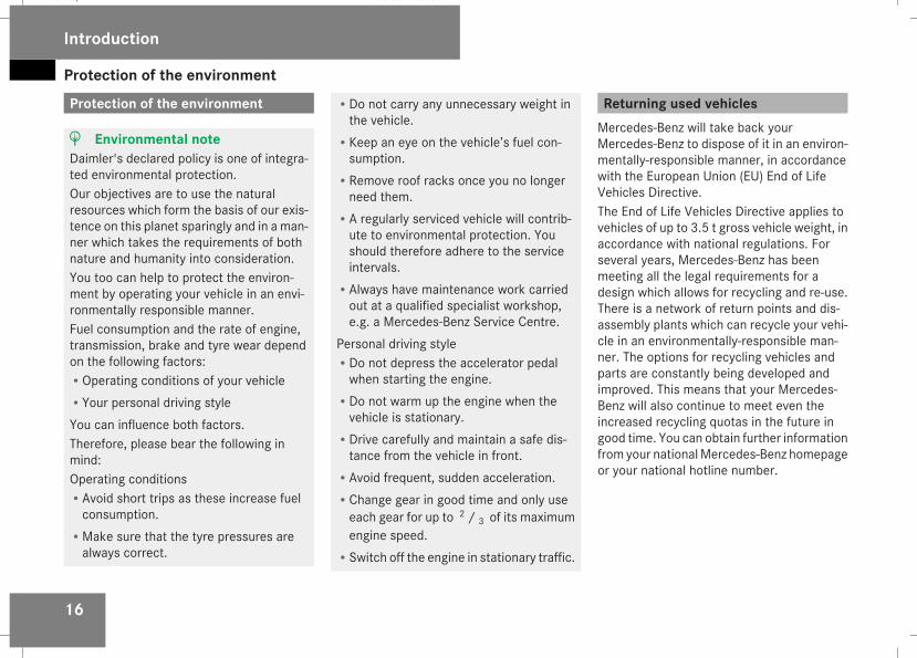
H Environmental noteDaimler's declared policy is one of integra-ted environmental protection.Our objectives are to use the naturalresources which form the basis of our exis-tence on this planet sparingly and in a man-ner which takes the requirements of bothnature and humanity into consideration.You too can help to protect the environ-ment by operating your vehicle in an envi-ronmentally responsible manner.Fuel consumption and the rate of engine,transmission, brake and tyre wear dependon the following factors:ROperating conditions of your vehicleRYour personal driving styleYou can influence both factors.Therefore, please bear the following inmind:Operating conditionsRAvoid short trips as these increase fuelconsumption.
RMake sure that the tyre pressures arealways correct.
RDo not carry any unnecessary weight inthe vehicle.
RKeep an eye on the vehicle’s fuel con-sumption.
RRemove roof racks once you no longerneed them.
RA regularly serviced vehicle will contrib-ute to environmental protection. Youshould therefore adhere to the serviceintervals.
RAlways have maintenance work carriedout at a qualified specialist workshop,e.g. a Mercedes-Benz Service Centre.
Personal driving styleRDo not depress the accelerator pedalwhen starting the engine.
RDo not warm up the engine when thevehicle is stationary.
RDrive carefully and maintain a safe dis-tance from the vehicle in front.
RAvoid frequent, sudden acceleration.RChange gear in good time and only useeach gear for up to 2 / 3 of its maximumengine speed.
RSwitch off the engine in stationary traffic.
Returning used vehiclesMercedes-Benz will take back yourMercedes-Benz to dispose of it in an environ-mentally-responsible manner, in accordancewith the European Union (EU) End of LifeVehicles Directive.The End of Life Vehicles Directive applies tovehicles of up to 3.5 t gross vehicle weight, inaccordance with national regulations. Forseveral years, Mercedes-Benz has beenmeeting all the legal requirements for adesign which allows for recycling and re-use.There is a network of return points and dis-assembly plants which can recycle your vehi-cle in an environmentally-responsible man-ner. The options for recycling vehicles andparts are constantly being developed andimproved. This means that your Mercedes-Benz will also continue to meet even theincreased recycling quotas in the future ingood time. You can obtain further informationfrom your nationalMercedes-Benz homepageor your national hotline number.
Introduction
211_AKB; 2; 5, en-GBmkalafa, Version: 2.9.4
2008-02-29T16:57:07+01:00 - Seite 16
Dateiname: 6515_3416_02_buchblock.pdf; preflight
Operating safety
17
Operating safety
Safety notes
G Risk of accident and injuryAll work on the vehicle and, in particular,work relevant to safety or on safety-relatedsystems must be carried out at a qualifiedspecialist workshop. The specialist work-shop must have the necessary specialistknowledge and tools to carry out the workrequired. Mercedes-Benz recommendsthat you use a Mercedes-Benz ServiceCentre for this purpose.
G Risk of accident and injurySome safety systems only function whenthe engine is running. Therefore, do notswitch off the engine when driving. Other-wise, the safety systems in your vehiclemay no longer function correctly andthereby not provide you or others with theintended degree of protection. This alsoincreases the danger of your losing controlof your vehicle and thereby the risk of caus-ing an accident.
G Risk of accident and injuryWork carried out incorrectly, or alterationsmade to the vehicle, e.g. rerouting of cables
under coverings, could cause the safetysystems of your vehicle to stop workingproperly. The safety systems would thus nolonger protect you and other persons asintended. In addition, there is the dangerthat you may lose control of your vehicleand thus cause an accident.All work and alterations to the vehicle, e.g.installations ormodifications, should there-fore be carried out at a qualified specialistworkshop.
G Risk of accidentA heavy impact to the underbody, tyres orwheels, for examplewhen bottoming out onrough terrain or driving over an obstacle athigh speed, could damage your vehicle. Asa result, you could cause an accident. Thisalso applies to vehicles which are equippedwith underbody protection.For this reason, drive slowly over obstacles,avoid bottoming out the vehicle in roughterrain and, if necessary, have your vehiclechecked at a qualified specialist workshop.
G Risk of accidentIf work on electronic equipment and itssoftware is carried out incorrectly, thisequipment could stop functioning. The
electronic systems are networked via inter-faces. Tampering with these electronic sys-tems could cause malfunctions in systemswhich have not been modified. Such mal-functions can seriously jeopardise the vehi-cle’s operating safety and your own safetyas well.Therefore have all work on and modifica-tions to electronic components carried outby a qualified workshop.
Vehicle registrationMercedes-Benz may ask its Service Centresto carry out technical inspections on certainvehicles to improve their quality or safety.If you did not purchase your vehicle from anauthorised specialist dealer and your vehiclehas never been inspected at a Mercedes-Benz Service Centre, it is possible that yourvehicle is not registered in your name withMercedes-Benz. Mercedes-Benz can onlyinform you about vehicle checks if it has yourregistration data.It is advisable to register your vehicle with aMercedes-Benz Service Centre.
Introduction
211_AKB; 2; 5, en-GBmkalafa, Version: 2.9.4
2008-02-29T16:57:07+01:00 - Seite 17
Z
Dateiname: 6515_3416_02_buchblock.pdf; preflight
Operating safety
18
Inform Mercedes-Benz as soon as possibleabout any change in address or vehicle own-ership.
Correct useObserve the following informationwhen usingyour vehicle:RThe safety notes in this manualRThe "Technical data" section in this manualRNational road traffic regulationsRNational road traffic licensing regulations
G Risk of injuryVarious warning stickers are affixed to yourvehicle. Their purpose is to draw your atten-tion, and the attention of others, to variousdangers. Therefore, do not remove anywarning stickers unless the sticker clearlystates that you may do so.If you remove the warning stickers, you orothers could be injured by failing to recog-nise certain dangers.
Introduction
211_AKB; 2; 5, en-GBmkalafa, Version: 2.9.4
2008-02-29T16:57:07+01:00 - Seite 18
Dateiname: 6515_3416_02_buchblock.pdf; preflight
19
Exterior view ....................................... 20Cockpit ................................................. 22Instrument cluster .............................. 26Multi-function steering wheel ............ 30Centre console .................................... 31Overhead control panel ...................... 34Door control panel .............................. 35Stowage compartments ..................... 36
At a glance
211_AKB; 2; 5, en-GBmkalafa, Version: 2.9.4
2008-02-29T16:57:07+01:00 - Seite 19
Dateiname: 6515_3416_02_buchblock.pdf; preflight
Exterior view
20
Exterior view
At a glance
211_AKB; 2; 5, en-GBmkalafa, Version: 2.9.4
2008-02-29T16:57:07+01:00 - Seite 20
Dateiname: 6515_3416_02_buchblock.pdf; preflight
Exterior view
21
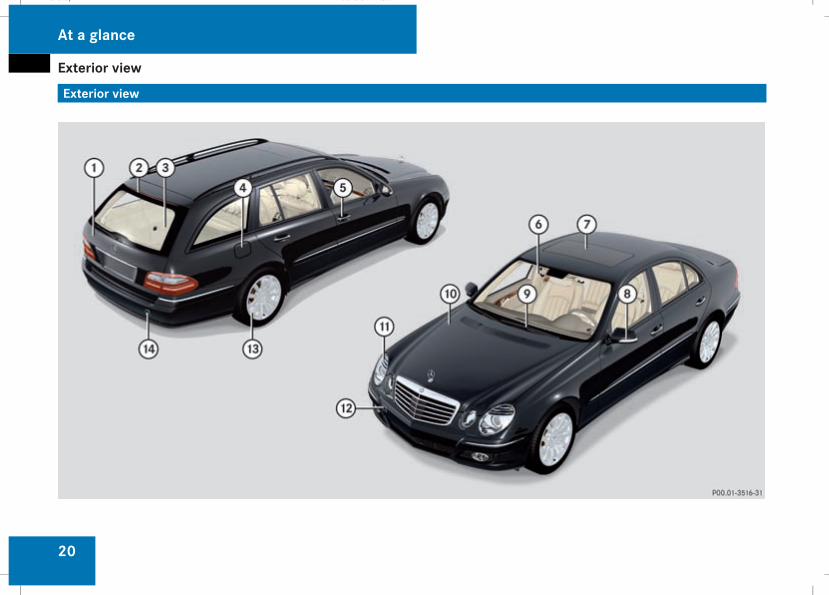
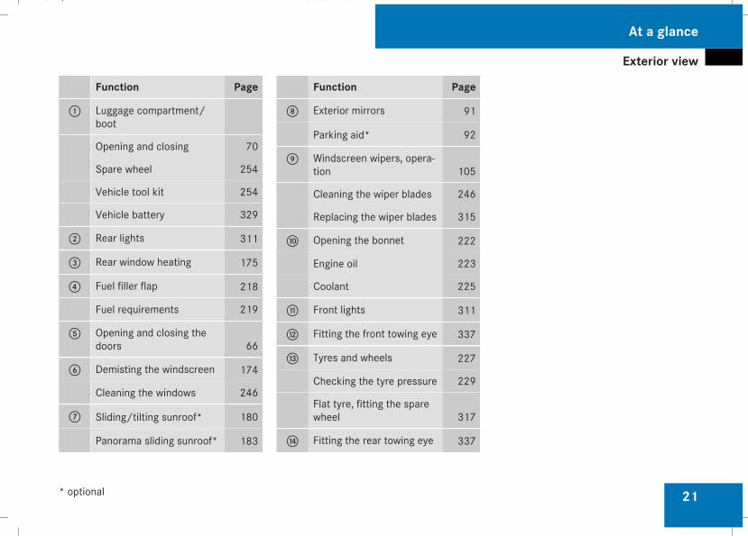
Function Page
1 Luggage compartment/boot
Opening and closing 70
Spare wheel 254
Vehicle tool kit 254
Vehicle battery 329
2 Rear lights 311
3 Rear window heating 175
4 Fuel filler flap 218
Fuel requirements 219
5 Opening and closing thedoors 66
6 Demisting the windscreen 174
Cleaning the windows 246
7 Sliding/tilting sunroof* 180
Panorama sliding sunroof* 183
Function Page
8 Exterior mirrors 91
Parking aid* 92
9 Windscreen wipers, opera-tion 105
Cleaning the wiper blades 246
Replacing the wiper blades 315
a Opening the bonnet 222
Engine oil 223
Coolant 225
b Front lights 311
c Fitting the front towing eye 337
d Tyres and wheels 227
Checking the tyre pressure 229
Flat tyre, fitting the sparewheel 317
e Fitting the rear towing eye 337
At a glance
* optional
211_AKB; 2; 5, en-GBmkalafa, Version: 2.9.4
2008-02-29T16:57:07+01:00 - Seite 21
Dateiname: 6515_3416_02_buchblock.pdf; preflight
Cockpit
22
Cockpit
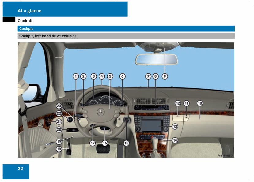
Cockpit, left-hand-drive vehicles
At a glance
211_AKB; 2; 5, en-GBmkalafa, Version: 2.9.4
2008-02-29T16:57:07+01:00 - Seite 22
Dateiname: 6515_3416_02_buchblock.pdf; preflight
Cockpit
23
Function Page
1 Combination switch with:
• Main-beam headlamps 101
• Turn signals 101
• Windscreen wipers 105
• Estate: rear windowwiper 106
2 Cruise control lever for:
• Cruise control 143
• Distronic* 145
• Speedtronic 152
3 Instrument cluster 26
4 Multi-function steeringwheel 30
5 Horn
6 Linguatronic lever* – seeseparate operating instruc-tions
Function Page
7 Parktronic* warning dis-play 160
8 Controls Thermatic or 4-zone Thermotronic* 164
Switches the rear windowheating on/off 175
9 Overhead control panel 34
a Glove compartment 205
b Opens the glove compart-ment 205
c Opens the spectacles com-partment/mobile phonecompartment 206
d Controls COMAND APS*and the audio system*, seethe respective operatinginstructions
e Centre console 31
f Ignition lock 76
Function Page
g Adjusts the steering wheelmanually 89
h Adjusts the steering wheelelectrically* 89
Switches the steeringwheel heating* on/off 90
j Parking brake 113
k Opens the bonnet 222
l Releases the parking brake 113
m Door control panel 35
n Light switch 99
o Adjusts the headlamprange 102
At a glance
* optional
211_AKB; 2; 5, en-GBmkalafa, Version: 2.9.4
2008-02-29T16:57:07+01:00 - Seite 23
Dateiname: 6515_3416_02_buchblock.pdf; preflight
Cockpit
24
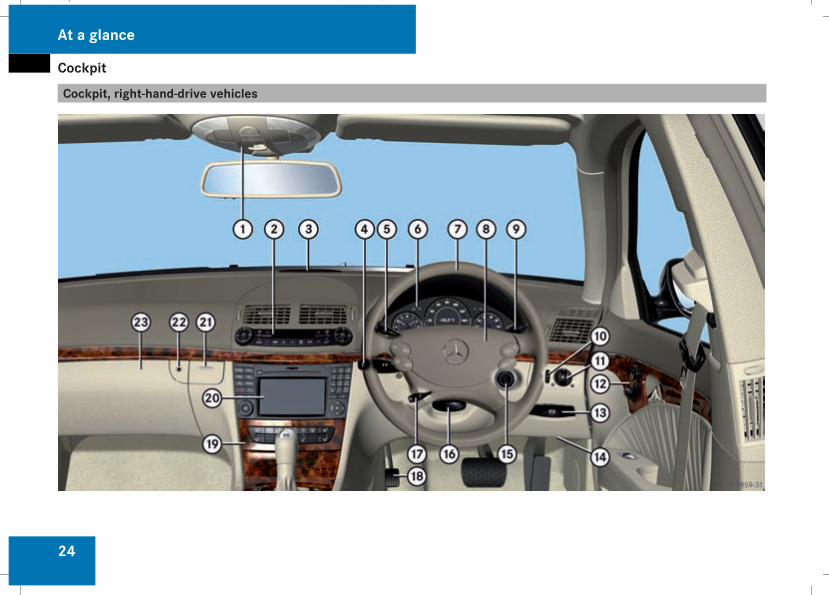
Cockpit, right-hand-drive vehicles
At a glance
211_AKB; 2; 5, en-GBmkalafa, Version: 2.9.4
2008-02-29T16:57:07+01:00 - Seite 24
Dateiname: 6515_3416_02_buchblock.pdf; preflight
Cockpit
25
Function Page
1 Overhead control panel 34
2 Controls Thermatic or 4-zone Thermotronic* 164
Switches the rear windowheating on/off 175
3 Parktronic* warning dis-play 160
4 Combination switch with:
• Main-beam headlamps 101
• Turn signals 101
• Windscreen wipers 105
• Estate: rear windowwiper 106
5 Cruise control lever for:
• Cruise control 143
• Distronic* 145
• Speedtronic 152
Function Page
6 Instrument cluster
7 Multi-function steeringwheel 30
8 Horn
9 Linguatronic lever* – seeseparate operating instruc-tions
a Adjusts the headlamprange 102
b Light switch 99
c Door control panel 35
d Releases the parking brake 113
e Opens the bonnet 222
f Ignition lock 76
g Adjusts the steering wheelmanually 89
Function Page
h Adjusts the steering wheelelectrically* 89
Switches the steeringwheel heating* on/off 90
j Parking brake 113
k Centre console 31
l Controls COMAND APS*and the audio system*, seethe respective operatinginstructions
m Opens the spectacles com-partment/mobile phonecompartment 206
n Opens the glove compart-ment 205
o Glove compartment 205
At a glance
* optional
211_AKB; 2; 5, en-GBmkalafa, Version: 2.9.4
2008-02-29T16:57:07+01:00 - Seite 25
Dateiname: 6515_3416_02_buchblock.pdf; preflight
Instrument cluster
26
Instrument cluster
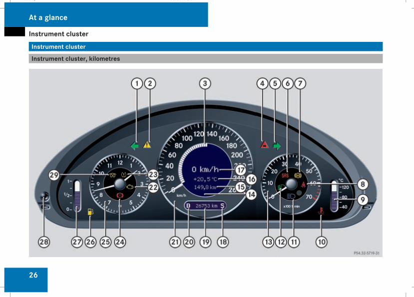
Instrument cluster, kilometres
At a glance
211_AKB; 2; 5, en-GBmkalafa, Version: 2.9.4
2008-02-29T16:57:07+01:00 - Seite 26
Dateiname: 6515_3416_02_buchblock.pdf; preflight

Instrument cluster
27
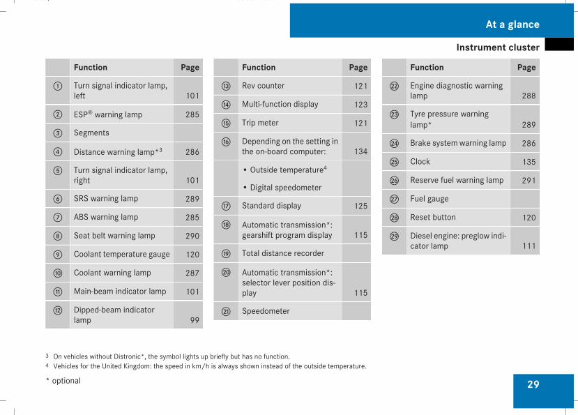
Function Page
1 Turn signal indicator lamp,left 101
2 ESP® warning lamp 285
3 Segments
4 Distance warning lamp*1 286
5 Turn signal indicator lamp,right 101
6 SRS warning lamp 289
7 ABS warning lamp 285
8 Seat belt warning lamp 290
9 Coolant temperature gauge 120
a Coolant warning lamp 287
b Main-beam indicator lamp 101
c Dipped-beam indicatorlamp 99
Function Page
d Rev counter 121
e Multi-function display 123
f Trip meter 121
g Depending on the setting inthe on-board computer: 134
• Outside temperature2
• Digital speedometer
h Standard display 125
j Automatic transmission*:gearshift program display 115
k Total distance recorder
l Automatic transmission*:selector lever position dis-play 115
m Speedometer
Function Page
n Engine diagnostic warninglamp 288
o Tyre pressure warninglamp* 289
p Brake systemwarning lamp 286
q Clock 135
r Reserve fuel warning lamp 291
s Fuel gauge
t Reset button 120
u Diesel engine: preglow indi-cator lamp 111
1 On vehicles without Distronic*, the symbol lights up briefly but has no function.2 Vehicles for the United Kingdom: the speed in km/h is always shown instead of the outside temperature.
At a glance
* optional
211_AKB; 2; 5, en-GBmkalafa, Version: 2.9.4
2008-02-29T16:57:07+01:00 - Seite 27
Dateiname: 6515_3416_02_buchblock.pdf; preflight
Instrument cluster
28
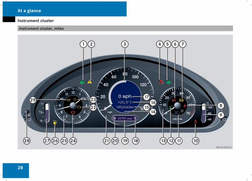
Instrument cluster, miles
At a glance
211_AKB; 2; 5, en-GBmkalafa, Version: 2.9.4
2008-02-29T16:57:07+01:00 - Seite 28
Dateiname: 6515_3416_02_buchblock.pdf; preflight
Instrument cluster
29
Function Page
1 Turn signal indicator lamp,left 101
2 ESP® warning lamp 285
3 Segments
4 Distance warning lamp*3 286
5 Turn signal indicator lamp,right 101
6 SRS warning lamp 289
7 ABS warning lamp 285
8 Seat belt warning lamp 290
9 Coolant temperature gauge 120
a Coolant warning lamp 287
b Main-beam indicator lamp 101
c Dipped-beam indicatorlamp 99
Function Page
d Rev counter 121
e Multi-function display 123
f Trip meter 121
g Depending on the setting inthe on-board computer: 134
• Outside temperature4
• Digital speedometer
h Standard display 125
j Automatic transmission*:gearshift program display 115
k Total distance recorder
l Automatic transmission*:selector lever position dis-play 115
m Speedometer
Function Page
n Engine diagnostic warninglamp 288
o Tyre pressure warninglamp* 289
p Brake systemwarning lamp 286
q Clock 135
r Reserve fuel warning lamp 291
s Fuel gauge
t Reset button 120
u Diesel engine: preglow indi-cator lamp 111
3 On vehicles without Distronic*, the symbol lights up briefly but has no function.4 Vehicles for the United Kingdom: the speed in km/h is always shown instead of the outside temperature.
At a glance
* optional
211_AKB; 2; 5, en-GBmkalafa, Version: 2.9.4
2008-02-29T16:57:07+01:00 - Seite 29
Dateiname: 6515_3416_02_buchblock.pdf; preflight
Multi-function steering wheel
30
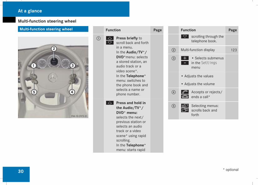
Multi-function steering wheel Function Page
1 jk
Press briefly toscroll back and forthin a menu.In the Audio/TV*/DVD*menu: selectsa stored station, anaudio track or avideo scene*.In the Telephone*menu: switches tothe phone book andselects a name orphone number.
j Press and hold inthe Audio/TV*/DVD* menu:selects the next/previous station orselects an audiotrack or a videoscene* using rapidscrolling.In the Telephone*menu: starts rapid
Function Pagek scrolling through the
telephone book.
2 Multi-function display 123
3 æ-
• Selects submenusin the Settingsmenu
• Adjusts the values
• Adjusts the volume
4 st
Accepts or rejects/ends a call*
5 èÿ
Selecting menus:scrolls back andforth
At a glance
* optional
211_AKB; 2; 5, en-GBmkalafa, Version: 2.9.4
2008-02-29T16:57:07+01:00 - Seite 30
Dateiname: 6515_3416_02_buchblock.pdf; preflight
Centre console
31
Centre console
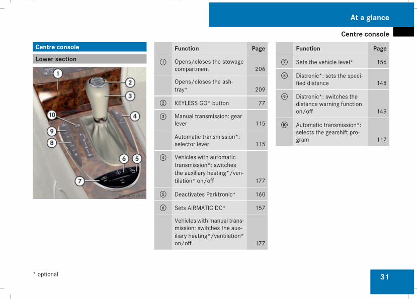
Lower sectionFunction Page
1 Opens/closes the stowagecompartment 206
Opens/closes the ash-tray* 209
2 KEYLESS GO* button 77
3 Manual transmission: gearlever 115
Automatic transmission*:selector lever 115
4 Vehicles with automatictransmission*: switchesthe auxiliary heating*/ven-tilation* on/off 177
5 Deactivates Parktronic* 160
6 Sets AIRMATIC DC* 157
Vehicles with manual trans-mission: switches the aux-iliary heating*/ventilation*on/off 177
Function Page
7 Sets the vehicle level* 156
8 Distronic*: sets the speci-fied distance 148
9 Distronic*: switches thedistance warning functionon/off 149
a Automatic transmission*:selects the gearshift pro-gram 117
At a glance
* optional
211_AKB; 2; 5, en-GBmkalafa, Version: 2.9.4
2008-02-29T16:57:07+01:00 - Seite 31
Dateiname: 6515_3416_02_buchblock.pdf; preflight
Centre console
32
Upper section
At a glance
211_AKB; 2; 5, en-GBmkalafa, Version: 2.9.4
2008-02-29T16:57:07+01:00 - Seite 32
Dateiname: 6515_3416_02_buchblock.pdf; preflight
Centre console
33
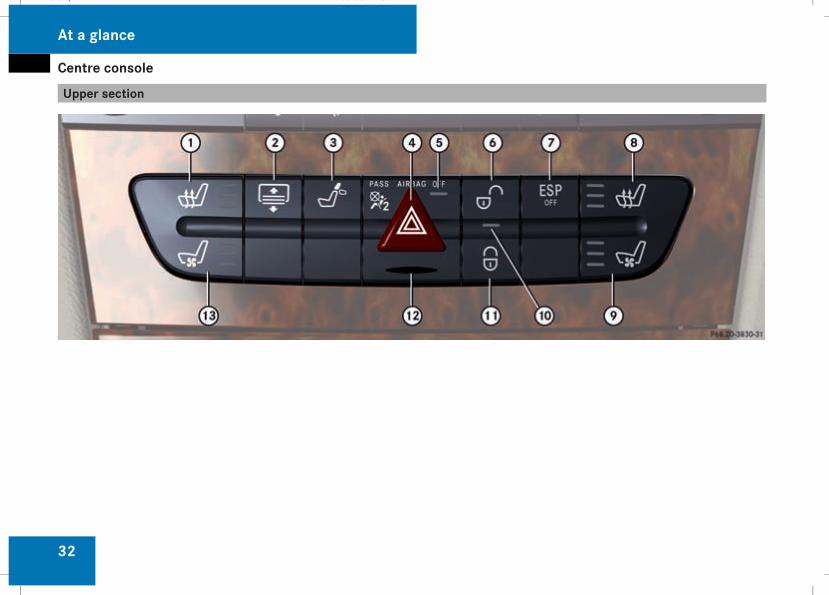
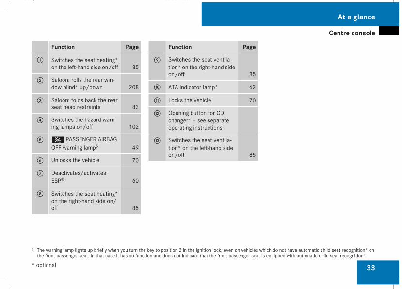
Function Page
1 Switches the seat heating*on the left-hand side on/off 85
2 Saloon: rolls the rear win-dow blind* up/down 208
3 Saloon: folds back the rearseat head restraints 82
4 Switches the hazard warn-ing lamps on/off 102
5 5 PASSENGER AIRBAGOFF warning lamp5 49
6 Unlocks the vehicle 70
7 Deactivates/activatesESP® 60
8 Switches the seat heating*on the right-hand side on/off 85
Function Page
9 Switches the seat ventila-tion* on the right-hand sideon/off 85
a ATA indicator lamp* 62
b Locks the vehicle 70
c Opening button for CDchanger* – see separateoperating instructions
d Switches the seat ventila-tion* on the left-hand sideon/off 85
5 The warning lamp lights up briefly when you turn the key to position 2 in the ignition lock, even on vehicles which do not have automatic child seat recognition* onthe front-passenger seat. In that case it has no function and does not indicate that the front-passenger seat is equipped with automatic child seat recognition*.
At a glance
* optional
211_AKB; 2; 5, en-GBmkalafa, Version: 2.9.4
2008-02-29T16:57:07+01:00 - Seite 33
Dateiname: 6515_3416_02_buchblock.pdf; preflight
Overhead control panel
34
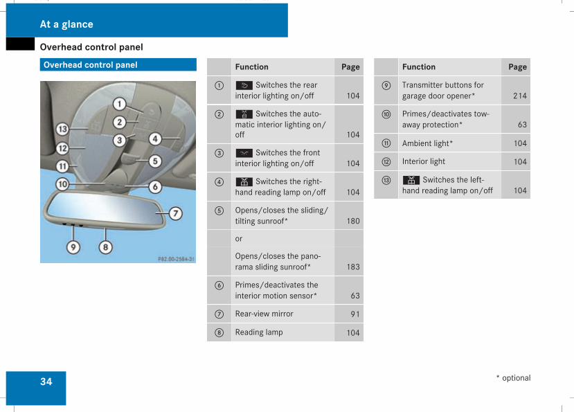
Overhead control panel Function Page
1 ò Switches the rearinterior lighting on/off 104
2 ¡ Switches the auto-matic interior lighting on/off 104
3 ð Switches the frontinterior lighting on/off 104
4 X Switches the right-hand reading lamp on/off 104
5 Opens/closes the sliding/tilting sunroof* 180
or
Opens/closes the pano-rama sliding sunroof* 183
6 Primes/deactivates theinterior motion sensor* 63
7 Rear-view mirror 91
8 Reading lamp 104
Function Page
9 Transmitter buttons forgarage door opener* 214
a Primes/deactivates tow-away protection* 63
b Ambient light* 104
c Interior light 104
d X Switches the left-hand reading lamp on/off 104
At a glance
* optional
211_AKB; 2; 5, en-GBmkalafa, Version: 2.9.4
2008-02-29T16:57:07+01:00 - Seite 34
Dateiname: 6515_3416_02_buchblock.pdf; preflight
Door control panel
35
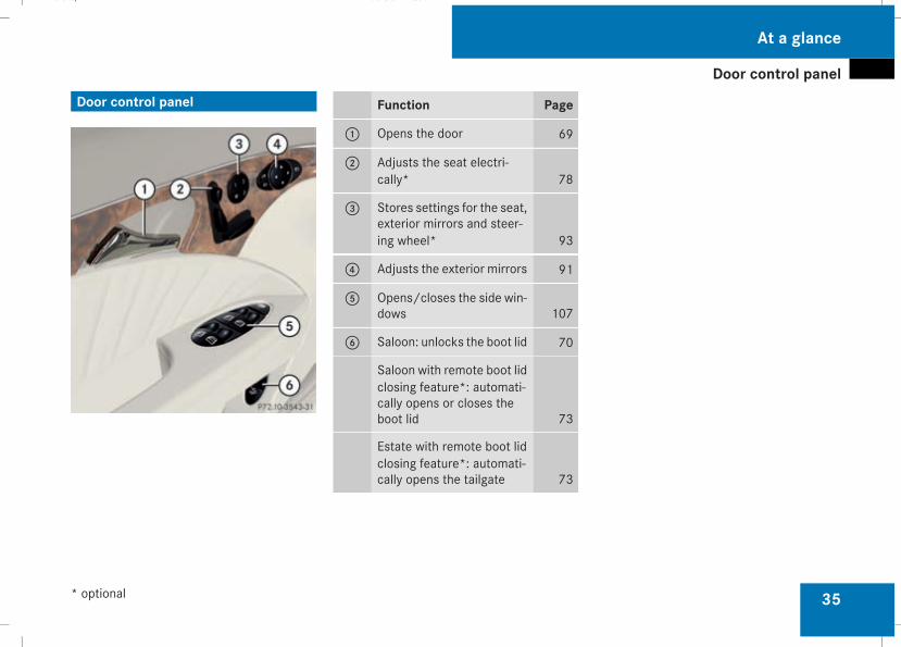
Door control panel Function Page
1 Opens the door 69
2 Adjusts the seat electri-cally* 78
3 Stores settings for the seat,exterior mirrors and steer-ing wheel* 93
4 Adjusts the exterior mirrors 91
5 Opens/closes the side win-dows 107
6 Saloon: unlocks the boot lid 70
Saloon with remote boot lidclosing feature*: automati-cally opens or closes theboot lid 73
Estate with remote boot lidclosing feature*: automati-cally opens the tailgate 73
At a glance
* optional
211_AKB; 2; 5, en-GBmkalafa, Version: 2.9.4
2008-02-29T16:57:07+01:00 - Seite 35
Dateiname: 6515_3416_02_buchblock.pdf; preflight
Stowage compartments
36
Stowage compartments
At a glance
211_AKB; 2; 5, en-GBmkalafa, Version: 2.9.4
2008-02-29T16:57:07+01:00 - Seite 36
Dateiname: 6515_3416_02_buchblock.pdf; preflight

Stowage compartments
37
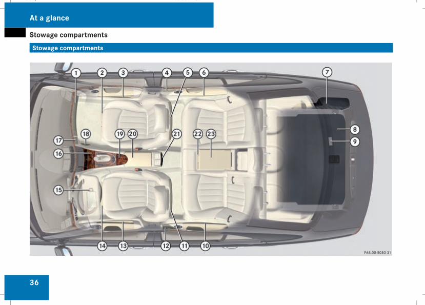
Function Page
1 Glove compartment 205
2 Front-passenger seat stow-age compartmentwith first-aid kit 253
3 Door stowage pocket
4 Ashtray* 209
5 Ruffled pocket
6 Door stowage pocket
7 Luggage net
8 Stowage well under theboot floor 192
9 Hooks at the top of the boot 195
a Door stowage pocket
b Ruffled pocket
c Ashtray* 209
d Door stowage pocket
Function Page
e Driver's seat stowage com-partment with fire extin-guisher* 253
f Sun visor card clip 207
g Stowage compartment inthe centre console 206
Socket 210
Ashtray* 209
Cigarette lighter* 209
h Spectacles compartment/mobile phone compart-ment 206
j Luggage net in the front-passenger footwell 190
k Stowage compartment infront of the armrest 206
Cup holder* in the centreconsole 186
Function Page
l Stowage compartment/telephone compartmentunder the armrest 206
m Stowage compartment inthe centre console at therear 207
Socket 210
n Cup holder in the rear seatarmrest 186
o Stowage compartment inthe rear seat armrest 207
At a glance
* optional
211_AKB; 2; 5, en-GBmkalafa, Version: 2.9.4
2008-02-29T16:57:07+01:00 - Seite 37
Dateiname: 6515_3416_02_buchblock.pdf; preflight
Stowage compartments
38
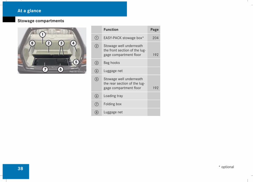
Function Page
1 EASY-PACK stowage box* 204
2 Stowage well underneaththe front section of the lug-gage compartment floor 192
3 Bag hooks
4 Luggage net
5 Stowage well underneaththe rear section of the lug-gage compartment floor 192
6 Loading tray
7 Folding box
8 Luggage net
At a glance
* optional
211_AKB; 2; 5, en-GBmkalafa, Version: 2.9.4
2008-02-29T16:57:07+01:00 - Seite 38
Dateiname: 6515_3416_02_buchblock.pdf; preflight
39
Occupant safety .................................. 40Driving safety systems ....................... 58Anti-theft systems .............................. 62
Safety
211_AKB; 2; 5, en-GBmkalafa, Version: 2.9.4
2008-02-29T16:57:07+01:00 - Seite 39
Dateiname: 6515_3416_02_buchblock.pdf; preflight
Occupant safety
40
Occupant safety
Notes on occupant safetySeat belts, together with belt tensioners, beltforce limiters and airbags, are coordinatedrestraint systems. They reduce the risk ofinjury in defined accident situations andthereby increase occupant safety. However,seat belts and airbags generally do not pro-tect against objects penetrating the vehiclefrom the outside.To ensure that the restraint systems candeliver their full potential protection, youshould ensure that:Rthe seat and head restraint are adjustedproperly (Y page 77)
Rthe seat belt has been fastened properly(Y page 95)
Rthe airbags can inflate properly if they aredeployed (Y page 43)
Rthe steering wheel is adjusted properly(Y page 89)
Rthe restraint systems have not been modi-fied
i An airbag increases the protection ofvehicle occupants wearing a seat belt.
However, airbags are only an additionalrestraint system which complements, butdoes not replace, the seat belt. All vehicleoccupants must wear their seat belt cor-rectly at all times, even if the vehicle isequipped with airbags. This is because - onthe one hand - airbags are not deployed inall types of accident, as in some situationsairbag deployment would not increase theprotection afforded to vehicle occupants,provided they are wearing their seat beltcorrectly. On the other hand, airbag deploy-ment only provides increased protection ifthe seat belt is worn correctly because:Rthe seat belt helps to keep the vehicleoccupant in the best position in relationto the airbag
Rfor example, in a head-on collision, theseat belt can more adequately preventthe occupant from being propelledtowards the force of the impact, and isthus better suited to prevent injury
Therefore, in accident situations where anairbag is deployed, it only provides protec-tion in addition to the seat belt if the seatbelt is being worn correctly.
G Risk of accident and injuryAlways have maintenance work carried outat a qualified specialist workshop whichhas the necessary specialist knowledgeand tools to carry out the work required.Mercedes-Benz recommends that you usea Mercedes-Benz Service Centre for thispurpose.In particular, work relevant to safety or onsafety-related systems must be carried outat a qualified specialist workshop. If thiswork is not carried out correctly, the oper-ating safety of your vehicle may be affec-ted. There is a risk of an accident and injury.
G Risk of injuryThe restraint systemmay not work as inten-ded if the following components have beenmodified or work on these components hasnot been performed correctly:Rrestraint system, consisting of the seatbelts and anchorages, belt tensioners,belt force limiters, airbags
RwiringRnetworked electronic systemsAirbags or belt tensioners could then fail,e.g. in the event of an accident in which the
Safety
211_AKB; 2; 5, en-GBmkalafa, Version: 2.9.4
2008-02-29T16:57:07+01:00 - Seite 40
Dateiname: 6515_3416_02_buchblock.pdf; preflight
Occupant safety
41
deceleration force would normally be highenough to trigger the systems, or theycould be triggered unintentionally. Nevercarry out any modifications on the restraintsystems.Never tamper with electronic componentsand their software.
SRS (Supplemental Restraint System)The SRS reduces the risk of occupants com-ing into contact with the vehicle's interior inthe event of an accident. It can also reducethe forces to which occupants are subjectedduring an accident.The SRS consists of:Rthe1 warning lampRbelt tensionersRbelt force limitersRairbags
The11 warning lampThe SRS functions are checked regularlywhen you turn on the ignition and when theengine is running. Malfunctions can thereforebe detected in good time.
The1 warning lamp in the instrumentcluster lights up when the ignition is switchedon. It goes out no later than a few secondsafter the engine is started.G Risk of injuryIf SRS is malfunctioning, individual systemsmay be activated unintentionally or not betriggered in the event of an accident withheavy braking.A malfunction has occurred if the1warning lamp:Rdoes not light up when you switch on theignition
Rdoes not go out after the engine has beenrunning for a few seconds
Rlights up again once the engine is runningIn this case, have SRS checked immedi-ately at a qualified specialist workshop.
Triggering of belt tensioners, belt forcelimiters and airbagsIn the event of a collision, the sensor in theairbag control unit evaluates important phys-ical data such as duration, direction and forceof the vehicle deceleration or acceleration.Based on the evaluation of this data, and
depending on the vehicle's rate of longitudi-nal deceleration in a collision, the airbag con-trol unit pre-emptively triggers the belttensioners in the first stage.
i The front belt tensioners can only be trig-gered if the belt tongue is correctlyengaged in the seat belt buckle.
The front airbags are only deployed if there isan even higher rate of vehicle deceleration ina longitudinal direction.Your vehicle has adaptive, dual stage frontairbags. When the first activation thresholdhas been reached, the front airbag is filledwith enough propellant gas to minimise therisk of injury. The front airbag is only fullyinflated if a second threshold is reachedwithin a few milliseconds, due to the controlunit having detected further deceleration.
Criteria for triggering belt tensioners andairbagsIn the first stage of a collision, the airbag con-trol unit evaluates the duration and directionof vehicle acceleration or deceleration inorder to determine whether it is necessary totrigger the belt tensioner and/or airbag.The belt tensioner and airbag triggeringthresholds are variable and are adapted to therate of deceleration of the vehicle. This proc-
Safety
211_AKB; 2; 5, en-GBmkalafa, Version: 2.9.4
2008-02-29T16:57:07+01:00 - Seite 41
Z
Dateiname: 6515_3416_02_buchblock.pdf; preflight
Occupant safety
42
ess is pre-emptive in nature as the airbagmust be deployed during – and not at the endof – the collision.
i Airbags are not deployed in all types ofaccidents. They are controlled by complexsensor technology and evaluation logic.This process is pre-emptive in nature asairbag deployment must take place duringthe impact and must be adapted to providecalculated, additional protection for thevehicle occupants. Not all airbags aredeployed in an accident.The different airbag systems work inde-pendently of each other. However, thedeployment of each individual system willdepend on the type of accident determinedby the control system in the first stages ofthe collision (head-on collision, side impactand overturn) and the extent of the acci-dent (in particular, the vehicle's rate ofdeceleration or acceleration).
The rate of vehicle deceleration or accelera-tion and the direction of the force are basi-cally determined by:Rthe distribution of forces during the colli-sion
Rthe collision angle
Rthe deformation characteristics of the vehi-cle
Rthe characteristics of the object with whichthe vehicle has collided, e.g. the other vehi-cle
Factorswhich can only be seen andmeasuredafter a collision has occurred do not play adecisive role in the deployment of an airbag,nor do they provide an indication of it.The vehicle may be deformed significantly,e. g. on the bonnet or the wing, without anairbag being deployed. This is the case if onlyparts which are relatively easily deformed areaffected and the necessary deceleration doesnot occur. Conversely, airbags may bedeployed even though the vehicle suffers onlyminor deformations. This is the case if, forexample, very rigid vehicle parts such as lon-gitudinal body members are affected and suf-ficient deceleration occurs as a result.
Belt tensioners, belt force limitersThe front seat belts and the outer seat beltsin the rear are equipped with belt tensioners.
! Do not engage the seat belt tongue in thebuckle on the front-passenger seat if theseat is not occupied. Otherwise the belt
tensioner could be activated in an emer-gency.
If the seat belt is also equipped with a beltforce limiter, the force exerted by the seatbelt on the seat occupant is reduced.Belt tensioners tighten the seat belts in anaccident, pulling themclose against the body.
i Belt tensioners do not correct incorrectseat positions or incorrectly fastened seatbelts.Belt tensioners do not pull occupants backtowards the backrest.
The front belt force limiters are synchronisedwith the front airbags, which distribute theforces exerted by the belt force limiters onthe occupant over a greater area.When the ignition is switched on, the belt ten-sioner is triggered:Ronly if the restraint systems are operational(the1 warning lamp lights up after theignition is switched on and goes out oncethe engine is running) (Y page 41)
Rfor each three-point seat belt in the front ofthe vehicle when the belt tongue isengaged in the buckle
Rin the event of a head-on or rear-end colli-sion if the vehicle decelerates or acceler-
Safety
211_AKB; 2; 5, en-GBmkalafa, Version: 2.9.4
2008-02-29T16:57:07+01:00 - Seite 42
Dateiname: 6515_3416_02_buchblock.pdf; preflight
Occupant safety
43
ates rapidly in a longitudinal directionduring the initial stages of the impact
Rin certain situations if the vehicle over-turns, and the system determines that itcan provide additional protection
When the belt tensioners are triggered youwill hear a bang, which will not cause anyharm to your hearing, and a small amount ofpowdermay also be released. The1warn-ing lamp lights up.G Risk of injuryIf the seat belt tensioners have been trig-gered, they provide no additional protec-tion in the event of another accident.Therefore, have belt tensioners which havebeen triggered replaced at a qualified spe-cialist workshop.Comply with safety regulations when dis-posing of belt tensioners. Any Mercedes-Benz Service Centre can provide details ofthese regulations.
AirbagsAirbag deployment slows down and restrictsthe movement of the vehicle occupant.When the the airbags are triggered you willhear a bang, which will not cause any harm to
your hearing, and a small amount of powdermay also be released. The1warning lamplights up.The SRS/AIRBAG symbol indicates the loca-tion of the airbags.G Risk of injuryAirbags provide additional protection; theyare not, however, a substitute for seatbelts.Observe the following notes to reduce therisk of serious or even fatal injury if an air-bag is deployed:RAll vehicle occupants — in particular preg-nant women — must wear their seat beltcorrectly at all times and lean backagainst the backrest, which should bepositioned as close to the vertical as pos-sible. The head restraint must supportthe back of the head at about eye level.
RAlways secure children less than1.50 m tall or under 12 years of age insuitable child restraint systems.
RAll vehicle occupants must select a seatposition that is as far away from the air-bag as possible. The driver's seat posi-tion must allow the vehicle to be drivensafely. The driver's chest should be as far
away from themiddle of the driver's frontairbag cover as possible.
RMove the front-passenger seat as farback as possible, especially if a child issecured in a child restraint system on theseat.
RVehicle occupants – in particular, chil-dren – must not lean their head into thearea of the window in which the sidebag/windowbag is deployed.
RRearward-facing child restraint systemsmust not be fitted to the front-passengerseat unless the front-passenger front air-bag has been disabled. On the front-passenger seat, the front-passengerfront airbag is only deactivated if a childrestraint system with automatic childseat recognition is fitted to the front-passenger seat*. The5 PASSENGERAIRBAG OFF warning lamp must be con-stantly lit.If either the rearward-facing childrestraint system or the front-passengerseat* of your vehicle do not have auto-matic child seat recognition, childrenmust be secured in a child restraint sys-tem on a suitable seat in the rear. If you
Safety
* optional
211_AKB; 2; 5, en-GBmkalafa, Version: 2.9.4
2008-02-29T16:57:07+01:00 - Seite 43
Z
Dateiname: 6515_3416_02_buchblock.pdf; preflight
Occupant safety
44
secure a forward-facing child restraintsystem to the front-passenger seat, youmust move the front-passenger seat asfar back as possible.
RMake sure there are no heavy or sharp-edged objects in pockets of clothing.
RDo not lean forwards, e.g. over the coverof the driver's front airbag, particularlywhen the vehicle is in motion.
RDo not put your feet on the dashboard.ROnly hold the steering wheel by the rim.This allows the airbag to inflate fully. Youcould be injured if the airbag is deployedand you are holding the inside of thesteering wheel.
RDo not lean on the doors from inside thevehicle.
RMake sure that there are no people, ani-mals or objects between the vehicleoccupants and the area of deployment ofthe airbag.
RDo not place any objects between theseat backrest and the door.
RDo not hang any hard objects, for exam-ple coat hangers, on the grab handles orcoat hooks.
RDo not attach accessories, e.g. cup hold-ers, to the doors.
It is not possible to rule out a risk of injuriescaused by an airbag due to the high speedat which the airbag is required to deploy.
G Risk of injuryThe airbag's functionality can only be guar-anteed if the following parts are not cov-ered and no badges or stickers areattached to them:RPadded steering wheel bossRFront-passenger front airbag coverROuter side of front seatsRRear door trims
G Risk of injuryWhen an airbag deploys, a small amount ofpowder is released. The powder may causeshort-term breathing difficulties to personssuffering from asthma or other pulmonaryconditions.
In order to prevent potential breathing dif-ficulties you should leave the vehicle assoon as it is safe to do so. You can also openthe window to allow fresh air to enter theinterior. The powder does not constitute ahealth hazard and does not indicate thatthere is a fire in the vehicle.
G Risk of injuryThe airbag parts are hot after the airbag hasbeen deployed. Do not touch them, other-wise you may burn yourself.Have the airbags checked at a qualifiedspecialist workshop. Otherwise, occupantsare not protected by the airbags in theevent of another accident.
Front airbagsThe front airbags are designed to increaseprotection for the driver's and front-passenger head and chest.
Safety
211_AKB; 2; 5, en-GBmkalafa, Version: 2.9.4
2008-02-29T16:57:07+01:00 - Seite 44
Dateiname: 6515_3416_02_buchblock.pdf; preflight
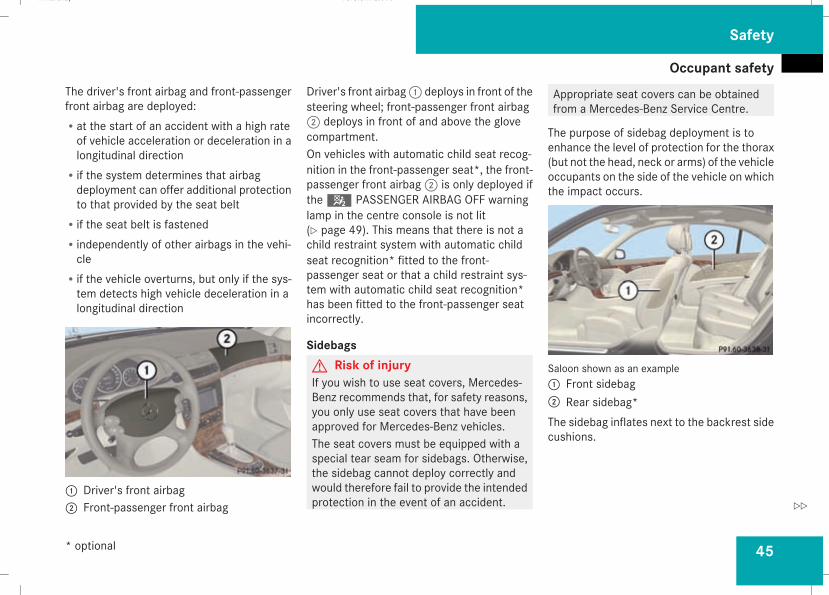
Occupant safety
45
The driver's front airbag and front-passengerfront airbag are deployed:Rat the start of an accident with a high rateof vehicle acceleration or deceleration in alongitudinal direction
Rif the system determines that airbagdeployment can offer additional protectionto that provided by the seat belt
Rif the seat belt is fastenedRindependently of other airbags in the vehi-cle
Rif the vehicle overturns, but only if the sys-tem detects high vehicle deceleration in alongitudinal direction
1 Driver's front airbag2 Front-passenger front airbag
Driver's front airbag1 deploys in front of thesteering wheel; front-passenger front airbag2 deploys in front of and above the glovecompartment.On vehicles with automatic child seat recog-nition in the front-passenger seat*, the front-passenger front airbag2 is only deployed ifthe5 PASSENGER AIRBAG OFF warninglamp in the centre console is not lit(Y page 49). This means that there is not achild restraint system with automatic childseat recognition* fitted to the front-passenger seat or that a child restraint sys-tem with automatic child seat recognition*has been fitted to the front-passenger seatincorrectly.
SidebagsG Risk of injuryIf you wish to use seat covers, Mercedes-Benz recommends that, for safety reasons,you only use seat covers that have beenapproved for Mercedes-Benz vehicles.The seat covers must be equipped with aspecial tear seam for sidebags. Otherwise,the sidebag cannot deploy correctly andwould therefore fail to provide the intendedprotection in the event of an accident.
Appropriate seat covers can be obtainedfrom a Mercedes-Benz Service Centre.
The purpose of sidebag deployment is toenhance the level of protection for the thorax(but not the head, neck or arms) of the vehicleoccupants on the side of the vehicle on whichthe impact occurs.
Saloon shown as an example1 Front sidebag2 Rear sidebag*The sidebag inflates next to the backrest sidecushions.
Safety
* optional
211_AKB; 2; 5, en-GBmkalafa, Version: 2.9.4
2008-02-29T16:57:07+01:00 - Seite 45
Z
Dateiname: 6515_3416_02_buchblock.pdf; preflight
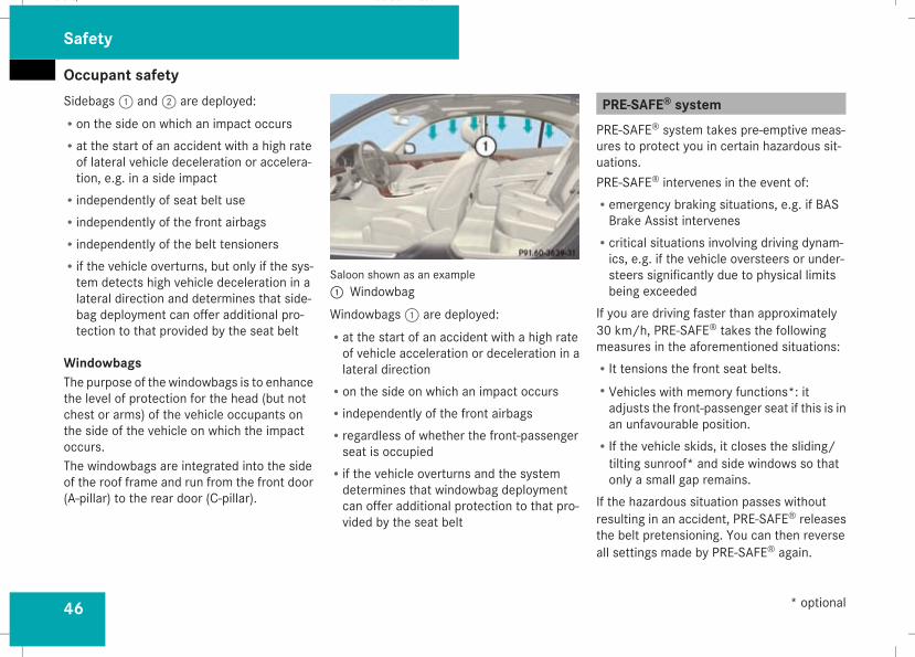
Occupant safety
46
Sidebags1 and2 are deployed:Ron the side on which an impact occursRat the start of an accident with a high rateof lateral vehicle deceleration or accelera-tion, e.g. in a side impact
Rindependently of seat belt useRindependently of the front airbagsRindependently of the belt tensionersRif the vehicle overturns, but only if the sys-tem detects high vehicle deceleration in alateral direction and determines that side-bag deployment can offer additional pro-tection to that provided by the seat belt
WindowbagsThe purpose of the windowbags is to enhancethe level of protection for the head (but notchest or arms) of the vehicle occupants onthe side of the vehicle on which the impactoccurs.The windowbags are integrated into the sideof the roof frame and run from the front door(A-pillar) to the rear door (C-pillar).
Saloon shown as an example1 WindowbagWindowbags1 are deployed:Rat the start of an accident with a high rateof vehicle acceleration or deceleration in alateral direction
Ron the side on which an impact occursRindependently of the front airbagsRregardless of whether the front-passengerseat is occupied
Rif the vehicle overturns and the systemdetermines that windowbag deploymentcan offer additional protection to that pro-vided by the seat belt
PRE-SAFE® systemPRE-SAFE® system takes pre-emptive meas-ures to protect you in certain hazardous sit-uations.PRE-SAFE® intervenes in the event of:Remergency braking situations, e.g. if BASBrake Assist intervenes
Rcritical situations involving driving dynam-ics, e.g. if the vehicle oversteers or under-steers significantly due to physical limitsbeing exceeded
If you are driving faster than approximately30 km/h, PRE-SAFE® takes the followingmeasures in the aforementioned situations:RIt tensions the front seat belts.RVehicles with memory functions*: itadjusts the front-passenger seat if this is inan unfavourable position.
RIf the vehicle skids, it closes the sliding/tilting sunroof* and side windows so thatonly a small gap remains.
If the hazardous situation passes withoutresulting in an accident, PRE-SAFE® releasesthe belt pretensioning. You can then reverseall settings made by PRE-SAFE® again.
Safety
* optional
211_AKB; 2; 5, en-GBmkalafa, Version: 2.9.4
2008-02-29T16:57:07+01:00 - Seite 46
Dateiname: 6515_3416_02_buchblock.pdf; preflight
Occupant safety
47
If the seat belts are not released:X Move the backrest or the seat back slightlyuntil the belt tension is reduced.The locking mechanism releases.
G Risk of injuryMake sure when adjusting the seat thatnobody can become trapped.
! Make sure that there are no objects in thefootwell or behind the seatswhen adjustingthe seats. You could otherwise damage theseats and the objects.
NECK-PRO head restraintNECK-PRO head restraints are designed toincrease protection to the driver's and front-passenger's head and neck. To this end, thehead restraints on the driver's and front-passenger seats are moved forwards andupwards in the event of a rear-end collision inthe direction of travel. This provides betterhead support.G Risk of injuryHead restraint covers prevent the NECK-PRO head restraints from triggering cor-rectly. Consequently, the NECK-PRO head
restraints cannot provide the intended levelof protection. Do not use head restraintcovers.
If the NECK-PRO head restraints are triggeredin an accident, you must reset the headrestraints on the driver's and front-passengerseats (Y page 309). Head restraints that havebeen triggered are tilted forwards.
Children in the vehicleIf a child is travelling in your vehicle, securethe child using a child restraint system whichis appropriate to the size and age of the childand recommended for Mercedes-Benz vehi-cles. Preferably, you should fit the restraintsystem to a suitable rear seat. Ensure that thechild is strapped in throughout the trip.You can obtain information about the correctchild restraint system from any Mercedes-Benz Service Centre.
i It is advisable to use Mercedes-Benz careproducts to clean child restraint systems.Information about this can be obtainedfrom any Mercedes-Benz Service Centre.
G Risk of injuryDo not leave children unsupervised in thevehicle, even if they are secured in a childrestraint system. Children could injurethemselves on parts of the vehicle. Theycould also be seriously or even fatallyinjured by prolonged exposure to extremeheat or cold.Do not expose the child restraint system todirect sunlight. The metallic parts of thechild restraint systemcould heat up and thechild could be burned by them.If children open a door, they could injurethemselves and others. They could get outand injure themselves or be injured by apassing vehicle.Please also observe the information onHOLD. Relevant information can be foundin the index.
G Risk of injuryAnunsecured or incorrectly positioned loadincreases the risk of injury to the child inthe event of:Ran accidentRa braking manoeuvreRa sudden change of direction
Safety
211_AKB; 2; 5, en-GBmkalafa, Version: 2.9.4
2008-02-29T16:57:07+01:00 - Seite 47
Z
Dateiname: 6515_3416_02_buchblock.pdf; preflight
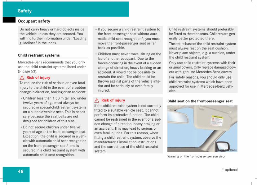
Occupant safety
48
Do not carry heavy or hard objects insidethe vehicle unless they are secured. Youwill find further information under "Loadingguidelines" in the index.
Child restraint systemsMercedes-Benz recommends that you onlyuse the child restraint systems listed under(Y page 53).G Risk of injuryTo reduce the risk of serious or even fatalinjury to the child in the event of a suddenchange in direction, braking or an accident:RChildren less than 1.50 m tall and undertwelve years of age must always besecured in special child restraint systemson a suitable vehicle seat. This is neces-sary because the seat belts are notdesigned for children of this size.
RDo not secure children under twelveyears of age on the front-passenger seat.Exception: the child is secured in a vehi-cle with automatic child seat recognitionon the front-passenger seat* and issecured in a child restraint system withautomatic child seat recognition.
RIf you secure a child restraint system tothe front-passenger seat without auto-matic child seat recognition*, you mustmove the front-passenger seat as farback as possible.
RChildren must never travel sitting on thelap of another occupant. Due to theforces occurring in the event of a suddenchange of direction, heavy braking or anaccident, it would not be possible torestrain the child. The child could bethrown against parts of the vehicle inte-rior and be seriously or even fatallyinjured.
G Risk of injuryIf the child restraint system is not correctlyfitted to a suitable vehicle seat, it cannotperform its protective function. The childcannot be restrained in the event of a sud-den change of direction, heavy braking oran accident. This may lead to serious oreven fatal injuries. For this reason, whenfitting a child restraint system, observe themanufacturer's installation instructionsand the correct use of the child restraintsystem.
Child restraint systems should preferablybe fitted to the rear seats. Children are gen-erally better protected there.The entire base of the child restraint systemmust always rest on the seat cushion.Never place objects, e.g. a cushion, underthe child restraint system.Only use child restraint systems with theiroriginal covers. Only replace damaged cov-ers with genuine Mercedes-Benz covers.For safety reasons, you should only usechild restraint systems which have beenapproved for use in Mercedes-Benz vehi-cles.
Child seat on the front-passenger seat
Warning on the front-passenger sun visor
Safety
* optional
211_AKB; 2; 5, en-GBmkalafa, Version: 2.9.4
2008-02-29T16:57:07+01:00 - Seite 48
Dateiname: 6515_3416_02_buchblock.pdf; preflight
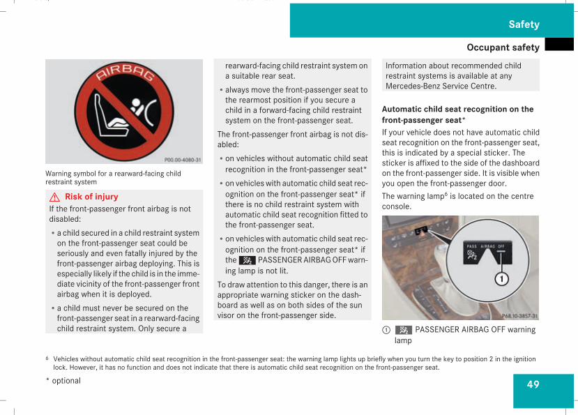
Occupant safety
49
Warning symbol for a rearward-facing childrestraint system
G Risk of injuryIf the front-passenger front airbag is notdisabled:Ra child secured in a child restraint systemon the front-passenger seat could beseriously and even fatally injured by thefront-passenger airbag deploying. This isespecially likely if the child is in the imme-diate vicinity of the front-passenger frontairbag when it is deployed.
Ra child must never be secured on thefront-passenger seat in a rearward-facingchild restraint system. Only secure a
rearward-facing child restraint system ona suitable rear seat.
Ralways move the front-passenger seat tothe rearmost position if you secure achild in a forward-facing child restraintsystem on the front-passenger seat.
The front-passenger front airbag is not dis-abled:Ron vehicles without automatic child seatrecognition in the front-passenger seat*
Ron vehicles with automatic child seat rec-ognition on the front-passenger seat* ifthere is no child restraint system withautomatic child seat recognition fitted tothe front-passenger seat.
Ron vehicles with automatic child seat rec-ognition on the front-passenger seat* ifthe5 PASSENGERAIRBAGOFFwarn-ing lamp is not lit.
To draw attention to this danger, there is anappropriate warning sticker on the dash-board as well as on both sides of the sunvisor on the front-passenger side.
Information about recommended childrestraint systems is available at anyMercedes-Benz Service Centre.
Automatic child seat recognition on thefront-passenger seat*If your vehicle does not have automatic childseat recognition on the front-passenger seat,this is indicated by a special sticker. Thesticker is affixed to the side of the dashboardon the front-passenger side. It is visible whenyou open the front-passenger door.The warning lamp6 is located on the centreconsole.
15 PASSENGER AIRBAG OFF warninglamp
6 Vehicles without automatic child seat recognition in the front-passenger seat: the warning lamp lights up briefly when you turn the key to position 2 in the ignitionlock. However, it has no function and does not indicate that there is automatic child seat recognition on the front-passenger seat.
Safety
* optional
211_AKB; 2; 5, en-GBmkalafa, Version: 2.9.4
2008-02-29T16:57:07+01:00 - Seite 49
Z
Dateiname: 6515_3416_02_buchblock.pdf; preflight
Occupant safety
50
The front-passenger seat sensor system forchild restraint systems detects whether aspecial Mercedes-Benz child seat with auto-matic child seat recognition has been fitted.In such cases,5 PASSENGER AIRBAGOFF indicator lamp1 lights up. The front-passenger airbag is deactivated.G Risk of injuryIf the5 PASSENGER AIRBAG OFF warn-ing lamp does not light up when the childrestraint system is fitted, the front-passenger front airbag has not been disa-bled. If the front-passenger front airbag isdeployed, the child could be seriously oreven fatally injured.Proceed as follows:Rdo not use a rearward-facing childrestraint system on the front-passengerseat.
Rfit a rearward-facing child restraint sys-tem on a suitable rear seat.
orRonly use a forward-facing child restraintsystem on the front-passenger seat andmove the front-passenger seat to its rear-most position.
Rhave the automatic child seat recognitionchecked at a qualified specialist work-shop.
To ensure that the automatic child seat rec-ognition on the front-passenger seat func-tions correctly, never place objects (suchas a cushion) under the child restraint sys-tem. The entire base of the child restraintsystem must always rest on the seat cush-ion. An incorrectly fitted child restraint sys-tem cannot perform its intended protectivefunction in the event of an accident, andcould lead to injuries.
i The windowbag, the sidebag and the belttensioner on the front-passenger side are
still active even when the front-passengerfront airbag is disabled.
G Risk of injuryDo not place items of electronic equipmenton the front-passenger seat, e.g.:Rlaptops, when switched onRmobile phonesRcards with transponders, e.g. ski passesor access cards
Signals from electronic equipment cancause interference in the automatic childseat recognition sensor system. This canlead to a system malfunction. This maycause the5 PASSENGER AIRBAG OFFwarning lamp to light up without therebeing a child seat with automatic child seatrecognition fitted. This means that thefront-passenger airbag is not deployed dur-ing an accident. It is also possible that the5 PASSENGER AIRBAG OFF warninglamp will not light up briefly if you turn thekey in the ignition lock to position 2.
Safety
211_AKB; 2; 5, en-GBmkalafa, Version: 2.9.4
2008-02-29T16:57:07+01:00 - Seite 50
Dateiname: 6515_3416_02_buchblock.pdf; preflight
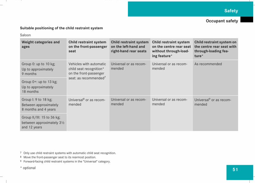
Occupant safety
51
Suitable positioning of the child restraint system
Saloon
Weight categories andages
Child restraint systemon the front-passengerseat
Child restraint systemon the left-hand andright-hand rear seats
Child restraint systemon the centre rear seatwithout through-load-ing feature*
Child restraint systemonthe centre rear seat withthrough-loading fea-ture*
Group 0: up to 10 kg;Up to approximately9 months
Vehicles with automaticchild seat recognition*on the front-passengerseat: as recommended7
Universal or as recom-mended
Universal or as recom-mended
As recommended
Group 0+: up to 13 kg;Up to approximately18 months
Group I: 9 to 18 kg;Between approximately8 months and 4 years
Universal8 or as recom-mended
Universal or as recom-mended
Universal or as recom-mended
Universal9 or as recom-mended
Group II/III: 15 to 36 kg;between approximately 3½and 12 years
7 Only use child restraint systems with automatic child seat recognition.8 Move the front-passenger seat to its rearmost position.9 Forward-facing child restraint systems in the "Universal" category.
Safety
* optional
211_AKB; 2; 5, en-GBmkalafa, Version: 2.9.4
2008-02-29T16:57:07+01:00 - Seite 51
Z
Dateiname: 6515_3416_02_buchblock.pdf; preflight
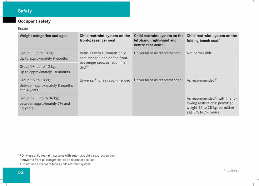
Occupant safety
52
Estate
Weight categories and ages Child restraint system on thefront-passenger seat
Child restraint system on theleft-hand, right-hand andcentre rear seats
Child restraint system on thefolding bench seat*
Group 0: up to 10 kg;Up to approximately 9 months
Vehicles with automatic childseat recognition* on the front-passenger seat: as recommen-ded10
Universal or as recommended Not permissible
Group 0+: up to 13 kg;Up to approximately 18 months
Group I: 9 to 18 kg;Between approximately 8 monthsand 4 years
Universal11 or as recommended Universal or as recommended As recommended12
Group II/III: 15 to 36 kg;between approximately 3½ and12 years
As recommended12 with the fol-lowing restrictions: permittedweight 15 to 25 kg, permittedage 3½ to 7½ years
10 Only use child restraint systems with automatic child seat recognition.11Move the front-passenger seat to its rearmost position.12 Do not use a rearward-facing child restraint system.
Safety
* optional
211_AKB; 2; 5, en-GBmkalafa, Version: 2.9.4
2008-02-29T16:57:07+01:00 - Seite 52
Dateiname: 6515_3416_02_buchblock.pdf; preflight
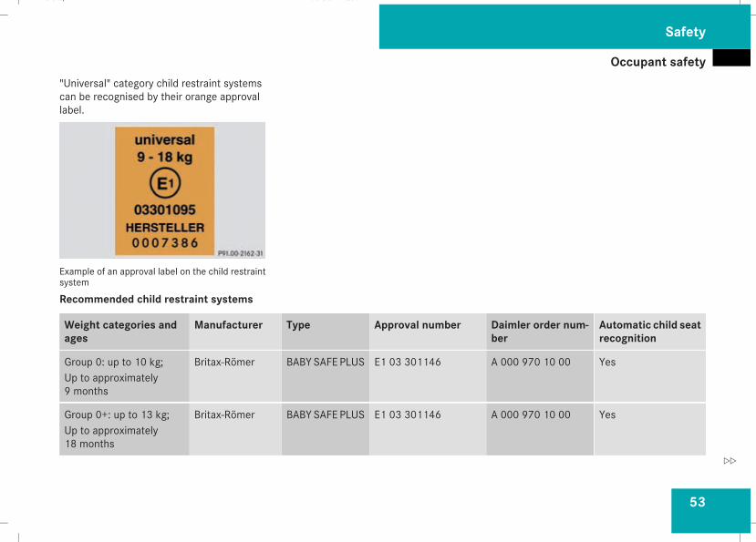
Occupant safety
53
"Universal" category child restraint systemscan be recognised by their orange approvallabel.
Example of an approval label on the child restraintsystem
Recommended child restraint systems
Weight categories andages
Manufacturer Type Approval number Daimler order num-ber
Automatic child seatrecognition
Group 0: up to 10 kg;Up to approximately9 months
Britax-Römer BABY SAFE PLUS E1 03 301146 A 000 970 10 00 Yes
Group 0+: up to 13 kg;Up to approximately18 months
Britax-Römer BABY SAFE PLUS E1 03 301146 A 000 970 10 00 Yes
Safety
211_AKB; 2; 5, en-GBmkalafa, Version: 2.9.4
2008-02-29T16:57:07+01:00 - Seite 53
Z
Dateiname: 6515_3416_02_buchblock.pdf; preflight
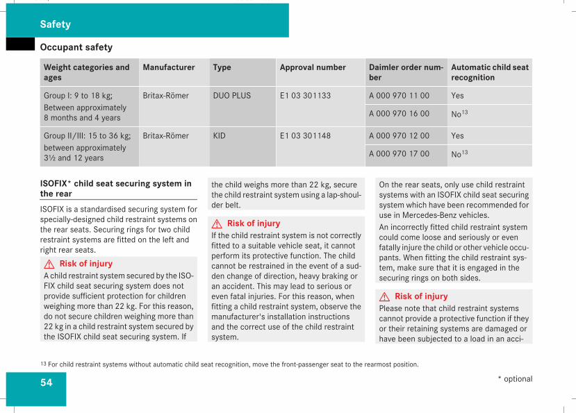
Occupant safety
54
Weight categories andages
Manufacturer Type Approval number Daimler order num-ber
Automatic child seatrecognition
Group I: 9 to 18 kg;Between approximately8 months and 4 years
Britax-Römer DUO PLUS E1 03 301133 A 000 970 11 00 Yes
A 000 970 16 00 No13
Group II/III: 15 to 36 kg;between approximately3½ and 12 years
Britax-Römer KID E1 03 301148 A 000 970 12 00 Yes
A 000 970 17 00 No13
ISOFIX* child seat securing system inthe rearISOFIX is a standardised securing system forspecially-designed child restraint systems onthe rear seats. Securing rings for two childrestraint systems are fitted on the left andright rear seats.G Risk of injuryA child restraint system secured by the ISO-FIX child seat securing system does notprovide sufficient protection for childrenweighing more than 22 kg. For this reason,do not secure children weighing more than22 kg in a child restraint system secured bythe ISOFIX child seat securing system. If
the child weighs more than 22 kg, securethe child restraint system using a lap-shoul-der belt.
G Risk of injuryIf the child restraint system is not correctlyfitted to a suitable vehicle seat, it cannotperform its protective function. The childcannot be restrained in the event of a sud-den change of direction, heavy braking oran accident. This may lead to serious oreven fatal injuries. For this reason, whenfitting a child restraint system, observe themanufacturer's installation instructionsand the correct use of the child restraintsystem.
On the rear seats, only use child restraintsystems with an ISOFIX child seat securingsystem which have been recommended foruse in Mercedes-Benz vehicles.An incorrectly fitted child restraint systemcould come loose and seriously or evenfatally injure the child or other vehicle occu-pants. When fitting the child restraint sys-tem, make sure that it is engaged in thesecuring rings on both sides.
G Risk of injuryPlease note that child restraint systemscannot provide a protective function if theyor their retaining systems are damaged orhave been subjected to a load in an acci-
13 For child restraint systems without automatic child seat recognition, move the front-passenger seat to the rearmost position.
Safety
* optional
211_AKB; 2; 5, en-GBmkalafa, Version: 2.9.4
2008-02-29T16:57:07+01:00 - Seite 54
Dateiname: 6515_3416_02_buchblock.pdf; preflight
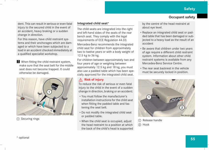
Occupant safety
55
dent. This can result in serious or even fatalinjury to the secured child in the event ofan accident, heavy braking or a suddenchange in direction.For this reason, have child restraint sys-tems and their anchorages which are dam-aged or which have been subjected to aload in an accident checked immediately ata qualified specialist workshop.
! When fitting the child restraint system,make sure that the seat belt for the middleseat does not become trapped. It couldotherwise be damaged.
1 Securing rings
Integrated child seat*The child seats are integrated into the rightand left-hand sides of the seats of the rearbench seat. They comply with the legalrequirements of ECE Regulation 44.03.Mercedes-Benz recommends the integratedchild seat for children from approximatelytwo to twelve years or with a body weight of12.5 kg to 36 kg.For children between approximately two andfour years of age or weighing betweenapproximately 12.5 kg and 18 kg, you mustalso use a padded table which has been spe-cially approved for the integrated child seat.G Risk of injuryTo reduce the risk of serious or even fatalinjury to the child in the event of a suddenchange in direction, braking or an accident:RYou must follow the manufacturer'sinstallation instructions for the child seatwhen fitting the padded table and fas-tening the seat belt.
RDo not modify the integrated child seator padded table.
RWhen the child seat is occupied, adjustthe head restraint to a position at whichthe back of the child's head is supported
by the centre of the head restraint atabout eye level.
RReplace an integrated child seat or pad-ded table that has been damaged or sub-jected to a heavy load as the result of anaccident
RBe aware that children under two yearsof age require a different child restraintsystem. Information about other childrestraint systems is available from anyMercedes-Benz Service Centre.
RThe rear seat backrest in the vehiclemust be securely locked in position.
1 Release handle2 Hook
Safety
* optional
211_AKB; 2; 5, en-GBmkalafa, Version: 2.9.4
2008-02-29T16:57:07+01:00 - Seite 55
Z
Dateiname: 6515_3416_02_buchblock.pdf; preflight
Occupant safety
56
Folding out the child seatX Pull release handle1 forwards.X Push the child seat upwards and back untilit engages.
Fastening a child's seat beltG Risk of injuryTo reduce the risk of serious or even fatalinjury to the child in the event of a suddenchange in direction, braking or an accident:RThe shoulder belt section of the seat beltmust be routed across the middle of thechild's shoulder – never across thechild's neck – and be pulled tight againstthe child's chest. The lap section of theseat belt must be routed across thechild's pelvis – not across the abdomen– and be pulled tight against the child'sbody; retighten the belt strap if neces-sary.
RNever secure more than one child at atime in the child restraint system.
RThe belt must be routed through thehook.
RThe belt strap must not be trapped ortwisted, nor rub against any sharp edges.
Also observe the assembly instructions forthe padded table and the additional warn-ings and information about risk of injury.
X Pull the belt smoothly from the belt reel.X Guide the lower lap section of the beltthrough hook2.
X Engage the belt tongue in the buckle.X If the integrated child seat is being usedwithout the padded table, make sure thatthe belt:
Ris routed as low as possible across the pel-vic area, in front of the hips
Ris tightened across the lap by pullingupwards on the child's shoulder belt
Ris tight and is routed across the middle ofthe child's shoulder
Ris not twisted and does not pass across thechild's neck or under the child's arm
X Adjust the head restraint (Y page 81)
Folding in the child seatX Pull release handle1 forwards.X Push the child seat back into the seat untilit engages.
Child-proof locksIf children are travelling in the vehicle, you canactivate the child-proof locks for the reardoors.
Child-proof locks for the rear doorsThe child-proof locks on the rear doors enableyou to secure each door individually. A lockeddoor cannot be opened from the inside. Thedoor can be opened from the outside if thevehicle is unlocked.G Risk of accident and injuryIf children are travelling in the vehicle, acti-vate the child-proof locks for the rear doorsand the override switch for the rear win-dows. The children could otherwise openthe doors or windows while the vehicle is inmotion and injure themselves or others.
Safety
211_AKB; 2; 5, en-GBmkalafa, Version: 2.9.4
2008-02-29T16:57:07+01:00 - Seite 56
Dateiname: 6515_3416_02_buchblock.pdf; preflight
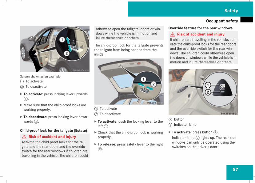
Occupant safety
57
Saloon shown as an example1 To activate2 To deactivate
X To activate: press locking lever upwards1.
X Make sure that the child-proof locks areworking properly.
X To deactivate: press locking lever down-wards2.
Child-proof lock for the tailgate (Estate)G Risk of accident and injuryActivate the child-proof locks for the tail-gate and the rear doors and the overrideswitch for the rear windows if children aretravelling in the vehicle. The children could
otherwise open the tailgate, doors or win-dows while the vehicle is in motion andinjure themselves or others.
The child-proof lock for the tailgate preventsthe tailgate from being opened from theinside.
1 To activate2 To deactivate
X To activate: push the locking lever to theleft1.
X Check that the child-proof lock is workingproperly.
X To release: press safety lever to the right2.
Override feature for the rear windowsG Risk of accident and injuryIf children are travelling in the vehicle, acti-vate the child-proof locks for the rear doorsand the override switch for the rear win-dows. The children could otherwise openthe doors or windows while the vehicle is inmotion and injure themselves or others.
1 Button2 Indicator lamp
X To activate: press button1.Indicator lamp2 lights up. The rear sidewindows can only be operated using theswitches on the driver's door.
Safety
211_AKB; 2; 5, en-GBmkalafa, Version: 2.9.4
2008-02-29T16:57:07+01:00 - Seite 57
Z
Dateiname: 6515_3416_02_buchblock.pdf; preflight
Driving safety systems
58
X To deactivate: press button1.Indicator lamp2 goes out. You can oper-ate the rear side windows using theswitches in the rear compartment.
Driving safety systems
Overview of driving safety systemsIn this section, you will find information aboutthe following driving safety systems:RABS (Anti-lock Braking System)RBAS (Brake Assist System)RAdaptive brake lampsRESP® (Electronic Stability Program)REBV (electronic brake-power distribution)RADAPTIVE BRAKE
i In wintry road conditions, always use win-ter tyres (M+S tyres) and, where necessary,snow chains. Only in this way will the driv-ing safety systems described in this sectionwork as effectively as possible.
G Risk of accidentThe risk of an accident is significantlyincreased by driving too fast. This is partic-ularly the case when cornering as well ason wet or slippery roads or when driving tooclose to the vehicle in front.The driving safety systems described in thissection cannot reduce this risk nor overridethe laws of physics.
For this reason, always adapt your drivingstyle to suit the prevailing road andweatherconditions. Maintain sufficient distancefrom other road users and objects on theroad.
ABS (Anti-lock Braking System)ABS regulates brake pressure in such a waythat the wheels do not lock when you brake.This allows you to continue steering the vehi-cle when braking.ABS works from a speed of about 8 km/hupwards, regardless of road surface condi-tions. ABS works on slippery surfaces, evenwhen you only brake gently.G Risk of accidentDo not depress the brake pedal severaltimes in quick succession (pumping).Depress the brake firmly and evenly. Pump-ing the brake pedal reduces the brakingeffect.
BrakingIf ABS intervenes when braking, you will feela pulsing in the brake pedal.
Safety
211_AKB; 2; 5, en-GBmkalafa, Version: 2.9.4
2008-02-29T16:57:07+01:00 - Seite 58
Dateiname: 6515_3416_02_buchblock.pdf; preflight
Driving safety systems
59
X If ABS intervenes: continue to depress thebrake pedal with force until the braking sit-uation is over.
X To make a full brake application:depress the brake pedal with full force.
G Risk of accidentIf ABS is faulty, the wheels could lock whenbraking. This limits the steerability of thevehicle when braking and the braking dis-tance may increase.If ABS is deactivated due to a malfunction,then BAS and ESP are also deactivated.There is an increased risk of your vehicleskidding in certain situations.You should always adapt your driving styleto suit the prevailing road and weather con-ditions.
BAS (Brake Assist)BAS operates in emergency braking situa-tions. If you depress the brake pedal quickly,BAS automatically boosts the braking force,thus shortening the stopping distance.X Keep the brake pedal firmly depressed untilthe emergency braking situation is over.ABS prevents the wheels from locking.
The brakes will function as usual once yourelease the brake pedal. BAS is deactivated.G Risk of accidentIf BAS has malfunctioned, the braking sys-tem remains available with full brake boost-ing effect. However, braking force is notautomatically increased in emergencybraking situations and the stopping dis-tance may increase.
Adaptive brake lampsi Adaptive brake lamps are only available incertain countries.
If you brake sharply from a speed of morethan 50 km/h or if braking is assisted by BAS,the brake lamps flash rapidly. In this way,traffic travelling behind you is warned in aneven more noticeable manner.If you brake sharply from a speed of morethan 70 km/h to a standstill, the hazardwarn-ing lamps are activated automatically. If thebrakes are applied again, the brake lampslight up continuously. The hazard warninglamps switch off automatically if you drivefaster than 10 km/h again. You can alsoswitch off the hazard warning lamps using thehazard warning switch button (Y page 102).
Safety
211_AKB; 2; 5, en-GBmkalafa, Version: 2.9.4
2008-02-29T16:57:07+01:00 - Seite 59
Z
Dateiname: 6515_3416_02_buchblock.pdf; preflight
Driving safety systems
60
ESP® (Electronic Stability Program)ESP® monitors driving stability and traction,i.e. power transmission between the tyresand the road surface.If ESP® detects that the vehicle is deviatingfrom the direction desired by the driver, oneor more wheels are braked to stabilise thevehicle. The engine output is also modified, ifnecessary, to keep the vehicle on the desiredcourse within physical limits. ESP® assiststhe driver when pulling away on wet or slip-pery roads. ESP® can also stabilise the vehi-cle during braking.When ESP® intervenes, thev warninglamp flashes in the instrument cluster.G Risk of accidentIf thev warning lamp in the instrumentcluster flashes, proceed as follows:RDo not deactivate ESP® under any cir-cumstances.
ROnly depress the accelerator pedal as faras necessary when pulling away.
RAdapt your driving style to suit the pre-vailing road and weather conditions.
The vehicle could otherwise go into a skid.
ESP® cannot reduce the risk of an accidentif you drive too fast. ESP® cannot overridethe laws of physics.
! If the vehicle is to be towed with the frontor rear axle raised, the ignition must beswitched off (key in position 0 or 1 in theignition lock). Application of the brakes byESP® could otherwise destroy the brakesystem on the front or rear axle.
! Vehicles with 4MATIC* may not be towedwith the front or rear axle raised.
i Only use wheels with the recommendedtyre sizes. Only then will ESP® functionproperly.
Deactivating/activating ESP®
ESP® is activated automatically when theengine is running.It may be best to deactivate ESP® in the fol-lowing situations:Rwhen using snow chainsRin deep snowRon sand or gravel
G Risk of accidentActivate ESP® as soon as the situationsdescribed above no longer apply. ESP® willotherwise not be able to stabilise the vehi-cle if the vehicle starts to skid or a wheelstarts to spin.
If you deactivate ESP®:RESP® no longer improves driving stability.Rengine torque is not limited and the drivewheels are able to spin. The spinningwheels produce a cutting effect for bettertraction.
Rtraction control is still activated.RESP® still provides support when youbrake.
i If ESP® is deactivated and one or morewheels start to spin, thevwarning lampin the instrument cluster flashes. In suchsituations ESP® will not stabilise the vehi-cle.
Safety
* optional
211_AKB; 2; 5, en-GBmkalafa, Version: 2.9.4
2008-02-29T16:57:07+01:00 - Seite 60
Dateiname: 6515_3416_02_buchblock.pdf; preflight
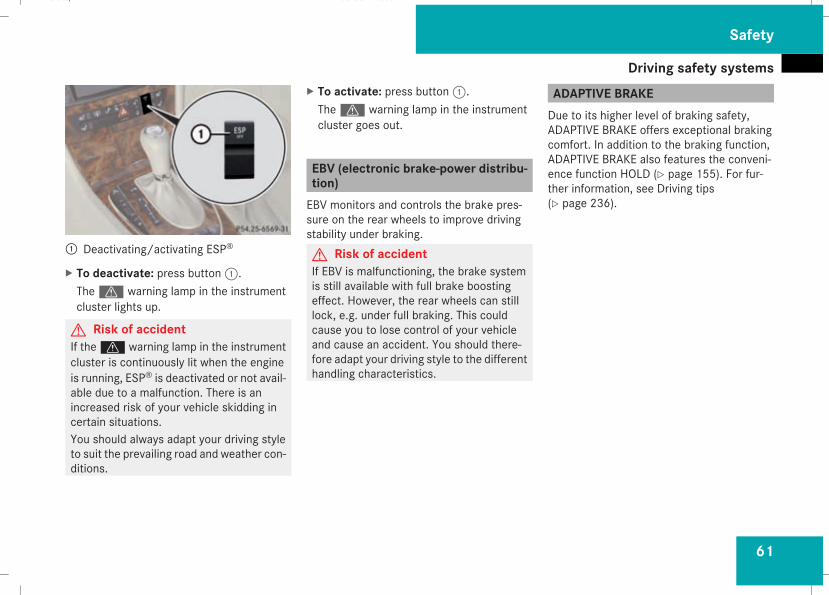
Driving safety systems
61
1 Deactivating/activating ESP®
X To deactivate: press button1.Thev warning lamp in the instrumentcluster lights up.
G Risk of accidentIf thev warning lamp in the instrumentcluster is continuously lit when the engineis running, ESP® is deactivated or not avail-able due to a malfunction. There is anincreased risk of your vehicle skidding incertain situations.You should always adapt your driving styleto suit the prevailing road and weather con-ditions.
X To activate: press button1.Thev warning lamp in the instrumentcluster goes out.
EBV (electronic brake-power distribu-tion)EBV monitors and controls the brake pres-sure on the rear wheels to improve drivingstability under braking.G Risk of accidentIf EBV is malfunctioning, the brake systemis still available with full brake boostingeffect. However, the rear wheels can stilllock, e.g. under full braking. This couldcause you to lose control of your vehicleand cause an accident. You should there-fore adapt your driving style to the differenthandling characteristics.
ADAPTIVE BRAKEDue to its higher level of braking safety,ADAPTIVE BRAKE offers exceptional brakingcomfort. In addition to the braking function,ADAPTIVE BRAKE also features the conveni-ence function HOLD (Y page 155). For fur-ther information, see Driving tips(Y page 236).
Safety
211_AKB; 2; 5, en-GBmkalafa, Version: 2.9.4
2008-02-29T16:57:07+01:00 - Seite 61
Z
Dateiname: 6515_3416_02_buchblock.pdf; preflight
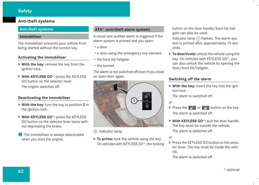
Anti-theft systems
62
Anti-theft systems
ImmobiliserThe immobiliser prevents your vehicle frombeing started without the correct key.
Activating the immobiliserX With the key: remove the key from theignition lock.
X With KEYLESS GO*: press the KEYLESSGO button on the selector lever.The engine switches off.
Deactivating the immobiliserX With the key: turn the key to position 2 inthe ignition lock.
X With KEYLESS GO*: press the KEYLESSGO button on the selector lever twice with-out depressing the brake.
i The immobiliser is always deactivatedwhen you start the engine.
ATA* (anti-theft alarm system)A visual and audible alarm is triggered if thealarm system is primed and you open:Ra doorRa door using the emergency key elementRthe boot lid/tailgateRthe bonnetThe alarm is not switched off even if you closean open door again.
1 Indicator lamp
X To prime: lock the vehicle using the key.On vehicles with KEYLESS GO*, the locking
button on the door handle/boot lid/tail-gate can also be used.Indicator lamp1 flashes. The alarm sys-tem is primed after approximately 15 sec-onds.
X Todeactivate: unlock the vehicle using thekey. On vehicles with KEYLESS GO*, youcan also unlock the vehicle by opening thedoor/boot lid/tailgate.
Switching off the alarmX With the key: insert the key into the igni-tion lock.The alarm is switched off.
orX Press theŒ or‹ button on the key.The alarm is switched off.
X With KEYLESS GO*: pull the door handle.The key must be outside the vehicle.The alarm is switched off.
orX Press the KEYLESS GO button on the selec-tor lever. The key must be inside the vehi-cle.The alarm is switched off.
Safety
* optional
211_AKB; 2; 5, en-GBmkalafa, Version: 2.9.4
2008-02-29T16:57:07+01:00 - Seite 62
Dateiname: 6515_3416_02_buchblock.pdf; preflight
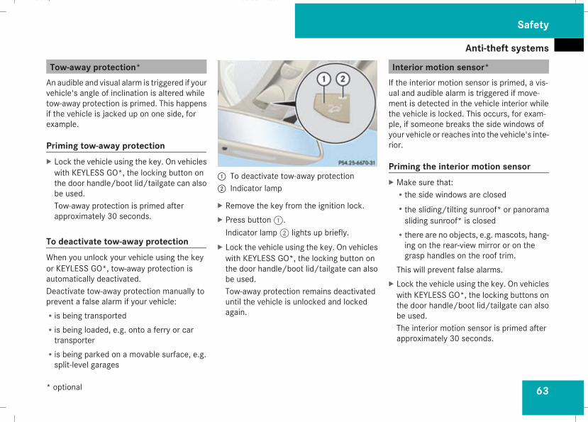
Anti-theft systems
63
Tow-away protection*An audible and visual alarm is triggered if yourvehicle's angle of inclination is altered whiletow-away protection is primed. This happensif the vehicle is jacked up on one side, forexample.
Priming tow-away protectionX Lock the vehicle using the key. On vehicleswith KEYLESS GO*, the locking button onthe door handle/boot lid/tailgate can alsobe used.Tow-away protection is primed afterapproximately 30 seconds.
To deactivate tow-away protectionWhen you unlock your vehicle using the keyor KEYLESS GO*, tow-away protection isautomatically deactivated.Deactivate tow-away protection manually toprevent a false alarm if your vehicle:Ris being transportedRis being loaded, e.g. onto a ferry or cartransporter
Ris being parked on a movable surface, e.g.split-level garages
1 To deactivate tow-away protection2 Indicator lamp
X Remove the key from the ignition lock.X Press button1.Indicator lamp2 lights up briefly.
X Lock the vehicle using the key. On vehicleswith KEYLESS GO*, the locking button onthe door handle/boot lid/tailgate can alsobe used.Tow-away protection remains deactivateduntil the vehicle is unlocked and lockedagain.
Interior motion sensor*If the interior motion sensor is primed, a vis-ual and audible alarm is triggered if move-ment is detected in the vehicle interior whilethe vehicle is locked. This occurs, for exam-ple, if someone breaks the side windows ofyour vehicle or reaches into the vehicle's inte-rior.
Priming the interior motion sensorX Make sure that:
Rthe side windows are closedRthe sliding/tilting sunroof* or panoramasliding sunroof* is closed
Rthere are no objects, e.g. mascots, hang-ing on the rear-view mirror or on thegrasp handles on the roof trim.
This will prevent false alarms.X Lock the vehicle using the key. On vehicleswith KEYLESS GO*, the locking buttons onthe door handle/boot lid/tailgate can alsobe used.The interior motion sensor is primed afterapproximately 30 seconds.
Safety
* optional
211_AKB; 2; 5, en-GBmkalafa, Version: 2.9.4
2008-02-29T16:57:07+01:00 - Seite 63
Z
Dateiname: 6515_3416_02_buchblock.pdf; preflight
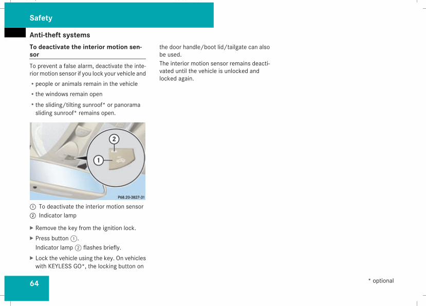
Anti-theft systems
64
To deactivate the interior motion sen-sorTo prevent a false alarm, deactivate the inte-riormotion sensor if you lock your vehicle andRpeople or animals remain in the vehicleRthe windows remain openRthe sliding/tilting sunroof* or panoramasliding sunroof* remains open.
1 To deactivate the interior motion sensor2 Indicator lamp
X Remove the key from the ignition lock.X Press button1.Indicator lamp2 flashes briefly.
X Lock the vehicle using the key. On vehicleswith KEYLESS GO*, the locking button on
the door handle/boot lid/tailgate can alsobe used.The interior motion sensor remains deacti-vated until the vehicle is unlocked andlocked again.
Safety
* optional
211_AKB; 2; 5, en-GBmkalafa, Version: 2.9.4
2008-02-29T16:57:07+01:00 - Seite 64
Dateiname: 6515_3416_02_buchblock.pdf; preflight
65
Opening and closing ........................... 66Key positions ....................................... 76Seats .................................................... 77Steering wheel .................................... 89Mirrors ................................................. 91Memory functions* ............................. 93Seat belts ............................................. 95Lights ................................................... 99Windscreen wipers ........................... 105Side windows .................................... 107
Driving and parking .......................... 110Transmission ..................................... 114Instrument cluster ............................ 120On-board computer .......................... 121Driving systems ................................ 142Air conditioning ................................. 162Sliding sunroof .................................. 180Loading and stowing ........................ 186Features ............................................. 207
Controls
211_AKB; 2; 5, en-GBmkalafa, Version: 2.9.4
2008-02-29T16:57:07+01:00 - Seite 65
Dateiname: 6515_3416_02_buchblock.pdf; preflight
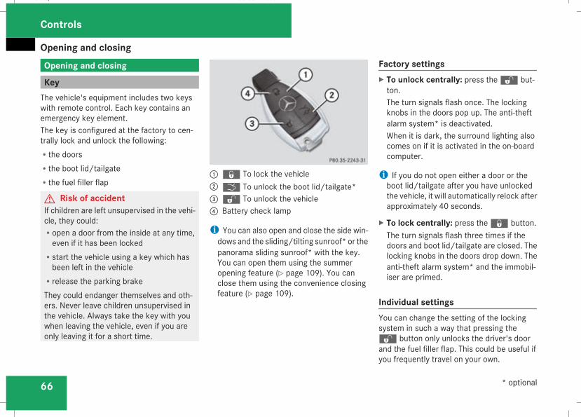
Opening and closing
66
Opening and closing
KeyThe vehicle's equipment includes two keyswith remote control. Each key contains anemergency key element.The key is configured at the factory to cen-trally lock and unlock the following:Rthe doorsRthe boot lid/tailgateRthe fuel filler flap
G Risk of accidentIf children are left unsupervised in the vehi-cle, they could:Ropen a door from the inside at any time,even if it has been locked
Rstart the vehicle using a key which hasbeen left in the vehicle
Rrelease the parking brakeThey could endanger themselves and oth-ers. Never leave children unsupervised inthe vehicle. Always take the key with youwhen leaving the vehicle, even if you areonly leaving it for a short time.
1j To lock the vehicle2i To unlock the boot lid/tailgate*3k To unlock the vehicle4 Battery check lamp
i You can also open and close the side win-dows and the sliding/tilting sunroof* or thepanorama sliding sunroof* with the key.You can open them using the summeropening feature (Y page 109). You canclose them using the convenience closingfeature (Y page 109).
Factory settingsX To unlock centrally: press thek but-ton.The turn signals flash once. The lockingknobs in the doors pop up. The anti-theftalarm system* is deactivated.When it is dark, the surround lighting alsocomes on if it is activated in the on-boardcomputer.
i If you do not open either a door or theboot lid/tailgate after you have unlockedthe vehicle, it will automatically relock afterapproximately 40 seconds.
X To lock centrally: press thej button.The turn signals flash three times if thedoors and boot lid/tailgate are closed. Thelocking knobs in the doors drop down. Theanti-theft alarm system* and the immobil-iser are primed.
Individual settingsYou can change the setting of the lockingsystem in such a way that pressing thek button only unlocks the driver's doorand the fuel filler flap. This could be useful ifyou frequently travel on your own.
Controls
* optional
211_AKB; 2; 5, en-GBmkalafa, Version: 2.9.4
2008-02-29T16:57:07+01:00 - Seite 66
Dateiname: 6515_3416_02_buchblock.pdf; preflight
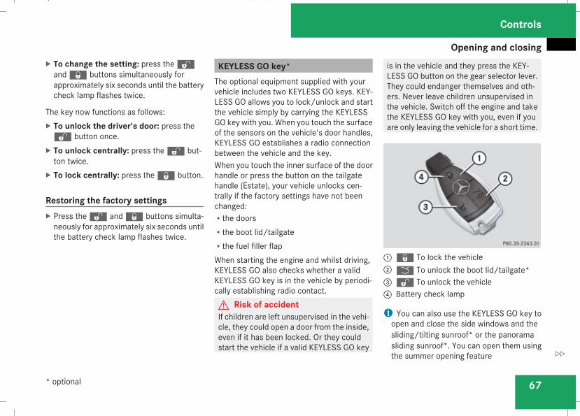
Opening and closing
67
X To change the setting: press thekandj buttons simultaneously forapproximately six seconds until the batterycheck lamp flashes twice.
The key now functions as follows:X To unlock the driver's door: press thek button once.
X To unlock centrally: press thek but-ton twice.
X To lock centrally: press thej button.
Restoring the factory settingsX Press thek andj buttons simulta-neously for approximately six seconds untilthe battery check lamp flashes twice.
KEYLESS GO key*The optional equipment supplied with yourvehicle includes two KEYLESS GO keys. KEY-LESS GO allows you to lock/unlock and startthe vehicle simply by carrying the KEYLESSGO key with you. When you touch the surfaceof the sensors on the vehicle's door handles,KEYLESS GO establishes a radio connectionbetween the vehicle and the key.When you touch the inner surface of the doorhandle or press the button on the tailgatehandle (Estate), your vehicle unlocks cen-trally if the factory settings have not beenchanged:Rthe doorsRthe boot lid/tailgateRthe fuel filler flapWhen starting the engine and whilst driving,KEYLESS GO also checks whether a validKEYLESS GO key is in the vehicle by periodi-cally establishing radio contact.G Risk of accidentIf children are left unsupervised in the vehi-cle, they could open a door from the inside,even if it has been locked. Or they couldstart the vehicle if a valid KEYLESS GO key
is in the vehicle and they press the KEY-LESS GO button on the gear selector lever.They could endanger themselves and oth-ers. Never leave children unsupervised inthe vehicle. Switch off the engine and takethe KEYLESS GO key with you, even if youare only leaving the vehicle for a short time.
1j To lock the vehicle2i To unlock the boot lid/tailgate*3k To unlock the vehicle4 Battery check lamp
i You can also use the KEYLESS GO key toopen and close the side windows and thesliding/tilting sunroof* or the panoramasliding sunroof*. You can open them usingthe summer opening feature
Controls
* optional
211_AKB; 2; 5, en-GBmkalafa, Version: 2.9.4
2008-02-29T16:57:07+01:00 - Seite 67
Z
Dateiname: 6515_3416_02_buchblock.pdf; preflight
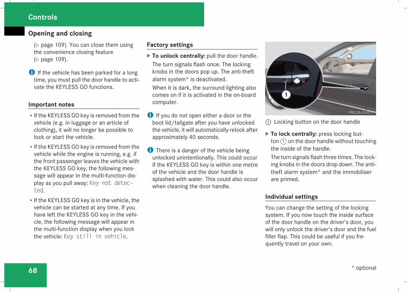
Opening and closing
68
(Y page 109). You can close them usingthe convenience closing feature(Y page 109).
i If the vehicle has been parked for a longtime, you must pull the door handle to acti-vate the KEYLESS GO functions.
Important notesRIf the KEYLESS GO key is removed from thevehicle (e.g. in luggage or an article ofclothing), it will no longer be possible tolock or start the vehicle.
RIf the KEYLESS GO key is removed from thevehicle while the engine is running, e.g. ifthe front passenger leaves the vehicle withthe KEYLESS GO key, the following mes-sage will appear in the multi-function dis-play as you pull away: Key not detec-ted.
RIf the KEYLESS GO key is in the vehicle, thevehicle can be started at any time. If youhave left the KEYLESS GO key in the vehi-cle, the following message will appear inthe multi-function display when you lockthe vehicle: Key still in vehicle.
Factory settingsX To unlock centrally: pull the door handle.The turn signals flash once. The lockingknobs in the doors pop up. The anti-theftalarm system* is deactivated.When it is dark, the surround lighting alsocomes on if it is activated in the on-boardcomputer.
i If you do not open either a door or theboot lid/tailgate after you have unlockedthe vehicle, it will automatically relock afterapproximately 40 seconds.
i There is a danger of the vehicle beingunlocked unintentionally. This could occurif the KEYLESS GO key is within one metreof the vehicle and the door handle issplashed with water. This could also occurwhen cleaning the door handle.
1 Locking button on the door handle
X To lock centrally: press locking but-ton1 on the door handle without touchingthe inside of the handle.The turn signals flash three times. The lock-ing knobs in the doors drop down. The anti-theft alarm system* and the immobiliserare primed.
Individual settingsYou can change the setting of the lockingsystem. If you now touch the inside surfaceof the door handle on the driver's door, youwill only unlock the driver's door and the fuelfiller flap. This could be useful if you fre-quently travel on your own.
Controls
* optional
211_AKB; 2; 5, en-GBmkalafa, Version: 2.9.4
2008-02-29T16:57:07+01:00 - Seite 68
Dateiname: 6515_3416_02_buchblock.pdf; preflight
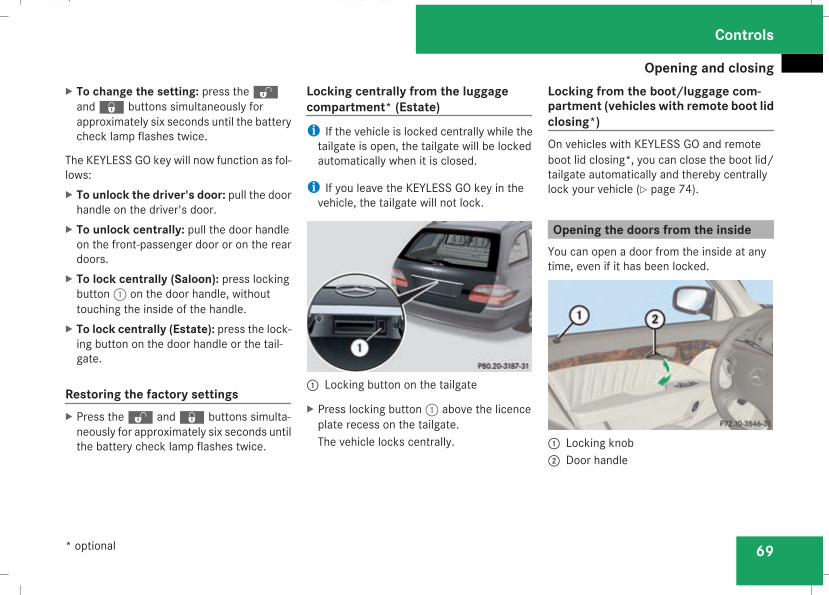
Opening and closing
69
X To change the setting: press thekandj buttons simultaneously forapproximately six seconds until the batterycheck lamp flashes twice.
The KEYLESS GO key will now function as fol-lows:X To unlock the driver's door: pull the doorhandle on the driver's door.
X To unlock centrally: pull the door handleon the front-passenger door or on the reardoors.
X To lock centrally (Saloon): press lockingbutton1 on the door handle, withouttouching the inside of the handle.
X To lock centrally (Estate): press the lock-ing button on the door handle or the tail-gate.
Restoring the factory settingsX Press thek andj buttons simulta-neously for approximately six seconds untilthe battery check lamp flashes twice.
Locking centrally from the luggagecompartment* (Estate)i If the vehicle is locked centrally while thetailgate is open, the tailgate will be lockedautomatically when it is closed.
i If you leave the KEYLESS GO key in thevehicle, the tailgate will not lock.
1 Locking button on the tailgate
X Press locking button1 above the licenceplate recess on the tailgate.The vehicle locks centrally.
Locking from the boot/luggage com-partment (vehicles with remote boot lidclosing*)On vehicles with KEYLESS GO and remoteboot lid closing*, you can close the boot lid/tailgate automatically and thereby centrallylock your vehicle (Y page 74).
Opening the doors from the insideYou can open a door from the inside at anytime, even if it has been locked.
1 Locking knob2 Door handle
Controls
* optional
211_AKB; 2; 5, en-GBmkalafa, Version: 2.9.4
2008-02-29T16:57:07+01:00 - Seite 69
Z
Dateiname: 6515_3416_02_buchblock.pdf; preflight
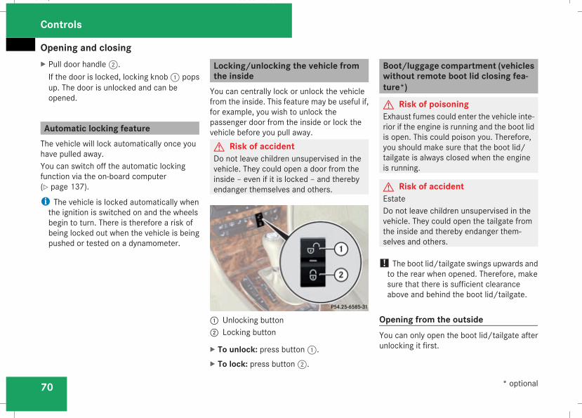
Opening and closing
70
X Pull door handle2.If the door is locked, locking knob1 popsup. The door is unlocked and can beopened.
Automatic locking featureThe vehicle will lock automatically once youhave pulled away.You can switch off the automatic lockingfunction via the on-board computer(Y page 137).
i The vehicle is locked automatically whenthe ignition is switched on and the wheelsbegin to turn. There is therefore a risk ofbeing locked out when the vehicle is beingpushed or tested on a dynamometer.
Locking/unlocking the vehicle fromthe insideYou can centrally lock or unlock the vehiclefrom the inside. This feature may be useful if,for example, you wish to unlock thepassenger door from the inside or lock thevehicle before you pull away.G Risk of accidentDo not leave children unsupervised in thevehicle. They could open a door from theinside – even if it is locked – and therebyendanger themselves and others.
1 Unlocking button2 Locking button
X To unlock: press button1.X To lock: press button2.
Boot/luggage compartment (vehicleswithout remote boot lid closing fea-ture*)
G Risk of poisoningExhaust fumes could enter the vehicle inte-rior if the engine is running and the boot lidis open. This could poison you. Therefore,you should make sure that the boot lid/tailgate is always closed when the engineis running.
G Risk of accidentEstateDo not leave children unsupervised in thevehicle. They could open the tailgate fromthe inside and thereby endanger them-selves and others.
! The boot lid/tailgate swings upwards andto the rear when opened. Therefore, makesure that there is sufficient clearanceabove and behind the boot lid/tailgate.
Opening from the outsideYou can only open the boot lid/tailgate afterunlocking it first.
Controls
* optional
211_AKB; 2; 5, en-GBmkalafa, Version: 2.9.4
2008-02-29T16:57:07+01:00 - Seite 70
Dateiname: 6515_3416_02_buchblock.pdf; preflight
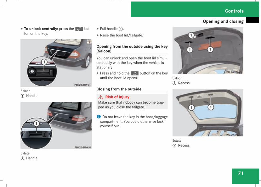
Opening and closing
71
X To unlock centrally: press thek but-ton on the key.
Saloon1 Handle
Estate1 Handle
X Pull handle1.X Raise the boot lid/tailgate.
Opening from the outside using the key(Saloon)You can unlock and open the boot lid simul-taneously with the key when the vehicle isstationary.X Press and hold thei button on the keyuntil the boot lid opens.
Closing from the outside
G Risk of injuryMake sure that nobody can become trap-ped as you close the tailgate.
i Do not leave the key in the boot/luggagecompartment. You could otherwise lockyourself out.
Saloon1 Recess
Estate1 Recess
Controls
211_AKB; 2; 5, en-GBmkalafa, Version: 2.9.4
2008-02-29T16:57:07+01:00 - Seite 71
Z
Dateiname: 6515_3416_02_buchblock.pdf; preflight
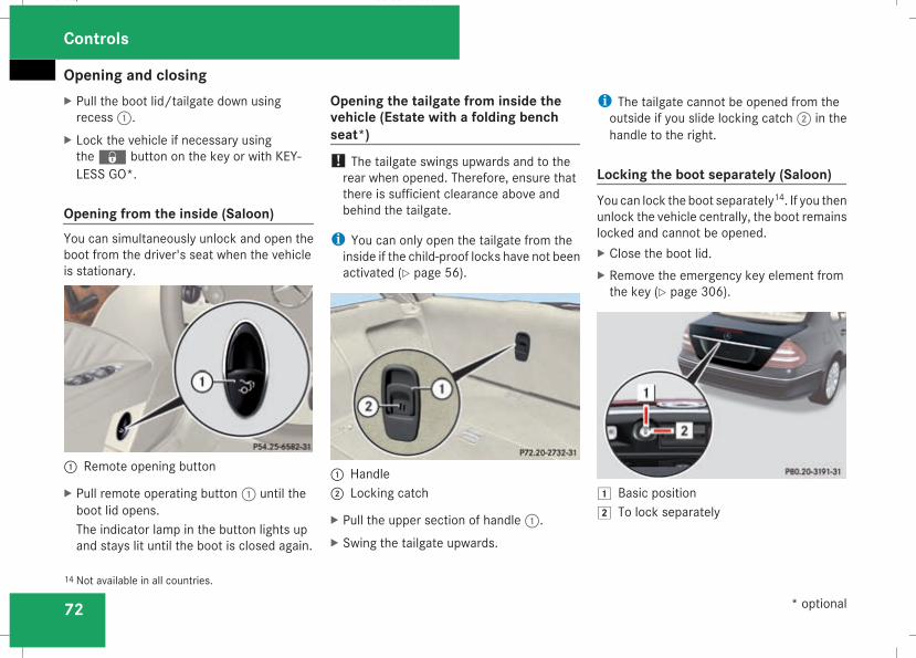
Opening and closing
72
X Pull the boot lid/tailgate down usingrecess1.
X Lock the vehicle if necessary usingthej button on the key or with KEY-LESS GO*.
Opening from the inside (Saloon)You can simultaneously unlock and open theboot from the driver's seat when the vehicleis stationary.
1 Remote opening button
X Pull remote operating button1 until theboot lid opens.The indicator lamp in the button lights upand stays lit until the boot is closed again.
Opening the tailgate from inside thevehicle (Estate with a folding benchseat*)! The tailgate swings upwards and to therear when opened. Therefore, ensure thatthere is sufficient clearance above andbehind the tailgate.
i You can only open the tailgate from theinside if the child-proof locks have not beenactivated (Y page 56).
1 Handle2 Locking catch
X Pull the upper section of handle1.X Swing the tailgate upwards.
i The tailgate cannot be opened from theoutside if you slide locking catch2 in thehandle to the right.
Locking the boot separately (Saloon)You can lock the boot separately14. If you thenunlock the vehicle centrally, the boot remainslocked and cannot be opened.X Close the boot lid.X Remove the emergency key element fromthe key (Y page 306).
$ Basic position% To lock separately
14 Not available in all countries.
Controls
* optional
211_AKB; 2; 5, en-GBmkalafa, Version: 2.9.4
2008-02-29T16:57:07+01:00 - Seite 72
Dateiname: 6515_3416_02_buchblock.pdf; preflight
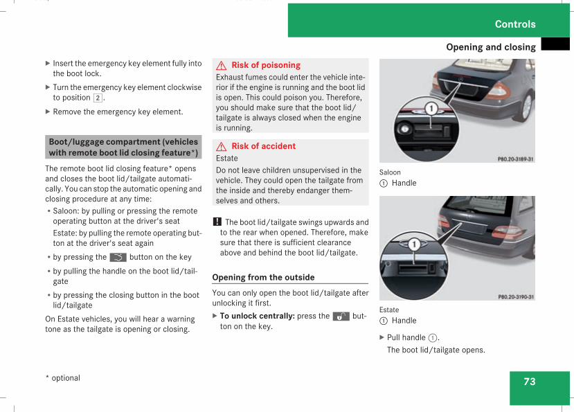
Opening and closing
73
X Insert the emergency key element fully intothe boot lock.
X Turn the emergency key element clockwiseto position%.
X Remove the emergency key element.
Boot/luggage compartment (vehicleswith remote boot lid closing feature*)The remote boot lid closing feature* opensand closes the boot lid/tailgate automati-cally. You can stop the automatic opening andclosing procedure at any time:RSaloon: by pulling or pressing the remoteoperating button at the driver's seatEstate: by pulling the remote operating but-ton at the driver's seat again
Rby pressing thei button on the keyRby pulling the handle on the boot lid/tail-gate
Rby pressing the closing button in the bootlid/tailgate
On Estate vehicles, you will hear a warningtone as the tailgate is opening or closing.
G Risk of poisoningExhaust fumes could enter the vehicle inte-rior if the engine is running and the boot lidis open. This could poison you. Therefore,you should make sure that the boot lid/tailgate is always closed when the engineis running.
G Risk of accidentEstateDo not leave children unsupervised in thevehicle. They could open the tailgate fromthe inside and thereby endanger them-selves and others.
! The boot lid/tailgate swings upwards andto the rear when opened. Therefore, makesure that there is sufficient clearanceabove and behind the boot lid/tailgate.
Opening from the outsideYou can only open the boot lid/tailgate afterunlocking it first.X To unlock centrally: press thek but-ton on the key.
Saloon1 Handle
Estate1 Handle
X Pull handle1.The boot lid/tailgate opens.
Controls
* optional
211_AKB; 2; 5, en-GBmkalafa, Version: 2.9.4
2008-02-29T16:57:07+01:00 - Seite 73
Z
Dateiname: 6515_3416_02_buchblock.pdf; preflight
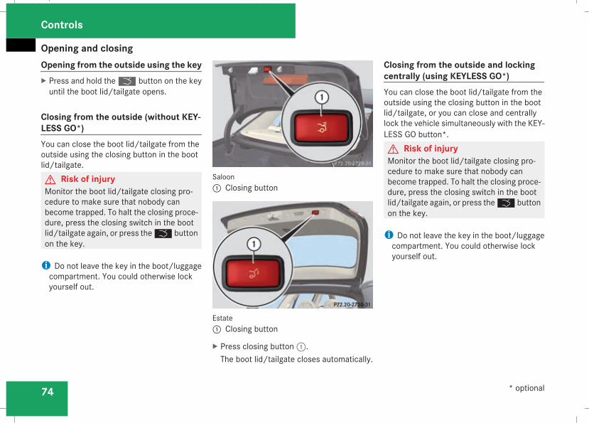
Opening and closing
74
Opening from the outside using the keyX Press and hold thei button on the keyuntil the boot lid/tailgate opens.
Closing from the outside (without KEY-LESS GO*)You can close the boot lid/tailgate from theoutside using the closing button in the bootlid/tailgate.G Risk of injuryMonitor the boot lid/tailgate closing pro-cedure to make sure that nobody canbecome trapped. To halt the closing proce-dure, press the closing switch in the bootlid/tailgate again, or press thei buttonon the key.
i Do not leave the key in the boot/luggagecompartment. You could otherwise lockyourself out.
Saloon1 Closing button
Estate1 Closing button
X Press closing button1.The boot lid/tailgate closes automatically.
Closing from the outside and lockingcentrally (using KEYLESS GO*)You can close the boot lid/tailgate from theoutside using the closing button in the bootlid/tailgate, or you can close and centrallylock the vehicle simultaneously with the KEY-LESS GO button*.G Risk of injuryMonitor the boot lid/tailgate closing pro-cedure to make sure that nobody canbecome trapped. To halt the closing proce-dure, press the closing switch in the bootlid/tailgate again, or press thei buttonon the key.
i Do not leave the key in the boot/luggagecompartment. You could otherwise lockyourself out.
Controls
* optional
211_AKB; 2; 5, en-GBmkalafa, Version: 2.9.4
2008-02-29T16:57:07+01:00 - Seite 74
Dateiname: 6515_3416_02_buchblock.pdf; preflight
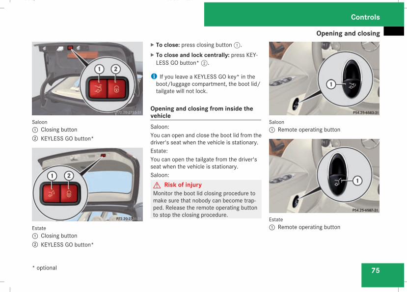
Opening and closing
75
Saloon1 Closing button2 KEYLESS GO button*
Estate1 Closing button2 KEYLESS GO button*
X To close: press closing button1.X To close and lock centrally: press KEY-LESS GO button*2.
i If you leave a KEYLESS GO key* in theboot/luggage compartment, the boot lid/tailgate will not lock.
Opening and closing from inside thevehicleSaloon:You can open and close the boot lid from thedriver's seat when the vehicle is stationary.Estate:You can open the tailgate from the driver'sseat when the vehicle is stationary.Saloon:G Risk of injuryMonitor the boot lid closing procedure tomake sure that nobody can become trap-ped. Release the remote operating buttonto stop the closing procedure.
Saloon1 Remote operating button
Estate1 Remote operating button
Controls
* optional
211_AKB; 2; 5, en-GBmkalafa, Version: 2.9.4
2008-02-29T16:57:07+01:00 - Seite 75
Z
Dateiname: 6515_3416_02_buchblock.pdf; preflight
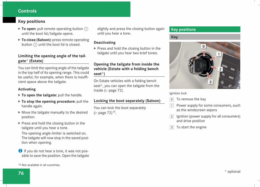
Key positions
76
X To open: pull remote operating button1until the boot lid/tailgate opens.
X To close (Saloon): press remote operatingbutton1 until the boot lid is closed.
Limiting the opening angle of the tail-gate* (Estate)You can limit the opening angle of the tailgatein the top half of its opening range. This couldbe useful, for example, when there is insuffi-cient space above the tailgate.
ActivatingX To open the tailgate: pull the handle.X To stop the opening procedure: pull thehandle again.
X Move the tailgate manually to the desiredposition.
X Press and hold the closing button in thetailgate until you hear a tone.The opening angle limiter is switched on.The tailgate will now stop in the saved posi-tion when opening.
i If you do not hear a tone, it was not pos-sible to save the position. Open the tailgate
slightly and press the closing button againuntil you hear a tone.
DeactivatingX Press and hold the closing button in thetailgate until you hear two brief tones.
Opening the tailgate from inside thevehicle (Estate with a folding benchseat*)On Estate vehicles with a folding benchseat*, you can open the tailgate from theinside (Y page 72).
Locking the boot separately (Saloon)You can lock the boot separately(Y page 72)15.
Key positions
Key
Ignition lock
} To remove the key$ Power supply for some consumers, such
as the windscreen wipers% Ignition (power supply for all consumers)
and drive position& To start the engine
15 Not available in all countries.
Controls
* optional
211_AKB; 2; 5, en-GBmkalafa, Version: 2.9.4
2008-02-29T16:57:07+01:00 - Seite 76
Dateiname: 6515_3416_02_buchblock.pdf; preflight
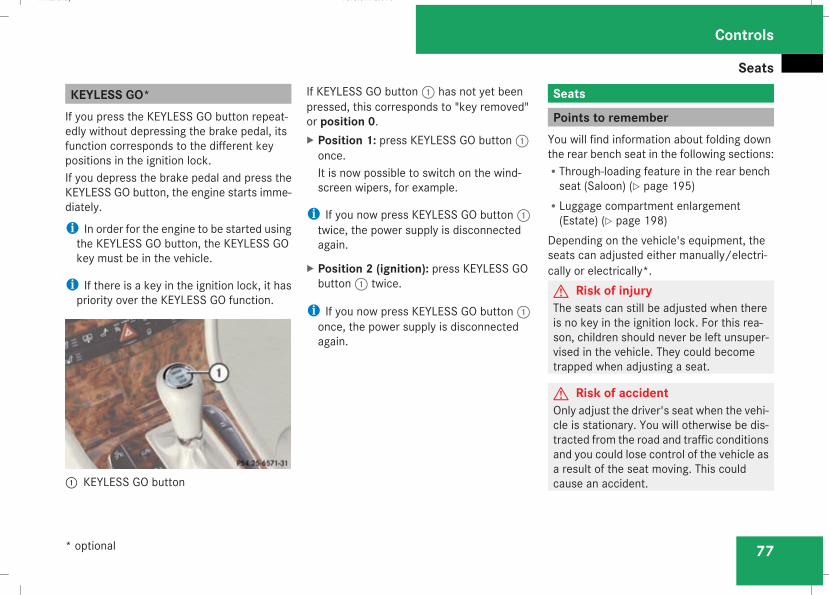
Seats
77
KEYLESS GO*If you press the KEYLESS GO button repeat-edly without depressing the brake pedal, itsfunction corresponds to the different keypositions in the ignition lock.If you depress the brake pedal and press theKEYLESS GO button, the engine starts imme-diately.
i In order for the engine to be started usingthe KEYLESS GO button, the KEYLESS GOkey must be in the vehicle.
i If there is a key in the ignition lock, it haspriority over the KEYLESS GO function.
1 KEYLESS GO button
If KEYLESS GO button1 has not yet beenpressed, this corresponds to "key removed"or position 0.X Position 1: press KEYLESS GO button1once.It is now possible to switch on the wind-screen wipers, for example.
i If you now press KEYLESS GO button1twice, the power supply is disconnectedagain.
X Position 2 (ignition): press KEYLESS GObutton1 twice.
i If you now press KEYLESS GO button1once, the power supply is disconnectedagain.
Seats
Points to rememberYou will find information about folding downthe rear bench seat in the following sections:RThrough-loading feature in the rear benchseat (Saloon) (Y page 195)
RLuggage compartment enlargement(Estate) (Y page 198)
Depending on the vehicle's equipment, theseats can adjusted either manually/electri-cally or electrically*.G Risk of injuryThe seats can still be adjusted when thereis no key in the ignition lock. For this rea-son, children should never be left unsuper-vised in the vehicle. They could becometrapped when adjusting a seat.
G Risk of accidentOnly adjust the driver's seat when the vehi-cle is stationary. You will otherwise be dis-tracted from the road and traffic conditionsand you could lose control of the vehicle asa result of the seat moving. This couldcause an accident.
Controls
* optional
211_AKB; 2; 5, en-GBmkalafa, Version: 2.9.4
2008-02-29T16:57:07+01:00 - Seite 77
Z
Dateiname: 6515_3416_02_buchblock.pdf; preflight
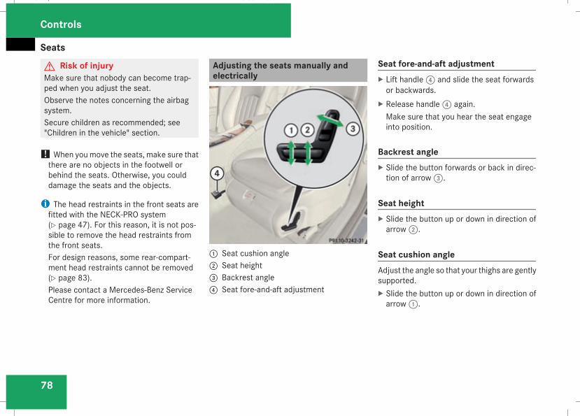
Seats
78
G Risk of injuryMake sure that nobody can become trap-ped when you adjust the seat.Observe the notes concerning the airbagsystem.Secure children as recommended; see"Children in the vehicle" section.
! When youmove the seats, make sure thatthere are no objects in the footwell orbehind the seats. Otherwise, you coulddamage the seats and the objects.
i The head restraints in the front seats arefitted with the NECK-PRO system(Y page 47). For this reason, it is not pos-sible to remove the head restraints fromthe front seats.For design reasons, some rear-compart-ment head restraints cannot be removed(Y page 83).Please contact a Mercedes-Benz ServiceCentre for more information.
Adjusting the seats manually andelectrically
1 Seat cushion angle2 Seat height3 Backrest angle4 Seat fore-and-aft adjustment
Seat fore-and-aft adjustmentX Lift handle4 and slide the seat forwardsor backwards.
X Release handle4 again.Make sure that you hear the seat engageinto position.
Backrest angleX Slide the button forwards or back in direc-tion of arrow3.
Seat heightX Slide the button up or down in direction ofarrow2.
Seat cushion angleAdjust the angle so that your thighs are gentlysupported.X Slide the button up or down in direction ofarrow1.
Controls
211_AKB; 2; 5, en-GBmkalafa, Version: 2.9.4
2008-02-29T16:57:07+01:00 - Seite 78
Dateiname: 6515_3416_02_buchblock.pdf; preflight
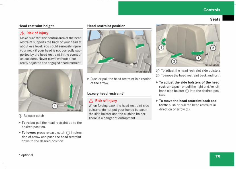
Seats
79
Head restraint height
G Risk of injuryMake sure that the central area of the headrestraint supports the back of your head atabout eye level. You could seriously injureyour neck if your head is not correctly sup-ported by the head restraint in the event ofan accident. Never travel without a cor-rectly adjusted and engaged head restraint.
1 Release catch
X To raise: pull the head restraint up to thedesired position.
X To lower: press release catch1 in direc-tion of arrow and push the head restraintdown to the desired position.
Head restraint position
X Push or pull the head restraint in directionof the arrow.
Luxury head restraint*
G Risk of injuryWhen folding back the head restraint sidebolsters, do not put your hands betweenthe side bolster and the cushion holder.There is a danger of entrapment.
1 To adjust the head restraint side bolsters2 Tomove the head restraint back and forth
X To adjust the side bolsters of the headrestraint: push or pull the right and/or left-hand side bolster1 into the desired posi-tion.
X To move the head restraint back andforth: push or pull the head restraint indirection of arrow2.
Controls
* optional
211_AKB; 2; 5, en-GBmkalafa, Version: 2.9.4
2008-02-29T16:57:07+01:00 - Seite 79
Z
Dateiname: 6515_3416_02_buchblock.pdf; preflight
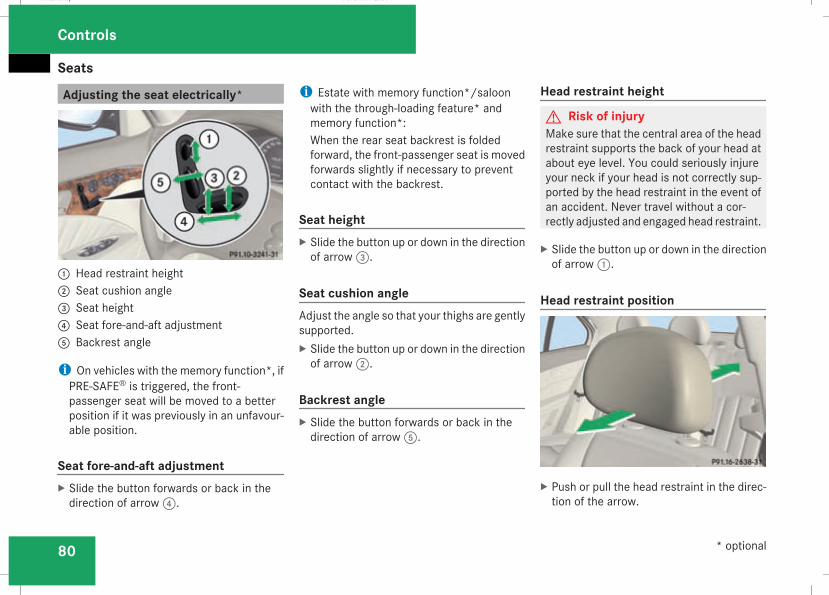
Seats
80
Adjusting the seat electrically*
1 Head restraint height2 Seat cushion angle3 Seat height4 Seat fore-and-aft adjustment5 Backrest angle
i On vehicles with the memory function*, ifPRE-SAFE® is triggered, the front-passenger seat will be moved to a betterposition if it was previously in an unfavour-able position.
Seat fore-and-aft adjustmentX Slide the button forwards or back in thedirection of arrow4.
i Estate with memory function*/saloonwith the through-loading feature* andmemory function*:When the rear seat backrest is foldedforward, the front-passenger seat is movedforwards slightly if necessary to preventcontact with the backrest.
Seat heightX Slide the button up or down in the directionof arrow3.
Seat cushion angleAdjust the angle so that your thighs are gentlysupported.X Slide the button up or down in the directionof arrow2.
Backrest angleX Slide the button forwards or back in thedirection of arrow5.
Head restraint height
G Risk of injuryMake sure that the central area of the headrestraint supports the back of your head atabout eye level. You could seriously injureyour neck if your head is not correctly sup-ported by the head restraint in the event ofan accident. Never travel without a cor-rectly adjusted and engaged head restraint.
X Slide the button up or down in the directionof arrow1.
Head restraint position
X Push or pull the head restraint in the direc-tion of the arrow.
Controls
* optional
211_AKB; 2; 5, en-GBmkalafa, Version: 2.9.4
2008-02-29T16:57:07+01:00 - Seite 80
Dateiname: 6515_3416_02_buchblock.pdf; preflight
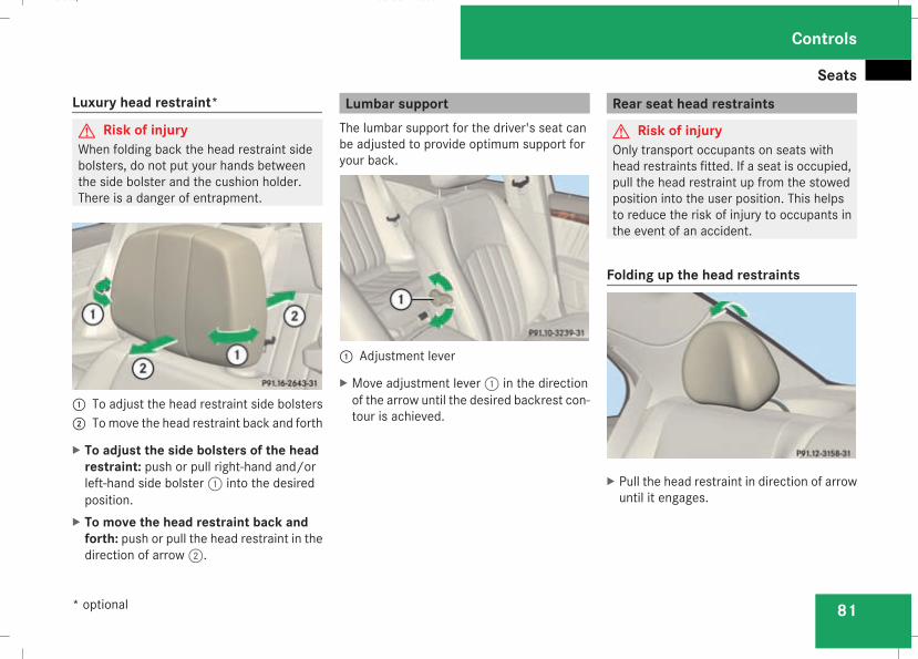
Seats
81
Luxury head restraint*
G Risk of injuryWhen folding back the head restraint sidebolsters, do not put your hands betweenthe side bolster and the cushion holder.There is a danger of entrapment.
1 To adjust the head restraint side bolsters2 Tomove the head restraint back and forth
X To adjust the side bolsters of the headrestraint: push or pull right-hand and/orleft-hand side bolster1 into the desiredposition.
X To move the head restraint back andforth: push or pull the head restraint in thedirection of arrow2.
Lumbar supportThe lumbar support for the driver's seat canbe adjusted to provide optimum support foryour back.
1 Adjustment lever
X Move adjustment lever1 in the directionof the arrow until the desired backrest con-tour is achieved.
Rear seat head restraints
G Risk of injuryOnly transport occupants on seats withhead restraints fitted. If a seat is occupied,pull the head restraint up from the stowedposition into the user position. This helpsto reduce the risk of injury to occupants inthe event of an accident.
Folding up the head restraints
X Pull the head restraint in direction of arrowuntil it engages.
Controls
* optional
211_AKB; 2; 5, en-GBmkalafa, Version: 2.9.4
2008-02-29T16:57:07+01:00 - Seite 81
Z
Dateiname: 6515_3416_02_buchblock.pdf; preflight
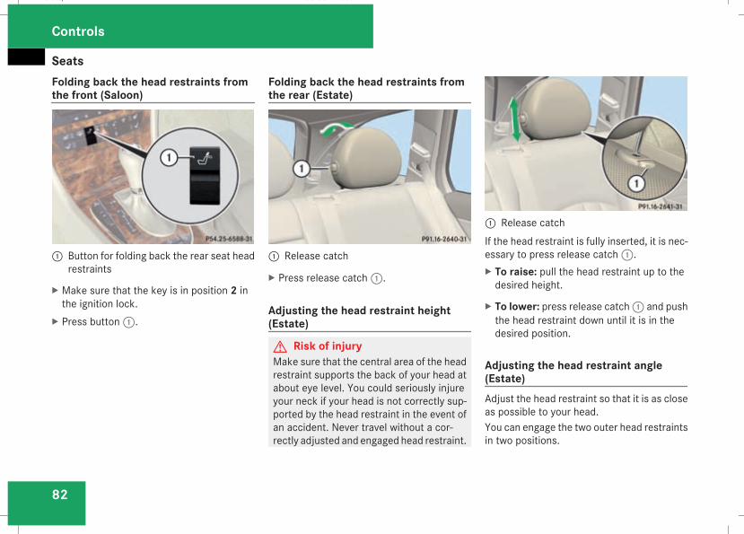
Seats
82
Folding back the head restraints fromthe front (Saloon)
1 Button for folding back the rear seat headrestraints
X Make sure that the key is in position 2 inthe ignition lock.
X Press button1.
Folding back the head restraints fromthe rear (Estate)
1 Release catch
X Press release catch1.
Adjusting the head restraint height(Estate)
G Risk of injuryMake sure that the central area of the headrestraint supports the back of your head atabout eye level. You could seriously injureyour neck if your head is not correctly sup-ported by the head restraint in the event ofan accident. Never travel without a cor-rectly adjusted and engaged head restraint.
1 Release catchIf the head restraint is fully inserted, it is nec-essary to press release catch1.X To raise: pull the head restraint up to thedesired height.
X To lower: press release catch1 and pushthe head restraint down until it is in thedesired position.
Adjusting the head restraint angle(Estate)Adjust the head restraint so that it is as closeas possible to your head.You can engage the two outer head restraintsin two positions.
Controls
211_AKB; 2; 5, en-GBmkalafa, Version: 2.9.4
2008-02-29T16:57:07+01:00 - Seite 82
Dateiname: 6515_3416_02_buchblock.pdf; preflight
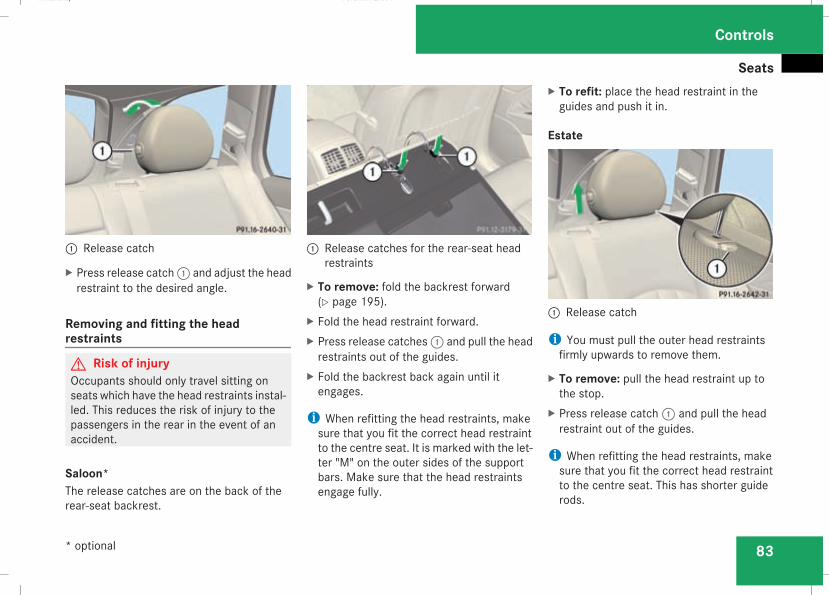
Seats
83
1 Release catch
X Press release catch1 and adjust the headrestraint to the desired angle.
Removing and fitting the headrestraints
G Risk of injuryOccupants should only travel sitting onseats which have the head restraints instal-led. This reduces the risk of injury to thepassengers in the rear in the event of anaccident.
Saloon*The release catches are on the back of therear-seat backrest.
1 Release catches for the rear-seat headrestraints
X To remove: fold the backrest forward(Y page 195).
X Fold the head restraint forward.X Press release catches1 and pull the headrestraints out of the guides.
X Fold the backrest back again until itengages.
i When refitting the head restraints, makesure that you fit the correct head restraintto the centre seat. It is marked with the let-ter "M" on the outer sides of the supportbars. Make sure that the head restraintsengage fully.
X To refit: place the head restraint in theguides and push it in.
Estate
1 Release catch
i You must pull the outer head restraintsfirmly upwards to remove them.
X To remove: pull the head restraint up tothe stop.
X Press release catch1 and pull the headrestraint out of the guides.
i When refitting the head restraints, makesure that you fit the correct head restraintto the centre seat. This has shorter guiderods.
Controls
* optional
211_AKB; 2; 5, en-GBmkalafa, Version: 2.9.4
2008-02-29T16:57:07+01:00 - Seite 83
Z
Dateiname: 6515_3416_02_buchblock.pdf; preflight
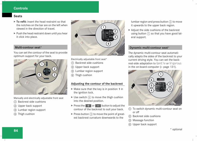
Seats
84
X To refit: insert the head restraint so thatthe notches on the bar are on the left whenviewed in the direction of travel.
X Push the head restraint down until you hearit click into place.
Multi-contour seat*You can set the contour of the seat to provideoptimum support for your back.
Manually and electrically adjustable front seat1 Backrest side cushions2 Upper back support3 Lumbar region support4 Thigh cushion
Electrically adjustable front seat*1 Backrest side cushions2 Upper back support3 Lumbar region support4 Thigh cushion
Adjusting the contour of the backrestX Make sure that the key is in position 1 inthe ignition lock.
X Use switch4 to move the thigh cushioninto the desired position.
X Press theæ orç button to adjust thecontour of the backrest to suit your back.
X Press button3 to move the point of great-est backrest curvature downwards to the
lumbar region and press button2 to moveit upwards to the upper back region.
X Adjust the side cushions of the backrestusing button1 so that you have good lat-eral support.
Dynamic multi-contour seat*The dynamic multi-contour seat automati-cally adapts the sides of the backrest to yourcurrent driving style. You can set the back-rest-side adaptation to Gentle or Vigorousin the on-board computer (Y page 131).
1 To switch dynamic multi-contour seat onor off2 Backrest side cushions3 Massage function4 Upper back support
Controls
* optional
211_AKB; 2; 5, en-GBmkalafa, Version: 2.9.4
2008-02-29T16:57:07+01:00 - Seite 84
Dateiname: 6515_3416_02_buchblock.pdf; preflight
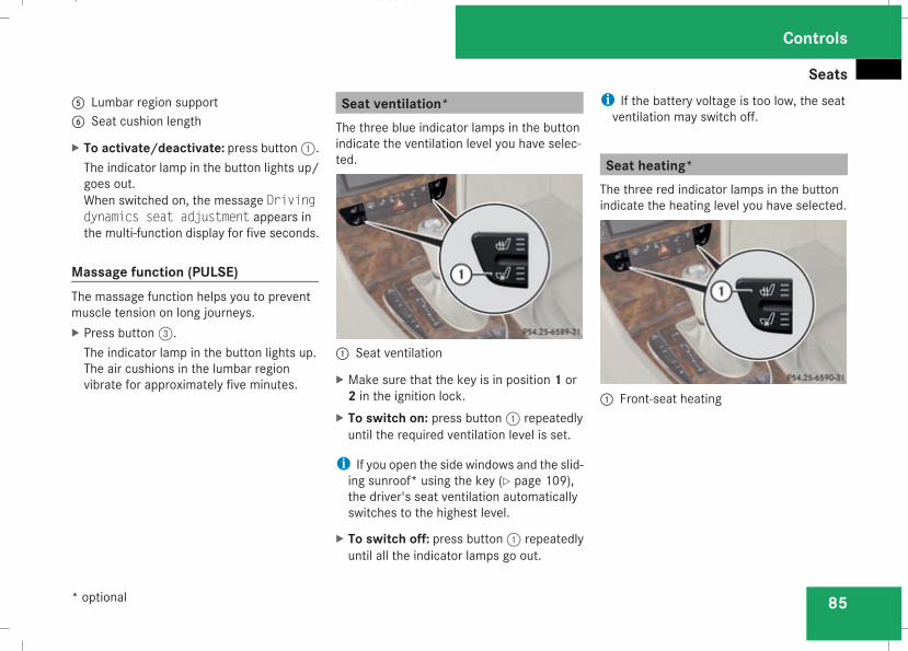
Seats
85
5 Lumbar region support6 Seat cushion length
X To activate/deactivate: press button1.The indicator lamp in the button lights up/goes out.When switched on, the message Drivingdynamics seat adjustment appears inthe multi-function display for five seconds.
Massage function (PULSE)The massage function helps you to preventmuscle tension on long journeys.X Press button3.The indicator lamp in the button lights up.The air cushions in the lumbar regionvibrate for approximately five minutes.
Seat ventilation*The three blue indicator lamps in the buttonindicate the ventilation level you have selec-ted.
1 Seat ventilation
X Make sure that the key is in position 1 or2 in the ignition lock.
X To switch on: press button1 repeatedlyuntil the required ventilation level is set.
i If you open the side windows and the slid-ing sunroof* using the key (Y page 109),the driver's seat ventilation automaticallyswitches to the highest level.
X To switch off: press button1 repeatedlyuntil all the indicator lamps go out.
i If the battery voltage is too low, the seatventilation may switch off.
Seat heating*The three red indicator lamps in the buttonindicate the heating level you have selected.
1 Front-seat heating
Controls
* optional
211_AKB; 2; 5, en-GBmkalafa, Version: 2.9.4
2008-02-29T16:57:07+01:00 - Seite 85
Z
Dateiname: 6515_3416_02_buchblock.pdf; preflight
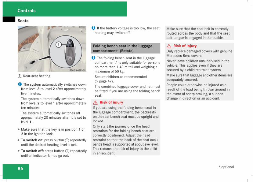
Seats
86
1 Rear-seat heating
i The system automatically switches downfrom level 3 to level 2 after approximatelyfive minutes.The system automatically switches downfrom level 2 to level 1 after approximatelyten minutes.The system automatically switches offapproximately 20 minutes after it is set tolevel 1.
X Make sure that the key is in position 1 or2 in the ignition lock.
X To switch on: press button1 repeatedlyuntil the desired heating level is set.
X To switch off: press button1 repeatedlyuntil all indicator lamps go out.
i If the battery voltage is too low, the seatheating may switch off.
Folding bench seat in the luggagecompartment* (Estate)i The folding bench seat in the luggagecompartment* is only suitable for personsno more than 1.40 m tall and weighing amaximum of 50 kg.Secure children as recommended(Y page 47).The combined luggage cover and net mustbe fitted if you are using the folding benchseat.
G Risk of injuryIf you are using the folding bench seat inthe luggage compartment, the backrestson the rear bench seat must be upright andlocked.Only start the journey once the headrestraints for the folding bench seat arecorrectly positioned. Adjust the headrestraint so that the back of the seat occu-pant's head is supported at about eye level.This reduces the risk of injury to the childin an accident.
Make sure that the seat belt is correctlyrouted across the body and that the seatbelt tongue is engaged in the buckle.
G Risk of injuryOnly replace damaged covers with genuineMercedes-Benz covers.Never leave children unsupervised in thevehicle. This applies even if they aresecured by a child restraint system.Make sure that luggage and other items areadequately secured.People could otherwise be injured as aresult of the load being thrown around inthe event of sharp braking, a suddenchange in direction or an accident.
Controls
* optional
211_AKB; 2; 5, en-GBmkalafa, Version: 2.9.4
2008-02-29T16:57:07+01:00 - Seite 86
Dateiname: 6515_3416_02_buchblock.pdf; preflight
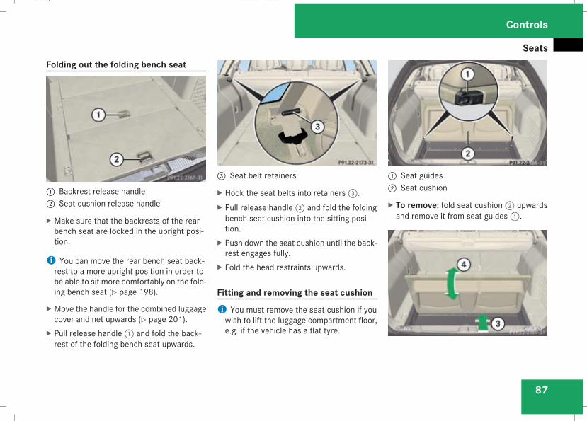
Seats
87
Folding out the folding bench seat
1 Backrest release handle2 Seat cushion release handle
X Make sure that the backrests of the rearbench seat are locked in the upright posi-tion.
i You can move the rear bench seat back-rest to a more upright position in order tobe able to sit more comfortably on the fold-ing bench seat (Y page 198).
X Move the handle for the combined luggagecover and net upwards (Y page 201).
X Pull release handle1 and fold the back-rest of the folding bench seat upwards.
3 Seat belt retainers
X Hook the seat belts into retainers3.X Pull release handle2 and fold the foldingbench seat cushion into the sitting posi-tion.
X Push down the seat cushion until the back-rest engages fully.
X Fold the head restraints upwards.
Fitting and removing the seat cushioni You must remove the seat cushion if youwish to lift the luggage compartment floor,e.g. if the vehicle has a flat tyre.
1 Seat guides2 Seat cushion
X To remove: fold seat cushion2 upwardsand remove it from seat guides1.
Controls
211_AKB; 2; 5, en-GBmkalafa, Version: 2.9.4
2008-02-29T16:57:07+01:00 - Seite 87
Z
Dateiname: 6515_3416_02_buchblock.pdf; preflight
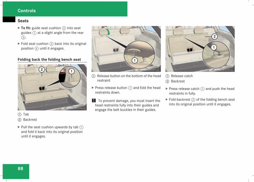
Seats
88
X To fit: guide seat cushion2 into seatguides1 at a slight angle from the rear3.
X Fold seat cushion2 back into its originalposition4 until it engages.
Folding back the folding bench seat
1 Tab2 Backrest
X Pull the seat cushion upwards by tab1and fold it back into its original positionuntil it engages.
1 Release button on the bottom of the headrestraint
X Press release button1 and fold the headrestraints down.
! To prevent damage, you must insert thehead restraints fully into their guides andengage the belt buckles in their guides.
1 Release catch2 Backrest
X Press release catch1 and push the headrestraints in fully.
X Fold backrest2 of the folding bench seatinto its original position until it engages.
Controls
211_AKB; 2; 5, en-GBmkalafa, Version: 2.9.4
2008-02-29T16:57:07+01:00 - Seite 88
Dateiname: 6515_3416_02_buchblock.pdf; preflight
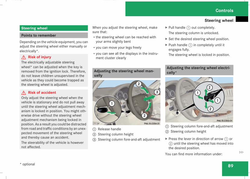
Steering wheel
89
Steering wheel
Points to rememberDepending on the vehicle equipment, you canadjust the steering wheel either manually orelectrically*.G Risk of injuryThe electrically adjustable steeringwheel* can be adjusted when the key isremoved from the ignition lock. Therefore,do not leave children unsupervised in thevehicle as they could become trapped asthe steering wheel is adjusted.
G Risk of accidentOnly adjust the steering wheel when thevehicle is stationary and do not pull awayuntil the steering wheel adjustment mech-anism is locked in position. You might oth-erwise drive without the steering wheeladjustment mechanism being locked inposition. As a result you could be distractedfrom road and traffic conditions by an unex-pected movement of the steering wheeland thereby cause an accident.The steerability of the vehicle is howevernot affected.
When you adjust the steering wheel, makesure that:Rthe steering wheel can be reached withyour arms slightly bent
Ryou can move your legs freelyRyou can see all the displays in the instru-ment cluster clearly
Adjusting the steering wheel man-ually
1 Release handle2 Steering column height3 Steering column fore-and-aft adjustment
X Pull handle1 out completely.The steering column is unlocked.
X Set the desired steering wheel position.X Push handle1 in completely until itengages fully.The steering wheel is locked in position.
Adjusting the steering wheel electri-cally*
1 Steering column fore-and-aft adjustment2 Steering column height
X Press the lever in direction of arrow1 or2 until the steering wheel has moved intothe desired position.
You can find more information under:
Controls
* optional
211_AKB; 2; 5, en-GBmkalafa, Version: 2.9.4
2008-02-29T16:57:07+01:00 - Seite 89
Z
Dateiname: 6515_3416_02_buchblock.pdf; preflight
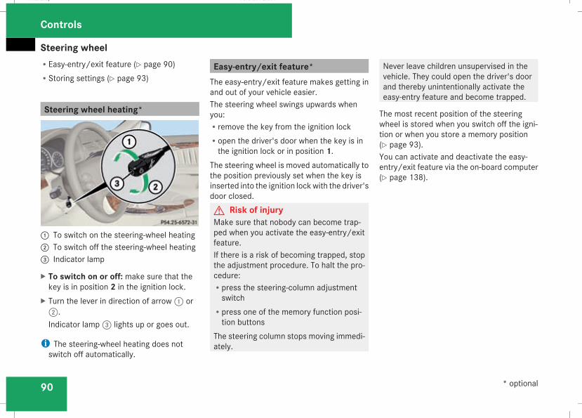
Steering wheel
90
REasy-entry/exit feature (Y page 90)RStoring settings (Y page 93)
Steering wheel heating*
1 To switch on the steering-wheel heating2 To switch off the steering-wheel heating3 Indicator lamp
X To switch on or off: make sure that thekey is in position 2 in the ignition lock.
X Turn the lever in direction of arrow1 or2.Indicator lamp3 lights up or goes out.
i The steering-wheel heating does notswitch off automatically.
Easy-entry/exit feature*The easy-entry/exit feature makes getting inand out of your vehicle easier.The steering wheel swings upwards whenyou:Rremove the key from the ignition lockRopen the driver's door when the key is inthe ignition lock or in position 1.
The steering wheel is moved automatically tothe position previously set when the key isinserted into the ignition lockwith the driver'sdoor closed.G Risk of injuryMake sure that nobody can become trap-ped when you activate the easy-entry/exitfeature.If there is a risk of becoming trapped, stopthe adjustment procedure. To halt the pro-cedure:Rpress the steering-column adjustmentswitch
Rpress one of the memory function posi-tion buttons
The steering column stops moving immedi-ately.
Never leave children unsupervised in thevehicle. They could open the driver's doorand thereby unintentionally activate theeasy-entry feature and become trapped.
The most recent position of the steeringwheel is stored when you switch off the igni-tion or when you store a memory position(Y page 93).You can activate and deactivate the easy-entry/exit feature via the on-board computer(Y page 138).
Controls
* optional
211_AKB; 2; 5, en-GBmkalafa, Version: 2.9.4
2008-02-29T16:57:07+01:00 - Seite 90
Dateiname: 6515_3416_02_buchblock.pdf; preflight
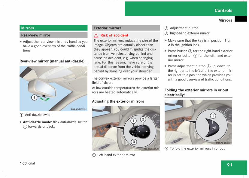
Mirrors
91
Mirrors
Rear-view mirrorX Adjust the rear-view mirror by hand so youhave a good overview of the traffic condi-tions.
Rear-view mirror (manual anti-dazzle)
1 Anti-dazzle switch
X Anti-dazzle mode: flick anti-dazzle switch1 forwards or back.
Exterior mirrors
G Risk of accidentThe exterior mirrors reduce the size of theimage. Objects are actually closer thanthey appear. You could misjudge the dis-tance from vehicles driving behind andcause an accident, e.g. when changinglane. For this reason, make sure of theactual distance from the vehicle drivingbehind by glancing over your shoulder.
The convex exterior mirrors provide a largerfield of vision.At low outside temperatures the exterior mir-rors are heated automatically.
Adjusting the exterior mirrors
1 Left-hand exterior mirror
2 Adjustment button3 Right-hand exterior mirror
X Make sure that the key is in position 1 or2 in the ignition lock.
X Press button3 for the right-hand exteriormirror or button1 for the left-hand exte-rior mirror.
X Press adjustment button2 up, down, tothe right or to the left until the exterior mir-ror is set to a position which provides youwith a good overview of traffic conditions.
Folding the exterior mirrors in or outelectrically*
1 To fold the exterior mirrors in or out
Controls
* optional
211_AKB; 2; 5, en-GBmkalafa, Version: 2.9.4
2008-02-29T16:57:07+01:00 - Seite 91
Z
Dateiname: 6515_3416_02_buchblock.pdf; preflight
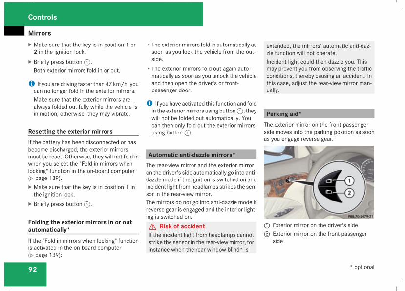
Mirrors
92
X Make sure that the key is in position 1 or2 in the ignition lock.
X Briefly press button1.Both exterior mirrors fold in or out.
i If you are driving faster than 47 km/h, youcan no longer fold in the exterior mirrors.Make sure that the exterior mirrors arealways folded out fully while the vehicle isin motion; otherwise, they may vibrate.
Resetting the exterior mirrorsIf the battery has been disconnected or hasbecome discharged, the exterior mirrorsmust be reset. Otherwise, they will not fold inwhen you select the "Fold in mirrors whenlocking" function in the on-board computer(Y page 139).X Make sure that the key is in position 1 inthe ignition lock.
X Briefly press button1.
Folding the exterior mirrors in or outautomatically*If the "Fold in mirrors when locking" functionis activated in the on-board computer(Y page 139):
RThe exteriormirrors fold in automatically assoon as you lock the vehicle from the out-side.
RThe exterior mirrors fold out again auto-matically as soon as you unlock the vehicleand then open the driver's or front-passenger door.
i If you have activated this function and foldin the exteriormirrors using button1, theywill not be folded out automatically. Youcan then only fold out the exterior mirrorsusing button1.
Automatic anti-dazzle mirrors*The rear-view mirror and the exterior mirroron the driver's side automatically go into anti-dazzle mode if the ignition is switched on andincident light fromheadlamps strikes the sen-sor in the rear-view mirror.The mirrors do not go into anti-dazzle mode ifreverse gear is engaged and the interior light-ing is switched on.G Risk of accidentIf the incident light from headlamps cannotstrike the sensor in the rear-viewmirror, forinstance when the rear window blind* is
extended, the mirrors' automatic anti-daz-zle function will not operate.Incident light could then dazzle you. Thismay prevent you from observing the trafficconditions, thereby causing an accident. Inthis case, adjust the rear-view mirror man-ually.
Parking aid*The exterior mirror on the front-passengerside moves into the parking position as soonas you engage reverse gear.
1 Exterior mirror on the driver's side2 Exterior mirror on the front-passenger
side
Controls
* optional
211_AKB; 2; 5, en-GBmkalafa, Version: 2.9.4
2008-02-29T16:57:07+01:00 - Seite 92
Dateiname: 6515_3416_02_buchblock.pdf; preflight
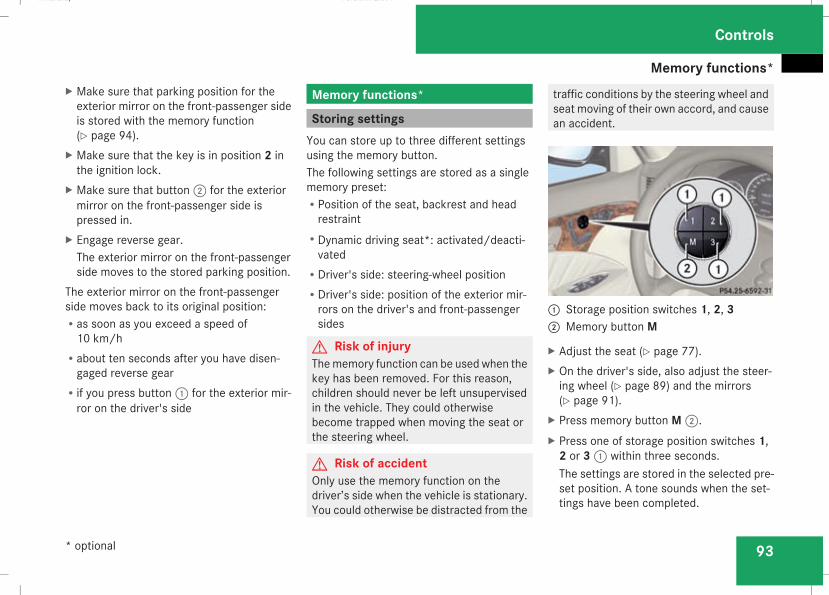
Memory functions*
93
X Make sure that parking position for theexterior mirror on the front-passenger sideis stored with the memory function(Y page 94).
X Make sure that the key is in position 2 inthe ignition lock.
X Make sure that button2 for the exteriormirror on the front-passenger side ispressed in.
X Engage reverse gear.The exterior mirror on the front-passengerside moves to the stored parking position.
The exterior mirror on the front-passengerside moves back to its original position:Ras soon as you exceed a speed of10 km/h
Rabout ten seconds after you have disen-gaged reverse gear
Rif you press button1 for the exterior mir-ror on the driver's side
Memory functions*
Storing settingsYou can store up to three different settingsusing the memory button.The following settings are stored as a singlememory preset:RPosition of the seat, backrest and headrestraint
RDynamic driving seat*: activated/deacti-vated
RDriver's side: steering-wheel positionRDriver's side: position of the exterior mir-rors on the driver's and front-passengersides
G Risk of injuryThememory function can be used when thekey has been removed. For this reason,children should never be left unsupervisedin the vehicle. They could otherwisebecome trapped when moving the seat orthe steering wheel.
G Risk of accidentOnly use the memory function on thedriver’s side when the vehicle is stationary.You could otherwise be distracted from the
traffic conditions by the steering wheel andseat moving of their own accord, and causean accident.
1 Storage position switches 1, 2, 32 Memory button M
X Adjust the seat (Y page 77).X On the driver's side, also adjust the steer-ing wheel (Y page 89) and the mirrors(Y page 91).
X Press memory button M2.X Press one of storage position switches 1,2 or 31 within three seconds.The settings are stored in the selected pre-set position. A tone sounds when the set-tings have been completed.
Controls
* optional
211_AKB; 2; 5, en-GBmkalafa, Version: 2.9.4
2008-02-29T16:57:07+01:00 - Seite 93
Z
Dateiname: 6515_3416_02_buchblock.pdf; preflight
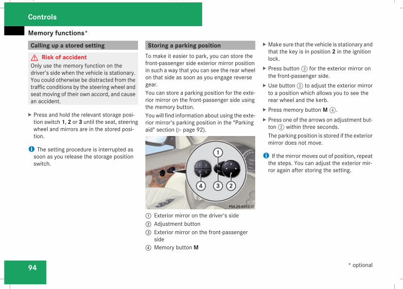
Memory functions*
94
Calling up a stored setting
G Risk of accidentOnly use the memory function on thedriver’s side when the vehicle is stationary.You could otherwise be distracted from thetraffic conditions by the steering wheel andseat moving of their own accord, and causean accident.
X Press and hold the relevant storage posi-tion switch 1, 2 or 3 until the seat, steeringwheel and mirrors are in the stored posi-tion.
i The setting procedure is interrupted assoon as you release the storage positionswitch.
Storing a parking positionTo make it easier to park, you can store thefront-passenger side exterior mirror positionin such a way that you can see the rear wheelon that side as soon as you engage reversegear.You can store a parking position for the exte-rior mirror on the front-passenger side usingthe memory button.Youwill find information about using the exte-rior mirror's parking position in the "Parkingaid" section (Y page 92).
1 Exterior mirror on the driver's side2 Adjustment button3 Exterior mirror on the front-passenger
side4 Memory button M
X Make sure that the vehicle is stationary andthat the key is in position 2 in the ignitionlock.
X Press button3 for the exterior mirror onthe front-passenger side.
X Use button2 to adjust the exterior mirrorto a position which allows you to see therear wheel and the kerb.
X Press memory button M4.X Press one of the arrows on adjustment but-ton2 within three seconds.The parking position is stored if the exteriormirror does not move.
i If the mirror moves out of position, repeatthe steps. You can adjust the exterior mir-ror again after storing the setting.
Controls
* optional
211_AKB; 2; 5, en-GBmkalafa, Version: 2.9.4
2008-02-29T16:57:07+01:00 - Seite 94
Dateiname: 6515_3416_02_buchblock.pdf; preflight
Seat belts
95
Seat belts
Wearing seat beltsSeat belts are the most effective means ofrestraining the movement of vehicle occu-pants in the event of an accident. Thisreduces the risk of vehicle occupants cominginto contact with the vehicle interior.G Risk of injuryA seat belt which is not worn correctly, orwhich has not been engaged in the seat beltbuckle correctly, cannot perform its inten-ded protective function. Under certain cir-cumstances this could cause severe oreven fatal injuries.Make sure that all occupants – in particular,pregnant women – wear their seat belt cor-rectly at all times.RThe seat belt must pass closely over yourbody and must not be twisted. Youshould therefore avoid wearing bulkyclothing (e.g. a winter coat). The shoulderbelt section must be routed across themiddle of your shoulder – on no accountacross your neck or under your arm – andpulled tight against your upper body. Thelap belt must always pass across your lapas low down as possible, i.e. over your
hip joints – not across your abdomen. Ifnecessary, push down the belt strapslightly and then retighten it in the roll-updirection.
RDo not route the belt strap across sharpor fragile objects, especially if these arelocated on or in your clothing, e.g. spec-tacles, pencils, keys, etc. The seat beltstrap could be damaged and tear in anaccident and you or other vehicle occu-pants could be injured.
ROnly one person should use each seatbelt at any one time. Childrenmust nevertravel sitting on the lap of other occu-pants. It would not be possible to restrainthe child in the event of a sudden changein direction, braking or an accident. Thiscould result in severe or even fatal inju-ries to the child and other occupants.
RPersons less than 1.50 m tall cannotwear the seat belts correctly. For thisreason, secure persons less than 1.50 mtall in specially designed, suitablerestraint systems.
RChildren less than 1.50 m tall or under12 years of age cannot wear the seatbelts properly. Therefore, always securethese children in suitable child restraint
systems on suitable vehicle seats. Youcan find more information under "Chil-dren in the vehicle" in the "Safety" sec-tion of the Owner's Manual. Follow themanufacturer's installation instructionswhen fitting the child restraint system.
RDonot secure any objectswith a seat beltif the seat belt is also being used by oneof the vehicle's occupants.
G Risk of injuryThe seat belt does not offer the intendedlevel of protection unless the backrest isalmost vertical. Under certain circumstan-ces this could cause severe or even fatalinjuries.Before starting a journey, make sure thatthe seat is properly adjusted and that thebackrest is almost vertical.
G Risk of injuryA dirty or damaged seat belt or a seat beltthat has been subjected to a load in anaccident or modified no longer offers theintended level of protection. Under certaincircumstances this could cause severe oreven fatal injuries.
Controls
211_AKB; 2; 5, en-GBmkalafa, Version: 2.9.4
2008-02-29T16:57:07+01:00 - Seite 95
Z
Dateiname: 6515_3416_02_buchblock.pdf; preflight
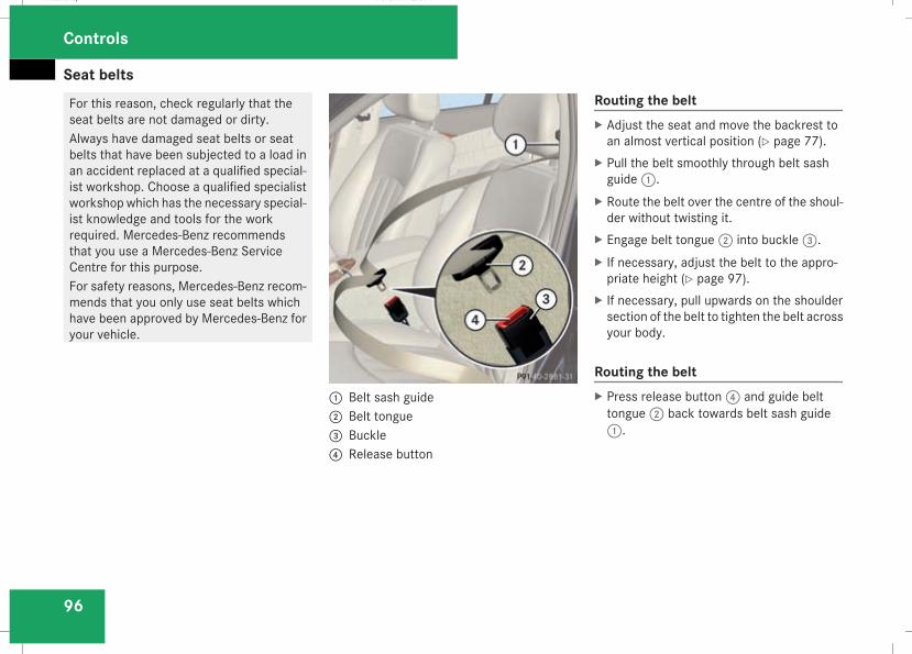
Seat belts
96
For this reason, check regularly that theseat belts are not damaged or dirty.Always have damaged seat belts or seatbelts that have been subjected to a load inan accident replaced at a qualified special-ist workshop. Choose a qualified specialistworkshop which has the necessary special-ist knowledge and tools for the workrequired. Mercedes-Benz recommendsthat you use a Mercedes-Benz ServiceCentre for this purpose.For safety reasons, Mercedes-Benz recom-mends that you only use seat belts whichhave been approved by Mercedes-Benz foryour vehicle.
1 Belt sash guide2 Belt tongue3 Buckle4 Release button
Routing the beltX Adjust the seat and move the backrest toan almost vertical position (Y page 77).
X Pull the belt smoothly through belt sashguide1.
X Route the belt over the centre of the shoul-der without twisting it.
X Engage belt tongue2 into buckle3.X If necessary, adjust the belt to the appro-priate height (Y page 97).
X If necessary, pull upwards on the shouldersection of the belt to tighten the belt acrossyour body.
Routing the beltX Press release button4 and guide belttongue2 back towards belt sash guide1.
Controls
211_AKB; 2; 5, en-GBmkalafa, Version: 2.9.4
2008-02-29T16:57:07+01:00 - Seite 96
Dateiname: 6515_3416_02_buchblock.pdf; preflight
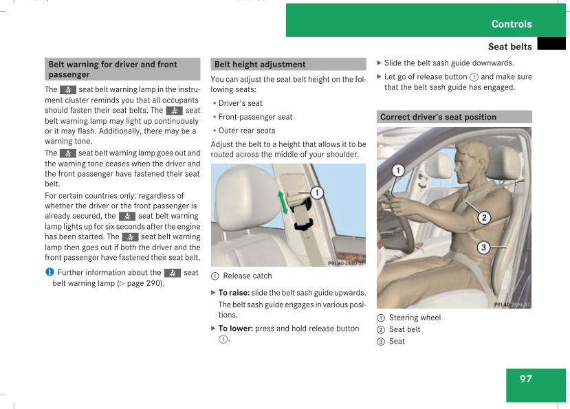
Seat belts
97
Belt warning for driver and frontpassengerThe< seat belt warning lamp in the instru-ment cluster reminds you that all occupantsshould fasten their seat belts. The< seatbelt warning lamp may light up continuouslyor it may flash. Additionally, there may be awarning tone.The< seat belt warning lamp goes out andthe warning tone ceases when the driver andthe front passenger have fastened their seatbelt.For certain countries only: regardless ofwhether the driver or the front passenger isalready secured, the< seat belt warninglamp lights up for six seconds after the enginehas been started. The< seat belt warninglamp then goes out if both the driver and thefront passenger have fastened their seat belt.
i Further information about the< seatbelt warning lamp (Y page 290).
Belt height adjustmentYou can adjust the seat belt height on the fol-lowing seats:RDriver's seatRFront-passenger seatROuter rear seatsAdjust the belt to a height that allows it to berouted across the middle of your shoulder.
1 Release catch
X To raise: slide the belt sash guide upwards.The belt sash guide engages in various posi-tions.
X To lower: press and hold release button1.
X Slide the belt sash guide downwards.X Let go of release button1 and make surethat the belt sash guide has engaged.
Correct driver's seat position
1 Steering wheel2 Seat belt3 Seat
Controls
211_AKB; 2; 5, en-GBmkalafa, Version: 2.9.4
2008-02-29T16:57:07+01:00 - Seite 97
Z
Dateiname: 6515_3416_02_buchblock.pdf; preflight
Seat belts
98
G Risk of accidentOnly adjust the driver's seat when the vehi-cle is stationary. You will otherwise be dis-tracted from the road and traffic conditionsand you could lose control of the vehicle asa result of the seat moving. This couldcause an accident.
G Risk of accidentOnly adjust the steering wheel when thevehicle is stationary and do not pull awayuntil the steering wheel adjustment mech-anism is locked in position. You might oth-erwise drive without the steering wheeladjustment mechanism being locked inposition. As a result you could be distractedfrom road and traffic conditions by an unex-pected movement of the steering wheeland thereby cause an accident.The steerability of the vehicle is howevernot affected.
X Check whether seat3 and the headrestraint are adjusted properly(Y page 77).
Make sure that:Ryou are as far away from the driver's frontairbag as possible
Ryou are sitting in a normal upright posi-tion
Ryou can fasten the seat belt properlyRyou have moved the backrest to analmost vertical position
Ryou have set the seat angle so that yourthighs are gently supported
Ryou can depress the pedals properlyRyou have adjusted the head restraint sothat the back of your head is supportedat eye level by the central area of thehead restraint
X Check whether steering wheel1 is adjus-ted properly (Y page 89).Make sure that:Ryou can hold the steeringwheel with yourarms slightly bent
Ryou can move your legs freelyRyou can see all the displays in the instru-ment cluster clearly
X Check whether you have fastened seat belt2 properly (Y page 95).
It should:Rfit snugly across your bodyRbe routed across the middle of yourshoulder
Rrouted in your pelvic area across the hipjoints
Controls
211_AKB; 2; 5, en-GBmkalafa, Version: 2.9.4
2008-02-29T16:57:07+01:00 - Seite 98
Dateiname: 6515_3416_02_buchblock.pdf; preflight
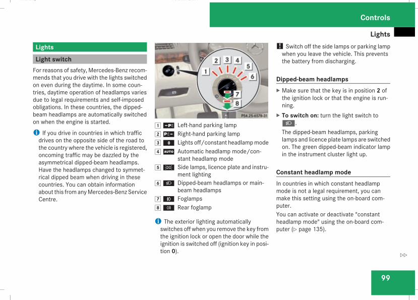
Lights
99
Lights
Light switchFor reasons of safety, Mercedes-Benz recom-mends that you drive with the lights switchedon even during the daytime. In some coun-tries, daytime operation of headlamps variesdue to legal requirements and self-imposedobligations. In these countries, the dipped-beam headlamps are automatically switchedon when the engine is started.
i If you drive in countries in which trafficdrives on the opposite side of the road tothe country where the vehicle is registered,oncoming traffic may be dazzled by theasymmetrical dipped-beam headlamps.Have the headlamps changed to symmet-rical dipped beam when driving in thesecountries. You can obtain informationabout this fromanyMercedes-Benz ServiceCentre.
$a Left-hand parking lamp%g Right-hand parking lamp&M Lights off/constant headlampmode(U Automatic headlamp mode/con-
stant headlamp mode)C Side lamps, licence plate and instru-
ment lighting*B Dipped-beam headlamps or main-
beam headlamps,¥ Foglamps.† Rear foglamp
i The exterior lighting automaticallyswitches off when you remove the key fromthe ignition lock or open the door while theignition is switched off (ignition key in posi-tion 0).
! Switch off the side lamps or parking lampwhen you leave the vehicle. This preventsthe battery from discharging.
Dipped-beam headlampsX Make sure that the key is in position 2 ofthe ignition lock or that the engine is run-ning.
X To switch on: turn the light switch toB.The dipped-beam headlamps, parkinglamps and licence plate lamps are switchedon. The green dipped-beam indicator lampin the instrument cluster light up.
Constant headlamp modeIn countries in which constant headlampmode is not a legal requirement, you canmake this setting using the on-board com-puter.You can activate or deactivate "constantheadlamp mode" using the on-board com-puter (Y page 135).
Controls
211_AKB; 2; 5, en-GBmkalafa, Version: 2.9.4
2008-02-29T16:57:07+01:00 - Seite 99
Z
Dateiname: 6515_3416_02_buchblock.pdf; preflight
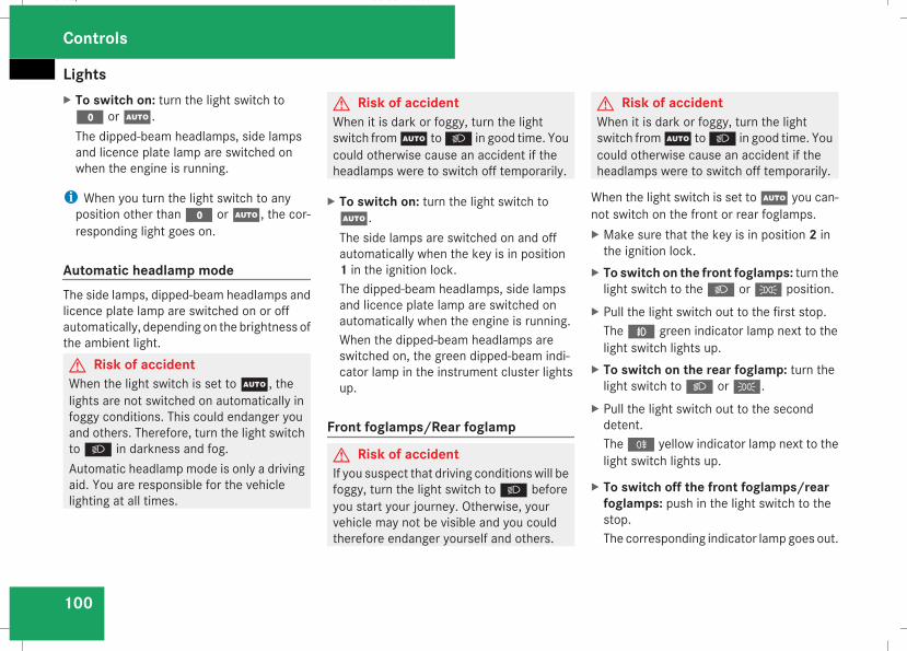
Lights
100
X To switch on: turn the light switch toM orU.The dipped-beam headlamps, side lampsand licence plate lamp are switched onwhen the engine is running.
i When you turn the light switch to anyposition other thanM orU, the cor-responding light goes on.
Automatic headlamp modeThe side lamps, dipped-beam headlamps andlicence plate lamp are switched on or offautomatically, depending on the brightness ofthe ambient light.G Risk of accidentWhen the light switch is set toU, thelights are not switched on automatically infoggy conditions. This could endanger youand others. Therefore, turn the light switchtoB in darkness and fog.Automatic headlamp mode is only a drivingaid. You are responsible for the vehiclelighting at all times.
G Risk of accidentWhen it is dark or foggy, turn the lightswitch fromU toB in good time. Youcould otherwise cause an accident if theheadlamps were to switch off temporarily.
X To switch on: turn the light switch toU.The side lamps are switched on and offautomatically when the key is in position1 in the ignition lock.The dipped-beam headlamps, side lampsand licence plate lamp are switched onautomatically when the engine is running.When the dipped-beam headlamps areswitched on, the green dipped-beam indi-cator lamp in the instrument cluster lightsup.
Front foglamps/Rear foglamp
G Risk of accidentIf you suspect that driving conditionswill befoggy, turn the light switch toB beforeyou start your journey. Otherwise, yourvehicle may not be visible and you couldtherefore endanger yourself and others.
G Risk of accidentWhen it is dark or foggy, turn the lightswitch fromU toB in good time. Youcould otherwise cause an accident if theheadlamps were to switch off temporarily.
When the light switch is set toU you can-not switch on the front or rear foglamps.X Make sure that the key is in position 2 inthe ignition lock.
X To switch on the front foglamps: turn thelight switch to theB orC position.
X Pull the light switch out to the first stop.The¥ green indicator lamp next to thelight switch lights up.
X To switch on the rear foglamp: turn thelight switch toB orC.
X Pull the light switch out to the seconddetent.The† yellow indicator lamp next to thelight switch lights up.
X To switch off the front foglamps/rearfoglamps: push in the light switch to thestop.The corresponding indicator lamp goes out.
Controls
211_AKB; 2; 5, en-GBmkalafa, Version: 2.9.4
2008-02-29T16:57:07+01:00 - Seite 100
Dateiname: 6515_3416_02_buchblock.pdf; preflight
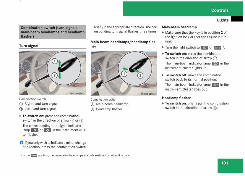
Lights
101
Combination switch (turn signals,main-beam headlamps and headlampflasher)
Turn signal
Combination switch1 Right-hand turn signal2 Left-hand turn signal
X To switch on: press the combinationswitch in the direction of arrow1 or2.The corresponding turn signal indicatorlampK orL in the instrument clus-ter flashes.
i If you onlywish to indicate aminor changeof direction, press the combination switch
briefly in the appropriate direction. The cor-responding turn signal flashes three times.
Main-beam headlamps/headlamp flas-her
Combination switch1 Main-beam headlamp2 Headlamp flasher
Main-beam headlampX Make sure that the key is in position 2 ofthe ignition lock or that the engine is run-ning.
X Turn the light switch toB orU16.X To switch on: press the combinationswitch in the direction of arrow1.The main-beam indicator lampA in theinstrument cluster lights up.
X To switch off: move the combinationswitch back to its normal position.The main-beam indicator lampA in theinstrument cluster goes out.
Headlamp flasherX To switch on: briefly pull the combinationswitch in the direction of arrow2.
16 In theU position, the main-beam headlamps are only switched on when it is dark.
Controls
211_AKB; 2; 5, en-GBmkalafa, Version: 2.9.4
2008-02-29T16:57:07+01:00 - Seite 101
Z
Dateiname: 6515_3416_02_buchblock.pdf; preflight
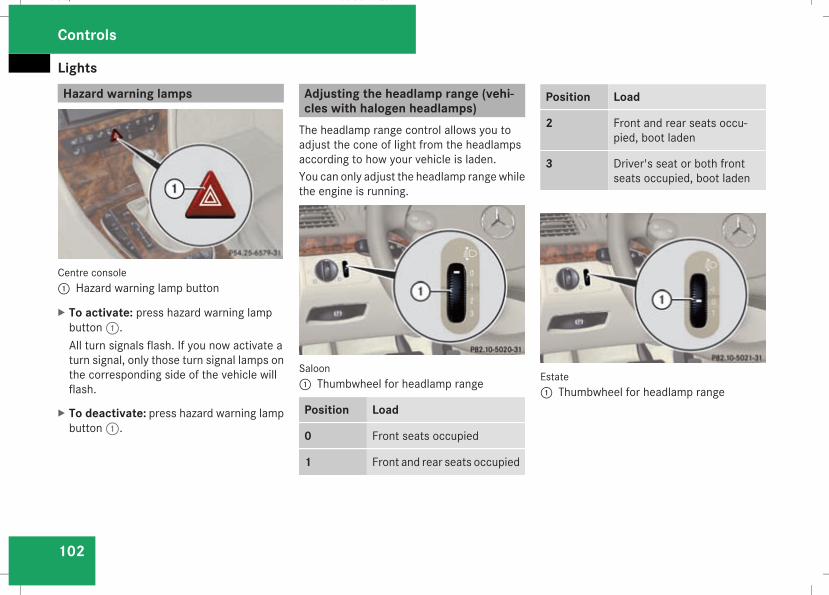
Lights
102
Hazard warning lamps
Centre console1 Hazard warning lamp button
X To activate: press hazard warning lampbutton1.All turn signals flash. If you now activate aturn signal, only those turn signal lamps onthe corresponding side of the vehicle willflash.
X To deactivate: press hazard warning lampbutton1.
Adjusting the headlamp range (vehi-cles with halogen headlamps)The headlamp range control allows you toadjust the cone of light from the headlampsaccording to how your vehicle is laden.You can only adjust the headlamp rangewhilethe engine is running.
Saloon1 Thumbwheel for headlamp range
Position Load
0 Front seats occupied
1 Front and rear seats occupied
Position Load
2 Front and rear seats occu-pied, boot laden
3 Driver's seat or both frontseats occupied, boot laden
Estate1 Thumbwheel for headlamp range
Controls
211_AKB; 2; 5, en-GBmkalafa, Version: 2.9.4
2008-02-29T16:57:07+01:00 - Seite 102
Dateiname: 6515_3416_02_buchblock.pdf; preflight
Lights
103
Position Load
-1 Front and rear seats occupiedorFront and rear seats occu-pied, luggage compartmentladen
0 Front seats occupied
1 Driver's seat occupied, lug-gage compartment laden
X Turn thumbwheel for headlamp range1 tothe position which corresponds to the loadin your vehicle.
Headlamp cleaning system*The headlamps are cleaned automatically ifthe "Wipewithwindscreenwasher fluid" func-tion is operated five times while the lights areon and the engine is running. When youswitch off the ignition, the automatic head-lamp cleaning system is reset and counting isresumed from 0.
Intelligent Light System* (vehicleswith bi-xenon headlamps*)The Intelligent Light System adapts the light-ing of the front headlamps to the prevailingdriving conditions so that the road is illumi-nated better.
i The Intelligent Light System is only activewhen it is dark.
The Intelligent Light System comprises:RActive light functionRCornering light functionRMotorway modeRExtended range foglamps
Active light functionFor the active light function, the dipped-beamheadlamps swivel horizontally. The swivelangle changes according to the respectivedriving situation. The active light function isnot active when the vehicle is stationary.
Cornering light functionSpecially designed headlamps light up thearea into which you are driving when turningcorners.If you are driving at speeds below 40 km/h,the cornering light function is activated eitherby the turn signals or when the steering wheelis turned. If you are driving at speeds above40 km/h the cornering light function is deac-tivated.
Switching onX Make sure that the engine is running.X Switch on the dipped-beam headlamps.X Switch off the fog lights.X Switch on the turn signal.The cornering light on the same side as theturn signal comes on, even if you turn thesteering wheel in the opposite directionafter indicating.
Controls
* optional
211_AKB; 2; 5, en-GBmkalafa, Version: 2.9.4
2008-02-29T16:57:07+01:00 - Seite 103
Z
Dateiname: 6515_3416_02_buchblock.pdf; preflight
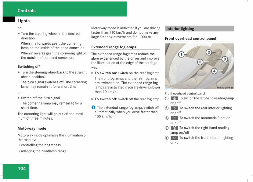
Lights
104
orX Turn the steering wheel in the desireddirection.When in a forwards gear: the corneringlamp on the inside of the bend comes on.When in reverse gear: the cornering light onthe outside of the bend comes on.
Switching offX Turn the steering wheel back to the straightahead position.The turn signal switches off. The corneringlamp may remain lit for a short time.
orX Switch off the turn signal.The cornering lamp may remain lit for ashort time.
The cornering light will go out after a maxi-mum of three minutes.
Motorway modeMotorway mode optimises the illumination ofthe road by:Rcontrolling the brightnessRadapting the headlamp range
Motorway mode is activated if you are drivingfaster than 110 km/h and do not make anylarge steering movements for 1,000 m.
Extended range foglampsThe extended range foglamps reduce theglare experienced by the driver and improvethe illumination of the edge of the carriage-way.X To switch on: switch on the rear foglamp.The front foglamps and the rear foglampare switched on. The extended range fog-lamps are activated if you are driving slowerthan 70 km/h.
X To switch off: switch off the rear foglamp.
i The extended range foglamps switch offautomatically when you drive faster than100 km/h.
Interior lighting
Front overhead control panel
Front overhead control panel1X To switch the left-hand reading lamp
on/off2ò To switch the rear interior lighting
on/off3¡ To switch the automatic function
on/off4X To switch the right-hand reading
lamp on/off5ð To switch the front interior lighting
on/off
Controls
211_AKB; 2; 5, en-GBmkalafa, Version: 2.9.4
2008-02-29T16:57:07+01:00 - Seite 104
Dateiname: 6515_3416_02_buchblock.pdf; preflight
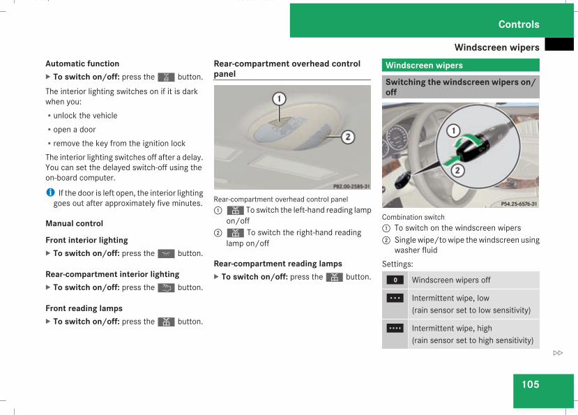
Windscreen wipers
105
Automatic functionX To switch on/off: press the¡ button.
The interior lighting switches on if it is darkwhen you:Runlock the vehicleRopen a doorRremove the key from the ignition lockThe interior lighting switches off after a delay.You can set the delayed switch-off using theon-board computer.
i If the door is left open, the interior lightinggoes out after approximately five minutes.
Manual control
Front interior lightingX To switch on/off: press theð button.
Rear-compartment interior lightingX To switch on/off: press the¦ button.
Front reading lampsX To switch on/off: press theX button.
Rear-compartment overhead controlpanel
Rear-compartment overhead control panel1X To switch the left-hand reading lamp
on/off2X To switch the right-hand reading
lamp on/off
Rear-compartment reading lampsX To switch on/off: press theX button.
Windscreen wipers
Switching the windscreen wipers on/off
Combination switch1 To switch on the windscreen wipers2 Single wipe/towipe thewindscreen using
washer fluidSettings:
M Windscreen wipers off
U Intermittent wipe, low(rain sensor set to low sensitivity)
V Intermittent wipe, high(rain sensor set to high sensitivity)
Controls
211_AKB; 2; 5, en-GBmkalafa, Version: 2.9.4
2008-02-29T16:57:07+01:00 - Seite 105
Z
Dateiname: 6515_3416_02_buchblock.pdf; preflight
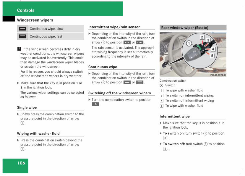
Windscreen wipers
106
u Continuous wipe, slow
t Continuous wipe, fast
! If the windscreen becomes dirty in dryweather conditions, the windscreen wipersmay be activated inadvertently. This couldthen damage the windscreen wiper bladesor scratch the windscreen.For this reason, you should always switchoff the windscreen wipers in dry weather.
X Make sure that the key is in position 1 or2 in the ignition lock.The various wiper settings can be selectedas follows:
Single wipeX Briefly press the combination switch to thepressure point in the direction of arrow2.
Wiping with washer fluidX Press the combination switch beyond thepressure point in the direction of arrow2.
Intermittent wipe/rain sensorX Depending on the intensity of the rain, turnthe combination switch in the direction ofarrow1 to positionU orV.The rain sensor is activated. The appropri-ate wiping frequency is set automaticallyaccording to the intensity of the rain.
Continuous wipeX Depending on the intensity of the rain, turnthe combination switch in the direction ofarrow1 to positionu ort.
Switching off the windscreen wipersX Turn the combination switch to positionM.
Rear window wiper (Estate)
Combination switch1 Switch% To wipe with washer fluid& To switch on intermittent wiping( To switch off intermittent wiping) To wipe with washer fluid
Intermittent wipeX Make sure that the key is in position 1 inthe ignition lock.
X To switch on: turn switch1 to position&.
X To switch off: turn switch1 to position(.
Controls
211_AKB; 2; 5, en-GBmkalafa, Version: 2.9.4
2008-02-29T16:57:07+01:00 - Seite 106
Dateiname: 6515_3416_02_buchblock.pdf; preflight
Side windows
107
Wiping with washer fluidX Make sure that the key is in position 1 inthe ignition lock.
X Turn switch1 to position% or posi-tion) and hold it there until the rearwindow has been cleaned.The rear window is wiped for a further fiveseconds after the switch is released.
Side windows
Opening/closing the side windows
G Risk of injuryMake sure that nobody can become trap-ped between the side window and the doorframe as a side window is opened. Do nottouch or lean against the side window dur-ing the opening procedure. You couldbecome trapped between the side windowand the door frame as the window movesdown. If danger threatens, release theswitch or pull the switch upwards to closethe side window again.
G Risk of injuryMake sure that nobody can become trap-ped as you close a side window. If dangerthreatens, release the switch or press theswitch a second time to open the side win-dow again.
G Risk of injuryNever leave children unsupervised in thevehicle. Always take the key with you whenleaving the vehicle, even if you only leave itfor a short time.
G Risk of injuryDo not leave children unsupervised in thevehicle, even if they are secured in a childrestraint system. The children could:Rbe seriously or even fatally injured onparts of the vehicle
Rbe seriously or even fatally injured byprolonged exposure to extremely high orextremely low temperatures
If children open a door, they could:Rseriously or even fatally injure other peo-ple
Rget out of the vehicle, thereby injuringthemselves or be seriously or even fatallyinjured by a passing vehicle
Activate the child-proof locks if children aretravelling in the vehicle. They could other-wise open doors or windows while the vehi-cle is in motion and thereby injure them-selves or others.
i It is also possible to open and close theside windows from the outside using the"Summer opening" (Y page 109) and "con-venience closing" (Y page 109) featuresrespectively.
Controls
211_AKB; 2; 5, en-GBmkalafa, Version: 2.9.4
2008-02-29T16:57:07+01:00 - Seite 107
Z
Dateiname: 6515_3416_02_buchblock.pdf; preflight
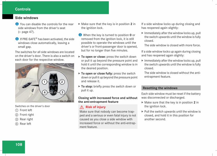
Side windows
108
i You can disable the controls for the rearside windows from the driver's seat(Y page 47).
i If PRE-SAFE® has been activated, the sidewindows close automatically, leaving asmall gap.
The switches for all side windows are locatedon the driver's door. There is also a switch oneach door for the respective window.
Switches on the driver's door1 Front left2 Front right3 Rear right4 Rear left
X Make sure that the key is in position 2 inthe ignition lock.
i When the key is turned to position 0 orremoved from the ignition lock, it is stillpossible to operate the windows until thedriver's or front-passenger door is opened,but for no longer than five minutes.
X To open or close: press the switch downor pull it up beyond the pressure point andhold it until the corresponding window is inthe desired position.
X To open or close fully: press the switchdownor pull it up beyond the pressure pointand release it.
X To stop: briefly press the switch down orpull it up.
Closing with increased force and withoutthe anti-entrapment featureG Risk of injuryMake sure that nobody can become trap-ped and a serious or even fatal injury is notcaused as you close a side window withincreased force or without the anti-entrap-ment feature.
If a side window locks up during closing andhas reopened again slightly:X Immediately after the window locks up, pullthe switch upwards until the window is fullyclosed.The side window is closed with more force.
If a side window locks up again during closingand has reopened again slightly:X Immediately after the window locks up, pullthe switch upwards until the window is fullyclosed.The side window is closed without the anti-entrapment feature.
Resetting the windowsEach side windowmust be reset if the batterywas disconnected or discharged.X Make sure that the key is in position 2 inthe ignition lock.
X Pull the switch upwards until the window isclosed, and hold it in this position foranother second.
Controls
211_AKB; 2; 5, en-GBmkalafa, Version: 2.9.4
2008-02-29T16:57:07+01:00 - Seite 108
Dateiname: 6515_3416_02_buchblock.pdf; preflight
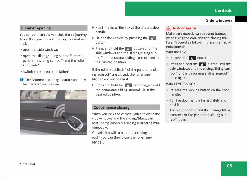
Side windows
109
Summer openingYou can ventilate the vehicle before a journey.To do this, you can use the key to simultane-ously:Ropen the side windowsRopen the sliding/tilting sunroof* or thepanorama sliding sunroof* and the rollersunblinds*
Rswitch on the seat ventilation*
i The "Summer opening" feature can onlybe operated via the key.
X Point the tip of the key at the driver's doorhandle.
X Unlock the vehicle by pressing thekbutton.
X Press and hold thek button until theside windows and the sliding/tilting sun-roof* or panorama sliding sunroof* are inthe desired position.
If the roller sunblinds* of the panorama slid-ing sunroof* are closed, the roller sun-blinds* are opened first.X Press and hold thek button again untilthe panorama sliding sunroof* is in thedesired position.
Convenience closingWhen you lock the vehicle, you can close theside windows and the sliding/tilting sun-roof* or the panorama sliding sunroof* simul-taneously.On vehicles with a panorama sliding sun-roof* you can then close the roller sun-blinds*.
G Risk of injuryMake sure nobody can become trappedwhen using the convenience closing fea-ture. Proceed as follows if there is a risk ofentrapment:With the key:RRelease thej button.RPress and hold thek button until theside windows and the sliding/tilting sun-roof* or the panorama sliding sunroof*open again.
With KEYLESS GO*:RRelease the locking button on the doorhandle.
RPull the door handle immediately andhold it.The side windows and the sliding/tiltingsunroof* or the panorama sliding sun-roof* open.
Controls
* optional
211_AKB; 2; 5, en-GBmkalafa, Version: 2.9.4
2008-02-29T16:57:07+01:00 - Seite 109
Z
Dateiname: 6515_3416_02_buchblock.pdf; preflight
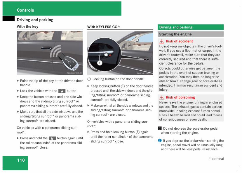
Driving and parking
110
With the key
X Point the tip of the key at the driver's doorhandle.
X Lock the vehicle with thej button.X Keep the button pressed until the side win-dows and the sliding/tilting sunroof* orpanorama sliding sunroof* are fully closed.
X Make sure that all the sidewindows and thesliding/tilting sunroof* or panorama slid-ing sunroof* are closed.
On vehicles with a panorama sliding sun-roof*:X Press and hold thej button again untilthe roller sunblinds* of the panorama slid-ing sunroof* close.
With KEYLESS GO*:
1 Locking button on the door handle
X Keep locking button1 on the door handlepressed until the sidewindows and the slid-ing/tilting sunroof* or panorama slidingsunroof* are fully closed.
X Make sure that all the sidewindows and thesliding/tilting sunroof* or panorama slid-ing sunroof* are closed.
On vehicles with a panorama sliding sun-roof*:X Press and hold locking button1 againuntil the roller sunblinds* of the panoramasliding sunroof* close.
Driving and parking
Starting the engine
G Risk of accidentDo not keep any objects in the driver's foot-well. If you use a floormat or carpet in thedriver's footwell, make sure that they arecorrectly secured and that there is suffi-cient clearance for the pedals.Objects could otherwise get between thepedals in the event of sudden braking oracceleration. You may then no longer beable to brake, change gear or accelerate asintended. Thismay result in an accident andinjury.
G Risk of poisoningNever leave the engine running in enclosedspaces. The exhaust gases contain carbonmonoxide. Inhaling exhaust fumes consti-tutes a health hazard and could lead to lossof consciousness or even death.
! Do not depress the accelerator pedalwhen starting the engine.
i If you depress the brakewhen starting theengine, pedal travel will be unusually longand there will be less pedal resistance.
Controls
* optional
211_AKB; 2; 5, en-GBmkalafa, Version: 2.9.4
2008-02-29T16:57:07+01:00 - Seite 110
Dateiname: 6515_3416_02_buchblock.pdf; preflight
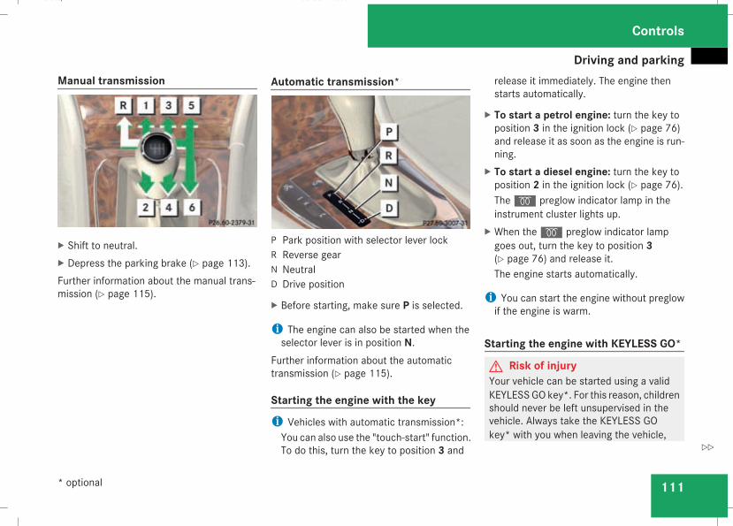
Driving and parking
111
Manual transmission
X Shift to neutral.X Depress the parking brake (Y page 113).Further information about the manual trans-mission (Y page 115).
Automatic transmission*
P Park position with selector lever lockR Reverse gearN NeutralD Drive position
X Before starting, make sure P is selected.
i The engine can also be started when theselector lever is in position N.
Further information about the automatictransmission (Y page 115).
Starting the engine with the key
i Vehicles with automatic transmission*:You can also use the "touch-start" function.To do this, turn the key to position 3 and
release it immediately. The engine thenstarts automatically.
X To start a petrol engine: turn the key toposition 3 in the ignition lock (Y page 76)and release it as soon as the engine is run-ning.
X To start a diesel engine: turn the key toposition 2 in the ignition lock (Y page 76).Theq preglow indicator lamp in theinstrument cluster lights up.
X When theq preglow indicator lampgoes out, turn the key to position 3(Y page 76) and release it.The engine starts automatically.
i You can start the engine without preglowif the engine is warm.
Starting the engine with KEYLESS GO*
G Risk of injuryYour vehicle can be started using a validKEYLESSGO key*. For this reason, childrenshould never be left unsupervised in thevehicle. Always take the KEYLESS GOkey* with you when leaving the vehicle,
Controls
* optional
211_AKB; 2; 5, en-GBmkalafa, Version: 2.9.4
2008-02-29T16:57:07+01:00 - Seite 111
Z
Dateiname: 6515_3416_02_buchblock.pdf; preflight
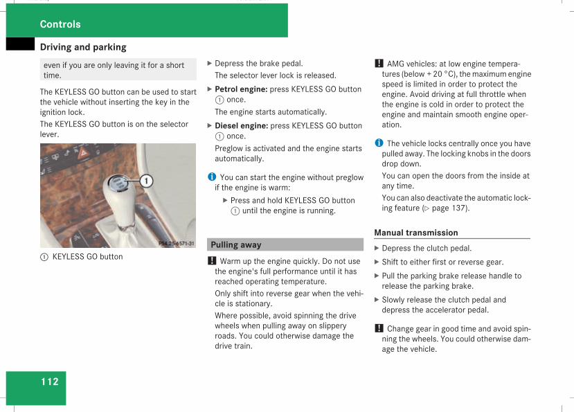
Driving and parking
112
even if you are only leaving it for a shorttime.
The KEYLESS GO button can be used to startthe vehicle without inserting the key in theignition lock.The KEYLESS GO button is on the selectorlever.
1 KEYLESS GO button
X Depress the brake pedal.The selector lever lock is released.
X Petrol engine: press KEYLESS GO button1 once.The engine starts automatically.
X Diesel engine: press KEYLESS GO button1 once.Preglow is activated and the engine startsautomatically.
i You can start the engine without preglowif the engine is warm:X Press and hold KEYLESS GO button1 until the engine is running.
Pulling away! Warm up the engine quickly. Do not usethe engine's full performance until it hasreached operating temperature.Only shift into reverse gear when the vehi-cle is stationary.Where possible, avoid spinning the drivewheels when pulling away on slipperyroads. You could otherwise damage thedrive train.
! AMG vehicles: at low engine tempera-tures (below + 20 °C), themaximumenginespeed is limited in order to protect theengine. Avoid driving at full throttle whenthe engine is cold in order to protect theengine and maintain smooth engine oper-ation.
i The vehicle locks centrally once you havepulled away. The locking knobs in the doorsdrop down.You can open the doors from the inside atany time.You can also deactivate the automatic lock-ing feature (Y page 137).
Manual transmissionX Depress the clutch pedal.X Shift to either first or reverse gear.X Pull the parking brake release handle torelease the parking brake.
X Slowly release the clutch pedal anddepress the accelerator pedal.
! Change gear in good time and avoid spin-ning the wheels. You could otherwise dam-age the vehicle.
Controls
211_AKB; 2; 5, en-GBmkalafa, Version: 2.9.4
2008-02-29T16:57:07+01:00 - Seite 112
Dateiname: 6515_3416_02_buchblock.pdf; preflight
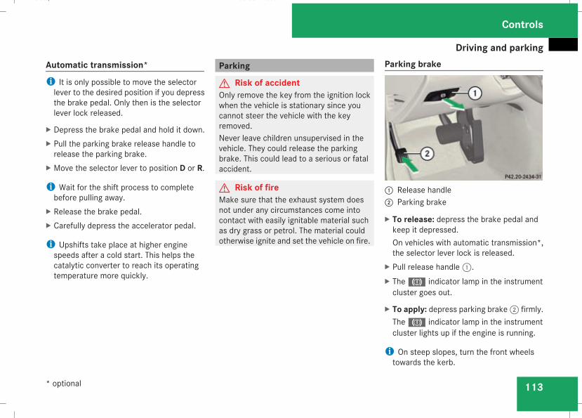
Driving and parking
113
Automatic transmission*i It is only possible to move the selectorlever to the desired position if you depressthe brake pedal. Only then is the selectorlever lock released.
X Depress the brake pedal and hold it down.X Pull the parking brake release handle torelease the parking brake.
X Move the selector lever to position D or R.
i Wait for the shift process to completebefore pulling away.
X Release the brake pedal.X Carefully depress the accelerator pedal.
i Upshifts take place at higher enginespeeds after a cold start. This helps thecatalytic converter to reach its operatingtemperature more quickly.
Parking
G Risk of accidentOnly remove the key from the ignition lockwhen the vehicle is stationary since youcannot steer the vehicle with the keyremoved.Never leave children unsupervised in thevehicle. They could release the parkingbrake. This could lead to a serious or fatalaccident.
G Risk of fireMake sure that the exhaust system doesnot under any circumstances come intocontact with easily ignitable material suchas dry grass or petrol. The material couldotherwise ignite and set the vehicle on fire.
Parking brake
1 Release handle2 Parking brake
X To release: depress the brake pedal andkeep it depressed.On vehicles with automatic transmission*,the selector lever lock is released.
X Pull release handle1.X The3 indicator lamp in the instrumentcluster goes out.
X To apply: depress parking brake2 firmly.The3 indicator lamp in the instrumentcluster lights up if the engine is running.
i On steep slopes, turn the front wheelstowards the kerb.
Controls
* optional
211_AKB; 2; 5, en-GBmkalafa, Version: 2.9.4
2008-02-29T16:57:07+01:00 - Seite 113
Z
Dateiname: 6515_3416_02_buchblock.pdf; preflight
Transmission
114
Switching off the engine
G Risk of accidentIf the engine is not running, there is nopower assistance for the steering andbrakes. Steering and braking then takesmuch more effort.As a result, you might lose control of thevehicle, cause an accident and injure your-self and others.Do not switch off the engine while driving.
Vehicles with manual transmissionX Shift to either first or reverse gear.X Turn the key to position 0(Y page 76) in theignition lock and remove it.The immobiliser is activated.
Vehicles with automatic transmission*X Move the selector lever to P.
Using the keyX Turn the key to position 0(Y page 76) in theignition lock and remove it.The immobiliser is activated.
Using KEYLESS GO*X Press and hold the KEYLESS GO button(Y page 77).The engine stops and all the lamps in theinstrument cluster go out (Y page 26).
Transmission
Introduction to the transmission
G Risk of accidentThe movement of the pedals must not beimpaired in any way. Do not keep anyobjects in the driver's footwell. Make surethat floormats or carpets are correctlysecured and that there is sufficient clear-ance for the pedals.
G Risk of accidentDo not change down for additional enginebraking on a slippery road surface. Thiscould cause the drive wheels to lose theirgrip and the vehicle could skid. This couldcause you to lose control of your vehicleand cause an accident.
Controls
* optional
211_AKB; 2; 5, en-GBmkalafa, Version: 2.9.4
2008-02-29T16:57:07+01:00 - Seite 114
Dateiname: 6515_3416_02_buchblock.pdf; preflight
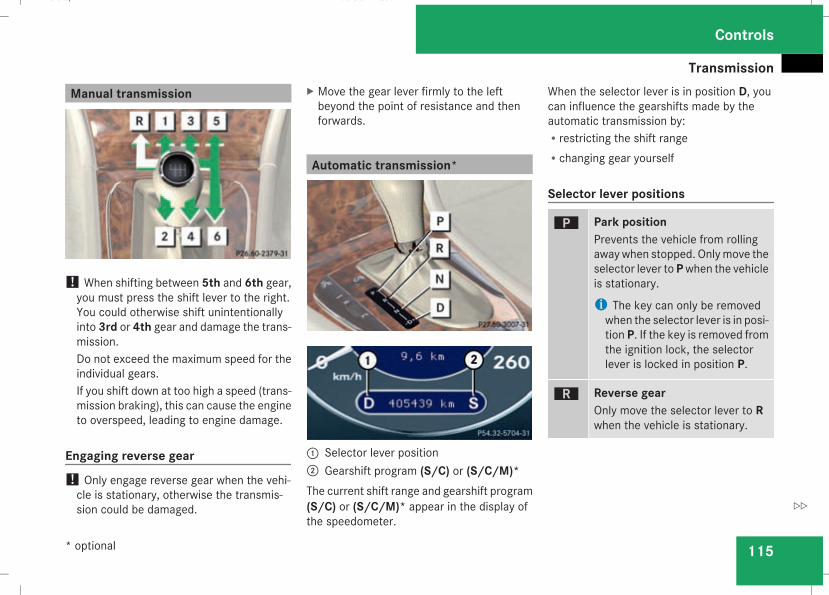
Transmission
115
Manual transmission
! When shifting between 5th and 6th gear,you must press the shift lever to the right.You could otherwise shift unintentionallyinto 3rd or 4th gear and damage the trans-mission.Do not exceed the maximum speed for theindividual gears.If you shift down at too high a speed (trans-mission braking), this can cause the engineto overspeed, leading to engine damage.
Engaging reverse gear! Only engage reverse gear when the vehi-cle is stationary, otherwise the transmis-sion could be damaged.
X Move the gear lever firmly to the leftbeyond the point of resistance and thenforwards.
Automatic transmission*
1 Selector lever position2 Gearshift program (S/C) or (S/C/M)*The current shift range and gearshift program(S/C) or (S/C/M)* appear in the display ofthe speedometer.
When the selector lever is in position D, youcan influence the gearshifts made by theautomatic transmission by:Rrestricting the shift rangeRchanging gear yourself
Selector lever positions
ì Park positionPrevents the vehicle from rollingawaywhen stopped. Onlymove theselector lever toPwhen the vehicleis stationary.
i The key can only be removedwhen the selector lever is in posi-tion P. If the key is removed fromthe ignition lock, the selectorlever is locked in position P.
í Reverse gearOnly move the selector lever to Rwhen the vehicle is stationary.
Controls
* optional
211_AKB; 2; 5, en-GBmkalafa, Version: 2.9.4
2008-02-29T16:57:07+01:00 - Seite 115
Z
Dateiname: 6515_3416_02_buchblock.pdf; preflight
Transmission
116
ë NeutralReleasing the brakes will allow youto move the vehicle freely, e.g. topush it or tow it.Do not move the selector lever toN while you are driving. The auto-matic transmission could other-wise be damaged.If ESP® is deactivated or faulty:only move the selector lever to N ifthe vehicle is in danger of skidding,e.g. on icy roads.
ê DriveThe automatic transmissionchanges gear automatically. Allforward gears are available.
One-touch gearshiftingWhen the selector lever is in position D, youcan perform gearshifts yourself, even on vehi-cles with automatic transmission.X To shift up: briefly press the selector leverto the right towards D+.The automatic transmission shifts up to thenext gear, depending on the gearshift pro-
gram selected. This also extends the shiftrange.
X To shift down: briefly press the selectorlever to the left towards D–.The automatic transmission shifts down tothe next gear, depending on the gear cur-rently selected. This also restricts the shiftrange.
i To prevent the engine from overrevving,the automatic transmission does not shiftdown if you push the selector lever towardsD– while driving at too high a speed.
X To derestrict the shift range: press andhold the selector lever towards D+ until Dis shown once more in the display.The automatic transmission shifts from thecurrent shift range directly to D.
X To select the most effective shiftrange: press and hold the selector lever tothe left towards D–.The automatic transmission will shift to arange which allows ideal acceleration anddeceleration. To do this, the automatictransmission will shift down one or moregears.
Shift rangesWhen the selector lever is in position D, it ispossible to restrict or derestrict the shiftrange for the automatic transmission.X Briefly press the selector lever to the righttowards D+ or to the left towards D–.The shift range selected is shown in thedisplay. The automatic transmission shiftsonly as far as the selected gear.
i If the maximum engine speed for the shiftrange is reached and you continue to accel-erate, the automatic transmission shifts upin order to prevent the engine from over-revving even if the shift range is restricted.
Driving situation
è The braking effect of the engine canbe used in this position.
Controls
211_AKB; 2; 5, en-GBmkalafa, Version: 2.9.4
2008-02-29T16:57:07+01:00 - Seite 116
Dateiname: 6515_3416_02_buchblock.pdf; preflight
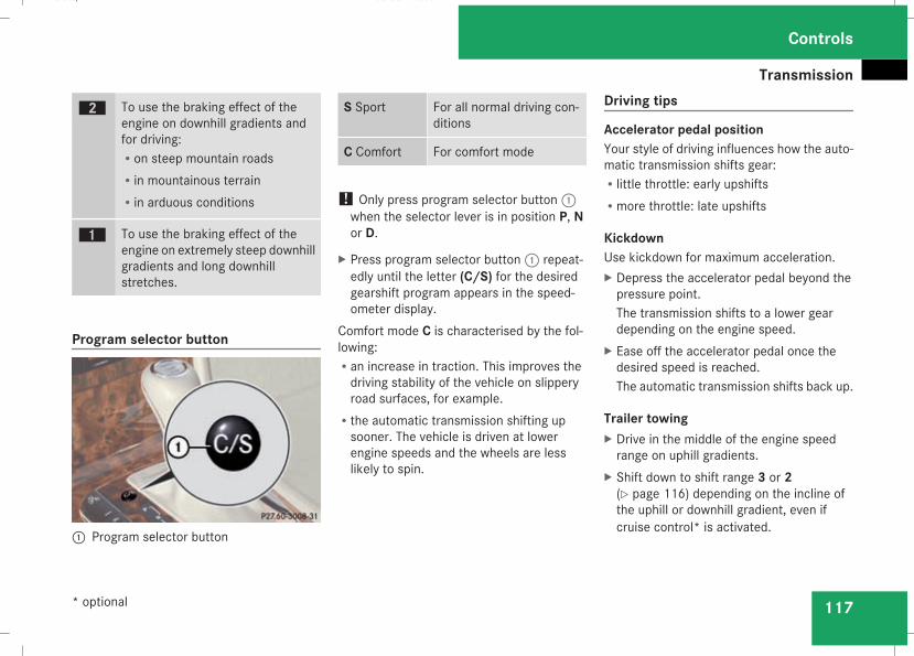
Transmission
117
ç To use the braking effect of theengine on downhill gradients andfor driving:Ron steep mountain roadsRin mountainous terrainRin arduous conditions
æ To use the braking effect of theengine on extremely steep downhillgradients and long downhillstretches.
Program selector button
1 Program selector button
S Sport For all normal driving con-ditions
C Comfort For comfort mode
! Only press program selector button1when the selector lever is in position P, Nor D.
X Press program selector button1 repeat-edly until the letter (C/S) for the desiredgearshift program appears in the speed-ometer display.
Comfort mode C is characterised by the fol-lowing:Ran increase in traction. This improves thedriving stability of the vehicle on slipperyroad surfaces, for example.
Rthe automatic transmission shifting upsooner. The vehicle is driven at lowerengine speeds and the wheels are lesslikely to spin.
Driving tips
Accelerator pedal positionYour style of driving influences how the auto-matic transmission shifts gear:Rlittle throttle: early upshiftsRmore throttle: late upshifts
KickdownUse kickdown for maximum acceleration.X Depress the accelerator pedal beyond thepressure point.The transmission shifts to a lower geardepending on the engine speed.
X Ease off the accelerator pedal once thedesired speed is reached.The automatic transmission shifts back up.
Trailer towingX Drive in the middle of the engine speedrange on uphill gradients.
X Shift down to shift range 3 or 2(Y page 116) depending on the incline ofthe uphill or downhill gradient, even ifcruise control* is activated.
Controls
* optional
211_AKB; 2; 5, en-GBmkalafa, Version: 2.9.4
2008-02-29T16:57:07+01:00 - Seite 117
Z
Dateiname: 6515_3416_02_buchblock.pdf; preflight
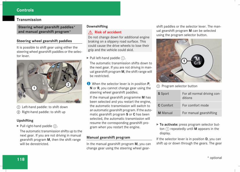
Transmission
118
Steering wheel gearshift paddles*and manual gearshift program*
Steering wheel gearshift paddlesIt is possible to shift gear using either thesteering wheel gearshift paddles or the selec-tor lever.
1 Left-hand paddle: to shift down2 Right-hand paddle: to shift up
UpshiftingX Pull right-hand paddle2.The automatic transmission shifts up to thenext gear. If you are not driving in manualgearshift program M, then the shift rangewill be derestricted.
DownshiftingG Risk of accidentDo not change down for additional enginebraking on a slippery road surface. Thiscould cause the drive wheels to lose theirgrip and the vehicle could skid.
X Pull left-hand paddle1.The automatic transmission shifts down tothe next gear. If you are not driving in man-ual gearshift programM, the shift range willbe restricted.
i When the selector lever is in position P,N or R, you cannot change gear using thesteering wheel gearshift paddles.If the manual gearshift programme M hasbeen selected and you restart the engine,the automatic transmission will switch toan automatic gearshift program. If the auto-matic gearshift program S or C has beenselected, the automatic transmission willresume the corresponding gearshift pro-gram when you restart the engine.
Manual gearshift programIn the manual gearshift program M, you canchange gear using the steering wheel gear-
shift paddles or the selector lever. The man-ual gearshift program M can be selectedusing the program selector button.
1 Program selector button
S Sport For all normal driving con-ditions
C Comfort For comfort mode
M Manual For manual gearshifting
X To activate: press program selector but-ton1 repeatedly until M appears in thedisplay.
If the selector lever is in position D, you canshift up or down through the gears. The gear
Controls
* optional
211_AKB; 2; 5, en-GBmkalafa, Version: 2.9.4
2008-02-29T16:57:07+01:00 - Seite 118
Dateiname: 6515_3416_02_buchblock.pdf; preflight
Transmission
119
currently selected and engaged is shown inthe display.
UpshiftingX Briefly press the selector lever to the righttowards D+
orX Pull the right-hand steering wheel gearshiftpaddle (Y page 118).The automatic transmission shifts up to thenext gear.
Vehicles with AMG engines! In manual gearshift programM, the auto-matic transmission does not shift up auto-matically even when the limiting speed forthe current gear is reached. When the lim-iting speed is reached, the fuel supply is cutto prevent the engine from overrevving.You must make sure that the engine speeddoes not reach the red area of the rev coun-ter. There is otherwise a risk of enginedamage.
X Shift up a gear when the ^ upshift symbolappears in the display instead of M.
When the AMG display is switched on, thedisplay colour changes to red and UP appears
next to the gear indicator, instructing you toshift up.
DownshiftingG Risk of accidentDo not change down for additional enginebraking on a slippery road surface. Thiscould cause the drive wheels to lose theirgrip and the vehicle could skid.
X Briefly press the selector lever to the lefttowards D-
orX Pull the left-hand steering wheel gearshiftpaddle (Y page 118).The automatic transmission shifts down tothe next gear.
i For maximum acceleration, pull the left-hand steering wheel gearshift paddle untilthe transmission selects the optimum gearfor the current speed.
Kickdowni It is not possible to use kickdown in themanual gearshift program M on vehicleswith AMG engines.
You can also use kickdown for maximumacceleration in manual gearshift program M.X Depress the accelerator pedal beyond thepressure point.The transmission shifts to a lower geardepending on the engine speed.
i It is not possible to shift gears using thesteering wheel gearshift paddles duringkickdown.
Controls
211_AKB; 2; 5, en-GBmkalafa, Version: 2.9.4
2008-02-29T16:57:07+01:00 - Seite 119
Z
Dateiname: 6515_3416_02_buchblock.pdf; preflight
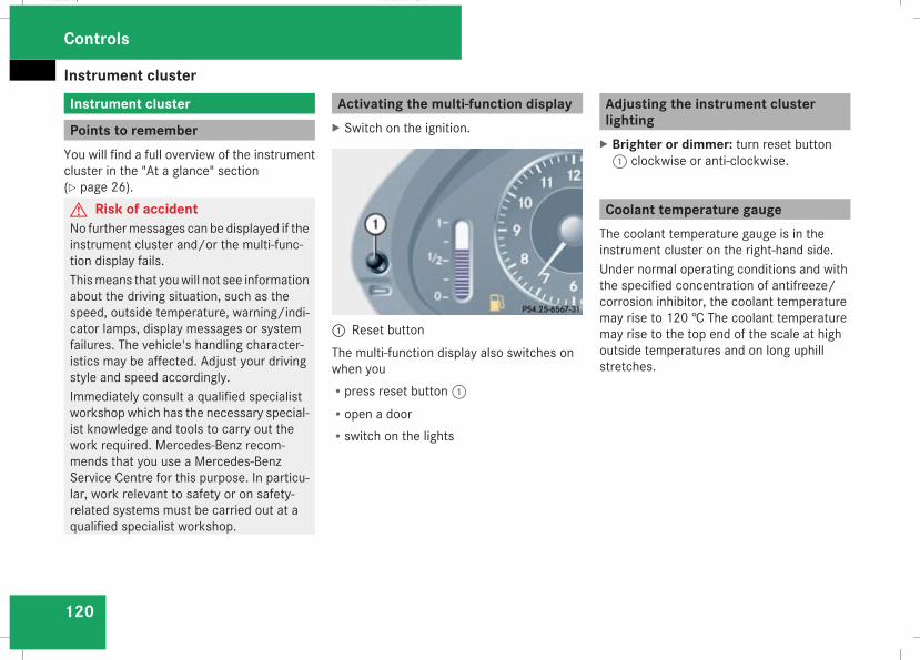
Instrument cluster
120
Instrument cluster
Points to rememberYou will find a full overview of the instrumentcluster in the "At a glance" section(Y page 26).G Risk of accidentNo furthermessages can be displayed if theinstrument cluster and/or the multi-func-tion display fails.Thismeans that youwill not see informationabout the driving situation, such as thespeed, outside temperature, warning/indi-cator lamps, display messages or systemfailures. The vehicle's handling character-istics may be affected. Adjust your drivingstyle and speed accordingly.Immediately consult a qualified specialistworkshop which has the necessary special-ist knowledge and tools to carry out thework required. Mercedes-Benz recom-mends that you use a Mercedes-BenzService Centre for this purpose. In particu-lar, work relevant to safety or on safety-related systems must be carried out at aqualified specialist workshop.
Activating the multi-function displayX Switch on the ignition.
1 Reset buttonThe multi-function display also switches onwhen youRpress reset button1Ropen a doorRswitch on the lights
Adjusting the instrument clusterlightingX Brighter or dimmer: turn reset button1 clockwise or anti-clockwise.
Coolant temperature gaugeThe coolant temperature gauge is in theinstrument cluster on the right-hand side.Under normal operating conditions and withthe specified concentration of antifreeze/corrosion inhibitor, the coolant temperaturemay rise to 120 † The coolant temperaturemay rise to the top end of the scale at highoutside temperatures and on long uphillstretches.
Controls
211_AKB; 2; 5, en-GBmkalafa, Version: 2.9.4
2008-02-29T16:57:07+01:00 - Seite 120
Dateiname: 6515_3416_02_buchblock.pdf; preflight
On-board computer
121
Resetting the trip meterX Select the standard display menu(Y page 125).
X Press and hold reset button1 until the tripmeter is reset.
Speedometer with segmentsThe segments in the speedometer indicatewhich speed range is available.Cruise control mode:The segments light up from the stored speedto the maximum speed.Distronic* mode:One or two segments around the storedspeed light up.Variable Speedtronic mode:The segments light up from the start of thescale to the selected limit speed.
Rev counterThe red band in the rev counter indicates theengine's overrevving range. The fuel supply isinterrupted to protect the engine when thered band is reached.
! Do not drive in the overrevving range.Doing so will damage the engine.
H Environmental noteAvoid driving at high engine speeds, as thisincreases your vehicle's consumptionunnecessarily and pollutes the environ-ment through increased emissions.
Outside temperature display
G Risk of accidentThe road surface may be icy, especially inwooded areas or on bridges, even if tem-peratures are just above freezing point. Thevehicle could skid if you fail to adapt yourdriving style. You should therefore alwaysadapt your driving style and speed to suitthe weather conditions.
There is a short delay before a change in out-side temperature is displayed.
On-board computer
Points to rememberThe on-board computer is activated as soonas the key is turned to position 1 in the igni-tion lock. You can use the on-board computerto call up information relating to your vehicleand to make and adjust settings.You can call up the next service due date,select the display language for the instrumentcluster and set other functions.G Risk of accidentOnly use the on-board computer when roadand traffic conditions permit. You wouldotherwise be distracted and unable to con-centrate properly on driving, and couldcause an accident.
The on-board computer shows information inthe multi-function display.
Controls
* optional
211_AKB; 2; 5, en-GBmkalafa, Version: 2.9.4
2008-02-29T16:57:07+01:00 - Seite 121
Z
Dateiname: 6515_3416_02_buchblock.pdf; preflight
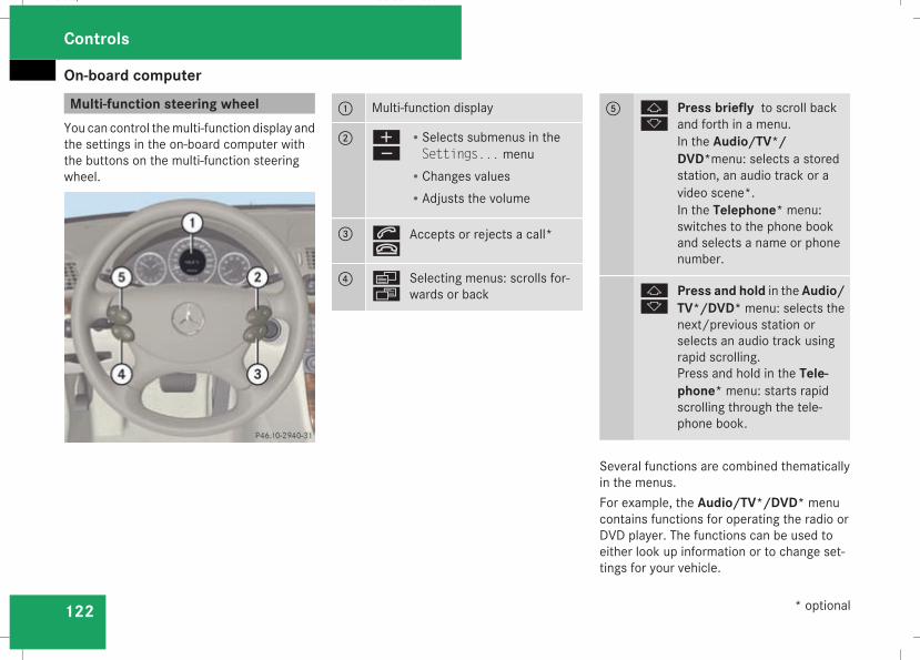
On-board computer
122
Multi-function steering wheelYou can control themulti-function display andthe settings in the on-board computer withthe buttons on the multi-function steeringwheel.
1 Multi-function display
2 æç
RSelects submenus in theSettings... menu
RChanges valuesRAdjusts the volume
3 st
Accepts or rejects a call*
4 èÿ
Selecting menus: scrolls for-wards or back
5 jk
Press briefly to scroll backand forth in a menu.In the Audio/TV*/DVD*menu: selects a storedstation, an audio track or avideo scene*.In the Telephone* menu:switches to the phone bookand selects a name or phonenumber.
jk
Press and hold in the Audio/TV*/DVD* menu: selects thenext/previous station orselects an audio track usingrapid scrolling.Press and hold in the Tele-phone* menu: starts rapidscrolling through the tele-phone book.
Several functions are combined thematicallyin the menus.For example, the Audio/TV*/DVD* menucontains functions for operating the radio orDVD player. The functions can be used toeither look up information or to change set-tings for your vehicle.
Controls
* optional
211_AKB; 2; 5, en-GBmkalafa, Version: 2.9.4
2008-02-29T16:57:07+01:00 - Seite 122
Dateiname: 6515_3416_02_buchblock.pdf; preflight
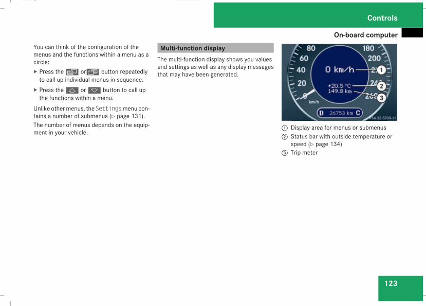
On-board computer
123
You can think of the configuration of themenus and the functions within a menu as acircle:X Press theè orÿ button repeatedlyto call up individual menus in sequence.
X Press thej ork button to call upthe functions within a menu.
Unlike othermenus, the Settingsmenu con-tains a number of submenus (Y page 131).The number of menus depends on the equip-ment in your vehicle.
Multi-function displayThe multi-function display shows you valuesand settings as well as any display messagesthat may have been generated.
1 Display area for menus or submenus2 Status bar with outside temperature or
speed (Y page 134)3 Trip meter
Controls
211_AKB; 2; 5, en-GBmkalafa, Version: 2.9.4
2008-02-29T16:57:07+01:00 - Seite 123
Z
Dateiname: 6515_3416_02_buchblock.pdf; preflight
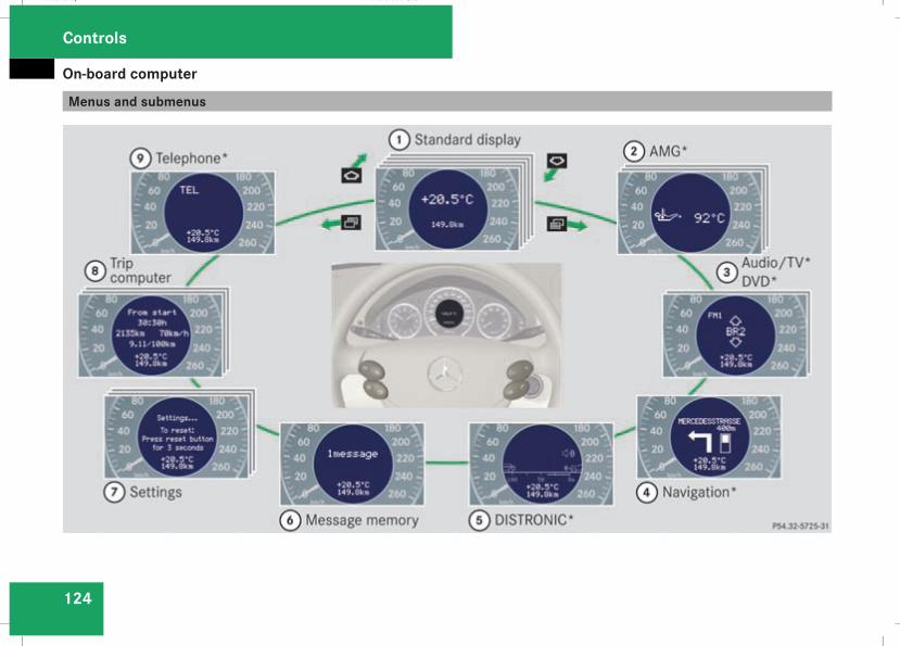
On-board computer
124
Menus and submenus
Controls
211_AKB; 2; 5, en-GBmkalafa, Version: 2.9.4
2008-02-29T16:57:07+01:00 - Seite 124
Dateiname: 6515_3416_02_buchblock.pdf; preflight
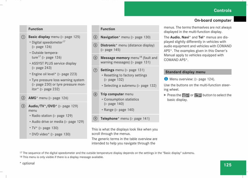
On-board computer
125
Function
1 Basic display menu (Y page 125)RDigital speedometer17(Y page 126)
ROutside tempera-ture17 (Y page 126)
RASSYST PLUS service display(Y page 243)
REngine oil level* (Y page 223)RTyre pressure loss warning system(Y page 230) or tyre pressure mon-itor* (Y page 232)
2 AMG* menu (Y page 126)
3 Audio/TV*/DVD* (Y page 129)menuRRadio station (Y page 129)RAudio drive or media (Y page 129)RTV* (Y page 130)RDVD video* (Y page 130)
Function
4 Navigation* menu (Y page 130)
5 Distronic* menu (distance display)(Y page 145)
6 Message memory menu18 (fault andwarning messages) (Y page 131)
7 Settings menu (Y page 131)RResetting to factory settings(Y page 132)
RSelecting a submenu (Y page 132)
8 Trip computer menuRConsumption statistics(Y page 140)
RRange (Y page 140)
9 Telephone* menu (Y page 141)
This is what the displays look like when youscroll through the menus.The generic terms in the table overview areintended to help you navigate through the
menus. The terms themselves are not alwaysdisplayed in the multi-function display.The Audio, Navi* and Tel* menus are dis-played slightly differently in vehicles withaudio equipment and vehicles with COMANDAPS*. The examples given in this Owner'sManual apply to vehicles equipped withCOMAND APS*.
Standard display menui Menu overview: (Y page 124).Use the buttons on the multi-function steer-ing wheel.X Press theè or· button to select thebasic display.
17 The sequence of the digital speedometer and the outside temperature display depends on the settings in the "Basic display" submenu.18 This menu is only visible if there is a display message available.
Controls
* optional
211_AKB; 2; 5, en-GBmkalafa, Version: 2.9.4
2008-02-29T16:57:07+01:00 - Seite 125
Z
Dateiname: 6515_3416_02_buchblock.pdf; preflight
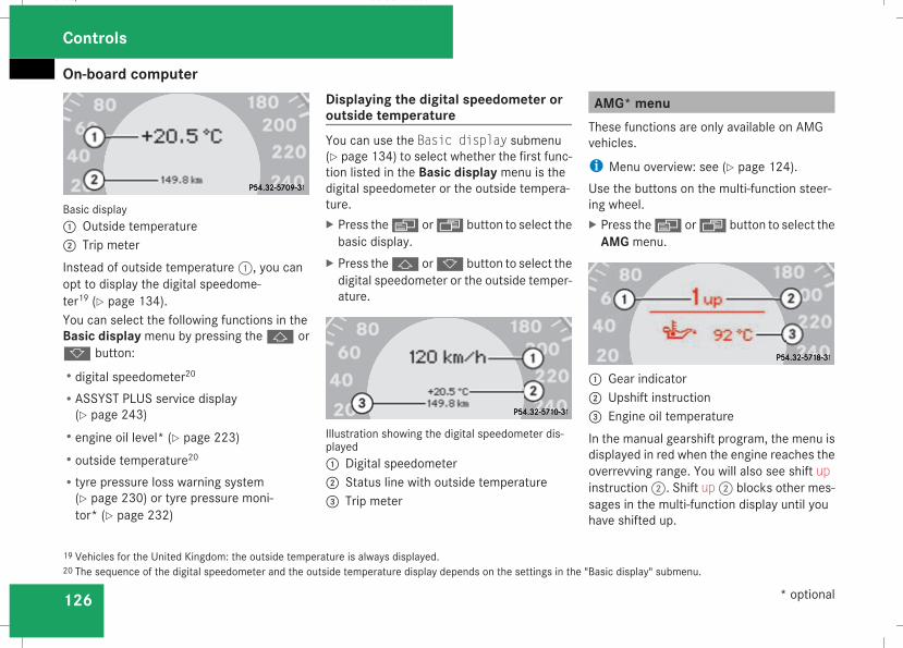
On-board computer
126
Basic display1 Outside temperature2 Trip meterInstead of outside temperature1, you canopt to display the digital speedome-ter19 (Y page 134).You can select the following functions in theBasic display menu by pressing thej ork button:Rdigital speedometer20
RASSYST PLUS service display(Y page 243)
Rengine oil level* (Y page 223)Routside temperature20
Rtyre pressure loss warning system(Y page 230) or tyre pressure moni-tor* (Y page 232)
Displaying the digital speedometer oroutside temperatureYou can use the Basic display submenu(Y page 134) to select whether the first func-tion listed in the Basic display menu is thedigital speedometer or the outside tempera-ture.X Press theè or· button to select thebasic display.
X Press thej ork button to select thedigital speedometer or the outside temper-ature.
Illustration showing the digital speedometer dis-played1 Digital speedometer2 Status line with outside temperature3 Trip meter
AMG* menuThese functions are only available on AMGvehicles.
i Menu overview: see (Y page 124).Use the buttons on the multi-function steer-ing wheel.X Press theè or· button to select theAMG menu.
1 Gear indicator2 Upshift instruction3 Engine oil temperatureIn the manual gearshift program, the menu isdisplayed in red when the engine reaches theoverrevving range. You will also see shift upinstruction2. Shift up2 blocks other mes-sages in the multi-function display until youhave shifted up.
19 Vehicles for the United Kingdom: the outside temperature is always displayed.20 The sequence of the digital speedometer and the outside temperature display depends on the settings in the "Basic display" submenu.
Controls
* optional
211_AKB; 2; 5, en-GBmkalafa, Version: 2.9.4
2008-02-29T16:57:07+01:00 - Seite 126
Dateiname: 6515_3416_02_buchblock.pdf; preflight
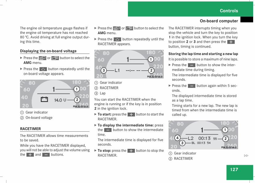
On-board computer
127
The engine oil temperature gauge flashes ifthe engine oil temperature has not reached80 †. Avoid driving at full engine output dur-ing this time.
Displaying the on-board voltageX Press theè or· button to select theAMG menu.
X Press thej button repeatedly until theon-board voltage appears.
1 Gear indicator2 On-board voltage
RACETIMERThe RACETIMER allows time measurementsto be saved.While you have the RACETIMER displayed,youwill not be able to adjust the volume usingtheæ andç buttons.
X Press theè or· button to select theAMG menu.
X Press thej button repeatedly until theRACETIMER appears.
1 Gear indicator2 RACETIMER3 LapYou can start the RACETIMER when theengine is running or if the key is in position2 in the ignition lock.X To start: press theæ button to start theRACETIMER.
X To display the intermediate time: presstheç button to show the intermediatetime.The intermediate time is displayed for fiveseconds.
X To stop: press theæ button to stop theRACETIMER.
The RACETIMER interrupts timing when youstop the vehicle and turn the key to position1 in the ignition lock. When you turn the keyto position 2 or 3 and then press theæbutton, timing is continued.
Storing the lap time and starting a new lapIt is possible to store a maximum of nine laps.X Press theç button to show the inter-mediate time during timing.The intermediate time is displayed for fiveseconds.
X Press theç button again within 5 sec-onds.The displayed intermediate time is storedas a lap time.Timing starts for a new lap. The new lap istimed from when the intermediate time iscalled up.
1 Gear indicator2 RACETIMER
Controls
211_AKB; 2; 5, en-GBmkalafa, Version: 2.9.4
2008-02-29T16:57:07+01:00 - Seite 127
Z
Dateiname: 6515_3416_02_buchblock.pdf; preflight
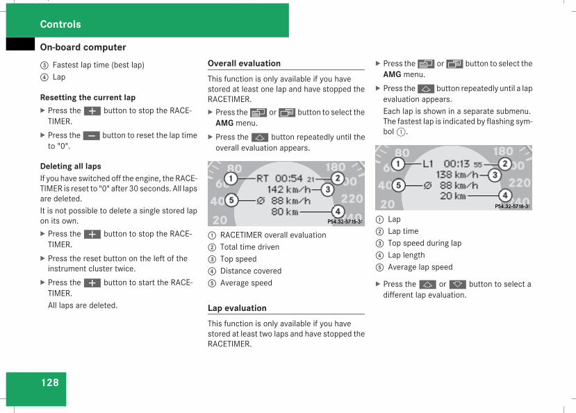
On-board computer
128
3 Fastest lap time (best lap)4 Lap
Resetting the current lapX Press theæ button to stop the RACE-TIMER.
X Press theç button to reset the lap timeto "0".
Deleting all lapsIf you have switched off the engine, the RACE-TIMER is reset to "0" after 30 seconds. All lapsare deleted.It is not possible to delete a single stored lapon its own.X Press theæ button to stop the RACE-TIMER.
X Press the reset button on the left of theinstrument cluster twice.
X Press theæ button to start the RACE-TIMER.All laps are deleted.
Overall evaluationThis function is only available if you havestored at least one lap and have stopped theRACETIMER.X Press theè or· button to select theAMG menu.
X Press thej button repeatedly until theoverall evaluation appears.
1 RACETIMER overall evaluation2 Total time driven3 Top speed4 Distance covered5 Average speed
Lap evaluationThis function is only available if you havestored at least two laps and have stopped theRACETIMER.
X Press theè or· button to select theAMG menu.
X Press thej button repeatedly until a lapevaluation appears.Each lap is shown in a separate submenu.The fastest lap is indicated by flashing sym-bol1.
1 Lap2 Lap time3 Top speed during lap4 Lap length5 Average lap speed
X Press thej ork button to select adifferent lap evaluation.
Controls
211_AKB; 2; 5, en-GBmkalafa, Version: 2.9.4
2008-02-29T16:57:07+01:00 - Seite 128
Dateiname: 6515_3416_02_buchblock.pdf; preflight
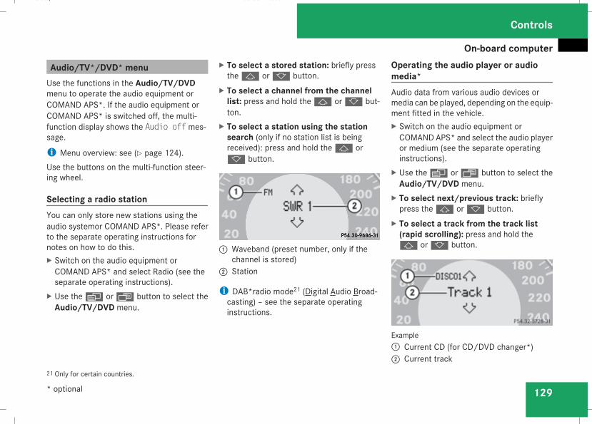
On-board computer
129
Audio/TV*/DVD* menuUse the functions in the Audio/TV/DVDmenu to operate the audio equipment orCOMAND APS*. If the audio equipment orCOMAND APS* is switched off, the multi-function display shows the Audio off mes-sage.
i Menu overview: see (Y page 124).Use the buttons on the multi-function steer-ing wheel.
Selecting a radio stationYou can only store new stations using theaudio systemor COMAND APS*. Please referto the separate operating instructions fornotes on how to do this.X Switch on the audio equipment orCOMAND APS* and select Radio (see theseparate operating instructions).
X Use theè or· button to select theAudio/TV/DVD menu.
X To select a stored station: briefly pressthej ork button.
X To select a channel from the channellist: press and hold thej ork but-ton.
X To select a station using the stationsearch (only if no station list is beingreceived): press and hold thej ork button.
1 Waveband (preset number, only if thechannel is stored)2 Station
i DAB*radio mode21 (Digital Audio Broad-casting) – see the separate operatinginstructions.
Operating the audio player or audiomedia*Audio data from various audio devices ormedia can be played, depending on the equip-ment fitted in the vehicle.X Switch on the audio equipment orCOMAND APS* and select the audio playeror medium (see the separate operatinginstructions).
X Use theè or· button to select theAudio/TV/DVD menu.
X To select next/previous track: brieflypress thej ork button.
X To select a track from the track list(rapid scrolling): press and hold thej ork button.
Example1 Current CD (for CD/DVD changer*)2 Current track
21 Only for certain countries.
Controls
* optional
211_AKB; 2; 5, en-GBmkalafa, Version: 2.9.4
2008-02-29T16:57:07+01:00 - Seite 129
Z
Dateiname: 6515_3416_02_buchblock.pdf; preflight
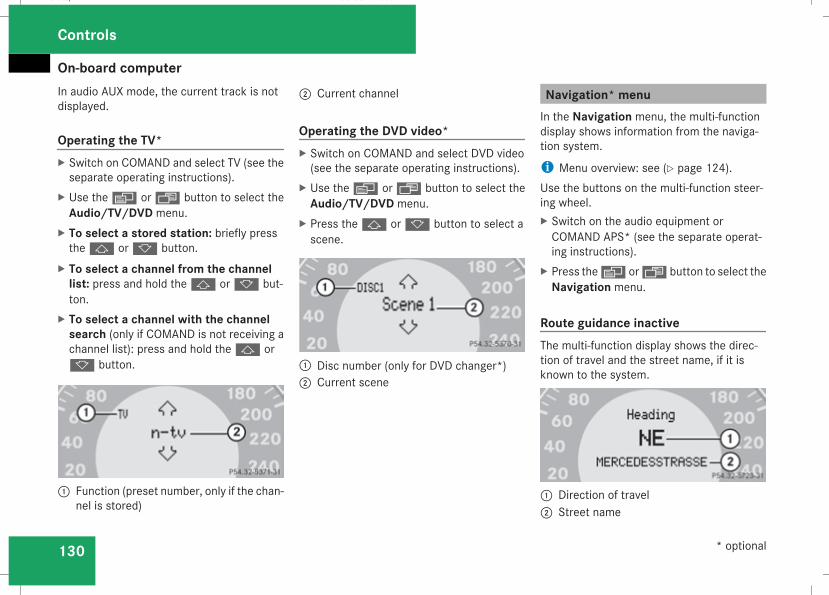
On-board computer
130
In audio AUX mode, the current track is notdisplayed.
Operating the TV*X Switch on COMAND and select TV (see theseparate operating instructions).
X Use theè or· button to select theAudio/TV/DVD menu.
X To select a stored station: briefly pressthej ork button.
X To select a channel from the channellist: press and hold thej ork but-ton.
X To select a channel with the channelsearch (only if COMAND is not receiving achannel list): press and hold thej ork button.
1 Function (preset number, only if the chan-nel is stored)
2 Current channel
Operating the DVD video*X Switch on COMAND and select DVD video(see the separate operating instructions).
X Use theè or· button to select theAudio/TV/DVD menu.
X Press thej ork button to select ascene.
1 Disc number (only for DVD changer*)2 Current scene
Navigation* menuIn the Navigation menu, the multi-functiondisplay shows information from the naviga-tion system.
i Menu overview: see (Y page 124).Use the buttons on the multi-function steer-ing wheel.X Switch on the audio equipment orCOMAND APS* (see the separate operat-ing instructions).
X Press theè or· button to select theNavigation menu.
Route guidance inactiveThe multi-function display shows the direc-tion of travel and the street name, if it isknown to the system.
1 Direction of travel2 Street name
Controls
* optional
211_AKB; 2; 5, en-GBmkalafa, Version: 2.9.4
2008-02-29T16:57:07+01:00 - Seite 130
Dateiname: 6515_3416_02_buchblock.pdf; preflight
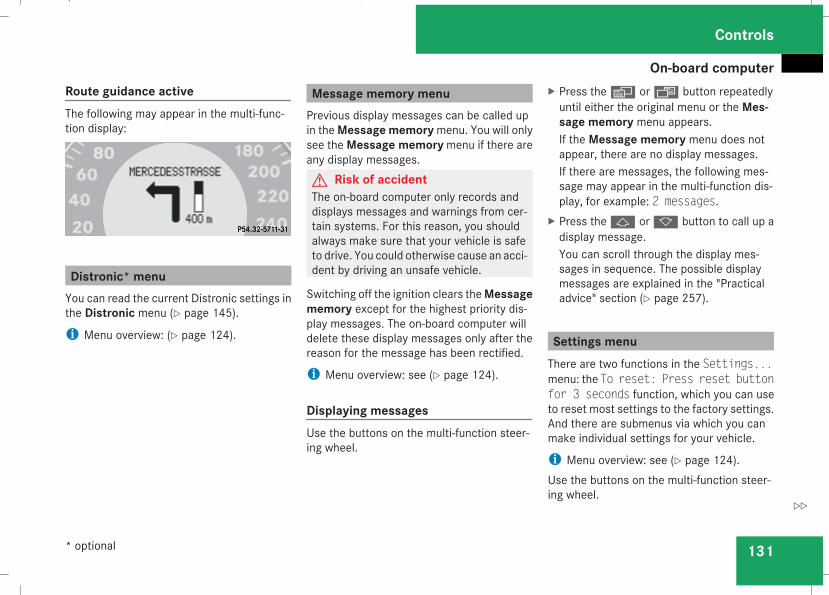
On-board computer
131
Route guidance activeThe following may appear in the multi-func-tion display:
Distronic* menuYou can read the current Distronic settings inthe Distronic menu (Y page 145).
i Menu overview: (Y page 124).
Message memory menuPrevious display messages can be called upin theMessage memorymenu. You will onlysee theMessage memorymenu if there areany display messages.G Risk of accidentThe on-board computer only records anddisplays messages and warnings from cer-tain systems. For this reason, you shouldalways make sure that your vehicle is safeto drive. You could otherwise cause an acci-dent by driving an unsafe vehicle.
Switching off the ignition clears theMessagememory except for the highest priority dis-play messages. The on-board computer willdelete these display messages only after thereason for the message has been rectified.
i Menu overview: see (Y page 124).
Displaying messagesUse the buttons on the multi-function steer-ing wheel.
X Press theè or· button repeatedlyuntil either the original menu or the Mes-sage memory menu appears.If the Message memory menu does notappear, there are no display messages.If there are messages, the following mes-sage may appear in the multi-function dis-play, for example: 2 messages.
X Press thej ork button to call up adisplay message.You can scroll through the display mes-sages in sequence. The possible displaymessages are explained in the "Practicaladvice" section (Y page 257).
Settings menuThere are two functions in the Settings...menu: the To reset: Press reset buttonfor 3 seconds function, which you can useto reset most settings to the factory settings.And there are submenus via which you canmake individual settings for your vehicle.
i Menu overview: see (Y page 124).Use the buttons on the multi-function steer-ing wheel.
Controls
* optional
211_AKB; 2; 5, en-GBmkalafa, Version: 2.9.4
2008-02-29T16:57:07+01:00 - Seite 131
Z
Dateiname: 6515_3416_02_buchblock.pdf; preflight
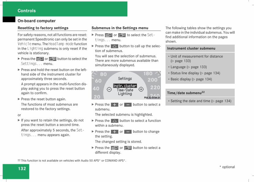
On-board computer
132
Resetting to factory settingsFor safety reasons, not all functions are reset:permanent Speedtronic can only be set in theVehiclemenu. The Headlamp mode functionin the Lighting submenu is only reset if thevehicle is stationary.X Press theè or· button to select theSettings... menu.
X Press and hold the reset button on the left-hand side of the instrument cluster forapproximately three seconds.A prompt appears in the multi-function dis-play asking you to press the reset buttonagain to confirm.
X Press the reset button again.The functions of most submenus arerestored to the factory settings.
orX If you want to retain the settings, do notpress the reset button a second time.After approximately 5 seconds, the Set-tings... menu appears again.
Submenus in the Settings menuX Pressè or· to select the Set-tings... menu.
X Press thej button to call up the selec-tion of submenus.You will see the selection of submenus.There are more submenus available thansimultaneously displayed.
X Press theæ orç button to select asubmenu.The selected submenu is highlighted.
X Press thej button to select a functionwithin a submenu.
X Press theæ orç button to changethe setting.The changed setting is stored.
X Press theè orÿ button to select adifferent display.
The following tables show the settings youcanmake in the individual submenus. Youwillfind additional information on the pagesshown.
Instrument cluster submenu
RUnit of measurement for distance(Y page 133)
RLanguage (Y page 133)RStatus line display (Y page 134)RBasic display (Y page 134)
Time/date submenu22
RSetting the date and time (Y page 134)
22 This function is not available on vehicles with Audio 50 APS* or COMAND APS*.
Controls
* optional
211_AKB; 2; 5, en-GBmkalafa, Version: 2.9.4
2008-02-29T16:57:07+01:00 - Seite 132
Dateiname: 6515_3416_02_buchblock.pdf; preflight
On-board computer
133
Lighting submenu
RConstant headlamp mode (Y page 135)RSurround lighting (Y page 135)RAmbient lighting* (Y page 136)RExterior lighting delayed switch-off(Y page 136)
RInterior lighting delayed switch-off(Y page 136)
RIntelligent Light System* (Y page 137)
Vehicle submenu
RPermanent Speedtronic (Y page 154)RAutomatic locking feature (Y page 137)
Heater* submenu
RSelecting the switch-on time for the aux-iliary heating* (Y page 137)
RChanging the switch-on time for the aux-iliary heating* (Y page 138)
Convenience submenu*
REasy-entry/exit feature* (Y page 138)RFold in mirrors when locking the vehi-cle* (Y page 139)
Dynamic driving seat* submenu
RSettings for the driver's and front-passenger seat (Y page 139)
Selecting the unit of measurement fordistanceThe selected unit of measurement for dis-tance applies to:Rthe total distance recorder and the tripmeter
Rthe trip computerRthe digital speedometer23
Rcruise controlRSpeedtronicRDistronic*
X Press theè or· button to select theSettings... menu.
X Press thej button to call up the selec-tion of submenus.
X Press theæ orç button to select theInstr. cluster submenu.
X Press thej button to select Displayunit Speed-/odometer.
X Press theæ orç button to selectkm (kilometres) or miles as the unit ofmeasurement for distance.
X Press thej,è orÿ button toselect a different display.
Selecting the languageX Press theè or· button to select theSettings... menu.
X Press thej button to call up the selec-tion of submenus.
X Press theæ orç button to select theInstr. cluster submenu.
X Press thej button to select Lan-guage.
23 Vehicles for the United Kingdom: the digital speedometer always displays km/h.
Controls
* optional
211_AKB; 2; 5, en-GBmkalafa, Version: 2.9.4
2008-02-29T16:57:07+01:00 - Seite 133
Z
Dateiname: 6515_3416_02_buchblock.pdf; preflight
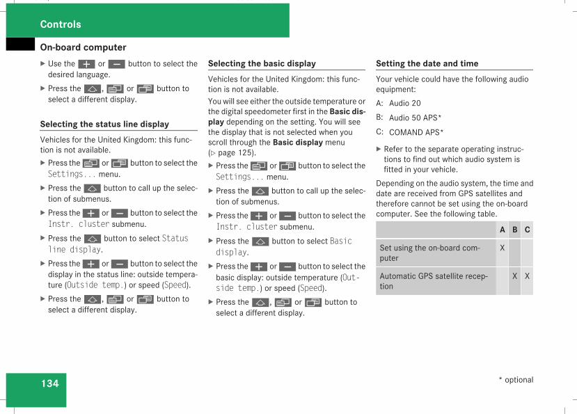
On-board computer
134
X Use theæ orç button to select thedesired language.
X Press thej,è orÿ button toselect a different display.
Selecting the status line displayVehicles for the United Kingdom: this func-tion is not available.X Press theè or· button to select theSettings... menu.
X Press thej button to call up the selec-tion of submenus.
X Press theæ orç button to select theInstr. cluster submenu.
X Press thej button to select Statusline display.
X Press theæ orç button to select thedisplay in the status line: outside tempera-ture (Outside temp.) or speed (Speed).
X Press thej,è orÿ button toselect a different display.
Selecting the basic displayVehicles for the United Kingdom: this func-tion is not available.You will see either the outside temperature orthe digital speedometer first in the Basic dis-play depending on the setting. You will seethe display that is not selected when youscroll through the Basic display menu(Y page 125).X Press theè or· button to select theSettings... menu.
X Press thej button to call up the selec-tion of submenus.
X Press theæ orç button to select theInstr. cluster submenu.
X Press thej button to select Basicdisplay.
X Press theæ orç button to select thebasic display: outside temperature (Out-side temp.) or speed (Speed).
X Press thej,è orÿ button toselect a different display.
Setting the date and timeYour vehicle could have the following audioequipment:A: Audio 20B: Audio 50 APS*C: COMAND APS*
X Refer to the separate operating instruc-tions to find out which audio system isfitted in your vehicle.
Depending on the audio system, the time anddate are received from GPS satellites andtherefore cannot be set using the on-boardcomputer. See the following table.
A B C
Set using the on-board com-puter
X
Automatic GPS satellite recep-tion
X X
Controls
* optional
211_AKB; 2; 5, en-GBmkalafa, Version: 2.9.4
2008-02-29T16:57:07+01:00 - Seite 134
Dateiname: 6515_3416_02_buchblock.pdf; preflight
On-board computer
135
X Press theè or· button to select theSettings... menu.
X Press thej button to call up the selec-tion of submenus.
X Press theæ orç button to select theTime/Date submenu.
Setting the timeX Use thej button to select Clock,hours Press R to confirm (or Clock,minutes Press R to confirm).
X Press theæ orç button to set avalue.
X Press the reset button on the left of theinstrument cluster.The set time is stored.
Setting the dateX Press thej button to select Set dateDay (or Set date Month or Set dateYear).
X Press theæ orç button to set thevalues.
X Press thej,è orÿ button toselect a different display.
Setting constant headlamp modeIf you have set constant headlamp mode andthe light switch is in positionM orU,the side lamps, dipped-beam headlamps andlicence plate lighting are switched on auto-matically when the engine is running. Turningthe light switch to a different positionswitches on the corresponding lights. Makesure that the light switch is turned toB orU if you switch off constant headlampmode while driving in the dark.In countries in which constant headlampmode is a legal requirement, Constant is thefactory setting.X Press theè or· button to select theSettings... menu.
X Press thej button to call up the selec-tion of submenus.
X Press theæ orç button to select theLighting submenu.
X Press thej button to select Headlampmode.
X Press theæ orç button to set themode for the headlamps to Manual or Con-stant (constant headlamp mode).
X Press thej,è orÿ button toselect a different display.
Switching the surround lighting on oroffIf the surround lighting is switched on, thefollowing lights will be switched on automat-ically in the dark after you have unlocked thevehicle using the key:Rthe side lampsRthe tail lampsRthe licence plate lightingRthe front foglampsThe surround lighting switches off automati-cally if you open the driver's door or after 40seconds.X Pressè or· to select the Set-tings... menu.
X Press thej button to call up the selec-tion of submenus.
X Press theæ orç button to select theLighting submenu.
Controls
211_AKB; 2; 5, en-GBmkalafa, Version: 2.9.4
2008-02-29T16:57:07+01:00 - Seite 135
Z
Dateiname: 6515_3416_02_buchblock.pdf; preflight
On-board computer
136
X Press thej button to select the Sur-round lighting function.
X Press theæ orç button to switchthe Surround lighting function on oroff.
X Press thej,è orÿ button toselect a different display.
Setting the ambient lighting*X Press theè or· button to select theSettings... menu.
X Press thej button to call up the selec-tion of submenus.
X Press theæ orç button to select theLighting submenu.
X Press thej button to select Ambientlight.
X Press theæ orç button to adjust thebrightness to any level from 0 (off) to 5(bright).
X Press thej,è orÿ button toselect a different display.
Activating/deactivating the exteriorlighting delayed switch-offYou can set whether the exterior lightingshould remain on for 15 seconds after thedoors are closed when it is dark using theHeadlamps delayed switch-off function.If none of the doors are opened after theengine is switched off or if an open door is notclosed, the exterior lighting goes out after60 seconds.When you have set a delayed switch-off timeand then switch off the engine, the followingremain lit:Rthe side lampsRthe tail lampsRthe licence plate lightingRthe front foglamps
X Pressè or· to select the Set-tings... menu.
X Press thej button to call up the selec-tion of submenus.
X Press theæ orç button to select theLighting submenu.
X Press thej button to select Headlampsdelayed switch-off.
X Press theæ orç button to activateor deactivate the Headlamps delayedswitch-off feature.
X Press thej,è orÿ button toselect a different display.
To temporarily deactivate the delayed switch-off:X Before leaving the vehicle, turn the key toposition 0 in the ignition lock.
X Turn the key to position 2 in the ignitionlock and back to position 0.Delayed switch-off is deactivated. It is reac-tivated as soon as you start the engineagain.
Activating/deactivating the interiorlighting delayed switch-offThe Interior lighting delayed switch-off function allows you to set whether theinterior lighting should remain on for 10 sec-onds after the key is removed from the igni-tion lock when it is dark.X Press theè or· button to select theSettings... menu.
X Press thej button to call up the selec-tion of submenus.
Controls
* optional
211_AKB; 2; 5, en-GBmkalafa, Version: 2.9.4
2008-02-29T16:57:07+01:00 - Seite 136
Dateiname: 6515_3416_02_buchblock.pdf; preflight
On-board computer
137
X Press theæ orç button to select theLighting submenu.
X Press thej button to select Interiorlighting delayed switch-off.
X Press theæ orç button to activateor deactivate the Interior lightingdelayed switch-off feature.
X Press thej,è orÿ button toselect a different display.
Switching the Intelligent Light Sys-tem* on/offYou can set whether motorway mode, theactive light system and the extended rangefoglamps are to be activated using theIntelligent Light System function.X Press theè or· button to select theSettings... menu.
X Press thej button to call up the selec-tion of submenus.
X Press theæ orç button to select theLighting submenu.
X Press thej button to select Intelli-gent Light System.
X Press theæ orç button to switchthe Intelligent Light System on/off.
X Press thej,è orÿ button toselect a different display.
Activating/deactivating the automaticdoor locking featureThe Automatic door locking featureallows you to set whether your vehicle willlock centrally from a speed of about15 km/h upwards.
i For more information on the automaticlocking feature, see (Y page 70).
X Press theè or· button to select theSettings... menu.
X Press thej button to call up the selec-tion of submenus.
X Press theæ orç button to select theVehicle submenu.
X Press thej button to select Automaticdoor locking.
X Press theæ orç button to activateor deactivate the Automatic door lock-ing feature.
X Press thej,è orÿ button toselect a different display.
Selecting the switch-on time for theauxiliary heating*This function is only available if the vehiclehas an auxiliary heating system.The Auxiliary heat. function allows you toselect three switch-on times. You can set theexact switch-on time using the other func-tions in the Heater submenu.The auxiliary heating adopts the Thermatic or4-zone Thermotronic* temperature setting.Theminimumandmaximum temperature set-tings for the auxiliary heating are 20 † and24 † respectively.You can switch off the auxiliary heating byusing the remote control or the auxiliary heat-ing button on the centre console.The auxiliary heating is switched off automat-ically after 50 minutes. This time can bechanged. To do this, visit a qualified specialistworkshop, e.g. a Mercedes-Benz ServiceCentre.
Controls
* optional
211_AKB; 2; 5, en-GBmkalafa, Version: 2.9.4
2008-02-29T16:57:07+01:00 - Seite 137
Z
Dateiname: 6515_3416_02_buchblock.pdf; preflight
On-board computer
138
G Risk of fire and poisoningThe operation of the auxiliary heating pro-duces hot, toxic exhaust fumes. The fuelvapours produced during refuelling couldignite on the hot exhaust system.Do not switch on the auxiliary heating atfilling stations or in enclosed spaces, forinstance, a garage, if there is no air extrac-tion system.You could otherwise endanger yourself andothers.
The Auxiliary heat. function can be calledup directly.X Turn the key to position1 or2 in the ignitionlock.
X Press the button for the auxiliary heating onthe centre console (Y page 178).
orX Press theè or· button to select theSettings... menu.
X Press thej button to call up the selec-tion of submenus.
X Press theæ orç button to select theHeater submenu.
X Press thej button to select Auxiliaryheat..
X Press theæ orç button to selectone of the three switch-on times or Timeroff (auxiliary heating switched off).When a switch-on time is selected, the yel-low indicator lamp lights up in the auxiliaryheating button.
X Press thej,è orÿ button toselect a different display.
Changing the switch-on time for theauxiliary heating*This function is only displayed if you haveselected a switch-on time. Here you can enterthe time at which the auxiliary heating is tobe switched on.X Press theè or· button to select theSettings... menu.
X Press thej button to call up the selec-tion of submenus.
X Press theæ orç button to select theHeater submenu.
X Press thej button to select Switch-ontime X Set hours.
X Press theæ orç button to set thehour.
X Press thej button to select Switch-ontime X Set minutes.
X Press theæ orç button to set theminutes.After changing from one menu to another,the new time setting is stored. The yellowindicator lamp lights up on the button forthe auxiliary heating on the centre console.
X Press thej,è orÿ button toselect a different display.
Activating/deactivating the easy-entry/exit feature*i For more information on the easy-entry/exit feature, see (Y page 90).
G Risk of injuryWhen the easy-entry/exit feature is active,the steering wheel moves. There is a risk ofoccupants becoming trapped. Before acti-vating the easy-entry/exit feature, makesure that nobody can become trapped.Do not leave children unsupervised in thevehicle, even if they are secured in a childrestraint system. The children could openthe driver's door and thereby unintention-
Controls
* optional
211_AKB; 2; 5, en-GBmkalafa, Version: 2.9.4
2008-02-29T16:57:07+01:00 - Seite 138
Dateiname: 6515_3416_02_buchblock.pdf; preflight
On-board computer
139
ally activate the easy-entry/exit featureand become trapped.
X Press theè or· button to select theSettings... menu.
X Press thej button to call up the selec-tion of submenus.
X Press theæ orç button to select theConvenience submenu.
X Press thej button to select the EASY-ENTRY system.
X Press theæ orç button to activateor deactivate the EASY-ENTRY system.
X Press thej,è orÿ button toselect a different display.
Activating/deactivating the Fold in mir-rors when locking* functionThe Fold in mirrors when locking func-tion allows you to determine whether theexterior mirrors should fold in when you lockthe vehicle. When you switch on the ignition,the exterior mirrors fold out again.If you have switched the function on and youfold in the exterior mirrors using the buttonon the door (Y page 92), they will not fold out
automatically. The exterior mirrors can thenonly be folded out using the button on thedoor.X Press theè or· button to select theSettings... menu.
X Press thej button to call up the selec-tion of submenus.
X Press theæ orç button to select theConvenience submenu.
X Press thej button to select Fold inmirrors when locking.
X Press theæ orç button to activateor deactivate the Fold in mirrors whenlocking feature.
X Press thej,è orÿ button toselect a different display.
Selecting a setting for the dynamic driv-ing seat*i Formore information on the dynamic driv-ing seat, see (Y page 84).
X Press theè or· button to select theSettings... menu.
X Press thej button to call up the selec-tion of submenus.
X Press theæ orç button to select theDriving dynamics seat adjustmentsubmenu.
X Press thej button to select Drivingdyn. seat adjust., driver or Drivingdyn. seat adjust., front-pass..
X Press theæ orç button to select thedesired seat setting: Gentle for a soft seatsetting or Vigorous for a hard seat setting.
X Press thej,è orÿ button toselect a different display.
Trip computer menuYou can use the Trip computer menu to callup or reset statistical data for your vehicle.
i You can select km or miles as the unit ofmeasurement for distance (Y page 133).
i Menu overview: see (Y page 124).Use the buttons on the multi-function steer-ing wheel.
Consumption statistics from startThe values refer to the start of the journey.
Controls
* optional
211_AKB; 2; 5, en-GBmkalafa, Version: 2.9.4
2008-02-29T16:57:07+01:00 - Seite 139
Z
Dateiname: 6515_3416_02_buchblock.pdf; preflight
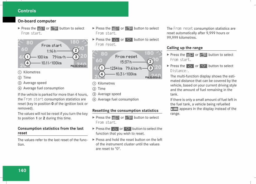
On-board computer
140
X Press theè or· button to selectFrom start.
1 Kilometres2 Time3 Average speed4 Average fuel consumptionIf the vehicle is parked for more than 4 hours,the From start consumption statistics arereset (key in position 0 of the ignition lock orremoved).The values will not be reset if you turn the keyto position 1 or 2 during this time.
Consumption statistics from the lastresetThe values refer to the last reset of the func-tion.
X Press theè or· button to selectFrom start.
X Press thej ork button to selectFrom reset.
1 Kilometres2 Time3 Average speed4 Average fuel consumption
Resetting the consumption statisticsX Press theè or· button to selectFrom start.
X Press thej ork button to select thefunction that you wish to reset.
X Press and hold the reset button on the leftof the instrument cluster until the valuesare reset to "0".
The From reset consumption statistics arereset automatically after 9,999 hours or99,999 kilometres.
Calling up the rangeX Press theè or· button to selectFrom start.
X Press thej ork button to selectDistance:.The multi-function display shows the esti-mated distance that can be covered by thevehicle, based on your current driving styleand the amount of fuel remaining in thetank.If there is only a small amount of fuel left inthe fuel tank, a vehicle being refuelled¿ appears in the display instead of therange.
Controls
211_AKB; 2; 5, en-GBmkalafa, Version: 2.9.4
2008-02-29T16:57:07+01:00 - Seite 140
Dateiname: 6515_3416_02_buchblock.pdf; preflight
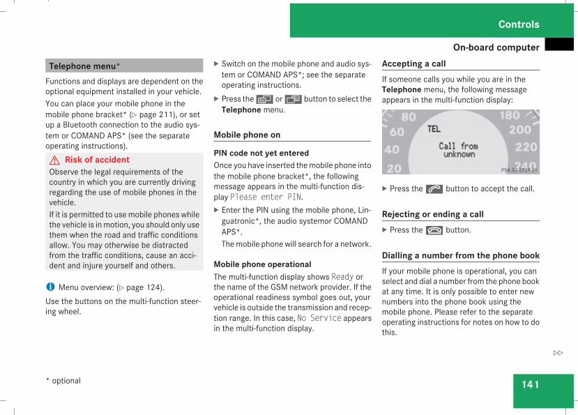
On-board computer
141
Telephone menu*Functions and displays are dependent on theoptional equipment installed in your vehicle.You can place your mobile phone in themobile phone bracket* (Y page 211), or setup a Bluetooth connection to the audio sys-tem or COMAND APS* (see the separateoperating instructions).G Risk of accidentObserve the legal requirements of thecountry in which you are currently drivingregarding the use of mobile phones in thevehicle.If it is permitted to usemobile phones whilethe vehicle is inmotion, you should only usethem when the road and traffic conditionsallow. You may otherwise be distractedfrom the traffic conditions, cause an acci-dent and injure yourself and others.
i Menu overview: (Y page 124).Use the buttons on the multi-function steer-ing wheel.
X Switch on the mobile phone and audio sys-tem or COMAND APS*; see the separateoperating instructions.
X Press theè or· button to select theTelephone menu.
Mobile phone on
PIN code not yet enteredOnce you have inserted themobile phone intothe mobile phone bracket*, the followingmessage appears in the multi-function dis-play Please enter PIN.X Enter the PIN using the mobile phone, Lin-guatronic*, the audio systemor COMANDAPS*.Themobile phone will search for a network.
Mobile phone operationalThe multi-function display shows Ready orthe name of the GSM network provider. If theoperational readiness symbol goes out, yourvehicle is outside the transmission and recep-tion range. In this case, No Service appearsin the multi-function display.
Accepting a callIf someone calls you while you are in theTelephone menu, the following messageappears in the multi-function display:
X Press thes button to accept the call.
Rejecting or ending a callX Press thet button.
Dialling a number from the phone bookIf your mobile phone is operational, you canselect and dial a number from the phone bookat any time. It is only possible to enter newnumbers into the phone book using themobile phone. Please refer to the separateoperating instructions for notes on how to dothis.
Controls
* optional
211_AKB; 2; 5, en-GBmkalafa, Version: 2.9.4
2008-02-29T16:57:07+01:00 - Seite 141
Z
Dateiname: 6515_3416_02_buchblock.pdf; preflight
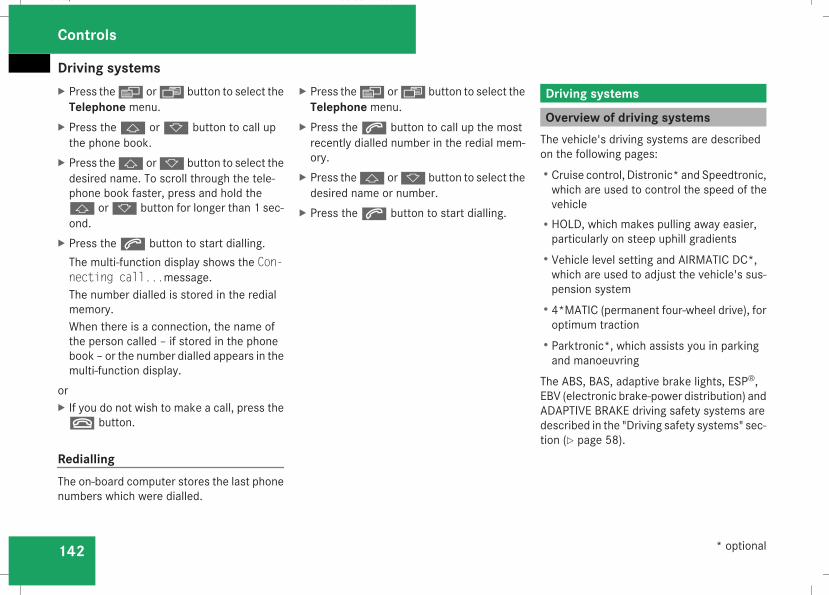
Driving systems
142
X Press theè or· button to select theTelephone menu.
X Press thej ork button to call upthe phone book.
X Press thej ork button to select thedesired name. To scroll through the tele-phone book faster, press and hold thej ork button for longer than 1 sec-ond.
X Press thes button to start dialling.The multi-function display shows the Con-necting call...message.The number dialled is stored in the redialmemory.When there is a connection, the name ofthe person called – if stored in the phonebook – or the number dialled appears in themulti-function display.
orX If you do not wish to make a call, press thet button.
RediallingThe on-board computer stores the last phonenumbers which were dialled.
X Press theè or· button to select theTelephone menu.
X Press thes button to call up the mostrecently dialled number in the redial mem-ory.
X Press thej ork button to select thedesired name or number.
X Press thes button to start dialling.
Driving systems
Overview of driving systemsThe vehicle's driving systems are describedon the following pages:RCruise control, Distronic* and Speedtronic,which are used to control the speed of thevehicle
RHOLD, which makes pulling away easier,particularly on steep uphill gradients
RVehicle level setting and AIRMATIC DC*,which are used to adjust the vehicle's sus-pension system
R4*MATIC (permanent four-wheel drive), foroptimum traction
RParktronic*, which assists you in parkingand manoeuvring
The ABS, BAS, adaptive brake lights, ESP®,EBV (electronic brake-power distribution) andADAPTIVE BRAKE driving safety systems aredescribed in the "Driving safety systems" sec-tion (Y page 58).
Controls
* optional
211_AKB; 2; 5, en-GBmkalafa, Version: 2.9.4
2008-02-29T16:57:07+01:00 - Seite 142
Dateiname: 6515_3416_02_buchblock.pdf; preflight

Driving systems
143
Cruise controlCruise control maintains a constant roadspeed for you. It brakes automatically in orderto avoid exceeding the set speed. On long andsteep downhill gradients, especially if thevehicle is laden or towing a trailer, you mustshift to a lower gear in good time or selectshift range1,2 or3 in vehicleswith automatictransmission*. By doing so you will make useof the braking effect of the engine, whichrelieves the load on the brake system andprevents the brakes from overheating andwearing too quickly.G Risk of accidentDo not change down for additional enginebraking on a slippery road surface. Thiscould cause the drive wheels to lose theirgrip and the vehicle could skid.
Use cruise control only if road and traffic con-ditions make it appropriate to maintain asteady speed for a prolonged period. You canstore any road speed above 30 km/h.G Risk of accidentCruise control cannot take account of roadand traffic conditions.Always pay attention to traffic conditionseven when cruise control is activated.
Cruise control is only an aid designed toassist driving. You are responsible for thevehicle's speed and for braking in goodtime.
G Risk of accidentDo not use cruise control:Rin road and traffic conditions which donot allow you to maintain a constantspeed (e.g. heavy traffic or windingroads). You could otherwise cause anaccident.
Ron slippery roads. Braking or accelerat-ing could cause the drive wheels to losetraction and the vehicle could then skid.
Rwhen there is poor visibility, e.g. due tofog, heavy rain or snow
Cruise control display in the speedom-eterWhen cruise control is activated, the seg-ments from the set speed to the maximumspeed light up in the multi-function display.
1 Segments
Cruise control leverYou can operate cruise control and variableSpeedtronic with the cruise control lever.The LIM indicator lamp on the cruise controllever indicates which system you have selec-ted:RLIM indicator lamp off:cruise control is selected
RLIM indicator lamp lit:variable Speedtronic is selected
Controls
* optional
211_AKB; 2; 5, en-GBmkalafa, Version: 2.9.4
2008-02-29T16:57:07+01:00 - Seite 143
Z
Dateiname: 6515_3416_02_buchblock.pdf; preflight
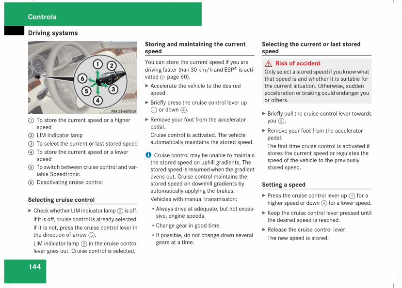
Driving systems
144
1 To store the current speed or a higherspeed2 LIM indicator lamp3 To select the current or last stored speed4 To store the current speed or a lower
speed5 To switch between cruise control and var-
iable Speedtronic6 Deactivating cruise control
Selecting cruise controlX Checkwhether LIM indicator lamp2 is off.If it is off, cruise control is already selected.If it is not, press the cruise control lever inthe direction of arrow5.LIM indicator lamp2 in the cruise controllever goes out. Cruise control is selected.
Storing and maintaining the currentspeedYou can store the current speed if you aredriving faster than 30 km/h and ESP® is acti-vated (Y page 60).X Accelerate the vehicle to the desiredspeed.
X Briefly press the cruise control lever up1 or down4.
X Remove your foot from the acceleratorpedal.Cruise control is activated. The vehicleautomatically maintains the stored speed.
i Cruise control may be unable to maintainthe stored speed on uphill gradients. Thestored speed is resumed when the gradientevens out. Cruise control maintains thestored speed on downhill gradients byautomatically applying the brakes.Vehicles with manual transmission:RAlways drive at adequate, but not exces-sive, engine speeds.
RChange gear in good time.RIf possible, do not change down severalgears at a time.
Selecting the current or last storedspeed
G Risk of accidentOnly select a stored speed if you knowwhatthat speed is and whether it is suitable forthe current situation. Otherwise, suddenacceleration or braking could endanger youor others.
X Briefly pull the cruise control lever towardsyou3.
X Remove your foot from the acceleratorpedal.The first time cruise control is activated itstores the current speed or regulates thespeed of the vehicle to the previouslystored speed.
Setting a speedX Press the cruise control lever up1 for ahigher speed or down4 for a lower speed.
X Keep the cruise control lever pressed untilthe desired speed is reached.
X Release the cruise control lever.The new speed is stored.
Controls
211_AKB; 2; 5, en-GBmkalafa, Version: 2.9.4
2008-02-29T16:57:07+01:00 - Seite 144
Dateiname: 6515_3416_02_buchblock.pdf; preflight
Driving systems
145
i Cruise control is not deactivated if youdepress the accelerator pedal. For exam-ple, if you accelerate briefly to overtake,cruise control adjusts the vehicle's speedto the last speed stored after you have fin-ished overtaking.
i Deceleration of the vehicle by means ofthe cruise control lever is assisted by auto-matic application of the brakes.Vehicles with automatic transmission*:On long downhill gradients, the automatictransmission shifts down as a furthermeas-ure.
Making fine adjustments in 1 km/hincrementsX Briefly press the cruise control lever up1 for a higher speed or down4 for alower speed.The last speed stored is increased orreduced.
Deactivating cruise controlThere are several ways to deactivate cruisecontrol:
X Briefly press the cruise control lever for-wards6.
orX Brake.orX Briefly press the cruise control lever in thedirection of arrow5.Variable Speedtronic is selected. LIM indi-cator lamp2 in the cruise control leverlights up.
Cruise control is automatically deactivated if,for example:Ryou depress the parking brakeRyou are driving at less than 30 km/hRESP® is intervening or you deactivateESP®
Ryoumove the selector lever toN in vehicleswith automatic transmission* while driving
If cruise control is deactivated, you will heara warning tone. You will see the Cruise con-trol off message in the multi-function dis-play for approximately five seconds.
i The last speed stored is cleared when youswitch off the engine.
Distronic*Distronic regulates the speed and automati-cally maintains the distance to the vehicle infront. It brakes automatically in order to avoidexceeding the set speed. On long and steepdownhill gradients, especially if the vehicle isladen or towing a trailer, you must select shiftrange 1, 2 or 3. By doing so,you will make useof the braking effect of the engine, whichrelieves the load on the brake system andprevents the brakes from overheating andwearing too quickly.G Risk of accidentDo not change down for additional enginebraking on a slippery road surface. Thiscould cause the drive wheels to lose theirgrip and the vehicle could skid.
G Risk of accidentDistronic is only an aid designed to assistdriving. The driver remains fully responsiblefor the vehicle's distance from other vehi-cles, the vehicle's speed and braking ingood time.
Controls
* optional
211_AKB; 2; 5, en-GBmkalafa, Version: 2.9.4
2008-02-29T16:57:07+01:00 - Seite 145
Z
Dateiname: 6515_3416_02_buchblock.pdf; preflight
Driving systems
146
Distronic does not react to:RpedestriansRstationary obstacles on the road, e.g. sta-tionary or parked vehicles
Roncoming and crossing trafficDistronic may not detect narrow vehiclesdriving in front, e.g. motorcycles, or vehi-cles driving on a different line. Therefore,always pay attention to traffic conditionseven when Distronic is activated. Other-wise, you may fail to recognise dangers intime, could cause an accident and injureyourself and others.
If a slower-moving vehicle is detected in front,Distronic causes your vehicle to brake andmaintain a preset distance to the vehicle infront.G Risk of accidentDistronic cannot take account of road andtraffic conditions. Deactivate, or do notactivate, Distronic if it does not detect thevehicle in front, or if it no longer detects it.This is especially the case:Rbefore cornersRon filter lanes
Rwhen changing to a lane with faster mov-ing traffic
Rin complex driving situations or wherethe lanes are diverted, e.g. at motorway/roadway construction sites
Otherwise, Distronic maintains the currentspeed or accelerates to the set speed.Distronic cannot take account of weatherconditions. Deactivate, or do not activate,Distronic:Rif the roads are slippery, snow-covered oricy. The wheels could lose their gripunder braking or acceleration. The vehi-cle could start to skid.
Rif the sensors are dirty or there is poorvisibility, e.g. due to snow, rain or fog.Distance control may be impaired.
Always pay attention to traffic conditionseven when Distronic is activated. Other-wise, you may fail to recognise dangers intime, could cause an accident and injureyourself and others.
If there is no vehicle in front, Distronic oper-ates in the same way as cruise control. Dis-tronic functions in the 30 km/h to180 km/h range.
G Risk of accidentDistronic brakes your vehicle at amaximumof 2 m/s2, depending on its speed. Thiscorresponds to approximately 20% of yourvehicle's maximum braking power. Youmust also apply the brakes yourself if thisbraking power is not sufficient.If Distronic detects a risk of collision with avehicle in front, an intermittent warningtone sounds. In addition, thel distancewarning lamp in the instrument clusterlights up. Brake to avoid a collision.
Cruise control leverWith the cruise control lever you can operateDistronic and variable Speedtronic.The LIM indicator lamp on the cruise controllever indicates which system you have selec-ted:RLIM indicator lamp off:Distronic is selected
RLIM indicator lamp lit:variable Speedtronic is selected
Controls
211_AKB; 2; 5, en-GBmkalafa, Version: 2.9.4
2008-02-29T16:57:07+01:00 - Seite 146
Dateiname: 6515_3416_02_buchblock.pdf; preflight
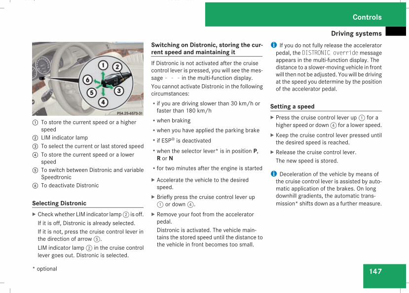
Driving systems
147
1 To store the current speed or a higherspeed2 LIM indicator lamp3 To select the current or last stored speed4 To store the current speed or a lower
speed5 To switch between Distronic and variable
Speedtronic6 To deactivate Distronic
Selecting DistronicX Checkwhether LIM indicator lamp2 is off.If it is off, Distronic is already selected.If it is not, press the cruise control lever inthe direction of arrow5.LIM indicator lamp2 in the cruise controllever goes out. Distronic is selected.
Switching on Distronic, storing the cur-rent speed and maintaining itIf Distronic is not activated after the cruisecontrol lever is pressed, you will see the mes-sage - - - in the multi-function display.You cannot activate Distronic in the followingcircumstances:Rif you are driving slower than 30 km/h orfaster than 180 km/h
Rwhen brakingRwhen you have applied the parking brakeRif ESP® is deactivatedRwhen the selector lever* is in position P,R or N
Rfor two minutes after the engine is started
X Accelerate the vehicle to the desiredspeed.
X Briefly press the cruise control lever up1 or down4.
X Remove your foot from the acceleratorpedal.Distronic is activated. The vehicle main-tains the stored speed until the distance tothe vehicle in front becomes too small.
i If you do not fully release the acceleratorpedal, the DISTRONIC override messageappears in the multi-function display. Thedistance to a slower-moving vehicle in frontwill then not be adjusted. Youwill be drivingat the speed you determine by the positionof the accelerator pedal.
Setting a speedX Press the cruise control lever up1 for ahigher speed or down4 for a lower speed.
X Keep the cruise control lever pressed untilthe desired speed is reached.
X Release the cruise control lever.The new speed is stored.
i Deceleration of the vehicle by means ofthe cruise control lever is assisted by auto-matic application of the brakes. On longdownhill gradients, the automatic trans-mission* shifts down as a further measure.
Controls
* optional
211_AKB; 2; 5, en-GBmkalafa, Version: 2.9.4
2008-02-29T16:57:07+01:00 - Seite 147
Z
Dateiname: 6515_3416_02_buchblock.pdf; preflight
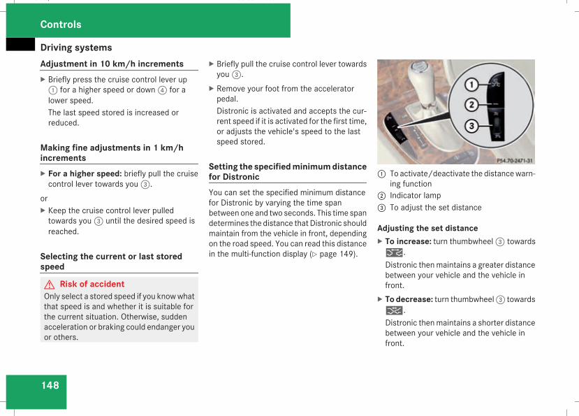
Driving systems
148
Adjustment in 10 km/h incrementsX Briefly press the cruise control lever up1 for a higher speed or down4 for alower speed.The last speed stored is increased orreduced.
Making fine adjustments in 1 km/hincrementsX For a higher speed: briefly pull the cruisecontrol lever towards you3.
orX Keep the cruise control lever pulledtowards you3 until the desired speed isreached.
Selecting the current or last storedspeed
G Risk of accidentOnly select a stored speed if you knowwhatthat speed is and whether it is suitable forthe current situation. Otherwise, suddenacceleration or braking could endanger youor others.
X Briefly pull the cruise control lever towardsyou3.
X Remove your foot from the acceleratorpedal.Distronic is activated and accepts the cur-rent speed if it is activated for the first time,or adjusts the vehicle's speed to the lastspeed stored.
Setting the specifiedminimumdistancefor DistronicYou can set the specified minimum distancefor Distronic by varying the time spanbetween one and two seconds. This time spandetermines the distance that Distronic shouldmaintain from the vehicle in front, dependingon the road speed. You can read this distancein the multi-function display (Y page 149).
1 To activate/deactivate the distancewarn-ing function2 Indicator lamp3 To adjust the set distance
Adjusting the set distanceX To increase: turn thumbwheel3 towards¯.Distronic thenmaintains a greater distancebetween your vehicle and the vehicle infront.
X To decrease: turn thumbwheel3 towards®.Distronic thenmaintains a shorter distancebetween your vehicle and the vehicle infront.
Controls
211_AKB; 2; 5, en-GBmkalafa, Version: 2.9.4
2008-02-29T16:57:07+01:00 - Seite 148
Dateiname: 6515_3416_02_buchblock.pdf; preflight
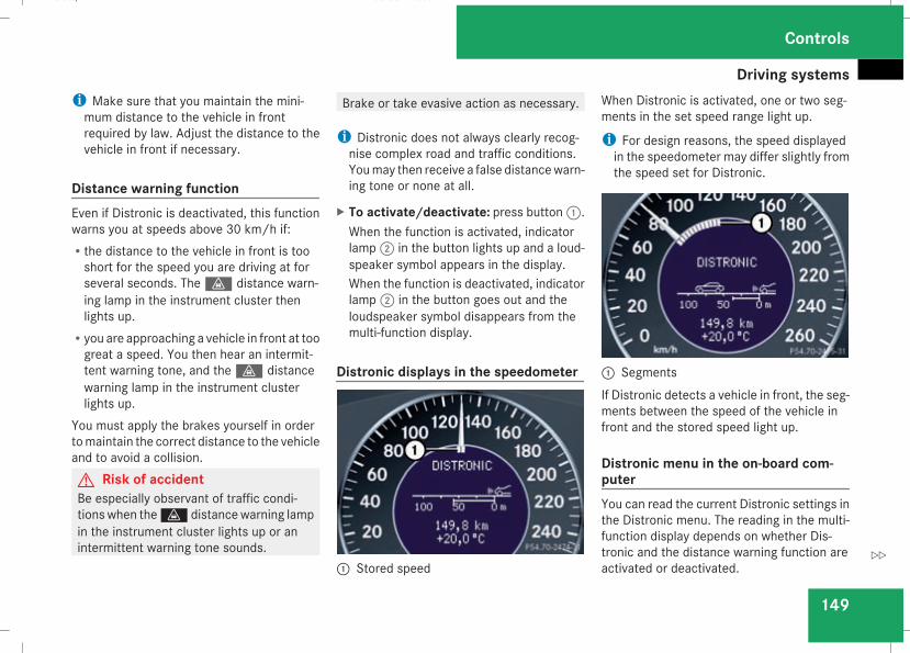
Driving systems
149
i Make sure that you maintain the mini-mum distance to the vehicle in frontrequired by law. Adjust the distance to thevehicle in front if necessary.
Distance warning functionEven if Distronic is deactivated, this functionwarns you at speeds above 30 km/h if:Rthe distance to the vehicle in front is tooshort for the speed you are driving at forseveral seconds. Thel distance warn-ing lamp in the instrument cluster thenlights up.
Ryou are approaching a vehicle in front at toogreat a speed. You then hear an intermit-tent warning tone, and thel distancewarning lamp in the instrument clusterlights up.
You must apply the brakes yourself in ordertomaintain the correct distance to the vehicleand to avoid a collision.G Risk of accidentBe especially observant of traffic condi-tions when thel distancewarning lampin the instrument cluster lights up or anintermittent warning tone sounds.
Brake or take evasive action as necessary.
i Distronic does not always clearly recog-nise complex road and traffic conditions.Youmay then receive a false distancewarn-ing tone or none at all.
X To activate/deactivate: press button1.When the function is activated, indicatorlamp2 in the button lights up and a loud-speaker symbol appears in the display.When the function is deactivated, indicatorlamp2 in the button goes out and theloudspeaker symbol disappears from themulti-function display.
Distronic displays in the speedometer
1 Stored speed
When Distronic is activated, one or two seg-ments in the set speed range light up.
i For design reasons, the speed displayedin the speedometer may differ slightly fromthe speed set for Distronic.
1 SegmentsIf Distronic detects a vehicle in front, the seg-ments between the speed of the vehicle infront and the stored speed light up.
Distronic menu in the on-board com-puterYou can read the current Distronic settings inthe Distronic menu. The reading in the multi-function display depends on whether Dis-tronic and the distance warning function areactivated or deactivated.
Controls
211_AKB; 2; 5, en-GBmkalafa, Version: 2.9.4
2008-02-29T16:57:07+01:00 - Seite 149
Z
Dateiname: 6515_3416_02_buchblock.pdf; preflight
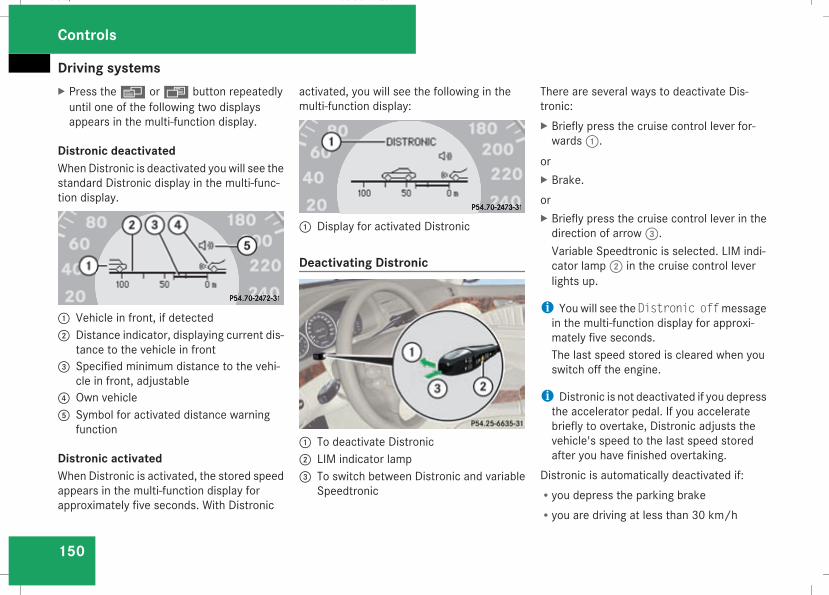
Driving systems
150
X Press theè orÿ button repeatedlyuntil one of the following two displaysappears in the multi-function display.
Distronic deactivatedWhenDistronic is deactivated youwill see thestandard Distronic display in the multi-func-tion display.
1 Vehicle in front, if detected2 Distance indicator, displaying current dis-
tance to the vehicle in front3 Specified minimum distance to the vehi-
cle in front, adjustable4 Own vehicle5 Symbol for activated distance warning
function
Distronic activatedWhen Distronic is activated, the stored speedappears in the multi-function display forapproximately five seconds. With Distronic
activated, you will see the following in themulti-function display:
1 Display for activated Distronic
Deactivating Distronic
1 To deactivate Distronic2 LIM indicator lamp3 To switch between Distronic and variable
Speedtronic
There are several ways to deactivate Dis-tronic:X Briefly press the cruise control lever for-wards1.
orX Brake.orX Briefly press the cruise control lever in thedirection of arrow3.Variable Speedtronic is selected. LIM indi-cator lamp2 in the cruise control leverlights up.
i You will see the Distronic offmessagein the multi-function display for approxi-mately five seconds.The last speed stored is cleared when youswitch off the engine.
i Distronic is not deactivated if you depressthe accelerator pedal. If you acceleratebriefly to overtake, Distronic adjusts thevehicle's speed to the last speed storedafter you have finished overtaking.
Distronic is automatically deactivated if:Ryou depress the parking brakeRyou are driving at less than 30 km/h
Controls
211_AKB; 2; 5, en-GBmkalafa, Version: 2.9.4
2008-02-29T16:57:07+01:00 - Seite 150
Dateiname: 6515_3416_02_buchblock.pdf; preflight
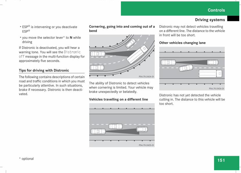
Driving systems
151
RESP® is intervening or you deactivateESP®
Ryou move the selector lever* to N whiledriving
If Distronic is deactivated, you will hear awarning tone. You will see the Distronicoffmessage in the multi-function display forapproximately five seconds.
Tips for driving with DistronicThe following contains descriptions of certainroad and traffic conditions in which you mustbe particularly attentive. In such situations,brake if necessary. Distronic is then deacti-vated.
Cornering, going into and coming out of abend
The ability of Distronic to detect vehicleswhen cornering is limited. Your vehicle maybrake unexpectedly or belatedly.
Vehicles travelling on a different line
Distronic may not detect vehicles travellingon a different line. The distance to the vehiclein front will be too short.
Other vehicles changing lane
Distronic has not yet detected the vehiclecutting in. The distance to this vehicle will betoo short.
Controls
* optional
211_AKB; 2; 5, en-GBmkalafa, Version: 2.9.4
2008-02-29T16:57:07+01:00 - Seite 151
Z
Dateiname: 6515_3416_02_buchblock.pdf; preflight
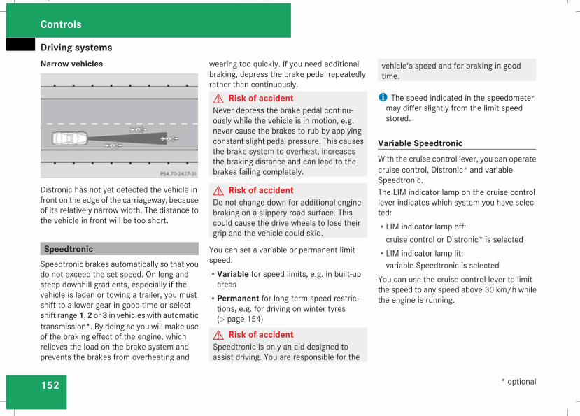
Driving systems
152
Narrow vehicles
Distronic has not yet detected the vehicle infront on the edge of the carriageway, becauseof its relatively narrow width. The distance tothe vehicle in front will be too short.
SpeedtronicSpeedtronic brakes automatically so that youdo not exceed the set speed. On long andsteep downhill gradients, especially if thevehicle is laden or towing a trailer, you mustshift to a lower gear in good time or selectshift range1,2 or3 in vehicleswith automatictransmission*. By doing so you will make useof the braking effect of the engine, whichrelieves the load on the brake system andprevents the brakes from overheating and
wearing too quickly. If you need additionalbraking, depress the brake pedal repeatedlyrather than continuously.G Risk of accidentNever depress the brake pedal continu-ously while the vehicle is in motion, e.g.never cause the brakes to rub by applyingconstant slight pedal pressure. This causesthe brake system to overheat, increasesthe braking distance and can lead to thebrakes failing completely.
G Risk of accidentDo not change down for additional enginebraking on a slippery road surface. Thiscould cause the drive wheels to lose theirgrip and the vehicle could skid.
You can set a variable or permanent limitspeed:RVariable for speed limits, e.g. in built-upareas
RPermanent for long-term speed restric-tions, e.g. for driving on winter tyres(Y page 154)
G Risk of accidentSpeedtronic is only an aid designed toassist driving. You are responsible for the
vehicle's speed and for braking in goodtime.
i The speed indicated in the speedometermay differ slightly from the limit speedstored.
Variable SpeedtronicWith the cruise control lever, you can operatecruise control, Distronic* and variableSpeedtronic.The LIM indicator lamp on the cruise controllever indicates which system you have selec-ted:RLIM indicator lamp off:cruise control or Distronic* is selected
RLIM indicator lamp lit:variable Speedtronic is selected
You can use the cruise control lever to limitthe speed to any speed above 30 km/h whilethe engine is running.
Controls
* optional
211_AKB; 2; 5, en-GBmkalafa, Version: 2.9.4
2008-02-29T16:57:07+01:00 - Seite 152
Dateiname: 6515_3416_02_buchblock.pdf; preflight
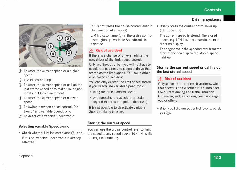
Driving systems
153
1 To store the current speed or a higherspeed2 LIM indicator lamp3 To store the current speed or call up the
last stored speed or to make fine adjust-ments in 1 km/h increments4 To store the current speed or a lower
speed5 To switch between cruise control, Dis-
tronic* and variable Speedtronic6 To deactivate variable Speedtronic
Selecting variable SpeedtronicX Checkwhether LIM indicator lamp2 is on.If it is on, variable Speedtronic is alreadyselected.
If it is not, press the cruise control lever inthe direction of arrow5.LIM indicator lamp2 in the cruise controllever lights up. Variable Speedtronic isselected.
G Risk of accidentIf there is a change of drivers, advise thenew driver of the limit speed stored.Only use Speedtronic if you will not have toaccelerate suddenly to a speed above thatstored as the limit speed. You could other-wise cause an accident.You can only exceed the limit speed storedif you deactivate variable Speedtronic:Rusing the cruise control lever.Rby depressing the accelerator pedalbeyond the pressure point (kickdown).
It is not possible to deactivate variableSpeedtronic by braking.
Storing the current speedYou can use the cruise control lever to limitthe speed to any speed above 30 km/h whilethe engine is running.
X Briefly press the cruise control lever up1 or down4.The current speed is stored. The storedspeed, e.g. LIM km/h, appears in the multi-function display.The segments in the speedometer from thestart of the scale up to the stored speedlight up.
Storing the current speed or calling upthe last stored speed
G Risk of accidentOnly select a stored speed if you knowwhatthat speed is and whether it is suitable forthe current driving and traffic situation.Otherwise, sudden braking could endangeryou or others.
X Briefly pull the cruise control lever towardsyou3.
Controls
* optional
211_AKB; 2; 5, en-GBmkalafa, Version: 2.9.4
2008-02-29T16:57:07+01:00 - Seite 153
Z
Dateiname: 6515_3416_02_buchblock.pdf; preflight
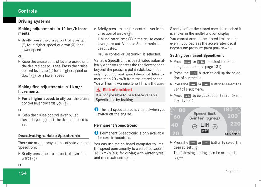
Driving systems
154
Making adjustments in 10 km/h incre-mentsX Briefly press the cruise control lever up1 for a higher speed or down4 for alower speed.
orX Keep the cruise control lever pressed untilthe desired speed is set. Press the cruisecontrol lever, up1 for a higher speed ordown4 for a lower speed.
Making fine adjustments in 1 km/hincrementsX For a higher speed: briefly pull the cruisecontrol lever towards you3.
orX Keep the cruise control lever pulledtowards you3 until the desired speed isset.
Deactivating variable SpeedtronicThere are several ways to deactivate variableSpeedtronic:X Briefly press the cruise control lever for-wards6.
or
X Briefly press the cruise control lever in thedirection of arrow5.LIM indicator lamp2 in the cruise controllever goes out. Variable Speedtronic isdeactivated.Cruise control or Distronic* is selected.
Variable Speedtronic is deactivated automat-ically when you depress the accelerator pedalbeyond the pressure point (kickdown) butonly if your current speed does not differ bymore than 20 km/h from the stored speed.You will hear a warning tone if this is the case.G Risk of accidentIt is not possible to deactivate variableSpeedtronic by braking.
i The last speed stored is cleared when youswitch off the engine.
Permanent Speedtronici Permanent Speedtronic is only availablefor certain countries.
You can use the on-board computer to limitthe speed permanently to a value between160 km/h (e.g. for driving with winter tyres)and the maximum speed.
Shortly before the stored speed is reached itis shown in the multi-function display.You cannot exceed the stored limit speed,even if you depress the accelerator pedalbeyond the pressure point (kickdown).
Setting permanent SpeedtronicX Pressè or· to select the Set-tings... menu (Y page 131).
X Press thej button to call up the selec-tion of submenus.
X Press theæ orç button to select theVehicle submenu.
X Pressj to select Speed limit (win-ter tyres).
X Press theæ orç button to select thedesired setting.The following settings can be selected:ROff
Controls
* optional
211_AKB; 2; 5, en-GBmkalafa, Version: 2.9.4
2008-02-29T16:57:07+01:00 - Seite 154
Dateiname: 6515_3416_02_buchblock.pdf; preflight
Driving systems
155
Permanent Speedtronic is deactivated.RA limit speed between 240 km/h and160 km/h in increments of 10 km/h.
X To select a different display, press thej,è orÿ button.
HOLDHOLD relieves the strain on the driver:Rwhen pulling away, especially on steepslopes
Rwhen manoeuvring on steep slopesRwhen waiting in trafficThe vehicle is kept stationary without thedriver having to depress the brake pedal.The braking effect is cancelled and HOLDdeactivated when you depress the accelera-tor pedal to pull away.
Activation conditionsYou can activate HOLD if:Rthe vehicle is stationaryRthe engine is runningRthe driver's door is closedRthe parking brake is not applied
Rthe bonnet is closedRon vehicles with automatic transmission*,the selector lever is in position D, R or N
Activating HOLDX Make sure that the activation conditionsare met.
X Depress the brake.X Depress the brake again quickly untilHOLD appears in the display.HOLD is activated. You can release thebrake pedal.
i If depressing the brake pedal the firsttime does not activate HOLD, wait brieflyand then try again.
G Risk of accidentThe vehicle's brakes are applied whenHOLD is activated. For this reason, deacti-vate HOLD if the vehicle is to be set inmotion by other means (e.g. in a car washor by towing).
Deactivating HOLDHOLD is deactivated if:Ryou accelerate. On vehicles with automatictransmission*, only if the selector lever isin position D or R.
Rthe selector lever is moved to P on vehicleswith automatic transmission*
Ryou release the brakes completely andapply them again with a certain amount ofpressure until the HOLD message in themulti-function display goes out
G Risk of accidentNever get out of the vehicle when HOLD isactivated.HOLD must never be operated or deactiva-ted by a passenger or from outside thevehicle.HOLD does not replace the parking brakeand must not be used for parking.The HOLD braking effect is cancelled andthe vehicle can start moving if:
Controls
* optional
211_AKB; 2; 5, en-GBmkalafa, Version: 2.9.4
2008-02-29T16:57:07+01:00 - Seite 155
Z
Dateiname: 6515_3416_02_buchblock.pdf; preflight
Driving systems
156
RHOLD is deactivated by depressing theaccelerator pedal or the brake pedal
Rthere is a malfunction in the system or aninterruption in the power supply, e.g. bat-tery failure
Rthe electrical system in the engine com-partment, the battery or the fuses aretampered with
Rthe battery is disconnected
G Risk of accidentIf you wish to leave the vehicle or park it,deactivate HOLD and secure the vehicleagainst rolling away.
You will see a warning message in the multi-function display if HOLD is activated and:Rthe driver's door is opened and you releasethe seat belt
Rthe ignition is switched offRthe bonnet is openedVehicles with manual transmission:Brake immediatelyX Immediately depress the brake pedal firmlyuntil the warning message in the multi-function display goes out. This deactivatesHOLD.
Vehicles with automatic transmission*:Selector lever in park positionX Move the selector lever to P to prevent thevehicle from rolling away.HOLD is deactivated. Thewarningmessagein the multi-function display goes out.
A horn will also sound at regular intervals ifHOLD is activated and you:Rstop the engine and open the driver's doorRopen the bonnetThe horn draws your attention to the fact thatthe vehicle has been parked while HOLD isstill activated. The sound becomes louder ifyou attempt to lock the vehicle. The vehicleis not locked until HOLD is deactivated.
i If the ignition has been switched off, theengine cannot be restarted until HOLD isdeactivated.
If there is a fault in the systemor power supplywhile HOLD is activated, the Brake immedi-atelymessage appears in the multi-functiondisplay. Immediately depress the brake firmlyuntil the warning message disappears fromthe multi-function display, or in vehicles withautomatic transmission*, move the selectorlever to P. This deactivates HOLD.
AIRMATIC DC*
Vehicle levelYour vehicle automatically adjusts its rideheight to reduce petrol consumption andimprove driving safety.The following vehicle levels are possible:RNormalRRaisedRLoweredThe "Normal" and "Raised" vehicle levels canbe set manually.The "Lowered" vehicle level is set automati-cally:Rat speeds above 140 km/hRif you have selected "Sports tuning I orII" (Y page 157)
Setting the vehicle level manuallySelect the "Normal" setting for normal roadsurfaces and "Raised" for driving with snowchains or on particularly poor road surfaces.G Risk of injuryMake sure that nobody is in the vicinity ofthe wheel housing or under the vehicle
Controls
* optional
211_AKB; 2; 5, en-GBmkalafa, Version: 2.9.4
2008-02-29T16:57:07+01:00 - Seite 156
Dateiname: 6515_3416_02_buchblock.pdf; preflight
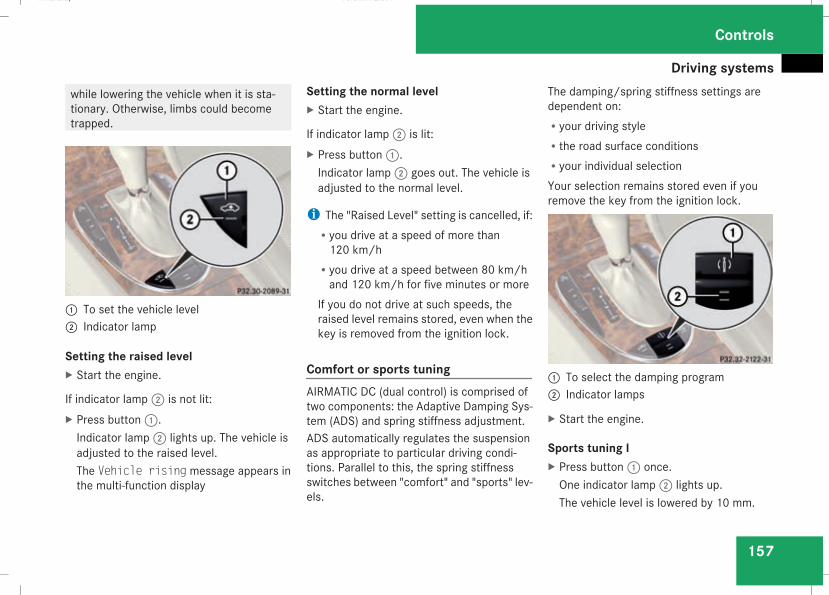
Driving systems
157
while lowering the vehicle when it is sta-tionary. Otherwise, limbs could becometrapped.
1 To set the vehicle level2 Indicator lamp
Setting the raised levelX Start the engine.
If indicator lamp2 is not lit:X Press button1.Indicator lamp2 lights up. The vehicle isadjusted to the raised level.The Vehicle rising message appears inthe multi-function display
Setting the normal levelX Start the engine.
If indicator lamp2 is lit:X Press button1.Indicator lamp2 goes out. The vehicle isadjusted to the normal level.
i The "Raised Level" setting is cancelled, if:Ryou drive at a speed of more than120 km/h
Ryou drive at a speed between 80 km/hand 120 km/h for five minutes or more
If you do not drive at such speeds, theraised level remains stored, even when thekey is removed from the ignition lock.
Comfort or sports tuningAIRMATIC DC (dual control) is comprised oftwo components: the Adaptive Damping Sys-tem (ADS) and spring stiffness adjustment.ADS automatically regulates the suspensionas appropriate to particular driving condi-tions. Parallel to this, the spring stiffnessswitches between "comfort" and "sports" lev-els.
The damping/spring stiffness settings aredependent on:Ryour driving styleRthe road surface conditionsRyour individual selectionYour selection remains stored even if youremove the key from the ignition lock.
1 To select the damping program2 Indicator lamps
X Start the engine.
Sports tuning IX Press button1 once.One indicator lamp2 lights up.The vehicle level is lowered by 10 mm.
Controls
211_AKB; 2; 5, en-GBmkalafa, Version: 2.9.4
2008-02-29T16:57:07+01:00 - Seite 157
Z
Dateiname: 6515_3416_02_buchblock.pdf; preflight
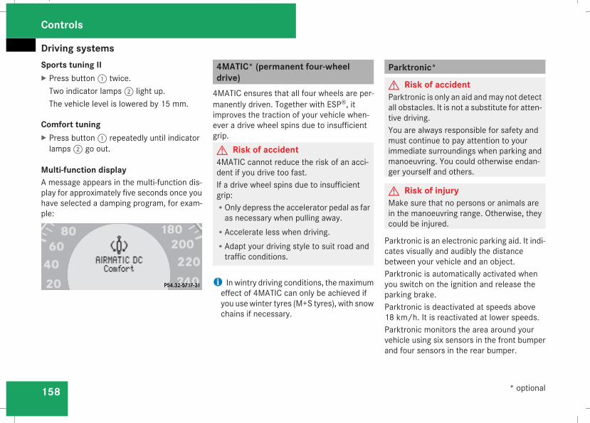
Driving systems
158
Sports tuning IIX Press button1 twice.Two indicator lamps2 light up.The vehicle level is lowered by 15 mm.
Comfort tuningX Press button1 repeatedly until indicatorlamps2 go out.
Multi-function displayA message appears in the multi-function dis-play for approximately five seconds once youhave selected a damping program, for exam-ple:
4MATIC* (permanent four-wheeldrive)4MATIC ensures that all four wheels are per-manently driven. Together with ESP®, itimproves the traction of your vehicle when-ever a drive wheel spins due to insufficientgrip.G Risk of accident4MATIC cannot reduce the risk of an acci-dent if you drive too fast.If a drive wheel spins due to insufficientgrip:ROnly depress the accelerator pedal as faras necessary when pulling away.
RAccelerate less when driving.RAdapt your driving style to suit road andtraffic conditions.
i In wintry driving conditions, themaximumeffect of 4MATIC can only be achieved ifyou usewinter tyres (M+S tyres), with snowchains if necessary.
Parktronic*
G Risk of accidentParktronic is only an aid andmay not detectall obstacles. It is not a substitute for atten-tive driving.You are always responsible for safety andmust continue to pay attention to yourimmediate surroundings when parking andmanoeuvring. You could otherwise endan-ger yourself and others.
G Risk of injuryMake sure that no persons or animals arein the manoeuvring range. Otherwise, theycould be injured.
Parktronic is an electronic parking aid. It indi-cates visually and audibly the distancebetween your vehicle and an object.Parktronic is automatically activated whenyou switch on the ignition and release theparking brake.Parktronic is deactivated at speeds above18 km/h. It is reactivated at lower speeds.Parktronic monitors the area around yourvehicle using six sensors in the front bumperand four sensors in the rear bumper.
Controls
* optional
211_AKB; 2; 5, en-GBmkalafa, Version: 2.9.4
2008-02-29T16:57:07+01:00 - Seite 158
Dateiname: 6515_3416_02_buchblock.pdf; preflight
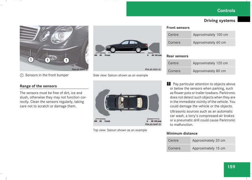
Driving systems
159
1 Sensors in the front bumper
Range of the sensorsThe sensors must be free of dirt, ice andslush, otherwise they may not function cor-rectly. Clean the sensors regularly, takingcare not to scratch or damage them.
Side view: Saloon shown as an example
Top view: Saloon shown as an example
Front sensors
Centre Approximately 100 cm
Corners Approximately 60 cm
Rear sensors
Centre Approximately 120 cm
Corners Approximately 80 cm
! Pay particular attention to objects aboveor below the sensors when parking, suchas flower pots or trailer towbars. Parktronicdoes not detect such objects when they arein the immediate vicinity of the vehicle. Youcould damage the vehicle or the objects.Ultrasonic sources such as an automaticcar wash, a lorry's compressed-air brakesor a pneumatic drill could cause Parktronicto malfunction.
Minimum distance
Centre Approximately 20 cm
Corners Approximately 15 cm
Controls
211_AKB; 2; 5, en-GBmkalafa, Version: 2.9.4
2008-02-29T16:57:07+01:00 - Seite 159
Z
Dateiname: 6515_3416_02_buchblock.pdf; preflight
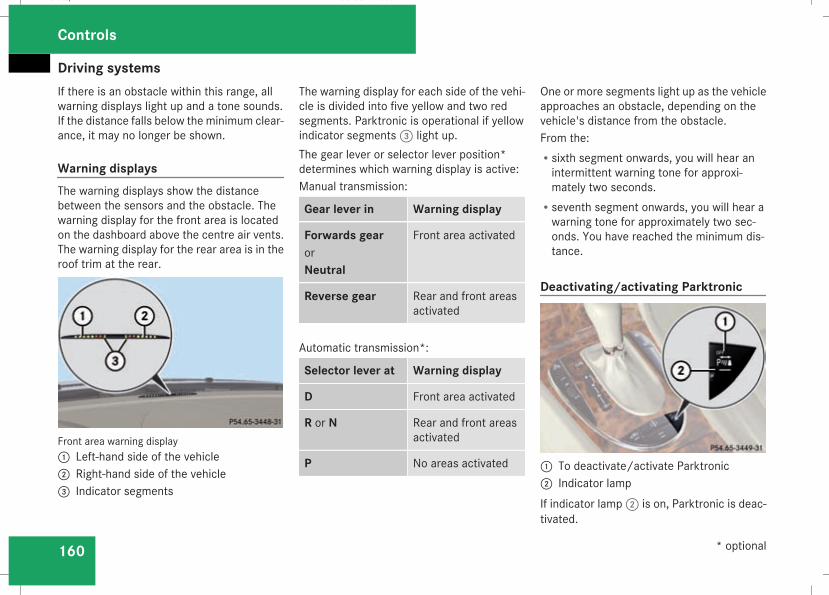
Driving systems
160
If there is an obstacle within this range, allwarning displays light up and a tone sounds.If the distance falls below the minimum clear-ance, it may no longer be shown.
Warning displaysThe warning displays show the distancebetween the sensors and the obstacle. Thewarning display for the front area is locatedon the dashboard above the centre air vents.The warning display for the rear area is in theroof trim at the rear.
Front area warning display1 Left-hand side of the vehicle2 Right-hand side of the vehicle3 Indicator segments
The warning display for each side of the vehi-cle is divided into five yellow and two redsegments. Parktronic is operational if yellowindicator segments3 light up.The gear lever or selector lever position*determines which warning display is active:Manual transmission:
Gear lever in Warning display
Forwards gearorNeutral
Front area activated
Reverse gear Rear and front areasactivated
Automatic transmission*:
Selector lever at Warning display
D Front area activated
R or N Rear and front areasactivated
P No areas activated
One or more segments light up as the vehicleapproaches an obstacle, depending on thevehicle's distance from the obstacle.From the:Rsixth segment onwards, you will hear anintermittent warning tone for approxi-mately two seconds.
Rseventh segment onwards, you will hear awarning tone for approximately two sec-onds. You have reached the minimum dis-tance.
Deactivating/activating Parktronic
1 To deactivate/activate Parktronic2 Indicator lampIf indicator lamp2 is on, Parktronic is deac-tivated.
Controls
* optional
211_AKB; 2; 5, en-GBmkalafa, Version: 2.9.4
2008-02-29T16:57:07+01:00 - Seite 160
Dateiname: 6515_3416_02_buchblock.pdf; preflight
Driving systems
161
i Parktronic is automatically activatedwhen you turn the key to position 2 in theignition lock.
Trailer towing*Parktronic is deactivated for the rear areawhen you establish an electrical connectionbetween your vehicle and the trailer.
! Fold in the ball coupling if the trailer towhitch is not required. Parktronic measuresthe minimum detection range to an obsta-cle from the bumper, not the ball coupling.
Controls
* optional
211_AKB; 2; 5, en-GBmkalafa, Version: 2.9.4
2008-02-29T16:57:07+01:00 - Seite 161
Z
Dateiname: 6515_3416_02_buchblock.pdf; preflight
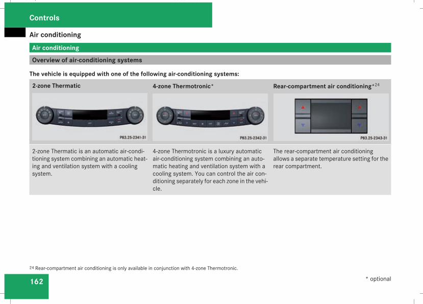
Air conditioning
162
Air conditioning
Overview of air-conditioning systems
The vehicle is equipped with one of the following air-conditioning systems:
2-zone Thermatic 4-zone Thermotronic* Rear-compartment air conditioning*24
2-zone Thermatic is an automatic air-condi-tioning system combining an automatic heat-ing and ventilation system with a coolingsystem.
4-zone Thermotronic is a luxury automaticair-conditioning system combining an auto-matic heating and ventilation system with acooling system. You can control the air con-ditioning separately for each zone in the vehi-cle.
The rear-compartment air conditioningallows a separate temperature setting for therear compartment.
24 Rear-compartment air conditioning is only available in conjunction with 4-zone Thermotronic.
Controls
* optional
211_AKB; 2; 5, en-GBmkalafa, Version: 2.9.4
2008-02-29T16:57:07+01:00 - Seite 162
Dateiname: 6515_3416_02_buchblock.pdf; preflight
Air conditioning
163
General notes2-zone Thermatic controls the temperature ofthe vehicle interior and filters out undesirablesubstances from the air.4-zone Thermotronic* controls the tempera-ture and the humidity of the vehicle interiorand filters out undesirable substances fromthe air.2-zone Thermatic/4-zone Thermotronic* isonly operational when the engine is running.Optimum operation is only achieved whenyou drive with the side windows and sliding/
tilting sunroof*/panorama sliding sunroof*closed.
i Ventilate the vehicle for a brief periodduring warm weather, e.g. using the sum-mer opening feature (Y page 109). This willspeed up the cooling process and thedesired interior temperature will bereached more quickly.
i The integrated filter filters out most par-ticles of dust and completely filters outpollen. A clogged filter reduces the amount
of air supplied to the vehicle interior. Forthis reason, you should always observe theinterval for replacing the filter, which isspecified in the Service Booklet. As itdepends on environmental conditions, e.g.heavy air pollution, the interval may beshorter than stated in the Service Booklet.
G Risk of accidentObserve the settings recommended on thefollowing pages. The windows could other-wise mist up. This may obstruct your viewof the traffic situation, thereby causing anaccident.
Controls
* optional
211_AKB; 2; 5, en-GBmkalafa, Version: 2.9.4
2008-02-29T16:57:07+01:00 - Seite 163
Z
Dateiname: 6515_3416_02_buchblock.pdf; preflight
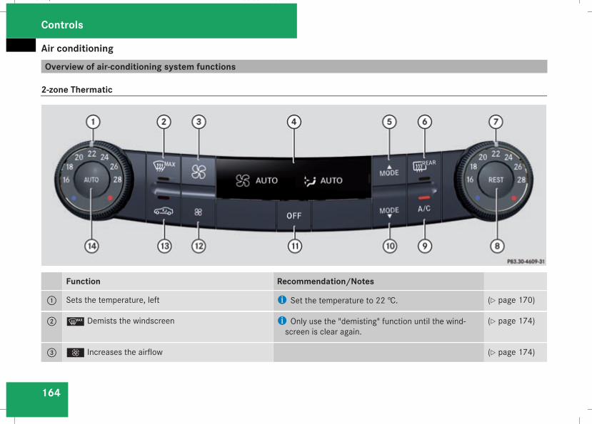
Air conditioning
164
Overview of air-conditioning system functions
2-zone Thermatic
Function Recommendation/Notes
1 Sets the temperature, left i Set the temperature to 22 †. (Y page 170)
2 y Demists the windscreen i Only use the "demisting" function until the wind-screen is clear again.
(Y page 174)
3 Q Increases the airflow (Y page 174)
Controls
211_AKB; 2; 5, en-GBmkalafa, Version: 2.9.4
2008-02-29T16:57:07+01:00 - Seite 164
Dateiname: 6515_3416_02_buchblock.pdf; preflight
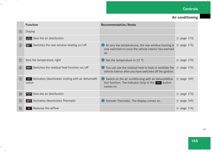
Air conditioning
165
Function Recommendation/Notes
4 Display
5 © Sets the air distribution (Y page 173)
6 ¯ Switches the rear window heating on/off i At very low temperatures, the rear window heating isonly switched on once the vehicle interior has warmedup.
(Y page 175)
7 Sets the temperature, right i Set the temperature to 22 †. (Y page 170)
8 T Switches the residual heat function on/off i You can use the residual heat to heat or ventilate thevehicle interior after you have switched off the ignition.
(Y page 176)
9 2 Activates/deactivates cooling with air dehumidifi-cation
i Switch on the air conditioning with air-dehumidifica-tion function. The indicator lamp in the2 buttoncomes on.
(Y page 169)
a ª Sets the air distribution (Y page 173)
b ´ Activates/deactivates Thermatic i Activate Thermatic. The display comes on. (Y page 169)
c · Reduces the airflow (Y page 174)
Controls
211_AKB; 2; 5, en-GBmkalafa, Version: 2.9.4
2008-02-29T16:57:07+01:00 - Seite 165
Z
Dateiname: 6515_3416_02_buchblock.pdf; preflight
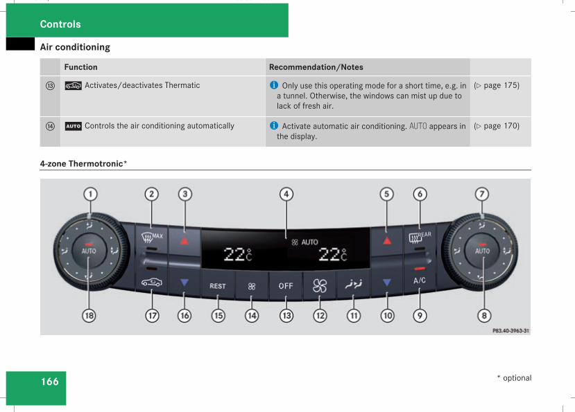
Air conditioning
166
Function Recommendation/Notes
d , Activates/deactivates Thermatic i Only use this operating mode for a short time, e.g. ina tunnel. Otherwise, the windows can mist up due tolack of fresh air.
(Y page 175)
e U Controls the air conditioning automatically i Activate automatic air conditioning. AUTO appears inthe display.
(Y page 170)
4-zone Thermotronic*
Controls
* optional
211_AKB; 2; 5, en-GBmkalafa, Version: 2.9.4
2008-02-29T16:57:07+01:00 - Seite 166
Dateiname: 6515_3416_02_buchblock.pdf; preflight
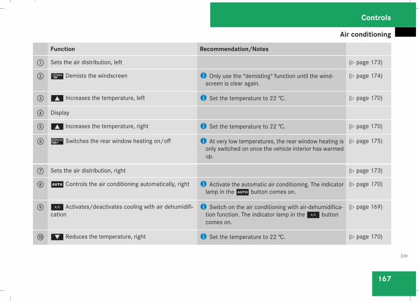
Air conditioning
167
Function Recommendation/Notes
1 Sets the air distribution, left (Y page 173)
2 y Demists the windscreen i Only use the "demisting" function until the wind-screen is clear again.
(Y page 174)
3 $ Increases the temperature, left i Set the temperature to 22 †. (Y page 170)
4 Display
5 $ Increases the temperature, right i Set the temperature to 22 †. (Y page 170)
6 ¯ Switches the rear window heating on/off i At very low temperatures, the rear window heating isonly switched on once the vehicle interior has warmedup.
(Y page 175)
7 Sets the air distribution, right (Y page 173)
8 U Controls the air conditioning automatically, right i Activate the automatic air conditioning. The indicatorlamp in theU button comes on.
(Y page 170)
9 2 Activates/deactivates cooling with air dehumidifi-cation
i Switch on the air conditioning with air-dehumidifica-tion function. The indicator lamp in the2 buttoncomes on.
(Y page 169)
a % Reduces the temperature, right i Set the temperature to 22 †. (Y page 170)
Controls
211_AKB; 2; 5, en-GBmkalafa, Version: 2.9.4
2008-02-29T16:57:07+01:00 - Seite 167
Z
Dateiname: 6515_3416_02_buchblock.pdf; preflight
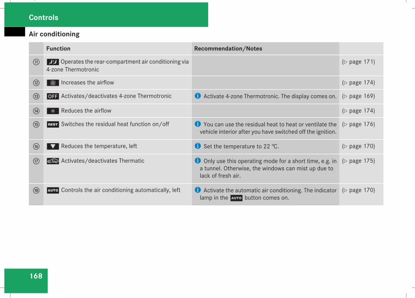
Air conditioning
168
Function Recommendation/Notes
b ™Operates the rear-compartment air conditioning via4-zone Thermotronic
(Y page 171)
c Q Increases the airflow (Y page 174)
d ´ Activates/deactivates 4-zone Thermotronic i Activate 4-zone Thermotronic. The display comes on. (Y page 169)
e · Reduces the airflow (Y page 174)
f T Switches the residual heat function on/off i You can use the residual heat to heat or ventilate thevehicle interior after you have switched off the ignition.
(Y page 176)
g % Reduces the temperature, left i Set the temperature to 22 †. (Y page 170)
h , Activates/deactivates Thermatic i Only use this operating mode for a short time, e.g. ina tunnel. Otherwise, the windows can mist up due tolack of fresh air.
(Y page 175)
j U Controls the air conditioning automatically, left i Activate the automatic air conditioning. The indicatorlamp in theU button comes on.
(Y page 170)
Controls
211_AKB; 2; 5, en-GBmkalafa, Version: 2.9.4
2008-02-29T16:57:07+01:00 - Seite 168
Dateiname: 6515_3416_02_buchblock.pdf; preflight
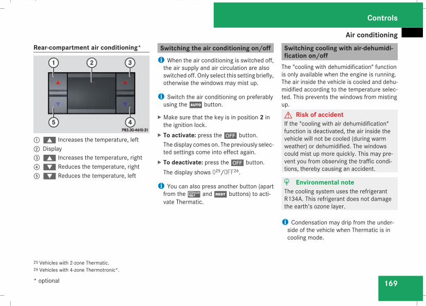
Air conditioning
169
Rear-compartment air conditioning*
1$ Increases the temperature, left2 Display3$ Increases the temperature, right4% Reduces the temperature, right5% Reduces the temperature, left
Switching the air conditioning on/offi When the air conditioning is switched off,the air supply and air circulation are alsoswitched off. Only select this setting briefly,otherwise the windows may mist up.
i Switch the air conditioning on preferablyusing theU button.
X Make sure that the key is in position 2 inthe ignition lock.
X To activate: press the´ button.The display comes on. The previously selec-ted settings come into effect again.
X To deactivate: press the´ button.The display shows 025/OFF26.
i You can also press another button (apartfrom the¯ andT buttons) to acti-vate Thermatic.
Switching cooling with air-dehumidi-fication on/offThe "cooling with dehumidification" functionis only available when the engine is running.The air inside the vehicle is cooled and dehu-midified according to the temperature selec-ted. This prevents the windows from mistingup.G Risk of accidentIf the "cooling with air dehumidification"function is deactivated, the air inside thevehicle will not be cooled (during warmweather) or dehumidified. The windowscould mist up more quickly. This may pre-vent you from observing the traffic condi-tions, thereby causing an accident.
H Environmental noteThe cooling system uses the refrigerantR134A. This refrigerant does not damagethe earth's ozone layer.
i Condensation may drip from the under-side of the vehicle when Thermatic is incooling mode.
25 Vehicles with 2-zone Thermatic.26 Vehicles with 4-zone Thermotronic*.
Controls
* optional
211_AKB; 2; 5, en-GBmkalafa, Version: 2.9.4
2008-02-29T16:57:07+01:00 - Seite 169
Z
Dateiname: 6515_3416_02_buchblock.pdf; preflight
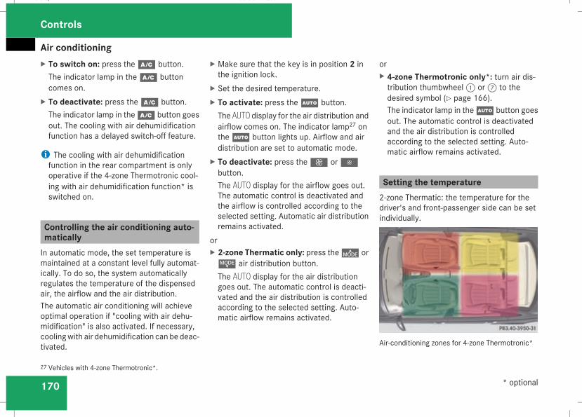
Air conditioning
170
X To switch on: press theœ button.The indicator lamp in theœ buttoncomes on.
X To deactivate: press theœ button.The indicator lamp in theœ button goesout. The cooling with air dehumidificationfunction has a delayed switch-off feature.
i The cooling with air dehumidificationfunction in the rear compartment is onlyoperative if the 4-zone Thermotronic cool-ing with air dehumidification function* isswitched on.
Controlling the air conditioning auto-maticallyIn automatic mode, the set temperature ismaintained at a constant level fully automat-ically. To do so, the system automaticallyregulates the temperature of the dispensedair, the airflow and the air distribution.The automatic air conditioning will achieveoptimal operation if "cooling with air dehu-midification" is also activated. If necessary,coolingwith air dehumidification can be deac-tivated.
X Make sure that the key is in position 2 inthe ignition lock.
X Set the desired temperature.X To activate: press theU button.The AUTO display for the air distribution andairflow comes on. The indicator lamp27 ontheU button lights up. Airflow and airdistribution are set to automatic mode.
X To deactivate: press theQ or·button.The AUTO display for the airflow goes out.The automatic control is deactivated andthe airflow is controlled according to theselected setting. Automatic air distributionremains activated.
orX 2-zone Thermatic only: press the© orª air distribution button.The AUTO display for the air distributiongoes out. The automatic control is deacti-vated and the air distribution is controlledaccording to the selected setting. Auto-matic airflow remains activated.
orX 4-zone Thermotronic only*: turn air dis-tribution thumbwheel1 or7 to thedesired symbol (Y page 166).The indicator lamp in theU button goesout. The automatic control is deactivatedand the air distribution is controlledaccording to the selected setting. Auto-matic airflow remains activated.
Setting the temperature2-zone Thermatic: the temperature for thedriver's and front-passenger side can be setindividually.
Air-conditioning zones for 4-zone Thermotronic*
27 Vehicles with 4-zone Thermotronic*.
Controls
* optional
211_AKB; 2; 5, en-GBmkalafa, Version: 2.9.4
2008-02-29T16:57:07+01:00 - Seite 170
Dateiname: 6515_3416_02_buchblock.pdf; preflight

Air conditioning
171
4-zone Thermotronic*: the temperature foreach of the four air-conditioning zones can beset individually. You can set the temperatureseparately for the driver's and front-passenger sides as well as for the left andright sides of the rear compartment.
Setting the temperature in the frontcompartment using 2-zone ThermaticX Make sure that the key is in position 2 inthe ignition lock.
X To increase/reduce: turn thumbwheels1 and7 clockwise or anti-clockwise(Y page 164). Only change the temperaturesetting in small increments. Start at 22 †.
Setting the temperature in the frontcompartment via 4-zoneThermotronic*X Make sure that the key is in position 2 inthe ignition lock.
X To increase/reduce: press the$ or% button. Only change the temperaturesetting in small increments. Start at 22 †.The set temperature is shown in the 4-zoneThermotronic* display.
Setting the temperature in the rearcompartment via 4-zoneThermotronic*X Make sure that the key is in position 2 inthe ignition lock.
X Press the™ button.The 4-zone Thermotronic* display switchesto the rear-compartment air-conditioningsettings.
X To increase/reduce: press the$ or% button. Only change the temperaturesetting in small increments. Start at 22 †.The set temperature is shown in the 4-zoneThermotronic* display. The 4-zoneThermotronic* display changes back to thestandard display about five seconds after abutton is pressed.
i You can also return to the standard dis-play by pressing the™ button again.
Setting the rear-compartment temper-ature via the rear-compartment air con-ditioning*X Make sure that the key is in position 2 inthe ignition lock.
X To increase/reduce: press the$ or% button. Only change the temperaturesetting in small increments. Start at 22 †.
Adjusting the air vents
G Risk of injuryVery hot or very cold air can flow from theair vents. This could cause burns or frost-bite to bare skin in the immediate vicinityof the vents. Keep bare skin away fromthese air outlets. If necessary, direct theairflow away to a different area of the vehi-cle interior.
Please observe the following notes to ensurethat the air can flow freely through the airvents:RKeep the air inlet between the windscreenand the bonnet free of deposits, such as ice
Controls
* optional
211_AKB; 2; 5, en-GBmkalafa, Version: 2.9.4
2008-02-29T16:57:07+01:00 - Seite 171
Z
Dateiname: 6515_3416_02_buchblock.pdf; preflight
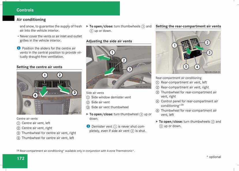
Air conditioning
172
and snow, to guarantee the supply of freshair into the vehicle interior.
RNever cover the vents or air inlet and outletgrilles in the vehicle interior.
i Position the sliders for the centre airvents in the central position to provide vir-tually draught-free ventilation.
Setting the centre air vents
Centre air vents1 Centre air vent, left2 Centre air vent, right3 Thumbwheel for centre air vent, right4 Thumbwheel for centre air vent, left
X To open/close: turn thumbwheels3 and4 up or down.
Adjusting the side air vents
Side air vents1 Side window demister vent2 Side air vent3 Side air vent thumbwheel
X To open/close: turn thumbwheel3 up ordown.
i Demister vent1 is never shut com-pletely, even if side air vent2 is shut.
Setting the rear-compartment air vents
Rear-compartment air conditioning1 Rear-compartment air vent, left2 Rear-compartment air vent, right3 Thumbwheel for rear-compartment air
vent, right4 Control panel for rear-compartment air
conditioning*285 Thumbwheel for rear-compartment air
vent, left
X To open/close: turn thumbwheels3 and5 up or down.
28 Rear-compartment air conditioning* available only in conjunction with 4-zone Thermotronic*.
Controls
* optional
211_AKB; 2; 5, en-GBmkalafa, Version: 2.9.4
2008-02-29T16:57:07+01:00 - Seite 172
Dateiname: 6515_3416_02_buchblock.pdf; preflight
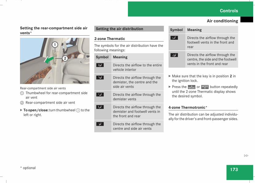
Air conditioning
173
Setting the rear-compartment side airvents*
Rear-compartment side air vents1 Thumbwheel for rear-compartment side
air vent2 Rear-compartment side air vent
X Toopen/close: turn thumbwheel1 to theleft or right.
Setting the air distribution
2-zone ThermaticThe symbols for the air distribution have thefollowing meanings:
Symbol Meaning
b Directs the airflow to the entirevehicle interior
c Directs the airflow through thedemister, the centre and theside air vents
Z Directs the airflow through thedemister vents
X Directs the airflow through thedemister and footwell vents inthe front and rear
a Directs the airflow through thecentre and side air vents
Symbol Meaning
Y Directs the airflow through thefootwell vents in the front andrear
Ú Directs the airflow through thecentre, the side and the footwellvents in the front and rear
X Make sure that the key is in position 2 inthe ignition lock.
X Press the© orª button repeatedlyuntil the 2-zone Thermatic display showsthe desired symbol.
4-zone Thermotronic*The air distribution can be adjusted individu-ally for the driver's and front-passenger sides.
Controls
* optional
211_AKB; 2; 5, en-GBmkalafa, Version: 2.9.4
2008-02-29T16:57:07+01:00 - Seite 173
Z
Dateiname: 6515_3416_02_buchblock.pdf; preflight
Air conditioning
174
The symbols for the air distribution have thefollowing meanings:
Symbol Meaning
Z Directs the airflow through thecentre, the side and the demis-ter air vents
a Directs the airflow through thecentre and side air vents
X Directs the airflow to the entirevehicle interior
Y Directs the airflow through thecentre, the side and the foot-well vents in the front and rear
X Make sure that the key is in position 2 inthe ignition lock.
X Turn thumbwheel1 or7 to the corre-sponding symbol (Y page 166). The thumb-wheel can also be turned to the areabetween two symbols.
Setting the airflowX Make sure that the key is in position 2 inthe ignition lock.
X To increase/reduce: press theQ or· button.
Demisting the windscreeni You should only select the "demisting"function until the windscreen is clear again.
X Make sure that the key is in position 2 inthe ignition lock.
X To activate: press they button.The indicator lamp in they buttoncomes on.The system automatically switches to thefollowing functions:Rcooling with air dehumidification onRhigh airflow29
Rhigh temperature29
Rair distribution to the windscreen andfront side windows
Rair-recirculation mode off
X To deactivate: press they button.The indicator lamp in they button goesout. The previously selected settings comeinto effect again. The cooling with air dehu-midification function remains on. Air-recir-culation mode remains deactivated.
orX Press theU button.The indicator lamp in they button goesout. Airflow and air distribution are set toautomatic mode.
orX 2-zone Thermatic: turn thumbwheels1or7 clockwise or anti-clockwise(Y page 164).
orX 2-zone Thermatic: press theQ or· button.
29 Depending on the outside temperature.
Controls
211_AKB; 2; 5, en-GBmkalafa, Version: 2.9.4
2008-02-29T16:57:07+01:00 - Seite 174
Dateiname: 6515_3416_02_buchblock.pdf; preflight
Air conditioning
175
Demisting the windows
Windows misted up on the insideX Activate the "cooling function with air-dehumidification" function.
X Activate the automatic mode.X If the windows continue tomist up, activatethe "demisting" function.
Windows misted up on the outsideX Activate the windscreen wipers.X 2-zone Thermatic: press and hold the© orª button until thea,ÚorY symbol is shown in the display.
X 4-zone Thermotronic*: turn the thumb-wheel for air distribution to theY ora symbol.
i You should only select this setting untilthe windscreen is clear again.
Switching the rear window heatingon/off
G Risk of accidentClear all windows of ice or snow before set-ting off. Impaired visibility could otherwiseendanger you and others.
i At very low temperatures, the rear win-dow heating is only switched on once thevehicle interior has warmed up.
i The rear window heating has a high cur-rent draw. You should therefore switch itoff as soon as the window is clear, as it onlyswitches off automatically after approxi-mately six to twenty minutes.
i If the battery voltage is too low, the rearwindow heating may switch off.
i Saloon: there are aerial wires in the upperarea of the rear window; this area is there-fore not heated.
X Make sure that the key is in position 2 inthe ignition lock.
X Press the¯ button.The indicator lamp in the¯ button lightsup or goes out.
Activating/deactivating air-recircula-tion modeYou can deactivate the flow of fresh air ifunpleasant odours are entering the vehiclefrom outside. The air already inside the vehi-cle will then be recirculated.G Risk of accidentOnly switch over to air-recirculation modebriefly at low outside temperatures. Other-wise, the windows could mist up, thusimpairing visibility and endangering your-self and others. This may prevent you fromobserving the traffic conditions, therebycausing an accident.
X Make sure that the key is in position 2 inthe ignition lock.
X To activate: press the, button.The indicator lamp in the, buttoncomes on.
i Air-recirculation mode is activated auto-matically at high outside temperatures.When air-recirculation mode is activatedautomatically, the indicator lamp inthe, button is not lit.Outside air is added after about30 minutes.
Controls
* optional
211_AKB; 2; 5, en-GBmkalafa, Version: 2.9.4
2008-02-29T16:57:07+01:00 - Seite 175
Z
Dateiname: 6515_3416_02_buchblock.pdf; preflight
Air conditioning
176
X To deactivate: press the, button.The indicator lamp in the, button goesout.
i Air-recirculation mode switches off auto-matically:Rafter approximately five minutes at out-side temperatures below approximately5 †
Rafter approximately five minutes if the airdehumidification is deactivated
Rafter approximately 30 minutes at out-side temperatures above approximately5 †
Air-recirculation mode with the conve-nience opening/closing feature
G Risk of injuryMake sure that nobody can become trap-ped between the side window and the doorframe as the side windows are opened andclosed. Do not place objects or lean againstthe side window when it is being opened orclosed. You or the objects could be drawnin or become trapped between the sidewindow and the door frame as the window
moves. If there is a risk of entrapment,press the, button again. If necessary,press the switch that stops, opens or closesthe side window in the opposite direction.Make sure that nobody can become trap-ped when you open or close the sliding/tilting sunroof*/panorama sliding sun-roof*. If there is a risk of entrapment, pressthe, button again. If necessary, pressthe switch that stops, opens or closes thesliding/tilting sunroof*/panorama slidingsunroof* in the opposite direction.
X Convenience closing: press and holdthe, button until the side windows andthe sliding/tilting sunroof*/panoramasliding sunroof* have closed.The indicator lamp in the, buttoncomes on. Air-recirculation mode is activa-ted.
X Convenience opening: press and holdthe, button until the side windows andthe sliding/tilting sunroof*/panoramasliding sunroof* have reached their originalposition.The indicator lamp in the, button goesout. Air-recirculation mode is deactivated.
i If you open the side windows or the slid-ing/tilting sunroof* or panorama slidingsunroof* manually after closing using theconvenience closing feature, it will remainin this position when opened using the con-venience opening feature.
Switching the residual heat on and offIt is possible to make use of the residual heatof the engine to continue heating the station-ary vehicle for up to 30 minutes after theengine has been switched off. The heatingtime depends on the set interior temperature.
i The blower will run at a low speed regard-less of the airflow setting.
i If you activate the "residual heat" functionat high temperatures, only the ventilationwill be activated. The blower runs atmedium speed.
X Make sure that the key is in position 0 inthe ignition lock or that it has beenremoved.
X To switch on: press theT button.REST appears in the display.
Controls
* optional
211_AKB; 2; 5, en-GBmkalafa, Version: 2.9.4
2008-02-29T16:57:07+01:00 - Seite 176
Dateiname: 6515_3416_02_buchblock.pdf; preflight
Air conditioning
177
X To deactivate: press theT button.REST is no longer shown in the display.
i The residual heat automatically switchesoff after around 30minutes or if:Rthe ignition is switched onRthe battery voltage drops
Switching auxiliary heating/ventila-tion* on/off
G Risk of poisoningExhaust fumes are produced when the aux-iliary heating is in operation. Inhaling theseexhaust fumes can be poisonous. Youshould therefore switch off the auxiliaryheating in confined spaces without anextraction system, e.g. a garage.
G Risk of fireWhen operating the auxiliary heating, partsof the vehicle may become very hot, andhighly inflammable material such as fuelscould be ignited. Operating the auxiliaryheating is thus prohibited at filling stationsor when your vehicle is being refuelled. You
must therefore switch off the auxiliary heat-ing at filling stations.
The auxiliary heating heats the air in the vehi-cle interior to a temperature between 20 †and 24†,without depending on heat emittedby the running engine. The auxiliary heatingis operated using fuel directly from the vehi-cle's fuel tank. For this reason, the tank con-tent must be at least at reserve fuel level toensure that the auxiliary heating functions.The auxiliary heating/ventilation automati-cally adjusts to changes in temperature andweather conditions. For this reason, the aux-iliary heating could switch from ventilationmode to heating mode or from heating modeto ventilation mode.You cannot use the auxiliary ventilation tocool the vehicle interior to a temperaturelower than the outside temperature.
Before activatingX Make sure that the key is in position 2 inthe ignition lock.
X Set the temperature to a value between20 † and 24 †.
The auxiliary heating/ventilation can be acti-vated even when the air conditioning is being
controlled manually. Optimum comfort canbe attained when the system is set to auto-matic mode. Set the desired temperaturewithin this range. If a higher temperature isset, the vehicle is heated to 24 †. If a lowertemperature is set, the vehicle is heated to20 †.
Activating/deactivating the auxiliaryheating/ventilationThe auxiliary heating/ventilation can be acti-vated or deactivated using the remote controlor the button on the centre console.The on-board computer can be used to spec-ify up to three departure times, one of whichmay be preselected (Y page 138).
Controls
* optional
211_AKB; 2; 5, en-GBmkalafa, Version: 2.9.4
2008-02-29T16:57:07+01:00 - Seite 177
Z
Dateiname: 6515_3416_02_buchblock.pdf; preflight
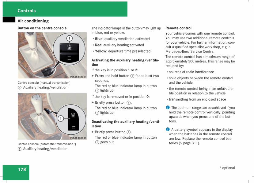
Air conditioning
178
Button on the centre console
Centre console (manual transmission)1 Auxiliary heating/ventilation
Centre console (automatic transmission*)1 Auxiliary heating/ventilation
The indicator lamps in the buttonmay light upin blue, red or yellow.RBlue: auxiliary ventilation activatedRRed: auxiliary heating activatedRYellow: departure time preselected
Activating the auxiliary heating/ventila-tionIf the key is in position 1 or 2:X Press and hold button1 for at least twoseconds.The red or blue indicator lamp in button1 lights up.
If the key is removed or in position 0:X Briefly press button1.The red or blue indicator lamp in button1 lights up.
Deactivating the auxiliary heating/venti-lationX Briefly press button1.The red or blue indicator lamp in button1 goes out.
Remote controlYour vehicle comes with one remote control.You may use two additional remote controlsfor your vehicle. For further information, con-sult a qualified specialist workshop, e.g. aMercedes-Benz Service Centre.The remote control has a maximum range ofapproximately 300metres. This rangemay bereduced by:Rsources of radio interferenceRsolid objects between the remote controland the vehicle
Rthe remote control being in an unfavoura-ble position in relation to the vehicle
Rtransmitting from an enclosed space
i The optimum range can be achieved if youhold the remote control vertically, pointingupwards when you press one of the but-tons.
i A battery symbol appears in the displaywhen the batteries in the remote controlare low. Replace the remote control bat-teries (Y page 311).
Controls
* optional
211_AKB; 2; 5, en-GBmkalafa, Version: 2.9.4
2008-02-29T16:57:07+01:00 - Seite 178
Dateiname: 6515_3416_02_buchblock.pdf; preflight
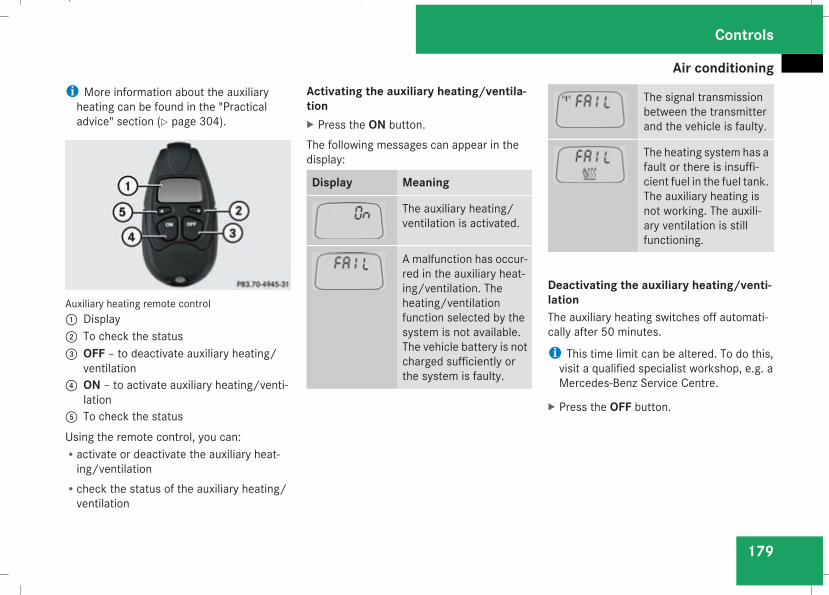
Air conditioning
179
i More information about the auxiliaryheating can be found in the "Practicaladvice" section (Y page 304).
Auxiliary heating remote control1 Display2 To check the status3 OFF – to deactivate auxiliary heating/
ventilation4 ON – to activate auxiliary heating/venti-
lation5 To check the statusUsing the remote control, you can:Ractivate or deactivate the auxiliary heat-ing/ventilation
Rcheck the status of the auxiliary heating/ventilation
Activating the auxiliary heating/ventila-tionX Press the ON button.The following messages can appear in thedisplay:
Display Meaning
The auxiliary heating/ventilation is activated.
A malfunction has occur-red in the auxiliary heat-ing/ventilation. Theheating/ventilationfunction selected by thesystem is not available.The vehicle battery is notcharged sufficiently orthe system is faulty.
The signal transmissionbetween the transmitterand the vehicle is faulty.
The heating system has afault or there is insuffi-cient fuel in the fuel tank.The auxiliary heating isnot working. The auxili-ary ventilation is stillfunctioning.
Deactivating the auxiliary heating/venti-lationThe auxiliary heating switches off automati-cally after 50 minutes.
i This time limit can be altered. To do this,visit a qualified specialist workshop, e.g. aMercedes-Benz Service Centre.
X Press the OFF button.
Controls
211_AKB; 2; 5, en-GBmkalafa, Version: 2.9.4
2008-02-29T16:57:07+01:00 - Seite 179
Z
Dateiname: 6515_3416_02_buchblock.pdf; preflight
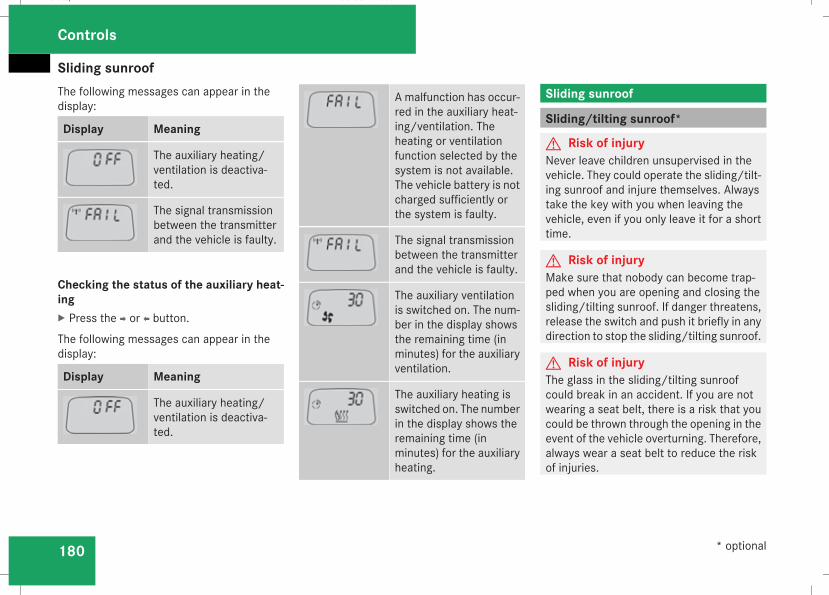
Sliding sunroof
180
The following messages can appear in thedisplay:
Display Meaning
The auxiliary heating/ventilation is deactiva-ted.
The signal transmissionbetween the transmitterand the vehicle is faulty.
Checking the status of the auxiliary heat-ingX Press the p or o button.
The following messages can appear in thedisplay:
Display Meaning
The auxiliary heating/ventilation is deactiva-ted.
A malfunction has occur-red in the auxiliary heat-ing/ventilation. Theheating or ventilationfunction selected by thesystem is not available.The vehicle battery is notcharged sufficiently orthe system is faulty.
The signal transmissionbetween the transmitterand the vehicle is faulty.
The auxiliary ventilationis switched on. The num-ber in the display showsthe remaining time (inminutes) for the auxiliaryventilation.
The auxiliary heating isswitched on. The numberin the display shows theremaining time (inminutes) for the auxiliaryheating.
Sliding sunroof
Sliding/tilting sunroof*
G Risk of injuryNever leave children unsupervised in thevehicle. They could operate the sliding/tilt-ing sunroof and injure themselves. Alwaystake the key with you when leaving thevehicle, even if you only leave it for a shorttime.
G Risk of injuryMake sure that nobody can become trap-ped when you are opening and closing thesliding/tilting sunroof. If danger threatens,release the switch and push it briefly in anydirection to stop the sliding/tilting sunroof.
G Risk of injuryThe glass in the sliding/tilting sunroofcould break in an accident. If you are notwearing a seat belt, there is a risk that youcould be thrown through the opening in theevent of the vehicle overturning. Therefore,always wear a seat belt to reduce the riskof injuries.
Controls
* optional
211_AKB; 2; 5, en-GBmkalafa, Version: 2.9.4
2008-02-29T16:57:07+01:00 - Seite 180
Dateiname: 6515_3416_02_buchblock.pdf; preflight
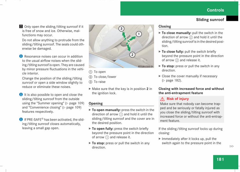
Sliding sunroof
181
! Only open the sliding/tilting sunroof if itis free of snow and ice. Otherwise, mal-functions may occur.Do not allow anything to protrude from thesliding/tilting sunroof. The seals could oth-erwise be damaged.
i Resonance noises can occur in additionto the usual airflow noises when the slid-ing/tilting sunroof is open. They are causedby minor pressure fluctuations in the vehi-cle interior.Change the position of the sliding/tiltingsunroof or open a side window slightly toreduce or eliminate these noises.
i It is also possible to open and close thesliding/tilting sunroof from the outsideusing the "Summer opening" (Y page 109)and "Convenience closing" (Y page 109)features respectively.
i If PRE-SAFE® has been activated, the slid-ing/tilting sunroof closes automatically,leaving a small gap open.
1 To open2 To close/lower3 To raise
X Make sure that the key is in position 2 inthe ignition lock.
OpeningX To open manually: press the switch in thedirection of arrow1 and hold it until thesliding/tilting sunroof and the cover are inthe desired position.
X To open fully: press the switch brieflybeyond the pressure point in the directionof arrow1 and release it.
X To stop: press or pull the switch in anydirection.
ClosingX To close manually: pull the switch in thedirection of arrow2 and hold it until thesliding/tilting sunroof is in the desired posi-tion.
X To close fully: pull the switch brieflybeyond the pressure point in the directionof arrow2 and release it.
X To stop: press or pull the switch in anydirection.
X Close the cover manually if necessary(Y page 182).
Closing with increased force and withoutthe anti-entrapment featureG Risk of injuryMake sure that nobody can become trap-ped and be seriously or fatally injured asyou close the sliding/tilting sunroof withincreased force or without the anti-entrap-ment feature.
If the sliding/tilting sunroof locks up duringclosing:X Immediately after it locks up, pull theswitch again to the pressure point in the
Controls
211_AKB; 2; 5, en-GBmkalafa, Version: 2.9.4
2008-02-29T16:57:07+01:00 - Seite 181
Z
Dateiname: 6515_3416_02_buchblock.pdf; preflight
Sliding sunroof
182
direction of arrow2 until the sliding/tilt-ing sunroof is closed.The sliding/tilting sunroof is closed withmore force.
If the sliding/tilting sunroof locks up duringclosing again:X Immediately after it locks up, pull theswitch again to the pressure point in thedirection of arrow2 until the sliding/tilt-ing sunroof is closed.The sliding/tilting sunroof is closedwithoutthe anti-entrapment feature.
RaisingThe sliding/tilting sunroof can be raised atthe rear for ventilation.X To raise manually: press the switch in thedirection of arrow3 and hold it until thesliding/tilting sunroof is in the desired posi-tion.
X To raise fully: briefly press the switchbeyond the pressure point in the directionof arrow3 and release it.
X To stop: press or pull the switch in anydirection.
Lowering and closingX To lower manually: pull the switch in thedirection of arrow2 and hold it until thesliding/tilting sunroof is in the desired posi-tion.
X To lower fully: pull the switch brieflybeyond the pressure point in the directionof arrow2 and release it.
X To stop: press or pull the switch in anydirection.
Rain closing feature*The sliding/tilting sunroof closes automati-cally:Rif it starts to rainRat extreme outside temperaturesRafter 12 hoursRif there is amalfunction in the power supplyThe rear of the sliding/tilting sunroof is thenraised in order to ventilate the interior of thevehicle.
i The sliding/tilting sunroof is openedslightly again if it is obstructed while beingclosed by the rain closing feature. The rainclosing feature is then deactivated.
i The sliding/tilting sunroof does not closeif:Rit is raised at the rearRit is blockedRno rain is falling on the windscreen (e.g.because the vehicle is under a bridge orin a carport)
Opening and closing the coverThe cover functions as a sunblind. When youopen the sliding/tilting sunroof, the covermoves back with it.When the sliding/tilting sunroof is closed orraised at the rear, you can open or close thecover manually.
Resetting the sliding/tilting sunroofReset the sliding/tilting sunroof if it does notmove smoothly, or if the battery was discon-nected or discharged.X Remove the fuse for the sliding/tilting sun-roof in the main fuse box (Y page 341).
X Reinsert the fuse.X Make sure that the key is in position 2 inthe ignition lock.
Controls
* optional
211_AKB; 2; 5, en-GBmkalafa, Version: 2.9.4
2008-02-29T16:57:07+01:00 - Seite 182
Dateiname: 6515_3416_02_buchblock.pdf; preflight
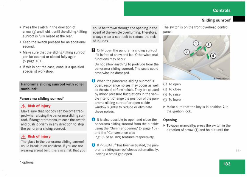
Sliding sunroof
183
X Press the switch in the direction ofarrow3 and hold it until the sliding/tiltingsunroof is fully raised at the rear.
X Keep the switch pressed for an additionalsecond.
X Make sure that the sliding/tilting sunroofcan be opened or closed fully again(Y page 181).
X If this is not the case, consult a qualifiedspecialist workshop.
Panorama sliding sunroof with rollersunblind*
Panorama sliding sunroof
G Risk of injuryMake sure that nobody can become trap-pedwhen closing the panorama sliding sun-roof. If danger threatens, release the switchand push it briefly in any direction to stopthe panorama sliding sunroof.
G Risk of injuryThe glass in the panorama sliding sunroofcould break in an accident. If you are notwearing a seat belt, there is a risk that you
could be thrown through the opening in theevent of the vehicle overturning. Therefore,always wear a seat belt to reduce the riskof injuries.
! Only open the panorama sliding sunroofif it is free of snow and ice. Otherwise, mal-functions may occur.Do not allow anything to protrude from thepanorama sliding sunroof. The seals couldotherwise be damaged.
i When the panorama sliding sunroof isopen, resonance noises may occur as wellas the usual airflow noises. They are causedby minor pressure fluctuations in the vehi-cle interior. Change the position of the pan-orama sliding sunroof or open a sidewindow slightly to reduce or eliminatethese noises.
i It is also possible to open and close thepanorama sliding sunroof from the outsideusing the "Summer opening" (Y page 109)and the "Convenience clos-ing" (Y page 109) features respectively.
i If PRE-SAFE® has been activated, the pan-orama sliding sunroof closes automatically,leaving a small gap open.
The switch is on the front overhead controlpanel.
1 To open2 To close3 To raise4 To lower
X Make sure that the key is in position 2 inthe ignition lock.
OpeningX To open manually: press the switch in thedirection of arrow1 and hold it until the
Controls
* optional
211_AKB; 2; 5, en-GBmkalafa, Version: 2.9.4
2008-02-29T16:57:07+01:00 - Seite 183
Z
Dateiname: 6515_3416_02_buchblock.pdf; preflight
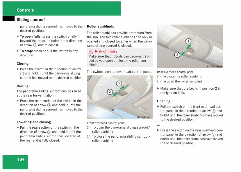
Sliding sunroof
184
panorama sliding sunroof has moved to thedesired position.
X To open fully: press the switch brieflybeyond the pressure point in the directionof arrow1 and release it.
X To stop: press or pull the switch in anydirection.
ClosingX Press the switch in the direction of arrow2 and hold it until the panorama slidingsunroof has moved to the desired position.
RaisingThe panorama sliding sunroof can be raisedat the rear for ventilation.X Press the rear section of the switch in thedirection of arrow3 and hold it until thepanorama sliding sunroof has moved to thedesired position.
Lowering and closingX Pull the rear section of the switch in thedirection of arrow4 and hold it until thepanorama sliding sunroof has lowered atthe rear and is fully closed.
Roller sunblindsThe roller sunblinds provide protection fromthe sun. The two roller sunblinds can only beopened and closed together when the pano-rama sliding sunroof is closed.G Risk of injuryMake sure that nobody can become trap-ped as you open or close the roller sun-blinds.
The switch is on the overhead control panel.
Front overhead control panel1 To open the panorama sliding sunroof/
roller sunblind2 To close the panorama sliding sunroof/
roller sunblind
Rear overhead control panel1 To close the roller sunblind2 To open the roller sunblind
X Make sure that the key is in position 2 inthe ignition lock.
OpeningX Pull the switch on the front overhead con-trol panel in the direction of arrow1 andhold it until the roller sunblinds havemovedto the desired position.
orX Press the switch on the rear overhead con-trol panel in the direction of arrow2 andhold it until the roller sunblinds havemovedto the desired position.
Controls
211_AKB; 2; 5, en-GBmkalafa, Version: 2.9.4
2008-02-29T16:57:07+01:00 - Seite 184
Dateiname: 6515_3416_02_buchblock.pdf; preflight
Sliding sunroof
185
To open the roller sunblinds fully, proceed asfollows:X Pull the switch on the front overhead con-trol panel beyond the pressure point in thedirection of arrow1.
orX Press the switch on the rear overhead con-trol panel beyond the pressure point in thedirection of arrow2.
X To stop: press or pull one of the switchesin any direction.
ClosingX Press the switch on the front overhead con-trol panel in the direction of arrow2 andhold it until the roller sunblinds havemovedto the desired position.
orX Pull the switch on the rear overhead controlpanel in the direction of arrow1 and holdit until the roller sunblinds have moved tothe desired position.
Resetting the panorama sliding sunroofand the roller sunblindsReset the panorama sliding sunroof and theroller sunblinds if the panorama sliding sun-roof does not move smoothly, or if the batterywas disconnected or discharged.X Remove the fuse for the panorama slidingsunroof in the main fuse box(Y page 341).
X Reinsert the fuse.X Make sure that the key is in position 2 inthe ignition lock.
X Close the roller sunblinds fully.X Keep the switch pressed for an additionalsecond.
X Open the roller sunblinds fully.X Keep the switch pressed for an additionalsecond.
X Raise the panorama sliding sunroof fully.X Keep the switch pressed for an additionalsecond.
X Close the panorama sliding sunroof fully.X Keep the switch pressed for an additionalsecond.
X Check that the panorama sliding sunroofcan be opened fully again (Y page 183).
X If this is not the case, consult a qualifiedspecialist workshop.
Controls
211_AKB; 2; 5, en-GBmkalafa, Version: 2.9.4
2008-02-29T16:57:07+01:00 - Seite 185
Z
Dateiname: 6515_3416_02_buchblock.pdf; preflight
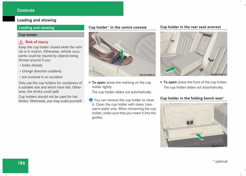
Loading and stowing
186
Loading and stowing
Cup holder
G Risk of injuryKeep the cup holder closed while the vehi-cle is in motion. Otherwise, vehicle occu-pants could be injured by objects beingthrown around if you:Rbrake sharplyRchange direction suddenlyRare involved in an accidentOnly use the cup holders for containers ofa suitable size and which have lids. Other-wise, the drinks could spill.Cup holders should not be used for hotdrinks. Otherwise, you may scald yourself.
Cup holder* in the centre console
X To open: press the marking on the cupholder lightly.The cup holder slides out automatically.
i You can remove the cup holder to cleanit. Clean the cup holder with clean, luke-warm water only. When reinserting the cupholder, make sure that you insert it into theguides.
Cup holder in the rear seat armrest
X To open: press the front of the cup holder.The cup holder slides out automatically.
Cup holder in the folding bench seat*
Controls
* optional
211_AKB; 2; 5, en-GBmkalafa, Version: 2.9.4
2008-02-29T16:57:07+01:00 - Seite 186
Dateiname: 6515_3416_02_buchblock.pdf; preflight
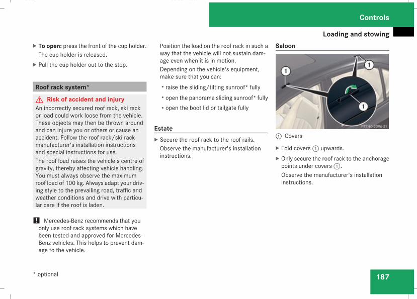
Loading and stowing
187
X To open: press the front of the cup holder.The cup holder is released.
X Pull the cup holder out to the stop.
Roof rack system*
G Risk of accident and injuryAn incorrectly secured roof rack, ski rackor load could work loose from the vehicle.These objects may then be thrown aroundand can injure you or others or cause anaccident. Follow the roof rack/ski rackmanufacturer's installation instructionsand special instructions for use.The roof load raises the vehicle's centre ofgravity, thereby affecting vehicle handling.You must always observe the maximumroof load of 100 kg. Always adapt your driv-ing style to the prevailing road, traffic andweather conditions and drive with particu-lar care if the roof is laden.
! Mercedes-Benz recommends that youonly use roof rack systems which havebeen tested and approved for Mercedes-Benz vehicles. This helps to prevent dam-age to the vehicle.
Position the load on the roof rack in such away that the vehicle will not sustain dam-age even when it is in motion.Depending on the vehicle's equipment,make sure that you can:Rraise the sliding/tilting sunroof* fullyRopen the panorama sliding sunroof* fullyRopen the boot lid or tailgate fully
EstateX Secure the roof rack to the roof rails.Observe the manufacturer's installationinstructions.
Saloon
1 Covers
X Fold covers1 upwards.X Only secure the roof rack to the anchoragepoints under covers1.Observe the manufacturer's installationinstructions.
Controls
* optional
211_AKB; 2; 5, en-GBmkalafa, Version: 2.9.4
2008-02-29T16:57:07+01:00 - Seite 187
Z
Dateiname: 6515_3416_02_buchblock.pdf; preflight
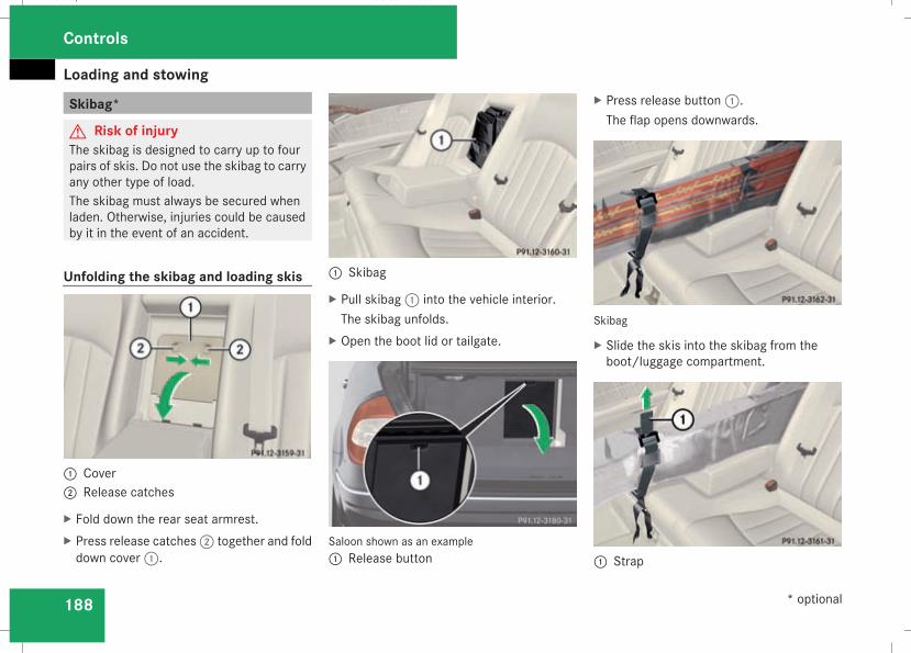
Loading and stowing
188
Skibag*
G Risk of injuryThe skibag is designed to carry up to fourpairs of skis. Do not use the skibag to carryany other type of load.The skibag must always be secured whenladen. Otherwise, injuries could be causedby it in the event of an accident.
Unfolding the skibag and loading skis
1 Cover2 Release catches
X Fold down the rear seat armrest.X Press release catches2 together and folddown cover1.
1 Skibag
X Pull skibag1 into the vehicle interior.The skibag unfolds.
X Open the boot lid or tailgate.
Saloon shown as an example1 Release button
X Press release button1.The flap opens downwards.
Skibag
X Slide the skis into the skibag from theboot/luggage compartment.
1 Strap
Controls
* optional
211_AKB; 2; 5, en-GBmkalafa, Version: 2.9.4
2008-02-29T16:57:07+01:00 - Seite 188
Dateiname: 6515_3416_02_buchblock.pdf; preflight
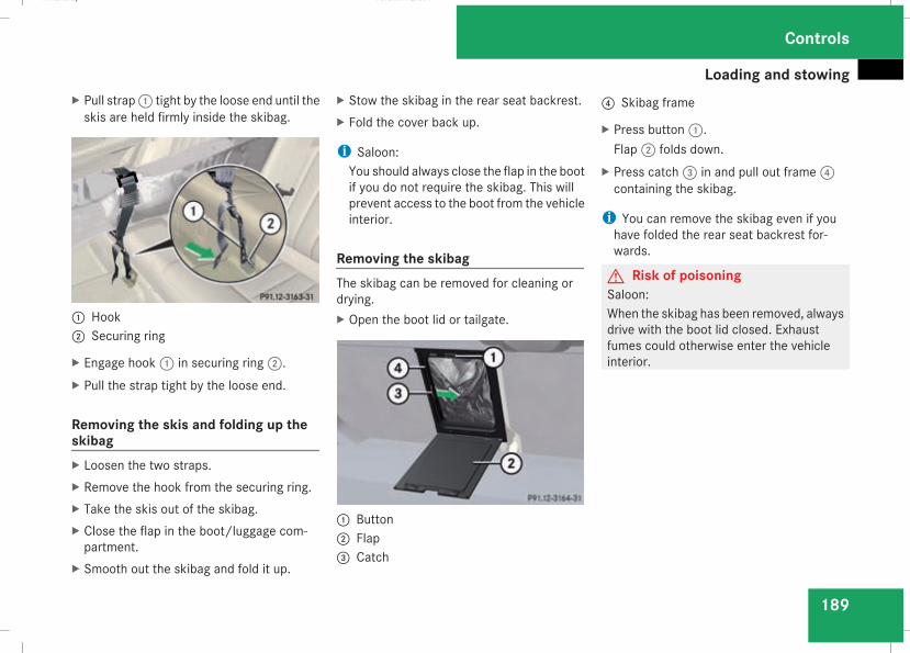
Loading and stowing
189
X Pull strap1 tight by the loose end until theskis are held firmly inside the skibag.
1 Hook2 Securing ring
X Engage hook1 in securing ring2.X Pull the strap tight by the loose end.
Removing the skis and folding up theskibagX Loosen the two straps.X Remove the hook from the securing ring.X Take the skis out of the skibag.X Close the flap in the boot/luggage com-partment.
X Smooth out the skibag and fold it up.
X Stow the skibag in the rear seat backrest.X Fold the cover back up.
i Saloon:You should always close the flap in the bootif you do not require the skibag. This willprevent access to the boot from the vehicleinterior.
Removing the skibagThe skibag can be removed for cleaning ordrying.X Open the boot lid or tailgate.
1 Button2 Flap3 Catch
4 Skibag frame
X Press button1.Flap2 folds down.
X Press catch3 in and pull out frame4containing the skibag.
i You can remove the skibag even if youhave folded the rear seat backrest for-wards.
G Risk of poisoningSaloon:When the skibag has been removed, alwaysdrive with the boot lid closed. Exhaustfumes could otherwise enter the vehicleinterior.
Controls
211_AKB; 2; 5, en-GBmkalafa, Version: 2.9.4
2008-02-29T16:57:07+01:00 - Seite 189
Z
Dateiname: 6515_3416_02_buchblock.pdf; preflight
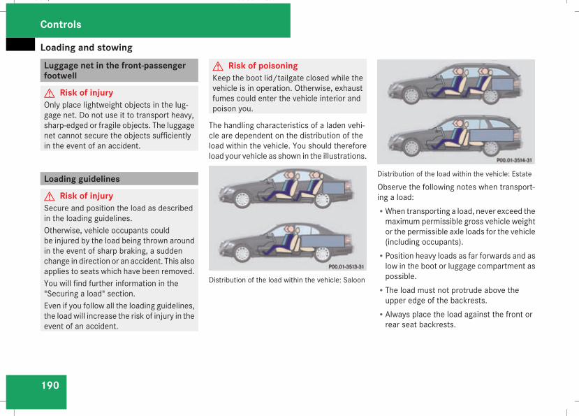
Loading and stowing
190
Luggage net in the front-passengerfootwell
G Risk of injuryOnly place lightweight objects in the lug-gage net. Do not use it to transport heavy,sharp-edged or fragile objects. The luggagenet cannot secure the objects sufficientlyin the event of an accident.
Loading guidelines
G Risk of injurySecure and position the load as describedin the loading guidelines.Otherwise, vehicle occupants couldbe injured by the load being thrown aroundin the event of sharp braking, a suddenchange in direction or an accident. This alsoapplies to seats which have been removed.You will find further information in the"Securing a load" section.Even if you follow all the loading guidelines,the loadwill increase the risk of injury in theevent of an accident.
G Risk of poisoningKeep the boot lid/tailgate closed while thevehicle is in operation. Otherwise, exhaustfumes could enter the vehicle interior andpoison you.
The handling characteristics of a laden vehi-cle are dependent on the distribution of theload within the vehicle. You should thereforeload your vehicle as shown in the illustrations.
Distribution of the load within the vehicle: Saloon
Distribution of the load within the vehicle: Estate
Observe the following notes when transport-ing a load:RWhen transporting a load, never exceed themaximum permissible gross vehicle weightor the permissible axle loads for the vehicle(including occupants).
RPosition heavy loads as far forwards and aslow in the boot or luggage compartment aspossible.
RThe load must not protrude above theupper edge of the backrests.
RAlways place the load against the front orrear seat backrests.
Controls
211_AKB; 2; 5, en-GBmkalafa, Version: 2.9.4
2008-02-29T16:57:07+01:00 - Seite 190
Dateiname: 6515_3416_02_buchblock.pdf; preflight
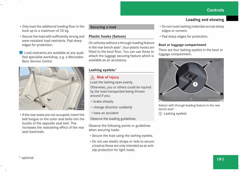
Loading and stowing
191
ROnly load the additional loading floor in theboot up to a maximum of 20 kg.
RSecure the load with sufficiently strong andwear-resistant load restraints. Pad sharpedges for protection.
i Load restraints are available at any quali-fied specialist workshop, e.g. a Mercedes-Benz Service Centre.
RIf the rear seats are not occupied, insert thebelt tongue on the outer seat belts into thebuckle of the opposite seat belt. Thisincreases the restraining effect of the rearseat backrests.
Securing a load
Plastic hooks (Saloon)On vehicles without a through-loading featurein the rear bench seat*, four plastic hooks arefitted to the boot floor. You can use these toattach the luggage securing feature which isavailable as an accessory.
Lashing eyelets*
G Risk of injuryLoad the lashing eyes evenly.Otherwise, you or others could be injuredby the load transported being thrownaround if you:Rbrake sharplyRchange direction suddenlyRhave an accidentObserve the loading guidelines.
Observe the following points or guidelineswhen securing loads:RSecure the load using the lashing eyelets.RDo not use elastic straps or nets to securea load as these are only intended as an anti-slip protection for light loads.
RDo not route lashingmaterials across sharpedges or corners.
RPad sharp edges for protection.
Boot or luggage compartmentThere are four lashing eyelets in the boot orluggage compartment.
Saloon with through-loading feature in the rearbench seat*1 Lashing eyelets
Controls
* optional
211_AKB; 2; 5, en-GBmkalafa, Version: 2.9.4
2008-02-29T16:57:07+01:00 - Seite 191
Z
Dateiname: 6515_3416_02_buchblock.pdf; preflight
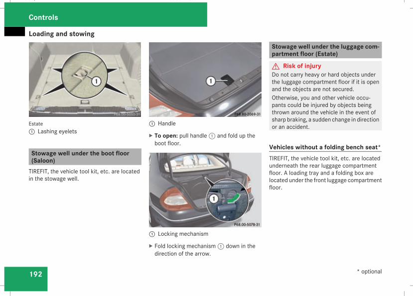
Loading and stowing
192
Estate1 Lashing eyelets
Stowage well under the boot floor(Saloon)TIREFIT, the vehicle tool kit, etc. are locatedin the stowage well.
1 Handle
X To open: pull handle1 and fold up theboot floor.
1 Locking mechanism
X Fold locking mechanism1 down in thedirection of the arrow.
Stowage well under the luggage com-partment floor (Estate)
G Risk of injuryDo not carry heavy or hard objects underthe luggage compartment floor if it is openand the objects are not secured.Otherwise, you and other vehicle occu-pants could be injured by objects beingthrown around the vehicle in the event ofsharp braking, a sudden change in directionor an accident.
Vehicles without a folding bench seat*TIREFIT, the vehicle tool kit, etc. are locatedunderneath the rear luggage compartmentfloor. A loading tray and a folding box arelocated under the front luggage compartmentfloor.
Controls
* optional
211_AKB; 2; 5, en-GBmkalafa, Version: 2.9.4
2008-02-29T16:57:07+01:00 - Seite 192
Dateiname: 6515_3416_02_buchblock.pdf; preflight
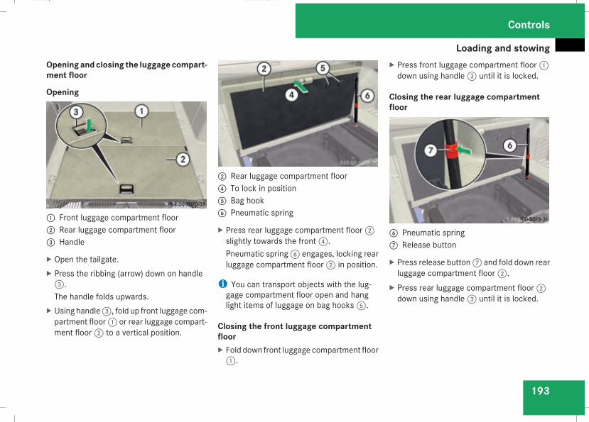
Loading and stowing
193
Opening andclosing the luggage compart-ment floor
Opening
1 Front luggage compartment floor2 Rear luggage compartment floor3 Handle
X Open the tailgate.X Press the ribbing (arrow) down on handle3.The handle folds upwards.
X Using handle3, fold up front luggage com-partment floor1 or rear luggage compart-ment floor2 to a vertical position.
2 Rear luggage compartment floor4 To lock in position5 Bag hook6 Pneumatic spring
X Press rear luggage compartment floor2slightly towards the front4.Pneumatic spring6 engages, locking rearluggage compartment floor2 in position.
i You can transport objects with the lug-gage compartment floor open and hanglight items of luggage on bag hooks5.
Closing the front luggage compartmentfloorX Fold down front luggage compartment floor1.
X Press front luggage compartment floor1down using handle3 until it is locked.
Closing the rear luggage compartmentfloor
6 Pneumatic spring7 Release button
X Press release button7 and fold down rearluggage compartment floor2.
X Press rear luggage compartment floor2down using handle3 until it is locked.
Controls
211_AKB; 2; 5, en-GBmkalafa, Version: 2.9.4
2008-02-29T16:57:07+01:00 - Seite 193
Z
Dateiname: 6515_3416_02_buchblock.pdf; preflight
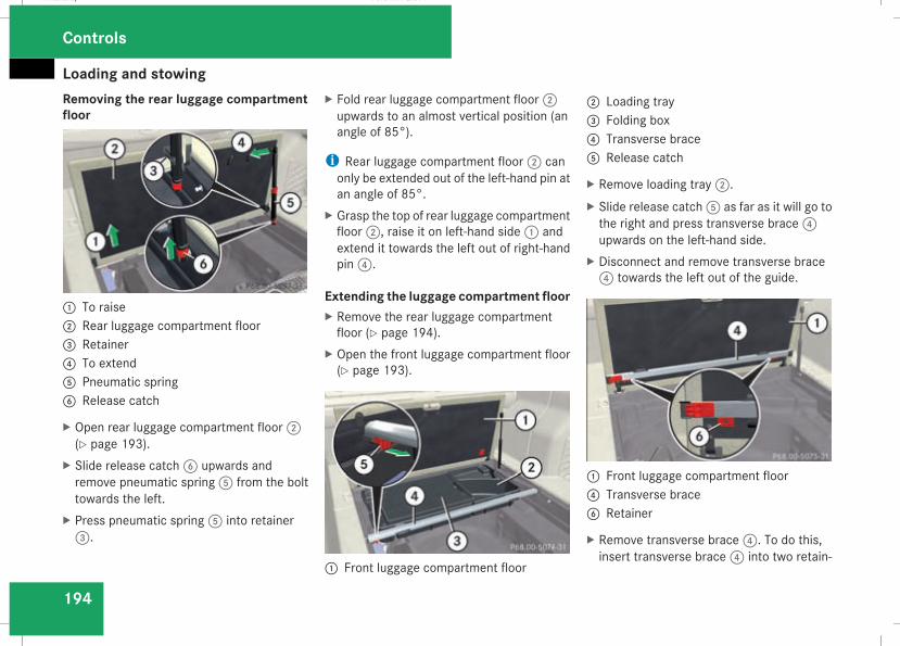
Loading and stowing
194
Removing the rear luggage compartmentfloor
1 To raise2 Rear luggage compartment floor3 Retainer4 To extend5 Pneumatic spring6 Release catch
X Open rear luggage compartment floor2(Y page 193).
X Slide release catch6 upwards andremove pneumatic spring5 from the bolttowards the left.
X Press pneumatic spring5 into retainer3.
X Fold rear luggage compartment floor2upwards to an almost vertical position (anangle of 85°).
i Rear luggage compartment floor2 canonly be extended out of the left-hand pin atan angle of 85°.
X Grasp the top of rear luggage compartmentfloor2, raise it on left-hand side1 andextend it towards the left out of right-handpin4.
Extending the luggage compartment floorX Remove the rear luggage compartmentfloor (Y page 194).
X Open the front luggage compartment floor(Y page 193).
1 Front luggage compartment floor
2 Loading tray3 Folding box4 Transverse brace5 Release catch
X Remove loading tray2.X Slide release catch5 as far as it will go tothe right and press transverse brace4upwards on the left-hand side.
X Disconnect and remove transverse brace4 towards the left out of the guide.
1 Front luggage compartment floor4 Transverse brace6 Retainer
X Remove transverse brace4. To do this,insert transverse brace4 into two retain-
Controls
211_AKB; 2; 5, en-GBmkalafa, Version: 2.9.4
2008-02-29T16:57:07+01:00 - Seite 194
Dateiname: 6515_3416_02_buchblock.pdf; preflight
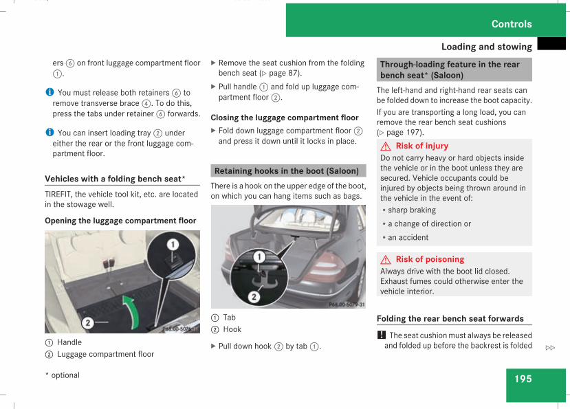
Loading and stowing
195
ers6 on front luggage compartment floor1.
i You must release both retainers6 toremove transverse brace4. To do this,press the tabs under retainer6 forwards.
i You can insert loading tray2 undereither the rear or the front luggage com-partment floor.
Vehicles with a folding bench seat*TIREFIT, the vehicle tool kit, etc. are locatedin the stowage well.
Opening the luggage compartment floor
1 Handle2 Luggage compartment floor
X Remove the seat cushion from the foldingbench seat (Y page 87).
X Pull handle1 and fold up luggage com-partment floor2.
Closing the luggage compartment floorX Fold down luggage compartment floor2and press it down until it locks in place.
Retaining hooks in the boot (Saloon)There is a hook on the upper edge of the boot,on which you can hang items such as bags.
1 Tab2 Hook
X Pull down hook2 by tab1.
Through-loading feature in the rearbench seat* (Saloon)The left-hand and right-hand rear seats canbe folded down to increase the boot capacity.If you are transporting a long load, you canremove the rear bench seat cushions(Y page 197).G Risk of injuryDo not carry heavy or hard objects insidethe vehicle or in the boot unless they aresecured. Vehicle occupants could beinjured by objects being thrown around inthe vehicle in the event of:Rsharp brakingRa change of direction orRan accident
G Risk of poisoningAlways drive with the boot lid closed.Exhaust fumes could otherwise enter thevehicle interior.
Folding the rear bench seat forwards! The seat cushionmust always be releasedand folded up before the backrest is folded
Controls
* optional
211_AKB; 2; 5, en-GBmkalafa, Version: 2.9.4
2008-02-29T16:57:07+01:00 - Seite 195
Z
Dateiname: 6515_3416_02_buchblock.pdf; preflight
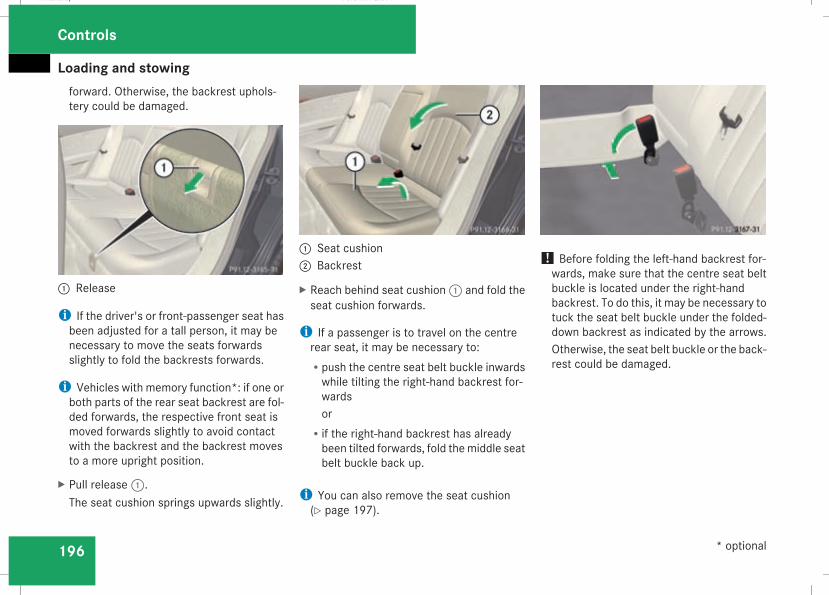
Loading and stowing
196
forward. Otherwise, the backrest uphols-tery could be damaged.
1 Release
i If the driver's or front-passenger seat hasbeen adjusted for a tall person, it may benecessary to move the seats forwardsslightly to fold the backrests forwards.
i Vehicles with memory function*: if one orboth parts of the rear seat backrest are fol-ded forwards, the respective front seat ismoved forwards slightly to avoid contactwith the backrest and the backrest movesto a more upright position.
X Pull release1.The seat cushion springs upwards slightly.
1 Seat cushion2 Backrest
X Reach behind seat cushion1 and fold theseat cushion forwards.
i If a passenger is to travel on the centrerear seat, it may be necessary to:Rpush the centre seat belt buckle inwardswhile tilting the right-hand backrest for-wardsor
Rif the right-hand backrest has alreadybeen tilted forwards, fold themiddle seatbelt buckle back up.
i You can also remove the seat cushion(Y page 197).
! Before folding the left-hand backrest for-wards, make sure that the centre seat beltbuckle is located under the right-handbackrest. To do this, it may be necessary totuck the seat belt buckle under the folded-down backrest as indicated by the arrows.Otherwise, the seat belt buckle or the back-rest could be damaged.
Controls
* optional
211_AKB; 2; 5, en-GBmkalafa, Version: 2.9.4
2008-02-29T16:57:07+01:00 - Seite 196
Dateiname: 6515_3416_02_buchblock.pdf; preflight
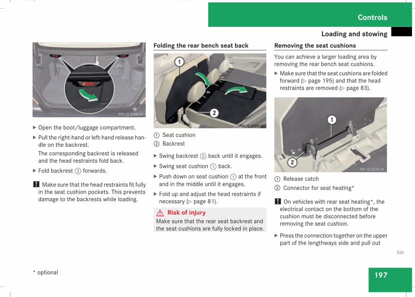
Loading and stowing
197
X Open the boot/luggage compartment.X Pull the right-hand or left-hand release han-dle on the backrest.The corresponding backrest is releasedand the head restraints fold back.
X Fold backrest2 forwards.
! Make sure that the head restraints fit fullyin the seat cushion pockets. This preventsdamage to the backrests while loading.
Folding the rear bench seat back
1 Seat cushion2 Backrest
X Swing backrest2 back until it engages.X Swing seat cushion1 back.X Push down on seat cushion1 at the frontand in the middle until it engages.
X Fold up and adjust the head restraints ifnecessary (Y page 81).
G Risk of injuryMake sure that the rear seat backrest andthe seat cushions are fully locked in place.
Removing the seat cushionsYou can achieve a larger loading area byremoving the rear bench seat cushions.X Make sure that the seat cushions are foldedforward (Y page 195) and that the headrestraints are removed (Y page 83).
1 Release catch2 Connector for seat heating*
! On vehicles with rear seat heating*, theelectrical contact on the bottom of thecushion must be disconnected beforeremoving the seat cushion.
X Press the connection together on the upperpart of the lengthways side and pull out
Controls
* optional
211_AKB; 2; 5, en-GBmkalafa, Version: 2.9.4
2008-02-29T16:57:07+01:00 - Seite 197
Z
Dateiname: 6515_3416_02_buchblock.pdf; preflight
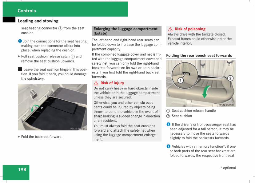
Loading and stowing
198
seat heating connector2 from the seatcushion.
i Join the connections for the seat heating,making sure the connector clicks intoplace, when replacing the cushion.
X Pull seat cushion release catch1 andremove the seat cushion upwards.
! Leave the seat cushion hinge in this posi-tion. If you fold it back, you could damagethe upholstery.
X Fold the backrest forward.
Enlarging the luggage compartment(Estate)The left-hand and right-hand rear seats canbe folded down to increase the luggage com-partment capacity.If the combined luggage cover and net is fit-ted with the luggage compartment cover andsafety net, you can only fold the right-handbackrest forwards on its own or both backr-ests if you first fold the right-hand backrestforwards.G Risk of injuryDo not carry heavy or hard objects insidethe vehicle or in the luggage compartmentunless they are secured.Otherwise, you and other vehicle occu-pants could be injured by objects beingthrown around the vehicle in the event ofsharp braking, a sudden change in directionor an accident.You must always fold the seat cushionsforward and attach the safety net whenusing the luggage compartment enlarge-ment.
G Risk of poisoningAlways drive with the tailgate closed.Exhaust fumes could otherwise enter thevehicle interior.
Folding the rear bench seat forwards
1 Seat cushion release handle2 Seat cushion
i If the driver's or front-passenger seat hasbeen adjusted for a tall person, it may benecessary to move the seats forwardsslightly to fold the backrests forwards.
i Vehicles with a memory function*: if oneor both parts of the rear seat backrest arefolded forwards, the respective front seat
Controls
* optional
211_AKB; 2; 5, en-GBmkalafa, Version: 2.9.4
2008-02-29T16:57:07+01:00 - Seite 198
Dateiname: 6515_3416_02_buchblock.pdf; preflight
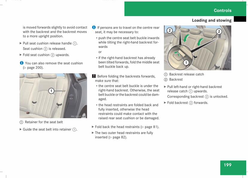
Loading and stowing
199
is moved forwards slightly to avoid contactwith the backrest and the backrest movesto a more upright position.
X Pull seat cushion release handle1.Seat cushion2 is released.
X Fold seat cushion2 upwards.
i You can also remove the seat cushion(Y page 200).
1 Retainer for the seat belt
X Guide the seat belt into retainer1.
i If persons are to travel on the centre rearseat, it may be necessary to:Rpush the centre seat belt buckle inwardswhile tilting the right-hand backrest for-wardsor
Rif the right-hand backrest has alreadybeen tilted forwards, fold themiddle seatbelt buckle back up.
! Before folding the backrests forwards,make sure that:Rthe centre seat belt buckle is under theright-hand backrest. Otherwise, the seatbelt buckle or the backrest could be dam-aged.
Rthe head restraints are folded back andfully inserted, otherwise the headrestraints could make contact with theraised rear seat cushion or be damaged.
X Fold back the head restraints (Y page 81).X The two outer head restraints are fullyinserted (Y page 82).
1 Backrest release catch2 Backrest
X Pull left-hand or right-hand backrestrelease catch1 upwards.Corresponding backrest2 is unlocked.
X Fold backrest2 forwards.
Controls
211_AKB; 2; 5, en-GBmkalafa, Version: 2.9.4
2008-02-29T16:57:07+01:00 - Seite 199
Z
Dateiname: 6515_3416_02_buchblock.pdf; preflight
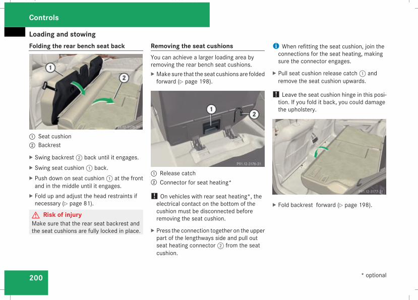
Loading and stowing
200
Folding the rear bench seat back
1 Seat cushion2 Backrest
X Swing backrest2 back until it engages.X Swing seat cushion1 back.X Push down on seat cushion1 at the frontand in the middle until it engages.
X Fold up and adjust the head restraints ifnecessary (Y page 81).
G Risk of injuryMake sure that the rear seat backrest andthe seat cushions are fully locked in place.
Removing the seat cushionsYou can achieve a larger loading area byremoving the rear bench seat cushions.X Make sure that the seat cushions are foldedforward (Y page 198).
1 Release catch2 Connector for seat heating*
! On vehicles with rear seat heating*, theelectrical contact on the bottom of thecushion must be disconnected beforeremoving the seat cushion.
X Press the connection together on the upperpart of the lengthways side and pull outseat heating connector2 from the seatcushion.
i When refitting the seat cushion, join theconnections for the seat heating, makingsure the connector engages.
X Pull seat cushion release catch1 andremove the seat cushion upwards.
! Leave the seat cushion hinge in this posi-tion. If you fold it back, you could damagethe upholstery.
X Fold backrest forward (Y page 198).
Controls
* optional
211_AKB; 2; 5, en-GBmkalafa, Version: 2.9.4
2008-02-29T16:57:07+01:00 - Seite 200
Dateiname: 6515_3416_02_buchblock.pdf; preflight
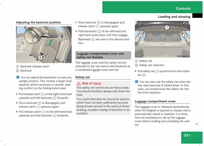
Loading and stowing
201
Adjusting the backrest position
1 Backrest release catch2 Backrest
i You can adjust the backrests to a second,upright position. This creates a larger loadcapacity where necessary or greater seat-ing comfort on the folding bench seat.
X Pull release catch1 on the right-hand seatupwards and fold backrest2 forwards.
X Once backrest2 is disengaged, pullrelease catch1 upwards again.
X Pull release catch1 on the left-hand seatupwards and fold backrest2 forwards.
X Once backrest2 is disengaged, pullrelease catch1 upwards again.
X Fold backrests2 of the left-hand andright-hand seats back until they engage.Backrests2 are now in the second posi-tion.
Luggage compartment cover andsafety net (Estate)The luggage cover and the safety net areattached to the rear bench seat backrest asa combined luggage cover and net.
Safety net
G Risk of injuryThe safety net cannot secure heavy loads.You should therefore always lash down theload.You could otherwise be injured by objectswhich have not been sufficiently securedbeing thrown around in the event of sharpbraking, a sudden change of direction or anaccident.
1 Safety net2 Safety net retainers
X Pull safety net1 up and hook it into retain-ers2.
i You can also use the safety net when therear seat backrest is folded down. In thiscase, you should hook the safety net intothe front retainers.
Luggage compartment coverThe luggage cover is released automaticallywhen the tailgate is opened or closed, and isautomatically raised or lowered. It is there-fore not necessary to roll up the luggagecover before loading and unloading the vehi-cle.
Controls
211_AKB; 2; 5, en-GBmkalafa, Version: 2.9.4
2008-02-29T16:57:07+01:00 - Seite 201
Z
Dateiname: 6515_3416_02_buchblock.pdf; preflight
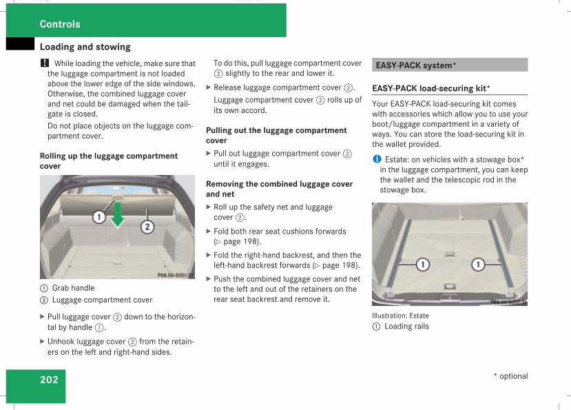
Loading and stowing
202
! While loading the vehicle, make sure thatthe luggage compartment is not loadedabove the lower edge of the side windows.Otherwise, the combined luggage coverand net could be damaged when the tail-gate is closed.Do not place objects on the luggage com-partment cover.
Rolling up the luggage compartmentcover
1 Grab handle2 Luggage compartment cover
X Pull luggage cover2 down to the horizon-tal by handle1.
X Unhook luggage cover2 from the retain-ers on the left and right-hand sides.
To do this, pull luggage compartment cover2 slightly to the rear and lower it.
X Release luggage compartment cover2.Luggage compartment cover2 rolls up ofits own accord.
Pulling out the luggage compartmentcoverX Pull out luggage compartment cover2until it engages.
Removing the combined luggage coverand netX Roll up the safety net and luggagecover2.
X Fold both rear seat cushions forwards(Y page 198).
X Fold the right-hand backrest, and then theleft-hand backrest forwards (Y page 198).
X Push the combined luggage cover and netto the left and out of the retainers on therear seat backrest and remove it.
EASY-PACK system*
EASY-PACK load-securing kit*Your EASY-PACK load-securing kit comeswith accessories which allow you to use yourboot/luggage compartment in a variety ofways. You can store the load-securing kit inthe wallet provided.
i Estate: on vehicles with a stowage box*in the luggage compartment, you can keepthe wallet and the telescopic rod in thestowage box.
Illustration: Estate1 Loading rails
Controls
* optional
211_AKB; 2; 5, en-GBmkalafa, Version: 2.9.4
2008-02-29T16:57:07+01:00 - Seite 202
Dateiname: 6515_3416_02_buchblock.pdf; preflight
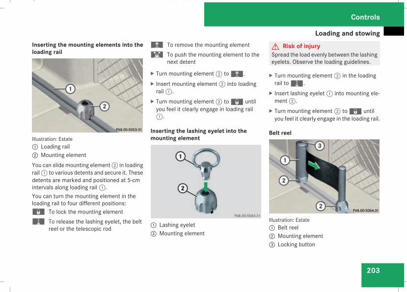
Loading and stowing
203
Inserting the mounting elements into theloading rail
Illustration: Estate1 Loading rail2 Mounting elementYou can slide mounting element2 in loadingrail1 to various detents and secure it. Thesedetents are marked and positioned at 5-cmintervals along loading rail1.You can turn the mounting element in theloading rail to four different positions:‹ To lock the mounting elementN To release the lashing eyelet, the belt
reel or the telescopic rod
L To remove the mounting elementS To push the mounting element to the
next detent
X Turn mounting element2 toL.X Insert mounting element2 into loadingrail1.
X Turn mounting element2 to‹ untilyou feel it clearly engage in loading rail1.
Inserting the lashing eyelet into themounting element
1 Lashing eyelet2 Mounting element
G Risk of injurySpread the load evenly between the lashingeyelets. Observe the loading guidelines.
X Turn mounting element2 in the loadingrail toN.
X Insert lashing eyelet1 into mounting ele-ment2.
X Turn mounting element2 to‹ untilyou feel it clearly engage in the loading rail.
Belt reel
Illustration: Estate1 Belt reel2 Mounting element3 Locking button
Controls
211_AKB; 2; 5, en-GBmkalafa, Version: 2.9.4
2008-02-29T16:57:07+01:00 - Seite 203
Z
Dateiname: 6515_3416_02_buchblock.pdf; preflight
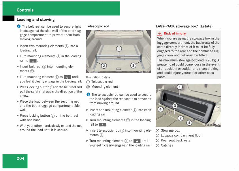
Loading and stowing
204
i The belt reel can be used to secure lightloads against the side wall of the boot/lug-gage compartment to prevent them frommoving around.
X Insert two mounting elements2 into aloading rail.
X Turn mounting elements2 in the loadingrail toN.
X Insert belt reel3 into mounting ele-ments2.
X Turn mounting element2 to‹ untilyou feel it clearly engage in the loading rail.
X Press locking button1 on the belt reel andpull the safety net out in the direction of thearrow.
X Place the load between the securing netand the boot/luggage compartment sidewall.
X Press locking button3 on the belt reelwith one hand.
X With your other hand, slowly extend the netaround the load until it is secure.
Telescopic rod
Illustration: Estate1 Telescopic rod2 Mounting element
i The telescopic rod can be used to securethe load against the rear seats to prevent itfrom moving around.
X Insert one mounting element2 into eachloading rail.
X Turn mounting elements2 in the loadingrail toN.
X Insert telescopic rod1 into mounting ele-ments2.
X Turn mounting element2 to‹ untilyou feel it clearly engage in the loading rail.
EASY-PACK stowage box* (Estate)
G Risk of injuryWhen you are using the stowage box in theluggage compartment, the backrests of theseats directly in front of it must be fullyengaged to the rear and the combined lug-gage cover and net must be fitted.The maximum stowage box load is 20 kg. Agreater load could come loose in the eventof an accident or sudden and sharp braking,and could injure yourself or other occu-pants.
1 Stowage box2 Luggage compartment floor3 Rear seat backrests4 Catches
Controls
211_AKB; 2; 5, en-GBmkalafa, Version: 2.9.4
2008-02-29T16:57:07+01:00 - Seite 204
Dateiname: 6515_3416_02_buchblock.pdf; preflight
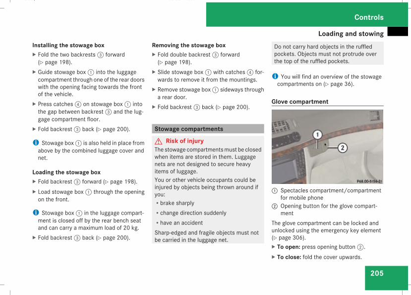
Loading and stowing
205
Installing the stowage boxX Fold the two backrests3 forward(Y page 198).
X Guide stowage box1 into the luggagecompartment through one of the rear doorswith the opening facing towards the frontof the vehicle.
X Press catches4 on stowage box1 intothe gap between backrest3 and the lug-gage compartment floor.
X Fold backrest3 back (Y page 200).
i Stowage box1 is also held in place fromabove by the combined luggage cover andnet.
Loading the stowage boxX Fold backrest3 forward (Y page 198).X Load stowage box1 through the openingon the front.
i Stowage box1 in the luggage compart-ment is closed off by the rear bench seatand can carry a maximum load of 20 kg.
X Fold backrest3 back (Y page 200).
Removing the stowage boxX Fold double backrest3 forward(Y page 198).
X Slide stowage box1 with catches4 for-wards to remove it from the mountings.
X Remove stowage box1 sideways througha rear door.
X Fold backrest3 back (Y page 200).
Stowage compartments
G Risk of injuryThe stowage compartmentsmust be closedwhen items are stored in them. Luggagenets are not designed to secure heavyitems of luggage.You or other vehicle occupants could beinjured by objects being thrown around ifyou:Rbrake sharplyRchange direction suddenlyRhave an accidentSharp-edged and fragile objects must notbe carried in the luggage net.
Do not carry hard objects in the ruffledpockets. Objects must not protrude overthe top of the ruffled pockets.
i You will find an overview of the stowagecompartments on (Y page 36).
Glove compartment
1 Spectacles compartment/compartmentfor mobile phone2 Opening button for the glove compart-
mentThe glove compartment can be locked andunlocked using the emergency key element(Y page 306).X To open: press opening button2.X To close: fold the cover upwards.
Controls
211_AKB; 2; 5, en-GBmkalafa, Version: 2.9.4
2008-02-29T16:57:07+01:00 - Seite 205
Z
Dateiname: 6515_3416_02_buchblock.pdf; preflight
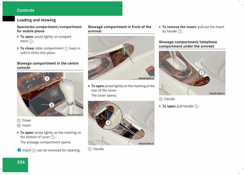
Loading and stowing
206
Spectacles compartment/compartmentfor mobile phoneX To open: press lightly on compart-ment1.
X To close: slide compartment1 back inuntil it clicks into place.
Stowage compartment in the centreconsole
1 Cover2 Insert
X To open: press lightly on the marking onthe bottom of cover1.The stowage compartment opens.
i Insert2 can be removed for cleaning.
Stowage compartment in front of thearmrest
X To open: press lightly on themarking at therear of the cover.The cover opens.
1 Handle
X To remove the insert: pull out the insertby handle1.
Stowage compartment/telephonecompartment under the armrest
1 Handle
X To open: pull handle1.
Controls
211_AKB; 2; 5, en-GBmkalafa, Version: 2.9.4
2008-02-29T16:57:07+01:00 - Seite 206
Dateiname: 6515_3416_02_buchblock.pdf; preflight
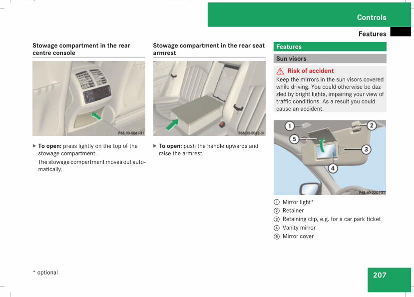
Features
207
Stowage compartment in the rearcentre console
X To open: press lightly on the top of thestowage compartment.The stowage compartmentmoves out auto-matically.
Stowage compartment in the rear seatarmrest
X To open: push the handle upwards andraise the armrest.
Features
Sun visors
G Risk of accidentKeep the mirrors in the sun visors coveredwhile driving. You could otherwise be daz-zled by bright lights, impairing your view oftraffic conditions. As a result you couldcause an accident.
1 Mirror light*2 Retainer3 Retaining clip, e.g. for a car park ticket4 Vanity mirror5 Mirror cover
Controls
* optional
211_AKB; 2; 5, en-GBmkalafa, Version: 2.9.4
2008-02-29T16:57:07+01:00 - Seite 207
Z
Dateiname: 6515_3416_02_buchblock.pdf; preflight
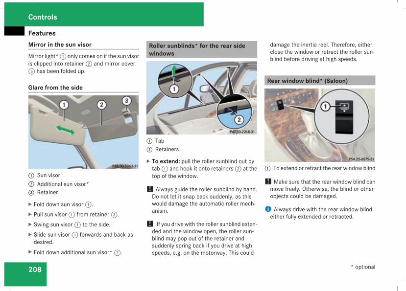
Features
208
Mirror in the sun visorMirror light*1 only comes on if the sun visoris clipped into retainer2 and mirror cover5 has been folded up.
Glare from the side
1 Sun visor2 Additional sun visor*3 Retainer
X Fold down sun visor1.X Pull sun visor1 from retainer3.X Swing sun visor1 to the side.X Slide sun visor1 forwards and back asdesired.
X Fold down additional sun visor*2.
Roller sunblinds* for the rear sidewindows
1 Tab2 Retainers
X To extend: pull the roller sunblind out bytab1 and hook it onto retainers2 at thetop of the window.
! Always guide the roller sunblind by hand.Do not let it snap back suddenly, as thiswould damage the automatic roller mech-anism.
! If you drive with the roller sunblind exten-ded and the window open, the roller sun-blind may pop out of the retainer andsuddenly spring back if you drive at highspeeds, e.g. on the motorway. This could
damage the inertia reel. Therefore, eitherclose the window or retract the roller sun-blind before driving at high speeds.
Rear window blind* (Saloon)
1 To extend or retract the rear window blind
! Make sure that the rear window blind canmove freely. Otherwise, the blind or otherobjects could be damaged.
i Always drive with the rear window blindeither fully extended or retracted.
Controls
* optional
211_AKB; 2; 5, en-GBmkalafa, Version: 2.9.4
2008-02-29T16:57:07+01:00 - Seite 208
Dateiname: 6515_3416_02_buchblock.pdf; preflight
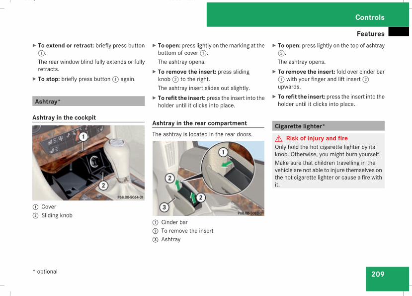
Features
209
X To extend or retract: briefly press button1.The rear window blind fully extends or fullyretracts.
X To stop: briefly press button1 again.
Ashtray*
Ashtray in the cockpit
1 Cover2 Sliding knob
X To open: press lightly on themarking at thebottom of cover1.The ashtray opens.
X To remove the insert: press slidingknob2 to the right.The ashtray insert slides out slightly.
X To refit the insert: press the insert into theholder until it clicks into place.
Ashtray in the rear compartmentThe ashtray is located in the rear doors.
1 Cinder bar2 To remove the insert3 Ashtray
X To open: press lightly on the top of ashtray3.The ashtray opens.
X To remove the insert: fold over cinder bar1 with your finger and lift insert2upwards.
X To refit the insert: press the insert into theholder until it clicks into place.
Cigarette lighter*
G Risk of injury and fireOnly hold the hot cigarette lighter by itsknob. Otherwise, you might burn yourself.Make sure that children travelling in thevehicle are not able to injure themselves onthe hot cigarette lighter or cause a fire withit.
Controls
* optional
211_AKB; 2; 5, en-GBmkalafa, Version: 2.9.4
2008-02-29T16:57:07+01:00 - Seite 209
Z
Dateiname: 6515_3416_02_buchblock.pdf; preflight
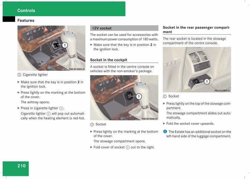
Features
210
1 Cigarette lighter
X Make sure that the key is in position 2 inthe ignition lock.
X Press lightly on the marking at the bottomof the cover.The ashtray opens.
X Press in cigarette lighter1.Cigarette lighter1 will pop out automati-cally when the heating element is red-hot.
12V socketThe socket can be used for accessories withamaximumpower consumption of 180watts.X Make sure that the key is in position 2 inthe ignition lock.
Socket in the cockpitA socket is fitted in the centre console onvehicles with the non-smoker's package.
1 Socket
X Press lightly on the marking at the bottomof the cover.The stowage compartment opens.
X Fold cover of socket1 out to the right.
Socket in the rear passenger compart-mentThe rear socket is located in the stowagecompartment of the centre console.
1 Socket
X Press lightly on the top of the stowage com-partment.The stowage compartment slides out auto-matically.
X Fold the socket cover upwards.
i The Estate has an additional socket on theleft-hand side of the luggage compartment.
Controls
211_AKB; 2; 5, en-GBmkalafa, Version: 2.9.4
2008-02-29T16:57:07+01:00 - Seite 210
Dateiname: 6515_3416_02_buchblock.pdf; preflight
Features
211
Mobile phone*
G Risk of accidentObserve the legal requirements of thecountry in which you are currently drivingregarding operating mobile communica-tions equipment in a vehicle.If it is permitted by law to operate commu-nications equipment while the vehicle is inmotion, you must only do so when the traf-fic situation allows. You could otherwise bedistracted from the traffic conditions,cause an accident and injure yourself andothers.Two-way radios and fax equipment usedwithout low-reflection exterior aerials caninterfere with the vehicle's electronics andthereby jeopardise the operating safety ofthe vehicle and your safety. Youmust there-fore only use this equipment if it is correctlyconnected to a separate reflection-freeexterior aerial.
G Risk of injuryExcessive electromagnetic radiation maycause damage to your health and the healthof others. Using an exterior aerial takes intoaccount current scientific discussions
relating to the possible health risk posed byelectromagnetic fields.
i In order to ensure optimum signal qualityfor mobile phones and to minimise mutualinterference between the vehicle electron-ics andmobile phones,Mercedes-Benz rec-ommends the use of an approved exterioraerial. An exterior aerial conducts the elec-tromagnetic fields generated by a wirelessdevice to the exterior of the vehicle; thefield strength within the vehicle interior islower than in a vehicle that does not havean exterior aerial.
i There are various mobile phone bracketsthat may be fitted to your vehicle; in somecases these are country-specific. You canobtain these mobile phone brackets from aqualified specialist workshop, e.g. aMercedes-Benz Service Centre. The func-tions and services available when you usethe phone depend on your mobile phonemodel and service provider.
The mobile phone bracket is in the armrest.X Open the telephone compartment(Y page 206).
Inserting the mobile phone into themobile phone bracketIf themobile phone is inserted into themobilephone bracket, you can only speak to the per-son you are calling using the hands-free sys-tem.
! Do not attempt to remove the mobilephone and the telephone bracket together.You could otherwise damage the mobilephone bracket.
X Remove the cover of the aerial plug fromthe back of the mobile phone and keep it ina safe place.
Controls
* optional
211_AKB; 2; 5, en-GBmkalafa, Version: 2.9.4
2008-02-29T16:57:07+01:00 - Seite 211
Z
Dateiname: 6515_3416_02_buchblock.pdf; preflight
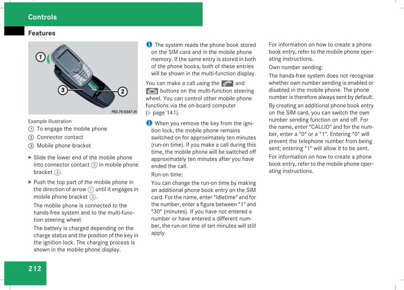
Features
212
Example illustration1 To engage the mobile phone2 Connector contact3 Mobile phone bracket
X Slide the lower end of the mobile phoneinto connector contact2 in mobile phonebracket3.
X Push the top part of the mobile phone inthe direction of arrow1 until it engages inmobile phone bracket3.The mobile phone is connected to thehands-free system and to the multi-func-tion steering wheel.The battery is charged depending on thecharge status and the position of the key inthe ignition lock. The charging process isshown in the mobile phone display.
i The system reads the phone book storedon the SIM card and in the mobile phonememory. If the same entry is stored in bothof the phone books, both of these entrieswill be shown in the multi-function display.
You can make a call using thes andt buttons on the multi-function steeringwheel. You can control other mobile phonefunctions via the on-board computer(Y page 141).
i When you remove the key from the igni-tion lock, the mobile phone remainsswitched on for approximately ten minutes(run-on time). If you make a call during thistime, the mobile phone will be switched offapproximately ten minutes after you haveended the call.Run-on time:You can change the run-on time by makingan additional phone book entry on the SIMcard. For the name, enter "Idletime" and forthe number, enter a figure between "1" and"30" (minutes). If you have not entered anumber or have entered a different num-ber, the run-on time of ten minutes will stillapply.
For information on how to create a phonebook entry, refer to the mobile phone oper-ating instructions.Own number sending:The hands-free system does not recognisewhether own number sending is enabled ordisabled in the mobile phone. The phonenumber is therefore always sent by default.By creating an additional phone book entryon the SIM card, you can switch the ownnumber sending function on and off. Forthe name, enter "CALLID" and for the num-ber, enter a "0" or a "1". Entering "0" willprevent the telephone number from beingsent; entering "1" will allow it to be sent.For information on how to create a phonebook entry, refer to the mobile phone oper-ating instructions.
Controls
211_AKB; 2; 5, en-GBmkalafa, Version: 2.9.4
2008-02-29T16:57:07+01:00 - Seite 212
Dateiname: 6515_3416_02_buchblock.pdf; preflight
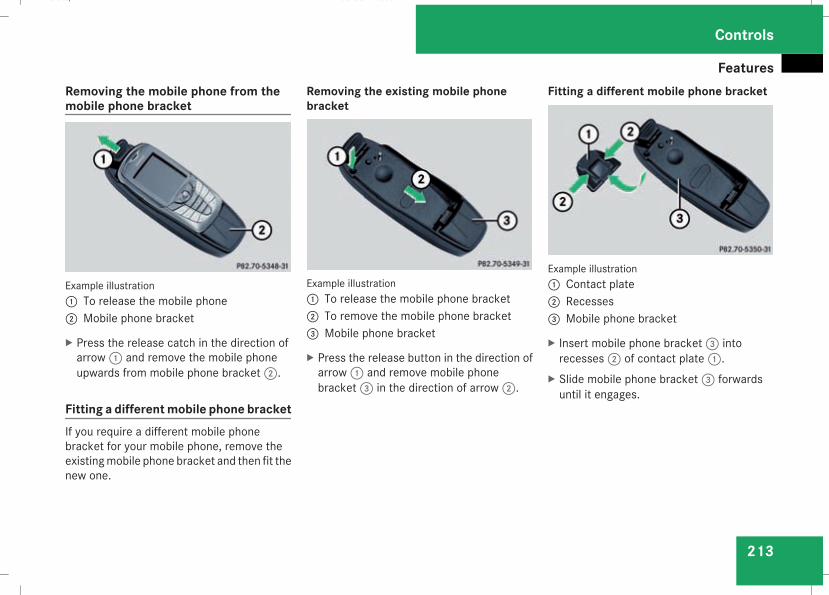
Features
213
Removing the mobile phone from themobile phone bracket
Example illustration1 To release the mobile phone2 Mobile phone bracket
X Press the release catch in the direction ofarrow1 and remove the mobile phoneupwards from mobile phone bracket2.
Fitting a differentmobile phone bracketIf you require a different mobile phonebracket for your mobile phone, remove theexistingmobile phone bracket and then fit thenew one.
Removing the existing mobile phonebracket
Example illustration1 To release the mobile phone bracket2 To remove the mobile phone bracket3 Mobile phone bracket
X Press the release button in the direction ofarrow1 and remove mobile phonebracket3 in the direction of arrow2.
Fitting a different mobile phone bracket
Example illustration1 Contact plate2 Recesses3 Mobile phone bracket
X Insert mobile phone bracket3 intorecesses2 of contact plate1.
X Slide mobile phone bracket3 forwardsuntil it engages.
Controls
211_AKB; 2; 5, en-GBmkalafa, Version: 2.9.4
2008-02-29T16:57:07+01:00 - Seite 213
Z
Dateiname: 6515_3416_02_buchblock.pdf; preflight
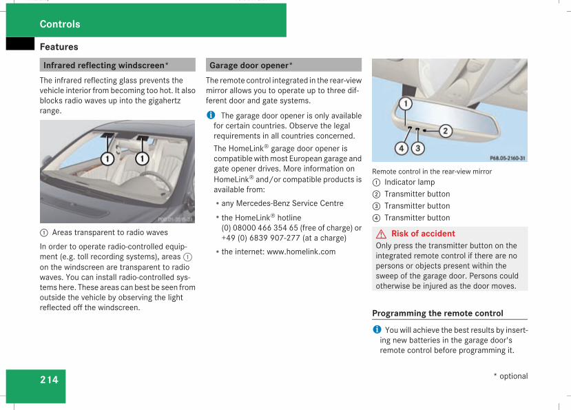
Features
214
Infrared reflecting windscreen*The infrared reflecting glass prevents thevehicle interior from becoming too hot. It alsoblocks radio waves up into the gigahertzrange.
1 Areas transparent to radio wavesIn order to operate radio-controlled equip-ment (e.g. toll recording systems), areas1on the windscreen are transparent to radiowaves. You can install radio-controlled sys-tems here. These areas can best be seen fromoutside the vehicle by observing the lightreflected off the windscreen.
Garage door opener*The remote control integrated in the rear-viewmirror allows you to operate up to three dif-ferent door and gate systems.
i The garage door opener is only availablefor certain countries. Observe the legalrequirements in all countries concerned.The HomeLink® garage door opener iscompatible withmost European garage andgate opener drives. More information onHomeLink® and/or compatible products isavailable from:Rany Mercedes-Benz Service CentreRthe HomeLink® hotline(0) 08000 466 354 65 (free of charge) or+49 (0) 6839 907-277 (at a charge)
Rthe internet: www.homelink.com
Remote control in the rear-view mirror1 Indicator lamp2 Transmitter button3 Transmitter button4 Transmitter button
G Risk of accidentOnly press the transmitter button on theintegrated remote control if there are nopersons or objects present within thesweep of the garage door. Persons couldotherwise be injured as the door moves.
Programming the remote controli You will achieve the best results by insert-ing new batteries in the garage door'sremote control before programming it.
Controls
* optional
211_AKB; 2; 5, en-GBmkalafa, Version: 2.9.4
2008-02-29T16:57:07+01:00 - Seite 214
Dateiname: 6515_3416_02_buchblock.pdf; preflight
Features
215
X Erase the memory of the integrated remotecontrol (Y page 216) before programmingit for the first time.
X Turn the key to position 2 in the ignitionlock.
X Press and hold one of transmitter buttons2 to4 on the integrated remote control.Indicator lamp1 starts to flash after ashort while. It flashes about once a second.
i Indicator lamp1 flashes immediatelythe first time the transmitter button is pro-grammed. If this transmitter button hasalready been programmed, indicatorlamp1 will only start flashing at a rate ofonce a second after 20 seconds haveelapsed.
X Keep the transmitter buttons depressed.X Point the garage door's remote control withthe transmitter towards the left-hand sideof the rear-view mirror from a distance of 5to 20 cm.
i The distance between the garage door'sremote control and the integrated garagedoor opener depends on the system of thegarage door drive. You might require sev-eral attempts. You should test every posi-
tion for at least 20 seconds before tryinganother position.
X Keep the transmitter button on the garagedoor's remote control depressed until indi-cator lamp1 starts to flash rapidly.The programming was successful if indica-tor lamp1 flashes rapidly.
X Release the transmitter buttons on thegarage door's remote control and the inte-grated remote control.
If indicator lamp1 goes out after approxi-mately 20 seconds and did not flash rapidlybefore this:X Release the transmitter buttons on theintegrated and portable remote controls.
X Repeat the programming procedure. At thesame time change the distance betweenthe garage door's remote control and thetransmitter buttons in the rear-view mirror.
i If the garage door system works with arolling code, after programming you mustsynchronise the remote control integratedin the rear-viewmirror with the garage doorsystem receiver.You will find further information in thegarage door opening system's operating
instructions, e.g. the sections on “Synchro-nising the transmitter” or “Registering anew transmitter”. You can also call the hot-line mentioned above.
Opening or closing the garage doorOnce programmed, the integrated remotecontrol will assume the function of the garagedoor system's remote control. Please readthe operating instructions for the garage doorsystem.X Turn the key to position 2 in the ignitionlock.
X Press the transmitter button on the rear-view mirror that you have programmed tooperate the garage door.Garage door system with fixed code: indi-cator lamp1 lights up continuously.Garage door system with rolling code: indi-cator lamp1 flashes briefly and then lightsup for approximately two seconds. This isrepeated for up to 20 seconds.
i The transmitter will transmit a signal foras long as the transmitter button is beingpressed. The transmission will be haltedafter a maximum of 20 seconds and indi-
Controls
211_AKB; 2; 5, en-GBmkalafa, Version: 2.9.4
2008-02-29T16:57:07+01:00 - Seite 215
Z
Dateiname: 6515_3416_02_buchblock.pdf; preflight
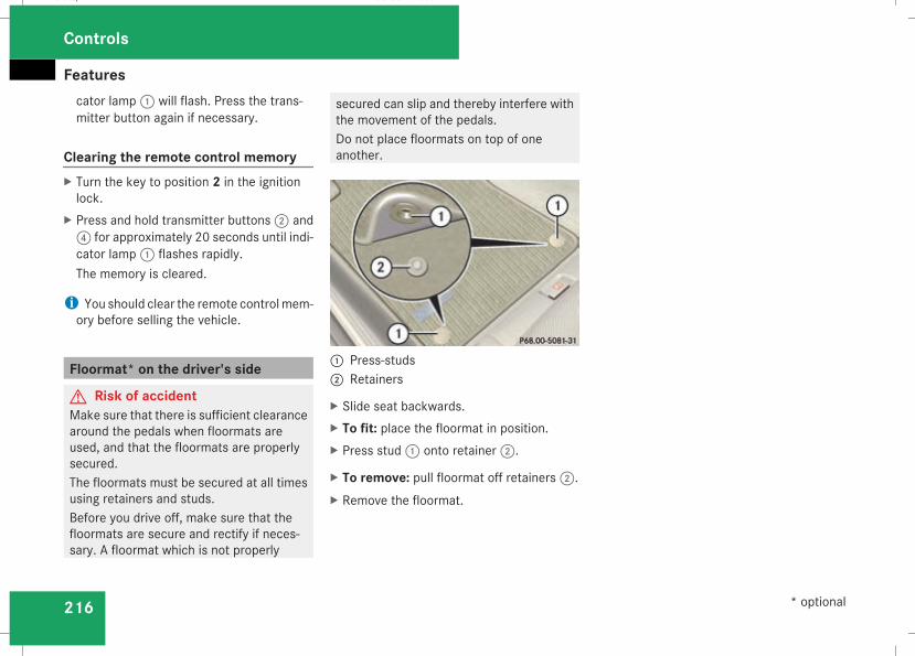
Features
216
cator lamp1 will flash. Press the trans-mitter button again if necessary.
Clearing the remote control memoryX Turn the key to position 2 in the ignitionlock.
X Press and hold transmitter buttons2 and4 for approximately 20 seconds until indi-cator lamp1 flashes rapidly.The memory is cleared.
i You should clear the remote controlmem-ory before selling the vehicle.
Floormat* on the driver's side
G Risk of accidentMake sure that there is sufficient clearancearound the pedals when floormats areused, and that the floormats are properlysecured.The floormats must be secured at all timesusing retainers and studs.Before you drive off, make sure that thefloormats are secure and rectify if neces-sary. A floormat which is not properly
secured can slip and thereby interfere withthe movement of the pedals.Do not place floormats on top of oneanother.
1 Press-studs2 Retainers
X Slide seat backwards.X To fit: place the floormat in position.X Press stud1 onto retainer2.
X To remove: pull floormat off retainers2.X Remove the floormat.
Controls
* optional
211_AKB; 2; 5, en-GBmkalafa, Version: 2.9.4
2008-02-29T16:57:07+01:00 - Seite 216
Dateiname: 6515_3416_02_buchblock.pdf; preflight
217
Running-in notes ............................... 218Refuelling ........................................... 218Engine compartment ........................ 222Tyres and wheels .............................. 227Winter driving ................................... 234Driving tips ........................................ 236Driving abroad ................................... 238Trailer towing .................................... 239Service ............................................... 243Care .................................................... 244
Operation
211_AKB; 2; 5, en-GBmkalafa, Version: 2.9.4
2008-02-29T16:57:07+01:00 - Seite 217
Dateiname: 6515_3416_02_buchblock.pdf; preflight
Refuelling
218
Running-in notes
The first 1,500 kmIf you treat the engine with sufficient carefrom the very start, it will reward you withexcellent performance for a very long periodafterwards.RYou should therefore drive at varying roadand engine speeds for the first 1,500 km.
RAvoid heavy loads, e.g. driving at full throt-tle, during this time. Do not exceed 2/3 ofthe maximum permissible engine speed foreach gear.
RChange gear in good time.RDo not shift down a gear manually in orderto brake.
Vehicles with automatic transmission*:RTry to avoid depressing the acceleratorpedal beyond the pressure point (kick-down).
ROnly use ranges 3, 2 or 1 for slow driving,e.g. in mountainous terrain.
After 1,500 km you may gradually bring thevehicle up to full road and engine speeds.Additional driving tips for AMG vehicles:
RDo not drive faster than 140 km/h for thefirst 1,500 km.
ROnly bring the engine up to a maximumspeed of 4,500 rpm for a brief period.
i You should also observe these notes if theengine or rear axle transmission on yourvehicle has been replaced.
AMG vehicles with a rear axle differ-ential lock*Your vehicle is equipped with a self-lockingdifferential on the rear axle. To better protectthe differential gear on the rear axle, youshould perform an oil change after a running-in phase of 3,000 km. This oil change willincrease the service life of your differential.Have the oil change performed at a qualifiedspecialist workshop. Mercedes-Benz recom-mends that you use aMercedes-Benz ServiceCentre for this purpose.
Refuelling
Refuelling
G Risk of explosionFuel is highly flammable. Fire, naked flamesand smoking are therefore prohibited whenhandling fuels.Switch off the engine and the auxiliary heat-ing* before refuelling.
G Risk of injuryDo not come into direct contact with fuel.Direct skin contact with fuels or the inha-lation of fuel vapours is a health hazard.
G Risk of fireDo not use petrol to refuel vehicles with adiesel engine. Never mix diesel with petrol.This causes damage to the fuel system andengine and could result in the vehicle catch-ing fire.
! Do not use petrol to refuel vehicles with adiesel engine. Do not use diesel to refuelvehicles with a petrol engine. Even smallamounts of the wrong fuel will cause dam-age to the injection system. Damage result-ing from adding the wrong fuel is notcovered by the warranty.
Operation
* optional
211_AKB; 2; 5, en-GBmkalafa, Version: 2.9.4
2008-02-29T16:57:07+01:00 - Seite 218
Dateiname: 6515_3416_02_buchblock.pdf; preflight
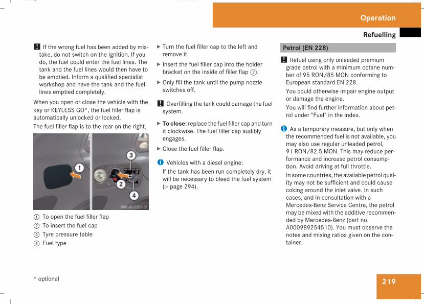
Refuelling
219
! If the wrong fuel has been added by mis-take, do not switch on the ignition. If youdo, the fuel could enter the fuel lines. Thetank and the fuel lines would then have tobe emptied. Inform a qualified specialistworkshop and have the tank and the fuellines emptied completely.
When you open or close the vehicle with thekey or KEYLESS GO*, the fuel filler flap isautomatically unlocked or locked.The fuel filler flap is to the rear on the right.
1 To open the fuel filler flap2 To insert the fuel cap3 Tyre pressure table4 Fuel type
X Turn the fuel filler cap to the left andremove it.
X Insert the fuel filler cap into the holderbracket on the inside of filler flap2.
X Only fill the tank until the pump nozzleswitches off.
! Overfilling the tank could damage the fuelsystem.
X To close: replace the fuel filler cap and turnit clockwise. The fuel filler cap audiblyengages.
X Close the fuel filler flap.
i Vehicles with a diesel engine:If the tank has been run completely dry, itwill be necessary to bleed the fuel system(Y page 294).
Petrol (EN 228)! Refuel using only unleaded premiumgrade petrol with a minimum octane num-ber of 95 RON/85 MON conforming toEuropean standard EN 228.You could otherwise impair engine outputor damage the engine.You will find further information about pet-rol under "Fuel" in the index.
i As a temporary measure, but only whenthe recommended fuel is not available, youmay also use regular unleaded petrol,91 RON/82.5 MON. This may reduce per-formance and increase petrol consump-tion. Avoid driving at full throttle.In some countries, the available petrol qual-ity may not be sufficient and could causecoking around the inlet valve. In suchcases, and in consultation with aMercedes-Benz Service Centre, the petrolmay be mixed with the additive recommen-ded by Mercedes-Benz (part no.A000989254510). You must observe thenotes and mixing ratios given on the con-tainer.
Operation
* optional
211_AKB; 2; 5, en-GBmkalafa, Version: 2.9.4
2008-02-29T16:57:07+01:00 - Seite 219
Z
Dateiname: 6515_3416_02_buchblock.pdf; preflight
Refuelling
220
E 350 CGI! Refuel using only unleaded premiumgrade petrol with a minimum octane num-ber of 95 RON/85 MON conforming toEuropean standard EN 228.You could otherwise impair engine outputor damage the engine.You will find further information about pet-rol under "Technical data" in the index.
i In some countries, only petrol of insuffi-cient quality (high-sulphur fuel) may beavailable. This fuel can temporarily produceunpleasant odours, especially on shortjourneys. Refuellingwith petrol of sufficientquality (sulphur-free fuel) will reduce suchodours.
AMG vehicles! Refuel using only super unleaded petrolwith a minimum octane number of 98RON/88 MON conforming to Europeanstandard EN 228.You could otherwise impair engine outputor damage the engine.You will find further information about pet-rol under "Technical data" in the index.
i If the recommended fuel is not availableand only as a temporary measure, you mayalso use premium unleaded petrol,95 RON/85 MON. This may reduce per-formance and increase petrol consump-tion. You must avoid driving at full throttle.
! In emergencies, only when the recom-mended fuel is not available, you may alsouse standard unleaded petrol, 91 RON/82.5 MON. However, using this fuel resultsin considerably higher petrol consumptionand significantly reduced performance.Avoid driving at full throttle, and only drivein drive program C.If no fuel other than regular petrol fuel 91RON/82.5 MON or a lower grade is per-manently available, you should have thevehicle adapted to run on this fuel by thelocal after-sales service.
Diesel (EN 590)! Only use diesel that complies with theEN 590 European standard.You could otherwise impair engine outputor damage the engine.You will find further information about die-sel under "Fuel" in the index.
! When refuelling vehicles with a diesel par-ticle filter in countries outside the EU, onlylow-sulphur Euro diesel with less than0.005 percent sulphur content by weightshould be used. In countries in which dieselwith a higher sulphur content is available(e.g. 0.035 percent by weight), the engineoil should be renewed at more frequentintervals. More information about intervalsfor changing the engine oil can be obtainedfrom any Mercedes-Benz Service Centre.
! Using fuel that does not comply with EN590 can increase wear and damage theengine and the exhaust system. Do not usethe following:RMarine dieselRHeating oilRBio-diesel
Operation
211_AKB; 2; 5, en-GBmkalafa, Version: 2.9.4
2008-02-29T16:57:07+01:00 - Seite 220
Dateiname: 6515_3416_02_buchblock.pdf; preflight
Refuelling
221
RVegetable oilRPetrolRPetroleumRKeroseneDo not add such fuels to diesel fuel and donot use any special additives (exception:flow improvers – see "Low outside temper-atures").Damage caused by the use of unapprovedfuels or additives is not covered by the war-ranty.
E 300 BLUETEC! When refuelling vehicles with a diesel par-ticle filter in countries outside the EU, onlylow-sulphur Euro diesel with less than0.005 percent sulphur content by weight (<50 ppm) should be used.
Low outside temperaturesThe flow properties of diesel may be insuffi-cient at low ambient temperatures.To prevent operating problems, diesel fuelwith improved cold flow qualities is availableduring the winter months. Your vehicle must
be refuelled with this winter diesel at temper-atures of -5 °C or below.You can use this winter diesel at tempera-tures down to about -20 °Cwithout problems.If only summer diesel fuel or less cold-resist-ant winter diesel fuel (e.g. in Mediterraneanregions) is available, you should add anamount of flow improver to the fuel corre-sponding to the outside temperature.Mix the additive with the diesel in good time,before the flow properties of the dieselbecome insufficient. Otherwise,malfunctionscan only be rectified by heating the entire fuelsystem, e.g. by parking the vehicle in a heatedgarage.G Risk of fireDo not use petrol to refuel vehicles with adiesel engine. Never mix diesel with petrol.This would damage the fuel system andengine and could result in a vehicle fire.
Flow improverThe effectiveness of a flow improver is notguaranteedwith every fuel. Observe the infor-mation provided by the manufacturer whenusing a flow improver. Only use flow improv-ers that have been tested and approved byMercedes-Benz. Information about flow
improvers that have been tested andapproved by Mercedes-Benz can be obtainedfrom any Mercedes-Benz Service Centre.
Operation
211_AKB; 2; 5, en-GBmkalafa, Version: 2.9.4
2008-02-29T16:57:07+01:00 - Seite 221
Z
Dateiname: 6515_3416_02_buchblock.pdf; preflight
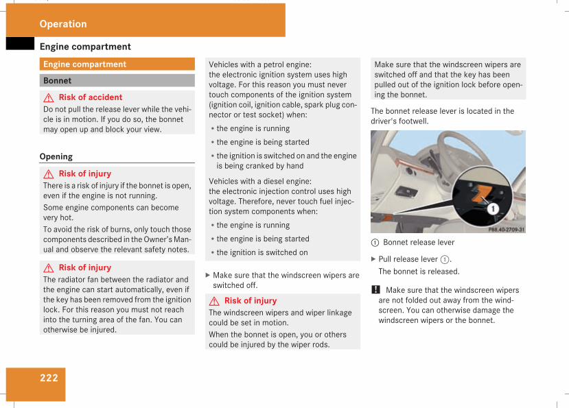
Engine compartment
222
Engine compartment
Bonnet
G Risk of accidentDo not pull the release lever while the vehi-cle is in motion. If you do so, the bonnetmay open up and block your view.
Opening
G Risk of injuryThere is a risk of injury if the bonnet is open,even if the engine is not running.Some engine components can becomevery hot.To avoid the risk of burns, only touch thosecomponents described in theOwner’sMan-ual and observe the relevant safety notes.
G Risk of injuryThe radiator fan between the radiator andthe engine can start automatically, even ifthe key has been removed from the ignitionlock. For this reason you must not reachinto the turning area of the fan. You canotherwise be injured.
Vehicles with a petrol engine:the electronic ignition system uses highvoltage. For this reason you must nevertouch components of the ignition system(ignition coil, ignition cable, spark plug con-nector or test socket) when:Rthe engine is runningRthe engine is being startedRthe ignition is switched on and the engineis being cranked by hand
Vehicles with a diesel engine:the electronic injection control uses highvoltage. Therefore, never touch fuel injec-tion system components when:Rthe engine is runningRthe engine is being startedRthe ignition is switched on
X Make sure that the windscreen wipers areswitched off.
G Risk of injuryThe windscreen wipers and wiper linkagecould be set in motion.When the bonnet is open, you or otherscould be injured by the wiper rods.
Make sure that the windscreen wipers areswitched off and that the key has beenpulled out of the ignition lock before open-ing the bonnet.
The bonnet release lever is located in thedriver's footwell.
1 Bonnet release lever
X Pull release lever1.The bonnet is released.
! Make sure that the windscreen wipersare not folded out away from the wind-screen. You can otherwise damage thewindscreen wipers or the bonnet.
Operation
211_AKB; 2; 5, en-GBmkalafa, Version: 2.9.4
2008-02-29T16:57:07+01:00 - Seite 222
Dateiname: 6515_3416_02_buchblock.pdf; preflight
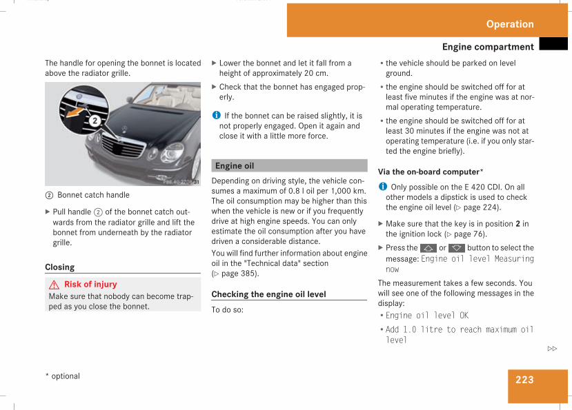
Engine compartment
223
The handle for opening the bonnet is locatedabove the radiator grille.
2 Bonnet catch handle
X Pull handle2 of the bonnet catch out-wards from the radiator grille and lift thebonnet from underneath by the radiatorgrille.
Closing
G Risk of injuryMake sure that nobody can become trap-ped as you close the bonnet.
X Lower the bonnet and let it fall from aheight of approximately 20 cm.
X Check that the bonnet has engaged prop-erly.
i If the bonnet can be raised slightly, it isnot properly engaged. Open it again andclose it with a little more force.
Engine oilDepending on driving style, the vehicle con-sumes a maximum of 0.8 l oil per 1,000 km.The oil consumption may be higher than thiswhen the vehicle is new or if you frequentlydrive at high engine speeds. You can onlyestimate the oil consumption after you havedriven a considerable distance.You will find further information about engineoil in the "Technical data" section(Y page 385).
Checking the engine oil levelTo do so:
Rthe vehicle should be parked on levelground.
Rthe engine should be switched off for atleast five minutes if the engine was at nor-mal operating temperature.
Rthe engine should be switched off for atleast 30 minutes if the engine was not atoperating temperature (i.e. if you only star-ted the engine briefly).
Via the on-board computer*i Only possible on the E 420 CDI. On allother models a dipstick is used to checkthe engine oil level (Y page 224).
X Make sure that the key is in position 2 inthe ignition lock (Y page 76).
X Press thej ork button to select themessage: Engine oil level Measuringnow
The measurement takes a few seconds. Youwill see one of the following messages in thedisplay:REngine oil level OKRAdd 1.0 litre to reach maximum oillevel
Operation
* optional
211_AKB; 2; 5, en-GBmkalafa, Version: 2.9.4
2008-02-29T16:57:07+01:00 - Seite 223
Z
Dateiname: 6515_3416_02_buchblock.pdf; preflight
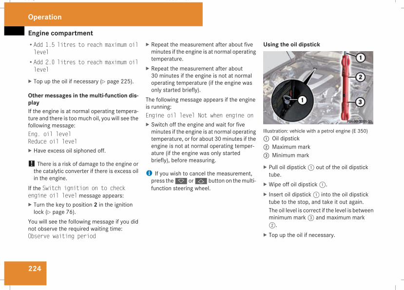
Engine compartment
224
RAdd 1.5 litres to reach maximum oillevel
RAdd 2.0 litres to reach maximum oillevel
X Top up the oil if necessary (Y page 225).
Other messages in the multi-function dis-playIf the engine is at normal operating tempera-ture and there is toomuch oil, you will see thefollowing message:Eng. oil levelReduce oil levelX Have excess oil siphoned off.
! There is a risk of damage to the engine orthe catalytic converter if there is excess oilin the engine.
If the Switch ignition on to checkengine oil level message appears:X Turn the key to position 2 in the ignitionlock (Y page 76).
You will see the following message if you didnot observe the required waiting time:Observe waiting period
X Repeat the measurement after about fiveminutes if the engine is at normal operatingtemperature.
X Repeat the measurement after about30 minutes if the engine is not at normaloperating temperature (if the engine wasonly started briefly).
The following message appears if the engineis running:Engine oil level Not when engine onX Switch off the engine and wait for fiveminutes if the engine is at normal operatingtemperature, or for about 30 minutes if theengine is not at normal operating temper-ature (if the engine was only startedbriefly), before measuring.
i If you wish to cancel the measurement,press thek orj button on themulti-function steering wheel.
Using the oil dipstick
Illustration: vehicle with a petrol engine (E 350)1 Oil dipstick2 Maximum mark3 Minimum mark
X Pull oil dipstick1 out of the oil dipsticktube.
X Wipe off oil dipstick1.X Insert oil dipstick1 into the oil dipsticktube to the stop, and take it out again.The oil level is correct if the level is betweenminimum mark3 and maximum mark2.
X Top up the oil if necessary.
Operation
211_AKB; 2; 5, en-GBmkalafa, Version: 2.9.4
2008-02-29T16:57:07+01:00 - Seite 224
Dateiname: 6515_3416_02_buchblock.pdf; preflight
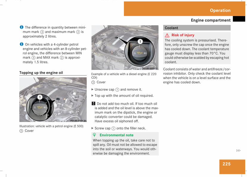
Engine compartment
225
i The difference in quantity between mini-mum mark3 and maximum mark2 isapproximately 2 litres.
i On vehicles with a 4-cylinder petrolengine and vehicles with an 8-cylinder pet-rol engine, the difference between MINmark3 and MAX mark2 is approxi-mately 1.5 litres.
Topping up the engine oil
Illustration: vehicle with a petrol engine (E 500)1 Cover
Example of a vehicle with a diesel engine (E 220CDI)1 Cover
X Unscrew cap1 and remove it.X Top up with the amount of oil required.
! Do not add too much oil. If too much oilis added and the oil level is above the max-imum mark on the dipstick, the engine orcatalytic converter could be damaged.Have excess oil siphoned off.
X Screw cap1 onto the filler neck.
H Environmental noteWhen topping up the oil, take care not tospill any. Oil must not be allowed to escapeinto the soil or waterways. You would oth-erwise be damaging the environment.
Coolant
G Risk of injuryThe cooling system is pressurised. There-fore, only unscrew the cap once the enginehas cooled down. The coolant temperaturegauge must display less than 70°C. Youcould otherwise be scalded by escaping hotcoolant.
Coolant consists of water and antifreeze/cor-rosion inhibitor. Only check the coolant levelwhen the vehicle is on a level surface and theengine has cooled down.
Operation
211_AKB; 2; 5, en-GBmkalafa, Version: 2.9.4
2008-02-29T16:57:07+01:00 - Seite 225
Z
Dateiname: 6515_3416_02_buchblock.pdf; preflight
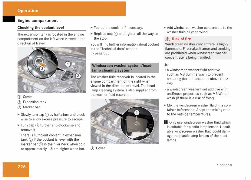
Engine compartment
226
Checking the coolant levelThe expansion tank is located in the enginecompartment on the left when viewed in thedirection of travel.
1 Cover2 Expansion tank3 Marker bar
X Slowly turn cap1 by half a turn anti-clock-wise to allow excess pressure to escape.
X Turn cap1 further anti-clockwise andremove it.There is sufficient coolant in expansiontank2 if the coolant is level with themarker bar3 in the filler neck when coldor approximately 1.5 cm higher when hot.
X Top up the coolant if necessary.X Replace cap1 and tighten all the way tothe stop.
Youwill find further information about coolantin the "Technical data" section(Y page 388).
Windscreen washer system/head-lamp cleaning system*The washer fluid reservoir is located in theengine compartment on the right whenviewed in the direction of travel. The head-lamp cleaning system is also supplied fromthe washer fluid reservoir.
1 Cover
X Add windscreen washer concentrate to thewasher fluid all year round.
G Risk of fireWindscreen washer concentrate is highlyflammable. Fire, naked flames and smokingare prohibited when windscreen washerconcentrate is being handled.
UseRa windscreen washer fluid additivesuch as MB Summerwash to preventsmearing (for temperatures above freez-ing).
Ra windscreen washer fluid additive withantifreeze properties such as MB Winter-wash (if there is a risk of frost).
X Mix the windscreen washer fluid in a con-tainer beforehand. Adapt the mixing ratioto the outside temperatures.
! Only use windscreen washer fluid whichis suitable for plastic lamp lenses. Unsuit-able windscreen washer fluid could dam-age the plastic lamp lenses of the head-lamps.
Operation
* optional
211_AKB; 2; 5, en-GBmkalafa, Version: 2.9.4
2008-02-29T16:57:07+01:00 - Seite 226
Dateiname: 6515_3416_02_buchblock.pdf; preflight
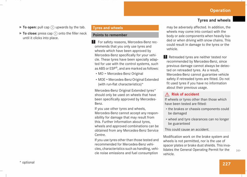
Tyres and wheels
227
X To open: pull cap1 upwards by the tab.X To close: press cap1 onto the filler neckuntil it clicks into place.
Tyres and wheels
Points to remember! For safety reasons, Mercedes-Benz rec-ommends that you only use tyres andwheels which have been approved byMercedes-Benz specifically for your vehi-cle. These tyres have been specially adap-ted for use with the control systems, suchas ABS or ESP®, and aremarked as follows:RMO = Mercedes-Benz OriginalRMOE=Mercedes-BenzOriginal Extended(with run-flat characteristics)*
Mercedes-Benz Original Extended tyres*should only be used on wheels that havebeen specifically approved by Mercedes-Benz.If you use other tyres and wheels,Mercedes-Benz cannot accept any respon-sibility for damage that may result fromthis. Further information about tyres,wheels and approved combinations can beobtained from any Mercedes-Benz ServiceCentre.If you use tyres other than those tested andrecommended for Mercedes-Benz vehi-cles, characteristics such as handling, vehi-cle noise emissions and fuel consumption
may be adversely affected. In addition, thewheels may come into contact with thebody or axle components when heavily loa-ded or when driving with snow chains. Thiscould result in damage to the tyres or thevehicle.
! Retreaded tyres are neither tested norrecommended by Mercedes-Benz, sinceprevious damage cannot always be detec-ted on retreaded tyres. As a result,Mercedes-Benz cannot guarantee vehiclesafety if retreaded tyres are fitted. Do notfit used tyres if you have no informationabout their previous usage.
G Risk of accidentIf wheels or tyres other than those whichhave been tested are fitted:Rthe brakes or chassis components couldbe damaged
Rwheel and tyre clearances can no longerbe guaranteed
This could cause an accident.
Modification work on the brake system andwheels is not permitted, nor is the use ofspacer plates or brake dust shields. This inva-lidates the General Operating Permit for thevehicle.
Operation
* optional
211_AKB; 2; 5, en-GBmkalafa, Version: 2.9.4
2008-02-29T16:57:07+01:00 - Seite 227
Z
Dateiname: 6515_3416_02_buchblock.pdf; preflight
Tyres and wheels
228
Notes on selecting, fitting and replacingtyresROnly fit tyres and wheels of the same typeand make.
ROnly fit tyres of the correct size onto thewheels.
RAfter fitting new tyres, run them in at mod-erate speeds for the first 100 km as theyonly reach their full performance after thisdistance.
RFit new tyres on the front wheels first iftyres of the same size are required on thefront and rear wheels.
RReplace the tyres after six years at the lat-est, regardless of wear. This also applies tothe spare wheel*.
RDo not drive with tyres which have too littletread depth as this significantly reducesthe traction on wet roads (aquaplaning).
! Store tyres that are not being used in acool, dry and preferably dark place. Protectthe tyres against oil, grease, petrol and die-sel.
Notes on regularly inspecting wheelsand tyresRRegularly check the wheels and tyres ofyour vehicle for damage (e.g. cuts, punctu-res, tears, bumps on tyres and deforma-tion, cracks or severe corrosion onwheels),at least every 14 days, as well as after off-road trips or after travelling on rough roads.Damaged wheels could cause a loss of tyrepressure.
RRegularly check the tyre tread depth andthe condition of the tread across the wholewidth of the tyre (Y page 229). If neces-sary, turn the front wheels to full lock inorder to inspect the inner side of the tyresurface.
RAll wheels must have a valve cap to protectthe valve against dirt and moisture.
RRegularly check the pressure of all yourtyres (including the spare tyre*), particu-larly prior to long trips, and correct thepressure as necessary (Y page 229).
Notes on drivingRWhile driving, pay attention to vibrations,noises and unusual handling characteris-tics, e.g. pulling to one side. This may indi-
cate that the wheels or tyres are damaged.If you suspect that a tyre is defective,reduce your speed and stop the vehicle assoon as possible to check the wheels andtyres for damage. Hidden tyre damagecould also be causing the unusual handlingcharacteristics. If you find no signs of dam-age, have the wheels and tyres inspectedat a specialist workshop, for example at aMercedes-Benz Service Centre.
RWhen parking your vehicle, make sure thatthe tyres do not get deformed by the kerbor other obstacles. If it is necessary to driveover kerbs, speed humps or similar, try todo so slowly and at an obtuse angle. Oth-erwise, the tyres, particularly the sidewalls,could get damaged.
Operation
* optional
211_AKB; 2; 5, en-GBmkalafa, Version: 2.9.4
2008-02-29T16:57:07+01:00 - Seite 228
Dateiname: 6515_3416_02_buchblock.pdf; preflight
Tyres and wheels
229
Direction of rotation
Direction of rotationTyres with a specified direction of rotationhave additional benefits, e.g. if there is a riskof aquaplaning. You will only gain these ben-efits if the correct direction of rotation isobserved.An arrow on the sidewall of the tyre indicatesits correct direction of rotation.
i You may fit a spare tyre* against thedirection of rotation.
MOExtended run-flat system*The MOExtended run-flat system allows youto continue driving the vehicle even when oneor more tyres lose all air pressure.The MOExtended run-flat systemmay only beused in conjunction with the tyre pressureloss warning system or the tyre pressuremonitor* and on wheels specifically tested byMercedes-Benz.
i Vehicles with MOExtended run-flat sys-tem are not equipped with the TIREFITkit*30.
It is therefore recommended to additionallyequip your vehicle with the TIREFIT kit*when fitting tyres that do not feature run-flat properties, e.g. winter tyres.
i A TIREFIT kit* is available from any quali-fied specialist workshop, e.g. a Mercedes-Benz Service Centre.
You will find notes on driving with a flat tyrein the "Practical advice" section(Y page 328).
Tyre tread
G Risk of accidentBear in mind that:Rtyre grip decreases rapidly on wet roadswhen the tread depth is less than 3 mm.You should thus replace tyres that haveinsufficient tread.
Rwinter tyres should be replaced when thetread depth is 4 mm or less because oth-erwise they no longer provide adequategrip.
Rthe tread on a tyre may not wear evenly.You should thus regularly check the tread
depth and the condition of the treadacross the entire width of all tyres. If nec-essary, turn the steering wheel so thatyou can see the tyre tread more easily.
You could otherwise lose control of thevehicle and cause an accident due to thereduced grip of the tyres on the road.
Tyre pressures
G Risk of accidentTyre pressure that is either too high or toolow has a negative effect on the vehicle’sdriving safety, which could lead you tocause an accident. You should thereforeregularly check the pressure of all yourtyres (including the spare tyre*), particu-larly prior to long trips, and correct thepressure as necessary.
To test tyre pressure, use a suitable pressuregauge. The outer appearance of a tyre doesnot permit any reliable conclusion about thetyre pressure. On vehicles fittedwith the elec-tronic tyre pressure monitor*, the tyre pres-sure can be checked in the on-board com-puter.
30 Only for certain countries
Operation
* optional
211_AKB; 2; 5, en-GBmkalafa, Version: 2.9.4
2008-02-29T16:57:07+01:00 - Seite 229
Z
Dateiname: 6515_3416_02_buchblock.pdf; preflight
Tyres and wheels
230
If the vehicle is to be heavily laden or drivenat high speeds, the tyre pressure must beadapted according to the specifications givenin the fuel filler flap (Y page 218).Use the highest specified tyre pressure forthe spare wheel*.G Risk of accidentShould the tyre pressure drop repeatedly:RCheck the tyre for foreign bodies.RCheck whether the wheel is losing air orthe valve is leaking.
Tyre pressure that is too low has a negativeeffect on the vehicle’s active safety, whichcould lead to your causing an accident.
Tyre pressure changes by approximately0.1 bar for every 10 °C change in ambienttemperature.If you measure the tyre pressure in enclosedspaces where the temperature differs fromthe outside temperature, you will have to cor-rect the measured value accordingly.When the vehicle is driven, the tyre tempera-ture, and with it the tyre pressure, willincrease depending on the road speed andthe load on the tyres.
Therefore, you should only correct tyre pres-sures when the tyres are cold.The pressure of warm tyres should only becorrected if it is too low for the current oper-ating conditions.You will find a table of tyre pressures for var-ious operating conditions on the inside ofyour vehicle's fuel filler flap.Driving with tyre pressure that is too high ortoo low can:Rshorten the service life of the tyresRcause increased tyre damageRhave a negative effect on handling charac-teristics (e.g. by causing aquaplaning)
E 350 CGI31/E 300 BLUETEC: the values onthe tyre pressure information label (fuel fillerflap) are for the use of the vehicle in partiallyladen and fully laden condition whilst drivingat maximum speed.Despite what is stated on the tyre pressureinformation label, for speeds up to210 km/h the values stated can be reducedas follows, without a reduction in safety:-0.4 bar /-6 psi: E 350 CGI-0.3 bar/-4 psi: E 300 BLUETEC
This improves the ride comfort of your vehi-cle, however the fuel consumption couldincrease slightly.Also check the tyre pressure of the sparewheel*.H Environmental noteCheck the tyre pressure regularly, at leastevery 14 days.
Tyre pressure loss warning system
G Risk of accidentThe tyre pressure losswarning systemdoesnot warn you of an incorrectly set tyre pres-sure. The table on the inside of the fuel fillerflap will help you decide whether the tyrepressures should be corrected.The tyre pressure losswarning systemdoesnot replace the need to regularly checkyour vehicle's tyre pressures, since an evenloss of pressure on several tyres at thesame time cannot be detected by the tyrepressure loss warning system.The tyre pressure loss warning system isnot able to warn you of a sudden loss of
31 Only for certain countries.
Operation
* optional
211_AKB; 2; 5, en-GBmkalafa, Version: 2.9.4
2008-02-29T16:57:07+01:00 - Seite 230
Dateiname: 6515_3416_02_buchblock.pdf; preflight
Tyres and wheels
231
pressure, e.g. if the tyre is penetrated by aforeign object.In the event of a sudden loss of pressure,bring the vehicle to a halt by braking care-fully. Do not make any sudden steeringmovements when doing so.
While the vehicle is in motion, the tyre pres-sure loss warning system monitors the settyre pressure using the rotational speed ofthe wheels. This enables the system to detectsignificant pressure loss in a tyre. If the speedof rotation of a wheel changes as a result ofa loss of pressure, a corresponding warningmessage will appear in the multi-function dis-play.The function of the tyre pressure loss warningsystem is limited or delayed if:Rsnow chains are fitted to your vehicle'styres
Rroad conditions are wintryRyou are driving on sand or gravelRyou adopt a very sporty driving style (cor-nering at high speeds or driving with highrates of acceleration)
Ryou are towing a very heavy or large trailerRyou are driving with a heavy load (in thevehicle or on the roof)
Restarting the tyre pressure loss warn-ing systemRestart the tyre pressure losswarning systemif you have:Rchanged the tyre pressureRchanged the wheels or tyresRfitted new wheels or tyres
X Before restarting, consult the table of tyrepressures on the inside of the fuel filler flapto ensure that the tyre pressure in all fourtyres is set correctly for the operating con-ditions concerned.
X Also observe the notes in the section ontyre pressures (Y page 229).
G Risk of accidentThe tyre pressure loss warning system canonly give reliable warnings if you have setthe correct tyre pressure.If an incorrect tyre pressure is set, theseincorrect values will be monitored.A tyre with insufficient pressure results inan instability of the vehicle when driving,thus increasing the risk of an accident.
X Make sure that the key is in position 2 inthe ignition lock.The standard display appears in the multi-function display (Y page 125).
X Pressk orj to select the tyre pres-sure function:Run Flat Indicator activeMenu: R-Buttonæ
X Press the reset button on the left of theinstrument cluster.The following message appears in themulti-function display:Restart Run Flat Indicator?Yes Cancel
If you wish to confirm the restart:X Press theæ button.The following message appears in themulti-function display:Run Flat Indicator restartedAfter a teach-in period, the tyre pressureloss warning system will monitor the settyre pressures of all four tyres.
If you wish to cancel the restart:X Press theç button.
orX Wait until the message
Operation
211_AKB; 2; 5, en-GBmkalafa, Version: 2.9.4
2008-02-29T16:57:07+01:00 - Seite 231
Z
Dateiname: 6515_3416_02_buchblock.pdf; preflight
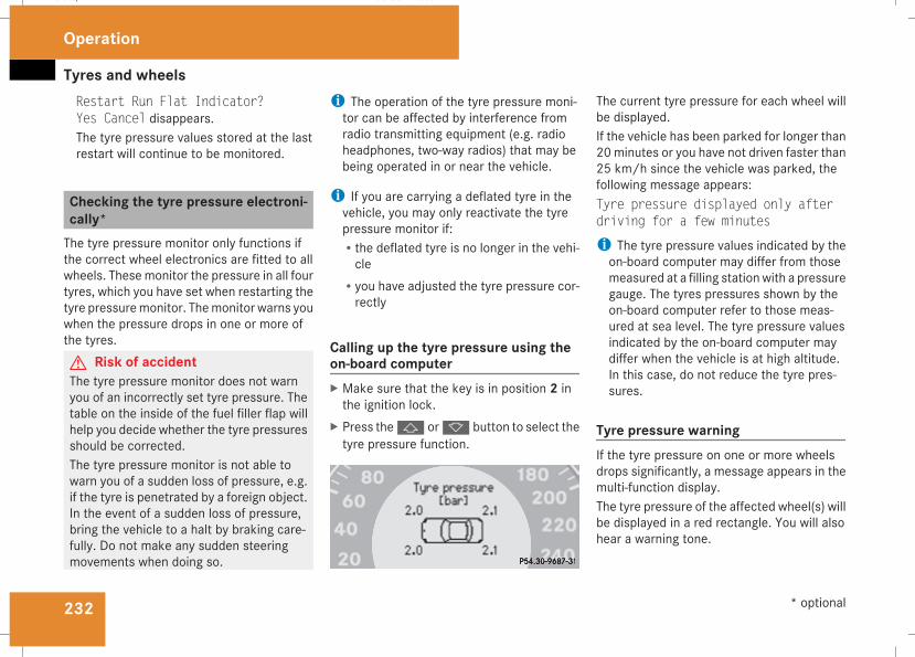
Tyres and wheels
232
Restart Run Flat Indicator?Yes Cancel disappears.The tyre pressure values stored at the lastrestart will continue to be monitored.
Checking the tyre pressure electroni-cally*The tyre pressure monitor only functions ifthe correct wheel electronics are fitted to allwheels. Thesemonitor the pressure in all fourtyres, which you have set when restarting thetyre pressuremonitor. Themonitor warns youwhen the pressure drops in one or more ofthe tyres.G Risk of accidentThe tyre pressure monitor does not warnyou of an incorrectly set tyre pressure. Thetable on the inside of the fuel filler flap willhelp you decide whether the tyre pressuresshould be corrected.The tyre pressure monitor is not able towarn you of a sudden loss of pressure, e.g.if the tyre is penetrated by a foreign object.In the event of a sudden loss of pressure,bring the vehicle to a halt by braking care-fully. Do not make any sudden steeringmovements when doing so.
i The operation of the tyre pressure moni-tor can be affected by interference fromradio transmitting equipment (e.g. radioheadphones, two-way radios) that may bebeing operated in or near the vehicle.
i If you are carrying a deflated tyre in thevehicle, you may only reactivate the tyrepressure monitor if:Rthe deflated tyre is no longer in the vehi-cle
Ryou have adjusted the tyre pressure cor-rectly
Calling up the tyre pressure using theon-board computerX Make sure that the key is in position 2 inthe ignition lock.
X Press thej ork button to select thetyre pressure function.
The current tyre pressure for each wheel willbe displayed.If the vehicle has been parked for longer than20minutes or you have not driven faster than25 km/h since the vehicle was parked, thefollowing message appears:Tyre pressure displayed only afterdriving for a few minutes
i The tyre pressure values indicated by theon-board computer may differ from thosemeasured at a filling stationwith a pressuregauge. The tyres pressures shown by theon-board computer refer to those meas-ured at sea level. The tyre pressure valuesindicated by the on-board computer maydiffer when the vehicle is at high altitude.In this case, do not reduce the tyre pres-sures.
Tyre pressure warningIf the tyre pressure on one or more wheelsdrops significantly, a message appears in themulti-function display.The tyre pressure of the affected wheel(s) willbe displayed in a red rectangle. You will alsohear a warning tone.
Operation
* optional
211_AKB; 2; 5, en-GBmkalafa, Version: 2.9.4
2008-02-29T16:57:07+01:00 - Seite 232
Dateiname: 6515_3416_02_buchblock.pdf; preflight
Tyres and wheels
233
Restarting the tyre pressure monitorIn most cases, the tyre pressure monitor willautomatically detect the new reference val-ues, e.g. if you have:Rchanged the tyre pressureRchanged the wheels or tyresRfitted new wheels or tyresIf you wish to define the new reference valuesmanually:X Use the table on the inside of the fuel fillerflap to ensure that the tyre pressure is setcorrectly in all four tyres for the currentoperating conditions.Also observe the notes in the section ontyre pressures (Y page 229).
X Make sure that the key is in position 2 inthe ignition lock.The standard display appears in the multi-function display (Y page 125).
X Press thej ork button to select theTyre pressure function orwait until thefollowing message appears:Tyre pressure displayed only afterdriving for a few minutes
X Press the reset button on the left of theinstrument cluster (Y page 243).The following message appears in themulti-function display: Check currenttyre pressure?
X Press theæ button.The following message appears in themulti-function display:Tyre pressure monitor restartedThe tyre pressure monitor has stored thepressure of the tyres as a new referencevalue.
If you wish to cancel the restart:X Press theç button.
Interchanging the wheels
G Risk of accidentInterchange the front and rear wheels onlyif they have the samedimensions: for exam-ple size, offset, etc.After every wheel interchange/change,have the tightening torque checked at aqualified specialist workshop that has thenecessary specialist knowledge and toolsto carry out the work required. Mercedes-
Benz recommends that you use aMercedes-Benz Service Centre for this pur-pose. In particular, work relevant to safetyor on safety-related systems must be car-ried out at a qualified specialist workshop.The wheels could work loose if they are nottightened to a torque of 130 Nm.For safety reasons, Mercedes-Benz recom-mends that you only use wheel bolts of thecorrect size which have been approved forMercedes-Benz vehicles.
The wheels may be interchanged every5,000 km to 10,000 km depending on thedegree of tyre wear, provided that the vehiclehas the same size front and rear tyres. Do notreverse the direction of tyre rotation.The wear patterns on the front and rear tyresdiffer depending on the operating conditions.Interchange the wheels before a clear wearpattern has formed on the tyres. The fronttyres typically wear more on the shouldersand the rear tyres in the centre.Clean the contact surfaces of the wheel andthe brake disc thoroughly every time a wheelis interchanged. Check the tyre pressure and,if necessary, restart the tyre pressure losswarning system or the tyre pressure moni-tor*.
Operation
* optional
211_AKB; 2; 5, en-GBmkalafa, Version: 2.9.4
2008-02-29T16:57:07+01:00 - Seite 233
Z
Dateiname: 6515_3416_02_buchblock.pdf; preflight
Winter driving
234
! On vehicles fitted with a tyre pressuremonitor*, electronic components are loca-ted in the wheel.Tyre fitting tools should not be applied inthe area of the valve, as this could damagethe electronic components.Always have the wheels interchanged/changed at a qualified specialist workshop,e.g. a Mercedes-Benz Service Centre.
Winter driving
Points to rememberHave your vehicle winterproofed at a qualifiedspecialist workshop, e.g. at a Mercedes-BenzService Centre, at the onset of winter.
Winter tyresUse winter tyres at temperatures below +7 °C and on snow or ice-covered roads. Onlythen can the effect of the ABS, ESP® and4MATIC* driving systems be ensured in win-ter too.Use winter tyres of the same make and treadon all wheels to maintain safe handling char-acteristics.G Risk of accidentWinter tyres with a tread depth of less than4 mm must be replaced immediately. Theyare no longer suitable for winter use, canno longer provide sufficient grip. This couldcause you to lose control of your vehicleand cause an accident.
Always observe the maximum permittedspeed specified for the winter tyres you havefitted. If you fit winter tyres which have a
lower maximum permitted speed than that ofthe vehicle, affix an appropriate warning signin the driver's field of vision. This can beobtained at a qualified specialist workshop,e.g. from a Mercedes-Benz Service Centre.In such circumstances, you should alsorestrict the maximum speed of the vehicleusing permanent Speedtronic 32 to the maxi-mum permissible speed for winter tyres(Y page 154).Once you have fitted the winter tyres:X Check the tyre pressures (Y page 229).X Restart the tyre pressure moni-tor* (Y page 232).
G Risk of accidentIf you fit the spare wheel* when driving withwinter tyres, bear in mind that driving sta-bility will be impaired owing to unstablecornering characteristics caused by the dif-ferent tyres. You should therefore adaptyour driving style and drive carefully.Have the spare wheel* replaced at thenearest qualified specialist workshopwhich has the necessary specialist knowl-edge and tools to carry out the workrequired. Mercedes-Benz recommends
32 Only available for certain countries.
Operation
* optional
211_AKB; 2; 5, en-GBmkalafa, Version: 2.9.4
2008-02-29T16:57:07+01:00 - Seite 234
Dateiname: 6515_3416_02_buchblock.pdf; preflight
Winter driving
235
that you use a Mercedes-Benz ServiceCentre for this purpose. In particular, workrelevant to safety or on safety-related sys-tems must be carried out at a qualifiedspecialist workshop.
Snow chainsFor safety reasons, Mercedes-Benz recom-mends that you only use snow chains whichhave been specially approved for your vehicleby Mercedes-Benz or are of a correspondingstandard of quality.
! Information about the use of snow chain-compatible AMG winter tyres is applicablefor AMG tyres. Use of snow chains is onlypermissible with these tyres.
If you intend to fit snow chains, please bearthe following points in mind:RSnow chains cannot be fitted to all wheel/tyre combinations.
RSnow chains must not be fitted to emer-gency spare wheels, e.g. the "Minispare" orcollapsible emergency spare wheel.
RAlways fit snow chains to both rear wheels,even on vehicles with 4MATIC*. Comply
with the manufacturer's installationinstructions.
! If snow chains are fitted to the frontwheels, they may come into contact withthe bodywork and axle components whenthe vehicle is in motion and damage thetyre or the vehicle.
On vehicles with AIRMATIC DC*, you mustonly drive at raised vehicle level if snowchains have been fitted (Y page 156).Do not exceed the maximum permissiblespeed of 50 km/h.
i You may wish to deactivate ESP® whenpulling away with snow chains fitted(Y page 60). This way you can allow thewheels to spin in a controlled manner, ach-ieving an increased driving force (cuttingaction).
Winter driving
G Risk of accidentDo not shift down for additional enginebraking on a slippery road surface. Thiscould cause the drive wheels to lose theirgrip and the vehicle could skid.
You should drive particularly carefully on slip-pery road surfaces. Avoid sudden accelera-tion, steering and braking manoeuvres.If the vehicle threatens to skid or cannot bestopped when moving at low speed:X Vehicles withmanual transmission: engageneutral.
X Vehicles with automatic transmission*:shift the selector lever to N.
X Try to bring the vehicle under control usingcorrective steering.
Operation
* optional
211_AKB; 2; 5, en-GBmkalafa, Version: 2.9.4
2008-02-29T16:57:07+01:00 - Seite 235
Z
Dateiname: 6515_3416_02_buchblock.pdf; preflight
Driving tips
236
Driving tips
Rolling with the engine switched off
G Risk of accidentDo not switch off the engine while the vehi-cle is in motion.There is no power assistance for the steer-ing or the service brake when the engine isnot running.Steering and braking require significantlymore effort and you could lose control ofthe vehicle and cause an accident as aresult.
Braking
G Risk of accidentDo not change down for additional enginebraking on a slippery road surface. Thiscould cause the drive wheels to lose theirgrip and the vehicle could skid.
G Risk of accidentMake sure that other road users are notendangered by your braking.
Downhill gradientsOn long and steep downhill stretches, espe-cially if the vehicle is laden or towing a trailer,you must shift to a lower gear in good time or,on vehicles with automatic transmission*,select shift range 1, 2 or 3.i This also applies if you have activatedcruise control, Speedtronic or Distronic*.
This uses the braking effect of the engine andyou will not have to brake to such an extentto maintain the same speed. This relieves theload on the brake system and prevents thebrakes from overheating and wearing tooquickly. If you need additional braking,depress the brake pedal repeatedly ratherthan continuously.
Heavy and light loadsIf the brakes have been subjected to a heavyload, do not stop the vehicle immediately, butdrive on for a short while. This allows the air-flow to cool the brakes more quickly.G Risk of accidentNever depress the brake pedal continu-ously while the vehicle is in motion, e.g.never cause the brakes to rub by applying
constant slight pedal pressure. This causesthe brake system to overheat, increasesthe braking distance and can lead to thebrakes failing completely.
If the brakes have been used onlymoderately,you should occasionally test their effective-ness. To do this, brake more firmly from ahigher speed. This improves the grip of thebrakes.
Wet roadsIf driving in heavy rain for a prolonged periodof time without braking, there may be adelayed reaction from the brakes, when brak-ing for the first time. You must brake harder.You must therefore maintain a greater dis-tance from the vehicle in front.Brake firmly after driving on a wet road. Thisway the brake discs will becomewarm, dryingmore quickly, which will protect them againstcorrosion.
Operation
* optional
211_AKB; 2; 5, en-GBmkalafa, Version: 2.9.4
2008-02-29T16:57:07+01:00 - Seite 236
Dateiname: 6515_3416_02_buchblock.pdf; preflight
Driving tips
237
Limited braking performance on saltedroads
G Risk of accidentThe layer of salt on the brake discs and thebrake pads/linings may cause a delay inthe braking effect, resulting in a signifi-cantly longer braking distance, which couldlead to an accident.To avoid this danger, you should:Roccasionally brake carefully, without put-ting other road users at risk, when youare driving on salted roads. This helps toremove any salt that may have started tobuild up on the brake discs and the brakepads/linings.
Rmaintain a greater distance to the vehicleahead and drive with particular care.
Rcarefully apply the brakes at the end of atrip and immediately after commencing anew trip, so that salt residues areremoved from the brake disc.
New brake pads/liningsFor safety reasons, Mercedes-Benz recom-mends that you only have brake pads/liningsfitted to your vehicle that have been approved
for Mercedes-Benz vehicles or which corre-spond to an equivalent quality standard.Brake pads/linings which have not beenapproved for Mercedes-Benz or which are notof an equivalent quality could affect your vehi-cle's operating safety.G Risk of accidentNew brake pads/linings only reach theiroptimum braking effect after several hun-dred kilometres of driving. Before this opti-mum braking effect is reached, you shouldcompensate for the reduced braking effectby applying greater pressure when braking.This also applies after the brake discs or thebrake pads/linings have been replaced.
High-performance brake system forAMG vehiclesThe high-performance brake system isdesigned for heavy loads. Braking can there-fore cause noises. This will depend on:RspeedRbraking forceRenvironmental conditions, such as temper-ature and humidity
The wear of individual components of thebrake system, such as the brake pads/linings
or brake discs, depends on the individual driv-ing style and operating conditions.Because of this, it is impossible to state amileage that will be valid under all circum-stances. An aggressive driving style will leadto high wear.
Tyre grip
G Risk of accidentWhereas the vehicle can be fully controlledat a certain speed on dry roads, you mustreduce your speed on wet or icy roads toachieve the same road safety. Otherwiseyou could cause an accident.Pay particular attention to the road condi-tions at temperatures around freezingpoint.If ice has formed on the road surface (e.g.from fog), a light film of water rapidly formson the ice when you brake, considerablyreducing tyre grip. Drive with particularcare in such weather conditions.
Operation
211_AKB; 2; 5, en-GBmkalafa, Version: 2.9.4
2008-02-29T16:57:07+01:00 - Seite 237
Z
Dateiname: 6515_3416_02_buchblock.pdf; preflight
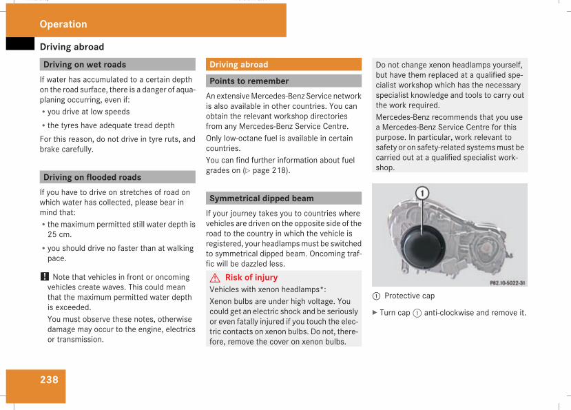
Driving abroad
238
Driving on wet roadsIf water has accumulated to a certain depthon the road surface, there is a danger of aqua-planing occurring, even if:Ryou drive at low speedsRthe tyres have adequate tread depthFor this reason, do not drive in tyre ruts, andbrake carefully.
Driving on flooded roadsIf you have to drive on stretches of road onwhich water has collected, please bear inmind that:Rthe maximum permitted still water depth is25 cm.
Ryou should drive no faster than at walkingpace.
! Note that vehicles in front or oncomingvehicles create waves. This could meanthat the maximum permitted water depthis exceeded.You must observe these notes, otherwisedamage may occur to the engine, electricsor transmission.
Driving abroad
Points to rememberAnextensiveMercedes-Benz Service networkis also available in other countries. You canobtain the relevant workshop directoriesfrom any Mercedes-Benz Service Centre.Only low-octane fuel is available in certaincountries.You can find further information about fuelgrades on (Y page 218).
Symmetrical dipped beamIf your journey takes you to countries wherevehicles are driven on the opposite side of theroad to the country in which the vehicle isregistered, your headlampsmust be switchedto symmetrical dipped beam. Oncoming traf-fic will be dazzled less.G Risk of injuryVehicles with xenon headlamps*:Xenon bulbs are under high voltage. Youcould get an electric shock and be seriouslyor even fatally injured if you touch the elec-tric contacts on xenon bulbs. Do not, there-fore, remove the cover on xenon bulbs.
Do not change xenon headlamps yourself,but have them replaced at a qualified spe-cialist workshop which has the necessaryspecialist knowledge and tools to carry outthe work required.Mercedes-Benz recommends that you usea Mercedes-Benz Service Centre for thispurpose. In particular, work relevant tosafety or on safety-related systemsmust becarried out at a qualified specialist work-shop.
1 Protective cap
X Turn cap1 anti-clockwise and remove it.
Operation
211_AKB; 2; 5, en-GBmkalafa, Version: 2.9.4
2008-02-29T16:57:07+01:00 - Seite 238
Dateiname: 6515_3416_02_buchblock.pdf; preflight
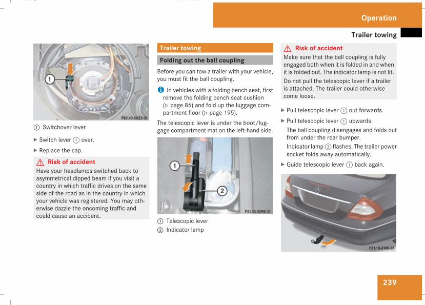
Trailer towing
239
1 Switchover lever
X Switch lever1 over.X Replace the cap.
G Risk of accidentHave your headlamps switched back toasymmetrical dipped beam if you visit acountry in which traffic drives on the sameside of the road as in the country in whichyour vehicle was registered. You may oth-erwise dazzle the oncoming traffic andcould cause an accident.
Trailer towing
Folding out the ball couplingBefore you can tow a trailer with your vehicle,you must fit the ball coupling.
i In vehicles with a folding bench seat, firstremove the folding bench seat cushion(Y page 86) and fold up the luggage com-partment floor (Y page 195).
The telescopic lever is under the boot/lug-gage compartment mat on the left-hand side.
1 Telescopic lever2 Indicator lamp
G Risk of accidentMake sure that the ball coupling is fullyengaged both when it is folded in and whenit is folded out. The indicator lamp is not lit.Do not pull the telescopic lever if a traileris attached. The trailer could otherwisecome loose.
X Pull telescopic lever1 out forwards.X Pull telescopic lever1 upwards.The ball coupling disengages and folds outfrom under the rear bumper.Indicator lamp2 flashes. The trailer powersocket folds away automatically.
X Guide telescopic lever1 back again.
Operation
211_AKB; 2; 5, en-GBmkalafa, Version: 2.9.4
2008-02-29T16:57:07+01:00 - Seite 239
Z
Dateiname: 6515_3416_02_buchblock.pdf; preflight
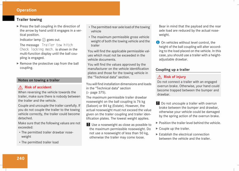
Trailer towing
240
X Press the ball coupling in the direction ofthe arrow by hand until it engages in a ver-tical position.Indicator lamp2 goes out.The message Trailer tow hitchCheck locking mech. is shown in themulti-function display until the ball cou-pling is engaged.
X Remove the protective cap from the ballcoupling.
Notes on towing a trailer
G Risk of accidentWhen reversing the vehicle towards thetrailer, make sure there is nobody betweenthe trailer and the vehicle.Couple and uncouple the trailer carefully. Ifyou do not couple the trailer to the towingvehicle correctly, the trailer could becomedetached.Make sure that the following values are notexceeded:RThe permitted trailer drawbar nose-weight
RThe permitted trailer load
RThe permitted rear axle load of the towingvehicle
RThe maximum permissible gross vehicleweight of both the towing vehicle and thetrailer
You will find the applicable permissible val-ues which must not be exceeded in thevehicle documents.You will find the values approved by themanufacturer on the vehicle identificationplates and those for the towing vehicle inthe “Technical data” section.
Youwill find installation dimensions and loadsin the "Technical data" section(Y page 375).The maximum permissible trailer drawbarnoseweight on the ball coupling is 76 kg(Saloon) or 84 kg (Estate). However, theactual noseweight must not exceed the valuegiven on the trailer coupling and trailer iden-tification plates. The lowest weight applies.
! Use a noseweight as close as possible tothe maximum permissible noseweight. Donot use a noseweight of less than 50 kg,otherwise the trailer may come loose.
Bear in mind that the payload and the rearaxle load are reduced by the actual nose-weight.
i On vehicles without level control, theheight of the ball coupling will alter accord-ing to the load placed on the vehicle. In thiscase, you should use a trailer with a height-adjustable drawbar.
Coupling up a trailer
G Risk of injuryDo not connect a trailer with an engagedoverrun brake. Otherwise, your hand couldbecome trapped between the bumper anddrawbar.
! Do not uncouple a trailer with overrunbrake between the bumper and drawbar,otherwise your vehicle could be damagedby the spring action of the overrun brake.
X Position the trailer level behind the vehicle.X Couple up the trailer.X Establish the electrical connectionbetween the vehicle and the trailer.
Operation
211_AKB; 2; 5, en-GBmkalafa, Version: 2.9.4
2008-02-29T16:57:07+01:00 - Seite 240
Dateiname: 6515_3416_02_buchblock.pdf; preflight
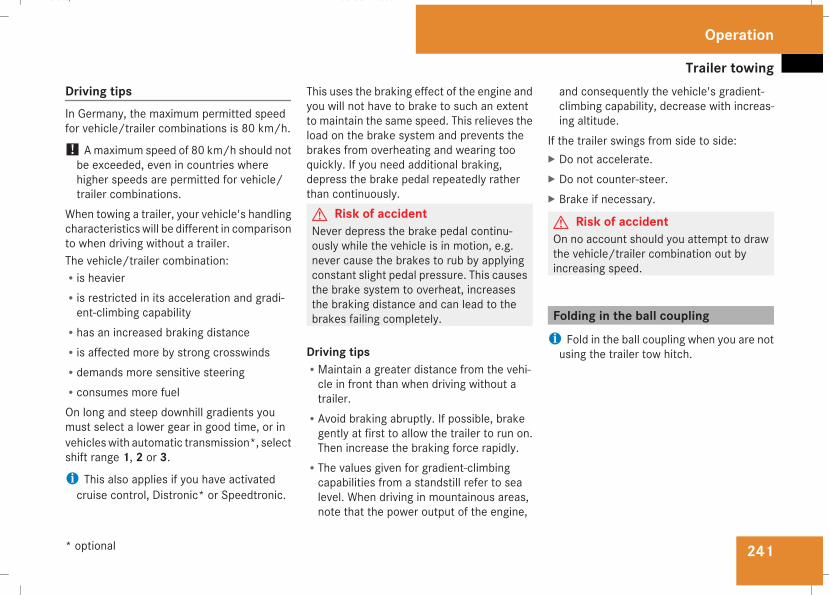
Trailer towing
241
Driving tipsIn Germany, the maximum permitted speedfor vehicle/trailer combinations is 80 km/h.
! Amaximum speed of 80 km/h should notbe exceeded, even in countries wherehigher speeds are permitted for vehicle/trailer combinations.
When towing a trailer, your vehicle's handlingcharacteristics will be different in comparisonto when driving without a trailer.The vehicle/trailer combination:Ris heavierRis restricted in its acceleration and gradi-ent-climbing capability
Rhas an increased braking distanceRis affected more by strong crosswindsRdemands more sensitive steeringRconsumes more fuelOn long and steep downhill gradients youmust select a lower gear in good time, or invehicleswith automatic transmission*, selectshift range 1, 2 or 3.i This also applies if you have activatedcruise control, Distronic* or Speedtronic.
This uses the braking effect of the engine andyou will not have to brake to such an extentto maintain the same speed. This relieves theload on the brake system and prevents thebrakes from overheating and wearing tooquickly. If you need additional braking,depress the brake pedal repeatedly ratherthan continuously.G Risk of accidentNever depress the brake pedal continu-ously while the vehicle is in motion, e.g.never cause the brakes to rub by applyingconstant slight pedal pressure. This causesthe brake system to overheat, increasesthe braking distance and can lead to thebrakes failing completely.
Driving tipsRMaintain a greater distance from the vehi-cle in front than when driving without atrailer.
RAvoid braking abruptly. If possible, brakegently at first to allow the trailer to run on.Then increase the braking force rapidly.
RThe values given for gradient-climbingcapabilities from a standstill refer to sealevel. When driving in mountainous areas,note that the power output of the engine,
and consequently the vehicle's gradient-climbing capability, decrease with increas-ing altitude.
If the trailer swings from side to side:X Do not accelerate.X Do not counter-steer.X Brake if necessary.
G Risk of accidentOn no account should you attempt to drawthe vehicle/trailer combination out byincreasing speed.
Folding in the ball couplingi Fold in the ball coupling when you are notusing the trailer tow hitch.
Operation
* optional
211_AKB; 2; 5, en-GBmkalafa, Version: 2.9.4
2008-02-29T16:57:07+01:00 - Seite 241
Z
Dateiname: 6515_3416_02_buchblock.pdf; preflight
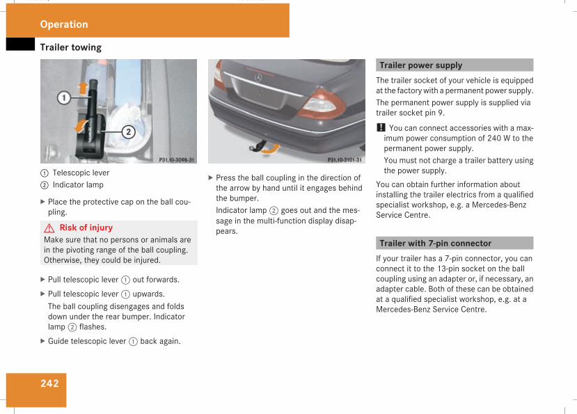
Trailer towing
242
1 Telescopic lever2 Indicator lamp
X Place the protective cap on the ball cou-pling.
G Risk of injuryMake sure that no persons or animals arein the pivoting range of the ball coupling.Otherwise, they could be injured.
X Pull telescopic lever1 out forwards.X Pull telescopic lever1 upwards.The ball coupling disengages and foldsdown under the rear bumper. Indicatorlamp2 flashes.
X Guide telescopic lever1 back again.
X Press the ball coupling in the direction ofthe arrow by hand until it engages behindthe bumper.Indicator lamp2 goes out and the mes-sage in the multi-function display disap-pears.
Trailer power supplyThe trailer socket of your vehicle is equippedat the factorywith a permanent power supply.The permanent power supply is supplied viatrailer socket pin 9.
! You can connect accessories with a max-imum power consumption of 240 W to thepermanent power supply.You must not charge a trailer battery usingthe power supply.
You can obtain further information aboutinstalling the trailer electrics from a qualifiedspecialist workshop, e.g. a Mercedes-BenzService Centre.
Trailer with 7-pin connectorIf your trailer has a 7-pin connector, you canconnect it to the 13-pin socket on the ballcoupling using an adapter or, if necessary, anadapter cable. Both of these can be obtainedat a qualified specialist workshop, e.g. at aMercedes-Benz Service Centre.
Operation
211_AKB; 2; 5, en-GBmkalafa, Version: 2.9.4
2008-02-29T16:57:07+01:00 - Seite 242
Dateiname: 6515_3416_02_buchblock.pdf; preflight
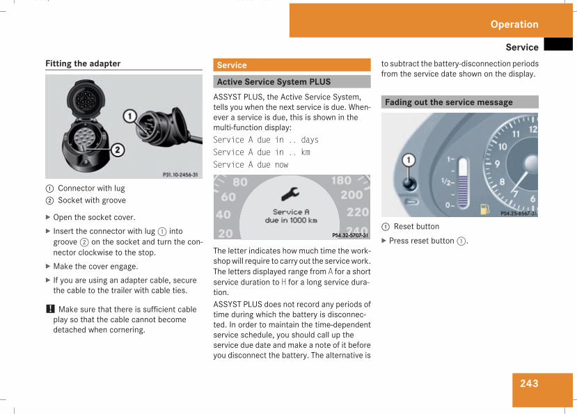
Service
243
Fitting the adapter
1 Connector with lug2 Socket with groove
X Open the socket cover.X Insert the connector with lug1 intogroove2 on the socket and turn the con-nector clockwise to the stop.
X Make the cover engage.X If you are using an adapter cable, securethe cable to the trailer with cable ties.
! Make sure that there is sufficient cableplay so that the cable cannot becomedetached when cornering.
Service
Active Service System PLUSASSYST PLUS, the Active Service System,tells you when the next service is due. When-ever a service is due, this is shown in themulti-function display:Service A due in .. daysService A due in .. kmService A due now
The letter indicates how much time the work-shopwill require to carry out the servicework.The letters displayed range from A for a shortservice duration to H for a long service dura-tion.ASSYST PLUS does not record any periods oftime during which the battery is disconnec-ted. In order to maintain the time-dependentservice schedule, you should call up theservice due date and make a note of it beforeyou disconnect the battery. The alternative is
to subtract the battery-disconnection periodsfrom the service date shown on the display.
Fading out the service message
1 Reset buttonX Press reset button1.
Operation
211_AKB; 2; 5, en-GBmkalafa, Version: 2.9.4
2008-02-29T16:57:07+01:00 - Seite 243
Z
Dateiname: 6515_3416_02_buchblock.pdf; preflight
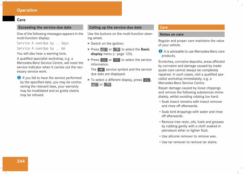
Care
244
Exceeding the service due dateOne of the following messages appears in themulti-function display:Service A overdue by .. daysService A overdue by .. kmYou will also hear a warning tone.A qualified specialist workshop, e.g. aMercedes-Benz Service Centre, will reset theservice indicator when it carries out the nec-essary service work.
i If you fail to have the service performedby the specified date, you may be contra-vening the relevant laws, your warrantymay be invalidated and ex gratia claimsmay be refused.
Calling up the service due dateUse the buttons on the multi-function steer-ing wheel.X Switch on the ignition.X Pressè orÿ to select the Basicdisplay menu (Y page 125).
X Pressj ork to select the serviceinformation.The9 service symbol and the servicedue date are displayed.
X To select a different display, pressj,è orÿ.
Care
Notes on careRegular and proper care maintains the valueof your vehicle.
i It is advisable to use Mercedes-Benz careproducts.
Scratches, corrosive deposits, areas affectedby corrosion and damage caused by inade-quate care cannot always be completelyrepaired. In such cases, visit a qualified spe-cialist workshop immediately, e.g. aMercedes-Benz Service Centre.Repair damage caused by loose chippingsand remove the following substances imme-diately, whilst avoiding rubbing too hard:RSoak insect remains with insect removerand rinse off afterwards.
RSoak bird droppings with water and rinseoff afterwards.
RRemove tree resin, oils, fuels and greasesby rubbing gently with a cloth soaked inpetroleum ether or lighter fluid.
RUse silicone remover to remove wax.RUse tar remover to remove tar stains.
Operation
211_AKB; 2; 5, en-GBmkalafa, Version: 2.9.4
2008-02-29T16:57:07+01:00 - Seite 244
Dateiname: 6515_3416_02_buchblock.pdf; preflight
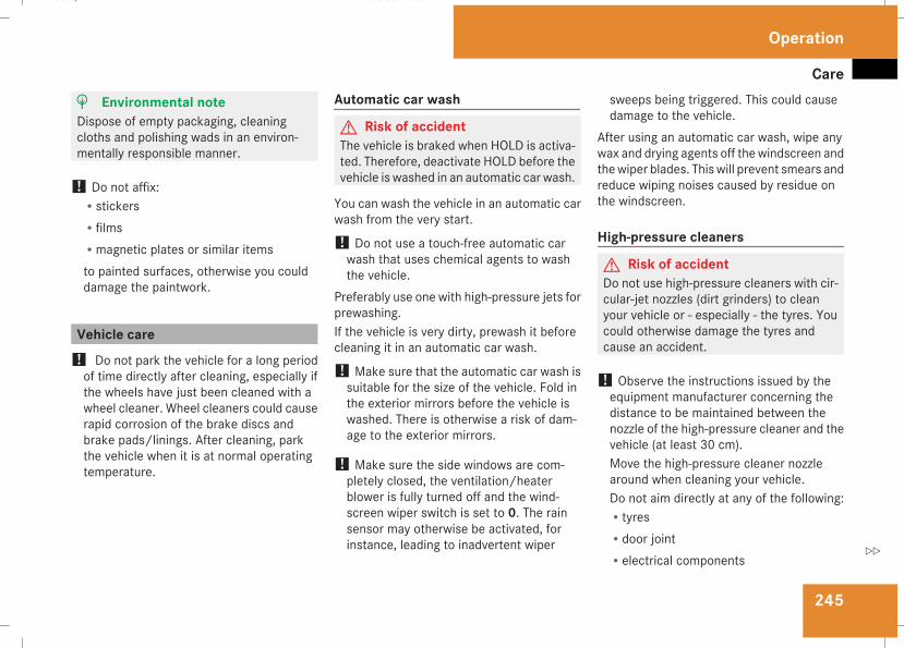
Care
245
H Environmental noteDispose of empty packaging, cleaningcloths and polishing wads in an environ-mentally responsible manner.
! Do not affix:RstickersRfilmsRmagnetic plates or similar itemsto painted surfaces, otherwise you coulddamage the paintwork.
Vehicle care! Do not park the vehicle for a long periodof time directly after cleaning, especially ifthe wheels have just been cleaned with awheel cleaner. Wheel cleaners could causerapid corrosion of the brake discs andbrake pads/linings. After cleaning, parkthe vehicle when it is at normal operatingtemperature.
Automatic car wash
G Risk of accidentThe vehicle is braked when HOLD is activa-ted. Therefore, deactivate HOLD before thevehicle is washed in an automatic car wash.
You can wash the vehicle in an automatic carwash from the very start.
! Do not use a touch-free automatic carwash that uses chemical agents to washthe vehicle.
Preferably use one with high-pressure jets forprewashing.If the vehicle is very dirty, prewash it beforecleaning it in an automatic car wash.
! Make sure that the automatic car wash issuitable for the size of the vehicle. Fold inthe exterior mirrors before the vehicle iswashed. There is otherwise a risk of dam-age to the exterior mirrors.
! Make sure the side windows are com-pletely closed, the ventilation/heaterblower is fully turned off and the wind-screen wiper switch is set to 0. The rainsensor may otherwise be activated, forinstance, leading to inadvertent wiper
sweeps being triggered. This could causedamage to the vehicle.
After using an automatic car wash, wipe anywax and drying agents off the windscreen andthewiper blades. Thiswill prevent smears andreduce wiping noises caused by residue onthe windscreen.
High-pressure cleaners
G Risk of accidentDo not use high-pressure cleaners with cir-cular-jet nozzles (dirt grinders) to cleanyour vehicle or - especially - the tyres. Youcould otherwise damage the tyres andcause an accident.
! Observe the instructions issued by theequipment manufacturer concerning thedistance to be maintained between thenozzle of the high-pressure cleaner and thevehicle (at least 30 cm).Move the high-pressure cleaner nozzlearound when cleaning your vehicle.Do not aim directly at any of the following:RtyresRdoor jointRelectrical components
Operation
211_AKB; 2; 5, en-GBmkalafa, Version: 2.9.4
2008-02-29T16:57:07+01:00 - Seite 245
Z
Dateiname: 6515_3416_02_buchblock.pdf; preflight
Care
246
RbatteryRconnectorsRlightsRsealsDamaged seals or electrical componentscan lead to failures or leaks.
Cleaning the wiper blades and the out-side of the windscreen
G Risk of injuryTurn the key to position 0 in the ignitionlock before cleaning the windscreen or thewiper blades. There is otherwise a risk ofthe windscreen wipers being set in motionand causing injury.
X Turn the key to position 1 in the ignitionlock (Y page 76).
X Set the windscreen wipers to positionu on the combination switch(Y page 105).
X Turn the key to position0 or remove it whenthe wiper arms are vertical (Y page 76).
! Only fold the wiper arms away from thewindscreenwhen they are in a vertical posi-tion, otherwise youwill damage the bonnet.
X Fold the wiper arms away from the wind-screen until you feel them engage.
X Clean thewindscreen and thewiper blades.X Fold the windscreen wipers back againbefore the ignition is switched on.
! Do not clean the wiper blades too often,otherwise the rubber may become porous,resulting in wiper noise.
Cleaning the windows! Do not use dry cloths, abrasive products,solvents or cleaning agents containing sol-vents to clean the inside of the windows.Clean the insides of the windows with adamp cloth or commercially-available glasscleaner. Avoid touching the inside of therear windscreen and the side windows withhard objects, e.g. ice scrapers or rings. Youcould otherwise cause damage to the win-dows, rear window heating or aerial on therear window.
i Anti-glare film retrofitted to the insides ofthe windows could interfere with radio ormobile phone reception, especially if it isconductive or metal-coated film. Informa-tion about anti-glare film can be obtainedfrom any Mercedes-Benz Service Centre.
Cleaning the headlampsX Clean the headlamp lenses with a wetsponge.
! Only use washer fluid which is suitablefor plastic lenses. Unsuitable washer fluidcould damage the plastic lenses of theheadlamps.Do not use the following:Rdry clothsRabrasive cleaning agentsRsolventsRcleaning agents containing solventYou could otherwise scratch or damage thesurface of the lenses.
Operation
211_AKB; 2; 5, en-GBmkalafa, Version: 2.9.4
2008-02-29T16:57:07+01:00 - Seite 246
Dateiname: 6515_3416_02_buchblock.pdf; preflight
Care
247
Plastic trim! Do not use dry, coarse or hard cloths anddo not scrub. Doing so will scratch or dam-age the surfaces.
X Wipe plastic parts with a damp, lint-freecloth (e.g. a microfibre cloth).
X Light soiling: use a low-foaming soap (e.g.a light liquid hand soap) diluted in water.
X Heavy soiling: use a cleaning agent that issolvent-free and non-corrosive. Mercedes-Benz recommends that you use aMercedes-Benz cleaning product for thispurpose.
Cleaning the steering wheel boss anddashboardX Moisten a clean lint-free cloth with water.X Clean the plastic parts and the dashboard.X If particularly dirty, use a mild detergent.
G Risk of injuryDo not use cleaners and cockpit caresprays containing solvents to clean thecockpit and steering wheel boss. Cleanerscontaining solvents cause the surface tobecome porous and in the event of an air-
bag being triggered, plastic parts that havebecome loose could cause considerableinjuries.
Leather upholstery*! Cleaning
RClean genuine leather covers using adamp cloth, then wipe the covers downusing a dry cloth. When doing this, makesure that the leather does not becomesoaked. For leather care, you should useleather care foam A 001 986 59 71 10.You can purchase this from anyMercedes-Benz Service Centre.
RClean artificial leather coverswith a clothmoistened with a solution containing 1%detergent (e. g. washing up liquid).
RClean fabric covers with a microfibrecloth moistened with a solution contain-ing 1% detergent (e.g. washing up liquid).When cleaning, take care not to rub toovigorously and always wipe entire seatsections to avoid leaving visible lines.Leave the seat to dry afterwards. Clean-
ing results depend on the type of dirt andhow long it has been there.
RClean Alcantara covers with a dampcloth. Make sure you wipe entire seatsections to avoid leaving visible lines.
i Note that leather covers are a naturalproduct and as such are subject to a naturalageing process and may react differently(e.g. increased formation of wrinkles) tocertain environmental influences (such ashigh humidity, intense heat).Note that regular care is essential to ensurethat the quality (both appearance and com-fort) of the covers is retained over time.
Care of exhaust tail pipes (AMG vehi-cles)Impurities combined with the effects of roadgrit and corrosive environmental factors maycause flash rust to form on the surface.Regular care of the exhaust tail pipes willensure that their original shine is restored.
! Do not clean exhaust tail pipes with alka-line-based cleaning agents such as wheelcleaner.
Operation
* optional
211_AKB; 2; 5, en-GBmkalafa, Version: 2.9.4
2008-02-29T16:57:07+01:00 - Seite 247
Z
Dateiname: 6515_3416_02_buchblock.pdf; preflight
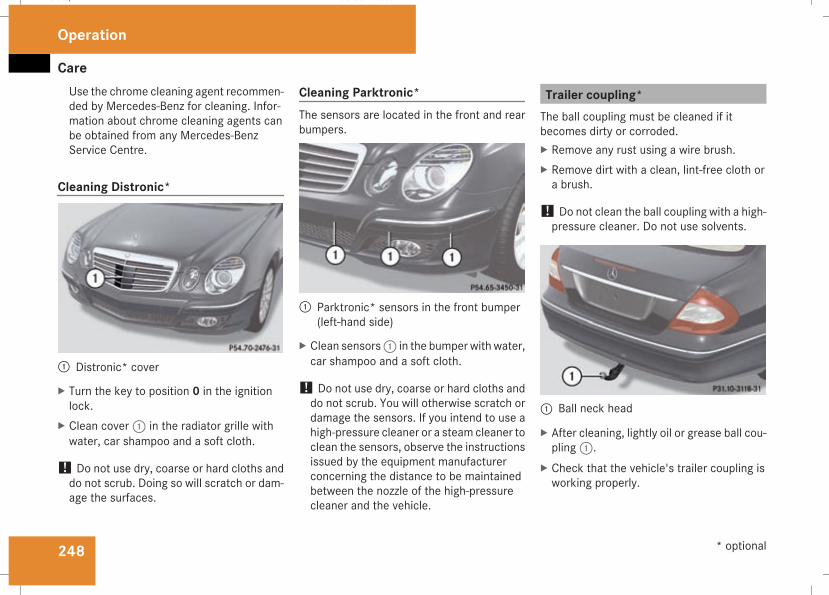
Care
248
Use the chrome cleaning agent recommen-ded by Mercedes-Benz for cleaning. Infor-mation about chrome cleaning agents canbe obtained from any Mercedes-BenzService Centre.
Cleaning Distronic*
1 Distronic* cover
X Turn the key to position 0 in the ignitionlock.
X Clean cover1 in the radiator grille withwater, car shampoo and a soft cloth.
! Do not use dry, coarse or hard cloths anddo not scrub. Doing so will scratch or dam-age the surfaces.
Cleaning Parktronic*The sensors are located in the front and rearbumpers.
1 Parktronic* sensors in the front bumper(left-hand side)
X Clean sensors1 in the bumper with water,car shampoo and a soft cloth.
! Do not use dry, coarse or hard cloths anddo not scrub. You will otherwise scratch ordamage the sensors. If you intend to use ahigh-pressure cleaner or a steam cleaner toclean the sensors, observe the instructionsissued by the equipment manufacturerconcerning the distance to be maintainedbetween the nozzle of the high-pressurecleaner and the vehicle.
Trailer coupling*The ball coupling must be cleaned if itbecomes dirty or corroded.X Remove any rust using a wire brush.X Remove dirt with a clean, lint-free cloth ora brush.
! Do not clean the ball coupling with a high-pressure cleaner. Do not use solvents.
1 Ball neck head
X After cleaning, lightly oil or grease ball cou-pling1.
X Check that the vehicle's trailer coupling isworking properly.
Operation
* optional
211_AKB; 2; 5, en-GBmkalafa, Version: 2.9.4
2008-02-29T16:57:07+01:00 - Seite 248
Dateiname: 6515_3416_02_buchblock.pdf; preflight
Care
249
i Maintenance on the ball coupling andtrailer coupling can also be performed byany Mercedes-Benz Service Centre.
H Environmental noteDispose of oily and greasy cloths in an envi-ronmentally-responsible manner.
Operation
211_AKB; 2; 5, en-GBmkalafa, Version: 2.9.4
2008-02-29T16:57:07+01:00 - Seite 249
Z
Dateiname: 6515_3416_02_buchblock.pdf; preflight

250
211_AKB; 2; 5, en-GBmkalafa, Version: 2.9.4
2008-02-29T16:57:07+01:00 - Seite 250
Dateiname: 6515_3416_02_buchblock.pdf; preflight
251
Where will I find...? ........................... 252Display messages ............................. 257Troubleshooting ................................ 282Locking/unlocking in an emer-gency ................................................. 306Resetting triggered NECK-PROhead restraints .................................. 309Changing the batteries ..................... 310Changing the bulbs ........................... 311Replacing the wiper blades .............. 315Flat tyre ............................................. 317Battery ............................................... 329Jump-starting .................................... 333Towing and tow-starting .................. 337Fuses .................................................. 340
Practical advice
211_AKB; 2; 5, en-GBmkalafa, Version: 2.9.4
2008-02-29T16:57:07+01:00 - Seite 251
Dateiname: 6515_3416_02_buchblock.pdf; preflight
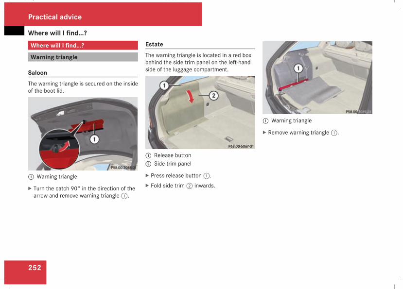
Where will I find...?
252
Where will I find...?
Warning triangle
SaloonThe warning triangle is secured on the insideof the boot lid.
1 Warning triangle
X Turn the catch 90° in the direction of thearrow and remove warning triangle1.
EstateThe warning triangle is located in a red boxbehind the side trim panel on the left-handside of the luggage compartment.
1 Release button2 Side trim panel
X Press release button1.X Fold side trim2 inwards.
1 Warning triangle
X Remove warning triangle1.
Practical advice
211_AKB; 2; 5, en-GBmkalafa, Version: 2.9.4
2008-02-29T16:57:07+01:00 - Seite 252
Dateiname: 6515_3416_02_buchblock.pdf; preflight
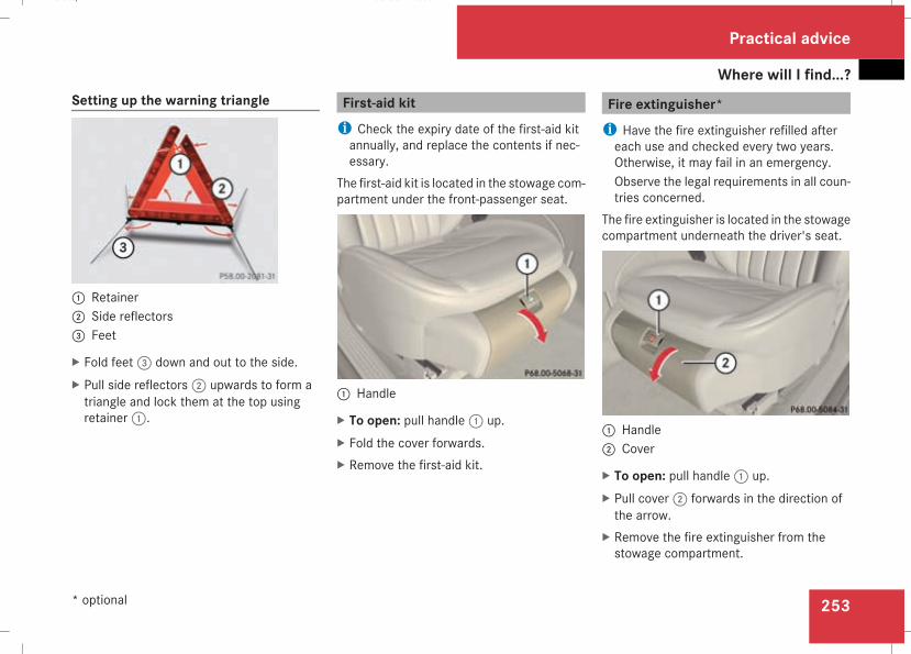
Where will I find...?
253
Setting up the warning triangle
1 Retainer2 Side reflectors3 Feet
X Fold feet3 down and out to the side.X Pull side reflectors2 upwards to form atriangle and lock them at the top usingretainer1.
First-aid kiti Check the expiry date of the first-aid kitannually, and replace the contents if nec-essary.
The first-aid kit is located in the stowage com-partment under the front-passenger seat.
1 Handle
X To open: pull handle1 up.X Fold the cover forwards.X Remove the first-aid kit.
Fire extinguisher*i Have the fire extinguisher refilled aftereach use and checked every two years.Otherwise, it may fail in an emergency.Observe the legal requirements in all coun-tries concerned.
The fire extinguisher is located in the stowagecompartment underneath the driver's seat.
1 Handle2 Cover
X To open: pull handle1 up.X Pull cover2 forwards in the direction ofthe arrow.
X Remove the fire extinguisher from thestowage compartment.
Practical advice
* optional
211_AKB; 2; 5, en-GBmkalafa, Version: 2.9.4
2008-02-29T16:57:07+01:00 - Seite 253
Z
Dateiname: 6515_3416_02_buchblock.pdf; preflight
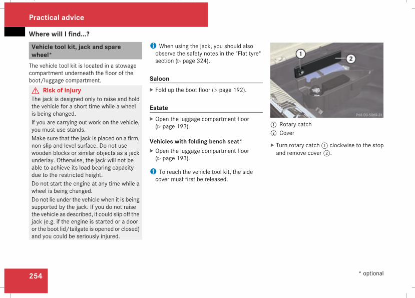
Where will I find...?
254
Vehicle tool kit, jack and sparewheel*The vehicle tool kit is located in a stowagecompartment underneath the floor of theboot/luggage compartment.G Risk of injuryThe jack is designed only to raise and holdthe vehicle for a short time while a wheelis being changed.If you are carrying out work on the vehicle,you must use stands.Make sure that the jack is placed on a firm,non-slip and level surface. Do not usewooden blocks or similar objects as a jackunderlay. Otherwise, the jack will not beable to achieve its load-bearing capacitydue to the restricted height.Do not start the engine at any time while awheel is being changed.Do not lie under the vehicle when it is beingsupported by the jack. If you do not raisethe vehicle as described, it could slip off thejack (e.g. if the engine is started or a dooror the boot lid/tailgate is opened or closed)and you could be seriously injured.
i When using the jack, you should alsoobserve the safety notes in the "Flat tyre"section (Y page 324).
SaloonX Fold up the boot floor (Y page 192).
EstateX Open the luggage compartment floor(Y page 193).
Vehicles with folding bench seat*X Open the luggage compartment floor(Y page 193).
i To reach the vehicle tool kit, the sidecover must first be released.
1 Rotary catch2 Cover
X Turn rotary catch1 clockwise to the stopand remove cover2.
Practical advice
* optional
211_AKB; 2; 5, en-GBmkalafa, Version: 2.9.4
2008-02-29T16:57:07+01:00 - Seite 254
Dateiname: 6515_3416_02_buchblock.pdf; preflight
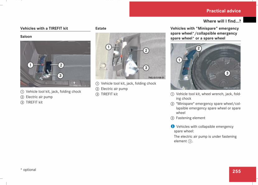
Where will I find...?
255
Vehicles with a TIREFIT kit
Saloon
1 Vehicle tool kit, jack, folding chock2 Electric air pump3 TIREFIT kit
Estate
1 Vehicle tool kit, jack, folding chock2 Electric air pump3 TIREFIT kit
Vehicles with "Minispare" emergencyspare wheel*/collapsible emergencyspare wheel* or a spare wheel
1 Vehicle tool kit, wheel wrench, jack, fold-ing chock2 "Minispare" emergency spare wheel/col-
lapsible emergency spare wheel or sparewheel3 Fastening element
i Vehicles with collapsible emergencyspare wheel:The electric air pump is under fasteningelement3.
Practical advice
* optional
211_AKB; 2; 5, en-GBmkalafa, Version: 2.9.4
2008-02-29T16:57:07+01:00 - Seite 255
Z
Dateiname: 6515_3416_02_buchblock.pdf; preflight
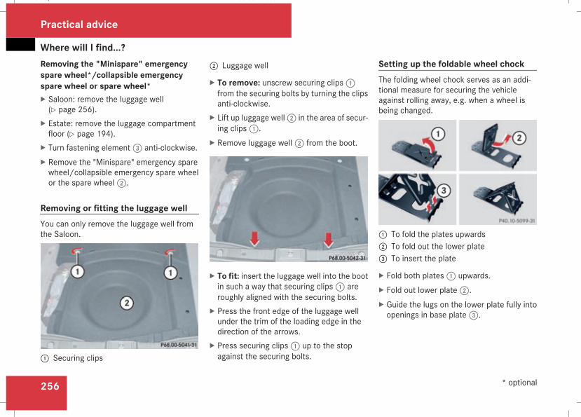
Where will I find...?
256
Removing the "Minispare" emergencyspare wheel*/collapsible emergencyspare wheel or spare wheel*X Saloon: remove the luggage well(Y page 256).
X Estate: remove the luggage compartmentfloor (Y page 194).
X Turn fastening element3 anti-clockwise.X Remove the "Minispare" emergency sparewheel/collapsible emergency spare wheelor the spare wheel2.
Removing or fitting the luggage wellYou can only remove the luggage well fromthe Saloon.
1 Securing clips
2 Luggage well
X To remove: unscrew securing clips1from the securing bolts by turning the clipsanti-clockwise.
X Lift up luggage well2 in the area of secur-ing clips1.
X Remove luggage well2 from the boot.
X To fit: insert the luggage well into the bootin such a way that securing clips1 areroughly aligned with the securing bolts.
X Press the front edge of the luggage wellunder the trim of the loading edge in thedirection of the arrows.
X Press securing clips1 up to the stopagainst the securing bolts.
Setting up the foldable wheel chockThe folding wheel chock serves as an addi-tional measure for securing the vehicleagainst rolling away, e.g. when a wheel isbeing changed.
1 To fold the plates upwards2 To fold out the lower plate3 To insert the plate
X Fold both plates1 upwards.X Fold out lower plate2.X Guide the lugs on the lower plate fully intoopenings in base plate3.
Practical advice
* optional
211_AKB; 2; 5, en-GBmkalafa, Version: 2.9.4
2008-02-29T16:57:07+01:00 - Seite 256
Dateiname: 6515_3416_02_buchblock.pdf; preflight
Display messages
257
Display messages
NotesThe on-board computer shows warnings ormalfunctions in the multi-function display.Certain display messages are accompaniedby a warning tone or a continuous tone.Themulti-function display shows high-prioritydisplay messages in red. In the followingtables, these display messages are printed inred.Please respond in accordance with the dis-play messages and follow the additionalnotes in this Owner's Manual.G Risk of accidentNo furthermessages can be displayed if theinstrument cluster and/or the multi-func-tion display fails.Thismeans that youwill not see informationabout the driving situation, such as the
speed, outside temperature, warning/indi-cator lamps, display messages or systemfailures. The vehicle's handling character-istics may be affected. Adjust your drivingstyle and speed accordingly.Immediately consult a qualified specialistworkshop which has the necessary special-ist knowledge and tools to carry out thework required. Mercedes-Benz recom-mends that you use a Mercedes-BenzService Centre for this purpose. In particu-lar, work relevant to safety or on safety-related systems must be carried out at aqualified specialist workshop.
When you stop and park the vehicle, pleaseobserve the instructions provided for HOLD(Y page 155) and parking (Y page 113).The following tables contain all the displaymessages.
Hiding display messagesAfter a few seconds, the on-board computerautomatically hides some low priority displaymessages. Other messages remain visible inthe multi-function display until you hide themyourself.Some high priority display messages cannotbe hidden. The multi-function display showsthese messages continuously until the cau-ses of the messages have been remedied.Use the buttons on the multi-function steer-ing wheel.X Use theè,·,j ork buttonto select another display.The on-board computer saves certain dis-play messages in the message mem-ory (Y page 131).
Practical advice
211_AKB; 2; 5, en-GBmkalafa, Version: 2.9.4
2008-02-29T16:57:07+01:00 - Seite 257
Z
Dateiname: 6515_3416_02_buchblock.pdf; preflight
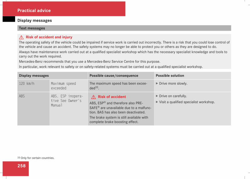
Display messages
258
Text messages
G Risk of accident and injuryThe operating safety of the vehicle could be impaired if service work is carried out incorrectly. There is a risk that you could lose control ofthe vehicle and cause an accident. The safety systems may no longer be able to protect you or others as they are designed to do.Always have maintenance work carried out at a qualified specialist workshop which has the necessary specialist knowledge and tools tocarry out the work required.Mercedes-Benz recommends that you use a Mercedes-Benz Service Centre for this purpose.In particular, work relevant to safety or on safety-related systems must be carried out at a qualified specialist workshop.
Display messages Possible cause/consequence Possible solution
120 km/h Maximum speedexceeded
The maximum speed has been excee-ded33.
X Drive more slowly.
ABS ABS, ESP inopera-tive See Owner'sManual
G Risk of accidentABS, ESP® and therefore also PRE-SAFE® are unavailable due to a malfunc-tion. BAS has also been deactivated.The brake system is still available withcomplete brake boosting effect.
X Drive on carefully.X Visit a qualified specialist workshop.
33 Only for certain countries.
Practical advice
211_AKB; 2; 5, en-GBmkalafa, Version: 2.9.4
2008-02-29T16:57:07+01:00 - Seite 258
Dateiname: 6515_3416_02_buchblock.pdf; preflight
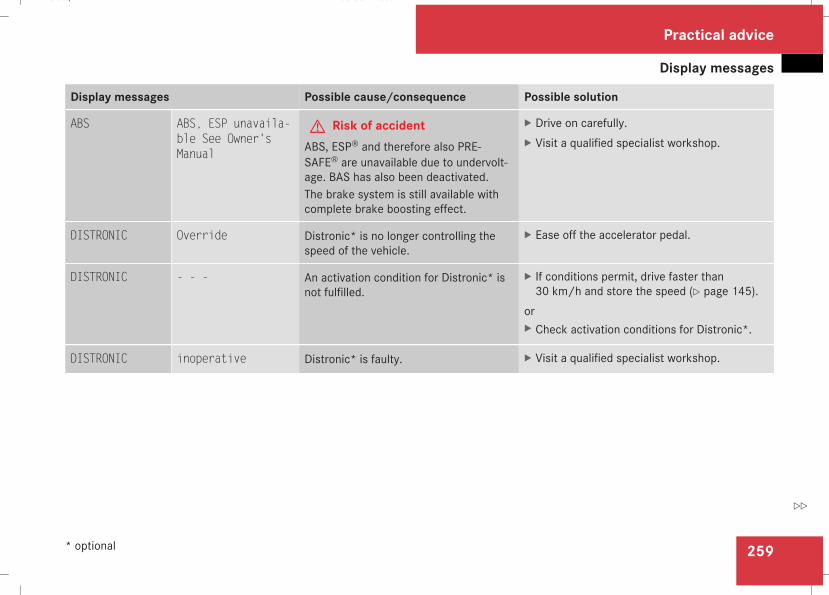
Display messages
259
Display messages Possible cause/consequence Possible solution
ABS ABS, ESP unavaila-ble See Owner'sManual
G Risk of accidentABS, ESP® and therefore also PRE-SAFE® are unavailable due to undervolt-age. BAS has also been deactivated.The brake system is still available withcomplete brake boosting effect.
X Drive on carefully.X Visit a qualified specialist workshop.
DISTRONIC Override Distronic* is no longer controlling thespeed of the vehicle.
X Ease off the accelerator pedal.
DISTRONIC - - - An activation condition for Distronic* isnot fulfilled.
X If conditions permit, drive faster than30 km/h and store the speed (Y page 145).
orX Check activation conditions for Distronic*.
DISTRONIC inoperative Distronic* is faulty. X Visit a qualified specialist workshop.
Practical advice
* optional
211_AKB; 2; 5, en-GBmkalafa, Version: 2.9.4
2008-02-29T16:57:07+01:00 - Seite 259
Z
Dateiname: 6515_3416_02_buchblock.pdf; preflight
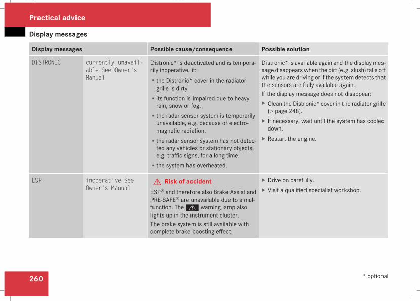
Display messages
260
Display messages Possible cause/consequence Possible solution
DISTRONIC currently unavail-able See Owner'sManual
Distronic* is deactivated and is tempora-rily inoperative, if:Rthe Distronic* cover in the radiatorgrille is dirty
Rits function is impaired due to heavyrain, snow or fog.
Rthe radar sensor system is temporarilyunavailable, e.g. because of electro-magnetic radiation.
Rthe radar sensor system has not detec-ted any vehicles or stationary objects,e.g. traffic signs, for a long time.
Rthe system has overheated.
Distronic* is available again and the display mes-sage disappears when the dirt (e.g. slush) falls offwhile you are driving or if the system detects thatthe sensors are fully available again.If the display message does not disappear:X Clean the Distronic* cover in the radiator grille(Y page 248).
X If necessary, wait until the system has cooleddown.
X Restart the engine.
ESP inoperative SeeOwner's Manual
G Risk of accidentESP® and therefore also Brake Assist andPRE-SAFE® are unavailable due to a mal-function. Thev warning lamp alsolights up in the instrument cluster.The brake system is still available withcomplete brake boosting effect.
X Drive on carefully.X Visit a qualified specialist workshop.
Practical advice
* optional
211_AKB; 2; 5, en-GBmkalafa, Version: 2.9.4
2008-02-29T16:57:07+01:00 - Seite 260
Dateiname: 6515_3416_02_buchblock.pdf; preflight
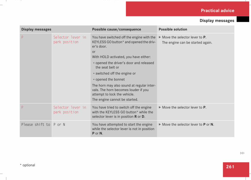
Display messages
261
Display messages Possible cause/consequence Possible solution
P Selector lever inpark position
You have switched off the engine with theKEYLESSGObutton* and opened the driv-er's door.orWith HOLD activated, you have either:Ropened the driver’s door and releasedthe seat belt or
Rswitched off the engine orRopened the bonnetThe horn may also sound at regular inter-vals. The horn becomes louder if youattempt to lock the vehicle.The engine cannot be started.
X Move the selector lever to P.The engine can be started again.
P Selector lever inpark position
You have tried to switch off the enginewith the KEYLESS GO button* while theselector lever is in position R or D.
X Move the selector lever to P.
Please shift to P or N You have attempted to start the enginewhile the selector lever is not in positionP or N.
X Move the selector lever to P or N.
Practical advice
* optional
211_AKB; 2; 5, en-GBmkalafa, Version: 2.9.4
2008-02-29T16:57:07+01:00 - Seite 261
Z
Dateiname: 6515_3416_02_buchblock.pdf; preflight
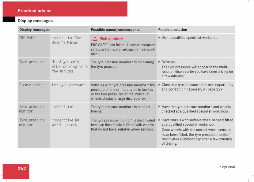
Display messages
262
Display messages Possible cause/consequence Possible solution
PRE-SAFE inoperative SeeOwner's Manual
G Risk of injuryPRE-SAFE® has failed. All other occupantsafety systems, e.g. airbags, remain avail-able.
X Visit a qualified specialist workshop.
Tyre pressure displayed onlyafter driving for afew minutes
The tyre pressure monitor* is measuringthe tyre pressure.
X Drive on.The tyre pressures will appear in the multi-function display after you have been driving fora few minutes.
Please correct the tyre pressure Vehicles with tyre pressure monitor*: thepressure of one or more tyres is too lowor the tyre pressures of the individualwheels display a large discrepancy.
X Check the tyre pressure at the next opportunityand correct it if necessary (Y page 229).
Tyre pressuremonitor
inoperative The tyre pressure monitor* is malfunc-tioning.
X Have the tyre pressure monitor* and wheelschecked at a qualified specialist workshop.
Tyre pressuremonitor
inoperative Nowheel sensors
The tyre pressure monitor* is deactivatedbecause the vehicle is fitted with wheelsthat do not have suitable wheel sensors.
X Have wheels with suitable wheel sensors fittedat a qualified specialist workshop.Once wheels with the correct wheel sensorshave been fitted, the tyre pressure monitor*reactivates automatically after a few minutesof driving.
Practical advice
* optional
211_AKB; 2; 5, en-GBmkalafa, Version: 2.9.4
2008-02-29T16:57:07+01:00 - Seite 262
Dateiname: 6515_3416_02_buchblock.pdf; preflight
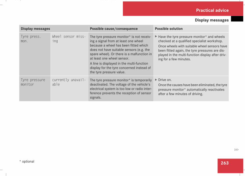
Display messages
263
Display messages Possible cause/consequence Possible solution
Tyre press.mon.
Wheel sensor miss-ing
The tyre pressure monitor* is not receiv-ing a signal from at least one wheelbecause a wheel has been fitted whichdoes not have suitable sensors (e.g. thespare wheel). Or there is a malfunction inat least one wheel sensor.A line is displayed in the multi-functiondisplay for the tyre concerned instead ofthe tyre pressure value.
X Have the tyre pressure monitor* and wheelschecked at a qualified specialist workshop.Once wheels with suitable wheel sensors havebeen fitted again, the tyre pressures are dis-played in the multi-function display after driv-ing for a few minutes.
Tyre pressuremonitor
currently unavail-able
The tyre pressure monitor* is temporarilydeactivated. The voltage of the vehicle'selectrical system is too low or radio inter-ference prevents the reception of sensorsignals.
X Drive on.Once the causes have been eliminated, the tyrepressure monitor* automatically reactivatesafter a few minutes of driving.
Practical advice
* optional
211_AKB; 2; 5, en-GBmkalafa, Version: 2.9.4
2008-02-29T16:57:07+01:00 - Seite 263
Z
Dateiname: 6515_3416_02_buchblock.pdf; preflight
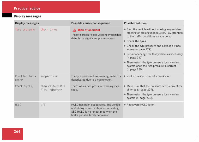
Display messages
264
Display messages Possible cause/consequence Possible solution
Tyre pressure Check tyres G Risk of accidentThe tyre pressure losswarning systemhasdetected a significant pressure loss.
X Stop the vehicle without making any suddensteering or braking manoeuvres. Pay attentionto the traffic conditions as you do so.
X Check the tyres.X Check the tyre pressure and correct it if nec-essary (Y page 229).
X Repair or change the faulty wheel as necessary(Y page 317).
X Then restart the tyre pressure loss warningsystem once the tyre pressure is correct(Y page 230).
Run Flat Indi-cator
inoperative The tyre pressure loss warning system isdeactivated due to a malfunction.
X Visit a qualified specialist workshop.
Check tyres, then restart RunFlat Indicator
There was a tyre pressure warning mes-sage.
X Make sure that the pressure set is correct forall tyres (Y page 229).
X Then restart the tyre pressure loss warningsystem (Y page 230).
HOLD off HOLD has been deactivated. The vehicleis skidding or a condition for activatingSBC HOLD is no longer met when thebrake pedal is firmly depressed.
X Reactivate HOLD later.
Practical advice
211_AKB; 2; 5, en-GBmkalafa, Version: 2.9.4
2008-02-29T16:57:07+01:00 - Seite 264
Dateiname: 6515_3416_02_buchblock.pdf; preflight
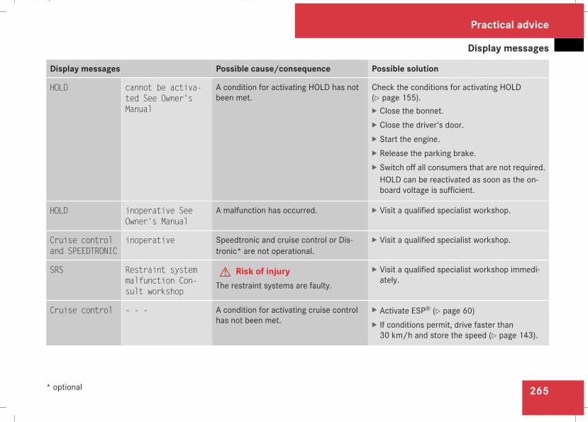
Display messages
265
Display messages Possible cause/consequence Possible solution
HOLD cannot be activa-ted See Owner'sManual
A condition for activating HOLD has notbeen met.
Check the conditions for activating HOLD(Y page 155).X Close the bonnet.X Close the driver's door.X Start the engine.X Release the parking brake.X Switch off all consumers that are not required.HOLD can be reactivated as soon as the on-board voltage is sufficient.
HOLD inoperative SeeOwner's Manual
A malfunction has occurred. X Visit a qualified specialist workshop.
Cruise controland SPEEDTRONIC
inoperative Speedtronic and cruise control or Dis-tronic* are not operational.
X Visit a qualified specialist workshop.
SRS Restraint systemmalfunction Con-sult workshop
G Risk of injuryThe restraint systems are faulty.
X Visit a qualified specialist workshop immedi-ately.
Cruise control - - - A condition for activating cruise controlhas not been met.
X Activate ESP® (Y page 60)X If conditions permit, drive faster than30 km/h and store the speed (Y page 143).
Practical advice
* optional
211_AKB; 2; 5, en-GBmkalafa, Version: 2.9.4
2008-02-29T16:57:07+01:00 - Seite 265
Z
Dateiname: 6515_3416_02_buchblock.pdf; preflight
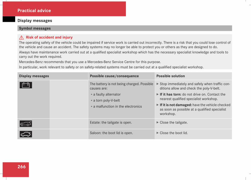
Display messages
266
Symbol messages
G Risk of accident and injuryThe operating safety of the vehicle could be impaired if service work is carried out incorrectly. There is a risk that you could lose control ofthe vehicle and cause an accident. The safety systems may no longer be able to protect you or others as they are designed to do.Always have maintenance work carried out at a qualified specialist workshop which has the necessary specialist knowledge and tools tocarry out the work required.Mercedes-Benz recommends that you use a Mercedes-Benz Service Centre for this purpose.In particular, work relevant to safety or on safety-related systems must be carried out at a qualified specialist workshop.
Display messages Possible cause/consequence Possible solution
# The battery is not being charged. Possiblecauses are:Ra faulty alternatorRa torn poly-V-beltRa malfunction in the electronics
X Stop immediately and safely when traffic con-ditions allow and check the poly-V-belt.
X If it has torn: do not drive on. Contact thenearest qualified specialist workshop.
X If it is not damaged: have the vehicle checkedas soon as possible at a qualified specialistworkshop.
& Estate: the tailgate is open. X Close the tailgate.
Ê Saloon: the boot lid is open. X Close the boot lid.
Practical advice
211_AKB; 2; 5, en-GBmkalafa, Version: 2.9.4
2008-02-29T16:57:07+01:00 - Seite 266
Dateiname: 6515_3416_02_buchblock.pdf; preflight
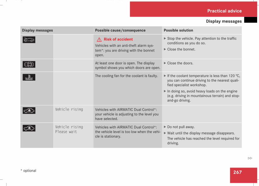
Display messages
267
Display messages Possible cause/consequence Possible solution
Y G Risk of accidentVehicles with an anti-theft alarm sys-tem*: you are driving with the bonnetopen.
X Stop the vehicle. Pay attention to the trafficconditions as you do so.
X Close the bonnet.
V At least one door is open. The displaysymbol shows you which doors are open.
X Close the doors.
D The cooling fan for the coolant is faulty. X If the coolant temperature is less than 120 †,you can continue driving to the nearest quali-fied specialist workshop.
X In doing so, avoid heavy loads on the engine(e.g. driving in mountainous terrain) and stop-and-go driving.
@ Vehicle rising Vehicles with AIRMATIC Dual Control*:your vehicle is adjusting to the level youhave selected.
@ Vehicle risingPlease wait
Vehicles with AIRMATIC Dual Control*:the vehicle level is too low when the vehi-cle is stationary.
X Do not pull away.X Wait until the display message disappears.The vehicle has reached the level required fordriving.
Practical advice
* optional
211_AKB; 2; 5, en-GBmkalafa, Version: 2.9.4
2008-02-29T16:57:07+01:00 - Seite 267
Z
Dateiname: 6515_3416_02_buchblock.pdf; preflight
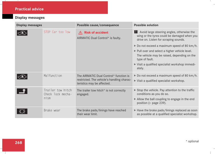
Display messages
268
Display messages Possible cause/consequence Possible solution
@ STOP Car too low G Risk of accidentAIRMATIC Dual Control* is faulty.
! Avoid large steering angles, otherwise thewing or the tyres could be damaged when youdrive on. Listen for scraping sounds.
X Do not exceed a maximum speed of 80 km/h.X Pull over and select a higher vehicle level.The vehicle may be raised, depending on thetype of fault.
X Visit a qualified specialist workshop immedi-ately.
@ Malfunction The AIRMATIC Dual Control* function isrestricted. The vehicle's handling charac-teristics may be affected.
X Do not exceed a maximum speed of 80 km/h.X Visit a qualified specialist workshop.
\ Trailer tow hitchCheck lock mecha-nism
The trailer tow hitch* is not correctlyengaged.
X Stop the vehicle. Pay attention to the trafficconditions as you do so.
X Allow the ball coupling to engage in the endposition (Y page 239).
2 Brake wear The brake pads/linings have reachedtheir wear limit.
X Have the brake pads/linings replaced as soonas possible at a qualified specialist workshop.
Practical advice
* optional
211_AKB; 2; 5, en-GBmkalafa, Version: 2.9.4
2008-02-29T16:57:07+01:00 - Seite 268
Dateiname: 6515_3416_02_buchblock.pdf; preflight
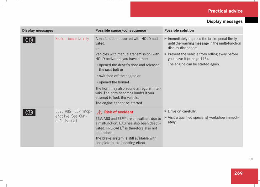
Display messages
269
Display messages Possible cause/consequence Possible solution
3 Brake immediately A malfunction occurred with HOLD acti-vated.orVehicles with manual transmission: withHOLD activated, you have either:Ropened the driver’s door and releasedthe seat belt or
Rswitched off the engine orRopened the bonnetThe horn may also sound at regular inter-vals. The horn becomes louder if youattempt to lock the vehicle.The engine cannot be started.
X Immediately depress the brake pedal firmlyuntil the warningmessage in themulti-functiondisplay disappears.
X Prevent the vehicle from rolling away beforeyou leave it (Y page 113).The engine can be started again.
3 EBV, ABS, ESP inop-erative See Own-er's Manual
G Risk of accidentEBV, ABS and ESP® are unavailable due toa malfunction. BAS has also been deacti-vated. PRE-SAFE® is therefore also notoperational.The brake system is still available withcomplete brake boosting effect.
X Drive on carefully.X Visit a qualified specialist workshop immedi-ately.
Practical advice
211_AKB; 2; 5, en-GBmkalafa, Version: 2.9.4
2008-02-29T16:57:07+01:00 - Seite 269
Z
Dateiname: 6515_3416_02_buchblock.pdf; preflight
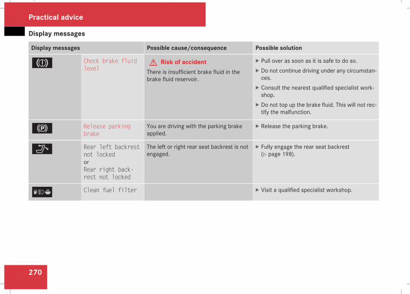
Display messages
270
Display messages Possible cause/consequence Possible solution
3 Check brake fluidlevel
G Risk of accidentThere is insufficient brake fluid in thebrake fluid reservoir.
X Pull over as soon as it is safe to do so.X Do not continue driving under any circumstan-ces.
X Consult the nearest qualified specialist work-shop.
X Do not top up the brake fluid. This will not rec-tify the malfunction.
! Release parkingbrake
You are driving with the parking brakeapplied.
X Release the parking brake.
? Rear left backrestnot lockedorRear right back-rest not locked
The left or right rear seat backrest is notengaged.
X Fully engage the rear seat backrest(Y page 198).
[ Clean fuel filter X Visit a qualified specialist workshop.
Practical advice
211_AKB; 2; 5, en-GBmkalafa, Version: 2.9.4
2008-02-29T16:57:07+01:00 - Seite 270
Dateiname: 6515_3416_02_buchblock.pdf; preflight
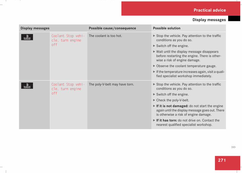
Display messages
271
Display messages Possible cause/consequence Possible solution
D Coolant Stop vehi-cle, turn engineoff
The coolant is too hot. X Stop the vehicle. Pay attention to the trafficconditions as you do so.
X Switch off the engine.X Wait until the display message disappearsbefore restarting the engine. There is other-wise a risk of engine damage.
X Observe the coolant temperature gauge.X If the temperature increases again, visit a quali-fied specialist workshop immediately.
D Coolant Stop vehi-cle, turn engineoff
The poly-V-belt may have torn. X Stop the vehicle. Pay attention to the trafficconditions as you do so.
X Switch off the engine.X Check the poly-V-belt.X If it is not damaged: do not start the engineagain until the displaymessage goes out. Thereis otherwise a risk of engine damage.
X If it has torn: do not drive on. Contact thenearest qualified specialist workshop.
Practical advice
211_AKB; 2; 5, en-GBmkalafa, Version: 2.9.4
2008-02-29T16:57:07+01:00 - Seite 271
Z
Dateiname: 6515_3416_02_buchblock.pdf; preflight
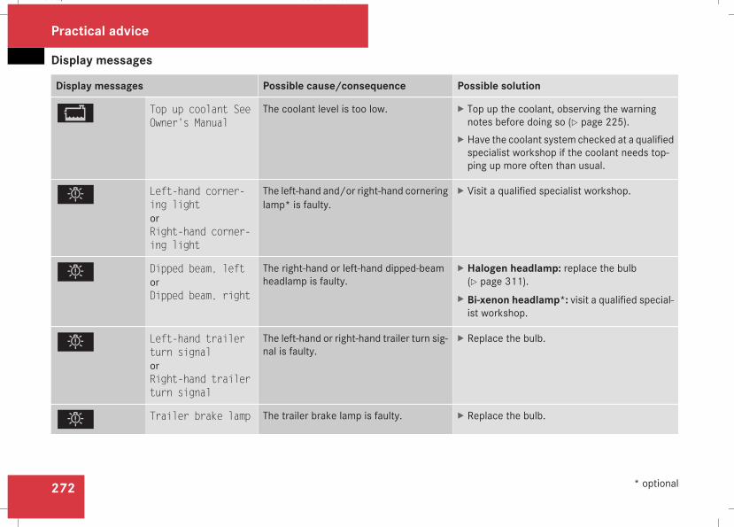
Display messages
272
Display messages Possible cause/consequence Possible solution
B Top up coolant SeeOwner's Manual
The coolant level is too low. X Top up the coolant, observing the warningnotes before doing so (Y page 225).
X Have the coolant system checked at a qualifiedspecialist workshop if the coolant needs top-ping up more often than usual.
. Left-hand corner-ing lightorRight-hand corner-ing light
The left-hand and/or right-hand corneringlamp* is faulty.
X Visit a qualified specialist workshop.
. Dipped beam, leftorDipped beam, right
The right-hand or left-hand dipped-beamheadlamp is faulty.
X Halogen headlamp: replace the bulb(Y page 311).
X Bi-xenon headlamp*: visit a qualified special-ist workshop.
. Left-hand trailerturn signalorRight-hand trailerturn signal
The left-hand or right-hand trailer turn sig-nal is faulty.
X Replace the bulb.
. Trailer brake lamp The trailer brake lamp is faulty. X Replace the bulb.
Practical advice
* optional
211_AKB; 2; 5, en-GBmkalafa, Version: 2.9.4
2008-02-29T16:57:07+01:00 - Seite 272
Dateiname: 6515_3416_02_buchblock.pdf; preflight
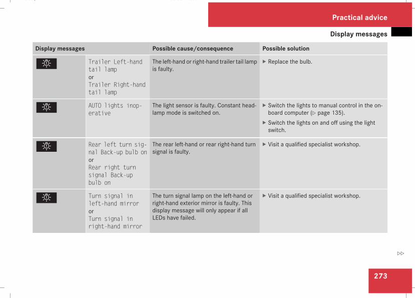
Display messages
273
Display messages Possible cause/consequence Possible solution
. Trailer Left-handtail lamporTrailer Right-handtail lamp
The left-hand or right-hand trailer tail lampis faulty.
X Replace the bulb.
. AUTO lights inop-erative
The light sensor is faulty. Constant head-lamp mode is switched on.
X Switch the lights to manual control in the on-board computer (Y page 135).
X Switch the lights on and off using the lightswitch.
. Rear left turn sig-nal Back-up bulb onorRear right turnsignal Back-upbulb on
The rear left-hand or rear right-hand turnsignal is faulty.
X Visit a qualified specialist workshop.
. Turn signal inleft-hand mirrororTurn signal inright-hand mirror
The turn signal lamp on the left-hand orright-hand exterior mirror is faulty. Thisdisplay message will only appear if allLEDs have failed.
X Visit a qualified specialist workshop.
Practical advice
211_AKB; 2; 5, en-GBmkalafa, Version: 2.9.4
2008-02-29T16:57:07+01:00 - Seite 273
Z
Dateiname: 6515_3416_02_buchblock.pdf; preflight
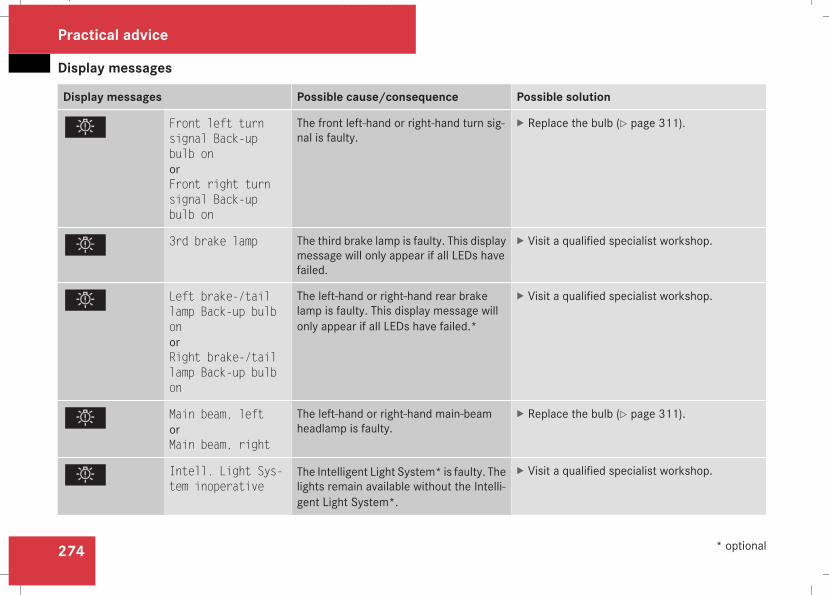
Display messages
274
Display messages Possible cause/consequence Possible solution
. Front left turnsignal Back-upbulb onorFront right turnsignal Back-upbulb on
The front left-hand or right-hand turn sig-nal is faulty.
X Replace the bulb (Y page 311).
. 3rd brake lamp The third brake lamp is faulty. This displaymessage will only appear if all LEDs havefailed.
X Visit a qualified specialist workshop.
. Left brake-/taillamp Back-up bulbonorRight brake-/taillamp Back-up bulbon
The left-hand or right-hand rear brakelamp is faulty. This display message willonly appear if all LEDs have failed.*
X Visit a qualified specialist workshop.
. Main beam, leftorMain beam, right
The left-hand or right-hand main-beamheadlamp is faulty.
X Replace the bulb (Y page 311).
. Intell. Light Sys-tem inoperative
The Intelligent Light System* is faulty. Thelights remain available without the Intelli-gent Light System*.
X Visit a qualified specialist workshop.
Practical advice
* optional
211_AKB; 2; 5, en-GBmkalafa, Version: 2.9.4
2008-02-29T16:57:07+01:00 - Seite 274
Dateiname: 6515_3416_02_buchblock.pdf; preflight
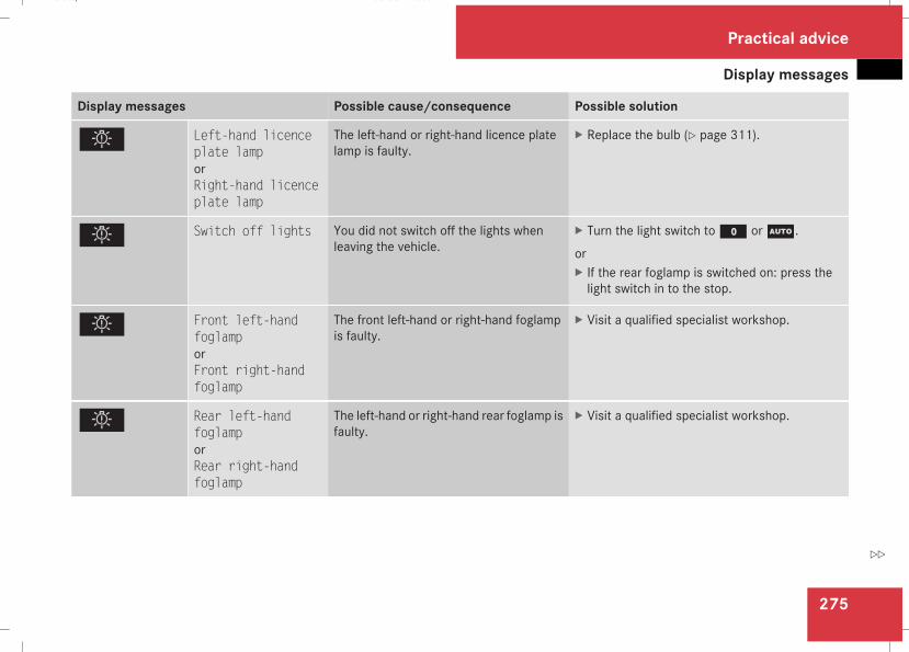
Display messages
275
Display messages Possible cause/consequence Possible solution
. Left-hand licenceplate lamporRight-hand licenceplate lamp
The left-hand or right-hand licence platelamp is faulty.
X Replace the bulb (Y page 311).
. Switch off lights You did not switch off the lights whenleaving the vehicle.
X Turn the light switch toM orU.
orX If the rear foglamp is switched on: press thelight switch in to the stop.
. Front left-handfoglamporFront right-handfoglamp
The front left-hand or right-hand foglampis faulty.
X Visit a qualified specialist workshop.
. Rear left-handfoglamporRear right-handfoglamp
The left-hand or right-hand rear foglamp isfaulty.
X Visit a qualified specialist workshop.
Practical advice
211_AKB; 2; 5, en-GBmkalafa, Version: 2.9.4
2008-02-29T16:57:07+01:00 - Seite 275
Z
Dateiname: 6515_3416_02_buchblock.pdf; preflight
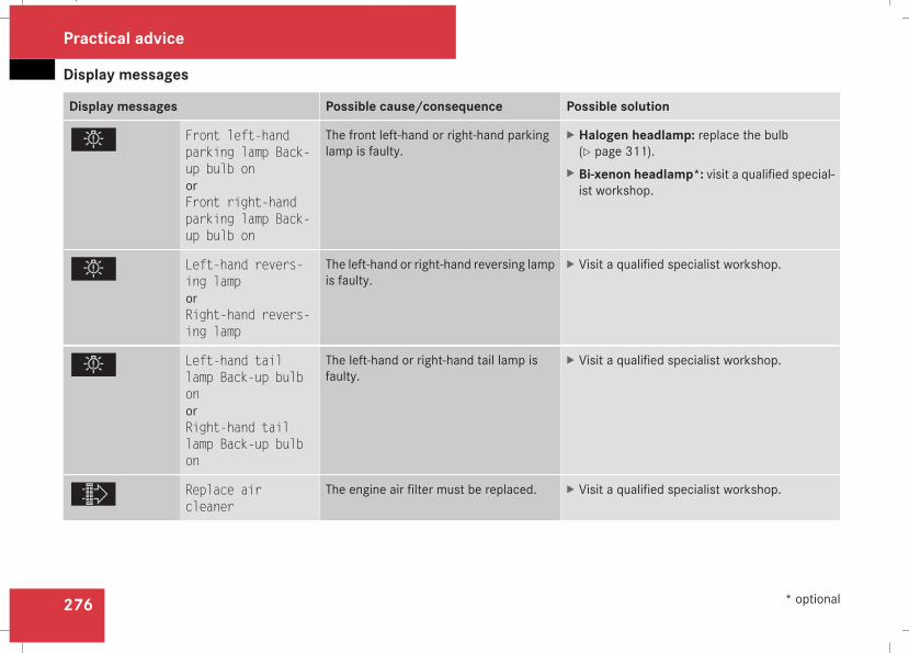
Display messages
276
Display messages Possible cause/consequence Possible solution
. Front left-handparking lamp Back-up bulb onorFront right-handparking lamp Back-up bulb on
The front left-hand or right-hand parkinglamp is faulty.
X Halogen headlamp: replace the bulb(Y page 311).
X Bi-xenon headlamp*: visit a qualified special-ist workshop.
. Left-hand revers-ing lamporRight-hand revers-ing lamp
The left-hand or right-hand reversing lampis faulty.
X Visit a qualified specialist workshop.
. Left-hand taillamp Back-up bulbonorRight-hand taillamp Back-up bulbon
The left-hand or right-hand tail lamp isfaulty.
X Visit a qualified specialist workshop.
ò Replace aircleaner
The engine air filter must be replaced. X Visit a qualified specialist workshop.
Practical advice
* optional
211_AKB; 2; 5, en-GBmkalafa, Version: 2.9.4
2008-02-29T16:57:07+01:00 - Seite 276
Dateiname: 6515_3416_02_buchblock.pdf; preflight
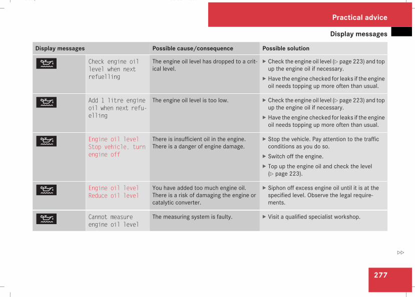
Display messages
277
Display messages Possible cause/consequence Possible solution
N Check engine oillevel when nextrefuelling
The engine oil level has dropped to a crit-ical level.
X Check the engine oil level (Y page 223) and topup the engine oil if necessary.
X Have the engine checked for leaks if the engineoil needs topping up more often than usual.
N Add 1 litre engineoil when next refu-elling
The engine oil level is too low. X Check the engine oil level (Y page 223) and topup the engine oil if necessary.
X Have the engine checked for leaks if the engineoil needs topping up more often than usual.
N Engine oil levelStop vehicle, turnengine off
There is insufficient oil in the engine.There is a danger of engine damage.
X Stop the vehicle. Pay attention to the trafficconditions as you do so.
X Switch off the engine.X Top up the engine oil and check the level(Y page 223).
N Engine oil levelReduce oil level
You have added too much engine oil.There is a risk of damaging the engine orcatalytic converter.
X Siphon off excess engine oil until it is at thespecified level. Observe the legal require-ments.
N Cannot measureengine oil level
The measuring system is faulty. X Visit a qualified specialist workshop.
Practical advice
211_AKB; 2; 5, en-GBmkalafa, Version: 2.9.4
2008-02-29T16:57:07+01:00 - Seite 277
Z
Dateiname: 6515_3416_02_buchblock.pdf; preflight
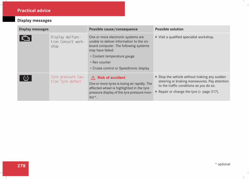
Display messages
278
Display messages Possible cause/consequence Possible solution
± Display malfunc-tion Consult work-shop
One or more electronic systems areunable to deliver information to the on-board computer. The following systemsmay have failed:RCoolant temperature gaugeRRev counterRCruise control or Speedtronic display
X Visit a qualified specialist workshop.
H Tyre pressure Cau-tion Tyre defect
G Risk of accidentOne or more tyres is losing air rapidly. Theaffected wheel is highlighted in the tyrepressure display of the tyre pressuremon-itor*.
X Stop the vehicle without making any suddensteering or braking manoeuvres. Pay attentionto the traffic conditions as you do so.
X Repair or change the tyre (Y page 317).
Practical advice
* optional
211_AKB; 2; 5, en-GBmkalafa, Version: 2.9.4
2008-02-29T16:57:07+01:00 - Seite 278
Dateiname: 6515_3416_02_buchblock.pdf; preflight
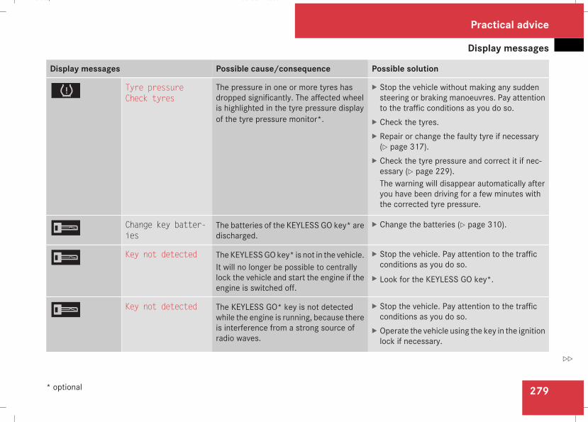
Display messages
279
Display messages Possible cause/consequence Possible solution
H Tyre pressureCheck tyres
The pressure in one or more tyres hasdropped significantly. The affected wheelis highlighted in the tyre pressure displayof the tyre pressure monitor*.
X Stop the vehicle without making any suddensteering or braking manoeuvres. Pay attentionto the traffic conditions as you do so.
X Check the tyres.X Repair or change the faulty tyre if necessary(Y page 317).
X Check the tyre pressure and correct it if nec-essary (Y page 229).The warning will disappear automatically afteryou have been driving for a few minutes withthe corrected tyre pressure.
I Change key batter-ies
The batteries of the KEYLESS GO key* aredischarged.
X Change the batteries (Y page 310).
I Key not detected TheKEYLESSGOkey* is not in the vehicle.It will no longer be possible to centrallylock the vehicle and start the engine if theengine is switched off.
X Stop the vehicle. Pay attention to the trafficconditions as you do so.
X Look for the KEYLESS GO key*.
I Key not detected The KEYLESS GO* key is not detectedwhile the engine is running, because thereis interference from a strong source ofradio waves.
X Stop the vehicle. Pay attention to the trafficconditions as you do so.
X Operate the vehicle using the key in the ignitionlock if necessary.
Practical advice
* optional
211_AKB; 2; 5, en-GBmkalafa, Version: 2.9.4
2008-02-29T16:57:07+01:00 - Seite 279
Z
Dateiname: 6515_3416_02_buchblock.pdf; preflight
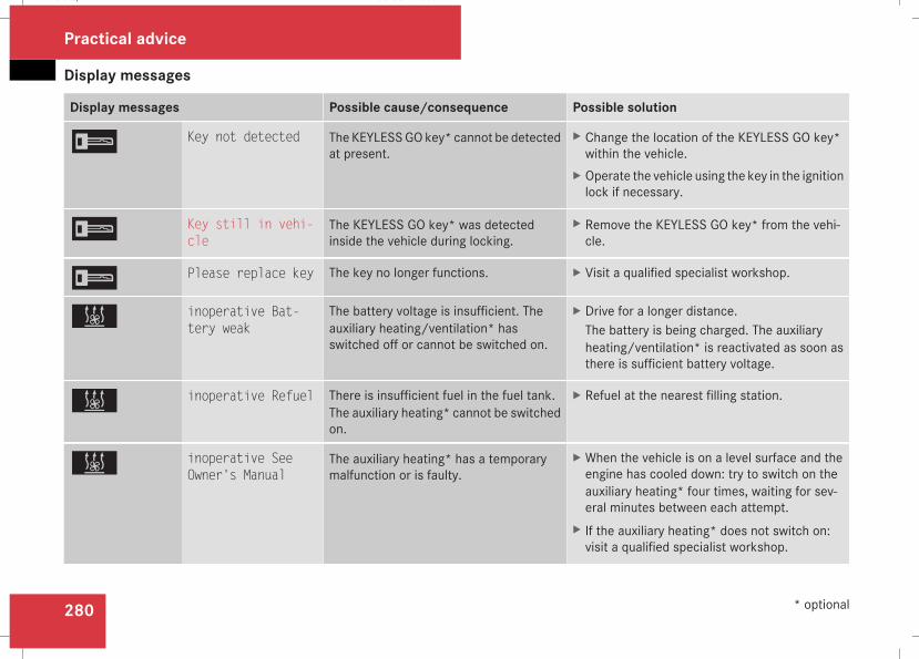
Display messages
280
Display messages Possible cause/consequence Possible solution
I Key not detected The KEYLESSGOkey* cannot be detectedat present.
X Change the location of the KEYLESS GO key*within the vehicle.
X Operate the vehicle using the key in the ignitionlock if necessary.
I Key still in vehi-cle
The KEYLESS GO key* was detectedinside the vehicle during locking.
X Remove the KEYLESS GO key* from the vehi-cle.
I Please replace key The key no longer functions. X Visit a qualified specialist workshop.
X inoperative Bat-tery weak
The battery voltage is insufficient. Theauxiliary heating/ventilation* hasswitched off or cannot be switched on.
X Drive for a longer distance.The battery is being charged. The auxiliaryheating/ventilation* is reactivated as soon asthere is sufficient battery voltage.
X inoperative Refuel There is insufficient fuel in the fuel tank.The auxiliary heating* cannot be switchedon.
X Refuel at the nearest filling station.
X inoperative SeeOwner's Manual
The auxiliary heating* has a temporarymalfunction or is faulty.
X When the vehicle is on a level surface and theengine has cooled down: try to switch on theauxiliary heating* four times, waiting for sev-eral minutes between each attempt.
X If the auxiliary heating* does not switch on:visit a qualified specialist workshop.
Practical advice
* optional
211_AKB; 2; 5, en-GBmkalafa, Version: 2.9.4
2008-02-29T16:57:07+01:00 - Seite 280
Dateiname: 6515_3416_02_buchblock.pdf; preflight
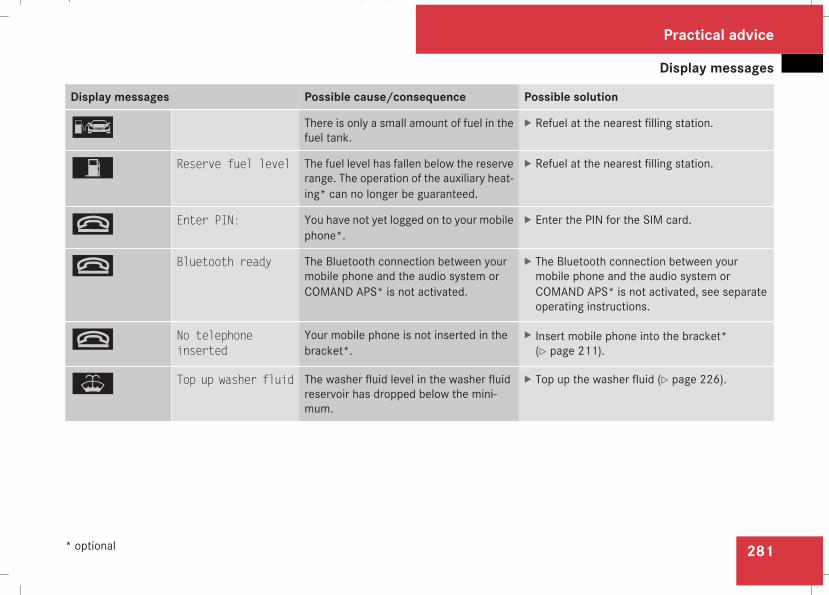
Display messages
281
Display messages Possible cause/consequence Possible solution
¿ There is only a small amount of fuel in thefuel tank.
X Refuel at the nearest filling station.
W Reserve fuel level The fuel level has fallen below the reserverange. The operation of the auxiliary heat-ing* can no longer be guaranteed.
X Refuel at the nearest filling station.
t Enter PIN: You have not yet logged on to your mobilephone*.
X Enter the PIN for the SIM card.
t Bluetooth ready The Bluetooth connection between yourmobile phone and the audio system orCOMAND APS* is not activated.
X The Bluetooth connection between yourmobile phone and the audio system orCOMAND APS* is not activated, see separateoperating instructions.
t No telephoneinserted
Your mobile phone is not inserted in thebracket*.
X Insert mobile phone into the bracket*(Y page 211).
W Top up washer fluid The washer fluid level in the washer fluidreservoir has dropped below the mini-mum.
X Top up the washer fluid (Y page 226).
Practical advice
* optional
211_AKB; 2; 5, en-GBmkalafa, Version: 2.9.4
2008-02-29T16:57:07+01:00 - Seite 281
Z
Dateiname: 6515_3416_02_buchblock.pdf; preflight
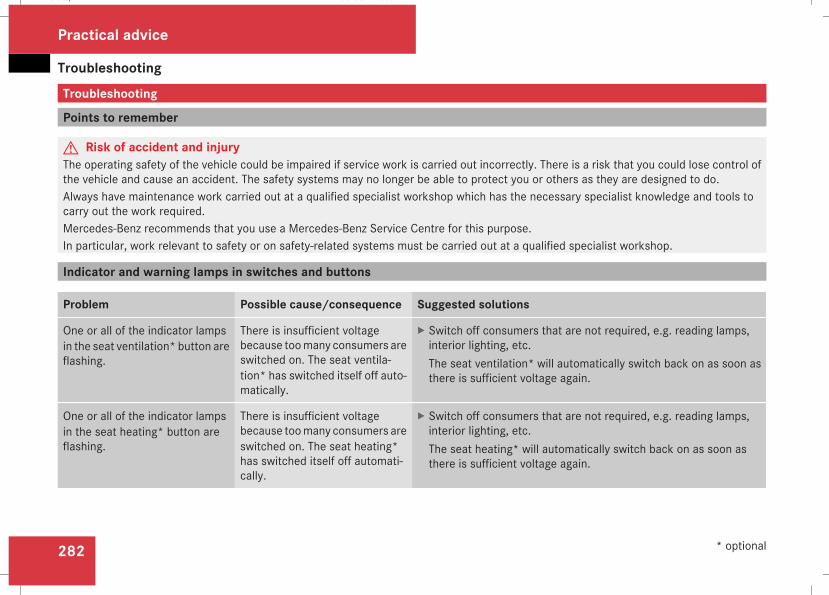
Troubleshooting
282
Troubleshooting
Points to remember
G Risk of accident and injuryThe operating safety of the vehicle could be impaired if service work is carried out incorrectly. There is a risk that you could lose control ofthe vehicle and cause an accident. The safety systems may no longer be able to protect you or others as they are designed to do.Always have maintenance work carried out at a qualified specialist workshop which has the necessary specialist knowledge and tools tocarry out the work required.Mercedes-Benz recommends that you use a Mercedes-Benz Service Centre for this purpose.In particular, work relevant to safety or on safety-related systems must be carried out at a qualified specialist workshop.
Indicator and warning lamps in switches and buttons
Problem Possible cause/consequence Suggested solutions
One or all of the indicator lampsin the seat ventilation* button areflashing.
There is insufficient voltagebecause toomany consumers areswitched on. The seat ventila-tion* has switched itself off auto-matically.
X Switch off consumers that are not required, e.g. reading lamps,interior lighting, etc.The seat ventilation* will automatically switch back on as soon asthere is sufficient voltage again.
One or all of the indicator lampsin the seat heating* button areflashing.
There is insufficient voltagebecause toomany consumers areswitched on. The seat heating*has switched itself off automati-cally.
X Switch off consumers that are not required, e.g. reading lamps,interior lighting, etc.The seat heating* will automatically switch back on as soon asthere is sufficient voltage again.
Practical advice
* optional
211_AKB; 2; 5, en-GBmkalafa, Version: 2.9.4
2008-02-29T16:57:07+01:00 - Seite 282
Dateiname: 6515_3416_02_buchblock.pdf; preflight
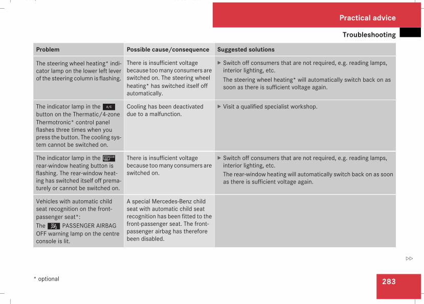
Troubleshooting
283
Problem Possible cause/consequence Suggested solutions
The steering wheel heating* indi-cator lamp on the lower left leverof the steering column is flashing.
There is insufficient voltagebecause toomany consumers areswitched on. The steering wheelheating* has switched itself offautomatically.
X Switch off consumers that are not required, e.g. reading lamps,interior lighting, etc.The steering wheel heating* will automatically switch back on assoon as there is sufficient voltage again.
The indicator lamp in the2button on the Thermatic/4-zoneThermotronic* control panelflashes three times when youpress the button. The cooling sys-tem cannot be switched on.
Cooling has been deactivateddue to a malfunction.
X Visit a qualified specialist workshop.
The indicator lamp in the¯rear-window heating button isflashing. The rear-window heat-ing has switched itself off prema-turely or cannot be switched on.
There is insufficient voltagebecause toomany consumers areswitched on.
X Switch off consumers that are not required, e.g. reading lamps,interior lighting, etc.The rear-window heating will automatically switch back on as soonas there is sufficient voltage again.
Vehicles with automatic childseat recognition on the front-passenger seat*:The5 PASSENGER AIRBAGOFF warning lamp on the centreconsole is lit.
A special Mercedes-Benz childseat with automatic child seatrecognition has been fitted to thefront-passenger seat. The front-passenger airbag has thereforebeen disabled.
Practical advice
* optional
211_AKB; 2; 5, en-GBmkalafa, Version: 2.9.4
2008-02-29T16:57:07+01:00 - Seite 283
Z
Dateiname: 6515_3416_02_buchblock.pdf; preflight
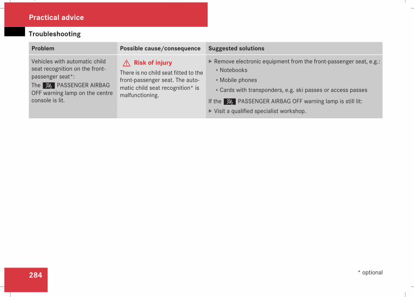
Troubleshooting
284
Problem Possible cause/consequence Suggested solutions
Vehicles with automatic childseat recognition on the front-passenger seat*:The5 PASSENGER AIRBAGOFF warning lamp on the centreconsole is lit.
G Risk of injuryThere is no child seat fitted to thefront-passenger seat. The auto-matic child seat recognition* ismalfunctioning.
X Remove electronic equipment from the front-passenger seat, e.g.:RNotebooksRMobile phonesRCards with transponders, e.g. ski passes or access passes
If the5 PASSENGER AIRBAG OFF warning lamp is still lit:X Visit a qualified specialist workshop.
Practical advice
* optional
211_AKB; 2; 5, en-GBmkalafa, Version: 2.9.4
2008-02-29T16:57:07+01:00 - Seite 284
Dateiname: 6515_3416_02_buchblock.pdf; preflight
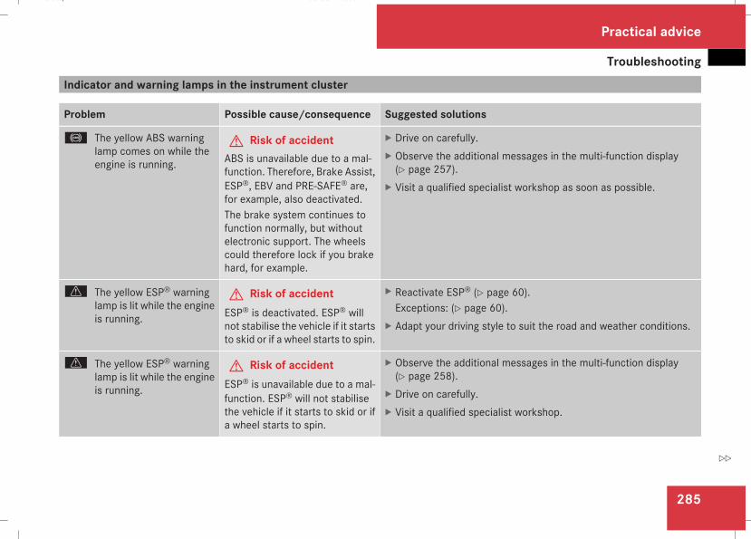
Troubleshooting
285
Indicator and warning lamps in the instrument cluster
Problem Possible cause/consequence Suggested solutions
- The yellow ABS warninglamp comes on while theengine is running.
G Risk of accidentABS is unavailable due to a mal-function. Therefore, Brake Assist,ESP®, EBV and PRE-SAFE® are,for example, also deactivated.The brake system continues tofunction normally, but withoutelectronic support. The wheelscould therefore lock if you brakehard, for example.
X Drive on carefully.X Observe the additional messages in the multi-function display(Y page 257).
X Visit a qualified specialist workshop as soon as possible.
v The yellow ESP® warninglamp is lit while the engineis running.
G Risk of accidentESP® is deactivated. ESP® willnot stabilise the vehicle if it startsto skid or if a wheel starts to spin.
X Reactivate ESP® (Y page 60).Exceptions: (Y page 60).
X Adapt your driving style to suit the road and weather conditions.
v The yellow ESP® warninglamp is lit while the engineis running.
G Risk of accidentESP® is unavailable due to a mal-function. ESP® will not stabilisethe vehicle if it starts to skid or ifa wheel starts to spin.
X Observe the additional messages in the multi-function display(Y page 258).
X Drive on carefully.X Visit a qualified specialist workshop.
Practical advice
211_AKB; 2; 5, en-GBmkalafa, Version: 2.9.4
2008-02-29T16:57:07+01:00 - Seite 285
Z
Dateiname: 6515_3416_02_buchblock.pdf; preflight
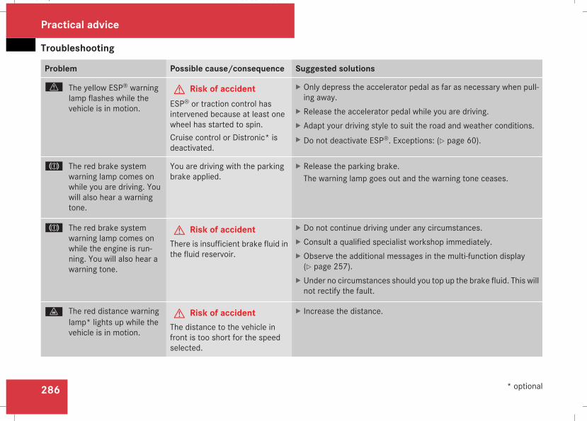
Troubleshooting
286
Problem Possible cause/consequence Suggested solutions
v The yellow ESP® warninglamp flashes while thevehicle is in motion.
G Risk of accidentESP® or traction control hasintervened because at least onewheel has started to spin.Cruise control or Distronic* isdeactivated.
X Only depress the accelerator pedal as far as necessary when pull-ing away.
X Release the accelerator pedal while you are driving.X Adapt your driving style to suit the road and weather conditions.X Do not deactivate ESP®. Exceptions: (Y page 60).
3 The red brake systemwarning lamp comes onwhile you are driving. Youwill also hear a warningtone.
You are driving with the parkingbrake applied.
X Release the parking brake.The warning lamp goes out and the warning tone ceases.
3 The red brake systemwarning lamp comes onwhile the engine is run-ning. You will also hear awarning tone.
G Risk of accidentThere is insufficient brake fluid inthe fluid reservoir.
X Do not continue driving under any circumstances.X Consult a qualified specialist workshop immediately.X Observe the additional messages in the multi-function display(Y page 257).
X Under no circumstances should you top up the brake fluid. This willnot rectify the fault.
l The red distance warninglamp* lights up while thevehicle is in motion.
G Risk of accidentThe distance to the vehicle infront is too short for the speedselected.
X Increase the distance.
Practical advice
* optional
211_AKB; 2; 5, en-GBmkalafa, Version: 2.9.4
2008-02-29T16:57:07+01:00 - Seite 286
Dateiname: 6515_3416_02_buchblock.pdf; preflight
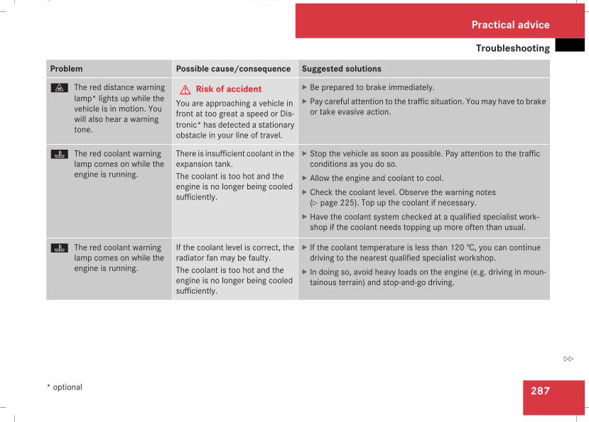
Troubleshooting
287
Problem Possible cause/consequence Suggested solutions
l The red distance warninglamp* lights up while thevehicle is in motion. Youwill also hear a warningtone.
G Risk of accidentYou are approaching a vehicle infront at too great a speed or Dis-tronic* has detected a stationaryobstacle in your line of travel.
X Be prepared to brake immediately.X Pay careful attention to the traffic situation. You may have to brakeor take evasive action.
D The red coolant warninglamp comes on while theengine is running.
There is insufficient coolant in theexpansion tank.The coolant is too hot and theengine is no longer being cooledsufficiently.
X Stop the vehicle as soon as possible. Pay attention to the trafficconditions as you do so.
X Allow the engine and coolant to cool.X Check the coolant level. Observe the warning notes(Y page 225). Top up the coolant if necessary.
X Have the coolant system checked at a qualified specialist work-shop if the coolant needs topping up more often than usual.
D The red coolant warninglamp comes on while theengine is running.
If the coolant level is correct, theradiator fan may be faulty.The coolant is too hot and theengine is no longer being cooledsufficiently.
X If the coolant temperature is less than 120 †, you can continuedriving to the nearest qualified specialist workshop.
X In doing so, avoid heavy loads on the engine (e.g. driving in moun-tainous terrain) and stop-and-go driving.
Practical advice
* optional
211_AKB; 2; 5, en-GBmkalafa, Version: 2.9.4
2008-02-29T16:57:07+01:00 - Seite 287
Z
Dateiname: 6515_3416_02_buchblock.pdf; preflight
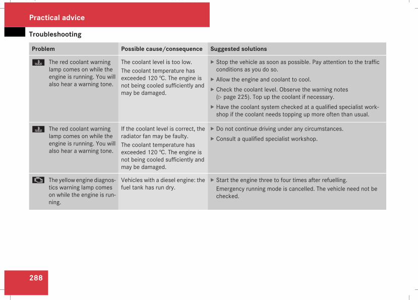
Troubleshooting
288
Problem Possible cause/consequence Suggested solutions
D The red coolant warninglamp comes on while theengine is running. You willalso hear a warning tone.
The coolant level is too low.The coolant temperature hasexceeded 120 †. The engine isnot being cooled sufficiently andmay be damaged.
X Stop the vehicle as soon as possible. Pay attention to the trafficconditions as you do so.
X Allow the engine and coolant to cool.X Check the coolant level. Observe the warning notes(Y page 225). Top up the coolant if necessary.
X Have the coolant system checked at a qualified specialist work-shop if the coolant needs topping up more often than usual.
D The red coolant warninglamp comes on while theengine is running. You willalso hear a warning tone.
If the coolant level is correct, theradiator fan may be faulty.The coolant temperature hasexceeded 120 †. The engine isnot being cooled sufficiently andmay be damaged.
X Do not continue driving under any circumstances.X Consult a qualified specialist workshop.
± The yellow engine diagnos-tics warning lamp comeson while the engine is run-ning.
Vehicles with a diesel engine: thefuel tank has run dry.
X Start the engine three to four times after refuelling.Emergency running mode is cancelled. The vehicle need not bechecked.
Practical advice
211_AKB; 2; 5, en-GBmkalafa, Version: 2.9.4
2008-02-29T16:57:07+01:00 - Seite 288
Dateiname: 6515_3416_02_buchblock.pdf; preflight
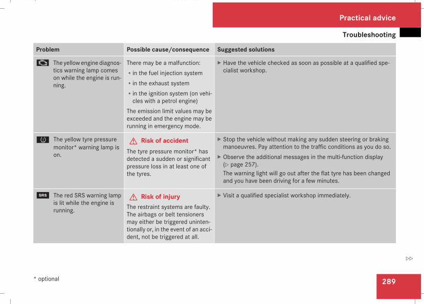
Troubleshooting
289
Problem Possible cause/consequence Suggested solutions
± The yellow engine diagnos-tics warning lamp comeson while the engine is run-ning.
There may be a malfunction:Rin the fuel injection systemRin the exhaust systemRin the ignition system (on vehi-cles with a petrol engine)
The emission limit values may beexceeded and the engine may berunning in emergency mode.
X Have the vehicle checked as soon as possible at a qualified spe-cialist workshop.
H The yellow tyre pressuremonitor* warning lamp ison.
G Risk of accidentThe tyre pressure monitor* hasdetected a sudden or significantpressure loss in at least one ofthe tyres.
X Stop the vehicle without making any sudden steering or brakingmanoeuvres. Pay attention to the traffic conditions as you do so.
X Observe the additional messages in the multi-function display(Y page 257).The warning light will go out after the flat tyre has been changedand you have been driving for a few minutes.
1 The red SRS warning lampis lit while the engine isrunning.
G Risk of injuryThe restraint systems are faulty.The airbags or belt tensionersmay either be triggered uninten-tionally or, in the event of an acci-dent, not be triggered at all.
X Visit a qualified specialist workshop immediately.
Practical advice
* optional
211_AKB; 2; 5, en-GBmkalafa, Version: 2.9.4
2008-02-29T16:57:07+01:00 - Seite 289
Z
Dateiname: 6515_3416_02_buchblock.pdf; preflight
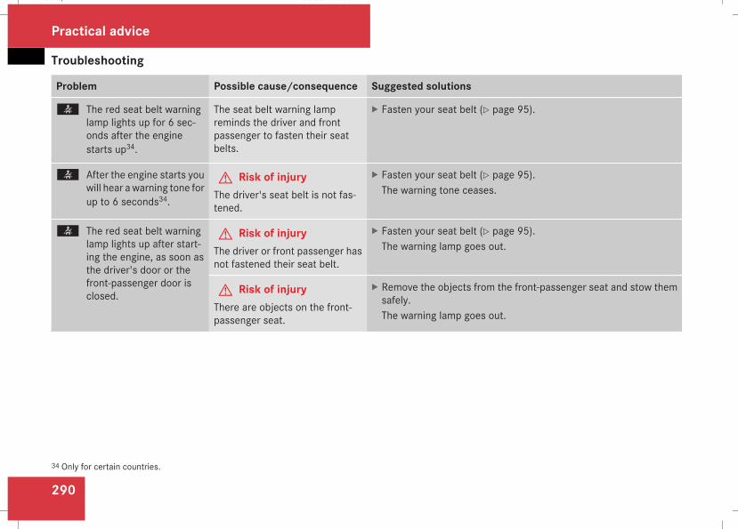
Troubleshooting
290
Problem Possible cause/consequence Suggested solutions
< The red seat belt warninglamp lights up for 6 sec-onds after the enginestarts up34.
The seat belt warning lampreminds the driver and frontpassenger to fasten their seatbelts.
X Fasten your seat belt (Y page 95).
< After the engine starts youwill hear awarning tone forup to 6 seconds34.
G Risk of injuryThe driver's seat belt is not fas-tened.
X Fasten your seat belt (Y page 95).The warning tone ceases.
< The red seat belt warninglamp lights up after start-ing the engine, as soon asthe driver's door or thefront-passenger door isclosed.
G Risk of injuryThe driver or front passenger hasnot fastened their seat belt.
X Fasten your seat belt (Y page 95).The warning lamp goes out.
G Risk of injuryThere are objects on the front-passenger seat.
X Remove the objects from the front-passenger seat and stow themsafely.The warning lamp goes out.
34 Only for certain countries.
Practical advice
211_AKB; 2; 5, en-GBmkalafa, Version: 2.9.4
2008-02-29T16:57:07+01:00 - Seite 290
Dateiname: 6515_3416_02_buchblock.pdf; preflight
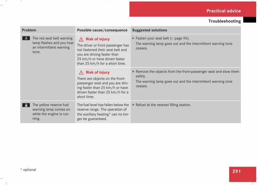
Troubleshooting
291
Problem Possible cause/consequence Suggested solutions
< The red seat belt warninglamp flashes and you hearan intermittent warningtone.
G Risk of injuryThe driver or front passenger hasnot fastened their seat belt andyou are driving faster than25 km/h or have driven fasterthan 25 km/h for a short time.
X Fasten your seat belt (Y page 95).The warning lamp goes out and the intermittent warning toneceases.
G Risk of injuryThere are objects on the front-passenger seat and you are driv-ing faster than 25 km/h or havedriven faster than 25 km/h for ashort time.
X Remove the objects from the front-passenger seat and stow themsafely.The warning lamp goes out and the intermittent warning toneceases.
W The yellow reserve fuelwarning lamp comes onwhile the engine is run-ning.
The fuel level has fallen below thereserve range. The operation ofthe auxiliary heating* can no lon-ger be guaranteed.
X Refuel at the nearest filling station.
Practical advice
* optional
211_AKB; 2; 5, en-GBmkalafa, Version: 2.9.4
2008-02-29T16:57:07+01:00 - Seite 291
Z
Dateiname: 6515_3416_02_buchblock.pdf; preflight
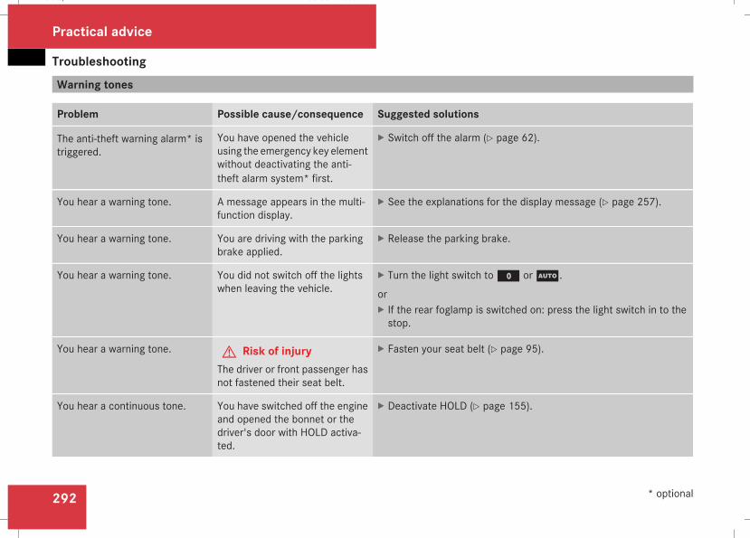
Troubleshooting
292
Warning tones
Problem Possible cause/consequence Suggested solutions
The anti-theft warning alarm* istriggered.
You have opened the vehicleusing the emergency key elementwithout deactivating the anti-theft alarm system* first.
X Switch off the alarm (Y page 62).
You hear a warning tone. A message appears in the multi-function display.
X See the explanations for the display message (Y page 257).
You hear a warning tone. You are driving with the parkingbrake applied.
X Release the parking brake.
You hear a warning tone. You did not switch off the lightswhen leaving the vehicle.
X Turn the light switch toM orU.
orX If the rear foglamp is switched on: press the light switch in to thestop.
You hear a warning tone. G Risk of injuryThe driver or front passenger hasnot fastened their seat belt.
X Fasten your seat belt (Y page 95).
You hear a continuous tone. You have switched off the engineand opened the bonnet or thedriver's door with HOLD activa-ted.
X Deactivate HOLD (Y page 155).
Practical advice
* optional
211_AKB; 2; 5, en-GBmkalafa, Version: 2.9.4
2008-02-29T16:57:07+01:00 - Seite 292
Dateiname: 6515_3416_02_buchblock.pdf; preflight
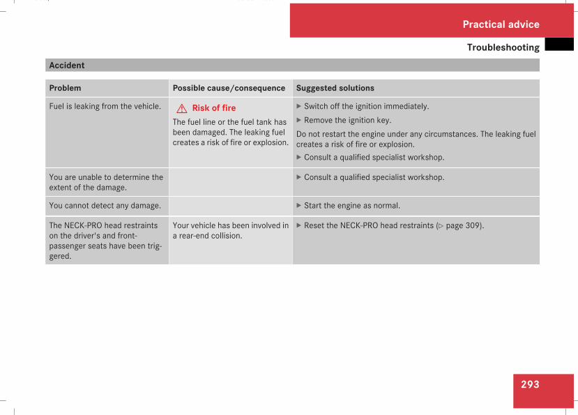
Troubleshooting
293
Accident
Problem Possible cause/consequence Suggested solutions
Fuel is leaking from the vehicle. G Risk of fireThe fuel line or the fuel tank hasbeen damaged. The leaking fuelcreates a risk of fire or explosion.
X Switch off the ignition immediately.X Remove the ignition key.Do not restart the engine under any circumstances. The leaking fuelcreates a risk of fire or explosion.X Consult a qualified specialist workshop.
You are unable to determine theextent of the damage.
X Consult a qualified specialist workshop.
You cannot detect any damage. X Start the engine as normal.
The NECK-PRO head restraintson the driver's and front-passenger seats have been trig-gered.
Your vehicle has been involved ina rear-end collision.
X Reset the NECK-PRO head restraints (Y page 309).
Practical advice
211_AKB; 2; 5, en-GBmkalafa, Version: 2.9.4
2008-02-29T16:57:07+01:00 - Seite 293
Z
Dateiname: 6515_3416_02_buchblock.pdf; preflight
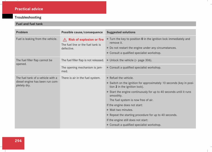
Troubleshooting
294
Fuel and fuel tank
Problem Possible cause/consequence Suggested solutions
Fuel is leaking from the vehicle. G Risk of explosion or fireThe fuel line or the fuel tank isdefective.
X Turn the key to position 0 in the ignition lock immediately andremove it.
X Do not restart the engine under any circumstances.X Consult a qualified specialist workshop.
The fuel filler flap cannot beopened.
The fuel filler flap is not released. X Unlock the vehicle (Y page 306).
The opening mechanism is jam-med.
X Consult a qualified specialist workshop.
The fuel tank of a vehicle with adiesel engine has been run com-pletely dry.
There is air in the fuel system. X Refuel the vehicle.X Switch on the ignition for approximately 10 seconds (key in posi-tion 2 in the ignition lock).
X Start the engine continuously for up to 40 seconds until it runssmoothly.The fuel system is now free of air.
If the engine does not start:X Wait two minutes.X Repeat the starting procedure for up to 40 seconds.If the engine still does not start:X Consult a qualified specialist workshop.
Practical advice
211_AKB; 2; 5, en-GBmkalafa, Version: 2.9.4
2008-02-29T16:57:07+01:00 - Seite 294
Dateiname: 6515_3416_02_buchblock.pdf; preflight
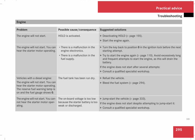
Troubleshooting
295
Engine
Problem Possible cause/consequence Suggested solutions
The engine will not start. HOLD is activated. X Deactivating HOLD (Y page 155).X Start the engine again.
The engine will not start. You canhear the starter motor operating.
RThere is a malfunction in theengine electronics.
RThere is a malfunction in thefuel supply.
X Turn the key back to position 0 in the ignition lock before the nextstarting attempt.
X Try to start the engine again (Y page 110). Avoid excessively longand frequent attempts to start the engine, as this will drain thebattery.
If the engine does not start after several attempts:X Consult a qualified specialist workshop.
Vehicles with a diesel engine:The engine will not start. You canhear the starter motor operating.The reserve fuel warning lamp ison and the fuel gauge shows 0.
The fuel tank has been run dry. X Refuel the vehicle.X Bleed the fuel system (Y page 294).
The engine will not start. You can-not hear the starter motor oper-ating.
The on-board voltage is too lowbecause the starter battery is tooweak or discharged.
X Jump-start the vehicle (Y page 333).If the engine does not start despite attempting to jump-start it:X Consult a qualified specialist workshop.
Practical advice
211_AKB; 2; 5, en-GBmkalafa, Version: 2.9.4
2008-02-29T16:57:07+01:00 - Seite 295
Z
Dateiname: 6515_3416_02_buchblock.pdf; preflight

Troubleshooting
296
Problem Possible cause/consequence Suggested solutions
Vehicles with a petrol engine:The engine is not runningsmoothly and is misfiring.
There is a malfunction in theengine electronics or a mechani-cal component of the engine con-trol unit.
X Only depress the accelerator pedal slightly.X Have the cause rectified immediately at a qualified specialist work-shop.Otherwise, non-combusted fuelmay get into the catalytic converterand damage it.
A coolant temperature of over120 °C is displayed. The coolantwarning lamp may also be on anda warning tone may sound(Y page 120).
The coolant level is too low. Thecoolant is too hot and the engineis no longer being cooled suffi-ciently.
X Stop as soon as possible and allow the engine and the coolant tocool down.
X Check the coolant level (Y page 225). Observe the warning notesas you do so and top up the coolant if necessary.
If the coolant level is correct, theradiator fan may be faulty. Thecoolant is too hot and the engineis no longer being cooled suffi-ciently.
X If the coolant temperature is less than 120 °C, you can continuedriving to the nearest qualified specialist workshop.
X Avoid heavy loads on the engine as you do so, e.g. driving onmountain roads and stop/start driving.
Practical advice
211_AKB; 2; 5, en-GBmkalafa, Version: 2.9.4
2008-02-29T16:57:07+01:00 - Seite 296
Dateiname: 6515_3416_02_buchblock.pdf; preflight
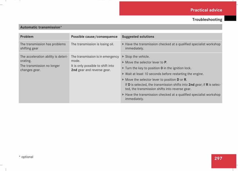
Troubleshooting
297
Automatic transmission*
Problem Possible cause/consequence Suggested solutions
The transmission has problemsshifting gear
The transmission is losing oil. X Have the transmission checked at a qualified specialist workshopimmediately.
The acceleration ability is deteri-orating.The transmission no longerchanges gear.
The transmission is in emergencymode.It is only possible to shift into2nd gear and reverse gear.
X Stop the vehicle.X Move the selector lever to P.X Turn the key to position 0 in the ignition lock.X Wait at least 10 seconds before restarting the engine.X Move the selector lever to position D or R.If D is selected, the transmission shifts into 2nd gear; if R is selec-ted, the transmission shifts into reverse gear.
X Have the transmission checked at a qualified specialist workshopimmediately.
Practical advice
* optional
211_AKB; 2; 5, en-GBmkalafa, Version: 2.9.4
2008-02-29T16:57:07+01:00 - Seite 297
Z
Dateiname: 6515_3416_02_buchblock.pdf; preflight
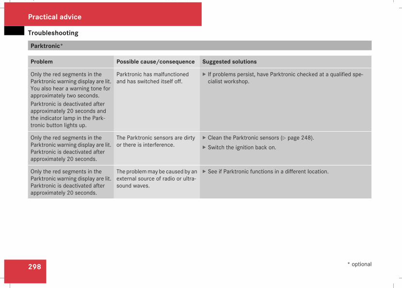
Troubleshooting
298
Parktronic*
Problem Possible cause/consequence Suggested solutions
Only the red segments in theParktronic warning display are lit.You also hear a warning tone forapproximately two seconds.Parktronic is deactivated afterapproximately 20 seconds andthe indicator lamp in the Park-tronic button lights up.
Parktronic has malfunctionedand has switched itself off.
X If problems persist, have Parktronic checked at a qualified spe-cialist workshop.
Only the red segments in theParktronic warning display are lit.Parktronic is deactivated afterapproximately 20 seconds.
The Parktronic sensors are dirtyor there is interference.
X Clean the Parktronic sensors (Y page 248).X Switch the ignition back on.
Only the red segments in theParktronic warning display are lit.Parktronic is deactivated afterapproximately 20 seconds.
The problemmay be caused by anexternal source of radio or ultra-sound waves.
X See if Parktronic functions in a different location.
Practical advice
* optional
211_AKB; 2; 5, en-GBmkalafa, Version: 2.9.4
2008-02-29T16:57:07+01:00 - Seite 298
Dateiname: 6515_3416_02_buchblock.pdf; preflight
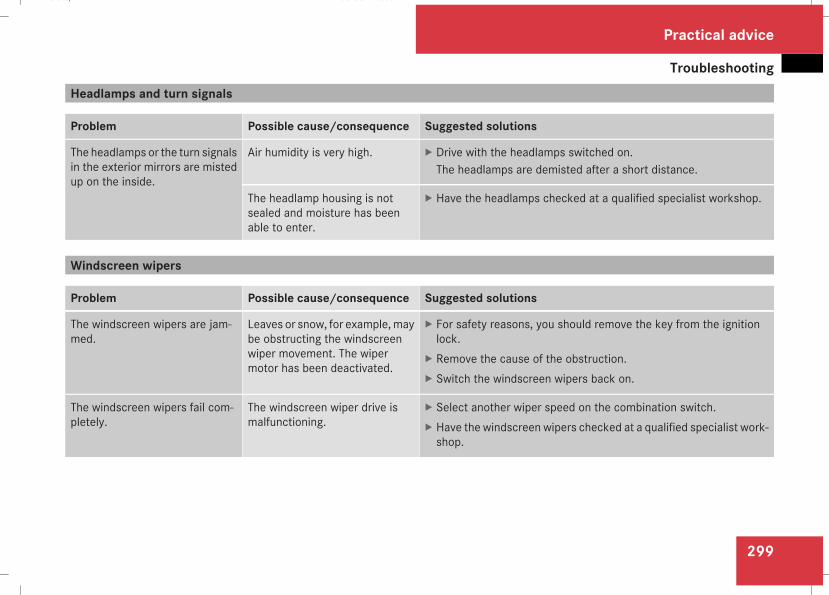
Troubleshooting
299
Headlamps and turn signals
Problem Possible cause/consequence Suggested solutions
The headlamps or the turn signalsin the exterior mirrors are mistedup on the inside.
Air humidity is very high. X Drive with the headlamps switched on.The headlamps are demisted after a short distance.
The headlamp housing is notsealed and moisture has beenable to enter.
X Have the headlamps checked at a qualified specialist workshop.
Windscreen wipers
Problem Possible cause/consequence Suggested solutions
The windscreen wipers are jam-med.
Leaves or snow, for example,maybe obstructing the windscreenwiper movement. The wipermotor has been deactivated.
X For safety reasons, you should remove the key from the ignitionlock.
X Remove the cause of the obstruction.X Switch the windscreen wipers back on.
The windscreen wipers fail com-pletely.
The windscreen wiper drive ismalfunctioning.
X Select another wiper speed on the combination switch.X Have the windscreen wipers checked at a qualified specialist work-shop.
Practical advice
211_AKB; 2; 5, en-GBmkalafa, Version: 2.9.4
2008-02-29T16:57:07+01:00 - Seite 299
Z
Dateiname: 6515_3416_02_buchblock.pdf; preflight
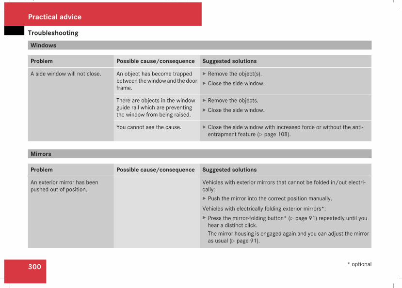
Troubleshooting
300
Windows
Problem Possible cause/consequence Suggested solutions
A side window will not close. An object has become trappedbetween thewindowand the doorframe.
X Remove the object(s).X Close the side window.
There are objects in the windowguide rail which are preventingthe window from being raised.
X Remove the objects.X Close the side window.
You cannot see the cause. X Close the side window with increased force or without the anti-entrapment feature (Y page 108).
Mirrors
Problem Possible cause/consequence Suggested solutions
An exterior mirror has beenpushed out of position.
Vehicles with exterior mirrors that cannot be folded in/out electri-cally:X Push the mirror into the correct position manually.
Vehicles with electrically folding exterior mirrors*:X Press the mirror-folding button* (Y page 91) repeatedly until youhear a distinct click.The mirror housing is engaged again and you can adjust the mirroras usual (Y page 91).
Practical advice
* optional
211_AKB; 2; 5, en-GBmkalafa, Version: 2.9.4
2008-02-29T16:57:07+01:00 - Seite 300
Dateiname: 6515_3416_02_buchblock.pdf; preflight
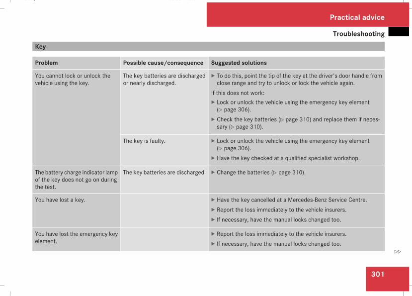
Troubleshooting
301
Key
Problem Possible cause/consequence Suggested solutions
You cannot lock or unlock thevehicle using the key.
The key batteries are dischargedor nearly discharged.
X To do this, point the tip of the key at the driver's door handle fromclose range and try to unlock or lock the vehicle again.
If this does not work:X Lock or unlock the vehicle using the emergency key element(Y page 306).
X Check the key batteries (Y page 310) and replace them if neces-sary (Y page 310).
The key is faulty. X Lock or unlock the vehicle using the emergency key element(Y page 306).
X Have the key checked at a qualified specialist workshop.
The battery charge indicator lampof the key does not go on duringthe test.
The key batteries are discharged. X Change the batteries (Y page 310).
You have lost a key. X Have the key cancelled at a Mercedes-Benz Service Centre.X Report the loss immediately to the vehicle insurers.X If necessary, have the manual locks changed too.
You have lost the emergency keyelement.
X Report the loss immediately to the vehicle insurers.X If necessary, have the manual locks changed too.
Practical advice
211_AKB; 2; 5, en-GBmkalafa, Version: 2.9.4
2008-02-29T16:57:07+01:00 - Seite 301
Z
Dateiname: 6515_3416_02_buchblock.pdf; preflight
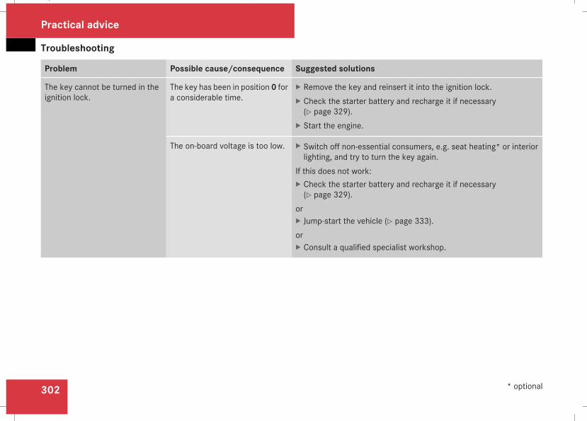
Troubleshooting
302
Problem Possible cause/consequence Suggested solutions
The key cannot be turned in theignition lock.
The key has been in position 0 fora considerable time.
X Remove the key and reinsert it into the ignition lock.X Check the starter battery and recharge it if necessary(Y page 329).
X Start the engine.
The on-board voltage is too low. X Switch off non-essential consumers, e.g. seat heating* or interiorlighting, and try to turn the key again.
If this does not work:X Check the starter battery and recharge it if necessary(Y page 329).
orX Jump-start the vehicle (Y page 333).orX Consult a qualified specialist workshop.
Practical advice
* optional
211_AKB; 2; 5, en-GBmkalafa, Version: 2.9.4
2008-02-29T16:57:07+01:00 - Seite 302
Dateiname: 6515_3416_02_buchblock.pdf; preflight
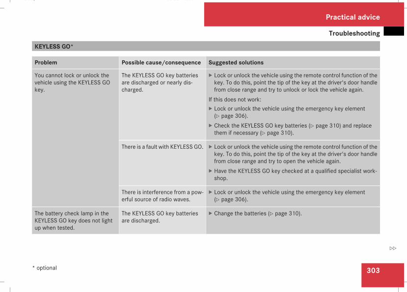
Troubleshooting
303
KEYLESS GO*
Problem Possible cause/consequence Suggested solutions
You cannot lock or unlock thevehicle using the KEYLESS GOkey.
The KEYLESS GO key batteriesare discharged or nearly dis-charged.
X Lock or unlock the vehicle using the remote control function of thekey. To do this, point the tip of the key at the driver's door handlefrom close range and try to unlock or lock the vehicle again.
If this does not work:X Lock or unlock the vehicle using the emergency key element(Y page 306).
X Check the KEYLESS GO key batteries (Y page 310) and replacethem if necessary (Y page 310).
There is a fault with KEYLESS GO. X Lock or unlock the vehicle using the remote control function of thekey. To do this, point the tip of the key at the driver's door handlefrom close range and try to open the vehicle again.
X Have the KEYLESS GO key checked at a qualified specialist work-shop.
There is interference from a pow-erful source of radio waves.
X Lock or unlock the vehicle using the emergency key element(Y page 306).
The battery check lamp in theKEYLESS GO key does not lightup when tested.
The KEYLESS GO key batteriesare discharged.
X Change the batteries (Y page 310).
Practical advice
* optional
211_AKB; 2; 5, en-GBmkalafa, Version: 2.9.4
2008-02-29T16:57:07+01:00 - Seite 303
Z
Dateiname: 6515_3416_02_buchblock.pdf; preflight
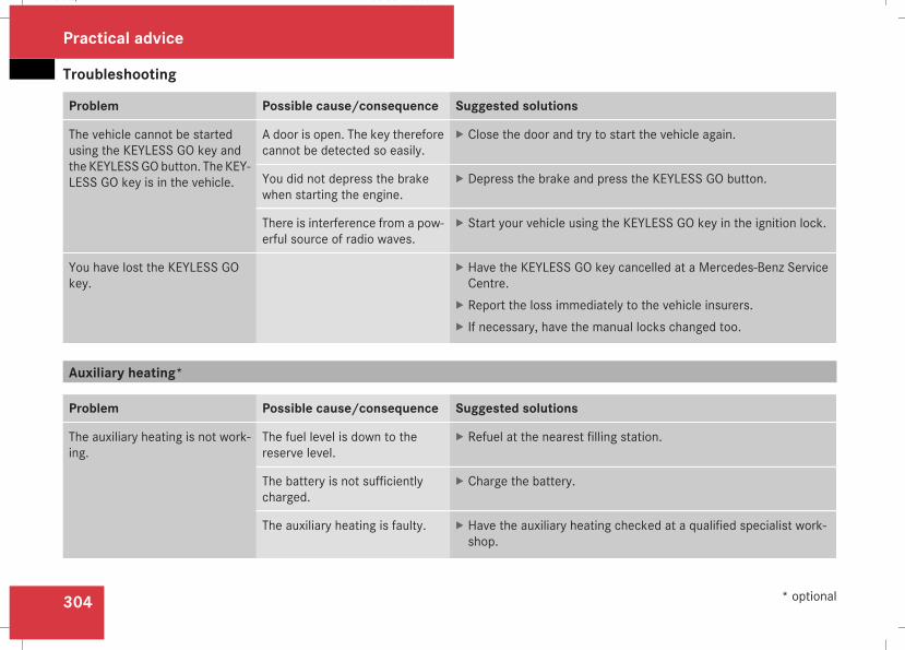
Troubleshooting
304
Problem Possible cause/consequence Suggested solutions
The vehicle cannot be startedusing the KEYLESS GO key andthe KEYLESSGObutton. The KEY-LESS GO key is in the vehicle.
A door is open. The key thereforecannot be detected so easily.
X Close the door and try to start the vehicle again.
You did not depress the brakewhen starting the engine.
X Depress the brake and press the KEYLESS GO button.
There is interference from a pow-erful source of radio waves.
X Start your vehicle using the KEYLESS GO key in the ignition lock.
You have lost the KEYLESS GOkey.
X Have the KEYLESS GO key cancelled at a Mercedes-Benz ServiceCentre.
X Report the loss immediately to the vehicle insurers.X If necessary, have the manual locks changed too.
Auxiliary heating*
Problem Possible cause/consequence Suggested solutions
The auxiliary heating is not work-ing.
The fuel level is down to thereserve level.
X Refuel at the nearest filling station.
The battery is not sufficientlycharged.
X Charge the battery.
The auxiliary heating is faulty. X Have the auxiliary heating checked at a qualified specialist work-shop.
Practical advice
* optional
211_AKB; 2; 5, en-GBmkalafa, Version: 2.9.4
2008-02-29T16:57:07+01:00 - Seite 304
Dateiname: 6515_3416_02_buchblock.pdf; preflight
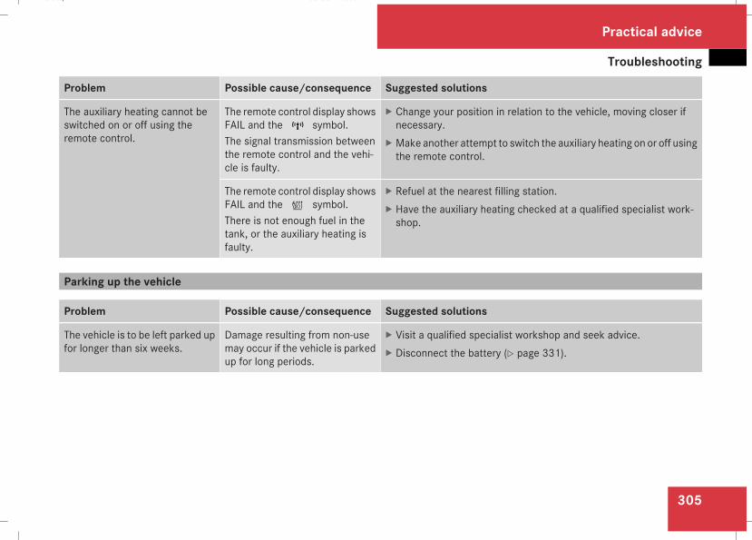
Troubleshooting
305
Problem Possible cause/consequence Suggested solutions
The auxiliary heating cannot beswitched on or off using theremote control.
The remote control display showsFAIL and the¢ symbol.The signal transmission betweenthe remote control and the vehi-cle is faulty.
X Change your position in relation to the vehicle, moving closer ifnecessary.
X Make another attempt to switch the auxiliary heating on or off usingthe remote control.
The remote control display showsFAIL and the¡ symbol.There is not enough fuel in thetank, or the auxiliary heating isfaulty.
X Refuel at the nearest filling station.X Have the auxiliary heating checked at a qualified specialist work-shop.
Parking up the vehicle
Problem Possible cause/consequence Suggested solutions
The vehicle is to be left parked upfor longer than six weeks.
Damage resulting from non-usemay occur if the vehicle is parkedup for long periods.
X Visit a qualified specialist workshop and seek advice.X Disconnect the battery (Y page 331).
Practical advice
211_AKB; 2; 5, en-GBmkalafa, Version: 2.9.4
2008-02-29T16:57:07+01:00 - Seite 305
Z
Dateiname: 6515_3416_02_buchblock.pdf; preflight
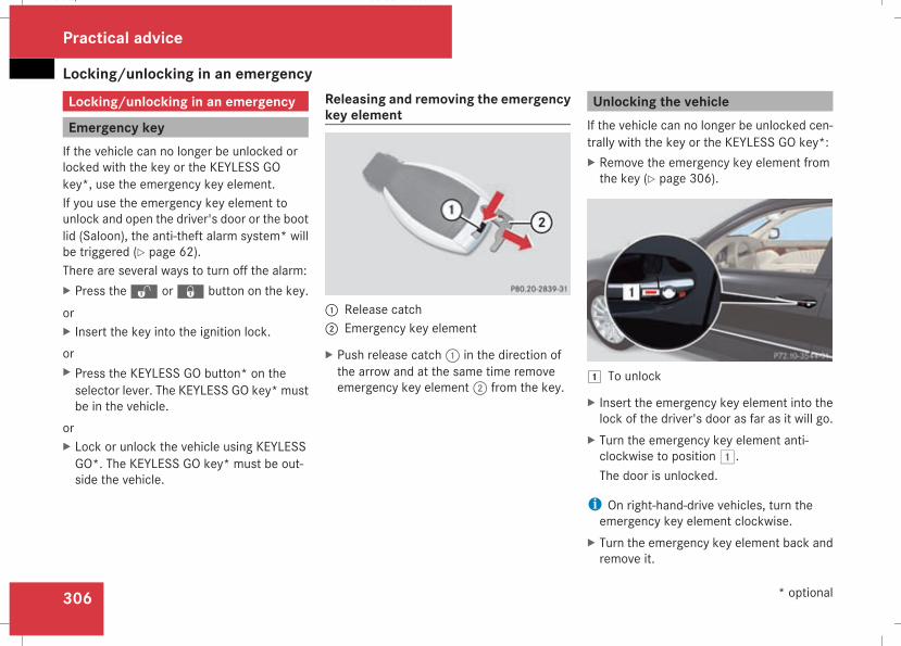
Locking/unlocking in an emergency
306
Locking/unlocking in an emergency
Emergency keyIf the vehicle can no longer be unlocked orlocked with the key or the KEYLESS GOkey*, use the emergency key element.If you use the emergency key element tounlock and open the driver's door or the bootlid (Saloon), the anti-theft alarm system* willbe triggered (Y page 62).There are several ways to turn off the alarm:X Press thek orj button on the key.orX Insert the key into the ignition lock.orX Press the KEYLESS GO button* on theselector lever. The KEYLESS GO key* mustbe in the vehicle.
orX Lock or unlock the vehicle using KEYLESSGO*. The KEYLESS GO key* must be out-side the vehicle.
Releasing and removing the emergencykey element
1 Release catch2 Emergency key element
X Push release catch1 in the direction ofthe arrow and at the same time removeemergency key element2 from the key.
Unlocking the vehicleIf the vehicle can no longer be unlocked cen-trally with the key or the KEYLESS GO key*:X Remove the emergency key element fromthe key (Y page 306).
$ To unlock
X Insert the emergency key element into thelock of the driver's door as far as it will go.
X Turn the emergency key element anti-clockwise to position$.The door is unlocked.
i On right-hand-drive vehicles, turn theemergency key element clockwise.
X Turn the emergency key element back andremove it.
Practical advice
* optional
211_AKB; 2; 5, en-GBmkalafa, Version: 2.9.4
2008-02-29T16:57:07+01:00 - Seite 306
Dateiname: 6515_3416_02_buchblock.pdf; preflight
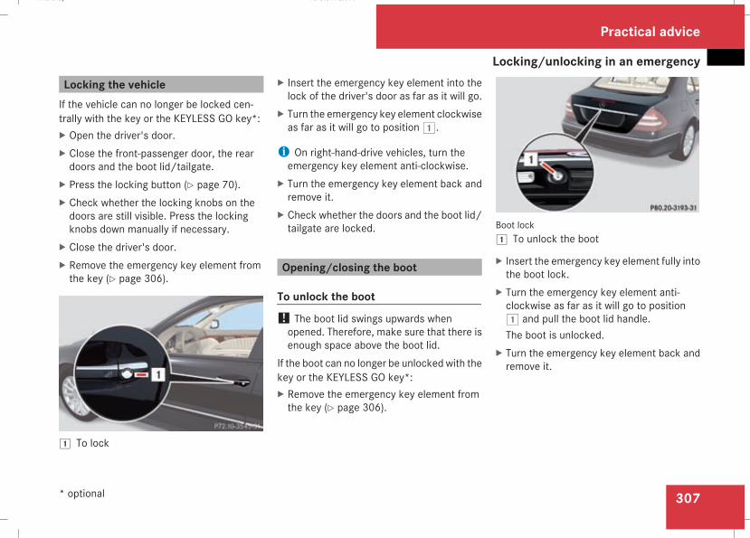
Locking/unlocking in an emergency
307
Locking the vehicleIf the vehicle can no longer be locked cen-trally with the key or the KEYLESS GO key*:X Open the driver's door.X Close the front-passenger door, the reardoors and the boot lid/tailgate.
X Press the locking button (Y page 70).X Check whether the locking knobs on thedoors are still visible. Press the lockingknobs down manually if necessary.
X Close the driver's door.X Remove the emergency key element fromthe key (Y page 306).
$ To lock
X Insert the emergency key element into thelock of the driver's door as far as it will go.
X Turn the emergency key element clockwiseas far as it will go to position$.
i On right-hand-drive vehicles, turn theemergency key element anti-clockwise.
X Turn the emergency key element back andremove it.
X Check whether the doors and the boot lid/tailgate are locked.
Opening/closing the boot
To unlock the boot! The boot lid swings upwards whenopened. Therefore, make sure that there isenough space above the boot lid.
If the boot can no longer be unlocked with thekey or the KEYLESS GO key*:X Remove the emergency key element fromthe key (Y page 306).
Boot lock$ To unlock the boot
X Insert the emergency key element fully intothe boot lock.
X Turn the emergency key element anti-clockwise as far as it will go to position$ and pull the boot lid handle.The boot is unlocked.
X Turn the emergency key element back andremove it.
Practical advice
* optional
211_AKB; 2; 5, en-GBmkalafa, Version: 2.9.4
2008-02-29T16:57:07+01:00 - Seite 307
Z
Dateiname: 6515_3416_02_buchblock.pdf; preflight
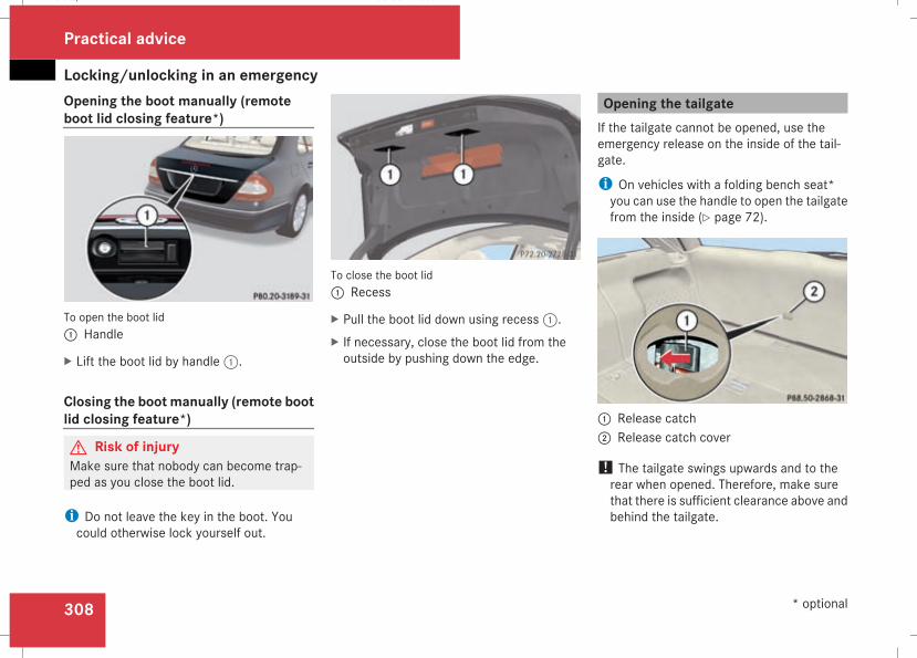
Locking/unlocking in an emergency
308
Opening the boot manually (remoteboot lid closing feature*)
To open the boot lid1 Handle
X Lift the boot lid by handle1.
Closing the boot manually (remote bootlid closing feature*)
G Risk of injuryMake sure that nobody can become trap-ped as you close the boot lid.
i Do not leave the key in the boot. Youcould otherwise lock yourself out.
To close the boot lid1 Recess
X Pull the boot lid down using recess1.X If necessary, close the boot lid from theoutside by pushing down the edge.
Opening the tailgateIf the tailgate cannot be opened, use theemergency release on the inside of the tail-gate.
i On vehicles with a folding bench seat*you can use the handle to open the tailgatefrom the inside (Y page 72).
1 Release catch2 Release catch cover
! The tailgate swings upwards and to therear when opened. Therefore, make surethat there is sufficient clearance above andbehind the tailgate.
Practical advice
* optional
211_AKB; 2; 5, en-GBmkalafa, Version: 2.9.4
2008-02-29T16:57:07+01:00 - Seite 308
Dateiname: 6515_3416_02_buchblock.pdf; preflight
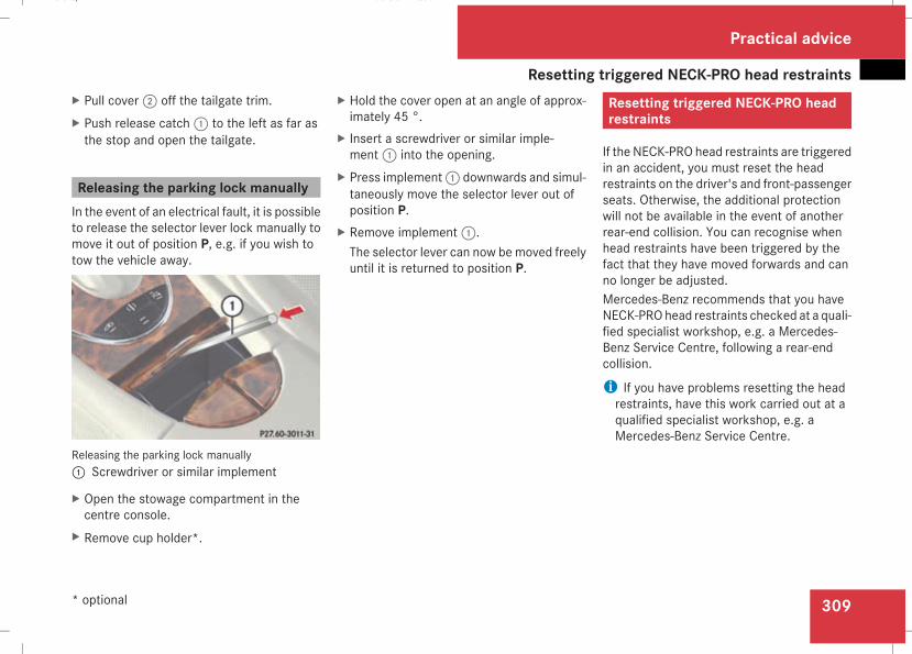
Resetting triggered NECK-PRO head restraints
309
X Pull cover2 off the tailgate trim.X Push release catch1 to the left as far asthe stop and open the tailgate.
Releasing the parking lock manuallyIn the event of an electrical fault, it is possibleto release the selector lever lock manually tomove it out of position P, e.g. if you wish totow the vehicle away.
Releasing the parking lock manually1 Screwdriver or similar implement
X Open the stowage compartment in thecentre console.
X Remove cup holder*.
X Hold the cover open at an angle of approx-imately 45 °.
X Insert a screwdriver or similar imple-ment1 into the opening.
X Press implement1 downwards and simul-taneously move the selector lever out ofposition P.
X Remove implement1.The selector lever can now bemoved freelyuntil it is returned to position P.
Resetting triggered NECK-PRO headrestraints
If the NECK-PRO head restraints are triggeredin an accident, you must reset the headrestraints on the driver's and front-passengerseats. Otherwise, the additional protectionwill not be available in the event of anotherrear-end collision. You can recognise whenhead restraints have been triggered by thefact that they have moved forwards and canno longer be adjusted.Mercedes-Benz recommends that you haveNECK-PROhead restraints checked at a quali-fied specialist workshop, e.g. a Mercedes-Benz Service Centre, following a rear-endcollision.
i If you have problems resetting the headrestraints, have this work carried out at aqualified specialist workshop, e.g. aMercedes-Benz Service Centre.
Practical advice
* optional
211_AKB; 2; 5, en-GBmkalafa, Version: 2.9.4
2008-02-29T16:57:07+01:00 - Seite 309
Z
Dateiname: 6515_3416_02_buchblock.pdf; preflight
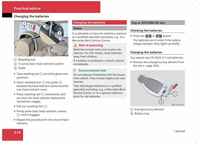
Changing the batteries
310
1 Resetting tool2 To press back head restraint cushion3 Guide
X Take resetting tool1 out of the glove com-partment.
X Insert resetting tool1 into guide3between the head restraint cushion and therear head restraint cover.
X Press resetting tool1 downwards untilyou hear the head restraint deploymentmechanism engage.
X Pull out resetting tool1.X Firmly press back head restraint cushion2 until it engages.
X Repeat this procedure for the second headrestraint.
Changing the batteries
NotesIt is advisable to have the batteries replacedat a qualified specialist workshop, e.g. at aMercedes-Benz Service Centre.G Risk of poisoningBatteries contain toxic and caustic sub-stances. For this reason, keep batteriesaway from children.If a battery is swallowed, consult a doctorimmediately.
H Environmental noteDo not dispose of batteries with the house-hold rubbish. They contain highly toxic sub-stances.Take discharged batteries to a qualifiedspecialist workshop, e.g. a Mercedes-BenzService Centre, or to a special collectionpoint for old batteries.
Key or KEYLESS GO key*
Checking the batteriesX Press thej ork button.The batteries are in order if the batterycharge indicator lamp lights up briefly.
Changing the batteriesYou require two CR 2025 3 V cell batteries.X Remove the emergency key element fromthe key (Y page 306).
1 Emergency key element2 Battery tray
Practical advice
* optional
211_AKB; 2; 5, en-GBmkalafa, Version: 2.9.4
2008-02-29T16:57:07+01:00 - Seite 310
Dateiname: 6515_3416_02_buchblock.pdf; preflight
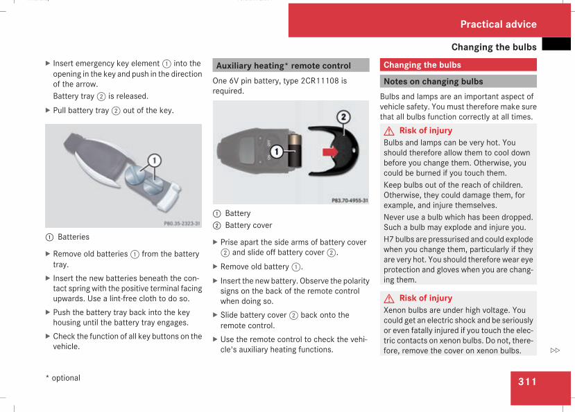
Changing the bulbs
311
X Insert emergency key element1 into theopening in the key and push in the directionof the arrow.Battery tray2 is released.
X Pull battery tray2 out of the key.
1 Batteries
X Remove old batteries1 from the batterytray.
X Insert the new batteries beneath the con-tact spring with the positive terminal facingupwards. Use a lint-free cloth to do so.
X Push the battery tray back into the keyhousing until the battery tray engages.
X Check the function of all key buttons on thevehicle.
Auxiliary heating* remote controlOne 6V pin battery, type 2CR11108 isrequired.
1 Battery2 Battery cover
X Prise apart the side arms of battery cover2 and slide off battery cover2.
X Remove old battery1.X Insert the new battery. Observe the polaritysigns on the back of the remote controlwhen doing so.
X Slide battery cover2 back onto theremote control.
X Use the remote control to check the vehi-cle's auxiliary heating functions.
Changing the bulbs
Notes on changing bulbsBulbs and lamps are an important aspect ofvehicle safety. You must therefore make surethat all bulbs function correctly at all times.G Risk of injuryBulbs and lamps can be very hot. Youshould therefore allow them to cool downbefore you change them. Otherwise, youcould be burned if you touch them.Keep bulbs out of the reach of children.Otherwise, they could damage them, forexample, and injure themselves.Never use a bulb which has been dropped.Such a bulb may explode and injure you.H7bulbs are pressurised and could explodewhen you change them, particularly if theyare very hot. You should therefore wear eyeprotection and gloves when you are chang-ing them.
G Risk of injuryXenon bulbs are under high voltage. Youcould get an electric shock and be seriouslyor even fatally injured if you touch the elec-tric contacts on xenon bulbs. Do not, there-fore, remove the cover on xenon bulbs.
Practical advice
* optional
211_AKB; 2; 5, en-GBmkalafa, Version: 2.9.4
2008-02-29T16:57:07+01:00 - Seite 311
Z
Dateiname: 6515_3416_02_buchblock.pdf; preflight
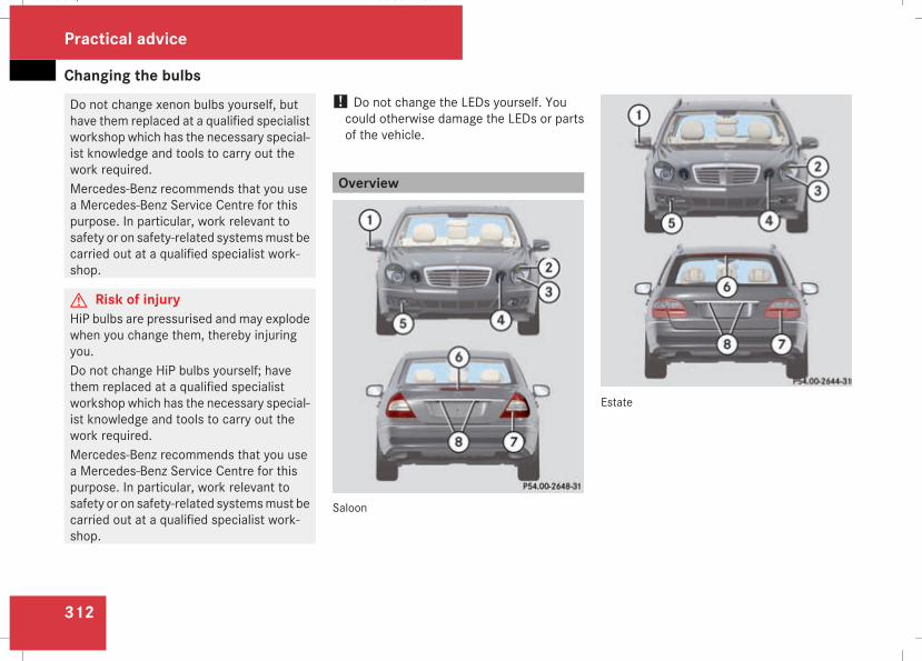
Changing the bulbs
312
Do not change xenon bulbs yourself, buthave them replaced at a qualified specialistworkshop which has the necessary special-ist knowledge and tools to carry out thework required.Mercedes-Benz recommends that you usea Mercedes-Benz Service Centre for thispurpose. In particular, work relevant tosafety or on safety-related systemsmust becarried out at a qualified specialist work-shop.
G Risk of injuryHiP bulbs are pressurised and may explodewhen you change them, thereby injuringyou.Do not change HiP bulbs yourself; havethem replaced at a qualified specialistworkshop which has the necessary special-ist knowledge and tools to carry out thework required.Mercedes-Benz recommends that you usea Mercedes-Benz Service Centre for thispurpose. In particular, work relevant tosafety or on safety-related systemsmust becarried out at a qualified specialist work-shop.
! Do not change the LEDs yourself. Youcould otherwise damage the LEDs or partsof the vehicle.
Overview
Saloon
Estate
Practical advice
211_AKB; 2; 5, en-GBmkalafa, Version: 2.9.4
2008-02-29T16:57:07+01:00 - Seite 312
Dateiname: 6515_3416_02_buchblock.pdf; preflight
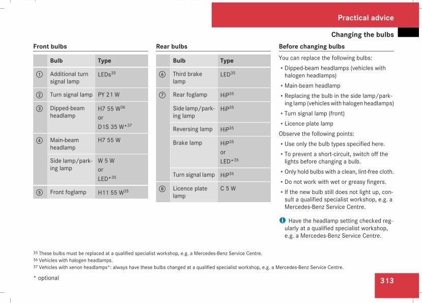
Changing the bulbs
313
Front bulbs
Bulb Type
1 Additional turnsignal lamp
LEDs35
2 Turn signal lamp PY 21 W
3 Dipped-beamheadlamp
H7 55 W36
orD1S 35 W*37
4 Main-beamheadlamp
H7 55 W
Side lamp/park-ing lamp
W 5 WorLED*35
5 Front foglamp H11 55 W35
Rear bulbs
Bulb Type
6 Third brakelamp
LED35
7 Rear foglamp HiP35
Side lamp/park-ing lamp
HiP35
Reversing lamp HiP35
Brake lamp HiP35
orLED*35
Turn signal lamp HiP35
8 Licence platelamp
C 5 W
Before changing bulbsYou can replace the following bulbs:RDipped-beam headlamps (vehicles withhalogen headlamps)
RMain-beam headlampRReplacing the bulb in the side lamp/park-ing lamp (vehicleswith halogen headlamps)
RTurn signal lamp (front)RLicence plate lampObserve the following points:RUse only the bulb types specified here.RTo prevent a short-circuit, switch off thelights before changing a bulb.
ROnly hold bulbs with a clean, lint-free cloth.RDo not work with wet or greasy fingers.RIf the new bulb still does not light up, con-sult a qualified specialist workshop, e.g. aMercedes-Benz Service Centre.
i Have the headlamp setting checked reg-ularly at a qualified specialist workshop,e.g. a Mercedes-Benz Service Centre.
35 These bulbs must be replaced at a qualified specialist workshop, e.g. a Mercedes-Benz Service Centre.36 Vehicles with halogen headlamps.37 Vehicles with xenon headlamps*: always have these bulbs changed at a qualified specialist workshop, e.g. a Mercedes-Benz Service Centre.
Practical advice
* optional
211_AKB; 2; 5, en-GBmkalafa, Version: 2.9.4
2008-02-29T16:57:07+01:00 - Seite 313
Z
Dateiname: 6515_3416_02_buchblock.pdf; preflight
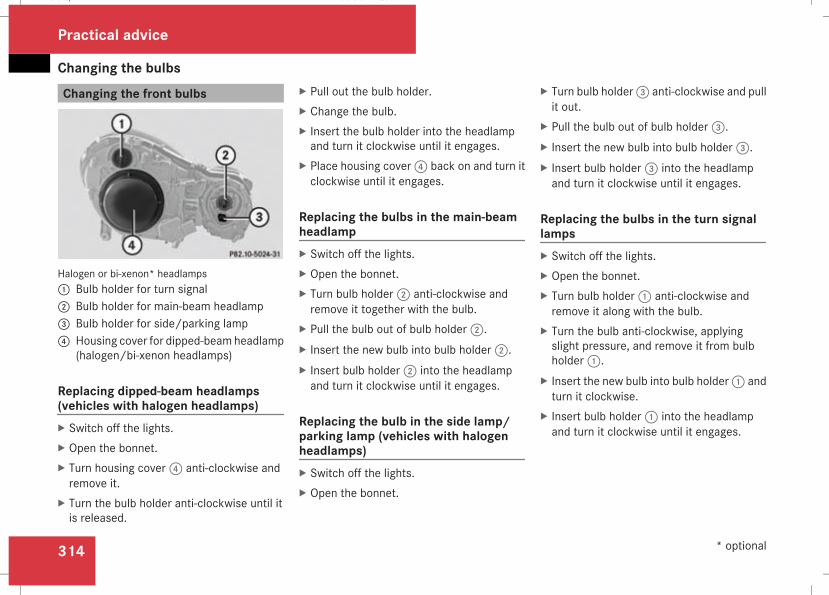
Changing the bulbs
314
Changing the front bulbs
Halogen or bi-xenon* headlamps1 Bulb holder for turn signal2 Bulb holder for main-beam headlamp3 Bulb holder for side/parking lamp4 Housing cover for dipped-beam headlamp
(halogen/bi-xenon headlamps)
Replacing dipped-beam headlamps(vehicles with halogen headlamps)X Switch off the lights.X Open the bonnet.X Turn housing cover4 anti-clockwise andremove it.
X Turn the bulb holder anti-clockwise until itis released.
X Pull out the bulb holder.X Change the bulb.X Insert the bulb holder into the headlampand turn it clockwise until it engages.
X Place housing cover4 back on and turn itclockwise until it engages.
Replacing the bulbs in the main-beamheadlampX Switch off the lights.X Open the bonnet.X Turn bulb holder2 anti-clockwise andremove it together with the bulb.
X Pull the bulb out of bulb holder2.X Insert the new bulb into bulb holder2.X Insert bulb holder2 into the headlampand turn it clockwise until it engages.
Replacing the bulb in the side lamp/parking lamp (vehicles with halogenheadlamps)X Switch off the lights.X Open the bonnet.
X Turn bulb holder3 anti-clockwise and pullit out.
X Pull the bulb out of bulb holder3.X Insert the new bulb into bulb holder3.X Insert bulb holder3 into the headlampand turn it clockwise until it engages.
Replacing the bulbs in the turn signallampsX Switch off the lights.X Open the bonnet.X Turn bulb holder1 anti-clockwise andremove it along with the bulb.
X Turn the bulb anti-clockwise, applyingslight pressure, and remove it from bulbholder1.
X Insert the new bulb into bulb holder1 andturn it clockwise.
X Insert bulb holder1 into the headlampand turn it clockwise until it engages.
Practical advice
* optional
211_AKB; 2; 5, en-GBmkalafa, Version: 2.9.4
2008-02-29T16:57:07+01:00 - Seite 314
Dateiname: 6515_3416_02_buchblock.pdf; preflight
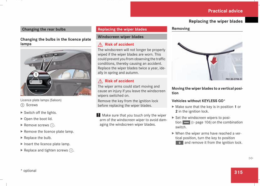
Replacing the wiper blades
315
Changing the rear bulbs
Changing the bulbs in the licence platelamps
Licence plate lamps (Saloon)1 Screws
X Switch off the lights.X Open the boot lid.X Remove screws1.X Remove the licence plate lamp.X Replace the bulb.X Insert the licence plate lamp.X Replace and tighten screws1.
Replacing the wiper blades
Windscreen wiper blades
G Risk of accidentThe windscreen will not longer be properlywiped if the wiper blades are worn. Thiscould prevent you fromobserving the trafficconditions, thereby causing an accident.Replace the wiper blades twice a year, ide-ally in spring and autumn.
G Risk of accidentThe wiper arms could start moving andcause an injury if you leave the windscreenwipers switched on.Remove the key from the ignition lockbefore replacing the wiper blades.
! Make sure that you touch only the wiperarm of the windscreen wiper to avoid dam-aging the windscreen wiper blades.
Removing
Moving thewiper blades to a vertical posi-tion
Vehicles without KEYLESS GO*X Make sure that the key is in position 1 or2 in the ignition lock.
X Set the windscreen wipers to posi-tionu (Y page 106) on the combinationswitch.
X When the wiper arms have reached a ver-tical position, turn the key to positionM and remove it from the ignition lock.
Practical advice
* optional
211_AKB; 2; 5, en-GBmkalafa, Version: 2.9.4
2008-02-29T16:57:07+01:00 - Seite 315
Z
Dateiname: 6515_3416_02_buchblock.pdf; preflight
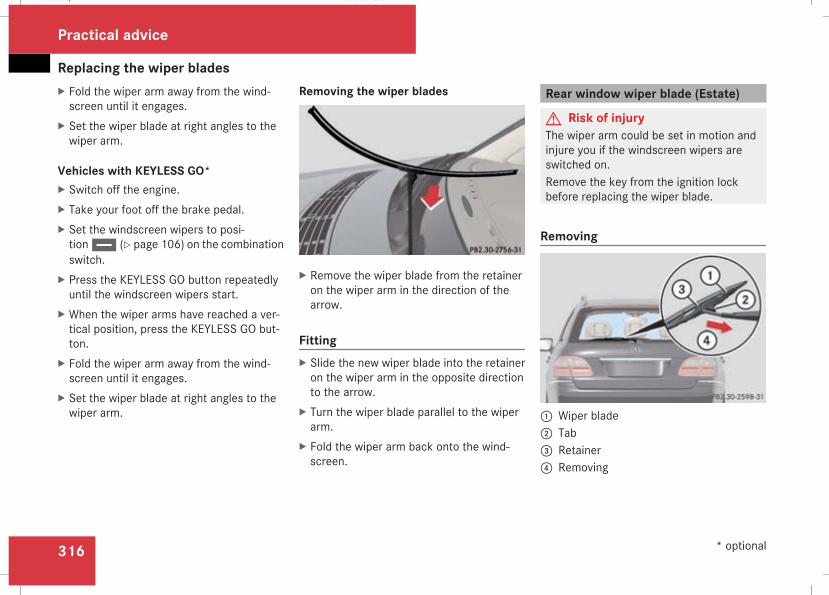
Replacing the wiper blades
316
X Fold the wiper arm away from the wind-screen until it engages.
X Set the wiper blade at right angles to thewiper arm.
Vehicles with KEYLESS GO*X Switch off the engine.X Take your foot off the brake pedal.X Set the windscreen wipers to posi-tionu (Y page 106) on the combinationswitch.
X Press the KEYLESS GO button repeatedlyuntil the windscreen wipers start.
X When the wiper arms have reached a ver-tical position, press the KEYLESS GO but-ton.
X Fold the wiper arm away from the wind-screen until it engages.
X Set the wiper blade at right angles to thewiper arm.
Removing the wiper blades
X Remove the wiper blade from the retaineron the wiper arm in the direction of thearrow.
FittingX Slide the new wiper blade into the retaineron the wiper arm in the opposite directionto the arrow.
X Turn the wiper blade parallel to the wiperarm.
X Fold the wiper arm back onto the wind-screen.
Rear window wiper blade (Estate)
G Risk of injuryThe wiper arm could be set in motion andinjure you if the windscreen wipers areswitched on.Remove the key from the ignition lockbefore replacing the wiper blade.
Removing
1 Wiper blade2 Tab3 Retainer4 Removing
Practical advice
* optional
211_AKB; 2; 5, en-GBmkalafa, Version: 2.9.4
2008-02-29T16:57:07+01:00 - Seite 316
Dateiname: 6515_3416_02_buchblock.pdf; preflight
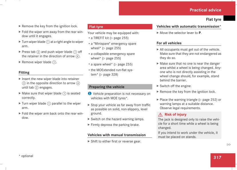
Flat tyre
317
X Remove the key from the ignition lock.X Fold the wiper arm away from the rear win-dow until it engages.
X Turnwiper blade1 at a right angle towiperarm.
X Press tab2 and push wiper blade1 offthe retainer in the direction of arrow4.
X Remove wiper blade1.
FittingX Insert the new wiper blade into retainer3 in the opposite direction to arrow4until tab2 engages.
X Make sure that wiper blade1 is seatedcorrectly.
X Turn wiper blade1 parallel to the wiperarm.
X Fold the wiper arm back onto the rear win-dow.
Flat tyreYour vehicle may be equipped with:Ra TIREFIT kit (Y page 255)Ra "Minispare" emergency sparewheel* (Y page 255)
Ra collapsible emergency sparewheel* (Y page 255)
Ra spare wheel* (Y page 255)Rthe MOExtended run-flat sys-tem* (Y page 328)
Preparing the vehiclei Vehicle preparation is not necessary onvehicles with MOE tyres*.
X Stop your vehicle as far away from trafficas possible on solid, non-slippery, levelground.
X Switch on the hazard warning lamps.X Firmly depress the parking brake.
Vehicles with manual transmissionX Shift to either first or reverse gear.
Vehicles with automatic transmission*X Move the selector lever to P.
For all vehiclesX All occupants must get out of the vehicle.Make sure that they are not endangered asthey do so.
X Make sure that no one is near the dangerarea whilst a wheel is being changed. Any-one who is not directly assisting in thewheel change should, for example, standbehind the barrier.
X Switch off the engine.X Remove the key from the ignition lock.
X Place the warning triangle (Y page 252) orwarning lamps at a suitable distance.Observe legal requirements.
G Risk of injuryThe jack is designed only to raise the vehi-cle for a short time while a wheel is beingchanged.If you intend to work under the vehicle, itmust be placed on stands.
Practical advice
* optional
211_AKB; 2; 5, en-GBmkalafa, Version: 2.9.4
2008-02-29T16:57:07+01:00 - Seite 317
Z
Dateiname: 6515_3416_02_buchblock.pdf; preflight
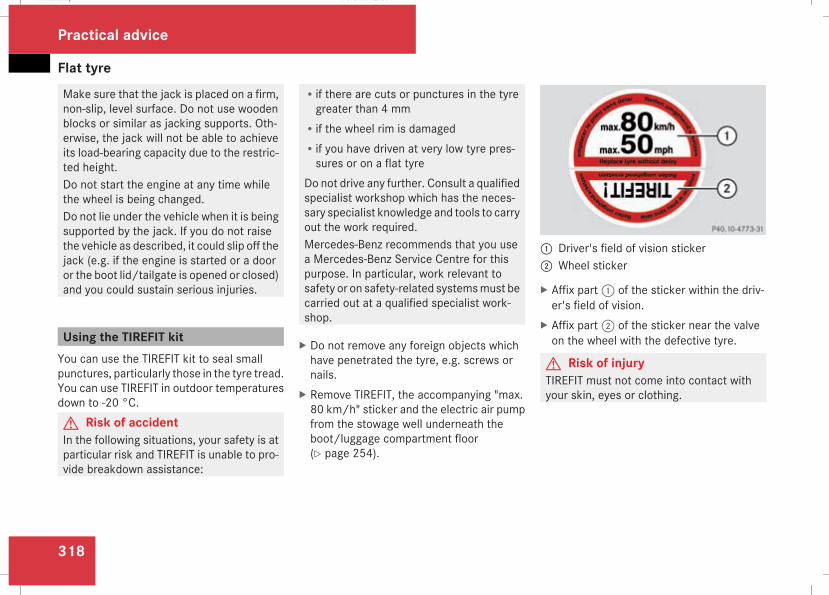
Flat tyre
318
Make sure that the jack is placed on a firm,non-slip, level surface. Do not use woodenblocks or similar as jacking supports. Oth-erwise, the jack will not be able to achieveits load-bearing capacity due to the restric-ted height.Do not start the engine at any time whilethe wheel is being changed.Do not lie under the vehicle when it is beingsupported by the jack. If you do not raisethe vehicle as described, it could slip off thejack (e.g. if the engine is started or a dooror the boot lid/tailgate is opened or closed)and you could sustain serious injuries.
Using the TIREFIT kitYou can use the TIREFIT kit to seal smallpunctures, particularly those in the tyre tread.You can use TIREFIT in outdoor temperaturesdown to -20 °C.G Risk of accidentIn the following situations, your safety is atparticular risk and TIREFIT is unable to pro-vide breakdown assistance:
Rif there are cuts or punctures in the tyregreater than 4 mm
Rif the wheel rim is damagedRif you have driven at very low tyre pres-sures or on a flat tyre
Do not drive any further. Consult a qualifiedspecialist workshop which has the neces-sary specialist knowledge and tools to carryout the work required.Mercedes-Benz recommends that you usea Mercedes-Benz Service Centre for thispurpose. In particular, work relevant tosafety or on safety-related systemsmust becarried out at a qualified specialist work-shop.
X Do not remove any foreign objects whichhave penetrated the tyre, e.g. screws ornails.
X Remove TIREFIT, the accompanying "max.80 km/h" sticker and the electric air pumpfrom the stowage well underneath theboot/luggage compartment floor(Y page 254).
1 Driver's field of vision sticker2 Wheel sticker
X Affix part1 of the sticker within the driv-er's field of vision.
X Affix part2 of the sticker near the valveon the wheel with the defective tyre.
G Risk of injuryTIREFIT must not come into contact withyour skin, eyes or clothing.
Practical advice
211_AKB; 2; 5, en-GBmkalafa, Version: 2.9.4
2008-02-29T16:57:07+01:00 - Seite 318
Dateiname: 6515_3416_02_buchblock.pdf; preflight
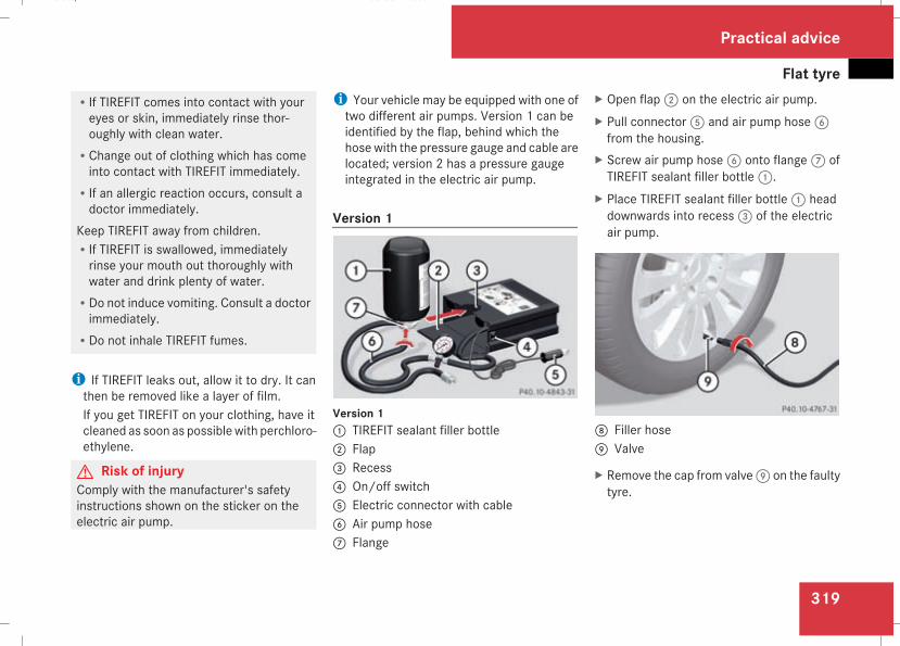
Flat tyre
319
RIf TIREFIT comes into contact with youreyes or skin, immediately rinse thor-oughly with clean water.
RChange out of clothing which has comeinto contact with TIREFIT immediately.
RIf an allergic reaction occurs, consult adoctor immediately.
Keep TIREFIT away from children.RIf TIREFIT is swallowed, immediatelyrinse your mouth out thoroughly withwater and drink plenty of water.
RDo not induce vomiting. Consult a doctorimmediately.
RDo not inhale TIREFIT fumes.
i If TIREFIT leaks out, allow it to dry. It canthen be removed like a layer of film.If you get TIREFIT on your clothing, have itcleaned as soon as possiblewith perchloro-ethylene.
G Risk of injuryComply with the manufacturer's safetyinstructions shown on the sticker on theelectric air pump.
i Your vehicle may be equipped with one oftwo different air pumps. Version 1 can beidentified by the flap, behind which thehose with the pressure gauge and cable arelocated; version 2 has a pressure gaugeintegrated in the electric air pump.
Version 1
Version 11 TIREFIT sealant filler bottle2 Flap3 Recess4 On/off switch5 Electric connector with cable6 Air pump hose7 Flange
X Open flap2 on the electric air pump.X Pull connector5 and air pump hose6from the housing.
X Screw air pump hose6 onto flange7 ofTIREFIT sealant filler bottle1.
X Place TIREFIT sealant filler bottle1 headdownwards into recess3 of the electricair pump.
8 Filler hose9 Valve
X Remove the cap from valve9 on the faultytyre.
Practical advice
211_AKB; 2; 5, en-GBmkalafa, Version: 2.9.4
2008-02-29T16:57:07+01:00 - Seite 319
Z
Dateiname: 6515_3416_02_buchblock.pdf; preflight
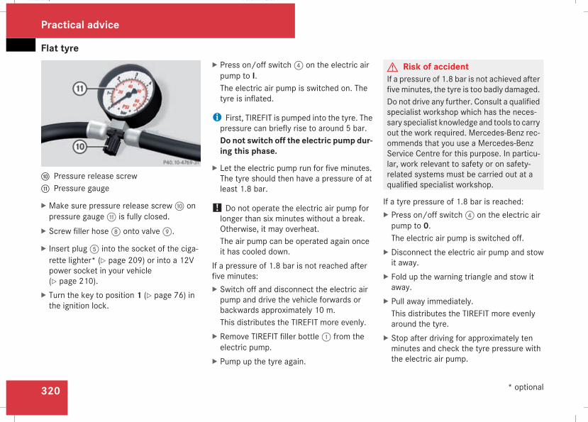
Flat tyre
320
a Pressure release screwb Pressure gauge
X Make sure pressure release screwa onpressure gaugeb is fully closed.
X Screw filler hose8 onto valve9.
X Insert plug5 into the socket of the ciga-rette lighter* (Y page 209) or into a 12Vpower socket in your vehicle(Y page 210).
X Turn the key to position 1 (Y page 76) inthe ignition lock.
X Press on/off switch4 on the electric airpump to I.The electric air pump is switched on. Thetyre is inflated.
i First, TIREFIT is pumped into the tyre. Thepressure can briefly rise to around 5 bar.Do not switch off the electric pump dur-ing this phase.
X Let the electric pump run for five minutes.The tyre should then have a pressure of atleast 1.8 bar.
! Do not operate the electric air pump forlonger than six minutes without a break.Otherwise, it may overheat.The air pump can be operated again onceit has cooled down.
If a pressure of 1.8 bar is not reached afterfive minutes:X Switch off and disconnect the electric airpump and drive the vehicle forwards orbackwards approximately 10 m.This distributes the TIREFIT more evenly.
X Remove TIREFIT filler bottle1 from theelectric pump.
X Pump up the tyre again.
G Risk of accidentIf a pressure of 1.8 bar is not achieved afterfiveminutes, the tyre is too badly damaged.Do not drive any further. Consult a qualifiedspecialist workshop which has the neces-sary specialist knowledge and tools to carryout the work required. Mercedes-Benz rec-ommends that you use a Mercedes-BenzService Centre for this purpose. In particu-lar, work relevant to safety or on safety-related systems must be carried out at aqualified specialist workshop.
If a tyre pressure of 1.8 bar is reached:X Press on/off switch4 on the electric airpump to 0.The electric air pump is switched off.
X Disconnect the electric air pump and stowit away.
X Fold up the warning triangle and stow itaway.
X Pull away immediately.This distributes the TIREFIT more evenlyaround the tyre.
X Stop after driving for approximately tenminutes and check the tyre pressure withthe electric air pump.
Practical advice
* optional
211_AKB; 2; 5, en-GBmkalafa, Version: 2.9.4
2008-02-29T16:57:07+01:00 - Seite 320
Dateiname: 6515_3416_02_buchblock.pdf; preflight
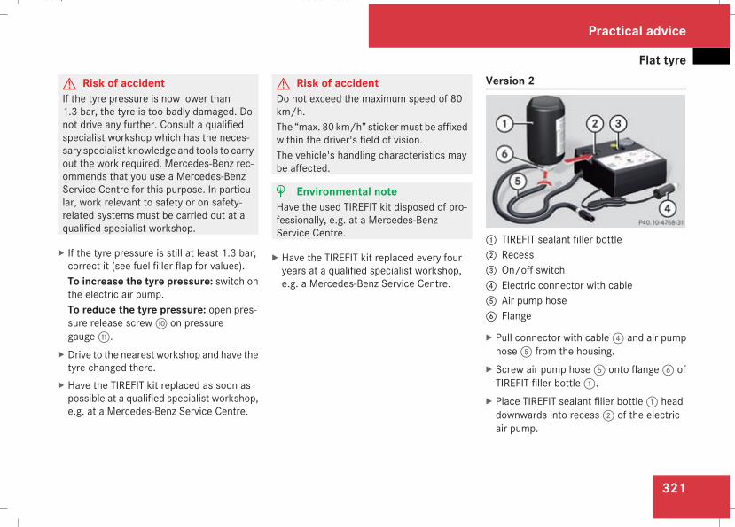
Flat tyre
321
G Risk of accidentIf the tyre pressure is now lower than1.3 bar, the tyre is too badly damaged. Donot drive any further. Consult a qualifiedspecialist workshop which has the neces-sary specialist knowledge and tools to carryout the work required. Mercedes-Benz rec-ommends that you use a Mercedes-BenzService Centre for this purpose. In particu-lar, work relevant to safety or on safety-related systems must be carried out at aqualified specialist workshop.
X If the tyre pressure is still at least 1.3 bar,correct it (see fuel filler flap for values).To increase the tyre pressure: switch onthe electric air pump.To reduce the tyre pressure: open pres-sure release screwa on pressuregaugeb.
X Drive to the nearest workshop and have thetyre changed there.
X Have the TIREFIT kit replaced as soon aspossible at a qualified specialist workshop,e.g. at a Mercedes-Benz Service Centre.
G Risk of accidentDo not exceed the maximum speed of 80km/h.The “max. 80 km/h” stickermust be affixedwithin the driver's field of vision.The vehicle's handling characteristics maybe affected.
H Environmental noteHave the used TIREFIT kit disposed of pro-fessionally, e.g. at a Mercedes-BenzService Centre.
X Have the TIREFIT kit replaced every fouryears at a qualified specialist workshop,e.g. a Mercedes-Benz Service Centre.
Version 2
1 TIREFIT sealant filler bottle2 Recess3 On/off switch4 Electric connector with cable5 Air pump hose6 Flange
X Pull connector with cable4 and air pumphose5 from the housing.
X Screw air pump hose5 onto flange6 ofTIREFIT filler bottle1.
X Place TIREFIT sealant filler bottle1 headdownwards into recess2 of the electricair pump.
Practical advice
211_AKB; 2; 5, en-GBmkalafa, Version: 2.9.4
2008-02-29T16:57:07+01:00 - Seite 321
Z
Dateiname: 6515_3416_02_buchblock.pdf; preflight
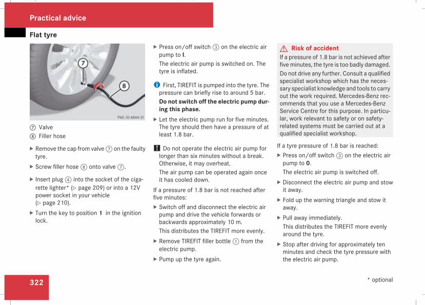
Flat tyre
322
7 Valve8 Filler hose
X Remove the cap from valve7 on the faultytyre.
X Screw filler hose8 onto valve7.
X Insert plug4 into the socket of the ciga-rette lighter* (Y page 209) or into a 12Vpower socket in your vehicle(Y page 210).
X Turn the key to position 1 in the ignitionlock.
X Press on/off switch3 on the electric airpump to I.The electric air pump is switched on. Thetyre is inflated.
i First, TIREFIT is pumped into the tyre. Thepressure can briefly rise to around 5 bar.Do not switch off the electric pump dur-ing this phase.
X Let the electric pump run for five minutes.The tyre should then have a pressure of atleast 1.8 bar.
! Do not operate the electric air pump forlonger than six minutes without a break.Otherwise, it may overheat.The air pump can be operated again onceit has cooled down.
If a pressure of 1.8 bar is not reached afterfive minutes:X Switch off and disconnect the electric airpump and drive the vehicle forwards orbackwards approximately 10 m.This distributes the TIREFIT more evenly.
X Remove TIREFIT filler bottle1 from theelectric pump.
X Pump up the tyre again.
G Risk of accidentIf a pressure of 1.8 bar is not achieved afterfiveminutes, the tyre is too badly damaged.Do not drive any further. Consult a qualifiedspecialist workshop which has the neces-sary specialist knowledge and tools to carryout the work required. Mercedes-Benz rec-ommends that you use a Mercedes-BenzService Centre for this purpose. In particu-lar, work relevant to safety or on safety-related systems must be carried out at aqualified specialist workshop.
If a tyre pressure of 1.8 bar is reached:X Press on/off switch3 on the electric airpump to 0.The electric air pump is switched off.
X Disconnect the electric air pump and stowit away.
X Fold up the warning triangle and stow itaway.
X Pull away immediately.This distributes the TIREFIT more evenlyaround the tyre.
X Stop after driving for approximately tenminutes and check the tyre pressure withthe electric air pump.
Practical advice
* optional
211_AKB; 2; 5, en-GBmkalafa, Version: 2.9.4
2008-02-29T16:57:07+01:00 - Seite 322
Dateiname: 6515_3416_02_buchblock.pdf; preflight
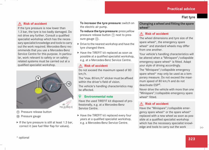
Flat tyre
323
G Risk of accidentIf the tyre pressure is now lower than1.3 bar, the tyre is too badly damaged. Donot drive any further. Consult a qualifiedspecialist workshop which has the neces-sary specialist knowledge and tools to carryout the work required. Mercedes-Benz rec-ommends that you use a Mercedes-BenzService Centre for this purpose. In particu-lar, work relevant to safety or on safety-related systems must be carried out at aqualified specialist workshop.
9 Pressure release buttona Pressure gauge
X If the tyre pressure is still at least 1.3 bar,correct it (see fuel filler flap for values).
To increase the tyre pressure: switch onthe electric air pump.To reduce the tyre pressure: press yellowpressure release button9 next to pres-sure gaugea.
X Drive to the nearest workshop and have thetyre changed there.
X Have the TIREFIT kit replaced as soon aspossible at a qualified specialist workshop,e.g. at a Mercedes-Benz Service Centre.
G Risk of accidentDo not exceed the maximum speed of 80km/h.The “max. 80 km/h” stickermust be affixedwithin the driver's field of vision.The vehicle's handling characteristics maybe affected.
H Environmental noteHave the used TIREFIT kit disposed of pro-fessionally, e.g. at a Mercedes-BenzService Centre.
X Have the TIREFIT kit replaced every fouryears at a qualified specialist workshop,e.g. a Mercedes-Benz Service Centre.
Changingawheel and fitting the sparewheel*
G Risk of accidentThe wheel dimensions and tyre size of thespare wheel*, the emergency sparewheel* and standard wheels may differfrom one another.Your vehicle's handling characteristics willbe altered when a "Minispare"/collapsibleemergency spare wheel* is fitted. Adaptyour style of driving accordingly.The "Minispare"/collapsible emergencyspare wheel* may only be used as a tem-porary measure. Do not exceed the maxi-mum speed of 80 km/h and do notdeactivate ESP®.Never drive the vehicle with more than one“Minispare”/collapsible emergency sparewheel* fitted.
G Risk of accidentHave the “Minispare”/collapsible emer-gency spare wheel* or the spare wheel*replaced with a new wheel as soon as pos-sible at a qualified specialist workshopwhich has the necessary specialist knowl-edge and tools to carry out the work
Practical advice
* optional
211_AKB; 2; 5, en-GBmkalafa, Version: 2.9.4
2008-02-29T16:57:07+01:00 - Seite 323
Z
Dateiname: 6515_3416_02_buchblock.pdf; preflight
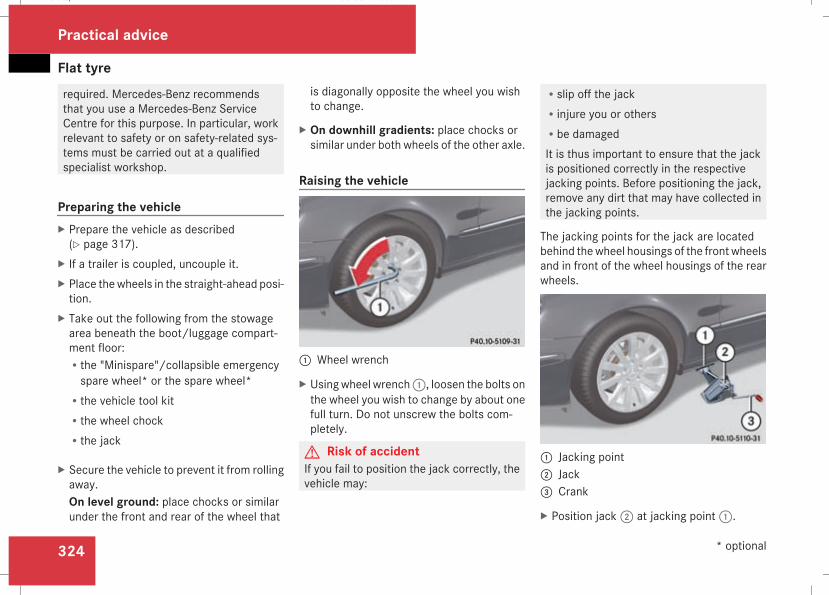
Flat tyre
324
required. Mercedes-Benz recommendsthat you use a Mercedes-Benz ServiceCentre for this purpose. In particular, workrelevant to safety or on safety-related sys-tems must be carried out at a qualifiedspecialist workshop.
Preparing the vehicleX Prepare the vehicle as described(Y page 317).
X If a trailer is coupled, uncouple it.X Place thewheels in the straight-ahead posi-tion.
X Take out the following from the stowagearea beneath the boot/luggage compart-ment floor:Rthe "Minispare"/collapsible emergencyspare wheel* or the spare wheel*
Rthe vehicle tool kitRthe wheel chockRthe jack
X Secure the vehicle to prevent it from rollingaway.On level ground: place chocks or similarunder the front and rear of the wheel that
is diagonally opposite the wheel you wishto change.
X On downhill gradients: place chocks orsimilar under both wheels of the other axle.
Raising the vehicle
1 Wheel wrench
X Usingwheel wrench1, loosen the bolts onthe wheel you wish to change by about onefull turn. Do not unscrew the bolts com-pletely.
G Risk of accidentIf you fail to position the jack correctly, thevehicle may:
Rslip off the jackRinjure you or othersRbe damagedIt is thus important to ensure that the jackis positioned correctly in the respectivejacking points. Before positioning the jack,remove any dirt that may have collected inthe jacking points.
The jacking points for the jack are locatedbehind thewheel housings of the front wheelsand in front of the wheel housings of the rearwheels.
1 Jacking point2 Jack3 Crank
X Position jack2 at jacking point1.
Practical advice
* optional
211_AKB; 2; 5, en-GBmkalafa, Version: 2.9.4
2008-02-29T16:57:07+01:00 - Seite 324
Dateiname: 6515_3416_02_buchblock.pdf; preflight
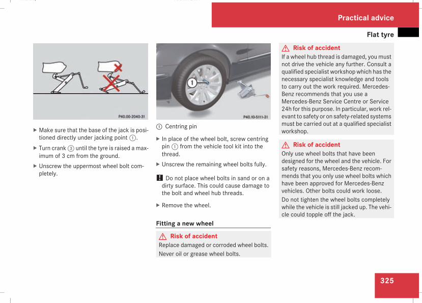
Flat tyre
325
X Make sure that the base of the jack is posi-tioned directly under jacking point1.
X Turn crank3 until the tyre is raised a max-imum of 3 cm from the ground.
X Unscrew the uppermost wheel bolt com-pletely.
1 Centring pin
X In place of the wheel bolt, screw centringpin1 from the vehicle tool kit into thethread.
X Unscrew the remaining wheel bolts fully.
! Do not place wheel bolts in sand or on adirty surface. This could cause damage tothe bolt and wheel hub threads.
X Remove the wheel.
Fitting a new wheel
G Risk of accidentReplace damaged or corroded wheel bolts.Never oil or grease wheel bolts.
G Risk of accidentIf a wheel hub thread is damaged, you mustnot drive the vehicle any further. Consult aqualified specialist workshopwhich has thenecessary specialist knowledge and toolsto carry out the work required. Mercedes-Benz recommends that you use aMercedes-Benz Service Centre or Service24h for this purpose. In particular, work rel-evant to safety or on safety-related systemsmust be carried out at a qualified specialistworkshop.
G Risk of accidentOnly use wheel bolts that have beendesigned for the wheel and the vehicle. Forsafety reasons, Mercedes-Benz recom-mends that you only use wheel bolts whichhave been approved for Mercedes-Benzvehicles. Other bolts could work loose.Do not tighten the wheel bolts completelywhile the vehicle is still jacked up. The vehi-cle could topple off the jack.
Practical advice
211_AKB; 2; 5, en-GBmkalafa, Version: 2.9.4
2008-02-29T16:57:07+01:00 - Seite 325
Z
Dateiname: 6515_3416_02_buchblock.pdf; preflight
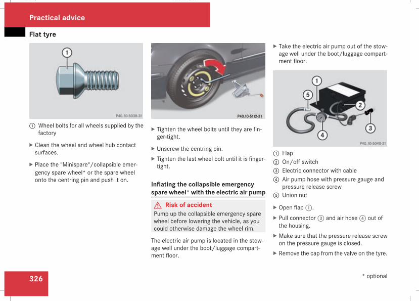
Flat tyre
326
1 Wheel bolts for all wheels supplied by thefactory
X Clean the wheel and wheel hub contactsurfaces.
X Place the "Minispare"/collapsible emer-gency spare wheel* or the spare wheelonto the centring pin and push it on.
X Tighten the wheel bolts until they are fin-ger-tight.
X Unscrew the centring pin.X Tighten the last wheel bolt until it is finger-tight.
Inflating the collapsible emergencyspare wheel* with the electric air pump
G Risk of accidentPump up the collapsible emergency sparewheel before lowering the vehicle, as youcould otherwise damage the wheel rim.
The electric air pump is located in the stow-age well under the boot/luggage compart-ment floor.
X Take the electric air pump out of the stow-age well under the boot/luggage compart-ment floor.
1 Flap2 On/off switch3 Electric connector with cable4 Air pump hose with pressure gauge and
pressure release screw5 Union nut
X Open flap1.X Pull connector3 and air hose4 out ofthe housing.
X Make sure that the pressure release screwon the pressure gauge is closed.
X Remove the cap from the valve on the tyre.
Practical advice
* optional
211_AKB; 2; 5, en-GBmkalafa, Version: 2.9.4
2008-02-29T16:57:07+01:00 - Seite 326
Dateiname: 6515_3416_02_buchblock.pdf; preflight
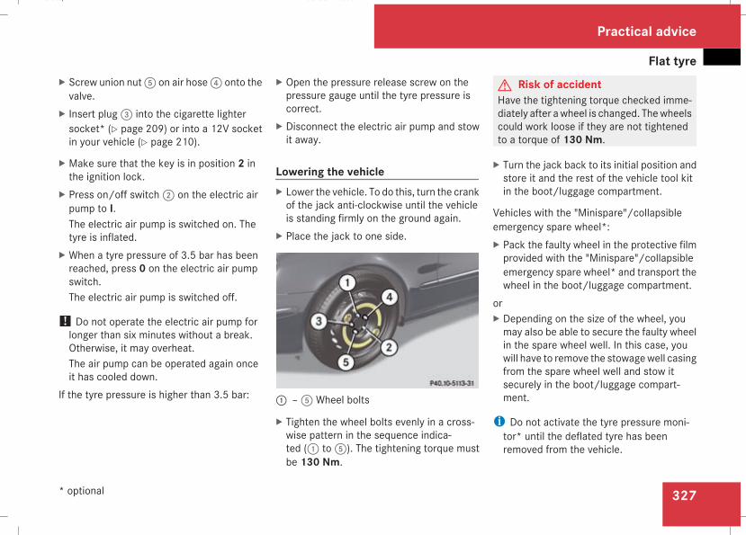
Flat tyre
327
X Screw union nut5 on air hose4 onto thevalve.
X Insert plug3 into the cigarette lightersocket* (Y page 209) or into a 12V socketin your vehicle (Y page 210).
X Make sure that the key is in position 2 inthe ignition lock.
X Press on/off switch2 on the electric airpump to I.The electric air pump is switched on. Thetyre is inflated.
X When a tyre pressure of 3.5 bar has beenreached, press 0 on the electric air pumpswitch.The electric air pump is switched off.
! Do not operate the electric air pump forlonger than six minutes without a break.Otherwise, it may overheat.The air pump can be operated again onceit has cooled down.
If the tyre pressure is higher than 3.5 bar:
X Open the pressure release screw on thepressure gauge until the tyre pressure iscorrect.
X Disconnect the electric air pump and stowit away.
Lowering the vehicleX Lower the vehicle. To do this, turn the crankof the jack anti-clockwise until the vehicleis standing firmly on the ground again.
X Place the jack to one side.
1 –5 Wheel bolts
X Tighten the wheel bolts evenly in a cross-wise pattern in the sequence indica-ted (1 to5). The tightening torque mustbe 130 Nm.
G Risk of accidentHave the tightening torque checked imme-diately after awheel is changed. Thewheelscould work loose if they are not tightenedto a torque of 130 Nm.
X Turn the jack back to its initial position andstore it and the rest of the vehicle tool kitin the boot/luggage compartment.
Vehicles with the "Minispare"/collapsibleemergency spare wheel*:X Pack the faulty wheel in the protective filmprovided with the "Minispare"/collapsibleemergency spare wheel* and transport thewheel in the boot/luggage compartment.
orX Depending on the size of the wheel, youmay also be able to secure the faulty wheelin the spare wheel well. In this case, youwill have to remove the stowagewell casingfrom the spare wheel well and stow itsecurely in the boot/luggage compart-ment.
i Do not activate the tyre pressure moni-tor* until the deflated tyre has beenremoved from the vehicle.
Practical advice
* optional
211_AKB; 2; 5, en-GBmkalafa, Version: 2.9.4
2008-02-29T16:57:07+01:00 - Seite 327
Z
Dateiname: 6515_3416_02_buchblock.pdf; preflight
Flat tyre
328
MOExtended run-flat system*The MOExtended run-flat system must onlybe used in conjunction with the tyre pressureloss warning system or the tyre pressuremonitor*.
! Themaximumpermissible distancewhichcan be driven in run-flat mode depends onthe load in the vehicle. It is 50 km if thevehicle is partially laden and 30 km if fullyladen.The maximum range that can be driven inemergency operation is measured from thepoint at which the pressure loss warningmessage appears in the multi-function dis-play.You must not exceed a maximum speed of80 km/h.
i Vehicles featuring the MOExtended run-flat system are not equipped with theTIREFIT kit*.It is therefore recommended to additionallyequip your vehicle with the TIREFIT kit*when fitting tyres that do not feature run-flat properties, e.g. winter tyres.
i A TIREFIT kit* is available from any quali-fied specialist workshop, e.g. a Mercedes-Benz Service Centre.
G Risk of accidentThe handling characteristics of your vehicledeteriorate in run-flat mode, for example:Rwhen corneringRwhen brakingRwhen accelerating rapidlyAdapt your driving style accordingly andavoid sudden changes in direction and sud-den acceleration, as well as driving overobstacles (i.e. kerbs, potholes), and drivingoff-road. This is particularly the case whenthe vehicle is heavily laden.The maximum permissible distance thatcan be driven in run-flat mode depends toa large extent on the loads placed on thevehicle. It can be shorter due to highspeeds, a heavy load, sudden accelerationand/or manoeuvring, the road surface con-dition, outside temperature, etc., or furtherif you drive carefully and conservatively.Do not continue to drive in run-flat mode if:Ryou hear banging noisesRthe vehicle starts to shake
Ryou see smoke and smell rubberRESP® is intervening constantlyRthere are tears in the sidewalls of the tyreAfter driving in run-flat mode, you musthave the rims checked for damage at aqualified specialist workshopwhich has thenecessary specialist knowledge and toolsto carry out the work required. The faultytyre must be replaced in every case.Mercedes-Benz recommends that you usea Mercedes-Benz Service Centre for thispurpose. In particular, work relevant tosafety or on safety-related systemsmust becarried out at a qualified specialist work-shop.
i On a vehicle with MOExtended tyres, onlyMOExtended spare tyres should be used.These must be of the size specified for thevehicle.
Practical advice
* optional
211_AKB; 2; 5, en-GBmkalafa, Version: 2.9.4
2008-02-29T16:57:07+01:00 - Seite 328
Dateiname: 6515_3416_02_buchblock.pdf; preflight
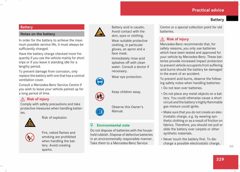
Battery
329
Battery
Notes on the batteryIn order for the battery to achieve the maxi-mum possible service life, it must always besufficiently charged.Have the battery charge checked more fre-quently if you use the vehicle mainly for shorttrips or if you leave it standing idle for alengthy period.To prevent damage from corrosion, onlyreplace the battery with one that has a centralventilation cover.Consult a Mercedes-Benz Service Centre ifyou wish to leave your vehicle parked up fora long period of time.G Risk of injuryComply with safety precautions and takeprotective measures when handling batter-ies.
Risk of explosion
Fire, naked flames andsmoking are prohibitedwhen handling the bat-tery. Avoid creatingsparks.
Battery acid is caustic.Avoid contact with theskin, eyes or clothing.Wear suitable protectiveclothing, in particulargloves, an apron and aface mask.Immediately rinse acidsplashes off with cleanwater. Consult a doctor ifnecessary.Wear eye protection.
Keep children away.
Observe this Owner'sManual.
H Environmental noteDo not dispose of batteries with the house-hold rubbish. Dispose of defective batteriesin an environmentally responsible manner.Take them to a Mercedes-Benz Service
Centre or a special collection point for oldbatteries.
G Risk of injuryMercedes-Benz recommends that, forsafety reasons, you only use batterieswhich have been tested and approved foryour vehicle by Mercedes-Benz. These bat-teries provide increased impact protectionto prevent vehicle occupants from sufferingacid burns should the battery be damagedin the event of an accident.To prevent acid burns, observe the follow-ing safety notes when handling batteries:RDo not lean over batteries.RDo not place any metal objects on a bat-tery. You could otherwise cause a shortcircuit and the battery's highly flammablegas mixture could ignite.
RMake sure that you do not create an elec-trostatic charge, e.g. by wearing syn-thetic clothing or as a result of friction onfabrics. Therefore, you should not pull orslide the battery over carpets or othersynthetic materials.
RNever touch the battery first. To dis-charge a possible electrostatic charge,
Practical advice
211_AKB; 2; 5, en-GBmkalafa, Version: 2.9.4
2008-02-29T16:57:07+01:00 - Seite 329
Z
Dateiname: 6515_3416_02_buchblock.pdf; preflight
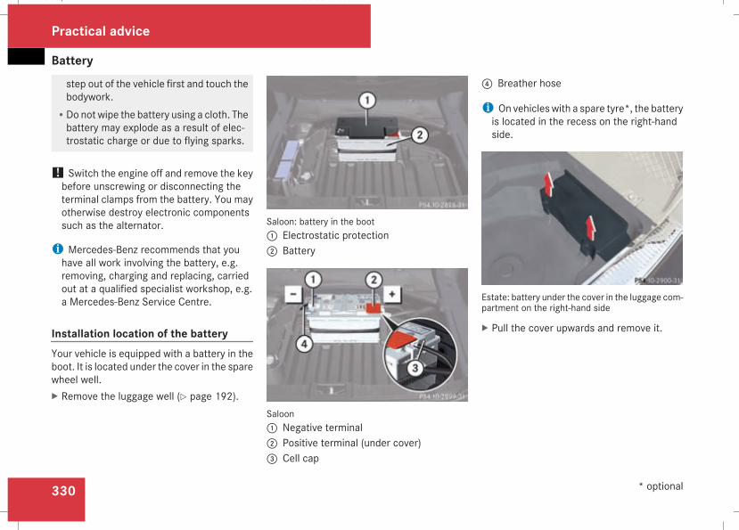
Battery
330
step out of the vehicle first and touch thebodywork.
RDo not wipe the battery using a cloth. Thebattery may explode as a result of elec-trostatic charge or due to flying sparks.
! Switch the engine off and remove the keybefore unscrewing or disconnecting theterminal clamps from the battery. You mayotherwise destroy electronic componentssuch as the alternator.
i Mercedes-Benz recommends that youhave all work involving the battery, e.g.removing, charging and replacing, carriedout at a qualified specialist workshop, e.g.a Mercedes-Benz Service Centre.
Installation location of the batteryYour vehicle is equipped with a battery in theboot. It is located under the cover in the sparewheel well.X Remove the luggage well (Y page 192).
Saloon: battery in the boot1 Electrostatic protection2 Battery
Saloon1 Negative terminal2 Positive terminal (under cover)3 Cell cap
4 Breather hose
i On vehicles with a spare tyre*, the batteryis located in the recess on the right-handside.
Estate: battery under the cover in the luggage com-partment on the right-hand side
X Pull the cover upwards and remove it.
Practical advice
* optional
211_AKB; 2; 5, en-GBmkalafa, Version: 2.9.4
2008-02-29T16:57:07+01:00 - Seite 330
Dateiname: 6515_3416_02_buchblock.pdf; preflight
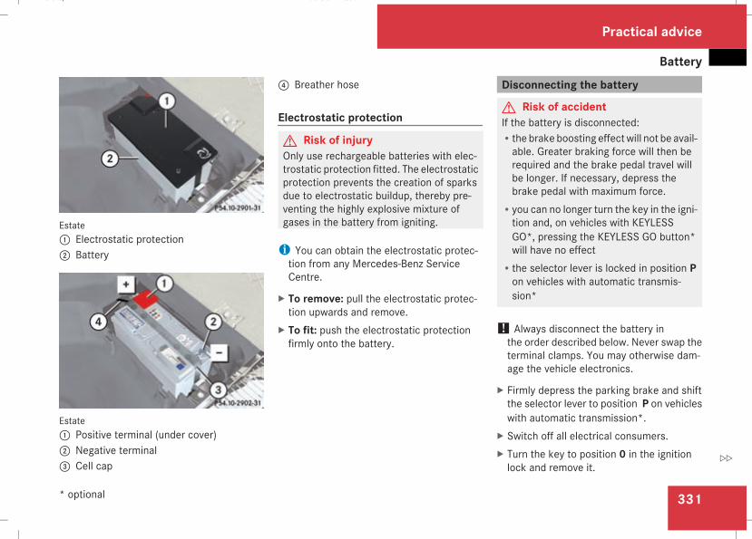
Battery
331
Estate1 Electrostatic protection2 Battery
Estate1 Positive terminal (under cover)2 Negative terminal3 Cell cap
4 Breather hose
Electrostatic protection
G Risk of injuryOnly use rechargeable batteries with elec-trostatic protection fitted. The electrostaticprotection prevents the creation of sparksdue to electrostatic buildup, thereby pre-venting the highly explosive mixture ofgases in the battery from igniting.
i You can obtain the electrostatic protec-tion from any Mercedes-Benz ServiceCentre.
X To remove: pull the electrostatic protec-tion upwards and remove.
X To fit: push the electrostatic protectionfirmly onto the battery.
Disconnecting the battery
G Risk of accidentIf the battery is disconnected:Rthe brake boosting effectwill not be avail-able. Greater braking force will then berequired and the brake pedal travel willbe longer. If necessary, depress thebrake pedal with maximum force.
Ryou can no longer turn the key in the igni-tion and, on vehicles with KEYLESSGO*, pressing the KEYLESS GO button*will have no effect
Rthe selector lever is locked in position Pon vehicles with automatic transmis-sion*
! Always disconnect the battery inthe order described below. Never swap theterminal clamps. You may otherwise dam-age the vehicle electronics.
X Firmly depress the parking brake and shiftthe selector lever to position P on vehicleswith automatic transmission*.
X Switch off all electrical consumers.X Turn the key to position 0 in the ignitionlock and remove it.
Practical advice
* optional
211_AKB; 2; 5, en-GBmkalafa, Version: 2.9.4
2008-02-29T16:57:07+01:00 - Seite 331
Z
Dateiname: 6515_3416_02_buchblock.pdf; preflight
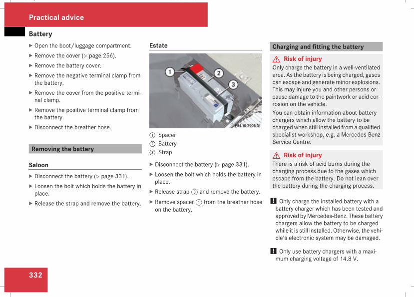
Battery
332
X Open the boot/luggage compartment.X Remove the cover (Y page 256).X Remove the battery cover.X Remove the negative terminal clamp fromthe battery.
X Remove the cover from the positive termi-nal clamp.
X Remove the positive terminal clamp fromthe battery.
X Disconnect the breather hose.
Removing the battery
SaloonX Disconnect the battery (Y page 331).X Loosen the bolt which holds the battery inplace.
X Release the strap and remove the battery.
Estate
1 Spacer2 Battery3 Strap
X Disconnect the battery (Y page 331).X Loosen the bolt which holds the battery inplace.
X Release strap3 and remove the battery.X Remove spacer1 from the breather hoseon the battery.
Charging and fitting the battery
G Risk of injuryOnly charge the battery in a well-ventilatedarea. As the battery is being charged, gasescan escape and generateminor explosions.This may injure you and other persons orcause damage to the paintwork or acid cor-rosion on the vehicle.You can obtain information about batterychargers which allow the battery to becharged when still installed from a qualifiedspecialist workshop, e.g. a Mercedes-BenzService Centre.
G Risk of injuryThere is a risk of acid burns during thecharging process due to the gases whichescape from the battery. Do not lean overthe battery during the charging process.
! Only charge the installed battery with abattery charger which has been tested andapproved byMercedes-Benz. These batterychargers allow the battery to be chargedwhile it is still installed. Otherwise, the vehi-cle's electronic system may be damaged.
! Only use battery chargers with a maxi-mum charging voltage of 14.8 V.
Practical advice
211_AKB; 2; 5, en-GBmkalafa, Version: 2.9.4
2008-02-29T16:57:07+01:00 - Seite 332
Dateiname: 6515_3416_02_buchblock.pdf; preflight
Jump-starting
333
X Charge the battery. Observe the notes inthe operating instructions for your batterycharger.
X Refit the charged battery.To do this, follow the steps described in"Removing the battery" (Y page 332) inreverse order.
! Do not fit refillable batteries without elec-trostatic protection. The electrostatic dis-charge could otherwise cause the batteryto explode. The battery acid released couldcause damage to your vehicle.
Further information on electrostatic protec-tion (Y page 331).G Risk of injuryBattery acid is caustic. Avoid contact withthe skin, eyes or clothing.
Reconnecting the battery! Always reconnect the battery in thesequence described below. Never swap theterminal clamps. You may otherwise dam-age the vehicle electronics.
X Switch off all electrical consumers.X Connect the positive terminal clamp andsecure the cover.
X Connect the negative terminal clamp.X Connect the breather hose. Make sure thata cell cap is fitted between the battery andthe breather hose.
X Refit the electrostatic protection if neces-sary (Y page 331).
i If the battery power supply has been inter-rupted (e.g. if it has been reconnected), youmust carry out the following tasks:RSet the time (Y page 135).RReset the sliding/tilting sunroof*(Y page 182).
RReset the function for folding the exteriormirrors in/out automatically* by foldingthe mirrors out once (Y page 91).
Jump-starting
Jump-starting your vehicleIf your vehicle's battery is discharged, theengine can be jump-started from anothervehicle or from an external battery using jumpleads.Observe the following points:RJump-starting may only be performed whenthe engine and catalytic converter are cold.
RDo not start the engine if the battery is fro-zen. Let the battery thaw first.
RJump-starting may only be performed frombatteries with a nominal voltage of 12 V.
ROnly use jump leads which are protectedagainst polarity reversal and which have asufficient cross-section and insulated ter-minal clamps.
i Jump leads which are protected againstpolarity reversal and further informationabout jump-starting can be obtained fromany Mercedes-Benz Service Centre.
! Avoid repeated and lengthy startingattempts.Never start the vehicle using a rapid batterycharger.
Practical advice
* optional
211_AKB; 2; 5, en-GBmkalafa, Version: 2.9.4
2008-02-29T16:57:07+01:00 - Seite 333
Z
Dateiname: 6515_3416_02_buchblock.pdf; preflight
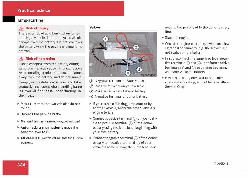
Jump-starting
334
G Risk of injuryThere is a risk of acid burns when jump-starting a vehicle due to the gases whichescape from the battery. Do not lean overthe battery while the engine is being jump-started.
G Risk of explosionGases escaping from the battery duringjump-starting may cause minor explosions.Avoid creating sparks. Keep naked flamesaway from the battery, and do not smoke.Comply with safety precautions and takeprotective measures when handling batter-ies. You will find these under “Battery” inthe index.
X Make sure that the two vehicles do nottouch.
X Depress the parking brake.
X Manual transmission: engage neutral.X Automatic transmission*: move theselector lever to P.
X All vehicles: switch off all electrical con-sumers.
Saloon
1 Negative terminal on your vehicle2 Positive terminal on your vehicle3 Positive terminal of donor battery4 Negative terminal of donor battery
X If your vehicle is being jump-started byanother vehicle, allow the other vehicle'sengine to idle.
X Connect positive terminal2 on your vehi-cle to positive terminal3 of the donorbattery using the jump lead, beginning withyour own battery.
X Connect negative terminal4 of the donorbattery to negative terminal1 of yourvehicle's battery using the jump lead, con-
necting the jump lead to the donor batteryfirst.
X Start the engine.X When the engine is running, switch on a fewelectrical consumers, e.g. the blower. Donot switch on the lights.
X First disconnect the jump lead from nega-tive terminals1 and4, then frompositiveterminals2 and3 each time beginningwith your vehicle's battery.
X Have the battery checked at a qualifiedspecialist workshop, e.g. a Mercedes-BenzService Centre.
Practical advice
* optional
211_AKB; 2; 5, en-GBmkalafa, Version: 2.9.4
2008-02-29T16:57:07+01:00 - Seite 334
Dateiname: 6515_3416_02_buchblock.pdf; preflight
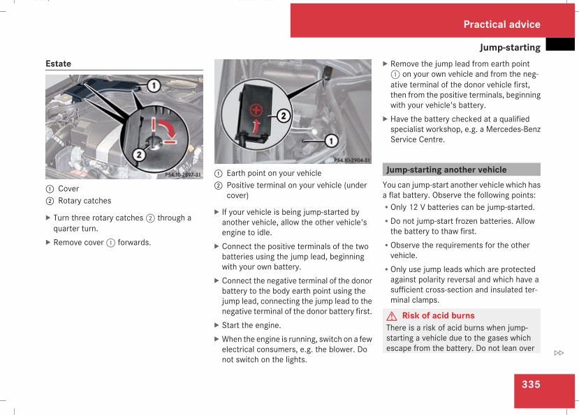
Jump-starting
335
Estate
1 Cover2 Rotary catches
X Turn three rotary catches2 through aquarter turn.
X Remove cover1 forwards.
1 Earth point on your vehicle2 Positive terminal on your vehicle (under
cover)
X If your vehicle is being jump-started byanother vehicle, allow the other vehicle'sengine to idle.
X Connect the positive terminals of the twobatteries using the jump lead, beginningwith your own battery.
X Connect the negative terminal of the donorbattery to the body earth point using thejump lead, connecting the jump lead to thenegative terminal of the donor battery first.
X Start the engine.X When the engine is running, switch on a fewelectrical consumers, e.g. the blower. Donot switch on the lights.
X Remove the jump lead from earth point1 on your own vehicle and from the neg-ative terminal of the donor vehicle first,then from the positive terminals, beginningwith your vehicle's battery.
X Have the battery checked at a qualifiedspecialist workshop, e.g. a Mercedes-BenzService Centre.
Jump-starting another vehicleYou can jump-start another vehicle which hasa flat battery. Observe the following points:ROnly 12 V batteries can be jump-started.RDo not jump-start frozen batteries. Allowthe battery to thaw first.
RObserve the requirements for the othervehicle.
ROnly use jump leads which are protectedagainst polarity reversal and which have asufficient cross-section and insulated ter-minal clamps.
G Risk of acid burnsThere is a risk of acid burns when jump-starting a vehicle due to the gases whichescape from the battery. Do not lean over
Practical advice
211_AKB; 2; 5, en-GBmkalafa, Version: 2.9.4
2008-02-29T16:57:07+01:00 - Seite 335
Z
Dateiname: 6515_3416_02_buchblock.pdf; preflight
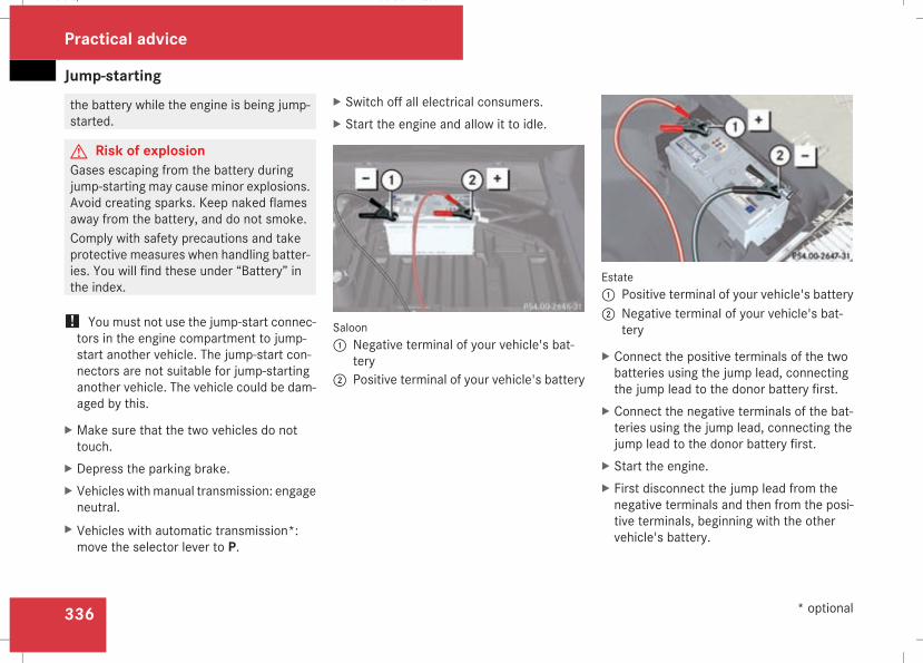
Jump-starting
336
the battery while the engine is being jump-started.
G Risk of explosionGases escaping from the battery duringjump-starting may cause minor explosions.Avoid creating sparks. Keep naked flamesaway from the battery, and do not smoke.Comply with safety precautions and takeprotective measures when handling batter-ies. You will find these under “Battery” inthe index.
! You must not use the jump-start connec-tors in the engine compartment to jump-start another vehicle. The jump-start con-nectors are not suitable for jump-startinganother vehicle. The vehicle could be dam-aged by this.
X Make sure that the two vehicles do nottouch.
X Depress the parking brake.X Vehicles withmanual transmission: engageneutral.
X Vehicles with automatic transmission*:move the selector lever to P.
X Switch off all electrical consumers.X Start the engine and allow it to idle.
Saloon1 Negative terminal of your vehicle's bat-
tery2 Positive terminal of your vehicle's battery
Estate1 Positive terminal of your vehicle's battery2 Negative terminal of your vehicle's bat-
tery
X Connect the positive terminals of the twobatteries using the jump lead, connectingthe jump lead to the donor battery first.
X Connect the negative terminals of the bat-teries using the jump lead, connecting thejump lead to the donor battery first.
X Start the engine.X First disconnect the jump lead from thenegative terminals and then from the posi-tive terminals, beginning with the othervehicle's battery.
Practical advice
* optional
211_AKB; 2; 5, en-GBmkalafa, Version: 2.9.4
2008-02-29T16:57:07+01:00 - Seite 336
Dateiname: 6515_3416_02_buchblock.pdf; preflight
Towing and tow-starting
337
Towing and tow-starting
Points to remember
G Risk of accidentIf you tow the vehicle, you must use a rigidtowing bar if:Rthe engine is not runningRthere is a brake system malfunctionRthe voltage supply or the vehicle's elec-trical system is damaged
The electric power steering and the brakeforce boosting effect do not work when theengine is not running. Greater braking forcewill then be required and the brake pedaltravel will be longer. If necessary, depressthe brake pedal with maximum force.Do not tow the vehicle if the key cannot beturned in the ignition lock. If this is the case,the steering is locked and the vehicle can-not be steered.If you tow or tow-start another vehicle, itsweight must not exceed the maximum per-missible gross vehicle weight of your vehi-cle.
G Risk of accidentThe vehicle is braked when HOLD is activa-ted. Therefore, deactivate HOLD if the vehi-cle is to be towed.If you tow or tow-start another vehicle, itsweight must not exceed the maximum per-missible gross vehicle weight of your vehi-cle.
It is better to have the vehicle transportedthan to have it towed.When towing, observe the legal requirementsin all countries concerned.
! When towing, pull away slowly and with-out jerking. If the tractive power is too high,the vehicles could be damaged. Do not usethe towing eye for recovery.
! You may tow the vehicle for a maximumof 50 km. A towing speed of 50 km/h mustnot be exceeded.With towing distances over 50 km, theentire vehicle needs to be lifted up andtransported.
! Only secure the tow cable or towing barto the towing eyes. You may otherwisedamage the vehicle.
RVehicles with an automatic transmission*must not be tow-started.
RIf the engine does not start, try jump start-ing (Y page 333).
RIf it is not possible to jump-start the vehicle,have it towed to the nearest qualified spe-cialist workshop, e.g. a Mercedes-BenzService Centre.
RIf the vehicle has suffered transmissiondamage, only tow it with the propeller shaftdisconnected.
RThe automatic transmission* selector levermust be in the N position when towing thevehicle away.
RIf you are towing the vehicle over a consid-erable distance, this must only be donewith the rear axle raised.
RThe ignition must be switched off if you aretowing the vehicle with the front/rear axleraised. Intervention by ESP® could other-wise damage the brake system.
RVehicles with 4MATIC* may not be towedwith the front or rear axle raised.
RBefore towing the vehicle, make sure thatthe battery is connected and charged. Oth-erwise:
Practical advice
* optional
211_AKB; 2; 5, en-GBmkalafa, Version: 2.9.4
2008-02-29T16:57:07+01:00 - Seite 337
Z
Dateiname: 6515_3416_02_buchblock.pdf; preflight
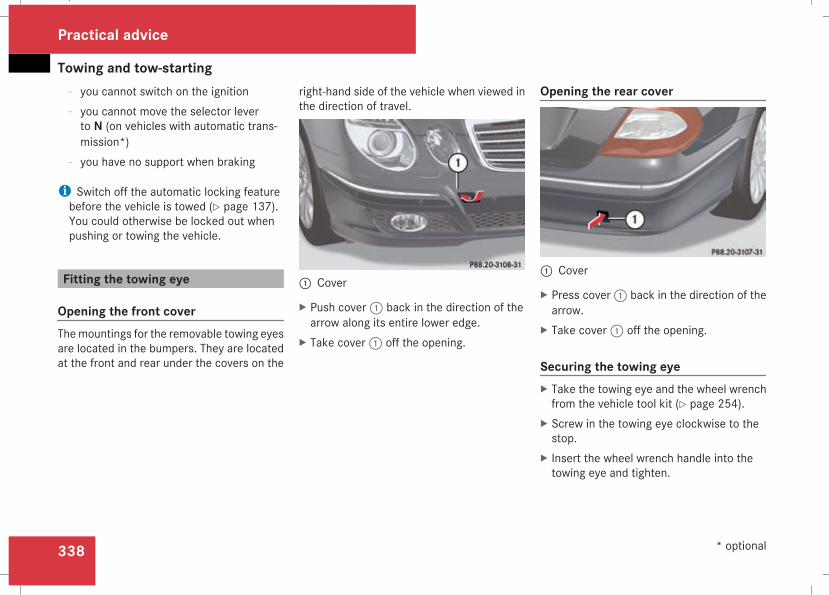
Towing and tow-starting
338
- you cannot switch on the ignition- you cannot move the selector leverto N (on vehicles with automatic trans-mission*)
- you have no support when braking
i Switch off the automatic locking featurebefore the vehicle is towed (Y page 137).You could otherwise be locked out whenpushing or towing the vehicle.
Fitting the towing eye
Opening the front coverThemountings for the removable towing eyesare located in the bumpers. They are locatedat the front and rear under the covers on the
right-hand side of the vehicle when viewed inthe direction of travel.
1 Cover
X Push cover1 back in the direction of thearrow along its entire lower edge.
X Take cover1 off the opening.
Opening the rear cover
1 Cover
X Press cover1 back in the direction of thearrow.
X Take cover1 off the opening.
Securing the towing eyeX Take the towing eye and the wheel wrenchfrom the vehicle tool kit (Y page 254).
X Screw in the towing eye clockwise to thestop.
X Insert the wheel wrench handle into thetowing eye and tighten.
Practical advice
* optional
211_AKB; 2; 5, en-GBmkalafa, Version: 2.9.4
2008-02-29T16:57:07+01:00 - Seite 338
Dateiname: 6515_3416_02_buchblock.pdf; preflight
Towing and tow-starting
339
Towing the vehicle! You may tow the vehicle for a maximumof 50 km. A towing speed of 50 km/h mustnot be exceeded.With towing distances over 50 km, theentire vehicle needs to be lifted up andtransported.
! Vehicles with 4MATIC* may not be towedwith the front or rear axle raised.
! The engine must be switched off (key inignition lock in position 0 or position 1) ifthe vehicle is being towedwith the rear axleraised or if the parking brake is being testedon a dynamometer. Intervention by ESP®could otherwise damage the brake system.
Vehicles with manual transmissionX Turn the key to position 2 in the ignitionlock.
X Shift to neutral.
Vehicles with automatic transmission*X Turn the key to position 2 in the ignitionlock.
X Move the selector lever to N.
Tow-starting (emergency enginestarting)Please note:RVehicles with an automatic transmission*must not be tow-started.
RThe battery must be connected.RThe engine and catalytic converter must becold.
RAvoid repeated and lengthy startingattempts.
Vehicles with manual transmissionX Turn the key to position 2 in the ignitionlock.
X Fully depress the clutch pedal.X Shift to neutral.
X Tow the vehicle or let it roll.X Shift to a suitable gear and bring the clutchpedal up slowly. Do not depress the accel-erator pedal.The engine is started.
Removing the towing eyeX Take the wheel wrench from the vehicletool kit (Y page 254).
X Insert the wheel wrench handle into thetowing eye and turn it anti-clockwise.
X Unscrew the towing eye.
X Replace the cover and press it until itengages.
X Return the towing eye and the wheelwrench to the vehicle tool kit.
Practical advice
* optional
211_AKB; 2; 5, en-GBmkalafa, Version: 2.9.4
2008-02-29T16:57:07+01:00 - Seite 339
Z
Dateiname: 6515_3416_02_buchblock.pdf; preflight
Fuses
340
Transporting the vehicleThe towing eyes can be used to pull the vehi-cle onto a trailer or transporter for transport-ing purposes.
! Only lash the vehicle down by the wheelsor wheel rims, not by parts of the vehiclesuch as axle or steering components. Thevehicle could otherwise be damaged.
Vehicles with manual transmissionX Shift to neutral.
Vehicles with automatic transmission*X Turn the key to position 2 in the ignitionlock.
X Move the selector lever to N.
Fuses
Notes on changing fusesThe fuses in your vehicle serve to close downfaulty circuits. If a fuse blows, all the compo-nents on the circuit and their functions willfail.Blown fuses must be replaced with fuses ofthe same rating, which you can recognise bythe colour and value. The fuse ratings are lis-ted in the fuse allocation chart. A Mercedes-Benz Service Centre will be happy to adviseyou.G Risk of fireOnly use fuses that have been approved forMercedes-Benz vehicles and which havethe correct fuse rating for the systems con-cerned. Do not attempt to repair or bridgefaulty fuses. Otherwise, a circuit overloadcould cause a fire. Have the cause tracedand rectified at a qualified specialist work-shop, e.g. aMercedes-Benz Service Centre.
If the newly inserted fuse also blows, have thecause traced and rectified at a qualified spe-cialist workshop, e.g. a Mercedes-BenzService Centre.
! Only use fuses that have been approvedfor Mercedes-Benz vehicles and whichhave the correct fuse rating for the systemconcerned. Otherwise, components or sys-tems could be damaged.
The fuses are located in various fuse boxes:RMain fuse box on the driver's side of thedashboard
RFuse box in the boot/luggage compart-ment on the left-hand side of the vehicle
Fuse allocation chartThe fuse allocation chart is in the main fusebox in the dashboard.
Before changing a fuseX Park the vehicle.X Switch off all electrical consumers.X Remove the key from the ignition lock.
Practical advice
* optional
211_AKB; 2; 5, en-GBmkalafa, Version: 2.9.4
2008-02-29T16:57:07+01:00 - Seite 340
Dateiname: 6515_3416_02_buchblock.pdf; preflight
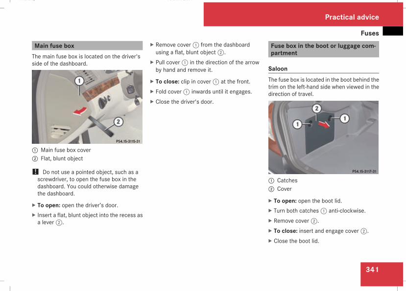
Fuses
341
Main fuse boxThe main fuse box is located on the driver'sside of the dashboard.
1 Main fuse box cover2 Flat, blunt object
! Do not use a pointed object, such as ascrewdriver, to open the fuse box in thedashboard. You could otherwise damagethe dashboard.
X To open: open the driver’s door.X Insert a flat, blunt object into the recess asa lever2.
X Remove cover1 from the dashboardusing a flat, blunt object2.
X Pull cover1 in the direction of the arrowby hand and remove it.
X To close: clip in cover1 at the front.X Fold cover1 inwards until it engages.X Close the driver's door.
Fuse box in the boot or luggage com-partment
SaloonThe fuse box is located in the boot behind thetrim on the left-hand side when viewed in thedirection of travel.
1 Catches2 Cover
X To open: open the boot lid.X Turn both catches1 anti-clockwise.X Remove cover2.X To close: insert and engage cover2.X Close the boot lid.
Practical advice
211_AKB; 2; 5, en-GBmkalafa, Version: 2.9.4
2008-02-29T16:57:07+01:00 - Seite 341
Z
Dateiname: 6515_3416_02_buchblock.pdf; preflight
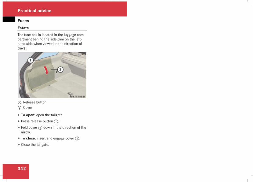
Fuses
342
EstateThe fuse box is located in the luggage com-partment behind the side trim on the left-hand side when viewed in the direction oftravel.
1 Release button2 Cover
X To open: open the tailgate.X Press release button1.X Fold cover2 down in the direction of thearrow.
X To close: insert and engage cover2.X Close the tailgate.
Practical advice
211_AKB; 2; 5, en-GBmkalafa, Version: 2.9.4
2008-02-29T16:57:07+01:00 - Seite 342
Dateiname: 6515_3416_02_buchblock.pdf; preflight
343
Introduction to technical data ......... 344Genuine Mercedes-Benz parts ......... 344Vehicle electronics ........................... 345Vehicle identification plates ............ 346Engine ................................................ 348Performance ...................................... 352Tyres and wheels .............................. 356Vehicle dimensions .......................... 366Vehicle weights ................................. 369Trailer coupling* ............................... 375Service products and capacities ..... 377Frequencies for garage door open-ers* .................................................... 391
Technical data
211_AKB; 2; 5, en-GBmkalafa, Version: 2.9.4
2008-02-29T16:57:07+01:00 - Seite 343
Dateiname: 6515_3416_02_buchblock.pdf; preflight
Genuine Mercedes-Benz parts
344
Introduction to technical data
i The technical data was determined inaccordance with EU directives. All dataapplies to the vehicle's standard equip-ment. The data may therefore differ forvehicles with optional equipment. You canobtain further information from aMercedes-Benz Service Centre.
Genuine Mercedes-Benz parts
Mercedes-Benz tests genuine parts and con-version parts and accessories which havebeen specifically approved for your vehicle fortheir reliability, safety and suitability. Despiteongoing market research, Mercedes-Benz isunable to evaluate other parts. Mercedes-Benz therefore accepts no responsibility forthe use of such parts in Mercedes-Benz vehi-cles, even if they have been independently orofficially approved.In Germany and someother countries, certainparts are only officially approved for installa-tion or modification if they comply with legalrequirements. All genuine Mercedes-Benzparts meet this requirement. The use of non-approved parts may invalidate the vehicle'sgeneral operating permit. This is the case if:Rthey cause a change of the vehicle typefrom that for which the vehicle's generaloperating permit was granted
Rother road users could be endangeredRthe emission or noise levels are adverselyaffected
The use of non-approved parts could affectyour vehicle's operating safety. Mercedes-Benz therefore recommends genuine
Mercedes-Benz parts and conversion partsand accessories that have been approved foryour vehicle.H Environmental noteDaimler also supplies reconditionedassemblies and parts which are of the samequality as new parts and to which the samewarranty applies.
Genuine Mercedes-Benz parts and approvedconversion parts and accessories are availa-ble from Mercedes-Benz Service Centres.There, you can also receive advice about tech-nical modifications and have the parts pro-fessionally fitted.Always quote the vehicle identification num-ber and the engine number when orderinggenuine parts. You will find these numbers onthe vehicle data card in the Service Bookletor on your vehicle's identification plates(Y page 346).
Technical data
211_AKB; 2; 5, en-GBmkalafa, Version: 2.9.4
2008-02-29T16:57:07+01:00 - Seite 344
Dateiname: 6515_3416_02_buchblock.pdf; preflight
Vehicle electronics
345
Vehicle electronics
Tampering with the engine electron-ics
G Risk of accidentOnly have work on the engine electronicsand related components carried out at aqualified specialist workshopwhich has thenecessary specialist knowledge and toolsto carry out the work required. Mercedes-Benz recommends that you use aMercedes-Benz Service Centre for this pur-pose. In particular, work relevant to safetyor on safety-related systems must be car-ried out at a qualified specialist workshop.The vehicle's roadworthiness could other-wise be affected.
! Only have work done on the engine elec-tronics and its associated parts, such ascontrol units, sensors and connector leads,carried out at a qualified specialist work-shop, e.g. a Mercedes-Benz ServiceCentre. Otherwise, vehicle componentsmay wear more quickly and your vehicle'swarranty and operating permitmay be inva-lidated.
Retrofitting electrical and electronicequipmentElectrical and electronic equipment can jeop-ardise the operating safety of your vehicle. Ifequipment of this kind is retrofitted, it mustbe type-approved and bear the e mark. Thee mark may be obtained from the equipmentmanufacturer or an authorised testing centre.
! Damage or consequential damage arisingfrom fitting equipment not approvedby Mercedes-Benz is not covered by theMercedes-Benz warranty.
If you wish to install two-way radios in thevehicle, you must obtain formal approval.Mercedes-Benz approves the installation oftwo-way radios if such equipment is installedprofessionally and a low-reflection exterioraerial is used.The transmission output of the two-way radiomust not exceed the maximum transmissionoutputs listed.G Risk of accidentTwo-way radios may interfere with the vehi-cle electronics and thereby jeopardise theoperational safety of the vehicle and yourown safety if:
Rthey do not have an exterior aerialRthe exterior aerial is not a low-reflectionaerial
Rthe exterior aerial has been fitted incor-rectly
G Risk of injuryExcessive electromagnetic radiation mayalso cause damage to your health and thehealth of others. Using an exterior aerialtakes into account current scientific dis-cussions relating to the possible health haz-ards that may result from electromagneticfields.For this reason, only have the exterior aerialfitted at a qualified specialist workshopwhich has the necessary specialist knowl-edge and tools to carry out the workrequired. Mercedes-Benz recommendsthat you use a Mercedes-Benz ServiceCentre for this purpose. In particular, workrelevant to safety or on safety-related sys-tems must be carried out at a qualifiedspecialist workshop.
i Mercedes-Benz recommends the use ofan approved exterior aerial. This ensuresoptimal reception quality for mobile tele-
Technical data
211_AKB; 2; 5, en-GBmkalafa, Version: 2.9.4
2008-02-29T16:57:07+01:00 - Seite 345
Z
Dateiname: 6515_3416_02_buchblock.pdf; preflight
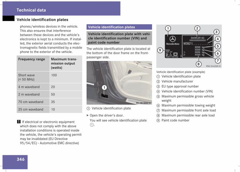
Vehicle identification plates
346
phones/wireless devices in the vehicle.This also ensures that interferencebetween these devices and the vehicle'selectronics is kept to a minimum. If instal-led, the exterior aerial conducts the elec-tromagnetic fields transmitted by a mobilephone to the exterior of the vehicle.
Frequency range Maximum trans-mission output(watts)
Short wave(< 50 MHz)
100
4 m waveband 20
2 m waveband 50
70 cm waveband 35
25 cm waveband 10
! If electrical or electronic equipmentwhich does not comply with the aboveinstallation conditions is operated insidethe vehicle, the vehicle's operating permitmay be invalidated (EU Directive95/54/EC) - Automotive EMC directive)
Vehicle identification plates
Vehicle identification plate with vehi-cle identification number (VIN) andpaint code numberThe vehicle identification plate is located atthe bottom of the door frame on the front-passenger side.
1 Vehicle identification plate
X Open the driver's door.You will see vehicle identification plate1.
Vehicle identification plate (example)1 Vehicle identification plate2 Vehicle manufacturer3 EU type approval number4 Vehicle identification number (VIN)5 Maximum permissible gross vehicle
weight6 Maximum permissible towing weight7 Maximum permissible front axle load8 Maximum permissible rear axle load9 Paint code number
Technical data
211_AKB; 2; 5, en-GBmkalafa, Version: 2.9.4
2008-02-29T16:57:07+01:00 - Seite 346
Dateiname: 6515_3416_02_buchblock.pdf; preflight
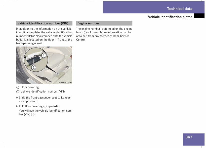
Vehicle identification plates
347
Vehicle identification number (VIN)In addition to the information on the vehicleidentification plate, the vehicle identificationnumber (VIN) is also stamped onto the vehiclebody. It is located on the floor in front of thefront-passenger seat.
1 Floor covering2 Vehicle identification number (VIN)
X Slide the front-passenger seat to its rear-most position.
X Fold floor covering1 upwards.You will see the vehicle identification num-ber (VIN)2.
Engine numberThe engine number is stamped on the engineblock (crankcase). More information can beobtained from any Mercedes-Benz ServiceCentre.
Technical data
211_AKB; 2; 5, en-GBmkalafa, Version: 2.9.4
2008-02-29T16:57:07+01:00 - Seite 347
Z
Dateiname: 6515_3416_02_buchblock.pdf; preflight
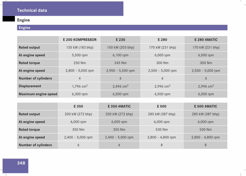
Engine
348
Engine
E 200 KOMPRESSOR E 230 E 280 E 280 4MATIC
Rated output 135 kW (183 bhp) 150 kW (203 bhp) 170 kW (231 bhp) 170 kW (231 bhp)
At engine speed 5,500 rpm 6,100 rpm 6,000 rpm 6,000 rpm
Rated torque 250 Nm 245 Nm 300 Nm 300 Nm
At engine speed 2,800 – 5,000 rpm 2,900 – 5,500 rpm 2,500 – 5,000 rpm 2,500 – 5,000 rpm
Number of cylinders 4 6 6 6
Displacement 1,796 cm3 2,496 cm3 2,996 cm3 2,996 cm3
Maximum engine speed 6,300 rpm 6,500 rpm 6,500 rpm 6,500 rpm
E 350 E 350 4MATIC E 500 E 500 4MATIC
Rated output 200 kW (272 bhp) 200 kW (272 bhp) 285 kW (387 bhp) 285 kW (387 bhp)
At engine speed 6,000 rpm 6,000 rpm 6,000 rpm 6,000 rpm
Rated torque 350 Nm 350 Nm 530 Nm 530 Nm
At engine speed 2,400 – 5,000 rpm 2,400 – 5,000 rpm 2,800 – 4,800 rpm 2,800 – 4,800 rpm
Number of cylinders 6 6 8 8
Technical data
211_AKB; 2; 5, en-GBmkalafa, Version: 2.9.4
2008-02-29T16:57:07+01:00 - Seite 348
Dateiname: 6515_3416_02_buchblock.pdf; preflight
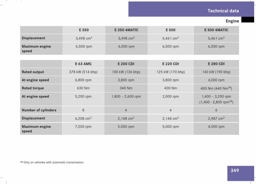
Engine
349
E 350 E 350 4MATIC E 500 E 500 4MATIC
Displacement 3,498 cm3 3,498 cm3 5,461 cm3 5,461 cm3
Maximum enginespeed
6,500 rpm 6,500 rpm 6,500 rpm 6,500 rpm
E 63 AMG E 200 CDI E 220 CDI E 280 CDI
Rated output 378 kW (514 bhp) 100 kW (136 bhp) 125 kW (170 bhp) 140 kW (190 bhp)
At engine speed 6,800 rpm 3,800 rpm 3,800 rpm 4,000 rpm
Rated torque 630 Nm 340 Nm 400 Nm 400 Nm (440 Nm38)
At engine speed 5,200 rpm 1,800 – 2,600 rpm 2,000 rpm 1,400 – 3,200 rpm(1,400 - 2,800 rpm38)
Number of cylinders 8 4 4 6
Displacement 6,208 cm3 2,148 cm3 2,148 cm3 2,987 cm3
Maximum enginespeed
7,200 rpm 5,000 rpm 5,000 rpm 4,500 rpm
38 Only on vehicles with automatic transmission.
Technical data
211_AKB; 2; 5, en-GBmkalafa, Version: 2.9.4
2008-02-29T16:57:07+01:00 - Seite 349
Z
Dateiname: 6515_3416_02_buchblock.pdf; preflight
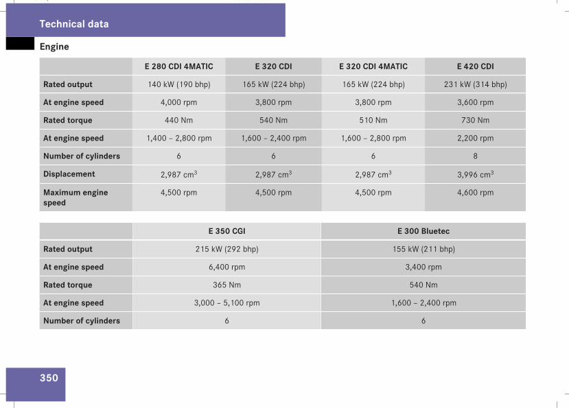
Engine
350
E 280 CDI 4MATIC E 320 CDI E 320 CDI 4MATIC E 420 CDI
Rated output 140 kW (190 bhp) 165 kW (224 bhp) 165 kW (224 bhp) 231 kW (314 bhp)
At engine speed 4,000 rpm 3,800 rpm 3,800 rpm 3,600 rpm
Rated torque 440 Nm 540 Nm 510 Nm 730 Nm
At engine speed 1,400 – 2,800 rpm 1,600 – 2,400 rpm 1,600 – 2,800 rpm 2,200 rpm
Number of cylinders 6 6 6 8
Displacement 2,987 cm3 2,987 cm3 2,987 cm3 3,996 cm3
Maximum enginespeed
4,500 rpm 4,500 rpm 4,500 rpm 4,600 rpm
E 350 CGI E 300 Bluetec
Rated output 215 kW (292 bhp) 155 kW (211 bhp)
At engine speed 6,400 rpm 3,400 rpm
Rated torque 365 Nm 540 Nm
At engine speed 3,000 – 5,100 rpm 1,600 – 2,400 rpm
Number of cylinders 6 6
Technical data
211_AKB; 2; 5, en-GBmkalafa, Version: 2.9.4
2008-02-29T16:57:07+01:00 - Seite 350
Dateiname: 6515_3416_02_buchblock.pdf; preflight
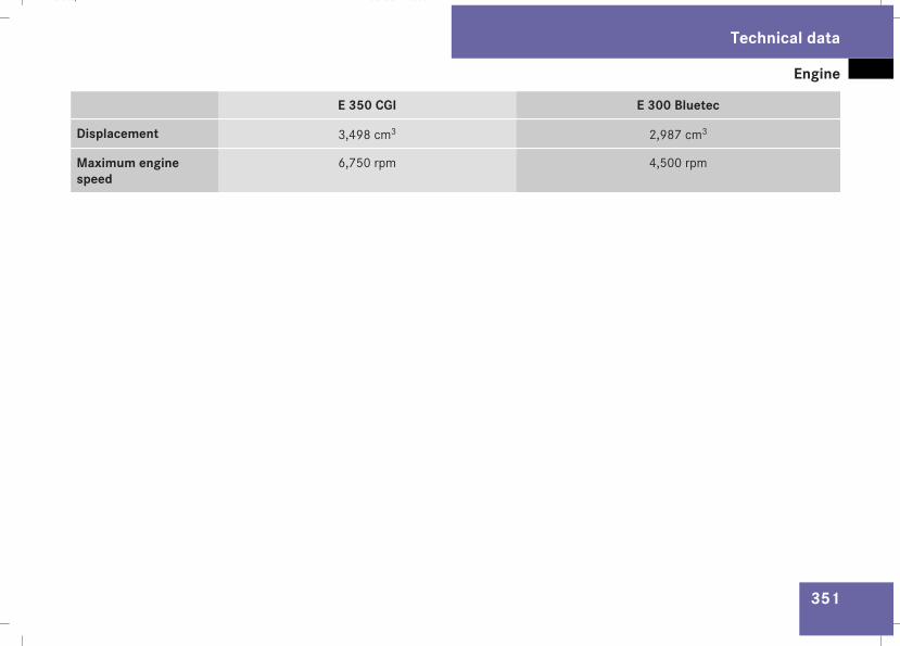
Engine
351
E 350 CGI E 300 Bluetec
Displacement 3,498 cm3 2,987 cm3
Maximum enginespeed
6,750 rpm 4,500 rpm
Technical data
211_AKB; 2; 5, en-GBmkalafa, Version: 2.9.4
2008-02-29T16:57:07+01:00 - Seite 351
Z
Dateiname: 6515_3416_02_buchblock.pdf; preflight
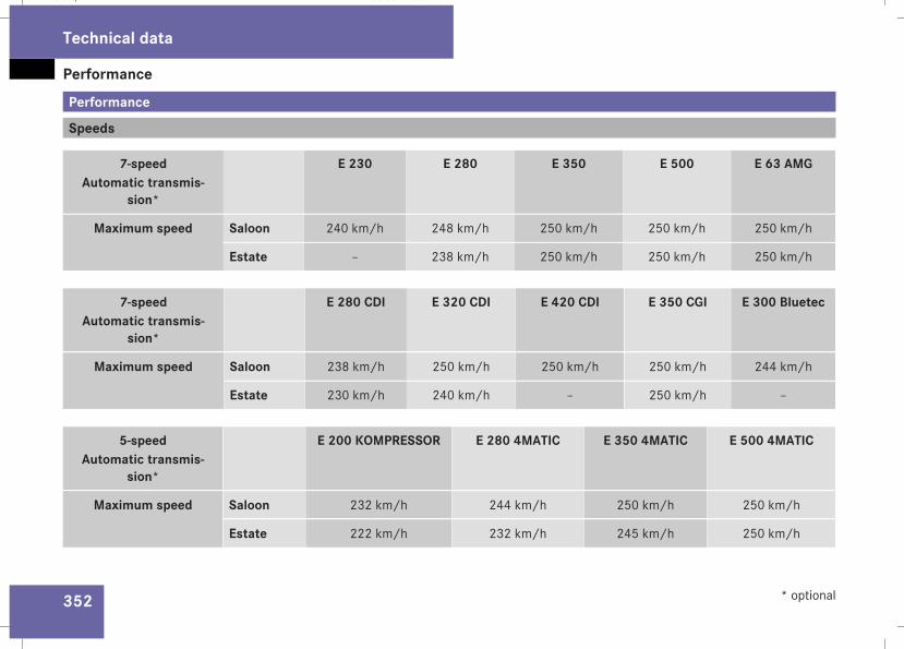
Performance
352
Performance
Speeds
7-speedAutomatic transmis-
sion*
E 230 E 280 E 350 E 500 E 63 AMG
Maximum speed Saloon 240 km/h 248 km/h 250 km/h 250 km/h 250 km/h
Estate – 238 km/h 250 km/h 250 km/h 250 km/h
7-speedAutomatic transmis-
sion*
E 280 CDI E 320 CDI E 420 CDI E 350 CGI E 300 Bluetec
Maximum speed Saloon 238 km/h 250 km/h 250 km/h 250 km/h 244 km/h
Estate 230 km/h 240 km/h – 250 km/h –
5-speedAutomatic transmis-
sion*
E 200 KOMPRESSOR E 280 4MATIC E 350 4MATIC E 500 4MATIC
Maximum speed Saloon 232 km/h 244 km/h 250 km/h 250 km/h
Estate 222 km/h 232 km/h 245 km/h 250 km/h
Technical data
* optional
211_AKB; 2; 5, en-GBmkalafa, Version: 2.9.4
2008-02-29T16:57:07+01:00 - Seite 352
Dateiname: 6515_3416_02_buchblock.pdf; preflight
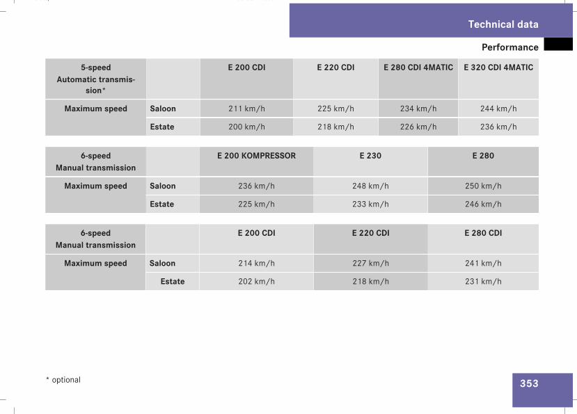
Performance
353
5-speedAutomatic transmis-
sion*
E 200 CDI E 220 CDI E 280 CDI 4MATIC E 320 CDI 4MATIC
Maximum speed Saloon 211 km/h 225 km/h 234 km/h 244 km/h
Estate 200 km/h 218 km/h 226 km/h 236 km/h
6-speedManual transmission
E 200 KOMPRESSOR E 230 E 280
Maximum speed Saloon 236 km/h 248 km/h 250 km/h
Estate 225 km/h 233 km/h 246 km/h
6-speedManual transmission
E 200 CDI E 220 CDI E 280 CDI
Maximum speed Saloon 214 km/h 227 km/h 241 km/h
Estate 202 km/h 218 km/h 231 km/h
Technical data
* optional
211_AKB; 2; 5, en-GBmkalafa, Version: 2.9.4
2008-02-29T16:57:07+01:00 - Seite 353
Z
Dateiname: 6515_3416_02_buchblock.pdf; preflight
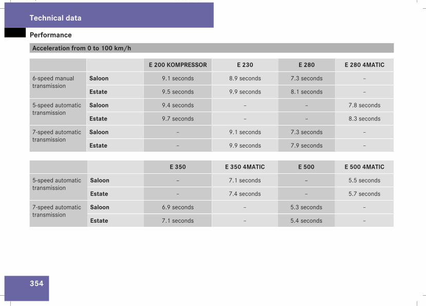
Performance
354
Acceleration from 0 to 100 km/h
E 200 KOMPRESSOR E 230 E 280 E 280 4MATIC
6-speed manualtransmission
Saloon 9.1 seconds 8.9 seconds 7.3 seconds –
Estate 9.5 seconds 9.9 seconds 8.1 seconds –
5-speed automatictransmission
Saloon 9.4 seconds – – 7.8 seconds
Estate 9.7 seconds – – 8.3 seconds
7-speed automatictransmission
Saloon – 9.1 seconds 7.3 seconds –
Estate – 9.9 seconds 7.9 seconds –
E 350 E 350 4MATIC E 500 E 500 4MATIC
5-speed automatictransmission
Saloon – 7.1 seconds – 5.5 seconds
Estate – 7.4 seconds – 5.7 seconds
7-speed automatictransmission
Saloon 6.9 seconds – 5.3 seconds –
Estate 7.1 seconds – 5.4 seconds –
Technical data
211_AKB; 2; 5, en-GBmkalafa, Version: 2.9.4
2008-02-29T16:57:07+01:00 - Seite 354
Dateiname: 6515_3416_02_buchblock.pdf; preflight
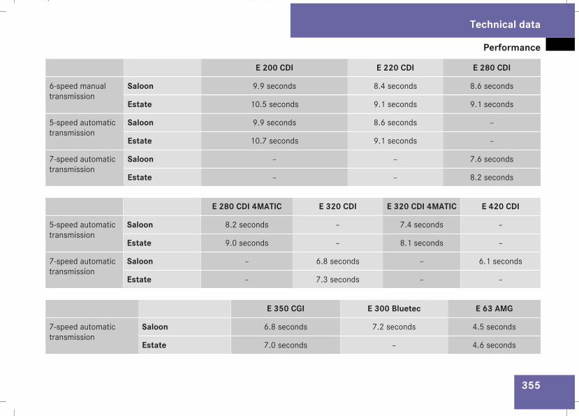
Performance
355
E 200 CDI E 220 CDI E 280 CDI
6-speed manualtransmission
Saloon 9.9 seconds 8.4 seconds 8.6 seconds
Estate 10.5 seconds 9.1 seconds 9.1 seconds
5-speed automatictransmission
Saloon 9.9 seconds 8.6 seconds –
Estate 10.7 seconds 9.1 seconds –
7-speed automatictransmission
Saloon – – 7.6 seconds
Estate – – 8.2 seconds
E 280 CDI 4MATIC E 320 CDI E 320 CDI 4MATIC E 420 CDI
5-speed automatictransmission
Saloon 8.2 seconds – 7.4 seconds –
Estate 9.0 seconds – 8.1 seconds –
7-speed automatictransmission
Saloon – 6.8 seconds – 6.1 seconds
Estate – 7.3 seconds – –
E 350 CGI E 300 Bluetec E 63 AMG
7-speed automatictransmission
Saloon 6.8 seconds 7.2 seconds 4.5 seconds
Estate 7.0 seconds – 4.6 seconds
Technical data
211_AKB; 2; 5, en-GBmkalafa, Version: 2.9.4
2008-02-29T16:57:07+01:00 - Seite 355
Z
Dateiname: 6515_3416_02_buchblock.pdf; preflight
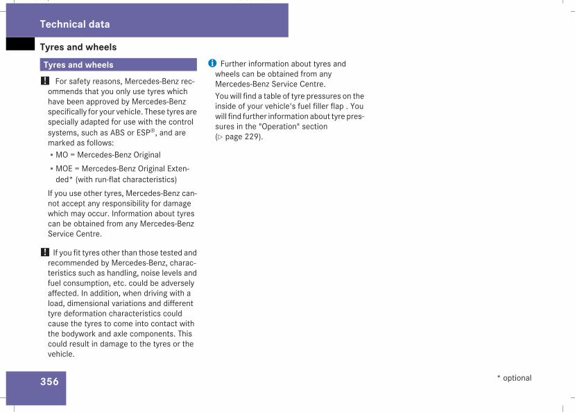
Tyres and wheels
356
Tyres and wheels! For safety reasons, Mercedes-Benz rec-ommends that you only use tyres whichhave been approved by Mercedes-Benzspecifically for your vehicle. These tyres arespecially adapted for use with the controlsystems, such as ABS or ESP®, and aremarked as follows:RMO = Mercedes-Benz OriginalRMOE = Mercedes-Benz Original Exten-ded* (with run-flat characteristics)
If you use other tyres, Mercedes-Benz can-not accept any responsibility for damagewhich may occur. Information about tyrescan be obtained from any Mercedes-BenzService Centre.
! If you fit tyres other than those tested andrecommended by Mercedes-Benz, charac-teristics such as handling, noise levels andfuel consumption, etc. could be adverselyaffected. In addition, when driving with aload, dimensional variations and differenttyre deformation characteristics couldcause the tyres to come into contact withthe bodywork and axle components. Thiscould result in damage to the tyres or thevehicle.
i Further information about tyres andwheels can be obtained from anyMercedes-Benz Service Centre.You will find a table of tyre pressures on theinside of your vehicle's fuel filler flap . Youwill find further information about tyre pres-sures in the "Operation" section(Y page 229).
Technical data
* optional
211_AKB; 2; 5, en-GBmkalafa, Version: 2.9.4
2008-02-29T16:57:07+01:00 - Seite 356
Dateiname: 6515_3416_02_buchblock.pdf; preflight
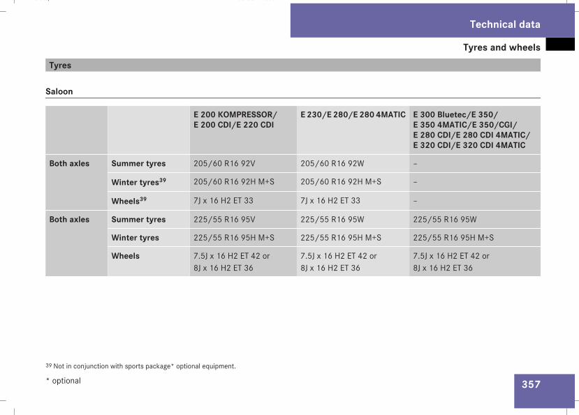
Tyres and wheels
357
Tyres
Saloon
E 200 KOMPRESSOR/E 200 CDI/E 220 CDI
E 230/E 280/E 280 4MATIC E 300 Bluetec/E 350/E 350 4MATIC/E 350/CGI/E 280 CDI/E 280 CDI 4MATIC/E 320 CDI/E 320 CDI 4MATIC
Both axles Summer tyres 205/60 R16 92V 205/60 R16 92W –
Winter tyres39 205/60 R16 92H M+S 205/60 R16 92H M+S –
Wheels39 7J x 16 H2 ET 33 7J x 16 H2 ET 33 –
Both axles Summer tyres 225/55 R16 95V 225/55 R16 95W 225/55 R16 95W
Winter tyres 225/55 R16 95H M+S 225/55 R16 95H M+S 225/55 R16 95H M+S
Wheels 7.5J x 16 H2 ET 42 or8J x 16 H2 ET 36
7.5J x 16 H2 ET 42 or8J x 16 H2 ET 36
7.5J x 16 H2 ET 42 or8J x 16 H2 ET 36
39 Not in conjunction with sports package* optional equipment.
Technical data
* optional
211_AKB; 2; 5, en-GBmkalafa, Version: 2.9.4
2008-02-29T16:57:07+01:00 - Seite 357
Z
Dateiname: 6515_3416_02_buchblock.pdf; preflight
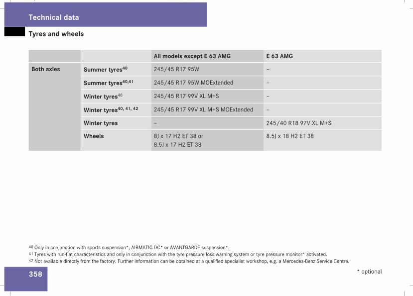
Tyres and wheels
358
All models except E 63 AMG E 63 AMG
Both axles Summer tyres40 245/45 R17 95W –
Summer tyres40,41 245/45 R17 95W MOExtended –
Winter tyres40 245/45 R17 99V XL M+S –
Winter tyres40, 41, 42 245/45 R17 99V XL M+S MOExtended –
Winter tyres – 245/40 R18 97V XL M+S
Wheels 8J x 17 H2 ET 38 or8.5J x 17 H2 ET 38
8.5J x 18 H2 ET 38
40 Only in conjunction with sports suspension*, AIRMATIC DC* or AVANTGARDE suspension*.41 Tyres with run-flat characteristics and only in conjunction with the tyre pressure loss warning system or tyre pressure monitor* activated.42 Not available directly from the factory. Further information can be obtained at a qualified specialist workshop, e.g. a Mercedes-Benz Service Centre.
Technical data
* optional
211_AKB; 2; 5, en-GBmkalafa, Version: 2.9.4
2008-02-29T16:57:07+01:00 - Seite 358
Dateiname: 6515_3416_02_buchblock.pdf; preflight
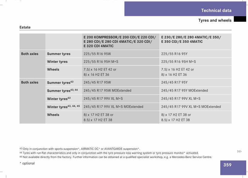
Tyres and wheels
359
Estate
E 200 KOMPRESSOR/E 200 CDI/E 220 CDI/E 280 CDI/E 280 CDI 4MATIC/E 320 CDI/E 320 CDI 4MATIC
E 230/E 280/E 280 4MATIC/E 350/E 350 CGI/E 350 4MATIC
Both axles Summer tyres 225/55 R16 95W 225/55 R16 95Y
Winter tyres 225/55 R16 95H M+S 225/55 R16 95H M+S
Wheels 7.5J x 16 H2 ET 42 or8J x 16 H2 ET 36
7.5J x 16 H2 ET 42 or8J x 16 H2 ET 36
Both axles Summer tyres43 245/45 R17 95W 245/45 R17 95Y
Summer tyres43, 44 245/45 R17 95W MOExtended 245/45 R17 95Y MOExtended
Winter tyres43 245/45 R17 99V XL M+S 245/45 R17 99V XL M+S
Winter tyres43, 44, 45 245/45 R17 99V XL M+S MOExtended 245/45 R17 99V XL M+S MOExtended
Wheels 8J x 17 H2 ET 38 or8.5J x 17 H2 ET 38
8J x 17 H2 ET 38 or8.5J x 17 H2 ET 38
43 Only in conjunction with sports suspension*, AIRMATIC DC* or AVANTGARDE suspension*.44 Tyres with run-flat characteristics and only in conjunction with the tyre pressure loss warning system or tyre pressure monitor* activated.45 Not available directly from the factory. Further information can be obtained at a qualified specialist workshop, e.g. a Mercedes-Benz Service Centre.
Technical data
* optional
211_AKB; 2; 5, en-GBmkalafa, Version: 2.9.4
2008-02-29T16:57:07+01:00 - Seite 359
Z
Dateiname: 6515_3416_02_buchblock.pdf; preflight
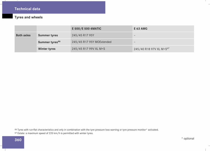
Tyres and wheels
360
E 500/E 500 4MATIC E 63 AMG
Both axles Summer tyres 245/45 R17 95Y –
Summer tyres46 245/45 R17 95Y MOExtended –
Winter tyres 245/45 R17 99V XL M+S 245/40 R18 97V XL M+S47
46 Tyres with run-flat characteristics and only in combination with the tyre pressure loss warning or tyre pressure monitor* activated.47 Estate: a maximum speed of 220 km/h is permitted with winter tyres.
Technical data
* optional
211_AKB; 2; 5, en-GBmkalafa, Version: 2.9.4
2008-02-29T16:57:07+01:00 - Seite 360
Dateiname: 6515_3416_02_buchblock.pdf; preflight
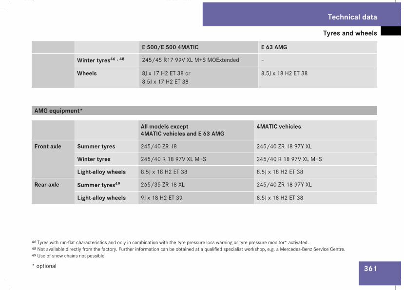
Tyres and wheels
361
E 500/E 500 4MATIC E 63 AMG
Winter tyres46 , 48 245/45 R17 99V XL M+S MOExtended –
Wheels 8J x 17 H2 ET 38 or8.5J x 17 H2 ET 38
8.5J x 18 H2 ET 38
AMG equipment*
All models except4MATIC vehicles and E 63 AMG
4MATIC vehicles
Front axle Summer tyres 245/40 ZR 18 245/40 ZR 18 97Y XL
Winter tyres 245/40 R 18 97V XL M+S 245/40 R 18 97V XL M+S
Light-alloy wheels 8.5J x 18 H2 ET 38 8.5J x 18 H2 ET 38
Rear axle Summer tyres49 265/35 ZR 18 XL 245/40 ZR 18 97Y XL
Light-alloy wheels 9J x 18 H2 ET 39 8.5J x 18 H2 ET 38
46 Tyres with run-flat characteristics and only in combination with the tyre pressure loss warning or tyre pressure monitor* activated.48 Not available directly from the factory. Further information can be obtained at a qualified specialist workshop, e.g. a Mercedes-Benz Service Centre.49 Use of snow chains not possible.
Technical data
* optional
211_AKB; 2; 5, en-GBmkalafa, Version: 2.9.4
2008-02-29T16:57:07+01:00 - Seite 361
Z
Dateiname: 6515_3416_02_buchblock.pdf; preflight
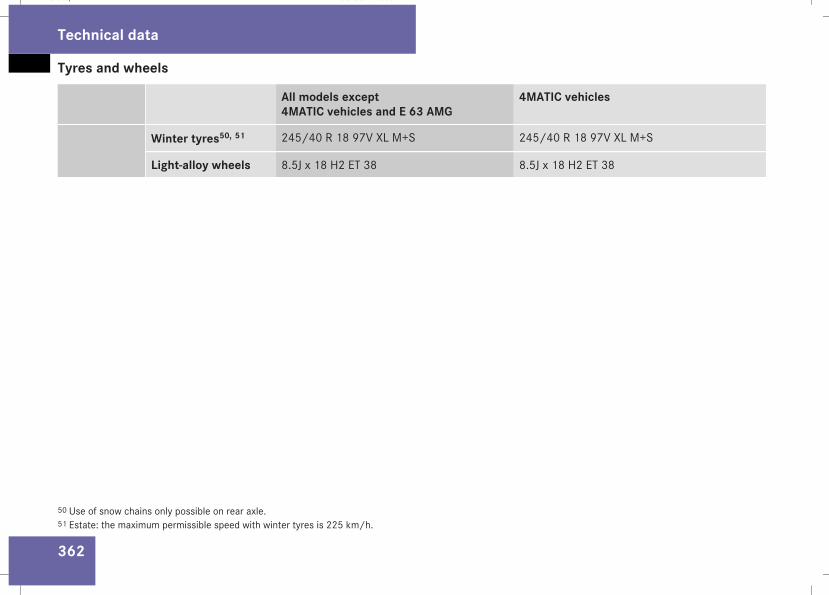
Tyres and wheels
362
All models except4MATIC vehicles and E 63 AMG
4MATIC vehicles
Winter tyres50, 51 245/40 R 18 97V XL M+S 245/40 R 18 97V XL M+S
Light-alloy wheels 8.5J x 18 H2 ET 38 8.5J x 18 H2 ET 38
50 Use of snow chains only possible on rear axle.51 Estate: the maximum permissible speed with winter tyres is 225 km/h.
Technical data
211_AKB; 2; 5, en-GBmkalafa, Version: 2.9.4
2008-02-29T16:57:07+01:00 - Seite 362
Dateiname: 6515_3416_02_buchblock.pdf; preflight
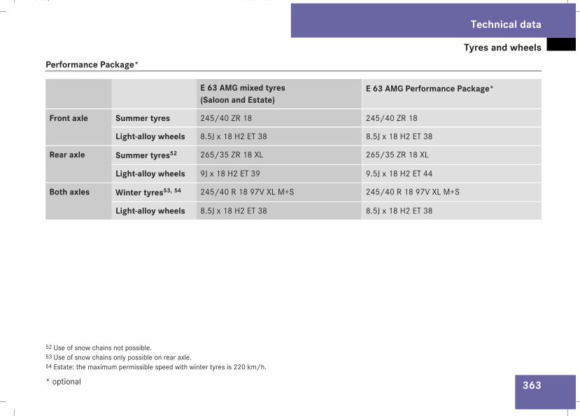
Tyres and wheels
363
Performance Package*
E 63 AMG mixed tyres(Saloon and Estate)
E 63 AMG Performance Package*
Front axle Summer tyres 245/40 ZR 18 245/40 ZR 18
Light-alloy wheels 8.5J x 18 H2 ET 38 8.5J x 18 H2 ET 38
Rear axle Summer tyres52 265/35 ZR 18 XL 265/35 ZR 18 XL
Light-alloy wheels 9J x 18 H2 ET 39 9.5J x 18 H2 ET 44
Both axles Winter tyres53, 54 245/40 R 18 97V XL M+S 245/40 R 18 97V XL M+S
Light-alloy wheels 8.5J x 18 H2 ET 38 8.5J x 18 H2 ET 38
52 Use of snow chains not possible.53 Use of snow chains only possible on rear axle.54 Estate: the maximum permissible speed with winter tyres is 220 km/h.
Technical data
* optional
211_AKB; 2; 5, en-GBmkalafa, Version: 2.9.4
2008-02-29T16:57:07+01:00 - Seite 363
Z
Dateiname: 6515_3416_02_buchblock.pdf; preflight
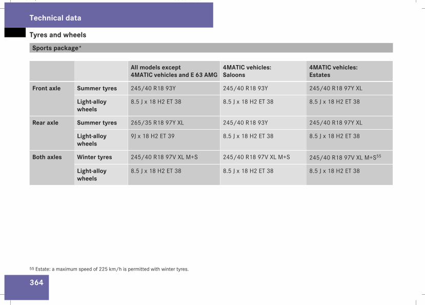
Tyres and wheels
364
Sports package*
All models except4MATIC vehicles and E 63 AMG
4MATIC vehicles:Saloons
4MATIC vehicles:Estates
Front axle Summer tyres 245/40 R18 93Y 245/40 R18 93Y 245/40 R18 97Y XL
Light-alloywheels
8.5 J x 18 H2 ET 38 8.5 J x 18 H2 ET 38 8.5 J x 18 H2 ET 38
Rear axle Summer tyres 265/35 R18 97Y XL 245/40 R18 93Y 245/40 R18 97Y XL
Light-alloywheels
9J x 18 H2 ET 39 8.5 J x 18 H2 ET 38 8.5 J x 18 H2 ET 38
Both axles Winter tyres 245/40 R18 97V XL M+S 245/40 R18 97V XL M+S 245/40 R18 97V XL M+S55
Light-alloywheels
8.5 J x 18 H2 ET 38 8.5 J x 18 H2 ET 38 8.5 J x 18 H2 ET 38
55 Estate: a maximum speed of 225 km/h is permitted with winter tyres.
Technical data
211_AKB; 2; 5, en-GBmkalafa, Version: 2.9.4
2008-02-29T16:57:07+01:00 - Seite 364
Dateiname: 6515_3416_02_buchblock.pdf; preflight
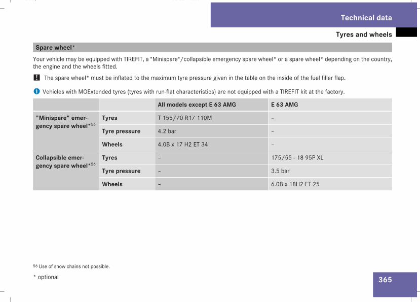
Tyres and wheels
365
Spare wheel*Your vehicle may be equipped with TIREFIT, a "Minispare"/collapsible emergency spare wheel* or a spare wheel* depending on the country,the engine and the wheels fitted.
! The spare wheel* must be inflated to the maximum tyre pressure given in the table on the inside of the fuel filler flap.
i Vehicles with MOExtended tyres (tyres with run-flat characteristics) are not equipped with a TIREFIT kit at the factory.
All models except E 63 AMG E 63 AMG
"Minispare" emer-gency spare wheel*56
Tyres T 155/70 R17 110M –
Tyre pressure 4.2 bar –
Wheels 4.0B x 17 H2 ET 34 –
Collapsible emer-gency spare wheel*56
Tyres – 175/55 - 18 95P XL
Tyre pressure – 3.5 bar
Wheels – 6.0B x 18H2 ET 25
56 Use of snow chains not possible.
Technical data
* optional
211_AKB; 2; 5, en-GBmkalafa, Version: 2.9.4
2008-02-29T16:57:07+01:00 - Seite 365
Z
Dateiname: 6515_3416_02_buchblock.pdf; preflight
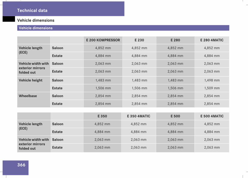
Vehicle dimensions
366
Vehicle dimensions
E 200 KOMPRESSOR E 230 E 280 E 280 4MATIC
Vehicle length(ECE)
Saloon 4,852 mm 4,852 mm 4,852 mm 4,852 mm
Estate 4,884 mm 4,884 mm 4,884 mm 4,884 mm
Vehiclewidthwithexterior mirrorsfolded out
Saloon 2,063 mm 2,063 mm 2,063 mm 2,063 mm
Estate 2,063 mm 2,063 mm 2,063 mm 2,063 mm
Vehicle height Saloon 1,483 mm 1,483 mm 1,483 mm 1,498 mm
Estate 1,506 mm 1,506 mm 1,506 mm 1,509 mm
Wheelbase Saloon 2,854 mm 2,854 mm 2,854 mm 2,854 mm
Estate 2,854 mm 2,854 mm 2,854 mm 2,854 mm
E 350 E 350 4MATIC E 500 E 500 4MATIC
Vehicle length(ECE)
Saloon 4,852 mm 4,852 mm 4,852 mm 4,852 mm
Estate 4,884 mm 4,884 mm 4,884 mm 4,884 mm
Vehicle widthwithexterior mirrorsfolded out
Saloon 2,063 mm 2,063 mm 2,063 mm 2,063 mm
Estate 2,063 mm 2,063 mm 2,063 mm 2,063 mm
Technical data
211_AKB; 2; 5, en-GBmkalafa, Version: 2.9.4
2008-02-29T16:57:07+01:00 - Seite 366
Dateiname: 6515_3416_02_buchblock.pdf; preflight
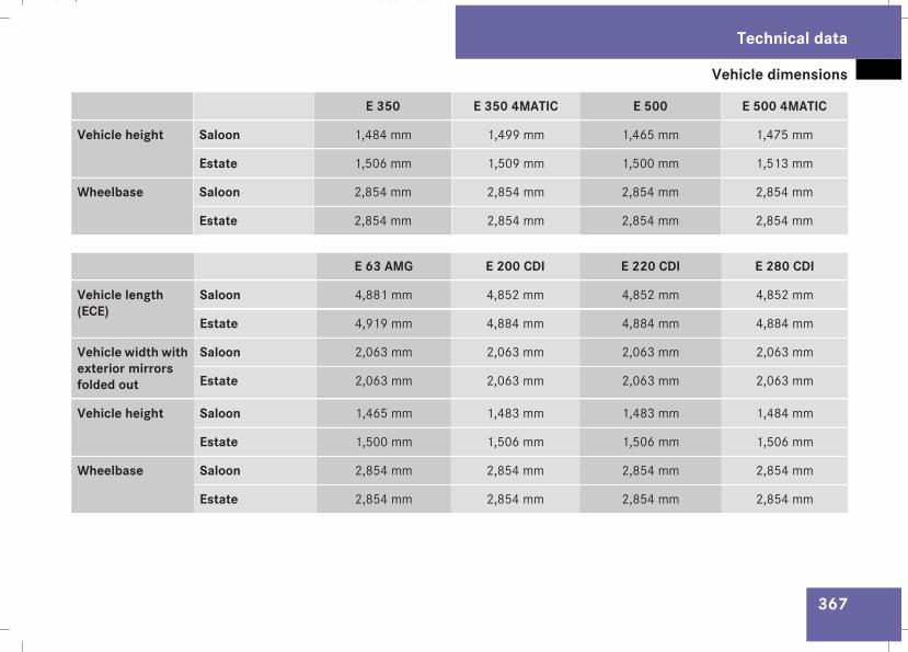
Vehicle dimensions
367
E 350 E 350 4MATIC E 500 E 500 4MATIC
Vehicle height Saloon 1,484 mm 1,499 mm 1,465 mm 1,475 mm
Estate 1,506 mm 1,509 mm 1,500 mm 1,513 mm
Wheelbase Saloon 2,854 mm 2,854 mm 2,854 mm 2,854 mm
Estate 2,854 mm 2,854 mm 2,854 mm 2,854 mm
E 63 AMG E 200 CDI E 220 CDI E 280 CDI
Vehicle length(ECE)
Saloon 4,881 mm 4,852 mm 4,852 mm 4,852 mm
Estate 4,919 mm 4,884 mm 4,884 mm 4,884 mm
Vehicle width withexterior mirrorsfolded out
Saloon 2,063 mm 2,063 mm 2,063 mm 2,063 mm
Estate 2,063 mm 2,063 mm 2,063 mm 2,063 mm
Vehicle height Saloon 1,465 mm 1,483 mm 1,483 mm 1,484 mm
Estate 1,500 mm 1,506 mm 1,506 mm 1,506 mm
Wheelbase Saloon 2,854 mm 2,854 mm 2,854 mm 2,854 mm
Estate 2,854 mm 2,854 mm 2,854 mm 2,854 mm
Technical data
211_AKB; 2; 5, en-GBmkalafa, Version: 2.9.4
2008-02-29T16:57:07+01:00 - Seite 367
Z
Dateiname: 6515_3416_02_buchblock.pdf; preflight
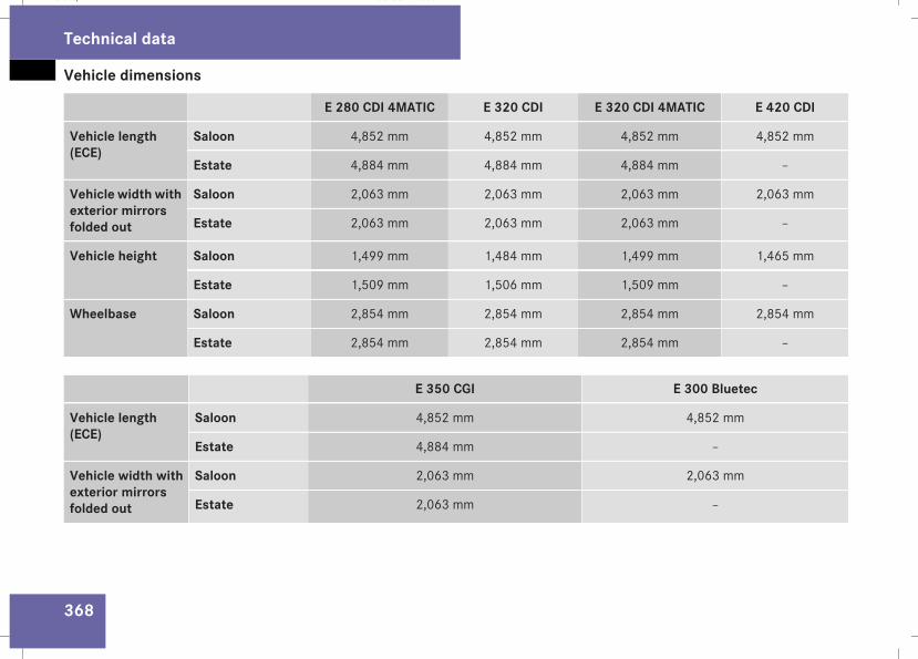
Vehicle dimensions
368
E 280 CDI 4MATIC E 320 CDI E 320 CDI 4MATIC E 420 CDI
Vehicle length(ECE)
Saloon 4,852 mm 4,852 mm 4,852 mm 4,852 mm
Estate 4,884 mm 4,884 mm 4,884 mm –
Vehicle width withexterior mirrorsfolded out
Saloon 2,063 mm 2,063 mm 2,063 mm 2,063 mm
Estate 2,063 mm 2,063 mm 2,063 mm –
Vehicle height Saloon 1,499 mm 1,484 mm 1,499 mm 1,465 mm
Estate 1,509 mm 1,506 mm 1,509 mm –
Wheelbase Saloon 2,854 mm 2,854 mm 2,854 mm 2,854 mm
Estate 2,854 mm 2,854 mm 2,854 mm –
E 350 CGI E 300 Bluetec
Vehicle length(ECE)
Saloon 4,852 mm 4,852 mm
Estate 4,884 mm –
Vehicle width withexterior mirrorsfolded out
Saloon 2,063 mm 2,063 mm
Estate 2,063 mm –
Technical data
211_AKB; 2; 5, en-GBmkalafa, Version: 2.9.4
2008-02-29T16:57:07+01:00 - Seite 368
Dateiname: 6515_3416_02_buchblock.pdf; preflight
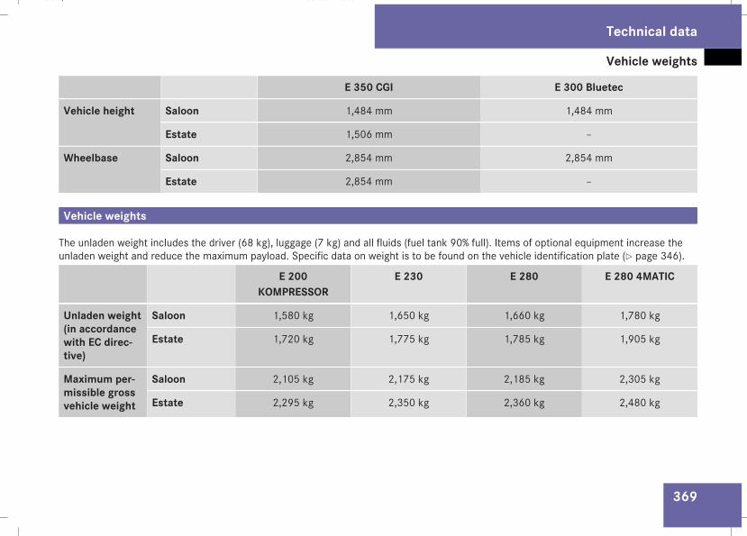
Vehicle weights
369
E 350 CGI E 300 Bluetec
Vehicle height Saloon 1,484 mm 1,484 mm
Estate 1,506 mm –
Wheelbase Saloon 2,854 mm 2,854 mm
Estate 2,854 mm –
Vehicle weights
The unladen weight includes the driver (68 kg), luggage (7 kg) and all fluids (fuel tank 90% full). Items of optional equipment increase theunladen weight and reduce the maximum payload. Specific data on weight is to be found on the vehicle identification plate (Y page 346).
E 200KOMPRESSOR
E 230 E 280 E 280 4MATIC
Unladen weight(in accordancewith EC direc-tive)
Saloon 1,580 kg 1,650 kg 1,660 kg 1,780 kg
Estate 1,720 kg 1,775 kg 1,785 kg 1,905 kg
Maximum per-missible grossvehicle weight
Saloon 2,105 kg 2,175 kg 2,185 kg 2,305 kg
Estate 2,295 kg 2,350 kg 2,360 kg 2,480 kg
Technical data
211_AKB; 2; 5, en-GBmkalafa, Version: 2.9.4
2008-02-29T16:57:07+01:00 - Seite 369
Z
Dateiname: 6515_3416_02_buchblock.pdf; preflight
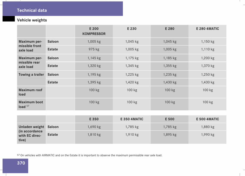
Vehicle weights
370
E 200KOMPRESSOR
E 230 E 280 E 280 4MATIC
Maximum per-missible frontaxle load
Saloon 1,005 kg 1,045 kg 1,045 kg 1,150 kg
Estate 975 kg 1,005 kg 1,005 kg 1,110 kg
Maximum per-missible rearaxle load
Saloon 1,145 kg 1,175 kg 1,185 kg 1,200 kg
Estate 1,320 kg 1,345 kg 1,355 kg 1,370 kg
Towing a trailer Saloon 1,195 kg 1,225 kg 1,235 kg 1,250 kg
Estate 1,395 kg 1,420 kg 1,430 kg 1,430 kg
Maximum roofload
100 kg 100 kg 100 kg 100 kg
Maximum bootload 57
100 kg 100 kg 100 kg 100 kg
E 350 E 350 4MATIC E 500 E 500 4MATIC
Unladen weight(in accordancewith EC direc-tive)
Saloon 1,690 kg 1,785 kg 1,785 kg 1,880 kg
Estate 1,810 kg 1,910 kg 1,895 kg 1,990 kg
57 On vehicles with AIRMATIC and on the Estate it is important to observe the maximum permissible rear axle load.
Technical data
211_AKB; 2; 5, en-GBmkalafa, Version: 2.9.4
2008-02-29T16:57:07+01:00 - Seite 370
Dateiname: 6515_3416_02_buchblock.pdf; preflight
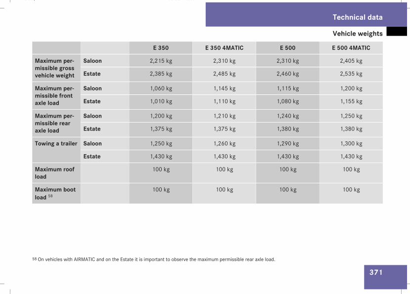
Vehicle weights
371
E 350 E 350 4MATIC E 500 E 500 4MATIC
Maximum per-missible grossvehicle weight
Saloon 2,215 kg 2,310 kg 2,310 kg 2,405 kg
Estate 2,385 kg 2,485 kg 2,460 kg 2,535 kg
Maximum per-missible frontaxle load
Saloon 1,060 kg 1,145 kg 1,115 kg 1,200 kg
Estate 1,010 kg 1,110 kg 1,080 kg 1,155 kg
Maximum per-missible rearaxle load
Saloon 1,200 kg 1,210 kg 1,240 kg 1,250 kg
Estate 1,375 kg 1,375 kg 1,380 kg 1,380 kg
Towing a trailer Saloon 1,250 kg 1,260 kg 1,290 kg 1,300 kg
Estate 1,430 kg 1,430 kg 1,430 kg 1,430 kg
Maximum roofload
100 kg 100 kg 100 kg 100 kg
Maximum bootload 58
100 kg 100 kg 100 kg 100 kg
58 On vehicles with AIRMATIC and on the Estate it is important to observe the maximum permissible rear axle load.
Technical data
211_AKB; 2; 5, en-GBmkalafa, Version: 2.9.4
2008-02-29T16:57:07+01:00 - Seite 371
Z
Dateiname: 6515_3416_02_buchblock.pdf; preflight

Vehicle weights
372
E 63 AMG E 200 CDI E 220 CDI E 280 CDI
Unladen weight(in accordancewith EC direc-tive)
Saloon 1,840 kg 1,615 kg 1,615 kg 1,715 kg
Estate 1,955 kg 1,785 kg 1,785 kg 1,845 kg
Maximum per-missible grossvehicle weight
Saloon 2,365 kg 2,140 kg 2,140 kg 2,240 kg
Estate 2,460 kg 2,360 kg 2,360 kg 2,420 kg
Maximum per-missible frontaxle load
Saloon 1,165 kg 1,040 kg 1,040 kg 1,105 kg
Estate 1,110 kg 1,025 kg 1,025 kg 1,060 kg
Maximum per-missible rearaxle load
Saloon 1,245 kg 1,145 kg 1,145 kg 1,180 kg
Estate 1,350 kg 1,335 kg 1,335 kg 1,360 kg
Towing a trailer Saloon – 1,195 kg 1,195 kg 1,230 kg
Estate – 1,385 kg 1,385 kg 1,410 kg
Maximum roofload
100 kg 100 kg 100 kg 100 kg
Maximum bootload 59
100 kg 100 kg 100 kg 100 kg
59 On vehicles with AIRMATIC and on the Estate it is important to observe the maximum permissible rear axle load.
Technical data
211_AKB; 2; 5, en-GBmkalafa, Version: 2.9.4
2008-02-29T16:57:07+01:00 - Seite 372
Dateiname: 6515_3416_02_buchblock.pdf; preflight
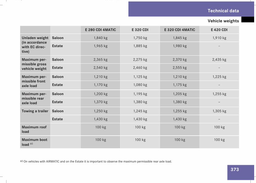
Vehicle weights
373
E 280 CDI 4MATIC E 320 CDI E 320 CDI 4MATIC E 420 CDI
Unladen weight(in accordancewith EC direc-tive)
Saloon 1,840 kg 1,750 kg 1,845 kg 1,910 kg
Estate 1,965 kg 1,885 kg 1,980 kg –
Maximum per-missible grossvehicle weight
Saloon 2,365 kg 2,275 kg 2,370 kg 2,435 kg
Estate 2,540 kg 2,460 kg 2,555 kg –
Maximum per-missible frontaxle load
Saloon 1,210 kg 1,125 kg 1,210 kg 1,225 kg
Estate 1,170 kg 1,080 kg 1,175 kg –
Maximum per-missible rearaxle load
Saloon 1,200 kg 1,195 kg 1,205 kg 1,255 kg
Estate 1,370 kg 1,380 kg 1,380 kg –
Towing a trailer Saloon 1,250 kg 1,245 kg 1,255 kg 1,305 kg
Estate 1,430 kg 1,430 kg 1,430 kg –
Maximum roofload
100 kg 100 kg 100 kg 100 kg
Maximum bootload 60
100 kg 100 kg 100 kg 100 kg
60 On vehicles with AIRMATIC and on the Estate it is important to observe the maximum permissible rear axle load.
Technical data
211_AKB; 2; 5, en-GBmkalafa, Version: 2.9.4
2008-02-29T16:57:07+01:00 - Seite 373
Z
Dateiname: 6515_3416_02_buchblock.pdf; preflight
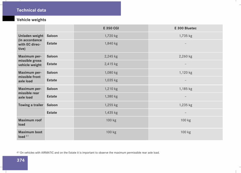
Vehicle weights
374
E 350 CGI E 300 Bluetec
Unladen weight(in accordancewith EC direc-tive)
Saloon 1,720 kg 1,735 kg
Estate 1,840 kg –
Maximum per-missible grossvehicle weight
Saloon 2,245 kg 2,260 kg
Estate 2,415 kg –
Maximum per-missible frontaxle load
Saloon 1,080 kg 1,120 kg
Estate 1,035 kg –
Maximum per-missible rearaxle load
Saloon 1,210 kg 1,185 kg
Estate 1,380 kg –
Towing a trailer Saloon 1,255 kg 1,235 kg
Estate 1,435 kg –
Maximum roofload
100 kg 100 kg
Maximum bootload 61
100 kg 100 kg
61 On vehicles with AIRMATIC and on the Estate it is important to observe the maximum permissible rear axle load.
Technical data
211_AKB; 2; 5, en-GBmkalafa, Version: 2.9.4
2008-02-29T16:57:07+01:00 - Seite 374
Dateiname: 6515_3416_02_buchblock.pdf; preflight
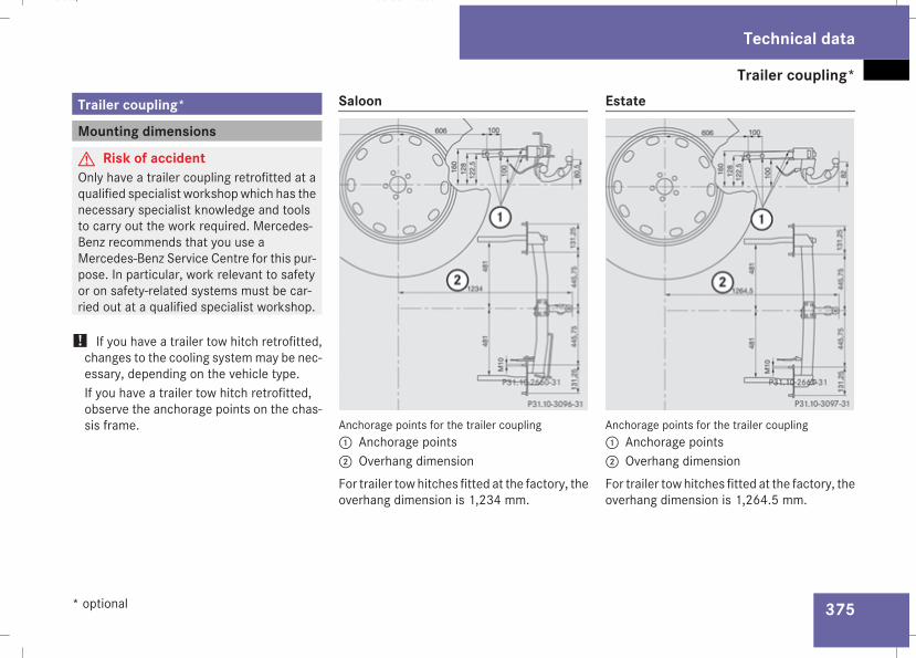
Trailer coupling*
375
Trailer coupling*
Mounting dimensions
G Risk of accidentOnly have a trailer coupling retrofitted at aqualified specialist workshopwhich has thenecessary specialist knowledge and toolsto carry out the work required. Mercedes-Benz recommends that you use aMercedes-Benz Service Centre for this pur-pose. In particular, work relevant to safetyor on safety-related systems must be car-ried out at a qualified specialist workshop.
! If you have a trailer tow hitch retrofitted,changes to the cooling systemmay be nec-essary, depending on the vehicle type.If you have a trailer tow hitch retrofitted,observe the anchorage points on the chas-sis frame.
Saloon
Anchorage points for the trailer coupling1 Anchorage points2 Overhang dimensionFor trailer tow hitches fitted at the factory, theoverhang dimension is 1,234 mm.
Estate
Anchorage points for the trailer coupling1 Anchorage points2 Overhang dimensionFor trailer tow hitches fitted at the factory, theoverhang dimension is 1,264.5 mm.
Technical data
* optional
211_AKB; 2; 5, en-GBmkalafa, Version: 2.9.4
2008-02-29T16:57:07+01:00 - Seite 375
Z
Dateiname: 6515_3416_02_buchblock.pdf; preflight
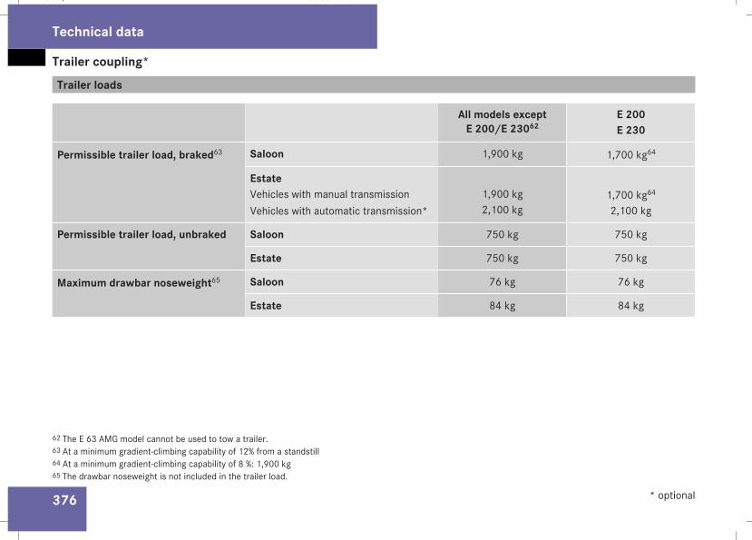
Trailer coupling*
376
Trailer loads
All models exceptE 200/E 23062
E 200E 230
Permissible trailer load, braked63 Saloon 1,900 kg 1,700 kg64
EstateVehicles with manual transmissionVehicles with automatic transmission*
1,900 kg2,100 kg
1,700 kg64
2,100 kg
Permissible trailer load, unbraked Saloon 750 kg 750 kg
Estate 750 kg 750 kg
Maximum drawbar noseweight65 Saloon 76 kg 76 kg
Estate 84 kg 84 kg
62 The E 63 AMG model cannot be used to tow a trailer.63 At a minimum gradient-climbing capability of 12% from a standstill64 At a minimum gradient-climbing capability of 8 %: 1,900 kg65 The drawbar noseweight is not included in the trailer load.
Technical data
* optional
211_AKB; 2; 5, en-GBmkalafa, Version: 2.9.4
2008-02-29T16:57:07+01:00 - Seite 376
Dateiname: 6515_3416_02_buchblock.pdf; preflight
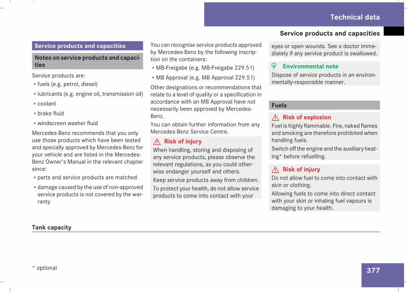
Service products and capacities
377
Service products and capacities
Notes on service products and capaci-tiesService products are:Rfuels (e.g. petrol, diesel)Rlubricants (e.g. engine oil, transmission oil)RcoolantRbrake fluidRwindscreen washer fluidMercedes-Benz recommends that you onlyuse those products which have been testedand specially approved by Mercedes-Benz foryour vehicle and are listed in the Mercedes-Benz Owner's Manual in the relevant chaptersince:Rparts and service products are matchedRdamage caused by the use of non-approvedservice products is not covered by the war-ranty
You can recognise service products approvedby Mercedes-Benz by the following inscrip-tion on the containers:RMB-Freigabe (e.g. MB-Freigabe 229.51)RMB Approval (e.g. MB Approval 229.51)Other designations or recommendations thatrelate to a level of quality or a specification inaccordance with an MB Approval have notnecessarily been approved by Mercedes-Benz.You can obtain further information from anyMercedes-Benz Service Centre.G Risk of injuryWhen handling, storing and disposing ofany service products, please observe therelevant regulations, as you could other-wise endanger yourself and others.Keep service products away from children.To protect your health, do not allow serviceproducts to come into contact with your
eyes or open wounds. See a doctor imme-diately if any service product is swallowed.
H Environmental noteDispose of service products in an environ-mentally-responsible manner.
Fuels
G Risk of explosionFuel is highly flammable. Fire, naked flamesand smoking are therefore prohibited whenhandling fuels.Switch off the engine and the auxiliary heat-ing* before refuelling.
G Risk of injuryDo not allow fuel to come into contact withskin or clothing.Allowing fuels to come into direct contactwith your skin or inhaling fuel vapours isdamaging to your health.
Tank capacity
Technical data
* optional
211_AKB; 2; 5, en-GBmkalafa, Version: 2.9.4
2008-02-29T16:57:07+01:00 - Seite 377
Z
Dateiname: 6515_3416_02_buchblock.pdf; preflight
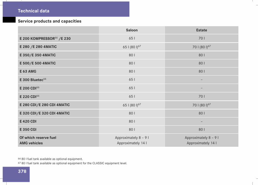
Service products and capacities
378
Saloon Estate
E 200 KOMPRESSOR66 /E 230 65 l 70 l
E 280 /E 280 4MATIC 65 l (80 l)67 70 l (80 l)67
E 350/E 350 4MATIC 80 l 80 l
E 500/E 500 4MATIC 80 l 80 l
E 63 AMG 80 l 80 l
E 300 Bluetec66 65 l –
E 200 CDI66 65 l –
E 220 CDI66 65 l 70 l
E 280 CDI/E 280 CDI 4MATIC 65 l (80 l)67 70 l (80 l)67
E 320 CDI/E 320 CDI 4MATIC 80 l 80 l
E 420 CDI 80 l –
E 350 CGI 80 l 80 l
Of which reserve fuelAMG vehicles
Approximately 8 – 9 lApproximately 14 l
Approximately 8 – 9 lApproximately 14 l
66 80 l fuel tank available as optional equipment.67 80 l fuel tank available as optional equipment for the CLASSIC equipment level.
Technical data
211_AKB; 2; 5, en-GBmkalafa, Version: 2.9.4
2008-02-29T16:57:07+01:00 - Seite 378
Dateiname: 6515_3416_02_buchblock.pdf; preflight
Service products and capacities
379
! Do not use petrol to refuel vehicles with adiesel engine. Do not use diesel to refuelvehicles with a petrol engine. Never mixdiesel with petrol. Even small amounts ofthe wrong fuel result in damage to theinjection system. Damage resulting fromadding the wrong fuel is not covered by thewarranty.
More information about refuelling and fuelscan be found in the "Operation" section.
Introduction to fuel consumptionThe vehicle will use more fuel than usual inthe following situations:
Rat very low temperaturesRin urban trafficRon short tripsRwhen towing a trailerRin mountainous terrainThe consumption figures have been deter-mined in accordance with EU Directive80/1268/EEC test conditions.
i Only for certain countries: the currentconsumption and emissions values of yourvehicle can be found in the COC papers(EC-CERTIFICATEOFCONFORMITY). Thesedocuments are supplied when the vehicleis delivered.
! Do not use any special additives, as theycan cause malfunctions and engine dam-age. Damage resulting from the use of suchadditives is not covered by the Mercedes-Benz warranty.
H Environmental noteCO2 (carbon dioxide) is the gas which sci-entists believe to be principally responsiblefor global warming (the greenhouse effect).Your vehicle's CO2 emissions are directlyrelated to fuel consumption and thereforedepend on:Refficient use of the fuel by the engineRdriving styleRother non-technical factors, such as envi-ronmental influences or road conditions
You can minimise your vehicle's CO2 emis-sions by driving carefully and having it serv-iced regularly.
Technical data
211_AKB; 2; 5, en-GBmkalafa, Version: 2.9.4
2008-02-29T16:57:07+01:00 - Seite 379
Z
Dateiname: 6515_3416_02_buchblock.pdf; preflight
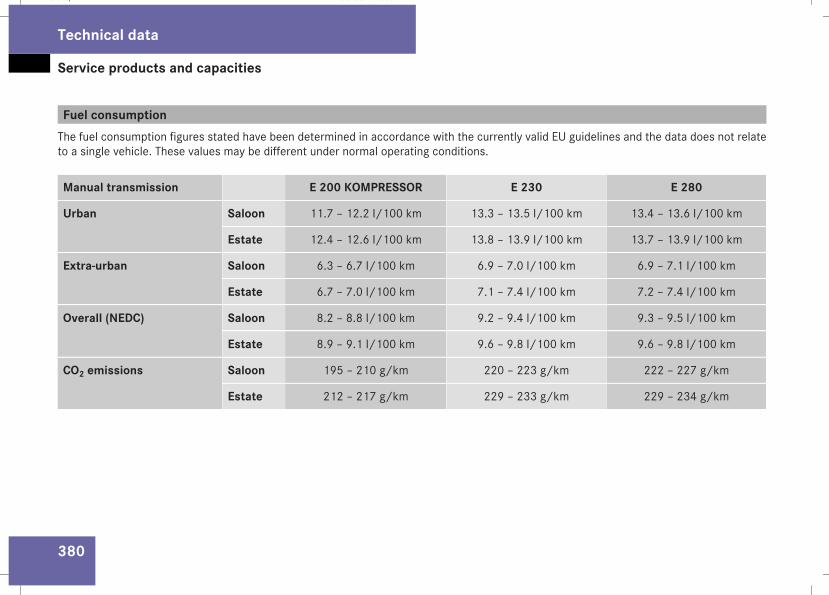
Service products and capacities
380
Fuel consumptionThe fuel consumption figures stated have been determined in accordance with the currently valid EU guidelines and the data does not relateto a single vehicle. These values may be different under normal operating conditions.
Manual transmission E 200 KOMPRESSOR E 230 E 280
Urban Saloon 11.7 – 12.2 l/100 km 13.3 – 13.5 l/100 km 13.4 – 13.6 l/100 km
Estate 12.4 – 12.6 l/100 km 13.8 – 13.9 l/100 km 13.7 – 13.9 l/100 km
Extra-urban Saloon 6.3 – 6.7 l/100 km 6.9 – 7.0 l/100 km 6.9 – 7.1 l/100 km
Estate 6.7 – 7.0 l/100 km 7.1 – 7.4 l/100 km 7.2 – 7.4 l/100 km
Overall (NEDC) Saloon 8.2 – 8.8 l/100 km 9.2 – 9.4 l/100 km 9.3 – 9.5 l/100 km
Estate 8.9 – 9.1 l/100 km 9.6 – 9.8 l/100 km 9.6 – 9.8 l/100 km
CO2 emissions Saloon 195 – 210 g/km 220 – 223 g/km 222 – 227 g/km
Estate 212 – 217 g/km 229 – 233 g/km 229 – 234 g/km
Technical data
211_AKB; 2; 5, en-GBmkalafa, Version: 2.9.4
2008-02-29T16:57:07+01:00 - Seite 380
Dateiname: 6515_3416_02_buchblock.pdf; preflight
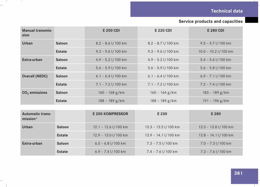
Service products and capacities
381
Manual transmis-sion
E 200 CDI E 220 CDI E 280 CDI
Urban Saloon 8.2 – 8.6 l/100 km 8.2 – 8.7 l/100 km 9.5 – 9.7 l/100 km
Estate 9.3 – 9.6 l/100 km 9.3 – 9.6 l/100 km 10.0 – 10.2 l/100 km
Extra-urban Saloon 4.9 – 5.2 l/100 km 4.9 – 5.2 l/100 km 5.4 – 5.6 l/100 km
Estate 5.6 – 5.9 l/100 km 5.6 – 5.9 l/100 km 5.6 – 5.8 l/100 km
Overall (NEDC) Saloon 6.1 – 6.4 l/100 km 6.1 – 6.4 l/100 km 6.9 – 7.1 l/100 km
Estate 7.1 – 7.2 l/100 km 7.1 – 7.2 l/100 km 7.2 – 7.4 l/100 km
CO2 emissions Saloon 160 – 168 g/km 160 – 164 g/km 183 – 189 g/km
Estate 188 – 189 g/km 188 – 189 g/km 191 – 196 g/km
Automatic trans-mission*
E 200 KOMPRESSOR E 230 E 280
Urban Saloon 12.1 – 12.6 l/100 km 13.3 – 13.5 l/100 km 13.5 – 13.8 l/100 km
Estate 12.9 – 13.0 l/100 km 13.9 – 14.1 l/100 km 13.8 – 14.1 l/100 km
Extra-urban Saloon 6.5 – 6.8 l/100 km 7.3 – 7.5 l/100 km 7.0 – 7.3 l/100 km
Estate 6.9 – 7.4 l/100 km 7.4 – 7.6 l/100 km 7.3 – 7.6 l/100 km
Technical data
211_AKB; 2; 5, en-GBmkalafa, Version: 2.9.4
2008-02-29T16:57:07+01:00 - Seite 381
Z
Dateiname: 6515_3416_02_buchblock.pdf; preflight

Service products and capacities
382
Automatic trans-mission*
E 200 KOMPRESSOR E 230 E 280
Overall (NEDC) Saloon 8.5 – 8.9 l/100 km 9.4 – 9.6 l/100 km 9.4 – 9.7 l/100 km
Estate 9.2 – 9.4 l/100 km 9.7 – 9.9 l/100 km 9.7 – 10.0 l/100 km
CO2 emissions Saloon 202 – 212 g/km 225 – 230 g/km 224 – 232 g/km
Estate 219 – 224 g/km 232 – 237 g/km 232 – 239 g/km
Automatic trans-mission*
E 280 4MATIC E 350 CGI E 300 Bluetec
Urban Saloon 13.8 – 14.2 l/100 km 13.0 – 13.5 l/100 km 9.9 – 10.1 l/100 km
Estate 14.3 – 14.6 l/100 km 13.1 – 13.6 l/100 km –
Extra-urban Saloon 7.6 – 8.0 l/100 km 6.3 – 6.7 l/100 km 5.6 – 5.9 l/100 km
Estate 8.0 – 8.3 l/100 km 6.5 – 7.0 l/100 km –
Overall (NEDC) Saloon 9.9 – 10.2 l/100 km 8.7 – 9.2 l/100 km 7.2 – 7.5 l/100 km
Estate 10.3 – 10.6 l/100 km 8.9 – 9.4 l/100 km –
CO2 emissions Saloon 237 – 245 g/km 208 – 219 g/km 189 – 199 g/km
Estate 246 – 253 g/km 213 – 224 g/km –
Technical data
* optional
211_AKB; 2; 5, en-GBmkalafa, Version: 2.9.4
2008-02-29T16:57:07+01:00 - Seite 382
Dateiname: 6515_3416_02_buchblock.pdf; preflight
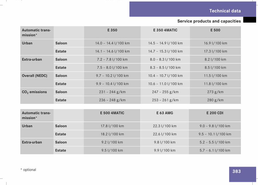
Service products and capacities
383
Automatic trans-mission*
E 350 E 350 4MATIC E 500
Urban Saloon 14.0 – 14.4 l/100 km 14.5 – 14.9 l/100 km 16.9 l/100 km
Estate 14.1 – 14.6 l/100 km 14.7 – 15.3 l/100 km 17.3 l/100 km
Extra-urban Saloon 7.2 – 7.8 l/100 km 8.0 – 8.3 l/100 km 8.2 l/100 km
Estate 7.5 – 8.0 l/100 km 8.3 – 8.5 l/100 km 8.5 l/100 km
Overall (NEDC) Saloon 9.7 – 10.2 l/100 km 10.4 – 10.7 l/100 km 11.5 l/100 km
Estate 9.9 – 10.4 l/100 km 10.6 – 11.0 l/100 km 11.8 l/100 km
CO2 emissions Saloon 231 – 244 g/km 247 – 255 g/km 273 g/km
Estate 236 – 248 g/km 253 – 261 g/km 280 g/km
Automatic trans-mission*
E 500 4MATIC E 63 AMG E 200 CDI
Urban Saloon 17.8 l/100 km 22.3 l/100 km 9.0 – 9.8 l/100 km
Estate 18.2 l/100 km 22.6 l/100 km 9.5 – 10.1 l/100 km
Extra-urban Saloon 9.2 l/100 km 9.8 l/100 km 5.2 – 5.5 l/100 km
Estate 9.5 l/100 km 9.9 l/100 km 5.7 – 6.1 l/100 km
Technical data
* optional
211_AKB; 2; 5, en-GBmkalafa, Version: 2.9.4
2008-02-29T16:57:07+01:00 - Seite 383
Z
Dateiname: 6515_3416_02_buchblock.pdf; preflight
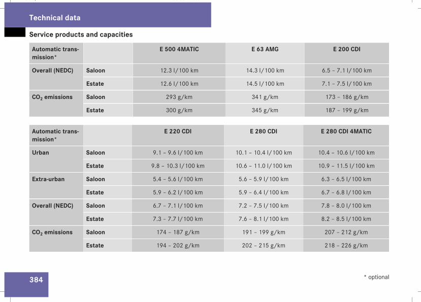
Service products and capacities
384
Automatic trans-mission*
E 500 4MATIC E 63 AMG E 200 CDI
Overall (NEDC) Saloon 12.3 l/100 km 14.3 l/100 km 6.5 – 7.1 l/100 km
Estate 12.6 l/100 km 14.5 l/100 km 7.1 – 7.5 l/100 km
CO2 emissions Saloon 293 g/km 341 g/km 173 – 186 g/km
Estate 300 g/km 345 g/km 187 – 199 g/km
Automatic trans-mission*
E 220 CDI E 280 CDI E 280 CDI 4MATIC
Urban Saloon 9.1 – 9.6 l/100 km 10.1 – 10.4 l/100 km 10.4 – 10.6 l/100 km
Estate 9.8 – 10.3 l/100 km 10.6 – 11.0 l/100 km 10.9 – 11.5 l/100 km
Extra-urban Saloon 5.4 – 5.6 l/100 km 5.6 – 5.9 l/100 km 6.3 – 6.5 l/100 km
Estate 5.9 – 6.2 l/100 km 5.9 – 6.4 l/100 km 6.7 – 6.8 l/100 km
Overall (NEDC) Saloon 6.7 – 7.1 l/100 km 7.2 – 7.5 l/100 km 7.8 – 8.0 l/100 km
Estate 7.3 – 7.7 l/100 km 7.6 – 8.1 l/100 km 8.2 – 8.5 l/100 km
CO2 emissions Saloon 174 – 187 g/km 191 – 199 g/km 207 – 212 g/km
Estate 194 – 202 g/km 202 – 215 g/km 218 – 226 g/km
Technical data
* optional
211_AKB; 2; 5, en-GBmkalafa, Version: 2.9.4
2008-02-29T16:57:07+01:00 - Seite 384
Dateiname: 6515_3416_02_buchblock.pdf; preflight
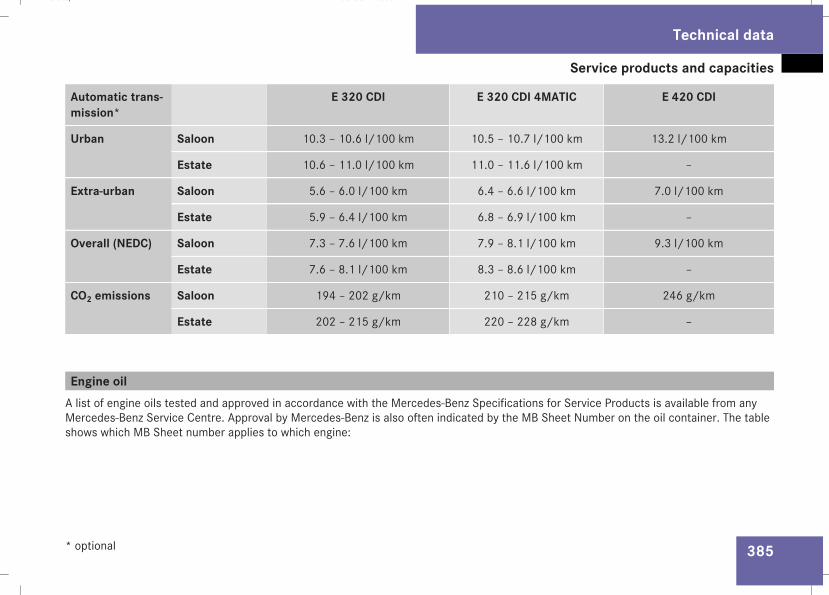
Service products and capacities
385
Automatic trans-mission*
E 320 CDI E 320 CDI 4MATIC E 420 CDI
Urban Saloon 10.3 – 10.6 l/100 km 10.5 – 10.7 l/100 km 13.2 l/100 km
Estate 10.6 – 11.0 l/100 km 11.0 – 11.6 l/100 km –
Extra-urban Saloon 5.6 – 6.0 l/100 km 6.4 – 6.6 l/100 km 7.0 l/100 km
Estate 5.9 – 6.4 l/100 km 6.8 – 6.9 l/100 km –
Overall (NEDC) Saloon 7.3 – 7.6 l/100 km 7.9 – 8.1 l/100 km 9.3 l/100 km
Estate 7.6 – 8.1 l/100 km 8.3 – 8.6 l/100 km –
CO2 emissions Saloon 194 – 202 g/km 210 – 215 g/km 246 g/km
Estate 202 – 215 g/km 220 – 228 g/km –
Engine oilA list of engine oils tested and approved in accordance with the Mercedes-Benz Specifications for Service Products is available from anyMercedes-Benz Service Centre. Approval by Mercedes-Benz is also often indicated by the MB Sheet Number on the oil container. The tableshows which MB Sheet number applies to which engine:
Technical data
* optional
211_AKB; 2; 5, en-GBmkalafa, Version: 2.9.4
2008-02-29T16:57:07+01:00 - Seite 385
Z
Dateiname: 6515_3416_02_buchblock.pdf; preflight
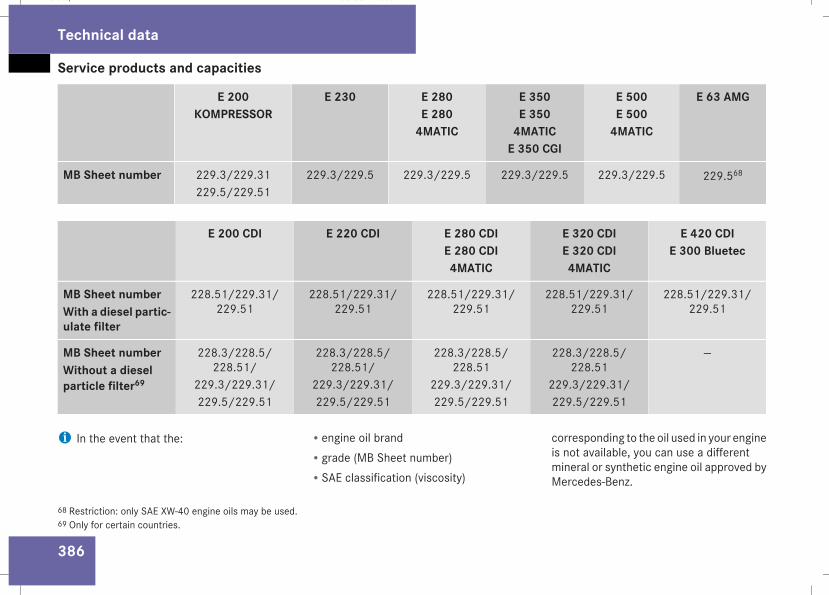
Service products and capacities
386
E 200KOMPRESSOR
E 230 E 280E 2804MATIC
E 350E 3504MATICE 350 CGI
E 500E 5004MATIC
E 63 AMG
MB Sheet number 229.3/229.31229.5/229.51
229.3/229.5 229.3/229.5 229.3/229.5 229.3/229.5 229.568
E 200 CDI E 220 CDI E 280 CDIE 280 CDI4MATIC
E 320 CDIE 320 CDI4MATIC
E 420 CDIE 300 Bluetec
MB Sheet numberWith a diesel partic-ulate filter
228.51/229.31/229.51
228.51/229.31/229.51
228.51/229.31/229.51
228.51/229.31/229.51
228.51/229.31/229.51
MB Sheet numberWithout a dieselparticle filter69
228.3/228.5/228.51/
229.3/229.31/229.5/229.51
228.3/228.5/228.51/
229.3/229.31/229.5/229.51
228.3/228.5/228.51
229.3/229.31/229.5/229.51
228.3/228.5/228.51
229.3/229.31/229.5/229.51
—
i In the event that the: Rengine oil brandRgrade (MB Sheet number)RSAE classification (viscosity)
corresponding to the oil used in your engineis not available, you can use a differentmineral or synthetic engine oil approved byMercedes-Benz.
68 Restriction: only SAE XW-40 engine oils may be used.69 Only for certain countries.
Technical data
211_AKB; 2; 5, en-GBmkalafa, Version: 2.9.4
2008-02-29T16:57:07+01:00 - Seite 386
Dateiname: 6515_3416_02_buchblock.pdf; preflight
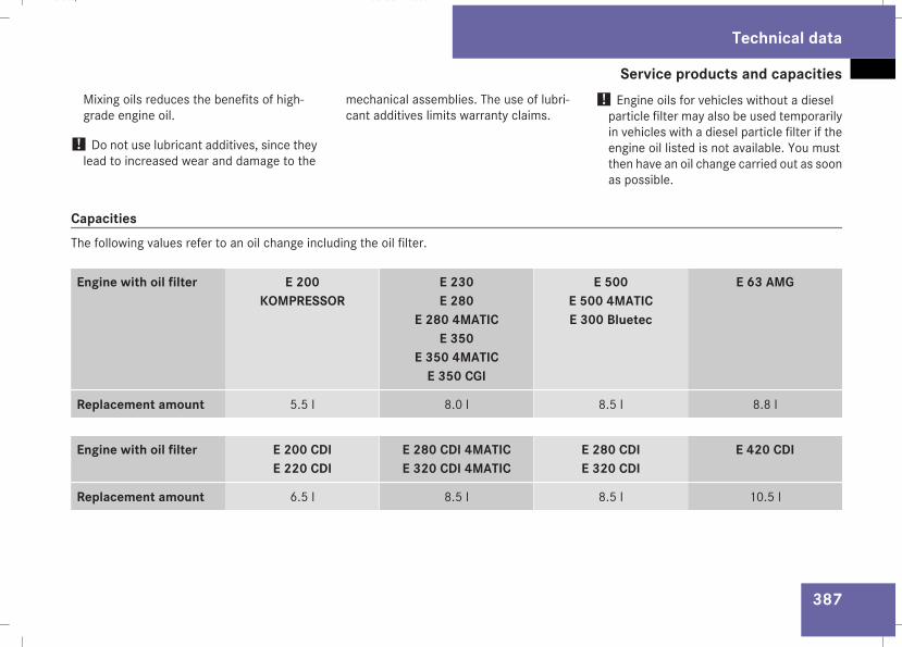
Service products and capacities
387
Mixing oils reduces the benefits of high-grade engine oil.
! Do not use lubricant additives, since theylead to increased wear and damage to the
mechanical assemblies. The use of lubri-cant additives limits warranty claims.
! Engine oils for vehicles without a dieselparticle filter may also be used temporarilyin vehicles with a diesel particle filter if theengine oil listed is not available. You mustthen have an oil change carried out as soonas possible.
CapacitiesThe following values refer to an oil change including the oil filter.
Engine with oil filter E 200KOMPRESSOR
E 230E 280
E 280 4MATICE 350
E 350 4MATICE 350 CGI
E 500E 500 4MATICE 300 Bluetec
E 63 AMG
Replacement amount 5.5 l 8.0 l 8.5 l 8.8 l
Engine with oil filter E 200 CDIE 220 CDI
E 280 CDI 4MATICE 320 CDI 4MATIC
E 280 CDIE 320 CDI
E 420 CDI
Replacement amount 6.5 l 8.5 l 8.5 l 10.5 l
Technical data
211_AKB; 2; 5, en-GBmkalafa, Version: 2.9.4
2008-02-29T16:57:07+01:00 - Seite 387
Z
Dateiname: 6515_3416_02_buchblock.pdf; preflight
Service products and capacities
388
CoolantThe coolant is a mixture of water and anti-freeze/corrosion inhibitor. It performs thefollowing tasks:Ranti-corrosion protectionRantifreeze protectionRraising the boiling point
i When the vehicle is first delivered, it istopped up with a coolant that will ensureadequate antifreeze and corrosion protec-tion.
! Only top up with coolant that has beenpremixed with the desired quantity of anti-freeze protection. You could otherwisedamage the engine.There is more information about coolantand topping it up on Mercedes-Benz Spec-ifications for Service Products Sheet310.1.
! Always use a suitable coolant mixture,even in countries where high temperaturesprevail.Otherwise, the cooling system will not besufficiently protected from corrosion, andthe boiling point will be too low.
If antifreeze/corrosion inhibitor is present inthe correct concentration, the boiling point ofthe coolant will be around 130 °C.The antifreeze/corrosion inhibitor concentra-tion in the cooling system should:Rbe at least 50%. This will protect the coolingsystem against freezing down to around –37 °C.
Rnot exceed 55% concentration (antifreezeprotection down to –45 °C), otherwise heatwill not be effectively dissipated.
If the vehicle has lost coolant, top it up withequal amounts of water and antifreeze/cor-rosion inhibitor. Mercedes-Benz recom-mends using an antifreeze/corrosion inhibi-tor which has been approved for Mercedes-Benz.
! The cooling system contains a fillingwhich must be renewed after 15 years, orafter 250,000 km at the latest. Have therenewal confirmed in the Service Booklet.The warranty is only valid if you top up withan antifreeze/corrosion inhibitor whichhas been approved by Mercedes-Benz, andobserve the recommended mixing ratios.
Technical data
211_AKB; 2; 5, en-GBmkalafa, Version: 2.9.4
2008-02-29T16:57:07+01:00 - Seite 388
Dateiname: 6515_3416_02_buchblock.pdf; preflight
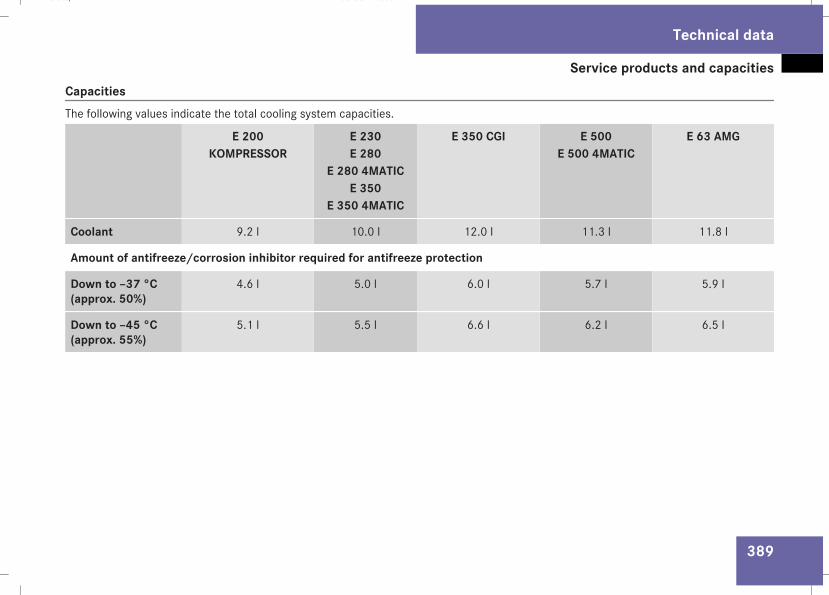
Service products and capacities
389
CapacitiesThe following values indicate the total cooling system capacities.
E 200KOMPRESSOR
E 230E 280
E 280 4MATICE 350
E 350 4MATIC
E 350 CGI E 500E 500 4MATIC
E 63 AMG
Coolant 9.2 l 10.0 l 12.0 l 11.3 l 11.8 l
Amount of antifreeze/corrosion inhibitor required for antifreeze protection
Down to –37 °C(approx. 50%)
4.6 l 5.0 l 6.0 l 5.7 l 5.9 l
Down to –45 °C(approx. 55%)
5.1 l 5.5 l 6.6 l 6.2 l 6.5 l
Technical data
211_AKB; 2; 5, en-GBmkalafa, Version: 2.9.4
2008-02-29T16:57:07+01:00 - Seite 389
Z
Dateiname: 6515_3416_02_buchblock.pdf; preflight
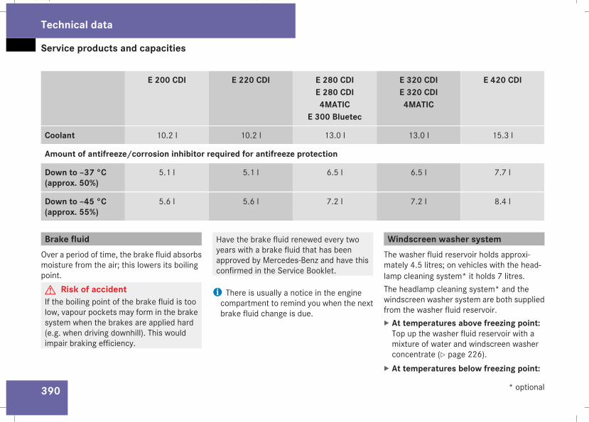
Service products and capacities
390
E 200 CDI E 220 CDI E 280 CDIE 280 CDI4MATIC
E 300 Bluetec
E 320 CDIE 320 CDI4MATIC
E 420 CDI
Coolant 10.2 l 10.2 l 13.0 l 13.0 l 15.3 l
Amount of antifreeze/corrosion inhibitor required for antifreeze protection
Down to –37 °C(approx. 50%)
5.1 l 5.1 l 6.5 l 6.5 l 7.7 l
Down to –45 °C(approx. 55%)
5.6 l 5.6 l 7.2 l 7.2 l 8.4 l
Brake fluidOver a period of time, the brake fluid absorbsmoisture from the air; this lowers its boilingpoint.G Risk of accidentIf the boiling point of the brake fluid is toolow, vapour pockets may form in the brakesystem when the brakes are applied hard(e.g. when driving downhill). This wouldimpair braking efficiency.
Have the brake fluid renewed every twoyears with a brake fluid that has beenapproved by Mercedes-Benz and have thisconfirmed in the Service Booklet.
i There is usually a notice in the enginecompartment to remind you when the nextbrake fluid change is due.
Windscreen washer systemThe washer fluid reservoir holds approxi-mately 4.5 litres; on vehicles with the head-lamp cleaning system* it holds 7 litres.The headlamp cleaning system* and thewindscreen washer system are both suppliedfrom the washer fluid reservoir.X At temperatures above freezing point:Top up the washer fluid reservoir with amixture of water and windscreen washerconcentrate (Y page 226).
X At temperatures below freezing point:
Technical data
* optional
211_AKB; 2; 5, en-GBmkalafa, Version: 2.9.4
2008-02-29T16:57:07+01:00 - Seite 390
Dateiname: 6515_3416_02_buchblock.pdf; preflight
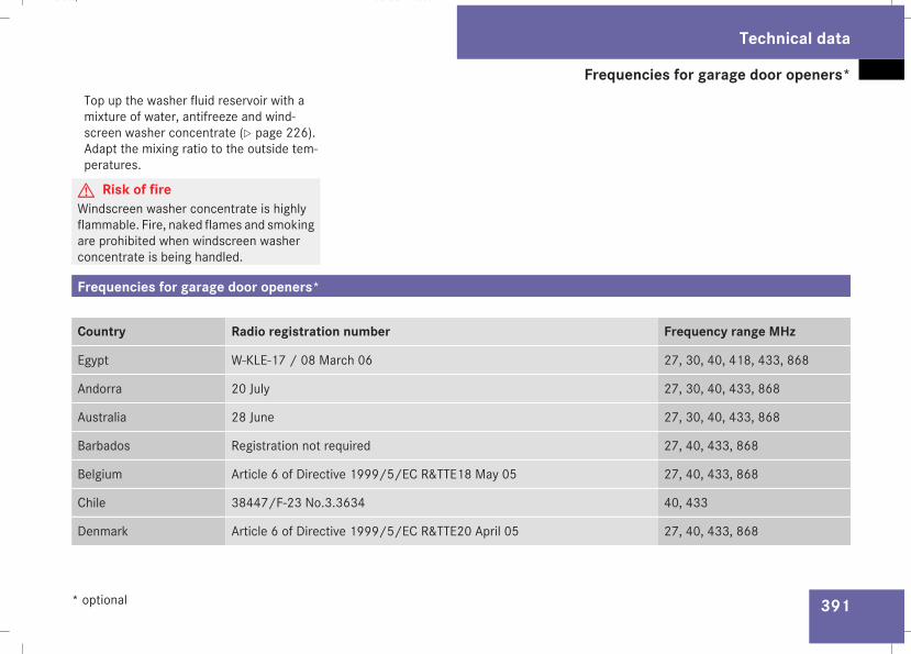
Frequencies for garage door openers*
391
Top up the washer fluid reservoir with amixture of water, antifreeze and wind-screen washer concentrate (Y page 226).Adapt the mixing ratio to the outside tem-peratures.
G Risk of fireWindscreen washer concentrate is highlyflammable. Fire, naked flames and smokingare prohibited when windscreen washerconcentrate is being handled.
Frequencies for garage door openers*
Country Radio registration number Frequency range MHz
Egypt W-KLE-17 / 08 March 06 27, 30, 40, 418, 433, 868
Andorra 20 July 27, 30, 40, 433, 868
Australia 28 June 27, 30, 40, 433, 868
Barbados Registration not required 27, 40, 433, 868
Belgium Article 6 of Directive 1999/5/EC R&TTE18 May 05 27, 40, 433, 868
Chile 38447/F-23 No.3.3634 40, 433
Denmark Article 6 of Directive 1999/5/EC R&TTE20 April 05 27, 40, 433, 868
Technical data
* optional
211_AKB; 2; 5, en-GBmkalafa, Version: 2.9.4
2008-02-29T16:57:07+01:00 - Seite 391
Z
Dateiname: 6515_3416_02_buchblock.pdf; preflight
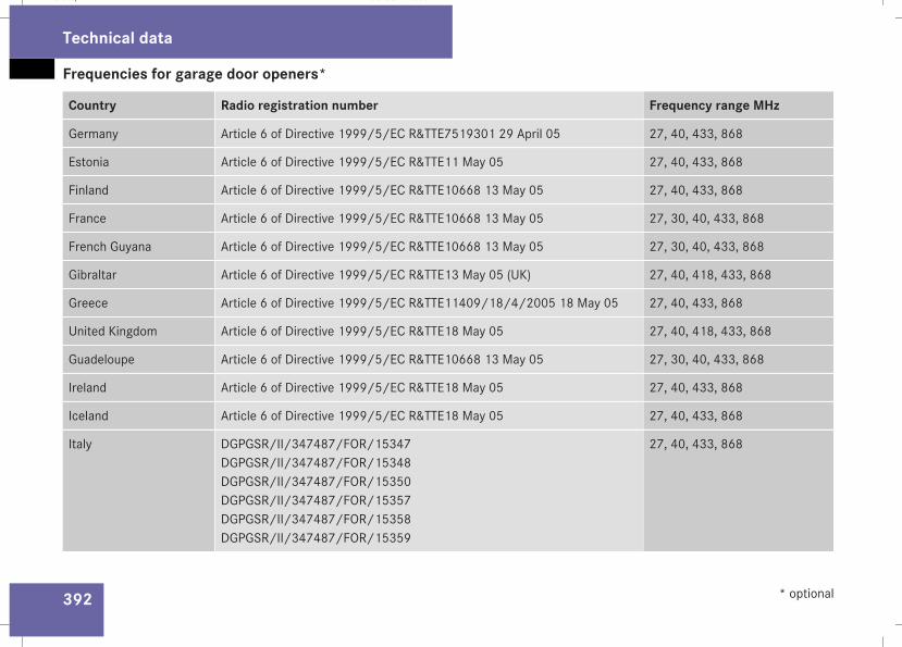
Frequencies for garage door openers*
392
Country Radio registration number Frequency range MHz
Germany Article 6 of Directive 1999/5/EC R&TTE7519301 29 April 05 27, 40, 433, 868
Estonia Article 6 of Directive 1999/5/EC R&TTE11 May 05 27, 40, 433, 868
Finland Article 6 of Directive 1999/5/EC R&TTE10668 13 May 05 27, 40, 433, 868
France Article 6 of Directive 1999/5/EC R&TTE10668 13 May 05 27, 30, 40, 433, 868
French Guyana Article 6 of Directive 1999/5/EC R&TTE10668 13 May 05 27, 30, 40, 433, 868
Gibraltar Article 6 of Directive 1999/5/EC R&TTE13 May 05 (UK) 27, 40, 418, 433, 868
Greece Article 6 of Directive 1999/5/EC R&TTE11409/18/4/2005 18 May 05 27, 40, 433, 868
United Kingdom Article 6 of Directive 1999/5/EC R&TTE18 May 05 27, 40, 418, 433, 868
Guadeloupe Article 6 of Directive 1999/5/EC R&TTE10668 13 May 05 27, 30, 40, 433, 868
Ireland Article 6 of Directive 1999/5/EC R&TTE18 May 05 27, 40, 433, 868
Iceland Article 6 of Directive 1999/5/EC R&TTE18 May 05 27, 40, 433, 868
Italy DGPGSR/II/347487/FOR/15347DGPGSR/II/347487/FOR/15348DGPGSR/II/347487/FOR/15350DGPGSR/II/347487/FOR/15357DGPGSR/II/347487/FOR/15358DGPGSR/II/347487/FOR/15359
27, 40, 433, 868
Technical data
* optional
211_AKB; 2; 5, en-GBmkalafa, Version: 2.9.4
2008-02-29T16:57:07+01:00 - Seite 392
Dateiname: 6515_3416_02_buchblock.pdf; preflight
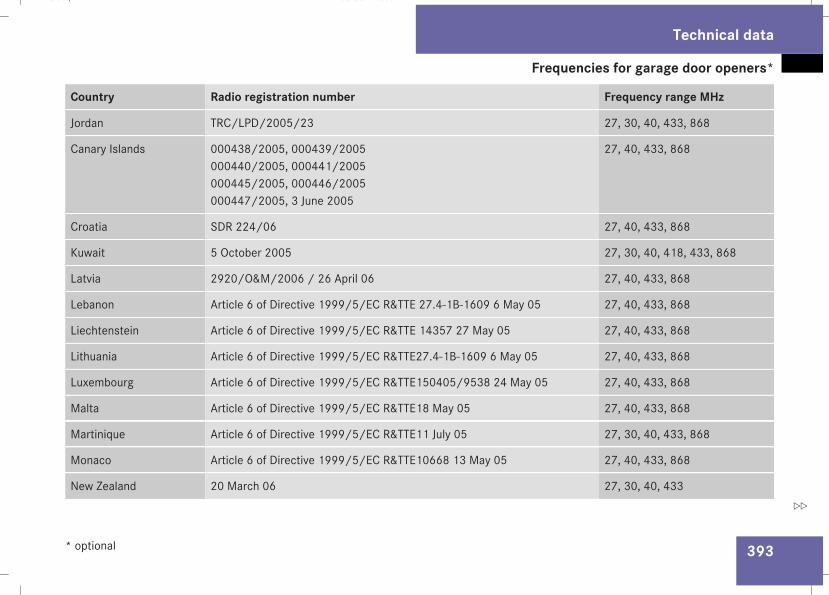
Frequencies for garage door openers*
393
Country Radio registration number Frequency range MHz
Jordan TRC/LPD/2005/23 27, 30, 40, 433, 868
Canary Islands 000438/2005, 000439/2005000440/2005, 000441/2005000445/2005, 000446/2005000447/2005, 3 June 2005
27, 40, 433, 868
Croatia SDR 224/06 27, 40, 433, 868
Kuwait 5 October 2005 27, 30, 40, 418, 433, 868
Latvia 2920/O&M/2006 / 26 April 06 27, 40, 433, 868
Lebanon Article 6 of Directive 1999/5/EC R&TTE 27.4-1B-1609 6 May 05 27, 40, 433, 868
Liechtenstein Article 6 of Directive 1999/5/EC R&TTE 14357 27 May 05 27, 40, 433, 868
Lithuania Article 6 of Directive 1999/5/EC R&TTE27.4-1B-1609 6 May 05 27, 40, 433, 868
Luxembourg Article 6 of Directive 1999/5/EC R&TTE150405/9538 24 May 05 27, 40, 433, 868
Malta Article 6 of Directive 1999/5/EC R&TTE18 May 05 27, 40, 433, 868
Martinique Article 6 of Directive 1999/5/EC R&TTE11 July 05 27, 30, 40, 433, 868
Monaco Article 6 of Directive 1999/5/EC R&TTE10668 13 May 05 27, 40, 433, 868
New Zealand 20 March 06 27, 30, 40, 433
Technical data
* optional
211_AKB; 2; 5, en-GBmkalafa, Version: 2.9.4
2008-02-29T16:57:07+01:00 - Seite 393
Z
Dateiname: 6515_3416_02_buchblock.pdf; preflight
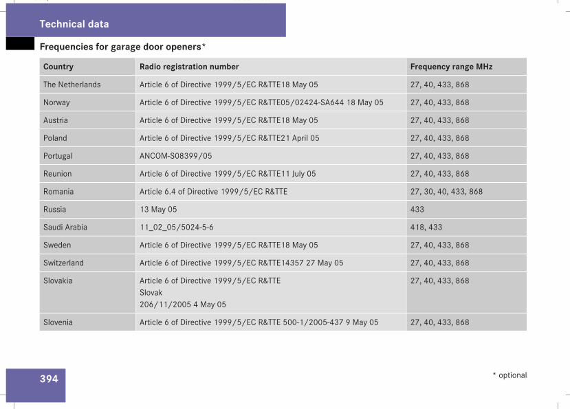
Frequencies for garage door openers*
394
Country Radio registration number Frequency range MHz
The Netherlands Article 6 of Directive 1999/5/EC R&TTE18 May 05 27, 40, 433, 868
Norway Article 6 of Directive 1999/5/EC R&TTE05/02424-SA644 18 May 05 27, 40, 433, 868
Austria Article 6 of Directive 1999/5/EC R&TTE18 May 05 27, 40, 433, 868
Poland Article 6 of Directive 1999/5/EC R&TTE21 April 05 27, 40, 433, 868
Portugal ANCOM-S08399/05 27, 40, 433, 868
Reunion Article 6 of Directive 1999/5/EC R&TTE11 July 05 27, 40, 433, 868
Romania Article 6.4 of Directive 1999/5/EC R&TTE 27, 30, 40, 433, 868
Russia 13 May 05 433
Saudi Arabia 11_02_05/5024-5-6 418, 433
Sweden Article 6 of Directive 1999/5/EC R&TTE18 May 05 27, 40, 433, 868
Switzerland Article 6 of Directive 1999/5/EC R&TTE14357 27 May 05 27, 40, 433, 868
Slovakia Article 6 of Directive 1999/5/EC R&TTESlovak206/11/2005 4 May 05
27, 40, 433, 868
Slovenia Article 6 of Directive 1999/5/EC R&TTE 500-1/2005-437 9 May 05 27, 40, 433, 868
Technical data
* optional
211_AKB; 2; 5, en-GBmkalafa, Version: 2.9.4
2008-02-29T16:57:07+01:00 - Seite 394
Dateiname: 6515_3416_02_buchblock.pdf; preflight
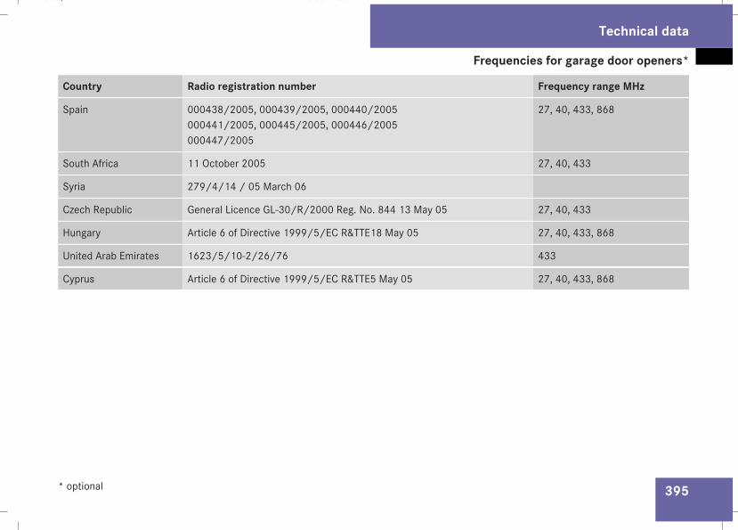
Frequencies for garage door openers*
395
Country Radio registration number Frequency range MHz
Spain 000438/2005, 000439/2005, 000440/2005000441/2005, 000445/2005, 000446/2005000447/2005
27, 40, 433, 868
South Africa 11 October 2005 27, 40, 433
Syria 279/4/14 / 05 March 06
Czech Republic General Licence GL-30/R/2000 Reg. No. 844 13 May 05 27, 40, 433
Hungary Article 6 of Directive 1999/5/EC R&TTE18 May 05 27, 40, 433, 868
United Arab Emirates 1623/5/10-2/26/76 433
Cyprus Article 6 of Directive 1999/5/EC R&TTE5 May 05 27, 40, 433, 868
Technical data
* optional
211_AKB; 2; 5, en-GBmkalafa, Version: 2.9.4
2008-02-29T16:57:07+01:00 - Seite 395
Z
Dateiname: 6515_3416_02_buchblock.pdf; preflight

396
211_AKB; 2; 5, en-GBmkalafa, Version: 2.9.4
2008-02-29T16:57:07+01:00 - Seite 396
Dateiname: 6515_3416_02_buchblock.pdf; preflight