medium voltage - cellpack
TRANSCRIPT

D81
3 | S
AP.
Nr.
1986
93 |
1112
Medium VoltageCatalogue 2013

Data, values and illustrations given in this documentation are correct and reliable according to the current state of our knowledge. They represent however no obligatory characteristic warranty. Such a warranty is made only by our product standards. The user of this product must decide on his own responsibility on its suitability for the intended application. Our liability for these products exclusively depends on our general trading conditions.
Changes in the sense of technical progress and misprint reserved.
© 2013, CELLPACK GmbH. All Rights Reserved.
www.cellpack.com
Safe connections
2 www.cellpack.com
Medium Voltage 2013 Medium Voltage 2013 Medium Voltage 2013 Medium Voltage 2013
Cable accessories for screened cables
Introduction | Cellpack Technology
Cable accessories for unscreened cables
Cable accessories for paper-insulated cables
Cable accessories for screened cables
according to British Standard
Cable accessories for the industries
Accessories
Index
4
24
30
70
90
102
106
136
Page
Medium Voltage 2013 Medium Voltage 2013
3 www.cellpack.com
Medium Voltage 2013 Medium Voltage 2013
Cable accessories are indispensable components of a cable network which exert a direct influenceon its quality. The same level of operational safety must be guaranteed for the accessories asfor the cable itself. Due to high operational costs incurred by medium voltage networks, it isnecessary to avoid outages. The safe, quick and easy assembly of cable accessories is thereforeessential for network reliability. Exceptional innovative solutions are thus required to ensure thatexcessive demands are not placed on the capabilities of assembly staff. We produce innovative, high-performance cable accessories for medium voltage networks based on the stress control system developed by Cellpack.
We offer a full range of products for a wide variety of applications using heat shrink, silicone, slip-on, plug-in and cast resin technologies which comply with the standard requirements for energy suppliers and the set industrial norms. The system components of all of our cable accessories are compatible so as to ensure safe and reliable functioning. As a result of intensive testing carried out in our laboratories, as well as numerous type tests carried out in international test facilities, we are able to guarantee an operationally reliable conductor connection, an adequate insulation level and excellent resistance against all environmental influences for all our cable accessories. All our medium voltage products are tested according to DIN VDE 0278, CENELEC HD 629.1, HD 629.2, IEC 60502-4 and comply with IEEE and BS requirements.
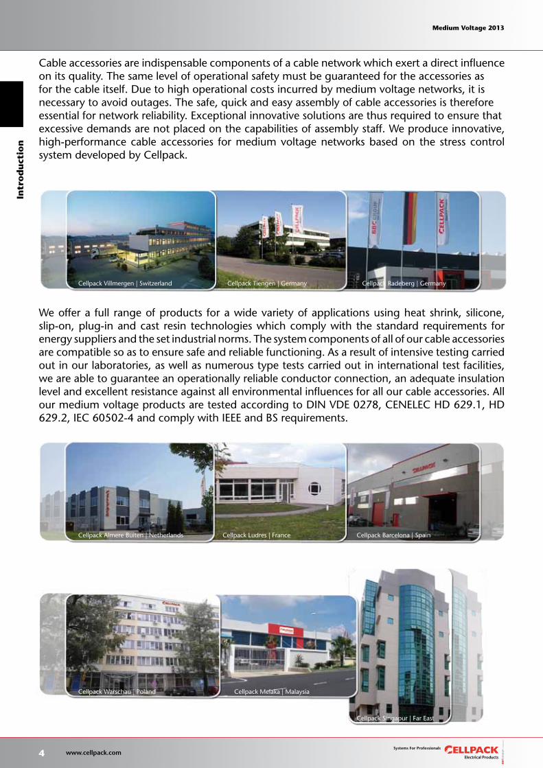
Cellpack Villmergen | Switzerland Cellpack Tiengen | Germany
Cellpack Almere Buiten | Netherlands Cellpack Barcelona | Spain
Cellpack Warschau | Poland Cellpack Melaka | Malaysia
Cellpack Radeberg | Germany
Cellpack Singapur | Far East
Cellpack Ludres | France
4 www.cellpack.com
Medium Voltage 2013 Medium Voltage 2013In
tro
du
ctio
n Medium Voltage 2013 Medium Voltage 2013
Stress control in MV cable accessories
Removal of the cable insulation and the outer semi-conducting layer when connecting or terminating medium voltage cables results in damage to the cable structure. In addition to this, the electric field becomes strongly inhomogeneous at particular points. During this process the electric field strength value greatly increases, resulting in a risk of partial discharge, breakdown or spikes.
Stress control influences the strong inhomogeneous field distribution at the cable end so as to reduce the high field strengths to a non-critical value. Refractive stress control is the most suitable method for medium voltage cable accessories. It offers the following significant advantages over other methods:• Leaner stress control element design, enabling the development of compact solutions which are very easy to assemble.• Reduced sensitivity to incorrect positioning or incorrect cable preparation, allowing compensation for errors made during assembly.
Refractive stress control
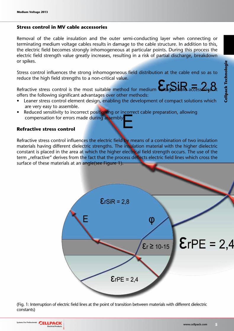
Refractive stress control influences the electric field by means of a combination of two insulation materials having different dielectric strengths. The insulation material with the higher dielectric constant is placed in the area at which the higher electrical field strength occurs. The use of the term „refractive“ derives from the fact that the process deflects electric field lines which cross thesurface of these materials at an angle(see Figure 1).
(Fig. 1: Interruption of electric field lines at the point of transition between materials with different dielectricconstants)
Medium Voltage 2013 Medium Voltage 2013
5 www.cellpack.com
Medium Voltage 2013 Medium Voltage 2013
Cel
lpac
k T
ech
no
log
ie
When using the above principle in medium voltage cable accessories, a thin stress control and insulation layer is placed in the region above the strippable edge of the outer semi-conducting layer (for cables with plastic insulation), or above the Hochstädter foil or lead sheath (for cables with paper insulation), or above the core insulation when the cable insulation has been removed. This layer has a considerably higher dielectric constant (εr) than the insulating material of the cable itself. This results in a targeted reduction of the original field strength (see Fig. 2).
(Fig. 2: Comparison of lines of equipotentiality in a plastic-insulated cable with the insulation removed, withand without refractive stress control).
Stress control element (FSE)
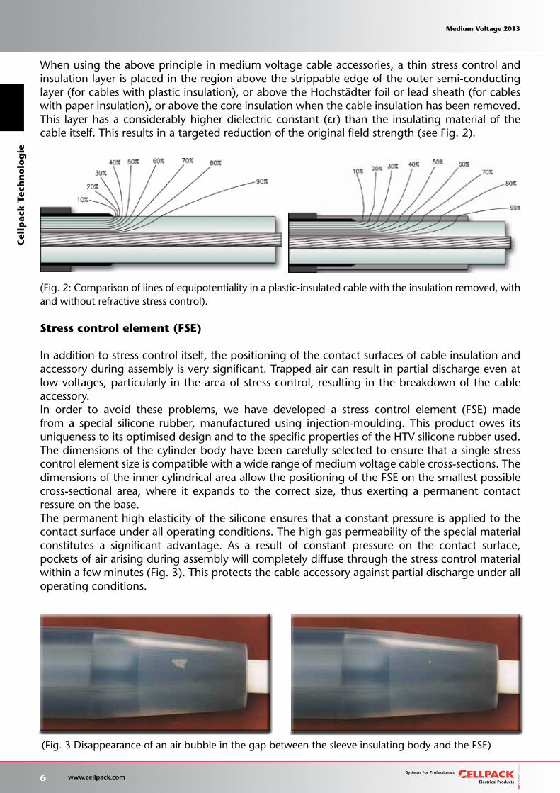
In addition to stress control itself, the positioning of the contact surfaces of cable insulation and accessory during assembly is very significant. Trapped air can result in partial discharge even at low voltages, particularly in the area of stress control, resulting in the breakdown of the cable accessory.In order to avoid these problems, we have developed a stress control element (FSE) made from a special silicone rubber, manufactured using injection-moulding. This product owes its uniqueness to its optimised design and to the specific properties of the HTV silicone rubber used. The dimensions of the cylinder body have been carefully selected to ensure that a single stress control element size is compatible with a wide range of medium voltage cable cross-sections. Thedimensions of the inner cylindrical area allow the positioning of the FSE on the smallest possible cross-sectional area, where it expands to the correct size, thus exerting a permanent contact ressure on the base.The permanent high elasticity of the silicone ensures that a constant pressure is applied to the contact surface under all operating conditions. The high gas permeability of the special material constitutes a significant advantage. As a result of constant pressure on the contact surface, pockets of air arising during assembly will completely diffuse through the stress control material within a few minutes (Fig. 3). This protects the cable accessory against partial discharge under all operating conditions.
(Fig. 3 Disappearance of an air bubble in the gap between the sleeve insulating body and the FSE)
6 www.cellpack.com
Medium Voltage 2013 Medium Voltage 2013C
ellp
ack T
ech
no
log
ie Medium Voltage 2013 Medium Voltage 2013
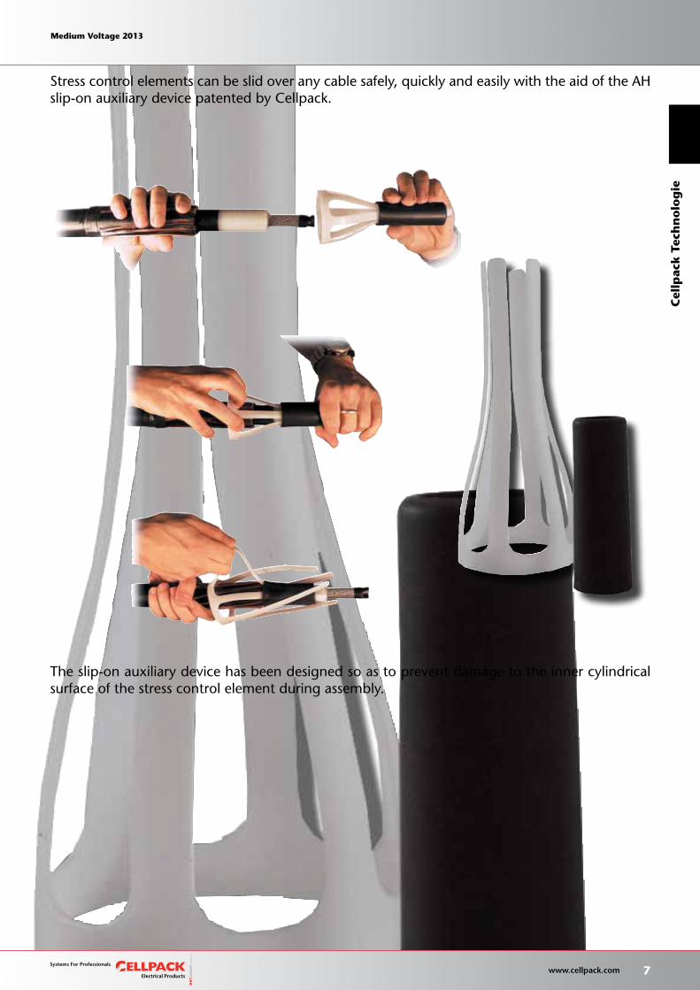
Stress control elements can be slid over any cable safely, quickly and easily with the aid of the AHslip-on auxiliary device patented by Cellpack.
The slip-on auxiliary device has been designed so as to prevent damage to the inner cylindrical surface of the stress control element during assembly.
Medium Voltage 2013 Medium Voltage 2013
7 www.cellpack.com
Medium Voltage 2013 Medium Voltage 2013
Cel
lpac
k T
ech
no
log
ie
Hybrid technology
Hybrid technology is a modular system developed by Cellpack which combines components made from silicone rubber with high voltage resistant heat shrink products. This renders our cable accessories compatible with all existing medium voltage cable cross-sections and ensures maximum operational reliability. The full product range comprises plug-in straight-through and transition joints, indoor and outdoor terminations for single- and three-core cables, which comply with the standard requirements for energy suppliers and the set industrial norms. We also offer products based on customer specifications.
Advantages
Our hybrid cable accessories offer a high level of operational safety in addition to the followingadvantages:•Safe,quickandeasyinstallation•Compactandspace-saving•Unlimitedshelflife•Adaptability
8 www.cellpack.com
Medium Voltage 2013 Medium Voltage 2013C
ellp
ack T
ech
no
log
ie Medium Voltage 2013 Medium Voltage 2013
Hybrid joint system
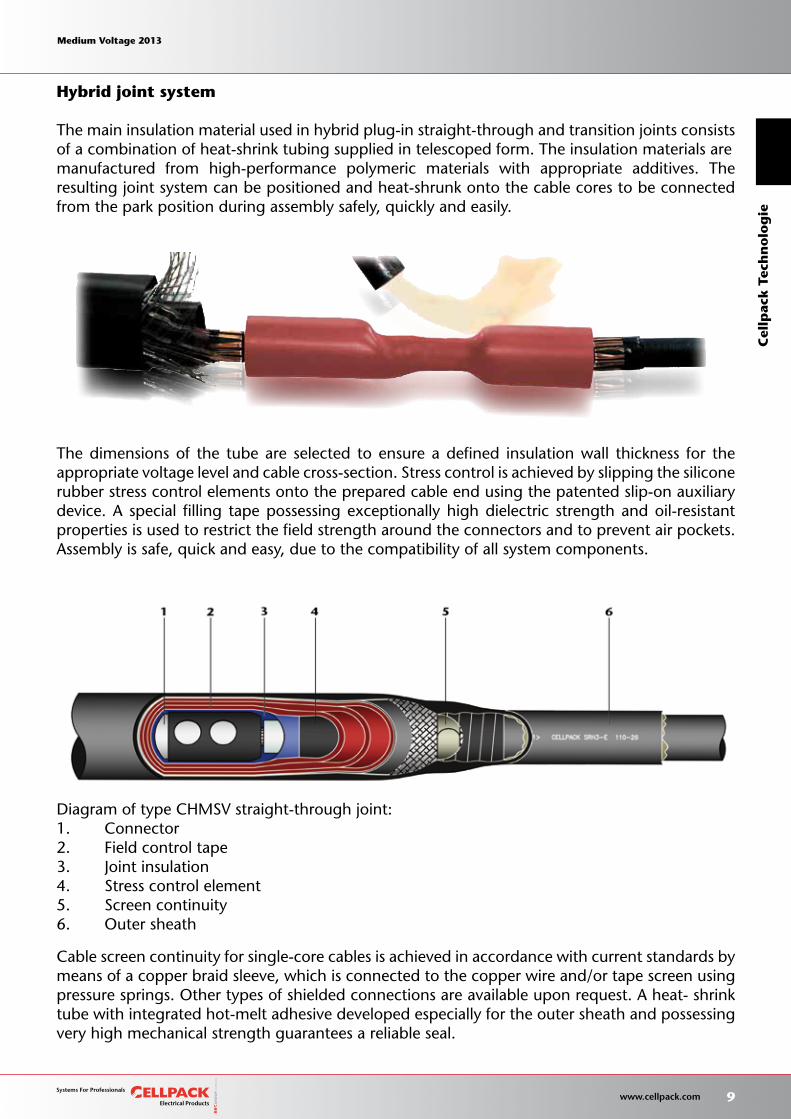
The main insulation material used in hybrid plug-in straight-through and transition joints consistsof a combination of heat-shrink tubing supplied in telescoped form. The insulation materials aremanufactured from high-performance polymeric materials with appropriate additives. The resulting joint system can be positioned and heat-shrunk onto the cable cores to be connected from the park position during assembly safely, quickly and easily.
The dimensions of the tube are selected to ensure a defined insulation wall thickness for the appropriate voltage level and cable cross-section. Stress control is achieved by slipping the siliconerubber stress control elements onto the prepared cable end using the patented slip-on auxiliary device. A special filling tape possessing exceptionally high dielectric strength and oil-resistant properties is used to restrict the field strength around the connectors and to prevent air pockets.Assembly is safe, quick and easy, due to the compatibility of all system components.
Cable screen continuity for single-core cables is achieved in accordance with current standards by means of a copper braid sleeve, which is connected to the copper wire and/or tape screen using pressure springs. Other types of shielded connections are available upon request. A heat- shrink tube with integrated hot-melt adhesive developed especially for the outer sheath and possessing very high mechanical strength guarantees a reliable seal.
Diagram of type CHMSV straight-through joint:1. Connector2. Field control tape3. Joint insulation4. Stress control element5. Screen continuity6. Outer sheath
Medium Voltage 2013 Medium Voltage 2013
9 www.cellpack.com
Medium Voltage 2013 Medium Voltage 2013
Cel
lpac
k T
ech
no
log
ie
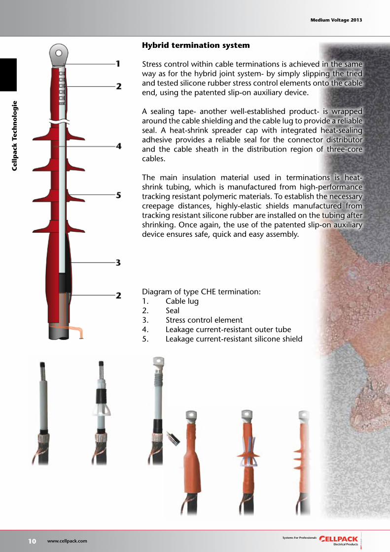
Hybrid termination system
Stress control within cable terminations is achieved in the same way as for the hybrid joint system- by simply slipping the tried and tested silicone rubber stress control elements onto the cable end, using the patented slip-on auxiliary device.
A sealing tape- another well-established product- is wrapped around the cable shielding and the cable lug to provide a reliable seal. A heat-shrink spreader cap with integrated heat-sealing adhesive provides a reliable seal for the connector distributor and the cable sheath in the distribution region of three-core cables.
The main insulation material used in terminations is heat-shrink tubing, which is manufactured from high-performance tracking resistant polymeric materials. To establish the necessary creepage distances, highly-elastic shields manufactured from tracking resistant silicone rubber are installed on the tubing after shrinking. Once again, the use of the patented slip-on auxiliary device ensures safe, quick and easy assembly.
Diagram of type CHE termination:1. Cable lug2. Seal3. Stress control element4. Leakage current-resistant outer tube5. Leakage current-resistant silicone shield
10 www.cellpack.com
Medium Voltage 2013 Medium Voltage 2013C
ellp
ack T
ech
no
log
ie Medium Voltage 2013 Medium Voltage 2013
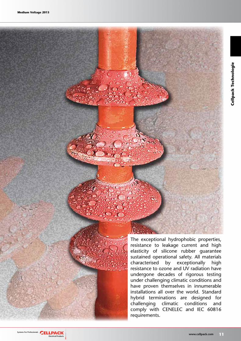
The exceptional hydrophobic properties, resistance to leakage current and high elasticity of silicone rubber guarantee sustained operational safety. All materials characterised by exceptionally high resistancetoozoneandUVradiationhaveundergone decades of rigorous testing under challenging climatic conditions and have proven themselves in innumerable installations all over the world. Standard hybrid terminations are designed for challenging climatic conditions and comply with CENELEC and IEC 60816 requirements.
Medium Voltage 2013 Medium Voltage 2013
11 www.cellpack.com
Medium Voltage 2013 Medium Voltage 2013
Cel
lpac
k T
ech
no
log
ie
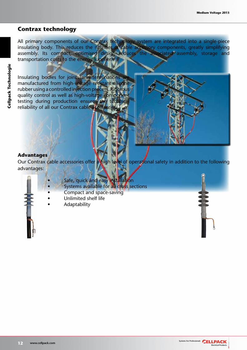
Contrax technology
All primary components of our Contrax technology system are integrated into a single-piece insulating body. This reduces the number of cable accessory components, greatly simplifying assembly. Its compact, optimised design reduces the associated assembly, storage and transportation costs to the energy supplier.
Insulating bodies for joints and terminations are manufactured from high-voltage resistant silicone rubber using a controlled injection process. Rigorous quality control as well as high-voltage component testing during production ensures the technical reliability of all our Contrax cable accessories.
AdvantagesOur Contrax cable accessories offer a high level of operational safety in addition to the following advantages:
• Safe,quickandeasyinstallation • Systemsavailableforallcrosssections • Compactandspace-saving • Unlimitedshelflife • Adaptability
12 www.cellpack.com
Medium Voltage 2013 Medium Voltage 2013C
ellp
ack T
ech
no
log
ie Medium Voltage 2013 Medium Voltage 2013
Contrax joint system
The single-piece insulating body of Contrax plug-in straight-through joints consists of an inner conductive electrode which acts as a Faraday cage around the connector with the main insulating layer above it, and an outer semi-conducting layer. Each joint body comes equipped with an integrated slip-on auxiliary device for easy assembly and the prevention of damage during installation.
Stress control at the cable end is achieved as above, by simply sliding our tried and tested siliconerubber stress control element onto the prepared cable using the patented slip-on auxiliary device.A special feature of the Contrax joint is that the stress control element is also used to control theelectric field on the inner semi-conducting layer of the insulating body at high voltage against theouter semi-conducting layer of the joint body at earth potential.
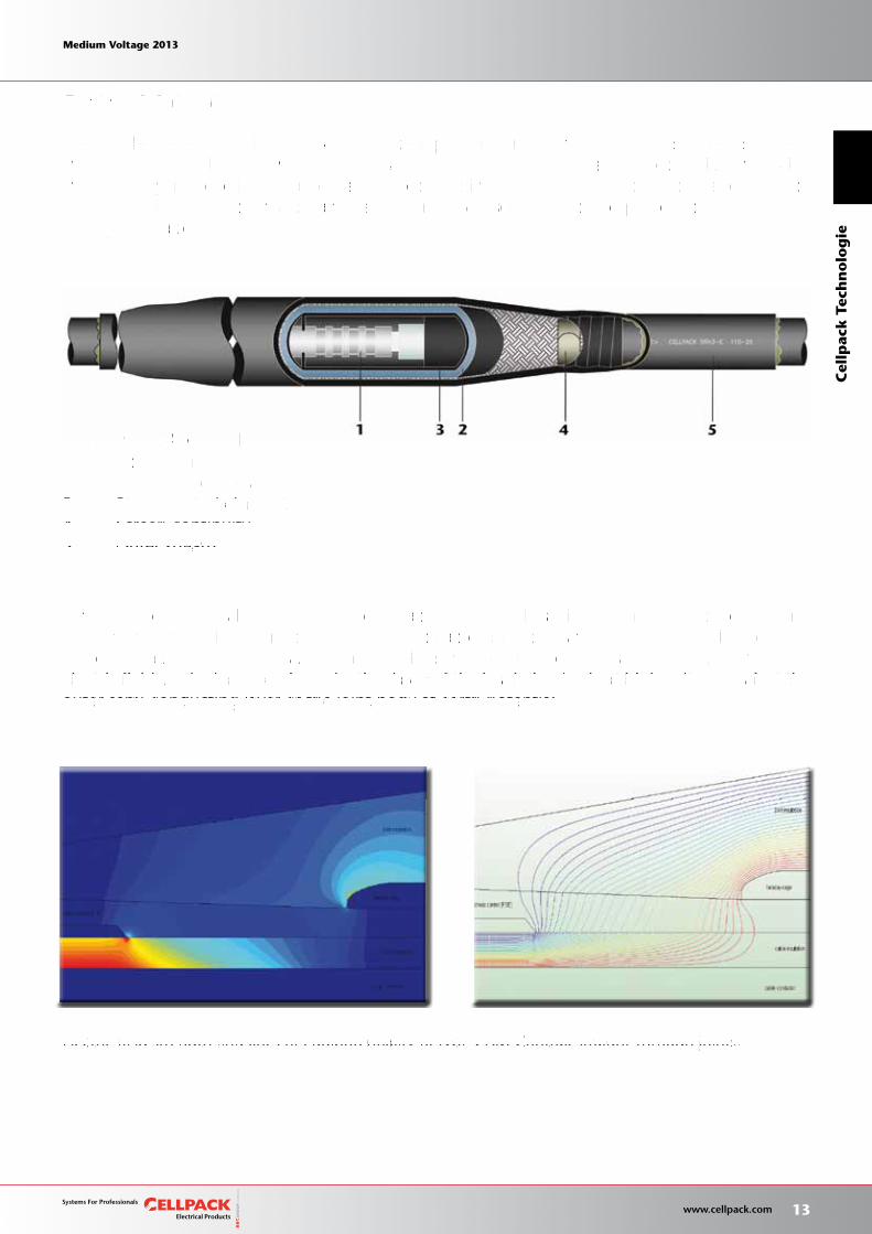
Electric field strength and lines of equipotentiality of type CAM Contrax straight-through joints.
Diagram of CAM joint body:1. Connector2. Single-piece insulating body3. Stress control element4. Screen continuity5. Outer sheath
Medium Voltage 2013 Medium Voltage 2013
13 www.cellpack.com
Medium Voltage 2013 Medium Voltage 2013
Cel
lpac
k T
ech
no
log
ie
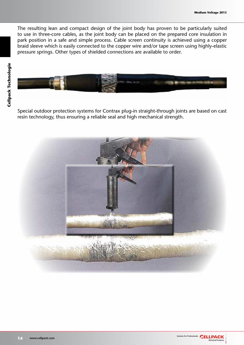
The resulting lean and compact design of the joint body has proven to be particularly suited to use in three-core cables, as the joint body can be placed on the prepared core insulation in park position in a safe and simple process. Cable screen continuity is achieved using a copper braid sleeve which is easily connected to the copper wire and/or tape screen using highly-elastic pressure springs. Other types of shielded connections are available to order.
Special outdoor protection systems for Contrax plug-in straight-through joints are based on castresin technology, thus ensuring a reliable seal and high mechanical strength.
14 www.cellpack.com
Medium Voltage 2013 Medium Voltage 2013C
ellp
ack T
ech
no
log
ie Medium Voltage 2013 Medium Voltage 2013
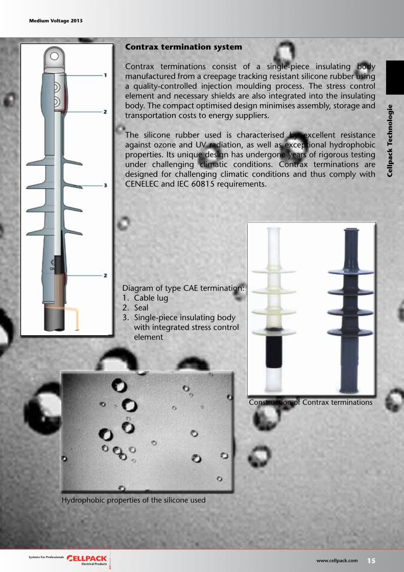
Contrax termination system
Contrax terminations consist of a single-piece insulating body manufactured from a creepage tracking resistant silicone rubber using a quality-controlled injection moulding process. The stress control element and necessary shields are also integrated into the insulating body. The compact optimised design minimises assembly, storage and transportation costs to energy suppliers.
The silicone rubber used is characterised by excellent resistance againstozoneandUVradiation,aswellasexceptionalhydrophobicproperties. Its unique design has undergone years of rigorous testing under challenging climatic conditions. Contrax terminations are designed for challenging climatic conditions and thus comply with CENELEC and IEC 60815 requirements.
Construction of Contrax terminations
Hydrophobic properties of the silicone used
Diagram of type CAE termination:1. Cable lug2. Seal3. Single-piece insulating body with integrated stress control element
Medium Voltage 2013 Medium Voltage 2013
15 www.cellpack.com
Medium Voltage 2013 Medium Voltage 2013
Cel
lpac
k T
ech
no
log
ie
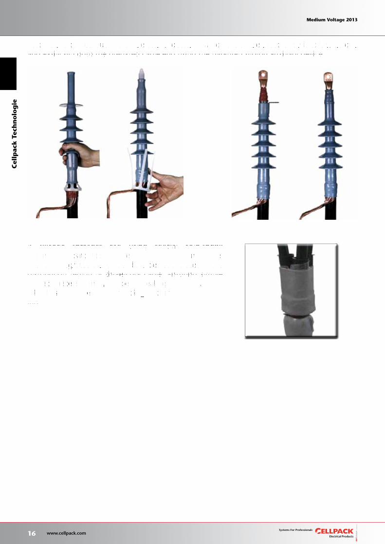
Assembly is carried out in a single-step process, in which the single-piece body is safely, quickly and easily slid onto the prepared cable end using the patented slip-on auxiliary device.
A silicone spreader cap using special cold-shrink technology, patented by Cellpack, and silicone tubes with an integrated slip-on auxiliary device are used in the distribution region of three-core cable, ensuring simple and accurate assembly. A special sealing tape provides a reliable seal at the cable shielding and around the cable lug.
16 www.cellpack.com
Medium Voltage 2013 Medium Voltage 2013C
ellp
ack T
ech
no
log
ie Medium Voltage 2013 Medium Voltage 2013
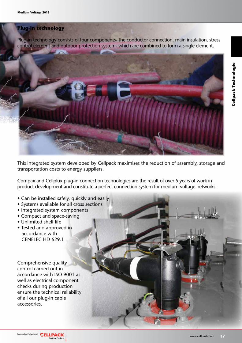
Plug-in technology
Plug-in technology consists of four components- the conductor connection, main insulation, stress control element and outdoor protection system- which are combined to form a single element.
This integrated system developed by Cellpack maximises the reduction of assembly, storage and transportation costs to energy suppliers.
Compax and Cellplux plug-in connection technologies are the result of over 5 years of work in product development and constitute a perfect connection system for medium-voltage networks.
•Canbeinstalledsafely,quicklyandeasily•Systemsavailableforallcrosssections•Integratedsystemcomponents•Compactandspace-saving•Unlimitedshelflife•Testedandapprovedin accordance with CENELEC HD 629.1
Comprehensive quality control carried out in accordance with ISO 9001 as well as electrical component checks during production ensure the technical reliability of all our plug-in cable accessories.
Medium Voltage 2013 Medium Voltage 2013
17 www.cellpack.com
Medium Voltage 2013 Medium Voltage 2013
Cel
lpac
k T
ech
no
log
ie
Compax plug-in straight-through joint
This joint has been especially developed for connecting plastic-insulated medium voltage single-core cables. All system components are compatible to ensure that assembly is extremely safe, quick and easy.
This innovative integration concept allows for much of the assembly process, previously carried out on-site, to be performed under controlled conditions and subjected to electrical testing at the Cellpack factory. Only a few assembly steps remain to be performed on-site.
Advantages:
• Safe, quick and easy assembly• Only standard tools required• Suitable for use in confined spaces• Products available for all cross sections• Robust design• Reduction in storage and transportation costs• Unlimitedshelf-life
18 www.cellpack.com
Medium Voltage 2013 Medium Voltage 2013C
ellp
ack T
ech
no
log
ie Medium Voltage 2013 Medium Voltage 2013
7 6 2 4 531
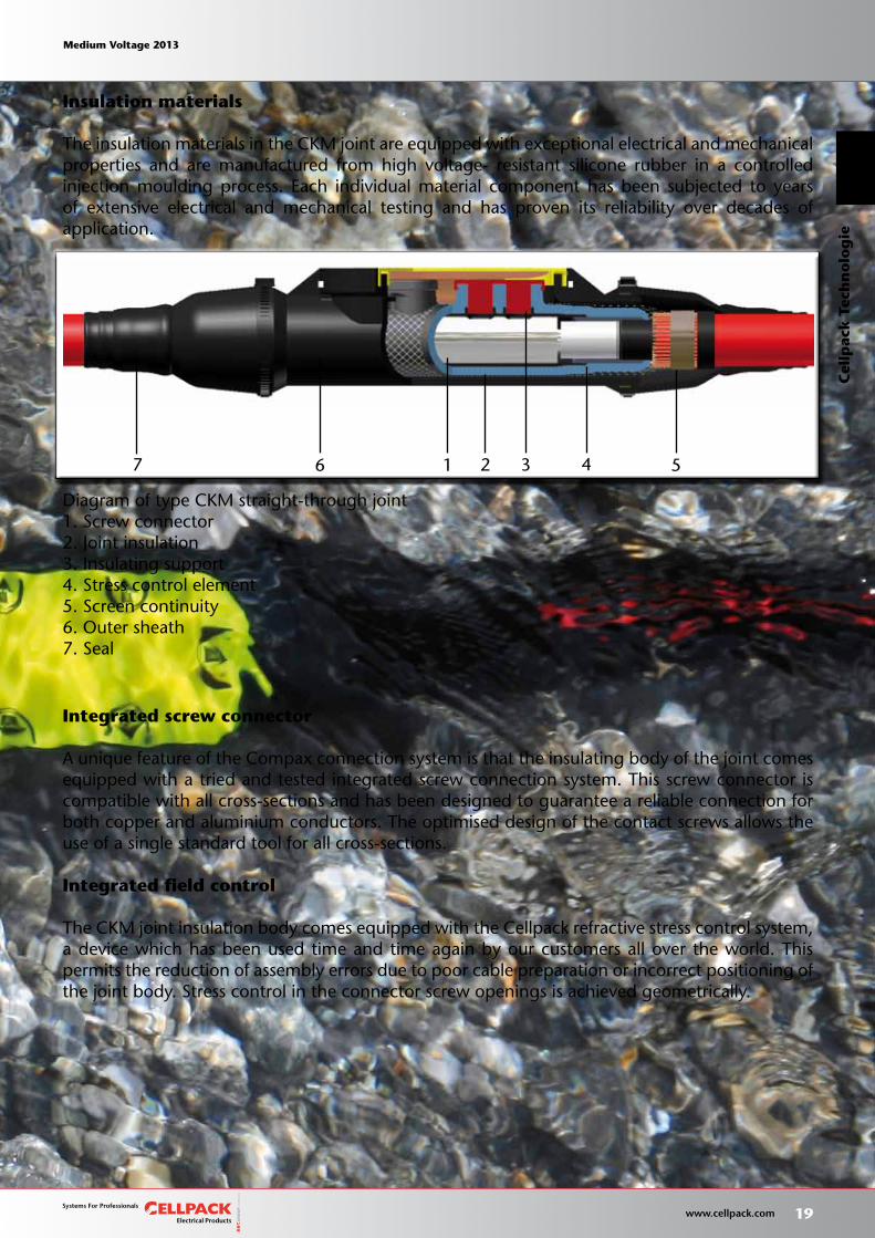
Insulation materials
The insulation materials in the CKM joint are equipped with exceptional electrical and mechanicalproperties and are manufactured from high voltage- resistant silicone rubber in a controlled injection moulding process. Each individual material component has been subjected to years of extensive electrical and mechanical testing and has proven its reliability over decades of application.
Integrated screw connector
A unique feature of the Compax connection system is that the insulating body of the joint comesequipped with a tried and tested integrated screw connection system. This screw connector is compatible with all cross-sections and has been designed to guarantee a reliable connection for both copper and aluminium conductors. The optimised design of the contact screws allows the use of a single standard tool for all cross-sections.
Integrated field control
The CKM joint insulation body comes equipped with the Cellpack refractive stress control system, a device which has been used time and time again by our customers all over the world. This permits the reduction of assembly errors due to poor cable preparation or incorrect positioning ofthe joint body. Stress control in the connector screw openings is achieved geometrically.
Diagram of type CKM straight-through joint1. Screw connector2. Joint insulation3. Insulating support4. Stress control element5. Screen continuity6. Outer sheath7. Seal
Medium Voltage 2013 Medium Voltage 2013
19 www.cellpack.com
Medium Voltage 2013 Medium Voltage 2013
Cel
lpac
k T
ech
no
log
ie
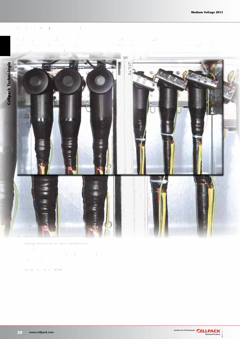
Cellplux plug-in connectors
Cellplux plug-in cable connection components have been especially developed to connect plastic-insulated medium voltage cables. All system components are compatible to ensure that assembly is extremely safe, quick and easy.
This innovative integration concept allows for much of the assembly process, previously carried out on-site, to be performed under controlled conditions and subjected to electrical testing at theCellpack factory. Only a few assembly steps remain to be performed on-site.
Advantages:
Cellplux plug-in cable connection components guarantee reliable operational safety and offer thefollowing advantages:
• High level of operational safety• Safe, quick and easy assembly• Standard tools may be used• Suitable for use in confined spaces• Products available for all cross sections• Robust design• Unlimitedshelflife
20 www.cellpack.com
Medium Voltage 2013 Medium Voltage 2013C
ellp
ack T
ech
no
log
ie Medium Voltage 2013 Medium Voltage 2013
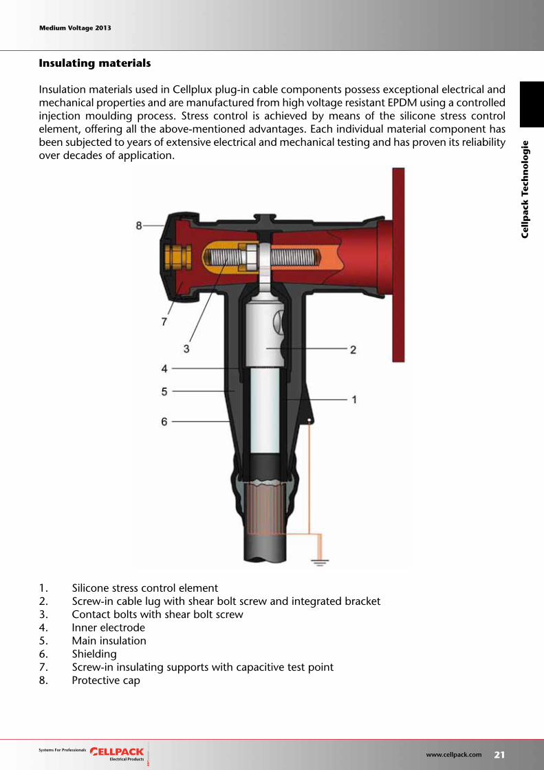
Insulating materials
Insulation materials used in Cellplux plug-in cable components possess exceptional electrical and mechanical properties and are manufactured from high voltage resistant EPDM using a controlled injection moulding process. Stress control is achieved by means of the silicone stress control element, offering all the above-mentioned advantages. Each individual material component has been subjected to years of extensive electrical and mechanical testing and has proven its reliability over decades of application.
1. Silicone stress control element2. Screw-in cable lug with shear bolt screw and integrated bracket3. Contact bolts with shear bolt screw4. Inner electrode5. Main insulation6. Shielding7. Screw-in insulating supports with capacitive test point8. Protective cap
Medium Voltage 2013 Medium Voltage 2013
21 www.cellpack.com
Medium Voltage 2013 Medium Voltage 2013
Cel
lpac
k T
ech
no
log
ie

Stress control
This system is also equipped with Cellpack’s integrated refractive stress control system, which has a proven track record of reliability. This eliminates the possibility of incorrect cable preparation and dramatically reduces the number of possible assembly errors.
Protection from exposed electrical parts
Cellplux plug-in cable component shieldingaa is made from conductive EPDM rubber over 3mmthick. All products have successfully undergone tests for insulation failure detection.
Screw-in cable lug and screw-in contact bolts
Cellplux plug-in cable components are equipped with a tried and tested screw-in cable lug system, compatible with all cross-sections, which has been designed to guarantee reliable connection for both copper and aluminium conductors. The optimised design of the contact bolts permits the use of a single Monventional tool for assembly across the entire range of cross sections. The shear bolt screw system is also used for CTS screw-type plug-in connection contact bolts connecting the cable lug to the connecting terminal. This eliminates the possibilty of errors during assembly.
22 www.cellpack.com
Medium Voltage 2013 Medium Voltage 2013C
ellp
ack T
ech
no
log
ie Medium Voltage 2013 Medium Voltage 2013
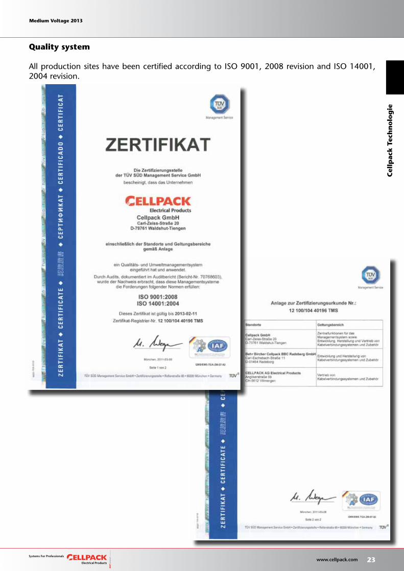
Quality system
All production sites have been certified according to ISO 9001, 2008 revision and ISO 14001, 2004 revision.
Medium Voltage 2013 Medium Voltage 2013
23 www.cellpack.com
Medium Voltage 2013 Medium Voltage 2013
Cel
lpac
k T
ech
no
log
ie

For pros by pros
24 www.cellpack.com
Medium Voltage 2013 Medium Voltage 2013 Medium Voltage 2013 Medium Voltage 2013
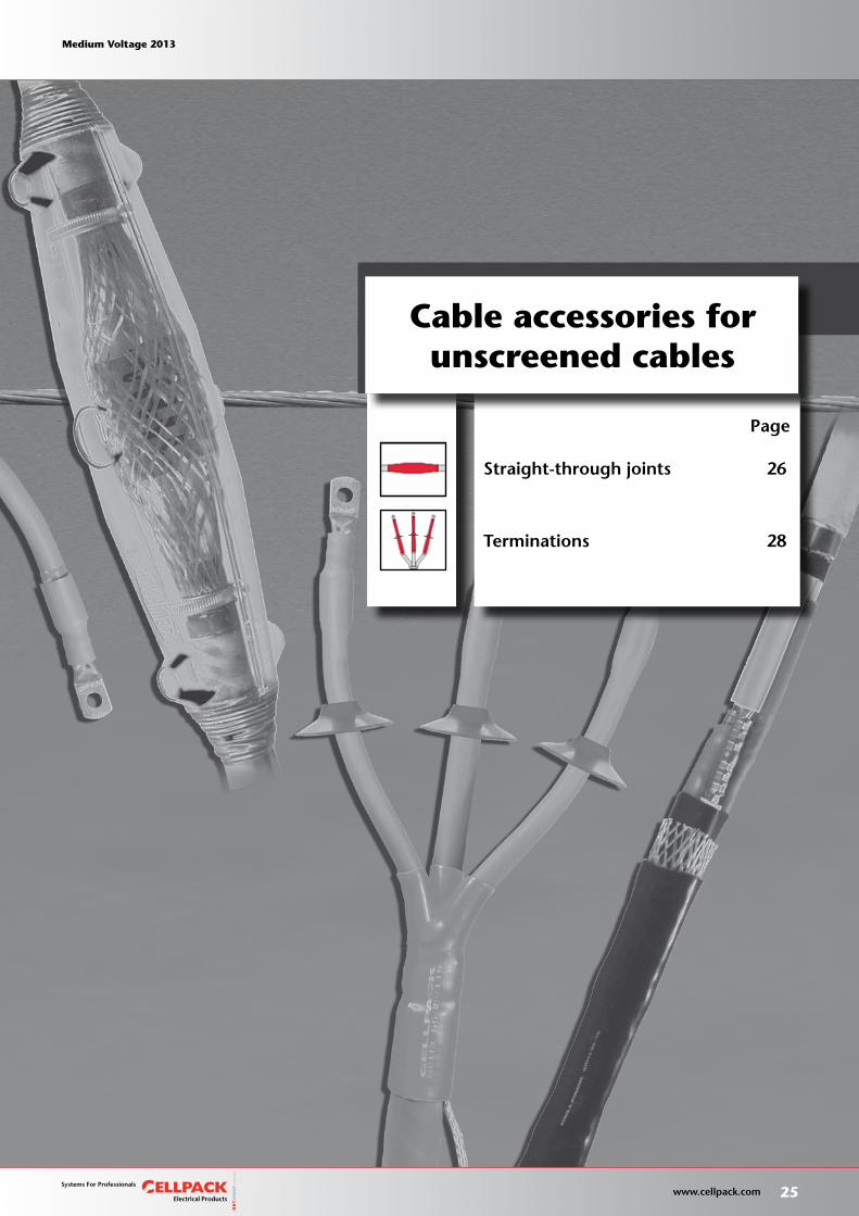
Straight-through joints 26
Terminations 28
Page
Cable accessories forunscreened cables
Medium Voltage 2013 Medium Voltage 2013
25 www.cellpack.com
Medium Voltage 2013 Medium Voltage 2013
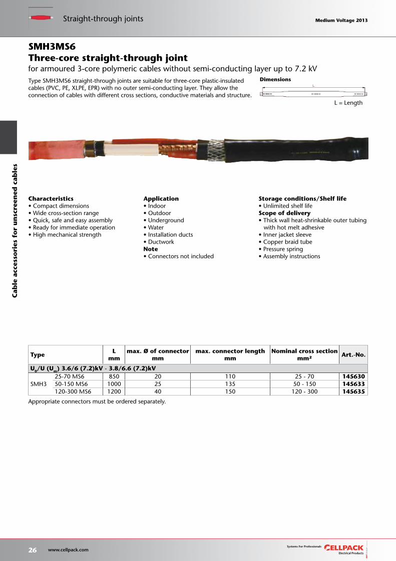
L = Length
Storage conditions/Shelf life•UnlimitedshelflifeScope of delivery•Thickwallheat-shrinkableoutertubing with hot melt adhesive•Innerjacketsleeve•Copperbraidtube•Pressurespring•Assemblyinstructions
TypeL
mm max. Ø of connector
mm max. connector length
mm Nominal cross section
mm²Art.-No.
U0/U (Um) 3.6/6 (7.2)kV - 3.8/6.6 (7.2)kV
SMH325-70 MS6 850 20 110 25 - 70 14563050-150 MS6 1000 25 135 50 - 150 145633120-300 MS6 1200 40 150 120 - 300 145635
Dimensions
Appropriate connectors must be ordered separately.
Characteristics•Compactdimensions•Widecross-sectionrange•Quick,safeandeasyassembly•Readyforimmediateoperation•Highmechanicalstrength
Application•Indoor•Outdoor•Underground•Water•Installationducts•DuctworkNote•Connectorsnotincluded
Type SMH3MS6 straight-through joints are suitable for three-core plastic-insulated cables (PVC, PE, XLPE, EPR) with no outer semi-conducting layer. They allow the connection of cables with different cross sections, conductive materials and structure.
for armoured 3-core polymeric cables without semi-conducting layer up to 7.2 kVThree-core straight-through jointSMH3MS6
26 www.cellpack.com
Medium Voltage 2013 Medium Voltage 2013Straight-through jointsC
able
acc
esso
ries
fo
r u
nsc
reen
ed c
able
s Medium Voltage 2013 Medium Voltage 2013
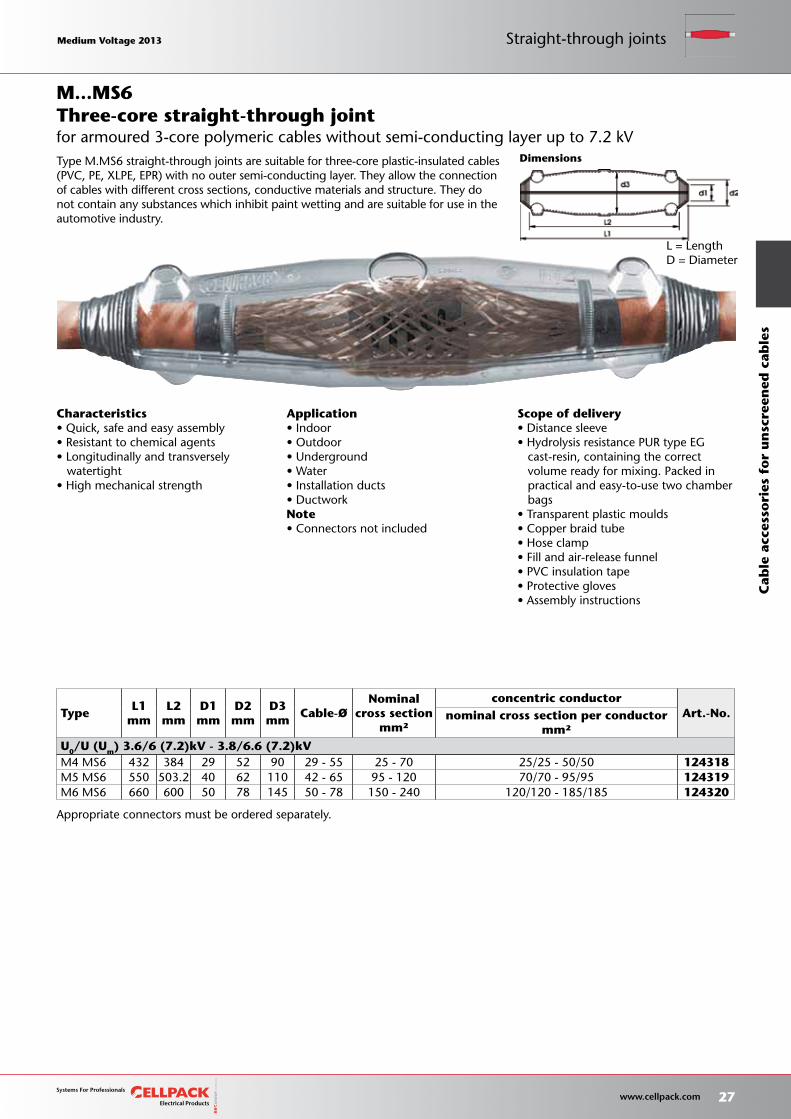
Appropriate connectors must be ordered separately.
L = LengthD = Diameter
Dimensions
Scope of delivery•Distancesleeve•HydrolysisresistancePURtypeEG cast-resin, containing the correct volume ready for mixing. Packed in practical and easy-to-use two chamber bags•Transparentplasticmoulds•Copperbraidtube•Hoseclamp•Fillandair-releasefunnel•PVCinsulationtape•Protectivegloves•Assemblyinstructions
Characteristics•Quick,safeandeasyassembly•Resistanttochemicalagents•Longitudinallyandtransversely watertight•Highmechanicalstrength
Application•Indoor•Outdoor•Underground•Water•Installationducts•DuctworkNote•Connectorsnotincluded
Three-core straight-through joint
Type M.MS6 straight-through joints are suitable for three-core plastic-insulated cables (PVC, PE, XLPE, EPR) with no outer semi-conducting layer. They allow the connection of cables with different cross sections, conductive materials and structure. They do not contain any substances which inhibit paint wetting and are suitable for use in the automotive industry.
TypeL1
mm L2
mm D1mm
D2mm
D3mm
Cable-ØNominal
cross section mm²
concentric conductorArt.-No.nominal cross section per conductor
mm² U0/U (Um) 3.6/6 (7.2)kV - 3.8/6.6 (7.2)kVM4 MS6 432 384 29 52 90 29 - 55 25 - 70 25/25 - 50/50 124318M5 MS6 550 503.2 40 62 110 42 - 65 95 - 120 70/70 - 95/95 124319M6 MS6 660 600 50 78 145 50 - 78 150 - 240 120/120 - 185/185 124320
for armoured 3-core polymeric cables without semi-conducting layer up to 7.2 kV
M...MS6
Medium Voltage 2013 Medium Voltage 2013
27 www.cellpack.com
Medium Voltage 2013 Medium Voltage 2013 Straight-through joints
Cab
le a
cces
sori
es f
or
un
scre
ened
cab
les
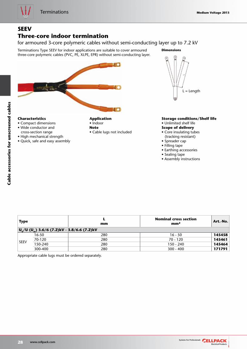
Appropriate cable lugs must be ordered separately.
L = Length
TypeL
mm Nominal cross section
mm²Art.-No.
U0/U (Um) 3.6/6 (7.2)kV - 3.8/6.6 (7.2)kV
SEEV
16-50 280 16 - 50 14545870-120 280 70 - 120 145461150-240 280 150 - 240 145464300-400 280 300 - 400 171791
Storage conditions/Shelf life•UnlimitedshelflifeScope of delivery•Coreinsulatingtubes (tracking resistant)•Spreadercap•Fillingtape•Earthingaccessories•Sealingtape•Assemblyinstructions
Dimensions
Characteristics•Compactdimensions•Wideconductorand cross-section range•Highmechanicalstrength•Quick,safeandeasyassembly
Application•IndoorNote•Cablelugsnotincluded
Terminations Type SEEV for indoor applications are suitable to cover armoured three-core polymeric cables (PVC, PE, XLPE, EPR) without semi-conducting layer.
for armoured 3-core polymeric cables without semi-conducting layer up to 7.2 kVThree-core indoor terminationSEEV
28 www.cellpack.com
Medium Voltage 2013 Medium Voltage 2013C
able
acc
esso
ries
fo
r u
nsc
reen
ed c
able
sTerminations Medium Voltage 2013 Medium Voltage 2013
Appropriate cable lugs must be ordered separately.
L = LengthØ S = Diameter of cable shed
TypeL
mm Nominal cross section
mm²Ø Smm
Art.-No.
U0/U (Um) 3.6/6 (7.2)kV - 3.8/6.6 (7.2)kV
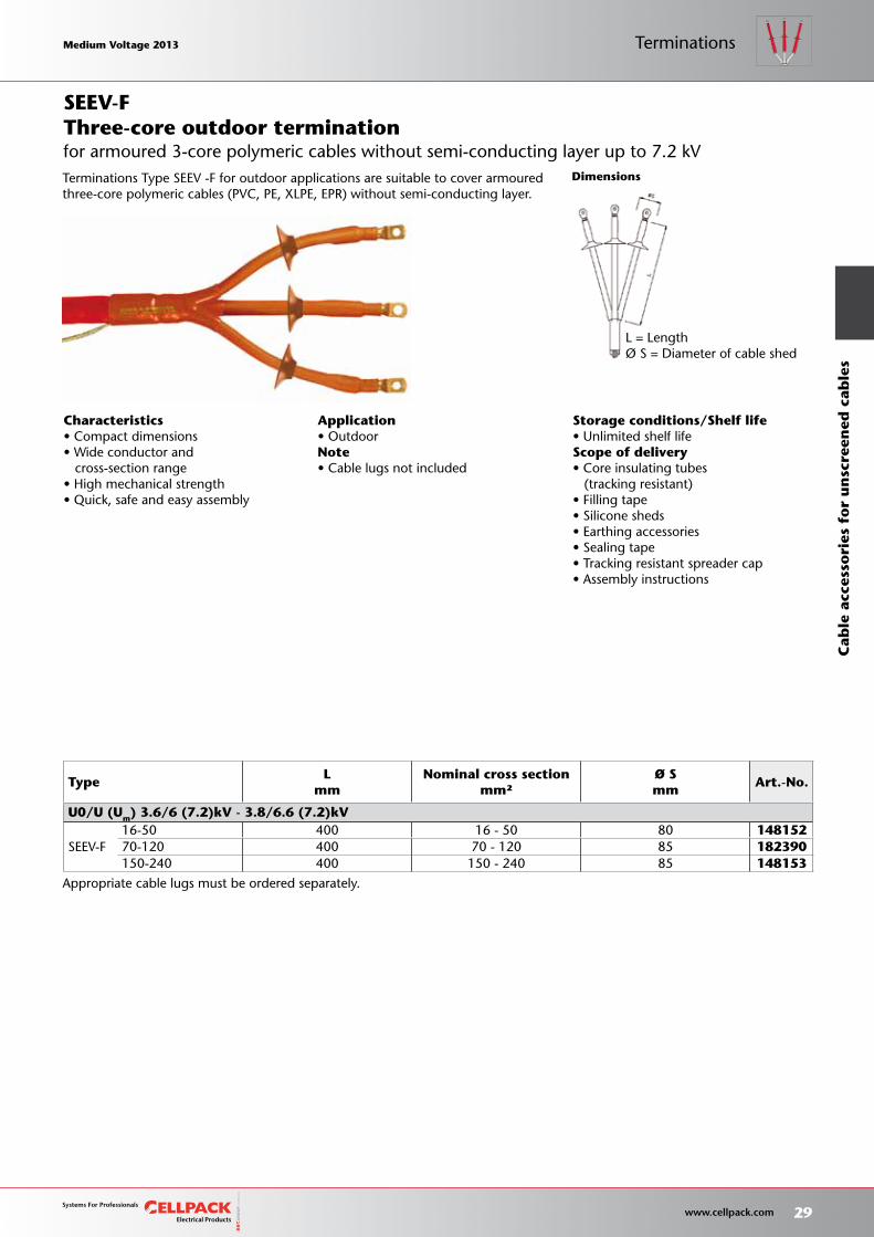
SEEV-F16-50 400 16 - 50 80 14815270-120 400 70 - 120 85 182390150-240 400 150 - 240 85 148153
Storage conditions/Shelf life•UnlimitedshelflifeScope of delivery•Coreinsulatingtubes (tracking resistant)•Fillingtape•Siliconesheds•Earthingaccessories•Sealingtape•Trackingresistantspreadercap•Assemblyinstructions
Dimensions
Characteristics•Compactdimensions•Wideconductorand cross-section range•Highmechanicalstrength•Quick,safeandeasyassembly
Application•OutdoorNote•Cablelugsnotincluded
Terminations Type SEEV -F for outdoor applications are suitable to cover armoured three-core polymeric cables (PVC, PE, XLPE, EPR) without semi-conducting layer.
for armoured 3-core polymeric cables without semi-conducting layer up to 7.2 kVThree-core outdoor terminationSEEV-F
Medium Voltage 2013 Medium Voltage 2013
29 www.cellpack.com
Medium Voltage 2013 Medium Voltage 2013
Cab
le a
cces
sori
es f
or
un
scre
ened
cab
les
Terminations

30 www.cellpack.com
Medium Voltage 2013 Medium Voltage 2013 Medium Voltage 2013 Medium Voltage 2013
Straight-through joints forsingle-core cables 32
Termination for single-core cables 37
Straight-through joints for3-core cables 59
Termination for 3-core cables 63
Page
Cable accessories forscreened cables
Scaling the heights safely
Medium Voltage 2013 Medium Voltage 2013
31 www.cellpack.com
Medium Voltage 2013 Medium Voltage 2013
Heat-shrinkable straight-through joints, larger cross section on request
Dimensions
Storage conditions/Shelf life• Unlimited shelf lifeScope of delivery• Thick wall heat-shrinkable insulation tubing• Thick wall heat-shrinkable outer tubing with hot melt adhesive• Silicone stress-control elements• Copper braid tube• Pressure springs• Innovative screw connector with conductive sheath• Stress control filling tape (blue)• Assembly instructionsTests• CENELEC HD 629.1 (DIN VDE 0278, part 629-1)
TypeL
mm
min. Ø over conductor insulation
after removal of outersemi-conducting layer
mm
Nominal cross section mm²
Art.-No.
12kV 17.5kV 24kV 36kV
U0/U (Um) 6/10 (12)kV - 6.35/11 (12)kV
CHMSV 12kV
25-95 600 12.6 25 - 95 25813070-150 600 14.7 70 - 150 25813195-240 600 17.3 95 - 240 258132240-400 650 23.1 240 - 400 258133
U0/U (Um) 8.7/15 (17.5)kV
CHMSV 17kV
25-95 600 14.7 25 - 95 25813570-150 600 18.0 70 - 150 25813695-240 600 19.9 95 - 240 258137240-400 700 24.0 240 - 400 258138
U0/U (Um) 12/20 (24)kV - 12.7/22 (24)kV
CHMSV 24kV
16-95 600 14.7 16 - 95 25814050-150 600 17.3 50 - 150 25814195-240 600 19.9 95 - 240 258142240-400 700 27.3 240 - 400 258143
U0/U (Um) 18/30 (36)kV - 19/33 (36)kV
CHMSV 36kV50-150 600 20.9 50 - 150 25814495-240 600 24.2 95 - 240 258145240-400 700 32.0 240 - 400 258146
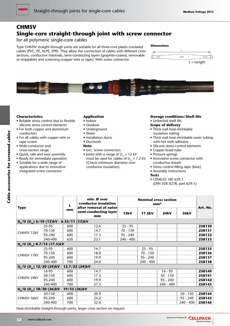
Characteristics• Reliable stress control due to flexible silicone stress control elements• For both copper and aluminium conductors• For all cables with copper wire or tape screen• Wide conductor and cross-section range• Quick, safe and easy assembly• Ready for immediate operation• Suitable for a wide range of applications due to innovative integrated screw connector
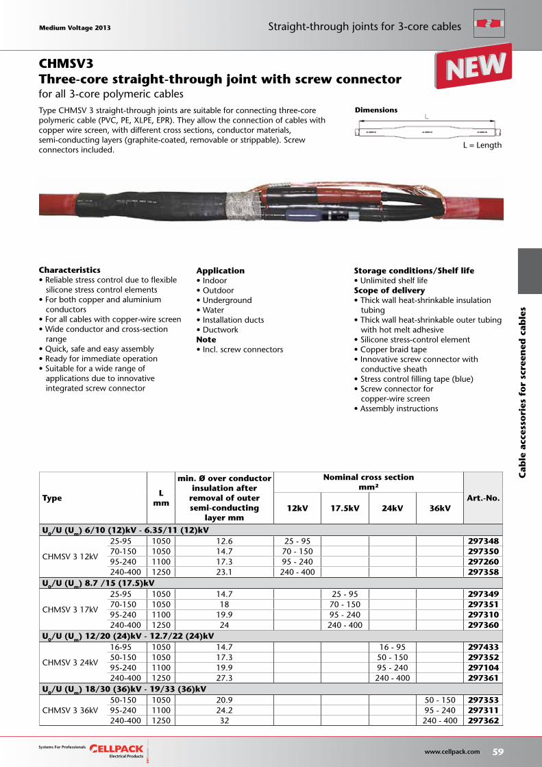
Application• Indoor• Outdoor• Underground• Water• Installation ducts• DuctworkNote• Incl. Screw connectors• Joints with a range of Um = 12 kV must be used for cables of Um = 7.2 kV. (Check minimum diameter over conductor insulation).
Single-core straight-through joint with screw connector
Type CHMSV straight-through joints are suitable for all three-core plastic-insulated cables (PVC, PE, XLPE, EPR). They allow the connection of cables with different cross sections, conductive materials, semi-conducting layers (graphite-coated, removable or strippable) and screening (copper wire or tape). With screw connector.
CHMSV
for all polymeric single-core cables
L = Length
32 www.cellpack.com
Medium Voltage 2013 Medium Voltage 2013C
able
acc
esso
ries
fo
r sc
reen
ed c
able
sStraight-through joints for single-core cables Medium Voltage 2013 Medium Voltage 2013
Storage conditions/Shelf life• Unlimited shelf lifeScope of delivery• Thick wall heat-shrinkable insulation tubing• Thick wall heat-shrinkable outer tubing with hot melt adhesive• Silicone stress-control elements• Copper braid tube• Pressure springs• Stress control filling tape (blue)• Assembly instructionsTests• CENELEC HD 629.1 (DIN VDE 0278, part 629-1)
Dimensions
L = Length
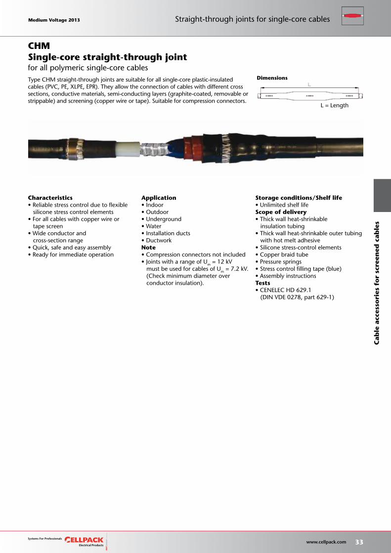
Characteristics• Reliable stress control due to flexible silicone stress control elements• For all cables with copper wire or tape screen• Wide conductor and cross-section range• Quick, safe and easy assembly• Ready for immediate operation
Application• Indoor• Outdoor• Underground• Water• Installation ducts• DuctworkNote• Compression connectors not included• Joints with a range of Um = 12 kV must be used for cables of Um = 7.2 kV. (Check minimum diameter over conductor insulation).
Single-core straight-through joint
Type CHM straight-through joints are suitable for all single-core plastic-insulated cables (PVC, PE, XLPE, EPR). They allow the connection of cables with different cross sections, conductive materials, semi-conducting layers (graphite-coated, removable or strippable) and screening (copper wire or tape). Suitable for compression connectors.
CHM
for all polymeric single-core cables
Medium Voltage 2013 Medium Voltage 2013
33 www.cellpack.com
Medium Voltage 2013 Medium Voltage 2013
Cab
le a
cces
sori
es f
or
scre
ened
cab
les
Straight-through joints for single-core cables
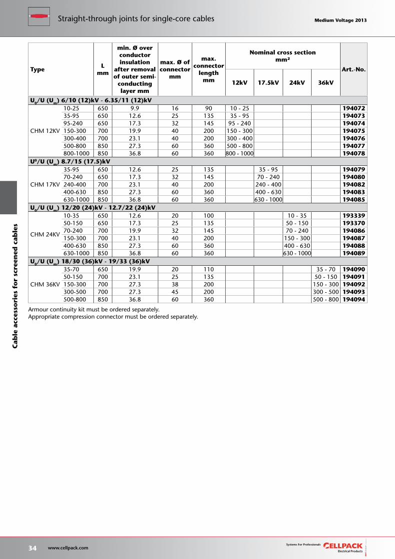
TypeL
mm
min. Ø over conductorinsulation
after removal of outer semi-
conductinglayer mm
max. Ø of connector
mm
max. connector
lengthmm
Nominal cross sectionmm²
Art.-No.
12kV 17.5kV 24kV 36kV
U0/U (Um) 6/10 (12)kV - 6.35/11 (12)kV
CHM 12KV
10-25 650 9.9 16 90 10 - 25 19407235-95 650 12.6 25 135 35 - 95 19407395-240 650 17.3 32 145 95 - 240 194074150-300 700 19.9 40 200 150 - 300 194075300-400 700 23.1 40 200 300 - 400 194076500-800 850 27.3 60 360 500 - 800 194077800-1000 850 36.8 60 360 800 - 1000 194078
U0/U (Um) 8.7/15 (17.5)kV
CHM 17KV
35-95 650 12.6 25 135 35 - 95 19407970-240 650 17.3 32 145 70 - 240 194080240-400 700 23.1 40 200 240 - 400 194082400-630 850 27.3 60 360 400 - 630 194083630-1000 850 36.8 60 360 630 - 1000 194085
U0/U (Um) 12/20 (24)kV - 12.7/22 (24)kV
CHM 24KV
10-35 650 12.6 20 100 10 - 35 19333950-150 650 17.3 25 135 50 - 150 19337070-240 700 19.9 32 145 70 - 240 194086150-300 700 23.1 40 200 150 - 300 194087400-630 850 27.3 60 360 400 - 630 194088630-1000 850 36.8 60 360 630 - 1000 194089
U0/U (Um) 18/30 (36)kV - 19/33 (36)kV
CHM 36KV
35-70 650 19.9 20 110 35 - 70 19409050-150 700 23.1 25 135 50 - 150 194091150-300 700 27.3 38 200 150 - 300 194092300-500 700 27.3 45 200 300 - 500 194093500-800 850 36.8 60 360 500 - 800 194094
Armour continuity kit must be ordered separately.Appropriate compression connector must be ordered separately.
34 www.cellpack.com
Medium Voltage 2013 Medium Voltage 2013C
able
acc
esso
ries
fo
r sc
reen
ed c
able
sStraight-through joints for single-core cables Medium Voltage 2013 Medium Voltage 2013
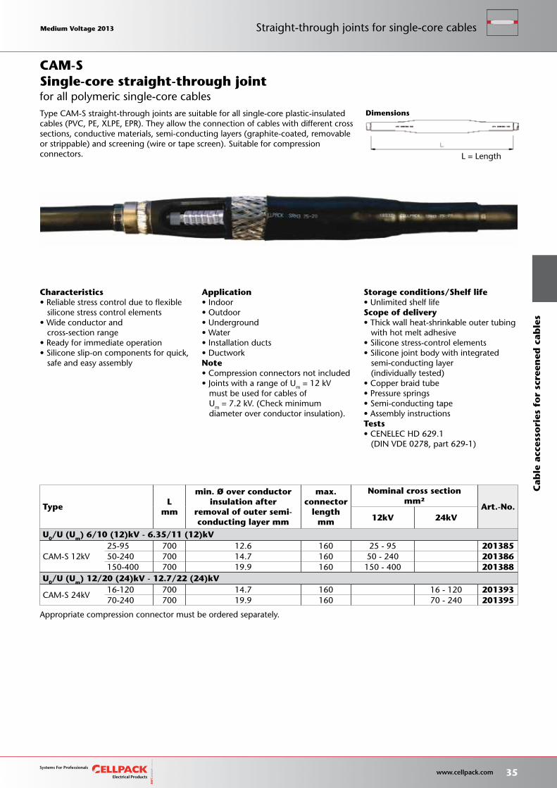
L = Length
Storage conditions/Shelf life• Unlimited shelf lifeScope of delivery• Thick wall heat-shrinkable outer tubing with hot melt adhesive• Silicone stress-control elements• Silicone joint body with integrated semi-conducting layer (individually tested)• Copper braid tube• Pressure springs• Semi-conducting tape• Assembly instructionsTests• CENELEC HD 629.1 (DIN VDE 0278, part 629-1)
Appropriate compression connector must be ordered separately.
Characteristics• Reliable stress control due to flexible silicone stress control elements• Wide conductor and cross-section range• Ready for immediate operation• Silicone slip-on components for quick, safe and easy assembly
Application• Indoor• Outdoor• Underground• Water• Installation ducts• DuctworkNote• Compression connectors not included• Joints with a range of Um = 12 kV must be used for cables of Um = 7.2 kV. (Check minimum diameter over conductor insulation).
Type CAM-S straight-through joints are suitable for all single-core plastic-insulated cables (PVC, PE, XLPE, EPR). They allow the connection of cables with different cross sections, conductive materials, semi-conducting layers (graphite-coated, removable or strippable) and screening (wire or tape screen). Suitable for compression connectors.
TypeL
mm
min. Ø over conductorinsulation after
removal of outer semi-conducting layer mm
max. connector
lengthmm
Nominal cross sectionmm²
Art.-No.12kV 24kV
U0/U (Um) 6/10 (12)kV - 6.35/11 (12)kV
CAM-S 12kV25-95 700 12.6 160 25 - 95 20138550-240 700 14.7 160 50 - 240 201386150-400 700 19.9 160 150 - 400 201388
U0/U (Um) 12/20 (24)kV - 12.7/22 (24)kV
CAM-S 24kV16-120 700 14.7 160 16 - 120 20139370-240 700 19.9 160 70 - 240 201395
Dimensions
for all polymeric single-core cablesSingle-core straight-through jointCAM-S
Medium Voltage 2013 Medium Voltage 2013
35 www.cellpack.com
Medium Voltage 2013 Medium Voltage 2013
Cab
le a
cces
sori
es f
or
scre
ened
cab
les
Straight-through joints for single-core cables
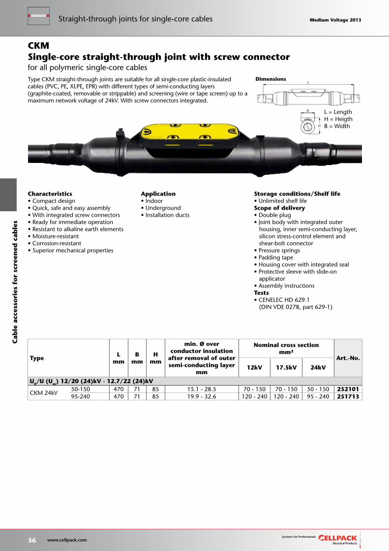
Storage conditions/Shelf life• Unlimited shelf lifeScope of delivery• Double plug• Joint body with integrated outer housing, inner semi-conducting layer, silicon stress-control element and shear-bolt connector• Pressure springs• Padding tape• Housing cover with integrated seal• Protective sleeve with slide-on applicator• Assembly instructionsTests• CENELEC HD 629.1 (DIN VDE 0278, part 629-1)
Dimensions
L = LengthH = HeigthB = Width
TypeL
mm B
mm H
mm
min. Ø over conductor insulation
after removal of outersemi-conducting layer
mm
Nominal cross sectionmm²
Art.-No.
12kV 17.5kV 24kV
U0/U (Um) 12/20 (24)kV - 12.7/22 (24)kV
CKM 24kV50-150 470 71 85 15.1 - 28.5 70 - 150 70 - 150 50 - 150 25210195-240 470 71 85 19.9 - 32.6 120 - 240 120 - 240 95 - 240 251713
Application• Indoor• Underground• Installation ducts
Characteristics• Compact design• Quick, safe and easy assembly• With integrated screw connectors• Ready for immediate operation• Resistant to alkaline earth elements• Moisture-resistant• Corrosion-resistant• Superior mechanical properties
Single-core straight-through joint with screw connector
Type CKM straight-through joints are suitable for all single-core plastic-insulated cables (PVC, PE, XLPE, EPR) with different types of semi-conducting layers (graphite-coated, removable or strippable) and screening (wire or tape screen) up to a maximum network voltage of 24kV. With screw connectors integrated.
CKM
for all polymeric single-core cables
36 www.cellpack.com
Medium Voltage 2013 Medium Voltage 2013C
able
acc
esso
ries
fo
r sc
reen
ed c
able
sStraight-through joints for single-core cables Medium Voltage 2013 Medium Voltage 2013
L = LengthØ S = Diameter of cable sheds
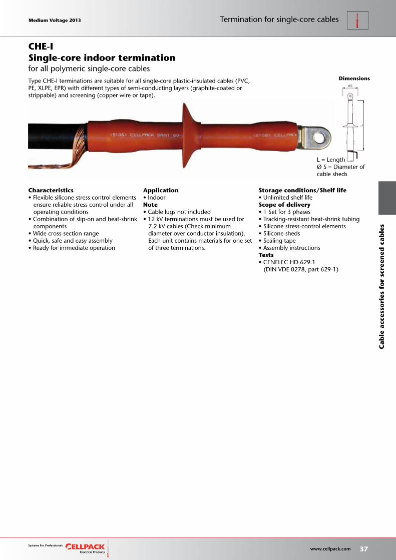
Storage conditions/Shelf life• Unlimited shelf lifeScope of delivery• 1 Set for 3 phases• Tracking-resistant heat-shrink tubing• Silicone stress-control elements• Silicone sheds• Sealing tape• Assembly instructionsTests• CENELEC HD 629.1 (DIN VDE 0278, part 629-1)
Application• IndoorNote• Cable lugs not included• 12 kV terminations must be used for 7.2 kV cables (Check minimum diameter over conductor insulation). Each unit contains materials for one set of three terminations.
Dimensions
Characteristics• Flexible silicone stress control elements ensure reliable stress control under all operating conditions• Combination of slip-on and heat-shrink components• Wide cross-section range• Quick, safe and easy assembly• Ready for immediate operation
Type CHE-I terminations are suitable for all single-core plastic-insulated cables (PVC, PE, XLPE, EPR) with different types of semi-conducting layers (graphite-coated or strippable) and screening (copper wire or tape).
for all polymeric single-core cablesSingle-core indoor terminationCHE-I
Medium Voltage 2013 Medium Voltage 2013
37 www.cellpack.com
Medium Voltage 2013 Medium Voltage 2013
Cab
le a
cces
sori
es f
or
scre
ened
cab
les
Termination for single-core cables
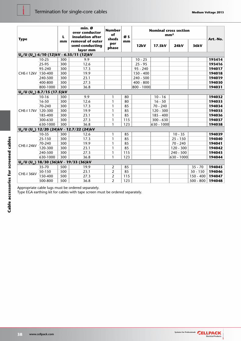
TypeL
mm
min. Øover conductorinsulation after
removal of outersemi-conducting
layer mm
Number of
sheds per
phase
Ø Smm
Nominal cross sectionmm²
Art.-No.
12kV 17.5kV 24kV 36kV
U0/U (Um) 6/10 (12)kV - 6.35/11 (12)kV
CHE-I 12kV
10-25 300 9.9 10 - 25 19341425-95 300 12.6 25 - 95 19341695-240 300 17.3 95 - 240 194017150-400 300 19.9 150 - 400 194018240-500 300 23.1 240 - 500 194019400-800 300 27.3 400 - 800 194030800-1000 300 36.8 800 - 1000 194031
U0/U (Um) 8.7/15 (17.5)kV
CHE-I 17kV
10-16 300 9.9 1 80 10 - 16 19403216-50 300 12.6 1 80 16 - 50 19403370-240 300 17.3 1 85 70 - 240 194034120-300 300 19.9 1 85 120 - 300 194035185-400 300 23.1 1 85 185 - 400 194036300-630 300 27.3 1 115 300 - 630 194037630-1000 300 36.8 1 123 630 - 1000 194038
U0/U (Um) 12/20 (24)kV - 12.7/22 (24)kV
CHE-I 24kV
10-35 300 12.6 1 85 10 - 35 19403925-150 300 17.3 1 85 25 - 150 19404070-240 300 19.9 1 85 70 - 240 194041120-300 300 23.1 1 85 120 - 300 194042240-500 300 27.3 1 115 240 - 500 194043630-1000 300 36.8 1 123 630 - 1000 194044
U0/U (Um) 18/30 (36)kV - 19/33 (36)kV
CHE-I 36kV
35-70 500 19.9 2 85 35 - 70 19404550-150 500 23.1 2 85 50 - 150 194046150-400 500 27.3 2 115 150 - 400 194047500-800 500 36.8 2 123 500 - 800 194048
Appropriate cable lugs must be ordered separately.Type EGA earthing kit for cables with tape screen must be ordered separately.
38 www.cellpack.com
Medium Voltage 2013 Medium Voltage 2013C
able
acc
esso
ries
fo
r sc
reen
ed c
able
sTermination for single-core cables Medium Voltage 2013 Medium Voltage 2013
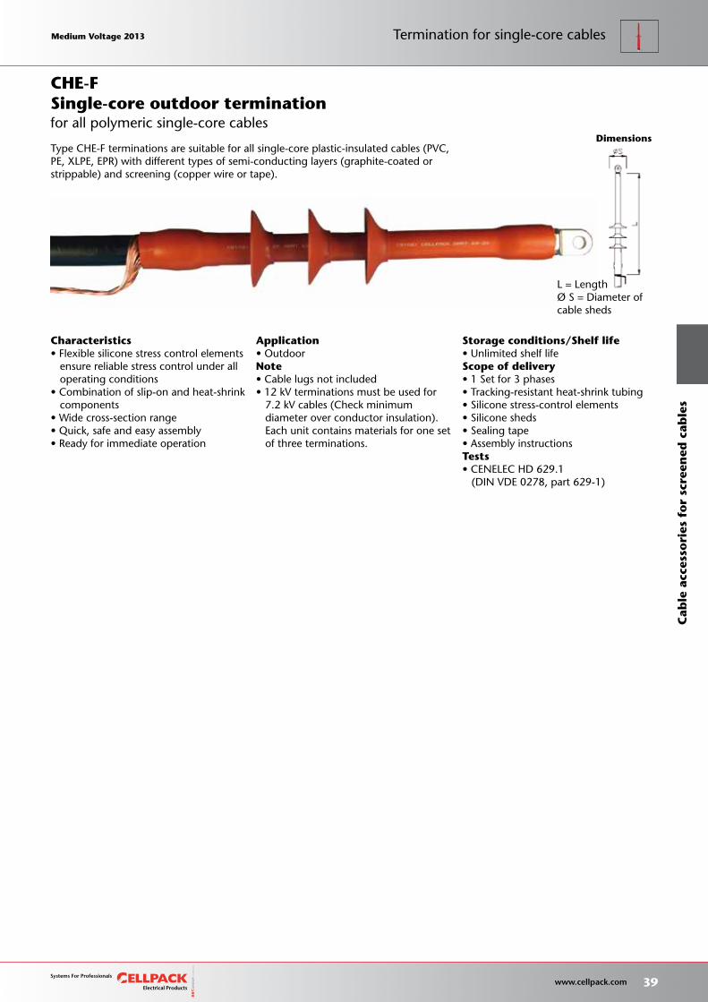
Storage conditions/Shelf life• Unlimited shelf lifeScope of delivery• 1 Set for 3 phases• Tracking-resistant heat-shrink tubing• Silicone stress-control elements• Silicone sheds• Sealing tape• Assembly instructionsTests• CENELEC HD 629.1 (DIN VDE 0278, part 629-1)
Dimensions
L = LengthØ S = Diameter of cable sheds
Application• OutdoorNote• Cable lugs not included• 12 kV terminations must be used for 7.2 kV cables (Check minimum diameter over conductor insulation). Each unit contains materials for one set of three terminations.
Characteristics• Flexible silicone stress control elements ensure reliable stress control under all operating conditions• Combination of slip-on and heat-shrink components• Wide cross-section range• Quick, safe and easy assembly• Ready for immediate operation
Single-core outdoor termination
Type CHE-F terminations are suitable for all single-core plastic-insulated cables (PVC, PE, XLPE, EPR) with different types of semi-conducting layers (graphite-coated or strippable) and screening (copper wire or tape).
CHE-F
for all polymeric single-core cables
Medium Voltage 2013 Medium Voltage 2013
39 www.cellpack.com
Medium Voltage 2013 Medium Voltage 2013
Cab
le a
cces
sori
es f
or
scre
ened
cab
les
Termination for single-core cables
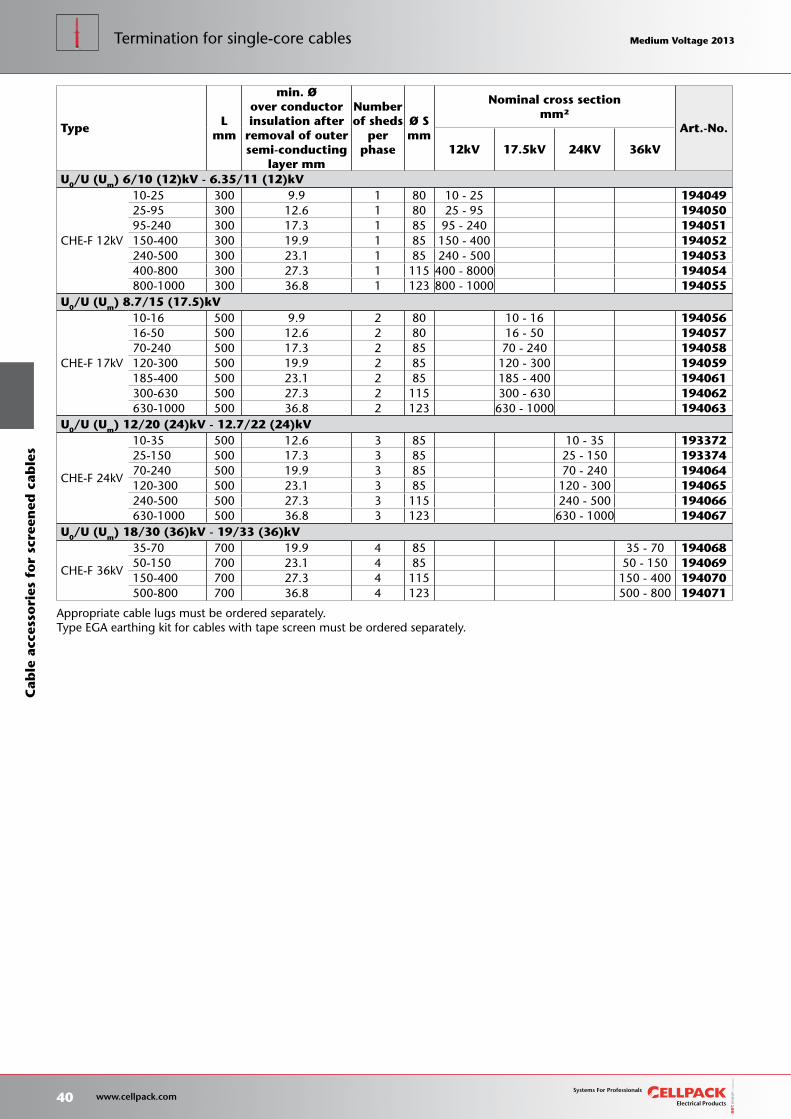
TypeL
mm
min. Øover conductorinsulation after
removal of outersemi-conducting
layer mm
Numberof sheds
per phase
Ø Smm
Nominal cross sectionmm²
Art.-No.
12kV 17.5kV 24KV 36kV
U0/U (Um) 6/10 (12)kV - 6.35/11 (12)kV
CHE-F 12kV
10-25 300 9.9 1 80 10 - 25 19404925-95 300 12.6 1 80 25 - 95 19405095-240 300 17.3 1 85 95 - 240 194051150-400 300 19.9 1 85 150 - 400 194052240-500 300 23.1 1 85 240 - 500 194053400-800 300 27.3 1 115 400 - 8000 194054800-1000 300 36.8 1 123 800 - 1000 194055
U0/U (Um) 8.7/15 (17.5)kV
CHE-F 17kV
10-16 500 9.9 2 80 10 - 16 19405616-50 500 12.6 2 80 16 - 50 19405770-240 500 17.3 2 85 70 - 240 194058120-300 500 19.9 2 85 120 - 300 194059185-400 500 23.1 2 85 185 - 400 194061300-630 500 27.3 2 115 300 - 630 194062630-1000 500 36.8 2 123 630 - 1000 194063
U0/U (Um) 12/20 (24)kV - 12.7/22 (24)kV
CHE-F 24kV
10-35 500 12.6 3 85 10 - 35 19337225-150 500 17.3 3 85 25 - 150 19337470-240 500 19.9 3 85 70 - 240 194064120-300 500 23.1 3 85 120 - 300 194065240-500 500 27.3 3 115 240 - 500 194066630-1000 500 36.8 3 123 630 - 1000 194067
U0/U (Um) 18/30 (36)kV - 19/33 (36)kV
CHE-F 36kV
35-70 700 19.9 4 85 35 - 70 19406850-150 700 23.1 4 85 50 - 150 194069150-400 700 27.3 4 115 150 - 400 194070500-800 700 36.8 4 123 500 - 800 194071
Appropriate cable lugs must be ordered separately.Type EGA earthing kit for cables with tape screen must be ordered separately.
40 www.cellpack.com
Medium Voltage 2013 Medium Voltage 2013C
able
acc
esso
ries
fo
r sc
reen
ed c
able
sTermination for single-core cables Medium Voltage 2013 Medium Voltage 2013
Dimensions
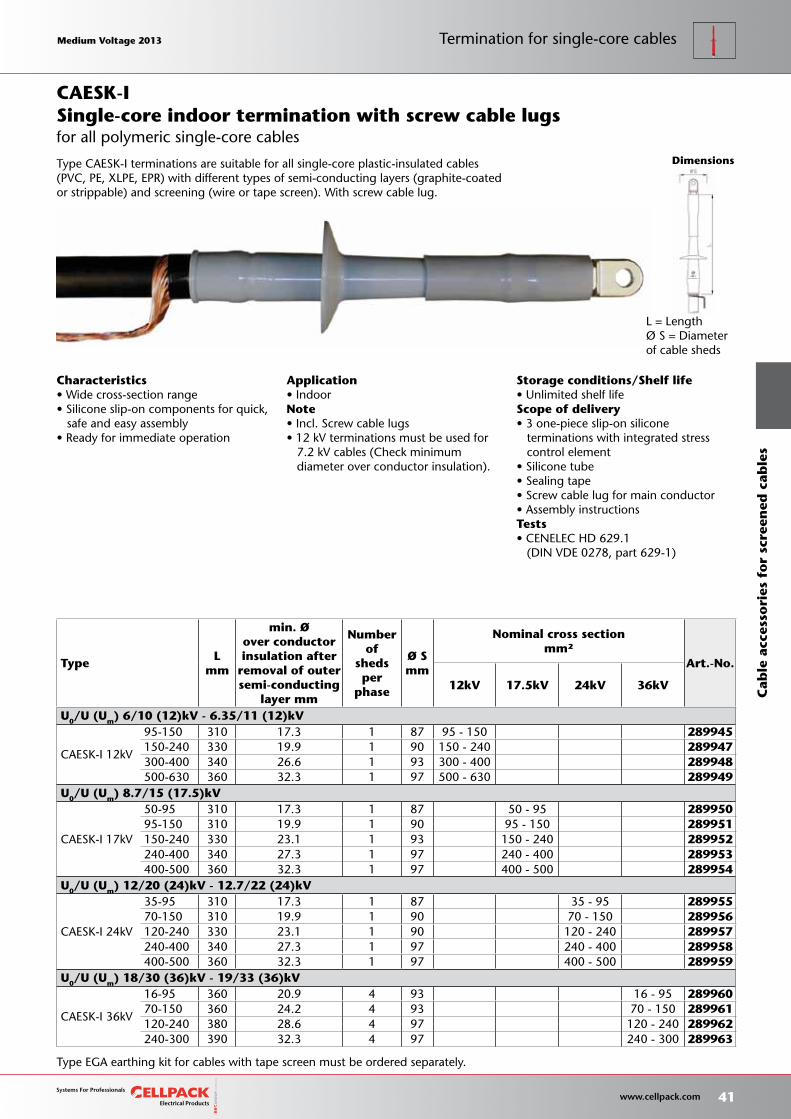
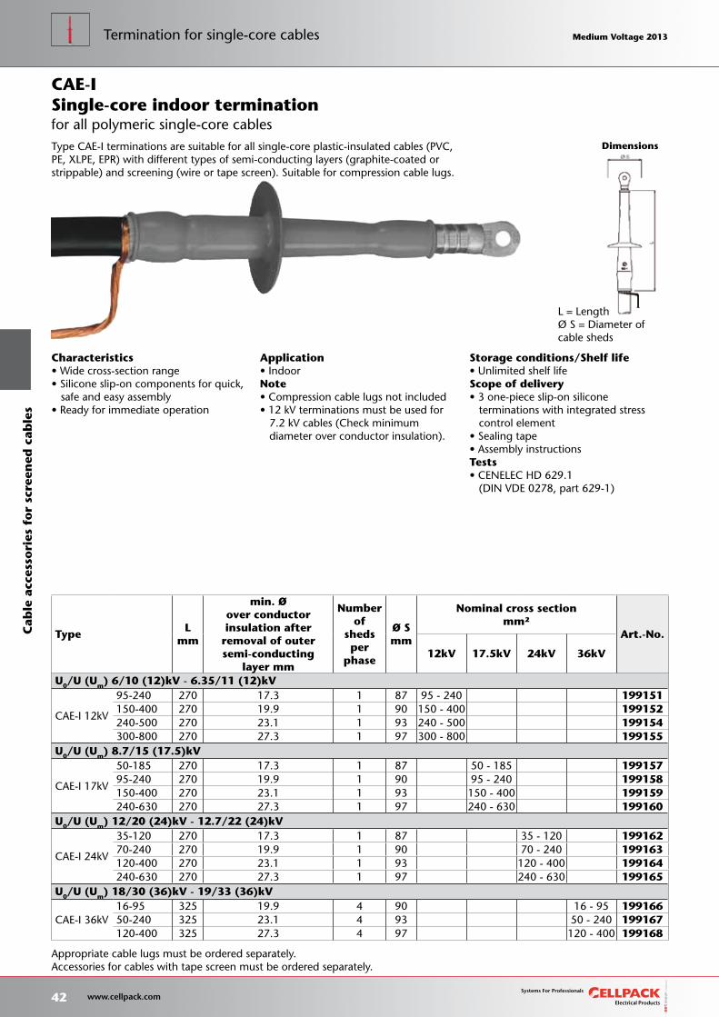
Storage conditions/Shelf life• Unlimited shelf lifeScope of delivery• 3 one-piece slip-on silicone terminations with integrated stress control element• Silicone tube• Sealing tape• Screw cable lug for main conductor• Assembly instructionsTests• CENELEC HD 629.1 (DIN VDE 0278, part 629-1)
Type EGA earthing kit for cables with tape screen must be ordered separately.
TypeL
mm
min. Øover conductorinsulation after
removal of outersemi-conducting
layer mm
Number of
sheds per
phase
Ø Smm
Nominal cross sectionmm²
Art.-No.
12kV 17.5kV 24kV 36kV
U0/U (Um) 6/10 (12)kV - 6.35/11 (12)kV
CAESK-I 12kV
95-150 310 17.3 1 87 95 - 150 289945150-240 330 19.9 1 90 150 - 240 289947300-400 340 26.6 1 93 300 - 400 289948500-630 360 32.3 1 97 500 - 630 289949
U0/U (Um) 8.7/15 (17.5)kV
CAESK-I 17kV
50-95 310 17.3 1 87 50 - 95 28995095-150 310 19.9 1 90 95 - 150 289951150-240 330 23.1 1 93 150 - 240 289952240-400 340 27.3 1 97 240 - 400 289953400-500 360 32.3 1 97 400 - 500 289954
U0/U (Um) 12/20 (24)kV - 12.7/22 (24)kV
CAESK-I 24kV
35-95 310 17.3 1 87 35 - 95 28995570-150 310 19.9 1 90 70 - 150 289956120-240 330 23.1 1 90 120 - 240 289957240-400 340 27.3 1 97 240 - 400 289958400-500 360 32.3 1 97 400 - 500 289959
U0/U (Um) 18/30 (36)kV - 19/33 (36)kV
CAESK-I 36kV
16-95 360 20.9 4 93 16 - 95 28996070-150 360 24.2 4 93 70 - 150 289961120-240 380 28.6 4 97 120 - 240 289962240-300 390 32.3 4 97 240 - 300 289963
Application• IndoorNote• Incl. Screw cable lugs• 12 kV terminations must be used for 7.2 kV cables (Check minimum diameter over conductor insulation).
Characteristics• Wide cross-section range• Silicone slip-on components for quick, safe and easy assembly• Ready for immediate operation
Single-core indoor termination with screw cable lugs
L = LengthØ S = Diameter of cable sheds
Type CAESK-I terminations are suitable for all single-core plastic-insulated cables (PVC, PE, XLPE, EPR) with different types of semi-conducting layers (graphite-coated or strippable) and screening (wire or tape screen). With screw cable lug.
CAESK-I
for all polymeric single-core cables
Medium Voltage 2013 Medium Voltage 2013
41 www.cellpack.com
Medium Voltage 2013 Medium Voltage 2013
Cab
le a
cces
sori
es f
or
scre
ened
cab
les
Termination for single-core cables
L = LengthØ S = Diameter of cable sheds
Storage conditions/Shelf life• Unlimited shelf lifeScope of delivery• 3 one-piece slip-on silicone terminations with integrated stress control element• Sealing tape• Assembly instructionsTests• CENELEC HD 629.1 (DIN VDE 0278, part 629-1)
Characteristics• Wide cross-section range• Silicone slip-on components for quick, safe and easy assembly• Ready for immediate operation
Application• IndoorNote• Compression cable lugs not included• 12 kV terminations must be used for 7.2 kV cables (Check minimum diameter over conductor insulation).
TypeL
mm
min. Øover conductorinsulation after
removal of outersemi-conducting
layer mm
Number of
sheds per
phase
Ø Smm
Nominal cross sectionmm²
Art.-No.
12kV 17.5kV 24kV 36kV
U0/U (Um) 6/10 (12)kV - 6.35/11 (12)kV
CAE-I 12kV
95-240 270 17.3 1 87 95 - 240 199151150-400 270 19.9 1 90 150 - 400 199152240-500 270 23.1 1 93 240 - 500 199154300-800 270 27.3 1 97 300 - 800 199155
U0/U (Um) 8.7/15 (17.5)kV
CAE-I 17kV
50-185 270 17.3 1 87 50 - 185 19915795-240 270 19.9 1 90 95 - 240 199158150-400 270 23.1 1 93 150 - 400 199159240-630 270 27.3 1 97 240 - 630 199160
U0/U (Um) 12/20 (24)kV - 12.7/22 (24)kV
CAE-I 24kV
35-120 270 17.3 1 87 35 - 120 19916270-240 270 19.9 1 90 70 - 240 199163120-400 270 23.1 1 93 120 - 400 199164240-630 270 27.3 1 97 240 - 630 199165
U0/U (Um) 18/30 (36)kV - 19/33 (36)kV
CAE-I 36kV16-95 325 19.9 4 90 16 - 95 19916650-240 325 23.1 4 93 50 - 240 199167120-400 325 27.3 4 97 120 - 400 199168
Dimensions
Appropriate cable lugs must be ordered separately.Accessories for cables with tape screen must be ordered separately.
Type CAE-I terminations are suitable for all single-core plastic-insulated cables (PVC, PE, XLPE, EPR) with different types of semi-conducting layers (graphite-coated or strippable) and screening (wire or tape screen). Suitable for compression cable lugs.
for all polymeric single-core cablesSingle-core indoor terminationCAE-I
42 www.cellpack.com
Medium Voltage 2013 Medium Voltage 2013C
able
acc
esso
ries
fo
r sc
reen
ed c
able
sTermination for single-core cables Medium Voltage 2013 Medium Voltage 2013
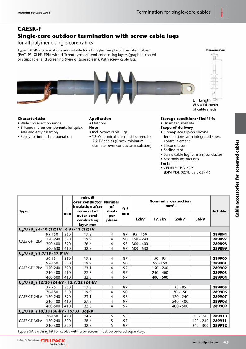
Type EGA earthing kit for cables with tape screen must be ordered separately.
Dimensions
Storage conditions/Shelf life• Unlimited shelf lifeScope of delivery• 3 one-piece slip-on silicone terminations with integrated stress control element• Silicone tube• Sealing tape• Screw cable lug for main conductor• Assembly instructionsTests• CENELEC HD 629.1 (DIN VDE 0278, part 629-1)
TypeL
mm
min. Øover conductorinsulation after
removal of outer semi-conductinglayer mm
Number of
sheds per
phase
Ø Smm
Nominal cross sectionmm²
Art.-No.
12kV 17.5kV 24kV 36kV
U0/U (Um) 6/10 (12)kV - 6.35/11 (12)kV
CAESK-F 12kV
95-150 360 17.3 4 87 95 - 150 289894150-240 390 19.9 4 90 150 - 240 289897300-400 390 26.6 4 93 300 - 400 289898500-630 410 32.3 4 97 500 - 630 289899
U0/U (Um) 8.7/15 (17.5)kV
CAESK-F 17kV
50-95 360 17.3 4 87 50 - 95 28990095-150 360 19.9 4 90 95 - 150 289901150-240 390 23.1 4 97 150 - 240 289902240-400 410 27.3 4 97 240 - 400 289903400-500 410 32.3 4 97 400 - 500 289904
U0/U (Um) 12/20 (24)kV - 12.7/22 (24)kV
CAESK-F 24kV
35-95 360 17.3 4 87 35 - 95 28990570-150 360 19.9 4 90 70 - 150 289906120-240 390 23.1 4 93 120 - 240 289907240-400 410 27.3 4 97 240 - 400 289908400-500 410 32.3 4 97 400 - 500 289909
U0/U (Um) 18/30 (36)kV - 19/33 (36)kV
CAESK-F 36kV70-150 470 24.2 5 93 70 - 150 289910120-240 500 28.6 5 97 120 - 240 289911240-300 500 32.3 5 97 240 - 300 289912
Application• OutdoorNote• Incl. Screw cable lugs• 12 kV terminations must be used for 7.2 kV cables (Check minimum diameter over conductor insulation).
Characteristics• Wide cross-section range• Silicone slip-on components for quick, safe and easy assembly• Ready for immediate operation
Single-core outdoor termination with screw cable lugs
L = LengthØ S = Diameter of cable sheds
Type CAESK-F terminations are suitable for all single-core plastic-insulated cables (PVC, PE, XLPE, EPR) with different types of semi-conducting layers (graphite-coated or strippable) and screening (wire or tape screen). With screw cable lug.
CAESK-F
for all polymeric single-core cables
Medium Voltage 2013 Medium Voltage 2013
43 www.cellpack.com
Medium Voltage 2013 Medium Voltage 2013
Cab
le a
cces
sori
es f
or
scre
ened
cab
les
Termination for single-core cables
L = LengthØ S = Diameter of cable sheds
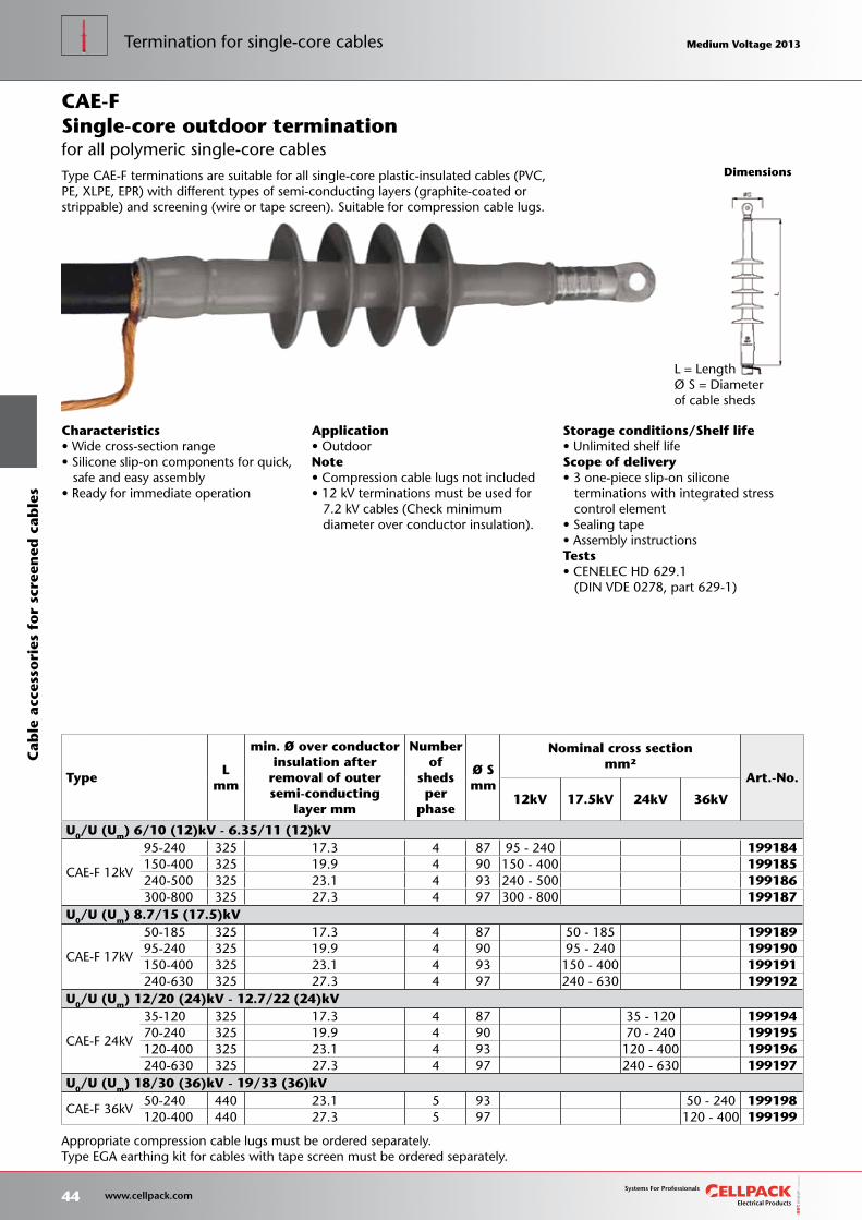
Storage conditions/Shelf life• Unlimited shelf lifeScope of delivery• 3 one-piece slip-on silicone terminations with integrated stress control element• Sealing tape• Assembly instructionsTests• CENELEC HD 629.1 (DIN VDE 0278, part 629-1)
Characteristics• Wide cross-section range• Silicone slip-on components for quick, safe and easy assembly• Ready for immediate operation
Application• OutdoorNote• Compression cable lugs not included• 12 kV terminations must be used for 7.2 kV cables (Check minimum diameter over conductor insulation).
TypeL
mm
min. Ø over conductorinsulation after
removal of outersemi-conducting
layer mm
Number of
sheds per
phase
Ø Smm
Nominal cross sectionmm²
Art.-No.
12kV 17.5kV 24kV 36kV
U0/U (Um) 6/10 (12)kV - 6.35/11 (12)kV
CAE-F 12kV
95-240 325 17.3 4 87 95 - 240 199184150-400 325 19.9 4 90 150 - 400 199185240-500 325 23.1 4 93 240 - 500 199186300-800 325 27.3 4 97 300 - 800 199187
U0/U (Um) 8.7/15 (17.5)kV
CAE-F 17kV
50-185 325 17.3 4 87 50 - 185 19918995-240 325 19.9 4 90 95 - 240 199190150-400 325 23.1 4 93 150 - 400 199191240-630 325 27.3 4 97 240 - 630 199192
U0/U (Um) 12/20 (24)kV - 12.7/22 (24)kV
CAE-F 24kV
35-120 325 17.3 4 87 35 - 120 19919470-240 325 19.9 4 90 70 - 240 199195120-400 325 23.1 4 93 120 - 400 199196240-630 325 27.3 4 97 240 - 630 199197
U0/U (Um) 18/30 (36)kV - 19/33 (36)kV
CAE-F 36kV50-240 440 23.1 5 93 50 - 240 199198120-400 440 27.3 5 97 120 - 400 199199
Dimensions
Appropriate compression cable lugs must be ordered separately.Type EGA earthing kit for cables with tape screen must be ordered separately.
Type CAE-F terminations are suitable for all single-core plastic-insulated cables (PVC, PE, XLPE, EPR) with different types of semi-conducting layers (graphite-coated or strippable) and screening (wire or tape screen). Suitable for compression cable lugs.
for all polymeric single-core cablesSingle-core outdoor terminationCAE-F
44 www.cellpack.com
Medium Voltage 2013 Medium Voltage 2013C
able
acc
esso
ries
fo
r sc
reen
ed c
able
sTermination for single-core cables Medium Voltage 2013 Medium Voltage 2013

Storage conditions/Shelf life• Unlimited shelf lifeScope of delivery• Set of 3 separable cable connectors• Silicone stress-control elements• Earthing kit• Assembly accessories• Screw cable lug for main conductor• Assembly instructionsTests• CENELEC HD 629.1 (DIN VDE 0278, part 629-1)
Dimensions
TypeL
mm B
mm H
mm
min. Ø over conductorinsulation after
removal of outersemi-conducting
layer mm
Nominal cross sectionmm²
Art.-No.
12kV 17.5kV 24kV
U0/U (Um) 6/10 (12)kV - 12.7/22 (24)kV
CWS 250A 24kV16-95 M/EGA 176 80 178 14.7 50 - 95 25 - 95 16 - 95 29516770-150 M/EGA 176 80 178 19.9 120 - 150 95 - 150 70 - 150 293792
Characteristics• with capacitive measuring point• Individually tested• Outer semi-conducting layer made of semi-conductive EPDM provides protection from exposed electrical parts.• Cable sheath insulation fault test may be performed under voltage• For both copper and aluminium conductors• Quick, safe and easy assembly• Suitable for a wide range of applications due to integrated screw cable lug
Application• Indoor
Elbow separable cable connector with capacitive measuring point
L = LengthH = HeigthB = Width
Cellplux elbow separable cable connectors are suitable for the connection of all plastic-insulated single-core cables (PVC,PE, XLPE, EPR) with different types of semi-conducting layers (graphite-coated, removable or strippable) and screening (wire or tape screen) to switching equipment and transformers having plug-in connections for Type A outer cone system terminals (in accordance with EN 50180, EN 50181 and DIN 47636) up to a maximum network voltage of 24 kV.
CWS 250A/M
for all polymeric single-core cables
Medium Voltage 2013 Medium Voltage 2013
45 www.cellpack.com
Medium Voltage 2013 Medium Voltage 2013
Cab
le a
cces
sori
es f
or
scre
ened
cab
les
Termination for single-core cables
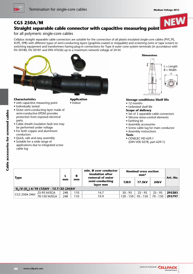
Storage conditions/Shelf life• 12 months• Unlimited shelf lifeScope of delivery• Set of 3 separable cable connectors• Silicone stress-control elements• Earthing kit• Assembly accessories• Screw cable lug for main conductor• Assembly instructionsTests• CENELEC HD 629.1 (DIN VDE 0278, part 629-1)
Dimensions
TypeL
mm B
mm
min. Ø over conductorinsulation after
removal of outersemi-conducting
layer mm
Nominal cross sectionmm²
Art.-No.
12kV 17.5kV 24kV
U0/U (Um) 6/10 (12)kV - 12.7/22 (24)kV
CGS 250A 24kV25-95 M/EGA 248 110 14.7 50 - 95 25 - 95 25 - 95 29528370-150 M/EGA 248 110 19.9 120 - 150 95 - 150 70 - 150 293797
Characteristics• with capacitive measuring point• Individually tested• Outer semi-conducting layer made of semi-conductive EPDM provides protection from exposed electrical parts.• Cable sheath insulation fault test may be performed under voltage• For both copper and aluminium conductors• Quick, safe and easy assembly• Suitable for a wide range of applications due to integrated screw cable lug
Application• Indoor
Straight separable cable connector with capacitive measuring point
L = LengthB = Width
Cellplux straight separable cable connectors are suitable for the connection of all plastic-insulated single-core cables (PVC,PE, XLPE, EPR) with different types of semi-conducting layers (graphite-coated or strippable) and screening (wire or tape screen) to switching equipment and transformers having plug-in connections for Type A outer cone system terminals (in accordance with EN 50180, EN 50181 and DIN 47636) up to a maximum network voltage of 24 kV.
CGS 250A/M
for all polymeric single-core cables
46 www.cellpack.com
Medium Voltage 2013 Medium Voltage 2013C
able
acc
esso
ries
fo
r sc
reen
ed c
able
sTermination for single-core cables Medium Voltage 2013 Medium Voltage 2013
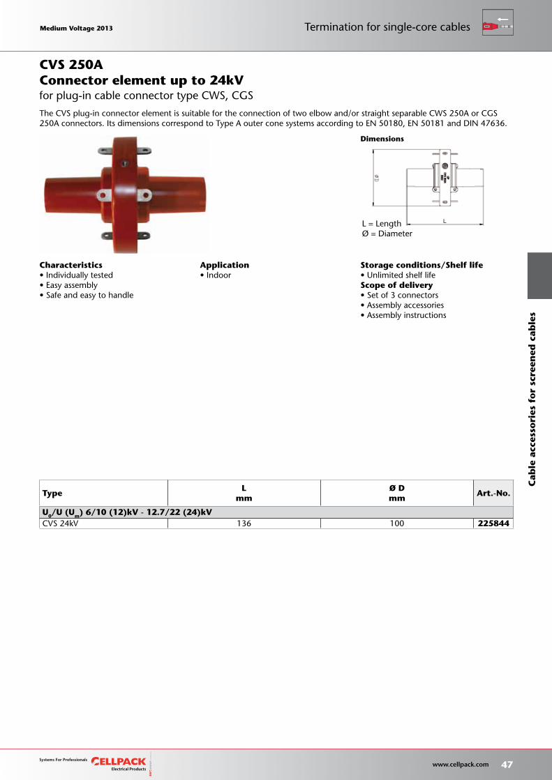
Storage conditions/Shelf life• Unlimited shelf lifeScope of delivery• Set of 3 connectors• Assembly accessories• Assembly instructions
Dimensions
TypeL
mm Ø Dmm
Art.-No.
U0/U (Um) 6/10 (12)kV - 12.7/22 (24)kVCVS 24kV 136 100 225844
Application• Indoor
Characteristics• Individually tested• Easy assembly• Safe and easy to handle
Connector element up to 24kV
L = LengthØ = Diameter
The CVS plug-in connector element is suitable for the connection of two elbow and/or straight separable CWS 250A or CGS 250A connectors. Its dimensions correspond to Type A outer cone systems according to EN 50180, EN 50181 and DIN 47636.
CVS 250A
for plug-in cable connector type CWS, CGS
Medium Voltage 2013 Medium Voltage 2013
47 www.cellpack.com
Medium Voltage 2013 Medium Voltage 2013
Cab
le a
cces
sori
es f
or
scre
ened
cab
les
Termination for single-core cables
Dimensions
TypeL
mm B
mm H
mm
min. Ø over conductor
insulation afterremoval of outersemi-conducting
layer mm
Nominal cross sectionmm²
Art.-No.
12kV 17.5kV 24kV 36kV
U0/U (Um) 6/10 (12)kV - 12.7/22 (24)kV
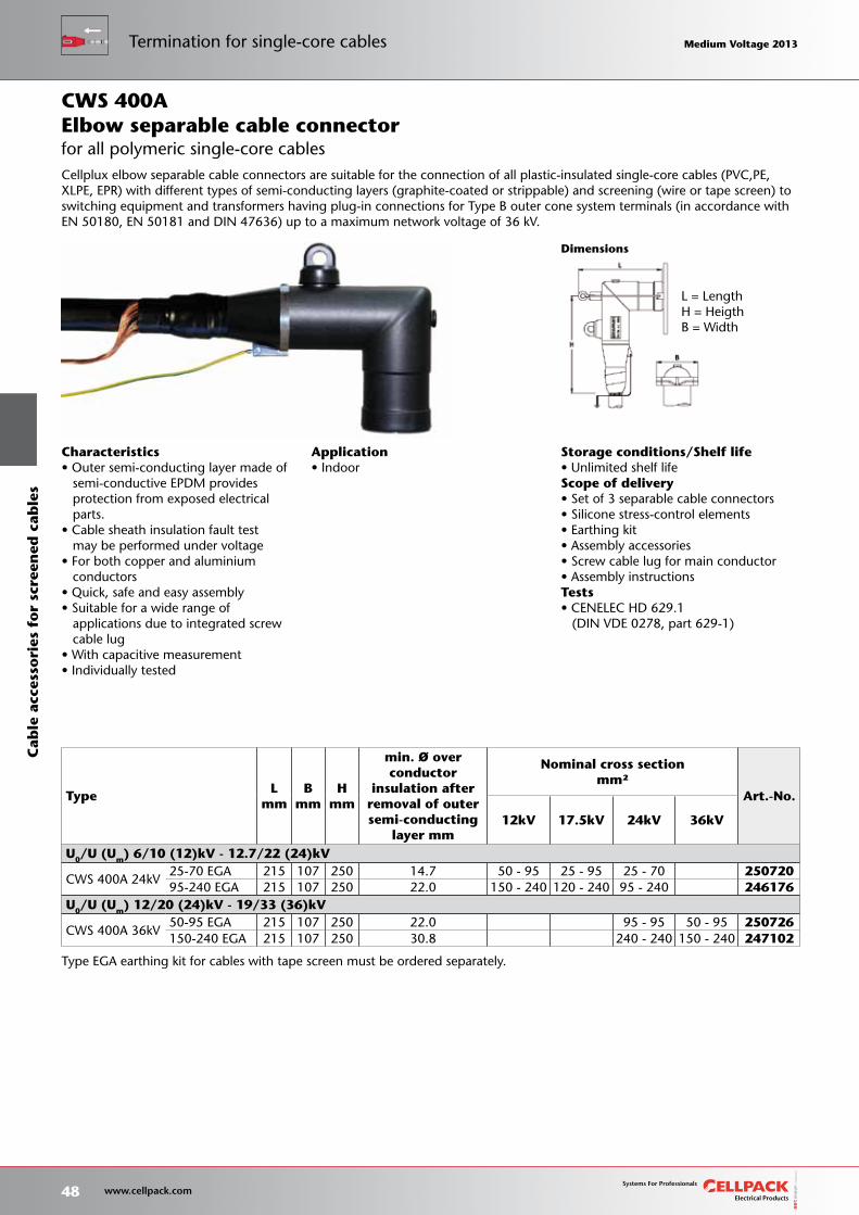
CWS 400A 24kV25-70 EGA 215 107 250 14.7 50 - 95 25 - 95 25 - 70 25072095-240 EGA 215 107 250 22.0 150 - 240 120 - 240 95 - 240 246176
U0/U (Um) 12/20 (24)kV - 19/33 (36)kV
CWS 400A 36kV50-95 EGA 215 107 250 22.0 95 - 95 50 - 95 250726150-240 EGA 215 107 250 30.8 240 - 240 150 - 240 247102
Type EGA earthing kit for cables with tape screen must be ordered separately.
Characteristics• Outer semi-conducting layer made of semi-conductive EPDM provides protection from exposed electrical parts.• Cable sheath insulation fault test may be performed under voltage• For both copper and aluminium conductors• Quick, safe and easy assembly• Suitable for a wide range of applications due to integrated screw cable lug• With capacitive measurement• Individually tested
Application• Indoor
Elbow separable cable connector
Cellplux elbow separable cable connectors are suitable for the connection of all plastic-insulated single-core cables (PVC,PE, XLPE, EPR) with different types of semi-conducting layers (graphite-coated or strippable) and screening (wire or tape screen) to switching equipment and transformers having plug-in connections for Type B outer cone system terminals (in accordance with EN 50180, EN 50181 and DIN 47636) up to a maximum network voltage of 36 kV.
CWS 400A
for all polymeric single-core cables
L = LengthH = HeigthB = Width
Storage conditions/Shelf life• Unlimited shelf lifeScope of delivery• Set of 3 separable cable connectors• Silicone stress-control elements• Earthing kit• Assembly accessories• Screw cable lug for main conductor• Assembly instructionsTests• CENELEC HD 629.1 (DIN VDE 0278, part 629-1)
48 www.cellpack.com
Medium Voltage 2013 Medium Voltage 2013C
able
acc
esso
ries
fo
r sc
reen
ed c
able
sTermination for single-core cables Medium Voltage 2013 Medium Voltage 2013
Storage conditions/Shelf life• Unlimited shelf lifeScope of delivery• Set of 3 separable cable connectors• Silicone stress-control elements• Earthing kit• Assembly accessories• Screw cable lug for main conductor• Assembly instructionsTests• CENELEC HD 629.1 (DIN VDE 0278, part 629-1)
Dimensions
Type EGA earthing kit for cables with tape screen must be ordered separately.More T-socket connexions on request
TypeL
mm B
mm H
mm
min. Øover conductorinsulation after
removal of outersemi-conducting
layer mm
Nominal cross sectionmm²
Art.-No.
12kV 17.5kV 24kV 36kV
U0/U (Um) 6/10 (12)kV - 12.7/22 (24)kV
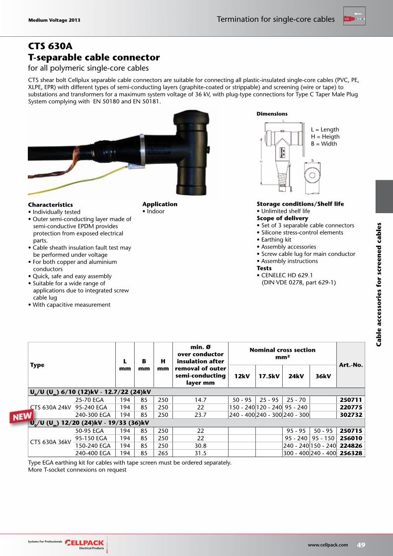
CTS 630A 24kV25-70 EGA 194 85 250 14.7 50 - 95 25 - 95 25 - 70 25071195-240 EGA 194 85 250 22 150 - 240 120 - 240 95 - 240 220775240-300 EGA 194 85 250 23.7 240 - 400 240 - 300 240 - 300 302732
U0/U (Um) 12/20 (24)kV - 19/33 (36)kV
CTS 630A 36kV
50-95 EGA 194 85 250 22 95 - 95 50 - 95 25071595-150 EGA 194 85 250 22 95 - 240 95 - 150 256010150-240 EGA 194 85 250 30.8 240 - 240 150 - 240 224826240-400 EGA 194 85 265 31.5 300 - 400 240 - 400 256328
Application• Indoor
Characteristics• Individually tested• Outer semi-conducting layer made of semi-conductive EPDM provides protection from exposed electrical parts.• Cable sheath insulation fault test may be performed under voltage• For both copper and aluminium conductors• Quick, safe and easy assembly• Suitable for a wide range of applications due to integrated screw cable lug• With capacitive measurement
T-separable cable connector
L = LengthH = HeigthB = Width
CTS shear bolt Cellplux separable cable connectors are suitable for connecting all plastic-insulated single-core cables (PVC, PE, XLPE, EPR) with different types of semi-conducting layers (graphite-coated or strippable) and screening (wire or tape) to substations and transformers for a maximum system voltage of 36 kV, with plug-type connections for Type C Taper Male Plug System complying with EN 50180 and EN 50181.
CTS 630A
for all polymeric single-core cables
Medium Voltage 2013 Medium Voltage 2013
49 www.cellpack.com
Medium Voltage 2013 Medium Voltage 2013
Cab
le a
cces
sori
es f
or
scre
ened
cab
les
Termination for single-core cables
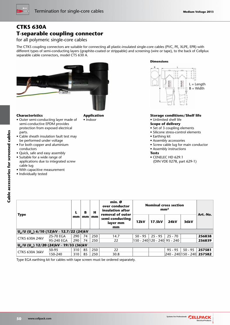
Storage conditions/Shelf life• Unlimited shelf lifeScope of delivery• Set of 3 coupling elements• Silicone stress-control elements• Earthing kit• Assembly accessories• Screw cable lug for main conductor• Assembly instructionsTests• CENELEC HD 629.1 (DIN VDE 0278, part 629-1)
Dimensions
Type EGA earthing kit for cables with tape screen must be ordered separately.
TypeL
mm B
mm H
mm
min. Øover conductorinsulation after
removal of outersemi-conducting
layer mmmm
Nominal cross sectionmm²
Art.-No.
12kV 17.5kV 24kV 36kV
U0/U (Um) 6/10 (12)kV - 12.7/22 (24)kV
CTKS 630A 24kV25-70 EGA 290 74 250 14.7 50 - 95 25 - 95 25 - 70 25683895-240 EGA 290 74 250 22 150 - 240 120 - 240 95 - 240 256839
U0/U (Um) 12/20 (24)kV - 19/33 (36)kV
CTKS 630A 36kV50-95 310 85 250 22 95 - 95 50 - 95 257581150-240 310 85 250 30.8 240 - 240 150 - 240 257582
Application• Indoor
Characteristics• Outer semi-conducting layer made of semi-conductive EPDM provides protection from exposed electrical parts.• Cable sheath insulation fault test may be performed under voltage• For both copper and aluminium conductors• Quick, safe and easy assembly• Suitable for a wide range of applications due to integrated screw cable lug• With capacitive measurement• Individually tested
T-separable coupling connector
L = LengthB = Width
The CTKS coupling connectors are suitable for connecting all plastic-insulated single-core cables (PVC, PE, XLPE, EPR) with different types of semi-conducting layers (graphite-coated or strippable) and screening (wire or tape), to the back of Cellplux separable cable connectors, model CTS 630 A.
CTKS 630A
for all polymeric single-core cables
50 www.cellpack.com
Medium Voltage 2013 Medium Voltage 2013C
able
acc
esso
ries
fo
r sc
reen
ed c
able
sTermination for single-core cables Medium Voltage 2013 Medium Voltage 2013
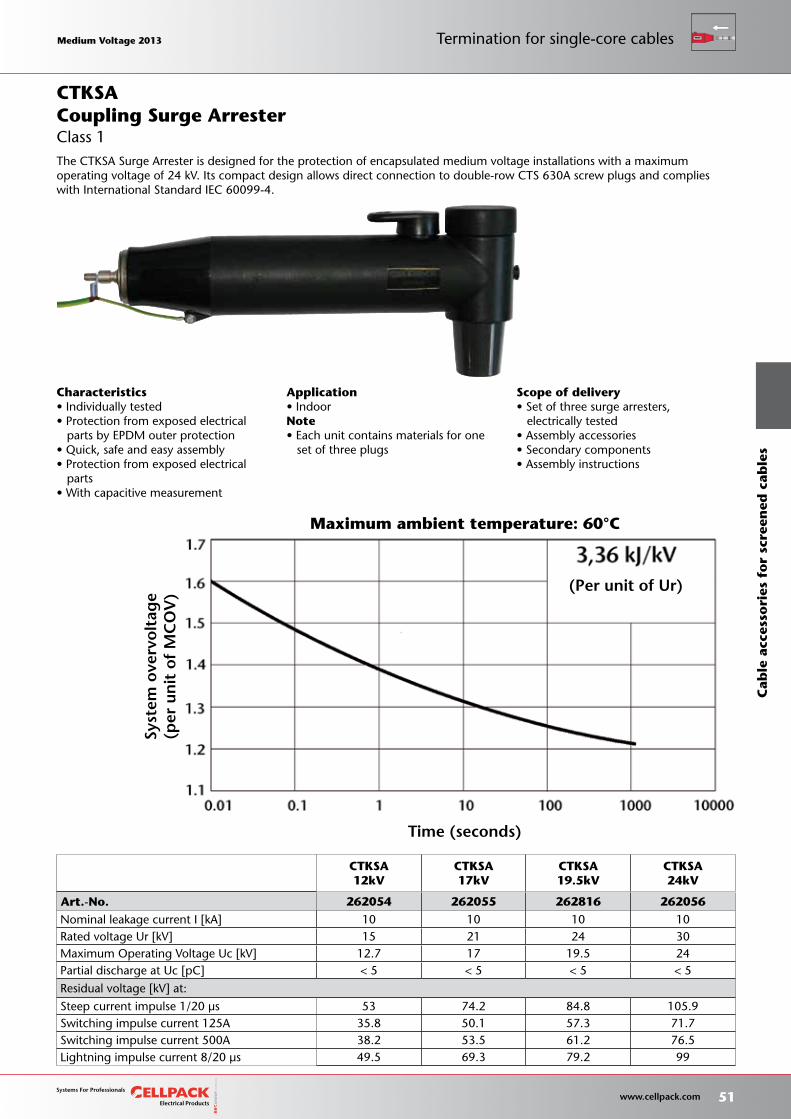
Scope of delivery• Set of three surge arresters, electrically tested• Assembly accessories• Secondary components• Assembly instructions
CTKSA12kV
CTKSA17kV
CTKSA19.5kV
CTKSA24kV
Art.-No. 262054 262055 262816 262056 Nominal leakage current I [kA] 10 10 10 10 Rated voltage Ur [kV] 15 21 24 30 Maximum Operating Voltage Uc [kV] 12.7 17 19.5 24 Partial discharge at Uc [pC] < 5 < 5 < 5 < 5
Residual voltage [kV] at:
Steep current impulse 1/20 μs 53 74.2 84.8 105.9 Switching impulse current 125A 35.8 50.1 57.3 71.7 Switching impulse current 500A 38.2 53.5 61.2 76.5 Lightning impulse current 8/20 μs 49.5 69.3 79.2 99
Characteristics• Individually tested• Protection from exposed electrical parts by EPDM outer protection• Quick, safe and easy assembly• Protection from exposed electrical parts• With capacitive measurement
Application• IndoorNote• Each unit contains materials for one set of three plugs
Coupling Surge Arrester
The CTKSA Surge Arrester is designed for the protection of encapsulated medium voltage installations with a maximumoperating voltage of 24 kV. Its compact design allows direct connection to double-row CTS 630A screw plugs and complies with International Standard IEC 60099-4.
CTKSA
Class 1Sy
stem
ove
rvo
ltag
e (p
er u
nit
of
MC
OV
)
Maximum ambient temperature: 60°C
Time (seconds)
(Per unit of Ur)
Medium Voltage 2013 Medium Voltage 2013
51 www.cellpack.com
Medium Voltage 2013 Medium Voltage 2013
Cab
le a
cces
sori
es f
or
scre
ened
cab
les
Termination for single-core cables
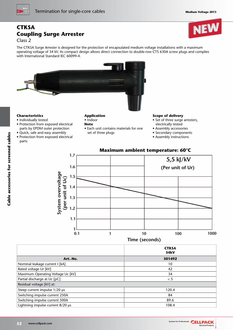
Scope of delivery• Set of three surge arresters, electrically tested• Assembly accessories• Secondary components• Assembly instructions
CTKSA34kV
Art.-No. 301492 Nominal leakage current I [kA] 10 Rated voltage Ur [kV] 42 Maximum Operating Voltage Uc [kV] 34 Partial discharge at Uc [pC] < 5
Residual voltage [kV] at:
Steep current impulse 1/20 μs 120.4
Switching impulse current 250A 84 Switching impulse current 500A 89.6 Lightning impulse current 8/20 μs 108.4
Characteristics• Individually tested• Protection from exposed electrical parts by EPDM outer protection• Quick, safe and easy assembly• Protection from exposed electrical parts
Application• IndoorNote• Each unit contains materials for one set of three plugs
Coupling Surge Arrester
The CTKSA Surge Arrester is designed for the protection of encapsulated medium voltage installations with a maximumoperating voltage of 34 kV. Its compact design allows direct connection to double-row CTS 630A screw plugs and complies with International Standard IEC 60099-4.
CTKSA
Class 2
Syst
em o
verv
olt
age
(per
un
it o
f U
c)
Maximum ambient temperature: 60°C
Time (seconds)
(Per unit of Ur)
52 www.cellpack.com
Medium Voltage 2013 Medium Voltage 2013C
able
acc
esso
ries
fo
r sc
reen
ed c
able
sTermination for single-core cables Medium Voltage 2013 Medium Voltage 2013
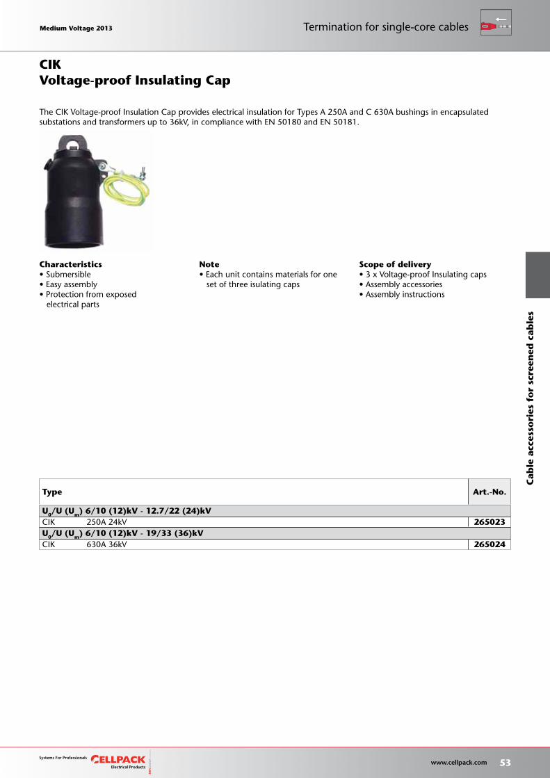
Note• Each unit contains materials for one set of three isulating caps
Scope of delivery• 3 x Voltage-proof Insulating caps• Assembly accessories• Assembly instructions
Type Art.-No.
U0/U (Um) 6/10 (12)kV - 12.7/22 (24)kVCIK 250A 24kV 265023 U0/U (Um) 6/10 (12)kV - 19/33 (36)kVCIK 630A 36kV 265024
Characteristics• Submersible• Easy assembly• Protection from exposed electrical parts
Voltage-proof Insulating Cap
The CIK Voltage-proof Insulation Cap provides electrical insulation for Types A 250A and C 630A bushings in encapsulatedsubstations and transformers up to 36kV, in compliance with EN 50180 and EN 50181.
CIK
Medium Voltage 2013 Medium Voltage 2013
53 www.cellpack.com
Medium Voltage 2013 Medium Voltage 2013
Cab
le a
cces
sori
es f
or
scre
ened
cab
les
Termination for single-core cables
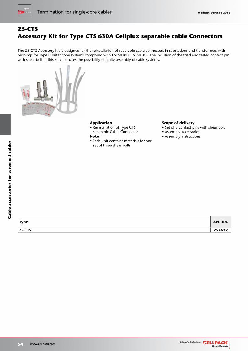
Scope of delivery• Set of 3 contact pins with shear bolt• Assembly accessories• Assembly instructions
Type Art.-No.
ZS-CTS 257622
Application• Reinstallation of Type CTS separable Cable ConnectorNote• Each unit contains materials for one set of three shear bolts
Accessory Kit for Type CTS 630A Cellplux separable cable Connectors
The ZS-CTS Accessory Kit is designed for the reinstallation of separable cable connectors in substations and transformers with bushings for Type C outer cone systems complying with EN 50180, EN 50181. The inclusion of the tried and tested contact pin with shear bolt in this kit eliminates the possibility of faulty assembly of cable systems.
ZS-CTS
54 www.cellpack.com
Medium Voltage 2013 Medium Voltage 2013C
able
acc
esso
ries
fo
r sc
reen
ed c
able
sTermination for single-core cables Medium Voltage 2013 Medium Voltage 2013
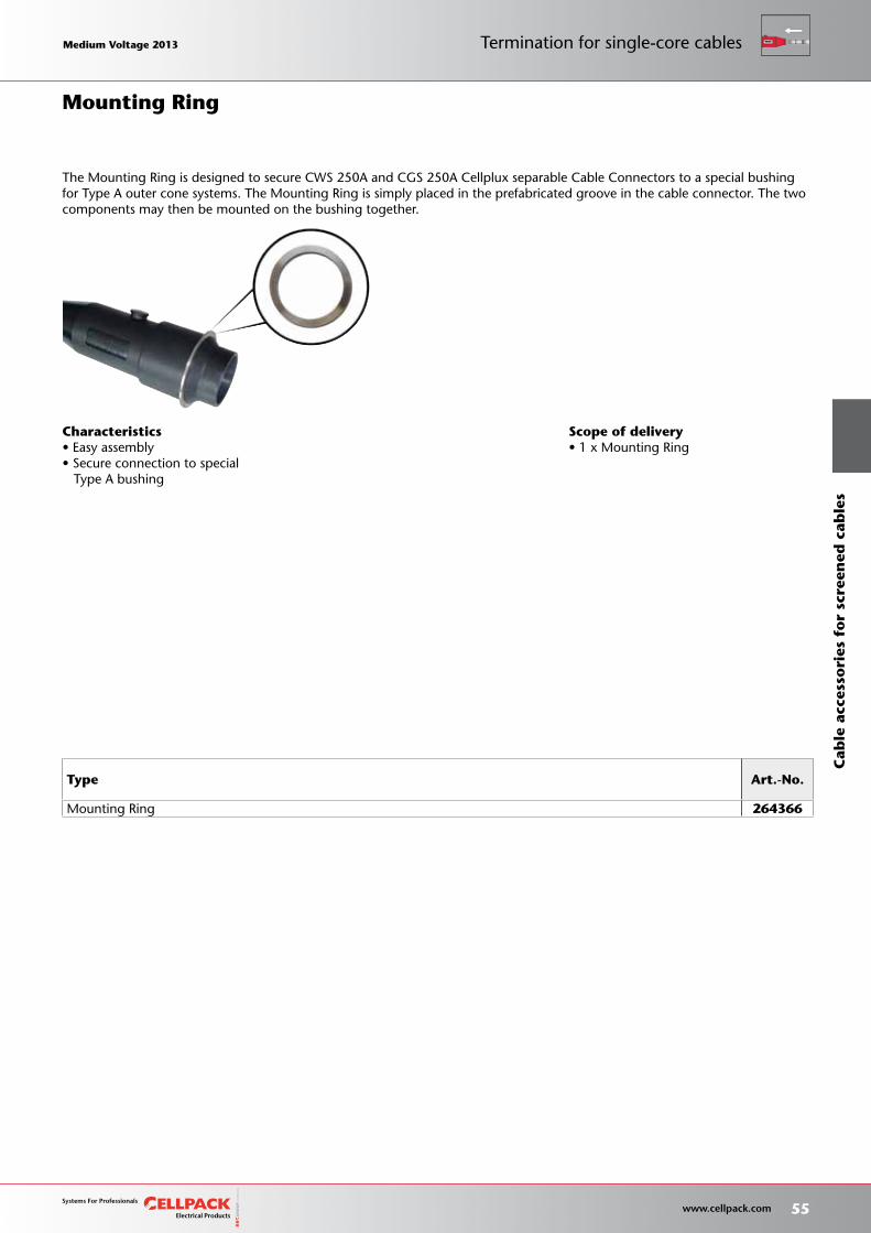
Scope of delivery• 1 x Mounting Ring
Type Art.-No.
Mounting Ring 264366
Characteristics• Easy assembly• Secure connection to special Type A bushing
The Mounting Ring is designed to secure CWS 250A and CGS 250A Cellplux separable Cable Connectors to a special bushing for Type A outer cone systems. The Mounting Ring is simply placed in the prefabricated groove in the cable connector. The two components may then be mounted on the bushing together.
Mounting Ring
Medium Voltage 2013 Medium Voltage 2013
55 www.cellpack.com
Medium Voltage 2013 Medium Voltage 2013
Cab
le a
cces
sori
es f
or
scre
ened
cab
les
Termination for single-core cables
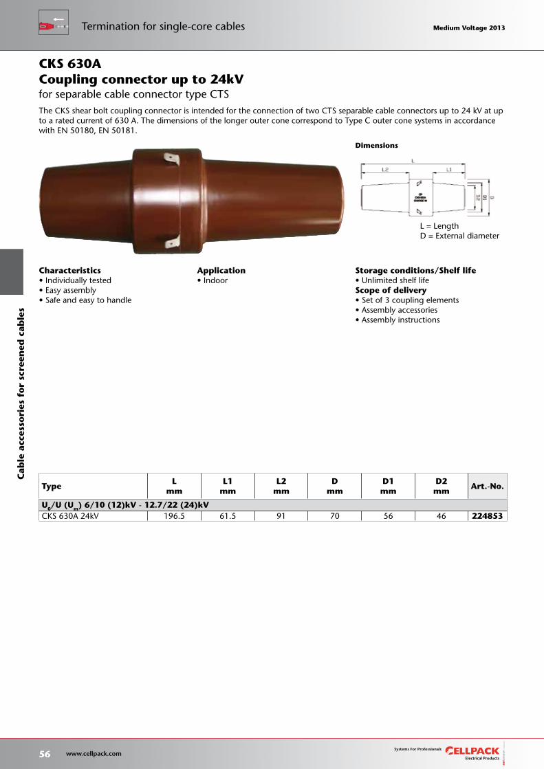
Storage conditions/Shelf life• Unlimited shelf lifeScope of delivery• Set of 3 coupling elements• Assembly accessories• Assembly instructions
L = LengthD = External diameter
Dimensions
The CKS shear bolt coupling connector is intended for the connection of two CTS separable cable connectors up to 24 kV at up to a rated current of 630 A. The dimensions of the longer outer cone correspond to Type C outer cone systems in accordance with EN 50180, EN 50181.
for separable cable connector type CTS
TypeL
mm L1
mm L2
mm D
mm D1mm
D2mm
Art.-No.
U0/U (Um) 6/10 (12)kV - 12.7/22 (24)kVCKS 630A 24kV 196.5 61.5 91 70 56 46 224853
CKS 630A
Characteristics• Individually tested• Easy assembly• Safe and easy to handle
Application• Indoor
Coupling connector up to 24kV
56 www.cellpack.com
Medium Voltage 2013 Medium Voltage 2013C
able
acc
esso
ries
fo
r sc
reen
ed c
able
sTermination for single-core cables Medium Voltage 2013 Medium Voltage 2013
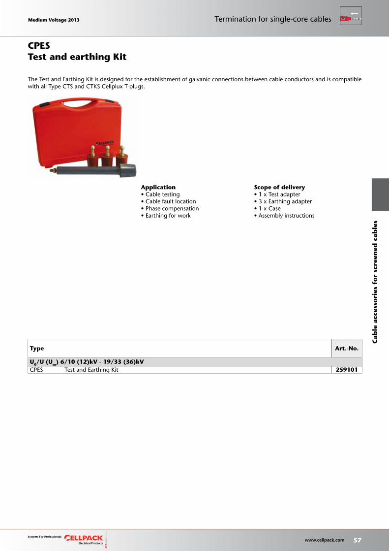
Scope of delivery• 1 x Test adapter• 3 x Earthing adapter• 1 x Case• Assembly instructions
Type Art.-No.
U0/U (Um) 6/10 (12)kV - 19/33 (36)kVCPES Test and Earthing Kit 259101
Application• Cable testing• Cable fault location• Phase compensation• Earthing for work
Test and earthing Kit
The Test and Earthing Kit is designed for the establishment of galvanic connections between cable conductors and is compatible with all Type CTS and CTKS Cellplux T-plugs.
CPES
Medium Voltage 2013 Medium Voltage 2013
57 www.cellpack.com
Medium Voltage 2013 Medium Voltage 2013
Cab
le a
cces
sori
es f
or
scre
ened
cab
les
Termination for single-core cables
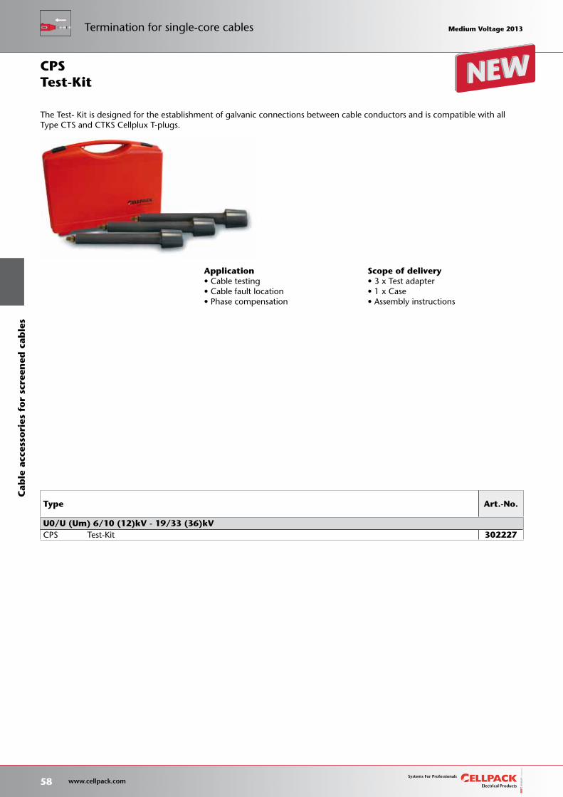
Scope of delivery• 3 x Test adapter• 1 x Case• Assembly instructions
The Test- Kit is designed for the establishment of galvanic connections between cable conductors and is compatible with all Type CTS and CTKS Cellplux T-plugs.
Type Art.-No.
U0/U (Um) 6/10 (12)kV - 19/33 (36)kVCPS Test-Kit 302227
Application• Cable testing• Cable fault location• Phase compensation
Test-KitCPS
58 www.cellpack.com
Medium Voltage 2013 Medium Voltage 2013C
able
acc
esso
ries
fo
r sc
reen
ed c
able
sTermination for single-core cables Medium Voltage 2013 Medium Voltage 2013
Dimensions
Storage conditions/Shelf life• Unlimited shelf lifeScope of delivery• Thick wall heat-shrinkable insulation tubing• Thick wall heat-shrinkable outer tubing with hot melt adhesive• Silicone stress-control element• Copper braid tape• Innovative screw connector with conductive sheath• Stress control filling tape (blue)• Screw connector for copper-wire screen• Assembly instructions
TypeL
mm
min. Ø over conductorinsulation after
removal of outer semi-conducting
layer mm
Nominal cross sectionmm²
Art.-No.12kV 17.5kV 24kV 36kV
U0/U (Um) 6/10 (12)kV - 6.35/11 (12)kV
CHMSV 3 12kV
25-95 1050 12.6 25 - 95 29734870-150 1050 14.7 70 - 150 29735095-240 1100 17.3 95 - 240 297260240-400 1250 23.1 240 - 400 297358
U0/U (Um) 8.7 /15 (17.5)kV
CHMSV 3 17kV
25-95 1050 14.7 25 - 95 29734970-150 1050 18 70 - 150 29735195-240 1100 19.9 95 - 240 297310240-400 1250 24 240 - 400 297360
U0/U (Um) 12/20 (24)kV - 12.7/22 (24)kV
CHMSV 3 24kV
16-95 1050 14.7 16 - 95 29743350-150 1050 17.3 50 - 150 29735295-240 1100 19.9 95 - 240 297104240-400 1250 27.3 240 - 400 297361
U0/U (Um) 18/30 (36)kV - 19/33 (36)kV
CHMSV 3 36kV50-150 1050 20.9 50 - 150 29735395-240 1100 24.2 95 - 240 297311240-400 1250 32 240 - 400 297362
Characteristics• Reliable stress control due to flexible silicone stress control elements• For both copper and aluminium conductors• For all cables with copper-wire screen• Wide conductor and cross-section range• Quick, safe and easy assembly• Ready for immediate operation• Suitable for a wide range of applications due to innovative integrated screw connector
Application• Indoor• Outdoor• Underground• Water• Installation ducts• DuctworkNote• Incl. screw connectors
Three-core straight-through joint with screw connector
L = Length
Type CHMSV 3 straight-through joints are suitable for connecting three-core polymeric cable (PVC, PE, XLPE, EPR). They allow the connection of cables with copper wire screen, with different cross sections, conductor materials, semi-conducting layers (graphite-coated, removable or strippable). Screw connectors included.
CHMSV3
for all 3-core polymeric cables
Medium Voltage 2013 Medium Voltage 2013
59 www.cellpack.com
Medium Voltage 2013 Medium Voltage 2013
Cab
le a
cces
sori
es f
or
scre
ened
cab
les
Straight-through joints for 3-core cables
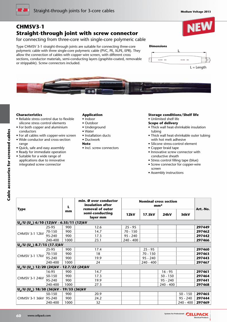
Dimensions
Storage conditions/Shelf life• Unlimited shelf lifeScope of delivery• Thick wall heat-shrinkable insulation tubing• Thick wall heat-shrinkable outer tubing with hot melt adhesive• Silicone stress-control element• Copper braid tape• Innovative screw connector with conductive sheath• Stress control filling tape (blue)• Screw connector for copper-wire screen• Assembly instructions
TypeL
mm
min. Ø over conductorinsulation after
removal of outersemi-conducting
layer mm
Nominal cross sectionmm²
Art.-No.
12kV 17.5kV 24kV 36kV
U0/U (Um) 6/10 (12)kV - 6.35/11 (12)kV
CHMSV 3-1 12kV
25-95 900 12.6 25 - 95 29744970-150 900 14.7 70 - 150 29746295-240 900 17.3 95 - 240 297442240-400 1000 23.1 240 - 400 297466
U0/U (Um) 8.7/15 (17.5)kV
CHMSV 3-1 17kV
25-95 900 17.4 25 - 95 29746070-150 900 18 70 - 150 29746395-240 900 19.9 95 - 240 297443240-400 1000 24 240 - 400 297467
U0/U (Um) 12/20 (24)kV - 12.7/22 (24)kV
CHMSV 3-1 24kV
16-95 900 14.7 16 - 95 29746150-150 900 17.3 50 - 150 29746495-240 900 19.9 95 - 240 297441240-400 1000 27.3 240 - 400 297468
U0/U (Um) 18/30 (36)kV - 19/33 (36)kV
CHMSV 3-1 36kV50-150 900 20.9 50 - 150 29746595-240 900 24.2 95 - 240 297444240-400 1000 32 240 - 400 297469
Characteristics• Reliable stress control due to flexible silicone stress control elements• For both copper and aluminium conductors• For all cables with copper-wire screen• Wide conductor and cross-section range• Quick, safe and easy assembly• Ready for immediate operation• Suitable for a wide range of applications due to innovative integrated screw connector
Application• Indoor• Outdoor• Underground• Water• Installation ducts• DuctworkNote• Incl. screw connectors
Straight-through joint with screw connector
L = Length
Type CHMSV 3-1 straight-through joints are suitable for connecting three-core polymeric cable with three single-core polymeric cable (PVC, PE, XLPE, EPR). They allow the connection of cables with copper wire screen, with different cross sections, conductor materials, semi-conducting layers (graphite-coated, removable or strippable). Screw connectors included.
CHMSV3-1
for connecting from three-core with single-core polymeric cable
60 www.cellpack.com
Medium Voltage 2013 Medium Voltage 2013C
able
acc
esso
ries
fo
r sc
reen
ed c
able
sStraight-through joints for 3-core cables Medium Voltage 2013 Medium Voltage 2013
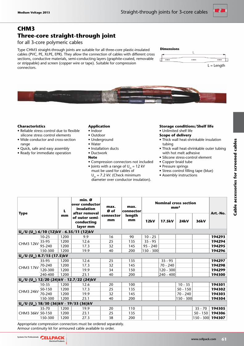
Storage conditions/Shelf life• Unlimited shelf lifeScope of delivery• Thick wall heat-shrinkable insulation tubing• Thick wall heat-shrinkable outer tubing with hot melt adhesive• Silicone stress-control element• Copper braid tube• Pressure springs• Stress control filling tape (blue)• Assembly instructions
Appropriate compression connectors must be ordered separately.Armour continuity kit for armoured cable available to order.
L = Length
Characteristics• Reliable stress control due to flexible silicone stress control elements• Wide conductor and cross-section range• Quick, safe and easy assembly• Ready for immediate operation
Application• Indoor• Outdoor• Underground• Water• Installation ducts• DuctworkNote• Compression connectors not included• Joints with a range of Um = 12 kV must be used for cables of Um = 7.2 kV. (Check minimum diameter over conductor insulation).
TypeL
mm
min. Øover conductor
insulation after removal of outer semi-
conductinglayer mm
max.Ø of
connectormm
max.connector
lengthmm
Nominal cross sectionmm²
Art.-No.
12kV 17.5kV 24kV 36kV
U0/U (Um) 6/10 (12)kV - 6.35/11 (12)kV
CHM3 12kV
10-25 1200 9.9 16 90 10 - 25 19429335-95 1200 12.6 25 135 35 - 95 19429495-240 1200 17.3 32 145 95 - 240 194295150-300 1200 19.9 40 200 150 - 300 194296
U0/U (Um) 8.7/15 (17.5)kV
CHM3 17kV
35-95 1200 12.6 25 135 35 - 95 19429770-240 1200 17.3 32 145 70 - 240 194298120-300 1200 19.9 34 150 120 - 300 194299240-400 1200 23.1 40 200 240 - 400 194300
U0/U (Um) 12/20 (24)kV - 12.7/22 (24)kV
CHM3 24kV
10-35 1200 12.6 20 100 10 - 35 19430150-150 1200 17.3 25 135 50 - 150 19430270-240 1200 19.9 32 145 70 - 240 194303150-300 1200 23.1 40 200 150 - 300 194304
U0/U (Um) 18/30 (36)kV - 19/33 (36)kV
CHM3 36kV35-70 1200 19.9 20 110 35 - 70 19430550-150 1200 23.1 25 135 50 - 150 194306150-300 1200 27.3 38 200 150 - 300 194307
DimensionsType CHM3 straight-through joints are suitable for all three-core plastic-insulated cables (PVC, PE, XLPE, EPR). They allow the connection of cables with different cross sections, conductive materials, semi-conducting layers (graphite-coated, removable or strippable) and screen (copper wire or tape). Suitable for compression connectors.
for all 3-core polymeric cablesThree-core straight-through jointCHM3
Medium Voltage 2013 Medium Voltage 2013
61 www.cellpack.com
Medium Voltage 2013 Medium Voltage 2013
Cab
le a
cces
sori
es f
or
scre
ened
cab
les
Straight-through joints for 3-core cables
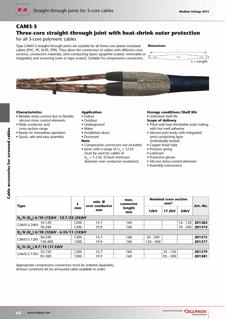
Storage conditions/Shelf life• Unlimited shelf lifeScope of delivery• Thick wall heat-shrinkable outer tubing with hot melt adhesive• Silicone joint body with integrated semi-conducting layer (individually tested)• Copper braid tube• Pressure spring• Lubricant• Protective gloves• Silicone stress-control elements• Assembly instructions
Appropriate compression connectors must be ordered separately.Armour continuity kit for armoured cable available to order.
Dimensions
TypeL
mm
min. Øover conductor
mm
max.connector
lengthmm
Nominal cross sectionmm²
Art.-No.
12kV 17.5kV 24kV
U0/U (Um) 6/10 (12)kV - 12.7/22 (24)kV
CAM3-S 24kV16-120 1200 14.7 160 16 - 120 20138270-240 1200 19.9 160 70 - 240 201374
U0/U (Um) 6/10 (12)kV - 6.35/11 (12)kV
CAM3-S 12kV50-240 1200 14.7 160 50 - 240 201375150-400 1200 19.9 160 150 - 400 201377
U0/U (Um) 8.7/15 (17.5)kV
CAM3-S 17kV35-150 1200 14.7 160 35 - 150 20137995-300 1200 19.9 160 95 - 300 201381
Characteristics• Reliable stress control due to flexible silicone stress control elements• Wide conductor and cross-section range• Ready for immediate operation• Quick, safe and easy assembly
Application• Indoor• Outdoor• Underground• Water• Installation ducts• DuctworkNote• Compression connectors not included• Joints with a range of Um = 12 kV must be used for cables of Um = 7.2 kV. (Check minimum diameter over conductor insulation).
Three-core straight-through joint with heat-shrink outer protection
L = Length
Type CAM3-S straight-through joints are suitable for all three-core plastic-insulated cables (PVC, PE, XLPE, EPR). They allow the connection of cables with different cross sections, conductive materials, semi-conducting layers (graphite-coated, removable or strippable) and screening (wire or tape screen). Suitable for compression connectors.
CAM3-S
for all 3-core polymeric cables
62 www.cellpack.com
Medium Voltage 2013 Medium Voltage 2013C
able
acc
esso
ries
fo
r sc
reen
ed c
able
sStraight-through joints for 3-core cables Medium Voltage 2013 Medium Voltage 2013
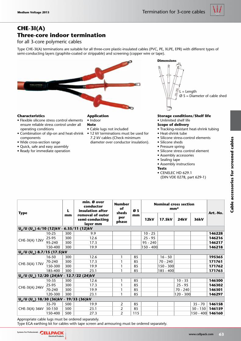
Storage conditions/Shelf life• Unlimited shelf lifeScope of delivery• Tracking-resistant heat-shrink tubing• Heat-shrink tube• Silicone stress-control elements• Silicone sheds• Pressure spring• Silicone stress control element• Assembly accessories• Sealing tape• Assembly instructionsTests• CENELEC HD 629.1 (DIN VDE 0278, part 629-1)
Dimensions
L = LengthØ S = Diameter of cable shed
Characteristics• Flexible silicone stress control elements ensure reliable stress control under all operating conditions• Combination of slip-on and heat-shrink components• Wide cross-section range• Quick, safe and easy assembly• Ready for immediate operation
Application• IndoorNote• Cable lugs not included• 12 kV terminations must be used for 7.2 kV cables (Check minimum diameter over conductor insulation).
Three-core indoor termination
Type CHE-3I(A) terminations are suitable for all three-core plastic-insulated cables (PVC, PE, XLPE, EPR) with different types of semi-conducting layers (graphite-coated or strippable) and screening (copper wire or tape).
CHE-3I(A)
for all 3-core polymeric cables
TypeL
mm
min. Ø over conductor
insulation afterremoval of outersemi-conducting
layer mm
Number of
sheds per
phase
Ø Smm
Nominal cross sectionmm²
Art.-No.
12kV 17.5kV 24kV 36kV
U0/U (Um) 6/10 (12)kV - 6.35/11 (12)kV
CHE-3I(A) 12kV
10-25 300 9.9 10 - 25 14622825-95 300 12.6 25 - 95 14621695-240 300 17.3 95 - 240 146217150-400 300 19.9 150 - 400 146218
U0/U (Um) 8.7/15 (17.5)kV
CHE-3I(A) 17kV
16-50 300 12.6 1 85 16 - 50 19536570-240 300 17.3 1 85 70 - 240 171761150-300 300 19.9 1 85 150 - 300 171762185-400 300 23.1 1 85 185 - 400 171763
U0/U (Um) 12/20 (24)kV - 12.7/22 (24)kV
CHE-3I(A) 24kV
10-35 300 12.6 1 85 10 - 35 14630025-95 300 17.3 1 85 25 - 95 14630270-240 300 19.9 1 85 70 - 240 146301120-300 300 23.1 1 85 120 - 300 146297
U0/U (Um) 18/30 (36)kV - 19/33 (36)kV
CHE-3I(A) 36kV35-70 500 19.9 2 85 35 - 70 14615850-150 500 23.1 2 85 50 - 150 146159150-400 500 27.3 2 115 150 - 400 146160
Appropriate cable lugs must be ordered separately.Type EGA earthing kit for cables with tape screen and armouring must be ordered separately.
Medium Voltage 2013 Medium Voltage 2013
63 www.cellpack.com
Medium Voltage 2013 Medium Voltage 2013 Termination for 3-core cables
Cab
le a
cces
sori
es f
or
scre
ened
cab
les
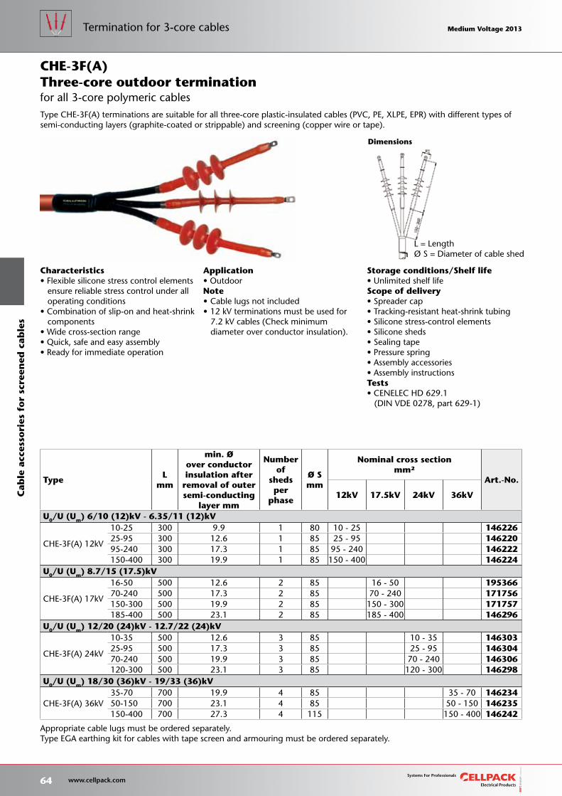
Storage conditions/Shelf life• Unlimited shelf lifeScope of delivery• Spreader cap• Tracking-resistant heat-shrink tubing• Silicone stress-control elements• Silicone sheds• Sealing tape• Pressure spring• Assembly accessories• Assembly instructionsTests• CENELEC HD 629.1 (DIN VDE 0278, part 629-1)
L = LengthØ S = Diameter of cable shed
Characteristics• Flexible silicone stress control elements ensure reliable stress control under all operating conditions• Combination of slip-on and heat-shrink components• Wide cross-section range• Quick, safe and easy assembly• Ready for immediate operation
Dimensions
Application• OutdoorNote• Cable lugs not included• 12 kV terminations must be used for 7.2 kV cables (Check minimum diameter over conductor insulation).
Type CHE-3F(A) terminations are suitable for all three-core plastic-insulated cables (PVC, PE, XLPE, EPR) with different types of semi-conducting layers (graphite-coated or strippable) and screening (copper wire or tape).
for all 3-core polymeric cablesThree-core outdoor terminationCHE-3F(A)
Appropriate cable lugs must be ordered separately.Type EGA earthing kit for cables with tape screen and armouring must be ordered separately.
TypeL
mm
min. Øover conductorinsulation after
removal of outersemi-conducting
layer mm
Number of
sheds per
phase
Ø Smm
Nominal cross sectionmm²
Art.-No.
12kV 17.5kV 24kV 36kV
U0/U (Um) 6/10 (12)kV - 6.35/11 (12)kV
CHE-3F(A) 12kV
10-25 300 9.9 1 80 10 - 25 14622625-95 300 12.6 1 85 25 - 95 14622095-240 300 17.3 1 85 95 - 240 146222150-400 300 19.9 1 85 150 - 400 146224
U0/U (Um) 8.7/15 (17.5)kV
CHE-3F(A) 17kV
16-50 500 12.6 2 85 16 - 50 19536670-240 500 17.3 2 85 70 - 240 171756150-300 500 19.9 2 85 150 - 300 171757185-400 500 23.1 2 85 185 - 400 146296
U0/U (Um) 12/20 (24)kV - 12.7/22 (24)kV
CHE-3F(A) 24kV
10-35 500 12.6 3 85 10 - 35 14630325-95 500 17.3 3 85 25 - 95 14630470-240 500 19.9 3 85 70 - 240 146306120-300 500 23.1 3 85 120 - 300 146298
U0/U (Um) 18/30 (36)kV - 19/33 (36)kV
CHE-3F(A) 36kV35-70 700 19.9 4 85 35 - 70 14623450-150 700 23.1 4 85 50 - 150 146235150-400 700 27.3 4 115 150 - 400 146242
64 www.cellpack.com
Medium Voltage 2013 Medium Voltage 2013Termination for 3-core cablesC
able
acc
esso
ries
fo
r sc
reen
ed c
able
s Medium Voltage 2013 Medium Voltage 2013
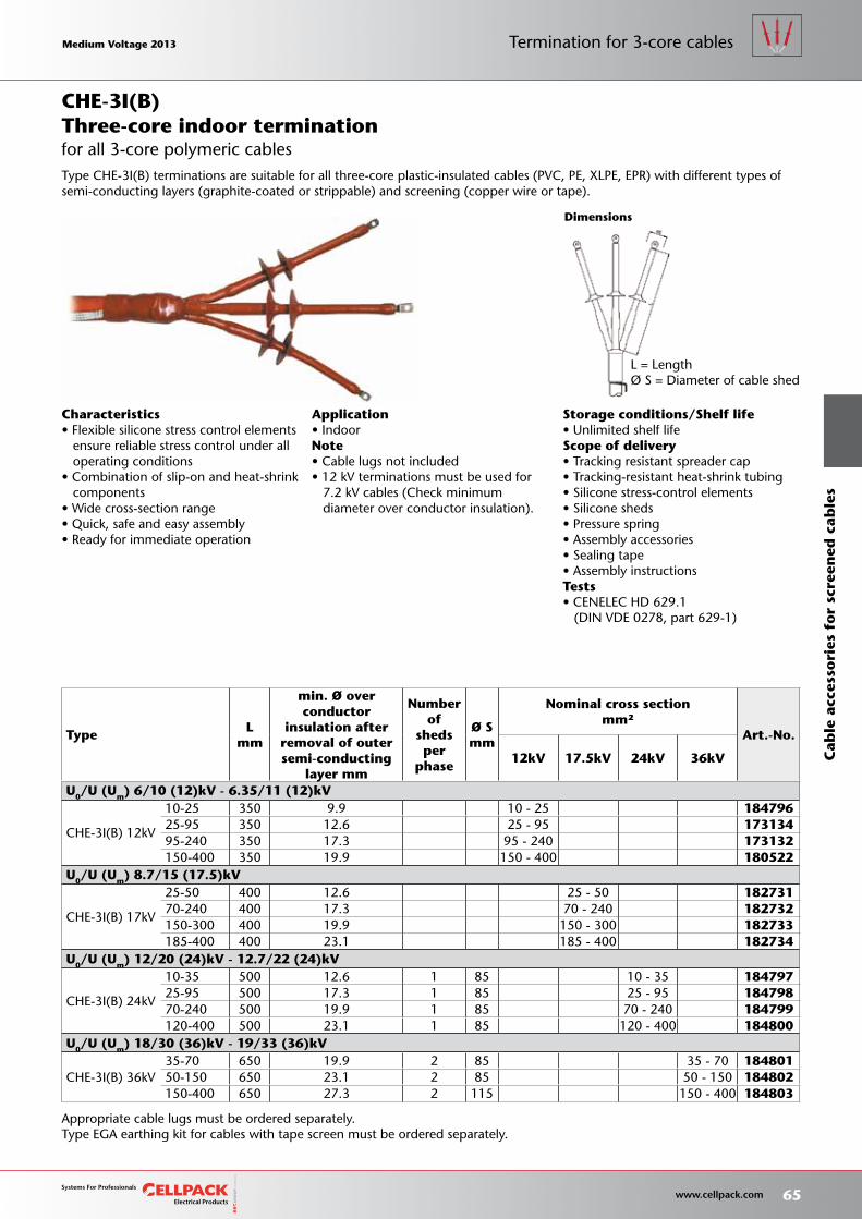
Storage conditions/Shelf life• Unlimited shelf lifeScope of delivery• Tracking resistant spreader cap• Tracking-resistant heat-shrink tubing• Silicone stress-control elements• Silicone sheds• Pressure spring• Assembly accessories• Sealing tape• Assembly instructionsTests• CENELEC HD 629.1 (DIN VDE 0278, part 629-1)
L = LengthØ S = Diameter of cable shed
Characteristics• Flexible silicone stress control elements ensure reliable stress control under all operating conditions• Combination of slip-on and heat-shrink components• Wide cross-section range• Quick, safe and easy assembly• Ready for immediate operation
Application• IndoorNote• Cable lugs not included• 12 kV terminations must be used for 7.2 kV cables (Check minimum diameter over conductor insulation).
TypeL
mm
min. Ø over conductor
insulation afterremoval of outersemi-conducting
layer mm
Number of
sheds per
phase
Ø Smm
Nominal cross sectionmm²
Art.-No.
12kV 17.5kV 24kV 36kV
U0/U (Um) 6/10 (12)kV - 6.35/11 (12)kV
CHE-3I(B) 12kV
10-25 350 9.9 10 - 25 18479625-95 350 12.6 25 - 95 17313495-240 350 17.3 95 - 240 173132150-400 350 19.9 150 - 400 180522
U0/U (Um) 8.7/15 (17.5)kV
CHE-3I(B) 17kV
25-50 400 12.6 25 - 50 18273170-240 400 17.3 70 - 240 182732150-300 400 19.9 150 - 300 182733185-400 400 23.1 185 - 400 182734
U0/U (Um) 12/20 (24)kV - 12.7/22 (24)kV
CHE-3I(B) 24kV
10-35 500 12.6 1 85 10 - 35 18479725-95 500 17.3 1 85 25 - 95 18479870-240 500 19.9 1 85 70 - 240 184799120-400 500 23.1 1 85 120 - 400 184800
U0/U (Um) 18/30 (36)kV - 19/33 (36)kV
CHE-3I(B) 36kV35-70 650 19.9 2 85 35 - 70 18480150-150 650 23.1 2 85 50 - 150 184802150-400 650 27.3 2 115 150 - 400 184803
Dimensions
Appropriate cable lugs must be ordered separately.Type EGA earthing kit for cables with tape screen must be ordered separately.
Type CHE-3I(B) terminations are suitable for all three-core plastic-insulated cables (PVC, PE, XLPE, EPR) with different types of semi-conducting layers (graphite-coated or strippable) and screening (copper wire or tape).
for all 3-core polymeric cablesThree-core indoor terminationCHE-3I(B)
Medium Voltage 2013 Medium Voltage 2013
65 www.cellpack.com
Medium Voltage 2013 Medium Voltage 2013 Termination for 3-core cables
Cab
le a
cces
sori
es f
or
scre
ened
cab
les
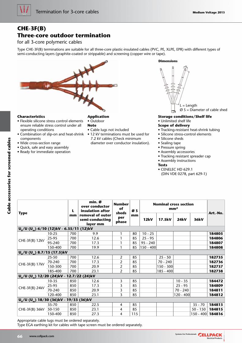
Storage conditions/Shelf life• Unlimited shelf lifeScope of delivery• Tracking-resistant heat-shrink tubing• Silicone stress-control elements• Silicone sheds• Sealing tape• Pressure spring• Assembly accessories• Tracking resistant spreader cap• Assembly instructionsTests• CENELEC HD 629.1 (DIN VDE 0278, part 629-1)
L = LengthØ S = Diameter of cable shed
Characteristics• Flexible silicone stress control elements ensure reliable stress control under all operating conditions• Combination of slip-on and heat-shrink components• Wide cross-section range• Quick, safe and easy assembly• Ready for immediate operation
Application• OutdoorNote• Cable lugs not included• 12 kV terminations must be used for 7.2 kV cables (Check minimum diameter over conductor insulation).
TypeL
mm
min. Øover conductorinsulation after
removal of outersemi-conducting
layer mm
Number of
sheds per
phase
Ø Smm
Nominal cross sectionmm²
Art.-No.
12kV 17.5kV 24kV 36kV
U0/U (Um) 6/10 (12)kV - 6.35/11 (12)kV
CHE-3F(B) 12kV
10-25 700 9.9 1 80 10 - 25 18480525-95 700 12.6 1 85 25 - 95 18480695-240 700 17.3 1 85 95 - 240 184807150-400 700 19.9 1 85 150 - 400 184808
U0/U (Um) 8.7/15 (17.5)kV
CHE-3F(B) 17kV
25-50 700 12.6 2 85 25 - 50 18273570-240 700 17.3 2 85 70 - 240 182736150-300 700 20.9 2 85 150 - 300 182737185-400 700 23.1 2 85 185 - 400 182738
U0/U (Um) 12/20 (24)kV - 12.7/22 (24)kV
CHE-3F(B) 24kV
10-35 850 12.6 3 85 10 - 35 18447225-95 850 17.3 3 85 25 - 95 18480970-240 850 20.9 3 85 70 - 240 184811120-400 850 23.1 3 85 120 - 400 184812
U0/U (Um) 18/30 (36)kV - 19/33 (36)kV
CHE-3F(B) 36kV35-70 850 22.5 4 85 35 - 70 18481350-150 850 23.1 4 85 50 - 150 184815150-400 850 27.3 4 115 150 - 400 184816
Dimensions
Appropriate cable lugs must be ordered separately.Type EGA earthing kit for cables with tape screen must be ordered separately.
Type CHE-3F(B) terminations are suitable for all three-core plastic-insulated cables (PVC, PE, XLPE, EPR) with different types of semi-conducting layers (graphite-coated or strippable) and screening (copper wire or tape).
for all 3-core polymeric cablesThree-core outdoor terminationCHE-3F(B)
66 www.cellpack.com
Medium Voltage 2013 Medium Voltage 2013Termination for 3-core cablesC
able
acc
esso
ries
fo
r sc
reen
ed c
able
s Medium Voltage 2013 Medium Voltage 2013
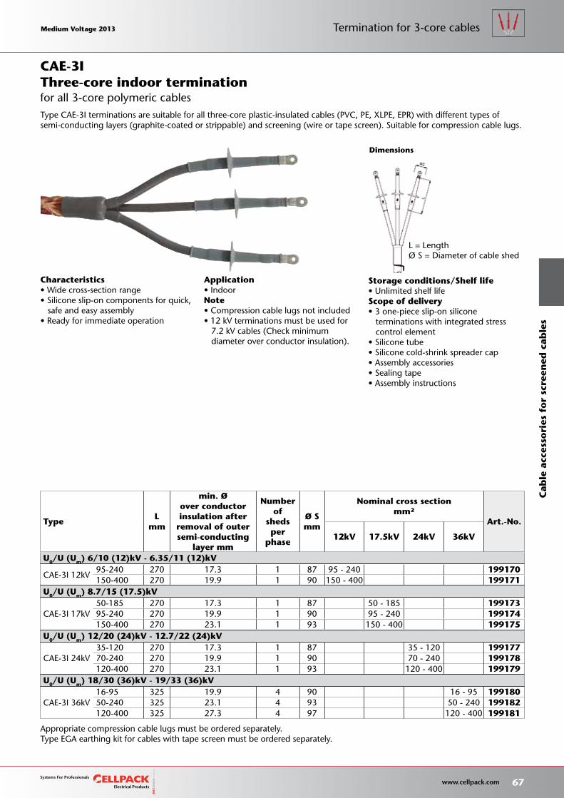
Storage conditions/Shelf life• Unlimited shelf lifeScope of delivery• 3 one-piece slip-on silicone terminations with integrated stress control element• Silicone tube• Silicone cold-shrink spreader cap• Assembly accessories• Sealing tape• Assembly instructions
L = LengthØ S = Diameter of cable shed
Characteristics• Wide cross-section range• Silicone slip-on components for quick, safe and easy assembly• Ready for immediate operation
Application• IndoorNote• Compression cable lugs not included• 12 kV terminations must be used for 7.2 kV cables (Check minimum diameter over conductor insulation).
TypeL
mm
min. Øover conductorinsulation after
removal of outersemi-conducting
layer mm
Number of
sheds per
phase
Ø Smm
Nominal cross sectionmm²
Art.-No.
12kV 17.5kV 24kV 36kV
U0/U (Um) 6/10 (12)kV - 6.35/11 (12)kV
CAE-3I 12kV95-240 270 17.3 1 87 95 - 240 199170150-400 270 19.9 1 90 150 - 400 199171
U0/U (Um) 8.7/15 (17.5)kV
CAE-3I 17kV50-185 270 17.3 1 87 50 - 185 19917395-240 270 19.9 1 90 95 - 240 199174150-400 270 23.1 1 93 150 - 400 199175
U0/U (Um) 12/20 (24)kV - 12.7/22 (24)kV
CAE-3I 24kV35-120 270 17.3 1 87 35 - 120 19917770-240 270 19.9 1 90 70 - 240 199178120-400 270 23.1 1 93 120 - 400 199179
U0/U (Um) 18/30 (36)kV - 19/33 (36)kV
CAE-3I 36kV16-95 325 19.9 4 90 16 - 95 19918050-240 325 23.1 4 93 50 - 240 199182120-400 325 27.3 4 97 120 - 400 199181
Dimensions
Appropriate compression cable lugs must be ordered separately.Type EGA earthing kit for cables with tape screen must be ordered separately.
Type CAE-3I terminations are suitable for all three-core plastic-insulated cables (PVC, PE, XLPE, EPR) with different types of semi-conducting layers (graphite-coated or strippable) and screening (wire or tape screen). Suitable for compression cable lugs.
for all 3-core polymeric cablesThree-core indoor terminationCAE-3I
Medium Voltage 2013 Medium Voltage 2013
67 www.cellpack.com
Medium Voltage 2013 Medium Voltage 2013 Termination for 3-core cables
Cab
le a
cces
sori
es f
or
scre
ened
cab
les
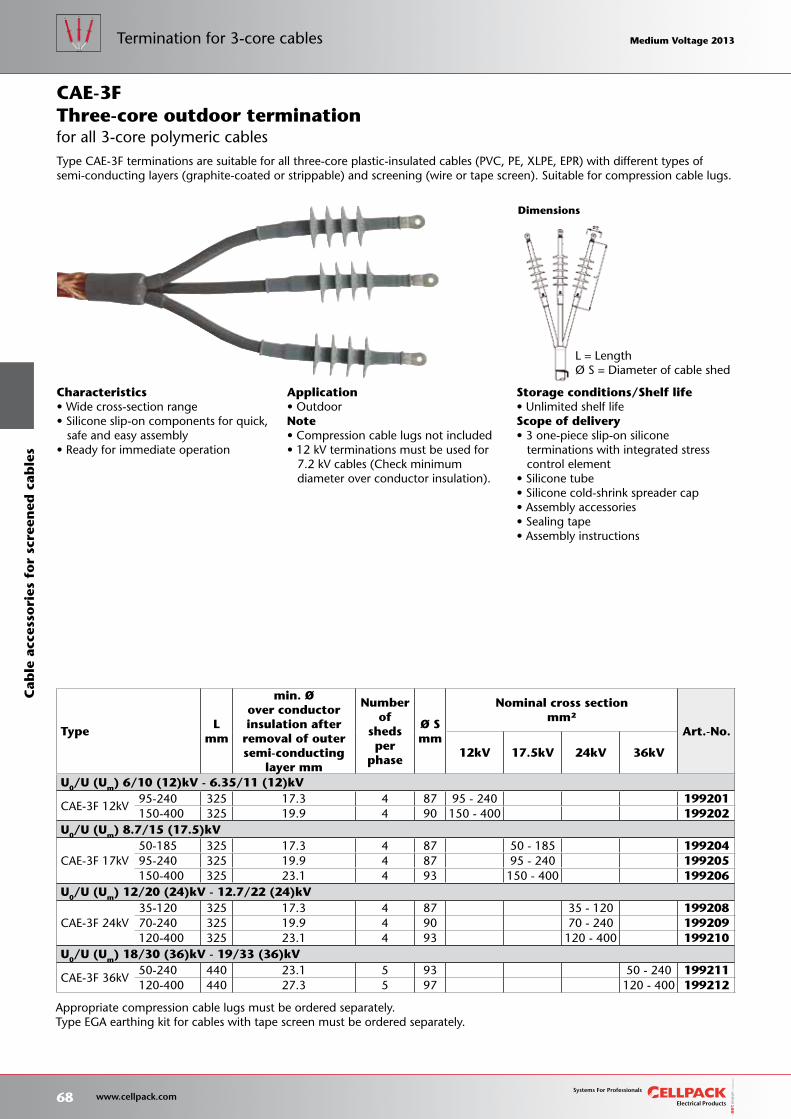
Storage conditions/Shelf life• Unlimited shelf lifeScope of delivery• 3 one-piece slip-on silicone terminations with integrated stress control element• Silicone tube• Silicone cold-shrink spreader cap• Assembly accessories• Sealing tape• Assembly instructions
L = LengthØ S = Diameter of cable shed
Characteristics• Wide cross-section range• Silicone slip-on components for quick, safe and easy assembly• Ready for immediate operation
Application• OutdoorNote• Compression cable lugs not included• 12 kV terminations must be used for 7.2 kV cables (Check minimum diameter over conductor insulation).
TypeL
mm
min. Øover conductorinsulation after
removal of outersemi-conducting
layer mm
Number of
sheds per
phase
Ø Smm
Nominal cross sectionmm²
Art.-No.
12kV 17.5kV 24kV 36kV
U0/U (Um) 6/10 (12)kV - 6.35/11 (12)kV
CAE-3F 12kV95-240 325 17.3 4 87 95 - 240 199201150-400 325 19.9 4 90 150 - 400 199202
U0/U (Um) 8.7/15 (17.5)kV
CAE-3F 17kV50-185 325 17.3 4 87 50 - 185 19920495-240 325 19.9 4 87 95 - 240 199205150-400 325 23.1 4 93 150 - 400 199206
U0/U (Um) 12/20 (24)kV - 12.7/22 (24)kV
CAE-3F 24kV35-120 325 17.3 4 87 35 - 120 19920870-240 325 19.9 4 90 70 - 240 199209120-400 325 23.1 4 93 120 - 400 199210
U0/U (Um) 18/30 (36)kV - 19/33 (36)kV
CAE-3F 36kV50-240 440 23.1 5 93 50 - 240 199211120-400 440 27.3 5 97 120 - 400 199212
Dimensions
Appropriate compression cable lugs must be ordered separately.Type EGA earthing kit for cables with tape screen must be ordered separately.
Type CAE-3F terminations are suitable for all three-core plastic-insulated cables (PVC, PE, XLPE, EPR) with different types of semi-conducting layers (graphite-coated or strippable) and screening (wire or tape screen). Suitable for compression cable lugs.
for all 3-core polymeric cablesThree-core outdoor terminationCAE-3F
68 www.cellpack.com
Medium Voltage 2013 Medium Voltage 2013Termination for 3-core cablesC
able
acc
esso
ries
fo
r sc
reen
ed c
able
s Medium Voltage 2013 Medium Voltage 2013
Medium Voltage 2013 Medium Voltage 2013
69 www.cellpack.com
Medium Voltage 2013 Medium Voltage 2013 Termination for 3-core cables
Cab
le a
cces
sori
es f
or
scre
ened
cab
les

We help you achieve the highest standards70 www.cellpack.com
Medium Voltage 2013 Medium Voltage 2013 Medium Voltage 2013 Medium Voltage 2013
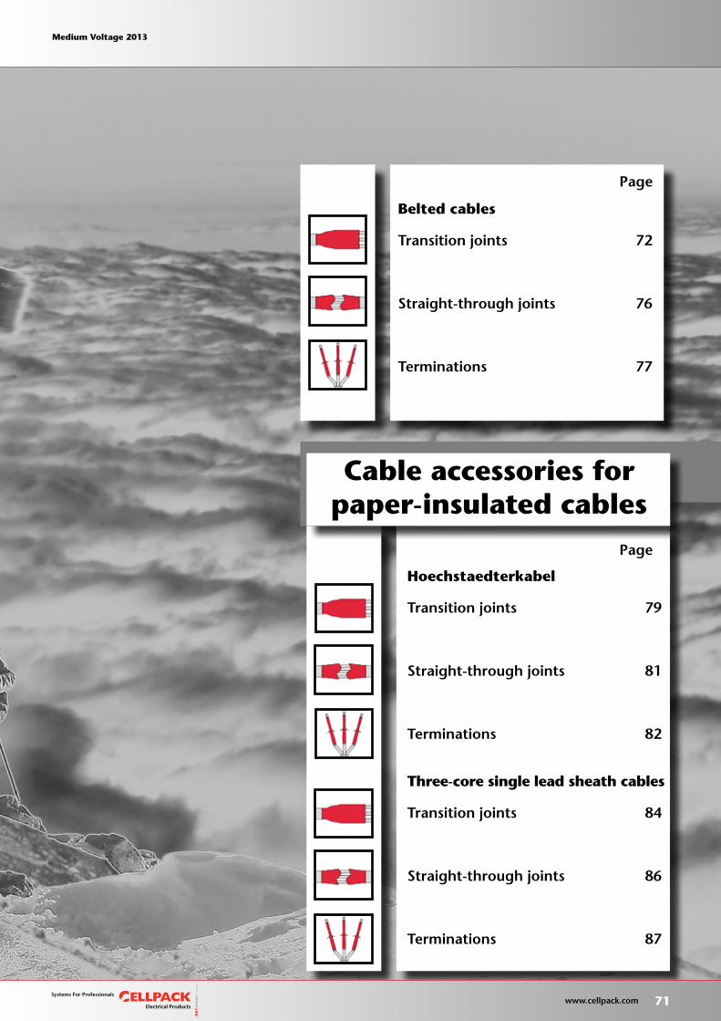
Cable accessories forpaper-insulated cables
Hoechstaedterkabel
Transition joints 79
Straight-through joints 81
Terminations 82
Three-core single lead sheath cables
Transition joints 84
Straight-through joints 86
Terminations 87
Belted cables
Transition joints 72
Straight-through joints 76
Terminations 77
Page
Page
We help you achieve the highest standards
Medium Voltage 2013 Medium Voltage 2013
71 www.cellpack.com
Medium Voltage 2013 Medium Voltage 2013
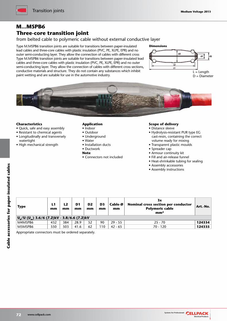
Appropriate connectors must be ordered separately.
L = LengthD = Diameter
Dimensions
Scope of delivery• Distance sleeve• Hydrolysis-resistant PUR type EG cast-resin, containing the correct volume ready for mixing• Transparent plastic moulds• Spreader cap• Armour continuity kit• Fill and air-release funnel• Heat-shrinkable tubing for sealing• Assembly accessories• Assembly instructions
Characteristics• Quick, safe and easy assembly• Resistant to chemical agents• Longitudinally and transversely watertight• High mechanical strength
Application• Indoor• Outdoor• Underground• Water• Installation ducts• DuctworkNote• Connectors not included
TypeL1
mm L2
mm D1mm
D2mm
D3mm
Cable-Ømm
3xNominal cross section per conductor
Polymeric cablemm²
Art.-No.
U0/U (Um) 3.6/6 (7.2)kV - 3.8/6.6 (7.2)kVM4MSPB6 432 384 28.9 52 90 29 - 55 25 - 70 124334M5MSPB6 550 503 41.6 62 110 42 - 65 70 - 120 124335
M...MSPB6
Type M.MSPB6 transition joints are suitable for transitions between paper-insulated lead cables and three-core cables with plastic insulation (PVC, PE, XLPE, EPR) and no outer semi-conducting layer. They allow the connection of cables with different cross Type M.MSPB6 transition joints are suitable for transitions between paper-insulated lead cables and three-core cables with plastic insulation (PVC, PE, XLPE, EPR) and no outer semi-conducting layer. They allow the connection of cables with different cross sections, conductive materials and structure. They do not contain any substances which inhibit paint wetting and are suitable for use in the automotive industry.
from belted cable to polymeric cable without external conductive layerThree-core transition joint
72 www.cellpack.com
Medium Voltage 2013 Medium Voltage 2013Transition jointsC
able
acc
esso
ries
fo
r p
aper
-in
sula
ted
cab
les
Medium Voltage 2013 Medium Voltage 2013
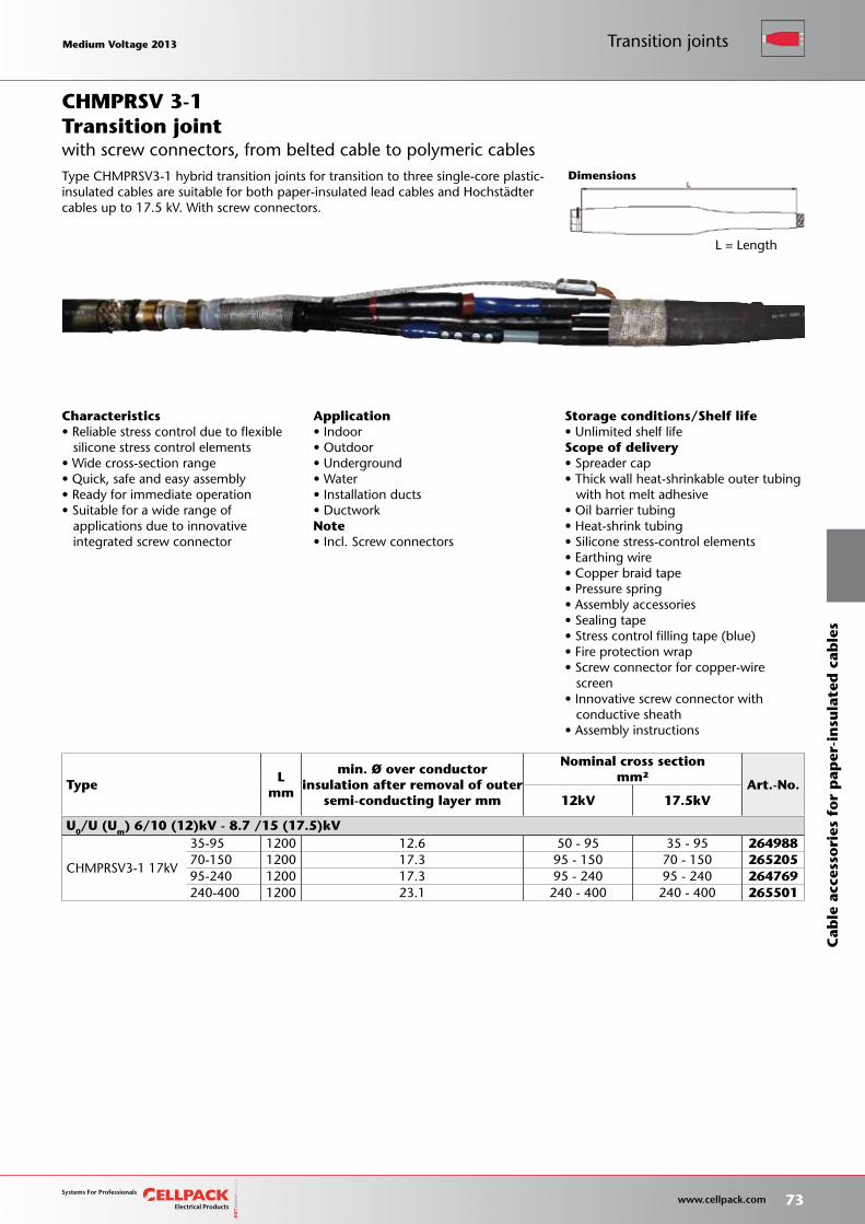
Storage conditions/Shelf life• Unlimited shelf lifeScope of delivery• Spreader cap• Thick wall heat-shrinkable outer tubing with hot melt adhesive• Oil barrier tubing• Heat-shrink tubing• Silicone stress-control elements• Earthing wire• Copper braid tape• Pressure spring• Assembly accessories• Sealing tape• Stress control filling tape (blue)• Fire protection wrap• Screw connector for copper-wire screen• Innovative screw connector with conductive sheath• Assembly instructions
Dimensions
TypeL
mm
min. Ø over conductorinsulation after removal of outer
semi-conducting layer mm
Nominal cross sectionmm²
Art.-No.12kV 17.5kV
U0/U (Um) 6/10 (12)kV - 8.7 /15 (17.5)kV
CHMPRSV3-1 17kV
35-95 1200 12.6 50 - 95 35 - 95 26498870-150 1200 17.3 95 - 150 70 - 150 26520595-240 1200 17.3 95 - 240 95 - 240 264769240-400 1200 23.1 240 - 400 240 - 400 265501
Application• Indoor• Outdoor• Underground• Water• Installation ducts• DuctworkNote• Incl. Screw connectors
Characteristics• Reliable stress control due to flexible silicone stress control elements• Wide cross-section range• Quick, safe and easy assembly• Ready for immediate operation• Suitable for a wide range of applications due to innovative integrated screw connector
Transition joint
L = Length
Type CHMPRSV3-1 hybrid transition joints for transition to three single-core plastic-insulated cables are suitable for both paper-insulated lead cables and Hochstadter cables up to 17.5 kV. With screw connectors.
CHMPRSV 3-1
with screw connectors, from belted cable to polymeric cables
Medium Voltage 2013 Medium Voltage 2013
73 www.cellpack.com
Medium Voltage 2013 Medium Voltage 2013 Transition joints
Cab
le a
cces
sori
es f
or
pap
er-i
nsu
late
d c
able
s
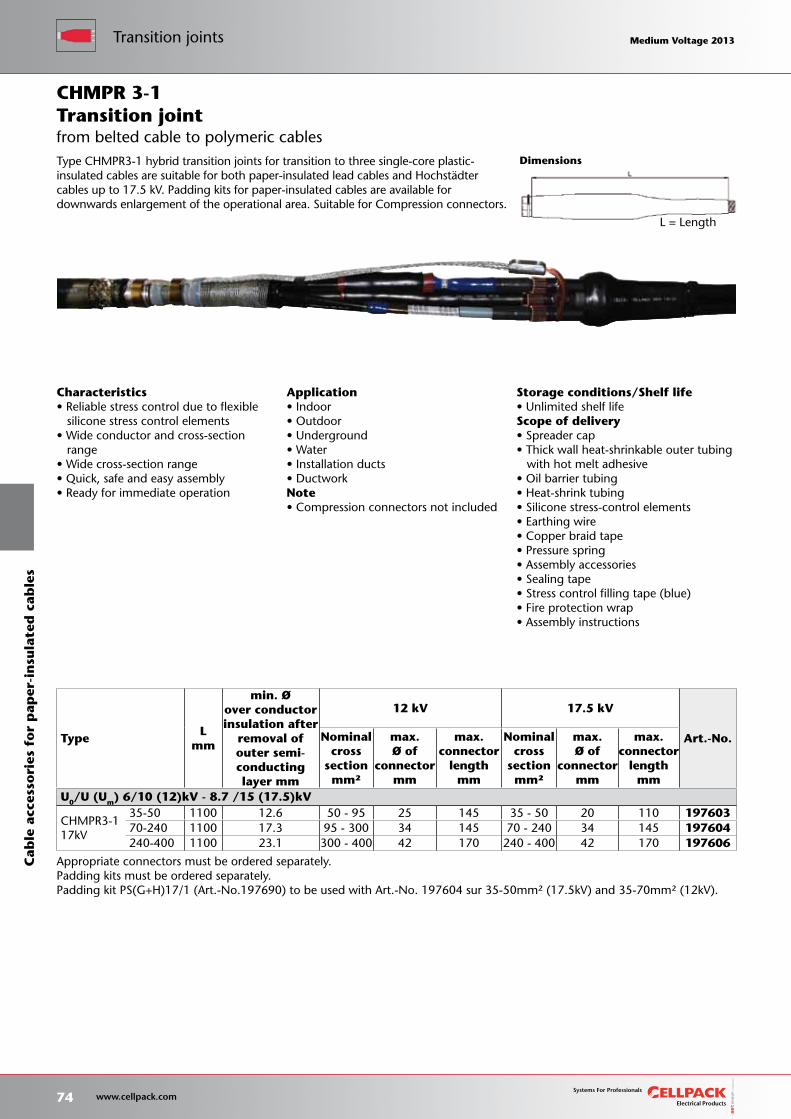
Storage conditions/Shelf life• Unlimited shelf lifeScope of delivery• Spreader cap• Thick wall heat-shrinkable outer tubing with hot melt adhesive• Oil barrier tubing• Heat-shrink tubing• Silicone stress-control elements• Earthing wire• Copper braid tape• Pressure spring• Assembly accessories• Sealing tape• Stress control filling tape (blue)• Fire protection wrap• Assembly instructions
Dimensions
L = Length
TypeL
mm
min. Øover conductorinsulation after
removal of outer semi-conductinglayer mm
12 kV 17.5 kV
Art.-No.Nominalcross
sectionmm²
max.Ø of
connectormm
max.connector
lengthmm
Nominalcross
sectionmm²
max.Ø of
connectormm
max.connector
lengthmm
U0/U (Um) 6/10 (12)kV - 8.7 /15 (17.5)kV
CHMPR3-1 17kV
35-50 1100 12.6 50 - 95 25 145 35 - 50 20 110 19760370-240 1100 17.3 95 - 300 34 145 70 - 240 34 145 197604240-400 1100 23.1 300 - 400 42 170 240 - 400 42 170 197606
Characteristics• Reliable stress control due to flexible silicone stress control elements• Wide conductor and cross-section range• Wide cross-section range• Quick, safe and easy assembly• Ready for immediate operation
Application• Indoor• Outdoor• Underground• Water• Installation ducts• DuctworkNote• Compression connectors not included
Transition joint
Appropriate connectors must be ordered separately.Padding kits must be ordered separately.Padding kit PS(G+H)17/1 (Art.-No.197690) to be used with Art.-No. 197604 sur 35-50mm² (17.5kV) and 35-70mm² (12kV).
Type CHMPR3-1 hybrid transition joints for transition to three single-core plastic-insulated cables are suitable for both paper-insulated lead cables and Hochstadter cables up to 17.5 kV. Padding kits for paper-insulated cables are available for downwards enlargement of the operational area. Suitable for Compression connectors.
CHMPR 3-1
from belted cable to polymeric cables
74 www.cellpack.com
Medium Voltage 2013 Medium Voltage 2013Transition jointsC
able
acc
esso
ries
fo
r p
aper
-in
sula
ted
cab
les
Medium Voltage 2013 Medium Voltage 2013
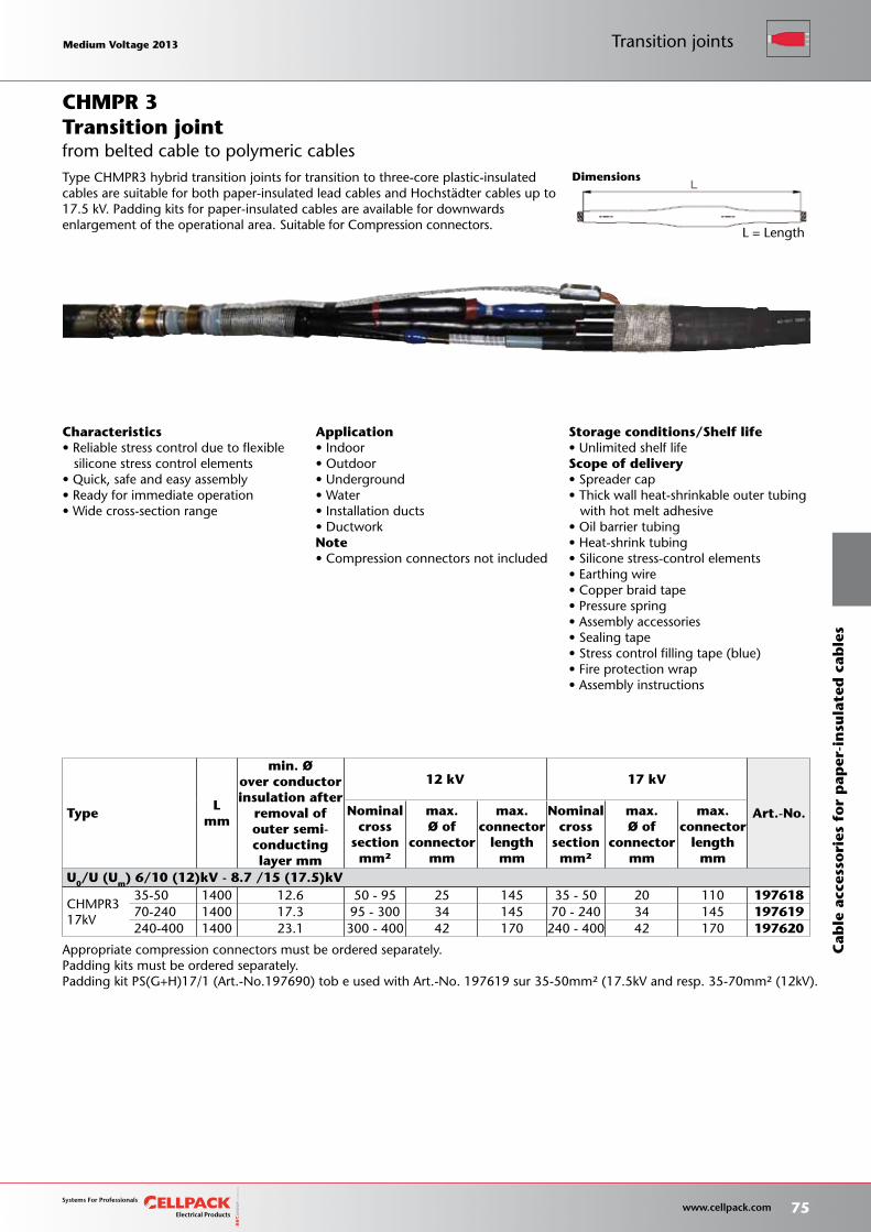
Storage conditions/Shelf life• Unlimited shelf lifeScope of delivery• Spreader cap• Thick wall heat-shrinkable outer tubing with hot melt adhesive• Oil barrier tubing• Heat-shrink tubing• Silicone stress-control elements• Earthing wire• Copper braid tape• Pressure spring• Assembly accessories• Sealing tape• Stress control filling tape (blue)• Fire protection wrap• Assembly instructions
Dimensions
TypeL
mm
min. Øover conductorinsulation after
removal of outer semi-conductinglayer mm
12 kV 17 kV
Art.-No.Nominalcross
sectionmm²
max.Ø of
connectormm
max.connector
lengthmm
Nominalcross
sectionmm²
max.Ø of
connectormm
max.connector
lengthmm
U0/U (Um) 6/10 (12)kV - 8.7 /15 (17.5)kV
CHMPR3 17kV
35-50 1400 12.6 50 - 95 25 145 35 - 50 20 110 19761870-240 1400 17.3 95 - 300 34 145 70 - 240 34 145 197619240-400 1400 23.1 300 - 400 42 170 240 - 400 42 170 197620
L = Length
Characteristics• Reliable stress control due to flexible silicone stress control elements• Quick, safe and easy assembly• Ready for immediate operation• Wide cross-section range
Application• Indoor• Outdoor• Underground• Water• Installation ducts• DuctworkNote• Compression connectors not included
Transition joint
Appropriate compression connectors must be ordered separately.Padding kits must be ordered separately.Padding kit PS(G+H)17/1 (Art.-No.197690) tob e used with Art.-No. 197619 sur 35-50mm² (17.5kV and resp. 35-70mm² (12kV).
Type CHMPR3 hybrid transition joints for transition to three-core plastic-insulated cables are suitable for both paper-insulated lead cables and Hochstadter cables up to 17.5 kV. Padding kits for paper-insulated cables are available for downwards enlargement of the operational area. Suitable for Compression connectors.
CHMPR 3
from belted cable to polymeric cables
Medium Voltage 2013 Medium Voltage 2013
75 www.cellpack.com
Medium Voltage 2013 Medium Voltage 2013 Transition joints
Cab
le a
cces
sori
es f
or
pap
er-i
nsu
late
d c
able
s
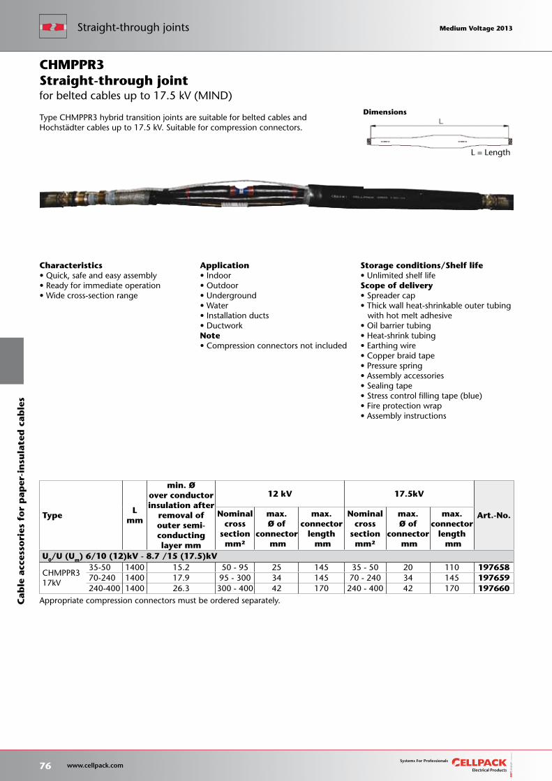
Storage conditions/Shelf life• Unlimited shelf lifeScope of delivery• Spreader cap• Thick wall heat-shrinkable outer tubing with hot melt adhesive• Oil barrier tubing• Heat-shrink tubing• Earthing wire• Copper braid tape• Pressure spring• Assembly accessories• Sealing tape• Stress control filling tape (blue)• Fire protection wrap• Assembly instructions
L = Length
TypeL
mm
min. Øover conductorinsulation after
removal of outer semi-conductinglayer mm
12 kV 17.5kV
Art.-No.Nominalcross
sectionmm²
max.Ø of
connector mm
max.connector
length mm
Nominalcross
sectionmm²
max.Ø of
connector mm
max.connector
length mm
U0/U (Um) 6/10 (12)kV - 8.7 /15 (17.5)kV
CHMPPR3 17kV
35-50 1400 15.2 50 - 95 25 145 35 - 50 20 110 19765870-240 1400 17.9 95 - 300 34 145 70 - 240 34 145 197659240-400 1400 26.3 300 - 400 42 170 240 - 400 42 170 197660
Dimensions
Appropriate compression connectors must be ordered separately.
Characteristics• Quick, safe and easy assembly• Ready for immediate operation• Wide cross-section range
Application• Indoor• Outdoor• Underground• Water• Installation ducts• DuctworkNote• Compression connectors not included
Type CHMPPR3 hybrid transition joints are suitable for belted cables and Hochstadter cables up to 17.5 kV. Suitable for compression connectors.
for belted cables up to 17.5 kV (MIND)Straight-through jointCHMPPR3
76 www.cellpack.com
Medium Voltage 2013 Medium Voltage 2013C
able
acc
esso
ries
fo
r p
aper
-in
sula
ted
cab
les
Straight-through joints Medium Voltage 2013 Medium Voltage 2013
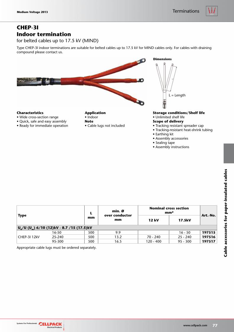
Storage conditions/Shelf life• Unlimited shelf lifeScope of delivery• Tracking resistant spreader cap• Tracking-resistant heat-shrink tubing• Earthing kit• Assembly accessories• Sealing tape• Assembly instructions
Appropriate cable lugs must be ordered separately.
L = Length
TypeL
mm
min. Øover conductor
mm
Nominal cross sectionmm²
Art.-No.12 kV 17.5kV
U0/U (Um) 6/10 (12)kV - 8.7 /15 (17.5)kV
CHEP-3I 12kV16-50 500 9.9 16 - 50 19751525-240 500 13.2 70 - 240 25 - 240 19751695-300 500 16.5 120 - 400 95 - 300 197517
Dimensions
Characteristics• Wide cross-section range• Quick, safe and easy assembly• Ready for immediate operation
Application• IndoorNote• Cable lugs not included
Type CHEP-3I indoor terminations are suitable for belted cables up to 17.5 kV for MIND cables only. For cables with draining compound please contact us.
for belted cables up to 17.5 kV (MIND)Indoor terminationCHEP-3I
Medium Voltage 2013 Medium Voltage 2013
77 www.cellpack.com
Medium Voltage 2013 Medium Voltage 2013
Cab
le a
cces
sori
es f
or
pap
er-i
nsu
late
d c
able
s
Terminations
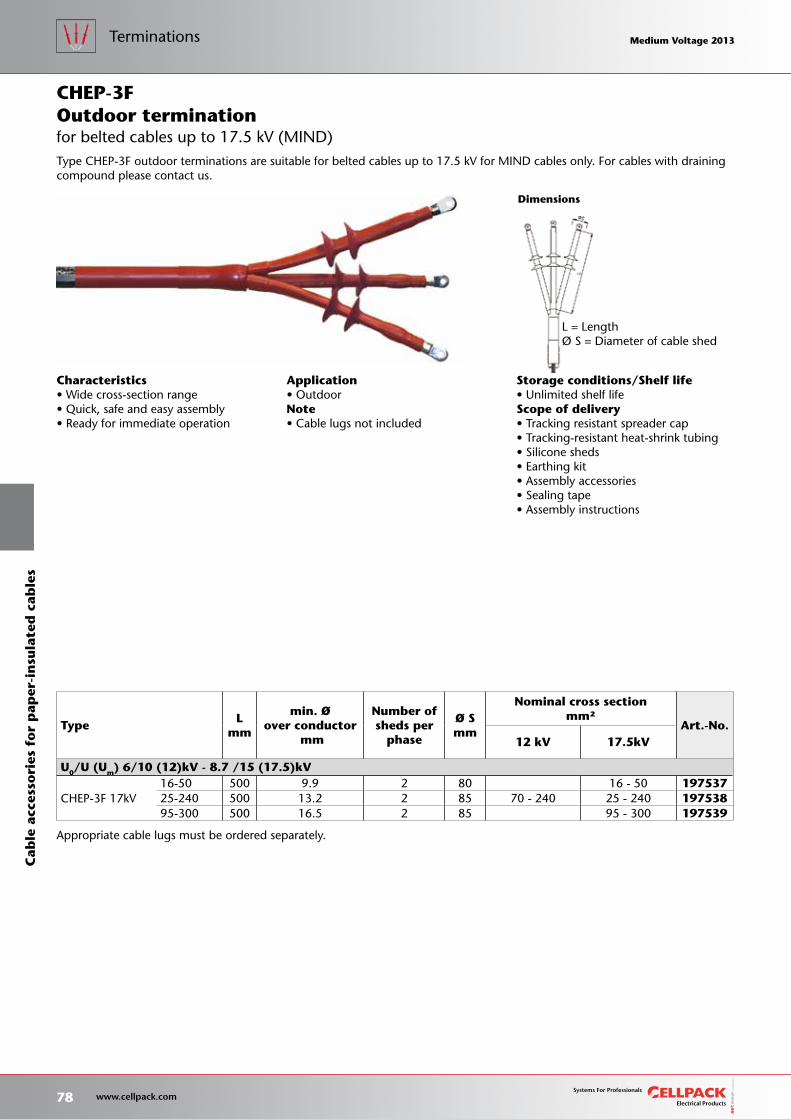
Storage conditions/Shelf life• Unlimited shelf lifeScope of delivery• Tracking resistant spreader cap• Tracking-resistant heat-shrink tubing• Silicone sheds• Earthing kit• Assembly accessories• Sealing tape• Assembly instructions
L = LengthØ S = Diameter of cable shed
TypeL
mm
min. Øover conductor
mm
Number ofsheds per
phase
Ø Smm
Nominal cross sectionmm²
Art.-No.12 kV 17.5kV
U0/U (Um) 6/10 (12)kV - 8.7 /15 (17.5)kV
CHEP-3F 17kV16-50 500 9.9 2 80 16 - 50 19753725-240 500 13.2 2 85 70 - 240 25 - 240 19753895-300 500 16.5 2 85 95 - 300 197539
Dimensions
Appropriate cable lugs must be ordered separately.
Characteristics• Wide cross-section range• Quick, safe and easy assembly• Ready for immediate operation
Application• OutdoorNote• Cable lugs not included
Type CHEP-3F outdoor terminations are suitable for belted cables up to 17.5 kV for MIND cables only. For cables with draining compound please contact us.
for belted cables up to 17.5 kV (MIND)Outdoor terminationCHEP-3F
78 www.cellpack.com
Medium Voltage 2013 Medium Voltage 2013C
able
acc
esso
ries
fo
r p
aper
-in
sula
ted
cab
les
Terminations Medium Voltage 2013 Medium Voltage 2013
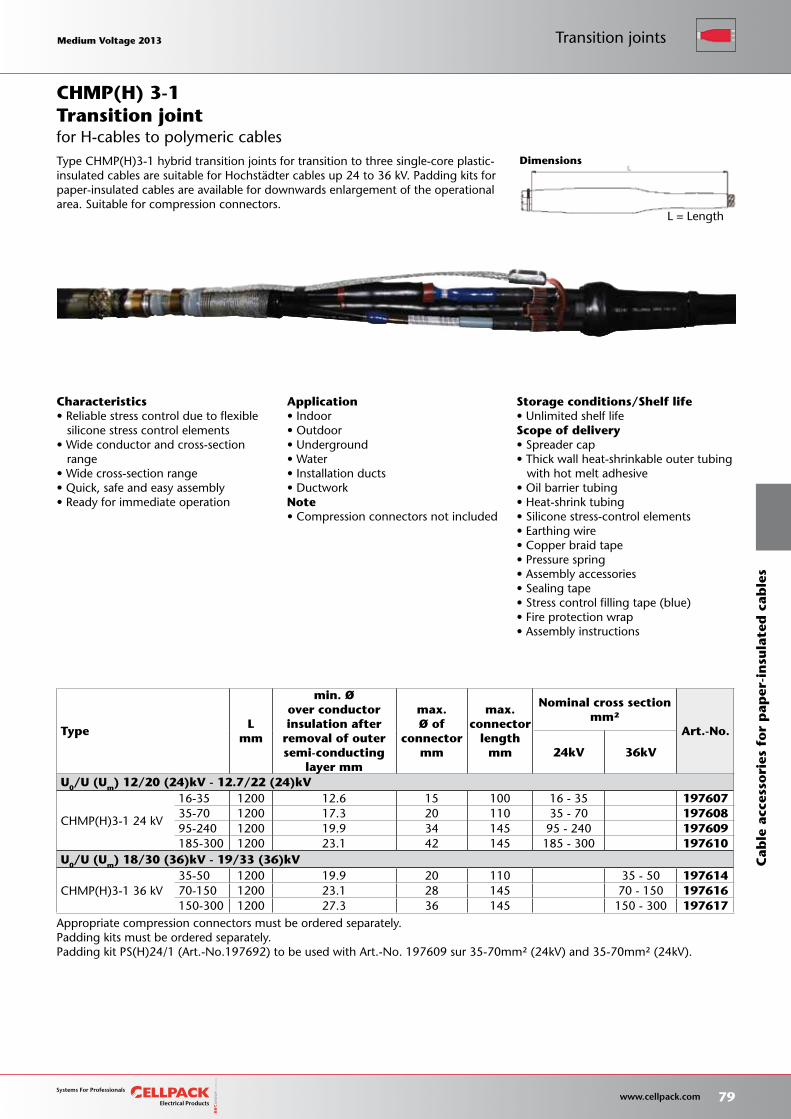
Storage conditions/Shelf life• Unlimited shelf lifeScope of delivery• Spreader cap• Thick wall heat-shrinkable outer tubing with hot melt adhesive• Oil barrier tubing• Heat-shrink tubing• Silicone stress-control elements• Earthing wire• Copper braid tape• Pressure spring• Assembly accessories• Sealing tape• Stress control filling tape (blue)• Fire protection wrap• Assembly instructions
L = Length
Dimensions
Transition joint
TypeL
mm
min. Øover conductorinsulation after
removal of outersemi-conducting
layer mm
max.Ø of
connectormm
max.connector
lengthmm
Nominal cross sectionmm²
Art.-No.
24kV 36kV
U0/U (Um) 12/20 (24)kV - 12.7/22 (24)kV
CHMP(H)3-1 24 kV
16-35 1200 12.6 15 100 16 - 35 19760735-70 1200 17.3 20 110 35 - 70 19760895-240 1200 19.9 34 145 95 - 240 197609185-300 1200 23.1 42 145 185 - 300 197610
U0/U (Um) 18/30 (36)kV - 19/33 (36)kV
CHMP(H)3-1 36 kV35-50 1200 19.9 20 110 35 - 50 19761470-150 1200 23.1 28 145 70 - 150 197616150-300 1200 27.3 36 145 150 - 300 197617
Appropriate compression connectors must be ordered separately.Padding kits must be ordered separately.Padding kit PS(H)24/1 (Art.-No.197692) to be used with Art.-No. 197609 sur 35-70mm² (24kV) and 35-70mm² (24kV).
Application• Indoor• Outdoor• Underground• Water• Installation ducts• DuctworkNote• Compression connectors not included
CHMP(H) 3-1
Characteristics• Reliable stress control due to flexible silicone stress control elements• Wide conductor and cross-section range• Wide cross-section range• Quick, safe and easy assembly• Ready for immediate operation
Type CHMP(H)3-1 hybrid transition joints for transition to three single-core plastic-insulated cables are suitable for Hochstadter cables up 24 to 36 kV. Padding kits for paper-insulated cables are available for downwards enlargement of the operational area. Suitable for compression connectors.
for H-cables to polymeric cables
Medium Voltage 2013 Medium Voltage 2013
79 www.cellpack.com
Medium Voltage 2013 Medium Voltage 2013 Transition joints
Cab
le a
cces
sori
es f
or
pap
er-i
nsu
late
d c
able
s
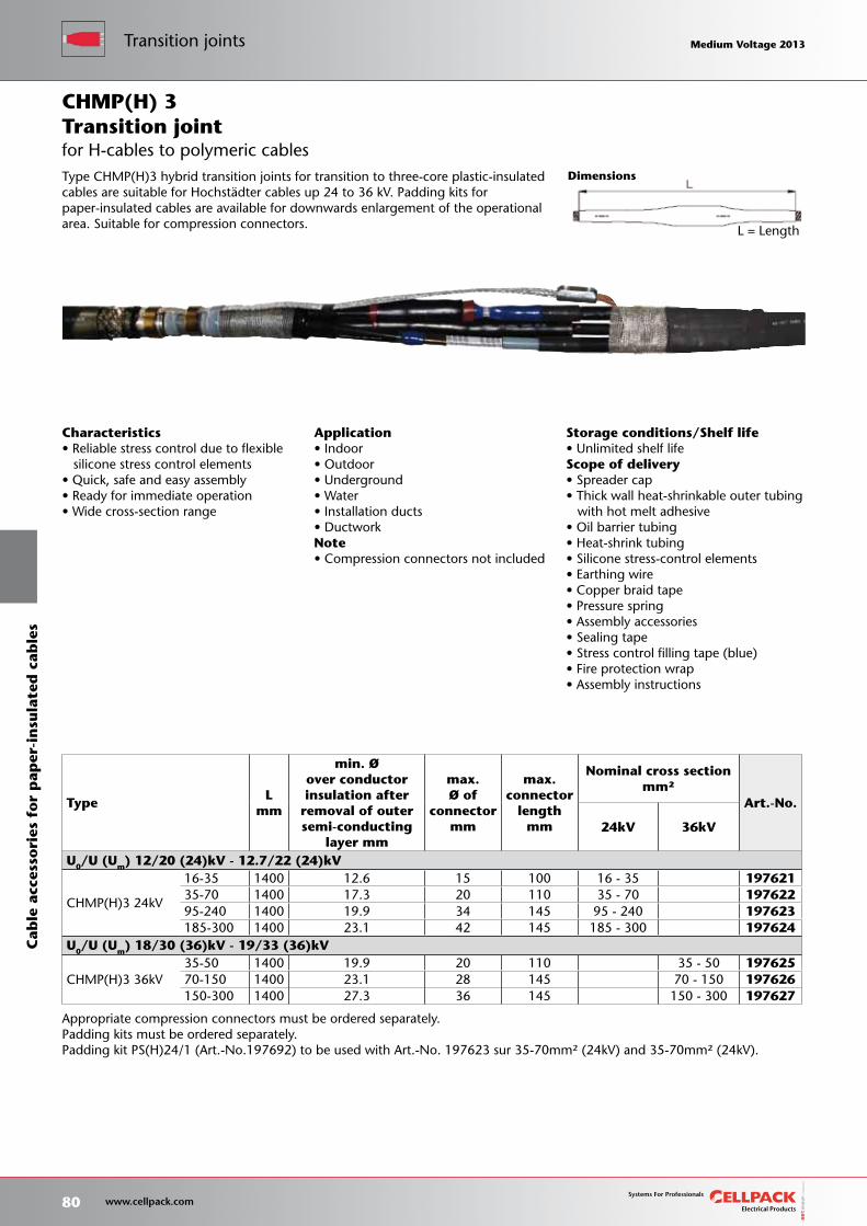
Storage conditions/Shelf life• Unlimited shelf lifeScope of delivery• Spreader cap• Thick wall heat-shrinkable outer tubing with hot melt adhesive• Oil barrier tubing• Heat-shrink tubing• Silicone stress-control elements• Earthing wire• Copper braid tape• Pressure spring• Assembly accessories• Sealing tape• Stress control filling tape (blue)• Fire protection wrap• Assembly instructions
Dimensions
L = Length
Application• Indoor• Outdoor• Underground• Water• Installation ducts• DuctworkNote• Compression connectors not included
TypeL
mm
min. Øover conductorinsulation after
removal of outersemi-conducting
layer mm
max.Ø of
connectormm
max.connector
lengthmm
Nominal cross sectionmm²
Art.-No.
24kV 36kV
U0/U (Um) 12/20 (24)kV - 12.7/22 (24)kV
CHMP(H)3 24kV
16-35 1400 12.6 15 100 16 - 35 19762135-70 1400 17.3 20 110 35 - 70 19762295-240 1400 19.9 34 145 95 - 240 197623185-300 1400 23.1 42 145 185 - 300 197624
U0/U (Um) 18/30 (36)kV - 19/33 (36)kV
CHMP(H)3 36kV35-50 1400 19.9 20 110 35 - 50 19762570-150 1400 23.1 28 145 70 - 150 197626150-300 1400 27.3 36 145 150 - 300 197627
Characteristics• Reliable stress control due to flexible silicone stress control elements• Quick, safe and easy assembly• Ready for immediate operation• Wide cross-section range
Transition joint
Appropriate compression connectors must be ordered separately.Padding kits must be ordered separately.Padding kit PS(H)24/1 (Art.-No.197692) to be used with Art.-No. 197623 sur 35-70mm² (24kV) and 35-70mm² (24kV).
Type CHMP(H)3 hybrid transition joints for transition to three-core plastic-insulated cables are suitable for Hochstadter cables up 24 to 36 kV. Padding kits for paper-insulated cables are available for downwards enlargement of the operational area. Suitable for compression connectors.
CHMP(H) 3
for H-cables to polymeric cables
80 www.cellpack.com
Medium Voltage 2013 Medium Voltage 2013Transition jointsC
able
acc
esso
ries
fo
r p
aper
-in
sula
ted
cab
les
Medium Voltage 2013 Medium Voltage 2013
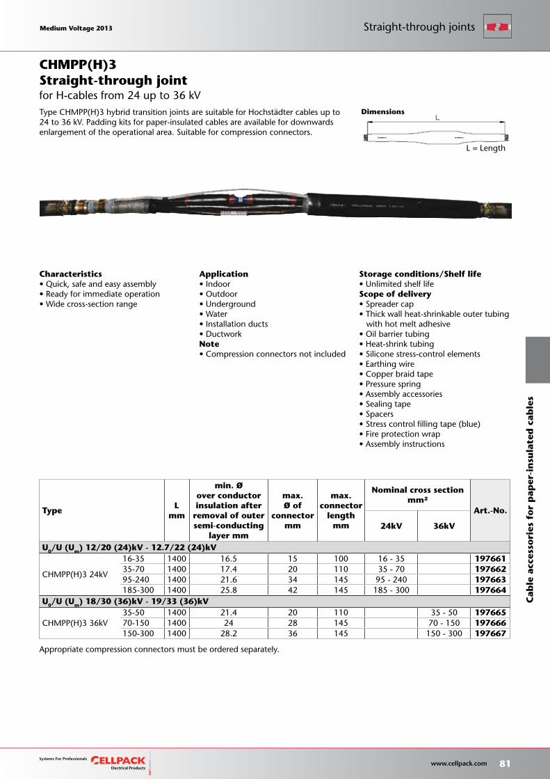
Storage conditions/Shelf life• Unlimited shelf lifeScope of delivery• Spreader cap• Thick wall heat-shrinkable outer tubing with hot melt adhesive• Oil barrier tubing• Heat-shrink tubing• Silicone stress-control elements• Earthing wire• Copper braid tape• Pressure spring• Assembly accessories• Sealing tape• Spacers• Stress control filling tape (blue)• Fire protection wrap• Assembly instructions
L = Length
Dimensions
Appropriate compression connectors must be ordered separately.
Characteristics• Quick, safe and easy assembly• Ready for immediate operation• Wide cross-section range
Application• Indoor• Outdoor• Underground• Water• Installation ducts• DuctworkNote• Compression connectors not included
for H-cables from 24 up to 36 kVStraight-through jointCHMPP(H)3
TypeL
mm
min. Øover conductorinsulation after
removal of outersemi-conducting
layer mm
max.Ø of
connectormm
max.connector
lengthmm
Nominal cross sectionmm²
Art.-No.
24kV 36kV
U0/U (Um) 12/20 (24)kV - 12.7/22 (24)kV
CHMPP(H)3 24kV
16-35 1400 16.5 15 100 16 - 35 19766135-70 1400 17.4 20 110 35 - 70 19766295-240 1400 21.6 34 145 95 - 240 197663185-300 1400 25.8 42 145 185 - 300 197664
U0/U (Um) 18/30 (36)kV - 19/33 (36)kV
CHMPP(H)3 36kV35-50 1400 21.4 20 110 35 - 50 19766570-150 1400 24 28 145 70 - 150 197666150-300 1400 28.2 36 145 150 - 300 197667
Type CHMPP(H)3 hybrid transition joints are suitable for Hochstadter cables up to 24 to 36 kV. Padding kits for paper-insulated cables are available for downwards enlargement of the operational area. Suitable for compression connectors.
Medium Voltage 2013 Medium Voltage 2013
81 www.cellpack.com
Medium Voltage 2013 Medium Voltage 2013
Cab
le a
cces
sori
es f
or
pap
er-i
nsu
late
d c
able
s
Straight-through joints
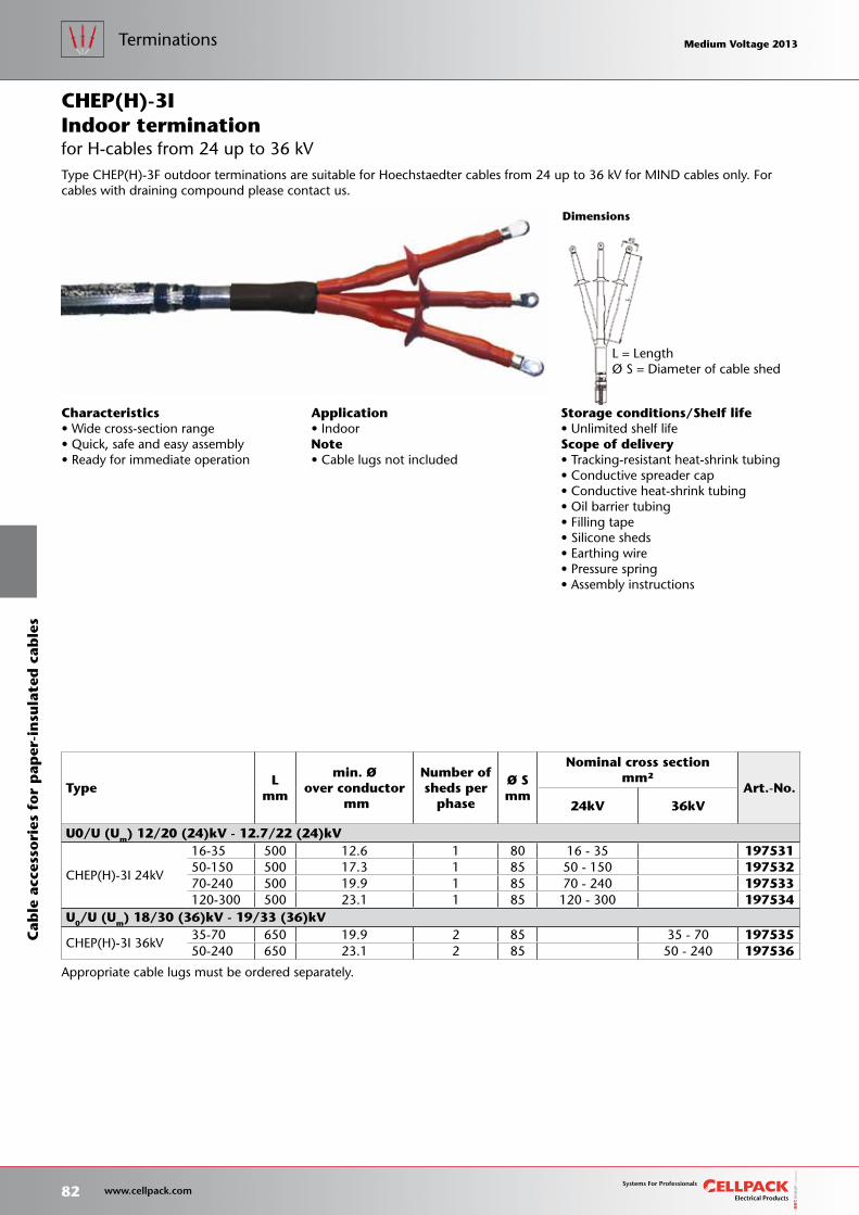
Storage conditions/Shelf life• Unlimited shelf lifeScope of delivery• Tracking-resistant heat-shrink tubing• Conductive spreader cap• Conductive heat-shrink tubing• Oil barrier tubing• Filling tape• Silicone sheds• Earthing wire• Pressure spring• Assembly instructions
L = LengthØ S = Diameter of cable shed
TypeL
mm
min. Øover conductor
mm
Number ofsheds per
phase
Ø Smm
Nominal cross sectionmm²
Art.-No.24kV 36kV
U0/U (Um) 12/20 (24)kV - 12.7/22 (24)kV
CHEP(H)-3I 24kV
16-35 500 12.6 1 80 16 - 35 19753150-150 500 17.3 1 85 50 - 150 19753270-240 500 19.9 1 85 70 - 240 197533120-300 500 23.1 1 85 120 - 300 197534
U0/U (Um) 18/30 (36)kV - 19/33 (36)kV
CHEP(H)-3I 36kV35-70 650 19.9 2 85 35 - 70 19753550-240 650 23.1 2 85 50 - 240 197536
Dimensions
Appropriate cable lugs must be ordered separately.
Characteristics• Wide cross-section range• Quick, safe and easy assembly• Ready for immediate operation
Application• IndoorNote• Cable lugs not included
Type CHEP(H)-3F outdoor terminations are suitable for Hoechstaedter cables from 24 up to 36 kV for MIND cables only. For cables with draining compound please contact us.
for H-cables from 24 up to 36 kVIndoor terminationCHEP(H)-3I
82 www.cellpack.com
Medium Voltage 2013 Medium Voltage 2013C
able
acc
esso
ries
fo
r p
aper
-in
sula
ted
cab
les
Terminations Medium Voltage 2013 Medium Voltage 2013
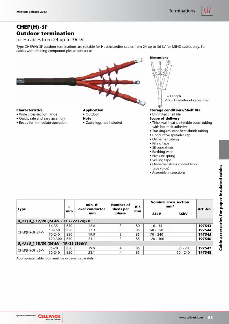
Storage conditions/Shelf life• Unlimited shelf lifeScope of delivery• Thick wall heat-shrinkable outer tubing with hot melt adhesive• Tracking-resistant heat-shrink tubing• Conductive spreader cap• Oil barrier tubing• Filling tape• Silicone sheds• Earthing wire• Pressure spring• Sealing tape• Oil-barrier stress control filling tape (blue)• Assembly instructions
L = LengthØ S = Diameter of cable shed
TypeL
mm
min. Øover conductor
mm
Number ofsheds per
phase
Ø Smm
Nominal cross sectionmm²
Art.-No.24kV 36kV
U0/U (Um) 12/20 (24)kV - 12.7/22 (24)kV
CHEP(H)-3F 24kV
16-35 850 12.6 3 80 16 - 35 19754350-150 850 17.3 3 85 50 - 150 19754470-240 850 19.9 3 85 70 - 240 197545120-300 850 23.1 3 85 120 - 300 197546
U0/U (Um) 18/30 (36)kV - 19/33 (36)kV
CHEP(H)-3F 36kV35-70 850 19.9 4 85 35 - 70 19754750-240 850 23.1 4 85 50 - 240 197548
Dimensions
Appropriate cable lugs must be ordered separately.
Characteristics• Wide cross-section range• Quick, safe and easy assembly• Ready for immediate operation
Application• OutdoorNote• Cable lugs not included
Type CHEP(H)-3F outdoor terminations are suitable for Hoechstaedter cables from 24 up to 36 kV for MIND cables only. For cables with draining compound please contact us.
for H-cables from 24 up to 36 kVOutdoor terminationCHEP(H)-3F
Medium Voltage 2013 Medium Voltage 2013
83 www.cellpack.com
Medium Voltage 2013 Medium Voltage 2013
Cab
le a
cces
sori
es f
or
pap
er-i
nsu
late
d c
able
s
Terminations
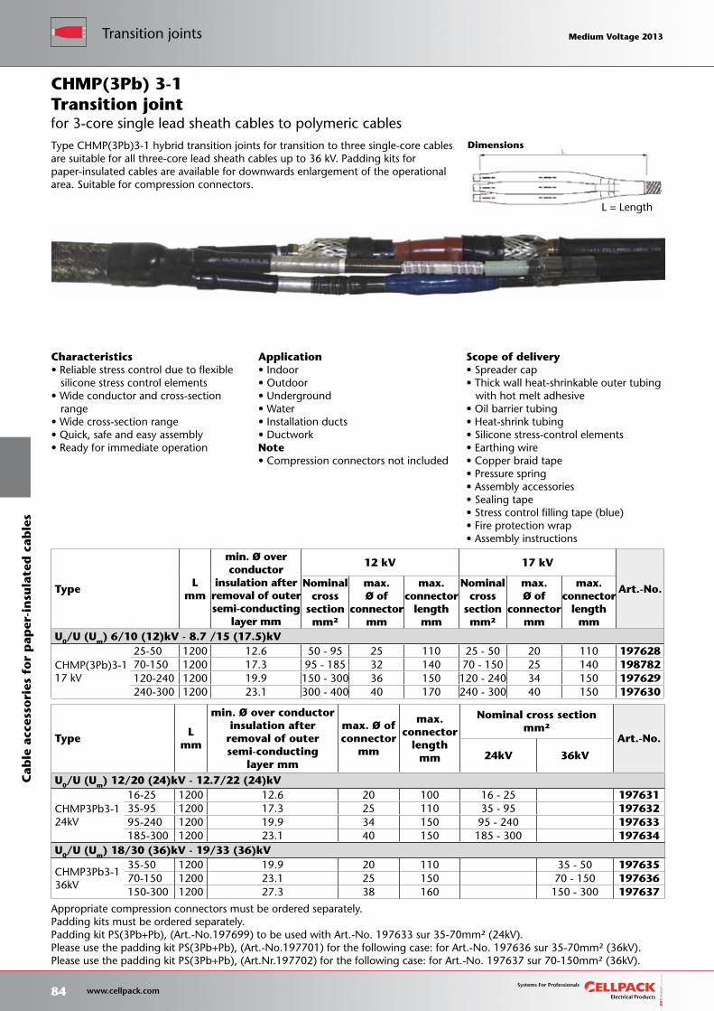
Scope of delivery• Spreader cap• Thick wall heat-shrinkable outer tubing with hot melt adhesive• Oil barrier tubing• Heat-shrink tubing• Silicone stress-control elements• Earthing wire• Copper braid tape• Pressure spring• Assembly accessories• Sealing tape• Stress control filling tape (blue)• Fire protection wrap• Assembly instructions
Dimensions
L = Length
TypeL
mm
min. Ø over conductor
insulation afterremoval of outer semi-conducting
layer mm
12 kV 17 kV
Art.-No.Nominalcross
sectionmm²
max.Ø of
connectormm
max.connector
lengthmm
Nominalcross
sectionmm²
max.Ø of
connectormm
max.connector
lengthmm
U0/U (Um) 6/10 (12)kV - 8.7 /15 (17.5)kV
CHMP(3Pb)3-1 17 kV
25-50 1200 12.6 50 - 95 25 110 25 - 50 20 110 19762870-150 1200 17.3 95 - 185 32 140 70 - 150 25 140 198782120-240 1200 19.9 150 - 300 36 150 120 - 240 34 150 197629240-300 1200 23.1 300 - 400 40 170 240 - 300 40 150 197630
Characteristics• Reliable stress control due to flexible silicone stress control elements• Wide conductor and cross-section range• Wide cross-section range• Quick, safe and easy assembly• Ready for immediate operation
Application• Indoor• Outdoor• Underground• Water• Installation ducts• DuctworkNote• Compression connectors not included
Transition joint
Appropriate compression connectors must be ordered separately.Padding kits must be ordered separately.Padding kit PS(3Pb+Pb), (Art.-No.197699) to be used with Art.-No. 197633 sur 35-70mm² (24kV).Please use the padding kit PS(3Pb+Pb), (Art.-No.197701) for the following case: for Art.-No. 197636 sur 35-70mm² (36kV).Please use the padding kit PS(3Pb+Pb), (Art.Nr.197702) for the following case: for Art.-No. 197637 sur 70-150mm² (36kV).
Type CHMP(3Pb)3-1 hybrid transition joints for transition to three single-core cables are suitable for all three-core lead sheath cables up to 36 kV. Padding kits for paper-insulated cables are available for downwards enlargement of the operational area. Suitable for compression connectors.
CHMP(3Pb) 3-1
for 3-core single lead sheath cables to polymeric cables
TypeL
mm
min. Ø over conductorinsulation after
removal of outersemi-conducting
layer mm
max. Ø ofconnector
mm
max.connector
lengthmm
Nominal cross sectionmm²
Art.-No.
24kV 36kV
U0/U (Um) 12/20 (24)kV - 12.7/22 (24)kV
CHMP3Pb3-1 24kV
16-25 1200 12.6 20 100 16 - 25 19763135-95 1200 17.3 25 110 35 - 95 19763295-240 1200 19.9 34 150 95 - 240 197633185-300 1200 23.1 40 150 185 - 300 197634
U0/U (Um) 18/30 (36)kV - 19/33 (36)kV
CHMP3Pb3-1 36kV
35-50 1200 19.9 20 110 35 - 50 19763570-150 1200 23.1 25 150 70 - 150 197636150-300 1200 27.3 38 160 150 - 300 197637
84 www.cellpack.com
Medium Voltage 2013 Medium Voltage 2013Transition jointsC
able
acc
esso
ries
fo
r p
aper
-in
sula
ted
cab
les
Medium Voltage 2013 Medium Voltage 2013
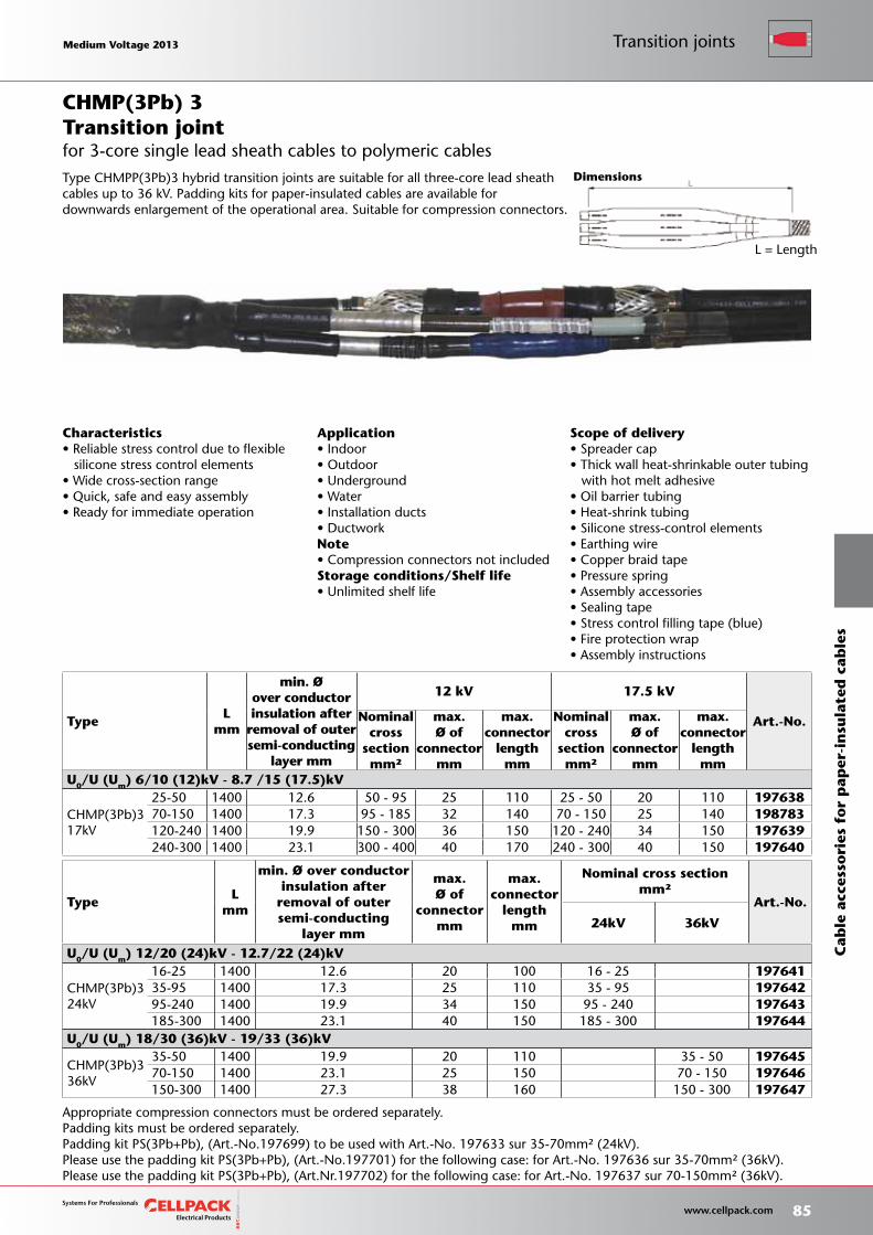
Scope of delivery• Spreader cap• Thick wall heat-shrinkable outer tubing with hot melt adhesive• Oil barrier tubing• Heat-shrink tubing• Silicone stress-control elements• Earthing wire• Copper braid tape• Pressure spring• Assembly accessories• Sealing tape• Stress control filling tape (blue)• Fire protection wrap• Assembly instructions
Dimensions
L = Length
TypeL
mm
min. Øover conductorinsulation after
removal of outersemi-conducting
layer mm
12 kV 17.5 kV
Art.-No.Nominalcross
sectionmm²
max.Ø of
connectormm
max.connector
lengthmm
Nominalcross
sectionmm²
max.Ø of
connectormm
max.connector
lengthmm
U0/U (Um) 6/10 (12)kV - 8.7 /15 (17.5)kV
CHMP(3Pb)3 17kV
25-50 1400 12.6 50 - 95 25 110 25 - 50 20 110 19763870-150 1400 17.3 95 - 185 32 140 70 - 150 25 140 198783120-240 1400 19.9 150 - 300 36 150 120 - 240 34 150 197639240-300 1400 23.1 300 - 400 40 170 240 - 300 40 150 197640
Characteristics• Reliable stress control due to flexible silicone stress control elements• Wide cross-section range• Quick, safe and easy assembly• Ready for immediate operation
Application• Indoor• Outdoor• Underground• Water• Installation ducts• DuctworkNote• Compression connectors not includedStorage conditions/Shelf life• Unlimited shelf life
Transition joint
Appropriate compression connectors must be ordered separately.Padding kits must be ordered separately.Padding kit PS(3Pb+Pb), (Art.-No.197699) to be used with Art.-No. 197633 sur 35-70mm² (24kV).Please use the padding kit PS(3Pb+Pb), (Art.-No.197701) for the following case: for Art.-No. 197636 sur 35-70mm² (36kV).Please use the padding kit PS(3Pb+Pb), (Art.Nr.197702) for the following case: for Art.-No. 197637 sur 70-150mm² (36kV).
Type CHMPP(3Pb)3 hybrid transition joints are suitable for all three-core lead sheath cables up to 36 kV. Padding kits for paper-insulated cables are available for downwards enlargement of the operational area. Suitable for compression connectors.
CHMP(3Pb) 3
for 3-core single lead sheath cables to polymeric cables
TypeL
mm
min. Ø over conductorinsulation after
removal of outersemi-conducting
layer mm
max.Ø of
connectormm
max.connector
lengthmm
Nominal cross sectionmm²
Art.-No.
24kV 36kV
U0/U (Um) 12/20 (24)kV - 12.7/22 (24)kV
CHMP(3Pb)3 24kV
16-25 1400 12.6 20 100 16 - 25 19764135-95 1400 17.3 25 110 35 - 95 19764295-240 1400 19.9 34 150 95 - 240 197643185-300 1400 23.1 40 150 185 - 300 197644
U0/U (Um) 18/30 (36)kV - 19/33 (36)kV
CHMP(3Pb)3 36kV
35-50 1400 19.9 20 110 35 - 50 19764570-150 1400 23.1 25 150 70 - 150 197646150-300 1400 27.3 38 160 150 - 300 197647
Medium Voltage 2013 Medium Voltage 2013
85 www.cellpack.com
Medium Voltage 2013 Medium Voltage 2013 Transition joints
Cab
le a
cces
sori
es f
or
pap
er-i
nsu
late
d c
able
s
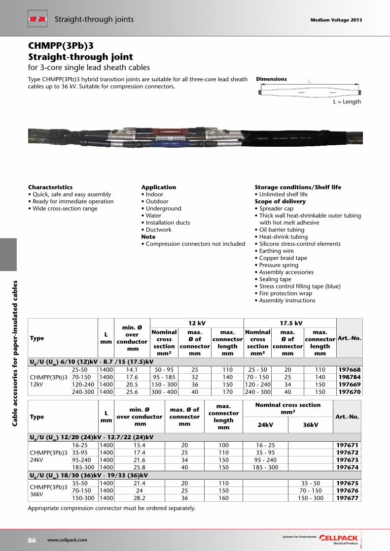
Storage conditions/Shelf life• Unlimited shelf lifeScope of delivery• Spreader cap• Thick wall heat-shrinkable outer tubing with hot melt adhesive• Oil barrier tubing• Heat-shrink tubing• Silicone stress-control elements• Earthing wire• Copper braid tape• Pressure spring• Assembly accessories• Sealing tape• Stress control filling tape (blue)• Fire protection wrap• Assembly instructions
Application• Indoor• Outdoor• Underground• Water• Installation ducts• DuctworkNote• Compression connectors not included
Dimensions
L = Length
TypeL
mm
min. Øover
conductor mm
12 kV 17.5 kV
Art.-No.Nominal
crosssectionmm²
max.Ø of
connectormm
max.connector
lengthmm
Nominalcross
sectionmm²
max.Ø of
connectormm
max.connector
lengthmm
U0/U (Um) 6/10 (12)kV - 8.7 /15 (17.5)kV
CHMPP(3Pb)3 12kV
25-50 1400 14.1 50 - 95 25 110 25 - 50 20 110 19766870-150 1400 17.6 95 - 185 32 140 70 - 150 25 140 198784120-240 1400 20.5 150 - 300 36 150 120 - 240 34 150 197669240-300 1400 25.6 300 - 400 40 170 240 - 300 40 150 197670
Characteristics• Quick, safe and easy assembly• Ready for immediate operation• Wide cross-section range
Straight-through joint
Appropriate compression connector must be ordered separately.
Type CHMPP(3Pb)3 hybrid transition joints are suitable for all three-core lead sheath cables up to 36 kV. Suitable for compression connectors.
CHMPP(3Pb)3
for 3-core single lead sheath cables
TypeL
mm
min. Øover conductor
mm
max. Ø ofconnector
mm
max.connector
lengthmm
Nominal cross sectionmm²
Art.-No.24kV 36kV
U0/U (Um) 12/20 (24)kV - 12.7/22 (24)kV
CHMPP(3Pb)3 24kV
16-25 1400 15.4 20 100 16 - 25 19767135-95 1400 17.4 25 110 35 - 95 19767295-240 1400 21.6 34 150 95 - 240 197673185-300 1400 25.8 40 150 185 - 300 197674
U0/U (Um) 18/30 (36)kV - 19/33 (36)kV
CHMPP(3Pb)3 36kV
35-50 1400 21.4 20 110 35 - 50 19767570-150 1400 24 25 150 70 - 150 197676150-300 1400 28.2 36 160 150 - 300 197677
86 www.cellpack.com
Medium Voltage 2013 Medium Voltage 2013C
able
acc
esso
ries
fo
r p
aper
-in
sula
ted
cab
les
Straight-through joints Medium Voltage 2013 Medium Voltage 2013
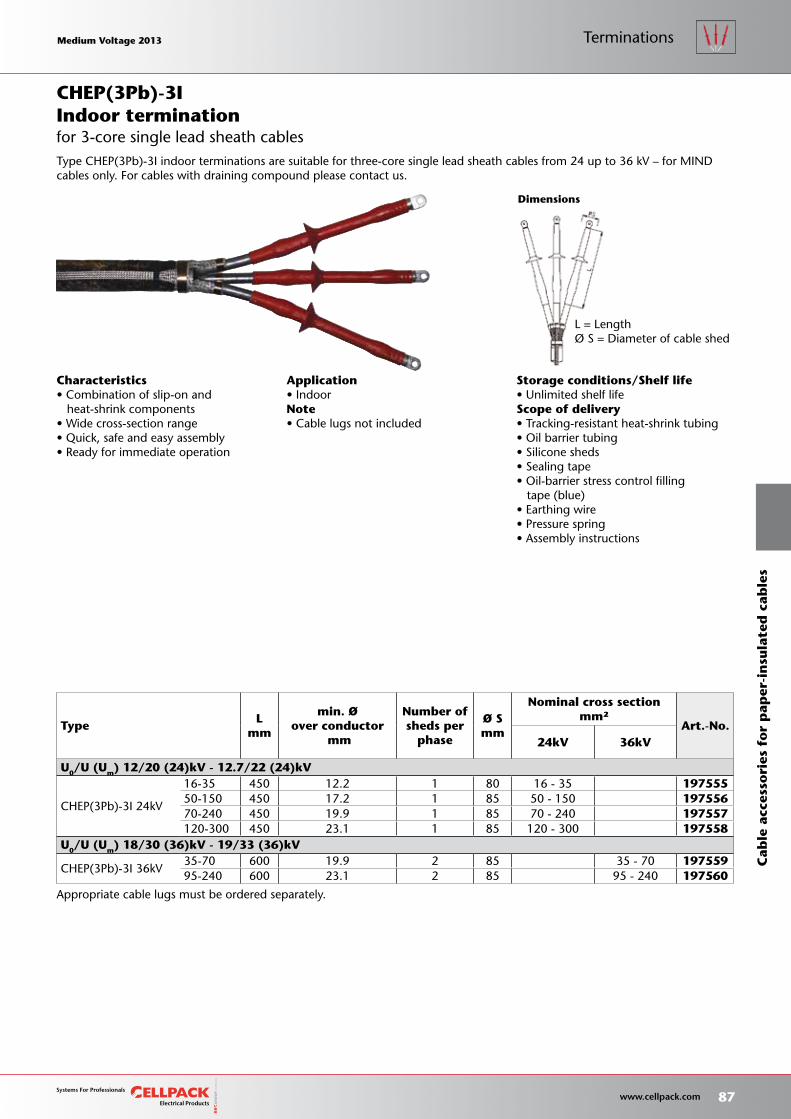
Storage conditions/Shelf life• Unlimited shelf lifeScope of delivery• Tracking-resistant heat-shrink tubing• Oil barrier tubing• Silicone sheds• Sealing tape• Oil-barrier stress control filling tape (blue)• Earthing wire• Pressure spring• Assembly instructions
L = LengthØ S = Diameter of cable shed
TypeL
mm
min. Øover conductor
mm
Number ofsheds per
phase
Ø Smm
Nominal cross sectionmm²
Art.-No.24kV 36kV
U0/U (Um) 12/20 (24)kV - 12.7/22 (24)kV
CHEP(3Pb)-3I 24kV
16-35 450 12.2 1 80 16 - 35 19755550-150 450 17.2 1 85 50 - 150 19755670-240 450 19.9 1 85 70 - 240 197557120-300 450 23.1 1 85 120 - 300 197558
U0/U (Um) 18/30 (36)kV - 19/33 (36)kV
CHEP(3Pb)-3I 36kV35-70 600 19.9 2 85 35 - 70 19755995-240 600 23.1 2 85 95 - 240 197560
Dimensions
Appropriate cable lugs must be ordered separately.
Characteristics• Combination of slip-on and heat-shrink components• Wide cross-section range• Quick, safe and easy assembly• Ready for immediate operation
Application• IndoorNote• Cable lugs not included
Type CHEP(3Pb)-3I indoor terminations are suitable for three-core single lead sheath cables from 24 up to 36 kV – for MIND cables only. For cables with draining compound please contact us.
for 3-core single lead sheath cablesIndoor terminationCHEP(3Pb)-3I
Medium Voltage 2013 Medium Voltage 2013
87 www.cellpack.com
Medium Voltage 2013 Medium Voltage 2013
Cab
le a
cces
sori
es f
or
pap
er-i
nsu
late
d c
able
s
Terminations
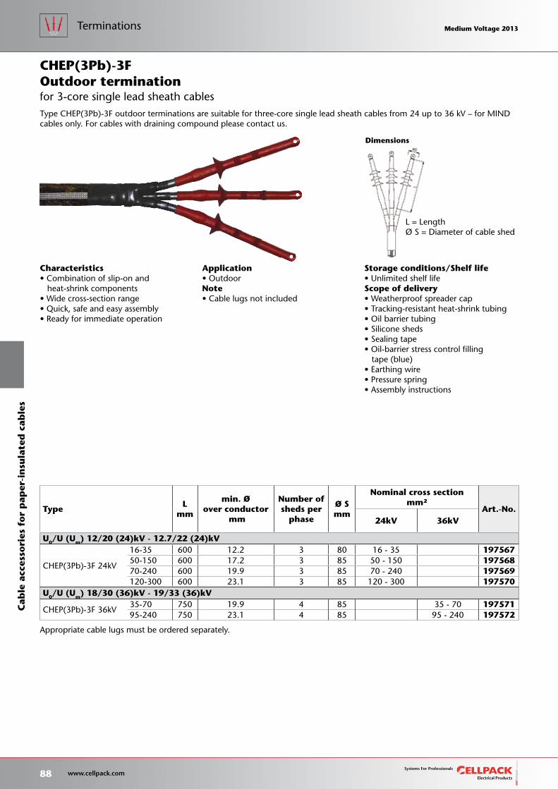
Storage conditions/Shelf life• Unlimited shelf lifeScope of delivery• Weatherproof spreader cap• Tracking-resistant heat-shrink tubing• Oil barrier tubing• Silicone sheds• Sealing tape• Oil-barrier stress control filling tape (blue)• Earthing wire• Pressure spring• Assembly instructions
L = LengthØ S = Diameter of cable shed
TypeL
mm
min. Øover conductor
mm
Number ofsheds per
phase
Ø Smm
Nominal cross sectionmm²
Art.-No.24kV 36kV
U0/U (Um) 12/20 (24)kV - 12.7/22 (24)kV
CHEP(3Pb)-3F 24kV
16-35 600 12.2 3 80 16 - 35 19756750-150 600 17.2 3 85 50 - 150 19756870-240 600 19.9 3 85 70 - 240 197569120-300 600 23.1 3 85 120 - 300 197570
U0/U (Um) 18/30 (36)kV - 19/33 (36)kV
CHEP(3Pb)-3F 36kV35-70 750 19.9 4 85 35 - 70 19757195-240 750 23.1 4 85 95 - 240 197572
Dimensions
Appropriate cable lugs must be ordered separately.
Characteristics• Combination of slip-on and heat-shrink components• Wide cross-section range• Quick, safe and easy assembly• Ready for immediate operation
Application• OutdoorNote• Cable lugs not included
Type CHEP(3Pb)-3F outdoor terminations are suitable for three-core single lead sheath cables from 24 up to 36 kV – for MIND cables only. For cables with draining compound please contact us.
for 3-core single lead sheath cablesOutdoor terminationCHEP(3Pb)-3F
88 www.cellpack.com
Medium Voltage 2013 Medium Voltage 2013C
able
acc
esso
ries
fo
r p
aper
-in
sula
ted
cab
les
Terminations Medium Voltage 2013 Medium Voltage 2013
Medium Voltage 2013 Medium Voltage 2013
89 www.cellpack.com
Medium Voltage 2013 Medium Voltage 2013
Cab
le a
cces
sori
es f
or
pap
er-i
nsu
late
d c
able
s
Terminations

Complete safety
90 www.cellpack.com
Medium Voltage 2013 Medium Voltage 2013 Medium Voltage 2013 Medium Voltage 2013

Straight-through joints forsingle-core cables 92
Straight-through joints for3-core cables 93
Terminations for single-core cables 94
Terminations for 3-core cables 96
Accessories 98
Cable accessories for screened cables according to
British Standard
Complete safety Page
Medium Voltage 2013 Medium Voltage 2013
91 www.cellpack.com
Medium Voltage 2013 Medium Voltage 2013
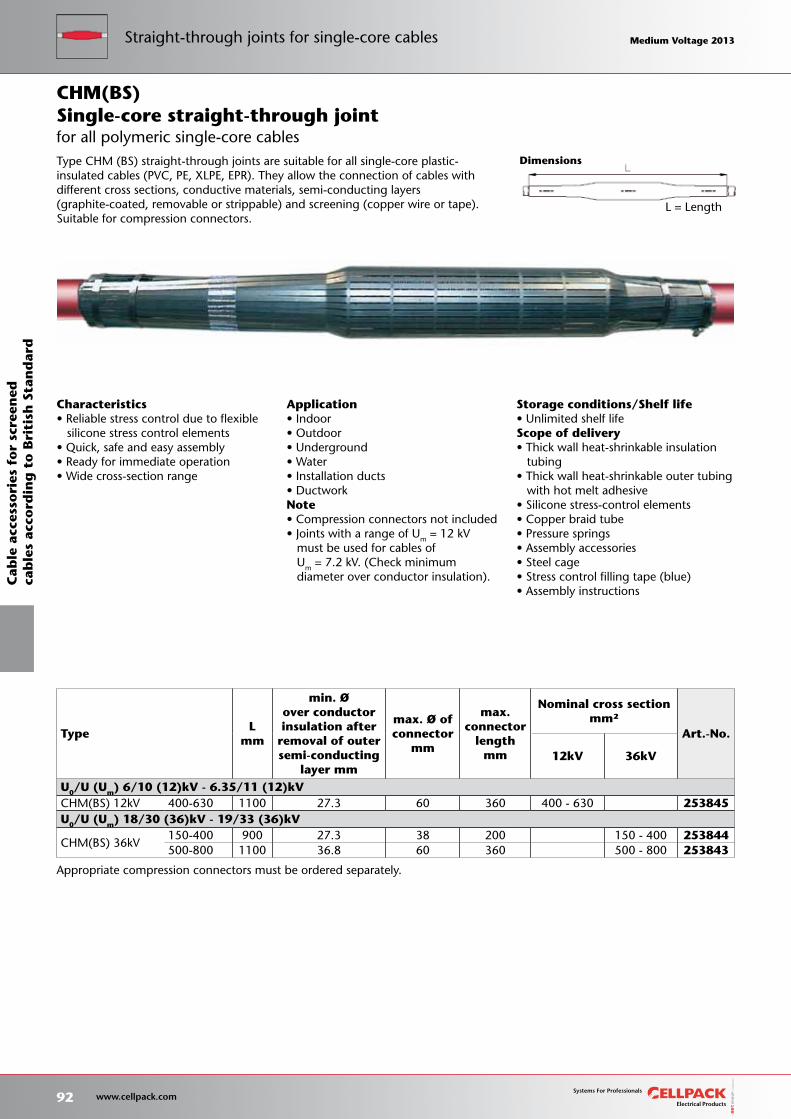
Storage conditions/Shelf life• Unlimited shelf lifeScope of delivery• Thick wall heat-shrinkable insulation tubing• Thick wall heat-shrinkable outer tubing with hot melt adhesive• Silicone stress-control elements• Copper braid tube• Pressure springs• Assembly accessories• Steel cage• Stress control filling tape (blue)• Assembly instructions
Dimensions
L = Length
Appropriate compression connectors must be ordered separately.
TypeL
mm
min. Øover conductorinsulation after
removal of outersemi-conducting
layer mm
max. Ø ofconnector
mm
max.connector
lengthmm
Nominal cross sectionmm²
Art.-No.
12kV 36kV
U0/U (Um) 6/10 (12)kV - 6.35/11 (12)kVCHM(BS) 12kV 400-630 1100 27.3 60 360 400 - 630 253845
U0/U (Um) 18/30 (36)kV - 19/33 (36)kV
CHM(BS) 36kV150-400 900 27.3 38 200 150 - 400 253844500-800 1100 36.8 60 360 500 - 800 253843
for all polymeric single-core cables
CHM(BS)
Characteristics• Reliable stress control due to flexible silicone stress control elements• Quick, safe and easy assembly• Ready for immediate operation• Wide cross-section range
Application• Indoor• Outdoor• Underground• Water• Installation ducts• DuctworkNote• Compression connectors not included• Joints with a range of Um = 12 kV must be used for cables of Um = 7.2 kV. (Check minimum diameter over conductor insulation).
Single-core straight-through joint
Type CHM (BS) straight-through joints are suitable for all single-core plastic-insulated cables (PVC, PE, XLPE, EPR). They allow the connection of cables with different cross sections, conductive materials, semi-conducting layers (graphite-coated, removable or strippable) and screening (copper wire or tape). Suitable for compression connectors.
92 www.cellpack.com
Medium Voltage 2013 Medium Voltage 2013Straight-through joints for single-core cables
Cab
le a
cces
sori
es f
or
scre
ened
cab
les
acco
rdin
g t
o B
riti
sh S
tan
dar
d Medium Voltage 2013 Medium Voltage 2013
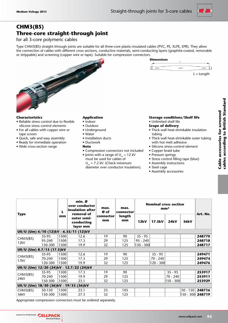
Storage conditions/Shelf life• Unlimited shelf lifeScope of delivery• Thick wall heat-shrinkable insulation tubing• Thick wall heat-shrinkable outer tubing with hot melt adhesive• Silicone stress-control element• Copper braid tube• Pressure springs• Stress control filling tape (blue)• Assembly instructions• Steel cage• Assembly accessories
Dimensions
L = Length
TypeL
mm
min. Øover conductorinsulation after
removal of outer semi-conductinglayer mm
max.Ø of
connectormm
max.connector
lengthmm
Nominal cross sectionmm²
Art.-No.
12kV 17.5kV 24kV 36kV
U0/U (Um) 6/10 (12)kV - 6.35/11 (12)kV
CHM3(BS) 12kV
35-95 1500 12.6 19 90 35 - 95 24877095-240 1500 17.3 29 125 95 - 240 248718150-300 1500 19.9 32 125 150 - 300 248717
U0/U (Um) 8.7/15 (17.5)kV
CHM3(BS) 17kV
35-95 1500 12.6 19 90 35 - 95 24947170-240 1500 17.3 29 125 70 - 240 249474120-300 1500 19.9 32 125 120 - 300 249476
U0/U (Um) 12/20 (24)kV - 12.7/22 (24)kV
CHM3(BS) 24kV
35-95 1500 17.3 19 90 35 - 95 25391770-240 1500 19.9 29 125 70 - 240 253911150-300 1500 23.1 32 125 150 - 300 253929
U0/U (Um) 18/30 (36)kV - 19/33 (36)kVCHM3(BS) 36kV
50-150 1500 23.1 23 105 50 - 150 248716150-300 1500 27.3 32 125 150 - 300 248719
for all 3-core polymeric cables
CHM3(BS)
Characteristics• Reliable stress control due to flexible silicone stress control elements• For all cables with copper wire or tape screen• Quick, safe and easy assembly• Ready for immediate operation• Wide cross-section range
Application• Indoor• Outdoor• Underground• Water• Installation ducts• DuctworkNote• Compression connectors not included• Joints with a range of Um = 12 kV must be used for cables of Um = 7.2 kV. (Check minimum diameter over conductor insulation).
Three-core straight-through joint
Appropriate compression connectors must be ordered separately.
Type CHM3(BS) straight-through joints are suitable for all three-core plastic-insulated cables (PVC, PE, XLPE, EPR). They allow the connection of cables with different cross sections, conductive materials, semi-conducting layers (graphite-coated, removable or strippable) and screening (copper wire or tape). Suitable for compression connectors.
Medium Voltage 2013 Medium Voltage 2013
93 www.cellpack.com
Medium Voltage 2013 Medium Voltage 2013
Cab
le a
cces
sori
es f
or
scre
ened
cab
les
acco
rdin
g t
o B
riti
sh S
tan
dar
d
Straight-through joints for 3-core cables
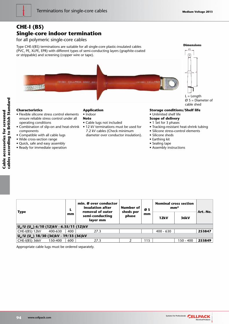
Storage conditions/Shelf life• Unlimited shelf lifeScope of delivery• 1 Set for 3 phases• Tracking-resistant heat-shrink tubing• Silicone stress-control elements• Silicone sheds• Earthing kit• Sealing tape• Assembly instructions
Dimensions
L = LengthØ S = Diameter of cable shed
TypeL
mm
min. Ø over conductorinsulation after
removal of outersemi-conducting
layer mm
Number ofsheds per
phase
Ø Smm
Nominal cross sectionmm²
Art.-No.
12kV 36kV
U0/U (Um) 6/10 (12)kV - 6.35/11 (12)kVCHE-I(BS) 12kV 400-630 400 27.3 400 - 630 253847
U0/U (Um) 18/30 (36)kV - 19/33 (36)kVCHE-I(BS) 36kV 150-400 600 27.3 2 115 150 - 400 253849
for all polymeric single-core cables
CHE-I (BS)
Characteristics• Flexible silicone stress control elements ensure reliable stress control under all operating conditions• Combination of slip-on and heat-shrink components• Compatible with all cable lugs• Wide cross-section range• Quick, safe and easy assembly• Ready for immediate operation
Application• IndoorNote• Cable lugs not included• 12 kV terminations must be used for 7.2 kV cables (Check minimum diameter over conductor insulation).
Single-core indoor termination
Appropriate cable lugs must be ordered separately.
Type CHE-I(BS) terminations are suitable for all single-core plastic-insulated cables (PVC, PE, XLPE, EPR) with different types of semi-conducting layers (graphite-coated or strippable) and screening (copper wire or tape).
94 www.cellpack.com
Medium Voltage 2013 Medium Voltage 2013
Cab
le a
cces
sori
es f
or
scre
ened
cab
les
acco
rdin
g t
o B
riti
sh S
tan
dar
dTerminations for single-core cables Medium Voltage 2013 Medium Voltage 2013
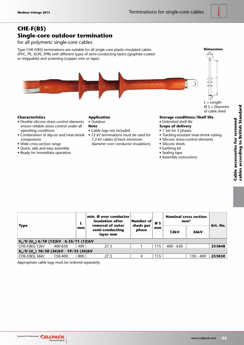
Storage conditions/Shelf life• Unlimited shelf lifeScope of delivery• 1 Set for 3 phases• Tracking-resistant heat-shrink tubing• Silicone stress-control elements• Silicone sheds• Earthing kit• Sealing tape• Assembly instructions
Dimensions
L = LengthØ S = Diameter of cable shed
TypeL
mm
min. Ø over conductorinsulation after
removal of outersemi-conducting
layer mm
Number ofsheds per
phase
Ø Smm
Nominal cross sectionmm²
Art.-No.
12kV 36kV
U0/U (Um) 6/10 (12)kV - 6.35/11 (12)kVCHE-F(BS) 12kV 400-630 400 27.3 1 115 400 - 630 253848 U0/U (Um) 18/30 (36)kV - 19/33 (36)kVCHE-F(BS) 36kV 150-400 800 27.3 4 115 150 - 400 253850
for all polymeric single-core cables
CHE-F(BS)
Characteristics• Flexible silicone stress control elements ensure reliable stress control under all operating conditions• Combination of slip-on and heat-shrink components• Wide cross-section range• Quick, safe and easy assembly• Ready for immediate operation
Application• OutdoorNote• Cable lugs not included• 12 kV terminations must be used for 7.2 kV cables (Check minimum diameter over conductor insulation).
Single-core outdoor termination
Appropriate cable lugs must be ordered separately.
Type CHE-F(BS) terminations are suitable for all single-core plastic-insulated cables (PVC, PE, XLPE, EPR) with different types of semi-conducting layers (graphite-coated or strippable) and screening (copper wire or tape).
Medium Voltage 2013 Medium Voltage 2013
95 www.cellpack.com
Medium Voltage 2013 Medium Voltage 2013
Cab
le a
cces
sori
es f
or
scre
ened
cab
les
acco
rdin
g t
o B
riti
sh S
tan
dar
d
Terminations for single-core cables
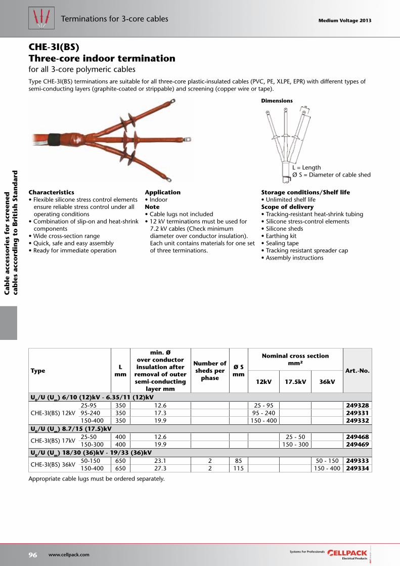
Storage conditions/Shelf life• Unlimited shelf lifeScope of delivery• Tracking-resistant heat-shrink tubing• Silicone stress-control elements• Silicone sheds• Earthing kit• Sealing tape• Tracking resistant spreader cap• Assembly instructions
Dimensions
L = LengthØ S = Diameter of cable shed
TypeL
mm
min. Øover conductorinsulation after
removal of outersemi-conducting
layer mm
Number ofsheds per
phase
Ø Smm
Nominal cross sectionmm²
Art.-No.
12kV 17.5kV 36kV
U0/U (Um) 6/10 (12)kV - 6.35/11 (12)kV
CHE-3I(BS) 12kV25-95 350 12.6 25 - 95 24932895-240 350 17.3 95 - 240 249331150-400 350 19.9 150 - 400 249332
U0/U (Um) 8.7/15 (17.5)kV
CHE-3I(BS) 17kV25-50 400 12.6 25 - 50 249468150-300 400 19.9 150 - 300 249469
U0/U (Um) 18/30 (36)kV - 19/33 (36)kV
CHE-3I(BS) 36kV50-150 650 23.1 2 85 50 - 150 249333150-400 650 27.3 2 115 150 - 400 249334
for all 3-core polymeric cables
CHE-3I(BS)
Characteristics• Flexible silicone stress control elements ensure reliable stress control under all operating conditions• Combination of slip-on and heat-shrink components• Wide cross-section range• Quick, safe and easy assembly• Ready for immediate operation
Application• IndoorNote• Cable lugs not included• 12 kV terminations must be used for 7.2 kV cables (Check minimum diameter over conductor insulation). Each unit contains materials for one set of three terminations.
Three-core indoor termination
Appropriate cable lugs must be ordered separately.
Type CHE-3I(BS) terminations are suitable for all three-core plastic-insulated cables (PVC, PE, XLPE, EPR) with different types of semi-conducting layers (graphite-coated or strippable) and screening (copper wire or tape).
96 www.cellpack.com
Medium Voltage 2013 Medium Voltage 2013
Cab
le a
cces
sori
es f
or
scre
ened
cab
les
acco
rdin
g t
o B
riti
sh S
tan
dar
dTerminations for 3-core cables Medium Voltage 2013 Medium Voltage 2013
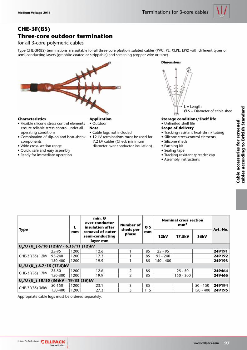
Storage conditions/Shelf life• Unlimited shelf lifeScope of delivery• Tracking-resistant heat-shrink tubing• Silicone stress-control elements• Silicone sheds• Earthing kit• Sealing tape• Tracking resistant spreader cap• Assembly instructions
Dimensions
L = LengthØ S = Diameter of cable shed
TypeL
mm
min. Øover conductorinsulation after
removal of outersemi-conducting
layer mm
Number ofsheds per
phase
Ø Smm
Nominal cross sectionmm²
Art.-No.
12kV 17.5kV 36kV
U0/U (Um) 6/10 (12)kV - 6.35/11 (12)kV
CHE-3F(BS) 12kV25-95 1200 12.6 1 85 25 - 95 24919195-240 1200 17.3 1 85 95 - 240 249192150-400 1200 19.9 1 85 150 - 400 249193
U0/U (Um) 8.7/15 (17.5)kV
CHE-3F(BS) 17kV25-50 1200 12.6 2 85 25 - 50 249464150-300 1200 19.9 2 85 150 - 300 249466
U0/U (Um) 18/30 (36)kV - 19/33 (36)kV
CHE-3F(BS) 36kV50-150 1200 23.1 3 85 50 - 150 249194150-400 1200 27.3 3 115 150 - 400 249195
for all 3-core polymeric cables
CHE-3F(BS)
Characteristics• Flexible silicone stress control elements ensure reliable stress control under all operating conditions• Combination of slip-on and heat-shrink components• Wide cross-section range• Quick, safe and easy assembly• Ready for immediate operation
Application• OutdoorNote• Cable lugs not included• 12 kV terminations must be used for 7.2 kV cables (Check minimum diameter over conductor insulation).
Three-core outdoor termination
Appropriate cable lugs must be ordered separately.
Type CHE-3F(BS) terminations are suitable for all three-core plastic-insulated cables (PVC, PE, XLPE, EPR) with different types of semi-conducting layers (graphite-coated or strippable) and screening (copper wire or tape).
Medium Voltage 2013 Medium Voltage 2013
97 www.cellpack.com
Medium Voltage 2013 Medium Voltage 2013
Cab
le a
cces
sori
es f
or
scre
ened
cab
les
acco
rdin
g t
o B
riti
sh S
tan
dar
d
Terminations for 3-core cables
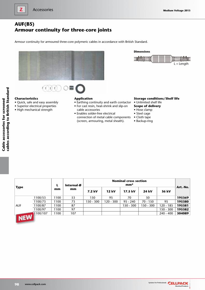
Storage conditions/Shelf life• Unlimited shelf lifeScope of delivery• Hose clamp• Steel cage• Cloth tape• Backup-ring
TypeL
mm Internal-Ø
mm
Nominal cross sectionmm²
Art.-No.7.2 kV 12 kV 17.5 kV 24 kV 36 kV
AUF
1100/53 1100 53 150 95 70 50 1953691100/73 1100 73 150 - 300 120 - 300 95 - 240 70 - 150 95 1953801100/87 1100 87 150 - 300 150 - 300 120 - 185 1953811100/97 1100 97 150 - 300 1953821100/107 1100 107 240 - 400 304089
Dimensions
Characteristics• Quick, safe and easy assembly• Superior electrical properties• High mechanical strength
Application• Earthing continuity and earth contactor• For cast resin, heat-shrink and slip-on cable accessories• Enables solder-free electrical connection of metal cable components (screen, armouring, metal sheath).
Armour continuity for three-core joints
Armour continuity for armoured three-core polymeric cables in accordance with British Standard.
AUF(BS)
L = Length
98 www.cellpack.com
Medium Voltage 2013 Medium Voltage 2013
Cab
le a
cces
sori
es f
or
scre
ened
cab
les
acco
rdin
g t
o B
riti
sh S
tan
dar
dAccessories Medium Voltage 2013 Medium Voltage 2013
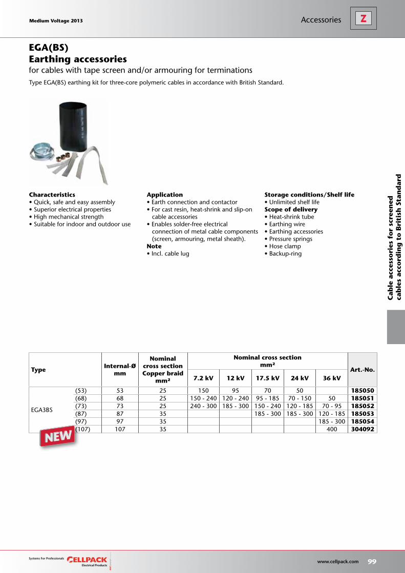
Storage conditions/Shelf life• Unlimited shelf lifeScope of delivery• Heat-shrink tube• Earthing wire• Earthing accessories• Pressure springs• Hose clamp• Backup-ring
TypeInternal-Ø
mm
Nominal cross sectionCopper braid
mm²
Nominal cross sectionmm²
Art.-No.7.2 kV 12 kV 17.5 kV 24 kV 36 kV
EGA3BS
(53) 53 25 150 95 70 50 185050(68) 68 25 150 - 240 120 - 240 95 - 185 70 - 150 50 185051(73) 73 25 240 - 300 185 - 300 150 - 240 120 - 185 70 - 95 185052(87) 87 35 185 - 300 185 - 300 120 - 185 185053(97) 97 35 185 - 300 185054(107) 107 35 400 304092
Characteristics• Quick, safe and easy assembly• Superior electrical properties• High mechanical strength• Suitable for indoor and outdoor use
Application• Earth connection and contactor• For cast resin, heat-shrink and slip-on cable accessories• Enables solder-free electrical connection of metal cable components (screen, armouring, metal sheath).Note• Incl. cable lug
Earthing accessories
Type EGA(BS) earthing kit for three-core polymeric cables in accordance with British Standard.
EGA(BS)
for cables with tape screen and/or armouring for terminations
Medium Voltage 2013 Medium Voltage 2013
99 www.cellpack.com
Medium Voltage 2013 Medium Voltage 2013
Cab
le a
cces
sori
es f
or
scre
ened
cab
les
acco
rdin
g t
o B
riti
sh S
tan
dar
d
Accessories
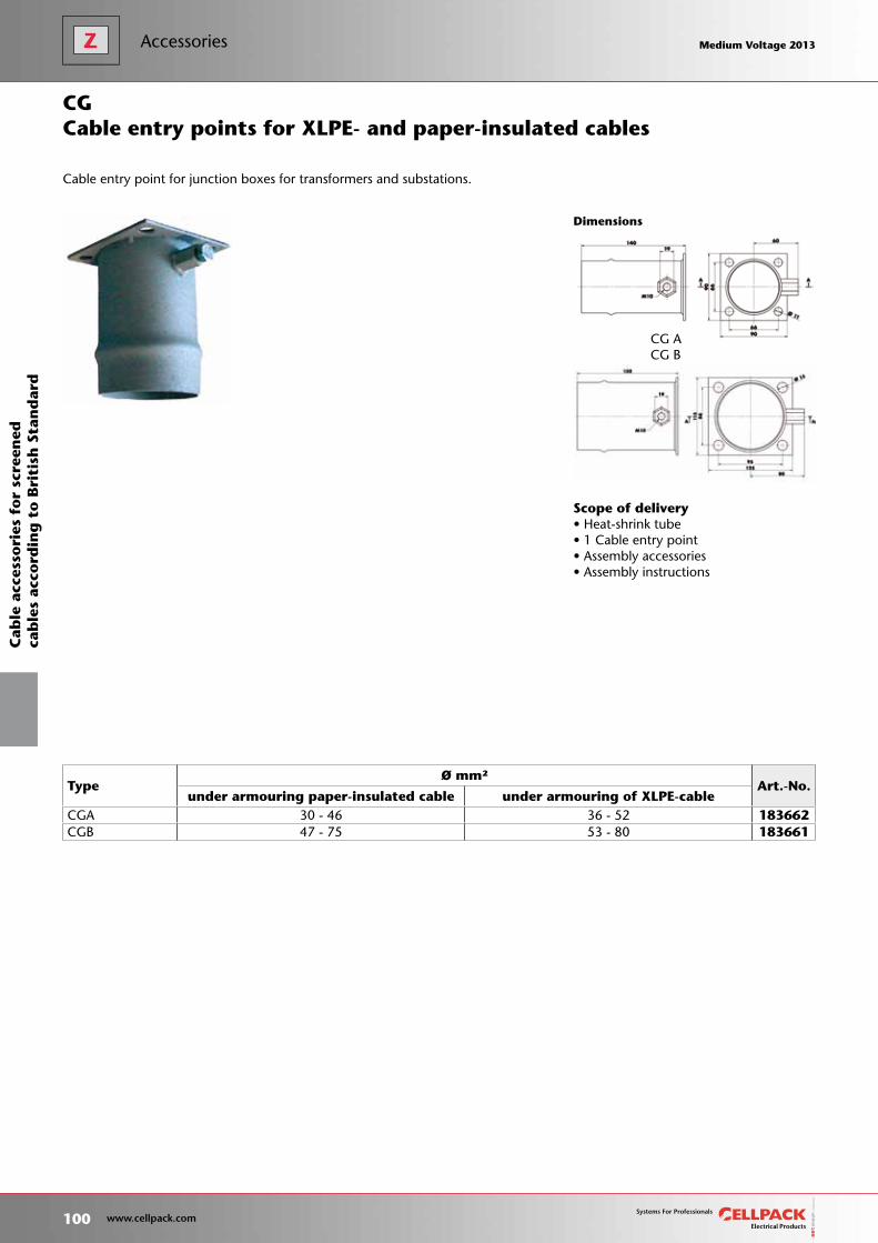
Scope of delivery• Heat-shrink tube• 1 Cable entry point• Assembly accessories• Assembly instructions
Dimensions
CG ACG B
TypeØ mm²
Art.-No.under armouring paper-insulated cable under armouring of XLPE-cable
CGA 30 - 46 36 - 52 183662CGB 47 - 75 53 - 80 183661
Cable entry points for XLPE- and paper-insulated cables
Cable entry point for junction boxes for transformers and substations.
CG
100 www.cellpack.com
Medium Voltage 2013 Medium Voltage 2013
Cab
le a
cces
sori
es f
or
scre
ened
cab
les
acco
rdin
g t
o B
riti
sh S
tan
dar
dAccessories Medium Voltage 2013 Medium Voltage 2013
Medium Voltage 2013 Medium Voltage 2013
101 www.cellpack.com
Medium Voltage 2013 Medium Voltage 2013
Cab
le a
cces
sori
es f
or
scre
ened
cab
les
acco
rdin
g t
o B
riti
sh S
tan
dar
d
Accessories

Customised solutions
102 www.cellpack.com
Medium Voltage 2013 Medium Voltage 2013 Medium Voltage 2013 Medium Voltage 2013

Customised solutions
Cable accessories for the industries
Cable accessories forindustries 104
Page
Medium Voltage 2013 Medium Voltage 2013
103 www.cellpack.com
Medium Voltage 2013 Medium Voltage 2013

Cellpack‘s product portfolio also includes special solutions for the oil and gas, mining and ship-building industries as well as for offshore applications.These cable accessories are exposed to rain, salt, chemicals and extreme mechanical loads.
The products especially designed for these applications comply with current international norms such as IEC and Cenelec, and with industry specific accreditation requirements. More specific information is available on request.
104 www.cellpack.com
Medium Voltage 2013 Medium Voltage 2013Cable accessories for shipyard-industrieC
able
acc
esso
ries
fo
r th
e sh
ipb
uil
din
g i
nd
ust
ry Medium Voltage 2013 Medium Voltage 2013

Medium Voltage 2013 Medium Voltage 2013
105 www.cellpack.com
Medium Voltage 2013 Medium Voltage 2013 Cable accessories for shipyard-industrie
Cab
le a
cces
sori
es f
or
the
ship
bu
ild
ing
in
du
stry
We won‘t leave you in the lurch!
106 www.cellpack.com
Medium Voltage 2013 Medium Voltage 2013 Medium Voltage 2013 Medium Voltage 2013
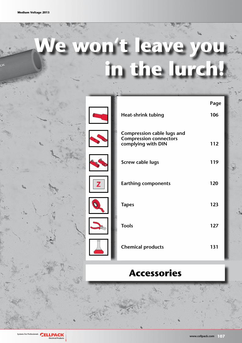
Heat-shrink tubing 106
Compression cable lugs andCompression connectorscomplying with DIN 112
Screw cable lugs 119
Earthing components 120
Tapes 123
Tools 127
Chemical products 131
We won‘t leave you in the lurch!
Accessories
Page
Medium Voltage 2013 Medium Voltage 2013
107 www.cellpack.com
Medium Voltage 2013 Medium Voltage 2013
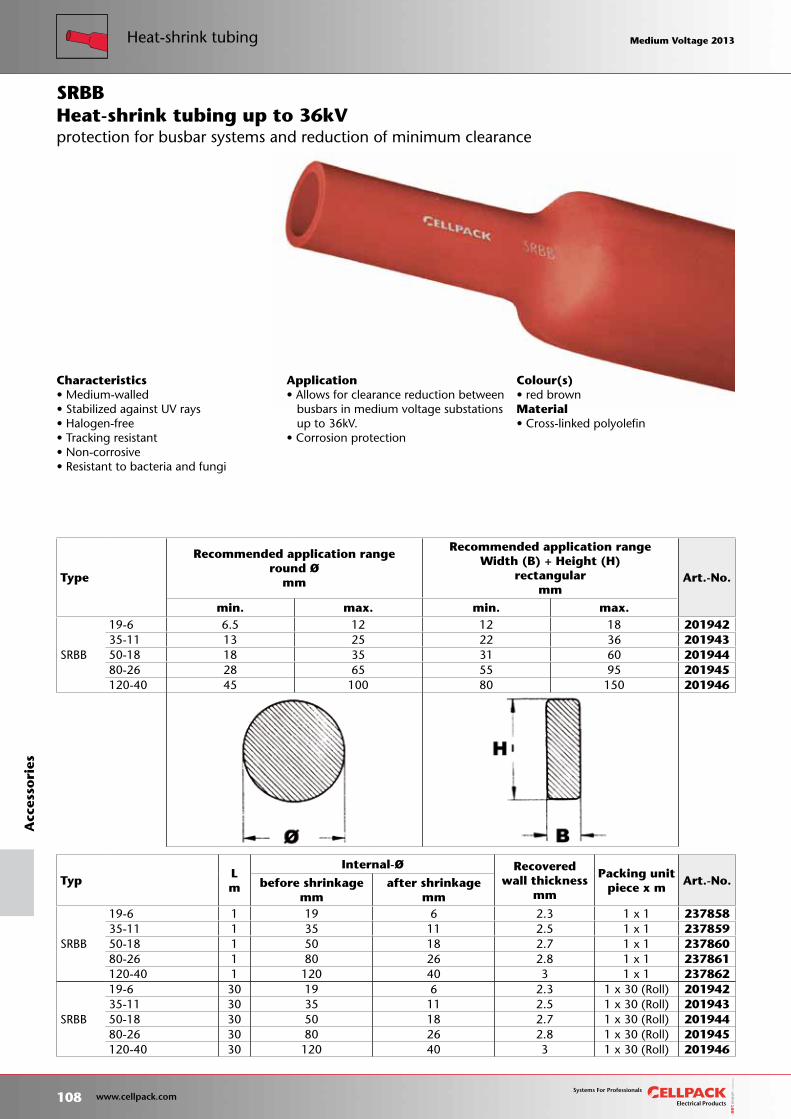
Colour(s)• red brownMaterial• Cross-linked polyolefin
Heat-shrink tubing up to 36kV
Characteristics• Medium-walled• Stabilized against UV rays• Halogen-free• Tracking resistant• Non-corrosive• Resistant to bacteria and fungi
TypLm
Internal-Ø Recoveredwall thickness
mm
Packing unit piece x m
Art.-No.before shrinkage mm
after shrinkage mm
SRBB
19-6 1 19 6 2.3 1 x 1 23785835-11 1 35 11 2.5 1 x 1 23785950-18 1 50 18 2.7 1 x 1 23786080-26 1 80 26 2.8 1 x 1 237861120-40 1 120 40 3 1 x 1 237862
SRBB
19-6 30 19 6 2.3 1 x 30 (Roll) 20194235-11 30 35 11 2.5 1 x 30 (Roll) 20194350-18 30 50 18 2.7 1 x 30 (Roll) 20194480-26 30 80 26 2.8 1 x 30 (Roll) 201945120-40 30 120 40 3 1 x 30 (Roll) 201946
SRBB
Application• Allows for clearance reduction between busbars in medium voltage substations up to 36kV.• Corrosion protection
protection for busbar systems and reduction of minimum clearance
Type
Recommended application rangeround Ø
mm
Recommended application rangeWidth (B) + Height (H)
rectangularmm
Art.-No.
min. max. min. max.
SRBB
19-6 6.5 12 12 18 20194235-11 13 25 22 36 20194350-18 18 35 31 60 20194480-26 28 65 55 95 201945120-40 45 100 80 150 201946
108 www.cellpack.com
Medium Voltage 2013 Medium Voltage 2013Heat-shrink tubingA
cces
sori
es Medium Voltage 2013 Medium Voltage 2013
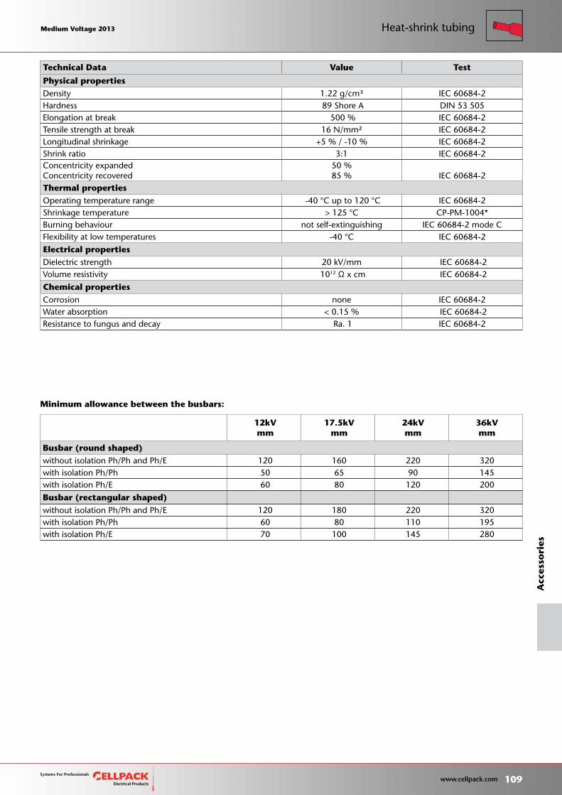
Minimum allowance between the busbars:
Technical Data Value Test
Physical properties Density 1.22 g/cm³ IEC 60684-2 Hardness 89 Shore A DIN 53 505 Elongation at break 500 % IEC 60684-2 Tensile strength at break 16 N/mm² IEC 60684-2 Longitudinal shrinkage +5 % / -10 % IEC 60684-2 Shrink ratio 3:1 IEC 60684-2 Concentricity expanded Concentricity recovered
50 %85 % IEC 60684-2
Thermal properties Operating temperature range -40 °C up to 120 °C IEC 60684-2 Shrinkage temperature > 125 °C CP-PM-1004* Burning behaviour not self-extinguishing IEC 60684-2 mode C Flexibility at low temperatures -40 °C IEC 60684-2 Electrical properties Dielectric strength 20 kV/mm IEC 60684-2 Volume resistivity 1012 Ω x cm IEC 60684-2 Chemical properties Corrosion none IEC 60684-2 Water absorption < 0.15 % IEC 60684-2 Resistance to fungus and decay Ra. 1 IEC 60684-2
12kVmm
17.5kVmm
24kVmm
36kVmm
Busbar (round shaped)without isolation Ph/Ph and Ph/E 120 160 220 320with isolation Ph/Ph 50 65 90 145with isolation Ph/E 60 80 120 200
Busbar (rectangular shaped)
without isolation Ph/Ph and Ph/E 120 180 220 320with isolation Ph/Ph 60 80 110 195with isolation Ph/E 70 100 145 280
Medium Voltage 2013 Medium Voltage 2013
109 www.cellpack.com
Medium Voltage 2013 Medium Voltage 2013 Heat-shrink tubing
Acc
esso
ries
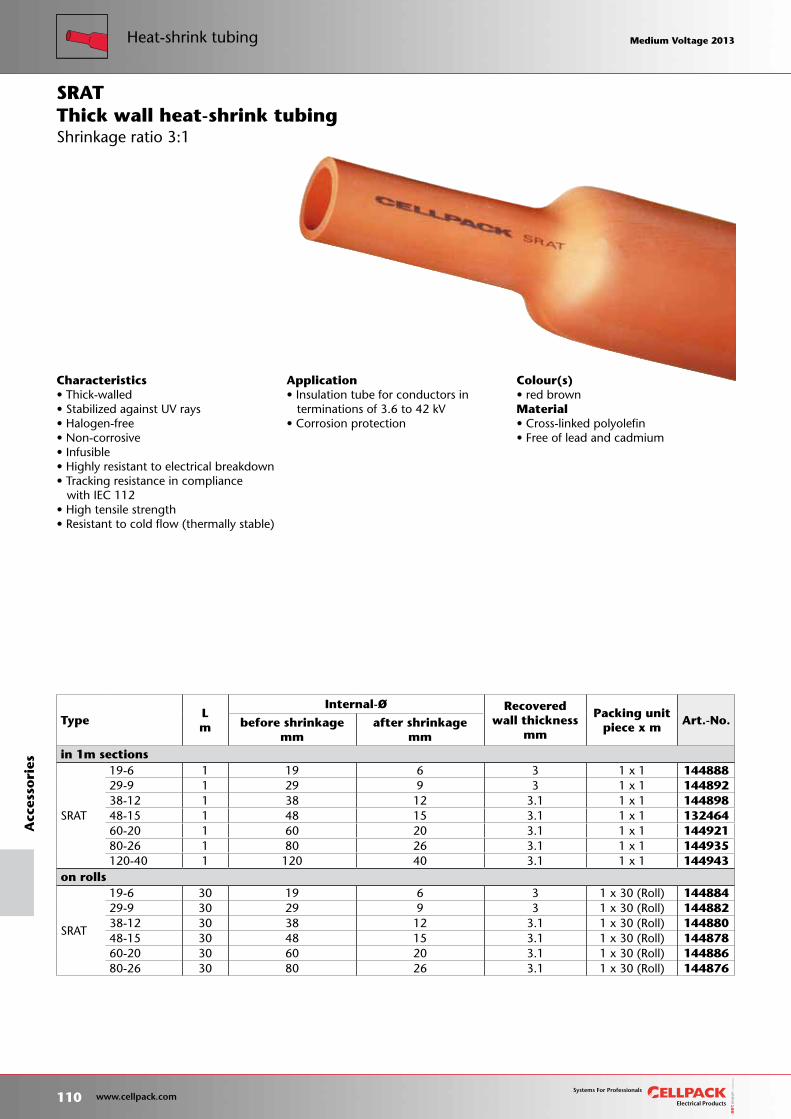
Colour(s)• red brownMaterial• Cross-linked polyolefin• Free of lead and cadmium
TypeLm
Internal-Ø Recoveredwall thickness
mm
Packing unit piece x m
Art.-No.before shrinkagemm
after shrinkagemm
in 1m sections
SRAT
19-6 1 19 6 3 1 x 1 14488829-9 1 29 9 3 1 x 1 14489238-12 1 38 12 3.1 1 x 1 14489848-15 1 48 15 3.1 1 x 1 13246460-20 1 60 20 3.1 1 x 1 14492180-26 1 80 26 3.1 1 x 1 144935120-40 1 120 40 3.1 1 x 1 144943
on rolls
SRAT
19-6 30 19 6 3 1 x 30 (Roll) 14488429-9 30 29 9 3 1 x 30 (Roll) 14488238-12 30 38 12 3.1 1 x 30 (Roll) 14488048-15 30 48 15 3.1 1 x 30 (Roll) 14487860-20 30 60 20 3.1 1 x 30 (Roll) 14488680-26 30 80 26 3.1 1 x 30 (Roll) 144876
SRAT
Characteristics• Thick-walled• Stabilized against UV rays• Halogen-free• Non-corrosive• Infusible• Highly resistant to electrical breakdown• Tracking resistance in compliance with IEC 112• High tensile strength• Resistant to cold flow (thermally stable)
Application• Insulation tube for conductors in terminations of 3.6 to 42 kV• Corrosion protection
Shrinkage ratio 3:1Thick wall heat-shrink tubing
110 www.cellpack.com
Medium Voltage 2013 Medium Voltage 2013Heat-shrink tubingA
cces
sori
es Medium Voltage 2013 Medium Voltage 2013
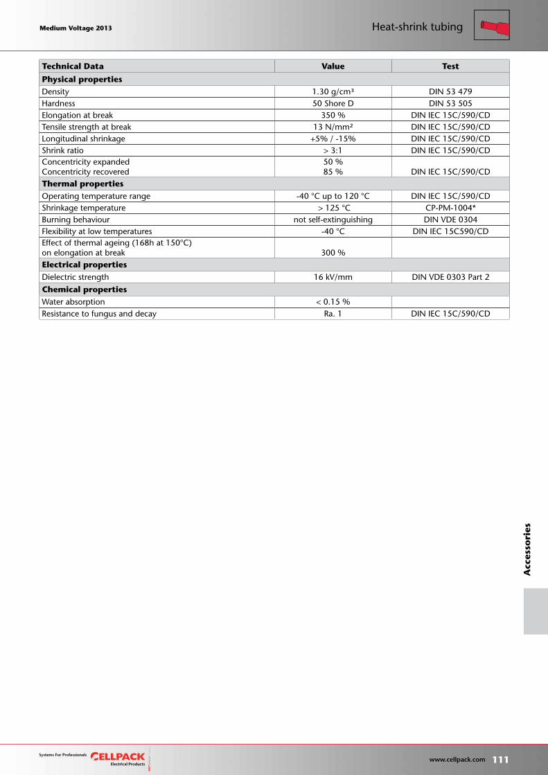
Technical Data Value Test
Physical properties Density 1.30 g/cm³ DIN 53 479 Hardness 50 Shore D DIN 53 505 Elongation at break 350 % DIN IEC 15C/590/CD Tensile strength at break 13 N/mm² DIN IEC 15C/590/CD Longitudinal shrinkage +5% / -15% DIN IEC 15C/590/CD Shrink ratio > 3:1 DIN IEC 15C/590/CD Concentricity expanded Concentricity recovered
50 %85 % DIN IEC 15C/590/CD
Thermal properties Operating temperature range -40 °C up to 120 °C DIN IEC 15C/590/CD Shrinkage temperature > 125 °C CP-PM-1004* Burning behaviour not self-extinguishing DIN VDE 0304 Flexibility at low temperatures -40 °C DIN IEC 15C590/CD Effect of thermal ageing (168h at 150°C) on elongation at break 300 % Electrical properties
Dielectric strength 16 kV/mm DIN VDE 0303 Part 2
Chemical properties Water absorption < 0.15 % Resistance to fungus and decay Ra. 1 DIN IEC 15C/590/CD
Medium Voltage 2013 Medium Voltage 2013
111 www.cellpack.com
Medium Voltage 2013 Medium Voltage 2013 Heat-shrink tubing
Acc
esso
ries
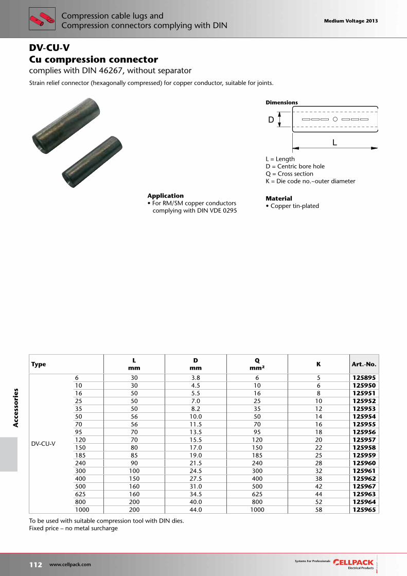
Material• Copper tin-plated
To be used with suitable compression tool with DIN dies.Fixed price – no metal surcharge
D
L
Dimensions
L = LengthD = Centric bore holeQ = Cross sectionK = Die code no.~outer diameter
Application• For RM/SM copper conductors complying with DIN VDE 0295
Cu compression connector
Strain relief connector (hexagonally compressed) for copper conductor, suitable for joints.
DV-CU-V
complies with DIN 46267, without separator
TypeL
mm D
mm Q
mm²K Art.-No.
DV-CU-V
6 30 3.8 6 5 12589510 30 4.5 10 6 12595016 50 5.5 16 8 12595125 50 7.0 25 10 12595235 50 8.2 35 12 12595350 56 10.0 50 14 12595470 56 11.5 70 16 12595595 70 13.5 95 18 125956120 70 15.5 120 20 125957150 80 17.0 150 22 125958185 85 19.0 185 25 125959240 90 21.5 240 28 125960300 100 24.5 300 32 125961400 150 27.5 400 38 125962500 160 31.0 500 42 125967625 160 34.5 625 44 125963800 200 40.0 800 52 1259641000 200 44.0 1000 58 125965
112 www.cellpack.com
Medium Voltage 2013 Medium Voltage 2013A
cces
sori
esCompression cable lugs andCompression connectors complying with DIN
Medium Voltage 2013 Medium Voltage 2013
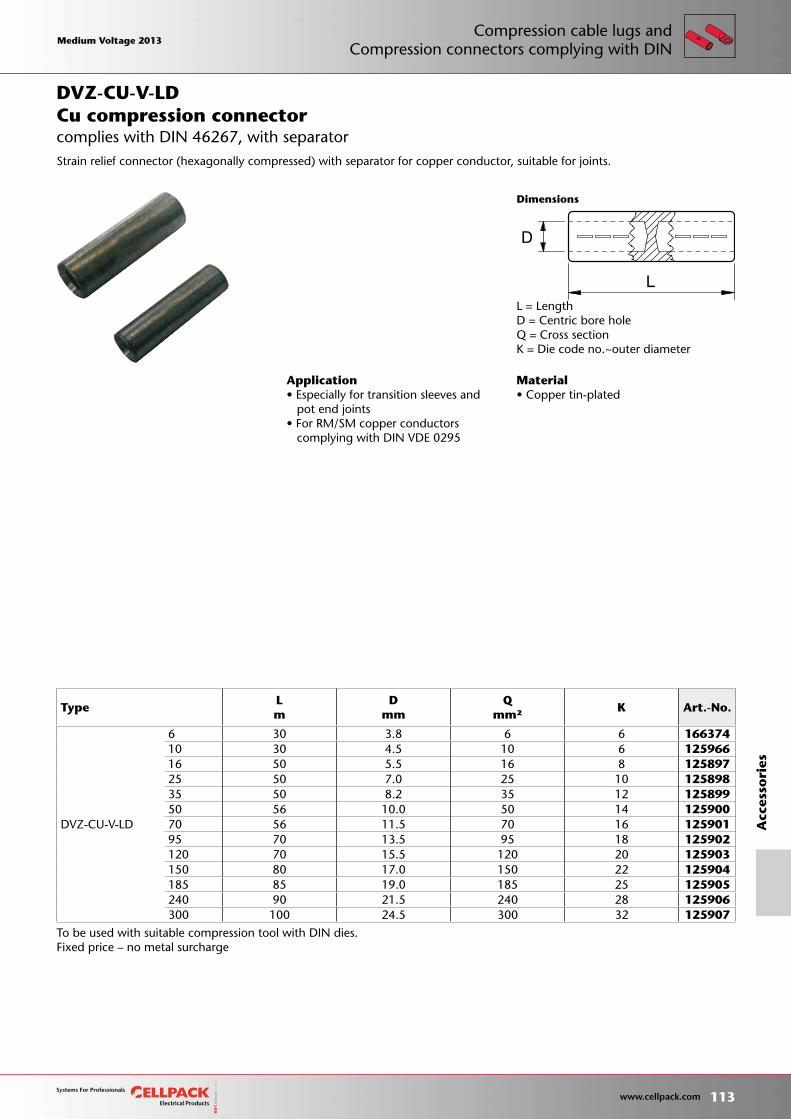
Material• Copper tin-plated
To be used with suitable compression tool with DIN dies.Fixed price – no metal surcharge
D
L
Dimensions
Application• Especially for transition sleeves and pot end joints• For RM/SM copper conductors complying with DIN VDE 0295
L = LengthD = Centric bore holeQ = Cross sectionK = Die code no.~outer diameter
Cu compression connector
Strain relief connector (hexagonally compressed) with separator for copper conductor, suitable for joints.
DVZ-CU-V-LD
complies with DIN 46267, with separator
TypeLm
Dmm
Qmm²
K Art.-No.
DVZ-CU-V-LD
6 30 3.8 6 6 16637410 30 4.5 10 6 12596616 50 5.5 16 8 12589725 50 7.0 25 10 12589835 50 8.2 35 12 12589950 56 10.0 50 14 12590070 56 11.5 70 16 12590195 70 13.5 95 18 125902120 70 15.5 120 20 125903150 80 17.0 150 22 125904185 85 19.0 185 25 125905240 90 21.5 240 28 125906300 100 24.5 300 32 125907
Medium Voltage 2013 Medium Voltage 2013
113 www.cellpack.com
Medium Voltage 2013 Medium Voltage 2013
Acc
esso
ries
Compression cable lugs andCompression connectors complying with DIN
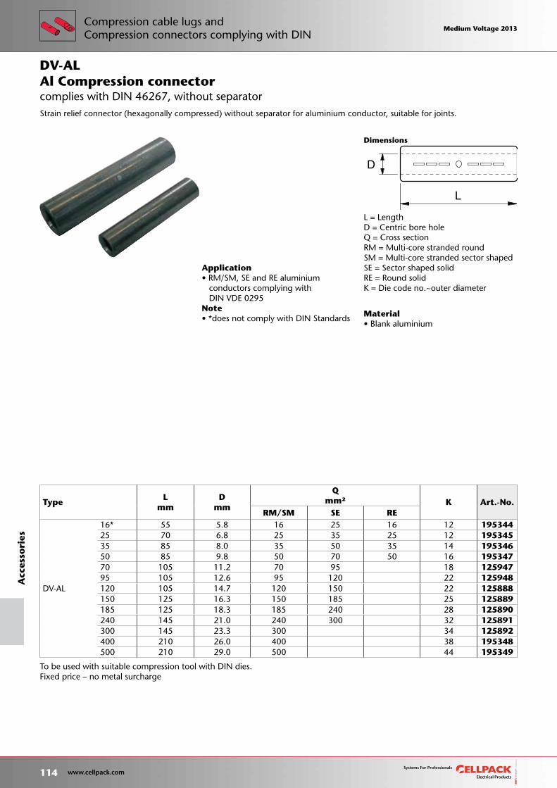
Material• Blank aluminium
To be used with suitable compression tool with DIN dies.Fixed price – no metal surcharge
D
L
Dimensions
L = LengthD = Centric bore holeQ = Cross sectionRM = Multi-core stranded roundSM = Multi-core stranded sector shapedSE = Sector shaped solidRE = Round solidK = Die code no.~outer diameter
Application• RM/SM, SE and RE aluminium conductors complying with DIN VDE 0295Note• *does not comply with DIN Standards
Al Compression connector
Strain relief connector (hexagonally compressed) without separator for aluminium conductor, suitable for joints.
DV-AL
complies with DIN 46267, without separator
TypeL
mm D
mm
Qmm² K Art.-No.
RM/SM SE RE
DV-AL
16* 55 5.8 16 25 16 12 19534425 70 6.8 25 35 25 12 19534535 85 8.0 35 50 35 14 19534650 85 9.8 50 70 50 16 19534770 105 11.2 70 95 18 12594795 105 12.6 95 120 22 125948120 105 14.7 120 150 22 125888150 125 16.3 150 185 25 125889185 125 18.3 185 240 28 125890240 145 21.0 240 300 32 125891300 145 23.3 300 34 125892400 210 26.0 400 38 195348500 210 29.0 500 44 195349
114 www.cellpack.com
Medium Voltage 2013 Medium Voltage 2013A
cces
sori
esCompression cable lugs andCompression connectors complying with DIN
Medium Voltage 2013 Medium Voltage 2013
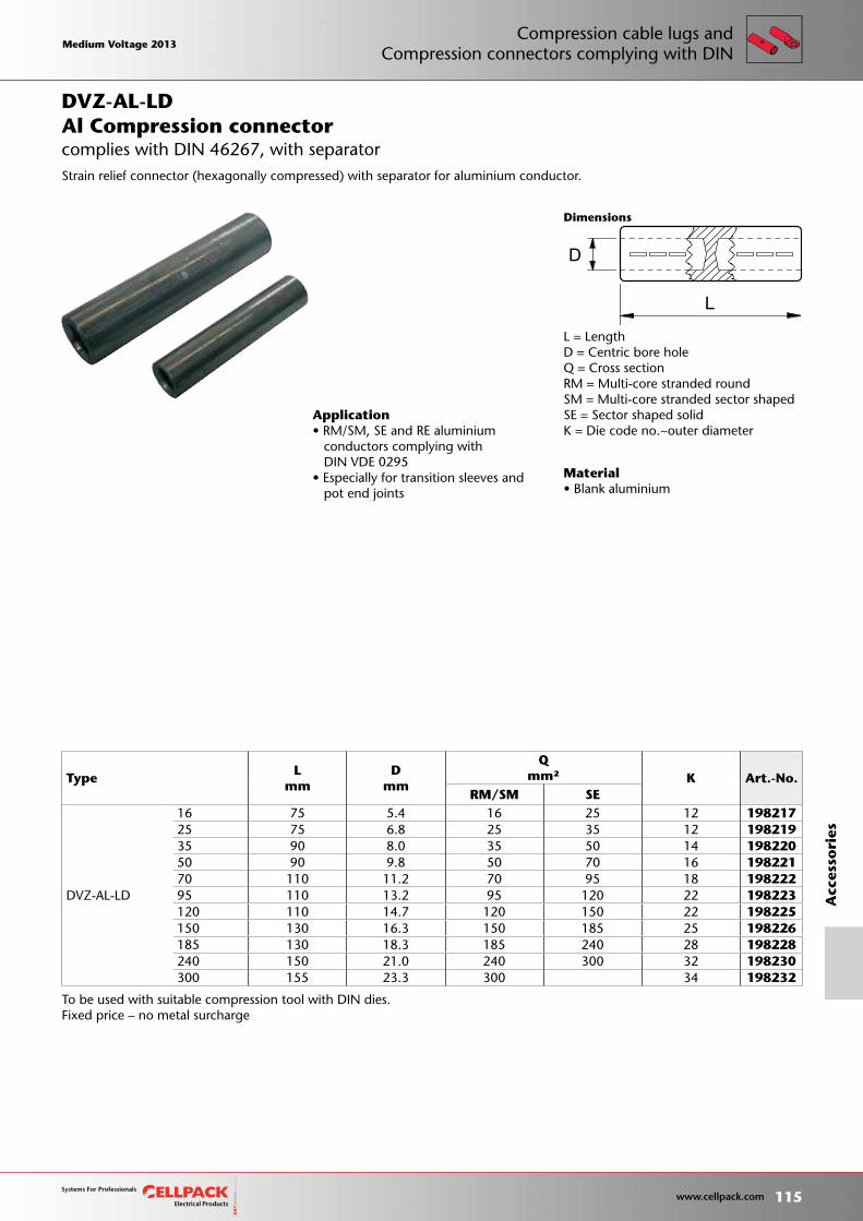
Material• Blank aluminium
To be used with suitable compression tool with DIN dies.Fixed price – no metal surcharge
D
L
Dimensions
L = LengthD = Centric bore holeQ = Cross sectionRM = Multi-core stranded roundSM = Multi-core stranded sector shapedSE = Sector shaped solidK = Die code no.~outer diameter
Application• RM/SM, SE and RE aluminium conductors complying with DIN VDE 0295• Especially for transition sleeves and pot end joints
Al Compression connector
Strain relief connector (hexagonally compressed) with separator for aluminium conductor.
DVZ-AL-LD
complies with DIN 46267, with separator
TypeL
mm D
mm
Qmm² K Art.-No.
RM/SM SE
DVZ-AL-LD
16 75 5.4 16 25 12 19821725 75 6.8 25 35 12 19821935 90 8.0 35 50 14 19822050 90 9.8 50 70 16 19822170 110 11.2 70 95 18 19822295 110 13.2 95 120 22 198223120 110 14.7 120 150 22 198225150 130 16.3 150 185 25 198226185 130 18.3 185 240 28 198228240 150 21.0 240 300 32 198230300 155 23.3 300 34 198232
Medium Voltage 2013 Medium Voltage 2013
115 www.cellpack.com
Medium Voltage 2013 Medium Voltage 2013
Acc
esso
ries
Compression cable lugs andCompression connectors complying with DIN
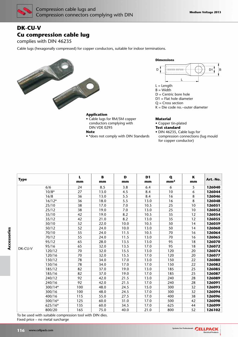
Material• Copper tin-platedTest standard• DIN 46235, Cable lugs for compression connections (lug mould for copper conductor)
To be used with suitable compression tool with DIN dies.Fixed price – no metal surcharge
L
D1 B D
Dimensions
L = LengthB = WidthD = Centric bore holeD1 = Flat hole diameterQ = Cross sectionK = Die code no.~outer diameter
Application• Cable lugs for RM/SM copper conductors complying with DIN VDE 0295Note• *does not comply with DIN Standards
Cu compression cable lug
Cable lugs (hexagonally compressed) for copper conductors, suitable for indoor terminations.
DK-CU-V
complies with DIN 46235
TypeL
mm B
mm D
mm D1mm
Qmm²
Kmm
Art.-No.
DK-CU-V
6/6 24 8.5 3.8 6.4 6 5 12604010/8* 27 13.0 4.5 8.4 10 6 12604416/8 36 13.0 5.5 8.4 16 8 12604616/12* 36 18.0 5.5 13.0 16 8 12604825/10 38 17.0 7.0 10.5 25 10 12605125/12 38 19.0 7.0 13.0 25 10 12605235/10 42 19.0 8.2 10.5 35 12 12605435/12 42 21.0 8.2 13.0 35 12 12605550/10 52 22.0 10.0 10.5 50 14 12605950/12 52 24.0 10.0 13.0 50 14 12606070/10 55 24.0 11.5 10.5 70 16 12606470/12 55 24.0 11.5 13.0 70 16 12606595/12 65 28.0 13.5 13.0 95 18 12607095/16 65 32.0 13.5 17.0 95 18 126072120/12 70 32.0 15.5 13.0 120 20 126074120/16 70 32.0 15.5 17.0 120 20 126077150/12 78 34.0 17.0 13.0 150 22 126080150/16 78 34.0 17.0 17.0 150 22 126082185/12 82 37.0 19.0 13.0 185 25 126085185/16 82 37.0 19.0 17.0 185 25 126087240/12 92 42.0 21.5 13.0 240 28 126089240/16 92 42.0 21.5 17.0 240 28 126091300/14* 100 48.0 24.5 15.0 300 32 126093300/16 100 48.0 24.5 17.0 300 32 126094400/16 115 55.0 27.5 17.0 400 38 126096500/16* 125 60.0 31.0 17.0 500 42 126098625/16* 135 60.0 34.5 17.0 625 44 126099800/20 165 75.0 40.0 21.0 800 52 126102
116 www.cellpack.com
Medium Voltage 2013 Medium Voltage 2013A
cces
sori
esCompression cable lugs andCompression connectors complying with DIN
Medium Voltage 2013 Medium Voltage 2013
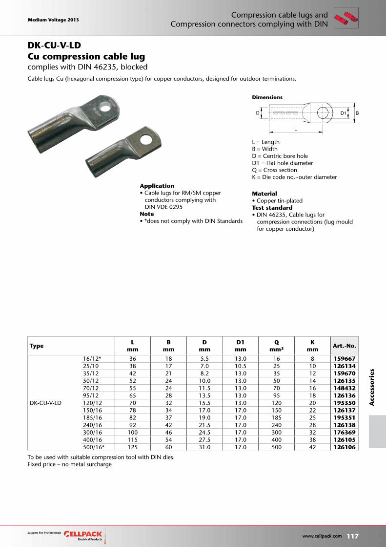
To be used with suitable compression tool with DIN dies.Fixed price – no metal surcharge
L
D1 B D
Dimensions
Material• Copper tin-platedTest standard• DIN 46235, Cable lugs for compression connections (lug mould for copper conductor)
L = LengthB = WidthD = Centric bore holeD1 = Flat hole diameterQ = Cross sectionK = Die code no.~outer diameter
Application• Cable lugs for RM/SM copper conductors complying with DIN VDE 0295Note• *does not comply with DIN Standards
Cu compression cable lug
Cable lugs Cu (hexagonal compression type) for copper conductors, designed for outdoor terminations.
DK-CU-V-LD
complies with DIN 46235, blocked
TypeL
mm B
mm D
mm D1mm
Qmm²
Kmm
Art.-No.
DK-CU-V-LD
16/12* 36 18 5.5 13.0 16 8 15966725/10 38 17 7.0 10.5 25 10 12613435/12 42 21 8.2 13.0 35 12 15967050/12 52 24 10.0 13.0 50 14 12613570/12 55 24 11.5 13.0 70 16 14843295/12 65 28 13.5 13.0 95 18 126136120/12 70 32 15.5 13.0 120 20 195350150/16 78 34 17.0 17.0 150 22 126137185/16 82 37 19.0 17.0 185 25 195351240/16 92 42 21.5 17.0 240 28 126138300/16 100 46 24.5 17.0 300 32 176369400/16 115 54 27.5 17.0 400 38 126105500/16* 125 60 31.0 17.0 500 42 126106
Medium Voltage 2013 Medium Voltage 2013
117 www.cellpack.com
Medium Voltage 2013 Medium Voltage 2013
Acc
esso
ries
Compression cable lugs andCompression connectors complying with DIN
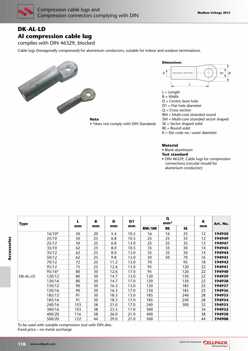
To be used with suitable compression tool with DIN dies.Fixed price – no metal surcharge
D
L
D1 B
Dimensions
Material• Blank aluminiumTest standard• DIN 46329, Cable lugs for compression connections (circular mould for aluminium conductor)
Note• *does not comply with DIN Standards
TypeL
mm B
mm D
mm D1mm
Qmm² K
mmArt.-No.
RM/SM RE SE
DK-AL-LD
16/10* 50 20 5.4 10.5 16 16 25 12 19495025/10 50 25 6.8 10.5 25 25 35 12 19494925/12 50 25 6.8 13.0 25 25 35 12 19494735/10 62 25 8.0 10.5 35 35 50 14 19494535/12 62 25 8.0 13.0 35 35 50 14 19494450/12 62 25 9.8 13.0 50 50 70 16 19494370/12 72 25 11.2 13.0 70 95 18 19494295/12 75 25 12.6 13.0 95 120 22 19494195/16* 80 30 12.6 17.0 95 120 22 194940120/12 80 30 14.7 13.0 120 150 22 194939120/16 80 30 14.7 17.0 120 150 22 194938150/12 90 30 16.3 13.0 150 185 25 194937150/16 90 30 16.3 17.0 150 185 25 194936185/12 91 30 18.3 13.0 185 240 28 194935185/16 91 30 18.3 17.0 185 240 28 194934240/16 103 38 21.0 17.0 240 300 32 194933300/16 103 38 23.3 17.0 300 34 194932400/20 116 38 26.0 21.0 400 38 194930500/20 122 44 29.0 21.0 500 44 194908
L = LengthB = WidthD = Centric bore holeD1 = Flat hole diameterQ = Cross sectionRM = Multi-core stranded roundSM = Multi-core stranded sector shapedSE = Sector shaped solidRE = Round solidK = Die code no.~outer diameter
Al compression cable lug
Cable lugs (hexagonally compressed) for aluminium conductors, suitable for indoor and outdoor terminations.
DK-AL-LD
complies with DIN 46329, blocked
118 www.cellpack.com
Medium Voltage 2013 Medium Voltage 2013A
cces
sori
esCompression cable lugs andCompression connectors complying with DIN
Medium Voltage 2013 Medium Voltage 2013
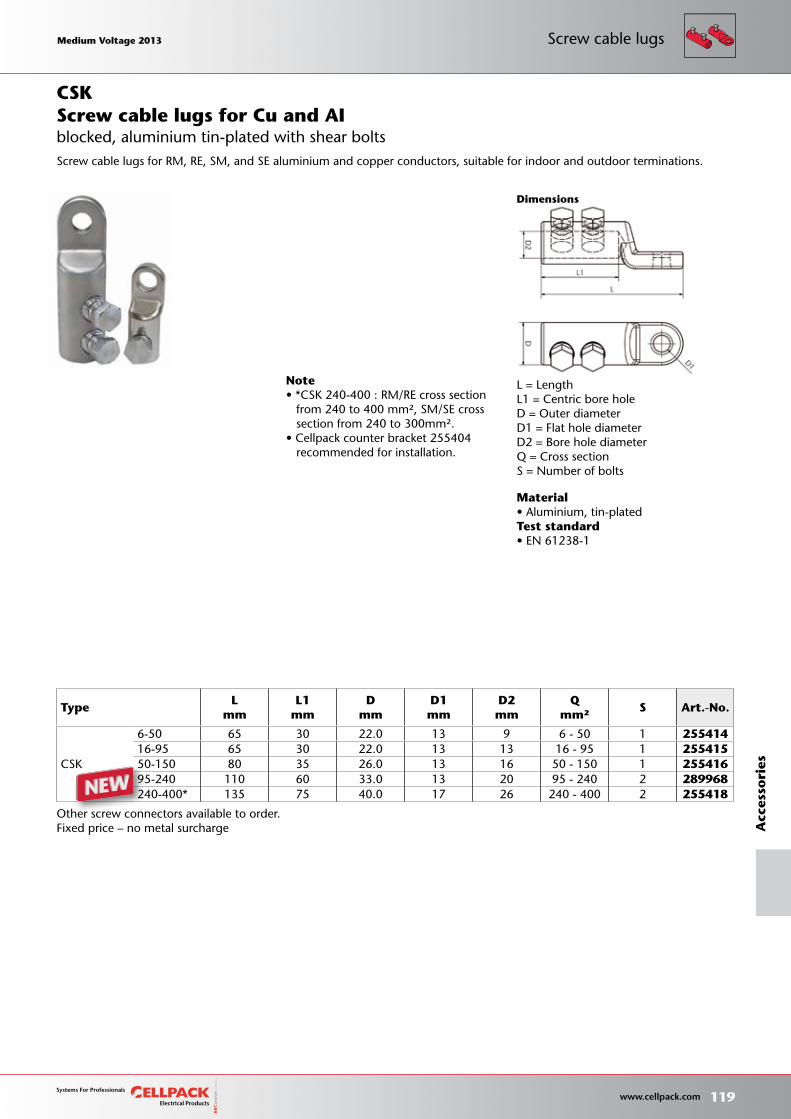
Material• Aluminium, tin-platedTest standard• EN 61238-1
Dimensions
Other screw connectors available to order.Fixed price – no metal surcharge
L = LengthL1 = Centric bore holeD = Outer diameterD1 = Flat hole diameterD2 = Bore hole diameterQ = Cross sectionS = Number of bolts
TypeL
mmL1
mm D
mm D1mm
D2mm
Qmm²
S Art.-No.
CSK
6-50 65 30 22.0 13 9 6 - 50 1 25541416-95 65 30 22.0 13 13 16 - 95 1 25541550-150 80 35 26.0 13 16 50 - 150 1 25541695-240 110 60 33.0 13 20 95 - 240 2 289968240-400* 135 75 40.0 17 26 240 - 400 2 255418
Screw cable lugs for Cu and AI
Note• *CSK 240-400 : RM/RE cross section from 240 to 400 mm², SM/SE cross section from 240 to 300mm². • Cellpack counter bracket 255404 recommended for installation.
Screw cable lugs for RM, RE, SM, and SE aluminium and copper conductors, suitable for indoor and outdoor terminations.
CSK
blocked, aluminium tin-plated with shear bolts
Medium Voltage 2013 Medium Voltage 2013
119 www.cellpack.com
Medium Voltage 2013 Medium Voltage 2013
Acc
esso
ries
Screw cable lugs
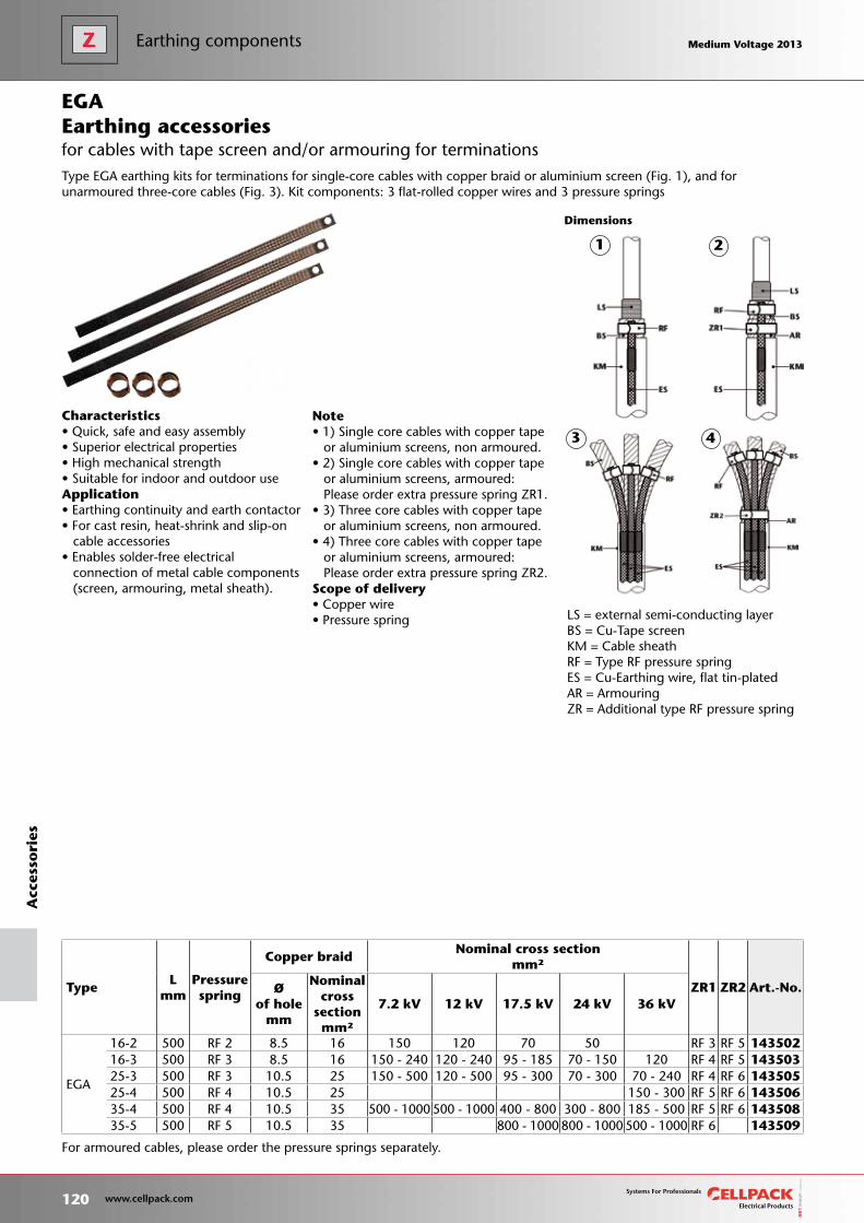
For armoured cables, please order the pressure springs separately.
Note• 1) Single core cables with copper tape or aluminium screens, non armoured.• 2) Single core cables with copper tape or aluminium screens, armoured: Please order extra pressure spring ZR1.• 3) Three core cables with copper tape or aluminium screens, non armoured.• 4) Three core cables with copper tape or aluminium screens, armoured: Please order extra pressure spring ZR2.Scope of delivery• Copper wire• Pressure spring
Dimensions
LS = external semi-conducting layerBS = Cu-Tape screenKM = Cable sheathRF = Type RF pressure spring ES = Cu-Earthing wire, flat tin-platedAR = ArmouringZR = Additional type RF pressure spring
Characteristics• Quick, safe and easy assembly• Superior electrical properties• High mechanical strength• Suitable for indoor and outdoor useApplication• Earthing continuity and earth contactor• For cast resin, heat-shrink and slip-on cable accessories• Enables solder-free electrical connection of metal cable components (screen, armouring, metal sheath).
Type EGA earthing kits for terminations for single-core cables with copper braid or aluminium screen (Fig. 1), and for unarmoured three-core cables (Fig. 3). Kit components: 3 flat-rolled copper wires and 3 pressure springs
TypeL
mm Pressurespring
Copper braidNominal cross section
mm²
ZR1 ZR2 Art.-No.Øof hole
mm
Nominalcross
sectionmm²
7.2 kV 12 kV 17.5 kV 24 kV 36 kV
EGA
16-2 500 RF 2 8.5 16 150 120 70 50 RF 3 RF 5 14350216-3 500 RF 3 8.5 16 150 - 240 120 - 240 95 - 185 70 - 150 120 RF 4 RF 5 14350325-3 500 RF 3 10.5 25 150 - 500 120 - 500 95 - 300 70 - 300 70 - 240 RF 4 RF 6 14350525-4 500 RF 4 10.5 25 150 - 300 RF 5 RF 6 14350635-4 500 RF 4 10.5 35 500 - 1000 500 - 1000 400 - 800 300 - 800 185 - 500 RF 5 RF 6 14350835-5 500 RF 5 10.5 35 800 - 1000 800 - 1000 500 - 1000 RF 6 143509
EGA
for cables with tape screen and/or armouring for terminationsEarthing accessories
2
3 4
1
120 www.cellpack.com
Medium Voltage 2013 Medium Voltage 2013A
cces
sori
esEarthing components Medium Voltage 2013 Medium Voltage 2013
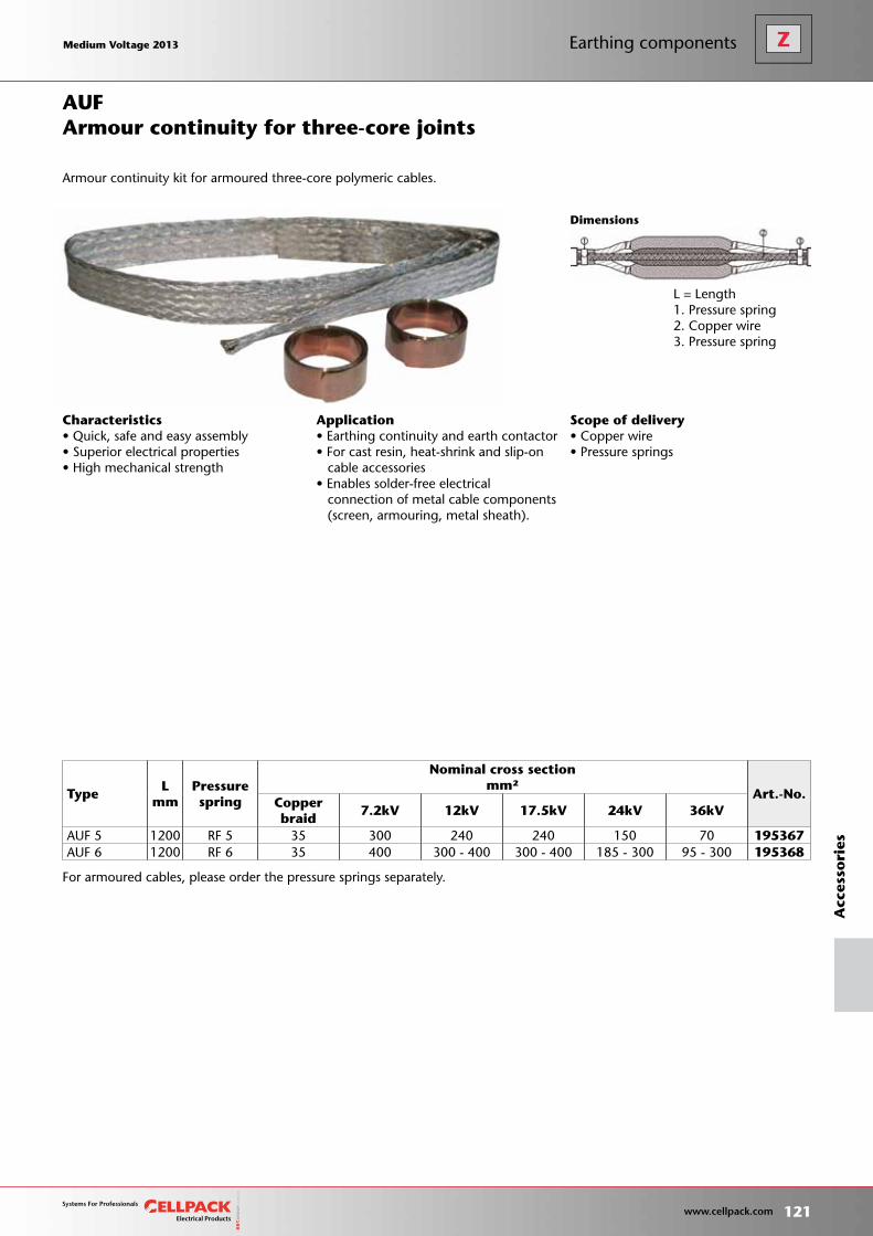
L = Length1. Pressure spring2. Copper wire3. Pressure spring
Dimensions
Scope of delivery• Copper wire• Pressure springs
Characteristics• Quick, safe and easy assembly• Superior electrical properties• High mechanical strength
Application• Earthing continuity and earth contactor• For cast resin, heat-shrink and slip-on cable accessories• Enables solder-free electrical connection of metal cable components (screen, armouring, metal sheath).
TypeL
mm Pressurespring
Nominal cross section mm²
Art.-No.Copperbraid
7.2kV 12kV 17.5kV 24kV 36kV
AUF 5 1200 RF 5 35 300 240 240 150 70 195367AUF 6 1200 RF 6 35 400 300 - 400 300 - 400 185 - 300 95 - 300 195368
Armour continuity for three-core joints
Armour continuity kit for armoured three-core polymeric cables.
AUF
For armoured cables, please order the pressure springs separately.
Medium Voltage 2013 Medium Voltage 2013
121 www.cellpack.com
Medium Voltage 2013 Medium Voltage 2013
Acc
esso
ries
Earthing components
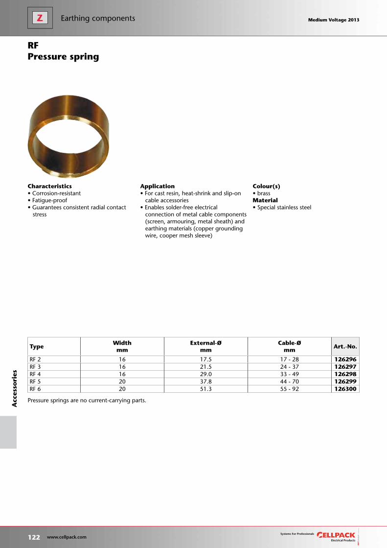
Colour(s)• brassMaterial• Special stainless steel
Pressure springs are no current-carrying parts.
Characteristics• Corrosion-resistant• Fatigue-proof• Guarantees consistent radial contact stress
Application• For cast resin, heat-shrink and slip-on cable accessories• Enables solder-free electrical connection of metal cable components (screen, armouring, metal sheath) and earthing materials (copper grounding wire, cooper mesh sleeve)
Pressure springRF
TypeWidthmm
External-Ømm
Cable-Ømm
Art.-No.
RF 2 16 17.5 17 - 28 126296RF 3 16 21.5 24 - 37 126297RF 4 16 29.0 33 - 49 126298RF 5 20 37.8 44 - 70 126299RF 6 20 51.3 55 - 92 126300
122 www.cellpack.com
Medium Voltage 2013 Medium Voltage 2013A
cces
sori
esEarthing components Medium Voltage 2013 Medium Voltage 2013
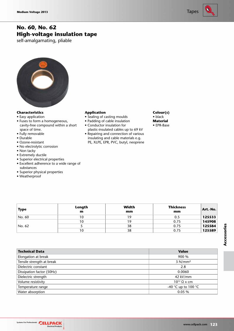
Colour(s)• blackMaterial• EPR-Base
TypeLength
m Widthmm
Thicknessmm
Art.-No.
No. 60 10 19 0.5 125533
No. 6210 19 0.75 1459085 38 0.75 125584
10 38 0.75 125589
No. 60, No. 62
Characteristics• Easy application• Fuses to form a homogeneous, cavity-free compound within a short space of time.• Fully removable• Durable• Ozone-resistant • No electrolytic corrosion• Non tacky• Extremely ductile• Superior electrical properties• Excellent adherence to a wide range of substances• Superior physical properties• Weatherproof
Application• Sealing of casting moulds• Padding of cable insulation• Conductor insulation for plastic-insulated cables up to 69 kV• Repairing and connection of various insulating and cable materials e.g. PE, XLPE, EPR, PVC, butyl, neoprene
self-amalgamating, pliableHigh-voltage insulation tape
Technical Data Value Elongation at break 900 % Tensile strength at break 3 N/mm² Dielectric constant 2.8 Dissipation factor (50Hz) 0.0060 Dielectric strength 42 kV/mm Volume resistivity 1012 Ω x cm Temperature range -40 °C up to 100 °C Water absorption 0.05 %
Medium Voltage 2013 Medium Voltage 2013
123 www.cellpack.com
Medium Voltage 2013 Medium Voltage 2013
Acc
esso
ries
Tapes
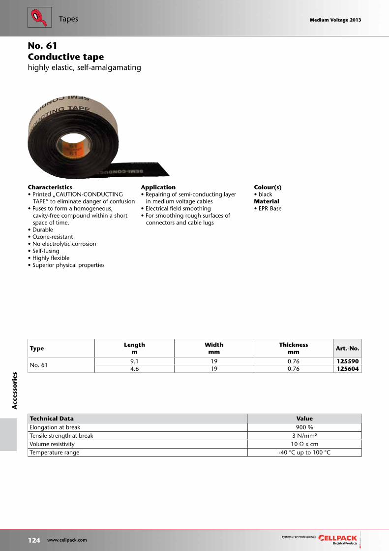
highly elastic, self-amalgamating
Colour(s)• blackMaterial• EPR-Base
TypeLength
m Widthmm
Thicknessmm
Art.-No.
No. 619.1 19 0.76 1255904.6 19 0.76 125604
No. 61
Characteristics• Printed „CAUTION-CONDUCTING TAPE“ to eliminate danger of confusion• Fuses to form a homogeneous, cavity-free compound within a short space of time.• Durable• Ozone-resistant • No electrolytic corrosion• Self-fusing• Highly flexible• Superior physical properties
Application• Repairing of semi-conducting layer in medium voltage cables• Electrical field smoothing• For smoothing rough surfaces of connectors and cable lugs
Conductive tape
Technical Data Value Elongation at break 900 % Tensile strength at break 3 N/mm² Volume resistivity 10 Ω x cm Temperature range -40 °C up to 100 °C
124 www.cellpack.com
Medium Voltage 2013 Medium Voltage 2013A
cces
sori
esTapes Medium Voltage 2013 Medium Voltage 2013
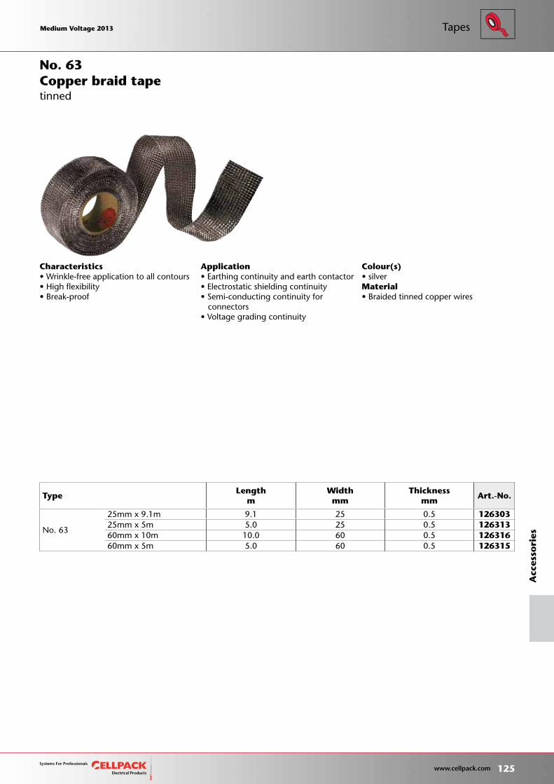
Colour(s)• silverMaterial• Braided tinned copper wires
Characteristics• Wrinkle-free application to all contours• High flexibility• Break-proof
Application• Earthing continuity and earth contactor• Electrostatic shielding continuity• Semi-conducting continuity for connectors• Voltage grading continuity
Copper braid tapeNo. 63
tinned
TypeLength
m Widthmm
Thicknessmm
Art.-No.
No. 63
25mm x 9.1m 9.1 25 0.5 12630325mm x 5m 5.0 25 0.5 12631360mm x 10m 10.0 60 0.5 12631660mm x 5m 5.0 60 0.5 126315
Medium Voltage 2013 Medium Voltage 2013
125 www.cellpack.com
Medium Voltage 2013 Medium Voltage 2013
Acc
esso
ries
Tapes

Colour(s)• black
Characteristics• Self-fusing• 100% waterproof• Superior electrical properties• High tensile strength
Application• Repairing of damaged sheaths of all plastic- and rubber-insulated cables and conductorsNote• The use of a repair joint such as MZ is mandatory in case of damage extending beyond the cable sheath to the core insulation, screen or armour.
Repair tapeNo. 72
TypeLength
m Widthmm
Thicknessmm
Art.-No.
No. 72 10 25 0.75 125587
126 www.cellpack.com
Medium Voltage 2013 Medium Voltage 2013A
cces
sori
esTapes Medium Voltage 2013 Medium Voltage 2013
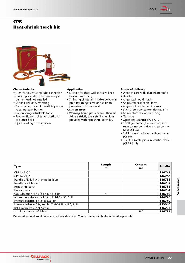
Scope of delivery• Wooden case with aluminium profile• Handle• Angulated hot-air torch• Angulated heat-shrink torch• Angulated needle point burner• 3 x R 3 pressure control device, 8“ li• Anti-rupture device for tubing• Gas tube• Open-end spanner SW 17/19• Small gas bottle (0.4l content), incl. tube connection valve and suspension hook (CPB6)• Refill connector for a small gas bottle (CPB6)• 3 x DIN Kombi pressure control device (CPB5 8“ li)
Characteristics• User-friendly rotating tube connector• Gas supply shuts off automatically if burner head not installed• Minimal risk of overheating• Flame extinguished immediately upon releasing push button• Continuously adjustable flame• Bayonet fitting facilitates substitution of burner head• Quick-starting piezo ignition
Application• Suitable for thick wall adhesive-lined heat-shrink tubing• Shrinking of heat-shrinkable polyolefin products using flame or hot air on pre-extruded compoundCaution note• Warning: liquid gas is heavier than air. Adhere strictly to safety instructions provided with heat-shrink torch kit.
Heat-shrink torch kit
Delivered in an aluminium side-faced wooden case. Components can also be ordered separately.
CPB
TypeLength
m Content
mlArt.-No.
CPB 5 (Set) * 146765CPB 6 (Set) * 146766Handle CPB 5/6 with piezo ignition 146781Needle point burner 146782Heat-shrink torch 146783Hot-air torch 146784Gas tube HD 4.4 R 3/8 LH x R 3/8 LH 4 146769Anti-rupture device for tubing R 3/8” x 3/8” LH 146770Pressure balance R 3/8“ x 3/8“ LH 146780Pressure balance DIN/Kombi 21,8-14 LH x R 3/8 LH 123960Refill connector, DIN Kombi 146786Small gas bottle, refillable 400 146785
Medium Voltage 2013 Medium Voltage 2013
127 www.cellpack.com
Medium Voltage 2013 Medium Voltage 2013
Acc
esso
ries
Tools
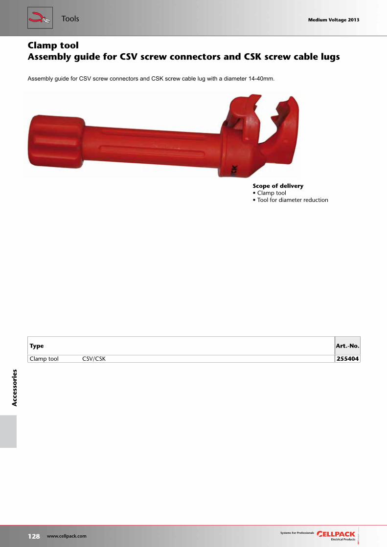
Scope of delivery• Clamp tool• Tool for diameter reduction
Assembly guide for CSV screw connectors and CSK screw cable lug with a diameter 14-40mm.
Type Art.-No.
Clamp tool CSV/CSK 255404
Assembly guide for CSV screw connectors and CSK screw cable lugsClamp tool
128 www.cellpack.com
Medium Voltage 2013 Medium Voltage 2013A
cces
sori
esTools Medium Voltage 2013 Medium Voltage 2013
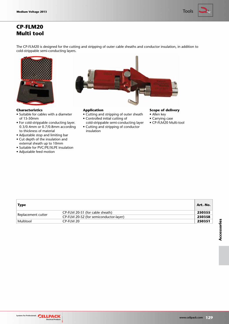
Scope of delivery• Allen key• Carrying case• CP-FLM20 Multi-tool
Characteristics• Suitable for cables with a diameter of 15-50mm• For cold-strippable conducting layer. 0.3/0.4mm or 0.7/0.8mm according to thickness of material• Adjustable stop and limiting bar• Cut depth of the insulation and external sheath up to 10mm• Suitable for PVC/PE/XLPE insulation• Adjustable feed motion
Application• Cutting and stripping of outer sheath• Controlled initial cutting of cold-strippable semi-conducting layer• Cutting and stripping of conductor insulation
Type Art.-No.
Replacement cutterCP-FLM 20-S1 (for cable sheath) 250355CP-FLM 20-S2 (for semiconductor-layer) 250358
Multitool CP-FLM 20 250351
Multi tool
The CP-FLM20 is designed for the cutting and stripping of outer cable sheaths and conductor insulation, in addition to cold-strippable semi-conducting layers.
CP-FLM20
Medium Voltage 2013 Medium Voltage 2013
129 www.cellpack.com
Medium Voltage 2013 Medium Voltage 2013
Acc
esso
ries
Tools
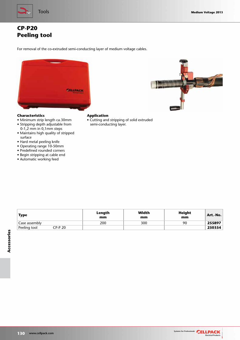
Characteristics• Minimum strip length ca.30mm• Stripping depth adjustable from 0-1,2 mm in 0,1mm steps• Maintains high quality of stripped surface• Hard metal peeling knife• Operating range 10-50mm• Predefined rounded corners• Begin stripping at cable end• Automatic working feed
Application• Cutting and stripping of solid extruded semi-conducting layer.
TypeLength
mm Widthmm
Heightmm
Art.-No.
Case assembly 200 300 90 255897Peeling tool CP-P 20 250354
Peeling tool
For removal of the co-extruded semi-conducting layer of medium voltage cables.
CP-P20
130 www.cellpack.com
Medium Voltage 2013 Medium Voltage 2013A
cces
sori
esTools Medium Voltage 2013 Medium Voltage 2013
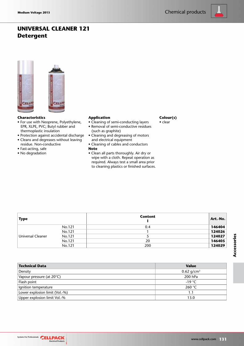
Colour(s)• clear
Characteristics• For use with Neoprene, Polyethylene, EPR, XLPE, PVC; Butyl rubber and thermoplastic insulation• Protection against accidental discharge• Cleans and degreases without leaving residue. Non-conductive• Fast-acting, safe• No degradation
Application• Cleaning of semi-conducting layers• Removal of semi-conductive residues (such as graphite)• Cleaning and degreasing of motors and electrical equipment• Cleaning of cables and conductorsNote• Clean all parts thoroughly. Air dry or wipe with a cloth. Repeat operation as required. Always test a small area prior to cleaning plastics or finished surfaces.
DetergentUNIVERSAL CLEANER 121
TypeContent
lArt.-No.
Universal Cleaner
No.121 0.4 146404No.121 1 124026No.121 5 124027No.121 20 146405No.121 200 124029
Technical Data Value Density 0.62 g/cm3
Vapour pressure (at 20°C) 200 hPa Flash point -19 °C Ignition temperature 260 °C Lower explosion limit (Vol.-%) 1.1 Upper explosion limit Vol.-% 13.0
Medium Voltage 2013 Medium Voltage 2013
131 www.cellpack.com
Medium Voltage 2013 Medium Voltage 2013
Acc
esso
ries
Chemical products

Colour(s)• grey
Zinc spray No. 171 is not approved according to the the food regulations and the construction material norms release 8/76 from the Institute for Construction Technology.
Characteristics• Smooth, fine porous film• With hydrocarbon propellant (flammable)• Varnishable• Can be spot-welded• Dries quickly• Unmarked in compliance with ARB material regulations• No hazard rating, in compliance with VBF• Weatherproof• Electrically conductive• Frost-resistant
Application• Long-lasting corrosion protection• Repairing of damaged zinc layer• Repairing of galvanised surfaces• Substitute for red lead primer• Primer for use in auto repair• Sealing of cavities• Cold galvanising• Oxidation protection• Rust prevention• Underground protection
Anti-corrosion spray
Zinc spray No. 171 binds to steel and iron surfaces using an electrochemical application to build a flexible protection film. This gives the parts an active cathodic corrosion protection.
ZINC SPRAY 171
TypeContent
lArt.-No.
Zinc spray No.171 0.4 124030
Technical Data Value Density 0.95 g/cm3
Degree of zinc purity 99 %
132 www.cellpack.com
Medium Voltage 2013 Medium Voltage 2013A
cces
sori
esChemical products Medium Voltage 2013 Medium Voltage 2013
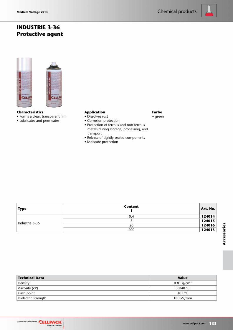
Farbe• green
Characteristics• Forms a clear, transparent film• Lubricates and permeates
Application• Dissolves rust• Corrosion protection• Protection of ferrous and non-ferrous metals during storage, processing, and transport• Release of tightly-sealed components• Moisture protection
Protective agentINDUSTRIE 3-36
TypeContent
lArt.-No.
Industrie 3-36
0.4 1240145 12401520 124016
200 124013
Technical Data Value Density 0.81 g/cm3
Viscosity (cP) 30/40 °C Flash point 105 °C Dielectric strength 180 kV/mm
Medium Voltage 2013 Medium Voltage 2013
133 www.cellpack.com
Medium Voltage 2013 Medium Voltage 2013
Acc
esso
ries
Chemical products
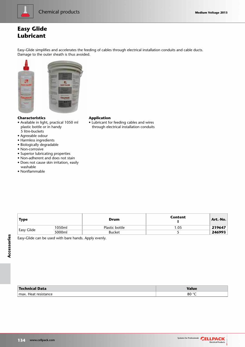
Type DrumContent
lArt.-No.
Easy Glide1050ml Plastic bottle 1.05 2196475000ml Bucket 5 246993
Characteristics• Available in light, practical 1050 ml plastic bottle or in handy 5 litre-buckets• Agreeable odour• Harmless ingredients• Biologically degradable• Non-corrosive• Superior lubricating properties• Non-adherent and does not stain• Does not cause skin irritation, easily washable• Nonflammable
Application• Lubricant for feeding cables and wires through electrical installation conduits
Lubricant
Easy-Glide can be used with bare hands. Apply evenly.
Easy-Glide simplifies and accelerates the feeding of cables through electrical installation conduits and cable ducts. Damage to the outer sheath is thus avoided.
Easy Glide
Technical Data Value max. Heat resistance 80 °C
134 www.cellpack.com
Medium Voltage 2013 Medium Voltage 2013A
cces
sori
esChemical products Medium Voltage 2013 Medium Voltage 2013
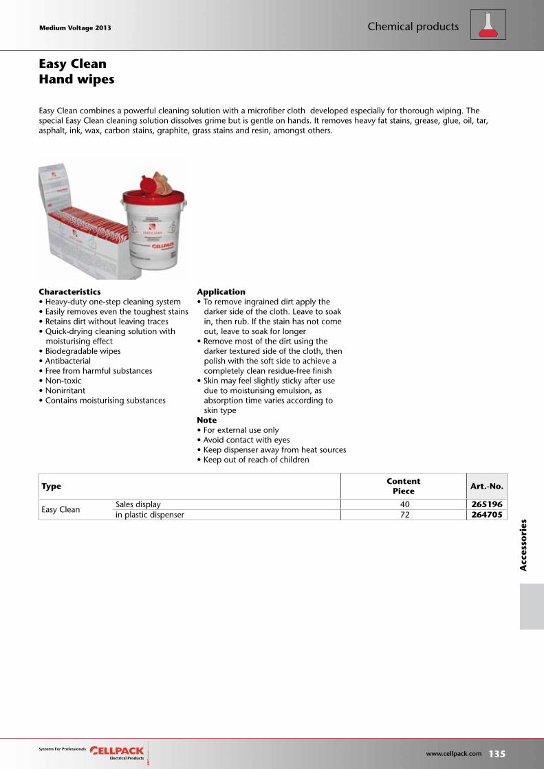
TypeContent
PieceArt.-No.
Easy CleanSales display 40 265196in plastic dispenser 72 264705
Application• To remove ingrained dirt apply the darker side of the cloth. Leave to soak in, then rub. If the stain has not come out, leave to soak for longer• Remove most of the dirt using the darker textured side of the cloth, then polish with the soft side to achieve a completely clean residue-free finish• Skin may feel slightly sticky after use due to moisturising emulsion, as absorption time varies according to skin typeNote• For external use only• Avoid contact with eyes• Keep dispenser away from heat sources• Keep out of reach of children
Characteristics• Heavy-duty one-step cleaning system• Easily removes even the toughest stains• Retains dirt without leaving traces• Quick-drying cleaning solution with moisturising effect• Biodegradable wipes• Antibacterial• Free from harmful substances• Non-toxic• Nonirritant• Contains moisturising substances
Hand wipes
Easy Clean combines a powerful cleaning solution with a microfiber cloth developed especially for thorough wiping. The special Easy Clean cleaning solution dissolves grime but is gentle on hands. It removes heavy fat stains, grease, glue, oil, tar, asphalt, ink, wax, carbon stains, graphite, grass stains and resin, amongst others.
Easy Clean
Medium Voltage 2013 Medium Voltage 2013
135 www.cellpack.com
Medium Voltage 2013 Medium Voltage 2013
Acc
esso
ries
Chemical products

136 www.cellpack.com
Medium Voltage 2013 Medium Voltage 2013 Medium Voltage 2013 Medium Voltage 2013

Ahead throughgroundbreaking
technology
Type index 138
Catalogue number index 140
Index
Page
Medium Voltage 2013 Medium Voltage 2013
137 www.cellpack.com
Medium Voltage 2013 Medium Voltage 2013
L
M
Accessory Kit for Type CTS 630A Cellplux Plug-In Cable Connectors ...................................................54Al compression cable lug ......................................118Al Compression connector ............................114, 115Anti-corrosion spray ..............................................132Armour continuity for three-core joints ...........98, 121Assembly guide for CSV screw connectors and CSK screw cable lugs ...................................................128AUF ......................................................................121AUF(BS) ..................................................................98
Cable entry points for XLPE- and paper-insulated cables ...................................................................100CAE-3F ...................................................................68CAE-3I ....................................................................67CAE-F .....................................................................44CAE-I ......................................................................42CAESK-F .................................................................43CAESK-I ..................................................................41CAM3-S ..................................................................62CAM-S ....................................................................35CG .......................................................................100CGS 250A ..............................................................46CHE-3F(A) ..............................................................64CHE-3F(B) ...............................................................66CHE-3F(BS) .............................................................97CHE-3I(A) ...............................................................63CHE-3I(B) ...............................................................65CHE-3I(BS) .............................................................96CHE-F .....................................................................39CHE-F(BS) ...............................................................95CHE-I ......................................................................37CHE-I ......................................................................94CHEP(3Pb)-3F .........................................................88CHEP(3Pb)-3I .........................................................87CHEP(H)-3F ............................................................83CHEP(H)-3I .............................................................82CHEP-3F .................................................................78CHEP-3I ..................................................................77CHM ......................................................................33CHM(BS) ................................................................92CHM3 ....................................................................61CHM3(BS) ..............................................................93CHMP(3Pb) 3 .........................................................85CHMP(3Pb) 3-1 ......................................................84CHMP(H) 3 .............................................................80CHMP(H) 3-1 .........................................................79CHMPP(3Pb)3 ........................................................86CHMPP(H)3 ............................................................81CHMPPR3 ...............................................................76CHMPR 3 ................................................................75CHMPR 3-1 ............................................................74CHMPRSV 3-1 ........................................................73CHMSV ..................................................................32CHMSV3 ................................................................59CHMSV3-1 .............................................................60CIK .........................................................................53CKM .......................................................................36CKS 630A ...............................................................56
Clamp tool ...........................................................128Conductive tape ...................................................124Connector element up to 24kV ..............................47Copper braid tape ................................................125Coupling connector 630A up to 24kV .....................56CPB ......................................................................127CPES .......................................................................57CP-FLM20 ............................................................129CP-P20 .................................................................130CPS ........................................................................58CSK ......................................................................119CTKS 630A .............................................................50CTKSA ....................................................................51CTKSA ....................................................................52CTS 630A ...............................................................49Cu compression cable lug .............................116, 117Cu compression connector ...........................112, 113CVS 250A ...............................................................47CWS 250A ..............................................................45CWS 400A ..............................................................48
Detergent .............................................................131DK-AL-LD .............................................................118DK-CU-V ...............................................................116DK-CU-V-LD .........................................................117DV-AL ...................................................................114DV-CU-V ...............................................................112DVZ-AL-LD ...........................................................115DVZ-CU-V-LD .......................................................113
Earthing accessories ........................................99, 120Easy Clean ............................................................135Easy Glide .............................................................134EGA ......................................................................120EGA(BS) ..................................................................99Elbow plug-in cable connector ...............................48Elbow plug-in cable connector with capacitive measurement .........................................................45
Hand wipes ..........................................................135Heat-shrink torch kit .............................................127Heat-shrink tubing up to 36kV ..............................108High-voltage insulation tape .................................123
Indoor termination .....................................77, 82, 87INDUSTRIE 3-36 ...................................................133
Lubricant ..............................................................134
M...MS6 .................................................................27M...MSPB6 .............................................................72Mounting Ring .......................................................55Multi tool .............................................................129
A
C
D
E
H
I
138 www.cellpack.com
Medium Voltage 2013 Medium Voltage 2013In
dex
Medium Voltage 2013 Medium Voltage 2013
No. 60, No. 62 .....................................................123No. 61 ..................................................................124No. 63 ..................................................................125No. 72 ..................................................................126
Outdoor termination ..................................78, 83, 88
Peeling tool ..........................................................130Plug- In Surge Arrester ......................................51, 52Pressure spring .....................................................122Protective agent ...................................................133
Repair tape ...........................................................126RF .........................................................................122
Screw cable lugs for Cu and AI .............................119SEEV .......................................................................28SEEV-F ....................................................................29Single-core indoor termination ...................37, 42, 94Single-core indoor termination with screw cable lugs .....................................................41Single-core outdoor termination .................39, 44, 95Single-core outdoor termination with screw cable lugs .....................................................43Single-core straight-through joint ...............33, 35, 92Single-core straight-through joint with screw connector ...............................................32, 36SMH3MS6 ..............................................................26SRAT .....................................................................110SRBB .....................................................................108Straight plug-in cable connector with capacitive measurement .........................................46Straight-through joint .................................76, 81, 86Straight-through joint with screw connector ...........60
Test and Earthing Kit ...............................................57Test-Kit ...................................................................58Thick wall heat-shrink tubing ................................110Three-core indoor termination ........28, 63, 65, 67, 96Three-core outdoor termination .....29, 64, 66, 68, 97Three-core straight-through joint ..........26, 27, 61, 93Three-core straight-through joint with heat-shrink outer protection ...................................62Three-core straight-through joint with screw connector .....................................................59Three-core transisition joint ....................................72T-plug and socket connexion ..................................50Transition joint 73, 74, 75, 79, 80, 84, 85T-socket connexion .................................................49
UNIVERSAL CLEANER 121 .....................................131
Voltage-proof Insulating Cap ..................................53
ZINC SPRAY 171 ...................................................132ZS-CTS ...................................................................54
N
P
R
S
T
U
V
Z
O
Medium Voltage 2013 Medium Voltage 2013
139 www.cellpack.com
Medium Voltage 2013 Medium Voltage 2013
Ind
ex
123960...........127
124013...........133124014...........133124015...........133124016...........133124026...........131124027...........131124029...........131124030...........132124318.............27124319.............27124320.............27124334.............72124335.............72
125533...........123125584...........123125587...........126125589...........123125590...........124125604...........124125888...........114125889...........114125890...........114125891...........114125892...........114125895...........112125897...........113125898...........113125899...........113125900...........113125901...........113125902...........113125903...........113125904...........113125905...........113125906...........113125907...........113125947...........114125948...........114125950...........112125951...........112125952...........112125953...........112125954...........112125955...........112125956...........112125957...........112125958...........112125959...........112125960...........112125961...........112125962...........112125963...........112125964...........112125965...........112125966...........113125967...........112
185050.............99185051.............99185052.............99185053.............99185054.............99
193339.............34193370.............34193372.............40193374.............40193414.............38193416.............38
194017.............38194018.............38194019.............38194030.............38194031.............38194032.............38194033.............38194034.............38194035.............38194036.............38194037.............38194038.............38194039.............38194040.............38194041.............38194042.............38194043.............38194044.............38194045.............38194046.............38194047.............38194048.............38194049.............40194050.............40194051.............40194052.............40194053.............40194054.............40194055.............40194056.............40194057.............40194058.............40194059.............40194061.............40194062.............40194063.............40194064.............40194065.............40194066.............40194067.............40194068.............40194069.............40194070.............40194071.............40194072.............34194073.............34
126040...........116126044...........116126046...........116126048...........116126051...........116126052...........116126054...........116126055...........116126059...........116126060...........116126064...........116126065...........116126070...........116126072...........116126074...........116126077...........116126080...........116126082...........116126085...........116126087...........116126089...........116126091...........116126093...........116126094...........116126096...........116126098...........116126099...........116126102...........116126105...........117126106...........117126134...........117126135...........117126136...........117126137...........117126138...........117126296...........122126297...........122126298...........122126299...........122126300...........122126303...........125126313...........125126315...........125126316...........125
132464...........110
143502...........120143503...........120143505...........120143506...........120143508...........120143509...........120
144876...........110144878...........110144880...........110144882...........110
144884...........110144886...........110144888...........110144892...........110144898...........110144921...........110144935...........110144943...........110
145458.............28145461.............28145464.............28145630.............26145633.............26145635.............26145908...........123
146158.............63146159.............63146160.............63146216.............63146217.............63146218.............63146220.............64146222.............64146224.............64146226.............64146228.............63146234.............64146235.............64146242.............64146296.............64146297.............63146298.............64146300.............63146301.............63146302.............63146303.............64146304.............64146306.............64146404...........131146405...........131146765...........127146766...........127146769...........127146770...........127146780...........127146781...........127146782...........127146783...........127146784...........127146785...........127146786...........127
148152.............29148153.............29148432...........117
159667...........117159670...........117
166374...........113
171756.............64171757.............64171761.............63171762.............63171763.............63171791.............28
173132.............65173134.............65
176369...........117
180522.............65
182390.............29182731.............65182732.............65182733.............65182734.............65182735.............66182736.............66182737.............66182738.............66
183661...........100183662...........100
184472.............66184796.............65184797.............65184798.............65184799.............65184800.............65184801.............65184802.............65184803.............65184805.............66184806.............66184807.............66184808.............66184809.............66184811.............66184812.............66184813.............66184815.............66184816.............66
123...
124...
125...
126...
132...
143...
144...
145...
146...
148...
159...
166...
171...
173...
176...
180...
182...
183...
184...
185...
193...
194...
140 www.cellpack.com
Medium Voltage 2013 Medium Voltage 2013In
dex
Medium Voltage 2013 Medium Voltage 2013
194074.............34194075.............34194076.............34194077.............34194078.............34194079.............34194080.............34194082.............34194083.............34194085.............34194086.............34194087.............34194088.............34194089.............34194090.............34194091.............34194092.............34194093.............34194094.............34194293.............61194294.............61194295.............61194296.............61194297.............61194298.............61194299.............61194300.............61194301.............61194302.............61194303.............61194304.............61194305.............61194306.............61194307.............61194908...........118194930...........118194932...........118194933...........118194934...........118194935...........118194936...........118194937...........118194938...........118194939...........118194940...........118194941...........118194942...........118194943...........118194944...........118194945...........118194947...........118194949...........118194950...........118
195344...........114195345...........114195346...........114195347...........114195348...........114195349...........114195350...........117
201944...........108201944...........108201945...........108201945...........108201946...........108201946...........108
219647...........134
220775.............49
224826.............49224853.............56
225844.............47
237858...........108237859...........108237860...........108237861...........108237862...........108
246176.............48246993...........134
247102.............48
248716.............93248717.............93248718.............93248719.............93248770.............93
249191.............97249192.............97249193.............97249194.............97249195.............97249328.............96249331.............96249332.............96249333.............96249334.............96249464.............97249466.............97249468.............96249469.............96249471.............93249474.............93249476.............93
250351...........129
195351...........117195365.............63195366.............64195367...........121195368...........121195369.............98195380.............98195381.............98195382.............98
197515.............77197516.............77197517.............77197531.............82197532.............82197533.............82197534.............82197535.............82197536.............82197537.............78197538.............78197539.............78197543.............83197544.............83197545.............83197546.............83197547.............83197548.............83197555.............87197556.............87197557.............87197558.............87197559.............87197560.............87197567.............88197568.............88197569.............88197570.............88197571.............88197572.............88197603.............74197604.............74197606.............74197607.............79197608.............79197609.............79197610.............79197614.............79197616.............79197617.............79197618.............75197619.............75197620.............75197621.............80197622.............80197623.............80197624.............80197625.............80197626.............80197627.............80197628.............84
199158.............42199159.............42199160.............42199162.............42199163.............42199164.............42199165.............42199166.............42199167.............42199168.............42199170.............67199171.............67199173.............67199174.............67199175.............67199177.............67199178.............67199179.............67199180.............67199181.............67199182.............67199184.............44199185.............44199186.............44199187.............44199189.............44199190.............44199191.............44199192.............44199194.............44199195.............44199196.............44199197.............44199198.............44199199.............44199201.............68199202.............68199204.............68199205.............68199206.............68199208.............68199209.............68199210.............68199211.............68199212.............68
201374.............62201375.............62201377.............62201379.............62201381.............62201382.............62201385.............35201386.............35201388.............35201393.............35201395.............35201942...........108201942...........108201943...........108201943...........108
197629.............84197630.............84197631.............84197632.............84197633.............84197634.............84197635.............84197636.............84197637.............84197638.............85197639.............85197640.............85197641.............85197642.............85197643.............85197644.............85197645.............85197646.............85197647.............85197658.............76197659.............76197660.............76197661.............81197662.............81197663.............81197664.............81197665.............81197666.............81197667.............81197668.............86197669.............86197670.............86197671.............86197672.............86197673.............86197674.............86197675.............86197676.............86197677.............86
198217...........115198219...........115198220...........115198221...........115198222...........115198223...........115198225...........115198226...........115198228...........115198230...........115198232...........115198782.............84198783.............85198784.............86
199151.............42199152.............42199154.............42199155.............42199157.............42
195...
197...
198...
199...
201...
219...
220...
224...
225...
237...
246...
247...
248...
249...
250...
Medium Voltage 2013 Medium Voltage 2013
141 www.cellpack.com
Medium Voltage 2013 Medium Voltage 2013
Ind
ex
250354...........130250355...........129250358...........129250711.............49250715.............49250720.............48250726.............48
251713.............36
252101.............36
253843.............92253844.............92253845.............92253847.............94253848.............95253849.............94253850.............95253911.............93253917.............93253929.............93
255404...........128255414...........119255415...........119255416...........119255418...........119255897...........130
256010.............49256328.............49256838.............50256839.............50
257581.............50257582.............50257622.............54
258130.............32258131.............32258132.............32258133.............32258135.............32258136.............32258137.............32258138.............32258140.............32258141.............32258142.............32258143.............32258144.............32258145.............32258146.............32
259101.............57
262054.............51262055.............51262056.............51262816.............51
264366.............55264705...........135264769.............73264988.............73
265023.............53265024.............53265196...........135265205.............73265501.............73
289894.............43289897.............43289898.............43289899.............43289900.............43289901.............43289902.............43289903.............43289904.............43289905.............43289906.............43289907.............43289908.............43289909.............43289910.............43289911.............43289912.............43289945.............41289947.............41289948.............41289949.............41289950.............41289951.............41289952.............41289953.............41289954.............41289955.............41289956.............41289957.............41289958.............41289959.............41289960.............41289961.............41289962.............41289963.............41289968...........119
293792.............45
293797.............46
295167.............45295283.............46
297104.............59297260.............59297310.............59297311.............59297348.............59297349.............59297350.............59297351.............59297352.............59297353.............59297358.............59297360.............59297361.............59297362.............59297433.............59297441.............60297442.............60297443.............60297444.............60297449.............60297460.............60297461.............60297462.............60297463.............60297464.............60297465.............60297466.............60297467.............60297468.............60297469.............60
301492.............52
302227.............58302732.............49
304089.............98304092.............99
251...
252...
253...
255...
256...
257...
258...
262...
259...
264...
265...
289...
132...
295...
297...
301...
302...
304...
142 www.cellpack.com
Medium Voltage 2013 Medium Voltage 2013In
dex
Medium Voltage 2013 Medium Voltage 2013
Medium Voltage 2013 Medium Voltage 2013
143 www.cellpack.com
Medium Voltage 2013 Medium Voltage 2013
Ind
ex

www.cellpack.com
Cellpack AG Electrical Products Anglikerstrasse 99 5612 Villmergen SchweizTel. +41 56 618 12 34Fax +41 56 618 12 [email protected]
Cellpack GmbH Carl-Zeiss-Straße 2079761 Waldshut-TiengenDeutschlandTel. +49 7741 6007-0Fax +49 7741 [email protected]
Cellpack Benelux B.V.Keersluisweg 131332 EE Almere BuitenNederlandTel. +31 36 549 03 36Fax +31 36 532 74 [email protected]
Behr Bircher Cellpack Ibérica, S.A.C/.Mas Pujol, nr. 47 – Nave 4Pol. Ind. Sector V08520 – Les Franqueses del VàllèsBarcelona – EspañaTel. +34 93 846 63 76Fax +34 93 849 12 [email protected]
Behr Bircher Cellpack BBC France s.à.r.l.277, Boulevard des Technologies 54710 LudresFranceTel. +33 3 83 25 60 07Fax +33 3 83 25 88 [email protected]
Cellpack Polska Sp. z o.o.ul. Matuszewska 14,03-876 WarszawaPolska Tel. +48 022 853 53 54 Fax +48 022 853 53 [email protected]
Cellpack Far East (PTE) LTD.128 Joo Seng Road # 06 – 01Singapore 368356Tel. +65 6747 7024 Fax +65 6841 [email protected]
Behr Bircher Cellpack BBC Malaysia Sdn. Bhd.No. 8, Jalan TU 50Taman Tasik UtamaAyer Keroh75450 MelakaMalaysiaTel. + 60 6 251 95 30Fax + 60 6 251 95 [email protected]