mechanical design of the magdalena ridge observatory interferometer
TRANSCRIPT

���������� ������������������������������������������
������������������������������������������������������������������������������������������������� �������������������������������������������������������������� ��������������������������������������������
Mechanical Design of the Magdalena Ridge Observatory Interferometer
Fernando G. Santoroa - Andres M. Oli varesa - Chris D. Salcidoa - Stephen R.
Jimeneza - Xi aowei Sunb - Christopher A. Haniff b - David F. Buscherb - Michell e J. Creech-Eakmana - Colby A. Jurgensona - Ali sa V. Shtromberga - Eric J. Bakkera -
Rob J. Seli naa - Martin Fisherb - John S Youngb - Donald M.A. Wil sonb aNMT/MRO Project Off ice, 801 Leroy Pl - 87801 - Socorro - NM - USA
bUniversity of Cambridge, Cavendish Laboratory, Cambridge - UK
ABSTRACT
We report on the mechanical design currently performed at the Magdalena Ridge Observatory Interferometer (MROI) and how the construction, assembly, integration and veri f ication are planned towards commissioning. Novel features were added to the mechanical design, and high level of automation and reli abilit y are being devised, which all ows the number of ref lections to be kept down to a minimum possible. This includes unit telescope and associated enclosure and transporter, fast tip-tilt system, beam relay system, delay li ne system, beam compressor, automated ali gnment system, beam turning mirror, switchyard, fr inge tracker and vacuum system.
Keywords: Optical i nterferometer, delay li ne, beam combining, fr inge tracker, AIV plan.
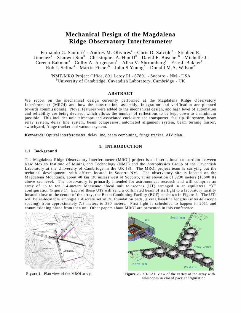
1. INTRODUCTION 1.1 Background The Magdalena Ridge Observatory Interferometer (MROI) project is an international consortium between New Mexico Institute of Mining and Technology (NMT) and the Astrophysics Group of the Cavendish Laboratory at the University of Cambridge in the UK [8] . The MROI project team is carrying out the technical development, with off ices located in Socorro-NM. The observatory site is located on the Magdalena Mountains, about 48 km (30 mil es) west of Socorro, at an elevation of 3230 meters (10600 f t) above sea level . The observatory is primaril y intended for astronomical research and will comprise an array of up to ten 1.4-PHWHUV� 0HUVHQQH� DIRFDO� XQLW� WHOHVFRSHV� �87�� DUUDQJHG� LQ� DQ� HTXLODWHUDO� ³<´�configuration (Figure 1). Each of these UTs will send a colli mated beam of starli ght to a laboratory facilit y located close to the center of the array, the Beam Combining Facilit y (BCF) as shown in Figure 2. The UTs will be re-locatable amongst a discrete set of 28 foundation pads, giving baseli ne lengths (inter-telescope spacing) from approximately 7.8 meters to 380 meters. Fi rst li ght is scheduled to happen in 2011 and commissioning phase from then on. Other papers about MROI are presented in this conference.
Figure 2 - 3D-CAD view of the vertex of the array with telescopes in closed pack conf iguration.
BCF
Array vertex
West arm North arm
South arm
Figure 1 - Plan view of the MROI array.
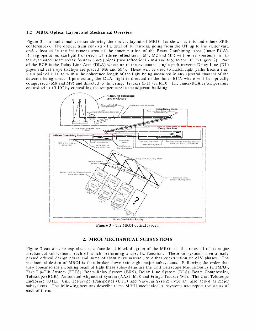
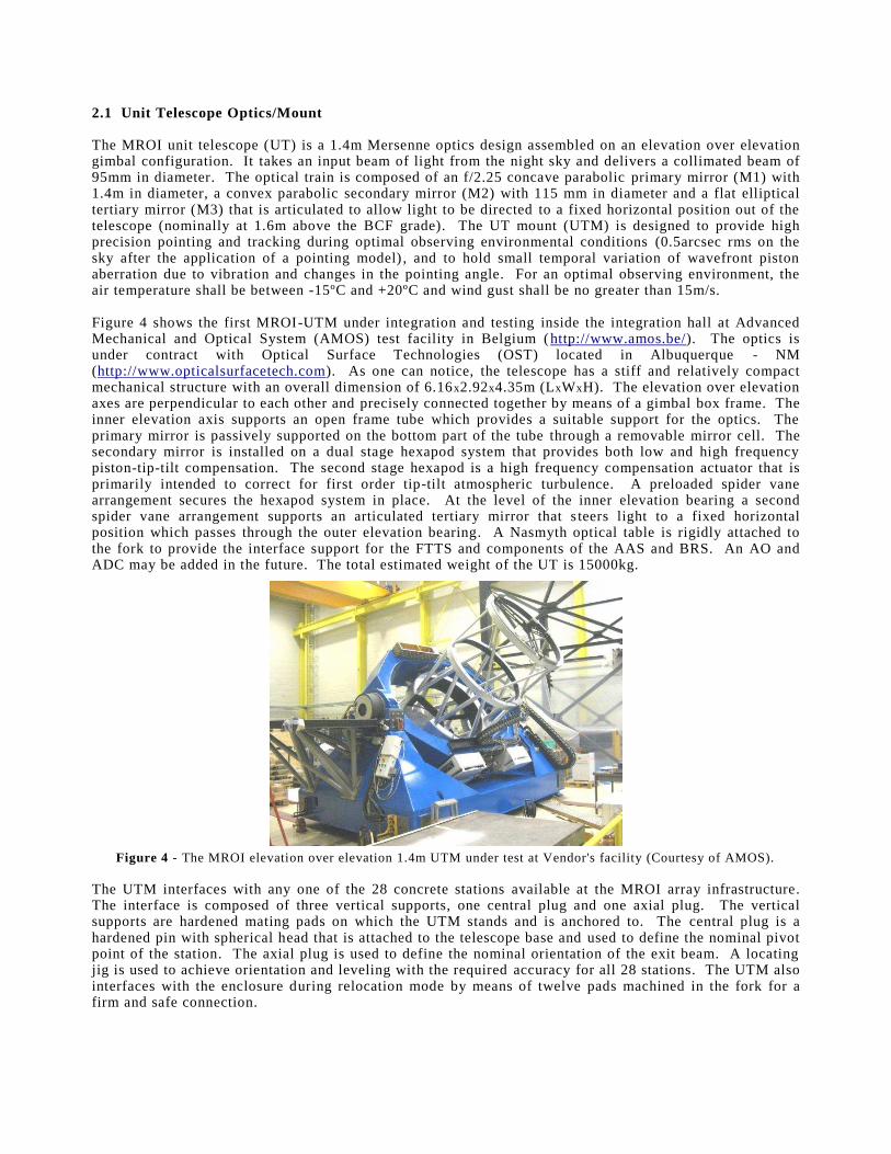
2.1 Unit Telescope Optics/Mount The MROI unit telescope (UT) is a 1.4m Mersenne optics design assembled on an elevation over elevation gimbal conf iguration. I t takes an input beam of li ght from the night sky and deli vers a colli mated beam of 95mm in diameter. The optical train is composed of an f /2.25 concave paraboli c primary mirror (M1) with 1.4m in diameter, a convex paraboli c secondary mirror (M2) with 115 mm in diameter and a f lat elli ptical tertiary mirror (M3) that is articulated to all ow li ght to be directed to a f ixed horizontal positi on out of the telescope (nominall y at 1.6m above the BCF grade). The UT mount (UTM) is designed to provide high precision pointing and tracking during optimal observing environmental conditi ons (0.5arcsec rms on the sky after the appli cation of a pointing model) , and to hold small temporal variation of wavefront piston aberration due to vibration and changes in the pointing angle. For an optimal observing environment, the air temperature shall be between -15ºC and +20ºC and wind gust shall be no greater than 15m/s. Figure 4 shows the f i rst MROI-UTM under integration and testing inside the integration hall at Advanced Mechanical and Optical System (AMOS) test facilit y in Belgium (http://www.amos.be/). The optics is under contract with Optical Surface Technologies (OST) located in Albuquerque - NM (http://www.opticalsurfacetech.com). As one can notice, the telescope has a sti ff and relatively compact mechanical structure with an overall dimension of 6.16x2.92x4.35m (LxWxH). The elevation over elevation axes are perpendicular to each other and precisely connected together by means of a gimbal box frame. The inner elevation axis supports an open frame tube which provides a suitable support for the optics. The primary mirror is passively supported on the bottom part of the tube through a removable mirror cell . The secondary mirror is install ed on a dual stage hexapod system that provides both low and high frequency piston-tip-tilt compensation. The second stage hexapod is a high frequency compensation actuator that is primaril y intended to correct for f i rst order tip-tilt atmospheric turbulence. A preloaded spider vane arrangement secures the hexapod system in place. At the level of the inner elevation bearing a second spider vane arrangement supports an articulated tertiary mi rror that steers li ght to a f ixed horizontal positi on which passes through the outer elevation bearing. A Nasmyth optical table is rigidly attached to the fork to provide the interface support for the FTTS and components of the AA S and BRS. An AO and ADC may be added in the future. The total estimated weight of the UT is 15000kg.
Figure 4 - The MROI elevation over elevation 1.4m UTM under test at Vendor's facilit y (Courtesy of AMOS).
The UTM interfaces with any one of the 28 concrete stations avail able at the MROI array infrastructure. The interface is composed of three vertical supports, one central plug and one axial plug. The vertical supports are hardened mating pads on which the UTM stands and is anchored to. The central plug is a hardened pin with spherical head that is attached to the telescope base and used to def ine the nominal pivot point of the station. The axial plug is used to def ine the nominal orientation of the exit beam. A locating ji g is used to achieve orientation and leveli ng with the required accuracy for all 28 stations. The UTM also interfaces with the enclosure during relocation mode by means of twelve pads machined in the fork for a f i rm and safe connection.
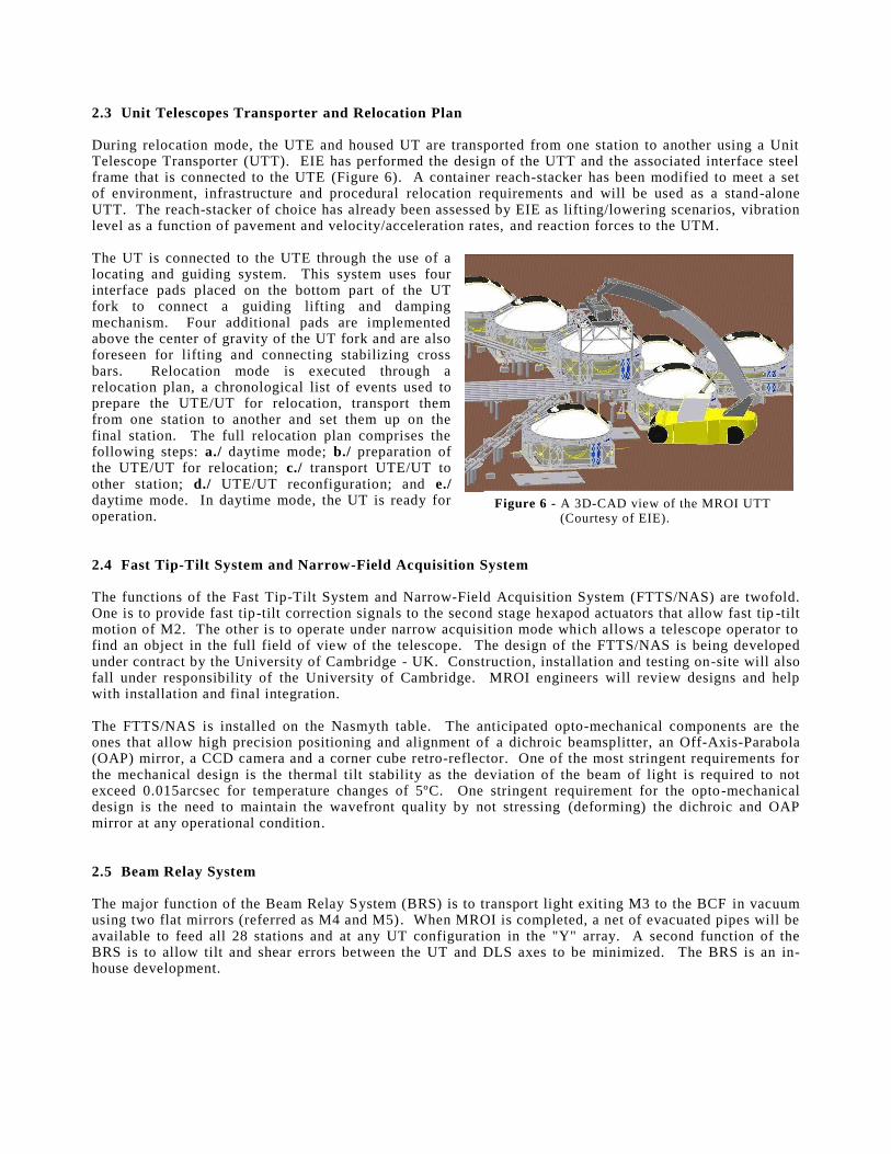
2.3 Unit Telescopes Transporter and Relocation Plan During relocation mode, the UTE and housed UT are transported from one station to another using a Unit Telescope Transporter (UTT). EIE has performed the design of the UTT and the associated interface steel frame that is connected to the UTE (Figure 6). A container reach-stacker has been modi f ied to meet a set of environment, infrastructure and procedural relocation requirements and will be used as a stand-alone UTT. The reach-stacker of choice has already been assessed by EIE as li f ting/lowering scenarios, vibration level as a function of pavement and velocity/acceleration rates, and reaction forces to the UTM. The UT is connected to the UTE through the use of a locating and guiding system. This system uses four interface pads placed on the bottom part of the UT fork to connect a guiding li f ting and damping mechanism. Four additi onal pads are implemented above the center of gravity of the UT fork and are also foreseen for li f ting and connecting stabili zing cross bars. Relocation mode is executed through a relocation plan, a chronological li st of events used to prepare the UTE/UT for relocation, transport them from one station to another and set them up on the f inal station. The full relocation plan comprises the foll owing steps: a./ daytime mode; b./ preparation of the UTE/UT for relocation; c./ transport UTE/UT to other station; d./ UTE/UT reconfiguration; and e./ daytime mode. In daytime mode, the UT is ready for operation. 2.4 Fast Tip-Tilt System and Narrow-Field Acquisition System The functions of the Fast Tip-Tilt System and Narrow-Field Acquisiti on System (FTTS/NAS) are twofold. One is to provide fast tip-tilt correction signals to the second stage hexapod actuators that all ow fast tip-tilt motion of M2. The other is to operate under narrow acquisiti on mode which all ows a telescope operator to f ind an object in the full f ield of view of the telescope. The design of the FTTS/NAS is being developed under contract by the University of Cambridge - UK. Construction, install ation and testing on-site will also fall under responsibilit y of the University of Cambridge. MROI engineers will review designs and help with install ation and f inal integration. The FTTS/NAS is install ed on the Nasmyth table. The anticipated opto-mechanical components are the ones that all ow high precision positi oning and ali gnment of a dichroic beamsplitt er, an Off- Axis-Parabola (OAP) mirror, a CCD camera and a corner cube retro-ref lector. One of the most stringent requirements for the mechanical design is the thermal tilt stabilit y as the deviation of the beam of li ght is required to not exceed 0.015arcsec for temperature changes of 5ºC. One stringent requirement for the opto-mechanical design is the need to maintain the wavefront qualit y by not stressing (deforming) the dichroic and OAP mirror at any operational conditi on. 2.5 Beam Relay System The major function of the Beam Relay System (BRS) is to transport li ght exiti ng M3 to the BCF in vacuum using two f lat mirrors (referred as M4 and M5). When MROI is completed, a net of evacuated pipes will be avail able to feed all 28 stations and at any UT conf iguration in the "Y" array. A second function of the BRS is to all ow tilt and shear errors between the UT and DLS axes to be minimized. The BRS is an in-house development.
Figure 6 - A 3D-CAD view of the MROI UTT (Courtesy of EIE).
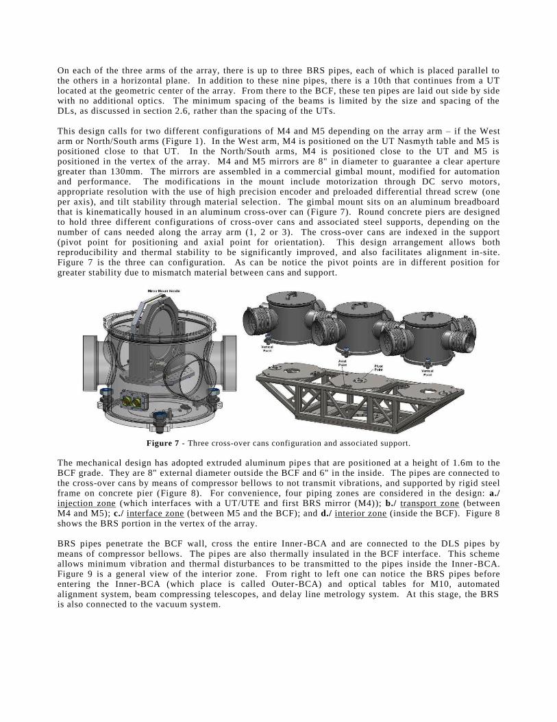
On each of the three arms of the array, there is up to three BRS pipes, each of which is placed parall el to the others in a horizontal plane. In additi on to these nine pipes, there is a 10th that continues from a UT located at the geometric center of the array. From there to the BCF, these ten pipes are laid out side by side with no additi onal optics. The minimum spacing of the beams is li mited by the size and spacing of the DLs, as discussed in section 2.6, rather than the spacing of the UTs. This design call s for two di ff erent conf igurations of M4 and M5 depending on the array arm ± i f the West arm or North/South arms (Figure 1). In the West arm, M4 is positi oned on the UT Nasmyth table and M5 is positi oned close to that UT. In the North/South arms, M4 is positi oned close to the UT and M5 is positi oned in the vertex of the array. M4 and M5 mirrors are 8" in diameter to guarantee a clear aperture greater than 130mm. The mirrors are assembled in a commercial gimbal mount, modi f ied for automation and performance. The modi f ications in the mount include motorization through DC servo motors, appropriate resolution with the use of high precision encoder and preloaded di ff erential thread screw (one per axis), and tilt stabilit y through material selection. The gimbal mount sits on an aluminum breadboard that is kinematicall y housed in an aluminum cross-over can (Figure 7). Round concrete piers are designed to hold three di ff erent conf igurations of cross-over cans and associated steel supports, depending on the number of cans needed along the array arm (1, 2 or 3). The cross-over cans are indexed in the support (pivot point for positi oning and axial point for orientation). This design arrangement all ows both reproducibilit y and thermal stabilit y to be signi f icantly improved, and also facilit ates ali gnment in-site. Figure 7 is the three can conf iguration. As can be notice the pivot points are in di ff erent positi on for greater stabilit y due to mismatch material between cans and support.
Figure 7 - Three cross-over cans conf iguration and associated support.
The mechanical design has adopted extruded aluminum pipes that are positi oned at a height of 1.6m to the BCF grade. They are 8" external diameter outside the BCF and 6" in the inside. The pipes are connected to the cross-over cans by means of compressor bell ows to not transmit vibrations, and supported by rigid steel frame on concrete pier (Figure 8). For convenience, four piping zones are considered in the design: a./ injection zone (which interfaces with a UT/UTE and f i rst BRS mirror (M4)); b./ transport zone (between M4 and M5); c./ interface zone (between M5 and the BCF); and d./ interior zone (inside the BCF). Figure 8 shows the BRS portion in the vertex of the array. BRS pipes penetrate the BCF wall , cross the enti re Inner -BCA and are connected to the DLS pipes by means of compressor bell ows. The pi pes are also thermall y insulated in the BCF interface. This scheme all ows minimum vibration and thermal disturbances to be transmitted to the pipes inside the Inner -BCA. Figure 9 is a general view of the interior zone. From right to lef t one can notice the BRS pipes before entering the Inner-BCA (which place is call ed Outer-BCA) and optical tables for M10, automated ali gnment system, beam compressing telescopes, and delay li ne metrology system. At this stage, the BRS is also connected to the vacuum system.
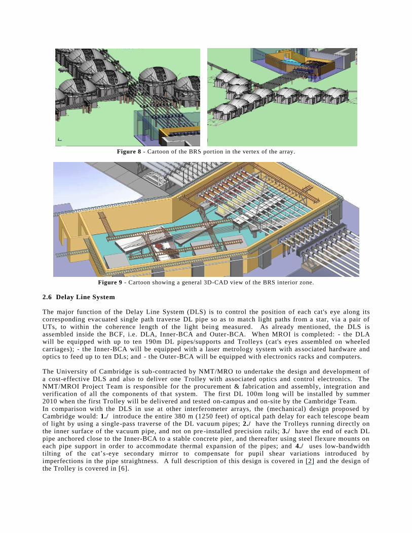
Figure 8 - Cartoon of the BRS portion in the vertex of the array.
Figure 9 - Cartoon showing a general 3D-CAD view of the BRS interior zone.
2.6 Delay Line System The major function of the Delay L ine System (DLS) is to control the positi on of each cat's eye along its corresponding evacuated single path traverse DL pipe so as to match li ght paths from a star, via a pair of UTs, to within the coherence length of the li ght being measured. As already mentioned, the DLS is assembled inside the BCF, i .e. DLA, Inner-BCA and Outer-BCA. When MROI is completed: - the DLA will be equipped with up to ten 190m DL pipes/supports and Troll eys (cat's eyes assembled on wheeled carriages); - the Inner-BCA will be equipped with a laser metrology system with associated hardware and optics to feed up to ten DLs; and - the Outer-BCA will be equipped with electronics racks and computers. The University of Cambridge is sub-contracted by NMT/MRO to undertake the design and development of a cost-eff ective DLS and also to deli ver one Troll ey with associated optics and control electronics. The NMT/MROI Project Team is responsible for the procurement & fabrication and assembly, integration and veri f ication of all the components of that system. The f i rst DL 100m long will be install ed by summer 2010 when the f i rst Troll ey will be deli vered and tested on-campus and on-site by the Cambridge Team. In comparison with the DLS in use at other interferometer arrays, the (mechanical) design proposed by Cambridge would: 1./ introduce the enti re 380 m (1250 feet) of optical path delay for each telescope beam of li ght by using a single-pass traverse of the DL vacuum pipes; 2./ have the Troll eys running directly on the inner surface of the vacuum pipe, and not on pre-install ed precision rail s; 3./ have the end of each DL pipe anchored close to the Inner-BCA to a stable concrete pier, and thereaf ter using steel f lexure mounts on each pipe support in order to accommodate thermal expansion of the pipes; and 4./ uses low-bandwidth tLOWLQJ� RI� WKH� FDW¶V-eye secondary mirror to compensate for pupil shear variations introduced by imperfections in the pipe straightness. A full description of this design is covered in [2] and the design of the Troll ey is covered in [6] .
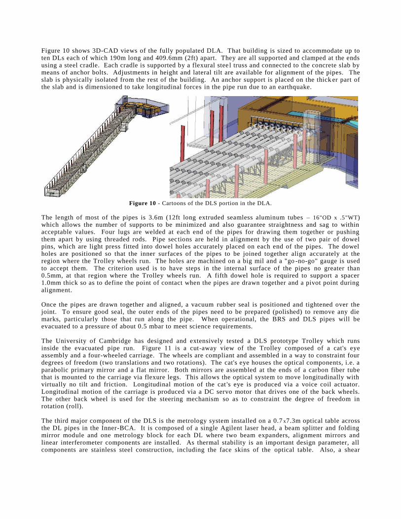
Figure 10 shows 3D-CAD views of the full y populated DLA. That buil ding is sized to accommodate up to ten DLs each of which 190m long and 409.6mm (2ft) apart. They are all supported and clamped at the ends using a steel cradle. Each cradle is supported by a f lexural steel truss and connected to the concrete slab by means of anchor bolts. Adjustments in height and lateral tilt are avail able for ali gnment of the pipes. The slab is physicall y isolated from the rest of the buil ding. An anchor support is placed on the thick er part of the slab and is dimensioned to take longitudinal forces in the pipe run due to an earthquake.
Figure 10 - Cartoons of the DLS portion in the DLA.
The length of most of the pipes is 3.6m (12ft long extruded seamless aluminum tubes ± 16"OD x .5"WT) which all ows the number of supports to be minimized and also guarantee straightness and sag to within acceptable values. Four lugs are welded at each end of the pipes for drawing them together or pushing them apart by using threaded rods. Pipe sections are held in ali gnment by the use of two pair of dowel pins, which are li ght press f itted into dowel holes accurately placed on each end of the pipes. The dowel holes are positi oned so that the inner surfaces of the pipes to be joined together ali gn accurately at the region where the Troll ey wheels run. The holes are machined on a big mil and a "go-no-go" gauge is used to accept them. The criterion used is to have steps in the internal surface of the pipes no greater than 0.5mm, at that region where the Troll ey wheels run. A f i f th dowel hole is required to support a spacer 1.0mm thick so as to def ine the point of contact when the pipes are drawn together and a pivot point during ali gnment. Once the pipes are drawn together and ali gned, a vacuum rubber seal is positi oned and tightened over the joint. To ensure good seal , the outer ends of the pipes need to be prepared (poli shed) to remove any die marks, particularly those that run along the pipe. When operational , the BRS and DLS pipes will be evacuated to a pressure of about 0.5 mbar to meet science requirements. The University of Cambridge has designed and extensively tested a DLS prototype Troll ey which runs inside the evacuated pipe run. Figure 11 is a cut-away view of the Troll ey composed of a cat's eye assembly and a four-wheeled carriage. The wheels are compli ant and assembled in a way to constraint four degrees of freedom (two translations and two rotations). The cat's eye houses the optical components, i .e. a paraboli c primary mirror and a f lat mi rror. Both mirrors are assembled at the ends of a carbon f iber tube that is mounted to the carriage via f lexure legs. This all ows the optical system to move longitudinall y with vi rtuall y no tilt and fr iction. Longitudinal motion of the cat 's eye is produced via a voice coil actuator. Longitudinal motion of the carriage is produced via a DC servo motor that drives one of the back wheels. The other back wheel is used for the steering mechanism so as to constraint the degree of freedom in rotation (roll ). The thi rd major component of the DLS is the metrology system install ed on a 0.7x7.3m optical table across the DL pipes in the Inner-BCA. I t is composed of a single Agil ent laser head, a beam splitt er and folding mirror module and one metrology block for each DL where two beam expanders, ali gnment mirrors and li near interferometer components are install ed. As thermal stabilit y is an important design parameter, all components are stainless steel construction, including the face skins of the optical table. Also, a shear
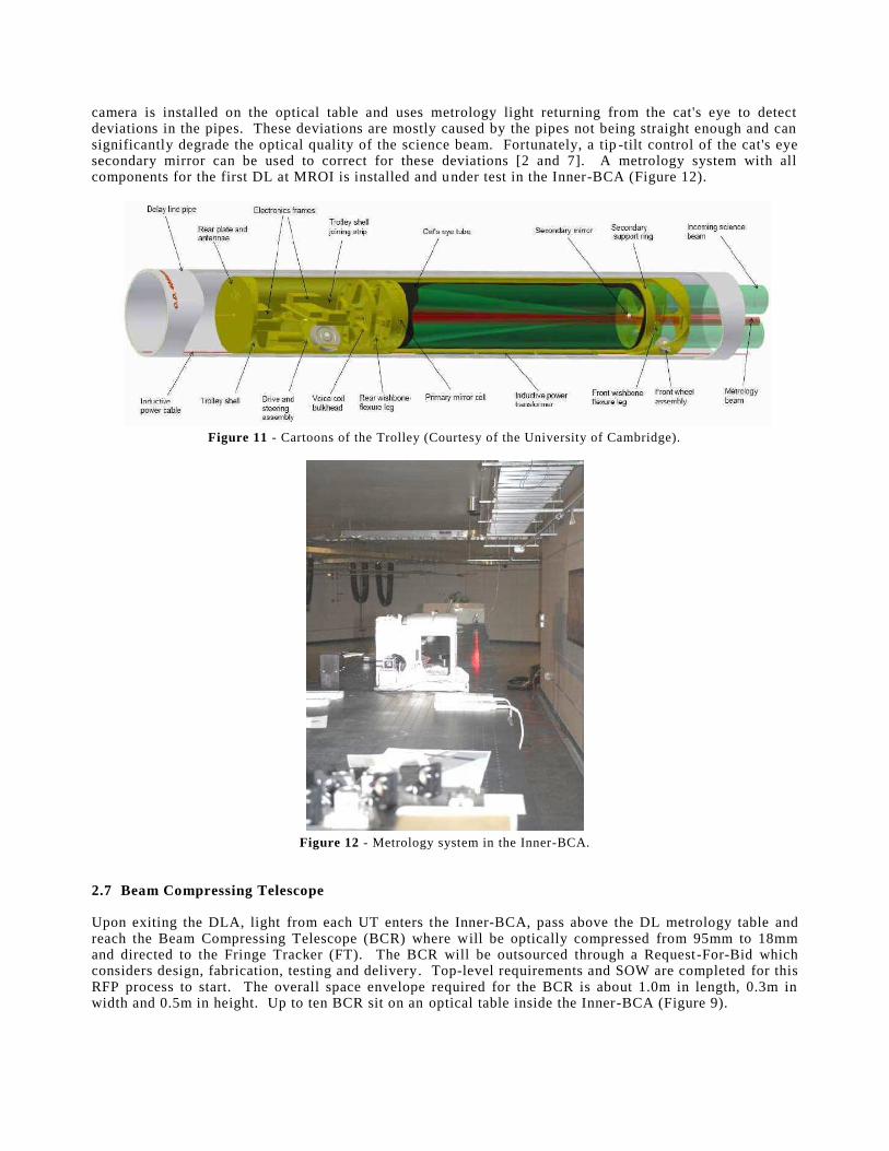
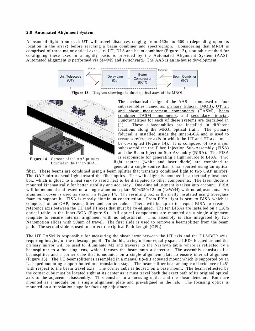
camera is install ed on the optical table and uses metrology li ght returning from the cat's eye to detect deviations in the pipes. These deviations are mostly caused by the pipes not being straight enough and can signi f icantl y degrade the optical qualit y of the science beam. Fortunately, a tip-tilt control of the cat's eye secondary mi rror can be used to correct for these deviations [2 and 7] . A metrology system with all components for the f i rst DL at MROI is install ed and under test in the Inner-BCA (Figure 12).
Figure 11 - Cartoons of the Troll ey (Courtesy of the Universit y of Cambridge).
Figure 12 - Metrology system in the Inner-BCA.
2.7 Beam Compressing Telescope Upon exiti ng the DLA, li ght from each UT enters the Inner-BCA, pass above the DL metrology table and reach the Beam Compressing Telescope (BCR) where will be opticall y compressed from 95mm to 18mm and directed to the Fringe Tracker (FT). The BCR will be outsourced through a Request-For-Bid which considers design, fabrication, testing and deli very. Top-level requirements and SOW are completed for this RFP process to start. The overall space envelope required for the BCR is about 1.0m in length, 0.3m in width and 0.5m in height. Up to ten BCR sit on an optical table inside the Inner-BCA (Figure 9).
2.8 Automated Alignment System A beam of li ght from each UT will travel distances ranging from 460m to 660m (depending upon its location in the array) before reaching a beam combiner and spectrograph. Considering that MROI is comprised of three major optical axes, i .e. UT, DLS and beam combiner (Figure 13), a suitable method for co-ali gning these axes in a nightly basis is provided by the Automated Ali gnment System (AA S). Automated ali gnment is performed via M4/M5 and switchyard. The AA S is an in-house development.
Figure 13 - Diagram showing the three optical axes of the MROI.
The mechanical design of the AA S is composed of four subassembli es named as: primary f iducial (MOB), UT tilt and shear measurement components (TASM), beam combiner TASM components, and secondary f iducial . Functionaliti es for each of these systems are described in [1] . These subassembli es are install ed in di ff erent locations along the MROI optical train. The primary f iducial i s install ed inside the Inner-BCA and is used to create a reference axis in which the UT and FT axes must be co-ali gned (Figure 14). I t is composed of two major subassembli es: the Fiber Injection Sub-Assembly (FISA) and the Beam Injection Sub-Assembly (BISA). The FISA is responsible for generating a li ght source to BISA. Two
li ght sources (white and laser diode) are combined to generate a single source that is transported using an optical
f iber. These beams are combined using a beam splitt er that transmi ts combined li ght to two OAP mirrors. The OAP mirrors send li ght toward the f iber optics. The white li ght is mounted in a thermall y insulated box, which is glued to a heat sink to avoid heat to be dissipated to other components. The laser diode is mounted kinematicall y for better stabilit y and accuracy. One-time adjustment is taken into account. FISA will be mounted and tested on a single aluminum plate 500x350x12mm (LxWxH) with no adjustments. An aluminum cover is used as shown in Figure 14. The resulti ng box is thermall y insulated using f iberglass foam to support it . FISA is mostly aluminum construction. From FISA li ght is sent to BISA which is composed of an OAP, beamsplitt er and corner cube. There will be up to ten equal BISA to create a reference axis between the UT and FT axes that must be co-ali gned. The ten BISAs are install ed on a 1x6m optical table in the Inner-BCA (Figure 9). All optical components are mounted on a single ali gnment template to ensure internal ali gnment with no adjustment. This assembly is also integrated by two Nanomotion sli des with 50mm of travel . The f i rst sli de is used to remove a beamsplitt er from the beam path. The second sli de is used to correct the Optical Path Length (OPL). The UT TASM is responsible for measuring the shear error between the UT axis and the DLS/BCR axis, requiring imaging of the telescope pupil . To do this, a ring of four equall y spaced LEDs located around the primary mirror will be used to ill uminate M2 and traverse to the Nasmyth table where is ref lected by a beamsplitt er to a focusing lens, which focuses the beam onto a detector. The assembly consists of a beamsplitt er and a corner cube that is mounted on a single ali gnment plate to ensure internal ali gnment (Figure 15). The UT beamsplitt er is assembled in a manual tip-tilt actuated mount which is supported by an L-shaped mounting support bolted to a translation stage. The beamsplitt er is at an angle of incidence of 45º with respect to the beam travel axis. The corner cube is housed on a base mount. The beam ref lected by the corner cube must be located right at its center as it must travel back the exact path of its original optical axis to the adjacent subassembly. This consists in a focusing optics and the shear detector. Both are mounted as a module on a single ali gnment plate and pre-ali gned in the lab. The focusing optics is mounted on a translation stage for focusing adjustment.
Figure 14 - Cartoon of the AA S primary f iducial in the Inner-BCA.
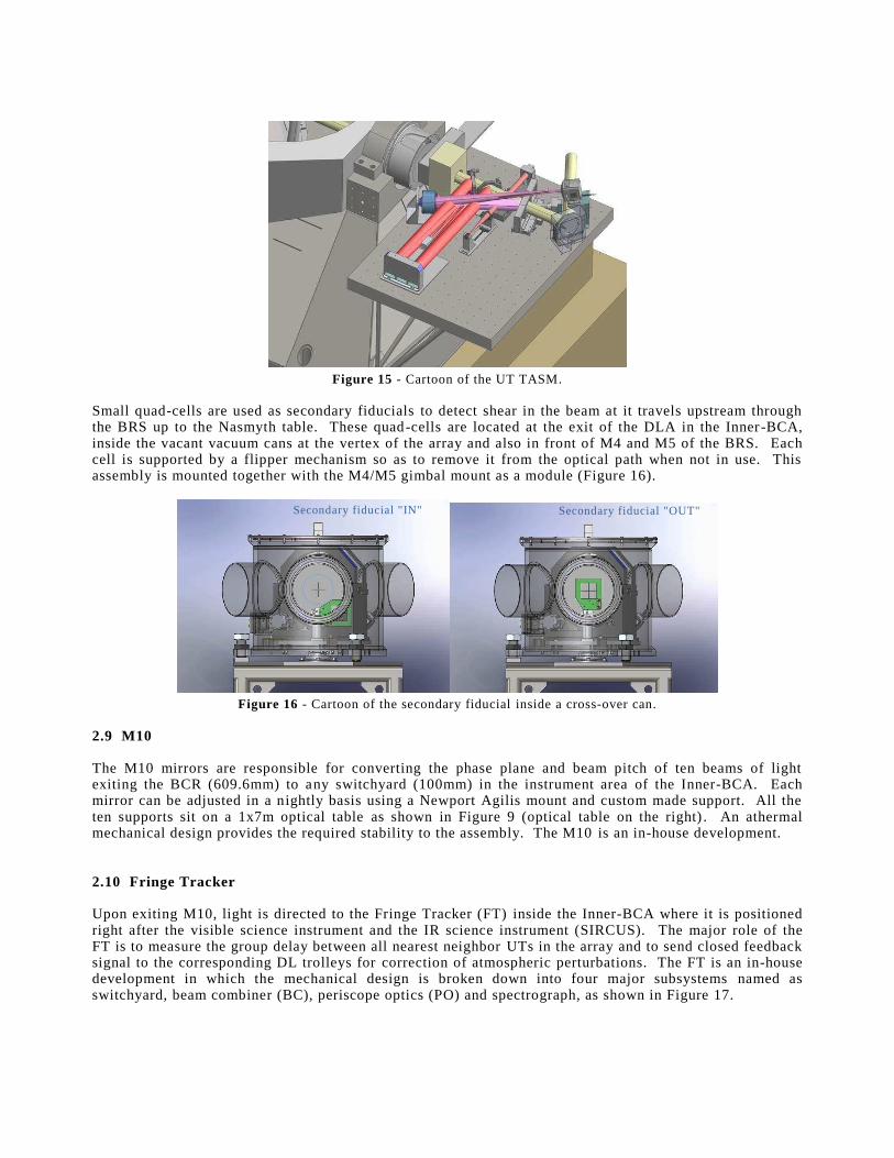
Figure 15 - Cartoon of the UT TASM.
Small quad-cell s are used as secondary f iducials to detect shear in the beam at it travels upstream through the BRS up to the Nasmyth table. These quad-cell s are located at the exit of the DLA in the Inner-BCA, inside the vacant vacuum cans at the vertex of the array and also in front of M4 and M5 of the BRS. Each cell i s supported by a f li pper mechanism so as to remove it from the optical path when not in use. This assembly is mounted together with the M4/M5 gimbal mount as a module (Figure 16).
Figure 16 - Cartoon of the secondary f iducial inside a cross-over can.
2.9 M10 The M10 mirrors are responsible for converting the phase plane and beam pitch of ten beams of li ght exiti ng the BCR (609.6mm) to any switchyard (100mm) in the instrument area of the Inner-BCA. Each mirror can be adjusted in a nightly basis using a Newport Agili s mount and custom made support. All the ten supports sit on a 1x7m optical table as shown in Figure 9 (optical table on the right) . An athermal mechanical design provides the required stabilit y to the assembly. The M10 is an in-house development. 2.10 Fringe Tracker Upon exiti ng M10, li ght is di rected to the Fringe Tracker (FT) inside the Inner-BCA where it is positi oned right after the visible science instrument and the IR science instrument (SIRCUS). The major role of the FT is to measure the group delay between all nearest neighbor UTs in the array and to send closed feedback signal to the corresponding DL troll eys for correction of atmospheric perturbations. The FT is an in-house development in which the mechanical design is broken down into four major subsystems named as switchyard, beam combiner (BC), periscope optics (PO) and spectrograph, as shown in Figure 17.
Secondary f iducial " IN" Secondary f iducial "OUT"
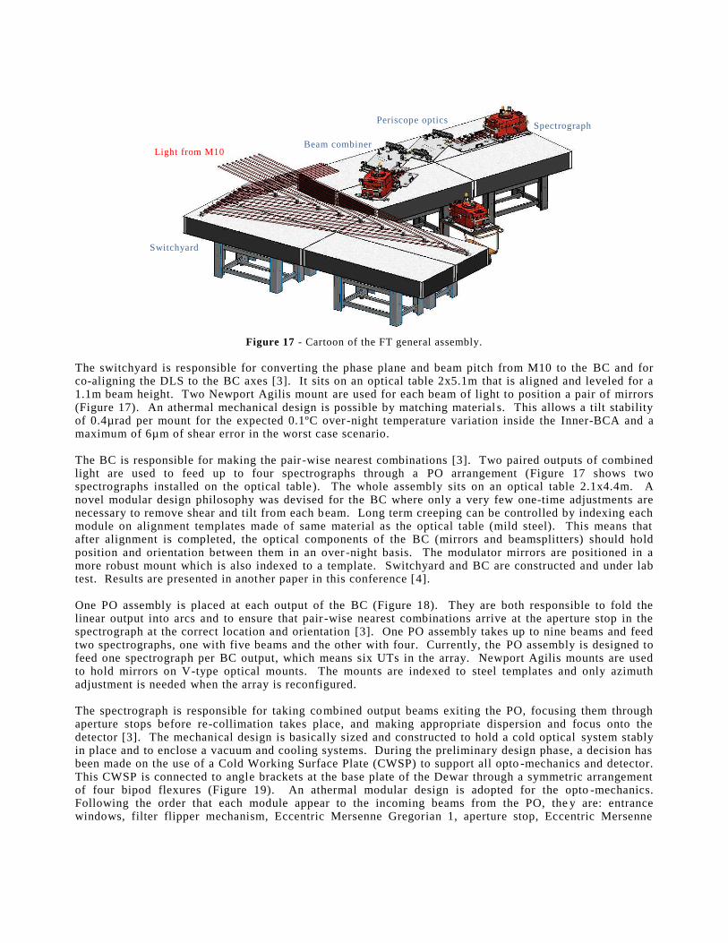
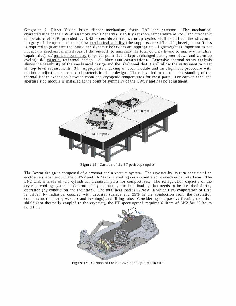
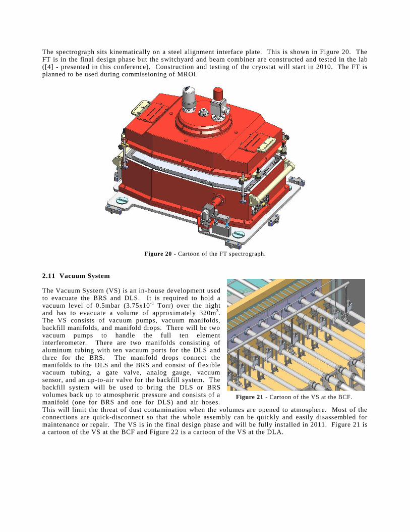
Figure 17 - Cartoon of the FT general assembly. The switchyard is responsible for converting the phase plane and beam pitch from M10 to the BC and for co-ali gning the DLS to the BC axes [3] . I t sits on an optical table 2x5.1m that is ali gned and leveled for a 1.1m beam height. Two Newport Agili s mount are used for each beam of li ght to positi on a pair of mirrors (Figure 17). An athermal mechanical design is possible by matching material s. This all ows a tilt stabilit y of 0.4µrad per mount for the expected 0.1ºC over -night temperature variation inside the Inner-BCA and a maximum of 6µm of shear error in the worst case scenario. The BC is responsible for making the pair -wise nearest combinations [3] . Two paired outputs of combined li ght are used to feed up to four spectrographs through a PO arrangement (Figure 17 shows two spectrographs install ed on the optical table). The whole assembly sits on an optical table 2.1x4.4m. A novel modular design phil osophy was devised for the BC where only a very few one-time adjustments are necessary to remove shear and tilt from each beam. Long term creeping can be controll ed by indexing each module on ali gnment templates made of same material as the optical table (mil d steel). This means that after ali gnment is completed, the optical components of the BC (mirrors and beamsplitt ers) should hold positi on and orientation between them in an over -night basis. The modulator mirrors are positi oned in a more robust mount which is also indexed to a template. Switchyard and BC are constructed and under lab test. Results are presented in another paper in this conference [ 4] . One PO assembly is placed at each output of the BC (Figure 18). They are both responsible to fold the li near output into arcs and to ensure that pair -wise nearest combinations arrive at the aperture stop in the spectrograph at the correct location and orientation [3] . One PO assembly takes up to nine beams and feed two spectrographs, one with f ive beams and the other with four. Currently, the PO assembly is designed to feed one spectrograph per BC output, which means six UTs in the array. Newport Agili s mounts are used to hold mirrors on V -type optical mounts. The mounts are indexed to steel templates and only azimuth adjustment is needed when the array is reconfigured. The spectrograph is responsible for taking combined output beams exiti ng the PO, focusing them through aperture stops before re-colli mation takes place, and making appropriate dispersion and focus onto the detector [3] . The mechanical design is basicall y sized and constructed to hold a cold optical system stably in place and to enclose a vacuum and cooli ng systems. During the preli minary design phase, a decision has been made on the use of a Cold Working Surface Plate (CWSP) to support all opto-mechanics and detector. This CWSP is connected to angl e brackets at the base plate of the Dewar through a symmetric arrangement of four bipod f lexures (Figure 19). An athermal modular design is adopted for the opto-mechanics. Foll owing the order that each module appear to the incoming beams from the PO, they are: entrance windows, f ilt er f li pper mechanism, Eccentric Mersenne Gregorian 1, aperture stop, Eccentric Mersenne
Switchyard
Beam combiner
Periscope optics Spectrograph
Light from M10
Gregorian 2, Direct Vision Prism f li pper mechanism, focus OAP and detector. The mechanical characteristics of the CWSP assembly are: a./ thermal stabilit y (at room temperature of 25ºC and cryogenic temperature of 77K provided by LN2 - cool -down and warm-up cycles shall not aff ect the structural integrity of the opto-mechanics); b./ mechanical stabilit y (the supports are sti ff and li ghtweight - sti ff ness is required to guarantee that static and dynamic behaviors are appropriate - li ghtweight is important to not impact the mechanical interfaces of the support, to minimize the total cold parts and to improve handli ng capabiliti es); c./ point of symmetry (physical point that is kept unchanged during cool -down and warm-up cycles); d./ material (athermal design - all aluminum construction). Extensive thermal -stress analysis shows the feasibilit y of the mechanical design and the li keli hood that it w ill all ow the instrument to meet all top level requirements [3] . Appropriate indexing of each module and an ali gnment procedure with minimum adjustments are also characteristic of the design. These have led to a clear understanding of the thermal li near expansion between room and cryogenic temperatures for most parts. For convenience, the aperture stop module is install ed at the point of symmetry of the CWSP and has no adjustment.
Figure 18 - Cartoon of the FT peri scope optics.
The Dewar design is composed of a cryostat and a vacuum system. The cryostat by its turn consists of an enclosure shaped around the CWSP and LN2 tank, a cooli ng system and electro-mechanical interfaces. The LN2 tank is made of two cyli ndrical aluminum parts for compactness. The refr igeration capacity of the cryostat cooli ng system is determined by estimating the heat loading that needs to be absorbed during operation (by conduction and radiation). The total heat load is 12.98W in which 61% evaporation of LN2 is driven by radiation coupled with cryostat surface and 39% is via conduction from the insulation components (supports, washers and bushings) and f illi ng tube. Considering one passive f loating radiation shield (not thermall y coupled to the cryostat), the FT spectrograph requires 6 lit ers of LN2 for 30 hours hold time.
Figure 19 - Cartoon of the FT CWSP and opto-mechanics.
BC Output 1
BC Output 2
Light
The spectrograph sits kinematicall y on a steel ali gnment interface plate. This is shown in Figure 20. The FT is in the f inal design phase but the switchyard and beam combiner are constructed and tested in the lab ([4] - presented in this conference). Construction and testing of the cryostat will start in 2010. The FT is planned to be used during commissioning of MROI.
Figure 20 - Cartoon of the FT spectrograph.
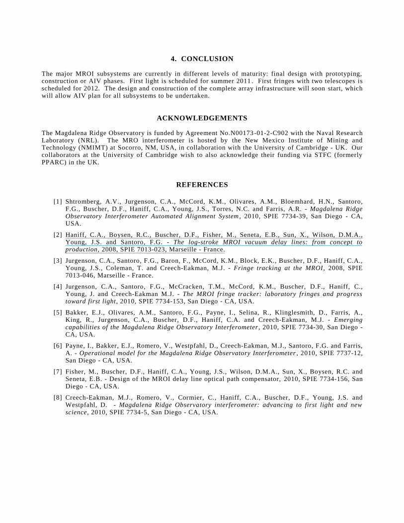
2.11 Vacuum System The Vacuum System (VS) is an in-house development used to evacuate the BRS and DLS. I t i s required to hold a vacuum level of 0.5mbar (3.75x10⁻¹ Torr) over the night and has to evacuate a volume of approximately 320m3. The VS consists of vacuum pumps, vacuum mani folds, backf ill mani folds, and mani fold drops. There will be two vacuum pumps to handle the full ten element interferometer. There are two mani folds consisting of aluminum tubing with ten vacuum ports for the DLS and three for the BRS. The mani fold drops connect the mani folds to the DLS and the BRS and consist of f lexible vacuum tubing, a gate valve, analog gauge, vacuum sensor, and an up-to-air valve for the backf ill system. The backf ill system will be used to bring the DLS or BRS volumes back up to atmospheric pressure and consists of a mani fold (one for BRS and one for DLS) and air hoses. This will li mit the threat of dust contamination when the volumes are opened to atmosphere. Most of the connections are quick-disconnect so that the whole assembly can be quickly and easil y disassembled for maintenance or repair. The VS is in the f inal design phase and will be full y install ed in 2011. Figure 21 is a cartoon of the VS at the BCF and Figure 22 is a cartoon of the VS at the DLA.
Figure 21 - Cartoon of the VS at the BCF.
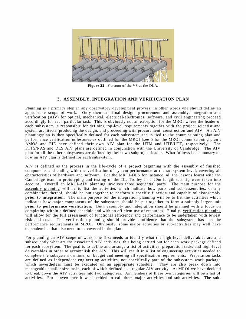
Figure 22 - Cartoon of the VS at the DLA.
3. ASSEMBLY, INTEGRATION AND VERIFICATION PLAN Planning is a primary step in any observatory development process; in other words one should def ine an appropriate scope of work. Only then can f inal design, procurement and assembly, integration and veri f ication (AIV) for optical , mechanical , electrical -electronics, software, and civil engineering proceed accordingly for each particular task. This is obviously not an exception for the MROI where the leader of each subsystem is responsible for def ining top-level requirements together with the project scientist and system architects, producing the design, and proceeding with procurement, construction and AIV. An AIV planning/plan is then speci f icall y def ined for each subsystem and is tied to the commissioning plan and performance veri f ication mil estones as outli ned for the MROI [ see 5 for the MROI commissioning plan] . AMOS and EIE have def ined their own AIV plan for the UTM and UTE/UTT, respectively. The FTTS/NAS and DLS AIV plans are def ined in conjunction with the University of Cambridge. The AIV plan for all the other subsystems are def ined by their own subproject leader. What foll ows is a summary on how an AIV plan is def ined for each subsystem. AIV is def ined as the process in the li fe-cycle of a project beginning with the assembly of f inished components and ending with the veri f ication of system performance at the subsystem level , covering all characteristics of hardware and software. For the MROI-DLS for instance, all the lessons learnt with the Cambridge team in prototyping and testing of the DL Troll ey in a 20m length test rig were taken into account. Overall an MROI-AIV planning involves three sequential parts. The main purpose for the assembly planning will be to li st the activiti es which indicate how parts and sub-assembli es, or any combination thereof, should be put together to perform a speci f ic function and capable of disassembly prior to integration. The main purpose for the integration planning will be to li st the activiti es which indicates how major components of the subsystem should be put together to form a suitably larger unit prior to performance verification . Both assembly and integration should be planned with a focus on completing within a def ined schedule and with an eff icient use of resources. Finall y, veri f ication planning will all ow for the full assessment of functional eff iciency and performance to be undertaken with lowest risk and cost. The veri f ication planning should provide conf idence that the subsystem has met the performance requirements at MROI. Obviously, some major activiti es or sub-activiti es may well have dependencies that also need to be covered in the plan. For planning an AIV scope of work, one f i rst needs to identi fy what the high-level deli verables are and subsequently what are the associated AIV activiti es, this being carried out for each work package def ined for each subsystem. The goal is to def ine and arrange a li st of activiti es, preparation tasks and high-level deli verables in order to accompli sh the AIV. This will result in a li st of engineering activiti es needed to complete the subsystem on time, on budget and meeting all speci f ication requirements. Preparation tasks are def ined as independent engineering activiti es, not speci f icall y part of the subsystem work package which nevertheless must be executed on an appropriate schedule. They are also break down into manageable small er size tasks, each of which def ined as a regular AIV activity. At MROI we have decided to break down the AIV activiti es into two categories. As members of these two categories will be a li st of activiti es. For convenience it was decided to call them major activiti es and sub-activiti es. The sub-

activiti es are the small er pieces whose sizes are small enough to all ow precise estimation of resources (cost, schedule, and physical resources), execution and monitoring. Af ter this document is completed, reviewed and revised, an AIV Project Plan is prepared. As part of this plan, each sub-activity def ined in the AIV planning may be broken down into a sequence of lower -level tasks. Each of these tasks is then associated with a Description or a Work Def initi on Task Sheet (WDTS). These are numbered as a subset of the WBS, foll owing the MROI numbering system, and li st full detail s and dependencies of the actual task to be carried out. Each Description provides a brief explanation of the hardware/software being deli vered, as well as the technical interfaces and related documentation. Each WDTS provides f inal level of technical detail s as information on the requirements for the task, the task input/output, the task duration, resources, required equipment & faciliti es, appli cable documents, task procedure and any special notes. Sub-activiti es that contain tasks with a signi f icant level of complexity and/or are safety criti cal must have their procedures documented to an appropriate level of detail to ensure risk miti gation. Estimates on schedule and task duration will also incorporate contingencies. The main subsections of the WDTS are described below:
a. Task name and WBS: This are the name of the task and the MROI part number;
b. Major input: This li sts the hardware required for the task to be reali zed;
c. Task output: This li sts what the outcome is for the task;
d. Requirements: This li sts the speciali sts involved during the task, the major faciliti es required, the dependencies, the major documents where speci f ic information can be obtained and any speciali zed equipment;
e. Task procedure: This is a detail ed description of the task in terms of preparation, set -up, measurements and technical eff ort, together with information on safety ; and
f. Notes: This is optional reserved to special notes and footnotes. The AIV Planning and AIV Project Plan documents for each subsystem are expected to be used by the MROI-PM, the System Architects, the Cambridge Team, the subsystem leader and members of the team to demonstrate that the as-designed WPs, and consequently the whole MROI subsystems meet or exceed all the speci f ication requirements. The commissioning of MROI then starts [5] .
Figure 23 - Aerial view of the MROI site with a 3D-CAD drawing
overlaid with the array infrastructure (Courtesy of M3 Engineering).
4. CONCLUSION
The major MROI subsystems are currently in di ff erent levels of maturity: f inal design with prototyping, construction or AIV phases. Fi rst li ght is scheduled for summer 2011. Fi rst fr inges with two telescopes is scheduled for 2012. The design and construction of the complete array infrastructure will soon start, which will all ow AIV plan for all subsystems to be undertaken.
ACKNOWLEDGEMENTS The Magdalena Ridge Observatory is funded by Agreement No.N00173-01-2-C902 with the Naval Research Laboratory (NRL). The MRO interferometer is hosted by the New Mexico Institute of Mining and Technology (NMIMT) at Socorro, NM, USA, in coll aboration with the University of Cambridge - UK. Our coll aborators at the University of Cambridge wish to also acknowledge their funding via STFC (formerly PPARC) in the UK.
REFERENCES
[1] Shtromberg, A.V., Jurgenson, C.A., McCord, K.M., Oli vares, A.M., Bloemhard, H.N., Santoro, F.G., Buscher, D.F., Hani ff , C.A., Young, J.S., Torres, N.C. and Farris, A.R. - Magdalena Ridge Observatory Interferometer Automated Alignment System , 2010, SPIE 7734-39, San Diego - CA, USA.
[2] Hani ff , C.A., Boysen, R.C., Buscher, D.F., Fisher, M., Seneta, E.B., Sun, X., Wil son, D.M.A., Young, J.S. and Santoro, F.G. - The log-stroke MROI vacuum delay lines: from concept to production, 2008, SPIE 7013-023, Marseill e - France.
[3] Jurgenson, C.A., Santoro, F.G., Baron, F., McCord, K.M., Block, E.K., Buscher, D.F., Hani ff , C.A., Young, J.S., Coleman, T. and Creech-Eakman, M.J. - Fringe tracking at the MROI, 2008, SPIE 7013-046, Marseill e - France.
[4] Jurgenson, C.A., Santoro, F.G., McCracken, T.M., McCord, K.M., Buscher, D.F., Hani ff , C., Young, J. and Creech-Eakman M.J. - The MROI fringe tracker: laboratory fringes and progress toward first light, 2010, SPIE 7734-153, San Diego - CA, USA.
[5] Bakker, E.J., Oli vares, A.M., Santoro, F.G., Payne, I., Seli na, R., Kli nglesmith, D., Farris, A., King, R., Jurgenson, C.A., Buscher, D.F., Hani ff , C.A. and Creech-Eakman, M.J. - Emerging capabilities of the Magdalena Ridge Observatory Interferometer , 2010, SPIE 7734-30, San Diego - CA, USA.
[6] Payne, I ., Bakker, E.J., Romero, V., Westpfahl , D., Creech-Eakman, M.J., Santoro, F.G. and Farris, A. - Operational model for the Magdalena Ridge Observatory Interferometer , 2010, SPIE 7737-12, San Diego - CA, USA.
[7] Fisher, M., Buscher, D.F., Hani ff , C.A., Young, J.S., Wil son, D.M.A., Sun, X., Boysen, R.C. and Seneta, E.B. - Design of the MROI delay li ne optical path compensator, 2010, SPIE 7734-156, San Diego - CA, USA.
[8] Creech-Eakman, M.J., Romero, V., Cormier, C., Hani ff , C.A., Buscher, D.F., Young, J.S. and Westpfahl , D. - Magdalena Ridge Observatory interferometer: advancing to first light and new science, 2010, SPIE 7734-5, San Diego - CA, USA.