mechanical behavior of the storage tanks
TRANSCRIPT
7th EUROMECH Solid Mechanics Conference J. Ambrósio et.al. (eds.)
Lisbon, Portugal, September 7-11, 2009
MECHANICAL BEHAVIOR OF THE STORAGE TANKS
Víctor Flores C.1, Héctor A. Sánchez S.1, María J. Pérez de la C.1 and Carlos Cortés S.2
1SEPI - ESIA, Instituto Politécnico Nacional U. P. Adolfo López Mateos Gustavo A. Madero, 07738, México, D. F
e-mail: [email protected], [email protected], [email protected], [email protected]
2 Instituto Mexicano del Petróleo Eje Lázaro Cárdenas No. 152, Apto. Postal 14-805, 07730 México, D. F.
e-mail: [email protected]
Keywords: Computational Mechanics, behavior of tanks, mechanical behavior, liquid con-tainers, distribution of the hydrodynamics pressures.
Abstract. This work studies the mechanical behavior of two geometries of the storage tanks under horizontal action at the base, by numerical procedure, based in the finite element me-thod (FEM) through of the discretization dominion with triangular elements, satisfying the Laplace equation, also are reviewed others analytical and numerical solution that they are in Literature. The objective is to calculate and evaluate the distribution of the hydrodynamics pressures on the walls of containers under seismic acceleration, for which numerical models are made, that consider the properties of the material, the fluid characteristics and the real geometry of the steel storage tanks. It is observed that the impulsive hydrodynamic pressures obtained with this numerical procedure compared with the others are a good agree. Finally the dynamic response of the tanks is analyzed, involving the numerical modeling by FEM and simplified procedures of the two relevant codes [2, 4].
Víctor Flores C., Héctor A. Sánchez S., María J. Pérez de la C. and Carlos Cortés S.
2
1 INTRODUCTION
The experience obtained in the natural disasters such as the earthquakes on deposits or sto-rage tanks, reveals that to diminish the structural vulnerability at acceptable levels they are needed preventive actions and suitable designs. Storage tanks are structures that due to its na-ture and behavior require criteria of analyses that consider the hydrodynamic effects on the walls and the bottom of the container. Therefore with the purpose to respond to these necessi-ties as well as to study the mechanical behavior and hydrodynamic pressure distribution on the walls of the tanks has been necessary to carry out the revision and evaluation of the ana-lytical developments used in the analysis and design of this type of structures. Consequently, the objective of this work is to show by means of a numerical procedure, based on the method of the finite element (FEM), the distribution of hydrodynamic pressures in containers gener-ated by a horizontal acceleration. Then in these analysis are ignored the viscosity of the fluid and the turbulence, satisfying the Laplace equation.
On the other hand, the recommendations of the standards are evaluated such as, API-650 [2]and CFE-93[4], and the numerical models to represent the interaction fluid-structure effect has been developed with the aid of code ANSYS[1], with the purpose to study the influence of walls flexibility in the distribution of pressures hydrodynamics.
For the analysis were considered two geometries, rectangular and cylindrical sections of the tanks, in order to evaluate both numerical models and its results such as due to hydrostatic and hydrodynamics loads by analytical procedure of the plate and shell theories, obtaining a very good agreement between analytical and numerical results.
1.1 Background
The early advances of the seismic analysis in the behavior and response of the liquid stor-age tanks considered the rigid walls and focused their attention on the dynamic behavior of the contained liquid of the tanks against lateral excitation from earthquake loading as a phe-nomenon of strong vibration. Housner formulated an idealization to consider the response of the fluid in rectangular and cylindrical rigid tanks under a seismic excitation. The study dis-played values for equivalent masses and their locations that represent the hydrodynamic ef-fects due to the movement of rigid body of the container and the hydrodynamic effects due to the fundamental vibration way of the liquid.
The solution for the design of containers suggest by Housner, considers that the seismic re-sponse for typical problems of containers can be separated in a system of equations which go-vern sloshing effect of the free surface of the liquid, and a connected system which governs the structural ways that are influenced by the mass and the force generated by the pressure of the liquid, had to the separation of the frequency of the typical surface of slosh, the liquid and the response of the wall of the container, the approach is given in terms of two separated problems. Slosh of the surface of the liquid it happens with the lowest frequency in relation to the response of the walls.
The dynamic behavior and response of the tanks under lateral excitation is generally non-linear in nature and has been the subject of extensive research. The problem was first ad-dressed by Housner for the case of a fixed base rigid upright cylindrical tank under seismic excitation. The motion of the liquid inside the tank results in hydrodynamic pressure loading on the tank walls and Housner assumed that the response of the rigid tank could be split into two hydrodynamic components namely:
Víctor Flores C., Héctor A. Sánchez S., María J. Pérez de la C. and Carlos Cortes S.
3
Impulsive component due to rigid-body motion of the liquid. Under dynamic loading, part of the liquid moves synchronously with the tank as an added mass and is subject to the same acceleration levels as the tank. This is hereafter called the “rigid-impulsive” component.
Convective component due to sloshing of the liquid at the free surface. Under lateral exci-tation, oscillations of the fluid occur and this results in the generation of pressures on the walls, base and roof of the tank.
Based on the assumptions that: • The liquid is incompressible and inviscid, • Motion of liquid is irrotational and satisfies Laplace’s equation, • Structural and liquid motions remain linearly elastic in conjunction with the bound-ary conditions and • Radial velocities of liquid and tank wall must be the same for rigid tank.
Moreover, the earthquake of Alaska in 1964 caused great damages in tanks of modern de-sign reason why new investigations began considering the dynamic characteristics of flexible containers. Additionally, the development of hardware and numerical techniques associates, have capacity of the solution well-known. Several studies have been carried out to investigate the dynamic interaction between the deformable wall of the tank and the liquid by means of the finite element method. A different consideration from the solution of the problem was made by Veletsos, the tank was considered like a system with a single degree of freedom and that vibrates in a prescribed way. Veletsos and Yang obtained the natural frequency of the container with liquid by the Rayleigh-Ritz method, late on Veletsos and Yang obtained sup-plementary results testing models on reduced scale; nevertheless, most of these studies were referred to the associated dynamic problems the aerospace uses [8].
2 CHARACTERISTICS OF TH E STRUCTURES ANALYZED
The structures selected are typical structures employed in the oil national industry; conse-quently it has been used real values of the geometric and mechanical properties that constitute it. The research is developed in the following way, the storage tanks are modeled through a fine mesh composed by finite shells and fluid elements, and they are analyzed applying the finite element method (FEM), considering constant thickness t of wall that contribute to mod-ify the dynamic behavior. It is studied the flexibility of the shell walls and the sloshing effect generated by the seismic action of the fluid on the steel walls.
2.1 General considerations
The walls of the rectangular and cylindrical reservoirs are considered as thin plates with an elastic behavior. The vessels are submitted to vibrations due to dynamic excitations. The seismic behavior of these structures is studied by fluid – structure interaction system. The general hypotheses employed in the analysis are: • the vessels are constituted by constant thickness t along wall height H, • the material is isotropic homogenous and elastic, • exist loads applied on the plates and it is considered also the own weight (mass).
2.2 Geometrical and mechanical characteristics of the tanks studied
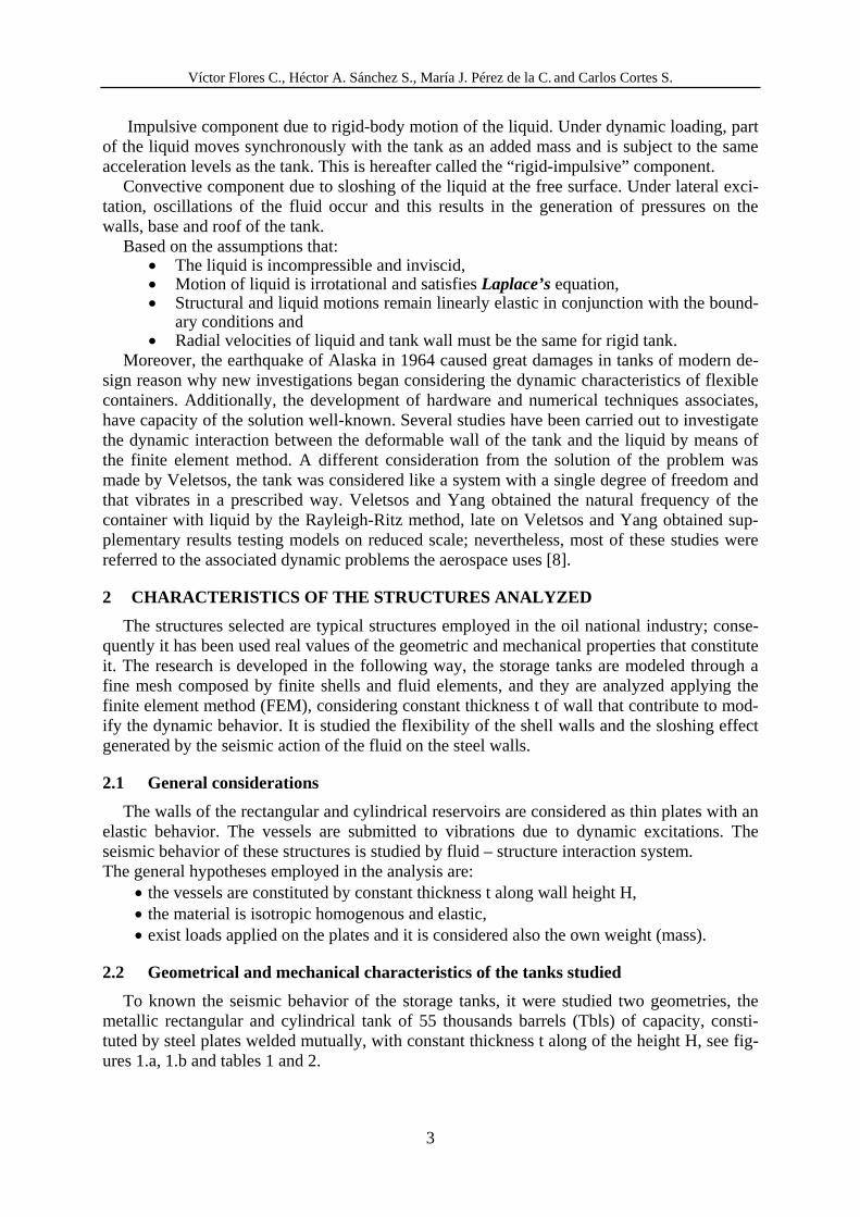
To known the seismic behavior of the storage tanks, it were studied two geometries, the metallic rectangular and cylindrical tank of 55 thousands barrels (Tbls) of capacity, consti-tuted by steel plates welded mutually, with constant thickness t along of the height H, see fig-ures 1.a, 1.b and tables 1 and 2.
Víctor Flores C., Héctor A. Sánchez S., María J. Pérez de la C. and Carlos Cortés S.
4
a) Rectangular geometry b) Circular geometry
Figure 1: Reservoirs studied (55 Tbls).
Geometrical characteristics Rectangular
55 Tbls Circular 55 Tbls
HT total (m) 12.19 12.192 HL liquid (m) 10.99 10.99
R(m) ---- 15.24 A(m) 23.93 ---- L(m) 30.48 ----
Table 1: Geometrical characteristic of the tanks
Mechanical characteristics of the materials Es 206,000 Young modulus of steel Mpa ν 0.3 Poisson’s ratio of material γs 76,910.4 Weight per unit of volume of the steel N/m3 ρs 7,840 Mass per unit of volume of the steel (N/m3)/g γl 9,810 Weight per unit of volume of the liquid N/m3 ρl 1,000 Mass per unit of volume of the liquid (N/m3)/g γ 2,206 Bulk of compressibility of the fluid Mpa
Table 2: Mechanical characteristics of materials of steel storage tanks
3 THEORETICAL AND MATHEM ATICAL ARRANGEMENT
3.1 Finite elements method
For the study of the hydrodynamics pressures on the rectangular geometry using the Finite Element Method (FEM), in this research, it is considered a bi-dimensional dominion like which it is in figure 2. Then, for a system of accelerations given and a movement of small amplitude, it is possible to be demonstrated that for an incompressible, inviscid and irrota-tional liquid the pressures satisfy the Laplace equation. Furthermore, structural and liquid mo-tions remain linearly elastic in conjunction with the boundary conditions. Radial velocities of liquid and tank wall must be the same for rigid tank.
02 =∇ p (1)
02
2
2
2 =∂∂+∂
∂y
p
x
p
Víctor Flores C., Héctor A. Sánchez S., María J. Pérez de la C. and Carlos Cortes S.
5
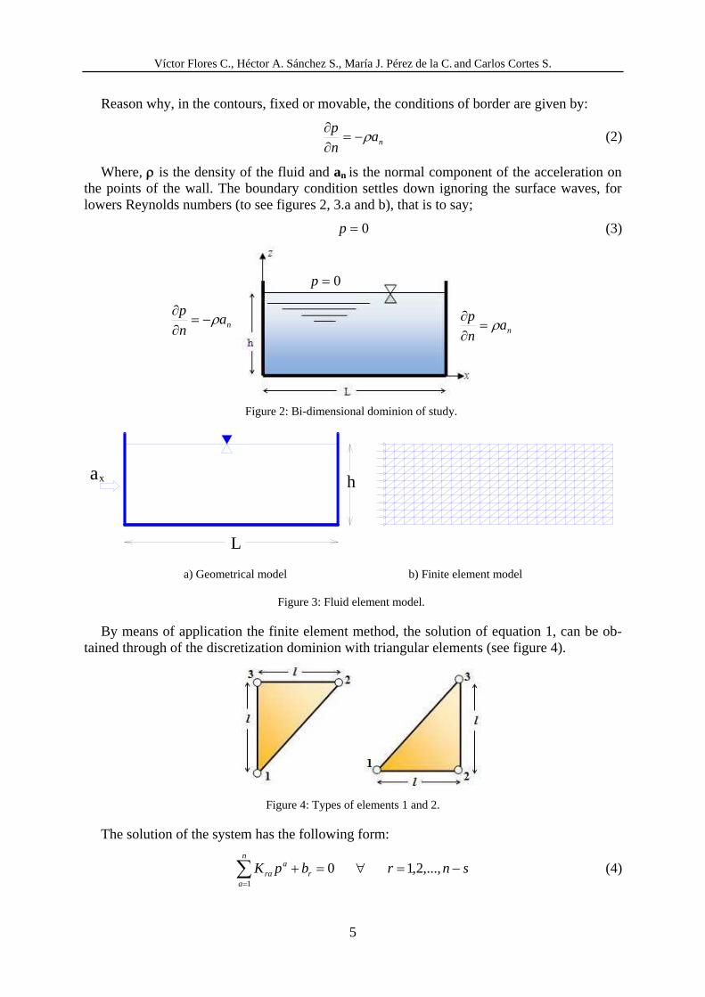
Reason why, in the contours, fixed or movable, the conditions of border are given by:
nan
p ρ−=∂∂
(2)
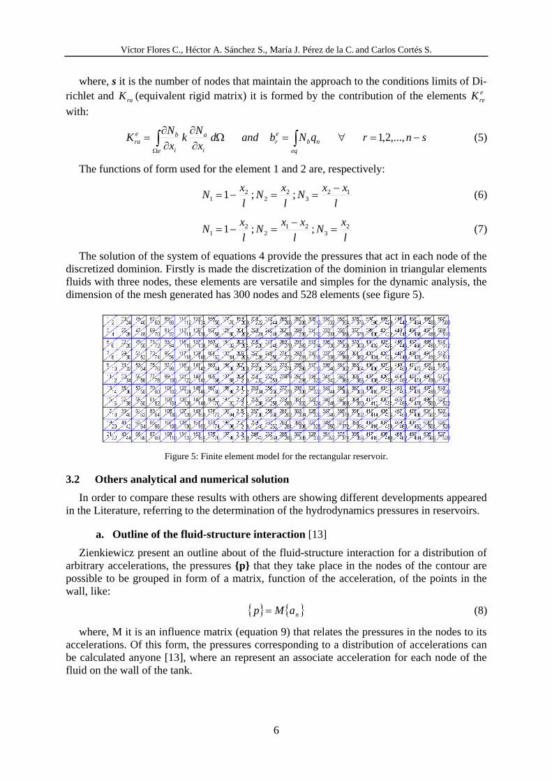
Where, ρ is the density of the fluid and an is the normal component of the acceleration on the points of the wall. The boundary condition settles down ignoring the surface waves, for lowers Reynolds numbers (to see figures 2, 3.a and b), that is to say;
0=p (3)
Figure 2: Bi-dimensional dominion of study.
a) Geometrical model b) Finite element model
Figure 3: Fluid element model.
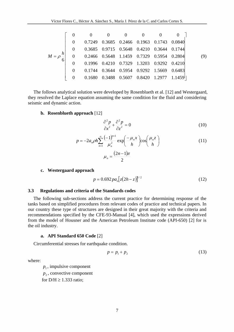
By means of application the finite element method, the solution of equation 1, can be ob-tained through of the discretization dominion with triangular elements (see figure 4).
Figure 4: Types of elements 1 and 2.
The solution of the system has the following form:
01
=+∑= r
n
a
ara bpK snr −=∀ ,...,2,1 (4)
L
a x h
nan
p ρ−=∂∂
0=p
nan
p ρ=∂∂
Víctor Flores C., Héctor A. Sánchez S., María J. Pérez de la C. and Carlos Cortés S.
6
where, s it is the number of nodes that maintain the approach to the conditions limits of Di-richlet and raK (equivalent rigid matrix) it is formed by the contribution of the elements ereK
with:
∫∫ =Ω∂∂
∂∂=
Ω eq
nber
e i
a
i
bera qNbandd
x
Nk
x
NK snr −=∀ ,...,2,1 (5)
The functions of form used for the element 1 and 2 are, respectively:
l
xxN
l
xN
l
xN 12
32
22
1 ;;1−==−= (6)
l
xN
l
xxN
l
xN 2
321
22
1 ;;1 =−=−= (7)
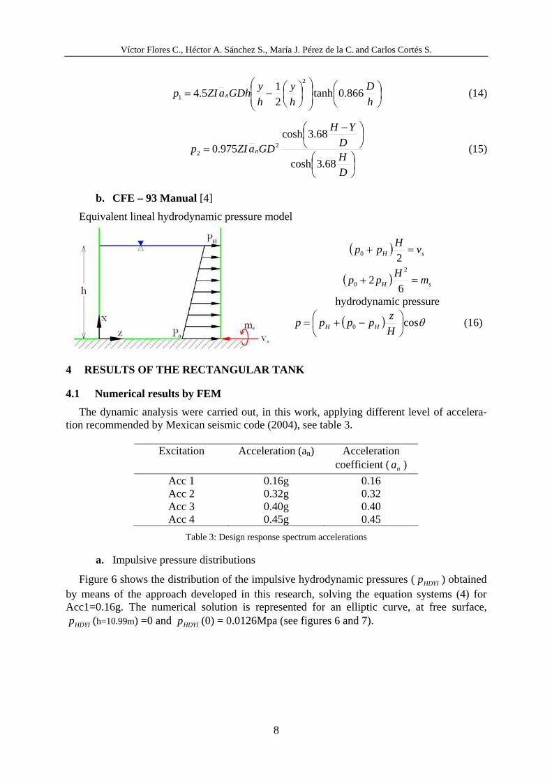
The solution of the system of equations 4 provide the pressures that act in each node of the discretized dominion. Firstly is made the discretization of the dominion in triangular elements fluids with three nodes, these elements are versatile and simples for the dynamic analysis, the dimension of the mesh generated has 300 nodes and 528 elements (see figure 5).
Figure 5: Finite element model for the rectangular reservoir.
3.2 Others analytical and numerical solution
In order to compare these results with others are showing different developments appeared in the Literature, referring to the determination of the hydrodynamics pressures in reservoirs.
a. Outline of the fluid-structure interaction [13]
Zienkiewicz present an outline about of the fluid-structure interaction for a distribution of arbitrary accelerations, the pressures {p} that they take place in the nodes of the contour are possible to be grouped in form of a matrix, function of the acceleration, of the points in the wall, like:
{ } { }naMp = (8)
where, M it is an influence matrix (equation 9) that relates the pressures in the nodes to its accelerations. Of this form, the pressures corresponding to a distribution of accelerations can be calculated anyone [13], where an represent an associate acceleration for each node of the fluid on the wall of the tank.
Víctor Flores C., Héctor A. Sánchez S., María J. Pérez de la C. and Carlos Cortes S.
7
⎥⎥⎥⎥⎥⎥⎥⎥⎥
⎦
⎤
⎢⎢⎢⎢⎢⎢⎢⎢⎢
⎣
⎡
=
1459.12977.18420.05607.03488.01680.00
6483.05669.19292.05954.03644.01744.00
4210.09292.03203.17329.04210.01996.00
2804.05954.07329.01459.15648.02466.00
1744.03644.04210.05648.09715.03685.00
0840.01743.01963.02466.03685.07249.00
0000000
6h
M ρ (9)
The follows analytical solution were developed by Rosenblueth et al. [12] and Westergaard,
they resolved the Laplace equation assuming the same condition for the fluid and considering seismic and dynamic action.
b. Rosenblueth approach [12]
02
2
2
2 =∂∂+∂
∂z
p
x
p (10)
( ) ⎟⎠
⎞⎜⎝⎛⎟⎠
⎞⎜⎝⎛ −−−= ∑∞=
+
h
z
h
xhap nn
n n
n
n
μμμρ cosexp1
21
2
1
(11)
( )
2
12 πμ −= nn
c. Westergaard approach
( )[ ] 2/12692.0 zhzpap n −= (12)
3.3 Regulations and criteria of the Standards codes
The following sub-sections address the current practice for determining response of the tanks based on simplified procedures from relevant codes of practice and technical papers. In our country these type of structures are designed in their great majority with the criteria and recommendations specified by the CFE-93-Manual [4], which used the expressions derived from the model of Housner and the American Petroleum Institute code (API-650) [2] for is the oil industry.
a. API Standard 650 Code [2]
Circumferential stresses for earthquake condition.
21 ppp += (13)
where:
1p , impulsive component
2p , convective component
for D/H ≥ 1.333 ratio;
Víctor Flores C., Héctor A. Sánchez S., María J. Pérez de la C. and Carlos Cortés S.
8
⎟⎠⎞⎜⎝
⎛⎟⎟⎠⎞
⎜⎜⎝⎛ ⎟⎠
⎞⎜⎝⎛−=
h
D
h
y
h
yGDhaZIp n 866.0tanh
21
5.42
1 (14)
⎟⎠⎞⎜⎝
⎛⎟⎠⎞⎜⎝
⎛ −=
D
HD
YH
GDaZIp n
68.3cosh
68.3cosh975.0 2
2 (15)
b. CFE – 93 Manual [4]
Equivalent lineal hydrodynamic pressure model
( ) sH vH
pp =+20
( ) sH mH
pp =+6
22
0
hydrodynamic pressure
( ) θcos0 ⎟⎠⎞⎜⎝
⎛ −+=H
zpppp HH (16)
4 RESULTS OF THE RECTANGULAR TANK
4.1 Numerical results by FEM
The dynamic analysis were carried out, in this work, applying different level of accelera-tion recommended by Mexican seismic code (2004), see table 3.
Excitation Acceleration (an) Acceleration
coefficient ( na )
Acc 1 0.16g 0.16 Acc 2 0.32g 0.32 Acc 3 0.40g 0.40 Acc 4 0.45g 0.45
Table 3: Design response spectrum accelerations
a. Impulsive pressure distributions
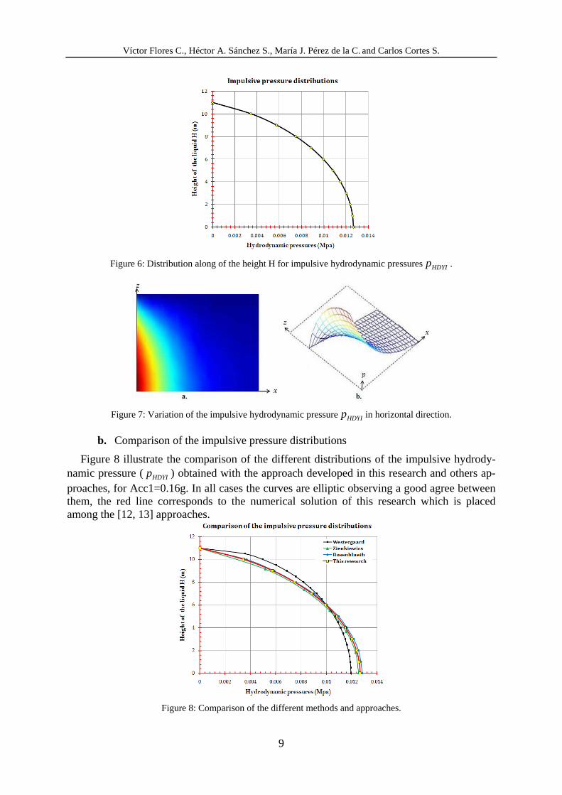
Figure 6 shows the distribution of the impulsive hydrodynamic pressures (HDYIp ) obtained by means of the approach developed in this research, solving the equation systems (4) for Acc1=0.16g. The numerical solution is represented for an elliptic curve, at free surface,
HDYIp (h=10.99m) =0 and HDYIp (0) = 0.0126Mpa (see figures 6 and 7).
Víctor Flores C., Héctor A. Sánchez S., María J. Pérez de la C. and Carlos Cortes S.
9
Figure 6: Distribution along of the height H for impulsive hydrodynamic pressuresHDYIp .
Figure 7: Variation of the impulsive hydrodynamic pressureHDYIp in horizontal direction.
b. Comparison of the impulsive pressure distributions
Figure 8 illustrate the comparison of the different distributions of the impulsive hydrody-namic pressure (HDYIp ) obtained with the approach developed in this research and others ap-proaches, for Acc1=0.16g. In all cases the curves are elliptic observing a good agree between them, the red line corresponds to the numerical solution of this research which is placed among the [12, 13] approaches.
Figure 8: Comparison of the different methods and approaches.
Víctor Flores C., Héctor A. Sánchez S., María J. Pérez de la C. and Carlos Cortés S.
10
4.2 Numerical results of the hydrostatic pressure of the rectangular tanks by (ANSYS) [1]
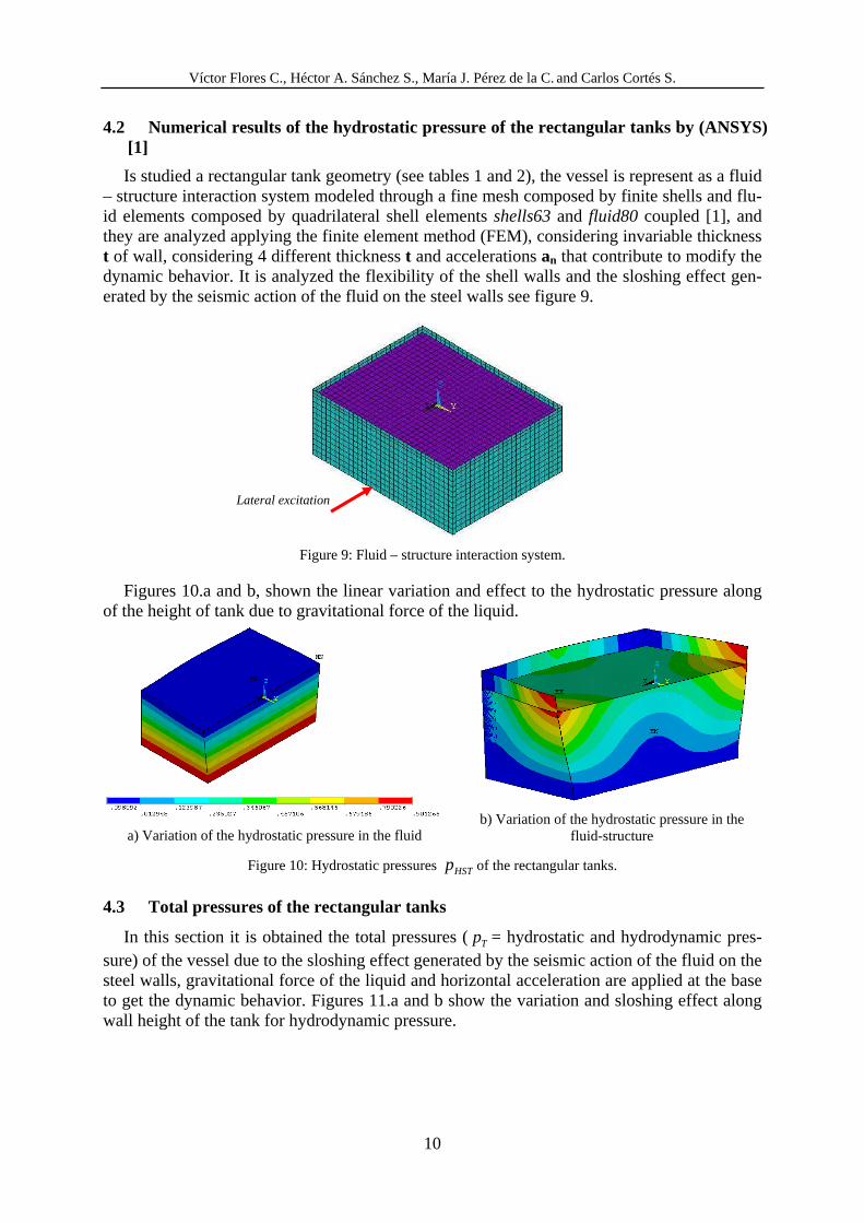
Is studied a rectangular tank geometry (see tables 1 and 2), the vessel is represent as a fluid – structure interaction system modeled through a fine mesh composed by finite shells and flu-id elements composed by quadrilateral shell elements shells63 and fluid80 coupled [1], and they are analyzed applying the finite element method (FEM), considering invariable thickness t of wall, considering 4 different thickness t and accelerations an that contribute to modify the dynamic behavior. It is analyzed the flexibility of the shell walls and the sloshing effect gen-erated by the seismic action of the fluid on the steel walls see figure 9.
Figure 9: Fluid – structure interaction system.
Figures 10.a and b, shown the linear variation and effect to the hydrostatic pressure along of the height of tank due to gravitational force of the liquid.
a) Variation of the hydrostatic pressure in the fluid
b) Variation of the hydrostatic pressure in the
fluid-structure
Figure 10: Hydrostatic pressures HSTp of the rectangular tanks.
4.3 Total pressures of the rectangular tanks
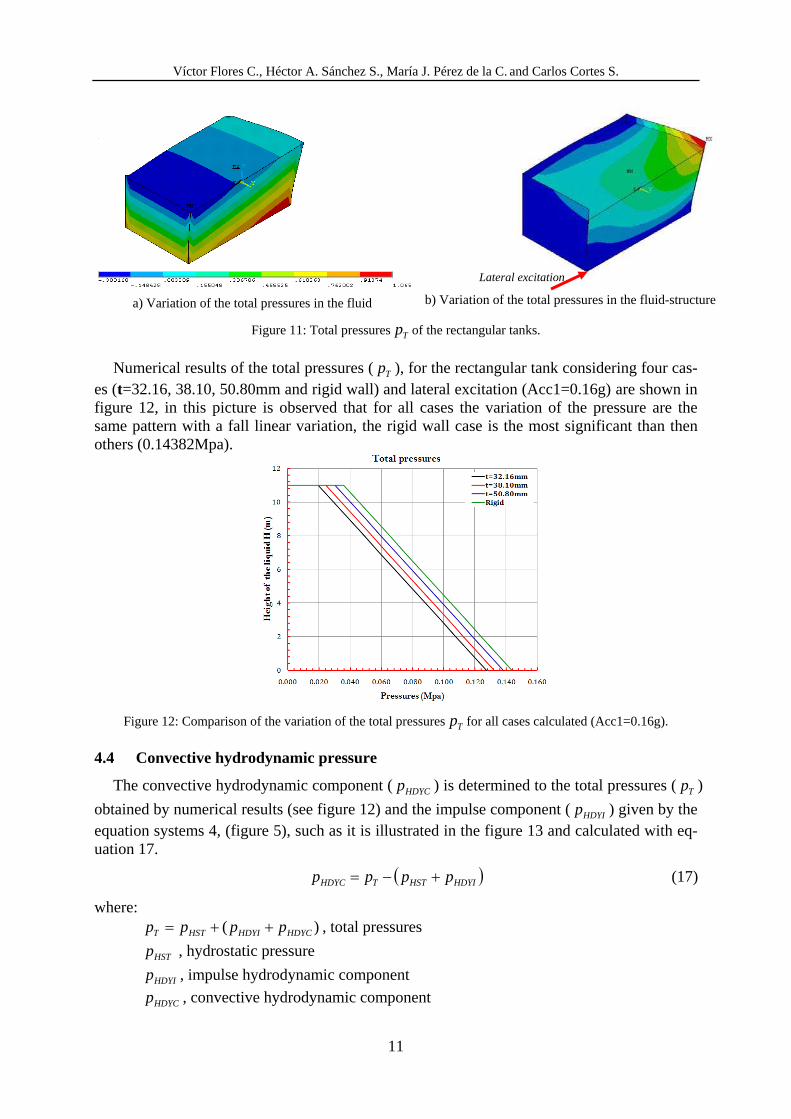
In this section it is obtained the total pressures (Tp = hydrostatic and hydrodynamic pres-sure) of the vessel due to the sloshing effect generated by the seismic action of the fluid on the steel walls, gravitational force of the liquid and horizontal acceleration are applied at the base to get the dynamic behavior. Figures 11.a and b show the variation and sloshing effect along wall height of the tank for hydrodynamic pressure.
Lateral excitation
Víctor Flores C., Héctor A. Sánchez S., María J. Pérez de la C. and Carlos Cortes S.
11
a) Variation of the total pressures in the fluid
b) Variation of the total pressures in the fluid-structure
Figure 11: Total pressuresTp of the rectangular tanks.
Numerical results of the total pressures (Tp ), for the rectangular tank considering four cas-es (t=32.16, 38.10, 50.80mm and rigid wall) and lateral excitation (Acc1=0.16g) are shown in figure 12, in this picture is observed that for all cases the variation of the pressure are the same pattern with a fall linear variation, the rigid wall case is the most significant than then others (0.14382Mpa).
Figure 12: Comparison of the variation of the total pressuresTp for all cases calculated (Acc1=0.16g).
4.4 Convective hydrodynamic pressure
The convective hydrodynamic component (HDYCp ) is determined to the total pressures (Tp )
obtained by numerical results (see figure 12) and the impulse component (HDYIp ) given by the equation systems 4, (figure 5), such as it is illustrated in the figure 13 and calculated with eq-uation 17.
( )HDYIHSTTHDYC pppp +−= (17)
where: )( HDYCHDYIHSTT pppp ++= , total pressures
HSTp , hydrostatic pressure
HDYIp , impulse hydrodynamic component
HDYCp , convective hydrodynamic component
Lateral excitation
Víctor Flores C., Héctor A. Sánchez S., María J. Pérez de la C. and Carlos Cortés S.
12
Hydrodynamic pressures
PressuresH
eigh
t of t
he li
quid
Impulsive pressures
Convective pressures
Hydrostatic pressures
Figure 13: Total pressures )( HDYCHDYIHSTT pppp ++= .
Figures 14.a and b showing the impulsive (HDYIp ) and convective (HDYCp ) hydrodynamic components hydrostatic pressures, for all cases analyzed and Acc1=0.16g.
a) Impulsive hydrodynamic componentHDYIp
(Acc1=0.16g)
b) Convective hydrodynamic componentHDYCp for all
cases calculated
Figure14: Impulsive and convective hydrodynamic components.
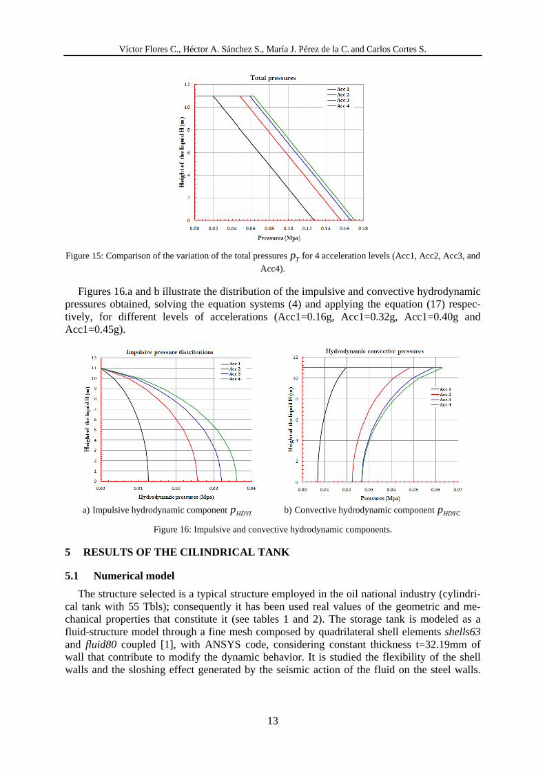
The aim of this part is study the behavior of the vessel for different acceleration levels con-sidered (Acc1=0.16g, Acc2=0.32g, Acc3=0.40g and Acc4=0.45g) and t=32.16mm. The nu-merical results of the total pressures distribution observe that this distribution has a linear variation and increase gradually with the acceleration level, reaching at maximum value of pressure of 0.168Mpa (see figure 15).
Víctor Flores C., Héctor A. Sánchez S., María J. Pérez de la C. and Carlos Cortes S.
13
Figure 15: Comparison of the variation of the total pressuresTp for 4 acceleration levels (Acc1, Acc2, Acc3, and
Acc4).
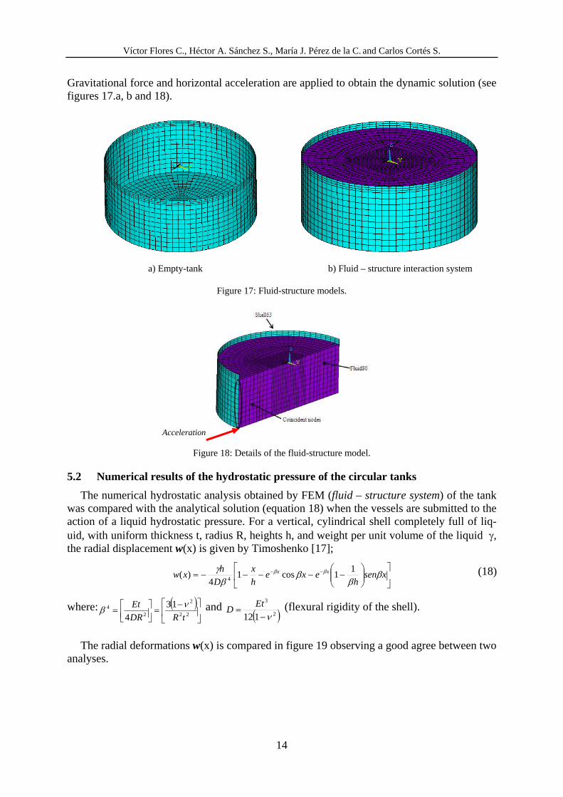
Figures 16.a and b illustrate the distribution of the impulsive and convective hydrodynamic pressures obtained, solving the equation systems (4) and applying the equation (17) respec-tively, for different levels of accelerations (Acc1=0.16g, Acc1=0.32g, Acc1=0.40g and Acc1=0.45g).
a) Impulsive hydrodynamic componentHDYIp b) Convective hydrodynamic componentHDYCp
Figure 16: Impulsive and convective hydrodynamic components.
5 RESULTS OF THE CILINDRICAL TANK
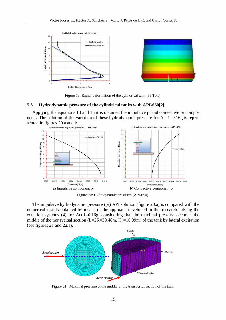
5.1 Numerical model
The structure selected is a typical structure employed in the oil national industry (cylindri-cal tank with 55 Tbls); consequently it has been used real values of the geometric and me-chanical properties that constitute it (see tables 1 and 2). The storage tank is modeled as a fluid-structure model through a fine mesh composed by quadrilateral shell elements shells63 and fluid80 coupled [1], with ANSYS code, considering constant thickness t=32.19mm of wall that contribute to modify the dynamic behavior. It is studied the flexibility of the shell walls and the sloshing effect generated by the seismic action of the fluid on the steel walls.
Víctor Flores C., Héctor A. Sánchez S., María J. Pérez de la C. and Carlos Cortés S.
14
Gravitational force and horizontal acceleration are applied to obtain the dynamic solution (see figures 17.a, b and 18).
a) Empty-tank b) Fluid – structure interaction system
Figure 17: Fluid-structure models.
Figure 18: Details of the fluid-structure model.
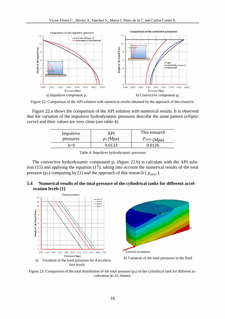
5.2 Numerical results of the hydrostatic pressure of the circular tanks
The numerical hydrostatic analysis obtained by FEM (fluid – structure system) of the tank was compared with the analytical solution (equation 18) when the vessels are submitted to the action of a liquid hydrostatic pressure. For a vertical, cylindrical shell completely full of liq-uid, with uniform thickness t, radius R, heights h, and weight per unit volume of the liquid γ, the radial displacement w(x) is given by Timoshenko [17];
⎥⎦⎤⎢⎣
⎡ ⎟⎟⎠⎞⎜⎜⎝
⎛ −−−−−= −− xsenh
exeh
x
D
hxw xx ββββ
γ ββ 11cos1
4)(
4 (18)
where: ( )⎥⎦⎤⎢⎣⎡ −=⎥⎦
⎤⎢⎣⎡=
22
2
24 13
4 tRDR
Et νβ and ( )2
3
112 ν−= EtD (flexural rigidity of the shell).
The radial deformations w(x) is compared in figure 19 observing a good agree between two
analyses.
Acceleration
Víctor Flores C., Héctor A. Sánchez S., María J. Pérez de la C. and Carlos Cortes S.
15
Figure 19: Radial deformation of the cylindrical tank (55 Tbls).
5.3 Hydrodynamic pressure of the cylindrical tanks with API-650[2]
Applying the equations 14 and 15 it is obtained the impulsive p1 and convective p2 compo-nents. The solution of the variation of these hydrodynamic pressure for Acc1=0.16g is repre-sented in figures 20.a and b.
a) Impulsive component p1 b) Convective component p2
Figure 20: Hydrodynamic pressures (API-650).
The impulsive hydrodynamic pressure (p1) API solution (figure 20.a) is compared with the numerical results obtained by means of the approach developed in this research solving the equation systems (4) for Acc1=0.16g, considering that the maximal pressure occur at the middle of the transversal section (L=2R=30.48m, HL=10.99m) of the tank by lateral excitation (see figures 21 and 22.a).
Figure 21: Maximal pressure at the middle of the transversal section of the tank.
Acceleration
Acceleration
Víctor Flores C., Héctor A. Sánchez S., María J. Pérez de la C. and Carlos Cortés S.
16
a) Impulsive component p1 b) Convective component p2
Figure 22: Comparison of the API solution with numerical results obtained by the approach of this research.
Figure 22.a shows the comparison of the API solution with numerical results. It is observed that the variation of the impulsive hydrodynamic pressures describe the same pattern (elliptic curve) and their values are very close (see table 4).
Impulsive pressures
API p1 (Mpa)
This research
HDYIp (Mpa) h=0 0.0133 0.0126
Table 4: Impulsive hydrodynamic pressures
The convective hydrodynamic component p2 (figure 22.b) is calculate with the API solu-tion (15) and applying the equation (17), taking into account the numerical results of the total pressure (pT) computing by [1] and the approach of this research (HDYIp ).
5.4 Numerical results of the total pressure of the cylindrical tanks for different accel-eration levels [1]
a) Variation of the total pressures for 4 accelera-
tion levels
b) Variation of the total pressures in the fluid
Figure 23: Comparison of the total distribution of the total pressure (pT) of the cylindrical tank for different ac-celeration (t=32.16mm).
Lateral excitation
Víctor Flores C., Héctor A. Sánchez S., María J. Pérez de la C. and Carlos Cortes S.
17
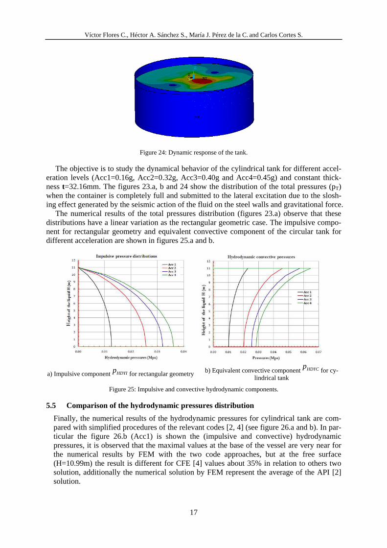
Figure 24: Dynamic response of the tank.
The objective is to study the dynamical behavior of the cylindrical tank for different accel-eration levels (Acc1=0.16g, Acc2=0.32g, Acc3=0.40g and Acc4=0.45g) and constant thick-ness t=32.16mm. The figures 23.a, b and 24 show the distribution of the total pressures (pT) when the container is completely full and submitted to the lateral excitation due to the slosh-ing effect generated by the seismic action of the fluid on the steel walls and gravitational force.
The numerical results of the total pressures distribution (figures 23.a) observe that these distributions have a linear variation as the rectangular geometric case. The impulsive compo-nent for rectangular geometry and equivalent convective component of the circular tank for different acceleration are shown in figures 25.a and b.
a) Impulsive componentHDYIp for rectangular geometry b) Equivalent convective componentHDYCpfor cy-
lindrical tank
Figure 25: Impulsive and convective hydrodynamic components.
5.5 Comparison of the hydrodynamic pressures distribution
Finally, the numerical results of the hydrodynamic pressures for cylindrical tank are com-pared with simplified procedures of the relevant codes [2, 4] (see figure 26.a and b). In par-ticular the figure 26.b (Acc1) is shown the (impulsive and convective) hydrodynamic pressures, it is observed that the maximal values at the base of the vessel are very near for the numerical results by FEM with the two code approaches, but at the free surface (H=10.99m) the result is different for CFE [4] values about 35% in relation to others two solution, additionally the numerical solution by FEM represent the average of the API [2] solution.

Víctor Flores C., Héctor A. Sánchez S., María J. Pérez de la C. and Carlos Cortés S.
18
a) (Impulsive +convective) hydrodynamic pres-
sures by FEM b) Comparison of the (impulsive and convective)
hydrodynamic pressures
Figure 26: Comparison of the hydrodynamic pressures (FEM, [2, 4]).
6 CONCLUSIONS
• The numerical results obtained to distribution of the impulsive pressures (HDYIp ) gener-ated by a horizontal acceleration for the rectangular geometry by means of the procedure developed and based on the method the finite element (FEM) through of the discretiza-tion dominion with triangular elements, satisfying the Laplace equation, showing a good agree between others solutions as the Westergaard.
• The convective component (HDYCp ) is determinate considering this impulsive pressures
( HDYIp ) and the total pressure (Tp ) is obtained with fluid-structure interaction model composed by quadrilateral shell elements shells63 and fluid80 coupled [1], for different, thickness t and acceleration levels.
• The hydrostatic and dynamic response (impulsive and convective pressures) of the full steel cylindrical tank is study as a fluid-structure model composed by quadrilateral shell elements shells63 and fluid80 coupled [1], for different acceleration levels and (t=32.19mm). It is observed a good agree results between numerical and theoretical result, for the hydrostatic case.
• The dynamic response of the cylindrical tank is analyzed, involving the numerical mod-eling by FEM and simplified procedures of the two relevant codes [2, 4]. The impulsive component (p1) with API solution is compared with the approach developed in this re-search, regarding that the maximal pressure occur at the middle of the transversal section of the tank by lateral excitation, describing the same pattern (elliptic curve), and their values are very close. Finally, it is observed that the maximal hydrodynamic pressures at the base of the vessel are very near for the numerical results by FEM with the two code approaches, but at the free surface the result is different for CFE [4] code about 35% in relation to others two solution; additionally the numerical solution by FEM represent the average of the API [2] solution.
Víctor Flores C., Héctor A. Sánchez S., María J. Pérez de la C. and Carlos Cortes S.
19
REFERENCES
[1] ANSYS Release, ANSYS, Inc. Theory Reference, ANSYS Inc., 2005.
[2] API Standard 650, Welded Steel Tanks for Oil Storage, Eleven Edition, 2007.
[3] ASCE, Fluid/structure interaction during seismic excitation, A report by the ASCE Committee on Seismic Analysis on Nuclear Structures and Materials of the Structural Division, USA, 74 pp., 1994.
[4] CFE-93, Manual de diseño de obras civiles diseño por sismo. Comisión Federal de Electricidad, IIE, México D.F., 1993.
[5] T. W. Cooper, and T. P. Wachholz, Performance of petroleum storage tanks during earthquakes. ASCE, 2003.
[6] Y.C. Fung and E.E. Sechler, Thin-shell structures. Ed. by Fung, Prentice-Hall, Inc. En-glewood Cliffs, New Jersey, 1974.
[7] M. A. Haroum and W.G. Housner, Seismic design of liquid storage tanks. ASCE, Pro-ceedings J. of Technical Councils, Vol. 107, No. TC1, April, 191-345, 1981.
[8] M. A. Haroum, Vibration studies and test of liquid storage tanks. Earthquake Engineer-ing and Structural Dynamics, Vol. 11, 179-206, 1983.
[9] W.G. Housner, Selected earthquake engineering papers of George W. Housner. ASCE, New York, 1983.
[10] P.K. Malhotra, T. Wenk and M. Wieland, Simple procedure for seismic analysis of liq-uid-storage tanks. Structural Engineering International, 2003.
[11] I. Nachtigall, N. Gebbeken, and G.J. Urrutia, On the analysis of vertical circular cylin-drical tanks under earthquake excitation at its base. Engineering Structures, 2003.
[12] E. Rosemblueth, and N.M. Newmark, Fundamentos de ingeniería sísmica. Ed. Diana. México, 1976.
[13] O. C. Zienkiewicz, El método de los elementos finitos. Ed. Reverté. Barcelona, 1980.
[14] O. C. Zienkiewicz, R.L. Taylor, and P. Nithiarasu, The finite element method for fluid dynamics. Ed. Elsevier, Butterworth Heinemann, 2000.
[15] S. H. Sánchez, and S.C. Cortés, Structural behavior of liquid filled storage tanks of large capacity placed in seismic zones of high risk in Mexico. Proceedings 13th World Conference on Earthquake Engineering, Vancouver, B.C., Canada, August 1-6, 2004, Paper No. 2665, 2004.
[16] S. H. Sánchez, S.C. Cortés, L.J. Alamilla, M. Pérez, De C., C.V. Flores and R.E. Con-treras, Comportamiento sísmico de tanques de almacenamiento de líquidos de gran ca-pacidad ubicados en zonas sísmicas. Reporte del proyecto de Investigación SIP-20060825, IPN. México, 2007.
[17] S.T. Timoshenko and S.P. Krieger, Theory of plates and shells. 2°Ed. McGraw-Hill Int., Tokyo, Japan, 1959.