maximum permissible exposures for ocular safety (ansi 2000), with emphasis on ophthalmic devices
TRANSCRIPT

1TZshtenlloela
antPlsut(mi
1250 J. Opt. Soc. Am. A/Vol. 24, No. 5 /May 2007 Delori et al.
Maximum permissible exposures for ocular safety(ANSI 2000), with emphasis on ophthalmic
devices
François C. Delori
Schepens Eye Research Institute and Department of Ophthalmology, Harvard Medical School,Boston, Massachusetts 02114, USA
Robert H. Webb
Schepens Eye Research Institute and Wellman Center for Photomedicine, Massachusetts General Hospital,Harvard Medical School, Boston, Massachusetts 02114, USA
David H. Sliney
U.S. Army Center for Health Promotion and Preventive Medicine, Aberdeen Proving Ground,Maryland 21010, USA
Received August 10, 2006; accepted September 26, 2006;posted October 25, 2006 (Doc. ID 73925); published April 11, 2007
After discussing the rationale and assumptions of the ANSI Z136.1-2000 Standard for protection of the humaneye from laser exposure, we present the concise formulation of the exposure limits expressed as maximumpermissible radiant exposure (in J/cm2) for light overfilling the pupil. We then translate the Standard to aform that is more practical for typical ophthalmic devices or in vision research situations, implementing thespecial qualifications of the Standard. The safety limits are then expressed as radiant power (watts) enteringthe pupil of the eye. Exposure by repetitive pulses is also addressed, as this is frequently employed in oph-thalmic applications. Examples are given that will familiarize potential users with this format. © 2007 Opti-cal Society of America
OCIS codes: 170.4460, 330.3350.
sllntsctcfa7th
2LRf
ds(c
. INTRODUCTIONhe American National Standards Institute (ANSI)136.1-2000 Standard1 is one of several safetytandards2–6 that were developed to protect persons fromazardous exposures from industrial, medical, and mili-ary lasers with an emphasis on exposures of the eye. Thexposure limits given by the different standards areearly identical. Many standards,2,7 but not all,6 separate
asers and broadband sources; the recommended exposureimits are not substantially different for both.8 Thus, usef the ANSI Standard for narrow spectral bands (light-mitting diodes, etc.) is common practice. For broadbandight sources, spectral weighting functions must bedded.2,6,7
Ocular exposures are not always accidental but maylso be intentional, as in retinal imaging and other diag-ostic applications. Special considerations for the use ofhe Standard in these special applications are required.roper application of the Standard is a challenge, particu-
arly in ophthalmic applications.9–11 The Standard (as ithould be) is very rules oriented and does not explain thenderlying assumptions. An adjustment of the Interna-ional Commission on Non-Ionizing Radiation ProtectionICNIRP) broadband guidelines7 for ophthalmic instru-ents was recently published,12 but its scope is more lim-
ted than the ANSI Standard.
1084-7529/07/051250-16/$15.00 © 2
The purpose of this paper is to offer a concise, step-by-tep, implementation of the Standard for eye safety fromight exposure and to explain much of the rationale thated to its current formulation. After a brief review of reti-al light damage mechanisms, we discuss the assump-ions on which the ANSI Z136.1-2000 Standard and othertandards are based (Sections 2 and 3) and present a con-ise formulation of the Standard (Section 5). We thenranslate this formulation in a form that is directly appli-able to ophthalmic applications (Section 6), accountingor various assumptions embedded in the Standard. Welso address exposure limits for repetitive pulses (Section) since these are frequently used in ophthalmic applica-ions [scanning laser ophthalmoscope (SLO), optical co-erence tomography, etc.].
. DAMAGE MECHANISMS AND EXPOSUREIMITSetinal damage from light exposure occurs principally
rom three mechanisms.Thermal damage is due to protein denaturation in-
uced by temperature increases secondary to light ab-orption by melanin in the retinal pigment epitheliumRPE). For exposure durations longer than �20 �s, heatan dissipate out of the exposed area during the exposure
007 Optical Society of America

acdsifimd
�nLf
ltpTd
tcnaealpA“aa
tl2�we
3LTs
ATtaep
ilscfa
BTt
tlrbptitS
CAptep4bsmm
mcjddwctdb
DTtTchrs
EATtflmpe6ttUjor
4Ak
Delori et al. Vol. 24, No. 5 /May 2007/J. Opt. Soc. Am. A 1251
nd the energy needed to produce retinal damage in-reases with less than a linear dependence on exposureuration (t0.75 dependence).13,14 For exposure durationshorter than �20 �s, heat diffusion can be neglected dur-ng the exposure durations, as the absorbed energy is con-ned to the irradiated volume of tissue (thermal confine-ent regime).15 The energy needed to produce retinal
amage is then independent of exposure duration.Thermoacoustic damage occurs for pulses shorter than1 ns and is associated with various nonlinear mecha-isms (laser-induced breakdown, self-focusing, etc.).16
ess energy is then needed to cause retinal damage thanor longer pulse duration.
Photochemical damage occurs at short visible wave-engths and for exposure duration longer than �1 s and ishought to be the result of a photo-oxidative insult to thehotoreceptors and to lipofuscin pigments in the RPE.17,18
he energy needed to cause photochemical damage is in-ependent of exposure duration.The ANSI Standard is based on numerous experimen-
al determinations of damage thresholds for differentombinations of wavelength, exposure duration, and reti-al spot size.19 Most experimental studies were made innimals (monkey, rabbit) and involved probit analysis ofxperimental threshold lesions.20 Results of new studies,s well as information from the analysis of accidentalight damage, generate changes in the Standard as timeasses. Periodic review of the Standard is required by theNSI procedures,1 and this is an ongoing process. A new
ANSI 2005 Standard” is currently in the final steps ofpproval, but so far it incorporates no changes that wouldffect this paper.21
Retinal irradiances or retinal radiant energies causinghreshold retinal damage were converted into exposureimits that are generally expressed, in the ANSI Z136.1-000, as maximum permissible (MP) radiant exposureJ/cm2� for laser beams overfilling the pupil of the eye,hich is the most common situation for accidental laserxposures.
. ASSUMPTIONS LEADING TO EXPOSUREIMITShe Standard’s conversions of damage thresholds to expo-ure limits were based on several important assumptions.
. Safety Factor and Applicabilityhe exposure limits were set to be at least 10 times lower
han the damage “threshold,” expressed as a 50% prob-bility of a minimum visible lesion. This factor was gen-rally considered adequate even when the slope of therobability (“probit”) curve is relatively shallow.20
The Standard was derived for healthy, alert individualsn occupational settings. Alert subjects exposed to brightight will either close their eyes or look away. This aver-ion reflex is not included in the Standard but can be ac-ounted for by selecting the exposure duration of 0.25 sor wavelengths in the 400–700 nm range (class 2 lasersre based on an exposure duration of 0.25 s).22
. Diameter of the Pupilhe Standard was developed under the assumption thathe incident radiation overfills the natural pupil (iris) of
he eye and that the pupil would constrict under brightights in the visible spectrum. The duration of this pupileflex is 0.2 to 1.0 s. Therefore, the pupil was assumed toe 7 mm in diameter (maximum natural dilation) for ex-osures shorter than 0.2–1.0 s. For longer exposures inhe visible spectrum, the pupil was assumed to constrictn response to bright light to a diameter of 3 mm. Thus,he protective effect of pupil constriction is included in thetandard.
. Minimal Retinal Dimensionn underlying assumption in the Standard is that, for ex-osure by a collimated beam for durations less than �1 s,he minimal retinal image is effectively �25 �m in diam-ter (visual angle of 1.5 mrad, termed �min). Although theoint-spread function of the eye measured at half power is–6 �m wide,23,24 the sharp central peak is surroundedy a larger area containing substantial energy frommall-angle forward scattering.23,24 The resulting “ther-al image” is �25 �m, and the smallest observed ther-al lesions were also of that order.25,26
For exposure duration longer than �1 s, eye move-ents redistribute the light over larger retinal areas, de-
reasing the retinal irradiance and thus the risk for in-ury compared with the instantaneous profile 25 �m iniameter.27 For exposures of 100 s, the Standard uses aiameter of �190 �m (visual angle of 11 mrad), whichas in part based on the size of accidental lesions in oc-
upational situations.19,26 For even longer exposure dura-ions, when task-determined eye and head movementsominate, the dimension of exposed retina is assumed toe �1.7 mm in diameter (visual angle of 100 mrad or 5°).
. Ocular Mediahe retina is partially protected by absorption of light by
he ocular media (cornea, crystalline lens, and vitreous).he crystalline lens absorbs light for ��400 nm, but theornea and vitreous absorb for ��300 nm, allowingarmful radiation (UV) to reach the retina if the lens isemoved. Absorption by the ocular media of young adultubjects was incorporated into the Standard.28
. Deviation from These Assumptions May Requiredded Cautionhe potential increased risk of laser exposures in oph-
halmic devices caused by the inhibition of the pupil re-ex (mydriatic drugs) or by the restriction of eye and headovements was considered by the ANSI Zl36.1-2000 in
aragraph Section 8.3 (“Special qualifications for ocularxposures”), and this will be discussed here in Subsection.A. There is concern about the possible increased suscep-ibility of older people and those with retinal disease andhe low absorption of the ocular media (particularly in theV and short wavelengths) encountered in aphakic sub-
ects and in infants (who also have higher concentrationsf RPE melanin).29 Thus caution (and common sense) isecommended in these situations.
. EXPOSURE PARAMETERSssessment of the safety of ocular exposure requiresnowledge of the power or energy of the radiation inci-

dadste
�fioG
Trtg
tevwfrad
wH
wsE
Tt�
oceetp
5SNATn4smCp
Ab
(tdddr[swe
pl�rMtrfw
FNoqt
1252 J. Opt. Soc. Am. A/Vol. 24, No. 5 /May 2007 Delori et al.
ent on the eye, the wavelength �, the exposure duration,nd the size of exposed retinal area. Measurements of ra-iant exposure or irradiance at the corneal plane aretraightforward.19,30 For visible and near-IR wavelengths,he Standard requires measurements over a 7 mm diam-ter area.
To quantify the area of retinal exposure, the (full) anglein radians is measured from the pupil, roughly at the
rst nodal point of the eye (Fig. 1). Taking dr as the extentf this area and fe as the eye’s focal length (fe=1.7 cm,ulstrand’s model eye),
� = 2 tan−1dr
2fe�
dr
fe. �1�
he right term of Eq. (1) is a small-angle approximation,esulting in only a 5% error at 45°. All subsequent equa-ions use this approximation. A circular retinal area isiven by
Aretina ��
4�fe��2. �2�
In free or Newtonian illumination [Fig. 1(a)],31 a dis-ant source irradiates an area larger than the pupil of theye. This is the condition for which the Standard was de-eloped. The visual angle � is then given by ��ds /shere ds is the extent of the source and s its distance
rom the eye [Fig. 1(a)]. The solid angle � subtended by aound source is ���� /4��2. If the (time) integrated radi-nce of the source is Ls (in J/cm2 sr), then the corneal ra-iant exposure Hc �J/cm2� is given by
Hc = Ls� ��
4Ls�
2, �3�
ith � expressed in radians. The retinal radiant exposurer �J/cm2� is
ig. 1. Modes of illumination of the retina. (a) Free- orewtonian-illumination condition where the pupil of the eye is
verfilled by the incident light. (b) Maxwellian illumination fre-uently used in ophthalmic devices where the incident illumina-ion occupies a small fraction of the pupil.
Hr = Hc
Apupil
Aretina� Hc�
dp2
fe2�2
, �4�
here dp is the diameter of the pupil and � the transmis-ion of the ocular media. Substituting Hc from Eq. (3) intoq. (4) gives
Hr = Ls��
4�dp
fe�2
. �5�
he retinal radiant exposure expressed as a function ofhe integrated radiance of the source Ls is independent of.In Maxwellian illumination,31 which is often used in
phthalmic instruments, the light emerging from an opti-al system enters the eye with known angle � through anntrance pupil that will generally be smaller than theye’s natural pupil. Then the retinal radiant exposure ishe power entering the pupil �, divided by the retinal ex-osed area given by Eq. (2):
Hr =4
��fe��2��. �6�
. CONCISE PRESENTATION OF THE ANSITANDARD: FREE VIEWING ANDATURAL PUPIL. Rationalehe Standard gives the MP radiant exposure at the cor-ea (MPHc in J/cm2) in ANSI Tables 5a and 5b (pp. 45,6), devoted to “small sources” and “extended sources,” re-pectively. The MPHc for extended sources is obtained byultiplying the MPHc of a small source by a parameterE, which is a function of the visual angle � [Table 2 (up-er part)]. Thus,
MPHc,Ext Source = CE MPHc,Small Source. �7�
NSI Tables 5a and 5b differ only by CE and were com-ined here in Table 1.We also grouped the thermal limits in five equations
left side of Table 1), corresponding to the exposure dura-ion intervals used in the Standard. Wavelength-ependent parameters CT (which combines the Stan-ard’s parameters CA and CC) and CJ (which account for aiscontinuity32) are given in Table 2 (lower part). The pa-ameters CA and CC are crude representations of1/absorption spectrum of melanin] and the absorptionpectrum of the ocular media, respectively. Both increaseith wavelength, resulting in a higher MPHc, and higher
xposure is permissible.The variation of CE with visual angle [Table 2 (upper
art)] essentially reflects thermal modeling33–35 and bio-ogical data on thresholds for thermal damage.36–38 For��max, CE and MPHc increase linearly with �. The MPetinal radiant exposure, which is proportional withPHc /�2 [Eq. (4)], thus decreases with �. This reflects
he higher thresholds for thermal damage for smallather than large areas because heat dissipation is muchaster for a small area. For ��max, CE is proportionalith �2 and the retinal radiant exposure is independent

otst
mpft1�wss
mAp[ifsia��td
BVTt4c fiafifMoaat
CPWf1s1
pt
2
Delori et al. Vol. 24, No. 5 /May 2007/J. Opt. Soc. Am. A 1253
f � [Eq. (4)]. This corresponds with findings that damagehresholds expressed in retinal radiant exposure are con-tant because heat dissipation occurs principally towardhe choroid.
The exposure duration tmin is the “thermal confine-ent” duration during which heat flow away from the ex-
osed site is small15; the MP exposure is independent of tor t� tmin (cell 3, Table 1; MPHc constant). Heat dissipa-ion is assumed to be significant for t tmin (cell 4, Table; MPHc increasing as t0.75). For exposures longer than T210–100 s�, the Standard assumes that head movementsill spread the beam over larger areas of the retina (Sub-
ection 3.C); the limits are then relaxed and set at a con-tant corneal or retinal irradiance (cell 5, Table 1).
The photochemical MPHc’s in Table 1 (right side)atch the corresponding photochemical limits in theNSI Table 5b (under “Dual limits”) except that we ex-ressed all limits in corneal radiant exposures MPHcsource-integrated radiance converted using Eq. (3)] andncorporated the limiting angular subtense �, defined in aootnote of ANSI Table 5b. This reflects the Standard’s as-umption (Subsection 3.C) that the minimal visual angles �=11 mrad for an exposure duration from 0.7 to 100 snd then increases gradually (slanted line in Table 1) to=110 mrad for an exposure duration longer than 104 s
2.8 h). The wavelength-dependent parameter CB mimicshe inverse of the action spectrum of photochemicalamage.17
Table 1. Maximum Permissible Radiant Exposu
. Use of the Concise ANSI Z136.1-2000 Standard (Freeiewing)he formulation of the Standard in Table 1 is identical to
he ANSI Z136.1-2000 Standard for wavelengths from00 to 1400 nm. The MP levels for thermal and photo-hemical damage are dual limits for ��600 nm and t0.7 s, and the smaller MP level is used. To use Table 1,
rst identify the “cell” that corresponds to the applicationt hand (T2 and tmin in Table 2 may also be needed). Thennd the relevant parameters (CE ,T2 ,CT ,CJ ,CB, and tmin)
rom Table 2. The MPHc may be calculated. MPHc is theP radiant exposure (in J/cm2) at the cornea for light
verfilling the pupil. For �1050 nm, it is not required toccount for the absorption by the ocular media since thisbsorption is incorporated in the MPHc [increase by a fac-or of 8; Table 2 (lower part)].
. Example: Extended Source Viewing with Naturalupilhat is the MP corneal radiant exposure permitted for
ree viewing, during 50 s, of a 5 cm diameter disk locatedm from the eye and illuminated by a double Nd:YAG la-
er ��=532 nm�? This is example 59 in the Standard (p.16).
The visual angle is �=5/100=50 mrad. Table 2 (upperart) gives T2=100.0102�97+50�=31.6 s. Since tT2, we usehe equation in cell 5 of Table 1:
Hc (in J/cm ) at the Cornea (Overfilling Pupil)
re MP
1254 J. Opt. Soc. Am. A/Vol. 24, No. 5 /May 2007 Delori et al.
Table 2. Parameters to be Used in Tables 1 and 3
Table 3. Maximum Permissible Radiant Power MP� (in watts) Entering the Natural or Dilated Pupil

wa�ce
w(i2
6AAOtarpwlmhasmStt3d
eitdflm
Dpci=llpTtaas2
eP2
b(lthsrtpti�m
iaislriscv
gohfs
BIptfpttseoo“
ccto1ntrbio
Delori et al. Vol. 24, No. 5 /May 2007/J. Opt. Soc. Am. A 1255
MPHc,thermal = 1.8 10−3 CT CE T2−0.25 t
= 1.27 J/cm2,
here we used CT=1 ���700 nm, Table 2 (lower part)]nd CE=0.66750=33.4 [Table 2 (upper part)]. Since �600 nm and t0.7 s, we also calculate the photochemi-
al limit. Since �11 mrad and t�100 s, we use thequation in cell 7 of Table 1:
MPHC,photochemical = 7.85 10−5 CB �2 = 8.57 J/cm2,
here we substituted CB=100.02�532−450��43.7 [Table 2lower part)]. The thermal limit is smaller, so 1.27 J/cm2
s the MPHc. The corresponding MP corneal irradiance is5.4 mW/cm2.
. ANSI STANDARD FOR OPHTHALMICPPLICATIONS. Rationaleptical devices that image the retina or perform diagnos-
ic tests often bring light into the eye through a smallrea of the natural pupil (Maxwellian illumination). Theest of the pupil may be used for observational optics, andupil dilation with mydriatic drugs is often required,hich paralyzes both the pupillary constriction and the
ens accommodation. Eye and head movements are ofteninimized by the use of “fixation” targets and chin-and-ead rests. Bite bars and retinal image stabilization maylso be used. Thus, the protective effects from pupil con-triction (Subsection 3.B) and from eye and head move-ents (Subsection 3.C) that are incorporated into thetandard (Table 1) may not exist in ophthalmic applica-ions. The Standard addresses these issues in ANSI Sec-ion 8.3, “Special Qualifications for Ocular Exposures” (p.8), which provides guidance on correction for these un-erlying assumptions.In addition to implementing Section 8.3, we choose to
xpress the exposure limits for ophthalmic applications inntrapupillary radiant power � (watts). That is the quan-ity generally measured by radiometers. Since the Stan-ard expresses the exposure limits as radiant exposureor light overfilling the natural pupil (Table 1), we calcu-ate the MP radiant power MP� (in watts), for both ther-
al and photochemical limits:
MP� = MPHc�Ap,7
P 1
t. �8�
ivision by the exposure duration, t, converts energy toower. The term in square brackets is the pupil area (inm2) that is assumed in the Standard (Subsection 3.B). Its Ap,7, the area of a 0.7 cm diameter pupil �Ap,70.385 cm2�, divided by a “pupil factor” P � 1� that simu-
ates the pupil response to light, varying with both wave-ength and exposure duration [Table 2 (lower part)].39 Theupil factor is designed to correct the ANSI equations inable 1, whose MP levels are higher (relaxed) based onhe assumption that the pupil will constrict in response to
bright light. Note that the photochemical limit is alsoffected by the factor P. Indeed, ANSI Section 8.3(1)tates that the retinal radiant exposure should not exceed.7C J/cm2, which corresponds to the MP retinal radiant
Bxposure predicted by Eqs. (6) and (8) after substitution of=5.44 and MPHc (cell 7 of Table 1); the result is actually.45CB J/cm2).40
ANSI Section 8.3(1) also addresses eye and head immo-ilization. The minimal visual angle is reduced from �Subsection 5.A) to 1.5 mrad for all exposure durationsonger than 0.1 s. Although not specifically indicated inhe Standard, the thermal limiting exposure T2 (eye andead movements) was increased to 104 s for similar rea-ons. We have chosen the very conservative exposure du-ation limit of 104 s �2.8 h�. We expect investigators to setheir own duration limit, depending upon the type of ex-eriments, and to accordingly calculate the MP level forheir specific situation. For example, most patients’ test-ng could readily be accomplished in less than 5 min300 s�, whereas some psychophysical research testingay require longer exposure durations.The MP�’s in Table 3 were obtained by converting, us-
ng Eq. (8), the MPHc’s of Table 1. Cell 4 of Table 3 is splitt t=0.07 s (the lower exposure limit of the pupil factor P)nto cells 4a and 4b, and cell 5 is now restricted to expo-ure durations 104 s. Cells 7 and 9 of the photochemicalimits are similarly converted but with P=5.44 incorpo-ated into the constants [Table 2 (lower part)]. The limit-ng angle � of Table 1 is reduced to 1.5 mrad for all expo-ure durations shorter than 104 s, thereby eliminatingells 6 and 8 of Table 1 and extending cells 7 and 9 for allalues of �.
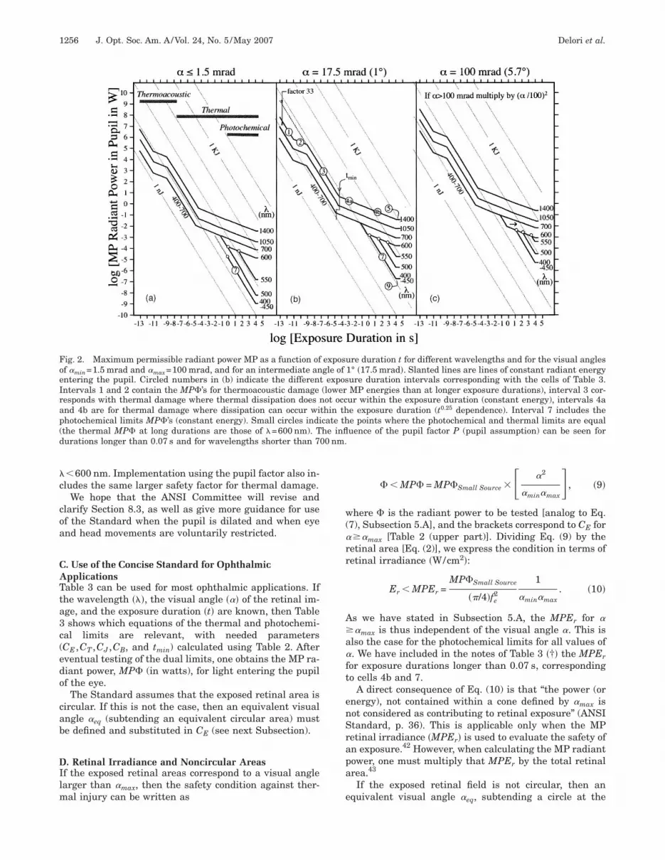
Table 3, together with parameters defined in Table 2,ives the MP intrapupillary radiant power after removalf the assumptions concerning pupil constriction and eye/ead movements. Figure 2 shows the MP� levels as a
unction of exposure duration for three values of the vi-ual angle.
. Limitations and Compromisesmplementation of ANSI Z136.1 Section 8.3 raises twooints of concern. First, an apparent discontinuity be-ween the thermal and the photochemical limits appearsor small spot sizes and short wavelengths (Fig. 2, leftanel, line marked “7”). This is a consequence of the facthat the ANSI Committee simplified the expressions forhe photochemical limits to assume a minimal exposureize of �190 �m ��=11 mrad� to account for involuntaryye movements. However, Section 8.3 of the Standard rec-mmends the minimum size of 1.5 mrad for duration t0.7 s. We suggest extrapolating the photochemical limit
f cell 7 toward a shorter exposure duration (line marked7” in Fig. 2, left).41
Second, the plot of MP� versus duration exhibits a dis-ontinuity toward lower MP values (t0.07 s, Fig. 2)aused by the pupil factor P. This is disturbing becausehe threshold level for thermal damage decreases continu-usly with increasing exposure duration between 0.1 and00 s. In fact, the MPHc (Table 1) should have a disconti-uity toward high MP values to reflect the increased pro-ection afforded by the assumed constriction of the natu-al pupil. Yet the MPHc show no such trend. This isecause the ANSI framers attempted to simplify the lim-ts by accepting a larger safety factor (10P�50 insteadf �10) for thermal damage at times exceeding �1 s and
�c
coa
CATta3c(edo
cab
DIlm
w(�rr
A a�ft
enSrapa
e
FoeIrap(d 00 nm.
1256 J. Opt. Soc. Am. A/Vol. 24, No. 5 /May 2007 Delori et al.
�600 nm. Implementation using the pupil factor also in-ludes the same larger safety factor for thermal damage.
We hope that the ANSI Committee will revise andlarify Section 8.3, as well as give more guidance for usef the Standard when the pupil is dilated and when eyend head movements are voluntarily restricted.
. Use of the Concise Standard for Ophthalmicpplicationsable 3 can be used for most ophthalmic applications. Ifhe wavelength ���, the visual angle ��� of the retinal im-ge, and the exposure duration �t� are known, then Tableshows which equations of the thermal and photochemi-
al limits are relevant, with needed parametersCE ,CT ,CJ ,CB, and tmin) calculated using Table 2. Afterventual testing of the dual limits, one obtains the MP ra-iant power, MP� (in watts), for light entering the pupilf the eye.
The Standard assumes that the exposed retinal area isircular. If this is not the case, then an equivalent visualngle �eq (subtending an equivalent circular area) muste defined and substituted in CE (see next Subsection).
. Retinal Irradiance and Noncircular Areasf the exposed retinal areas correspond to a visual anglearger than �max, then the safety condition against ther-
al injury can be written as
ig. 2. Maximum permissible radiant power MP as a function off �min=1.5 mrad and �max=100 mrad, and for an intermediate anntering the pupil. Circled numbers in (b) indicate the differenntervals 1 and 2 contain the MP�’s for thermoacoustic damageesponds with thermal damage where thermal dissipation does nnd 4b are for thermal damage where dissipation can occur wihotochemical limits MP�’s (constant energy). Small circles indithe thermal MP� at long durations are those of �=600 nm). Turations longer than 0.07 s and for wavelengths shorter than 7
� � MP� = MP�Small Source � �2
�min�max , �9�
here � is the radiant power to be tested [analog to Eq.7), Subsection 5.A], and the brackets correspond to CE for �max [Table 2 (upper part)]. Dividing Eq. (9) by theetinal area [Eq. (2)], we express the condition in terms ofetinal irradiance �W/cm2�:
Er � MPEr =MP�Small Source
��/4�fe2
1
�min�max. �10�
s we have stated in Subsection 5.A, the MPEr for ��max is thus independent of the visual angle �. This is
lso the case for the photochemical limits for all values of. We have included in the notes of Table 3 �†� the MPEr
or exposure durations longer than 0.07 s, correspondingo cells 4b and 7.
A direct consequence of Eq. (10) is that “the power (ornergy), not contained within a cone defined by �max isot considered as contributing to retinal exposure” (ANSItandard, p. 36). This is applicable only when the MPetinal irradiance �MPEr� is used to evaluate the safety ofn exposure.42 However, when calculating the MP radiantower, one must multiply that MPEr by the total retinalrea.43
If the exposed retinal field is not circular, then anquivalent visual angle � , subtending a circle at the
ure duration t for different wavelengths and for the visual angles1° �17.5 mrad�. Slanted lines are lines of constant radiant energyure duration intervals corresponding with the cells of Table 3.MP energies than at longer exposure durations), interval 3 cor-ur within the exposure duration (constant energy), intervals 4ae exposure duration (t0.25 dependence). Interval 7 includes thee points where the photochemical and thermal limits are equaluence of the pupil factor P (pupil assumption) can be seen for
exposgle of
t expos(lowerot occ
thin thcate thhe infl
eq

rsMie
Wp
3ocagatt��tEa
ssic
fi�
sutmmor
ERipii
w“tpTab
Fsduobtliu
Delori et al. Vol. 24, No. 5 /May 2007/J. Opt. Soc. Am. A 1257
etina, is first defined. The thermal MP���=�eq corre-ponding to this �eq is calculated using Table 3. However,P���=�eq is the limiting power for an area correspond-
ng to �eq, and it must be scaled to obtain the MP� for thentire field:
MP� = MP�Small Source CE�� = �eq
Area of noncircular field
Area of circle subtended by �eq. �11�
e define CE� as an effective scaling factor for use in com-utation of the MP� for noncircular sources:
CE� = CE�� = �eq Area of noncircular field
Area of circle subtended by �eq.
�12�
For a rectangular area, the Standard recommends (p.6) using an equivalent, �eq, equal to the arithmetic meanf dimensions of the rectangle [the ANSI 2005 (Ref. 21)larifies the current Standard]. If �L and �W are thengles subtending the length and the width of the rectan-ular field, respectively, then �eq=0.5��L+�W�. Addition-lly, the smaller dimension must be set to �min if it is lesshan �min and dimensions greater than �max should be seto �max. Thus, �eq=0.5��max+�W� only if �L is larger thanmax, and �eq=�max if both dimensions are larger thanmax. The factor CE is calculated using �eq and is substi-uted in Eq. (10) to yield the effective CE� and the MP�.xpressions for CE� were calculated using Eq. (12) for rect-ngles of various dimensions (Table 4) as well as for
Table 4. Effective CE� Used in Evaluating the MP�for Exposures in Rectangular Areas
quares and slits. Note that CE� , and thus the MP�, forhort slits ��L��max� is nearly constant (the MP retinalrradiance decreases with �L, and the area of the slit in-reases with �L since its width is constant).
Note that an earlier version of the ANSI Standard44 de-ned �eq as the geometric mean ��L�W. This is similar toeq, defined as the angular diameter of a circle with theame area as the rectangular field ��4/���L�W, and wassed occasionally.11 However, mathematical models ofhermal injury led to the empirical result that the arith-etic mean was more appropriate than the geometricean.45,46 Since considerable uncertainty exists as to the
ptimal simulation of oblong and slit-shaped areas, weecommend the use of the arithmetic mean.
. Retinal Illuminanceetinal illuminance is the equivalent of retinal irradiance
n the world of psychophysics. It describes the brightnesserceived by an observer. Retinal illuminance (expressedn photopic Trolands31) is given as a function of the retinalrradiance Er �W/cm2� by47
Photopic illuminance �trolands� = 1.97 109Vph,�Er,
�13�
here Vph is the photopic visibility function. We derivedMP illuminance” at different wavelengths (Fig. 3) fromhe MP retinal irradiances for the thermal ��5.7° � andhotochemical limits (exposure duration, 300 and 30 s).hus, a retinal illuminance of 6 log photopic Trolands ist least 10 times below the safety limits for wavelengthsetween 490 and 790 nm.48
ig. 3. Photopic retinal illuminances for which the exposureafety limit is reached, as a function of wavelength, for exposureurations of 30 and 300 s. Retinal illuminances were calculatedsing Eq. (13) from the MP retinal irradiance given in the notesf Table 3 �†� for visual angles larger than 5.7°. The limits woulde higher (more safe) for smaller visual angles. The dots indicatehe longest wavelength at which the photochemical limit was theimiting factor. The scale on the right shows the level of bleach-ng of the cone photoreceptors, calculated for the 300 s exposuresing Rushton’s data.48

FOAppGmipTtstlt
GEAr4utwwo
pt
w==af
papm
nltc=cM
a
HPPmsbstdtWtd
M60fTtT
w2=swetn
7TecepFt
Foataes4
1258 J. Opt. Soc. Am. A/Vol. 24, No. 5 /May 2007 Delori et al.
. Computer Implementation of the ANSI forphthalmic Applicationll MP radiant exposures MP� defined by Table 3 [witharameters defined in Tables 2 (upper part) and 2 (lowerart)] can be readily computed using simple programs.49
raphical representation of the MP�, with separate ther-al and photochemical limits, as demonstrated in Fig. 4,
s highly recommended. With such programs, the MP�lot changes instantly as values of � and � are entered.he plots also can show the exposure to be tested and ex-rapolations to higher power �MP�� and to longer expo-ure duration �MPt�, as shown in Fig. 4. Another advan-age of the MP� plots for thermal and photochemicalimits is that one can instantly assess the dual limit (andhen calculate only the lower one).
. Example: Retinal Fluorophotometer (Singlexposure)n experimental retinal fluorophotometer that measuresetinal fluorophores over a circular field of 3° uses a88 nm argon laser. The intrapupillary radiant powersed for excitation is �ex=450 �W, and a shutter limitshe exposure duration to t=180 ms. The pupil is dilatedith a mydriatic drug. How safe is this exposure andhat is the safe time if the shutter fails and remainspen?
The visual angle is �=17.53° =52 mrad [Table 2 (up-er part)]. Since t�0.7 s, we need only to examine thehermal limit, which is given by cell 4b of Table 3:
MP� = �6.93 10−4CTCEP−1t−0.25 = 19 mW,
here we used CT=1 ���700 nm� and P= �0.18/0.07�0.75
2.03 [cell a, Table 2 (lower part)] and CE=0.6675234.7 [Table 2 (upper part)]. In this and subsequent ex-mples, we will use � to indicate the expression that isound in Table 3. The MP� is well above the specified
ig. 4. Maximum permissible radiant power MP� as a functionf exposure duration t (for �=488 nm and �=53 mrad, in this ex-mple). The circled numbers correspond to the different time in-ervals and cell numbers of Table 3. Point A represents the radi-nt power �450 �W� and exposure duration �180 ms� of thexample in Subsection 6.G. Point B is at the MP� at that expo-ure duration, and point C is at the MP exposure duration for50 �W (to assess MP duration after shutter failure).
ower, and the exposure is safe by a factor of 42. This ex-mple is illustrated in Fig. 4. Point A represents the ex-osure that we are testing, and point B is the MP� ther-al limit for the 180 ms shutter time.If the shutter is defective and remains open, then one
eeds to know how long it takes to reach the exposureimit. This is represented by point C (Fig. 4), which is onhe photochemical limit, corresponding to the equation inell 7 (of Table 3). The parameter CB is 100.020�488−450�
5.75 [Table 2 (lower part)]. The MP exposure duration isalculated by equating the incident power �ex to theP�,
MP� = 450 10−6 = �5.59 10−6CB�2t−1 = 8.7
10−2t−1 W,
nd then solving for t. We obtain MPt=193 s or 3.2 min.
. Example: Photodynamic Therapy (Control withouthotosensitizer)hotodynamic therapy is used to destroy neovascularembranes under the retina.50 An injection of a photosen-
itizer, verteporfin, is followed by irradiation of the mem-rane with a laser diode at �=689 nm (near the peak ab-orption of verteporfin). The patient’s pupil is dilated andhe eye is immobilized. The membrane is typically 5° iniameter. The concept is that the exposure will affect onlyhe photosensitized tissue without damaging the RPE.
hat is the longest exposure duration that will achievehis in the absence of the photosensitizer if a retinal irra-iance of 0.6 W/cm2 is used?We assume that � 5.7° and thus is in the range whereP retinal irradiance is independent of � (Subsection
.D). The retinal area and radiant power are at least
.023 cm2 [Eq. (2)] and 13 mW, respectively, and the MP�or 700 nm [arrow, Fig. 2(c)] will be reached after �100 s.his is in the range of cell 4b of Table 3. Thus, we equate
he corresponding MP retinal irradiance MPEr (notes inable 3) to 0.6 W/cm2:
MPEr = �2.04CTP−1t−0.25 = 1.69t−0.25 = 0.6 W/cm2,
here we used CT=1 and P=100.0074�700−689�=1.21 [Table(lower part)]. Thus, the MP exposure duration is MPt�1.69/0.6�4=63 s (retinal radiant exposure of MPHr=630.6=37 J/cm2). The current clinical protocol uses the
lightly longer exposure duration of 83 s �50 J/cm2�,hich does not result in permanent RPE damage.50 How-
ver, the same retinal irradiance with an exposure dura-ion of 250 s �150 J/cm2� caused RPE damage in someormal eyes.51
. EXPOSURE BY REPETITIVE PULSEShe material above describes safety limits for single-pulsexposures. The Standard also addresses the exposure byomplex trains of pulses. We describe here the case ofvenly spaced pulses, each with the same energy. Such aulse train is described by its pulse repetition frequency, its total duration T, the number n of pulses �n=FT�,
he duration t and peak radiant power � of a single
1 1
pfQ
Tspapeow
ATspgbceM
bpcwat�m
cm
vRplfsatMlstc
p“i�
pt5epip
ctef
Delori et al. Vol. 24, No. 5 /May 2007/J. Opt. Soc. Am. A 1259
ulse, the energy per pulse Q1�Q1=�1t1�, and the dutyactor �=Ft1. The average radiant power �av is related to
1 and �1 by
�av = Q1F = �1�. �14�
he ANSI Standard applies three “rules” that define threeeparate MP exposures. The rule that yields the highestrotection is used (lowest MP exposure). These MP levelsre expressed in the same units so they can be easily com-ared with one another: These units may be the radiantxposure per pulse (MPHc,1 in J/cm2; as in the Standard)r the average radiant power of the train (MP�av inatts).
. Rationale of the Three Ruleshe first rule tests whether the radiant exposure Hc,1 of aingle pulse (duration: t1) does not exceed the MPHc�t1 atulse duration t1 [line 1 of Table 5 (left part)]. In the moreeneral form of the Standard, it tests the safety of therightest pulse in a train of uneven pulses, but this limitan also be smallest for our formulation of equally spacedquienergy pulses (see below). The correspondingP�av=�MP��t1�, where � is the duty factor.The second rule protects against average-power heat
uildup in thermal injury and cumulative injury from thehotochemical damage mechanism. It tests the safety of aontinuous-wave (CW) equivalent exposure of duration Tith a constant-power radiant power (equal to the aver-ge power of the train). The MP�av is then MP��T, andhe corresponding radiant exposure per pulse is1/n�MPHc�T. Both thermal and photochemical limitsust be tested separately [line 2 of Table 5 (left part)].The third rule protects against subthreshold pulse-
umulative thermal injury and applies only to the ther-al limits. A tutorial published by Thomas et al.52 pro-
Table 5. Repetitive Pulses (Evenly
ides helpful information on the application of rule 3.ule 3 essentially tests whether an exposure by a longulse of duration nt1 is safe. It is based on the thermalimits of cells 3 and 4 of Table 1 [Fig. 5(a)]. The Standardormulation of rule 3 is as follows: “The exposure of anyingle pulse within the group of pulses (each separated byt least tmin) shall not exceed the single-pulse MPE (for1 tmin) multiplied by…n−0.25. Rule 3 applies only to
PE’s for thermal injury, where all pulses delivered iness than tmin are treated as a single pulse.” The lasttatement is explained in Fig. 5 and essentially meanshat such pulses occur in the regime of thermalonfinement.52,53
We consider two cases depending upon whether theulse repetition frequency is higher or lower than thecritical pulse repetition frequency” Fcr, which is definedn the Standard as Fcr=1/ tmin. It equals 55.5 kHz �400
��1050 nm� or 20 kHz �1050���1400 nm�.First, F�Fcr with pulses of duration t1 tmin, since all
ulses with t1� tmin were replaced by pulses of durationmin [k=1; pulse train 1, and train 2 with t1= tmin; Fig(b)]. The safety limit is calculated as the limit for anquivalent exposure with duration nt1 (total radiant ex-osure, nHc,1). The MPHc is that given by the expressionn cell 4 of Table 1. The MP radiant exposure �J/cm2� perulse for rule 3 is then
MPHc,1 =MPHc�nt1
n= n0.75
MPHc�t1
n= n−0.25MPHc�t1,
�15�
orresponding to the first sentence in the above formula-ion for F�Fcr [line 3, Table 5 (left part)]. Thus, the MPnergy/pulse for a multipulse exposure is the MP energyor a single-pulse exposure, reduced by a factor of n0.25.
ced Pulse of Equal EnergyÕPulse)
Spa
Wm
Elf
tn
orttflrap
BTppteMpcHb
Fort(“Isgadsrrs
Fvba(rwcpadIMT
1260 J. Opt. Soc. Am. A/Vol. 24, No. 5 /May 2007 Delori et al.
e have also expressed Eq. (15) as a function of the ther-al limit of rule 2, �1/n�MP�T:
MPHc,1 =MPHc�nt1
n= �nt1
T �0.75MPHc�T
n
= �0.75MPHc�T
n. �16�
quation (16) shows that rule 3 always yields a lowerimit (more restrictive) than the thermal limit derivedrom rule 2. The corresponding MP average radiant power
ig. 5. (a) Maximum permissible radiant exposure as a functionf exposure duration (Table 1). For repetitive pulse exposures,ule 3 essentially uses the limits of cells 3 and 4 (hatched line);he constant MPHc�tmin is assumed to extend 10−13 s to tmin.52,53
b) Pulse trains illustrating the Standard’s statement thatpulses delivered in less than tmin are treated as a single pulse.”f one or more pulses occur within the time-interval of tmin, ashown by pulse trains 2, 3, and 4, then the MP level for that sub-roup of k pulses (k 1; total energy kHc,1) is MPHc�tmin. Indeed,s seen in (a), the MPHc for t� tmin is independent of exposureuration and is equal to MPHc�tmin. In terms of light safety, theubgroup is thus equivalent to a “single pulse” with any pulse du-ation between and including 100 fs and tmin.53 We select the du-ation tmin as the duration for the “single pulse,” as indicated byhaded pulses.
hrough the pupil, MP�av, can be expressed as−0.25�MP��t1 [line 3, Table 5 (left part)].Second, if F Fcr, then subgroups of more than 1 pulse
ccur within the time frame of tmin and each subgroup iseplaced by a “single” pulse [Fig. 5(b)]. The time betweenhese pulses is also tmin, and the pulse train is equivalento a CW exposure of duration T. The MP level per pulseor rule 3 when F Fcr is thus the same as the thermalimit derived in rule 2, and there is thus no need to testule 3 if FFcr. If the pulse train duration T� tmin, thenll pulses occur during tmin, and the same reasoning ap-lies �T= tmin�.
. Use of the Three Rules for Repetitive Pulse Exposureable 5 (left part)] gives the MPHc per pulse for a train ofulses (evenly spaced pulses of the same energy perulse) according to the three ANSI rules (to be used withhe MPHc of Table 1) as well as the corresponding MP av-rage intrapupillary radiant power of the pulse train,P�av (to be used with the MP� of Table 3). In a com-
uter implementation, all three rules can be readily cal-ulated and the one with the smallest MP limit selected.owever, manual computation of the rules is facilitatedy predicting which rules should be tested [Table 5 (right
ig. 6. Maximum permissible average radiant power MP�a�
ersus the pulse repetition frequency F, illustrating the applica-ility of the three ANSI rules when t1 is smaller than tmin (cells bnd e, Table 5). For low F, the MP�a� of rule 3 increases with Fslope F0.75) and is always smaller than the thermal MP�a� ofule 2 (shown only for the full range for �=700 nm). For shorteravelengths ��=450 nm�, the photochemical limit of rule 2 be-
omes the limiting factor for F�Fcr if F is high enough �F1 kHz�. For high F, rule 2 is the only limiting factor (thermal or
hotochemical limits). The line marked with * (not drawn fully tovoid confusion) is that for rule 1 if t1 were in the 100 fs to 10 psuration range. It is 33 times lower than the other line for rule 1.t demonstrates graphically that rule 1 can yield the lowest
P�a� and that it must be tested if t1�1 ns (as indicated inable 5).

pF3btetr
CAemTtp
bla
FTc=
t2
u
g=l
upp
iM=
DFArF�e
S(
nt2
M
u[
oT
ulat1
ro
Rapo
EWSza=ccft
tv(lSmst
blrsti�
Delori et al. Vol. 24, No. 5 /May 2007/J. Opt. Soc. Am. A 1261
art), bold numbers] for particular intervals of F and t1.or example, if F�Fcr and t1 tmin (cell b), then only rule, with t= tmin, and the photochemical limit of rule 2 muste tested. Figure 6 gives a graphical illustration of howhe MPFav varies with the pulse repetition frequency forach of the rules. In addition to illustrating the interrela-ionship between rule 2 and 3, it shows graphically howule 1 can become the most limiting factor if t1�1 ns.
. Example: Repetitive Pulses of Low Frequencybeam from a xenon arc lamp is filtered by an interfer-
nce filter [center �=450 nm; FWHM=15 nm] and isodulated at F=5 kHz with a pulse duration of t1=5 �s.he beam irradiates a 2° diameter area of the retina for aotal duration of T=45 s. What is the MP average radiantower entering the pupil?We use the ANSI Standard for this nonlaser application
ecause the bandwidth is small �15 nm� and because simi-ar MP levels are recommended by the ANSI Standardnd by the broadband guidelines (for the aphakic eye).7,12
The duration tmin is 18 �s [Table 2 (lower part)], andcr is 55.5 kHz. Since F�Fcr and 1 ns� t1�18 �s (cell b ofable 5), we calculate the MP�av’s for rule 2 (photochemi-al limit) and rule 3. The visual angle is given by �17.52=35 mrad [Table 2 (upper part)].Rule 2. The “average-power” photochemical limit is
hat of the continuous exposure of duration T=45 s (line, Table 5) or, using the expression in cell 7 of Table 3,
MP�av,2 = MP��T = �5.56 10−6CB�2T−1 = 1.51
10−4 W,
sing CB=1.0 ��=450 nm, Table 2 (lower part)].Rule 3. The MP�av for the “multiple-pulse” rule is
iven on line 3 of Table 5. The number of pulses is nFT=2.25105, and we use t1= tmin=1 �s (rule 3*). The
imit MP��tmin is given in cell 4a of Table 3:
MP�av,3 = n−0.25�MP�th�t1
= n−0.25�min�6.93 10−4CTCE�tmin�−0.25
= 1.01 10−3 W,
sing �min=Ftmin=0.09 (duty factor of the equivalentulse train), CT=1 and CE=0.66735=23 [Table 2 (upperart)].The lowest MP�av is that defined by rule 2, and MP�av
s thus 151 �W. The MP beam power before modulation isP�av divided by the duty factor of the train �=Ft10.025. Thus, the beam power should not exceed 6.0 mW.
. Example: Repetitive Pulses of Very HighrequencyTi:sapphire laser, tuned at 825 nm, is focused on the
etina in a 6 �m spot. The pulse repetition frequency is=90 MHz with single-pulse duration of t1=120 fs
1.2.10−13 s�.54 What is the MP average radiant power forxposure durations of 100 �s and 150 ns?
The duration tmin is again 18 �s, and Fcr is 55.5 kHz.ince FFcr and t1�1 ns, we refer to cell d of Table 5
right part) or the thermal limits for rule 1 and 2 (“2ph” is
ot calculated since �600 nm). Since the spot is smallerhan �min �25 �m�, we use �min=25 �m or 1.5 mrad [Table(upper part)].Rule 1. The MP�av is derived from the single pulseP�, using cell 1 of Table 3:
MP�av,1 = �MP��t1
= ��5.78 10−9CTCJCEt1−1 = 9.26 10−1 W,
sing �=Ft1=1.0810−5, CT=100.002�825−700�=1.78, CJ=1Table 2 (lower part)], and CE=1 [Table 2 (upper part)].
Rule 2. The thermal “average-power” limit is the MP�f a continuous exposure of T=100 �s duration (cell 2,able 5) and is given in cell 4a of Table 3:
MP�av,2 = MP��T
= �6.93 10−4CTCET−0.25 = 1.23 10−2 W,
sing the same parameters as above. Thus, rule 2 yields aower MP�av than rule 1 does, and it defines the limitingverage radiant power �12.3 mW� for the train with dura-ion of 100 �s. The MP energy per pulse is MP�av /F or37 pJ/pulse (peak power, 1.1 kW).If the duration of the train is reduced to T=150 ns, then
ule 1 is unchanged, but rule 2 is recalculated using cell 3f Table 3:
MP�av,2 = MP��T = �1.93 10−7CTCJCET−1 = 2.29 W.
ule 2 now produces a larger MP�av than rule 1 does,nd the latter thus sets a limit of 926 mW average radiantower for the train. The MP energy per pulse is MP�av /Fr 10.3 nJ/pulse (peak power, 85 kW).
. Example: Scanning Laser Opthalmoscopese find the MP beam power, MP�B, for routine use of
LOs operating at F frames/s, each frame having R hori-ontal lines �R=512�. The retinal field is square (visualngle of side, �F). We choose a total exposure duration T300 s �5 min� as a realistic duration for most clinical (in-luding angiography) and experimental situations. Wealculate MP�B for fields ranging from a visual angle �From 1° to 50° ��F=17.5 to 875 mrad�, frame rate F from 5o 30 Hz, and wavelengths from 488 to 800 nm.55–59
There is probably no perfect method to evaluate the po-ential hazard from the retinal exposure of an SLO. Ob-iously, one should first consider whether the static beamno scanning) is below the maximum level for class 1asers,22 and if so, the task is finished. However, mostLOs, while safe, require that the beam be scanning to re-ain safe. For computing the MP�B, we use several
imulated exposures and select the simulation that yieldshe lowest MP�B.
The most commonly used simulation is that of a CWeam uniformly distributed over the entire field (“CW”imits). For the thermal limit, the MP beam power is de-ived directly from the expressions in cell 4b of Table 3,ubstituting t=300 s and the effective CE� correspondingo a square retinal field [Eq. (12); Table 4]. The latter isndicated by parentheses in the following equations. For
�100 mrad, the MP� (in watts) is given by
F B
a
Ts
ts�“ahtphfltlcwetstv
lole5Tti=
pc“i
T�
rpsiM
a
T��=
bm1uStpfi2
ssaftt
ptdthpofts
8BSueieprM�aL
1262 J. Opt. Soc. Am. A/Vol. 24, No. 5 /May 2007 Delori et al.
MP�B,CW,th = �6.93 10−4CT� 4�F
��min�P300
−1 t−0.25�= 1.41 10−4CTP300
−1 �F, �17�
nd for � 100 mrad by
MP�B,CW,th =�6.93 10−4CT� 4�F2
��max�min�P300
−1 t−0.25�= 1.41 10−6CTP300
−1 �F2 . �18�
he photochemical limit (in watts) is given by the expres-ion in cell 7 of Table 3:
MP�B,CW,ph = �5.56 10−6CB
4
��F
2t−1� = 2.36 10−8CB�F2 .
�19�
We compare this “CW” exposure with a pulsed exposurehat more closely mimics the SLO situation. As the beamcans across a minimal retinal spot size for laser safety25 �m�, the exposure is similar to that from a pulsedsmall-source” beam. The temperature gradient is highestt the leading edge, and the peak temperature will beighest at the trailing edge of the moving beam. Highemperature gradients are also present in directions per-endicular to the beam.60 In the horizontal direction,owever, the heat energy either is confined or the heatow is very small because the temperature gradient (tohe area that has just been exposed) is small. Since theine-scan duration �1/FR� tmin (65 �s for F=30 Hz), weonsider an exposure of a segment of a raster line. In theorst case, the length of that segment would be that cov-red by the scan during a time equal to the confinementime tmin. Indeed, there would be little or no heat diffu-ion in any direction during such an exposure duration, ashe absorbed energy remains contained in the irradiatedolume of tissue.15
We thus calculate the MP beam power for a “pulsedine-segment (PLS) exposure” with single-pulse durationf tmin over a slit-shaped retinal area with the angularength that is covered in tmin. The width of that areaquals the beam diameter. The latter is as small as–8 �m and is smaller than 25 �m (minimal spot size).he angular width of the line segment is thus �min. Sincehe angular length of the raster line is �L and its durations 1/FR, the length of the segment is �S=�FFRtmin ��S0.05�F and 0.27�F for F=5 and 30 Hz, respectively).Since the F�Fcr and t1= tmin, we use Table 5 (right
art) at the limit between cells b and c. The photochemi-al limit (calculation not shown) is larger than that in theCW” case. The thermal MP�B (in watts) is calculated us-ng rule 3 or 3* (line in Table 3):
MP�B,PLS =MP�av
�
= n−0.25�*
��6.93 10−4CTCE� t1
−0.25 , �20�
he duty factor � is the duty factor of the simulation, and* is that used in rule 3*. Both are equal to Ft . The du-
mination t1 is tmin or 18 �s (��1050 nm). The number ofulses is n=FT with T=300 s. The scaling factor CE� for alit-shaped retinal area is given by Eq. (12) (Table 4, us-ng �S as slit length). Substitution in Eq. (20) gives the
P�B (in watts) for �S�100 mrad as
MP�B,PLS = 4.01 10−5F0.75CT�F/�1 + 0.0061 �FF�,
�21�
nd for �S�100 mrad as
MP�B,PLS = 5.92 10−7F0.75CT�F. �22�
he transition between the two equations occurs whenS=�FFRtmin=100 mrad or when the angular field size isF=10900/F. This is for a field of 362 mrad �20.7° � for F30 Hz, but for a field of �F3620 mrad for F=5 Hz.We now address the added exposure of our line segment
y all the scan lines that occur within its height (1.5rad). The number of such lines is m=�minR /�F, which isfor �F�44° but m=44 for �F=1° (m must be rounded
p). The exposure is then m tmin-long pulses per frame.ince the exposure is m times larger, we must decreasehe MP�B’s defined by rule 2 (average) by m. Since allulses are tmin long, we must decrease the MP�B’s de-ned by rule 3 by m0.25. The photochemical limits for ruleand for the “CW” case now are identical.Comparison of the MP�B (Fig. 7) obtained from the CW
imulations and from the pulsed exposure simulationhows that the commonly used “CW limits” for the SLOppear to provide the greatest degree of protection onlyor small fields at short wavelengths. The PLS exposure ishe limiting factor for small fields and wavelengths longerhan 700 nm and for large field at all wavelengths.
Finally, it is important to note that the average beamower of an SLO measured at the cornea is always lowerhan the beam power that is incident on the retina. In-eed, the laser beam is turned off during reset of the ver-ical (slow) scan and during the “fly-back time” of theorizontal (fast) scan. The latter duration is very short forolygon scanners but represents slightly more than 50%f the time for resonant galvanometer scanners. There-ore, the measured power can be as much as 1.1 (polygon)o 2.5 (galvanometer) times smaller than the power thathould be evaluated for safe operation of an SLO.
. MULTIPLE LASER EXPOSURE ANDROADBAND SOURCESafety of multilaser exposure of the retina can be testedsing the ANSI Standard (ANSI Section 8.2.1).59,61 Thexposure by several lasers in the same time domain (cellsn Table 3) are additive on a proportional basis of spectralffectiveness with allowance of all wavelength-dependentarameters [CB ,CT ,CJ, and P; Table 2 (lower part)]. Theadiant power � of each laser is first compared with theP��� for that wavelength; the exposure is safe if/MP����1. Simultaneous exposure of the same retinal
rea by several lasers is then assessed, as proposed byyon,62 by calculating

Trnbn
ar“dstolAfst
w
�d�p
Thi�s
9Pepsta
triwpvt=d2Tao
1WZetcgavGge
AT(f
f
Fafi5sM(eptfd
Delori et al. Vol. 24, No. 5 /May 2007/J. Opt. Soc. Am. A 1263
��1
MP���1+
��2
MP���2+ ¯ � 1. �23�
hermal and photochemical limits must be assessed sepa-ately. This approach has been tested only in a limitedumber of experimental situations.63 It should, therefore,e employed with caution when synergistic actions of reti-al biological effects are suspected.The exposure safety for broadband sources is generally
ssessed by the ICNIRP Guidelines for “broadband”adiation,7 or by other standards.2,6 These guidelines usehazard functions” for thermal and photochemical retinalamage. The spectral distribution of the broadbandource is weighted by the hazard functions. The summa-ion of the weighted distribution over the spectral rangef the source must then be smaller than the exposureimit (for a specific exposure duration and retinal area).lthough the ANSI Standard was developed specifically
or lasers, it is possible, in principle, to assess broadbandources with this Standard.9 The exposure safety condi-ion for thermal damage would then be equated as
�400
1400 ����
MP������ � 1 or �
400
1400 ����
CT���CJ���P���−1��
� MP��700�, �24�
here ���� is the spectral radiant power of the source at
ig. 7. Maximum permissible beam power (in mW) for SLOs asfunction of the visual angle subtending the side of the square
eld for an exposure duration of 300 s, for frame rates of 30 andimages/s (512 raster lines), and for different wavelengths (as
hown). For each wavelength, the plots show the lowest of theP powers corresponding to the different simulated exposures
see text). Solid curves, MP power corresponding to the pulsedxposure of a raster-line segment. Dashed lines, MP power, com-uted for the photochemical limits, for a CW beam uniformly dis-ributed over the entire field. Double lines, MP power, computedor the thermal limits, corresponding to a CW beam uniformlyistributed over the entire field.
�W nm−1� and CT, CJ, and P−1 are the wavelength depen-ant parameters of Table 2 (lower part)]. The productCTCJP−1� is 1 at 700 nm. Similarly, the photochemical ex-osure limits can be written as
�400
1400 ����
CB����� � MP��450�. �25�
he parameter CB is 1 at 450 nm. Equations (24) and (25)ave the same form as the exposure safety condition used
n the broadband guideline. The inverse of the productCTCJP−1� and the inverse of CB are equivalent to the re-pective hazard functions used in these guideline.
. ADDITIONAL SAFETY ISSUEShotochemical damage is additive, and caution should bexercised in a situation of multiple exposures such as re-eated testing of patients or volunteers in the same ses-ion. A good rule is if ��600 nm, do not exceed the pho-ochemical MP� divided by the number of exposures over24 h period.Maxwellian illumination of the retina, and instrumen-
ation for corneal and crystalline lens examination andesearch, often use high radiant exposures or irradiancesn the anterior segment of the eye. Since the Standardas developed for light overfilling the pupil, it includesrotection for light damage in the anterior segment in theisible spectrum, and the Standard extends to the UV andhe IR, where damage is likely to occur. For �380–1400 nm, a spectrally flat limit was recently intro-uced that recommends MP corneal irradiances of5t−0.75 W/cm2 for t�10 s, and 4.0 W/cm2 for t10 s.12
he iris may also be vulnerable to light damage in somepplications, and the beam should never be left “parked”n the iris.
0. CONCLUSIONSe have developed a compact presentation of the ANSI
136.1-2000 Standard for protection of the eye from laserxposures, with emphasis on light exposures from oph-halmic instruments. We have suggested several smallhanges (all conservative) prompted by inaccuracies andaps in the Standard. Our approach allows for systematicnalysis of the safety of light exposure for most optical de-ices and for straightforward computer implementation.raphical representation of exposure parameters to-ether with the exposure limits helps in understandingach exposure safety assessment.
CKNOWLEDGMENTShis work was supported in part by grants R01 EY008511
FCD), R01 EY14165 (RHW), and RO1 EY14106 (RHW)rom the National Institutes of Health.
Corresponding author F. C. Delori’s e-mail address [email protected].

R
1
1
1
1
1
1
1
1
1
1
2
2
2
2
2
2
2
2
2
2
3
3
3
3
3
3
3
3
1264 J. Opt. Soc. Am. A/Vol. 24, No. 5 /May 2007 Delori et al.
EFERENCES AND NOTES1. ANSI, “American National Standard for safe use of lasers
(ANSI 136.1),” ANSI 136.1-2000 (The Laser Institute ofAmerica, 2000).
2. ACGIH, American Conference of Governmental IndustrialHygienists; TLVs and BEIs (ACGIH, 2005).
3. International Commission on Non-Ionizing RadiationProtection, “Guidelines on limits of exposure to laserradiation of wavelengths between 180 nm and1,000 microns,” Health Phys. 71, 804–819 (1996).
4. International Commission on Non-Ionizing RadiationProtection, “Revision of guidelines on limits of exposure tolaser radiation of wavelengths between 400 nm and1.4 micron,” Health Phys. 79, 431–440 (2000).
5. International Electrotechnical Commission (IEC), “Safetyof laser products,” IEC 60825 (IEC, 2001).
6. Health Council of the Netherlands (HCN), “Health basedexposure limits for electromagnetic radiation in thewavelength range from 100 nanometre to 1 millimetre,”(HCN, 1993).
7. International Commission on Non-Ionizing RadiationProtection, “Guidelines on limits of exposure to broad-bandincoherent optical radiation (0.38 to 3 microns),” HealthPhys. 73, 539–554 (1997).
8. J. J. Vos and D. van Norren, “Retinal damage by opticalradiation. An alternative to current, ACGIH-inspiredguidelines,” Clin. Exp. Optom. 88, 200–211 (2005).
9. F. C. Delori, J. S. Parker, and M. A. Mainster, “Light levelsin fundus photography and fluorescein angiography,”Vision Res. 20, 1099–1104 (1980).
0. M. A. Mainster, W. T. Ham, Jr., and F. C. Delori, “Potentialretinal hazards. Instrument and environmental lightsources,” Ophthalmology 90, 927–932 (1983).
1. G. C. de Wit, “Safety norms for Maxwellian view laserscanning devices based on the ANSI standards,” HealthPhys. 71, 766–769 (1996).
2. D. Sliney, D. Aron-Rosa, F. Delori, F. Fankhauser,R. Landry, M. Mainster, J. Marshall, B. Rassow, B. Stuck,S. Trokel, T. M. West, and M. Wolffe, “Adjustmentof guidelines for exposure of the eye to optical radiationfrom ocular instruments: statement from a task groupof the International Commission on Non-Ionizing Radia-tion Protection (ICNIRP),” Appl. Opt. 44, 2162–2176(2005).
3. D. H. Sliney, “Retinal injury from laser radiation,”Nonlinear Opt. 21, 1–17 (1999).
4. D. J. Lund, “Action spectrum for retinal thermal damage,”in Measurements of Optical Radiation Hazards, R. Matthesand D. Sliney, eds. (International Commission on Non-Ionizing Optical Radiation, 1998), pp. 209–228.
5. Thermal confinement occurs when the energy is deliveredso rapidly that the energy absorbed in the relaxationvolume of irradiated tissue is not changed by heat flow. The“thermal confinement duration” �tmin� is the durationduring which confinement is assumed to occur. Thisduration increases with the wavelength because therelaxation volume of irradiated tissue is increased(stronger penetration of light in the deeper layers of thefundus). The duration tmin is very small when therelaxation volume is small (both in the UV and the IR)when penetration into tissue is small (skin).
6. B. A. Rockwell, D. X. Hammer, R. A. Hopkins, D. J. Payne,C. A. Toth, W. P. Roach, J. J. Druessel, P. K. Kennedy, R. E.Amnotte, B. Eilert, S. Phillips, G. D. Noojin, D. J. Stolarski,and C. Cain, “Ultrashort laser pulse bioeffects and safety,”J. Laser Appl. 11, 42–44 (1999).
7. W. T. J. Ham and H. A. Mueller, “The photopathology andnature of the blue light and near-UV retinal lesionsproduced by lasers and other optical sources,” in LaserApplications in Medicine and Biology, M. L. Wolbarsht, ed.(Plenum, 1989), pp. 191–246.
8. B. E. Stuck, “The retina and action spectrum forpnotoretintis,” in Measurements of Optical Radiation
Hazards, R. Matthes and D. Sliney, eds. (InternationalCommission on Non-Ionizing Optical Radiation, 1998), pp.193–208.
9. D. Sliney and M. Wolbarsht, Safety with Lasers and OtherOptical Sources (Plenum, 1980), p. 469.
0. D. H. Sliney, J. Mellerio, V. P. Gabel, and K. Schulmeister,“What is the meaning of threshold in laser injuryexperiments? Implications for human exposure limits,”Health Phys. 82, 335–347 (2002).
1. Drafts of the ANSI 2005 Standard reveal no substantialchanges in Table 5a and 5b of the current Standard, in thedefinition of parameters �CE ,CA ,CC ,CB ,T2 ,� ,P , tmin� inSection 8.3 (“Special Qualifications for Ocular Exposures”),and some clarifications in the assessment of exposures byrepetitive pulses. Table and paragraph numbers remainthe same. Among many other changes, the new Standardcontains revised and modified definitions of parametersand a drastic revision in the classification of lasers.
2. Class 1 lasers are those that cannot emit radiation inexcess of the MP level for exposure durations longer than2.7 h �104 s�. There is no hazard. Class 2 lasers are thosethat cannot emit radiation in excess of the MP level�400–700 nm� for exposure durations longer than 0.25 s(aversion reflex). See ANSI Standard1 for completeclassification.
3. R. W. Gubisch, “Optical performance of the human eye,” J.Opt. Soc. Am. 57, 407–415 (1967).
4. D. H. Sliney and B. C. Frasier, “Evaluation of opticalradiation hazards,” Appl. Opt. 12, 1–24 (1973).
5. E. S. Beatrice, D. I. Randolph, H. Zwick, B. E. Stuck, andD. J. Lund, “Laser hazards: biomedical threshold levelinvestigations,” Mil. Med. 142, 889–891 (1977).
6. J. W. Ness, H. Zwick, B. E. Stuck, D. J. Lund, B. J. Lund,J. W. Molchany, and D. H. Sliney, “Retinal image motionduring deliberate fixation: implications to laser safetyfor long duration viewing,” Health Phys. 78, 131–142(2000).
7. A. A. Skavenski, D. A. Robinson, R. M. Steinman, and G. T.Timberlake, “Miniature eye movements of fixation inrhesus monkey,” Vision Res. 15, 1269–1273 (1975).
8. W. J. Geeraets and E. R. Berry, “Ocular spectralcharacteristics as related to hazards from lasers and othersources,” Am. J. Ophthalmol. 66, 15–20 (1968).
9. L. Feeney-Burns, E. S. Hilderbrand, and S. Eldridge,“Aging human RPE: morphometric analysis of macular,equatorial, and peripheral cells,” Invest. Ophthalmol.Visual Sci. 25, 195–200 (1984).
0. D. H. Sliney and M. L. Wolborsht, “Safety standards andmeasurement techniques for high intensity light sources,”Vision Res. 20, 1133–1141 (1980).
1. S. A. Burns and R. H. Webb, “Optical generation of thevisual stimulus,” in Handbook of Optics, M. Bass, E. W. vanStryland, D. R. Williams, and W. L. Wolfe, eds. (McGraw-Hill, 1994), pp. 1–28.
2. CJ is not explicitly named in the Standard but wasincluded here to reflect a factor-2 discontinuity in theStandard: MPHc’s in the 700–1050 nm range are 2 timessmaller than those in the corresponding 1050–1400 nmrange.
3. J. J. Vos, “A theory of retinal burns,” Bull. Math. Biophys.24, 115–128 (1962).
4. C. R. Thompson, B. S. Gerstman, S. L. Jacques, and M. E.Rogers, “Melanin granule model for laser-induced thermaldamage in the retina,” Bull. Math. Biol. 58, 513–553(1996).
5. M. A. Mainster, T. J. White, J. H. Tips, and P. W. Wilson,“Retinal temperature increases produced by intense lightsources,” J. Opt. Soc. Am. 60, 264–270 (1970).
6. E. S. Beatrice and G. D. Frisch, “Retinal laser damagethresholds as a function of image diameter,” Arch. Environ.Health 27, 322–326 (1973).
7. J. A. Zuclich, D. J. Lund, P. R. Edsall, R. C. Hollins, P. A.Smith, B. E. Stuck, L. N. McLin, and S. Till, “Variation oflaser-induced retinal damage threshold with retinal imagesize,” J. Laser Appl. 12, 74–80 (2000).

3
3
4
4
4
4
4
4
4
4
4
4
5
5
5
5
5
5
5
5
5
5
6
6
6
6
Delori et al. Vol. 24, No. 5 /May 2007/J. Opt. Soc. Am. A 1265
8. D. J. Lund, K. Schulmeister, B. Seiser, and F. Edthofer,“Laser-induced retinal injury thresholds: variation withretinal irradiated area,” Proc. SPIE 5688, 469–478 (2005).
9. The pupil factor P is not used explicitly in the Standard.For 400 � 600 nm and t 0.7 s, the pupil diameter isassumed to be 3 mm, and the factor P is �7/3�2=5.44 (cell b;rounded down to 5.4 in the Standard). The Standardprovides interpolations that we translated in Table 2(upper part): between 0.07 s and 0.7 s (cell a) and between600 and 700 nm (cell d). We added an interpolation for thecombined interval 0.07� t�0.7 s and 400 � 600 nm thatwas not covered in the Standard (cell c); P is then theproduct of the values in cells a and d, divided by 5.44.
0. The discrepancy comes from reducing the source radiancefrom 100 CB J cm−2 sr−1 (ANSI Table 5b) to 20 CB J cm−2 sr−1
[ANSI Section 8.3(1)], and thus a factor of 5, to account forchange in the pupil diameter instead of a factor 5.44 [ANSISection 8.3(2)].
1. Extrapolation of the MP� from cell 7 (Table 3) towardshorter exposure durations intersects the MP� from cell 4aat a duration tex=2.7510−3�CB��1.33. The shortest valuefor tex occurs for CB=1 �400���450 nm� and �=1.5 mradand equals 4.7 ms.
2. The IEC5 laser safety Standards defines CE differentlyfrom the ANSI Standard for large sources (CE,IEC=�max /�min for all ��max). The reason is that the IECStandard emphasizes measurements and requires one tomeasure only the power or energy arriving within a coneangle of �max; hence, CE is constant for larger angles.However, the ANSI Standard emphasizes calculationsrather than measurements and therefore provides an ever-increasing CE for angles increasing beyond �max.
3. For a circular area with � �max exposed with a radiantpower �total, the power �in within a cone of angle �max��in= ��max /��2�total is compared with the MP�in calculatedusing CE=�max /�min. The factor CE is thus essentiallyreplaced by �� /�max�2��max /�min�= ��2 /�min�max�, identicalto the value of CE for � �max already incorporated into theStandard (Table II[a]). The method of “ignoring the poweroutside an �max-cone” is identical to proper application ofthe current Standard for circular fields.
4. ANSI, “American National Standard for safe use of lasers(ANSI 136.1),” ANSI 136.1-1993 (Revision of ANSI 136.1-1986) (The Laser Institute of America, 1993).
5. D. E. Freund, R. L. McCally, R. A. Farrel, and D. H. Sliney,“A theoretical comparison of retinal temperature changesresulting from exposure to rectangular and Gaussianbeams,” Lasers Life Sci. 7, 71–89 (1996).
6. D. E. Freund and D. H. Sliney, “Dependence of retinalmodel temperature calculations on beam shape andabsorption coefficients,” Lasers Life Sci. 8, 229–247 (1999).
7. G. Wyszecki and W. S. Stiles, Color Science: Concepts andMethods, Quantitative Data and Formulae, 2nd ed. (Wiley,1982).
8. W.H.A. Rushton, “Visual pigments in man,” in Handbook ofSensory Physiology, H. J. A. Dartnall, ed. (Springer-Verlag,1972), pp. 364–394.
9. We have developed such programs written in an Excelspreadsheet (Microsoft, Mac, or PC). We will share thisprogram with interested individuals only if they assumefull responsibility for its use . If interested, contact F. C.Delori by e-mail at [email protected].
Individuals can also write their own. However, be aware ofsmall discrepancies in Tables 1 to 3 between the limits orparameters given in neighboring cells. For example, InTable 1, there is a 5% difference between the MPHc’s givenon the left and right sides of the �=� line. In Table 2 (lowerpart), there is a 4% difference between the pupil factor Pgiven in cells 1 and 2 (at t=0.7 s).
0. T. S. Group, “Photodynamic therapy of subfoveal choroidalneovascularization in age-related macular degenerationwith verteporfin: one-year results of 2 randomized clinicaltrials—TAP report. Treatment of age-related maculardegeneration with photodynamic therapy (TAP) StudyGroup,” Arch. Ophthalmol. 117, 1329–1345 (1999).
1. D. Husain, J. W. Miller, N. Michaud, E. Connolly, T. J.Flotte, and E. S. Gragoudas, “Intravenous infusion ofliposomal benzoporphyrin derivative for photodynamictherapy of experimental choroidal neovascularization,”Arch. Ophthalmol. 114, 978–985 (1996).
2. R. J. Thomas, B. A. Rockwell, W. J. Marshall, R. C. Aldrich,S. A. Zimmerman, and R. J. Rockwell, “A procedure formultiple-pulse maximum permissible exposuredetermination under the Z136.1-2000 American NationalStandard for Safe Use of Lasers,” J. Laser Appl. 13,134–140 (2001).
3. For application of rule 3, the MP radiant exposure for cell 3of Table 1 applies to an exposure duration as short as 100 fs(the limit of the Standard).52 This is because theformulation of rule 3 predates the introduction of the moreconservative thermoacoustic limits (cells 1 and 2, Table 1).
4. M. Han, A. Bindewald-Wittich, F. G. Holz, G. Giese, M. H.Niemz, S. Snyder, H. Sun, J. Yu, M. Agopov, O. LaSchiazza, and J. F. Bille, “Two-photon excitedautofluorescence imaging of human retinal pigmentepithelial cells,” J. Biomed. Opt. 11, 010501 (2006).
5. R. H. Webb, G. W. Hughes, and F. C. Delori, “Confocalscanning laser ophthalmoscope,” Appl. Opt. 26, 1492–1449(1987).
6. R. W. Webb, G. W. Hughes, and O. Pomerantzeff, “Flyingspot TV ophthalmoscope,” Appl. Opt. 19, 2991–2997 (1980).
7. F. Romero-Borja, K. Venkateswaran, A. Roorda, and T.Hebert, “Optical slicing of human retinal tissue in vivowith the adaptive optics scanning laser ophthalmoscope,”Appl. Opt. 44, 4032–4040 (2005).
8. Commercially available SLO’s are manufactured byHeidelberg Engineering (Heideberg, Germany) and byConfocal Technologies (Buena Vista, Virginia).
9. D. C. Gray, W. Merigan, J. I. Wolfing, B. P. Gee, J. Porter,A. Dubra, T. H. Twietmeyer, K. Ahmad, R. Tumbar, F.Reinholz, and D. R. Williams, “In vivo fluorescence imagingof primate retinal ganglion cells and retinal pigmentepithelial cells,” Opt. Express 14, 7144–7158 (2006).
0. U. Klingbeil, “Safety aspects of laser scanningophthalmoscopes,” Health Phys. 51, 81–93 (1986).
1. L. Li and J. S. Rosenshein, “Safety considerations forsimultaneous multiple wavelength exposure in scanninglaser ophthalmoscopes,” Health Phys. 64, 170–177 (1993).
2. T. L. Lyon, “Hazard analysis technique for multiplewavelength lasers,” Health Phys. 49, 221–226 (1985).
3. W. Roach, R. Thomas, G. Buffington, G. Polhamus, J.Notabartolo, C. DiCarlo, K. Stockton, D. Stolarski, K.Schuster, V. Carothers, B. Rockwell, and C. Cain,“Simultaneous exposure using 532 and 860 nm lasers forvisible lesion thresholds in the rhesus retina,” Health Phys.90, 241–249 (2006).