matrix composite fabrication - uwc etd
TRANSCRIPT
NiAl AND STEEL AS MATRICES AND TiC AND
OXYNITRIDES AS REINFORCEMENTS IN METAL-
MATRIX COMPOSITE FABRICATION
SIGQIBO TEMPLETON CAMAGU
A thesis submitted in fulfilment of the requirement for the degree
of Doctor Philosophiae in the Department of Physics and
Astronomy, University of the Western Cape.
Supervisor: Dr A. S. Bolokang, Council for Scientific and Industrial Research (Advanced Materials Engineering); University of the Western Cape
Co-Supervisor: Prof. C. J. Arendse, University of the Western Cape
27 OCTOBER 2021
http://etd.uwc.ac.za/
ii
ACKNOWLEDGEMENTS
I would like to acknowledge the following people for the role they played during this
research
• My supervisors, Dr Sylvester A. Bolokang and Prof. Christopher J. Arendse who
relentlessly offered encouragement, support and constant availability throughout.
• CSIR AME staff, Dr Robert T Tshikhudo who encouraged me to pursue the PhD
study and supported my application to the CSIR for funding of this study. Dr
Sagren Govender, Dr Maria N. Mathabathe, Mr Ndumiso Mnguni, Mrs Zizo
Gxowa-Penxa, Ms Pfarelo Daswa, Ms Mary Mojalefa and many more AME
staffers offered a lot of support.
• Dr Sagren Govender, thank you for your open-door policy – always available for
a chat and support.
• Ms Mary Mojalefa, thank you for conferring the “PhD” upon me before a university
could.
• Mrs Christa Marais, Information Scientist at CSIR BEI, thank you for ensuring that
I have uninterrupted access to scientific literature search engines during the
lockdown period and your alerts that are always on point.
• UWC Physics Department staff, Dr Franscious R. Cummings, Dr Theophillus F.G.
Muller, Mrs Angela Adams, and Natasha Peterson thank you for your assistance
and hospitality.
• To my family, Nomonde Camagu (my wife), Onesimo Matshini (my daughter),
Bonani Camagu and Lakhiwe Camagu (my sons) as well as my mother,
Nothemba Camagu, thank you for being my inspiration.
• Finally, I would like to thank the Department of Science and Innovation – CSIR
Titanium Centre of Competence (TiCoC) for their financial support.
http://etd.uwc.ac.za/
iii
DECLARATION
I declare that
“NiAl AND STEEL AS MATRICES AND TiC AND
OXYNITRIDES AS REINFORCEMENTS IN METAL-
MATRIX COMPOSITE FABRICATION”
is my own work except where otherwise stated and acknowledged by means of
complete references. I state that this work has not been previously accepted in
substance for any degree and is not being submitted in candidature for any degree.
Sigqibo Templeton Camagu
Signature: 27 OCTOBER 2021
http://etd.uwc.ac.za/
iv
KEYWORDS
NiAl AND STEEL AS MATRICES AND TiC AND OXYNITRIDES
AS REINFORCEMENTS IN METAL-MATRIX COMPOSITE FABRICATION
SIGQIBO TEMPLETON CAMAGU
Nickel Aluminium
Titanium Carbide
Steel Alloy
Oxynitrides
Metal Matrix Composites
Metal Powder Compaction
Sintering
Oxidation
Thermal Behaviour
Electron Back Scatter Diffraction
High Resolution Scanning Electron Microscopy
Deferential Scanning Calorimetry
Lattice Parameter
X ray Diffraction
Microhardness
http://etd.uwc.ac.za/
v
LIST OF ARTICLES INCLUDED IN THIS DISSERTATION
1. S.T. Camagu, N.M. Mathabathe, D.E. Motaung, T.F.G. Muller, C.J. Arendse, A.S.
Bolokang, “Investigation into the thermal behaviour of the B2–NiAl intermetallic
alloy produced by compaction and sintering of the elemental Ni and Al powders”,
Vacuum 169 (2019) 108919.
2. S. T. Camagu, D. E. Motaung, A. S. Bolokang, C. J. Arendse, “Microstructure and
hardness of Steel/Ni–TiC composite produced by compaction and sintering”,
Materials Today: Proceedings 38 (2021) 553–557.
3. S.T. Camagu, A.S. Bolokang, T.F.G. Muller, D.E. Motaung, C.J. Arendse, “Surface
characterization and formation mechanism of the ceramic TiO2-xNx spherical
powder induced by annealing in air”, Powder Technology 351 (2019) 229–237.
OTHER RESEARCH AND DEVELOPMENT OUTPUTS
Journal Publications
4. A.S. Bolokang, D.E. Motaung, C.J. Arendse, S.T. Camagu, T.F.G. Muller,
“Structure–property analysis of the Mg–TiO2 and Mg–Sn–TiO2 composites
intended for biomedical application”, Materials Letters 161 (2015) 328–331.
5. S. L. Pityana, S. T. Camagu, J. Dutta Majumdar, “Laser surface alloying of Al with
Cu and Mo powders”, The Journal of The Southern African Institute of Mining and
Metallurgy, 115 (2015) 193-198.
6. C. J. Oliphant, C. J. Arendse, S. T. Camagu, H. Swart, “EBSD analysis of tungsten-
filament carburization during the hot-wire CVD of multi-walled carbon nanotubes”
Microscopy and Microanalysis, Microscopy Society of America 2013, 1-10.
http://etd.uwc.ac.za/
vi
7. A.S. Bolokang, M.J. Phasha, S.T. Camagu, D.E. Motaung and S. Bhero, “Effect of
thermal treatment on mechanically deformed cobalt powder” Int. Journal of
Refractory Metals and Hard Materials 31 (2012) 258–262.
Conference Publications
8. S.T. Camagu, G. Govender, H. Moller, “Wear behaviour of A356 aluminium alloy
reinforced with micron and nano size SiC particles”, Materials Science Forum,
Trans Tech Publication, 765 (2013), 554-557
9. L. Ivanchev, S.T. Camagu, and G. Govender, “Semi-solid high pressure die casting
of metal matrix composites produced by liquid state processing” Semi State
Phenomena, Trans Tech Publication, 192-193(2012), 61-65
http://etd.uwc.ac.za/
GRAPHICAL ABSTRACT
http://etd.uwc.ac.za/
ABSTRACT
Metal matrix composites harness the superior attributes of their individual constituents to
form high performance materials that would rather be impossible from monolithic
substances. Owing to many possible combinations, a myriad of metal matrix composite
systems can be fabricated with a metal (or a metal alloy) as a matrix (continuous) phase
and a ceramic as a reinforcement (discontinuous) phase. The current study focuses on
two matrices, namely Nickel Aluminide and Austenitic Steel as well as two reinforcements
namely, Titanium Carbide and Oxynitrides. NiAl alloys are candidates for high
temperature structural materials due to their high melting temperature, low density, good
thermal conductivity, and excellent oxidation resistance. This class of materials has
however found limited applications due to low room temperature ductility and poor
machinability. Stainless steel is still the lifeblood for several industrial applications due to
their multipurpose attributes, long life cycle and recyclability. TiC is the third most used
reinforcement behind SiC and Al2O3. Metal oxynitrides have been developed as materials
for photocatalytic, gas sensing and various other applications. For the current study, of
the eight aspects (two matrices, two reinforcements and four composite systems) are
studied and some are captured by means of peer reviewed publications in scientific
journals. The article-based research study covered the following:
A B2–NiAl intermetallic synthesized by mixing of elemental Ni and Al powders followed
by cold compacting and sintering exhibited excessive brittle behaviour for samples
sintered at higher (1300 °C) than those sintered at lower (750 °C) temperatures. The B2–
NiAl intermetallic developed a thin scale of stable Al2O3 alloy upon oxidation in air at 750
°C for 120 h. The B2–NiAl intermetallic developed a thin scale of stable Al2O3 upon
oxidation in air at 750 °C for 120 h. The Al2O3 formed a barrier on the sample’s surface
which prevented further oxidation except for traces of Al2O3 formed via intergranular
http://etd.uwc.ac.za/
ix
oxidation which transformed into a metastable monoclinic oxynitride phase due to
nitrogen (N) contamination.
A Ni62.5Al37.5TiC1.28 composite was developed via elemental powder mixing (of Ni, Ai, and
TiC), compaction and sintering at 650 ºC. The chemical reaction during sintering showed
that thermal explosion (TE) occurs when a small amount of nanosized TiC powder was
added forming martensite NiAl laths, Ni3Al and TiC phases.
Steel/Ni reinforced with 1.0–1.5 wt% TiC composite synthesized by compaction and
sintering comprised of the the FCC Steel/Ni matrix for 1.0 wt % TiC- Steel/Ni composite
the 1.5 wt% TiC- Steel/Ni composite is comprised of the BCC Steel/Ni phase. The FCC
Steel/Ni (1.0 wt% TiC) composite exhibited lower average hardness compared to the B2
Steel/Ni (1.5 wt% TiC) phase.
Titanium oxynitride (TiO2-xNx) formed on the surfaces of spherical Ti powder particles
upon heat treatment in air at 500, 600, 700 and 800 °C. At 500 °C a hexagonal closed
packed (HCP) TiOx film was formed while a TiO2 film was observed after annealing at 600
°C and eventually a TiO2-xNx layer coated the spherical Ti particles at 700 and 800 °C due
to N diffusion within the TiO2 crystal lattice.
A ceramic composite material of A356-1Sn-5Ni-(TiO2-x-Nx) composition was developed.
The TiO2-x-Nx ceramic particles were bonded without forming any intermetallic particles
such as Al3Ti with Ti. The structural analysis showed that a tetragonal TiO2-xNx with lattice
parameters a=4.585 Å; c=2.960 Å, HCP TiOx phase with lattice parameters a=5.140 Å
c=9.480 Å and FCC phase with lattice parameter a=5.572 Å were formed.
http://etd.uwc.ac.za/
TABLE OF CONTENTS
x
TABLE OF CONTENTS
ACKNOWLEDGEMENTS ...................................................................................................... ii
DECLARATION ..................................................................................................................... iii
KEYWORDS ........................................................................................................................... iv
LIST OF ARTICLES INCLUDED IN THIS DISSERTATION ...............................................v
OTHER RESEARCH AND DEVELOPMENT OUTPUTS .....................................................v
GRAPHICAL ABSTRACT .................................................................................................... vii
ABSTRACT ........................................................................................................................... viii
TABLE OF CONTENTS ...........................................................................................................x
CHAPTER ONE ........................................................................................................................1
1. INTRODUCTION .............................................................................................................1
1.1 GENERAL BACKGROUND AND NEED FOR THE RESEARCH .......................1
1.2 PROBLEM STATEMENT ........................................................................................3
1.3 OBJECTIVES OF THE RESEARCH .......................................................................5
1.4 RESEARCH LAYOUT .............................................................................................5
CHAPTER TWO .......................................................................................................................7
2. LITERATURE REVIEW ..............................................................................................7
2.1 NICKEL ALUMINIDES ...........................................................................................7
2.1.1 Synthesis of NiAl Alloys .......................................................................................7
2.1.2 Grain Refinement of NiAl ...................................................................................13
2.1.3 Alloying of NiAl ..................................................................................................17
2.2 NICKEL ALUMINIDES METAL MATRIX COMPOSITES................................21
2.2.1 Ex-situ fabrication ................................................................................................21
2.2.2 In-situ fabrication .................................................................................................22
2.2.3 Enhanced tribology of NiAl composites ..............................................................26
2.3 STEEL METAL MATRIX COMPOSITES ............................................................28
2.4 METAL OXYNITRIDES ........................................................................................34
2.4.1 Metal Oxynitrides in Photocatalysis ....................................................................34
2.4.2 Synthesis of Metal Oxynitrides ............................................................................36
2.5 References ................................................................................................................46
CHAPTER THREE: ................................................................................................................60
3. SYNTHESIS OF NiAl, OXYNITRIDES AND ASSOCIATED MMCs ........................60
3.1 FABRICATION OF NiAl ALLOY .........................................................................60
http://etd.uwc.ac.za/
TABLE OF CONTENTS
xi
3.2 FABRICATION OF TiC-REINFORCED NiAl BASED ALLOY .........................60
3.3 FABRICATION OF TiC-REINFORCED STEEL BASED ALLOY .....................61
3.4 FABRICATION OF Ti OXYNITRIDE ..................................................................62
3.5 FABRICATION OF Ti OXYNITRIDE-REINFORCED NiAl BASED ALLOY ..62
CHAPTER FOUR ....................................................................................................................64
CHAPTER FIVE .....................................................................................................................93
CHAPTER SIX ......................................................................................................................108
CHAPTER SEVEN ...............................................................................................................119
CHAPTER EIGHT ................................................................................................................143
CHAPTER NINE ...................................................................................................................154
9.1 CONCLUDING REMARKS AND FUTURE WORK ...................................................154
9.1.1 Concluding Remarks .............................................................................................154
9.1.2 Future Work ..........................................................................................................157
http://etd.uwc.ac.za/
INTRODUCTION
1
CHAPTER ONE
1. INTRODUCTION
1.1 GENERAL BACKGROUND AND NEED FOR THE RESEARCH
Although Metal Matrix Composites (MMCs) were initially developed for advanced military
systems, they have since found widespread applications in the ground transportation,
thermal management, aerospace, industrial, recreational and infrastructure industries [1].
The demand for lightweight materials and high mechanical performance has seen MMCs
being transformed from a topic of scientific and intellectual interest to a material of broad
technological and commercial significance [1,2]. MMCs combine the superior attributes
offered by their constituents resulting in a material that exhibits a unique balance of
physical and mechanical properties. High thermal and electrical conductivity, good
resistance to aggressive environments, good impact and erosion resistance, good fatigue
and fracture properties coupled with high strength and stiffness as well excellent wear
resistance and lower coefficient of thermal expansion is achievable by this class of
materials [2].
There is many possible MMC combinations that can be fabricated owing to the number
of matrices and reinforcements that are available [1]. Aluminium alloy matrix has been
the most popular due to its excellent strength/weight ratio, good corrosion resistance and
high thermal and electrical conductivity making its use ideal for automotive and aircraft
applications [2,3]. Aluminium-silicon alloys are the most widely used owing to their
commercial availability, possibility to be heat treated, excellent fluidity of which are
properties fundamental in all metal-casting processes [2]. Continuous and discontinuous
reinforcements have been incorporated into aluminium alloys to produce Aluminium
Matrix Composites (AMCs). Ceramic particulate reinforcements have received the most
http://etd.uwc.ac.za/
INTRODUCTION
2
attention due to the high strength, stiffness as well as high temperature stability of
ceramics. SiC is the reinforcement of largest commercial use (by volume) by a significant
margin, followed by Al2O3 and TiC [1].
Micro-ceramic particles are used to improve the yield and ultimate tensile strength of the
matrix metal but the ductility of MMCs drops with increasing content of reinforcing
particles [4]. This is due to the tendency of the “larger” particles to occupying the grain
boundaries [5]. This leads to low fracture toughness, low strength and hardness at high
temperatures and poor machinability [6]. This has led to the development of nano-
ceramic particle reinforcements in Metal Matrix Nano Composites (MMNCs). These
particles have the potential to influence the microstructure at the atomic level which could
lead to ultra-high-performance materials. There are several fabrication routes for MMNCs
which fall into two general categories namely, in-situ and ex-situ. During the ex-situ
fabrication, nano particle reinforcement is externally added to the matrix while in-situ
synthesis involves the production of reinforcements within the matrix during the
processing stage [6]. Ex-situ fabrication can be further divided into two categories, solid
state and liquid state [6]. Fabrication routes of MMNCs include mechanical alloying with
high energy milling, ball milling, nano-sintering, vortex process, spray deposition,
electrical plating, sol-gel synthesis, laser deposition etc. [4].
Liquid phase casting process of MMNCs can produce components with complex shapes.
The route is therefore attractive in production of near net shape lightweight bulk
components with uniform reinforcement distribution and structural integrity [4]. The major
drawback in fabrication of MMNCs has been the difficulty to obtain uniform dispersion of
nano-sized ceramic particles in liquid metals due to high viscosity, poor wetability in the
metal matrix and a large surface-to-volume ratio which induces agglomeration and
clustering [4–6]. This is the major reason why liquid state synthesis of MMNCs has proved
http://etd.uwc.ac.za/
INTRODUCTION
3
less successful despite Duralcan’s success in commercialising AlMMCs that are
fabricated via liquid state processing. The Advanced Casting Technologies (ACT)
research group of the Council for Scientific and Industrial Research (CSIR) has made
extensive research in this field. The research group has successfully demonstrated up to
40kg batches of SiC reinforced AlMMCs synthesized via liquid casting with comparable
microstructures to the most widely commercially available MMC material, Duralcan [7].
1.2 PROBLEM STATEMENT
• NiAl alloys are candidates for high temperature structural materials due to high
melting point (than Ni based superalloys), low density, high thermal conductivity,
and excellent oxidation resistance.
Despite these attractive attributes, this class of materials exhibits poor room
temperature ductility and machinability which has been a major drawback for its
use in specialised applications such as aerospace and automobile. Additional
second-phase modification for specialised applications such as in gas turbines is
thus required for NiAl.
The current study seeks to fabricate a beta NiAl alloy and further reinforce the alloy
with nano TiC or Ti (metal) oxynitride particles and study the resulting
microstructure.
• TiC is an extremely hard binary compound of Titanium and Carbon used in
refractories due to its high melting point (3140 ℃) and good thermal conductivity.
The grey-coloured cemented carbide material is extremely wear resistant and its
hardness coupled with wear resistance and lubricating properties has made it an
attractive material for cutting tools, coating drills punches etc.
http://etd.uwc.ac.za/
INTRODUCTION
4
The large surface area presented by powders and nanoparticles of TiC has led to
more effective application of this material as a reinforcement in nano metal matrix
composites.
• Metal Oxynitrides is an important class of materials that derives unique properties
of both the metal oxides and nitrides. Metal oxynitrides have found use as coatings
to enhance wear and corrosion resistance, pigments, magnets and their most
researched application being in photocatalysis for energy production, degradation
of pollutants etc.
Steel was also considered additionally to NiAl as a matrix for the current study.
• Steel was not necessarily considered as means to compare with NiAl as a matrix
but to increase the scope of use of this versatile and mostly widely used structural
material. Steel is by far the most recycled material as it undergoes recycling
without compromise in its performance. Further widening the scope of this versatile
and hugely recyclable material through enhancing its already impressive
mechanical properties will thus have very positive effect on the environmental
conservation.
http://etd.uwc.ac.za/
INTRODUCTION
5
1.3 OBJECTIVES OF THE RESEARCH
The specific objectives for this research are:
• To synthesize NiAl alloy via powder consolidation of elemental Ni and Al powders
and study the resulting alloy structure
• To synthesize a TiC reinforced NiAl based alloy and study the resulting composite
structure
• To synthesize a suitable metal oxynitride and study the resulting structure
• To synthesize a NiAl based alloy reinforced with the suitable metal oxynitride and
study the resulting composite structure
• To synthesize a steel-based alloy matrix reinforced with,
o TiC and study the resulting composite structure
o the suitable metal oxynitride and study the resulting composite structure
1.4 RESEARCH LAYOUT
This research is partitioned into four chapters.
• Chapter one: General background and need of the research which gives a bird’s
eye view on metal matrix composites as a subject of research, a problem
statement which contextualizes the need to conduct this research, the objectives
of the research which gives a concise scope of what the research seeks to achieve
as well as the research layout on how the work is presented in this thesis.
• Chapter two presents literature review about NiAl as a matrix alloy for the current
study. Techniques used to improve properties of NiAl are also presented. Steel as
matrix for metal matrix composites is considered and finally, a special class of
materials namely, metal oxynitrides is reviewed.
http://etd.uwc.ac.za/
INTRODUCTION
6
• Chapter three presents the synthesis of NiAl, Titanium Oxynitrides and Metal
Matrix Composites of interest.
• Chapters four to eight shows results and discussion broken up in into five studies
as per the objectives of the overall study, namely:
o Investigation into the thermal behaviour of the B2–NiAl intermetallic alloy
produced by compaction and sintering of the elemental Ni and Al powders
o Characterization of the Ni62.5Al37.5TiC1.28 composite produced via cold
pressing and sintering process
o Microstructure and hardness of Steel/Ni–TiC composite produced by
compaction and sintering
o Surface characterization and formation mechanism of the ceramic TiO2-xNx
spherical powder induced by annealing in air
o Low temperature synthesis and characterization of (A356Al, Sn, Ni, Ti) ON
ceramic composite
• Chapter nine presents the Concluding Remarks and Future Work.
http://etd.uwc.ac.za/
LITERATURE REVIEW
7
CHAPTER TWO
2. LITERATURE REVIEW
2.1 NICKEL ALUMINIDES
NiAl alloys have been a subject of great research for a number of studies due to their high
melting point, low density, good thermal conductivity and excellent oxidation resistance
[8] which makes them excellent candidates for structural materials [9–19]. According to
Bochenek et al.,[14] due to the growing need for advanced materials solutions in the
aerospace industry, NiAl alloys have regained more attention after decline of the scientific
reports on NiAl bulk material development in the beginning of the 21st century [11,14–
18,20].
2.1.1 Synthesis of NiAl Alloys
Recent literature studies reveal that powder metallurgy (PM) consolidation techniques
have been the most widely used to fabricate NiAl intermetallic alloys. Of the PM
processing routes, mechanical alloying (MA) has received lots of attention as a technique
for producing homogeneous and possible ductile of otherwise brittle intermetallics via
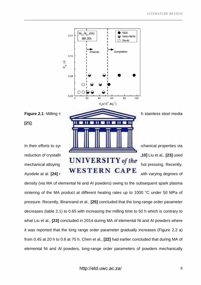
grain refinement. According to Hadef [21], Joadar et al., conducted MA of equiatomic
elemental Ni and Al powder blend and reported that the formation of NiAl required ~200
kJ kg-1 as well as ~550 kJ kg-1 for completion in a stainless steel grinding media as
mapped in figure 2.1.
http://etd.uwc.ac.za/
LITERATURE REVIEW
8
Figure 2.1: Milling map for NiAl formation on MA of Ni50Al50 with stainless steel media
[21].
In their efforts to synthesize NiAl intermetallics with improved mechanical properties via
reduction of crystallite size, Chen et al., [22], Krasnowski et al., [9,10] Liu et al., [23] used
mechanical alloying of elemental Ni and Al powders followed by hot pressing. Recently,
Ayodele at al. [24] reported on the successful synthesis of NiAl with varying degrees of
density (via MA of elemental Ni and Al powders) owing to the subsequent spark plasma
sintering of the MA product at different heating rates up to 1000 °C under 50 MPa of
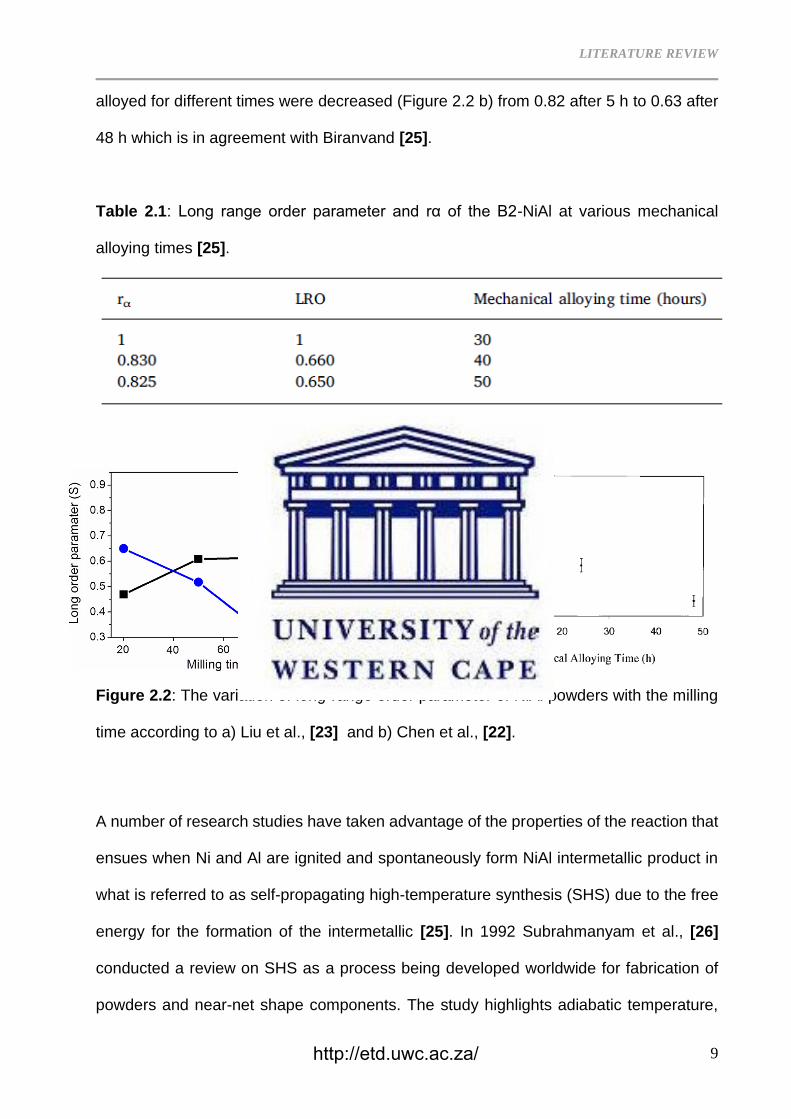
pressure. Recently, Biranvand et al., [25] concluded that the long-range order parameter
decreases (table 2.1) to 0.65 with increasing the milling time to 50 h which is contrary to
what Liu et al., [23] concluded in 2014 during MA of elemental Ni and Al powders where
it was reported that the long range order parameter gradually increases (Figure 2.2 a)
from 0.45 at 20 h to 0.6 at 70 h. Chen et al., [22] had earlier concluded that during MA of
elemental Ni and Al powders, long-range order parameters of powders mechanically
http://etd.uwc.ac.za/
LITERATURE REVIEW
9
alloyed for different times were decreased (Figure 2.2 b) from 0.82 after 5 h to 0.63 after
48 h which is in agreement with Biranvand [25].
Table 2.1: Long range order parameter and rα of the B2-NiAl at various mechanical
alloying times [25].
a) Liu et al b) Chen et al
Figure 2.2: The variation of long-range order parameter of NiAl powders with the milling
time according to a) Liu et al., [23] and b) Chen et al., [22].
A number of research studies have taken advantage of the properties of the reaction that
ensues when Ni and Al are ignited and spontaneously form NiAl intermetallic product in
what is referred to as self-propagating high-temperature synthesis (SHS) due to the free
energy for the formation of the intermetallic [25]. In 1992 Subrahmanyam et al., [26]
conducted a review on SHS as a process being developed worldwide for fabrication of
powders and near-net shape components. The study highlights adiabatic temperature,
http://etd.uwc.ac.za/
LITERATURE REVIEW
10
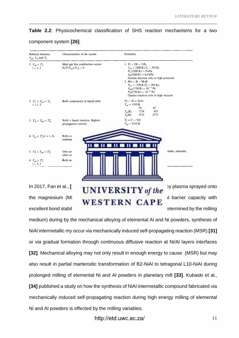
Tad as a critical parameter for SHS reaction and Merzhanov made a physico-chemical
classification (Table 2.2) of SHS mechanisms for a binary system based on the adiabatic,
melting, and boiling temperatures of reactants. In 2019, Yunmao et al., [27] used
combustion in SHS synthesis and space holder method of elementary Ni, Al and NaCl to
fabricate a highly porous (>80%) single phase NiAl with a hierarchical open-cell structure
via controlled sintering conditions and volume fraction of the space holder NaCl. Zhao et
al., [28] used combustion and hot pressing in SHS to fabricate NiAl intermetallic alloy with
true ultimate compression strength of 100272
94
+
− MPa, fracture strain of 21.6±1.8%, work-
hardening capacity (Hc) of 40.109.0
074.0
+
− and the Vickers micro-hardness is 360
15
19
+
− HV.
Ozdemir et al., [29] determined that the combustion reaction between aluminium and
carbonyl-nickel occurs at 655 °C to form NiAl intermetallic in open air under 150 MPa
uniaxial pressure.
http://etd.uwc.ac.za/
LITERATURE REVIEW
11
Table 2.2: Physicochemical classification of SHS reaction mechanisms for a two
component system [26].
In 2017, Fan et al., [30] used SHS to fabricate NiAl alloy which they plasma sprayed onto
the magnesium (MB26) alloy substrate to enhance its thermal barrier capacity with
excellent bond stability. Depending on the energy generated (as determined by the milling
medium) during by the mechanical alloying of elemental Al and Ni powders, synthesis of
NiAl intermetallic my occur via mechanically induced self-propagating reaction (MSR) [31]
or via gradual formation through continuous diffusive reaction at Ni/Al layers interfaces
[32]. Mechanical alloying may not only result in enough energy to cause (MSR) but may
also result in partial martensitic transformation of B2-NiAl to tetragonal L10-NiAl during
prolonged milling of elemental Ni and Al powders in planetary mill [33]. Kubaski et al.,
[34] published a study on how the synthesis of NiAl intermetallic compound fabricated via
mechanically induced self-propagating reaction during high energy milling of elemental
Ni and Al powders is effected by the milling variables.
http://etd.uwc.ac.za/
LITERATURE REVIEW
12
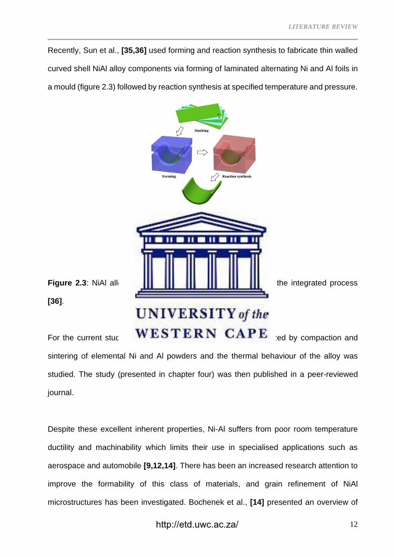
Recently, Sun et al., [35,36] used forming and reaction synthesis to fabricate thin walled
curved shell NiAl alloy components via forming of laminated alternating Ni and Al foils in
a mould (figure 2.3) followed by reaction synthesis at specified temperature and pressure.
Figure 2.3: NiAl alloy thin-walled component manufactured by the integrated process
[36].
For the current study, B2–NiAl intermetallic alloy was synthesized by compaction and
sintering of elemental Ni and Al powders and the thermal behaviour of the alloy was
studied. The study (presented in chapter four) was then published in a peer-reviewed
journal.
Despite these excellent inherent properties, Ni-Al suffers from poor room temperature
ductility and machinability which limits their use in specialised applications such as
aerospace and automobile [9,12,14]. There has been an increased research attention to
improve the formability of this class of materials, and grain refinement of NiAl
microstructures has been investigated. Bochenek et al., [14] presented an overview of
http://etd.uwc.ac.za/
LITERATURE REVIEW
13
research on NiAl processing and indicated methods that are promising in solving the low
fracture toughness of this intermetallic alloy at room temperature. In the same overview,
other material properties relevant for high temperature applications are also addressed.
2.1.2 Grain Refinement of NiAl
Various studies have been aimed at fabricating NiAl structures with nano crystalline [9-
12,22,23,31–34,37] grain size to improve their ductility or formability. Grain refinement in
NiAl has been achieved via a carefully controlled fabrication route, addition of refiners as
well as precipitate strengthening.
Powder consolidation fabrication routes whereby elemental powders are premixed, milled
below a nanocrystalline size range followed by controlled high pressure sintering with
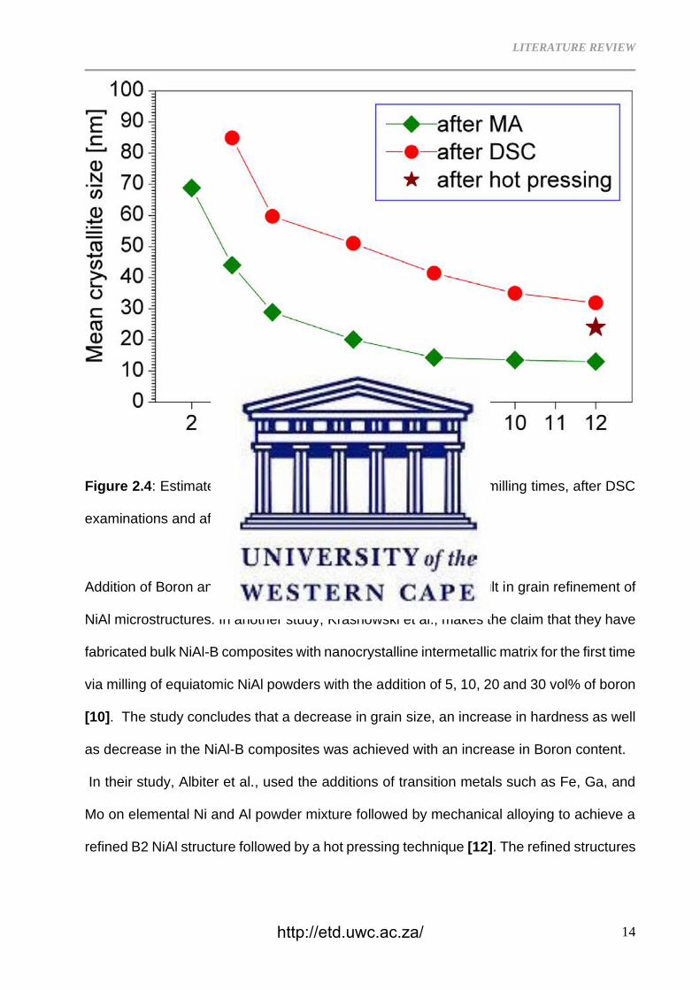
limited grain growth have been explored. Using this fabrication route, Krasnowski et al.,
produced a NiAl intermetallic alloy with a mean crystallite size of 13 nm upon milling of
Ni-50% Al powder mixture [9]. The pre-milled intermetallic alloy powder was sintered at
800°C under 900 GPa of pressure. The high-pressure sintering preserved the nanometric
crystallite size with limited grain growth to 24 nm resulting in a nanocrystalline NiAl
intermetallic alloy with improved hardness of 9.53 GPa. The milling time to achieve
optimal starting crystallite size is a critical determining factor in achieving a
nanocrystalline material and Krasnowski et al., estimated the mean crystallite size at
various fabrication stages of the NiAl polycrystalline alloy, figure 2.4.
http://etd.uwc.ac.za/
LITERATURE REVIEW
14
Figure 2.4: Estimated mean crystallite size of NiAl after various milling times, after DSC
examinations and after consolidation [9].
Addition of Boron and transition elements has been found to result in grain refinement of
NiAl microstructures. In another study, Krasnowski et al., makes the claim that they have
fabricated bulk NiAl-B composites with nanocrystalline intermetallic matrix for the first time
via milling of equiatomic NiAl powders with the addition of 5, 10, 20 and 30 vol% of boron
[10]. The study concludes that a decrease in grain size, an increase in hardness as well
as decrease in the NiAl-B composites was achieved with an increase in Boron content.
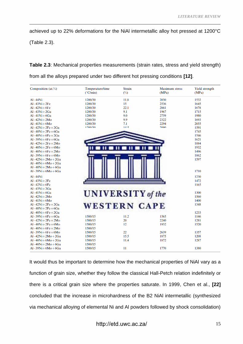
In their study, Albiter et al., used the additions of transition metals such as Fe, Ga, and
Mo on elemental Ni and Al powder mixture followed by mechanical alloying to achieve a
refined B2 NiAl structure followed by a hot pressing technique [12]. The refined structures
http://etd.uwc.ac.za/
LITERATURE REVIEW
15
achieved up to 22% deformations for the NiAl intermetallic alloy hot pressed at 1200°C
(Table 2.3).
Table 2.3: Mechanical properties measurements (strain rates, stress and yield strength)
from all the alloys prepared under two different hot pressing conditions [12].
It would thus be important to determine how the mechanical properties of NiAl vary as a
function of grain size, whether they follow the classical Hall-Petch relation indefinitely or
there is a critical grain size where the properties saturate. In 1999, Chen et al., [22]
concluded that the increase in microhardness of the B2 NiAl intermetallic (synthesized
via mechanical alloying of elemental Ni and Al powders followed by shock consolidation)
http://etd.uwc.ac.za/
LITERATURE REVIEW
16
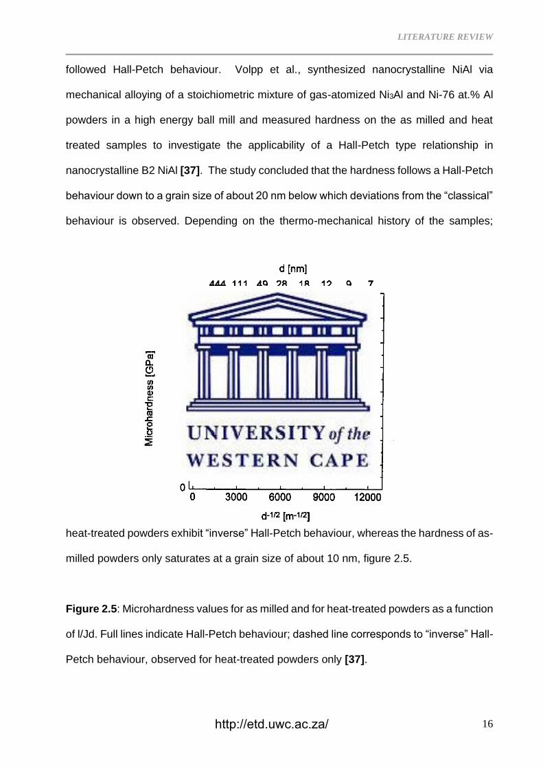
followed Hall-Petch behaviour. Volpp et al., synthesized nanocrystalline NiAl via
mechanical alloying of a stoichiometric mixture of gas-atomized Ni3Al and Ni-76 at.% Al
powders in a high energy ball mill and measured hardness on the as milled and heat
treated samples to investigate the applicability of a Hall-Petch type relationship in
nanocrystalline B2 NiAl [37]. The study concluded that the hardness follows a Hall-Petch
behaviour down to a grain size of about 20 nm below which deviations from the “classical”
behaviour is observed. Depending on the thermo-mechanical history of the samples;
heat-treated powders exhibit “inverse” Hall-Petch behaviour, whereas the hardness of as-
milled powders only saturates at a grain size of about 10 nm, figure 2.5.
Figure 2.5: Microhardness values for as milled and for heat-treated powders as a function
of l/Jd. Full lines indicate Hall-Petch behaviour; dashed line corresponds to “inverse” Hall-
Petch behaviour, observed for heat-treated powders only [37].
http://etd.uwc.ac.za/
LITERATURE REVIEW
17
Despite efforts to improve ductility of NiAl via grain refinement, the near zero plasticity at
room temperature coupled with low temperature strength above 800 °C has limited the
use of polycrystalline NiAl [38].
2.1.3 Alloying of NiAl
Addition of other metals coupled with fabrication techniques to further improve the
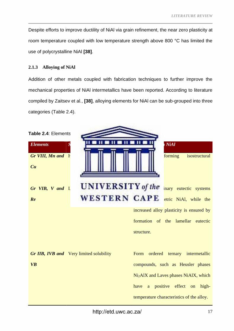
mechanical properties of NiAl intermetallics have been reported. According to literature
compiled by Zaitsev et al., [38], alloying elements for NiAl can be sub-grouped into three
categories (Table 2.4).
Table 2.4: Elements used for alloying NiAl-based alloys [38].
Elements Solubility in NiAl Interaction with NiAl
Gr VIII, Mn and
Cu
Highly soluble Prone to forming isostructural
compounds.
Gr VIB, V and
Re
Low solubility Form pseudobinary eutectic systems
with stoichiometric NiAl, while the
increased alloy plasticity is ensured by
formation of the lamellar eutectic
structure.
Gr IIB, IVB and
VB
Very limited solubility Form ordered ternary intermetallic
compounds, such as Heusler phases
Ni2AlX and Laves phases NiAlX, which
have a positive effect on high-
temperature characteristics of the alloy.
http://etd.uwc.ac.za/
LITERATURE REVIEW
18
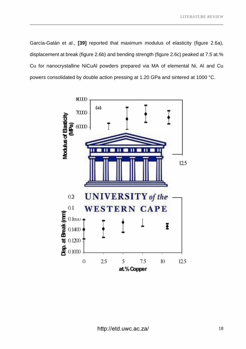
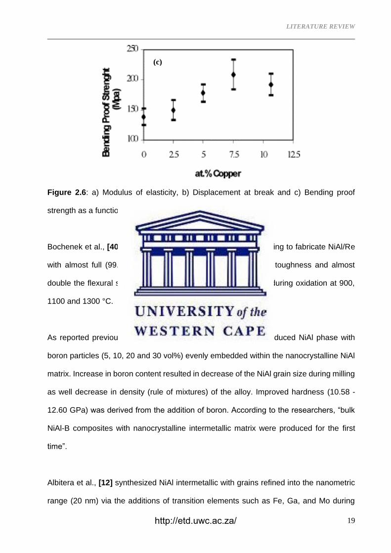
García-Galán et al., [39] reported that maximum modulus of elasticity (figure 2.6a),
displacement at break (figure 2.6b) and bending strength (figure 2.6c) peaked at 7.5 at.%
Cu for nanocrystalline NiCuAl powders prepared via MA of elemental Ni, Al and Cu
powers consolidated by double action pressing at 1.20 GPa and sintered at 1000 °C.
(a)
(b)
http://etd.uwc.ac.za/
LITERATURE REVIEW
19
Figure 2.6: a) Modulus of elasticity, b) Displacement at break and c) Bending proof
strength as a function Cu additions into NiAl [39].
Bochenek et al., [40] used hot pressing and spark plasma sintering to fabricate NiAl/Re
with almost full (99.9%) density, 60% improvement in fracture toughness and almost
double the flexural strength of NiAl and no significant changes during oxidation at 900,
1100 and 1300 °C.
As reported previously, Krasnowski et al., [10] successfully produced NiAl phase with
boron particles (5, 10, 20 and 30 vol%) evenly embedded within the nanocrystalline NiAl
matrix. Increase in boron content resulted in decrease of the NiAl grain size during milling
as well decrease in density (rule of mixtures) of the alloy. Improved hardness (10.58 -
12.60 GPa) was derived from the addition of boron. According to the researchers, “bulk
NiAl-B composites with nanocrystalline intermetallic matrix were produced for the first
time”.
Albitera et al., [12] synthesized NiAl intermetallic with grains refined into the nanometric
range (20 nm) via the additions of transition elements such as Fe, Ga, and Mo during
(c)
http://etd.uwc.ac.za/
LITERATURE REVIEW
20
mechanical alloying and densification via hot pressing techniques. According to the
investigators, these minor additions of the transition elements form a solid solution (B2)
with the intermetallic structure of NiAl resulting in up to 22% deformations.
http://etd.uwc.ac.za/
LITERATURE REVIEW
21
2.2 NICKEL ALUMINIDES METAL MATRIX COMPOSITES
Powder metallurgy (PM) techniques used to fabricate NiAl intermetallic alloy discussed
above have been extended to synthesize in-situ as well as ex-situ ceramic particle
reinforced NiAl. This endeavour seeks to achieve ceramic particles (reinforcement)
evenly dispersed in the microstructure of a continuous NiAl matrix to improve ductility of
NiAl intermetallic alloy. TiC [16,41], Al2O3 [8,42,43], TiB2 [44], TiC/TiB2 [15,20,45,46],
TiC/Al2O3 [17], TiB2/Al2O3 [47], TiB2/TiN [48] and carbon nanotubes [18,49,50] are some
of the reinforcements used to reinforce NiAl to fabricate NiAl intermetallic alloy matrix
composites.
2.2.1 Ex-situ fabrication
During ex-situ synthesis of metal matrix composites, a reinforcing ceramic phase is
externally added into the metal matrix during liquid state casting or solid-state fabrication.
Recently Talas et al., [20] fabricated NiAl reinforced with either TiC of TiB2 in the range
0.5, 1, 2, 4 and 8 wt % via ex-situ compacting of premixed Ni, Al and either TiC or TiB2
powders followed by melting in vacuum. Talas reported an improved hardness of the
composite with increasing content of TiC or TiB2 which dropped significantly upon heat
treatment of the composite attributable to a possible particle sizes and interparticle
distance increased by coarsening. The investigation does not report on the
ductility/deformability of the as cast and heat-treated composite samples. Li et al., [51]
synthesized NiAl-BaO/TiO2 composite via ball milling of NiAl intermetallic, BaO and TiO2
powders followed by sintering at 1300°C for 1 h under a pressure of 20 MPa. The 20%
BaO /TiO2 composite exhibited microhardness and yield strength of 474.5 and 2786 MPa
respectively with a decrease in the friction coefficient and wear rate at 800°C. In 2018, in
an unconventional reinforcement/matrix setup Sonber et al., [19] used NiAl as a
http://etd.uwc.ac.za/
LITERATURE REVIEW
22
reinforcement for ZrB2 and concluded that an increase in the content of NiAl resulted in
decrease in hardness and an increase in fracture toughness. It is thus judicious to
conclude that by classical definition of the matrix-reinforcement, NiAl is the matrix while
the ZrB2 is the reinforcement in the setup.
2.2.2 In-situ fabrication
During in-situ synthesis of metal matrix composites, a chemical reaction leads to the
formation of very fine and thermodynamically stable reinforcing ceramic phase within a
continuous metal matrix. Feedstocks have been used during self-propagating high-
temperature synthesis (SHS) to achieve microstructures with in-situ reinforcement
particles homogeneously distributed within NiAl intermetallic matrix. Fan et al., [15] and
Shen et al., [45] used SHS of Ni–Al–Ti–B4C feedstock to in-situ fabricate NiAl-TiC-TiB2
intermetallic matrix composite. Zhang et al., [11] in-situ synthesized TiB2 reinforced NiAl
with 35.2% increase in room temperature compressive strength via arc melting of Ti-B-
Ni-Al system. The reaction process was found to proceed in two steps: firstly, Ni, Al
reacted with Ti to form transient phase AlNi2Ti, and then AlNi2Ti reacted with B to form
TiB2 particles, which serve as reinforcements with a uniform distribution within the NiAl
matrix. On another study, Zhao et al., [52,53] used Ni–Al–Nb–B4C system to fabricate
NbB2–NbxC/NiAl composite via the combustion synthesis and hot pressing technique. In
2011, Zhao et al., [52] reported on the microstructures, interfaces, compression
properties and work-hardening effect of the resulting NiAl-matrix composites reinforced
with 5-20 wt.% ceramic particulates (Nb2C, NbC and NbB2) noting that an increase in the
ceramic particulate content resulted in increase in the ultimate and yield compression
strengths while the fracture strain and hardening (Hc) decreased. The researcher
concluded that the composite with the least (5%) amount of particulate exhibited the best
combination of mechanical properties: compression fracture strain of 18.3%, an ultimate
http://etd.uwc.ac.za/

LITERATURE REVIEW
23
compression strength of 1479 MPa, and a value of Hc =1.29. Zhao et al., [53] conducted
a similar investigating on NiAl matrix composite reinforced with 1.7 wt.% NbB2 and NbxC
(x =1 or 2) fabricated using the same technique. The NiAl-matrix composite showed a
strong strain rate sensitivity whereby yield strength of the NbB2–NbxC/NiAl composite
decreases while the fracture strain and the work-hardening capacity (Hc) increase with
decreasing strain rate. Compression fracture strain of 20.1%, an ultimate compression
strength of 1472 MPa, and a value of Hc =1.41 was achieved with reduced volume
fraction of the reinforcement at a strain rate of 2.0 x 10⁻⁵s-1. Zhao et al., [54] also studied
the microstructure, compression property and work-hardening effect of the NiAl-matrix
composite reinforced by 5 vol.% TaB and TaB2 fabricated via combustion synthesis of Ni-
Al-Ta-B system. The researchers arrived at similar conclusions that NiAl-matrix
composite exhibits remarkable strain-rate-dependent compression properties and work-
hardening effect.
Song et al., [47] used SHS of Ni, Al, B2O3 and TiO2 premixed and green compacted
powders to synthesize (TiB2+Al2O3)/NiAl composites of 2−5 μm TiB2 grains embedded in
Al2O3 clusters, while a small number of TiB2 particles disperse in the NiAl matrix according
to the schematic microstructural evolution depicted in figure 2.7. The investigators go on
to postulate - “the higher the TiB2+Al2O3 content is, the more the regular shapes and
homogeneous distributions of TiB2 and Al2O3 will be present in the NiAl matrix”.
http://etd.uwc.ac.za/
LITERATURE REVIEW
24
Figure 2.7: a) Sketch of reaction processes and structure evolution modes: (a) Mixed
initial powders; (b) Al and B2O3 begin to melt; (c) Grains of NiAl, TiB2 and Al2O3 formatting;
(d−f) Morphologies of products with 10%, 20% and 30% (Al+TiO2+B2O3), respectively
[47].
Similarly, Shokati et al., [48] fabricated NiAl matrix composite powder reinforced with 0–
40 wt.% (TiB2–TiN) from Ni, Al, Ti and hexagonal boron nitride (h-BN) powders via
combustion synthesis. The first reaction between Ni and Al caused an energy release
http://etd.uwc.ac.za/
LITERATURE REVIEW
25
which melted Al(Ni), Ni, NiAl and Ti and decomposed BN into free B and N which in turn
diffused and dissolved into the Ni-Al–Ti liquid phases. Finally, TiN and TiB2 particulates
precipitate out of the saturated solution. Good bonding between reinforcement and matrix,
increased and uniformity of distribution of reinforcements in NiAl matrix and formation of
sub-micron TiB2 and TiN embedded in NiAl matrix resulted in high hardness making this
composite powder a good precursor for thermal spray applications.
Rahaei [16] achieved improved mechanical properties (Table 2.5) compared to those
documented in literature and deduced that ±28 vol.% TiC content in 3D space of the
continuous NiAl matrix leads to attainment of discrete TiC particles. Feasibility of heat
transfer and decreasing of thermal stress in comparison with long-range interconnectivity
of TiC particles in NiAl-TiC (bi-continuous) composite makes this composite a good
candidate material for high temperature applications.
Table 2.5: Mechanical properties of NiAl intermetallic and Ni-Al-TiC composite achieved
by Rahaei [16] compared to previous studies.
Widodo et al., [17] concluded that the exothermicity of the system increases with addition
of TiO2/Al/C content into NiAl. This resulted in increased maximum reaction temperature
http://etd.uwc.ac.za/
LITERATURE REVIEW
26
porosity during in-situ fabrication of NiAl-TiC-Al2O3 intermetallic ceramic composite via
self-propagation synthesis using Ni, Al, C and TiO2 as precursors. The reactions occur in
two stages whereby exothermic reaction of Ni and Al leads to the formation of NiAl
followed by TiO2, Al, and C forming TiC-Al2O3. Olusoji et al., [18] arrived at a similar
conclusion that high sintering heating rate resulted in porosity due to lack of contact area
between particles during ex-situ fabrication of multi-walled carbon nanotubes (CNT)
reinforced NiAl fabricated via planetary ball milling of Ni, Al and CNT elementary powders
followed by spark plasma sintering at 50, 100 and 150 °C/min [50]. Recently, Troncy et
al., [8], aluminothermically reacted pre-oxidized Ni with Al to fabricate mixed compounds
of NixAly containing in-situ continuous generated network of Al2O3 surrounding NixAly
intermetallic compounds in a composite that has a potential to form self-healing coatings.
2.2.3 Enhanced tribology of NiAl composites
Self-healing/lubricating is a technique that has been used to improve tribological
properties of various materials and silver has been added to various microstructures as
its malleability results in self-healing/lubricating. Feng et al., [55] synthesized NiAl-NbC-
Ag composites via vacuum-hot-pressing sintering with direct addition of AgNbO3 powders
onto NiAl intermetallic alloy to form a composite that exhibited lower friction coefficient
compared to NiAl. Additionally, the lubricating glaze layer consisting of Ag2Nb4O11,
AgNbO3 and AgNb3O8 was formed by tribo-chemical reaction on the worn surfaces when
the test temperatures got to 600 °C and 800 °C. Han et al., [56] synthesized
NiAl/muscovite composites via spark plasma sintering of Ni, Al, B2O3 and
KAl2(AlSi3O10)(OH)2 (muscovite) with the muscovite well dispersed in the self-lubricating
composite microstructure resulting in improved wear properties peaking at 9 wt%
muscovite content. Zhu et al., [57] synthesized NiAl, NiAl-Cr-Mo and ZnO/Cuo reinforced
http://etd.uwc.ac.za/
LITERATURE REVIEW
27
NiAl-Cr-Mo matrix composites via high temperature solid state reaction forming new
phases (such as NiZn3, Cu0.81Ni0.19 and Al2O3) during the fabrication process. The ZnO
reinforced NiAl-Cr-Mo matrix composites exhibited low wear rate at 800 and 1000 °C in
comparison with NiAl and NiAl-Cr-Mo while the CuO reinforced NiAl-Cr-Mo matrix
composites exhibited self-lubricating performance at 800 °C, which was attributed to the
presence of the glaze layer containing CuO and MoO3. Liu et al., [58] ex-situ added
hydrothermally synthesized silver vanadate (Ag3VO4) nanoparticles to pre-mechanically
milled Ni and Al powder and further milled to fabricate NiAl-Ag3VO4 composite. The
sintered composite consisted of Ag, and V oxide precipitates distributed homogeneously
in the nanocrystalline NiAl matrix. An increase in Ag3VO4 content resulted in increase in
density while microhardness decreased due to formation of high density soft metallic Ag.
Excellent tribological properties were obtained at 900 °C due to the production of silver
vanadate “lubricant”. Shi eat al., [59] reinforced NiAl matrix with different solid lubricant
additions (PbO, Ti3SiC2–MoS2, Ti3SiC2–WS2) to fabricate self-lubricating composites for
use in high temperature friction and wear applications. Pin-on-disc dry sliding wear tests
on the fabricated composite against Si3N4 balls showed:
i) Composites with Ti3SiC2–MoS2 binary lubricant exhibited excellent self-lubricating
and anti-wear properties over a wide temperature range,
ii) MoS2 lubricated better at low temperatures, while Ti3SiC2 lubricated better at high
temperatures, and,
iii) Ti3SiC2–MoS2 binary lubricant presented the best synergetic lubricating effect of
the three candidate compositions.
For the current study, NiAl intermetallic alloy reinforced with TiC particles was synthesized
via cold pressing and sintering of the elemental Ni, Al, and TiC particles powders. This
study has been submitted for scientific peer review.
http://etd.uwc.ac.za/
LITERATURE REVIEW
28
2.3 STEEL METAL MATRIX COMPOSITES
Stainless steel is still the lifeblood for several industrial applications due to their
multipurpose attributes, long life cycle and recyclability. Clare Broadbent [60]
demonstrated the benefits of recycling steel to achieve a circular economy. It is therefore
vital to widen the scope of this material into applications where it is not traditionally used.
Careful incorporation of chosen reinforcements into steel matrices will open a myriad of
further specialised applications for this material. TiC reinforced steels have attracted
interest as engineering materials for a few attractive attributes derived from the composite
material.
Tul et al., [61] explored TiC reinforced steels as engineering materials for inertial
instruments and aerospace applications due to their excellent mechanical properties and
machinability. Due to demands for dimensional stability in extreme operational
environments for these components to avoid navigation errors, the study used thermal-
cold cycling to improve the dimensional stability of TiC reinforced steel matrix composite.
Xiao et al., [62] on the other hand investigated the microstructure, properties, and
dimensional stability of a TiC-reinforced steel matrix composite during tempering to
identify the underlying stabilizing mechanisms using commercial annealed TiC reinforced
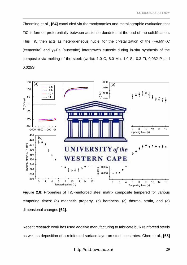
steel and concluded that the composite achieved optimal properties after 10 h (figure 2.8)
of tempering.
Cho et al., [63] Fabricated TiC reinforced stainless steel composites via liquid pressing
infiltration process and investigated their high-temperature compressive strengths and
concluded that TiC reinforcement successfully suppressed softening of SUS431 matrix,
resulting in about 5 times higher strength than that of SUS431 at 1050 °C.
http://etd.uwc.ac.za/
LITERATURE REVIEW
29
Zhenming et al., [64] concluded via thermodynamics and metallographic evaluation that
TiC is formed preferentially between austenite dendrites at the end of the solidification.
This TiC then acts as heterogeneous nuclei for the crystallization of the (Fe,Mn)3C
(cementite) and γ2-Fe (austenite) intergrowth eutectic during in-situ synthesis of the
composite via melting of the steel: (wt.%): 1.0 C, 8.0 Mn, 1.0 Si, 0.3 Ti, 0.032 P and
0.025S
Figure 2.8: Properties of TiC-reinforced steel matrix composite tempered for various
tempering times: (a) magnetic property, (b) hardness, (c) thermal strain, and (d)
dimensional changes [62].
Recent research work has used additive manufacturing to fabricate bulk reinforced steels
as well as deposition of a reinforced surface layer on steel substrates. Chen et al., [65]
http://etd.uwc.ac.za/
LITERATURE REVIEW
30
used course (> 50 µm) TiC to reinforce steel via laser cladding. The researchers could
afford to use course particles due to high temperatures attained during fabrication, which
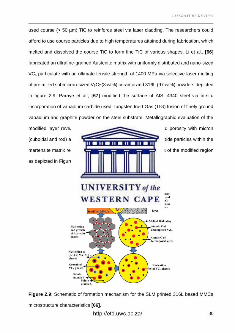
melted and dissolved the course TiC to form fine TiC of various shapes. Li et al., [66]
fabricated an ultrafine-grained Austenite matrix with uniformly distributed and nano-sized
VCx particulate with an ultimate tensile strength of 1400 MPa via selective laser melting
of pre milled submicron-sized V8C7 (3 wt%) ceramic and 316L (97 wt%) powders depicted
in figure 2.9. Paraye et al., [67] modified the surface of AISI 4340 steel via in-situ
incorporation of vanadium carbide used Tungsten Inert Gas (TIG) fusion of finely ground
vanadium and graphite powder on the steel substrate. Metallographic evaluation of the
modified layer revealed a fusion zone free of micro cracks and porosity with micron
(cuboidal and rod) as well as nano (cuboidal) size vanadium carbide particles within the
martensite matrix resulting in significant increase in the hardness of the modified region
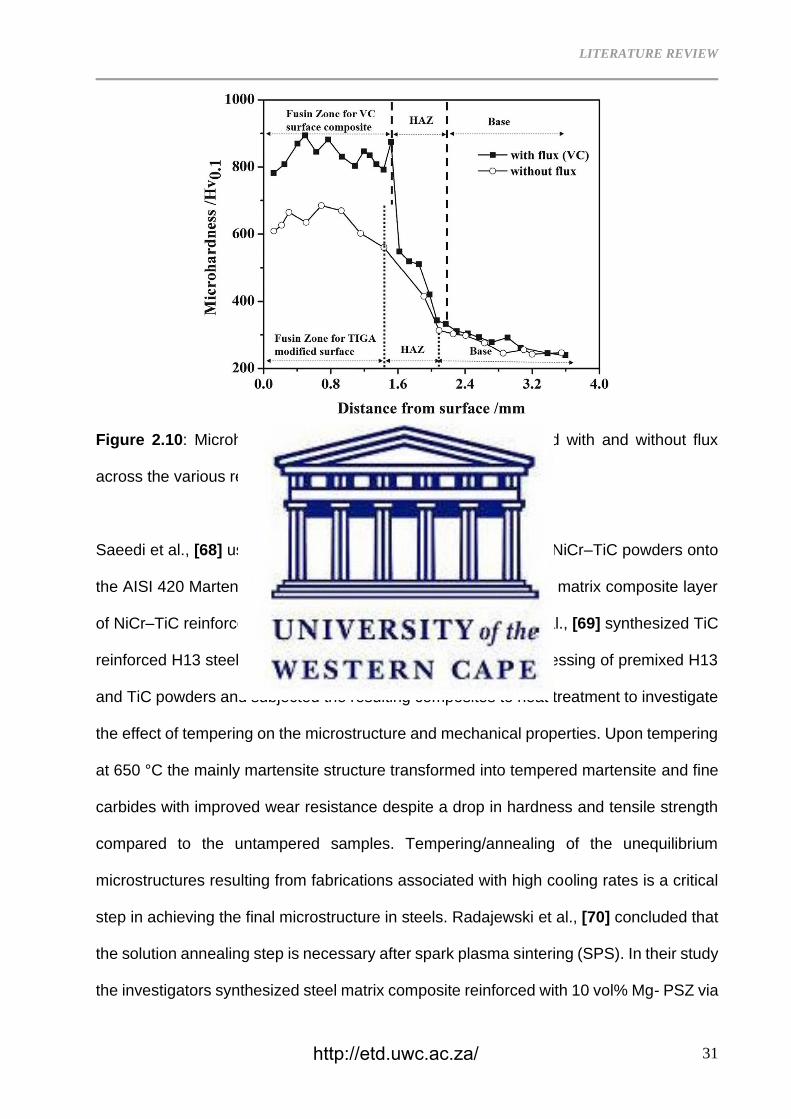
as depicted in Figure 2.10.
Figure 2.9: Schematic of formation mechanism for the SLM printed 316L based MMCs
microstructure characteristics [66].
http://etd.uwc.ac.za/
LITERATURE REVIEW
31
Figure 2.10: Microhardness distribution of the surface modified with and without flux
across the various region [67].
Saeedi et al., [68] used pulsed Nd: YAG laser to inject NiCr and NiCr–TiC powders onto
the AISI 420 Martensitic stainless steel substrate to form a metal matrix composite layer
of NiCr–TiC reinforced steel with enhanced hardness. Zhang et al., [69] synthesized TiC
reinforced H13 steel matrix composites via laser deposition processing of premixed H13
and TiC powders and subjected the resulting composites to heat treatment to investigate
the effect of tempering on the microstructure and mechanical properties. Upon tempering
at 650 °C the mainly martensite structure transformed into tempered martensite and fine
carbides with improved wear resistance despite a drop in hardness and tensile strength
compared to the untampered samples. Tempering/annealing of the unequilibrium
microstructures resulting from fabrications associated with high cooling rates is a critical
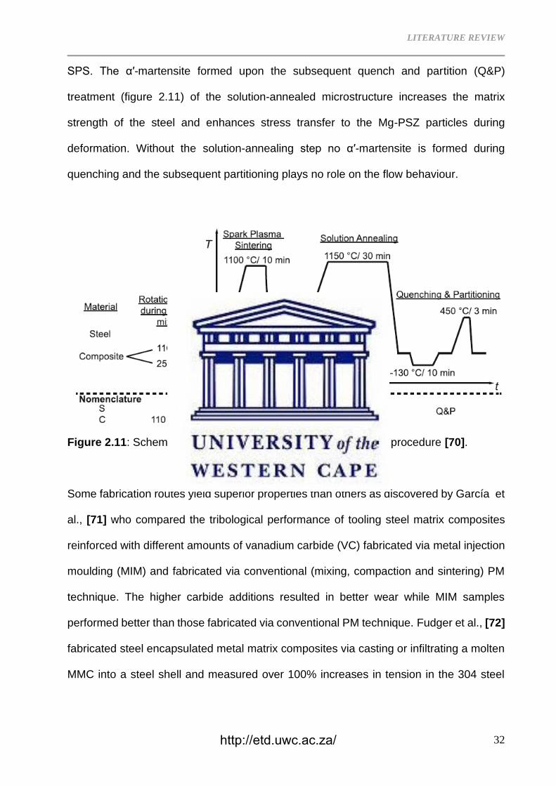
step in achieving the final microstructure in steels. Radajewski et al., [70] concluded that
the solution annealing step is necessary after spark plasma sintering (SPS). In their study
the investigators synthesized steel matrix composite reinforced with 10 vol% Mg- PSZ via
http://etd.uwc.ac.za/
LITERATURE REVIEW
32
SPS. The α′-martensite formed upon the subsequent quench and partition (Q&P)
treatment (figure 2.11) of the solution-annealed microstructure increases the matrix
strength of the steel and enhances stress transfer to the Mg-PSZ particles during
deformation. Without the solution-annealing step no α′-martensite is formed during
quenching and the subsequent partitioning plays no role on the flow behaviour.
Figure 2.11: Schematic representation of the sample processing procedure [70].
Some fabrication routes yield superior properties than others as discovered by García et
al., [71] who compared the tribological performance of tooling steel matrix composites
reinforced with different amounts of vanadium carbide (VC) fabricated via metal injection
moulding (MIM) and fabricated via conventional (mixing, compaction and sintering) PM
technique. The higher carbide additions resulted in better wear while MIM samples
performed better than those fabricated via conventional PM technique. Fudger et al., [72]
fabricated steel encapsulated metal matrix composites via casting or infiltrating a molten
MMC into a steel shell and measured over 100% increases in tension in the 304 steel
http://etd.uwc.ac.za/
LITERATURE REVIEW
33
and nearly 100% increase in compression in the Al2O3 due to the high coefficient of
expansion mismatch between 304 SS surrounding the Al-Al2O3.
Determining bulk properties of MMCs is often a challenge and Ma et al., [73] used
Hadfield steel reinforced with niobium carbide as an example to propose a conceptual
model to calculate the bulk hardness of particle-reinforced metal matrix composites. This
is done by simulating an indentation process on a specimen of a homogenous material,
whose stress-strain curve is exactly same as the one extracted from modelling a single
direction tension/compression testing on a much smaller scale equivalent MMC rather
than simulation on a specimen of the MMC directly. This is done to overcome the difficulty
associated with implementing the numerical simulation directly on the MMC, as it requires
a huge amount of calculation time as the MMC specimen used for indentation modelling
may contain millions of particles.
For the current study, Steel/Ni-TiC composite produced by compaction and sintering had
its microstructure and hardness investigated. The study was then published in a peer
reviewed scientific journal:
http://etd.uwc.ac.za/
LITERATURE REVIEW
34
2.4 METAL OXYNITRIDES
Transition [74–83], rare earth and alkaline [76,81] earth metal oxynitrides have found
prominence as an important class of materials due to unique properties derived from
combining the desirable attributes of both the oxides and the nitrides [74]. The increased
covalence and more polarization of bonds with metals due to nitrogen’s less
electronegativity and more polarizability than oxygen affects the electronic properties
resulting in new magnetic, conducting and dielectric materials [75]. Oxynitrides have
found applications in improving wear and corrosion [74,78,82], capacitance [80–83],
pigments [84], phosphors, dielectrics, magnets [75] and arguable their most researched
application, photocatalysis. Photocatalytic prowess of oxynitrides has been a subject of
research in the field of energy and environmental applications such as production of
Hydrogen via water splitting [74–76,81], pollutant degradation, CO2 conversion and
antimicrobial disinfection [76].
2.4.1 Metal Oxynitrides in Photocatalysis
Superior light harvesting ability (narrow band-gap energy) compared to metal oxides (> 3
eV) and moderate photostability has transition metal oxynitride perovskites [AB(O,N)3]
thrust into the research spotlight as an emerging class of inorganic materials [74,81].
In their review, Manan et al., [74] provides a summary of the progress in visible-light
induced water splitting via oxynitrides for generation of hydrogen as a clean and
sustainable source of energy and gives an overview on the photocatalysts developed in
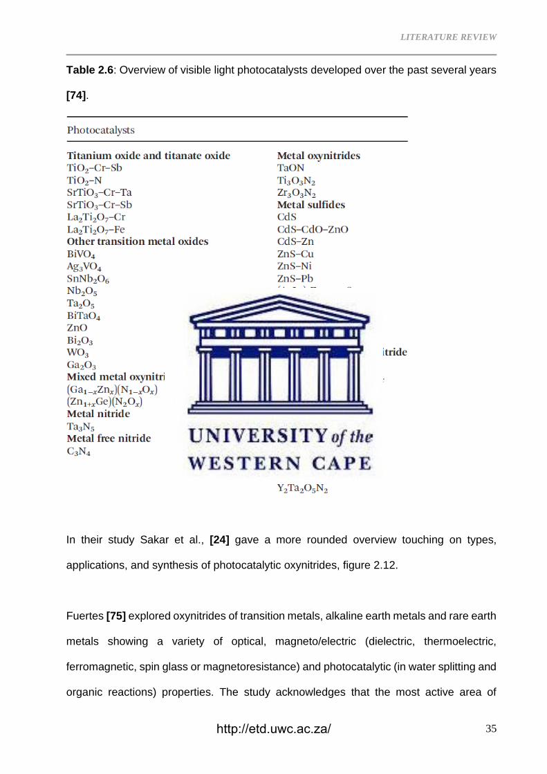
the past several years, Table 2.6.
http://etd.uwc.ac.za/
LITERATURE REVIEW
35
Table 2.6: Overview of visible light photocatalysts developed over the past several years
[74].
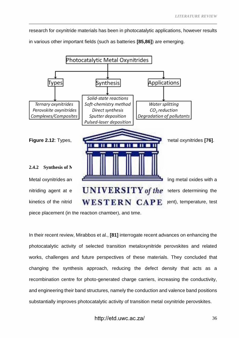
In their study Sakar et al., [24] gave a more rounded overview touching on types,
applications, and synthesis of photocatalytic oxynitrides, figure 2.12.
Fuertes [75] explored oxynitrides of transition metals, alkaline earth metals and rare earth
metals showing a variety of optical, magneto/electric (dielectric, thermoelectric,
ferromagnetic, spin glass or magnetoresistance) and photocatalytic (in water splitting and
organic reactions) properties. The study acknowledges that the most active area of
http://etd.uwc.ac.za/
LITERATURE REVIEW
36
research for oxynitride materials has been in photocatalytic applications, however results
in various other important fields (such as batteries [85,86]) are emerging.
Figure 2.12: Types, synthesis and applications of photocatalytic metal oxynitrides [76].
2.4.2 Synthesis of Metal Oxynitrides
Metal oxynitrides are generally prepared by exposing corresponding metal oxides with a
nitriding agent at elevated temperatures. The important parameters determining the
kinetics of the nitriding process are flow rate (of the nitriding agent), temperature, test
piece placement (in the reaction chamber), and time.
In their recent review, Mirabbos et al., [81] interrogate recent advances on enhancing the
photocatalytic activity of selected transition metaloxynitride perovskites and related
works, challenges and future perspectives of these materials. They concluded that
changing the synthesis approach, reducing the defect density that acts as a
recombination centre for photo-generated charge carriers, increasing the conductivity,
and engineering their band structures, namely the conduction and valence band positions
substantially improves photocatalytic activity of transition metal oxynitride perovskites.
http://etd.uwc.ac.za/
LITERATURE REVIEW
37
Thermal ammonolysis [74–77]
This involves the use of gaseous NH3 as a nitriding agent on a corresponding oxide
at elevated temperatures according to the equation:
Oxide + NH3 (g) = Oxynitride + H2O (v)
At temperatures above 500 °C NH3 dissociates into N2 and H2. Low temperature
processing results in difficulty with achieving homogeneous N stoichiometry and
inferior sintering densification. If a reducing environment is desired, a gas mixture
of N2/H2 (90/10 or 95/5 v/v) is used at high temperatures (1300 – 1600 °C) on a
stoichiometric mixture of metal oxides, carbonates and/or nitrides under a high-
pressure nitrogen. This solid-state reaction requires high activation energy due to
the high triple bond energy between the N atoms, which requires the use of high
temperatures, high flow rate of the nitriding (gas) agent and/or longer times. Oró-
Solé et al., [87] synthesized a new EuTi0.5O3-xNx perovskites with tuned N/O
(0.87<N<1.63) ratios by carefully controlling the treatment temperature and
ammonia flow rate during the ammonolysis of scheelite EuW0.5O4. The study
concludes that increasing nitrogen content results in changes on the structural and
magneto-electric properties such as contraction of the unit cell volume and a
reduction of symmetry from cubic to orthorhombic.
I. Soft Chemistry [74,76]
As stated above, the reaction kinetics for nitriding can be sluggish due to the
stability of the N2 triple bond. Co-precipitation, sol-gel, Pechini method, templating
and ultrafast evaporation-induced self-assembly or a combination of these is used
to synthesize the precursor (oxide) instead of the traditional calcination. This
resulting precursor exhibits improved sensitivity and reactivity and consequently
http://etd.uwc.ac.za/
LITERATURE REVIEW
38
the reaction time, temperature and amount of nitriding gas can be reduced during
the subsequent nitriding step.
II. Direct Synthesis [74,76,77,88]
During direct synthesis, an N-rich agent such as urea, amides, imides, and azides
are used as sources of nitrogen. Formation of carbon residues, impurities and
secondary phases has been reported as a drawback when using excess N sources
such as urea. Gomathi et al., [77] synthesized ternary metal oxynitrides of the
formulae MTaO2N (M = Ca, Sr or Ba), MNbO2N (M = Sr or Ba), LaTiO2N and
SrMoO3-xNx. Urea was used as the nitriding agent by heating the corresponding
metal carbonates and transition metal oxides with excess urea. The investigators
claim this route yields metal oxynitrides that are generally stoichiometric and in the
form of nanoparticles.
III. Sputter Deposition [74,76]
Thin films of perovskite oxynitrides have been successfully deposited on substrate
surfaces via reactive radio frequency magnetron sputtering for photocatalytic
applications. Unfortunately, this process has been reported to suffer from off
stoichiometry thin films.
IV. Pulsed-Laser Deposition [74,76]
Similarly, to sputter deposition, pulsed-laser deposition is used to achieve thin films
of oxynitrides on a substrate. A lattice mismatch between the deposited surface
layer and the substrate is the major drawback since this process is based on the
epitaxial growth of material onto a substrate.
http://etd.uwc.ac.za/
LITERATURE REVIEW
39
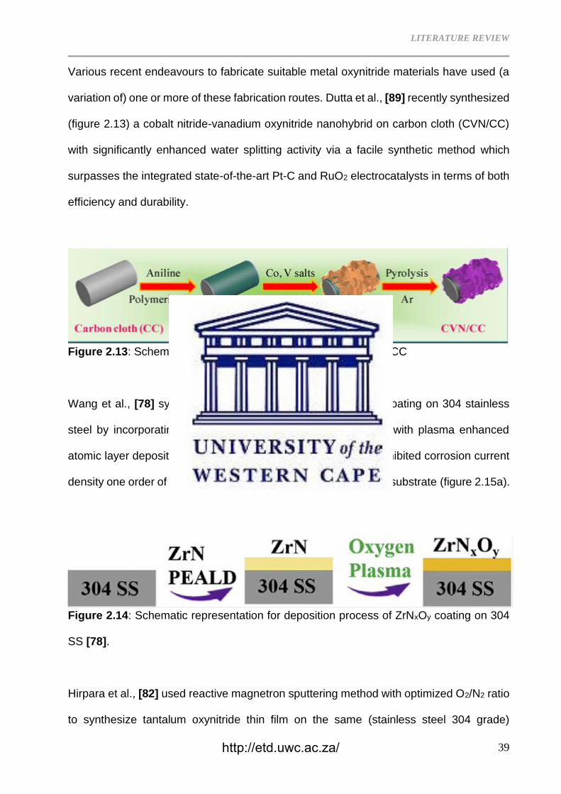
Various recent endeavours to fabricate suitable metal oxynitride materials have used (a
variation of) one or more of these fabrication routes. Dutta et al., [89] recently synthesized
(figure 2.13) a cobalt nitride-vanadium oxynitride nanohybrid on carbon cloth (CVN/CC)
with significantly enhanced water splitting activity via a facile synthetic method which
surpasses the integrated state-of-the-art Pt-C and RuO2 electrocatalysts in terms of both
efficiency and durability.
Figure 2.13: Schematic representation for the synthesis of CVN/CC
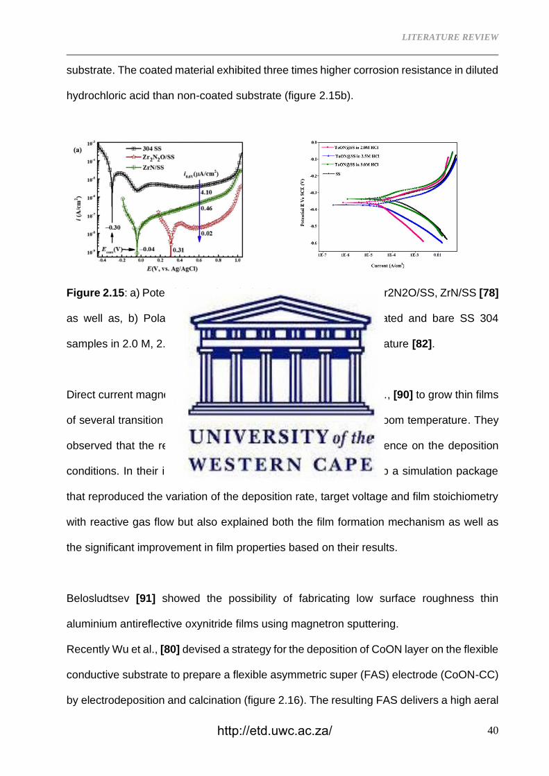
Wang et al., [78] synthesized a zirconium oxynitride (Zr2N2O) coating on 304 stainless
steel by incorporating a controlled amount of oxygen into ZrN with plasma enhanced
atomic layer deposition. The resulting oxynitride (figure 2.14) exhibited corrosion current
density one order of magnitude lower than that of the ZrN coated substrate (figure 2.15a).
Figure 2.14: Schematic representation for deposition process of ZrNxOy coating on 304
SS [78].
Hirpara et al., [82] used reactive magnetron sputtering method with optimized O2/N2 ratio
to synthesize tantalum oxynitride thin film on the same (stainless steel 304 grade)
http://etd.uwc.ac.za/
LITERATURE REVIEW
40
substrate. The coated material exhibited three times higher corrosion resistance in diluted
hydrochloric acid than non-coated substrate (figure 2.15b).
Figure 2.15: a) Potentiodynamic polarization curves for 304 SS, Zr2N2O/SS, ZrN/SS [78]
as well as, b) Polarization test for tantalum oxynitride film-coated and bare SS 304
samples in 2.0 M, 2.5M and 3.0M HCl electrolyte at room temperature [82].
Direct current magnetron sputtering was used by Venkataraj et al., [90] to grow thin films
of several transition metal (Ti, Zr, Hf, Nb and Ta) oxynitrides at room temperature. They
observed that the resulting film properties had a strong dependence on the deposition
conditions. In their investigation, Venkataraj did not only develop a simulation package
that reproduced the variation of the deposition rate, target voltage and film stoichiometry
with reactive gas flow but also explained both the film formation mechanism as well as
the significant improvement in film properties based on their results.
Belosludtsev [91] showed the possibility of fabricating low surface roughness thin
aluminium antireflective oxynitride films using magnetron sputtering.
Recently Wu et al., [80] devised a strategy for the deposition of CoON layer on the flexible
conductive substrate to prepare a flexible asymmetric super (FAS) electrode (CoON-CC)
by electrodeposition and calcination (figure 2.16). The resulting FAS delivers a high aeral
http://etd.uwc.ac.za/
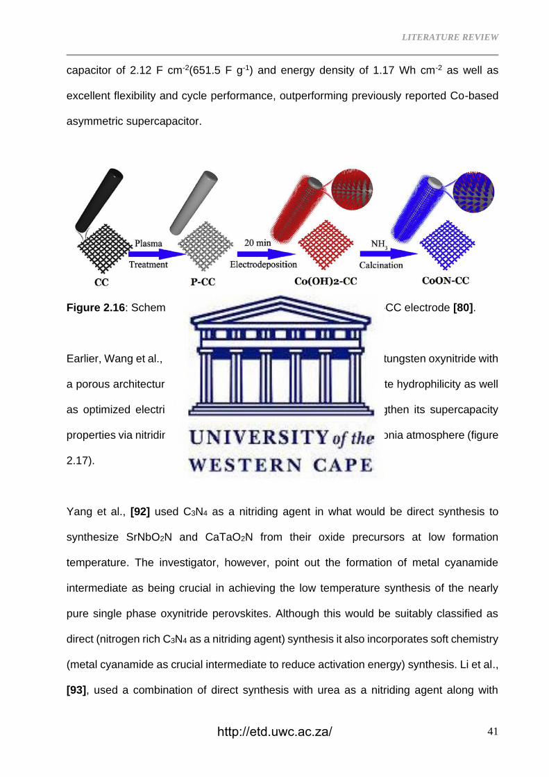
LITERATURE REVIEW
41
capacitor of 2.12 F cm-2(651.5 F g-1) and energy density of 1.17 Wh cm-2 as well as
excellent flexibility and cycle performance, outperforming previously reported Co-based
asymmetric supercapacitor.
Figure 2.16: Schematic presentation for the fabrication of CoON-CC electrode [80].
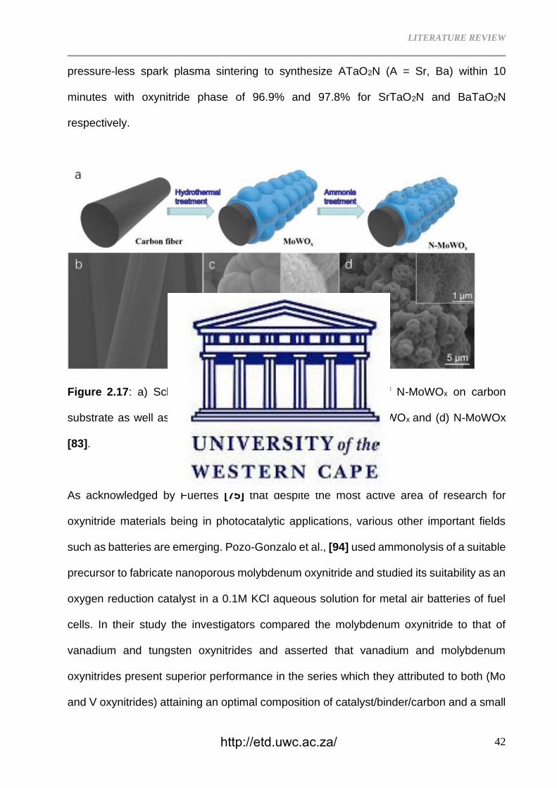
Earlier, Wang et al., [83] designed and synthesized molybdenum tungsten oxynitride with
a porous architecture enlarged specific surface area with complete hydrophilicity as well
as optimized electrical conductivity, which synergistically strengthen its supercapacity
properties via nitriding its bimetallic oxide counterpart under ammonia atmosphere (figure
2.17).
Yang et al., [92] used C3N4 as a nitriding agent in what would be direct synthesis to
synthesize SrNbO2N and CaTaO2N from their oxide precursors at low formation
temperature. The investigator, however, point out the formation of metal cyanamide
intermediate as being crucial in achieving the low temperature synthesis of the nearly
pure single phase oxynitride perovskites. Although this would be suitably classified as
direct (nitrogen rich C3N4 as a nitriding agent) synthesis it also incorporates soft chemistry
(metal cyanamide as crucial intermediate to reduce activation energy) synthesis. Li et al.,
[93], used a combination of direct synthesis with urea as a nitriding agent along with
http://etd.uwc.ac.za/
LITERATURE REVIEW
42
pressure-less spark plasma sintering to synthesize ATaO2N (A = Sr, Ba) within 10
minutes with oxynitride phase of 96.9% and 97.8% for SrTaO2N and BaTaO2N
respectively.
Figure 2.17: a) Schematic representation for the synthesis of N-MoWOx on carbon
substrate as well as SEM images of the b) carbon fiber, c) MoWOx and (d) N-MoWOx
[83].
As acknowledged by Fuertes [75] that despite the most active area of research for
oxynitride materials being in photocatalytic applications, various other important fields
such as batteries are emerging. Pozo-Gonzalo et al., [94] used ammonolysis of a suitable
precursor to fabricate nanoporous molybdenum oxynitride and studied its suitability as an
oxygen reduction catalyst in a 0.1M KCl aqueous solution for metal air batteries of fuel
cells. In their study the investigators compared the molybdenum oxynitride to that of
vanadium and tungsten oxynitrides and asserted that vanadium and molybdenum
oxynitrides present superior performance in the series which they attributed to both (Mo
and V oxynitrides) attaining an optimal composition of catalyst/binder/carbon and a small
http://etd.uwc.ac.za/
LITERATURE REVIEW
43
percentage of oxygen in the oxynitride composition. More recently, Ko et al., [95] used
RF sputtering to directly deposit the most applied material (Lithium phosphorus oxynitride
(LiPON)) in the thin film battery industry. A 200 nm layer on Li foil provided the best
stability and performance of the Li anode in the cycling evaluation of Li│Li symmetric cells
and LiCoO2│Li cells.
An oxynitride with reduced particle size exhibits improved photocatalytic performance
through increasing the active surface area, which allows the generation of more electron-
hole pairs that contribute to the water reduction and oxidation reactions. Most research
has thus been designed to synthesize oxynitrides with increased surface area as can be
seen from several studies highlighted in this review referring to nanoscale products.
Haydous et al., [96] achieved an eightfold increase in the BET surface of BaTaOxNy
perovskite particles using laser fragmentation method in liquid flow to increase the
specific surface area up to a maximum BET area of 32.43 m2g-1. Wang et al., [97]
hydrothermally fabricated Zn2GeO4 precursor nanorods with a smooth surface followed
by nitriding of the precursor at 800 °C for 6 h to synthesize (Zn1+xGe)(N2Ox) nanotubes
(Figure 2.18) with rough surface area without a template for formation of a tube structure.
The researchers attribute the transformation of the nanorods onto nanotubes despite no
template for formation of a tube structure to ordered morphological transformation from
Zn2GeO4 nanorod during nitriding. The resulting (Zn1+xGe)(N2Ox), exhibited enhanced
photocatalytic NOx decomposition activity under both ultraviolet and visible light irradiation
compared to the one synthesized via conventional solid-state reaction.
http://etd.uwc.ac.za/
LITERATURE REVIEW
44
Figure 2.18: Schematic representation for the two-steps preparation process of
(Zn1+xGe)(N2Ox) nanotubes [97].
To tailor the optical, electronic, and structural properties of the oxynitrides, continuous
control of anion composition is desirable during synthesis. Harayama et al., [79]
developed a compact ΔE-E telescope elastic recoil detection analysis (ERDA) system
(figure 2.19) designed to identify the recoils of O and N from metal oxynitrides thin films
irradiated with 40 MeV 35Cl7+. The investigators also confirmed availability of the gas
ionization chamber for identifying the recoils of lithium, carbon, and fluorine over and
above those of O and N.
Figure 2.19: Schematic of scattering chamber setup equipped with the DE-E telescope
ERDA and the RBS detectors [79].
http://etd.uwc.ac.za/
LITERATURE REVIEW
45
As stated previously, titanium as a transition metal has its oxynitride as one class of
materials that has been studied for various applications. Due to their enhance stability in
air and moisture as well as smaller band gaps compare to pure oxides, nitrogen doping
in TiO2 tunes the band gap from ultraviolet to visible range which leads to electronic
and/or optical properties [74].
For the current study, TiO2-xNx synthesized via annealing of commercial purity titanium
powder in air was characterized. The study was then published in a peer reviewed journal.
The Titanium oxynitrides were then used as reinforcement material for the selected
matrices, e.g. - A356Al alloy, Sn, Ni and Ti powders were blended with Titanium oxynitride
followed by cold pressing and sintering. The resulting composite structure was
characterised. This study has been submitted for scientific peer review.
http://etd.uwc.ac.za/
LITERATURE REVIEW
46
2.5 References
2.1 D. Miracle, Metal matrix composites – From science to technological significance,
Compos. Sci. Technol. 65 (2005) 2526–2540.
https://doi.org/10.1016/j.compscitech.2005.05.027.
2.2 Advances in laser processing of Metal Matrix Composites (MMCS), in: Gisario,
Annamaria; Veniali, F, Rome, 2010. https://doi.org/10.2351/1.5062072.
2.3 J. Hemanth, Development and property evaluation of aluminum alloy reinforced
with nano-ZrO2 metal matrix composites (NMMCs), Mater. Sci. Eng. A. 507 (2009)
110–113. https://doi.org/10.1016/j.msea.2008.11.039.
2.4 Y. Yang, J. Lan, X. Li, Study on bulk aluminum matrix nano-composite fabricated
by ultrasonic dispersion of nano-sized SiC particles in molten aluminum alloy,
Mater. Sci. Eng. A. 380 (2004) 378–383.
https://doi.org/10.1016/j.msea.2004.03.073.
2.5 Z. Zhang, D.L. Chen, Contribution of Orowan strengthening effect in particulate-
reinforced metal matrix nanocomposites, Mater. Sci. Eng. A. 483–484 (2008) 148–
152. https://doi.org/10.1016/j.msea.2006.10.184.
2.6 C. Borgonovo, D. Apelian, Manufacture of Aluminum Nanocomposites: A Critical
Review, Mater. Sci. Forum. 678 (2011) 1–22.
https://doi.org/10.4028/www.scientific.net/MSF.678.1.
2.7 G. Govender, The Light Metals Development Network Yearly Report for the Period
1 April 2019 – 31 March 2020 to the Department of Science and Innovation of South
Africa – Focus Area: Light Metals (Aluminium), Pretoria, 2020.
2.8 R. Troncy, G. Bonnet, F. Pedraza, Microstructural characterization of NiAl–Al2O3
composite materials obtained by in situ aluminothermic reduction of NiO for
potential coating applications, Mater. Chem. Phys. (2020) 123124.
http://etd.uwc.ac.za/
LITERATURE REVIEW
47
https://doi.org/10.1016/j.matchemphys.2020.123124.
2.9 M. Krasnowski, S. Gierlotka, S. Ciołek, T. Kulik, Nanocrystalline NiAl intermetallic
alloy with high hardness produced by mechanical alloying and hot-pressing
consolidation, Adv. Powder Technol. 30 (2019) 1312–1318.
https://doi.org/10.1016/j.apt.2019.04.006.
2.10 M. Krasnowski, S. Gierlotka, T. Kulik, NiAl-B composites with nanocrystalline
intermetallic matrix produced by mechanical alloying and consolidation, Adv.
Powder Technol. 30 (2019) 2742–2750. https://doi.org/10.1016/j.apt.2019.08.021.
2.11 H. Zhang, H. Zhu, J. Huang, J. Li, Z. Xie, In-situTiB2-NiAl composites synthesized
by arc melting: Chemical reaction,microstructure and mechanical strength, Mater.
Sci. Eng. A. 719 (2018) 140–146. https://doi.org/10.1016/j.msea.2018.01.125.
2.12 A. Albiter, M. Salazar, E. Bedolla, R.A.L. Drew, R. Perez, Improvement of the
mechanical properties in a nanocrystalline NiAl intermetallic alloy with Fe, Ga and
Mo additions, Mater. Sci. Eng. A. 347 (2003) 154–164.
https://doi.org/10.1016/S0921-5093(02)00563-4.
2.13 Z. Sun, B. Liu, C. He, L. Xie, Q. Peng, Shift of creep mechanism in nanocrystalline
NiAl alloy, Materials (Basel). 12 (2019). https://doi.org/10.3390/ma12162508.
2.14 K. Bochenek, M. Basista, Advances in processing of NiAl intermetallic alloys and
composites for high temperature aerospace applications, Prog. Aerosp. Sci. 79
(2015) 136–146. https://doi.org/10.1016/j.paerosci.2015.09.003.
2.15 X. Fan, W. Huang, X. Zhou, B. Zou, Preparation and characterization of NiAl–TiC–
TiB2 intermetallic matrix composite coatings by atmospheric plasma spraying of
SHS powders, Ceram. Int. 46 (2020) 10512–10520.
https://doi.org/10.1016/j.ceramint.2020.01.052.
2.16 M.B. Rahaei, In-Situ Manufacturing of NiAl-TiC Composites with Three
Dimensional (3D) Discrete Particular Network and Bi-Continuous Microstructures,
http://etd.uwc.ac.za/
LITERATURE REVIEW
48
Adv. Powder Technol. 30 (2019) 1025–1033.
https://doi.org/10.1016/j.apt.2019.02.017.
2.17 T.W.B. Riyadi, T. Zhang, D. Marchant, X. Zhu, NiAl–TiC–Al2O3 composite formed
by self-propagation high-temperature synthesis process: Combustion behaviour,
microstructure, and properties, J. Alloys Compd. 805 (2019) 104–112.
https://doi.org/10.1016/j.jallcom.2019.04.349.
2.18 O.O. Ayodele, A.O. Adegbenjo, M.A. Awotunde, M.B. Shongwe, P.A. Olubambi,
The influence of heating rate on the microstructural evolutions and mechanical
properties of spark plasma sintered multi-walled carbon nanotubes reinforced NiAl
intermetallic matrix composites, Mater. Sci. Eng. A. 773 (2020) 138869.
https://doi.org/10.1016/j.msea.2019.138869.
2.19 J.K. Sonber, T.S.R.C. Murthy, K. Sairam, A. Nagaraj, S. Majumdar, V. Kain, ZrB2
based novel composite with NiAl as reinforcement phase, Int. J. Refract. Met. Hard
Mater. 70 (2018) 56–65. https://doi.org/10.1016/j.ijrmhm.2017.09.013.
2.20 Ş. Talaş, G Oruç, Characterization of TiC and TiB2 reinforced Nickel Aluminide
(NiAl) based metal matrix composites cast by in situ vacuum suction arc melting,
Vacuum. 172 (2020). https://doi.org/10.1016/j.vacuum.2019.109066.
2.21 F. Hadef, Synthesis and disordering of B2 TM-Al (TM = Fe, Ni, Co) intermetallic
alloys by high energy ball milling: A review, Powder Technol. 311 (2017) 556–578.
https://doi.org/10.1016/j.powtec.2017.01.082.
2.22 T. Chen, J.M. Hampikian, N.N. Thadhani, Synthesis and characterization of
mechanically alloyed and shock-consolidated nanocrystalline NiAl intermetallic,
Acta Mater. 47 (1999) 2567–2579. https://doi.org/10.1016/S1359-6454(99)00059-
2.
2.23 E. Liu, J. Jia, Y. Bai, W. Wang, Y. Gao, Study on preparation and mechanical
property of nanocrystalline NiAl intermetallic, Mater. Des. 53 (2014) 596–601.
http://etd.uwc.ac.za/
LITERATURE REVIEW
49
https://doi.org/10.1016/j.matdes.2013.07.052.
2.24 O.O. Ayodele, M.A. Awotunde, A.O. Adegbenjo, M.B. Shongwe, B.A. Obadele, P.A.
Olubambi, Synthesis and heating rate effect on the mechanical properties of NiAl
intermetallic compound, Mater. Today Proc. 28 (2020) 785–788.
https://doi.org/10.1016/j.matpr.2019.12.298.
2.25 K.H. Biranvand, M. Vaezi, M. Razavi, Thermodynamic study on the formation of
order-disorder structure of the NiAl intermetallic compound by semi-empirical
model, Phys. B Condens. Matter. 561 (2019) 43–53.
https://doi.org/10.1016/j.physb.2019.02.050.
2.26 M.V. J. SUBRAHMANYAM, Review Self-propagating high-temperature synthesis,
J. Mater. Sci. 27 (1992) 6249–6273.
https://link.springer.com/content/pdf/10.1007/BF00576271.pdf.
2.27 Y. Shu, A. Suzuki, N. Takata, M. Kobashi, Fabrication of porous NiAl intermetallic
compounds with a hierarchical open-cell structure by combustion synthesis
reaction and space holder method, J. Mater. Process. Technol. 264 (2019) 182–
189. https://doi.org/10.1016/j.jmatprotec.2018.09.010.
2.28 H.L. Zhao, F. Qiu, S.B. Jin, Q.C. Jiang, High work-hardening effect of the pure NiAl
intermetallic compound fabricated by the combustion synthesis and hot pressing
technique, Mater. Lett. 65 (2011) 2604–2606.
https://doi.org/10.1016/j.matlet.2011.05.091.
2.29 O. Ozdemir, S. Zeytin, C. Bindal, A study on NiAl produced by pressure-assisted
combustion synthesis, Vacuum. 84 (2009) 430–437.
https://doi.org/10.1016/j.vacuum.2009.09.006.
2.30 X. Fan, L. Zhu, W. Huang, Investigation of NiAl intermetallic compound as bond
coat for thermal barrier coatings on Mg alloy, J. Alloys Compd. 729 (2017) 617–
626. https://doi.org/10.1016/j.jallcom.2017.09.190.
http://etd.uwc.ac.za/
LITERATURE REVIEW
50
2.31 E.T. Kubaski, O.M. Cintho, J.L. Antoniassi, H. Kahn, J.D.T. Capocchi, Obtaining
NiAl intermetallic compound using different milling devices, Adv. Powder Technol.
23 (2012) 667–672. https://doi.org/10.1016/j.apt.2011.08.005.
2.32 M.H. Enayati, F. Karimzadeh, S.Z. Anvari, Synthesis of nanocrystalline NiAl by
mechanical alloying, J. Mater. Process. Technol. 200 (2008) 312–315.
https://doi.org/10.1016/j.jmatprotec.2007.09.023.
2.33 A. Mashreghi, M.M. Moshksar, Partial martensitic transformation of nanocrystalline
NiAl intermetallic during mechanical alloying, J. Alloys Compd. 482 (2009) 196–
198. https://doi.org/10.1016/j.jallcom.2009.03.156.
2.34 E.T. Kubaski, O.M. Cintho, J.D.T. Capocchi, Effect of milling variables on the
synthesis of NiAl intermetallic compound by mechanical alloying, Powder Technol.
214 (2011) 77–82. https://doi.org/10.1016/j.powtec.2011.07.038.
2.35 Y. Sun, P. Lin, S.J. Yuan, A novel method for fabricating NiAl alloy sheet
components using laminated Ni/Al foils, Mater. Sci. Eng. A. 754 (2019) 428–436.
https://doi.org/10.1016/j.msea.2019.03.069.
2.36 Y. Sun, P. Lin, S.J. Yuan, A novel process for integrated forming and reaction
synthesis of NiAl alloy curved shells, J. Mater. Process. Technol. 285 (2020)
116798. https://doi.org/10.1016/j.jmatprotec.2020.116798.
2.37 T. Volpp, E. Göring, W.M. Kuschke, E. Arzt, Grain size determination and limits to
Hall-Petch behavior in nanocrystalline NiAl powders, Nanostructured Mater. 8
(1997) 855–865. https://doi.org/10.1016/S0965-9773(98)00019-1.
2.38 A.A. Zaitsev, Z.A. Sentyurina, E.A. Levashov, Y.S. Pogozhev, V.N. Sanin, P.A.
Loginov, M.I. Petrzhik, Structure and properties of NiAl-Cr(Co,Hf) alloys prepared
by centrifugal SHS casting. Part 1 – Room temperature investigations, Mater. Sci.
Eng. A. 690 (2017) 463–472. https://doi.org/10.1016/j.msea.2016.09.075.
2.39 S. García-Galán, G. Arámburo-Pérez, C. González-Rivera, J. Juárez-Islas, The
http://etd.uwc.ac.za/
LITERATURE REVIEW
51
effect of Cu-macroalloying on β-NiAl intermetallic compound obtained by
mechanical alloying, J. Mater. Process. Technol. 143–144 (2003) 551–554.
https://doi.org/10.1016/S0924-0136(03)00353-4.
2.40 K. Bochenek, W. Węglewski, J. Morgiel, M. Basista, Influence of rhenium addition
on microstructure, mechanical properties and oxidation resistance of NiAl obtained
by powder metallurgy, Mater. Sci. Eng. A. 735 (2018) 121–130.
https://doi.org/10.1016/j.msea.2018.08.032.
2.41 Z.P. Xing, L.G. Yu, J.T. Guo, J.Y. Dai, G.Y. An, Z.Q. Hu, Microstructure and
compression properties of NiAl-matrix in situ composites reinforced by TiC
particulate, J. Mater. Sci. Lett. 14 (1995) 443–445.
https://doi.org/10.1007/BF00274567.
2.42 Z. Zhang, L. Li, J.C. Yang, γ-Al2O3 thin film formation via oxidation of β-NiAl(1 1
0), Acta Mater. 59 (2011) 5905–5916.
https://doi.org/10.1016/j.actamat.2011.05.064.
2.43 M. Beyhaghi, J. Vahdati Khaki, M. Manawan, A. Kiani-Rashid, M. Kashefi, S.
Jonsson, In-situ synthesis and characterization of nano-structured NiAl-Al2O3
composite during high energy ball milling, Powder Technol. 329 (2018) 95–106.
https://doi.org/10.1016/j.powtec.2018.01.052.
2.44 H. Zhang, H. Zhu, J. Huang, J. Li, Z. Xie, In-situ TiB2-NiAl composites synthesized
by arc melting: Chemical reaction, microstructure and mechanical strength, Mater.
Sci. Eng. A. 719 (2018) 140–146. https://doi.org/10.1016/j.msea.2018.01.125.
2.45 J. Shen, B. Zou, X. Cai, S. Dong, X. Cao, Fabrication and properties of TiB2-TiC
reinforced NiAl coatings by reactive plasma spraying on AZ91D magnesium alloy,
Surf. Coatings Technol. 378 (2019) 125055.
https://doi.org/10.1016/j.surfcoat.2019.125055.
2.46 H.Z. Cui, L. Ma, L.L. Cao, F.L. Teng, N. Cui, Effect of NiAl content on phases and
http://etd.uwc.ac.za/
LITERATURE REVIEW
52
microstructures of TiC-TiB 2-NiAl composites fabricated by reaction synthesis,
Trans. Nonferrous Met. Soc. China (English Ed. 24 (2014) 346–353.
https://doi.org/10.1016/S1003-6326(14)63067-3.
2.47 X. jie SONG, H. zhi CUI, L. li CAO, P.Y. GULYAEV, Microstructure and evolution
of (TiB2+Al2O3)/NiAl composites prepared by self-propagation high-temperature
synthesis, Trans. Nonferrous Met. Soc. China (English Ed. 26 (2016) 1878–1884.
https://doi.org/10.1016/S1003-6326(16)64265-6.
2.48 A.A. Shokati, N. Parvin, M. Shokati, Combustion synthesis of NiAl matrix composite
powder reinforced by TiB 2 and TiN particulates from Ni-Al-Ti-BN reaction system,
J. Alloys Compd. 585 (2014) 637–643.
https://doi.org/10.1016/j.jallcom.2013.09.020.
2.49 M. Awotunde, A. Adegbenjo, O. Ayodele, M. Okoro, M. Shongwe, P. Olubambi,
Influence of carbon nanotubes addition on the mechanical properties of nickel
aluminide – NiAl, Mater. Today Proc. (2020) 8–12.
https://doi.org/10.1016/j.matpr.2019.12.231.
2.50 O.O. Ayodele, A.O. Adegbenjo, M.A. Awotunde, S.O. Akinwamide, M.B. Shongwe,
P.A. Olubambi, Planetary ball milling of MWCNTs reinforced NiAl composites,
Mater. Today Proc. (2020). https://doi.org/10.1016/j.matpr.2019.12.291.
2.51 B. Li, Y. Gao, X. Hou, C. Li, H. Guo, Y. Kang, Y. Li, Q. Zheng, S. Zhao,
Microstructure, mechanical and tribological properties of NiAl matrix composites
with addition of BaO/TiO2 binary oxides, Tribol. Int. 144 (2020).
https://doi.org/10.1016/j.triboint.2019.106108.
2.52 H. Zhao, F. Qiu, S. Jin, Q. Jiang, High room-temperature plastic and work-
hardening effect of the NiAl-matrix composites reinforced by particulates,
Intermetallics. 19 (2011) 376–381. https://doi.org/10.1016/j.intermet.2010.10.023.
2.53 H.L. Zhao, F. Qiu, S.B. Jin, Q.C. Jiang, Effect of different strain rates on
http://etd.uwc.ac.za/
LITERATURE REVIEW
53
compression property and work-hardening behavior for the NiAl-matrix composite
with 1.7wt.% NbB 2 and Nb xC, Mater. Sci. Eng. A. 534 (2012) 22–25.
https://doi.org/10.1016/j.msea.2011.10.113.
2.54 H.L. Zhao, F. Qiu, S.B. Jin, Q.C. Jiang, Compression properties and work-
hardening effect of the NiAl-matrix composite with TaB 2 and TaB, Intermetallics.
27 (2012) 1–5. https://doi.org/10.1016/j.intermet.2012.01.016.
2.55 X. Feng, C. Lu, J. Jia, J. Xue, Q. Wang, Y. Sun, W. Wang, G. Yi, High temperature
tribological behaviors and wear mechanisms of NiAl–NbC–Ag composites formed
by in-situ decomposition of AgNbO3, Tribol. Int. 141 (2020) 105898.
https://doi.org/10.1016/j.triboint.2019.105898.
2.56 Y. Han, K. Yang, P. Jing, B. Xue, W. Ma, Mechanical and tribological properties of
NiAl/muscovite composites, J. Alloys Compd. 741 (2018) 765–774.
https://doi.org/10.1016/j.jallcom.2018.01.169.
2.57 S. Zhu, Q. Bi, M. Niu, J. Yang, W. Liu, Tribological behavior of NiAl matrix
composites with addition of oxides at high temperatures, Wear. 274–275 (2012)
423–434. https://doi.org/10.1016/j.wear.2011.11.006.
2.58 E. Liu, Y. Bai, Y. Gao, G. Yi, J. Jia, Tribological properties of NiAl-based composites
containing Ag 3VO4 nanoparticles at elevated temperatures, Tribol. Int. 80 (2014)
25–33. https://doi.org/10.1016/j.triboint.2014.06.014.
2.59 X. Shi, W. Zhai, M. Wang, Z. Xu, J. Yao, S. Song, Y. Wang, Tribological behaviors
of NiAl based self-lubricating composites containing different solid lubricants at
elevated temperatures, Wear. 310 (2014) 1–11.
https://doi.org/10.1016/j.wear.2013.12.002.
2.60 C. Broadbent, Int J Life Cycle Assess, Int J Life Cycle Assess. 21 (d. g.) 1658–
1665. https://doi.org/10.1007/s11367-016-1081-1.
2.61 X.X. Tu, L.R. Xiao, X.J. Zhao, Z.Y. Cai, Z.W. Peng, D.M. Wei, Effects of thermal-
http://etd.uwc.ac.za/
LITERATURE REVIEW
54
cold cycling on the dimensional stability of TiC reinforced steel matrix composite,
Mater. Lett. 279 (2020) 10–14. https://doi.org/10.1016/j.matlet.2020.128483.
2.62 L.R. Xiao, X.X. Tu, X.J. Zhao, Z.Y. Cai, Y.F. Song, Microstructural evolution and
dimensional stability of TiC-reinforced steel matrix composite during tempering,
Mater. Lett. 259 (2020) 8–12. https://doi.org/10.1016/j.matlet.2019.126871.
2.63 S. Cho, Y.H. Lee, S. Ko, H. Park, D. Lee, S. Shin, I. Jo, Y. Kim, S.B. Lee, S.K. Lee,
Enhanced high-temperature compressive strength of TiC reinforced stainless steel
matrix composites fabricated by liquid pressing infiltration process, J. Alloys
Compd. 817 (2020) 152714. https://doi.org/10.1016/j.jallcom.2019.152714.
2.64 X. Zhenming, L. Gaofei, G. Qingfeng, J. Qichuan, TiC as heterogeneous nuclei of
the (Fe, Mn)3C and austenite intergrowth eutectic in austenite steel matrix wear
resistant composite, Mater. Res. Bull. 39 (2004) 457–463.
https://doi.org/10.1016/j.materresbull.2003.10.014.
2.65 H. Chen, Y. Lu, Y. Sun, Y. Wei, X. Wang, D. Liu, Coarse TiC particles reinforced
H13 steel matrix composites produced by laser cladding, Surf. Coatings Technol.
395 (2020) 125867. https://doi.org/10.1016/j.surfcoat.2020.125867.
2.66 B. Li, B. Qian, Y. Xu, Z. Liu, J. Zhang, F. Xuan, Additive manufacturing of ultrafine-
grained austenitic stainless steel matrix composite via vanadium carbide
reinforcement addition and selective laser melting: Formation mechanism and
strengthening effect, Mater. Sci. Eng. A. 745 (2019) 495–508.
https://doi.org/10.1016/j.msea.2019.01.008.
2.67 N.K. Paraye, P.K. Ghosh, S. Das, A novel approach to synthesize surface
composite by in-situ grown VC reinforcement in steel matrix via TIG arcing, Surf.
Coatings Technol. 399 (2020) 126129.
https://doi.org/10.1016/j.surfcoat.2020.126129.
2.68 R. Saeedi, R. Shoja-Razavi, S.-R. Bakhshi, M. Erfanmanesh, A. Ahmadi-Bani,
http://etd.uwc.ac.za/
LITERATURE REVIEW
55
Optimization and characterization of laser cladding of NiCr and NiCr–TiC composite
coatings on AISI 420 stainless steel, Ceram. Int. (2020) 1–14.
https://doi.org/10.1016/j.ceramint.2020.09.284.
2.69 M. Zhang, C. Li, Q. Gao, J. Fang, T.L. Wu, K.H. Wang, The effect of heat treatment
on microstructure and properties of laser-deposited TiC reinforced H13 steel matrix
composites, Optik (Stuttg). 206 (2020) 164286.
https://doi.org/10.1016/j.ijleo.2020.164286.
2.70 M. Radajewski, S. Decker, M. Wendler, L. Krüger, Materials Science & Engineering
A Influence of solution annealing on microstructure and mechanical properties of a
quenched and partitioned steel matrix composite processed by SPS, Mater. Sci.
Eng. A. 799 (2021) 140277. https://doi.org/10.1016/j.msea.2020.140277.
2.71 C. García, F. Martín, G. Herranz, C. Berges, A. Romero, Effect of adding carbides
on dry sliding wear behaviour of steel matrix composites processed by metal
injection moulding, Wear. 414–415 (2018) 182–193.
https://doi.org/10.1016/j.wear.2018.08.010.
2.72 S. Fudger, D. Sediako, P. Karandikar, C. Ni, Residual stress induced mechanical
property enhancement in steel encapsulated light metal matrix composites, Mater.
Sci. Eng. A. 699 (2017) 10–17. https://doi.org/10.1016/j.msea.2017.05.073.
2.73 L. Ma, C. Huang, K. Dolman, X. Tang, J. Yang, Z. Shi, Z.S. Liu, A method to
calculate the bulk hardness of metal matrix composite using Hadfield steel
reinforced with niobium carbide particles as an example, Mech. Mater. 112 (2017)
154–162. https://doi.org/10.1016/j.mechmat.2017.06.005.
2.74 M. Ahmed, G. Xinxin, A review of metal oxynitrides for photocatalysis, Inorg. Chem.
Front. 3 (2016) 578–590. https://doi.org/10.1039/C5QI00202H.
2.75 A. Fuertes, Metal oxynitrides as emerging materials with photocatalytic and
electronic properties, Mater. Horizons. 2 (2015) 453–461.
http://etd.uwc.ac.za/
LITERATURE REVIEW
56
https://doi.org/10.1039/C5MH00046G.
2.76 M. Sakar, R.M. Prakash, K. Shinde, G.R. Balakrishna, Revisiting the materials and
mechanism of metal oxynitrides for photocatalysis, Int. J. Hydrogen Energy. 45
(2020) 7691–7705. https://doi.org/10.1016/j.ijhydene.2019.04.222.
2.77 A. Gomathi, S. Reshma, C.N.R. Rao, A simple urea-based route to ternary metal
oxynitride nanoparticles, J. Solid State Chem. 182 (2009) 72–76.
https://doi.org/10.1016/j.jssc.2008.10.004.
2.78 X.Z. Wang, T.P. Muneshwar, H.Q. Fan, K. Cadien, J.L. Luo, Achieving ultrahigh
corrosion resistance and conductive zirconium oxynitride coating on metal bipolar
plates by plasma enhanced atomic layer deposition, J. Power Sources. 397 (2018)
32–36. https://doi.org/10.1016/j.jpowsour.2018.07.009.
2.79 I. Harayama, K. Nagashima, Y. Hirose, H. Matsuzaki, D. Sekiba, Development of
ΔE-E telescope ERDA with 40 MeV 35Cl7+ beam at MALT in the University of
Tokyo optimized for analysis of metal oxynitride thin films, Nucl. Instruments
Methods Phys. Res. Sect. B Beam Interact. with Mater. Atoms. 384 (2016) 61–67.
https://doi.org/10.1016/j.nimb.2016.07.019.
2.80 X. Wu, B. Huang, Q. Wang, Y. Wang, Evaluation of the role of nitrogen atoms in
cobalt oxynitride electrodes for flexible asymmetric supercapacitors, Electrochim.
Acta. 353 (2020) 136603. https://doi.org/10.1016/j.electacta.2020.136603.
2.81 M. Hojamberdiev, K. Kawashima, Exploring flux-grown transition metal oxynitride
perovskites for photocatalytic water oxidation: A minireview, Energy Reports. 6
(2020) 13–24. https://doi.org/10.1016/j.egyr.2019.09.021.
2.82 J. Hirpara, V. Chawla, R. Chandra, Investigation of tantalum oxynitride for hard and
anti-corrosive coating application in diluted hydrochloric acid solutions, Mater.
Today Commun. 23 (2020) 101113.
https://doi.org/10.1016/j.mtcomm.2020.101113.
http://etd.uwc.ac.za/
LITERATURE REVIEW
57
2.83 Z. Wang, X. Liu, J. Liu, Y. Zeng, J. Shi, Y. Tong, X. Lu, Porous molybdenum
tungsten oxynitrides enable long-life supercapacitors with high capacitance, J.
Power Sources. 442 (2019) 227247.
https://doi.org/10.1016/j.jpowsour.2019.227247.
2.84 R. Aguiar, D. Logvinovich, A. Weidenkaff, A. Rachel, A. Reller, S.G. Ebbinghaus,
The vast colour spectrum of ternary metal oxynitride pigments, Dye. Pigment. 76
(2008) 70–75. https://doi.org/10.1016/j.dyepig.2006.08.029.
2.85 C. Pozo-Gonzalo, O. Kartachova, A.A.J. Torriero, P.C. Howlett, A.M. Glushenkov,
D.M. Fabijanic, Y. Chen, S. Poissonnet, M. Forsyth, Nanoporous transition metal
oxynitrides as catalysts for the oxygen reduction reaction, Electrochim. Acta. 103
(2013) 151–160. https://doi.org/10.1016/j.electacta.2013.04.012.
2.86 J. Ko, D.H. Cho, D. Kim, Y.S. Yoon, Suppression of formation of lithium dendrite
via surface modification by 2-D lithium phosphorous oxynitride as a highly stable
anode for metal lithium batteries, J. Alloys Compd. (2020) 156280.
https://doi.org/10.1016/j.jallcom.2020.156280.
2.87 J. Oró-Solé, C. Frontera, A.P. Black, A. Castets, K.L. Velásquez-Méndez, J.
Fontcuberta, A. Fuertes, Structural, magnetic and electronic properties of
EuTi0.5W0.5O3-xNx perovskite oxynitrides, J. Solid State Chem. 286 (2020).
https://doi.org/10.1016/j.jssc.2020.121274.
2.88 Q. Yang, Y. Masubuchi, M. Higuchi, Synthesis of perovskite-type oxynitrides
SrNb(O,N)3 and CaTa(O,N)3 using carbon nitride, Ceram. Int. 46 (2020) 13941–
13944. https://doi.org/10.1016/j.ceramint.2020.02.191.
2.89 S. Dutta, A. Indra, Y. Feng, H.S. Han, T. Song, Promoting electrocatalytic overall
water splitting with nanohybrid of transition metal nitride-oxynitride, Appl. Catal. B
Environ. 241 (2019) 521–527. https://doi.org/10.1016/j.apcatb.2018.09.061.
2.90 S. Venkataraj, D. Severin, S.H. Mohamed, J. Ngaruiya, O. Kappertz, M. Wuttig,
http://etd.uwc.ac.za/
LITERATURE REVIEW
58
Towards understanding the superior properties of transition metal oxynitrides
prepared by reactive DC magnetron sputtering, Thin Solid Films. 502 (2006) 228–
234. https://doi.org/10.1016/j.tsf.2005.07.280.
2.91 A. Belosludtsev, N. Kyžas, A. Selskis, R. Narbutiene, Design, preparation and
characterization of antireflective coatings using oxynitride films, Opt. Mater. (Amst).
98 (2019) 109430. https://doi.org/10.1016/j.optmat.2019.109430.
2.92 Q. Yang, Y. Masubuchi, M. Higuchi, Synthesis of perovskite-type oxynitrides
SrNb(O,N)3 and CaTa(O,N)3 using carbon nitride, Ceram. Int. 46 (2020) 13941–
13944. https://doi.org/10.1016/j.ceramint.2020.02.191.
2.93 D. Li, L. Zeng, B. Li, X. Yang, Q. Yu, Z. Wu, Rapid synthesis of dielectric tantalum-
based oxynitrides, Mater. Des. 187 (2020) 108416.
https://doi.org/10.1016/j.matdes.2019.108416.
2.94 C. Pozo-Gonzalo, O. Kartachova, A.A.J. Torriero, P.C. Howlett, A.M. Glushenkov,
D.M. Fabijanic, Y. Chen, S. Poissonnet, M. Forsyth, Nanoporous transition metal
oxynitrides as catalysts for the oxygen reduction reaction, Electrochim. Acta. 103
(2013) 151–160. https://doi.org/10.1016/j.electacta.2013.04.012.
2.95 J. Ko, D.H. Cho, D. Kim, Y.S. Yoon, Suppression of formation of lithium dendrite
via surface modification by 2-D lithium phosphorous oxynitride as a highly stable
anode for metal lithium batteries, J. Alloys Compd. (2020) 156280.
https://doi.org/10.1016/j.jallcom.2020.156280.
2.96 F. Haydous, F. Waag, W. Si, F. Li, S. Barcikowski, B. Gökce, T. Lippert, The effect
of downstream laser fragmentation on the specific surface area and
photoelectrochemical performance of barium tantalum oxynitride, Appl. Surf. Sci.
510 (2020) 145429. https://doi.org/10.1016/j.apsusc.2020.145429.
2.97 J. Wang, Y. Asakura, S. Yin, Synthesis of zinc germanium oxynitride nanotube as
a visible-light driven photocatalyst for NOx decomposition through ordered
http://etd.uwc.ac.za/
LITERATURE REVIEW
59
morphological transformation from Zn2GeO4 nanorod obtained by hydrothermal reaction,
J. Hazard. Mater. 396 (2020) 122709.
https://doi.org/10.1016/j.jhazmat.2020.122709.
http://etd.uwc.ac.za/
EXPERIMENTAL PROCEDURE
60
CHAPTER THREE
3. SYNTHESIS OF NiAl, OXYNITRIDES AND MMCs
3.1 FABRICATION OF NiAl ALLOY
Elemental Ni (99.8%) and Al (99.9%) powders were blended to obtain a homogeneous
mixture at 1:1 at. ratio. The blended powder was then cold pressed into cylindrical (17mm
diameter) coupons at 15 MPa. The cold-pressed coupons were sintered at 750 °C ± 10
°C and 1300 °C ± 10 °C in a tube furnace in air. At 750 °C the three compact samples
were sintered for 24, 48 and 120 h each while at 1300 °C ± 10 °C three samples were
annealed for 24 h followed by air cooling. The 1300 °C – sintered samples (brittle lumps)
were easily crushed into powder by using a porcelain rod in a porcelain bowl due to their
brittle nature after sintering. The 750 °C (120 h) was subjected to thermal oxidation at
similar temperature and time (750 °C (120 h).
3.2 FABRICATION OF TiC-REINFORCED NiAl BASED ALLOY
Elemental Ni (99.8%), Al (99.9%) and nanoparticles (50 – 100 nm) of TiC powders were
blended according Ni62.5Al37.5TiC1.28 composition. The powder mixture was cold-pressed
into cylindrical (17mm diameter) coupons at 20 MPa and sintered at 650 ºC in a Carbolite
tube furnace flowing with argon (Ar) for 6 hours (h). The morphology of the Ni, Al and TiC
powders, the microstructure of the sintered and polished NiAlTiC were investigated using
a high-resolution scanning electron microscope (HR-SEM, Auriga ZEISS) coupled with a
Robinson Backscatter Electron Detector and an Oxford Link Pentafet energy dispersive
x-ray spectroscopy (EDS) detector. MicroVickers hardness tests were performed
applying a load of 300 Kgf and dwelling time of 10s were employed for the micro-hardness
http://etd.uwc.ac.za/
EXPERIMENTAL PROCEDURE
61
measurements. Hardness profiles throughout the specimens were measured at 0.2mm
intervals and average of 32 measurements.
3.3 FABRICATION OF TiC-REINFORCED STEEL BASED ALLOY
The steel powder is composed 0.68 wt.% Si, 1.78 wt.% Cr, 1.08 wt.% Mn and 0.29 wt.%
C. The steel and nickel powders were mixed at 3:1 weight ratio and added to 1.0 and 1.5
wt% nanosized (50 – 100 nm) TiC powder, respectively. The 3:1 powder ratio in
composition was chosen since Ni is an austenite stabilizer to induce ductility of the matrix.
Addition of 1.0 and 1.5 wt% nanosized TiC powder was added to improve the hardness
of the composite material and produce a composite material with combination of hardness
and ductility. Powder mixtures were then cold pressed at 30 MPa enough pressure to
produce compacts with minimum porosity, sintered in the argon flowing tube furnace at
1400 °C for 2 hours to avoid contamination such as O2 and N2 gases. Metallographic
examinations were conducted on the as-sintered specimens, which were ground up-to
4000 SiC grit papers, with subsequent polishing in colloidal silica. The microstructures
were observed by the scanning electron microscopy (SEM) which is equipped with energy
dispersion spectroscopy (EDS) for micro-analyses. In addition to this, phase identification
was performed using x-ray diffraction (XRD) technique with CuKα radiation λ=1.54062 Å
and 2θ from 20°-90°. Micro-Vickers hardness (HV) measurements were performed at
applied load of 500 gf and dwelling time of 10s. Hardness profiles throughout the
specimens were measured at average of at-least 10 measurements.
http://etd.uwc.ac.za/
EXPERIMENTAL PROCEDURE
62
3.4 FABRICATION OF Ti OXYNITRIDE
Atomised commercially pure (CP) Ti (99.8%) powder was used in the current
investigation. Samples of CP Ti powder were annealed in a muffle furnace for 2 h in air
at 500, 600, 700 and 800 °C, respectively followed by furnace-cooling. Another sample
of CP Ti powder was annealed at 800 °C followed by air-cooling. The density of the
powders was measured by Micromeritics AccuPyc II 1340 Gas Pycnometer. Powder
morphology analysis was conducted using a high-resolution scanning electron
microscope (HR-SEM, Auriga ZEISS) coupled with a Robinson Backscatter Electron
Detector and an Oxford Link Pentafet energy dispersive x-ray spectroscopy (EDS)
detector. Phase evolution was determined with the use of a PANalytical X’pert PRO PW
3040/60 X-ray diffraction (XRD) machine, using Cu Kα radiation as source. The
topography of the spherical Ti powder particles was analysed using atomic force
microscopy (AFM, Veeco, Digital Instruments). Thermal analysis was carried out using
Differential Scanning Calorimetry (DSC) and Thermo Gravinometry (TG) incorporated in
NETZSCH STA. Powder samples were heated up to 1200 °C and cooled to room
temperature using Al2O3 as a baseline during the thermal analysis. A heating rate of 20
°C min−1 under argon gas with 20 ml/L standard flow rate was used.
3.5 FABRICATION OF Ti OXYNITRIDE-REINFORCED NiAl BASED
ALLOY
Atomised pure Ti (99.8%) powder was used in the current investigation. The powder was
annealed in a muffle furnace for 2 h under normal air atmospheric conditions at 500, 600,
700, 800 °C followed by furnace cooling. On another experiment, the powder was
annealed at 800 °C followed by air-cooling. Micromeritics AccuPyc II 1340 Gas
Pycnometer measured the density of the powders. Microstructural examinations were
http://etd.uwc.ac.za/
EXPERIMENTAL PROCEDURE
63
conducted using conventional methods. The specimen alloys were ground up-to 4000
SiC grit papers into a mirror-like surface, with subsequent polishing in colloidal silica. The
morphology of the crushed powders was investigated using a high-resolution scanning
electron microscope (HR-SEM, Auriga ZEISS) coupled with a Robinson Backscatter
Electron Detector and an Oxford Link Pentafet energy dispersive x-ray spectroscopy
(EDS) detector. Phase evolution was determined with the use of a PANalytical X’pert
PRO PW 3040/60 X-ray diffraction (XRD) machine, using Cu Kα radiation as source. The
surface morphology of the powders was characterized using Zeiss-Auriga field-emission
scanning electron microscope (FE-SEM) attached with a Robinson Backscatter Electron
Detector (RBSD) and an Oxford Link Pentafet energy dispersive x-ray spectroscopy
(EDS) detector. A PANalytical X’pert PRO PW 3040/60 X-ray diffraction (XRD) machine
fitted with a Cu Kα radiation source was used to probe the structure and crystallinity of
nanostructures.
http://etd.uwc.ac.za/
RESULTS AND DISCUSSION
64
CHAPTER FOUR
Investigation into the thermal behaviour of the B2–NiAl intermetallic
alloy produced by compaction and sintering of the elemental Ni and Al
powders
Published in Vacuum Journal
Abstract
A cubic B2–NiAl alloy was synthesized by mixing of elemental Ni and Al powders followed
by cold compacting and sintering of some samples at 750 °C and other samples at 1300
°C. The alloys sintered at 1300 °C exhibited a brittle B2–NiAl structure easily crushable
into powder, while the 750 °C sintered alloys were not nearly as brittle. Electron
Backscatter Diffraction (EBSD) results show that the B2–NiAl alloy sintered at 750 °C for
a longer time (120 h) has larger grain size associated with the <111> -oriented grains
encountering high mobility boundaries than the alloy sintered at 750 °C for a shorter time
(48 h). Sample morphologies were analysed using the Scanning Electron Microscope
(SEM). Structural development of the alloy was studied via the x-ray diffraction (XRD)
technique. The B2–NiAl intermetallic developed a thin scale of stable Al2O3 alloy due to
oxidation in air at 750 °C for 120 h. As a result, further oxidation on the sample's surface
was restricted, except the traces of Al2O3 formed via intergranular oxidation transformed
into a metastable monoclinic oxynitride phase due to nitrogen (N) contamination.
Keywords: B2-NiAl, Brittle, Cubic, Intermetallic, EBSD
http://etd.uwc.ac.za/
RESULTS AND DISCUSSION
65
4.1 Introduction
Nickel aluminide (Al–Ni) are promising materials for high-temperature applications due to
high stability of the Al3Ni eutectic at elevated temperatures. This important heat-resistant
class of alloy materials is used in manufacturing of aerospace gas turbine engine blades.
The major drawback of this alloy class is making them into a net or near net components
owing to their poor machinability [1]. Ni–Al compounds have an excellent combination of
mechanical, physical and chemical properties such as low density, high melting point,
high temperature oxidation resistance, high strength and catalytic characteristics [2, 3].
These alloys are also widely used as coatings for protecting low temperature substrate
materials from high temperature corrosion in oxidizing or carburizing atmospheres [4–6].
NiAl–based composites exhibit excellent wear properties at high temperatures [7]. The
microstructure of nanocrystalline NiAl has been studied extensively to understand their
properties [8] including corrosion behaviour [9]. This class of materials has found
application in the petrochemical industry as a catalyst [10, 11]. Rayhan et al. [12] studied
the reduction of benzophenones and concluded that the nature of the hydrogenated
products depends on temperature, reaction time, volume of water, and amount of Raney
Ni–Al alloy being used (in/during) environmentally friendly chemical process. Raney Ni–
Al alloy in water is a powerful reducing agent [12]. Additionally, Xu et al. [13] utilized Ni–
Al compounds for the decomposition of methanol into H2, CO and CO2. Formation of
intermetallic Al–Ni alloy occurs through exothermic reactions between Ni and Al [14–17].
The intermetallic can be successfully formed via mechanical alloying of elemental Ni and
Al powder mixtures [18–20]. Nanocrystalline NiAl materials are fabricated via mechanical
alloying of elemental Ni and Al powders followed by hot-pressing sintering technique. Al–
Ni nano-powder with 45 at.% nickel has been synthesized via explosion of electrically
heated twisted pure Al and Ni wires in an argon atmosphere [21]. This combustion
http://etd.uwc.ac.za/
RESULTS AND DISCUSSION
66
reaction between Al and Ni takes place in a thermal explosion mode under near adiabatic
conditions [22]. At temperatures between 1300 °C and 1600 °C, β-NiAl generates sudden
heat and an increase in temperature to produce an alloy with good ductility [22]. The
production of the intermetallic has been reportedly carried out in an electrical resistance
furnace in open air under 150 MPa uniaxial pressure at 1050 °C for 1 h [23]. Dong et al.
[24], reported a porous NiAl synthesized form 575 °C–750 °C temperature range after
pre-heating at 575 °C. In their study, Dong et al. concluded that the pore size strongly
depends on the volume expansion determined by the intensity of exothermic reaction
from the preheating temperature to the final sintering temperature. Hinstling–Brounstein
diffusion model showed that the thermal explosion phenomenon is impossible at solid-
phase interaction [25]. The NiAl intermetallic alloy has a poor fracture toughness at room
temperature due to its high ordering energy with slip limited to <100> plane as its three
independent slip systems are below the ductile-to-brittle transition temperature (DBTT)
[26]. During fabrication of AlNi alloy, sintering has been explored at various temperatures
and environments. For example, Dong et al. [24], preheated the NiAl compacts prior to
sintering at 1000 °C under controlled environment. The reaction between Ni and Al has
been found to occur at the melting temperature of aluminium resulting in a temperature
rise to between 854 °C and 1300 °C in multilayer Ni/Al reaction piles conducted in vacuum
[22]. In the current study, we studied the difference in Ni50Al powder compacts sintered
at 750 °C and 1300 °C in air. The effect of air cooling from 1300 °C and material
characterization are discussed in detail including EBSD technique to determine the
preferential growth of grains with <111> orientations.
http://etd.uwc.ac.za/
RESULTS AND DISCUSSION
67
4.2 Experimental Details
Experimental work
Elemental Ni (99.8%) and Al (99.9%) powders were blended to obtain a homogeneous
mixture at 1:1 at. ratio. The blended powder was then cold pressed into cylindrical (17mm
diameter) coupons at 15 MPa. The cold-pressed coupons were sintered at 750 °C ± 10
°C and 1300 °C ± 10 °C in a tube furnace in air. At 750 °C the three compact samples
were sintered for 24, 48 and 120 h each while at 1300 °C ± 10 °C three samples were
annealed for 24 h followed by air cooling. 24, 48 and 120 h sintering temperatures were
picked as durations whereby any structural chages due elevated temperature exposure
in air would be expected to occur. The 1300 °C – sintered samples (brittle lumps) were
easily crushed into powder by using a porcelain rod in a porcelain bowl due to their brittle
nature after sintering. The 750 °C (120 h) was subjected to thermal oxidation at similar
temperature and time (750 °C (120 h).
Characterization
The morphology of the elemental Ni and Al, blended nickel aluminium (NiAl) powders as
well sintered NiAl was investigated using a high-resolution scanning electron microscope
(HR-SEM, Auriga ZEISS) coupled with a Robinson Backscatter Electron Detector and an
Oxford Link Pentafet energy dispersive x-ray spectroscopy (EDS) detector. Samples
analysed using EBSD were polished up to colloidal silica followed by electro-polishing
according to Mathabathe et al. [27]. The specimens produced good diffraction patterns,
and orientation determination consisted of 1, Kikuchi band detection, 2, Kikuchi band
identification. It has indexing of pattern, 3, determination of orientation which was based
on calculation of the orientation of the corresponding crystal lattice with respect to
reference frame. The crystal orientation is then defined by three Euler angles (ϕ1, φ, ϕ2)
Stojakovic [28]. Representation of successive conventional rotations to match the crystal
http://etd.uwc.ac.za/
RESULTS AND DISCUSSION
68
orientation with a Cartesian co-ordinate system related with sample surface [27].
Furthermore, grain orientation, was studied using advanced fit band detection and
indexing algorithm, the HKL CHANNEL 5. Phase evolution was determined with the use
of a PANalytical X'pert PRO PW 3040/60 X-ray diffraction (XRD) machine, using Cu Kα
radiation as a source. Thermal analysis of the milled powder (brittle sample sintered at
1300 °C) as well as the three samples with high 3- dimensional stability (sintered at 750
°C) was carried out using a Differential Scanning Calorimetry (DSC). Three samples
sintered at 750 °C were sectioned using a precision cutter with diamond blade to
3×3×3mm and heated up to 1200 °C in air and cooled to room temperature for the DSC
evaluation. The green density and porosity of the Ni50Al compacts were determined by
using the Archimedes' principle using water as the medium. A Micromeritics AccuPyc II
1340 gas pycnometer was used to measure the true density of the sintered material while
the Microtrac Bluewave Particle Size Analyser was used to measure the particle sizes of
the elemental Ni and Al. Oxygen content on the sintered NiAl was determined by means
of ELTRA ONH 2000 PC under Helium gas atmosphere. Microhardness measurements
on the sintered samples was performed according to ASTM standards E384-11.
A load of 20 kg/f was applied with a dwelling time of 10s were employed during the
microhardness testing. The hardness on the sintered samples was measured from the
surface into the bulk of the specimen. Nine hardness measurements were taken at each
fixed distance from the surface (and at 0.2mm intervals) and an average hardness value
(for the particular distance) was computed from the nine values.
http://etd.uwc.ac.za/
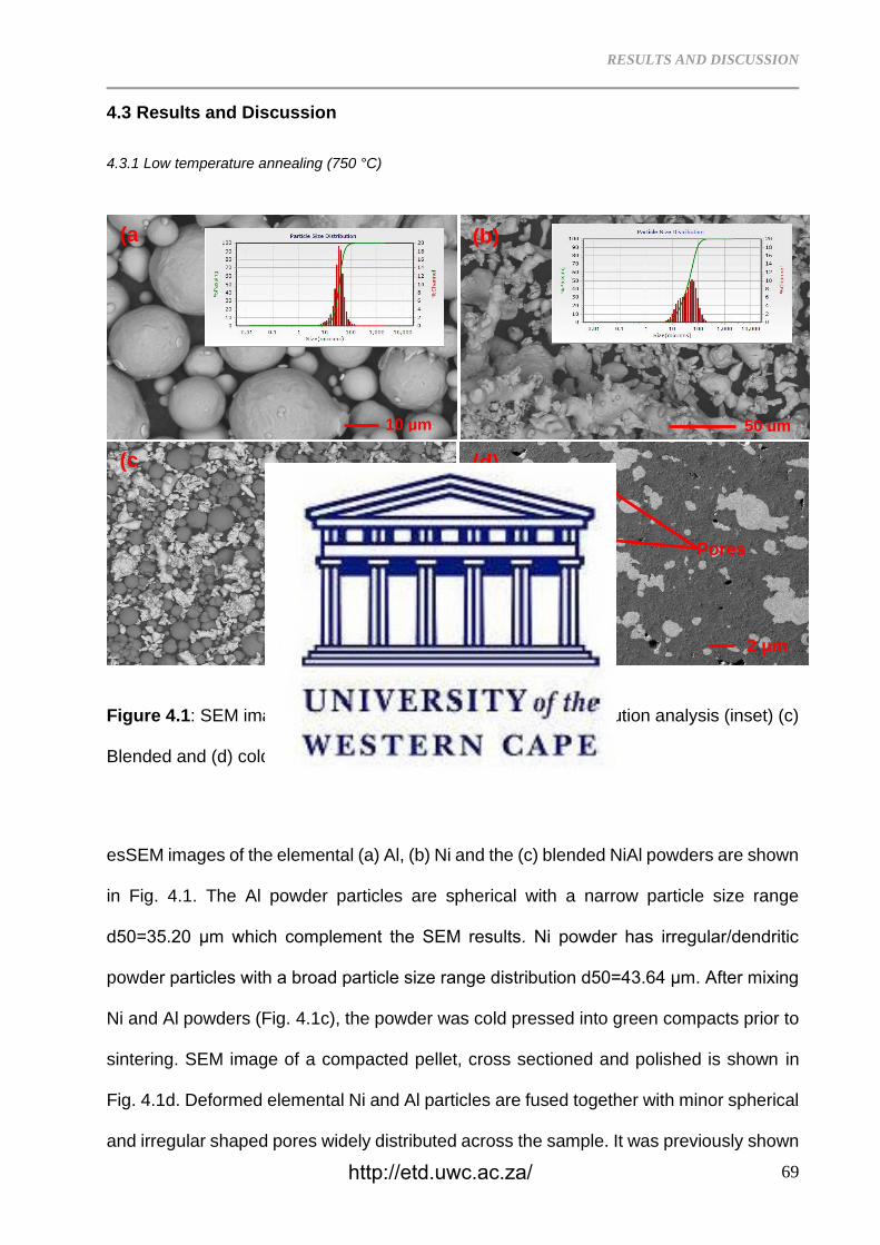
RESULTS AND DISCUSSION
69
4.3 Results and Discussion
4.3.1 Low temperature annealing (750 °C)
Figure 4.1: SEM images of (a) Al, (b) Ni, with particle size distribution analysis (inset) (c)
Blended and (d) cold pressed Ni50Al powder particles.
esSEM images of the elemental (a) Al, (b) Ni and the (c) blended NiAl powders are shown
in Fig. 4.1. The Al powder particles are spherical with a narrow particle size range
d50=35.20 μm which complement the SEM results. Ni powder has irregular/dendritic
powder particles with a broad particle size range distribution d50=43.64 μm. After mixing
Ni and Al powders (Fig. 4.1c), the powder was cold pressed into green compacts prior to
sintering. SEM image of a compacted pellet, cross sectioned and polished is shown in
Fig. 4.1d. Deformed elemental Ni and Al particles are fused together with minor spherical
and irregular shaped pores widely distributed across the sample. It was previously shown
100
(c
)
50 µm
(b)
10 µm
(a
)
2 µm
(d)
Ni
A
Pores
http://etd.uwc.ac.za/
RESULTS AND DISCUSSION
70
that cold compaction is an important factor prior to sintering since re-arrangement of
particles and crystal orientation is realized [29]. Green density of the samples was
determined by the Archimedes principles while the density of the sintered samples were
measured by the Pycnometer and porosity was determined according to eq. (2). Table
4.1 displays the calculated densities of the green compacts ranging from 4.701 g/cm3 to
4.810 g/cm3 obtained by using eq. (1). Upon sintering at 750 °C for 24, 48 and 120 h, the
densities of the samples increased to 5.59 ± 0.081 g/cm3, 5.61 ± 0.065 g/cm3, 5.65 ±
0.032 g/cm3, respectively. The sample sintered 1300 °C (24 h) measured a density of
5.60 ± 0.069 g/cm3. From the theoretical density of the B2 NiAl (5.913 g/cm3) [30,31], the
relative densities upon sintering for 24, 48 and 120 h (750 °C) are computed at 94.5%,
94.9% and 95.6% (Table 4.1).
=𝑚
𝑣 (1)
where ρ (density of the sample), m=mass and v=volume. Porosity can thus be calculated
using the relation:
= 1 −𝑡
𝑚
(2)
where σ is porosity, ρt is the theoretical density while ρm is the measured density. The
oxygen content of the B2 NiAl alloy progressively increased upon sintering at 750 °C from
0.103 ± 0.026% (24 h), 0.120 ± 0.031% (48 h) and 0.152 ± 0.045% (120 h). The 1300 °C
sintered sample has an oxygen content of 0.276 ± 0.027%. After additional oxidation for
120 h on of the 750 °C sample sintered for 24 h, the oxygen content further increased to
2.499 ± 0.332%.
http://etd.uwc.ac.za/
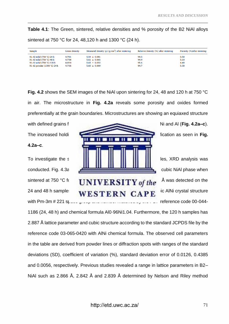
RESULTS AND DISCUSSION
71
Table 4.1: The Green, sintered, relative densities and % porosity of the B2 NiAl alloys
sintered at 750 °C for 24, 48,120 h and 1300 °C (24 h).
Fig. 4.2 shows the SEM images of the NiAl upon sintering for 24, 48 and 120 h at 750 °C
in air. The microstructure in Fig. 4.2a reveals some porosity and oxides formed
preferentially at the grain boundaries. Microstructures are showing an equiaxed structure
with defined grains formed after an exothermic reaction between Ni and Al (Fig. 4.2a–c).
The increased holding time encouraged grain growth and densification as seen in Fig.
4.2a–c.
To investigate the structural development of the sintered samples, XRD analysis was
conducted. Fig. 4.3a–c shows the XRD pattern revealing a single cubic NiAl phase when
sintered at 750 °C for 24, 48 and 120 h. Lattice parameter 2.881 Å was detected on the
24 and 48 h samples. These lattice parameters belong to the cubic AlNi crystal structure
with Pm-3m # 221 space group and number matched by the PDF reference code 00-044-
1186 (24, 48 h) and chemical formula Al0·96Ni1.04. Furthermore, the 120 h samples has
2.887 Å lattice parameter and cubic structure according to the standard JCPDS file by the
reference code 03-065-0420 with AlNi chemical formula. The observed cell parameters
in the table are derived from powder lines or diffraction spots with ranges of the standard
deviations (SD), coefficient of variation (%), standard deviation error of 0.0126, 0.4385
and 0.0056, respectively. Previous studies revealed a range in lattice parameters in B2–
NiAl such as 2.866 Å, 2.842 Å and 2.839 Å determined by Nelson and Riley method
http://etd.uwc.ac.za/
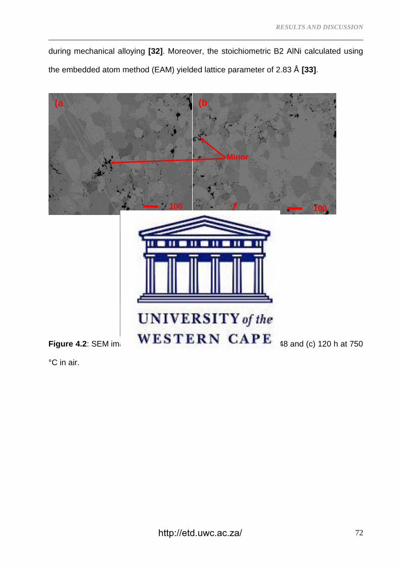
RESULTS AND DISCUSSION
72
during mechanical alloying [32]. Moreover, the stoichiometric B2 AlNi calculated using
the embedded atom method (EAM) yielded lattice parameter of 2.83 Å [33].
Figure 4.2: SEM images of the NiAl alloy sintered for (a) 24, (b) 48 and (c) 120 h at 750
°C in air.
100
µm
(c
)
100
µm
(b
)
100
µm
(a
)
NiAl
grains
Minor
Oxides
http://etd.uwc.ac.za/
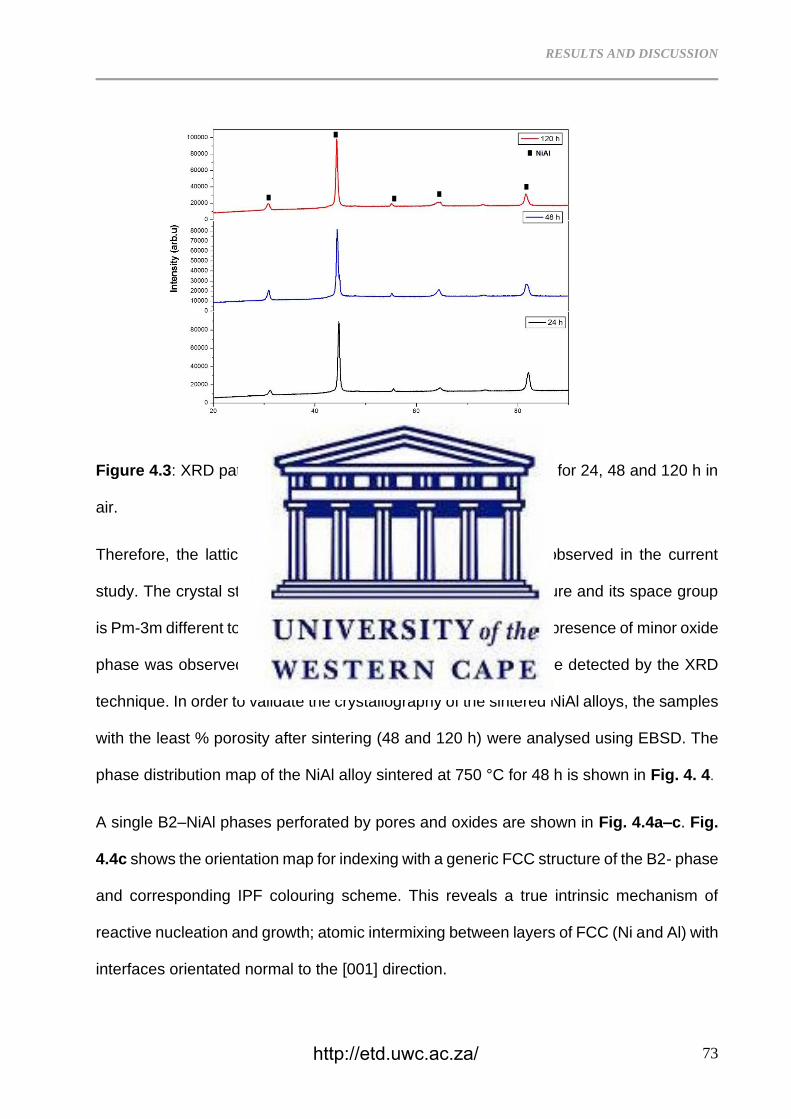
RESULTS AND DISCUSSION
73
Figure 4.3: XRD pattern of the NiAl compacts sintered at 750 °C for 24, 48 and 120 h in
air.
Therefore, the lattice parameters of the B2–NiAl can vary as observed in the current
study. The crystal structure of NiAl is primitive cubic CsCl structure and its space group
is Pm-3m different to body centered cubic structure. Although the presence of minor oxide
phase was observed in the SEM image (Fig. 4.2), it could not be detected by the XRD
technique. In order to validate the crystallography of the sintered NiAl alloys, the samples
with the least % porosity after sintering (48 and 120 h) were analysed using EBSD. The
phase distribution map of the NiAl alloy sintered at 750 °C for 48 h is shown in Fig. 4. 4.
A single B2–NiAl phases perforated by pores and oxides are shown in Fig. 4.4a–c. Fig.
4.4c shows the orientation map for indexing with a generic FCC structure of the B2- phase
and corresponding IPF colouring scheme. This reveals a true intrinsic mechanism of
reactive nucleation and growth; atomic intermixing between layers of FCC (Ni and Al) with
interfaces orientated normal to the [001] direction.
http://etd.uwc.ac.za/
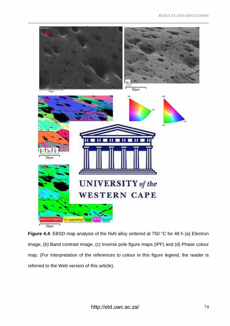
RESULTS AND DISCUSSION
74
Figure 4.4: EBSD map analysis of the NiAl alloy sintered at 750 °C for 48 h (a) Electron
image, (b) Band contrast image, (c) Inverse pole figure maps (IPF) and (d) Phase colour
map. (For interpretation of the references to colour in this figure legend, the reader is
referred to the Web version of this article).
(b) (a)
(c)
(d)
http://etd.uwc.ac.za/
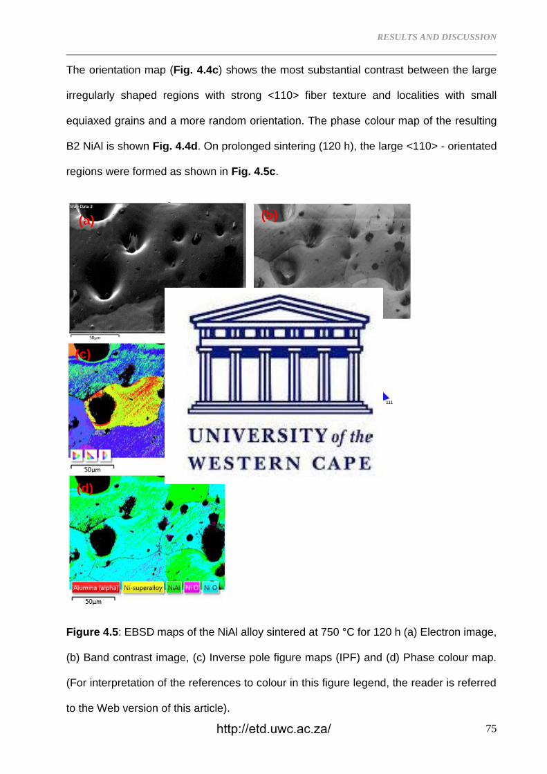
RESULTS AND DISCUSSION
75
The orientation map (Fig. 4.4c) shows the most substantial contrast between the large
irregularly shaped regions with strong <110> fiber texture and localities with small
equiaxed grains and a more random orientation. The phase colour map of the resulting
B2 NiAl is shown Fig. 4.4d. On prolonged sintering (120 h), the large <110> - orientated
regions were formed as shown in Fig. 4.5c.
Figure 4.5: EBSD maps of the NiAl alloy sintered at 750 °C for 120 h (a) Electron image,
(b) Band contrast image, (c) Inverse pole figure maps (IPF) and (d) Phase colour map.
(For interpretation of the references to colour in this figure legend, the reader is referred
to the Web version of this article).
(a)
)
(b)
(c)
(d)
http://etd.uwc.ac.za/
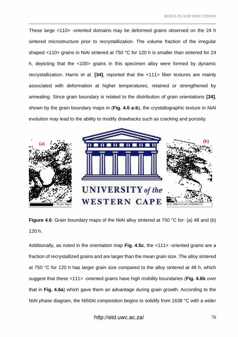
RESULTS AND DISCUSSION
76
These large <110> -oriented domains may be deformed grains observed on the 24 h
sintered microstructure prior to recrystallization. The volume fraction of the irregular
shaped <110> grains in NiAl sintered at 750 °C for 120 h is smaller than sintered for 24
h, depicting that the <100> grains in this specimen alloy were formed by dynamic
recrystallization. Harris et al. [34], reported that the <111> fiber textures are mainly
associated with deformation at higher temperatures, retained or strengthened by
annealing. Since grain boundary is related to the distribution of grain orientations [34],
shown by the grain boundary maps in (Fig. 4.6 a-b), the crystallographic texture in NiAl
evolution may lead to the ability to modify drawbacks such as cracking and porosity.
Figure 4.6: Grain boundary maps of the NiAl alloy sintered at 750 °C for: (a) 48 and (b)
120 h.
Additionally, as noted in the orientation map Fig. 4.5c, the <111> -oriented grains are a
fraction of recrystallized grains and are larger than the mean grain size. The alloy sintered
at 750 °C for 120 h has larger grain size compared to the alloy sintered at 48 h, which
suggest that these <111> -oriented grains have high mobility boundaries (Fig. 4.6b over
that in Fig. 4.6a) which gave them an advantage during grain growth. According to the
NiAl phase diagram, the Ni50Al composition begins to solidify from 1638 °C with a wider
(a) (b)
http://etd.uwc.ac.za/
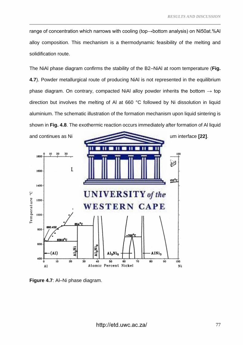
RESULTS AND DISCUSSION
77
range of concentration which narrows with cooling (top→bottom analysis) on Ni50at.%Al
alloy composition. This mechanism is a thermodynamic feasibility of the melting and
solidification route.
The NiAl phase diagram confirms the stability of the B2–NiAl at room temperature (Fig.
4.7). Powder metallurgical route of producing NiAl is not represented in the equilibrium
phase diagram. On contrary, compacted NiAl alloy powder inherits the bottom → top
direction but involves the melting of Al at 660 °C followed by Ni dissolution in liquid
aluminium. The schematic illustration of the formation mechanism upon liquid sintering is
shown in Fig. 4.8. The exothermic reaction occurs immediately after formation of Al liquid
and continues as Ni dissolves through a solid–liquid non-equilibrium interface [22].
Figure 4.7: Al–Ni phase diagram.
http://etd.uwc.ac.za/
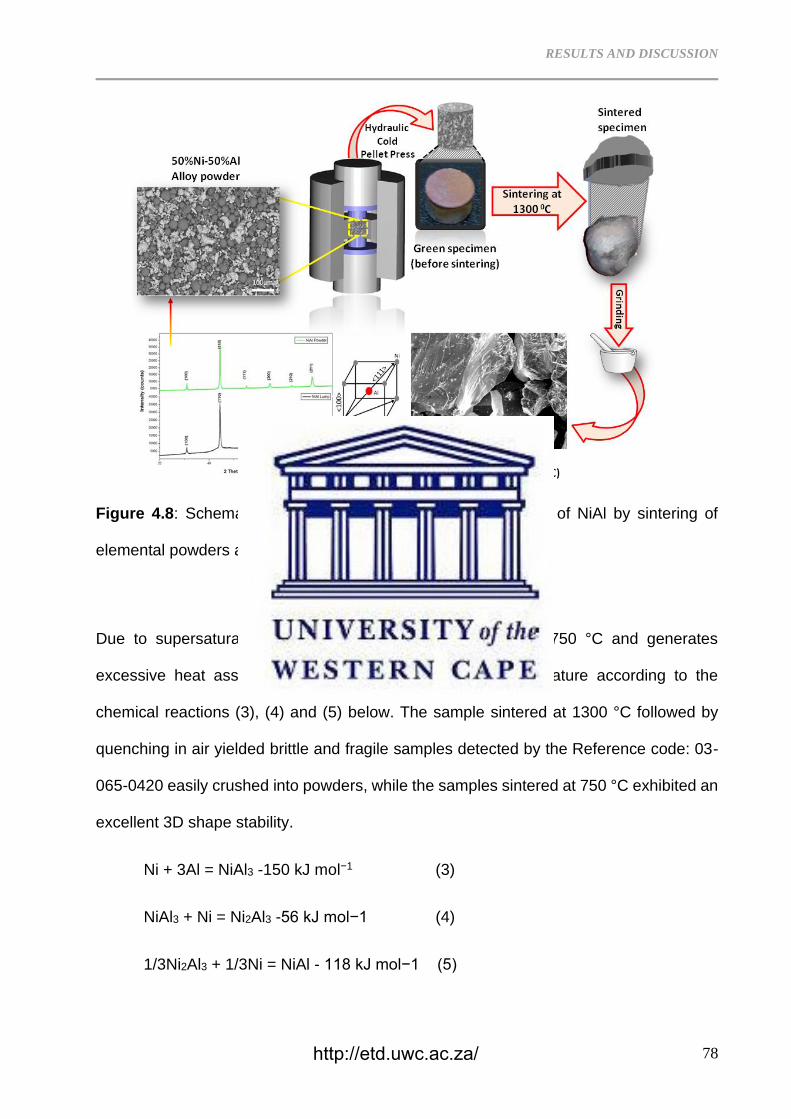
RESULTS AND DISCUSSION
78
Figure 4.8: Schematic illustration of the formation mechanism of NiAl by sintering of
elemental powders at 1300 °C in air.
Due to supersaturation, solid equilibrium NiAl forms around 750 °C and generates
excessive heat associated with a sudden increase in temperature according to the
chemical reactions (3), (4) and (5) below. The sample sintered at 1300 °C followed by
quenching in air yielded brittle and fragile samples detected by the Reference code: 03-
065-0420 easily crushed into powders, while the samples sintered at 750 °C exhibited an
excellent 3D shape stability.
Ni + 3Al = NiAl3 -150 kJ mol−1 (3)
NiAl3 + Ni = Ni2Al3 -56 kJ mol−1 (4)
1/3Ni2Al3 + 1/3Ni = NiAl - 118 kJ mol−1 (5)
http://etd.uwc.ac.za/
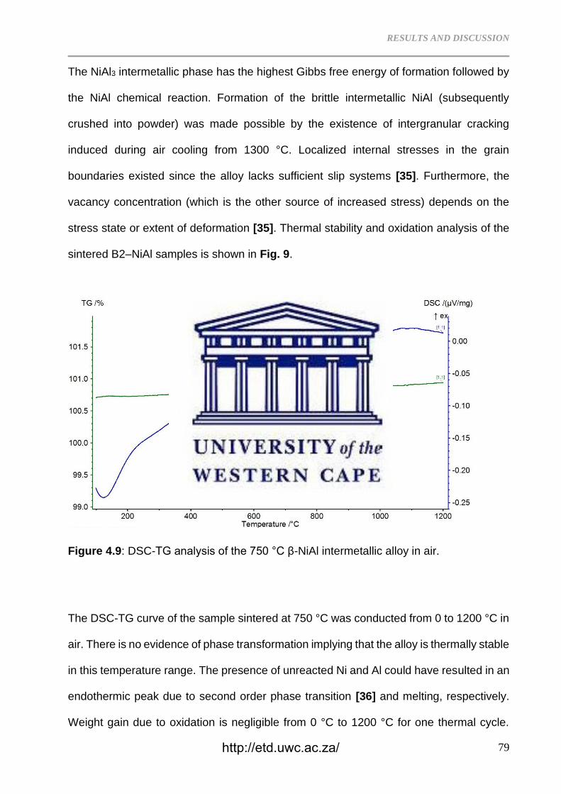
RESULTS AND DISCUSSION
79
The NiAl3 intermetallic phase has the highest Gibbs free energy of formation followed by
the NiAl chemical reaction. Formation of the brittle intermetallic NiAl (subsequently
crushed into powder) was made possible by the existence of intergranular cracking
induced during air cooling from 1300 °C. Localized internal stresses in the grain
boundaries existed since the alloy lacks sufficient slip systems [35]. Furthermore, the
vacancy concentration (which is the other source of increased stress) depends on the
stress state or extent of deformation [35]. Thermal stability and oxidation analysis of the
sintered B2–NiAl samples is shown in Fig. 9.
Figure 4.9: DSC-TG analysis of the 750 °C β-NiAl intermetallic alloy in air.
The DSC-TG curve of the sample sintered at 750 °C was conducted from 0 to 1200 °C in
air. There is no evidence of phase transformation implying that the alloy is thermally stable
in this temperature range. The presence of unreacted Ni and Al could have resulted in an
endothermic peak due to second order phase transition [36] and melting, respectively.
Weight gain due to oxidation is negligible from 0 °C to 1200 °C for one thermal cycle.
http://etd.uwc.ac.za/
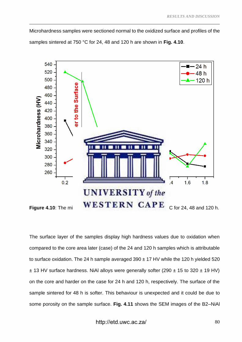
RESULTS AND DISCUSSION
80
Microhardness samples were sectioned normal to the oxidized surface and profiles of the
samples sintered at 750 °C for 24, 48 and 120 h are shown in Fig. 4.10.
Figure 4.10: The microhardness of the B2–NiAl sintered at 750 °C for 24, 48 and 120 h.
The surface layer of the samples display high hardness values due to oxidation when
compared to the core area later (case) of the 24 and 120 h samples which is attributable
to surface oxidation. The 24 h sample averaged 390 ± 17 HV while the 120 h yielded 520
± 13 HV surface hardness. NiAl alloys were generally softer (290 ± 15 to 320 ± 19 HV)
on the core and harder on the case for 24 h and 120 h, respectively. The surface of the
sample sintered for 48 h is softer. This behaviour is unexpected and it could be due to
some porosity on the sample surface. Fig. 4.11 shows the SEM images of the B2–NiAl
http://etd.uwc.ac.za/
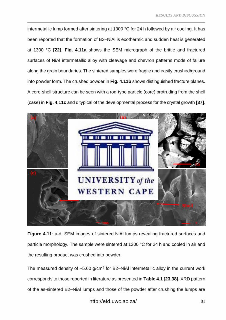
RESULTS AND DISCUSSION
81
intermetallic lump formed after sintering at 1300 °C for 24 h followed by air cooling. It has
been reported that the formation of B2–NiAl is exothermic and sudden heat is generated
at 1300 °C [22]. Fig. 4.11a shows the SEM micrograph of the brittle and fractured
surfaces of NiAl intermetallic alloy with cleavage and chevron patterns mode of failure
along the grain boundaries. The sintered samples were fragile and easily crushed/ground
into powder form. The crushed powder in Fig. 4.11b shows distinguished fracture planes.
A core-shell structure can be seen with a rod-type particle (core) protruding from the shell
(case) in Fig. 4.11c and d typical of the developmental process for the crystal growth [37].
Figure 4.11: a-d: SEM images of sintered NiAl lumps revealing fractured surfaces and
particle morphology. The sample were sintered at 1300 °C for 24 h and cooled in air and
the resulting product was crushed into powder.
The measured density of ~5.60 g/cm3 for B2–NiAl intermetallic alloy in the current work
corresponds to those reported in literature as presented in Table 4.1 [23,38]. XRD pattern
of the as-sintered B2–NiAl lumps and those of the powder after crushing the lumps are
200 2
1 50
(a) (b)
(c) (d)
Core
Shell
http://etd.uwc.ac.za/
RESULTS AND DISCUSSION
82
shown in Fig. 4.12. The analysis revealed an ordered single phase cubic B2 crystal
structure of Pm-3m space group and CsCl superlattice structure with a=2.885 Å. It has
been reported that the B2–NiAl intermetallic compound substitutes a single-crystal nickel-
base superalloy due to its high melting temperature, low density and high oxidation
resistance [39]. Accordingly, the B2–NiAl phase forms a protective oxide layer at
temperatures above 1200 °C [40] but lack strength and toughness at room temperature
[41]. The B2–NiAl phase exists over a wide concentration range extending across the
stoichiometric (1:1) composition. Its unit cell consists of two simple cubic sub-lattices at
equiatomic composition. All the Al atoms occupy the cube corners of one sublattice and
Ni-atoms occupy the corners of the other sublattice [42]. Additionally, the crushed powder
retained the B2 crystal structure (Fig. 4.9a) with a slightly smaller lattice parameter of a
= 2.881 Å. Typically, NiAl reaction follows the sequence; Ni + Al→NiAl3→Ni2Al3→NiAl
[37,43]. The fragile nature of the sample sintered at 1300 °C for 24 h is attributed mainly
to air cooling and minor oxide impurities along the grain boundaries. XRD pattern of the
cubic (B2)–NiAl alloy sintered at 750 °C for 120 h and further oxidized at 750 °C for 120
h in air is presented in Fig. 4.13. The B2–NiAl crystal structure shows stability after
prolonged oxidation retaining a lattice parameter a=2.887 Å (Fig. 4.13). B2 NiAl lattice
parameters obtained from XRD analysis were compared with the calculated lattice
parameters using Eq. (6) on the (110) most intense peak and presented in Table 4.2.
Table 4.2: The XRD and calculated lattice parameters of the sintered NiAl at 750 °C for
120 h and their PDF reference codes as well as the measured oxygen content.
http://etd.uwc.ac.za/
RESULTS AND DISCUSSION
83
Figure 4.12: XRD pattern of the NiAl lump obtained after sintering at 1300 °C for 24 h
and that of the lump after crushing into powder.
The detected oxide layer was predominantly Al2O3 on the surface of B2–NiAl alloy having
lattice parameters a=4.735 Å; c=12.918 Å. Additionally, a monoclinic phase (a=5.743 Å;
c=8.1046 Å) was detected and attributed to a metastable oxynitride which is attributed to
N pick-up as confirmed by the EDS analysis in Fig. 13 [44]. These lattice parameters are
not similar to those of the monoclinic aluminium oxide reported in literature (a=11.810 Å;
b=2.90 Å; c=5.610 Å) [43]. Minor peaks of the rhombohedral (RHL) phase were also
detected.
dhkl= for BCC NiAl (6) )(
222lkh
ao
++
http://etd.uwc.ac.za/
RESULTS AND DISCUSSION
84
where d is the d = spacing of (110) peak while a0 is the lattice parameter. B2–NiAl alloy
powder was further exposed at 750 °C in air for 120 h. There is evidence of excessive
grain growth after thermal oxidation.
This alloy is resistant to oxidation due to a thin scale of the stable Al2O3 which forms a
protective layer that inhibits further oxidation (Fig. 4.14). The presence of Al in NiAl
promotes selective oxidation of Al during formation of an Al2O3 layer with no evidence of
any Ni oxide [44].
Figure 4.13: XRD pattern of the NiAl sample sintered at 750 °C for 120 h and further
oxidized in air at 750 °C for 120 h.
Diffusion processes through the oxide layer is the rate determining factor for any further
oxidation of the alloy and its kinetics can be described by the parabolic rate of a law of
diffusion-controlled oxidation in Eq. (7):
http://etd.uwc.ac.za/
RESULTS AND DISCUSSION
85
(Δm/A2)=kp.t (7)
Whereby (Δm/A) is the weight gain per unit area, kp is the parabolic rate constant
depending on oxidation temperature and is calculated from the slopes of the (Δm/A)2
versus treatment time graphs and t is time [44]. The relationship between parabolic rate
constant kp and temperature T can be expressed by an Arrhenius-type Eq. (8):
𝐷 = 𝐷0𝑒𝑥𝑝 (−𝑄
𝑅𝑇) (8)
D0 is a constant, Q is an activation energy (J/mol) for oxide formation, R is gas constant
(8.314 J/mol.K) and T is absolute temperature (K). In the current experiment, negligible
mass loss of 0.0002 g (0.02%) after 120 h at 750 °C on the sample was recorded.
Figure 4.14: SEM images of the β-NiAl alloy sintered at 750 °C for 120 h and further
oxidized in air at 750 °C for 120 h.
10
µm
10 µm
10 µm
Grain Imprints
Smooth NiAl regions
Al2O3
(a) (b)
(c)
http://etd.uwc.ac.za/
RESULTS AND DISCUSSION
86
A spallation of the oxide layer was observed as shown in Fig. 4.14c. The underlying B2–
NiAl alloy exposed by the oxide scale spallation shows a mixture of grain imprints and
smooth regions resembling spallation behaviour [43, 45]. Zhang et al. [46], emphasized
the dependence of the epitaxial relationship between NiAl and γ-Al2O3 and surface
roughness on the oxidation temperature. Additionally, there is lattice mismatch-induced
strain energy during oxide growth between the γ-Al2O3 and the NiAl parent metal which
promotes spallation of the oxide later. Elemental distribution is shown by the EDS
mapping of the B2–NiAl oxidized alloy in Fig. 4.15. The nitrogen attributed to the
stabilization of the metastable monoclinic oxynitride phase was detected. In general, NiAl
intermetallic alloy shows good resistance to cyclic oxidation.
Figure 4.15: EDS mapping of the β-NiAl alloy powder after oxidation in air at 750 °C for
120 h.
http://etd.uwc.ac.za/
RESULTS AND DISCUSSION
87
4.4 Conclusion
A single phase cubic B2–NiAl alloy was synthesized through mixing of elemental Ni and
Al powders followed by cold compacting and sintering. Microstructure of the sintered
samples at 750 °C for 24, 48 and 120 h revealed equiaxed grain structure. The 750 °C
for 24, 48 and 120 h process achieved well-sintered intermetallic alloys. Sintering of the
Ni50 atm. %Al at 1300 °C yielded brittle B2 NiAl lumps that were easily crushable into
powder form. Morphology of the brittle powder resembled core-shell growth properties.
XRD analysis detected a single cubic B2–NiAl intermetallic phase with comparable lattice
parameters for both sintering temperatures of at 750 and 1300 °C. EBSD results
demonstrated that the microstructural grains in B2–NiAl alloy sintered at 48 and 120 h
were recrystallized and consumed by preferential growth of grains in the <111>
orientations, with prolonged annealing times. The density measured for the samples
averaged at ~5.60 g/cm3. The B2–NiAl intermetallic developed a thin scale of stable Al2O3
alloy due to oxidation in air at 750 °C for 120 h. As a result, further oxidation on the
sample's surface was restricted, except the traces of Al2O3 that formed via intergranular
oxidation and transformed into a metastable monoclinic oxynitride phase due N
contamination.
References
4.1 L. Fang, S.F. Zhang, F. Xi, R.H. Yang, K. Mukai, Measurement and analysis of liquid
density of Ni–Al binary alloys, J. Alloy. Compd. 493 (2010) 465–470.
4.2 E. Sugiarti, F. Destyorini, K.A. Zaini, Y. Wang, N. Hashimoto, S. Ohnuki, S. Hayashi,
Characterization of Ni-based coatings on carbon steel by electron microscopy, Surf. Coat.
Technol. 265 (2015) 68–77.
4.3 D.B. Miracle, Overview No. 104: The physical and mechanical properties of NiAl, Acta
Mater. 41 (1993) 649–684.
http://etd.uwc.ac.za/
RESULTS AND DISCUSSION
88
4.4 Z.D. Xiang, S.R. Rose, P.K. Datta, Low-temperature formation and oxidation
resistance of nickel aluminide/nickel hybrid coatings on alloy steels, Scr. Mater. 59 (2008)
99–102.
4.5 C.M. Bao, U. Dahlborg, N. Adkins, M. Calvo-Dahlborg, Structural characterisation of
Al–Ni powders produced by gas atomisation, J. Alloy. Compd. 481 (2009) 199-206.
4.6 D.J. Jarvis, D. Voss, IMPRESS Integrated Project—An overview paper, Mater. Sci.
Eng. A 413 (2005) 583-591.
4.7 J. Guo, Z. Wang, L. Sheng, L. Zhou, C. Yuan, Z. Chen, L. Song, Wear properties of
NiAl based materials, Prog. Nat. Sci: Mater. Int. 22 (5) (2012) 414–425.
4.8 M. Beyhaghi, J. V. Khaki, M. Manawan, A. Kiani-Rashid, M. Kashefi, S. Jonsson, In-
situ synthesis and characterization of nano-structured NiAl-Al2O3 composite during high
energy ball milling, Pow. Technol. 329 (2018) 95–106.
4.9 W.R. Osório, L.C. Peixoto, M.V. Canté, A. Garcia, Microstructure features affecting
mechanical properties and corrosion behaviour of a hypoeutectic Al–Ni alloy, Mater. Des.
31 (2010) 4485–4489.
4.10 J.L. Cheng, H.H. Hng, H.Y. Ng, P.C. Soon, Y.W. Lee, Deposition of nickel
nanoparticles onto aluminum powders using a modified polyol process, Mater. Res. Bull.
44 (2009) 95-99.
4.11 Z. Halem, N. Halem, M. Abrudeanu, S. Chekroude, C. Petot, G. Petot-Ervas,
Transport properties of Al or Cr-doped nickel oxide relevant to the thermal oxidation of
dilute Ni-Al and Ni-Cr alloys, Solid State Ion. 297 (2016) 13-19.
4.12 U. Rayhan, J.H. Do, T. Arimura, T. Yamato, Reduction of carbonyl compounds by
Raney Ni-Al alloy and Al powder in the presence of noble metal catalysts in water, Comp.
Rendus Chim. 18 (2015) 685-692.
4.13 Y. Xu, S. Kameoka, K. Kishida, M. Demura, A. Tsai, T. Hirano, Catalytic properties
of Ni3Al intermetallic for methanol decomposition, Mater. Trans. 45
http://etd.uwc.ac.za/
RESULTS AND DISCUSSION
89
(2004) 3177-3179.
4.14 M.C. Dumez, R.M. Marin-Ayral, J.C. Tédenac, The role of experimental parameters
in combustion synthesis of NiAl under high gas pressure, J. Alloy. Compd. 268 (1998)
141–151.
4.15 J.P. Lebrat, A. Varma, Self-propagating high-temperature synthesis of Ni3Al,
Combust. Sci. Technol. 88 (1993) 211–222.
4.16 L. Plazanet, F. Nardou, Reaction process during relative sintering of NiAl, J. Mater.
Sci. 33 (1998) 2129–2136.
4.17 P. Swaminathan, M.D. Grapes, K. Woll , S.C. Barron , D.A. Lavan , T.P. Weihs,
Studying exothermic reactions in the Ni–Al system at rapid heating rates using a
nanocalorimeter, J. Appl. Phys. 113 (2013) 143509.
4.18 M.H. Enayati, F. Karimzadeh, S.Z. Anvari, Synthesis of nanocrystalline NiAl by
mechanical alloying, J. Mater. Proc. Technol. 200 (2008) 312–315.
4.19 S. Garćıa-Galán, G. Arámburo-Pérez, C. González-Rivera, J. Juárez-Islas, The
effect of Cu-macroalloying on β-NiAl intermetallic compound obtained by mechanical
alloying, J. Mater. Proc. Technol. 143–144 (2003) 551–554.
4.20 A. Mashreghi, M.M. Moshksar, Partial martensitic transformation of nanocrystalline
NiAl intermetallic during mechanical alloying, J. Alloy. Compd. 482 (2009) 196–198.
4.21 A. Abraham, H. Nie, M. Schoenitz, A.B. Vorozhtsov, M. Lerner, A. Pervikov, N.
Rodkevich, E.L. Dreizin, Bimetal Al–Ni nano-powders for energetic formulations,
Combust. Flame 173 (2016) 179–186.
4.22 P. Zhu, J.C.M. Li, C.T. Liu, Reaction mechanism of combustion synthesis of NiAl,
Mater. Sci. Eng. A 329-331 (2002) 57–68
4.23 O. Ozdemir, S. Zeytin, C. Bindal, A study on NiAl produced by pressure-assisted
combustion synthesis, Vacuum 84 (2010) 430–437.
http://etd.uwc.ac.za/
RESULTS AND DISCUSSION
90
4.24 H.X. Dong, Y.H. He, J. Zou, N.P. Xu, B.Y. Huang, C.T. Liu, Effect of preheating
treatment at 575 ◦C of green compacts on porous NiAl, J. Alloy. Compd. 492 (2010) 219–
225.
4.25 V. Yu. Filimonov, K. B. Koshelev, A. A. Sytnikov, Thermal modes of heterogeneous
exothermic reactions. Solid-phase interaction, Combust. Flame 185 (2017) 93–104.
4.26 M.L. Weaver, M.J. Kaufman, R.D. Noebe, The effects of alloy purity on the
mechanical behavior of soft oriented NiAl single crystals, Scripta Metallurg. Mater. 29, (8)
(1993) 1113-1118.
4.27 M. N. Mathabathe, A. S. Bolokang, G. Govender, R. J. Mostert, C. W. Siyasiya,
Structure-property orientation relationship of a gamma/alpha2/Ti5Si3 in as-cast Ti-45Al-
2Nb-0.7Cr-0.3Si intermetallic alloy, J. Alloy. Compd. 765 (2018) 690–699.
4.28 D. Stojakovic, Electron backscatter diffraction in materials characterization, Proc.
Appl. Ceram. 6 (1) (2012) 1-13.
4.29 AS Bolokang, M.J. Phasha, Effect of mechanical milling and cold pressing on Co
powder, J. Metallurgy. 2012 (2012) 1-7.
4.30 T. Chen, J.M. Hampikian, N.N. Thadhani, Synthesis and characterization of
mechanically alloyed and shock-consolidated nanocrystalline NiAl intermetallic. Acta
Mater. 47 (8) (1999) 2567-2579.
4.31 Kamil Bochenek, Witold Węglewski, Jerzy Morgiel, Michał Basista, Influence of
rhenium addition on microstructure, mechanical properties and oxidation resistance of
NiAl obtained by powder metallurgy, Mater. Sci. Eng. A 735 (2018) 121–130.
4.32 K.E. Harris, F. Ebrahimi, H. Garmestani, Texture evolution in NiAl, Mater. Sci. Eng.
A 247 (1998) 187–194.
4.33 F. Ebrahimi, T. G. Hoyle, brittle-to-ductile transition in polycrystalline NiAl, Acta
mater. 45 (10) (1997) 4193-4204.
http://etd.uwc.ac.za/
RESULTS AND DISCUSSION
91
4.34 AS Bolokang, M.J. Phasha, Thermal analysis on the curie temperature of
nanocrystalline Ni powder produced by ball milling, Adv. Pow. Metallurg. 22 (2011) 518-
521.
4.35 A. Slager, D. Kesse, A family of Ductile Intermetallic Compounds, Nat. Mater. 2
(2003) 587-591. S. An, J. Li, Y. Li, S. Li, Q. Wang, B. Liu, Two-step crystal growth
mechanism during crystallization of an undercooled Ni50Al50 alloy, Scientific Reports |
6:31062 | DOI: 10.1038/srep31062.
4.36 O. Ozdemir, S. Zeytin, C. Bindal, Characterization of NiAl with cobalt produced by
combustion synthesis, J. Alloy. Compd. 508 (2010) 216–221.
4.37 Q. Wu, S. Li, Y. Ma, S. Gong, Study on behavior of NiAl coating with different Ni/Al
ratios, Vacuum 93 (2013) 37–44.
4.38 M. Adabi, A.A. Amadeh, Electrodeposition mechanism of Ni-Al composite coating,
Trans. Non Ferr. Met. Soc. China 24 (2014) 3189–3195.
4.39 X. Yang, X. Peng, F. Wang, Effect of annealing treatment on the oxidation of an
electrodeposited alumina-forming Ni–Al nanocomposite, Corros. Sci. 50 (2008)
3227–3232.
4.40 A. Paul, A.A. Kodentsov, F.J.J. van Loo, On diffusion in the β-NiAl phase, J. Alloy.
Compd. 403 (2005) 147–153.
4.41 I. Levin, L.A. Bendersky, D.G. Brandon, M. Ruhle, Cubic to monoclinic phase
transformation in alumina, Acta mater. 45 (9) (1997) 3659-3669.
4.42 A.S. Bolokang, D.E. Motaung, C.J. Arendse, T.F.G. Muller, Morphology and
structural development of reduced anatase-TiO2 by pure Ti powder upon annealing and
nitridation: Synthesis of TiOx and TiOxNy powders, Mater. Char. 100 (2015) 41–49.
4.43 C. Kaplin, R. Ivanov, M. Paliwal, I-H. Jung, M. Brochu, The effect of nanostructure
on the oxidation of NiAl, Intermetallics 54 (2014) 209-217.
4.44 H.J. Grabke, Oxidation of NiAl and FeAl, Intermetallics 7 (1999) 1153–1158.
http://etd.uwc.ac.za/
RESULTS AND DISCUSSION
92
4.45 Z. Zhang, L. Li, J.C. Yang, γ-Al2O3 thin film formation via oxidation of β-NiAl (110),
Acta Mater. 59 (2011) 5905–5916.
http://etd.uwc.ac.za/
RESULTS AND DISCUSSION
93
CHAPTER FIVE
Characterization of the Ni62.5Al37.5TiC1.28 composite produced via cold
pressing and sintering process
Paper submitted for peer review
Abstract
The Ni62.5Al37.5TiC1.28 composite was developed by powder mixing, compaction and
sintering at 650 ºC. The chemical reaction during sintering showed that self-propagating
high-temperature synthesis (SHS) occurs when a small amount of nanosized (50 – 100
nm) TiC powder was added. The effect of cold pressing on the low temperature TE is
proposed. Martensite NiAl laths, Ni3Al and TiC phases were formed.
Keywords: Martensite; Thermal explosion; TiC; NiAl; cold pressing
5.1 Introduction
The Nickel aluminide (NiAl) alloys are interesting systems with melting temperature of
1640 ºC and contains the ordered B2 intermetallic NiAl with unique physical and
mechanical properties for high temperature applications [1]. However, there is a need to
improve its low temperature strength which limits the alloy application. The Ni-Al system
reveals a range of phases depending on the starting chemical composition. These phases
include the high-temperature Al3Ni eutectic used in production of aerospace gas turbine
engine blades, hence it is considered an attractive structural material for high-temperature
applications [2]. In particular, the Al45 at. %Ni was formed via explosion of electrically
heated twisted pure Al and Ni wires in an argon atmosphere [3]. Operating temperatures
as low as 575 °C–750 °C were effective to synthesize porous NiAl intermetallic alloy due
http://etd.uwc.ac.za/
RESULTS AND DISCUSSION
94
to exothermic reaction [4]. Thermal explosion (TE) and ignition of various Ni-Al powder
blends, rolled and magnetron sputtered films, compacts of mechanically activated and
non-activated mixtures were explored under mechanical activation. A single cubic B2–
NiAl phase was synthesized through mixing of elemental Ni and Al powders followed by
cold compacting and sintering [5]. Cubic B2–NiAl alloy was synthesized after sintering of
the cold pressed compacts at 750 °C and 1300 °C, respectively. The compacts sintered
at 1300 °C were brittle while those sintered at 750 °C sintered were not as brittle. The TE
process of stoichiometric Ni–Al system was investigated by time-resolved X-ray diffraction
techniques to trace the dynamics of phase transformation during rapid, gasless
heterogeneous reactions [6]. Authors compared the TE of un-milled and mechanically
milled NiAl and concluded that the former occur due to melting, while the latter is by solid
state reaction. This behaviour implies that deformations create fresh surfaces for a solid-
state reaction to occur between Ni and Al particles during mechanical milling. The
mechanical activation leads to a decrease in activation barrier while the ignition becomes
possible at low temperatures below the melting point of Al [7]. In this work, the effect of
nanosized TiC powder on the microstructure of (Ni-37.5at%Al)-1.28vol%TiC composite
was investigated. Nickel is a strategic metal for both ferromagnetic and non-magnetic
shape memory alloys (SMAs) [8-11]. Despite limited investigations on this metal
properties linked to SMAs, it has been shown to exhibit second-order phase transition
(ferromagnetic to paramagnetic) when heated to high temperatures [12, 13]. This phase
transition is affected by mechanical deformations [14, 15]. The formation of martensite
laths reinforced with small amount of nanosized TiC reported in this paper has not been
previously encountered by the authors. Moreover, it is proposed that surface mechanical
deformation induced by cold pressing triggers the thermal explosion at lower
temperatures.
http://etd.uwc.ac.za/
RESULTS AND DISCUSSION
95
5.2 Experimental Work
Elemental Ni (99.8%), Al (99.9%) and nanoparticles of TiC powders were blended to
synthesize a TiC reinforced NiAl. A NiAl with Ni-37.5at%Al was initially mixed followed by
addition of 1.28 Vol.% TiC of the total TiC-NiAl mixture. The powder mixture was cold-
pressed into cylindrical (17mm diameter) coupons at 20 MPa and sintered at 650 ºC in a
Carbolite tube furnace with flowing argon (Ar) for 6 hours (h). The resulting composite is
losely refered to as Ni62.5Al37.5TiC1.28. The morphology of the Ni, Al and TiC powdersas
well as the microstructure of the sintered and polished NiAlTiC composite were
investigated using a high-resolution scanning electron microscope (HR-SEM, Auriga
ZEISS) coupled with a Robinson Backscatter Electron Detector and an Oxford Link
Pentafet energy dispersive x-ray spectroscopy (EDS) detector. MicroVickers hardness
tests were performed by applying a load of 300 Kgf and dwelling time of 10s. Hardness
was measured across the polished surface specimens at 0.2mm intervals and an average
of 32 measurements computed per distance from the surface.
http://etd.uwc.ac.za/
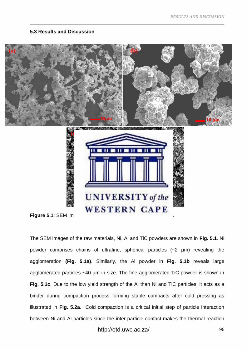
RESULTS AND DISCUSSION
96
5.3 Results and Discussion
Figure 5.1: SEM images of the (a) Ni, (b) Al and (c) TiC powders.
The SEM images of the raw materials, Ni, Al and TiC powders are shown in Fig. 5.1. Ni
powder comprises chains of ultrafine, spherical particles (~2 µm) revealing the
agglomeration (Fig. 5.1a). Similarly, the Al powder in Fig. 5.1b reveals large
agglomerated particles ~40 µm in size. The fine agglomerated TiC powder is shown in
Fig. 5.1c. Due to the low yield strength of the Al than Ni and TiC particles, it acts as a
binder during compaction process forming stable compacts after cold pressing as
illustrated in Fig. 5.2a. Cold compaction is a critical initial step of particle interaction
between Ni and Al particles since the inter-particle contact makes the thermal reaction
10µm
(a)
10 µm
(b)
100 µm
(c)
http://etd.uwc.ac.za/
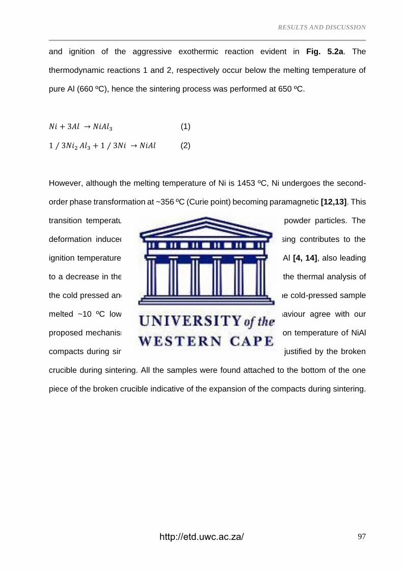
RESULTS AND DISCUSSION
97
and ignition of the aggressive exothermic reaction evident in Fig. 5.2a. The
thermodynamic reactions 1 and 2, respectively occur below the melting temperature of
pure Al (660 ºC), hence the sintering process was performed at 650 ºC.
𝑁𝑖 + 3𝐴𝑙 → 𝑁𝑖𝐴𝑙3 (1)
1 ⁄ 3𝑁𝑖2 𝐴𝑙3 + 1 ⁄ 3𝑁𝑖 → 𝑁𝑖𝐴𝑙 (2)
However, although the melting temperature of Ni is 1453 ºC, Ni undergoes the second-
order phase transformation at ~356 ºC (Curie point) becoming paramagnetic [12,13]. This
transition temperature can be affected by deformation of the powder particles. The
deformation induced on the particles surfaces after cold pressing contributes to the
ignition temperature occurring below the melting temperature of Al [4, 14], also leading
to a decrease in the activation barrier [16]. Fig. 5.2b, c reveals the thermal analysis of
the cold pressed and free flowing Al powders. It is evident that the cold-pressed sample
melted ~10 ºC lower than the free-flowing powder. This behaviour agree with our
proposed mechanism on the effect of cold pressing on the ignition temperature of NiAl
compacts during sintering. As a result, the occurrence of TE is justified by the broken
crucible during sintering. All the samples were found attached to the bottom of the one
piece of the broken crucible indicative of the expansion of the compacts during sintering.
http://etd.uwc.ac.za/
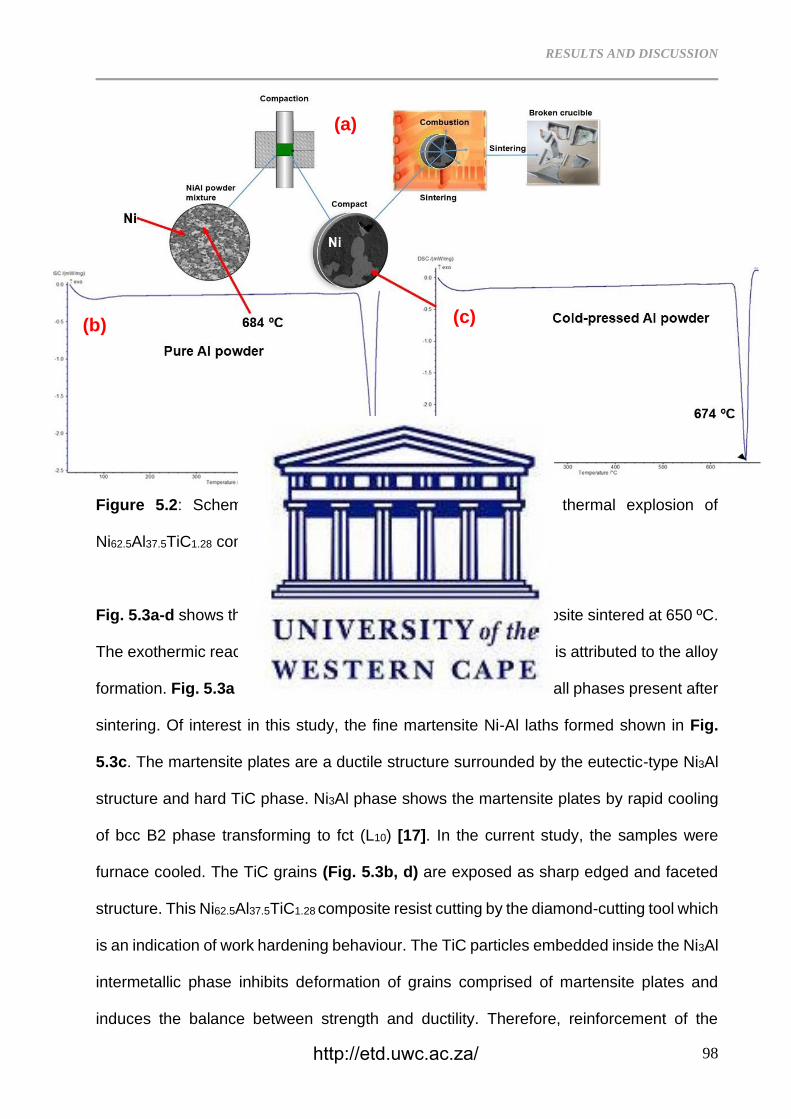
RESULTS AND DISCUSSION
98
Figure 5.2: Schematic representation of the synthesis and thermal explosion of
Ni62.5Al37.5TiC1.28 composition during sintering.
Fig. 5.3a-d shows the SEM images of the Ni62.5Al37.5TiC1.28 composite sintered at 650 ºC.
The exothermic reaction accompanied by the TE during sintering is attributed to the alloy
formation. Fig. 5.3a shows the resulting microstructure revealing all phases present after
sintering. Of interest in this study, the fine martensite Ni-Al laths formed shown in Fig.
5.3c. The martensite plates are a ductile structure surrounded by the eutectic-type Ni3Al
structure and hard TiC phase. Ni3Al phase shows the martensite plates by rapid cooling
of bcc B2 phase transforming to fct (L10) [17]. In the current study, the samples were
furnace cooled. The TiC grains (Fig. 5.3b, d) are exposed as sharp edged and faceted
structure. This Ni62.5Al37.5TiC1.28 composite resist cutting by the diamond-cutting tool which
is an indication of work hardening behaviour. The TiC particles embedded inside the Ni3Al
intermetallic phase inhibits deformation of grains comprised of martensite plates and
induces the balance between strength and ductility. Therefore, reinforcement of the
(a)
(b) (c)
http://etd.uwc.ac.za/
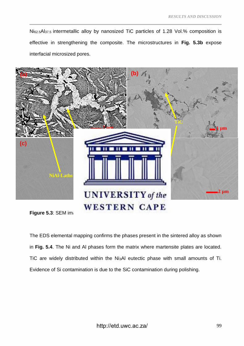
RESULTS AND DISCUSSION
99
Ni62.5Al37.5 intermetallic alloy by nanosized TiC particles of 1.28 Vol.% composition is
effective in strengthening the composite. The microstructures in Fig. 5.3b expose
interfacial microsized pores.
Figure 5.3: SEM images of the 650 ºC-sintered Ni62.5Al37.5TiC1.28
The EDS elemental mapping confirms the phases present in the sintered alloy as shown
in Fig. 5.4. The Ni and Al phases form the matrix where martensite plates are located.
TiC are widely distributed within the Ni3Al eutectic phase with small amounts of Ti.
Evidence of Si contamination is due to the SiC contamination during polishing.
1 µm
1 µm 2 µm
2 µm
NiAl-Laths
TiC
Ni3(Al,Ti)
(a)
(c) (d)
(b)
http://etd.uwc.ac.za/
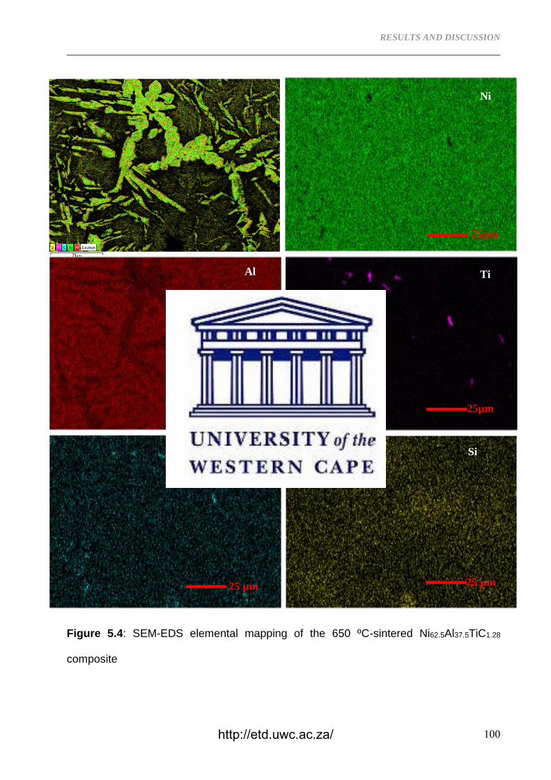
RESULTS AND DISCUSSION
100
Figure 5.4: SEM-EDS elemental mapping of the 650 ºC-sintered Ni62.5Al37.5TiC1.28
composite
Si
25 µm
C
25 µm
Ti
25µm
Ni
25µm
Al
25 µm
http://etd.uwc.ac.za/

RESULTS AND DISCUSSION
101
Ni62.5Al37.5 is a Ni-rich composition on the Ni-Al phase diagram as represented in Fig.
5.5b. Due to addition of TiC particles that impeded diffusion in the microstructure,
martensite structure was formed, as evident in Fig. 5.5a. The Ni62.5Al37.5TiC1.28 composite
resisting the cutting by the diamond cutting tool is an indication of the work hardening
effect. This behaviour is like those shown by the Fe-Mn steels strengthening mechanism
[16] due to intergranular brittle Ni3Al and TiC precipitates [18, 19]. The martensite phase
has developed due to thermally activated dislocation motion by the movement of atoms
over distances that are less than the inter-atomic spacing [20]. Mostly, the Ni-Al
martensite laths are exposed after water quenching (WQ) due to residual stress [21]. The
WQ promotes the Ni3Al precipitation at grain boundaries. Filho et al. [22] reported the
twinning and multiple dislocations dictating the strain hardening mechanisms in austenite,
which in the current study was induced by TiC nanoparticles during the thermal explosion.
The TiC particles and the Ni3(Al,Ti) phase have enclosed the martensite laths restricting
further deformation, hence making it difficult to cut the material. The precipitation of the
faceted TiC and Ni3(Al,Ti) particles is in agreement with literature [23].
http://etd.uwc.ac.za/
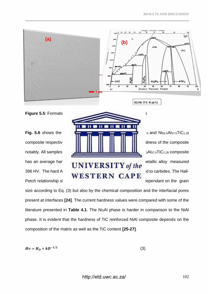
RESULTS AND DISCUSSION
102
Figure 5.5: Formation mechanism of the Ni62.5Al37.5TiC composite
Fig. 5.6 shows the microhardness of the carbide free Ni62.5Al37.5 and Ni62.5Al37.5TiC1.28
composite respectively. Addition of 1.28 Vol.% increased the hardness of the composite
notably. All samples were sintered at 650 ºC for 6 hours. The Ni62.5Al37.5TiC1.28 composite
has an average hardness of 431 HV while the Ni62.5Al37.5 intermetallic alloy measured
396 HV. The hard Al3Ni intermetallic phase is less brittle compared to carbides. The Hall-
Petch relationship shows that the hardness of the composite is dependant on the grain
size according to Eq. (3) but also by the chemical composition and the interfacial pores
present at interfaces [24]. The current hardness values were compared with some of the
literature presented in Table 4.1. The Ni3Al phase is harder in comparison to the NiAl
phase. It is evident that the hardness of TiC reinforced NiAl composite depends on the
composition of the matrix as well as the TiC content [25-27].
𝑯𝒗 = 𝑯𝑶 + 𝒌𝑫−𝟏/𝟐 (3)
(a) (b)
http://etd.uwc.ac.za/
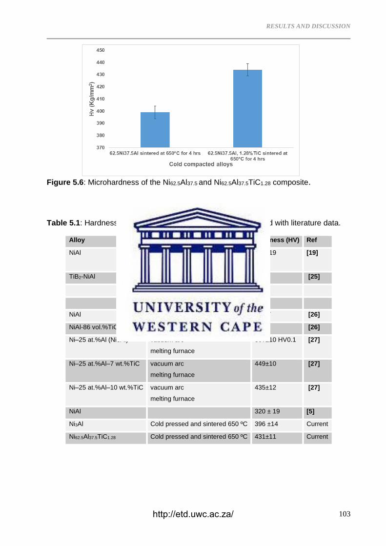
RESULTS AND DISCUSSION
103
Figure 5.6: Microhardness of the Ni62.5Al37.5 and Ni62.5Al37.5TiC1.28 composite.
Table 5.1: Hardness of the Ni62.5Al37.5TiC1.28 composite compared with literature data.
Alloy Process Hardness (HV) Ref
NiAl BM-vacuum hot pressing 360±19
[19]
TiB2-NiAl Vacuum arc melting 670 [25]
As-cast 55
Heat treated 361
NiAl Cold Isostatic pressing 244.7 [26]
NiAl-86 vol.%TiC 1428 [26]
Ni–25 at.%Al (Ni3Al) vacuum arc
melting furnace
307±10 HV0.1 [27]
Ni–25 at.%Al–7 wt.%TiC vacuum arc
melting furnace
449±10 [27]
Ni–25 at.%Al–10 wt.%TiC vacuum arc
melting furnace
435±12 [27]
NiAl 320 ± 19 [5]
Ni3Al Cold pressed and sintered 650 ºC 396 ±14 Current
Ni62.5Al37.5TiC1.28 Cold pressed and sintered 650 ºC 431±11 Current
http://etd.uwc.ac.za/
RESULTS AND DISCUSSION
104
5.4 Conclusion
The Ni62.5Al37.5TiC1.28 composite was developed by mixing of elemental Ni, Al and TiC,
compaction and sintering at 650 ºC. The chemical reaction during sintering, showed that
self-propagating high-temperature synthesis (SHS) occured during the synthesis of the
composite. The cold pressing process reduced the activation/ignition temperature of the
surface Ni/Al particle interaction, which propagated to the core of the compact. The
resultant microstructure revealed martensitic NiAl plates surrounded by the hard Ni3Al
and TiC particles. The formed composite resisted the diamond tool cutting attributable to
the work hardening behaviour of the composite. The average hardness measured for the
Ni62.5Al37.5TiC1.28 composite was 431±11 HV whereas that of the Ni62.5Al37.5TiC wass 396
±14 HV.
References
5.1 O. Ozdemir, S. Zeytin, C. Bindal, Characterization of NiAl with cobalt produced by
combustion synthesis, J. Alloys Compd. 508 (2010) 216–221.
5.2 K. Bochenek, M. Basista, Advances in processing of NiAl intermetallic alloys and
composites for high temperature aerospace applications, Prog. Aero. Sci. 79 (2015)136–
146.
5.3 A. Abraham, H. Nie, M. Schoenitz, A.B. Vorozhtsov, M. Lerner, A. Pervikov, N.
Rodkevich, E.L. Dreizin, Bimetal Al–Ni nano-powders for energetic formulations
Combust. Flame 173 (2016) 179–186.
http://etd.uwc.ac.za/
RESULTS AND DISCUSSION
105
5.4 H.X. Dong, Y.H. He, J. Zou, N.P. Xu, B.Y. Huang, C.T. Liu, Effect of preheating
treatment at 575°C of green compacts on porous NiAl, J. Alloy. Comp. 492 (2010) 219–
225.
5.5 S.T. Camagu, N.M. Mathabathe, D.E. Motaung, T.F.G. Muller, C.J. Arendse, A.S.
Bolokang, Investigation into the thermal behaviour of the B2–NiAl intermetallic alloy
produced by compaction and sintering of the elemental Ni and Al powders, Vacuum 169
(2019) 108919.
5.6 A.S. Mukasyan, J.D.E. White, D. Kovalev, N. Kochetov, V. Ponomarev, S.F. Son,
Dynamics of phase transformation during thermal explosion in the Al–Ni system:
Influence of mechanical activation, Physica B 405 (2010) 778–784.
5.7 J.D.E. White, R.V. Reeves, S.F. Son, A.S. Mukasyan, J. Phys. Chem. A 113 (2009)
13541–13547.
5.8 A. Aydogdu, Y. Aydogdu, O. Adiguzel, Long-term ageing behaviour of martensite in
shape memory Cu–Al–Ni alloys, J. Mater. Proc. Technol. 153–154 (2004) 164–169.
5.9 A. Eftifeeva, E. Panchenko, Y. Chumlyakov, E. Yanushonite, G. Gerstein, H. J. Maier,
On the high cyclic stability of the tensile two-way shape memory effect in stress-induced
martensite aged Co35Ni35Al30 single crystals, Mater. Sci. Eng. A, 799 (2021) 140166.
5.10 Yu Chao, Kang Guozheng, Rao Wei, Song Di, Modelling the stress-induced multi-
step martensite transformation of single crystal NiMnGa ferromagnetic shape memory
alloys, Mech. Mater. 134 (2019) 204-218.
5.11 A.S. Bolokang, M.N. Mathabathe, S. Chikosha, D.E. Motaung, Investigating the heat
resistant properties of the TiNi shape memory alloy on the B19′→B2 phase transformation
using the alloy powder, Surf. Interf. 20 (2020) 100608.
5.12 A.S. Bolokang, M.J. Phasha, Solid-state transformation in ball milled nickel powder,
Mater. Lett. 64 (2010) 1894–1897.
http://etd.uwc.ac.za/
RESULTS AND DISCUSSION
106
5.13 A.S. Bolokang, M.J. Phasha, Thermal analysis on the curie temperature of
nanocrystalline Ni produced by ball milling, Adv. Pow. Technol. 22 (2011) 518–521.
5.14 A.S. Bolokang, M.J. Phasha, S.T. Camagu, D.E. Motaung, S. Bhero, Effect of
thermal treatment on mechanically milled cobalt powder, Int. J. Refract. Met. Hard Mater.
31 (2012) 258–262.
5.15 AS Bolokang, MJ Phasha, DE Motaung, S Bhero, Effect of mechanical milling and
cold pressing on co powder, Journal of Metallurgy, 2012 (2012) |Article
ID 290873 | https://doi.org/10.1155/2012/290873
5.16 R. Xiong, H. Peng, S. Wang, H. Si, Y. Wen, Effect of stacking fault energy on work
hardening behaviors in Fe–Mn–Si–C high manganese steels by varying silicon and
carbon contents, Mater. Des. 85 (2015) 707–714.
5.17 Y. Li, C. Li, J. Wu, Y. Wu, Z. Ma, L. Yu, H. Li, Y. Liu, Formation of multiply twinned
martensite plates in rapidly solidified Ni3Al-based superalloys, Mater. Lett. 250 (2019)
147–150.
5.18 H. Zhao, F. Qiu, S. Jin, Q. Jiang, High room-temperature plastic and work-hardening
effect of the NiAl-matrix composites reinforced by particulates, Intermetallics 19 20 11)
376-381.
5.19 H.L. Zhao, F. Qiu, S.B. Jin, Q.C. Jiang, High work-hardening effect of the pure NiAl
intermetallic compound fabricated by the combustion synthesis and hot pressing
technique, Mater. Lett. 65 (2011) 2604–2606.
5.20 M. Clancy, M.J. Pomeroy, C. Dickinson, Austenite and martensite microstructures in
splat-cooled Ni-Al, J. Alloys Compd. 523 (2012) 11– 15.
5.21 Y.X. Cui, L. Zhen, D.Z. Yang, G.P. Bi, Q. Wang, Effect of quenching rate on
microstructures of a NiAl alloy, Mater. Lett. 48 (2001) 121–126.
http://etd.uwc.ac.za/
RESULTS AND DISCUSSION
107
5.22 I.R. Souza Filho, M.J.R. Sandim, D. Ponge, H.R.Z. Sandim, D. Raabe, Strain
hardening mechanisms during cold rolling of a high-Mn steel: interplay between
submicron defects and microtexture, Mater. Sci. Eng. A 754 (2019) 636–649.
5.23 O.O. Marenych, A.G. Kostryzhev, Z. Pan, H. Li, S. van Duin, Comparative effect of
Mn/Ti solute atoms and TiC/Ni3(Al,Ti) nano-particles on work hardening behaviour in
NiCu alloys fabricated by wire arc additive manufacturing, Mater. Sci. Eng. 753 (2019)
262–275.
5.24 B.M. Moshtaghioun, D. Gomez-Garcia, A. Dominguez-Rodriguez, R.I. Todd, Grain
size dependence of hardness and fracture toughness in pure near fully-dense boron
carbide ceramics, J. Eur. Ceram. Soc. 36 (7) (2016) 1829–1834.
5.25 S¸. Talas¸, G. Oruç, Characterization of TiC and TiB2 reinforced Nickel Aluminide
(NiAl) based metal matrix composites cast by in situ vacuum suction arc melting, Vacuum
172 (2020) 109066.
5.26 M.X. Gao, Y. Pan, F.J. Oliveira, J.L. Baptista, J.M. Vieira, Interpenetrating
microstructure and fracture mechanism of NiAl/TiC composites by pressureless melt
infiltration, Mater. Lett. 58 (2004) 1761– 1765.
5.27 A.E. Karantzalis, A. Lekatou, K. Tsirka, Solidification observations and sliding wear
behavior of vacuum arc melting processed Ni–Al–TiC composites, Mater. Charact. 69
(2012) 97–107.
http://etd.uwc.ac.za/
RESULTS AND DISCUSSION
108
CHAPTER SIX
Microstructure and hardness of Steel/Ni–TiC composite produced by
compaction and sintering
Published in Materials Today: Proceedings
Abstract
The Steel/Ni reinforced with 1.0–1.5 wt% TiC composite material was developed by
compaction and sintering processes. Optical microscopy and Zeiss-Auriga field-emission
scanning electron microscope (FESEM) revealed that the TiC particles segregated
around the spherical Steel/Ni grains. Moreover, the 1.0 wt % TiC- Steel/Ni composite has
the FCC Steel/Ni matrix while the 1.5 wt% TiC- Steel/Ni composite is comprised of the
BCC Steel/Ni phase. The large TiC grains were found mostly on the 1.0 wt% TiC- Steel/Ni
composite. Additionally, the 1.5 wt% TiC-Steel/Ni composite was composed of the
ultrafine TiC grains that surrounded the FeNi spherical grains. The FCC Steel/Ni (1.0 wt%
TiC)) composite has lower average hardness compared to the B2 Steel/Ni (1.5 wt% TiC)
phase.
Keywords: Composite; Steel/Ni; TiC; Phase transformation; Interface
6.1 Introduction
Reinforced composite materials are different from cemented carbides. The cemented
carbides are composite materials comprised of the brittle refractory carbide material i.e
WC, TiC fused by a binder such as Co, Ni, Fe powders by means of cold pressing followed
by sintering to provide good combination of high hardness, wear resistance, good
http://etd.uwc.ac.za/
RESULTS AND DISCUSSION
109
strength and adequate fracture toughness [1–4]. The carbide particles are added to a
commonly ferromagnetic metallic binders (Co, Fe, Ni) [5,6]. The TiC is an abrasive
resistance material with FCC crystal structure and properties such as high thermal
resistance, good hardness, elastic modulus, low density, chemical stability, and excellent
wear and oxidation resistance [7]. Combination of binder materials can be used in
cemented carbide production. For example, the sintered TiC-Fe-Co-Ni-Cr-Mo cermets
has hardness of 64 HRC to 68 HRC with the best corrosion resistance [8]. This multi-
alloying of several metals are high entropy alloys. They provide better mechanical
properties in TiC reinforced composites [9]. The expected phases could be FeTi which
further decompose at high temperature providing the feasibility of Ti and C forming TiC
[9]. High entropy alloys proved to refine grain size, promote high yield strength and high
strain hardening [10]. Furthermore, the Ni/TiC composite layers has yielded a well
distributed TiC particles through a matrix with average hardness of 1540 Vickers
positioning a material as a good candidate for wear resistance applications [11]. On the
other hand, composites are classified by the carbide particle reinforcements, whisker
reinforcements, fiber reinforcements etc [12]. Other studies show that the Fe–Cr–Ni
reinforced TiC matrix composite leads to creep resistance improvement [13]. The
(Fe,Ni)–TiC MMC prepared by direct metal laser sintering led to FCC to BCC matrix phase
transformation which resulted in the cracking of composite material. To avoid cracking of
the material, the TiC addition was reduced although with challenges of porosity [14]. This
is because the laser sintered materials are associated with rapid cooling that induce
highly strained metastable phases [15]. This process may lead to high stresses that will
lead to material cracking. Microstructure of Fe–TiC composite cladding resulted in
martensitic structure with high hardness [16]. TiC-Fe composite has the high hardness
and strength when free C is avoided in the microstructure. The strong interfacial bonding
between the TiC particles and Fe alloy matrix contribute to the improved mechanical
http://etd.uwc.ac.za/
RESULTS AND DISCUSSION
110
properties. The interfaces of TiC and the matrix showed no reaction with the structure of
the matrix changing from FCC structure to BCC and FCC bi-phase structure [17]. The
presence of hard TiC particles in ferrous matrix promotes high hardness of the metal
matrix composite which can be used as effective coating materials [18]. In this study,
steel and Ni powders were mixed to form a matrix reinforced with ultrafine TiC particles.
Since, Ni is an austenite stabilizer and a poor carbide former, an FCC (austenite) matrix
reinforced with fine TiC hard particles was realized.
6.2 Experimental procedure
The steel powder is composed 0.68 wt.% Si, 1.78 wt.% Cr, 1.08 wt.% Mn and 0.29 wt.%
C. The steel and nickel powders were mixed at 3:1 weight ratio and added to 1.0 and 1.5
wt.% nanosized TiC powder, respectively. The 3:1 powder ration in composition was
chosen since Ni is an austenite stabilizer to induce ductility of the matrix. Addition if 1.0
and 1.5 wt.% nanosized TiC powder was added to improve the hardness of the composite
material and produce a composite material with combination of hardness and ductility.
Low content (1 to 5 wt.%) of nano particles within a composite is favoured as higher
content results in agglomeration of the nano particles on the grain boundaries which leads
to compromised mechanical properties. Powder mixtures were then cold pressed at 30
MPa enough pressure to produce compacts with minimum porosity, sintered in the argon
flowing tube furnace at 1400 °C for 2 hours to avoid contamination such as O2 and N2
gases. Metallographic examinations were conducted on the as-sintered specimens,
which were ground up-to 4000 SiC grit papers, with subsequent polishing in colloidal
silica. The microstructures were observed by the scanning electron microscopy (SEM)
which is equipped with energy dispersion spectroscopy (EDS) for micro-analyses. In
addition to this, phase identification was performed using x-ray diffraction (XRD)
technique with CuKα radiation λ=1.54062 Å and 2θ from 20°-90°. Micro-Vickers hardness
http://etd.uwc.ac.za/
RESULTS AND DISCUSSION
111
(HV) measurements were performed at applied load of 500 gf and dwelling time of 10s.
Hardness profiles throughout the specimens were measured at average of at-least 10
measurements.
6.3 Results and Discussions
The optical microstructure of the 1.0 TiC- Steel/Ni composite is shown in Fig. 1a while the
1.5 wt. % TiC- Steel/Ni composites are illustrated in Fig. 1b-c. Three phase have emerged
after sintering which were distinguished by the light, light-grey and dark-grey colours. The
spherical light phase belongs to the FeNi matrix while the light-grey and dark-grey phases
are TiC phase. The TiC grains were segregated and surrounded the spherical Steel/Ni
grains. The TiC grains are very fine and expected to increase the hardness/strength of
the composite. Some of the TiC ultrafine grains were dispersed on the surface of the
Steel/Ni grains.
http://etd.uwc.ac.za/
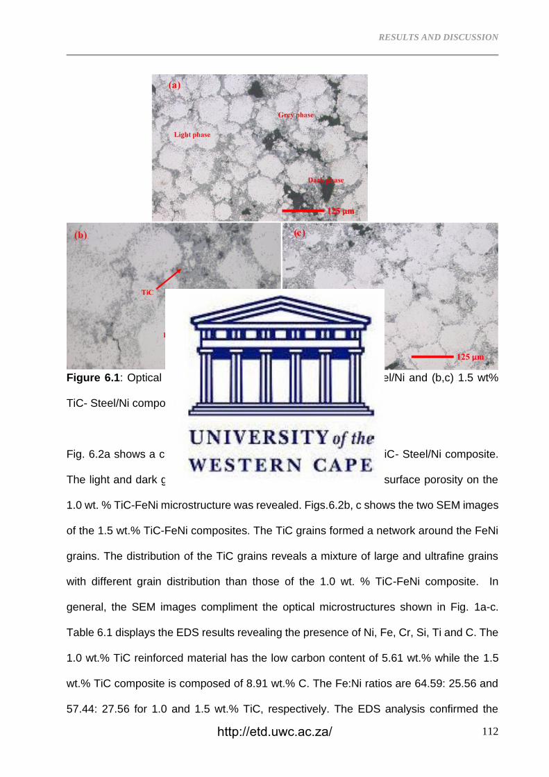
RESULTS AND DISCUSSION
112
Figure 6.1: Optical microstructures of the (a) 1.0 wt% TiC- Steel/Ni and (b,c) 1.5 wt%
TiC- Steel/Ni composite at different magnifications.
Fig. 6.2a shows a corresponding SEM image of the 1.0 wt. % TiC- Steel/Ni composite.
The light and dark grey TiC grains were evident. Moreover, the surface porosity on the
1.0 wt. % TiC-FeNi microstructure was revealed. Figs.6.2b, c shows the two SEM images
of the 1.5 wt.% TiC-FeNi composites. The TiC grains formed a network around the FeNi
grains. The distribution of the TiC grains reveals a mixture of large and ultrafine grains
with different grain distribution than those of the 1.0 wt. % TiC-FeNi composite. In
general, the SEM images compliment the optical microstructures shown in Fig. 1a-c.
Table 6.1 displays the EDS results revealing the presence of Ni, Fe, Cr, Si, Ti and C. The
1.0 wt.% TiC reinforced material has the low carbon content of 5.61 wt.% while the 1.5
wt.% TiC composite is composed of 8.91 wt.% C. The Fe:Ni ratios are 64.59: 25.56 and
57.44: 27.56 for 1.0 and 1.5 wt.% TiC, respectively. The EDS analysis confirmed the
http://etd.uwc.ac.za/
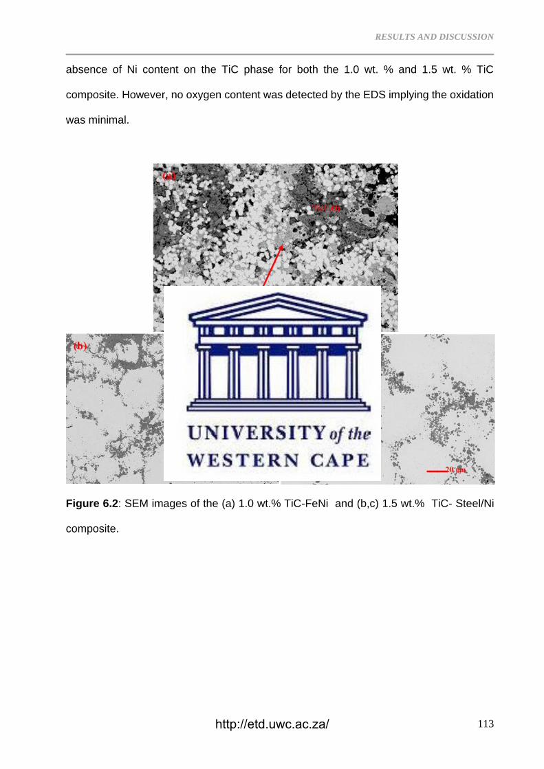
RESULTS AND DISCUSSION
113
absence of Ni content on the TiC phase for both the 1.0 wt. % and 1.5 wt. % TiC
composite. However, no oxygen content was detected by the EDS implying the oxidation
was minimal.
Figure 6.2: SEM images of the (a) 1.0 wt.% TiC-FeNi and (b,c) 1.5 wt.% TiC- Steel/Ni
composite.
http://etd.uwc.ac.za/
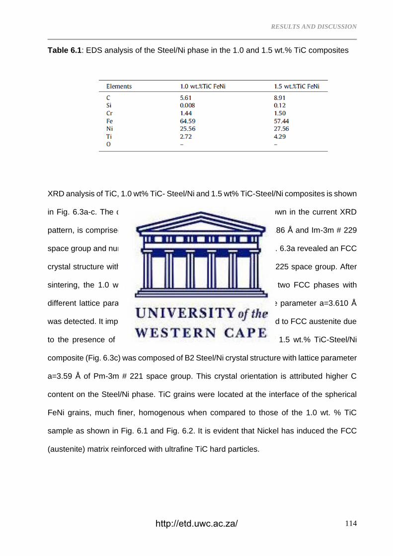
RESULTS AND DISCUSSION
114
Table 6.1: EDS analysis of the Steel/Ni phase in the 1.0 and 1.5 wt.% TiC composites
XRD analysis of TiC, 1.0 wt% TiC- Steel/Ni and 1.5 wt% TiC-Steel/Ni composites is shown
in Fig. 6.3a-c. The crystal structure of the steel powder, not shown in the current XRD
pattern, is comprised of BCC (ferrite) with lattice parameter a=2.86 Å and Im-3m # 229
space group and number. The XRD analysis of TiC powder in Fig. 6.3a revealed an FCC
crystal structure with lattice parameter a=4.303 Å and Fm-3m # 225 space group. After
sintering, the 1.0 wt% TiC-Steel/Ni mixture (Fig. 6.3b) reveals two FCC phases with
different lattice parameters. The FCC Steel/Ni matrix with lattice parameter a=3.610 Å
was detected. It implies that the BCC steel phase has transformed to FCC austenite due
to the presence of Ni. On the other hand, the XRD pattern of 1.5 wt.% TiC-Steel/Ni
composite (Fig. 6.3c) was composed of B2 Steel/Ni crystal structure with lattice parameter
a=3.59 Å of Pm-3m # 221 space group. This crystal orientation is attributed higher C
content on the Steel/Ni phase. TiC grains were located at the interface of the spherical
FeNi grains, much finer, homogenous when compared to those of the 1.0 wt. % TiC
sample as shown in Fig. 6.1 and Fig. 6.2. It is evident that Nickel has induced the FCC
(austenite) matrix reinforced with ultrafine TiC hard particles.
http://etd.uwc.ac.za/
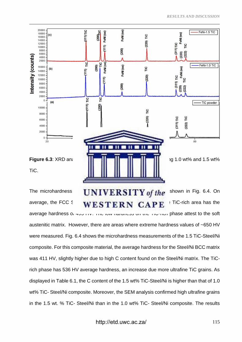
RESULTS AND DISCUSSION
115
Figure 6.3: XRD analysis of the TiC- Steel/Ni composite containing 1.0 wt% and 1.5 wt%
TiC.
The microhardness of the 1.0 wt% TiC-Steel/Ni composite is shown in Fig. 6.4. On
average, the FCC Steel/Ni matrix is composed of 308 Hv while TiC-rich area has the
average hardness of 495 HV. The low hardness on the TiC-rich phase attest to the soft
austenitic matrix. However, there are areas where extreme hardness values of ~650 HV
were measured. Fig. 6.4 shows the microhardness measurements of the 1.5 TiC-Steel/Ni
composite. For this composite material, the average hardness for the Steel/Ni BCC matrix
was 411 HV, slightly higher due to high C content found on the Steel/Ni matrix. The TiC-
rich phase has 536 HV average hardness, an increase due more ultrafine TiC grains. As
displayed in Table 6.1, the C content of the 1.5 wt% TiC-Steel/Ni is higher than that of 1.0
wt% TiC- Steel/Ni composite. Moreover, the SEM analysis confirmed high ultrafine grains
in the 1.5 wt. % TiC- Steel/Ni than in the 1.0 wt% TiC- Steel/Ni composite. The results
http://etd.uwc.ac.za/
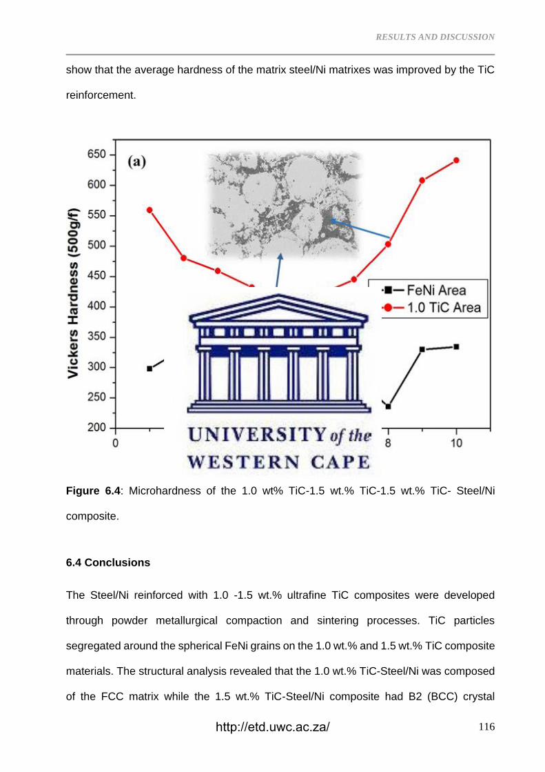
RESULTS AND DISCUSSION
116
show that the average hardness of the matrix steel/Ni matrixes was improved by the TiC
reinforcement.
Figure 6.4: Microhardness of the 1.0 wt% TiC-1.5 wt.% TiC-1.5 wt.% TiC- Steel/Ni
composite.
6.4 Conclusions
The Steel/Ni reinforced with 1.0 -1.5 wt.% ultrafine TiC composites were developed
through powder metallurgical compaction and sintering processes. TiC particles
segregated around the spherical FeNi grains on the 1.0 wt.% and 1.5 wt.% TiC composite
materials. The structural analysis revealed that the 1.0 wt.% TiC-Steel/Ni was composed
of the FCC matrix while the 1.5 wt.% TiC-Steel/Ni composite had B2 (BCC) crystal
http://etd.uwc.ac.za/
RESULTS AND DISCUSSION
117
structure. Larger TiC grains were found on the 1.0 wt.% TiC-Steel/Ni composite. On the
1.5 wt.% TiC-Steel/Ni composite, the spherical Steel/Ni matrix was surrounded by the
ultrafine TiC grains. The 1.0 wt.% TiC-Steel/Ni composite was composed of lower
average hardness when compared to the 1.5 wt.% TiC-FeNi composite.
References
6.1 S. Fang, L. Llanes, Mater. Charact. 159 (2020) 110061
6.2 I. Konyashin, L.I. Klyachko, Int. J. Refract. Met. Hard Mater. 49 (9–26) (2015).
6.3 Q. Ding, Y. Zheng, Z. Ke, G. T. Zhang, H. Wu, X.Y. Xu, X. Lu, X. Zhu, Int. J. Refract.
Met. Hard Mater. 87 (2020) 105166
6.4 A.S. Bolokang, M.J. Phasha, C. Oliphant, D. Motaung, Int. J. Refract. Met. Hard Mater.
29 (2011) 108–111.
6.5 A.S. Bolokang, M. J. Phasha, D. E.Motaung, and S. Bhero, J. Metallurgy, 2012 (2012)
1-7, Article ID 290873.
6.6 A.S. Bolokang, M.J. Phasha, Adv. Pow. Metallurg. 22 (2011) 518-521.
6.7 Y. Tan, H. Cai, X. Cheng, Z. Ma, Z. Xu, Z. Zhou, Mater. Lett. 228 (2018) 1–4.
6.8 Q. Zhuang, N. Lin, Y. He, X. Kang, Ceram. Int. 43 (2017) 15992–15998.
6.9 X. Sun, H. Zhu, J. Li, J. Huang, Z. Xie, Mater. Sci. Eng. A 743 (2019) 540–545.
6.10 D. Yim, P. Sathiyamoorthi, S-J. Hong, H. S. Kim, J. Alloys Compd. 781 (2019) 389-
396.
6.11 M.R. Gorjia, C. Edtmaier, S. Sanjabi, Mater. Des. 125 (2017) 167–179.
6.12 L.J. Huang, L. Geng, H.X. Peng, Prog. Mater. Sci. 71 (2015)
6.13 X.D. Hui, Y.S. Yang, Z.F. Wang, G.Q. Yuan, X.C. Chen, Mater. Sci. Eng. A 282
(2000) 187–192.
6.14 A. Gäärd, P. Krakhmalev, J. Bergström, J. Alloys Compd. 421 (2006) 166–171.
6.15 A. Botes, A.S. Bolokang, I. Kortidisc, V. Matjeke, Surf. Interf. 14 (2019) 296–304.
http://etd.uwc.ac.za/
RESULTS AND DISCUSSION
118
6.16 H. Zeinali Moghaddam, M. Sharifitabar, G. Roudini, Surf. Coat. Technol. 361 (2019)
91–101.
6.17 J. Lee, D. Lee, M. H. Song, W. Rheed, H. J. Ryu, S. H. Hong, J. Mater. Sci. Technol.
34 (2018) 1397–1404.
6.18 J. Zhua, L. Zhonga, Y. Xua, X. Cai, F. Bai, Y. Ding, Z. Lu, H. Wu. Vacuum 155 (2018)
631–636.
http://etd.uwc.ac.za/
RESULTS AND DISCUSSION
119
CHAPTER SEVEN
Surface characterization and formation mechanism of the ceramic TiO2-
xNx spherical powder induced by annealing in air
Published in Powder Technology Journal
Abstract
Mechanism for the formation of titanium oxynitride (TiO2-xNx) on the surfaces of spherical
Ti powder particles upon heat treatment in air at 500, 600, 700 and 800 °C was
investigated. The results showed that the first at 500 °C a hexagonal closed packed
(HCP) TiOx film was formed while a TiO2 film was observed after annealing at 600 °C and
eventually a TiO2-xNx layer coated the spherical Ti particles at 700 and 800 °C due to N
diffusion within the TiO2 crystal lattice. The resulting surface structure was studied by
means of x-ray diffraction (XRD) while the surface morphology of the powders was
characterized using the scanning electron microscope (SEM) attached with energy
dispersive x-ray spectroscopy (EDS) detector. The AFM images confirmed that when the
N content increases (800 °C-heat treated sample) the powder loses its triangular grains
(700 °C-annealed sample) to irregular shaped grains.
Keywords: Titanium; TiO2-xNx; Oxidation; Characterization, Thermal analysis
7.1 Introduction
Titania (TiO2) is widely used in the electronics, ceramics, medicine, chemical, energy
(solar), environmental applications and pigment industries [1-4]. TiO2 is a well-known
mineral that occurs in three phases: rutile, anatase, and brookite, each having different
crystal structures. By contrast, titanium nitride (TiN), is coating material wits excellent
http://etd.uwc.ac.za/
RESULTS AND DISCUSSION
120
chemical stability and excellent tribological properties which can be produced by
combustion of powder in air [5]. At high temperatures both TiO2 and TiN accept N and O
atoms, respectively, to occupy interstitial sites and form titanium oxynitride (TiOxNy)
another class of important composite materials. The TiOxNy films rich in oxygen are used
as thin film resistors [6], solar selective collectors [7, 8] while the nitrogen rich TiOxNy
films are used as anti-reflective coatings [9] and biomaterials coated stents with a better
clinical performance compared to uncoated stainless steel stents [10,11]. This class of
materials is known to possess excellent electronic and optical properties [1]. Furthermore,
titanium oxynitrides have recently been explored as possible gas sensing materials with
promising performance [12, 13]. Photocatalytic properties of titanium oxynitride can be
used in super hydrophilic windows, air purification devices, and for degradation of organic
molecules on titanium oxynitride surfaces [14]. Formation of oxynitrides on titanium alloys
is achieved by different techniques including gas diffusion treatment during annealing [15,
16], chemical process [17] and radio frequency magnetron sputtering deposition [18].
The feasibility of mixed metal titanium oxynitride has been extensively explored for
various applications [18-20]. The binder system is a common way of producing ceramic
nitrides and oxynitrides. Combination of Al-Ni binder for cBN-based composites produced
outstanding mechanical properties with acceptable flexural strength, fracture toughness,
hardness, and abrasive [21]. Similarly, as aluminium metal matrix composite such as Al-
Si alloys with improved their wear resistance are developed from the oxides or mixed-
metal oxides [22]. These materials can be used in defence, aerospace, automobile, and
other structural applications as fuel efficient advanced materials for different tribological
applications [23]. The oxide/nitride layer formation on Ti surface involves a solid-state
diffusion process when Ti is exposed in oxygen or air. Some of the manufacturing
processes such as laser cladding prefer spherical particles for 3D printing [24] hence the
study on the formation of the oxidised spherical particles is necessary. The formation of
http://etd.uwc.ac.za/
RESULTS AND DISCUSSION
121
the nitride layer on spherical Ti particle and their thermal stability revealed structural
change and phase transformation depending on the annealing temperature [25]. It has
been acknowledged that metal oxides are of great importance and has impact in the
current environmental challenges as well as electronics due to their capability to generate
charge carriers when they are energised. They are also potential photocatalyst, hence
these materials should be considered necessary. The current study illustrates the stages
of oxide layer deposited on the spherical Ti particle using annealing process in air.
7.2 Experimental Details
Atomised commerically pure (CP) Ti (99.8%) powder was used in the current
investigation. Samples of CP Ti powder were annealed in a muffle furnace for 2 h in air
at 500, 600, 700, 800 °C, respectively followed by furnace-cooling. Another sample of CP
Ti powder was annealed at 800 °C followed by air-cooling. The density of the powders
was measured by Micromeritics AccuPyc II 1340 Gas Pycnometer. Powder morphology
analysis was conducted using a high-resolution scanning electron microscope (HR-SEM,
Auriga ZEISS) coupled with a Robinson Backscatter Electron Detector and an Oxford
Link Pentafet energy dispersive x-ray spectroscopy (EDS) detector. Phase evolution was
determined with the use of a PANalytical X’pert PRO PW 3040/60 X-ray diffraction (XRD)
machine, using Cu Kα radiation as source. The topography of the spherical Ti powder
particles was analysed using atomic force microscopy (AFM, Veeco, Digital Instruments).
Thermal analysis was carried out using Differential Scanning Calorimetry (DSC) and
Thermo Gravinometry (TG) incorporated in NETZSCH STA. Powder samples were
heated up to 1200 °C and cooled to room temperature using Al2O3 as a baseline during
the thermal analysis. A heating rate of 20 °C min−1 under argon gas with 20 ml/L standard
flow rate was used.
http://etd.uwc.ac.za/
RESULTS AND DISCUSSION
122
7.3 Results and Discussion
7.3.1 Powder Characterization
Figure 7.1: XRD pattern of the Ti powder oxidised at (a) 500, (b) 600, (c) 700 and (d) 800
°C.
Fig. 7.1. shows XRD pattern of the CP Ti powder after annealing at (a) 500, (b) 600, (c)
700 and (d) 800 °C in air. Pure Ti has an HCP crystal structure with lattice parameters
a=2.951; c=4.684 and c/a=1.587. Upon annealing at 500 °C, the Ti powder, the lattice
parameters of the HCP phase have changed to a= 5,140 Å; c= 9.480 Å with c/a=1.844
which is attributable to HCP TiOx phase (Fig. 7.1a). Minor peaks belonging to tetragonal
rutile TiO2 phase co-existing with the HCP TiOx have started to emerge upon annealing
at 600 °C as shown in Fig. 7.1b. These tetragonal XRD peaks increased in intensity at
700 and 800 °C powder samples, respectively (Fig. 7.1c-d). The rutile-type phase has
(d)
(c)
(b)
(a)
http://etd.uwc.ac.za/
RESULTS AND DISCUSSION
123
the lattice parameters of a= 4.591 Å; c=2.958 Å and c/a=0.644 attributable to titanium
oxynitride formation. The current findings agree with those of Kikuchi et al., [26] whereby
nitrogen diffusion on commercially pure (CP) Ti was found to occur above 600 °C.
However, in the current study, nitrogen diffusion seems to prefer the intergranular
penetration on the spherical particle. Kikuchi et al., [26] conducted investigation on
material annealed in nitrogen environment while for the current study; the annealing was
done in air, hence the different diffusion mechanism.
Figure 7.2: Change in the colours of the powders associated with phase transformation
upon annealing.
As shown in Fig. 7.1, the XRD analysis confirmed transformation in pure Ti during
annealing in air as follows; Ti (HCP) → TiOx (HCP) → TiO2/ TiO2-xNx. Due to the strong
affinity of O for Ti when compared to N, a rapid formation of the blue TiOx film forms on
the particle surfaces at 500 °C as shown in Fig. 7.2. The chemical reactions with their
free energy formations are presented in Eq. 1-3. This implies that the formation of TiOx
http://etd.uwc.ac.za/
RESULTS AND DISCUSSION
124
is favourable to form first followed by TiO2. Once the TiO2 has formed at high temperatures
(700 to 800 °C), the N atoms diffuses into rutile. These crystal structure changes also
yield physical changes as shown in Fig. 7.2. The powder changes from grey (Ti) to blue
(TiOx). The sample annealed at 600 °C displays a mixture of grey and yellow colours.
Upon annealing at 700 and 800 °C the yellow colour became more conspicuous. These
observations are in agreement with the structural development identified by the XRD
analysis as the powder comprises a mixture of phases.
2Ti +O →2TiO ΔG°1200°C= -827 kJ/ mol (1)
Ti + O2 →TiO2 ΔG°1200°C = -711 kJ/ mol (2)
Ti + 1/2N2 →TiN ΔG°1200°C = -418 kJ/ mol (3)
http://etd.uwc.ac.za/
RESULTS AND DISCUSSION
125
Figure 7.3: SEM images of the furnace-cooled (a) CP Ti, (b) 500, (c) 600, (d) 700, (e)
and 800 °C powder annealed in air
Powder of varying particle sizes can be seen. Upon annealing at 500 °C, the smaller and
the larger particles fused forming satellites (Fig. 7.3b). Furthermore, the spherical
particles revealed porous and rough surfaces. Porosity layer on the particle surfaces
100 µm 100 µm
100 µm 100 µm
100 µm
Hollow
(c) (d)
(a) (b)
Ultrafine agglomerates
Oxide surface film
(e)
Particle Collapse
Exposed ultrafine
Particle
http://etd.uwc.ac.za/
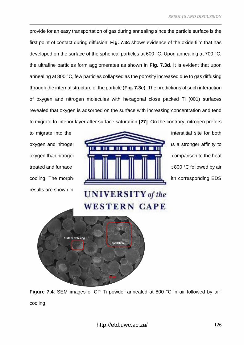
RESULTS AND DISCUSSION
126
provide for an easy transportation of gas during annealing since the particle surface is the
first point of contact during diffusion. Fig. 7.3c shows evidence of the oxide film that has
developed on the surface of the spherical particles at 600 °C. Upon annealing at 700 °C,
the ultrafine particles form agglomerates as shown in Fig. 7.3d. It is evident that upon
annealing at 800 °C, few particles collapsed as the porosity increased due to gas diffusing
through the internal structure of the particle (Fig. 7.3e). The predictions of such interaction
of oxygen and nitrogen molecules with hexagonal close packed Ti (001) surfaces
revealed that oxygen is adsorbed on the surface with increasing concentration and tend
to migrate to interior layer after surface saturation [27]. On the contrary, nitrogen prefers
to migrate into the interior layers favourably in the octahedral interstitial site for both
oxygen and nitrogen [27]. This study further confirms that Ti has a stronger affinity to
oxygen than nitrogen and their diversity in reactivity. By means of comparison to the heat
treated and furnace cooled samples, a sample was heat treated at 800 °C followed by air
cooling. The morphology and surface analysis of the powder with corresponding EDS
results are shown in Fig. 7.4 and Fig. 7.5.
Figure 7.4: SEM images of CP Ti powder annealed at 800 °C in air followed by air-
cooling.
http://etd.uwc.ac.za/
RESULTS AND DISCUSSION
127
Surface cracking and spallation (Fig. 7.4) due to thermal stresses is observed on the air
quenched powder. This behaviour is attributed to a mismatch in thermal expansion
between surface layers (Ti/TiOx/TiO2/TiO2-xNx) [28-30]. This linear coefficient of thermal
expansion for different layers can be explained by Eq 4.
𝛼𝐿 =1
𝐿0
∆𝐿
∆𝑇 (4)
Where L is the coefficient of thermal expansion (CTE), L0 and the lineal expansion of the
material with respect to the temperature ΔL/ΔT. The mismatch in thermal expansion
between TiO2-xNx, TiO2 and TiOx increase and decrease at higher and lower temperatures
[28]. Due to high cooling rates, the TiO2-xNx film experienced higher stresses than the
core structure underneath. A model for such hard films developed by Limarga and
Wilkinson revealed a large residual stress induced in the nitride scale due to the mismatch
of creep rates [31].
http://etd.uwc.ac.za/
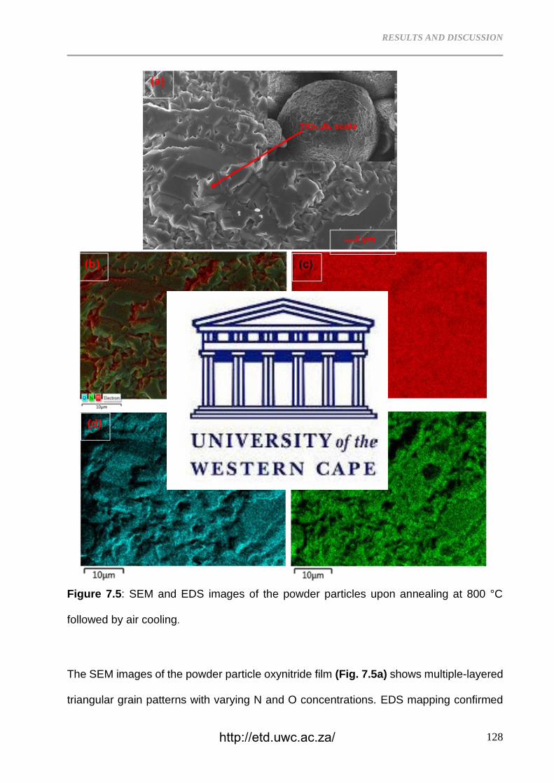
RESULTS AND DISCUSSION
128
Figure 7.5: SEM and EDS images of the powder particles upon annealing at 800 °C
followed by air cooling.
The SEM images of the powder particle oxynitride film (Fig. 7.5a) shows multiple-layered
triangular grain patterns with varying N and O concentrations. EDS mapping confirmed
http://etd.uwc.ac.za/
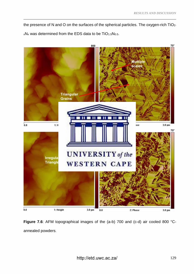
RESULTS AND DISCUSSION
129
the presence of N and O on the surfaces of the spherical particles. The oxygen-rich TiO2-
xNx was determined from the EDS data to be TiO1.5N0.5.
Figure 7.6: AFM topographical images of the (a-b) 700 and (c-d) air cooled 800 °C-
annealed powders.
http://etd.uwc.ac.za/
RESULTS AND DISCUSSION
130
The prismatic triangular TiO2-xNx grains developed upon annealing at 700 °C are shown
in Fig. 7.6a-b. These grains are stacked in a multiple layered structure (Fig. 7.6a). In Fig.
7.6b, the two-phase structure displays ultrafine particles located between the triangular
grains. The AFM images of the air cooled 800 °C-annealed Ti powder in Fig. 7.6c-d
revealed that the multi-layered grains have lost the original triangular shape. These AFM
images agree with the SEM analysis of the oxide film in Fig. 7.5a. The surface film lost
its triangular shape due to increased annealing temperature that resulted in higher
concentration of nitrogen content in the TiO2-xNx phase. The oxynitriding is intensive at
800 °C leading to formation of surface layer based on rutile TiO2 phase, however the
oxynitriding temperature in Ti alloys might be higher than that of CP Ti [32]. In pure Ti
powder, 700 and 800 °C is sufficient to induce similar surface oxynitride layer. Annealing
at high temperatures such as 700 and 800 °C reduces the TiO2 (110) surface while
creating point defects in the rows of bridging O atoms leading to O vacancies which get
occupied by N atoms [33]. Even if the stable rutile TiO2 and FCC TiN forms or TiO2−TiN
interface during annealing, there will be an exchange of N and O in the interface region
to promote titanium oxynitride [34].
http://etd.uwc.ac.za/
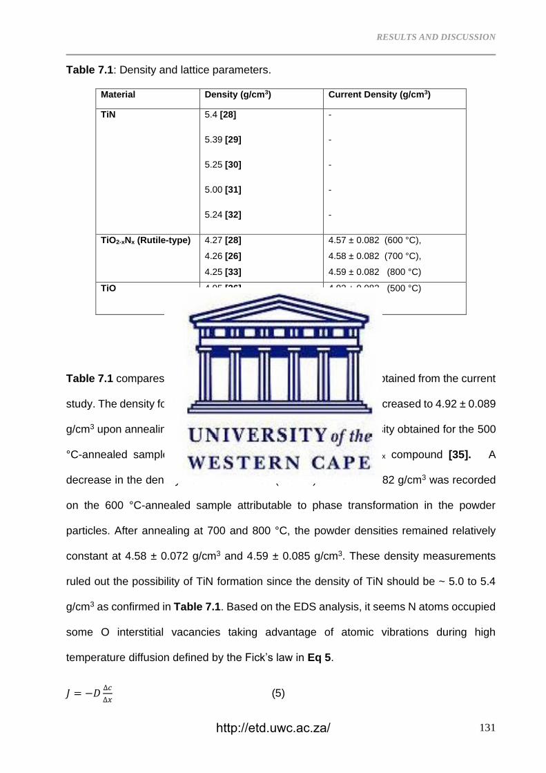
RESULTS AND DISCUSSION
131
Table 7.1: Density and lattice parameters.
Material Density (g/cm3) Current Density (g/cm3)
TiN 5.4 [28]
5.39 [29]
5.25 [30]
5.00 [31]
5.24 [32]
-
-
-
-
-
TiO2-xNx (Rutile-type)
4.27 [28]
4.26 [26]
4.25 [33]
4.57 ± 0.082 (600 °C),
4.58 ± 0.082 (700 °C),
4.59 ± 0.082 (800 °C)
TiO 4.95 [26]
4.92 ± 0.082 (500 °C)
Table 7.1 compares the data reported in literature with the one obtained from the current
study. The density for CP Ti was measured at 4.48 g/cm3 which increased to 4.92 ± 0.089
g/cm3 upon annealing at 500 °C. According to literature, the density obtained for the 500
°C-annealed sample corresponds with the density of the TiOx compound [35]. A
decrease in the density from 4.92 ± 0.089 (500 °C) to 4.57 ± 0.082 g/cm3 was recorded
on the 600 °C-annealed sample attributable to phase transformation in the powder
particles. After annealing at 700 and 800 °C, the powder densities remained relatively
constant at 4.58 ± 0.072 g/cm3 and 4.59 ± 0.085 g/cm3. These density measurements
ruled out the possibility of TiN formation since the density of TiN should be ~ 5.0 to 5.4
g/cm3 as confirmed in Table 7.1. Based on the EDS analysis, it seems N atoms occupied
some O interstitial vacancies taking advantage of atomic vibrations during high
temperature diffusion defined by the Fick’s law in Eq 5.
𝐽 = −𝐷∆𝑐
∆𝑥 (5)
http://etd.uwc.ac.za/
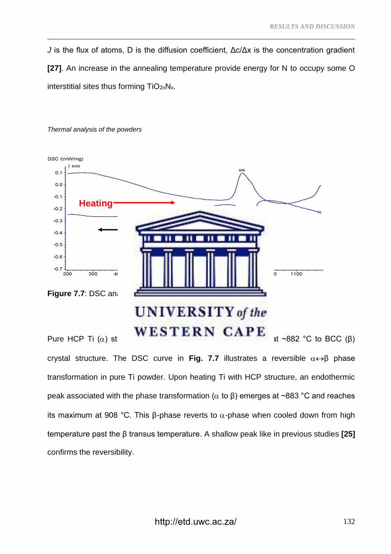
RESULTS AND DISCUSSION
132
J is the flux of atoms, D is the diffusion coefficient, Δc/Δx is the concentration gradient
[27]. An increase in the annealing temperature provide energy for N to occupy some O
interstitial sites thus forming TiO2xNx.
Thermal analysis of the powders
Figure 7.7: DSC analysis of the CP Ti powder
Pure HCP Ti () structure undergoes a phase transformation at ~882 °C to BCC (β)
crystal structure. The DSC curve in Fig. 7.7 illustrates a reversible β phase
transformation in pure Ti powder. Upon heating Ti with HCP structure, an endothermic
peak associated with the phase transformation ( to β) emerges at ~883 °C and reaches
its maximum at 908 °C. This β-phase reverts to -phase when cooled down from high
temperature past the β transus temperature. A shallow peak like in previous studies [25]
confirms the reversibility.
Heating
http://etd.uwc.ac.za/
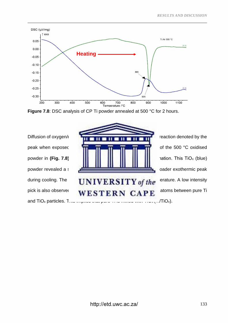
RESULTS AND DISCUSSION
133
Figure 7.8: DSC analysis of CP Ti powder annealed at 500 °C for 2 hours.
Diffusion of oxygen/nitrogen molecules promotes the exothermic reaction denoted by the
peak when exposed to high temperature [25]. The DSC curve of the 500 °C oxidised
powder in (Fig. 7.8) shows the β reversible phase transformation. This TiOx (blue)
powder revealed a sharp endothermic peak on heating and a broader exothermic peak
during cooling. The peaks have slightly shifted to the lower temperature. A low intensity
pick is also observed at ~ 700 °C due to the exchange of oxygen atoms between pure Ti
and TiOx particles. This implies that pure Ti is mixed with TiOx (Ti/TiOx).
Heating
Cooling
http://etd.uwc.ac.za/
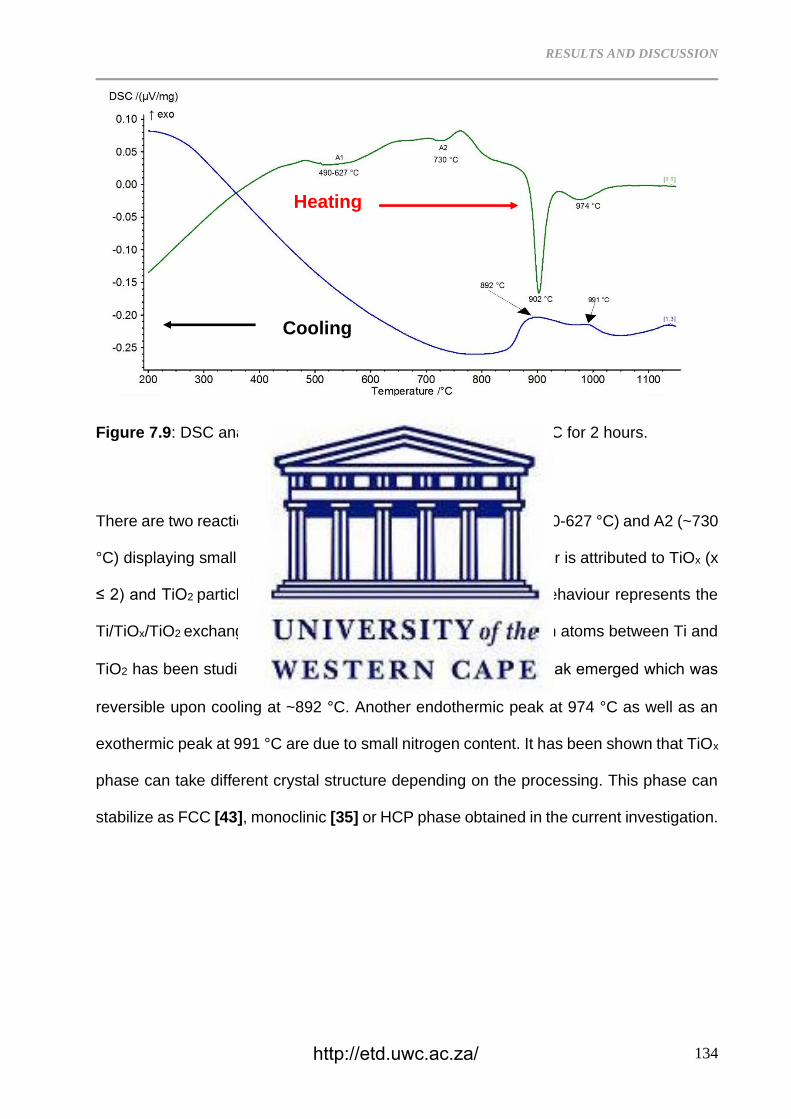
RESULTS AND DISCUSSION
134
Figure 7.9: DSC analysis of the CP Ti powder annealed at 600 °C for 2 hours.
There are two reactions that were observed upon heating: A1 (490-627 °C) and A2 (~730
°C) displaying small endothermic peaks (Fig. 7.9). This behaviour is attributed to TiOx (x
≤ 2) and TiO2 particles as detected by the XRD analysis. The behaviour represents the
Ti/TiOx/TiO2 exchange in oxygen atoms. The exchange in oxygen atoms between Ti and
TiO2 has been studied [35, 42]. At 902 °C, →β endothermic peak emerged which was
reversible upon cooling at ~892 °C. Another endothermic peak at 974 °C as well as an
exothermic peak at 991 °C are due to small nitrogen content. It has been shown that TiOx
phase can take different crystal structure depending on the processing. This phase can
stabilize as FCC [43], monoclinic [35] or HCP phase obtained in the current investigation.
Heating
Cooling
http://etd.uwc.ac.za/
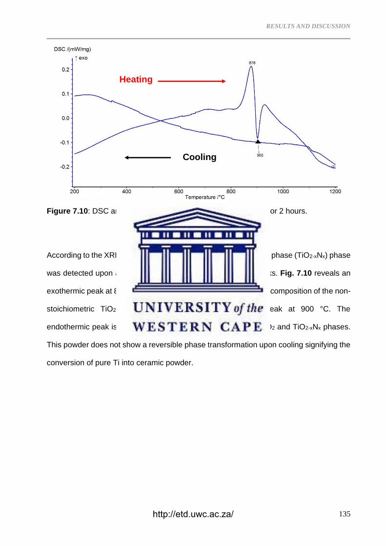
RESULTS AND DISCUSSION
135
Figure 7.10: DSC analysis of CP Ti powder annealed at 700 °C for 2 hours.
According to the XRD analysis (Fig. 7.1), the rutile-type oxynitride phase (TiO2-xNx) phase
was detected upon annealing at 700 °C with few TiOx XRD peaks. Fig. 7.10 reveals an
exothermic peak at 878 °C instead of endothermic peak due to decomposition of the non-
stoichiometric TiO2-xNx overlapping with the endothermic peak at 900 °C. The
endothermic peak is due to ionic reactions between the TiOx/TiO2 and TiO2-xNx phases.
This powder does not show a reversible phase transformation upon cooling signifying the
conversion of pure Ti into ceramic powder.
Cooling
Heating
http://etd.uwc.ac.za/
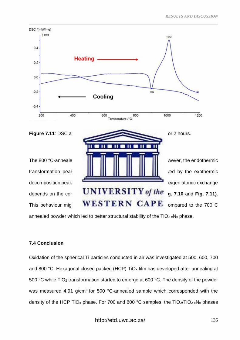
RESULTS AND DISCUSSION
136
Figure 7.11: DSC analysis of CP Ti powder annealed at 800 °C for 2 hours.
The 800 °C-annealed sample shows overlapping DSC peaks. However, the endothermic
transformation peak was the first to emerge at 899 °C followed by the exothermic
decomposition peak at 1012 °C. This behaviour confirm that the oxygen atomic exchange
depends on the concentrations of TiO2-xNx and TiOx phases (Fig. 7.10 and Fig. 7.11).
This behaviour might be due to higher amount of N content compared to the 700 C
annealed powder which led to better structural stability of the TiO2-xNx phase.
7.4 Conclusion
Oxidation of the spherical Ti particles conducted in air was investigated at 500, 600, 700
and 800 °C. Hexagonal closed packed (HCP) TiOx film has developed after annealing at
500 °C while TiO2 transformation started to emerge at 600 °C. The density of the powder
was measured 4.91 g/cm3 for 500 °C-annealed sample which corresponded with the
density of the HCP TiOx phase. For 700 and 800 °C samples, the TiO2/TiO2-xNx phases
http://etd.uwc.ac.za/
RESULTS AND DISCUSSION
137
were formed. Despite the formation of the oxide layers on the 500 and 600 °C annealed
Ti samples, the powder showed β phase transformation. On contrary, the 700 and
800 °C-annealed powders revealed an exothermic peak overlapping with the endothermic
peak and the endothermic peak overlapping with exothermic peak, respectively. The
powder did not yield a reversible phase transition. This behaviour was due to the
exchange in oxygen atoms between the non-stoichiometric TiOx and TiO2-xNx phases and
determined by the N/O contents. The AFM images illustrated that when the N content
increases (800 °C-annealed sample) the powder lost its triangular grains (700 °C-
annealed sample) and became irregular shaped grains.
References
7.1 D. Švadlák, J. Shánˇelová, J. Málek, L.A. Pérez-Maqueda, J.M. Criado, T. Mitsuhashi,
Nanocrystallization of anatase in amorphous TiO2. Thermochimica Acta, 414 (2004)137–
143.
7.2 M. Wagemaker, W. J. H. Borghols, F. M. Mulder, Large Impact of Particle Size on
Insertion Reactions. A Case for Anatase LixTiO2. J. American Cheml Soc, 129 (2007)
4323−4327.
7.3 X. Chen, S.S. Mao, Titanium dioxide nanomaterials: Synthesis, properties,
modifications and applications. Chem Rev. 107 (2007) 2891–2959.
7.4 X. Su, Q. Wu, X.Zhan, J. Wu, S. Wei, Z. Guo, Advanced titania nano-structures and
composites for lithium ion battery. J. Mater Sci, 47 (2012) 2519–2534.
7.5 X. Song, D. Gopireddy, C.G. Takoudis, Characterization of titanium oxynitride films
deposited by low pressure chemical vapor deposition using amide Ti precursor, Thin Solid
Films 516 (2008) 6330–6335.
http://etd.uwc.ac.za/
RESULTS AND DISCUSSION
138
7.6 N.D. Cuong, D.-J. Kim, B.-D. Kang, C.S. Kim, S.-G. Yoon, Analysis of nitrogen species
in titanium oxynitride ALD films, Microelectron. Reliab.47 (2007) 752–754.
7.7 C. Nunes, V. Teixeira, M.L. Prates, N.P. Barradas, A.D. Sequeira, Graded selective
coatings based on chromium and titanium oxynitride, Thin Solid Films 442 (2003) 173–
178.
7.8 R. Escobar-Galindoa, E. Guillénb, I. Herasc, G. Rincón-Llorented, M. Alcón-Camase,
F. Lungwitzf, F. Munnikf, E. Schumannf, I. Azkonag, M. Krausef, Design of high-
temperature solar-selective coatings based on aluminium titanium oxynitrides AlyTi1-
y(OxN1-x). Part 2: Experimental validation and durability tests at high temperature, Solar
Energy Mater Solar Cells 185 (2018) 183–191.
7.9 F. Maury, F.-D. Duminica, TiOxNy coatings grown by atmospheric pressure metal
organic chemical vapor deposition, Surf. Coat. Technol. 205 (2010) 1287–1293.
7.10 J. Koerner, L.A. Butterworth, I.V. Mayer, R. Dasbach, H.J. Busscher, Bacterial
adhesion to titanium-oxy-nitride (TiNOX) coatings with different resistivities: a novel
approach for the development of biomaterials, Biomater. 23 (2002) 2835–2840.
7.11 J.M. Chappé, N. Martin, G. Terwagne, J. Lintymer, J. Gavoille, J. Takadoum, Water
as reactive gas to prepare titanium oxynitride thin films by reactive sputtering. Thin Solid
Films, 440 (2003) 66–73.
7.12 R. Asahi, T. Morikawa, T. Ohwaki, K. Aoki, Y. Taga, Visible-light photocatalysis in
nitrogen- doped titanium oxides. Science, 293 (2001) 269–271.
7.13 S. Piscanec, L.C. Ciacchi, E. Vesselli, G. Comelli, O. Sbaizero, S. Meriani, A. De
Vita, Bioactivity of TiN-coated titanium implants, Acta Mater. 52 (2004) 1237-1245.
http://etd.uwc.ac.za/
RESULTS AND DISCUSSION
139
7.14 I. Seki, S. Yamaura, Reduction of Titanium Dioxide to Metallic Titanium by
Nitridization and Thermal Decomposition. Mater. Trans. 58 (3) (2017) 361-363.
7.15 O.I. Yaskiv, I.M. Pohrelyuk, V.M. Fedirko, D.B. Lee, O.V. Tkachuk, Formation of
oxynitrides on titanium alloys by gas diffusion treatment, Thin Solid Films 519 (2011)
6508–6514.
7.16 A.S. Bolokang, Z.P. Tshabalala, G.F. Malgas, I. Kortidis, H.C. Swart, D.E. Motaung,
Room temperature ferromagnetism and CH4 gas sensing of titanium oxynitride induced
by milling and annealing, Mater. Chem. Phys. 193 (2017) 512-523.
7.17 M. Arunachalam, G. Yun, K-S. Ahn, W-S. Seo, D.S. Jung, S. H. Kang, Unique
photoelectrochemical behavior of TiO2 nanorods wrapped with novel titanium Oxy-Nitride
(TiOxNy) nanoparticles, Int. J. hydro. energy 43 (2018) 16458-16467.
7.18 Z. Yu, H. Xua, G. Zhu, D. Yan, A. Yu, Lithium titanium oxynitride thin film with
enhanced lithium storage and rate capability, Appl. Surf. Sci. 368 (2016) 173–176.
7.19 A.S. Bolokang, D.E. Motaung, C.J. Arendse, T.F.G. Muller, Production of titanium–
tin alloy powder by ball milling: Formation of titanium–tin oxynitride composite powder
produced by annealing in air, J. Alloys Compd. 622 (2015) 824–830.
7.20 R. L. Porto, R. Frappiera, J.B. Ducrosa, C. Auchera, H. Mosqueda, S. Chenu, B.
Chavillon, F. Tessier, F. Chevire, T. Brousse, Titanium and vanadium oxynitride powders
as pseudo-capacitive materials for electrochemical capacitors, Electrochimica Acta 82
(2012) 257– 262.
7.21 L. Li, Y. Zhao, K. Sun, H. Ji, D. Feng, Z. Li, Composition, microstructure and
mechanical properties of cBN-based composites sintered with AlN-Al-Ni binder, Ceram.
Int. 44 (2018) 16915–16922.
http://etd.uwc.ac.za/
RESULTS AND DISCUSSION
140
7.22 S. Sharma, T. Nanda, O.P. Pandey, Effect of particle size on dry sliding wear
behaviour of sillimanite reinforced aluminium matrix composites, Ceram. Int. 44 (2018)
104–114.
7.23 E. Ghasali, A. Pakseresht, A. Rahbari, H. Eslami-shahed, M. Alizadeh, T.
Ebadzadeh, Mechanical properties and microstructure characterization of spark plasma
and conventional sintering of Al-SiC-TiC composites, J. Alloy. Compd. 666 (2016) 366–
371,
7.24 H.H. Nersisyan, B.U. Yoo, Y.M. Kim, H.T. Son, K.Y. Lee, J.H. Lee, Gas-phase
supported rapid manufacturing of Ti-6Al-4V alloy spherical particles for 3D printing,
Chem. Eng. J. 304 (2016) 232–240.
7.25 A.S. Bolokang, M.J. Phasha, Formation of titanium nitride produced from
nanocrystalline titanium powder under nitrogen atmosphere, Int. J. Refract. Met. Hard.
Mater. 28 (2010) 610–615.
7.26 A.S. Bolokang, D.E. Motaung, C.J. Arendse, T.F.G. Muller, Morphology and
structural development of reduced anatase-TiO2 by pure Ti powder upon annealing and
nitridation: Synthesis of TiOx and TiOxNy powders. Mater. Charact. 100 (2015) 41–49.
7.27 D.R. Askeland, The Science and Engineering of Materials, Third S.I. Edition, Stanley
Thornes Publishers Ltd, United Kingdom, pp. 111-133.
7.28 D. Choi, P.N. Kumta, Nanocrystalline TiN Derived by a Two-Step Halide Approach
for Electrochemical Capacitors. J. Electrochem Soc, 153 (2006) A2298-A2303.
7.29 B.M. Moshtaghioun, D. Gómez-García, A. Domínguez-Rodríguez, Spark plasma
sintering of titanium nitride in nitrogen: Does it affect the sinterability and the mechanical
properties? J. Euro. Ceram. Soc. 38 (2018) 1190–1196.
http://etd.uwc.ac.za/
RESULTS AND DISCUSSION
141
7.30 M. Drygas´, C. Czosnek, R.T. Paine, J.F. Janik, Two-Stage Aerosol Synthesis of
Titanium Nitride TiN and Titanium Oxynitride TiOxNy Nanopowders of Spherical Particle
Morphology. Chem. Mater. 18 (2006)3122-3129.
7.31 C. Marinescu, A. Sofronia, C. Rusti, R. Piticescu, V. Badilita, E. Vasile, R. Baies,
S.Tanasescu, DSC investigation of nanocrystalline TiO2 powder. J. Therm. Anal
Calorimetry, 103 (2011) 49–57.
7.32 X. Yang, C. Li, B. Yang, W. Wang, Y. Qian, Optical properties of titanium oxynitride
nanocrystals synthesized via a thermal liquid–solid metathesis reaction. Chem. Phys.
Lett. 383 (2004) 502–506.
7.33 A.S. Bolokang, D.E. Motaung, C.J. Arendse, T.F.G. Muller, Formation of face-
centered cubic and tetragonal titanium oxynitride by low temperature annealing of ball
milled titanium powder in air. Adv. Pow. Technol. 26 (2015) 169–174.
7.34 Y. Lin, D. Zou, X. Chen, M. Qiu, H. Kameyama, Y. Fan, Low temperature sintering
preparation of high-permeability TiO2/Ti composite membrane via facile coating method,
Appl. Surf. Sci. 349 (2015) 8–16.
7.35 L. Zhu, Y. Zhang, T. Hu, P. Leicht, Y. Liu, Oxidation resistance and thermal stability
of Ti(C,N) and Ti(C,N,O) coatings deposited by chemical vapor deposition, Int. J. Refract.
Met. Hard Mater. 54 (2016) 295–303
7.36 M. Jamesh, T.S.N. Sankara Narayanan, P.K. Chu, Thermal oxidation of titanium:
Evaluation of corrosion resistance as a function of cooling rate, Mater. Chem. Phys. 138
(2013) 565-572.
7.37 A.M. Limarga, D.S. Wilkinson, A model for the effect of creep deformation and
intrinsic growth stress on oxide/nitride scale growth rates with application to the nitridation
of -TiAl, Mater. Sci. Eng. A 415 (2006) 94–103.
http://etd.uwc.ac.za/
RESULTS AND DISCUSSION
142
7.38 R. German, Powder Metallurgy Science. Princeton, New Jersey, USA: Metal Powder
Industry Federation; 1994. p. 451–5.
7.39 B. Avar, S. Ozcan, Structural evolutions in Ti and TiO2 powders by ball milling and
subsequent heat treatments, Ceram. Int. 40 (2014) 11123–11130.
7.40 A.S. Bolokang, D.E.Motaung, C.J. Arendse, T.F.G. Muller, Morphology and
structural development of reduced anatase-TiO2 by pure Ti powder upon annealing and
nitridation: Synthesis of TiOx and TiOxNy powders, Materials Characterization 100 (2015)
41–49.
http://etd.uwc.ac.za/
RESULTS AND DISCUSSION
143
CHAPTER EIGHT
The A356-1Sn-5Ni-(TiO2-xNx) ceramic composite developed at low
temperatures
Paper submitted for peer review
Abstract
A ceramic composite material of A356-1Sn-5Ni-(TiO2-x-Nx) composition was developed.
The TiO2-x-Nx ceramic particles were bonded without forming any intermetallic particles
such as Al3Ti with Ti. The structural analysis showed that a tetragonal TiO2-xNx with lattice
parameters a=4.585 Å; c=2.960 Å, HCP TiOx phase with lattice parameters a=5.140 Å
c=9.480 Å and FCC phase with lattice parameter a=5.572 Å were formed.
Keywords; A356-Sn-Ni; TiO2-x-Nx; Ceramic particles; Binder.
8.1 Introduction
Titania (TiO2) is a well-known mineral that occurs in three phases: rutile, anatase, and
brookite, each having different crystal structures. It is widely used in the electronics,
ceramics, medicine, chemical, energy (solar), environmental applications and pigment
industries [1, 2]. Titanium nitride (TiN) on the other hand is a technological strategic
coating material due to its excellent chemical stability and excellent tribological properties
[3]. TiO2 and TiN accept N and O atoms, respectively, occupying interstitial positions at
high temperatures to form titanium oxynitride, (TiOxNy), another important class of
material. The oxygen rich TiOxNy films are used as thin film resistors [3] and solar
http://etd.uwc.ac.za/
RESULTS AND DISCUSSION
144
selective collectors [4] while the nitrogen-rich TiOxNy films are used as anti-reflective
coatings [5] and biomaterials coated stents with a better clinical performance compared
to uncoated stainless steel stents [6]. As stated previously, Titanium oxynitrides is an
important class of materials. Formation of oxynitrides on titanium alloys is achieved by
different techniques, which include gas diffusion treatment during annealing [7], chemical
process [8] and radio frequency magnetron sputtering deposition [9]. The feasibility of
mixed metal titanium oxynitride has been extensively explored for various applications
[9]. The binder system is a common way of producing ceramic nitrides and/or oxynitrides.
Sintering of cBN-based composites with AlN-Al-Ni as a binder produced outstanding
mechanical properties with acceptable flexural strength, fracture toughness, hardness,
and abrasiveness [10]. Ni is also a binder that is ferromagnetic and capable of
transforming at high temperatures or under mechanical deformations [11]. The rate of
oxide and subsequently oxynitride layer deposition is determined by the metal’s affinity to
O or N atoms at a particular temperature. In our recent publication, we reported on thermal
analysis of the spherical Ti particles before and after surface contamination [12]. In the
current investigation, a low melting temperature binder composed of A356-1Sn-5Ni was
mixed with TiO2-x-Nx ceramic particles to develop a composite material.
8.2 Experimental Details
The pre-synthesized (chapter seven) TiO2-x-Nx powders were mixed with A356, Sn and
Ni powders followed by compaction at 200 MPa. The compacts were sintered at 700 and
800 ºC, respectively for 6 hours. The microstructure of the polished A356-1Sn-5Ni-(TiO2-
x-Nx) ceramic composite was investigated using a high-resolution scanning electron
microscope (HR-SEM, Auriga ZEISS) coupled with a Robinson Backscatter Electron
Detector and an Oxford Link Pentafet energy dispersive x-ray spectroscopy (EDS)
http://etd.uwc.ac.za/
RESULTS AND DISCUSSION
145
detector. Phase evolution was determined with the use of a PANalytical X’pert PRO PW
3040/60 X-ray diffraction (XRD) machine, using Cu Kα radiation as source.
8.3 Results and Discussion
Figure 8.1: Oxynitride formation progression during annealing of spherical Ti powder
Fig. 8.1 shows images of Ti powders annealed at different temperatures in air. Ti has
high affinity for interstitial O, N, H and C. More than one interstitial element such as O and
N react with Ti powder to form oxynitride. The process to produce oxynitride powders was
explored in the previous study which showed TiO2-xNx layer on the spherical Ti particles
surfaces at 700 and 800 °C [12]. These powders are potential reinforcements for
manufacturing of metal matrix composites (MMCs) whereby a ductile or low melting
temperature matrix binds the ceramic particles. The 700 and 800 °C annealed TiO2-xNx
powders were added to A356-Sn-Ni binder to produce A356-Sn-Ni (TiO2-xNx) composites.
→ → → →
500 °C 0 °C 600 °C 700 °C 800 °C
HCP Ti HCP TiOx HCP TiOx/TiO2
Air Air Air Air
HCP TiOx/TiO2/ TiO2-xNx HCP TiOx/TiO2/ TiO2-xNx → → → →
http://etd.uwc.ac.za/
RESULTS AND DISCUSSION
146
Fig. 1: The SEM micrographs of (a) binary (Ti-48Al), (b) ternary (Ti-48Al-2Nb), (c)
quaternary (Ti-48Al-2Nb-0.7Cr) and (d) quinary (Ti-48Al-2Nb-0.7Cr-0.3Si)
Figure 8.2: Optical and SEM images of the (a & c) 700 °C (b & d) 800 °C sintered A356-
1Sn-5Ni-(TiO2-xNx) composites.
Fig. 8.2 shows A356-1Sn-5Ni-(TiO2-xNx) composite after sintering at 700 and 800 °C
respectively. The hard spherical Ti particles coated with a TiO2-xNx layer are evident in
the microstructure as a distinguished dark coating attributed to the reaction with O and N.
The 700 ºC samples are shown in Fig. 8.2a and c while the 800 ºC is shown in Fig. 8.2b
and d. Some particles were exposed to severe oxidation leading particle collapse. These
particles become initiation point of porosity. It is evident that the binder completely wet
the spherical particles due to the low melting temperature of Sn and Al. Due to
immiscibility between A356 and Sn, the Sn melts and become and the increased diffusion
200 µm
(c)
100 µm
(d)
(a)
150 µm
(b)
70 µm
Collapsed particle
Porosity
Ti/TiO2-xNx
Al-Sn-Niss
http://etd.uwc.ac.za/
RESULTS AND DISCUSSION
147
of the metal improves the kinetics of the reaction. The A356 Al alloy used contained 7%
Si, 0.3% Mg, 0.2% Fe (max) and 0.1% Zn (max) as alloying elements. The sintering
temperature leads to melting of Sn followed by the A356 alloy and might result in the loss
of Mg due to its low vaporization. The optical and SEM microstructures of the A356-1Sn-
5Ni-(700°C-TiO2-xNx) composite are presented in Fig. 8.2a and c, while A356-1Sn-5Ni-
(800°C-TiO2-xNx) are presented in Fig.8.2b and d. The spherical Ti particles enclosed by
the TiO2-xNx layer are bonded by A356-1Sn-5Ni matrix. The TiO2-xNx coated particles in
Fig. 8.2a and c (700°C) appears less damaged compared to the 800 °C-annealed
samples. More collapsed particles are evident in Fig. 8.2d attributed to more content of N
and O on the surface layer due to high temperature oxidation. The A356-1Sn-5Ni alloy
successfully bonded the ceramic TiO2-xNx particles through liquid-phase sintering
mechanism.
http://etd.uwc.ac.za/
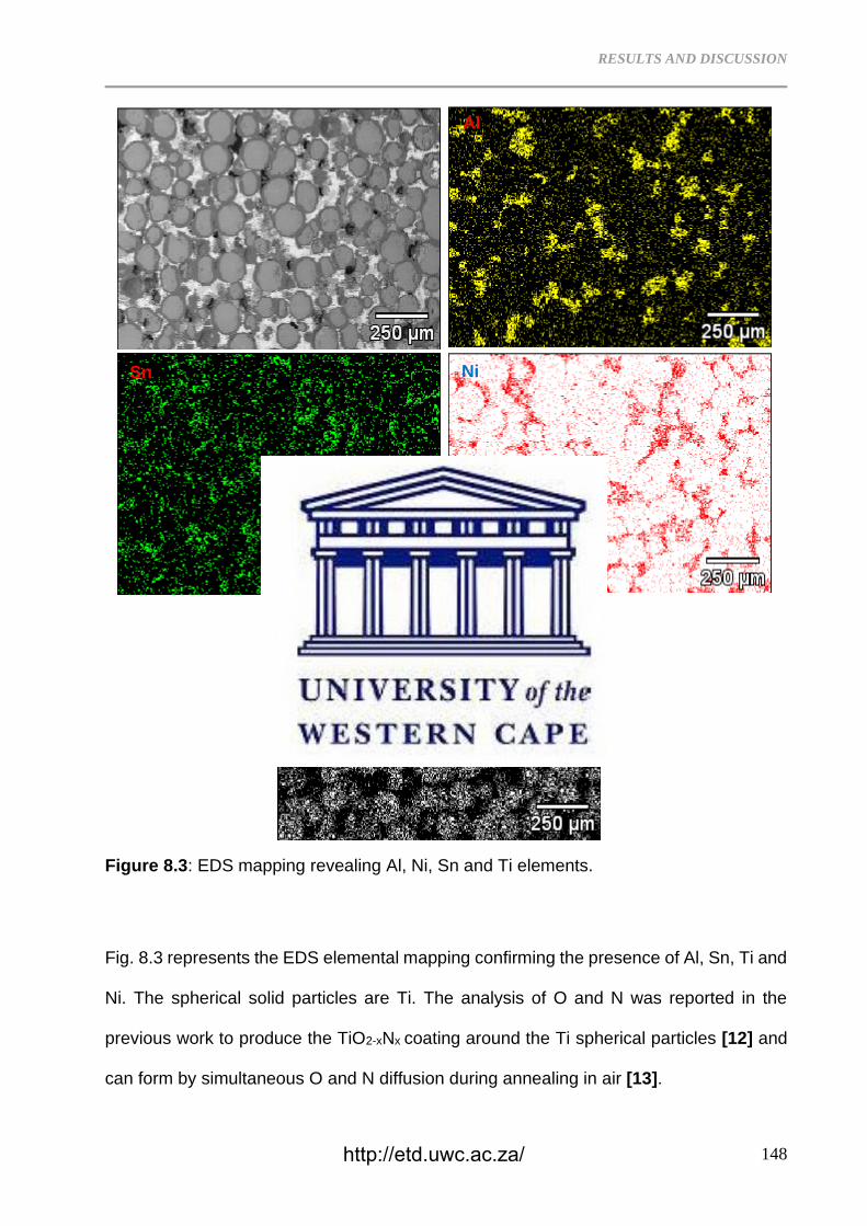
RESULTS AND DISCUSSION
148
Figure 8.3: EDS mapping revealing Al, Ni, Sn and Ti elements.
Fig. 8.3 represents the EDS elemental mapping confirming the presence of Al, Sn, Ti and
Ni. The spherical solid particles are Ti. The analysis of O and N was reported in the
previous work to produce the TiO2-xNx coating around the Ti spherical particles [12] and
can form by simultaneous O and N diffusion during annealing in air [13].
Al
Ti
Ni Sn
http://etd.uwc.ac.za/
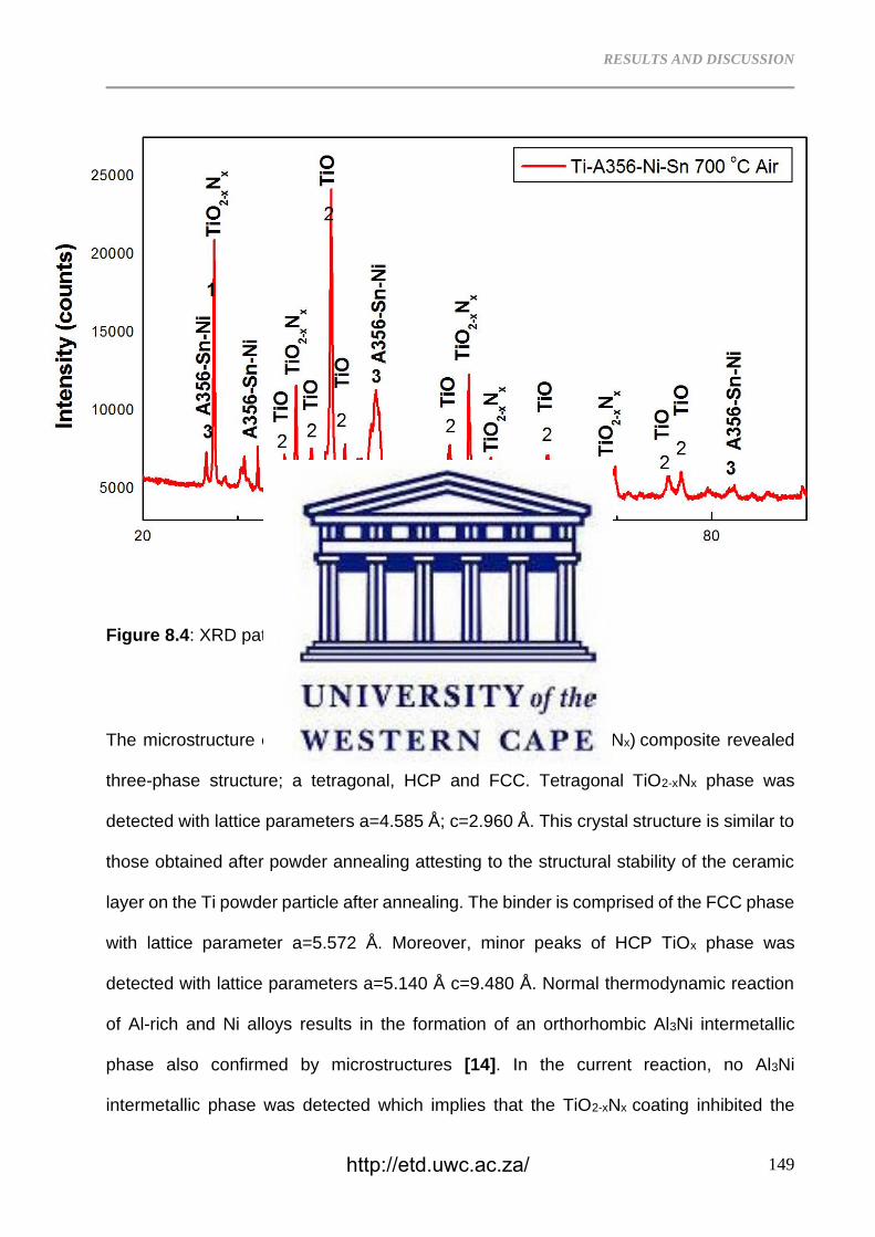
RESULTS AND DISCUSSION
149
Figure 8.4: XRD pattern of the A356-Ni-Si-Ti composite
The microstructure of the ceramic A356-1Sn-5Ni-(800 °C-TiO2-xNx) composite revealed
three-phase structure; a tetragonal, HCP and FCC. Tetragonal TiO2-xNx phase was
detected with lattice parameters a=4.585 Å; c=2.960 Å. This crystal structure is similar to
those obtained after powder annealing attesting to the structural stability of the ceramic
layer on the Ti powder particle after annealing. The binder is comprised of the FCC phase
with lattice parameter a=5.572 Å. Moreover, minor peaks of HCP TiOx phase was
detected with lattice parameters a=5.140 Å c=9.480 Å. Normal thermodynamic reaction
of Al-rich and Ni alloys results in the formation of an orthorhombic Al3Ni intermetallic
phase also confirmed by microstructures [14]. In the current reaction, no Al3Ni
intermetallic phase was detected which implies that the TiO2-xNx coating inhibited the
http://etd.uwc.ac.za/
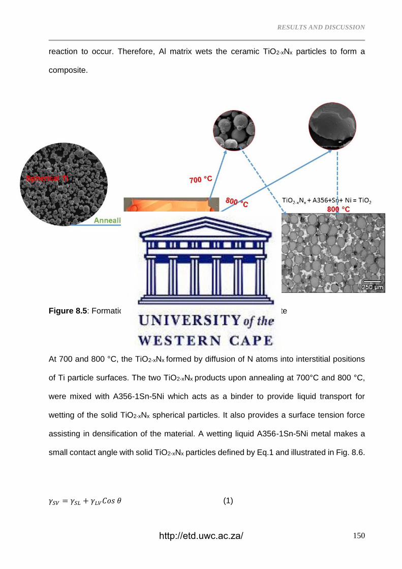
RESULTS AND DISCUSSION
150
reaction to occur. Therefore, Al matrix wets the ceramic TiO2-xNx particles to form a
composite.
Figure 8.5: Formation mechanism of the A356-Sn-Ni-Ti composite
At 700 and 800 °C, the TiO2-xNx formed by diffusion of N atoms into interstitial positions
of Ti particle surfaces. The two TiO2-xNx products upon annealing at 700°C and 800 °C,
were mixed with A356-1Sn-5Ni which acts as a binder to provide liquid transport for
wetting of the solid TiO2-xNx spherical particles. It also provides a surface tension force
assisting in densification of the material. A wetting liquid A356-1Sn-5Ni metal makes a
small contact angle with solid TiO2-xNx particles defined by Eq.1 and illustrated in Fig. 8.6.
𝛾𝑆𝑉 = 𝛾𝑆𝐿 + 𝛾𝐿𝑉𝐶𝑜𝑠 𝜃 (1)
http://etd.uwc.ac.za/
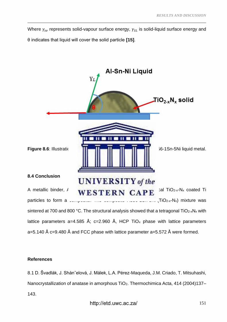
RESULTS AND DISCUSSION
151
Where 𝛾𝑠𝑣 represents solid-vapour surface energy, 𝛾𝑆𝐿 is solid-liquid surface energy and
θ indicates that liquid will cover the solid particle [15].
Figure 8.6: Illustration of the solid TiO2-xNx particle wetting by A356-1Sn-5Ni liquid metal.
8.4 Conclusion
A metallic binder, A356-1Sn-5Ni was used to bind the spherical TiO2-x-Nx coated Ti
particles to form a composite. The composite A356-1Sn-5Ni-(TiO2-x-Nx) mixture was
sintered at 700 and 800 °C. The structural analysis showed that a tetragonal TiO2-xNx with
lattice parameters a=4.585 Å; c=2.960 Å, HCP TiOx phase with lattice parameters
a=5.140 Å c=9.480 Å and FCC phase with lattice parameter a=5.572 Å were formed.
References
8.1 D. Švadlák, J. Shánˇelová, J. Málek, L.A. Pérez-Maqueda, J.M. Criado, T. Mitsuhashi,
Nanocrystallization of anatase in amorphous TiO2. Thermochimica Acta, 414 (2004)137–
143.
http://etd.uwc.ac.za/
RESULTS AND DISCUSSION
152
8.2 M. Wagemaker, W. J. H. Borghols, F. M. Mulder, Large Impact of Particle Size on
Insertion Reactions. A Case for Anatase LixTiO2. J. American Cheml Soc, 129 (2007)
4323−4327.
8.3 N.D. Cuong, D.-J. Kim, B.-D. Kang, C.S. Kim, S.-G. Yoon, Analysis of nitrogen species
in titanium oxynitride ALD films, Microelectron. Reliab.47 (2007) 752–754.
8.4 C. Nunes, V. Teixeira, M.L. Prates, N.P. Barradas, A.D. Sequeira, Graded selective
coatings based on chromium and titanium oxynitride, Thin Solid Films 442 (2003) 173–
178.
8.5 F. Maury, F.-D. Duminica, TiOxNy coatings grown by atmospheric pressure metal
organic chemical vapor deposition, Surf. Coat. Technol. 205 (2010) 1287–1293.
8.6 J. Koerner, L.A. Butterworth, I.V. Mayer, R. Dasbach, H.J. Busscher, Bacterial
adhesion to titanium-oxy-nitride (TiNOX) coatings with different resistivities: a novel
approach for the development of biomaterials, Biomater. 23 (2002) 2835–2840.
8.7 A.S. Bolokang, Z.P. Tshabalala, G.F. Malgas, I. Kortidis, H.C. Swart, D.E. Motaung,
Room temperature ferromagnetism and CH4 gas sensing of titanium oxynitride induced
by milling and annealing, Mater. Chem. Phys. 193 (2017) 512-523.
8.8 M. Arunachalam, G. Yun, K-S. Ahn, W-S. Seo, D.S. Jung, S. H. Kang, Unique
photoelectrochemical behavior of TiO2 nanorods wrapped with novel titanium Oxy-Nitride
(TiOxNy) nanoparticles, Int. J. hydro. energy 43 (2018) 16458-16467.
8.9 Z. Yu, H. Xua, G. Zhu, D. Yan, A. Yu, Lithium titanium oxynitride thin film with
enhanced lithium storage and rate capability, Appl. Surf. Sci. 368 (2016) 173–176.
http://etd.uwc.ac.za/
RESULTS AND DISCUSSION
153
8.10 L. Li, Y. Zhao, K. Sun, H. Ji, D. Feng, Z. Li, Composition, microstructure and
mechanical properties of cBN-based composites sintered with AlN-Al-Ni binder, Ceram.
Int. 44 (2018) 16915–16922.
8.11 AS Bolokang, MJ Phasha, Thermal analysis on the curie temperature of
nanocrystalline Ni produced by ball milling, Advanced Powder Technology 22 (4), 518-
521.
8.12 S.T. Camagu, A.S. Bolokang, T.F.G. Muller, D.E.Motaung, C.J. Arendse, Surface
characterization and formation mechanism of the ceramic TiO2-xNx spherical powder
induced by annealing in air, Powder Technology 351 (2019) 229–237.
8.13 M.N. Mathabathe, G. Govender, C.W. Siyasiya, R.J. Mostert, A.S. Bolokang,
Surface characterization of the cyclically oxidized γ-Ti-48Al-2Nb-0.7Cr alloy after
nitridation, Materials Characterization 154 (2019) 94–102.
8.14 Z. Gxowa-Penxa, P. Daswa, R. Modiba, M.N. Mathabathe, A.S. Bolokang,
Development and characterization of Al–Al3Ni–Sn metal matrix composite, Materials
Chemistry and Physics 259 (2021) 124027.
8.15 O.O. Marenych, A.G. Kostryzhev, Z. Pan, H. Li, S. van Duin, Comparative effect of
Mn/Ti solute atoms and TiC/Ni3(Al,Ti) nano-particles on work hardening behaviour in
NiCu alloys fabricated by wire arc additive manufacturing, Mater. Sci. Eng. 753 (2019)
262–275.
http://etd.uwc.ac.za/
CONCLUDING REMARKS AND FUTURE WORK
154
CHAPTER NINE
9.1 CONCLUDING REMARKS AND FUTURE WORK
As per the objectives as set out on section 1.3 for the current research, the following
concluding remarks are drawn:
9.1.1 Concluding Remarks
Objective 1: To synthesize NiAl alloy via powder consolidation of elemental Ni and Al
powders and study the resulting alloy structure.
• Commercially pure Ni and Al powders were blended at 1:1 atomic ratio to obtain
a homogeneous mixture, which was cold pressed into cylindrical coupons. Upon
sintering followed by air-cooling, the samples exhibited a well-sintered single
phase cubic B2-NiAl with equiaxed grain structure with comparable lattice
parameters for lower (750 ℃) and higher (1300 ℃) sintering temperatures. The
sample sintered at 1300 ℃ was brittle and the product was hand crushed into a
powder using a rod and porcelain bowl. Prolonged sintering (48 and 120 h)
resulted in recrystallized grains consumed by preferential growth in the <111>
orientations as revealed by the Electron Backscatter Diffraction analysis. A thin
scale of Al2O3 was detected upon prolonged (120 h) oxidation in air. The Al2O3
acted as a protective layer preventing any further bulk oxidation of the sample
except for traces of Al2O3 that formed via intergranular oxidation and transformed
into a metastable monoclinic oxynitride phase due N contamination.
Objective 2: To synthesize a TiC reinforced NiAl based alloy and study the resulting
composite structure.
http://etd.uwc.ac.za/
CONCLUDING REMARKS AND FUTURE WORK
155
• The Ni62.5Al37.5TiC1.28 composite was developed by powder mixing, compaction
and sintering at 650 ºC. The chemical reaction during sintering showed that
thermal explosion (TE) occured when small amount of nanosized TiC powder was
added. The cold pressing process reduced the activation/ignition temperature of
the surface Ni/Al particle interaction, which propagated to the core of the compact.
The resultant microstructure revealed martensitic NiAl plates surrounded by the
hard Ni3Al and TiC particles. The formed composite resisted the diamond tool
cutting attributable to the work hardening behaviour of the composite. The
Ni62.5Al37.5TiC1.28 composite has an average hardness of 431±11 HV while the
Ni62.5Al37.5TiC1.28 is 396±14 HV.
Objective 3: To synthesize a suitable metal oxynitride and study the resulting structure.
• Commercially pure samples of spherical Ti powder were oxidized at 500, 600, 700
and 800 ℃ respectively. Lower temperature oxidation (500 ℃) resulted in the
formation of hexagonal close packed TiOx (x ≤ 2) while intermediate temperature
(600 ℃) oxidation resulted in the formation of TiO2 compared to oxidation at higher
temperatures (700 and 800 ℃) whereby TiO2/TiO2-xNx phases were detected via
X-ray diffraction analysis. Thermal analysis of the samples oxidised at lower
temperatures (500 and 600 ℃) revealed α ↔ β phase transformation, which was
indicative of the presence of pure titanium. Oxidation at higher temperatures (700
and 800 ℃) yielded no such phase transformation, which meant that the entire
titanium had not only oxidised but nitride as well forming a Ti oxynitride via the
exchange in oxygen atoms between the non-stoichiometric TiOx and TiO2-xNx
phases. An increase in temperature results in an increase in N content as shown
by the atomic force microscopy (AFM) imagery.
http://etd.uwc.ac.za/
CONCLUDING REMARKS AND FUTURE WORK
156
Objective 4: To synthesize a NiAl based alloy reinforced with the suitable metal oxynitride
and study the resulting composite structure.
• A metallic binder with A356-1Sn-5Ni composition was developed for the TiO2-xNx
ceramic powder. The composite A356-1Sn-5Ni-(TiO2-xNx) mixture was liquid-
phase sintered at 800 °C. The structural analysis showed that a tetragonal TiO2-
xNx with lattice parameters a=4.585 Å; c=2.960 Å, HCP TiOx phase with lattice
parameters a=5.140 Å; c=9.480 Å and FCC phase with lattice parameter a=5.572
Å were detected in composite material. The density of 4.91 g/cm3 measured on
500 °C annealed sample confirmed the formation of TiOx phase. Furthermore,
dissolution of N at higher temperatures (600, 700 and 800 °C) was accompanied
by decrease in density confirming formation of rutile titanium oxynitride.
Objective 5: To synthesize a steel alloy-based matrix reinforced with TiC and study the
resulting composite structure.
• The Steel/Ni reinforced with 1.0 -1.5 wt.% ultrafine TiC composites were
developed through powder metallurgical compaction and sintering processes. TiC
particles segregated around the spherical FeNi grains on the 1.0 wt.% and 1.5
wt.% TiC composite materials. The structural analysis revealed that the 1.0 wt.%
TiC-Steel/Ni was composed of the FCC matrix while the 1.5 wt.% TiC-Steel/Ni
composite had B2 (BCC) crystal structure. Larger TiC grains were found on the
1.0 wt.% TiC-Steel/Ni composite. On the 1.5 wt.% TiC-Steel/Ni composite, the
spherical Steel/Ni matrix was surrounded by the ultrafine TiC grains. The 1.0 wt.%
TiC-Steel/Ni composite was composed of lower average hardness compared to
the 1.5 wt.% TiC-FeNi composite.
http://etd.uwc.ac.za/
CONCLUDING REMARKS AND FUTURE WORK
157
9.1.2 Future Work
To round up the current study and meet all the objectives set out, the last activity is to:
• Select a suitable steel-based alloy powder,
• Blend the suitable steel-based alloy powder with Titanium oxynitride powder,
• Cold press the blend into cylindrical coupon,
• Sinter the cylindrical coupons to fabricate a composite,
• Perform metallurgical evaluation on the resulting composite, and
• Document the results for peer review.
http://etd.uwc.ac.za/