manual_pl_cs210.pdf - clear-com
TRANSCRIPT
1. INTRODUCTION
A. THE CLEAR-COM CONCEPT
Clear-Com is a closed-circuit in- mic input lines (200 ohms) andtercom system that provides high- specially designed circuitry makeintelligibility, two-way communica- Clear-Com channels virtually immunetions in high- or low-noise envi- to RF and dimmer noise.ronments. A basic intercom systemcontains a one- or multi-channel Clear-Com Main Stations, Power Sup-Main Station interconnected with plies, and some Remote Stationsvarious remote headset and speaker provide an auxiliary program inputstations. with its own volume control, which
al lows the station operator toClear-Com manufactures a wide va- monitor external audio.riety of portable, rack-mount, andcustom-mount intercoms. All are Visual Signal Circuitry, a standardcompatible, allowing systems to be feature on most stations, allowsset up according to specific needs. the user to attract the attentionThe Clear-Com System interfaces of operators who have removed theirwith virtually any other type of headsets or turned off their spea-communications systems (call Clear- kers.Con or see your dealer for info).
Depending upon the type of Main andClear-Com Stations normally inter- Remote Stations selected, a maximumconnect with standard, 2-conductor amount of Remote Stations from 12shielded microphone cable; they (speaker) to 100 (headset) can beinclude inputs for XLR-type, 3-pin connected along one mile of wire.connectors. One wire in the mic Remote Stations bridge the intercomcable carries DC power (28-30 line at a very high impedance, andvolts) from the Main Station to the place a minimum load on the line.remote stations, and the other wire Audio level remains constant, nevercarries the audio signal. The fluctuating even when stationsshield acts as common ground. Au- leave or join the line.dio termination is required at onlyone point in the intercom system, The regulated DC voltage providedand is usually provided by the Main by Main Stations and Power Sup-Station or Power Supply. plies enables remote stations to
operate; they run at minimal cur-Clear-Com is a "distributed ampli- rent (10 milliamperes quiescent forfier system:" each main and remote headset stations, 20 ma quiescentstation contains its own mic pream for speaker stations) while genera-plifier, power amplifier (for head- ting extremely loud listen volumesset or speaker), and signalling (greater than 110 dB SPL). Thecircuitry. Every intercom has Auto- higher voltage and low current keepmatic Headset Detection, a circuit voltage losses to a minimum in longthat shuts off the mic preamp when lines. If the voltage drops due tothe mic or headset is not connec- the addition of cable or many sta-ted, so background noise is not tions, Clear-Com equipment conti-increased by an unused but on-line nues operating normally with less(connected) station. Low-impedance than 12 volts available.
breaker pops out and the adjacent its weather-resistant enclosure.red LED illuminates. Removing theshort, then pressing the circuit- Easy Interconnectionbreaker button automatically resets The CS-210 provides three 3-pin,the system. male XLR outputs for output of
Channel A (connectors are wired inThe CS-210 provides audio termina- parallel) and three of the same fortion for the intercom system. Channel B output. Intercom signals
are fed from the CS-210 withThe CS-210 can be ganged together standard mic cable; see nextwith other CS-210's for multiple section.two-channel systems and back-uppower support. The unit is light- The CS-210 is available with aweight, weather-resistant, and as- rack-mount kit for adapting it tosembled with a sturdy plastic car- standard 19" equipment racks. Therying strap on top and four protec- Clear-Com part number for the CS-tive rubber feet on the bottom of 210 Rack-Ear Kit is 820020.
3
1 m ) C M z mc
mflMZ
z~~~~~~~~~~~~~~~~~~~~~~~C Z, rm z _
<I- n 0- Zm
X 17 .. Z
Xt| 0 r 2 OM
0 ~ ~ ~ 00a O-4m
zw-c0 m~~4~f m
z~~~zn
z
-4~~~~m
__ ~~~x
cn4 M) O'2C)~~~~llogo 0
z O-~~~-4o 0
a~~*0 zCD
z
z
11. SYSTEM INTERCONNECTION
A. INPUTS & OUTPUTS: WHAT CABLE TO USE
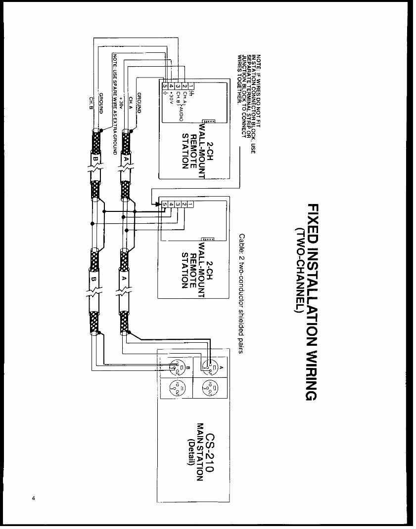
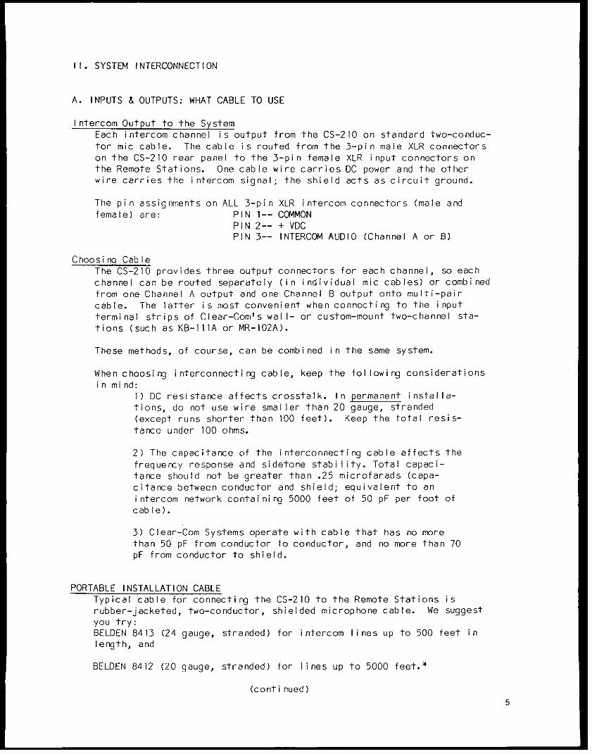
Intercom Output to the SystemEach intercom channel is output from the CS-210 on standard two-conduc-tor mic cable. The cable is routed from the 3-pin male XLR connectorson the CS-210 rear panel to the 3-pin female XLR input connectors onthe Remote Stations. One cable wire carries DC power and the otherwire carries the intercom signal; the shield acts as circuit ground.
The pin assignments on ALL 3-pin XLR intercom connectors (male andfemale) are: PIN 1-- COMMON
PIN 2-- + VDCPIN 3-- INTERCOM AUDIO (Channel A or B)
Choosing CableThe CS-210 provides three output connectors for each channel, so eachchannel can be routed separately (in individual mic cables) or combinedfrom one Channel A output and one Channel B output onto multi-paircable. The latter is most convenient when connecting to the inputterminal strips of Clear-Com's wall- or custom-mount two-channel sta-tions (such as KB-IIIA or MR-102A).
These methods, of course, can be combined in the same system.
When choosing interconnecting cable, keep the fol lowing considerationsin mind:
1) DC resistance affects crosstalk. In permanent installa-tions, do not use wire smaller than 20 gauge, stranded(except runs shorter than 100 feet). Keep the total resis-tance under 100 ohms.
2) The capacitance of the interconnecting cable affects thefrequency response and sidetone stability. Total capaci-tance should not be greater than .25 microfarads (capa-citance between conductor and shield; equivalent to anintercom network containing 5000 feet of 50 pF per foot ofcable).
3) Clear-Com Systems operate with cable that has no morethan 50 pF from conductor to conductor, and no more than 70pF from conductor to shield.
PORTABLE INSTALLATION CABLETypical cable for connecting the CS-210 to the Remote Stations isrubber-jacketed, two-conductor, shielded microphone cable. We suggestyou try:BELDEN 8413 (24 gauge, stranded) for intercom lines up to 500 feet inlength, and
BELDEN 8412 (20 gauge, stranded) for lines up to 5000 feet.*
(continued)5
SYSTEM INTERCONNECTION, CONTINUED
Portable Interconnection MethodsPortable Remote Stations each have a pair of input and output connec-tors which are wired in parallel, allowing you to set up a "daisy-chain" when instal lating the system. A diagram in this section illu-strates the daisy-chain method. As an alternative, Clear-Com's ModelQP-100 "Quadropuss Line-Splitter" is a small interconnect device thataccepts one cable input and provides three outputs. Both the daisy-chain and line-splitting methods lessen the cable needed and simplifythe installation process.
PERMANENT INSTALLATION CABLETo install wall-mount and custom-mount remote stations, we recommendyou use vinyl-insulated and jacketed cable; it costs less and iseasier to pull through conduit than the rubber-insulated cable. Uselow capacitance cable. We suggest you try:BELDEN 8762 (20 gauge, stranded) for applications up to 500 feet, andBELDEN 8760 (18 gauge, stranded) for up to 5000 feet.*
If conduit is avai lable when installing permanent Remote Stations, runinterconnect cable through the conduits to each wall-mounted unit.
NOTE: "Signal ground" (Pin I on intercom connectors) and "chassisground" are NOT the same point. Do NOT connect Pin I and the chassistogether. The chassis is insulated from the signal ground with acapacitor (.01 microfarad, 1.4kv). This eliminates the hum and poten-tial shock hazards that can arise if stations are at a different groundpotential.
In installations where conduit is NOT used, and equipment doesn't sharea common ground, it is good engineering practice to run an additionalground wire to tie all chasses together (this decreases susceptibilityto electrical noise fields).
*If you choose not to use Belden cable, use an equivalent type withsimilar wire gauge and capacitance. Cable, especially in longer runs,should have low DC resistance (less than 15 ohms per 1000 feet; largediameter conductors) and low interconductor capacitance (less than orequal to 50 pF per foot of cable: capacitance between conductor and shield).
Multi-Channel Cable ConsiderationsWhen installing a system that includes two-channel (or more) stations,each channel may be routed individually to the remote station withseparate mic cables, OR two channels may be routed together with two-pair, individually-shielded cable (Belden 8723).
CrosstalkWhen multiple channels are fed to remote stations, the amount of cross-talk is proportional to the amount of DC resistance in the groundreturn. Two ohms of resistance or less is ideal; 2 ohms will give you40 dB of isolation. Anything greater than 2 ohms will increase cross-talk. Each channel must be fed in its own separate shield. Tie anyunused wires in the interconnect cable to ground (Pin 1), therebyfurther improving the crosstalk.
6
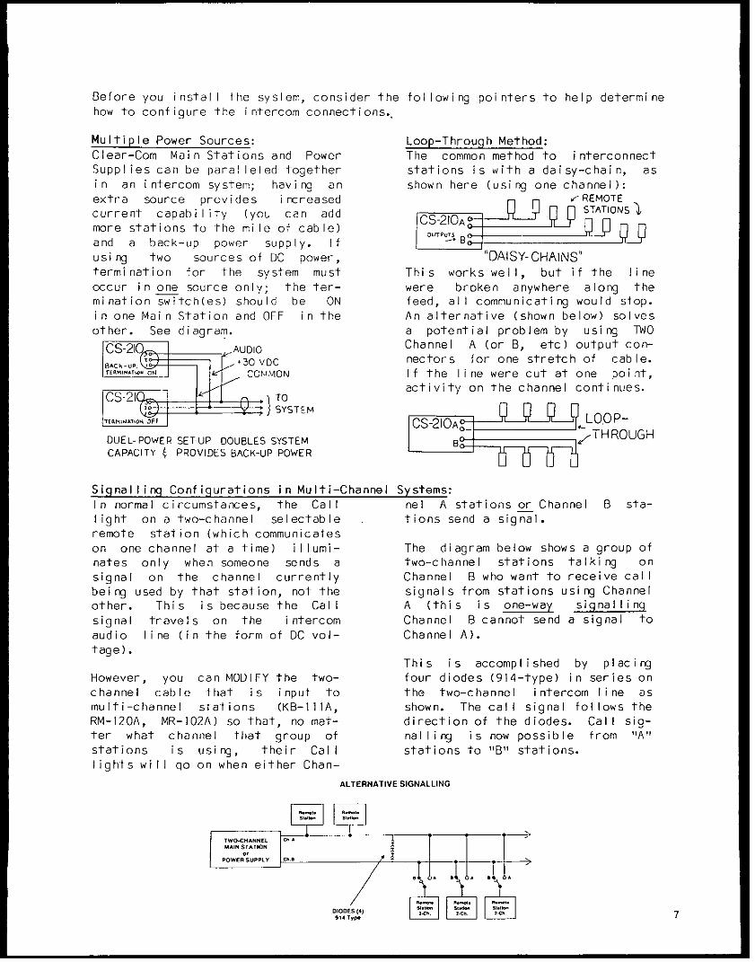
Before you install the system, consider the fol lowing poi nters to help determinehow to configure the intercom connections.
Multiple Power Sources: Loop-Through Method:Clear-Com Main Stations and Power The common method to interconnectSupplies can be paralleled together stations is with a daisy-chain, asin an intercom system; having an shown here (using one channel):extra source provides i ncreased n REMOTEcurrent capability (you can add CS 210A n STATIONS
more stations to the mile of cable) Q Band a back-up power supply. Ifusing two sources of DC power, "DAISY-CHAlNS'termination for the system must This works well, but if the lineoccur in one source only; the ter- were broken anywhere along themination switch(es) should be ON feed, all communicating would stop.in one Main Station and OFF in the An alternative (shown below) solvesother. See diagram. a potential problem by using TWO
CS-210ffi 1 _ AUDIO Channel A (or B, etc) output con-9.ce-u> = _ (-30 VDC nectors for one stretch of cable.
tstm~xioscszCOMlMON If the line were cut at one point,
TO-21CL_ l e C activity on the channel continues.
i=F }SYSTEM CS- 20 LOOP-
DUEL-POWER SETUP DOUBLES SYSTEM B >-;,THROUGHCAPACITY 4 PROVIDES BACK-UP POWER
Signalling Configurations in Multi-Channel Systems:In normal circumstances, the Call nel A stations or Channel B sta-light on a two-channel selectable tions send a signal.remote station (which communicateson one channel at a time) illumi- The diagram below shows a group ofnates only when someone sends a two-channel stations talking onsignal on the channel currently Channel B who want to receive callbeing used by that station, not the signals from stations using Channelother. This is because the Call A (this is one-way signallingsignal travels on the intercom Channel B cannot send a signal toaudio line (in the form of DC vol- Channel A).tage).
This is accomplished by placingHowever, you can MODIFY the two- four diodes (914-type) in series onchannel cable that is input to the two-channel intercom line asmulti-channel stations (KB-IIIA, shown. The call signal follows theRM-120A, MR-102A) so that, no mat- direction of the diodes. Call sig-ter what channel that group of naIling is now possible from "A"stations is using, their Call stations to "B" stations.lights will go on when either Chan-
ALTERNATIVE SIGNALLING
:IODE ( / ,'.. 1O '924sl Tyk .
B. THE CS-210 MAIN STATION
The CS-210 is a portable, two- voice output to the intercom chan-channel main station with a regu- nels.lated power supply and a versatilemonitoring system. It features Cal t Siqnal linqexcel lent speech intelligibility in Visual "Call" Signalling attractsall noise-levels. the attention of people who have
removed their headsets or turnedThe CS-210 contains a mic preamp off their speakers. The CS-210with a limiter and can support two front panel provides a "Call" but-dynamic headsets/handsets. The ton. Pressing it signals the sta-headset output connector label led tions on any channel whose "Monitor"headset 1" is switchable, with is Select" button is engaged and illu-a toggle switch that sets the "mic minated.on" "mic off" and "momentary mic on'(on)'." The CS-210's four-watt When a remote station sends a Cal I
power amp can drive a standard signal, the lamp in the MonitorClear-Com headset to levels greater Select button associated with thatthan 110 dB SPL. station's channel lights brightly,
whether or not the Monitor is "on."Monitoring SystemThe CS-210 provides DC voltage and Program inputthe ability to talk & listen on two The CS-210 accepts a balanced, mic-separate channels. It supports and level OR line-level program inputmonitors two intercom lines con- which can be monitored in the head-taining as many as 60 remote head- set(s). The external program isset or 12 remote speaker stations. assignable to either or both chan-
nels, and mixes with the intercomThe CS-210 operator monitors the signal. Program volume for theintercom channels by pressing the operator's headset is adjustablelocking "Monitor Select" buttons with a knob on the front panel.(one for Channel A, one for ChannelB). These buttons light dimly when Sidetoneengaged. Either channel may be The Sidetone Adjust control on themonitored separately, or both si- front panel allows the CS-210 ope-multaneously (without tying the two rator to vary the level of his/herchannels together). The CS-210 own voice as heard in the headset;controls the headset listen level lowering the amount of sidetoneof channel activity with a Volume helps suppress acoustic feedbackknob on the front panel. when using the CS-210 with an ex-
ternal speaker and a gooseneck mic.Stage Announce (Paging)On its rear panel, the CS-210 pro- Power Supply Protectionvides an output (line-level, bal- The CS-210 power supply is regu-anced) from the mic preamp. The lated, current-limited, and pro-"Stage Announce" button on the vides 30 volts DC at one amperefront panel activates this output, from a 115V or 230V (switch-select-allowing the CS-210 operator to able) AC mains supply. The CS-210speak into the mic or handset and has a circuit breaker to protectobtain access to an external spea- the system from miswired cable orker/amp system. The Stage Announce shorts in the lines. If a shortbutton also mutes the operator's occurs, the front panel circuit
continued
2
B. INTERCONNECTION SET-UP
After determining system configuration and channel assignment, pick alocation for the CS-210; it can be anywhere as long as it is provided witha source of 105-125 VAC, 50-60 Hz (power consumption is 60 watts maximum).
1) Use standard shielded mic cable (see previous section). ALWAYSAVOID BENDS IN THE CABLING; allow at least 3" behind rack-mountunits for cable extending from rear panels.
2) Route all cables from the Main Station to the Remote Stations. Pinassignments on ALL 3-pin intercom connectors are:
PIN 1-- commonPIN 2-- +30 volts DCPIN 3-- intercom audio
3) Route cables away from heavy AC power sources, such as lightingpanels, electric motors, or power transformers.
4) In permanent installations, BE SURE TO INSTALL THE SYSTEM INACCORDANCE WITH APPROVED LOCAL BUILDING CODE.
5) If program monitoring is required, input the external signal to the3-pin female connector on the CS-210 rear panel. The station opera-tor hears the program in the headset, mixed with the intercom acti-vity. The program pre-amp's gain is switch-selectable (on rearpanel) for either mic level (-75dBv nominal input signal) or line-level (-15dBv nominal). The input must be balanced 300k ohms in lineposition, 3-6k ohms in mic position.
6) Turn on power switch (it should illuminate), plug in headset(s) andset Intercom, Program, and Sidetone levels.
NOTE about HEADSETS AND MICS: The CS-210 headset connectors (likeall Clear-Com dynamic headset connectors) are 4-pin, male XLR. Theconnector label led "Headset I" works with the Mic On/Off/(MomentaryOn) toggle switch above it. The headset connector pin-out assign-ment is: PIN 1--mic common
PIN 2--mic hotPIN 3--headphone commonPIN 4--headphone hot
DO NOT place the headset(s) within two feet of an AC power transfor-mer or the mic(s) will pick up a hum.To meet optimum performance specs, the the headsets used (handsets,mics, etc) should have the following characteristics:
Microphone type: dynamicImpedance: 150-250 ohmsOutput Level: -55 dBHeadphone Type: dynamicOutput Impedance: 300-2000 ohms
The system should now be ready to run!
AA I J< S(FI MoTl W.j2 rs Wr o WuIe2 smepalt
A .. ..... m0m cS cw
MIX~~~~~~~~~~~~~~~~~~~~~~~~1 CSC1
Im~~~~~~~~~~~.. ...
[W~~~~~~~~~~l ~ ~ r p or e1 i
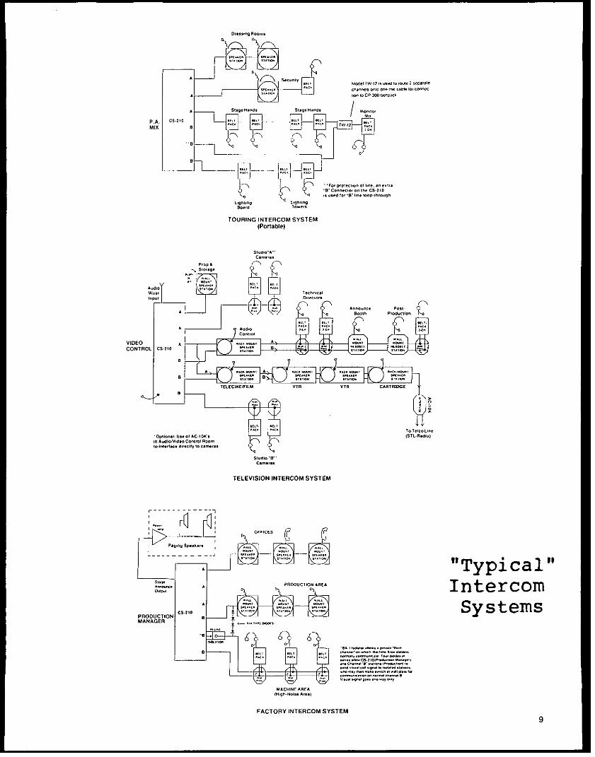
TOURING INTERCOM SYSTEM(Portable)
o Sirnrge
Ado
VIDEO AACONTROL CS5|o
OpliWoi1: Ueril AC.ID STTlTdrlin AodioPrdeO Cronlelri w t
TELEVISION INTERCOM SYSTEM
- ---- - -F-C-S-@
. "Typical"s>_0 PROGUCTION AREA Intercom
PRODUCTION C5a219 @ SSystem sMANAGER E . ... .
~~~~~~~~~~~~~~~~~~r.., ,_o. C-iier r.n srri
E~~~~~~~~~~~~~~~~~~~~~ii Ioe ;er ris .... oi :' r:i ors o
MACNINE AREA
FACTORY INTERCOM SYSTEM
111. OPERATION OF THE CS-210 MAIN STATION
A. Front Panel Controls and Connectors
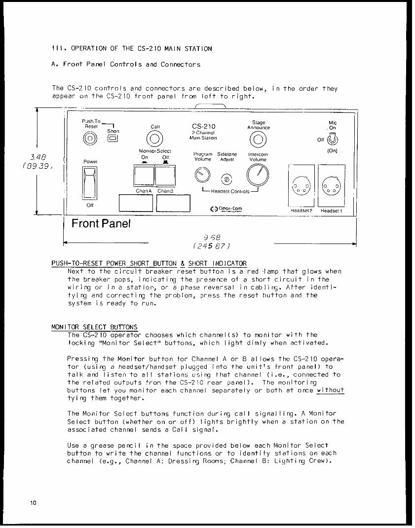
The CS-210 controls and connectors are described below, in the order theyappear on the CS-210 front panel from left to right.
Push To Stage MicReset Call CS-21 0 Announce On
Short 2 Channel
Q Kf0 Main S(alin Q1moni 4o Select Program Sidelone Intercom On)346 On Oil Volume Adjust Volume
3.4e Power ALH
Off()lo-o
Front Panel;_ _ _ __ _ _ 9 66
(245 87)
PUSH-TO-RESET POWER SHORT BUTTON & SHORT INDICATORNext to the circuit breaker reset button is a red lamp that glows whenthe breaker pops, indicating the presence of a short circuit in thewiring or in a station, or a phase reversal in cabling. After identi-fying and correcting the problem, press the reset button and thesystem is ready to run.
MONITOR SELECT BUTTONSThe CS-210 operator chooses which channel(s) to monitor with thelocking "Monitor Select" buttons, which light dimly when activated.
Pressing the Monitor button for Channel A or B allows the CS-2 10 opera-tor (using a headset/handset plugged into the unit's front panel) totalk and listen to all stations using that channel (i.e., connected tothe related outputs from the CS-210 rear panel). The monitoringbuttons let you monitor each channel separately or both at once withouttying them together.
The Monitor Select buttons function during call signalling. A MonitorSelect button (whether on or off) lights brightly when a station on theassociated channel sends a Call signal.
Use a grease pencil in the space provided below each Monitor Selectbutton to write the channel functions or to identify stations on eachchannel (e.g., Channel A: Dressing Rooms; Channel B: Lighting Crew).
10
CALL (Visual Call Signalling)Pressing the CALL button activates the Visual Signal circuit in theintercom system, allowing you to attract the attention of other opera-tors who have removed their headsets or turned off their speakers (thecall signal also activates the remote page function at designatedremote stations).
The Call button signals all stations on the channel selected for moni-toring. If the Monitor Select button for Channel A is "on,t' pressingCall will signal all stations on Channel A only. If both Monitor but-tons are on, pressing Call causes the lamps at all stations to light.
When a remote station activates the signal circuit, the CS-210 MonitorSelect button for the station's channel will light brightly (whether onor off).
PROGRAM VOLUMEThe "Program Volume" knob controls program level for the CS-210 head-set(s) AND for the intercom system. For information about signalinput, see next section ("Rear Panel Controls and Connectors").
The CS-210 internal electronics contain jumpers that are factory-set tosend program to the CS-210 headset(s) and the intercom system.
The CS-210 operator decides whether one or both channels receive theprogram by setting the channel-select switch on the station's rearpanel.
SIDETONE ADJUSTThe "Sidetone Adjust" knob controls the overall volume level of theoperator's voice as he/she hears it in the headset, and simultaneouslyprevents feedback when the CS-210 is connected to an external speaker.It does not affect the level of the operator's voice going to otherstations, or the level of any incoming signals. Sidetone level needsto be set just once (if at all), even when stations join or leave thesystem.
INTERCOM VOLUMEThis knob adjusts the overall volume of intercom activity heard by theCS-210 operator(s).
STAGE ANNOUNCEThe "Stage Announce" function lets the CS-210 operator make announce-ments via an external speaker/amp system. For these paging applica-tions, the CS-210 provides a balanced, line-level (0 dB) output signalto the Stage Announce connector (3-pin male XLR) on the rear panel.The front panel pushbutton activates this output and simultaneouslymutes the operator's voice to the intercom channels.
HEADSET CONNECTORS;MIC ON/OFF/(ON) SWITCH
There are two dynamic headset connectors on the CS-2 10 front panel; theone labelled Headset I is associated with the Mic On/Off/(Momentary On)toggle switch above it.
When there is no input to either headset connector, the CS-210's micpreamplifier shuts off automatically. This eliminates any noise pick-up at the unused input.
The headset connector pin-out assignment is:PIN 1--mic commonPIN 2--mic hotPIN 3--headphone commonPIN 4--headphone hot
When operatirng the system, DO NOT place the headset(s) within two feetof an AC power transformer or the mic(s) will pick up a hum.
OTHER OPERATIONAL CONSIDERATIONS
TerminationOne audio termination per channel is required, and the CS-210 is set upwith internal jumpers to provide that termi nation (that is, if it isthe only power-supplying station in the system).
The intercom line terminations are removable resistors, appropriatelymarked on the printed circuit board. They can be pulled to allow theCS-210 to operate as a "remote" station if another power supply isconnected to the system. If your system does include a second CS-2 10or other Main Station or Power Supply, system termination is providedby just ONE source. The termination switches in all Power Supplies/Main Stations must be "off" except at one "master" location. (Do notattempt to remove jumpers without the proper test equipment and know-ledge of electronic adjustment procedures.)
Unconnected Channel Inputs/OutputsIf your system includes a multi-channel station that has one or more ofits channels not physically connected (e.g., empty input connector),the unconnected channel(s) MUST be terminated at that station (THIS AP-PLIES TO ALL STATIONS: MAIN, REMOTE, OR POWER SUPPLY).
12
Rear Panel Controls and Connectors
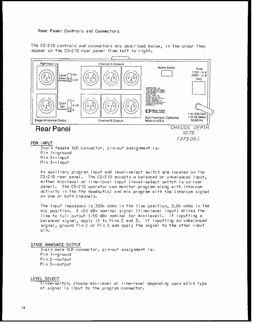
The CS-210 controls and connectors are described below, in the order theyappear on the CS-210 rear panel from left to right.
Pgm Input Channel A Outputst Mains Select Fuse
(|) Level g Mic (X l230V -i/ AWARN'ING 0
I~~~~~~~~~ vvAUT[C I; .
_a A S RI A RCitS12 Chan I2 I/2
Se, JA+B 03 00 j0 0 0 0300 rCo
AA.!L11.._1 115 -23 ASan Francisco, California 1 10 VA (Max)
Stag AnnunceOutput Channel B Oupt Made in U.S.A. 50/60 Hz
Rear Panel CHASSIS DEP/0. 75
(273.05)PGM INPUT
3-pin female XLR connector; pin-out assignment is:Pin 1--groundPin 2--inputPin 3--input
An auxiliary program input and level-select switch are located on theCS-210 rear panel. The CS-210 accepts a balanced or unbalanced input,either mic-level or line-level input (level-select switch is on rearpanel). The CS-210 operator can monitor program along with intercomactivity in the the headset(s) and mix program with the intercom signalon one or both channels.
The input impedance is 300k ohms in the line position, 3.6k ohms in themic position. A -20 dBv nominal signal (line-level input) drives theline to full output (-50 dBv nominal for mic-level). If inputting abalanced signal, apply it to Pins 2 and 3. If inputting an unbalancedsignal, ground Pin 2 or Pin 3 and apply the signal to the other inputpin.
STAGE ANNOUNCE OUTPUT3-pin male XLR connector; pin-out assignment is:Pin 1--groundPin 2--outputPin 3--output
LEVEL SELECTSlide-switch; choose mic-level or line-level depending upon which typeof signal is input to the program connector.
1 4
CHAN SEL (A/A+B/B)Slide-switch; choose which channel(s) will receive program input tomonitor: either Channel A only, both A and B, or Channel B only.
CHANNEL A & B OUTPUTS3-pin male XLR connectors; pin-out assignment is:Pin 1-- groundPin 2-- DC voltagePin 3-- intercom audio (channel A or B)
MAINS SELECTSlide-switch; choose 115V or 230V depending on source of AC power. TheCS-210 is set up with a fuse for operation from 115VAC; you must changethe fuse from 1/2 amp value to 1/4 amp (slow-blow) if operation from230VAC is required.
15
C. Warranty and Maintenance
Your Clear-Com System contains mod- meets or exceeds all specifica-ular, solid-state equipment that tions. All units are guaranteed byallows system expansion and field Clear-Com against defects in mate-servicability. Efficient ventila- rials and workmanship for one yeartion is inherent in chassis design. fol lowi ng date of purchase (90 daysRugged packaging guards against for headsets--see warranty cardabuse; the chassis are 16 gauge enclosed with each unit).alumninum or stainless steel, withdouble-sided, glass epoxy, plug-in Our Engineering and Service Depart-PC boards. Our conservatively- ments will gladly give you techni-engineered circuitry assures the cal advice and assistance. If youlongest component life. We shield have any questions regarding opera-heavily against hum, RFI pick-up, tion, modifications, or applica-and solid-state dimmer noise. tions of your intercom system, call
us between 9 and 5 at 415-861-Before shipping, we test each unit 6666 (Pacific Standard Time).individually to ensure that it
17
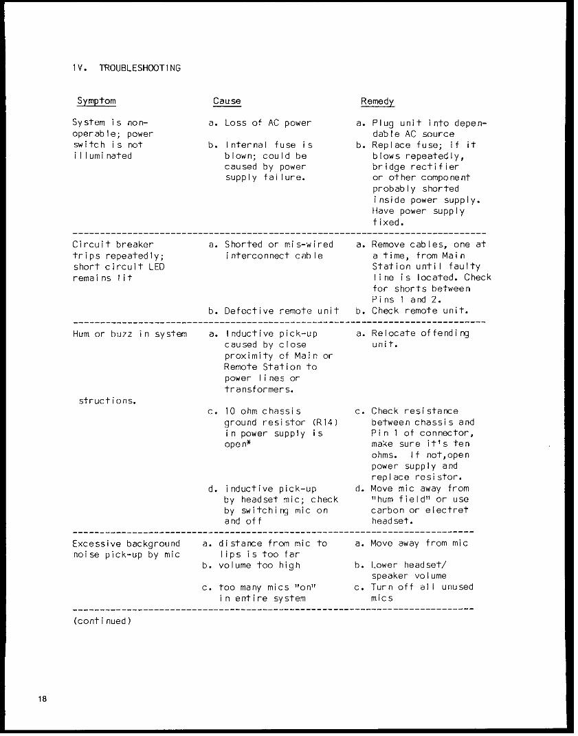
IV. TROUBLESHOOTING
Symptom Cause Remedy
System is non- a. Loss of AC power a. Plug unit into depen-operable; power dable AC sourceswitch is not b. Internal fuse is b. Replace fuse; if itilluminated blown; could be blows repeatedly,
caused by power bridge rectifiersupply failure. or other component
probably shortedinside power supply.Have power supplyfixed.
Circuit breaker a. Shorted or mis-wired a. Remove cables, one attrips repeatedly; interconnect cable a time, from Mainshort circuit LED Station until faultyremains lit line is located. Check
for shorts betweenPins 1 and 2.
b. Defective remote unit b. Check remote unit.____________________________________________________________________________
Hum or buzz in system a. Inductive pick-up a. Relocate offendingcaused by close unit.proximity of Main orRemote Station topower lines ortransformers.
structions.c. 10 ohm chassis c. Check resistance
ground resistor (R14) between chassis andin power supply is Pin 1 of connector,open* make sure it's ten
ohms. If not,openpower supply andreplace resistor.
d. inductive pick-up d. Move mic away fromby headset mic; check "hum field" or useby switching mic on carbon or electretand off headset.
__________________________________________________________________________
Excessive background a. distance from mic to a. Move away from micnoise pick-up by mic lips is too far
b. volume too high b. Lower headset/speaker volume
c. too many mics "on" c. Turn off all unusedin entire system mics
(continued)
18
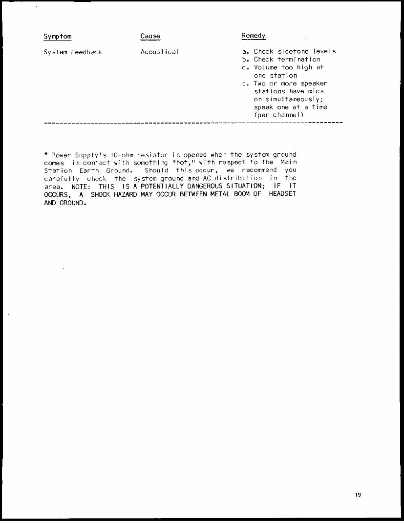
Symptom Cause Remedy
System Feedback Acoustical a. Check sidetone levelsb. Check terminationc. Volume too high at
one stationd. Two or more speaker
stations have micson simultaneously;speak one at a time(per channel)
* Power Supply's 10-ohm resistor is opened when the system groundcomes in contact with something "hot," with respect to the MainStation Earth Ground. Should this occur, we recommend youcarefully check the system ground and AC distribution in thearea. NOTE: THIS IS A POTENTIALLY DANGEROUS SITUATION; IF ITOCCURS, A SHOCK HAZARD MAY OCCUR BETWEEN METAL BOOM OF HEADSETAND GROUND.
19
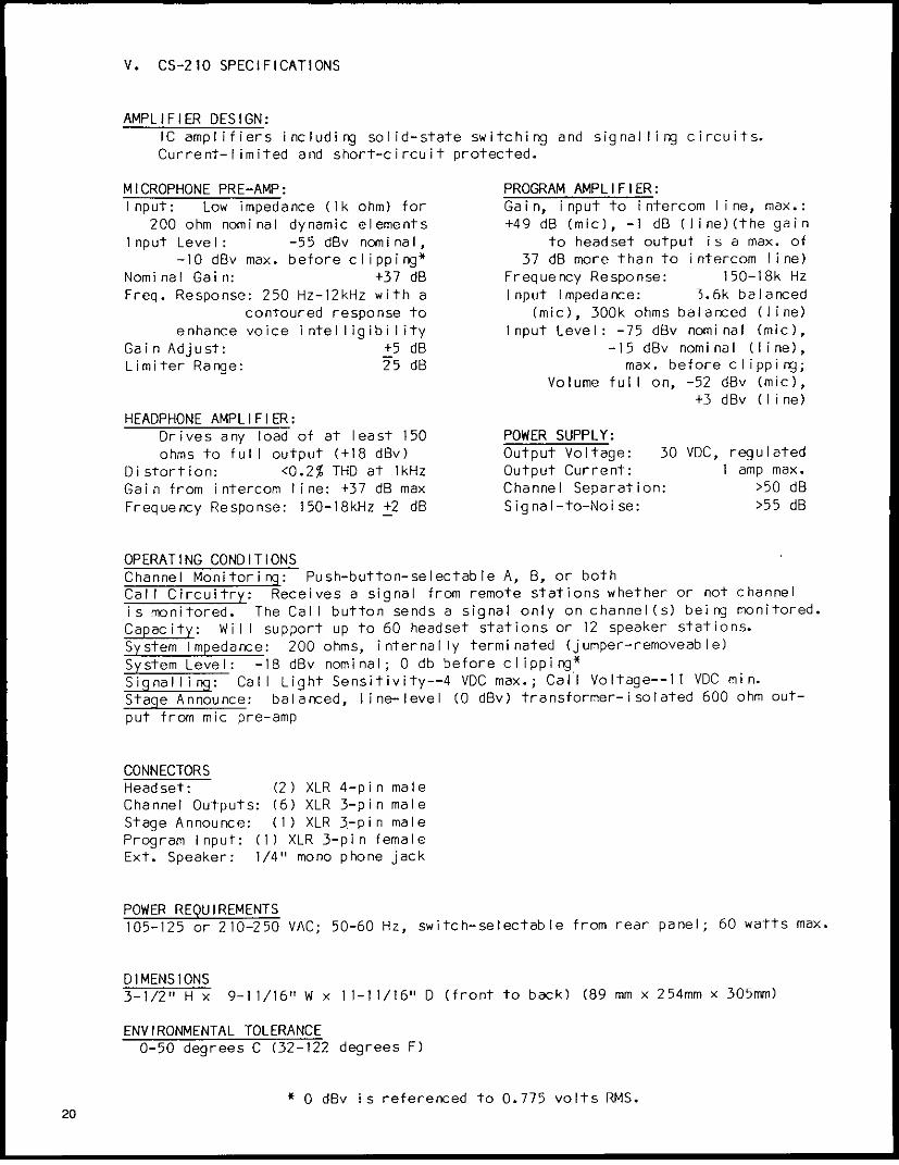
V. CS-210 SPECIFICATIONS
AMPLIFIER DESIGN:IC amplifiers includi ng solid-state switching and signal ling circuits.Current-limited and short-circuit protected.
MICROPHONE PRE-AMP: PROGRAM AMPLIFIER:Input: Low impedance (Ik ohm) for Gain, input to intercom line, max.:
200 ohm nominal dynamic elements +49 dB (mic), -1 dB (line)(the gainInput Level: -55 dBv nominal, to headset output is a max. of
-10 dBv max. before clipping* 37 dB more than to intercom line)Nominal Gain: +37 dB Frequency Response: 150-18k HzFreq. Response: 250 Hz-12kHz with a I nput Impedance: 3.6k balanced
contoured response to (mic), 300k ohms balanced (line)enhance voice intelligibility Input Level: -75 dBv nominal (mic),
Gain Adjust: +5 dB -15 dBv nominal (line),Limiter Range: 25 dB max. before clipping;
Volume full on, -52 dBv (mic),+3 dBv (line)
HEADPHONE AMPLIFIER:Drives any load of at least 150 POWER SUPPLY:ohms to full output (+18 dBv) Output Voltage: 30 VDC, regulated
Distortion: <0.2% THD at 1kHz Output Current: i amp max.Gain from intercom line: +37 dB max Channel Separation: >50 dBFrequency Response: 150-18kHz +2 dB Signal-to-Noise: >55 dB
OPERATING CONDITIONSChannel Monitoring: Push-button-selectable A, B, or bothCall Circuitry: Receives a signal from remote stations whether or not channelis monitored. The Call button sends a signal only on channel(s) being monitored.Capacity: Will support up to 60 headset stations or 12 speaker stations.System Impedance: 200 ohms, internally terminated (jumper-removeable)System Level: -18 dBv nominal; 0 db before clipping*Signallingi: Call Light Sensitivity--4 VDC max.; Call Voltage--11 VDC min.Stage Announce: balanced, line-level (0 dBv) transformer-isolated 600 ohm out-put from mic pre-amp
CONNECTORSHeadset: (2) XLR 4-pin maleChannel Outputs: (6) XLR 3-pin maleStage Announce: (1) XLR 3-pin maleProgram Input: (1) XLR 3-pin femaleExt. Speaker: 1/4" mono phone jack
POWER REQUIREMENTS105-125 or 210-250 VAC; 50-60 Hz, switch-selectable from rear panel; 60 watts max.
DIMENSIONS3-1/2" H x 9-11/16" W x 11-11/16" D (front to back) (89 mm x 254mm x 305mm)
ENVIRONMENTAL TOLERANCE0-50 degrees C (32-122 degrees F)
* 0 dBv is referenced to 0.775 volts RMS.20
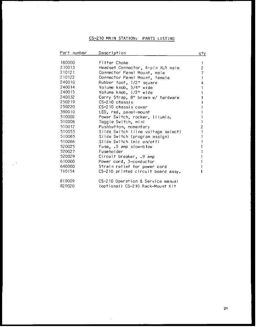
CS-210 MAIN STATION: PARTS LISTING
Part number Description qty
180000 Filter Choke I210013 Headset Connector, 4-pin XLR male 2210121 Connector Panel Mount, male 7210122 Connector Panel Mount, female 1240010 Rubber foot, 1/2" square 4240014 Volume knob, 3/4" wide 1240015 Volume knob, 1/2"t wide 1240032 Carry Strap, 8" brown w/ hardware 1250219 CS-210 chassis 1250220 CS-210 chassis cover 1390010 LED, red, panel-mount 1510002 Power Switch, rocker, illumin. 1510006 Toggle Switch, mini 1510012 Pushbutton, momentary 2510053 Slide Switch (line voltage select) 1510065 Slide Switch (program assign) I510066 Slide Switch (mic on/off) 1520025 Fuse, .5 amp slow-blow 1520027 Fuseholder 1520029 Circuit breaker, .9 amp 1610000 Power cord, 3-conductor 1640000 Strain relief for power cord 1710154 CS-210 printed circuit board assy. 1
810009 CS-210 Operation & Service manual820020 (optional) CS-210 Rack-Mount Kit
21
11 i-- - =X- - -- - - =- =- - - - -Z. Z ;I - -