manual to design rwh's system
TRANSCRIPT

Chapter 3
Components of Rainwater Harvesting System
3.1 Roof Catchment
In a rainwater harvesting system, the only area for house
owner to harvest rainwater is the roof. However, if the
users want to increase additional capacity, an open barn or
rain barn can be built beside the house roof. Harvested rain
water quality can varied according to different type of roof
catchment material, country’s climate, and surrounding
environment (Vasudevan, 2002).
3.1.1 Metal Roof
Smoother surface of roof can enhance the harvesting ability.
A common used roofing material for rainwater harvesting is
Galvalume, which consists of 55% aluminum and 45% zinc
alloy-coated sheet steel (Texas, 2005).
3.1.2 Clay or Concrete Roof
Clay and concrete tile are porous. These types of materials
are suitable for potable system as well as non-potable
system. However, it may cause 10% of runoff loss due to the
tiles texture. The solution is to coat it with sealant to
reduce loss. However, sealant may have chance of toxins
leaching even though it can prevent bacterial growth (Texas,
2005).
3.1.3 Roof Area Calculations
The size of roof area has a huge impact on the collection of
rainwater for a house or building. Before calculating the
roof area, it is important to determine which parts of roof
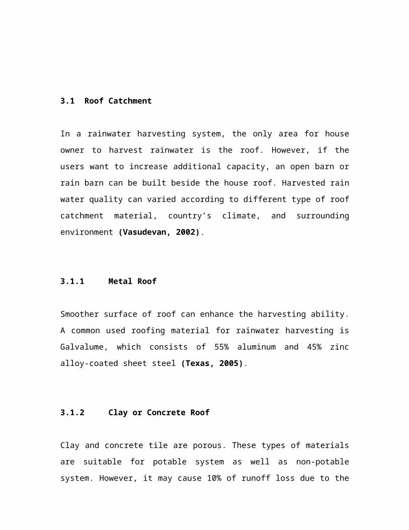
can be used for collecting rainwater. Figure 3.1.1 shows
three different types of roof slope along with their
formulae for roof area calculations (DID, 2012)
(a) Single Sloping Roof Freely Exposed to the Wind
Ac=Ah+Av
2
Eq. 3.1a
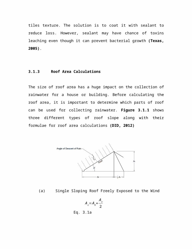
(b) Single Sloping Roof Partially Exposed to the Wind
Ac=Ah+12
(Av2−Av1) Eq.
3.1b
(c) Two Adjacent Sloping Roofs
Ac=Ah1+Ah2+12
(Av2−Av1)
Eq. 3.1c
Figure 3.1.1: Roof Catchment Areas (DID, 2012) 3.2 Gutter and Downpipe
Gutters are used to capture the rainwater running off from
the roof and downpipes are used to deliver the rainwater
into the rainwater storage tank. Inadequate number of
downpipes, excessive long roof length, steep roof slopes,
and less perform gutter maintenance, are among the reasons
of spillage or overrunning of rainwater. Therefore, it is
advisable to consult the gutter supplier for the best
installation.
In allocating potable use water system, gutter and
downpipes cannot use lead material. This is due to slightly
acidic quality of rain could dissolve lead and thus
contaminate the water supply. The most common materials of
gutters for both potable and non-potable systems are PVC,
vinyl, seamless aluminum and galvanized steel (Georgia,
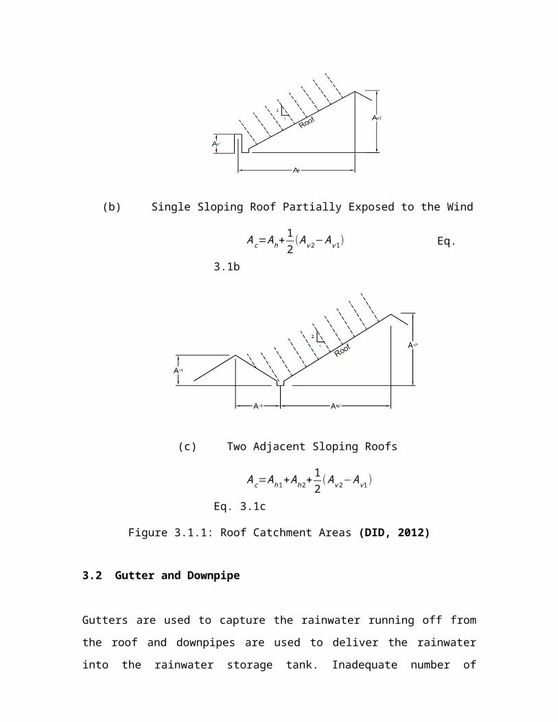
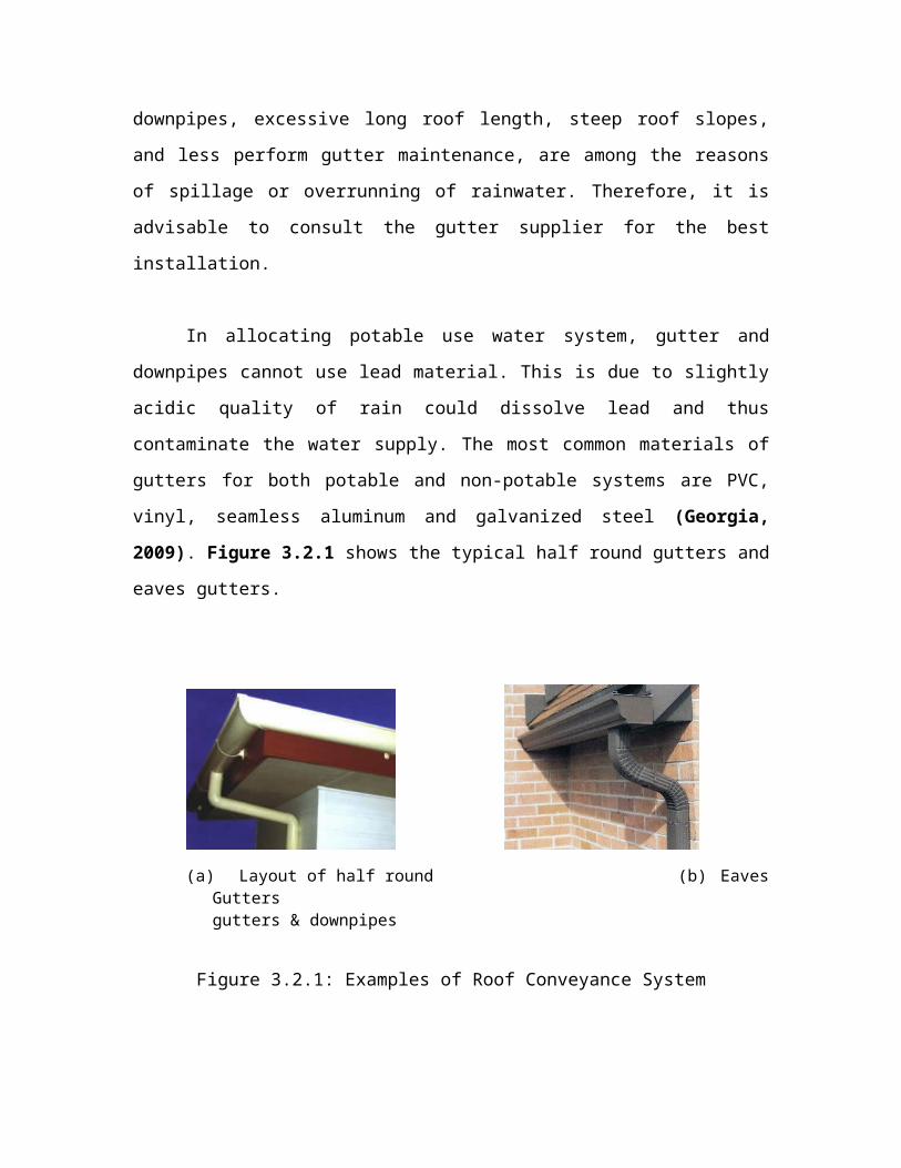
2009). Figure 3.2.1 shows the typical half round gutters and
eaves gutters.
(a) Layout of half round (b) Eaves
Guttersgutters & downpipes
Figure 3.2.1: Examples of Roof Conveyance System
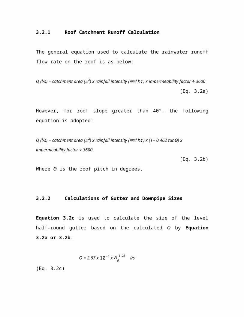
3.2.1 Roof Catchment Runoff Calculation
The general equation used to calculate the rainwater runoff
flow rate on the roof is as below:
Q (l/s) = catchment area (m2) x rainfall intensity (mm/hr) x impermeability factor ÷ 3600
(Eq. 3.2a)
However, for roof slope greater than 40°, the following
equation is adopted:
Q (l/s) = catchment area (m2) x rainfall intensity (mm/hr) x (1+ 0.462 tanϴ) x
impermeability factor ÷ 3600
(Eq. 3.2b)
Where ϴ is the roof pitch in degrees.
3.2.2 Calculations of Gutter and Downpipe Sizes
Equation 3.2c is used to calculate the size of the level
half-round gutter based on the calculated Q by Equation
3.2a or 3.2b:
Q = 2.67 x 10⁻⁵ x Ag1.25 l/s
(Eq. 3.2c)

Where Ag is cross sectional area of the half-round gutter in
mm2.
On the other hand, Equation 3.2d is used to calculate the
size of other shapes of level gutter based on the calculated
Q by Equation 3.2a or 3.2b:
Q = 9.67105 x √ Ao
3
W l/s
(Eq. 3.2d)
Where Ao is the cross sectional area of flow at gutter
outlet in mm2, and W is the width of water surface.
Note:
For 1:600 gradient of gutter, Q is increased by 40%; while
the frictional resistance of gutter can reduce Q by 10% and
each bending can reduce 25% of Q.
Tables 3.2.1a, 3.2.1b, 3.2.2a, 3.2.2b, 3.2.3a and
3.2.3b show the sizes of half round and rectangular gutters
with downpipes calculated based on Equations 3.2a - 3.2d for
various design rainfall intensities of 50-mm/h, 100-mm/h and
150-mm/h. The calculations were based on the assumptions of
(i) roof pitch is 30o; (ii) 1:600 gradient of gutter and Q
is increased by 40%; (iii) the frictional resistance of
gutter can reduce Q by 10%; and (iv) no bending gutter.
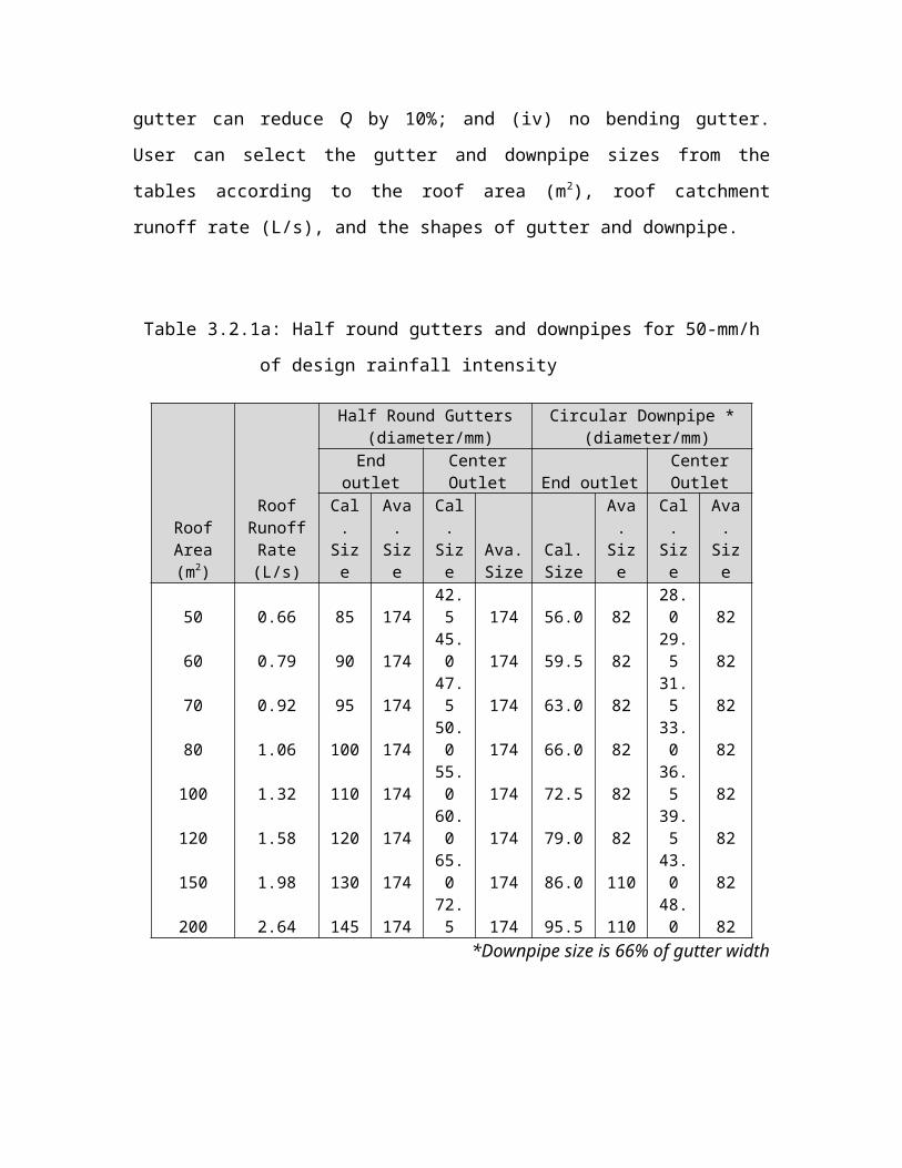
User can select the gutter and downpipe sizes from the
tables according to the roof area (m2), roof catchment
runoff rate (L/s), and the shapes of gutter and downpipe.
Table 3.2.1a: Half round gutters and downpipes for 50-mm/h
of design rainfall intensity
RoofArea(m2)
RoofRunoffRate(L/s)
Half Round Gutters (diameter/mm)
Circular Downpipe * (diameter/mm)
Endoutlet
CenterOutlet End outlet
CenterOutlet
Cal.Size
Ava.Size
Cal.Size
Ava.Size
Cal.Size
Ava.Size
Cal.
Size
Ava.
Size
50 0.66 85 17442.5 174 56.0 82
28.0 82
60 0.79 90 17445.0 174 59.5 82
29.5 82
70 0.92 95 17447.5 174 63.0 82
31.5 82
80 1.06 100 17450.0 174 66.0 82
33.0 82
100 1.32 110 17455.0 174 72.5 82
36.5 82
120 1.58 120 17460.0 174 79.0 82
39.5 82
150 1.98 130 17465.0 174 86.0 110
43.0 82
200 2.64 145 17472.5 174 95.5 110
48.0 82
*Downpipe size is 66% of gutter width
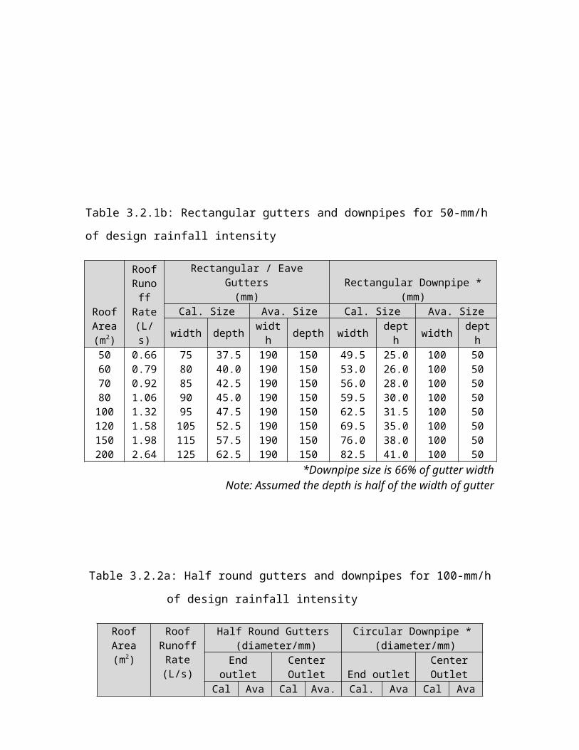
Table 3.2.1b: Rectangular gutters and downpipes for 50-mm/h
of design rainfall intensity
RoofArea(m2)
RoofRunoff
Rate(L/s)
Rectangular / EaveGutters(mm)
Rectangular Downpipe *(mm)
Cal. Size Ava. Size Cal. Size Ava. Size
width depth width depth width dept
h width depth
50 0.66 75 37.5 190 150 49.5 25.0 100 5060 0.79 80 40.0 190 150 53.0 26.0 100 5070 0.92 85 42.5 190 150 56.0 28.0 100 5080 1.06 90 45.0 190 150 59.5 30.0 100 50100 1.32 95 47.5 190 150 62.5 31.5 100 50120 1.58 105 52.5 190 150 69.5 35.0 100 50150 1.98 115 57.5 190 150 76.0 38.0 100 50200 2.64 125 62.5 190 150 82.5 41.0 100 50 *Downpipe size is 66% of gutter width
Note: Assumed the depth is half of the width of gutter
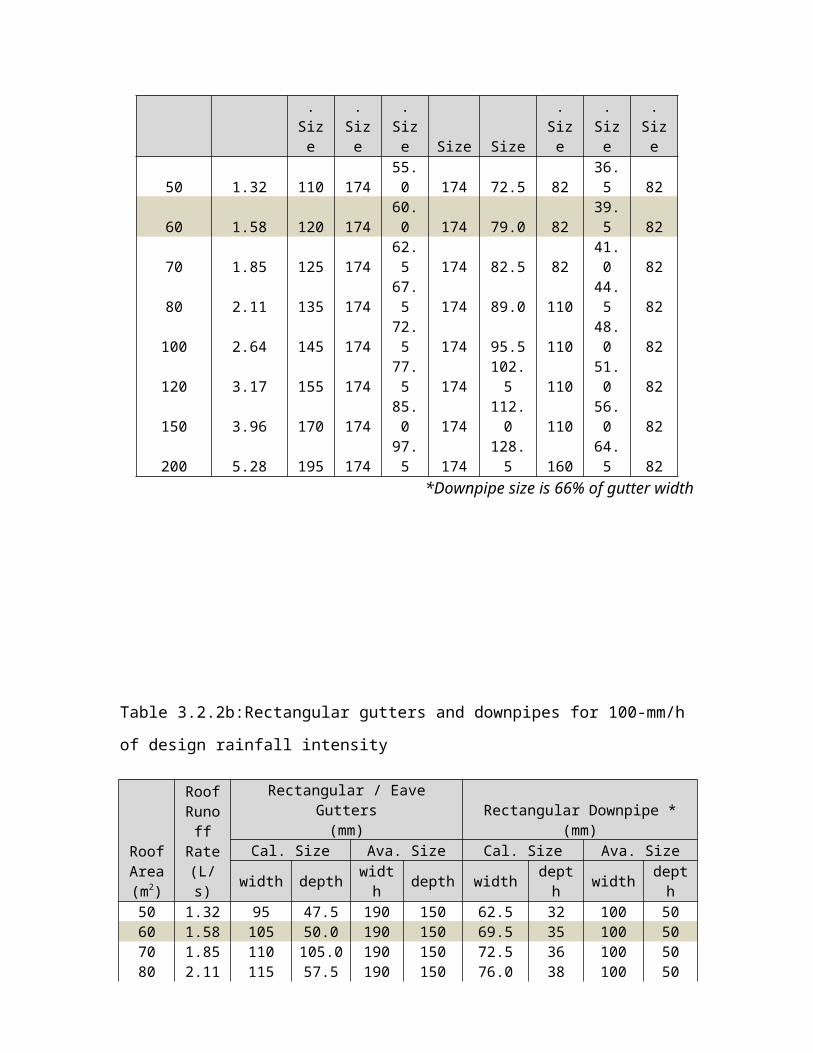
Table 3.2.2a: Half round gutters and downpipes for 100-mm/h
of design rainfall intensity
RoofArea(m2)
RoofRunoffRate(L/s)
Half Round Gutters (diameter/mm)
Circular Downpipe * (diameter/mm)
Endoutlet
CenterOutlet End outlet
CenterOutlet
Cal Ava Cal Ava. Cal. Ava Cal Ava
.Size
.Size
.Size Size Size
.Size
.Size
.Size
50 1.32 110 17455.0 174 72.5 82
36.5 82
60 1.58 120 17460.0 174 79.0 82
39.5 82
70 1.85 125 17462.5 174 82.5 82
41.0 82
80 2.11 135 17467.5 174 89.0 110
44.5 82
100 2.64 145 17472.5 174 95.5 110
48.0 82
120 3.17 155 17477.5 174
102.5 110
51.0 82
150 3.96 170 17485.0 174
112.0 110
56.0 82
200 5.28 195 17497.5 174
128.5 160
64.5 82
*Downpipe size is 66% of gutter width
Table 3.2.2b:Rectangular gutters and downpipes for 100-mm/h
of design rainfall intensity
RoofArea(m2)
RoofRunoff
Rate(L/s)
Rectangular / EaveGutters(mm)
Rectangular Downpipe *(mm)
Cal. Size Ava. Size Cal. Size Ava. Size
width depth width depth width dept
h width depth
50 1.32 95 47.5 190 150 62.5 32 100 5060 1.58 105 50.0 190 150 69.5 35 100 5070 1.85 110 105.0 190 150 72.5 36 100 5080 2.11 115 57.5 190 150 76.0 38 100 50
100 2.64 125 62.5 190 150 82.5 41 100 50120 3.17 135 67.5 190 150 89.0 45 100 50150 3.96 150 75.0 190 150 99.0 50 100 50200 5.28 165 82.5 190 150 109.0 55 120 80 *Downpipe size is 66% of gutter width
Note: Assumed the depth is half of the width of gutter
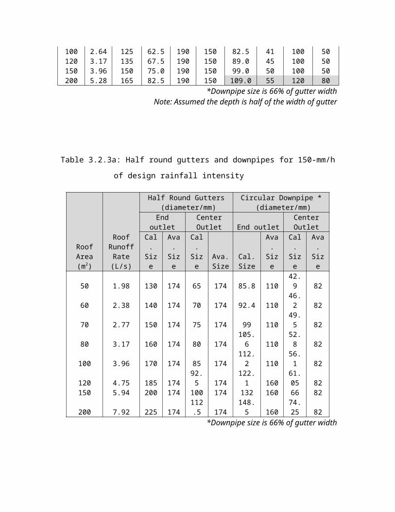
Table 3.2.3a: Half round gutters and downpipes for 150-mm/h
of design rainfall intensity
RoofArea(m2)
RoofRunoffRate(L/s)
Half Round Gutters (diameter/mm)
Circular Downpipe * (diameter/mm)
Endoutlet
CenterOutlet End outlet
CenterOutlet
Cal.
Size
Ava.
Size
Cal.
Size
Ava.Size
Cal.Size
Ava.
Size
Cal.
Size
Ava.
Size
50 1.98 130 174 65 174 85.8 11042.9 82
60 2.38 140 174 70 174 92.4 11046.2 82
70 2.77 150 174 75 174 99 11049.5 82
80 3.17 160 174 80 174105.6 110
52.8 82
100 3.96 170 174 85 174112.2 110
56.1 82
120 4.75 185 17492.5 174
122.1 160
61.05 82
150 5.94 200 174 100 174 132 160 66 82
200 7.92 225 174112.5 174
148.5 160
74.25 82
*Downpipe size is 66% of gutter width
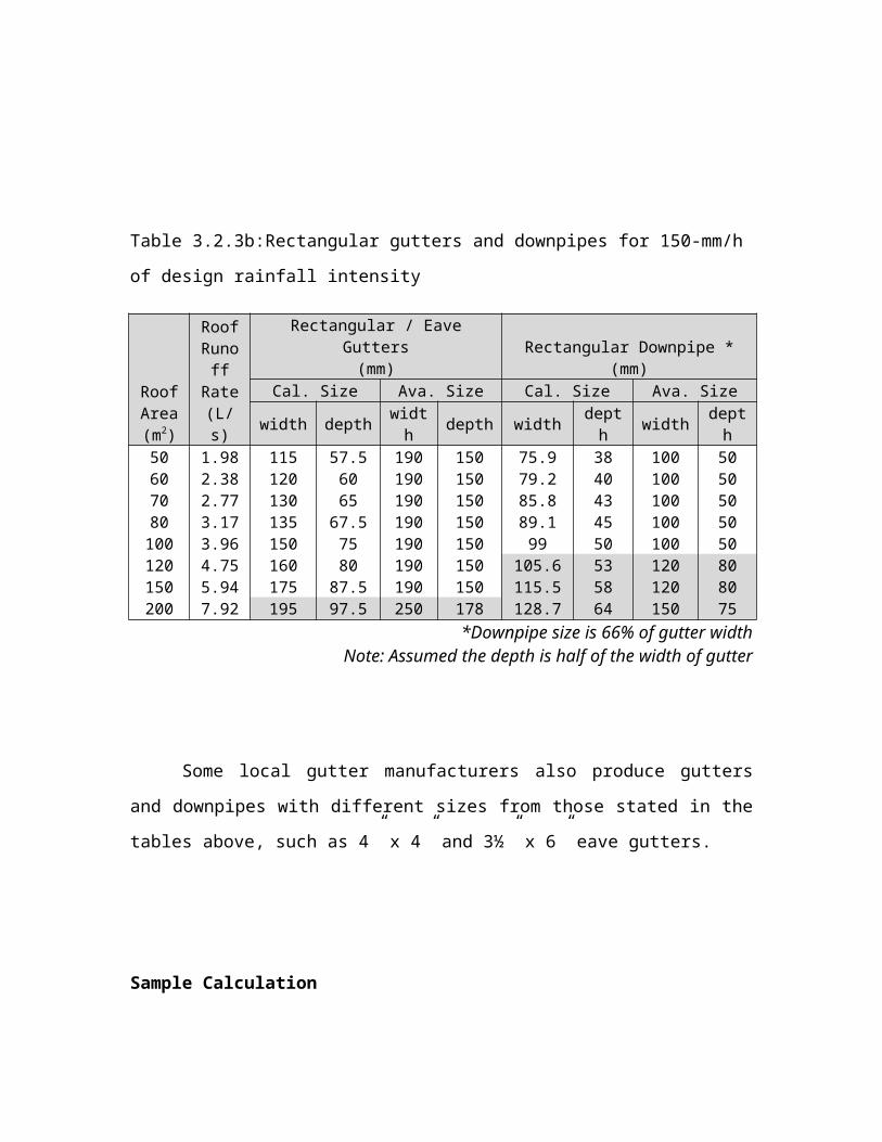
Table 3.2.3b:Rectangular gutters and downpipes for 150-mm/h
of design rainfall intensity
RoofArea(m2)
RoofRunoff
Rate(L/s)
Rectangular / EaveGutters(mm)
Rectangular Downpipe *(mm)
Cal. Size Ava. Size Cal. Size Ava. Size
width depth width depth width dept
h width depth
50 1.98 115 57.5 190 150 75.9 38 100 5060 2.38 120 60 190 150 79.2 40 100 5070 2.77 130 65 190 150 85.8 43 100 5080 3.17 135 67.5 190 150 89.1 45 100 50100 3.96 150 75 190 150 99 50 100 50120 4.75 160 80 190 150 105.6 53 120 80150 5.94 175 87.5 190 150 115.5 58 120 80200 7.92 195 97.5 250 178 128.7 64 150 75 *Downpipe size is 66% of gutter width
Note: Assumed the depth is half of the width of gutter
Some local gutter manufacturers also produce gutters
and downpipes with different sizes from those stated in the
tables above, such as 4” x 4” and 3½” x 6” eave gutters.
Sample Calculation
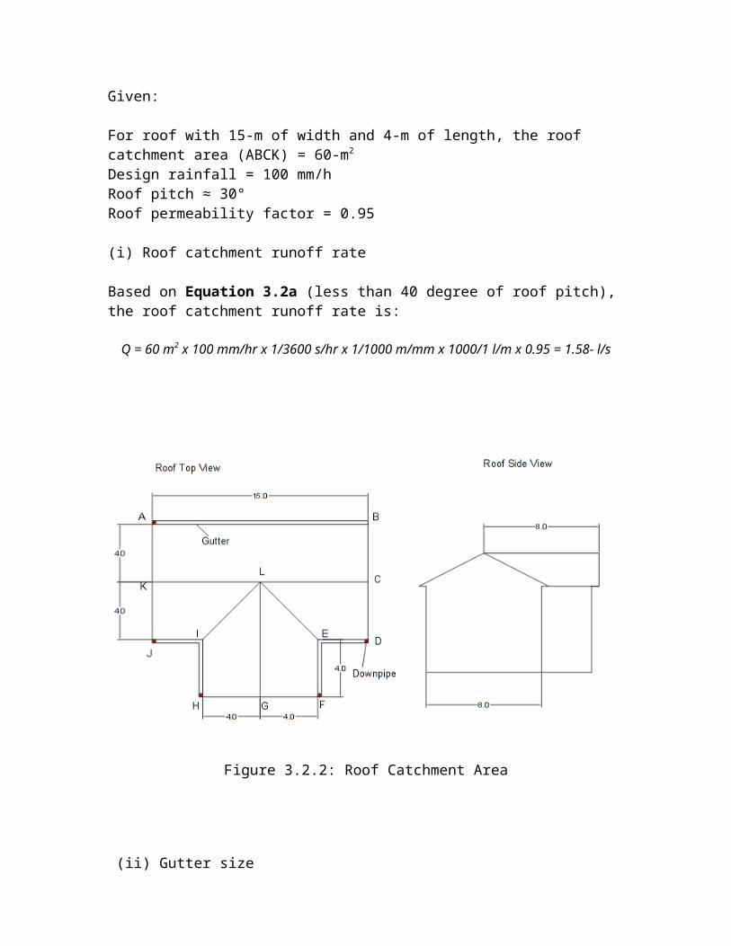
Given:
For roof with 15-m of width and 4-m of length, the roof catchment area (ABCK) = 60-m2
Design rainfall = 100 mm/hRoof pitch ≈ 30°Roof permeability factor = 0.95
(i) Roof catchment runoff rate
Based on Equation 3.2a (less than 40 degree of roof pitch), the roof catchment runoff rate is:
Q = 60 m2 x 100 mm/hr x 1/3600 s/hr x 1/1000 m/mm x 1000/1 l/m x 0.95 = 1.58- l/s
Figure 3.2.2: Roof Catchment Area
(ii) Gutter size
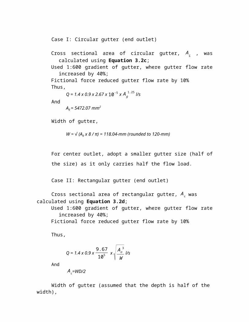
Case I: Circular gutter (end outlet)
Cross sectional area of circular gutter, Ag , wascalculated using Equation 3.2c;
Used 1:600 gradient of gutter, where gutter flow rateincreased by 40%;
Fictional force reduced gutter flow rate by 10%Thus,
Q = 1.4 x 0.9 x 2.67 x 10−5 x Ag1.25 l/s
AndAg = 5472.07 mm2
Width of gutter,
W = (A√ g x 8 / π) = 118.04-mm (rounded to 120-mm)
For center outlet, adopt a smaller gutter size (half of
the size) as it only carries half the flow load.
Case II: Rectangular gutter (end outlet)
Cross sectional area of rectangular gutter, Ao was calculated using Equation 3.2d;
Used 1:600 gradient of gutter, where gutter flow rateincreased by 40%;
Fictional force reduced gutter flow rate by 10%
Thus,
Q = 1.4 x 0.9 x 9.67105
x √ Ao3
W l/s
And Ao=WD/2
Width of gutter (assumed that the depth is half of the width),
1.5833 = 1.4 x 0.9 x 9.67105
x √ W2D3
8 = 1.4 x 0.9 x
9.67105 x √ W5
64
W = 101.56-mm (rounded to 105-mm)
(iii) Downpipe size (for both circular and rectangular gutters)
Assumed to be 66% of gutter width, thus:
Case I:
Circular gutter should adopt 79-mm diameter of downpipefor end outlet design and 39.5-mm diameter of downpipe for center outlet design;
Case II: Rectangular gutter should adopt 69.5-mm width and 35-mmdepth of downpipe
3.2.2.1 MSMA’s Method for Eave Gutter Design
Table 3.2.4 shows the sizes of eave gutters read from Charts
3.2.1 and 3.2.2 from a design rainfall intensity of
100-mm/h. Charts 3.2.1 and 3.2.2 show the relationships
among roof catchment area, design rainfall intensity and
cross sectional area of eave gutter. Finally, Table 3.2.5
shows the respective sizes of downpipes.
Table 3.2.4: Sizes of gutters and downpipes (DID, 2012)
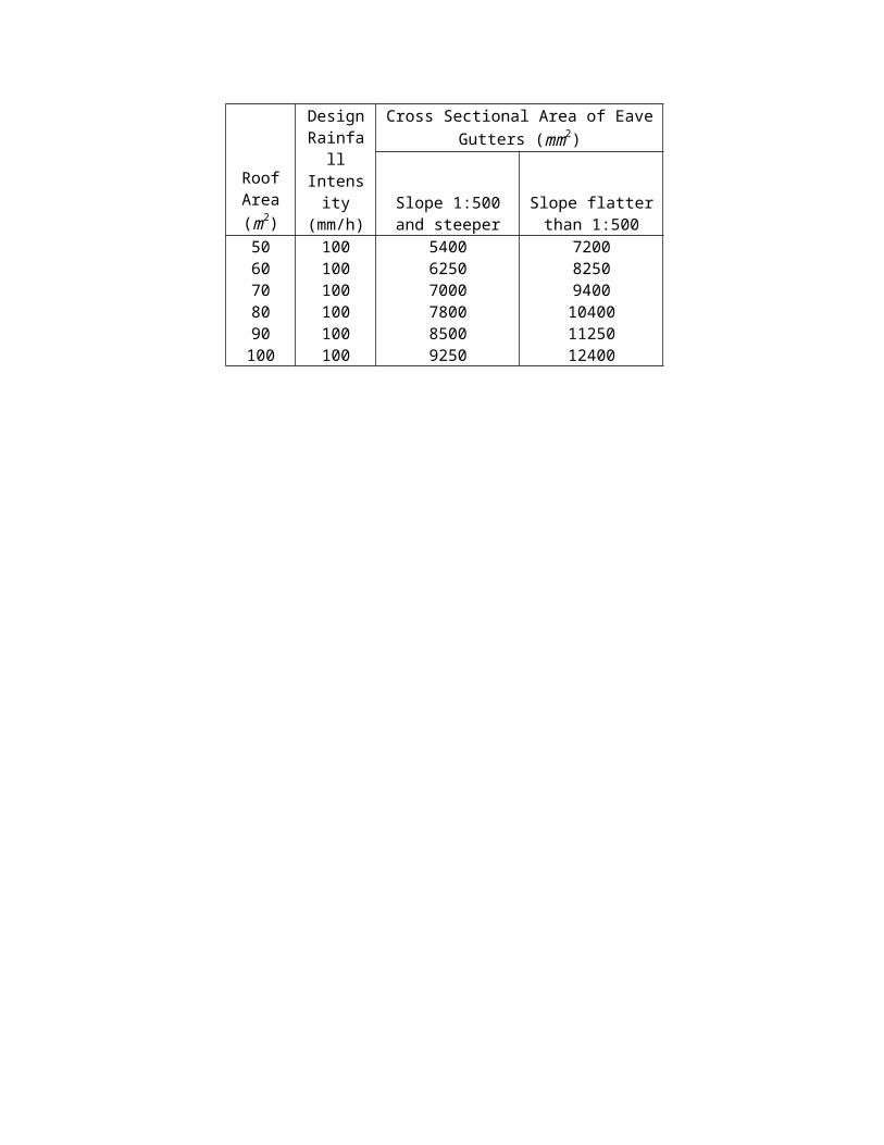
RoofArea(m2)
DesignRainfall
Intensity
(mm/h)
Cross Sectional Area of EaveGutters (mm2)
Slope 1:500and steeper
Slope flatterthan 1:500
50 100 5400 720060 100 6250 825070 100 7000 940080 100 7800 1040090 100 8500 11250100 100 9250 12400
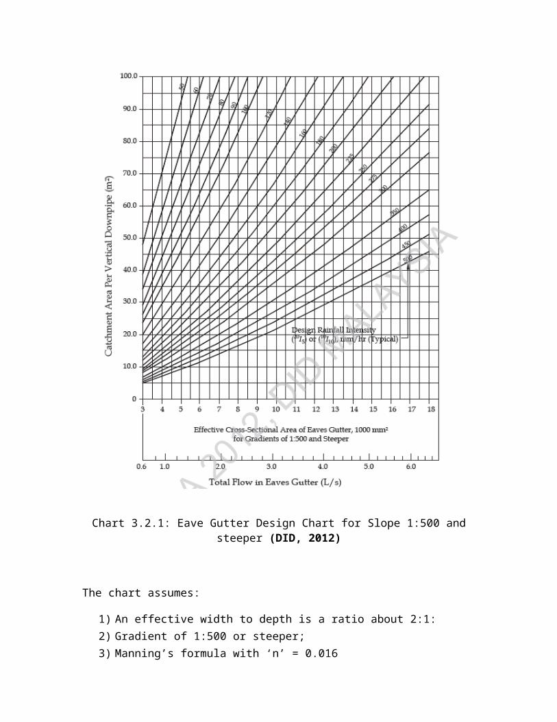
Chart 3.2.1: Eave Gutter Design Chart for Slope 1:500 andsteeper (DID, 2012)
The chart assumes:
1) An effective width to depth is a ratio about 2:1:2) Gradient of 1:500 or steeper;3) Manning’s formula with ‘n’ = 0.016
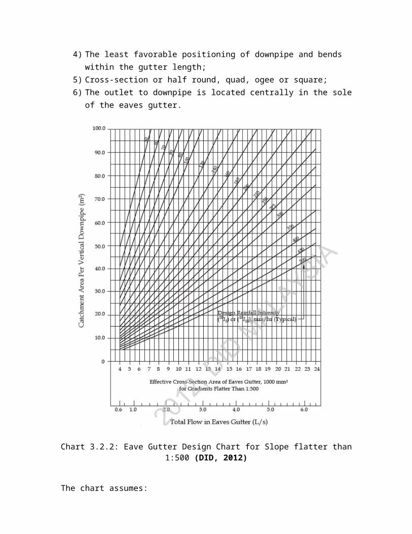
4) The least favorable positioning of downpipe and bends within the gutter length;
5) Cross-section or half round, quad, ogee or square;6) The outlet to downpipe is located centrally in the sole
of the eaves gutter.
Chart 3.2.2: Eave Gutter Design Chart for Slope flatter than1:500 (DID, 2012)
The chart assumes:
1) An effective width to depth is a ratio about 2:1:2) Gradient of flow flatter than 1:500;3) Manning’s formula with ‘n’ = 0.0164) The least favorable positioning of downpipe and bends
within the gutter length;5) Cross-section or half round, quad, ogee or square;6) The outlet to downpipe is located centrally in the sole
of the eaves gutter.
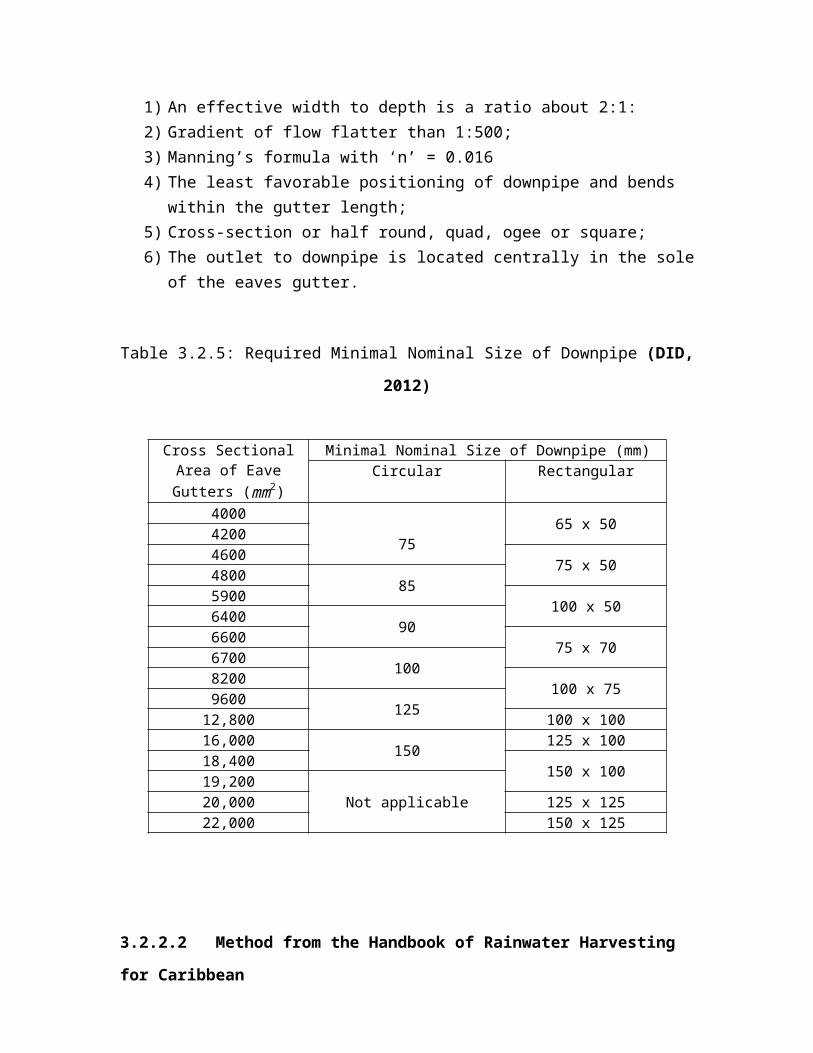
Table 3.2.5: Required Minimal Nominal Size of Downpipe (DID,
2012)
Cross SectionalArea of EaveGutters (mm2)
Minimal Nominal Size of Downpipe (mm)Circular Rectangular
4000
7565 x 504200
4600 75 x 504800 855900 100 x 506400 906600 75 x 706700 1008200 100 x 759600 12512,800 100 x 10016,000 150 125 x 10018,400 150 x 10019,200
Not applicable20,000 125 x 12522,000 150 x 125
3.2.2.2 Method from the Handbook of Rainwater Harvesting
for Caribbean

Caribbean’s Rainwater Harvesting Handbook (UNEP, 2009) was
intended as a practical guideline to introduce and assist
the citizens in the Caribbean region to construct their
rainwater harvesting systems. The handbook provides several
technical information and guidelines that are useful for
tropical region like Malaysia. The rational method was used
to calculate the roof runoff.
Tables 3.2.6a and 3.2.6b show the recommended runoff
coefficients for various catchment types and the sizes of
gutters and downpipes, respectively. Type of gutters
recommended here is PVC gutters since they do not rust and
the rainwater quality can be maintained over a long period.
Gutters must slope towards the tank and the gradient must
not more than 1:100.
Table 3.2.6a: Runoff coefficients for various catchment
types (UNEP, 2009)
Type of Catchment Runoff coefficientsRoof catchmentsTilesCorrugated metal sheets
0.8 – 0.90.7 – 0.9
Ground surface coveringsConcreteBrick pavement
0.6 – 0.80.5 – 0.6
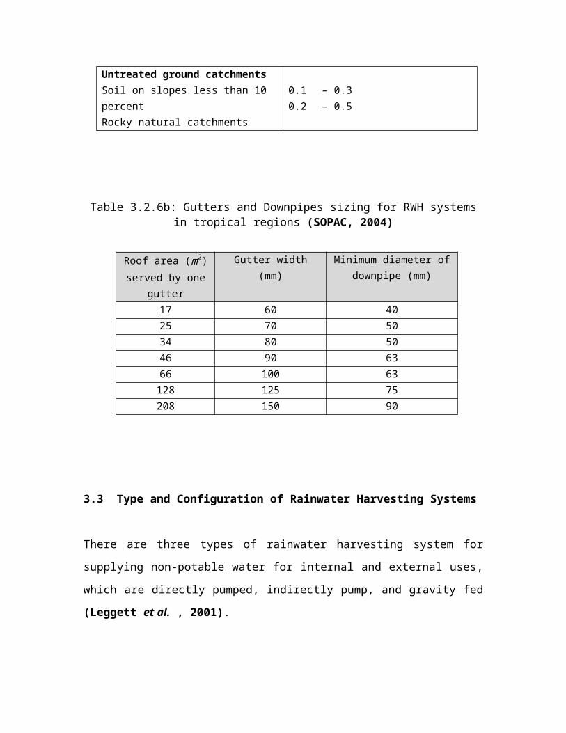
Untreated ground catchmentsSoil on slopes less than 10 percentRocky natural catchments
0.1 – 0.30.2 – 0.5
Table 3.2.6b: Gutters and Downpipes sizing for RWH systemsin tropical regions (SOPAC, 2004)
Roof area (m2)served by one
gutter
Gutter width(mm)
Minimum diameter ofdownpipe (mm)
17 60 4025 70 5034 80 5046 90 6366 100 63128 125 75208 150 90
3.3 Type and Configuration of Rainwater Harvesting Systems
There are three types of rainwater harvesting system for
supplying non-potable water for internal and external uses,
which are directly pumped, indirectly pump, and gravity fed
(Leggett et al. , 2001).
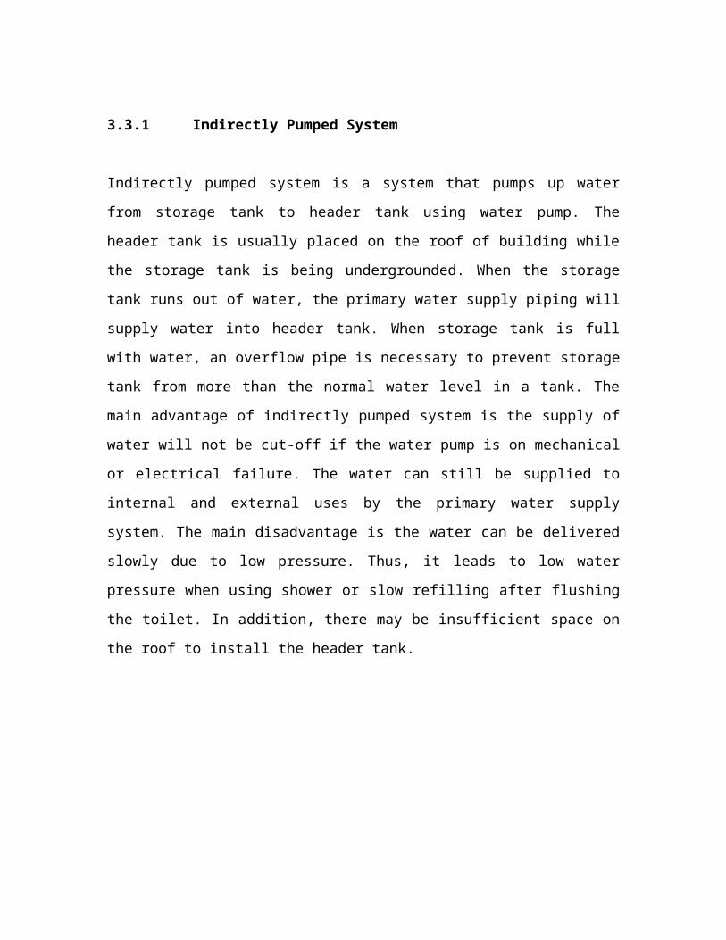
3.3.1 Indirectly Pumped System
Indirectly pumped system is a system that pumps up water
from storage tank to header tank using water pump. The
header tank is usually placed on the roof of building while
the storage tank is being undergrounded. When the storage
tank runs out of water, the primary water supply piping will
supply water into header tank. When storage tank is full
with water, an overflow pipe is necessary to prevent storage
tank from more than the normal water level in a tank. The
main advantage of indirectly pumped system is the supply of
water will not be cut-off if the water pump is on mechanical
or electrical failure. The water can still be supplied to
internal and external uses by the primary water supply
system. The main disadvantage is the water can be delivered
slowly due to low pressure. Thus, it leads to low water
pressure when using shower or slow refilling after flushing
the toilet. In addition, there may be insufficient space on
the roof to install the header tank.
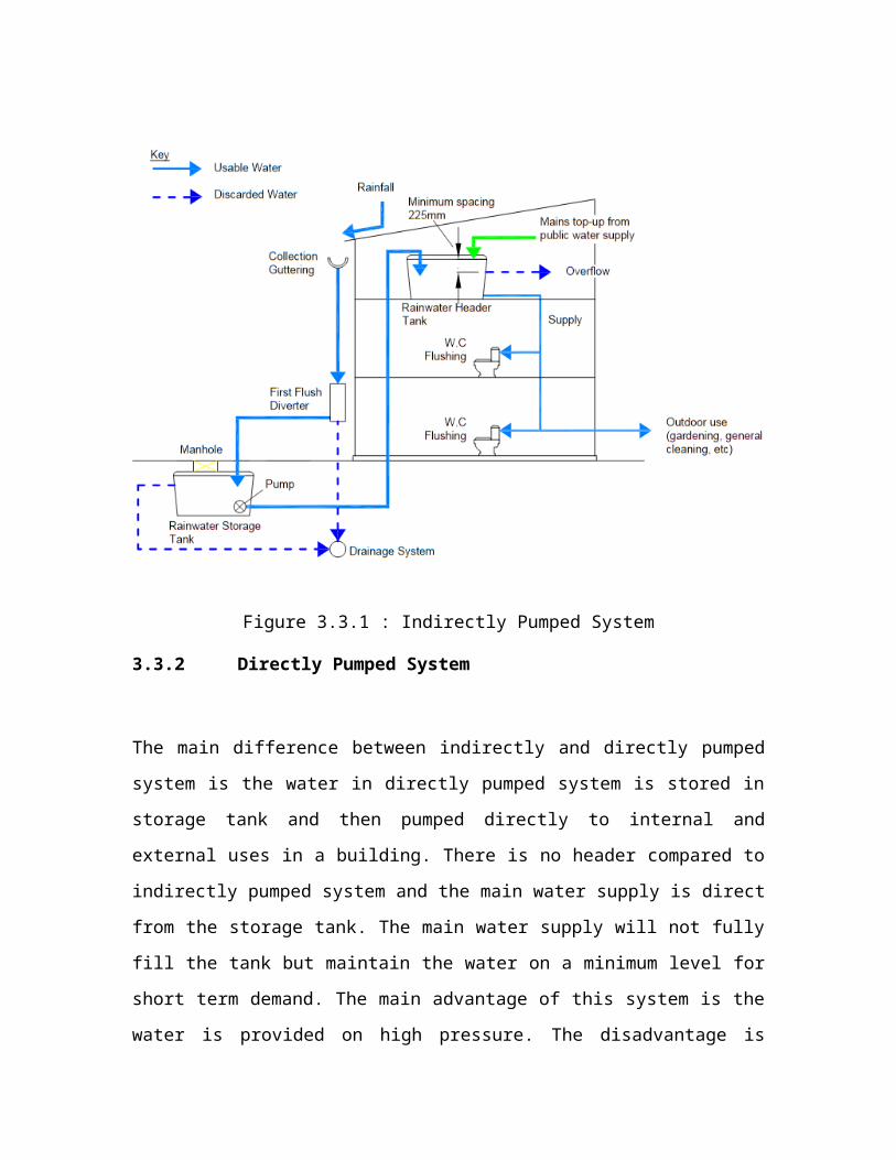
Figure 3.3.1 : Indirectly Pumped System
3.3.2 Directly Pumped System
The main difference between indirectly and directly pumped
system is the water in directly pumped system is stored in
storage tank and then pumped directly to internal and
external uses in a building. There is no header compared to
indirectly pumped system and the main water supply is direct
from the storage tank. The main water supply will not fully
fill the tank but maintain the water on a minimum level for
short term demand. The main advantage of this system is the
water is provided on high pressure. The disadvantage is
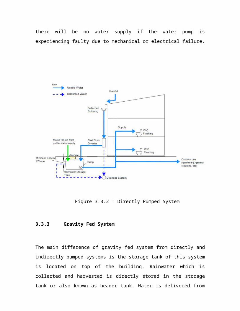
there will be no water supply if the water pump is
experiencing faulty due to mechanical or electrical failure.
Figure 3.3.2 : Directly Pumped System
3.3.3 Gravity Fed System
The main difference of gravity fed system from directly and
indirectly pumped systems is the storage tank of this system
is located on top of the building. Rainwater which is
collected and harvested is directly stored in the storage
tank or also known as header tank. Water is delivered from
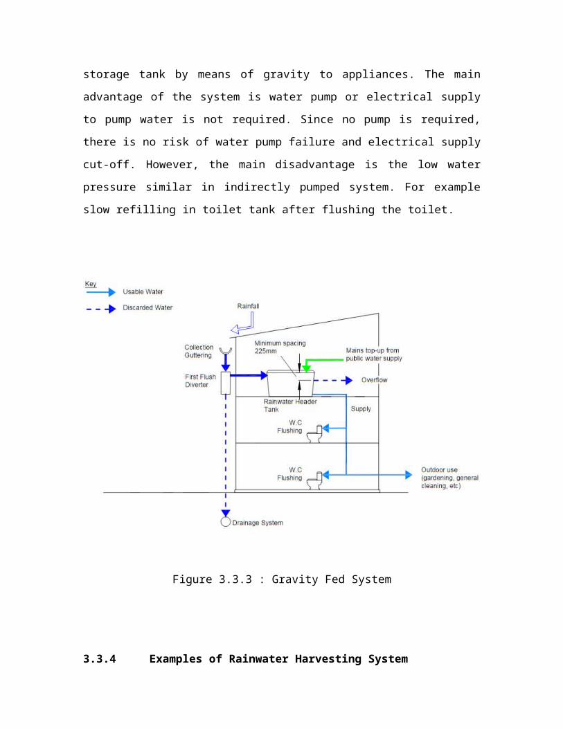
storage tank by means of gravity to appliances. The main
advantage of the system is water pump or electrical supply
to pump water is not required. Since no pump is required,
there is no risk of water pump failure and electrical supply
cut-off. However, the main disadvantage is the low water
pressure similar in indirectly pumped system. For example
slow refilling in toilet tank after flushing the toilet.
Figure 3.3.3 : Gravity Fed System
3.3.4 Examples of Rainwater Harvesting System
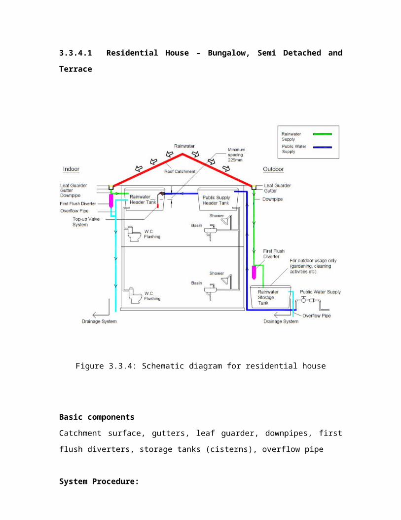
3.3.4.1 Residential House – Bungalow, Semi Detached and
Terrace
Figure 3.3.4: Schematic diagram for residential house
Basic components
Catchment surface, gutters, leaf guarder, downpipes, first
flush diverters, storage tanks (cisterns), overflow pipe
System Procedure:
1) Harvest rainwater from roof;
2) Filter roof dirt through leaf guarder and first flush
diverter;
3) Deliver rainwater using gutter and downpipe;
4) Storing clean rainwater in the storage tanks;
5) In case there is shortage of water or no rainfall, the
public water supply is topped up into the storage
tanks.
3.3.4.2 High Rise Building – Condominium, Commercial and Office Tower
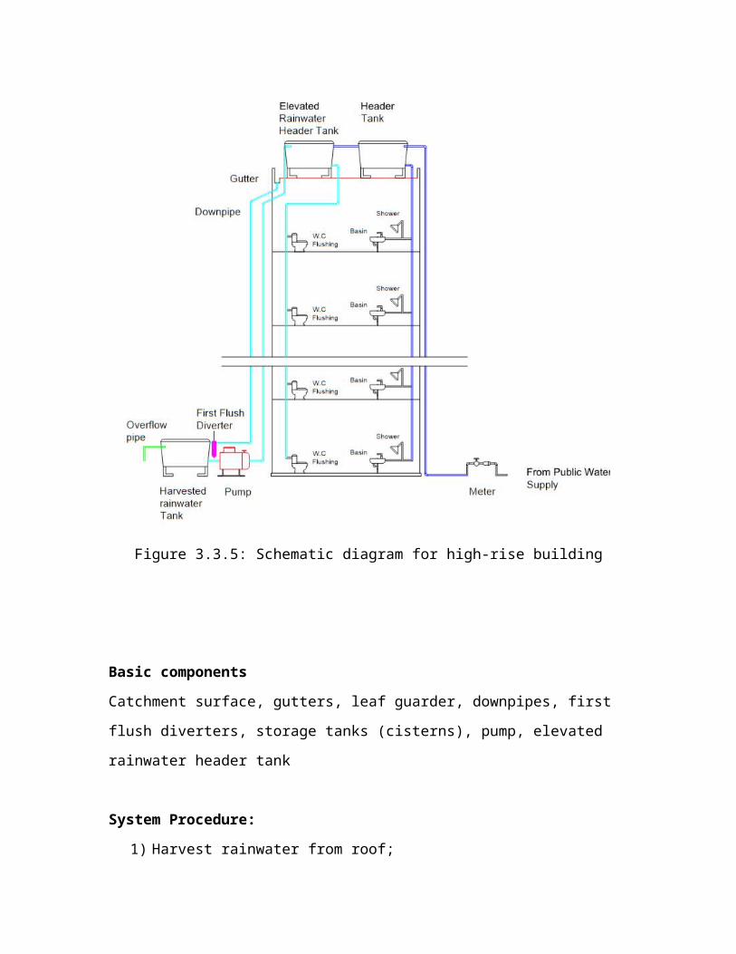
Figure 3.3.5: Schematic diagram for high-rise building
Basic components
Catchment surface, gutters, leaf guarder, downpipes, first
flush diverters, storage tanks (cisterns), pump, elevated
rainwater header tank
System Procedure:
1) Harvest rainwater from roof;

2) Filter roof dirt through leaf guarder and first flush
diverter;
3) Deliver rainwater using gutter and downpipe;
4) Collecting the first flush rainwater before water
entering the storage tank.
5) Storing clean rainwater in the on the ground storage
tank;
6) The pump is used to lift the rainwater up to the
elevated rainwater header tank installed on the roof
top of the high rise building;
7) In case there is shortage of water or no rainfall, the
public water supply is topped up into the elevated
rainwater header tank.
3.4 Pumping System
There are two types of pumping systems, namely pressurized
water supply system and header pressure system. For
pressurized system, pressure tank is required to maintain
the pressure throughout the system. Pump is functioning when
the pressure is drop. For header pressure system, water is
lifted up by the pump from storage tank to elevated tank,
and the water supplies to devices by gravity force (UNEP,
2009).
3.4.1 Selection of Pump
To select an appropriate type of pump for a rainwater
harvesting system, the following five steps must be followed
(Alberta, 2010):
Step I: Select the appropriate pump
Submersible pump and jet pump are the most common types of
pump that used in the residential house. Submersible pump is
located inside the tank and can function properly even fully
submerged inside the water tank; while jet pump is located
outside the tank. Comparisons among submersible pump, jet
pump and centrifugal pump, and their advantages and
disadvantages, are shown in Table 3.4.1.
Step II: Select the configuration of pump (speed of flow
rate)
Two available pump controllers can be selected to configure
the rainwater supply system.
(a) Constant speed pump:
Following a large drop in the system pressure, a
constant speed pump will activate and pump water at a
fixed rate to replenish the volume of water stored in
elevated tank;
(b)Variable Speed Drive (VSD) / Variable Frequency Drive
(VFD) pump:
VSD/VFD pumps can increase or decrease the speed of the
pump impeller to provide more or less water as needed
by the pressure system.
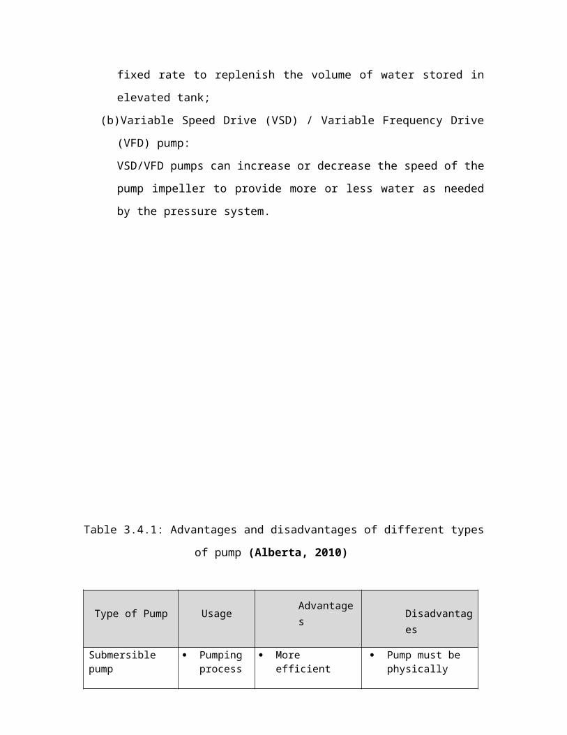
Table 3.4.1: Advantages and disadvantages of different types
of pump (Alberta, 2010)
Type of Pump Usage Advantages Disadvantag
es
Submersible pump
Pumping process
More efficient
Pump must be physically
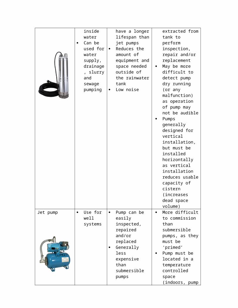
inside water
Can be used forwater supply, drainage, slurryand sewage pumping
have a longerlifespan thanjet pumps
Reduces the amount of equipment andspace needed outside of the rainwatertank
Low noise
extracted fromtank to perform inspection, repair and/or replacement
May be more difficult to detect pump dry running (or any malfunction) as operation of pump may not be audible
Pumps generally designed for vertical installation, but must be installed horizontally as vertical installation reduces usablecapacity of cistern (increases dead space volume)
Jet pump Use for well systems
Pump can be easily inspected, repaired and/or replaced
Generally less expensive than submersible pumps
More difficultto commission than submersible pumps, as theymust be ‘primed’
Pump must be located in a temperature controlled space (indoors, pump
house, etc.) Pump operation
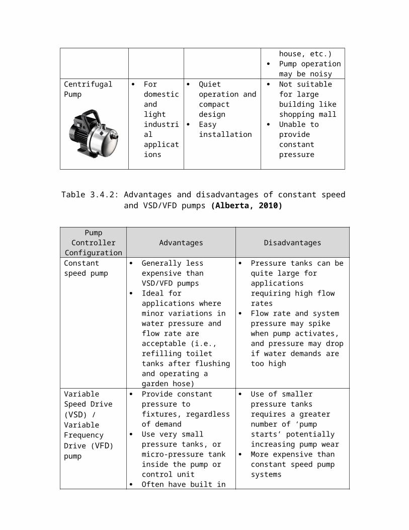
may be noisyCentrifugal Pump
For domesticand light industrial applications
Quiet operation andcompact design
Easy installation
Not suitable for large building like shopping mall
Unable to provide constant pressure
Table 3.4.2: Advantages and disadvantages of constant speedand VSD/VFD pumps (Alberta, 2010)
PumpController
ConfigurationAdvantages Disadvantages
Constant speed pump
Generally less expensive than VSD/VFD pumps
Ideal for applications where minor variations in water pressure and flow rate are acceptable (i.e., refilling toilet tanks after flushingand operating a garden hose)
Pressure tanks can bequite large for applications requiring high flow rates
Flow rate and system pressure may spike when pump activates, and pressure may dropif water demands are too high
Variable Speed Drive (VSD) / Variable Frequency Drive (VFD) pump
Provide constant pressure to fixtures, regardlessof demand
Use very small pressure tanks, or micro-pressure tank inside the pump or control unit
Often have built in
Use of smaller pressure tanks requires a greater number of ‘pump starts’ potentially increasing pump wear
More expensive than constant speed pump systems
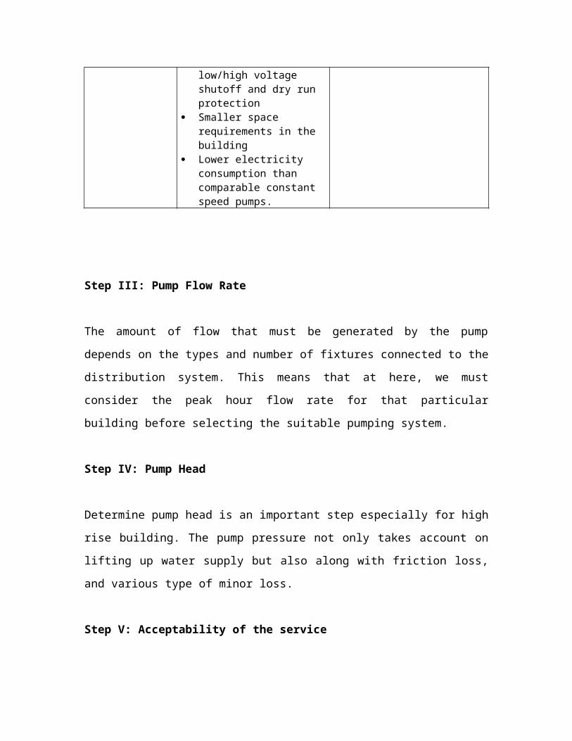
low/high voltage shutoff and dry run protection
Smaller space requirements in the building
Lower electricity consumption than comparable constant speed pumps.
Step III: Pump Flow Rate
The amount of flow that must be generated by the pump
depends on the types and number of fixtures connected to the
distribution system. This means that at here, we must
consider the peak hour flow rate for that particular
building before selecting the suitable pumping system.
Step IV: Pump Head
Determine pump head is an important step especially for high
rise building. The pump pressure not only takes account on
lifting up water supply but also along with friction loss,
and various type of minor loss.
Step V: Acceptability of the service
Last issue to consider is that whether usage of pump is
acceptable for that building. Some of the system may
interrupted by pump downtime. For small residential housing,
several times of service interruption is acceptable. For
multi-residential or commercial buildings, it is important
to avoid pumping service went down at peak hour. The most
common way is to install an elevated tank on top of the
building.
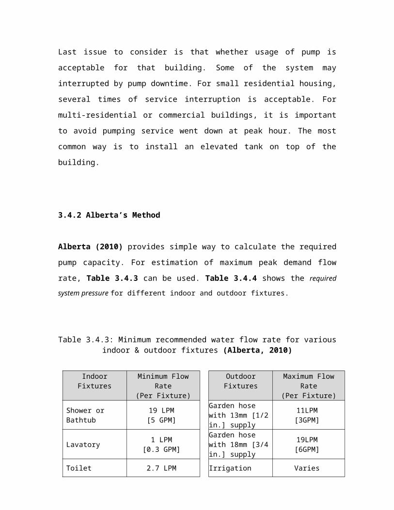
3.4.2 Alberta’s Method
Alberta (2010) provides simple way to calculate the required
pump capacity. For estimation of maximum peak demand flow
rate, Table 3.4.3 can be used. Table 3.4.4 shows the required
system pressure for different indoor and outdoor fixtures.
Table 3.4.3: Minimum recommended water flow rate for variousindoor & outdoor fixtures (Alberta, 2010)
IndoorFixtures
Minimum FlowRate
(Per Fixture)
OutdoorFixtures
Maximum FlowRate
(Per Fixture)
Shower or Bathtub
19 LPM[5 GPM]
Garden hose with 13mm [1/2in.] supply
11LPM[3GPM]
Lavatory 1 LPM[0.3 GPM]
Garden hose with 18mm [3/4in.] supply
19LPM[6GPM]
Toilet 2.7 LPM Irrigation Varies
[0.7 GPM] system(Consultsupplier/
contractor)
Kitchen Sink 1.6 LPM[0.4 GPM]
Washing Machine
19 LPM[5 GPM]
Dishwasher 7.6 LPM[2 GPM]
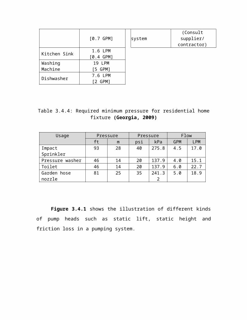
Table 3.4.4: Required minimum pressure for residential homefixture (Georgia, 2009)
Usage Pressure Pressure Flowft m psi kPa GPM LPM
Impact Sprinkler
93 28 40 275.8 4.5 17.0
Pressure washer 46 14 20 137.9 4.0 15.1Toilet 46 14 20 137.9 6.0 22.7Garden hose nozzle
81 25 35 241.32
5.0 18.9
Figure 3.4.1 shows the illustration of different kinds
of pump heads such as static lift, static height and
friction loss in a pumping system.
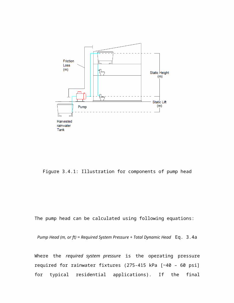
Figure 3.4.1: Illustration for components of pump head
The pump head can be calculated using following equations:
Pump Head (m, or ft) = Required System Pressure + Total Dynamic Head Eq. 3.4a
Where the required system pressure is the operating pressure
required for rainwater fixtures (275-415 kPa [~40 – 60 psi]
for typical residential applications). If the final
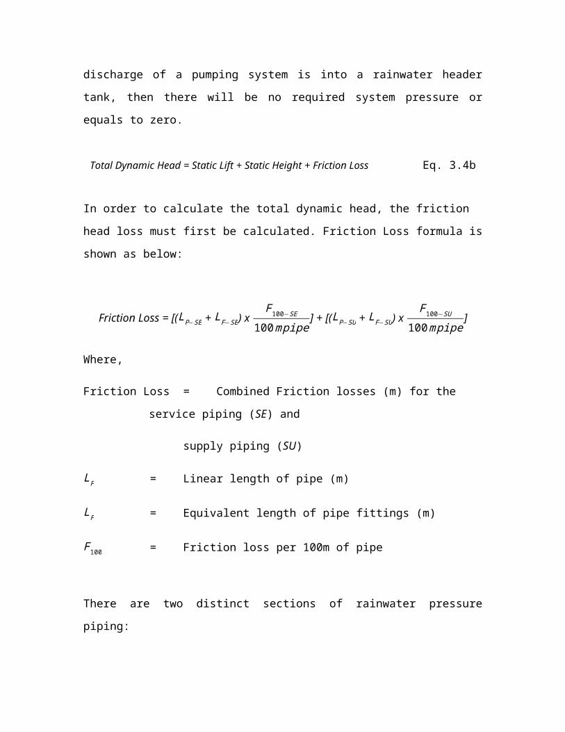
discharge of a pumping system is into a rainwater header
tank, then there will be no required system pressure or
equals to zero.
Total Dynamic Head = Static Lift + Static Height + Friction Loss Eq. 3.4b
In order to calculate the total dynamic head, the friction
head loss must first be calculated. Friction Loss formula is
shown as below:
Friction Loss = [(LP−SE + LF−SE) x F100−SE
100mpipe] + [(LP−SU + LF−SU) x
F100−SU
100mpipe]
Where,
Friction Loss = Combined Friction losses (m) for the
service piping (SE) and
supply piping (SU)
LP = Linear length of pipe (m)
LF = Equivalent length of pipe fittings (m)
F100 = Friction loss per 100m of pipe
There are two distinct sections of rainwater pressure
piping:
1) Rainwater serviced pipe: The section of pipe from
storage tank to a jet pump (or pressure tank/control
unit for submersible pumps)
2) Rainwater supplied pipe: The section of pipe from jet
pump (or pressure tank/control unit for submersible
pumps) to permitted fixtures
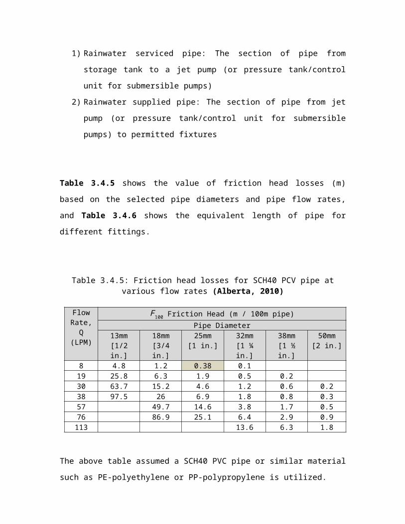
Table 3.4.5 shows the value of friction head losses (m)
based on the selected pipe diameters and pipe flow rates,
and Table 3.4.6 shows the equivalent length of pipe for
different fittings.
Table 3.4.5: Friction head losses for SCH40 PCV pipe atvarious flow rates (Alberta, 2010)
FlowRate,
Q(LPM)
F100 Friction Head (m / 100m pipe)Pipe Diameter
13mm[1/2in.]
18mm[3/4in.]
25mm[1 in.]
32mm[1 ¼in.]
38mm[1 ½in.]
50mm[2 in.]
8 4.8 1.2 0.38 0.119 25.8 6.3 1.9 0.5 0.230 63.7 15.2 4.6 1.2 0.6 0.238 97.5 26 6.9 1.8 0.8 0.357 49.7 14.6 3.8 1.7 0.576 86.9 25.1 6.4 2.9 0.9113 13.6 6.3 1.8
The above table assumed a SCH40 PVC pipe or similar material
such as PE-polyethylene or PP-polypropylene is utilized.
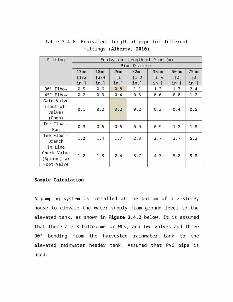
Table 3.4.6: Equivalent length of pipe for differentfittings (Alberta, 2010)
Fitting Equivalent Length of Pipe (m)Pipe Diameter
13mm[1/2in.]
18mm[3/4in.]
25mm[1
in.]
32mm[1 ¼in.]
38mm[1 ½in.]
50mm[2
in.]
75mm[3
in.]90° Elbow 0.5 0.6 0.8 1.1 1.3 1.7 2.445° Elbow 0.2 0.3 0.4 0.5 0.6 0.8 1.2Gate Valve(shut-offvalve)(Open)
0.1 0.2 0.2 0.2 0.3 0.4 0.5
Tee Flow –Run 0.3 0.6 0.6 0.9 0.9 1.2 1.8
Tee Flow –Branch 1.0 1.4 1.7 2.3 2.7 3.7 5.2
In LineCheck Valve(Spring) orFoot Valve
1.2 1.8 2.4 3.7 4.3 5.8 9.8
Sample Calculation
A pumping system is installed at the bottom of a 2-storey
house to elevate the water supply from ground level to the
elevated tank, as shown in Figure 3.4.2 below. It is assumed
that there are 3 bathrooms or WCs, and two valves and three
90° bending from the harvested rainwater tank to the
elevated rainwater header tank. Assumed that PVC pipe is
used.
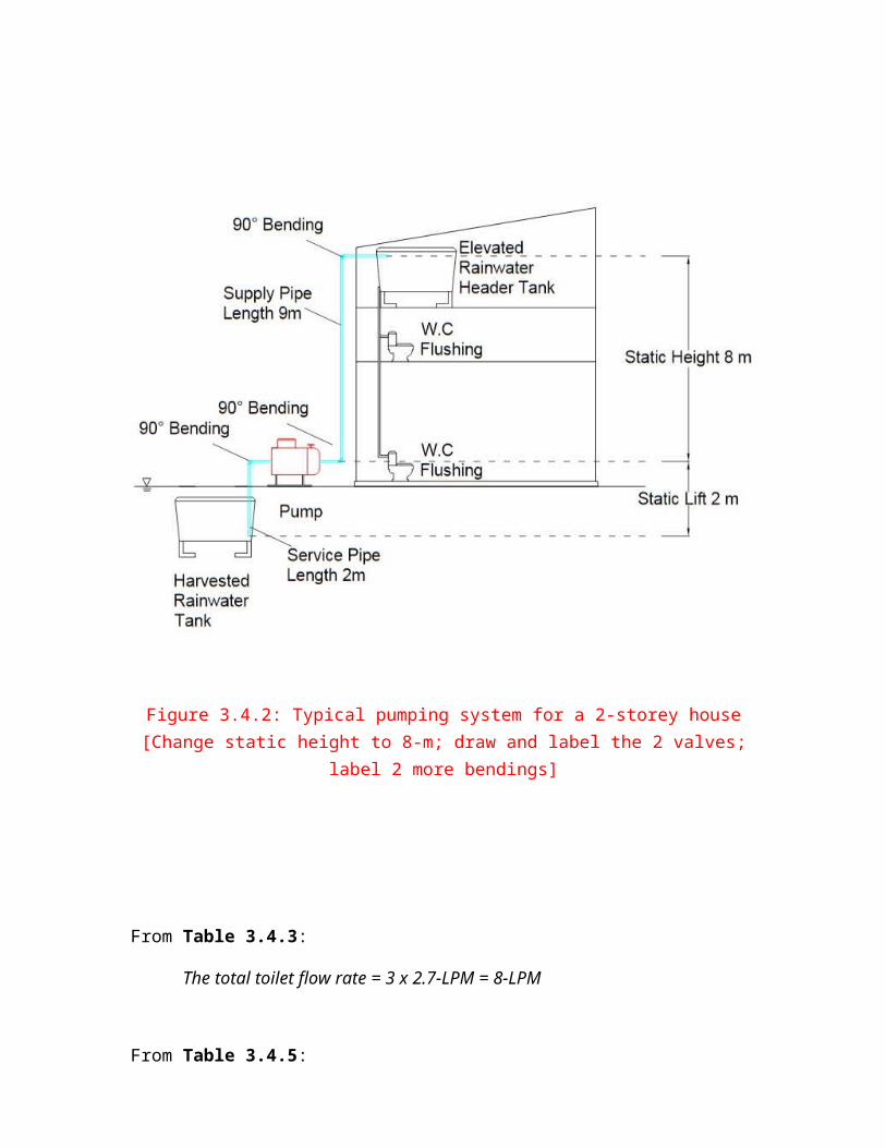
Figure 3.4.2: Typical pumping system for a 2-storey house[Change static height to 8-m; draw and label the 2 valves;
label 2 more bendings]
From Table 3.4.3:
The total toilet flow rate = 3 x 2.7-LPM = 8-LPM
From Table 3.4.5:

For a flow rate of 8-LPM with rainwater serviced pipe and
rainwater supplied pipe sizes of 25mm [1 inch],
F100−SE = 0.38 m /100 m pipe
F100−SU = 0.38 m /100 m pipe
From Table 3.4.6:
For one (1) 90° bending in rainwater serviced pipe and two
(2) 90° bending in rainwater supplied pipe,
Serviced pipe with one 90° bending, LF−SE = 0.8 m
Supplied pipe with two 90° bending, LF−SU = 0.8 x 2 =1.6m
And,
Serviced pipe gate valve, LF−SE=¿ 0.2m
Supplied pipe gate valve, LF−SU=¿ 0.2m
Thus,
Friction Loss = [(LP−SE + LF−SE) x F100−SE
100mpipe] + [(LP−SU + LF−SU) x
F100−SU
100mpipe]
= [(2+(0.8+0.2)) x 0.38
100mpipe ] + [(9+(1.6+0.2)) x 0.38
100mpipe ]
= 0.052-m
Then,
Total Dynamic Head = Static Lift + Static Height + Friction Loss
= 2 + 8 + 0.05244
= 10.052-m
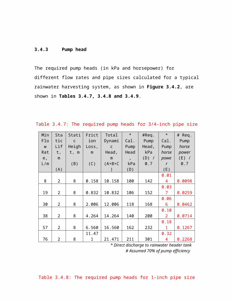
3.4.3 Pump head
The required pump heads (in kPa and horsepower) for
different flow rates and pipe sizes calculated for a typical
rainwater harvesting system, as shown in Figure 3.4.2, are
shown in Tables 3.4.7, 3.4.8 and 3.4.9.
Table 3.4.7: The required pump heads for 3/4-inch pipe size
MinFlow
Rate,L/m
StaticLift,m
(A)
Static
Height, m
(B)
Friction
Loss,m
(C)
TotalDynami
cHead,m
(A+B+C)
*Cal.PumpHead,
kPa(D)
#Req.PumpHead,kPa
(D) /0.7
*Cal.Pumphorsepowe
r(E)
# Req.Pumphorsepower(E) /0.7
8 2 8 0.158 10.158 100 1420.014 0.0098
19 2 8 0.832 10.832 106 1520.037 0.0259
30 2 8 2.006 12.006 118 1680.066 0.0462
38 2 8 4.264 14.264 140 2000.102 0.0714
57 2 8 6.560 16.560 162 2320.181 0.1267
76 2 811.471 21.471 211 301
0.324 0.2268
* Direct discharge to rainwater header tank# Assumed 70% of pump efficiency
Table 3.4.8: The required pump heads for 1-inch pipe size

MinFlowRate,L/m
StaticLift,m
(A)
Static
Height,m
(B)
Friction
Loss,m
(C)
TotalDynami
cHead,m
(A+B+C)
*Cal.PumpHead,
kPa(D)
#Req.PumpHead,kPa
(D) /0.7
*Cal.Pumphorsepower(E)
# Req.Pumphorsepower(E) /0.7
8 2 8 0.052 10.052 99 141 0.01 0.00719 2 8 0.262 10.262 101 144 0.03 0.02130 2 8 0.635 10.635 104 149 0.04 0.02838 2 8 0.952 10.952 107 153 0.06 0.04257 2 8 2.015 12.015 118 168 0.09 0.06376 2 8 3.464 13.464 132 189 0.14 0.098
* Direct discharge to rainwater header tank# Assumed 70% of pump efficiency
Table 3.4.9: The required pump heads for 1 1/4 -inch pipesize
MinFlowRate,L/m
StaticLift, m
(A)
Static
Height, m
(B)
Friction
Loss,m
(C)
TotalDynami
cHead,m
(A+B+C)
*Cal.PumpHead,
kPa(D)
#Req.PumpHead,kPa
(D) /0.7
*Cal.Pumphorsepower(E)
# Req.Pumphorsepower(E) /0.7
8 2 8 0.015 10.015 98 140 0.01 0.00719 2 8 0.074 10.074 99 141 0.03 0.02130 2 8 0.176 10.176 100 143 0.05 0.03538 2 8 0.380 10.380 102 145 0.07 0.04957 2 8 0.559 10.559 104 148 0.11 0.07776 2 8 0.941 10.941 107 153 0.15 0.105113 2 8 2.000 12.000 118 168 0.25 0.175
* Direct discharge to rainwater header tank# Assumed 70% of pump efficiency
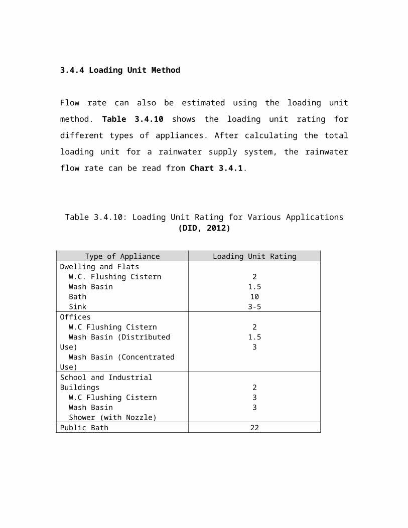
3.4.4 Loading Unit Method
Flow rate can also be estimated using the loading unit
method. Table 3.4.10 shows the loading unit rating for
different types of appliances. After calculating the total
loading unit for a rainwater supply system, the rainwater
flow rate can be read from Chart 3.4.1.
Table 3.4.10: Loading Unit Rating for Various Applications(DID, 2012)
Type of Appliance Loading Unit RatingDwelling and Flats W.C. Flushing Cistern Wash Basin Bath Sink
21.5103-5
Offices W.C Flushing Cistern Wash Basin (Distributed Use) Wash Basin (Concentrated Use)
21.53
School and Industrial Buildings W.C Flushing Cistern Wash Basin Shower (with Nozzle)
233
Public Bath 22
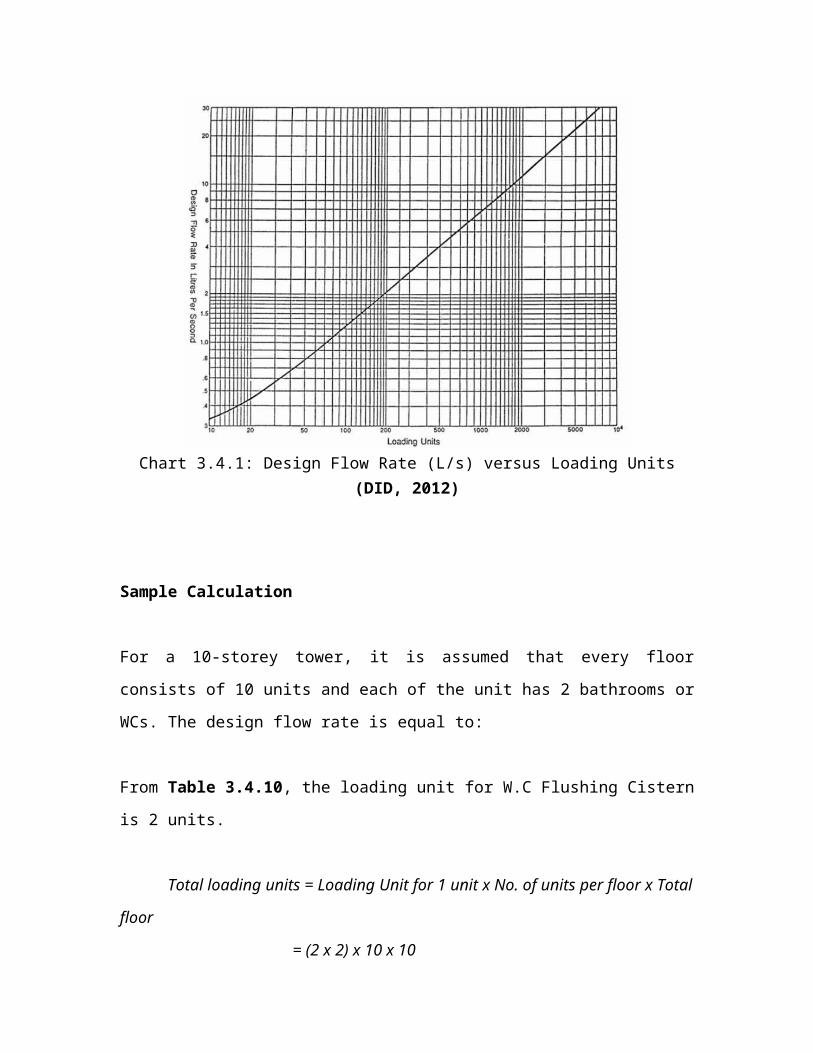
Chart 3.4.1: Design Flow Rate (L/s) versus Loading Units(DID, 2012)
Sample Calculation
For a 10-storey tower, it is assumed that every floor
consists of 10 units and each of the unit has 2 bathrooms or
WCs. The design flow rate is equal to:
From Table 3.4.10, the loading unit for W.C Flushing Cistern
is 2 units.
Total loading units = Loading Unit for 1 unit x No. of units per floor x Total
floor
= (2 x 2) x 10 x 10
= 400-units
From Chart 3.4.1:
Q = 3.51-l/s = 0.00351- m3/s
3.5 Top-up System
There is always a time when there is insufficient of
rainwater to meet the demand. In this situation, it is
necessary to have another alternative water supply for the
water supply system. Top-up device can be used to solve this
problem. When the water level inside the rainwater tank is
getting lower, the top up system will start filling up the
rainwater tank by transferring water from the public water
supply.
Rainwater must not flow into the public water supply
system. Water from the public water supply can flow into the
rainwater tank subjected to it being equipped with a one-way
non return valve, or the overflow pipe in the rainwater tank
is located at least 225-mm lower from the inlet pipe to the
rainwater tank (Selangor, 2012).
3.5.1 Types of Top-up System

There are various types of top-up system available for the
rainwater supply system. It is advisable to select the top-
up system wisely to avoid overflow, storage run down or
extra expense for unnecessary system. Basically, there are
two types of top-up systems namely automatic top-up system
and manual top-up system. Table 3.5.1 shows the advantages
and disadvantages of automatic top-up system and manual top-
up system.
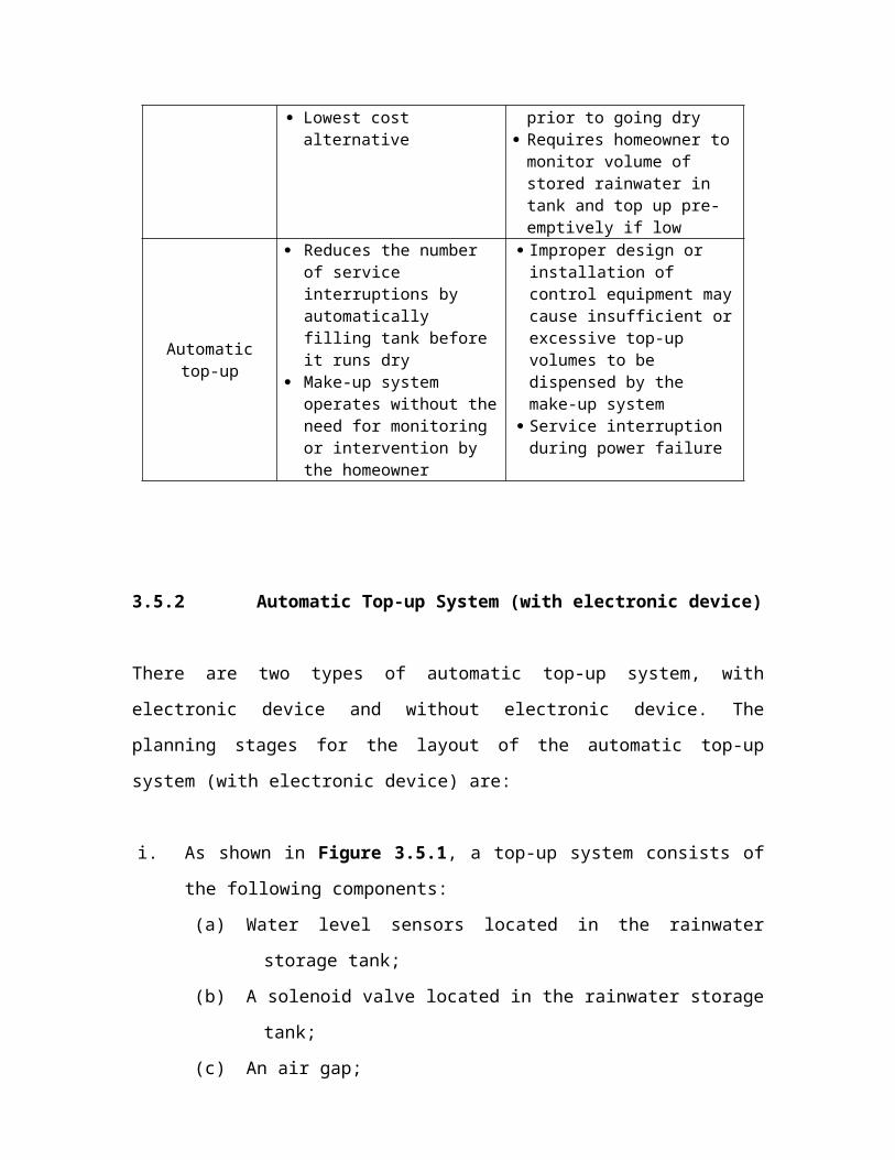
Table 3.5.1: Advantages and disadvantages of top-up systems
(Canada, 2012)
Make-upwater method Advantages Disadvantages
Manual top-up
Simplest method to design and install due to reduced control equipment requirements
May result in serviceinterruptions (for example, no water forflushing toilets) if tank not topped up
Lowest cost alternative
prior to going dry Requires homeowner tomonitor volume of stored rainwater in tank and top up pre-emptively if low
Automatictop-up
Reduces the number of service interruptions by automatically filling tank before it runs dry
Make-up system operates without theneed for monitoring or intervention by the homeowner
Improper design or installation of control equipment maycause insufficient orexcessive top-up volumes to be dispensed by the make-up system
Service interruption during power failure
3.5.2 Automatic Top-up System (with electronic device)
There are two types of automatic top-up system, with
electronic device and without electronic device. The
planning stages for the layout of the automatic top-up
system (with electronic device) are:
i. As shown in Figure 3.5.1, a top-up system consists of
the following components:
(a) Water level sensors located in the rainwater
storage tank;
(b) A solenoid valve located in the rainwater storage
tank;
(c) An air gap;
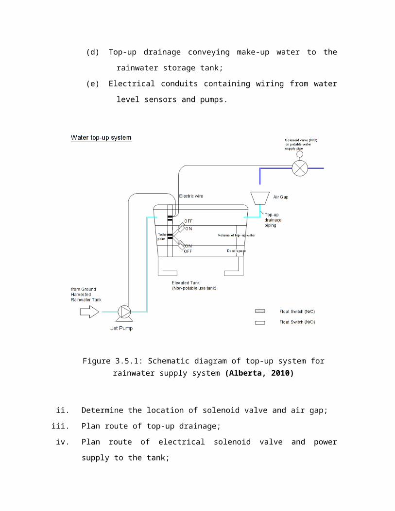
(d) Top-up drainage conveying make-up water to the
rainwater storage tank;
(e) Electrical conduits containing wiring from water
level sensors and pumps.
Figure 3.5.1: Schematic diagram of top-up system forrainwater supply system (Alberta, 2010)
ii. Determine the location of solenoid valve and air gap;
iii. Plan route of top-up drainage;
iv. Plan route of electrical solenoid valve and power
supply to the tank;

v. Contact municipality and other service providers to
ensure that the planning layout do not conflict with
the current building systems like sewerage, piping,
electricity, building structures, etc.
3.5.2.1 Control Equipment
The control equipment is shown in Table 3.5.2 below:
Table 3.5.2: Control equipment (Canada, 2012)
Controlequipment
Description Devices/optionsavailable
Water level sensor
A device inside the tank is used to sense water level
Can control (turn onor off) warning lights, solenoid valves and/or pumps,based on water level
Float switch Ultrasonic level
sensor Liquid levels
switch (Float switch is typicallyused for residential applications).
Shut-off valve
A device that is manually opened (or closed) to permit (or prevent) the flow of water
Integrated into the RWH pressure system to manage water flowand isolate components of the makeup system (for example, solenoid valves and backflow preventers)
Types: ball valves,gate valves
Shut-off valves selected must be approved for handlingwater under pressure.
Solenoid A valve that Come in a variety of
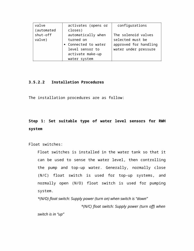
valve (automated shut-off valve)
activates (opens or closes) automatically when turned on
Connected to water level sensor to activate make-up water system
configurations
The solenoid valves selected must be approved for handlingwater under pressure
3.5.2.2 Installation Procedures
The installation procedures are as follow:
Step 1: Set suitable type of water level sensors for RWH
system
Float switches:
Float switches is installed in the water tank so that it
can be used to sense the water level, then controlling
the pump and top-up water. Generally, normally close
(N/C) float switch is used for top-up systems, and
normally open (N/O) float switch is used for pumping
system.
*(N/O) float switch: Supply power (turn on) when switch is “down”
*(N/C) float switch: Supply power (turn off) when
switch is in “up”
Other water level sensors should be selected properly and
installation procedure should be handled carefully with
applicable codes & regulations.
Step 2: Installation of solenoid valves and shut-off valves
(a) Select suitable valves type
(b) Valve size must be the same size as piping system.
(c) Top-up systems use an (N/C) solenoid valve.
(d) Solenoid valve should be installed on the top of the
air gap and soft close/slow close solenoid is
recommended.
(e) Solenoid valves must be wired into a power supply in
conjunction with water level sensor.
(f) Must be installed by a licensed plumber or
technician.
(g) If soft/slow close valve is not used, a water hammer
arrester shall be installed on public water supply
piping upstream.
(h) All procedure should handle with care with applicable
codes & regulations.
Step 3: Installation of Air Gap
Air gap is required to prevent backflow. It needs to be
noted that rainwater cannot be mixed with the public water
supply)
(a) The air gap height must be at least 25-mm, 1-inch or
twice the diameter of water pipe.
(b) To prevent splash and water damage:
i. install flow restrictor at upstream of valve
ii. install aerator at place public water supply
terminate
iii. extend length of pipe and cut an angle no less
than 45° at end pipe
(c) All procedure should handle with care with applicable
codes & regulations
3.5.3 Automatic Top-up System (without electronic device)
Top-up valve, as shown in Figure 3.5.2, can effectively
maintain supply when demand exceeds the rainwater supply and
it does not require electricity supply or complex float
switch devices.
3.5.3.1 Operating Principle
Under normal conditions, rainwater will fill the tank. If
the rainwater level drops below a pre-set level, the top-up
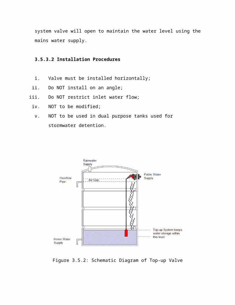
system valve will open to maintain the water level using the
mains water supply.
3.5.3.2 Installation Procedures
i. Valve must be installed horizontally;
ii. Do NOT install on an angle;
iii. Do NOT restrict inlet water flow;
iv. NOT to be modified;
v. NOT to be used in dual purpose tanks used for
stormwater detention.
Figure 3.5.2: Schematic Diagram of Top-up Valve
3.6 Leaf Guarder
Leaf guarder, which is also known as leaf screen or gutter
guarder, fit along the length of the gutter. It is one of
the filter components at the pre-treatment stage of the
rainwater harvesting system. It is usually a ¼-inch mesh
screens in wire frames. They do come in aluminium, plastics
and vinyl for user’s requirement.
Purpose of installing leaf guarder is to separate the
leaves and other debris those are washed down from the roof

catchment surface. The leaf guarder is said to be the first
stage filtration that screen out the large particles such as
leaves, bloom and twigs in the collected rainwater. Through
removing the large particles, the subsequent components and
devices in the rainwater harvesting system are said to be
protected as accumulation of the large particles in the
system may deteriorate the quality of the rainwater. Simple
maintenance is required to clean the leaf guarder regularly.
Decomposition of the leaves and other debris may expand the
bacteria activities and cause harmful consequences to the
rainwater collected. Maintenance may be operated weekly or
monthly depend on the debris accumulation speed.
In Malaysia, according to KPKT (2009), an ordinary net
mesh or stainless mesh can be used at roof drain and gutter.
It is suggested by the manual that installation of the leaf
guarder shall adopt a net or screen mesh of 2 to 10-mm is
satisfactory, as shown in Figure 3.6.1.
Figure 3.6.1: Net of gutter (KPKT, 2009)

3.6.1 Types of Leaf Guarder
There are numerous types of leaf guarders available in the
local and overseas market. It is noted that installation of
gutter leaf guarder depends on the size of the gutter.
Figure 3.6.2 shows some examples of leaf guarder available
in local and overseas.
Some of the available materials include powder coated
steel, Stainless steel, black rubberized vinyl, industrial
strength nylon, High Density Industrial Strength
Polyethylene (HDPE) and aluminum.
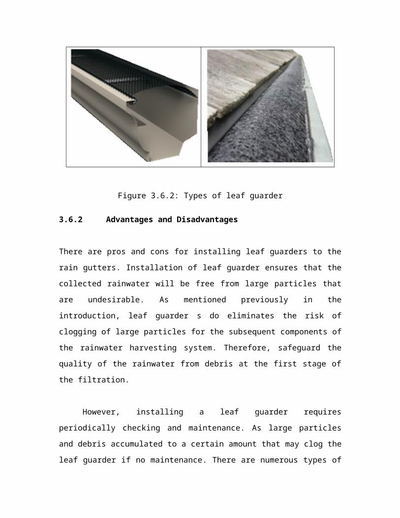
Figure 3.6.2: Types of leaf guarder
3.6.2 Advantages and Disadvantages
There are pros and cons for installing leaf guarders to the
rain gutters. Installation of leaf guarder ensures that the
collected rainwater will be free from large particles that
are undesirable. As mentioned previously in the
introduction, leaf guarder s do eliminates the risk of
clogging of large particles for the subsequent components of
the rainwater harvesting system. Therefore, safeguard the
quality of the rainwater from debris at the first stage of
the filtration.
However, installing a leaf guarder requires
periodically checking and maintenance. As large particles
and debris accumulated to a certain amount that may clog the
leaf guarder if no maintenance. There are numerous types of

leaf guarders available in the market currently, as shown in
Figure 3.6.2, which can overcome these disadvantages.
3.7 First Flush System
Rainwater is one of the purest forms of water and is
initially clean to be used. When it rains, rainwater wash
down from roof where contamination occurs. The rainwater may
collect certain amount of undesirable matters from the roof
such as fecal matter, dead animal bodies, chemical residues,
sediments, bacteria and etc. This rainwater is also known as
first flush water. Therefore, a first flush diverter is
necessary to carry out this first stage filtration. When the
first flush water is removed, bacterial activities from
fecal bacteria and other water borne bacteria would be
greatly reduced. Therefore rainwater harvested in the system
is generally cleaner and safer to be used.
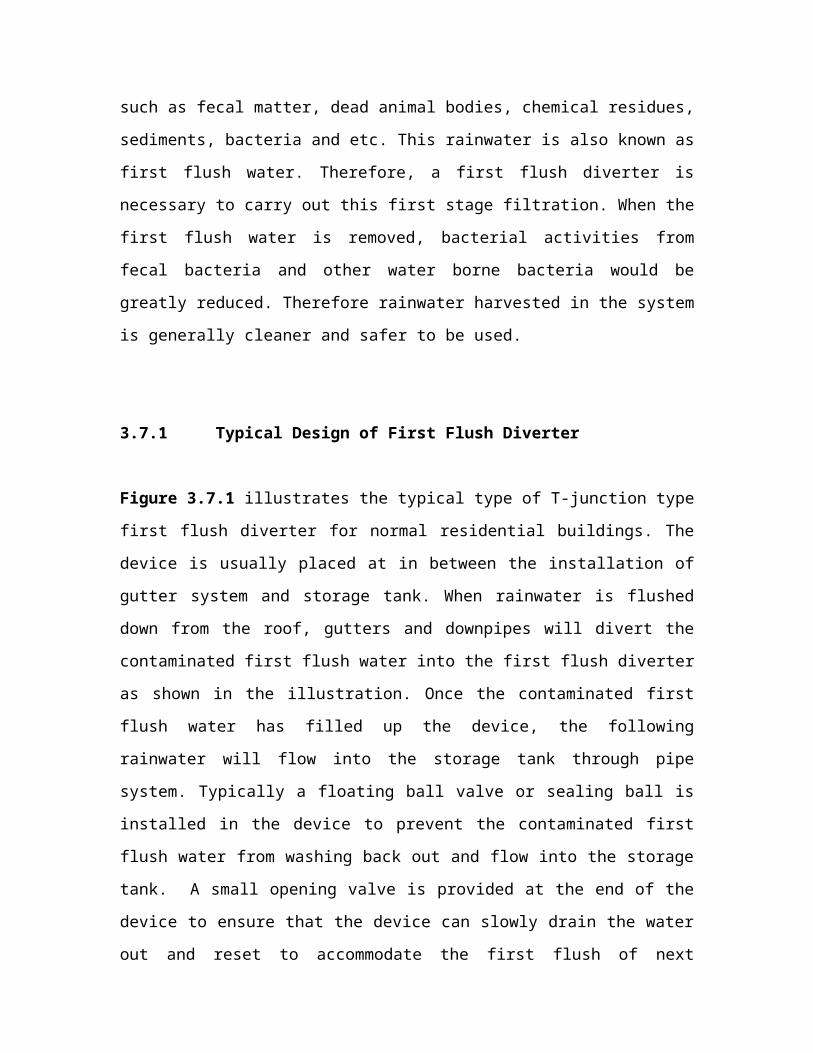
3.7.1 Typical Design of First Flush Diverter
Figure 3.7.1 illustrates the typical type of T-junction type
first flush diverter for normal residential buildings. The
device is usually placed at in between the installation of
gutter system and storage tank. When rainwater is flushed
down from the roof, gutters and downpipes will divert the
contaminated first flush water into the first flush diverter
as shown in the illustration. Once the contaminated first
flush water has filled up the device, the following
rainwater will flow into the storage tank through pipe
system. Typically a floating ball valve or sealing ball is
installed in the device to prevent the contaminated first
flush water from washing back out and flow into the storage
tank. A small opening valve is provided at the end of the
device to ensure that the device can slowly drain the water
out and reset to accommodate the first flush of next
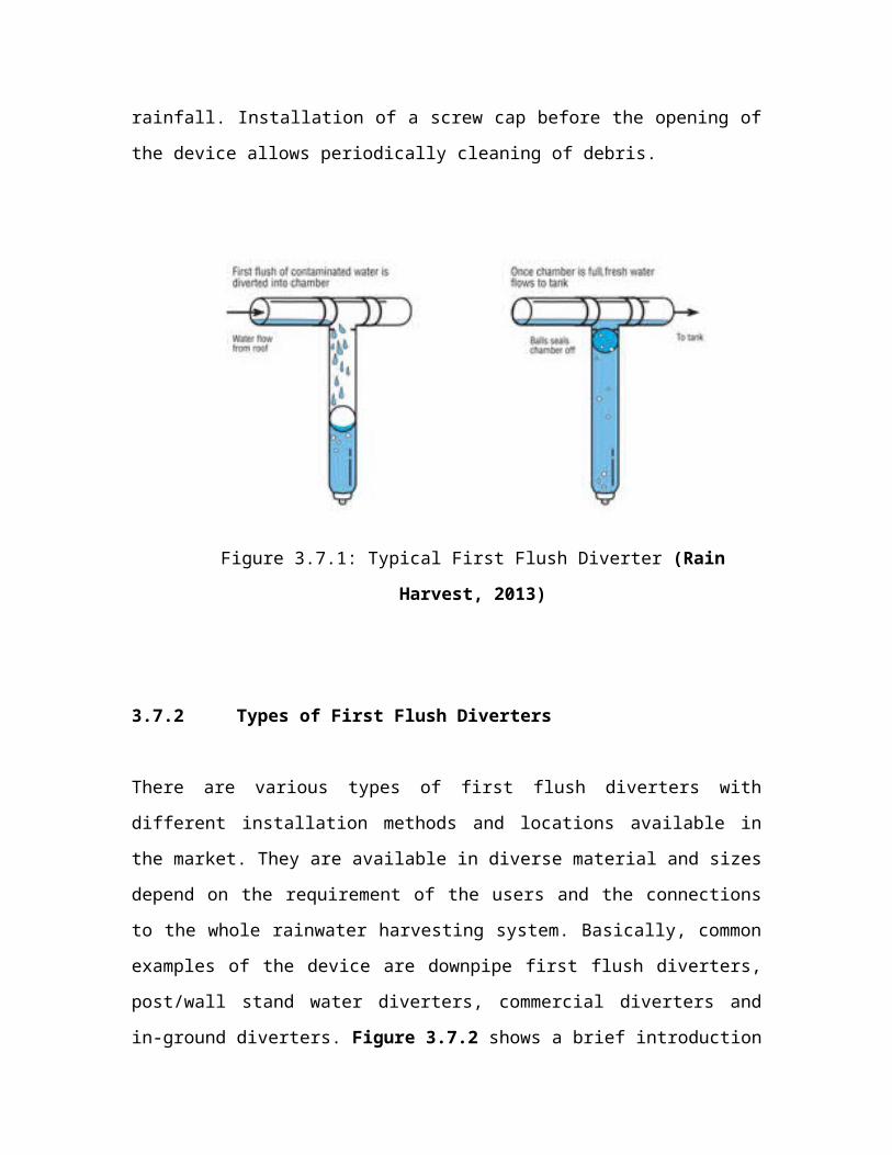
rainfall. Installation of a screw cap before the opening of
the device allows periodically cleaning of debris.
Figure 3.7.1: Typical First Flush Diverter (Rain
Harvest, 2013)
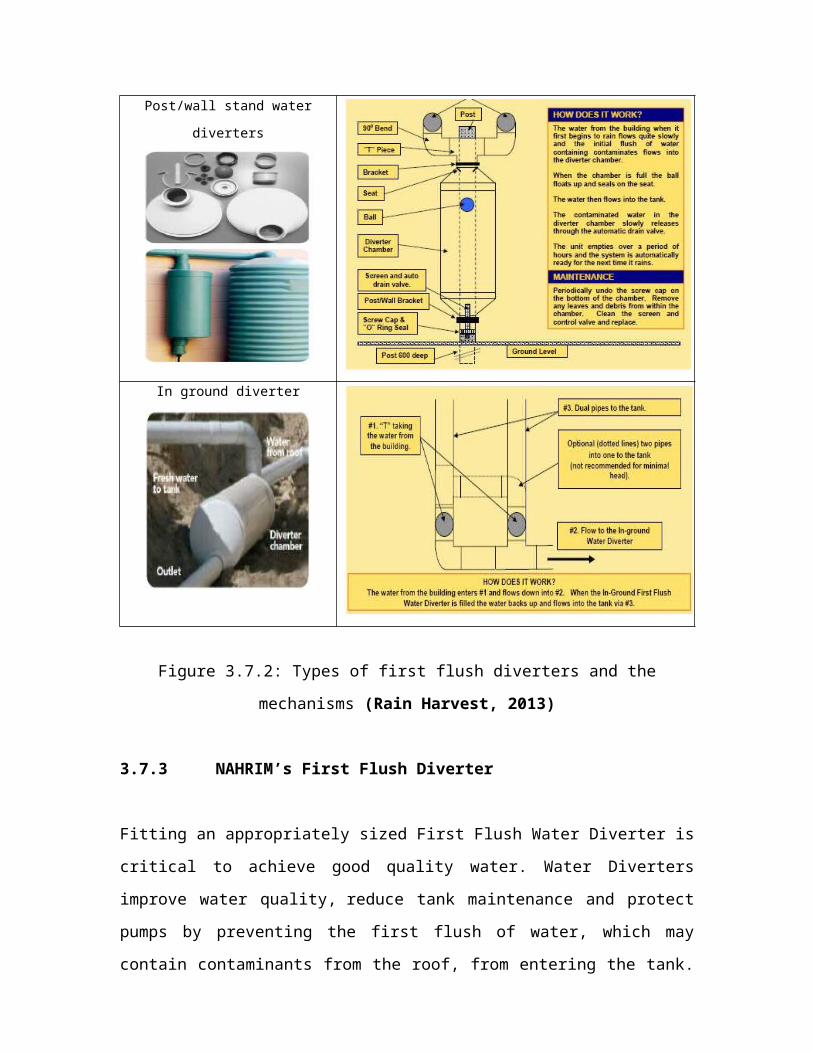
3.7.2 Types of First Flush Diverters
There are various types of first flush diverters with
different installation methods and locations available in
the market. They are available in diverse material and sizes
depend on the requirement of the users and the connections
to the whole rainwater harvesting system. Basically, common
examples of the device are downpipe first flush diverters,
post/wall stand water diverters, commercial diverters and
in-ground diverters. Figure 3.7.2 shows a brief introduction
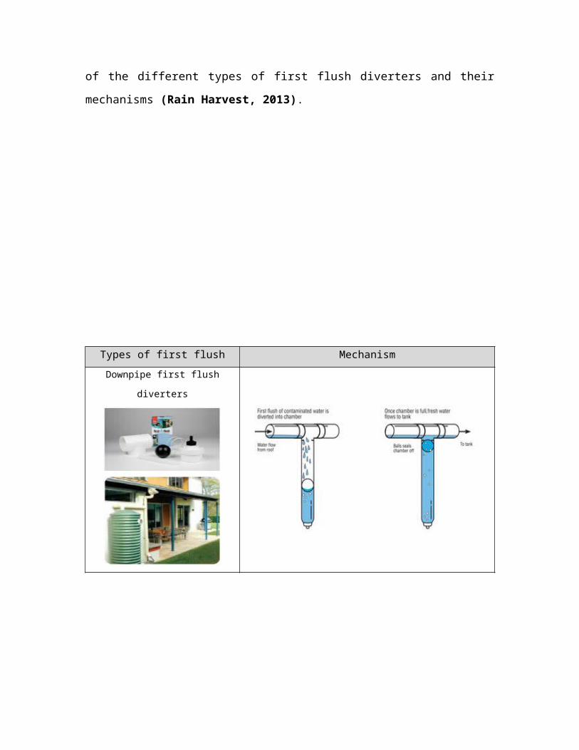
of the different types of first flush diverters and their
mechanisms (Rain Harvest, 2013).
Types of first flush MechanismDownpipe first flush
diverters
Post/wall stand water
diverters
In ground diverter
Figure 3.7.2: Types of first flush diverters and the
mechanisms (Rain Harvest, 2013)
3.7.3 NAHRIM’s First Flush Diverter
Fitting an appropriately sized First Flush Water Diverter is
critical to achieve good quality water. Water Diverters
improve water quality, reduce tank maintenance and protect
pumps by preventing the first flush of water, which may
contain contaminants from the roof, from entering the tank.
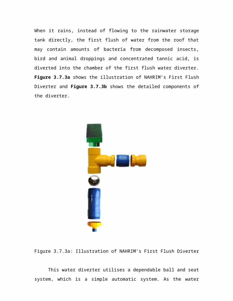
When it rains, instead of flowing to the rainwater storage
tank directly, the first flush of water from the roof that
may contain amounts of bacteria from decomposed insects,
bird and animal droppings and concentrated tannic acid, is
diverted into the chamber of the first flush water diverter.
Figure 3.7.3a shows the illustration of NAHRIM’s First Flush
Diverter and Figure 3.7.3b shows the detailed components of
the diverter.
Figure 3.7.3a: Illustration of NAHRIM’s First Flush Diverter
This water diverter utilises a dependable ball and seat
system, which is a simple automatic system. As the water
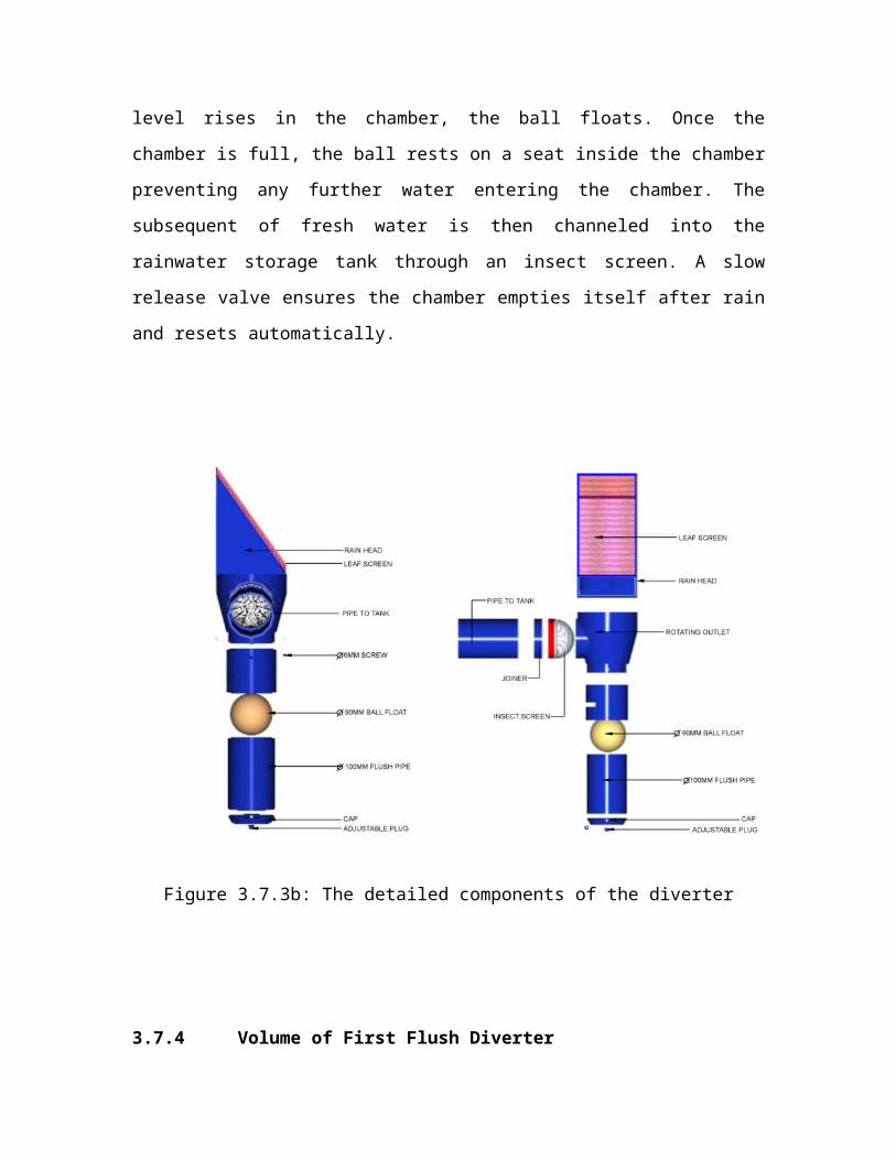
level rises in the chamber, the ball floats. Once the
chamber is full, the ball rests on a seat inside the chamber
preventing any further water entering the chamber. The
subsequent of fresh water is then channeled into the
rainwater storage tank through an insect screen. A slow
release valve ensures the chamber empties itself after rain
and resets automatically.
Figure 3.7.3b: The detailed components of the diverter
3.7.4 Volume of First Flush Diverter
Users could also design the volumes of their first flush
diverters. A minimum design criterion is that the first
flush device should divert the first 0.5-mm (or, 1.0-mm) of
the rainfall (first flush depth). To calculate the volume of
rainwater needed to be diverted, multiplies the length and
width of the roof by the first flush depth.
Required volume of diverted water (m3) = roof length (m) * roof width (m) * first flush
depth (m)
Eq. 3.7a
For example, a house with 10-m long by 5-m wide would
need to divert at least 0.025-m3 (or, 0.05-m3 if 1.0-mm of
first flush depth is used) of first flush. This is the
amount of first flush that a simple-pipe first flush device
would have to divert. By dividing the required volume of
first flush with the cross sectional area of the pipe (πr2),
the necessary pipe length for the simple-pipe first flush
device can be calculated from the following equation:
Pipe length (m) = Required volume of diverted water (m3) / πr2
Eq. 3.7b
A first flush downpipe of 200 mm diameter (100 mm
radius) would need to be at least 0.8-m (1.6-m if 1.0-mm of
first flush depth is used) long.
3.7.5 The Malaysian’s Condition
3.7.5.1 KPKT
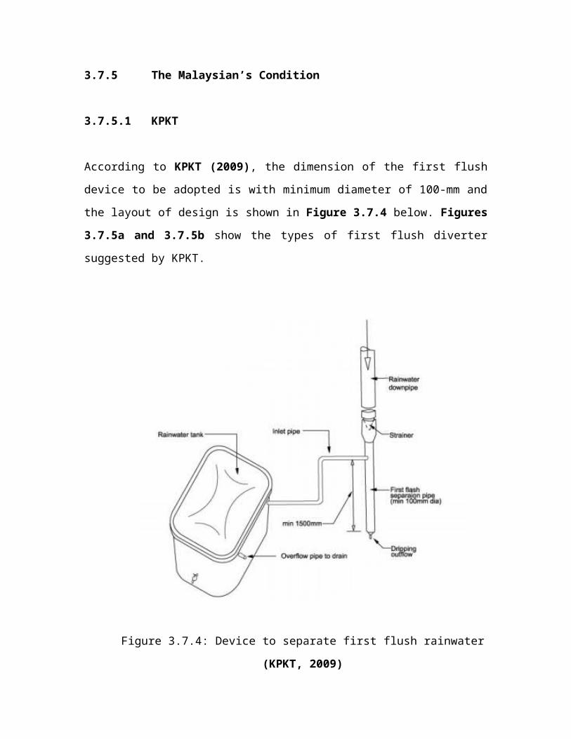
According to KPKT (2009), the dimension of the first flush
device to be adopted is with minimum diameter of 100-mm and
the layout of design is shown in Figure 3.7.4 below. Figures
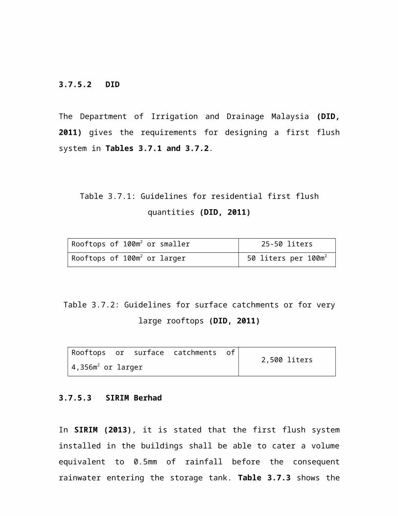
3.7.5a and 3.7.5b show the types of first flush diverter
suggested by KPKT.
Figure 3.7.4: Device to separate first flush rainwater
(KPKT, 2009)
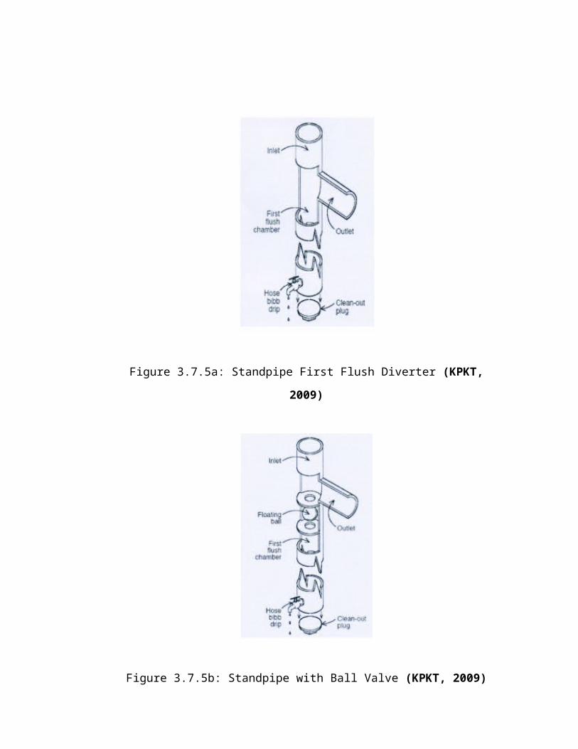
Figure 3.7.5a: Standpipe First Flush Diverter (KPKT,
2009)
Figure 3.7.5b: Standpipe with Ball Valve (KPKT, 2009)
3.7.5.2 DID
The Department of Irrigation and Drainage Malaysia (DID,
2011) gives the requirements for designing a first flush
system in Tables 3.7.1 and 3.7.2.
Table 3.7.1: Guidelines for residential first flush
quantities (DID, 2011)
Rooftops of 100m2 or smaller 25-50 litersRooftops of 100m2 or larger 50 liters per 100m2
Table 3.7.2: Guidelines for surface catchments or for very
large rooftops (DID, 2011)
Rooftops or surface catchments of
4,356m2 or larger2,500 liters
3.7.5.3 SIRIM Berhad
In SIRIM (2013), it is stated that the first flush system
installed in the buildings shall be able to cater a volume
equivalent to 0.5mm of rainfall before the consequent
rainwater entering the storage tank. Table 3.7.3 shows the
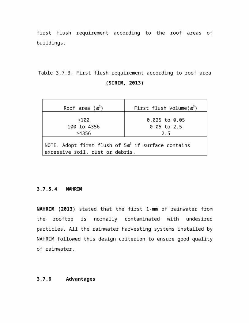
first flush requirement according to the roof areas of
buildings.
Table 3.7.3: First flush requirement according to roof area
(SIRIM, 2013)
Roof area (m2) First flush volume(m3)
<100100 to 4356
>4356
0.025 to 0.050.05 to 2.5
2.5
NOTE. Adopt first flush of 5m3 if surface contains excessive soil, dust or debris.
3.7.5.4 NAHRIM
NAHRIM (2013) stated that the first 1-mm of rainwater from
the rooftop is normally contaminated with undesired
particles. All the rainwater harvesting systems installed by
NAHRIM followed this design criterion to ensure good quality
of rainwater.
3.7.6 Advantages
It is noted that the first flush diverter is operating
automatically, which is simple and user friendly. Most of
the first flush diverter is simple and easy to be installed.
It does not require manual intervention and is almost
maintenance free.
The device could safeguard the quality of the rainwater
through prevention of undesirable matters and pollutants
from entering the storage tank at the first stage of
rainwater harvesting. Therefore, the rainwater collected
could be directly used for non-potable purpose without
further complicated treatments. Besides, without
accumulation of the undesirable contaminants allows
protection to the subsequent system. Also, no power is
required to operate a first flush diverter. The technology
is a low-tech and low-cost demand to improve the rainwater
quality in ease.
