manual of winching operations the gliding centre husbands
TRANSCRIPT
Manual of Winching Operations
The Gliding Centre
Husbands Bosworth

The Gliding Centre Winch Manual Page ii 2018 v1.0
REVISION HISTORY
Version Author Date Changes
1.0 P. Howard 12/01/2018 First draft
The Gliding Centre Winch Manual Page iii 2018 v1.0
THE GLIDINGCENTRE
HUSBANDS BOSWORTH AIRFIELD
MANUAL OF WINCHING OPERATIONS
Table of Contents
1. Introduction. ........................................................................................................................... 1
2. General Description. .............................................................................................................. 2
3. Operation. ............................................................................................................................... 3
3.1. Controls .................................................................................................................................. 3
3.2. Daily inspections. ................................................................................................................... 3
3.3. Setting up the winching operation. ......................................................................................... 4
3.4. Signalling system and communication with the launch point. ................................................ 4
3.5. Launching operation. ............................................................................................................. 5
3.6. Retrieving the cables. ............................................................................................................. 5
3.7. Strobe. .................................................................................................................................... 6
4. Maintenance and repairs. ...................................................................................................... 7
4.1. Cable repairs. .......................................................................................................................... 7
4.2. Recording the number of launches/cable replacement. .......................................................... 7
5. Safety. ..................................................................................................................................... 8
5.1. Safety procedures - general operation. ................................................................................. 8
5.2. Emergency procedures .......................................................................................................... 9
Launch Failures. ...................................................................................................................... 9
Glider unable to release. ........................................................................................................ 9
Possibility of cables falling across overhead electricity lines. .............................................. 10
6. Training. ................................................................................................................................ 10
6.1. Training programme. ............................................................................................................ 10
6.2. Individual records. ................................................................................................................ 10
7. Appendix A. In the cab - the controls. .................................................................................. 11
8. Appendix B Winch Launch Cable Failure at Husbands Bosworth Airfield – Risk Assessment 13
8.1. Introduction .......................................................................................................................... 13
8.2. Normal Winching Operations ............................................................................................... 13
8.3. Operating in Crosswinds ....................................................................................................... 14
8.4. Winch Cable Failure – Why ................................................................................................... 15
8.5. Likelihood of Cable Failure ................................................................................................... 15
8.6. Existing Mitigation ................................................................................................................ 16
8.7. Discussion on Failure of Steel Cable ..................................................................................... 16
8.8. Mitigation ............................................................................................................................. 17
8.9. Conclusion ............................................................................................................................ 17

The Gliding Centre Winch Manual Page 1 2018 v1.0
THE GLIDING CENTRE - HUSBANDS BOSWORTH AIRFIELD
WINCHING MANUAL
1. Introduction.
Launching gliders by means of a winch has been practiced by the Gliding Centre (Coventry Gliding
Club) since the club was formed in 1953. Over that period of time the club has accrued considerable
operational and technical experience in that method of glider launching.
The safety and efficiency of the operation is entirely dependent upon all the parties involved being
fully trained and competent.
To this end it is essential that the launching team, namely:
The launch point personnel (nominated by the team leader)
The driver of the tractor retrieving the cables
The winch driver.
Carry out their duties strictly in accordance with the instructions contained within this manual.
Anyone on the launching team must have read and understood the contents of this manual and sign
their name to this effect in the appropriate section.
Additionally, winch drivers and tractor drivers must be trained in accordance with the procedures
set out in this manual and will only be permitted to drive the winch or tractor on their own when
they have satisfied the winch master of their ability at which time their pilot record card will be
endorsed to show that they are qualified.

The Gliding Centre Winch Manual Page 2 2018 v1.0
2. General Description.
The winch referred to in this manual was constructed in 1987 by L. Goodman & Son, to a special
design developed over a period of years to suit the particular requirements of the operation at
Husbands Bosworth airfield.
The winch has four drums, mounted in line and each independently selectable driven by a 10.5 litre
(640 cu in) Perkins ZB TV8.640 Turbo diesel engine, through a torque converter. Two independently
operated braking systems are fitted to each drum. One operates automatically to provide drag
during cable retrieve. The other is operated by the brake lever in the cab and controls the selected
drum.
The engine is located at the end of the chassis directly behind the driver’s cab. The chassis being
constructed from a reinforced, modular steel framework with a double wheel rigid axle at the engine
end and a pick-up hitch at the other.
An emergency guillotine cable release system is fitted which when operated in the cab will sever all
four cables automatically in the event of the glider not being able to release.
The Gliding Centre Winch Manual Page 3 2018 v1.0
3. Operation.
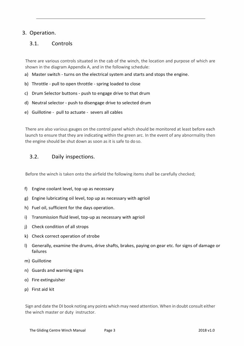
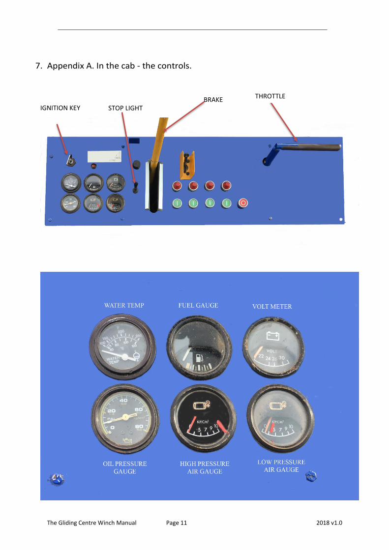
3.1. Controls
There are various controls situated in the cab of the winch, the location and purpose of which are
shown in the diagram Appendix A, and in the following schedule:
a) Master switch - turns on the electrical system and starts and stops the engine.
b) Throttle - pull to open throttle - spring loaded to close
c) Drum Selector buttons - push to engage drive to that drum
d) Neutral selector - push to disengage drive to selected drum
e) Guillotine - pull to actuate - severs all cables
There are also various gauges on the control panel which should be monitored at least before each
launch to ensure that they are indicating within the green arc. In the event of any abnormality then
the engine should be shut down as soon as it is safe to do so.
3.2. Daily inspections.
Before the winch is taken onto the airfield the following items shall be carefully checked;
f) Engine coolant level, top up as necessary
g) Engine lubricating oil level, top up as necessary with agrioil
h) Fuel oil, sufficient for the days operation.
i) Transmission fluid level, top-up as necessary with agrioil
j) Check condition of all strops
k) Check correct operation of strobe
l) Generally, examine the drums, drive shafts, brakes, paying on gear etc. for signs of damage or failures
m) Guillotine
n) Guards and warning signs
o) Fire extinguisher
p) First aid kit
Sign and date the DI book noting any points which may need attention. When in doubt consult either
the winch master or duty instructor.

The Gliding Centre Winch Manual Page 4 2018 v1.0
3.3. Setting up the winching operation.
a) At the start of each flying day the winch driver will report to the duty instructor to agree the location of the winch. Under normal conditions the winch will be located in either of the east/west locations. However, these points may be altered according to the prevailing conditions. Close liaison between the launching team throughout the days flying is essential.
b) Drive the winch into position and park at 90 degrees to the cable run.
c) Carry out a communication check and obtain permission to p u l l out cables.
d) Warm up the engine.
3.4. Signalling system and communication with the launch point.
At all times a clear and unambiguous system of communication must exist between the winch and
launch point. This can be either lights or radio. However, if radio alone is used then this must be
supplemented with lights to give a visual stop signal to the winch. For example, car headlights could
be used if the lights on the control box are unserviceable.
All light signals will be white and shall be given in accordance with the BGA rules and laws para, 5.7.
namely:
Take up slack, the take-off path being clear, Dashes of one second duration with three second
intervals.
All out - Quick dots at one second intervals.
Stop - Steady continuous light.
Problems and emergencies at the winch shall be communicated to the launch point by means of a
stop signal from the winch, supplemented by radio communication.
The Gliding Centre Winch Manual Page 5 2018 v1.0
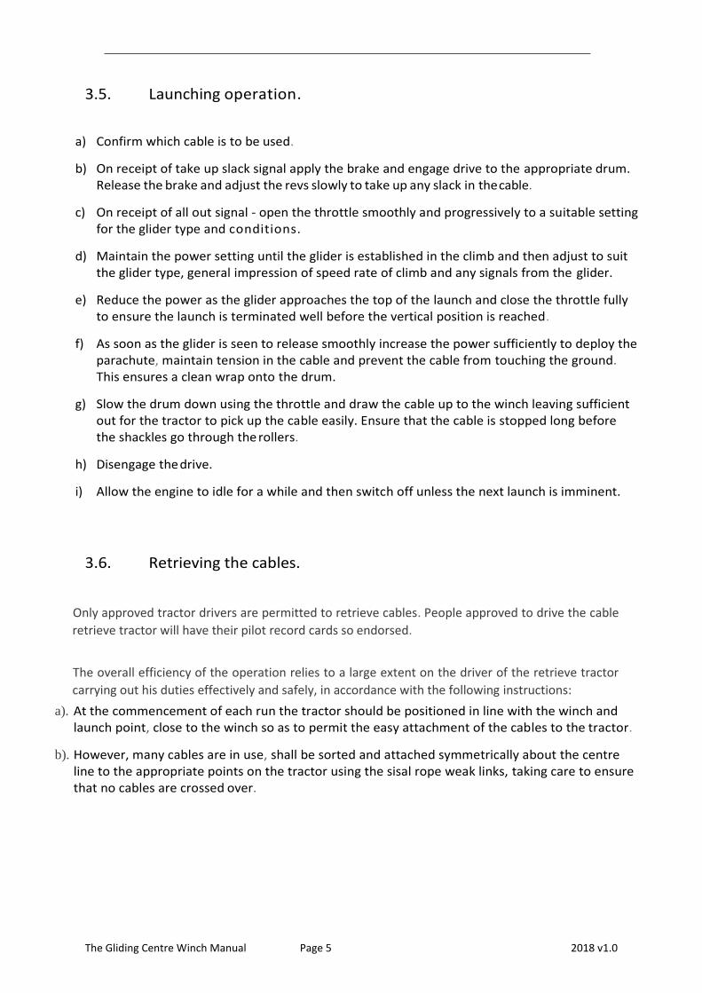
3.5. Launching operation.
a) Confirm which cable is to be used.
b) On receipt of take up slack signal apply the brake and engage drive to the appropriate drum. Release the brake and adjust the revs slowly to take up any slack in the cable.
c) On receipt of all out signal - open the throttle smoothly and progressively to a suitable setting for the glider type and conditions.
d) Maintain the power setting until the glider is established in the climb and then adjust to suit the glider type, general impression of speed rate of climb and any signals from the glider.
e) Reduce the power as the glider approaches the top of the launch and close the throttle fully to ensure the launch is terminated well before the vertical position is reached.
f) As soon as the glider is seen to release smoothly increase the power sufficiently to deploy the parachute, maintain tension in the cable and prevent the cable from touching the ground. This ensures a clean wrap onto the drum.
g) Slow the drum down using the throttle and draw the cable up to the winch leaving sufficient out for the tractor to pick up the cable easily. Ensure that the cable is stopped long before the shackles go through the rollers.
h) Disengage the drive.
i) Allow the engine to idle for a while and then switch off unless the next launch is imminent.
3.6. Retrieving the cables.
Only approved tractor drivers are permitted to retrieve cables. People approved to drive the cable
retrieve tractor will have their pilot record cards so endorsed.
The overall efficiency of the operation relies to a large extent on the driver of the retrieve tractor
carrying out his duties effectively and safely, in accordance with the following instructions:
a). At the commencement of each run the tractor should be positioned in line with the winch and launch point, close to the winch so as to permit the easy attachment of the cables to the tractor.
b). However, many cables are in use, shall be sorted and attached symmetrically about the centre line to the appropriate points on the tractor using the sisal rope weak links, taking care to ensure that no cables are crossed over.

The Gliding Centre Winch Manual Page 6 2018 v1.0
c). Before moving off on the retrieve run, the tractor driver shall satisfy himself that all is in order and then only when he is given the take up slack signal by the winch driver shall he move off slowly to take up the slack in the cables between the tractor and the winch. At all times during the take up slack period he must not only carefully observe the signals from the winch but also keep a careful eye on the cables and winch itself to ensure that cables are running out smoothly. If any problem is observed the tractor must be stopped not withstanding any contrary signal from the winch.
d). Upon receiving the all-out signal from the winch, the tractor shall accelerate to approximately 12mph for the run down the airfield to the launch point. The cables must be laid out in as straight a line as possible using the aiming point technique, aiming to arrive clear of the upwind wing tip of the first glider in the winch queue. Upon nearing the launch point the tractor shall be slowed down progressively to a halt. Check that it is clear behind and then slowly back up to relieve the tension in the cables.
e). During the run to the launch point the tractor driver shall occasionally check that the retrieve is satisfactory by looking back at the winch to see if there is a stop signal. If one is noticed then the tractor shall be stopped progressively, and shall not move off again with the cables until a take up slack signal is received from the winch.
f). Should a cable become detached from the tractor during the retrieve for whatever reason, the retrieve shall continue to the launch point. The discarded cable will be drawn back to the winch by the winch driver.
g). During the run to the launch point the tractor driver shall also continually keep a good lookout for aircraft. If during the run the tractor driver considers that his continued progress would pose a serious hazard to a landing aircraft then he should progressively slow down or bring the tractor to a halt and only continue when the hazard is clear. Give way to aircraft.
h). At all times the cable retrieve tractor shall be operated in accordance with the safety instructions for tractor driving as detailed in the tractor driving section of the flying order book.
i). If the cable run deviates from a straight line then inform the duty instructor and winch driver in case there is any danger of the cables being crossed. If there is any doubt the cables should be drawn in and then pulled out again.
3.7. Strobe.
It is important to ensure that during the DI that the strobe operates. It will only operate when
one of the four drums is selected in the drive position. Its purpose is to provide a visual warning
to all concerned including aircraft, persons and the farmer that the winch is operating.
The Gliding Centre Winch Manual Page 7 2018 v1.0
4. Maintenance and repairs.
4.1. Cable repairs.
Cable repairs will only be carried out by approved winch drivers.
A complete record of all repair work shall be made in the DI book listing the date of the
repair and the name and signature of the person carrying out the repair.
a) Clean cut each end of the cable with the cutters provided.
b) Thread on two ferrules and overlap the cable by 5 - 6 inches.
c) Place the ferrule and cable between the dies vertically and centrally.
d) Tighten the release valve and operate the hand pump until the swage faces just meet.
e) Unscrew the release valve to release the ram and extract the formed swage.
f) Repeat for second ferrule.
Attention.
Do not apply more pressure than is required to bring the swage faces together. Do not overtighten the release valve. Do not press any flash back into the splice Do not use any ferrules other than those provided.
4.2. Recording the number of launches/cable replacement.
Each time a launch is undertaken the recorder on the cab roof will be manually
advanced. Records of the number of launches will be kept by the winch master and
entered in appendix C of the master copy of this manual on a monthly basis at a time
coincident with cable measurement checks. The results will be aggregated to give an
approximation of the number of launches per cable.
Cables will be replaced after ten thousand (10,000) launches, spread evenly throughout
the four drums or on an annual basis, whichever is the sooner.
The cables shall be reversed, end to end after either five thousand (5000) launches or six
months whichever is the sooner.
The Gliding Centre Winch Manual Page 8 2018 v1.0
All such tasks shall be recorded in the DI book immediately after the work is carried out,
detailing the work and the name of the person carrying out the work, their signature and date
upon which the work was carried out.
5. Safety.
5.1. Safety procedures - general operation.
The following general safety procedures shall be carefully followed by the winch driver at all times:
a) Before launching, the winch driver must ensure that the launch area between the winch and the glider is clear of aircraft, vehicles and persons and that the area above the winch is clear of aircraft.
b) If during the course of the launch any event occurs which could place the crew of the glider or any other persons at risk then the launch should be abandoned.
c) Before and during launching, no person or vehicle, apart from the retrieve tractor, will be permitted within 15 metres of the rear and ends of the winch.
d) During launching the retrieve tractor shall be positioned close to the cab end of the winch behind the line of the drums.
e) Only two persons are permitted in the cab at any one time.
f) If it is necessary to carry out work or inspections on and around the cable drums, paying on gear, drive shafts, brakes, or any other part of the moving machinery then the engine must be switched off and the key removed.
g) The stop light shall be displayed at all times when persons have need to work on the cables or any other part of the moving machinery in operational conditions.
h) Winch launching, particularly in crosswind condition s, should not be undertaken if there is any possibility of the cable dropping beyond the southern airfield boundary. With a southerly cross wind component, be aware of the danger of cables falling beyond the perimeter track in the caravan p a r k .
i) Gliders must not be launched into cloud.
j) Glider launches above 3000 feet agl are not permitted.
The Gliding Centre Winch Manual Page 9 2018 v1.0
5.2. Emergency procedures
Launch Failures.
a) Because it is often difficult to determine whether the failure is the weak link or cable, reduce power immediately to bring the cable to rest and avoid any conflict between the glider and parachute. If the glider is going around it may be possible to draw the cable in whilst the glider is flying. If the glider lands ahead the cable must be stopped. Do not draw the cable in until it is confirmed clear.
b) If the weak link has failed the cable should be winched in. The weak link should be repaired at the winch. When the cable is towed out again the weak link can be replaced at the launch point.
c) If the cable has broken the end attached to the winch should be drawn in and the free end retrieved from the field by the cable tractor. A repair can be executed at the winch, taking care to thread the cable through the paying on gear correctly.
Glider unable to release.
If a glider is unable to release from the cable then very careful consideration must be given as
to whether to guillotine the cables. Such action would be necessary if in the opinion of the
winch driver the glider was obviously unable to release and the continued attachment of the
cable constituted a serious threat to the gliders safety. In which case the following procedures
should be followed:
a) The throttle should be closed.
b) the drive de-selected to the drum to which the glider is attached. c). Operate the guillotine switch.
c) Radio the launch point to advice your actions and put on the stop light.
d) Remain in the cab until the glider has landed, carefully observe the cable descent and if there is any suspicion that the cables may have fallen across overhead electrical lines remain where you are avoiding any contact with metallic objects until help arrives.

The Gliding Centre Winch Manual Page 10 2018 v1.0
Possibility of cables falling across overhead electricity lines.
If it looks as though the cable will fall across an overhead electricity line, then following
procedures should be followed.
a) Cut the throttle and apply the brake.
b) Avoid touching any metallic objects.
c) Remain seated in the cab until help arrives.
Confirmation that the cable and winch are 'alive' will be by the cable arcing and smouldering at
points along the ground where it lays.
6. Training.
6.1. Training programme.
Before attempting to drive the winch, the prospective driver shall observe a qualified winch driver
carry out a minimum of 12 launches. He should become completely familiar with all the controls and
carefully note the manner and order of the qualified driver’s actions.
After witnessing the 12 launches the trainee may operate the winch under the supervision of a
approved winch driver instructor. The names of current approved winch driver instructors are
available in the office.
The syllabus shall be signed by the instructor when in his opinion the trainee is competent in that
particular section of the training. The syllabus shall be carefully followed and only when all sections
have been completed to the total satisfaction of the instructor, shall the trainee be allowed to drive
the winch unsupervised.
6.2. Individual records.
Upon completion of training a winch driver will be signed off when his record card is endorsed
with winch driving.
The Gliding Centre Winch Manual Page 11 2018 v1.0
7. Appendix A. In the cab - the controls.
THROTTLE BRAKE IGNITION KEY STOP LIGHT

The Gliding Centre Winch Manual Page 12 2018 v1.0
The Gliding Centre Winch Manual Page 13 2018 v1.0
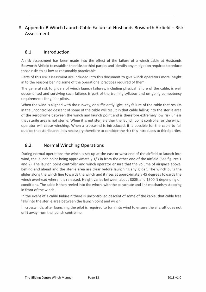
8. Appendix B Winch Launch Cable Failure at Husbands Bosworth Airfield – Risk Assessment
8.1. Introduction
A risk assessment has been made into the effect of the failure of a winch cable at Husbands
Bosworth Airfield to establish the risks to third parties and identify any mitigation required to reduce
those risks to as low as reasonably practicable.
Parts of this risk assessment are included into this document to give winch operators more insight
in to the reasons behind some of the operational practices required of them.
The general risk to gliders of winch launch failures, including physical failure of the cable, is well
documented and surviving such failures is part of the training syllabus and on-going competency
requirements for glider pilots.
When the wind is aligned with the runway, or sufficiently light, any failure of the cable that results
in the uncontrolled descent of some of the cable will result in that cable falling into the sterile area
of the aerodrome between the winch and launch point and is therefore extremely low risk unless
that sterile area is not sterile. When it is not sterile either the launch point controller or the winch
operator will cease winching. When a crosswind is introduced, it is possible for the cable to fall
outside that sterile area. It is necessary therefore to consider the risk this introduces to third parties.
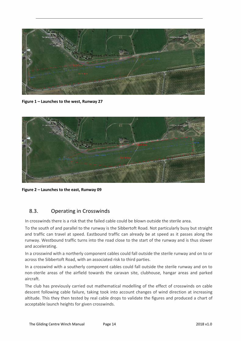
8.2. Normal Winching Operations
During normal operations the winch is set up at the east or west end of the airfield to launch into
wind, the launch point being approximately 1/3 in from the other end of the airfield (See figures 1
and 2). The launch point controller and winch operator ensure that the volume of airspace above,
behind and ahead and the sterile area are clear before launching any glider. The winch pulls the
glider along the winch line towards the winch and it rises at approximately 45 degrees towards the
winch overhead where it is released. Height varies between about 800ft and 1500 ft depending on
conditions. The cable is then reeled into the winch, with the parachute and link mechanism stopping
in front of the winch.
In the event of a cable failure if there is uncontrolled descent of some of the cable, that cable free
falls into the sterile area between the launch point and winch.
In crosswinds, after launching the pilot is required to turn into wind to ensure the aircraft does not
drift away from the launch centreline.
The Gliding Centre Winch Manual Page 14 2018 v1.0
Figure 1 – Launches to the west, Runway 27
Figure 2 – Launches to the east, Runway 09
8.3. Operating in Crosswinds
In crosswinds there is a risk that the failed cable could be blown outside the sterile area.
To the south of and parallel to the runway is the Sibbertoft Road. Not particularly busy but straight
and traffic can travel at speed. Eastbound traffic can already be at speed as it passes along the
runway. Westbound traffic turns into the road close to the start of the runway and is thus slower
and accelerating.
In a crosswind with a northerly component cables could fall outside the sterile runway and on to or
across the Sibbertoft Road, with an associated risk to third parties.
In a crosswind with a southerly component cables could fall outside the sterile runway and on to
non-sterile areas of the airfield towards the caravan site, clubhouse, hangar areas and parked
aircraft.
The club has previously carried out mathematical modelling of the effect of crosswinds on cable
descent following cable failure, taking took into account changes of wind direction at increasing
altitude. This they then tested by real cable drops to validate the figures and produced a chart of
acceptable launch heights for given crosswinds.
The Gliding Centre Winch Manual Page 15 2018 v1.0
In crosswinds pilots are required to turn into wind (‘lay-off’) after becoming airborne and thus
maintain a track over or upwind of the centreline between winch and launch point. Cable failures
within these parameters are calculated to ensure that cable will land within the sterile area.
The figures that were produced for that study are no longer available. However, according to the
professional winch driver this does appear to be the case.
There is nevertheless, always a remote possibility that a pilot will not lay-off adequately AND a cable
failure will occur. The club is well aware of that risk and Instructors and winch operators, both the
professional and club members, ensure that lay-offs are appropriate for the conditions.
8.4. Winch Cable Failure – Why
The cable used by the Gliding Centre is 4.5mm galvanized stranded cable. When new, the breaking
strength of the cable is in excess of 3000 pounds, far stronger than needed for a launch.
In addition, the cable is attached to the glider via a weak link designed to fail before the glider and
cable can be overstressed. This cable has not been known to break during a launch unless it has been
poorly spliced (splices are made with copper swages and a swaging tool), or a splice has become
worn or the cable has become worn with age. Husbands Bosworth Airfield is grass which is benign
to the cables.
The Gliding Centre winch is a 4-drum design so each cable is generally used for every fourth launch.
The club’s professional winch operator advises that new cable does not break while winching but
cables weaken with use and can break eventually. If they do it is usually as a result of snagging at
the drum. This is usually after a launch when cables are released under tension, or when cables have
been snagged on the drum while being reeled out if the drag brake fails.
Subsequently, repaired cables have been known to fail. The older the cable the more likely it is to
fail and consequently cables are replaced annually.
Cables are attached to the glider by a weak link and parachute. In the event of a failure the parachute
slows the rate of decent but does mean the descending cable/parachute can drift with the wind.
Approximately 24000 launches take place annually so each cable is used for about 600 launches
each year. Inspection on 8 May 2017, after a full year of use showed cable 1 in good condition with
one non-critical join, cable 2 in good condition with one non-critical join and one critical join, both
had started to fray in 3 and 5 places respectively. Cable 3 had no joins but was in poor condition
with nearly 30 frays and cable 4 also had no joins, was in poor condition with 12 frays. The critical
join on cable 2 was as a result of a failure 400m from the aircraft end while being reeled in after a
launch.
8.5. Likelihood of Cable Failure
The club does not kept records of cable failures. The club’s professional winch driver estimates that
over the last 10 years when the cables have been replaced annually there are less than 2 cable
failures per year leading to a cable falling to the ground. Several have fallen outside the sterile area
to the south, the rest within the sterile area. Anecdotally before then there were more failures
including occasions when the cable has fallen into Sibbertoft Road.
The likelihood of a cable failure is therefore approximately 2 per annum.
The Gliding Centre Winch Manual Page 16 2018 v1.0
The likelihood of a cable falling outside the sterile area to the south is approximately 1 every 5 years
The likelihood of a cable falling outside the sterile area to the north is less than 1 every 10 years.
Though it must be recognised that these figures are not definitive Risk from a Falling Cable
Falling cable, in itself does not present much of a risk to humans, vehicles or structures. The top of
the falling cable has a parachute attached and it is lowered slowly. As soon as one end has reached
the ground the cable lays itself out slowly. If a person were to be hit it is not expected to do more
than surprise that person. Vehicles and structures are unlikely to be affected but delicate aircraft
could suffer minor or cosmetic damage if the cable was dragged across them.
Should the cable fall into Sibbertoft Road it may affect members of the public. The weight of cable
and parachute descent will cause the cable to lay on the road but it could be supported, to a degree,
either side of the road by the fence or hedging. It is therefore possible that it could be a risk for a
brief moment while in descent or at the supported ends.
Cars, vans and trucks hitting such a cable would be damaged at least cosmetically and the driver
could be startled. Cyclists and motorcyclists could be dismounted. Horse riders could be thrown
from startled horses but pedestrians should be at very low risk. All of these scenarios require the
rare event of a cable break, combined with the rare event of the cable landing in the road to coincide
with a passing 3rd party at exactly the correct time.
The Club is aware that the risk to third parties, particularly in northerly crosswinds, and polices the
rules rigorously. If the wind or forecast wind is near the limits then winching does not start.
Current Procedures Following a Cable Failure
In the event of a cable failing and falling outside the sterile area to the south, helpers and the winch
driver will attempt to find and retrieve the cable.
In the event of a cable failing and falling over the road, the procedure is that the winch driver drives
the tractor as quickly as possible to the road and stops traffic. The launch point controller also sends
someone to the other end of the road to stop traffic. The cable is then retrieved.
8.6. Existing Mitigation
Mitigation already is already in place; lay-off, no winching outside safe conditions and closing
Sibbertoft Road after a cable failure.
There are four possible method of reducing the risk of a cable falling across the road:
Reduce the likelihood of the cable failing.
Reduce the likelihood of a failed cable falling across the road.
Reduce the likelihood of aircraft drifting south of the centreline in northerly winds.
Cease winching when there is any northerly crosswind component.
8.7. Discussion on Failure of Steel Cable
4.5mm stranded steel cable that is new has not been known to fail spontaneously. Initial failures
have occurred as a result of snagging at the winch end caused by operator error or cable release
under tension throwing a loop.
Following such a failure, cables are reconnected using two swages. These swages can subsequently
strike the paying-in gear causing shock loading. It is also possible that swaging can affect the cable
strength. Subsequent failures in the area around the swages have occurred.
The Gliding Centre Winch Manual Page 17 2018 v1.0
Evidently it is possible to run a cloth along the cable and snag it on broken strands in the vicinity of
the swaged joints.
Because it is cumulative wear, the cables are replaced annually.
It stands to reason that if cables are not damaged because of operator error or release under tension
they should have a much lower failure rate. Preventative maintenance on the cable could also be
effective on reducing cable failure.
For example. Each cable should have a log book detailing each failure; cause, repair and position of
repair. Each cable could be inspected by hand every so many launches. Each repair could be cut out
a safe distance either side of the swage (the weakened area) after a given number of launches and
before shock loading the cable becomes an issue.
8.8. Mitigation
The possibility of closing the Sibbertoft Road during northerly wind launches was discussed and
dismissed as unlikely to be possible. It was also suggested that an illuminated stop signal / warning
lights could be deployed within the airfield perimeter and used to stop oncoming traffic in the event
of a cable failure.
The following mitigation is recommended:
Pre-season briefing of all winch operators, instructors and launch point controllers to remind them
of the risks of cable misuse and failure and their responsibilities.
Launch point controllers to remind all pilots of the lay-off requirements in crosswinds.
Maintain a log for each winch drum detailing all cable damage.
Adopt a regime of replacing cable repairs after a given number of launches.
Replace the cables at the start of the summer season and adopt a regime of a manual cable
inspection every month in summer, 2 months in winter.
8.9. Conclusion
The current procedures and mitigation ensure that current operations remain safe providing they
are correctly applied.
The risk to horse riders and motorcyclists must be further considered by reducing the likelihood of
the winch cable failing by better preventative maintenance.