maintenance management order
TRANSCRIPT
Web Access: http://mtsc.usps.gov
SUBJECT:
TO:
Operational and Preventive Maintenance Guidelines for the Automated Package Processing System (APPS) All APPS Sites
DATE:
NO:
FILE CODE:
February 4, 2013
MMO-018-13
R3
mtho:mm12112ab
This Maintenance Management Order (MMO) provides updated Operational and Preventive Maintenance Guidelines for the Automated Package Processing System (APPS) and supersedes MMO-096-12, dated August 10, 2012 and has been modified due to limitations on Electronic Condition Based Maintenance (eCBM) which cannot trigger Operational Tasks based upon time and piece count thresholds. Operational checks have been divided into Tourly and Daily tasks only. Operational tasks which were triggered using time and piece counts were inserted into to PM Tasks after task 166 and are numbered 166.1 through 166.4 to prevent renumbering of non-affected tasks. MMO-096-12 superseded MMO-85-10, dated August 09, 2010, and also obsoleted MMO-115-05 APPS, Operational Maintenance Work-Hours, dated January 19, 2006 as this bulletin outlines specific Operational Maintenance tasks and times.
The workhours indicated in the workload estimate (Attachment 1) are based on historical run hour data for each machine and reflect the maximum annual workhours required to maintain each system. Actual workhour requirements and the frequency of tasks are dependent on run time and pieces processed. Therefore, PM workhour requirements will vary day-to-day based on site specific machine utilization. Management may modify task frequencies to address local conditions.
The minimum maintenance skill level required to perform each task is included in the Minimum Skill Level column of each checklist. This does not preclude higher level employees from performing any of this work.
Preventive Maintenance (PM) guidelines provide maintenance employees with the recommended task based maintenance activities. The Electronic Conditioned Based Maintenance (eCBM) is an abbreviated task list that represents a portion of the PM checklist. The complete master PM checklist must be accessible to all maintenance employees when performing PM and eCBM task based maintenance activities.
MAINTENANCE TECHNICAL SUPPORT CENTER
HEADQUARTERS MAINTENANCE OPERATIONS
UNITED STATES POSTAL SERVICE
Maintenance Management Order
MMO-018-13 Maintenance Technical Support Center
2
WARNING
Various products requiring Material Safety Data Sheets (MSDS) may be utilized during the performance of the procedures in this bulletin. Ensure the current MSDS for each product used is on file and available to all employees. When reordering such a product, it is suggested that current MSDS be requested. Refer to MSDS for appropriate personal protective equipment.
WARNING
Steps contained in this bulletin may require the use of Personal Protective Equipment (PPE). Refer to the current Electrical Work Plan (EWP) MMO for appropriate PPE requirements.
WARNING
The use of compressed or blown air is prohibited. An alternative cleaning method such as a HEPA filtered vacuum cleaner, a damp rag, lint-free cloth, or brush must be used in place of compressed or blown air.
Direct any questions or comments concerning this bulletin to the MTSC HelpDesk, online at http://mtsc.usps.gov/apps/remedyticket/index.cfm or call (800) 366-4123 or (405) 573-2123.
Manager Maintenance Technical Support Center HQ Maintenance Operations
Attachments:
1. Summary of Workload Estimate for APPS System
2. APPS Master Checklist: 03-APPS-AA-001-M: PM
3. APPS Master Checklist:09-APPS-AA-001-M: Operational Maintenance (Tourly)
4. APPS Master Checklist: 09-APPS-AA-002-M: Operational Maintenance (Daily)
Maintenance Technical Support Center MMO-018-13
Attachment 1 1
ATTACHMENT 1
SUMMARY
WORKLOAD ESTIMATE
FOR
APPS SYSTEM
MMO-018-13 Maintenance Technical Support Center
2 Attachment 1
THIS PAGE BLANK
Maintenance Technical Support Center MMO-018-13
Attachment 1 3
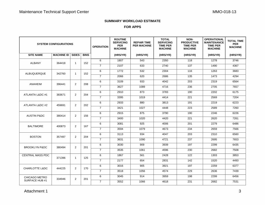
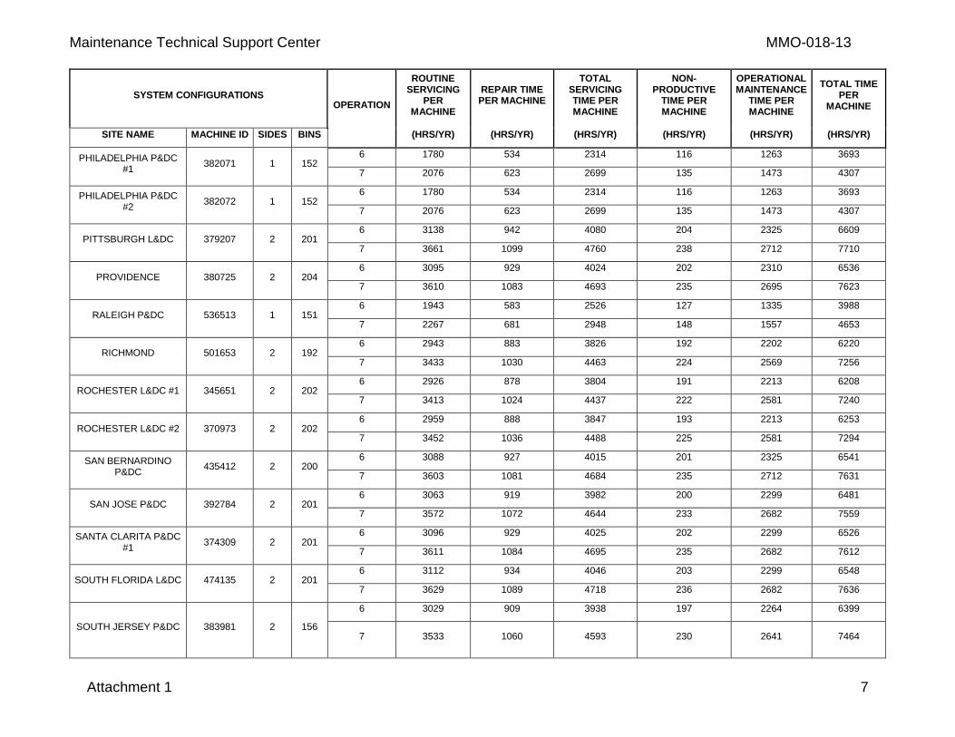
SUMMARY WORKLOAD ESTIMATE
FOR APPS
SYSTEM CONFIGURATIONS OPERATION
ROUTINE SERVICING
PER MACHINE
REPAIR TIME
PER MACHINE
TOTAL SERVICING TIME PER MACHINE
NON-PRODUCTIVE
TIME PER MACHINE
OPERATIONAL MAINTENANCE
TIME PER MACHINE
TOTAL TIME PER
MACHINE
SITE NAME MACHINE ID SIDES BINS (HRS/YR) (HRS/YR) (HRS/YR) (HRS/YR) (HRS/YR) (HRS/YR)
ALBANY 364418 1 152 6 1807 543 2350 118 1278 3746
7 2107 633 2740 137 1490 4367
ALBUQUERQUE 342760 1 152 6 1772 532 2304 116 1263 3683
7 2066 620 2686 135 1473 4294
ANAHEIM 396441 2 208 6 3109 933 4042 203 2319 6564
7 3627 1089 4716 236 2705 7657
ATLANTA L&DC #1 383671 2 204 6 2910 873 3783 190 2202 6175
7 3395 1019 4414 221 2569 7204
ATLANTA L&DC #2 459691 2 202 6 2933 880 3813 191 2219 6223
7 3421 1027 4448 223 2589 7260
AUSTIN P&DC 380414 2 156 6 2915 875 3790 190 2246 6226
7 3400 1020 4420 221 2620 7261
BALTIMORE 400873 2 167 6 3081 925 4006 201 2279 6486
7 3594 1079 4673 234 2659 7566
BOSTON 357497 2 204 6 3113 934 4047 203 2310 6560
7 3631 1090 4721 237 2695 7653
BROOKLYN P&DC 380494 2 201 6 3030 909 3939 197 2299 6435
7 3535 1061 4596 230 2682 7508
CENTRAL MASS PDC
371396 1 125
6 1867 561 2428 122 1303 3853
7 2177 654 2831 142 1520 4493
CHARLOTTE L&DC 444225 2 170 6 3016 905 3921 197 2259 6377
7 3518 1056 4574 229 2636 7439
CHICAGO METRO SURFACE HUB #1
334946 2 201 6 3045 914 3959 198 2299 6456
7 3552 1066 4618 231 2682 7531
MMO-018-13 Maintenance Technical Support Center
4 Attachment 1
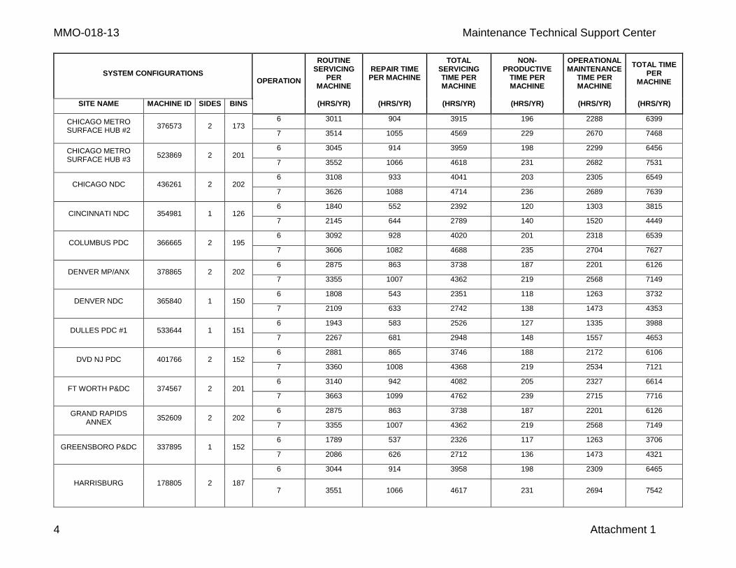
SYSTEM CONFIGURATIONS OPERATION
ROUTINE SERVICING
PER MACHINE
REPAIR TIME
PER MACHINE
TOTAL SERVICING TIME PER MACHINE
NON-PRODUCTIVE
TIME PER MACHINE
OPERATIONAL MAINTENANCE
TIME PER MACHINE
TOTAL TIME PER
MACHINE
SITE NAME MACHINE ID SIDES BINS (HRS/YR) (HRS/YR) (HRS/YR) (HRS/YR) (HRS/YR) (HRS/YR)
CHICAGO METRO SURFACE HUB #2
376573 2 173 6 3011 904 3915 196 2288 6399
7 3514 1055 4569 229 2670 7468
CHICAGO METRO SURFACE HUB #3
523869 2 201 6 3045 914 3959 198 2299 6456
7 3552 1066 4618 231 2682 7531
CHICAGO NDC 436261 2 202 6 3108 933 4041 203 2305 6549
7 3626 1088 4714 236 2689 7639
CINCINNATI NDC 354981 1 126 6 1840 552 2392 120 1303 3815
7 2145 644 2789 140 1520 4449
COLUMBUS PDC 366665 2 195 6 3092 928 4020 201 2318 6539
7 3606 1082 4688 235 2704 7627
DENVER MP/ANX 378865 2 202 6 2875 863 3738 187 2201 6126
7 3355 1007 4362 219 2568 7149
DENVER NDC 365840 1 150 6 1808 543 2351 118 1263 3732
7 2109 633 2742 138 1473 4353
DULLES PDC #1 533644 1 151 6 1943 583 2526 127 1335 3988
7 2267 681 2948 148 1557 4653
DVD NJ PDC 401766 2 152 6 2881 865 3746 188 2172 6106
7 3360 1008 4368 219 2534 7121
FT WORTH P&DC 374567 2 201 6 3140 942 4082 205 2327 6614
7 3663 1099 4762 239 2715 7716
GRAND RAPIDS ANNEX
352609 2 202 6 2875 863 3738 187 2201 6126
7 3355 1007 4362 219 2568 7149
GREENSBORO P&DC 337895 1 152 6 1789 537 2326 117 1263 3706
7 2086 626 2712 136 1473 4321
HARRISBURG
178805 2 187
6 3044 914 3958 198 2309 6465
7 3551 1066 4617 231 2694 7542
Maintenance Technical Support Center MMO-018-13
Attachment 1 5
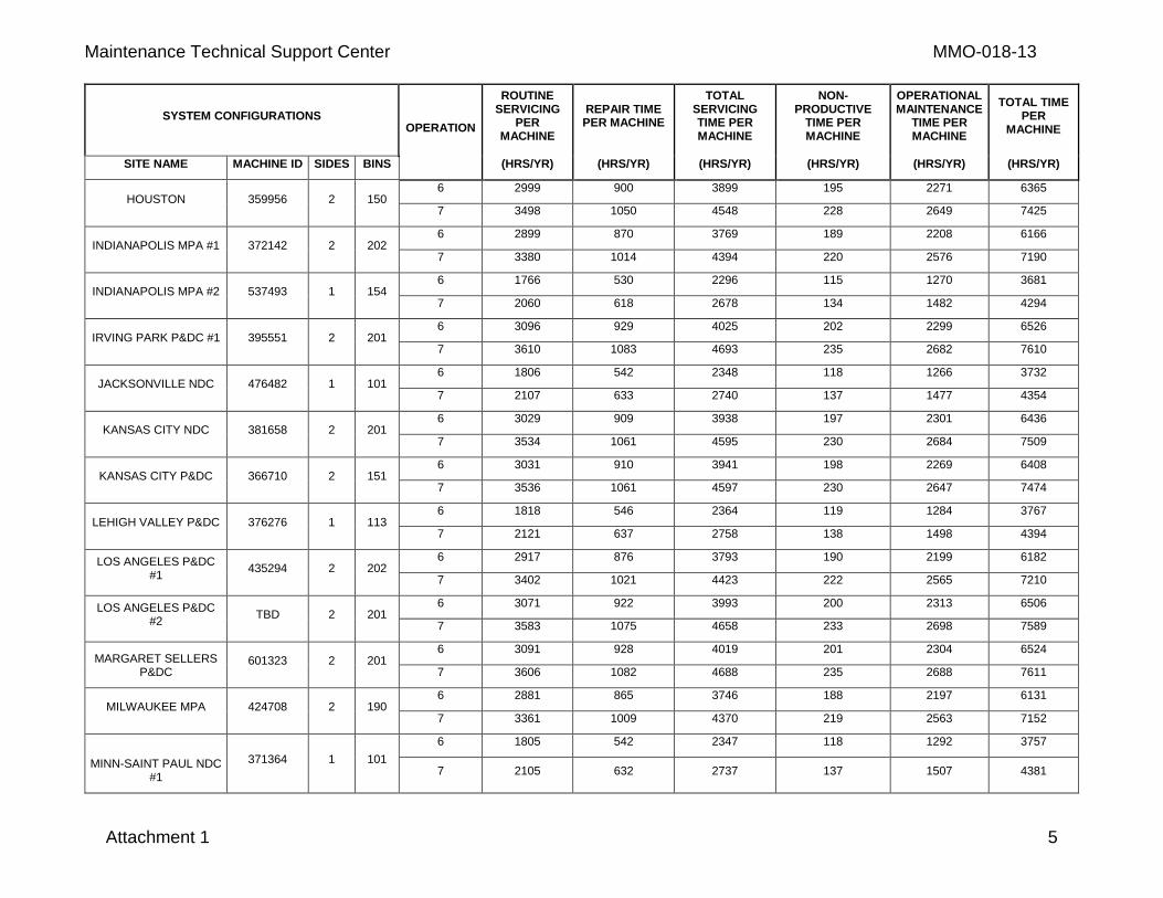
SYSTEM CONFIGURATIONS OPERATION
ROUTINE SERVICING
PER MACHINE
REPAIR TIME
PER MACHINE
TOTAL SERVICING TIME PER MACHINE
NON-PRODUCTIVE
TIME PER MACHINE
OPERATIONAL MAINTENANCE
TIME PER MACHINE
TOTAL TIME PER
MACHINE
SITE NAME MACHINE ID SIDES BINS (HRS/YR) (HRS/YR) (HRS/YR) (HRS/YR) (HRS/YR) (HRS/YR)
HOUSTON 359956 2 150 6 2999 900 3899 195 2271 6365
7 3498 1050 4548 228 2649 7425
INDIANAPOLIS MPA #1 372142 2 202 6 2899 870 3769 189 2208 6166
7 3380 1014 4394 220 2576 7190
INDIANAPOLIS MPA #2 537493 1 154 6 1766 530 2296 115 1270 3681
7 2060 618 2678 134 1482 4294
IRVING PARK P&DC #1 395551 2 201 6 3096 929 4025 202 2299 6526
7 3610 1083 4693 235 2682 7610
JACKSONVILLE NDC 476482 1 101 6 1806 542 2348 118 1266 3732
7 2107 633 2740 137 1477 4354
KANSAS CITY NDC 381658 2 201 6 3029 909 3938 197 2301 6436
7 3534 1061 4595 230 2684 7509
KANSAS CITY P&DC 366710 2 151 6 3031 910 3941 198 2269 6408
7 3536 1061 4597 230 2647 7474
LEHIGH VALLEY P&DC 376276 1 113 6 1818 546 2364 119 1284 3767
7 2121 637 2758 138 1498 4394
LOS ANGELES P&DC #1
435294 2 202 6 2917 876 3793 190 2199 6182
7 3402 1021 4423 222 2565 7210
LOS ANGELES P&DC #2
TBD 2 201 6 3071 922 3993 200 2313 6506
7 3583 1075 4658 233 2698 7589
MARGARET SELLERS P&DC
601323 2 201 6 3091 928 4019 201 2304 6524
7 3606 1082 4688 235 2688 7611
MILWAUKEE MPA 424708 2 190 6 2881 865 3746 188 2197 6131
7 3361 1009 4370 219 2563 7152
MINN-SAINT PAUL NDC #1
371364 1 101
6 1805 542 2347 118 1292 3757
7 2105 632 2737 137 1507 4381
MMO-018-13 Maintenance Technical Support Center
6 Attachment 1
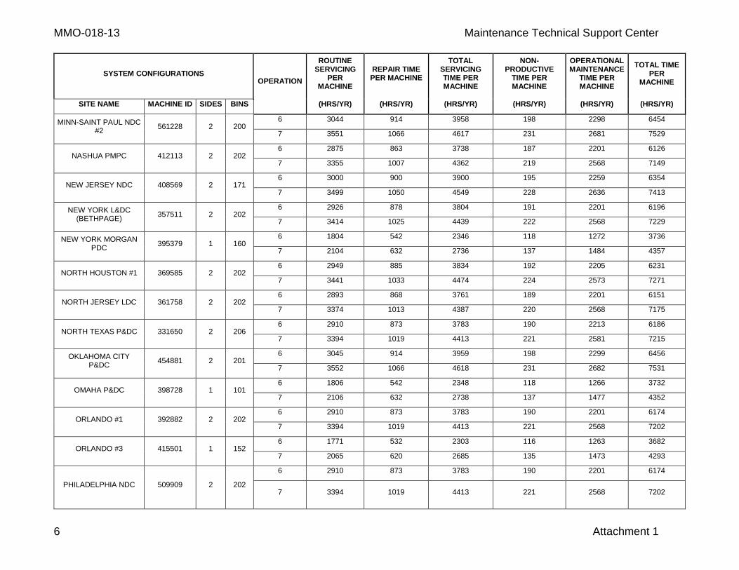
SYSTEM CONFIGURATIONS OPERATION
ROUTINE SERVICING
PER MACHINE
REPAIR TIME
PER MACHINE
TOTAL SERVICING TIME PER MACHINE
NON-PRODUCTIVE
TIME PER MACHINE
OPERATIONAL MAINTENANCE
TIME PER MACHINE
TOTAL TIME PER
MACHINE
SITE NAME MACHINE ID SIDES BINS (HRS/YR) (HRS/YR) (HRS/YR) (HRS/YR) (HRS/YR) (HRS/YR)
MINN-SAINT PAUL NDC #2
561228 2 200 6 3044 914 3958 198 2298 6454
7 3551 1066 4617 231 2681 7529
NASHUA PMPC 412113 2 202 6 2875 863 3738 187 2201 6126
7 3355 1007 4362 219 2568 7149
NEW JERSEY NDC 408569 2 171 6 3000 900 3900 195 2259 6354
7 3499 1050 4549 228 2636 7413
NEW YORK L&DC (BETHPAGE)
357511 2 202 6 2926 878 3804 191 2201 6196
7 3414 1025 4439 222 2568 7229
NEW YORK MORGAN PDC
395379 1 160 6 1804 542 2346 118 1272 3736
7 2104 632 2736 137 1484 4357
NORTH HOUSTON #1 369585 2 202 6 2949 885 3834 192 2205 6231
7 3441 1033 4474 224 2573 7271
NORTH JERSEY LDC 361758 2 202 6 2893 868 3761 189 2201 6151
7 3374 1013 4387 220 2568 7175
NORTH TEXAS P&DC 331650 2 206 6 2910 873 3783 190 2213 6186
7 3394 1019 4413 221 2581 7215
OKLAHOMA CITY P&DC
454881 2 201 6 3045 914 3959 198 2299 6456
7 3552 1066 4618 231 2682 7531
OMAHA P&DC 398728 1 101 6 1806 542 2348 118 1266 3732
7 2106 632 2738 137 1477 4352
ORLANDO #1 392882 2 202 6 2910 873 3783 190 2201 6174
7 3394 1019 4413 221 2568 7202
ORLANDO #3 415501 1 152 6 1771 532 2303 116 1263 3682
7 2065 620 2685 135 1473 4293
PHILADELPHIA NDC
509909 2 202
6 2910 873 3783 190 2201 6174
7 3394 1019 4413 221 2568 7202
Maintenance Technical Support Center MMO-018-13
Attachment 1 7
SYSTEM CONFIGURATIONS OPERATION
ROUTINE SERVICING
PER MACHINE
REPAIR TIME
PER MACHINE
TOTAL SERVICING TIME PER MACHINE
NON-PRODUCTIVE
TIME PER MACHINE
OPERATIONAL MAINTENANCE
TIME PER MACHINE
TOTAL TIME PER
MACHINE
SITE NAME MACHINE ID SIDES BINS (HRS/YR) (HRS/YR) (HRS/YR) (HRS/YR) (HRS/YR) (HRS/YR)
PHILADELPHIA P&DC #1
382071 1 152 6 1780 534 2314 116 1263 3693
7 2076 623 2699 135 1473 4307
PHILADELPHIA P&DC #2
382072 1 152 6 1780 534 2314 116 1263 3693
7 2076 623 2699 135 1473 4307
PITTSBURGH L&DC 379207 2 201 6 3138 942 4080 204 2325 6609
7 3661 1099 4760 238 2712 7710
PROVIDENCE 380725 2 204 6 3095 929 4024 202 2310 6536
7 3610 1083 4693 235 2695 7623
RALEIGH P&DC 536513 1 151 6 1943 583 2526 127 1335 3988
7 2267 681 2948 148 1557 4653
RICHMOND 501653 2 192 6 2943 883 3826 192 2202 6220
7 3433 1030 4463 224 2569 7256
ROCHESTER L&DC #1 345651 2 202 6 2926 878 3804 191 2213 6208
7 3413 1024 4437 222 2581 7240
ROCHESTER L&DC #2 370973 2 202 6 2959 888 3847 193 2213 6253
7 3452 1036 4488 225 2581 7294
SAN BERNARDINO P&DC
435412 2 200 6 3088 927 4015 201 2325 6541
7 3603 1081 4684 235 2712 7631
SAN JOSE P&DC 392784 2 201 6 3063 919 3982 200 2299 6481
7 3572 1072 4644 233 2682 7559
SANTA CLARITA P&DC #1
374309 2 201 6 3096 929 4025 202 2299 6526
7 3611 1084 4695 235 2682 7612
SOUTH FLORIDA L&DC 474135 2 201 6 3112 934 4046 203 2299 6548
7 3629 1089 4718 236 2682 7636
SOUTH JERSEY P&DC
383981 2 156
6 3029 909 3938 197 2264 6399
7 3533 1060 4593 230 2641 7464
MMO-018-13 Maintenance Technical Support Center
8 Attachment 1
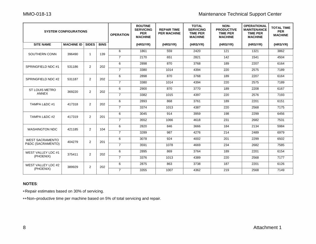
SYSTEM CONFIGURATIONS OPERATION
ROUTINE SERVICING
PER MACHINE
REPAIR TIME
PER MACHINE
TOTAL SERVICING TIME PER MACHINE
NON-PRODUCTIVE
TIME PER MACHINE
OPERATIONAL MAINTENANCE
TIME PER MACHINE
TOTAL TIME PER
MACHINE
SITE NAME MACHINE ID SIDES BINS (HRS/YR) (HRS/YR) (HRS/YR) (HRS/YR) (HRS/YR) (HRS/YR)
SOUTHERN CONN 396490 1 139 6 1861 559 2420 121 1321 3862
7 2170 651 2821 142 1541 4504
SPRINGFIELD NDC #1 531186 2 202 6 2898 870 3768 189 2207 6164
7 3380 1014 4394 220 2575 7189
SPRINGFIELD NDC #2 531187 2 202 6 2898 870 3768 189 2207 6164
7 3380 1014 4394 220 2575 7189
ST LOUIS METRO ANNEX
369220 2 202 6 2900 870 3770 189 2208 6167
7 3382 1015 4397 220 2576 7193
TAMPA L&DC #1 417318 2 202 6 2893 868 3761 189 2201 6151
7 3374 1013 4387 220 2568 7175
TAMPA L&DC #2 417319 2 201 6 3045 914 3959 198 2299 6456
7 3552 1066 4618 231 2682 7531
WASHINGTON NDC 421185 2 104 6 2820 846 3666 184 2134 5984
7 3289 987 4276 214 2489 6979
WEST SACRAMENTO P&DC (SACRAMENTO)
404279 2 201 6 3078 924 4002 201 2299 6502
7 3591 1078 4669 234 2682 7585
WEST VALLEY LDC #1 (PHOENIX)
375411 2 202 6 2895 869 3764 189 2201 6154
7 3376 1013 4389 220 2568 7177
WEST VALLEY LDC #2 (PHOENIX)
389929 2 202 6 2875 863 3738 187 2201 6126
7 3355 1007 4362 219 2568 7149
NOTES:
Repair estimates based on 30% of servicing.
Non–productive time per machine based on 5% of total servicing and repair.
Maintenance Technical Support Center MMO-018-13
Attachment 2 1
ATTACHMENT 2
APPS MASTER CHECKLIST
03-APPS-AA-001-M
Time Total: See Attachment 1
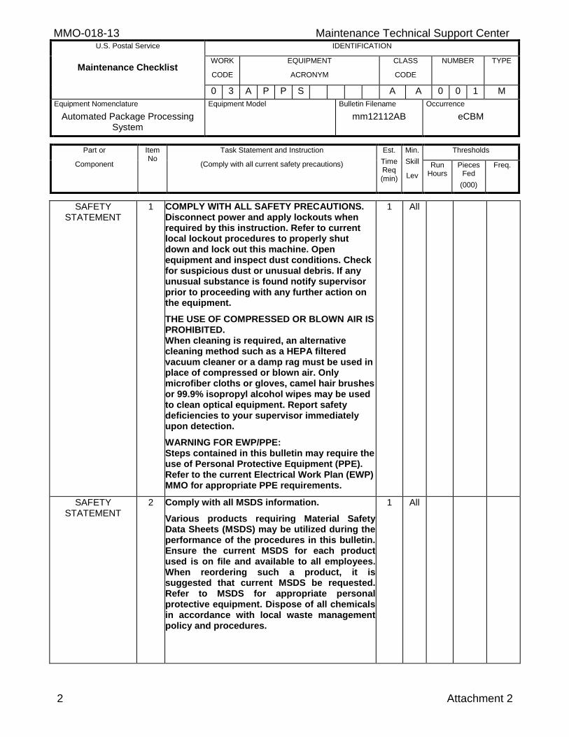
MMO-018-13 Maintenance Technical Support Center U.S. Postal Service IDENTIFICATION
Maintenance Checklist WORK
CODE
EQUIPMENT
ACRONYM
CLASS
CODE
NUMBER TYPE
0 3 A P P S A A 0 0 1 M
Equipment Nomenclature
Automated Package Processing System
Equipment Model
Bulletin Filename
mm12112AB
Occurrence
eCBM
Part or
Component
Item No
Task Statement and Instruction
(Comply with all current safety precautions)
Est.
Time Req (min)
Min.
Skill
Lev
Thresholds
Run Hours
Pieces Fed
(000)
Freq.
2 Attachment 2
SAFETY STATEMENT
1 COMPLY WITH ALL SAFETY PRECAUTIONS. Disconnect power and apply lockouts when required by this instruction. Refer to current local lockout procedures to properly shut down and lock out this machine. Open equipment and inspect dust conditions. Check for suspicious dust or unusual debris. If any unusual substance is found notify supervisor prior to proceeding with any further action on the equipment.
THE USE OF COMPRESSED OR BLOWN AIR IS PROHIBITED. When cleaning is required, an alternative cleaning method such as a HEPA filtered vacuum cleaner or a damp rag must be used in place of compressed or blown air. Only microfiber cloths or gloves, camel hair brushes or 99.9% isopropyl alcohol wipes may be used to clean optical equipment. Report safety deficiencies to your supervisor immediately upon detection.
WARNING FOR EWP/PPE: Steps contained in this bulletin may require the use of Personal Protective Equipment (PPE). Refer to the current Electrical Work Plan (EWP) MMO for appropriate PPE requirements.
1 All
SAFETY STATEMENT
2 Comply with all MSDS information.
Various products requiring Material Safety Data Sheets (MSDS) may be utilized during the performance of the procedures in this bulletin. Ensure the current MSDS for each product used is on file and available to all employees. When reordering such a product, it is suggested that current MSDS be requested. Refer to MSDS for appropriate personal protective equipment. Dispose of all chemicals in accordance with local waste management policy and procedures.
1 All
Maintenance Technical Support Center MMO-018-13 U.S. Postal Service IDENTIFICATION
Maintenance Checklist WORK
CODE
EQUIPMENT
ACRONYM
CLASS
CODE
NUMBER TYPE
0 3 A P P S A A 0 0 1 M
Equipment Nomenclature
Automated Package Processing System
Equipment Model
Bulletin Filename
mm12112AB
Occurrence
eCBM
Part or
Component
Item No
Task Statement and Instruction
(Comply with all current safety precautions)
Est.
Time Req (min)
Min.
Skill
Lev
Thresholds
Run Hours
Pieces Fed
(000)
Freq.
Attachment 2 3
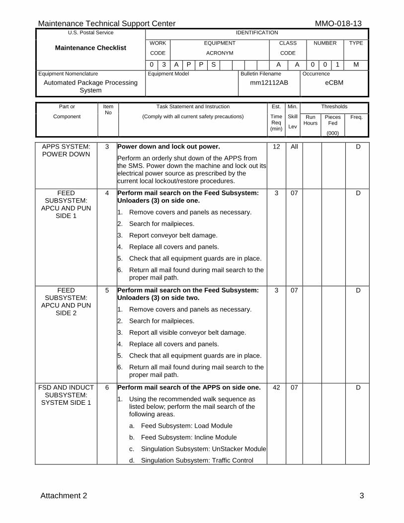
APPS SYSTEM: POWER DOWN
3 Power down and lock out power.
Perform an orderly shut down of the APPS from the SMS. Power down the machine and lock out its electrical power source as prescribed by the current local lockout/restore procedures.
12 All D
FEED SUBSYSTEM:
APCU AND PUN SIDE 1
4 Perform mail search on the Feed Subsystem: Unloaders (3) on side one.
1. Remove covers and panels as necessary.
2. Search for mailpieces.
3. Report conveyor belt damage.
4. Replace all covers and panels.
5. Check that all equipment guards are in place.
6. Return all mail found during mail search to the proper mail path.
3 07 D
FEED SUBSYSTEM:
APCU AND PUN SIDE 2
5 Perform mail search on the Feed Subsystem: Unloaders (3) on side two.
1. Remove covers and panels as necessary.
2. Search for mailpieces.
3. Report all visible conveyor belt damage.
4. Replace all covers and panels.
5. Check that all equipment guards are in place.
6. Return all mail found during mail search to the proper mail path.
3 07 D
FSD AND INDUCT SUBSYSTEM:
SYSTEM SIDE 1
6 Perform mail search of the APPS on side one.
1. Using the recommended walk sequence as listed below; perform the mail search of the following areas.
a. Feed Subsystem: Load Module
b. Feed Subsystem: Incline Module
c. Singulation Subsystem: UnStacker Module
d. Singulation Subsystem: Traffic Control
42 07 D
MMO-018-13 Maintenance Technical Support Center U.S. Postal Service IDENTIFICATION
Maintenance Checklist WORK
CODE
EQUIPMENT
ACRONYM
CLASS
CODE
NUMBER TYPE
0 3 A P P S A A 0 0 1 M
Equipment Nomenclature
Automated Package Processing System
Equipment Model
Bulletin Filename
mm12112AB
Occurrence
eCBM
Part or
Component
Item No
Task Statement and Instruction
(Comply with all current safety precautions)
Est.
Time Req (min)
Min.
Skill
Lev
Thresholds
Run Hours
Pieces Fed
(000)
Freq.
4 Attachment 2
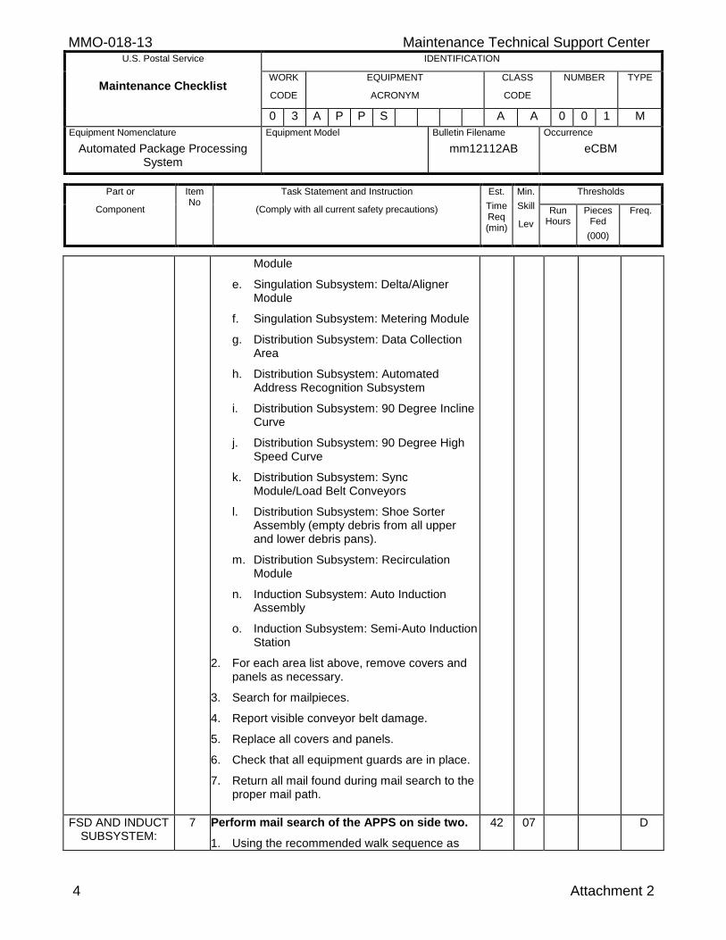
Module
e. Singulation Subsystem: Delta/Aligner Module
f. Singulation Subsystem: Metering Module
g. Distribution Subsystem: Data Collection Area
h. Distribution Subsystem: Automated Address Recognition Subsystem
i. Distribution Subsystem: 90 Degree Incline Curve
j. Distribution Subsystem: 90 Degree High Speed Curve
k. Distribution Subsystem: Sync Module/Load Belt Conveyors
l. Distribution Subsystem: Shoe Sorter Assembly (empty debris from all upper and lower debris pans).
m. Distribution Subsystem: Recirculation Module
n. Induction Subsystem: Auto Induction Assembly
o. Induction Subsystem: Semi-Auto Induction Station
2. For each area list above, remove covers and panels as necessary.
3. Search for mailpieces.
4. Report visible conveyor belt damage.
5. Replace all covers and panels.
6. Check that all equipment guards are in place.
7. Return all mail found during mail search to the proper mail path.
FSD AND INDUCT SUBSYSTEM:
7 Perform mail search of the APPS on side two.
1. Using the recommended walk sequence as
42 07 D
Maintenance Technical Support Center MMO-018-13 U.S. Postal Service IDENTIFICATION
Maintenance Checklist WORK
CODE
EQUIPMENT
ACRONYM
CLASS
CODE
NUMBER TYPE
0 3 A P P S A A 0 0 1 M
Equipment Nomenclature
Automated Package Processing System
Equipment Model
Bulletin Filename
mm12112AB
Occurrence
eCBM
Part or
Component
Item No
Task Statement and Instruction
(Comply with all current safety precautions)
Est.
Time Req (min)
Min.
Skill
Lev
Thresholds
Run Hours
Pieces Fed
(000)
Freq.
Attachment 2 5
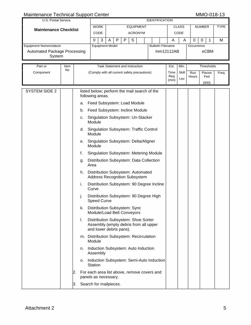
SYSTEM SIDE 2 listed below; perform the mail search of the following areas.
a. Feed Subsystem: Load Module
b. Feed Subsystem: Incline Module
c. Singulation Subsystem: Un-Stacker Module
d. Singulation Subsystem: Traffic Control Module
e. Singulation Subsystem: Delta/Aligner Module
f. Singulation Subsystem: Metering Module
g. Distribution Subsystem: Data Collection Area
h. Distribution Subsystem: Automated Address Recognition Subsystem
i. Distribution Subsystem: 90 Degree Incline Curve
j. Distribution Subsystem: 90 Degree High Speed Curve
k. Distribution Subsystem: Sync Module/Load Belt Conveyors
l. Distribution Subsystem: Shoe Sorter Assembly (empty debris from all upper and lower debris pans).
m. Distribution Subsystem: Recirculation Module
n. Induction Subsystem: Auto Induction Assembly
o. Induction Subsystem: Semi-Auto Induction Station
2. For each area list above, remove covers and panels as necessary.
3. Search for mailpieces.
MMO-018-13 Maintenance Technical Support Center U.S. Postal Service IDENTIFICATION
Maintenance Checklist WORK
CODE
EQUIPMENT
ACRONYM
CLASS
CODE
NUMBER TYPE
0 3 A P P S A A 0 0 1 M
Equipment Nomenclature
Automated Package Processing System
Equipment Model
Bulletin Filename
mm12112AB
Occurrence
eCBM
Part or
Component
Item No
Task Statement and Instruction
(Comply with all current safety precautions)
Est.
Time Req (min)
Min.
Skill
Lev
Thresholds
Run Hours
Pieces Fed
(000)
Freq.
6 Attachment 2
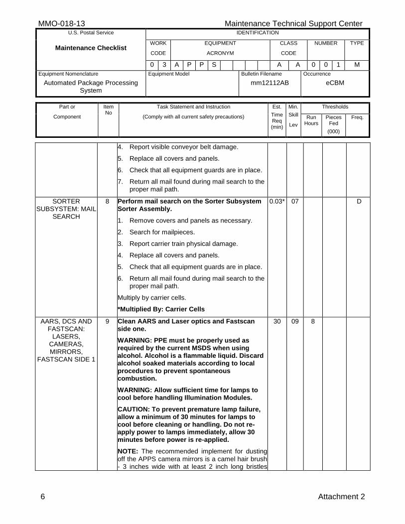
4. Report visible conveyor belt damage.
5. Replace all covers and panels.
6. Check that all equipment guards are in place.
7. Return all mail found during mail search to the proper mail path.
SORTER SUBSYSTEM: MAIL
SEARCH
8 Perform mail search on the Sorter Subsystem Sorter Assembly.
1. Remove covers and panels as necessary.
2. Search for mailpieces.
3. Report carrier train physical damage.
4. Replace all covers and panels.
5. Check that all equipment guards are in place.
6. Return all mail found during mail search to the proper mail path.
Multiply by carrier cells.
*Multiplied By: Carrier Cells
0.03* 07 D
AARS, DCS AND FASTSCAN:
LASERS, CAMERAS, MIRRORS,
FASTSCAN SIDE 1
9 Clean AARS and Laser optics and Fastscan side one.
WARNING: PPE must be properly used as required by the current MSDS when using alcohol. Alcohol is a flammable liquid. Discard alcohol soaked materials according to local procedures to prevent spontaneous combustion.
WARNING: Allow sufficient time for lamps to cool before handling Illumination Modules.
CAUTION: To prevent premature lamp failure, allow a minimum of 30 minutes for lamps to cool before cleaning or handling. Do not re-apply power to lamps immediately, allow 30 minutes before power is re-applied.
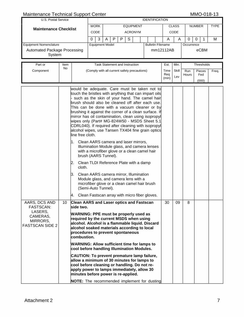
NOTE: The recommended implement for dusting off the APPS camera mirrors is a camel hair brush - 3 inches wide with at least 2 inch long bristles
30 09 8
Maintenance Technical Support Center MMO-018-13 U.S. Postal Service IDENTIFICATION
Maintenance Checklist WORK
CODE
EQUIPMENT
ACRONYM
CLASS
CODE
NUMBER TYPE
0 3 A P P S A A 0 0 1 M
Equipment Nomenclature
Automated Package Processing System
Equipment Model
Bulletin Filename
mm12112AB
Occurrence
eCBM
Part or
Component
Item No
Task Statement and Instruction
(Comply with all current safety precautions)
Est.
Time Req (min)
Min.
Skill
Lev
Thresholds
Run Hours
Pieces Fed
(000)
Freq.
Attachment 2 7
would be adequate. Care must be taken not to touch the bristles with anything that can impart oils - such as the skin of your hand. The camel hair brush should also be cleaned off after each use. This can be done with a vacuum cleaner or by brushing it against the corner of a clean surface. If mirror has oil contamination, clean using isopropyl wipes only (Part# MG-824W50 - MSDS Sheet 5.1 CDRL040). If required after cleaning with isopropyl alcohol wipes, use Tansen TX404 fine grain optics line free cloth.
1. Clean AARS camera and laser mirrors, Illumination Module glass, and camera lenses with a microfiber glove or a clean camel hair brush (AARS Tunnel).
2. Clean TLDI Reference Plate with a damp cloth.
3. Clean AARS camera mirror, Illumination Module glass, and camera lens with a microfiber glove or a clean camel hair brush (Semi-Auto Tunnel).
4. Clean Fastscan array with micro fiber gloves.
AARS, DCS AND FASTSCAN:
LASERS, CAMERAS, MIRRORS,
FASTSCAN SIDE 2
10 Clean AARS and Laser optics and Fastscan side two.
WARNING: PPE must be properly used as required by the current MSDS when using alcohol. Alcohol is a flammable liquid. Discard alcohol soaked materials according to local procedures to prevent spontaneous combustion.
WARNING: Allow sufficient time for lamps to cool before handling Illumination Modules.
CAUTION: To prevent premature lamp failure, allow a minimum of 30 minutes for lamps to cool before cleaning or handling. Do not re-apply power to lamps immediately, allow 30 minutes before power is re-applied.
NOTE: The recommended implement for dusting
30 09 8
MMO-018-13 Maintenance Technical Support Center U.S. Postal Service IDENTIFICATION
Maintenance Checklist WORK
CODE
EQUIPMENT
ACRONYM
CLASS
CODE
NUMBER TYPE
0 3 A P P S A A 0 0 1 M
Equipment Nomenclature
Automated Package Processing System
Equipment Model
Bulletin Filename
mm12112AB
Occurrence
eCBM
Part or
Component
Item No
Task Statement and Instruction
(Comply with all current safety precautions)
Est.
Time Req (min)
Min.
Skill
Lev
Thresholds
Run Hours
Pieces Fed
(000)
Freq.
8 Attachment 2
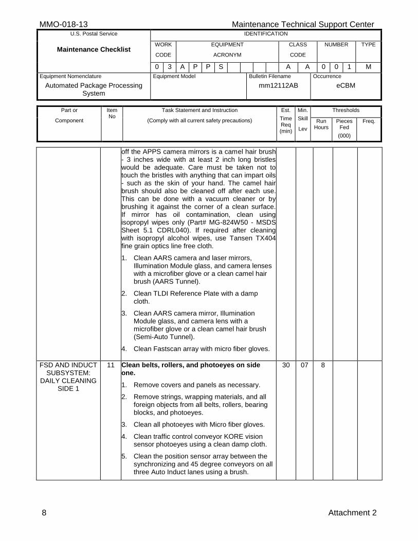
off the APPS camera mirrors is a camel hair brush - 3 inches wide with at least 2 inch long bristles would be adequate. Care must be taken not to touch the bristles with anything that can impart oils - such as the skin of your hand. The camel hair brush should also be cleaned off after each use. This can be done with a vacuum cleaner or by brushing it against the corner of a clean surface. If mirror has oil contamination, clean using isopropyl wipes only (Part# MG-824W50 - MSDS Sheet 5.1 CDRL040). If required after cleaning with isopropyl alcohol wipes, use Tansen TX404 fine grain optics line free cloth.
1. Clean AARS camera and laser mirrors, Illumination Module glass, and camera lenses with a microfiber glove or a clean camel hair brush (AARS Tunnel).
2. Clean TLDI Reference Plate with a damp cloth.
3. Clean AARS camera mirror, Illumination Module glass, and camera lens with a microfiber glove or a clean camel hair brush (Semi-Auto Tunnel).
4. Clean Fastscan array with micro fiber gloves.
FSD AND INDUCT SUBSYSTEM:
DAILY CLEANING SIDE 1
11 Clean belts, rollers, and photoeyes on side one.
1. Remove covers and panels as necessary.
2. Remove strings, wrapping materials, and all foreign objects from all belts, rollers, bearing blocks, and photoeyes.
3. Clean all photoeyes with Micro fiber gloves.
4. Clean traffic control conveyor KORE vision sensor photoeyes using a clean damp cloth.
5. Clean the position sensor array between the synchronizing and 45 degree conveyors on all three Auto Induct lanes using a brush.
30 07 8
Maintenance Technical Support Center MMO-018-13 U.S. Postal Service IDENTIFICATION
Maintenance Checklist WORK
CODE
EQUIPMENT
ACRONYM
CLASS
CODE
NUMBER TYPE
0 3 A P P S A A 0 0 1 M
Equipment Nomenclature
Automated Package Processing System
Equipment Model
Bulletin Filename
mm12112AB
Occurrence
eCBM
Part or
Component
Item No
Task Statement and Instruction
(Comply with all current safety precautions)
Est.
Time Req (min)
Min.
Skill
Lev
Thresholds
Run Hours
Pieces Fed
(000)
Freq.
Attachment 2 9
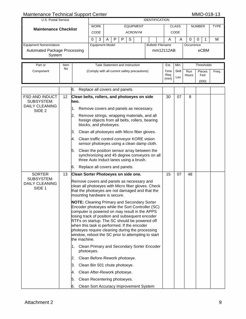
6. Replace all covers and panels.
FSD AND INDUCT SUBSYSTEM:
DAILY CLEANING SIDE 2
12 Clean belts, rollers, and photoeyes on side two.
1. Remove covers and panels as necessary.
2. Remove strings, wrapping materials, and all foreign objects from all belts, rollers, bearing blocks, and photoeyes.
3. Clean all photoeyes with Micro fiber gloves.
4. Clean traffic control conveyor KORE vision sensor photoeyes using a clean damp cloth.
5. Clean the position sensor array between the synchronizing and 45 degree conveyors on all three Auto Induct lanes using a brush.
6. Replace all covers and panels.
30 07 8
SORTER SUBSYSTEM:
DAILY CLEANING SIDE 1
13 Clean Sorter Photoeyes on side one.
Remove covers and panels as necessary and clean all photoeyes with Micro fiber gloves. Check that the photoeyes are not damaged and that the mounting hardware is secure.
NOTE: Cleaning Primary and Secondary Sorter Encoder photoeyes while the Sort Controller (SC) computer is powered on may result in the APPS losing track of position and subsequent encoder RTFs on startup. The SC should be powered off when this task is performed. If the encoder photeyes require cleaning during the processing window, reboot the SC prior to attempting to start the machine.
1. Clean Primary and Secondary Sorter Encoder photoeyes.
2. Clean Before-Rework photoeye.
3. Clean Bin 501 chute photoeye.
4. Clean After-Rework photoeye.
5. Clean Recentering photoeyes.
6. Clean Sort Accuracy Improvement System
15 07 48
MMO-018-13 Maintenance Technical Support Center U.S. Postal Service IDENTIFICATION
Maintenance Checklist WORK
CODE
EQUIPMENT
ACRONYM
CLASS
CODE
NUMBER TYPE
0 3 A P P S A A 0 0 1 M
Equipment Nomenclature
Automated Package Processing System
Equipment Model
Bulletin Filename
mm12112AB
Occurrence
eCBM
Part or
Component
Item No
Task Statement and Instruction
(Comply with all current safety precautions)
Est.
Time Req (min)
Min.
Skill
Lev
Thresholds
Run Hours
Pieces Fed
(000)
Freq.
10 Attachment 2
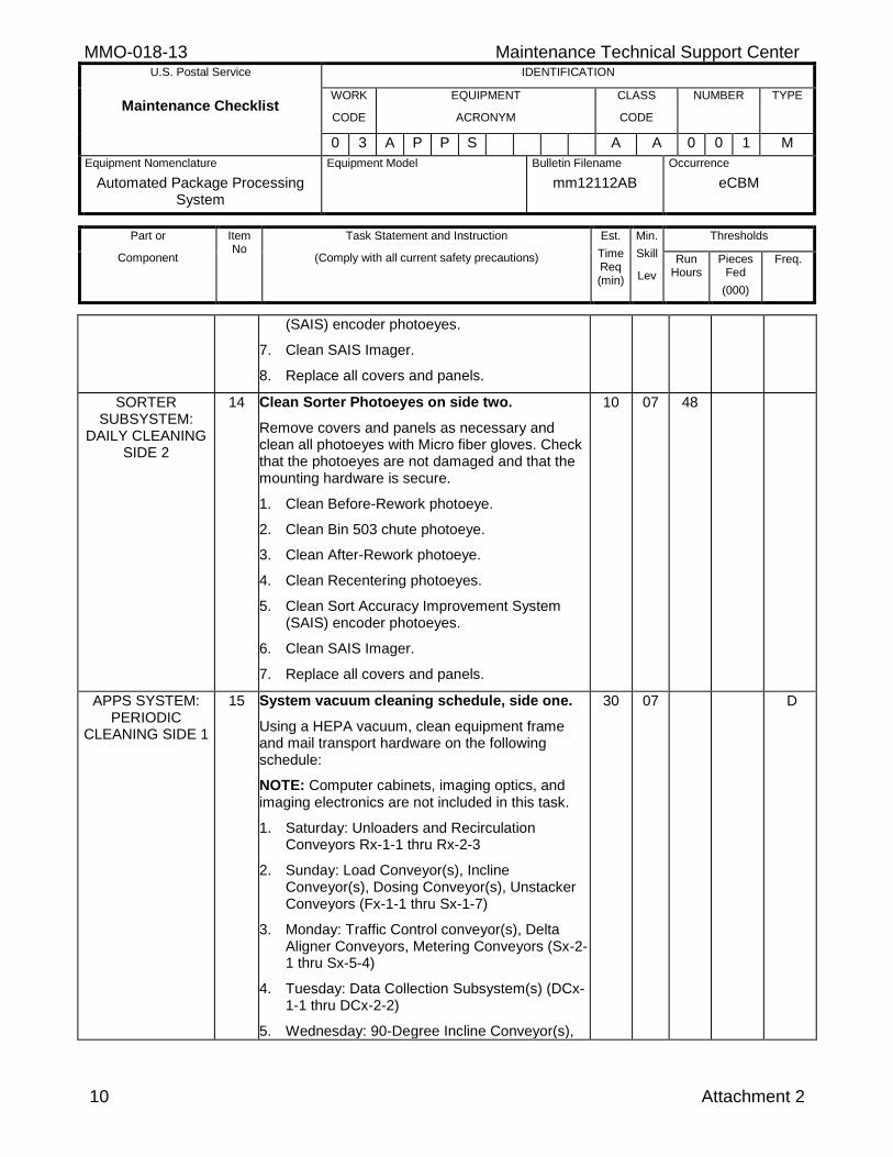
(SAIS) encoder photoeyes.
7. Clean SAIS Imager.
8. Replace all covers and panels.
SORTER SUBSYSTEM:
DAILY CLEANING SIDE 2
14 Clean Sorter Photoeyes on side two.
Remove covers and panels as necessary and clean all photoeyes with Micro fiber gloves. Check that the photoeyes are not damaged and that the mounting hardware is secure.
1. Clean Before-Rework photoeye.
2. Clean Bin 503 chute photoeye.
3. Clean After-Rework photoeye.
4. Clean Recentering photoeyes.
5. Clean Sort Accuracy Improvement System (SAIS) encoder photoeyes.
6. Clean SAIS Imager.
7. Replace all covers and panels.
10 07 48
APPS SYSTEM: PERIODIC
CLEANING SIDE 1
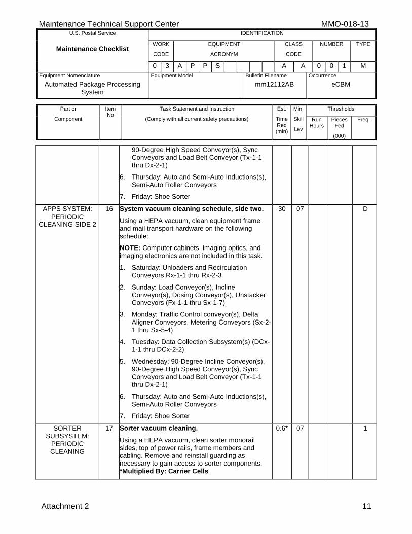
15 System vacuum cleaning schedule, side one.
Using a HEPA vacuum, clean equipment frame and mail transport hardware on the following schedule:
NOTE: Computer cabinets, imaging optics, and imaging electronics are not included in this task.
1. Saturday: Unloaders and Recirculation Conveyors Rx-1-1 thru Rx-2-3
2. Sunday: Load Conveyor(s), Incline Conveyor(s), Dosing Conveyor(s), Unstacker Conveyors (Fx-1-1 thru Sx-1-7)
3. Monday: Traffic Control conveyor(s), Delta Aligner Conveyors, Metering Conveyors (Sx-2-1 thru Sx-5-4)
4. Tuesday: Data Collection Subsystem(s) (DCx-1-1 thru DCx-2-2)
5. Wednesday: 90-Degree Incline Conveyor(s),
30 07 D
Maintenance Technical Support Center MMO-018-13 U.S. Postal Service IDENTIFICATION
Maintenance Checklist WORK
CODE
EQUIPMENT
ACRONYM
CLASS
CODE
NUMBER TYPE
0 3 A P P S A A 0 0 1 M
Equipment Nomenclature
Automated Package Processing System
Equipment Model
Bulletin Filename
mm12112AB
Occurrence
eCBM
Part or
Component
Item No
Task Statement and Instruction
(Comply with all current safety precautions)
Est.
Time Req (min)
Min.
Skill
Lev
Thresholds
Run Hours
Pieces Fed
(000)
Freq.
Attachment 2 11
90-Degree High Speed Conveyor(s), Sync Conveyors and Load Belt Conveyor (Tx-1-1 thru Dx-2-1)
6. Thursday: Auto and Semi-Auto Inductions(s), Semi-Auto Roller Conveyors
7. Friday: Shoe Sorter
APPS SYSTEM: PERIODIC
CLEANING SIDE 2
16 System vacuum cleaning schedule, side two.
Using a HEPA vacuum, clean equipment frame and mail transport hardware on the following schedule:
NOTE: Computer cabinets, imaging optics, and imaging electronics are not included in this task.
1. Saturday: Unloaders and Recirculation Conveyors Rx-1-1 thru Rx-2-3
2. Sunday: Load Conveyor(s), Incline Conveyor(s), Dosing Conveyor(s), Unstacker Conveyors (Fx-1-1 thru Sx-1-7)
3. Monday: Traffic Control conveyor(s), Delta Aligner Conveyors, Metering Conveyors (Sx-2-1 thru Sx-5-4)
4. Tuesday: Data Collection Subsystem(s) (DCx-1-1 thru DCx-2-2)
5. Wednesday: 90-Degree Incline Conveyor(s), 90-Degree High Speed Conveyor(s), Sync Conveyors and Load Belt Conveyor (Tx-1-1 thru Dx-2-1)
6. Thursday: Auto and Semi-Auto Inductions(s), Semi-Auto Roller Conveyors
7. Friday: Shoe Sorter
30 07 D
SORTER SUBSYSTEM:
PERIODIC CLEANING
17 Sorter vacuum cleaning.
Using a HEPA vacuum, clean sorter monorail sides, top of power rails, frame members and cabling. Remove and reinstall guarding as necessary to gain access to sorter components. *Multiplied By: Carrier Cells
0.6* 07 1
MMO-018-13 Maintenance Technical Support Center U.S. Postal Service IDENTIFICATION
Maintenance Checklist WORK
CODE
EQUIPMENT
ACRONYM
CLASS
CODE
NUMBER TYPE
0 3 A P P S A A 0 0 1 M
Equipment Nomenclature
Automated Package Processing System
Equipment Model
Bulletin Filename
mm12112AB
Occurrence
eCBM
Part or
Component
Item No
Task Statement and Instruction
(Comply with all current safety precautions)
Est.
Time Req (min)
Min.
Skill
Lev
Thresholds
Run Hours
Pieces Fed
(000)
Freq.
12 Attachment 2
CANVAS TENTS & WIREWAY: PERIODIC
CLEANING SIDE 1
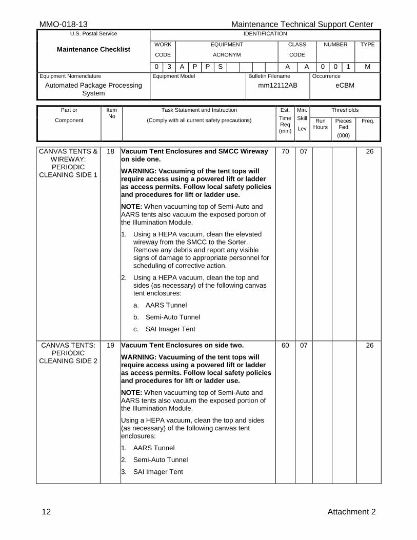
18 Vacuum Tent Enclosures and SMCC Wireway on side one.
WARNING: Vacuuming of the tent tops will require access using a powered lift or ladder as access permits. Follow local safety policies and procedures for lift or ladder use.
NOTE: When vacuuming top of Semi-Auto and AARS tents also vacuum the exposed portion of the Illumination Module.
1. Using a HEPA vacuum, clean the elevated wireway from the SMCC to the Sorter. Remove any debris and report any visible signs of damage to appropriate personnel for scheduling of corrective action.
2. Using a HEPA vacuum, clean the top and sides (as necessary) of the following canvas tent enclosures:
a. AARS Tunnel
b. Semi-Auto Tunnel
c. SAI Imager Tent
70 07 26
CANVAS TENTS: PERIODIC
CLEANING SIDE 2
19 Vacuum Tent Enclosures on side two.
WARNING: Vacuuming of the tent tops will require access using a powered lift or ladder as access permits. Follow local safety policies and procedures for lift or ladder use.
NOTE: When vacuuming top of Semi-Auto and AARS tents also vacuum the exposed portion of the Illumination Module.
Using a HEPA vacuum, clean the top and sides (as necessary) of the following canvas tent enclosures:
1. AARS Tunnel
2. Semi-Auto Tunnel
3. SAI Imager Tent
60 07 26
Maintenance Technical Support Center MMO-018-13 U.S. Postal Service IDENTIFICATION
Maintenance Checklist WORK
CODE
EQUIPMENT
ACRONYM
CLASS
CODE
NUMBER TYPE
0 3 A P P S A A 0 0 1 M
Equipment Nomenclature
Automated Package Processing System
Equipment Model
Bulletin Filename
mm12112AB
Occurrence
eCBM
Part or
Component
Item No
Task Statement and Instruction
(Comply with all current safety precautions)
Est.
Time Req (min)
Min.
Skill
Lev
Thresholds
Run Hours
Pieces Fed
(000)
Freq.
Attachment 2 13
FEED SUBSYSTEM:
SAFETY BARRIERS SIDE 1
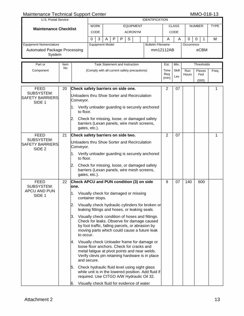
20 Check safety barriers on side one.
Unloaders thru Shoe Sorter and Recirculation Conveyor.
1. Verify unloader guarding is securely anchored to floor.
2. Check for missing, loose, or damaged safety barriers (Lexan panels, wire mesh screens, gates, etc.).
2 07 1
FEED SUBSYSTEM:
SAFETY BARRIERS SIDE 2
21 Check safety barriers on side two.
Unloaders thru Shoe Sorter and Recirculation Conveyor.
1. Verify unloader guarding is securely anchored to floor.
2. Check for missing, loose, or damaged safety barriers (Lexan panels, wire mesh screens, gates, etc.).
2 07 1
FEED SUBSYSTEM:
APCU AND PUN SIDE 1
22 Check APCU and PUN condition (3) on side one.
1. Visually check for damaged or missing container stops.
2. Visually check hydraulic cylinders for broken or leaking fittings and hoses, or leaking seals.
3. Visually check condition of hoses and fittings. Check for leaks. Observe for damage caused by foot traffic, falling parcels, or abrasion by moving parts which could cause a future leak to occur.
4. Visually check Unloader frame for damage or loose floor anchors. Check for cracks and metal fatigue at pivot points and near welds. Verify clevis pin retaining hardware is in place and secure.
5. Check hydraulic fluid level using sight glass while unit is in the lowered position. Add fluid if required. Use CITGO A/W Hydraulic Oil 32.
6. Visually check fluid for evidence of water
9 07 140 600
MMO-018-13 Maintenance Technical Support Center U.S. Postal Service IDENTIFICATION
Maintenance Checklist WORK
CODE
EQUIPMENT
ACRONYM
CLASS
CODE
NUMBER TYPE
0 3 A P P S A A 0 0 1 M
Equipment Nomenclature
Automated Package Processing System
Equipment Model
Bulletin Filename
mm12112AB
Occurrence
eCBM
Part or
Component
Item No
Task Statement and Instruction
(Comply with all current safety precautions)
Est.
Time Req (min)
Min.
Skill
Lev
Thresholds
Run Hours
Pieces Fed
(000)
Freq.
14 Attachment 2
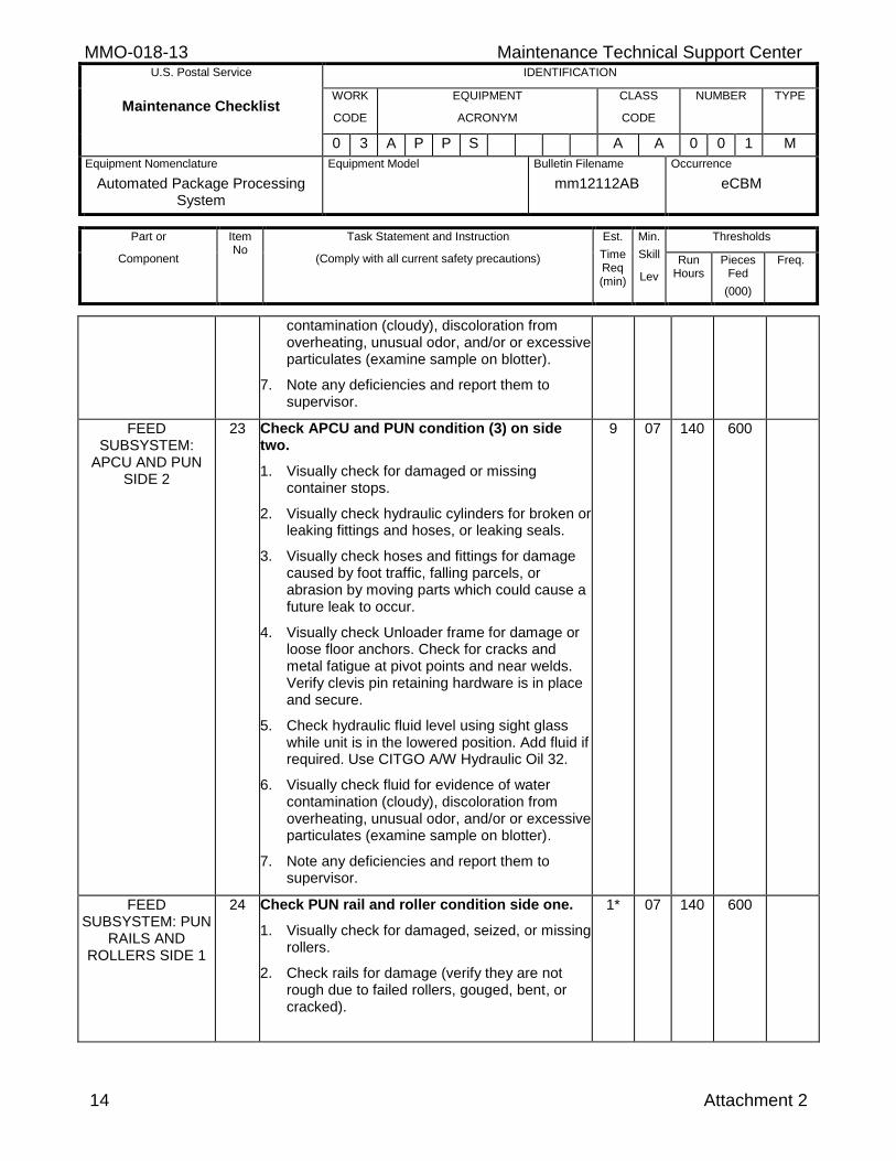
contamination (cloudy), discoloration from overheating, unusual odor, and/or or excessive particulates (examine sample on blotter).
7. Note any deficiencies and report them to supervisor.
FEED SUBSYSTEM:
APCU AND PUN SIDE 2
23 Check APCU and PUN condition (3) on side two.
1. Visually check for damaged or missing container stops.
2. Visually check hydraulic cylinders for broken or leaking fittings and hoses, or leaking seals.
3. Visually check hoses and fittings for damage caused by foot traffic, falling parcels, or abrasion by moving parts which could cause a future leak to occur.
4. Visually check Unloader frame for damage or loose floor anchors. Check for cracks and metal fatigue at pivot points and near welds. Verify clevis pin retaining hardware is in place and secure.
5. Check hydraulic fluid level using sight glass while unit is in the lowered position. Add fluid if required. Use CITGO A/W Hydraulic Oil 32.
6. Visually check fluid for evidence of water contamination (cloudy), discoloration from overheating, unusual odor, and/or or excessive particulates (examine sample on blotter).
7. Note any deficiencies and report them to supervisor.
9 07 140 600
FEED SUBSYSTEM: PUN
RAILS AND ROLLERS SIDE 1
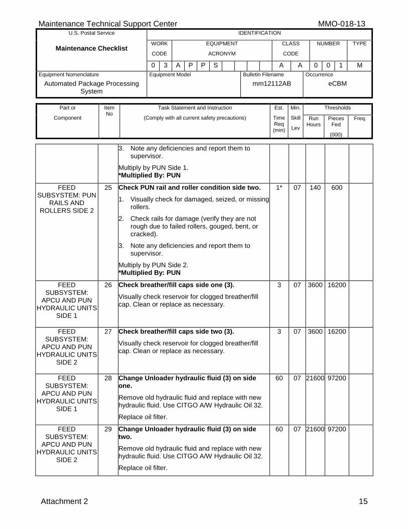
24 Check PUN rail and roller condition side one.
1. Visually check for damaged, seized, or missing rollers.
2. Check rails for damage (verify they are not rough due to failed rollers, gouged, bent, or cracked).
1* 07 140 600
Maintenance Technical Support Center MMO-018-13 U.S. Postal Service IDENTIFICATION
Maintenance Checklist WORK
CODE
EQUIPMENT
ACRONYM
CLASS
CODE
NUMBER TYPE
0 3 A P P S A A 0 0 1 M
Equipment Nomenclature
Automated Package Processing System
Equipment Model
Bulletin Filename
mm12112AB
Occurrence
eCBM
Part or
Component
Item No
Task Statement and Instruction
(Comply with all current safety precautions)
Est.
Time Req (min)
Min.
Skill
Lev
Thresholds
Run Hours
Pieces Fed
(000)
Freq.
Attachment 2 15
3. Note any deficiencies and report them to supervisor.
Multiply by PUN Side 1. *Multiplied By: PUN
FEED SUBSYSTEM: PUN
RAILS AND ROLLERS SIDE 2
25 Check PUN rail and roller condition side two.
1. Visually check for damaged, seized, or missing rollers.
2. Check rails for damage (verify they are not rough due to failed rollers, gouged, bent, or cracked).
3. Note any deficiencies and report them to supervisor.
Multiply by PUN Side 2. *Multiplied By: PUN
1* 07 140 600
FEED SUBSYSTEM:
APCU AND PUN HYDRAULIC UNITS
SIDE 1
26 Check breather/fill caps side one (3).
Visually check reservoir for clogged breather/fill cap. Clean or replace as necessary.
3 07 3600 16200
FEED SUBSYSTEM:
APCU AND PUN HYDRAULIC UNITS
SIDE 2
27 Check breather/fill caps side two (3).
Visually check reservoir for clogged breather/fill cap. Clean or replace as necessary.
3 07 3600 16200
FEED SUBSYSTEM:
APCU AND PUN HYDRAULIC UNITS
SIDE 1
28 Change Unloader hydraulic fluid (3) on side one.
Remove old hydraulic fluid and replace with new hydraulic fluid. Use CITGO A/W Hydraulic Oil 32.
Replace oil filter.
60 07 21600 97200
FEED SUBSYSTEM:
APCU AND PUN HYDRAULIC UNITS
SIDE 2
29 Change Unloader hydraulic fluid (3) on side two.
Remove old hydraulic fluid and replace with new hydraulic fluid. Use CITGO A/W Hydraulic Oil 32.
Replace oil filter.
60 07 21600 97200
MMO-018-13 Maintenance Technical Support Center U.S. Postal Service IDENTIFICATION
Maintenance Checklist WORK
CODE
EQUIPMENT
ACRONYM
CLASS
CODE
NUMBER TYPE
0 3 A P P S A A 0 0 1 M
Equipment Nomenclature
Automated Package Processing System
Equipment Model
Bulletin Filename
mm12112AB
Occurrence
eCBM
Part or
Component
Item No
Task Statement and Instruction
(Comply with all current safety precautions)
Est.
Time Req (min)
Min.
Skill
Lev
Thresholds
Run Hours
Pieces Fed
(000)
Freq.
16 Attachment 2
FEED SUBSYSTEM:
LOAD CONVEYOR SIDE 1
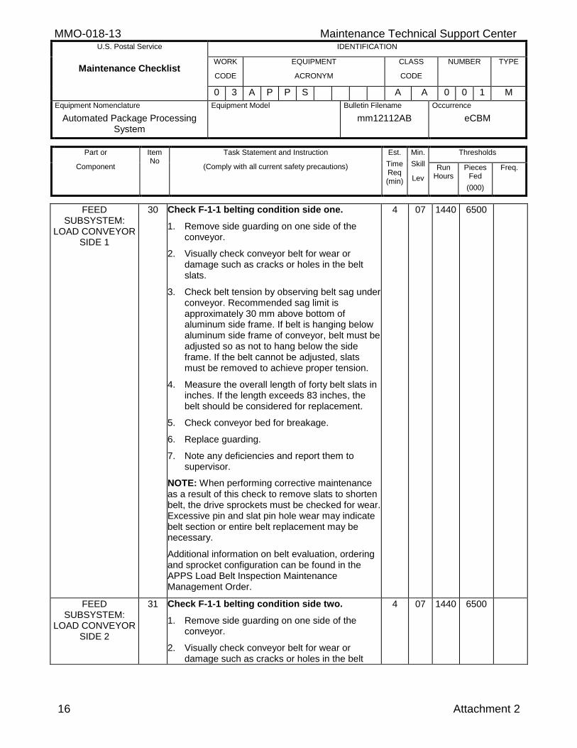
30 Check F-1-1 belting condition side one.
1. Remove side guarding on one side of the conveyor.
2. Visually check conveyor belt for wear or damage such as cracks or holes in the belt slats.
3. Check belt tension by observing belt sag under conveyor. Recommended sag limit is approximately 30 mm above bottom of aluminum side frame. If belt is hanging below aluminum side frame of conveyor, belt must be adjusted so as not to hang below the side frame. If the belt cannot be adjusted, slats must be removed to achieve proper tension.
4. Measure the overall length of forty belt slats in inches. If the length exceeds 83 inches, the belt should be considered for replacement.
5. Check conveyor bed for breakage.
6. Replace guarding.
7. Note any deficiencies and report them to supervisor.
NOTE: When performing corrective maintenance as a result of this check to remove slats to shorten belt, the drive sprockets must be checked for wear. Excessive pin and slat pin hole wear may indicate belt section or entire belt replacement may be necessary.
Additional information on belt evaluation, ordering and sprocket configuration can be found in the APPS Load Belt Inspection Maintenance Management Order.
4 07 1440 6500
FEED SUBSYSTEM:
LOAD CONVEYOR SIDE 2
31 Check F-1-1 belting condition side two.
1. Remove side guarding on one side of the conveyor.
2. Visually check conveyor belt for wear or damage such as cracks or holes in the belt
4 07 1440 6500
Maintenance Technical Support Center MMO-018-13 U.S. Postal Service IDENTIFICATION
Maintenance Checklist WORK
CODE
EQUIPMENT
ACRONYM
CLASS
CODE
NUMBER TYPE
0 3 A P P S A A 0 0 1 M
Equipment Nomenclature
Automated Package Processing System
Equipment Model
Bulletin Filename
mm12112AB
Occurrence
eCBM
Part or
Component
Item No
Task Statement and Instruction
(Comply with all current safety precautions)
Est.
Time Req (min)
Min.
Skill
Lev
Thresholds
Run Hours
Pieces Fed
(000)
Freq.
Attachment 2 17
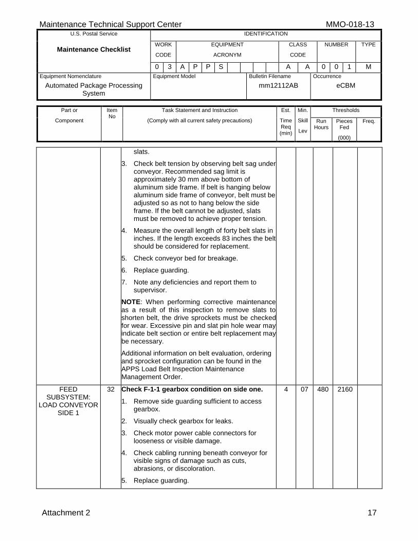
slats.
3. Check belt tension by observing belt sag under conveyor. Recommended sag limit is approximately 30 mm above bottom of aluminum side frame. If belt is hanging below aluminum side frame of conveyor, belt must be adjusted so as not to hang below the side frame. If the belt cannot be adjusted, slats must be removed to achieve proper tension.
4. Measure the overall length of forty belt slats in inches. If the length exceeds 83 inches the belt should be considered for replacement.
5. Check conveyor bed for breakage.
6. Replace guarding.
7. Note any deficiencies and report them to supervisor.
NOTE: When performing corrective maintenance as a result of this inspection to remove slats to shorten belt, the drive sprockets must be checked for wear. Excessive pin and slat pin hole wear may indicate belt section or entire belt replacement may be necessary.
Additional information on belt evaluation, ordering and sprocket configuration can be found in the APPS Load Belt Inspection Maintenance Management Order.
FEED SUBSYSTEM:
LOAD CONVEYOR SIDE 1
32 Check F-1-1 gearbox condition on side one.
1. Remove side guarding sufficient to access gearbox.
2. Visually check gearbox for leaks.
3. Check motor power cable connectors for looseness or visible damage.
4. Check cabling running beneath conveyor for visible signs of damage such as cuts, abrasions, or discoloration.
5. Replace guarding.
4 07 480 2160
MMO-018-13 Maintenance Technical Support Center U.S. Postal Service IDENTIFICATION
Maintenance Checklist WORK
CODE
EQUIPMENT
ACRONYM
CLASS
CODE
NUMBER TYPE
0 3 A P P S A A 0 0 1 M
Equipment Nomenclature
Automated Package Processing System
Equipment Model
Bulletin Filename
mm12112AB
Occurrence
eCBM
Part or
Component
Item No
Task Statement and Instruction
(Comply with all current safety precautions)
Est.
Time Req (min)
Min.
Skill
Lev
Thresholds
Run Hours
Pieces Fed
(000)
Freq.
18 Attachment 2
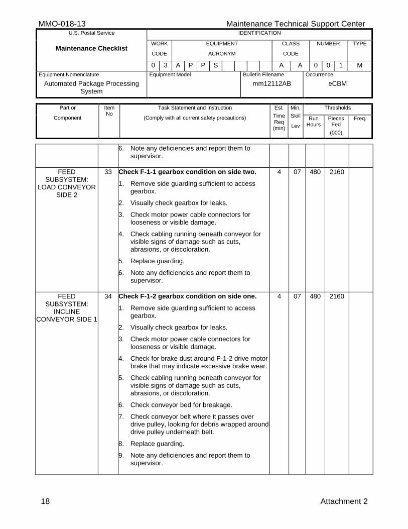
6. Note any deficiencies and report them to supervisor.
FEED SUBSYSTEM:
LOAD CONVEYOR SIDE 2
33 Check F-1-1 gearbox condition on side two.
1. Remove side guarding sufficient to access gearbox.
2. Visually check gearbox for leaks.
3. Check motor power cable connectors for looseness or visible damage.
4. Check cabling running beneath conveyor for visible signs of damage such as cuts, abrasions, or discoloration.
5. Replace guarding.
6. Note any deficiencies and report them to supervisor.
4 07 480 2160
FEED SUBSYSTEM:
INCLINE CONVEYOR SIDE 1
34 Check F-1-2 gearbox condition on side one.
1. Remove side guarding sufficient to access gearbox.
2. Visually check gearbox for leaks.
3. Check motor power cable connectors for looseness or visible damage.
4. Check for brake dust around F-1-2 drive motor brake that may indicate excessive brake wear.
5. Check cabling running beneath conveyor for visible signs of damage such as cuts, abrasions, or discoloration.
6. Check conveyor bed for breakage.
7. Check conveyor belt where it passes over drive pulley, looking for debris wrapped around drive pulley underneath belt.
8. Replace guarding.
9. Note any deficiencies and report them to supervisor.
4 07 480 2160
Maintenance Technical Support Center MMO-018-13 U.S. Postal Service IDENTIFICATION
Maintenance Checklist WORK
CODE
EQUIPMENT
ACRONYM
CLASS
CODE
NUMBER TYPE
0 3 A P P S A A 0 0 1 M
Equipment Nomenclature
Automated Package Processing System
Equipment Model
Bulletin Filename
mm12112AB
Occurrence
eCBM
Part or
Component
Item No
Task Statement and Instruction
(Comply with all current safety precautions)
Est.
Time Req (min)
Min.
Skill
Lev
Thresholds
Run Hours
Pieces Fed
(000)
Freq.
Attachment 2 19
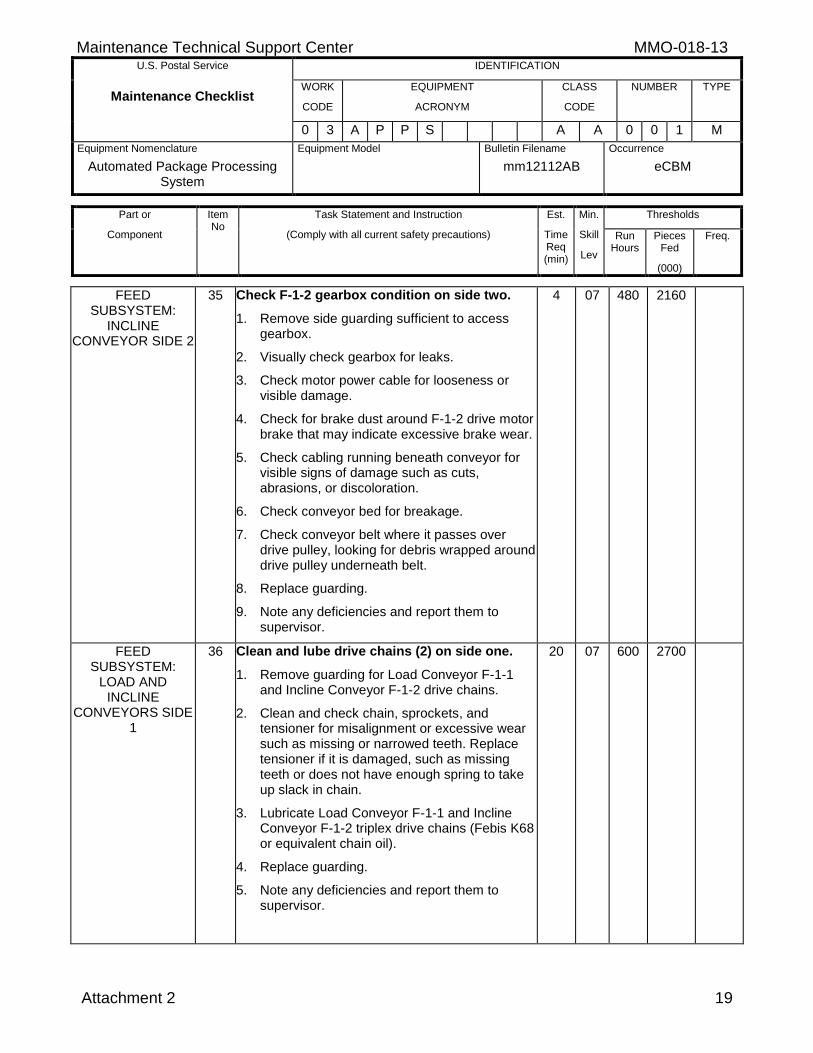
FEED SUBSYSTEM:
INCLINE CONVEYOR SIDE 2
35 Check F-1-2 gearbox condition on side two.
1. Remove side guarding sufficient to access gearbox.
2. Visually check gearbox for leaks.
3. Check motor power cable for looseness or visible damage.
4. Check for brake dust around F-1-2 drive motor brake that may indicate excessive brake wear.
5. Check cabling running beneath conveyor for visible signs of damage such as cuts, abrasions, or discoloration.
6. Check conveyor bed for breakage.
7. Check conveyor belt where it passes over drive pulley, looking for debris wrapped around drive pulley underneath belt.
8. Replace guarding.
9. Note any deficiencies and report them to supervisor.
4 07 480 2160
FEED SUBSYSTEM:
LOAD AND INCLINE
CONVEYORS SIDE 1
36 Clean and lube drive chains (2) on side one.
1. Remove guarding for Load Conveyor F-1-1 and Incline Conveyor F-1-2 drive chains.
2. Clean and check chain, sprockets, and tensioner for misalignment or excessive wear such as missing or narrowed teeth. Replace tensioner if it is damaged, such as missing teeth or does not have enough spring to take up slack in chain.
3. Lubricate Load Conveyor F-1-1 and Incline Conveyor F-1-2 triplex drive chains (Febis K68 or equivalent chain oil).
4. Replace guarding.
5. Note any deficiencies and report them to supervisor.
20 07 600 2700
MMO-018-13 Maintenance Technical Support Center U.S. Postal Service IDENTIFICATION
Maintenance Checklist WORK
CODE
EQUIPMENT
ACRONYM
CLASS
CODE
NUMBER TYPE
0 3 A P P S A A 0 0 1 M
Equipment Nomenclature
Automated Package Processing System
Equipment Model
Bulletin Filename
mm12112AB
Occurrence
eCBM
Part or
Component
Item No
Task Statement and Instruction
(Comply with all current safety precautions)
Est.
Time Req (min)
Min.
Skill
Lev
Thresholds
Run Hours
Pieces Fed
(000)
Freq.
20 Attachment 2
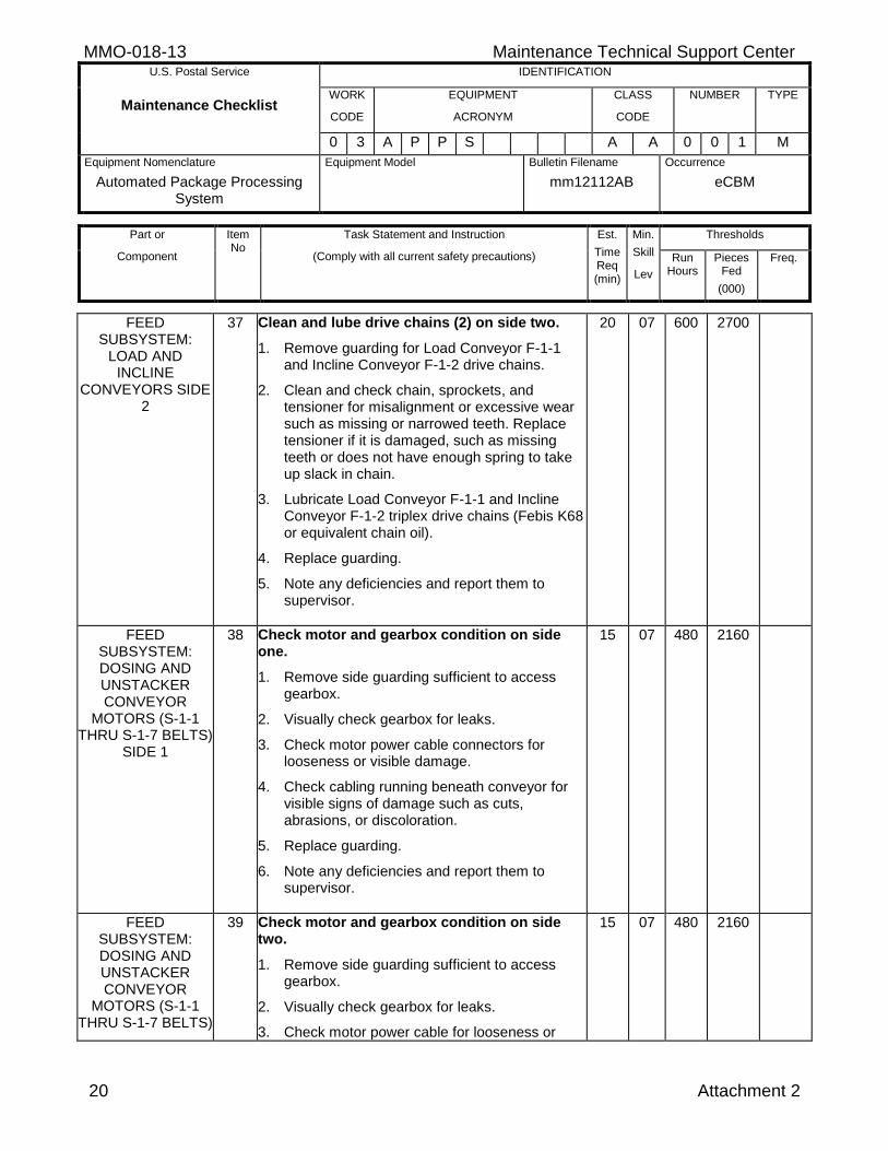
FEED SUBSYSTEM:
LOAD AND INCLINE
CONVEYORS SIDE 2
37 Clean and lube drive chains (2) on side two.
1. Remove guarding for Load Conveyor F-1-1 and Incline Conveyor F-1-2 drive chains.
2. Clean and check chain, sprockets, and tensioner for misalignment or excessive wear such as missing or narrowed teeth. Replace tensioner if it is damaged, such as missing teeth or does not have enough spring to take up slack in chain.
3. Lubricate Load Conveyor F-1-1 and Incline Conveyor F-1-2 triplex drive chains (Febis K68 or equivalent chain oil).
4. Replace guarding.
5. Note any deficiencies and report them to supervisor.
20 07 600 2700
FEED SUBSYSTEM: DOSING AND UNSTACKER CONVEYOR
MOTORS (S-1-1 THRU S-1-7 BELTS)
SIDE 1
38 Check motor and gearbox condition on side one.
1. Remove side guarding sufficient to access gearbox.
2. Visually check gearbox for leaks.
3. Check motor power cable connectors for looseness or visible damage.
4. Check cabling running beneath conveyor for visible signs of damage such as cuts, abrasions, or discoloration.
5. Replace guarding.
6. Note any deficiencies and report them to supervisor.
15 07 480 2160
FEED SUBSYSTEM: DOSING AND UNSTACKER CONVEYOR
MOTORS (S-1-1 THRU S-1-7 BELTS)
39 Check motor and gearbox condition on side two.
1. Remove side guarding sufficient to access gearbox.
2. Visually check gearbox for leaks.
3. Check motor power cable for looseness or
15 07 480 2160
Maintenance Technical Support Center MMO-018-13 U.S. Postal Service IDENTIFICATION
Maintenance Checklist WORK
CODE
EQUIPMENT
ACRONYM
CLASS
CODE
NUMBER TYPE
0 3 A P P S A A 0 0 1 M
Equipment Nomenclature
Automated Package Processing System
Equipment Model
Bulletin Filename
mm12112AB
Occurrence
eCBM
Part or
Component
Item No
Task Statement and Instruction
(Comply with all current safety precautions)
Est.
Time Req (min)
Min.
Skill
Lev
Thresholds
Run Hours
Pieces Fed
(000)
Freq.
Attachment 2 21
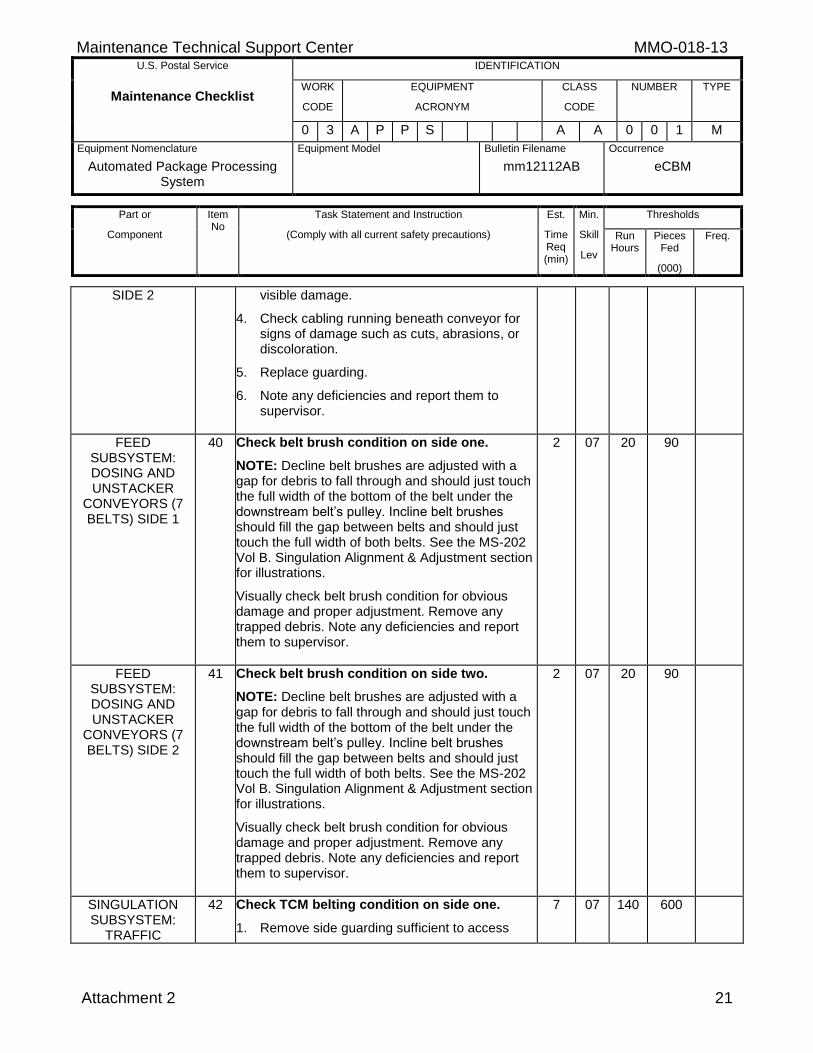
SIDE 2 visible damage.
4. Check cabling running beneath conveyor for signs of damage such as cuts, abrasions, or discoloration.
5. Replace guarding.
6. Note any deficiencies and report them to supervisor.
FEED SUBSYSTEM: DOSING AND UNSTACKER
CONVEYORS (7 BELTS) SIDE 1
40 Check belt brush condition on side one.
NOTE: Decline belt brushes are adjusted with a gap for debris to fall through and should just touch the full width of the bottom of the belt under the downstream belt’s pulley. Incline belt brushes should fill the gap between belts and should just touch the full width of both belts. See the MS-202 Vol B. Singulation Alignment & Adjustment section for illustrations.
Visually check belt brush condition for obvious damage and proper adjustment. Remove any trapped debris. Note any deficiencies and report them to supervisor.
2 07 20 90
FEED SUBSYSTEM: DOSING AND UNSTACKER
CONVEYORS (7 BELTS) SIDE 2
41 Check belt brush condition on side two.
NOTE: Decline belt brushes are adjusted with a gap for debris to fall through and should just touch the full width of the bottom of the belt under the downstream belt’s pulley. Incline belt brushes should fill the gap between belts and should just touch the full width of both belts. See the MS-202 Vol B. Singulation Alignment & Adjustment section for illustrations.
Visually check belt brush condition for obvious damage and proper adjustment. Remove any trapped debris. Note any deficiencies and report them to supervisor.
2 07 20 90
SINGULATION SUBSYSTEM:
TRAFFIC
42 Check TCM belting condition on side one.
1. Remove side guarding sufficient to access
7 07 140 600
MMO-018-13 Maintenance Technical Support Center U.S. Postal Service IDENTIFICATION
Maintenance Checklist WORK
CODE
EQUIPMENT
ACRONYM
CLASS
CODE
NUMBER TYPE
0 3 A P P S A A 0 0 1 M
Equipment Nomenclature
Automated Package Processing System
Equipment Model
Bulletin Filename
mm12112AB
Occurrence
eCBM
Part or
Component
Item No
Task Statement and Instruction
(Comply with all current safety precautions)
Est.
Time Req (min)
Min.
Skill
Lev
Thresholds
Run Hours
Pieces Fed
(000)
Freq.
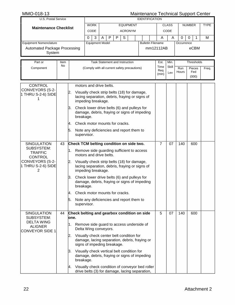
22 Attachment 2
CONTROL CONVEYORS (S-2-1 THRU S-2-6) SIDE
1
motors and drive belts.
2. Visually check strip belts (18) for damage, lacing separation, debris, fraying or signs of impeding breakage.
3. Check lower drive belts (6) and pulleys for damage, debris, fraying or signs of impeding breakage.
4. Check motor mounts for cracks.
5. Note any deficiencies and report them to supervisor.
SINGULATION SUBSYSTEM:
TRAFFIC CONTROL
CONVEYORS (S-2-1 THRU S-2-6) SIDE
2
43 Check TCM belting condition on side two.
1. Remove side guarding sufficient to access motors and drive belts.
2. Visually check strip belts (18) for damage, lacing separation, debris, fraying or signs of impeding breakage.
3. Check lower drive belts (6) and pulleys for damage, debris, fraying or signs of impeding breakage.
4. Check motor mounts for cracks.
5. Note any deficiencies and report them to supervisor.
7 07 140 600
SINGULATION SUBSYSTEM: DELTA WING
ALIGNER CONVEYOR SIDE 1
44 Check belting and gearbox condition on side one.
1. Remove side guard to access underside of Delta Wing conveyors.
2. Visually check center belt condition for damage, lacing separation, debris, fraying or signs of impeding breakage.
3. Visually check vertical belt condition for damage, debris, fraying or signs of impeding breakage.
4. Visually check condition of conveyor bed roller drive belts (3) for damage, lacing separation,
5 07 140 600
Maintenance Technical Support Center MMO-018-13 U.S. Postal Service IDENTIFICATION
Maintenance Checklist WORK
CODE
EQUIPMENT
ACRONYM
CLASS
CODE
NUMBER TYPE
0 3 A P P S A A 0 0 1 M
Equipment Nomenclature
Automated Package Processing System
Equipment Model
Bulletin Filename
mm12112AB
Occurrence
eCBM
Part or
Component
Item No
Task Statement and Instruction
(Comply with all current safety precautions)
Est.
Time Req (min)
Min.
Skill
Lev
Thresholds
Run Hours
Pieces Fed
(000)
Freq.
Attachment 2 23
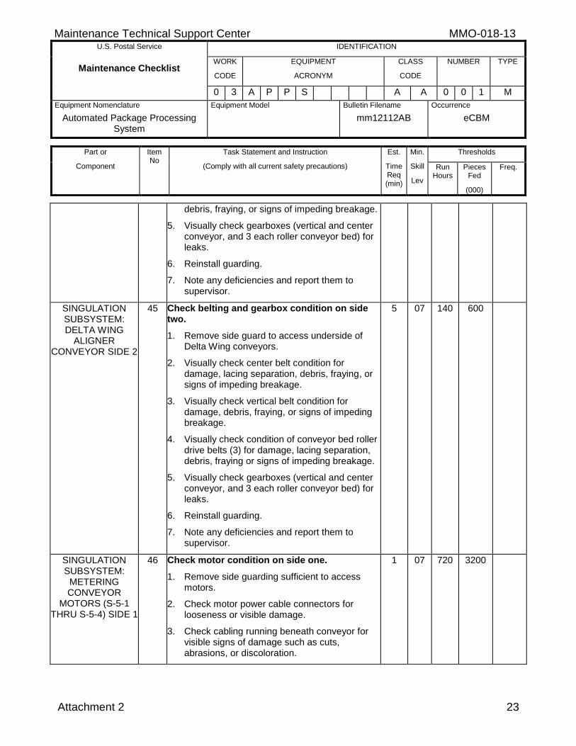
debris, fraying, or signs of impeding breakage.
5. Visually check gearboxes (vertical and center conveyor, and 3 each roller conveyor bed) for leaks.
6. Reinstall guarding.
7. Note any deficiencies and report them to supervisor.
SINGULATION SUBSYSTEM: DELTA WING
ALIGNER CONVEYOR SIDE 2
45 Check belting and gearbox condition on side two.
1. Remove side guard to access underside of Delta Wing conveyors.
2. Visually check center belt condition for damage, lacing separation, debris, fraying, or signs of impeding breakage.
3. Visually check vertical belt condition for damage, debris, fraying, or signs of impeding breakage.
4. Visually check condition of conveyor bed roller drive belts (3) for damage, lacing separation, debris, fraying or signs of impeding breakage.
5. Visually check gearboxes (vertical and center conveyor, and 3 each roller conveyor bed) for leaks.
6. Reinstall guarding.
7. Note any deficiencies and report them to supervisor.
5 07 140 600
SINGULATION SUBSYSTEM:
METERING CONVEYOR
MOTORS (S-5-1 THRU S-5-4) SIDE 1
46 Check motor condition on side one.
1. Remove side guarding sufficient to access motors.
2. Check motor power cable connectors for looseness or visible damage.
3. Check cabling running beneath conveyor for visible signs of damage such as cuts, abrasions, or discoloration.
1 07 720 3200
MMO-018-13 Maintenance Technical Support Center U.S. Postal Service IDENTIFICATION
Maintenance Checklist WORK
CODE
EQUIPMENT
ACRONYM
CLASS
CODE
NUMBER TYPE
0 3 A P P S A A 0 0 1 M
Equipment Nomenclature
Automated Package Processing System
Equipment Model
Bulletin Filename
mm12112AB
Occurrence
eCBM
Part or
Component
Item No
Task Statement and Instruction
(Comply with all current safety precautions)
Est.
Time Req (min)
Min.
Skill
Lev
Thresholds
Run Hours
Pieces Fed
(000)
Freq.
24 Attachment 2
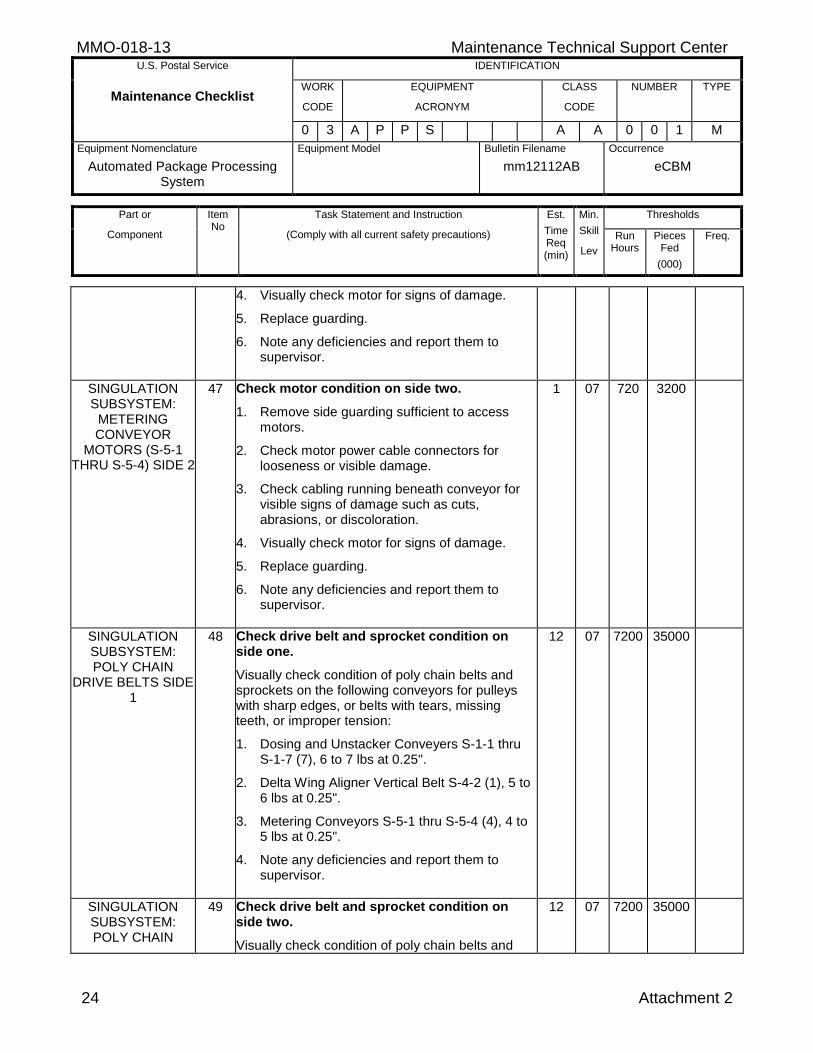
4. Visually check motor for signs of damage.
5. Replace guarding.
6. Note any deficiencies and report them to supervisor.
SINGULATION SUBSYSTEM:
METERING CONVEYOR
MOTORS (S-5-1 THRU S-5-4) SIDE 2
47 Check motor condition on side two.
1. Remove side guarding sufficient to access motors.
2. Check motor power cable connectors for looseness or visible damage.
3. Check cabling running beneath conveyor for visible signs of damage such as cuts, abrasions, or discoloration.
4. Visually check motor for signs of damage.
5. Replace guarding.
6. Note any deficiencies and report them to supervisor.
1 07 720 3200
SINGULATION SUBSYSTEM: POLY CHAIN
DRIVE BELTS SIDE 1
48 Check drive belt and sprocket condition on side one.
Visually check condition of poly chain belts and sprockets on the following conveyors for pulleys with sharp edges, or belts with tears, missing teeth, or improper tension:
1. Dosing and Unstacker Conveyers S-1-1 thru S-1-7 (7), 6 to 7 lbs at 0.25".
2. Delta Wing Aligner Vertical Belt S-4-2 (1), 5 to 6 lbs at 0.25".
3. Metering Conveyors S-5-1 thru S-5-4 (4), 4 to 5 lbs at 0.25".
4. Note any deficiencies and report them to supervisor.
12 07 7200 35000
SINGULATION SUBSYSTEM: POLY CHAIN
49 Check drive belt and sprocket condition on side two.
Visually check condition of poly chain belts and
12 07 7200 35000
Maintenance Technical Support Center MMO-018-13 U.S. Postal Service IDENTIFICATION
Maintenance Checklist WORK
CODE
EQUIPMENT
ACRONYM
CLASS
CODE
NUMBER TYPE
0 3 A P P S A A 0 0 1 M
Equipment Nomenclature
Automated Package Processing System
Equipment Model
Bulletin Filename
mm12112AB
Occurrence
eCBM
Part or
Component
Item No
Task Statement and Instruction
(Comply with all current safety precautions)
Est.
Time Req (min)
Min.
Skill
Lev
Thresholds
Run Hours
Pieces Fed
(000)
Freq.
Attachment 2 25
DRIVE BELTS SIDE 2
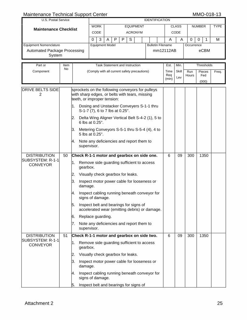
sprockets on the following conveyors for pulleys with sharp edges, or belts with tears, missing teeth, or improper tension:
1. Dosing and Unstacker Conveyers S-1-1 thru S-1-7 (7), 6 to 7 lbs at 0.25".
2. Delta Wing Aligner Vertical Belt S-4-2 (1), 5 to 6 lbs at 0.25".
3. Metering Conveyors S-5-1 thru S-5-4 (4), 4 to 5 lbs at 0.25".
4. Note any deficiencies and report them to supervisor.
DISTRIBUTION SUBSYSTEM: R-1-1
CONVEYOR
50 Check R-1-1 motor and gearbox on side one.
1. Remove side guarding sufficient to access gearbox.
2. Visually check gearbox for leaks.
3. Inspect motor power cable for looseness or damage.
4. Inspect cabling running beneath conveyor for signs of damage.
5. Inspect belt and bearings for signs of accelerated wear (emitting debris) or damage.
6. Replace guarding.
7. Note any deficiencies and report them to supervisor.
6 09 300 1350
DISTRIBUTION SUBSYSTEM: R-1-1
CONVEYOR
51 Check R-1-1 motor and gearbox on side two.
1. Remove side guarding sufficient to access gearbox.
2. Visually check gearbox for leaks.
3. Inspect motor power cable for looseness or damage.
4. Inspect cabling running beneath conveyor for signs of damage.
5. Inspect belt and bearings for signs of
6 09 300 1350
MMO-018-13 Maintenance Technical Support Center U.S. Postal Service IDENTIFICATION
Maintenance Checklist WORK
CODE
EQUIPMENT
ACRONYM
CLASS
CODE
NUMBER TYPE
0 3 A P P S A A 0 0 1 M
Equipment Nomenclature
Automated Package Processing System
Equipment Model
Bulletin Filename
mm12112AB
Occurrence
eCBM
Part or
Component
Item No
Task Statement and Instruction
(Comply with all current safety precautions)
Est.
Time Req (min)
Min.
Skill
Lev
Thresholds
Run Hours
Pieces Fed
(000)
Freq.
26 Attachment 2
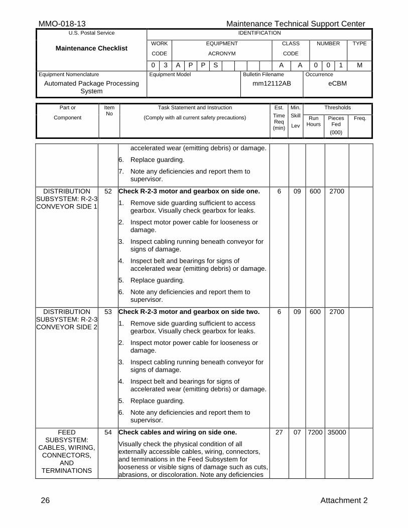
accelerated wear (emitting debris) or damage.
6. Replace guarding.
7. Note any deficiencies and report them to supervisor.
DISTRIBUTION SUBSYSTEM: R-2-3 CONVEYOR SIDE 1
52 Check R-2-3 motor and gearbox on side one.
1. Remove side guarding sufficient to access gearbox. Visually check gearbox for leaks.
2. Inspect motor power cable for looseness or damage.
3. Inspect cabling running beneath conveyor for signs of damage.
4. Inspect belt and bearings for signs of accelerated wear (emitting debris) or damage.
5. Replace guarding.
6. Note any deficiencies and report them to supervisor.
6 09 600 2700
DISTRIBUTION SUBSYSTEM: R-2-3 CONVEYOR SIDE 2
53 Check R-2-3 motor and gearbox on side two.
1. Remove side guarding sufficient to access gearbox. Visually check gearbox for leaks.
2. Inspect motor power cable for looseness or damage.
3. Inspect cabling running beneath conveyor for signs of damage.
4. Inspect belt and bearings for signs of accelerated wear (emitting debris) or damage.
5. Replace guarding.
6. Note any deficiencies and report them to supervisor.
6 09 600 2700
FEED SUBSYSTEM:
CABLES, WIRING, CONNECTORS,
AND TERMINATIONS
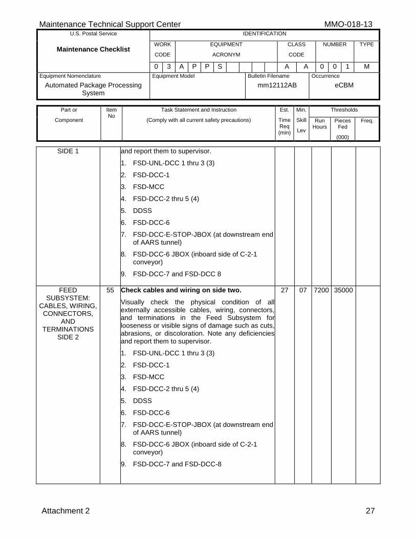
54 Check cables and wiring on side one.
Visually check the physical condition of all externally accessible cables, wiring, connectors, and terminations in the Feed Subsystem for looseness or visible signs of damage such as cuts, abrasions, or discoloration. Note any deficiencies
27 07 7200 35000
Maintenance Technical Support Center MMO-018-13 U.S. Postal Service IDENTIFICATION
Maintenance Checklist WORK
CODE
EQUIPMENT
ACRONYM
CLASS
CODE
NUMBER TYPE
0 3 A P P S A A 0 0 1 M
Equipment Nomenclature
Automated Package Processing System
Equipment Model
Bulletin Filename
mm12112AB
Occurrence
eCBM
Part or
Component
Item No
Task Statement and Instruction
(Comply with all current safety precautions)
Est.
Time Req (min)
Min.
Skill
Lev
Thresholds
Run Hours
Pieces Fed
(000)
Freq.
Attachment 2 27
SIDE 1 and report them to supervisor.
1. FSD-UNL-DCC 1 thru 3 (3)
2. FSD-DCC-1
3. FSD-MCC
4. FSD-DCC-2 thru 5 (4)
5. DDSS
6. FSD-DCC-6
7. FSD-DCC-E-STOP-JBOX (at downstream end of AARS tunnel)
8. FSD-DCC-6 JBOX (inboard side of C-2-1 conveyor)
9. FSD-DCC-7 and FSD-DCC 8
FEED SUBSYSTEM:
CABLES, WIRING, CONNECTORS,
AND TERMINATIONS
SIDE 2
55 Check cables and wiring on side two.
Visually check the physical condition of all externally accessible cables, wiring, connectors, and terminations in the Feed Subsystem for looseness or visible signs of damage such as cuts, abrasions, or discoloration. Note any deficiencies and report them to supervisor.
1. FSD-UNL-DCC 1 thru 3 (3)
2. FSD-DCC-1
3. FSD-MCC
4. FSD-DCC-2 thru 5 (4)
5. DDSS
6. FSD-DCC-6
7. FSD-DCC-E-STOP-JBOX (at downstream end of AARS tunnel)
8. FSD-DCC-6 JBOX (inboard side of C-2-1 conveyor)
9. FSD-DCC-7 and FSD-DCC-8
27 07 7200 35000
MMO-018-13 Maintenance Technical Support Center U.S. Postal Service IDENTIFICATION
Maintenance Checklist WORK
CODE
EQUIPMENT
ACRONYM
CLASS
CODE
NUMBER TYPE
0 3 A P P S A A 0 0 1 M
Equipment Nomenclature
Automated Package Processing System
Equipment Model
Bulletin Filename
mm12112AB
Occurrence
eCBM
Part or
Component
Item No
Task Statement and Instruction
(Comply with all current safety precautions)
Est.
Time Req (min)
Min.
Skill
Lev
Thresholds
Run Hours
Pieces Fed
(000)
Freq.
28 Attachment 2
FEED SUBSYSTEM:
LEXAN PANELS SIDE 1
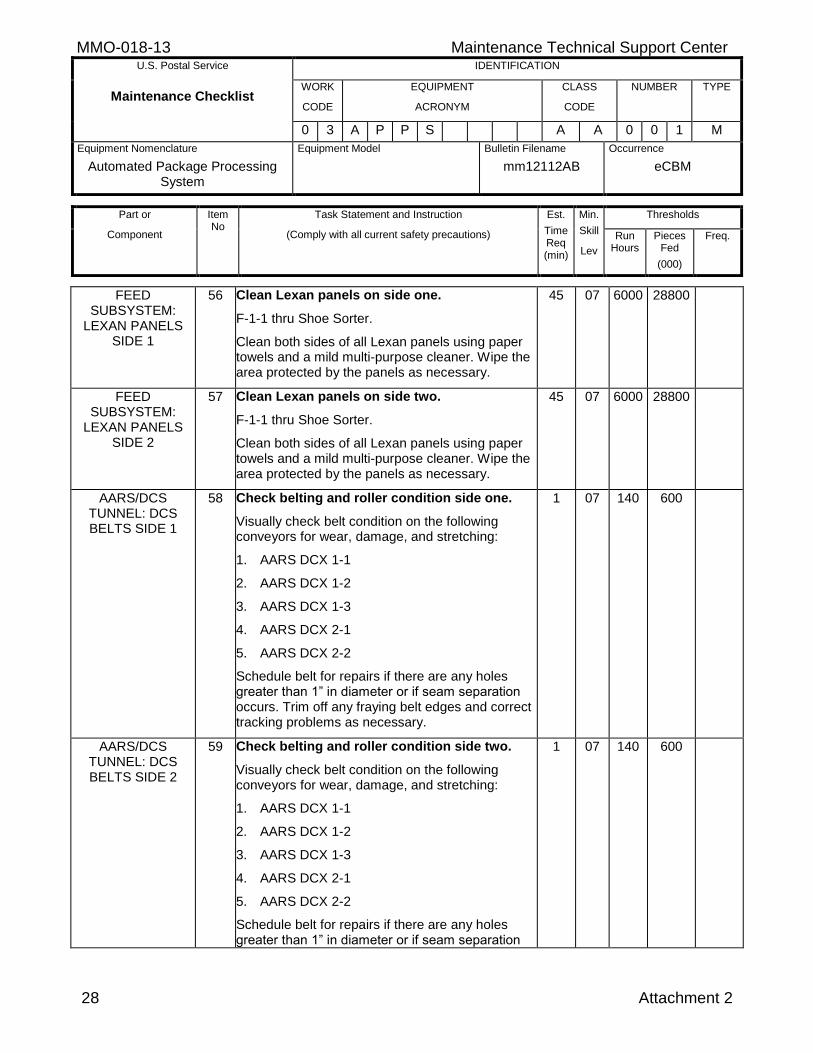
56 Clean Lexan panels on side one.
F-1-1 thru Shoe Sorter.
Clean both sides of all Lexan panels using paper towels and a mild multi-purpose cleaner. Wipe the area protected by the panels as necessary.
45 07 6000 28800
FEED SUBSYSTEM:
LEXAN PANELS SIDE 2
57 Clean Lexan panels on side two.
F-1-1 thru Shoe Sorter.
Clean both sides of all Lexan panels using paper towels and a mild multi-purpose cleaner. Wipe the area protected by the panels as necessary.
45 07 6000 28800
AARS/DCS TUNNEL: DCS BELTS SIDE 1
58 Check belting and roller condition side one.
Visually check belt condition on the following conveyors for wear, damage, and stretching:
1. AARS DCX 1-1
2. AARS DCX 1-2
3. AARS DCX 1-3
4. AARS DCX 2-1
5. AARS DCX 2-2
Schedule belt for repairs if there are any holes greater than 1” in diameter or if seam separation occurs. Trim off any fraying belt edges and correct tracking problems as necessary.
1 07 140 600
AARS/DCS TUNNEL: DCS BELTS SIDE 2
59 Check belting and roller condition side two.
Visually check belt condition on the following conveyors for wear, damage, and stretching:
1. AARS DCX 1-1
2. AARS DCX 1-2
3. AARS DCX 1-3
4. AARS DCX 2-1
5. AARS DCX 2-2
Schedule belt for repairs if there are any holes greater than 1” in diameter or if seam separation
1 07 140 600
Maintenance Technical Support Center MMO-018-13 U.S. Postal Service IDENTIFICATION
Maintenance Checklist WORK
CODE
EQUIPMENT
ACRONYM
CLASS
CODE
NUMBER TYPE
0 3 A P P S A A 0 0 1 M
Equipment Nomenclature
Automated Package Processing System
Equipment Model
Bulletin Filename
mm12112AB
Occurrence
eCBM
Part or
Component
Item No
Task Statement and Instruction
(Comply with all current safety precautions)
Est.
Time Req (min)
Min.
Skill
Lev
Thresholds
Run Hours
Pieces Fed
(000)
Freq.
Attachment 2 29
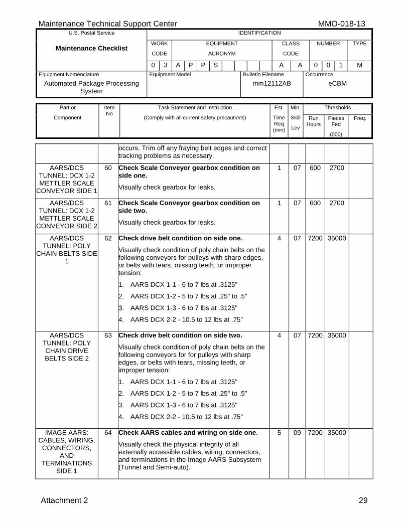
occurs. Trim off any fraying belt edges and correct tracking problems as necessary.
AARS/DCS TUNNEL: DCX 1-2 METTLER SCALE
CONVEYOR SIDE 1
60 Check Scale Conveyor gearbox condition on side one.
Visually check gearbox for leaks.
1 07 600 2700
AARS/DCS TUNNEL: DCX 1-2 METTLER SCALE
CONVEYOR SIDE 2
61 Check Scale Conveyor gearbox condition on side two.
Visually check gearbox for leaks.
1 07 600 2700
AARS/DCS TUNNEL: POLY
CHAIN BELTS SIDE 1
62 Check drive belt condition on side one.
Visually check condition of poly chain belts on the following conveyors for pulleys with sharp edges, or belts with tears, missing teeth, or improper tension:
1. AARS DCX 1-1 - 6 to 7 lbs at .3125"
2. AARS DCX 1-2 - 5 to 7 lbs at .25" to .5"
3. AARS DCX 1-3 - 6 to 7 lbs at .3125"
4. AARS DCX 2-2 - 10.5 to 12 lbs at .75"
4 07 7200 35000
AARS/DCS TUNNEL: POLY CHAIN DRIVE BELTS SIDE 2
63 Check drive belt condition on side two.
Visually check condition of poly chain belts on the following conveyors for for pulleys with sharp edges, or belts with tears, missing teeth, or improper tension:
1. AARS DCX 1-1 - 6 to 7 lbs at .3125"
2. AARS DCX 1-2 - 5 to 7 lbs at .25" to .5"
3. AARS DCX 1-3 - 6 to 7 lbs at .3125"
4. AARS DCX 2-2 - 10.5 to 12 lbs at .75"
4 07 7200 35000
IMAGE AARS: CABLES, WIRING,
CONNECTORS, AND
TERMINATIONS SIDE 1
64 Check AARS cables and wiring on side one.
Visually check the physical integrity of all externally accessible cables, wiring, connectors, and terminations in the Image AARS Subsystem (Tunnel and Semi-auto).
5 09 7200 35000
MMO-018-13 Maintenance Technical Support Center U.S. Postal Service IDENTIFICATION
Maintenance Checklist WORK
CODE
EQUIPMENT
ACRONYM
CLASS
CODE
NUMBER TYPE
0 3 A P P S A A 0 0 1 M
Equipment Nomenclature
Automated Package Processing System
Equipment Model
Bulletin Filename
mm12112AB
Occurrence
eCBM
Part or
Component
Item No
Task Statement and Instruction
(Comply with all current safety precautions)
Est.
Time Req (min)
Min.
Skill
Lev
Thresholds
Run Hours
Pieces Fed
(000)
Freq.
30 Attachment 2
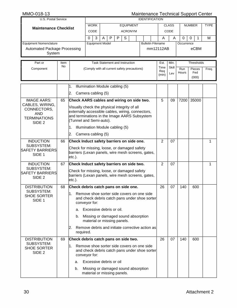
1. Illumination Module cabling (5)
2. Camera cabling (5)
IMAGE AARS: CABLES, WIRING,
CONNECTORS, AND
TERMINATIONS SIDE 2
65 Check AARS cables and wiring on side two.
Visually check the physical integrity of all externally accessible cables, wiring, connectors, and terminations in the Image AARS Subsystem (Tunnel and Semi-auto).
1. Illumination Module cabling (5)
2. Camera cabling (5)
5 09 7200 35000
INDUCTION SUBSYSTEM:
SAFETY BARRIERS SIDE 1
66 Check Induct safety barriers on side one.
Check for missing, loose, or damaged safety barriers (Lexan panels, wire mesh screens, gates, etc.).
2 07 1
INDUCTION SUBSYSTEM:
SAFETY BARRIERS SIDE 2
67 Check Induct safety barriers on side two.
Check for missing, loose, or damaged safety barriers (Lexan panels, wire mesh screens, gates, etc.).
2 07 1
DISTRIBUTION SUBSYSTEM:
SHOE SORTER SIDE 1
68 Check debris catch pans on side one.
1. Remove shoe sorter side covers on one side and check debris catch pans under shoe sorter conveyor for:
a. Excessive debris or oil.
b. Missing or damaged sound absorption material or missing panels.
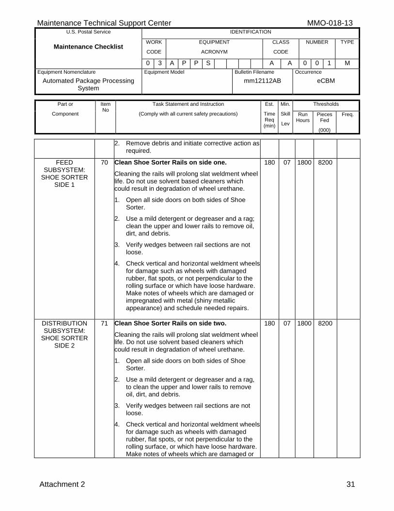
2. Remove debris and initiate corrective action as required.
26 07 140 600
DISTRIBUTION SUBSYSTEM:
SHOE SORTER SIDE 2
69 Check debris catch pans on side two.
1. Remove shoe sorter side covers on one side and check debris catch pans under shoe sorter conveyor for:
a. Excessive debris or oil
b. Missing or damaged sound absorption material or missing panels.
26 07 140 600
Maintenance Technical Support Center MMO-018-13 U.S. Postal Service IDENTIFICATION
Maintenance Checklist WORK
CODE
EQUIPMENT
ACRONYM
CLASS
CODE
NUMBER TYPE
0 3 A P P S A A 0 0 1 M
Equipment Nomenclature
Automated Package Processing System
Equipment Model
Bulletin Filename
mm12112AB
Occurrence
eCBM
Part or
Component
Item No
Task Statement and Instruction
(Comply with all current safety precautions)
Est.
Time Req (min)
Min.
Skill
Lev
Thresholds
Run Hours
Pieces Fed
(000)
Freq.
Attachment 2 31
2. Remove debris and initiate corrective action as required.
FEED SUBSYSTEM:
SHOE SORTER SIDE 1
70 Clean Shoe Sorter Rails on side one.
Cleaning the rails will prolong slat weldment wheel life. Do not use solvent based cleaners which could result in degradation of wheel urethane.
1. Open all side doors on both sides of Shoe Sorter.
2. Use a mild detergent or degreaser and a rag; clean the upper and lower rails to remove oil, dirt, and debris.
3. Verify wedges between rail sections are not loose.
4. Check vertical and horizontal weldment wheels for damage such as wheels with damaged rubber, flat spots, or not perpendicular to the rolling surface or which have loose hardware. Make notes of wheels which are damaged or impregnated with metal (shiny metallic appearance) and schedule needed repairs.
180 07 1800 8200
DISTRIBUTION SUBSYSTEM:
SHOE SORTER SIDE 2
71 Clean Shoe Sorter Rails on side two.
Cleaning the rails will prolong slat weldment wheel life. Do not use solvent based cleaners which could result in degradation of wheel urethane.
1. Open all side doors on both sides of Shoe Sorter.
2. Use a mild detergent or degreaser and a rag, to clean the upper and lower rails to remove oil, dirt, and debris.
3. Verify wedges between rail sections are not loose.
4. Check vertical and horizontal weldment wheels for damage such as wheels with damaged rubber, flat spots, or not perpendicular to the rolling surface, or which have loose hardware. Make notes of wheels which are damaged or
180 07 1800 8200
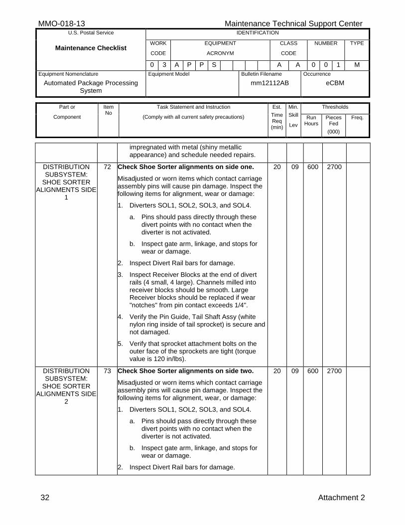
MMO-018-13 Maintenance Technical Support Center U.S. Postal Service IDENTIFICATION
Maintenance Checklist WORK
CODE
EQUIPMENT
ACRONYM
CLASS
CODE
NUMBER TYPE
0 3 A P P S A A 0 0 1 M
Equipment Nomenclature
Automated Package Processing System
Equipment Model
Bulletin Filename
mm12112AB
Occurrence
eCBM
Part or
Component
Item No
Task Statement and Instruction
(Comply with all current safety precautions)
Est.
Time Req (min)
Min.
Skill
Lev
Thresholds
Run Hours
Pieces Fed
(000)
Freq.
32 Attachment 2
impregnated with metal (shiny metallic appearance) and schedule needed repairs.
DISTRIBUTION SUBSYSTEM:
SHOE SORTER ALIGNMENTS SIDE
1
72 Check Shoe Sorter alignments on side one.
Misadjusted or worn items which contact carriage assembly pins will cause pin damage. Inspect the following items for alignment, wear or damage:
1. Diverters SOL1, SOL2, SOL3, and SOL4.
a. Pins should pass directly through these divert points with no contact when the diverter is not activated.
b. Inspect gate arm, linkage, and stops for wear or damage.
2. Inspect Divert Rail bars for damage.
3. Inspect Receiver Blocks at the end of divert rails (4 small, 4 large). Channels milled into receiver blocks should be smooth. Large Receiver blocks should be replaced if wear "notches" from pin contact exceeds 1/4".
4. Verify the Pin Guide, Tail Shaft Assy (white nylon ring inside of tail sprocket) is secure and not damaged.
5. Verify that sprocket attachment bolts on the outer face of the sprockets are tight (torque value is 120 in/lbs).
20 09 600 2700
DISTRIBUTION SUBSYSTEM:
SHOE SORTER ALIGNMENTS SIDE
2
73 Check Shoe Sorter alignments on side two.
Misadjusted or worn items which contact carriage assembly pins will cause pin damage. Inspect the following items for alignment, wear, or damage:
1. Diverters SOL1, SOL2, SOL3, and SOL4.
a. Pins should pass directly through these divert points with no contact when the diverter is not activated.
b. Inspect gate arm, linkage, and stops for wear or damage.
2. Inspect Divert Rail bars for damage.
20 09 600 2700
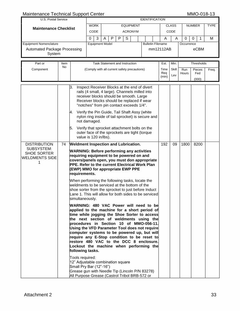
Maintenance Technical Support Center MMO-018-13 U.S. Postal Service IDENTIFICATION
Maintenance Checklist WORK
CODE
EQUIPMENT
ACRONYM
CLASS
CODE
NUMBER TYPE
0 3 A P P S A A 0 0 1 M
Equipment Nomenclature
Automated Package Processing System
Equipment Model
Bulletin Filename
mm12112AB
Occurrence
eCBM
Part or
Component
Item No
Task Statement and Instruction
(Comply with all current safety precautions)
Est.
Time Req (min)
Min.
Skill
Lev
Thresholds
Run Hours
Pieces Fed
(000)
Freq.
Attachment 2 33
3. Inspect Receiver Blocks at the end of divert rails (4 small, 4 large). Channels milled into receiver blocks should be smooth. Large Receiver blocks should be replaced if wear "notches" from pin contact exceeds 1/4".
4. Verify the Pin Guide, Tail Shaft Assy (white nylon ring inside of tail sprocket) is secure and not damaged.
5. Verify that sprocket attachment bolts on the outer face of the sprockets are tight (torque value is 120 in/lbs).
DISTRIBUTION SUBSYSTEM:
SHOE SORTER WELDMENTS SIDE
1
74 Weldment Inspection and Lubrication.
WARNING: Before performing any activities requiring equipment to be powered on and covers/panels open, you must don appropriate PPE. Refer to the current Electrical Work Plan (EWP) MMO for appropriate EWP PPE requirements.
When performing the following tasks, locate the weldments to be serviced at the bottom of the shoe sorter from the sprocket to just before Induct Lane 1. This will allow for both sides to be serviced simultaneously.
WARNING: 480 VAC Power will need to be applied to the machine for a short period of time while jogging the Shoe Sorter to access the next section of weldments using the procedures in Section 10 of MMO-056-11. Using the VFD Parameter Tool does not require computer systems to be powered up, but will require any E-Stop condition to be reset to restore 480 VAC to the DCC 8 enclosure. Lockout the machine when performing the following tasks.
Tools required: 12” Adjustable combination square Small Pry Bar (12”-16”) Grease gun with Needle Tip (Lincoln P/N 83278) All Purpose Grease (Castrol Tribol BRB-572 or
192 09 1800 8200
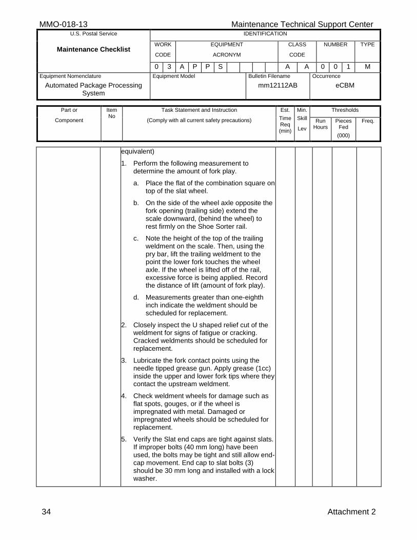
MMO-018-13 Maintenance Technical Support Center U.S. Postal Service IDENTIFICATION
Maintenance Checklist WORK
CODE
EQUIPMENT
ACRONYM
CLASS
CODE
NUMBER TYPE
0 3 A P P S A A 0 0 1 M
Equipment Nomenclature
Automated Package Processing System
Equipment Model
Bulletin Filename
mm12112AB
Occurrence
eCBM
Part or
Component
Item No
Task Statement and Instruction
(Comply with all current safety precautions)
Est.
Time Req (min)
Min.
Skill
Lev
Thresholds
Run Hours
Pieces Fed
(000)
Freq.
34 Attachment 2
equivalent)
1. Perform the following measurement to determine the amount of fork play.
a. Place the flat of the combination square on top of the slat wheel.
b. On the side of the wheel axle opposite the fork opening (trailing side) extend the scale downward, (behind the wheel) to rest firmly on the Shoe Sorter rail.
c. Note the height of the top of the trailing weldment on the scale. Then, using the pry bar, lift the trailing weldment to the point the lower fork touches the wheel axle. If the wheel is lifted off of the rail, excessive force is being applied. Record the distance of lift (amount of fork play).
d. Measurements greater than one-eighth inch indicate the weldment should be scheduled for replacement.
2. Closely inspect the U shaped relief cut of the weldment for signs of fatigue or cracking. Cracked weldments should be scheduled for replacement.
3. Lubricate the fork contact points using the needle tipped grease gun. Apply grease (1cc) inside the upper and lower fork tips where they contact the upstream weldment.
4. Check weldment wheels for damage such as flat spots, gouges, or if the wheel is impregnated with metal. Damaged or impregnated wheels should be scheduled for replacement.
5. Verify the Slat end caps are tight against slats. If improper bolts (40 mm long) have been used, the bolts may be tight and still allow end-cap movement. End cap to slat bolts (3) should be 30 mm long and installed with a lock washer.
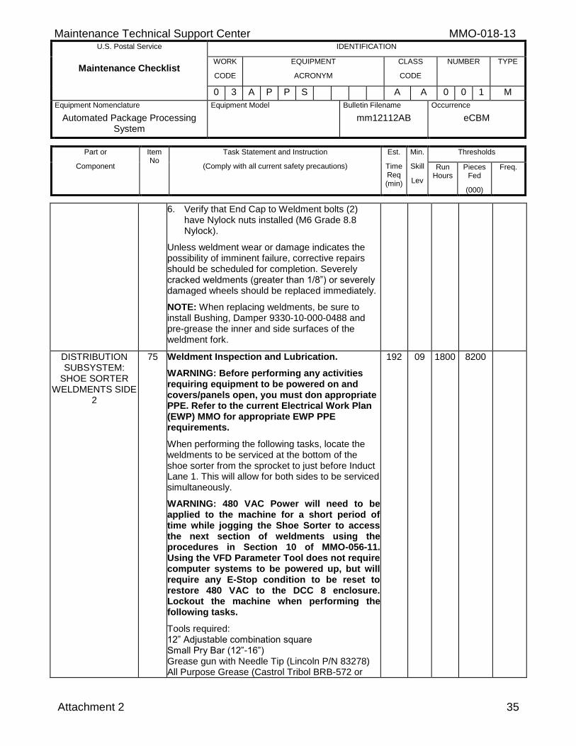
Maintenance Technical Support Center MMO-018-13 U.S. Postal Service IDENTIFICATION
Maintenance Checklist WORK
CODE
EQUIPMENT
ACRONYM
CLASS
CODE
NUMBER TYPE
0 3 A P P S A A 0 0 1 M
Equipment Nomenclature
Automated Package Processing System
Equipment Model
Bulletin Filename
mm12112AB
Occurrence
eCBM
Part or
Component
Item No
Task Statement and Instruction
(Comply with all current safety precautions)
Est.
Time Req (min)
Min.
Skill
Lev
Thresholds
Run Hours
Pieces Fed
(000)
Freq.
Attachment 2 35
6. Verify that End Cap to Weldment bolts (2) have Nylock nuts installed (M6 Grade 8.8 Nylock).
Unless weldment wear or damage indicates the possibility of imminent failure, corrective repairs should be scheduled for completion. Severely cracked weldments (greater than 1/8”) or severely damaged wheels should be replaced immediately.
NOTE: When replacing weldments, be sure to install Bushing, Damper 9330-10-000-0488 and pre-grease the inner and side surfaces of the weldment fork.
DISTRIBUTION SUBSYSTEM:
SHOE SORTER WELDMENTS SIDE
2
75 Weldment Inspection and Lubrication.
WARNING: Before performing any activities requiring equipment to be powered on and covers/panels open, you must don appropriate PPE. Refer to the current Electrical Work Plan (EWP) MMO for appropriate EWP PPE requirements.
When performing the following tasks, locate the weldments to be serviced at the bottom of the shoe sorter from the sprocket to just before Induct Lane 1. This will allow for both sides to be serviced simultaneously.
WARNING: 480 VAC Power will need to be applied to the machine for a short period of time while jogging the Shoe Sorter to access the next section of weldments using the procedures in Section 10 of MMO-056-11. Using the VFD Parameter Tool does not require computer systems to be powered up, but will require any E-Stop condition to be reset to restore 480 VAC to the DCC 8 enclosure. Lockout the machine when performing the following tasks.
Tools required: 12” Adjustable combination square Small Pry Bar (12”-16”) Grease gun with Needle Tip (Lincoln P/N 83278) All Purpose Grease (Castrol Tribol BRB-572 or
192 09 1800 8200

MMO-018-13 Maintenance Technical Support Center U.S. Postal Service IDENTIFICATION
Maintenance Checklist WORK
CODE
EQUIPMENT
ACRONYM
CLASS
CODE
NUMBER TYPE
0 3 A P P S A A 0 0 1 M
Equipment Nomenclature
Automated Package Processing System
Equipment Model
Bulletin Filename
mm12112AB
Occurrence
eCBM
Part or
Component
Item No
Task Statement and Instruction
(Comply with all current safety precautions)
Est.
Time Req (min)
Min.
Skill
Lev
Thresholds
Run Hours
Pieces Fed
(000)
Freq.
36 Attachment 2
equivalent)
1. Perform the following measurement to determine the amount of fork play.
a. Place the flat of the combination square on top of the slat wheel.
b. On the side of the wheel axle opposite the fork opening (trailing side), extend the scale downward, (behind the wheel) to rest firmly on the Shoe Sorter rail.
c. Note the height of the top of the trailing weldment on the scale. Then, using the pry bar, lift the trailing weldment to the point the lower fork touches the wheel axle. If the wheel is lifted off of the rail, excessive force is being applied. Record the distance of lift (amount of fork play).
d. Measurements greater than one-eighth inch indicate the weldment should be scheduled for replacement.
2. Closely inspect the U shaped relief cut of the weldment for signs of fatigue or cracking. Cracked weldments should be scheduled for replacement.
3. Lubricate the fork contact points using the needle tipped grease gun. Apply grease (1cc) inside the upper and lower fork tips where they contact the upstream weldment.
4. Check weldment wheels for damage such as flat spots, gouges or if the wheel is impregnated with metal. Damaged or impregnated wheels should be scheduled for replacement.
5. Verify the Slat end caps are tight against slats. If improper bolts (40 mm long) have been used, the bolts may be tight and still allow end-cap movement. End cap to slat bolts (3) should be 30 mm long and installed with a lock washer.
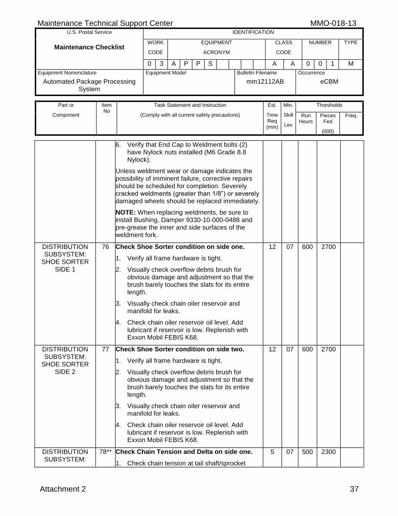
Maintenance Technical Support Center MMO-018-13 U.S. Postal Service IDENTIFICATION
Maintenance Checklist WORK
CODE
EQUIPMENT
ACRONYM
CLASS
CODE
NUMBER TYPE
0 3 A P P S A A 0 0 1 M
Equipment Nomenclature
Automated Package Processing System
Equipment Model
Bulletin Filename
mm12112AB
Occurrence
eCBM
Part or
Component
Item No
Task Statement and Instruction
(Comply with all current safety precautions)
Est.
Time Req (min)
Min.
Skill
Lev
Thresholds
Run Hours
Pieces Fed
(000)
Freq.
Attachment 2 37
6. Verify that End Cap to Weldment bolts (2) have Nylock nuts installed (M6 Grade 8.8 Nylock).
Unless weldment wear or damage indicates the possibility of imminent failure, corrective repairs should be scheduled for completion. Severely cracked weldments (greater than 1/8”) or severely damaged wheels should be replaced immediately.
NOTE: When replacing weldments, be sure to install Bushing, Damper 9330-10-000-0488 and pre-grease the inner and side surfaces of the weldment fork.
DISTRIBUTION SUBSYSTEM:
SHOE SORTER SIDE 1
76 Check Shoe Sorter condition on side one.
1. Verify all frame hardware is tight.
2. Visually check overflow debris brush for obvious damage and adjustment so that the brush barely touches the slats for its entire length.
3. Visually check chain oiler reservoir and manifold for leaks.
4. Check chain oiler reservoir oil level. Add lubricant if reservoir is low. Replenish with Exxon Mobil FEBIS K68.
12 07 600 2700
DISTRIBUTION SUBSYSTEM:
SHOE SORTER SIDE 2
77 Check Shoe Sorter condition on side two.
1. Verify all frame hardware is tight.
2. Visually check overflow debris brush for obvious damage and adjustment so that the brush barely touches the slats for its entire length.
3. Visually check chain oiler reservoir and manifold for leaks.
4. Check chain oiler reservoir oil level. Add lubricant if reservoir is low. Replenish with Exxon Mobil FEBIS K68.
12 07 600 2700
DISTRIBUTION SUBSYSTEM:
78** Check Chain Tension and Delta on side one.
1. Check chain tension at tail shaft/sprocket
5 07 500 2300
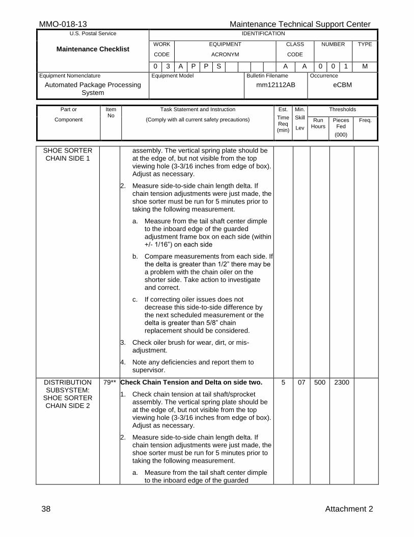
MMO-018-13 Maintenance Technical Support Center U.S. Postal Service IDENTIFICATION
Maintenance Checklist WORK
CODE
EQUIPMENT
ACRONYM
CLASS
CODE
NUMBER TYPE
0 3 A P P S A A 0 0 1 M
Equipment Nomenclature
Automated Package Processing System
Equipment Model
Bulletin Filename
mm12112AB
Occurrence
eCBM
Part or
Component
Item No
Task Statement and Instruction
(Comply with all current safety precautions)
Est.
Time Req (min)
Min.
Skill
Lev
Thresholds
Run Hours
Pieces Fed
(000)
Freq.
38 Attachment 2
SHOE SORTER CHAIN SIDE 1
assembly. The vertical spring plate should be at the edge of, but not visible from the top viewing hole (3-3/16 inches from edge of box). Adjust as necessary.
2. Measure side-to-side chain length delta. If chain tension adjustments were just made, the shoe sorter must be run for 5 minutes prior to taking the following measurement.
a. Measure from the tail shaft center dimple to the inboard edge of the guarded adjustment frame box on each side (within +/- 1/16”) on each side
b. Compare measurements from each side. If the delta is greater than 1/2” there may be a problem with the chain oiler on the shorter side. Take action to investigate and correct.
c. If correcting oiler issues does not decrease this side-to-side difference by the next scheduled measurement or the delta is greater than 5/8” chain replacement should be considered.
3. Check oiler brush for wear, dirt, or mis-adjustment.
4. Note any deficiencies and report them to supervisor.
DISTRIBUTION SUBSYSTEM:
SHOE SORTER CHAIN SIDE 2
79** Check Chain Tension and Delta on side two.
1. Check chain tension at tail shaft/sprocket assembly. The vertical spring plate should be at the edge of, but not visible from the top viewing hole (3-3/16 inches from edge of box). Adjust as necessary.
2. Measure side-to-side chain length delta. If chain tension adjustments were just made, the shoe sorter must be run for 5 minutes prior to taking the following measurement.
a. Measure from the tail shaft center dimple to the inboard edge of the guarded
5 07 500 2300
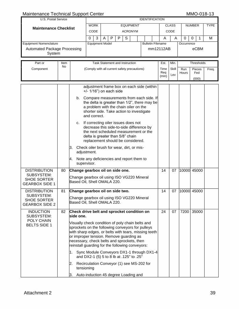
Maintenance Technical Support Center MMO-018-13 U.S. Postal Service IDENTIFICATION
Maintenance Checklist WORK
CODE
EQUIPMENT
ACRONYM
CLASS
CODE
NUMBER TYPE
0 3 A P P S A A 0 0 1 M
Equipment Nomenclature
Automated Package Processing System
Equipment Model
Bulletin Filename
mm12112AB
Occurrence
eCBM
Part or
Component
Item No
Task Statement and Instruction
(Comply with all current safety precautions)
Est.
Time Req (min)
Min.
Skill
Lev
Thresholds
Run Hours
Pieces Fed
(000)
Freq.
Attachment 2 39
adjustment frame box on each side (within +/- 1/16”) on each side
b. Compare measurements from each side. If the delta is greater than 1/2”, there may be a problem with the chain oiler on the shorter side. Take action to investigate and correct.
c. If correcting oiler issues does not decrease this side-to-side difference by the next scheduled measurement or the delta is greater than 5/8” chain replacement should be considered.
3. Check oiler brush for wear, dirt, or mis-adjustment.
4. Note any deficiencies and report them to supervisor.
DISTRIBUTION SUBSYSTEM:
SHOE SORTER GEARBOX SIDE 1
80 Change gearbox oil on side one.
Change gearbox oil using ISO VG220 Mineral Based Oil, Shell OMALA 220.
14 07 10000 45000
DISTRIBUTION SUBSYSTEM:
SHOE SORTER GEARBOX SIDE 2
81 Change gearbox oil on side two.
Change gearbox oil using ISO VG220 Mineral Based Oil, Shell OMALA 220.
14 07 10000 45000
INDUCTION SUBSYSTEM: POLY CHAIN
BELTS SIDE 1
82 Check drive belt and sprocket condition on side one.
Visually check condition of poly chain belts and sprockets on the following conveyors for pulleys with sharp edges, or belts with tears, missing teeth or improper tension. Remove guarding as necessary, check belts and sprockets, then reinstall guarding for the following conveyors:
1. Sync Module Conveyors DX1-1 through DX1-4 and DX2-1 (5) 5 to 8 lb at .125" to .25"
2. Recirculation Conveyor (1) see MS-202 for tensioning
3. Auto-induction 45 degree Loading and
24 07 7200 35000
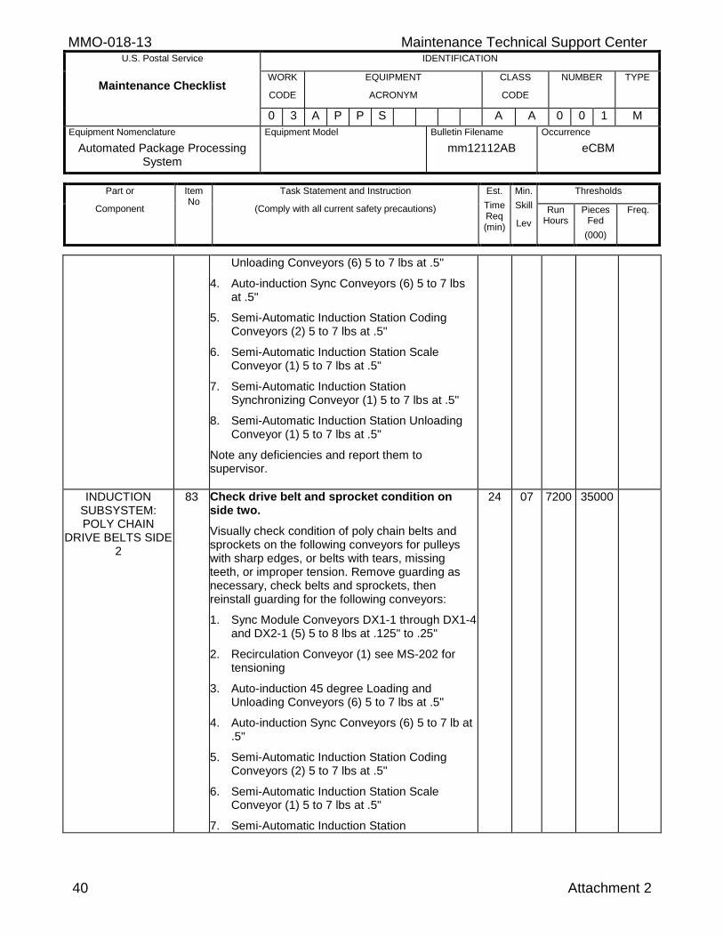
MMO-018-13 Maintenance Technical Support Center U.S. Postal Service IDENTIFICATION
Maintenance Checklist WORK
CODE
EQUIPMENT
ACRONYM
CLASS
CODE
NUMBER TYPE
0 3 A P P S A A 0 0 1 M
Equipment Nomenclature
Automated Package Processing System
Equipment Model
Bulletin Filename
mm12112AB
Occurrence
eCBM
Part or
Component
Item No
Task Statement and Instruction
(Comply with all current safety precautions)
Est.
Time Req (min)
Min.
Skill
Lev
Thresholds
Run Hours
Pieces Fed
(000)
Freq.
40 Attachment 2
Unloading Conveyors (6) 5 to 7 lbs at .5"
4. Auto-induction Sync Conveyors (6) 5 to 7 lbs at .5"
5. Semi-Automatic Induction Station Coding Conveyors (2) 5 to 7 lbs at .5"
6. Semi-Automatic Induction Station Scale Conveyor (1) 5 to 7 lbs at .5"
7. Semi-Automatic Induction Station Synchronizing Conveyor (1) 5 to 7 lbs at .5"
8. Semi-Automatic Induction Station Unloading Conveyor (1) 5 to 7 lbs at .5"
Note any deficiencies and report them to supervisor.
INDUCTION SUBSYSTEM: POLY CHAIN
DRIVE BELTS SIDE 2
83 Check drive belt and sprocket condition on side two.
Visually check condition of poly chain belts and sprockets on the following conveyors for pulleys with sharp edges, or belts with tears, missing teeth, or improper tension. Remove guarding as necessary, check belts and sprockets, then reinstall guarding for the following conveyors:
1. Sync Module Conveyors DX1-1 through DX1-4 and DX2-1 (5) 5 to 8 lbs at .125" to .25"
2. Recirculation Conveyor (1) see MS-202 for tensioning
3. Auto-induction 45 degree Loading and Unloading Conveyors (6) 5 to 7 lbs at .5"
4. Auto-induction Sync Conveyors (6) 5 to 7 lb at .5"
5. Semi-Automatic Induction Station Coding Conveyors (2) 5 to 7 lbs at .5"
6. Semi-Automatic Induction Station Scale Conveyor (1) 5 to 7 lbs at .5"
7. Semi-Automatic Induction Station
24 07 7200 35000
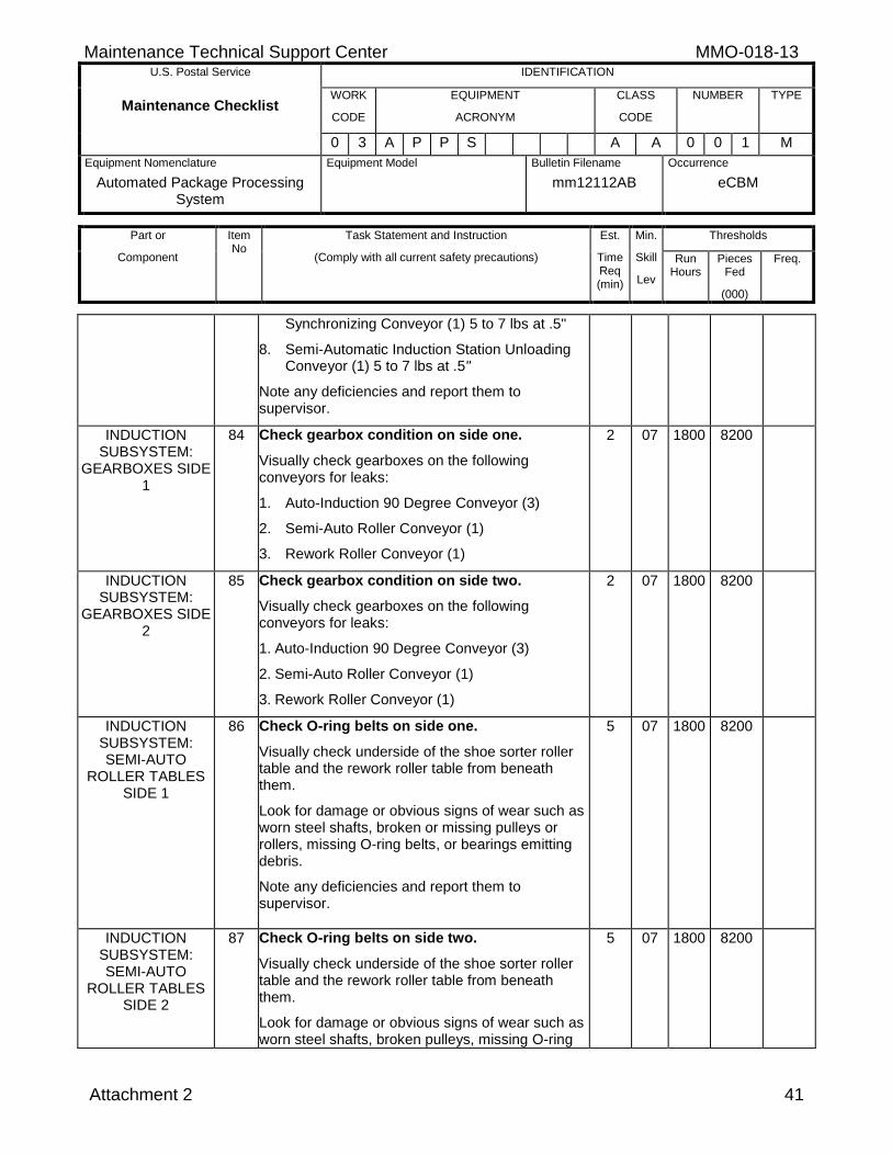
Maintenance Technical Support Center MMO-018-13 U.S. Postal Service IDENTIFICATION
Maintenance Checklist WORK
CODE
EQUIPMENT
ACRONYM
CLASS
CODE
NUMBER TYPE
0 3 A P P S A A 0 0 1 M
Equipment Nomenclature
Automated Package Processing System
Equipment Model
Bulletin Filename
mm12112AB
Occurrence
eCBM
Part or
Component
Item No
Task Statement and Instruction
(Comply with all current safety precautions)
Est.
Time Req (min)
Min.
Skill
Lev
Thresholds
Run Hours
Pieces Fed
(000)
Freq.
Attachment 2 41
Synchronizing Conveyor (1) 5 to 7 lbs at .5"
8. Semi-Automatic Induction Station Unloading Conveyor (1) 5 to 7 lbs at .5"
Note any deficiencies and report them to supervisor.
INDUCTION SUBSYSTEM:
GEARBOXES SIDE 1
84 Check gearbox condition on side one.
Visually check gearboxes on the following conveyors for leaks:
1. Auto-Induction 90 Degree Conveyor (3)
2. Semi-Auto Roller Conveyor (1)
3. Rework Roller Conveyor (1)
2 07 1800 8200
INDUCTION SUBSYSTEM:
GEARBOXES SIDE 2
85 Check gearbox condition on side two.
Visually check gearboxes on the following conveyors for leaks:
1. Auto-Induction 90 Degree Conveyor (3)
2. Semi-Auto Roller Conveyor (1)
3. Rework Roller Conveyor (1)
2 07 1800 8200
INDUCTION SUBSYSTEM: SEMI-AUTO
ROLLER TABLES SIDE 1
86 Check O-ring belts on side one.
Visually check underside of the shoe sorter roller table and the rework roller table from beneath them.
Look for damage or obvious signs of wear such as worn steel shafts, broken or missing pulleys or rollers, missing O-ring belts, or bearings emitting debris.
Note any deficiencies and report them to supervisor.
5 07 1800 8200
INDUCTION SUBSYSTEM: SEMI-AUTO
ROLLER TABLES SIDE 2
87 Check O-ring belts on side two.
Visually check underside of the shoe sorter roller table and the rework roller table from beneath them.
Look for damage or obvious signs of wear such as worn steel shafts, broken pulleys, missing O-ring
5 07 1800 8200
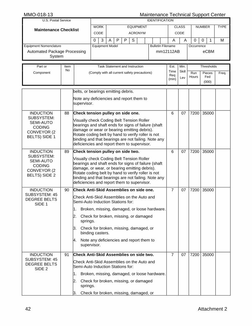
MMO-018-13 Maintenance Technical Support Center U.S. Postal Service IDENTIFICATION
Maintenance Checklist WORK
CODE
EQUIPMENT
ACRONYM
CLASS
CODE
NUMBER TYPE
0 3 A P P S A A 0 0 1 M
Equipment Nomenclature
Automated Package Processing System
Equipment Model
Bulletin Filename
mm12112AB
Occurrence
eCBM
Part or
Component
Item No
Task Statement and Instruction
(Comply with all current safety precautions)
Est.
Time Req (min)
Min.
Skill
Lev
Thresholds
Run Hours
Pieces Fed
(000)
Freq.
42 Attachment 2
belts, or bearings emitting debris.
Note any deficiencies and report them to supervisor.
INDUCTION SUBSYSTEM: SEMI-AUTO
CODING CONVEYOR (2 BELTS) SIDE 1
88 Check tension pulley on side one.
Visually check Coding Belt Tension Roller bearings and shaft ends for signs of failure (shaft damage or wear or bearing emitting debris). Rotate coding belt by hand to verify roller is not binding and that bearings are not failing. Note any deficiencies and report them to supervisor.
6 07 7200 35000
INDUCTION SUBSYSTEM: SEMI-AUTO
CODING CONVEYOR (2 BELTS) SIDE 2
89 Check tension pulley on side two.
Visually check Coding Belt Tension Roller bearings and shaft ends for signs of failure (shaft damage, or wear, or bearing emitting debris). Rotate coding belt by hand to verify roller is not binding and that bearings are not failing. Note any deficiencies and report them to supervisor.
6 07 7200 35000
INDUCTION SUBSYSTEM: 45 DEGREE BELTS
SIDE 1
90 Check Anti-Skid Assemblies on side one.
Check Anti-Skid Assemblies on the Auto and Semi-Auto Induction Stations for:
1. Broken, missing, damaged, or loose hardware.
2. Check for broken, missing, or damaged springs.
3. Check for broken, missing, damaged, or binding casters.
4. Note any deficiencies and report them to supervisor.
7 07 7200 35000
INDUCTION SUBSYSTEM: 45 DEGREE BELTS
SIDE 2
91 Check Anti-Skid Assemblies on side two.
Check Anti-Skid Assemblies on the Auto and Semi-Auto Induction Stations for:
1. Broken, missing, damaged, or loose hardware.
2. Check for broken, missing, or damaged springs.
3. Check for broken, missing, damaged, or
7 07 7200 35000
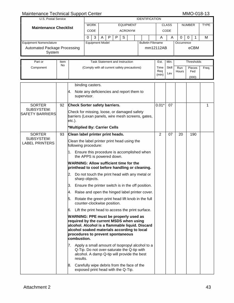
Maintenance Technical Support Center MMO-018-13 U.S. Postal Service IDENTIFICATION
Maintenance Checklist WORK
CODE
EQUIPMENT
ACRONYM
CLASS
CODE
NUMBER TYPE
0 3 A P P S A A 0 0 1 M
Equipment Nomenclature
Automated Package Processing System
Equipment Model
Bulletin Filename
mm12112AB
Occurrence
eCBM
Part or
Component
Item No
Task Statement and Instruction
(Comply with all current safety precautions)
Est.
Time Req (min)
Min.
Skill
Lev
Thresholds
Run Hours
Pieces Fed
(000)
Freq.
Attachment 2 43
binding casters.
4. Note any deficiencies and report them to supervisor.
SORTER SUBSYSTEM:
SAFETY BARRIERS
92 Check Sorter safety barriers.
Check for missing, loose, or damaged safety barriers (Lexan panels, wire mesh screens, gates, etc.).
*Multiplied By: Carrier Cells
0.01* 07 1
SORTER SUBSYSTEM:
LABEL PRINTERS
93 Clean label printer print heads.
Clean the label printer print head using the following procedure:
1. Ensure this procedure is accomplished when the APPS is powered down.
WARNING: Allow sufficient time for the printhead to cool before handling or cleaning.
2. Do not touch the print head with any metal or sharp objects.
3. Ensure the printer switch is in the off position.
4. Raise and open the hinged label printer cover.
5. Rotate the green print head lift knob in the full counter-clockwise position.
6. Lift the print head to access the print surface.
WARNING: PPE must be properly used as required by the current MSDS when using alcohol. Alcohol is a flammable liquid. Discard alcohol soaked materials according to local procedures to prevent spontaneous combustion.
7. Apply a small amount of Isopropyl alcohol to a Q-Tip. Do not over-saturate the Q-tip with alcohol. A damp Q-tip will provide the best results.
8. Carefully wipe debris from the face of the exposed print head with the Q-Tip.
2 07 20 190
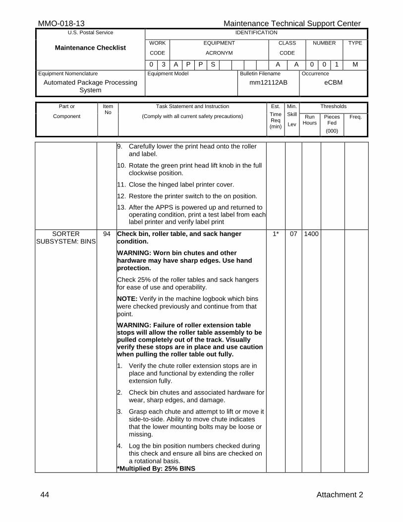
MMO-018-13 Maintenance Technical Support Center U.S. Postal Service IDENTIFICATION
Maintenance Checklist WORK
CODE
EQUIPMENT
ACRONYM
CLASS
CODE
NUMBER TYPE
0 3 A P P S A A 0 0 1 M
Equipment Nomenclature
Automated Package Processing System
Equipment Model
Bulletin Filename
mm12112AB
Occurrence
eCBM
Part or
Component
Item No
Task Statement and Instruction
(Comply with all current safety precautions)
Est.
Time Req (min)
Min.
Skill
Lev
Thresholds
Run Hours
Pieces Fed
(000)
Freq.
44 Attachment 2
9. Carefully lower the print head onto the roller and label.
10. Rotate the green print head lift knob in the full clockwise position.
11. Close the hinged label printer cover.
12. Restore the printer switch to the on position.
13. After the APPS is powered up and returned to operating condition, print a test label from each label printer and verify label print
SORTER SUBSYSTEM: BINS
94 Check bin, roller table, and sack hanger condition.
WARNING: Worn bin chutes and other hardware may have sharp edges. Use hand protection.
Check 25% of the roller tables and sack hangers for ease of use and operability.
NOTE: Verify in the machine logbook which bins were checked previously and continue from that point.
WARNING: Failure of roller extension table stops will allow the roller table assembly to be pulled completely out of the track. Visually verify these stops are in place and use caution when pulling the roller table out fully.
1. Verify the chute roller extension stops are in place and functional by extending the roller extension fully.
2. Check bin chutes and associated hardware for wear, sharp edges, and damage.
3. Grasp each chute and attempt to lift or move it side-to-side. Ability to move chute indicates that the lower mounting bolts may be loose or missing.
4. Log the bin position numbers checked during this check and ensure all bins are checked on a rotational basis.
*Multiplied By: 25% BINS
1* 07 1400
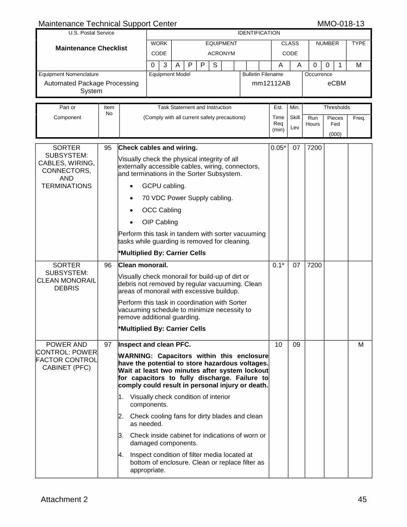
Maintenance Technical Support Center MMO-018-13 U.S. Postal Service IDENTIFICATION
Maintenance Checklist WORK
CODE
EQUIPMENT
ACRONYM
CLASS
CODE
NUMBER TYPE
0 3 A P P S A A 0 0 1 M
Equipment Nomenclature
Automated Package Processing System
Equipment Model
Bulletin Filename
mm12112AB
Occurrence
eCBM
Part or
Component
Item No
Task Statement and Instruction
(Comply with all current safety precautions)
Est.
Time Req (min)
Min.
Skill
Lev
Thresholds
Run Hours
Pieces Fed
(000)
Freq.
Attachment 2 45
SORTER SUBSYSTEM:
CABLES, WIRING, CONNECTORS,
AND TERMINATIONS
95 Check cables and wiring.
Visually check the physical integrity of all externally accessible cables, wiring, connectors, and terminations in the Sorter Subsystem.
GCPU cabling.
70 VDC Power Supply cabling.
OCC Cabling
OIP Cabling
Perform this task in tandem with sorter vacuuming tasks while guarding is removed for cleaning.
*Multiplied By: Carrier Cells
0.05* 07 7200
SORTER SUBSYSTEM:
CLEAN MONORAIL DEBRIS
96 Clean monorail.
Visually check monorail for build-up of dirt or debris not removed by regular vacuuming. Clean areas of monorail with excessive buildup.
Perform this task in coordination with Sorter vacuuming schedule to minimize necessity to remove additional guarding.
*Multiplied By: Carrier Cells
0.1* 07 7200
POWER AND CONTROL: POWER FACTOR CONTROL
CABINET (PFC)
97 Inspect and clean PFC.
WARNING: Capacitors within this enclosure have the potential to store hazardous voltages. Wait at least two minutes after system lockout for capacitors to fully discharge. Failure to comply could result in personal injury or death.
1. Visually check condition of interior components.
2. Check cooling fans for dirty blades and clean as needed.
3. Check inside cabinet for indications of worn or damaged components.
4. Inspect condition of filter media located at bottom of enclosure. Clean or replace filter as appropriate.
10 09 M
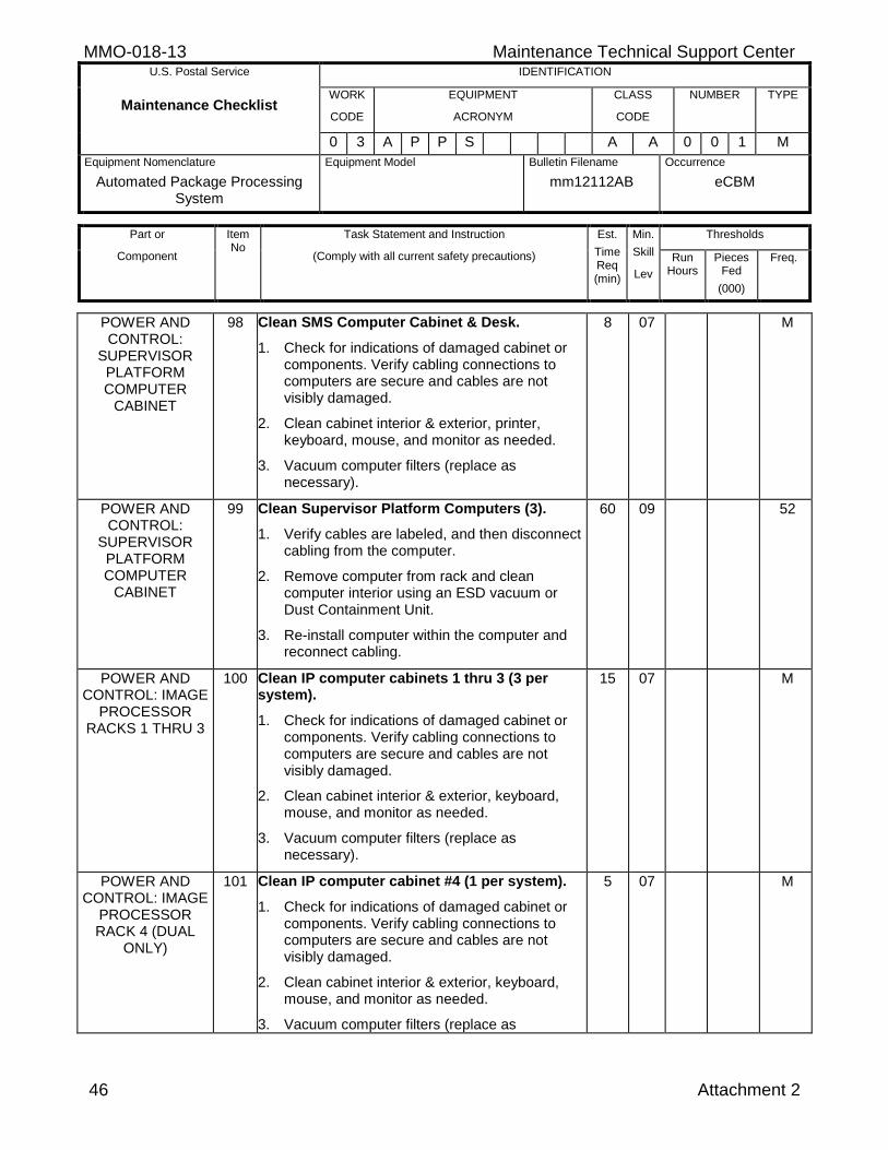
MMO-018-13 Maintenance Technical Support Center U.S. Postal Service IDENTIFICATION
Maintenance Checklist WORK
CODE
EQUIPMENT
ACRONYM
CLASS
CODE
NUMBER TYPE
0 3 A P P S A A 0 0 1 M
Equipment Nomenclature
Automated Package Processing System
Equipment Model
Bulletin Filename
mm12112AB
Occurrence
eCBM
Part or
Component
Item No
Task Statement and Instruction
(Comply with all current safety precautions)
Est.
Time Req (min)
Min.
Skill
Lev
Thresholds
Run Hours
Pieces Fed
(000)
Freq.
46 Attachment 2
POWER AND CONTROL:
SUPERVISOR PLATFORM COMPUTER
CABINET
98 Clean SMS Computer Cabinet & Desk.
1. Check for indications of damaged cabinet or components. Verify cabling connections to computers are secure and cables are not visibly damaged.
2. Clean cabinet interior & exterior, printer, keyboard, mouse, and monitor as needed.
3. Vacuum computer filters (replace as necessary).
8 07 M
POWER AND CONTROL:
SUPERVISOR PLATFORM COMPUTER
CABINET
99 Clean Supervisor Platform Computers (3).
1. Verify cables are labeled, and then disconnect cabling from the computer.
2. Remove computer from rack and clean computer interior using an ESD vacuum or Dust Containment Unit.
3. Re-install computer within the computer and reconnect cabling.
60 09 52
POWER AND CONTROL: IMAGE
PROCESSOR RACKS 1 THRU 3
100 Clean IP computer cabinets 1 thru 3 (3 per system).
1. Check for indications of damaged cabinet or components. Verify cabling connections to computers are secure and cables are not visibly damaged.
2. Clean cabinet interior & exterior, keyboard, mouse, and monitor as needed.
3. Vacuum computer filters (replace as necessary).
15 07 M
POWER AND CONTROL: IMAGE
PROCESSOR RACK 4 (DUAL
ONLY)
101 Clean IP computer cabinet #4 (1 per system).
1. Check for indications of damaged cabinet or components. Verify cabling connections to computers are secure and cables are not visibly damaged.
2. Clean cabinet interior & exterior, keyboard, mouse, and monitor as needed.
3. Vacuum computer filters (replace as
5 07 M
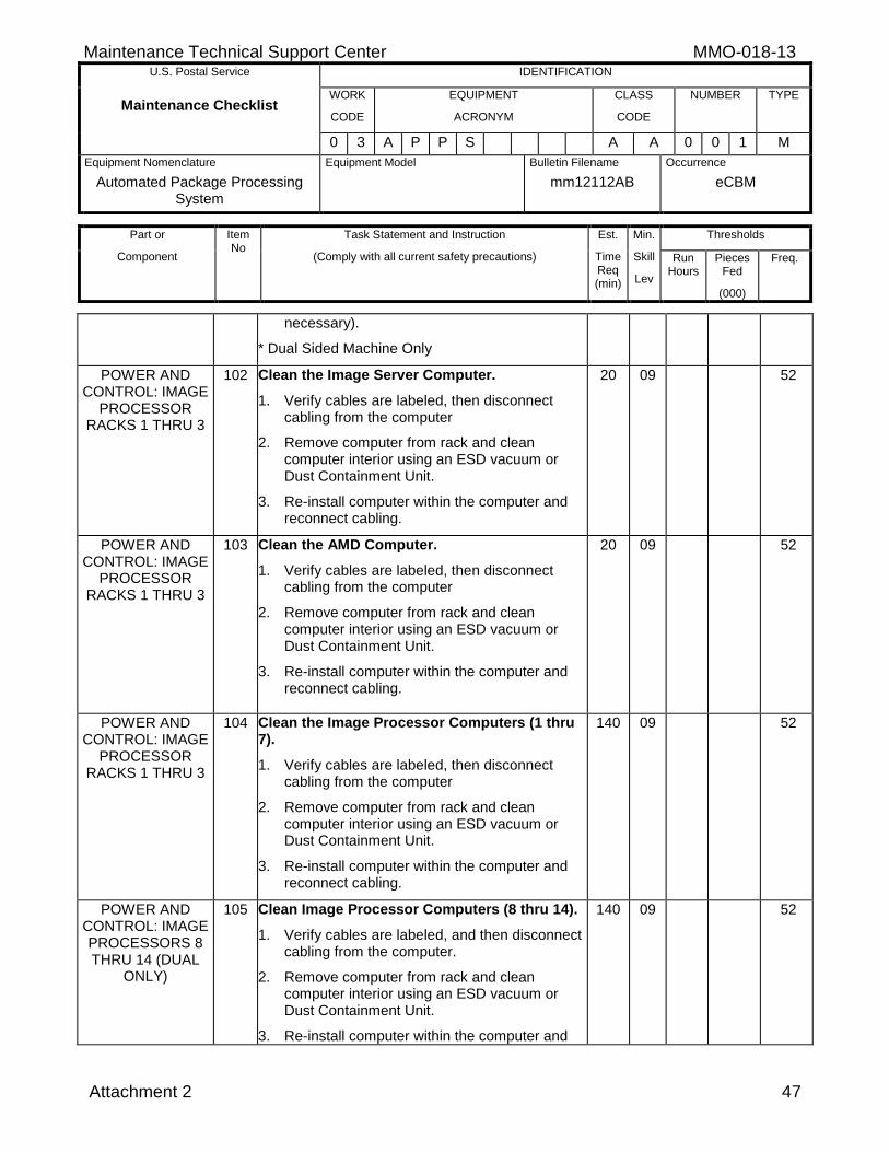
Maintenance Technical Support Center MMO-018-13 U.S. Postal Service IDENTIFICATION
Maintenance Checklist WORK
CODE
EQUIPMENT
ACRONYM
CLASS
CODE
NUMBER TYPE
0 3 A P P S A A 0 0 1 M
Equipment Nomenclature
Automated Package Processing System
Equipment Model
Bulletin Filename
mm12112AB
Occurrence
eCBM
Part or
Component
Item No
Task Statement and Instruction
(Comply with all current safety precautions)
Est.
Time Req (min)
Min.
Skill
Lev
Thresholds
Run Hours
Pieces Fed
(000)
Freq.
Attachment 2 47
necessary).
* Dual Sided Machine Only
POWER AND CONTROL: IMAGE
PROCESSOR RACKS 1 THRU 3
102 Clean the Image Server Computer.
1. Verify cables are labeled, then disconnect cabling from the computer
2. Remove computer from rack and clean computer interior using an ESD vacuum or Dust Containment Unit.
3. Re-install computer within the computer and reconnect cabling.
20 09 52
POWER AND CONTROL: IMAGE
PROCESSOR RACKS 1 THRU 3
103 Clean the AMD Computer.
1. Verify cables are labeled, then disconnect cabling from the computer
2. Remove computer from rack and clean computer interior using an ESD vacuum or Dust Containment Unit.
3. Re-install computer within the computer and reconnect cabling.
20 09 52
POWER AND CONTROL: IMAGE
PROCESSOR RACKS 1 THRU 3
104 Clean the Image Processor Computers (1 thru 7).
1. Verify cables are labeled, then disconnect cabling from the computer
2. Remove computer from rack and clean computer interior using an ESD vacuum or Dust Containment Unit.
3. Re-install computer within the computer and reconnect cabling.
140 09 52
POWER AND CONTROL: IMAGE PROCESSORS 8 THRU 14 (DUAL
ONLY)
105 Clean Image Processor Computers (8 thru 14).
1. Verify cables are labeled, and then disconnect cabling from the computer.
2. Remove computer from rack and clean computer interior using an ESD vacuum or Dust Containment Unit.
3. Re-install computer within the computer and
140 09 52
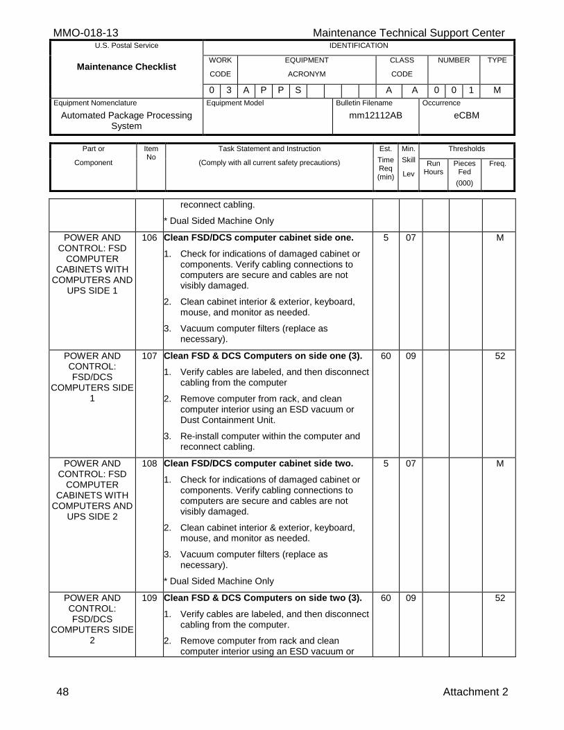
MMO-018-13 Maintenance Technical Support Center U.S. Postal Service IDENTIFICATION
Maintenance Checklist WORK
CODE
EQUIPMENT
ACRONYM
CLASS
CODE
NUMBER TYPE
0 3 A P P S A A 0 0 1 M
Equipment Nomenclature
Automated Package Processing System
Equipment Model
Bulletin Filename
mm12112AB
Occurrence
eCBM
Part or
Component
Item No
Task Statement and Instruction
(Comply with all current safety precautions)
Est.
Time Req (min)
Min.
Skill
Lev
Thresholds
Run Hours
Pieces Fed
(000)
Freq.
48 Attachment 2
reconnect cabling.
* Dual Sided Machine Only
POWER AND CONTROL: FSD
COMPUTER CABINETS WITH
COMPUTERS AND UPS SIDE 1
106 Clean FSD/DCS computer cabinet side one.
1. Check for indications of damaged cabinet or components. Verify cabling connections to computers are secure and cables are not visibly damaged.
2. Clean cabinet interior & exterior, keyboard, mouse, and monitor as needed.
3. Vacuum computer filters (replace as necessary).
5 07 M
POWER AND CONTROL: FSD/DCS
COMPUTERS SIDE 1
107 Clean FSD & DCS Computers on side one (3).
1. Verify cables are labeled, and then disconnect cabling from the computer
2. Remove computer from rack, and clean computer interior using an ESD vacuum or Dust Containment Unit.
3. Re-install computer within the computer and reconnect cabling.
60 09 52
POWER AND CONTROL: FSD
COMPUTER CABINETS WITH
COMPUTERS AND UPS SIDE 2
108 Clean FSD/DCS computer cabinet side two.
1. Check for indications of damaged cabinet or components. Verify cabling connections to computers are secure and cables are not visibly damaged.
2. Clean cabinet interior & exterior, keyboard, mouse, and monitor as needed.
3. Vacuum computer filters (replace as necessary).
* Dual Sided Machine Only
5 07 M
POWER AND CONTROL: FSD/DCS
COMPUTERS SIDE 2
109 Clean FSD & DCS Computers on side two (3).
1. Verify cables are labeled, and then disconnect cabling from the computer.
2. Remove computer from rack and clean computer interior using an ESD vacuum or
60 09 52
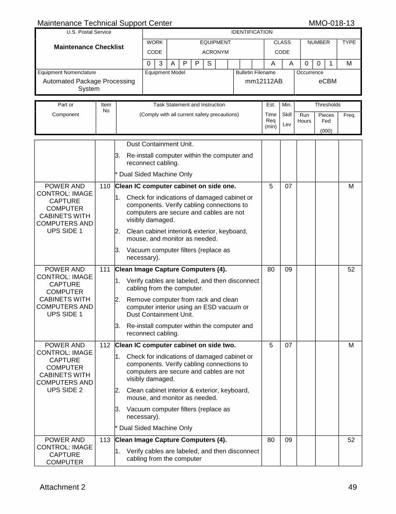
Maintenance Technical Support Center MMO-018-13 U.S. Postal Service IDENTIFICATION
Maintenance Checklist WORK
CODE
EQUIPMENT
ACRONYM
CLASS
CODE
NUMBER TYPE
0 3 A P P S A A 0 0 1 M
Equipment Nomenclature
Automated Package Processing System
Equipment Model
Bulletin Filename
mm12112AB
Occurrence
eCBM
Part or
Component
Item No
Task Statement and Instruction
(Comply with all current safety precautions)
Est.
Time Req (min)
Min.
Skill
Lev
Thresholds
Run Hours
Pieces Fed
(000)
Freq.
Attachment 2 49
Dust Containment Unit.
3. Re-install computer within the computer and reconnect cabling.
* Dual Sided Machine Only
POWER AND CONTROL: IMAGE
CAPTURE COMPUTER
CABINETS WITH COMPUTERS AND
UPS SIDE 1
110 Clean IC computer cabinet on side one.
1. Check for indications of damaged cabinet or components. Verify cabling connections to computers are secure and cables are not visibly damaged.
2. Clean cabinet interior& exterior, keyboard, mouse, and monitor as needed.
3. Vacuum computer filters (replace as necessary).
5 07 M
POWER AND CONTROL: IMAGE
CAPTURE COMPUTER
CABINETS WITH COMPUTERS AND
UPS SIDE 1
111 Clean Image Capture Computers (4).
1. Verify cables are labeled, and then disconnect cabling from the computer.
2. Remove computer from rack and clean computer interior using an ESD vacuum or Dust Containment Unit.
3. Re-install computer within the computer and reconnect cabling.
80 09 52
POWER AND CONTROL: IMAGE
CAPTURE COMPUTER
CABINETS WITH COMPUTERS AND
UPS SIDE 2
112 Clean IC computer cabinet on side two.
1. Check for indications of damaged cabinet or components. Verify cabling connections to computers are secure and cables are not visibly damaged.
2. Clean cabinet interior & exterior, keyboard, mouse, and monitor as needed.
3. Vacuum computer filters (replace as necessary).
* Dual Sided Machine Only
5 07 M
POWER AND CONTROL: IMAGE
CAPTURE COMPUTER
113 Clean Image Capture Computers (4).
1. Verify cables are labeled, and then disconnect cabling from the computer
80 09 52
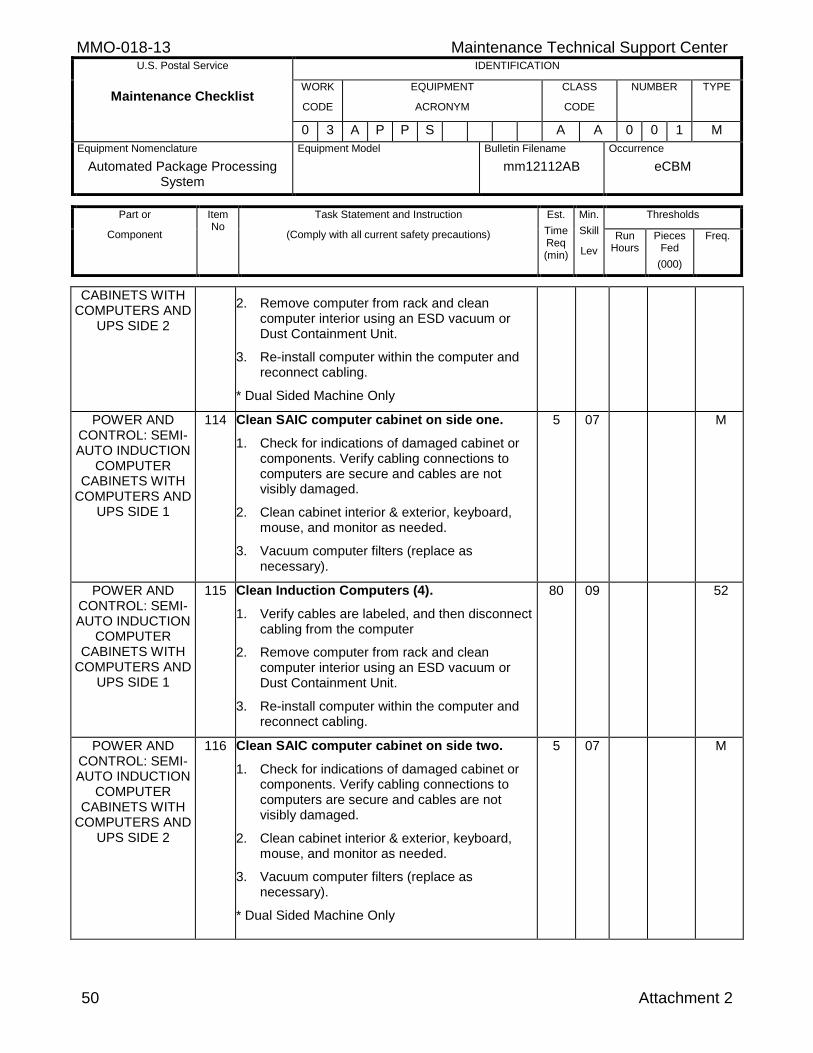
MMO-018-13 Maintenance Technical Support Center U.S. Postal Service IDENTIFICATION
Maintenance Checklist WORK
CODE
EQUIPMENT
ACRONYM
CLASS
CODE
NUMBER TYPE
0 3 A P P S A A 0 0 1 M
Equipment Nomenclature
Automated Package Processing System
Equipment Model
Bulletin Filename
mm12112AB
Occurrence
eCBM
Part or
Component
Item No
Task Statement and Instruction
(Comply with all current safety precautions)
Est.
Time Req (min)
Min.
Skill
Lev
Thresholds
Run Hours
Pieces Fed
(000)
Freq.
50 Attachment 2
CABINETS WITH COMPUTERS AND
UPS SIDE 2
2. Remove computer from rack and clean computer interior using an ESD vacuum or Dust Containment Unit.
3. Re-install computer within the computer and reconnect cabling.
* Dual Sided Machine Only
POWER AND CONTROL: SEMI-AUTO INDUCTION
COMPUTER CABINETS WITH
COMPUTERS AND UPS SIDE 1
114 Clean SAIC computer cabinet on side one.
1. Check for indications of damaged cabinet or components. Verify cabling connections to computers are secure and cables are not visibly damaged.
2. Clean cabinet interior & exterior, keyboard, mouse, and monitor as needed.
3. Vacuum computer filters (replace as necessary).
5 07 M
POWER AND CONTROL: SEMI-AUTO INDUCTION
COMPUTER CABINETS WITH
COMPUTERS AND UPS SIDE 1
115 Clean Induction Computers (4).
1. Verify cables are labeled, and then disconnect cabling from the computer
2. Remove computer from rack and clean computer interior using an ESD vacuum or Dust Containment Unit.
3. Re-install computer within the computer and reconnect cabling.
80 09 52
POWER AND CONTROL: SEMI-AUTO INDUCTION
COMPUTER CABINETS WITH
COMPUTERS AND UPS SIDE 2
116 Clean SAIC computer cabinet on side two.
1. Check for indications of damaged cabinet or components. Verify cabling connections to computers are secure and cables are not visibly damaged.
2. Clean cabinet interior & exterior, keyboard, mouse, and monitor as needed.
3. Vacuum computer filters (replace as necessary).
* Dual Sided Machine Only
5 07 M
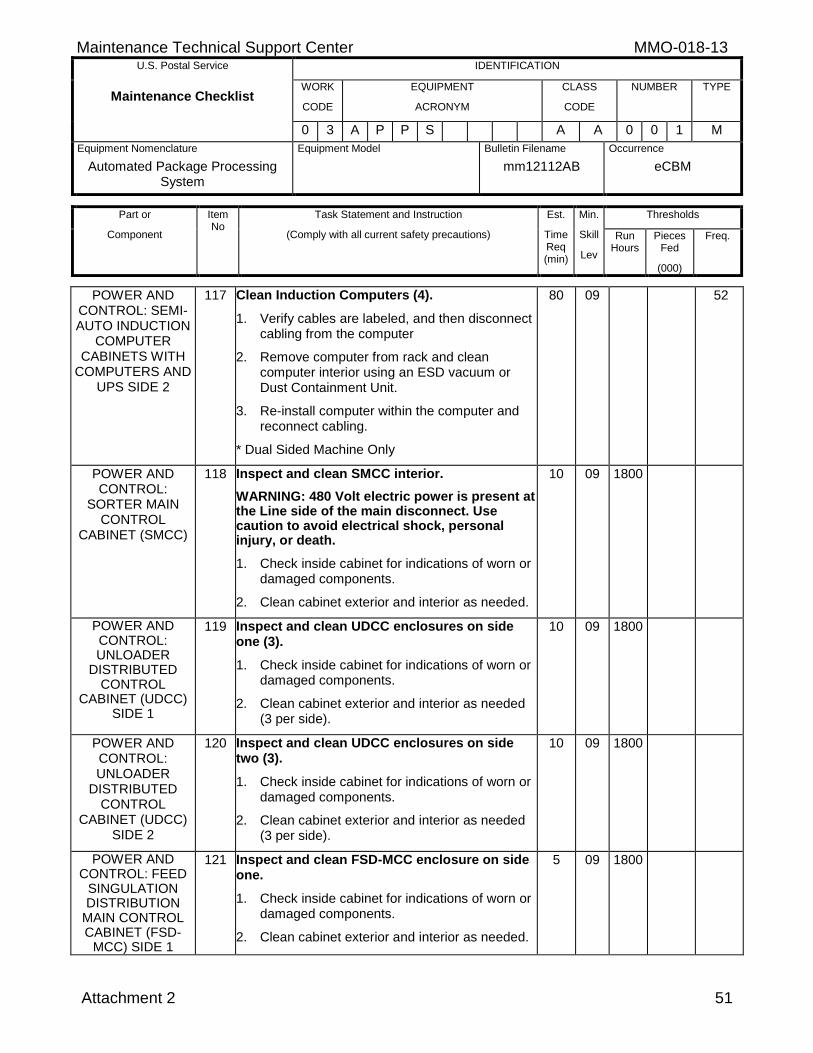
Maintenance Technical Support Center MMO-018-13 U.S. Postal Service IDENTIFICATION
Maintenance Checklist WORK
CODE
EQUIPMENT
ACRONYM
CLASS
CODE
NUMBER TYPE
0 3 A P P S A A 0 0 1 M
Equipment Nomenclature
Automated Package Processing System
Equipment Model
Bulletin Filename
mm12112AB
Occurrence
eCBM
Part or
Component
Item No
Task Statement and Instruction
(Comply with all current safety precautions)
Est.
Time Req (min)
Min.
Skill
Lev
Thresholds
Run Hours
Pieces Fed
(000)
Freq.
Attachment 2 51
POWER AND CONTROL: SEMI-AUTO INDUCTION
COMPUTER CABINETS WITH
COMPUTERS AND UPS SIDE 2
117 Clean Induction Computers (4).
1. Verify cables are labeled, and then disconnect cabling from the computer
2. Remove computer from rack and clean computer interior using an ESD vacuum or Dust Containment Unit.
3. Re-install computer within the computer and reconnect cabling.
* Dual Sided Machine Only
80 09 52
POWER AND CONTROL:
SORTER MAIN CONTROL
CABINET (SMCC)
118 Inspect and clean SMCC interior.
WARNING: 480 Volt electric power is present at the Line side of the main disconnect. Use caution to avoid electrical shock, personal injury, or death.
1. Check inside cabinet for indications of worn or damaged components.
2. Clean cabinet exterior and interior as needed.
10 09 1800
POWER AND CONTROL: UNLOADER
DISTRIBUTED CONTROL
CABINET (UDCC) SIDE 1
119 Inspect and clean UDCC enclosures on side one (3).
1. Check inside cabinet for indications of worn or damaged components.
2. Clean cabinet exterior and interior as needed (3 per side).
10 09 1800
POWER AND CONTROL: UNLOADER
DISTRIBUTED CONTROL
CABINET (UDCC) SIDE 2
120 Inspect and clean UDCC enclosures on side two (3).
1. Check inside cabinet for indications of worn or damaged components.
2. Clean cabinet exterior and interior as needed (3 per side).
10 09 1800
POWER AND CONTROL: FEED
SINGULATION DISTRIBUTION
MAIN CONTROL CABINET (FSD-
MCC) SIDE 1
121 Inspect and clean FSD-MCC enclosure on side one.
1. Check inside cabinet for indications of worn or damaged components.
2. Clean cabinet exterior and interior as needed.
5 09 1800
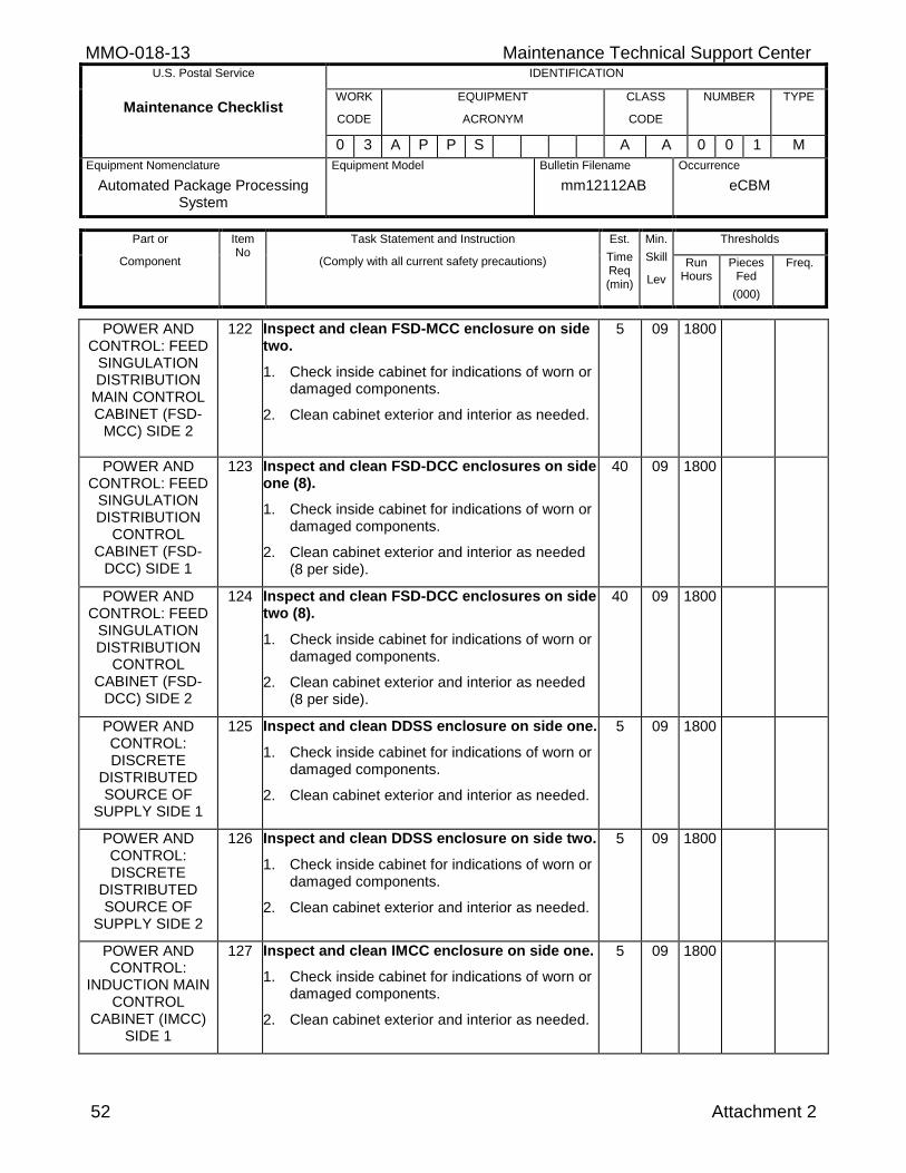
MMO-018-13 Maintenance Technical Support Center U.S. Postal Service IDENTIFICATION
Maintenance Checklist WORK
CODE
EQUIPMENT
ACRONYM
CLASS
CODE
NUMBER TYPE
0 3 A P P S A A 0 0 1 M
Equipment Nomenclature
Automated Package Processing System
Equipment Model
Bulletin Filename
mm12112AB
Occurrence
eCBM
Part or
Component
Item No
Task Statement and Instruction
(Comply with all current safety precautions)
Est.
Time Req (min)
Min.
Skill
Lev
Thresholds
Run Hours
Pieces Fed
(000)
Freq.
52 Attachment 2
POWER AND CONTROL: FEED
SINGULATION DISTRIBUTION
MAIN CONTROL CABINET (FSD-
MCC) SIDE 2
122 Inspect and clean FSD-MCC enclosure on side two.
1. Check inside cabinet for indications of worn or damaged components.
2. Clean cabinet exterior and interior as needed.
5 09 1800
POWER AND CONTROL: FEED
SINGULATION DISTRIBUTION
CONTROL CABINET (FSD-
DCC) SIDE 1
123 Inspect and clean FSD-DCC enclosures on side one (8).
1. Check inside cabinet for indications of worn or damaged components.
2. Clean cabinet exterior and interior as needed (8 per side).
40 09 1800
POWER AND CONTROL: FEED
SINGULATION DISTRIBUTION
CONTROL CABINET (FSD-
DCC) SIDE 2
124 Inspect and clean FSD-DCC enclosures on side two (8).
1. Check inside cabinet for indications of worn or damaged components.
2. Clean cabinet exterior and interior as needed (8 per side).
40 09 1800
POWER AND CONTROL: DISCRETE
DISTRIBUTED SOURCE OF
SUPPLY SIDE 1
125 Inspect and clean DDSS enclosure on side one.
1. Check inside cabinet for indications of worn or damaged components.
2. Clean cabinet exterior and interior as needed.
5 09 1800
POWER AND CONTROL: DISCRETE
DISTRIBUTED SOURCE OF
SUPPLY SIDE 2
126 Inspect and clean DDSS enclosure on side two.
1. Check inside cabinet for indications of worn or damaged components.
2. Clean cabinet exterior and interior as needed.
5 09 1800
POWER AND CONTROL:
INDUCTION MAIN CONTROL
CABINET (IMCC) SIDE 1
127 Inspect and clean IMCC enclosure on side one.
1. Check inside cabinet for indications of worn or damaged components.
2. Clean cabinet exterior and interior as needed.
5 09 1800
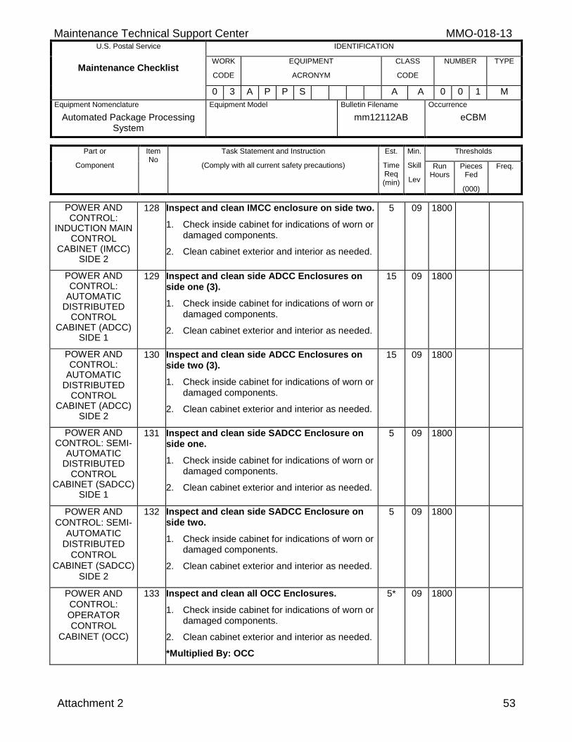
Maintenance Technical Support Center MMO-018-13 U.S. Postal Service IDENTIFICATION
Maintenance Checklist WORK
CODE
EQUIPMENT
ACRONYM
CLASS
CODE
NUMBER TYPE
0 3 A P P S A A 0 0 1 M
Equipment Nomenclature
Automated Package Processing System
Equipment Model
Bulletin Filename
mm12112AB
Occurrence
eCBM
Part or
Component
Item No
Task Statement and Instruction
(Comply with all current safety precautions)
Est.
Time Req (min)
Min.
Skill
Lev
Thresholds
Run Hours
Pieces Fed
(000)
Freq.
Attachment 2 53
POWER AND CONTROL:
INDUCTION MAIN CONTROL
CABINET (IMCC) SIDE 2
128 Inspect and clean IMCC enclosure on side two.
1. Check inside cabinet for indications of worn or damaged components.
2. Clean cabinet exterior and interior as needed.
5 09 1800
POWER AND CONTROL:
AUTOMATIC DISTRIBUTED
CONTROL CABINET (ADCC)
SIDE 1
129 Inspect and clean side ADCC Enclosures on side one (3).
1. Check inside cabinet for indications of worn or damaged components.
2. Clean cabinet exterior and interior as needed.
15 09 1800
POWER AND CONTROL:
AUTOMATIC DISTRIBUTED
CONTROL CABINET (ADCC)
SIDE 2
130 Inspect and clean side ADCC Enclosures on side two (3).
1. Check inside cabinet for indications of worn or damaged components.
2. Clean cabinet exterior and interior as needed.
15 09 1800
POWER AND CONTROL: SEMI-
AUTOMATIC DISTRIBUTED
CONTROL CABINET (SADCC)
SIDE 1
131 Inspect and clean side SADCC Enclosure on side one.
1. Check inside cabinet for indications of worn or damaged components.
2. Clean cabinet exterior and interior as needed.
5 09 1800
POWER AND CONTROL: SEMI-
AUTOMATIC DISTRIBUTED
CONTROL CABINET (SADCC)
SIDE 2
132 Inspect and clean side SADCC Enclosure on side two.
1. Check inside cabinet for indications of worn or damaged components.
2. Clean cabinet exterior and interior as needed.
5 09 1800
POWER AND CONTROL: OPERATOR CONTROL
CABINET (OCC)
133 Inspect and clean all OCC Enclosures.
1. Check inside cabinet for indications of worn or damaged components.
2. Clean cabinet exterior and interior as needed.
*Multiplied By: OCC
5* 09 1800
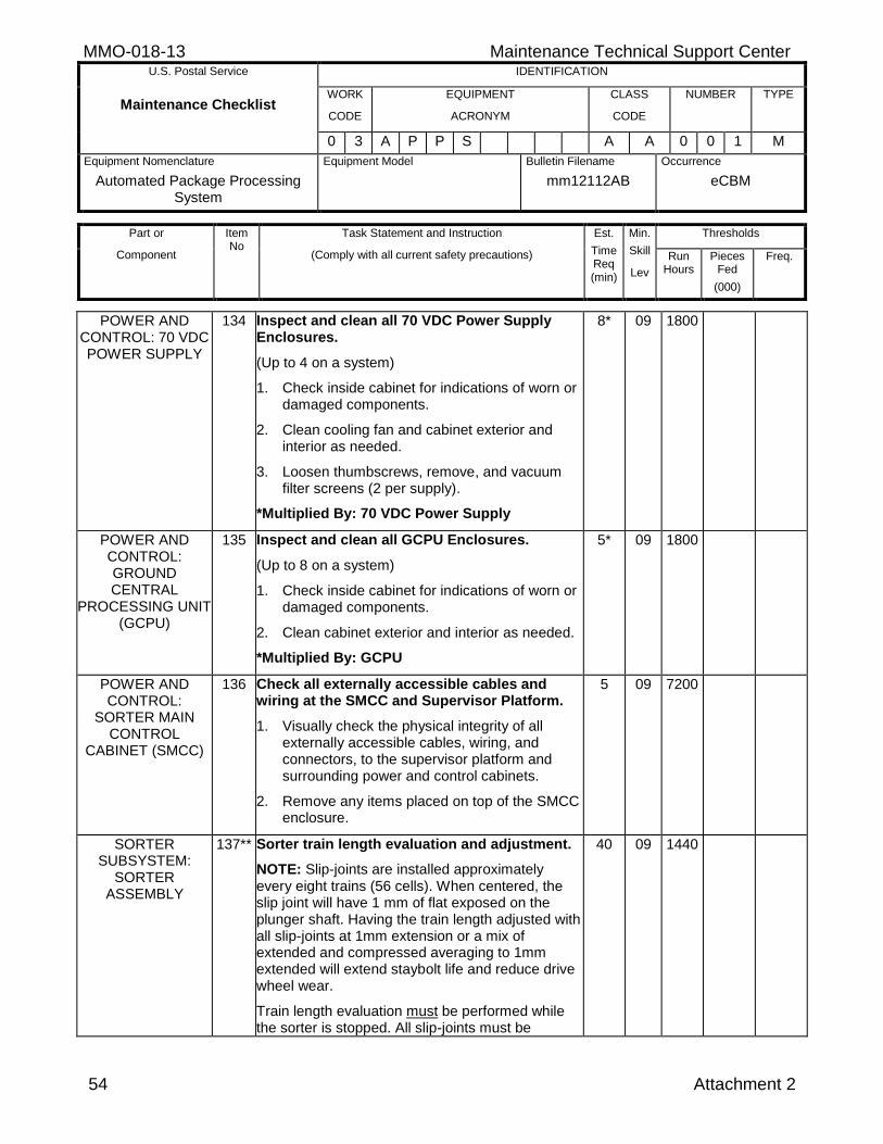
MMO-018-13 Maintenance Technical Support Center U.S. Postal Service IDENTIFICATION
Maintenance Checklist WORK
CODE
EQUIPMENT
ACRONYM
CLASS
CODE
NUMBER TYPE
0 3 A P P S A A 0 0 1 M
Equipment Nomenclature
Automated Package Processing System
Equipment Model
Bulletin Filename
mm12112AB
Occurrence
eCBM
Part or
Component
Item No
Task Statement and Instruction
(Comply with all current safety precautions)
Est.
Time Req (min)
Min.
Skill
Lev
Thresholds
Run Hours
Pieces Fed
(000)
Freq.
54 Attachment 2
POWER AND CONTROL: 70 VDC POWER SUPPLY
134 Inspect and clean all 70 VDC Power Supply Enclosures.
(Up to 4 on a system)
1. Check inside cabinet for indications of worn or damaged components.
2. Clean cooling fan and cabinet exterior and interior as needed.
3. Loosen thumbscrews, remove, and vacuum filter screens (2 per supply).
*Multiplied By: 70 VDC Power Supply
8* 09 1800
POWER AND CONTROL: GROUND CENTRAL
PROCESSING UNIT (GCPU)
135 Inspect and clean all GCPU Enclosures.
(Up to 8 on a system)
1. Check inside cabinet for indications of worn or damaged components.
2. Clean cabinet exterior and interior as needed.
*Multiplied By: GCPU
5* 09 1800
POWER AND CONTROL:
SORTER MAIN CONTROL
CABINET (SMCC)
136 Check all externally accessible cables and wiring at the SMCC and Supervisor Platform.
1. Visually check the physical integrity of all externally accessible cables, wiring, and connectors, to the supervisor platform and surrounding power and control cabinets.
2. Remove any items placed on top of the SMCC enclosure.
5 09 7200
SORTER SUBSYSTEM:
SORTER ASSEMBLY
137** Sorter train length evaluation and adjustment.
NOTE: Slip-joints are installed approximately every eight trains (56 cells). When centered, the slip joint will have 1 mm of flat exposed on the plunger shaft. Having the train length adjusted with all slip-joints at 1mm extension or a mix of extended and compressed averaging to 1mm extended will extend staybolt life and reduce drive wheel wear.
Train length evaluation must be performed while the sorter is stopped. All slip-joints must be
40 09 1440
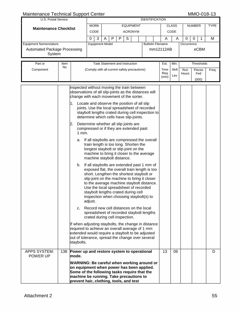
Maintenance Technical Support Center MMO-018-13 U.S. Postal Service IDENTIFICATION
Maintenance Checklist WORK
CODE
EQUIPMENT
ACRONYM
CLASS
CODE
NUMBER TYPE
0 3 A P P S A A 0 0 1 M
Equipment Nomenclature
Automated Package Processing System
Equipment Model
Bulletin Filename
mm12112AB
Occurrence
eCBM
Part or
Component
Item No
Task Statement and Instruction
(Comply with all current safety precautions)
Est.
Time Req (min)
Min.
Skill
Lev
Thresholds
Run Hours
Pieces Fed
(000)
Freq.
Attachment 2 55
inspected without moving the train between observations of all slip-joints as the distances will change with each movement of the sorter.
1. Locate and observe the position of all slip joints. Use the local spreadsheet of recorded staybolt lengths crated during cell inspection to determine which cells have slip-joints.
2. Determine whether all slip joints are compressed or if they are extended past 1 mm.
a. If all staybolts are compressed the overall train length is too long. Shorten the longest staybolt or slip-joint on the machine to bring it closer to the average machine staybolt distance.
b. If all staybolts are extended past 1 mm of exposed flat, the overall train length is too short. Lengthen the shortest staybolt or slip-joint on the machine to bring it closer to the average machine staybolt distance. Use the local spreadsheet of recorded staybolt lengths crated during cell inspection when choosing staybolt(s) to adjust.
c. Record new cell distances on the local spreadsheet of recorded staybolt lengths crated during cell inspection.
If when adjusting staybolts, the change in distance required to achieve an overall average of 1 mm extended would require a staybolt to be adjusted out of tolerance, spread the change over several staybolts.
APPS SYSTEM: POWER UP
138 Power up and restore system to operational mode.
WARNING: Be careful when working around or on equipment when power has been applied. Some of the following tasks require that the machine be running. Take precautions to prevent hair, clothing, tools, and test
13 09 D
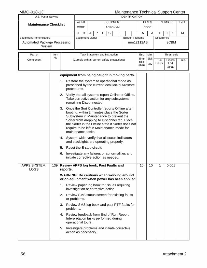
MMO-018-13 Maintenance Technical Support Center U.S. Postal Service IDENTIFICATION
Maintenance Checklist WORK
CODE
EQUIPMENT
ACRONYM
CLASS
CODE
NUMBER TYPE
0 3 A P P S A A 0 0 1 M
Equipment Nomenclature
Automated Package Processing System
Equipment Model
Bulletin Filename
mm12112AB
Occurrence
eCBM
Part or
Component
Item No
Task Statement and Instruction
(Comply with all current safety precautions)
Est.
Time Req (min)
Min.
Skill
Lev
Thresholds
Run Hours
Pieces Fed
(000)
Freq.
56 Attachment 2
equipment from being caught in moving parts.
1. Restore the system to operational mode as prescribed by the current local lockout/restore procedures.
2. Verify that all systems report Online or Offline. Take corrective action for any subsystems remaining Disconnected.
3. Once the Sort Controller reports Offline after booting, within 2 minutes place the Sorter Subsystem in Maintenance to prevent the Sorter from dropping to Disconnected. Place the Sorter in the Offline state if Sorter does not require to be left in Maintenance mode for maintenance tasks.
4. System-wide, verify that all status indicators and stacklights are operating properly.
5. Reset the E-stop circuit.
6. Investigate any failures or abnormalities and initiate corrective action as needed.
APPS SYSTEM: LOGS
139 Review APPS log book, Past Faults and reports.
WARNING: Be cautious when working around or on equipment when power has been applied.
1. Review paper log book for issues requiring investigation or corrective action.
2. Review SMS status screen for existing faults or problems.
3. Review SMS log book and past RTF faults for problems.
4. Review feedback from End of Run Report Interpretation tasks performed during operational tours.
5. Investigate problems and initiate corrective action as necessary.
10 10 1 0.001
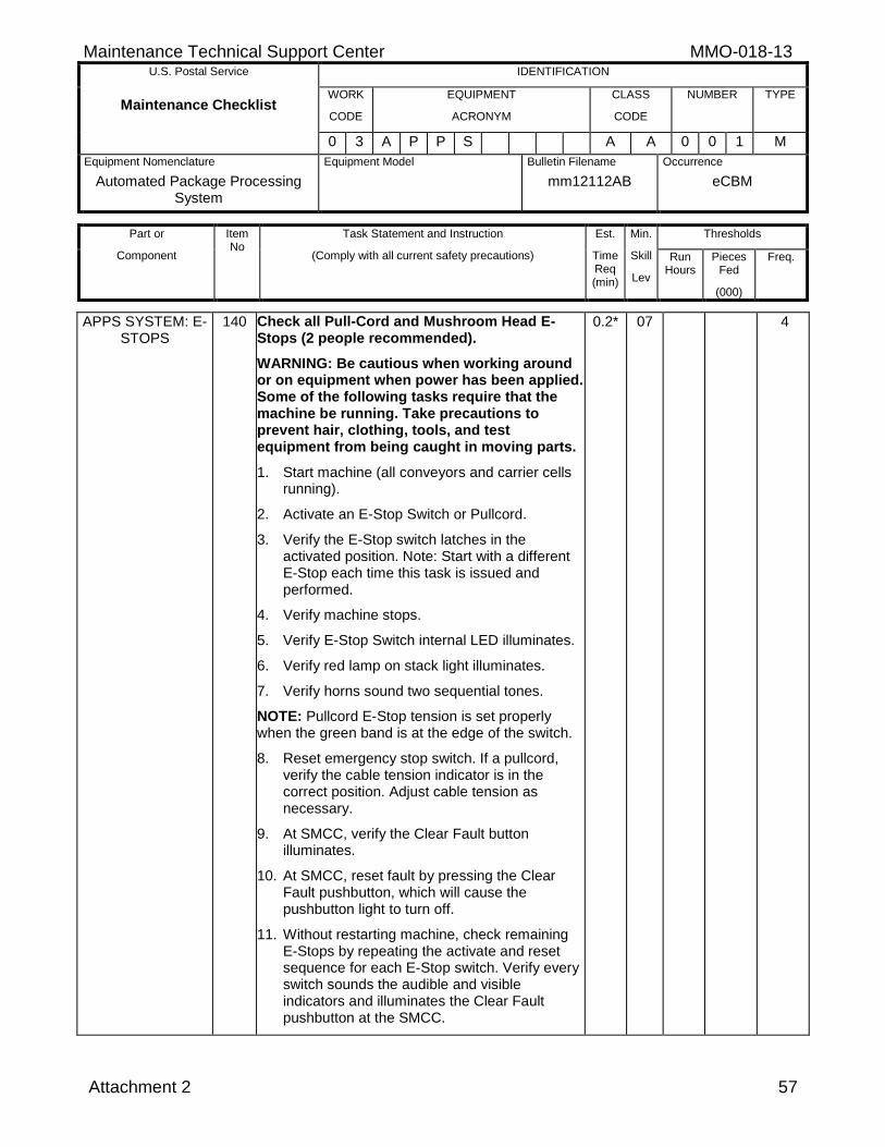
Maintenance Technical Support Center MMO-018-13 U.S. Postal Service IDENTIFICATION
Maintenance Checklist WORK
CODE
EQUIPMENT
ACRONYM
CLASS
CODE
NUMBER TYPE
0 3 A P P S A A 0 0 1 M
Equipment Nomenclature
Automated Package Processing System
Equipment Model
Bulletin Filename
mm12112AB
Occurrence
eCBM
Part or
Component
Item No
Task Statement and Instruction
(Comply with all current safety precautions)
Est.
Time Req (min)
Min.
Skill
Lev
Thresholds
Run Hours
Pieces Fed
(000)
Freq.
Attachment 2 57
APPS SYSTEM: E-STOPS
140 Check all Pull-Cord and Mushroom Head E-Stops (2 people recommended).
WARNING: Be cautious when working around or on equipment when power has been applied. Some of the following tasks require that the machine be running. Take precautions to prevent hair, clothing, tools, and test equipment from being caught in moving parts.
1. Start machine (all conveyors and carrier cells running).
2. Activate an E-Stop Switch or Pullcord.
3. Verify the E-Stop switch latches in the activated position. Note: Start with a different E-Stop each time this task is issued and performed.
4. Verify machine stops.
5. Verify E-Stop Switch internal LED illuminates.
6. Verify red lamp on stack light illuminates.
7. Verify horns sound two sequential tones.
NOTE: Pullcord E-Stop tension is set properly when the green band is at the edge of the switch.
8. Reset emergency stop switch. If a pullcord, verify the cable tension indicator is in the correct position. Adjust cable tension as necessary.
9. At SMCC, verify the Clear Fault button illuminates.
10. At SMCC, reset fault by pressing the Clear Fault pushbutton, which will cause the pushbutton light to turn off.
11. Without restarting machine, check remaining E-Stops by repeating the activate and reset sequence for each E-Stop switch. Verify every switch sounds the audible and visible indicators and illuminates the Clear Fault pushbutton at the SMCC.
0.2* 07 4
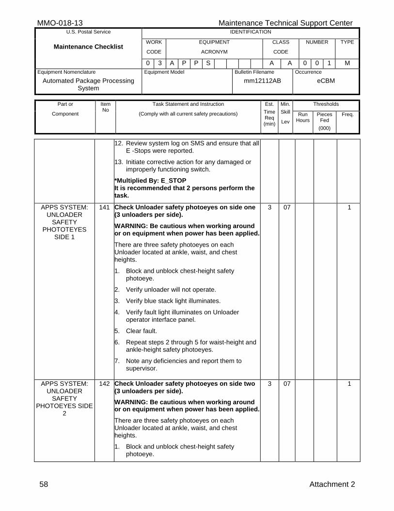
MMO-018-13 Maintenance Technical Support Center U.S. Postal Service IDENTIFICATION
Maintenance Checklist WORK
CODE
EQUIPMENT
ACRONYM
CLASS
CODE
NUMBER TYPE
0 3 A P P S A A 0 0 1 M
Equipment Nomenclature
Automated Package Processing System
Equipment Model
Bulletin Filename
mm12112AB
Occurrence
eCBM
Part or
Component
Item No
Task Statement and Instruction
(Comply with all current safety precautions)
Est.
Time Req (min)
Min.
Skill
Lev
Thresholds
Run Hours
Pieces Fed
(000)
Freq.
58 Attachment 2
12. Review system log on SMS and ensure that all E -Stops were reported.
13. Initiate corrective action for any damaged or improperly functioning switch.
*Multiplied By: E_STOP It is recommended that 2 persons perform the task.
APPS SYSTEM: UNLOADER
SAFETY PHOTOTEYES
SIDE 1
141 Check Unloader safety photoeyes on side one (3 unloaders per side).
WARNING: Be cautious when working around or on equipment when power has been applied.
There are three safety photoeyes on each Unloader located at ankle, waist, and chest heights.
1. Block and unblock chest-height safety photoeye.
2. Verify unloader will not operate.
3. Verify blue stack light illuminates.
4. Verify fault light illuminates on Unloader operator interface panel.
5. Clear fault.
6. Repeat steps 2 through 5 for waist-height and ankle-height safety photoeyes.
7. Note any deficiencies and report them to supervisor.
3 07 1
APPS SYSTEM: UNLOADER
SAFETY PHOTOEYES SIDE
2
142 Check Unloader safety photoeyes on side two (3 unloaders per side).
WARNING: Be cautious when working around or on equipment when power has been applied.
There are three safety photoeyes on each Unloader located at ankle, waist, and chest heights.
1. Block and unblock chest-height safety photoeye.
3 07 1
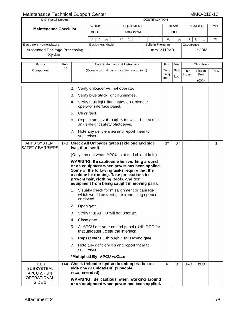
Maintenance Technical Support Center MMO-018-13 U.S. Postal Service IDENTIFICATION
Maintenance Checklist WORK
CODE
EQUIPMENT
ACRONYM
CLASS
CODE
NUMBER TYPE
0 3 A P P S A A 0 0 1 M
Equipment Nomenclature
Automated Package Processing System
Equipment Model
Bulletin Filename
mm12112AB
Occurrence
eCBM
Part or
Component
Item No
Task Statement and Instruction
(Comply with all current safety precautions)
Est.
Time Req (min)
Min.
Skill
Lev
Thresholds
Run Hours
Pieces Fed
(000)
Freq.
Attachment 2 59
2. Verify unloader will not operate.
3. Verify blue stack light illuminates.
4. Verify fault light illuminates on Unloader operator interface panel.
5. Clear fault.
6. Repeat steps 2 through 5 for waist-height and ankle-height safety photoeyes.
7. Note any deficiencies and report them to supervisor.
APPS SYSTEM: SAFETY BARRIERS
143 Check All Unloader gates (side one and side two, if present).
(Only present when APCU is at end of load belt.)
WARNING: Be cautious when working around or on equipment when power has been applied. Some of the following tasks require that the machine be running. Take precautions to prevent hair, clothing, tools, and test equipment from being caught in moving parts.
1. Visually check for misalignment or damage which would prevent gate from being opened or closed.
2. Open gate.
3. Verify that APCU will not operate.
4. Close gate.
5. At APCU operator control panel (UNL-DCC for that unloader), clear the interlock.
6. Repeat steps 1 through 4 for second gate.
7. Note any deficiencies and report them to supervisor.
*Multiplied By: APCU w/Gate
1* 07 1
FEED SUBSYSTEM: APCU & PUN
OPERATIONAL SIDE 1
144 Check Unloader hydraulic unit operation on side one (3 Unloaders) (2 people recommended).
WARNING: Be cautious when working around or on equipment when power has been applied.
6 07 140 600
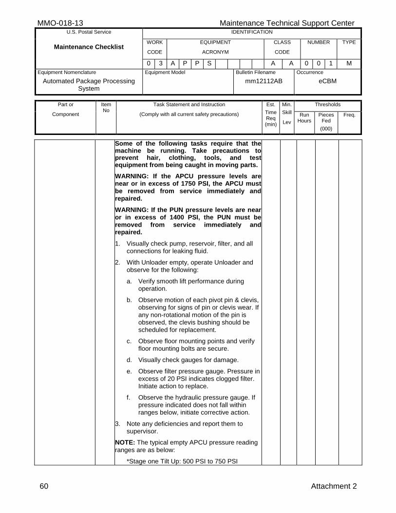
MMO-018-13 Maintenance Technical Support Center U.S. Postal Service IDENTIFICATION
Maintenance Checklist WORK
CODE
EQUIPMENT
ACRONYM
CLASS
CODE
NUMBER TYPE
0 3 A P P S A A 0 0 1 M
Equipment Nomenclature
Automated Package Processing System
Equipment Model
Bulletin Filename
mm12112AB
Occurrence
eCBM
Part or
Component
Item No
Task Statement and Instruction
(Comply with all current safety precautions)
Est.
Time Req (min)
Min.
Skill
Lev
Thresholds
Run Hours
Pieces Fed
(000)
Freq.
60 Attachment 2
Some of the following tasks require that the machine be running. Take precautions to prevent hair, clothing, tools, and test equipment from being caught in moving parts.
WARNING: If the APCU pressure levels are near or in excess of 1750 PSI, the APCU must be removed from service immediately and repaired.
WARNING: If the PUN pressure levels are near or in excess of 1400 PSI, the PUN must be removed from service immediately and repaired.
1. Visually check pump, reservoir, filter, and all connections for leaking fluid.
2. With Unloader empty, operate Unloader and observe for the following:
a. Verify smooth lift performance during operation.
b. Observe motion of each pivot pin & clevis, observing for signs of pin or clevis wear. If any non-rotational motion of the pin is observed, the clevis bushing should be scheduled for replacement.
c. Observe floor mounting points and verify floor mounting bolts are secure.
d. Visually check gauges for damage.
e. Observe filter pressure gauge. Pressure in excess of 20 PSI indicates clogged filter. Initiate action to replace.
f. Observe the hydraulic pressure gauge. If pressure indicated does not fall within ranges below, initiate corrective action.
3. Note any deficiencies and report them to supervisor.
NOTE: The typical empty APCU pressure reading ranges are as below:
*Stage one Tilt Up: 500 PSI to 750 PSI
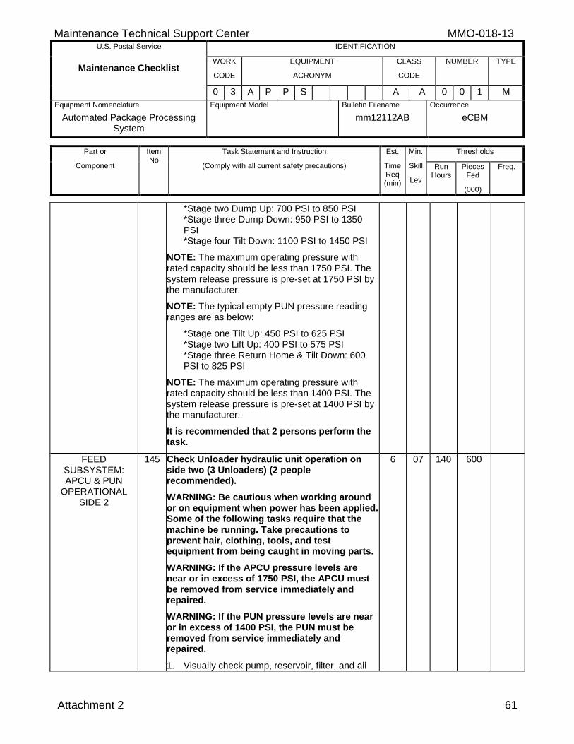
Maintenance Technical Support Center MMO-018-13 U.S. Postal Service IDENTIFICATION
Maintenance Checklist WORK
CODE
EQUIPMENT
ACRONYM
CLASS
CODE
NUMBER TYPE
0 3 A P P S A A 0 0 1 M
Equipment Nomenclature
Automated Package Processing System
Equipment Model
Bulletin Filename
mm12112AB
Occurrence
eCBM
Part or
Component
Item No
Task Statement and Instruction
(Comply with all current safety precautions)
Est.
Time Req (min)
Min.
Skill
Lev
Thresholds
Run Hours
Pieces Fed
(000)
Freq.
Attachment 2 61
*Stage two Dump Up: 700 PSI to 850 PSI *Stage three Dump Down: 950 PSI to 1350 PSI *Stage four Tilt Down: 1100 PSI to 1450 PSI
NOTE: The maximum operating pressure with rated capacity should be less than 1750 PSI. The system release pressure is pre-set at 1750 PSI by the manufacturer.
NOTE: The typical empty PUN pressure reading ranges are as below:
*Stage one Tilt Up: 450 PSI to 625 PSI *Stage two Lift Up: 400 PSI to 575 PSI *Stage three Return Home & Tilt Down: 600 PSI to 825 PSI
NOTE: The maximum operating pressure with rated capacity should be less than 1400 PSI. The system release pressure is pre-set at 1400 PSI by the manufacturer.
It is recommended that 2 persons perform the task.
FEED SUBSYSTEM: APCU & PUN
OPERATIONAL SIDE 2
145 Check Unloader hydraulic unit operation on side two (3 Unloaders) (2 people recommended).
WARNING: Be cautious when working around or on equipment when power has been applied. Some of the following tasks require that the machine be running. Take precautions to prevent hair, clothing, tools, and test equipment from being caught in moving parts.
WARNING: If the APCU pressure levels are near or in excess of 1750 PSI, the APCU must be removed from service immediately and repaired.
WARNING: If the PUN pressure levels are near or in excess of 1400 PSI, the PUN must be removed from service immediately and repaired.
1. Visually check pump, reservoir, filter, and all
6 07 140 600
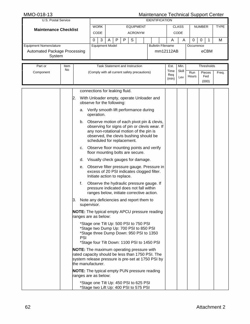
MMO-018-13 Maintenance Technical Support Center U.S. Postal Service IDENTIFICATION
Maintenance Checklist WORK
CODE
EQUIPMENT
ACRONYM
CLASS
CODE
NUMBER TYPE
0 3 A P P S A A 0 0 1 M
Equipment Nomenclature
Automated Package Processing System
Equipment Model
Bulletin Filename
mm12112AB
Occurrence
eCBM
Part or
Component
Item No
Task Statement and Instruction
(Comply with all current safety precautions)
Est.
Time Req (min)
Min.
Skill
Lev
Thresholds
Run Hours
Pieces Fed
(000)
Freq.
62 Attachment 2
connections for leaking fluid.
2. With Unloader empty, operate Unloader and observe for the following:
a. Verify smooth lift performance during operation.
b. Observe motion of each pivot pin & clevis, observing for signs of pin or clevis wear. If any non-rotational motion of the pin is observed, the clevis bushing should be scheduled for replacement.
c. Observe floor mounting points and verify floor mounting bolts are secure.
d. Visually check gauges for damage.
e. Observe filter pressure gauge. Pressure in excess of 20 PSI indicates clogged filter. Initiate action to replace.
f. Observe the hydraulic pressure gauge. If pressure indicated does not fall within ranges below, initiate corrective action.
3. Note any deficiencies and report them to supervisor.
NOTE: The typical empty APCU pressure reading ranges are as below:
*Stage one Tilt Up: 500 PSI to 750 PSI *Stage two Dump Up: 700 PSI to 850 PSI *Stage three Dump Down: 950 PSI to 1350 PSI *Stage four Tilt Down: 1100 PSI to 1450 PSI
NOTE: The maximum operating pressure with rated capacity should be less than 1750 PSI. The system release pressure is pre-set at 1750 PSI by the manufacturer.
NOTE: The typical empty PUN pressure reading ranges are as below:
*Stage one Tilt Up: 450 PSI to 625 PSI *Stage two Lift Up: 400 PSI to 575 PSI
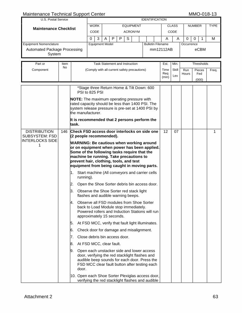
Maintenance Technical Support Center MMO-018-13 U.S. Postal Service IDENTIFICATION
Maintenance Checklist WORK
CODE
EQUIPMENT
ACRONYM
CLASS
CODE
NUMBER TYPE
0 3 A P P S A A 0 0 1 M
Equipment Nomenclature
Automated Package Processing System
Equipment Model
Bulletin Filename
mm12112AB
Occurrence
eCBM
Part or
Component
Item No
Task Statement and Instruction
(Comply with all current safety precautions)
Est.
Time Req (min)
Min.
Skill
Lev
Thresholds
Run Hours
Pieces Fed
(000)
Freq.
Attachment 2 63
*Stage three Return Home & Tilt Down: 600 PSI to 825 PSI
NOTE: The maximum operating pressure with rated capacity should be less than 1400 PSI. The system release pressure is pre-set at 1400 PSI by the manufacturer.
It is recommended that 2 persons perform the task.
DISTRIBUTION SUBSYSTEM: FSD INTERLOCKS SIDE
1
146 Check FSD access door interlocks on side one (2 people recommended).
WARNING: Be cautious when working around or on equipment when power has been applied. Some of the following tasks require that the machine be running. Take precautions to prevent hair, clothing, tools, and test equipment from being caught in moving parts.
1. Start machine (All conveyors and carrier cells running).
2. Open the Shoe Sorter debris bin access door.
3. Observe the Shoe Sorter red stack light flashes and audible warning beeps.
4. Observe all FSD modules from Shoe Sorter back to Load Module stop immediately. Powered rollers and Induction Stations will run approximately 15 seconds.
5. At FSD MCC, verify that fault light illuminates.
6. Check door for damage and misalignment.
7. Close debris bin access door.
8. At FSD MCC, clear fault.
9. Open each unstacker side and lower access door, verifying the red stacklight flashes and audible beep sounds for each door. Press the FSD MCC clear fault button after testing each door.
10. Open each Shoe Sorter Plexiglas access door, verifying the red stacklight flashes and audible
12 07 1
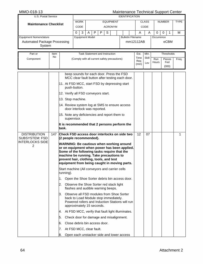
MMO-018-13 Maintenance Technical Support Center U.S. Postal Service IDENTIFICATION
Maintenance Checklist WORK
CODE
EQUIPMENT
ACRONYM
CLASS
CODE
NUMBER TYPE
0 3 A P P S A A 0 0 1 M
Equipment Nomenclature
Automated Package Processing System
Equipment Model
Bulletin Filename
mm12112AB
Occurrence
eCBM
Part or
Component
Item No
Task Statement and Instruction
(Comply with all current safety precautions)
Est.
Time Req (min)
Min.
Skill
Lev
Thresholds
Run Hours
Pieces Fed
(000)
Freq.
64 Attachment 2
beep sounds for each door. Press the FSD MCC clear fault button after testing each door.
11. At FSD MCC, start FSD by depressing start push-button.
12. Verify all FSD conveyors start.
13. Stop machine.
14. Review system log at SMS to ensure access door interlock was reported.
15. Note any deficiencies and report them to supervisor.
It is recommended that 2 persons perform the task.
DISTRIBUTION SUBSYSTEM: FSD INTERLOCKS SIDE
2
147 Check FSD access door interlocks on side two (2 people recommended).
WARNING: Be cautious when working around or on equipment when power has been applied. Some of the following tasks require that the machine be running. Take precautions to prevent hair, clothing, tools, and test equipment from being caught in moving parts.
Start machine (All conveyors and carrier cells running).
1. Open the Shoe Sorter debris bin access door.
2. Observe the Shoe Sorter red stack light flashes and audible warning beeps.
3. Observe all FSD modules from Shoe Sorter back to Load Module stop immediately. Powered rollers and Induction Stations will run approximately 15 seconds.
4. At FSD MCC, verify that fault light illuminates.
5. Check door for damage and misalignment.
6. Close debris bin access door.
7. At FSD MCC, clear fault.
8. Open each unstacker side and lower access
12 07 1
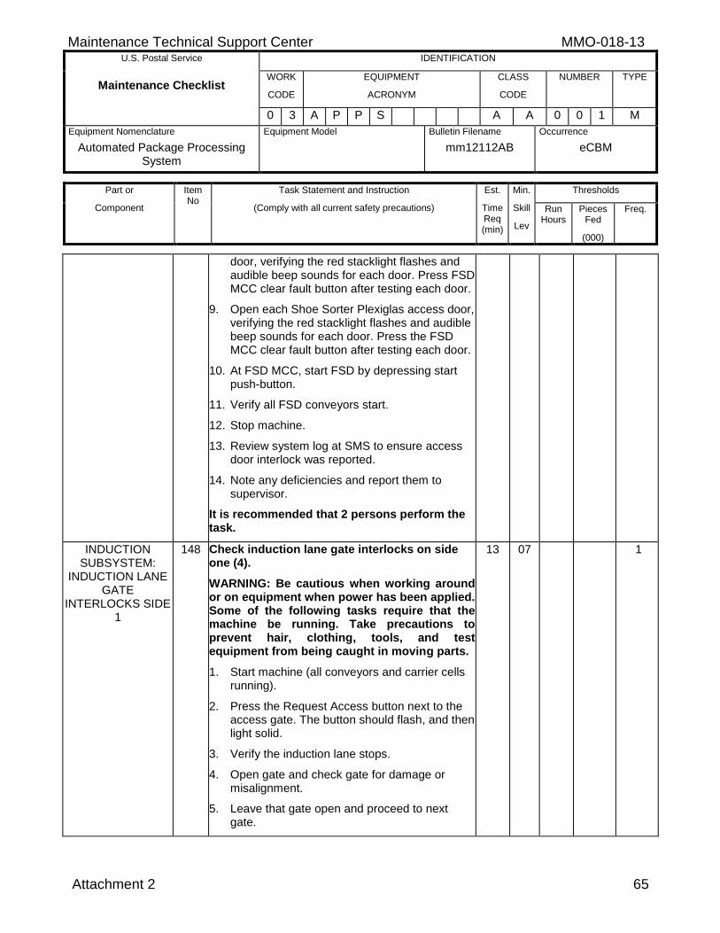
Maintenance Technical Support Center MMO-018-13 U.S. Postal Service IDENTIFICATION
Maintenance Checklist WORK
CODE
EQUIPMENT
ACRONYM
CLASS
CODE
NUMBER TYPE
0 3 A P P S A A 0 0 1 M
Equipment Nomenclature
Automated Package Processing System
Equipment Model
Bulletin Filename
mm12112AB
Occurrence
eCBM
Part or
Component
Item No
Task Statement and Instruction
(Comply with all current safety precautions)
Est.
Time Req (min)
Min.
Skill
Lev
Thresholds
Run Hours
Pieces Fed
(000)
Freq.
Attachment 2 65
door, verifying the red stacklight flashes and audible beep sounds for each door. Press FSD MCC clear fault button after testing each door.
9. Open each Shoe Sorter Plexiglas access door, verifying the red stacklight flashes and audible beep sounds for each door. Press the FSD MCC clear fault button after testing each door.
10. At FSD MCC, start FSD by depressing start push-button.
11. Verify all FSD conveyors start.
12. Stop machine.
13. Review system log at SMS to ensure access door interlock was reported.
14. Note any deficiencies and report them to supervisor.
It is recommended that 2 persons perform the task.
INDUCTION SUBSYSTEM:
INDUCTION LANE GATE
INTERLOCKS SIDE 1
148 Check induction lane gate interlocks on side one (4).
WARNING: Be cautious when working around or on equipment when power has been applied. Some of the following tasks require that the machine be running. Take precautions to prevent hair, clothing, tools, and test equipment from being caught in moving parts.
1. Start machine (all conveyors and carrier cells running).
2. Press the Request Access button next to the access gate. The button should flash, and then light solid.
3. Verify the induction lane stops.
4. Open gate and check gate for damage or misalignment.
5. Leave that gate open and proceed to next gate.
13 07 1
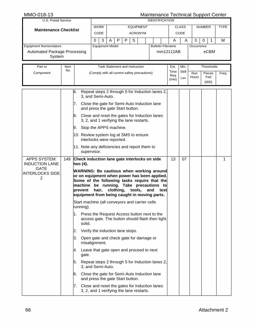
MMO-018-13 Maintenance Technical Support Center U.S. Postal Service IDENTIFICATION
Maintenance Checklist WORK
CODE
EQUIPMENT
ACRONYM
CLASS
CODE
NUMBER TYPE
0 3 A P P S A A 0 0 1 M
Equipment Nomenclature
Automated Package Processing System
Equipment Model
Bulletin Filename
mm12112AB
Occurrence
eCBM
Part or
Component
Item No
Task Statement and Instruction
(Comply with all current safety precautions)
Est.
Time Req (min)
Min.
Skill
Lev
Thresholds
Run Hours
Pieces Fed
(000)
Freq.
66 Attachment 2
6. Repeat steps 2 through 5 for Induction lanes 2, 3, and Semi-Auto.
7. Close the gate for Semi-Auto Induction lane and press the gate Start button.
8. Close and reset the gates for Induction lanes 3, 2, and 1 verifying the lane restarts.
9. Stop the APPS machine.
10. Review system log at SMS to ensure interlocks were reported.
11. Note any deficiencies and report them to supervisor.
APPS SYSTEM: INDUCTION LANE
GATE INTERLOCKS SIDE
2
149 Check induction lane gate interlocks on side two (4).
WARNING: Be cautious when working around or on equipment when power has been applied. Some of the following tasks require that the machine be running. Take precautions to prevent hair, clothing, tools, and test equipment from being caught in moving parts.
Start machine (all conveyors and carrier cells running).
1. Press the Request Access button next to the access gate. The button should flash then light solid.
2. Verify the induction lane stops.
3. Open gate and check gate for damage or misalignment.
4. Leave that gate open and proceed to next gate.
5. Repeat steps 2 through 5 for Induction lanes 2, 3, and Semi-Auto.
6. Close the gate for Semi-Auto Induction lane and press the gate Start button.
7. Close and reset the gates for Induction lanes 3, 2, and 1 verifying the lane restarts.
13 07 1
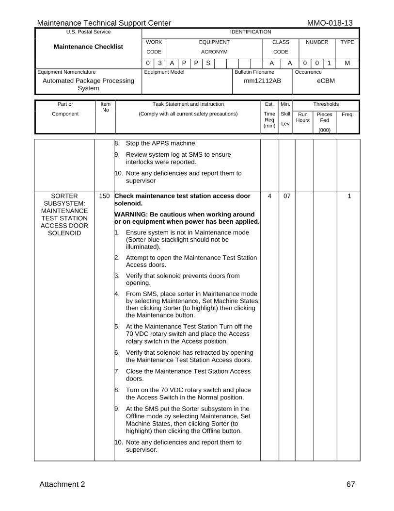
Maintenance Technical Support Center MMO-018-13 U.S. Postal Service IDENTIFICATION
Maintenance Checklist WORK
CODE
EQUIPMENT
ACRONYM
CLASS
CODE
NUMBER TYPE
0 3 A P P S A A 0 0 1 M
Equipment Nomenclature
Automated Package Processing System
Equipment Model
Bulletin Filename
mm12112AB
Occurrence
eCBM
Part or
Component
Item No
Task Statement and Instruction
(Comply with all current safety precautions)
Est.
Time Req (min)
Min.
Skill
Lev
Thresholds
Run Hours
Pieces Fed
(000)
Freq.
Attachment 2 67
8. Stop the APPS machine.
9. Review system log at SMS to ensure interlocks were reported.
10. Note any deficiencies and report them to supervisor
SORTER SUBSYSTEM:
MAINTENANCE TEST STATION ACCESS DOOR
SOLENOID
150 Check maintenance test station access door solenoid.
WARNING: Be cautious when working around or on equipment when power has been applied.
1. Ensure system is not in Maintenance mode (Sorter blue stacklight should not be illuminated).
2. Attempt to open the Maintenance Test Station Access doors.
3. Verify that solenoid prevents doors from opening.
4. From SMS, place sorter in Maintenance mode by selecting Maintenance, Set Machine States, then clicking Sorter (to highlight) then clicking the Maintenance button.
5. At the Maintenance Test Station Turn off the 70 VDC rotary switch and place the Access rotary switch in the Access position.
6. Verify that solenoid has retracted by opening the Maintenance Test Station Access doors.
7. Close the Maintenance Test Station Access doors.
8. Turn on the 70 VDC rotary switch and place the Access Switch in the Normal position.
9. At the SMS put the Sorter subsystem in the Offline mode by selecting Maintenance, Set Machine States, then clicking Sorter (to highlight) then clicking the Offline button.
10. Note any deficiencies and report them to supervisor.
4 07 1
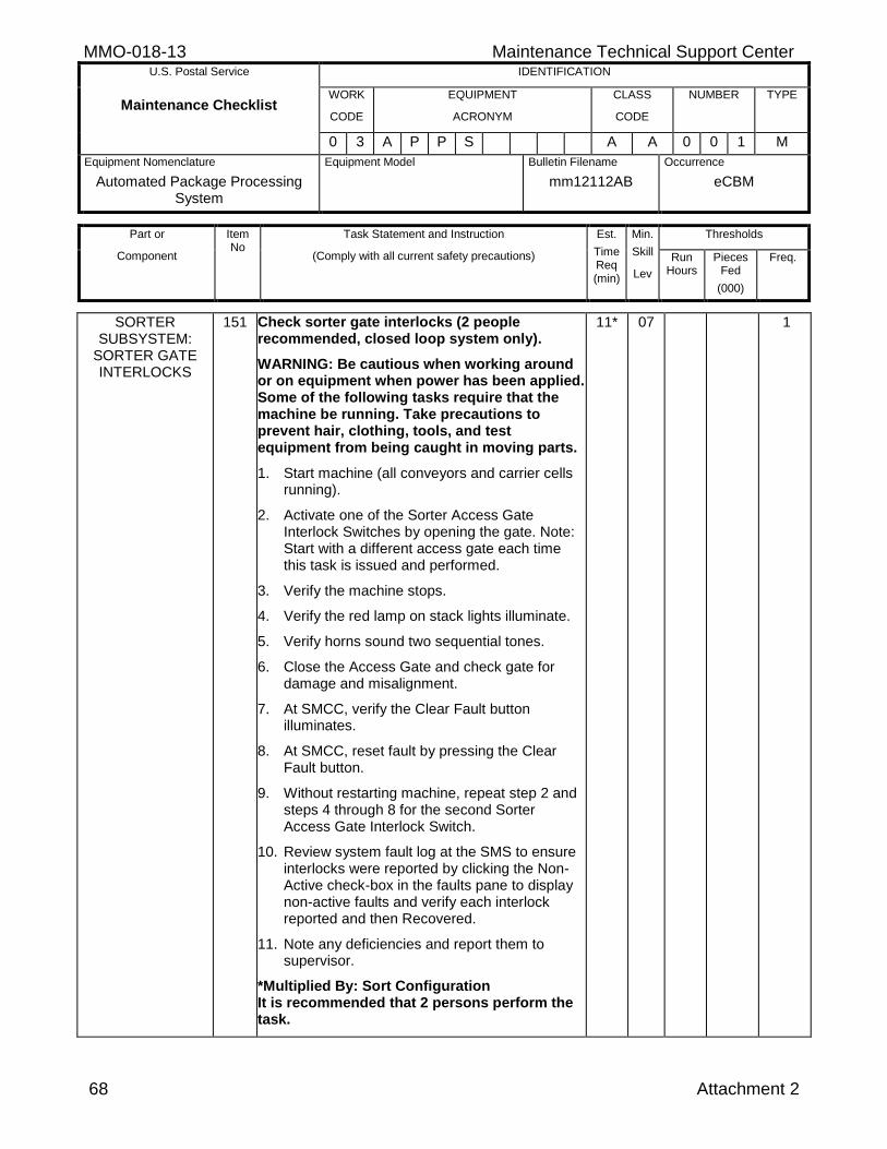
MMO-018-13 Maintenance Technical Support Center U.S. Postal Service IDENTIFICATION
Maintenance Checklist WORK
CODE
EQUIPMENT
ACRONYM
CLASS
CODE
NUMBER TYPE
0 3 A P P S A A 0 0 1 M
Equipment Nomenclature
Automated Package Processing System
Equipment Model
Bulletin Filename
mm12112AB
Occurrence
eCBM
Part or
Component
Item No
Task Statement and Instruction
(Comply with all current safety precautions)
Est.
Time Req (min)
Min.
Skill
Lev
Thresholds
Run Hours
Pieces Fed
(000)
Freq.
68 Attachment 2
SORTER SUBSYSTEM:
SORTER GATE INTERLOCKS
151 Check sorter gate interlocks (2 people recommended, closed loop system only).
WARNING: Be cautious when working around or on equipment when power has been applied. Some of the following tasks require that the machine be running. Take precautions to prevent hair, clothing, tools, and test equipment from being caught in moving parts.
1. Start machine (all conveyors and carrier cells running).
2. Activate one of the Sorter Access Gate Interlock Switches by opening the gate. Note: Start with a different access gate each time this task is issued and performed.
3. Verify the machine stops.
4. Verify the red lamp on stack lights illuminate.
5. Verify horns sound two sequential tones.
6. Close the Access Gate and check gate for damage and misalignment.
7. At SMCC, verify the Clear Fault button illuminates.
8. At SMCC, reset fault by pressing the Clear Fault button.
9. Without restarting machine, repeat step 2 and steps 4 through 8 for the second Sorter Access Gate Interlock Switch.
10. Review system fault log at the SMS to ensure interlocks were reported by clicking the Non-Active check-box in the faults pane to display non-active faults and verify each interlock reported and then Recovered.
11. Note any deficiencies and report them to supervisor.
*Multiplied By: Sort Configuration It is recommended that 2 persons perform the task.
11* 07 1
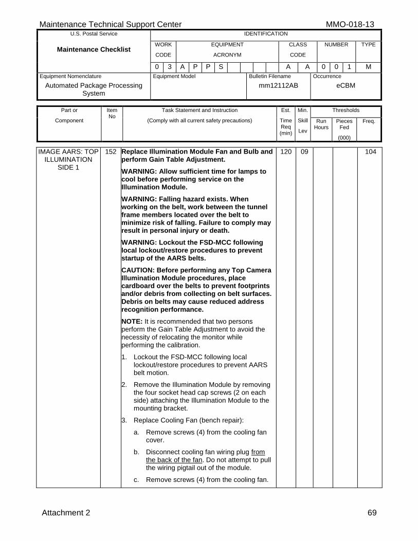
Maintenance Technical Support Center MMO-018-13 U.S. Postal Service IDENTIFICATION
Maintenance Checklist WORK
CODE
EQUIPMENT
ACRONYM
CLASS
CODE
NUMBER TYPE
0 3 A P P S A A 0 0 1 M
Equipment Nomenclature
Automated Package Processing System
Equipment Model
Bulletin Filename
mm12112AB
Occurrence
eCBM
Part or
Component
Item No
Task Statement and Instruction
(Comply with all current safety precautions)
Est.
Time Req (min)
Min.
Skill
Lev
Thresholds
Run Hours
Pieces Fed
(000)
Freq.
Attachment 2 69
IMAGE AARS: TOP ILLUMINATION
SIDE 1
152 Replace Illumination Module Fan and Bulb and perform Gain Table Adjustment.
WARNING: Allow sufficient time for lamps to cool before performing service on the Illumination Module.
WARNING: Falling hazard exists. When working on the belt, work between the tunnel frame members located over the belt to minimize risk of falling. Failure to comply may result in personal injury or death.
WARNING: Lockout the FSD-MCC following local lockout/restore procedures to prevent startup of the AARS belts.
CAUTION: Before performing any Top Camera Illumination Module procedures, place cardboard over the belts to prevent footprints and/or debris from collecting on belt surfaces. Debris on belts may cause reduced address recognition performance.
NOTE: It is recommended that two persons perform the Gain Table Adjustment to avoid the necessity of relocating the monitor while performing the calibration.
1. Lockout the FSD-MCC following local lockout/restore procedures to prevent AARS belt motion.
2. Remove the Illumination Module by removing the four socket head cap screws (2 on each side) attaching the Illumination Module to the mounting bracket.
3. Replace Cooling Fan (bench repair):
a. Remove screws (4) from the cooling fan cover.
b. Disconnect cooling fan wiring plug from the back of the fan. Do not attempt to pull the wiring pigtail out of the module.
c. Remove screws (4) from the cooling fan.
120 09 104
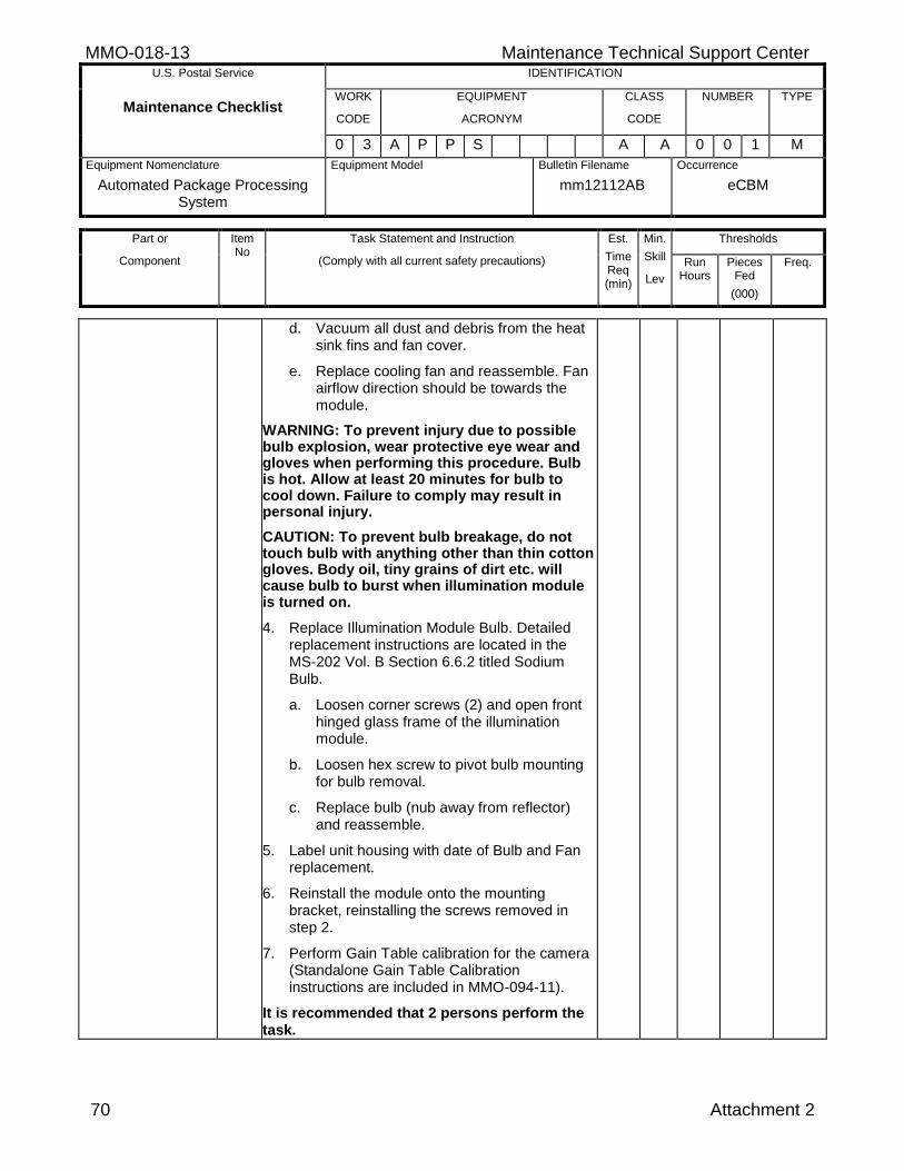
MMO-018-13 Maintenance Technical Support Center U.S. Postal Service IDENTIFICATION
Maintenance Checklist WORK
CODE
EQUIPMENT
ACRONYM
CLASS
CODE
NUMBER TYPE
0 3 A P P S A A 0 0 1 M
Equipment Nomenclature
Automated Package Processing System
Equipment Model
Bulletin Filename
mm12112AB
Occurrence
eCBM
Part or
Component
Item No
Task Statement and Instruction
(Comply with all current safety precautions)
Est.
Time Req (min)
Min.
Skill
Lev
Thresholds
Run Hours
Pieces Fed
(000)
Freq.
70 Attachment 2
d. Vacuum all dust and debris from the heat sink fins and fan cover.
e. Replace cooling fan and reassemble. Fan airflow direction should be towards the module.
WARNING: To prevent injury due to possible bulb explosion, wear protective eye wear and gloves when performing this procedure. Bulb is hot. Allow at least 20 minutes for bulb to cool down. Failure to comply may result in personal injury.
CAUTION: To prevent bulb breakage, do not touch bulb with anything other than thin cotton gloves. Body oil, tiny grains of dirt etc. will cause bulb to burst when illumination module is turned on.
4. Replace Illumination Module Bulb. Detailed replacement instructions are located in the MS-202 Vol. B Section 6.6.2 titled Sodium Bulb.
a. Loosen corner screws (2) and open front hinged glass frame of the illumination module.
b. Loosen hex screw to pivot bulb mounting for bulb removal.
c. Replace bulb (nub away from reflector) and reassemble.
5. Label unit housing with date of Bulb and Fan replacement.
6. Reinstall the module onto the mounting bracket, reinstalling the screws removed in step 2.
7. Perform Gain Table calibration for the camera (Standalone Gain Table Calibration instructions are included in MMO-094-11).
It is recommended that 2 persons perform the task.
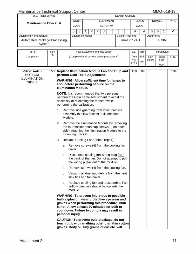
Maintenance Technical Support Center MMO-018-13 U.S. Postal Service IDENTIFICATION
Maintenance Checklist WORK
CODE
EQUIPMENT
ACRONYM
CLASS
CODE
NUMBER TYPE
0 3 A P P S A A 0 0 1 M
Equipment Nomenclature
Automated Package Processing System
Equipment Model
Bulletin Filename
mm12112AB
Occurrence
eCBM
Part or
Component
Item No
Task Statement and Instruction
(Comply with all current safety precautions)
Est.
Time Req (min)
Min.
Skill
Lev
Thresholds
Run Hours
Pieces Fed
(000)
Freq.
Attachment 2 71
IMAGE AARS: BOTTOM
ILLUMINATION SIDE 1
153 Replace Illumination Module Fan and Bulb and perform Gain Table Adjustment.
WARNING: Allow sufficient time for lamps to cool before performing service on the Illumination Module.
NOTE: It is recommended that two persons perform the Gain Table Adjustment to avoid the necessity of relocating the monitor while performing the calibration.
1. Remove side guarding from lower camera assembly to allow access to Illumination Module.
2. Remove the Illumination Module by removing the four socket head cap screws (2 on each side) attaching the Illumination Module to the mounting bracket.
3. Replace Cooling Fan (bench repair):
a. Remove screws (4) from the cooling fan cover.
b. Disconnect cooling fan wiring plug from the back of the fan. Do not attempt to pull the wiring pigtail out of the module.
c. Remove screws (4) from the cooling fan.
d. Vacuum all dust and debris from the heat sink fins and fan cover.
e. Replace cooling fan and reassemble. Fan airflow direction should be towards the module.
WARNING: To prevent injury due to possible bulb explosion, wear protective eye wear and gloves when performing this procedure. Bulb is hot. Allow at least 20 minutes for bulb to cool down. Failure to comply may result in personal injury.
CAUTION: To prevent bulb breakage, do not touch bulb with anything other than thin cotton gloves. Body oil, tiny grains of dirt etc. will
110 09 104
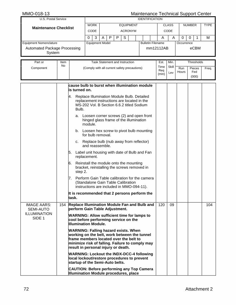
MMO-018-13 Maintenance Technical Support Center U.S. Postal Service IDENTIFICATION
Maintenance Checklist WORK
CODE
EQUIPMENT
ACRONYM
CLASS
CODE
NUMBER TYPE
0 3 A P P S A A 0 0 1 M
Equipment Nomenclature
Automated Package Processing System
Equipment Model
Bulletin Filename
mm12112AB
Occurrence
eCBM
Part or
Component
Item No
Task Statement and Instruction
(Comply with all current safety precautions)
Est.
Time Req (min)
Min.
Skill
Lev
Thresholds
Run Hours
Pieces Fed
(000)
Freq.
72 Attachment 2
cause bulb to burst when illumination module is turned on.
4. Replace Illumination Module Bulb. Detailed replacement instructions are located in the MS-202 Vol. B Section 6.6.2 titled Sodium Bulb.
a. Loosen corner screws (2) and open front hinged glass frame of the illumination module.
b. Loosen hex screw to pivot bulb mounting for bulb removal.
c. Replace bulb (nub away from reflector) and reassemble.
5. Label unit housing with date of Bulb and Fan replacement.
6. Reinstall the module onto the mounting bracket, reinstalling the screws removed in step 2.
7. Perform Gain Table calibration for the camera (Standalone Gain Table Calibration instructions are included in MMO-094-11).
It is recommended that 2 persons perform the task.
IMAGE AARS: SEMI-AUTO
ILLUMINATION SIDE 1
154 Replace Illumination Module Fan and Bulb and perform Gain Table Adjustment.
WARNING: Allow sufficient time for lamps to cool before performing service on the Illumination Module.
WARNING: Falling hazard exists. When working on the belt, work between the tunnel frame members located over the belt to minimize risk of falling. Failure to comply may result in personal injury or death.
WARNING: Lockout the INDX-DCC-4 following local lockout/restore procedures to prevent startup of the Semi-Auto belts.
CAUTION: Before performing any Top Camera Illumination Module procedures, place
120 09 104
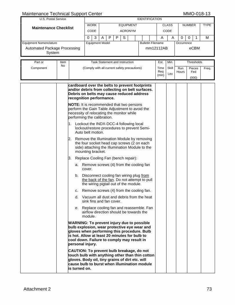
Maintenance Technical Support Center MMO-018-13 U.S. Postal Service IDENTIFICATION
Maintenance Checklist WORK
CODE
EQUIPMENT
ACRONYM
CLASS
CODE
NUMBER TYPE
0 3 A P P S A A 0 0 1 M
Equipment Nomenclature
Automated Package Processing System
Equipment Model
Bulletin Filename
mm12112AB
Occurrence
eCBM
Part or
Component
Item No
Task Statement and Instruction
(Comply with all current safety precautions)
Est.
Time Req (min)
Min.
Skill
Lev
Thresholds
Run Hours
Pieces Fed
(000)
Freq.
Attachment 2 73
cardboard over the belts to prevent footprints and/or debris from collecting on belt surfaces. Debris on belts may cause reduced address recognition performance.
NOTE: It is recommended that two persons perform the Gain Table Adjustment to avoid the necessity of relocating the monitor while performing the calibration.
1. Lockout the INDX-DCC-4 following local lockout/restore procedures to prevent Semi-Auto belt motion.
2. Remove the Illumination Module by removing the four socket head cap screws (2 on each side) attaching the Illumination Module to the mounting bracket.
3. Replace Cooling Fan (bench repair):
a. Remove screws (4) from the cooling fan cover.
b. Disconnect cooling fan wiring plug from the back of the fan. Do not attempt to pull the wiring pigtail out of the module.
c. Remove screws (4) from the cooling fan.
d. Vacuum all dust and debris from the heat sink fins and fan cover.
e. Replace cooling fan and reassemble. Fan airflow direction should be towards the module.
WARNING: To prevent injury due to possible bulb explosion, wear protective eye wear and gloves when performing this procedure. Bulb is hot. Allow at least 20 minutes for bulb to cool down. Failure to comply may result in personal injury.
CAUTION: To prevent bulb breakage, do not touch bulb with anything other than thin cotton gloves. Body oil, tiny grains of dirt etc. will cause bulb to burst when illumination module is turned on.
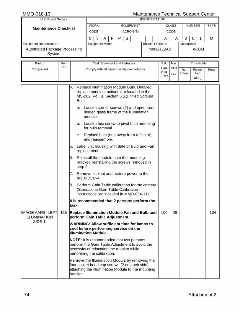
MMO-018-13 Maintenance Technical Support Center U.S. Postal Service IDENTIFICATION
Maintenance Checklist WORK
CODE
EQUIPMENT
ACRONYM
CLASS
CODE
NUMBER TYPE
0 3 A P P S A A 0 0 1 M
Equipment Nomenclature
Automated Package Processing System
Equipment Model
Bulletin Filename
mm12112AB
Occurrence
eCBM
Part or
Component
Item No
Task Statement and Instruction
(Comply with all current safety precautions)
Est.
Time Req (min)
Min.
Skill
Lev
Thresholds
Run Hours
Pieces Fed
(000)
Freq.
74 Attachment 2
4. Replace Illumination Module Bulb. Detailed replacement instructions are located in the MS-202, Vol. B, Section 6.6.2, titled Sodium Bulb.
a. Loosen corner screws (2) and open front hinged glass frame of the illumination module.
b. Loosen hex screw to pivot bulb mounting for bulb removal.
c. Replace bulb (nub away from reflector) and reassemble.
5. Label unit housing with date of Bulb and Fan replacement.
6. Reinstall the module onto the mounting bracket, reinstalling the screws removed in step 2.
7. Remove lockout and restore power to the INDX-DCC-4.
8. Perform Gain Table calibration for the camera (Standalone Gain Table Calibration instructions are included in MMO-094-11).
It is recommended that 2 persons perform the task.
IMAGE AARS: LEFT ILLUMINATION
SIDE 1
155 Replace Illumination Module Fan and Bulb and perform Gain Table Adjustment.
WARNING: Allow sufficient time for lamps to cool before performing service on the Illumination Module.
NOTE: It is recommended that two persons perform the Gain Table Adjustment to avoid the necessity of relocating the monitor while performing the calibration.
Remove the Illumination Module by removing the four socket head cap screws (2 on each side) attaching the Illumination Module to the mounting bracket.
100 09 104
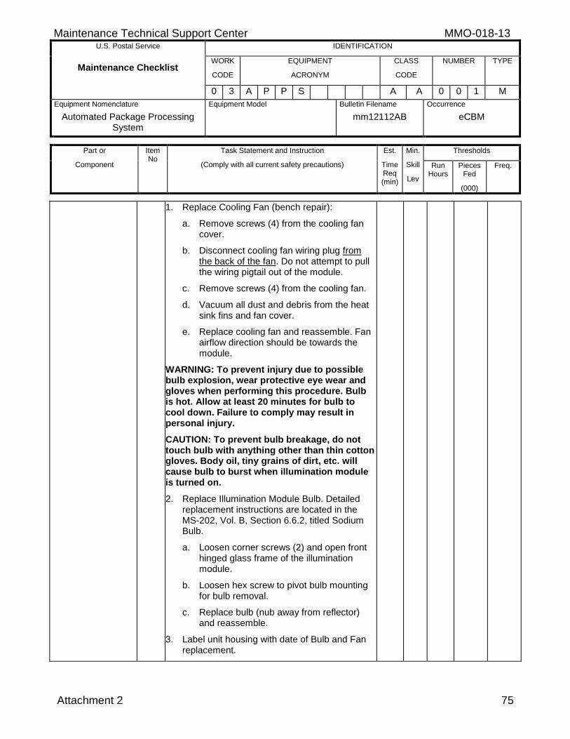
Maintenance Technical Support Center MMO-018-13 U.S. Postal Service IDENTIFICATION
Maintenance Checklist WORK
CODE
EQUIPMENT
ACRONYM
CLASS
CODE
NUMBER TYPE
0 3 A P P S A A 0 0 1 M
Equipment Nomenclature
Automated Package Processing System
Equipment Model
Bulletin Filename
mm12112AB
Occurrence
eCBM
Part or
Component
Item No
Task Statement and Instruction
(Comply with all current safety precautions)
Est.
Time Req (min)
Min.
Skill
Lev
Thresholds
Run Hours
Pieces Fed
(000)
Freq.
Attachment 2 75
1. Replace Cooling Fan (bench repair):
a. Remove screws (4) from the cooling fan cover.
b. Disconnect cooling fan wiring plug from the back of the fan. Do not attempt to pull the wiring pigtail out of the module.
c. Remove screws (4) from the cooling fan.
d. Vacuum all dust and debris from the heat sink fins and fan cover.
e. Replace cooling fan and reassemble. Fan airflow direction should be towards the module.
WARNING: To prevent injury due to possible bulb explosion, wear protective eye wear and gloves when performing this procedure. Bulb is hot. Allow at least 20 minutes for bulb to cool down. Failure to comply may result in personal injury.
CAUTION: To prevent bulb breakage, do not touch bulb with anything other than thin cotton gloves. Body oil, tiny grains of dirt, etc. will cause bulb to burst when illumination module is turned on.
2. Replace Illumination Module Bulb. Detailed replacement instructions are located in the MS-202, Vol. B, Section 6.6.2, titled Sodium Bulb.
a. Loosen corner screws (2) and open front hinged glass frame of the illumination module.
b. Loosen hex screw to pivot bulb mounting for bulb removal.
c. Replace bulb (nub away from reflector) and reassemble.
3. Label unit housing with date of Bulb and Fan replacement.
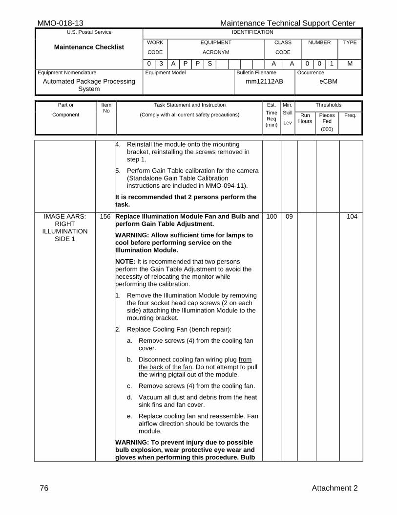
MMO-018-13 Maintenance Technical Support Center U.S. Postal Service IDENTIFICATION
Maintenance Checklist WORK
CODE
EQUIPMENT
ACRONYM
CLASS
CODE
NUMBER TYPE
0 3 A P P S A A 0 0 1 M
Equipment Nomenclature
Automated Package Processing System
Equipment Model
Bulletin Filename
mm12112AB
Occurrence
eCBM
Part or
Component
Item No
Task Statement and Instruction
(Comply with all current safety precautions)
Est.
Time Req (min)
Min.
Skill
Lev
Thresholds
Run Hours
Pieces Fed
(000)
Freq.
76 Attachment 2
4. Reinstall the module onto the mounting bracket, reinstalling the screws removed in step 1.
5. Perform Gain Table calibration for the camera (Standalone Gain Table Calibration instructions are included in MMO-094-11).
It is recommended that 2 persons perform the task.
IMAGE AARS: RIGHT
ILLUMINATION SIDE 1
156 Replace Illumination Module Fan and Bulb and perform Gain Table Adjustment.
WARNING: Allow sufficient time for lamps to cool before performing service on the Illumination Module.
NOTE: It is recommended that two persons perform the Gain Table Adjustment to avoid the necessity of relocating the monitor while performing the calibration.
1. Remove the Illumination Module by removing the four socket head cap screws (2 on each side) attaching the Illumination Module to the mounting bracket.
2. Replace Cooling Fan (bench repair):
a. Remove screws (4) from the cooling fan cover.
b. Disconnect cooling fan wiring plug from the back of the fan. Do not attempt to pull the wiring pigtail out of the module.
c. Remove screws (4) from the cooling fan.
d. Vacuum all dust and debris from the heat sink fins and fan cover.
e. Replace cooling fan and reassemble. Fan airflow direction should be towards the module.
WARNING: To prevent injury due to possible bulb explosion, wear protective eye wear and gloves when performing this procedure. Bulb
100 09 104
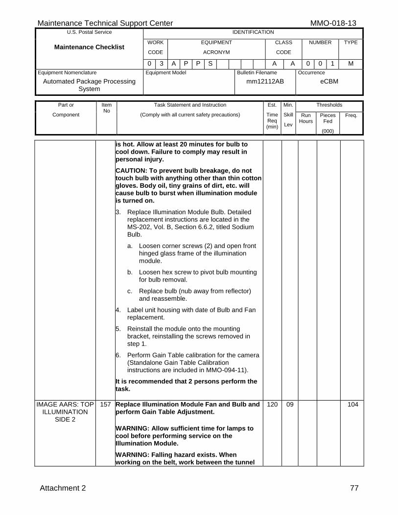
Maintenance Technical Support Center MMO-018-13 U.S. Postal Service IDENTIFICATION
Maintenance Checklist WORK
CODE
EQUIPMENT
ACRONYM
CLASS
CODE
NUMBER TYPE
0 3 A P P S A A 0 0 1 M
Equipment Nomenclature
Automated Package Processing System
Equipment Model
Bulletin Filename
mm12112AB
Occurrence
eCBM
Part or
Component
Item No
Task Statement and Instruction
(Comply with all current safety precautions)
Est.
Time Req (min)
Min.
Skill
Lev
Thresholds
Run Hours
Pieces Fed
(000)
Freq.
Attachment 2 77
is hot. Allow at least 20 minutes for bulb to cool down. Failure to comply may result in personal injury.
CAUTION: To prevent bulb breakage, do not touch bulb with anything other than thin cotton gloves. Body oil, tiny grains of dirt, etc. will cause bulb to burst when illumination module is turned on.
3. Replace Illumination Module Bulb. Detailed replacement instructions are located in the MS-202, Vol. B, Section 6.6.2, titled Sodium Bulb.
a. Loosen corner screws (2) and open front hinged glass frame of the illumination module.
b. Loosen hex screw to pivot bulb mounting for bulb removal.
c. Replace bulb (nub away from reflector) and reassemble.
4. Label unit housing with date of Bulb and Fan replacement.
5. Reinstall the module onto the mounting bracket, reinstalling the screws removed in step 1.
6. Perform Gain Table calibration for the camera (Standalone Gain Table Calibration instructions are included in MMO-094-11).
It is recommended that 2 persons perform the task.
IMAGE AARS: TOP ILLUMINATION
SIDE 2
157 Replace Illumination Module Fan and Bulb and perform Gain Table Adjustment.
WARNING: Allow sufficient time for lamps to cool before performing service on the Illumination Module.
WARNING: Falling hazard exists. When working on the belt, work between the tunnel
120 09 104
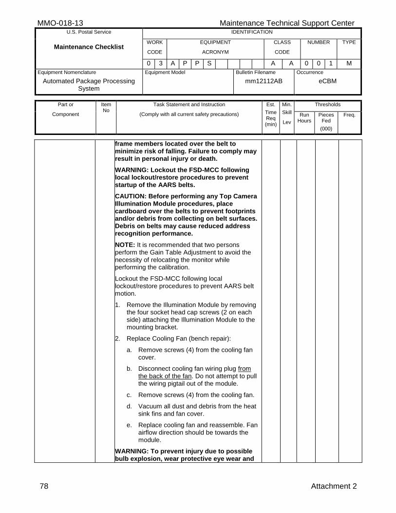
MMO-018-13 Maintenance Technical Support Center U.S. Postal Service IDENTIFICATION
Maintenance Checklist WORK
CODE
EQUIPMENT
ACRONYM
CLASS
CODE
NUMBER TYPE
0 3 A P P S A A 0 0 1 M
Equipment Nomenclature
Automated Package Processing System
Equipment Model
Bulletin Filename
mm12112AB
Occurrence
eCBM
Part or
Component
Item No
Task Statement and Instruction
(Comply with all current safety precautions)
Est.
Time Req (min)
Min.
Skill
Lev
Thresholds
Run Hours
Pieces Fed
(000)
Freq.
78 Attachment 2
frame members located over the belt to minimize risk of falling. Failure to comply may result in personal injury or death.
WARNING: Lockout the FSD-MCC following local lockout/restore procedures to prevent startup of the AARS belts.
CAUTION: Before performing any Top Camera Illumination Module procedures, place cardboard over the belts to prevent footprints and/or debris from collecting on belt surfaces. Debris on belts may cause reduced address recognition performance.
NOTE: It is recommended that two persons perform the Gain Table Adjustment to avoid the necessity of relocating the monitor while performing the calibration.
Lockout the FSD-MCC following local lockout/restore procedures to prevent AARS belt motion.
1. Remove the Illumination Module by removing the four socket head cap screws (2 on each side) attaching the Illumination Module to the mounting bracket.
2. Replace Cooling Fan (bench repair):
a. Remove screws (4) from the cooling fan cover.
b. Disconnect cooling fan wiring plug from the back of the fan. Do not attempt to pull the wiring pigtail out of the module.
c. Remove screws (4) from the cooling fan.
d. Vacuum all dust and debris from the heat sink fins and fan cover.
e. Replace cooling fan and reassemble. Fan airflow direction should be towards the module.
WARNING: To prevent injury due to possible bulb explosion, wear protective eye wear and
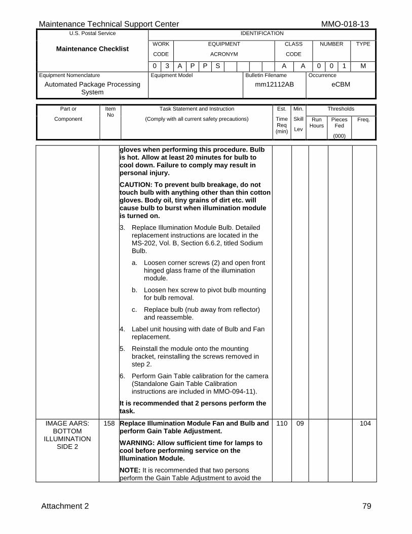
Maintenance Technical Support Center MMO-018-13 U.S. Postal Service IDENTIFICATION
Maintenance Checklist WORK
CODE
EQUIPMENT
ACRONYM
CLASS
CODE
NUMBER TYPE
0 3 A P P S A A 0 0 1 M
Equipment Nomenclature
Automated Package Processing System
Equipment Model
Bulletin Filename
mm12112AB
Occurrence
eCBM
Part or
Component
Item No
Task Statement and Instruction
(Comply with all current safety precautions)
Est.
Time Req (min)
Min.
Skill
Lev
Thresholds
Run Hours
Pieces Fed
(000)
Freq.
Attachment 2 79
gloves when performing this procedure. Bulb is hot. Allow at least 20 minutes for bulb to cool down. Failure to comply may result in personal injury.
CAUTION: To prevent bulb breakage, do not touch bulb with anything other than thin cotton gloves. Body oil, tiny grains of dirt etc. will cause bulb to burst when illumination module is turned on.
3. Replace Illumination Module Bulb. Detailed replacement instructions are located in the MS-202, Vol. B, Section 6.6.2, titled Sodium Bulb.
a. Loosen corner screws (2) and open front hinged glass frame of the illumination module.
b. Loosen hex screw to pivot bulb mounting for bulb removal.
c. Replace bulb (nub away from reflector) and reassemble.
4. Label unit housing with date of Bulb and Fan replacement.
5. Reinstall the module onto the mounting bracket, reinstalling the screws removed in step 2.
6. Perform Gain Table calibration for the camera (Standalone Gain Table Calibration instructions are included in MMO-094-11).
It is recommended that 2 persons perform the task.
IMAGE AARS: BOTTOM
ILLUMINATION SIDE 2
158 Replace Illumination Module Fan and Bulb and perform Gain Table Adjustment.
WARNING: Allow sufficient time for lamps to cool before performing service on the Illumination Module.
NOTE: It is recommended that two persons perform the Gain Table Adjustment to avoid the
110 09 104
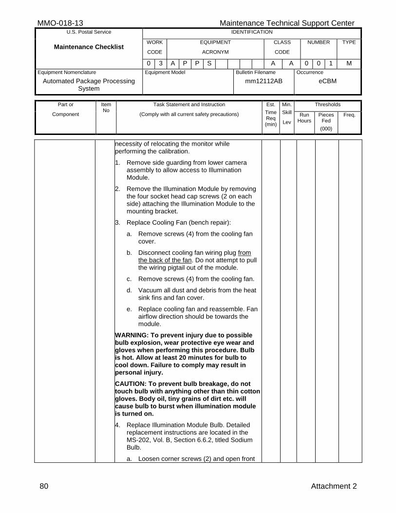
MMO-018-13 Maintenance Technical Support Center U.S. Postal Service IDENTIFICATION
Maintenance Checklist WORK
CODE
EQUIPMENT
ACRONYM
CLASS
CODE
NUMBER TYPE
0 3 A P P S A A 0 0 1 M
Equipment Nomenclature
Automated Package Processing System
Equipment Model
Bulletin Filename
mm12112AB
Occurrence
eCBM
Part or
Component
Item No
Task Statement and Instruction
(Comply with all current safety precautions)
Est.
Time Req (min)
Min.
Skill
Lev
Thresholds
Run Hours
Pieces Fed
(000)
Freq.
80 Attachment 2
necessity of relocating the monitor while performing the calibration.
1. Remove side guarding from lower camera assembly to allow access to Illumination Module.
2. Remove the Illumination Module by removing the four socket head cap screws (2 on each side) attaching the Illumination Module to the mounting bracket.
3. Replace Cooling Fan (bench repair):
a. Remove screws (4) from the cooling fan cover.
b. Disconnect cooling fan wiring plug from the back of the fan. Do not attempt to pull the wiring pigtail out of the module.
c. Remove screws (4) from the cooling fan.
d. Vacuum all dust and debris from the heat sink fins and fan cover.
e. Replace cooling fan and reassemble. Fan airflow direction should be towards the module.
WARNING: To prevent injury due to possible bulb explosion, wear protective eye wear and gloves when performing this procedure. Bulb is hot. Allow at least 20 minutes for bulb to cool down. Failure to comply may result in personal injury.
CAUTION: To prevent bulb breakage, do not touch bulb with anything other than thin cotton gloves. Body oil, tiny grains of dirt etc. will cause bulb to burst when illumination module is turned on.
4. Replace Illumination Module Bulb. Detailed replacement instructions are located in the MS-202, Vol. B, Section 6.6.2, titled Sodium Bulb.
a. Loosen corner screws (2) and open front
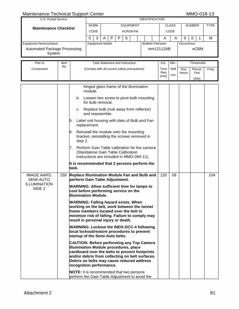
Maintenance Technical Support Center MMO-018-13 U.S. Postal Service IDENTIFICATION
Maintenance Checklist WORK
CODE
EQUIPMENT
ACRONYM
CLASS
CODE
NUMBER TYPE
0 3 A P P S A A 0 0 1 M
Equipment Nomenclature
Automated Package Processing System
Equipment Model
Bulletin Filename
mm12112AB
Occurrence
eCBM
Part or
Component
Item No
Task Statement and Instruction
(Comply with all current safety precautions)
Est.
Time Req (min)
Min.
Skill
Lev
Thresholds
Run Hours
Pieces Fed
(000)
Freq.
Attachment 2 81
hinged glass frame of the illumination module.
b. Loosen hex screw to pivot bulb mounting for bulb removal.
c. Replace bulb (nub away from reflector) and reassemble.
5. Label unit housing with date of Bulb and Fan replacement.
6. Reinstall the module onto the mounting bracket, reinstalling the screws removed in step 2.
7. Perform Gain Table calibration for the camera (Standalone Gain Table Calibration instructions are included in MMO-094-11).
It is recommended that 2 persons perform the task.
IMAGE AARS: SEMI-AUTO
ILLUMINATION SIDE 2
159 Replace Illumination Module Fan and Bulb and perform Gain Table Adjustment.
WARNING: Allow sufficient time for lamps to cool before performing service on the Illumination Module.
WARNING: Falling hazard exists. When working on the belt, work between the tunnel frame members located over the belt to minimize risk of falling. Failure to comply may result in personal injury or death.
WARNING: Lockout the INDX-DCC-4 following local lockout/restore procedures to prevent startup of the Semi-Auto belts.
CAUTION: Before performing any Top Camera Illumination Module procedures, place cardboard over the belts to prevent footprints and/or debris from collecting on belt surfaces. Debris on belts may cause reduced address recognition performance.
NOTE: It is recommended that two persons perform the Gain Table Adjustment to avoid the
120 09 104
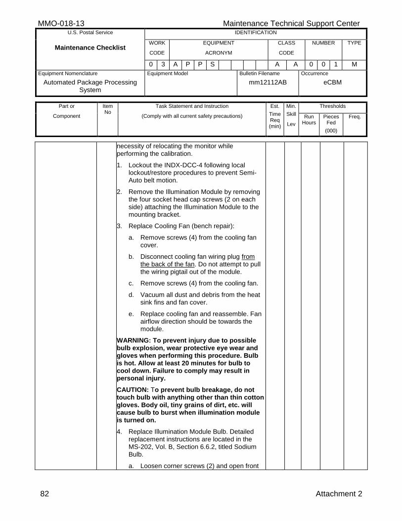
MMO-018-13 Maintenance Technical Support Center U.S. Postal Service IDENTIFICATION
Maintenance Checklist WORK
CODE
EQUIPMENT
ACRONYM
CLASS
CODE
NUMBER TYPE
0 3 A P P S A A 0 0 1 M
Equipment Nomenclature
Automated Package Processing System
Equipment Model
Bulletin Filename
mm12112AB
Occurrence
eCBM
Part or
Component
Item No
Task Statement and Instruction
(Comply with all current safety precautions)
Est.
Time Req (min)
Min.
Skill
Lev
Thresholds
Run Hours
Pieces Fed
(000)
Freq.
82 Attachment 2
necessity of relocating the monitor while performing the calibration.
1. Lockout the INDX-DCC-4 following local lockout/restore procedures to prevent Semi-Auto belt motion.
2. Remove the Illumination Module by removing the four socket head cap screws (2 on each side) attaching the Illumination Module to the mounting bracket.
3. Replace Cooling Fan (bench repair):
a. Remove screws (4) from the cooling fan cover.
b. Disconnect cooling fan wiring plug from the back of the fan. Do not attempt to pull the wiring pigtail out of the module.
c. Remove screws (4) from the cooling fan.
d. Vacuum all dust and debris from the heat sink fins and fan cover.
e. Replace cooling fan and reassemble. Fan airflow direction should be towards the module.
WARNING: To prevent injury due to possible bulb explosion, wear protective eye wear and gloves when performing this procedure. Bulb is hot. Allow at least 20 minutes for bulb to cool down. Failure to comply may result in personal injury.
CAUTION: To prevent bulb breakage, do not touch bulb with anything other than thin cotton gloves. Body oil, tiny grains of dirt, etc. will cause bulb to burst when illumination module is turned on.
4. Replace Illumination Module Bulb. Detailed replacement instructions are located in the MS-202, Vol. B, Section 6.6.2, titled Sodium Bulb.
a. Loosen corner screws (2) and open front
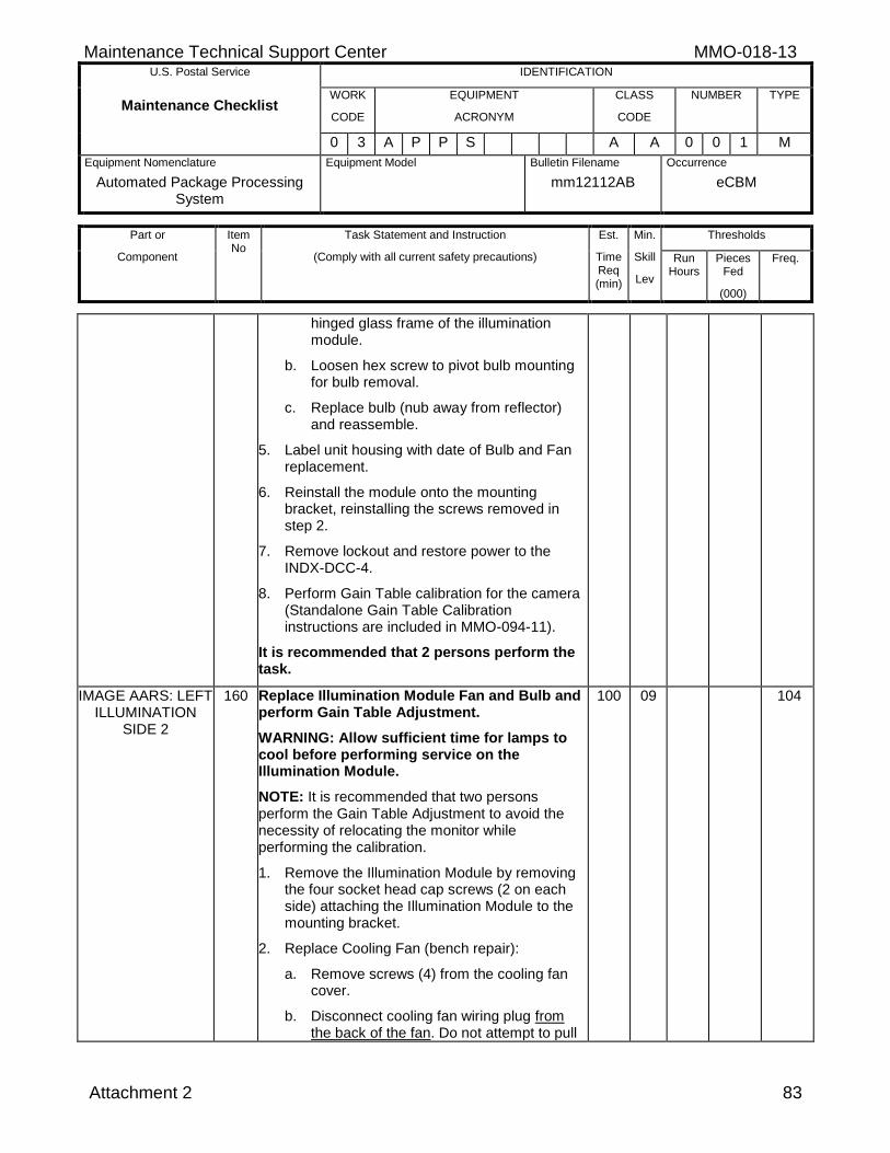
Maintenance Technical Support Center MMO-018-13 U.S. Postal Service IDENTIFICATION
Maintenance Checklist WORK
CODE
EQUIPMENT
ACRONYM
CLASS
CODE
NUMBER TYPE
0 3 A P P S A A 0 0 1 M
Equipment Nomenclature
Automated Package Processing System
Equipment Model
Bulletin Filename
mm12112AB
Occurrence
eCBM
Part or
Component
Item No
Task Statement and Instruction
(Comply with all current safety precautions)
Est.
Time Req (min)
Min.
Skill
Lev
Thresholds
Run Hours
Pieces Fed
(000)
Freq.
Attachment 2 83
hinged glass frame of the illumination module.
b. Loosen hex screw to pivot bulb mounting for bulb removal.
c. Replace bulb (nub away from reflector) and reassemble.
5. Label unit housing with date of Bulb and Fan replacement.
6. Reinstall the module onto the mounting bracket, reinstalling the screws removed in step 2.
7. Remove lockout and restore power to the INDX-DCC-4.
8. Perform Gain Table calibration for the camera (Standalone Gain Table Calibration instructions are included in MMO-094-11).
It is recommended that 2 persons perform the task.
IMAGE AARS: LEFT ILLUMINATION
SIDE 2
160 Replace Illumination Module Fan and Bulb and perform Gain Table Adjustment.
WARNING: Allow sufficient time for lamps to cool before performing service on the Illumination Module.
NOTE: It is recommended that two persons perform the Gain Table Adjustment to avoid the necessity of relocating the monitor while performing the calibration.
1. Remove the Illumination Module by removing the four socket head cap screws (2 on each side) attaching the Illumination Module to the mounting bracket.
2. Replace Cooling Fan (bench repair):
a. Remove screws (4) from the cooling fan cover.
b. Disconnect cooling fan wiring plug from the back of the fan. Do not attempt to pull
100 09 104
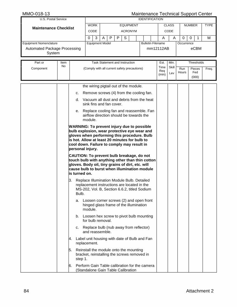
MMO-018-13 Maintenance Technical Support Center U.S. Postal Service IDENTIFICATION
Maintenance Checklist WORK
CODE
EQUIPMENT
ACRONYM
CLASS
CODE
NUMBER TYPE
0 3 A P P S A A 0 0 1 M
Equipment Nomenclature
Automated Package Processing System
Equipment Model
Bulletin Filename
mm12112AB
Occurrence
eCBM
Part or
Component
Item No
Task Statement and Instruction
(Comply with all current safety precautions)
Est.
Time Req (min)
Min.
Skill
Lev
Thresholds
Run Hours
Pieces Fed
(000)
Freq.
84 Attachment 2
the wiring pigtail out of the module.
c. Remove screws (4) from the cooling fan.
d. Vacuum all dust and debris from the heat sink fins and fan cover.
e. Replace cooling fan and reassemble. Fan airflow direction should be towards the module.
WARNING: To prevent injury due to possible bulb explosion, wear protective eye wear and gloves when performing this procedure. Bulb is hot. Allow at least 20 minutes for bulb to cool down. Failure to comply may result in personal injury.
CAUTION: To prevent bulb breakage, do not touch bulb with anything other than thin cotton gloves. Body oil, tiny grains of dirt, etc. will cause bulb to burst when illumination module is turned on.
3. Replace Illumination Module Bulb. Detailed replacement instructions are located in the MS-202, Vol. B, Section 6.6.2, titled Sodium Bulb.
a. Loosen corner screws (2) and open front hinged glass frame of the illumination module.
b. Loosen hex screw to pivot bulb mounting for bulb removal.
c. Replace bulb (nub away from reflector) and reassemble.
4. Label unit housing with date of Bulb and Fan replacement.
5. Reinstall the module onto the mounting bracket, reinstalling the screws removed in step 1.
6. Perform Gain Table calibration for the camera (Standalone Gain Table Calibration
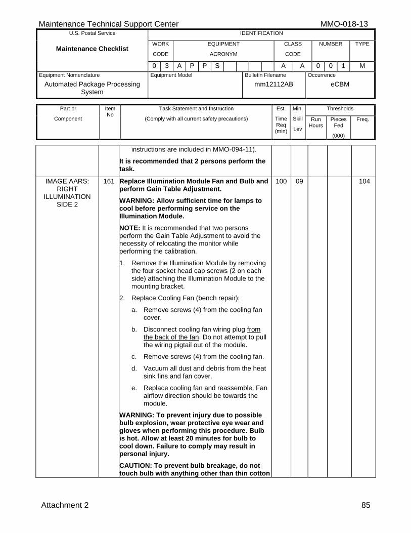
Maintenance Technical Support Center MMO-018-13 U.S. Postal Service IDENTIFICATION
Maintenance Checklist WORK
CODE
EQUIPMENT
ACRONYM
CLASS
CODE
NUMBER TYPE
0 3 A P P S A A 0 0 1 M
Equipment Nomenclature
Automated Package Processing System
Equipment Model
Bulletin Filename
mm12112AB
Occurrence
eCBM
Part or
Component
Item No
Task Statement and Instruction
(Comply with all current safety precautions)
Est.
Time Req (min)
Min.
Skill
Lev
Thresholds
Run Hours
Pieces Fed
(000)
Freq.
Attachment 2 85
instructions are included in MMO-094-11).
It is recommended that 2 persons perform the task.
IMAGE AARS: RIGHT
ILLUMINATION SIDE 2
161 Replace Illumination Module Fan and Bulb and perform Gain Table Adjustment.
WARNING: Allow sufficient time for lamps to cool before performing service on the Illumination Module.
NOTE: It is recommended that two persons perform the Gain Table Adjustment to avoid the necessity of relocating the monitor while performing the calibration.
1. Remove the Illumination Module by removing the four socket head cap screws (2 on each side) attaching the Illumination Module to the mounting bracket.
2. Replace Cooling Fan (bench repair):
a. Remove screws (4) from the cooling fan cover.
b. Disconnect cooling fan wiring plug from the back of the fan. Do not attempt to pull the wiring pigtail out of the module.
c. Remove screws (4) from the cooling fan.
d. Vacuum all dust and debris from the heat sink fins and fan cover.
e. Replace cooling fan and reassemble. Fan airflow direction should be towards the module.
WARNING: To prevent injury due to possible bulb explosion, wear protective eye wear and gloves when performing this procedure. Bulb is hot. Allow at least 20 minutes for bulb to cool down. Failure to comply may result in personal injury.
CAUTION: To prevent bulb breakage, do not touch bulb with anything other than thin cotton
100 09 104
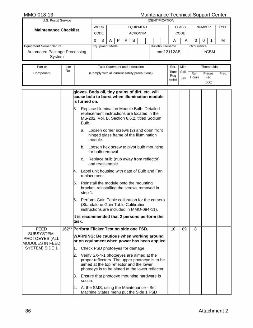
MMO-018-13 Maintenance Technical Support Center U.S. Postal Service IDENTIFICATION
Maintenance Checklist WORK
CODE
EQUIPMENT
ACRONYM
CLASS
CODE
NUMBER TYPE
0 3 A P P S A A 0 0 1 M
Equipment Nomenclature
Automated Package Processing System
Equipment Model
Bulletin Filename
mm12112AB
Occurrence
eCBM
Part or
Component
Item No
Task Statement and Instruction
(Comply with all current safety precautions)
Est.
Time Req (min)
Min.
Skill
Lev
Thresholds
Run Hours
Pieces Fed
(000)
Freq.
86 Attachment 2
gloves. Body oil, tiny grains of dirt, etc. will cause bulb to burst when illumination module is turned on.
3. Replace Illumination Module Bulb. Detailed replacement instructions are located in the MS-202, Vol. B, Section 6.6.2, titled Sodium Bulb.
a. Loosen corner screws (2) and open front hinged glass frame of the illumination module.
b. Loosen hex screw to pivot bulb mounting for bulb removal.
c. Replace bulb (nub away from reflector) and reassemble.
4. Label unit housing with date of Bulb and Fan replacement.
5. Reinstall the module onto the mounting bracket, reinstalling the screws removed in step 1.
6. Perform Gain Table calibration for the camera (Standalone Gain Table Calibration instructions are included in MMO-094-11).
It is recommended that 2 persons perform the task.
FEED SUBSYSTEM:
PHOTOEYES (ALL MODULES IN FEED
SYSTEM) SIDE 1
162** Perform Flicker Test on side one FSD.
WARNING: Be cautious when working around or on equipment when power has been applied.
1. Check FSD photoeyes for damage.
2. Verify SX-4-1 photoeyes are aimed at the proper reflectors. The upper photoeye is to be aimed at the top reflector and the lower photoeye is to be aimed at the lower reflector.
3. Ensure that photoeye mounting hardware is secure.
4. At the SMS, using the Maintenance - Set Machine States menu put the Side 1 FSD
10 09 8
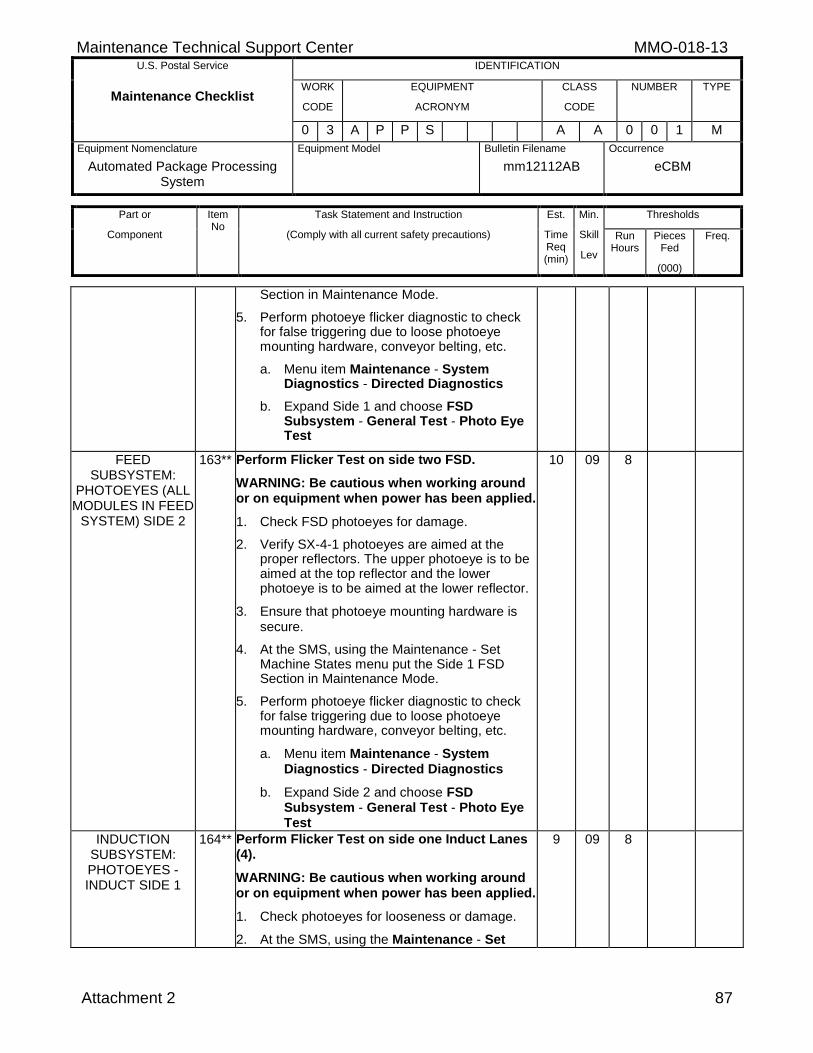
Maintenance Technical Support Center MMO-018-13 U.S. Postal Service IDENTIFICATION
Maintenance Checklist WORK
CODE
EQUIPMENT
ACRONYM
CLASS
CODE
NUMBER TYPE
0 3 A P P S A A 0 0 1 M
Equipment Nomenclature
Automated Package Processing System
Equipment Model
Bulletin Filename
mm12112AB
Occurrence
eCBM
Part or
Component
Item No
Task Statement and Instruction
(Comply with all current safety precautions)
Est.
Time Req (min)
Min.
Skill
Lev
Thresholds
Run Hours
Pieces Fed
(000)
Freq.
Attachment 2 87
Section in Maintenance Mode.
5. Perform photoeye flicker diagnostic to check for false triggering due to loose photoeye mounting hardware, conveyor belting, etc.
a. Menu item Maintenance - System Diagnostics - Directed Diagnostics
b. Expand Side 1 and choose FSD Subsystem - General Test - Photo Eye Test
FEED SUBSYSTEM:
PHOTOEYES (ALL MODULES IN FEED
SYSTEM) SIDE 2
163** Perform Flicker Test on side two FSD.
WARNING: Be cautious when working around or on equipment when power has been applied.
1. Check FSD photoeyes for damage.
2. Verify SX-4-1 photoeyes are aimed at the proper reflectors. The upper photoeye is to be aimed at the top reflector and the lower photoeye is to be aimed at the lower reflector.
3. Ensure that photoeye mounting hardware is secure.
4. At the SMS, using the Maintenance - Set Machine States menu put the Side 1 FSD Section in Maintenance Mode.
5. Perform photoeye flicker diagnostic to check for false triggering due to loose photoeye mounting hardware, conveyor belting, etc.
a. Menu item Maintenance - System Diagnostics - Directed Diagnostics
b. Expand Side 2 and choose FSD Subsystem - General Test - Photo Eye Test
10 09 8
INDUCTION SUBSYSTEM: PHOTOEYES - INDUCT SIDE 1
164** Perform Flicker Test on side one Induct Lanes (4).
WARNING: Be cautious when working around or on equipment when power has been applied.
1. Check photoeyes for looseness or damage.
2. At the SMS, using the Maintenance - Set
9 09 8
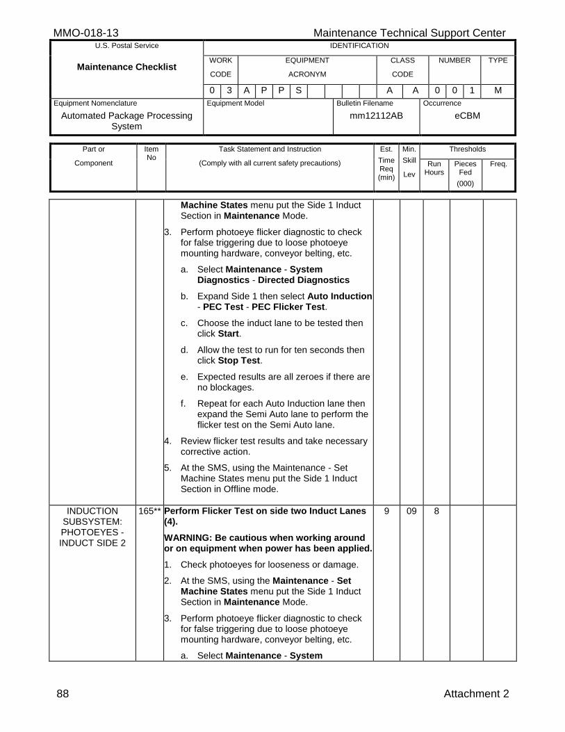
MMO-018-13 Maintenance Technical Support Center U.S. Postal Service IDENTIFICATION
Maintenance Checklist WORK
CODE
EQUIPMENT
ACRONYM
CLASS
CODE
NUMBER TYPE
0 3 A P P S A A 0 0 1 M
Equipment Nomenclature
Automated Package Processing System
Equipment Model
Bulletin Filename
mm12112AB
Occurrence
eCBM
Part or
Component
Item No
Task Statement and Instruction
(Comply with all current safety precautions)
Est.
Time Req (min)
Min.
Skill
Lev
Thresholds
Run Hours
Pieces Fed
(000)
Freq.
88 Attachment 2
Machine States menu put the Side 1 Induct Section in Maintenance Mode.
3. Perform photoeye flicker diagnostic to check for false triggering due to loose photoeye mounting hardware, conveyor belting, etc.
a. Select Maintenance - System Diagnostics - Directed Diagnostics
b. Expand Side 1 then select Auto Induction - PEC Test - PEC Flicker Test.
c. Choose the induct lane to be tested then click Start.
d. Allow the test to run for ten seconds then click Stop Test.
e. Expected results are all zeroes if there are no blockages.
f. Repeat for each Auto Induction lane then expand the Semi Auto lane to perform the flicker test on the Semi Auto lane.
4. Review flicker test results and take necessary corrective action.
5. At the SMS, using the Maintenance - Set Machine States menu put the Side 1 Induct Section in Offline mode.
INDUCTION SUBSYSTEM: PHOTOEYES - INDUCT SIDE 2
165** Perform Flicker Test on side two Induct Lanes (4).
WARNING: Be cautious when working around or on equipment when power has been applied.
1. Check photoeyes for looseness or damage.
2. At the SMS, using the Maintenance - Set Machine States menu put the Side 1 Induct Section in Maintenance Mode.
3. Perform photoeye flicker diagnostic to check for false triggering due to loose photoeye mounting hardware, conveyor belting, etc.
a. Select Maintenance - System
9 09 8
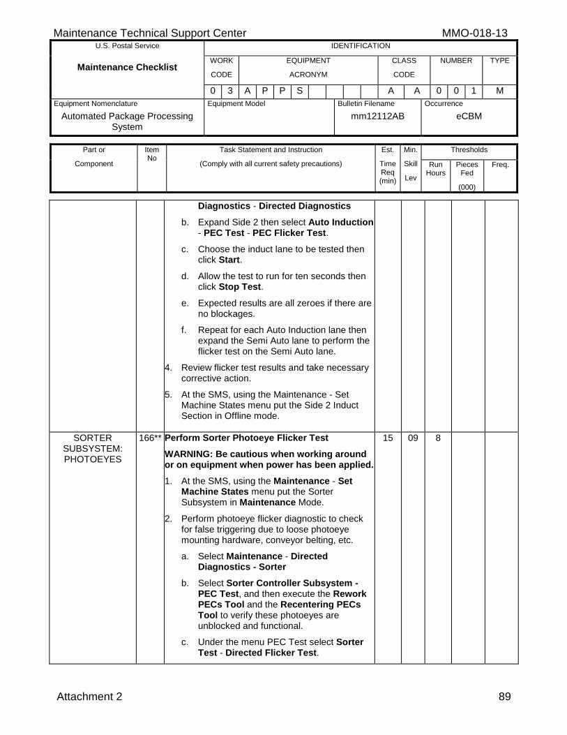
Maintenance Technical Support Center MMO-018-13 U.S. Postal Service IDENTIFICATION
Maintenance Checklist WORK
CODE
EQUIPMENT
ACRONYM
CLASS
CODE
NUMBER TYPE
0 3 A P P S A A 0 0 1 M
Equipment Nomenclature
Automated Package Processing System
Equipment Model
Bulletin Filename
mm12112AB
Occurrence
eCBM
Part or
Component
Item No
Task Statement and Instruction
(Comply with all current safety precautions)
Est.
Time Req (min)
Min.
Skill
Lev
Thresholds
Run Hours
Pieces Fed
(000)
Freq.
Attachment 2 89
Diagnostics - Directed Diagnostics
b. Expand Side 2 then select Auto Induction - PEC Test - PEC Flicker Test.
c. Choose the induct lane to be tested then click Start.
d. Allow the test to run for ten seconds then click Stop Test.
e. Expected results are all zeroes if there are no blockages.
f. Repeat for each Auto Induction lane then expand the Semi Auto lane to perform the flicker test on the Semi Auto lane.
4. Review flicker test results and take necessary corrective action.
5. At the SMS, using the Maintenance - Set Machine States menu put the Side 2 Induct Section in Offline mode.
SORTER SUBSYSTEM: PHOTOEYES
166** Perform Sorter Photoeye Flicker Test
WARNING: Be cautious when working around or on equipment when power has been applied.
1. At the SMS, using the Maintenance - Set Machine States menu put the Sorter Subsystem in Maintenance Mode.
2. Perform photoeye flicker diagnostic to check for false triggering due to loose photoeye mounting hardware, conveyor belting, etc.
a. Select Maintenance - Directed Diagnostics - Sorter
b. Select Sorter Controller Subsystem - PEC Test, and then execute the Rework PECs Tool and the Recentering PECs Tool to verify these photoeyes are unblocked and functional.
c. Under the menu PEC Test select Sorter Test - Directed Flicker Test.
15 09 8
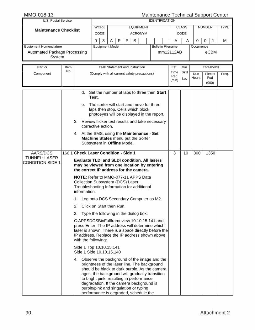
MMO-018-13 Maintenance Technical Support Center U.S. Postal Service IDENTIFICATION
Maintenance Checklist WORK
CODE
EQUIPMENT
ACRONYM
CLASS
CODE
NUMBER TYPE
0 3 A P P S A A 0 0 1 M
Equipment Nomenclature
Automated Package Processing System
Equipment Model
Bulletin Filename
mm12112AB
Occurrence
eCBM
Part or
Component
Item No
Task Statement and Instruction
(Comply with all current safety precautions)
Est.
Time Req (min)
Min.
Skill
Lev
Thresholds
Run Hours
Pieces Fed
(000)
Freq.
90 Attachment 2
d. Set the number of laps to three then Start Test.
e. The sorter will start and move for three laps then stop. Cells which block photoeyes will be displayed in the report.
3. Review flicker test results and take necessary corrective action.
4. At the SMS, using the Maintenance - Set Machine States menu put the Sorter Subsystem in Offline Mode.
AARS/DCS TUNNEL: LASER
CONDITION SIDE 1
166.1 Check Laser Condition - Side 1
Evaluate TLDI and SLDI condition. All lasers may be viewed from one location by entering the correct IP address for the camera.
NOTE: Refer to MMO-077-11 APPS Data Collection Subsystem (DCS) Laser Troubleshooting Information for additional information.
1. Log onto DCS Secondary Computer as M2.
2. Click on Start then Run.
3. Type the following in the dialog box:
C:APPSDCSBinFullframeview 10.10.15.141 and press Enter. The IP address will determine which laser is shown. There is a space directly before the IP address. Replace the IP address shown above with the following:
Side 1 Top 10.10.15.141 Side 1 Side 10.10.15.140
4. Observe the background of the image and the brightness of the laser line. The background should be black to dark purple. As the camera ages, the background will gradually transition to bright pink, resulting in performance degradation. If the camera background is purple/pink and singulation or typing performance is degraded, schedule the
3 10 300 1350
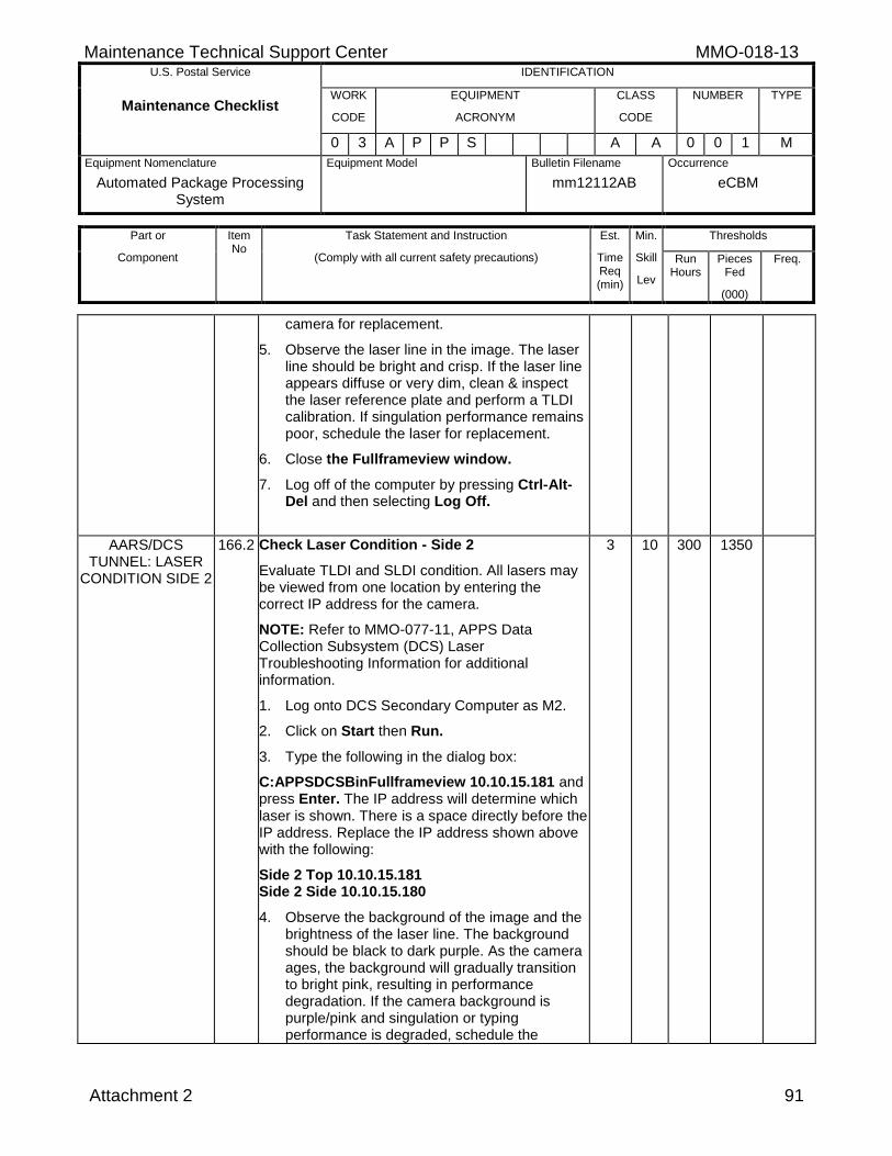
Maintenance Technical Support Center MMO-018-13 U.S. Postal Service IDENTIFICATION
Maintenance Checklist WORK
CODE
EQUIPMENT
ACRONYM
CLASS
CODE
NUMBER TYPE
0 3 A P P S A A 0 0 1 M
Equipment Nomenclature
Automated Package Processing System
Equipment Model
Bulletin Filename
mm12112AB
Occurrence
eCBM
Part or
Component
Item No
Task Statement and Instruction
(Comply with all current safety precautions)
Est.
Time Req (min)
Min.
Skill
Lev
Thresholds
Run Hours
Pieces Fed
(000)
Freq.
Attachment 2 91
camera for replacement.
5. Observe the laser line in the image. The laser line should be bright and crisp. If the laser line appears diffuse or very dim, clean & inspect the laser reference plate and perform a TLDI calibration. If singulation performance remains poor, schedule the laser for replacement.
6. Close the Fullframeview window.
7. Log off of the computer by pressing Ctrl-Alt-Del and then selecting Log Off.
AARS/DCS TUNNEL: LASER
CONDITION SIDE 2
166.2 Check Laser Condition - Side 2
Evaluate TLDI and SLDI condition. All lasers may be viewed from one location by entering the correct IP address for the camera.
NOTE: Refer to MMO-077-11, APPS Data Collection Subsystem (DCS) Laser Troubleshooting Information for additional information.
1. Log onto DCS Secondary Computer as M2.
2. Click on Start then Run.
3. Type the following in the dialog box:
C:APPSDCSBinFullframeview 10.10.15.181 and press Enter. The IP address will determine which laser is shown. There is a space directly before the IP address. Replace the IP address shown above with the following:
Side 2 Top 10.10.15.181 Side 2 Side 10.10.15.180
4. Observe the background of the image and the brightness of the laser line. The background should be black to dark purple. As the camera ages, the background will gradually transition to bright pink, resulting in performance degradation. If the camera background is purple/pink and singulation or typing performance is degraded, schedule the
3 10 300 1350
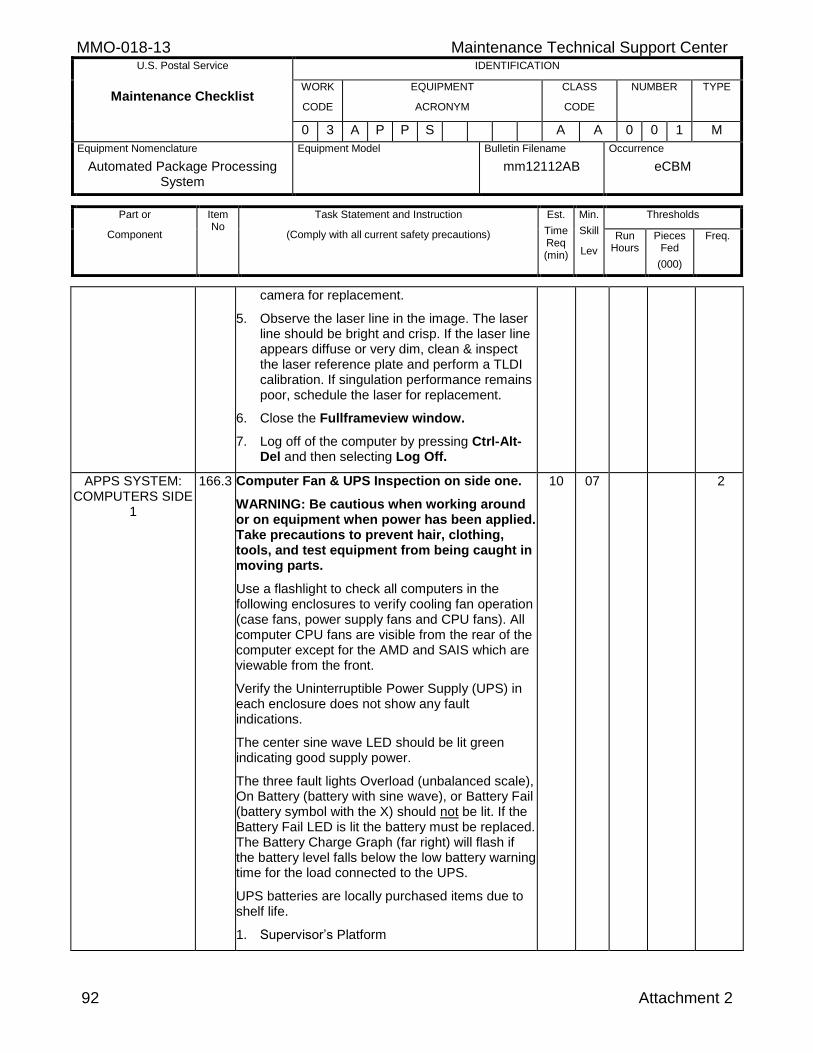
MMO-018-13 Maintenance Technical Support Center U.S. Postal Service IDENTIFICATION
Maintenance Checklist WORK
CODE
EQUIPMENT
ACRONYM
CLASS
CODE
NUMBER TYPE
0 3 A P P S A A 0 0 1 M
Equipment Nomenclature
Automated Package Processing System
Equipment Model
Bulletin Filename
mm12112AB
Occurrence
eCBM
Part or
Component
Item No
Task Statement and Instruction
(Comply with all current safety precautions)
Est.
Time Req (min)
Min.
Skill
Lev
Thresholds
Run Hours
Pieces Fed
(000)
Freq.
92 Attachment 2
camera for replacement.
5. Observe the laser line in the image. The laser line should be bright and crisp. If the laser line appears diffuse or very dim, clean & inspect the laser reference plate and perform a TLDI calibration. If singulation performance remains poor, schedule the laser for replacement.
6. Close the Fullframeview window.
7. Log off of the computer by pressing Ctrl-Alt-Del and then selecting Log Off.
APPS SYSTEM: COMPUTERS SIDE
1
166.3 Computer Fan & UPS Inspection on side one.
WARNING: Be cautious when working around or on equipment when power has been applied. Take precautions to prevent hair, clothing, tools, and test equipment from being caught in moving parts.
Use a flashlight to check all computers in the following enclosures to verify cooling fan operation (case fans, power supply fans and CPU fans). All computer CPU fans are visible from the rear of the computer except for the AMD and SAIS which are viewable from the front.
Verify the Uninterruptible Power Supply (UPS) in each enclosure does not show any fault indications.
The center sine wave LED should be lit green indicating good supply power.
The three fault lights Overload (unbalanced scale), On Battery (battery with sine wave), or Battery Fail (battery symbol with the X) should not be lit. If the Battery Fail LED is lit the battery must be replaced. The Battery Charge Graph (far right) will flash if the battery level falls below the low battery warning time for the load connected to the UPS.
UPS batteries are locally purchased items due to shelf life.
1. Supervisor’s Platform
10 07 2
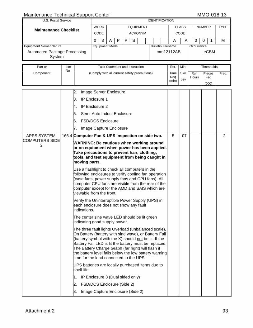
Maintenance Technical Support Center MMO-018-13 U.S. Postal Service IDENTIFICATION
Maintenance Checklist WORK
CODE
EQUIPMENT
ACRONYM
CLASS
CODE
NUMBER TYPE
0 3 A P P S A A 0 0 1 M
Equipment Nomenclature
Automated Package Processing System
Equipment Model
Bulletin Filename
mm12112AB
Occurrence
eCBM
Part or
Component
Item No
Task Statement and Instruction
(Comply with all current safety precautions)
Est.
Time Req (min)
Min.
Skill
Lev
Thresholds
Run Hours
Pieces Fed
(000)
Freq.
Attachment 2 93
2. Image Server Enclosure
3. IP Enclosure 1
4. IP Enclosure 2
5. Semi-Auto Induct Enclosure
6. FSD/DCS Enclosure
7. Image Capture Enclosure
APPS SYSTEM: COMPUTERS SIDE
2
166.4 Computer Fan & UPS Inspection on side two.
WARNING: Be cautious when working around or on equipment when power has been applied. Take precautions to prevent hair, clothing, tools, and test equipment from being caught in moving parts.
Use a flashlight to check all computers in the following enclosures to verify cooling fan operation (case fans, power supply fans and CPU fans). All computer CPU fans are visible from the rear of the computer except for the AMD and SAIS which are viewable from the front.
Verify the Uninterruptible Power Supply (UPS) in each enclosure does not show any fault indications.
The center sine wave LED should be lit green indicating good supply power.
The three fault lights Overload (unbalanced scale), On Battery (battery with sine wave), or Battery Fail (battery symbol with the X) should not be lit. If the Battery Fail LED is lit the battery must be replaced. The Battery Charge Graph (far right) will flash if the battery level falls below the low battery warning time for the load connected to the UPS.
UPS batteries are locally purchased items due to shelf life.
1. IP Enclosure 3 (Dual sided only)
2. FSD/DCS Enclosure (Side 2)
3. Image Capture Enclosure (Side 2)
5 07 2
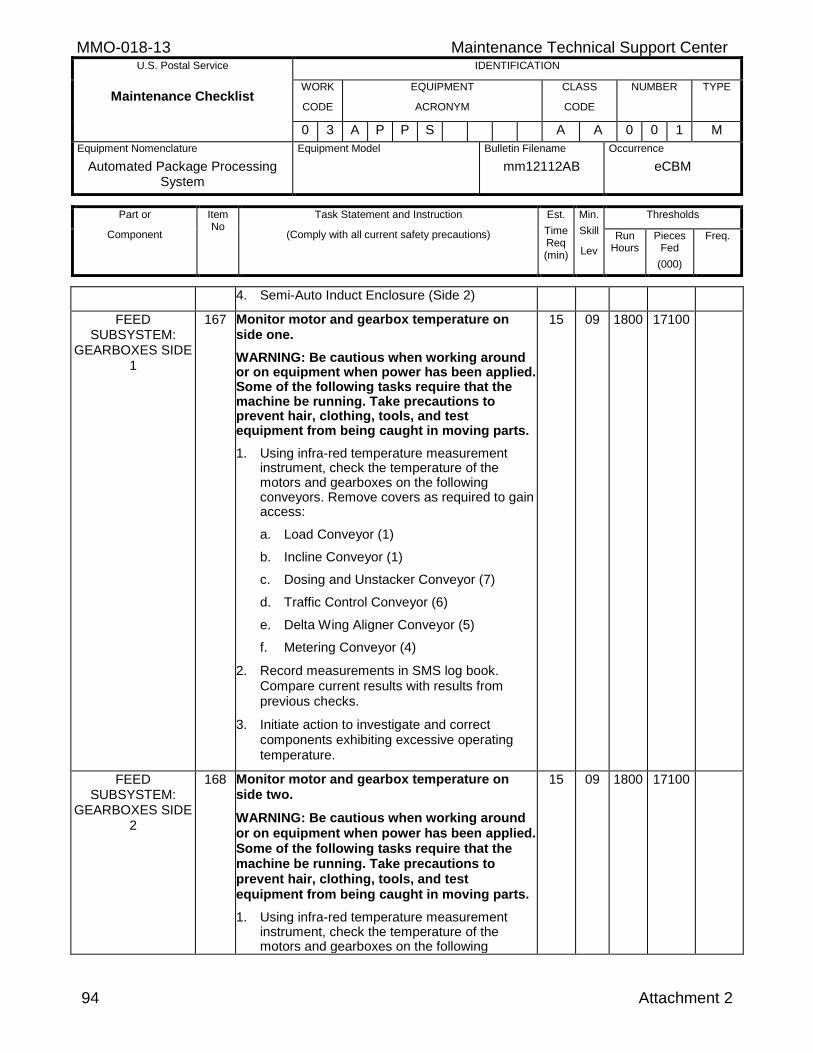
MMO-018-13 Maintenance Technical Support Center U.S. Postal Service IDENTIFICATION
Maintenance Checklist WORK
CODE
EQUIPMENT
ACRONYM
CLASS
CODE
NUMBER TYPE
0 3 A P P S A A 0 0 1 M
Equipment Nomenclature
Automated Package Processing System
Equipment Model
Bulletin Filename
mm12112AB
Occurrence
eCBM
Part or
Component
Item No
Task Statement and Instruction
(Comply with all current safety precautions)
Est.
Time Req (min)
Min.
Skill
Lev
Thresholds
Run Hours
Pieces Fed
(000)
Freq.
94 Attachment 2
4. Semi-Auto Induct Enclosure (Side 2)
FEED SUBSYSTEM:
GEARBOXES SIDE 1
167 Monitor motor and gearbox temperature on side one.
WARNING: Be cautious when working around or on equipment when power has been applied. Some of the following tasks require that the machine be running. Take precautions to prevent hair, clothing, tools, and test equipment from being caught in moving parts.
1. Using infra-red temperature measurement instrument, check the temperature of the motors and gearboxes on the following conveyors. Remove covers as required to gain access:
a. Load Conveyor (1)
b. Incline Conveyor (1)
c. Dosing and Unstacker Conveyor (7)
d. Traffic Control Conveyor (6)
e. Delta Wing Aligner Conveyor (5)
f. Metering Conveyor (4)
2. Record measurements in SMS log book. Compare current results with results from previous checks.
3. Initiate action to investigate and correct components exhibiting excessive operating temperature.
15 09 1800 17100
FEED SUBSYSTEM:
GEARBOXES SIDE 2
168 Monitor motor and gearbox temperature on side two.
WARNING: Be cautious when working around or on equipment when power has been applied. Some of the following tasks require that the machine be running. Take precautions to prevent hair, clothing, tools, and test equipment from being caught in moving parts.
1. Using infra-red temperature measurement instrument, check the temperature of the motors and gearboxes on the following
15 09 1800 17100
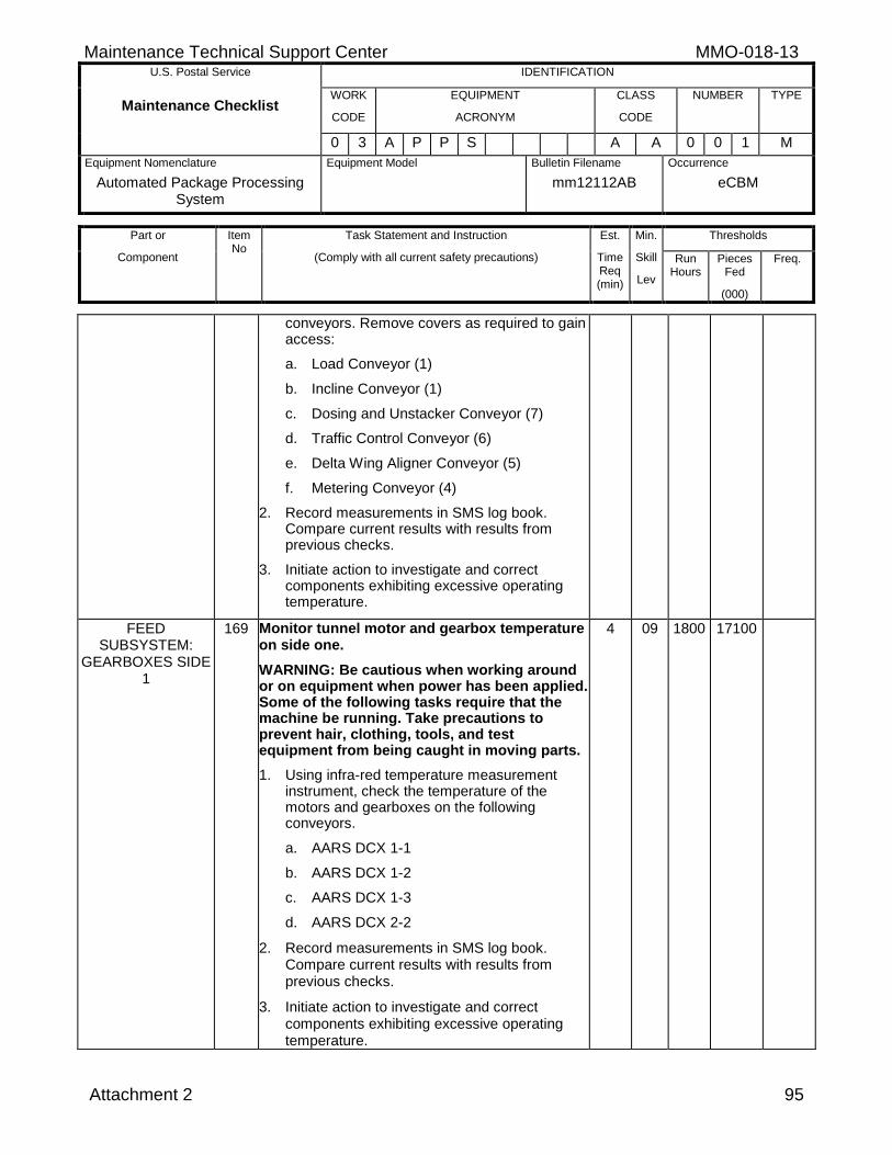
Maintenance Technical Support Center MMO-018-13 U.S. Postal Service IDENTIFICATION
Maintenance Checklist WORK
CODE
EQUIPMENT
ACRONYM
CLASS
CODE
NUMBER TYPE
0 3 A P P S A A 0 0 1 M
Equipment Nomenclature
Automated Package Processing System
Equipment Model
Bulletin Filename
mm12112AB
Occurrence
eCBM
Part or
Component
Item No
Task Statement and Instruction
(Comply with all current safety precautions)
Est.
Time Req (min)
Min.
Skill
Lev
Thresholds
Run Hours
Pieces Fed
(000)
Freq.
Attachment 2 95
conveyors. Remove covers as required to gain access:
a. Load Conveyor (1)
b. Incline Conveyor (1)
c. Dosing and Unstacker Conveyor (7)
d. Traffic Control Conveyor (6)
e. Delta Wing Aligner Conveyor (5)
f. Metering Conveyor (4)
2. Record measurements in SMS log book. Compare current results with results from previous checks.
3. Initiate action to investigate and correct components exhibiting excessive operating temperature.
FEED SUBSYSTEM:
GEARBOXES SIDE 1
169 Monitor tunnel motor and gearbox temperature on side one.
WARNING: Be cautious when working around or on equipment when power has been applied. Some of the following tasks require that the machine be running. Take precautions to prevent hair, clothing, tools, and test equipment from being caught in moving parts.
1. Using infra-red temperature measurement instrument, check the temperature of the motors and gearboxes on the following conveyors.
a. AARS DCX 1-1
b. AARS DCX 1-2
c. AARS DCX 1-3
d. AARS DCX 2-2
2. Record measurements in SMS log book. Compare current results with results from previous checks.
3. Initiate action to investigate and correct components exhibiting excessive operating temperature.
4 09 1800 17100
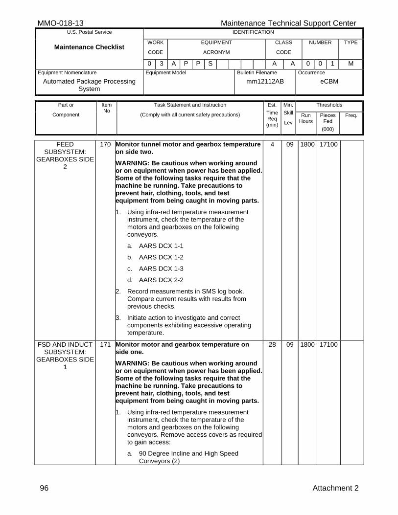
MMO-018-13 Maintenance Technical Support Center U.S. Postal Service IDENTIFICATION
Maintenance Checklist WORK
CODE
EQUIPMENT
ACRONYM
CLASS
CODE
NUMBER TYPE
0 3 A P P S A A 0 0 1 M
Equipment Nomenclature
Automated Package Processing System
Equipment Model
Bulletin Filename
mm12112AB
Occurrence
eCBM
Part or
Component
Item No
Task Statement and Instruction
(Comply with all current safety precautions)
Est.
Time Req (min)
Min.
Skill
Lev
Thresholds
Run Hours
Pieces Fed
(000)
Freq.
96 Attachment 2
FEED SUBSYSTEM:
GEARBOXES SIDE 2
170 Monitor tunnel motor and gearbox temperature on side two.
WARNING: Be cautious when working around or on equipment when power has been applied. Some of the following tasks require that the machine be running. Take precautions to prevent hair, clothing, tools, and test equipment from being caught in moving parts.
1. Using infra-red temperature measurement instrument, check the temperature of the motors and gearboxes on the following conveyors.
a. AARS DCX 1-1
b. AARS DCX 1-2
c. AARS DCX 1-3
d. AARS DCX 2-2
2. Record measurements in SMS log book. Compare current results with results from previous checks.
3. Initiate action to investigate and correct components exhibiting excessive operating temperature.
4 09 1800 17100
FSD AND INDUCT SUBSYSTEM:
GEARBOXES SIDE 1
171 Monitor motor and gearbox temperature on side one.
WARNING: Be cautious when working around or on equipment when power has been applied. Some of the following tasks require that the machine be running. Take precautions to prevent hair, clothing, tools, and test equipment from being caught in moving parts.
1. Using infra-red temperature measurement instrument, check the temperature of the motors and gearboxes on the following conveyors. Remove access covers as required to gain access:
a. 90 Degree Incline and High Speed Conveyors (2)
28 09 1800 17100
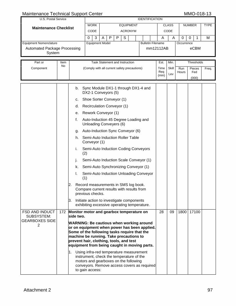
Maintenance Technical Support Center MMO-018-13 U.S. Postal Service IDENTIFICATION
Maintenance Checklist WORK
CODE
EQUIPMENT
ACRONYM
CLASS
CODE
NUMBER TYPE
0 3 A P P S A A 0 0 1 M
Equipment Nomenclature
Automated Package Processing System
Equipment Model
Bulletin Filename
mm12112AB
Occurrence
eCBM
Part or
Component
Item No
Task Statement and Instruction
(Comply with all current safety precautions)
Est.
Time Req (min)
Min.
Skill
Lev
Thresholds
Run Hours
Pieces Fed
(000)
Freq.
Attachment 2 97
b. Sync Module DX1-1 through DX1-4 and DX2-1 Conveyors (5)
c. Shoe Sorter Conveyor (1)
d. Recirculation Conveyor (1)
e. Rework Conveyor (1)
f. Auto-Induction 45 Degree Loading and Unloading Conveyers (6)
g. Auto-Induction Sync Conveyor (6)
h. Semi-Auto Induction Roller Table Conveyor (1)
i. Semi-Auto Induction Coding Conveyors (2)
j. Semi-Auto Induction Scale Conveyor (1)
k. Semi-Auto Synchronizing Conveyor (1)
l. Semi-Auto Induction Unloading Conveyor (1)
2. Record measurements in SMS log book. Compare current results with results from previous checks.
3. Initiate action to investigate components exhibiting excessive operating temperature.
FSD AND INDUCT SUBSYSTEM:
GEARBOXES SIDE 2
172 Monitor motor and gearbox temperature on side two.
WARNING: Be cautious when working around or on equipment when power has been applied. Some of the following tasks require that the machine be running. Take precautions to prevent hair, clothing, tools, and test equipment from being caught in moving parts.
1. Using infra-red temperature measurement instrument, check the temperature of the motors and gearboxes on the following conveyors. Remove access covers as required to gain access:
28 09 1800 17100
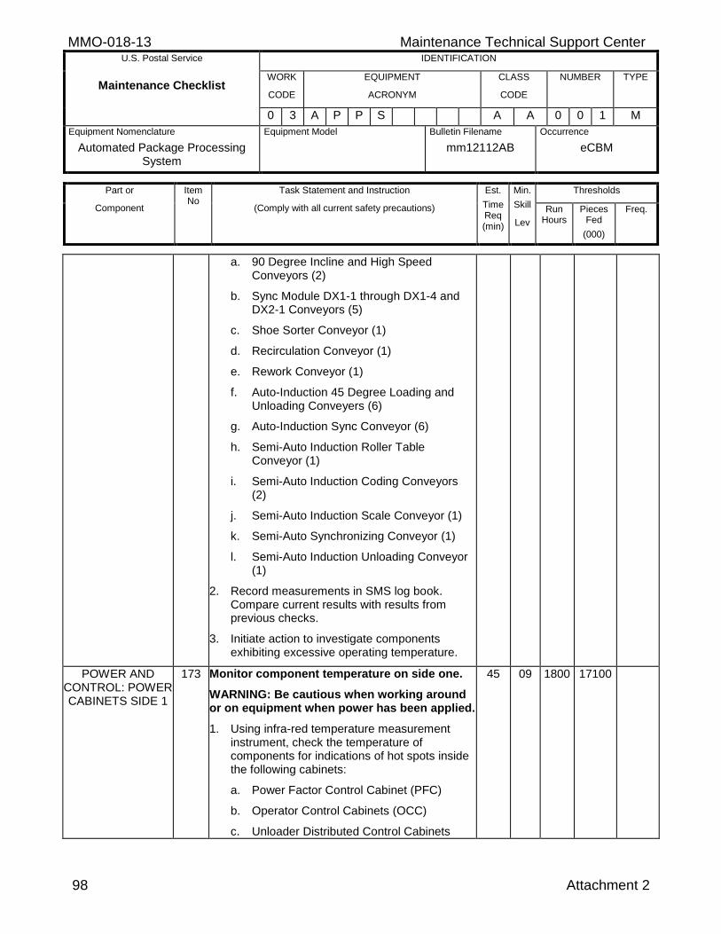
MMO-018-13 Maintenance Technical Support Center U.S. Postal Service IDENTIFICATION
Maintenance Checklist WORK
CODE
EQUIPMENT
ACRONYM
CLASS
CODE
NUMBER TYPE
0 3 A P P S A A 0 0 1 M
Equipment Nomenclature
Automated Package Processing System
Equipment Model
Bulletin Filename
mm12112AB
Occurrence
eCBM
Part or
Component
Item No
Task Statement and Instruction
(Comply with all current safety precautions)
Est.
Time Req (min)
Min.
Skill
Lev
Thresholds
Run Hours
Pieces Fed
(000)
Freq.
98 Attachment 2
a. 90 Degree Incline and High Speed Conveyors (2)
b. Sync Module DX1-1 through DX1-4 and DX2-1 Conveyors (5)
c. Shoe Sorter Conveyor (1)
d. Recirculation Conveyor (1)
e. Rework Conveyor (1)
f. Auto-Induction 45 Degree Loading and Unloading Conveyers (6)
g. Auto-Induction Sync Conveyor (6)
h. Semi-Auto Induction Roller Table Conveyor (1)
i. Semi-Auto Induction Coding Conveyors (2)
j. Semi-Auto Induction Scale Conveyor (1)
k. Semi-Auto Synchronizing Conveyor (1)
l. Semi-Auto Induction Unloading Conveyor (1)
2. Record measurements in SMS log book. Compare current results with results from previous checks.
3. Initiate action to investigate components exhibiting excessive operating temperature.
POWER AND CONTROL: POWER CABINETS SIDE 1
173 Monitor component temperature on side one.
WARNING: Be cautious when working around or on equipment when power has been applied.
1. Using infra-red temperature measurement instrument, check the temperature of components for indications of hot spots inside the following cabinets:
a. Power Factor Control Cabinet (PFC)
b. Operator Control Cabinets (OCC)
c. Unloader Distributed Control Cabinets
45 09 1800 17100
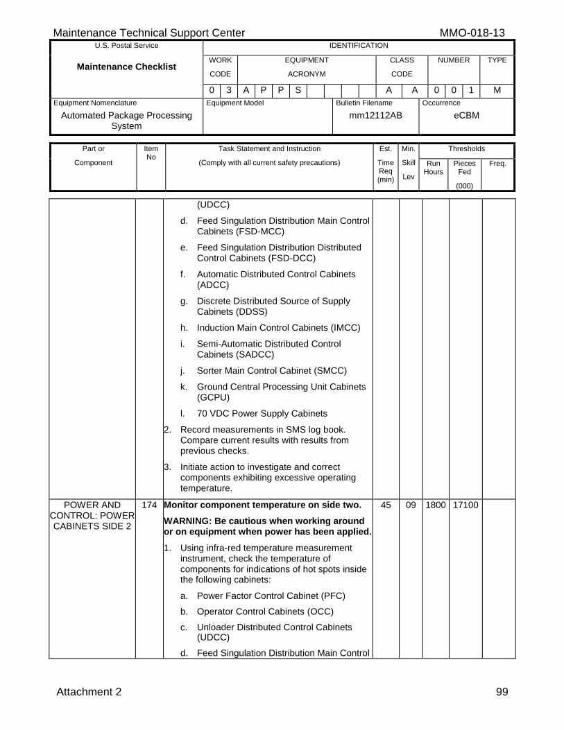
Maintenance Technical Support Center MMO-018-13 U.S. Postal Service IDENTIFICATION
Maintenance Checklist WORK
CODE
EQUIPMENT
ACRONYM
CLASS
CODE
NUMBER TYPE
0 3 A P P S A A 0 0 1 M
Equipment Nomenclature
Automated Package Processing System
Equipment Model
Bulletin Filename
mm12112AB
Occurrence
eCBM
Part or
Component
Item No
Task Statement and Instruction
(Comply with all current safety precautions)
Est.
Time Req (min)
Min.
Skill
Lev
Thresholds
Run Hours
Pieces Fed
(000)
Freq.
Attachment 2 99
(UDCC)
d. Feed Singulation Distribution Main Control Cabinets (FSD-MCC)
e. Feed Singulation Distribution Distributed Control Cabinets (FSD-DCC)
f. Automatic Distributed Control Cabinets (ADCC)
g. Discrete Distributed Source of Supply Cabinets (DDSS)
h. Induction Main Control Cabinets (IMCC)
i. Semi-Automatic Distributed Control Cabinets (SADCC)
j. Sorter Main Control Cabinet (SMCC)
k. Ground Central Processing Unit Cabinets (GCPU)
l. 70 VDC Power Supply Cabinets
2. Record measurements in SMS log book. Compare current results with results from previous checks.
3. Initiate action to investigate and correct components exhibiting excessive operating temperature.
POWER AND CONTROL: POWER CABINETS SIDE 2
174 Monitor component temperature on side two.
WARNING: Be cautious when working around or on equipment when power has been applied.
1. Using infra-red temperature measurement instrument, check the temperature of components for indications of hot spots inside the following cabinets:
a. Power Factor Control Cabinet (PFC)
b. Operator Control Cabinets (OCC)
c. Unloader Distributed Control Cabinets (UDCC)
d. Feed Singulation Distribution Main Control
45 09 1800 17100
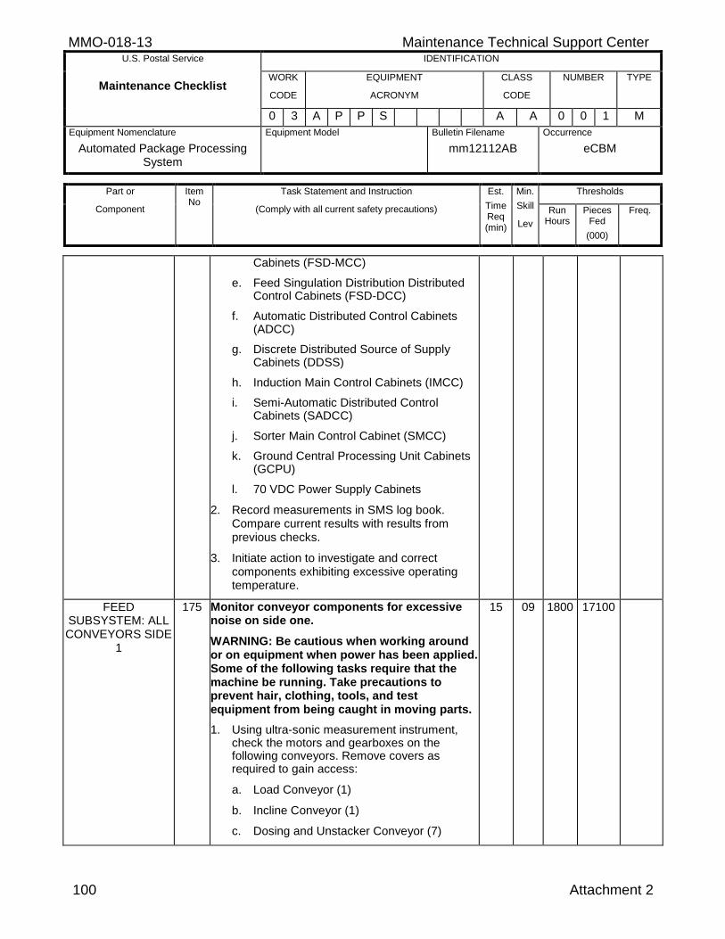
MMO-018-13 Maintenance Technical Support Center U.S. Postal Service IDENTIFICATION
Maintenance Checklist WORK
CODE
EQUIPMENT
ACRONYM
CLASS
CODE
NUMBER TYPE
0 3 A P P S A A 0 0 1 M
Equipment Nomenclature
Automated Package Processing System
Equipment Model
Bulletin Filename
mm12112AB
Occurrence
eCBM
Part or
Component
Item No
Task Statement and Instruction
(Comply with all current safety precautions)
Est.
Time Req (min)
Min.
Skill
Lev
Thresholds
Run Hours
Pieces Fed
(000)
Freq.
100 Attachment 2
Cabinets (FSD-MCC)
e. Feed Singulation Distribution Distributed Control Cabinets (FSD-DCC)
f. Automatic Distributed Control Cabinets (ADCC)
g. Discrete Distributed Source of Supply Cabinets (DDSS)
h. Induction Main Control Cabinets (IMCC)
i. Semi-Automatic Distributed Control Cabinets (SADCC)
j. Sorter Main Control Cabinet (SMCC)
k. Ground Central Processing Unit Cabinets (GCPU)
l. 70 VDC Power Supply Cabinets
2. Record measurements in SMS log book. Compare current results with results from previous checks.
3. Initiate action to investigate and correct components exhibiting excessive operating temperature.
FEED SUBSYSTEM: ALL CONVEYORS SIDE
1
175 Monitor conveyor components for excessive noise on side one.
WARNING: Be cautious when working around or on equipment when power has been applied. Some of the following tasks require that the machine be running. Take precautions to prevent hair, clothing, tools, and test equipment from being caught in moving parts.
1. Using ultra-sonic measurement instrument, check the motors and gearboxes on the following conveyors. Remove covers as required to gain access:
a. Load Conveyor (1)
b. Incline Conveyor (1)
c. Dosing and Unstacker Conveyor (7)
15 09 1800 17100
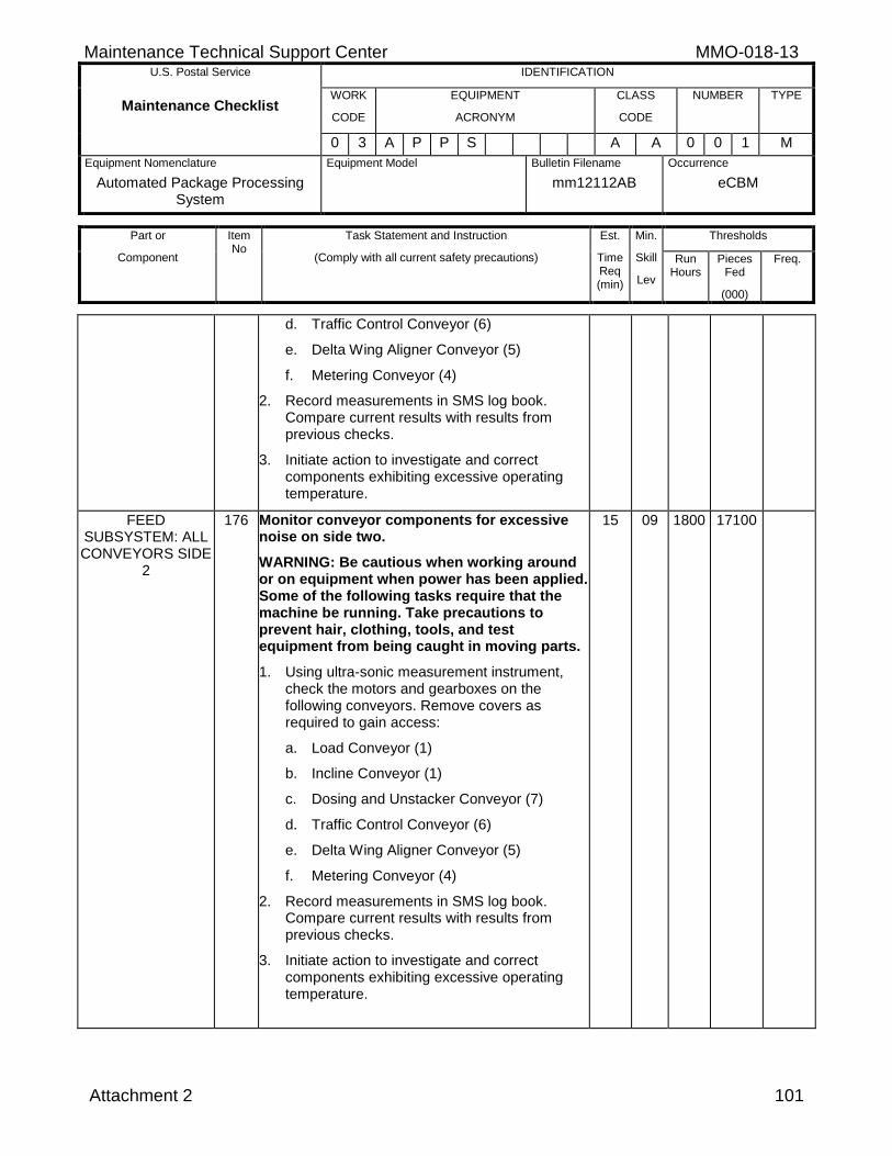
Maintenance Technical Support Center MMO-018-13 U.S. Postal Service IDENTIFICATION
Maintenance Checklist WORK
CODE
EQUIPMENT
ACRONYM
CLASS
CODE
NUMBER TYPE
0 3 A P P S A A 0 0 1 M
Equipment Nomenclature
Automated Package Processing System
Equipment Model
Bulletin Filename
mm12112AB
Occurrence
eCBM
Part or
Component
Item No
Task Statement and Instruction
(Comply with all current safety precautions)
Est.
Time Req (min)
Min.
Skill
Lev
Thresholds
Run Hours
Pieces Fed
(000)
Freq.
Attachment 2 101
d. Traffic Control Conveyor (6)
e. Delta Wing Aligner Conveyor (5)
f. Metering Conveyor (4)
2. Record measurements in SMS log book. Compare current results with results from previous checks.
3. Initiate action to investigate and correct components exhibiting excessive operating temperature.
FEED SUBSYSTEM: ALL CONVEYORS SIDE
2
176 Monitor conveyor components for excessive noise on side two.
WARNING: Be cautious when working around or on equipment when power has been applied. Some of the following tasks require that the machine be running. Take precautions to prevent hair, clothing, tools, and test equipment from being caught in moving parts.
1. Using ultra-sonic measurement instrument, check the motors and gearboxes on the following conveyors. Remove covers as required to gain access:
a. Load Conveyor (1)
b. Incline Conveyor (1)
c. Dosing and Unstacker Conveyor (7)
d. Traffic Control Conveyor (6)
e. Delta Wing Aligner Conveyor (5)
f. Metering Conveyor (4)
2. Record measurements in SMS log book. Compare current results with results from previous checks.
3. Initiate action to investigate and correct components exhibiting excessive operating temperature.
15 09 1800 17100
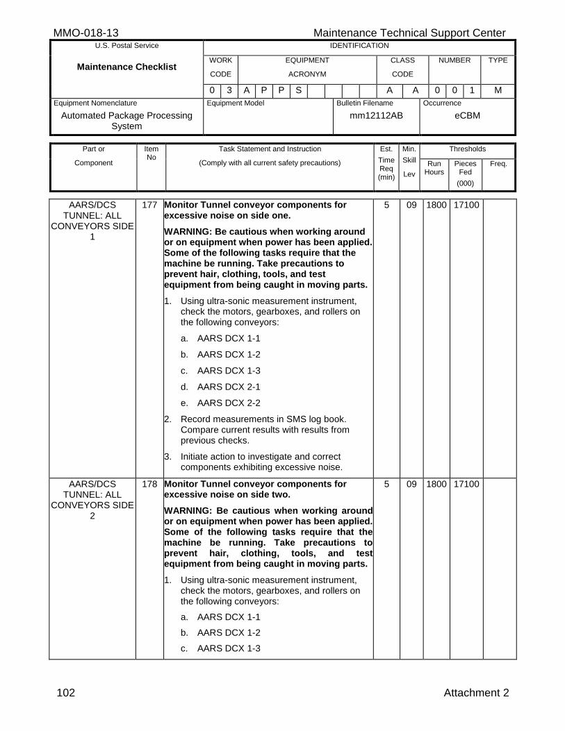
MMO-018-13 Maintenance Technical Support Center U.S. Postal Service IDENTIFICATION
Maintenance Checklist WORK
CODE
EQUIPMENT
ACRONYM
CLASS
CODE
NUMBER TYPE
0 3 A P P S A A 0 0 1 M
Equipment Nomenclature
Automated Package Processing System
Equipment Model
Bulletin Filename
mm12112AB
Occurrence
eCBM
Part or
Component
Item No
Task Statement and Instruction
(Comply with all current safety precautions)
Est.
Time Req (min)
Min.
Skill
Lev
Thresholds
Run Hours
Pieces Fed
(000)
Freq.
102 Attachment 2
AARS/DCS TUNNEL: ALL
CONVEYORS SIDE 1
177 Monitor Tunnel conveyor components for excessive noise on side one.
WARNING: Be cautious when working around or on equipment when power has been applied. Some of the following tasks require that the machine be running. Take precautions to prevent hair, clothing, tools, and test equipment from being caught in moving parts.
1. Using ultra-sonic measurement instrument, check the motors, gearboxes, and rollers on the following conveyors:
a. AARS DCX 1-1
b. AARS DCX 1-2
c. AARS DCX 1-3
d. AARS DCX 2-1
e. AARS DCX 2-2
2. Record measurements in SMS log book. Compare current results with results from previous checks.
3. Initiate action to investigate and correct components exhibiting excessive noise.
5 09 1800 17100
AARS/DCS TUNNEL: ALL
CONVEYORS SIDE 2
178 Monitor Tunnel conveyor components for excessive noise on side two.
WARNING: Be cautious when working around or on equipment when power has been applied. Some of the following tasks require that the machine be running. Take precautions to prevent hair, clothing, tools, and test equipment from being caught in moving parts.
1. Using ultra-sonic measurement instrument, check the motors, gearboxes, and rollers on the following conveyors:
a. AARS DCX 1-1
b. AARS DCX 1-2
c. AARS DCX 1-3
5 09 1800 17100
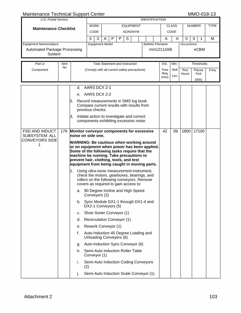
Maintenance Technical Support Center MMO-018-13 U.S. Postal Service IDENTIFICATION
Maintenance Checklist WORK
CODE
EQUIPMENT
ACRONYM
CLASS
CODE
NUMBER TYPE
0 3 A P P S A A 0 0 1 M
Equipment Nomenclature
Automated Package Processing System
Equipment Model
Bulletin Filename
mm12112AB
Occurrence
eCBM
Part or
Component
Item No
Task Statement and Instruction
(Comply with all current safety precautions)
Est.
Time Req (min)
Min.
Skill
Lev
Thresholds
Run Hours
Pieces Fed
(000)
Freq.
Attachment 2 103
d. AARS DCX 2-1
e. AARS DCX 2-2
2. Record measurements in SMS log book. Compare current results with results from previous checks.
3. Initiate action to investigate and correct components exhibiting excessive noise.
FSD AND INDUCT SUBSYSTEM: ALL CONVEYORS SIDE
1
179 Monitor conveyor components for excessive noise on side one.
WARNING: Be cautious when working around or on equipment when power has been applied. Some of the following tasks require that the machine be running. Take precautions to prevent hair, clothing, tools, and test equipment from being caught in moving parts.
1. Using ultra-sonic measurement instrument, check the motors, gearboxes, bearings, and rollers on the following conveyors. Remove covers as required to gain access to:
a. 90 Degree Incline and High Speed Conveyors (2)
b. Sync Module DX1-1 through DX1-4 and DX2-1 Conveyors (5)
c. Shoe Sorter Conveyor (1)
d. Recirculation Conveyor (1)
e. Rework Conveyor (1)
f. Auto-Induction 45 Degree Loading and Unloading Conveyers (6)
g. Auto-Induction Sync Conveyor (6)
h. Semi-Auto Induction Roller Table Conveyor (1)
i. Semi-Auto Induction Coding Conveyors (2)
j. Semi-Auto Induction Scale Conveyor (1)
42 09 1800 17100
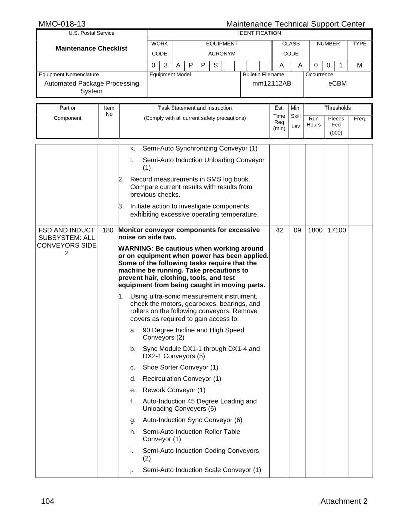
MMO-018-13 Maintenance Technical Support Center U.S. Postal Service IDENTIFICATION
Maintenance Checklist WORK
CODE
EQUIPMENT
ACRONYM
CLASS
CODE
NUMBER TYPE
0 3 A P P S A A 0 0 1 M
Equipment Nomenclature
Automated Package Processing System
Equipment Model
Bulletin Filename
mm12112AB
Occurrence
eCBM
Part or
Component
Item No
Task Statement and Instruction
(Comply with all current safety precautions)
Est.
Time Req (min)
Min.
Skill
Lev
Thresholds
Run Hours
Pieces Fed
(000)
Freq.
104 Attachment 2
k. Semi-Auto Synchronizing Conveyor (1)
l. Semi-Auto Induction Unloading Conveyor (1)
2. Record measurements in SMS log book. Compare current results with results from previous checks.
3. Initiate action to investigate components exhibiting excessive operating temperature.
FSD AND INDUCT SUBSYSTEM: ALL CONVEYORS SIDE
2
180 Monitor conveyor components for excessive noise on side two.
WARNING: Be cautious when working around or on equipment when power has been applied. Some of the following tasks require that the machine be running. Take precautions to prevent hair, clothing, tools, and test equipment from being caught in moving parts.
1. Using ultra-sonic measurement instrument, check the motors, gearboxes, bearings, and rollers on the following conveyors. Remove covers as required to gain access to:
a. 90 Degree Incline and High Speed Conveyors (2)
b. Sync Module DX1-1 through DX1-4 and DX2-1 Conveyors (5)
c. Shoe Sorter Conveyor (1)
d. Recirculation Conveyor (1)
e. Rework Conveyor (1)
f. Auto-Induction 45 Degree Loading and Unloading Conveyers (6)
g. Auto-Induction Sync Conveyor (6)
h. Semi-Auto Induction Roller Table Conveyor (1)
i. Semi-Auto Induction Coding Conveyors (2)
j. Semi-Auto Induction Scale Conveyor (1)
42 09 1800 17100
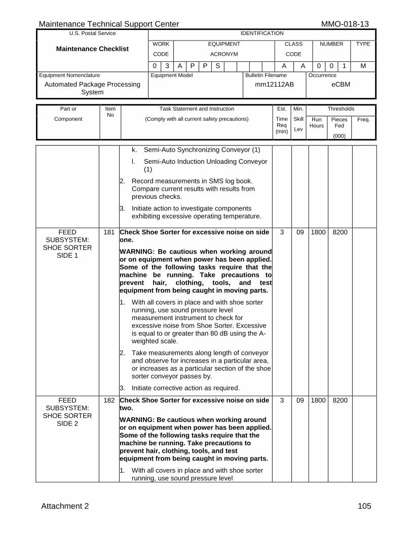
Maintenance Technical Support Center MMO-018-13 U.S. Postal Service IDENTIFICATION
Maintenance Checklist WORK
CODE
EQUIPMENT
ACRONYM
CLASS
CODE
NUMBER TYPE
0 3 A P P S A A 0 0 1 M
Equipment Nomenclature
Automated Package Processing System
Equipment Model
Bulletin Filename
mm12112AB
Occurrence
eCBM
Part or
Component
Item No
Task Statement and Instruction
(Comply with all current safety precautions)
Est.
Time Req (min)
Min.
Skill
Lev
Thresholds
Run Hours
Pieces Fed
(000)
Freq.
Attachment 2 105
k. Semi-Auto Synchronizing Conveyor (1)
l. Semi-Auto Induction Unloading Conveyor (1)
2. Record measurements in SMS log book. Compare current results with results from previous checks.
3. Initiate action to investigate components exhibiting excessive operating temperature.
FEED SUBSYSTEM:
SHOE SORTER SIDE 1
181 Check Shoe Sorter for excessive noise on side one.
WARNING: Be cautious when working around or on equipment when power has been applied. Some of the following tasks require that the machine be running. Take precautions to prevent hair, clothing, tools, and test equipment from being caught in moving parts.
1. With all covers in place and with shoe sorter running, use sound pressure level measurement instrument to check for excessive noise from Shoe Sorter. Excessive is equal to or greater than 80 dB using the A-weighted scale.
2. Take measurements along length of conveyor and observe for increases in a particular area, or increases as a particular section of the shoe sorter conveyor passes by.
3. Initiate corrective action as required.
3 09 1800 8200
FEED SUBSYSTEM:
SHOE SORTER SIDE 2
182 Check Shoe Sorter for excessive noise on side two.
WARNING: Be cautious when working around or on equipment when power has been applied. Some of the following tasks require that the machine be running. Take precautions to prevent hair, clothing, tools, and test equipment from being caught in moving parts.
1. With all covers in place and with shoe sorter running, use sound pressure level
3 09 1800 8200
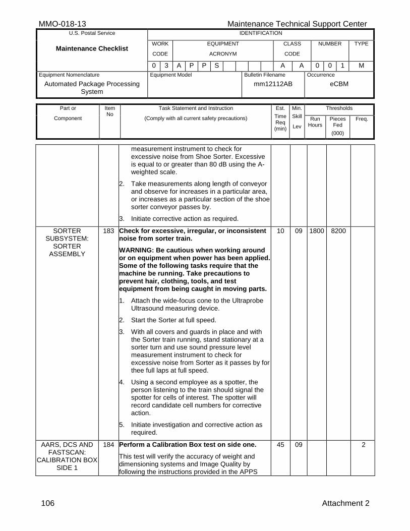
MMO-018-13 Maintenance Technical Support Center U.S. Postal Service IDENTIFICATION
Maintenance Checklist WORK
CODE
EQUIPMENT
ACRONYM
CLASS
CODE
NUMBER TYPE
0 3 A P P S A A 0 0 1 M
Equipment Nomenclature
Automated Package Processing System
Equipment Model
Bulletin Filename
mm12112AB
Occurrence
eCBM
Part or
Component
Item No
Task Statement and Instruction
(Comply with all current safety precautions)
Est.
Time Req (min)
Min.
Skill
Lev
Thresholds
Run Hours
Pieces Fed
(000)
Freq.
106 Attachment 2
measurement instrument to check for excessive noise from Shoe Sorter. Excessive is equal to or greater than 80 dB using the A-weighted scale.
2. Take measurements along length of conveyor and observe for increases in a particular area, or increases as a particular section of the shoe sorter conveyor passes by.
3. Initiate corrective action as required.
SORTER SUBSYSTEM:
SORTER ASSEMBLY
183 Check for excessive, irregular, or inconsistent noise from sorter train.
WARNING: Be cautious when working around or on equipment when power has been applied. Some of the following tasks require that the machine be running. Take precautions to prevent hair, clothing, tools, and test equipment from being caught in moving parts.
1. Attach the wide-focus cone to the Ultraprobe Ultrasound measuring device.
2. Start the Sorter at full speed.
3. With all covers and guards in place and with the Sorter train running, stand stationary at a sorter turn and use sound pressure level measurement instrument to check for excessive noise from Sorter as it passes by for thee full laps at full speed.
4. Using a second employee as a spotter, the person listening to the train should signal the spotter for cells of interest. The spotter will record candidate cell numbers for corrective action.
5. Initiate investigation and corrective action as required.
10 09 1800 8200
AARS, DCS AND FASTSCAN:
CALIBRATION BOX SIDE 1
184 Perform a Calibration Box test on side one.
This test will verify the accuracy of weight and dimensioning systems and Image Quality by following the instructions provided in the APPS
45 09 2
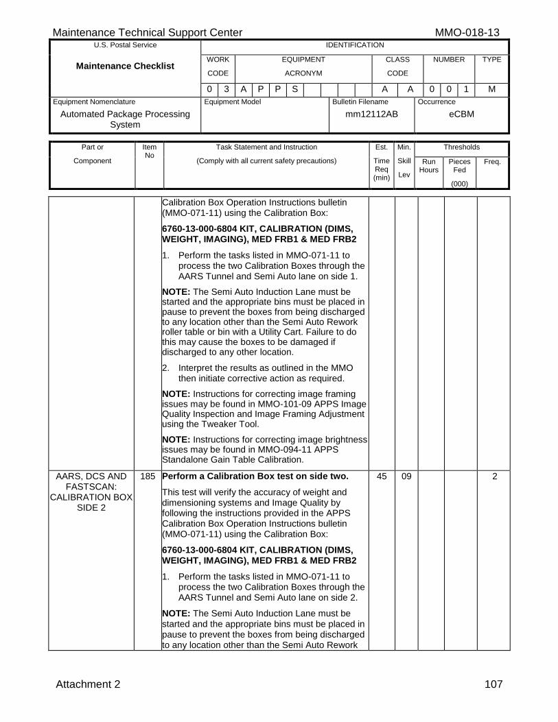
Maintenance Technical Support Center MMO-018-13 U.S. Postal Service IDENTIFICATION
Maintenance Checklist WORK
CODE
EQUIPMENT
ACRONYM
CLASS
CODE
NUMBER TYPE
0 3 A P P S A A 0 0 1 M
Equipment Nomenclature
Automated Package Processing System
Equipment Model
Bulletin Filename
mm12112AB
Occurrence
eCBM
Part or
Component
Item No
Task Statement and Instruction
(Comply with all current safety precautions)
Est.
Time Req (min)
Min.
Skill
Lev
Thresholds
Run Hours
Pieces Fed
(000)
Freq.
Attachment 2 107
Calibration Box Operation Instructions bulletin (MMO-071-11) using the Calibration Box:
6760-13-000-6804 KIT, CALIBRATION (DIMS, WEIGHT, IMAGING), MED FRB1 & MED FRB2
1. Perform the tasks listed in MMO-071-11 to process the two Calibration Boxes through the AARS Tunnel and Semi Auto lane on side 1.
NOTE: The Semi Auto Induction Lane must be started and the appropriate bins must be placed in pause to prevent the boxes from being discharged to any location other than the Semi Auto Rework roller table or bin with a Utility Cart. Failure to do this may cause the boxes to be damaged if discharged to any other location.
2. Interpret the results as outlined in the MMO then initiate corrective action as required.
NOTE: Instructions for correcting image framing issues may be found in MMO-101-09 APPS Image Quality Inspection and Image Framing Adjustment using the Tweaker Tool.
NOTE: Instructions for correcting image brightness issues may be found in MMO-094-11 APPS Standalone Gain Table Calibration.
AARS, DCS AND FASTSCAN:
CALIBRATION BOX SIDE 2
185 Perform a Calibration Box test on side two.
This test will verify the accuracy of weight and dimensioning systems and Image Quality by following the instructions provided in the APPS Calibration Box Operation Instructions bulletin (MMO-071-11) using the Calibration Box:
6760-13-000-6804 KIT, CALIBRATION (DIMS, WEIGHT, IMAGING), MED FRB1 & MED FRB2
1. Perform the tasks listed in MMO-071-11 to process the two Calibration Boxes through the AARS Tunnel and Semi Auto lane on side 2.
NOTE: The Semi Auto Induction Lane must be started and the appropriate bins must be placed in pause to prevent the boxes from being discharged to any location other than the Semi Auto Rework
45 09 2
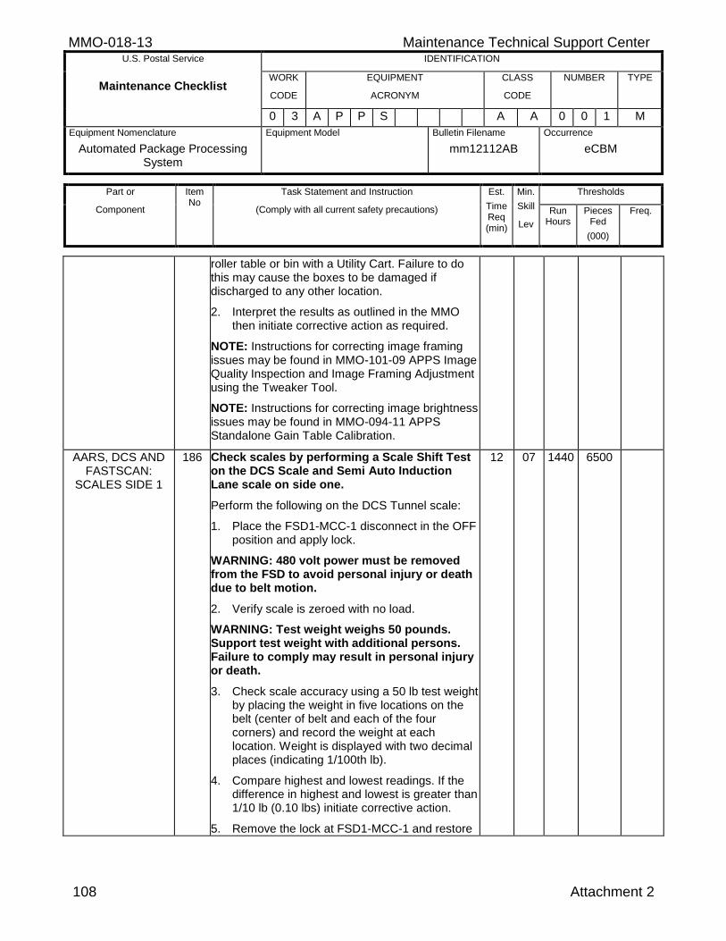
MMO-018-13 Maintenance Technical Support Center U.S. Postal Service IDENTIFICATION
Maintenance Checklist WORK
CODE
EQUIPMENT
ACRONYM
CLASS
CODE
NUMBER TYPE
0 3 A P P S A A 0 0 1 M
Equipment Nomenclature
Automated Package Processing System
Equipment Model
Bulletin Filename
mm12112AB
Occurrence
eCBM
Part or
Component
Item No
Task Statement and Instruction
(Comply with all current safety precautions)
Est.
Time Req (min)
Min.
Skill
Lev
Thresholds
Run Hours
Pieces Fed
(000)
Freq.
108 Attachment 2
roller table or bin with a Utility Cart. Failure to do this may cause the boxes to be damaged if discharged to any other location.
2. Interpret the results as outlined in the MMO then initiate corrective action as required.
NOTE: Instructions for correcting image framing issues may be found in MMO-101-09 APPS Image Quality Inspection and Image Framing Adjustment using the Tweaker Tool.
NOTE: Instructions for correcting image brightness issues may be found in MMO-094-11 APPS Standalone Gain Table Calibration.
AARS, DCS AND FASTSCAN:
SCALES SIDE 1
186 Check scales by performing a Scale Shift Test on the DCS Scale and Semi Auto Induction Lane scale on side one.
Perform the following on the DCS Tunnel scale:
1. Place the FSD1-MCC-1 disconnect in the OFF position and apply lock.
WARNING: 480 volt power must be removed from the FSD to avoid personal injury or death due to belt motion.
2. Verify scale is zeroed with no load.
WARNING: Test weight weighs 50 pounds. Support test weight with additional persons. Failure to comply may result in personal injury or death.
3. Check scale accuracy using a 50 lb test weight by placing the weight in five locations on the belt (center of belt and each of the four corners) and record the weight at each location. Weight is displayed with two decimal places (indicating 1/100th lb).
4. Compare highest and lowest readings. If the difference in highest and lowest is greater than 1/10 lb (0.10 lbs) initiate corrective action.
5. Remove the lock at FSD1-MCC-1 and restore
12 07 1440 6500
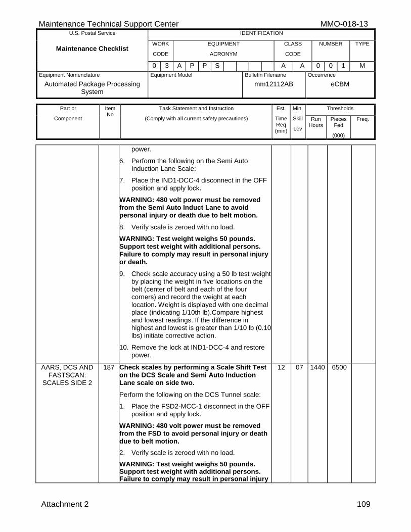
Maintenance Technical Support Center MMO-018-13 U.S. Postal Service IDENTIFICATION
Maintenance Checklist WORK
CODE
EQUIPMENT
ACRONYM
CLASS
CODE
NUMBER TYPE
0 3 A P P S A A 0 0 1 M
Equipment Nomenclature
Automated Package Processing System
Equipment Model
Bulletin Filename
mm12112AB
Occurrence
eCBM
Part or
Component
Item No
Task Statement and Instruction
(Comply with all current safety precautions)
Est.
Time Req (min)
Min.
Skill
Lev
Thresholds
Run Hours
Pieces Fed
(000)
Freq.
Attachment 2 109
power.
6. Perform the following on the Semi Auto Induction Lane Scale:
7. Place the IND1-DCC-4 disconnect in the OFF position and apply lock.
WARNING: 480 volt power must be removed from the Semi Auto Induct Lane to avoid personal injury or death due to belt motion.
8. Verify scale is zeroed with no load.
WARNING: Test weight weighs 50 pounds. Support test weight with additional persons. Failure to comply may result in personal injury or death.
9. Check scale accuracy using a 50 lb test weight by placing the weight in five locations on the belt (center of belt and each of the four corners) and record the weight at each location. Weight is displayed with one decimal place (indicating 1/10th lb).Compare highest and lowest readings. If the difference in highest and lowest is greater than 1/10 lb (0.10 lbs) initiate corrective action.
10. Remove the lock at IND1-DCC-4 and restore power.
AARS, DCS AND FASTSCAN:
SCALES SIDE 2
187 Check scales by performing a Scale Shift Test on the DCS Scale and Semi Auto Induction Lane scale on side two.
Perform the following on the DCS Tunnel scale:
1. Place the FSD2-MCC-1 disconnect in the OFF position and apply lock.
WARNING: 480 volt power must be removed from the FSD to avoid personal injury or death due to belt motion.
2. Verify scale is zeroed with no load.
WARNING: Test weight weighs 50 pounds. Support test weight with additional persons. Failure to comply may result in personal injury
12 07 1440 6500
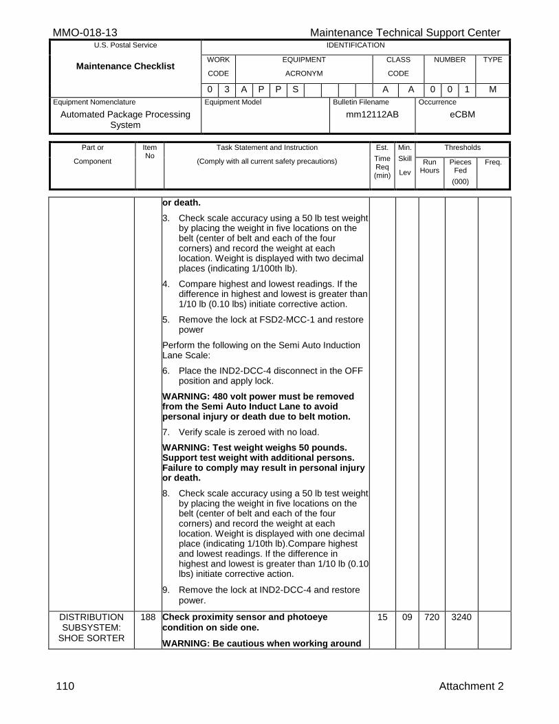
MMO-018-13 Maintenance Technical Support Center U.S. Postal Service IDENTIFICATION
Maintenance Checklist WORK
CODE
EQUIPMENT
ACRONYM
CLASS
CODE
NUMBER TYPE
0 3 A P P S A A 0 0 1 M
Equipment Nomenclature
Automated Package Processing System
Equipment Model
Bulletin Filename
mm12112AB
Occurrence
eCBM
Part or
Component
Item No
Task Statement and Instruction
(Comply with all current safety precautions)
Est.
Time Req (min)
Min.
Skill
Lev
Thresholds
Run Hours
Pieces Fed
(000)
Freq.
110 Attachment 2
or death.
3. Check scale accuracy using a 50 lb test weight by placing the weight in five locations on the belt (center of belt and each of the four corners) and record the weight at each location. Weight is displayed with two decimal places (indicating 1/100th lb).
4. Compare highest and lowest readings. If the difference in highest and lowest is greater than 1/10 lb (0.10 lbs) initiate corrective action.
5. Remove the lock at FSD2-MCC-1 and restore power
Perform the following on the Semi Auto Induction Lane Scale:
6. Place the IND2-DCC-4 disconnect in the OFF position and apply lock.
WARNING: 480 volt power must be removed from the Semi Auto Induct Lane to avoid personal injury or death due to belt motion.
7. Verify scale is zeroed with no load.
WARNING: Test weight weighs 50 pounds. Support test weight with additional persons. Failure to comply may result in personal injury or death.
8. Check scale accuracy using a 50 lb test weight by placing the weight in five locations on the belt (center of belt and each of the four corners) and record the weight at each location. Weight is displayed with one decimal place (indicating 1/10th lb).Compare highest and lowest readings. If the difference in highest and lowest is greater than 1/10 lb (0.10 lbs) initiate corrective action.
9. Remove the lock at IND2-DCC-4 and restore power.
DISTRIBUTION SUBSYSTEM:
SHOE SORTER
188 Check proximity sensor and photoeye condition on side one.
WARNING: Be cautious when working around
15 09 720 3240
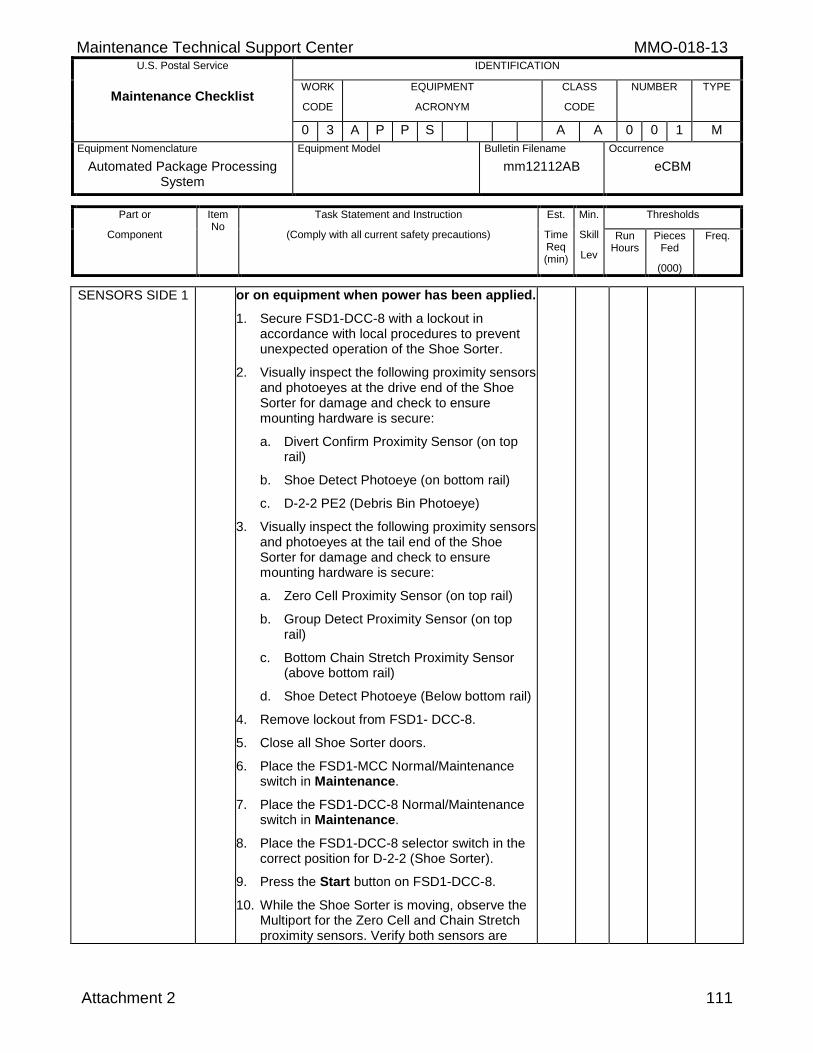
Maintenance Technical Support Center MMO-018-13 U.S. Postal Service IDENTIFICATION
Maintenance Checklist WORK
CODE
EQUIPMENT
ACRONYM
CLASS
CODE
NUMBER TYPE
0 3 A P P S A A 0 0 1 M
Equipment Nomenclature
Automated Package Processing System
Equipment Model
Bulletin Filename
mm12112AB
Occurrence
eCBM
Part or
Component
Item No
Task Statement and Instruction
(Comply with all current safety precautions)
Est.
Time Req (min)
Min.
Skill
Lev
Thresholds
Run Hours
Pieces Fed
(000)
Freq.
Attachment 2 111
SENSORS SIDE 1 or on equipment when power has been applied.
1. Secure FSD1-DCC-8 with a lockout in accordance with local procedures to prevent unexpected operation of the Shoe Sorter.
2. Visually inspect the following proximity sensors and photoeyes at the drive end of the Shoe Sorter for damage and check to ensure mounting hardware is secure:
a. Divert Confirm Proximity Sensor (on top rail)
b. Shoe Detect Photoeye (on bottom rail)
c. D-2-2 PE2 (Debris Bin Photoeye)
3. Visually inspect the following proximity sensors and photoeyes at the tail end of the Shoe Sorter for damage and check to ensure mounting hardware is secure:
a. Zero Cell Proximity Sensor (on top rail)
b. Group Detect Proximity Sensor (on top rail)
c. Bottom Chain Stretch Proximity Sensor (above bottom rail)
d. Shoe Detect Photoeye (Below bottom rail)
4. Remove lockout from FSD1- DCC-8.
5. Close all Shoe Sorter doors.
6. Place the FSD1-MCC Normal/Maintenance switch in Maintenance.
7. Place the FSD1-DCC-8 Normal/Maintenance switch in Maintenance.
8. Place the FSD1-DCC-8 selector switch in the correct position for D-2-2 (Shoe Sorter).
9. Press the Start button on FSD1-DCC-8.
10. While the Shoe Sorter is moving, observe the Multiport for the Zero Cell and Chain Stretch proximity sensors. Verify both sensors are
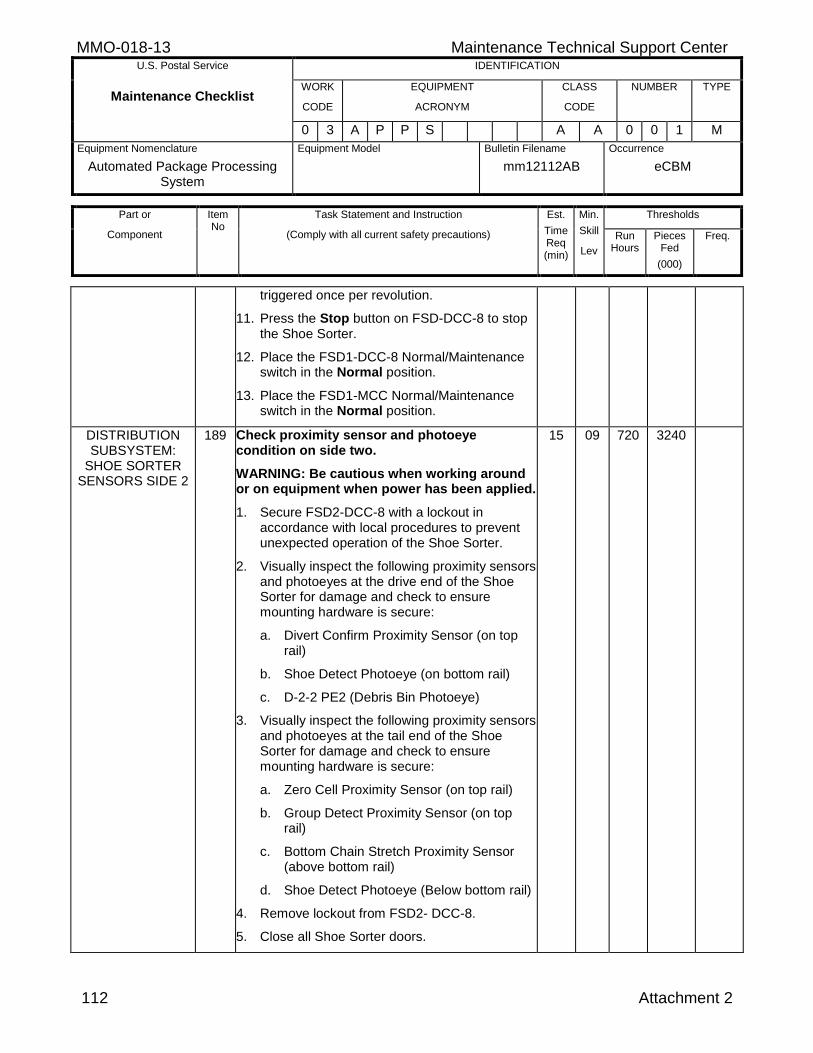
MMO-018-13 Maintenance Technical Support Center U.S. Postal Service IDENTIFICATION
Maintenance Checklist WORK
CODE
EQUIPMENT
ACRONYM
CLASS
CODE
NUMBER TYPE
0 3 A P P S A A 0 0 1 M
Equipment Nomenclature
Automated Package Processing System
Equipment Model
Bulletin Filename
mm12112AB
Occurrence
eCBM
Part or
Component
Item No
Task Statement and Instruction
(Comply with all current safety precautions)
Est.
Time Req (min)
Min.
Skill
Lev
Thresholds
Run Hours
Pieces Fed
(000)
Freq.
112 Attachment 2
triggered once per revolution.
11. Press the Stop button on FSD-DCC-8 to stop the Shoe Sorter.
12. Place the FSD1-DCC-8 Normal/Maintenance switch in the Normal position.
13. Place the FSD1-MCC Normal/Maintenance switch in the Normal position.
DISTRIBUTION SUBSYSTEM:
SHOE SORTER SENSORS SIDE 2
189 Check proximity sensor and photoeye condition on side two.
WARNING: Be cautious when working around or on equipment when power has been applied.
1. Secure FSD2-DCC-8 with a lockout in accordance with local procedures to prevent unexpected operation of the Shoe Sorter.
2. Visually inspect the following proximity sensors and photoeyes at the drive end of the Shoe Sorter for damage and check to ensure mounting hardware is secure:
a. Divert Confirm Proximity Sensor (on top rail)
b. Shoe Detect Photoeye (on bottom rail)
c. D-2-2 PE2 (Debris Bin Photoeye)
3. Visually inspect the following proximity sensors and photoeyes at the tail end of the Shoe Sorter for damage and check to ensure mounting hardware is secure:
a. Zero Cell Proximity Sensor (on top rail)
b. Group Detect Proximity Sensor (on top rail)
c. Bottom Chain Stretch Proximity Sensor (above bottom rail)
d. Shoe Detect Photoeye (Below bottom rail)
4. Remove lockout from FSD2- DCC-8.
5. Close all Shoe Sorter doors.
15 09 720 3240
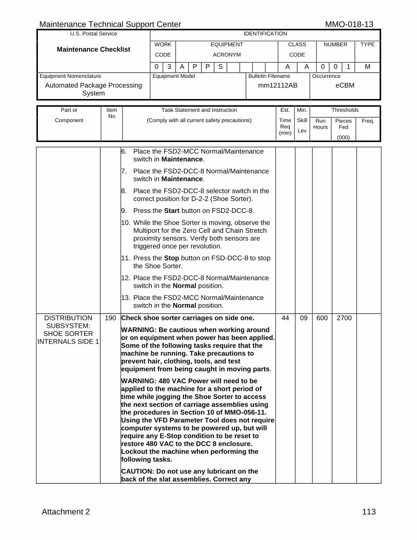
Maintenance Technical Support Center MMO-018-13 U.S. Postal Service IDENTIFICATION
Maintenance Checklist WORK
CODE
EQUIPMENT
ACRONYM
CLASS
CODE
NUMBER TYPE
0 3 A P P S A A 0 0 1 M
Equipment Nomenclature
Automated Package Processing System
Equipment Model
Bulletin Filename
mm12112AB
Occurrence
eCBM
Part or
Component
Item No
Task Statement and Instruction
(Comply with all current safety precautions)
Est.
Time Req (min)
Min.
Skill
Lev
Thresholds
Run Hours
Pieces Fed
(000)
Freq.
Attachment 2 113
6. Place the FSD2-MCC Normal/Maintenance switch in Maintenance.
7. Place the FSD2-DCC-8 Normal/Maintenance switch in Maintenance.
8. Place the FSD2-DCC-8 selector switch in the correct position for D-2-2 (Shoe Sorter).
9. Press the Start button on FSD2-DCC-8.
10. While the Shoe Sorter is moving, observe the Multiport for the Zero Cell and Chain Stretch proximity sensors. Verify both sensors are triggered once per revolution.
11. Press the Stop button on FSD-DCC-8 to stop the Shoe Sorter.
12. Place the FSD2-DCC-8 Normal/Maintenance switch in the Normal position.
13. Place the FSD2-MCC Normal/Maintenance switch in the Normal position.
DISTRIBUTION SUBSYSTEM:
SHOE SORTER INTERNALS SIDE 1
190 Check shoe sorter carriages on side one.
WARNING: Be cautious when working around or on equipment when power has been applied. Some of the following tasks require that the machine be running. Take precautions to prevent hair, clothing, tools, and test equipment from being caught in moving parts.
WARNING: 480 VAC Power will need to be applied to the machine for a short period of time while jogging the Shoe Sorter to access the next section of carriage assemblies using the procedures in Section 10 of MMO-056-11. Using the VFD Parameter Tool does not require computer systems to be powered up, but will require any E-Stop condition to be reset to restore 480 VAC to the DCC 8 enclosure. Lockout the machine when performing the following tasks.
CAUTION: Do not use any lubricant on the back of the slat assemblies. Correct any
44 09 600 2700
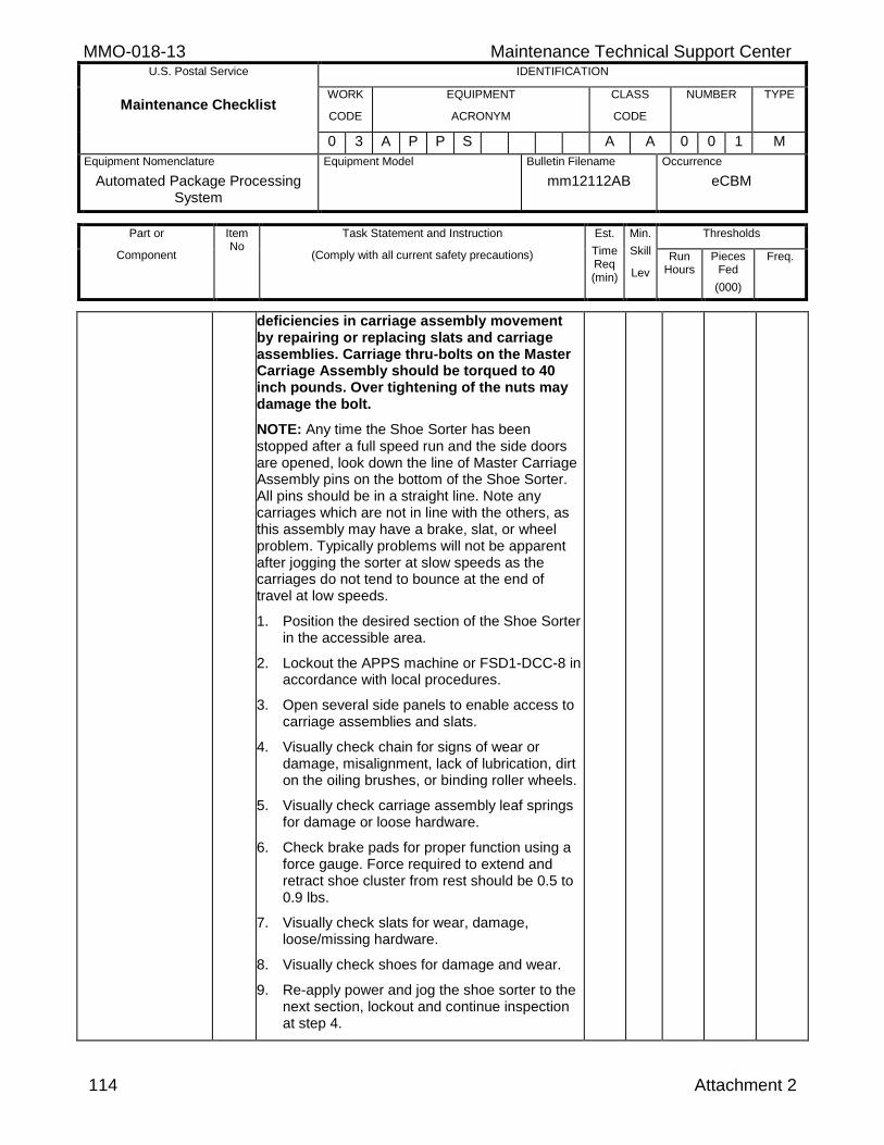
MMO-018-13 Maintenance Technical Support Center U.S. Postal Service IDENTIFICATION
Maintenance Checklist WORK
CODE
EQUIPMENT
ACRONYM
CLASS
CODE
NUMBER TYPE
0 3 A P P S A A 0 0 1 M
Equipment Nomenclature
Automated Package Processing System
Equipment Model
Bulletin Filename
mm12112AB
Occurrence
eCBM
Part or
Component
Item No
Task Statement and Instruction
(Comply with all current safety precautions)
Est.
Time Req (min)
Min.
Skill
Lev
Thresholds
Run Hours
Pieces Fed
(000)
Freq.
114 Attachment 2
deficiencies in carriage assembly movement by repairing or replacing slats and carriage assemblies. Carriage thru-bolts on the Master Carriage Assembly should be torqued to 40 inch pounds. Over tightening of the nuts may damage the bolt.
NOTE: Any time the Shoe Sorter has been stopped after a full speed run and the side doors are opened, look down the line of Master Carriage Assembly pins on the bottom of the Shoe Sorter. All pins should be in a straight line. Note any carriages which are not in line with the others, as this assembly may have a brake, slat, or wheel problem. Typically problems will not be apparent after jogging the sorter at slow speeds as the carriages do not tend to bounce at the end of travel at low speeds.
1. Position the desired section of the Shoe Sorter in the accessible area.
2. Lockout the APPS machine or FSD1-DCC-8 in accordance with local procedures.
3. Open several side panels to enable access to carriage assemblies and slats.
4. Visually check chain for signs of wear or damage, misalignment, lack of lubrication, dirt on the oiling brushes, or binding roller wheels.
5. Visually check carriage assembly leaf springs for damage or loose hardware.
6. Check brake pads for proper function using a force gauge. Force required to extend and retract shoe cluster from rest should be 0.5 to 0.9 lbs.
7. Visually check slats for wear, damage, loose/missing hardware.
8. Visually check shoes for damage and wear.
9. Re-apply power and jog the shoe sorter to the next section, lockout and continue inspection at step 4.
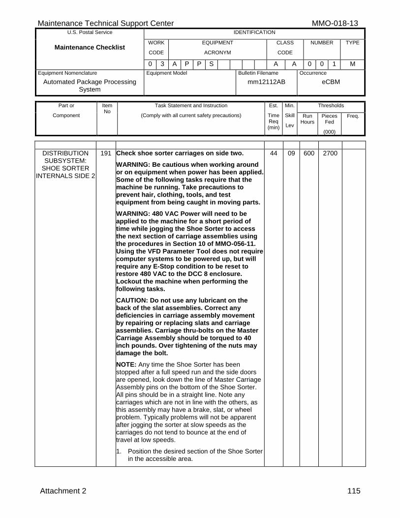
Maintenance Technical Support Center MMO-018-13 U.S. Postal Service IDENTIFICATION
Maintenance Checklist WORK
CODE
EQUIPMENT
ACRONYM
CLASS
CODE
NUMBER TYPE
0 3 A P P S A A 0 0 1 M
Equipment Nomenclature
Automated Package Processing System
Equipment Model
Bulletin Filename
mm12112AB
Occurrence
eCBM
Part or
Component
Item No
Task Statement and Instruction
(Comply with all current safety precautions)
Est.
Time Req (min)
Min.
Skill
Lev
Thresholds
Run Hours
Pieces Fed
(000)
Freq.
Attachment 2 115
DISTRIBUTION SUBSYSTEM:
SHOE SORTER INTERNALS SIDE 2
191 Check shoe sorter carriages on side two.
WARNING: Be cautious when working around or on equipment when power has been applied. Some of the following tasks require that the machine be running. Take precautions to prevent hair, clothing, tools, and test equipment from being caught in moving parts.
WARNING: 480 VAC Power will need to be applied to the machine for a short period of time while jogging the Shoe Sorter to access the next section of carriage assemblies using the procedures in Section 10 of MMO-056-11. Using the VFD Parameter Tool does not require computer systems to be powered up, but will require any E-Stop condition to be reset to restore 480 VAC to the DCC 8 enclosure. Lockout the machine when performing the following tasks.
CAUTION: Do not use any lubricant on the back of the slat assemblies. Correct any deficiencies in carriage assembly movement by repairing or replacing slats and carriage assemblies. Carriage thru-bolts on the Master Carriage Assembly should be torqued to 40 inch pounds. Over tightening of the nuts may damage the bolt.
NOTE: Any time the Shoe Sorter has been stopped after a full speed run and the side doors are opened, look down the line of Master Carriage Assembly pins on the bottom of the Shoe Sorter. All pins should be in a straight line. Note any carriages which are not in line with the others, as this assembly may have a brake, slat, or wheel problem. Typically problems will not be apparent after jogging the sorter at slow speeds as the carriages do not tend to bounce at the end of travel at low speeds.
1. Position the desired section of the Shoe Sorter in the accessible area.
44 09 600 2700
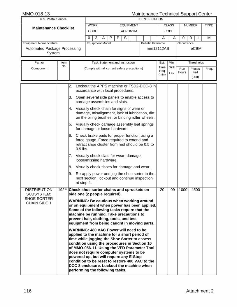
MMO-018-13 Maintenance Technical Support Center U.S. Postal Service IDENTIFICATION
Maintenance Checklist WORK
CODE
EQUIPMENT
ACRONYM
CLASS
CODE
NUMBER TYPE
0 3 A P P S A A 0 0 1 M
Equipment Nomenclature
Automated Package Processing System
Equipment Model
Bulletin Filename
mm12112AB
Occurrence
eCBM
Part or
Component
Item No
Task Statement and Instruction
(Comply with all current safety precautions)
Est.
Time Req (min)
Min.
Skill
Lev
Thresholds
Run Hours
Pieces Fed
(000)
Freq.
116 Attachment 2
2. Lockout the APPS machine or FSD2-DCC-8 in accordance with local procedures.
3. Open several side panels to enable access to carriage assemblies and slats.
4. Visually check chain for signs of wear or damage, misalignment, lack of lubrication, dirt on the oiling brushes, or binding roller wheels.
5. Visually check carriage assembly leaf springs for damage or loose hardware.
6. Check brake pads for proper function using a force gauge. Force required to extend and retract shoe cluster from rest should be 0.5 to 0.9 lbs.
7. Visually check slats for wear, damage, loose/missing hardware.
8. Visually check shoes for damage and wear.
9. Re-apply power and jog the shoe sorter to the next section, lockout and continue inspection at step 4.
DISTRIBUTION SUBSYSTEM:
SHOE SORTER CHAIN SIDE 1
192** Check shoe sorter chains and sprockets on side one (2 people required).
WARNING: Be cautious when working around or on equipment when power has been applied. Some of the following tasks require that the machine be running. Take precautions to prevent hair, clothing, tools, and test equipment from being caught in moving parts.
WARNING: 480 VAC Power will need to be applied to the machine for a short period of time while jogging the Shoe Sorter to assess condition using the procedures in Section 10 of MMO-056-11. Using the VFD Parameter Tool does not require computer systems to be powered up, but will require any E-Stop condition to be reset to restore 480 VAC to the DCC 8 enclosure. Lockout the machine when performing the following tasks.
20 09 1000 4500
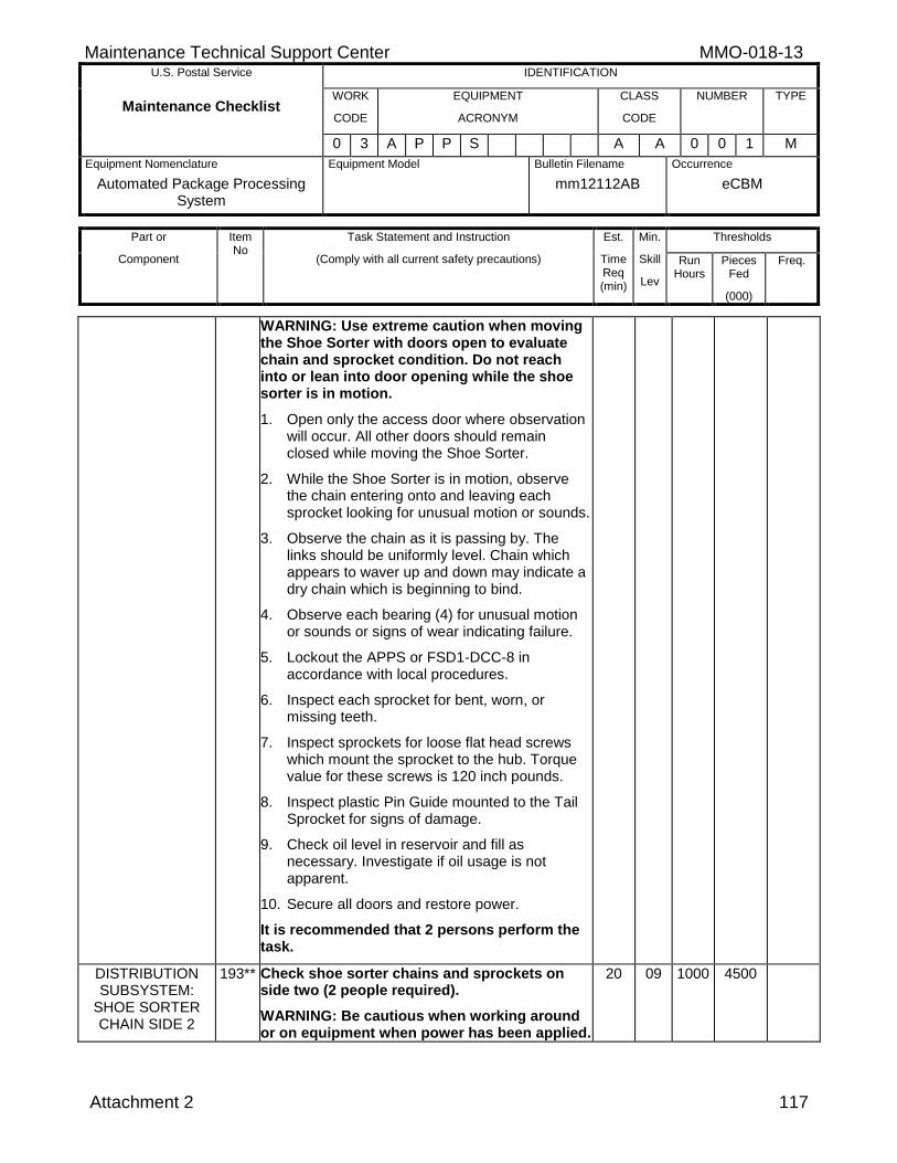
Maintenance Technical Support Center MMO-018-13 U.S. Postal Service IDENTIFICATION
Maintenance Checklist WORK
CODE
EQUIPMENT
ACRONYM
CLASS
CODE
NUMBER TYPE
0 3 A P P S A A 0 0 1 M
Equipment Nomenclature
Automated Package Processing System
Equipment Model
Bulletin Filename
mm12112AB
Occurrence
eCBM
Part or
Component
Item No
Task Statement and Instruction
(Comply with all current safety precautions)
Est.
Time Req (min)
Min.
Skill
Lev
Thresholds
Run Hours
Pieces Fed
(000)
Freq.
Attachment 2 117
WARNING: Use extreme caution when moving the Shoe Sorter with doors open to evaluate chain and sprocket condition. Do not reach into or lean into door opening while the shoe sorter is in motion.
1. Open only the access door where observation will occur. All other doors should remain closed while moving the Shoe Sorter.
2. While the Shoe Sorter is in motion, observe the chain entering onto and leaving each sprocket looking for unusual motion or sounds.
3. Observe the chain as it is passing by. The links should be uniformly level. Chain which appears to waver up and down may indicate a dry chain which is beginning to bind.
4. Observe each bearing (4) for unusual motion or sounds or signs of wear indicating failure.
5. Lockout the APPS or FSD1-DCC-8 in accordance with local procedures.
6. Inspect each sprocket for bent, worn, or missing teeth.
7. Inspect sprockets for loose flat head screws which mount the sprocket to the hub. Torque value for these screws is 120 inch pounds.
8. Inspect plastic Pin Guide mounted to the Tail Sprocket for signs of damage.
9. Check oil level in reservoir and fill as necessary. Investigate if oil usage is not apparent.
10. Secure all doors and restore power.
It is recommended that 2 persons perform the task.
DISTRIBUTION SUBSYSTEM:
SHOE SORTER CHAIN SIDE 2
193** Check shoe sorter chains and sprockets on side two (2 people required).
WARNING: Be cautious when working around or on equipment when power has been applied.
20 09 1000 4500
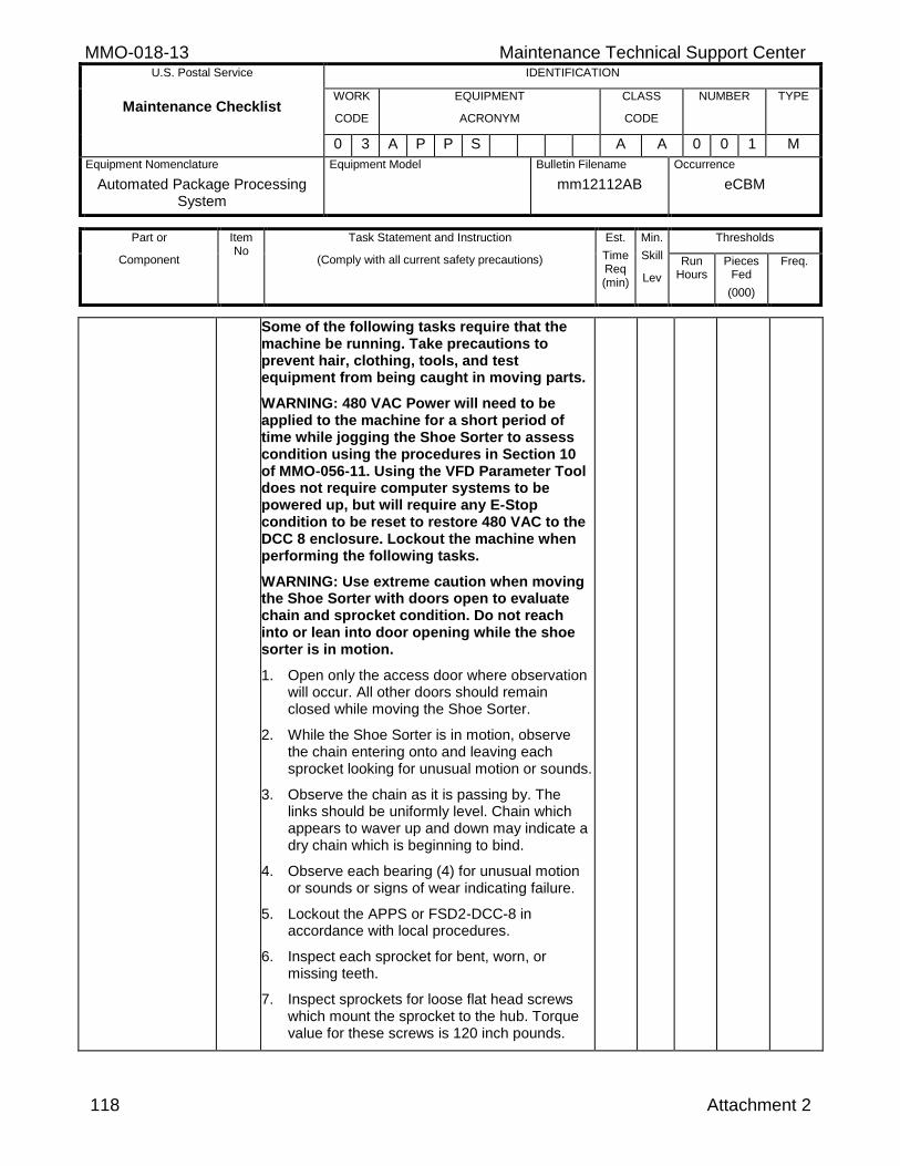
MMO-018-13 Maintenance Technical Support Center U.S. Postal Service IDENTIFICATION
Maintenance Checklist WORK
CODE
EQUIPMENT
ACRONYM
CLASS
CODE
NUMBER TYPE
0 3 A P P S A A 0 0 1 M
Equipment Nomenclature
Automated Package Processing System
Equipment Model
Bulletin Filename
mm12112AB
Occurrence
eCBM
Part or
Component
Item No
Task Statement and Instruction
(Comply with all current safety precautions)
Est.
Time Req (min)
Min.
Skill
Lev
Thresholds
Run Hours
Pieces Fed
(000)
Freq.
118 Attachment 2
Some of the following tasks require that the machine be running. Take precautions to prevent hair, clothing, tools, and test equipment from being caught in moving parts.
WARNING: 480 VAC Power will need to be applied to the machine for a short period of time while jogging the Shoe Sorter to assess condition using the procedures in Section 10 of MMO-056-11. Using the VFD Parameter Tool does not require computer systems to be powered up, but will require any E-Stop condition to be reset to restore 480 VAC to the DCC 8 enclosure. Lockout the machine when performing the following tasks.
WARNING: Use extreme caution when moving the Shoe Sorter with doors open to evaluate chain and sprocket condition. Do not reach into or lean into door opening while the shoe sorter is in motion.
1. Open only the access door where observation will occur. All other doors should remain closed while moving the Shoe Sorter.
2. While the Shoe Sorter is in motion, observe the chain entering onto and leaving each sprocket looking for unusual motion or sounds.
3. Observe the chain as it is passing by. The links should be uniformly level. Chain which appears to waver up and down may indicate a dry chain which is beginning to bind.
4. Observe each bearing (4) for unusual motion or sounds or signs of wear indicating failure.
5. Lockout the APPS or FSD2-DCC-8 in accordance with local procedures.
6. Inspect each sprocket for bent, worn, or missing teeth.
7. Inspect sprockets for loose flat head screws which mount the sprocket to the hub. Torque value for these screws is 120 inch pounds.
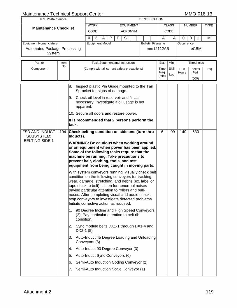
Maintenance Technical Support Center MMO-018-13 U.S. Postal Service IDENTIFICATION
Maintenance Checklist WORK
CODE
EQUIPMENT
ACRONYM
CLASS
CODE
NUMBER TYPE
0 3 A P P S A A 0 0 1 M
Equipment Nomenclature
Automated Package Processing System
Equipment Model
Bulletin Filename
mm12112AB
Occurrence
eCBM
Part or
Component
Item No
Task Statement and Instruction
(Comply with all current safety precautions)
Est.
Time Req (min)
Min.
Skill
Lev
Thresholds
Run Hours
Pieces Fed
(000)
Freq.
Attachment 2 119
8. Inspect plastic Pin Guide mounted to the Tail Sprocket for signs of damage.
9. Check oil level in reservoir and fill as necessary. Investigate if oil usage is not apparent.
10. Secure all doors and restore power.
It is recommended that 2 persons perform the task.
FSD AND INDUCT SUBSYSTEM:
BELTING SIDE 1
194 Check belting condition on side one (turn thru Inducts).
WARNING: Be cautious when working around or on equipment when power has been applied. Some of the following tasks require that the machine be running. Take precautions to prevent hair, clothing, tools, and test equipment from being caught in moving parts.
With system conveyors running, visually check belt condition on the following conveyors for tracking, wear, damage, stretching, and debris (ex. label or tape stuck to belt). Listen for abnormal noises paying particular attention to rollers and bull-noses. After completing visual and audio check, stop conveyors to investigate detected problems. Initiate corrective action as required:
1. 90 Degree Incline and High Speed Conveyors (2). Pay particular attention to belt rib condition.
2. Sync module belts DX1-1 through DX1-4 and DX2-1 (5)
3. Auto-Induct 45 Degree Loading and Unloading Conveyors (6)
4. Auto-Induct 90 Degree Conveyor (3)
5. Auto-Induct Sync Conveyors (6)
6. Semi-Auto Induction Coding Conveyor (2)
7. Semi-Auto Induction Scale Conveyor (1)
6 09 140 630
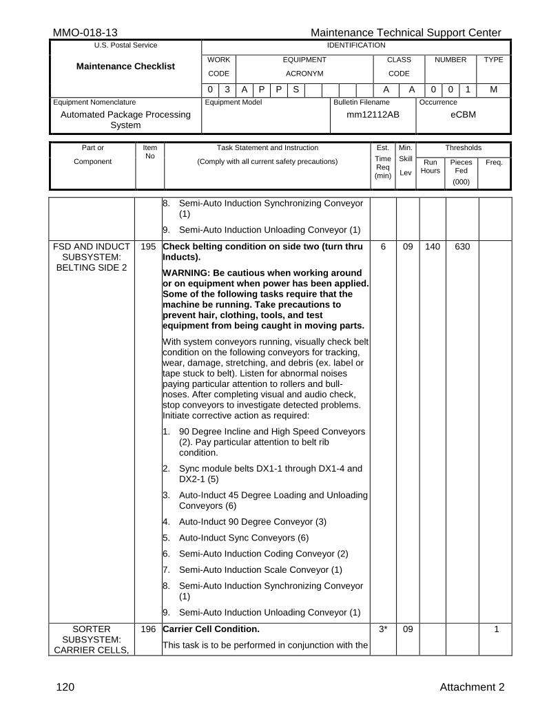
MMO-018-13 Maintenance Technical Support Center U.S. Postal Service IDENTIFICATION
Maintenance Checklist WORK
CODE
EQUIPMENT
ACRONYM
CLASS
CODE
NUMBER TYPE
0 3 A P P S A A 0 0 1 M
Equipment Nomenclature
Automated Package Processing System
Equipment Model
Bulletin Filename
mm12112AB
Occurrence
eCBM
Part or
Component
Item No
Task Statement and Instruction
(Comply with all current safety precautions)
Est.
Time Req (min)
Min.
Skill
Lev
Thresholds
Run Hours
Pieces Fed
(000)
Freq.
120 Attachment 2
8. Semi-Auto Induction Synchronizing Conveyor (1)
9. Semi-Auto Induction Unloading Conveyor (1)
FSD AND INDUCT SUBSYSTEM:
BELTING SIDE 2
195 Check belting condition on side two (turn thru Inducts).
WARNING: Be cautious when working around or on equipment when power has been applied. Some of the following tasks require that the machine be running. Take precautions to prevent hair, clothing, tools, and test equipment from being caught in moving parts.
With system conveyors running, visually check belt condition on the following conveyors for tracking, wear, damage, stretching, and debris (ex. label or tape stuck to belt). Listen for abnormal noises paying particular attention to rollers and bull-noses. After completing visual and audio check, stop conveyors to investigate detected problems. Initiate corrective action as required:
1. 90 Degree Incline and High Speed Conveyors (2). Pay particular attention to belt rib condition.
2. Sync module belts DX1-1 through DX1-4 and DX2-1 (5)
3. Auto-Induct 45 Degree Loading and Unloading Conveyors (6)
4. Auto-Induct 90 Degree Conveyor (3)
5. Auto-Induct Sync Conveyors (6)
6. Semi-Auto Induction Coding Conveyor (2)
7. Semi-Auto Induction Scale Conveyor (1)
8. Semi-Auto Induction Synchronizing Conveyor (1)
9. Semi-Auto Induction Unloading Conveyor (1)
6 09 140 630
SORTER SUBSYSTEM:
CARRIER CELLS,
196 Carrier Cell Condition.
This task is to be performed in conjunction with the
3* 09 1
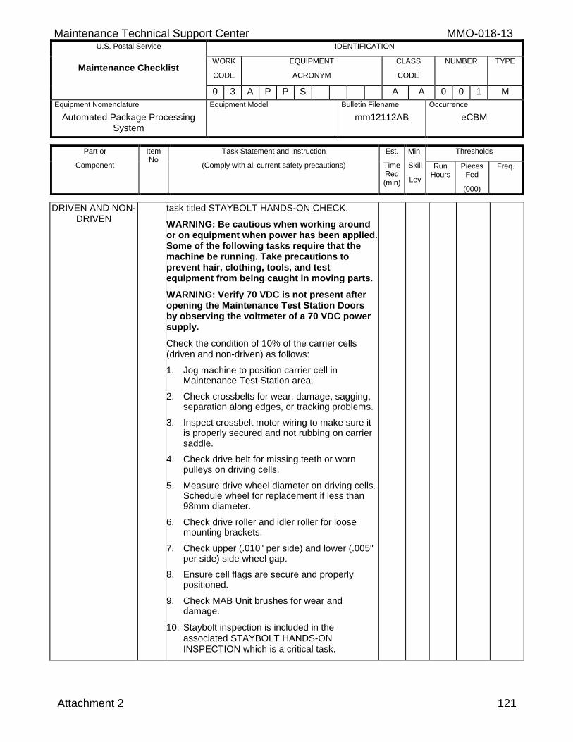
Maintenance Technical Support Center MMO-018-13 U.S. Postal Service IDENTIFICATION
Maintenance Checklist WORK
CODE
EQUIPMENT
ACRONYM
CLASS
CODE
NUMBER TYPE
0 3 A P P S A A 0 0 1 M
Equipment Nomenclature
Automated Package Processing System
Equipment Model
Bulletin Filename
mm12112AB
Occurrence
eCBM
Part or
Component
Item No
Task Statement and Instruction
(Comply with all current safety precautions)
Est.
Time Req (min)
Min.
Skill
Lev
Thresholds
Run Hours
Pieces Fed
(000)
Freq.
Attachment 2 121
DRIVEN AND NON-DRIVEN
task titled STAYBOLT HANDS-ON CHECK.
WARNING: Be cautious when working around or on equipment when power has been applied. Some of the following tasks require that the machine be running. Take precautions to prevent hair, clothing, tools, and test equipment from being caught in moving parts.
WARNING: Verify 70 VDC is not present after opening the Maintenance Test Station Doors by observing the voltmeter of a 70 VDC power supply.
Check the condition of 10% of the carrier cells (driven and non-driven) as follows:
1. Jog machine to position carrier cell in Maintenance Test Station area.
2. Check crossbelts for wear, damage, sagging, separation along edges, or tracking problems.
3. Inspect crossbelt motor wiring to make sure it is properly secured and not rubbing on carrier saddle.
4. Check drive belt for missing teeth or worn pulleys on driving cells.
5. Measure drive wheel diameter on driving cells. Schedule wheel for replacement if less than 98mm diameter.
6. Check drive roller and idler roller for loose mounting brackets.
7. Check upper (.010" per side) and lower (.005" per side) side wheel gap.
8. Ensure cell flags are secure and properly positioned.
9. Check MAB Unit brushes for wear and damage.
10. Staybolt inspection is included in the associated STAYBOLT HANDS-ON INSPECTION which is a critical task.
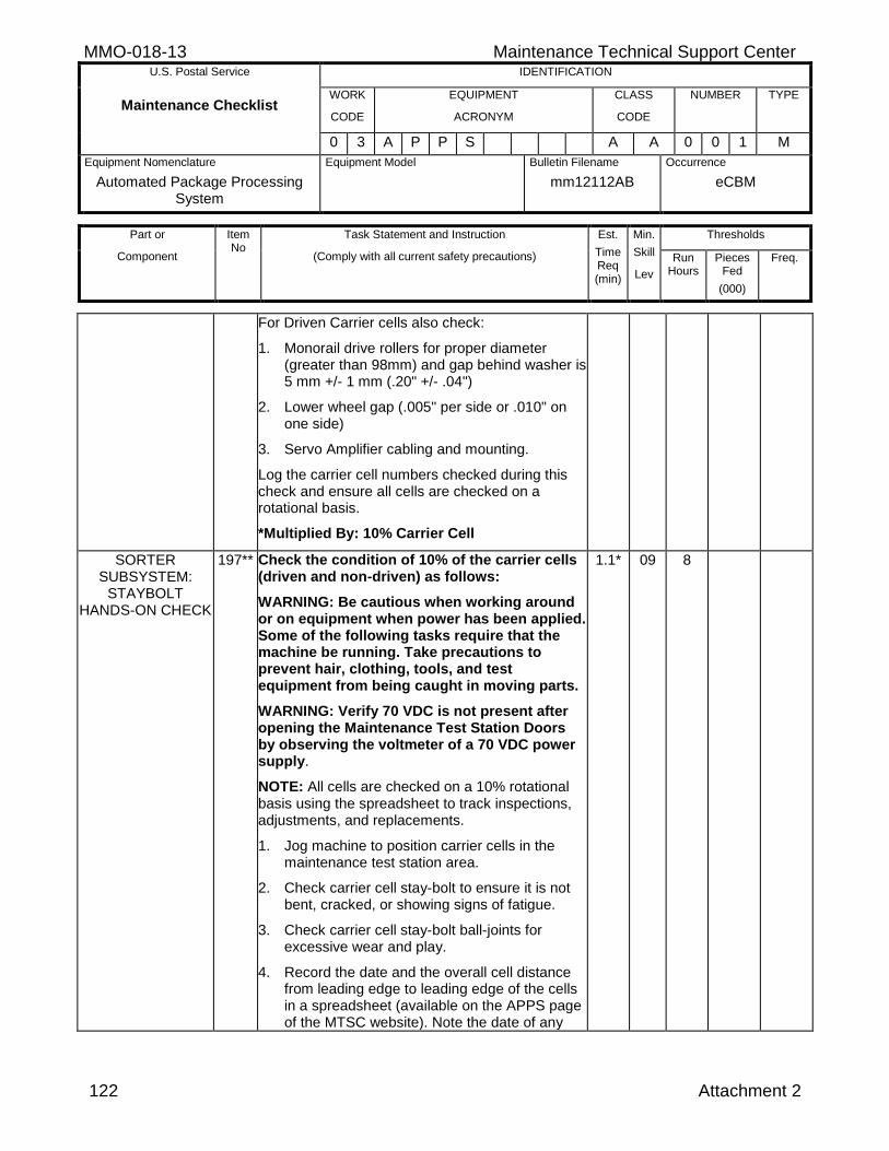
MMO-018-13 Maintenance Technical Support Center U.S. Postal Service IDENTIFICATION
Maintenance Checklist WORK
CODE
EQUIPMENT
ACRONYM
CLASS
CODE
NUMBER TYPE
0 3 A P P S A A 0 0 1 M
Equipment Nomenclature
Automated Package Processing System
Equipment Model
Bulletin Filename
mm12112AB
Occurrence
eCBM
Part or
Component
Item No
Task Statement and Instruction
(Comply with all current safety precautions)
Est.
Time Req (min)
Min.
Skill
Lev
Thresholds
Run Hours
Pieces Fed
(000)
Freq.
122 Attachment 2
For Driven Carrier cells also check:
1. Monorail drive rollers for proper diameter (greater than 98mm) and gap behind washer is 5 mm +/- 1 mm (.20" +/- .04")
2. Lower wheel gap (.005" per side or .010" on one side)
3. Servo Amplifier cabling and mounting.
Log the carrier cell numbers checked during this check and ensure all cells are checked on a rotational basis.
*Multiplied By: 10% Carrier Cell
SORTER SUBSYSTEM:
STAYBOLT HANDS-ON CHECK
197** Check the condition of 10% of the carrier cells (driven and non-driven) as follows:
WARNING: Be cautious when working around or on equipment when power has been applied. Some of the following tasks require that the machine be running. Take precautions to prevent hair, clothing, tools, and test equipment from being caught in moving parts.
WARNING: Verify 70 VDC is not present after opening the Maintenance Test Station Doors by observing the voltmeter of a 70 VDC power supply.
NOTE: All cells are checked on a 10% rotational basis using the spreadsheet to track inspections, adjustments, and replacements.
1. Jog machine to position carrier cells in the maintenance test station area.
2. Check carrier cell stay-bolt to ensure it is not bent, cracked, or showing signs of fatigue.
3. Check carrier cell stay-bolt ball-joints for excessive wear and play.
4. Record the date and the overall cell distance from leading edge to leading edge of the cells in a spreadsheet (available on the APPS page of the MTSC website). Note the date of any
1.1* 09 8
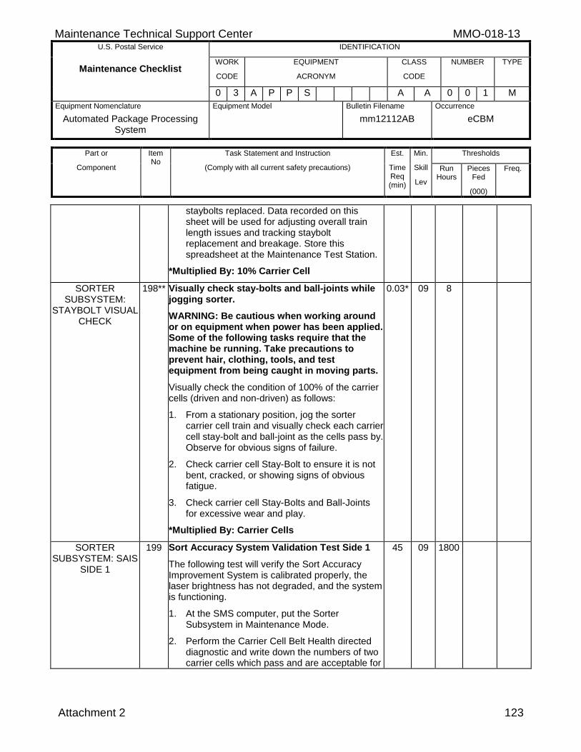
Maintenance Technical Support Center MMO-018-13 U.S. Postal Service IDENTIFICATION
Maintenance Checklist WORK
CODE
EQUIPMENT
ACRONYM
CLASS
CODE
NUMBER TYPE
0 3 A P P S A A 0 0 1 M
Equipment Nomenclature
Automated Package Processing System
Equipment Model
Bulletin Filename
mm12112AB
Occurrence
eCBM
Part or
Component
Item No
Task Statement and Instruction
(Comply with all current safety precautions)
Est.
Time Req (min)
Min.
Skill
Lev
Thresholds
Run Hours
Pieces Fed
(000)
Freq.
Attachment 2 123
staybolts replaced. Data recorded on this sheet will be used for adjusting overall train length issues and tracking staybolt replacement and breakage. Store this spreadsheet at the Maintenance Test Station.
*Multiplied By: 10% Carrier Cell
SORTER SUBSYSTEM:
STAYBOLT VISUAL CHECK
198** Visually check stay-bolts and ball-joints while jogging sorter.
WARNING: Be cautious when working around or on equipment when power has been applied. Some of the following tasks require that the machine be running. Take precautions to prevent hair, clothing, tools, and test equipment from being caught in moving parts.
Visually check the condition of 100% of the carrier cells (driven and non-driven) as follows:
1. From a stationary position, jog the sorter carrier cell train and visually check each carrier cell stay-bolt and ball-joint as the cells pass by. Observe for obvious signs of failure.
2. Check carrier cell Stay-Bolt to ensure it is not bent, cracked, or showing signs of obvious fatigue.
3. Check carrier cell Stay-Bolts and Ball-Joints for excessive wear and play.
*Multiplied By: Carrier Cells
0.03* 09 8
SORTER SUBSYSTEM: SAIS
SIDE 1
199 Sort Accuracy System Validation Test Side 1
The following test will verify the Sort Accuracy Improvement System is calibrated properly, the laser brightness has not degraded, and the system is functioning.
1. At the SMS computer, put the Sorter Subsystem in Maintenance Mode.
2. Perform the Carrier Cell Belt Health directed diagnostic and write down the numbers of two carrier cells which pass and are acceptable for
45 09 1800
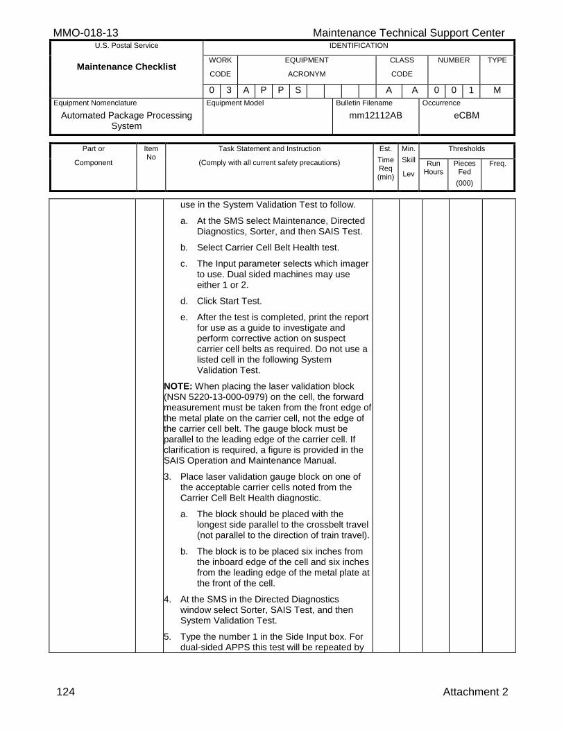
MMO-018-13 Maintenance Technical Support Center U.S. Postal Service IDENTIFICATION
Maintenance Checklist WORK
CODE
EQUIPMENT
ACRONYM
CLASS
CODE
NUMBER TYPE
0 3 A P P S A A 0 0 1 M
Equipment Nomenclature
Automated Package Processing System
Equipment Model
Bulletin Filename
mm12112AB
Occurrence
eCBM
Part or
Component
Item No
Task Statement and Instruction
(Comply with all current safety precautions)
Est.
Time Req (min)
Min.
Skill
Lev
Thresholds
Run Hours
Pieces Fed
(000)
Freq.
124 Attachment 2
use in the System Validation Test to follow.
a. At the SMS select Maintenance, Directed Diagnostics, Sorter, and then SAIS Test.
b. Select Carrier Cell Belt Health test.
c. The Input parameter selects which imager to use. Dual sided machines may use either 1 or 2.
d. Click Start Test.
e. After the test is completed, print the report for use as a guide to investigate and perform corrective action on suspect carrier cell belts as required. Do not use a listed cell in the following System Validation Test.
NOTE: When placing the laser validation block (NSN 5220-13-000-0979) on the cell, the forward measurement must be taken from the front edge of the metal plate on the carrier cell, not the edge of the carrier cell belt. The gauge block must be parallel to the leading edge of the carrier cell. If clarification is required, a figure is provided in the SAIS Operation and Maintenance Manual.
3. Place laser validation gauge block on one of the acceptable carrier cells noted from the Carrier Cell Belt Health diagnostic.
a. The block should be placed with the longest side parallel to the crossbelt travel (not parallel to the direction of train travel).
b. The block is to be placed six inches from the inboard edge of the cell and six inches from the leading edge of the metal plate at the front of the cell.
4. At the SMS in the Directed Diagnostics window select Sorter, SAIS Test, and then System Validation Test.
5. Type the number 1 in the Side Input box. For dual-sided APPS this test will be repeated by
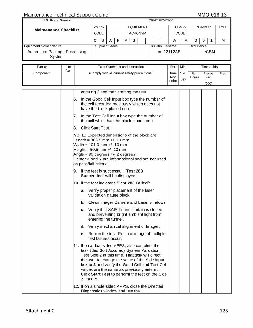
Maintenance Technical Support Center MMO-018-13 U.S. Postal Service IDENTIFICATION
Maintenance Checklist WORK
CODE
EQUIPMENT
ACRONYM
CLASS
CODE
NUMBER TYPE
0 3 A P P S A A 0 0 1 M
Equipment Nomenclature
Automated Package Processing System
Equipment Model
Bulletin Filename
mm12112AB
Occurrence
eCBM
Part or
Component
Item No
Task Statement and Instruction
(Comply with all current safety precautions)
Est.
Time Req (min)
Min.
Skill
Lev
Thresholds
Run Hours
Pieces Fed
(000)
Freq.
Attachment 2 125
entering 2 and then starting the test.
6. In the Good Cell Input box type the number of the cell recorded previously which does not have the block placed on it.
7. In the Test Cell Input box type the number of the cell which has the block placed on it.
8. Click Start Test.
NOTE: Expected dimensions of the block are: Length = 303.5 mm +/- 10 mm Width = 101.0 mm +/- 10 mm Height = 50.5 mm +/- 10 mm Angle = 90 degrees +/- 2 degrees Center X and Y are informational and are not used as pass/fail criteria.
9. If the test is successful, “Test 283 Succeeded” will be displayed.
10. If the test indicates “Test 283 Failed”:
a. Verify proper placement of the laser validation gauge block.
b. Clean Imager Camera and Laser windows.
c. Verify that SAIS Tunnel curtain is closed and preventing bright ambient light from entering the tunnel.
d. Verify mechanical alignment of Imager.
e. Re-run the test. Replace imager if multiple test failures occur.
11. If on a dual-sided APPS, also complete the task titled Sort Accuracy System Validation Test Side 2 at this time. That task will direct the user to change the value of the Side input box to 2 and verify the Good Cell and Test Cell values are the same as previously entered. Click Start Test to perform the test on the Side 2 Imager.
12. If on a single-sided APPS, close the Directed Diagnostics window and use the
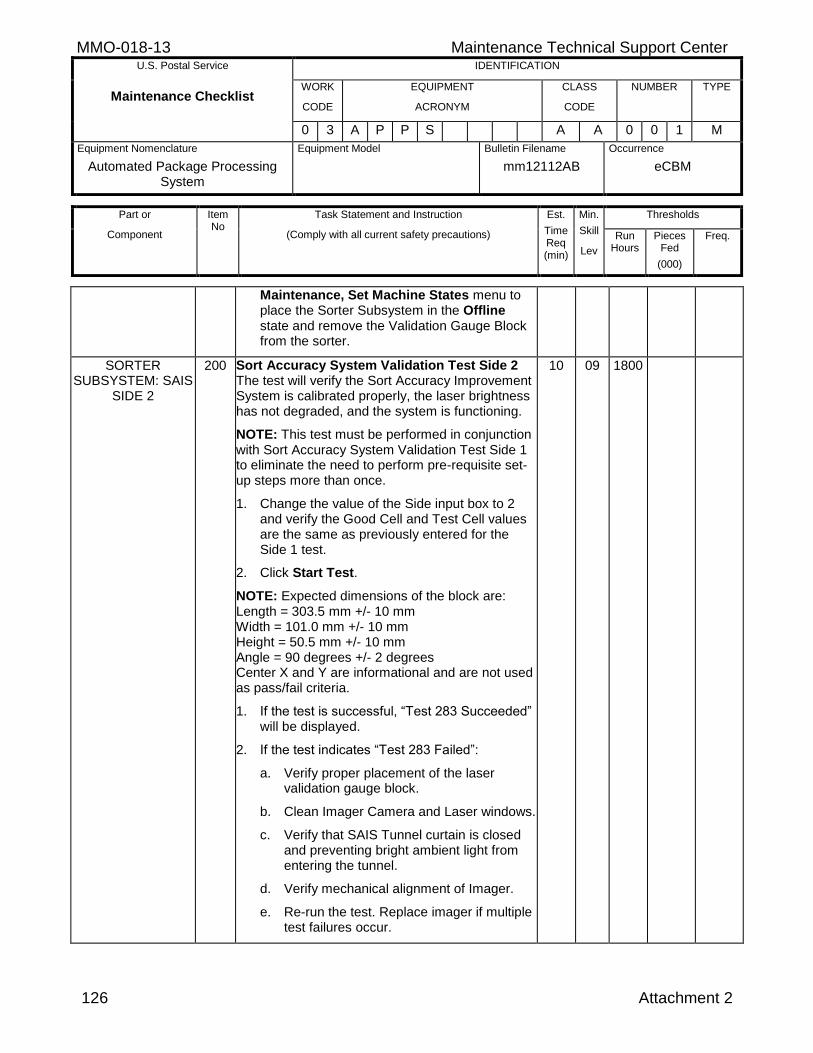
MMO-018-13 Maintenance Technical Support Center U.S. Postal Service IDENTIFICATION
Maintenance Checklist WORK
CODE
EQUIPMENT
ACRONYM
CLASS
CODE
NUMBER TYPE
0 3 A P P S A A 0 0 1 M
Equipment Nomenclature
Automated Package Processing System
Equipment Model
Bulletin Filename
mm12112AB
Occurrence
eCBM
Part or
Component
Item No
Task Statement and Instruction
(Comply with all current safety precautions)
Est.
Time Req (min)
Min.
Skill
Lev
Thresholds
Run Hours
Pieces Fed
(000)
Freq.
126 Attachment 2
Maintenance, Set Machine States menu to place the Sorter Subsystem in the Offline state and remove the Validation Gauge Block from the sorter.
SORTER SUBSYSTEM: SAIS
SIDE 2
200 Sort Accuracy System Validation Test Side 2 The test will verify the Sort Accuracy Improvement System is calibrated properly, the laser brightness has not degraded, and the system is functioning.
NOTE: This test must be performed in conjunction with Sort Accuracy System Validation Test Side 1 to eliminate the need to perform pre-requisite set-up steps more than once.
1. Change the value of the Side input box to 2 and verify the Good Cell and Test Cell values are the same as previously entered for the Side 1 test.
2. Click Start Test.
NOTE: Expected dimensions of the block are: Length = 303.5 mm +/- 10 mm Width = 101.0 mm +/- 10 mm Height = 50.5 mm +/- 10 mm Angle = 90 degrees +/- 2 degrees Center X and Y are informational and are not used as pass/fail criteria.
1. If the test is successful, “Test 283 Succeeded” will be displayed.
2. If the test indicates “Test 283 Failed”:
a. Verify proper placement of the laser validation gauge block.
b. Clean Imager Camera and Laser windows.
c. Verify that SAIS Tunnel curtain is closed and preventing bright ambient light from entering the tunnel.
d. Verify mechanical alignment of Imager.
e. Re-run the test. Replace imager if multiple test failures occur.
10 09 1800
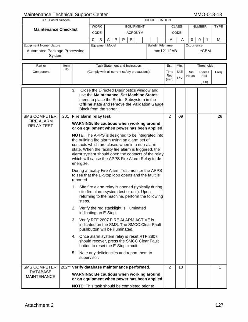
Maintenance Technical Support Center MMO-018-13 U.S. Postal Service IDENTIFICATION
Maintenance Checklist WORK
CODE
EQUIPMENT
ACRONYM
CLASS
CODE
NUMBER TYPE
0 3 A P P S A A 0 0 1 M
Equipment Nomenclature
Automated Package Processing System
Equipment Model
Bulletin Filename
mm12112AB
Occurrence
eCBM
Part or
Component
Item No
Task Statement and Instruction
(Comply with all current safety precautions)
Est.
Time Req (min)
Min.
Skill
Lev
Thresholds
Run Hours
Pieces Fed
(000)
Freq.
Attachment 2 127
3. Close the Directed Diagnostics window and use the Maintenance, Set Machine States menu to place the Sorter Subsystem in the Offline state and remove the Validation Gauge Block from the sorter.
SMS COMPUTER: FIRE ALARM RELAY TEST
201 Fire alarm relay test.
WARNING: Be cautious when working around or on equipment when power has been applied.
NOTE: The APPS is designed to be integrated into the building fire alarm using an alarm set of contacts which are closed when in a non-alarm state. When the facility fire alarm is triggered, the alarm system should open the contacts of the relay which will cause the APPS Fire Alarm Relay to de-energize.
During a facility Fire Alarm Test monitor the APPS to see that the E-Stop loop opens and the fault is reported.
1. Site fire alarm relay is opened (typically during site fire alarm system test or drill). Upon returning to the machine, perform the following steps.
2. Verify the red stacklight is illuminated indicating an E-Stop.
3. Verify RTF 2807 FIRE ALARM ACTIVE is indicated on the SMS. The SMCC Clear Fault pushbutton will be illuminated.
4. Once alarm system relay is reset RTF 2807 should recover, press the SMCC Clear Fault button to reset the E-Stop circuit.
5. Note any deficiencies and report them to supervisor.
2 09 26
SMS COMPUTER: DATABASE
MAINTENANCE
202** Verify database maintenance performed.
WARNING: Be cautious when working around or on equipment when power has been applied.
NOTE: This task should be completed prior to
2 10 1
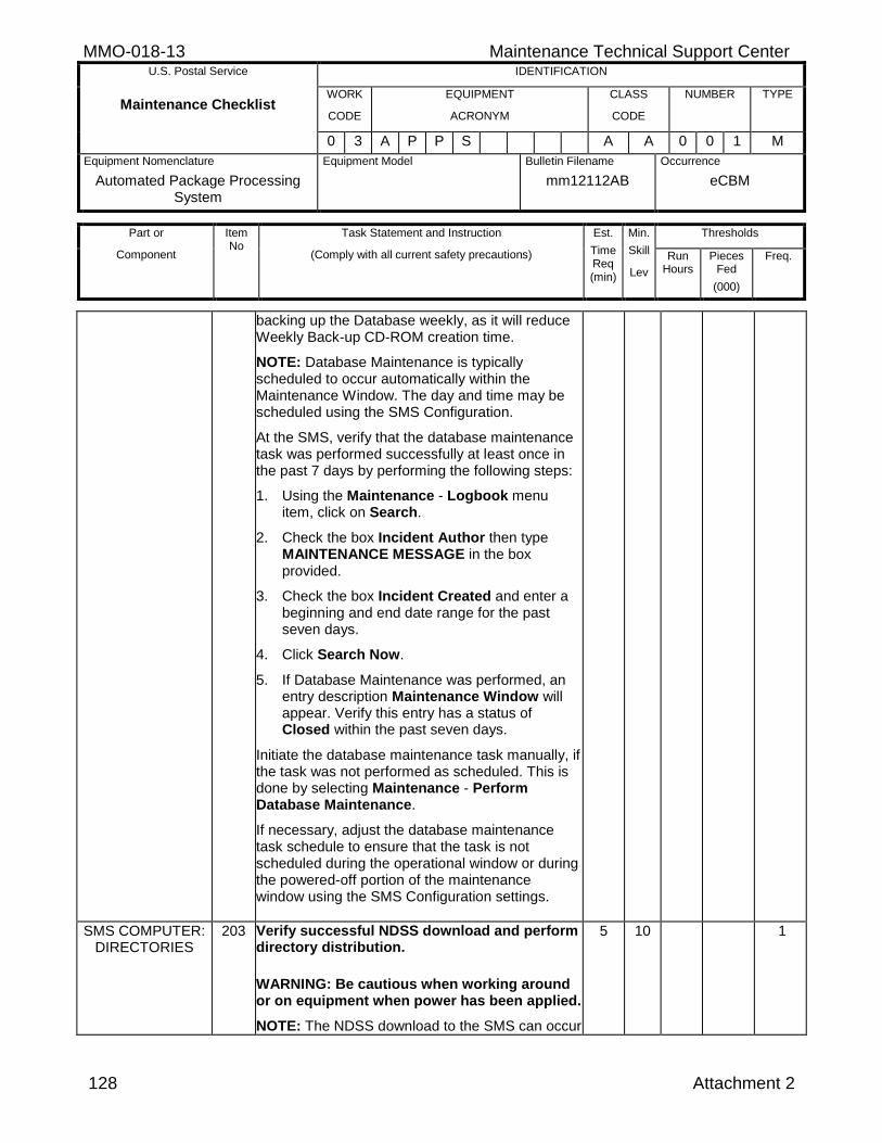
MMO-018-13 Maintenance Technical Support Center U.S. Postal Service IDENTIFICATION
Maintenance Checklist WORK
CODE
EQUIPMENT
ACRONYM
CLASS
CODE
NUMBER TYPE
0 3 A P P S A A 0 0 1 M
Equipment Nomenclature
Automated Package Processing System
Equipment Model
Bulletin Filename
mm12112AB
Occurrence
eCBM
Part or
Component
Item No
Task Statement and Instruction
(Comply with all current safety precautions)
Est.
Time Req (min)
Min.
Skill
Lev
Thresholds
Run Hours
Pieces Fed
(000)
Freq.
128 Attachment 2
backing up the Database weekly, as it will reduce Weekly Back-up CD-ROM creation time.
NOTE: Database Maintenance is typically scheduled to occur automatically within the Maintenance Window. The day and time may be scheduled using the SMS Configuration.
At the SMS, verify that the database maintenance task was performed successfully at least once in the past 7 days by performing the following steps:
1. Using the Maintenance - Logbook menu item, click on Search.
2. Check the box Incident Author then type MAINTENANCE MESSAGE in the box provided.
3. Check the box Incident Created and enter a beginning and end date range for the past seven days.
4. Click Search Now.
5. If Database Maintenance was performed, an entry description Maintenance Window will appear. Verify this entry has a status of Closed within the past seven days.
Initiate the database maintenance task manually, if the task was not performed as scheduled. This is done by selecting Maintenance - Perform Database Maintenance.
If necessary, adjust the database maintenance task schedule to ensure that the task is not scheduled during the operational window or during the powered-off portion of the maintenance window using the SMS Configuration settings.
SMS COMPUTER: DIRECTORIES
203 Verify successful NDSS download and perform directory distribution.
WARNING: Be cautious when working around or on equipment when power has been applied.
NOTE: The NDSS download to the SMS can occur
5 10 1
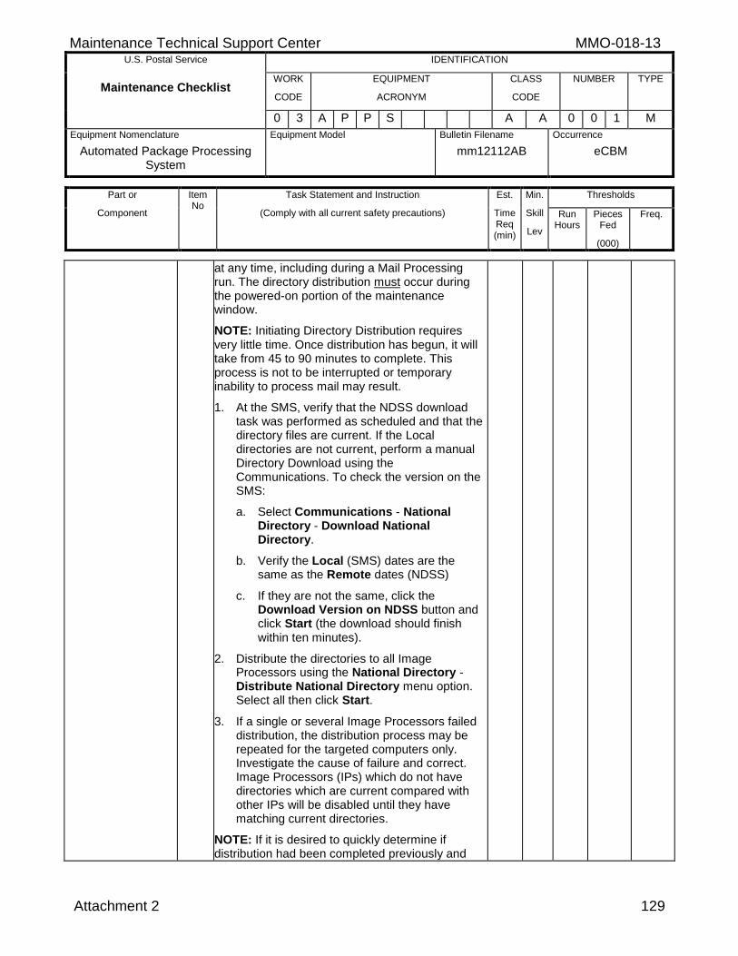
Maintenance Technical Support Center MMO-018-13 U.S. Postal Service IDENTIFICATION
Maintenance Checklist WORK
CODE
EQUIPMENT
ACRONYM
CLASS
CODE
NUMBER TYPE
0 3 A P P S A A 0 0 1 M
Equipment Nomenclature
Automated Package Processing System
Equipment Model
Bulletin Filename
mm12112AB
Occurrence
eCBM
Part or
Component
Item No
Task Statement and Instruction
(Comply with all current safety precautions)
Est.
Time Req (min)
Min.
Skill
Lev
Thresholds
Run Hours
Pieces Fed
(000)
Freq.
Attachment 2 129
at any time, including during a Mail Processing run. The directory distribution must occur during the powered-on portion of the maintenance window.
NOTE: Initiating Directory Distribution requires very little time. Once distribution has begun, it will take from 45 to 90 minutes to complete. This process is not to be interrupted or temporary inability to process mail may result.
1. At the SMS, verify that the NDSS download task was performed as scheduled and that the directory files are current. If the Local directories are not current, perform a manual Directory Download using the Communications. To check the version on the SMS:
a. Select Communications - National Directory - Download National Directory.
b. Verify the Local (SMS) dates are the same as the Remote dates (NDSS)
c. If they are not the same, click the Download Version on NDSS button and click Start (the download should finish within ten minutes).
2. Distribute the directories to all Image Processors using the National Directory - Distribute National Directory menu option. Select all then click Start.
3. If a single or several Image Processors failed distribution, the distribution process may be repeated for the targeted computers only. Investigate the cause of failure and correct. Image Processors (IPs) which do not have directories which are current compared with other IPs will be disabled until they have matching current directories.
NOTE: If it is desired to quickly determine if distribution had been completed previously and
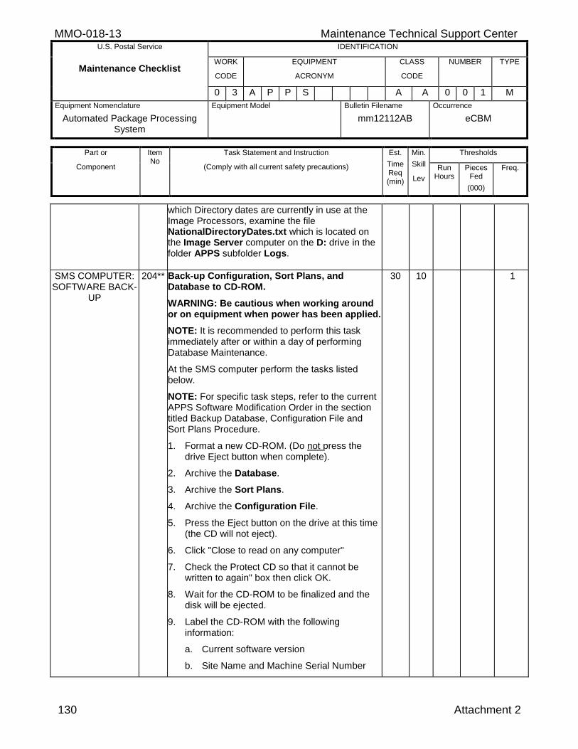
MMO-018-13 Maintenance Technical Support Center U.S. Postal Service IDENTIFICATION
Maintenance Checklist WORK
CODE
EQUIPMENT
ACRONYM
CLASS
CODE
NUMBER TYPE
0 3 A P P S A A 0 0 1 M
Equipment Nomenclature
Automated Package Processing System
Equipment Model
Bulletin Filename
mm12112AB
Occurrence
eCBM
Part or
Component
Item No
Task Statement and Instruction
(Comply with all current safety precautions)
Est.
Time Req (min)
Min.
Skill
Lev
Thresholds
Run Hours
Pieces Fed
(000)
Freq.
130 Attachment 2
which Directory dates are currently in use at the Image Processors, examine the file NationalDirectoryDates.txt which is located on the Image Server computer on the D: drive in the folder APPS subfolder Logs.
SMS COMPUTER: SOFTWARE BACK-
UP
204** Back-up Configuration, Sort Plans, and Database to CD-ROM.
WARNING: Be cautious when working around or on equipment when power has been applied.
NOTE: It is recommended to perform this task immediately after or within a day of performing Database Maintenance.
At the SMS computer perform the tasks listed below.
NOTE: For specific task steps, refer to the current APPS Software Modification Order in the section titled Backup Database, Configuration File and Sort Plans Procedure.
1. Format a new CD-ROM. (Do not press the drive Eject button when complete).
2. Archive the Database.
3. Archive the Sort Plans.
4. Archive the Configuration File.
5. Press the Eject button on the drive at this time (the CD will not eject).
6. Click "Close to read on any computer"
7. Check the Protect CD so that it cannot be written to again" box then click OK.
8. Wait for the CD-ROM to be finalized and the disk will be ejected.
9. Label the CD-ROM with the following information:
a. Current software version
b. Site Name and Machine Serial Number
30 10 1
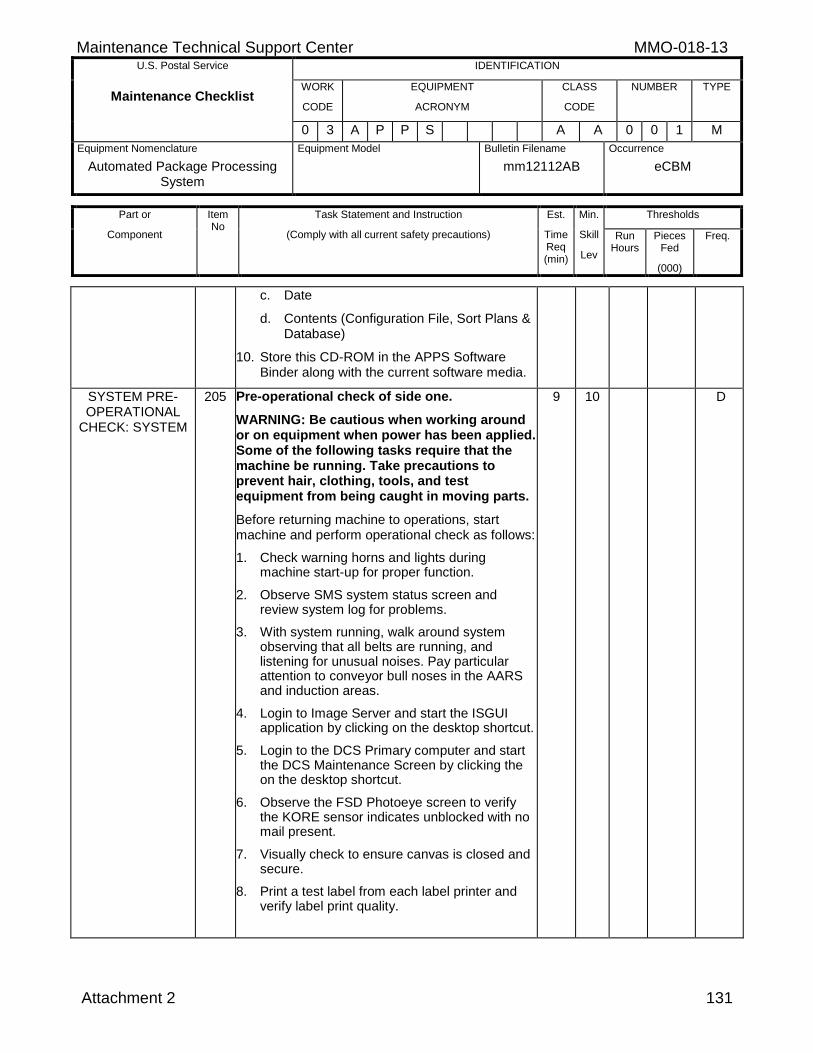
Maintenance Technical Support Center MMO-018-13 U.S. Postal Service IDENTIFICATION
Maintenance Checklist WORK
CODE
EQUIPMENT
ACRONYM
CLASS
CODE
NUMBER TYPE
0 3 A P P S A A 0 0 1 M
Equipment Nomenclature
Automated Package Processing System
Equipment Model
Bulletin Filename
mm12112AB
Occurrence
eCBM
Part or
Component
Item No
Task Statement and Instruction
(Comply with all current safety precautions)
Est.
Time Req (min)
Min.
Skill
Lev
Thresholds
Run Hours
Pieces Fed
(000)
Freq.
Attachment 2 131
c. Date
d. Contents (Configuration File, Sort Plans & Database)
10. Store this CD-ROM in the APPS Software Binder along with the current software media.
SYSTEM PRE-OPERATIONAL
CHECK: SYSTEM
205 Pre-operational check of side one.
WARNING: Be cautious when working around or on equipment when power has been applied. Some of the following tasks require that the machine be running. Take precautions to prevent hair, clothing, tools, and test equipment from being caught in moving parts.
Before returning machine to operations, start machine and perform operational check as follows:
1. Check warning horns and lights during machine start-up for proper function.
2. Observe SMS system status screen and review system log for problems.
3. With system running, walk around system observing that all belts are running, and listening for unusual noises. Pay particular attention to conveyor bull noses in the AARS and induction areas.
4. Login to Image Server and start the ISGUI application by clicking on the desktop shortcut.
5. Login to the DCS Primary computer and start the DCS Maintenance Screen by clicking the on the desktop shortcut.
6. Observe the FSD Photoeye screen to verify the KORE sensor indicates unblocked with no mail present.
7. Visually check to ensure canvas is closed and secure.
8. Print a test label from each label printer and verify label print quality.
9 10 D
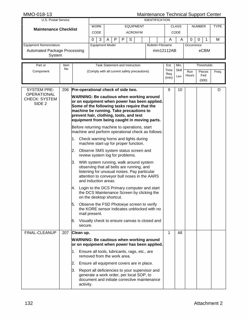
MMO-018-13 Maintenance Technical Support Center U.S. Postal Service IDENTIFICATION
Maintenance Checklist WORK
CODE
EQUIPMENT
ACRONYM
CLASS
CODE
NUMBER TYPE
0 3 A P P S A A 0 0 1 M
Equipment Nomenclature
Automated Package Processing System
Equipment Model
Bulletin Filename
mm12112AB
Occurrence
eCBM
Part or
Component
Item No
Task Statement and Instruction
(Comply with all current safety precautions)
Est.
Time Req (min)
Min.
Skill
Lev
Thresholds
Run Hours
Pieces Fed
(000)
Freq.
132 Attachment 2
SYSTEM PRE-OPERATIONAL
CHECK: SYSTEM SIDE 2
206 Pre-operational check of side two.
WARNING: Be cautious when working around or on equipment when power has been applied. Some of the following tasks require that the machine be running. Take precautions to prevent hair, clothing, tools, and test equipment from being caught in moving parts.
Before returning machine to operations, start machine and perform operational check as follows:
1. Check warning horns and lights during machine start-up for proper function.
2. Observe SMS system status screen and review system log for problems.
3. With system running, walk around system observing that all belts are running, and listening for unusual noises. Pay particular attention to conveyor bull noses in the AARS and induction areas.
4. Login to the DCS Primary computer and start the DCS Maintenance Screen by clicking the on the desktop shortcut.
5. Observe the FSD Photoeye screen to verify the KORE sensor indicates unblocked with no mail present.
6. Visually check to ensure canvas is closed and secure.
9 10 D
FINAL-CLEANUP 207 Clean up.
WARNING: Be cautious when working around or on equipment when power has been applied.
1. Ensure all tools, lubricants, rags, etc., are removed from the work area.
2. Ensure all equipment covers are in place.
3. Report all deficiencies to your supervisor and generate a work order, per local SOP, to document and initiate corrective maintenance activity.
1 All
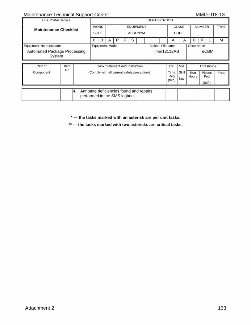
Maintenance Technical Support Center MMO-018-13 U.S. Postal Service IDENTIFICATION
Maintenance Checklist WORK
CODE
EQUIPMENT
ACRONYM
CLASS
CODE
NUMBER TYPE
0 3 A P P S A A 0 0 1 M
Equipment Nomenclature
Automated Package Processing System
Equipment Model
Bulletin Filename
mm12112AB
Occurrence
eCBM
Part or
Component
Item No
Task Statement and Instruction
(Comply with all current safety precautions)
Est.
Time Req (min)
Min.
Skill
Lev
Thresholds
Run Hours
Pieces Fed
(000)
Freq.
Attachment 2 133
4. Annotate deficiencies found and repairs performed in the SMS logbook.
* --- the tasks marked with an asterisk are per unit tasks.
** --- the tasks marked with two asterisks are critical tasks.
MMO-018-13 Maintenance Technical Support Center U.S. Postal Service IDENTIFICATION
Maintenance Checklist WORK
CODE
EQUIPMENT
ACRONYM
CLASS
CODE
NUMBER TYPE
0 3 A P P S A A 0 0 1 M
Equipment Nomenclature
Automated Package Processing System
Equipment Model
Bulletin Filename
mm12112AB
Occurrence
eCBM
Part or
Component
Item No
Task Statement and Instruction
(Comply with all current safety precautions)
Est.
Time Req (min)
Min.
Skill
Lev
Thresholds
Run Hours
Pieces Fed
(000)
Freq.
134 Attachment 2
THIS PAGE BLANK
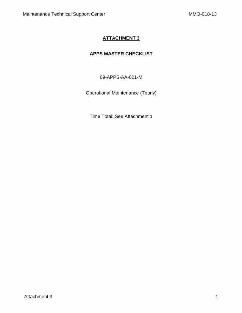
Maintenance Technical Support Center MMO-018-13
Attachment 3 1
ATTACHMENT 3
APPS MASTER CHECKLIST
09-APPS-AA-001-M
Operational Maintenance (Tourly)
Time Total: See Attachment 1
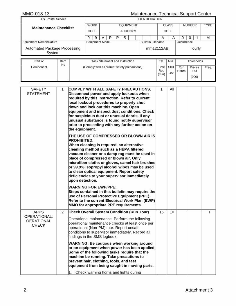
MMO-018-13 Maintenance Technical Support Center U.S. Postal Service IDENTIFICATION
Maintenance Checklist WORK
CODE
EQUIPMENT
ACRONYM
CLASS
CODE
NUMBER TYPE
0 9 A P P S A A 0 0 1 M Equipment Nomenclature
Automated Package Processing System
Equipment Model
Bulletin Filename
mm12112AB
Occurrence
Tourly
Part or
Component
Item No
Task Statement and Instruction
(Comply with all current safety precautions)
Est.
Time Req (min)
Min.
Skill
Lev
Thresholds
Run Hours
Pieces Fed
(000)
Freq.
2 Attachment 3
SAFETY STATEMENT
1 COMPLY WITH ALL SAFETY PRECAUTIONS. Disconnect power and apply lockouts when required by this instruction. Refer to current local lockout procedures to properly shut down and lock out this machine. Open equipment and inspect dust conditions. Check for suspicious dust or unusual debris. If any unusual substance is found notify supervisor prior to proceeding with any further action on the equipment.
THE USE OF COMPRESSED OR BLOWN AIR IS PROHIBITED. When cleaning is required, an alternative cleaning method such as a HEPA filtered vacuum cleaner or a damp rag must be used in place of compressed or blown air. Only microfiber cloths or gloves, camel hair brushes or 99.9% isopropyl alcohol wipes may be used to clean optical equipment. Report safety deficiencies to your supervisor immediately upon detection.
WARNING FOR EWP/PPE: Steps contained in this bulletin may require the use of Personal Protective Equipment (PPE). Refer to the current Electrical Work Plan (EWP) MMO for appropriate PPE requirements.
1 All
APPS OPERATIONAL: OERATIONAL
CHECK
2 Check Overall System Condition (Run Tour)
Operational maintenance. Perform the following operational maintenance checks at least once per operational (Non-PM) tour. Report unsafe conditions to supervisor immediately. Record all findings in the SMS logbook.
WARNING: Be cautious when working around or on equipment when power has been applied. Some of the following tasks require that the machine be running. Take precautions to prevent hair, clothing, tools, and test equipment from being caught in moving parts.
1. Check warning horns and lights during
15 10 T
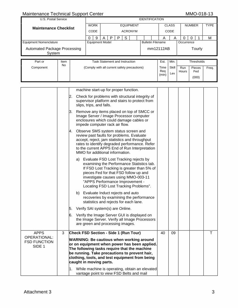
Maintenance Technical Support Center MMO-018-13 U.S. Postal Service IDENTIFICATION
Maintenance Checklist WORK
CODE
EQUIPMENT
ACRONYM
CLASS
CODE
NUMBER TYPE
0 9 A P P S A A 0 0 1 M Equipment Nomenclature
Automated Package Processing System
Equipment Model
Bulletin Filename
mm12112AB
Occurrence
Tourly
Part or
Component
Item No
Task Statement and Instruction
(Comply with all current safety precautions)
Est.
Time Req (min)
Min.
Skill
Lev
Thresholds
Run Hours
Pieces Fed
(000)
Freq.
Attachment 3 3
machine start-up for proper function.
2. Check for problems with structural integrity of supervisor platform and stairs to protect from slips, trips, and falls.
3. Remove any items placed on top of SMCC or Image Server / Image Processor computer enclosures which could damage cables or impede computer rack air flow.
4. Observe SMS system status screen and review past faults for problems. Evaluate accept, reject, jam statistics and throughput rates to identify degraded performance. Refer to the current APPS End of Run Interpretation MMO for additional information.
a) Evaluate FSD Lost Tracking rejects by examining the Performance Statistics tab. If FSD Lost Tracking is greater than 5% of pieces Fed for that FSD follow up and investigate causes using MMO-003-11 "APPS Performance Improvement - Locating FSD Lost Tracking Problems".
b) Evaluate Induct rejects and auto recoveries by examining the performance statistics and rejects for each lane.
5. Verify SAI system(s) are Online.
6. Verify the Image Server GUI is displayed on the Image Server. Verify all Image Processors are green and processing images.
APPS OPERATIONAL: FSD FUNCTION
SIDE 1
3 Check FSD Section - Side 1 (Run Tour)
WARNING: Be cautious when working around or on equipment when power has been applied. The following tasks require that the machine be running. Take precautions to prevent hair, clothing, tools, and test equipment from being caught in moving parts.
1. While machine is operating, obtain an elevated vantage point to view FSD Belts and mail
40 09 T
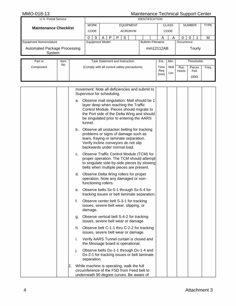
MMO-018-13 Maintenance Technical Support Center U.S. Postal Service IDENTIFICATION
Maintenance Checklist WORK
CODE
EQUIPMENT
ACRONYM
CLASS
CODE
NUMBER TYPE
0 9 A P P S A A 0 0 1 M Equipment Nomenclature
Automated Package Processing System
Equipment Model
Bulletin Filename
mm12112AB
Occurrence
Tourly
Part or
Component
Item No
Task Statement and Instruction
(Comply with all current safety precautions)
Est.
Time Req (min)
Min.
Skill
Lev
Thresholds
Run Hours
Pieces Fed
(000)
Freq.
4 Attachment 3
movement. Note all deficiencies and submit to Supervisor for scheduling.
a. Observe mail singulation. Mail should be 1 layer deep when reaching the Traffic Control Module. Pieces should migrate to the Port side of the Delta Wing and should be singulated prior to entering the AARS tunnel.
b. Observe all unstacker belting for tracking problems or signs of damage such as tears, fraying or laminate separation. Verify incline conveyors do not slip backwards under normal load.
c. Observe Traffic Control Module (TCM) for proper operation. The TCM should attempt to singulate side-by-side pieces by slowing belts when multiple pieces are present.
d. Observe Delta Wing rollers for proper operation. Note any damaged or non-functioning rollers.
e. Observe belts Sx-5-1 through Sx-5-4 for tracking issues or belt laminate separation.
f. Observe center belt S-3-1 for tracking issues, severe belt wear, slipping, or damage.
g. Observe vertical belt S-4-2 for tracking issues, severe belt wear or damage.
h. Observe belt C-1-1 thru C-2-2 for tracking issues, severe belt wear or damage.
i. Verify AARS Tunnel curtain is closed and the Message board is operational.
j. Observe belts Dx-1-1 through Dx-1-4 and Dx-2-1 for tracking issues or belt laminate separation.
2. While machine is operating, walk the full circumference of the FSD from Feed belt to underneath 90 degree curves. Be aware of
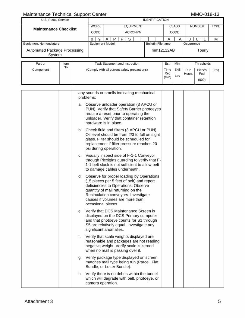
Maintenance Technical Support Center MMO-018-13 U.S. Postal Service IDENTIFICATION
Maintenance Checklist WORK
CODE
EQUIPMENT
ACRONYM
CLASS
CODE
NUMBER TYPE
0 9 A P P S A A 0 0 1 M Equipment Nomenclature
Automated Package Processing System
Equipment Model
Bulletin Filename
mm12112AB
Occurrence
Tourly
Part or
Component
Item No
Task Statement and Instruction
(Comply with all current safety precautions)
Est.
Time Req (min)
Min.
Skill
Lev
Thresholds
Run Hours
Pieces Fed
(000)
Freq.
Attachment 3 5
any sounds or smells indicating mechanical problems:
a. Observe unloader operation (3 APCU or PUN). Verify that Safety Barrier photoeyes require a reset prior to operating the unloader. Verify that container retention hardware is in place.
b. Check fluid and filters (3 APCU or PUN). Oil level should be from 2/3 to full on sight glass. Filter should be scheduled for replacement if filter pressure reaches 20 psi during operation.
c. Visually inspect side of F-1-1 Conveyor through Plexiglas guarding to verify that F-1-1 belt slack is not sufficient to allow belt to damage cables underneath.
d. Observe for proper loading by Operations (15 pieces per 5 feet of belt) and report deficiencies to Operations. Observe quantity of mail returning on the Recirculation conveyors. Investigate causes if volumes are more than occasional pieces.
e. Verify that DCS Maintenance Screen is displayed on the DCS Primary computer and that photoeye counts for S1 through S5 are relatively equal. Investigate any significant anomalies.
f. Verify that scale weights displayed are reasonable and packages are not reading negative weight. Verify scale is zeroed when no mail is passing over it.
g. Verify package type displayed on screen matches mail type being run (Parcel, Flat Bundle, or Letter Bundle).
h. Verify there is no debris within the tunnel which will degrade with belt, photoeye, or camera operation.
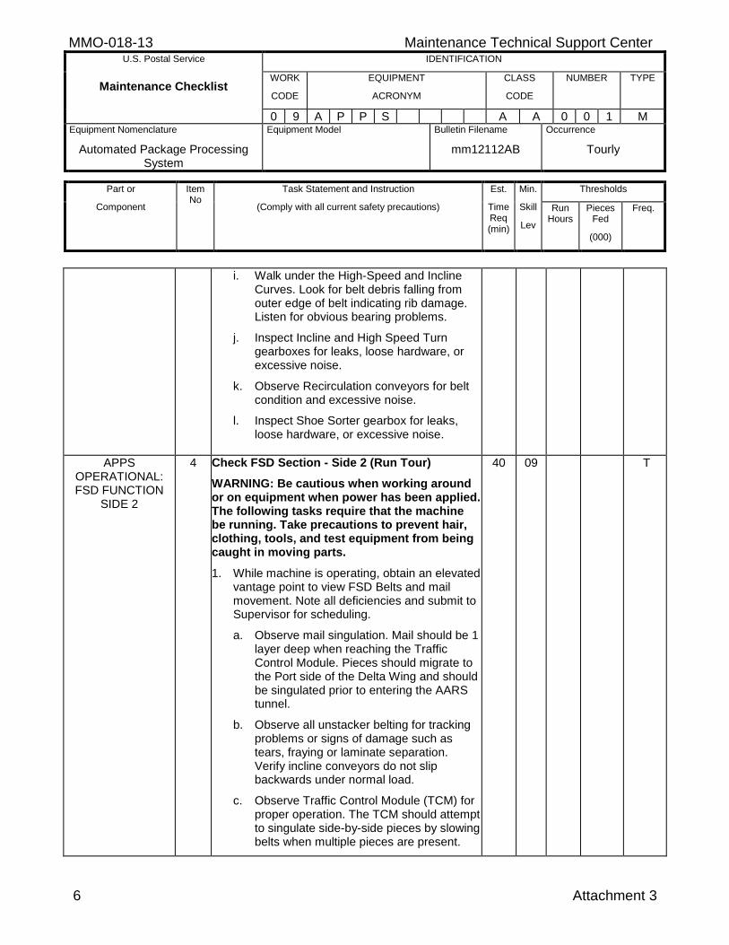
MMO-018-13 Maintenance Technical Support Center U.S. Postal Service IDENTIFICATION
Maintenance Checklist WORK
CODE
EQUIPMENT
ACRONYM
CLASS
CODE
NUMBER TYPE
0 9 A P P S A A 0 0 1 M Equipment Nomenclature
Automated Package Processing System
Equipment Model
Bulletin Filename
mm12112AB
Occurrence
Tourly
Part or
Component
Item No
Task Statement and Instruction
(Comply with all current safety precautions)
Est.
Time Req (min)
Min.
Skill
Lev
Thresholds
Run Hours
Pieces Fed
(000)
Freq.
6 Attachment 3
i. Walk under the High-Speed and Incline Curves. Look for belt debris falling from outer edge of belt indicating rib damage. Listen for obvious bearing problems.
j. Inspect Incline and High Speed Turn gearboxes for leaks, loose hardware, or excessive noise.
k. Observe Recirculation conveyors for belt condition and excessive noise.
l. Inspect Shoe Sorter gearbox for leaks, loose hardware, or excessive noise.
APPS OPERATIONAL: FSD FUNCTION
SIDE 2
4 Check FSD Section - Side 2 (Run Tour)
WARNING: Be cautious when working around or on equipment when power has been applied. The following tasks require that the machine be running. Take precautions to prevent hair, clothing, tools, and test equipment from being caught in moving parts.
1. While machine is operating, obtain an elevated vantage point to view FSD Belts and mail movement. Note all deficiencies and submit to Supervisor for scheduling.
a. Observe mail singulation. Mail should be 1 layer deep when reaching the Traffic Control Module. Pieces should migrate to the Port side of the Delta Wing and should be singulated prior to entering the AARS tunnel.
b. Observe all unstacker belting for tracking problems or signs of damage such as tears, fraying or laminate separation. Verify incline conveyors do not slip backwards under normal load.
c. Observe Traffic Control Module (TCM) for proper operation. The TCM should attempt to singulate side-by-side pieces by slowing belts when multiple pieces are present.
40 09 T
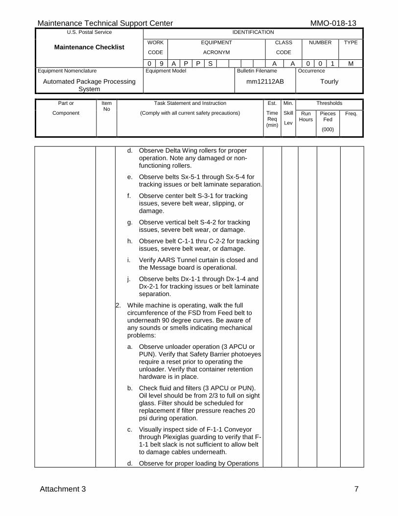
Maintenance Technical Support Center MMO-018-13 U.S. Postal Service IDENTIFICATION
Maintenance Checklist WORK
CODE
EQUIPMENT
ACRONYM
CLASS
CODE
NUMBER TYPE
0 9 A P P S A A 0 0 1 M Equipment Nomenclature
Automated Package Processing System
Equipment Model
Bulletin Filename
mm12112AB
Occurrence
Tourly
Part or
Component
Item No
Task Statement and Instruction
(Comply with all current safety precautions)
Est.
Time Req (min)
Min.
Skill
Lev
Thresholds
Run Hours
Pieces Fed
(000)
Freq.
Attachment 3 7
d. Observe Delta Wing rollers for proper operation. Note any damaged or non-functioning rollers.
e. Observe belts Sx-5-1 through Sx-5-4 for tracking issues or belt laminate separation.
f. Observe center belt S-3-1 for tracking issues, severe belt wear, slipping, or damage.
g. Observe vertical belt S-4-2 for tracking issues, severe belt wear, or damage.
h. Observe belt C-1-1 thru C-2-2 for tracking issues, severe belt wear, or damage.
i. Verify AARS Tunnel curtain is closed and the Message board is operational.
j. Observe belts Dx-1-1 through Dx-1-4 and Dx-2-1 for tracking issues or belt laminate separation.
2. While machine is operating, walk the full circumference of the FSD from Feed belt to underneath 90 degree curves. Be aware of any sounds or smells indicating mechanical problems:
a. Observe unloader operation (3 APCU or PUN). Verify that Safety Barrier photoeyes require a reset prior to operating the unloader. Verify that container retention hardware is in place.
b. Check fluid and filters (3 APCU or PUN). Oil level should be from 2/3 to full on sight glass. Filter should be scheduled for replacement if filter pressure reaches 20 psi during operation.
c. Visually inspect side of F-1-1 Conveyor through Plexiglas guarding to verify that F-1-1 belt slack is not sufficient to allow belt to damage cables underneath.
d. Observe for proper loading by Operations
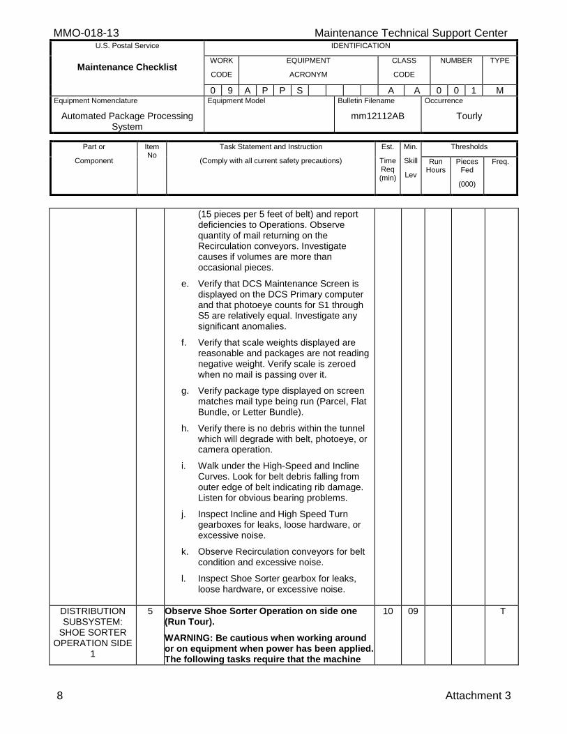
MMO-018-13 Maintenance Technical Support Center U.S. Postal Service IDENTIFICATION
Maintenance Checklist WORK
CODE
EQUIPMENT
ACRONYM
CLASS
CODE
NUMBER TYPE
0 9 A P P S A A 0 0 1 M Equipment Nomenclature
Automated Package Processing System
Equipment Model
Bulletin Filename
mm12112AB
Occurrence
Tourly
Part or
Component
Item No
Task Statement and Instruction
(Comply with all current safety precautions)
Est.
Time Req (min)
Min.
Skill
Lev
Thresholds
Run Hours
Pieces Fed
(000)
Freq.
8 Attachment 3
(15 pieces per 5 feet of belt) and report deficiencies to Operations. Observe quantity of mail returning on the Recirculation conveyors. Investigate causes if volumes are more than occasional pieces.
e. Verify that DCS Maintenance Screen is displayed on the DCS Primary computer and that photoeye counts for S1 through S5 are relatively equal. Investigate any significant anomalies.
f. Verify that scale weights displayed are reasonable and packages are not reading negative weight. Verify scale is zeroed when no mail is passing over it.
g. Verify package type displayed on screen matches mail type being run (Parcel, Flat Bundle, or Letter Bundle).
h. Verify there is no debris within the tunnel which will degrade with belt, photoeye, or camera operation.
i. Walk under the High-Speed and Incline Curves. Look for belt debris falling from outer edge of belt indicating rib damage. Listen for obvious bearing problems.
j. Inspect Incline and High Speed Turn gearboxes for leaks, loose hardware, or excessive noise.
k. Observe Recirculation conveyors for belt condition and excessive noise.
l. Inspect Shoe Sorter gearbox for leaks, loose hardware, or excessive noise.
DISTRIBUTION SUBSYSTEM:
SHOE SORTER OPERATION SIDE
1
5 Observe Shoe Sorter Operation on side one (Run Tour).
WARNING: Be cautious when working around or on equipment when power has been applied. The following tasks require that the machine
10 09 T
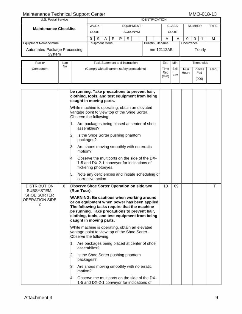
Maintenance Technical Support Center MMO-018-13 U.S. Postal Service IDENTIFICATION
Maintenance Checklist WORK
CODE
EQUIPMENT
ACRONYM
CLASS
CODE
NUMBER TYPE
0 9 A P P S A A 0 0 1 M Equipment Nomenclature
Automated Package Processing System
Equipment Model
Bulletin Filename
mm12112AB
Occurrence
Tourly
Part or
Component
Item No
Task Statement and Instruction
(Comply with all current safety precautions)
Est.
Time Req (min)
Min.
Skill
Lev
Thresholds
Run Hours
Pieces Fed
(000)
Freq.
Attachment 3 9
be running. Take precautions to prevent hair, clothing, tools, and test equipment from being caught in moving parts.
While machine is operating, obtain an elevated vantage point to view top of the Shoe Sorter. Observe the following:
1. Are packages being placed at center of shoe assemblies?
2. Is the Shoe Sorter pushing phantom packages?
3. Are shoes moving smoothly with no erratic motion?
4. Observe the multiports on the side of the DX-1-5 and DX-2-1 conveyor for indications of flickering photoeyes.
5. Note any deficiencies and initiate scheduling of corrective action.
DISTRIBUTION SUBSYSTEM:
SHOE SORTER OPERATION SIDE
2
6 Observe Shoe Sorter Operation on side two (Run Tour).
WARNING: Be cautious when working around or on equipment when power has been applied. The following tasks require that the machine be running. Take precautions to prevent hair, clothing, tools, and test equipment from being caught in moving parts.
While machine is operating, obtain an elevated vantage point to view top of the Shoe Sorter. Observe the following:
1. Are packages being placed at center of shoe assemblies?
2. Is the Shoe Sorter pushing phantom packages?
3. Are shoes moving smoothly with no erratic motion?
4. Observe the multiports on the side of the DX-1-5 and DX-2-1 conveyor for indications of
10 09 T
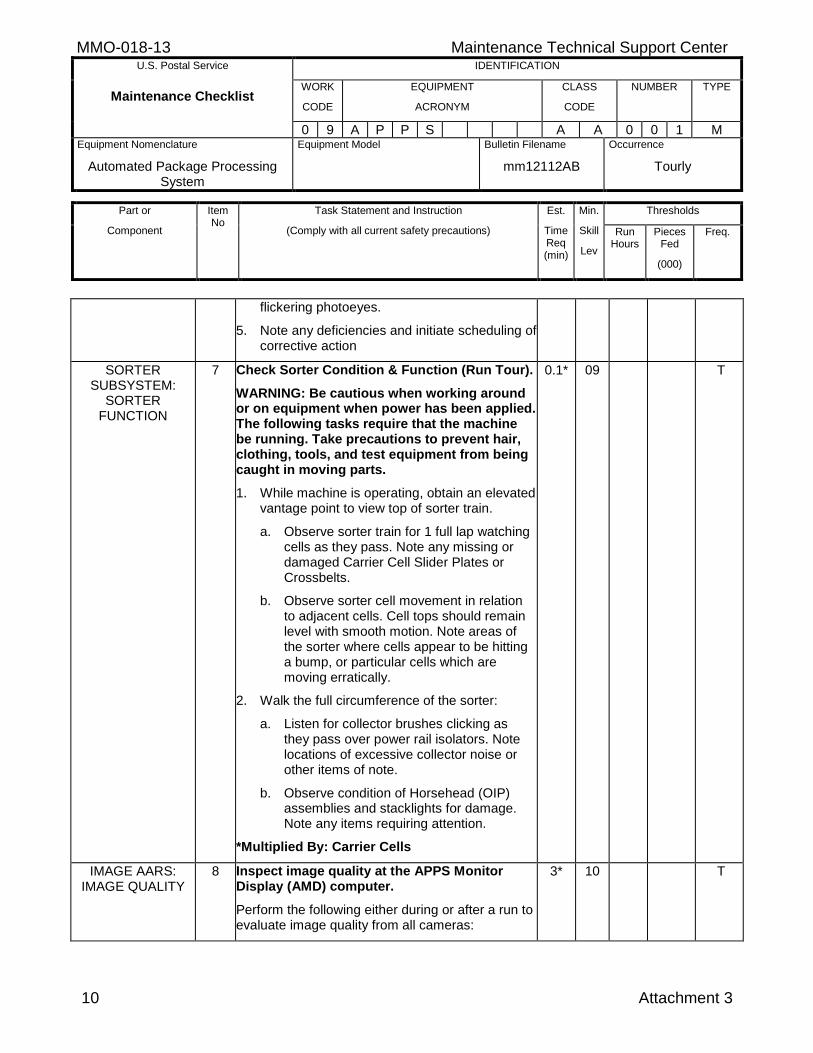
MMO-018-13 Maintenance Technical Support Center U.S. Postal Service IDENTIFICATION
Maintenance Checklist WORK
CODE
EQUIPMENT
ACRONYM
CLASS
CODE
NUMBER TYPE
0 9 A P P S A A 0 0 1 M Equipment Nomenclature
Automated Package Processing System
Equipment Model
Bulletin Filename
mm12112AB
Occurrence
Tourly
Part or
Component
Item No
Task Statement and Instruction
(Comply with all current safety precautions)
Est.
Time Req (min)
Min.
Skill
Lev
Thresholds
Run Hours
Pieces Fed
(000)
Freq.
10 Attachment 3
flickering photoeyes.
5. Note any deficiencies and initiate scheduling of corrective action
SORTER SUBSYSTEM:
SORTER FUNCTION
7 Check Sorter Condition & Function (Run Tour).
WARNING: Be cautious when working around or on equipment when power has been applied. The following tasks require that the machine be running. Take precautions to prevent hair, clothing, tools, and test equipment from being caught in moving parts.
1. While machine is operating, obtain an elevated vantage point to view top of sorter train.
a. Observe sorter train for 1 full lap watching cells as they pass. Note any missing or damaged Carrier Cell Slider Plates or Crossbelts.
b. Observe sorter cell movement in relation to adjacent cells. Cell tops should remain level with smooth motion. Note areas of the sorter where cells appear to be hitting a bump, or particular cells which are moving erratically.
2. Walk the full circumference of the sorter:
a. Listen for collector brushes clicking as they pass over power rail isolators. Note locations of excessive collector noise or other items of note.
b. Observe condition of Horsehead (OIP) assemblies and stacklights for damage. Note any items requiring attention.
*Multiplied By: Carrier Cells
0.1* 09 T
IMAGE AARS: IMAGE QUALITY
8 Inspect image quality at the APPS Monitor Display (AMD) computer.
Perform the following either during or after a run to evaluate image quality from all cameras:
3* 10 T
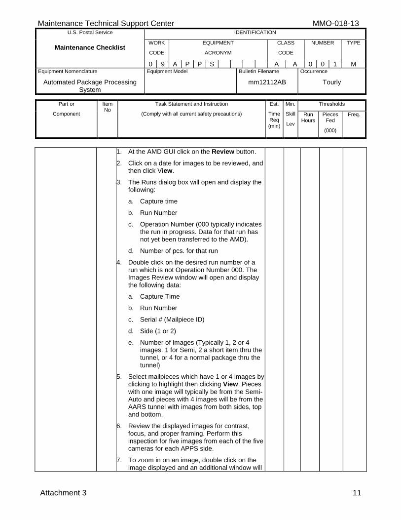
Maintenance Technical Support Center MMO-018-13 U.S. Postal Service IDENTIFICATION
Maintenance Checklist WORK
CODE
EQUIPMENT
ACRONYM
CLASS
CODE
NUMBER TYPE
0 9 A P P S A A 0 0 1 M Equipment Nomenclature
Automated Package Processing System
Equipment Model
Bulletin Filename
mm12112AB
Occurrence
Tourly
Part or
Component
Item No
Task Statement and Instruction
(Comply with all current safety precautions)
Est.
Time Req (min)
Min.
Skill
Lev
Thresholds
Run Hours
Pieces Fed
(000)
Freq.
Attachment 3 11
1. At the AMD GUI click on the Review button.
2. Click on a date for images to be reviewed, and then click View.
3. The Runs dialog box will open and display the following:
a. Capture time
b. Run Number
c. Operation Number (000 typically indicates the run in progress. Data for that run has not yet been transferred to the AMD).
d. Number of pcs. for that run
4. Double click on the desired run number of a run which is not Operation Number 000. The Images Review window will open and display the following data:
a. Capture Time
b. Run Number
c. Serial # (Mailpiece ID)
d. Side (1 or 2)
e. Number of Images (Typically 1, 2 or 4 images. 1 for Semi, 2 a short item thru the tunnel, or 4 for a normal package thru the tunnel)
5. Select mailpieces which have 1 or 4 images by clicking to highlight then clicking View. Pieces with one image will typically be from the Semi-Auto and pieces with 4 images will be from the AARS tunnel with images from both sides, top and bottom.
6. Review the displayed images for contrast, focus, and proper framing. Perform this inspection for five images from each of the five cameras for each APPS side.
7. To zoom in on an image, double click on the image displayed and an additional window will
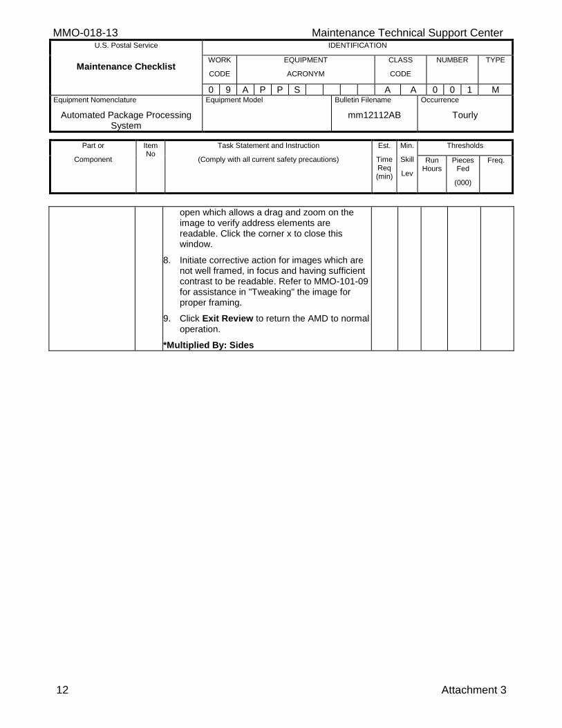
MMO-018-13 Maintenance Technical Support Center U.S. Postal Service IDENTIFICATION
Maintenance Checklist WORK
CODE
EQUIPMENT
ACRONYM
CLASS
CODE
NUMBER TYPE
0 9 A P P S A A 0 0 1 M Equipment Nomenclature
Automated Package Processing System
Equipment Model
Bulletin Filename
mm12112AB
Occurrence
Tourly
Part or
Component
Item No
Task Statement and Instruction
(Comply with all current safety precautions)
Est.
Time Req (min)
Min.
Skill
Lev
Thresholds
Run Hours
Pieces Fed
(000)
Freq.
12 Attachment 3
open which allows a drag and zoom on the image to verify address elements are readable. Click the corner x to close this window.
8. Initiate corrective action for images which are not well framed, in focus and having sufficient contrast to be readable. Refer to MMO-101-09 for assistance in "Tweaking" the image for proper framing.
9. Click Exit Review to return the AMD to normal operation.
*Multiplied By: Sides
Maintenance Technical Support Center MMO-018-13
Attachment 4 1
ATTACHMENT 4
APPS MASTER CHECKLIST
09-APPS-AA-002-M
Operational Maintenance (Daily)
Time Total: See Attachment 1
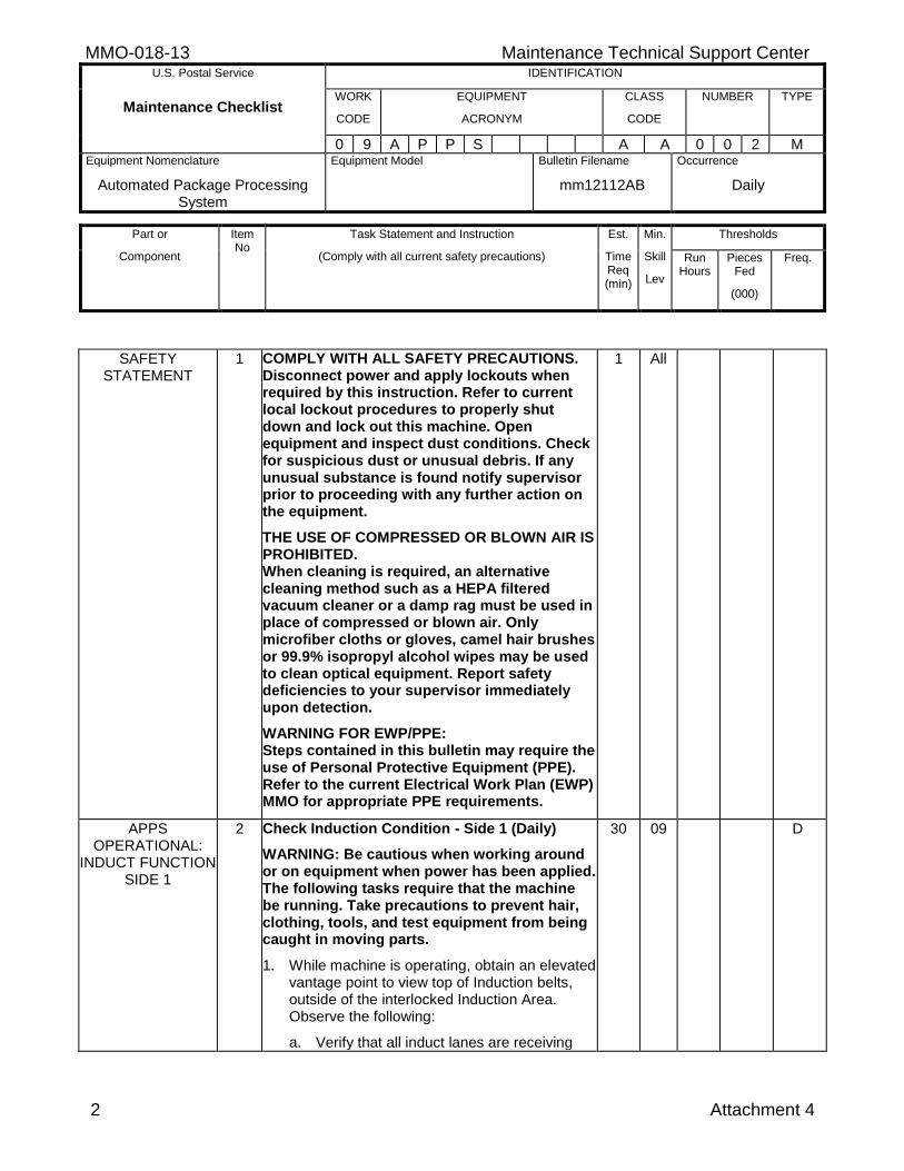
MMO-018-13 Maintenance Technical Support Center U.S. Postal Service IDENTIFICATION
Maintenance Checklist WORK
CODE
EQUIPMENT
ACRONYM
CLASS
CODE
NUMBER TYPE
0 9 A P P S A A 0 0 2 M Equipment Nomenclature
Automated Package Processing System
Equipment Model
Bulletin Filename
mm12112AB
Occurrence
Daily
Part or
Component
Item No
Task Statement and Instruction
(Comply with all current safety precautions)
Est.
Time Req (min)
Min.
Skill
Lev
Thresholds
Run Hours
Pieces Fed
(000)
Freq.
2 Attachment 4
SAFETY STATEMENT
1 COMPLY WITH ALL SAFETY PRECAUTIONS. Disconnect power and apply lockouts when required by this instruction. Refer to current local lockout procedures to properly shut down and lock out this machine. Open equipment and inspect dust conditions. Check for suspicious dust or unusual debris. If any unusual substance is found notify supervisor prior to proceeding with any further action on the equipment.
THE USE OF COMPRESSED OR BLOWN AIR IS PROHIBITED. When cleaning is required, an alternative cleaning method such as a HEPA filtered vacuum cleaner or a damp rag must be used in place of compressed or blown air. Only microfiber cloths or gloves, camel hair brushes or 99.9% isopropyl alcohol wipes may be used to clean optical equipment. Report safety deficiencies to your supervisor immediately upon detection.
WARNING FOR EWP/PPE: Steps contained in this bulletin may require the use of Personal Protective Equipment (PPE). Refer to the current Electrical Work Plan (EWP) MMO for appropriate PPE requirements.
1 All
APPS OPERATIONAL:
INDUCT FUNCTION SIDE 1
2 Check Induction Condition - Side 1 (Daily)
WARNING: Be cautious when working around or on equipment when power has been applied. The following tasks require that the machine be running. Take precautions to prevent hair, clothing, tools, and test equipment from being caught in moving parts.
1. While machine is operating, obtain an elevated vantage point to view top of Induction belts, outside of the interlocked Induction Area. Observe the following:
a. Verify that all induct lanes are receiving
30 09 D
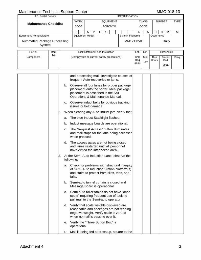
Maintenance Technical Support Center MMO-018-13 U.S. Postal Service IDENTIFICATION
Maintenance Checklist WORK
CODE
EQUIPMENT
ACRONYM
CLASS
CODE
NUMBER TYPE
0 9 A P P S A A 0 0 2 M Equipment Nomenclature
Automated Package Processing System
Equipment Model
Bulletin Filename
MM12112AB
Occurrence
Daily
Part or
Component
Item No
Task Statement and Instruction
(Comply with all current safety precautions)
Est.
Time Req (min)
Min.
Skill
Lev
Thresholds
Run Hours
Pieces Fed
(000)
Freq.
Attachment 4 3
and processing mail. Investigate causes of frequent Auto-recoveries or jams.
b. Observe all four lanes for proper package placement onto the sorter. Ideal package placement is described in the SAI Operations & Maintenance Manual.
c. Observe induct belts for obvious tracking issues or belt damage.
2. When clearing any Auto-Induct jam, verify that:
a. The blue Induct Stacklight flashes.
b. Induct message boards are operational.
c. The “Request Access” button illuminates and mail stops for the lane being accessed when pressed.
d. The access gates are not being closed and lanes restarted until all personnel have exited the interlocked area.
3. At the Semi-Auto Induction Lane, observe the following:
a. Check for problems with structural integrity of Semi-Auto Induction Station platform(s) and stairs to protect from slips, trips, and falls.
b. Semi-auto tunnel curtain is closed and Message Board is operational.
c. Semi-auto roller tables do not have “dead spots” requiring frequent use of tools to pull mail to the Semi-auto operator.
d. Verify that scale weights displayed are reasonable and packages are not reading negative weight. Verify scale is zeroed when no mail is passing over it.
e. Verify the “Three Button Box” is operational.
f. Mail is being fed address up, square to the
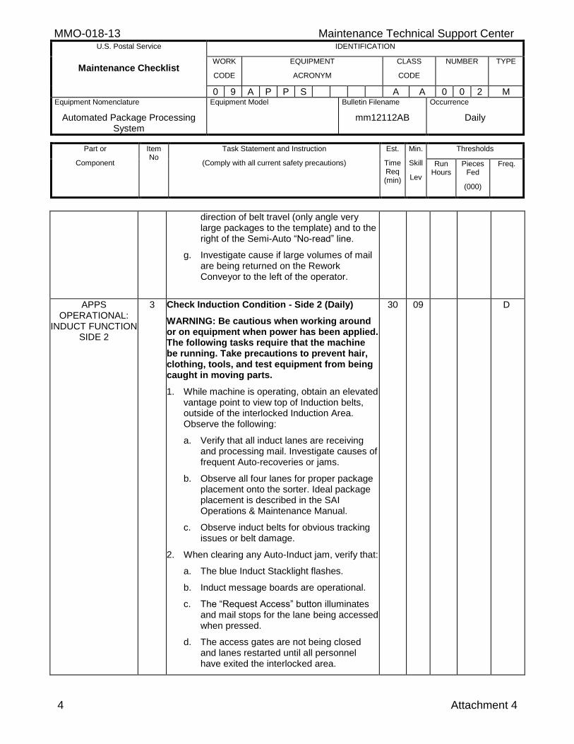
MMO-018-13 Maintenance Technical Support Center U.S. Postal Service IDENTIFICATION
Maintenance Checklist WORK
CODE
EQUIPMENT
ACRONYM
CLASS
CODE
NUMBER TYPE
0 9 A P P S A A 0 0 2 M Equipment Nomenclature
Automated Package Processing System
Equipment Model
Bulletin Filename
mm12112AB
Occurrence
Daily
Part or
Component
Item No
Task Statement and Instruction
(Comply with all current safety precautions)
Est.
Time Req (min)
Min.
Skill
Lev
Thresholds
Run Hours
Pieces Fed
(000)
Freq.
4 Attachment 4
direction of belt travel (only angle very large packages to the template) and to the right of the Semi-Auto “No-read” line.
g. Investigate cause if large volumes of mail are being returned on the Rework Conveyor to the left of the operator.
APPS OPERATIONAL:
INDUCT FUNCTION SIDE 2
3 Check Induction Condition - Side 2 (Daily)
WARNING: Be cautious when working around or on equipment when power has been applied. The following tasks require that the machine be running. Take precautions to prevent hair, clothing, tools, and test equipment from being caught in moving parts.
1. While machine is operating, obtain an elevated vantage point to view top of Induction belts, outside of the interlocked Induction Area. Observe the following:
a. Verify that all induct lanes are receiving and processing mail. Investigate causes of frequent Auto-recoveries or jams.
b. Observe all four lanes for proper package placement onto the sorter. Ideal package placement is described in the SAI Operations & Maintenance Manual.
c. Observe induct belts for obvious tracking issues or belt damage.
2. When clearing any Auto-Induct jam, verify that:
a. The blue Induct Stacklight flashes.
b. Induct message boards are operational.
c. The “Request Access” button illuminates and mail stops for the lane being accessed when pressed.
d. The access gates are not being closed and lanes restarted until all personnel have exited the interlocked area.
30 09 D
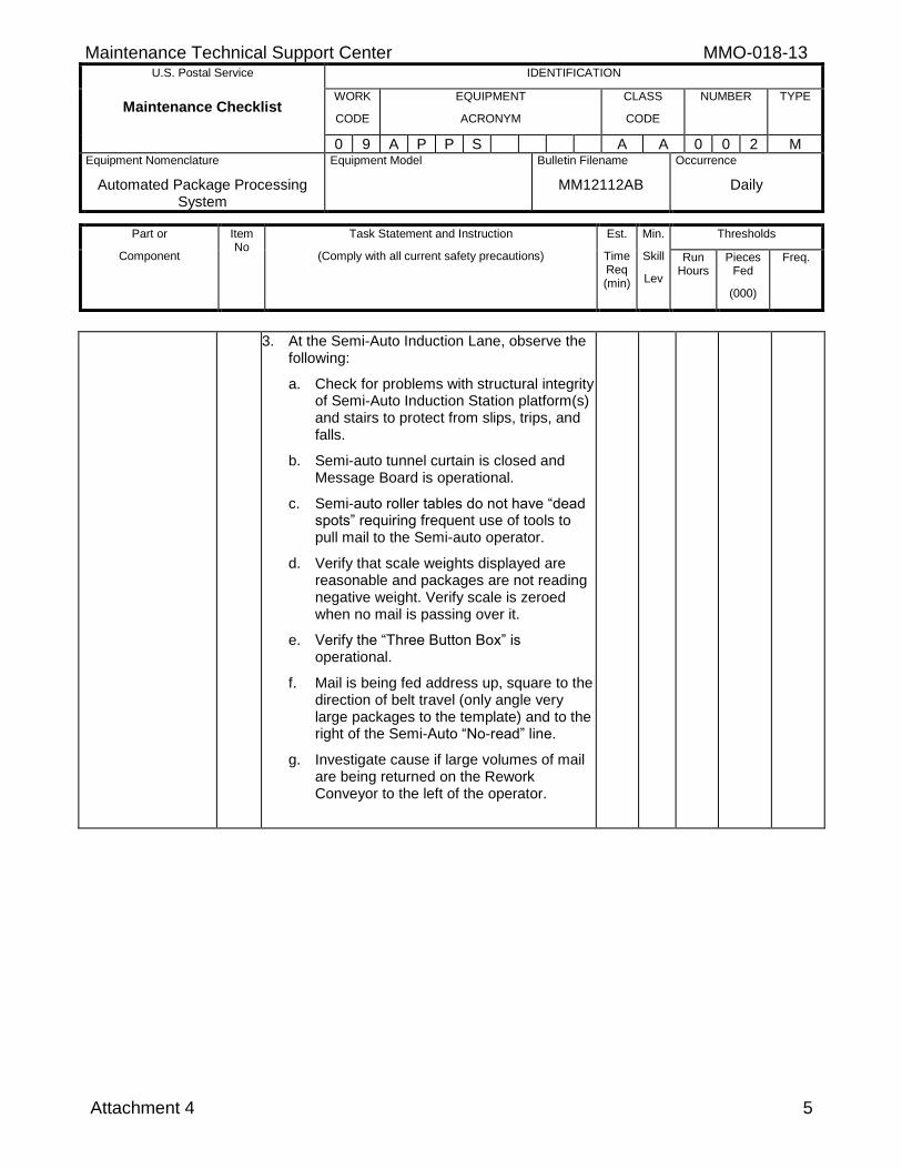
Maintenance Technical Support Center MMO-018-13 U.S. Postal Service IDENTIFICATION
Maintenance Checklist WORK
CODE
EQUIPMENT
ACRONYM
CLASS
CODE
NUMBER TYPE
0 9 A P P S A A 0 0 2 M Equipment Nomenclature
Automated Package Processing System
Equipment Model
Bulletin Filename
MM12112AB
Occurrence
Daily
Part or
Component
Item No
Task Statement and Instruction
(Comply with all current safety precautions)
Est.
Time Req (min)
Min.
Skill
Lev
Thresholds
Run Hours
Pieces Fed
(000)
Freq.
Attachment 4 5
3. At the Semi-Auto Induction Lane, observe the following:
a. Check for problems with structural integrity of Semi-Auto Induction Station platform(s) and stairs to protect from slips, trips, and falls.
b. Semi-auto tunnel curtain is closed and Message Board is operational.
c. Semi-auto roller tables do not have “dead spots” requiring frequent use of tools to pull mail to the Semi-auto operator.
d. Verify that scale weights displayed are reasonable and packages are not reading negative weight. Verify scale is zeroed when no mail is passing over it.
e. Verify the “Three Button Box” is operational.
f. Mail is being fed address up, square to the direction of belt travel (only angle very large packages to the template) and to the right of the Semi-Auto “No-read” line.
g. Investigate cause if large volumes of mail are being returned on the Rework Conveyor to the left of the operator.