magnetism electromagnetic induction notes 2
TRANSCRIPT
S4OP | Electromagnetic Induction | Notes 2 © JustEdu Holdings Pte Ltd
-1-
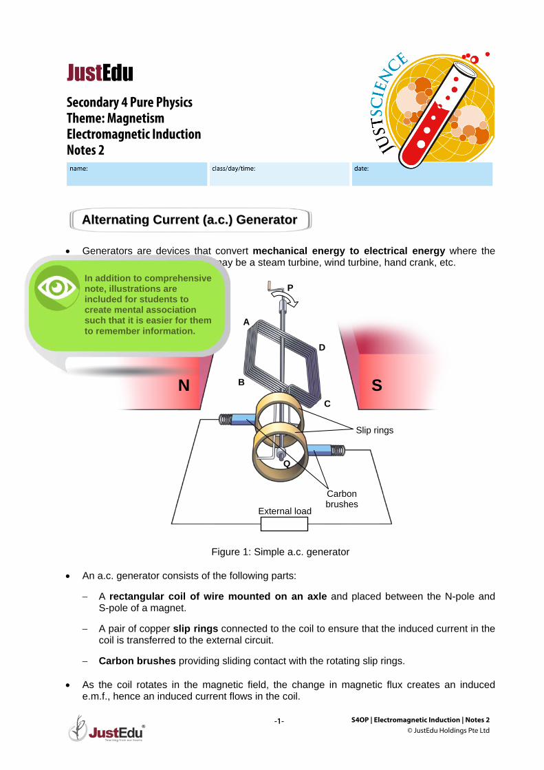
• Generators are devices that convert mechanical energy to electrical energy where the
source of mechanical energy may be a steam turbine, wind turbine, hand crank, etc.
Figure 1: Simple a.c. generator • An a.c. generator consists of the following parts:
− A rectangular coil of wire mounted on an axle and placed between the N-pole and S-pole of a magnet.
− A pair of copper slip rings connected to the coil to ensure that the induced current in the
coil is transferred to the external circuit.
− Carbon brushes providing sliding contact with the rotating slip rings. • As the coil rotates in the magnetic field, the change in magnetic flux creates an induced
e.m.f., hence an induced current flows in the coil.
AAlltteerrnnaattiinngg CCuurrrreenntt ((aa..cc..)) GGeenneerraattoorr
Secondary 4 Pure Physics Theme: Magnetism Electromagnetic Induction Notes 2
N S
D
C
B
A
Slip rings
Carbon brushes
External load
P
Q
In addition to comprehensive note, illustrations are included for students to create mental association such that it is easier for them to remember information.
S4OP | Electromagnetic Induction | Notes 2 © JustEdu Holdings Pte Ltd
-2-
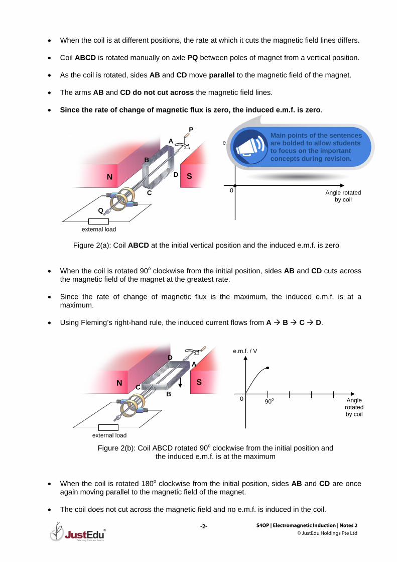
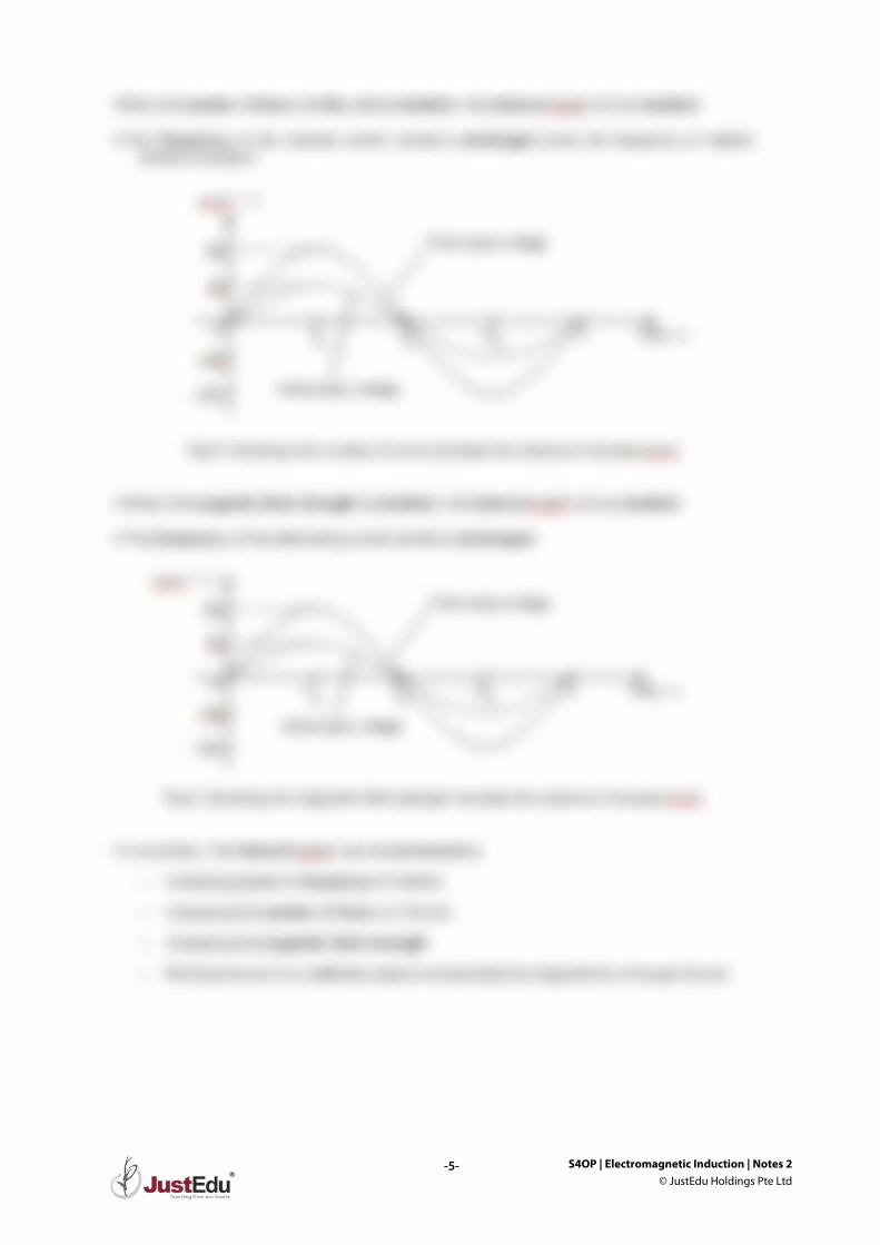
• When the coil is at different positions, the rate at which it cuts the magnetic field lines differs.
• Coil ABCD is rotated manually on axle PQ between poles of magnet from a vertical position. • As the coil is rotated, sides AB and CD move parallel to the magnetic field of the magnet.
• The arms AB and CD do not cut across the magnetic field lines.
• Since the rate of change of magnetic flux is zero, the induced e.m.f. is zero.
• When the coil is rotated 90o clockwise from the initial position, sides AB and CD cuts across the magnetic field of the magnet at the greatest rate.
• Since the rate of change of magnetic flux is the maximum, the induced e.m.f. is at a
maximum.
• Using Fleming’s right-hand rule, the induced current flows from A B C D.
• When the coil is rotated 180o clockwise from the initial position, sides AB and CD are once
again moving parallel to the magnetic field of the magnet. • The coil does not cut across the magnetic field and no e.m.f. is induced in the coil.
e.m.f. / V
Angle rotated by coil
0 90o
A
B C
D
N S
external load
Figure 2(b): Coil ABCD rotated 90o clockwise from the initial position and the induced e.m.f. is at the maximum
e.m.f. / V
Angle rotated by coil
0
Figure 2(a): Coil ABCD at the initial vertical position and the induced e.m.f. is zero
D
C
B
A
N S
external load
P
Q
Main points of the sentences are bolded to allow students to focus on the important concepts during revision.
S4OP | Electromagnetic Induction | Notes 2 © JustEdu Holdings Pte Ltd
-3-
As much as we would love to show you everything,
we cannot be showing you the best.
Do drop by any JustEdu centre to view the full set!
S4OP | Electromagnetic Induction | Notes 2 © JustEdu Holdings Pte Ltd
-4-
• The cycle continues as the coil rotates in the magnetic field to produce alternating e.m.f. which in turn produces an alternating current. Hence, the name alternating current generator.
• The period, T, is the time taken for the coil to make one complete rotation. The frequency of the rotation, f, is given by:
f = 1T
Formulas are placed in boxes to draw students’ attention to it quickly.
S4OP | Electromagnetic Induction | Notes 2 © JustEdu Holdings Pte Ltd
-5-
S4OP | Electromagnetic Induction | Notes 2 © JustEdu Holdings Pte Ltd
-6-
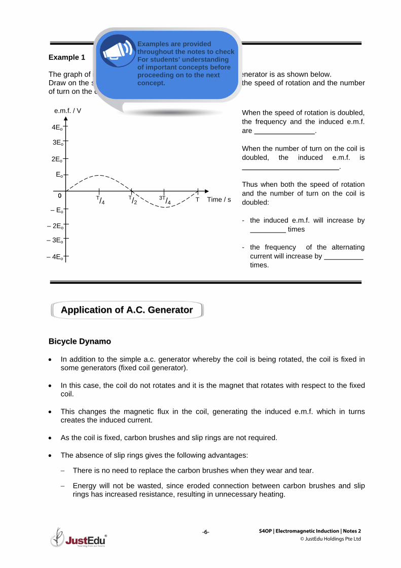
Example 1 The graph of induced e.m.f against time for a simple a.c. generator is as shown below. Draw on the same diagram, the output voltage when both the speed of rotation and the number of turn on the coil is doubled.
BBiiccyyccllee DDyynnaammoo • In addition to the simple a.c. generator whereby the coil is being rotated, the coil is fixed in
some generators (fixed coil generator). • In this case, the coil do not rotates and it is the magnet that rotates with respect to the fixed
coil.
• This changes the magnetic flux in the coil, generating the induced e.m.f. which in turns creates the induced current.
• As the coil is fixed, carbon brushes and slip rings are not required.
• The absence of slip rings gives the following advantages:
− There is no need to replace the carbon brushes when they wear and tear. − Energy will not be wasted, since eroded connection between carbon brushes and slip
rings has increased resistance, resulting in unnecessary heating.
AApppplliiccaattiioonn ooff AA..CC.. GGeenneerraattoorr
When the speed of rotation is doubled, the frequency and the induced e.m.f. are . When the number of turn on the coil is doubled, the induced e.m.f. is . Thus when both the speed of rotation and the number of turn on the coil is doubled: - the induced e.m.f. will increase by
times - the frequency of the alternating
current will increase by times.
e.m.f. / V
Time / s 0 T/2 3T/4 T T/4 0
Eo
– Eo
2Eo
– 2Eo
3Eo
4Eo
– 3Eo
– 4Eo
Examples are provided throughout the notes to check For students’ understanding of important concepts before proceeding on to the next concept.
S4OP | Electromagnetic Induction | Notes 2 © JustEdu Holdings Pte Ltd
-7-
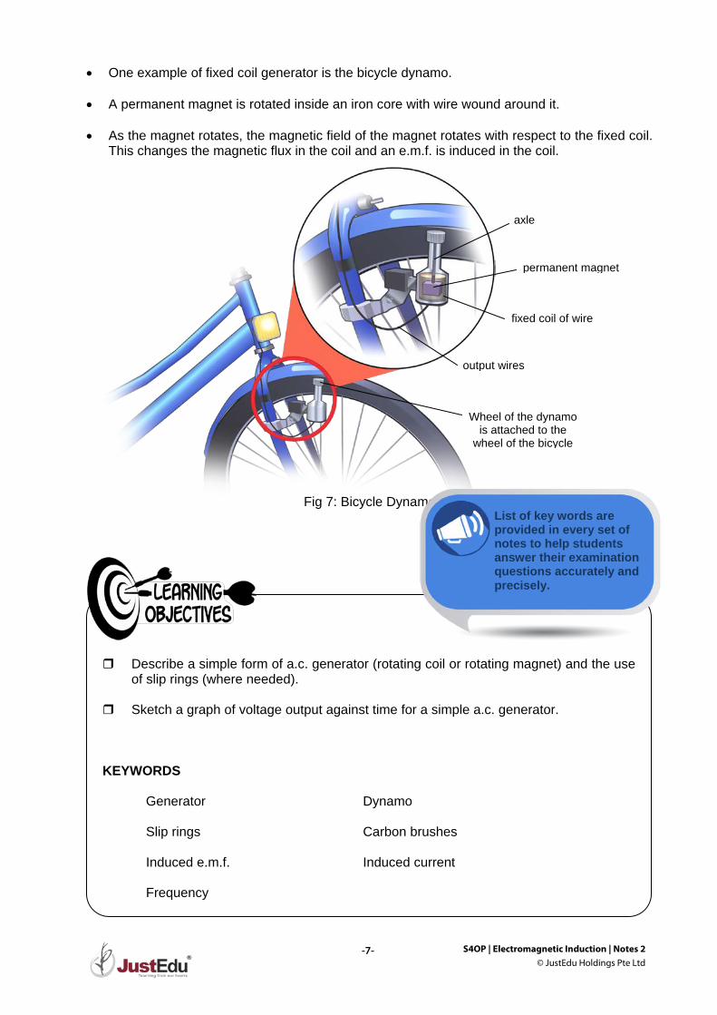
• One example of fixed coil generator is the bicycle dynamo.
• A permanent magnet is rotated inside an iron core with wire wound around it. • As the magnet rotates, the magnetic field of the magnet rotates with respect to the fixed coil.
This changes the magnetic flux in the coil and an e.m.f. is induced in the coil.
Fig 7: Bicycle Dynamo
Describe a simple form of a.c. generator (rotating coil or rotating magnet) and the use
of slip rings (where needed). Sketch a graph of voltage output against time for a simple a.c. generator. KEYWORDS Generator Dynamo Slip rings Carbon brushes Induced e.m.f. Induced current Frequency
Wheel of the dynamo is attached to the
wheel of the bicycle
permanent magnet
axle
fixed coil of wire
output wires
List of key words are provided in every set of notes to help students answer their examination questions accurately and precisely.

S4OP | Electromagnetic Induction | Ex 2 © JustEdu Holdings Pte Ltd
-1-
Secondary 4 Pure Physics Theme: Magnetism Electromagnetic Induction Exercise 2
A typical exercise will start with 5 to 15 multiple-choice questions. The first few questions will be more fundamental. The level of difficulty of questions will increase towards the end of each exercise. This is to allow students to grasp the basic concepts fully before applying the concepts to solve challenging questions.

S4OP | Electromagnetic Induction | Ex 2 © JustEdu Holdings Pte Ltd
-2-
Do drop by our centre to view the full set of materials.
S4OP | Electromagnetic Induction | Ex 2 © JustEdu Holdings Pte Ltd
-3-
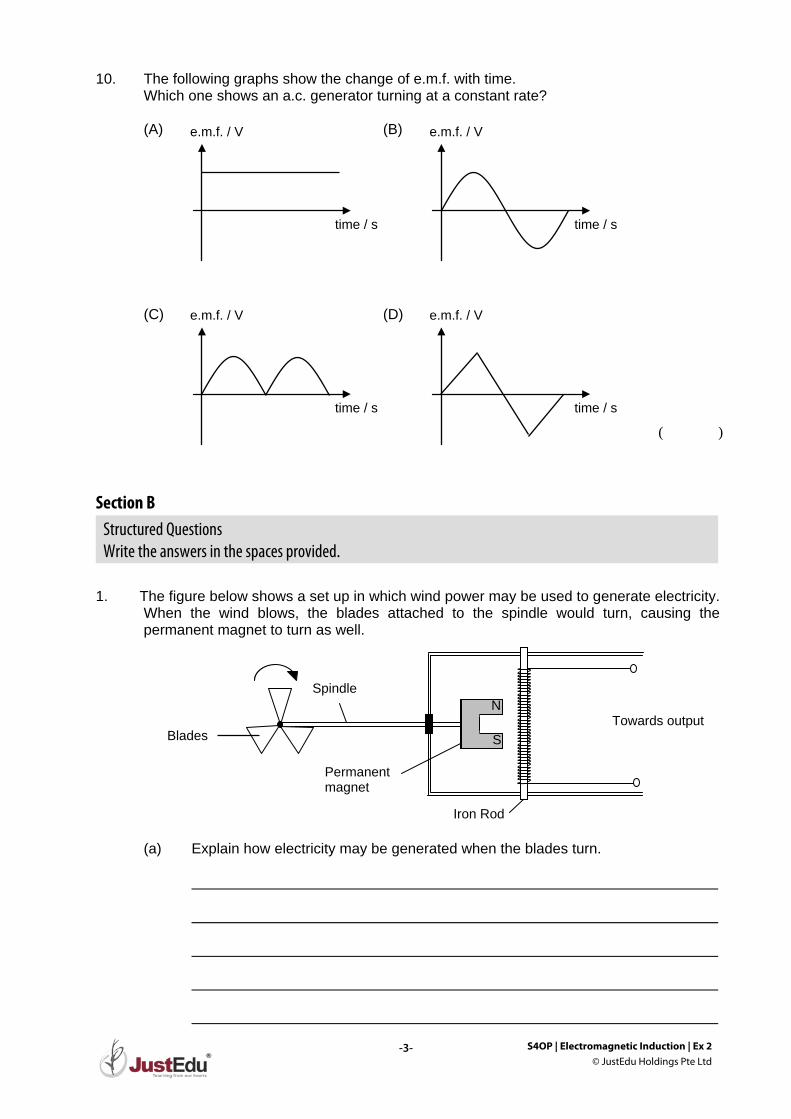
10. The following graphs show the change of e.m.f. with time. Which one shows an a.c. generator turning at a constant rate?
(A) (B) (C) (D) ( ) Section B
Structured Questions Write the answers in the spaces provided.
1. The figure below shows a set up in which wind power may be used to generate electricity.
When the wind blows, the blades attached to the spindle would turn, causing the permanent magnet to turn as well.
(a) Explain how electricity may be generated when the blades turn.
e.m.f. / V
time / s
e.m.f. / V
time / s
e.m.f. / V
time / s
e.m.f. / V
time / s
Towards output
Spindle
Iron Rod
Permanent magnet
N
S Blades
S4OP | Electromagnetic Induction | Ex 2 © JustEdu Holdings Pte Ltd
-4-
(b) State the purpose of the iron rod. (c) Suggest two ways to increase the current flowing toward the output without
increasing wind speed.
Do drop by our centre to view the full set of materials.

S4OP | Electromagnetic Induction | Ex 2 © JustEdu Holdings Pte Ltd
-5-
Do drop by our centre to view the full set of materials.
S4OP | Electromagnetic Induction | Ex 2 © JustEdu Holdings Pte Ltd
-6-
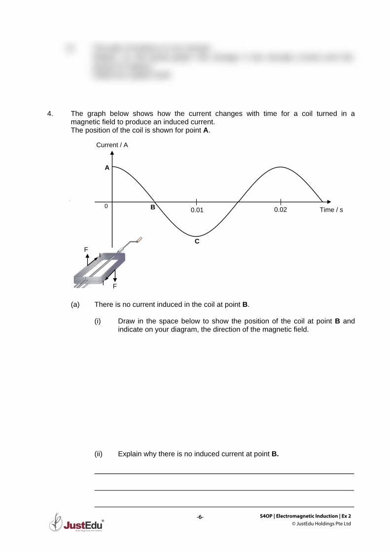
4. The graph below shows how the current changes with time for a coil turned in a
magnetic field to produce an induced current. The position of the coil is shown for point A. (a) There is no current induced in the coil at point B. (i) Draw in the space below to show the position of the coil at point B and
indicate on your diagram, the direction of the magnetic field. (ii) Explain why there is no induced current at point B.
Time / s 0 0.01 0.02
Current / A
A
B
C F
F I
I
S4OP | Electromagnetic Induction | Ex 2 © JustEdu Holdings Pte Ltd
-7-
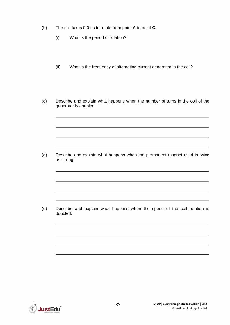
(b) The coil takes 0.01 s to rotate from point A to point C. (i) What is the period of rotation? (ii) What is the frequency of alternating current generated in the coil? (c) Describe and explain what happens when the number of turns in the coil of the
generator is doubled. (d) Describe and explain what happens when the permanent magnet used is twice
as strong. (e) Describe and explain what happens when the speed of the coil rotation is
doubled.