lsa 50.2 - 4 poles
TRANSCRIPT
This manual is to be given to
the end user
LSA 50.2 - 4 POLES ALTERNATORS
4
Installation and maintenance
4099 en - 03.2007 / a
2
INSTALLATION AND MAINTENANCE
LSA 50.2 - 4 POLESALTERNATORS
4099 en - 03.2007 / aLEROY-SOMER
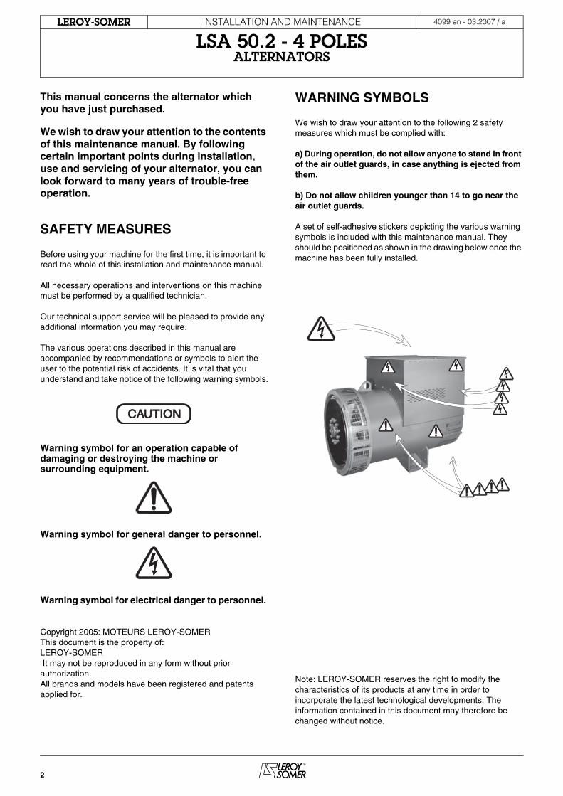
This manual concerns the alternator which you have just purchased.
We wish to draw your attention to the contents of this maintenance manual. By following certain important points during installation, use and servicing of your alternator, you can look forward to many years of trouble-free operation.
SAFETY MEASURES
Before using your machine for the first time, it is important to read the whole of this installation and maintenance manual.
All necessary operations and interventions on this machine must be performed by a qualified technician.
Our technical support service will be pleased to provide any additional information you may require.
The various operations described in this manual are accompanied by recommendations or symbols to alert the user to the potential risk of accidents. It is vital that you understand and take notice of the following warning symbols.
Warning symbol for an operation capable of damaging or destroying the machine or surrounding equipment.
Warning symbol for general danger to personnel.
Warning symbol for electrical danger to personnel.
Copyright 2005: MOTEURS LEROY-SOMERThis document is the property of:LEROY-SOMER It may not be reproduced in any form without prior authorization. All brands and models have been registered and patents applied for.
WARNING SYMBOLS
We wish to draw your attention to the following 2 safety measures which must be complied with:
a) During operation, do not allow anyone to stand in front of the air outlet guards, in case anything is ejected from them.
b) Do not allow children younger than 14 to go near the air outlet guards.
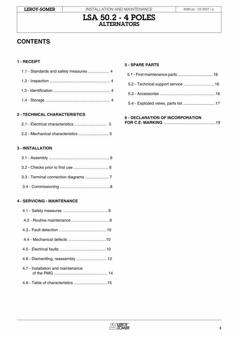
A set of self-adhesive stickers depicting the various warning symbols is included with this maintenance manual. They should be positioned as shown in the drawing below once the machine has been fully installed.
Note: LEROY-SOMER reserves the right to modify the characteristics of its products at any time in order to incorporate the latest technological developments. The information contained in this document may therefore be changed without notice.
CAUTIONCAUTION
3
INSTALLATION AND MAINTENANCE
LSA 50.2 - 4 POLESALTERNATORS
4099 en - 03.2007 / aLEROY-SOMER
CONTENTS
1 - RECEIPT
1.1 - Standards and safety measures ................... 4
1.2 - Inspection ...................................................... 4 1.3 - Identification ................................................... 4 1.4 - Storage .......................................................... 4
2 - TECHNICAL CHARACTERISTICS 2.1 - Electrical characteristics ............................. 5 2.2 - Mechanical characteristics ........................... 5
3 - INSTALLATION 3.1 - Assembly ...................................................... 6 3.2 - Checks prior to first use ............................... 6 3.3 - Terminal connection diagrams ..................... 7 3.4 - Commissioning .............................................8 4 - SERVICING - MAINTENANCE 4.1 - Safety measures .........................................9 4.2 - Routine maintenance ..................................9 4.3 - Fault detection ...........................................10 4.4 - Mechanical defects ..................................10 4.5 - Electrical faults ..........................................10 4.6 - Dismantling, reassembly ........................... 12 4.7 - Installation and maintenance of the PMG ................................................ 14 4.8 - Table of characteristics ..............................15
5 - SPARE PARTS
5.1 - First maintenance parts ................................16 5.2 - Technical support service ............................16 5.3 - Accessories ..................................................16
5.4 - Exploded views, parts list .............................17
6 - DECLARATION OF INCORPORATIONFOR C.E. MARKING ...............................................19
4
INSTALLATION AND MAINTENANCE
LSA 50.2 - 4 POLESALTERNATORS
RECEIPT
4099 en - 03.2007 / aLEROY-SOMER
1 - RECEIPT
1.1 - Standards and safety measuresOur alternators comply with most international standards and are compatible with:- The recommendations of the International Electrotechnical CommissionIEC 34-1, (EN 60034).- The recommendations of theInternational Standards Organisation ISO 8528.- The European Community directive 89/336/EEC on Electromagnetic Compatibility (EMC).- The European Community directives73/23/EEC and 93/68/EEC (Low Voltage Directive)They are CE marked with regard to the LVD (Low Voltage Directive) in their role as a machine component. A declaration of incorporation can be supplied on request.Before using your generator for the first time, read carefully the contents of this installation and maintenance manual, supplied with the machine. All operations performed on the generator should be undertaken by qualified personnel with specialist training in the commissioning, servicing and maintenance of electrical and mechanical machinery. This maintenance manual should be retained for the whole of the machine's life and be handed over with the contractual file.The various operations described in this manual are accompanied by recommendations or symbols to alert the user to the potential risk of accidents. It is vital that you understand and take notice of the warning symbols included with the machine.
1.2 - InspectionOn receipt of your alternator, check that it has not suffered any damage in transit. If there are obvious signs of damage, contact the transporter (you may be able to claim on their insurance) and after a visual check, turn the machine by hand to detect any malfunction.
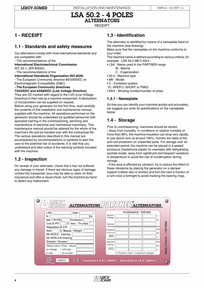
1.3 - IdentificationThe alternator is identified by means of a nameplate fixed on the machine (see drawing).Make sure that the nameplate on the machine conforms to your order.The machine name is defined according to various criteria, for example: LSA 50.2 M6 C 6S/4 -• LSA : Name used in the PARTNER range M : Marine C : Cogeneration • 50.2 : Machine type• M6 : Model• C : Excitation system (C: AREP/J: SHUNT or PMG)• 6S/4 : Winding number/number of poles 1.3.1 - Nameplate
So that you can identify your machine quickly and accurately, we suggest you write its specifications on the nameplate below.
1.4 - StoragePrior to commissioning, machines should be stored: - Away from humidity: In conditions of relative humidity of more than 90%, the machine insulation can drop very rapidly, to just above zero at around 100%; monitor the state of the anti-rust protection on unpainted parts. For storage over an extended period, the machine can be placed in a sealed enclosure (heatshrunk plastic for example) with dehydrating sachets inside, away from significant and frequent variations in temperature to avoid the risk of condensation during storage.- If the area is affected by vibration, try to reduce the effect of these vibrations by placing the generator on a damper support (rubber disc or similar) and turn the rotor a fraction of a turn once a fortnight to avoid marking the bearing rings.
ALTERNATEURS ALTERNATORS
LSA Date N 5700 125897 A15 Hz Min-1/R.P.M. 1500 Protection Cos Ø /P.F. 0,8 Cl. ther. / Th.class Régulateur/A.V.R. R 438 B Altit. m Masse / Weight Rlt AV/D.E bearing 6302 2 RS C3Rlt AR/N.D.E bearing 6303 2 RS C3Graisse / Grease 45g / 3600 h
Valeurs excit / Excit. values
en charge / full load
à vide / at no load Mad
e in
Fra
nce
- 1
024
959
/a
Tension Voltage
SecoursStd by
40C
(*) Tension maxi. / maximum voltage
27C
PUISSANCE / RATING
Conforme à C.E.I 60034-1. According to I.E.C 60034-1.166631
Connex.
kVA
kW
A
kVA
kW
A
V
Ph.
ContinueContinuous
USC
5
INSTALLATION AND MAINTENANCE
LSA 50.2 - 4 POLESALTERNATORS
TECHNICAL CHARACTERISTICS
4099 en - 03.2007 / aLEROY-SOMER
2 - TECHNICAL CHARACTERISTICS
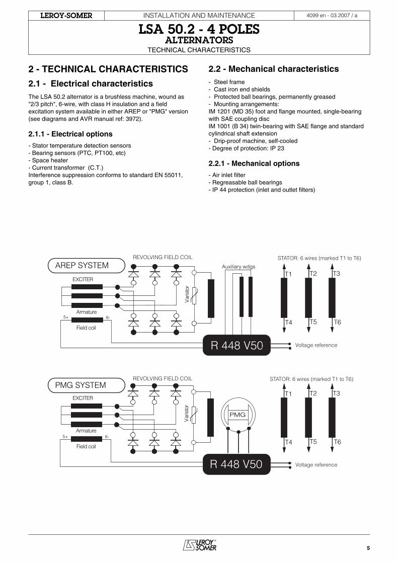
2.1 - Electrical characteristicsThe LSA 50.2 alternator is a brushless machine, wound as "2/3 pitch", 6-wire, with class H insulation and a field excitation system available in either AREP or "PMG" version (see diagrams and AVR manual ref: 3972).
2.1.1 - Electrical options
- Stator temperature detection sensors- Bearing sensors (PTC, PT100, etc)- Space heater- Current transformer (C.T.)Interference suppression conforms to standard EN 55011, group 1, class B.
2.2 - Mechanical characteristics- Steel frame- Cast iron end shields- Protected ball bearings, permanently greased- Mounting arrangements:IM 1201 (MD 35) foot and flange mounted, single-bearing with SAE coupling discIM 1001 (B 34) twin-bearing with SAE flange and standard cylindrical shaft extension- Drip-proof machine, self-cooled- Degree of protection: IP 23
2.2.1 - Mechanical options
- Air inlet filter - Regreasable ball bearings- IP 44 protection (inlet and outlet filters)
AREP SYSTEM
PMG SYSTEM
EXCITER
Field coil
Armature
EXCITER
Field coil
Armature
T1 T2 T3
T4 T5 T6
Var
isto
r
5+ 6-
R 448 V50
Auxiliary wdgs
T1 T2 T3
T4 T5 T6
Voltage reference
Var
isto
r
5+ 6-
R 448 V50
PMG
Voltage reference
REVOLVING FIELD COIL STATOR: 6 wires (marked T1 to T6)
REVOLVING FIELD COIL STATOR: 6 wires (marked T1 to T6)
6
INSTALLATION AND MAINTENANCE
LSA 50.2 - 4 POLESALTERNATORS
INSTALLATION
4099 en - 03.2007 / aLEROY-SOMER
3 - INSTALLATIONPersonnel undertaking the various operations indicated in this section must wear personal protective equipment appropriate for mechanical and electrical hazards.
3.1 - Assembly
All mechanical handling operations must be undertaken using suitable equipment and the machine must be horizontal. Check the weight of the machine on the nameplate before choosing the lifting tool.
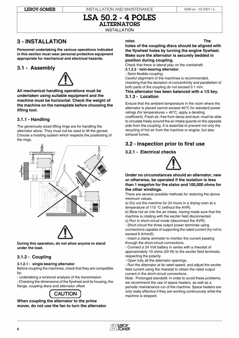
3.1.1 - Handling
The generously-sized lifting rings are for handling the alternator alone. They must not be used to lift the genset. Choose a hoisting system which respects the positioning of the rings.
During this operation, do not allow anyone to stand under the load.
3.1.2 - Coupling
3.1.2.1 - single-bearing alternatorBefore coupling the machines, check that they are compatible by:- undertaking a torsional analysis of the transmission- Checking the dimensions of the flywheel and its housing, the flange, coupling discs and alternator offset
When coupling the alternator to the prime mover, do not use the fan to turn the alternator
rotor. The holes of the coupling discs should be aligned with the flywheel holes by turning the engine flywheel.Make sure the alternator is securely bedded in position during coupling.Check that there is lateral play on the crankshaft.3.1.2.2 - twin-bearing alternator- Semi-flexible couplingCareful alignment of the machines is recommended, checking that the deviation of concentricity and parallelism of both parts of the coupling do not exceed 0.1 mm.This alternator has been balanced with a 1/2 key.3.1.3 - Location
Ensure that the ambient temperature in the room where the alternator is placed cannot exceed 40°C for standard power ratings (for temperatures > 40°C, apply a derating coefficient). Fresh air, free from damp and dust, must be able to circulate freely around the air intake guards on the opposite side from the coupling. It is essential to prevent not only the recycling of hot air from the machine or engine, but also exhaust fumes.
3.2 - Inspection prior to first use
3.2.1 - Electrical checks
Under no circumstances should an alternator, new or otherwise, be operated if the isolation is less than 1 megohm for the stator and 100,000 ohms for the other windings.There are several possible methods for restoring the above minimum values.a) Dry out the machine for 24 hours in a drying oven at a temperature of 110 °C (without the AVR).b) Blow hot air into the air intake, having made sure that the machine is rotating with the exciter field disconnected.c) Run in short-circuit mode (disconnect the AVR):- Short-circuit the three output power terminals using connections capable of supporting the rated current (try not to exceed 6 A/mm2).- Insert a clamp ammeter to monitor the current passing through the short-circuit connections.- Connect a 24 Volt battery in series with a rheostat of approximately 10 ohms (50 W) to the exciter field terminals, respecting the polarity.- Open fully all the alternator openings.- Run the alternator at its rated speed, and adjust the exciter field current using the rheostat to obtain the rated output current in the short-circuit connections.Note : Prolonged standstill: In order to avoid these problems, we recommend the use of space heaters, as well as a periodic maintenance run of the machine. Space heaters are only really effective if they are working continuously while the machine is stopped.CAUTIONCAUTION
7
INSTALLATION AND MAINTENANCE
LSA 50.2 - 4 POLESALTERNATORS
INSTALLATION
4099 en - 03.2007 / aLEROY-SOMER
3.2.2 - Mechanical checks
Before starting the machine for the first time, check that:- The winding connection corresponds to the site operating voltage (see section 3.3)- All fixing bolts and screws are tight- The cooling air is drawn in freely- The protective guards and housing are correctly in place- The standard direction of rotation is clockwise as seen from the shaft end (phase rotation in order 1 - 2 - 3) For anti-clockwise rotation, swap phases 2 and 3 and derate the machine by 5%.If mounting a C.T. for parallel operation, reverse the secondary wires S1, S2 on the AVR.
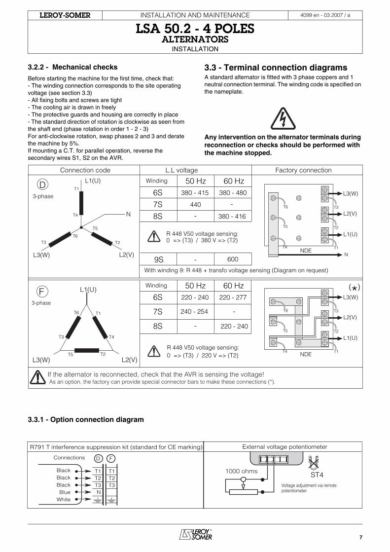
3.3 - Terminal connection diagramsA standard alternator is fitted with 3 phase coppers and 1 neutral connection terminal. The winding code is specified on the nameplate.
Any intervention on the alternator terminals during reconnection or checks should be performed with the machine stopped.
3.3.1 - Option connection diagram
Connection code L.L voltage Factory connection
3-phase
N
T1
T4
T3T6
T5
T2
L1(U)
L3(W) L2(V)
D
L1(U)
L3(W)
T1
T4T3
T6
T5 T2L2(V)
F3-phase
(*)
Winding 60 Hz50 Hz380 - 415 380 - 480
440
380 - 416
-
-
-
6S
7S
8S
Winding 60 Hz50 Hz
R 448 V50 voltage sensing:0 => (T3) / 220 V => (T2)
9S 600
220 - 240
220 - 240
220 - 277
240 - 254 -
-
6S
7S
8S
With winding 9: R 448 + transfo voltage sensing (Diagram on request)
NDE
L1(U)
L2(V)
L3(W)
T4
T6
T5
T1
T2
T3
N
If the alternator is reconnected, check that the AVR is sensing the voltage! As an option, the factory can provide special connector bars to make these connections (*).
R 448 V50 voltage sensing: 0 => (T3) / 380 V => (T2)
NDE
L1(U)
L2(V)
L3(W)
T4
T6
T5
T1
T2
T3
R791 T interference suppression kit (standard for CE marking) External voltage potentiometer
BlackBlackBlackBlue
White
Connections D F
T1 T1T2 T2T3 T3N
Voltage adjustment via remote potentiometer
ST41000 ohms
8
INSTALLATION AND MAINTENANCE
LSA 50.2 - 4 POLESALTERNATORS
INSTALLATION
4099 en - 03.2007 / aLEROY-SOMER
3.3.2 - Connection checks
Electrical installations must comply with the current legislation in force in the country of use.Check that:- The residual circuit-breaker conforms to the legislation on protection of personnel in force in the country of use, and has been correctly installed on the alternator power output as close as possible to the alternator. (In this case, disconnect the interference suppression module wire that links the neutral). - Any protection devices in place have not been tripped. - If there is an external AVR, the connections between the alternator and the panel are made in accordance with the connection diagram.- There is no phase-phase or phase-neutral short-circuit between the alternator output terminals and the genset control panel (part of the circuit not protected by circuit-breakers or relays in the panel).- The machine should be connected with the busbar separating the terminals as shown in the terminal connection diagram.
3.4 - Commissioning
The machine can only be started up and used if the installation is in accordance with the regulations and instructions defined in this manual.The machine is tested and set up at the factory. When first used with no load, make sure that the drive speed is correct and stable (see the nameplate). With the regreasable bearing option, we recommend greasing the bearings at the time of commissioning (see 4.2.3).On application of the load, the machine should achieve its rated speed and voltage; however, in the event of abnormal operation, the machine setting can be altered (follow the adjustment procedure in section 3.5). If the machine still operates incorrectly, the cause of the malfunction must be located (see section 4.4 and 4.5).
3.5 - Setting up
The various adjustments during tests must be made by aqualified technician. Take care that the drive speedspecified on the nameplate is reached beforecommencing adjustment. After operational testing,replace all access panels or covers.The AVR is the only means of making adjustments to the machine.
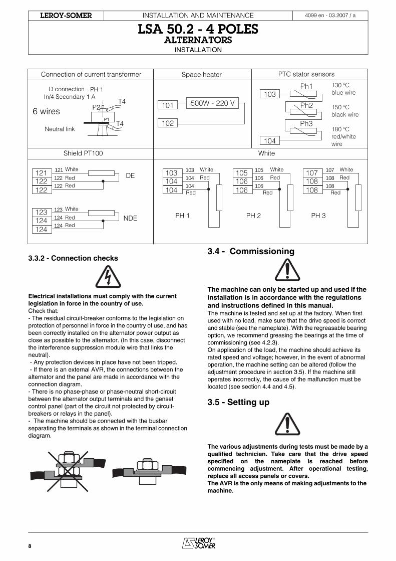
Connection of current transformer Space heater PTC stator sensors
Shield PT100 White
Neutral link
White
RedRed
6 wires
- PH 1 In/4 Secondary 1 A
D connection
P1
P2T4
T4
Ph1
Ph2
Ph3
101
102
103
104
130 ºCblue wire
150 ºCblack wire
180 ºCred/whitewire
500W - 220 V
121
122122
White
RedRed
123
124124
DE
NDE
122
122
124
124
123
121 103
104
104
105
106
106
107
108
108
White
Red Red Red
Red RedRed103
104104
PH 1
White105
106106
PH 2
White107
108108
PH 3
9
INSTALLATION AND MAINTENANCE
LSA 50.2 - 4 POLESALTERNATORS
SERVICING - MAINTENANCE
4099 en - 03.2007 / aLEROY-SOMER
4 - SERVICING - MAINTENANCE
4.1 - Safety measures
Servicing or troubleshooting must be carried out strictly in accordance with instructions so as to avoid the risk of accidents and to maintain the machine in its original state.
All such operations performed on the alternator should be undertaken by personnel trained in the commissioning, servicing and maintenance of electrical and mechanical components, who must wear personal protective equipment appropriate for mechanical and electrical hazards.
Before any intervention on the machine, ensure that it cannot be started by a manual or automatic system and that you have understood the operating principles of the system.
4.2 - Regular maintenance
4.2.1 - Checks after start-up
After approximately 20 hours of operation, check that all fixing screws on the machine are still tight, plus the general state of the machine and the various electrical connections in the installation.
4.2.2 - Cooling circuit
It is advisable to check that circulation of air is not reduced by partial blocking of the air intake and outlet guards: mud, fibre, soot, and to check whether the ventilation guards are corroded or scratched.
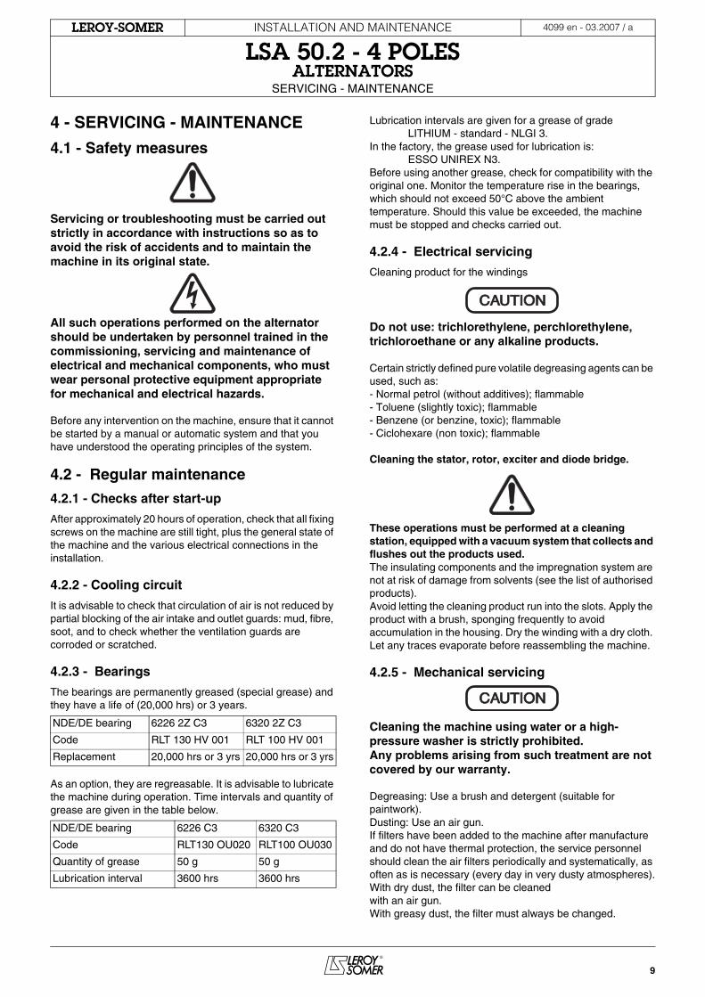
4.2.3 - Bearings
The bearings are permanently greased (special grease) and they have a life of (20,000 hrs) or 3 years.
As an option, they are regreasable. It is advisable to lubricate the machine during operation. Time intervals and quantity of grease are given in the table below.
Lubrication intervals are given for a grease of grade LITHIUM - standard - NLGI 3.In the factory, the grease used for lubrication is: ESSO UNIREX N3.Before using another grease, check for compatibility with the original one. Monitor the temperature rise in the bearings, which should not exceed 50°C above the ambient temperature. Should this value be exceeded, the machine must be stopped and checks carried out.
4.2.4 - Electrical servicing
Cleaning product for the windings
Do not use: trichlorethylene, perchlorethylene, trichloroethane or any alkaline products.
Certain strictly defined pure volatile degreasing agents can be used, such as:- Normal petrol (without additives); flammable- Toluene (slightly toxic); flammable- Benzene (or benzine, toxic); flammable- Ciclohexare (non toxic); flammable
Cleaning the stator, rotor, exciter and diode bridge.
These operations must be performed at a cleaning station, equipped with a vacuum system that collects and flushes out the products used.The insulating components and the impregnation system are not at risk of damage from solvents (see the list of authorised products).Avoid letting the cleaning product run into the slots. Apply the product with a brush, sponging frequently to avoid accumulation in the housing. Dry the winding with a dry cloth. Let any traces evaporate before reassembling the machine.
4.2.5 - Mechanical servicing
Cleaning the machine using water or a high-pressure washer is strictly prohibited.Any problems arising from such treatment are not covered by our warranty.
Degreasing: Use a brush and detergent (suitable for paintwork).Dusting: Use an air gun.If filters have been added to the machine after manufacture and do not have thermal protection, the service personnel should clean the air filters periodically and systematically, as often as is necessary (every day in very dusty atmospheres).With dry dust, the filter can be cleanedwith an air gun. With greasy dust, the filter must always be changed.
NDE/DE bearing 6226 2Z C3 6320 2Z C3
Code RLT 130 HV 001 RLT 100 HV 001
Replacement 20,000 hrs or 3 yrs 20,000 hrs or 3 yrs
NDE/DE bearing 6226 C3 6320 C3
Code RLT130 OU020 RLT100 OU030
Quantity of grease 50 g 50 g
Lubrication interval 3600 hrs 3600 hrs
CAUTIONCAUTION
CAUTIONCAUTION
10
INSTALLATION AND MAINTENANCE
LSA 50.2 - 4 POLESALTERNATORS
SERVICING - MAINTENANCE
4099 en - 03.2007 / aLEROY-SOMER
After cleaning the alternator, it is essential to check the winding insulation (see sections 3.2 and 4.8).
4.3 - Fault detectionIf, when commissioned, the alternator does not work normally, the source of the malfunction must be identified.To do this, check that:- The protection devices are set correctly - The connections comply with the diagrams in the manuals supplied with the machine- The genset speed is correct (see section 1.3)Repeat the operations defined in section 3.
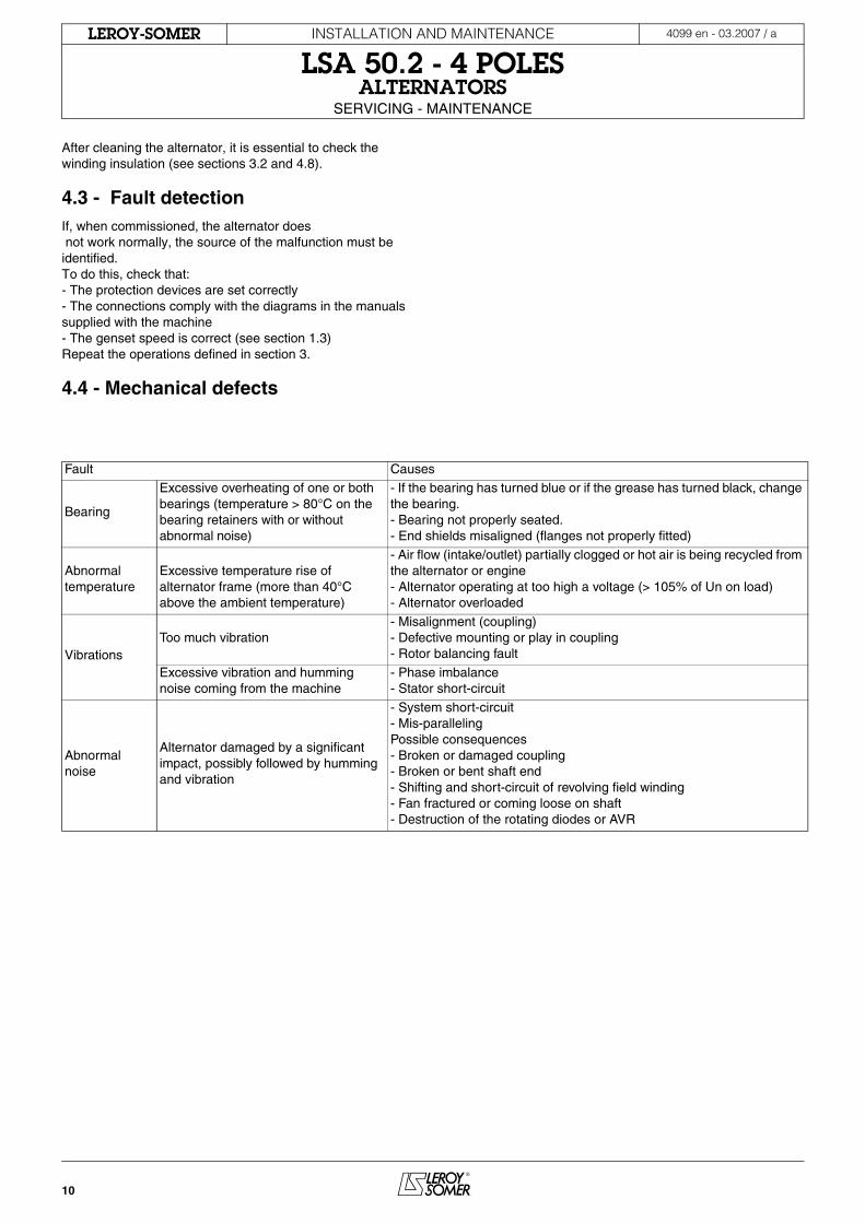
4.4 - Mechanical defects
Fault Causes
Bearing
Excessive overheating of one or both bearings (temperature > 80°C on the bearing retainers with or without abnormal noise)
- If the bearing has turned blue or if the grease has turned black, change the bearing.- Bearing not properly seated. - End shields misaligned (flanges not properly fitted)
Abnormal temperature
Excessive temperature rise of alternator frame (more than 40°C above the ambient temperature)
- Air flow (intake/outlet) partially clogged or hot air is being recycled from the alternator or engine- Alternator operating at too high a voltage (> 105% of Un on load)- Alternator overloaded
VibrationsToo much vibration
- Misalignment (coupling)- Defective mounting or play in coupling- Rotor balancing fault
Excessive vibration and humming noise coming from the machine
- Phase imbalance - Stator short-circuit
Abnormal noise
Alternator damaged by a significant impact, possibly followed by humming and vibration
- System short-circuit- Mis-parallelingPossible consequences - Broken or damaged coupling- Broken or bent shaft end- Shifting and short-circuit of revolving field winding- Fan fractured or coming loose on shaft- Destruction of the rotating diodes or AVR
11
INSTALLATION AND MAINTENANCE
LSA 50.2 - 4 POLESALTERNATORS
SERVICING - MAINTENANCE
4099 en - 03.2007 / aLEROY-SOMER
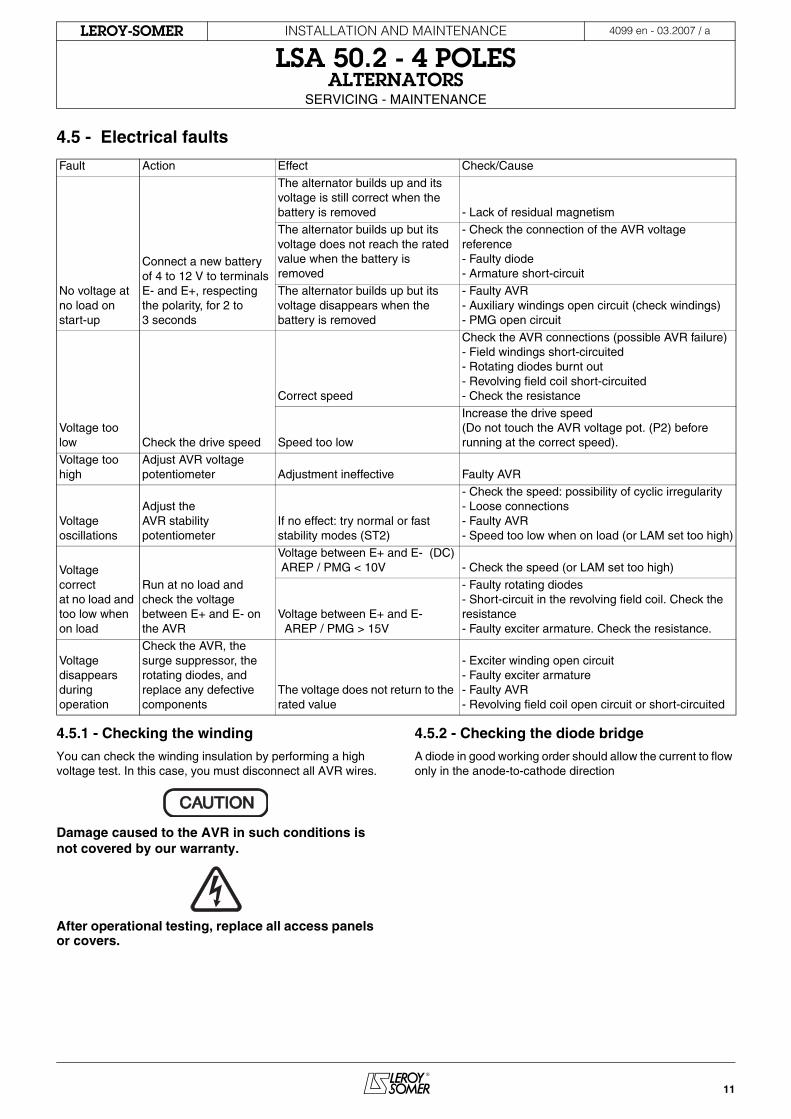
4.5 - Electrical faults
4.5.1 - Checking the winding
You can check the winding insulation by performing a high voltage test. In this case, you must disconnect all AVR wires.
Damage caused to the AVR in such conditions is not covered by our warranty.
After operational testing, replace all access panels or covers.
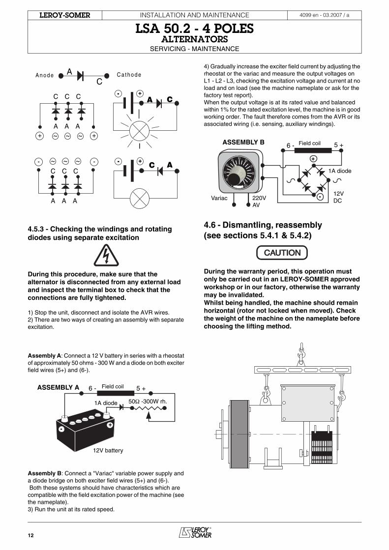
4.5.2 - Checking the diode bridge
A diode in good working order should allow the current to flow only in the anode-to-cathode direction
Fault Action Effect Check/Cause
No voltage at no load on start-up
Connect a new battery of 4 to 12 V to terminals E- and E+, respecting the polarity, for 2 to 3 seconds
The alternator builds up and its voltage is still correct when the battery is removed - Lack of residual magnetismThe alternator builds up but its voltage does not reach the rated value when the battery is removed
- Check the connection of the AVR voltage reference- Faulty diode- Armature short-circuit
The alternator builds up but its voltage disappears when the battery is removed
- Faulty AVR- Auxiliary windings open circuit (check windings)- PMG open circuit
Voltage too low Check the drive speed
Correct speed
Check the AVR connections (possible AVR failure)- Field windings short-circuited- Rotating diodes burnt out- Revolving field coil short-circuited - Check the resistance
Speed too low
Increase the drive speed (Do not touch the AVR voltage pot. (P2) before running at the correct speed).
Voltage too high
Adjust AVR voltage potentiometer Adjustment ineffective Faulty AVR
Voltage oscillations
Adjust the AVR stability potentiometer
If no effect: try normal or fast stability modes (ST2)
- Check the speed: possibility of cyclic irregularity- Loose connections- Faulty AVR- Speed too low when on load (or LAM set too high)
Voltage correctat no load and too low when on load
Run at no load and check the voltage between E+ and E- on the AVR
Voltage between E+ and E- (DC) AREP / PMG < 10V - Check the speed (or LAM set too high)
Voltage between E+ and E- AREP / PMG > 15V
- Faulty rotating diodes- Short-circuit in the revolving field coil. Check the resistance- Faulty exciter armature. Check the resistance.
Voltage disappears during operation
Check the AVR, the surge suppressor, the rotating diodes, and replace any defective components
The voltage does not return to the rated value
- Exciter winding open circuit- Faulty exciter armature- Faulty AVR- Revolving field coil open circuit or short-circuited
CAUTIONCAUTION
12
INSTALLATION AND MAINTENANCE
LSA 50.2 - 4 POLESALTERNATORS
SERVICING - MAINTENANCE
4099 en - 03.2007 / aLEROY-SOMER
4.5.3 - Checking the windings and rotating diodes using separate excitation
During this procedure, make sure that the alternator is disconnected from any external load and inspect the terminal box to check that the connections are fully tightened.
1) Stop the unit, disconnect and isolate the AVR wires.2) There are two ways of creating an assembly with separate excitation.
Assembly A: Connect a 12 V battery in series with a rheostat of approximately 50 ohms - 300 W and a diode on both exciter field wires (5+) and (6-).
Assembly B: Connect a "Variac" variable power supply and a diode bridge on both exciter field wires (5+) and (6-). Both these systems should have characteristics which are compatible with the field excitation power of the machine (see the nameplate).3) Run the unit at its rated speed.
4) Gradually increase the exciter field current by adjusting the rheostat or the variac and measure the output voltages on L1 - L2 - L3, checking the excitation voltage and current at no load and on load (see the machine nameplate or ask for the factory test report).When the output voltage is at its rated value and balanced within 1% for the rated excitation level, the machine is in good working order. The fault therefore comes from the AVR or its associated wiring (i.e. sensing, auxiliary windings).
4.6 - Dismantling, reassembly (see sections 5.4.1 & 5.4.2)
During the warranty period, this operation must only be carried out in an LEROY-SOMER approved workshop or in our factory, otherwise the warranty may be invalidated.Whilst being handled, the machine should remain horizontal (rotor not locked when moved). Check the weight of the machine on the nameplate before choosing the lifting method.
CAA n o d e C a t h o d e
- -
++ ~~~
C C C
A A A
C C C
A A A
~ ~ ~
-CA
+
- C A+
6 - 5 +
1A diode
12V battery
50Ω -300W rh.
-+
ASSEMBLY A Field coil
1A diode
-
+
6 - 5 +
Variac 220V AV
12V DC
50 60
7080
90
100
40
3020
10
0
ASSEMBLY B Field coil
CAUTIONCAUTION
13
INSTALLATION AND MAINTENANCE
LSA 50.2 - 4 POLESALTERNATORS
SERVICING - MAINTENANCE
4099 en - 03.2007 / aLEROY-SOMER
4.6.1 - Tools required
To fully dismantle the machine, we recommend using the tools listed below:- 1 ratchet spanner + extension- 1 torque wrench- 1 set of flat spanners: 8 mm, 10 mm, 18 mm- 1 socket set: 8, 10, 13, 16, 18, 21, 24, 30 mm- 1 socket with male ferrule: 5 mm - 1 puller
4.6.2 - Screw tightening torque
4.6.3 - Access to diodes
- Open the air intake grille (51).- Disconnect the diodes. - Check the 12 diodes using an ohmmeter or a battery lamp (see section 4.5.2).If the diodes are faulty,- Remove the surge suppressor (347).- Remove the "H" mounting nuts for the diode bridges on the support and the links to the armature.- Change the fitted caps, respecting the polarity.
4.6.4 - Access to connections and the regulation system
Access directly by removing the top of the cover (48) or the AVR access door (466).
4.6.5 - Replacing the NDE bearing
- Remove the air intake grille (51).- Remove the lid of the protective cover (48) and the side panels (366) and (367).- Remove the hook (21) and the cover rear panel (365).- Replace the hook (21) in order to manipulate the flange.- Disconnect the exciter wires (5+,6-).- Remove the screws (72) from the inner bearing cap (78). - Remove the screws (37).- Remove the shield (36).
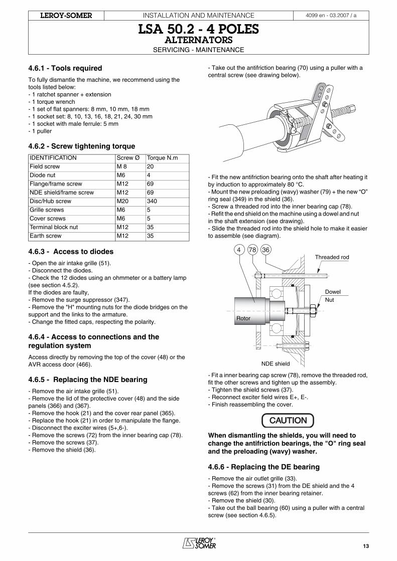
- Take out the antifriction bearing (70) using a puller with a central screw (see drawing below).
- Fit the new antifriction bearing onto the shaft after heating it by induction to approximately 80 °C.- Mount the new preloading (wavy) washer (79) + the new “O” ring seal (349) in the shield (36).- Screw a threaded rod into the inner bearing cap (78).- Refit the end shield on the machine using a dowel and nut in the shaft extension (see drawing).- Slide the threaded rod into the shield hole to make it easier to assemble (see diagram).
- Fit a inner bearing cap screw (78), remove the threaded rod, fit the other screws and tighten up the assembly.- Tighten the shield screws (37).- Reconnect exciter field wires E+, E-.- Finish reassembling the cover.
When dismantling the shields, you will need to change the antifriction bearings, the "O" ring seal and the preloading (wavy) washer.
4.6.6 - Replacing the DE bearing
- Remove the air outlet grille (33).- Remove the screws (31) from the DE shield and the 4 screws (62) from the inner bearing retainer.- Remove the shield (30).- Take out the ball bearing (60) using a puller with a central screw (see section 4.6.5).
IDENTIFICATION Screw Ø Torque N.m
Field screw M 8 20
Diode nut M6 4Flange/frame screw M12 69
NDE shield/frame screw M12 69
Disc/Hub screw M20 340Grille screws M6 5
Cover screws M6 5
Terminal block nut M12 35Earth screw M12 35
Rotor
NDE shield
Dowel Nut
Threaded rod4 78 36
CAUTIONCAUTION
14
INSTALLATION AND MAINTENANCE
LSA 50.2 - 4 POLESALTERNATORS
SERVICING - MAINTENANCE
4099 en - 03.2007 / aLEROY-SOMER
- Fit the new bearing, after heating it by induction to approximately 80 °C.- Screw two threaded rods into the inner bearing cap (68).- Refit the shield (30) on the machine.- Slide the threaded rods into the shield holes to make it easier to assemble (see basic diagram). - Tighten the bottom inner bearing cap screws (78), remove the threaded rod and fit the other screws.- Tighten the shield screws (31).- Refit the air outlet grille (33).
When dismantling the machine, always change the antifriction bearings.
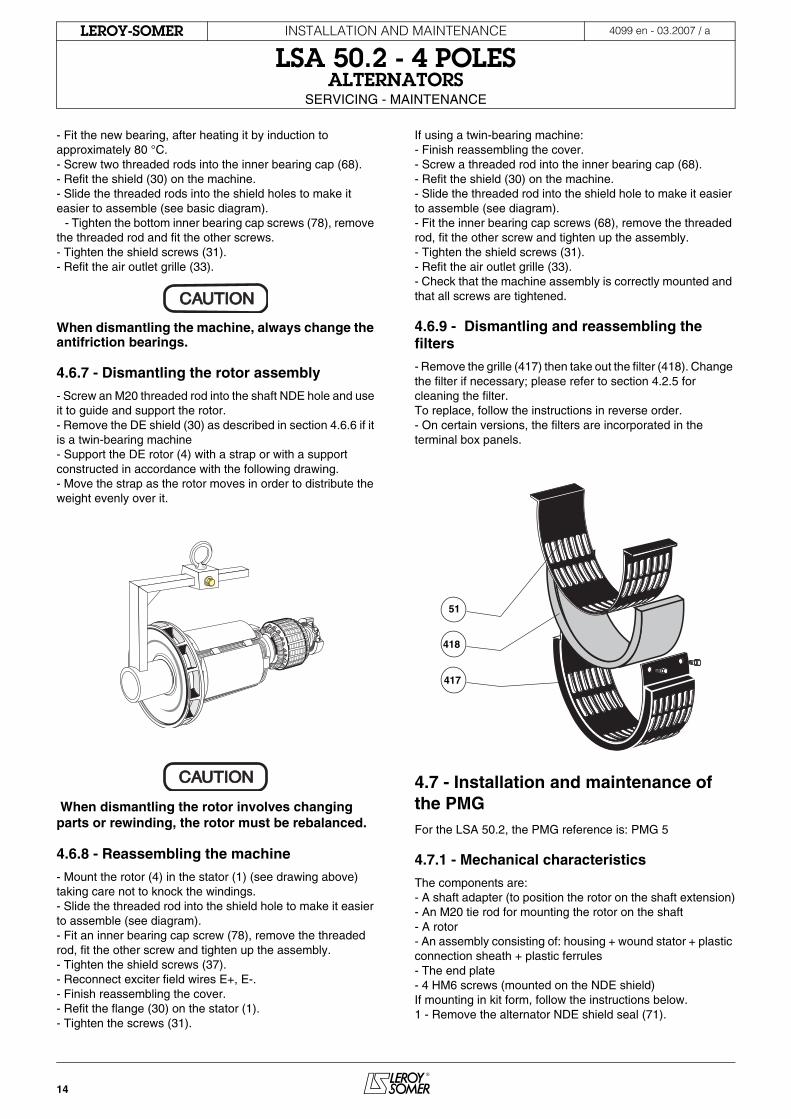
4.6.7 - Dismantling the rotor assembly
- Screw an M20 threaded rod into the shaft NDE hole and use it to guide and support the rotor.- Remove the DE shield (30) as described in section 4.6.6 if it is a twin-bearing machine - Support the DE rotor (4) with a strap or with a support constructed in accordance with the following drawing.- Move the strap as the rotor moves in order to distribute the weight evenly over it.
When dismantling the rotor involves changing parts or rewinding, the rotor must be rebalanced.
4.6.8 - Reassembling the machine
- Mount the rotor (4) in the stator (1) (see drawing above)taking care not to knock the windings.- Slide the threaded rod into the shield hole to make it easier to assemble (see diagram).- Fit an inner bearing cap screw (78), remove the threaded rod, fit the other screw and tighten up the assembly.- Tighten the shield screws (37).- Reconnect exciter field wires E+, E-.- Finish reassembling the cover.- Refit the flange (30) on the stator (1). - Tighten the screws (31).
If using a twin-bearing machine:- Finish reassembling the cover.- Screw a threaded rod into the inner bearing cap (68).- Refit the shield (30) on the machine.- Slide the threaded rod into the shield hole to make it easier to assemble (see diagram).- Fit the inner bearing cap screws (68), remove the threaded rod, fit the other screw and tighten up the assembly.- Tighten the shield screws (31).- Refit the air outlet grille (33).- Check that the machine assembly is correctly mounted and that all screws are tightened.
4.6.9 - Dismantling and reassembling the filters
- Remove the grille (417) then take out the filter (418). Change the filter if necessary; please refer to section 4.2.5 for cleaning the filter. To replace, follow the instructions in reverse order.- On certain versions, the filters are incorporated in the terminal box panels.
4.7 - Installation and maintenance of the PMGFor the LSA 50.2, the PMG reference is: PMG 5
4.7.1 - Mechanical characteristics
The components are:- A shaft adapter (to position the rotor on the shaft extension)- An M20 tie rod for mounting the rotor on the shaft - A rotor- An assembly consisting of: housing + wound stator + plastic connection sheath + plastic ferrules- The end plate- 4 HM6 screws (mounted on the NDE shield)If mounting in kit form, follow the instructions below.1 - Remove the alternator NDE shield seal (71).
CAUTIONCAUTION
CAUTIONCAUTION
418
417
51
15
INSTALLATION AND MAINTENANCE
LSA 50.2 - 4 POLESALTERNATORS
SERVICING - MAINTENANCE
4099 en - 03.2007 / aLEROY-SOMER
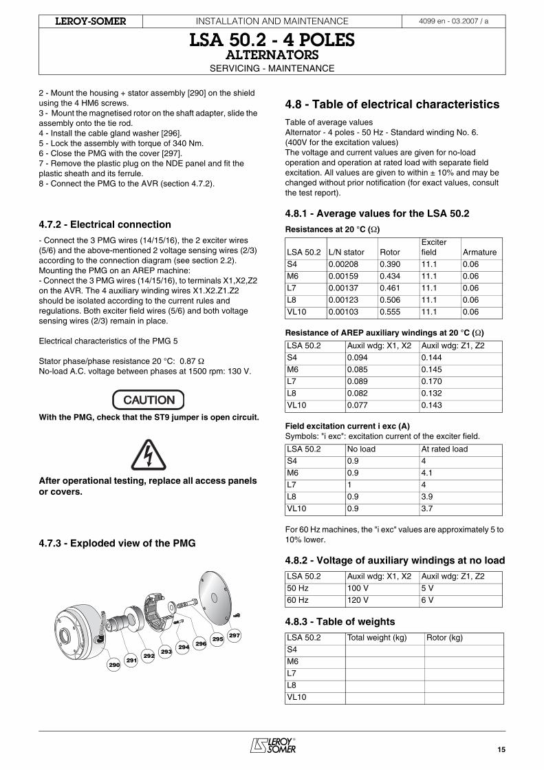
2 - Mount the housing + stator assembly [290] on the shield using the 4 HM6 screws.3 - Mount the magnetised rotor on the shaft adapter, slide the assembly onto the tie rod. 4 - Install the cable gland washer [296].5 - Lock the assembly with torque of 340 Nm. 6 - Close the PMG with the cover [297].7 - Remove the plastic plug on the NDE panel and fit the plastic sheath and its ferrule.8 - Connect the PMG to the AVR (section 4.7.2).
4.7.2 - Electrical connection
- Connect the 3 PMG wires (14/15/16), the 2 exciter wires(5/6) and the above-mentioned 2 voltage sensing wires (2/3) according to the connection diagram (see section 2.2).Mounting the PMG on an AREP machine:- Connect the 3 PMG wires (14/15/16), to terminals X1,X2,Z2 on the AVR. The 4 auxiliary winding wires X1.X2.Z1.Z2 should be isolated according to the current rules and regulations. Both exciter field wires (5/6) and both voltage sensing wires (2/3) remain in place.
Electrical characteristics of the PMG 5
Stator phase/phase resistance 20 °C: 0.87 ΩNo-load A.C. voltage between phases at 1500 rpm: 130 V.
With the PMG, check that the ST9 jumper is open circuit.
After operational testing, replace all access panels or covers.
4.7.3 - Exploded view of the PMG
4.8 - Table of electrical characteristicsTable of average valuesAlternator - 4 poles - 50 Hz - Standard winding No. 6. (400V for the excitation values)The voltage and current values are given for no-load operation and operation at rated load with separate field excitation. All values are given to within ± 10% and may be changed without prior notification (for exact values, consult the test report).
4.8.1 - Average values for the LSA 50.2
Resistances at 20 °C (Ω)
Resistance of AREP auxiliary windings at 20 °C (Ω)
Field excitation current i exc (A)Symbols: "i exc": excitation current of the exciter field.
For 60 Hz machines, the "i exc" values are approximately 5 to 10% lower.
4.8.2 - Voltage of auxiliary windings at no load
4.8.3 - Table of weights
CAUTIONCAUTION
290291
292293
294295
296297
LSA 50.2 L/N stator RotorExciter field Armature
S4 0.00208 0.390 11.1 0.06
M6 0.00159 0.434 11.1 0.06L7 0.00137 0.461 11.1 0.06
L8 0.00123 0.506 11.1 0.06
VL10 0.00103 0.555 11.1 0.06
LSA 50.2 Auxil wdg: X1, X2 Auxil wdg: Z1, Z2
S4 0.094 0.144
M6 0.085 0.145L7 0.089 0.170
L8 0.082 0.132
VL10 0.077 0.143
LSA 50.2 No load At rated loadS4 0.9 4
M6 0.9 4.1
L7 1 4L8 0.9 3.9
VL10 0.9 3.7
LSA 50.2 Auxil wdg: X1, X2 Auxil wdg: Z1, Z2
50 Hz 100 V 5 V
60 Hz 120 V 6 V
LSA 50.2 Total weight (kg) Rotor (kg)
S4
M6L7
L8
VL10
16
INSTALLATION AND MAINTENANCE
LSA 50.2 - 4 POLESALTERNATORS
SPARE PARTS
4099 en - 03.2007 / aLEROY-SOMER
5 - SPARE PARTS
5.1 - First maintenance partsEmergency repair kits are available as an option.They contain the following items:
5.2 - Technical support serviceOur technical support service will be pleased to provide any additional information you may require.
When ordering spare parts, you should indicate the complete machine type, its serial number and the information given on the nameplate.
Address your enquiry to your usual contact.
Part numbers should be identified from the exploded views and their description from the parts list.Our extensive network of service centres can dispatch the necessary parts without delay. To ensure correct operation and the safety of our machines, we recommend the use of original manufacturer spare parts.In the event of failure to comply with this advice, the manufacturer cannot be held responsible for any damage.
5.3 - Accessories
5.3.1 - Space heater for use when stopped
The space heater must run as soon as the alternator stops. It is installed at the rear of the machine. Its standard power is 500W with 220V or 250W with 110V on request.
Caution: The power supply is present when the machine is stopped.
5.3.2 - Temperature sensors with thermistors (PTC)
These are thermistor triplets with a positive temperature coefficient installed in the stator winding (1 per phase). There can be a maximum of 2 triplets in the winding (at 2 levels: warning and trip) and 1 or 2 thermistors in the shields.These sensors must be linked to adapted sensing relays (supplied optionally).Cold resistance of cold thermistor sensors: 100 to 250 Ω per sensor.
5.3.3 - Connection accessories
- 6-wire machines Requirements for coupling (F):- 3 shunts.
After operational testing, replace all access panels or covers.
AREP repair kit
R448 V50 automatic voltage regulator AEM 110 RE 022
Set of direct diodes ADE 491 EQ 013
Set of reverse diodes ADE 491 EQ 012
Surge suppressor CII PM 010
Single bearing kit
NDE bearing RLT 100 HV 001 'O' ring seal JOI 215 TB 001
Preloading wavy washer RLT 215 RB 005
Twin bearing kit
NDE bearing RLT 100 HV 001
DE bearing RLT 130 HV 001 'O' ring seal JOI 215 TB 001
Preloading wavy washer RLT 215 RB 005
17
INSTALLATION AND MAINTENANCE
LSA 50.2 - 4 POLESALTERNATORS
SPARE PARTS
4099 en - 03.2007 / aLEROY-SOMER
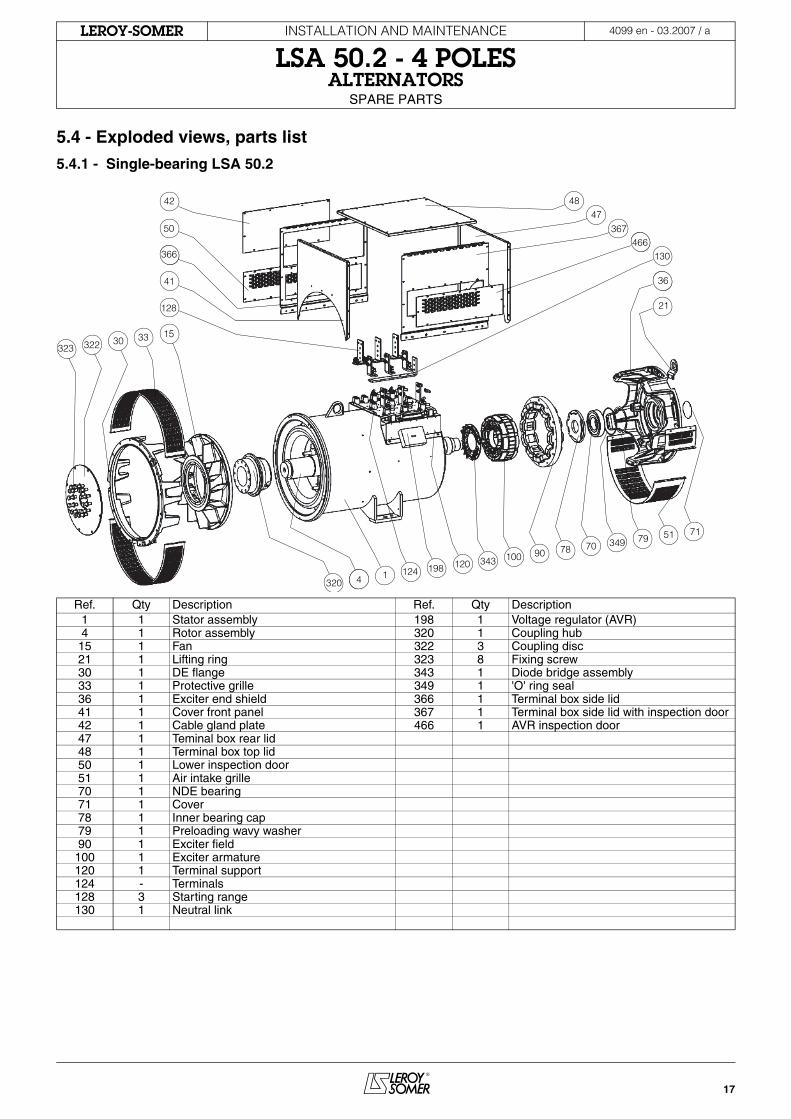
5.4 - Exploded views, parts list
5.4.1 - Single-bearing LSA 50.2
Ref. Qty Description Ref. Qty Description1 1 Stator assembly 198 1 Voltage regulator (AVR)4 1 Rotor assembly 320 1 Coupling hub
15 1 Fan 322 3 Coupling disc21 1 Lifting ring 323 8 Fixing screw30 1 DE flange 343 1 Diode bridge assembly33 1 Protective grille 349 1 'O' ring seal36 1 Exciter end shield 366 1 Terminal box side lid41 1 Cover front panel 367 1 Terminal box side lid with inspection door42 1 Cable gland plate 466 1 AVR inspection door 47 1 Teminal box rear lid48 1 Terminal box top lid50 1 Lower inspection door51 1 Air intake grille70 1 NDE bearing71 1 Cover78 1 Inner bearing cap79 1 Preloading wavy washer90 1 Exciter field
100 1 Exciter armature120 1 Terminal support124 - Terminals128 3 Starting range130 1 Neutral link
33
320
15
41
128
30
343 100198124
120
7051
7890
7971
349
323 322
50
366
42
4 1
466
4847
367466
130
21
36
18
INSTALLATION AND MAINTENANCE
LSA 50.2 - 4 POLESALTERNATORS
SPARE PARTS
4099 en - 03.2007 / aLEROY-SOMER
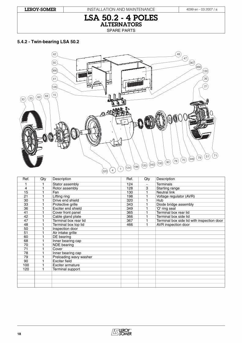
5.4.2 - Twin-bearing LSA 50.2
Ref. Qty Description Ref. Qty Description
1 1 Stator assembly 124 - Terminals4 1 Rotor assembly 128 3 Starting range
15 1 Fan 130 1 Neutral link21 1 Lifting ring 198 1 Voltage regulator (AVR)30 1 Drive end shield 320 1 Hub33 1 Protective grille 343 1 Diode bridge assembly36 1 Exciter end shield 349 1 'O' ring seal41 1 Cover front panel 365 1 Terminal box rear lid42 1 Cable gland plate 366 1 Terminal box side lid47 1 Terminal box rear lid 367 1 Terminal box side lid with inspection door48 1 Terminal box top lid 466 1 AVR inspection door 50 1 Inspection door51 1 Air intake grille60 1 DE bearing68 1 Inner bearing cap70 1 NDE bearing71 1 Cover78 1 Inner bearing cap79 1 Preloading wavy washer90 1 Exciter field
100 1 Exciter armature120 1 Terminal support
68
320
15
41
128
60
343 100198124
120
7051
7890
7971
349
30 33
50
366
42
4 1
466
4847
367466
130
21
36
19
INSTALLATION AND MAINTENANCE
LSA 50.2 - 4 POLESALTERNATORS
DECLARATION OF INCORPORATION FOR C.E. MARKING
4099 en - 03.2007 / aLEROY-SOMER
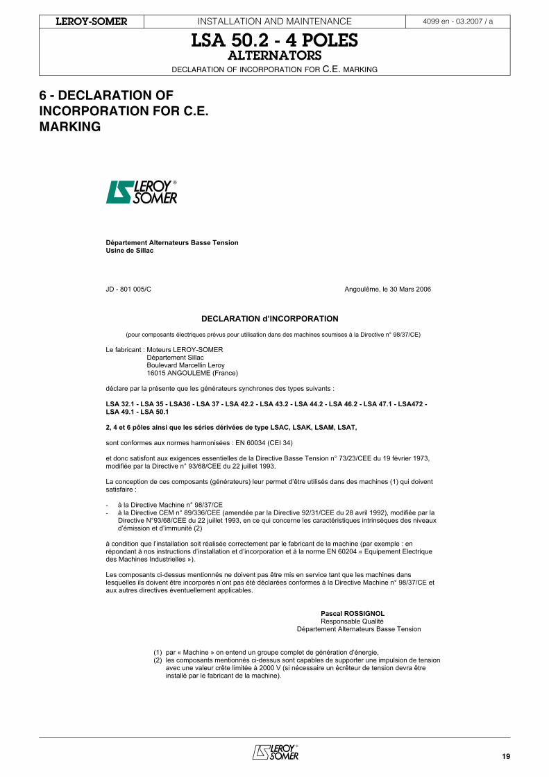
6 - DECLARATION OF INCORPORATION FOR C.E. MARKING
Département Alternateurs Basse Tension Usine de Sillac
JD - 801 005/C Angoulême, le 30 Mars 2006
DECLARATION d’INCORPORATION
(pour composants électriques prévus pour utilisation dans des machines soumises à la Directive n° 98/37/CE)
Le fabricant : Moteurs LEROY-SOMER Département Sillac Boulevard Marcellin Leroy 16015 ANGOULEME (France)
déclare par la présente que les générateurs synchrones des types suivants :
LSA 32.1 - LSA 35 - LSA36 - LSA 37 - LSA 42.2 - LSA 43.2 - LSA 44.2 - LSA 46.2 - LSA 47.1 - LSA472 - LSA 49.1 - LSA 50.1
2, 4 et 6 pôles ainsi que les séries dérivées de type LSAC, LSAK, LSAM, LSAT,
sont conformes aux normes harmonisées : EN 60034 (CEI 34)
et donc satisfont aux exigences essentielles de la Directive Basse Tension n° 73/23/CEE du 19 février 1973, modifiée par la Directive n° 93/68/CEE du 22 juillet 1993.
La conception de ces composants (générateurs) leur permet d’être utilisés dans des machines (1) qui doivent satisfaire :
- à la Directive Machine n° 98/37/CE - à la Directive CEM n° 89/336/CEE (amendée par la Directive 92/31/CEE du 28 avril 1992), modifiée par la
Directive N°93/68/CEE du 22 juillet 1993, en ce qui concerne les caractéristiques intrinsèques des niveauxd’émission et d’immunité (2)
à condition que l’installation soit réalisée correctement par le fabricant de la machine (par exemple : en répondant à nos instructions d’installation et d’incorporation et à la norme EN 60204 « Equipement Electrique des Machines Industrielles »).
Les composants ci-dessus mentionnés ne doivent pas être mis en service tant que les machines dans lesquelles ils doivent être incorporés n’ont pas été déclarées conformes à la Directive Machine n° 98/37/CE et aux autres directives éventuellement applicables.
Pascal ROSSIGNOL Responsable Qualité
Département Alternateurs Basse Tension
(1) par « Machine » on entend un groupe complet de génération d’énergie, (2) les composants mentionnés ci-dessus sont capables de supporter une impulsion de tension
avec une valeur crête limitée à 2000 V (si nécessaire un écrêteur de tension devra être installé par le fabricant de la machine).
LEROY-SOMER 16015 ANGOULÊME CEDEX - FRANCE
338 567 258 RCS ANGOULÊMELimited company with capital of 62,779,000 euro
www.leroy-somer.com