low‐temperature graphitization of amorphous carbon nanospheres
TRANSCRIPT
ChineseJournalofCatalysis35(2014)869–876 催化学报2014年第35卷第6期|www.chxb.cn
a v a i l a b l e a t www . s c i e n c e d i r e c t . c om
j o u r n a l h omep a g e : www . e l s e v i e r . c om / l o c a t e / c h n j c
Article (Special Issue on Carbon in Catalysis)
Low‐temperaturegraphitizationofamorphouscarbonnanospheres
KatiaBarberaa,*,LeoneFrusteria,GiuseppeItalianob,LorenzoSpadaroc,FrancescoFrusteric,SiglindaPerathonera,GabrieleCentiaaUniversityofMessinaandINSTM/CASPE(Lab.ofCatalysisforSustainableProductionandEnergy),DepartmentofElectronicEngineering,IndustrialChemistryandEngineering‐ContradadiDioI‐98166Messina,Italy
bEco‐RigenS.r.l.R&D–ContradaPianadelSignorec/oRaffineriadiGela,I‐93012Gela(CL),ItalycInstituteofAdvancedTechnologiesforEnergy“NicolaGiordano”(ITAE),DepartmentofEnergyandTransport(DET),NationalCouncilofResearch(CNR)‐SalitaS.LuciasopraContesse5I‐98126,Messina,Italy
A R T I C L E I N F O
A B S T R A C T
Articlehistory:Received20March2014Accepted9April2014Published20June2014
TheinvestigationbySEM/TEM,porosity,andX‐raydiffractionmeasurementsofthegraphitizationprocess starting fromamorphous carbon nanospheres, preparedby glucose carbonization, is re‐ported.Aspectsstudiedaretheannealingtemperatureinthe750–1000°Crange,thetypeofinertcarriergas,andtimeoftreatmentinthe2–6hrange.Itisinvestigatedhowtheseparametersinflu‐ence thestructuralandmorphologicalcharacteristicsof thecarbonmaterialsobtainedaswellastheirnanostructure.Itisshownthatitispossibletomaintainaftergraphitizationtheround‐shapedmacromorphology,ahighsurfaceareaandporosity,andespeciallya largestructuraldisorder inthegraphiticlayersstacking,withthepresenceofrathersmallordereddomains.Thesearecharac‐teristics interestingforvariouscatalyticapplications.ThekeyinobtainingthesecharacteristicsisthethermaltreatmentinaflowofN2.ItwasdemonstratedthattheuseofHeratherthanN2doesnotallowobtainingthesameresults.Theeffect isattributed to thepresenceof tracesofoxygen,enoughtocreatethepresenceofoxygenfunctionalgroupsonthesurfacetemperatureshigherthan750°C,whengraphitizationoccurs.Theseoxygen functionalgroups favorthegraphitizationpro‐cess.
©2014,DalianInstituteofChemicalPhysics,ChineseAcademyofSciences.PublishedbyElsevierB.V.Allrightsreserved.
Keywords:GraphitizationCarbonnanospheresCarbonstructuraldisorder
1. Introduction
Nanocarbons (also indicated as nano‐structured carbons)indicate carbonmaterials having a tailored nanoscale dimen‐sion and functional properties critically depending on theirnano‐scale features and architecture [1–13]. The role of thenanostructure in determining the performance and catalyticbehaviorofcarbonmaterialsiswellknown[1,14,15],andthusthesematerialsopeninterestingopportunitiesforcatalysis.
Nanocarbonsincludemanydifferenttypesofcarbonmate‐
rials suchasnano‐fibers, ‐coils, ‐diamond, ‐horns, ‐onion, full‐erene,etc.Theyfindincreasinginterestsascatalystsandmaybe actually considered as a novel class of catalyticmaterials.The range of applications goes from electrocatalysis (being aconductive support) and photocatalysis to novel supports formetal particles (for applications going from environmentalprotectiontocatalyticsyntheses).Inaddition,theiruseasmet‐al‐freecatalystsorelectrocatalysts(relatedtothespecifictypeof active sites present on the surface of the nanocarbon, asconsequence of defects, doping and surface treatments) was
*Correspondingauthor.Tel:+39‐090‐6765607;Fax:+39‐090‐391518;E‐mail:[email protected] INCAS“IntegrationofNanoreactorandmultisiteCAtalysis foraSustainablechemicalproduction”(Grantagreementno:245988),intheframeofwhichpartofthisworkwasrealized.DOI:10.1016/S1872‐2067(14)60098‐X|http://www.sciencedirect.com/science/journal/18722067|Chin.J.Catal.,Vol.35,No.6,June2014
870 KatiaBarberaetal./ChineseJournalofCatalysis35(2014)869–876
showntooffernewexcitingpossibilities[16–21].Their catalytic properties derive from their unique combi‐
nationof chemicalproperties, inferredbysp, sp2, and sp3hy‐bridized bonds, with the several structural arrangements, i.e.linear, planar, or tetrahedrical geometries [22]. Metal‐freenanocarbons show interesting catalytic properties in variousreactions,goingfromalkaneactivationandoxidativedehydro‐genation[23–25]to theselectivegas‐phaseoxidationofacro‐leintoacrylicacid[26].
Inthe latterreaction, forexample, thesp2carbonactsasabifunctional catalyst: thenucleophilicoxygenatoms terminat‐ing the graphite (0001) surface abstract the formylhydrogenandtheactivatedaldehydegetsoxidizedbyepoxide‐typemo‐bileoxygens.Ingeneral,forsp2nanocarbons,high‐energysitesprovidedbythedanglingbondofthesp2hybridizationarelo‐catedat the edges (prismatic sites).These sites are saturatedbyheteroatoms(dependingonthepre‐treatment),providingarich surface catalytic reactivity for both acid‐base and redoxchemistry. If the graphitic sheets contain defects in form ofpentagonal,heptagonal,orlargernon‐hexagonalunits,anaddi‐tionalchargepresentcanassisttheactivationordissociationofadsorbing molecules. In addition, if the graphitic sheets arecurled,thenthestrainonthesp2centersleadstochargelocali‐zationandincreasesthepoorreactivityofthebasalplane.
The nanostructure, type of surface species, and hybridiza‐tionofsurfacecarbonatoms,whichmaybeenhancedfromthepresenceofstrainsandcurvaturesaswellasdegreeofgraphi‐tization,areallaspectsdeterminingthecatalyticperformance.An example is the synthesis of phosgene, which is still pro‐ducedusingcarbonasindustrialcatalystinanannualamountof about 5–6 million tons, in spite of the well‐known safetyissues (high toxicity of the products and hazardous reactionconditions) [27].Phosgene is a chemical intermediateused inthemanufactureof importantindustrialproductssuchaspol‐yurethanes, polycarbonates, pharmaceuticals, and agrochemi‐cals.Metal‐freecarboncatalystsshowbetterperformancethanothermaterials,but thespecificnatureof thecarbonstronglyinfluences theperformance [28], although the exactnatureofthe active sites is still unknown. In fact, Cl2 dissociation andfurtherCOhalogenationareprobablythefirststepsinthereac‐tion of phosgene synthesis from CO and Cl2, and it is knownthat reaction mechanism considerably depends on thenanocarbonstucture[29].
In addition to specific nanostructure properties, the car‐bon‐based catalysts should possess porosity characteristicsdifferentfromthosenecessaryinotherrelevantareasofappli‐cationofcarbonmaterials(i.e.sorption,molecularseparations,and gas storage), becausemicroporositymay reduce catalysteffectiveness.Masstransport,particularlyinfastreactions,cansignificantly limit the reaction rate, but equally relevant, instrongly exothermic reactions, is heat transport, which mayresultdetrimentalnotonlyincatalyticperformance(especiallyselectivity), but also in long‐term stabilityof the carbon cata‐lyst. The degree of graphitization is a way to improve heattransferandcontrolsurfacereactivity.Forthisreason,thespe‐cificnanostructureandsurfacenatureofcarboncatalystsplayaspecificroleintheirperformanceforphosgenesynthesis[28].
Carbonnanospheresareanoveltypeofnanocarbonmateri‐als, which attracted interest for the presence of different hy‐bridized bond surface sites and of curling planes,whichmaychange the reactivity of graphitic sheets. Several papers havebeenpublishedonthesematerials,forapplicationsgoingfrommanufacture of electrodes to catalysis [30–38], showing howthegraphitizationdegreeofthecarbonplaysanimportantrolein determining its properties. Nevertheless, a key issue is toavoidthedestructionoftheotherimportantcharacteristicsforreactivity,suchasporosityandtypeofsurfacespecies(relatedtohybridizedbondsurfacesites,defects,etc.).
Usually,thegraphitizationprocessismadebyapplyinghighcurrentdensitiesor temperatures (>2500 °C) [39–41].Aparttheneed touseapropergraphitizablecarbonprecursorsuchasCNF[42,43],themaindisadvantagesoftheseprocessesarethe high energy consumption, the low yield, and the surfacearea loss. There is also a change in the characteristicnanostructure. Briston et al. [44], for example, have analyzedthetransformationofamorphousporouscarbonnanospheresunder Jouleheating,observingsignificantcarbonorderingre‐sulting in the formationof a3Dnetworkofbuckledgraphiticsheets.Thepeculiar carbon reactivity characteristics are thuslostintheprocess.
Hence, someattemptshavebeenmade inorder tographi‐tizecarbonatrelativelylowtemperature(<1000°C)bymeansof metals (Fe, Co, Ni, etc.), which accelerate the initiation[45,46]. Despite thewide application of thesemethodologies,theencapsulationof suchmetals into the framework leads totheneedoffurtherpurificationsteps.
Therefore, in thisworkwediscuss amethod to graphitizeamorphous carbon nanospheres, obtained by hydrothermaldecomposition of glucose, without using metals and with aprocedureallowingtomaintainhighthesurfaceareaminimiz‐ingchangesinthesurfacenanostructure.Thegoalistoobtainacrystalline arrangement with onion‐like structure, withoutsurface area loss. We investigated here the role of the mainexperimentalparameters in thetreatment(annealingtemper‐atureat750or1000°C,typeofinertcarriergas,timeofstreaminthe2–6hrange)andhowtheyinfluencethemorphologicalcharacteristicsofthecarbonmaterialsobtainedaswellastheirnanostructure.
2. Experimental
2.1. Amorphouscarbonsynthesis
Pureglucose(10wt%)wasdissolvedin180mLofdistilledwater to form a clear solution and placed in a Teflon‐sealedautoclaveat200°Cfor20h.Theproductwasthenseparatedbyfiltrationandwashedseveraltimeswithhotwater,acetone,andethanolsolvents.Then itwasdriedat100°Candfurthertreatedat200°Cfor2h.Thequantitativeyieldwasabout20wt%.ThissampleisindicatedasCHT.
2.2. Graphitizationprocedure
Foreachgraphitizationprocedure,ca.200mgofCHTwere
KatiaBarberaetal./ChineseJournalofCatalysis35(2014)869–876 871
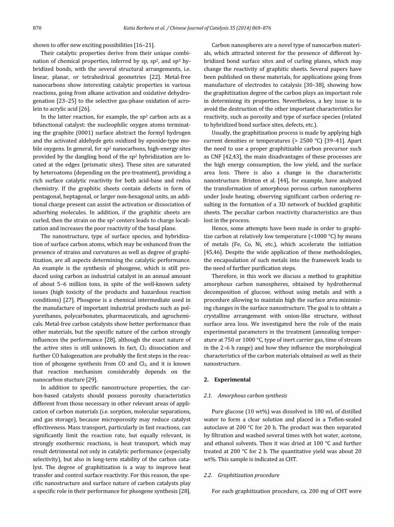
put in a vertical fixed bed reactor, as schematically shown inFig. 1. In each experiment, only a single parameter waschanged,i.e.,annealingtemperature(750or1000°C),isothermtimeonstream(2or6h),orcarrierofHeorN2gasflow(100STPmL/min).Forthemoreprominentsample,theconcentra‐tion of oxygen in N2 stream and the evolution of gases (CO2,H2O)duringannealingtreatmentwasfollowedbyuseofaHy‐denMass SpectrometerHP 2‐N, operating in SEMmode. ThesampleswereindicatedasX‐Y‐Z,whereXistypeofcarriergas(HeorN2),Ythereactiontemperature(°C),andZtheisothermtimeonstream.
2.3. Carboncharacterization
Samples were characterized by X‐ray powder diffraction(XRD)usingaPhilipsX‐Pertdiffractometerwithamonochro‐maticCuKα(λ=1.54056Å)radiationat40kVand30mA.Datawerecollectedovera2θrangeof10°–100°,withastepsizeof0.04°atatimeperstepof3s.Themorphologyofthesampleswasinvestigatedbyscanningelectronmicroscopy(SEM)usingaPhilipsXL‐30‐FEGSEMatanacceleratingvoltageof5kV.Toimprove the quality of images, the samples were previouslytreated with Au using a gold sputter coater device. For ele‐mental analysis, the energy dispersive X‐ray (EDX) analyzerwasemployedbyusingnotpre‐treatedsamples.Carbonmor‐phology structurewasalso investigatedby transmissionelec‐tronmicroscopy(TEM)usingaPhilipsCM12microscope(res‐olution0.2nm),providedwithahighresolutioncamera,atanaccelerating voltage of 120 kV. Suitable specimens for TEManalyses were prepared by ultrasonic dispersion in i‐propylalcoholaddingadropoftheresultingsuspensionontoaholeycarbonsupportedgrid.ThesurfaceareaswerecalculatedfromBET equation from the adsorption branch of the isotherms,obtainedat–196°ConaQuantachromesorptionanalyzer.Pri‐ortothemeasurements,sampleswereheatedinN2flowat350°Cfor1h.Themicroporeareaandvolumewereevaluatedbythet‐plotmethod.
RamanspectrawererecordedbyusingaRenishawRamanMicroscopespectrometer.AnAr+laseremittingat514nmwasused,inwhichtheoutputpowerwaslimitedinordertoavoid
sample damage. The photons scattered by the sample weredispersed by a 1800 lines/mm grating monochromator andsimultaneouslycollectedonaCCDcamera;thecollectionopticwas set at 50 objective. The spectrawere obtained by col‐lecting30acquisitions(eachof20s)onapowderedsampleinair.
FT‐IRspectrawerecollectedonpowdersamplesdilutedinKBr(1:1)at4cm–1resolution,usinganEquinox55spectrome‐ter equipped with an MCT detector and an environmentalchanneloperatingindiffusereflectancemode.Priortospectracollectionatr.t.,athermaltreatmentofthesamplesat150°CinArflow(20STPmL/min)wascarriedout.
X‐rayphotoelectronspectroscopy(XPS)datawereobtainedusingaPhysicalElectronicsGMBHPHI5800‐01spectrometeroperating with a monochromatized Al‐K radiation with apower beamof 300W.The pass energy for determinationofthe oxidation state and concentration of surface species was11.0and58.0eV,respectively.TheBEregionsofC1s(280–300eV)andO1s(524–544eV)wereinvestigated,takingtheAl2pline (73.0 eV) of aluminum standard as reference for signalcalibration.Ar+2kWsmallbeamsputteringwasperformedinordertoremoveadventiouscarbon.
3. Resultsanddiscussion
3.1. Surface‐initiatedordering
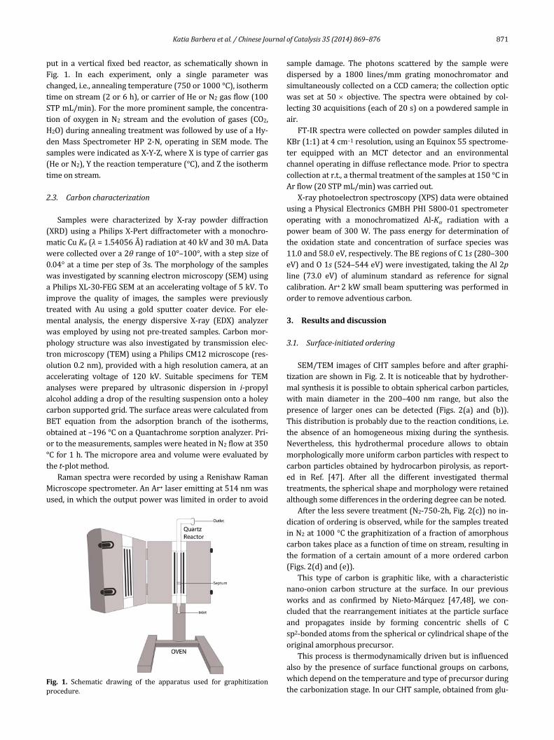
SEM/TEMimagesofCHTsamplesbeforeandaftergraphi‐tizationareshowninFig.2.Itisnoticeablethatbyhydrother‐malsynthesisitispossibletoobtainsphericalcarbonparticles,with main diameter in the 200–400 nm range, but also thepresence of larger ones can be detected (Figs. 2(a) and (b)).Thisdistributionisprobablyduetothereactionconditions,i.e.the absence of an homogeneousmixing during the synthesis.Nevertheless, this hydrothermal procedure allows to obtainmorphologicallymoreuniformcarbonparticleswithrespecttocarbonparticlesobtainedbyhydrocarbonpirolysis,asreport‐ed in Ref. [47]. After all the different investigated thermaltreatments,thesphericalshapeandmorphologywereretainedalthoughsomedifferencesintheorderingdegreecanbenoted.
Afterthelessseveretreatment(N2‐750‐2h,Fig.2(c))noin‐dicationoforderingisobserved,whileforthesamplestreatedinN2at1000°Cthegraphitizationofafractionofamorphouscarbontakesplaceasafunctionoftimeonstream,resultinginthe formation of a certain amount of amore ordered carbon(Figs.2(d)and(e)).
This type of carbon is graphitic like, with a characteristicnano‐onion carbon structure at the surface. In our previousworks and as confirmed by Nieto‐Márquez [47,48], we con‐cludedthat therearrangement initiatesat theparticlesurfaceand propagates inside by forming concentric shells of Csp2‐bondedatomsfromthesphericalorcylindricalshapeoftheoriginalamorphousprecursor.
Thisprocessisthermodynamicallydrivenbutisinfluencedalsoby thepresenceof surface functional groupson carbons,whichdependonthetemperatureandtypeofprecursorduringthecarbonizationstage.InourCHTsample,obtainedfromglu‐
Fig. 1. Schematic drawing of the apparatus used for graphitizationprocedure.
872 KatiaBarberaetal./ChineseJournalofCatalysis35(2014)869–876
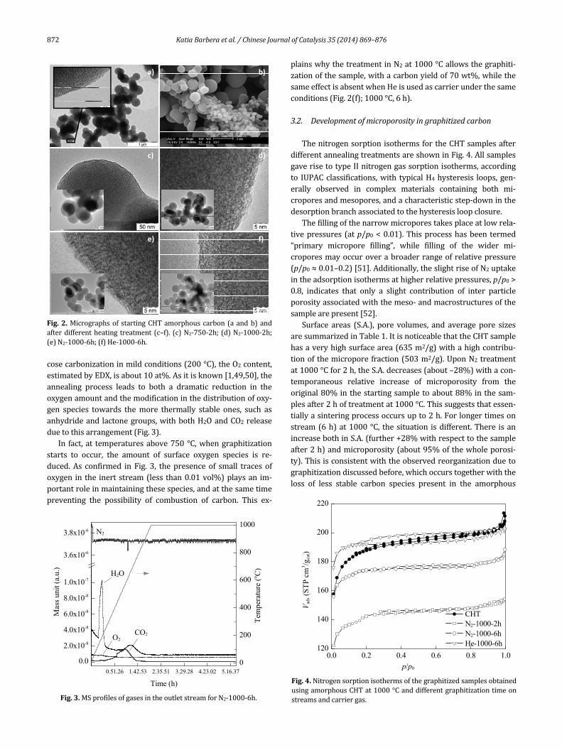
cosecarbonizationinmildconditions(200°C),theO2content,estimatedbyEDX,isabout10at%.Asitisknown[1,49,50],theannealing process leads to both a dramatic reduction in theoxygenamountandthemodificationinthedistributionofoxy‐gen species towards themore thermally stable ones, such asanhydrideandlactonegroups,withbothH2OandCO2releaseduetothisarrangement(Fig.3).
In fact,at temperaturesabove750°C,whengraphitizationstarts to occur, the amount of surface oxygen species is re‐duced.As confirmed inFig. 3, thepresenceof small tracesofoxygen inthe inertstream(less than0.01vol%)playsan im‐portantroleinmaintainingthesespecies,andatthesametimepreventing the possibility of combustion of carbon. This ex‐
plainswhythetreatmentinN2at1000°Callowsthegraphiti‐zationofthesample,withacarbonyieldof70wt%,whilethesameeffectisabsentwhenHeisusedascarrierunderthesameconditions(Fig.2(f);1000°C,6h).
3.2. Developmentofmicroporosityingraphitizedcarbon
ThenitrogensorptionisothermsfortheCHTsamplesafterdifferentannealingtreatmentsareshowninFig.4.AllsamplesgaverisetotypeIInitrogengassorptionisotherms,accordingto IUPACclassifications,with typicalH4hysteresis loops,gen‐erally observed in complex materials containing both mi‐croporesandmesopores,andacharacteristicstep‐downinthedesorptionbranchassociatedtothehysteresisloopclosure.
Thefillingofthenarrowmicroporestakesplaceatlowrela‐tivepressures (atp/p0<0.01).Thisprocesshasbeen termed“primary micropore filling”, while filling of the wider mi‐croporesmayoccuroverabroaderrangeofrelativepressure(p/p0≈0.01–0.2)[51].Additionally,theslightriseofN2uptakeintheadsorptionisothermsathigherrelativepressures,p/p0>0.8, indicates that only a slight contribution of inter particleporosityassociatedwiththemeso‐andmacrostructuresofthesamplearepresent[52].
Surface areas (S.A.), pore volumes, and average pore sizesaresummarizedinTable1.ItisnoticeablethattheCHTsamplehasaveryhighsurfacearea(635m2/g)withahighcontribu‐tionofthemicropore fraction(503m2/g).UponN2treatmentat1000°Cfor2h,theS.A.decreases(about–28%)withacon‐temporaneous relative increase of microporosity from theoriginal80%inthestartingsampletoabout88%inthesam‐plesafter2hoftreatmentat1000°C.Thissuggeststhatessen‐tiallyasinteringprocessoccursupto2h.Forlongertimesonstream(6h)at1000°C, thesituation isdifferent.There isanincreasebothinS.A.(further+28%withrespecttothesampleafter2h)andmicroporosity(about95%ofthewholeporosi‐ty).Thisisconsistentwiththeobservedreorganizationduetographitizationdiscussedbefore,whichoccurstogetherwiththeloss of less stable carbon species present in the amorphous
a) b)
c) d)
e) f)
Fig.2.Micrographsof startingCHTamorphouscarbon(aandb)andafterdifferentheating treatment(c–f). (c)N2‐750‐2h;(d)N2‐1000‐2h;(e)N2‐1000‐6h;(f)He‐1000‐6h.
0.51.26 1.42.53 2.35.51 3.29.28 4.23.02 5.16.37
0.0
2.0x10⁻⁸
4.0x10⁻⁸
6.0x10⁻⁸
8.0x10⁻⁸
1.0x10⁻⁷
3.6x10⁻⁶
3.8x10⁻⁶
0
200
400
600
800
1000N2
O2
Mas
s un
it (a
.u.)
Time (h)
H2O
CO2
Tem
pera
ture
(o C
)
Fig.3.MSprofilesofgasesintheoutletstreamforN2‐1000‐6h.
0.0 0.2 0.4 0.6 0.8 1.0120
140
160
180
200
220
CHT N2-1000-2h N2-1000-6h He-1000-6h
Vad
s (S
TP
cm
3 /gca
t)
p/p0
Fig.4.NitrogensorptionisothermsofthegraphitizedsamplesobtainedusingamorphousCHTat1000°Canddifferentgraphitizationtimeonstreamsandcarriergas.
KatiaBarberaetal./ChineseJournalofCatalysis35(2014)869–876 873
carbon(astypicallyoccursinpreparingactivatedcarbons).Inagreement,thetreatmentinHeinsteadofN2at1000°Cfor6h(Table1)leadstoasimilarS.A.ofthestartingsample,aswellassimilarfractionofmicroporosity(about80%).
Inprinciple, some interstitialNatoms in the carbonstruc‐turemayformduringtheannealingprocessat1000°Cinthepresence of N2 (although we have no metals in our samplepreparedfrompureglucose).Antonovetal.[53]observedthatdifferently from nitrogen atoms substituting carbon atoms,which hardlymove at 750 °C, interstitial nitrogen atoms aremobileduringannealingathightemperature.Thisprocessmaydecrease the activation energy to initialize the graphitizationprocess,according toNorfolketal. [54].However,webelievethatthisisanunlikelymechanismbecauseitrequirestodisso‐ciateN2. It is thusmore reasonable that the difference in thebehaviorisassociatedwiththepresenceoftracesofoxygenintheN2 flow,whichmodifies the amount of oxygen functionalgroupsduringthehightemperatureannealing(seeFig.3).Thisdifferentsurfacesituationisresponsiblefortheeasiergraphi‐tizationinthepresenceofN2ratherthanHe.
3.3. Evolutionofstructuralordering
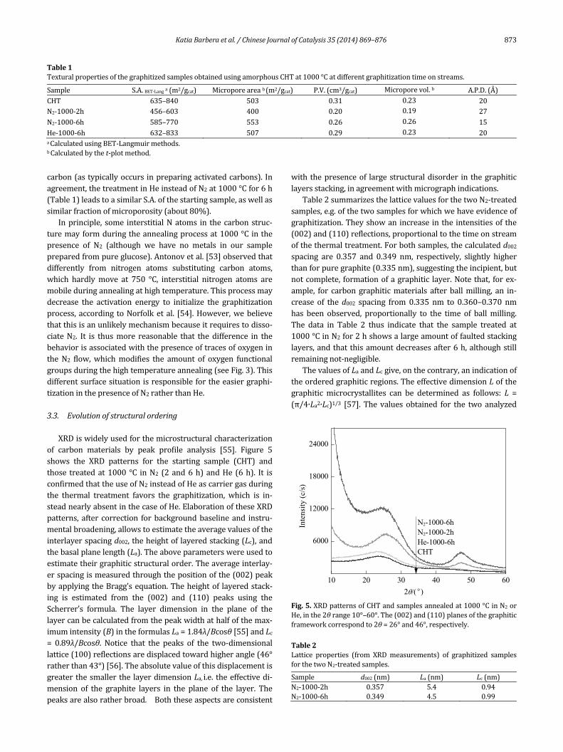
XRDiswidelyusedforthemicrostructuralcharacterizationof carbon materials by peak profile analysis [55]. Figure 5shows the XRD patterns for the starting sample (CHT) andthose treatedat1000 °C inN2 (2and6h)andHe (6h). It isconfirmedthattheuseofN2insteadofHeascarriergasduringthe thermal treatment favors the graphitization, which is in‐steadnearlyabsentinthecaseofHe.ElaborationoftheseXRDpatterns, after correction forbackgroundbaselineand instru‐mentalbroadening,allowstoestimatetheaveragevaluesoftheinterlayerspacingd002,theheightoflayeredstacking(Lc),andthebasalplanelength(La).Theaboveparameterswereusedtoestimatetheirgraphiticstructuralorder.Theaverageinterlay‐erspacingismeasuredthroughthepositionofthe(002)peakbyapplyingtheBragg’sequation.Theheightof layeredstack‐ing is estimated from the (002) and (110) peaks using theScherrer’s formula. The layer dimension in the plane of thelayercanbecalculatedfromthepeakwidthathalfofthemax‐imumintensity(B)intheformulasLa=1.84λ/Bcosθ[55]andLc= 0.89λ/Bcosθ. Notice that the peaks of the two‐dimensionallattice(100)reflectionsaredisplacedtowardhigherangle(46°ratherthan43°)[56].Theabsolutevalueofthisdisplacementisgreaterthesmallerthe layerdimensionLa,i.e. theeffectivedi‐mension of the graphite layers in the plane of the layer. Thepeaksarealsoratherbroad. Boththeseaspectsareconsistent
with thepresenceof largestructuraldisorder in thegraphiticlayersstacking,inagreementwithmicrographindications.
Table2summarizesthelatticevaluesforthetwoN2‐treatedsamples,e.g.ofthetwosamplesforwhichwehaveevidenceofgraphitization.Theyshowanincreaseinthe intensitiesofthe(002)and(110)reflections,proportionaltothetimeonstreamofthethermaltreatment.Forbothsamples,thecalculatedd002spacing are 0.357 and 0.349 nm, respectively, slightly higherthanforpuregraphite(0.335nm),suggestingtheincipient,butnotcomplete, formationofagraphitic layer.Notethat, forex‐ample, for carbongraphiticmaterials afterballmilling, an in‐crease of thed002 spacing from0.335 nm to 0.360–0.370 nmhas been observed, proportionally to the time of ballmilling.The data in Table 2 thus indicate that the sample treated at1000°CinN2for2hshowsalargeamountoffaultedstackinglayers,andthatthisamountdecreasesafter6h,althoughstillremainingnot‐negligible.
ThevaluesofLaandLcgive,onthecontrary,anindicationoftheorderedgraphiticregions.TheeffectivedimensionLofthegraphitic microcrystallites can be determined as follows: L =(π/4∙La2∙Lc)1/3 [57]. The values obtained for the two analyzed
Table1TexturalpropertiesofthegraphitizedsamplesobtainedusingamorphousCHTat1000°Catdifferentgraphitizationtimeonstreams.
Sample S.A.BET‐Langa(m2/gcat) Microporeareab(m2/gcat) P.V.(cm3/gcat) Microporevol.b A.P.D.(Å)CHT 635–840 503 0.31 0.23 20N2‐1000‐2h 456–603 400 0.20 0.19 27N2‐1000‐6h 585–770 553 0.26 0.26 15He‐1000‐6h 632–833 507 0.29 0.23 20aCalculatedusingBET‐Langmuirmethods. bCalculatedbythet‐plotmethod.
10 20 30 40 50 60
6000
12000
18000
24000
N2-1000-6hN2-1000-2hHe-1000-6hCHT
Inte
nsity
(c/
s)
2( o )
Fig.5.XRDpatternsofCHTandsamplesannealedat1000°CinN2orHe,inthe2θrange10°–60°.The(002)and(110)planesofthegraphiticframeworkcorrespondto2θ=26°and46°,respectively.
Table2Lattice properties (from XRDmeasurements) of graphitized samplesforthetwoN2‐treatedsamples.
Sample d002(nm) La(nm) Lc(nm)N2‐1000‐2h 0.357 5.4 0.94N2‐1000‐6h 0.349 4.5 0.99
874 KatiaBarberaetal./ChineseJournalofCatalysis35(2014)869–876
samples,2.4and2.56nm,indicatethepresenceofrathersmallordered domains, suggesting the very large orientational dis‐orderofthegraphiteplanes,anaspectessentialforenhancingthe reactivity of thesematerials and explaining the reason ofmaintaining a high surface area and porosity even for severeannealingprocedures(1000°C,6h).
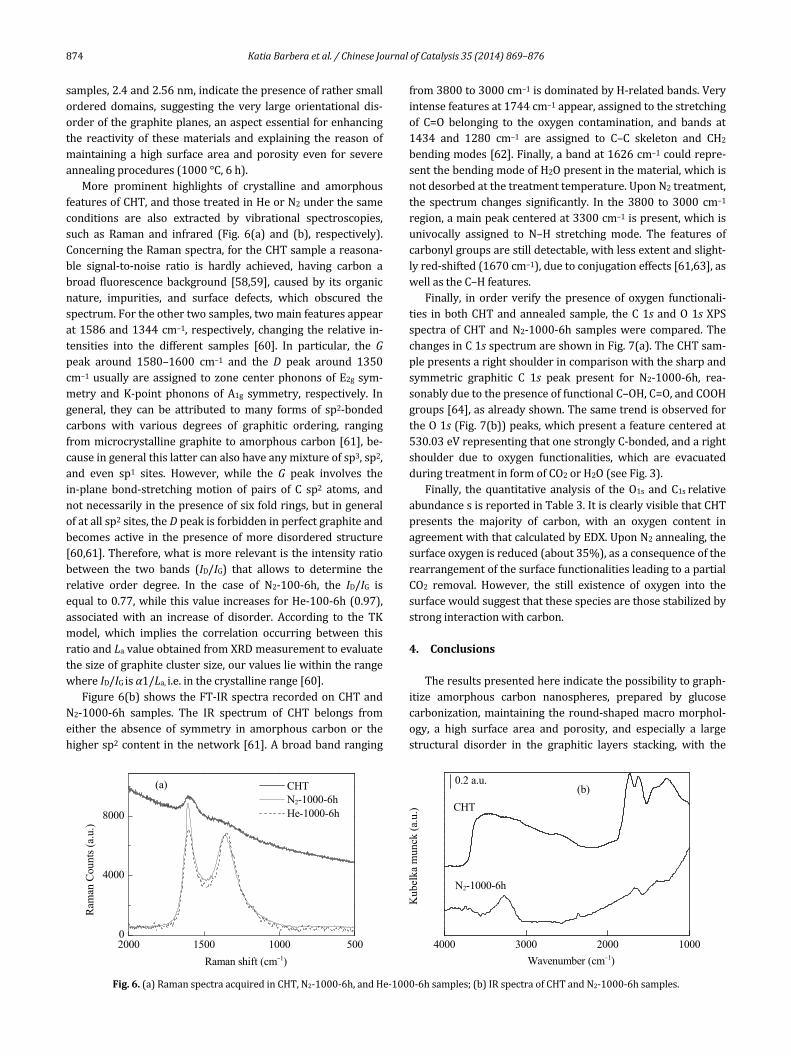
More prominent highlights of crystalline and amorphousfeaturesofCHT,andthosetreatedinHeorN2underthesameconditions are also extracted by vibrational spectroscopies,such as Raman and infrared (Fig. 6(a) and (b), respectively).ConcerningtheRamanspectra,fortheCHTsampleareasona‐ble signal‐to‐noise ratio is hardly achieved, having carbon abroad fluorescencebackground [58,59], causedby its organicnature, impurities, and surface defects, which obscured thespectrum.Fortheothertwosamples,twomainfeaturesappearat1586and1344cm–1, respectively,changingtherelative in‐tensities into the different samples [60]. In particular, the Gpeak around 1580–1600 cm–1 and the D peak around 1350cm–1usuallyareassigned tozonecenterphononsofE2g sym‐metry andK‐point phonons of A1g symmetry, respectively. Ingeneral, they can be attributed tomany forms of sp2‐bondedcarbons with various degrees of graphitic ordering, rangingfrommicrocrystallinegraphite toamorphouscarbon[61],be‐causeingeneralthislattercanalsohaveanymixtureofsp3,sp2,and even sp1 sites. However, while the G peak involves thein‐plane bond‐stretchingmotion of pairs of C sp2 atoms, andnotnecessarilyinthepresenceofsixfoldrings,butingeneralofatallsp2sites,theDpeakisforbiddeninperfectgraphiteandbecomes active in the presence ofmore disordered structure[60,61].Therefore,whatismorerelevantistheintensityratiobetween the two bands (ID/IG) that allows to determine therelative order degree. In the case of N2‐100‐6h, the ID/IG isequalto0.77,whilethisvalueincreasesforHe‐100‐6h(0.97),associated with an increase of disorder. According to the TKmodel, which implies the correlation occurring between thisratioandLavalueobtainedfromXRDmeasurementtoevaluatethesizeofgraphiteclustersize,ourvaluesliewithintherangewhereID/IGisα1/La,i.e.inthecrystallinerange[60].
Figure6(b)shows theFT‐IRspectrarecordedonCHTandN2‐1000‐6h samples. The IR spectrum of CHT belongs fromeither the absence of symmetry in amorphous carbon or thehighersp2content inthenetwork[61].Abroadbandranging
from3800to3000cm–1isdominatedbyH‐relatedbands.Veryintensefeaturesat1744cm–1appear,assignedtothestretchingof C=O belonging to the oxygen contamination, and bands at1434 and 1280 cm–1 are assigned to C–C skeleton and CH2bendingmodes[62].Finally,abandat1626cm–1couldrepre‐sentthebendingmodeofH2Opresentinthematerial,whichisnotdesorbedatthetreatmenttemperature.UponN2treatment,the spectrum changes significantly. In the 3800 to 3000 cm–1region,amainpeakcenteredat3300cm–1ispresent,whichisunivocally assigned to N–H stretching mode. The features ofcarbonylgroupsarestilldetectable,withlessextentandslight‐lyred‐shifted(1670cm–1),duetoconjugationeffects[61,63],aswellastheC–Hfeatures.
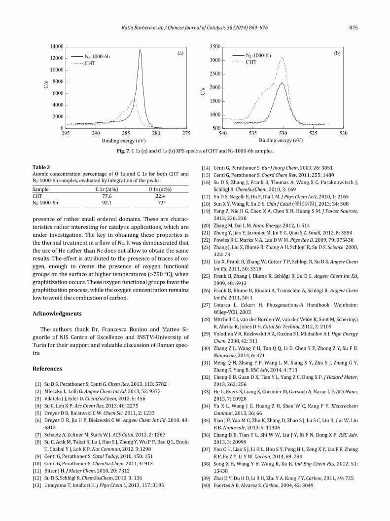
Finally, inorder verify thepresenceof oxygen functionali‐ties inbothCHTandannealedsample, theC1s andO1sXPSspectraofCHTandN2‐1000‐6hsampleswere compared.ThechangesinC1sspectrumareshowninFig.7(a).TheCHTsam‐plepresentsarightshoulderincomparisonwiththesharpandsymmetric graphitic C 1s peak present for N2‐1000‐6h, rea‐sonablyduetothepresenceoffunctionalC–OH,C=O,andCOOHgroups[64],asalreadyshown.ThesametrendisobservedfortheO1s(Fig.7(b))peaks,whichpresentafeaturecenteredat530.03eVrepresentingthatonestronglyC‐bonded,andarightshoulder due to oxygen functionalities, which are evacuatedduringtreatmentinformofCO2orH2O(seeFig.3).
Finally, the quantitative analysis of theO1s andC1srelativeabundancesisreportedinTable3.ItisclearlyvisiblethatCHTpresents the majority of carbon, with an oxygen content inagreementwiththatcalculatedbyEDX.UponN2annealing,thesurfaceoxygenisreduced(about35%),asaconsequenceoftherearrangementofthesurfacefunctionalitiesleadingtoapartialCO2 removal. However, the still existence of oxygen into thesurfacewouldsuggestthatthesespeciesarethosestabilizedbystronginteractionwithcarbon.
4. Conclusions
Theresultspresentedhereindicatethepossibilitytograph‐itize amorphous carbon nanospheres, prepared by glucosecarbonization,maintaining theround‐shapedmacromorphol‐ogy, a high surface area and porosity, and especially a largestructural disorder in the graphitic layers stacking, with the
2000 1500 1000 5000
4000
8000
CHT N2-1000-6h He-1000-6h
Ram
an C
ount
s (a
.u.)
Raman shift (cm1)
(a)
4000 3000 2000 1000
CHT
Kub
elka
mun
ck (
a.u.
)
Wavenumber (cm1)
N2-1000-6h
0.2 a.u.(b)
Fig.6.(a)RamanspectraacquiredinCHT,N2‐1000‐6h,andHe‐1000‐6hsamples;(b)IRspectraofCHTandN2‐1000‐6hsamples.
KatiaBarberaetal./ChineseJournalofCatalysis35(2014)869–876 875
presence of rather small ordered domains. These are charac‐teristicsratherinterestingforcatalyticapplications,whichareunder investigation. The key in obtaining these properties isthethermaltreatmentinaflowofN2.ItwasdemonstratedthattheuseofHeratherthanN2doesnotallowtoobtainthesameresults.Theeffectisattributedtothepresenceoftracesofox‐ygen, enough to create the presence of oxygen functionalgroupsonthesurfaceathighertemperatures(>750°C),whengraphitizationoccurs.Theseoxygenfunctionalgroupsfavorthegraphitizationprocess,whiletheoxygenconcentrationremainslowtoavoidthecombustionofcarbon.
Acknowledgments
The authors thank Dr. Francesca Bonino and Matteo Si‐gnorile of NIS Centre of Excellence and INSTM‐University ofTurinfortheirsupportandvaluablediscussionofRamanspec‐tra
References
[1] SuDS,PerathonerS,CentiG.ChemRev,2013,113:5782[2] MleczkoL,LolliG.AngewChemIntEd,2013,52:9372[3] VilatelaJJ,EderD.ChemSusChem,2012,5:456[4] SuC,LohKP.AccChemRes,2013,46:2275[5] DreyerDR,BielawskiCW.ChemSci,2011,2:1233[6] DreyerDR,JiaHP,BielawskiCW.AngewChemIntEd,2010,49:
6813[7] SchaetzA,ZeltnerM,StarkWJ.ACSCatal,2012,2:1267[8] SuC,AcikM,TakaiK,LuJ,HaoSJ,ZhengY,WuPP,BaoQL,Enoki
T,ChabalYJ,LohKP.NatCommun,2012,3:1298[9] CentiG,PerathonerS.CatalToday,2010,150:151[10] CentiG,PerathonerS.ChemSusChem,2011,4:913[11] BitterJH.JMaterChem,2010,20:7312[12] SuDS,SchlöglR.ChemSusChem,2010,3:136[13] UmeyamaT,ImahoriH.JPhysChemC,2013,117:3195
[14] CentiG,PerathonerS.EurJInorgChem,2009,26:3851[15] CentiG,PerathonerS.CoordChemRev,2011,255:1480[16] SuDS,Zhang J,FrankB,ThomasA,WangXC,Paraknowitsch J,
SchlöglR.ChemSusChem,2010,3:169[17] YuDS,NagelliE,DuF,DaiLM.JPhysChemLett,2010,1:2165[18] SunXY,WangR,SuDS.ChinJCatal(催化学报),2013,34:508[19] YangZ,NieHG,ChenXA,ChenXH,HuangSM.JPowerSources,
2013,236:238[20] ZhangM,DaiLM.NanoEnergy,2012,1:514[21] ZhengY,JiaoY,JaroniecM,JinYG,QiaoSZ.Small,2012,8:3550[22] PowlesRC,MarksNA,LauDWM.PhysRevB,2009,79:075430[23] ZhangJ,LiuX,BlumeR,ZhangAH,SchlöglR,SuDS.Science,2008,
322:73[24] LiuX,FrankB,ZhangW,CotterTP,SchlöglR,SuDS.AngewChem
IntEd,2011,50:3318[25] FrankB,ZhangJ,BlumeR,SchlöglR,SuDS.AngewChemIntEd,
2009,48:6913[26] FrankB,BlumeR,RinaldiA,TrunschkeA,SchlöglR.AngewChem
IntEd,2011,50:1[27] Cotarca L, Eckert H. Phosgenations‐A Handbook. Weinheim:
Wiley‐VCH,2003[28] MitchellCJ,vanderBordenW,vanderVeldeK,SmitM,Scheringa
R,AhrikaK,JonesDH.CatalSciTechnol,2012,2:2109[29] VolodinaVA,KozlovskiiAA,KuzinaSI,MikhailovAI.HighEnergy
Chem,2008,42:311[30] ZhangZL,WangYH,TanQQ,LiD,ChenYF,ZhongZY,SuFB.
Nanoscale,2014,6:371[31] MengQN, ZhangF F,WangLM, XiangSY, Zhu S J, ZhangGY,
ZhangK,YangB.RSCAdv,2014,4:713[32] ChangBB,GuanDX,TianYL,YangZC,DongXP.JHazardMater,
2013,262:256[33] HeG,EversS,LiangX,CuisinierM,GarsuchA,NazarLF.ACSNano,
2013,7:10920[34] YuX L,Wang J G,HuangZH, ShenWC,Kang FY.Electrochem
Commun,2013,36:66[35] XiaoJP,YaoMG,ZhuK,ZhangD,ZhaoSJ,LuSC,LiuB,CuiW,Liu
BB.Nanoscale,2013,5:11306[36] ChangBB,TianYL,ShiWW,LiuJY,XiFN,DongXP.RSCAdv,
2013,3:20999[37] YouCH,LiaoSJ,LiHL,HouSY,PengHL,ZengXY,LiuFF,Zheng
RP,FuZY,LiYW.Carbon,2014,69:294[38] SongXH,WangYB,WangK,XuR.IndEngChemRes,2012,51:
13438[39] ZhaiDY,DuHD,LiBH,ZhuYA,KangFY.Carbon,2011,49:725[40] FuertesAB,AlvarezS.Carbon,2004,42:3049
Table3Atomic concentration percentage of O 1s and C 1s for both CHT andN2‐1000‐6hsamples,evaluatedbyintegrationofthepeaks.
Sample C1s(at%) O1s(at%)CHT 77.6 22.4N2‐1000‐6h 92.1 7.9
540 535 530 525 520500
1000
1500
2000
2500
3000
3500
295 290 285 280 2750
2000
4000
6000
8000
10000
12000
14000
C/s
Binding energy (eV)
(b) N2-1000-6h CHT
N2-1000-6h CHT
C/s
Binding energy (eV)
(a)
Fig.7.C1s(a)andO1s(b)XPSspectraofCHTandN2‐1000‐6hsamples.
876 KatiaBarberaetal./ChineseJournalofCatalysis35(2014)869–876
[41] AsakaK,KaritaM,SaitoY.ApplPhysLett,2011,99:091907[42] SevillaM,SanchisC,Valdes‐SolisT,MorallonE,FuertesAB.JPhys
ChemC,2007,111:9749[43] RamosA,CaméanI,GarcìaAB.Carbon,2013,59:2[44] BristonK J,Martin JM,HeauC,MartinM, InksonB J.Nanotech‐
nology,2012,23:485602[45] SevillaM,FuertesAB.Carbon,2006,44:468[46] KasaharaN,ShiraishiS,OyaA.Carbon,2003,41:1654[47] FrusteriL,CannillaC,BarberaK,PerathonerS,CentiG,FrusteriF.
Carbon,2013,59:296[48] Nieto‐Marquez A, Espartera I, Lazo J C, RomeroA, Valverde J L.
ChemEngJ,2009,153:211[49] GenoveseC,AmpelliC,PerathonerS,CentiG.JEnergyChem,2013,
22:202[50] SuDS,CentiG.JEnergyChem,2013,22:151[51] ThommesM.ChemIngTechnol,2010,82:1059[52] Jiang J X, Su F B, Trewin A, Wood C D, Campbell N L, Niu H,
DickinsonC,GaninAY,RosseinskyMJ,KhimyakYZ,CooperAI.
AngewChemIntEd,2007,46:8574[53] AntonovD,HäußermannT,AirdA,Roth J,TrebinH‐R,MüllerC,
McGuinessL,JelezkoF,YamamotoT,IsoyaJ,PezzagnaS,MeijerJ,WrachtrupJ.MaterSci,2013,arXiv:1303.3730
[54] NorfolkC,KaufmannA,MukasyanA,VarmaA.Carbon,2006,44:301
[55] UngarT,GubiczaJ,RibarikG,PanteaC,ZerdaW.Carbon,2002,40:929
[56] BiscoeJ,WarrenBE.JApplPhys,1942,13:364[57] HaysD,PatrickJW,WalkerA.Fuel,1983,62:1079[58] AminzadehA.ApplSpectroscopy,1997,51:817[59] StairPC.AdvCatal,2007,51:75[60] FerrariAC,RobertsonJ.PhysRevB,2000,61:14095[61] ChuPK,LiLH.MaterChemPhys,2006,96:253[62] FerrariAC,RodilSE,RobertsonJ.PhysRevB,2003,67:155306[63] TangZH,ZhangLQ,ZengCF,LinTF,GuoBC.SoftMatter,2012,
8:9214[64] YumitoriS.JMaterSci,2000,35:139
GraphicalAbstract
Chin.J.Catal.,2014,35:869–876 doi:10.1016/S1872‐2067(14)60098‐X
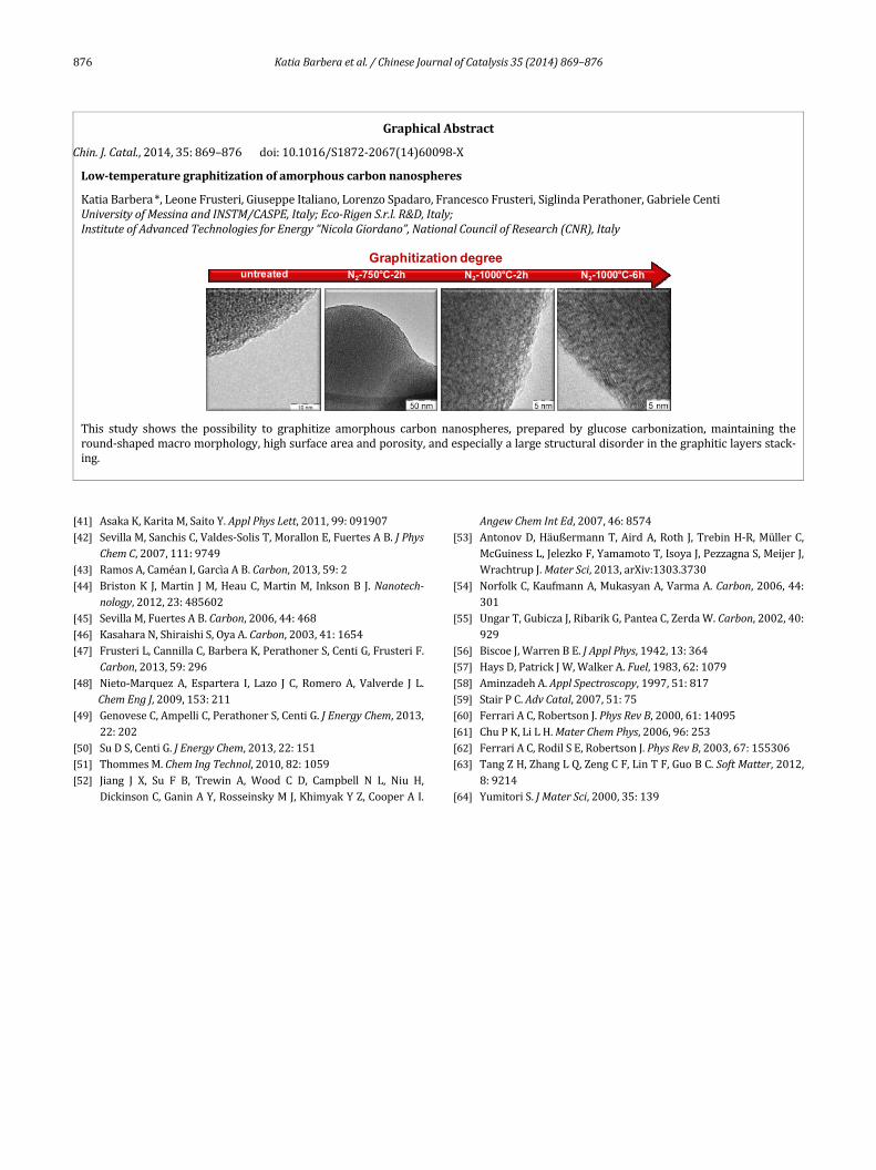
Low‐temperaturegraphitizationofamorphouscarbonnanospheres
KatiaBarbera*,LeoneFrusteri,GiuseppeItaliano,LorenzoSpadaro,FrancescoFrusteri,SiglindaPerathoner,GabrieleCentiUniversityofMessinaandINSTM/CASPE,Italy;Eco‐RigenS.r.l.R&D,Italy; InstituteofAdvancedTechnologiesforEnergy“NicolaGiordano”,NationalCouncilofResearch(CNR),Italy
Graphitization degreeN2-750°C-2h N2-1000°C-2h N2-1000°C-6h untreated
This study shows the possibility to graphitize amorphous carbon nanospheres, prepared by glucose carbonization, maintaining theround‐shapedmacromorphology,highsurfaceareaandporosity,andespeciallyalargestructuraldisorderinthegraphiticlayersstack‐ing.