long-term libration dynamics and stability analysis of electrodynamic tethers in spacecraft deorbit
TRANSCRIPT
Long-Term Libration Dynamics and Stability Analysisof Electrodynamic Tethers in Spacecraft Deorbit
R. Zhong1 and Z. H. Zhu2
Abstract: Electrodynamic tether systems orbiting the Earth are prone to libration instability because of periodic changes in the geomagneticfield, plasma density, and lunisolar gravitational attractions in addition to nonperiodic changes resulting from the irregularity of thegeomagnetic field, inhomogeneity of the Earth, and solar pressures. The long-term orbital and libration dynamics of a bare electrodynamictether in deorbiting obsolete satellites is investigated by considering space environmental perturbations of current-induced electrodynamicforce, atmospheric drag, Earth’s oblateness, irregularity of the geomagnetic field, variable space plasma density, solar radiation pressure, andlunisolar gravitational attractions. The electrodynamic tether is assumed to be rigid and the tethered spacecraft is modeled as a lumped mass.The study shows by numerical simulation that the out-of-plane libration is the primary source of libration instability in inclined orbits, whichdestabilizes the in-plane libration through nonlinear modal coupling. Accordingly, a simple stability criterion for current on/off switchingcontrol is derived from the libration energy of the tether to stabilize the out-of-plane libration by limiting the roll angle amplitude to a presetrange. This in turn stabilizes the in-plane libration. The control requires only the feedback of the maximum roll angle with a minimum intervalfor current on/off switching imposed to avoid excessive current switching. The effectiveness of the control strategy has been demonstrated byanalyzing the libration dynamics of electrodynamic tether with and without the current regulation in deorbiting satellites. Numerical resultsshow that this approach is very effective in stabilizing both in-plane and out-of-plane libration of a tethered system subjected to periodic andnonperiodic perturbations. DOI: 10.1061/(ASCE)AS.1943-5525.0000310. © 2014 American Society of Civil Engineers.
Author keywords: Electrodynamic tether; Dynamics; Stability; Libration; Control.
Introduction
Electrodynamic tethers (EDT) have strong potential in providingpropellantless propulsion for spacecraft by generating an electro-dynamic force (the Lorentz force) exerting on the tether (Hiteand McCoy 1988). One of the most appealing applications ofEDT propulsion is the space debris prevention and mitigation re-sulting from the crowded orbit, especially in low Earth orbit (LEO)(Penzo and Ammann 1989; Gilchrist et al. 2002; Sanmartin et al.2011; Jablonski and Scott 2009; Bilen et al. 2010). A recent study(Levin et al. 2012) shows that the cumulative distribution of thecollision-generated debris potential in LEO peaks around orbitalinclination angles at 71–74°, 81–83°, and the Sun-synchronized or-bit, whereas the distribution of operational satellites in LEO con-centrates around orbital inclination angles at 45–55°, 80–90°, andthe Sun-synchronized orbit. This will result in a high potential forspace collision, which is of major concern following the first-everspace collision between satellites Iridium 33 and Cosmos 2251 in2009 (Jakhu 2010). To make the application of EDT propulsion insatellite deorbit viable, it is imperative to maintain the tether withina certain range relative to the local vertical to ensure a rapidand secure orbital descent. However, it is well known (Levin1987; Pelaez et al. 2000) that the EDT is prone to the long-term
instabilities in both in-plane and out-of-plane libration resultingfrom the periodic excitation from the electrodynamic force as itorbits the Earth, especially in highly inclined orbits. Over time,the amplitude of libration oscillation gradually increases in bothin-plane and out-of-plane directions unbounded, leading to thetumbling of the entire EDT system.
The fundamental concern on the libration stability of an EDTsystem is the system-absorbed energy from the excitation ofelectrodynamic force through resonance, which is directly relatedto the current passing through the EDT. Among all of the pertur-bation forces contributing to the libration instability of an EDT sys-tem, the current is the only controllable input capable of altering theorbital elements and altitudes of an EDT system with constanttether length. For instance, Carroll (1985) specified five differentcurrent functions that can be used to change the orbital elementsby EDTs. Over the years, many current control functions/lawshave been proposed through the libration energy control, delayed-feedback control of libration rate, electrodynamic force control,energy rate control, and direct current control. Levin (1987) pro-posed a current control function based on the libration energy tostabilize the in-plane oscillation. Corsi and Iess (2001) found thatthe instability of a rigid EDT during deorbit is caused by the in-stability of out-of-plane libration, which destabilizes the in-planelibration through nonlinear modal coupling. Accordingly, a currentcontrol function was developed to stabilize the EDT libration basedon the level of a Lyapunov function. Hoyt and Forward (1998) in-vestigated the dynamics of a flexible EDT and concluded that theinstability was primarily caused by the instability of in-plane libra-tion. An adaptive feedback control scheme was developed to regu-late the current to prevent the in-plane libration energy fromincreasing by periodically monitoring the motion of several pointsalong the tether. Lanoix et al. (2005) investigated a current regu-lation scheme by imposing a sinusoidal current function at three
1Postdoctoral Fellow, Dept. of Earth and Space Science and Engineer-ing, York Univ., 4700 Keele St., Toronto, ON, Canada M3J 1P3.
2Associate Professor, Dept. of Earth and Space Science and Engineer-ing, York Univ., 4700 Keele St., Toronto, ON, Canada M3J 1P3 (corre-sponding author). E-mail: [email protected]
Note. This manuscript was submitted on August 22, 2012; approved onNovember 27, 2012; published online on November 29, 2012. Discussionperiod open until October 9, 2014; separate discussions must be submittedfor individual papers. This paper is part of the Journal of Aerospace En-gineering, © ASCE, ISSN 0893-1321/04014020(13)/$25.00.
© ASCE 04014020-1 J. Aerosp. Eng.
J. Aerosp. Eng. 2014.27.
Dow
nloa
ded
from
asc
elib
rary
.org
by
Shan
ghai
Jia
oton
g U
nive
rsity
on
10/1
5/14
. Cop
yrig
ht A
SCE
. For
per
sona
l use
onl
y; a
ll ri
ghts
res
erve
d.
times the orbital frequency to a constant current, to stabilize theout-of-plane libration during deorbit. Based on a stability functionderived from the system Hamiltonian function, Takeichi (2006)proposed a current on/off switching control function to stabilizethe EDT libration both in in-plane and out-of-plane libration duringdeorbit. Different from the energy measures, Peláez and Lorenzini(2005) developed two linear control laws to regulate the currentusing libration rate feedback. The first was a simple proportionalfeedback control of the difference between the present and refer-ence libration rates in in-plane and out-of-plane directions. The sec-ond was a time-delayed proportional feedback control of the samestate variables but used the delayed libration rates as the reference.The second control law was further developed to use the predictivelibration rates as the reference for feedback control by Williams(2009) or the one-period time-delayed as the reference for auto-synchronization control by Inarrea and Peláez (2010). Furthermore,Kojima and Sugimoto (2009) developed a current control law bymonitoring the electrodynamic force. Williams (2006) used the en-ergy rate feedback control to derive a current regulation function.Based on the port-controlled Hamiltonian functions, Larsen andBlanke (2011) proposed a passivity-based control law to derive acurrent control function to stabilize the libration motion.
The application of the previous studies generally requires thefeedback of multiple state variables and the computation of currentcontrol functions in real time. In the case of the end-of-missiondeorbit of micro/nano-satellites by EDTs, it is desirable to achievea secure orbital descent with the minimum control effort and theleast additional equipment because of the size/mass constraints.To address this need, a simple and practical current control strategy,capable of stabilizing both in-plane and out-of-plane libration withthe minimum control feedback, will be developed. Meanwhile, thelong-term libration stability accounting for multiple space pertur-bations and control input will be investigated.
Orbital Motion of Nano EDT System
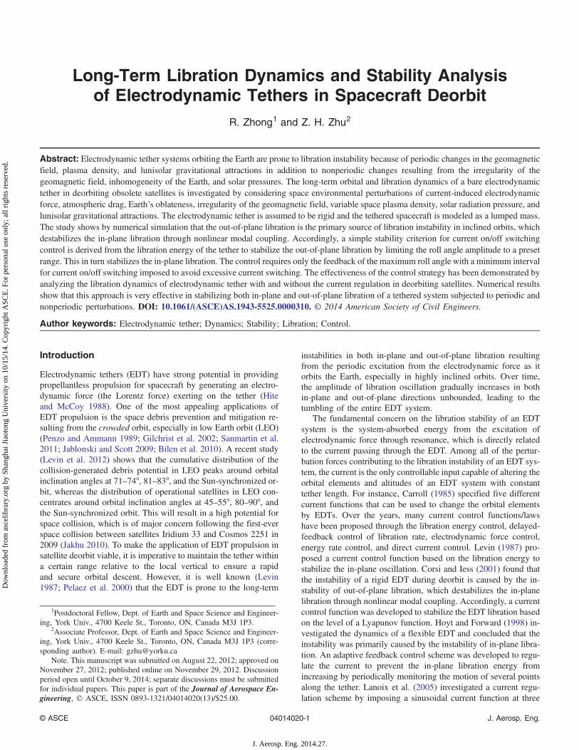
A nano EDT system is made of two nano-satellites connectedby a bare and electrically conductive tether in a geocentricinertial frame of Earth (OXYZ), as shown in Fig. 1. The centerof mass (CM) of such a system is located between the two
nano-satellites because the masses of two nano-satellites arecomparable. The bare tether will be used as an anode to attractfree electrons in the ambient ionospheric plasma, and a compactand lightweight field effect electron emitter (Aguero and Adamo2001) is assumed to be a cathode at the nano-satellite. The originof the inertial frame is assumed to be at the Earth’s center with thex-axis directed to the point of vernal equinox, the z-axis alignedwith the Earth’s rotational axis, and the y-axis completed a right-hand coordinate system, respectively. Considering the fact thatthe EDT length of the nano EDT system (<1 km) is extremelysmall compared with the Earth’s radius, one can safely modelthe nano EDT system as a lumped mass located at its CM inthe orbital dynamic analysis using the Gaussian perturbationequation (Vallado 2007), such as
_a ¼ 2
nffiffiffiffiffiffiffiffiffiffiffiffiffi1 − e2
p�Te sin f þ S
pr
�ð1aÞ
_Ω ¼ Wr sin u
na2ffiffiffiffiffiffiffiffiffiffiffiffiffi1 − e2
psin i
ð1bÞ
_i ¼ Wr cos u
na2ffiffiffiffiffiffiffiffiffiffiffiffiffi1 − e2
p ð1cÞ
_ex ¼ffiffiffiffiffiffiffiffiffiffiffiffiffi1− e2
p
na
�T sinuþ S
��1þ r
p
�cosuþ r
pex
��þ _Ωey cos i
ð1dÞ
_ey ¼ffiffiffiffiffiffiffiffiffiffiffiffiffi1 − e2
p
na
�−T cos uþ S
��1þ r
p
�sin uþ r
pey
��
− _Ωex cos i ð1eÞ
_η ¼ n − 1
na
"T
�2raþ
ffiffiffiffiffiffiffiffiffiffiffiffiffi1 − e2
p
1þffiffiffiffiffiffiffiffiffiffiffiffiffi1 − e2
p e cos f
�
− S
�1þ r
p
� ffiffiffiffiffiffiffiffiffiffiffiffiffi1 − e2
p
1þffiffiffiffiffiffiffiffiffiffiffiffiffi1 − e2
p e sin f
#− Wr cos i sin u
na2ffiffiffiffiffiffiffiffiffiffiffiffiffi1 − e2
psin i
ð1fÞ
where the classical orbital elements e, ω, and M in Eq. (1)are replaced by orbital parameters of ex (¼ e cosω), ey(¼ e sinω), and η (¼ M þ ω), respectively, so that singularitydoes not occur when the eccentricity of orbit approacheszero in the case of near-circular orbit. Furthermore, the pertur-bative acceleration components T and S are in the orbital planewith T being the radial component and S the componentperpendicular to T and pointing in the direction of satellite’smotion. The third acceleration component W completes aright-hand system.
The orbital perturbative accelerations (T, S, W) in Eq. (1) arecaused by space environmental perturbative forces, namely,(1) the electrodynamic (Lorentz) force on a current-carryingEDT resulting from the interaction with the Earth’s magneticfield, (2) the Earth’s atmospheric drag, (3) the Earth’s nonhomo-geneity and oblateness, (4) the Sun and Moon gravitational per-turbations, and (5) the solar radiation pressure, respectively. Thenano EDT system is assumed to be thrust-less in the considereddeorbit process. For the sake of simplicity in analysis, it is as-sumed that the atmosphere, geomagnetic field, and ambientplasma rotate with the Earth at the same rate. To account forthe Earth’s oblateness, the geodetic (instead of geocentric) altitudeFig. 1. Schematic of inertial coordinate system for EDT orbital motion
© ASCE 04014020-2 J. Aerosp. Eng.
J. Aerosp. Eng. 2014.27.
Dow
nloa
ded
from
asc
elib
rary
.org
by
Shan
ghai
Jia
oton
g U
nive
rsity
on
10/1
5/14
. Cop
yrig
ht A
SCE
. For
per
sona
l use
onl
y; a
ll ri
ghts
res
erve
d.
is used in the evaluation of environmental parameters such asthe atmospheric and plasma densities
hg ¼ r − rpoffiffiffiffiffiffiffiffiffiffiffiffiffiffiffiffiffiffiffiffiffiffiffiffiffi1 − e2E cos
2 θp ð2Þ
where the polar radius (rpo) and the eccentricity of the Earth’ssurface (eE) are set as 6,356.8 × 103 m and 0.081658 (NASA2012), respectively.
Electrodynamic Force
As an EDT crosses through the Earth’s magnetic field, a motionalelectric field ~Em is induced. The projection of motional electric
field along the EDT length in a body-fixed reference frame canbe written as
Em ¼ dVp
ds¼ −ð v⇀r × B
⇀Þ · l
⇀ð3Þ
v⇀
r ¼ v⇀ − ω
⇀E × r
⇀ ð4Þ
The Earth’s magnetic field is described by the IGRF2000 model(Davis 2004; Wertz 2003) in a body-fixed frame of the Earth
~B ¼
8><>:
Br
Bθ
Bϕ
9>=>; ¼
8>>>>>>><>>>>>>>:
P∞n¼1
�r0r
nþ2ðnþ 1ÞPn
m¼0½gmn cosðmϕÞ þ hmn sinðmϕÞ�Pmn ð~θÞ
P∞n¼1
�r0r
nþ2 Pn
m¼0½gmn cosðmϕÞ þ hmn sinðmϕÞ� ∂Pmn ð~θÞ∂ ~θ
1
sin θ
X∞n¼1
�r0r
nþ2 Xn
m¼0
m½gmn sinðmϕÞ − hmn cosðmϕÞ�Pmn ð ~θÞ
9>>>>>>>=>>>>>>>;
ð5Þ
where r0 ¼ 6,371.2 × 103 m is the reference radius of the Earth.The first-order approximation of Eq. (5) is the widely used in-
clined dipole magnetic field in the literature. However, the authors’recent work (Zhong and Zhu 2013) shows that the higher orderterms in Eq. (5) will cause a secular growth of the eccentricityof an orbit in inclined orbits. Accordingly, an approximation ofthe IGRF2000 model that includes up to seventh-order terms inEq. (5) is adopted to analyze the long-term dynamics and librationstability of EDT precisely.
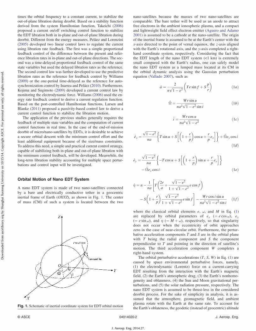
The resulting motional electric field will make the EDT partiallypositive and partially negative charged relative to the ambient iono-spheric plasma, depending on the difference between the tethervoltage (Vt) and the plasma voltage (Vp) (Sanmartin et al.1993). The bare EDT is used as an anode to attract free electronsfrom the ambient ionospheric plasma, and the electrons are emittedfrom a dedicated electron emitter, resulting in an electric current inthe tether (Fig. 2). The ions collected by the segment of negativelycharged EDT could be ignored because the mass of an ion is muchlarger than an electron.
Assume the space-charge and/or magnetic-guiding effects arenegligible because of the very small EDT diameter. Then, the in-duced current can be derived by the orbital-motion-limited (OML)model and the voltage-current relationship along an EDT can bewritten as per Sanmartin (1993) as
dIds
¼ qen∞D
(0 if Vt < Vp
− ffiffiffiffiffiffiffiffiffiffiffiffiffiffiffiffiffiffiffiffiffiffiffi2qeΔV=me
pif Vt > Vp
ð6aÞ
dΔVds
¼ − IσA
− Em ΔV ¼ Vt − Vp ð6bÞ
The n∞ in Eq. (6a) is the unperturbed ionospheric plasma den-sity and varies as functions of geomagnetic and solar conditions.The IRI 2007 model (Bilitza and Reinisch 2008) is adopted to de-termine the plasma density in Eq. (6a), where the input parameter,the orbital altitude, is corrected by the geodetic height to account
for the Earth’s oblateness as described in Eq. (2). The inducedcurrent will interact with the Earth’s magnetic field to generatethe electrodynamic force, or the Lorentz force, such that
d~FB ¼ −B⇀ × I l⇀ds ð7Þ
This force is always against the orbital motion of an EDT inLEO, which provides an electrodynamic drag to deorbit theEDT system.
Atmospheric Drag
The nano EDT system in LEO experiences an atmospheric dragbecause of the momentum exchange between free moleculesand arresting surfaces of EDT and nano-satellites. Thus, the atmos-pheric drag acting on the nano-satellites (~FA;s) and the elementlength ds of an EDT (d~FA;t) can be expressed as
~FA;s ¼ −0.5ρCdj v⇀rj v⇀rAd ð8aÞ
d~FA;t ¼ −0.5ρCdj v⇀rj v⇀rDds ð8bÞ
The drag coefficient Cd of a circular EDT in a free-molecularhyper-thermal flow in space can be simplified as a constant of2.2, whereas the Cd of a cubic nano-satellite is a constant of 1.6(Vallado 2007), respectively. The density of atmosphere varies rap-idly over the altitude and the 1976 atmospheric model of U.S.Standard Atmosphere (NOAA, NASA, and USAF 1976) is adoptedto calculate the atmospheric density at a given altitude. Again, thealtitude is corrected by Eq. (2) to get the geodetic height for densitycalculation.
Perturbation of the Earth’s Oblateness
The Earth’s nonhomogeneous gravitational potential function isgiven by (Davis 2004)
© ASCE 04014020-3 J. Aerosp. Eng.
J. Aerosp. Eng. 2014.27.
Dow
nloa
ded
from
asc
elib
rary
.org
by
Shan
ghai
Jia
oton
g U
nive
rsity
on
10/1
5/14
. Cop
yrig
ht A
SCE
. For
per
sona
l use
onl
y; a
ll ri
ghts
res
erve
d.
U ¼ −μr
X∞n¼2
�r0r
�n�JnPnðsin θÞ
−Xnm¼1
JnmPnmðsin θÞ cosmðϕ − ϕnmÞ�
ð9Þ
The perturbative acceleration resulting from the oblateness isderived by partial derivation of the potential function in Eq. (9) withrespect to the orbital elements. In this paper, only the zonal har-monic terms up to the fourth order are included in the perturbativeacceleration resulting from the oblateness. This is because the tess-eral harmonic terms are small compared with the zonal harmonicterms in LEO. In particular, the term J2 is the major oblatenessperturbation, which is a thousand times greater than the termsJ3 and J4, imposing a torque on any spacecraft in an inclined orbitalplane across the equator.
Lunisolar Attraction
The gravitational attractions of the Sun and Moon are two majorfactors influencing the dynamics of a nano EDT system other thanthe Earth’s because of the larger mass of the Sun and the shorterdistance between the EDT and the Moon. Considering the lunisolargravitational perturbations among the Sun, the Moon, the Earth,and an EDT system, the accelerations of the Earth and the EDTsystem can be written as
~aE ¼ 1
mE
�GmEDTmE
r3E;EDT~rE;EDT þ
GmSmE
r3E;S~rE;S þ
GmMmE
r3E;M~rE;M
�ð10Þ
~aEDT ¼ 1
mEDT
�GmEmEDT
r3EDT;E~rEDT;E þ GmSmEDT
r3EDT;S~rEDT;S
þ GmMmEDT
r3EDT;M~rEDT;M
�ð11Þ
Therefore, the gravitational acceleration of an EDT system rel-ative to the Earth is obtained by subtracting Eq. (11) from Eq. (10),such that
~aEDT − ~aE ¼ GðmE þmEDTÞ~rEDT;Er3EDT;E
þ GmS
�~rEDT;Sr3EDT;S
− ~rE;Sr3E;S
�
þGmM
�~rEDT;Mr3EDT;M
− ~rE;Mr3E;M
�≈ GmE
~rEDT;Er3EDT;E
þGmS
�~rEDT;Sr3EDT;S
− ~rE;Sr3E;S
�þGmM
�~rEDT;Mr3EDT;M
− ~rE;Mr3E;M
�
ð12Þ
The first term of the right-hand side of Eq. (12) is the gravita-tional force of the Earth. The term (mE þmEDT) is usually simpli-fied asmE because the mass of a nano EDT system is several ordersless in magnitude than the mass of the Earth. The second and thirdterms are the solar and lunar gravitational perturbative accelera-tions. The exact positions of the Sun and the Moon with respectto the Earth at any instant time are evaluated by the AstronomicalAlmanac (U.S. Naval Observatory and Her Majesty’s NauticalAlmanac Office 2011).
Solar Radiation Pressure
The solar radiation pressure is caused by the effect of photons emit-ted from the Sun with a nano EDT system. There are three types ofphoton interactions with a surface, namely, absorption, reflection(including specular reflection and diffuse reflection), and transmis-sion. Because the transmission will be minimized by surface treat-ment to attenuate its detrimental effects on payloads in spacemissions, the authors consider only the absorption and reflectionin the current study. The radiation pressure on a projected areaof dA of a spacecraft is given by Hughes (1986)
d~FR ¼ ΞcHðcos ζÞ cos ζ
�−�ð1þ CrsÞ cos ζ þ
2
3Crd
�~un
þ ð1 − CrsÞ sin ζ~ut�dA ð13Þ
The solar power per unit area near the Earth, Ξ, is assumed tobe a constant of 1,395 W · m−2. The constants Crs and Crd arethe coefficients of specular and diffuse reflectivity, and theirvalues are generally related to the character of the spacecraft.They are assumed to be 0.8 and 0.2 in this study as perHughes (1986).
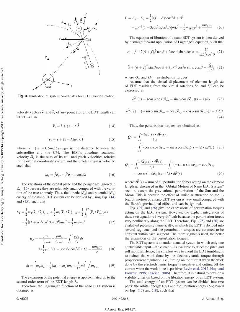
Libration Motion of Nano EDT System
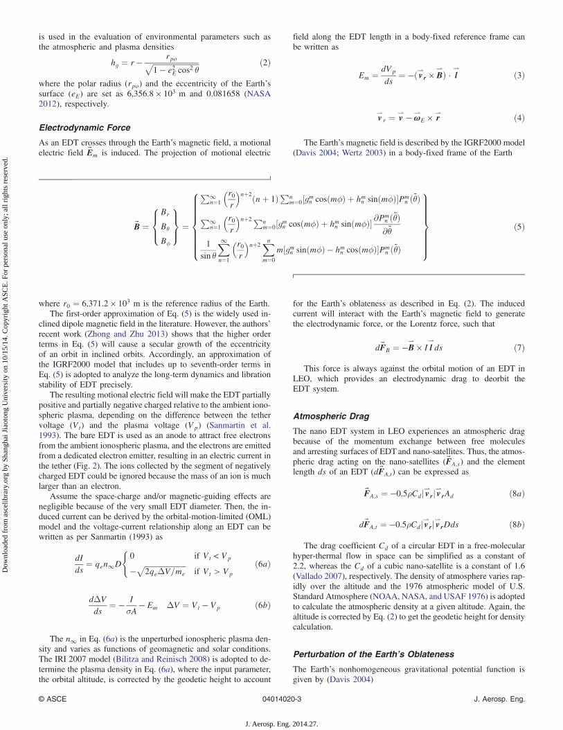
The libration motion of a nano EDT system is described in anorbital coordinate system (Fig. 3). The z-axis of the orbitalcoordinate system points from the Earth’s center to the CMof the nano EDT system, the x-axis lies in the orbital planeperpendicular to the z-axis, and the y-axis completes a right-hand coordinate system. The unit vectors along each axis aredenoted as ~eox, ~eoy, and ~eoz, respectively. In addition, an EDT-fixed coordinate system with unit vectors (~o, ~n, ~l) along eachaxis is introduced to describe the EDT’s attitudes with respectto the orbital coordinate system (x, y, z). The body-fixed coor-dinate system is assumed to be coincidental with the orbital co-ordinate system initially. The instant attitudes of EDT aredescribed by an in-plane angle α (pitch angle, rotating aroundthe y-axis) and followed by an out-of-plane angle β (roll angle,rotating around the x 0-axis, the x-axis after first rotating)(Fig. 3). For simplicity, the EDT’s flexibility is neglectedbecause of its relative short length. Thus, the position and
A
I
B
C
VtVp
V
s
∆∆V
Earth
I
s
0dI
ds≈
dIV
ds∝ ∆
Fig. 2. Scheme of a bare EDTand voltage=current variation [A = anodeend (assumed to be on the main satellite at this instant) of EDT;C = cathode end; and B = point with zero potential bias]
© ASCE 04014020-4 J. Aerosp. Eng.
J. Aerosp. Eng. 2014.27.
Dow
nloa
ded
from
asc
elib
rary
.org
by
Shan
ghai
Jia
oton
g U
nive
rsity
on
10/1
5/14
. Cop
yrig
ht A
SCE
. For
per
sona
l use
onl
y; a
ll ri
ghts
res
erve
d.
velocity vectors ~rs and ~vs of any point along the EDT length canbe written as
~rs ¼ ~rþ ðs − λÞ~l ð14Þ
~vs ¼ ~vþ ðs − λÞ ~ωt × ~l ð15Þ
where λ ¼ ðm1 þ 0.5mtÞL=mEDT is the distance between thesubsatellite and the CM. The EDT’s absolute rotationalvelocity ~ωt is the sum of its roll and pitch velocities relativeto the orbital coordinate system and the orbital angular velocity,such that
~ωt ¼ _f~eoy þ _β ~oþ _α cosβ~n ð16Þ
The variations of the orbital plane and the perigee are ignored inEq. (16) because they are relatively small compared with the varia-tion of the true anomaly. Thus, the kinetic (Ek) and potential (Ep)energy of the nano EDT system can be derived by using Eqs. (14)and (15), such that
Ek ¼1
2m1ð~vs • ~vsÞs¼L þ 1
2m2ð~vs • ~vsÞs¼0 þ
1
2
ZL
0
ð~vs • ~vsÞρtds
¼ 1
2½ð _f þ _αÞ2cos2β þ _β2� ~mL2 þ 1
2mEDTv2 ð17Þ
Ep ¼ − μm1
rs;s¼L− μm2
rs;s¼0
−Z
L
0
μρtrs
ds
≈ 1
2μr−3ð1 − 3cos2αcos2βÞ ~mL2 − μmEDT
rð18Þ
~m ¼�m1m2 þ
1
3ðm1 þm2Þmt þ
1
12m2
t
�mEDT ð19Þ
The expansion of the potential energy is approximated up to thesecond order term of the EDT length L.
Therefore, the Lagrangian function of the nano EDT system isobtained as
Γ ¼ Ek − Ep ¼ 1
2½ð _f þ _αÞ2cos2β þ _β2
− μr−3ð1 − 3cos2αcos2βÞ� ~mL2 þ 1
2mEDTv2 þ
μmEDT
rð20Þ
The equation of libration of a nano EDT system is then derivedby a straightforward application of Lagrange’s equation, such that
α̈þ f̈ − 2ð _αþ _fÞ _β tan β þ 3μr−3 sinα cosα ¼ Qα
~mL2cos2βð21Þ
β̈ þ ð _αþ _fÞ2 sin β cos β þ 3μr−3cos2α sin β cosβ ¼ Qβ
~mL2ð22Þ
where Qα and Qβ = perturbation torques.Assume that the virtual displacement of element length ds
of EDT resulting from the virtual rotations δα and δβ can beexpressed as
δ~dαðsÞ ¼ ðcosα cos β~eox − sinα cos β~eozÞðs − λÞδα ð23Þ
δ~dβðsÞ ¼ ð− sinα sin β~eox − cos β~eoy − cosα sinβ~eozÞðs − λÞδβð24Þ
Thus, the perturbation torques are obtained as
Qα ¼Z
L
0
δ~dαðsÞ • d~FðsÞδα
¼Z
L
0
ðcosα cos β~eox − sinα cos β~eozÞðs − λÞ • d~FðsÞ ð25Þ
Qβ ¼Z
L
0
δ~dβðsÞ • d~FðsÞδβ
¼Z
L
0
ð− sinα sin β~eox − cos β~eoy
− cosα sin β~eozÞðs − λÞ • d~FðsÞ ð26Þ
where d~FðsÞ = sum of all perturbation forces acting on the elementlength ds discussed in the “Orbital Motion of Nano EDT System”section, except the gravitational perturbation of the Sun and theMoon. This is because the effect of lunisolar attraction on the li-bration motion of a nano EDT system is very small compared withthe Earth’s gravitational effect and can be ignored.
Eqs. (25) and (26) give the expressions of perturbation torquesacting on the EDT system. However, the explicit integration ofthese two equations is very difficult because the perturbation forcesvary nonlinearly along the EDT. Therefore, Eqs. (25) and (26) areevaluated piecewise numerically, in which the EDT is divided intoseveral segments and the perturbation torques are assumed to beconstant within each segment. The more segments used, the betterthe estimation of the perturbation torques.
The EDT system is an under-actuated system in which only onecontrollable input—the current—is available to affect the pitch androll motions. Hence, the simplest way to avoid the EDT tumbling isto reduce the work done by the electrodynamic torque throughproper current regulation, i.e., turning on the current when the workdone by the electrodynamic torque is negative and cutting off thecurrent when the work done is positive (Levin et al. 2012; Hoyt andForward 1998; Takeichi 2006). Therefore, it is natural to develop astability criterion based on the libration energy of an EDT system.
The total energy of an EDT system can be divided into twoparts: the orbital energy (U1) and the libration energy (U2) basedon Eqs. (17) and (18), such that
Fig. 3. Illustration of system coordinates for EDT libration motion
© ASCE 04014020-5 J. Aerosp. Eng.
J. Aerosp. Eng. 2014.27.
Dow
nloa
ded
from
asc
elib
rary
.org
by
Shan
ghai
Jia
oton
g U
nive
rsity
on
10/1
5/14
. Cop
yrig
ht A
SCE
. For
per
sona
l use
onl
y; a
ll ri
ghts
res
erve
d.
U1 ¼1
2mEDTv2 − μmEDT
rð27Þ
U2 ¼1
2½ð _f þ _αÞ2cos2β þ _β2 þ μr−3ð1 − 3cos2αcos2βÞ� ~mL2
ð28Þ
Eq. (27) shows that the orbital energy U1 includes the orbitalpotential and kinetic energy of an EDTonly. It changes slowly dur-ing the deorbit process in a short period of time, for instance, oneturn of orbit. The libration energy U2 includes the kinetic and po-tential energy of EDT libration motion with respect to its CM. It isdirectly related to the work done by the current-induced electrody-namic force. Therefore, U2 can be treated as an indication ofwhether the EDT starts to tumble and can be used as a referencefor the current regulation. Because of the nonlinear coupling ofpitch and roll motion, it is generally difficult to find a good esti-mation of critical U2 over which an EDT would start to tumble.However, it is possible to find an upper energy bound where thetumbling would not happen definitely.
In general, an EDT system starts to tumble if libration anglesreach 90° and continue to increase. Thus, there are four possibletumbling conditions�
α ¼ π2; _α > 0
�;
�β ¼ π
2; _β > 0
�;�
α ¼ −π2; _α < 0
�;
�β ¼ π
2; _β < 0
�ð29Þ
Substituting these expressions into Eq. (28) yields
U2 ¼1
2½ð _f þ _αÞ2cos2β þ _β2 þ μr−3� ~mL2 ≥ 1
2μr−3A ~mL2 ð30Þ
Eq. (30) suggests that, in all cases, the tumbling energy is al-ways greater than ð1=2Þμr−3A ~mL2, which depends only on a simpleparameter: the radius of orbit apogee. Therefore, an upper bound oflibration energy is obtained that could be used for the current on/offregulation to prevent an EDT from tumbling, such that
U2 <1
2μr−3A ~mL2 ð31Þ
The estimation of libration energy U2 requires input of tetherlibration angles and their velocities, as indicated by Eq. (30).In reality, less measurement of libration motion is desired fornano-satellite deorbit because of the mass, size, and cost con-straints. With this in mind, a much simpler expression is derivedfor the upper bound of libration energy.
Assuming the pitch and roll angles are small, the equations ofpitch and roll motions can be linearized and decoupled fromEqs. (21) and (22) by ignoring the high-order coupling termsand the true anomaly term that is small in near-circular orbit,such as
α̈þ 3μr−3α ¼ Qα
~mL2cos2βð32Þ
β̈ þ 4μr−3β ¼ Qβ
~mL2ð33Þ
The homogeneous solutions of Eqs. (32) and (33) with zero ini-tial libration angles are then obtained as
_α ¼ αmax
ffiffiffiffiffiffiffiffiffiffiffiffi3μr−3
qcos
ffiffiffiffiffiffiffiffiffiffiffiffi3μr−3
qt ð34Þ
_β ¼ 2βmax
ffiffiffiffiffiffiffiffiffiffiμr−3
qcos 2
ffiffiffiffiffiffiffiffiffiffiμr−3
qt ð35Þ
Because the nano EDT system is assumed to be in a circular ornear-circular orbit during deorbiting, the velocity expressions oflibration angles in Eqs. (34) and (35) can be further approximatedin terms of the mean orbital angular rate, n, such that
_α≈ ffiffiffi3
pαmaxn cos
ffiffiffi3
pnt ð36Þ
_β ≈ 2βmaxn cos 2nt ð37ÞThus, an approximation of libration energy U2 can be derived in
terms of the maximum pitch and roll angles by substitutingEqs. (36) and (37) into Eq. (28)
U2 ≈ 1
2½ð _f þ
ffiffiffi3
pαmaxnÞ2 þ 4β2
maxn2 − 2μr−3� ~mL2
<1
2½ð1þ
ffiffiffi3
pαmaxÞ2 _f2P þ 4β2
max_f2P − 2μr−3A � ~mL2 ð38Þ
where the subscripts A and P denote variables at apogee and peri-gee, respectively. The upper bound of U2 in Eq. (31) will be sat-isfied if
ð1þffiffiffi3
pαmaxÞ2 þ 4β2
max < 3μr−3A _f−2P ≈ 3 ð39Þ
Because the roll motion destabilizes faster than the pitch motionin inclined orbits because of the out-of-plane disturbance (Corsiand Iess 2001), Eq. (39) can be simplified by replacing αmax withβmax, such that ffiffiffi
3p
βmax þ 3.5β2max < 1 ð40Þ
Hence, Eq. (40) defines a stability control criterion for currentswitching, which is simple and easy to implement by monitoringthe maximum roll angle only. This approach is very conservativebecause the worst cases are assumed most of the time in the der-ivation. In this study, the maximum roll angle limit is set to 15°.Moreover, an additional constraint is added to the current regula-tion, i.e., the current switch is not allowed to change its state unlessthe switching interval is greater than 10 min to avoid the possibleequipment failure caused by excessive and frequent current on/offswitching in a mission.
Results and Discussion
System Parameters and Initial Conditions forSimulation
A sample nano EDT system is used in the following numericalanalyses and the system parameters are given in Table 1. The sizeof the EDT and the mass of nano-satellites are determined by hard-ware constraints and mission objectives.
A nano EDT system is assumed to be initially in a circular orbitat an orbital altitude of 1,000 km, and the targeted altitude for deor-bit is assumed to be 250 km. The initial libration angles and veloc-ities of the EDT system are assumed to be zero. The deorbit abilityof an EDT is investigated in three cases: the equatorial orbit, thepolar orbit, and an orbit with an inclination angle of 57°. The57° inclination is a critical angle where the current in the EDT startsto change polarity periodically for the given parameters in Table 1
© ASCE 04014020-6 J. Aerosp. Eng.
J. Aerosp. Eng. 2014.27.
Dow
nloa
ded
from
asc
elib
rary
.org
by
Shan
ghai
Jia
oton
g U
nive
rsity
on
10/1
5/14
. Cop
yrig
ht A
SCE
. For
per
sona
l use
onl
y; a
ll ri
ghts
res
erve
d.
(Zhu and Zhong 2011). Numerical simulations were performed byMatlab/Simulink with a time step of 10 s to ensure a sufficient num-ber time steps within the shortest modal period of an EDT system(Zhu and Meguid 2008) for numerical accuracy and stability.Orbital and libration motions are solved by numerical integrationof Eqs. (1a–1f) and Eqs. (21) and (22), respectively. The perturba-tion forces in Eqs. (1a)–(1f) and the perturbation torques inEqs. (21) and (22) are evaluated by dividing the EDT into smallelements (50 segments for electrodynamic force and 10 segments
for all other perturbation forces). All perturbation forces (or tor-ques) acting on each element are added together, with the attitudeorientation of the EDT taken into consideration in the computation.
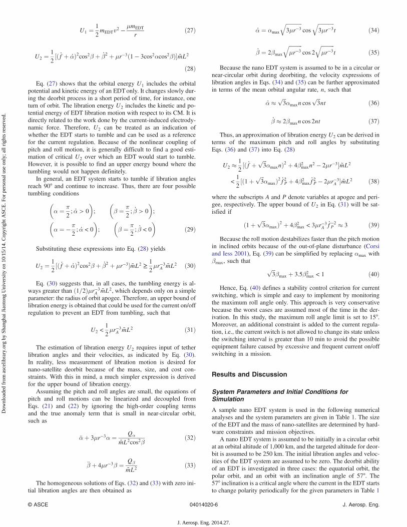
Induced Voltage with and without TetherLibration Motion
This section discusses the influence of libration motion on the in-duced voltage. Figs. 4–6 show the voltage variation versus orbitalheight in different cases. Fig. 4 shows that the induced voltages inthe equatorial orbit with and without tether libration considered arealmost the same. This is because the libration angles, both pitch androll, are small in most of the deorbiting time as seen in Fig. 7(a),
and the angle between the motional electric field ( v⇀
r × B⇀) and the
tether (~l) does not change much. As the orbital inclination in-creases, the out-of-plane libration (roll) increases, as shown inFigs. 7(c and d). Accordingly, the angle between the motional elec-
tric field ( v⇀
r × B⇀) and the tether (~l) changes because of increasing
roll oscillations, resulting in large variations of the induced voltageas per Eq. (3). Fig. 5 shows that the induced voltages in the
Table 1. Parameters of an EDT Nano-Satellite System
Parameters Values
Mass of main satellite 5 kgMass of subsatellite 1.75 kgMass of tether 0.25 kgDimensions of main satellite 0.2 × 0.2 × 0.2 mDimensions of subsatellite 0.1 × 0.17 × 0.1 mTether length 500 mTether diameter 0.0005 mTether conductivity (aluminum) 3.4014 × 10⁷ Ω−1 m−1
Fig. 4. Voltage variation versus orbital height in the equatorial orbit (a) with tether libration; (b) without tether libration
Fig. 5. Voltage variation versus orbital height in the 57° inclined orbit (a) with tether libration; (b) without tether libration
© ASCE 04014020-7 J. Aerosp. Eng.
J. Aerosp. Eng. 2014.27.
Dow
nloa
ded
from
asc
elib
rary
.org
by
Shan
ghai
Jia
oton
g U
nive
rsity
on
10/1
5/14
. Cop
yrig
ht A
SCE
. For
per
sona
l use
onl
y; a
ll ri
ghts
res
erve
d.
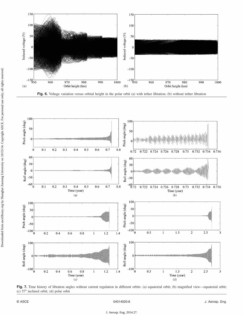
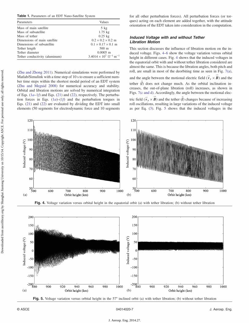
Fig. 6. Voltage variation versus orbital height in the polar orbit (a) with tether libration; (b) without tether libration
Fig. 7. Time history of libration angles without current regulation in different orbits: (a) equatorial orbit; (b) magnified view—equatorial orbit;(c) 57° inclined orbit; (d) polar orbit
© ASCE 04014020-8 J. Aerosp. Eng.
J. Aerosp. Eng. 2014.27.
Dow
nloa
ded
from
asc
elib
rary
.org
by
Shan
ghai
Jia
oton
g U
nive
rsity
on
10/1
5/14
. Cop
yrig
ht A
SCE
. For
per
sona
l use
onl
y; a
ll ri
ghts
res
erve
d.
57° inclined orbit increases rapidly as the libration angles increase.Without considering the tether libration, the induced voltage is a peri-odic function. Fig. 6 shows the similar pattern as shown in the57° inclined orbit. Because the voltage affects the current generationin the tether, which will in turn determine the electrodynamic forceacting on the EDT, these comparisons show that a strong couplingeffect exists between electric current and libration motion.
The effective deorbit force, or the projection of the electrody-namic force in the direction of orbital velocity, is not only affectedby the induced voltage, but also determined by the magnitude anddirection of the product of ~B and ~l, as seen in Eq. (7). The librationangles producing maximum-induced voltage do not necessarily en-sure maximum deorbit efficiency.
Deorbit of Nano EDT System without CurrentRegulation
As a benchmark for the effect of libration motion on the nanoEDT system deorbit process, the deorbit process without current
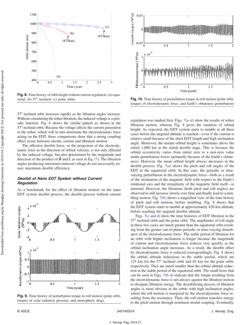
regulation was studied first. Figs. 7(a–d) show the results of tetherlibration motion, whereas Fig. 8 gives the variation of orbitalheight. As expected, the EDT system starts to tumble in all threecases before the targeted altitude is reached—even if the current isrelative small because of the short EDT length and high inclinationangle. Moreover, the instant orbital height is sometimes above theinitial 1,000 km at the initial deorbit stage. This is because theorbital eccentricity varies from initial zero to a non-zero valueunder perturbation forces (primarily because of the Earth’s oblate-ness). However, the mean orbital height always decreases in thedeorbit process. Fig. 7(a) shows the pitch and roll angles of theEDT in the equatorial orbit. In this case, the periodic or time-varying perturbation in the electrodynamic force—both as a resultof the inclination of the magnetic field with respect to the Earth’srotational axis and the irregularity of the magnetic field itself—isminimal. However, the librations (both pitch and roll angles) areobserved to still increase slowly over time and finally lead to a tum-bling motion. Fig. 7(b) shows a magnified view of the time historyof pitch and roll motions before tumbling. Fig. 8 shows thatthe EDT system starts to tumble at approximately 420-km altitude,before reaching the targeted deorbit altitude.
Figs. 7(c and d) show the time histories of EDT libration in the57° inclined orbit and the polar orbit. The amplitudes of roll anglein these two cases are much greater than the equatorial orbit result-ing from the greater out-of-plane periodic or time-varying disturb-ance of the electrodynamic force. The stable period of libration foran orbit with higher inclination is longer because the magnitudeof current and electrodynamic force reduces very quickly as theorbital inclination angle increases. As a result, the deorbit effectby electrodynamic force is reduced correspondingly. Fig. 8 showsthe orbital altitude reductions in the stable period, which are125 km for the 57° inclined orbit and 65 km for the polar orbit,respectively. They are much smaller than the orbital altitude reduc-tion in the stable period of the equatorial orbit. The small beats thatcan be seen in Figs. 7(b–d) indicate that the torque resulting fromthe electrodynamic force is not always against the libration motionto dissipate libration energy. The destabilizing process of librationangles is more obvious in the orbits with high inclination angles,where the roll motion is energized by the electrodynamic force re-sulting from the resonance. Then, the roll motion transfers energyto the pitch motion through nonlinear modal coupling. Eventually,
0 0.5 1 1.5 2 2.5 3400
500
600
700
800
900
1000
1100
Time (year)
Orb
it al
titud
e (k
m)
(a)
(b)
(c)
(875km)(935km)
Fig. 8. Time history of orbit height without current regulation: (a) equa-torial; (b) 57° inclined; (c) polar orbits
Fig. 9. Time history of perturbation torque in roll motion (polar orbit,torques of solar radiation pressure, and atmospheric drag)
Fig. 10. Time history of perturbation torque in roll motion (polar orbit,torques of electrodynamic force, and Earth’s oblateness perturbation)
© ASCE 04014020-9 J. Aerosp. Eng.
J. Aerosp. Eng. 2014.27.
Dow
nloa
ded
from
asc
elib
rary
.org
by
Shan
ghai
Jia
oton
g U
nive
rsity
on
10/1
5/14
. Cop
yrig
ht A
SCE
. For
per
sona
l use
onl
y; a
ll ri
ghts
res
erve
d.
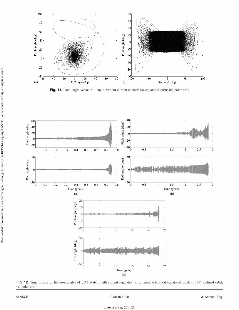
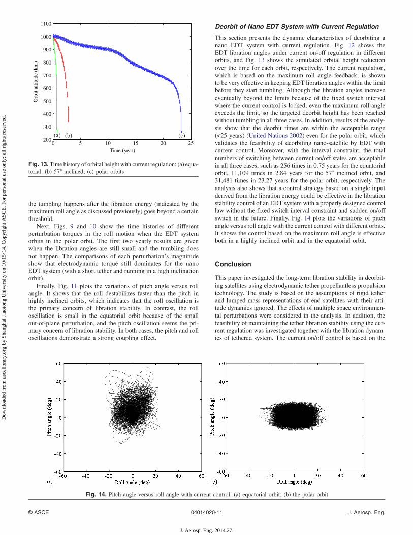
Fig. 11. Pitch angle versus roll angle without current control: (a) equatorial orbit; (b) polar orbit
Fig. 12. Time history of libration angles of EDT system with current regulation in different orbits: (a) equatorial orbit; (b) 57° inclined orbit;(c) polar orbit
© ASCE 04014020-10 J. Aerosp. Eng.
J. Aerosp. Eng. 2014.27.
Dow
nloa
ded
from
asc
elib
rary
.org
by
Shan
ghai
Jia
oton
g U
nive
rsity
on
10/1
5/14
. Cop
yrig
ht A
SCE
. For
per
sona
l use
onl
y; a
ll ri
ghts
res
erve
d.
the tumbling happens after the libration energy (indicated by themaximum roll angle as discussed previously) goes beyond a certainthreshold.
Next, Figs. 9 and 10 show the time histories of differentperturbation torques in the roll motion when the EDT systemorbits in the polar orbit. The first two yearly results are givenwhen the libration angles are still small and the tumbling doesnot happen. The comparisons of each perturbation’s magnitudeshow that electrodynamic torque still dominates for the nanoEDT system (with a short tether and running in a high inclinationorbit).
Finally, Fig. 11 plots the variations of pitch angle versus rollangle. It shows that the roll destabilizes faster than the pitch inhighly inclined orbits, which indicates that the roll oscillation isthe primary concern of libration stability. In contrast, the rolloscillation is small in the equatorial orbit because of the smallout-of-plane perturbation, and the pitch oscillation seems the pri-mary concern of libration stability. In both cases, the pitch and rolloscillations demonstrate a strong coupling effect.
Deorbit of Nano EDT System with Current Regulation
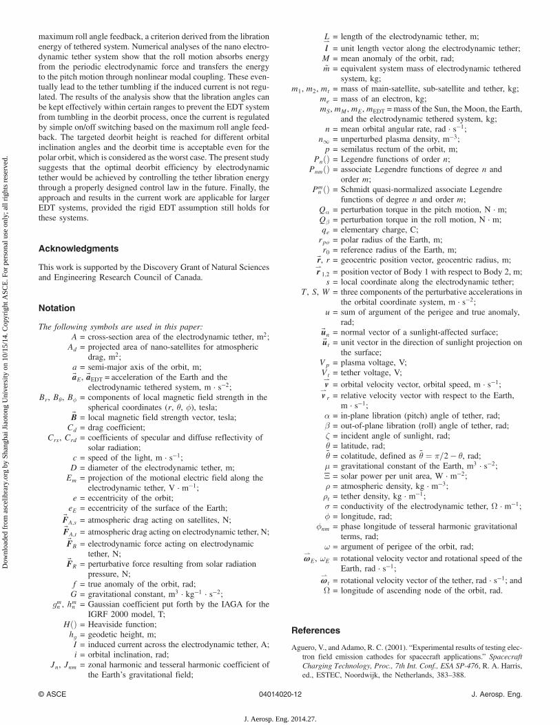
This section presents the dynamic characteristics of deorbiting anano EDT system with current regulation. Fig. 12 shows theEDT libration angles under current on-off regulation in differentorbits, and Fig. 13 shows the simulated orbital height reductionover the time for each orbit, respectively. The current regulation,which is based on the maximum roll angle feedback, is shownto be very effective in keeping EDT libration angles within the limitbefore they start tumbling. Although the libration angles increaseeventually beyond the limits because of the fixed switch intervalwhere the current control is locked, even the maximum roll angleexceeds the limit, so the targeted deorbit height has been reachedwithout tumbling in all three cases. In addition, results of the analy-sis show that the deorbit times are within the acceptable range(<25 years) (United Nations 2002) even for the polar orbit, whichvalidates the feasibility of deorbiting nano-satellite by EDT withcurrent control. Moreover, with the interval constraint, the totalnumbers of switching between current on/off states are acceptablein all three cases, such as 256 times in 0.75 years for the equatorialorbit, 11,109 times in 2.84 years for the 57° inclined orbit, and31,481 times in 23.27 years for the polar orbit, respectively. Theanalysis also shows that a control strategy based on a single inputderived from the libration energy could be effective in the librationstability control of an EDT system with a properly designed controllaw without the fixed switch interval constraint and sudden on/offswitch in the future. Finally, Fig. 14 plots the variations of pitchangle versus roll angle with the current control with different orbits.It shows the control based on the maximum roll angle is effectiveboth in a highly inclined orbit and in the equatorial orbit.
Conclusion
This paper investigated the long-term libration stability in deorbit-ing satellites using electrodynamic tether propellantless propulsiontechnology. The study is based on the assumptions of rigid tetherand lumped-mass representations of end satellites with their atti-tude dynamics ignored. The effects of multiple space environmen-tal perturbations were considered in the analysis. In addition, thefeasibility of maintaining the tether libration stability using the cur-rent regulation was investigated together with the libration dynam-ics of tethered system. The current on/off control is based on the
0 5 10 15 20 25200
300
400
500
600
700
800
900
1000
1100
Time (year)
Orb
it al
titud
e (k
m)
equitorial57 inclinedpolar
)c()b((a)
Fig. 13. Time history of orbital height with current regulation: (a) equa-torial; (b) 57° inclined; (c) polar orbits
Fig. 14. Pitch angle versus roll angle with current control: (a) equatorial orbit; (b) the polar orbit
© ASCE 04014020-11 J. Aerosp. Eng.
J. Aerosp. Eng. 2014.27.
Dow
nloa
ded
from
asc
elib
rary
.org
by
Shan
ghai
Jia
oton
g U
nive
rsity
on
10/1
5/14
. Cop
yrig
ht A
SCE
. For
per
sona
l use
onl
y; a
ll ri
ghts
res
erve
d.
maximum roll angle feedback, a criterion derived from the librationenergy of tethered system. Numerical analyses of the nano electro-dynamic tether system show that the roll motion absorbs energyfrom the periodic electrodynamic force and transfers the energyto the pitch motion through nonlinear modal coupling. These even-tually lead to the tether tumbling if the induced current is not regu-lated. The results of the analysis show that the libration angles canbe kept effectively within certain ranges to prevent the EDT systemfrom tumbling in the deorbit process, once the current is regulatedby simple on/off switching based on the maximum roll angle feed-back. The targeted deorbit height is reached for different orbitalinclination angles and the deorbit time is acceptable even for thepolar orbit, which is considered as the worst case. The present studysuggests that the optimal deorbit efficiency by electrodynamictether would be achieved by controlling the tether libration energythrough a properly designed control law in the future. Finally, theapproach and results in the current work are applicable for largerEDT systems, provided the rigid EDT assumption still holds forthese systems.
Acknowledgments
This work is supported by the Discovery Grant of Natural Sciencesand Engineering Research Council of Canada.
Notation
The following symbols are used in this paper:A = cross-section area of the electrodynamic tether, m2;Ad = projected area of nano-satellites for atmospheric
drag, m2;a = semi-major axis of the orbit, m;~aE, ~aEDT = acceleration of the Earth and the
electrodynamic tethered system, m · s−2;Br, Bθ, Bϕ = components of local magnetic field strength in the
spherical coordinates (r, θ, ϕ), tesla;~B = local magnetic field strength vector, tesla;
Cd = drag coefficient;Crs, Crd = coefficients of specular and diffuse reflectivity of
solar radiation;c = speed of the light, m · s−1;D = diameter of the electrodynamic tether, m;Em = projection of the motional electric field along the
electrodynamic tether, V · m−1;e = eccentricity of the orbit;
eE = eccentricity of the surface of the Earth;~FA;s = atmospheric drag acting on satellites, N;~FA;t = atmospheric drag acting on electrodynamic tether, N;~FB = electrodynamic force acting on electrodynamic
tether, N;~FR = perturbative force resulting from solar radiation
pressure, N;f = true anomaly of the orbit, rad;G = gravitational constant, m3 · kg−1 · s−2;
gmn , hmn = Gaussian coefficient put forth by the IAGA for theIGRF 2000 model, T;
HðÞ = Heaviside function;hg = geodetic height, m;I = induced current across the electrodynamic tether, A;i = orbital inclination, rad;
Jn, Jnm = zonal harmonic and tesseral harmonic coefficient ofthe Earth’s gravitational field;
L = length of the electrodynamic tether, m;l⇀
= unit length vector along the electrodynamic tether;M = mean anomaly of the orbit, rad;~m = equivalent system mass of electrodynamic tethered
system, kg;m1, m2, mt = mass of main-satellite, sub-satellite and tether, kg;
me = mass of an electron, kg;mS,mM,mE,mEDT =mass of the Sun, the Moon, the Earth,
and the electrodynamic tethered system, kg;n = mean orbital angular rate, rad · s−1;
n∞ = unperturbed plasma density, m−3;p = semilatus rectum of the orbit, m;
PnðÞ = Legendre functions of order n;PnmðÞ = associate Legendre functions of degree n and
order m;Pmn ðÞ = Schmidt quasi-normalized associate Legendre
functions of degree n and order m;Qα = perturbation torque in the pitch motion, N · m;Qβ = perturbation torque in the roll motion, N · m;qe = elementary charge, C;rpo = polar radius of the Earth, m;r0 = reference radius of the Earth, m;
~r, r = geocentric position vector, geocentric radius, m;r⇀
1;2 = position vector of Body 1 with respect to Body 2, m;s = local coordinate along the electrodynamic tether;
T, S, W = three components of the perturbative accelerations inthe orbital coordinate system, m · s−2;
u = sum of argument of the perigee and true anomaly,rad;
~un = normal vector of a sunlight-affected surface;~ut = unit vector in the direction of sunlight projection on
the surface;Vp = plasma voltage, V;Vt = tether voltage, V;v⇀
= orbital velocity vector, orbital speed, m · s−1;v⇀
r = relative velocity vector with respect to the Earth,m · s−1;
α = in-plane libration (pitch) angle of tether, rad;β = out-of-plane libration (roll) angle of tether, rad;ζ = incident angle of sunlight, rad;θ = latitude, rad;~θ = colatitude, defined as ~θ ¼ π=2 − θ, rad;μ = gravitational constant of the Earth, m3 · s−2;Ξ = solar power per unit area, W · m−2;ρ = atmospheric density, kg · m−3;ρt = tether density, kg · m−1;σ = conductivity of the electrodynamic tether, Ω · m−1;ϕ = longitude, rad;
ϕnm = phase longitude of tesseral harmonic gravitationalterms, rad;
ω = argument of perigee of the orbit, rad;ω⇀
E, ωE = rotational velocity vector and rotational speed of theEarth, rad · s−1;
ω⇀
t = rotational velocity vector of the tether, rad · s−1; andΩ = longitude of ascending node of the orbit, rad.
References
Aguero, V., and Adamo, R. C. (2001). “Experimental results of testing elec-tron field emission cathodes for spacecraft applications.” SpacecraftCharging Technology, Proc., 7th Int. Conf., ESA SP-476, R. A. Harris,ed., ESTEC, Noordwijk, the Netherlands, 383–388.
© ASCE 04014020-12 J. Aerosp. Eng.
J. Aerosp. Eng. 2014.27.
Dow
nloa
ded
from
asc
elib
rary
.org
by
Shan
ghai
Jia
oton
g U
nive
rsity
on
10/1
5/14
. Cop
yrig
ht A
SCE
. For
per
sona
l use
onl
y; a
ll ri
ghts
res
erve
d.
Bilen, S., et al. (2010). “Electrodynamic tethers for energy harvestingand propulsion on space platforms.” AIAA Space 2010 Conf. and Ex-position, AIAA, Reston, VA.
Bilitza, D., and Reinisch, B. W. (2008). “International reference ionosphere2007: Improvements and new parameters.” Adv. Space Res., 42(4),599–609.
Carroll, J. A. (1985). Guidebook for analysis of tether applications, NASA,San Diego, CA.
Corsi, J., and Iess, L. (2001). “Stability and control of electrodynamictethers for de-orbiting applications.” Acta Astronautica, 48(5–12),491–501.
Davis, J. (2004). “Mathematical modeling of earth’s magnetic field.” Tech-nical Note, Virginia Tech, Blacksburg, VA.
Gilchrist, B., et al. (2002). “The use of electrodynamic tethers for orbitmaintenance and deorbit of large spacecraft: A trade study of the NASAGLAST mission.” 38th AIAA/ASME/SAE/ASEE Joint Propulsion Conf.and Exhibition AIAA 2002-4044, AIAA, Reston, VA.
Hite, G. E., and McCoy, J. E. (1988). “The electrodynamic tether.” Am. J.Phys., 56(3), 222–225.
Hoyt, R. P., and Forward, R. L. (1998). “The terminator tether: A low-masssystem for end-of-life deorbit of LEO spacecraft.” Final Rep. on NASA/MSFC SBIR Phase I Contract NAS8-98108, Tethers Unlimited, Bothell,WA.
Hughes, P. C. (1986). Spacecraft attitude dynamics, Wiley, New York.Inarrea, M., and Peláez, J. (2010). “Libration control of electrodynamic
tethers using the extended time-delayed autosynchronization method.”J. Guidance Control. Dyn., 33(3), 923–933.
Jablonski, A. M., and Scott, R. (2009). “Deorbiting of microsatellites in lowearth orbit (LEO)—An introduction.” Can. Aeronaut Space J., 55(2),55–67.
Jakhu, R. S. (2010). “Iridium-cosmos collision and its implications forspace operations.” ESPI yearbook on space policy. 2008/2009: Settingnew trends, Wien Springer, New York, 254–275.
Kojima, H., and Sugimoto, T. (2009). “Stability analysis of in-plane andout-of-plane periodic motions of electrodynamic tether system ininclined elliptic orbit.” Acta Astronautica, 65(3–4), 477–488.
Lanoix, E. L. M., et al. (2005). “Effect of electrodynamic forces on theorbital dynamics of tethered satellites.” J. Guidance Control Dyn.,28(6), 1309–1315.
Larsen, M. B., and Blanke, M. (2011). “Passivity-based control of a rigidelectrodynamic tether.” J. Guid. Contr. Dynam., 34(1), 118–127.
Levin, E., Pearson, J., and Carroll, J. (2012). “Wholesale debris removalfrom LEO.” Acta Astronautica, 73, 100–108.
Levin, E. M. (1987). “Stability of the stationary motions of an electrody-namic tether system in orbit.” Cosmic Res., 25, 368–376.
NASA. (2012). Earth fact sheet, ⟨http://nssdc.gsfc.nasa.gov/planetary/factsheet/earthfact.html⟩ (Mar. 16, 2012).
NOAA, NASA, and USAF. (1976). The U.S standard atmosphere, U.S.Printing Office, Washington, DC.
Pelaez, J., Lorenzini, E. C., Lopez-Rebollal, O., and Ruiz, M. (2000).Spaceflight mechanics, AAS Publications, San Diego, CA, Vol. 105,1367.
Peláez, J., and Lorenzini, E. C. (2005). “Libration control of electrody-namic tethers in inclined orbit.” J. Guid. Contr. Dynam., 28(2),269–279.
Penzo, P. A., and Ammann, P. W. (1989). Tethers in space handbook, 2ndEd., NASA Office of Space Flight, Washington, DC.
Sanmartin, J. R., et al. (2011). “Propellantless deorbiting of space debris bybare electrodynamic tethers.” 62nd Int. Astronautical Congress 2011,Vol. 3, International Astronautical Federation (IAF), Paris, France,2239–2248.
Sanmartin, J. R., Martinez-Sanchez, M., and Ahedo, E. (1993). “Bare wireanodes for electrodynamic tethers.” J. Propul. Power, 9(3), 353–360.
Takeichi, N. (2006). “Practical operation strategy for deorbit of an electro-dynamic tethered system.” J. Spacecraft Rockets, 43(6), 1283–1288.
United Nations. (2002). “IADC space debris mitigation guidelines.” Inter-Agency Space Debris Coordination Committee Document IADC-02-01,United Nations Publication, New York.
U. S. Naval Observatory, and H. M. Nautical Almanac Office. (2011). Theastronomical almanac for the year 2012, United Kingdom Hydro-graphic Office, Taunton.
Vallado, D. A. (2007). Fundamentals of astrodynamics and applications,Microcosm Press, Springer, New York.
Wertz, J. R. (2003). Spacecraft attitude determination and control,Springer, Dordrecht.
Williams, P. (2006). “Energy rate feedback for libration control of electro-dynamic tethers.” J. Guid. Contr. Dynam., 29(1), 221–223.
Williams, P. (2009). “Librational stabilization of electrodynamic tethersusing time-delayed predictive control.” J. Guid. Contr. Dynam.,32(4), 1254–1268.
Zhong, R., and Zhu, Z. H. (2013). “Dynamics of nano-satellite deorbitby bare electrodynamic tether in low earth orbit.” J. Spacecraft Rockets,50(3), 691–700.
Zhu, Z. H., and Meguid, S. A. (2008). “Vibration analysis of a new curvedbeam element.” J. Sound Vib., 309(1–2), 86–95.
Zhu, Z. H., and Zhong, R. (2011). “Deorbiting dynamics of electrodynamictether.” Int. J. Aerosp. Lightweight Struct., 1(1), 47–66.
© ASCE 04014020-13 J. Aerosp. Eng.
J. Aerosp. Eng. 2014.27.
Dow
nloa
ded
from
asc
elib
rary
.org
by
Shan
ghai
Jia
oton
g U
nive
rsity
on
10/1
5/14
. Cop
yrig
ht A
SCE
. For
per
sona
l use
onl
y; a
ll ri
ghts
res
erve
d.