lm380 2.5w audio power amplifier
TRANSCRIPT
LM380
www.ti.com SNAS546C –DECEMBER 1994–REVISED APRIL 2013
LM380 2.5W Audio Power AmplifierCheck for Samples: LM380
1FEATURES DESCRIPTIONThe LM380 is a power audio amplifier for consumer• Wide Supply Voltage Range: 10V-22Vapplications. In order to hold system cost to a
• Low Quiescent Power Drain: 0.13W (VS= 18V) minimum, gain is internally fixed at 34 dB. A unique• Voltage Gain Fixed at 50 input stage allows ground referenced input signals.
The output automatically self-centers to one-half the• High Peak Current Capability: 1.3Asupply voltage.• Input Referenced to GNDThe output is short circuit proof with internal thermal• High Input Impedance: 150kΩlimiting. The package outline is standard dual-in-line.
• Low Distortion The LM380N uses a copper lead frame. The center• Quiescent Output Voltage is at One-Half of the three pins on either side comprise a heat sink. This
Supply Voltage makes the device easy to use in standard PC layouts.• Standard Dual-In-Line Package Uses include simple phonograph amplifiers,
intercoms, line drivers, teaching machine outputs,alarms, ultrasonic drivers, TV sound systems, AM-FMradio, small servo drivers, power converters, etc.
A selected part for more power on higher supplyvoltages is available as the LM384. For moreinformation see SNAA086.
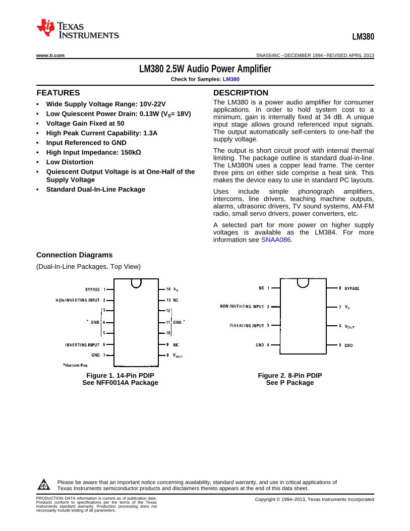
Connection Diagrams
(Dual-In-Line Packages, Top View)
Figure 1. 14-Pin PDIP Figure 2. 8-Pin PDIPSee NFF0014A Package See P Package
1
Please be aware that an important notice concerning availability, standard warranty, and use in critical applications ofTexas Instruments semiconductor products and disclaimers thereto appears at the end of this data sheet.
PRODUCTION DATA information is current as of publication date. Copyright © 1994–2013, Texas Instruments IncorporatedProducts conform to specifications per the terms of the TexasInstruments standard warranty. Production processing does notnecessarily include testing of all parameters.
LM380
SNAS546C –DECEMBER 1994–REVISED APRIL 2013 www.ti.com
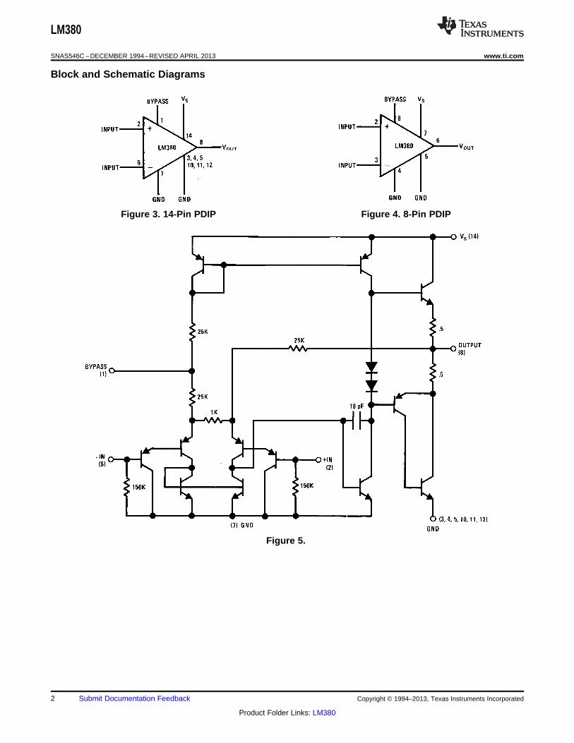
Block and Schematic Diagrams
Figure 3. 14-Pin PDIP Figure 4. 8-Pin PDIP
Figure 5.
2 Submit Documentation Feedback Copyright © 1994–2013, Texas Instruments Incorporated
Product Folder Links: LM380
LM380
www.ti.com SNAS546C –DECEMBER 1994–REVISED APRIL 2013
These devices have limited built-in ESD protection. The leads should be shorted together or the device placed in conductive foamduring storage or handling to prevent electrostatic damage to the MOS gates.
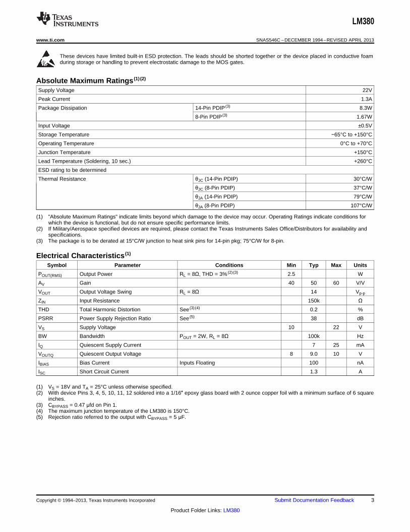
Absolute Maximum Ratings (1) (2)
Supply Voltage 22V
Peak Current 1.3A
Package Dissipation 14-Pin PDIP (3) 8.3W
8-Pin PDIP (3) 1.67W
Input Voltage ±0.5V
Storage Temperature −65°C to +150°C
Operating Temperature 0°C to +70°C
Junction Temperature +150°C
Lead Temperature (Soldering, 10 sec.) +260°C
ESD rating to be determined
Thermal Resistance θJC (14-Pin PDIP) 30°C/W
θJC (8-Pin PDIP) 37°C/W
θJA (14-Pin PDIP) 79°C/W
θJA (8-Pin PDIP) 107°C/W
(1) "Absolute Maximum Ratings" indicate limits beyond which damage to the device may occur. Operating Ratings indicate conditions forwhich the device is functional, but do not ensure specific performance limits.
(2) If Military/Aerospace specified devices are required, please contact the Texas Instruments Sales Office/Distributors for availability andspecifications.
(3) The package is to be derated at 15°C/W junction to heat sink pins for 14-pin pkg; 75°C/W for 8-pin.
Electrical Characteristics (1)
Symbol Parameter Conditions Min Typ Max Units
POUT(RMS) Output Power RL = 8Ω, THD = 3% (2) (3) 2.5 W
AV Gain 40 50 60 V/V
VOUT Output Voltage Swing RL = 8Ω 14 Vp-p
ZIN Input Resistance 150k ΩTHD Total Harmonic Distortion See (3) (4) 0.2 %
PSRR Power Supply Rejection Ratio See (5) 38 dB
VS Supply Voltage 10 22 V
BW Bandwidth POUT = 2W, RL = 8Ω 100k Hz
IQ Quiescent Supply Current 7 25 mA
VOUTQ Quiescent Output Voltage 8 9.0 10 V
IBIAS Bias Current Inputs Floating 100 nA
ISC Short Circuit Current 1.3 A
(1) VS = 18V and TA = 25°C unless otherwise specified.(2) With device Pins 3, 4, 5, 10, 11, 12 soldered into a 1/16″ epoxy glass board with 2 ounce copper foil with a minimum surface of 6 square
inches.(3) CBYPASS = 0.47 μfd on Pin 1.(4) The maximum junction temperature of the LM380 is 150°C.(5) Rejection ratio referred to the output with CBYPASS = 5 μF.
Copyright © 1994–2013, Texas Instruments Incorporated Submit Documentation Feedback 3
Product Folder Links: LM380
LM380
SNAS546C –DECEMBER 1994–REVISED APRIL 2013 www.ti.com
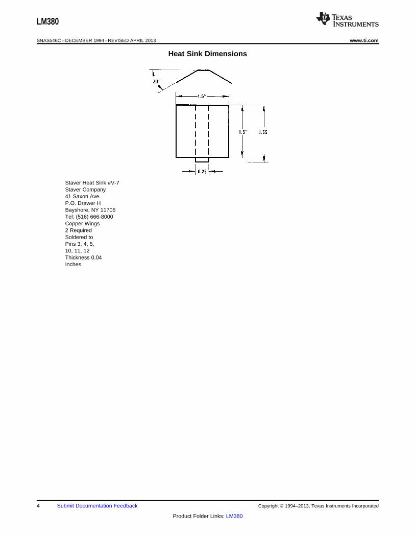
Heat Sink Dimensions
Staver Heat Sink #V-7Staver Company41 Saxon Ave.P.O. Drawer HBayshore, NY 11706Tel: (516) 666-8000Copper Wings2 RequiredSoldered toPins 3, 4, 5,10, 11, 12Thickness 0.04Inches
4 Submit Documentation Feedback Copyright © 1994–2013, Texas Instruments Incorporated
Product Folder Links: LM380
LM380
www.ti.com SNAS546C –DECEMBER 1994–REVISED APRIL 2013
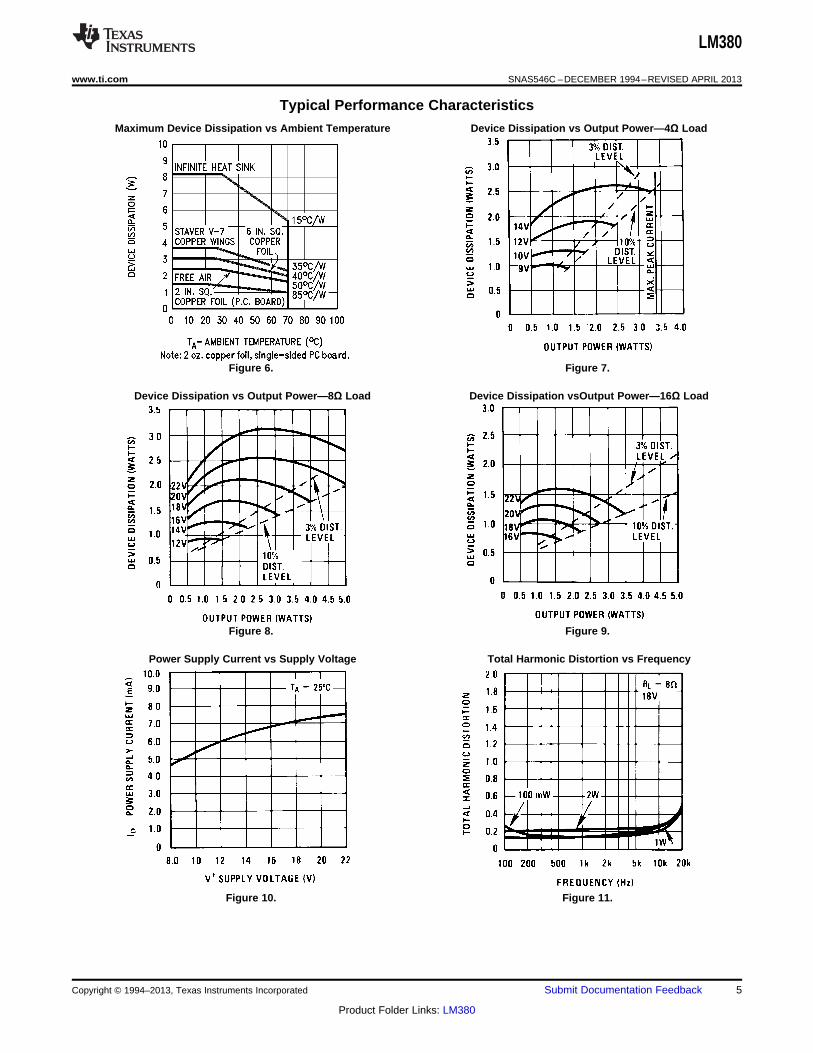
Typical Performance Characteristics
Maximum Device Dissipation vs Ambient Temperature Device Dissipation vs Output Power—4Ω Load
Figure 6. Figure 7.
Device Dissipation vs Output Power—8Ω Load Device Dissipation vsOutput Power—16Ω Load
Figure 8. Figure 9.
Power Supply Current vs Supply Voltage Total Harmonic Distortion vs Frequency
Figure 10. Figure 11.
Copyright © 1994–2013, Texas Instruments Incorporated Submit Documentation Feedback 5
Product Folder Links: LM380

LM380
SNAS546C –DECEMBER 1994–REVISED APRIL 2013 www.ti.com
Typical Performance Characteristics (continued)Output Voltage Gain and Phase vs Frequency Total Harmonic Distortion vs Output Power
Figure 12. Figure 13.
Device Dissipation vs Output Power Supply Decoupling vs Frequency
Figure 14. Figure 15.
6 Submit Documentation Feedback Copyright © 1994–2013, Texas Instruments Incorporated
Product Folder Links: LM380
LM380
www.ti.com SNAS546C –DECEMBER 1994–REVISED APRIL 2013
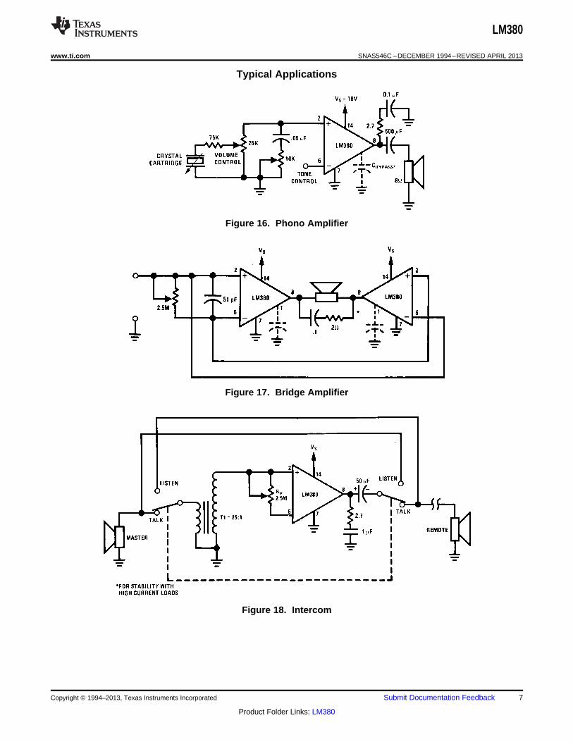
Typical Applications
Figure 16. Phono Amplifier
Figure 17. Bridge Amplifier
Figure 18. Intercom
Copyright © 1994–2013, Texas Instruments Incorporated Submit Documentation Feedback 7
Product Folder Links: LM380
LM380
SNAS546C –DECEMBER 1994–REVISED APRIL 2013 www.ti.com
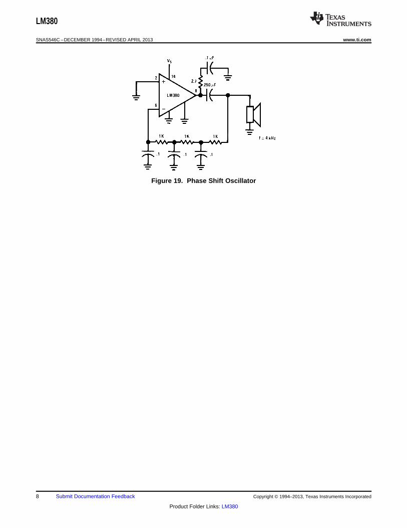
Figure 19. Phase Shift Oscillator
8 Submit Documentation Feedback Copyright © 1994–2013, Texas Instruments Incorporated
Product Folder Links: LM380
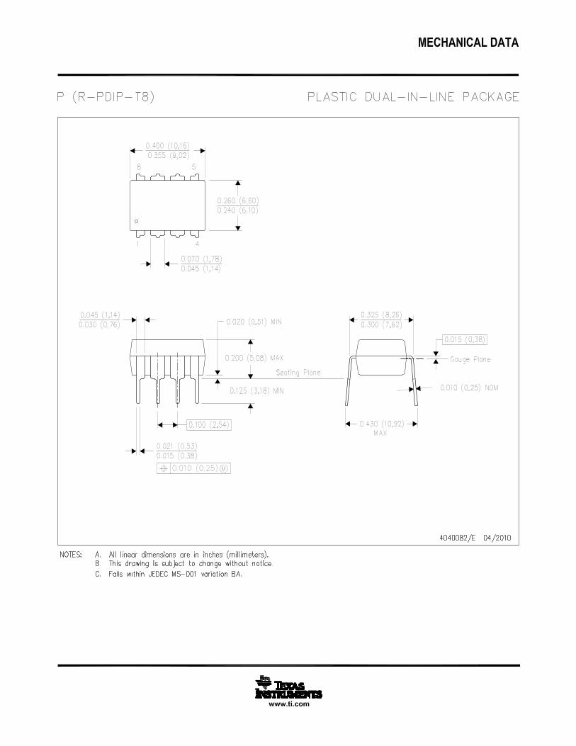
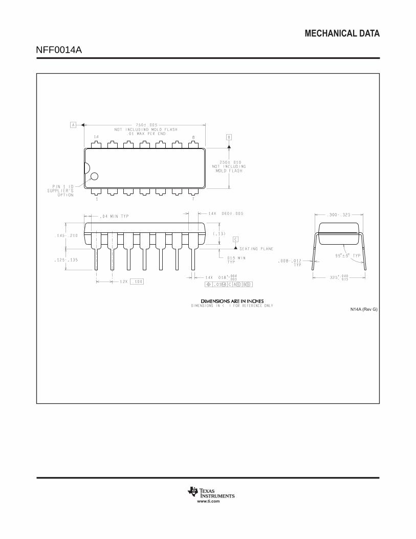
MECHANICAL DATA
N0014A
www.ti.com
N14A (Rev G)
NFF0014A