lessons from tailings dam failures—where to go from here?
TRANSCRIPT
minerals
Review
Lessons from Tailings Dam Failures—Where to Go from Here?
David John Williams
�����������������
Citation: Williams, D.J. Lessons from
Tailings Dam Failures—Where to Go
from Here? Minerals 2021, 11, 853.
https://doi.org/10.3390/min11080853
Academic Editors: Masoud
Zare-Naghadehi and
Javad Sattarvand
Received: 13 July 2021
Accepted: 5 August 2021
Published: 8 August 2021
Publisher’s Note: MDPI stays neutral
with regard to jurisdictional claims in
published maps and institutional affil-
iations.
Copyright: © 2021 by the author.
Licensee MDPI, Basel, Switzerland.
This article is an open access article
distributed under the terms and
conditions of the Creative Commons
Attribution (CC BY) license (https://
creativecommons.org/licenses/by/
4.0/).
Geotechnical Engineering Center, School of Civil Engineering, The University of Queensland,Brisbane, QLD 4066, Australia; [email protected]
Abstract: Different regions worldwide have adopted various approaches to tailings management,as a result of the site settings and local practices as they have evolved. Tailings dam failures havecontinued to occur in both developing and developed countries, necessitating a range of tailingsmanagement approaches. These failures, while rare, continue to occur at a frequency that exceedsboth industry and society expectations, and there is much to be learned from well-documentedcases. Tailings management continues to be overly reliant on a net present value approach using ahigh discount factor, rather than a whole-of-life approach that may result in safer and more stabletailings facilities and may also facilitate the eventual mine closure. There is a need for the furtherdevelopment and implementation of new tailings management technologies and innovations, andfor the application of whole-of-life costing of tailings facilities. Changes in tailings managementwill most readily be achieved at new mining projects, making change across the minerals industry agenerational process.
Keywords: foundation failure; improved management; lessons; liquefaction; site settings; slurrytailings; tailings dam failures
1. Introduction
The conventional deposition of slurry tailings behind dams that are raised progres-sively has led to an unacceptably high rate of catastrophic tailings dam failures, resultingin fatalities, damage to infrastructure and environmental harm. The rate of tailings damfailures is about two orders of magnitude higher than that of water dams, which aregenerally raised in a single lift to provide the required water storage.
Tailings dam failures that lead to high fatalities can prompt dramatic change, suchas occurred in Chile, following the catastrophic El Cobre tailings dam failure during anearthquake. This change was initiated by tailings professionals, who questioned whetherstable tailings dams could be constructed and operated in their highly seismic setting,and who made changes that ensured this was possible. The Global Industry Standardon Tailings Management (GISTM) and accompanying guides transpired as a result of thecatastrophic tailings dam failure near Brumadinho in Brazil in January 2019. For change tobe effective, active recognition and engagement is needed by all stakeholders.
This paper reviews the drivers of conventional tailings management, including thedominance of the net present value accounting approach, and the importance of eachsite’s climatic, topographic and seismic settings that must be accommodated both duringtailings operations and post-closure. Selected tailings dam failures are used to illustratethe main modes of failure of conventional tailings dams, and how they may be avoided,and the “as low as reasonably practicable” approach to reducing risk is discussed. The keyfeatures and requirements of the GISTM and the accompanying guides are reviewed, asis a comprehensive range of alternatives to the conventional deposition of slurry tailingsbehind dams. From these discussions, the expectations and implications of the GISTM,and the range of tailings management alternatives available, a path forward in tailingsmanagement is offered.
Minerals 2021, 11, 853. https://doi.org/10.3390/min11080853 https://www.mdpi.com/journal/minerals
Minerals 2021, 11, 853 2 of 35
2. Conventional Tailings Management2.1. Drivers of Conventional Tailings Management
The commonly held perception, supported by net present value (NPV) accounting,is that transporting tailings as a slurry to a surface dam is the most economical solution.Discounted long-term and rehabilitation costs “become” insignificant. Filtering tailings isperceived to be too expensive, despite reducing the storage volume and making it easierto rehabilitate to a high level. This has led to the widespread adoption of surface tailingsfacilities to store slurried tailings, delivered by robust and inexpensive centrifugal pumpsand pipelines. Initially, small storage areas are constructed, leading to soft and wet tailingsdeposits, storing entrained water.
Operating costs increase over time as capital expenditure is avoided or delayed. Thisresults in unintended increased storage volumes that must accommodate the entrainedwater, and more difficult rehabilitation of the tailings facility.
2.2. Importance of Site Settings
The key settings of a given mine site are the climate, the topography and the seismicityof the site. The site rainfall/precipitation and evaporation dictate the potential for thetailings to be exposed to desiccation. A dry climate makes slurry tailings disposal easier(e.g., in semi-arid regions of Australia, South Africa, and Southwestern USA). A wetclimate has the potential to maintain the wetness of tailings (e.g., in the wet tropics,including Brazil). A near-neutral water balance can be tipped over into net positive bytailings deposition, or net negative post-closure by evaporation from stored water (e.g., forCanadian oil sands tailings).
The topography of the site dictates the volume of “free storage” available in valleysand the tailings dam’s height. High seismicity will often govern tailings dam/storagedesign (e.g., in Chile and Peru). High seismicity may well need to be considered post-closure (in perpetuity) everywhere.
3. Lessons from Tailings Dam Failures3.1. Selected Tailings Dam Failures
For the purposes of this paper, a number of tailings dam failures have been selected,as shown on the timeline in Figure 1 [1–12].
Minerals 2021, 11, x FOR PEER REVIEW 2 of 34
2. Conventional Tailings Management
2.1. Drivers of Conventional Tailings Management
The commonly held perception, supported by net present value (NPV) accounting,
is that transporting tailings as a slurry to a surface dam is the most economical solution.
Discounted long-term and rehabilitation costs “become” insignificant. Filtering tailings is
perceived to be too expensive, despite reducing the storage volume and making it easier
to rehabilitate to a high level. This has led to the widespread adoption of surface tailings
facilities to store slurried tailings, delivered by robust and inexpensive centrifugal pumps
and pipelines. Initially, small storage areas are constructed, leading to soft and wet tailings
deposits, storing entrained water.
Operating costs increase over time as capital expenditure is avoided or delayed. This
results in unintended increased storage volumes that must accommodate the entrained
water, and more difficult rehabilitation of the tailings facility.
2.2. Importance of Site Settings
The key settings of a given mine site are the climate, the topography and the seismic-
ity of the site. The site rainfall/precipitation and evaporation dictate the potential for the
tailings to be exposed to desiccation. A dry climate makes slurry tailings disposal easier
(e.g., in semi-arid regions of Australia, South Africa, and Southwestern USA). A wet cli-
mate has the potential to maintain the wetness of tailings (e.g., in the wet tropics, includ-
ing Brazil). A near-neutral water balance can be tipped over into net positive by tailings
deposition, or net negative post-closure by evaporation from stored water (e.g., for Cana-
dian oil sands tailings).
The topography of the site dictates the volume of “free storage” available in valleys
and the tailings dam’s height. High seismicity will often govern tailings dam/storage de-
sign (e.g., in Chile and Peru). High seismicity may well need to be considered post-closure
(in perpetuity) everywhere.
3. Lessons from Tailings Dam Failures
3.1. Selected Tailings Dam Failures
For the purposes of this paper, a number of tailings dam failures have been selected,
as shown on the timeline in Figure 1 [1–12].
Figure 1. Timeline of selected tailings dam failures.
3.2. Some Root Causes of Tailings Dam Failures
Tailings dams that fail are marginally stable. Most tailings dams are stable and do
not fail. Failures typically arise from a combination of causes, with water being a key ele-
ment. Upstream constructed tailings dams are more prone to failure than downstream
dams. Tailings deposited as a slurry are potentially susceptible to seismic or flow lique-
faction, unless compacted and/or consolidated and desiccated. Weak foundation layers
may cause tailings dam failures. Excessive tailings dam failures threaten the mineral in-
dustry’s financial and social licenses to operate, and the control of their operations.
Figure 1. Timeline of selected tailings dam failures.
3.2. Some Root Causes of Tailings Dam Failures
Tailings dams that fail are marginally stable. Most tailings dams are stable and do notfail. Failures typically arise from a combination of causes, with water being a key element.Upstream constructed tailings dams are more prone to failure than downstream dams.Tailings deposited as a slurry are potentially susceptible to seismic or flow liquefaction,unless compacted and/or consolidated and desiccated. Weak foundation layers maycause tailings dam failures. Excessive tailings dam failures threaten the mineral industry’sfinancial and social licenses to operate, and the control of their operations.
Minerals 2021, 11, 853 3 of 35
3.3. Seismic Liquefaction Failures of Upstream Sand Dams in Chile
“Construction with, or on, liquefiable materials should be avoided”, according to Dr IzzatIdriss [13]. “You would not build a water dam using liquefiable materials or on a liquefiablefoundation, so why would we do this for tailings dams?” This is not to say that the upstreamraising of a tailings dam cannot be made to work.
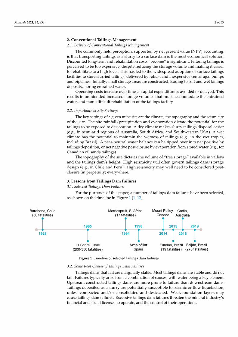
Among the fatal failures of steep upstream sand tailings dams in Chile, due to seismicliquefaction, are the Barahona No. 1 tailings dam failure in 1928 (Figure 2a) [1], andthe El Cobre old tailings dam failure in 1965 (Figure 2b) [2]. The Barahona tailings damunderwent liquefaction due to a magnitude 8.2 earthquake, resulting in 50 fatalities, anddid not lead to any changes to tailings management practices or regulations.
Minerals 2021, 11, x FOR PEER REVIEW 3 of 34
3.3. Seismic Liquefaction Failures of Upstream Sand Dams in Chile
“Construction with, or on, liquefiable materials should be avoided”, according to Dr Izzat
Idriss [13]. “You would not build a water dam using liquefiable materials or on a liquefiable
foundation, so why would we do this for tailings dams?” This is not to say that the upstream
raising of a tailings dam cannot be made to work.
Among the fatal failures of steep upstream sand tailings dams in Chile, due to seismic
liquefaction, are the Barahona No. 1 tailings dam failure in 1928 (Figure 2a) [1], and the El
Cobre old tailings dam failure in 1965 (Figure 2b) [2]. The Barahona tailings dam under-
went liquefaction due to a magnitude 8.2 earthquake, resulting in 50 fatalities, and did not
lead to any changes to tailings management practices or regulations.
The El Cobre tailings dam also underwent liquefaction due to a magnitude 7.4 earth-
quake, inundating the town of El Cobre, resulting in 200 to 350 fatalities (the number is
uncertain, due to the unknown number of occupants of the town at the time of the failure,
and an inability to recover all of the bodies).
The El Cobre failure led to tailings practitioners in Chile questioning whether a safe
tailings dam could be built to sustain large earthquakes. The industry responded rapidly
by flattening and compacting the downstream slopes of sand dams from the natural 2
(horizontal) to 1 (vertical angle) to 4 to 1 (essentially a doubling of the margin of stability),
and a change to the downstream construction, using either sand or earth fill. Later, a ge-
omembrane was added to the exposed upstream face of the dam to limit the ingress of
water from the contained slimes into the dam, and, in the case of sand dams, central sand
cyclone stations replaced the series of cyclones along the crest of the dam. Central cyclone
stations allowed greater control of the fines content of the sand (limiting this to less than
20%) and avoided weak spots being formed in the dam if one of the crest cyclones failed.
Regulations to formalize these changes were implemented 5 years later and beyond, and
these have also been adopted for tailings dams in seismically active Peru.
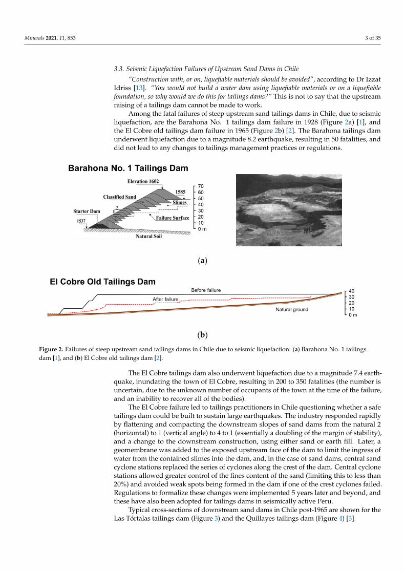
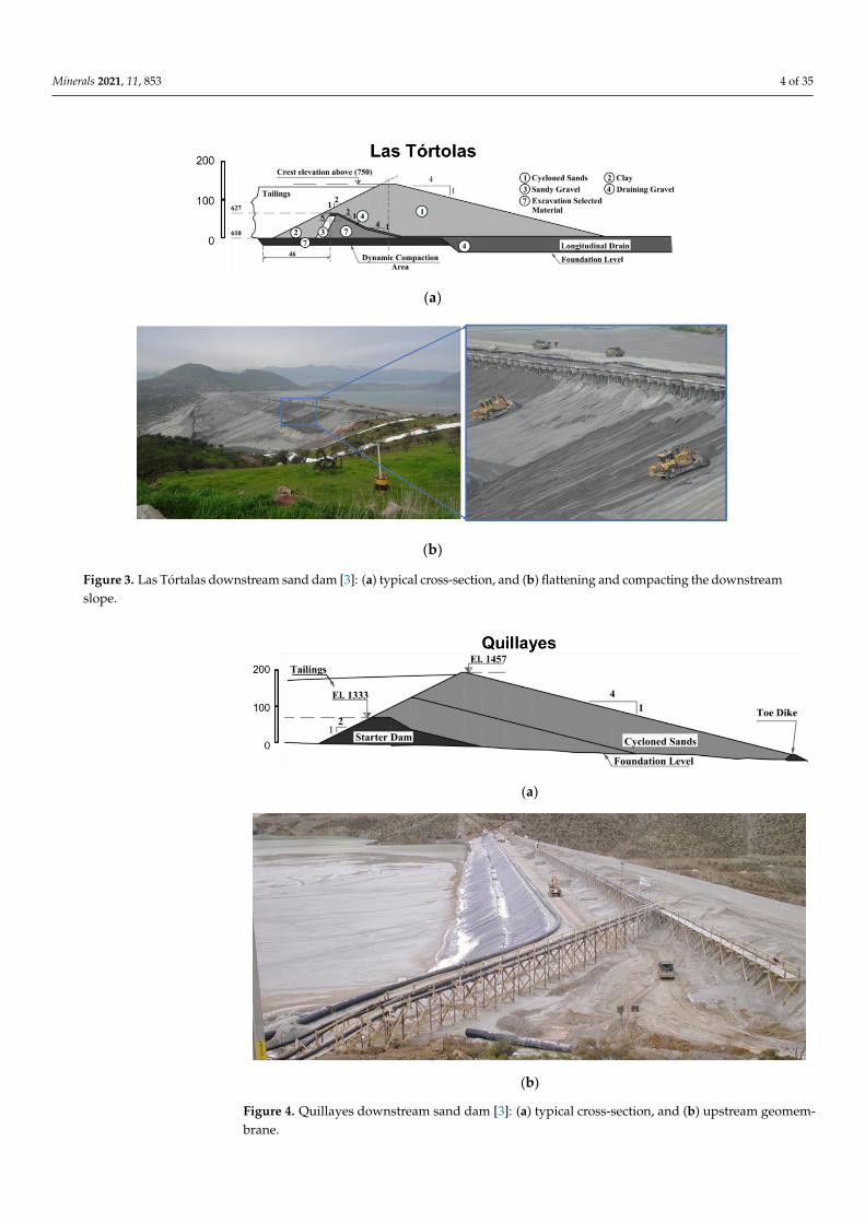
Typical cross-sections of downstream sand dams in Chile post-1965 are shown for
the Las Tórtalas tailings dam (Figure 3) and the Quillayes tailings dam (Figure 4) [3].
(a)
(b)
Figure 2. Failures of steep upstream sand tailings dams in Chile due to seismic liquefaction: (a)
Barahona No. 1 tailings dam [1], and (b) El Cobre old tailings dam [2].
Figure 2. Failures of steep upstream sand tailings dams in Chile due to seismic liquefaction: (a) Barahona No. 1 tailingsdam [1], and (b) El Cobre old tailings dam [2].
The El Cobre tailings dam also underwent liquefaction due to a magnitude 7.4 earth-quake, inundating the town of El Cobre, resulting in 200 to 350 fatalities (the number isuncertain, due to the unknown number of occupants of the town at the time of the failure,and an inability to recover all of the bodies).
The El Cobre failure led to tailings practitioners in Chile questioning whether a safetailings dam could be built to sustain large earthquakes. The industry responded rapidlyby flattening and compacting the downstream slopes of sand dams from the natural 2(horizontal) to 1 (vertical angle) to 4 to 1 (essentially a doubling of the margin of stability),and a change to the downstream construction, using either sand or earth fill. Later, ageomembrane was added to the exposed upstream face of the dam to limit the ingress ofwater from the contained slimes into the dam, and, in the case of sand dams, central sandcyclone stations replaced the series of cyclones along the crest of the dam. Central cyclonestations allowed greater control of the fines content of the sand (limiting this to less than20%) and avoided weak spots being formed in the dam if one of the crest cyclones failed.Regulations to formalize these changes were implemented 5 years later and beyond, andthese have also been adopted for tailings dams in seismically active Peru.
Typical cross-sections of downstream sand dams in Chile post-1965 are shown for theLas Tórtalas tailings dam (Figure 3) and the Quillayes tailings dam (Figure 4) [3].
Minerals 2021, 11, 853 4 of 35Minerals 2021, 11, x FOR PEER REVIEW 4 of 34
(a)
(b)
Figure 3. Las Tórtalas downstream sand dam [3]: (a) typical cross-section, and (b) flattening and
compacting the downstream slope.
(a)
(b)
Figure 4. Quillayes downstream sand dam [3]: (a) typical cross-section, and (b) upstream ge-
omembrane.
Figure 3. Las Tórtalas downstream sand dam [3]: (a) typical cross-section, and (b) flattening and compacting the downstreamslope.
Minerals 2021, 11, x FOR PEER REVIEW 4 of 34
(a)
(b)
Figure 3. Las Tórtalas downstream sand dam [3]: (a) typical cross-section, and (b) flattening and
compacting the downstream slope.
(a)
(b)
Figure 4. Quillayes downstream sand dam [3]: (a) typical cross-section, and (b) upstream ge-
omembrane.
Figure 4. Quillayes downstream sand dam [3]: (a) typical cross-section, and (b) upstream geomem-brane.
Minerals 2021, 11, 853 5 of 35
Of the approximately 740 tailings dams in Chile, about 100 are currently active, andthese are mostly downstream sand dams. Around 470 tailings dams are inactive, and theseare mostly upstream sand dams; about 170 are abandoned and are also mostly upstreamsand dams. Active downstream sand dams in Chile have performed well since 1965,due to improved construction methods. Only one dam has failed, after the 8.4magnitudeearthquake in 2010, resulting in four fatalities.
With the exception of a few inactive upstream sand dams in central Chile, most inactiveand abandoned upstream sand dams have performed well, since they have drained downin the dry Chilean climate. This is a “good” story about the capability of the mineralsindustry in Chile, and later in Peru, to allow for the high seismicity, which governs thestability of tailings dams in their region.
3.4. Overtopping/Flow Liquefaction Failures of a Tailings Dam
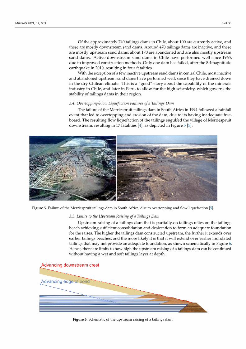
The failure of the Merriespruit tailings dam in South Africa in 1994 followed a rainfallevent that led to overtopping and erosion of the dam, due to its having inadequate free-board. The resulting flow liquefaction of the tailings engulfed the village of Merriespruitdownstream, resulting in 17 fatalities [4], as depicted in Figure 5 [5].
Minerals 2021, 11, x FOR PEER REVIEW 5 of 34
Of the approximately 740 tailings dams in Chile, about 100 are currently active, and
these are mostly downstream sand dams. Around 470 tailings dams are inactive, and these
are mostly upstream sand dams; about 170 are abandoned and are also mostly upstream
sand dams. Active downstream sand dams in Chile have performed well since 1965, due
to improved construction methods. Only one dam has failed, after the 8.4magnitude
earthquake in 2010, resulting in four fatalities.
With the exception of a few inactive upstream sand dams in central Chile, most inac-
tive and abandoned upstream sand dams have performed well, since they have drained
down in the dry Chilean climate. This is a “good” story about the capability of the miner-
als industry in Chile, and later in Peru, to allow for the high seismicity, which governs the
stability of tailings dams in their region.
3.4. Overtopping/Flow Liquefaction Failures of a Tailings Dam
The failure of the Merriespruit tailings dam in South Africa in 1994 followed a rainfall
event that led to overtopping and erosion of the dam, due to its having inadequate
freeboard. The resulting flow liquefaction of the tailings engulfed the village of
Merriespruit downstream, resulting in 17 fatalities [4], as depicted in Figure 5 [5].
Figure 5. Failure of the Merriespruit tailings dam in South Africa, due to overtopping and flow
liquefaction [5].
3.5. Limits to the Upstream Raising of a Tailings Dam
Upstream raising of a tailings dam that is partially on tailings relies on the tailings
beach achieving sufficient consolidation and desiccation to form an adequate foundation
for the raises. The higher the tailings dam constructed upstream, the further it extends
over earlier tailings beaches, and the more likely it is that it will extend over earlier inun-
dated tailings that may not provide an adequate foundation, as shown schematically in
Figure 6. Hence, there are limits to how high the upstream raising of a tailings dam can
be continued without having a wet and soft tailings layer at depth.
Figure 6. Schematic of the upstream raising of a tailings dam.
Figure 5. Failure of the Merriespruit tailings dam in South Africa, due to overtopping and flow liquefaction [5].
3.5. Limits to the Upstream Raising of a Tailings Dam
Upstream raising of a tailings dam that is partially on tailings relies on the tailingsbeach achieving sufficient consolidation and desiccation to form an adequate foundationfor the raises. The higher the tailings dam constructed upstream, the further it extends overearlier tailings beaches, and the more likely it is that it will extend over earlier inundatedtailings that may not provide an adequate foundation, as shown schematically in Figure 6.Hence, there are limits to how high the upstream raising of a tailings dam can be continuedwithout having a wet and soft tailings layer at depth.
Minerals 2021, 11, x FOR PEER REVIEW 5 of 34
Of the approximately 740 tailings dams in Chile, about 100 are currently active, and
these are mostly downstream sand dams. Around 470 tailings dams are inactive, and these
are mostly upstream sand dams; about 170 are abandoned and are also mostly upstream
sand dams. Active downstream sand dams in Chile have performed well since 1965, due
to improved construction methods. Only one dam has failed, after the 8.4magnitude
earthquake in 2010, resulting in four fatalities.
With the exception of a few inactive upstream sand dams in central Chile, most inac-
tive and abandoned upstream sand dams have performed well, since they have drained
down in the dry Chilean climate. This is a “good” story about the capability of the miner-
als industry in Chile, and later in Peru, to allow for the high seismicity, which governs the
stability of tailings dams in their region.
3.4. Overtopping/Flow Liquefaction Failures of a Tailings Dam
The failure of the Merriespruit tailings dam in South Africa in 1994 followed a rainfall
event that led to overtopping and erosion of the dam, due to its having inadequate
freeboard. The resulting flow liquefaction of the tailings engulfed the village of
Merriespruit downstream, resulting in 17 fatalities [4], as depicted in Figure 5 [5].
Figure 5. Failure of the Merriespruit tailings dam in South Africa, due to overtopping and flow
liquefaction [5].
3.5. Limits to the Upstream Raising of a Tailings Dam
Upstream raising of a tailings dam that is partially on tailings relies on the tailings
beach achieving sufficient consolidation and desiccation to form an adequate foundation
for the raises. The higher the tailings dam constructed upstream, the further it extends
over earlier tailings beaches, and the more likely it is that it will extend over earlier inun-
dated tailings that may not provide an adequate foundation, as shown schematically in
Figure 6. Hence, there are limits to how high the upstream raising of a tailings dam can
be continued without having a wet and soft tailings layer at depth.
Figure 6. Schematic of the upstream raising of a tailings dam.
Figure 6. Schematic of the upstream raising of a tailings dam.
Minerals 2021, 11, 853 6 of 35
3.6. Limits to the Raising of a Tailings Dam on Weak Foundation Layers
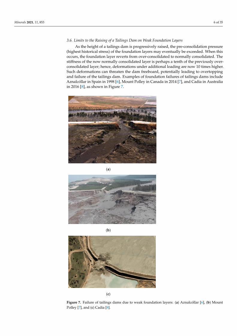
As the height of a tailings dam is progressively raised, the pre-consolidation pressure(highest historical stress) of the foundation layers may eventually be exceeded. When thisoccurs, the foundation layer reverts from over-consolidated to normally consolidated. Thestiffness of the now normally consolidated layer is perhaps a tenth of the previously over-consolidated layer; hence, deformations under additional loading are now 10 times higher.Such deformations can threaten the dam freeboard, potentially leading to overtoppingand failure of the tailings dam. Examples of foundation failures of tailings dams includeAznalcóllar in Spain in 1998 [6], Mount Polley in Canada in 2014 [7], and Cadia in Australiain 2016 [8], as shown in Figure 7.
Minerals 2021, 11, x FOR PEER REVIEW 6 of 34
3.6. Limits to the Raising of a Tailings Dam on Weak Foundation Layers
As the height of a tailings dam is progressively raised, the pre-consolidation pressure
(highest historical stress) of the foundation layers may eventually be exceeded. When this
occurs, the foundation layer reverts from over-consolidated to normally consolidated. The
stiffness of the now normally consolidated layer is perhaps a tenth of the previously over-
consolidated layer; hence, deformations under additional loading are now 10 times
higher. Such deformations can threaten the dam freeboard, potentially leading to over-
topping and failure of the tailings dam. Examples of foundation failures of tailings dams
include Aznalcóllar in Spain in 1998 [6], Mount Polley in Canada in 2014 [7], and Cadia in
Australia in 2016 [8], as shown in Figure 7.
(a)
(b)
(c)
Figure 7. Failure of tailings dams due to weak foundation layers: (a) Aznalcóllar [6], (b) Mount
Polley [7], and (c) Cadia [8]. Figure 7. Failure of tailings dams due to weak foundation layers: (a) Aznalcóllar [6], (b) MountPolley [7], and (c) Cadia [8].
Minerals 2021, 11, 853 7 of 35
3.7. Rapid Flow Liquefaction of Upstream Tailings Dams
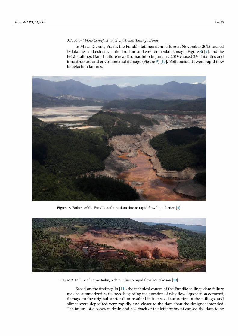
In Minas Gerais, Brazil, the Fundão tailings dam failure in November 2015 caused19 fatalities and extensive infrastructure and environmental damage (Figure 8) [9], and theFeijão tailings Dam I failure near Brumadinho in January 2019 caused 270 fatalities andinfrastructure and environmental damage (Figure 9) [10]. Both incidents were rapid flowliquefaction failures.
Minerals 2021, 11, x FOR PEER REVIEW 7 of 34
3.7. Rapid Flow Liquefaction of Upstream Tailings Dams
In Minas Gerais, Brazil, the Fundão tailings dam failure in November 2015 caused 19
fatalities and extensive infrastructure and environmental damage (Figure 8) [9], and the
Feijão tailings Dam I failure near Brumadinho in January 2019 caused 270 fatalities and
infrastructure and environmental damage (Figure 9) [10]. Both incidents were rapid flow
liquefaction failures.
Figure 8. Failure of the Fundão tailings dam due to rapid flow liquefaction [9].
Figure 9. Failure of Feijão tailings dam I due to rapid flow liquefaction [10].
Based on the findings in [11], the technical causes of the Fundão tailings dam failure
may be summarized as follows. Regarding the question of why flow liquefaction oc-
curred, damage to the original starter dam resulted in increased saturation of the tailings,
and slimes were deposited very rapidly and closer to the dam than the designer intended.
The failure of a concrete drain and a setback of the left abutment caused the dam to be
raised over the slimes, and compression and lateral extrusion of the slimes resulted in the
loosening of sand layers above. Regarding the question of why the flow liquefaction oc-
curred where it did, the setback left abutment, on softer, wetter slimes, was critical to sta-
bility. Regarding the question of why the flow liquefaction occurred when it did, a series
of three small seismic shocks occurred about 90 min prior to the failure, resulting in a
Figure 8. Failure of the Fundão tailings dam due to rapid flow liquefaction [9].
Minerals 2021, 11, x FOR PEER REVIEW 7 of 34
3.7. Rapid Flow Liquefaction of Upstream Tailings Dams
In Minas Gerais, Brazil, the Fundão tailings dam failure in November 2015 caused 19
fatalities and extensive infrastructure and environmental damage (Figure 8) [9], and the
Feijão tailings Dam I failure near Brumadinho in January 2019 caused 270 fatalities and
infrastructure and environmental damage (Figure 9) [10]. Both incidents were rapid flow
liquefaction failures.
Figure 8. Failure of the Fundão tailings dam due to rapid flow liquefaction [9].
Figure 9. Failure of Feijão tailings dam I due to rapid flow liquefaction [10].
Based on the findings in [11], the technical causes of the Fundão tailings dam failure
may be summarized as follows. Regarding the question of why flow liquefaction oc-
curred, damage to the original starter dam resulted in increased saturation of the tailings,
and slimes were deposited very rapidly and closer to the dam than the designer intended.
The failure of a concrete drain and a setback of the left abutment caused the dam to be
raised over the slimes, and compression and lateral extrusion of the slimes resulted in the
loosening of sand layers above. Regarding the question of why the flow liquefaction oc-
curred where it did, the setback left abutment, on softer, wetter slimes, was critical to sta-
bility. Regarding the question of why the flow liquefaction occurred when it did, a series
of three small seismic shocks occurred about 90 min prior to the failure, resulting in a
Figure 9. Failure of Feijão tailings dam I due to rapid flow liquefaction [10].
Based on the findings in [11], the technical causes of the Fundão tailings dam failuremay be summarized as follows. Regarding the question of why flow liquefaction occurred,damage to the original starter dam resulted in increased saturation of the tailings, andslimes were deposited very rapidly and closer to the dam than the designer intended.The failure of a concrete drain and a setback of the left abutment caused the dam to be
Minerals 2021, 11, 853 8 of 35
raised over the slimes, and compression and lateral extrusion of the slimes resulted inthe loosening of sand layers above. Regarding the question of why the flow liquefactionoccurred where it did, the setback left abutment, on softer, wetter slimes, was critical tostability. Regarding the question of why the flow liquefaction occurred when it did, a seriesof three small seismic shocks occurred about 90 min prior to the failure, resulting in a smalldeformation that was sufficient to initiate liquefaction of the marginally stable setback.
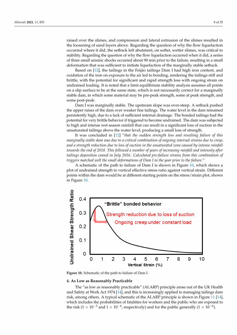
Based on [12], the tailings in the Feijão tailings Dam I had high iron content, andoxidation of the iron on exposure to the air led to bonding, rendering the tailings stiff andbrittle, with the potential for significant and rapid strength loss with ongoing strain onundrained loading. It is noted that a limit equilibrium stability analysis assumes all pointson a slip surface to be at the same state, which is not necessarily correct for a marginallystable dam, in which some material may be pre-peak strength, some at peak strength, andsome post-peak.
Dam I was marginally stable. The upstream slope was over-steep. A setback pushedthe upper raises of the dam over weaker fine tailings. The water level in the dam remainedpersistently high, due to a lack of sufficient internal drainage. The bonded tailings had thepotential for very brittle behavior if triggered to become undrained. The dam was subjectedto high and intense wet season rainfall that can result in a significant loss of suction in theunsaturated tailings above the water level, producing a small loss of strength.
It was concluded in [12] “that the sudden strength loss and resulting failure of thismarginally stable dam was due to a critical combination of ongoing internal strains due to creep,and a strength reduction due to loss of suction in the unsaturated zone caused by intense rainfalltowards the end of 2018. This followed a number of years of increasing rainfall and intensity aftertailings deposition ceased in July 2016. Calculated pre-failure strains from this combination oftriggers matched well the small deformations of Dam I in the year prior to the failure.”
A schematic of the path to failure of Dam I is shown in Figure 10, which shows aplot of undrained strength to vertical effective stress ratio against vertical strain. Differentpoints within the dam would be at different starting points on the stress/strain plot, shownin Figure 10.
Minerals 2021, 11, x FOR PEER REVIEW 8 of 34
small deformation that was sufficient to initiate liquefaction of the marginally stable set-
back.
Based on [12], the tailings in the Feijão tailings Dam I had high iron content, and
oxidation of the iron on exposure to the air led to bonding, rendering the tailings stiff and
brittle, with the potential for significant and rapid strength loss with ongoing strain on
undrained loading. It is noted that a limit equilibrium stability analysis assumes all points
on a slip surface to be at the same state, which is not necessarily correct for a marginally
stable dam, in which some material may be pre-peak strength, some at peak strength, and
some post-peak.
Dam I was marginally stable. The upstream slope was over-steep. A setback pushed
the upper raises of the dam over weaker fine tailings. The water level in the dam remained
persistently high, due to a lack of sufficient internal drainage. The bonded tailings had the
potential for very brittle behavior if triggered to become undrained. The dam was sub-
jected to high and intense wet season rainfall that can result in a significant loss of suction
in the unsaturated tailings above the water level, producing a small loss of strength.
It was concluded in [12] “that the sudden strength loss and resulting failure of this
marginally stable dam was due to a critical combination of ongoing internal strains due to creep,
and a strength reduction due to loss of suction in the unsaturated zone caused by intense rainfall
towards the end of 2018. This followed a number of years of increasing rainfall and intensity after
tailings deposition ceased in July 2016. Calculated pre-failure strains from this combination of
triggers matched well the small deformations of Dam I in the year prior to the failure.”
A schematic of the path to failure of Dam I is shown in Figure 10, which shows a plot
of undrained strength to vertical effective stress ratio against vertical strain. Different
points within the dam would be at different starting points on the stress/strain plot, shown
in Figure 10.
Figure 10. Schematic of the path to failure of Dam I.
4. As Low as Reasonably Practicable
The “as low as reasonably practicable” (ALARP) principle arose out of the UK Health
and Safety at Work Act 1974 [14], and this is increasingly applied to managing tailings
dam risk, among others. A typical schematic of the ALARP principle is shown in Figure
11 [14], which includes the probabilities of fatalities for workers and the public who are
exposed to the risk (1 × 10⁻³ and 1 × 10⁻⁴, respectively) and for the public generally (1 ×
10−6).
Figure 10. Schematic of the path to failure of Dam I.
4. As Low as Reasonably Practicable
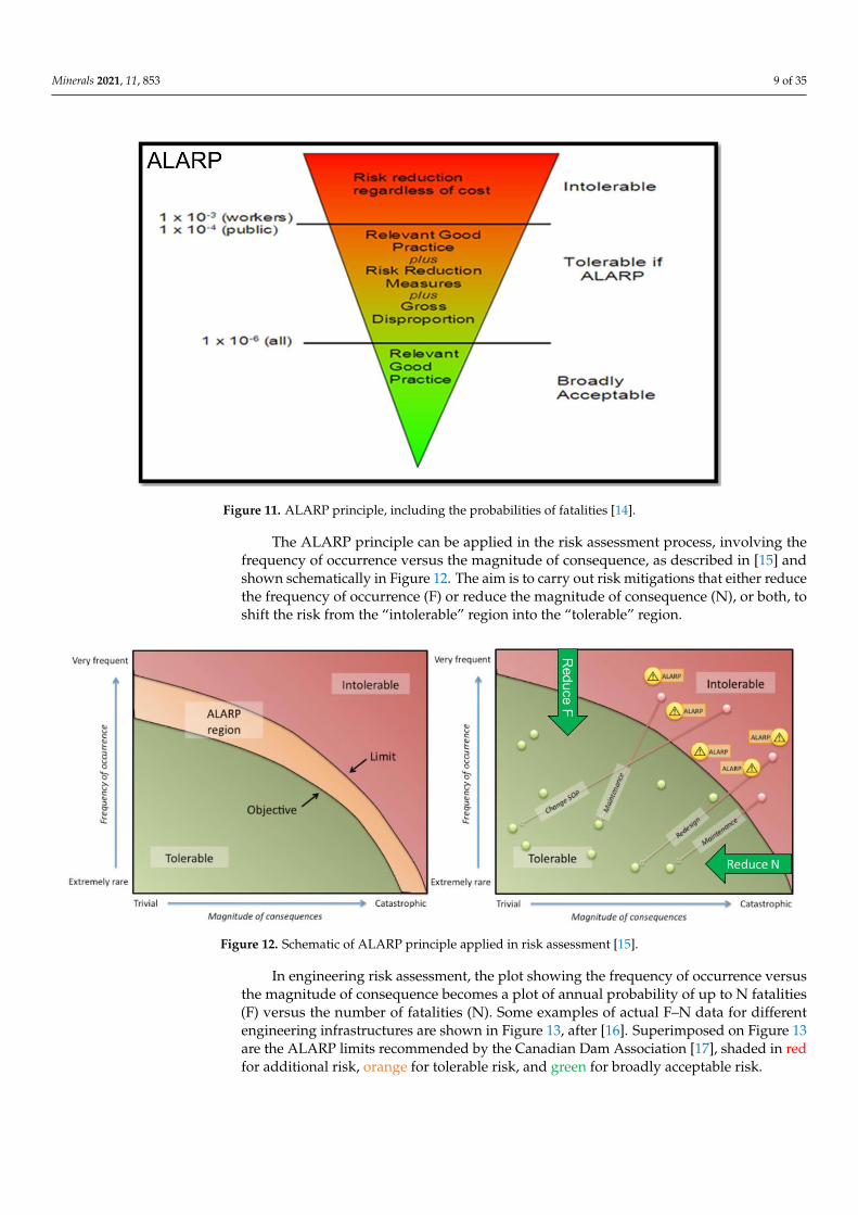
The “as low as reasonably practicable” (ALARP) principle arose out of the UK Healthand Safety at Work Act 1974 [14], and this is increasingly applied to managing tailings damrisk, among others. A typical schematic of the ALARP principle is shown in Figure 11 [14],which includes the probabilities of fatalities for workers and the public who are exposed tothe risk (1 × 10⁻³ and 1 × 10⁻⁴, respectively) and for the public generally (1 × 10⁻⁶).
Minerals 2021, 11, 853 9 of 35Minerals 2021, 11, x FOR PEER REVIEW 9 of 34
Figure 11. ALARP principle, including the probabilities of fatalities [14].
The ALARP principle can be applied in the risk assessment process, involving the
frequency of occurrence versus the magnitude of consequence, as described in [15] and
shown schematically in Figure 12. The aim is to carry out risk mitigations that either re-
duce the frequency of occurrence (F) or reduce the magnitude of consequence (N), or both,
to shift the risk from the “intolerable” region into the “tolerable” region.
Figure 12. Schematic of ALARP principle applied in risk assessment [15].
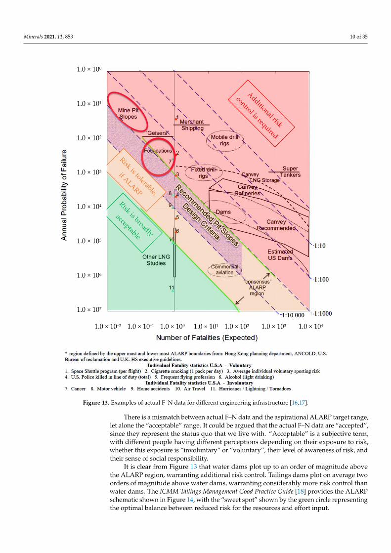
In engineering risk assessment, the plot showing the frequency of occurrence versus
the magnitude of consequence becomes a plot of annual probability of up to N fatalities
(F) versus the number of fatalities (N). Some examples of actual F–N data for different
engineering infrastructures are shown in Figure 13, after [16]. Superimposed on Figure 13
are the ALARP limits recommended by the Canadian Dam Association [17], shaded in
red for additional risk, orange for tolerable risk, and green for broadly acceptable risk.
Figure 11. ALARP principle, including the probabilities of fatalities [14].
The ALARP principle can be applied in the risk assessment process, involving thefrequency of occurrence versus the magnitude of consequence, as described in [15] andshown schematically in Figure 12. The aim is to carry out risk mitigations that either reducethe frequency of occurrence (F) or reduce the magnitude of consequence (N), or both, toshift the risk from the “intolerable” region into the “tolerable” region.
Minerals 2021, 11, x FOR PEER REVIEW 9 of 34
Figure 11. ALARP principle, including the probabilities of fatalities [14].
The ALARP principle can be applied in the risk assessment process, involving the
frequency of occurrence versus the magnitude of consequence, as described in [15] and
shown schematically in Figure 12. The aim is to carry out risk mitigations that either re-
duce the frequency of occurrence (F) or reduce the magnitude of consequence (N), or both,
to shift the risk from the “intolerable” region into the “tolerable” region.
Figure 12. Schematic of ALARP principle applied in risk assessment [15].
In engineering risk assessment, the plot showing the frequency of occurrence versus
the magnitude of consequence becomes a plot of annual probability of up to N fatalities
(F) versus the number of fatalities (N). Some examples of actual F–N data for different
engineering infrastructures are shown in Figure 13, after [16]. Superimposed on Figure 13
are the ALARP limits recommended by the Canadian Dam Association [17], shaded in
red for additional risk, orange for tolerable risk, and green for broadly acceptable risk.
Figure 12. Schematic of ALARP principle applied in risk assessment [15].
In engineering risk assessment, the plot showing the frequency of occurrence versusthe magnitude of consequence becomes a plot of annual probability of up to N fatalities(F) versus the number of fatalities (N). Some examples of actual F–N data for differentengineering infrastructures are shown in Figure 13, after [16]. Superimposed on Figure 13are the ALARP limits recommended by the Canadian Dam Association [17], shaded in redfor additional risk, orange for tolerable risk, and green for broadly acceptable risk.
Minerals 2021, 11, 853 10 of 35Minerals 2021, 11, x FOR PEER REVIEW 10 of 34
Figure 13. Examples of actual F–N data for different engineering infrastructure [16,17].
There is a mismatch between actual F–N data and the aspirational ALARP target
range, let alone the “acceptable” range. It could be argued that the actual F–N data are
“accepted”, since they represent the status quo that we live with. “Acceptable” is a
subjective term, with different people having different perceptions depending on their
exposure to risk, whether this exposure is “involuntary” or “voluntary”, their level of
awareness of risk, and their sense of social responsibility.
It is clear from Figure 13 that water dams plot up to an order of magnitude above the
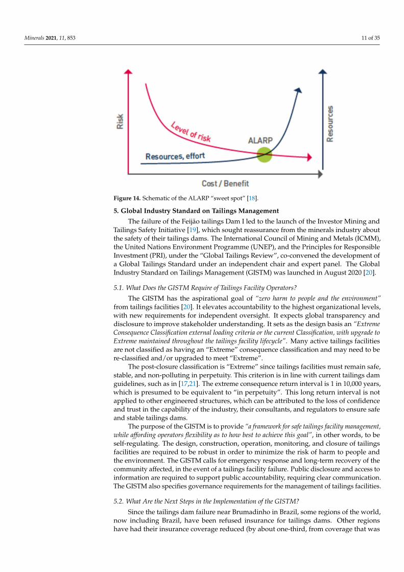
ALARP region, warranting additional risk control. Tailings dams plot on average two
orders of magnitude above water dams, warranting considerably more risk control than
water dams. The ICMM Tailings Management Good Practice Guide [18] provides the ALARP
schematic shown in Figure 14, with the “sweet spot” shown by the green circle
representing the optimal balance between reduced risk for the resources and effort input.
1.0 × 100
1.0 × 101
1.0 × 10²
1.0 × 10³
1.0 × 10⁴
1.0 × 10⁵
1.0 × 10⁶
1.0 × 10⁷
1.0 × 10⁻² 1.0 × 10⁻¹ 1.0 × 100 1.0 × 101 1.0 × 10² 1.0 × 10³ 1.0 × 10⁴
Figure 13. Examples of actual F–N data for different engineering infrastructure [16,17].
There is a mismatch between actual F–N data and the aspirational ALARP target range,let alone the “acceptable” range. It could be argued that the actual F–N data are “accepted”,since they represent the status quo that we live with. “Acceptable” is a subjective term,with different people having different perceptions depending on their exposure to risk,whether this exposure is “involuntary” or “voluntary”, their level of awareness of risk, andtheir sense of social responsibility.
It is clear from Figure 13 that water dams plot up to an order of magnitude abovethe ALARP region, warranting additional risk control. Tailings dams plot on average twoorders of magnitude above water dams, warranting considerably more risk control thanwater dams. The ICMM Tailings Management Good Practice Guide [18] provides the ALARPschematic shown in Figure 14, with the “sweet spot” shown by the green circle representingthe optimal balance between reduced risk for the resources and effort input.
Minerals 2021, 11, 853 11 of 35Minerals 2021, 11, x FOR PEER REVIEW 11 of 34
Figure 14. Schematic of the ALARP “sweet spot” [18].
5. Global Industry Standard on Tailings Management
The failure of the Feijão tailings Dam I led to the launch of the Investor Mining and
Tailings Safety Initiative [19], which sought reassurance from the minerals industry about
the safety of their tailings dams. The International Council of Mining and Metals (ICMM),
the United Nations Environment Programme (UNEP), and the Principles for Responsible
Investment (PRI), under the “Global Tailings Review”, co-convened the development of
a Global Tailings Standard under an independent chair and expert panel. The Global
Industry Standard on Tailings Management (GISTM) was launched in August 2020 [20].
5.1. What Does the GISTM Require of Tailings Facility Operators?
The GISTM has the aspirational goal of “zero harm to people and the environment” from
tailings facilities [20]. It elevates accountability to the highest organizational levels, with
new requirements for independent oversight. It expects global transparency and
disclosure to improve stakeholder understanding. It sets as the design basis an “Extreme
Consequence Classification external loading criteria or the current Classification, with upgrade to
Extreme maintained throughout the tailings facility lifecycle”. Many active tailings facilities are
not classified as having an “Extreme” consequence classification and may need to be re-
classified and/or upgraded to meet “Extreme”.
The post-closure classification is “Extreme” since tailings facilities must remain safe,
stable, and non-polluting in perpetuity. This criterion is in line with current tailings dam
guidelines, such as in [17,21]. The extreme consequence return interval is 1 in 10,000 years,
which is presumed to be equivalent to “in perpetuity”. This long return interval is not
applied to other engineered structures, which can be attributed to the loss of confidence
and trust in the capability of the industry, their consultants, and regulators to ensure safe
and stable tailings dams.
The purpose of the GISTM is to provide “a framework for safe tailings facility
management, while affording operators flexibility as to how best to achieve this goal”, in other
words, to be self-regulating. The design, construction, operation, monitoring, and closure
of tailings facilities are required to be robust in order to minimize the risk of harm to
people and the environment. The GISTM calls for emergency response and long-term
recovery of the community affected, in the event of a tailings facility failure. Public
disclosure and access to information are required to support public accountability,
requiring clear communication. The GISTM also specifies governance requirements for
the management of tailings facilities.
Figure 14. Schematic of the ALARP “sweet spot” [18].
5. Global Industry Standard on Tailings Management
The failure of the Feijão tailings Dam I led to the launch of the Investor Mining andTailings Safety Initiative [19], which sought reassurance from the minerals industry aboutthe safety of their tailings dams. The International Council of Mining and Metals (ICMM),the United Nations Environment Programme (UNEP), and the Principles for ResponsibleInvestment (PRI), under the “Global Tailings Review”, co-convened the development ofa Global Tailings Standard under an independent chair and expert panel. The GlobalIndustry Standard on Tailings Management (GISTM) was launched in August 2020 [20].
5.1. What Does the GISTM Require of Tailings Facility Operators?
The GISTM has the aspirational goal of “zero harm to people and the environment”from tailings facilities [20]. It elevates accountability to the highest organizational levels,with new requirements for independent oversight. It expects global transparency anddisclosure to improve stakeholder understanding. It sets as the design basis an “ExtremeConsequence Classification external loading criteria or the current Classification, with upgrade toExtreme maintained throughout the tailings facility lifecycle”. Many active tailings facilitiesare not classified as having an “Extreme” consequence classification and may need to bere-classified and/or upgraded to meet “Extreme”.
The post-closure classification is “Extreme” since tailings facilities must remain safe,stable, and non-polluting in perpetuity. This criterion is in line with current tailings damguidelines, such as in [17,21]. The extreme consequence return interval is 1 in 10,000 years,which is presumed to be equivalent to “in perpetuity”. This long return interval is notapplied to other engineered structures, which can be attributed to the loss of confidenceand trust in the capability of the industry, their consultants, and regulators to ensure safeand stable tailings dams.
The purpose of the GISTM is to provide “a framework for safe tailings facility management,while affording operators flexibility as to how best to achieve this goal”, in other words, to beself-regulating. The design, construction, operation, monitoring, and closure of tailingsfacilities are required to be robust in order to minimize the risk of harm to people andthe environment. The GISTM calls for emergency response and long-term recovery of thecommunity affected, in the event of a tailings facility failure. Public disclosure and access toinformation are required to support public accountability, requiring clear communication.The GISTM also specifies governance requirements for the management of tailings facilities.
5.2. What Are the Next Steps in the Implementation of the GISTM?
Since the tailings dam failure near Brumadinho in Brazil, some regions of the world,now including Brazil, have been refused insurance for tailings dams. Other regionshave had their insurance coverage reduced (by about one-third, from coverage that was
Minerals 2021, 11, 853 12 of 35
typically USD 300 million to USD 200 million, which is clearly insufficient to cover acatastrophic failure), and their premiums have increased (about two-fold). Some majormining companies are self-insuring their tailings facilities. However, mid-tier and smallmining companies with few mines cannot afford to not be insured. Access to finance fornew tailings facilities could be withheld from companies that do not comply with theGISTM.
The Global Tailings Review estimated that there are approximately 18,000 tailingsfacilities worldwide, of which approximately 3500 are active. The GISTM does not coverthe thousands of inactive and abandoned tailings facilities worldwide.
ICMM members, comprising 27 of the world’s major mining and metals companiesand operating about 1200 tailings facilities (about one-third of the world’s active facilities),have committed that all tailings facilities with “Extreme” and “Very high” potential conse-quences will be in conformance with the GISTM by August 2023, and all other facilitiesin conformance by August 2025 [20]. Non-ICMM members companies are encouraged tocomply with the GISTM.
5.3. Management of Tailings Facilities
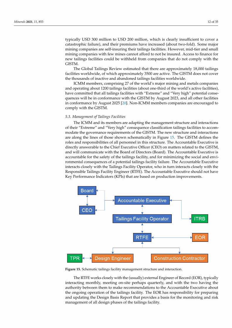
The ICMM and its members are adapting the management structure and interactionsof their “Extreme” and “Very high” consequence classification tailings facilities to accom-modate the governance requirements of the GISTM. The new structure and interactionsare along the lines of those shown schematically in Figure 15. The GISTM defines theroles and responsibilities of all personnel in this structure. The Accountable Executive isdirectly answerable to the Chief Executive Officer (CEO) on matters related to the GISTM,and will communicate with the Board of Directors (Board). The Accountable Executive isaccountable for the safety of the tailings facility, and for minimizing the social and envi-ronmental consequences of a potential tailings facility failure. The Accountable Executiveinteracts closely with the Tailings Facility Operator, who in turn interacts closely with theResponsible Tailings Facility Engineer (RTFE). The Accountable Executive should not haveKey Performance Indicators (KPIs) that are based on production improvements.
Minerals 2021, 11, x FOR PEER REVIEW 12 of 34
5.2. What Are the Next Steps in the Implementation of the GISTM?
Since the tailings dam failure near Brumadinho in Brazil, some regions of the world,
now including Brazil, have been refused insurance for tailings dams. Other regions have
had their insurance coverage reduced (by about one-third, from coverage that was
typically USD 300 million to USD 200 million, which is clearly insufficient to cover a
catastrophic failure), and their premiums have increased (about two-fold). Some major
mining companies are self-insuring their tailings facilities. However, mid-tier and small
mining companies with few mines cannot afford to not be insured. Access to finance for
new tailings facilities could be withheld from companies that do not comply with the
GISTM.
The Global Tailings Review estimated that there are approximately 18,000 tailings
facilities worldwide, of which approximately 3500 are active. The GISTM does not cover
the thousands of inactive and abandoned tailings facilities worldwide.
ICMM members, comprising 27 of the world’s major mining and metals companies
and operating about 1200 tailings facilities (about one-third of the world’s active facilities),
have committed that all tailings facilities with “Extreme” and “Very high” potential
consequences will be in conformance with the GISTM by August 2023, and all other
facilities in conformance by August 2025 [20]. Non-ICMM members companies are
encouraged to comply with the GISTM.
5.3. Management of Tailings Facilities
The ICMM and its members are adapting the management structure and interactions
of their “Extreme” and “Very high” consequence classification tailings facilities to
accommodate the governance requirements of the GISTM. The new structure and
interactions are along the lines of those shown schematically in Figure 15. The GISTM
defines the roles and responsibilities of all personnel in this structure. The Accountable
Executive is directly answerable to the Chief Executive Officer (CEO) on matters related
to the GISTM, and will communicate with the Board of Directors (Board). The
Accountable Executive is accountable for the safety of the tailings facility, and for
minimizing the social and environmental consequences of a potential tailings facility
failure. The Accountable Executive interacts closely with the Tailings Facility Operator,
who in turn interacts closely with the Responsible Tailings Facility Engineer (RTFE). The
Accountable Executive should not have Key Performance Indicators (KPIs) that are based
on production improvements.
Figure 15. Schematic tailings facility management structure and interaction. Figure 15. Schematic tailings facility management structure and interaction.
The RTFE works closely with the (usually) external Engineer of Record (EOR), typicallyinteracting monthly, meeting on-site perhaps quarterly, and with the two having theauthority between them to make recommendations to the Accountable Executive aboutthe ongoing operation of the tailings facility. The EOR has responsibility for preparingand updating the Design Basis Report that provides a basis for the monitoring and riskmanagement of all design phases of the tailings facility.
Minerals 2021, 11, 853 13 of 35
The RTFE and EOR also work closely with the Design Engineer and ConstructionContractor for the tailings facility. The design of the facility and sequential raises arereviewed by a third-party reviewer (TPR). According to the GISTM [20], dam safetyreviews are periodically and systematically carried out by a TPR “to assess and evaluate thesafety of a tailings facility against [“credible”] failure modes, in order to make a statement on thesafety of the facility. A safe tailings facility is one that performs its intended function under bothnormal and unusual conditions, does not impose an unacceptable risk to people, property or theenvironment, and meets applicable safety criteria.”
Credible failure modes are “technically feasible failure mechanisms given the tailings andfoundation, their parameters, geometry, drainage conditions and surface water control, throughoutthe lifecycle of the tailings facility. They typically vary during the lifecycle of the facility as theconditions vary, and the tailings facility requires sufficient resilience against each credible failuremode. Different failure modes will result in different failure scenarios. Credible catastrophic failuremodes do not exist for all tailings facilities, and are not associated with likelihood and not a reflectionof facility safety.”
According to the GISTM [20], the Independent Tailings Review Board (ITRB) “providesindependent technical review of the design, construction, operation, closure and management of thetailings facility. ITRB members are third parties who are not, and have not been, directly involvedwith the design or operation of the particular tailings facility. The expertise of the ITRB membersshould reflect the range of issues relevant to the facility, and its context and the complexity of theseissues.”
An ITRB would typically include a geotechnical expert, a hydrology or hydrogeologyexpert, as appropriate, a seismology expert for highly seismic locations, and possibly ageochemistry or geomorphology expert, as appropriate. The ITRB would typically meetprior to key changes in the life of the tailings facility, such as a dam raise, interacting mostclosely with the Tailings Facility Operator and the RTFE, and also with the EOR and DesignEngineer, and possibly also with the TPR. The ITRB should report its findings through theAccountable Executive to inform the company’s CEO and board.
A qualified EOR, TPR, or ITRB member would typically be able to handle perhapsfour tailings facilities. An estimated 70 ITRBs would be required for all operating tailingsfacilities globally, requiring over 200 tailings experts, with perhaps 10 times this numberof EORs and TPRs required. There are insufficient tailings experts available worldwideto meet this demand, particularly in the current COVID-19 climate that restricts travel tosites. The increasing availability of online training and certification in tailings managementwill assist in meeting this demand in the future, although the experience required for theseroles will take time to develop. Senior tailings professionals will need to mentor talentedearly-career professionals.
5.4. ICMM Documents Accompanying the GISTM
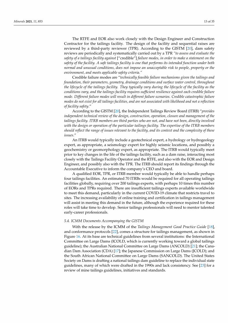
With the release by the ICMM of the Tailings Management Good Practice Guide [18],and conformance protocols [22], comes a structure for tailings management, as shown inFigure 16. At its base are technical guidelines from several institutions: the InternationalCommittee on Large Dams (ICOLD, which is currently working toward a global tailingsguideline); the Australian National Committee on Large Dams (ANCOLD) [21]; the Cana-dian Dam Association (CDA) [17]; the Japanese Commission on Large Dams (JCOLD); andthe South African National Committee on Large Dams (SANCOLD). The United StatesSociety on Dams is drafting a national tailings dam guideline to replace the individual stateguidelines, many of which were drafted in the 1990s and lack consistency. See [23] for areview of mine tailings guidelines, initiatives and standards.
Minerals 2021, 11, 853 14 of 35
Minerals 2021, 11, x FOR PEER REVIEW 14 of 34
States Society on Dams is drafting a national tailings dam guideline to replace the indi-
vidual state guidelines, many of which were drafted in the 1990s and lack consistency. See
[23] for a review of mine tailings guidelines, initiatives and standards.
At the apex of the structure shown in Figure 15 are the requirements of the GISTM
and commitments in the ICMM position statement on tailings governance [24]. Support-
ing guidance linking the technical guidelines and the specific commitments includes the
ICMM Tailings Management Good Practice Guide and conformance protocols, plus other
ICMM guides that deal with relevant environmental and social requirements.
It remains to be seen how this structure will be accommodated within the regulation
of tailings facilities, both regionally and globally. None of the structure shown in Figure
15 is specifically included in the legislation, although in the jurisdictions where they are
applied, the ANCOLD [21] and CDA [17] guidelines are taken by mining companies, reg-
ulators, and the courts to be de facto “standards” for tailings dam design.
Figure 16. Structure for tailings management [18].
6. Alternative Tailings Management Options
“In the wake of recent tailings dam failures, improved Management Resilience (that is,
Governance) is leading over improved Engineering Resilience, which would reduce Liability”,
according to Dr. Andy Robertson [25].
The GISTM [20] does not specify particular tailings management options that should
be allowed or disallowed, leaving this choice to the Operator. However, the GISTM does
require that tailings management options be reviewed and analyzed. For existing tailings
facilities, the Operator is required “to periodically review and refine the tailings technologies
and design, and management strategies, to minimize risk and improve environmental outcomes.
An exception applies to facilities that are demonstrated to be in a state of safe closure.” For new
tailings facilities, the Operator is required “to use the knowledge base and undertake a multi-
criteria alternatives analysis of all feasible sites, technologies and strategies for tailings
management. The goal of this analysis is to: (i) select an alternative that minimizes risks to people
and the environment throughout the tailings facility lifecycle; and (ii) minimize the volume of
tailings and water placed in external tailings facilities.”
The GISTM also requires the development and documentation of a “breach (dam break
and runout) analysis for the tailings facility using a methodology that considers credible failure
modes, site conditions, and the parameters of the tailings. When flowable materials (water and
liquefiable solids) are present at tailings facilities with a Consequence Classification of ‘High’, ‘Very
High’ or ‘Extreme’, the breach analysis results should include estimates of the physical area
Figure 16. Structure for tailings management [18].
At the apex of the structure shown in Figure 15 are the requirements of the GISTMand commitments in the ICMM position statement on tailings governance [24]. Supportingguidance linking the technical guidelines and the specific commitments includes the ICMMTailings Management Good Practice Guide and conformance protocols, plus other ICMMguides that deal with relevant environmental and social requirements.
It remains to be seen how this structure will be accommodated within the regulation oftailings facilities, both regionally and globally. None of the structure shown in Figure 15 isspecifically included in the legislation, although in the jurisdictions where they are applied,the ANCOLD [21] and CDA [17] guidelines are taken by mining companies, regulators,and the courts to be de facto “standards” for tailings dam design.
6. Alternative Tailings Management Options
“In the wake of recent tailings dam failures, improved Management Resilience (that is, Gover-nance) is leading over improved Engineering Resilience, which would reduce Liability”, accordingto Dr. Andy Robertson [25].
The GISTM [20] does not specify particular tailings management options that shouldbe allowed or disallowed, leaving this choice to the Operator. However, the GISTM doesrequire that tailings management options be reviewed and analyzed. For existing tailingsfacilities, the Operator is required “to periodically review and refine the tailings technologies anddesign, and management strategies, to minimize risk and improve environmental outcomes. Anexception applies to facilities that are demonstrated to be in a state of safe closure.” For new tailingsfacilities, the Operator is required “to use the knowledge base and undertake a multi-criteriaalternatives analysis of all feasible sites, technologies and strategies for tailings management. Thegoal of this analysis is to: (i) select an alternative that minimizes risks to people and the environmentthroughout the tailings facility lifecycle; and (ii) minimize the volume of tailings and water placedin external tailings facilities.”
The GISTM also requires the development and documentation of a “breach (dam breakand runout) analysis for the tailings facility using a methodology that considers credible failuremodes, site conditions, and the parameters of the tailings. When flowable materials (water andliquefiable solids) are present at tailings facilities with a Consequence Classification of ‘High’, ‘VeryHigh’ or ‘Extreme’, the breach analysis results should include estimates of the physical area impactedby a potential failure, flow arrival times, depth and velocities, and depth of material deposition.”
Minerals 2021, 11, 853 15 of 35
The results of the breach analysis should be used to identify and document thepotential human exposure and vulnerability to credible failure scenarios regarding aparticular tailings facility. The breach analysis should be updated whenever there is amaterial change either to the tailings facility or the physical area impacted.
According to Williams [26], “while the conventional disposal of tailings slurry can bethe optimal NPV and life-cycle choice for a given operation, there is often a divergence when awhole-of-life approach is fully considered.” Alternative approaches to tailings management aredescribed in the following sections.
6.1. Geotechnical versus Geochemical Stability of Stored Tailings
Fundamentally, the geotechnical stability of tailings is enhanced by dewatering anddensification, while the geochemical stability of potentially contaminating tailings (such asthose containing sulfides) is ensured by maintaining the tailings at near-saturation, to limitoxygen ingress. For the storage of tailings slurry in a surface facility, geotechnical stabilityand the potential for upstream construction are enhanced by cycling tailings deposition inthin layers, and by leaving time for consolidation and desiccation before the next layer isdeposited.
Geochemical stability is ensured by maintaining the tailings at a level that is at least85% saturated, to limit the diffusion of oxygen into a desaturating surface. This can beachieved by depositing fresh tailings slurry before the previous layer has been allowedto desiccate to less than this saturation limit. Geochemical stability is also enhanced forfine-grained and clay mineral-rich tailings that tend to hold onto water due to their lowpermeability. Perhaps counterintuitively, sulfidic tailings that tend to hardpan result in avirtually impermeable crust that limits moisture and hence contaminant flow, either as netdownward percolation or as evapotranspirative uptake into an overlying growth medium.Hardpans can have a permeability that is 10 to 100 times lower than that of uncementedtailings, and an oxygen diffusion rate up to 1000 times lower, causing them to maintain ahigh degree of saturation and to not pass water or oxygen [27]. However, hardpans maynot be continuous across the tailings’ surface.
For potentially contaminating tailings that are deposited in-pit, any pit lake should notbe allowed to become a “source” of contaminated water for surface or ground waters. It ispreferable that final pit lakes containing water of diminishing quality should be avoided bycompletely back-filling the pit, even if the pit were to remain a surface- and groundwater“sink”.
6.2. In-Plant Dewatering of Tailings
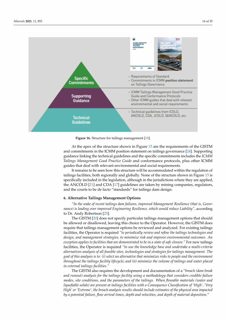
The in-plant recovery of process water is the most effective means of maximizingwater return for recycling and for recovering any residual process chemicals, assuming thatthe return water is suitable for reuse in the plant and that the tailings can be dewatered.The choice of the appropriate amount of in-plant dewatering is related to the tailingsdewatering continuum adapted from [28], as shown in Figure 17, which ranges from theinitial slurry-like state to a potentially soil-like state. The cost of mechanical dewatering oftailings increases exponentially with increasing dewatering, which is balanced by benefitsincluding the greater recovery of water and process chemicals and reduced tailings storagevolume.
Clay mineral-rich tailings, such as oil shale tailings, some coal tailings, and causticprocessing residues, such as red mud from bauxite refining, nickel laterite tailings, andoil sands tailings, are difficult to thicken, let alone filter. Slurry and thickened tailingsmay readily be pumped using robust, inexpensive centrifugal pumps. Paste tailingsrequire positive displacement or diaphragm pumps, which are an order of magnitude moreexpensive than centrifugal pumps and are more sensitive to variations in the input tailingsparticle size distribution and chemistry. Furthermore, a true paste will discharge like“toothpaste” and require continuous management of the deposition. To avoid the need to
Minerals 2021, 11, 853 16 of 35
pump paste tailings, they may be discharged through gravity to a completed undergroundmine, possibly as cemented paste tailings backfill, or to a completed pit.
Minerals 2021, 11, x FOR PEER REVIEW 16 of 34
particle size distribution and chemistry. Furthermore, a true paste will discharge like
“toothpaste” and require continuous management of the deposition. To avoid the need to
pump paste tailings, they may be discharged through gravity to a completed under-
ground mine, possibly as cemented paste tailings backfill, or to a completed pit.
Figure 17. The tailings dewatering continuum [28].
“Wet” tailings filter cake, which is potentially produced by centrifuging or cycloning,
is not pumpable, can potentially be conveyed or trucked, and typically flows on deposi-
tion. “Dry” tailings filter cake, which is potentially produced by a belt-press or filter plate,
and possibly by screw filter (used in sewage treatment, although it has not been applied
to tailings), can be conveyed, trucked, and potentially mixed with coarse-grained wastes,
and will not flow on deposition.
The optimal in-plant dewatering of tailings for disposal to a surface tailings storage
facility is likely to be of tailings thickened as much as possible but that is still able to be
pumped by robust, inexpensive centrifugal pumps. Paste tailings are best reserved for
gravity disposal underground or in-pit. Filtered tailings are potentially suited to “dry”
stacking, possibly with the compaction of at least the outer zone to prevent potential liq-
uefaction.
6.3. In-Facility Dewatering of Tailings
Water recovery from a surface tailings facility is generally limited to the recovery of
supernatant water (the water that pools at the end of the tailings beach). Tailings water is
lost to evaporation from the wet tailings and from the decant pond, from entrainment
within the tailings, and from seepage into the foundation and through the dam.
While the majority of the water from a tailings facility may be lost through evapora-
tion off freshly deposited wet tailings, minimizing the size of the decant pond and the
rapid return of supernatant water will minimize additional evaporation losses. Tailings
densification, due to self-weight consolidation, and desiccation on exposure, is far more
robust than in-plant thickening or filtration, being less affected by variations in the nature
of the tailings.
Water recovery from an in-pit tailings facility is more difficult than from a surface
tailings facility. Firstly, the rate of rising in-pit is generally much faster, due to the steep
geometry of the pit, compared with more shallow surface tailings facilities. Secondly, it is
difficult to recover water from a pit as it fills. Thirdly, the opportunity for desiccation of
in-pit tailings is limited by the usual water cover, and by shadows thrown from the pit
walls onto any exposed tailings. The faster rate of rising in-pit, only partial consolidation,
and limited or absent desiccation, result in limited dewatering and densification of the
tailings, and much higher water entrainment.
Figure 17. The tailings dewatering continuum [28].
“Wet” tailings filter cake, which is potentially produced by centrifuging or cycloning,is not pumpable, can potentially be conveyed or trucked, and typically flows on deposition.“Dry” tailings filter cake, which is potentially produced by a belt-press or filter plate, andpossibly by screw filter (used in sewage treatment, although it has not been applied totailings), can be conveyed, trucked, and potentially mixed with coarse-grained wastes, andwill not flow on deposition.
The optimal in-plant dewatering of tailings for disposal to a surface tailings storagefacility is likely to be of tailings thickened as much as possible but that is still able to bepumped by robust, inexpensive centrifugal pumps. Paste tailings are best reserved forgravity disposal underground or in-pit. Filtered tailings are potentially suited to “dry”stacking, possibly with the compaction of at least the outer zone to prevent potentialliquefaction.
6.3. In-Facility Dewatering of Tailings
Water recovery from a surface tailings facility is generally limited to the recovery ofsupernatant water (the water that pools at the end of the tailings beach). Tailings wateris lost to evaporation from the wet tailings and from the decant pond, from entrainmentwithin the tailings, and from seepage into the foundation and through the dam.
While the majority of the water from a tailings facility may be lost through evapo-ration off freshly deposited wet tailings, minimizing the size of the decant pond and therapid return of supernatant water will minimize additional evaporation losses. Tailingsdensification, due to self-weight consolidation, and desiccation on exposure, is far morerobust than in-plant thickening or filtration, being less affected by variations in the natureof the tailings.
Water recovery from an in-pit tailings facility is more difficult than from a surfacetailings facility. Firstly, the rate of rising in-pit is generally much faster, due to the steepgeometry of the pit, compared with more shallow surface tailings facilities. Secondly, itis difficult to recover water from a pit as it fills. Thirdly, the opportunity for desiccationof in-pit tailings is limited by the usual water cover, and by shadows thrown from the pitwalls onto any exposed tailings. The faster rate of rising in-pit, only partial consolidation,
Minerals 2021, 11, 853 17 of 35
and limited or absent desiccation, result in limited dewatering and densification of thetailings, and much higher water entrainment.
6.4. Coagulation, Flocculation and Secondary Flocculation
Coagulation concerns the initial supernatant water clarification through the settlingof colloids. Coagulation is both a chemical (charge neutralization of colloids) and a phys-ical (consequent aggregation of colloids) process. Coagulants are mostly cheap iron oraluminum salts, forming a highly ionic polymer of low molecular weight.
Flocculation concerns the agglomeration of dispersed particles. Flocculants are nor-mally high molecular weight, long-chain polymers that achieve flocculation relativelyslowly, primarily by bridging, but also by wrapping water. Polyacrylamide is a commonflocculant, either as negatively charged anionic for mineral particles or positively chargedcationic for organic particles, with divalent cations such as Ca2+ and Mg2+ aiding bridgeformation. The effectiveness of flocculation is dominated by the clay mineral content andtype of the tailings, and the salinity of the process water.
If conventional thickening and slurry tailings disposal fail to achieve adequate settlingand consolidation and supernatant water recovery, secondary (inline) flocculation can beapplied just prior to the discharge of the tailings, to re-flocculate conventionally thickenedtailings that have been shear-thinned by pumping.
It is important that the appropriate type and dosage of coagulants and flocculantsapplied to tailings be carefully selected, which generally involves trialing them both inthe laboratory and on-site. Flocculants, in particular, can be expensive, and over-dosingcan be counter-productive, leading to excessive “wrapping” of both the tailings particlesand entrained water. With variable tailings feeds, online monitoring of pH and electricalconductivity may be required, and the flocculant type and dosage should be adjusted tosuit.
6.5. On-Off Tailings Cells
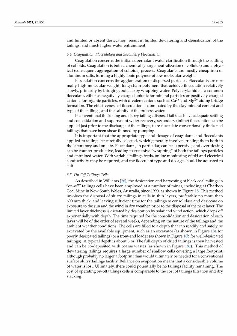
As described in Williams [26], the desiccation and harvesting of black coal tailings in“on-off” tailings cells have been employed at a number of mines, including at CharbonCoal Mine in New South Wales, Australia, since 1990, as shown in Figure 18. This methodinvolves the disposal of slurry tailings in cells in thin layers, preferably no more than600 mm thick, and leaving sufficient time for the tailings to consolidate and desiccate onexposure to the sun and the wind in dry weather, prior to the disposal of the next layer. Thelimited layer thickness is dictated by desiccation by solar and wind action, which drops offexponentially with depth. The time required for the consolidation and desiccation of eachlayer will be of the order of several weeks, depending on the nature of the tailings and theambient weather conditions. The cells are filled to a depth that can readily and safely beexcavated by the available equipment, such as an excavator (as shown in Figure 18a forpoorly desiccated tailings) or a front-end loader (as shown in Figure 18b for well-desiccatedtailings). A typical depth is about 3 m. The full depth of dried tailings is then harvestedand can be co-deposited with coarse wastes (as shown in Figure 18c). This method ofdewatering tailings requires a large number of shallow cells covering a large footprint,although probably no larger a footprint than would ultimately be needed for a conventionalsurface slurry tailings facility. Reliance on evaporation means that a considerable volumeof water is lost. Ultimately, there could potentially be no tailings facility remaining. Thecost of operating on-off tailings cells is comparable to the cost of tailings filtration and drystacking.
Minerals 2021, 11, 853 18 of 35Minerals 2021, 11, x FOR PEER REVIEW 18 of 34
(a)
(b) (c)
Figure 18. On-off coal tailings cells, showing: (a) insufficient desiccation, (b) effective, full-depth
desiccation, and (c) dumping harvested tailings with the coarse reject.
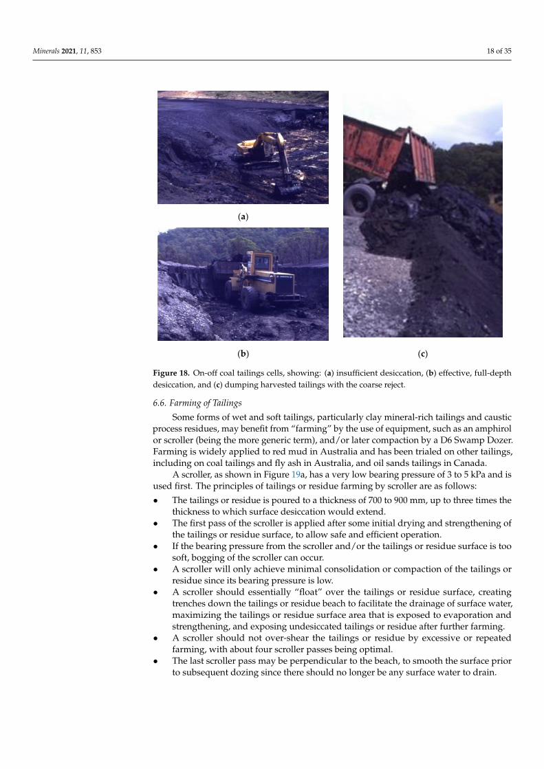
6.6. Farming of Tailings
Some forms of wet and soft tailings, particularly clay mineral-rich tailings and caustic
process residues, may benefit from “farming” by the use of equipment, such as an amphi-
rol or scroller (being the more generic term), and/or later compaction by a D6 Swamp
Dozer. Farming is widely applied to red mud in Australia and has been trialed on other
tailings, including on coal tailings and fly ash in Australia, and oil sands tailings in Can-
ada.
A scroller, as shown in Figure 19a, has a very low bearing pressure of 3 to 5 kPa and
is used first. The principles of tailings or residue farming by scroller are as follows:
The tailings or residue is poured to a thickness of 700 to 900 mm, up to three times
the thickness to which surface desiccation would extend.
The first pass of the scroller is applied after some initial drying and strengthening of
the tailings or residue surface, to allow safe and efficient operation.
If the bearing pressure from the scroller and/or the tailings or residue surface is too
soft, bogging of the scroller can occur.
A scroller will only achieve minimal consolidation or compaction of the tailings or
residue since its bearing pressure is low.
A scroller should essentially “float” over the tailings or residue surface, creating
trenches down the tailings or residue beach to facilitate the drainage of surface water,
maximizing the tailings or residue surface area that is exposed to evaporation and
strengthening, and exposing undesiccated tailings or residue after further farming.
A scroller should not over-shear the tailings or residue by excessive or repeated
farming, with about four scroller passes being optimal.
The last scroller pass may be perpendicular to the beach, to smooth the surface prior
to subsequent dozing since there should no longer be any surface water to drain.
Figure 18. On-off coal tailings cells, showing: (a) insufficient desiccation, (b) effective, full-depthdesiccation, and (c) dumping harvested tailings with the coarse reject.
6.6. Farming of Tailings
Some forms of wet and soft tailings, particularly clay mineral-rich tailings and causticprocess residues, may benefit from “farming” by the use of equipment, such as an amphirolor scroller (being the more generic term), and/or later compaction by a D6 Swamp Dozer.Farming is widely applied to red mud in Australia and has been trialed on other tailings,including on coal tailings and fly ash in Australia, and oil sands tailings in Canada.
A scroller, as shown in Figure 19a, has a very low bearing pressure of 3 to 5 kPa and isused first. The principles of tailings or residue farming by scroller are as follows:
• The tailings or residue is poured to a thickness of 700 to 900 mm, up to three times thethickness to which surface desiccation would extend.
• The first pass of the scroller is applied after some initial drying and strengthening ofthe tailings or residue surface, to allow safe and efficient operation.
• If the bearing pressure from the scroller and/or the tailings or residue surface is toosoft, bogging of the scroller can occur.
• A scroller will only achieve minimal consolidation or compaction of the tailings orresidue since its bearing pressure is low.
• A scroller should essentially “float” over the tailings or residue surface, creatingtrenches down the tailings or residue beach to facilitate the drainage of surface water,maximizing the tailings or residue surface area that is exposed to evaporation andstrengthening, and exposing undesiccated tailings or residue after further farming.
• A scroller should not over-shear the tailings or residue by excessive or repeatedfarming, with about four scroller passes being optimal.
• The last scroller pass may be perpendicular to the beach, to smooth the surface priorto subsequent dozing since there should no longer be any surface water to drain.
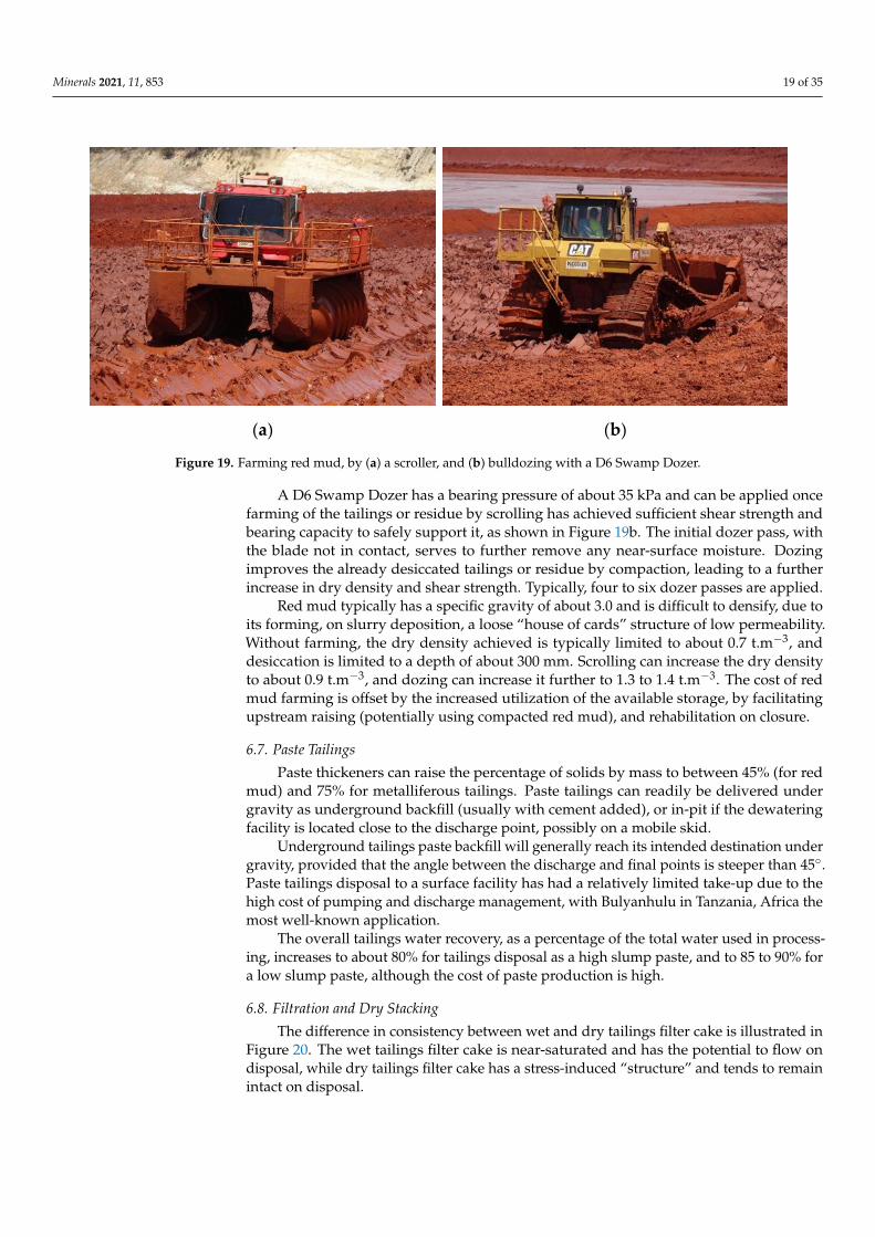
Minerals 2021, 11, 853 19 of 35
Minerals 2021, 11, x FOR PEER REVIEW 19 of 34
A D6 Swamp Dozer has a bearing pressure of about 35 kPa and can be applied once
farming of the tailings or residue by scrolling has achieved sufficient shear strength and
bearing capacity to safely support it, as shown in Figure 19b. The initial dozer pass, with
the blade not in contact, serves to further remove any near-surface moisture. Dozing
improves the already desiccated tailings or residue by compaction, leading to a further
increase in dry density and shear strength. Typically, four to six dozer passes are applied.
Red mud typically has a specific gravity of about 3.0 and is difficult to densify, due
to its forming, on slurry deposition, a loose “house of cards” structure of low permeability.
Without farming, the dry density achieved is typically limited to about 0.7 t.m−3, and
desiccation is limited to a depth of about 300 mm. Scrolling can increase the dry density
to about 0.9 t.m−3, and dozing can increase it further to 1.3 to 1.4 t.m−3. The cost of red mud
farming is offset by the increased utilization of the available storage, by facilitating
upstream raising (potentially using compacted red mud), and rehabilitation on closure.
(a) (b)
Figure 19. Farming red mud, by (a) a scroller, and (b) bulldozing with a D6 Swamp Dozer.
6.7. Paste Tailings
Paste thickeners can raise the percentage of solids by mass to between 45% (for red
mud) and 75% for metalliferous tailings. Paste tailings can readily be delivered under
gravity as underground backfill (usually with cement added), or in-pit if the dewatering
facility is located close to the discharge point, possibly on a mobile skid.
Underground tailings paste backfill will generally reach its intended destination un-
der gravity, provided that the angle between the discharge and final points is steeper than
45°. Paste tailings disposal to a surface facility has had a relatively limited take-up due to
the high cost of pumping and discharge management, with Bulyanhulu in Tanzania, Af-
rica the most well-known application.
The overall tailings water recovery, as a percentage of the total water used in pro-
cessing, increases to about 80% for tailings disposal as a high slump paste, and to 85 to
90% for a low slump paste, although the cost of paste production is high.
6.8. Filtration and Dry Stacking
The difference in consistency between wet and dry tailings filter cake is illustrated in
Figure 20. The wet tailings filter cake is near-saturated and has the potential to flow on
disposal, while dry tailings filter cake has a stress-induced “structure” and tends to re-
main intact on disposal.
Tailings filtration is best achieved under high pressure (1600 to 2100 kPa), with a
cycle time of up to about 20 min. Although termed “dry”, filtered tailings retain moisture
and are more correctly described as “unsaturated”. Dry tailings filter cake may be depos-
ited in a stack, although compaction may be required for geotechnical stability, to prevent
potential liquefaction, and to limit oxygen ingress and rainfall infiltration into potentially
contaminating tailings, in order to minimize contaminated seepage.
Figure 19. Farming red mud, by (a) a scroller, and (b) bulldozing with a D6 Swamp Dozer.
A D6 Swamp Dozer has a bearing pressure of about 35 kPa and can be applied oncefarming of the tailings or residue by scrolling has achieved sufficient shear strength andbearing capacity to safely support it, as shown in Figure 19b. The initial dozer pass, withthe blade not in contact, serves to further remove any near-surface moisture. Dozingimproves the already desiccated tailings or residue by compaction, leading to a furtherincrease in dry density and shear strength. Typically, four to six dozer passes are applied.
Red mud typically has a specific gravity of about 3.0 and is difficult to densify, due toits forming, on slurry deposition, a loose “house of cards” structure of low permeability.Without farming, the dry density achieved is typically limited to about 0.7 t.m−3, anddesiccation is limited to a depth of about 300 mm. Scrolling can increase the dry densityto about 0.9 t.m−3, and dozing can increase it further to 1.3 to 1.4 t.m−3. The cost of redmud farming is offset by the increased utilization of the available storage, by facilitatingupstream raising (potentially using compacted red mud), and rehabilitation on closure.
6.7. Paste Tailings
Paste thickeners can raise the percentage of solids by mass to between 45% (for redmud) and 75% for metalliferous tailings. Paste tailings can readily be delivered undergravity as underground backfill (usually with cement added), or in-pit if the dewateringfacility is located close to the discharge point, possibly on a mobile skid.
Underground tailings paste backfill will generally reach its intended destination undergravity, provided that the angle between the discharge and final points is steeper than 45◦.Paste tailings disposal to a surface facility has had a relatively limited take-up due to thehigh cost of pumping and discharge management, with Bulyanhulu in Tanzania, Africa themost well-known application.
The overall tailings water recovery, as a percentage of the total water used in process-ing, increases to about 80% for tailings disposal as a high slump paste, and to 85 to 90% fora low slump paste, although the cost of paste production is high.
6.8. Filtration and Dry Stacking
The difference in consistency between wet and dry tailings filter cake is illustrated inFigure 20. The wet tailings filter cake is near-saturated and has the potential to flow ondisposal, while dry tailings filter cake has a stress-induced “structure” and tends to remainintact on disposal.
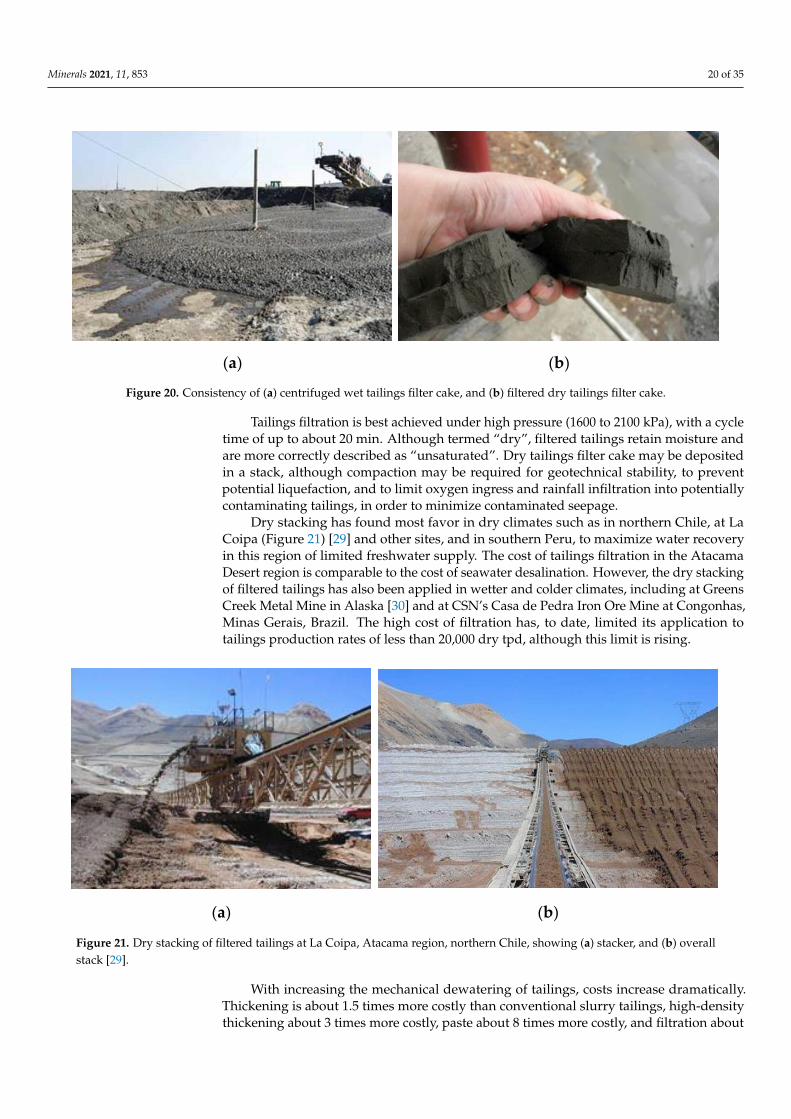
Minerals 2021, 11, 853 20 of 35Minerals 2021, 11, x FOR PEER REVIEW 20 of 34
(a) (b)
Figure 20. Consistency of (a) centrifuged wet tailings filter cake, and (b) filtered dry tailings filter
cake.
Dry stacking has found most favor in dry climates such as in northern Chile, at La
Coipa (Figure 21) [29] and other sites, and in southern Peru, to maximize water recovery
in this region of limited freshwater supply. The cost of tailings filtration in the Atacama
Desert region is comparable to the cost of seawater desalination. However, the dry stack-
ing of filtered tailings has also been applied in wetter and colder climates, including at
Greens Creek Metal Mine in Alaska [30] and at CSN’s Casa de Pedra Iron Ore Mine at
Congonhas, Minas Gerais, Brazil. The high cost of filtration has, to date, limited its appli-
cation to tailings production rates of less than 20,000 dry tpd, although this limit is rising.
(a) (b)
Figure 21. Dry stacking of filtered tailings at La Coipa, Atacama region, northern Chile, showing
(a) stacker, and (b) overall stack [29].
With increasing the mechanical dewatering of tailings, costs increase dramatically.
Thickening is about 1.5 times more costly than conventional slurry tailings, high-density
thickening about 3 times more costly, paste about 8 times more costly, and filtration about
27 times more costly than slurry tailings [31]. However, this cost comparison ignores cost
reductions due to increased process water recovery, the reduced storage volume required
with increasing tailings dewatering, the consequently reduced containment required, and
the reduced cost of rehabilitation and enhanced potential post-closure land use.
A more comprehensive cost comparison between slurry tailings deposition behind a
dam, and tailings filtration and dry stacking with compaction, is provided in [32]. Tailings
filtration and dry stacking with compaction indicated initial and average capital expendi-
ture savings of 38% and 64%, respectively (almost 4 times the operating expenditure), with
an average total cost saving of 33% over slurry tailings deposition behind a dam. The main
cost of slurry tailings deposition behind a dam is the cost of dam raising, exacerbated by
the low settled density and hence the high storage volume required for slurry tailings. In
addition to the 80% saving in storage volume, the filtered tailings would also: recover
Figure 20. Consistency of (a) centrifuged wet tailings filter cake, and (b) filtered dry tailings filter cake.
Tailings filtration is best achieved under high pressure (1600 to 2100 kPa), with a cycletime of up to about 20 min. Although termed “dry”, filtered tailings retain moisture andare more correctly described as “unsaturated”. Dry tailings filter cake may be depositedin a stack, although compaction may be required for geotechnical stability, to preventpotential liquefaction, and to limit oxygen ingress and rainfall infiltration into potentiallycontaminating tailings, in order to minimize contaminated seepage.
Dry stacking has found most favor in dry climates such as in northern Chile, at LaCoipa (Figure 21) [29] and other sites, and in southern Peru, to maximize water recoveryin this region of limited freshwater supply. The cost of tailings filtration in the AtacamaDesert region is comparable to the cost of seawater desalination. However, the dry stackingof filtered tailings has also been applied in wetter and colder climates, including at GreensCreek Metal Mine in Alaska [30] and at CSN’s Casa de Pedra Iron Ore Mine at Congonhas,Minas Gerais, Brazil. The high cost of filtration has, to date, limited its application totailings production rates of less than 20,000 dry tpd, although this limit is rising.
Minerals 2021, 11, x FOR PEER REVIEW 20 of 34
(a) (b)
Figure 20. Consistency of (a) centrifuged wet tailings filter cake, and (b) filtered dry tailings filter
cake.
Dry stacking has found most favor in dry climates such as in northern Chile, at La
Coipa (Figure 21) [29] and other sites, and in southern Peru, to maximize water recovery
in this region of limited freshwater supply. The cost of tailings filtration in the Atacama
Desert region is comparable to the cost of seawater desalination. However, the dry stack-
ing of filtered tailings has also been applied in wetter and colder climates, including at
Greens Creek Metal Mine in Alaska [30] and at CSN’s Casa de Pedra Iron Ore Mine at
Congonhas, Minas Gerais, Brazil. The high cost of filtration has, to date, limited its appli-
cation to tailings production rates of less than 20,000 dry tpd, although this limit is rising.
(a) (b)
Figure 21. Dry stacking of filtered tailings at La Coipa, Atacama region, northern Chile, showing
(a) stacker, and (b) overall stack [29].
With increasing the mechanical dewatering of tailings, costs increase dramatically.
Thickening is about 1.5 times more costly than conventional slurry tailings, high-density
thickening about 3 times more costly, paste about 8 times more costly, and filtration about
27 times more costly than slurry tailings [31]. However, this cost comparison ignores cost
reductions due to increased process water recovery, the reduced storage volume required
with increasing tailings dewatering, the consequently reduced containment required, and
the reduced cost of rehabilitation and enhanced potential post-closure land use.
A more comprehensive cost comparison between slurry tailings deposition behind a
dam, and tailings filtration and dry stacking with compaction, is provided in [32]. Tailings
filtration and dry stacking with compaction indicated initial and average capital expendi-
ture savings of 38% and 64%, respectively (almost 4 times the operating expenditure), with
an average total cost saving of 33% over slurry tailings deposition behind a dam. The main
cost of slurry tailings deposition behind a dam is the cost of dam raising, exacerbated by
the low settled density and hence the high storage volume required for slurry tailings. In
addition to the 80% saving in storage volume, the filtered tailings would also: recover
Figure 21. Dry stacking of filtered tailings at La Coipa, Atacama region, northern Chile, showing (a) stacker, and (b) overallstack [29].
With increasing the mechanical dewatering of tailings, costs increase dramatically.Thickening is about 1.5 times more costly than conventional slurry tailings, high-densitythickening about 3 times more costly, paste about 8 times more costly, and filtration about
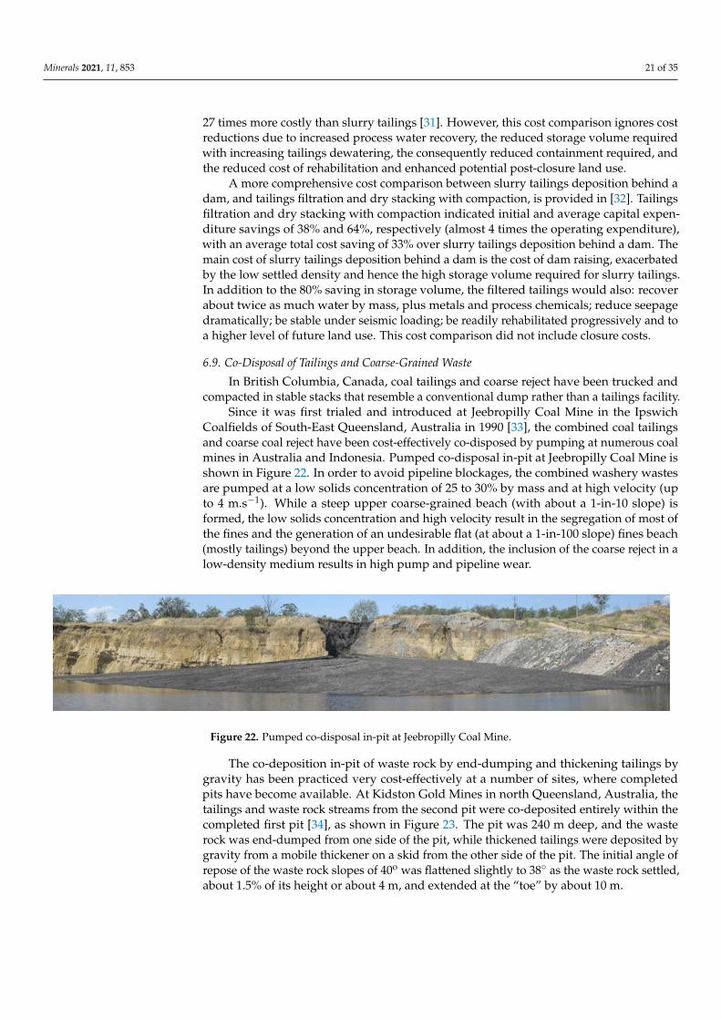
Minerals 2021, 11, 853 21 of 35
27 times more costly than slurry tailings [31]. However, this cost comparison ignores costreductions due to increased process water recovery, the reduced storage volume requiredwith increasing tailings dewatering, the consequently reduced containment required, andthe reduced cost of rehabilitation and enhanced potential post-closure land use.
A more comprehensive cost comparison between slurry tailings deposition behind adam, and tailings filtration and dry stacking with compaction, is provided in [32]. Tailingsfiltration and dry stacking with compaction indicated initial and average capital expen-diture savings of 38% and 64%, respectively (almost 4 times the operating expenditure),with an average total cost saving of 33% over slurry tailings deposition behind a dam. Themain cost of slurry tailings deposition behind a dam is the cost of dam raising, exacerbatedby the low settled density and hence the high storage volume required for slurry tailings.In addition to the 80% saving in storage volume, the filtered tailings would also: recoverabout twice as much water by mass, plus metals and process chemicals; reduce seepagedramatically; be stable under seismic loading; be readily rehabilitated progressively and toa higher level of future land use. This cost comparison did not include closure costs.
6.9. Co-Disposal of Tailings and Coarse-Grained Waste
In British Columbia, Canada, coal tailings and coarse reject have been trucked andcompacted in stable stacks that resemble a conventional dump rather than a tailings facility.
Since it was first trialed and introduced at Jeebropilly Coal Mine in the IpswichCoalfields of South-East Queensland, Australia in 1990 [33], the combined coal tailingsand coarse coal reject have been cost-effectively co-disposed by pumping at numerous coalmines in Australia and Indonesia. Pumped co-disposal in-pit at Jeebropilly Coal Mine isshown in Figure 22. In order to avoid pipeline blockages, the combined washery wastesare pumped at a low solids concentration of 25 to 30% by mass and at high velocity (upto 4 m.s−1). While a steep upper coarse-grained beach (with about a 1-in-10 slope) isformed, the low solids concentration and high velocity result in the segregation of most ofthe fines and the generation of an undesirable flat (at about a 1-in-100 slope) fines beach(mostly tailings) beyond the upper beach. In addition, the inclusion of the coarse reject in alow-density medium results in high pump and pipeline wear.
Minerals 2021, 11, x FOR PEER REVIEW 21 of 34
about twice as much water by mass, plus metals and process chemicals; reduce seepage
dramatically; be stable under seismic loading; be readily rehabilitated progressively and
to a higher level of future land use. This cost comparison did not include closure costs.
6.9. Co-Disposal of Tailings and Coarse-Grained Waste
In British Columbia, Canada, coal tailings and coarse reject have been trucked and
compacted in stable stacks that resemble a conventional dump rather than a tailings facil-
ity.
Since it was first trialed and introduced at Jeebropilly Coal Mine in the Ipswich Coal-
fields of South-East Queensland, Australia in 1990 [33], the combined coal tailings and
coarse coal reject have been cost-effectively co-disposed by pumping at numerous coal
mines in Australia and Indonesia. Pumped co-disposal in-pit at Jeebropilly Coal Mine is
shown in Figure 22. In order to avoid pipeline blockages, the combined washery wastes
are pumped at a low solids concentration of 25 to 30% by mass and at high velocity (up to
4 m.s−1). While a steep upper coarse-grained beach (with about a 1-in-10 slope) is formed,
the low solids concentration and high velocity result in the segregation of most of the fines
and the generation of an undesirable flat (at about a 1-in-100 slope) fines beach (mostly
tailings) beyond the upper beach. In addition, the inclusion of the coarse reject in a low-
density medium results in high pump and pipeline wear.
Figure 22. Pumped co-disposal in-pit at Jeebropilly Coal Mine.
The co-deposition in-pit of waste rock by end-dumping and thickening tailings by
gravity has been practiced very cost-effectively at a number of sites, where completed pits
have become available. At Kidston Gold Mines in north Queensland, Australia, the tail-
ings and waste rock streams from the second pit were co-deposited entirely within the
completed first pit [34], as shown in Figure 23. The pit was 240 m deep, and the waste rock
was end-dumped from one side of the pit, while thickened tailings were deposited by
gravity from a mobile thickener on a skid from the other side of the pit. The initial angle
of repose of the waste rock slopes of 40o was flattened slightly to 38° as the waste rock
settled, about 1.5% of its height or about 4 m, and extended at the “toe” by about 10 m.
Figure 23. In-pit co-deposition of waste rock and thickened tailings (left-hand pit) at Kidston Gold
Mines in north Queensland, Australia.
Figure 22. Pumped co-disposal in-pit at Jeebropilly Coal Mine.
The co-deposition in-pit of waste rock by end-dumping and thickening tailings bygravity has been practiced very cost-effectively at a number of sites, where completedpits have become available. At Kidston Gold Mines in north Queensland, Australia, thetailings and waste rock streams from the second pit were co-deposited entirely within thecompleted first pit [34], as shown in Figure 23. The pit was 240 m deep, and the wasterock was end-dumped from one side of the pit, while thickened tailings were deposited bygravity from a mobile thickener on a skid from the other side of the pit. The initial angle ofrepose of the waste rock slopes of 40o was flattened slightly to 38◦ as the waste rock settled,about 1.5% of its height or about 4 m, and extended at the “toe” by about 10 m.
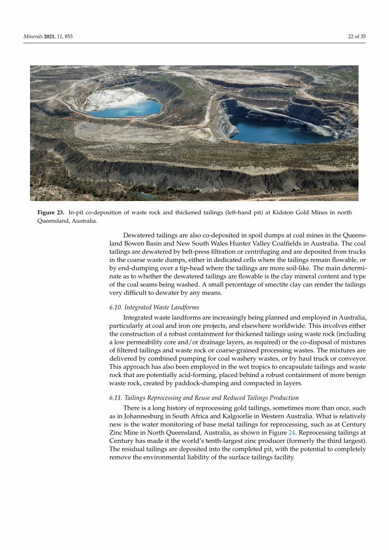
Minerals 2021, 11, 853 22 of 35
Minerals 2021, 11, x FOR PEER REVIEW 21 of 34
about twice as much water by mass, plus metals and process chemicals; reduce seepage
dramatically; be stable under seismic loading; be readily rehabilitated progressively and
to a higher level of future land use. This cost comparison did not include closure costs.
6.9. Co-Disposal of Tailings and Coarse-Grained Waste
In British Columbia, Canada, coal tailings and coarse reject have been trucked and
compacted in stable stacks that resemble a conventional dump rather than a tailings facil-
ity.
Since it was first trialed and introduced at Jeebropilly Coal Mine in the Ipswich Coal-
fields of South-East Queensland, Australia in 1990 [33], the combined coal tailings and
coarse coal reject have been cost-effectively co-disposed by pumping at numerous coal
mines in Australia and Indonesia. Pumped co-disposal in-pit at Jeebropilly Coal Mine is
shown in Figure 22. In order to avoid pipeline blockages, the combined washery wastes
are pumped at a low solids concentration of 25 to 30% by mass and at high velocity (up to
4 m.s−1). While a steep upper coarse-grained beach (with about a 1-in-10 slope) is formed,
the low solids concentration and high velocity result in the segregation of most of the fines
and the generation of an undesirable flat (at about a 1-in-100 slope) fines beach (mostly
tailings) beyond the upper beach. In addition, the inclusion of the coarse reject in a low-
density medium results in high pump and pipeline wear.
Figure 22. Pumped co-disposal in-pit at Jeebropilly Coal Mine.
The co-deposition in-pit of waste rock by end-dumping and thickening tailings by
gravity has been practiced very cost-effectively at a number of sites, where completed pits
have become available. At Kidston Gold Mines in north Queensland, Australia, the tail-
ings and waste rock streams from the second pit were co-deposited entirely within the
completed first pit [34], as shown in Figure 23. The pit was 240 m deep, and the waste rock
was end-dumped from one side of the pit, while thickened tailings were deposited by
gravity from a mobile thickener on a skid from the other side of the pit. The initial angle
of repose of the waste rock slopes of 40o was flattened slightly to 38° as the waste rock
settled, about 1.5% of its height or about 4 m, and extended at the “toe” by about 10 m.
Figure 23. In-pit co-deposition of waste rock and thickened tailings (left-hand pit) at Kidston Gold
Mines in north Queensland, Australia. Figure 23. In-pit co-deposition of waste rock and thickened tailings (left-hand pit) at Kidston Gold Mines in northQueensland, Australia.
Dewatered tailings are also co-deposited in spoil dumps at coal mines in the Queens-land Bowen Basin and New South Wales Hunter Valley Coalfields in Australia. The coaltailings are dewatered by belt-press filtration or centrifuging and are deposited from trucksin the coarse waste dumps, either in dedicated cells where the tailings remain flowable, orby end-dumping over a tip-head where the tailings are more soil-like. The main determi-nate as to whether the dewatered tailings are flowable is the clay mineral content and typeof the coal seams being washed. A small percentage of smectite clay can render the tailingsvery difficult to dewater by any means.
6.10. Integrated Waste Landforms
Integrated waste landforms are increasingly being planned and employed in Australia,particularly at coal and iron ore projects, and elsewhere worldwide. This involves eitherthe construction of a robust containment for thickened tailings using waste rock (includinga low permeability core and/or drainage layers, as required) or the co-disposal of mixturesof filtered tailings and waste rock or coarse-grained processing wastes. The mixtures aredelivered by combined pumping for coal washery wastes, or by haul truck or conveyor.This approach has also been employed in the wet tropics to encapsulate tailings and wasterock that are potentially acid-forming, placed behind a robust containment of more benignwaste rock, created by paddock-dumping and compacted in layers.
6.11. Tailings Reprocessing and Reuse and Reduced Tailings Production
There is a long history of reprocessing gold tailings, sometimes more than once, suchas in Johannesburg in South Africa and Kalgoorlie in Western Australia. What is relativelynew is the water monitoring of base metal tailings for reprocessing, such as at CenturyZinc Mine in North Queensland, Australia, as shown in Figure 24. Reprocessing tailings atCentury has made it the world’s tenth-largest zinc producer (formerly the third largest).The residual tailings are deposited into the completed pit, with the potential to completelyremove the environmental liability of the surface tailings facility.
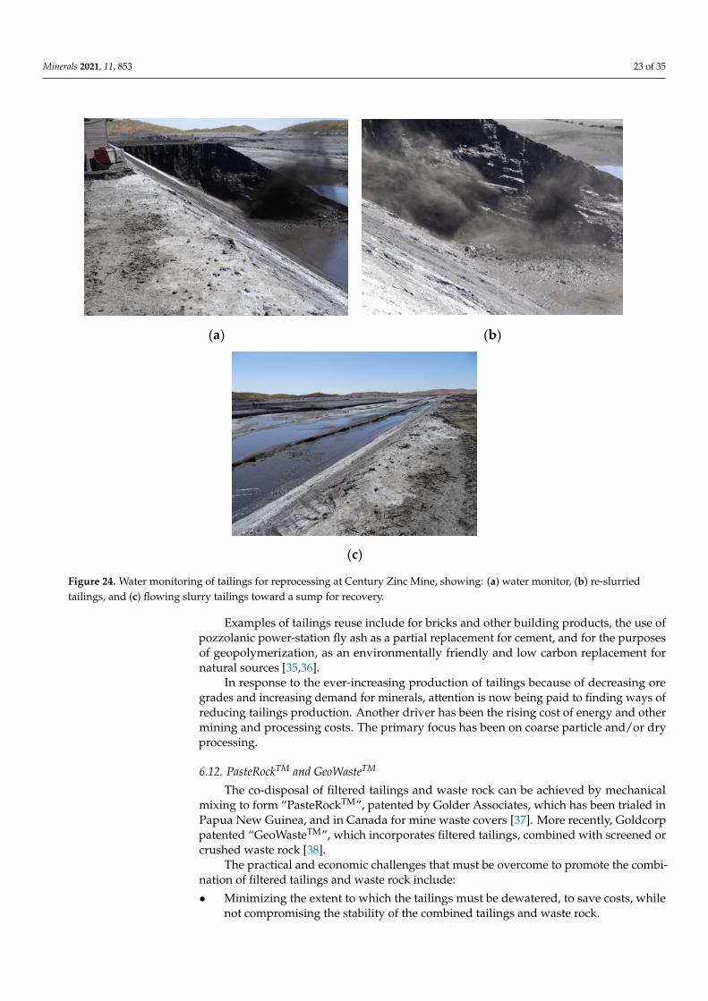
Minerals 2021, 11, 853 23 of 35
Minerals 2021, 11, x FOR PEER REVIEW 22 of 34
Dewatered tailings are also co-deposited in spoil dumps at coal mines in the Queens-
land Bowen Basin and New South Wales Hunter Valley Coalfields in Australia. The coal
tailings are dewatered by belt-press filtration or centrifuging and are deposited from
trucks in the coarse waste dumps, either in dedicated cells where the tailings remain flow-
able, or by end-dumping over a tip-head where the tailings are more soil-like. The main
determinate as to whether the dewatered tailings are flowable is the clay mineral content
and type of the coal seams being washed. A small percentage of smectite clay can render
the tailings very difficult to dewater by any means.
6.10. Integrated Waste Landforms
Integrated waste landforms are increasingly being planned and employed in Aus-
tralia, particularly at coal and iron ore projects, and elsewhere worldwide. This involves
either the construction of a robust containment for thickened tailings using waste rock
(including a low permeability core and/or drainage layers, as required) or the co-disposal
of mixtures of filtered tailings and waste rock or coarse-grained processing wastes. The
mixtures are delivered by combined pumping for coal washery wastes, or by haul truck
or conveyor. This approach has also been employed in the wet tropics to encapsulate tail-
ings and waste rock that are potentially acid-forming, placed behind a robust containment
of more benign waste rock, created by paddock-dumping and compacted in layers.
6.11. Tailings Reprocessing and Reuse and Reduced Tailings Production
There is a long history of reprocessing gold tailings, sometimes more than once, such
as in Johannesburg in South Africa and Kalgoorlie in Western Australia. What is relatively
new is the water monitoring of base metal tailings for reprocessing, such as at Century
Zinc Mine in North Queensland, Australia, as shown in Figure 24. Reprocessing tailings
at Century has made it the world’s tenth-largest zinc producer (formerly the third largest).
The residual tailings are deposited into the completed pit, with the potential to completely
remove the environmental liability of the surface tailings facility.
(a) (b)
(c)
Figure 24. Water monitoring of tailings for reprocessing at Century Zinc Mine, showing: (a) water monitor, (b) re-slurriedtailings, and (c) flowing slurry tailings toward a sump for recovery.
Examples of tailings reuse include for bricks and other building products, the use ofpozzolanic power-station fly ash as a partial replacement for cement, and for the purposesof geopolymerization, as an environmentally friendly and low carbon replacement fornatural sources [35,36].
In response to the ever-increasing production of tailings because of decreasing oregrades and increasing demand for minerals, attention is now being paid to finding ways ofreducing tailings production. Another driver has been the rising cost of energy and othermining and processing costs. The primary focus has been on coarse particle and/or dryprocessing.
6.12. PasteRockTM and GeoWasteTM
The co-disposal of filtered tailings and waste rock can be achieved by mechanicalmixing to form “PasteRockTM”, patented by Golder Associates, which has been trialed inPapua New Guinea, and in Canada for mine waste covers [37]. More recently, Goldcorppatented “GeoWasteTM”, which incorporates filtered tailings, combined with screened orcrushed waste rock [38].
The practical and economic challenges that must be overcome to promote the combi-nation of filtered tailings and waste rock include:
• Minimizing the extent to which the tailings must be dewatered, to save costs, whilenot compromising the stability of the combined tailings and waste rock.
Minerals 2021, 11, 853 24 of 35
• Minimizing the crushing or screening of the waste rock to allow mixing with thefiltered tailings and transportation. The largest size of the waste rock for conveying isabout 200 to 300 mm, while run-of-mine waste rock can be trucked.
• Achieving adequate mixing of the filtered tailings and waste rock. This is unlikely tooccur on a conveyor since the two waste streams tend to remain separate. It is alsounlikely to occur upon dumping from a haul truck since the coarse fraction tendsto ravel further. However, mixing may be achieved by placing a number of droppoints into hoppers along a conveyor line. It may also be achieved by placing thecoarse-grained waste rock in the base of a truck, with the filtered tailings over the topto the designed ratio, to avoid the filtered tailings sticking to the truck tray and toforce mixing on dumping.
• Compaction of the mixture may be required to produce a stable deposit, althoughcompaction could be restricted to the perimeter of the emplacement.
The benefits of combining filtered tailings and waste rock can include an increasedshear strength, reduced compressibility, and permeability that is lower than that of thewaste rock alone but is higher than that of tailings alone.
6.13. Briquetting of Tailings
Briquetting involves forcing a slurry between two rollers under very high stress (ofthe order of 50 MPa), and has been shown to be very effective in dewatering ultra-fineblack product coal [39]. In this study, the ultra-fine product coal that was initially at 40to 45% total moisture content (mass of water/total mass, expressed as a percentage) wasdewatered to briquettes of about 15% total moisture content (85% solids by mass). The veryhigh stresses imposed over a very limited time duration resulted in further dewatering ofthe briquettes in a dry atmosphere, to about 2 to 5% total moisture content (95% solids).The air-dried briquettes can re-wet in a humid atmosphere, but only to about 15% totalmoisture content, and they retain their “briquette” structure. However, the very highinitial capital and operating costs of briquetting, and scale-up issues, would discourage itsapplication to tailings.
6.14. Barriers to the Implementation of Innovative Tailings Management
The conventional disposal of slurry tailings remains the preferred choice for manymine sites. Barriers to the implementation of the wide range of innovative tailings manage-ment options available include:
• The continued use of NPV accounting with a high discount factor (typically 6 to 10%,which is three to five times the consumer price index). This approach favors tailingsmanagement options that are less costly (particularly in capital expenditure terms)in the short term, delaying long-term expenditure and rehabilitation. Favoring lowcapital expenditure can come at the expense of increasing operating expenditure, andis likely to exacerbate undesirable outcomes and blow-out rehabilitation costs.
• The mechanical dewatering of tailings, and the co-disposal of tailings and waste rock,are seen as too costly in a narrow comparison with conventional tailings transportand disposal as a thickened slurry, a view that is reinforced by NPV accounting.
• There are perceived and real technical difficulties associated with the mechanicaldewatering of tailings and the co-disposal of tailings and waste rock. Very fine-grained tailings and tailings with a high clay mineral content are difficult to thickenand filter, and it is difficult to mix tailings and coarse-grained waste.
• There is an underlying inherent resistance to change and doing something other thanwhat has always been done, often disguised as unsubstantiated claims about perceivedhigh costs, perceived technical obstacles, and perceived uncertainty.
• The uncertainty, and hence the perceived higher risk, attached to new approaches alsoserve to discourage innovation.
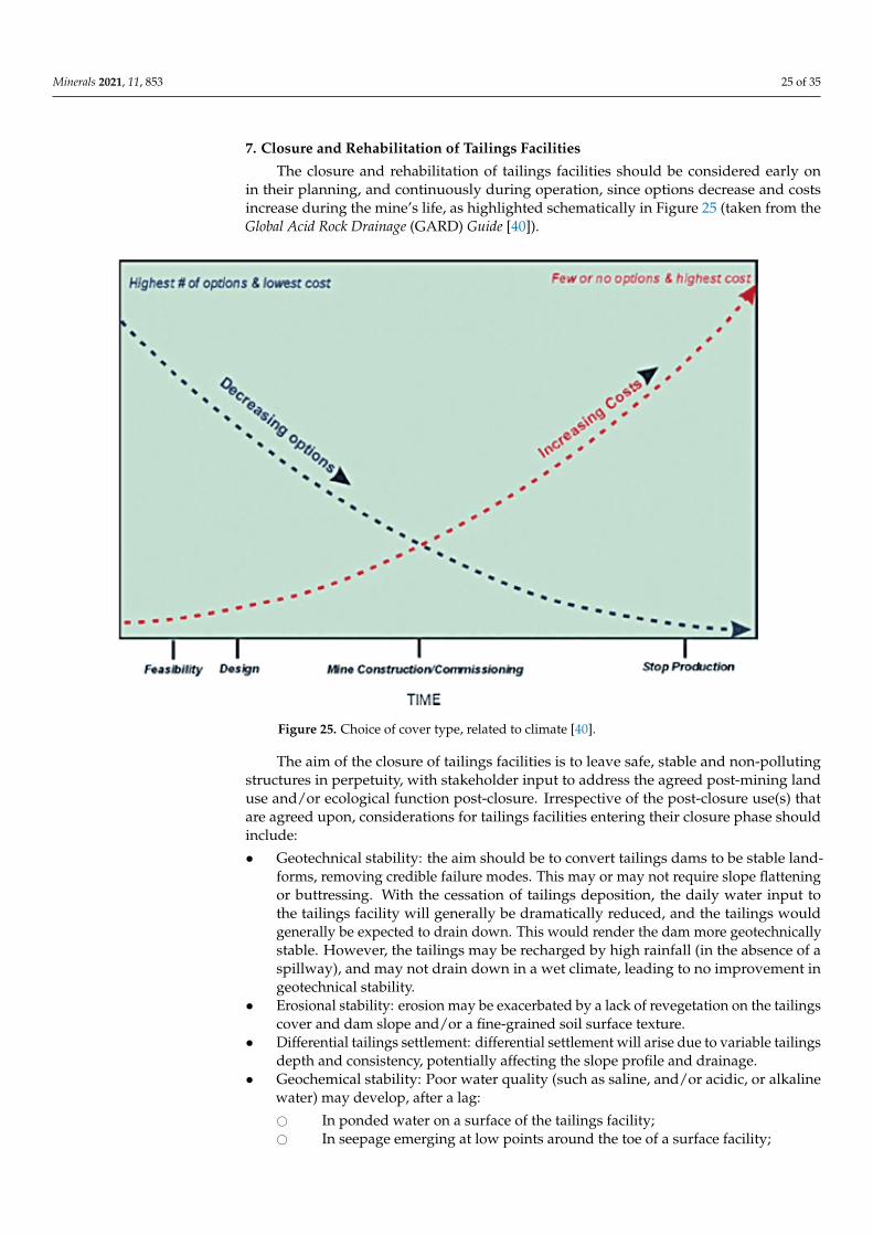
Minerals 2021, 11, 853 25 of 35
7. Closure and Rehabilitation of Tailings Facilities
The closure and rehabilitation of tailings facilities should be considered early onin their planning, and continuously during operation, since options decrease and costsincrease during the mine’s life, as highlighted schematically in Figure 25 (taken from theGlobal Acid Rock Drainage (GARD) Guide [40]).
Minerals 2021, 11, x FOR PEER REVIEW 25 of 34
Figure 25. Choice of cover type, related to climate [40].
Wet and soft tailings resulting from conventional slurry tailings deposition are diffi-
cult and expensive to physically cover and rehabilitate, particularly at the end of the mine
life, when the mine is no longer producing revenue and construction equipment is being
demobilized. Furthermore, such tailings will limit the future land-use potential of the fa-
cility. On the other hand, their high degree of saturation will limit the oxidation of any
sulfides present in the tailings, reducing the potential for contaminated seepage.
7.1. Covering Tailings
The rehabilitation of tailings can vary, including benign water covers in wet climates,
the direct revegetation of benign tailings, and soil covers, particularly in dry climates. As
shown in Figure 26, the GARD guide [40] recommends that the choice between cover
types is based on climatic conditions, guided by:
Water covers: appropriate in wet climates as effective oxygen barriers, provided that
they are a nominal 2-m deep to cater for wave action and potential mobilization of
tailings, are retained by stable dams, and have an adequate supply of rainfall-runoff
to maintain them.
Water-shedding soil covers: appropriate in moist climates to promote revegetation
for erosion protection, and rainfall runoff to limit net percolation of rainfall.
Store and release soil covers that store wet season rainfall, releasing it through
evapotranspiration during the dry season; appropriate for dry or seasonally dry
climates to sustain revegetation, limit net percolation of rainfall, and prevent erosion
through preventing rainfall-runoff during heavy rainfall events.
In seasonally dry climates, store and release covers are more robust than rainfall-
shedding covers since they better sustain revegetation, due to their greater rainfall infil-
tration and water storage capacity, and since they limit erosion by preventing rainfall run-
off. Store and release covers require a base sealing layer (or a desiccated, hardpan, or com-
pacted tailings surface, if suitable) to limit the breakthrough of rainfall infiltration into the
underlying tailings, and may take advantage of the natural tailings beach slope to direct
clean excess rainfall infiltration toward a collection point, limiting breakthrough into the
underlying tailings.
Figure 25. Choice of cover type, related to climate [40].
The aim of the closure of tailings facilities is to leave safe, stable and non-pollutingstructures in perpetuity, with stakeholder input to address the agreed post-mining landuse and/or ecological function post-closure. Irrespective of the post-closure use(s) thatare agreed upon, considerations for tailings facilities entering their closure phase shouldinclude:
• Geotechnical stability: the aim should be to convert tailings dams to be stable land-forms, removing credible failure modes. This may or may not require slope flatteningor buttressing. With the cessation of tailings deposition, the daily water input tothe tailings facility will generally be dramatically reduced, and the tailings wouldgenerally be expected to drain down. This would render the dam more geotechnicallystable. However, the tailings may be recharged by high rainfall (in the absence of aspillway), and may not drain down in a wet climate, leading to no improvement ingeotechnical stability.
• Erosional stability: erosion may be exacerbated by a lack of revegetation on the tailingscover and dam slope and/or a fine-grained soil surface texture.
• Differential tailings settlement: differential settlement will arise due to variable tailingsdepth and consistency, potentially affecting the slope profile and drainage.
• Geochemical stability: Poor water quality (such as saline, and/or acidic, or alkalinewater) may develop, after a lag:
# In ponded water on a surface of the tailings facility;# In seepage emerging at low points around the toe of a surface facility;
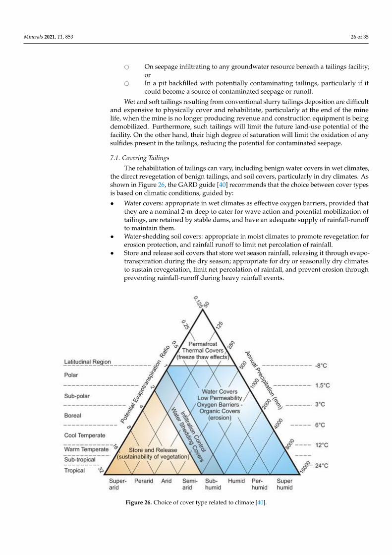
Minerals 2021, 11, 853 26 of 35
# On seepage infiltrating to any groundwater resource beneath a tailings facility;or
# In a pit backfilled with potentially contaminating tailings, particularly if itcould become a source of contaminated seepage or runoff.
Wet and soft tailings resulting from conventional slurry tailings deposition are difficultand expensive to physically cover and rehabilitate, particularly at the end of the minelife, when the mine is no longer producing revenue and construction equipment is beingdemobilized. Furthermore, such tailings will limit the future land-use potential of thefacility. On the other hand, their high degree of saturation will limit the oxidation of anysulfides present in the tailings, reducing the potential for contaminated seepage.
7.1. Covering Tailings
The rehabilitation of tailings can vary, including benign water covers in wet climates,the direct revegetation of benign tailings, and soil covers, particularly in dry climates. Asshown in Figure 26, the GARD guide [40] recommends that the choice between cover typesis based on climatic conditions, guided by:
• Water covers: appropriate in wet climates as effective oxygen barriers, provided thatthey are a nominal 2-m deep to cater for wave action and potential mobilization oftailings, are retained by stable dams, and have an adequate supply of rainfall-runoffto maintain them.
• Water-shedding soil covers: appropriate in moist climates to promote revegetation forerosion protection, and rainfall runoff to limit net percolation of rainfall.
• Store and release soil covers that store wet season rainfall, releasing it through evapo-transpiration during the dry season; appropriate for dry or seasonally dry climatesto sustain revegetation, limit net percolation of rainfall, and prevent erosion throughpreventing rainfall-runoff during heavy rainfall events.
Minerals 2021, 11, x FOR PEER REVIEW 26 of 34
Figure 26. Choice of cover type related to climate [40].
7.2. Soil Cover Designs
The GARD guide [40] also provides schematics of soil cover designs, as shown in
Figure 27, which increase in complexity, construction difficulties, potential performance
and cost from left to right. The implication from Figure 27 is that the more complex and
thick the cover, the more effective it will be. However, covers should be appropriate to the
site conditions, in particular the climate, and more complex and thicker covers may not
be the most effective choice for a given site, just more expensive. The schematics have
generated much confusion, particularly in Australia. The Base Case is a single growth
medium layer. Cover I, indicating a thicker single layer of growth medium than the Base
Case, is inferred to be “better” than the base case. However, thicker is not necessarily bet-
ter. A thick growth medium can lead to the infiltration of rainfall to a depth that makes it
inaccessible to revegetation. This can also lead to increased net percolation into the under-
lying tailings, producing a result that may be worse than having no cover at all, since the
cover would constitute a “sponge” that would increase rainfall infiltration, compared
with a desiccated, hardpan, or compacted tailings surface.
Cover II adds a capillary barrier (or break) beneath the growth medium, which may
be desirable for limiting the uptake of any salts from the underlying tailings into the
growth medium. A capillary barrier relies on a material that limits saturation and flow
driven by capillary action and must be carefully selected and sized to ensure that it is
effective and will remain so. One suitable capillary barrier material is clean gravel. Run-
of-mine waste rock would likely not be suitable for use as a capillary barrier without the
crushing of coarse-grained particles and screening to remove fines. A capillary barrier is
a “drain”, and so it should be overlain with a sealing layer to limit the net percolation of
rainfall into the underlying tailings.
Clean gravel would require a thickness of greater than 200 mm to remain effective as
a barrier. The capillary barrier thickness must allow for the possible infiltration of fines
from the overlying growth medium, which would render it less effective over time. The
particle size of the capillary barrier must be matched to that of the overlying growth me-
dium, using filter criteria, to ensure that the infiltration of fines into the capillary barrier
Figure 26. Choice of cover type related to climate [40].
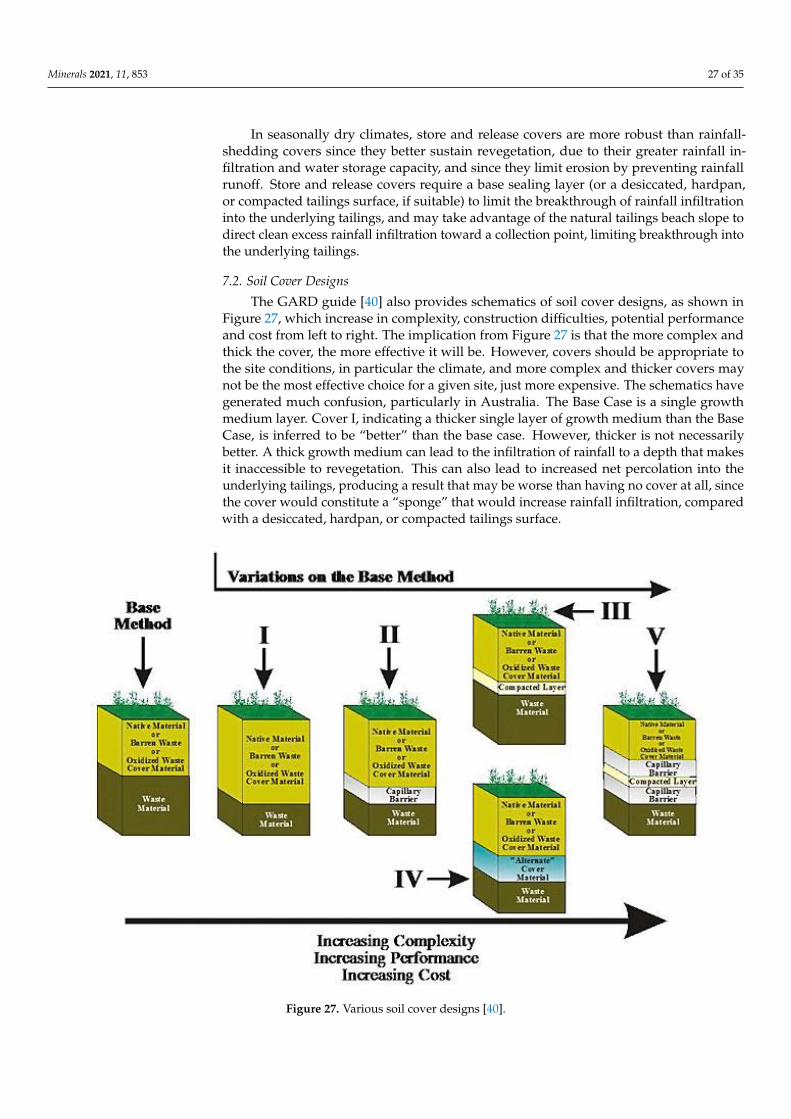
Minerals 2021, 11, 853 27 of 35
In seasonally dry climates, store and release covers are more robust than rainfall-shedding covers since they better sustain revegetation, due to their greater rainfall in-filtration and water storage capacity, and since they limit erosion by preventing rainfallrunoff. Store and release covers require a base sealing layer (or a desiccated, hardpan,or compacted tailings surface, if suitable) to limit the breakthrough of rainfall infiltrationinto the underlying tailings, and may take advantage of the natural tailings beach slope todirect clean excess rainfall infiltration toward a collection point, limiting breakthrough intothe underlying tailings.
7.2. Soil Cover Designs
The GARD guide [40] also provides schematics of soil cover designs, as shown inFigure 27, which increase in complexity, construction difficulties, potential performanceand cost from left to right. The implication from Figure 27 is that the more complex andthick the cover, the more effective it will be. However, covers should be appropriate tothe site conditions, in particular the climate, and more complex and thicker covers maynot be the most effective choice for a given site, just more expensive. The schematics havegenerated much confusion, particularly in Australia. The Base Case is a single growthmedium layer. Cover I, indicating a thicker single layer of growth medium than the BaseCase, is inferred to be “better” than the base case. However, thicker is not necessarilybetter. A thick growth medium can lead to the infiltration of rainfall to a depth that makesit inaccessible to revegetation. This can also lead to increased net percolation into theunderlying tailings, producing a result that may be worse than having no cover at all, sincethe cover would constitute a “sponge” that would increase rainfall infiltration, comparedwith a desiccated, hardpan, or compacted tailings surface.
Minerals 2021, 11, x FOR PEER REVIEW 27 of 34
is limited by “arching” between particles. Finding suitable material for an effective capil-
lary break, and ensuring its sustainability, are problematic.
Cover III adds a compacted (clayey) sealing layer beneath the growth medium, which
is desirable, particularly for a store and release cover, to “hold up” rainfall infiltration
within the overlying “rocky soil mulch” layer. Cover IV is a variation on Cover III, in
which the compacted layer is replaced by an “alternative” sealing layer, such as a ge-
omembrane, bituminous geomembrane, or geosynthetic clay liner (GCL). A sealing layer
could also potentially be achieved by a desiccated, hardpan, or compacted tailings surface.
Figure 27. Various soil cover designs [40].
Cover V incorporates three layers separating the growth medium from the tailings,
comprising a compacted fine-grained layer sandwiched between two capillary barriers.
This cover was apparently based on the cover with capillary barrier effects (CCBE) applied
at the Les Terrains Aurifères (LTA) mine site sulfide tailings impoundment, near Malartic,
Abitibi, in Québec, Canada, in a net positive precipitation climate [41].
The CCBE, constructed on the LTA tailings in 1998, comprises 500 mm of sand (a
capillary barrier) placed on the sulfidic tailings, overlain by 800 mm of fine-grained, non-
acid-generating tailings (a moisture-retaining layer) that is in turn overlain by more than
300 mm of sand and gravel (protection and drainage layer). The design objective was to
maintain a minimum degree of saturation of 85% in the moisture-retaining layer to effec-
tively reduce the oxygen flux from the atmosphere to the underlying acid-generating tail-
ings. Near-saturation of the moisture-retaining layer was to be maintained by a combina-
tion of enhanced rainfall infiltration and suction in the lower capillary barrier. The inten-
tion of the sand and gravel surface layer was to limit revegetation, so as not to reduce
rainfall infiltration. The same cover was applied to the side slopes of the tailings impound-
ment (also comprising sulfidic tailings).
The cover initially functioned as intended on the top of the impoundment, which
initially remained un-vegetated, but it was not so successful on the side slopes, due to
gravity drainage. However, volunteer revegetation was established on the LTA CCBE,
commencing the year after construction [42]. Eight functional groups of plants were iden-
tified, with herbaceous plants being the most abundant. Of the 11 tree species identified,
Figure 27. Various soil cover designs [40].
Minerals 2021, 11, 853 28 of 35
Cover II adds a capillary barrier (or break) beneath the growth medium, which may bedesirable for limiting the uptake of any salts from the underlying tailings into the growthmedium. A capillary barrier relies on a material that limits saturation and flow drivenby capillary action and must be carefully selected and sized to ensure that it is effectiveand will remain so. One suitable capillary barrier material is clean gravel. Run-of-minewaste rock would likely not be suitable for use as a capillary barrier without the crushingof coarse-grained particles and screening to remove fines. A capillary barrier is a “drain”,and so it should be overlain with a sealing layer to limit the net percolation of rainfall intothe underlying tailings.
Clean gravel would require a thickness of greater than 200 mm to remain effective as abarrier. The capillary barrier thickness must allow for the possible infiltration of fines fromthe overlying growth medium, which would render it less effective over time. The particlesize of the capillary barrier must be matched to that of the overlying growth medium, usingfilter criteria, to ensure that the infiltration of fines into the capillary barrier is limited by“arching” between particles. Finding suitable material for an effective capillary break, andensuring its sustainability, are problematic.
Cover III adds a compacted (clayey) sealing layer beneath the growth medium, whichis desirable, particularly for a store and release cover, to “hold up” rainfall infiltrationwithin the overlying “rocky soil mulch” layer. Cover IV is a variation on Cover III, in whichthe compacted layer is replaced by an “alternative” sealing layer, such as a geomembrane,bituminous geomembrane, or geosynthetic clay liner (GCL). A sealing layer could alsopotentially be achieved by a desiccated, hardpan, or compacted tailings surface.
Cover V incorporates three layers separating the growth medium from the tailings,comprising a compacted fine-grained layer sandwiched between two capillary barriers.This cover was apparently based on the cover with capillary barrier effects (CCBE) appliedat the Les Terrains Aurifères (LTA) mine site sulfide tailings impoundment, near Malartic,Abitibi, in Québec, Canada, in a net positive precipitation climate [41].
The CCBE, constructed on the LTA tailings in 1998, comprises 500 mm of sand (acapillary barrier) placed on the sulfidic tailings, overlain by 800 mm of fine-grained, non-acid-generating tailings (a moisture-retaining layer) that is in turn overlain by more than300 mm of sand and gravel (protection and drainage layer). The design objective wasto maintain a minimum degree of saturation of 85% in the moisture-retaining layer toeffectively reduce the oxygen flux from the atmosphere to the underlying acid-generatingtailings. Near-saturation of the moisture-retaining layer was to be maintained by a com-bination of enhanced rainfall infiltration and suction in the lower capillary barrier. Theintention of the sand and gravel surface layer was to limit revegetation, so as not to re-duce rainfall infiltration. The same cover was applied to the side slopes of the tailingsimpoundment (also comprising sulfidic tailings).
The cover initially functioned as intended on the top of the impoundment, whichinitially remained un-vegetated, but it was not so successful on the side slopes, due togravity drainage. However, volunteer revegetation was established on the LTA CCBE, com-mencing the year after construction [42]. Eight functional groups of plants were identified,with herbaceous plants being the most abundant. Of the 11 tree species identified, thefour most abundant were poplar, paper birch, black spruce and willow. Root excavationshowed that tree roots penetrated the moisture-retaining layer, with an average root depthof 400 mm and a maximum root depth of 1.7 m.
After 10 years, although the LTA CCBE was effective in reducing the oxygen flux fromthe atmosphere to the acid-generating tailings, the quality of the seepage from the tailingsimpoundment still did not meet the Québec water quality standards, and dolomitic drainswere constructed as a passive treatment [43].
The CCBE was designed for a specific purpose, in a net positive precipitation climate,and appears to be the only Cover Type V double capillary barrier cover applied in practice.Double capillary barrier (or break) covers have been promoted by some regulators inAustralia, notably in Queensland. This is perplexing, since the majority of mine sites in
Minerals 2021, 11, 853 29 of 35
Queensland, and elsewhere in Australia, are in semi-arid to arid climates, for which theGARD guide recommends a store and release cover. Attention is best paid to the design,materials selection, and construction of such store and release covers.
7.3. Store and Release Cover Design
The key elements of a store and release cover [44,45], which was developed forseasonal, dry climates, are: (i) a thick, loose, rocky soil with a mulch growth medium layerthat has an undulating surface to store the wet season rainfall without inducing runoff;(ii) an effective sealing layer at the base of the cover to hold-up rainfall infiltration; (iii) theappropriate choice of sustainable revegetation to release the stored rainfall during the wetseason, through evapotranspiration.
The required thickness of rocky soil mulch growth medium will depend on the wetseason rainfall pattern and the rooting depth of the vegetative cover applied and is typicallyup to 2-m thick. It is sized so as to accommodate within its available voids the majority ofthe wet season rainfall. The typical porosity of the loose, rocky soil mulch is about 0.25,providing up to 250 mm of storage volume per meter thickness of mulch.
Too thin a growth medium will not accommodate the wet season rainfall infiltrationand will not support revegetation during the dry season. Too thick a growth medium couldlead to rainfall infiltration beyond the reach of the revegetation. In a dry climate, store andrelease covers are more robust than rainfall-shedding covers, which have a more limitedstore and release capability and promote runoff and the potential for erosion.
The sealing layer should achieve a saturated hydraulic conductivity of less than10−8 m/s (equivalent to a potential percolation rate of less than 300 mm/year, when wateris available), so that in its usual unsaturated state in a dry climate its hydraulic conductivitywill be less than perhaps 10−10 m/s (a potential percolation rate of less than 3 mm/year).
In the typically dry climate found over much of Australia, and in other dry regions,rainfall occurs on only perhaps 30 days/year, so that water may be available on top of thesealing layer for perhaps 10% of the time, reducing the potential percolation rate to less than30 mm/year, or less than 5% of the typical average annual rainfall, similar to the typicalnatural percolation rate. High net percolation will be associated mainly with extremerainfall events. A store and release cover should cycle annually between wet and dry stateswithout a net wetting-up (which would lead to net percolation) or drying out (which wouldcause revegetation dieback and subsequent rainfall-induced erosion). An extreme rainfallevent may wet up the cover, potentially leading to net percolation into the underlyingtailings. In Australia’s generally arid to semi-arid climate, a mixed eucalypt tree coverrepresents the only sustainable means of achieving the required evapotranspiration ratesfrom a store and release cover that can handle extreme rainfall events and be sustainablein the long term. Australian eucalypts are quite adaptable to the climatic variability inthe country, and their water uptake can vary by an order of magnitude, according to theavailability of water.
There is ongoing concern and debate about the effect of tree roots on cover integrityon the tops of tailings facilities, from a number of standpoints. Tree roots can potentiallypenetrate through the cover thickness toward the underlying tailings. However, a desic-cated, hardpan or compacted tailings surface is essentially a root barrier. This gives treeroots no encouragement to penetrate to depth in search of moisture or nutrients. Instead,the tree roots would grow laterally through the overlying cover. Since the rocky soil mulchis loose and granular, trees are unlikely to promote cracking and the development ofpreferred seepage pathways through the cover. The height of the trees will be limitedby the climate, and by the thickness, water-holding and nutrient capacity of the rockysoil mulch, while their root patterns will not penetrate the sealing layer but will insteadgrow laterally. Sufficient rocky soil mulch thickness and limited tree height will lessen thepossibility of wind blow-down and any possible threat to the integrity of the cover. Shouldwind blow-down of shrubs and trees occur, the limited rooting depth will limit the impacton the cover, and the coarse-grained rocky soil mulch will tend to self-heal.
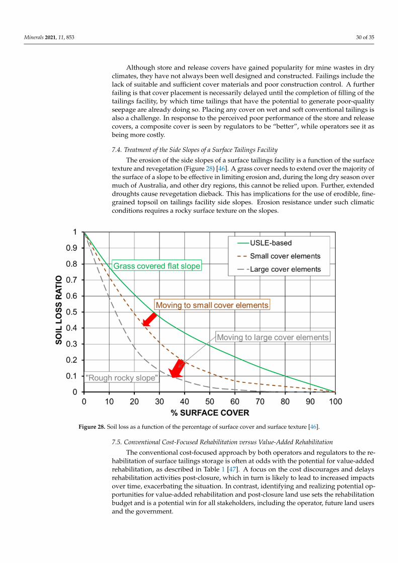
Minerals 2021, 11, 853 30 of 35
Although store and release covers have gained popularity for mine wastes in dryclimates, they have not always been well designed and constructed. Failings include thelack of suitable and sufficient cover materials and poor construction control. A furtherfailing is that cover placement is necessarily delayed until the completion of filling of thetailings facility, by which time tailings that have the potential to generate poor-qualityseepage are already doing so. Placing any cover on wet and soft conventional tailings isalso a challenge. In response to the perceived poor performance of the store and releasecovers, a composite cover is seen by regulators to be “better”, while operators see it asbeing more costly.
7.4. Treatment of the Side Slopes of a Surface Tailings Facility
The erosion of the side slopes of a surface tailings facility is a function of the surfacetexture and revegetation (Figure 28) [46]. A grass cover needs to extend over the majority ofthe surface of a slope to be effective in limiting erosion and, during the long dry season overmuch of Australia, and other dry regions, this cannot be relied upon. Further, extendeddroughts cause revegetation dieback. This has implications for the use of erodible, fine-grained topsoil on tailings facility side slopes. Erosion resistance under such climaticconditions requires a rocky surface texture on the slopes.
Minerals 2021, 11, x FOR PEER REVIEW 30 of 34
Figure 28. Soil loss as a function of the percentage of surface cover and surface texture [46].
Table 1. Conventional cost-based rehabilitation versus value-added rehabilitation.
Conventional Cost-Based Rehabilitation
Production rules
Rehabilitation is seen by the operator and regulator as a “cost”
The operator discounts cost over time, discouraging rehabilitation
Infrastructure such as power lines and buildings are stripped for little financial gain
Rehabilitation is limited to “smoothing” and “greening” (where sustainable)
Post-closure land use and function are limited
The operator is threatened with loss of financial and social licenses to operate
Value-Added Rehabilitation
Post-closure “value” is identified up-front
Examples of post-closure value include:
Reprocessing of tailings to extract metals of value, depositing the residual tailings
in-pit and reducing the rehabilitation liability;
Industrial land use;
Renewable energy–solar, wind and pumped storage, delivered to the grid via
mine transmission lines;
Agriculture and/or fishery impoundment;
Tourism and heritage (the older the better).
Value sets the rehabilitation budget
Potential wins for the operator, future land user and the government
8. Discussion and Conclusions
The commonly held perception that transporting tailings as a slurry to a surface dam
is the most economical solution has driven conventional slurry tailings disposal and needs
to be challenged. The way in which tailings management is costed needs to move beyond
relying largely on an NPV approach, with a high discount factor, to a more whole-of-life
cost approach. Tailings management must also consider the nature of the tailings and how
Figure 28. Soil loss as a function of the percentage of surface cover and surface texture [46].
7.5. Conventional Cost-Focused Rehabilitation versus Value-Added Rehabilitation
The conventional cost-focused approach by both operators and regulators to the re-habilitation of surface tailings storage is often at odds with the potential for value-addedrehabilitation, as described in Table 1 [47]. A focus on the cost discourages and delaysrehabilitation activities post-closure, which in turn is likely to lead to increased impactsover time, exacerbating the situation. In contrast, identifying and realizing potential op-portunities for value-added rehabilitation and post-closure land use sets the rehabilitationbudget and is a potential win for all stakeholders, including the operator, future land usersand the government.
Minerals 2021, 11, 853 31 of 35
Table 1. Conventional cost-based rehabilitation versus value-added rehabilitation.
Conventional Cost-Based Rehabilitation
Production rulesRehabilitation is seen by the operator and regulator as a “cost”
The operator discounts cost over time, discouraging rehabilitationInfrastructure such as power lines and buildings are stripped for little financial gain
Rehabilitation is limited to “smoothing” and “greening” (where sustainable)Post-closure land use and function are limited
The operator is threatened with loss of financial and social licenses to operate
Value-Added Rehabilitation
Post-closure “value” is identified up-frontExamples of post-closure value include:
• Reprocessing of tailings to extract metals of value, depositing the residual tailings in-pit andreducing the rehabilitation liability;
• Industrial land use;• Renewable energy–solar, wind and pumped storage, delivered to the grid via mine
transmission lines;• Agriculture and/or fishery impoundment;• Tourism and heritage (the older the better).
Value sets the rehabilitation budgetPotential wins for the operator, future land user and the government
8. Discussion and Conclusions
The commonly held perception that transporting tailings as a slurry to a surfacedam is the most economical solution has driven conventional slurry tailings disposaland needs to be challenged. The way in which tailings management is costed needs tomove beyond relying largely on an NPV approach, with a high discount factor, to a morewhole-of-life cost approach. Tailings management must also consider the nature of thetailings and how they may change through the life of the mine and, most importantly, theclimatic, topographic and seismic settings of the mine. The site settings are not under thecontrol of the operator, although they can and must be accommodated during operations.Post-closure, the site settings will dominate the long-term performance of a tailings facility.
The ongoing rate of tailings facility failures is unacceptable to both industry andsociety, and there is a need to restore lost confidence and trust in the industry’s abilityto safely manage tailings, the ability of their consultants and contractors to design andconstruct safe facilities, and the capability of regulators to oversee this.
Past tailings dam failures have highlighted that tailings dams that fail have marginalstability, and the technical causes of failures are reasonably well known. They include theinappropriate use in the past of upstream construction in highly seismic regions such asChile, and in wet climates such as Brazil. The industry in Chile responded to this, followingthe fatal 1965 El Cobre tailings dam failure, and turned around tailings practice there to beamong the safest worldwide. Since the 2019 Brumadinho tailings dam failure in Brazil’s wetclimate, the upstream construction of tailings dams is no longer allowed there, and a globaltailings standard (GISTM) has been developed. In more suitable climatic, topographic andseismic settings, where required controls are in place, upstream construction continues tobe successfully employed. Weak foundation layers have been identified as a potential riskto tailings dam stability, particularly since they are raised progressively.
Risk assessment and the ALARP approach are now routinely applied to tailingsmanagement, and past tailings dam failures have raised the ALARP bar to an extremelyhigh level, comparable to that applied to nuclear power stations. This is well above thatachieved by water dams and is much higher than that achieved by conventional slurrytailings facilities in the past.
The GISTM has the aspirational goal of zero harm to people and the environmentfrom tailings facilities, and elevates accountability to the highest organizational levels,
Minerals 2021, 11, 853 32 of 35
with new requirements for independent oversight. It expects global transparency anddisclosure to improve stakeholder understanding. It sets as the design basis an extremeconsequence classification or the current classification, with an upgrade to “Extreme”maintained throughout the tailings facility’s life-cycle, including at closure. Many activetailings facilities are not classified as having an “Extreme” consequence and may need tobe re-classified and/or upgraded to meet “Extreme”. A plethora of guides accompanyand complement the GISTM. Compliance with the GISTM is required of ICMM members,and is being taken up across the industry. This is challenging in the face of a shortage ofqualified and experienced tailings practitioners at all levels.
There is much scope for the further development and implementation of alternativetailings management technologies and innovations, which will change the overall mineplan, moving away from a siloed approach to mining, processing and waste management.The natural resistance to doing things differently from the way they are usually done, yetexpecting a different outcome, needs to be challenged.
Tailings facilities can be built to a similar margin of safety to that of water dams, at aprobability of failure of about 10−4. This would prevent many tailings facility failures, withthe associated loss of life, damage to infrastructure, and environmental harm. It wouldalso restore the industry’s financial and social licenses to operate, earning and restoringgreater control of their operations. The implementation of existing and new approachesto technologies in tailings management could help to eliminate the risks posed by someconventional tailings facilities, possibly removing the risks altogether. Such approachesand technologies include:
• Addressing both the geotechnical and geochemical stability of tailings, which can bein conflict;
• Optimizing in-plant dewatering of tailings, particularly by thickening or filtration,and also considering paste tailings, particularly for gravity disposal in undergroundmines or in completed pits;
• Optimizing in-facility dewatering of tailings, possibly including on-off cells, andfarming of deposited tailings that settle and consolidate poorly;
• Optimizing coagulation, flocculation and, where necessary, secondary flocculation,particularly for very fine-grained and clay mineral-rich tailings;
• Dry stacking of filtered tailings;• Co-disposal of tailings and coarse-grained wastes, including mixing filtered tailings
and waste rock;• In-pit tailings disposal, particularly if final pit lakes containing water of diminishing
quality can be avoided by complete back-filling;• Integrated waste landforms that recombine tailings and coarse-grained wastes;• Tailings reprocessing and reduced tailings production through coarse or dry process-
ing;• Possible briquetting of tailings, although this is unlikely to be economic; and• Value-added tailings rehabilitation post-closure.
As discussed in the paper, there are several barriers to the implementation of innova-tive tailings management where they are indicated by site-specific conditions, particularlywhere existing facilities are concerned. Change will be more readily achieved in newmining projects and, hence, change in tailings management for the minerals industry as awhole will necessarily be generational. Case studies of the successful implementation ofalternative tailings management and closure approaches should be published to informthe industry, their consultants and contractors, regulators, and other stakeholders. By thismeans, confidence and trust in the industry’s management and closure of tailings facilitiescan be restored.
Funding: This review received no external funding.
Conflicts of Interest: The author declares no conflict of interest.
Minerals 2021, 11, 853 33 of 35
Nomenclature of Abbreviations and Terms
ALARP As low as reasonably practicableANCOLD Australian National Committee on Large DamsBoard Board of DirectorsCCBE Cover with capillary barrier effectsCDA Canadian Dam AssociationCEO Chief Executive OfficerEOR Engineer of RecordF Frequency of occurrence or annual probability of up to N fatalitiesGCL Geosynthetic clay linerGISTM Global Industry Standard on Tailings ManagementICMM International Council of Mining and MetalsICOD International Committee on Large DamsITRB Independent Tailings Review BoardJCOLD Japanese Commission on Large DamsKPI Key Performance IndicatorsN Magnitude of occurrence or number of fatalitiesNPV Net present valuePre-consolidation pressure Highest historical stressPRI Principles for Responsible InvestmentRTFE Responsible Tailings Facility EngineerSANCOLD South African National Committee on Large DamsTPR Third-Party ReviewerUNEP United Nations Environment Programme
References1. Troncoso, J.H.; Avendaño, A.; Vergara, A. The Seismic Failure of Barahona Tailings Dam. In Proceedings of the Third International
Conference on Case Histories in Geotechnical Engineering, St. Louis, MO, USA, 1–4 June 1993; Paper No. 2.56. pp. 1473–1479.2. Dobry, R.; Alvarez, L. Seismic failures of Chilean tailings dams. ASCE J. Soil Mech. Found. Div. 1967, 93, 237–260. [CrossRef]3. Valenzuela, L. The 2015 Casagrande Lecture: Tailings Dams and Hydraulic Fills. In Proceedings of the Panamerican Conference,
Buenos Aires, Argentina, 17–22 September 2015; p. 45.4. Fourie, A.B.; Blight, G.E.; Papageorgiou, G. Static liquefaction as a possible explanation for the Merriespruit tailings dam failure.
Can. Geotech. J. 2001, 38, 707–719. [CrossRef]5. Merriespruit Tailings Dam Failure, Virginia, South Africa. Available online: https://www.tailings.info/casestudies/merriespruit.
htm (accessed on 30 June 2021).6. Remembering Aznacóllar: 20 Years after the Mining Disaster. Available online: https://www.birdlife.org/europe-and-central-
asia/news/remembering-aznac%C3%B3llar-20-years-after-mining-disaster (accessed on 30 June 2021).7. Six Years after Mount Polley Disaster, Expert Recommendations not Fully Implemented: Report. Available online: https:
//thenarwhal.ca/mount-polley-mine-expert-recommendations-not-implemented-report/ (accessed on 30 June 2021).8. Cadia Gold Mine: Planet Labs Imagery of the Sequence of Events of the Tailings Dam Failure in March 2018. Available online:
https://blogs.agu.org/landslideblog/2018/07/05/cadia-gold-mine/ (accessed on 30 June 2021).9. Another Two Brazil Dams ‘at Risk of Collapsing’. Available online: https://www.bbc.com/news/world-latin-america-34851895
(accessed on 30 June 2021).10. The Speed of the Brumadinho Tailings Dam Landslide. Available online: https://blogs.agu.org/landslideblog/2019/02/04
/brumadinho-tailings-dam-landslide/ (accessed on 30 June 2021).11. Fundão Tailings Dam Review Panel Report on the Immediate Causes of the Failure of the Fundão Dam. Available online:
http://fundaoinvestigation.com/wp-content/uploads/general/PR/en/FinalReport.pdf (accessed on 30 June 2021).12. Report of the Expert Panel on the Technical Causes of the Failure of Feijão Dam I. Available online: https://bdrb1
investigationstacc.z15.web.core.windows.net/assets/Feijao-Dam-I-Expert-Panel-Report-ENG.pdf (accessed on 30 June 2021).13. Idriss, I. (University of California, Davis, CA, USA). Personal communication, 2020.14. Guidance on ALARP Decisions in COMAH. SPC/Permissioning/37. Available online: https://www.hse.gov.uk/foi/internalops/
hid_circs/permissioning/spc_perm_37/ (accessed on 30 June 2021).15. ALARP: A Lazy and Risky Policy? Mark Horton, Director at MRO Analytics. Available online: https://www.linkedin.com/
pulse/alarp-lazy-risky-policy-mark-horton/ (accessed on 30 June 2021).16. Amoushahi, S.; Grenon, M.; Locat, J.; Turmel, D. Deterministic and probabilistic stability analysis of a mining rock slope in the
vicinity of a major public road—case study of the LAB Chrysotile mine in Canada. Can. Geotech. J. 2018, 55, 1391–1404. [CrossRef]17. CDA. Dam Safety Guidelines 2007 (Revised 2013); Canadian Dam Association: Ottawa, ON, Canada, 2013.
Minerals 2021, 11, 853 34 of 35
18. ICMM Tailings Management Good Practice Guide. Available online: https://www.icmm.com/website/publications/pdfs/environmental-stewardship/2021/guidance_tailings-management.pdf (accessed on 30 June 2021).
19. The Investor Mining and Tailings Safety Initiative. Available online: https://www.churchofengland.org/about/leadership-and-governance/church-england-pensions-board/pensions-board-investments/investor-1 (accessed on 30 June 2021).
20. Global Industry Standard on Tailings Management. 2020. Available online: https://globaltailingsreview.org/wp-content/uploads/2020/08/global-industry-standard_EN.pdf (accessed on 30 June 2021).
21. ANCOLD. Guidelines on Tailings Dams—Planning, Design, Construction, Operation and Closure; Revision 1; Australian NationalCommittee on Large Dams: Hobart, Australia, 2019.
22. ICMM Tailings Management Conformance Protocols. Available online: https://www.icmm.com/website/publications/pdfs/environmental-stewardship/2021/tailings_conformance_protocols.pdf (accessed on 30 June 2021).
23. Mine Tailings: A Review of Guidelines, Initiatives and Standards. Available online: https://gmggroup.org/tailings/ (accessedon 30 June 2021).
24. ICMM Tailings Governance Framework Position Statement. Available online: https://www.icmm.com/website/publications/pdfs/mining-principles/position-statements_tailings-governance.pdf (accessed on 30 June 2021).
25. Robertson, A.M. Tailings Governance Workshop. In Proceedings of the Mine Waste and Tailings 2018 Conference, Brisbane, QLD,Australia, 22 July 2018.
26. Williams, D.J. Chapter VI: The Role of Technology and Innovation in Improving Tailings Management. In towards Zero Harm—A Compendium of Papers Prepared for the Global Tailings Review. Available online: https://globaltailingsreview.org/wp-content/uploads/2020/09/Ch-VI-The-Role-of-Technology-and-Innovation-in-Improving-Tailings-Management.pdf (accessedon 30 June 2021).
27. Agnew, M.K. The Formation of Hardpans within Tailings as Possible Inhibitors of Acid Mine Drainage, Contaminant Release andDusting. Ph.D. Thesis, The University of Adelaide, Adelaide, Australia, 1998.
28. Davies, M.P.; Rice, S. An Alternative to Conventional Tailing Management—“Dry Stack” Filtered Tailings. In Proceedings of theTailings and Mine Waste 2004, Vail, CO, USA, 10–13 October 2004; pp. 411–422.
29. La Coipa, Atacama Region, Northern Chile. Available online: https://tailings.info/casestudies/lacoipa.htm (accessed on30 June 2021).
30. Condon, P.D.; Lear, K.G. Geochemical and Geotechnical Characteristics of Filter-Pressed Tailings at the Greens Creek Mine,Admiralty Island, Alaska. In Proceedings of the 7th International Conference on Acid Rock Drainage, St. Louis, MO, USA,26–30 March 2006; pp. 350–363.
31. Sahi, A.; El Mahboub, K.; Belem, T.; Maqsoud, A.; Mbonimpa, M. Dewatering of Mine Tailings Slurries Using SuperabsorbentPolymers (SAPs) Reclaimed from Industrial Reject of Baby Diapers: A Preliminary Study. Minerals 2019, 9, 785. [CrossRef]
32. Stockman, C.; Soto, J.; Gonzalez, D. Peruvian Gold-Cyanide Tailings Filtration—A Detailed Cost Comparison. In Proceedings ofthe 17th International Seminar on Paste and Thickened Tailings, Vancouver, BC, Canada, 8–12 June 2014; p. 4.
33. Morris, P.H.; Williams, D.J. Co-disposal of washery wastes at Jeebropilly Colliery, Queensland, Australia. Trans. Inst. Min. Metall.Sect. A Min. Ind. 1997, 106, A25–A29.
34. Williams, D.J.; Currey, N.A. Innovative Mine Site Rehabilitation in a Semi-Arid Climate. In Proceedings of the Tailings and MineWaste 2004, Vail, CO, USA, 10–13 October 2004; pp. 383–391.
35. Krishna, R.S.; Shaikh, F.; Mishra, I.; Lazorenko, G.; Kasprzhitskii, A. Mine tailings-based geopolymers: Properties, applicationsand industrial prospects. Ceram. Int. 2021, 47, 17826–17843. [CrossRef]
36. Lazorenko, G.; Kasprzhitskii, A.; Shaikh, F.; Krishna, R.S.; Mishra, J. Utilization potential of mine tailings in geopolymers:Physicochemical and environmental aspects. Process. Saf. Environ. Prot. 2021, 147, 559–577. [CrossRef]
37. Wilson, G.W.; Wickland, B.; Miskolczi, J. Design and Performance of Paste Rock Systems for Improved Mine Waste Management.In Proceedings of the Fifth International Seminar on the Management of Rock Dumps, Stockpiles and Heap Leach Pads, Perth,WA, Australia, 5–6 March 2008; pp. 107–116.
38. Burden, R.; Wilson, G.W.; Williams, D.J.; Jacobs, M. The Shear Strength of Filtered Tailings and Waste Rock Blends. In Proceedingsof the Tailings and Mine Waste 2018, Keystone, CO, USA, 29 September–1 October 2018; pp. 347–355.
39. Williams, D.J. Some mining applications of unsaturated soil mechanics. Geotech. Eng. 2012, 43, 83–98.40. International Network for Acid Prevention. Global Acid Rock Drainage Guide. Available online: http://www.gardguide.com/
index.php?title=Main_Page (accessed on 30 June 2021).41. Bussière, B.; Maqsoud, A.; Aubertin, M.; Martschuk, J.; McMullen, J.; Julien, M. Performance of the oxygen limiting cover at the
LTA site, Malartic, Québec. CIM Bull. 2006, 1, 1–11.42. Smirnova, E.; Bussière, B.; Tremblay, F.; Bergeron, Y. Vegetation succession and impacts of bio-intrusion on covers used to limit
acid mine drainage. J. Environ. Qual. 2011, 40, 133–143. [CrossRef] [PubMed]43. Bussière, B.; Potvin, R.; Dagenais, A.-M.; Aubertin, M.; Maqsoud, A.; Cyr, J. Restauration du site minier Lorraine, Latulipe,
Québec: Résultats de 10 ans de suivi. Déchets Sci. Tech. 2009, 54, 49–64. [CrossRef]44. Williams, D.J.; Wilson, G.W.; Currey, N.A. A Cover System for a Potentially Acid Forming Waste Rock Dump in a Dry Climate. In
Proceedings of the Tailings and Mine Waste 1997, Fort Collins, CO, USA, 13–17 January 1997; pp. 231–235.45. Williams, D.J. Mine Closure as a Driver for Waste Rock Dump Construction. In Proceedings of the Mine Closure Seminar, Perth,
WA, Australia, 13–15 September 2006; pp. 697–706.

Minerals 2021, 11, 853 35 of 35
46. So, H.B.; Sheridan, G.J.; Loch, R.J.; Carroll, C.; Willgoose, G.; Short, M.; Grabski, A. Post-Mining Landscape Parameters forErosion and Water Quality Control. Final Report on ACARP Projects C1629 and C4011. Australian Coal Association ResearchProject. 1998. Available online: https://www.acarp.com.au/ (accessed on 5 August 2021).
47. Williams, D.J. Obstacles to Effective Mine Closure, Rehabilitation and Relinquishment. In Proceedings of the Tailings and MineWaste 2019, Vancouver, BC, Canada, 17–20 November 2019; p. 16.