laser treatment of cemented carbide cutting tool
TRANSCRIPT
A
tbohtan©
K
1
ototlfpcmtcosc
posT
0d
Journal of Materials Processing Technology 183 (2007) 234–240
Laser treatment of cemented carbide cutting tool
C. Karatas a, B.S. Yilbas b,∗, A. Aleem b, M. Ahsan b
a Engineering Faculty, Hacettepe University, Ankara, Turkeyb Mechanical Engineering Department, KFUPM, Box 1913, Dhahran 31261, Saudi Arabia
Received 8 June 2006; received in revised form 27 August 2006; accepted 16 October 2006
bstract
Cemented carbide tools are widely used in machining industry due to their superior properties. Laser processing of the tool surface provideshermal integration of binding agent with carbide compounds in the surface region. This in turn improves the microstructure in the region irradiatedy the laser beam. In the present study, laser heating of cemented carbide tool surface is carried out. Temperature field in the irradiated region isbtained and temperature gradients as well as cooling rates in the surface region are predicted. Microstructural analysis prior and after the lasereated surface carried out. Fracture toughness of the laser treated surface is measured using indentation tests. It is found that Co and TaC melt in
he early heating period due to their relatively lower thermal conductivity than WC. High cooling rates and temperature gradients below the surfacere responsible for high thermal stresses developed in this region. Multi directional cracks are observed at the surface and formation of tungstenitride (WN) occurs in the surface region as illustrated by XRD measurements. 2006 Elsevier B.V. All rights reserved.ccwtwsAtswfbibbprLo
eywords: Cemented; Carbide; Tool; Laser; Treatment
. Introduction
Cemented carbide cutting tools find application in machiningf hard materials such as metal matrix composites and hypereu-ectic alloys. The life and performance of cutting tools dependn the wear and thermal responses during machining and frac-ure toughness of the tool. During the cutting process, appliedoad results in frictional heat generation, adhesion, abrasion, dif-usion and oxidation of the cutting edge. This situation is moreronounced when high speed cutting of hard materials is con-erned. Thermal integration of cemented carbide tool materialay improve the surface properties and fracture toughness of
he cutting tool. Thermal integration can be achieved throughontrolled melting and solidification of the tool material. Onef the techniques for thermal integration is laser melting; con-equently, investigation into laser melting of cemented carbideutting tool surface becomes essential.
Considerable research studies were carried out to examineerformance of cemented cutting tools. The cutting performance
f TiN-coated tungsten carbide tool with a cobalt interlayer wastudied by Kwon et al. [1]. They indicated that the tool life ofiN-coated tool with Co interlayer was improved over 36% as∗ Corresponding author.
awtwfi
924-0136/$ – see front matter © 2006 Elsevier B.V. All rights reserved.oi:10.1016/j.jmatprotec.2006.10.012
ompared to only TiN-coated tools. The performance of TiN-oated carbide inserts due to machining of AISI H13 tool steelas investigated by Ghani et al. [2]. They indicated that the
ool life was not affected significantly by the cutting speed thatas contrary to the early findings. Wear and tool life of tung-
ten carbide, PCBN and PCD cutting tools were examined byrsecularatne [3]. They showed that the most likely dominant
ool wear mechanism for tungsten carbide was diffusion. Theurface ablation of cobalt cemented tungsten carbide hard metalas carried out using a excimer laser. They suggested that the
ormation of non-stoichiometric tungsten carbide was resultedecause of the escaping of carbon element due to excessive heat-ng of surface by a pulsed laser irradiation. Laser clad nickelased and tungsten carbide composite coating were examinedy Wu et al. [4]. They showed from the wear tests that the com-osite coating with tungsten carbide hard phases improved wearesistance when compared with the nickel based alloy coating.aser produced functionally graded tungsten carbide coatingsn high speed steel were investigated by Riobkira-Fishman etl. [5]. They showed that the coating of 58 wt.% of tungsten hadear resistance significantly higher than the alloyed laser melted
ool steel. Laser modified surface layers of hot worked tool steelas examined by Dobrzanki et al. [6]. They indicated that thene grained martensitic structure was responsible for hardness
C. Karatas et al. / Journal of Materials Proce
Nomenclature
Cp specific heat capacity (J/kg K)k thermal conductivity (W/mK)t time (s)t* dimensionless time (αδ2t)T temperature (◦C)x distance (m)x* dimensionless distance (xδ)
Greek symbolsα thermal diffusivity (m2/s)δ absorption coefficient (m−1)
inTafiSnifi
baittmft
2
lmgad
T
wtatt
U
a
U
e
e
a
e
E
aa
3
asabsccnms
Sna
ρ density (kg/m3)
ncrease of the alloyed layer. Laser deposition of thin molybde-um and tungsten nitride films was studied by Berezndi et al. [7].hey indicated that increased nitrogen content in the films lead tomonotonous increase of electrical resistance. Tungsten nitridelm growth due to pulsed laser deposition was investigated byoto et al. [8]. They observed that the reaction of tungsten anditrogen was effective; in which case, nitrogen was integratedn the tungsten matrix changing gradually chemical states andlm properties.
In the present study, laser melting of cemented tungsten car-ide cutting tool is carried out under nitrogen assisting gasmbient. Nitrogen is introduced coaxially with a laser beammpinging onto the workpiece surface. Temperature rise dueo heating situation is simulated and temperature gradient inhe irradiated region is predicted. Metallurgical changes and
icrohardness in the laser irradiated region are examined. Theracture toughness of the irradiated surface is measured usinghe indentation test.
. Heating analysis
The Fourier heating law is considered when modeling theaser heating of the substrate surface. The details of the heating
odel and solution for the resulting heat transfer equation areiven in the previous study [9]; therefore, the resulting temper-ture equation is given below. The dimensionless temperatureistribution is [9]:
∗ = T ∗0 +
{e−x∗
(et∗ − U[t∗]) − et∗
2
[e−x∗
erfc
(−√
t∗ + x∗
2√
t∗
)− e−x∗
erfc
(√t∗ + x∗
2√
t∗
)][ √ ( )]}
+ 2 t∗√π
e−x∗2/4t∗ − x∗ erfcx∗
2√
t∗
−{
e−x∗(et∗−�t∗ − U[t∗ − �t∗]) − et∗−�t∗
2
t
4
t
ssing Technology 183 (2007) 234–240 235
×[
e−x∗erfc
(−√
t∗ − �t∗ + x∗
2√
t∗ − �t∗
)
− e−x∗erfc
(√t∗ − �t∗ + x∗
2√
t∗ − �t∗
)]
+[
2√
t∗ − �t∗√π
e−x∗2/4(t∗−�t∗)
− x∗ erfc
(x∗
2√
t∗ − �t∗
)]}(1)
here x* = xδ, t* = αδ2t, �t* = �tαδ2, T* = (T(kδ)/I0)I0, α, δ, k,, and �t are the laser peak power intensity, thermal diffusivity,bsorption depth, thermal conductivity, time and time shift dueo the second laser pulse, respectively. U[t*] and U[t* − �t*] arehe step input functions, which are:
[t∗] ={
1, t∗ > 0
0, t∗ < 0
}
nd
[t∗ − �t∗] ={
1, t∗ > �t∗
0, t∗ < �t∗
}
rfc is the complementary error function, which is:
rfc(z) = 1 − erf(z)
nd
rf z = 2
ρ
∫0e−t2 dt
q. (1) is the closed form solution for temperature distribution.The material properties and simulation conditions for Eq. (1)
re given in Table 1 [10]. The absorption coefficient (δ) is takens 6.17 × 10⁶ m−1 for all the materials simulated.
. Experimental
The CO2 laser (LC-ALPHAIII) delivering nominal output power of 2 kWt pulse mode with different frequencies is used to irradiate the workpieceurface. The nominal focal length of the focusing lens is 127 mm. Nitrogenssisting gas emerging from the conical nozzle and co-axially with the laseream is used. Laser treatment conditions are given in Table 2. Cemented tung-ten carbide cutting tool is considered as the workpiece and the elementalomposition of the cemented cutting tool material is given in Table 3. Theemented carbide tool consists of aggregates of particles of tungsten, tita-ium and tantalum carbides, with the sizes of 0.5–2 �m, bonded with cobaltetal via liquid-phase sintering. Fig. 1 shows the SEM micrograph of the tool
urface.Material characterization of the laser treated surfaces is carried out using
EM, XPS, XRD. JEOL 6460 electron microscopy is used for SEM exami-ations and Bruker D8 Advanced having Mo K� radiation is used for XRDnalysis. A typical setting of XRD was 40 kV and 30 mA.
Microhardness and indention tests are carried out to determine the fractureoughness of the surface.
. Determination of fracture toughness
The elastic response of the surface when subjected to inden-ion test needs to be examined through which the Young’s
236 C. Karatas et al. / Journal of Materials Processing Technology 183 (2007) 234–240
Table 1Thermal properties used in the simulations
TaC Co TiC WC
k (W/mK) 57.5 69 30.93 84.02Cp (J/kg K) 140 420 710.6 210ρ (kg/m3) 14500 8900 4920 15800α (m2/s) 2.83E-05 1.851E-05 8.858E-6 2.53E-05Tm (◦C) 3800 1495 3100 2800
Table 2Laser assisted surface treatment conditions
Transverse speed (mm/min) Power (W) Frequency (Hz) Nozzle gap (mm) Nozzle diameter (mm) Focus setting (mm) N2 pressure (kPa)
500 70 and 110 100 and 200 1.5 1.5 127 600
Table 3Elemental composition of cemented cutting tool used in the experiment (wt.%)
W
B
mY
E
wtc
E
woυ
iig
C Co TaC TiC
alance 2.35 3.64 22.88
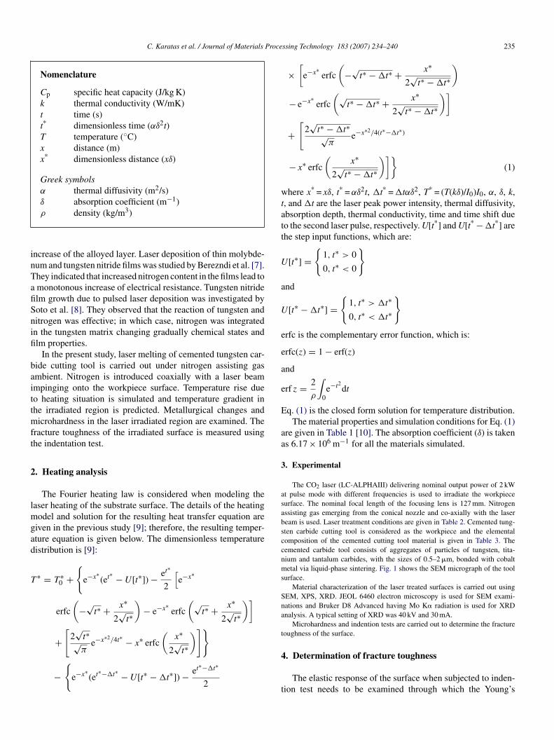
odulus can be determined. After considering Fig. 2, theoung’s modulus can be formulated as [11]:
∗ =(
9
16
)0.5
Ph−1.5R−0.5 (2)
here P is the applied load, h the elastic penetration of the inden-er and R is the indenter radius. The true modulus of elasticityan be determined using the indenter properties [11], i.e.:
= 1 − υ2
1/E∗ − (1 − υ2i )/Ei
(3)
here Ei and υi are the Young’s modulus and Poisson’s ratiof indenter, respectively. In the calculations Ei = 1141 GPa andi = 0.07 (diamond indenter) and υi = 0.24 [10] are taken.
The fraction toughness of the surface is measured using thendenter test data for microhardness (Vickers) and crack inhibit-ng. In this case, microhardness in HV and the crack lengthenerated due to indentation at the surface are measured. The
Fig. 1. SEM micrograph of cemented carbide tool surface.
Fn
fb
K
wag
TD
E
3
ig. 2. Geometric configuration of indentation tests in relation to fracture tough-ess measurement.
racture toughness (K) is calculated using the equation givenelow [11]:
= 0.016
(E
H
)0.5
PC−1.5 (4)
here H is the hardness (Vickers), P the applied load on indenternd C is the crack length. The data used for the calculations areiven in Table 4.
able 4ata obtained after indenting tests to be used in Eqs. (2) and (4)
(GPa) H (HV) P (N) C (�m) R (�m) h (�m)
57 1520 20 490 25 4.3

C. Karatas et al. / Journal of Materials Processing Technology 183 (2007) 234–240 237
Fp
5
tr
WftpathlftiohWvist
Fc
Fp
m(dItWr
mscfthifrTlh
ig. 3. Temporal variation of surface temperature of carbide compounds. Tem-erature profiles are shown up to the melting point of each compound.
. Results and discussions
Laser gas assisted processing of cemented tungsten carbideool surface is carried out. Temperature distribution and coolingates are predicted. Table 1 gives the simulation parameters.
Fig. 3 shows temporal variation of surface temperature forC, Co and TaC. TaC results the highest temperature, then
ollows TiC, Co and WC. This is because of low thermal conduc-ivity of TaC (Table 1). In this case, low thermal conductivityrevents heat diffusion from surface to solid bulk resulting inttainment of high temperature at the surface. It should be notedhat laser heating source in Eq. (1) is considered as a volumetriceat source, which decays exponentially with depth (Lambert’saw). Consequently, maximum temperature is attained in the sur-ace region due to high rate of absorption of power intensity inhis region. The rate of heating is the highest in the early heat-ng period as observed from Fig. 4, in which temporal variationf time derivative of temperature (∂T/∂t) is shown. Moreover,eating rate of TaC is the highest, then follows TiC, Co andC. This is because of surface temperature, which attains high
alues for TaC due to its low thermal conductivity and high melt-
ng temperature; therefore, heat diffusion from surface region toolid bulk is small. This increases the heating rate. It is expectedhat Co melts first, and then follows WC, TiC and TaC, sinceig. 4. Temporal variation of time derivative of surface temperature of carbideompounds. dT/dt profiles are shown up to the melting point of each compound.
tmt
Fds
ig. 5. Temperature distribution inside the carbide compounds. Temperaturerofiles are limited to the melting temperature of each compound at the surface.
elting temperature of Co is less than other carbide compoundsTable 1). However, TaC may undergo melting in the early stageespite the fact that its melting temperature is considerably high.n this case, rapid attainment of high surface temperature duringhe heating period enables to melt Co, TaC and TiC earlier than
C. This in turn modifies the WC microstructure in the surfaceegion prior to melting and after solidification.
Fig. 5 shows temperature distribution inside the substrateaterial for TaC, Co, TiC and WC for the heating period corre-
ponding to the time to reach melting temperature of individualarbide components. Temperature decreases sharply in the sur-ace region, this situation can also be seen form Fig. 6, in whichemperature gradient is shown. Temperature gradient attainsigh values for TaC and TiC, then followed by WC and Co. Thiss particularly true at some depth below the surface. It is, there-ore, expected that high temperature gradient causes high strainates in this region. Although, temperature gradient for TaC andiC is high, thermal stresses developed for these compounds is
ess likely due to early liquefaction. It should be noted that theigh magnitude of temperature gradient becomes important for
emperatures less then the melting temperature of the substrateaterial, which is particularly true for WC, since the meltingemperature is considerably high.
ig. 6. Temperature gradient inside the carbide compounds. Temperature gra-ient profiles are limited to the melting temperature of each compound at theurface.
238 C. Karatas et al. / Journal of Materials Processing Technology 183 (2007) 234–240
F
hspaomtstapgisasttattrp
l(tcf
TE
W
B
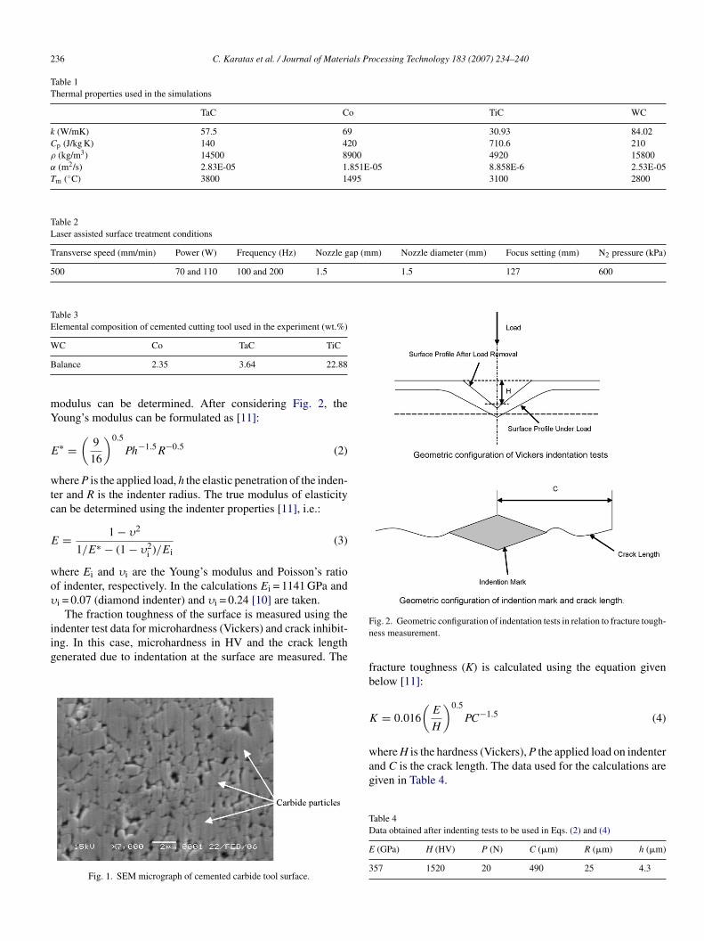
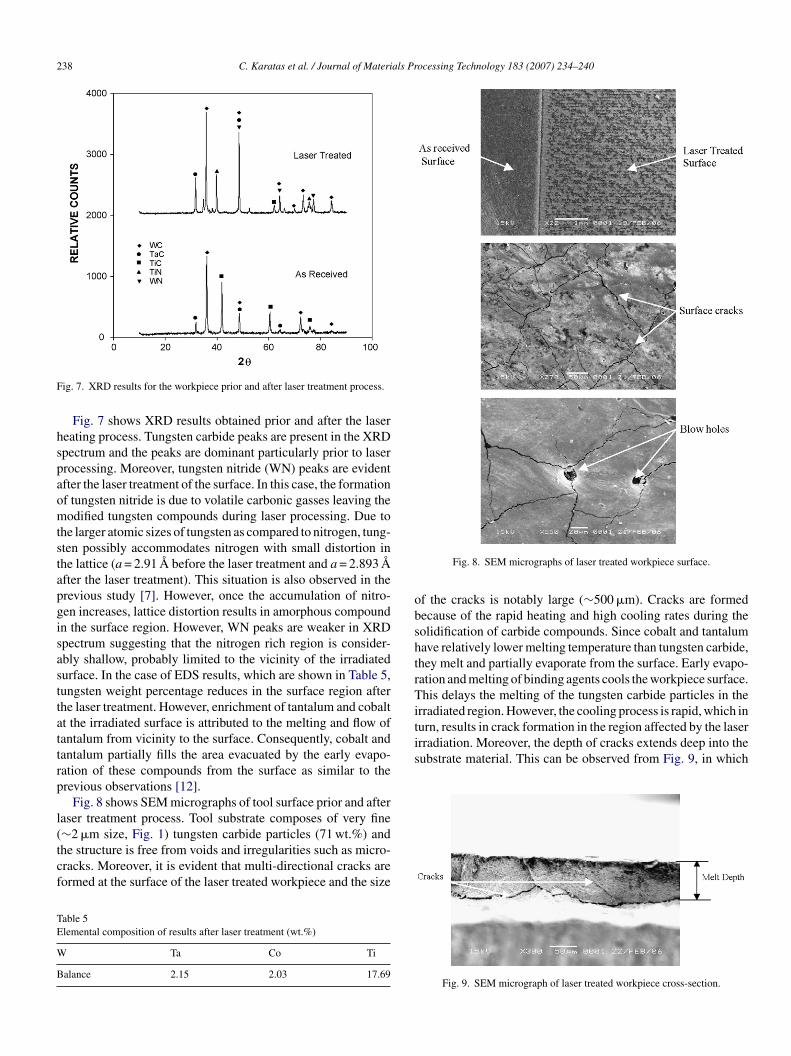
obshtrTiturn, results in crack formation in the region affected by the laserirradiation. Moreover, the depth of cracks extends deep into thesubstrate material. This can be observed from Fig. 9, in which
ig. 7. XRD results for the workpiece prior and after laser treatment process.
Fig. 7 shows XRD results obtained prior and after the lasereating process. Tungsten carbide peaks are present in the XRDpectrum and the peaks are dominant particularly prior to laserrocessing. Moreover, tungsten nitride (WN) peaks are evidentfter the laser treatment of the surface. In this case, the formationf tungsten nitride is due to volatile carbonic gasses leaving theodified tungsten compounds during laser processing. Due to
he larger atomic sizes of tungsten as compared to nitrogen, tung-ten possibly accommodates nitrogen with small distortion inhe lattice (a = 2.91 A before the laser treatment and a = 2.893 After the laser treatment). This situation is also observed in therevious study [7]. However, once the accumulation of nitro-en increases, lattice distortion results in amorphous compoundn the surface region. However, WN peaks are weaker in XRDpectrum suggesting that the nitrogen rich region is consider-bly shallow, probably limited to the vicinity of the irradiatedurface. In the case of EDS results, which are shown in Table 5,ungsten weight percentage reduces in the surface region afterhe laser treatment. However, enrichment of tantalum and cobaltt the irradiated surface is attributed to the melting and flow ofantalum from vicinity to the surface. Consequently, cobalt andantalum partially fills the area evacuated by the early evapo-ation of these compounds from the surface as similar to therevious observations [12].
Fig. 8 shows SEM micrographs of tool surface prior and afteraser treatment process. Tool substrate composes of very fine
∼2 �m size, Fig. 1) tungsten carbide particles (71 wt.%) andhe structure is free from voids and irregularities such as micro-racks. Moreover, it is evident that multi-directional cracks areormed at the surface of the laser treated workpiece and the sizeable 5lemental composition of results after laser treatment (wt.%)
Ta Co Ti
alance 2.15 2.03 17.69
Fig. 8. SEM micrographs of laser treated workpiece surface.
f the cracks is notably large (∼500 �m). Cracks are formedecause of the rapid heating and high cooling rates during theolidification of carbide compounds. Since cobalt and tantalumave relatively lower melting temperature than tungsten carbide,hey melt and partially evaporate from the surface. Early evapo-ation and melting of binding agents cools the workpiece surface.his delays the melting of the tungsten carbide particles in the
rradiated region. However, the cooling process is rapid, which in
Fig. 9. SEM micrograph of laser treated workpiece cross-section.
C. Karatas et al. / Journal of Materials Processing Technology 183 (2007) 234–240 239
Ff
coItwIofwhoairilrwpt
w
Table 6Microhardness measurement at the surface prior and after the laser treatment
As received surface (HV) Laser treated surface (HV)
1
Mifsocs[vta
6
tciltnartfaidcidEggoetf
A
sU
R
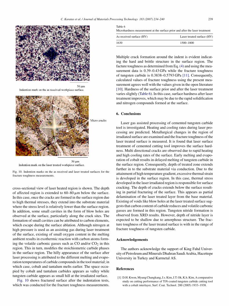
ig. 10. Indention marks on the as received and laser treated surfaces for theracture toughness measurements.
ross-sectional view of laser heated region is shown. The depthf affected region is extended to 60–80 �m below the surface.n this case, once the cracks are formed in the surface region dueo high thermal stresses, they extend into the substrate materialhere the stress level is relatively lower than the surface region.
n addition, some small cavities in the form of blow holes arebserved at the surface, particularly along the crack sites. Theormation of small cavities can be attributed to carbon elements,hich escape during the surface ablation. Although nitrogen atigh pressure is used as an assisting gas during laser treatmentf the surface, existing of small oxygen content in the meltingmbient results in exothermic reaction with carbon atoms form-ng the volatile carbonic gasses such as CO and/or CO2 in thisegion. This in turn, modifies the stoichiometric carbide phasesn the surface region. The hilly appearance of the surface afteraser processing is attributed to the different melting and evapo-ation temperatures of carbide compounds in the tool material; inhich case, cobalt and tantalum melts earlier. The space occu-ied by cobalt and tantalum carbides appears as valley while
ungsten carbide appears as small hill at the irradiated surface.Fig. 10 shows fractured surface after the indentation tests,hich was conducted for the fracture toughness measurements.
630 1500–1800
ultiple crack formation around the indent is evident indicat-ng the hard and brittle structure in the surface region. Theacture toughness as determined from Eq. (4) and using the mea-urement data is 0.39–0.43 GPa while the fracture toughnessf tungsten carbide is 0.3838–0.5793 GPa [11]. Consequently,alculated values of fracture toughness using the present mea-urement agrees well with the values given in the open literature10]. Hardness of the surface prior and after the laser treatmentaries slightly (Table 6). In this case, surface hardness after laserreatment improves, which may be due to the rapid solidificationnd nitrogen compounds formed at the surface.
. Conclusions
Laser gas assisted processing of cemented tungsten carbideool is investigated. Heating and cooling rates during laser pro-essing are predicted. Metallurgical changes in the region ofrradiated surface are examined and the fracture toughness of theaser treated surface is measured. It is found that laser surfacereatment of cemented cutting tool improves the surface hard-ess. Multi directional cracks are observed due to rapid heatingnd high cooling rates of the surface. Early melting and evapo-ation of cobalt results in delayed melting of tungsten carbide inhe surface region. Consequently, depth of treated zone extendsurther in to the substrate material via conduction. Due to thettainment of high temperature gradient, excessive thermal strains developed in the surface region. In this case, thermal stresseveloped in the laser irradiated region is responsible for surfaceracking. The depth of cracks extends below the surface result-ng in partial fracturing of the surface. This appears as partialelamination of the laser treated layer from the base material.xisting of voids like blow holes at the laser treated surface sug-ests that carbon content of carbide reduces and volatile carbonicasses are formed in this region. Tungsten nitride formation isbserved from XRD results. However, depth of nitride layer isxpected to be shallow due to amorphous structure. The frac-ure toughness of the laser treated surface is with in the range ofracture toughness of tungsten carbide.
cknowledgements
The authors acknowledge the support of King Fahd Univer-ity of Petroleum and Minerals Dhahran Saudi Arabia, Hacettepeniversity in Turkey and Karmetal AS.
eferences
[1] D.H. Kwon, Myung Changkang, J.s. Kim, J.T. Ok, K.h. Kim, A comparativestudy on cutting performance of TiN-coated tungsten carbide cutting toolwith a cobalt interlayer, Surf. Coat. Technol. 200 (2005) 1933–1938.
2 als Pr
[
[determination of high velocity oxy-fuel-sprayed bioceramic coatings, Surf.Coat. Technol. 155 (2002) 21–32.
40 C. Karatas et al. / Journal of Materi
[2] J.A. Ghani, I.A. Chodhary, H.H. Masjuki, Performance of P10 TiN coatedcarbide tools when end milling AISI H13 tool steel at high cutting speed,J. Mater. Process. Technol. 153–154 (2004) 1062–1066.
[3] J.A. Arsecularatne, L.C. Zhang, C. Montross, Wear and tool life of tungstencarbide, PCBN and PCD cutting tools, Int. J. Mach. Tool. Manuf. 46 (2000)482–491.
[4] P. Wu, C.Z. Zhou, X.N. tang, Microstructural characterization and wearbehaviour of laser cladded nickel-based and tungsten carbide compositecoatings, Surf. Coat. Technol. 166 (2003) 84–88.
[5] M. Riabkina-Fishman, E. Rabkin, P. Levin, N. Frage, M.P. Dariel, A.Weisheit, R. Galun, B.L. Mordike, Laser produced functionally gradedtungsten carbide coatings on M2 high-speed tool steel, Mater. Sci. Eng. A302 (2001) 106–114.
[6] L.A. Dobrzanski, M. bonek, E. Hajduczek, A. Klimpel, A. Lisiecki, Com-parison of the structures of the hot-work tool steels laser modified surfacelayers, J. Mater. Process. Technol. 164–165 (2005) 1014–1024.
[7] M. Bereznai, Z. Toth, A.P. Caricato, M. Fernandez, A. Luches, G. Majni, P.Mengucci, P.M. Nagy, A. Juhasz, L. Nanai, Reactive pulsed laser deposi-
[
ocessing Technology 183 (2007) 234–240
tion of thin molybdenum and tungsten-nitride films, Thin Solid Films 473(2005) 16–23.
[8] G. Soto, W. de la Cruz, F.F. Castillon, J.A. Diaz, R. Mochorro, M.H. Farias,Tungsten nitride films grown via pulsed laser deposition studied in situ byelectron spectroscopies, Appl. Surf. Sci. 214 (2003) 58–67.
[9] B.S. Yilbas, M. Kalyon, Repetitive laser pulse heating analysis: pulseparameter variation effects on closed form solution, Appl. Surf. Sci. 252(2006) 2242–2250.
10] H.J. Scussel, Friction and Wear of Cemented Carbides, ASM Handbook,vol.18, ASM Int., 1992, pp. 795.
11] H. Li, K.A. Khor, P. Cheang, Young’s modulus and fracture toughness
12] T. Li, Q. Lou, X. Dong, Y. Wei, J. Liu, “Escape of carbon element in surfaceablation of cobalt cemented tungsten carbide with pulsed UV laser, Appl.Surf. Sci. 172 (2001) 51–60.