l l table of contents - ciscomaster.ru
TRANSCRIPT
L
jm
L
mm
Table of Contents POP-1Volume 1
Course Introduction
OverviewLearner Skills and Knowledge
Course Goal and ObjectivesCourse Flow
Additional ReferencesCisco Glossary of Terms
Your Training Curriculum
Multisite Deployment Implementation
Overview
Module Objectives
Identifying Issues in a Multisite DeploymentObjectives
Multisite DeploymentIssues OverviewQuality Issues
Quality Issues Example: Jitterand Packet DropsBandwidth Issues
Example: Bandwidth IssuesBandwidth Issues Example: Voice and DataTraffic Competing for BandwidthBandwidth Issues Example: Load Caused byCentralized Media Services
Availability IssuesAvailability Issues Example: IPWAN Failure
Dial Plan IssuesExample: Variable-Length Numbering, E.164 Addressing, and DIDFixed vs. Variable-Length Numbering PlansDetectionof End of Dialing in Variable-Length Numbering PlansOptimized Call Routing and PSTN BackupExample: TEHOExample: Overlapping and Nonconsecutive NumbersVarious PSTN RequirementsIssues Caused by DifferentPSTN DialingDial Plan Scalability Issues
NAT and Security IssuesExample: NATSecurity Issues
SummaryReferences
identifying Multisite Deployment Solutions „
ObjectivesMultisite Deployment Solution OverviewQoS
QoS AdvantagesSolutions to Bandwidth Limitations
Low-Bandwidth Codecs and RTP-Header CompressionCodec Configuration inCisco Unified Communications ManagerDisabled Annunciator
Local vs. Remote Conference BridgesTranscoders
Guidelines for Transcoder ConfigurationMixed Conference BridgeMulticast MOH from Branch Router FlashMulticast MOH from Branch Router Flash ExampleMulticast MOHfrom Branch Router Flash: Cisco IOS Configuration ExampleAlternatives to Multicast MOH from Branch Router FlashPreventing Too Many Calls by CAC
1
1
3
4
5
5
6
1-1
1-1
1-1
1-3
1-3
1-4
1-6
1-7
1-8
1-8
1-9
1-10
1-11
1-12
1-13
1-16
1-17
1-18
1-20
1-21
1-22
1-23
1-25
1-26
1-28
1-29
1-30
1-30
1-31
1-31
1-32
1-33
1-34
1-35
1-37
1-38
1-39
1-40
1-41
1-42
1-44
1-45
1-47
1-49
1-50
1-51
AvailabilityPSTN BackupMGCP Fallback; Normal OperationMGCP Fallback: Fallback ModeFallback for IP Phones; Normal OperationFallback for IP Phones: Fallback ModeUsing CFUR toReach Remote-Site IP Phones Over the PSTN During WAN FailureUsing CFUR to Reach Usersof Unregistered Software IPPhoneson Their Cell PhonesAutomated Alternate RoutingMobility Solutions
Dial Plan Solutions
Dial Plan Components in Multisite DeploymentsGlobalized Call-Routing OverviewGlobalized Call Routing—Three PhasesGlobalized Call Routing Advantages
NATand Secunty SolutionsCisco Unified Border Element in Flow-Through Mode
SummaryReferences
Implementing Multisite ConnectionsObjectives
Multisite Connection OptionsCisco Unified Communications ManagerConnection Options OverviewCisco IOS Gateway Protocol Functions ReviewCisco IOS Gateway ProtocolComparison ReviewSIP Trunk CharacteristicsH.323 Trunk OverviewH 323 Trunk Comparison
MGCP Gateway Implementation ReviewCisco IOS Gateway MGCP Configuration Methods ReviewConfiguring Cisco IOS Gatewayfor MGCP—Example
H.323 Gateway Implementation ReviewCisco Unified Communications Manager H.323 Gateway ConfigurationCisco IOS H.323 Gateway Configuration
Trunk Implementation OverviewGatekeeper-Controlled ICT and H.225 Trunk Configuration OverviewTrunk Types Used by Special Applications
SIP Trunk ImplementationIntercluster and H.225 Trunk Implementation
Cisco Unified CommunicationsManager Gatekeeper-Controlled ICT and H.225 TrunkConfiguration
SummaryReferences
Implementing a Dial Plan for International Multisite DeploymentsObjectives
Multisite Dial Plan Overview
Dial Plan Requirements for Multisite Deployments with Distributed Call ProcessingDial Plan Scalability Solutions
Implementing Site Codes for On-Net CallsDigit Manipulation Requirements for UsingAccess and Site CodesCentralized Call-Processing Deployments: Access and Site Codes
Implementing PSTN Access in Cisco IOS GatewaysPSTN Access ExampleISDN TON
Example: ISDN TON—Calling NumberTransformation of Incoming CallImplementing Selective PSTN Breakout
Configuring IP Phones to Use Local PSTN GatewayImplementing PSTN Backup for On-Net Intersite Calls
DigitManipulation Requirements for PSTN Backup of On-Net Intersite Calls
1-52
1-53
1-54
1-55
1-56
1-57
1-58
1-59
1-60
1-61
1-62
1-64
1-65
1-68
1-70
1-72
1-73
1-74
1-75
1-77
1-77
1-78
1-79
1-80
1-81
1-82
1-83
1-84
1-86
1-87
1-89
1-91
1-93
1-94
1-95
1-96
1-97
1-98
1-100
1-102
1-105
1-105
1-107
1-107
1-108
1-109
1-110
1-112
1-113
1-114
1-115
1-116
1-117
1-118
1-119
1-120
1-121
1-122
ImplementingCisco Unified Communications Manager. Part 2 (CIPT2)v8.0 )2010 Cisco Systems, Inc.

Implementing TEHO ]_J24Considerations for Using Remote PSTN Gateways - l-i«TEHO Example Without Local Route Groups 1"127
mm TEHO Example with Local Route Groups 1"129Implementing Globalized Call Routing ]-] 31
Globalized Call Routing: Number Formats 1-133Normalization ofLocalized Call Ingress onGateways 1-136
mm Normalization of Localized Call Ingress from Phones 1-137Localized Call Egress atGateways 1-138Localized Call Egress at Phones 1-140
&. Globalized Call-Routing Example: Emergency Dialing 1-142mm Considering Globalized Call-Routing Interdependences 1-146
Globalized Call Routing—TEHO Advantages 1-147Globalized Call Routing—TEHO Example 1-148
* Summary I'ltnmm References I Icl*
Module Summary ,References 1-151
fk. Module Self-Check 1'153'§m Module Self-Check Answer Key 1'158
Centralized Call-Processina Redundancy Implementation 2^m- Overview 2-1Me Module Objectives 2-1
Examining Remote Site Redundancy Options 2^^. Objectives 2"3^^ Remote Site Redundancy Overview 2-4^m Remote Site Redundancy Technologies 2-5
When to Use MGCP Fallback 2-6When to Use Cisco Unified SRST 2-7
f When to Use Cisco Unified Communications Manager Express inSRST Mode 2-9•* Cisco Unified SRST Operation 2-10
Cisco Unified SRST Function: Switchover Signaling 2-11Cisco Unified SRST Function: Call FlowAfter Switchover 2-12
f Cisco Unified SRST Function: Switchback 2-13** Cisco Unified SRST Timing 2-14
MGCP Fallback Operation 2-15MGCP Gateway Fallback: Switchover 2-16
* MGCP Gateway Fallback: Switchback 2-17mm MGCP Gateway Fallback Process 2-18
Cisco Unified SRST Versions and Feature Support 2-19Cisco Unified SRST 8.0 Platform Density 2-20
f' Plus (+) Prefix and E.164Supportin Cisco Unified SRST 2-21*•' Support for Multiple MOH Sources 2-22
Dial Plan Requirements for MGCP Fallbackand Cisco Unified SRST Scenarios 2-23Ensure Connectivity for Remote Sites 2-24
** Ensure Connectivity from Main Site UsingCFUR 2-25*•* CFUR Considerations 2-26
CFUR Interaction with Globalized Call Routing 2-28CFUR ExampleWithoutGlobalized Call Routing 2-30
"* CFUR Examplewith Globalized Call Routing 2-31<•*» Keeping Calling Privileges Active in SRST Mode 2-32
Cisco Unified SRST Dial Plan Requirements Example 2-33Summary 2-34
* References 2-34
© 2010 Cisco Systems, Inc. Implementing Cisco Unified Communications Manager, Part2(CIPT2) v8.0
Implementing SRST and MGCP Fallback 2-35Objectives 2-35
MGCP Fallbackand Cisco Unified SRST Configuration Overview 2-36MGCP Fallback and Cisco Unified SRST Configuration Requirements 2-37
Cisco Unified Communications ManagerSRST Configuration 2-38Step 1: SRST Reference 2-39Step 2: Device Pool 2-40
Cisco IOS Gateway SRST Configuration 2-41Steps 1 and 2: Enabling Cisco Unified SRST and Setting Cisco Unified SRST IPAddress 2^2Steps 3 and 4: Setting Maximum Directory Numbers and Telephones 2-43Steps 5 and 6: Setting Maximum Directory Numbers Per Phone and Keepalive Timer 2^J4Cisco Unified SRST Configuration Example 2-45
Cisco IOS GatewayMGCP GatewayFallback Configuration 2-46Steps 1 and 2: Enabling MGCP Fallback and Setting Fallback Service 2-47MGCP Fallback Configuration Example 2-48
Cisco Unified Communications Manager Dial Plan Configuration for SRSTSupport 2-49Step 1: Define a CSS for CFUR 2-49Step 2: Setting Max Forward Unregistered Hops to DN 2-50Step 3: Configuring CFUR 2-51
Cisco IOS GatewayMGCP Fallback and Cisco Unified SRST Dial Plan Configuration 2-53Additional SRST Dial Plan Requirements 2-54Cisco Unified SRST Dial Plan Commands: Dial Peer 2-56Cisco Unified SRST Dial Plan Commands: Open Numbering Plans 2-60Cisco Unified SRST Dial Plan Commands: Number Modification (Voice Translation Profiles) 2-62Cisco Unified SRST Dial Plan Commands: Number Modification (Voice Translation Rules) 2-63Cisco Unified SRST Dial Plan Commands: Number Modification (Profile Activation) 2-64Cisco Unified SRST Dial Plan Commands: COR 2-65Cisco Unified SRST Dial Plan Example 2-67
Summary 2-70References 2-70
Implementing Cisco Unified Communications Manager Express in SRST Mode 2-71Objectives 2-71
Cisco Unified Communications Manager Express Overview 2-72Cisco Unified Communications Manager Express in SRST Mode 2-73When to Use Cisco Unified Communications Manager Express in SRST Mode 2-74
Cisco Unified Communications Manager Express Features 2-78Important Cisco Unified Communications Manager Express Features 2-79
General Configuration of Cisco Unified CommunicationsManager Express 2-80Cisco Unified Communications Manager Express: Basic Configuration Example 2-82Providing Phone Loads 2-83Cisco Unified Communications Manager Express: MOH 2-84Additional MOH Sources 2-85Additional Music on Hold Sources—Configuration Example 2-86
Configuration of Cisco Unified Communications Manager Express in SRST Mode 2-87Phone Provisioning Options 2-89Advantages of Cisco Unified Communications Manager Express in SRST Mode 2-90Phone Registration Process 2-91Configuring Cisco Unified Communications Manager Express in SRST Mode 2-92Cisco Unified Communications Manager Express in SRST Mode Configuration Example 2-94
Summary 2-95References 2-95
Module Summary 2-97References 2-97
Module Self-Check 2-99
Module Self-Check Answer Key 2-102
Implementing Cisco Unified Communications Manager. Part 2 (CIPT2] v8.0 ©2010 Cisco Systems, Inc
Bandwidth Management and CAC Implementation
OverviewModule Objectives
Managing Bandwidth
ObjectivesBandwidth Management OverviewCisco Unified Communications Manager
Review of Cisco Unified Communications
Example: Codec ConfigurationLocal Conference Bridge implementation
Example: Implementing Local ConferenceTranscoder Implementation
Example: Implementing a Transcoder at theConfiguration Procedure for ImplementingStep 1: Add Transcoder Resource in CiscoStep 2: Configure Transcoder Resource in
Multicast MOH from Branch Router FlashMulticast MOH from Branch Router Flash:Multicast MOH from Branch Router Flash:Multicast MOH: Address and Port Incremer tExample: Implementing Multicast MOH froi iConfiguration Procedure for ImplementingStep 1; Enable Multicast Routing on CiscoStep 2a: Configure MOH Audio SourcesStep 2b: Configure Multicast MOH inStep 2c: Enabling Multicast MOH at theStep 3: Enable Multicast MOH fromStep 4a: Configure the Maximum Hops toStep 4b: Use IP ACL at IP WAN RouterStep 4c: Disable Multicast Routing on IP
SummaryReferences
Implementing CAC
Codec Configurationl\ anager Codecs
ObjectivesCAC Overview
CAC in Cisco Unified Communications ManjagerStandard Locations
Locations: Hub-and-Spoke TopologyLocations: Full-Mesh TopologyConfiguration Procedure for Implementing Ijocations-Based CACLocations Configuration Example: Hub-and Spoke TopologyStep 1: Configure LocationsStep 2: Assign Locations to Devices
RSVP-Enabled Locations
Three Call Legs with RSVP-Enabled LocationsCharacteristics of Phone-to-RSVP Agent Ci II LegsCharacteristics of RSVP Agent-to-RSVP Agent Call LegHow RSVP Works
Configuration Procedure for Implementing RSVP-Enabled Locations-Based CACExample: RSVP-Enabled Locations ConfigurationStep 1: Configure RSVP Service ParametersStep 2: Configure RSVP Agents in Cisco IOS SoftwareStep 3: Add RSVP Agents to Cisco Unified Communications ManagerStep 4: Enable RSVP Between Location Pairs
Automated Alternate RoutingAAR Characteristics
AAR Example Without Local Route Groups and Globalized NumbersAAR Example with Local Route Groups and Globalized Numbers
I ridges at Two Sites
Main Site
ranscodersJnified Communications Managerisco IOS Software
ImplementationI legion Considerations, .ddress and Port Considerations
ExampleBranch Router Flash
lulticast MOH from Branch Router Flash
OS Routers
foi Multicast MOHCisco|Unified Communications Manager
ia Resource GroupsBranch!Router Flash at the Branch Router
Used for MOH RTP Packets
Ints rface
W VN Router Interface
© 2010 Cisco Systems. Inc. Implementing Cisco Unified Communications Manager, Part 2 (CIPT2) v8.0
3-1
3-1
3-1
3-3
3-3
3-4
3-6
3-7
3-8
3-10
3-11
3-13
3-15
3-17
3-18
3-19
3-21
3-23
3-24
3-25
3-27
3-30
3-31
3-32
3-33
3-34
3-35
3-36
3-37
3-38
3-39
3-39
3-41
3-41
3-42
3-43
3-44
3-45
3-46
3^17
3-48
3-49
3-50
3-51
3-52
3-53
3-54
3-55
3-57
3-58
3-59
3-63
3-65
3-66
3-68
3-69
3-70
3-72

AAR Considerations 3.74AAR Configuration Procedure 3-75Step 1: Configure AAR Service Parameters 3-76Step 3: Configure AAR Groups 3.77Step 4: Configure Phones for AAR 3-78
SIP Preconditions 3-80CAC Without SIP Preconditions 3-81CAC with SIP Preconditions 3-82SIP Preconditions Operation 3-83SIP Preconditions Call Flow Summary 3-85Fallback from End-to-End RSVP to Local RSVP 3-87SIP Preconditions Configuration Procedure 3-89Step 2a: Configure SIP Profile 3-90Step 2b: Apply SIP Profile to Trunk 3-91
H.323 Gatekeeper CAC 3-92Example: H.323 Gatekeeper Used for Call Routing (Address Resolution) Only 3-94Using an H.323 Gatekeeper for CAC 3-96Example: H.323 Gatekeeper Also Used for CAC 3-98Providing PSTN Backup for Calls Rejected by CAC 3-100Configuration Procedure for Implementing H.323 Gatekeeper-Controlled Trunks with CAC 3-102
Summary 3-104References 3-104
Module Summary 3-105References 3-105
Module Self-Check 3-107Module Self-Check Answer Key 3-109
Implementing Cisco Unified Communications Manager, Part 2 (CIPT2) v8.0 ©2010 Cisco Systems, Inc.
CIPT2
Course Introduction
OverviewImplemenling Cisco Unified Communicatioi simplementing a Cisco Unifiedglobalized call routing.CiscoServiceDiscovery (CCD). tail-end hop-off (TEHO),(SRST). and mobility features such as Devi
You will apply a dial plan for a multisite enfor remote sites during WAN failure and irequirements in the IP WAN. You will alsoSession Initiation Protocol (SIP) Preconditk
Learner Skills and KnowledgeThis subtopic lists the skills and knowledge that learners must possess tobenefit fully from thecourse. The subtopic also includes recommended Cisco learning offerings that learners shouldfirst complete to benefit fully from this course.
Manager, Part 2 (C1PT2) v8.0prepares you forCommunications solution in a multisite environment. It covers
Advertisement Framework (SAF) and Call ControlCisco Unified Survivable Remote Site Telephonye Mobility and Cisco Extension Mobility.
ironment including TEHO, configure survivabilityimplement solutions toreduce bandwidth
mable Call Admission Control (CAC) includingns and automated alternate routing (AAR).
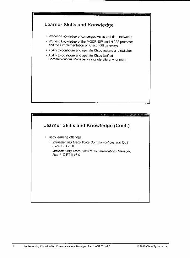
Learner Skills and Knowledge
• Working knowledge of converged voice and data networks
• Working knowledge of the MGCP, SIP, and H.323protocolsand their implementation on Cisco IOSgateways
• Ability to configure and operate Cisco routers and switches
* Ability to configure and operate Cisco UnifiedCommunicationsManager in a single-site environment
Learner Skills and Knowledge (Cont,)
• Cisco learning offerings:
Implementing Cisco Voice Communications and QoS(CVOICE) v8.0
Implementing Cisco Unified Communications Manager,PartT(CIPT1)v8.0
Implementing Cisco Unified Communications Manager, Part 2 (CIPT2) v8 0 >2010 Cisco Systems. Inc
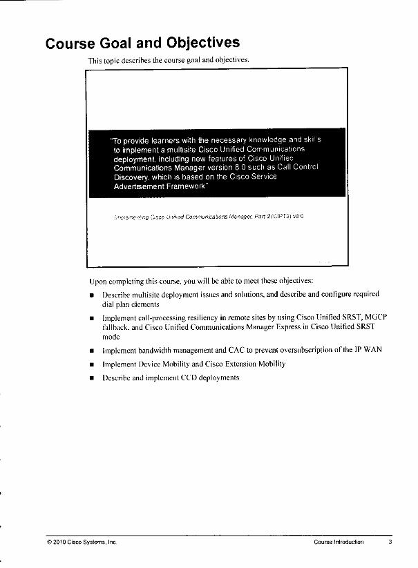
Course Goal and ObjectivesThis topicdescribes the course goaland objectives.
"To provide learners with the necessary knowledge and skillsto implement a multisite Cisco Unified Communicationsdeployment, including new features of Cisco UnifiedCommunications Manager version 8 0 such as Call ControlDiscovery, which is based on the Cisco ServiceAdvertisement Framework"
!iW!sme'-'i'ng Osco UnfrsdComfrvmcabons Manager, ran 2('CIP[2) v8 0
Uponcompleting this course, you will be able to meet these objectives:
• Describe multisitedeployment issuesand solutions, and describe and configure requireddial plan elements
• Implement call-processing resiliency in remote sitesby using Cisco Unified SRST, MGCPfallback, and Cisco Unified Communications Manager Express in Cisco Unified SRSTmode
• Implement bandwidth management and CACto preventoversubscription of the IP WAN
• Implement Device Mobility and Cisco Extension Mobility
• Describe and implement CCD deployments
© 2010 Cisco Systems. Inc. Course Introduction
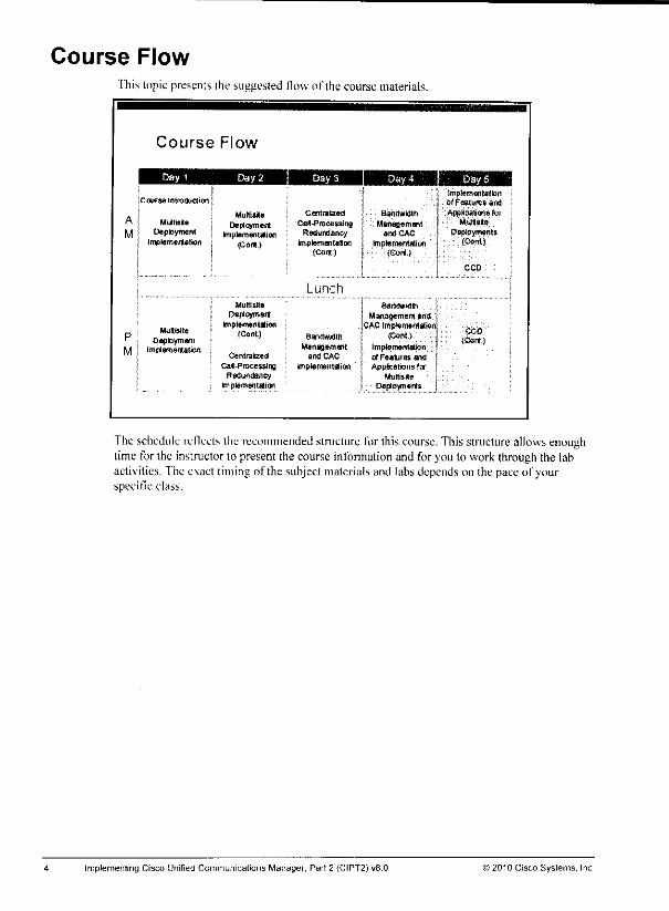
Course FlowThis topic presents the suggested flow of the course materials.
Course Flow
[Course Introduction [
. J MultisiteA j MJtsite | DeploymentM j Deployment ,. implementation
j Implementation , (Cot*.)
s implementation; of Features and
CentraIced Bandwidth 1 AppBcatena farCsS-P recessing Management j Multisite
Redundancy and CAC • DeploymentsImplements!on Implementation ; (Cont)
{Cont.) (Cor*) s
. MuKsite
' ; DeploymentM • fmplenientaliort
Lunch
Mufti sits BandwidthDeployment Management ana
Impiementiiofi CAC Implementation;(Cont) 8andwkJtn (Cont) j
Management Impiementation fCentrafzerJ and CAC of Features and '
Cal-Processing Implementation Applications forRedun&ncy Multisite
frnptementation Deplovmerts
CCD
CCD
(Cont)
The schedule reflectsthe recommended structure for this course. This structure allowsenoughtime for the instructor to present the course information and for you to work through the labactivities. Theexact timing of the subjectmaterials and liibs depends on the paceof yourspecific class.
Implementing Cisco Unified Communications Manager, Part 2 (CIPT2) v8.0 ©2010 Cisco Systems. Inc
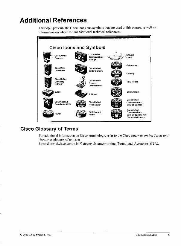
Additional ReferencesThis topic presents the Cisco icons and symbols thatareused in this course, as well asinformation on where to find additional technical references.
Cisco Icons and Symbols
Cisco Urified
Presence
Cisco UnrtyConnection
Cisco Unified
MessagingGas*a/
Coco Adapt veSecirty Appliance
Cisco Unified
Communications
Manager
_^^ Cisco Unifiedt^H Border Element
Personal
Communicator
Cisco Unified
SRST Router
SAF Enabled
Router
Network
Cloud
Gatekeeper
Gateway
Voice Router
Cisco Un ified
Communications
Manager Express
Cisco Unified
Communications
Manager Express withCisco Unity Express
Cisco Glossary of TermsFor additional information on Cisco terminology, refer to the Cisco Internetworking Terms andAcronyms glossary of terms athttp;/'docwiki.ciseo.com/wiki.'CatcgoiT:lntcrnctw'orking_"fernis_and_Acronytris_(I'fA).
© 2010 Cisco Systems. Inc. Course Introduction
Your Training CurriculumThis topic presents the training curriculum for this course.
You are encouraged to join the Cisco Certification Community, a discussion forum open toanyone holdinga valid CiscoCareerCertification (suchas CiscoCCIII",CCNA'. CCDA",CCNP'. CCDP". CCIP". CCVP".or CCSP*). It provides a gathering place for Ciscocertifiedprofessionals to share questions, suggestions, and information about Cisco Career Certificationprograms and other certification-related topics. For more information, visithttp://\v\\\\.cisa>.eom;go certifications.
Implementing Cisco Unified Communications Manager,Part 2 (CIPT2) v8 0 © 2010 Cisco Systems, Inc.
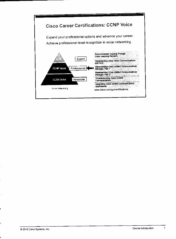
Cisco Career Certifications: CCNP Voice
Expand your professional options and advance your career.
Achieve professional-level recognition in voice networking.
Voice Metw or king
i 2010 Cisco Systems, Inc.
Recommended TrawwgThiouBttCisco Leamw*g Partners
implementing Qsco voiceCammunieaBansand QoS
tmpmmnms Cisco UnlfletS Cormmiricetans" Manage*. Pa* i
imptormntmg Oseo Unified CommunfeafionsManager, Pari 2TroiJWMBODflng Cttco UrfteaCamnwrtcaSons ___
'imgn^aseoWllkKlCommunicationsAppticatiom
www Cisco com/go/certificatons
Course Introduction

8 Implementing Cisco Unified Communications Manager, Part2 (CIPT2) v8.0 ©2010Cisco Systems, Inc.

Module 1
Multisite DeploymentImplementation
Overview
In a multisite Cisco Unified Communications Manager deployment, special requirements existthat are not necessary insingle-site deployments. To successfully deploy a multisite CiscoUnified Communications Manager solution, youneed to understand the issues andbe aware oftheir possible solutions.
This module discusses the issues in a multisite Cisco Unified Communications Managerdeployment, including selective public switched telephone network (PSTN) access and tail-endhop-off (TEHO).
Module ObjectivesUpon completing this module, you will be able to describe multisite deployment issues andsolutions, and describe and configure required dial plan elements.
This ability includes being able tomeet these objectives:
• Explain issues pertaining to multisite deployment andrelate the issues to multisiteconnection options
• Describe solutions formultisite deployment issues
• Configure gateways and trunks in multisite environments
• Implement adial plan to support inbound and outbound PSTN dialing, site-code dialing,and TL1IO in an international environment

1-2 Implementing Cisco Unified Communications Manager, Part 2(CIPT2) v8.0 ©2010 Cisco Systems. Inc.
Lesson 1
Identifying Issues in a MultisiteDeployment
OverviewWhen deploying Cisco Unified Communications Manager in a multisite environment, there aresome unique aspects that pertain only to multisite deployments that you need to consider.Deploying Cisco Unified Communications solutions among multiple sites requires anappropriate dial plan, adequate bandwidth between sites, implementation of quality of service(QoS). and a design that can survive IP WAN failures. This lesson identifies the issues that canarise in a multisite Cisco Unified Communications Manager deployment.
ObjectivesUpon completing this lesson, you will be able to explain issues pertaining to multisitedeployment and relate the issues to multisite connection options. This ability includes bein^able to meet these objectives:
• Describe issues pertaining to multisite deployments
• Describe quality issues in multisite deployments
• Describe issues with bandwidth in multisite deployments
• Describe availability issues in multisite deployments
• Describe dial plan issues in multisite]dep!oymentsi
• Describe NAT and security issues in multisite deployments
Multisite Deployment Issues OverviewThis topic provides an overview about issues pertaining to Cisco Unified CommunicationsManager multisite deployments.
Issues in Multisite Deployments
Mam Site
Cisco Unified
Communications
Manager
In a multisite deployment, several issues can arise. Of those issues, here are the most important:
• Quality issues: When real-time traffic like voice or video travels over a packet-switchingnetwork such as an IP network, delay-sensitive packets have to be given priority to avoidjitter resulting in decreased voice quality
• Bandwidth issues: Cisco Unified Communications solutions can include voice and video
streams, signaling traffic, management traffic, and application traffic, such as rich-mediaconferences. The additional bandwidth that is required when deploying a Cisco UnifiedCommunications solution has to be calculated and provisioned. These tasks ensure thaiclassical data applications and Cisco Unified Communications applications do not overloadthe available bandwidth. You should optimize bandwidth consumption by eliminatingunnecessary IP WAN traffic.
• Availabilih issues: When you are deploying Cisco Unified Communications Managerwith centralized call processing. IP phones register with the Cisco Unified CommunicationsManagerover the IP WAN. If gateways in remote sites arc using the Media GatewayControl Protocol (MGCP) as a signaling protocol, they also depend on the availability ofthe Cisco Unified Communications Manager as a call agent. It is important to implementfallback solutions for IP phones and gateways in scenarios in which the connection to CiscoUnified Communications Manager is broken because of IP WAN failure.
• Dial plan issues: Directory' numbers are usually unique per site, but they can overlapacrossmultiple sites. Overlapping directory numbers and other issues,such as numbers thatare not consecutive, have to be solved by the design of a multisite dial plan. Various publicswitched telephone network (PSTN)access codes in variouscountries arc anotherexampleof dial plan issues.
Implementing Cisco Unified Communications Manager, Part 2 (CIPT2) u8 0 © 2010 Cisco Systems. Inc.
• Network Address Translation (NAT) and security issues: Cisco UnifiedCommunications Manager and IP phones use IP primarily to communicate within theenterprise. The use of private IP addresses is very common within the enterprise. When thesystem should interact with a public IP network—for instance, when placing calls via anInternet telephony service provider (ITSP)—then Cisco Unilied Communications Managerand IP phone IP addresses have to be translated to public IP addresses. This translationmakes them visible on the Internet and, therefore, subject to attacks.
Note The issue of vulnerability when IP addresses are translated to public IP addresses is not
limited to multisite deployments.
)2010 Cisco Systems, Inc. Multisite Deployment Implementation 1-5
Quality IssuesThis topic describes quality issues in a Cisco Unified Communications Manager multisitedeployment.
Quality Issues
IP networks are not designed to carry real-time traffic
• Packet-by-packet delivery
• Packets can take different paths.
No guarantee for correct order.
Problem is solved by RTP sequence numbers.
• Bandwidth shared by multiple users and applications
Unpredictable available bandwidth
Dunng peaks, packets need to be buffered in queues.
• Causes variable delays (jitter)
• Packets get dropped in case of buffer congestion.
• Likely on highly loaded links like IP WAN used between sitesin a multisite environment.
Jitter and packet drops impact voice quality
IPnetworks arc notdesigned to carry real-time traffic. Because of thenature of the network andpaeket-bv-packet delivery in which eachpacket could takea different path, there is noguarantee that packets will arrive in thecorrect order at the destination. You can resolve thisissuebv using Real-Time Transport Protocol (RTP)sequence numbers.
Another issueis the fact that multiple usersand applications sharethe bandwidth, and theactual required bandwidth varies significantly evenovershort lapses of time. Therefore, thebandwidth that is available for Cisco Unified Communications Manager traffic isunpredictable. During peaks, packets need tobebuflered inqueues. Ifthecongestion occurs fortoo long, buffers get tilled upand packets aredropped. Higher queuing delays and packet dropsaremore likely on highly loaded, slow links, such asWAN links that areused between sites ina multisite environment. Asa result, quality issues are common and need to be resolved byimplementing QoS. Otherwise, voice packets are subject tovariable delays (jitter) and packetdrops, bothof whichimpactvoicequality.
1-6 Implementing Cisco Unified Communications Manager, Part2 (CIPT2) v80 >2010 Cisco Systems, Inc
Quality Issues Example: Jitter and Packet DropsThe figure illustrates how packets are queued during congestion.
Quality Issues Example: Jitter andPacket Drops
During congestion, packets are buffered in queues. Ifa queue is full, packetsget dropped.
Tail drops cause packet loss
• Voice quality is reduced.
Queuing delay causes jitter.
Voice quality is reduced.
During peaks, packets cannot be sent immediately because ofinterface congestion, so they havetobe stored in abuffer ("queued"). The time that the packet waits in such aqueue isreferred toas the "queuing delay." The length ofthis delay can vary widely. Ifthe queue is full, newlyreceived packets cannot be buffered, so they get dropped (this action is called "tail drop").Without any special treatment ofvoice packets, such as a FIFO processing model, the resultingjitter andpacket lossdecrease voice quality.
)2010 Cisco Systems. Inc. Multisite Deployment Implementation
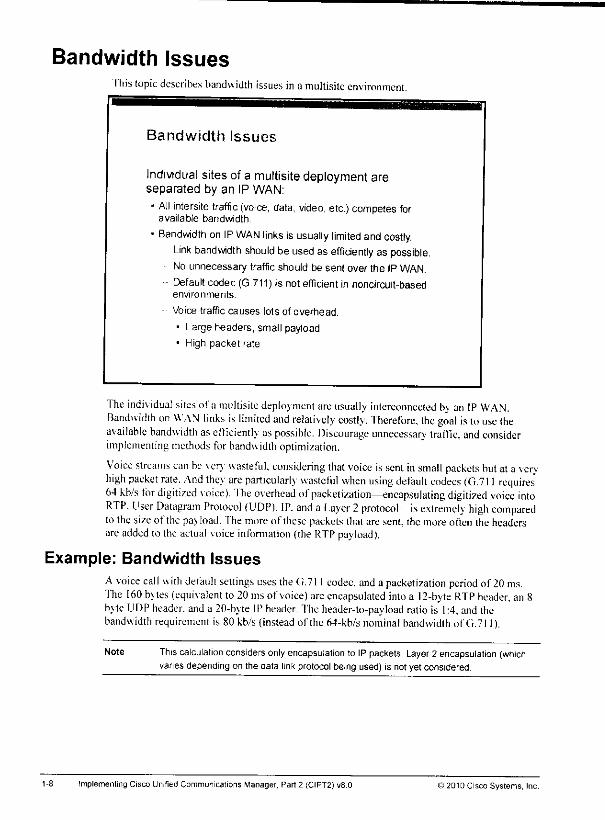
Bandwidth IssuesThis topicdescribes bandwidth issuesin a multisite environment.
Bandwidth Issues
Individual sites of a multisite deployment areseparated by an IP WAN:* All intersite traffic (voice, data, video, etc.)competes for
available bandwidth.
« Bandwidth on IP WAN links is usually limited and costly.Link bandwidth should be used as efficiently as possible.No unnecessary trafficshould be sent over the IP WAN.
Default codec (G.711) is not efficient in noncircuit-basedenvironments.
Voice traffic causes lots of overhead.
• Large headers, small payload• High packet rate
The individual sites of a multisite deploy ment areusually interconnected bv an IP WAN.Bandwidth on WAN links is limited and relatively costly. Therefore, the goal is touse (heavailable bandwidth asefficiently aspossible. Discourage unnecessary traffic, and considerimplemenling methods forbandwidth optimization.
Voice streams can he verv wasteful, considering that voice is sent in small packets but ataveryhigh packet rate. And they are particularly wasteful when using default codecs (G.711 requires'64 kb/s for digitized voice). The overhead of packeli/ation—encapsulating digitized voice intoRTP. User Datagram Protocol (UDP). IP. and a Layer 2protocol—is extremely high comparedto the size of the pavload. The more (tf these packets thai are sent, the more often the headersare addedto the actual voice information (the RTPpayload).
Example: Bandwidth IssuesA voice call with default setting's uses the G.71 I codec, anda paeketization period of 20 ms.The 160 bvtes (equivalent to 20msof voice) areencapsulated into a 12-byte RTP header, an8byte UDP header, anda 20-byte IPheader. Theheader-to-payload ratio is 1:4, andthebandwidth requirement is 80 kb/s (instead of the 64-kb/s nominal bandwidth of G.711).
Note This calculation considersonlyencapsulation to IPpackets. Layer 2 encapsulation (whichvanes depending on the data linkprotocol being used) is not yet considered.
Implementing Cisco Unified Communications Manager. Part 2 (CIPT2) v8.0 ©2010 Cisco Systems, Inc.

Bandwidth Issues Example:for Bandwidth
VDice and Data Traffic Competing
The example illustrates the higher ovdVhtransfer packets.
ead ofvoice packets when comparing them with file
Bandwidth IssuesData Traffic Compdt
Sample: Voice and:ing for Bandwidth
In multisite environments, media services such asmusic on hold (MOH), conferences, annunciators,and so on, can cause considerable bandwidthconsumption over the IP WAN.
Voice packets:• Small size
• High packet rate
• Large overhead
Data packets:• Large size
• Lower packet rate
• Small overhead
-wwr
Vo-ceand data packets arecompeting for IP WAN bandwdlh
As shown mthe figure and as already mentioned, voice packets consume lots of bandwidth thatis caused by the overhead of IP, UDP. and RTP headers that are added to small packets andsent at ahigh packet rate. Data packets such as afile transfer also add 40 bytes ofoverhead (20bytes IP and 20 bytes TCP), bu, the payload is as large as possible (filling up the maximumtransrmsston umt. or MTU^ypically about 1500 bytes. Because of the large payload thepacket rate ,s also lower, and overhead is not added, as is often the case with voice packets.Because of the inefficiency of voice packets, all unnecessary voice streams should be keptaway from .he IP WAN. Media resources, in particular, can be optimized in such away thatthey do not have to cross the IP WAN all the time, thus conserving valuable bandwidth Youcan achieve this optimization by utilizing local media resources.
>2010 Cisco Systems, Inc.Multisite Deployment Implementation 1-9
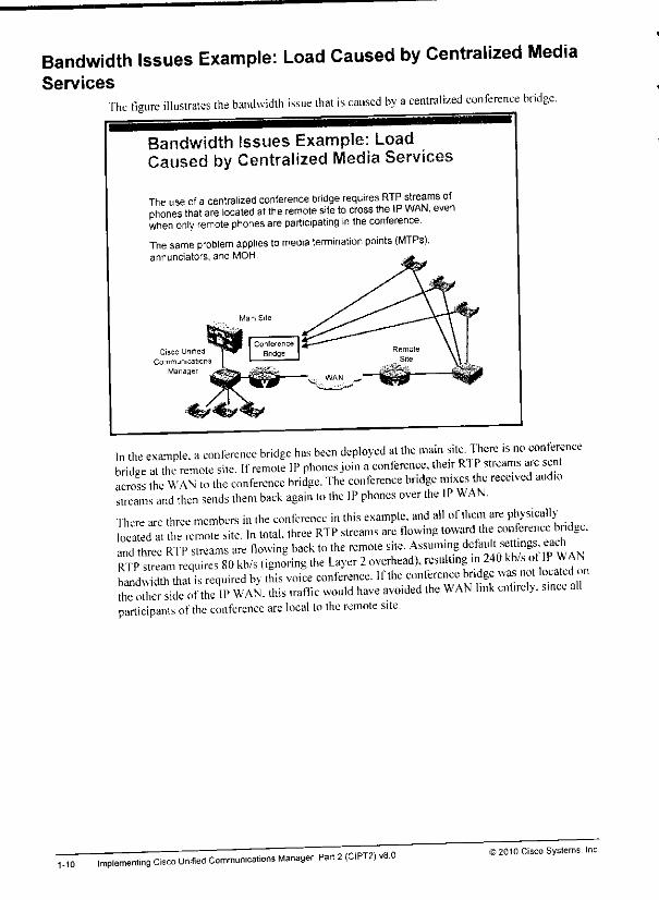
Bandwidth Issues Example: Load Caused by Centralized MediaServices
The figure illustrates the bandwidth issue that is caused by acentralized conference bridge.
1-10
Bandwidth Issues Example: LoadCaused by Centralized Media Services
The use ofa centralized conference bridge requires RTP streams ofphones that are located at the remote site to cross the IP WAN, evenwhen only remote phones areparticipating in the conference.
The same problem applies to media termination points (MTPs),annunciators, and MOH
Cisco Unified
Communications
Manager
in the example, aconference bridge has been deployed at the mam site. 1here >s no conferencebridge at the remote site. If remote IP phones join aconference, their Rl Pstreams are sentacross the WAN to the conference bridge. The conference bridge mixes the received audiostreams and then sends them back again to the IP phones over the IP WAN.There arc three members in the conference in this example, and all of .hem are physicallylocked at the remote site. In total, three RTP streams are flowing toward the coherence bndge.and three RTP streams are flowing back to the remote site. Assuming ^f^ett.ngs eachRTP stream requires 80 kb/s (ignoring the Layer 2overhead), resulting in 240 kb/s of IP WANbandwidth that is required bv this voice conference. If the conference bndge was not located nlife olr side of the IP WAN. this traffic would have avoided the WAN link entirely, since allparticipants ofthe conference are local to the remote site.
implementing Cisco Unified Communications Manager, Part 2(CIPT2) v8.0 >2010 Cisco Systems, Inc.
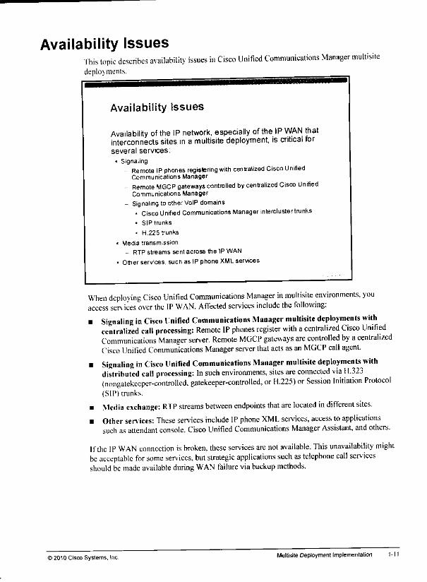
Availability IssuesThis topic describes availability issues in Cisco Unified Communications Manager multisitedeploy ments.
Availability Issues
Availability of the IP network, especially of the IP WAN thatinterconnects sites in a multisite deployment, is critical forseveral services;
• Signaling- Remote IPphones registering with centralized Cisco Unified
Communications Manager
- Remote MGCP gateways controlled bycentralized Cisco UnifiedCommunications Manager
- Signaling to othervblP domains- CiscoUnified Communications Manager tnterclustertrunks• SIP trunks
• H.225 trunks
• Media transmission
- RTP streams sent across the IP WAN
• Other services, such as IP phone XMLservices
When deploying Cisco Unified Communications Manager in multisite environments, youaccess services over the IP WAN. Affected services include the following:
• Signaling in Cisco Unified Communications Manager multisite deployments withcentralized call processing: Remote IP phones register with acentralized Cisco UnifiedCommunications Manager server. Remote MGCP gateways are controlled by acentralizedCisco Unified Communications Manager server thatacts asan MGCP call agent.
• Signaling in Cisco Unified Communications Manager multisite deployments withdistributed call processing: In such environments, sites are connected via H.323(nongatekeeper-controlled. gatekeeper-controlled, or H.225) or Session Initiation Protocol(SIP) trunks.
• Media exchange: RTP streams between endpoints that are located in different sites.• Otherservices: These services include IPphone XML services, access toapplications
such asattendant console. Cisco Unified Communications Manager Assistant, and others.
Ifthe IP WAN connection is broken, these services are not available. This unavailability mightbe acceptable for some services, but strategic applications such as telephone call servicesshould bemade available during WAN failure viabackup methods.
) 2010 Cisco Systems, Inc. Multisite Deployment Implementation 1-11
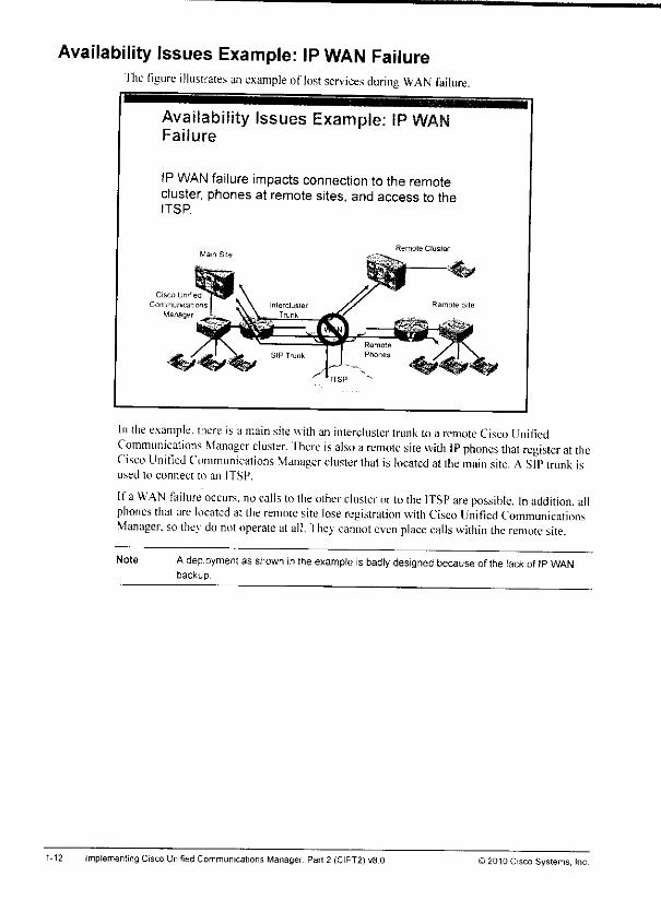
Availability Issues Example: IP WAN FailureThe figure illustrates an example oflost services during WAN failure.
Availability Issues Example: IPFailure
IP WAN failure impacts connection to the remotecluster, phones at remote sites, and access to theITSP.
Cisco Unified
Communications
Manager
Remote Cluster
In the example, there isa main site with an inlerclusler trunk to a remote Cisco UnifiedCommunications Manager cluster. There is also a remote site with IP phones that register at theCisco Unified Communications Manager cluster that is located at the main site. ASIP trunk isused to connect to an ITS!'.
Ifa WAN failure occurs, no calls to the other cluster orto the ITSP are possible. In addition, allphones that arelocated at the remote site lose registration with Cisco Unified CommunicationsManager, sothev do not operate atall. They cannot even place calls within the remote site.
Note Adeployment as shown inthe exampleis badly designedbecause of the lack of IPWANbackup.
1-12 ImplementingCisco Unified Communications Manager. Part 2 (CIPT2]v8.0 © 2010 Cisco Systems, Inc
Dial Plan IssuesThis topic describes dial plan issues in Cisco Unified Communications Manager multisiteenvironments.
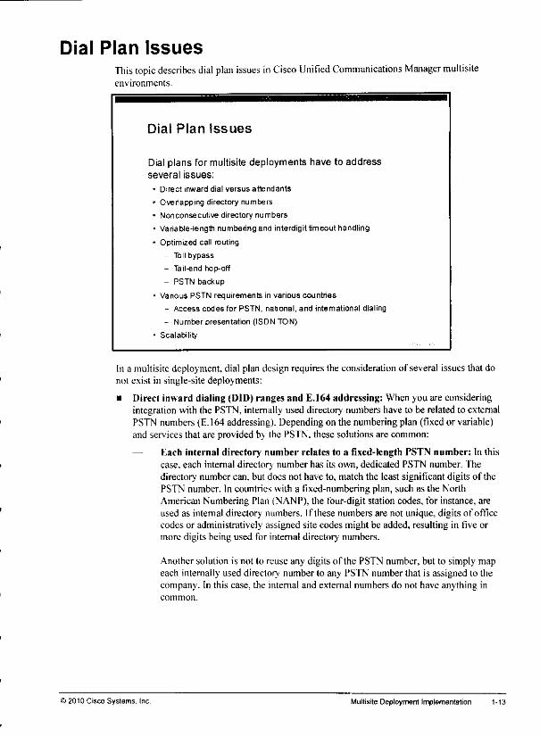
Dial Plan Issues
Dial plans for multisite deployments have to addressseveral issues:
* Direct inward dial versus attendants
• Overlapping directory numbers
• Nonconsecutive directory numbers
• Variable-length numbering and interdigit timeout handling
- Optimized call routing
- Toll bypass
- Tail-end hop-off
- PSTN backup
• Various PSTN requirements in various countries
- Access codes for PSTN, national, and international dialing
- Number presentation (ISDN TON)
• Scalability
In a multisite deployment, dial plan design requires the consideration of several issues that donot exist in single-site deployments:
• Direct inward dialing (DID) ranges and E.164 addressing: When you are consideringintegration with the PSTN, internally used directory numbers have to be related to externalPSTN numbers (E.164 addressing). Depending on the numbering plan (fixed or variable)and services that are provided bv the PSTN, these solutions are common:
Each internal directory number relates to a fixed-length PSTN number: In thiscase, each internal director; number has its own, dedicated PSTN number. Thedirectory number can, but does not have to, match the least significant digits of thePSTN number. In countries with a fixed-numbering plan, such as the NorthAmerican Numbering Plan (NANP). the four-digit station codes, for instance, areused as internal director;' numbers. If these numbers are not unique, digits of officecodes or administratively assigned site codes might be added, resulting in five ormore digits being used for internal directory numbers.
Another solution is not to reuse any digits of the PSTN number, but to simply mapeach internally used director.' number lo any PSTN number that is assigned to thecompany. In this case, the internal and external numbers do not have anything incommon.
©2010 Cisco Systems. Inc. Multisite Deployment Implementation
If the internally useddirector;' numbermatches the least significant digits of itscorresponding PSTN number, you can set significant digits at the gateway or trunk.Then you can also configure general external phone number masks, transformationmasks, or prefixes, because all internal director; numbers are changed to fullyqualified PSTN numbers in the same way. The internal directory number can becomposed ot parts of the PSTN number and administrativelyassigned digits. In thatcase, one or more translation rules have to be used for incoming calls, and one ormore calling-party transformation rules (transformation masks, external phonenumber masks, prefixes, and so on) have to be configured.
An internal director; number can be composed of site codes with PSTN stationcodes, site codes with various ranges (such as PSTN station codes 4100 to 4180 thatmap to director; numbers 1100 to 1180),or site codes with completely independentmappings of internal directory numbers to PSTN numbers.
— No direct inward dialing support in fixed-length numbering plans: To avoid therequirement of one PSTN number per internal directory number when using a fixed-length numbering plan, it is common to not allow direct inward dial to an extension.Instead, the PSTN trunk has a single number, and all PSTN calls that are routed tothat number arc sent to an attendant (or an autoattendant) from where the calls aretransferred to the appropriate internal extension.
Internal director; numbers arc part of a variable-length number: In countrieswith variable-length numbering plans, a (usually shorter) '"subscriber" number isassigned to the PSTN trunk. However, the PSTN routes all calls starting with thisnumber to the trunk: the caller can add more digits to identify the extension. There isno fixed number of additional digits or total digits (there is a maximum, however),which provides the freedom to select the length of directory numbers. A callersimplv adds the appropriate extension when placing a call to a specific user to thecompany's (short) PSTN number. If only the short PSTN number without anextension is dialed, the call is routed to an attendant within the company. ResidentialPSTN numbers are usuall; longer and do not allow additional digits to be added.The feature that is described here is available only on trunks.
Overlapping numbers: Users that are located at different sites can have the same director;'numbers assigned. Because director;' numbers are usually unique only within a site, amultisite deployment requires a solution for overlapping numbers.
Nonconsccutive numbers: Continuous ranges of numbers are important for summarizationof call-routing information. Such blocks can be represented by one or a few entries in acall-routing table (route patterns, dial-peer destination patterns, voice translation rules, andso on) and can keep the routing table short and simple. If each endpoint requires its ownentry in the call-routing table, the table gets too large, lots of memory is required, andlookups take moretime. Therefore, nonconsecutive numbers (somenumbers at one site,and other numbers of the same block at a different site) are not optimal for efficient callrouting.
Variable-length numbering: Some countries have fixed-length numbering plans forPSTN numbers, while others have variable-length numbering plans. A problem of variable-length numbers is thatthe length can be determined only by waiting fora timeout. If nomoredigits have beendialedfor the specifiedtime, the numberis considered to becomplete. Waiting for the timeout adds to the postdial delay.
1-14 Imolementing Cisco Unified Communications Manager. Part2 (CIPT2) v8.0 ©2010 Cisco Systems. Inc
• Optimized call routing: An IP WAN between sites with PSTN access allows PSTN tollbypass. Cisco Unified Communications Manager servers route calls between sites over theIP WAN instead of using the PSTN (toll bypass). In such scenarios, the PSTN should beused as a backup path only in the case of WAN failure. Another solution, which extends theidea of toll bypass, is to use the IP WANalso for PSTN calls: With tail-endhop-off(THHO), the IP WAN is used as much as possible, and the gateway that is closest to thedialed PSTN destination is used for the PSTN breakout. Finally, a backup path over thePSTN should be enabled for when a call cannot be sent over the IP WAN (for example, ifthe IP WAN is down or the maximum number of allowed calls is reached).
• Various PSTN requirements: Various countries—and sometimes even various PSTNproviders withinthe same country—can have variousrequirements regarding the PSTNdial rules. This situation can cause issueswhencalls can be routedvia multiplegateways,For example, if the requirements of a primary gateway are different from the requirementsof a backup gateway, numbers have to be transformed accordingly.
p,„ The calling number (the Automatic Number Identification, or ANI) ofcalls that are being^ received from the PSTN can be represented in various ways: as a7-digit subscriber
number, as a 10-digitnumber including the area code, or in international format with thecountry code in front of the area code. To standardize the calling number for all calls, theformat that is used mustbe known, andthe number has to be transformed accordingly. Incountries where PSTN numbers do nothavefixed lengths, it is impossible to detect the type(local, national, or international) of the number by the number onlyby looking at its length.Insuch cases, thetype ofnumber has to bespecified insignaling messages (forexample,by the ISDN type of number, or TON).
• Scalability: In large or verylarge deployments, dialplanscalability issues arise. Wheninterconnecting multiple Cisco Unified Communications Manager clusters or CiscoUnifiedCommunications Manager Express routers viatrunks, it isdifficult to implement a dial planon an any-to-any basis where each device or cluster needs to know which numbers orprefixes are found at which other system. In addition to the need to enter almost the samedial plan ateach system, a static configuration does not reflect true reachability. If there areany changes, the dial plans ateach system have tobe updated. Although there aresolutionsthatallow centralized dial plan configuration (forexample, H.323 gatekeepers), in verylarge deployments a dynamic discovery ofdirectory number ranges and prefixes wouldsimplify the implementation and provide a more scalable solution.
)2010 Cisco Systems. Inc. Multisj,e Dep|0ymen| implementation M5
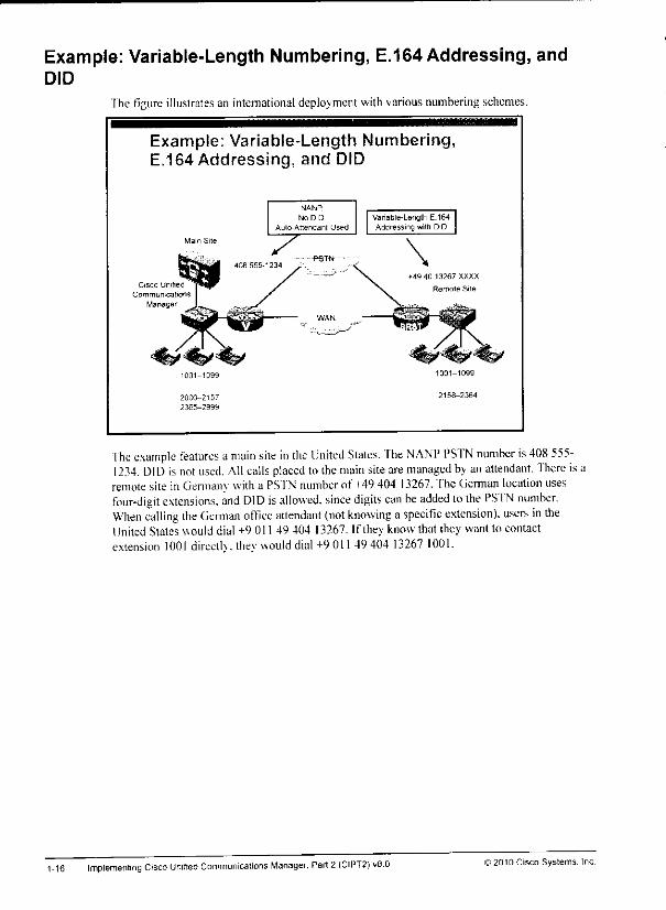
Example: Variable-Length Numbering, E.164 Addressing, andDID
The figure illustrates an international deployment with variousnumbering schemes.
Example: Variable-Length Numbering,E.164 Addressing, and
Cisco Unified
Communications
Manager
NANP.
No DID
Aulo-Attendanl Used
Variable-Length E.164Addressing with DID
"fhe example features a main site in the United Slates. The NANP PSTN number is408 555-1234. DID isnotused. All calls placed to themain site are managed byanattendant. There isaremote site in Gennanv with a PSf N numberof 149 404 13267. The Cierman location usesfour-digit extensions, and DID isallowed, since digits can be added to the PSTN number.When calling the German office attendant (not knowing aspecific extension), users in theUnited States would dial +9 011 49 404 13267. If they know that they want to contactextension 1001 dircclK. thev would dial+9 011 49 404 13267 1001.
1-16 Implementing Cisco Unmeet Communications Manager. Part 2 (CIPT2) v8.0 ©2010 Cisco Systems.

Fixed vs. Variable-Length Numbering PlansThe table compares characteristics of a fixed numbering plan with characteristics of a variable-length numbering plan.
Fixed vs. Variable-Length Numbering Plans
Examples:
• Witriir It S : "9 1 408 555-1234" or '1 555-1234" twilrifi Bia same area code)
• U.S to Austria1 "9 011 43 1 12345"
• WitHii Austria: "0 0 1 12345" or "0 1234" (withn the same area code)
• Austria to U.S.. "0 00 1 406 555-1234 " (1 is country code, not national access code)
Components, _ „ _, VsriSUle-Length Numbing£|*ea Numbering Plan " *
Example MAW Avetiia
Country code 1 43
Area code 3 digit 1-4 (Halt*
Subscriber numoer3-tfio.texchsng» cads ♦
^cfigistaawtcoas
9
3«mor»-<Igflt
"~ 0PSTN access code
National access code 1 0
International access code 01100 or*
(•+' uwd by e#Jpfion«)
A fixed numbering plan, such as the plan used in North America, features fixed-length areacodes and local numbers. An open numbering plan, such as the plan used in various countriesthat have not yet standardized their numbering plans, features variance in the length of the areacode or the local number, or both.
A country code is used to reach the particular telephone system for each country or specialservice.
An area code is used within many countries to route calls to a particular city, region, or specialservice. Depending on the country or region, it may also be referred to as a Numbering PlanArea (NPA), subscriber trunk dialing code, national destination code, or routing code.
The subscriber number represents the specific telephone number to be dialed, but does notinclude the country code, area code (if applicable), international prefix, or trunk prefix.
A trunk prefix refers to the initial digits to be dialed in a call within the United States,preceding the area code and the subscriber number.
An international prefix is the code to be dialed before an international number (the countrycode, the area code if any, and then the subscriber number).
The table contraststhe NANPand a variable-length numbering plan (the Austriannumberingplan, in this example).
>2010 Cisco Systems, Irrc Multisite Deployment Implementation 1-17
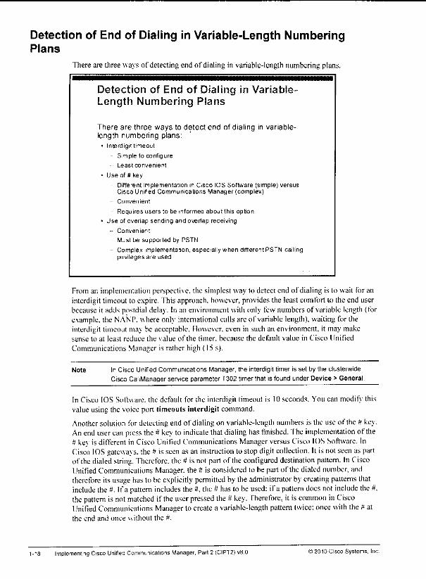
Detection of End of Dialing in Variable-Length NumberingPlans
There are three ways of detecting end of dialing in variable-length numbering plans.
Detection of End of Dialing in Variable-Length Numbering Plans
There are three ways to detect end of dialing in variable-length numbering plans:
• IntErdigit timeout
- Simple to configure
Least convenient
• Use of # key
Different implementation in Cisco IOS Software (simple) versusCisco Unified Communications Manager (complex)
- Convenient
Requires users to be informed aboutthis option
• Use of overlap sending and overlap receiving
-- Convenient
-- Must be supported by PSTN
- Complex implementation, especially when differentPSTN callingprivileges are used
From an implementation perspective, the simplest way to detect end of dialing is to wait for aninterdigit timeout to expire.This approach, however, provides the least comfort to the end userbecause it adds postdial delay. In an environment with only few numbers of variable length (forexample, the NANP. whereonly international calls are of variable length), waiting for theinterdigit timeout ma\ be acceptable. However, even in such an environment, it may makesense to at least reduce the value of the timer, because the default value in Cisco UnifiedCommunications Manager is rather high (15 s).
Note In Cisco Unified Communications Manager, the interdigit timer is set by the dusterwide
Cisco CallManager service parameter T302 timer that is found under Device > General.
In Cisco IOS Software, the default for the inlerdigit timeout is 10seconds. You can modifj thisvalue using the voice port timeouts interdigit command.
Another solution for detecting end of dialing on variable-length numbers is the use of the # ke\.An endusercan press the# kej to indicate thatdialing hasfinished. The implementation of the# kev is different in Cisco Unified Communications Manager versus Cisco IOS Software. InCisco IOSgatewa\s. the # is seen as an instruction to stop digit collection. It is not seen as partof the dialed string. Therefore, the# is not part of theconfigured destination pattern. In CiscoUnified Communications Manager, the # is considered to be partof the dialednumber, andtherefore itsusage hasto beexplicitly permitted by theadministrator by creating patterns thatinclude the it. If a pattern includes the it. the# hasto be used; ifa pattern doesnot include the#.the pattern is not matched if the user pressed the # key. Therefore, it is common inCiscoUnified Communications Manager to createa variable-length patterntwice: once with the itatthe end and once without the #.
1-18 Implementing Cisco Unified Communications Manager. Part 2 (CIPT2) v8 0 ©2010 Cisco Systems, Inc
Analternative wayof configuring such patterns is to endthe pattern with ![0-9#]. In thiscase,a single pattern supports bothwaysof dialing: withthe# andwithout the#. However, be aware
ff^ that the use ofsuch patterns can introduce other issues. For example, when using discard digitsinstructions that includeTrailing-^(for example, PreDot-Trail ing-#). This discarddigitinstruction will have an effectonly whenthere is a trailing# in the dialed number. If the # was
p.,* not used, the discard digit instruction is ignored and hence the PreDot component ofthe discardIM digit instruction is also not performed.
Allowing the use of the # to indicate end of dialingprovidesmore comfortto end users thanhaving them wait forthe interdigit timeout. However, thispossibility has to be communicatedto the end users, and it shouldbe implemented consistently. As mentioned earlier, it isautomatically permitted in Cisco IOS Softwarebut not in Cisco UnifiedCommunicationsManager.
The third way to indicate end of dialingis the use of overlapsend and overlapreceive.Ifoverlap is supported end-to-end, the digits that are dialed by the end user are sent one by oneover the signaling path. Then the receiving end system can inform the calling device once it hasreceived enough digits to route the call (number complete). Overlap send and receive iscommon in some European countries such as Germany and Austria. From a dial planimplementation perspective, overlap send and receive is difficult to implement when differentPSTN callingprivileges are desired. In this case,you have to collectenoughdigits locally(forexample, in Cisco Unified Communications Manager or Cisco IOS Software) to be able todecide to permit or deny the call. Only then can you start passing digits on to the PSTN one byone using overlap. For the end user, however, overlap send and receive is very comfortable,
pw because each call is processed as soon asenough digits have been dialed. Thenumber of digits§^ thatare sufficient varies perdialed PSTN number. Forexample, one local PSTN destination
may be reachable by a seven-digit number, whereas another local number may be uniquelyidentified only after receiving nine digits.
jte
L>2010 CiscoSystems, Inc. Multisite Deployment Implementation 1-19
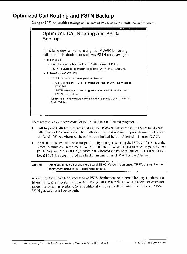
Optimized Call Routing and PSTN BackupUsing an 1P WAN enables savings on the cost of PSfN calls in a multisite en\ ironment.
Optimized Call Routing and PSTNBackup
In multisite environments, using the IP WAN for routingcalls to remote destinations allows PSTN cost savings:
• Toll bypass
Calls between sites use the IP WAN instead of PSTN.
PSTN is used as backup in case of IP WAN or CAC failure.
* Tail-end hop-off (TEHO)
- TEHO extends the conceptrjf toll bypass.
• Calls to remote PSTN locations use the IP WAN as much as
possible.
• PSTN breakout occurs at gateway located closestto thePSTN destination.
Local PSTN breakout is used as backup in case of IP WAN orCAC failure
"there are two wa\s to save costs for PSTN calls in a multisite deployment:
• Toll bypass: Calls between sites that use the IP WAN instead of the PSTN are toll-bypasscalls. The PSTN is used only when calls over the IP WAN are not possible—eitherbecauseof a WAN failure or because the call is not admitted by Call Admission Control (CAC).
• TEHO: TEHO extends the concept of toll bypass by also using the IP WAN for calls to theremote destinations in the PS'fN. With TIT 10. the IP WAN is used as much as possible andPSTN breakout occurs at the gateway that is located closest to the dialed PSTN destination.Local PSTN breakout is used as a backup in case of an IP WAN or CAC failure.
Caution Some countries do not allow the use of TEHO. When implementing TEHO, ensure that the
deployment complies with legal requirements.
When usingthe IP WAN lo reach remote PS'fN destinations or internal director) numbers at adifferent site, it is important to consider backup paths. When the IP WAN is down or when notenough bandwidth is available foran additional voicecall, calls shouldbe routed via the localPSTN gateways as a backup path.
1-20 Implementing Cisco Unified Communications Manager, Part 2 (CIPT2)v8 0 ©2010 Cisco Systems. Inc
l^.
IM
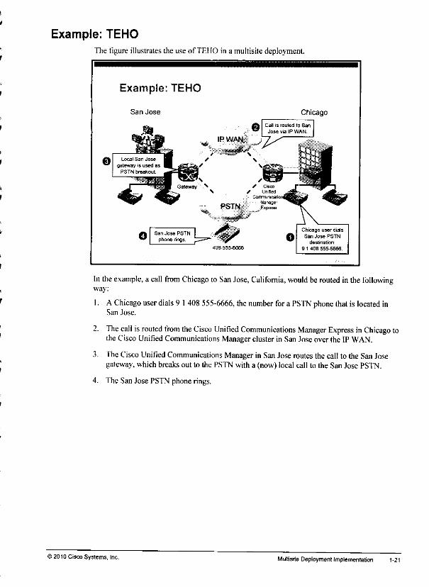
Example: TEHOThe figure illustrates the use of TEHO in a multisite deployment.
Example: TEHO
San Jose Chicago
403-555-6666
In the example, a call from Chicago to San Jose, California, would berouted inthefollowingway:
1. A Chicago userdials9 1408555-6666, the number fora PSTN phone thatis located inSan Jose.
2. Thecall is routed from theCisco Unified Communications Manager Express inChicago tothe Cisco Unified Communications Managercluster in San Jose over the IP WAN.
3. The Cisco Unified Communications Managerin SanJose routes the call to the San Josegateway, which breaks out to the PSTN with a (now) local call to the San Jose PSTN.
4. The San Jose PSTN phone rings.
'2010 Cisco Systems, Inc. Multisite Deployment Implementation 1-21
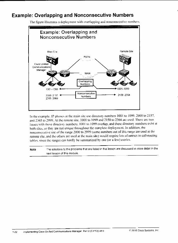
Example: Overlapping and Nonconsecutive NumbersThe figure illustrates a deployment with overlapping and nonconsecutive numbers.
Example: Overlapping andNonconsecutive Numbers
Wain Site
Cisco Unified
Communications
Manager
1001-1099 •*
2000-2157 +•
2365-2999
Nonconsecutive
Numbers
Remote Site
••1001-1099
-+• 2158-2364
In the example. IP phones ai the main site use directorv' numbers 1001 to 1099. 2000 to2157.and 2365 to 2999. At the remote site. 1001 to 1099and 2158 to 2364 are used. There are twoissueswith thesedirector, numbers: 1001 to 1099overlap; and thesedirectory numbers exist atboth sites, so they are notunique throughout thecomplete deployment. Inaddition, thenonconsecutive use ofthe range 2000 to 2999 (some numbers outof this range areused at theremote site, and the othersare usedat the mainsite) wouldrequire lotsof entries in call-routingtables, since the ranges can hardly besummarized byone (ora few) entries.
Note The solutions to the problems that are listed inthis lesson are discussed inmoredetail inthenext lesson of this module.
1-22 Implementing Cisco Unified Communications Manager, Part2 (CIPT2) v80 © 2010 Cisco Systems, Inc.
ttM.
**»
L
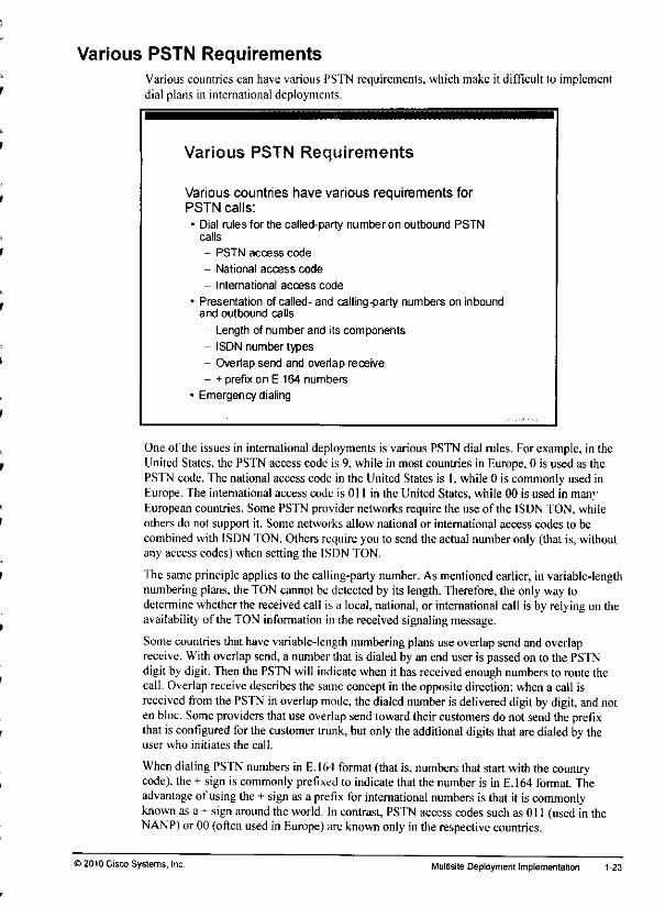
Various PSTN RequirementsVarious countries can have various PSTN requirements, which make it difficult to implementdial plans in international deployments.
Various PSTN Requirements
Various countries have various requirements forPSTN calls:
• Dial rules for the called-party numberon outbound PSTNcalls
- PSTN access code
- National access code
- International access code
• Presentation of called- and calling-party numbers on inboundand outbound calls
- Length of number and its components
- ISDN number types
- Overlap send and overlap receive
- + prefix on E.164 numbers
• Emergency dialing
One of the issues in international deployments is various PSTN dial rules. For example, in theUnited States, the PSTN access code is 9, while in most countries in Europe, 0 is used as thePSTN code. The national access code in the United States is I, while 0 is commonly used inEurope. The international access code is 011 in the UnitedStates,while 00 is used in manyEuropean countries. Some PSTN provider networks require the use of the ISDN TON, whileothers do not support it. Some networks allow national or international access codes to becombined with ISDN TON. Others require you to send the actual number only (that is, withoutany access codes) when setting the ISDN TON.
Thesame principle applies to thecalling-party number. Asmentioned earlier, invariable-lengthnumbering plans, the TONcannotbe detectedby its length.Therefore, the onlyway todetermine whetherthe receivedcall is a local,national, or international call is by relyingon theavailability of the TON information in the receivedsignalingmessage.
Some countries thathavevariable-length numbering plansuseoverlap sendandoverlapreceive. With overlapsend,a numberthat is dialed by an end user is passedon to the PSTNdigitbydigit. Then the PSTN will indicate when it has received enough numbers to routethecall. Overlap receivedescribes the same conceptin the oppositedirection:when a call isreceived from the PSTN inoverlap mode, the dialed number is delivered digitby digit, andnoten bloc. Some providers thatuseoverlap sendtoward theircustomers do notsendthe prefixthat is configured forthecustomer trunk, but only theadditional digitsthatare dialed by theuser who initiates the call.
When dialing PSTN numbers in E.164 format (that is,numbers thatstart with thecountrycode), the + sign is commonly prefixed to indicate that the number is in E.164 format. Theadvantage of using the+ sign as a prefix for international numbers is thatit iscommonlyknown as a + signaround the world. Incontrast, PSTN access codes suchas 011 (used in theNANP) or 00 (often used in Europe) areknown onlyin the respective countries.
>2010 Cisco Systems. Inc. Multisite Deployment Implementation 1-23
Finally, emergency dialing can be an issue in international deployments. As various countrieshave various emergenc\ numbers and various ways to place emergency calls, users are not surehow to dial the emergency number when roaming to other countries. An internationaldeployment should allow roaming users to use their home dialing rules when placingemergency calls. The system should then modify the called number as required at the respectivesite.
1-24 Implementing Cisco Unified Communications Manager. Part 2 (CIPT2) v8.0 ©2010 Cisco Systems, Inc.
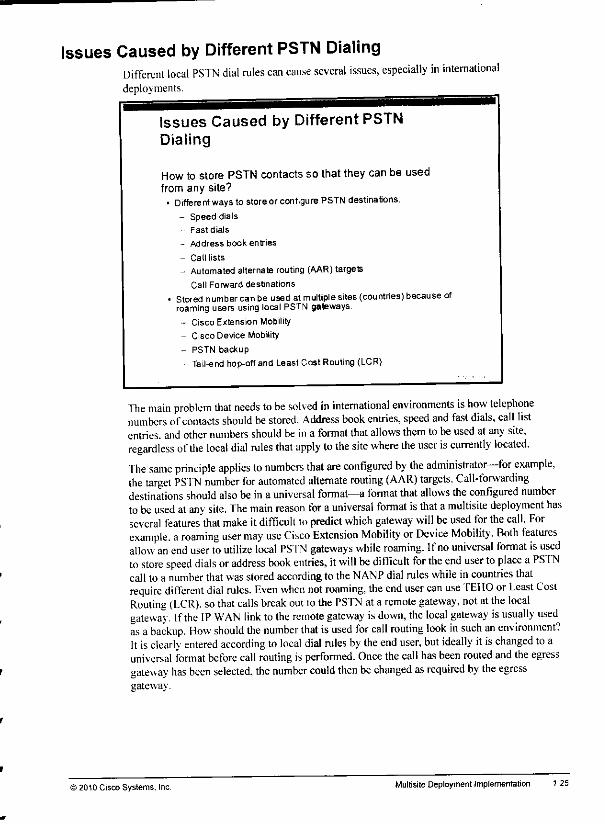
Issues Caused by Different PSTN DialingDifferent local PSTN dial rules can cause several issues, especially in internationaldeployments.
Issues Caused by Different PSTNDialing
How to store PSTN contacts so that they can be usedfrom any site?• Different ways to storeor configure PSTN destinations;
- Speed dials
- Fast dials
- Address book entries
- Call lists
- Automated alternate routing (AAR) targets
- Call Forward destinations
• Stored numbercan be used at multiple sites (countries) because ofroaming users using local PSTN gateways.
- Cisco Extension Mobility
- Cisco Device Mobility
- PSTN backup
- Tail-end hop-off and Least Cost Routing (LCR)
The main problem that needs to be solved in international environments is how telephonenumbers ofcontacts should bestored. Address book entries, speed and fast dials, call listentries, and other numbers should be in a format that allows them tobe used atany site,regardless of the local dial rules that apply to the site where the user is currently located.The same principle applies to numbers that are configured by the administrator—for example,the target PSTN number for automated alternate routing (AAR) targets. Call-forwardingdestinations should also be in a universal format—a format that allows the configured numberto be used atany site. The main reason for auniversal format is that amultisite deployment hasseveral features'that make itdifficult to predict which gateway will be used for the call. Forexample, aroaming user may use Cisco Extension Mobility or Device Mobility. Both featuresallow an end user toutilize local PSTN gateways while roaming. Ifno universal format isusedto store speed dials or address book entries, itwill be difficult for the end user to place aPSTNcall toa number that was stored according to the NANP dial rules while incountries thatrequire different dial rules. Even when not roaming, the end user can use TEHO orLeast CostRouting (LCR). so that calls break out to the PSTN at aremote gateway, not at the localgateway. Ifthe IP WAN link to the remote gateway is down, the local gateway is usually usedas abackup. How should the number that isused for call routing look in such an environment?It isclearly entered according to local dial rules by the end user, but ideally itischanged to auniversal format before call routing is performed. Once thecall has been routed and the egressgateway has been selected, the number could then be changed as required by the egressgateway.
© 2010 Cisco Systems. Inc. Multisite Deployment Implementation 1-25
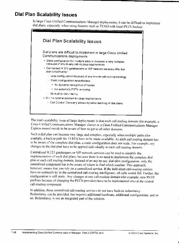
Dial Plan Scalability IssuesIn large Cisco Unified Communications Manager deployments, it can be difficult to implementdial plans, especially when using features such as TEHO with local PS'fN backup.
Dial Plan Scalability Issues
Dial plans are difficult to implement in large Cisco UnifiedCommunications deployments• Static configuration for multiple sites ordomains isvery complex
because of any-to-any call-routingrequirements.
• Centralized H.323 gatekeepersor SIP network services offer dialplan simplification.
- Less configuration becauseofany-to-one call-routing topology.• Static configuration nevertheless.
• No dynamic recognition of routes
• No automatic PSTN rerouting
No built-in redundancy
• Stillno optimal solution for large deployments
- Call Control Discovery allows dynamic learning of dial plans.
The main scalability issue oflarge deployments is that each call routing domain (for example, aCisco Unified Communications Manager cluster or aCisco Unified Communications ManagerExpress router) needs tobe aware of how to getto all other domains.
Such adial plan can become very large and complex, especially when multiple paths (forexample, abackup path for I'EHO) have to be made available. As each call routing domain hasto be aware ofthe complete dial plan, astatic configuration does not scale. For example, anvchanges in the dial plan have to be applied individually at each call routing domain.Centralized H.323 gatekeepers orSIP network services can be used to simplify iheimplementation ofsuch dial plans, because there is no need toimplement the complete dialplan at each call routing domain. Instead ofan any-to-any dial-plan configuration, only ihecentralized component has tobe aware ofwhere lo find which number. This approach,however, means thai vou rely on a centralized service. Ifthe individual call-routing entitieshave noconnectivity to the centralized call-routing intelligence, all calls would fail. Further, theconfiguration isstill static. Any changes atone call-routing domain (for example, new PSTNprefixes because of changing the PS'fN provider) have tobe implemented also at the centralcall-routing component.
In addition, these centralized call-routing services do not have built-in redundancy.Redundancv can be provided, but requires additional hardware, additional configuration, and soon. Redundancv is not an integrated part of the solution.
1-26 ImplementingCisco Unified Communications Manager. Part 2 (CIPT2]vB.O ©2010 Cisco Systems, Inc.
Answer KeyThe correct answers and expected solutions for the activities that are described in this guideappear here.
Lab 1-1 Answer Key: Implementing Basic MultisiteConnections
fhe solution is part of theactivity procedure and verification.
Lab 1-2 Answer Key: Implementing a Dial Plan for InternationalMultisite Deployments
fhesolution ispart of the activity procedure and verification.
Lab 2-1 Answer Key: Implementing SRST and MGCP Fallbackfhesolution ispari of the activity procedure and verification.
Lab 2-2 Answer Key: Implementing Cisco UnifiedCommunications Manager Express in SRST Mode
The solution ispart of the activity procedure and verification.
Lab 3-1 Answer Key: Implementing Bandwidth ManagementThe solution is part ofthe activity procedure and verification.
Lab 3-2 Answer Key: Implementing CACThe solution ispart of the activity procedure and verification.
Lab 4-1 Answer Key: Implementing Device MobilityThe solution ispart of the activity procedure and verification.
Lab 4-2 Answer Key: Implementing Cisco Extension Mobilityfhesolution is part of the activity procedure and verification.
Lab 5-1 Answer Key: Implementing SAF and CCDThe solution ispart of the activity procedure and verification.
Implementing Cisco Unrfied Communications Manager, Part 2(CIPT2) v8.0 ©2010 Cisco Systems, Inc
m
router eigrp SAF
service-family ipv4 autonomous-system 2
shutdown
Step 13 Verify that the IP path to all learned patterns is marked unreachable by using theshow voice saf dndb all command.
Activity VerificationYou have completed this task when you attain these results:• The BR-.t router learns patterns by CCD as described in the activity procedure.. Verifv that calls can be placed to patterns learned by CCD while being in SRST and MGCP
fallback mode.
Step 14 Place calls from your BR-.v site to all other three sites.• Verifv the path that each call takes by using the debug isdn q931 command at
all four gateways.
• Use site code dialing for calls to the other pod: 8-5 lv-200! or 8-5I r-2002 toIIQ-v phones and 8-52.V-3001 to the BR-v phone.
• Use four-digit extensions for calls to the local HQ-.t phones: 2001 or 2002.
Note When acall is placed to aphone located at one of the BR sites, the SIP INVITE is sent tothe advertising device (CUCM1-X or CUCM1-y). As the BR sites are in SRST mode, CiscoUnified Communications Managers will route the calls to their BR gateway via the PSTNbasedon theexisting CFUR configuration.
© 2010 Cisco Systems. Inc.Lab Guide 95
Note This dial peer is required for the CCD PSTN backup calls. The learned toDIDrule changesthe internally used site-code numbers from 8 followed by seven digits to E.164 numbers with
a plus prefix The CCD PSTN backup calls then match this dial peer where the + is stripped
and then 011 is prefixed.
The learned pattern 851x-2XXX refers to the HQ-x site. Until now calls between the two
sites of the same pod used four-digit dialing. CCD cannot advertise the HQ-x site with 4
digits to the BR-x SAF client and with site code prefixes to other SAF clients (the SAF clients
of the other pod). Usually, when using CCD, the internally used pattern for a given site has
to be the same at all sites.
However, the problem can also be solved in a way that allows users to continue using 4
digits for intersite calls within the same pod. You need to modify the dialed four- digit number
2XXX at the BR-x router to 851x2XXX before the outbound dial peer is selected.
Step 10 On the BR-.rrouter configure the following number expansion in order to allowBR-.v users to continue using four-digit intersite dialing towards the HQ site of thelocal pod (HQ-.t):
num-exp 2... 851x2...
Note Byconfiguring the number expansion command calls to four-digit numbers starting with 2(for example 2001) are expanded to site code dialing format (851x2001) before the selection
of the outgoing dial peer. The expanded number is used to select the outgoing dial peer(dial-peer 8 in this case) which refers to SAF-learned patterns. The BR-xgateway finds amatch in a learned pattern (851x2XXX) that is currently marked unavailable. Therefore, a
PSTNbackup call is placed usingthe learned toDID rule (4:+5551x555). The resulting call to•••5551x5552001 matches dial peer 999, which sends the call to the PSTN with a called
number of 0115551x5552001.
Simulate IP WAN Failure Between the HQ and the BR Sites
In this section \ou will break MGCP, SCCP. and SAF to simulate an IP WAN failure betweenthe HQ and BR sites of your pod.
Step11 You hav e to force the BR-.v router into SRST and MGCP fallback mode by breakingconnectivity between the BRsiteandCiscoUnified Communications Manager. Youcan do that by reapplying the access-list that was alreadyused in an earlier lab taskat the HQ-.r router:
i
interface serial ...
ip access-group 100 in
Note Use the interface that connects the HQ-x route with the BR-x router.
Step12 Break the SAT connection between your HQ router (HQ-.v) andyour BR router(BR-.r) in order to have the IP palhs marked unreachable by enleritig the followingcommands in global configuration mode of the \K)-x router:
94 Implementing Cisco UnifieO Communications Manager, Part 2 (CIPT2) v8.D ®2010 Cisco Systems. Inc.
-Jfe
Note The learned pattern 852x-3XXX refers to the BR-xsite itself.This pattern will not be used ata phone that is located at the BR-x site because four-digit dialing is used for internal calls. If
it was dialed, the call cannot use the advertised IP path (to Cisco Unified Communications
Manager CUCM1-x) because the IP WAN link is down. Remember that the BR-x gateway
normallydoes not use a local dial plan as it is configured as an MGCP gateway. Itwill onlylook to its local call routing table when the connection to the HQ site is broken, if a BR-x
user dials a number out of the 8-52x-3XXX range during SRST mode, the BR-x gateway
finds a learned pattern that is currently marked unavailable Therefore, the PSTN backup
path (toDID 4:+6652x555) is used to place a PSTN backup call. When this call is set up by
the BR-xgateway, the PSTN routes the call back to the BR-xgateway. This means thatcalling to the own site by site-code dialing works, but it would use two ISDN circuits as the
call is hairpinned at the PSTN
Enable Call Routing for CCD-learned Patterns and for CCD PSTN Backup CallsStep9 Onthe BR-\ router configure the following dial peersinorderto enable the gatewav
to use CCD-learned patterns and to enableCCD PSTN backupcalls:
dial-peer voice 8 voip
destination-pattern 8.
session target saf
Note Thisdial peer instructs Cisco Unified Communications Manager Expressto look to the CCD-learned patterns when a user diats 8 followed by seven digits.
The learned patterns 851y-2XXX and 852y-3XXX refer to the other pod. The IP destinationfor both patterns is the Cisco Unified Communications Manager of the other pod(CUCM1-y) However, as the IP WAN is down, the PSTN backup path has to be usedBased on the learned toDID rules (4:+5551y555 for pattern 851y-2XXX and 4:+6652y555 for
pattern 852y-3XXX) the BR-x gateway will placea directcall to the respective gatewayofthe other pod (HQ-yor BR-y).
) 2010 Cisco Systems. Inc
dial-peer voice 999 potE
destination-pattern +T
voice-port 0/0/0:23
prefix Oil
Lab Guide
exit-service-familyi
Step S Configure the SAF Client functionon your BR-jr router:
voice service saf
profile trunk-route 1
session protocol sip interface FastEthernetO/0 transport tcp port5C6C
channel 1 vrouter SAF asystem 1subscribe callcontrol wildcarded
Step 6 Configure outbound dial peers for intersite calls to use SAP:
dial-peer voice 8 voip
destination-pattern 8
session target saf
dial-peer voice 2 voip
destination-pattern 2...
session target saf
Verify CCD-learned Patterns
Step 7 On the BR-.xrouter enter the show voice saf dndb all command lo view learnedroutes. You should have learned a pattern for each of the four sites.
Step 8 On the BR-.v router enter the show voice saf dndb detail 851a2XXX command loview detailsof this specificlearned route. Repeat the command for the other threeteamed patterns.
Caution The X in the pattern of the show voice safdndbdetailcommand is case sensitive.
Note In each pod, Cisco Unified Communications Manager is thecall agentthatadvertises theHQ-xand BR-x patterns. Therefore, at the BR-x router 851x-2XXX and 852X-3XXX shouldbe listed as reachable bySIPat 10.x 1.1 while 851y-2XXX and 852y-3XXX should be listedas reachable by SIP at 10.y.1.1.
The BR-x router will never usethelearned SIP path. As long as there isnoIPconnectivityproblem, the ISDN PRl is MGCP-controlled and the BR-x phones are registered to CiscoUnified Communications Manager. Therefore no call routing occurs at the BR-x gatewayunder normal situation.
The learned patterns are only used incase ofIPWAN failure. In this case, however, the IPpath ofthe learned patterns ismarked unavailable andthe BR-x gateway which thenoperates in SRSTand MGCP fallback mode will use the learned patterns to placeCCDPSTN backup calls based on the learned toDID rules.
Implementing Cisco Unified Communications Manager, Part 2(CIPT2) v8.0 ©2010 Cisco Systems, Inc.
Step 10 Repeat the testcalls. Verify thatthecallsarererouted via the local PS'fN gatewa;mm b\ usingdebug isdn q931 command at bothgateways.
Note Be aware of the call flow in this scenario. After calling a phone of the other pod using site-
code dialing a CCD-learnedpattern is matched. The SAF-enabledSIP trunk is not useObecause the IPpath is marked unreachable (dueto shutting down SAF). The ToDID rule is
*•• applied to the matched pattern and a call to the {now globalized) number is placed using theAAR CSS.
The call matches the intersite pattern, which refers to the non-SAF-enabled SIP trunk as firstoption and to the local routegroupas second option. As ihe first option does notwork (due
"•* tothe access list), thecall is finally sent via the PSTN using the local gateway.
imm Step 11 Re-enable the SAF connection between the two HQ routers by entering thefollowing commands inglobal configuration mode at your HQ~.v router:
<**
router eigrp SAF
mm service-family ipv4 autonomous-system 2
no shutdown
Step 12 Remove theaccess listfrom theserial interface at yourIIQ-.v router.
*" Task 3: Configure Cisco Unified Communications Manager^ Express SRST on Branch Router to Learn Routes Using CCD
In this task, you will configure Cisco Unified Communications Manager Express SRST on them BR-.v router to learn routes from SAF using CCD. The learned patterns arc used for intersite
calls when the gateway is in SRST and MGCP fallback mode.
* Activity Procedure
Complete these steps:
Step 1 Open a Telnet session to your BR-x router (10.v.5.102).
wm Step 2 loiter the configure terminal command lo access the global configuration mode.
Make the Statically Configured Call Routes at the Cisco Unified Communications Manager**» Express SRST Router Inaccessible
Step 3 Shutdown ihe following dial peers:
<mm • Dial peer8y2 to destination pattern 85ly2...
• Dial peer8v3 to destination pattern 852y3...mm
• Dial peer2000to destination pattern 2..,
— Configure the SRST Router toSubscribe toSAF in Order to Learn Routes toOther SitesStep 4 Configure the SAF Forwarder function onyour BR-x router:
mm router eigrp SAF
-mm service-family ipv4 autonomous-system 1
-imt topology base
exit -sf -topology-
Lab Guide& 2010 Cisco Systems, Inc
(CUCMl-v) by reapplying the access-list that was already used in earlier labexercises in global configuration mode at your HQ-x router:
interface serial .. .
ip access-group 100 in
Note Use the interface that connects the HQ-x route with the HQ-y router.
Caution IP connectivity between the two Cisco Unified Communications Managers needs to be
broken in order to avoid that the CCD PSTN backup call is sent over the (non-SAF-enabled)
SIP trunk that has been created in an earlier lab exercise. Remember that intersite calls
placed to the other pod are not sent via the PSTN but via the IP WAN. The same applies to
TEHO calls placed to PSTN destinations attached to the HQ and BR gateways that are
located in the other pod. By applying the access list the SIP trunk is not operational anymore
and intersite calls placed to the other pod will use the PSTN as a backup path.
Make sure that the access list is applied at the HQ router of both pods. If the access list is
only applied at your local HQ router, you will experience very high post-dial delays when you
try to reach the other pod.
The reason for the post-dial delay is that the originating Cisco Unified Communications
Manager has to wait for a timeout when not being notified that the packet has been dropped.
Ifthe HQ router of the other pod does not drop the SIP INVITE sent by the local Cisco
Unified Communications Manager, then only the response packet that is originated by the
Cisco Unified Communications Manager of the other pod is dropped inbound at your HQrouter In this case only the Cisco Unified Communications Manager of the other pod is
notified that its response packet was dropped. The local, originating Cisco UnifiedCommunications Manager is not aware of any packet drops and hence has to wait for the
timeout to expire. After timeout expiration it willretry the call setup and the timeout will haveto be waited for again.
When both HQ routers are configured with the inbound access list at their interconnectingserial interface, then Cisco Unified Communications Manager will always be immediatelyaware of the network issue (packet drop) and switch over to the PSTN backup path withoutadditional delay.
• Break the SAF connection between your HQ router (I IQ-.v) and the IIQ router ofthe otherpod (HQ-v) by enteringthe following commands in globalconfiguration mode at your HQ-x router:
router eigrp SAF
service-family ipv4 autonomous-system 2
shutdown
Step9 UseCisco Unitied RTMT to verity that the IP pathsof the learned patternsaremarked unreachable.
implementing Cisco Unified Communications Manager, Part2 (CIPT2) u8.0 ©2010 Cisco Systems, Inc.
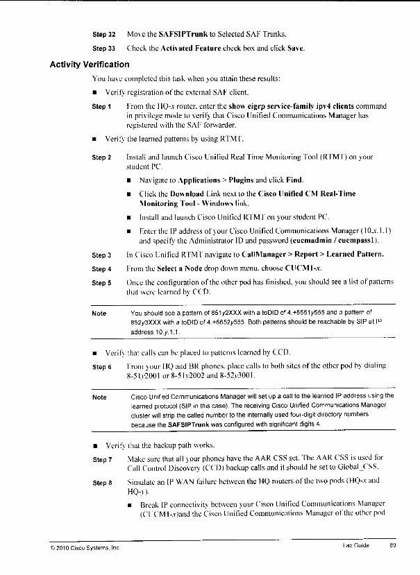
4M
Step 32 Move the SAFSlPTrunk to Selected SAF Trunks.
Step 33 Check the Activated Feature check box and click Save.
Activity Verification
You have completed this task when you attain these results:
• Verify registration of the external SAF client.
Step 1 from the I IQ-.v router, enter the show eigrp service-family ipv4 clients commandin privilege mode to verify that Cisco Unified Communications Manager hasregistered with the SAF forwarder.
• Verify the learned patterns by using RTMT.
Step 2 Install and launch Cisco Unified Real Time Monitoring Tool (RTMT) on yourstudent PC.
• Navigate to Applications > Plugins and click Find.
• Click the Download Link next to the Cisco Unified CM Real-Time
Monitoring Tool - Windows link.
• Install and launch Cisco Unified RI M f on your student PC.
• Enter the IP address of jour Cisco Unilied Communications Manager (10_v. 1.1)and specify the Administrator ID and password (cucmadmin /cucmpassl).
Step 3 In Cisco Unified RTMT navigate to CallManager > Report > [.earned Pattern.
Step 4 From the Select a Node drop down menu, choose CUOMI-a-.
Step 5 Once the configuration of the other pod has finished, you should see a list of patternsthat were learned by CCD.
Note You should see a pattern of 851/2XXX witha toDIDof 4:+5551y555 and a pattern of852/3XXX with a toDIDof4:+6652y555 Bothpatterns should be reachable by SIP at IPaddress I0.y.1.1.
• Verifv that calls can be placed to patterns learned by CCD.
Step 6 From jour IIQ and BRphones, placecalls to both sitesof the other pod by dialing8-5l.v2001 or8-5ly2002and8-52v3001.
Note Cisco Unified Communications Manager will set up a call to the learned IP address using thelearnedprotocol (SIP inthiscase). The receiving Cisco Unified Communications Managercluster will strip the called numberto the internally used four-digit directory numbersbecause the SAFSlPTrunk was configured with significant digits 4.
• Verify that the backup path works.
Step 7 Make sure that all your phones have the AAR CSS set. The AAR CSS isused forCall Control Discoverj (CCD)backup calls and it shouldbe set to Global.CSS.
Step 8 Simulate an IP WAN failure between the HQ routers ofthe two pods (HQ-.-c andHQ-y).
• Break IP connectivity between your Cisco Unilied Communications Manager(CUCMI-.x)and the Cisco Unified Communications Manager of the other pod
©2010 Cisco Systems, Inc Lab Guide
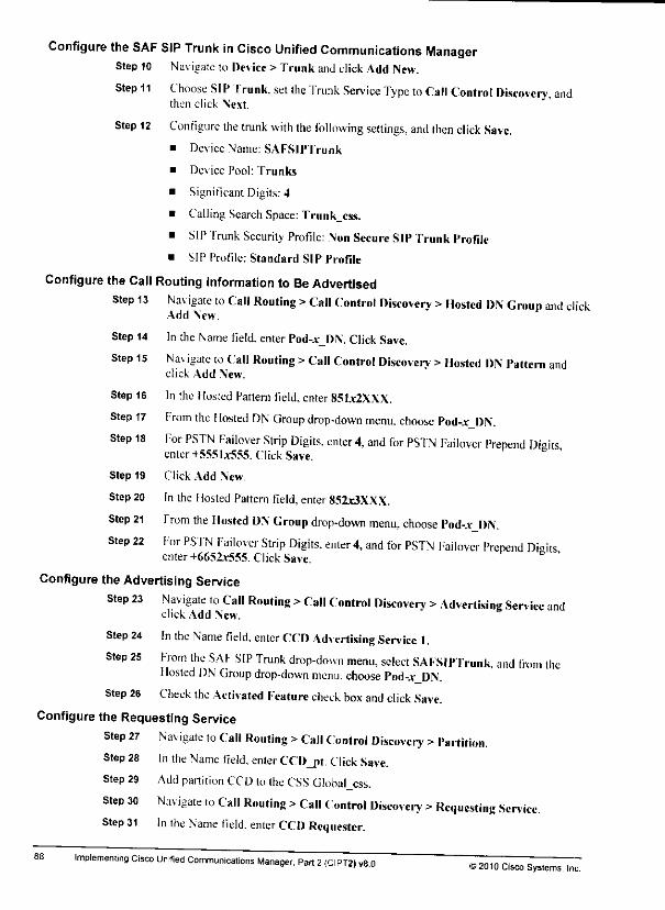
Configure the SAF SIP Trunk in Cisco Unified Communications ManagerStep 10 Navigate to Device > Trunk and click Add New.
Step 11 Choose SIP Trunk, set the Trunk Service Type to Call Control Discovery, andthen click Next.
Step 12 Configure the trunk with the following settings, and then click Save.
• Device Name: SAFSlPTrunk
• Device Pool: Trunks
• Significant Digits: 4
• CallingSearchSpace: Trunk_css.
• SIPTrunk Security Profile: Non Secure SIP Trunk Profile
• SIP Profile: Standard SIP Profile
Configure the Call Routing Information to Be AdvertisedStep 13 Navigate to Call Routing >Call Control Discovery >Hosted DN Croup and click
Add New.
Step 14 In the Name field, enterPod-*_DN. ClickSave.
Step 15 Na% igate to Call Routing >Call Control Discovery >Hosted DN Pattern andclick Add New.
Step 16 In the Hosted Pattern field, enter 851jc2XXX.
Step 17 From the Hosted DN Group drop-down menu, choose Pod-Jt DN.
Step 18 For PSTN Failover Strip Digits, enter 4, and for PS'fN Failover Prepend Digitsenter +5551jc555. Click Save. '
Step 19 Click Add New.
Step 20 In the Hosted Pattern field, enter 85Zx3XXX.
Step 21 From the Hosted DN Group drop-down menu, choose Pod-:r_DN.Step 22 For PSTN Failover Strip Digits, enter 4, and for PSTN Failover Prepend Digits
enter +6651r555. Click Save.
Configure the Advertising Service
Step 23 Navigate to Call Routing >Call Control Discovery >Advertising Service andclick Add New.
Step 24 In the Name field, enter CCD Advertising Service I.Step 25 From the SAF SIP Trunk drop-down menu, select SAFSlPTrunk, and from the
Hosted DN Group drop-down menu, choose Pod-.v DN.
Step 26 Check the Activated Feature cheek box and click Save.
Configure the Requesting Service
Step 27 Na\ igate to Call Routing >Call Control Discovery >Partition.Step 28 In the Name field, enter CCD_pt. Click Save.
Step 29 Add partition CCD lo the CSS GIobal_css.
Step 30 Navigate to Call Routing >Call Control Discovery >Requesting Service.Step 31 In me Name field, enter CCD Requester.
Implementing Cisco Unified Communications Manager, Part 2(CIPT2) v8.0 ©20)0 Cisco Systems, Inc.
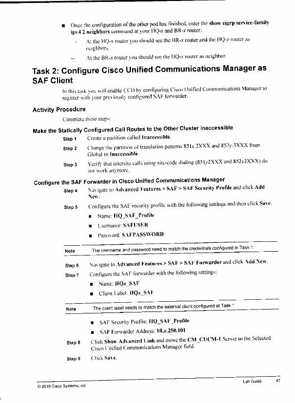
• Once the configuration ofthe other pod has finished, enter the show eigrp service-familyipv4 2 neighbors command at your HQ-.v and BR-.r router:
At the HQ-x router you should see the BR-.r router and the HQ-y router asneighbors.
Atthe BR-.\ router you should seetheIIQ-.v router as neighbor.
Task 2: Configure Cisco Unified Communications Manager asSAF Client
In this task you will enable CCD by configuring Cisco Unified Communications Manager toregister uith jour pre\ iousK configured SAF forwarder.
Activity Procedure
Complete these steps:
Make the SUtically Configured Call Routes tothe Other Cluster InaccessibleStep 1 Create a partition called Inaccessible.Step 2 Change the partition of translation patterns 851y.2XXX and 852y.3XXX from
Global to Inaccessible.
Step 3 VcrifS that intersite calls using site-code dialing (851y2XXX and 852y3XXX) donot work anymore.
Configure the SAF Forwarder in Cisco Unified Communications ManagerStep 4 Na^ igate to Advanced Features >SAF >SAF Security Profile and click Add
New.
Step 5 Configure the SAF security profile with the following settings and then click Save.• Name: HQ_SAF_Profile
• Username: SAFl'SER
• Password: SAFPASSWORD
Note The username and password need to match the credentials configured in Task 1
Step 6 Navigate to Advanced Features >SAF >SAF Forwarder and click Add New.Step 7 Configure the SAF forwarder with the following settings:
• Name: HQ.v_SAF
• Client Label: HQr_SAF
Note The client label needs to match the external client configured at Task 1
Step 8
© 2010 Cisco Systems, Inc
• SAF Security Profile: IIQjSAF_Profile
• SAF Forwarder Address: 10jf.250.l01
Click Show Advanced Link and move the CM_CUCM-1 Server to the SelectedCisco Unified Communications Manager field.
StepS Click Save.
Lab Guide 87
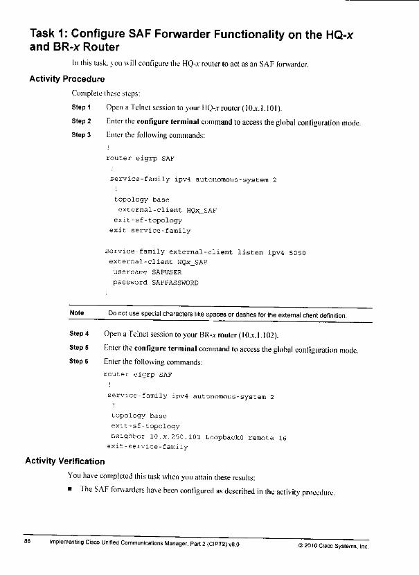
Task 1: Configure SAF Forwarder Functionality on the HQ-xand BR-x Router
In this task, you will configure the HQ-.r router to act as an SAF forwarder.
Activity Procedure
Complete these steps:
Step 1 Open a Telnet session to your HQ-.r router(IOjc. 1.10I).
Step 2 Enter theconfigure terminal command to access theglobal configuration mode.
Step 3 Enter the following commands:i
router eigrp SAF
service-family ipv4 autonomous-system 2i
topology base
external-client HQx_SAF
exit-sf-topology
exit service-family
service-family external-client listen ipv4 5050external-client HQx_SAF
username SAFUSER
password SAFPASSWORD
Note Do not use special characters like spacesor dashesfor theexternal client definition.
Step 4 Open a Telnet session toyour BR-x router (IO.v. 1. 102).
Step 5 Enter the configure terminal command toaccess the global configuration mode.Step 6 Enter the following commands:
router eigrp SAF
service-family ipv4 autonomous-system 2
topology base
exit-sf-topology
neighbor 10.x.250.101 LoopbackO remote 16
exit-service-family
Activity Verification
You have completed this task when you attain these results:
• The SAF forwarders have been configured as described in the activity procedure.
86 Implementing Cisco Unified Communications Manager. Part 2(CIPT2) v8.0 ©2010 Cisco Systems. Inc.

Lab 5-1: Implementing Cisco SAF and CCDComplete this lab activity lopractice what you learned inthe related module.
Activity ObjectiveIn this activity. \ou will implement CCD using Cisco SAF clients and forwarders. Aftercompleting this activity, you will be able tomeet these objectives:
• Configure SAF forwarder functionality on the HQ-.t and BR-.r routers
• Contigurc Cisco Unified Communications Manager asan advertising and requesting SAFclient
• Configure Cisco Unified Communications Manager Express onthe BR-.r router asarequesting SAF client
Visual ObjectiveThe figure illustrates what you will accomplish inthis activity.
Lab 5-1: Implementing Cisco SAFCCD
Phnnel-* Phane2-'
4DHCP 1 ICx 30/24 ioy_;y
101
Enable CCD toleam and advertise
call routinginformation
j&J2£
"' Frame S^SS PSTN
s:Enable SAF. configureSRST gateway to leamcall routing information
Required ResourcesThese are the resources and equipment that arc required tocomplete this activitv:
Cisco Unified Communications Manager
Student PC
Cisco IP Phones
Cisco IOS MGCP gateway
H.323 galeway
PSTN with PSTN phone
© 2010 Cisco Systems. Inc.Lab Guide 85
Step 15 From the Selecta Servicedrop-down menu,choose the EM service.Click Next.
Step 16 Click Subscribe, "fhe Cisco F.xiension Mobility service isdisplayed underSubscribed Services.
Step 17 Click Save, then close the window.
Step 18 Click Reset in the Phone Configuration window to reset the phone.
Step 19 Repeat the previous steps (enabling Cisco Unified Communications ManagerFxtension Mobility and subscribing tothe Cisco Extension Mobility IP phoneservice) for Phone2-.r and Phone.Vr.
Note As an alternative loperforming steps 3to19 you could have activated the EnterpriseSubscription check box when configuring theCisco Extension Mobility IP phone service.Enterprise subscriptions apply to all phones and to all device profiles.
Activity Verification
You havecompleted this task whenyou attain these results:
• You can log in and log out at Phone I-x, Phone2-jr, and Phone3-.r by performing Ihefollowing steps:
Step 1 Press the Services button.
Step2 Choose theCisco Extension Mobility service.
Step 3 Log in with username and PIN.
Step 4 The phone will reset and should (hen be loaded with your device profile, fhedirector, numbershouldchangeto 2405.
Step 5 Place calls to internal and external (PSTN) destination.
Note Cisco Extension Mobility does not modify device level settings such as region and locationordevice CSS and AAR CSS. These parameters arenot configurable in the device profile.The line CSS of the phone where a Cisco Extension Mobility user logs misupdated with theline CSS of the device profile. In this lab. the line CSS isHQ_css. This CSS provides accesstotheHQ translation patterns. Therefore, the PSTN dial rules ofthe HQ sitehave tobeused.
• The configured service parameters are working. This can be verified by performing thefollowing steps:
Step 1 Log in at Phone3-.v and place acall. Then wait for the maximum login timer (3minutes) to expire. You should be automatically logged out when the timer expires.
Step 2 Log in again at Phone3,v. Verify that the call list was cleared alter logout: use theRedial softkey and verify that the phone does not remember Ihe last destination.
Step 3 Do not log out. Log in at Phone 1-.t before the 3-minute timer expires. Once youhave logged in at Phone I-.t. you should be automatically logged out at Phone3-.v.because the multiple login behavior has been set lo auto-logout.
Note After logging out or being logged out of a phone, the phone reconfigures itself to its standardsettings
84 Implementing Cisco Unified Communications Manager. Part 2(CIPT2) v8.0 ©2010 Cisco Systems, Inc.

Task 4: Add the Cisco Extension Mobility IP Phone Service andSubscribe to IP Phones and Device Profiles
Inthistask, vou will addtheCisco Fxtension Mobility IPphone service andsubscribe it to IPphones and the deviceprofile.
Activity Procedure
Complete these sleps:
Add the Cisco Extension Mobility IP Phone ServiceStep 1 Go to Device >Device Settings >Phone Services and click Add New.
Step2 Define the following fields and click Save:
• Sen. ice Name: EM
• ASCII Service: EM
• Service Description: Extension Mobility Login/Logoff
• Service URL:hHp://10jc.l.l:8080/emapp/EMAppServlet?tlevice=#DKVICENAME#
Note The service URL is case-sensitive.
Service Category: XML Service
Service Type: Standard IP Phone Service
finable: Check
Note After you click Save, the Parameters pane will appear—Cisco Extension Mobility does notneed any additional parameters tobe specified.
Subscribe Device Profiles to the Cisco Extension Mobility IP PhoneServiceStep 3 Nav igate to Device >Device Settings >Device Profile and click the Find button.Step4 Click thedevice profile andy_dp.
Step 5 At the Related Links, choose Subscribc/linsubscribe Services: then click Go.Step 6 From the Select aService drop-down menu, choose the EM service. Click Next.Step 7 Click Subscribe. The Cisco Extension Mobility service is displayed under
Subscribed Services.
Step 8 Click Save, then close the window.
Enable Cisco Unified Communications Manager Extension Mobility atthe Phones andSubscribe the Cisco Extension Mobility IP Phone Service to IP Phones
Step 9 Nav igate to Device >Phone and click Eind.
Step 10 Open Phonel-a.
Step 11 In the Extension Information pane check the Enable Extension Mobility check box.Step 12 At the Log Out Profile drop-down menu, choose Use Current Device Settings.Step 13 Click Save and click OK in the pop-up window.Step 14 At the Related Links choose Subscribc/linsubscribe Services: then click Co.
© ;;010 Cisco Systems, IncLab Guide
Task 3: Add and Associate an End User with the User DeviceProfile
In this task, you will add an end user to Cisco Unified Communications Manager and associatethis user with the newly created device profile.
Activity Procedure
Complete these steps:
Add New User Through Cisco Unified Communications Manager AdministrationIn Cisco Unified Communications Manager, configure an end user:
Step 1 from PC-.r. access Cisco Unified Communications Manager Administration.Step2 Go to Eser Management > End User and click Add New.
Step 3 Configure a user with the attributes that follow, and save the newly created accountby clicking Save at the bottom of" the page or the Save symbol at the top ofthe EndUser Configuration window.
• UserID:andy
• Password: password
• PIN:12345
• Last Name: Szoldatics
• First Name: Andreas
Assign the Device Profile to the End User
Step 4 In the t.xtension Mobility pane of the End User Configuration window, from theAvailable Profiles list, choose the profile andy_dp and add it to the ControlledProfiles using the down arrow.
Steps Click Save.
Step 6 In User Management > End User, verify that the end user "andy" has been added toCisco Unified Communications Manager.
Activity Verification
You have completed thistaskwhen youattain these results:
• The end user "andv" is configured in User Management >End User as described in theactivity procedure.
• The device profile andy_dp is assigned to the end user as described in the activityprocedure.
82 Implementing Cisco Unified Communications Manager, Part 2(CIPT2) v8.0 ©2010 Cisco Systems, Inc
Task 2: Create a Device Profile for a UserIn this task, vou will create a device profile for theuser of Phone l-.v.
Activity Procedure
Complete these steps:
Step 1 Nav igate to Device >Device Settings >Device Profile.
Step 2 Click Add New.
Step 3 Tor ihe phone model, choose Cisco 7965. Click Next.
Step 4 Keep the SCCP signaling option and click Next.
Note If your Phonel -x is a different model, usethe model of your phone
Step 5 Filterthe following parameters:
• Device Profile Name: andy_dp
• Description: Device Profile-Andy
• User Hold MOH AudioSource: I-Samplc Audio Source
• User Locale: Knglish, I'nited States
• Phone Button Template: Standard 7965 SCCP
Note The phone button template depends on the phone model that you chose earlier.
• Soflkey Template: Standard User
Step 6 Click Save.
Step 7 In the Association Info pane, click the Line 111 Add anew DN link.Step 8 lor the director) number, enter 2405.
Step 9 Choose the route partition Internal.
Step 10 Choose the CSS HQ_Phones_CSS.Step 11 For the Exiemal Phone Number Mask value, enter +5551.v5552X\X.
Step 12 Click Save.
Activity VerificationYou nav ecompleted this task when you attain these results:• The new profile is configured in Dev ice >Device Settings >Device Profile as described in
the activity procedure.
• Director) number 2405 is associated with the new device profile andy_dp as described inthe activity procedure.
© 2010 Cisco Systems, IncLab Guide
• H.323 gateway
• PSTN with PS'I N phone
Task 1: Activate the Cisco Extension Mobility Service andConfigure the Corresponding Service Parameters
In this task, you will activate the Cisco Extension Mobility service and configure Ihe loginbehavior by setting ihe appropriate service parameters for the Cisco Extension Mobility service.
Activity Procedure
Complete these steps:
Step 1 Open Cisco Unified Serviceability.
Step 2 Go to Tools > Service Activation.
Step 3 Check the check box for the Cisco Extension Mobility service and click Save toactivate it.
Note The Cisco Extension Mobility service can be activated on multiple servers
Step 4
Note
In Cisco Unified Communications Manager Administration, navigate to SystcService Parameters.
Step5 From the Serverdrop-down menu, choose ltLv.1.1.
Step 6 From the Service drop-down menu, choose Cisco Extension Mobility.Step 7 Configure the following parameters:
• Enforce Intra-Cluster Maximum Login Time: True
• Intra-Cluster Maximum Login Time: 0:03
It is acommon configuration error to subscribe to the Cisco Extension Mobility service onlyat the IP phone and not also at the device profile. In such a situation, you cannot log out ofthe phone anymore once you have logged in. By setting the maximum login time to arelatively low value, you have a back door for this case, because an auto logout isperformed after expiration of the maximum login time. This is a common setup for a labenvironment.
• Intra-Cluster Multiple Login Behavior: Auto Logout• Remember the Last User Logged In:True
• Clear Call Log on Intra-Cluster EM: True
Steps Click Save.
Activity Verification
You have completed this task when vou attain these results:
• The Cisco Extension Mobility service parameters in System >Service Parameters tireconfigured as described in the lask.
Note Further venfication will bedone in a later task of this lab exercise.
80 Implementing Cisco Unrfied Communications Manager, Part 2(CIPT2) ve.O ©2010 Cisco Systems, Inc

Lab 4-2: Implementing Cisco Extension MobilityComplete this lab activity to practice what you learned in the related module.
Activity ObjectiveIn this activity. you will implement Cisco Extension Mobility for roaming users. Aftercompleting this activity, you will be able to meet these objectives:• Configure the sen ice parameters for Cisco Fxtension Mobility• Create a device profile for a user
• Add an end user
• Associate the end user withthe userdeviceprofile
• Subscribe IP phones and device profiles to the IP phone service for Cisco ExtensionMobility
Visual ObjectiveThe figure illustrates what vou will accomplish in this activity.
Lab 4-2: !rn
Mobility
=hpne'-< PI>one2
HCP ^T^DHCPJ Allow roaming
users to log in toany phone andhave personal
settings applied
Frame ^Sj PSTNRelay
Allow roaming users to login to any phone and havepersonal settings applied
Required ResourcesThese are the resources and equipment that arc required to complete this activity:• One Cisco Unified Communications Manager cluster
• Student PC
• Cisco IP Phones
• Cisco IOS MGCP gateway
© 2010 Cisco Systems. IncLab Guide 79
78
The local route group ofaroaming phone should be updated. Perform the following stepsfor verification:
Stepl
Step 2
Step 3
Note
Nav igate to Device > Phone and click Find.
Choose Phone2-.v.
At the phone configuration window, click the View Current Device MobilitySettings link next to the Device Mobility Mode parameter. Awindow will pop up,show ing ihecurrent configuration of the phone.
The local route group is nol shown in the pop-up window. You cannot verify that the localroute group has been updated by using the View Current Device Mobility Settings link.
Step 4 Log in to the HO-.v router and enable ISDN debugging with the debug isdn q931command. Make sure to turn onmonitoring with the terminal monitor command.
Step 5 Shut down the ISDN interface at the branch router so that the gatcwav cannot beused for TEHO calls to the BR PSTN.
Step 6 From the Phonc3-.v (which is currently roaming to the HQ site) place acall to theBR PSTN by using the home dial rules (for example, 9 5554444). 'fhe call uses theIIQ-.v gateway. This indicates that the local route group ofthe phone was updated bythe one configured in the roaming device pool.
Implementing Cisco Unified Communicatiot ;Manager, Part 2(CIPT2) v8.0©2010 Cisco Systems, Inc.
Step 17 Click Save.
Step 18 Click Add New and enter the following parameters in the Device Mobility IntoConfiguration window:
• Name: BR_dmi
• Subnet: KU.4.0
• Subnet Mask: 24
Step 19 Mov ethe Branch device pool from the Available Device Pools list to the SelectedDev ice Pools list.
Step 20 Click Save.
Enable Device Mobility Mode for the ClusterStep 21 Navigate to System>Service Parameters.
Step 22 from the Server drop-down list, choose Cisco Unilied Communications Manager10-v.l.l.
Step 23 From die Service drop-down list, choose Cisco CallManagerStep 24 In Clusierwide Parameters (Device- Phone), set the Device Mobility Mode to On.
Activity Verification
You have completed this task when vou attain these results:
• Phones can register at different physical locations. Perform the following steps torverification:
Step 1 Disconnect Phonc2-.r and Phone3-.v from the switch port.
Step 2 Reconnect Phone2-.r to the port of Phone3--v.
Step 3 Reconnect Phone3-.v lothe port of Phone2-„v.Step 4 Phone2-.v should register in the branch with its directory number 2002, and Phone3-A
should register in the headquarters with its directory number 300I.
Step 5 Place calls between any ofthe three phones.• Roaming phones have their roaming-sensitive settings updated based on the configuration
in the roaming dev ice pool. Perform the following steps for verification:
Step 1 Nav igate to Device >Phone and click Find.
Step 2 Choose Phone2-.v.
Step 3 At the phone configuration window, click the View Current Device MobilitySettings link next to the Device Mobility Mode parameter. Awindow is dtsplaved.which showsthe currentconfiguration of the phone.
Step 4 Verifv that the headquarters phone adapted lo its new physical location (branch) bychanging the roaming-sensitive settings (such as the location, region, and SRS 1reference).
Step 5 In order to sec that these updated settings are active, place acall from I'hone2-* loPhonel -.v. Press the ?button twice at both phones. The codec that is used tor the calshould be G.729.
Note When it is in the home location, Phone2-x uses G.722 for calls to Phone1-x.
i 2010 Cisco Systems. IncLab Guide
Task 1: Configure Device MobilityIn this task, vou will configure the Device Mobility feature so that roaming users can use theirhome dial rules, but can aiso use the local route group as abackup path for TEHO PSTN calls.
Activity Procedure
Complete these steps:
Configure Physical Locations
Step 1 Nav igate to System > Physical Location and click the Add New button.
Step 2 In the Physical location Configuration window, enter the following parameters:• Name: HQpl
• Description: Headquarters
Step 3 Click Save.
Click Add New and configure another physical location for the branch office, withthe following parameters:
Step 4
• Name: BR pi
• Description: Branch
Step 5 Click Save.
Note No DMGs are required. When no DMG is set at the roaming device pool and at the homedevice pool, the device-mobility-related settings are not updated. In this lab, globalized callrouting is used. Therefore, there is no need to change the device CSS, AAR group, or AARCSS,as theyare the same at allphones.
Configure Device Pools
Step6 Navigate to System > Device Pool andclickthe Find button.
Step 7 Choosethe devicepool Default.
Step 8 From the Physical Location drop-down menu, choose IIQ_pl.Step 9 Click Save and then reset the dev ice pool.
Step 10 In the Related finks pane, select Back To Find/List and then click Ihe Go button.Step 11 Choosethe devicepool Branch.
Step 12 From the Physical Location drop-down menu, choose BR__pl.Step 13 Click Save and then reset the device pool.
Create Device Mobility Infos
Step 14 Nav igate to System >Device Mobility >Device Mobility Info and click Add New.Step 15 Enter the following parameters in the Device Mobility Info Configuration window:
• Name: HQ_dmi
• Subnet: 10_v.2.0
• Subnet Mask: 24
Step 16 Move the Default device pool from the Available Device Pools list lo ihe SelectedDevice Pools list.
76 Implementing Cisco Unified Communications Manager, Part 2(CIPT2) v*0©2010 Cisco Systems. Inc.
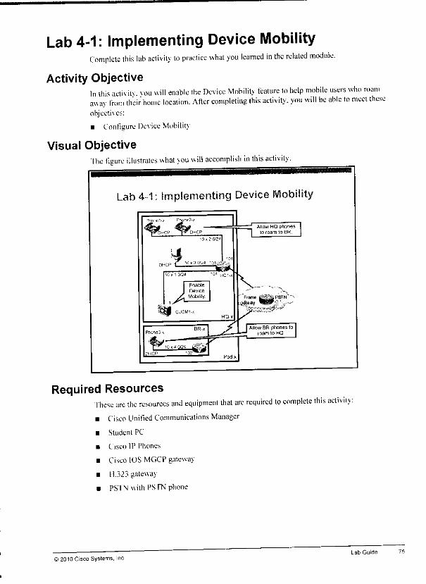
Lab 4-1: Implementing Device MobilityComplete this lab activity to practice what you learned in the related module.
Activity ObjectiveIn this activitv. vou will enable the Device Mobility feature to help mobile users who roamawav from their home location. After completing this activity, you will be able to meet theseobjectives:
• Configure Device Mobility
Visual ObjectiveThe figure illustrates what vou will accomplish in this activity.
Lab 4-1; Implementing Device
Required ResourcesThese are the resources and equipment that arc required to complete this activitv• Cisco Unified Communications Manager
• Student PC
• Cisco IP Phones
• Cisco IOS MGCP gateway
• H.323 gateway
• PSTN with PSTN phone
© 2010 Cisco Systems, IncLab Guide 75
Note The SIP trunk does not need to have access to the RSVP Agent media resource. Therefore,MRGs and MRGLs do not have to be modified.
Step 4 Nav igate to Device >Device Settings >SIP Profile and click the Add button. mmStep 5 In the Name field, enter SIPPrecondition, and scroll down lo the Trunk Specific
Configuration section. ^
Step 6 From the Reroute Incoming Request toNew Trunk Based On drop-down menu,select Never. ' |L
Step 7 From theRSVP Over SIP drop-down menu, select E2E and at theSIPRel IXXOptions, choose Send PRACK if Ixx Contains SDP. 'mt
Step 8 Go to the configuration page ofthe existing trunk called SIPJI'runk.
Step 9 From the SIP Profile drop down menu, select SIP_Precondition and click Save and **Apply.
Configure the RSVP Bandwidth at the IP WAN Interface That Connects to the Other Pod "**Step 10 At the subinterface that interconnects the headquarters and the other pod, configure jjL
the bandwidth thatcan bereserved by RSVP as follows:interface Serial... s«-
ip rsvp bandwidth 40
Test RSVP SIP Preconditions CAC 'L*
Note Check that the configuration of the other pod is also completed before continuing.
Step 11 Establish one call between your local headquarters phone and the other headquarterphone at the other pod and keep the call open. Try to set up asecond call by callingthe second headquarter phone for the other pod. The second call should be reroutedover the PSTN Use the debug isdn q931 command toverify thai the call is sentthrough the PSTN. The show seep connections rsvp command can be used toshowthe currently active connections atthe RSVP agent.
Activity Verification
You have completed this task when you attain these results:
• You configured SIP Preconditions between the two pods as described in the activityprocedure.
in
You can place one call between the two pods over the SIP trunk and end-to-end RSVP is ^used for that call as described intheactivity procedure.
When placing an additional call, the PSTN is used as abackup as described in the activity jkprocedure.
Note Make sure lo turn off all of the debug commands at all of the routers (use no debug altcommand).
Implementing Cisco Unified Communications Manager, Part 2(CIPT2) V8.0 ©2010 Cisco Systems, Inc.
2.
Step 19 Repeat the previous steps for Phonc2-* and Phone3-x
Modifying the RSVP Bandwidth So That All Calls FailStep 20 Reconfigure the RSVP bandwidth on one of the two routers to avalue below 40
kb/s. This will make all calls between branch and headquarters fail.
Step 21 Try calls between the headquarters and branch. The calls should be rerouted throughihe PSTN.
Configure One Phone for an Alternate CFNB DestinationStep 22 Change the configuration of the Phonel-.v line so that calls arc forwarded to aPSTN
number if2001 cannot he reached because ofCAC. Set the AAR destination maskto +556065554444.
Step 23 Try to call 2001 from the branch phone. The call should be sent to the PSTN phoneusing the BR gateway.
Allowing Calls over IP WAN AgainStep 24 Change the RSVP bandwidth back to40 on both routers.Step 25 Verify that one call between the headquarters and branch uses the IP WAN. Keep
that call open. Tr> calling the branch phone from another phone in the headquarters.You should see an incoming call at the branch phone (which is still in a call) comingthrough the PSTN. You can use the debug isdn q931 command to verify that callsarc using the PSTN path. The show seep connections rsvp command can be used tos,hou thecurrently active connections at the RSVP agent.
CleanupStep 26 Remov ethe (TNB setting at Phone 1-x by clearing the AAR destination mask at
line 1.
Activity VerificationYou have completed this task when vou attain these results:• When intracluster calls are rejected because there is no available bandwidth, the calls are
rerouted over the PSTN as described in the activity procedure.
Note Make sure to turn off all of the debug commands atall of the routers (use the no debug allcommand) ^
Task 4 (Optional): Configure SIP PreconditionsIn this task, you will modify the previously implemented RSVP-bascd CAC to implement end-to-endCAC for calls between pod 1and pod 2.
Activity Procedure
Complete these steps:
Enable End-to-End RSVP to Be Used for Calls Between the Two Pods Using the SIP TrunkSIP Preconditions-based CAC should allow one Ci.729 call between the two pods.Step 1 Cio to the configuration page of the existing location called Trunk.Step 2 Prom fhe Modifv Settings) to Other Locations pane, select the Iliib_None location,
and from the RSVP Setting drop down menu, choose Mandatory (V ideo Desired).
Step 3 ClickSave.
© 2010 Cisco Systems. IncLab Guide 73
Task 3: Configure AAR and CFNB to Route Calls over the PSTNIf They Are Not Admitted by the Deployed CAC Methods
In this task, you will configure a backup path for calls that are rejected by the previouslyimplemented CAC methods. These calls will be rerouted over the PSTN using AAR andCFNB.
Activity Procedure
Complete these steps:
Enable AAR
In the following steps, you will enable AAR by setting the Cisco CallManager serviceparameter Automated Alternate RoutingEnabled to True.
Step 1 Navigate to System > Service Parameters and choosethe Cisco UnifiedCommunications Manager(IOjc.1.1).
Step 2 From the Service drop-down menu, choose Cisco CallManager.
Step3 Locate theClusterwideParameters(System—CCM Automated AlternateRouting) pane.
Step 4 Set the Automated Alternate Routing Enable parameters toTrue.Step 5 Click Save.
Configure an AAR Group
Step 6 Navigate to Call Routing>AAR groups and click Add New.
Step 7 Enterthe name System_aar.
Step 8 Click Save.
Configuring Phones for AAR
Step 9 Navigate to Device > Phone and click Find.
Step 10 Choose Phonel-x.
Step 11 Click Line 1toget tothe Director) Number Configuration window.
Step 12 In the AAR Settings pane, choose System_AAR for the AAR Group.Step 13 Verify that the external phone number mask isin globalized format.Step 14 Click Save.
Step 15 From the Related Links, choose Configure Device and click <;».
Step 16 At the Phone Configuration window, choose Global ess for the AAR CSS.
Note When acall between the HQ and BR sites is not admitted, AAR will be used to place the callover the PSTN The AAR call will match the Wtranslation pattern first, and then the TEHOpattern of the local pod. The first option of the route list that is applied to the TEHO pattern isthe TEHO gateway. This, however, cannot be used, because there Is not enough bandwidthavailable between the HQ and BR sites. Therefore, the second option of the route list isused—the local route group.
Step 17 Click Save and then OK in the pop-up window.
Step 18 Reset the phone.
72 Implementing Cisco Unified Communications Manager, Part 2(CIPT2) v8.0 ©2010 Cisco Systems, Inc
Step 19 Click Save.
Put the RSVP Agents Into MRGsStep 20 Add the HQ-RSVP RSVP agent to theHQ_mrg MRG.
Step 21 Add the BR-RSYP RSVP agent tothe BR-SW-CFB_mrg MRG.
Test RSVP CAC
Note The RSVP configuration has tobe performed onboth sides. Unless both sides areconfigured for RSVP, the call will fail.
Step 22 Place a call between aheadquarters phone and a branch phone. The call should fail.
Step 23 Use the debug ip rsvp signaling command on the I\Q-x router to see why thereservation fails. Ilow much bandwidth do you expect tobe reserved? How much isaetuallv reserved0
Note During the call setup phase, the RSVP agents always attempt to reserve an additional 16kb/s (for signaling). Therefore, in this case, the RSVP bandwidth atthe interface must allow40 kb/s for the call togothrough. The extra 16 kb/s that that the RSVP agents attempt toreserve during call setup areimmediately released once the call issetup end-to-end.
Step 24 Change the RSVP bandwidth at the IP WAN interfaces on the IIQ-jc and on the BR-.i routers to 40 kb/s. Now the calls should go through. If you want, you can retrywith 39kb/s tomake sure that 40 kb/s is the absolute minimum for one G.729 call tobe allowed. Make surethatyouset it back to 40kb/safterward.
interface serial...
ip rsvp bandwidth 40
Note The RSVP bandwidth command has tobemodified on both sides. Unless both sides permitenough bandwidth for RSVP, thecall will fail. .^
Step 25 I stablish one call between aheadquarters phone and the branch phone and keep thecall open. Try to set up asecond call by calling the branch phone directory numberfrom the other phone inihe headquarters. The call should fail.
Activity VerificationYou have completed this task when you attain these results:• You modified Cisco Unified Communications Manager CAC between the IIub_None and
the branch locations to use RSVP asdescribed intheactivity procedure.
• RSVP permits one G.729 call between these two locations. Additional calls fail, because ofa lack ofavailable bandwidth asdescribed inthe activity procedure.
Note Make sure to turn off all of the debug commands at all of the routers (use the no debug allcommand) ^
) 2010 Cisco Systems. IncLab Guide
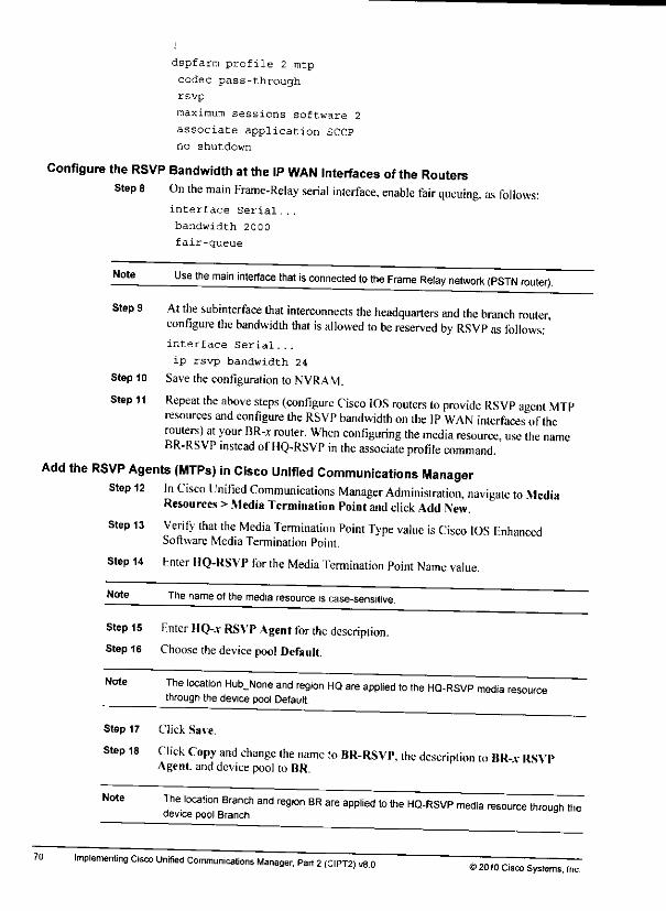
dspfarm profile 2 mtp
codec pass-through
rsvp
maximum sessions software 2
associate application SCCP
no shutdown
Configure the RSVP Bandwidth atthe IP WAN Interfaces ofthe RoutersSteps On the main Frame-Relay serial interface, enable fair queuing, as follows:
interface Serial...
bandwidth 2000
fair-queue
Note Use the main interface that is connected to the Frame Relay network (PSTN router).
Step 9 At the subinterface that interconnects the headquarters and the branch router,configure the bandwidth that is allowed to be reserved by RSVP as follows:'interface Serial...
ip rsvp bandwidth 24
Step 10 Savethe configuration to NVRAM.
Step 11 Repeat the above steps (configure Cisco IOS routers to provide RSVP agent MTPresources and configure the RSVP bandwidth onthe IPWAN interfaces of therouters) at your BR-x router. When configuring the media resource, use the nameBR-RSVP instead ofHQ-RSVP in the associate profile command.
Add the RSVP Agents (MTPs) in Cisco Unified Communications ManagerStep 12 In Cisco Unified Communications Manager Administration, navigate to Media
Resources >Media Termination Point and click Add New.
70
Step 13
Step 14 Enter HQ-RSVP for the Media Termination Point Name value.
Verify that the Media Termination Point Type value isCisco IOS EnhancedSoftware Media Termination Point.
Note Tne name ofthe media resource iscase-sensitive.
Step 15 Hnter HQ-* RSVP Agent for the description.Step 16 Choosethe devicepool Default.
Note The location Hob^None and region HQ are applied to the HQ-RSVP media resourcethrough the device pool Default.
Step 17 Click Save.
Step 18 Click Copy and change the name to BR-RSVP, the description to HR-a RSVPAgent, and device pool to BR.
Note The location Branch and region BR are applied to the HQ-RSVP media resource through thedevice pool Branch.
implementing Cisco Unmed Communications Manager. Part 2(CIPT2, ,8.0 ' ©2010 Cisco Systems, Inc.
Step 12 Repeat the previous steps lo apply the llub_Nonc location to the MOH.Onlydevice pool.
Step 13 Repeat the previous steps to apply the Branch location to the BR device pool.Step 14 Nav igate lo Device >Trunk and click the Find button.Step 15 Choose the SIP_Trunk.
Step 16 From the location drop-down menu, choose Trunk.
Step 17 Click Saveand reset the trunk.
Activity VerificationYou have completed this task when you attain these results:• You have configured and applied locations as specified in the activity procedure.• You cannot place more than one call to the other cluster using the SIP trunk (by dialing
851 v-2001. 85 ly-2002. or 852v-300l). The G.729 codec should be in use lor ibis call.• You cannot place more than one call to the branch phone (by dialing 3001). The (G.729
codec should be in use for this call.
Task 2: Configure RSVP-Enabled LocationsIn this task vou will change the previously implemented locations-based CAC to use RSVP inthe IP WAN for calls between the Hub^Nonc and Branch locations. 1his will be done bvdeploying RSVP agents at the headquarters and branch sites.
Activity Procedure
Complete these steps:
Enable RSVP toBe Used Between the Hub_None and the Branch LocationsIn the following steps, vou will change the branch location so that it uses RSVP toward the1lubNone location. RSVP should be mandatory between these two locations.Step 1 Nav igaie to System >Locations and click the Find button.Step2 Click Branch.Step 3 In the Modifv Sctting(s) to Other Locations pane, from the RSVP Setting drop-down
menu, choose the Hub_Nonc location and choose M»ndatory(Vidco Desired).Step 4 Click Save. You should see the changes in the Location RSVP Settings pane.
Click the Resync Bandwidth button to reset all CAC bandwidth usage, and clickOK in the pop-up window.
Step 5
Note RSVP is configured per pair of locations. The setting applies to both directions. Therefore,the configuration that you apply to one location automatically updates the other locationaccordingly .
Configure Cisco IOS Routers to Provide RSVP Agent MTP ResourcesStepG Connect to your HQ-jc router.
Step 7 Configure router IIQ-.v asfollows:seep ccm group 1associate profile 2 register HQ-RSVP
© 2010 Cisco Systems. IncLab Guide 69
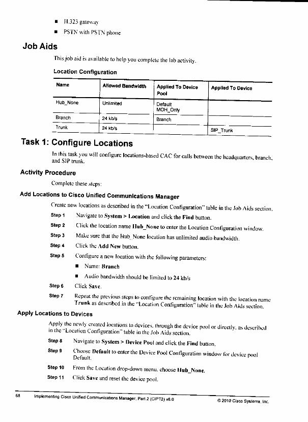
H.323 gateway
PSTN with PSTN phone
Job Aids
This job aid is available to help you complete the lab activity.
Location Configuration
Name Allowed Bandwidth Applied To DevicePool
Applied To Device
Hub_None Unlimited DefaultMOH_0nly
Branch 24 kb/s Branch
Trunk 24 kb/s SIPJTrunk
Task 1: Configure LocationsIn this task you will configure locations-based CAC for calls between the headquarters, branchand SIP trunk.
Activity Procedure
Complete these steps:
Add Locations to Cisco Unified Communications ManagerCreate new locations as described in the "Location Configuration" table in the .lob Aids section.Step 1 Navigate to System > Location and click the Find button.
Click the location name Hub_None to enter the Location Configuration window.Make sure that the Hub^None location has unlimited audio bandwidth.Click the Add New button.
Configure anew location with the following parameters:• Name: Branch
• Audio bandwidth should be limited to 24 kb/s
Click Save.
Step 2
Step 3
Step 4
Step 5
Step 6
Step 7 Repeat the previous steps to configure the remaining location with the location nameTrunk as described in the "Location Configuration" table in Ihe Job Aids section.
Apply Locations to Devices
68
Apply the newly created locations to devices, through the device pool or directly, as describedinthe Location Configuration" table in the Job Aids section.Steps
Steps
Step 10
Step 11
Navigate to System >Device Pool and click the Find button.
Choose Default to enter the Device Pool Configuration window for device poolDefault. •
From the Location drop-down menu, choose HubJSonc.Click Save and reset the device pool.
Implementing Cisco Unified Communications Manager, Part 2(CIPT2) v8.0>2010 Cisco Systems, Inc.
i»
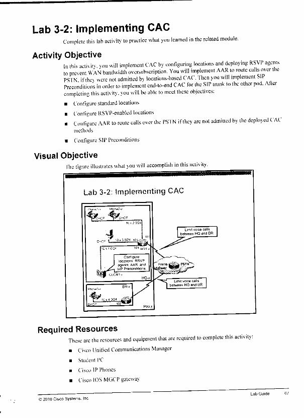
Lab 3-2: Implementing CACComplete this lab activity to practice what you learned in the related module.
Activity ObjectiveIn this ael.v itv. vou will implement CAC by configuring locations and deploying RSVP agentsto prevent WAN bandwidth oversubscription. You will implement AAR to route calls over thePSTN ifthev were not admitted bv locations-based CAC. Then you will mplement SIPPrecondition's in order to implement end-to-end CAC for the SIP trunk to the other pod. Aftercompleting this activity, you will be able lo meet these objectives:• Configure standard locations
• Configure RSVP-enabled locationsi Configure AAR to route calls over the PSTN if they arc not admitted by the deployed CAC
methods
• Configure SIP Preconditions
Visual Objectivefhe figure illustrates what vou will accomplish in this activity.
Configurelocations. RSVP
agents. AAR, and' _^- SIP Preconditions
HQ-.
;ۤ
Required ResourcesThese arc the resources and equipment that are required to complete this activity:• Cisco Unified Communications Manager
• Student PC
• Cisco IP Phones
• Cisco IOS MGCP gateway
2010 Cisco Systems. IncLab Guide
Enable Multicast MOH from Branch Router Flash at the BR-x SRST RouterStep 51 Configure the branch router as follows: Hi
telephony-service
multicast moh 239.1.1.1 port 16384 route 10.x.4.102 El
Note The moh moh-file-name command that is used to enable unicast MOH in SRST mode -already configured in an earlier lab exercise.
Step 52 Saveyour configuration to NVRAM.
Verify That Multicast MOH from Branch Router Flash WorksStep 53 Place acall from Phonel-* to Phone3-*, and at Phonel-*, put the call on hold
Phone3-* should play MOH. Keep the call in this state.Step 54 Pressthe Settings buttonat Phone3-x
Step 55 Choose option 2 Network Configuration.
Step 56 Press 6orscroll down toget tooption 6 IPAddress.
Step 57 Write down the IP address ofPhone3-*: 10. .4.Step 58 Using a web browser, browse tothe IP address ofPhone3-.v.
Step 59 Click the Stream 1link to see details about the current RTP stream.Step 60 The local address should be 239.1.1.1/16384, which indicates thai the phone listens
to the multicast MOH stream.
Note The phone now plays the locally generated multicast MOH stream.' ' . ___ -•*&•
Activity Verification
You have completed this task when you attain these results: Si
• Branch phones can play MOH created by the local SRST router as described in the activity eprocedure. J ^
Note More detailed verification was pan of the Activity Procedure.
66 Implementing Cisco Unified Communications Manager. Part 2(CIPT2) v8.0©2010 Cisco Systems, Inc.
Hm%
m*
Step 42 Press the Settings button atPhone3-.v.Step 43 Choose option 2Network Configuration.Step 44 Press 6or scroll down to get to option 6. IP Address.Step 45 Write down the IP address ofPhone3-.v: 10. .4.Step 46 Using aweb browser, browse to the IP address of Phone3-.r.
Note If you did not enable web access to the phone earlier, you need to enable it now, in order tobe ableto browse to the phone.
Step 47 Click the Stream 1link to see details about the current RTP stream.The local address should be 239.1.1.1/16384, which indicates that the phone listensto the multicast MOH stream. Keep the call in this stale so that you hear MOH.
Step 48
PreventMulticast MOH from Being Sent overthe IP WANStep 49 At router HQ-.t. disable multicast routing toward the branch by entering the
following commands:
interface Serial...
no ip pim sparse-dense-mode
Note Use the interface that connects to the BR-x router (IP WAN).
NoteAs soon as you enter the above commands, Phone3-x should not play MOH anymore Norwill it play TOH, because Cisco Unified Communications Manager is unaware that the phonenolonger receives theMOH audio stream _____
Step 50 At router BR-.r. disable multicast routing by entering the following commands:interface Serial...
no ip pim sparse-dense-mode
Note Use the interface that connects to the HQ-x router (IP WAN)
interface FastEthernet...
no ip pim sparse-dense-mode
no ip multicast-routing
Note Use the interface that connects to the branch phones.
Note
© 2010 Cisco Systems, Inc.
Mullicast MOH in SRST does not require multicast routing. It simply streams permanently atthe interface that is configured to be used by SRST. If the stream is requ.red on adifferentmterface (for example, when using aloopback for SRST) the interface or interfaces can bespecified using the route option of the multicast moh command (as shown in the next step)
Lab Guide 65
At this point, the MOH server shares the same region with all other headquarters devices Tolimit calls to these other devices to G.729 but allow G.7I Ibetween the MOH server and thebranch phones, the MOH server needs to be placed into aseparate, dedicated region Inaddition, the multicast MOH stream that is generated by the MOH server has to be blockedfrom the IP WAN. Then multicast MOH can be enabled at the BR-* SRST router.
Allow G.711 Between the MOH Server and Branch PhonesStep 29 In Cisco Unified Communications Manager Administration, navigate to System >
Region and click Add New.
Step 30 Enter MOH for the name and click Save.
m
it
k
Step 31 Using the Modify Relationship to other Regions pane, allow the G.722 and G711 &audio codecs to be used to the region HQ by highlighting the region HQ in theRegions list and choosing G.722/G.711 from the Audio Codec drop-down menu £.Click Save. mt
Step 32 Using the same technique, also allow the G.722 and G.711 audio codecs for calls m\between the region MOH and the region BR and for calls within the region MOH.Allow G.729 only for calls between the regions MOH and Trunks. m
Note You must click Save after each change in the Modify Relationship to Other Regions paneThe changes will then appear in the Region Relationships pane.
Note By limiting the audio codec to G.729 for calls between regions Trunks and MOH youeffectively disable MOH for these calls. The reason is that the MOH server is only streamingG.711 multicast MOH, and a multicast stream cannot be transcoded (which would berequired toward the region Trunks). This is desired, because G.729 MOH has only poorquality, and G.711 must not be sent over the IP WAN (used by the trunks).
Step33 Navigate to System > Device Pool andclickAdd New.
Step 34 Configure the following parameters for the new device pool:• Device Pool Name: MOH_Only
• Cisco Unified Communications Manager Group: Default• DateATime Group: CMLocal
• Region: MOH
• SRST Reference: Disable
Step 35 Click Save.
Step 36 Navigate to Media Resources >Music On Hold Server and click lind.Step 37 Choose HQ-SVV-MOH.
Step 38 Change the device pool from Default to MOH_Only.Step 39 Click Save.
Step 40 Reset the MOII server.
Verify That Multicast MOH Now Works to Branch PhonesStep 41 Place acall from Phone I,r to Phone3-x, and at Phone I-x put (lie call on hold
Phone3-.v should play MOH. Keep the call inthis state.
64 Implementing Cisco Unified Communications Manager. Par. 2(CIPT2) v8.0 ©2010 Cisco Systems, Inc.

Verify ThatMulticast MOH Is UsedStep 20 Place acall from Phonel-* to Phone2-x. and at Phoncl-x. put the call on hold.
Phone2-.v should play MOH. Keep the call inthis slate.
Step 21 Press the Settings button at Phonc2-.v.
Step 22 Choose option 2 Network Configuration.
Step 23 Press 6or scroll down to get to option 6, IP Address.Step24 Writedown the IP address ofPhonc2-.x: 10. .2. _Step 25 Using aweb browser, browse to the IP address ofPhone2-v.
Note If you did not enable web access to the phone earlier, you need to enable it now, in order tobe able to browse to the phone.
Step 26 Click the Stream I link to see details about the current RIP stream.Step 27 The Local Address should be 239.1.1.1 /16384. which indicates that the phone listens
lo the multicast MOH stream.
Step 28 Place acall from Phone I-x to Phone3-.v. and at Phone I-x put the call on hold.Phonc3-.v will play loneon hold only.
Note The reason that Phone3-x will play tone on hold instead of MOH is that the MOH server isconfigured for G.711 MOH only (this is the default configuration). However, before changingto multicast MOH, Phone3-x played MOH. This was possible by using the transcoder mediaresource The MOH server is configured with the device pool Default, which applies regionHQ and MRGL HQ_mrgl. This MRGL allows the MOH server to access the transcoder
Such a configuration is not recommended, because if MOH with the G.729 codec should bepermitted, it can be directly enabled on the MOH server (by using the Supported MOHCodecs service parameter of the Cisco IP Voice Media Streaming Application service)Using G.729 for MOH, however, is not recommended, because the G.729 codec audioquality for music is poor; G.729 is designed and optimized for human speech, and does notwork well with music.
Multicast audio streams cannot be transcoded, sobranch phones do not hear MOHanymore, because the MOH server was configured to use multicast MOH instead of unicastMOH You will solve this problem by implementing multicast MOH from branch router flash.
Enable Multicast MOH from Branch Router FlashWhen using multicast MOH from branch router flash, the branch router locally generates amulticast MOH stream. This stream must use attributes (destination address -that is. multicastgroup address-port numbers, and codec) that are identical to the attributes tor the multicastMOH stream that is generated by the Cisco Unified Communications Manager MOH serverthat is located at the headquarters. This is required because neither Cisco UnifiedCommunications Manager nor the branch IP phones are aware that the phones listen to astreamgenerated bv the local SRST gateway. Cisco Unified Communications Manager tel sthe phonelo listen to its stream (providing the attributes that were mentioned belore) in signalingmessages, and. therefore, the locally generated stream has to look exactly that way.Because SRST MOH supports only G.711, Cisco Unified Communications Manager also has toinstruct the phone to listen to aG.711 MOH stream. Consequently. G.711 must be enabledbetween branch phones and the MOH server in region configuration.
© 2010 Cisco Systems. IncLab Guide 63
Update MRGs to Use Multicast
Step 14 Navigate to Media Resources >Media Resource Group and click the Find button.Step 15 Choose theGeneralmrg MRG.
Step 16 Ifat least one multicast HQ-SW-MOI Iresource is available, cheek the UseMulticast for HQ-SW-MOH Audio check box in the Media Resource GroupConfiguration window.
Step 17 Click Save.
Enable MulticastRouting in the Network
Step 18 At router HQ-*, enable multicast routing using the following commands:ip multicast-routing
interface FastEthernet...
ip pim sparse-dense-mode
62
Note Use the interface that connects to the voice server network (CUCM-x).
interface FastEthernet...
ip pim sparse-dense-mode
Note Use the interface that connects to the headquarters phones.
interface Serial...
ip pim sparse-dense-mode
Note Use the interface that connects to the BR-x router (IP WAN).
Step 19 At router BR-*, enable multicast routing using the following commands;ip multicast-routing
interface Serial...
ip pim sparse-dense-mode
Note Use the interface that connects to the HQ-x router (IP WAN).
Note
Note
interface FastEthernet...
ip pim sparse-dense-mode
Use the interface that connects toIhe branch phones.
Multicast routing is now enabled for the voice server network, the headquarters phonenetwork, the branch phone network, and the link between HQ-x and BR-x (IP WAN).
Implementing Cisco Unified Communications Manager, Part 2(CIPT2) v8.012010 Cisco Systems, Inc.

Stepl
Step 2
Initiate an ad hoc conference from Phone3-jr (adding Phonel-* and Phone2,v>.
At each IP phone, press the ?button twice. Phonel-.v and Phonc2-.v should use theG729 codec and Phone3-j should use the G.711 codec. This is because theconference bridge is at the branch and G.7I I is only allowed locally at the branchbutnotbetween branch and headquarters. Keep the call open.
Step 3 At BR-.r. enter the show dspfarm cisp all command. You should see three usedconnections representing the three conference participants.
Step 4 r.nd the conference. Verifv thai all DSP resources arc freed by entering the sho»dspfarm dspall command again.
Step 5 Repeat the previous steps but initiate the conference from Phone I-x or Phonc2-.v.1his time Phonel-.v and Phone2-Jc should use G.7I I and Phone3,v should use G.729.The show dspfarm dsp all command will indicate that no conference resources areused at BR-.v. Issue the same command at I\Q-x and you will see atranscodersession for the connection of Phone.V.v to the conference bridge.
Task 5: Implement Multicast MOH from Branch Router FlashIn this task vou will first implement multicast MOII. Then you will implement multicast MOIIfrom branch'routcr Hash. This allows branch users to listen to MOH. but prevents the MOIIstreams from beingsent over the IP WAN.
Activity Procedure
Complete these steps:
EnableMulticast MOH in Cisco Unified Communications ManagerStep 1 In Cisco Unified Communications Manager Administration, navigate to Media
Resources >Music On Hold Audio Source and click the Find button.
Step 2 Choose the onlv available audio source and verify that the Play Continuously checkbox is checked.
Step 3 Check the Allow Multicasting check box.
Step 4 Click Save.
Step 5 Nav igate to Media Resources >Music On Hold Server and click ihe Find button.Step G Click the only available MOI Iserver (HO-SW-MOH).Step 7 Under Multicast Audio Source Information, check the Enable Multicast Audio
Sources on This MOH Server check box.
Steps Click Save.
Step 9 Verify the following parameters under Multicast Audio Source Information:• Base Multicast IP Address: 239.1.1.1
• Base Multicast Port Number: 16384
Step 10 Change the Increment Multicast value from Port Number to IP Address.Step 11 Under Selected Multicast Audio Sources, set the Max Hops value for the multicast-
enabled audio source to 3.
Step 12 Click Save.
Step 13 Reset the MOII server.
© 2010 Cisco Systems, Inc.Lab Guide

Step 17 Enter HQ_mrg for the name of the MRG.
Step 18 Enter HQ SW Conference Bridge for the description.Step 19 From the Available Media Resources pane, add HQ-SW-CFB to the Selected Media
Resources list.
Step 20 Click Save.
Step 21 Repeat the previous steps to add the other two MRGs, as described in the "MediaResource Group Configuration" table in theJobAids section.
Create MRGLs
mh
In these steps, you will configure dilTerenl MRGLs that allow IP phones to use their local t*conference bridge.
Step 22 Navigate to Media Resources> Media Resource Group List. **Step 23 Click the Add Newbutton. __
Step 24 Enter HQ_mrgl for the nameof the MRGL.
Step 25 From the Available Media Resource Groups pane, add the HQ-SW-CFB and m,General_mrg MRGs to the Selected Media Resource Groups list.
Step 26 Click Save. »
Step 27 Repeat the previous steps to add the other MRGL, as described in the "MediaResource Group List Configuration1" table in the Job Aids section. H
Assign MRGLs to Devices
In these steps, you will assign the newly created MRGLs to devices (phones, trunks and "*gateways) by configuring the appropriate MRGL in the available device pools. ' m,Step 28 Navigate to System > Device Pooland click Find.
Step 29 Choosethe devicepool Default. tt
Step 30 From the Media Resource Group List drop-down menu, choose IIQ_mrgl.Step 31 Click Save. WStep 32 Reset the device pool. m
Step 33 Repeat the previous steps for the other two device pools, assigning the MRGLs asdescribed in the "Device Pool Configuration" table in the Job Aids section. M
Activity Verification
You have completed this task when you attain these results: •
• BR-.v provides aconference hardware media resource (BR-HW-CFB) lhat is registered mwith Cisco Unified Communications Manager. Perform the following steps at router BR-v ""toverity the hardware media resource configuration and status-
mhStep 1 Enter the show seep command. Verify that the Conferencing Oper Stale is ACTIVEand that the TCP Link Status isCONNECTED. m
Step 2 Enter the show dspfarm profile 1command. Verify the stains, number ofavailableresources, and the listof supported codecs. m
• Conferences that are initiated by headquarters phones use the software eonlerenee bridgethat ,s located at the headquarters; branch phones use the hardware conference bridge that J£is located at the branch. Verify this by performing the following steps- "
60 Imptemenflng Cisco Unified Communications Manger, Part 2(CIPT2) v8.0 ©20)0 Cisco Systems, Inc.
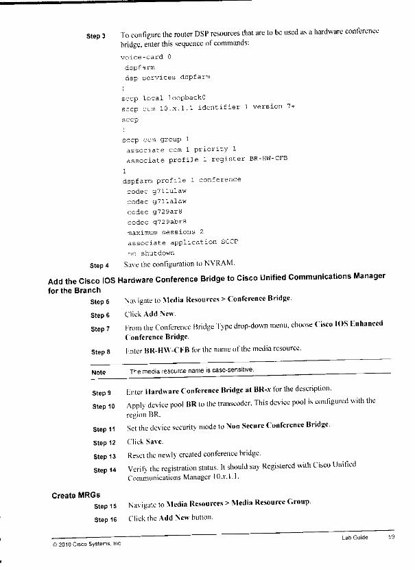
Step 3 To configure the router DSP resources that are to be used as ahardware conferencebridge, enter this sequence ofcommands:voice-card 0
dspfarm
dsp services dspfarm
seep local loopbackO
seep ccm 10.x.1.1 identifier 1 version 7+
seep
seep ccm group 1
associate ccm 1 priority 1
associate profile l register BR-HW-CFB
1
dspfarm profile 1 conference
codec g711ulaw
codec g711alaw
codec g729ar8
codec g729abr8
maximum sessions 2
associate application SCCP
no shutdown
Step 4 Save the configuration to NVRAM.
Add the Cisco IOS Hardware Conference Bridge to Cisco Unified Communications Managerfor the Branch
Step 5 Nav igate to Media Resources >Conference Bridge.
Step 6 Click Add New
Step 7 From the Conference Bridge Type drop-down menu, choose Cisco IOS FnhancedConference Bridge.
Step 8 Inter BR-HW-CFB for ihe name ofthe media resource.
Note Themedia resource name iscase-sensitive.
Step 9 Lnter Hardware Conference Bridge at BR-a" for the description.Step 10 Apply device pool BR to the transcoder. This device pool is configured with the
region BR.
Step 11 Set the device security mode to Non Secure Conference Bridge.Step 12 Click Save.
Step 13 Reset the newly created conference bridge.Step 14 Verily the registration status. It should say Registered with Cisco Unified
Communications Manager 10..V.L1.
Create MRGsStep 15 Nav igate to Media Resources >Media Resource Group.Step 16 Click the Add New button.
© 2010 Cisco Systems. IncLab Guide 59

Step 6 From the Transcoder Type drop-down menu, choose Cisco IOS Knhanced MediaTermination Point.
Step 7 Enter Hardware Transcoder at HQ-x for the description.Step 8 Enter HQ-HVV-XCD forthename of themedia resource.
Note The media resource name iscase-sensitive.
Step 9 Apply the device pool Default to the transcoder. This device pool is configured with ^the region HQ.
Step 10 Click Save. j*
Step 11 Reset the newly created transcoder.
Step 12 Verify the registration status. Itshould say Registered with Cisco Unified ""Communications Manager 10jr. I. I.
Activity Verification **
You have completed this task when you attain these results: §^• HQ-* provides atranscoding hardware media resource (HQ-HW-XCD) that is registered
with Cisco Unified Communications Manager. Perform the following steps at router HQ-* Htoverify the hardware media resource configuration and status:
Step 1 Enter the show seep command. Verify that the Transcoding Oper State is ACTIVE Bland that the TCP Link Status is CONNECTED.
Step 2 Enter the show dspfarm profile I command. Verify the status, number of available &resources, and the list of supported codecs.
• Branch phones can now join conferences on the G.711-only software conference bridge 1*even though they are not allowed to use the G.711 codec over the IP WAN. Verify this byperforming the following steps: m
Step 1 Set up an ad hoc conference with Phonel-*, Phone2-*, and Phone3-.v as members.Step 2 At each IP phone press the ?button twice. Phonel-* and Phone2-.r should show the ^
G.711 codec being used for the call, while Phone3-* shows G.729.
Step 3 At HQ-.v. enter the show dspfarm dsp all command. You should see two used *connections representing the two call legs ofthe transcoder (G.711 tothe softwareconference bndge and G.729 to Phone3-*). §fc
Task 4: Implement a Hardware Conference Bridge mIn this task, you will configure alocal hardware conference bridge at the branch You willimplement MRGs and MRGLs to ensure that IP phones use the local conference media Mi.resource. am
Activity Procedure jfcComplete these steps:
Configure aCisco IOS Router as aHardware Conference Media Resource for the BranchStep 1 Connect to your BR-*. f&
Step 2 Enter configuration mode.
58 Implementing Cisco Unified Communications Manager, Part 2(CIPT2) v8.012010 Cisco Systems, Inc.

Task 3: Implement TranscodersIn this task vou will implement atranscoder at the headquarters in order lo allow branch usersto join confe'renccs on aG.711-only software conference bridge, even though branch phonesare not allowed to use G.711 over the IP WAN. The transcoder will transcode the (..729 audiostream that is received from branch phones to aG.711 stream toward the software conferencebridge and vice versa.
Activity Procedure
Complete these steps:
Configure aTranscoder Media Resource in Cisco IOS SoftwareConfigure the IIQ-.v router as a transcoder resource.
Step 1 Connect to \our HQ-.* and enter configuration mode.Step 2 To configure router DSP resources to be used as atranscoder. enter this sequence of
commands:
voice-card 0
dspfarm
dsp services dspfarm
i
seep local loopbackO
seep ccm 10.x.1.1 identifier 1 version 7+
Note The highest possible SCCP version that can be specified in the seep ccm commanddepends on the Cisco IOS Software release that is used on the router.
seep
seep ccm group 1
associate ccm 1 priority 1
associate profile 1 register HQ-HW-XCD
dspfarm profile l transcodecodec g7llulaw
codec g711alaw
codec g729ar8
codec g729abr8
maximum sessions 2
associate application SCCP
no shutdown
Step 3 Save the configuration to NVRAM.
Add theTranscoder to Cisco Unified Communications ManagerAdd the transcoder to Cisco Unified Communications Manager and assign adevice pool thatuses the region HQ.
Step 4 Navigate to Media Resources >Transcoder.
Steps ClickAdd New.
)2010 Cisco Systems. IncLab Guide
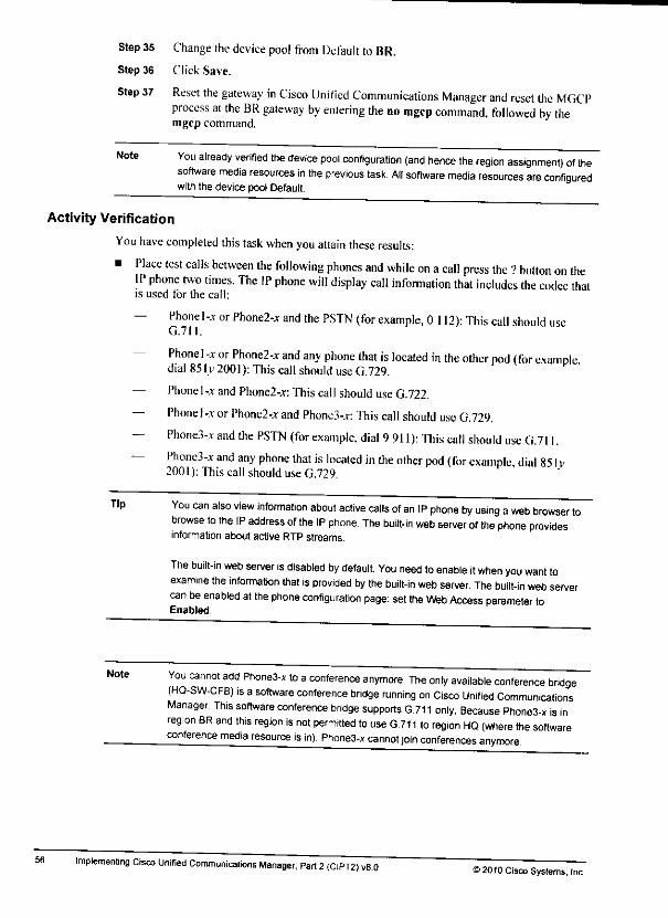
Step35 Change thedevice pool from Default to BR.
Step 36 Click Save.
Step 37 Reset the gateway in Cisco Unified Communications Manager and reset the MGCPprocess at the BR gateway by entering the no mgcp command, followed by themorn rnmmnniHmgcp command.
Note You already verified the device pool configuration (and hence the region assignment) of thesoftware media resources in the previous task. All software media resources are configuredwith the device pool Default
Activity Verification
You have completed this task when you attain these results:
• Place test calls between the following phones and while on acall press the 7button on theIP phone two times. The IP phone will display call information that includes the codec thaiis used for the call:
— Phone 1,r or Phone2-* and the PSTN (for example, 0 112): This call should useG.711.
— Phone I-x or Phone2-j; and any phone that is located in the other pod (for exampledial851y2001):ThiscallshoulduseC..729. '
— Phonel-j and Phone2-.r: This call shoulduse G.722.
— Phonel-.t orPhone2-;r and Phone3-*: This call should use G.729.
— Phone3-.v and the PSTN (for example, dial 9911): This call should use G.711.— Phone3-.v and any phone that islocated in the other pod (for cxumnle dial 851 v
2001 ):This call should use G.729.
56
Tip You can also view information about active calls of an IP phone by using aweb browser tobrowse to the IP address of the IP phone. The built-in web server of the phone providesinformation about active RTP streams.
The built-in web server is disabled by default. You need to enable it when you want toexamine the information that is provided by the built-in web server. The built-in web servercan be enabled at the phone configuration page: setthe Web Access parameter toEnabled
Note You cannot add Phone3-x to aconference anymore. The only available conference bridge(HQ-SW-CFB) is asoftware conference bridge running on Cisco Unified CommunicationsManager. This software conference bridge supports G.711 only, Because Phone3-x is inregion BR and Ihis region is not permitted to use G.711 to region HQ (where the softwareconference media resource is in), Phone3-x cannot join conferences anymore
implementing Cisco Unified Communications Manager, Part 2(CIPT2) v8.0 ©2010 Cisco Systems. Inc
I*
&

Step 17 Verify that the region issetto HQ.
Step 18 At the relaled links, choose Back To Find/List and click Go.Step 19 Choose the Branch device pool.
Step 20 Change the region lo BR.
Step 21 Click Save.
Step 22 Reset thedevice pool.Step 23 Click the Add New button and configure anew device pool with following
parameters:
• Name: Trunks
• Cisco Unified Communications Manager Group: Default
• Local Route Group: HQrg
Note The local route group at the trunk is required in order to allow received TEHO calls that areto besent to the BR gateway to bererouted via the backup path (standard local routegroup). Until now, the trunk had the device pool Detault applied, which also has the localroutegroupHQ_rg configured. ^^_
• Date-TimeGroup: CM Local
• Region: Trunks
• SRST Reference: Disable
Step 24 Click Save.
Apply Device Pools to DevicesIn these steps vou will applv device pools to devices as speci tied in the "Device PoolConfiguration"' table in the Job Aids section. This will assign the appropriate regions to thedevices.
Step 25 Nav igate to Device >Phone and click Find.Step 26 At the list of phones, verify that Phonel* and Phonc2-x are listed with device pool
Default and Phone3-.v is listed with device pool Branch.
Note Regions cannot be directly applied to devices. You have to create different device pools withregions and then apply the appropriate device pools to the devices.
Step 27 Navigate to Device >Trunk and click Find.
Step 28 Choose the SIP-Trunk.
Step 29 Change the dev ice pool from Default to Trunks.
Step 30 Click Save.
Step 31 Reset the trunk.Step 32 Nav igate to Device >Gateway, choose the option to Show endpoints. and click
Find.
Step 33 Verifv that the HO-.vgaleway(lO^.l.lOl) is listed with the device pool Default.Step 34 Choose the MGCP endpoinl of gateway BR-x (SO/SUO/OSl-OfflJBR-* or similar).
Lab Guide 55© 2010 Cisco Systems, Inc

• You can establish ad hoc conferences using the HQ-SW-CFB conference resource Verilythis by creating an ad hoc conference with Phonel*, Phone2-j, and Phone3-* as members.
• When acall is put on hold, the caller hears MOH. Verify this by establishing acall and thenputting the call on hold.
Task 2: Configure RegionsIn this task, you will configure regions in order to prevent audio streams that are sent over theIP WAN from using htgh-bandwidth codecs. Only G.729 will be permitted tor streams thattraverse the IP WAN. Refer to the table -Region Configuration" in the Job Aids section formore details. The regions are then applied to devices using device pools.
Activity Procedure
Complete these steps:
Create and Configure RegionsStep1 Navigate to System > RegionandclickFind.
Step 2 Choose the region Default.
Step 3 Change the name to HQ.
Step 4 Verify that G.722/G.7I Iaudio codecs are allowed for calls within regionheadquarters.
Step 5 Click Save.
Step 6 Click the Add New button.
Step 7 Enter Trunks for the name ofthe new region and click Save.
Using the Modify Relationship to other Regions pane, allow the G.729 audio codecTJ-.»" /Villi- llJltliin Hr^x^-^^.^- T 1.1 I • II- • . • »», -
Step 8
Step 9
Note
for calls within region Trunks by highlighting Trunks in the Regions list andchoosing G.729 from the Audio Codec drop-down menu. Click Save.
Using the same technique, allow the G.729 audio codec for calls between regionTrunks and region HQ.
You must click Save after each change in the Modify Relationship to Other Regions paneThe changes will then appear in the Region Relationships pane.
Step 10 Click Add New.
Step 11 Enter BR for the name ofthe new region and click Save.Step 12 Allow G.722/G.711 for calls within region BR.
Step 13 Allow G.729 for calls between regions BR and Trunks.
Step 14 Allow G.729 for calls between regions BR and HQ.Create and Configure Device Pools
In these steps, you add anew device pool for the trunks and update the existing device poolswith the new regions, as described in the "Device Pool Configuration" table in .he Job Aidsotciions.
Step 15 Navigate to System >Device Pool and click the Find button.Step 16 Choose the Default device pool.
54 Implementing Cisco Unified Communications Manager, Part 2(CIPT2) v8.0>2010 Cisco Systems. Inc.
•to

Task 1: Enable Software Media Resources on Cisco UnifiedCommunications Manager
In this task vou will enable the Cisco IP Voice Media Streaming Application service, whichprovides several software media resources running on Cisco Unified CommunicationsManager. You will change the default names and descriptions of these media resources.
Activity Procedure
Complete these steps:
Verify That the Cisco IP Voice Media Streaming Application Service Is ActivatedStep 1 Log in to Cisco Unified Serviceability and navigate to Tools >Control Center-
Feature Services.
Step 2 Verify that the Cisco IP Voice Media Streaming App service is activated andrunning at CUCMl-.v.
Note This service provides the following software media resources: Annunciator, ConferenceBridge, Media Termination Point, and Music on Hold Server.
Verify and Configure theSoftware Media ResourcesStep 3 Iog in to Cisco Unified Communications Manager Administration and navigate to
Media Resources >Annunciator and click Find.
Step 4 Verify the status of the media resource. It should be registered with your CiscoUnitied Communications Manager CUCMI-x (IO.r. I.I).
Step 5 Click the shown Annunciator media resource (ANN_2).Step 6 Change the Name to HQ-SW-ANN and the description lo Software Annunciator
atCICMl-.Y.
Step 7 Verifv that the Device Pool is Default.
Step8 Click Save.
Step9 Reset the media resource.Step 10 Repeal the previous steps for the following media resources using the specified
values:
Media Resource
Conference Bridge
Media TerminationPoint
MOH Server
Name
HQ-SW-CFB
HQ-SW-MTP
HQ-SW-MOH
Description
Software Conference Bridge atCUCMI-x
Software Media TerminationPoint at CUCMI-x
Software MOH Server atCUCMI-x
Activity VerificationYou have completed this task when you attain these results:• The Cisco IP Voice Media Streaming Application service is activated.. The following software media resources are registered with CUCMl-.v: Annunciator.
Conference Bridge. Media Termination Point, and MOH Server.
Lab Guide
J2010 Cisco Systems. Inc.
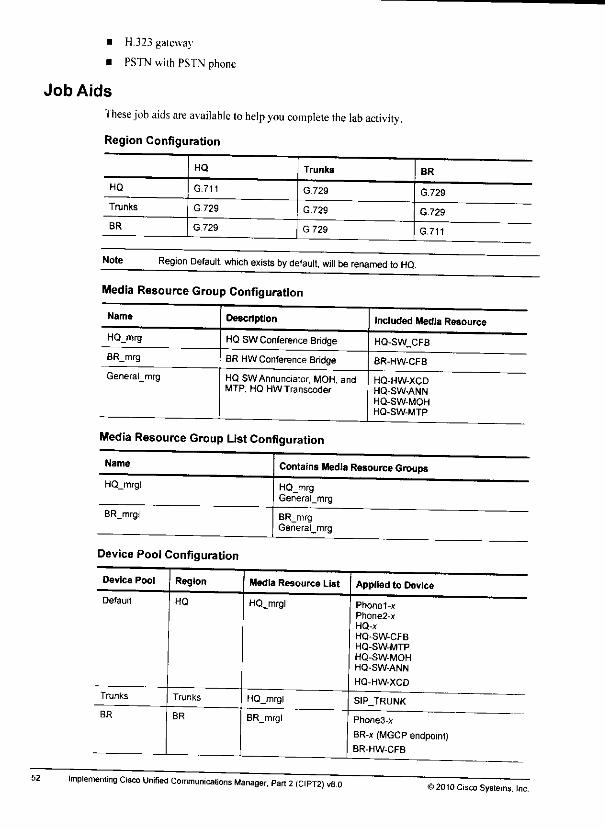
• H.323 gateway
• PSTN with PSTN phone
Job Aids
These job aids are available to help you complete the lab activity.
Region Configuration
52
HQ Trunks BR
HQ G.711 G.729 G.729
Trunks G.729 G.729 G.729
BR G.729 G729 G.711
Note Region Default, which exists by default, will be renamed to HQ.
Media Resource Group Configuration
Name Description Included Media Resource
HQ_mrg HQ SWConference Bridge HQ-SW_CFB
BR_mrg BR HWConference Bridge BR-HW-CFB
General_mrg HQ SW Annunciator, MOH andMTP; HQ HW Transcoder
HQ-HW-XCDHQ-SW-ANN
HQ-SW-MOHHQ-SW-MTP
Media Resource Group ListConfiguration
Name Contains IContainsMedia ResourceGroups
HQ_mrgl HQ_mrgGeneral_mrg
BR_mrgl
Device Pool Configuration
Device Pool Region
Default HQ
Trunks Trunks
BR BR
BR_mrgGeneraljnrg
Media Resource List
HQ_mrgl
HQ_mrgl
BR_mrgl
Implementing Cisco Unified Communications Manager, Part 2(CIPT2) v8.0
Applied to Device
Phone1-xPhone2-xHQ-x
HQ-SW-CFBHQ-SW-MTP
HQ-SW-MOHHQ-SW-ANN
HQ-HW-XCD
SIP_TRUNK
Phone3-x
BR-x (MGCP endpoint)BR-HW-CFB
©2010 Cisco Systems. Inc.
&
m

Lab 3-1: Implementing Bandwidth ManagementComplete this lab activity to practice what you learned in the related module.
Activity ObjectiveIn this activitv. vou will configure multicast MOH from branch router flash, regions, localconference bridges, and Iranseoders to reduce bandwidth requirements on the IP WAN. Aftercompleting this activ ity. you will be able to meet these objectives:• fnable software media resources onCisco Unified Communications Manager
• Configure regions
• Implement transcoders
• Implement a hardware conference bridge
• Implement multicast MOH from branch router flash
Visual ObjectiveThe figure illustrates what vou will accomplish in this activity.
Lab 3-1: Implementing BandwidthManagement
Implementconference bridge
and transcoder
Use low-bandwidth
codecs only in WAN
Use low-bandwidthcodecs only in WAN.
Implementlocalconference bndge;npiement multicast MOH from branch
router flash
Required ResourcesThese arc the resources and equipment that are required to complete this activity:• Cisco Unified Communications Manager
• Student PC
• Cisco IP Phones
• Cisco IOS MGCP gateway
© 2010 Cisco Systems. IncLab Guide
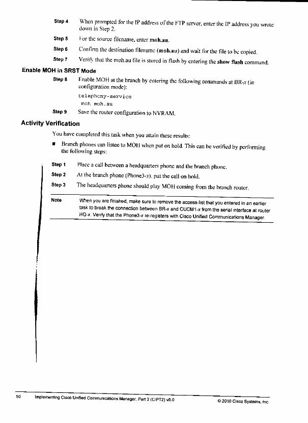
50
Step 4
Step 5
Steps
Step 7
Note
When prompted for the IP address of the FTP server, enter the IP address you wrotedown in Step 2.
For the source filename, enter moh.au.
Confirm the destination filename (moh.au) and wait for the file to be copied.Verify that the moh.au file isstored in flash by entering the show Hash command.
Enable MOH in SRST Mode
Step 8 Enable MOH at the branch by entering the following commands at BR-.v (inconfiguration mode):
telephony-service
moh moh.au
Step9 Savethe router configuration to NVRAM.
Activity Verification
You have completed this task when you attain these results:
• Branch phones can listen to MOH when put on hold. This can be verified by performingthe following steps:
Step 1 Place acall between aheadquarters phone and the branch phone.Step 2 At the branch phone (Phone3-^). putthecall on hold.
Step 3 The headquarters phone should play MOH coming from the branch router.
When you are finished, make sure to remove the access-list that you entered in an earliertask to break the connection between BR-x and CUCMI-x from the serial interface atrouterHQ-x. Verify that the Phone3-x re-registers with Cisco Unified Communications Manager.
Implementing Cisco Unified Communications Manager, Part 2(CIPT2) v8.0>2010 Cisco Systems, Inc.
&

Activity VerificationYou have completed this task when you attain these results:• To verify the SRST Fallback configuration, enter the show telephony-service command on
the branch router BR-.v.
• To verity that the current flies are accessible to IP phones, enter the show telephony-servicetftp-bindings command.
• To verify that SRST isworking, follow these steps:
Step 1 Break connective lo Cisco Unified Communications Manager by reapplying accesslist 100 in the incoming direction atthe interface ofthe HQ-.r router that connects tothe BR-.v router.
Step 2 Place acall from aheadquarters phone to the branch phone (300I). The call shouldwork: the calling party number should be the 10-digit PSTN number oftheheadquarters phone.
Step 3 Place acall from Phone3-.r to aheadquarters phone (use internal dialing: 2001 or2002). The call should work: the calling party number should be the I0-digit PS INnumber of the branch phone.
• lo verifv that ihe learned configuration was saved, display the configuration ofthe router:— Enter the show running-config command and verify that you see an cphone-dn and
cphonc in the configuration.
Note The next time the phone registers with Cisco Unified Communications Manager Express.Cisco Unified Communications Manager Express uses the stored configuration instead oflearning the phone configuration using SNAP. In order to configure a phone with featuresthat cannot be learned by SRST. you can preconrigure the ephone-dn only (and then theephone is learned) or ephone-dn and ephone _
Task 2: Configure MOH on Cisco Unified CommunicationsManager Express
In this task, vou will configure Cisco Unified Communications Manager Express to provideMOH lo Cisco IP phones.
Activity Procedure
Complete these steps:
Copy an MOH Audio File to the SRST RouterTo use MOH with Cisco Unified Communications Manager Express in SRST mode, the MOIIfile must be stored on the router flash.
Step 1 At PC-v. navigate to Start >Run and enter the cmtl command.In the command-line window, enter the ipconflg command to find out the IP addressof the PC. The IP address must be in network 10^.3.0/24. Write down the IP addresshere:
10. -3.
Vour instructor reinstalled and preconfigured an FTP server at PC-*. AMOH audiofile was stored at PC-.v and made accessible via FTP for anonymous user. Copy thistile to the Hash of vour BR-.v router by entering the copy ftp flash command:
Step 2
Step 3
2010 Cisco Systems, IncLab Guide
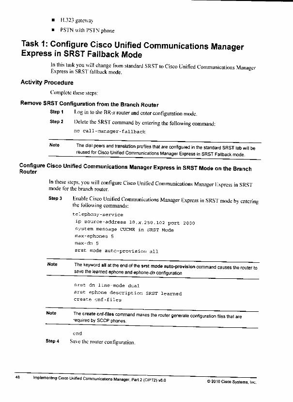
• H.323 gateway
• PSTN with PSTN phone
Task 1: Configure Cisco Unified Communications ManagerExpress in SRST Fallback Mode
In this task you will change from standard SRST to Cisco Unified Communications ManagerExpress in SRST fallback mode.
Activity Procedure
Complete thesesteps:
Remove SRST Configuration from the Branch Router
Step 1 Log in tothe BR-j router and enter configuration mode.
Step 2 Delete the SRST command by entering the following command:no call-manager-fallback
Note The dial peers and translation profiles that are configured in the standard SRST lab will bereused for Cisco Unified Communications Manager Express in SRST Fallback mode.
Configure Cisco Unified Communications Manager Express in SRST Mode on the BranchRouter
In these steps, you will configure Cisco Unified Communications Manager Lxpress in SRSTmode for the branch router.
48
Step 3 Enable Cisco Unified Communications Manager Express in SRSI mode by enteringthe following commands:
telephony-service
ip source-address 10.x.250.102 port 2000system message CUCME in SRST Mode
max-ephones 5
max-dn 5
srst mode auto-provision all
Note The keyword all at the end of the srst mode auto-provision command causes the router tosave the learned ephone and ephone-dn configuration.
srst dn line-mode dual
srst ephone description SRST learned
create cnf-files
Note The create cnf-files command makes the router generate configuration files that,required by SCCP phones.
end
Step4 Save the router configuration.
Implementing Cisco Unrfied Communications Manager. Part 2(CIPT2>v8.0©2010 Cisco Systems, Im,

Lab 2-2: Implementing Cisco UnifiedCommunications Manager Express in SRSTMode
Complete this lab activity to practice what you learned in the related module.
Activity ObjectiveIn this activitv vou will configure Cisco Unified Communications Manager Express in SRSTmode to provide basic telephony services lo phones that lost the connection to Cisco UnifiedCommunications Manager. In addition, you will enable MOII. After completing this activity,you will be able tomeet these objectives;• Configure Cisco Unified Communications Manager Express in SRST fallback mode• Configure MOI 1on Cisco Unified Communications Manager Express
Visual ObjectiveThe figure illustrates what you will accomplish in this activity.
Lab 2-2: Implementing Cisco UniManager Express in SRST Mode
fsed Communications
Required ResourcesThese are the resources and equipment that arc required to complete this activity:• Cisco Unified Communications Manager
• Student PC
• Cisco IP Phones
• Cisco IOS MGCP gatewa;
& 2010 Cisco Systems, Inc.Lab Guide
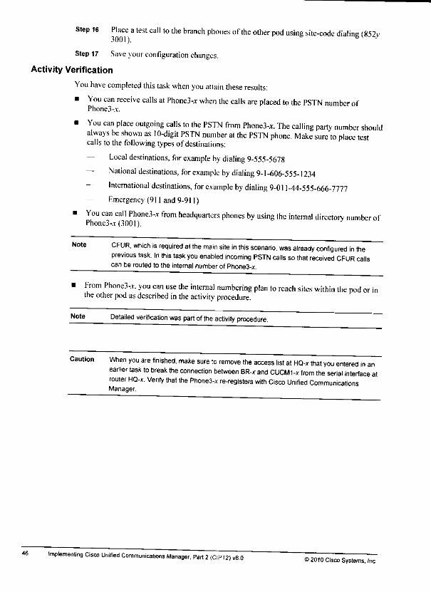
Step 16 Place atest call to the branch phones of the other pod using site-code dialing (852v300I).
Step 17 Save your configuration changes.
Activity Verification
You have completed this taskwhen you attain these results:
• You can receive calls at Phone3-jr when the calls are placed to the PSTN number ofPhone3-.v.
• You can place outgoing calls to the PSTN from Phone3-x The calling party number shouldalways be shown as 10-digit PSTN number at the PSTN phone. Make sure to place testcalls to the following types of destinations:
— Local destinations, for example by dialing 9-555-5678
— National destinations, for example by dialing 9-1-606-555-1234
— International destinations, for example by dialing 9-011-44-555-666-7777— Emergency (911 and 9-911)
• You can call Phone3-.r from headquarters phones by using the internal directory number ofPhone3-.T(300I).
46
Note CFUR, which is required at the main site in this scenario, was already configured in theprevious task. In this task you enabled incoming PSTN calls sothat received CFUR callscan be routed to the internal number of Phone3-x.
From Phone3,v. you can use the internal numbering plan to reach sites within the pod .the other pod asdescribed in the activity procedure.
Note Detailed verification was part of the activity procedure.
Caution When you are finished, make sure to remove the access list at HQ-x that you entered in anearlier task to break the connection between BR-x and CUCMI-x from the serial interface atrouter HQ-x. Verify that the Phone3-x re-registers with Cisco Unified CommunicationsManager.
implementing Cisco Unified Communications Manager, Part 2(CIPT2) v8.0 ©2010 Cisco Systems. Inc.
M»
Si
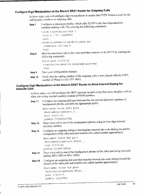
Configure Digit Manipulation at the Branch SRST Router for Outgoing CallsIn these steps, you will configure digit manipulation to ensure that PSTN format is used for thecalling partv numbers onoutgoing calls.Step 7 Configure atranslation profile, which adds 52r555 to the four-digit directory
numbers starting with 3by entering the following commands:voice translation-rule 2
rule 1 /'3/ /52X5553/
exit
voice translation-profile pstn-out
translate calling 2
exit
Step 8 Bind the translation rule to the voice port that connects to the PSTN by entering thefollowing commands:
voice-port 0/0/0:23translation-profile outgoing pstn-out
exit
Step 9 Save your configuration changes.Step 10 Verily that the calling number of the outgoing calls is now placed with the PSTN
number of Phone3-.v (52r 555 3001).
Configure Digit Manipulation at the Branch SRST Router to Allow Internal Dialing forIntersite Calls
In these steps, vou will configure the SRST gateway in such away that users can place calls toother sites using internal numbers instead ofPSTN numbers.Step 11 Configure an outgoing dial peer that matches the internal directory numbers of
headquarters phones and adds the appropriate prefix:dial-peer voice 2000 potsdestination-pattern 2...
port 0/0/0:23
prefix 0115551x5552Step 12 Place atest call to one of the headquarters phones using its four-digit internal
directory number.
Step 13 Configure an outgoing dial peer that matches internal site-code dialing toward theheadquarters of the other pod and modifies the called number appropriately:dial-peer voice 8y2 potsdestination-pattern 851y2...
port 0/0/0:23prefix 0115551y5552
Step 14 Place atest call to one of the headquarters phones of the other pod using site-codedialing (851 v2001 or851 v2002).
Step 15 Configure an outgoing dial peer that matches internal site-code dialing toward thebranch ofthe other pod and modifies the called number appropriately:dial-peer voice 8y3 potsdestination-pattern 852y3...
port 0/0/0:23
prefix 152y5553
© 2010 Cisco Systems. IncLab Guide
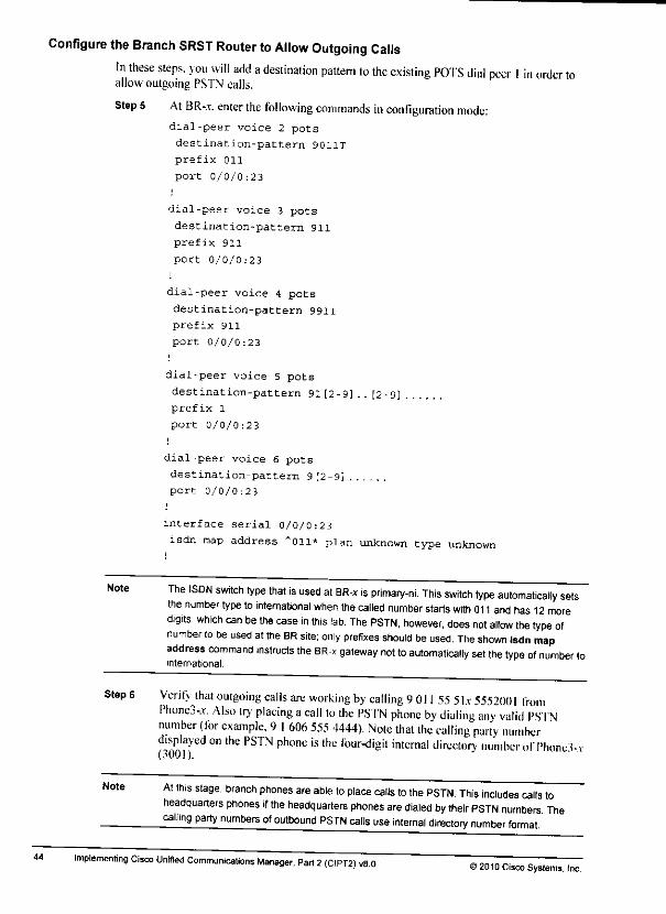
at
Configure the Branch SRST Router toAllow Outgoing CallsIn these steps, you will add adestination pattern to the existing POTS dial peer Iin order to S*allowoutgoing PSTN calls.
Step 5 At BR-.t. enter the following commands in configuration mode: •dial-peer voice 2 pots
destination-pattern 9011T Ifcprefix Oil
port 0/0/0:23 Jfe
dial-peer voice 3 pots ^Ldestination-pattern 911
prefix 911 m
port 0/0/0:23
dial-peer voice 4 pots
destination-pattern 9911 ,»,prefix 911 ••
port 0/0/0:23
dial-peer voice 5 pots
destination-pattern 91[2-9] .. [2-9] Kprefix 1
port 0/0/0:23 ||L
dial-peer voice 6 pots ?*
destination-pattern 9 [2-9]
port 0/0/0:23 a*.
interface serial 0/0/0:23 m.isdn map address "Oil* plan unknown type unknown
44
Note
Step 6
The ISDN switch type that is used at BR-x is primary-ni. This switch type automatically setsthe number type to international when the called number starts with 011 and has 12 moredigits, which can be the case in this lab. The PSTN, however, does not allow the type ofnumber to be used atthe BR site; only prefixes should be used. The shown isdn mapaddress command instructs the BR-x gateway not to automatically set the type of number tointernational.
Verify that outgoing calls are working by calling 9011 55 Six 5552001 fromPhone3-.r. Also try placing acall to the PSTN phone by dialing any valid PSTNnumber (for example, 91606 555 4444). Note that the calling party numberdisplayed on the PSTN phone is the four-digit internal directory number olThoncl-v
Note At this stage, branch phones are able to place calls to the PSTN. This includes calls toheadquarters phones if the headquarters phones are dialed by their PSTN numbers ThecaU'ng party numbers of outbound PSTN calls use internal directory number format
Implementing Cisco Unified Communications Manager, Part 2(CIPT2) v8.0 ©2D10 cisco Sys(emSi ,nc
Step 2 Verifv using the debug isdn q931 command whether the call hits the HR-* gateway.The call arrives at BR-.v. but DID is not enabled and the called party number is a 10-digit number and not a4-digit director) number.
Note Gateway BR-x accepts the call and, because DID is not enabled, it waits for dialed digits(two-stage dialing) If you manually enter 3001 at this stage, Phone3-x will ring
Task 4- Implement a Dial Plan at the SRST Gateway SupportingInbound and Outbound CallsWhen in MGCP Fallback or inSRST Mode or Both
In this task vou will configure adial plan at the SRST gateway that allows incoming calls thatare placed to the F164 PSTN number of the branch phones to be sent to the appropriatedirectorv number. In addition, you will implement PSTN access for branch users, finally, vouwill allow branch users to place calls to headquarters phones over the PS INby dialing internaldirector, numbers.
Activity Procedure
Complete these steps:
Configure the Branch SRST Router toAllow Incoming CallsIn these steps. >ou will configure an inbound dial peer to allow incoming calls to be routedcorrecllv.
Step 1 l.nable DID for the voice port that connects to the PSTN by entering the followingcommands:
dial-peer voice 1 pots
incoming called-number 52x5553...direct-inward-dial
port 0/0/0:23
Step 2 Configure atranslation profile to manipulate the incoming called number from thePSTN (the complete PSTN number 52.x 55530(11) to the four-digit directorv number,bv entering the following commands:voice translation-rule 1
rule 1 /*52x5553/ /3/
exit
voice translation-profile pstn-in
translate called l
Step 3 Bind the newly created translation profile to the voice port that connects lo thePSTN bv entering the following commands:voice-port 0/0/0:23translation-profile incoming pstn-in
NoteAt this stage, branch phones are reachable by their PSTN numbers. CFUR from theheadquarters should now work
Step 4 Verifv that incoming calls are working by calling 3001 from PhoneKt or Ph0nc2,v.Note 'that the calling parly number that is displayed at Phone3,v is the PS IN numberof the calling phone.
© 2010 Cisco Systems. IncLab Guide
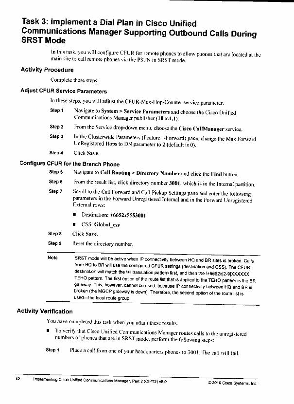
Task 3: Implement a Dial Plan in Cisco UnifiedCommunications Manager Supporting Outbound Calls DurinaSRST Mode y
In this task, you will configure CFUR for remote phones to allow phones that are located at themain siteto call remote phones viathe PS'fN in SRST mode.
Activity Procedure
Complete these steps:
Adjust CFUR Service Parameters
In these steps, you will adjust the CFUR-Max-Hop-Counter service parameter.Step 1 Navigate toSystem >Service Parameters and choose the Cisco Unilied
Communications Manager publisher (IOjc.1.I).
Step 2 From the Service drop-down menu, choose the Cisco CalfManager service.Step 3 In the Clusterwide Parameters (Feature—Forward) pane, change Ihe Max Forward
UnRegistered Hops toDN parameter to2 (default is0).Step 4 Click Save.
Configure CFUR for the Branch Phone
Step 5 Navigate toCall Routing >Directory Number and click the Find button.
Step 6 From the result list, click directorv number3001, which is in the Internal partition.Scroll to the Call Forward and Call Pickup Settings pane and enter the followingparameters in the Forward Unregistered Internal and in the Forward Unregistered
Step 7
Fxternal rows:
• Destination: +6651x5553001
• CSS: GlobaI_css
Step 8 Click Save.
Step 9 Reset the directory number.
Note SRST mode will be active when IP connectivity between HQ and BR sites is broken. Callsfrom HQ to BR will use the configured CFUR settings (destination and CSS). The CFURdestination will match the VH translation pattern first, and then the \+6652x[2-9]XXXXXXTEHO pattern. The first option of the route list that is applied to the TEHO pattern is the BRgateway This, however, cannot beused, because IP connectivity between HQ and BR isbroken {the MGCP gateway isdown) Therefore, the second option of the route list isused—the local route group.
Activity Verification
You have completed this task when you attain these results:
• To verify that Cisco Unified Communications Manager routes calls to the unregisterednumbers of phones that are in SRST mode, perform the following steps:
Step 1 Place acall from one ol'your headquarters phones to 300I. The call will fail.
42 Implementing Cisco Unified Communications Manager, Part 2<CIPT2)v8.0 ©2010 Cisco Systems, Inc.
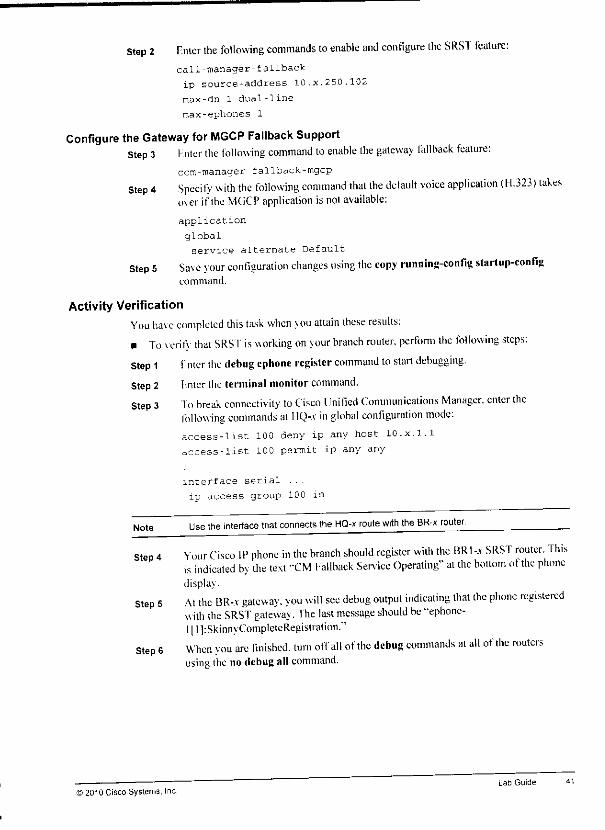
Step 2 Enter the following commands to enable and configure the SRST feature:call-manager-fallback
ip source-address 10.x.250.102
max-dn 1 dual-line
raax-ephones 1
Configure the Gateway for MGCP Fallback SupportStep 3 hntcr the following command to enable the gateway fallback feature:
ccm-manager fallback-mgcp
Step 4 Specify with the following command that the default voice application (H.323) takesover if the MGCP application is notavailable:
application
global
service alternate Default
Step 5 Save vour configuration changes using the copy running-config startup-con figcommand.
Activity VerificationYou have completed this task when you attain these results:• To verifv that SRSI' isworking on your branch router, perform the following steps:
Step 1 i; nter the debug ephone register command to start debugging.Step 2 Fnter the terminal monitor command.Step 3 To break connectivity to Cisco Unified Communications Manager, enter the
following commands at HQ-.v in global configuration mode:access-list 100 deny ip any host 10.x.1.1
access-list 100 permit ip any any
interface serial ...
ip access-group 100 in
Note Use the interface that connects the HQ-x route with the BR-x router
Step 4Your Cisco IP phone in the branch should register with the BRI-jc SRST router. Thisis indicated by the text "CM Fallback Service Operating" at the bottom of the phonedisplay.
Step 5 At the BR-.t gateway, you will see debug output indicating that the phone registeredwith the SRST gateway. The last message should be "ephone-l|l]:SkinnyCompleteRegistration."
Step 6 When you are finished, turn off all of the debug commands at all of the routersusing the nodebug all command.
© 2010 Cisco Systems, Inc.Lab Guide
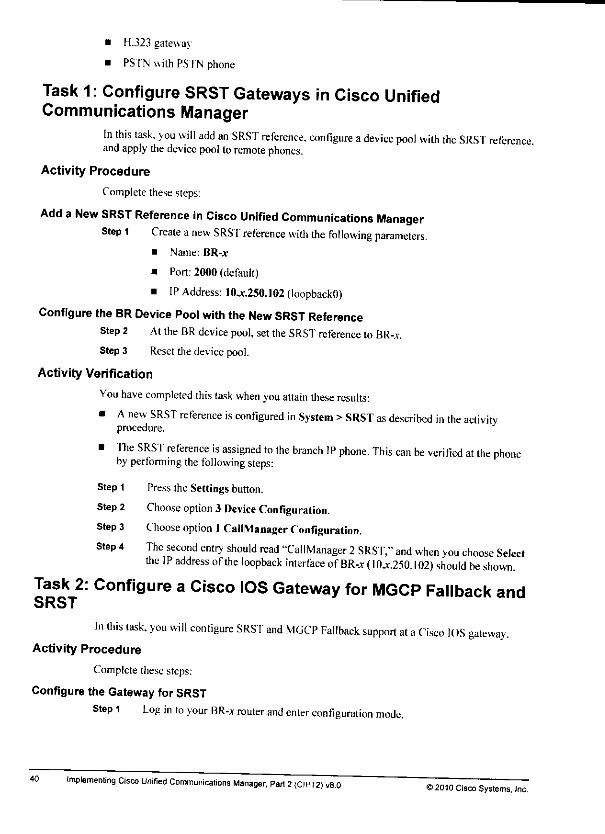
• HJ23 gateway
• PSTN with PSTN phone
Task 1: Configure SRST Gateways in Cisco UnifiedCommunications Manager
In this task, you will add an SRST reference, configure adevice pool with the SRST referenceand apply the device pool toremote phones.
Activity Procedure
Complete these steps:
Add aNew SRST Reference in Cisco Unified Communications ManagerStep 1 Create anew SRST reference with the following parameters.
• Name: BR-x
• Port: 2000 (default)
• IP Address: 10jt.250.102 (loopbackO)
Configure the BRDevice Pool withthe New SRST ReferenceStep 2 At the BRdevicepool, set the SRSTreference to BR-x.
Step 3 Reset the device pool.
Activity Verification
You have completed this task when you attain these results:
• Anew SRST reference is configured in System >SRST as described in the activity m,procedure. mm
• The SRST reference is assigned to the branch IP phone. This can be verified at Ihe phone gLby performing the following steps:
Step 1 Press the Settings button. fifeStep 2 Choose option 3 Device Configuration. »>
•frStep 3 Choose option I CallManager Configuration.
Step 4 The second entry should read "CallManager 2SRST," and when you choose Select hthe IP address of the loopback interface ofBR-* (10jc.250.I02) should be shown.
Task 2: Configure a Cisco IOS Gateway for MGCP Fallback and *SRST ^In this task, you will configure SRST and MGCP Fallback support at aCisco IOS gateway.
Activity Procedure lb
Complete these steps: «.m
Configure the Gateway for SRST
Step 1 Log in to your BR-x router and enter configuration mode. M*
40 Implementing Cisco Unified Communications Manager. Part 2(CIPT2) v8.0 ©2010 Cisco Systems, Inc.
3j£
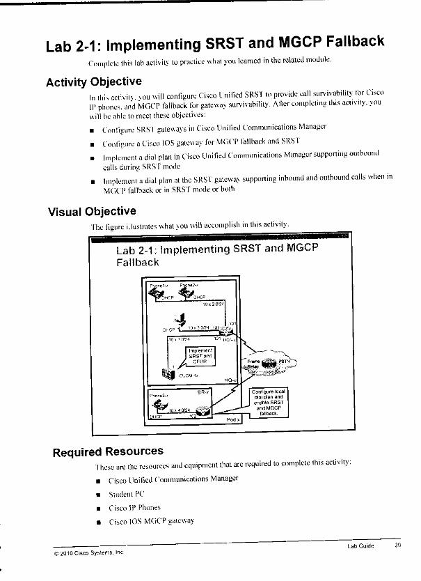
Lab 2-1: Implementing SRST and MGCP FallbackComplete this lab activity to practice what you learned in the related module.
Activity ObjectiveIn this activ itv vou will configure Cisco Linified SRST to provide call survivability for CiscoIP phones, and MGCP fallback for gateway survivability. After completing this activity, youwill be able lo meet these objectives:
• Configure SRSI gateways in Cisco Unified Communications Manager• Configure aCisco IOS gateway for MGCP fallback and SRST. Implement adial plan in Cisco Unified Communications Manager supporting outbound
calls during SRSTmode
• Implement adial plan at the SRST gateway supporting inbound and outbound calls when inMGCP fallback or in SRSTmodeor both
Visual ObjectiveThe figure illustrates what you will accomplish in this activity.
Lab 2-1; implementing SRST and MGCPFallback
Required ResourcesThese are the resources and equipment that are required to complete this activity:• Cisco Unified Communications Manager
• Student PC
• Cisco IP Phones
• Cisco IOS MGCP gateway
>2010 Cisco Systems, IncLab Guide 39

Configure Calling Party Transformations for TEHO Calls
Step 2 Create calling party transformation patterns for the HQ gateway. Refer to the"Localization ofCalling Party During Call Egress for Outbound TE110 Calls" tableof the Task Job Aids.
38
Note The gateway isalready configured with a calling party transformation CSS that has accessto the partition that you applied to the newly created transformation patterns.
Step 3 Place test calls to TEHO PSTN destinations located at the other pod. Use the debugisdn q93I command at the gateways ofthe other pod to verify that the TEHOgateway is used. Make sure that for TEHO calls through the HQ gateway, the callingnumber isthe number ofthe actual caller (in international format ifthe call comesfrom the BR site ofthe other pod and in national format ifthe call comes from theHQ site ofthe other pod) while the calling number for TEHO calls through Ihe BRgateway isalways the number ofthe BR attendant (52^5553001).
Verify PSTN Backup for TEHO to the Other Pod
Step 4 Shut down the serial interface that connects your pod with the other pod.Step 5 Repeat placing TEHO test calls from the HQ site and from the BR site to Ihe PSTN
destination located at the other pod. Although IP connectivity is broken, the callsshould still work, because they are rerouted via the second option ofthe route list:the local route group. Use the debug isdn q931 command to verify that the call isset up using the local PSTN gateway.
Step 6 Usethe no shutdown command on the serial interface.
Activity Verification
You have completed this taskwhen you attain this result:
• You can place TEHO calls to the other pod as described in the activity procedure.• When IP connectivity between the two pods is broken, the local gateway is used as a
backup asdescribed intheactivity procedure.
Implementing Cisco Unified Communications Manager. Part 2(CIPT2) v8.0 ©2010 Cisco Systems. Inc.

Task 6: Implement TEHO Between PodsIn this task, vou will configure TEHO between your pod and the other pod.
Task Job Aids
These job aids arc av ailable to help you complete the lab task.
Route Patterns for Outbound TEHO Calls
Route Pattern
V+5551yf2-9]XXXXXX
H6652yf2-9]XXXXXX
Configuration
Partition; System
Description TEHO to +55 51y(remote HQ)UrgentPriority: deactivatedGateway/RouteList intersite_rl
Partition: System
Description TEHO to +66 52y(remote BR)UrgentPriority: deactivated
Gateway/Route List: Intersitejl
Localization ofCalling Party During Call Egress for Outbound TEHO Calls
Calling PartyTransformation Pattern Configuration
\+55.51y5552XXX Partition. xfornvcg_HQ-out
Description: HQ (from remote HQ)Discard DigitsInstructions: PreDot
Number Type: National
\+.6652y5553XXX Partition: xform-cg__HQ-out
Description: HQ (from remote BR)Discard DigitsInstructions: PreDot
Number Type. International
NoteThe HQ PSTN allows remote calling numbers to be sent. The BR PSTN does not allowother calling numbers than the number that is assigned to the PSTN line. Therefore, TEHOcalls from the other pod to HQ are configured to use the numbers of the other pod for thecalling number while calls going through the BR gateway have already been configured inthe previous task to use the number of the BR attendant (3001) for the calling number it thecalling number is not in the locally assigned DID range. Further, the HQ PSTN requiresnumber types to be set, while the BR PSTN expects 10-digit calling numbers withoutnumber types ^ ___
Activity Procedure
Complete these steps:
Configure TEHO Route PatternsStep 1 Create route patterns for TEHO calls. Refer to the "Route Patterns tor Outbound
TEHOCalls" table of the Task Job Aids.
2010 Cisco Systems. IncLab Guide

Configure TEHO Route Patterns
Step3 Create route patterns forTEHO calls. Refer lo the"Route Patterns forOutboundTEHO Calls" table of the Task Job Aids.
Configure Calling Party Transformations for TEHO Calls
Step 4 Create calling party transformation patterns for the HQ and BR gateways. Refer tothe••Localization of Calling Party During Call Egress for Outbound TEHO Calls"table of the Task Job Aids.
Note The gateways arealready configured with a calling party transformation CSSthathasaccess tothe partition that you applied tothe newly created transformation patterns.
Step 5 Place test calls toTEHO PSTN destinations. Use the debug isdn q931 command to wverify that the TEHO gateway is used. Make sure that for IEl 10 calls through the mtHQ gateway, the calling number is the number ofthe BR phone (in international wWiformat) while the calling number for TEHO calls through the BR gateway isnot the MbIIQ number but the number ofthe BR attendant (52x5553001).
Verify PSTN Backup for TEHO Within the Pod 8Step 6 Shut down the ISDN interface at the IIQ gateway and try placing aTEI10 call from m
the BR phone. Because the primary path (through the TEHO gateway) does not •"work, the local gateway (BR) should beused asa backup.
Step 7 Use the no shutdown command on the ISDN interface. 8Step 8 Shut down the ISDN interface at the BR gateway and try placing aTEHO call from *&
the HQ phone. Because the primary path (through the TEHO gateway) does not '*imwork, the local gateway (HQ) should be used as a backup.
Step 9 Use the no shutdown command on the ISDN interface. m
Activity Verification w
You have completed this task when youattain this result:
• You can place TEHO calls within your pod as described in the activity procedure. 8• When IP connectivity between the two siles is broken, the local gateway is used as a B
backup as described in theactivity procedure. %m
36 Implementing Cisco Unified Communications Manager, Part 2(CIPT2) v8.0 ©2010 Cisco Systems, lire

Task 5: Implement TEHO Within Your PodIn this task, you will configure TEHO within your pod.
Task Job Aids
These jobaids arc available tohelp you complete the lab task.
Route Patterns for Outbound TEHO Calls
Route Pattern
\+5551x[2-9]XXXXXX
\+6652x[2-9jXXXXXX
Configuration
Partition. System
Description TEHO to +55 51x (local HQ)
Urgent Priority deactivated
Gateway/Route List TEHO-HQ_rl
Partition: System
Description: TEHOto +66 52* (localBR)
Urgent Priority: deactivatedGateway/Route List TEHO-BR_rl
Localization ofCalling Party During Call Egress forOutbound TEHO Calls
Calling Party TransformationPattern
\+.6652x5553XXX
Configuration
Partition: xform-cg_HQ-out
Description: HQ (from BR)
Discard Digits Instructions: PreDot
Number Type. International
Partition xform-cg_BR-out
Description: BR (from HQ)Calling PartyTransform Mask: 52x5553001
Note The HQ PSTN allows remote calling numbers to be sent. The BR PSTN does not allowother calling numbers than the number that is assigned to the PSTN line Therefore, TEHOcalls from BR to HQ are configured to use the BR number as the calling number while callsgoing through the BR gateway are configured to use the number of the BR attendant (3001)for the calling number if the calling number is not of the locally assigned DID range. Further,the HQ PSTN requires number types to be set while the BR PSTN expects 10 digit callingnumbers without number types ^
Activity Procedure
Complete these steps:
Configure Route Lists with the TEHO Gateways as First Option and the Local PSTNGateway as Backup
Step 1 Create aroute list that is called TEHO-HQ_rl and add the HQj-g and the StandardLocal Route Group item to the route list. Make sure that the HQ_rg is listed first.
Step 2 Create aroute list that is called TUIO-BR.rl and add the BR_rg and the Standardfocal Route Group item to the route list. Make sure that the BR_rg is listed first.
© 2010 Cisco Systems. IncLab Guide 35
Step 11 Make sure that the callingnumberis shownwith the internally useddirectory-number and a site-code dial prefix at the receiving phone (85 ly-2001 and 851v-2002for calls that are received from HQ phones of the other pod and 852_y-300l for callsthat are received from the BR phone of the other pod).
Verify PSTN Backup for the SIP TrunkStep 12 When the test calls between your pod and the other pod have finished you can start
testingthe PSTN backuppath. Shutdown the serial interface that connects your IIQrouter (HQ-*) to the HQ router of the other pod (HQ-_y).
Note This is the serial interface at the HQ router that is configured with IP address 10.zx.101 and
subnet mask 255.255.0.0.
As mentioned earlier, x is the number of your pod, and y is the number of your partner pod
(in the same group). Groups are pods 1 and 2, pods 3 and 4, pods 5 and 6, and pods 7 and
8. A z in an IP address stands for the pod numbers of your pod and your partner pod. They
are listed in ascending order. Examples: for pod 1, x=1, y=2, and z=12; for pod 2, x=2, y=1,
and z=12; for pod 3, x=3, y=4, and z=34, for pod 4, x=4, y=3, and z= 34, and so on.
Step 13 Continue placing test calls from the HQ site and from the BR site to the other podusing intersite dialing, Although IP connectivity is broken, the calls should stillwork, because they are rerouted via the second option of the route list: the localroute group. Use the debug isdn q931 command to verify that the call is set upusing the local PSTN gateway. Verify that the calling number is still shown with theinternally used directory number and a site-code dial prefix.
Step 14 Use the no shutdown command on the serial interface.
Activity Verification
You have completed this task when you attain this result:
• You can place calls to and receive calls from the other pod using site-code dialing asdescribed in the activity procedure.
• When IP connectivity between the two pods is broken, the PSTN is used as a backup asdescribed in the activity procedure.
• The calling number is always shown with the intemally used directory number and a site-code dial prefix as described in the activity procedure.
34 Implementing CiscoUnified Communications Manager, Part2 (CIPT2) v8.0 © 2010CiscoSystems.Inc.
i.
Configure Route Patterns for Globalized Intersite Calls Using the Previously CreatedIntersite Route List
Step 4 Create route patterns for intersite access. Refer to the "Route Patterns for OutboundIntersite Calls" tabic of the Task Job Aids.
Configure Translation Patterns for Inbound Calls
Note At this stage, you are ready to send calls to the other pod using globalized called and calling
numbers, in order to process the calls that are received from the other pod, you have to
change the received called number from globalized format to the internally used directory
number
This called number format change could be done with significant digits set to 4, configured
at the SIP trunk. However, as you want to use the SIP trunk also for TEHO in a later lab
task, the called number cannot be reduced to a four-digit number in general, only if the call
was placed to an internal phone and not when the call was placed to a TEHO destination.
Therefore, you will use translation patterns to modify the called number of inbound calls that
are received through the SIP trunk.
Step 5 Create translation patterns for received intersite calls. Refer to the "Changing theCalled Number of Calls Received Through the SIP Trunk" table of the Task JobAids,
Configure the SIP Trunk with a CSS That Has Access to Internal Phones
StepS Apply the CSS Ininkjjss to the SIP trunk.
Step 7 Reset the trunk.
Step 8 When the configuration of the other pod has finished, you can start placing test callsusing intersite dialing. Dial 8-51v-2001 and 8-5ly-2002 to reach the HQ phones ofthe other pod. dial 8-52v-300l to reach the BR phones of the other pod.
Note When receiving calls from the other pod, you will see the calling number in globalized format
(+55-51y-555-2001 and +55-51y-555-2002 for calls from the HQ phones of the other pod
and +66-52/-555-3001 for calls from the BR phone of the other pod).
In order to indicate that the call is coming from an interconnected site, the configuration will
be changed in the next steps so that the calling number is shown with the internally used
site code.
Configure the Calling Number of Intersite Calls to Be Shown with Site CodesStep 9 Create calling party transformation patterns for IIQ and BR phones. Refer to the
"Localization of CallingParty DuringCall Egress for Inbound Intersite Calls" tableof the Task Job Aids.
Note The phones are already configured with a calling partytransformation CSS that has accessto the partition that you applied to the newlycreated transformation patterns.
Step 10 Place lestcallsbetween thetwo pods using intersite dialing. Make surethatyouplace calls inboth directions. Dial 8-5!v-2001 and8-5l.y-2002 to reach the IIQphones of theotherpod. dial 8-52v-300l to reach the BRphones of theotherpod.
©2010 Cisco Systems. Inc Lab Guide

Changing the Called Number of Calls Received Through the SIP Trunk
Translation Pattern Configuration
\+5551x555 2XXX Partition: Internal
Description: SIP (to local HQ)
CSS Trunkcss
Urgent Priority: deactivated
Discard Digits Instructions: PreDot
\+6652x555.3XXX Partition: Internal
Description: SIP (to local BR)
CSS: Trunk_css
Urgent Priority: deactivated
Discard Digits Instructions: PreDot
Localization of Calling Party During Call Egress for Inbound Intersite Calls
Calling Party Transformation Pattern Configuration
\+5551y555 2XXX Partition: xform-cgJHQ-phones
Description: HQ-Phones {other pod HQ}
Discard Digits Instructions: PreDot
Prefix: 851y555
\+5551y555 2XXX Partition: xform-cg_BR-phones
Description: BR-Phones (other pod HQ)
Discard Digits Instructions: PreDot
Prefix 851y555
\+6652y555 3XXX Partition: xform-cg_HQ-phones
Description: HQ-Phones (other pod BR)
Discard Digits Instructions: PreDot
Prefix: 852/555
\+6652y555.3XXX Partition: xform-cg_BR-phones
Description: BR-Phones (other pod BR)
Discard Digits Instructions: PreDot
Prefix: 852y555
Activity Procedure
Complete these steps:
Configure a Route Group for the SIP Intercluster Trunk
Step 1 Create route group SIP_rg and add the SIP trunk to the route group.
Configure a Route List with the SIP Trunk as First Option and the PSTN as BackupStep 2 Create a route list that is called lntersite_rl and add SIP_rg and the Standard I.ocaI
Route Group item to the route list. Make sure that SIP_rg is listed first.
Configure Translation Patterns to Globalize Intersite Calls
Step 3 Create translation patterns for intersite access, Refer to the "Globalization of Calledand Calling Parties During Call Ingress for Outbound Intersite Calls" table of theTask Job Aids.
32 Implemenling Cisco Unified Communications Manager, Part 2 (CIPT2) v8.0 © 2010 Cisco Systems. Inc.
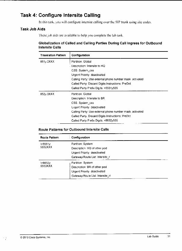
Task 4: Configure Intersite CallingIn this task, you will configure intersite calling over the SIP trunk using site codes.
Task Job Aids
These job aids are available to help you complete the lab task.
Globalization of Called and Calling Parties During Call Ingress for OutboundIntersite Calls
Translation Pattern Configuration
851/2XXX Partition: Global
Description: Intersite to HQ
CSS System__css
Urgent Priority: deactivated
Calling Party: Use external phone number mask: activated
Called Party Discard Digits Instructions: PreDot
Called Party Prefix Digits: +5551/555
852y.3XXX Partition. Global
Description: Intersite to BR
CSS System_css
Urgent Priority deactivated
Calling Party: Use external phone number mask: activated
Called Party Discard Digits Instructions: PreDot
Called Party Prefix Digits: +6652/555
Route Patterns for Outbound Intersite Calls
Route Pattern Configuration
\+5551y5552XXX
Partition: System
Description HQ of other pod
Urgent Priority: deactivated
Gateway/Route List: lntersite_rl
H6652/5553XXX
Partition System
Description: BR of other pod
Urgent Priority: deactivated
Gateway/Route List. Intersite_rl
© 2010 Cisco Systems, Inc Lab Guide
Note The calls fail because a callback is placed to the number as it was before localization took
place at the phone during call egress. Before localization, the number was in global format,
because the calling number received from the PSTN was globalized during call ingress.
In order to allow callbacks to globalized numbers, you have to add a \+! translation pattern.
The translation pattern will not change the called number, but only modifies the calling
number by applying the external phone number mask. Further, the translation pattern has a
CSS that has access to the \+! route pattern.
By adding such a translation pattern, you make sure that the calling number of the outbound
callback is globalized during call ingress and that you then match the \+! route pattern.
Applying the external phone number mask at the route pattern instead of the translation
pattern does not work before the configured global transformations are based on globalized
numbers. Digit manipulation that is configured at the route pattern and at the route list is
ignored by global transformations. Global transformations are based on the pre-transformed
number (that is, the number as it looks when hitting the route pattern), not on the
transformed number {that is, the number as it looks after route pattern or route list digit
manipulation has been applied).
Configure a Translation Pattern for Calls That Are Natively Using Globalized Format
Step 22 Create a translation pattern that is used by the HQ phones with the followingsettings:
• Translation Pattern: \+!
• Partition: Global
• Description: Calls to Globalized Numbers
• CSS: System_css
• Urgent Priority: activated
Note Translation patterns are urgent by default. Make sure that you do not disable Urgent Priority.
• Calling Party: Use external phone number mask: activated
Step 23 Retry placing callbacks from the HQ and BR phones by using the entries of thereceived calls list. The calls should work this time. Make sure that the callingnumber shown at the PSTN phone is using the correct format. Calls from the twoHQ phones should show a calling number of 5552001 and 5552002: calls from theBR phone should show a calling number of 52.X5553001.
Activity Verification
You ha\e completed this task when you attain this result:
• You can receive calls from the PSTN at HQand BRphonesas described in Iheactivityprocedure.
• PSTN calling numbers are shownin localized format as described in the activity procedure.
• Callbacks can be placed from \iQ and BR phonesto the PSTN. The calling number forcallbacks is set as described in the activity procedure.
30 Implementing Cisco Unified Communications Manager, Part2 (CIPT2) v8.0 ©2010 Cisco Systems, Inc.
Verify Inbound PSTN Calls to the HQ Site
Place test calls from the PSTN to an HQ phone. Use the local, national, and inlemalional line ofthe PSTN phone for the test calls.
Step 15 When placing a call from the local line of the PSTN phone, the caller ID shown onthe display of the HQ phone should be 5554444.
Note You can call the HQ phones by any valid PSTN number, regardless of the line of the PSTN
phone that you use Valid numbers are: 555-2001 and 555-2002, 0-51x-555-2001 and 0-
51x-555-2002, 00-55-51X-555-2001 and 00-55-51X-555-2002.
Step 16 When placing a call from the national line of the PSTN phone, the caller ID shounon the display of the HQ phone should be 06065554444.
Step 17 When placing a call from the international line of the PS'fN phone, the caller IDshown on the display of the I IQ phone should be +776065554444.
Verify Inbound PSTN Calls to the BR Site
Place test calls from the PSTN to a BR phone. Use the local, national, and international line ofthe PS'fN phone for the test calls.
Step 18 When placing a call from the local line of the PSTN phone, the caller ID shown onthe display of the BR phone should be 5Zy555444.
Note You can call the BR phone by any valid PSTN number regardless of the line of the PSTN
phone that you use. Valid numbers are: 555-3001, 1-52x-555-3001, and 011 -66-52x-555-
3001
Step 19
Step 20
When placing a call from the national line of the PSTN phone, the caller ID shownon ihe display of the BR phone should be 6065554444.
When placing a call from the international line of the PSTN phone, the caller IDshown on the display of the BR phone should be +776065554444.
Verify Callbacks
Step 21 Place callbacks from the IIQ and BRphones by usingthe entries of the receivedcalls list. The calls will fail.
©2010 Cisco Systems, Inc
Step 3 Sa\e \our configuration changes using the copy running-config startup-con figcommand.
Configure Routing to the Internal Directory Number at the HQ GatewayStep 4 Configure the HQ gateway with significant digits set to 4, and set the CSS to
Trunkcss.
Configure Globalization of Calling PSTN Number During Call Ingress at the HQ Gateway
Step 5 Configure the HQ gateway with the following incoming calling party prefixes basedon the number type:
• Unknown: +
• Subscriber: +555U'
• National: +55
• International: +
Step 6 Reset the gateway.
Configure Routing to the Internal Directory Number at the BR Gateway
Step 7 Configure the BR gateway with significant digits set to 4, and set the CSS toTrunk_css.
Configure Globalization of Calling PSTN Number During Call Ingress at the BR Gateway
Step 8 Configure the BR gateway with the following incoming calling party prefixes basedon the number type:
Unknown: +
Subscriber: +665Xv
National: +66
International: +
Step 9 Reset the gateway. Make sure that you also reset the MGCP process at the branchrouter by entering the no mgcp command, followed by the mgcp command.
Configure Localization of Calling PSTN Number During Call Egress
Step 10 Create calling party transformation patterns for HQ phones. Refer to the table of theTask Job Aids.
Step 11 Apply calling party transformation CSS xform-cg_HQ-phones ess to the IIQphones. Make sure that you clear the Use Device Pool Calling Party TransformationCSS check box.
Step 12 Create calling party transformation patterns for BR phones. Refer to the table of theTask Job Aids.
Step 13 Apply callingpartytransformation CSS xform-eg_BR-phones_css lo the BR phone.Make sure that you clear the Use Device Pool Calling Party Transformation CSScheck box.
Step 14 Reset all phones.
28 Implementing Cisco Unified Communications Manager. Part 2 (CIPT2) v8.0 ©2010 Cisco Systems, Inc.
— National call: dial any valid national number, for example 9 1 888 666 444. TheNational line at the PS'fN phone should ring: the called number that is shown in thedebug output should be 1888666444. and the number type should be unknown.
— International call: dial any valid international number, for example 9 011 88 2223.33 4444. The Intemtl line at the PSTN phone should ring; the called number that isshown in the debug output should be 911882223334444. and the number typeshould be international.
Task 3: Configure Inbound PSTN CallsIn this task. >ou will configure inbound PSTN calls.
Task Job Aids
This job aid is a\ailable to help you complete the lab task.
Localization of Calling Party During Call Egress for Inbound PSTN Calls
Calling Party Transformation Pattern Configuration
\+5551xXXXXXXX Partition: xform-cg_HQ-phones
Description HQ-Phones (Local)
Discard Digits Instructions: PreDot
\+55 XXXXXXXXXX Partition: xform-cgJHQ-phones
Description. HQ-Phones (National)
Discard Digits Instructions: PreDot
Prefix: 0
\+66 XXXXXXXXXX Partition: xform-cg_BR-phones
Description: BR-Phones (Local, National)
Discard Digits Instructions: PreDot
Note At the HQ site, end users expect to see local PSTN callers seven-digit numbers, national
callers with their national numbers and national access codes (0), and international callers
with a + prefix. Because allcaller IDsare globalizedat ingress, there is no need to modifythe caller ID of international callers when sending the call to the phone.
At the BR site, end users expect to see 10-digit caller IDs for local and national callers, and
see international callers with a + prefix (just like at the HQ site).
Activity Procedure
Complete these steps:
Configure the H.323 Gateway to Support Inbound PSTN CallsStep1 Reconfigure theexisting POTS dial peerto support inbound PSTN calls:
dial-peer voice 2 pots
direct-inward-dial
incoming called-number .
Reconfigure theexisting VoIP dial peerlo support inbound PSTN calls:
dial-peer voice 1
destination-pattern T
session target ipv4:10.x.1.1
Step 2
©2010 Cisco Systems Inc Lab Guide
Step19 Reset the BRgateway in Cisco Unified Communications Manager. Make surethatyoualsoresetthegateway itselfby entering the no mgcpcommand andthen themgcp command at the BR gateway.
Configure Localization of the Calling Number During Call EgressStep 20 Createcallingpartytransformation patternsfor the HQ gateway. Referto the
"Localization of Calling Party During Call Egress for Outbound PSTN Calls" tableof the Task Job Aids.
Step 21 Apply callingpartytransformation CSS xfonn-cg_HQ-out_css to the IIQgateway.Makesure that you clear the UseDevice Pool Calling PartyTransformation CSScheck box.
Step 22 Reset the HQ gateway in Cisco Unified Communications Manager.
Step23 Applycallingparty transformation CSS xform-cg BR-out_css to the BRgateway.Make sure that you clear the Use Device Pool Called Party Transformation CSScheck box.
Step 24 Reset the BR gateway in Cisco Unilied Communications Manager. Make sure thatyou also reset the gateway itself by entering the no mgcp command and then themgcp command at the BR gateway.
Activity Verification
You have completed this task when you attain this result:
• You can place calls to the PSTN from HQ phones. The HQ gateway is used for PSTNaccess. Use the debug isdn q931 command for verification of the called and callingnumbers for all types of calls. The calling number should always be seven digits (555 2001or 555 2002) with number type subscriber. The called number differs per destination:
— Emergency calls: dial 112 and 0 112. The Emergency line at the PSTN phoneshould ring; the called number that is shown in the debug output should be 112, andthe number type should be unknown.
— Local call: dial any valid local number, for example, 0 333 4444. Ihe I,ocal line atthe PSTN phone should ring; the called number that is shown in the debug outputshould be 3334444, and the number type should be subscriber,
— National call: dial any valid national number, for example, 0 0 888 666 444. TheNational line at the PSTN phone should ring; the called number thai is shown in thedebug output should be 888666444, and the number type should be national.
— International call: dial any valid international number, for example 0 00 88 222333 4444. The Intemtl line at the PSTN phone should ring; the called number that isshown in the debug output should be 882223334444, and the number type should beinternational.
• You can place calls to the PSTN from the BR phone. The BR gateway is used for PSTNaccess. Use the debug isdn q93l command for verification of the called and callingnumbers for all types of calls. The calling number should always be 10 digits (5Zv5553001) with no number type set (unknown). 'Ihe called number differs per destination:
— Emergency calls: dial 911 and 9-911. The Emergency line at Ihe PSTN phoneshould ring: the called number that is shown in the debug output should be 911, andthe number type should be unknown.
— Local call: dial any valid local number, for example 9 333 4444. The Local line titthe PSTN phone should ring: the called number that is shown in the debug outputshould be 3334444, and the number type should be unknown.
26 Implementing Cisco Unified Communications Manager, Part 2 (CIPT2)v8.0 © 2010 Cisco Systems, Inc.
Step 4 Save your configurationchanges using the copy running-config startup-configcommand.
Configure a System Route List Used for PSTN Access
Step 5 Create a route list that is called System_rl and add the Standard Local Route Groupitem to the route list.
Configure Site-Specific Route Groups
Step 6 Create route group HQ_rg and add the HQ gateway to the route group.
Step 7 Create route group BR_rg and add the BR gateway to the route group.
Configure Site-Specific Device Pools and Set the Local Route Group
Step 8 Configure the default device pool with local route group HQ_rg.
Step 9 Create a new device pool that is called BR, and configure the device pool with localroute group BR_rg.
Step 10 Apply the ncuK created device pool BR to the BR phone.
Configure Globalization of Called and Calling Number During Call Ingress
Step 11 Configure all phones with an external phone number mask using globalized formal.Use +555 Lv5552XXX for the HQ phones and +6652.V5553XXX for the BR phone.
Step 12 Create translation patterns for HQ PS'fN access. Refer lo the "Globalization ofCalled and ("ailing Parties During Call Ingress for Outbound PS IN Calls Placedfrom HQ Phones" table of the Task Job Aids.
Step 13 Create translation patterns for BR PS'fN access. Refer to the "Globalization ofCalled and Calling Parties During Call Ingress for Outbound PSTN Calls Placedfrom BR Phones" table of the Task Job Aids.
Configure Call Routing Based on Globalized Numbers
Step 14 Create a route pattern with the following sellings:
• Route Pattern: \+!
• Route Partition: System
• ( Description: PSTN_Access
• Urgent Priority: activated
• Gateway/Route List: System_rl
Configure Localization of the Called Number During Call EgressStep 15 Create called party transformation patterns for the IIQ gateway. Refer to the
"Localization of Called Party During Call Egress for Outbound PSTN Calls" tableof the Task Job Aids.
Step 16 Apply called party transformation CSS xform-cd_IIQ-out_css to the IIQ gateway.Make sure that you clear the Use Device Pool Called Party Transformation CSScheek box.
Step 17 Reset the HQ gateway in Cisco Unified Communications Manager.
Step 18 Apply called party transformation CSS xform-cd_BR-oul_css to the BRgateway.Make sure that >ou clear the Use Device Pool Called Party Transformation CSScheck box.
)2010 Cisco Systems, Inc. Lab Guide
Note Because the HQ gateway (H.323) has a dial peer withdestination pattern OT, PSTN accesscode 0 has to be sent to the H.323 gateway; it will be stripped at the H.323 gateway when
the call is sent out to the PSTN. The PSTN expects the HQ gateway to send ISDN number
types; the called numbers must not include any prefixes.
For the BR gateway (MGCP) all digit manipulation is performed in Cisco Unified
Communications Manager. The PSTN expects the BR gateway not to use ISDN number
types; national and international calls have to have the corresponding prefixes.
Localization of Calling Party During Call Egress for Outbound PSTN Calls
Calling Party Transformation Pattern Configuration
\+5551x5552XXX Partition: xform-cg_HQ-out
Description: HQ (Local)
Discard Digits Instructions: PreDot
Calling Party Number Type: Subscriber
\+66 52x5553XXX Partition: xform-cg_BR-out
Description: BR (Local)
Discard Digits Instructions: PreDot
Note The calling party number that is sent to the PSTN at the HQ site should use the shortest
possible format (subscriber). The type of number must be set appropriately. The calling
party number that is sent to the PSTN at the BR site should be the 10-digit national number.
The type of number must not to be set.
Activity Procedure
Complete these steps:
Configure the H.323 Gateway to Support Outbound PSTN Calls
Step 1 Configure a codec voice class that allows G.711 and G.729 lo be used:
voice class codec l
codec preference 1 g711ulaw
codec preference 2 g711alaw
codec preference 3 g729r8
Note At this time, all calls that are sent to the HQ-x gateway use G.711 only. However, in the next
lab exercise, TEHO will be enabled. At that time, G.729 will be used for TEHO callers.
Therefore all applicable codecs are configured now.
Step 2 Configure a VoIP dial peer for outbound PSTN calls:
dial-peer voice 1 voip
incoming called-number .
voice-class codec 1
Step 3 Configure a POTS dial peer for outbound PSTN calls:
dial-peer voice 2 pots
destination-pattern OT
port 0/0/0:15
Implementing Cisco Unified Communications Manager, Part 2 (CIPT2) v8.0 >2010 Cisco Systems, Inc.
Note Only translation pattern 9.911 should be configured with urgent priority. AN other patterns
are unique and therefore urgent priority is not needed. Translation pattern 9.911 could also
match pattern 9[2-9]XXXXXX and is configured with urgent priority so users dialing 9.911
do not have to wait for the interdigit timeout to expire.
Localization of Called Party During Call Egress for Outbound PSTN Calls
Called Party Transformation Pattern Configuration
\+5551xXXXXXXX Partition: xform-cd_HQ-out
Description HQ (Local)
Discard Digits Instructions: PreDot
Prefix 0
Called Party Number Type: Subscriber
\+55. XXXXXXXXXX Partition: xform-cd_HQ-out
Description: HQ (National)
Discard Digits Instructions: PreDot
Prefix: 0
Called Party Number Type: National
\+.! Partition xform-cd_HQ-out
Description HQ (Intl)
Discard Digits Instructions: PreDot
Prefix: 0
Called Party Number Type: International
\+.112 Partition xform-cd_HQ-out
Description: HQ (Emergency)
Discard Digits Instructions: PreDot
Prefix: 0
Called Party Number Type: Unknown
\+S652x XXXXXXX Partition xform-cd_BR-out
Description: BR (Local)
Discard Digits Instructions: PreDot
\+66 XXXXXXXXXX Partition xform-cd_BR-out
Description: BR (National)
Discard Digits Instructions: PreDot
Prefix 1
\+ l Partition: xform-cd_BR-out
Description: BR (Intl)
Discard Digits Instructions PreDot
Prefix 011
\+.911 Partition: xform-cd_BR-out
Description: BR (Emergency)
Discard Digits Instructions: PreDot
© 2010 Cisco Systems, Inc Lab Guide
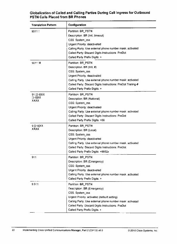
22
Globalization of Called and Calling Parties During Call Ingress for OutboundPSTN Calls Placed from BR Phones
Translation Pattern Configuration
9011.! Partition: BR_PSTN
Description: BR (Intl, timeout)
CSS System_css
Urgent Priority: deactivated
Calling Party: Use external phone number mask: activated
Called Party: Discard Digits Instructions: PreDot
Called Party Prefix Digits: +
9011 !# Partition: BR_PSTN
Description: BR (Intl, #)
CSS: System_css
Urgent Priority: deactivated
Calling Party: Use external phone number mask: activated
Called Party: Discard Digits Instructions: PreDot Trailing-*
Called Party Prefix Digits: +
91[2-9)XX[2-9]XXXXXX
Partition BR_PSTN
Description: BR (National)
CSS: System_css
Urgent Priority: deactivated
Calling Party: Use external phone number mask: activated
Called Party: Discard Digits Instructions: PreDot
Called Party Prefix Digits: +66
9 [2-9]XXXXXX
Partition. BR_PSTN
Description: BR (Local)
CSS: System_css
Urgent Priority: deactivated
Calling Party: Use external phone number mask: activated
Called Party: Discard Digits Instructions: PreDot
Called Party Prefix Digits: +6652x
911 Partition: BR__PSTN
Description: BR (Emergency)
CSS: System_css
Urgent Priority: deactivated
Calling Party. Use external phone number mask: activated
Called Party Prefix Digits: +
9.911 Partition BR_PSTN
Description: BR (Emergency)
CSS: System_css
Urgent Priority: activated (default setting)
Calling Party: Use external phone number mask: activated
Called Party: Discard Digits Instructions: PreDot
Called Party Prefix Digits. +
Implementing Cisco Unified Communications Manager, Part 2 (CIPT2) v8.0 ©2010CiscoSystems, Inc.

Translation Pattern
0.112
©2010Cisco Systems, Inc
Configuration
Partition HQ_PSTN
Description: HQ (Emergency)
CSS: System_css
Urgent Priority: deactivated
Calling Party: Use external phone number mask: activated
Called Party Discard Digits Instructions PreDot
Called Party Prefix Digits: +
Lab Guide

• You assigned partitions and CSSs to your IP phones. Each IP phone should still be able locall the other two IP phones. Verify this by placing test calls.
Task 2: Configure Outbound PSTN CallsIn this task, you will configure outbound PSTN calls using globalized call routing.
Task Job Aids
These job aids are available to help you complete the lab task.
Globalization of Called and Calling Parties During Call Ingress for OutboundPSTN Calls Placed from HQ Phones
Translation Pattern Configuration
000.! Partition: HQ_PSTN
Descnption: HQ (Intl, timeout}
CSS: System_css
Urgent Priority: deactivated
Calling Party: Use external phone number mask: activated
Called Party: Discard Digits Instructions: PreDot
Called Party Prefix Digits: +
000 !# Partition: HQ_PSTN
Description: HQ (Intl, #)
CSS. System_css
Urgent Priority: deactivated
Calling Party: Use external phone number mask: activated
Called Party: Discard Digits Instructions: PreDot Trailing-*
Called Party Prefix Digits: +
00.[2-9]XX[2-9]XXXXXX
Partition: HQ_PSTN
Description: HQ (National)
CSS: System_C5S
Urgent Priority: deactivated
Calling Party: Use external phone number mask: activated
Called Party: Discard Digits Instructions: PreDot
Called Party Prefix Digits: +55
0.[2-9]XXXXXX
Partition: HQ_PSTN
Description: HQ (Local)
CSS: System_css
Urgent Priority: deactivated
Calling Party: Use external phone number mask: activated
Called Party: Discard Digits Instructions: PreDot
Called Party Prefix Digits: +5551x
112 Partition: HQ_PSTN
Description: HQ (Emergency)
CSS: System_css
Urgent Priority: deactivated
Calling Party: Use external phone number mask: activated
Called Party Prefix Digits. +
20 Implementing Cisco Unified Communications Manager. Part2 (CIPT2) v8.0 ©2010 Cisco Systems, Inc.
a»
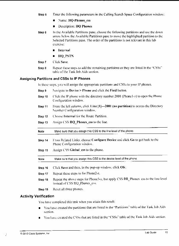
Step 5 Enter the following parameters in the Calling Search Space Configuration window:
• Name: HQ-Phones_css
• Description: HQ Phones
Step 6 In the A\ ailable Partitions pane, choose the following partitions and use the downarrow below the Available Partitions pane to move the highlighted partition to theSelected Partitions pane. The order of the partitions is not relevant in this labexercise:
• Internal
• IIQ_PSTN
Step 7 Click Save.
Step 8 Repeat these steps to add the remaining partitions as they are listed in the "CSSs"tabic of the Task Job Aids section.
Assigning Partitions and CSSs to IP Phones
In these steps, you will assign the appropriate partitions and CSSs to your IP phones.
Step 9 Na\ igate to Device > Phone and click the Find button.
Step 10 Click the IP phone with the directory number 2001 (Phonel-.v) to open the PhoneConfiguration window.
Step 11 From the left column, click Line |l]—2001 (no partition) to access the DirectoryNumber Configuration window.
Step 12 Choose Internal for the Route Partition.
Step 13 Assign CSS HQ_Phoncs_css to the line.
Note Make sure that you assign this CSS to the line level of the phone.
Step 14 from Related Links, chooseConfigure Deviceand click Go to get backlo thePhone Configuration window.
Step 15 Assign CSS Global_css lo the phone.
Note Make sure that you assign this CSS to the device level of the phone
Step 16 Click Save and then, in the pop-up window, click OK.
Step 17 Repeat these steps to for Phone2-.v.
Step 18 Repeat the above steps for Phone3-.v. butapply CSS RR Phones_css to the fine levelinstead of CSS H()_Phoncs_css.
Step 19 Reset all three phones.
Activity Verification
Youhavecompleted this task whenyou attain this result:
• You ha\e created thepartitions thatarelisted inihe"Partitions" table of the task Job Aidssection.
• You ha\e created the CSSs that arc listed in the "CSSs" tabic of the Task Job Aids section.
) 2010 Cisco Systems. !nc Lab Guide
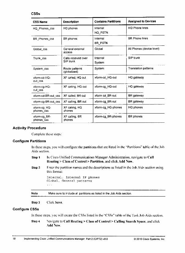
CSSs
CSS Name Description Contains Partitions Assigned to Devices
HQ_Phones_css HQ phones Internal
HQ_PSTN
HQ Phone lines
BR_Phones_css BR phones Internal
BR_PSTN
BR Phone lines
Global_css General external
access
Global All Phones (device level)
Trunk_css Calls received over
SIP trunk
Internal
System
SIP trunk
System^css Route patterns(globalized)
System Translation patterns
xform-cd-HQ-out_css
XF called, HQ out xform-cd_HQ-out HQ gateway
xform-cg-HQ-out_css
XF calling, HQ out xform-cg_HQ-out HQ gateway
xform-cd-BR-out_css XF called, BR out xform-cd_BR-out BR gateway
xform-cg-BR-out_css XF calling, BR out xform-cg_BR-out BR gateway
xform-cgJHQ-phones_css
XF calling, HQphones
xform-cg_HQ-phones HQ phones
xform-cg_BR-phones_css
XF calling, BRphones
xform-cg_BR-phones BR phones
Activity Procedure
Complete these steps:
Configure Partitions
In these steps, you will configure the partitions lhat are listed in the "Partitions" table of the JobAids section.
Step 1 In Cisco Unified Communications Manager Administration, navigate to ("allRouting > Class of Control > Partition, and click Add New.
Step 2 Fnter the partition names and the descriptions as listed in the Job Aids section usingthis format:
Internal, Internal IP phones
Global, General patterns
Note Make sure to include all partitions as listed in the Job Aids section.
Step 3 Click Save.
Configure CSSs
In these steps, you will create the CSSs listed in the "CSSs" table of Ihe Task Job Aids section.
Step 4 Na\ igate to Call Routing >Class of Control > Calling Search Space, and clickAdd New.
Implementing Cisco Unified Communications Manager, Part 2 (CIPT2) v8.0 ) 2010 Cisco Systems, Inc.

Task 1: Configure Partitions and CSSsIn this task. \ou will configure all partitions and CSSs that arc required for the following tasks.You will assign partitions and CSSs to phones and phone directory numbers.
Task Job Aids
These job aids are available to help \ou complete the lab task.
Partitions
Partition Name Description Assigned to Phones or Patterns
Internal Internal IP phones Directory numbers of phones
Global General patterns Translation patterns that are usedfor sile-code dialing and nativelydialed globalized numbers
HQ_PSTN PSTN as dialed by HQ users Translation patterns that are usedfor HQ PSTN dialing
BR_PSTN PSTN as dialed by BR users Translation patterns that are usedfor BR PSTN dialing
System System patterns Route patterns in globalized formatthat are used for PSTN access,TEHO, and intersite calls
xform-cd_HQ-out XF called, HQ out Called party transformation patternsthat are applied to the HQ gatewayfor outbound calls
xform-cg_HQ-out XF calling, HQ out Calling party transformation patternsthat are applied to the HQ gatewayfor outbound calls
xform-cd_BR-out XF called, BR out Called party transformation patternsthat are applied to the BR gatewayfor outbound calls
xform-cg_BR-out XF calling, BR out Calling party transformation patternsthat are applied to the BR gatewayfor outbound calls
xform-cg_HQ-phones
XF calling, HQ phones Calling party transformation patternsthat are applied to HQ phones forinbound calls
xform-cg_BR- phones XF calling, BR phones Calling party transformation patternsthat are applied to BR phones forinbound calls
© 20' 0 Cisco Systems. Inc Lab Guide
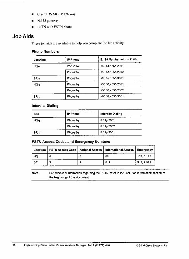
• Cisco IOS MGCP gateway
• H.323 gateway
• PSTN with PSTN phone
Job Aids
Thesejob aids are available to helpyou complete the lab activity.
Phone Numbers
16
Location IP Phone E.164 Number with + Prefix
HQ-x Phonel-x +55 51x555 2001
Phone2-x +55 51x555 2002
BR-x Phone3-x +66 52x 555 3001
HQ-y Phonel -y +55 51/555 2001
Phone2-y +55 51/ 555 2002
BR-y Phone3-y +66 52/555 3001
Intersite Dialing
Site IP Phone Intersite Dialing
HQ-y Phonel-y 8 51/2001
Phone2-y 8 51/2002
BR-y Phone3-y 8 52/ 3001
PSTN Access Codes and Emergency Numbers
Location PSTN Access Code National Access International Access Emergency
HQ 0 0 00 112,0112
BR 9 1 011 911,9 911
Note For additional information regarding the PSTN, refer to the Dial Plan Information section at
the beginning of this document
Implementing Cisco Unrfied Communications Manager, Part 2 (CIPT2) v8.0 >2010 Cisco Systems, Inc.
•to
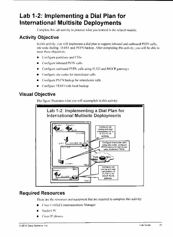
m
Lab 1-2: Implementing a Dial Plan forInternational Multisite Deployments
Complete this lab activity to practice what you learned in the related module.
Activity ObjectiveIn ibis activity, you will implement a dial plan to support inbound and outbound PSTN calls,site-code dialing. TFIfO. and PSTN backup. After completing this activity, you will be able tomeet these objectives;
• Configure partitions and CSSs
• Configure inbound PSTN calls
• Configure outbound PSTN calls using H.323 and MGCP gateways
• Configure site codes tor intercluster calls
• Configure PSTN backup for intercluster calls
• Configure TEHO with local backup
Visual ObjectiveThe figure illustrates what you will accomplish in this activity.
Lab 1-2: Implementing a Dial Plan fcInternational Multisite Deployments
Required Resources
Configure callrouting and digit
manipulation lor aH 323 PSTN
gateway
Configure intercluster callsusing site codes, configure
PSTN backup for interclustercalls, implement TEHO
Configure callrouting and digilmanipulation atCUCMI-x for
MGCP PSTN
gateway
These arc the resources and equipment that are required to complete this activity:
• Cisco Unified Communications Manager
• Student PC
• Cisco IP phones
) 2010 Cisco Systems. Inc. Lab Guide
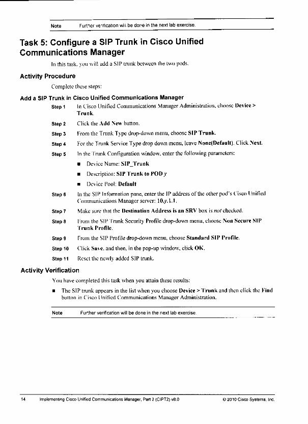
Note Further verification will be done in the next lab exercise.
Task 5: Configure a SIP Trunk in Cisco UnifiedCommunications Manager
In this task. >ou will add a SIP trunk between the two pods.
Activity Procedure
Complete these steps:
Add a SIP Trunk in Cisco Unified Communications Manager
Step1 In Cisco Unified Communications Manager Administration, choose Device >Trunk.
Step 2 Click the Add New button.
Step 3 Fromthe Trunk Type drop-down menu, choose SIP Trunk.
Step4 FortheTrunk Service Typedropdownmenu, leave None(Defaull). Click Next.
Step 5 In the Trunk Configuration window, enter the following parameters:
• Device Name: SIP_Trunk
• Description: SIP Trunk to POD/
• Device Pool: Default
Step 6 In the SIP Information pane, enter the IP address of the other pod's Cisco UniliedCommunications Manager server: \0.y.\A.
Step 7 Make sure that the Destination Address is an SRV box is not checked.
Step 8 From the SIP Trunk Security Profile drop-down menu, choose Non Secure SIPTrunk Profile.
Step 9 From the SIP Profile drop-down menu, choose Standard SIP Profile.
Step 10 Click Save, and then, in the pop-up window, click OK.
Step 11 Reset the newly added SIP trunk.
Activity Verification
You have completed this task when you attain these results:
• The SIP trunk appears in the list when you choose Device > Trunk and then click the Findbutton in Cisco Unified Communications Manager Administration.
Note Further verification will be done in the next lab exercise.
14 Implementing Cisco Unified Communications Manager, Part 2 (CIPT2) v8.0 © 2010 Cisco Syslems. Inc.
Reduce the Utilized B-Channels from 23 to 8
Step 11 Disable the configuration server byentering the following command inglobalconfiguration mode:
no ccm-manager config
Step 12 In global configuration mode, enter the following commands to shut down the voiceport that is associated with the Tl PRI:
voice-port 0/0/0:23
shutdown
Step 13 Disable PRI backhauling on the HI I) channel:
interface serial 0/0/0:23
no isdn bind-13 ccm-manager
Step 14 Remo\c the auloconfigured PRI group and add a new one:
controller tl 0/0/0
shutdown
no pri-group timeslots 1-24 service mgcp
pri-group timeslots 1-8 service mgcp
no shutdown
Step 15 Re-enable PRI backhauling:
interface serial 0/0/0:23
isdn bind-13 ccm-manager
end
Note Because you deactivated the configuration server feature, the MGCP process at the CiscoIOS gateway is not automatically reset anymore when you reset the gateway in CiscoUnified Communications Manager. You have to manually reset the MGCP process at theCisco IOS gateway every time after you reset the gateway in Cisco Unified Communications
Manager Enter the no mgcp command, followed by the mgcp command, in order to resetthe MGCP process at the Cisco IOS router.
Activity Verification
You have completed this task when you attain this result:
• Your MGCP gateway is successfully registered with Cisco Unified CommunicationsManager. This successful registration can be verified at the gateway as follows:
LIsc the show ccm-manager hosts command. The status should show Registered.
— Use the show mgcp endpoint command. All controlled ISDN PRI cndpoinl portsshould be up.
— Use the show mgcp command. The Admin State and ihe Opcr State should beactive.
Use the show isdn status command. Ihe Layer 2 slate should beMUI.TIPI.FJ:RAMFS F.STABUISIIF.D.
• Verify that the MGCP gateway and the MGCP endpoinls are registered in Cisco UnifiedCommunications Manager:
Step 1 Navigate lo Device > Gateway.
Step 2 Choose the option lo Shaw endpoinls and click Find. The status of the endpointshould be registered with IO.v.I.I.
©2010 Cisco Systems Inc LabGuide 13
Activity Verification
Youha\e completed this task whenyou attain this result:
• When youchoose Device > Gateway, choose theoption to Show endpoints. and clickFind, ihe MGCP gateway andits endpoints appear on the list.
Note Further verification will be done in the next task.
Task 4: Configure an MGCP GatewayIn this task, you will configure a Cisco IOS MGCP PSTN gateway thatis located at ihebranchto register with Cisco Unified Communications Manager.
Activity Procedure
Complete these steps:
Log in to BR-xStep 1 From PC-.v. connectto your headquarters router(HQ-x) using Telnet to
10_v.250.l02. Login usingthe password ciscoand switchto enablemode(usingthepassword cisco again).
Discover the Current Gateway Configuration and Verify IP ConnectivityStep 2 Display the currentrouterconfiguration by enteringshow running-config.
Note The gateway is currently not configured withany MGCP commands. The T1 or E1 controlleris not configured with a PRI group command. There is no ISDN PRI.
Step 3 Display the network interfaces and their IP configurations by entering Ihe show ipinterface brief command.
Step 4 Display the IP routing table by entering the show ip route command.
Configure the Cisco IOS Gateway for MGCP Using the Configuration Server Method
Step 5 Fnter the terminal monitor command to display the debug output that is generatedby the router.
Step 6 Enter the debug ccm-manager con fig-down load events command to debug theconfiguration server feature events.
Step 7 In global configuration mode, enter the following commands:
ccm-manager config server 10.x.1.1
ccm-manager config
Step 8 Monitor the debug output to verify the operation of the configuration server feature.Turn off all debugging by entering the no debug all command.
Step 9 Fnter the show running-config command. Your gateway should be configured forMGCP, "fhe configuration that was added by the configuration server featureincludes MGCP, controller, and ISDN PRI settings.
Step 10 Save your configuration changes using ihe copy running-config startup-configcommand.
12 Implementing Cisco UnrfiedCommunications Manager, Part 2 (CIPT2) v8.0 ©2010 Cisco Systems, Inc.

Note Further verification will be done in the next lab exercise.
Task 3: Add an MGCP Gateway to Cisco UnifiedCommunications Manager
Inthistask. >ou will addan MGCP gateway to Cisco Unified Communications Manager.
Activity Procedure
Complete these steps:
Configure an MGCPGateway in Cisco Unified Communications Manager
Note These steps are platform-dependent. Cross-check with your instructor to findout the actualhardware that is used for your MGCP gateway. This lab guide is based on the Cisco 2811
Integrated Services Router platform with a VW1C2-1MFT-T1E1-T1 in slot 0/0. You can also
use the show diag command at your router to display its hardware configuration.
Step 1 In Cisco Unified Communications Manager Administration, choose Device >Gateway and click the Add \cw button.
Step 2 From the Gateway lype drop-down menu, choose the gateway platform (forexample, a Cisco 2811 Integrated Services Router) that is used for Cisco IOS MGCPgateway BR-.r. Click Next.
Step 3 From the Protocol drop-down menu, choose the protocol type MGCP and clickNext
Step 4 [{nterthe following parameters in the Gateway Configuration window, and thenclick Save:
• Domain Name: BR-.v(in which x is your pod number)
• Description: BR-.v, Branch PSTN Gateway (MGCP)
• Cisco Unified Communications Manager Group: Default
• Module in Slot 0: NM-4VWK-MBRD
• Global ISDN Switch Type: NI2
Add MGCP Endpoints by Selecting Modules and Voice Interface Cards
Step 5 In ihe Configured Slots, VICs and Lndpoints pane, from Subunit 0 in Slot 0. choosethe module VWIC2-1MFT-T1F.I-T1. Click Save.
Step 6 Click the port icon on the right of the displayed endpoint 0/0/0.
Step 7 In the Gateway Configuration window, enter the following parameters:
• Description: BR-*, Branch PSTN Gateway (MGCP): ISDN PRI
• Device Poo!: Default
• PRI Protocol Type: PRI NT2
• Channel Selection Order: Top Down
Step 8 Click Save and. when the pop-up window appears, click OK.
Step 9 Reset the newh added MGCP endpoint.
<§ 20' 0 Cisco Systems. Inc Lab Guide
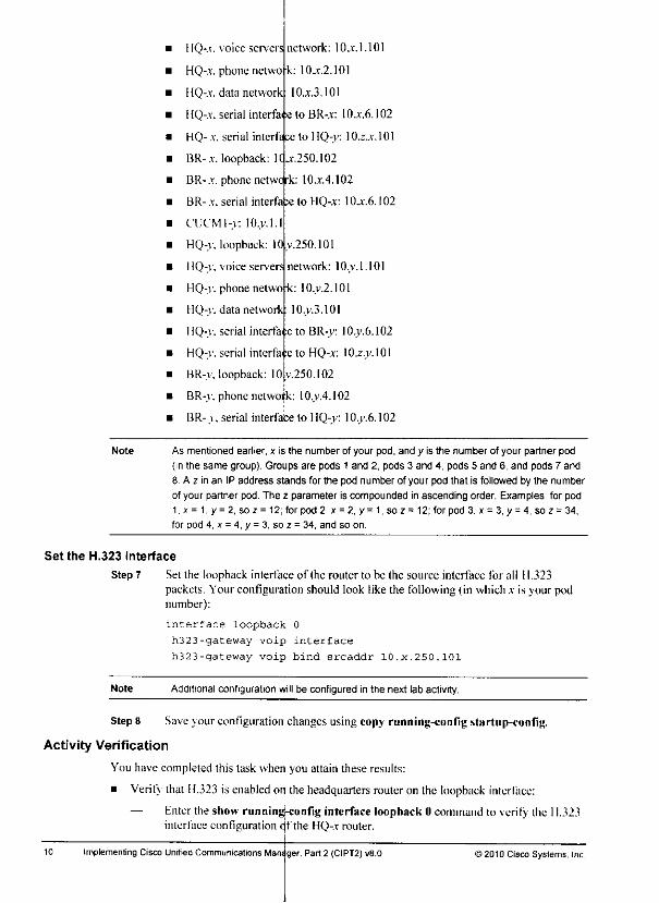
HQ-.t. voice servers network: IOjc.1.101
HQ-x phone netwo k: IOjt.2.101
HQ-x data network 10.x3.I01
HQ-x serial interfaie to BR-x IOjt.6.102
HQ-x. serial interface to HQ-y: 10.z-.jc.101
BR-.r. loopback: Kjc.250.102
BR-x phone netwerk: IOjt.4.102
BR-xserial inter!a ;e to HQ-x 10.x6.102
CUCMl-y: lO.v.l.l
HQ-y. loopback: 10 v.250.101
HQ-y. voice servers network: lO.y.1.101
HQ-y. phone netwo -k: IO.v.2.101
HQ-y. data network: lO.v.3.101
HQ-y. serial interface to BR-y: I0.y.6.102
HQ-v. serial interfa>e to HQ-x- 10.z.y. 101
BR-y. loopback: I0v.250.102
BR-y. phone network: lO.y.4.102
BR-.v. serial interface to HQ-y: 10.y.6.102
Note As mentioned earlier, x is the number of your pod, and y is the number of your partner pod
(in the same group). Groups are pods 1 and 2, pods 3 and 4, pods 5 and 6, and pods 7 and
8 A z in an IP address stands for the pod number of your pod that is followed by the number
of your partner pod. The z parameter is compounded in ascending order. Examples: for pod
1,x = 1, y = 2, soz = 12; for pod 2, x = 2,y= 1, soz= 12; for pod 3, x= 3. y = 4, soz = 34,
for pod 4, x = 4, y = 3, so z = 34, and so on.
Set the H.323 Interface
Step 7 Set the loopback interface of the router to be the source interface for all H.323packets. Your configuration should look like the following (in which x is your podnumber):
interface loopback 0
h323-gateway voip interface
h323-gateway voip bind sreaddr 10.x.250.101
Note Additional configuration will be configured in the next lab activity.
Step 8 Save jour configuration changes using copy running-con tig start up-con fig.
Activity Verification
You have completed this task when you attain these results:
• Verity that H.323 is enabledon the headquarters routeron the loopback interlace:
Enter the show running-config interfaceloopback0 command to verify the 11.323interface configuration df the HQ-.r router.
10 Implementing Cisco Unified Communications Mansger, Part 2 (CIPT2) v8.0 ©2010 Cisco Systems, Inc.
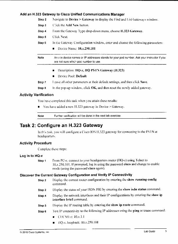
Add an H.323 Gateway to Cisco Unified Communications Manager
Step 2 Navigate to Device > Gateway to display the find and List Gateways window.
Step 3 Click the Add New button.
Step 4 from the Gateway '1 ype drop-down menu, choose 11.323 Gateway.
Step 5 Click Next.
Step 6 In the Gateway Configuration window, enter and choose the following parameters:
• Device Name: 10_v.250.101
Note An x in device names or IP addresses stands for your pod number. Ask your instructor if you
are not sure which pod number to use.
• Description: HQ-x IIQ PSTN Gateway (11.323)
• Device Pool: Default
Step 7 Leave all other parameters at their default settings, and then click Save.
Step 8 In ihe pop-up window, click OK, and then reset the newly added gateway.
Activity Verification
You have completed this task when you attain these results:
• You ha\e added a new H.323 gateway in Device > Gateway.
Note Further verification will be done in the next lab exercise.
Task 2: Configure an H.323 GatewayIn this tusk. \ou will configure a Cisco IOS H.323 gateway for connecting to the PSIN atheadquarters.
Activity Procedure
Complete these steps:
Log in to HQ-x
Step 1 From PC-x connect to your headquarters router (HQ-x) using Telnet toI0_v.250.l01. If prompted, log in usingthe password ciscoand changelo enablemode (using the password cisco again).
Discover the Current Gateway Configuration and Verify IP ConnectivityStep2 Display the current router configuration byentering the show running-config
command.
Step 3 Display the status ofyour ISDN PRI by entering theshowisdnstatuscommand.
Step4 Display the network interfaces andtheir IPconfigurations by entering the show ipinterface brief command.
Step5 Display the IProuting table byentering Ihe show ip route command.
Step 6 Test IP connectivity to the following IP addresses using the ping or trace command:
• CUCMI-x 10-t.I.I
• HQ-x loopback: I0_t.250.10I
)2010 Cisco Systems, inc Lab Guide
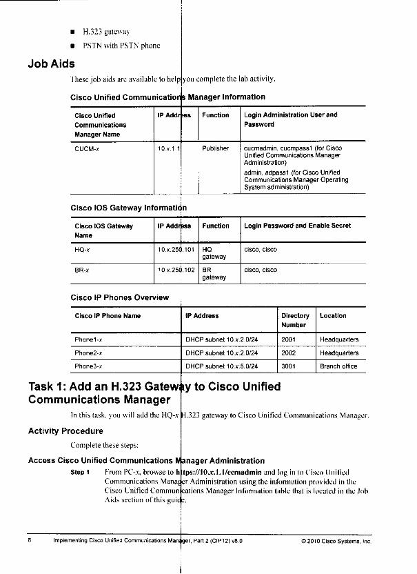
• H.323 gateway
• PSTN with PSTN phone
Job Aids
Thesejob aids are available to helpyou completethe lab activity,
Cisco Unified Communications Manager Information
Cisco Unified IP Addr (as Function Login Administration User and
Communications Password
Manager Name
CUCM-x 10.x. 1.1 Publisher cucmadmin, cucmpassl (for CiscoUnified Communications ManagerAdministration)
;
admin, adpassl (for Cisco UnifiedCommunications Manager OperatingSystem administration)
Cisco IOS Gateway Information
Cisco IOS Gateway
Name
IP Addrpss Function Login Password and Enable Secret
HQ-x 10x.25<).101 HQ
gatewaycisco, cisco
BR-X 10x.250.102 BR
gatewaycisco, cisco
Cisco IP Phones Overview
Cisco IP Phone Name IP Address Directory
Number
Location
Phonel-x DHCP subnet 10.X.2.0/24 2001 Headquarters
Phone2-x DHCP subnet 10.X.2.0/24 2002 Headquarters
Phone3-x DHCP subnet 10.X.5.0/24 3001 Branch office
Task 1: Add an H.323 Gatew
Communications ManagerIn this task, you will add the HQ-.v
Activity Procedure
Complete these steps:
Access Cisco Unified Communications IV
Step 1 From PC-.v. browse to h
Communications ManafCisco Unified Commun
Aids section of this guic
iy to Cisco Unified
-1.323gateway to Cisco Unified Communications Manager
anager Administration
tps://10.v.Ll/ccniadmin and log in lo Cisco Unifieder Administration using the information provided in thecations Manager Information table that is located in Ihe Jobs.
Implementing Cisco Unified Communications Manager. Part 2 (CIPT2) v8.0 ) 2010 Cisco Systems, Inc.
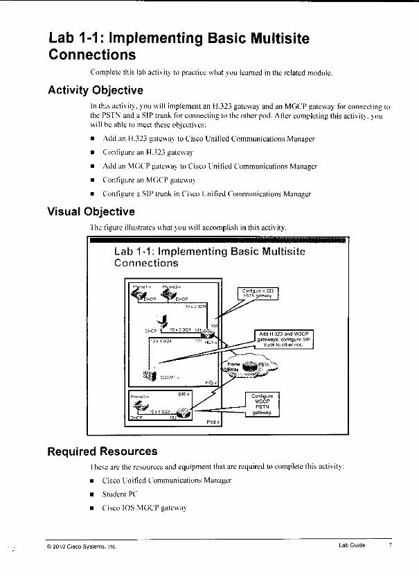
Lab 1-1: Implementing Basic MultisiteConnections
Complete this lab activity to practice what you learned in the related module.
Activity ObjectiveIn ihis activily. you will implement an H.323 gateway and an MGCP gateway for connecting tothe PSI'N and a SIP trunk for connecting to the other pod. AHercompleting this activity, youwill be able to meet these objectives:
Add an H.323 gateway to Cisco Unified Communications Manager
Configure an H.323 gateway
Add an MGCP gateway to Cisco Unified Communications Manager
Configure an MGCP gateway
Configure a SIP trunk in Cisco Unified Communications Manager
Visual Objective
'] he figure illustrates what you will accomplish in this activity.
Lab 1-1: Implementing Basic tVlultisiConnections
Required Resourcesfhese are the resources and equipment that arc required lo complete this activity:
• Cisco Unified Communications Manager
• Student PC
• Cisco IOS MGCP gateway
© 2010 Cisco Systems, Inc. Lab Guide
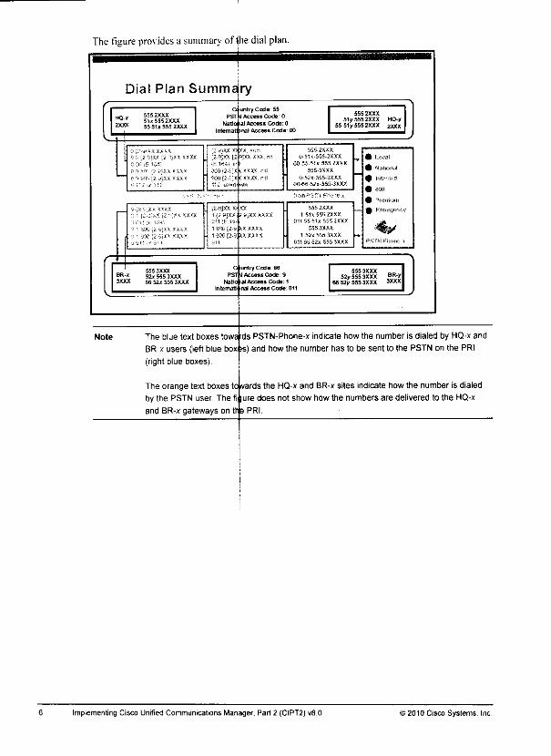
The figure pros idesa summary of (hedial plan.
Dial Plan Summs ry
HQ-I
2 XXX
Note
5552XXX51*S552XXX55 5U555 2XXX
b [2^:X< [i."•';>* xtxx
G 'nTf' [2 u'XX *Xi*'i :.ffi p.-j;xx <xx<
PSTN
Mati
:; »;xx x
;;-?jxx \:
i [2 y)y.t
intiyCode: 55Access Code 0
al Access Code: 0
Access Coda I
5552XXX51y5552XXX HQ-y
55 51/5552XXX zxxx
iiS5..XXX
U.^.-J55-3XXX
00-55-51 <-55S-£XX>;
55S-3XXX
0-«i-555.3XXX
00*9 Ml-5 5.1-3 XXX
.Tf P'l
1 80C [J •1 i'OO [2-
5SXXXX
<X*XXX
5!. 5 2 XXX
1 51iE5!)?XXX
(HIMMlBSSiXXX
5553XXX
1 52* 555 3XXX
011 SB 521 555 3XXX
5553XXX52I5553XXX
66 521 555 3XXX
The blue text boxes
BR-x users (leftblue box£s)(right blue boxes)
The orange text boxes
by the PSTN user. The
and BR-x gateways on
fll
It 3
y Code: 66
j Access Code: 9
Ial Access Code: 1nal Access Code: 011
555 3XXX52/555 3X XX
66 52y 555 3XXX
towards PSTN-Phone-x indicate how thenumber isdialed by HQ-x and;s) and how the number has to be sent to the PSTN on the PRI
tctwards the HQ-x and BR-x sites indicate how the number is dialed
ure does not show how the numbers are delivered to the HQ-x
PRI.
Implementing Cisco Unified Communications Manager. Part 2 (CIPT2) vfl.O 12010 Cisco Systems, Inc.
As shown in the table, thecalling number that isused by the PSTN phone depends on thePSfN phone line that is used to place the call.
Calling Number Presentation of Calls Placed from PSTN-Phone-x
PSTN-Phone-x Line Calling Number Presentation
Local 556 4444, TON - subscriber
National 606 555 4444, TON = national
Intemtl 77 606 555 4444, TON = international
800 "PSTN"
Premium none (CLIR)
Emergency 112. TON = unknown (when call is placed to HQsites)
911, TON - unknown (when call is placed to BRsites)
Note When calls are placed fromline 800, the calling number is not provided, the calling name"PSTN" is presented instead of a calling number.
When calls are placed from line Premium, CLIR is used.
fhe ISDN PRIs have to be configured as shown in the table.
ISDN PRI Configuration
HQ-x Gateways BR-x Gateways
Controller type E1 T1
Framing crc4 esf
Line code hdb3 b8zs
Clock source line line
Timeslot range 1-8, 16 1-8.24
ISDN switch type primary net5 pnmary-ni
©2010 Cisco Systems, Inc Lab Guide

Calls Sent to PSTN-Phone-x
Received from HQ-x Sites Received from BR-x
Sites
Sent to PSTN-
Phone-x Line
Local calls [2-9JXX XXXXTON = subscriber
[2-9]XXXXXXLocal
National calls [2-9JXX [2-9JXX XXXX,TON = national
1 [2-9]XX 2-9]XXXXXX
National
international calls (E.164 number of any length),TON = international
011 {E.164 number ofany length)
Intemtl
Toll-free calls 800 [2-9]XX XXXX,TON = national
1 800 [2-9]XX XXXX 800
Premium calls 900 [2-9JXX XXXX,TON = national
1 900 [2-9]XX XXXX Premium
Emergency calls 112,TON = Unknown
911 Emergency
Note The PSTN at the HQ sites allows remote calling numbers to be sent (for example in case ofTEHO or device mobility) The calling number that is sent to the PSTN through HQ
gateways should always be in the shortest-possible format. Calls originating at the local HQsite should use local format, calls originating at the HQ site of the other pod should use
national format, and calls originating at one of the two BR sites should use international
format
The PSTN at the BR sites does not allow remote calling numbers to be sent. The calling
number that is sent to the PSTN through BR gateways should always be in national format.
Calls originating at any remote site (BR site of the other pod, one of the two HQ sites)
should use the number of the local BR attendant (52x-555-3001).
Calls to the HQ and BR sites can be placed from PSTN-Phone-*, as shown in the table:
Calls That Can Be Placed from PSTN-Phone-x
Number Dialed at PSTN-
Phone-x, Sent to HQ-x Site
Number Dialed at PSTN-
Phone-x, Sent to BR-x Site
Local calls 555 2XXX 555 3XXX
National calls 0 51X555 2XXX 1 52x 555 3XXX
International calls 00 55 51x 555 2XXX 011 66 52x555 3XXX
Note The table shows the valid numbers that can be dialed at PSTN-Phone-x. No PSTN access
code is dialed from the PSTN phone. The presentation of the called number for these calls is
different The called number is always presented to the HQ and BR gateways without
prefixes and the TON is always set.
Implementing Cisco Unified Communications Manager, Part 2 (CIPT2) v8.0 ) 2010 Cisco Systems, Inc

The table pro\ ides an overview of the dial plan that is in use.
Dial Plan Overview
HQ-x Site BR-x Site
Internal directory number range 2XXX 3XXX
PSTN range in local (subscriber) format 555 2XXX 555 3XXX
PSTN range in national format 51x555 2XXX 52x 555 3XXX
PSTN range in international format 55 51* 555 2XXX 66 52x 555 3XXX
PSTN access code 0 9
National access code 0 1
International access code 00 011
Note The x is a variable indicating your pod number.
The PSTN accepts calls from the HQ and BR sites as shown in the table.
Calls Accepted by the PSTN
Received from HQ-x Sites Received from BR-x Sites
Local calls [2-9]XX XXXX,TON = subscriber
[2-9]XX XXXX
National calls 51x[2-9]XXXXXX.TON - national
1 52x [2-9]XX XXXX
International calls (E 164 number of any length),TON = international
011 (E.164 number of anylength)
Toll-free calls 800 [2-9JXX XXXX,TON = national
1 800 [2-9]XX XXXX
Premium calls 900 [2-9]XX [2-9]XXX,TON - national
1 900 [2-9]XX XXXX
Emergency calls 112,
TON = Unknown
911
Note When HQ gateways are sending calls to the PSTN, the gateways are required to set the
ISDN TON for the called number (see the table for details); national and international
prefixes must not be used.
When BR gateways are sending calls to the PSTN, the gateways are required to send
prefixes for national and international calls; the TON must not be set (it must be set to
Unknown).
The used PSTN numbenng plans do not fully represent the actual numbering plans that are
used in North America or Europe They only use some components of these PSTN
numbering plans.
Ifa dialed number matches the range that is used at one of the HQ or BR sites, the PSI'N routesthe call to that sile. All other valid calls are sent lo PSIN-Phone-.*. as shown in the table:
>2010 Cisco Systems. Inc. Lab Guide
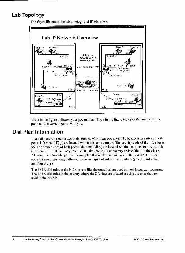
Lab TopologyThe figure illustrates the labtopology andIP addresses.
Lab IP Network Overview
Phone1-* Ptione--x
^^TJHCP ^^^DHCP
DHCP t
10. 1 0/24 10yHQ1-J
10 >_50 101/32 10
1011 0/24 iA~-*
*-_*
Note _ - x,
followed by y (inascending order)
, 101 10700/16 ^101
Phone2-y Phone1-y
DHCPf*^ DHCPP*^10 y 2 0/24
Pody
101 10y30J2J | DHCP
HQ1-y\ "• 10y10C4
10 y 250 101/32
BR_y Ptione3-y
10 y.250.102/3 4_ffiL_(PSI^? 10jj4 0/24 T*'
M02 DHCP
Ihe x in the figure indicates your pod number. They in the figure indicatesthe numberof thepod that will work together with you.
Dial Plan Information
Thedial plan is basedon two pods,each of whichhas two sites. The headquarters sites of bothpods (HQ-.v and HQ-y) are located within the samecountry. The country codeof the HQsites is55. The branchsitesof both pods (BR-x and BR-y) are located within the same country (whichis different from the country that the HQ sites are in), 'fhe country code of Ihe BR sites is 66.All sites use a fixed-length numbering plan that is like the one used in the NANP. The areacode is three digits long, followedby seven digits of subscriber numbers (grouped into threeand four digits).
The PSTN dial rules at the HQ sites are like the ones that are used in most European countries.The PSTN dial rules in the country where the BR sites are located are like the ones that areused in the NANP.
Implementing Cisco Unrfied Communications Manager. Part 2 (CIPT2) v8.0 © 2010 Cisco Systems. Inc.

CIPT2
Lab Guide
Overview
1 his guide presents the instructions and other infonnation concerning the lab activities for thiscourse. You can find the solutions in the lab activity Answer Key.
Outline
This guide includes these activities:
Lab 1-1
Lab 1-2
lab 2-1
Lab 2-2
Lab 3-1
Lab 3-2
Lab 4-1
Lab 4-2
Lab 5-1
Implementing Basic Multisite Connections
Implementinga Dial Plan for Internalional Multisite Deployments
Implementing SRST and MGCP fallback
Implementing Cisco Unified Communications Manager Kxpress in SRSI" Mode
Implementing Bandwidth Management
Implementing CAC
Implemenling Device Mobility
Implemenling Cisco Fxtension Mobility
Implementing Cisco SAP and CCD
Answer Ke\

Lab 3-2: Implementing CACActivityObjectiveVisual ObjectiveRequired ResourcesJob Aids
Task 1: Configure LocationsTask 2:Configure RSVP-Enabled LocationsTask 3: Configure AAR and CFNB toDeployed CAC MethodsTask4 (Optional): Configure SIP Pre[x>nditions
Lab 4-1: Implementing Device MobilityActivity ObjectiveVisual ObjectiveRequired ResourcesTask 1: Configure Device Mobility
Lab 4-2: Implementing CiscoExtension labilityActivity ObjectiveVisual ObjectiveRequired ResourcesTask 1: Activate the Cisco ExtensionParameters
Task 2: Create a Device Profile for a
Leam Routes Using CCDAnswer Key
Lab 1-1 Answer Key: Implementing Basic Multisite ConnectionsLab 1-2 Answer Key: Implementing aLab 2-1 Answer Key: Implementing
67
67
67
67
68
68
69
Route Calls over the PSTN IfThey Are Not Admitted by the72
73
75
75
75
75
76
79
79
79
79
Mobility Service and Configure the Corresponding Service80
81
82
User
Task 3: Add and Associate an End U ser with the User Device ProfileTask 4: Add the Cisco Extension Mollility IP Phone Service and Subscribe to IP Phones andDevice Profiles 83
Lab 5-1: Implementing Cisco SAF and CI ;D 85ActivityObjective 85Visual Objective 85Required Resources 85Task 1: Configure SAF Forwarder Fu ictionality on the HQ-x and BR-x Router 86Task 2: Configure Cisco Unified Corr nunications Manager as SAF Client 87Task 3: Configure Cisco Unified Corr nunications Manager Express SRST on Branch Router to
Dial Plan for International Multisite DeploymentsRST and MGCP Fallback
Lab 2-2Answer Key: Implementing (Jisco Unified Communications Manager Express in SRSTMode
Lab 3-1 Answer Key: Implementing Ejandwidth ManagementLab 3-2 Answer Key: Implementing CACLab 4-1 Answer Key: Implementing Cevice MobilityLab 4-2 Answer Key: Implementing Cisco Extension MobilityLab 5-1 Answer Key: Implementing . AF and CCD
91
96
96
96
96
96
96
96
96
96
96
Implementing Cisco Unified Communications Manager. Part 2 (CIPT2) v8.0 ) 2010 Cisco Systems, Inc.
Table of ContentsLab Guide
Overview 1Outline 1Lab Topology 2Dial Plan Information 2
Lab 1-1: Implementing Basic Multisite Connections 7Activity Objective 7Visual Objective 7Required Resources 7Job Aids 8Task 1: Add an H.323 Gateway to Cisco Unified Communications Manager 8Task 2: Configure an H.323 Gateway 9Task 3: Add an MGCP Gateway to Cisco Unified Communications Manager 11Task 4: Configure an MGCP Gateway 12Task 5: Configure a SIP Trunk in Cisco Unified Communications Manager 14
Lab 1-2: Implementing a Dial Plan for International Multisite Deployments 15Activity Objective 15Visual Objective 15Required Resources 15Job Aids 16
Task 1: Configure Partitions and CSSs 17Task 2: Configure Outbound PSTN Calls 20Task 3: Configure Inbound PSTN Calls 27Task 4: Configure Intersite Calling 31Task 5: implement TEHO Within Your Pod 35Task 6: Implement TEHO Between Pods 37
Lab 2-1: Implementing SRST and MGCP Fallback 39Activity Objective 39Visual Objective 39Required Resources 39Task 1: Configure SRST Gateways in Cisco Unified Communications Manager 40Task 2: Configure a Cisco IOS Gateway for MGCP Fallback and SRST 40Task 3: Implement a Dial Plan in Cisco Unified Communications Manager Supporting OutboundCalls During SRST Mode 42Task 4: Implement a Dial Plan at the SRST Gateway Supporting Inbound and Outbound CallsWhen in MGCP Fallback or in SRST Mode or Both 43
Lab 2-2: Implementing Cisco Unified Communications Manager Express in SRST Mode 47ActivityObjective 47Visual Objective 47Required Resources 47Task 1: Configure Cisco Unified Communications Manager Express in SRST Fallback Mode 48Task 2: Configure MOHon Cisco Unified Communications Manager Express 49
Lab 3-1: Implementing Bandwidth Management 51Activity Objective 51Visual Objective 51Required Resources 51Job Aids 52Task 1: Enable Software Media Resources on Cisco Unified Communications Manager 53Task 2: Configure Regions 54Task 3: Implement Transcoders 57Task 4: Implement a Hardware Conference Bridge 58Task 5: Implement Multicast MOHfrom Branch Router Flash 61

5-74 Impiementing Cisco Unified Communications Manaj :f, Part 2(CIPT2) v8.0 >2010 Cisco Systems, Inc.

Module Self-Check Answer KeyOD D.G
y_) h.L)
04) The toDID ruledescribes how to manipulate thelearned UN pattern in order to gelto thenumber h.should be used for a PSTNbackup call if the CCD path is unavailable.
(.)>) i:
06) D
Call Control Discovery©2010 Cisco Systems. Inc

5-72
06) Which CSS isused for CCD PSTN backup calls? (Source: Implementing SAF andCCD)
A) line CSS of the originating phoneB) device CSS of the originating phoneC) CSS of the SAF trunkD) AARCSS of the originating phoneK) CSS of the PSTN gateway
Implementing Cisco Unitied Communications Managt -, Part 2 (CIPT2) vB.O 12010 Cisco Systems, Inc.
at*

Module Self-CheckUse the questions here to re\ iew what \ou learned in this module, fhe correct answers andsolutions are found in the Module Self-Check Answer Key.
Ql) Which two ofthe following devices do not support CCD? (Choose two.) (Source:ImplementingSAF and CCD)
A) Cisco Unified SRST
B) Cisco IOS gatewayC) Cisco Unified Border ElementI)) Cisco IOS gatekeeperF.) Cisco Unified Communications ManagerF) Cisco Unified Communications Manager ExpressG) Cisco IOS Catalyst switches
Q2) Which two statements are true about SAF? (Choose two.) (Source: Implementing SAFand CCD)
A) SAF forwarders interpret the SAF header and SAF service data.B) An internal SAF client isallocated with a SAF forwarder.C) An internal SAF client resides in Cisco Unified Communications Manager.D| SAF clients do nothave to be Layer2-adjaccnt.1.) SAF requires FIGRP tobeused as the IProuting protocol.
Q3) Which two statements arc not true about CCD? (Choose two.) (Source: ImplemenlingSAF and CCD)
A) Call routing information is learned by the CCD requesting service.B) Call routing infonnation is advertised by the CCD advertising service.C) Load balancing occurs among trunk protocols and learned remote IP addresses.D) Learned call routing information can be placed into different partitions that are
based on the remote call control identity.F) Learned call routing information can be placed into different partitions that are
based on the remote IP address.
Q4) What is the purpose of the toDID rule in CCD? (Source: Implementing SAF and CCD)
Q5) Which of the following is not aconfiguration step when implementing SAF in CiscoUnified Communications Manager? (Source: Implementing SAF and CCD)
A) Configure SAF forwarder.B) Configure SAF trunk.C) Configure CCD advertising and requesting service.D) Configure hosted DN group and hosted DN pattern.F) Configure DN blockprofile.F) Configure blocked learned patterns.
) 2010 Cisco Systems. IncCall Control Discovery 5-71

5-70 Implementing Cisco Unrfied Communications Manaj er, Part 2 (CIPT2) v8.0 J2010 Cisco Systems, Inc.
Module SummaryThis topic summarizes the key points that were discussed in this module.
Module Summary
CCD allows separate calf routing domains such as CiscoUnified Communications Manager clusters and Cisco UnifiedCommunications Manager Express to utilize a SAF-enablednetwork for dynamic exchange of call-routing information.
This module started with a description of Call Control Discovery (CCD). which is a feature thatallows callagents to advertise andlearn dial plan information to and from a CiscoServiceAdvertisement Framework (SAF)-enabled network. It showed how SAF" works, how CCDutilizes SAF. and how SAF and CCD are implemented in a Cisco Unified Communicationssolution.
References
For additional infonnation. refer lo these resources:
• Cisco S\ stems. Inc. Cisco Unified Communications System 8.x SR\D. April 2010.hup:. \sww.cisco.eom/cti/US/docs/voice ip_eomm/euem/snid/S*/ue8\.html
• Cisco Systems. Inc. Cisco Unified Communications Manager Administration GuideRelease 8.0/1). February 2010.lmp:;www.eisco.com.'en.'LS/docs/\'oicc ip comni/cucm/admin/8 OLccnicfg/hccm-801cm.html
© 2010 Cisco Systems. Inc Call Control Discovery 5-69
SummaryThis topic summarizes the key points that were discussedin Ihis lesson.
References
Summary
• Dynamic distribution ofcall-routing information simplifies dial planimplementation in large or very large networks.
• SAF allowsany services to be advertised to and learned from aSAF-enabled network.
• CCD allows call agents toadvertise theinternal directory numbers thatthey serve, along with theappropriate PSTN numbers, using SAF.
1When a learned VoIP route toa directory number becomes invalid, thecall is automatically rerouted over the PSTN.
SAF and CCD implementation includes theconfiguration of SAFforwardersand SAF clients. SAFclients can be internal or external to theCisco IOS router used as a SAF forwarder.
Special considerations thatrelate to SAF and CCD implementationinclude deployments using SRST, TEHO, globalized call routing, andenvironments that have a SAF SIP trunk as well as a SAF H.323 trunk
For additional infonnation. refer to tlicse resources:
Cisco IOS Service Advertisemenhttp://www .cisco.com/en/US/dtuctsC'onfiguration GuidcC
Cisco Systems. Inc.Cisco Unijihtlp:'V\\w\\.cisco.(jom/en/US.'''do
CiscoSystems. Inc. Cisco UnifiRelease 8.0(1). February 2010.http://w ww.cisco.com/en.T ;S/doccm.html
Framework Configuration Guide 15.1 at/ios/saf/configura£ion/guide/saf_cg _ps 105')2_TSD_Prod
:er.html.haft'
ifiei
Unifiid Communications System 8.x SRND, April 2010.s/voicejp eomm/cuem/sntd/8xAic8\.himl
Communications Manager Administration Guide
s/voice_ip_comin/eucm/admin/8_0 l/ccmcig/hccin-801-
Implementing Cisco Unified Communications Manage -. Part 2 (CIPT2) v8.0 »2010 Cisco Systems, Inc.
Other SAF and CCD ConsiderationsThis subtopic describes additional issues that you need to consider when implementing CCD inCisco Unified Communications Manager.
Other SAF and CCD Considerate
If you donot assign a trunk when you configure the CCDrequesting service, Cisco Unified Communications Manager willnot subscribe to hosted DN service from SAF network; there is nolearned pattern inside the system.
Each hosted DN pattern must be unique.If a trunk isassigned toa route group or isassociated with a routepattern, you cannot enable SAF onthe trunk, and vice versa.You cannot enable SAF on SIP trunks that use authenticated orencrypted security profiles
Ifvou do not assign atrunk when you configure the CCD requesting service. Cisco UnifiedCommunications Manager uill not subscribe to the SAF forwarder. No routes will be learned.
Each hosted DN pattern must be globally unique.
Ifatrunk is assigned to aroute group or is associated with aroute pattern, you cannot enableSAF on the trunk, and vice \ ersa.
You cannot enable SAF on SIP trunks that use authenticated or encrypted security profiles.
©2010 Cisco Systems. IncCall Control Discovery

Cisco Unified Communications Manager Clusters and CCDConfiguration Modes
This subtopic describes considerations regarding Cisco Unified Communications ManagerCCD configuration modes.
Cisco Unified CommunicationsManager CCD Configuration Modes
• Basic configuration mode:
- All Cisco Unified Commurjications Manager servers use the sameprimary or secondary SAP forwarders.
• Advanced configuration mode:
- Multiple sets of forwarder^ can beconfigured and individually applied toCisco Unified Communications Managerservers.
- This mode is required whe|n clustering overtheWAN deployment modelis used.
Single-Site Cluster c^ Clustering ovpr the WAN Cisco UnifiedCommunicationsManager Cluster
Primary Secondary Primary SecondarySRF Forwarder SAFForwarder SAFForwarder SAFForwarder
When you are configuring aCisco Unified Communications Manager cluster with one ormoreSAF forwarders, by default, all Cisao Unified Communications Manager nodes that are appliedto the SAF-enabled trunk or trunks Via the device pool will register with the configured SAFforwarder.
First, you have to make sure that each local node uses adifferent SAF client ID. You can easilycheck the nodes by using aSAF client name that ends with @. In this case, each node willutilize the configured name that is followed by @and aunique node ID. At the SAF forwarder,you have toadd the basename keyword tothe end ofthe SAF external-client client-IDcommand, or you have to manually ^onfigure all names that are used by the nodes in yourcluster.
In some cases,you may not want allSAF forwarders. Forexample, as shbwnyou typically want to registernodesconfiguration, click the Show Advanced
nodes that should use SAF register with all configuredin the figure, when youuse clustering overthe WAN,
only with their local SAF forwarders. For thatlink at the SAF forwarder configuration page.
At the advanced configuration modeselectively with the configured SAF
page, you can associate individual members of the clusterforwarders.
5-66 Implementing Cisco Unified Communications Managbr, Part 2(CIPT2) v8.012010 Cisco Systems. Inc.
Trunk Considerations When Using Globalized Call RoutingThis subtopic describes considerations regarding the different trunk types when usingglobalized call routing.
Trunk Considerations When UsingGlobalized Call Routing
• OneSAF SIPtrunk andone SAF H323trunk can be configuredfor CCD
- If both are configured, load-sharing occurs.• with globalized call routing, PSTN numbers areto be dialed in E.164
format with + prefix
TEHO calls received via SAF are assumed tohave +in called number.Hosted directory number is in globalized format with +prefix.
- H 323 trunks do not send + (+ is stripped).- Requires incoming called-party prefix to be configured atH323 trunk
(prefix +).- Otherwise, received TEHO call cannotbe routed outto PSTN.
- Difficult totroubleshoot when H.323 and SIPtrunks are configuredfor SAF.
• Half of the callswork (SIP), and half ofthe callsfail (H.323)
As mentioned earlier, vou can configure one SAF-enabled SIP trunk or one SAf-enabled H.32.^trunk in Cisco Unified Communications Manager and in Cisco IOS Software. II both types oftrunk are used bv the advertising SAF client and both are used at the requesting SAF client,then all routes are learned twice—once per protocol. When placing acall to such aroute, load-sharing will occur, This means that half of the calls are setup using SIP, and half of the callsare signaled by H.323.When implementing TEHO and using globalized call routing, TFHO calls are expected to bereceived with a- prefix. The reason is that they are advertised that way and the incoming VoIPcall can be routed back out to the PSTN at the TEHO gateway when the called number is inglobalized format.
II 323 trunks however, do not send the +sign. When acall is received (or placed) through anH.323 trunk and the called number includes a+. the +sign is stripped. This does not happen onSIP trunks.
When vou rclv on the +to be received through the H.323 trunk, you have to configureincoming called-partv settings at the 11.323 trunk. Consequently, the +is prefixed before thereceived called-party number is matched in the call-routing table without the +.If vou have aSIP and an 11.323 trunk, and you do not prefix the 4- at the H.323 trunk due to theload-sharine algorithm, even' second call would fail (H.323) while the other half of the callswould work (SIP). Such apparently inconsistent errors are difficult lo troubleshoot.
Note When you expect to receive VoIP calls to internal directory numbers as well as to globalized(PSTN) numbers, make sure that your incoming called-party settings prefix only the +to thecalled numbers where it is required. You can either refer to the ISDN type of number or useglobal transformations in order to control which called-party numbers you can modify.
©2010 Cisco Systems, IncCall Control Discovery 5-65
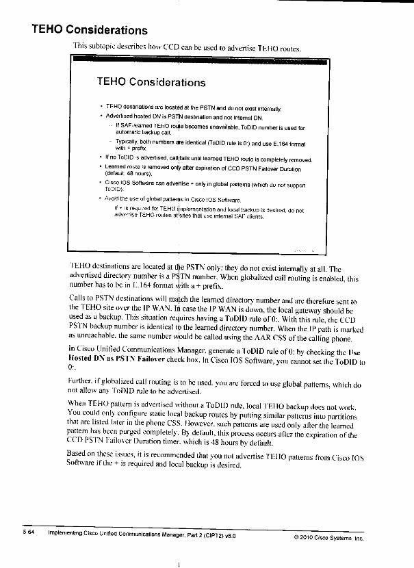
TEHO Considerations
5-64
This subtopic describes how CCD can be used toadvertise TEHO routes.
TEHO Considerations
1TEHO destinations are located atthe PSTN and do not exist intemally.• Advertised hosted DNis PSTNdestinationand not internal DN.
IfSAF-leamed TEHO route becomes unavailable, ToDID number isusedforautomatic backup call.
- Typically, both numbers are identical (ToDID rule is0:) anduse E 164formatwith + prefix.
If no ToDID is advertised, calljfails until learned TEHO route is completely removed.Learned route is removed only after expiration ofCCD PSTN Failover Duration(default: 48 hours).
Cisco IOS Software can advertise +only in global patterns (which do not supportToDID).
Avoid the use of global patterns in Cisco IOS Software.
• If - isrequired for TEHO implementation andlocal backup isdesired donotadvertise TEHO routes at'sites that use internal SAFclients.
TEHO destinations are located at tfye PSTN only; they do not exist internally at all. Theadvertised directors' number is aP^TN number. When globalized call routing is enabled, thisnumber has to be in E. 164 format vvith a + prefix.
Calls toPSTN destinations will match the learned directory' number and are therefore sent tothe TEHO site over the IP WAN. lit case the IP WAN is down, the local gateway should beused as a backup. This situation reduires having aToDID rule of0:. With this rule, the CCDPSTN backup number is identical tp the learned directory number. When the IP path is markedas unreachable, the same number would be called using the AAR CSS ofthe calling phone.In Cisco Unified Communications Manager, generate aToDID rule of 0: by checking the UseHosted DN as PSTN Failover check box. In Cisco IOS Software, you cannot set the ToDID to
Further, ifglobalized call routing is to be used, you are forced to use global patterns, which donot allow any ToDID rule to be advertised.
When TEHO pattern is advertised without aToDID rule, local TEHO backup does not workYou could only configure static local backup routes by putting similar patterns into partitionsthat are listed later in the phone CSS. Ilowever. such patterns are used only after the learnedpattern has been purged completely. By default, this process occurs after the expiration of theCC DPSTN Failover Duration timer, which is 48 hours by default.Based on these issues, it is recommended that you not advertise TEHO patterns from Cisco IOSSoftware ifthe + is required and local backup is desired.
Implementing Cisco Unified Communications Manager, Part 2(CIPT2) v8.0»2010 Cisco Systems, Inc.
gg.

Solution for PSTN Backup Advertised in E.164 Format WithoutLeading +
['his subtopic describes the workaround for CCD PS'fN backup calls lo PSTN destinations thatare in E.164 format without a •+ prefix.
Solution for PSTN Backup Advertis*E.164 Format Without Leading +
Called DN ExternalPhone Number Mask2G01. -MC8S5Sv.XaX
Standard AAR Call
Called NumberComposed IromDestination Phone
DN and hxlirriUl
• Si..
52001
AAR CSS
Partitions AAR
CCD PSTN Backup
Call
Called Number
Composed fromLearned DN Pallem
and 1c _'•[} F<"re
Route Pattern
Pattern \+'
Partition AAR
Urgent PnorityRoute List
PSTN
~J The +isprefixed for\ callsplaced with
^ AAR CSSifthecalled number does
not include +
already
It would be vcrv cumbersome to add all possible E. 164 numbers lo the overall dial plan ofCisco Unified Communications Manager. However, because CCD PSTN backup calls arealways placed with the use of the AAR CSS of the calling phone, you can add one translationpattern ' to apartition that is accessible only from the AAR CSS. At that pattern, you can prefixa+to the called-party number and set the CSS of the translation pattern to aCSS that hasaccess to the global PS'fN route pattern (\+!).That process solves the issue with CCD PS'fN backup calls. Ilowcver. if AAR is enabled, itwill break AAR. assuming that the AAR implementation is based on globalized call routing. ISthe external phone number mask of the destination phone is in E. 164 format with a+prefix,then AAR calls would not work anvmore. The reason is that they use the same CSS andtherefore would also match the !translation pattern that prefixes a+. In this case AAR callswould be placed to E. 164 numbers with two +signs. In order to also make AAR CSS cal swork vou have to add asecond translation pattern into the same partition that is accessiblefrom the AAR CSS onh -This second translation pattern \+! is not configured with any digitmanipulation but uses the same CSS as the other translation pattern (!). As aconsequence.AAR calls are passed on to the V+! route pattern without any digit manipulation (by matchingthe more specific \+! translation pattern, which docs not prefix a+). CCD PS 1Nbackup callsdo not match the Vi-! translation pattern and are therefore routes, as explained earlier.
Note
i_010 Cisco Systems,
The described solution is a workaround only. The implementation of advertised patterns inCisco IOS Software may be changed in the future so that +can be configured in theadvertised pattern and in the ToDID rule. If so, you should change from the describedworkaround to the solution that allows CCD PSTN backup calls to be placed to globalizednumbers. .
Call Control Discovery 5-63
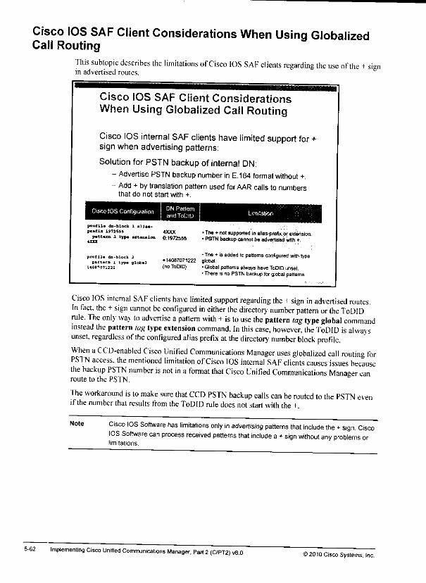
Cisco IOS SAF Client Considerations When Using GlobalizedCall Routing
This subtopic describes the limitations of Cisco IOS SAF clients regarding the use of the +signin advertised routes.
5-62
Cisco IOS SAF Client ConsiderationsWhen Using Globalized Call Routing
Cisco IOS internal SAF clients have limited support for +sign when advertising patterns:
Solution for PSTN backup of internal DN:- AdvertisePSTN backup number in E.164 formatwithout +.
- Add + bytranslation pattern used forAAR calls to numbersthat do not start with +.
Cisco IOS Configuration DN Patternand ToDID
p-atlla da-tlock 1 illu-
P-.-~_ 197.555 4XXXp«e-«B l tj-» uiuuios 0:1972555
•The+ not supported In-lias-prefix or extension.• PSTN backup canrroi be advertised with +.
profil. da-block 2
P_tt«rn 1 type globalH0470712-S
•The+ is added lo patternsconfigured with type♦ 14087071222 global,(noToDID) •Global patternsalways haveToDID unset.
•There is no PSTN backupforglobal patterns
Cisco IOS internal SAF clients have limited support regarding the +sign in advertised routes.In fact, the +sign cannot be configured in either the directory number pattern or the ToDIDrule, "fhe only way to advertise apattern with +is to use the pattern tag type global commandinstead the pattern tag type extension command. In this case, however, Ihe ToDID is alwaysunset, regardless ofthe configured alias prefix at the directory number block profile.When aCCD-enabled Cisco Unified Communications Manager uses globalized call routing forPST Naccess, the mentioned limitation ofCisco IOS internal SAF clients causes issues becausethe backup PSTN number is not in a format that Cisco Unified Communications Manaeer canroute to the PSTN.
The workaround is to make sure that CCD PSTN backup calls can be routed to the PSTN evenif the number that results from the ToDID rule does notstart with the+.
Note Cisco IOS Software has limitations only in advertising patterns that include the +sign. CiscoIOS Software can process received patterns that include a +sign without any problems orlimitations.
Implemenling Cisco Unified Communications Manager, Part 2(CIPT2) V8.0©2010 Cisco Systems, Inc.
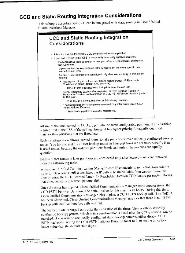
CCD and Static Routing Integration ConsiderationsThis subtopic describes how CCD can be integrated with static routing in Cisco UnifiedCommunications Manager.
CCD and Static Routing IntegrationConsiderations
All routes that are learned by CCDare put intothe same partition.If partition islisted first in CSS. il has pnority tor equally qualified matches
Partition allows learned routes tolake precedence over statically configuredbackup routes.
Make surethatbackup routes in later partitions are not more specific thanlearned hosted DNs
Routes in later partition areconsidered only after learned entry iscompletelydeleted
• The learned IP path istried until CCD Learned Pattern IPReachableDurationexpiration (default is 60 seconds)
IftheIPpathdoesnot work during this time, thecall fails.• ToDID isusedas backup after expiration ofCCD Learned Pattern IP
Reachable Duration until expiration ofCCD PSTN Failover Duration (defaultis 48 hours)
IfnoToDID is configured, the callfailsduring this time.• The learned pattern iscompletely removed only after expiration ofCCD
PSTN Failover Duration.
Static backup patterns are now considered.
All routes that are learned bv CCD are put into the same configurable partition. Ifthis partitionis listed first in the CSS ofthe calling phones, ithas higher priority for equally qualifiedmatches than partitions that arelisted later.Such aconfiguration allows learned routes to take precedence over statically configured backuproutes You have lo make sure that backup routes in later partitions are not more specific thanlearned routes, because the order ofpartitions is relevant only ifthe matches are equallyqualified.
Be aware that routes in later partitions arc considered only after learned routes are removedfrom the call-routing table.
When Cisco Unified Communications Manager loses IP connectivity to its SAF forwarder, itwails for 60 seconds until it considers the IP path to be unavailable. You can configure thistime by using the CCD learned Pattern 11' Reachable Duration CCD feature parameter. Duringthat time, and calls to learned patterns fail.
Once the timer has expired. Cisco Unified Communications Manager starts another timer, theCCD PSTN Failover Duration. The default value for this timer is 48 hours. During this timeCisco Unified Communications Manager tries to place aCCD PSTN backup call. 11 no loDIDhas been advertised. Cisco Unified Communications Manager assumes that there is no ISINbackup path and that therefore calls will fail.The learned route is purged only after the expiration of the timer. Then another (staticallyconfigured backup) pattern, which is in apartition that is listed after the CO) partition, can bematched If vol, want to use locally configured static backup patterns, etther disable t COPSTN backup b> setting the CCD PSTN Failover Duration timer to 0. or set the timer to alower value than the default {twodays).
© 2010 Cisco Systems, IncCall Control Discovery
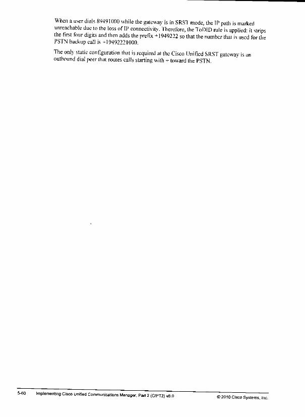
5-60
When auser dials 89491000 while the gateway is in SRST mode, the IP path is markedunreachable due to the loss of IP connectivity. Therefore, the ToDID rule is applied: it stripsthe first four digits and then adds the prefix +1949222 so that the number that is used for thePSTN backup call is +19492221000.
The only static configuration that is required at the Cisco Unified SRST gateway is anoutbound dial peer that routes calls starting with + toward the PSTN.
Implementing Cisco Unified Communications Manager, Pari 2(CIPT2) vB.O12010 Cisco Systems, Inc.
Hfc
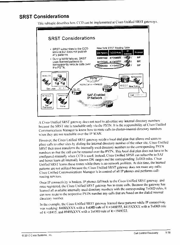
SRST ConsiderationsThis subtopic describes how CCD can be implemented at Cisco Unified SRST gateways.
SRST Considerations
New Yort(SRST Routing TableSRST subscribes to the CCDservice but does not publishany patterns.
During WAN failures, SRSTuses learned patterns totransparently reroute calls overthe PSTN.
DN Pattern TaDiDRule . Protocol
840BXXXX **14S855&' ;10©VB416XXXX 4:»14lB777- fC®'1
BlP
SIP
SIP
ACisco Unified SRST gateway does not need to advertise any internal directory numbersbecause the SRST site is reachable only via the PSTN. It is the responsibility ofCisco UnifiedCommunications Manager to know how to route calls lo cluster-internal directorv' numberswhen they arenot reachable overthe IP WAN.
However the Cisco Unified SRST gateway needs a local dial plan that allows end users toplace calls to other sites b\ dialing the internal directory number of the other site. Cisco linifiedSRS r then must transform the internally used directory numbers to the corresponding PS1Nnumbers so that the call can be rerouted over the PSTN. This local dial plan does not have to beconfigured manually when CCD is used. Instead, Cisco Unified SRST can subscribe to SAfand hence learn all internallv known DN ranges and the corresponding ToDID rules. CiscoUnified SRST learns these routes while there is no network problem. At this time, the learnedpatterns are not utilized because the Cisco Unified SRST gateway does not route any calls:Cisco Unified Communications Manager is in control ofall IP phones and performs call-routing sen, ices.
Once IP connectivity is broken. IP phones fall back to the Cisco Unified SRST gateway, andonce roistered, the Cisco Unified SRST gateway has to route calls. Because the gateway haslearned all available internallv used directory numbers with the corresponding ToDID rules, itcan now route to the respective PSTN number any calls that are based on the dialed internaldirectory number.
In the example, the Cisco Unified SRST gateway learned three patterns while IP connectivitywas working: 8408XXXX with aToDID rule of 4:+l408555, 8415XXXX with aToDID ruleof4:+l8415. and 8949XXXX with aToDID rule of4:+l949222.
)2010 Cisco Systems. Inc.Call Control Discovery 5-59
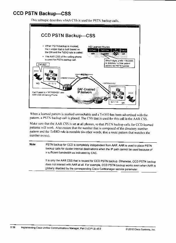
CCD PSTN Backup—CSSThis subtopic describes which CSS is used for PSTN backup calls.
5-58
CCD PSTN Backup—CSS
When PSTN backup is invoked,the number that is built based on
the DN and the ToDID rule is called.
The AAR CSS of the calling phoneis used for PSTN backup call.
HQ Learned Routes
Strip 0 digits, prefix +1972555to directory number patternI4XXX) (or PSTN number.
Call Placed to +19725554001 witfiAAR CSS of Calling Phone
When a learned pattern is marked unreachable anda ToDID has been advertised withthepattern,a PSTN backupcall is placed. TheCSS that is used for this call is the AARCSS.
Make sure that the AAR CSS is set atall phones, so that PS'fN backup calls for CCD-learnedpatterns will work. Also ensure that the number that is composed ofthe directory numberpattern and the ToDID rule isroutable (in other words, that a route pattern that matches thenumber exists).
Note PSTN backup for CCD iscompletely independent from AAR. AAR isused toplace PSTNbackup calls for cluster-internal destinations when the IP path cannot be used because ofinsufficient bandwidth as indicated by CAC.
It is only the AAR CSS that is reused for CCD PSTN backup. Otherwise, CCD PSTN backupdoes not interact with AAR at all. For example, CCD PSTN backup works even when AAR isglobally disabled by the corresponding Cisco CallManager service parameter.
Implementing Cisco Unified Communications Manager, Part 2(CIPT2) v8.0 !> 2010 Cisco Systems, Inc.
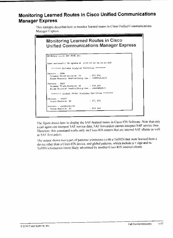
Monitoring Learned Routes in Cisco Unified CommunicationsManager Express
"Ihis subtopic describes how to monitor learned routes in Cisco linified CommunicationsManager Express.
Monitoring Learned Routes in CiscoUnified Communications Manager Express
BR2#shc sf dndb all
Last successful DB update 8 .010:03:12 16:03:27:838
........ private Dialplan Partition ********
Pattern - 2XXX
Primary Trunk-Bouts(B> ID : 273 274Aliaa-Routels) Prefix/Strip-Lan : -.498952121/0
Pattern - 3XXX
Primary Trunk-Route(s) ID : 270 269Alias-Route(B) Pretix/Strip-Len : ♦44228822/0
,,,,,... global (E164) Dialplan Partition •*•««*'
Pattern - *4420>
Trunk-Route!-} ID •- 271 272
Pattern - .16505051234
Trunk-Fouta(g) ID : 270 269
The figure shows how to display the SAF-leamed routes in Cisco IOS Software. Note that onl_acall agent can interpret SAF service data; SAF forwarders cannot interpret SAF service data.Therefore, this command works only on Cisco IOS routers that arc internal SAF clients as wellas SAF forwarder.
The output shows two types ofpatterns: extensions (with aToDID) that were learned from ade\ ice other than aCisco IOS device, and global patterns, which include a+sign and noToDID infonnation (most likely advertised by another Cisco IOS internal client).
) 2010 Cisco Systems, IncCall Control Discovery 5-57
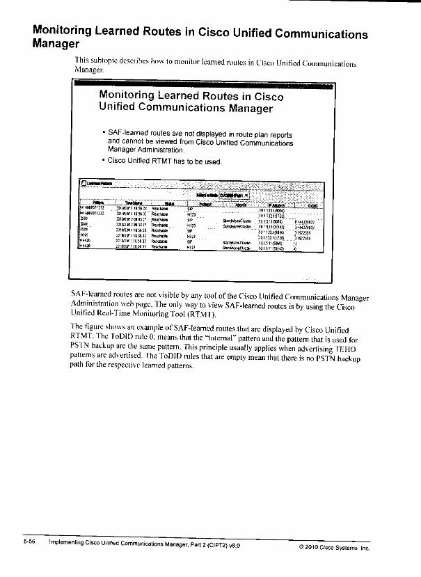
Monitoring Learned Routes in Cisco Unified CommunicationsManager
This subtopic describes how to monitor learned routes in Cisco Unified CommunicationsManager.
5-56
Monitoring Learned Routes in CiscoUnified Communications Manager
«SAF-learned routes are not displayed in route plan reportsand cannot be viewed from Cisco Unified CommunicationsManager Administration,
• Cisco Unified RTMT has to be used.
Oump-n
iM-rt-N. ctnuw-i -,
!408707131;
JraSBf„ a*» .Eatm _-j»<*'3HMJ1118563) Reich**?3f»3n!iS«3] Rotfuc*
2matw2W()j:7 RtmaM
M(lW)ni1SSS3J HM!hj»;ji«oiriis»ij rium
331*0*1185(3; Rsjuuw_H1OTJM1J1» 35 Reichit*
nitMi(fflio)H323 tnunci?:oi
SlttidWnKMlr 0151t(SM(iSUnrnkiwCluslH 015 IH3J143f
oiuiiaowj
01132 tci?.aiStan-UcneriLisiBi 01511(5060)
HSM SWkWWwCIusIb. ai.tici.t43t
t>-ummtSWKW
SAF-leamed routes are not visible by any tool of the Cisco Unified Communications ManagerAdministration web page. The only way to view SAF-leamed routes is by using the CiscoUnified Real-Time Monitoring Tool (RTMT).
The figure shows an example ofSAF-leamed routes that are displayed by Cisco UnifiedRTMT. The ToDID rule 0: means that the '-internal" pattern and the pattern that is used forPSTN backup are the same pattern. This principle usually applies when advertising TEHOpatterns are advertised. The ToDID rules that are empty mean that there is no PSTN backuppathforthe respective learned patterns.
Implemenling Cisco Unified Communications Manager, Part 2<CIPT2) v8.0>2010 Cisco Systems, Inc.
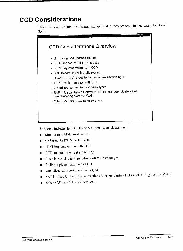
CCD ConsiderationsThis topic describes important issues that you need lo consider when implementing CCD andSAF.
CCD Considerations Overview
• Monitoring SAF-leamed routes
• CSS used for PSTN backup calls
• SRST implementation with CCD
• CCD integration with static routing• Cisco IOS SAF client limitations when advertising +
• TEHO implementation with CCD
• Globalized call routing and trunk types
• SAF in Cisco Unified Communications Manager clusters thatuse clustering over the WAN
• Other SAF and CCD considerations
This topic includes these CCD and SAF-related considerations:
• Monitoring SAF-learncd routes
• CSS used for PSTN backup calls
• SRST implementation with CCD
• CCD integration with static routing
• Cisco IOS SAF client limitations when advertising +
• TIJIO implementation with CCD
• Globalized call routing and trunk types
• SAF in Cisco Unified Communications Manager clusters that use clustering over th. WAN• Other SAF and CCD considerations
i2010 Cisco Systems. IncCall Control Discovery 5-55
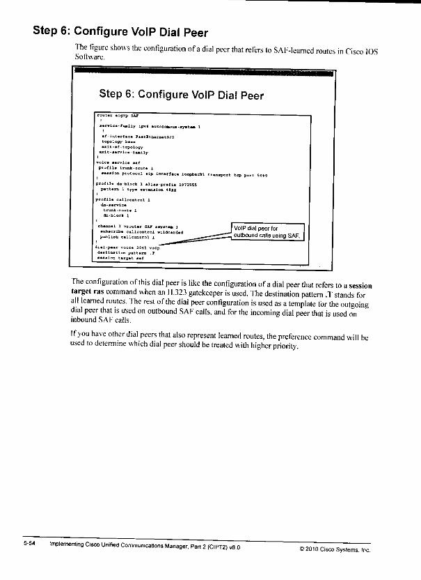
Step 6: Configure VoIP Dial Peer
5-54
The figure shows the configuration ofadial peer that refers to SAF-leamed routes in Cisco IOSSoftware.
Step 6: Configure VoIP Dial Peer
rout.t «lgrp SAP
• •Evic.-fM.ily lpv»
.f-int.rf.c. F«.tl[
topology £•••
•Kit-at-topologyult-»rvlca-Cully
Boic. l.tvig. ,.(
prof 11a trunk-rout*••••Ion protc
u tonohoua-ay•c•
• lp intarfaca loopbmckl tr.ui.port top pot
iflla da-block 1 allaa-pratlx 19725551 typa «t«n»ioQ 4111P»
icollli
da-jarvlca
trunk.tout*
da-block 1
cbumal 1 vrc
•ubacrib* ci
publish c.llI
dial-paar ,OK
c.llt
Sir ••yjtan 1
ntrol wildc*rdad
roj 1
!IH5 voip
VoIP dial peer foroutbound calls using SAF.
The configuration ofthis dial peer is like the configuration ofadial peer that refers to asessiontarget ras command when an H.323 gatekeeper isused. The destination pattern .Tstands forall learned routes. The rest of the dial peer configuration is used as atemplate for the outgoingdial peer that is irsed on outbound SAF calls, and for the incoming dial peer that is used oninbound SAF calls.
Ifyou have other dial peers that also represent learned routes, the preference command will beused to detemiine which dial peer should be treated with higher priority.
Implementing Cisco Unified Communications Manager. Part 2(CIPT2) vB 0>2010Cisco Systems, Inc.

Step 5: Configure Requesting Service"fhe figure shows the configuration of the advertising service in Cisco IOS Sotlware.
Step 5: Configure Requesting Service
router eigrp SAF
Bervice-family ipv4 autonomous-system 1
si-interface PastEtherriStO/0
topology baseexit-sf-topology
exit-service-faaily
profile trunk-route 1Bession protocol sip interface loopbackl transport tcp port 5060
profile dn-block 1 alias-prefix 1972555pattern 1 type extension 4XXX
I
profile callcontrol 1
trunk-route 1
dn-block 1
channel 1 vrouter SAF asysten 1subscribe callcontrol wildcards
publish callcontrol 1
SAF client is enabled forlearning (subscribe).
J
You can also configure the requesting service under channel tag vrouter EiGRP-ID asystcm-IS Use the subscribe callcontrol wildcarded command to enable the learning ofroutes thatare advertised by the SAF process that matches the autonomous system number that is specifiedat the channel configuration level.
i2010 Cisco Systems. IncCall Control Discovery 5-53
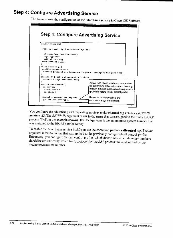
Step 4: Configure Advertising ServiceThe figure shows the configuration ofthe advertising service in Cisco IOS Software.
5-52
Step 4: Configure Advertising Service
router eigrp SAP
servi -e-family iPv4 autonomous ayst
s£-i terface FaetEthernetO/0topo ogy baseexit of-topology
exit- ervice-family
ervice saf
pro fi e trunk-route 1
ip interface loopbackl transport tcp port 5060
rofila dn-block 1 olias-prnfin 1972555pattern 1 type extension 4XXX
rofile callcontrol 1
dn-service
trunk-route 1
dn-block 1
channel 1 vrouter SAF asystepublish callcontrol 1
ActualSAF client,which you can enableforadvertising (shown here)and learning(shownin nextfigure). Advertising service(publish) refers to callcontrol profile.
Refers to EIGRP process andautonomous system number.
You configure the advertising and requesting services under channel tag vrouter E/GRP-IDasystem AS. "fhe EIGRP-ID argument refers to the name that was assigned to the router EIGRPprocess (SAF. in the example shown). The AS argument is the autonomous system number thatwasassigned to the EIGRP service family.
To enable the advertising service itself, you use the command publish callcontrol tag The tagargument refers to the tag that was applied to the previously configured call control profileEffectively, you configure the call control profile (which determines which directory numbersshould be advertised by which trunk protocol) by the SAF process that is identified by theautonomous svstem number.
Implementing Cisco Unifier) Communications Manager, Part 2(CIPT2) vS.O© 20)0 CiscoSystems, Inc.
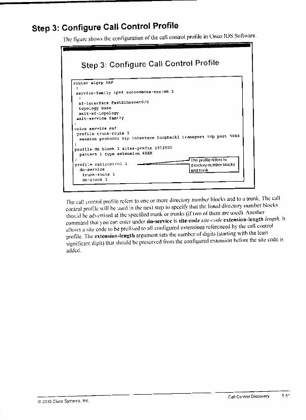
Step 3: Configure Call Control ProfileThe figure shows the configuration of the call control profile in Cisco IPS Software
Step 3: Configure Call Control Profile
router eigrp SAF
service-family ipv4 autonomous-system 1
sf-interface FastEthernet0/0topology baseexit-sf-topology
exit-service-family
voice service saf
profile trunk-route 1session protocol sip interface loopbackl transport top port 5060
1
profile dn-block 1 alias-prefix 1972555pattern 1 type extension 4XXX
profile callcontrol 1dn-service
trunk-route 1
dn-block 1
The profile refers todirectory number blocksand trunk.
fhe call control profile refers to one or more directory number blocks and to atrunk. 1he callcontrol profile will be used in the next step to specify that the listed directory number blocksshould be advertised at the specified trunk or trunks (if two ofthem are used). Anothercommand that xou can enter under dn-smice is site-code site-code extension-length length. Itallows asite code to be prefixed to all configured extensions referenced by the call controlprofile The extension-length argument sets the number of digits (starting with the leastsignificant digit) that should be preserved from the configured extension before the site code isadded.
© ;010 Cisco Systems. Inc.Call Control Discovery 5-51
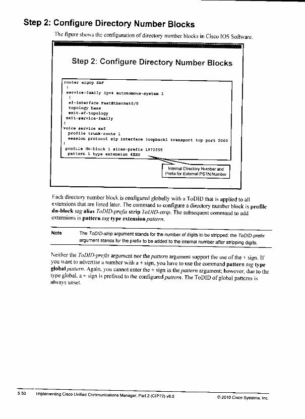
Step 2: Configure Directory Number BlocksThe figure shows the configuration ofdirectory number blocks in Cisco IOS Software.
5-50
Step 2: Configure Directory Number Blocks
router eigrp SAF
service-family ipv4 autonomous-system 11
sf-lnterface FastEthernet0/0topology base
exit-sf-topologyexit-service-family
1
voice service saf
profile trunk-route 1
session protocol sip interface loopbackl transport top port 5060
profile dn-block 1 alias-prefix 1972555pattern 1 type extension 4XXX
Internal Directory Number andPrefix for External PSTN Number
Each directory number block is configured globally with aToDID that is applied to allextensions that are listed later. The command to configure adirectory number block is profiledn-block tag alias ToDID-prefix strip ToDID-strip. The subsequent command toaddextensions is pattern lag type extension pattern.
Note The ToDID-strip argument stands for the number of digits to be stripped; the ToDID-prefixargument stands for the prefix tobeadded tothe internal number after stripping digits.
Neither the ToDID-prefix argument nor the pattern argument support the use of the +sign. Ifyou want to advertise anumber with a+sign, you have to use the command pattern tag typeglobal pattern. Again, you cannot enter the +sign in the pattern argument; however, due to thetype global, a+sign is prefixed to the configured pattern. The ToDID ofglobal patterns isalways unset.
Implementing Cisco Unified Communications Manager, Part 2(CIPT2) v8.0i* 2010 Cisco Systems, Inc.
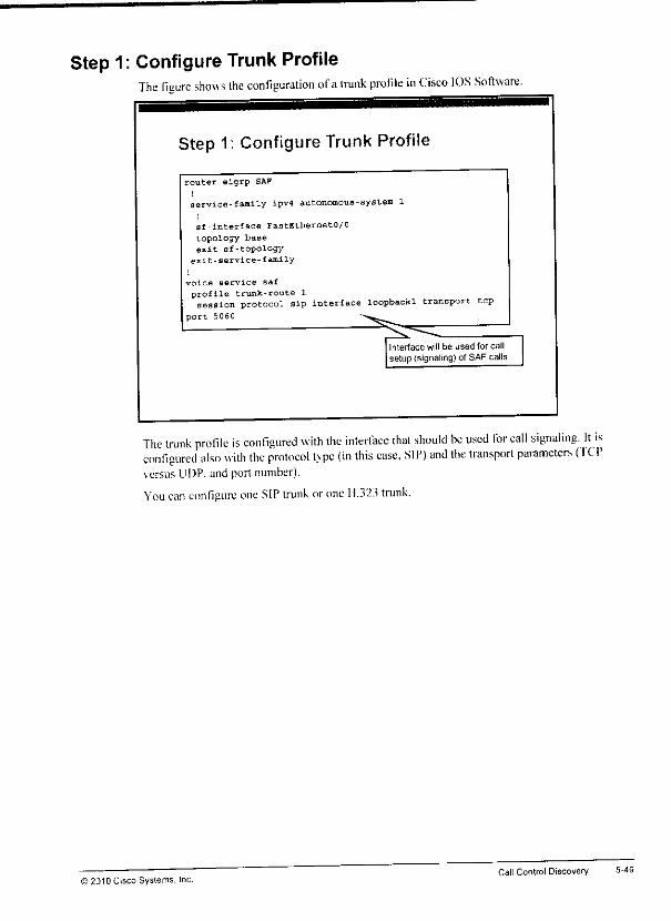
Step 1: Configure Trunk ProfileThe figure shows the configuration ofatrunk profile in Cisco IOS Software.
Step 1: Configure Trunk Profile
router eigrp SAF
service-family ipv4 autonomous-system 1
1
sf-interface FastEthernetO/O
topology baseexit-sf-topology
exit-service-family
voice service saf
profile trunk-route 1session protocol sip interface loopbackl transport tcp
port 5060
Interface will be used for callsetup (signaling) of SAFcalls.
The trunk profile is con figured with the interface that should be used for call signaling. It isconfigured also with the protocol type (in this case. SIP) and the transport parameters (I CPversus UDP. and port number).
You can configure one SIP trunk or one 11.323 trunk.
© 2310 Cisco Systems, Inc.Call Control Discovery 5-49

Internal SAF Client Configuration ProcedureThis subtopicshowsthe configuration procedure of an internal SAF client.
5-48
Internal SAF Client ConfigurationProcedure
1 Configure trunk profile.
2 Configure directory number blocks to be advertised.
3 Configure call control profile.
4 Configure advertising service.
5 Configure requesting service.
6 Configure VoIP dial peer referring to SAF.
The configuration steps that are listed in the figure are steps thai you can do multiple times, ifmultiple SAF forwarder processes are configured in separate autonomous systems. Each SAFclient channel that is configured with the advertising and the requesting service has to refer toanotherSAF autonomous system.
The CCD advertising service ofasingle SAF client channel can refer to multiple call controlprofiles. This capability allows the configuration oftwo trunk profiles (one SIP and one H.323trunk per call control profile). Only one trunk isrequired.
Implementing Cisco Unified Communications Manager, Part 2(CIPT2) v8.0S2010 Cisco Systems. Inc.
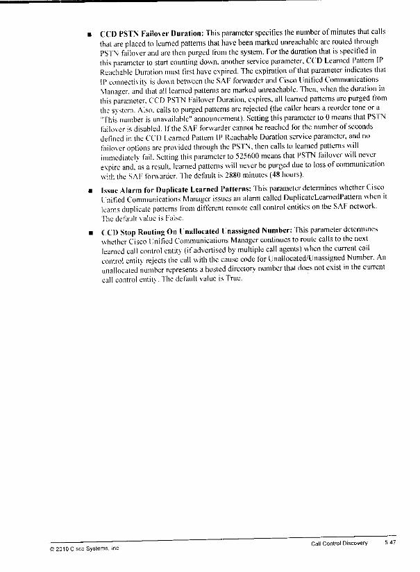
CCD PSTN Failover Duration: This parameter specifies the number ofminutes that callsthat are placed to learned patterns that have been marked unreachable are routed throughPSTN faikner and are then purged from the system. For the duration that isspecified inthis parameter to start counting down, another service parameter, CCD Learned Pattern IPReachable Duration must first have expired. Theexpiration of thatparameter indicates thatIPconnectivih is down between the SAF forwarder andCisco Unified CommunicationsManager, and that all learned patterns are marked unreachable. Then, when the duration inthis parameter. CCD PSI'N Failover Duration, expires, all learned patterns are purged fromthe system. Also, calls to purged patterns are rejected (the caller hears a reorder tone or a"This number is unavailable" announcement). Setting this parameter lo0 means that PSTNfailover is disabled. If the SAF forwarder cannot be reached for the number of secondsdefined inthe CCD Learned Pattern IP Reachable Duration service parameter, and nofailo\er options are provided through the PSTN, then calls to learned patterns willimmediateK fail. Setting this parameter to525600 means that PSTN failover will neverexpire and.'as aresult, learned patterns will never be purged due to loss of communicationwith the SAF forwarder, "fhedefault is 2880 minutes (48 hours).
Issue Alarm for Duplicate Learned Patterns: This parameter determines whether CiscoUnified Communications Manager issues an alarm called DuplicateLearnedPattern when itlearns duplicate patterns from different remote call control entities on the SAF network.The default value is False.
(CD Stop Routing On Unallocated I nassigncd Number: ihis parameter determine*whether Cisco Unified Communications Manager continues to route calls to Ihe nextlearned call control entitv (ifadvertised by multiple call agents) when the current cailcontrol entitv rejects the call with the cause code for Unallocated/Unassigned Number. Anunallocated number represents a hosted directory number that does not exist in the currentcall control entit\ . The default value is True.
© 21)10Cisco Systems, IncCall Control Discovery 5-47
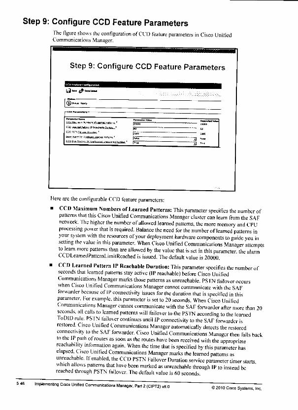
Step 9: Configure CCD Feature ParametersThe figure shows the configuration ofCCD feature parameters in Cisco UnifiedCommunications Manager.
5-46
Step 9; Configure CCD Feature Parameters
fli" ^s*«a
® **• ****!
l»H.*S£™ '.!< If.LfcUc ,m^ tsffitra" |FW>
••n-ajva.
~3 F"k*~3 T,"«
Here are the configurable CCD feature parameters:
• CCD Maximum Numbers ofLearned Patterns: This parameter specifies the number ofpatterns that this Cisco Unified Communications Manager cluster can learn from the SAFnetwork. The higher the number ofallowed learned patterns, the more memory and CPUprocessing power that is required. Balance the need for the number oflearned patterns inyour system with the resources ofyour deployment hardware components to guide you insetting the value in this parameter. When Cisco Unified Communications Manager attemptsto leam more patterns than are allowed by the value that is set in this parameter, the alarmCCDLeamedPatternLimitReached is issued. The default value is20000.
• CCD Learned Pattern IP Reachable Duration: This parameter specifies the number ofseconds that learned patterns stay active (IP reachable) before Cisco UnifiedCommunications Manager marks those patterns as unreachable. PSTN failover occurswhen Cisco Unified Communications Manager cannot communicate with the SAFforwarder because of IP connectivity issues for the duration that is specified in thisparameter. For example, this parameter is set to20seconds. When Cisco UnifiedCommunications Manager cannot communicate with the SAF forwarder after more than 20seconds, all calls to learned patterns will failover to the PSTN according to the learnedToDID rule. PS TN failover continues until IP connectivity to the SAF forwarder isrestored. Cisco Unified Communications Manager automatically detects the restoredconnects ity to the SAF forwarder. Cisco Unified Communications Manager then falls backto the IP path of routes as soon as the routes have been received with the appropriatereachability infonnation again. When the time that is specified by this parameter haselapsed. Cisco Unified Communications Manager marks the learned patterns asunreachable. Ifenabled, the CCD PSTN Failover Duration service parameter timer startswhich allows patterns that have been marked as unreachable through IP to instead bereached through PSTN failover. The default value is60seconds
Implementing Cisco Unified Communications Manager, Part 2{CIPT2) v8.0©2010 CiscoSystems, Inc.

Step 8: Configure CCD Blocked Learned PatternsThe figure shows the configuration of the CCD blocked learned patterns in Cisco UnifiedCommunications Manager.
Step 8; Configure CCD Blocked LearnedPatterns
Blocked wanted Pattern configuration
-Purge»""> ttock S*FCCD Learned Route* IntormatLe»rnesJ Pattern
Lesrres Ssttetn Prefix
Remote Call Control Identity
Remote IP
Patterns can be blocked basedon remote call control ID, remoteIP. and learned pattern orlearned prefix (the last two areexclusive!
Multiple blockingrules can beconfigured. Ifa learned patternmatches any rule, it is blocked
CCD blocked learned patterns are optional. If CCD blocked learned patterns are configured, allroutes that match any of the configured criteria arc blocked. As aresult, they are not added tothe call-routing table.
You can configure afilter that is applied to received routes in order to deny the learning ofroutes, usingthese criteria:• [earned pattern: The received pattern is checked in its entire length. If it matches ihe
configured learned pattern, it will not be added to the local call-routing table.• 1earned pattern prefix: The received patterns arc compared with the configured prefix,
sorting with the left-most digit. By using alearned pattern prefix for blocking receivedroutes you can filter internally used numbers by their leading digits-tor example, by theirsite code.
. Remote call control identity: Each call agent has aso-called SAF client ID By setting theremote call control identity, you can filter received routes that are based on the ID of thead\ertising call agent.
• Remote IP: B> setting this filler, you can block routes that arc based on the advertising IPaddress.
© £010 Cisco Systems, IncCall Control Discovery 5-45
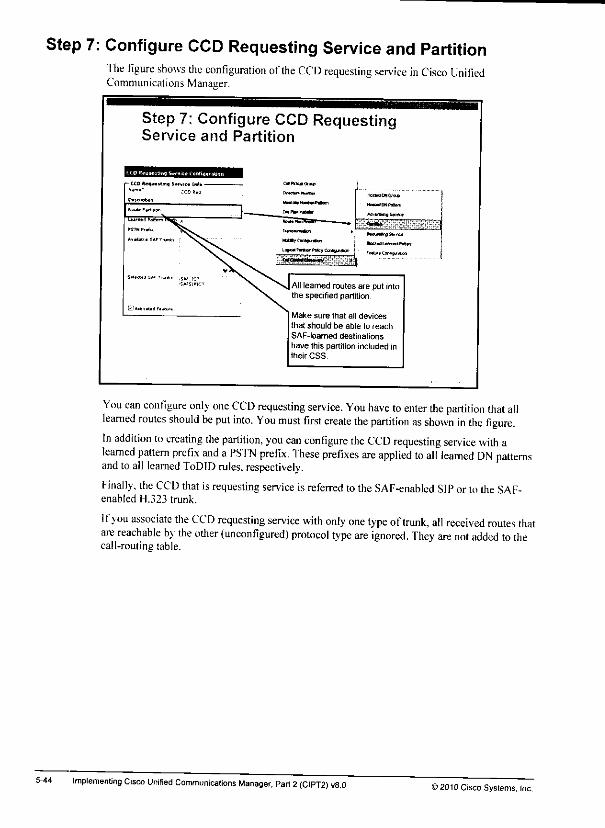
Step 7: Configure CCD Requesting Service and PartitionThe figure shows the configuration ofthe CCD requesting service in Cisco UnifiedCommunications Manager.
5-44
Step 7: Configure CCD RequestingService and Partition
Alllearned routes are put intothe specified partition.
Make sure that all devices
thai should be able to reachSAF-leamed destinationshave this partition included intheir CSS,
You can configure only one CCD requesting service. You have to enter the partition that alllearned routes should be put into. You must first create the partition as shown in the figure.In addition to creating the partition, you can configure the CCD requesting service with alearned pattern prefix and aPSTN prefix. These prefixes are applied to all learned DN patternsand to all learned ToDID rules, respectively.
Finally, the CCD that isrequesting service isreferred tothe SAF-enabled SIP orto the SAF-enabled H.323 trunk.
Ifyou associate the CCD requesting service with only one type oftrunk, all received routes thatare reachable by the other (unconfigured) protocol type are ignored. They are not added to thecall-routing table.
Implementing Cisco Unified Communications Manager, Part 2(CIPT2) v8.0;>2010 Cisco Systems, Inc.
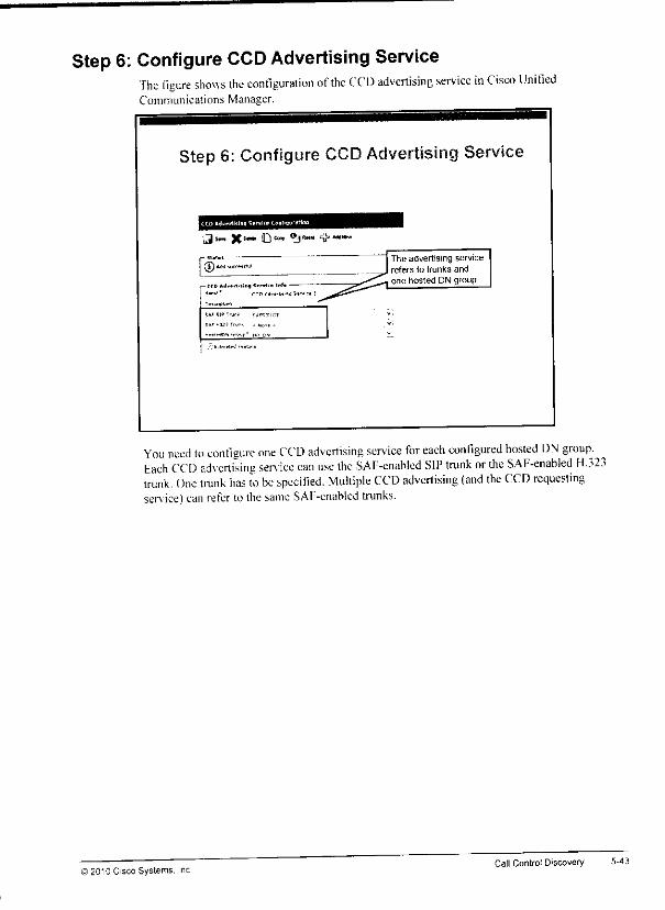
Step 6: Configure CCD Advertising ServiceThe figure shows the configuration of the CCV> advertising service in Cisco UnifiedCommunications Manager.
Step 6: Configure CCD Advertising Service
^Sr» X1™" O0™ <£}*•• 'V"""*"
> uri.fe-l.i)*) <.™ii« Inf. -
SVHIH*™-.. , p
The advertising servicerefers to trunks and
one hosted DN group
You need to configure one CCD advertising service for each eonligured hosted DN group. ^bach CCD advertising sen ice can use the SAF-enabled SIP trunk or the SAF-enabled H.323trunk. One trunk has to be specified. Multiple CCD advertising (and the CCD requestingsen ice)can refer to thesame SAF-enablcd trunks.
© 2010 Cisco Systems, IncCall Control Discovery
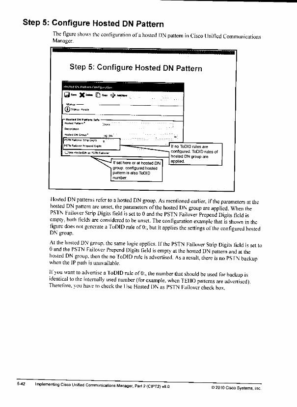
Step 5: Configure Hosted DN Pattern
5-42
The figure shows the configuration ofahosted DN pattern in Cisco Unified CommunicationsManager.
Step 5: Configure Hosted DN Pattern
Is-* X**" D0" sQ>*mmn
®'-
- Hotted ON PMttra rrrfo •Ho««fl »*t»re '
DeiciDbon
Hosted im Group"
If set here or at hosted DNgroup, configured hostedpartem is also ToDIDnumber.
If no ToDID rules are
configured, ToDID rules ofhosted DNgroup areapplied.
Hosted DN patterns refer to ahosted DN group. As mentioned earlier, ifthe parameters at thehosted DN pattern are unset, the parameters ofthe hosted DN group are applied. When thePSTN Failover Strip Digits field is set to 0and the PSTN Failover Prepend Digits field isempty, both fields are considered tobe unset. The configuration example that isshown in thefigure does not generate aToDID rule of 0:, but it applies the settings of the configured hostedDN group.
At the hosted DN group, the same logic applies. Ifthe PSTN Failover Strip Digits field is set to0and the PSTN Failover Prepend Digits field is empty at the hosted DN pattern and at thehosted DN group, then the no ToDID rule is advertised. As aresult, there is no PSTN backupwhen the IP path is unavailable.
If you want to advertise aToDID rule of 0:, the number that should be used for backup isidentical to the internally used number (for example, when TEHO patterns are advertised)Therefore, you have tocheck the Use Hosted DN as PSTN Failover check box.
Implementing Cisco Unified Communications Manager. Part 2(CIPT2) v8.0>2010 Cisco Systems. Inc.
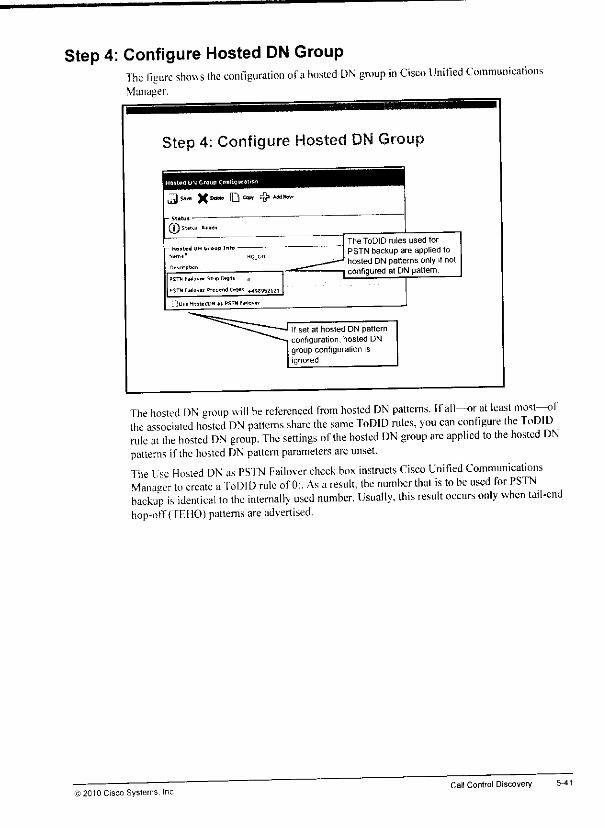
Step 4: Configure Hosted DN GroupThe figure shows the configuration ofahosted DN group in Cisco Unified CommunicationsManager.
Step 4; Configure Hosted
J^s.™ X0** D0"" &***"•
®-
- ltDflcd DN Sr
05™ ItJuvtK SOB DIOJIS 0
'.iUil HJiMOO" «! PSTNF*ltft>
The ToDID rules used forPSTN backup are applied tohosted DN patterns only if not
Tconfigured at DNpattern
if set at hosted DN patternconfiguration,hosted DNgroup configurationisignored
The hosted DN group will be referenced from hosted DN patterns. Ifall—or at least most—ofthe associated hosted DN patterns share the same ToDID rules, you can configure the ToDIDrule at the hosted DN group. The settings of the hosted DN group arc applied to the hosted DNpatterns if the hosted DN pattern parameters areunset.
The Use Hosted DN as PS'fN Failover check box instructs Cisco Unified CommunicationsManager to create aToDID rule of 0:. As aresult, the number that is to be used for PSTNbackup is identical to the internally used number. Usually, this result occurs only when tail-endhop-off (TF. HO) patterns are advertised.
) 2010 Cisco Systems, Inc.Call Control Discovery 5-41
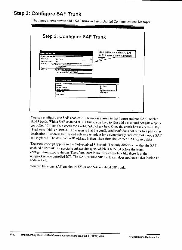
Step 3: Configure SAF TrunkThe figure shows how to add aSAF trunk in Cisco Unified Communications Manager.
5-40
Step 3: Configure SAF Trunk
^^^^^^^^^j
-- -"- -' in
[*™ tow'
SAF SIP trunk is shown. SAFH.323 trunk is also supported.
S!>T.ur* I
You can configure one SAF-enabled SIP trunk (as shown in the figure) and one SAF-enabledH.323 trunk. With aSAF-enabled H.323 trunk, you have to first add astandard nongatekeeper-controlled ICT and then check the Fnable SAF check box. Once the check box ischecked, theIP address field is disabled. The reason is that the configured trunk does not refer to aparticulardestination IP address but instead acts as a template for adynamically created trunk once aSAFcall isplaced. The destination IPaddress isthen taken from the learned SAF service data.
The same concept applies to the SAF-enabled SIP trunk. The only difference is that the SAF-enabled SIP trunk isa special trunk service type, which isselected before the trunkconfiguration page isshown. Therefore, there isno extra check box like there is atthenongatekeeper-controlled ICT. The SAF-enabled SIP trunk also does not have adestination IPaddress field.
You can have one SAF-enabled H.323 oroneSAF-enabled SIPtrunk.
Implementing Cisco Unified Communications Manager, Part 2{CIPT2) v8.0©2010 Cisco Systems, Inc.
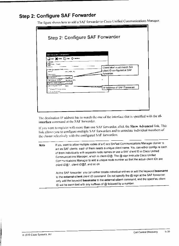
Step 2: Configure SAF ForwarderThe figure shows how to add aSAF forwarder to Cisco Unified Communications Manager.
Step 2; Configure SAF Forwarder
Client label must match SAFclient ID configured at SAFforwarder.
IPAddress of SAF Forwarder.i
The destination IP address has to match the one ofthe interface that is specified with the sf-interfaee command at the SAF forwarder.
If you want to register with more than one SAF forwarder, click the Show Advanced link. Thislink allows you to configure multiple SAF forwarders and to associate individual members oithe cluster selectively with the configured SAF forwarders.
Note If you want to allow multiple nodes of aCisco Unified Communications Manager clusier toact asSAF clients, each of them needs a unique client name. You can either configt re eachof them individually with separate node names or use aSAF client ID in Cisco UnifiedCommunications Manager, which is ctient-ID@ The @sign instructs Cisco UnifiedCommunications Manager to add a unique node number sothat the actual client IDs areclient-ID@1, client-ID@2, and so on.
At the SAF forwarder, you can either create individual entries or add the keyword basenameto the external-client client-ID command. Do not specify the @sign at the SAF forwarder:only add the keyword basename to the external-client command, and the specifieo clientID will bepermitted with any suffixes of @followed by a number.
©2010 Cisco Systems, IncCall Control Discovery 5-39
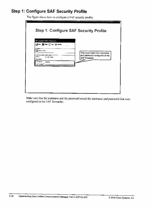
Step 1: Configure SAF Security ProfileThe figure showshow to configure a SAF securityprofile.
Step 1: Configure SAF Security Profile
©«
(trqitiw.
This must match the usemame
and password configured at theSAF forwarder.
Make sure that the username and the password match the username and password that wereconfigured at the SAF forwarder.
5-38 implementing Cisco Unified Communications Manager, Pari 2(CIPT2) v8.0 >2010 Cisco Systems, Inc.
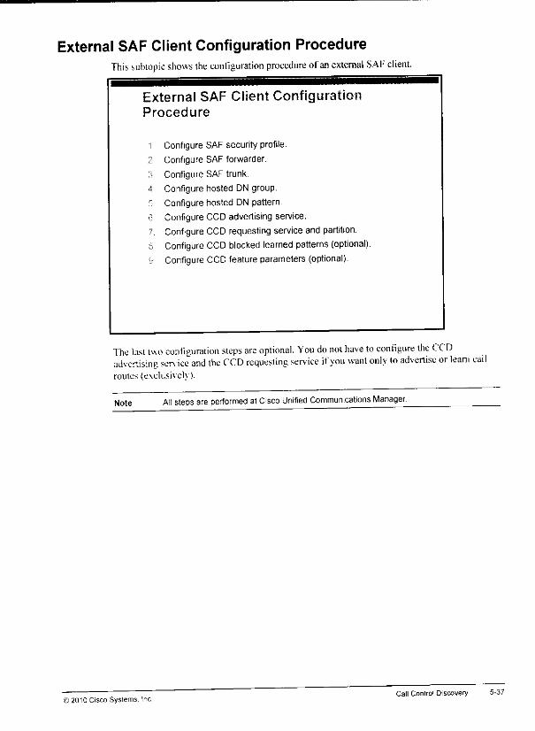
External SAF Client Configuration ProcedureThis subtopic shows the configuration procedure ofan external SAF client.
External SAF Client ConfigurationProcedure
1 Configure SAF security profile.
2 Configure SAF forwarder.
:> Configure SAF trunk.
4 Configure hosted DN group.
5 Configure hosted DN pattern.
6 ConfigureCCD advertising service.7 Configure CCD requesting service and partition.8 Configure CCD blocked learned patterns (optional).\i Configure CCD feature parameters (optional).
"fhe last two configuration steps are optional. You do not have to configure the CCDadvertising sen ice and the CCD requesting service ifyou want only lo advertise or leam callroutes (exclusively).
Note All stepsare performed at Cisco Unified Communications Manager.
© 2010 Cisco Systems. IncCall Control Discovery 5-37

Step 2: Configure SAF Forwarder to Support External SAFClients
The figure shows how lo configure a SAF forwarder to support an external SAF client.
5-36
Step 2: Configure SAF Forwarder toSupport External SAF Clients
router aigrp SAF
service-family Lpvi outoac1
sf-interface FastEthernet
topology base
e»it-Bf-topology
external-oliont HQSAP
1
service-family external-eli
external-client HQSAPUBername SAFUSEK
password SAFPASSWORD
This must match the SAF clientIID configured at theexternalSAF client.
at listen ipv4 5050
IUsername and password must matchthe settings at the external SAF client.
External client ID refers to theappropriate SAF process andautonomous system above.
Fach allowed exiemal client has to be listed in the service-family section. In addition, theusername and password that should be used by the external client have to be specified in theservice-family external client section.
Note If you want to allow multiple nodes of a Cisco Unified Communications Manager cluster toact asSAF clients, each of them needs aunique client name. You can either configure eachofthem individually with separate node names oruse a SAF client ID in Cisco UnifiedCommunications Manager, which isclient-ID@. The @sign instructs Cisco UnifiedCommunications Manager to add a unique node number sothat the actual client IDs areclient-ID®-}, client-ID@2, and so on.
At the SAF forwarder, you can either create individual entries or add the keyword basenameto the external-client client-ID command. Do not specify the @sign atthe SAF forwarder;only add the keyword basename to the external-client command, and the specified clientID wjjl bepermitted with any suffixes of@followed by a number.
Implementing Cisco Unifiea Communications Manager, Part 2(CIPT2) v8.032010 Cisco Systems, Inc.
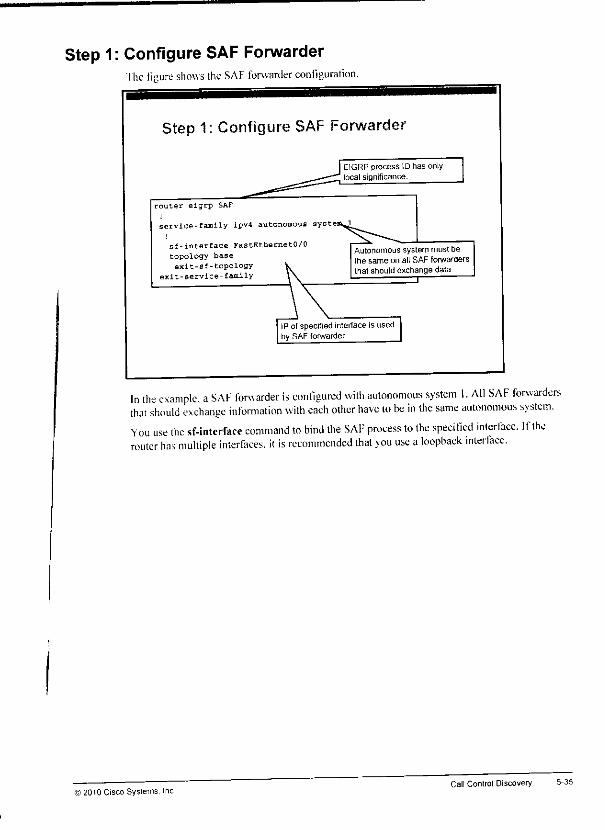
Step 1: Configure SAF Forwarderhe figure shows the SAF forwarder configuration.
Step 1: Configure SAF Forwarder
router eigrp SAF
service-family ipv4 autonomous-systew^^
sf-interface FastEthernetO/0
topology baseexit-sf-topology
exit-service-family
EIGRP process \0 has onlylocal significance.
Autonomous system must bethe same on all SAF forwardersthat should exchange data
"~l
IP of specified interface is used, by SAFforwarder:
In the example, aSAF forwarder is configured with autonomous system I. All SAF forwardersthat should exchange information with each other have to be in the same autonomous system.You use the sf-interface command to bind the SAF process to the specified interface. Iftherouter has multiple interfaces, if is recommended that you use aloopback interface.
>2010 Cisco Systems. IncCall Control Discovery 5-35
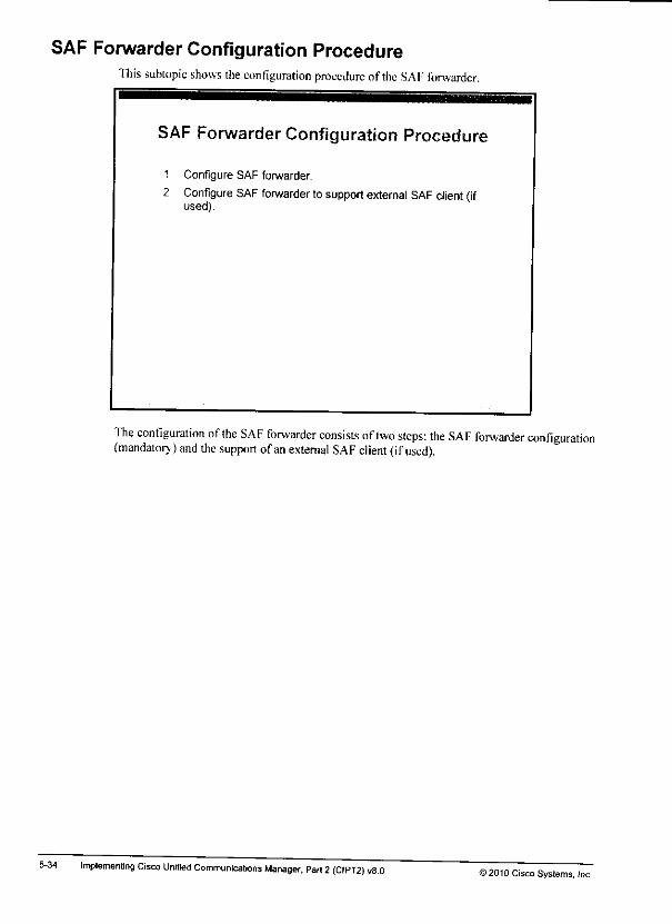
SAF Forwarder Configuration ProcedureThis subtopic shows the configuration procedure of the SAF forwarder.
SAF Forwarder Configuration Procedure
1 Configure SAF forwarder,
2 Configure SAF forwarder tosupport external SAF client (ifused).
The configuration ofthe SAF forwarder consists oftwo steps: the SAF forwarder configuration(mandatory) and the support ofan external SAF client (ifused).
5-34 Implementing Cisco Unified Communications Manager, Part 2(CIPT2) v8.0©2010 Cisco Systems, Inc.

Relationships of Internal SAF Client Configuration ElementsThis subtopic describes the relationships ofinternal SAF client configuration elements.
Relationships of Internal SAF ClientConfiguration Elements
SAF Client
SAF CH«« "Charmer
CCD Recjueslmg
Service
CCD Advertising
Service
DN Block
Profile
DN Block
Profile
Call Control Profile
Trunk Profile
The figure illustrates how internal SAF client configuration elements relate to each other.
Note The configuration that is shown in the figure is one that you can do multiple times, if multipleSAF forwarder processes are configured in separate autonomous systems. Each SAF client"channel" has to refer to another SAF autonomous system
The CCD advertising service of a single SAF client channel can refer to multiple call controlprofiles This capability allows the configuration of two trunk profiles (one SIP and one H.323trunk per call control profile). Only one trunk isrequired.
© 2010 Cisco Systems, IncCall Control Discovery
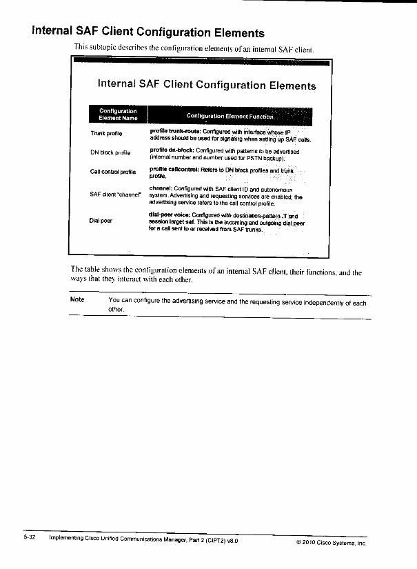
Internal SAF Client Configuration ElementsThis subtopic describes the configuration elements of an internal SAF client.
5-32
Internal SAF Client Configuration Elements
ConfigurationElement Name
Trunk profile
DN block profile
Call control profile
Configuration Element Function
profiletrunk-route: Configured withinterfacewhose IPaddressshould be usedforsignaling when setting upSAF calls.
profile dn-block: Configured withpatterns to be advertised(internal number and number used for PSTN backup).
profilecallcontrol: Refersto DN block profiles and trunkprofile.
channel: Configuredwith SAFclient IDand autonomousSAF client -channel' system. Advertising and requesting services areenabled; the
advertising service refersto the callcontrol profile.
dial-peer voice:Configured with destination-pattern .Tand0(81 f>e& session target saf. This isthe incoming and outgoing dial peer
for a caHsent to or received from SAF trunks.
The table shows the configuration elements ofan internal SAF client, their functions, and theways that they interact with each other.
Note You can configure the advertising service and the requesting service independently of eachother.
Implementing Cisco Unified Communicalions Manager, Part 2(CIPT2) v8.0>2010 Cisco Systems. Inc.
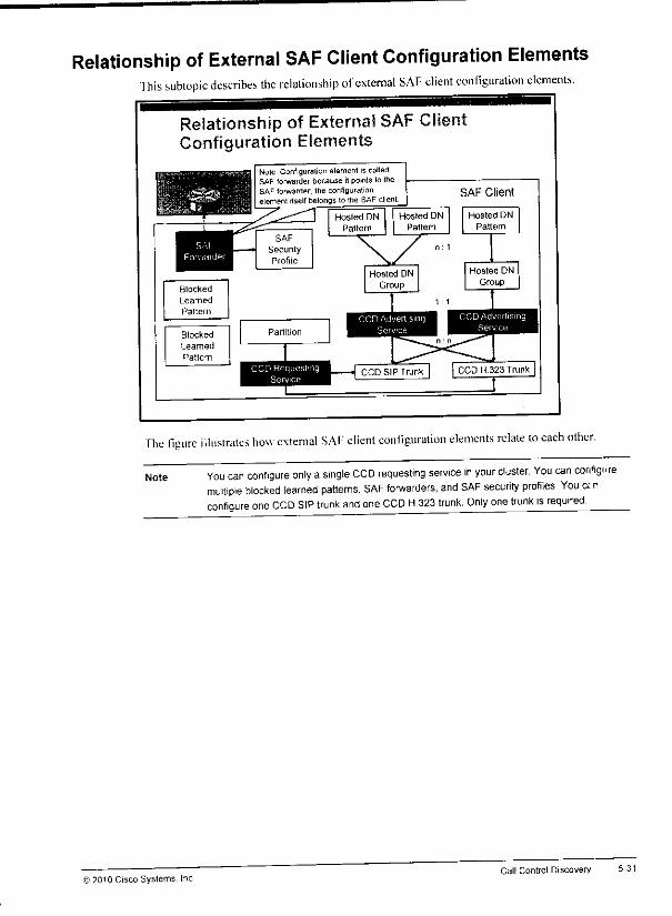
Relationship of External SAF Client Configuration ElementsThis subtopic describes the relationship ofexternal SAF client configuration elements.
Relationship of External SAF ClientConfiguration Elements
The figure illustrates how external SAF client configuration elements relate to each other.
NoteYou can configure only a single CCD requesting service in your cluster. You can configure
Itiple blocked learned patterns, SAF forwarders, and SAF security profiles. You a nnfigure one CCD SIP trunk and one CCD H.323 trunk. Only one trunk is required
© 2010 Cisco Systems. Inc
mu
co
Call Control Discovery 5-31
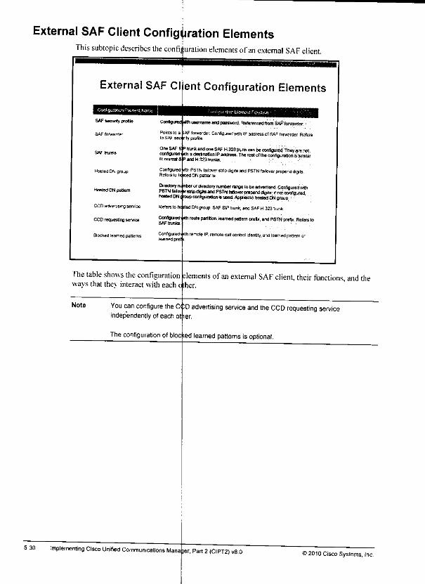
External SAF Client Configuration ElementsThis subtopic describes the confiiuralion elements ofan external SAF client.
5-30
External SAF Client Configuration Elements
SAF security profile
SAF forwarder
SAFtrur*s
Nested DNgroup
Hosted DN pattern
CCD advertising service
CCD requesting service
Blocked learned patterns
Catena *musernameBiWpasBV«n).Reienmc«J(tomSAFtOnWidar.
Points to a
to SAF secAFforwarder Configured with IPaddressofSAF forwarder Refersnty profile
trunk andone SAF H323 twr* canbeconfigured. Ttiey arenotti adestination IPaddress.Therestofthe confaurafjon isstrraiar
3andH323r/uni».
One SAFconfigureto normals
configured' Hti
Configured nthi PSTN laitover stripdigrtsand PSTN failover prepend diaits1 DN patterns
DirectoryPSTN
hosted DN
otdirectory number raneetoBeadvetttned. Configured wthpdiojaj andPSTN faliover prepaid aigHs; ifnotonofigwad
i •wipeonriguratlonriiH«).Appli8dtDhosted DNB'OUO
Refersto hoptedDNgroup, SAFSIPtrunk, and SAFH.323trunk
Configured<iitti route partition, teamed pattern prefix, and PSTN prefix. Refers to
Configurediith remote IP. remote call control identity, and learned pattern orlearned pre! ;
The table showsthe configurationways that they interact with each
elements of anexternal SAF client, their functions, and theo :her.
Note C< ;d advertising service and theCCD requesting serviceYou can configure the <
independently of each ot ler.
Theconfiguration ofbloc ;ed learned patterns is optional.
Implementing Cisco Unified Communications Mana jer, Part 2(CIPT2) v8.0>2010 Cisco Syslems, Inc.
«*
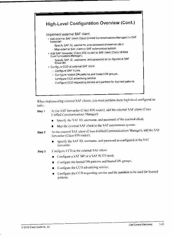
High-Level Configuration Overview (Cont)
Implement external SAF client:• Add external SAF client (Cisco Unified Communications Manager) to SAF
forwarder:
Specify SAF ID, username, and password of external client.Map external SAF client toSAF autonomous system.
• Add SAF forwarder (Cisco IOS router) toSAF client (Cisco UnifiedCommunications Manager).
- Specify SAF ID. username, and password asconfigured at SAFforwarder.
• Configure CCD at external SAF client.Configure SAF trunks
- Configure hosted DN patterns andhosted DN groups.ConfigureCCD advertisingservice.Configure CCD requesting service and partition for learned patterns.
When implementing external SAF clients, you must perfonn these high-level configurationtasks:
Stepl
Step 2
Step 3
At the SAF forwarder (Cisco IOS router), add the external SAF client (CiscoUnified Communications Manager):
• Specif\ the SAF ID. username. and password ofthe external client.• Map the external SAF client to the SAF autonomous system.
At the external SAF client (Cisco Unified Communications Manager), add the SAFforwarder (Cisco IOS router):
• Specify the SAF ID. username. and password as configured at the SAIforwarder.
Contigurc CCD atthe external SAF client:
• Configure a SAF SIP ora SAF H.323 trunk.• Configure the hosted DN patterns and hosted DN groups.
• Contigurc the CCD advertising service.• Configure the CCD requesting service and the partition to be used for learned
patterns.
5-29
i 2010 Cisco Systems, IncCall Control Discovery
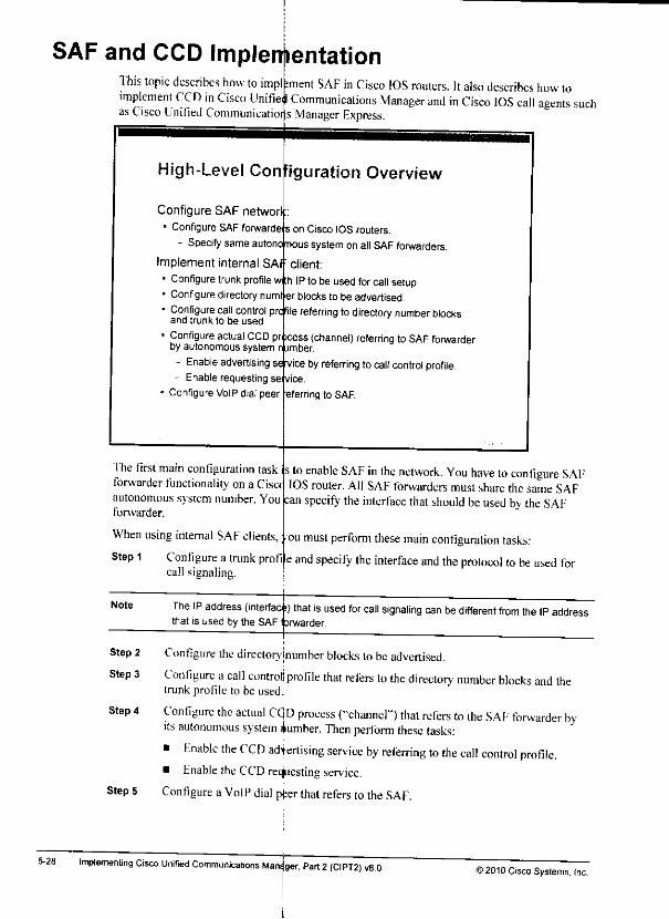
SAF and CCD Implementation
5-28
This topic describes how to implimplement CCD in Cisco Unifielas Cisco Unified Communicatior s
ment SAF in Cisco IOS routers. It alsodescribes howtoCommunications Manager and in Cisco IOS call agents suchManager Express.
High-Level Configuration Overview
Configure SAF networf• Configure SAF forwarde s
- Specify same autono nous
Implement internal SAI
• Configure trunk profilew:h• Configuredirectorynuml
Configure call controland trunk to be used.
on Cisco IOS routers.
system on all SAF forwarders,
client:
IP to be used forcall setup,er blocks to be advertised,
profile referring to directorynumber blocks
Configureactual CCDrby autonomous system
- Enable advertising- Enable requesting se
ConfigureVoIP dial peer
pn »cess (channel) referring to SAF forwardern jmber.
servicebyreferring to callcontrol profile,
eferring to SAF.
The first main configuration task :forwarder functionality on a Cisocautonomous system number. You
forwarder.
; toenable SAF inthe network. You have toconfigure SAFIOSrouter. All SAF forwarders must share the same SAF
:an specify the interface thatshould beused bytheSAF
Whenusinginternal SAF clients, •
Step 1 Configure a trunk profcall signaling.
oumustperform these main configuration tasks:
e and specify the interface and theprotocol to beused for
Note The IP address (interfaci) that is used for call signaling can be different from the IP addressthat isused by theSAF forwarder.
Step 2
Step 3
Step 4
Step 5
Configure the directoryjnumber blocks to be advertised.Configure acall controljprofile that refers to the directory number blocks and thetrunk profile to be used.
Configure the actual cqD process ("channel") that refers to the SAF forwarder byits autonomous system dumber. Then perfonn these tasks:
• Fnable the CCD advertising service by referring to the call control profile.• Fnable theCCD requesting service.
Configure a VoIP dial pier that refers to the SAF.
Implementing Cisco Unified Communications Mans per, Part 2(CIPT2) v8.012010 Cisco Systems, Inc.
*»

Note if the leamed pattern was removed when the IP path became unavailable, the originatingsite would not know what PSTN number to use for the backup call. By default, a route iscompletely removed only if it has not advertised for 48hours.
© 2010 Cisco Syslems. IncCall Control Discovery 5-27
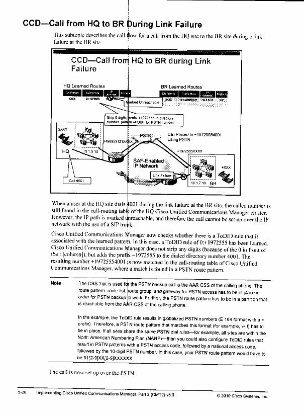
CCD—Call from HQ to BR During Link Failure
5-26
This subtopic describes the call $ow for acall from the HQ site to the BR site during a linkfailure at the BR site.
CCD—Call frorri HQ to BR during LinkFailure
BR Learned Routes
XKtX Q>.«a953tS1 101.5.10
- PSTtt • Cal1 Placed lo +19725554001" UsingPSTN
When a user at the HQ site dialsstill found in the call-routing tablHowever, the IP path is markednetwork with the use of a SIP
I00I during the link failure at the BRsite, the called numberisof the HQ Cisco Unified Communications Manager cluster.
i ireachable, and therefore the call cannot besetup over the IPtru ik
MCisco Unified Communicationsassociated with the leamed patteCisco Unified Communications
the : [column]), but adds the prefresulting number +19725554001Communications Manager, when
anager now checks whether there is a ToDID rule that isi. In this case, a ToDID rule of 0:+1972555 has been learned.
Manager does not strip any digits {because ofthe 0 in front of+1972555 to the dialeddirectorynumber4001.The
s now matched in the call-routing table of Cisco Unifieda match is found in a PSTN routepattern.
Note The CSS that is used fo •
route pattern, route list,
order for PSTN backup
is reachable from the
the PSTN backup call is theAAR CSSofthecalling phone. Theoutegroup, and gateway for PSTN access has to be inplace ino work. Further, the PSTN route pattern has tobe in a partition that
CSS of the calling phone.AAR
In the example, the ToDID rule results in globalized PSTN numbers (E.164 format with a +prefix) Therefore, a PSTN route pattern that matches this format (for example, \+.!) has tobein place. If all sites share the same PSTN dial rules-for example, all sites arewithin theNorth American Numbering Plan (NANP)—then you could also configure ToDID rules thatresult in PSTN patterns with a PSTN accesscode, followed by a national accesscodefollowed by the 10-digit PSTN number. In this case, your PSTN route pattern would have tobe91[2-9]XX[2-9]XXXXXX.
Thecall is now set up over the PSTN.
Implementing Cisco Unified Communications Manager, Part 2 (CIPT2) v8.0 © 2010 Cisco Systems, Inc.
CCD—Link Failure at BRThis subtopic describes how CCD manages a link failure between the SAF client and its SAFforwarder at the BR site.
CCD—Link Failure at
HQ Learned Routes BR learned Routes
B0« r);M0R6il!1 ' WI.S.10 SIP«M 0«1WI559
HQ 101510
Marked Unreachable
•- - PSTN-
•49S953i2ixxxx>s:;:::;;
SAF-EnabledIP Network
When the connection between the SAF client and the SAF forwarder at the BR site isbroken,the SAF forwarder atthe BR site detects this problem that is based on the missing keepalives ofthe registered SAF client.
The BR SAF forwarder sends an update throughout the SAF-enabled network so that all SAFforwarders are aware that the IP path to4XXX is currently unavailable. Other than in IProuting, the learned route is not removed, but only the IP path is marked unreachable.All SAF forwarders that have registered SAF clients now pass this update on totheir SAFclients, so that all SAF clients in the network can mark the IP path lo4XXX as unreachable.
As shown in the figure, the call-routing table at the HQ site also gets updated accordingly.
© 2010 Cisco Systems. IncCall Control Discovery

CCD—Call from HQ to BR
This subtopic describes the call flow for a call from the HQ site tothe BR site.
CCD—Call from HQ to BR
BR Learned Routes
WWt »*48WS3«1 W13.10
Call placed to 4001 using SIP trunk to 10.1.7.10.
PSTN;
The HQ site dials 4001. The called number is found in the call-routing table ofIhe IIQ CistUnified Communications Managercluster.
Note All learned routes are put into the same configurable partition The CSS of the calling phonemust have access to this partition in order for the call towork. If the calling phone does nothave access to the partition that includes all learned patterns and there isno match in anyother partition, the call fails.
Cisco Unified Communications Manager identifies the matched pattern as aCCD-learnedpattern. According to the learned route, the call has tobesetup through a SAF-enabled SIPtrunk, which is dynamically created tothe destination IP address as leamed by CCD (in thiscase. 10.1.7.10).
Thecall is now set up over the IPnetwork.
5-24 Implementing Cisco Unified Communications Manager, Part 2(CIPT2) v8.0>2010 Cisco Systems, Inc.

CCD—Propagation of BR RoutesThis subtopic describes how BR routes are propagated to the IIQ site.
CCD—Propagation of BR Routes
HQ Learned Routes
0-*!B7M65 10.1 T.10 SIP
BR Learned Routes
W&nmmmWmMmW mmnV^&mmmmmn^R Mf
ao« «»«0M»iai, 10.iS.1tt BIP
Learn hosled DN range and ToDIDrule and store in memory
PSTN
SAF-EnabledIP Network
Advertise hosted DN range
(4XXX) and ToDID rule(0+1972555).
M972555XXXX
The Cisco Unified Communications Manager cluster atthe BR site advertises its direeto >number range 4XXX with aToDID rule of0:+1972555 to its SAF forwarder, fhe SAFnetwork propagates this new route throughout the network, and the SAF forwarder at the HQsite sends the information to the HQ Cisco Unified Communications Manager cluster. The call-routing table of the HQ cluster is populated with the directory number pattern 4XXX and aToDID rule of 0:^1972555.
Again, onh aSIP trunk has been associated with the CCD advertising service at the originatingsite. Therefore, the IIQ cluster learns the route only forSll\
The network is in a converged state. All sites know about the routes ofall other sites.
) 2010 Cisco Systems, IncCall Control Discovery 5-23
CCD—Propagation of HQ RoutesThis subtopic describes how HQ routes are propagated tothe BR site.
5-22
CCD—Propagation of HQ Routes
HQ Learned Routes
Advertise hosted DN
range (2XXX) and ToDIDrule (0:^-498953121
BR Learned Routes
WW &MW85S1S1 W.J5.10" "~W
Learn hosted DNrangeand ToDID rule and store
in memory.
97255SXXXX
The Cisco Unified Communications Manager cluster at the HQ site advertises its directorynumber range 2XXX with a ToDID rule of0:+49895312I to itsSAF forwarder. The SAFnetwork propagates this new route throughout the network, and the SAF forwarder atthe BRsite sends the information to the BR Cisco Unified Communications Manager cluster. The call-routing table ofthe BR cluster ispopulated with the directory number pattern 2XXX and aToDID rule of 0:+498953121.
At the advertising site, only aSIP trunk has been associated with the CCD advertising service.Therefore, the BR cluster learns the route only for SIP.
Implementing Cisco Unified Communications Manager, Part 2(CIPT2) v8.0>2010 Cisco Systems. Inc.
m
CCD OperationThis topic describes how CCD works for on-net calls and how CCD reroutes calls to the PSTNif the IPpath is notavailable.
CCD—Base Configuration
HQLearned Routes BR Learned Routes
The figure shows the base configuration. There are two sites, each with aCisco UnifiedCommunications Manager cluster. One site (••HQ" in the figure) is located in Germany, and ithas -i DID ran°e of +4989^3121 XXXX. Intemally, range 2XXX is used. The other site ("BR )is in the United States: it has a DID range of+ I972555XXXX. Internally, the directory numberrange 4XXX is used.
12010 Cisco Systems. IncCall Control Discovery
All learned routes are put into one configurable partition. All devices that should have access toleamed routes need that partition to be included in their calling search space (CSS). Sometimesthe IP path tor alearned route may not be available, and aToDID rule may have beenadvertised with the hosted directory number. In that situation, acall to the transformed number(a ToDID rule that is applied to the advertised pattern) is placed with the automated alternaterouting(AAR)CSS of the callingdevice.
Note PSTN backup for CCD is completely independent from AAR. AAR is used to place PSTNbackup calls for cluster-internal destinations when the IP path cannot beused because ofinsufficient bandwidth as indicated by Call Admission Control (CAC).
It is only the AAR CSS that is reused for CCD PSTN backup. Otherwise, CCD PSTN backupdoes not interact with AAR atall. For example, CCD PSTN backup works even when AAR isglobally disabled by the corresponding Cisco CallManager service parameter.
5-20 Implementing Cisco Unified Communications Manager, Part 2(CIPT2) v8.0©2010 Cisco Systems. Inc.
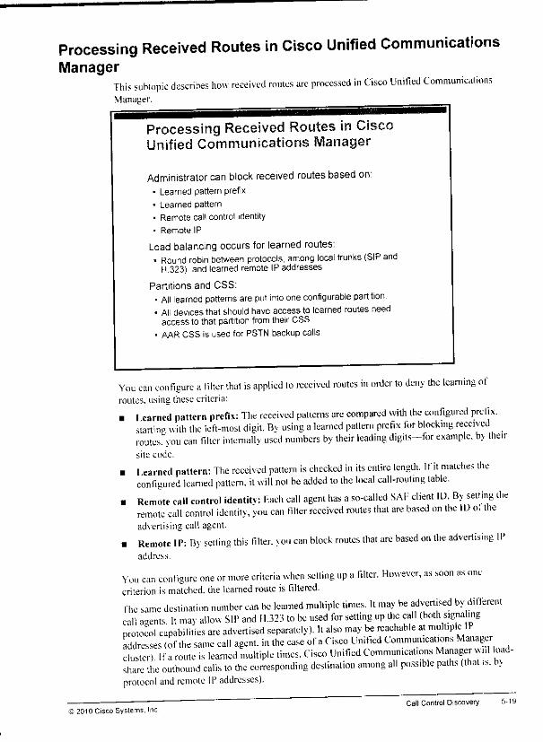
Processing Received Routes in Cisco Unified CommunicationsManager
This subtopic describes how received routes are processed in Cisco Unified CommunicationsManager,
Processing Received Routes inUnified Communications Manager
Administrator can block received routes based on;• Learned pattern prefix
• Learned pattern
• Remote call control identity
* Remote IP
Load balancing occurs for learned routes:• Round robin between protocols, among local trunks (SIP and
H 323), and learned remote IP addresses
Partitions and CSS:• All learned patterns are put into oneconfigurable partition.• All devices that should haveaccess to learned routes need
access to that partition fromtheir CSS• AAR CSS is used for PSTN backup calls.
You can configure afilter that is applied to received routes in order to deny the learning ofroutes, using these criteria:
• Iearned pattern prefix: The received patterns are compared with the configured prefix,starting with the left-most digit. By using alearned pattern prefix for blocking receiv edroutes, you can filter intemally used numbers by their leading digits—lor example, by theirsite code.
• 1earned pattern: The received pattern is checked in its entire length. If it matches theconfigured learned pattern, it will not be added to the local call-routing table.
• Remote call control identity: Each call agent has aso-called SAI-' client ID. By setting theremote call control identity, you can filter received routes that are based on the ID o. theadvertising call agent,
. Remote IP: By setting this filler, you can block routes that are based on the advertising IPaddress.
You can configure one or more criteria when setting up afilter. However, as soon as onecriterion ismatched, the learned route is filtered.The same destination number can be learned multiple times. It may be advertised by differentcall agents. It mav allow SIP and 11.323 to be used for setting up the call (both signa ingprotocol capabilities are advertised separately). It also may be reachable at multiple IPaddresses (of the same call agent, in the case of aCisco Unified Communications Managercluster). Ifa route is learned multiple times, Cisco Unified Communications Manager™! load-share the outbound calls to the corresponding destination among all possible paths (that is. t>>protocol and remote IP addresses).
S 2010 Cisco Systems. IncCall Control Discovery

Note Like thetrunks that areassociated with CCD advertising services, thetrunks thatareassociated with theCCD thatis requesting services are not used to learn patterns via SIP orH323. They determine theoutbound capabilities for calls thatare placed tolearneddestinations. If the CCD that isrequesting service isassociated only with anH.323 trunk,learned routes that areto bereached via SIP are not added to the call-routing table of thereceiving Cisco Unified Communications Manager.
The Cisco Unified Communications Manager nodes of the cluster that ispermitted to placeoutbound calls to learned routes are determined by the device pool that isapplied to thetrunk that is associatedwith the CCD requesting service.
5-18 Implementing Cisco Unified Communications Manager, Part 2(CIPT2) v8.0 >2010 Cisco Systems, Inc.
mm

CCD Services in Cisco Unified Communications ManagerThis subtopic describes the two CCD services that exist in acall agent such as Cisco UnifiedCommunications Manager.
CCD Services in Cisco UnifiedCommunications Manager
CCD advertising service* Responsible for advertising:
-- Hosted DN ranges
- PSTN failover information (ToDID rule)
- Trunk information
• Configured with one or two trunks (one SAF CCD SIP trunk andone SAF-enabled H.323 ICT supported)
CCD requesting service• Responsible for learning DN ranges from the SAF network* Exists only once per Cisco Unified Communications Manager
cluster
• Configured with one or two trunks (one SAF CCD SIP trunk andone SAF-enabled H.323 ICT)
fhe CCD advertising sen ice is configured with the directory' numbers that are to be advertised.In Cisco Unified Communications Manager, they are configured by so-called hosted DN(directorv number) ranges. Fach hosted DN range is configured with its PSTN failoverinformation (the ToDID rule for the hosted DN range). In addition, the signaling protocol andthe IP addresses ofthe call agents have to be advertised. They are configured by a trunk. Thetrunk can be a SAF-enabled H.323 intercluster trunk (ICT) ora SAF CCD SIP trunk. CCDadvertises call routes with one ormore call agent IP addresses. 1he IP addresses tobeadvertised are determined bv the device pool that isapplied tothe SAF-enabled trunk.
Note The trunk is not used to advertise call routes Call routes are advertised by CCD and SAFand not via H323 orSIP. The trunk isused todetermine the IP addresses ofthe call agentsand the supported signaling protocols, in case another call agent wants to establish a call toa learned call route
The CCD that is requesting service is responsible for subscribing to call-routing infonnationfrom its SAF forwarder. It allows Cisco Unified Communications Manager to leam routes fromthe SAF-enabled network. Onlv one CCD that is requesting service exists per Cisco UnifiedCommunications Manager cluster. However, like the advertising service, it can be configuredto accept patterns that are reachable via SIP or H.323. depending on the associated trunk ortrunks.
)2310 Cisco Systems. IncCall Control Discovery
5-16
• Number ofdigits to be stripped: The first part ofaToDID rule is the number of digits tobe stripped from the intemally used number. For example, ifsite code dialing is used andthe internally used number to reach ablock of directory numbers is 8-408-2XXX, you maywant to strip the leading 8408 before prefixing the necessary digits to directory numberrange 2XXX. In this case, your ToDID rule would start with 4: (because the four leadingdigits should bestripped).
• Prefix to be added to the (deflated) internal number: The second part ofaToDID rule isthe prefix that should be added to the intemally used number after digit stripping has beenperformed. In the previous example, ifthe PSTN direct inward dialing (DID) range of theintemally used directory number range 2XXX (dialed as 8-408-2XXX from other sites) is408 555-2XXX, the prefix would be 408555. Usually E.164 format with a+prefix is usedto represent the PSTN number, so the configured prefix would be+140855.
In the given example, the complete ToDID rule would be 4:+1408555, because the numbers tobe stripped and the prefix are separated by a column.
By advertising only the locally present internal numbers and the corresponding ToDID rule ateach call agent, the dial plan implementation oflarge networks is extremely simplified. Ifthereare any changes at acall agent, you have to change only the advertised number (range) and itsToDID mle at the affected call agent. All other call agents will dynamically leam the changes
Implementing Cisco Unified Communications Manager, Part 2(CIPT2) v8.0>2010 Cisco Systems, Inc.
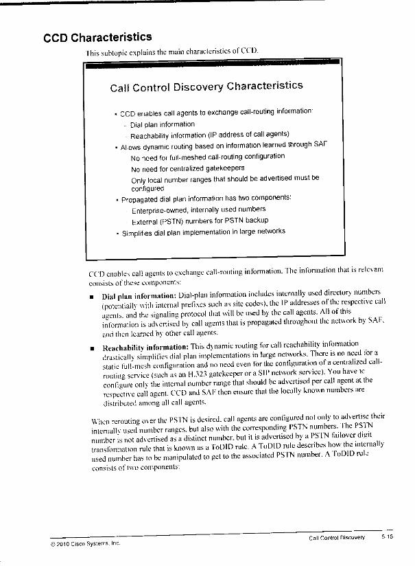
CCD CharacteristicsIhis subtopic explains the main characteristics ofCCD.
Call Control Discovery Characteristics
• CCD enables call agents to exchange call-routing information:•- Dial plan information
Reachability information (IP address ofcall agents)• Allows dynamic routing based on information learned through SAF
- No need for full-meshedcall-routing configuration
No need for centralized gatekeepers
Only local number ranges that should beadvertised must beconfigured
• Propagated dial plan information has two components:Enterprise-owned, internally used numbersExternal (PSTN) numbersfor PSTN backup
• Simplifies dial plan implementation in large networks
CCD enables call agents to exchange call-routing information. The infonnation that is relevantconsists of these components:
• Dial plan information: Dial-plan infonnation includes internally used directory numbers(potentially with internal prefixes such as site codes), the IP addresses of the respective callagents and the signaling protocol that will be used by the call agents. Ali ofthisinformation is advertised by call agents that is propagated throughout the network by SAP.and then learned by other call agents.
• Reachability information: This dynamic routing for call reachability infonnationdrastically simplifies dial plan implementations in large networks. There is no need lor astatic full-mesh configuration and no need even for the configuration of acentralized call-routing sen-ice (such as an H.323 gatekeeper or aSIP network service). You have tcconfigure onlv the internal number range that should be advertised per call agent at therespective call agent. CCD and SAF then ensure that the locally known numbers aredistributed among all call agents.
When rerouting over the PSTN is desired, call agents are configured not only to ^crtise theirinternallv used number ranges, but also with the corresponding PSTN numbers, Hie PS 1Nnumber is not advertised as adistinct number, but it is advertised by aPMNtailovcr digittransformation rule that is known as aToDID rule. AToDID rule describes how he mtemallyused number has to be manipulated to get to the associated PS TN number. AIoDID rul.consists of two components:
© 2010 Cisco Systems, Inc.Call Control Discovery 5-15
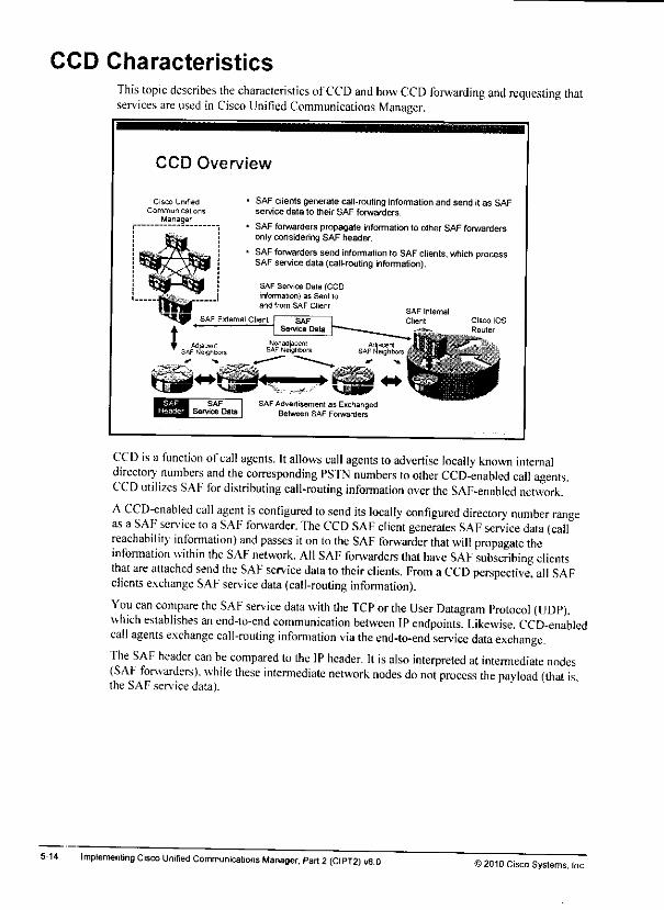
CCD Characteristics
5-u
This topic describes the characteristics ofCCD and how CCD forwarding and requesting thatservices are used in Cisco Unified Communications Manager.
CCD Overview
Cisco Unified
Communica lionsManager
SAF clients generate call-routinginformationand send it as SAFservice data to their SAF forwarders.
SAF forwarders propagate information to olher SAF forwardersonly considering SAF header.
SAF forwarders send information to SAF clients, which processSAFservice data (call-routing information).
SAF Service Oata (CCDinformation) as Sent loand from SAF Client
SAF External Clianl Cisco IOS
SAFAdvertisement as ExchangedBetween SAF Forwarders
CCD is a function ofcall agents. Itallows call agents to advertise locally known internaldirectory numbers and the corresponding PSTN numbers to other CCD-enabled call agents.CCD utilizes SAF for distributing call-routing infonnation over the SAF-enabled network.
ACCD-enabled call agent is configured to send its locally configured directory number rangeas a SAF service to a SAF forwarder. The CCD SAF client generates SAF service data (callreachability information) and passes iton to the SAF forwarder that will propagate theinformation within the SAF network. All SAF forwarders that have SAF subscribing clientsthat are attached send the SAF service data to their clients. From aCCD perspective, all SAFclients exchange SAF service data (call-routing information).
You can compare the SAF service data with the TCP or the User Datagram Protocol (UDP).which establishes an end-to-end communication between IP endpoints. Likewise, CCD-enabledcall agents exchange call-routing infomiation via the end-to-end service data exchange.The SAF header can be compared to the IP header. It is also interpreted at intermediate nodes(SAF forwarders), while these intermediate network nodes do not process the payload (that is.the SAF service data).
Implementing Cisco Unified Communications Manager, Part 2 (CIPT2) v8.0 © 2010 Cisco Systems, Inc.
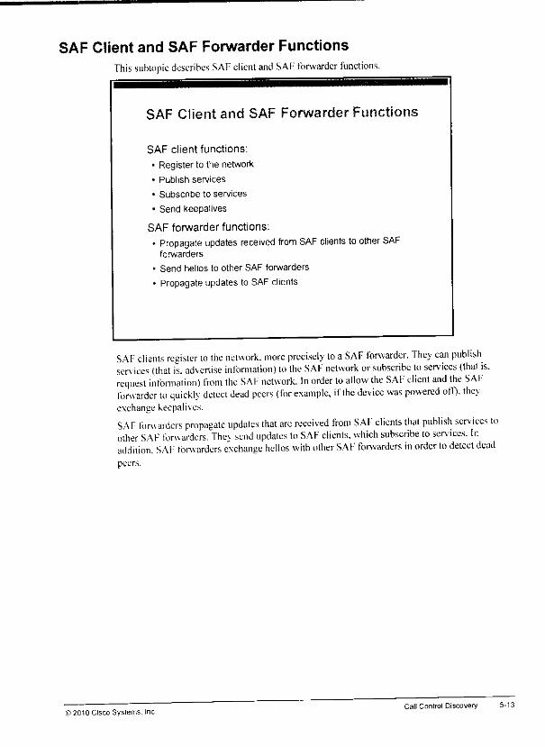
SAF Client and SAF Forwarder FunctionsThis subtopic describes SAF client and SAF forwarder functions.
SAF Client and SAF Forwarder Functions
SAF client functions:
• Register to the network
• Publish services
• Subscribe to services
• Send keepalives
SAF forwarder functions:
* Propagate updates received from SAF clients to other SAFforwarders
• Send hellos to other SAF forwarders
• Propagate updates to SAF clients
SAF clients register to the network, more precisely lo aSAF forwarder. They can publishsen ices (that is. advertise infonnation) to the SAF network or subscribe to services (that is.request infonnation) from the SAF network. In order to allow the SAF client and the SAFforwarder to quickly detect dead peers (for example, ifthe device was powered off), theyexchange keepalives.
SAF forwarders propagate updates that are received from SAF clients that publish sen ices toother SAF forwarders. Thev send updates to SAF clients, which subscribe to services. Ir.addition. SAF forwarders exchange hellos with other SAF forwarders in order to detect deadpeers.
© 2010 Cisco Systems. Inc.Call Control Discovery
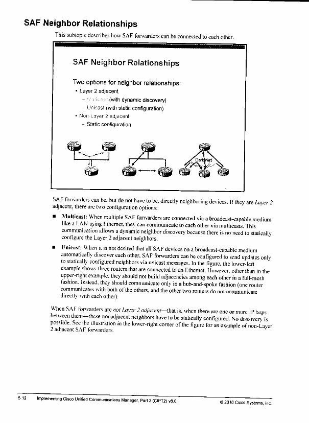
SAF Neighbor RelationshipsThis subtopic describes how SAF forwarders can be connected toeach otht
5-12
SAF Neighbor Relationships
Two options for neighbor relationships:• Layer 2 adjacent
- " k k- ?(with dynamic discovery)- Unicast (with static configuration)
• Non Layer 2 adjacent
- Static configuration
SAF forwarders can be. but do not have to be, directly neighboring devices. If they are Layer 2adjacent, there are two configuration options:
• Multicast: When multiple SAF forwarders are connected via abroadcast-capable mediumlike a LAN using Fthernet, they can communicate toeach other via multicasts. Thiscommunication allows adynamic neighbor discovery because there is no need to staticallyconfigure the Layer 2 adjacent neighbors.
• Unicast: When it is not desired that all SAF devices on abroadcast-capable mediumautomatically discover each other. SAF forwarders can be configured to send updates onlyto statically configured neighbors via unicast messages. In the figure, the lower-leftexample shows three routers that are connected to an Fthemct. However, other than in theupper-right example, they should not build adjacencies among each other in a full-meshfashion. Instead, they should communicate only in ahub-and-spoke fashion (one routercommunicates with both ofthe others, and the other two routers do not communicatedirectly with each other).
When SAF forwarders are not Layer 2adjacent—that is, when there are one or more IP hopsbetween them—these nonadjacent neighbors have to be statically configured. No discoverv ispossible. See the Hlustration in the lower-right comer of the figure for an example of non-L aver2 adjacent SAF forwarders.
Implementing Cisco Unified Communications Manager, Part 2(CIPT2) v8 0H2010 Cisco Systems. Inc.
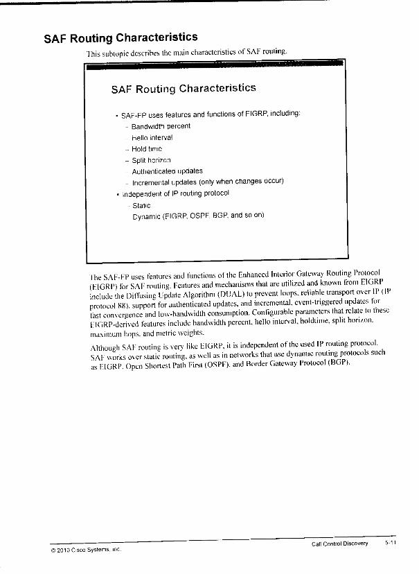
SAF Routing CharacteristicsThis subtopic describes the main characteristics ofSAF routing.
SAF Routing Characteristics
• SAF-FP uses features and functions of EIGRP, including:
- Bandwidth percent
Hello interval
Hold time
- Split horizon
Authenticated updates
- Incremental updates (only when changes occur)• Independent of IP routing protocol
Static
• Dynamic (EIGRP. OSPF, BGP, and so on)
The SAF-FP uses features and functions of the Enhanced Interior Gateway Routing Protocol(F1GRP) for SAF routing. Features and mechanisms that are utilized and known from EIGRPinclude the DifTusing Update Algorithm (DUAL) to prevent loops, reliable transport over IP (IPprotocol 88). support for authenticated updates, and incremental, event-triggered updates torfast convergence and low -bandwidth consumption. Configurable parameters that relate to theseFIGRP-derived features include bandwidth percent, hello interval, holdtime. split horizon,maximum hops, andmetric weights.Although SAF routing is verv like EIGRP, it is independent of the used IP routing protocol,SAF works over static routing, as well as in networks that use dynamic routing protocols suchas FIGRP Open Shortest Path First (OSPF). and Border Gateway Protocol (BGP).
i 2010 Cisco Systems. IncCall Control Discovery
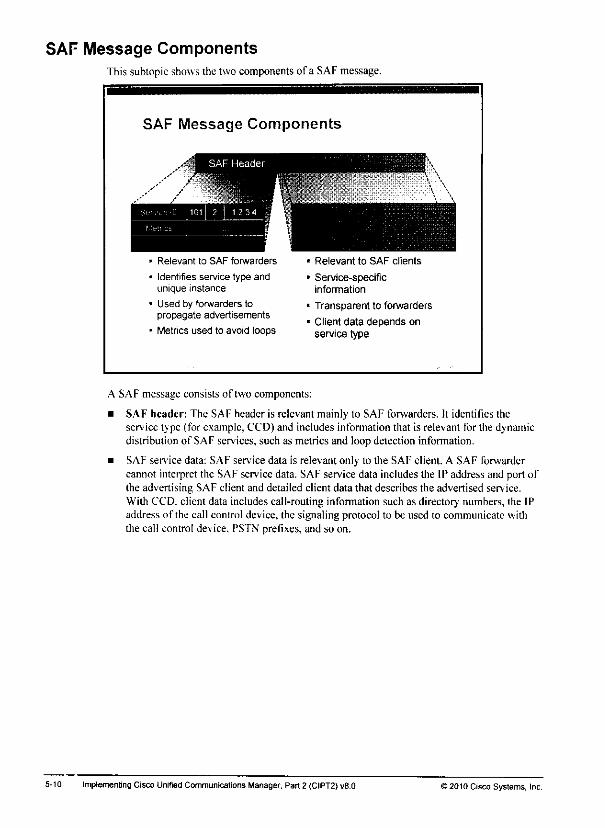
SAF Message ComponentsThis subtopic shows the two components of a SAF message.
SAF Message Components
Relevant to SAF forwarders
Identifies service type andunique instance
Used by forwarders topropagate advertisements
Metrics used to avoid loops
Relevant to SAF clients
Service-specificinformation
Transparent to forwarders
Client data depends onservice type
A SAF message consists of two components:
• SAF header: The SAF header is relevant mainly to SAF forwarders. It identifies theservice type (for example, CCD) and includes information that is relevant for the dynamicdistribution of SAF services, such as metrics and loop detection information.
• SAF service data: SAF service data is relevant only to the SAF client. A SAF forwardercannot interpret the SAF service data. SAF service data includes the IP address and port ofthe advertising SAF client and detailed client data that describes the advertised service.With CCD. client data includes call-routing information such as directory numbers, the IPaddress of the call control device, the signaling protocol to be used to communicate withthe call control device. PSTN prefixes, and so on.
5-10 ImplementingCisco Unified Communications Manager, Part 2 (CIPT2)v8.0 )2010 Cisco Systems, Inc.
*•
SAF Client TypesThis subtopic describes the two available CCD SAF client types.
SAF Client Types
SAF forwarder is always Cisco IOS router.
Two types of SAF clients:
External SAF clients
* SAF client and SAF forwarder aredifferent devices.
« SAF client is Cisco UnifiedCommunications Manager.
* SAF-CPisused.
• Internal SAF clients
• SAF client and SAF forwarder arecolocated functions within the
same device.
* SAF clients are Cisco UnifiedCommunications ManagerExpress, Cisco Unified SRST,Cisco Unified Border Element,and Cisco IOS gateways.
• Internal API is used
Cisco Unified
Communications
Manager
Internal
API
A SAF forwarder is alwavs a Cisco IOS router. Remember that SAF forwarders do not processthe propagated service infomiation. Their function is to propagate the informationwithin theSAF network and lo pass it on to SAF clients.
SAF clients then interpret the service infomiation. With CCD. the SAF client is a call controldevice, which sends and receives call-routing infomiation. Depending on the type of callcontrol device, the CCD device can be an internal or external SAF client:
• External SAF client: The SAF client and the SAF forwarder are two different devices.
They use the SAK-C1' for communication. An exampleof a CCDexternalSAF client isCisco Unified Communications Manager.
• Internal SAF client: The SAF client and the SAF forwarder arc two different functions
within the same device—a Cisco IOS router. They use an internal application programminginterface (API) for communication. Examples of CCD internal SAF clients are CiscoUnified Border Element. Cisco Unified SRST. Cisco Unified Communications ManagerExpress, and Cisco IOS gateways.
©2010 Cisco Systems, Inc Call Control Discovery
SAF Characteristics
This topic describes the characteristics of SAF.
SAF Components
SAF supports any servicelo be advertised
CCD is the first Cisco applicationusing SAF to advertise services(call routing)
SAF network components.
• Exchange serviceinformation amongeach other
• Use the SAF ForwardingProtocol (SA^-^PI
Advertise services lo andleam services from SAFforwarders
Use SAF Client Protocol( . ."I to interact withSAF forwarders
(With CCD) serve as callagents
Cisco Unified
Communications
Manager
Cisco UnifiedCommunications
Manager
SAF is a network-based, scalable, bandwidth-efficient, real-time approach to serviceadvertisement and discovery.
SAF can be used to advertise and learn any service to and from the SAF-enabled network. CCDis the first Cisco application that utilizes SAF. As mentioned earlier, the devices within the SAFnetwork are SAF forwarders. Theyhave the responsibility to propagate services within thenetwork. SAF forwarders do not interpret theservice information itself; they only guaranteefast and reliable exchange of the information. SAF forwarders use theSAF ForwardingProtocol (SAF-FP) between each other.
SAF forwarders can interact with SAF clients. A SAF client is an entity thatprocesses SAFservice data.A SAF client can independently advertise (generate) SAF service information tobe propagated in the network, or subscribe to (receive) SAF service information. A SAF clientcommunicates with oneor more SAF forwarders by the SAF Client Protocol (SAF-CP). WithCCD.the SAF client is a call agentsuch as Cisco Unified BorderElement, Cisco UnifiedSRST. Cisco Unified Communications Manager, Cisco Unified Communications ManagerExpress, and Cisco IOS gateways.
5-8 Implementing Cisco Unified Communications Manager, Part2 (CIPT2) vfl.O ) 2010 Cisco Systems, Inc.
Call Control Discovery OverviewThis subtopic provides an overview of CCD.
CCD Overview
CCD-enabled call agentsadvertise to and leam from
"the network"
SAF is used to distribute
information within the network.
SAF forwarders interact with
CCD-enabled call agents(SAF clients)
- SAF forwarder learns
information from SAF client
•- SAF forwarders exchangeinformation with each other.
SAF forwarder advertises
all learned information to
SAF client. CallAgent Catl/
With CCD.each CCD-enabled call agentadvertises locally found directory numbers ordirector.' number ranges and their corresponding PS'FN numbers orprefixes to theSAF-enabled network. In addition, each CCD-enabled call agent learnscall-routing infonnation fromthe network.
SAF isused to propagate infomiation within the SAF-enabled network. SAF forwardersinteract with CCD-enabled call agents (that is. SAF clients). A SAF forwarder learnsinfonnation from a SAF client. SAF forwarders exchange learned call-routing information witheach otherso that the SAF-enabled network is aware of all learned call routes. SAF forwardersdo notonh leam from SAF clients, but they alsoadvertise all learned information lo SAFclients, fhat way. all SAF clients are aware of all available call-routing information—internaldirector, numbers and their corresponding PSTN numbers.
©2010 Cisco Systems. IncCall Control Discovery
Scalable Dial Plan Solution for Large NetworksThis subtopic describes a scalable dial plansolution for large networks.
5-6
Scalable Dial Plan Solution for Large Networks
Solutions for dynamic exchange of routing information exist.- Dynamic IP routing protocols.
• Routers have local networks attached.
• Routers advertise local networks to other routers.
• All routers leam all available networks and how lo gel there.
Same concept can be used for call-routing information.
- Call-routing domains advertise telephone numbers or number ranges.
• Internal numbers and IP address for VoIP
• External numbers for PSTN backup
Call Control Discovery has been introduced with Cisco Unified CommunicationsManager Version 8.
- Call agents can advertise and leam call-routing information using• Cisco Unified Communications Manager
• Cisco Unified Communications Manager Express
• Cisco Unified SRST
• Cisco Unrfied Border Element
• Cisco IOS gateway
The problem of dynamically distributing reachability information is known also in areas otherthan call routing. In IP networks, for example, routing has changed from simple static routingto large, fully dynamic clouds, such as the Internet.
The solution for scalable IP routing is provided by dynamic routing protocols. IP routers havelocal networks that are attached. They advertise these locally known networks to other routersso that all routers can leam about all available networks and the path to get to those networks.
The same concept can be used to distribute call-routing infonnation. Each call-routing domainadvertises locally known telephone numbers or number ranges. Because local numbers aretypically used by internal patterns (using VoIP) as well as via the PSTN, each call-routingdomain advertises both the internally used numbers and the corresponding external PSTNnumbers.
Cisco CCD. a new feature that was introduced with Cisco Unified Communications ManagerVersion 8. provides exactly such a service. It allows Cisco Unified Border Element. CiscoUnified SRST. Cisco Unified Communications Manager, Cisco Unified CommunicationsManager Express, and Cisco IOS gateways to advertise and leam call-routing information inthe form of internal directory numbers and PSTN numbers or prefixes.
Implementing Cisco Unrfied Communications Manager, Part 2 (CIPT2) v8.0 ©2010 Cisco Systems, Inc.
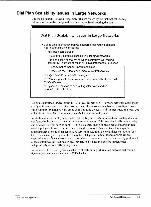
mm
Dial Plan Scalability Issues in Large NetworksThe main scalability issues in targe networks are caused by the fact that call-routinginfonnation has to be configured separately at each call-routing domain.
Dial Plan Scalability Issues m Large Networks
• Call-routing information between separate call-routing domainshas to be manually configured:
Full-mesh configuration
• Extremely complex, suitable only for small networks
Hub-and-spoke configuration when centralized call-routingentities (SIP network services or H.323 gatekeepers) are used
• Scales better than full-mesh topologies
• Requires redundant deployment of central services
• Changes have to be manually configured.
• PSTN backup has to be implemented independently at each call-routing domain.
• No dynamic exchange of call-routing information and noautomatic PSTN backup.
Without centralized services (such as H.323 gatekeepers or SIP network services), a full-meshconfiguration is required. In other words, each call control domain has to be configured withcall-routing information toward all other call-routing domains. This implementation model doesnot scale at all and therefore is suitable only for smaller deployments.
In a hub-and-spoke deplovment model, call-routing information for each call-routing domain iseonligured onk once at the centralized call-routing entity. This eentrali/ed call-routing entitycan be a SIP network service or an H.323 gatekeeper. Such a solution scales better than full-mesh topologies: however, it introduces a single point of failure and therefore requiresredundant deployment of the centralized service. In addition, the centralized call routing stillhas to be manually configured. For example, if telephone number ranges or prefixes arechanged at one of the call-routing domains, these changes also have to be manually performedat the centralized call-routing service. Further, PSTN backup has to be implementedindependently at each call-routing domain.
In summary, there is no dynamic exchange of call-routing infomiation between call-routingdomains, and there is no automatic PSTN backup.
i 2013 Cisco Systems, Inc. Call Control Discovery

SAF and CCD OverviewThis topic prov ides an overviewabout SAFand CCD.
5^
Dial Plans in Large Networks
Call Agem
Call Agent
Dial plans in large networks are difficult to implement and maintain.
Centralized call-routing intelligence improves scalability but stilldoes not scale well in very large networks.
Cal Asent Call tgtrl Call AOent_sia_Call Agent
CallAgent CallAgent CaHAgent CallAgent
Call Agent
Call Agent
In large networks with several call agents—such as Cisco Unified Communications ManagerExpress. Cisco Unified Communications Manager, Cisco Unified Border Element, CiscoUnified SRST. and Cisco IOS gateways—the implementation and maintenance of dial planscan be very complex.
The use of 11.323 gatekeepers or Session Initiation Protocol (SIP) network services reduces thecomplexity. However, dial plan implementation still does not scale well in very largedeployments.
Implementing Cisco Unified Communications Manager, Part 2 (CIPT2) v8.0 J2010 Cisco Systems, Inc.

Lesson 1
Implementing SAF and CCD
OverviewWith the increasing deployment of Cisco Unified Communications solutions, dial planshavebecome more complex to implement, especially in largeenterprises that consistof numerouscall control devices. Some examples of these call control devices arc Cisco Unified BorderElement. Cisco Unified Survivable Remote Site Telephony (SRST), Cisco UnifiedCommunications Manager. Cisco Unitied Communications Manager Express, and Cisco IOSgateways.
Tosimplifv dial plan implementation in large deployments, it isdesirable thatcall controldevices dynamically exchange call-routing infonnation so that no any-to-any staticconfiguration is required. Cisco Service Advertisement Framework (SAF) allows services to bepropagated through SAF-enabled network devices. Cisco Call Control Discovery (CCD) is thefirst application thatutilizes SAF to advertise services: the reachability of internal director.'numbers and publicswitched telephone network (PS'fN) backupnumbers.
This lesson explains how SAF works, describes its components, andshows how to configure it.The lesson also describes how CCD utilizes SAF to dynamically exchange call-routinginfonnation and how you can implement CCD in Cisco Unified Communications Managerandin Cisco IOS Software.
ObjectivesUpon completing ihis lesson, you will beable to describe and implement SAF clients andforwarders in an environment with CCD. This ability includes being able to meet theseobjectives:
Describe what SAF is. what CCD is. and how CCD utilizes SAF
Describe the characteristics of SAF
Describe the characteristics of CCD
Describe how CCD works
Describe how to implement SAF and CCD
Describe special considerations for using SAF and CCD

Implementing Cisco Unified Communications Manager, Part 2 (C1PT2)v8.0 © 2010 Cisco Systems, Inc
Module 5
Call Control Discovery
OverviewIn large deployments with many call agents, dial plan implementation can be very'complex.Cisco Service Advertisement Framework (SAF) and Call Control Discovery (CCD) allow callagents to propagate call-routing infonnation to the network and to learn routes from thenetwork. Thus. SAF and CCD facilitate the deployment of very large Cisco UnifiedCommunications solutions by greatly simplifying dial plan implementation.
This module explains how SAF and CCD work and how you can implement SAF and CCD toallow the duiamic discover) of call-routing information.
Module ObjectivesUpon completing this module, you will be able lo describe and implement CCD deployments.I his ability includes being able to meet this objective:
• Describe and implement the SAF client and forwarder in an environment with CCD

Module Self-Check Answer KeyQU B
Q2) C. D.G
03) A.C
Q4) C
Q5) B
06) B
Q7) A
Q8) CD
09) A. D. E
Q10) A, D
Oil) A, B
4-74 Implementing Cisco Unitied Communications Manager. Part 2 (CIPT2) v8.0 © 20t0 Cisco Systems, Inc.

Oil) Which two statements describe the result when theuser logs into adevice but is stilllogged in to another device? (Choose two.) (Source: Implementing Cisco ExtensionMobility)
A) If the multiple login behaviorserviceparameter is set to disallowed, the loginfails.
B) If the multiple loginbehaviorserviceparameter is set lo auto-logout, the user isautomatically logged out of the other device.
C) If the multiple login behaviorenterprise parameter is set to allowed, the loginsucceeds and the user also remains logged in at the other device.
D) If the multiple loginbehaviorenterprise parameter is set lo prompt, the user isgiven the option to log out of the other device first.
E) fhe login fails.
2010 C sco Systems, inc. Implementation of Features and Applications for Multisite Deployments

Q6) If no physical location is configured at the device pool, the physical location that isconfigured at the phone is used. (Source: Implementing Device Mobility)
A) true
B) false
Q7) Which of the following is not a problem when users roam between sites? (Source:
Implementing Cisco Extension Mobility)
A) The phones that they use have the wrong location and region settings.B) Users get the wrong extensions on their phones.C) Users get the wrong calling privileges.D) Users do not have speed dials available.
Q8) Which two settings cannot be updated when Cisco Extension Mobility is used?(Choose two.) (Source: Implementing Cisco Extension Mobility)
A) phone button templateB) softkey templateC) device CSSD) network localeE) phone service subscriptionsF) phone lines and speed dials
Q9) Which three configuration elements are not relevant for Cisco Extension Mobility
configuration? (Choose three.) (Source: Implementing Cisco Extension Mobility)
A) location
B) phoneC) end user
D) device security profileF) device poolF) device profileCi) phone service
010) Which two of the following are recommended approaches to implementation of calling
privileges when Fxtension Mobility is used? (Choose two.) (Source: ImplementingCisco Extension Mobility)
A) Configure the line or lines of the device profile of the user with a CSS thatincludes blocked route patterns for the destinations that the user should not beallowed to dial.
B) Do not configure a device CSS.C) Do not configure a line CSS.D) Configure the device with a CSS that includes all PSTN route patterns pointing
to die local gateway.E) Configure the line or lines of the physical phone with a CSS that includes
blocked route patterns for the destinations that the user should not be allowedto diai.
4-72 Implementing Cisco Unified Communications Manager, Part 2 (CIPT2) v8.0 © 2010 CiscoSystems, Inc.
Module Self-Check
©20'0
Use the questions here to review what you learned in this module. The correct answers andsolutions are found in the Module Self-Check Answer Key.
Qi)
021
03)
Q4)
05)
Which setting is not modified when a user is roaming between sites with a device1!(Source: Implementing Device Mobility)
A) region
B) directorv number
O location
D) SRST reference
Which three of the following are device mobility-related settings in Device Mobility?
(Choose three.) (Source: Implementing Device Mobility)
A) RegionB) SRST Reference
C) AAR Calling Search SpaceD) Device Mobility Calling Search SpaceF.) Media Resource Group ListF) Location
Ci) AAR Group
Which two statements are correct about (he relationship between Device Mobility
configuration elements? (Choose two.) (Source: Implementing Device Mobility'.
A) Device Mobility Infos refer to one or more device pools.B) Device pools refer to one or more physical locations.C) Device pools can refer to one device mobility group,D) Device pools can refer to one Device Mobility Info.E| Physical locations refer to device mobility groups.
Which statement is not correct about Device Mobility operation? (Source:
Implementing Device Mobility)
A) A dev icepool is selected basedon the IP address of the device.B) If the selected device pool is the home device pool, no changes are made.C) If the selected device pool is in a different device mobility group than the home
dev icepool, the device-mobility-related settings of the roaming devicepoolareapplied.
D) If the selected device pool is in a different physical location than the homedev ice pool, the roaming-sensitive settingsof the roaming devicepool areapplied.
Which statement is not correct about the interaction of Device Mobility and globalized
call routing? (Source: Implementing Device Mobility)
A) The user of a roaming phone can use the home dial rules.B) Fhe userof a roamingphone can use the homedial rules, but then the home
gateway is used all of the time.C) The user of a roaming phone can use the roaming gateway.D) The samedevicemobility groupcan be usedat all devicepools.
ico Systems. Inc Implementation of Features and Applications for MultisiteDeployments

4-70 Implementing Cisco Unified Communicalions Manager, Part 2 (CIPT2) v8.0 ©2010 Cisco Systems, Inc.
Mo lule Summary
Rel
This lopicsummarizes the kev points that were discussed in this module.
Module Summary
• Device Mobility allows users to roam between sites with theirphones.
• Cisco Extension Mobility allows users to log in to any phonein a Cisco Unified Communications Manager cluster andhave a personal profile applied to the phone.
fhismodulebegins with a description of Device Mobility. Itdescribed how Device Mobilitycan be implemented inenvironments with and without globalized call routing, fhen the -noduledescribed the operation and implementation ofCisco Extension Mobility that allows Cisco
! Unified Communications Manager users to log into an IP phone and have their personal profilej applied, regardless ofthe device and physical location that they are using.
frences
For additional infonnation. refer to these resources:
• Cisco Systems. Inc. Cisco Unified Communications System 8.x SRND, April 2010.hup: www.cisco.conVen/I IS/docvYoiee ip comm/cucm/srnd/Kx/iicSx.htmi
• Cisco Systems. Inc. Cisco Unified Communications Manager Administration GuideRelease 8.0(1). February 2010.!itlp:.:\\\\w.ei^co.conv'cn/US''docs;voiceJp_comm/cucm/admin/K_0 I.ecmcfg'bccn-SOl-em.html
• Cisco Systems. Inc. Cisco Unified Communications Manager Features and Services Guide.Release'8.0{i). March 2010.imp: www.cisL'o.coin't'iiT^.'docs/voice ip comm/eucm/admin/8 0 l/ccmfeat/fsg^-801-cm.html
;isco Systems. Inc Implementing Features and Applications for Multisite Deployments 4-69
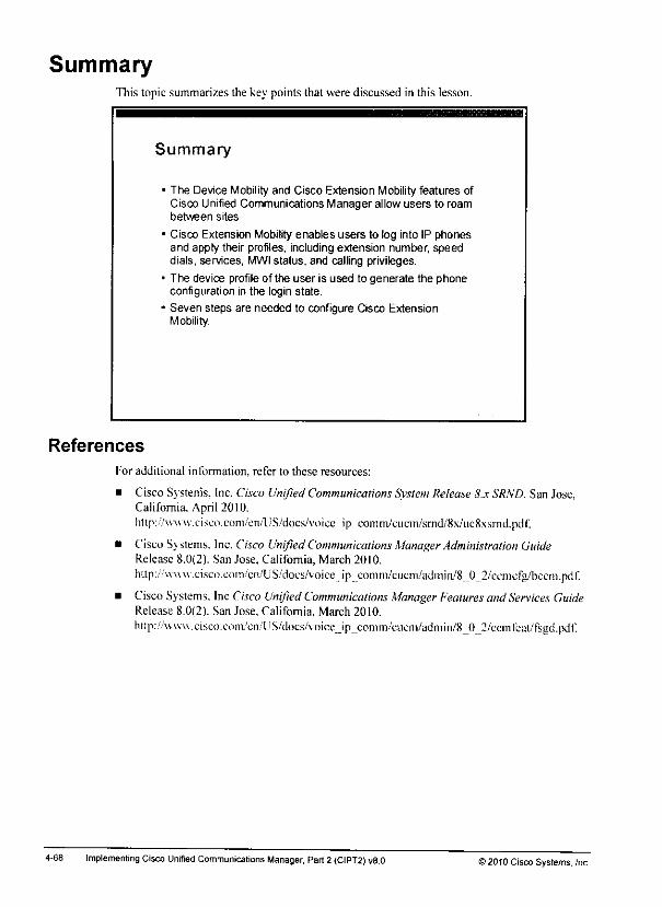
SummaryThis topic summarizes the key points that were discussed in this lesson.
References
Summary
The Device Mobility and Cisco Extension Mobility features ofCisco Unified Communications Manager allow users to roambetween sites,
Cisco Extension Mobility enables users to log into IP phonesand apply their profiles, including extension number, speeddials, services, MWIstatus, and calling privileges.
The device profile of the user is used to generate the phoneconfiguration in the login state.
Seven steps are needed to configure Cisco ExtensionMobility.
For additional information, refer to these resources:
• Cisco Systems. Inc. Cisco Unified Communications Svstem Release8.x SRND. San Jose,California. April 2010.http:/.'www.cisco.com/en/lJS/docs/voiee_ip_comm/eucm/srnd/8x/ue8.\srnd.pdf.
• Cisco Systems. Inc. Cisco Unified Communications Manager Administration GuideRelease 8.0(2). San Jose, California, March 2010.http:.'/v\ww.cisco.com''en/US/docs/voice ip comni/cuem/admin/8 0 2/ccmcfg/bccm.pdf.
• CiscoSystems. Inc Cisco Unified Communications Manager Features andServices GuideRelease 8.0(2). San Jose, California, March 2010.
http://vvw\\xisc().com/en/US/docs/voice__ip_comm/cucni/admin/8J)_2/cciiifeal/fsgd.pdf'.
4-68 Implementing Cisco Unified Communications Manager, Part2 (CIPT2) v8.0 ) 2010 Cisco Systems, Inc

Step 7b: Subscribe Phone to Cisco Extension Mobility PhoneSenvice
The last stepof Cisco Extension Mobility configuration is to subscribe the IP phoneto theCisco Extension Mobilitv phone service.
Step 7b: Subscribe Phone to Cisc<Extension Mobility Phone Service
In the Phone Configuration window, chooseSubscribe/Unsubscribe Services from Related Links to openthe Subscribed Cisco IP Phone Services window.
Subscribed Qgn IP Phone Services tor SeptMH4C**551S6 2 Enter the service
name as rt should
appear at the phone.rScnrtte lnfonnaMon
-Sulrairlbed Scrvic
-| rvcxl I Close
1 Choose the Cisco
Exlension Mobilityphone service byusing the nameassigned in Step 3Then, click Next
1 Logon 1 LcbjI'
FM Lngfm ' Loaon'
FM logon / '-v^fflt
3. Click Subscribe.
Then, click Save
The process ofsubscribing the IP phone tothe Cisco Extension Mobility service isthe same asthe process that was explained in Step 5. in which the device profile was subscribed totheCisco Extension Mobility service. In the Phone Configuration window, use the related linkSubscribe/Unsubscribe Services to open theSubscribed Cisco IP Phone Services window andsubscribe to the sen ice.
) 2010 Cisco Systems, Inc Implementation ofFeatures and Applications for Multisite Deployments 4-67
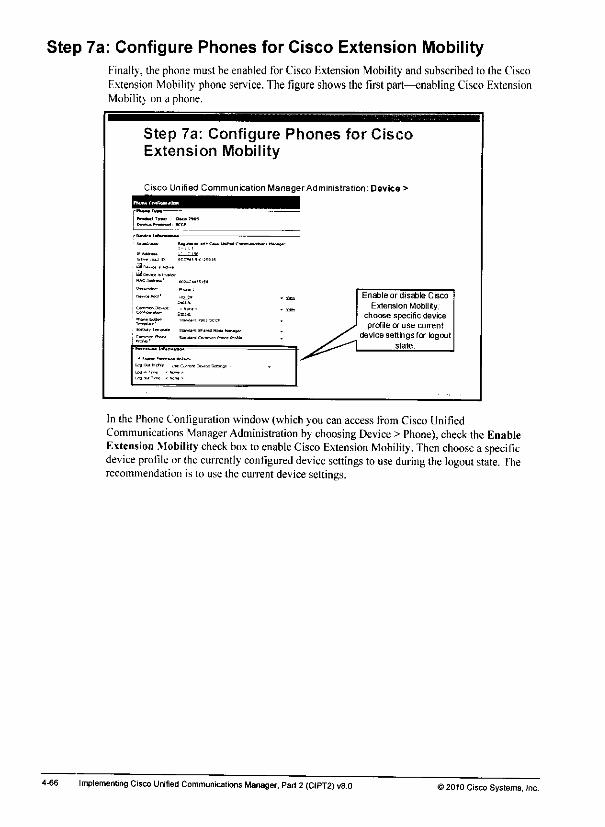
Step 7a: Configure Phones for Cisco Extension MobilityFinally, the phone must be enabled for Cisco Extension Mobility and subscribed to the CiscoExtension Mobility phone service. The figure shows the first part—enabling Cisco ExtensionMobilitv on a phone.
Step 7a: Configure Phones for CiscoExtension Mobility
Cisco Unified Communication ManagerAdministration: Device >
kJ Oct* rt I.
Enable or disable Cisco
Extension Mobility;choose specific deviceprofile or use current
device settings for logoutstate.
In the PhoneConfiguration window(which you can access from Cisco UnifiedCommunications Manager Administration by choosing Device > Phone), check the EnableExtension Mobility check box toenable Cisco Extension Mobility. Then choose a specificdevice profile or the currently configured device settings to use during the logout state. Therecommendation is to use the currentdevicesettings.
4-66 Implementing Cisco Unified Communications Manager, Part2 (CIPT2) v8.0 >2010 Cisco Systems, Inc.
B*.

Step 6: Associate Users with Device ProfilesThis step describes how to associate users withdeviceprofiles.
Step 6: Associate Users with DeviceProfiles
Cisco Unified Communications ManagerAdministration: User Management > End User
l™" —11 1
Usei ID and PINaie
] used for CiscoJ Extension Mobility login~< =====1
-fr.--.o-* «j-t*f
-
Associate user
VA
/
A
device profiles,optionally, set
default profile(if moielhan
one controlled
profile exists)
Inthe End User Configuration window (which youcanaccess from Cisco linifiedCommunications Manager Administration by choosing User Management > End User), choosethe device profile orprofiles that you want toassociate with the user in the list ofAvailableProfiles. Click the down arrow to add them lo the list of Controlled Profiles.
©2010 Cisco Systems. Inc Implementation ofFeatures and Applications for Multisite Deployments 4-6S
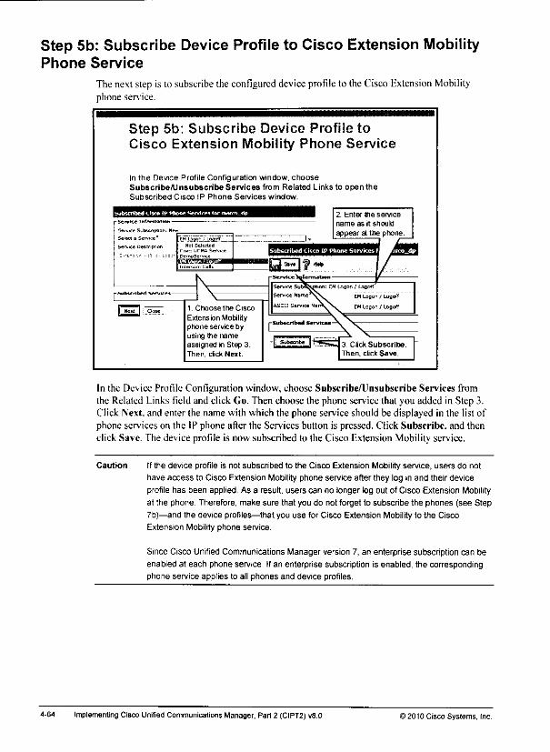
Step 5b: Subscribe Device Profile to Cisco Extension MobilityPhone Service
The next step is to subscribe the configured deviceprofileto the Cisco Extension Mobilityphone service.
Step 5b: Subscribe Device Profile toCisco Extension Mobility Phone Service
In the Device Profile Configuration window, chooseSubscribe/Unsubscribe Services from Related Links to open theSubscribed Cisco IP Phone Services window.
Sew* a £erv-c*'
5ei-Lic« Des^ripfic
ESmmmmmm^LmmmW
EH Lo^on ; LagotfNot Selected -
Sen.-*
0* mo5e<v«
2. EnlerBie service
name as it should
appear at the phone.
otion: EM Logon / Logoff
EM Logon .' Logoff
EM Logon / Logoff
- Subscribed Services
1. Choose the Cisco
Extension Mobilityphone service byusing the nameassigned in Step 3.Then, cick Next.
3. Click Subscribe.
Then, click Save,
In the Device Profile Configuration window, choose Subscribe/Unsubscribe Services fromthe Related Links field and click Go. Then choose the phone service that you added in Step 3.Click Next, and enter the name with which the phone service should be displayed in the list ofphone services on the IP phone after the Services button is pressed. Click Subscribe, and thenclick Save. The device profile is now subscribed to the Cisco Extension Mobility service.
Caution If the device profile is not subscribed to the Cisco Extension Mobility service, users do not
have access to Cisco Extension Mobility phone service after they log in and their device
profile has been applied. As a result, users can no longer log out of Cisco Extension Mobility
at the phone. Therefore, make sure that you do not forget to subscribe the phones (see Step
7b)—and the device profiles—that you use for Cisco Extension Mobility to the Cisco
Extension Mobility phone service.
Since Cisco Unified Communications Manager version 7, an enterprise subscription can beenabled at each phone service. If an enterprise subscription is enabled, the corresponding
phone service applies to all phones and device profiles.
4-64 ImplementingCisco Unified CommunicationsManager, Part 2 (CIPT2)vfl.O >2010 Cisco Systems, Inc.
mm
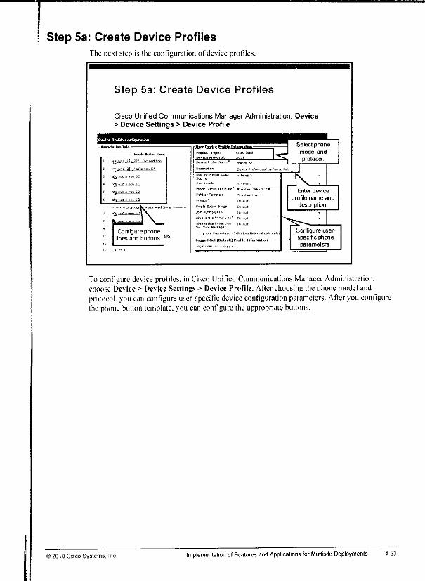
m
Step 5a: Create Device ProfilesThe next step is the configuration of device profiles.
Step 5a: Create Device Profiles
Cisco Unified Communications Manager Administration: Device> Device Settings > Device Profile
Configure phonelines and buttons.
PKor n.*-™ TrPijtn.E*
Setter Tcmcla-rB
[g-.=rr
1 (Default) Profile l«lfOrM*lkirl-
5 modeiand
protoccrf.
IK^Enter device
profile name anddescription.
Configure user-specific phoneparameters.
To configure device profiles, in Cisco Unified Communications ManagerAdministration,choose Device > Device Settings > Device Profile. After choosing the phone model andprotocol, vou can configure user-specific deviceconfiguration parameters. Afteryou configurethe phone button template, you can configure the appropriate buttons.
© 2010 Cisco Systems. Inc Implementation of Features and Applications for Multisite Deployments 4-63
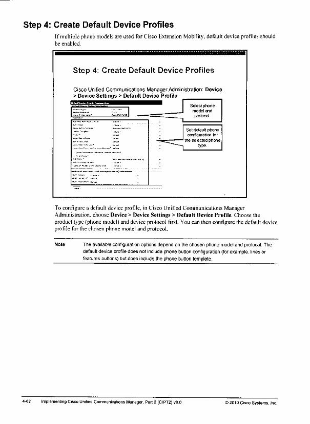
Step 4: Create Default Device ProfilesIf multiple phone models are used for Cisco Extension Mobility, default device profiles shouldbe enabled.
Step 4: Create Default Device Profiles
Cisco Unified Communications Manager Administration: Device> Device Settings > Default Device Profile
1 Select phoneJ modeland
™"
Set default phoneconfiguration for
the selected phonetype.
—
To configure a default device profile, in Cisco Unified Communications ManagerAdministration, choose Device > Device Settings > Default Device Profile. Choose theproduct type (phone model) and device protocol first. You can then configure the default deviceprofile for the chosen phone model and protocol.
Note The available configurationoptions depend on the chosen phone model and protocol. Thedefault device profiledoes not include phone button configuration (forexample, lines orfeatures buttons) but does include the phone button template.
4-62 Implementing Cisco Unified Communications Manager, Part 2 (CIPT2) v8.0 52010 Cisco Systems, Inc.
«M
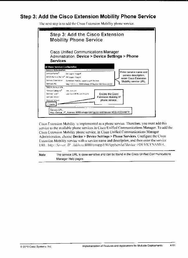
Step 3: Add the Cisco Extension Mobility Phone Servicefhe next step is to add the Cisco I'xlension Mobility phone service.
Step 3: Add the Cisco ExtensionMobility Phone Service
Cisco Unified Communications ManagerAdministration: Device > Device Settings > PhoneServices
IP Ptwne Servke*, Configuration
S»rvi£P Name' EH Logon ,' LogcC
A5CTI Service f*a'n EH Logon ,J LOQOt*
S=rv>cc Descfipt.oi Extension Mcbilil. ..ckju Uicif 5trv.c
Semce UHL htrp ''101 i.i.eoeoien OPC'EWAnpSt vlet'devicc-tDI <l
Enter service name and
service description;enter Cisco Extension
Mobility service URL.
^?rMrj Catega
Enable the Cisco
Extension Mobility IPphone service.
Setvice URLhtlp /:Server_IP_Aa<t-ess S0SO'emBpp/EMAppServlePdevice=#OEVICENAMEB
Cisco fxtension Mobility is implemented as a phoneservice, fherefore,you must add thisservice to the available phoneservices in Cisco Unified Communications Manager. To add theCisco Extension Mobility phone service, in Cisco Unified Communications ManagerAdministration, choose Device> DeviceSettings > Phone Services. Configure the CiscoFxtension Mobility service with a service name anddescription, andthenentertheserviceURI.:http:'.V/'rt'r IP ,-W(//-csj:8080.'cinapn/l:MAppScrv!cl?dc\icc=rfI)l'.VICFNAMI;.S.
Note The service URL is case-sensitive and can be found in the Cisco Unified Communications
Manager Help pages.
© 2010 Cisco Systems, Inc Implementation ofFeatures andApplications for Multisite Deployments 4-61

Step 2: Set Cisco Extension Mobility Service ParametersThe Cisco Extension Mobility service has several configurable service parameters.
Step 2: Set Cisco ExtensionService Parameters
Cisco Unified Communications ManagerAdministration: System > Service Parameters
Cisco Fxtension Mobility can be configured with the following service parameters.
If the Enforce Intra-cluster Maximum Login Time parameter is set to True, the user isautomatically logged out after the Intra-cluster Maximum Login Time expires. The Intra-clusterMultiple Login Behavior parameter specifies how to process users who log into a device but arestill logged in at another device. There are three options: Login can be denied, login can beallowed, or the user can be logged out automatically from a phone on which the user logged inearlier and did not log out.
Alphanumeric User ID can be enabled or disabled, and the last logged in username can beremembered (and presented as a default on the next login) by setting the Remember the LastUser Logged In parameter to True. Call lists can be preserved or cleared at logout, dependingon the setting of the Clear Call Logs on Intra-Cluster EM service parameter.
Note All of these parameters are clusterwide service parameters of the Cisco Extension Mobility
service and can be accessed from Cisco Unified Communications Manager Administration
by choosing System > Service Parameters.
4-60 Implemenling Cisco Unified Communications Manager, Part 2 (CIPT2) v8.0 >2010 Cisco Systems, Inc.
mm
mm.
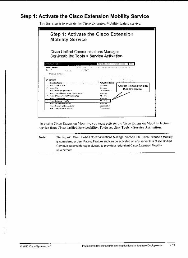
*>
Step 1: Activate the Cisco Extension Mobility Servicefhe first step is to activate the Cisco Extension Mobility feature service.
Step 1: Activate the Cisco ExtenshMobility Service
Cisco Unified Communications ManagerServiceability: Tools > Service Activation
mI Control Center - feature Services -
Select Serve*
Se
C'CCl 10 Snr,ltC5
• do
CMSenhw
: Tiimn Umii MK<HBMil**WCisco CalWanswer Ace rated
CISCO Tttp Activated
Cisco Messaging IrtprTicp Oe actuated
CKfo unrfifd Mobile Vane fides? Ser.-c Attested
Cisco ]P Vo<e. Media Streamy Aoo Ac! vsted
LZ Cisco Entensran MeMitY *««t™ (^Cisco Eflenri^d Finlftiorrf 'dilated
Cisco Dialed PfljmDei Analyser Deadly ate d
Cisco CHCP Menrto- Swv.™ I>e actuated
ActivateCisco Extension
Mobility service.
lo enable Cisco Extension Mobility,you must activate the Cisco Extension Mobility featureservice from Cisco Unified Serviceability. To do so, click Tools > Service Activation.
Note Starting with Cisco Unified Communications Manager Version 6.0, Cisco Extension Mobilityis considered a User Facing Feature and can be activated on any server in a Cisco UnifiedCommunications Manager cluster, to provide a redundant Cisco Extension Mobility
environment
© 2010 Cisco Systems. Inc. Implementation of Features and Applications for Multisite Deployments 4-59

Cisco Extension Mobility ConfigurationThis topic describes how to configure Cisco Extension Mobility.
Cisco Extension Mobility ConfigurationSteps
1 Activate the Cisco Extension Mobility service.
2 Set Cisco Extension Mobility service parameters.
3 Add the Cisco Extension Mobility phone service.
A Create default device profiles for all phone models used(optional).
5. Create device profiles and subscribe them to the CiscoExtension Mobility phone service.
6 Create end users and associate them with device profiles.
7. Enable Cisco Extension Mobilityfor phones and subscribephones to the Cisco Extension Mobilityservice.
The figure lists the steps that are required to configure Cisco Extension Mobility in CiscoUnified Communications Manager. The following topics explain these steps in detail.
4-5S Implementing Cisco Unified Communications Manager, Part 2 (CIPT2) v8.0 12010 Cisco Systems, Inc.
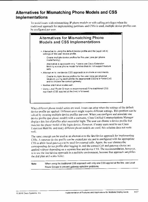
Alternatives for Mismatching Phone Models and CSSImplementations
To avoid issues with mismatching IP phone models or with calling privileges when thetraditional approach for implementing partitions andCSSs is used, multiple device profiles canbe configured per user.
Alternatives for Mismatching PhoneModels and CSS Implementations
Alternative to using the default device profile and the (applicable)settings of the user device profile.
Create multiple device profiles for the user (one per phonemodel family).
Alternative ts applicable only ifusers use Cisco ExtensionMobility across phone model families that do not support featuresafe
Alternative to line/device CSS approach in multisite environments.
Create multiple device prof les for the user (one per physicallocation), giving each profile the appropriate CSS to enforce CoSand to choose the conect gateway.
Neither alternative scales well.
Using Local Route Groups is recommended ifthe traditionalCSSapproach (CSS applied at the line) is followed.
When different phone model series are used, issues can arise when the settings of the defaultdevice protlle are applied. DilTerenl users might require different settings. This problem can besolved by creating multiple device profiles peruser. When you configure and associate onedevice profile (per phone model) with a username, Cisco Unified Communications Managerdisplavs this list ofprofiles after successful login. The user can choose adevice profile thatmatches the phone model ofthe login device. Ilowever. ifmany users need touse CiscoE\tension Mobility and many different phone models arcused, this solution does notscalewell.
The same concept can be used as an alternative tothe line/device approach for implementingCSSs. Aseparate device profile can be created per site and is configured with the appropriateCSS toallow local gatewa> s tobe used for external calls. Again, the user chooses thecorresponding device profile after logging in. and the correct CoS and gateway choice areapplied without depending on a separate line and device CSS. The recommendation, however,is to use the line/device approach ina multisite environment, because that approach simplifiesthe dial plan and scales belter.
Note When using thetraditional CSS approach with only oneCSS applied at theline, useLocalRoute Groups to prevent gateway-selectionproblems.
© 2010 Cisco Systems. Inc implementation ofFeatures and Applications for Multisite Deployments 4-57
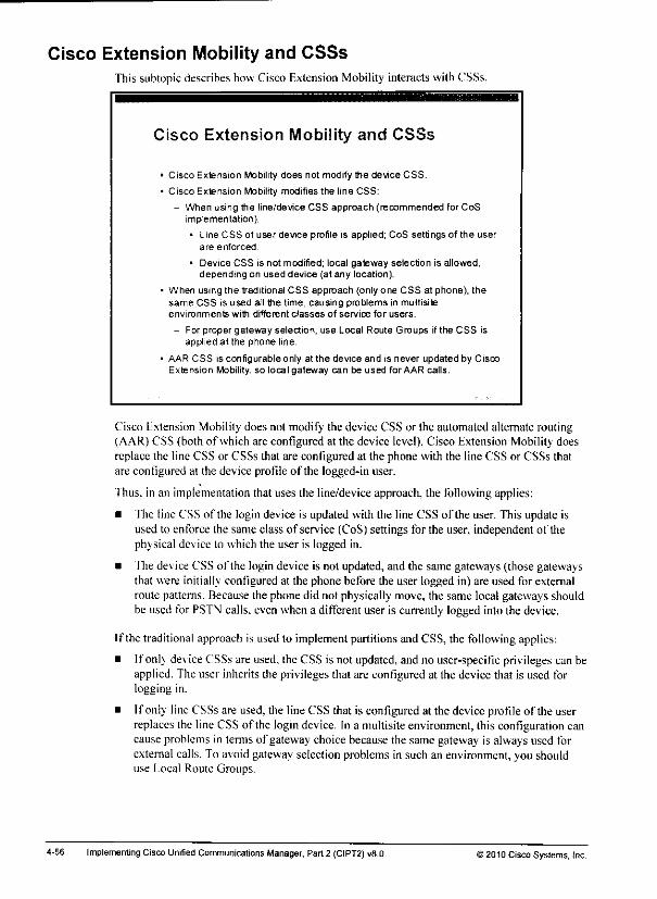
Cisco Extension Mobility and CSSsThis subtopicdescribes how Cisco F.xiension Mobility interacts with CSSs.
Cisco Extension Mobility and CSSs
• Cisco Extension Mobility does not modify the device CSS.
• Cisco Extension Mobility modifies the line CSS:
- When using the line/device CSS approach (recommended for CoSimplementation).
• Line CSS of user device profile is applied; CoS settings of the userare enforced
• Device CSS is not modified; local gateway selection is allowed,depending on used device (at any location).
• When using the traditional CSS approach (only one CSS at phone), thesame CSS is used all the time, causing problems in multisiteenvironments with different classes of sen/ice for users.
- For proper gateway selection, use Local Route Groups if the CSS isapplied at the phone line.
• AAR CSS is configurable only at the device and is never updated by CiscoExtension Mobility, so local gateway can be used for AAR calls.
Cisco Extension Mobility does not modify the device CSS or the automated alternate routing(AAR) CSS (both of which are configured at the device level). Cisco Extension Mobility doesreplace the line CSS or CSSs that are configured at the phone with the line CSS or CSSs thatare configured at the device profile of the logged-in user.
Thus, in an implementation that uses the line/device approach, the following applies:
• The line CSS of the login device is updated with the line CSS of the user. This update isused to enforce the same class of service (CoS) settings for the user, independent of thephysical device to which the user is logged in.
• The device CSS of the login device is not updated, and the same gateways (those gatewaysthat were initially configured at the phone before the user logged in) are used for externalroute patterns. Because the phone did not physically move, the same local gateways shouldbe used for PSTN calls, even when a different user is currently logged into the device.
If the traditional approach is used to implement partitions and CSS, the following applies:
• If only deviceCSSs are used, the CSS is not updated, and no user-specific privileges can beapplied. The user inherits the privileges that are configured at the device that is used forlogging in.
• If only line CSSs are used, the line CSS that is configured at the device profile of the userreplaces the line CSSof the logindevice. In a multisiteenvironment, this configuration cancause problems in terms of gateway choice because the same gateway is always used forexternal calls. To avoid gateway selection problems in such an environment, you shoulduse Local Route Groups.
4-56 ImplementingCisco Unified CommunicationsManager, Part 2 (CIPT2)v8.0 © 20t0 Cisco Systems, Inc.

mm
2. The phone button template and the softkey template of the default device profile areapplied to the Cisco Unified IP Phone 7905.
3. The user has access to the phone services that are configured in the Cisco Unified IP Phone7905 default de\ ice profile.
) 2010 Cisco Systems, Inc Implementation ofFeaturesand Applications forMullisite Deployments 4-55

How Cisco Extension Mobility Handles Phone ModelDifferences
This subtopic describes the phone configuration process when Cisco Extension Mobility isusedwith different phone models.
How Cisco Extension Mobility HandlesPhone Model Differences
When a phone model mismatch is identified, CiscoExtension Mobility works as follows:
• Device profile:
- Copy all dev ice-independent parameters from the device profileof the u ser
• Default device profile:
- Apply devtce-dependentparameters, such as phone button andsoftkey template, from the default device profile.
• Device profile
- Copy device-dependent parameters that can be applied (such asphone lines and feature buttons, ifsupported by the appliedphone button template).
- Apply phone service subscriptions from the device profile of theuser (if phone services are supported at the phone that is used).
After successful authentication, if the phone model series of the device protlle does not matchthe phone model series of the used phone, the following happens:
1. Device-dependent parameters, such as phone button template and softkey template, fromthe default device profile are applied lo the phone.
2. Then the system copies all device-independent configuration settings (user hold audiosource, user locale, speed dials, and line configuration, except for the parameters that arespecified under I inc Setting for This Device) from the device profile to the login device.
3. Next, the applicable device-dependentparameters of the device profile of the user areapplied. These parameters include buttons(such as line and feature buttons) that are basedon the phone button template that has been applied from the default device profile.
4. Finally, if supported on the login device, phone service subscriptions from the deviceprofile of the user are applied to the phone.
5. If the device profile of the user does not have phone services that arc configured, thesystem uses the phone services that are configured in the default device profile of the logindevice.
For example, the following events occur when a user who has a device profile for a CiscoUnified IP Phone 7960 logs into a Cisco Unified IP Phone 7905:
I. The personal user hold audio source, user locale, speed dials (if supported by the phonebutton template that is configured in the Cisco Unified IP Phone 7905 default deviceprofile), and directory number configuration of the user are applied to the Cisco Unified IPPhone 7905.
4-54 Implementing Cisco Unified Communications Manager, Part 2 (CIPT2) vB.O >2010 Cisco Systems, Inc.

Default Device Profile and Feature Safe
This subtopic describes the feature safe functionality of Cisco Extension Mobility.
Default Device Profile and Feature Safe
The default deviceprofile is applied only ifthe phone model series is different(feature safe)
Phones can use any phone buttontemplate that has the number of linebuttons that the phone model supports
Series 794x models are equivalentand can share a Cisco Extension
Mobiity profile.
Series 796x models are equivalentand can share a Cisco ExtensionMobiity profile.
Series 797x models are equivalentand can share a Cisco ExtensionMobiity profile
No administration tasks are required toactivate a Cisco Extension Mobility featuresafe
Cisco Extension Mobility feature safe isprotocol independent.
Log In
Cisco Unified IP
Phone 7945
Phone model
is similar
User dewce
profile isused
User Device
Prose tor
CISCO
Unified fPProne 7940
Ihe default deuce profile is applied only ifa users device profile and the phone on which theuser tries to log in are of a different phone model scries (for example, Cisco Unified IP PhoneScries 794x. 796x. or 797x).
When the phone model scries of the physical phone and the user device profile are the same,the feature safe function allows different phone models lo be used for user device profiles andphysical phone models.
for example, a user with an associated device profile for a Cisco Unified IP Phone 7940 phonecan log into a Cisco Unified IP Phone 7945 phone without having the default device profileapplied.
No administrative tasks are required to enable feature safe. Feature safe is independent of theused signaling protocol (SIP or SCCP).
© 2010 Cisco Systems. Inc Implementation of Features and Applications for Multisite Deployments
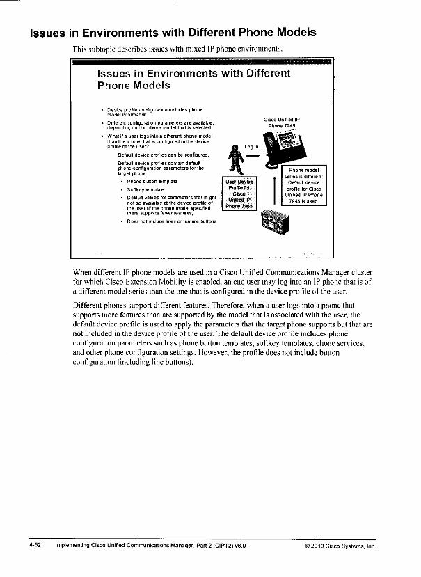
Issues in Environments with Different Phone Models
This subtopic describes issues with mixed IP phone environments.
Issues in Environments with DifferentPhone Models
Device profile configu ration ineludes phonemobel inform at on.
Different conigu ration parameters are available,depending on the phone model lhal is selected
What ifa user logs into a different phone modelthan Ihe model tiat s conlgured in the deviceprofile of the user'
Default device profiles can be configured
- Default device profiles contain defaultphone-configuration parameters for thelarge! phone:
• Phone button template
• Softkey template
• 0etaiilt values for parameters that mightnot be available at the device profile ofthe user (if fhe phone model specifiedthere supports fewer features)
• Ooes not include lines or feature buttons
Log In
User Dovfcs
PmBftfor
CiscoUnified IP
Phone 7965
Cisco unified IP
Phone 7945
Phone model
series is different
Default device
profile for CiscoUnified IP Phone
7945 is used.
When different IP phone models are used in a Cisco Unified Communications Manager clusterfor which Cisco Extension Mobility is enabled, an end user may log into an IP phone that is ofa different model series than the one that is configured in the device profile of the user.
Different phones support different features. Therefore, when a user logs into a phone thatsupports more features than are supported by the model that is associated with the user, thedefault device profile is used to apply the parameters that the target phone supports but that arenot included in the device profile of the user. The default device profile includes phoneconfiguration parameters such as phone button templates, softkey templates, phone services,and other phone configuration settings. However, the profile does not include buttonconfiguration (including line buttons).
4-52 ImplementingCisco Unified CommunicationsManager, Part 2 (CIPT2)v8.0 >2010 Cisco Systems, Inc.

5. The IP phone is reset and loads the updated configuration.
Now. the phone can be used as it would be used in the home location. Directory' numbers,speed dials. MWI. and so on. are all correct, regardless of the location and the IP phone that isused.
Users can log out of Cisco Extension Mobility by pressing the Services button and choosingLogout in the Cisco Extension Mobility service. If users do not logout themselves, the systemautomatically logs them out after the expiration of the maximum login lime (if the appropriatesen ice parameter has been configured accordingly).
The user is also automatically logged out of a phone when the user logs into another phone andwhen Cisco Unified Communications Manager is configured for auto-logout on multiplelogins. Another option is that the next user of the phone logs out a previous user so that the newuser can log in and have the phone that is updated with the settings of that new user. Afterlogout. Cisco Unified Communications Manager reconfigures the phone either with thestandard configuration of the IP phone or by using another device profile (as specified in thePhone Configuration window).
©2010 Cisco Systems. Inc. Implementation ofFeatures andApplications for Multisite Deployments 4-51
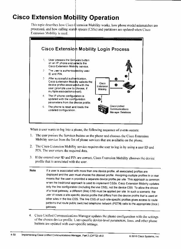
Cisco Extension Mot ility OperationThis topic describes how Cisco I xtension Mobility works, how phone model mismatches areprocessed, and how calling scare l spaces (CSSs) and partitions areupdated when CiscoExtension Mobilitv is used.
Cisco Extension Mobility Login Process
User presses the Sen ices buttonon an IP phone and selects theCisco Extension Mobi ity service.
The user is authenticated by userID and PIN
After successful authentication,Cisco Extension Mobility selects thedeviceprofile associatedwith theuser (prompts user to choose, ifmultiple associations e'xist).The IP phone configurjation isupdated with the configurationparameters from the device profile.
The phone is reset and loads theupdated configuration.
Cisco Unified
Communications
Manager Database
When a userwants to log into a phone, the following sequence of events occurs:
1. Theuserpresses theServices button on the phone andchooses theCiscoExtensionMobility service from the list ofphone services that are available onthe phone.
2. The Cisco Extension Mobility service requires the user to log inby using a user ID andPIN. The user enters the required data.
3. Ifthe entered user ID and PIN are correct, Cisco Extension Mobility chooses the deviceprofile that is associated with the user.
Note If a user isassociated with more than onedevice profile, all associated profiles aredisplayed andtheuser must choose thedesired profile. Assigning multiple profiles toa usermeansthatthe useris provided a separatedevice profile per site. This approach is commonwhen thetraditional approach isused toimplement CSSs. Cisco Extension Mobility updatesonlythe lineconfiguration (including the line CSS), not the device CSS. To allowthe choiceofa local gateway, a different (line) CSS must be applied persite. In such a scenario, theuserchoosesa site-specific device profile thatdiffers from thedevice profile thatis usedatother sites in theline CSS. The line CSS ofsuch site-specific profiles gives accessto routepatterns that route public switched telephone network (PSTN) calls tothe appropriate (local)gateway
4. Cisco Unified Communications Manager updates the phone configuration with the settingsofthe chosen device profile. User-specific device-level parameters, lines, and other phonebuttons areupdated with user-specific settings.
4-50 Implementing Cisco Unified Communications Manager, Part 2 (C1PT2) v8.0 ) 2010 Cisco Systems, Inc
m
m
mm
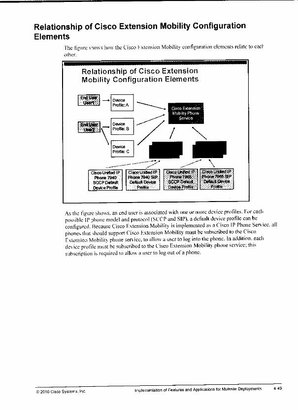
mm
Relationship of Cisco Extension Mobility ConfigurationElements
The figure shows how the Cisco Extension Mobility configuration elements relate toeaclother.
Relationship of Cisco ExtensionMobility Configuration Elements
'••'tm&k —Device
Profile: A
Oevice
Profile: BStilt N—
\\
Device
Profile: C
Cisco Unified IP
Phone 7940SCCPDef&ft
Device Profile
Cisco Unified IPPhone 7940 SIPOefeuS Device
Cisco Extension
MobilityPhoneService
Cisco Unified !P
SCCP DefaultDevice Proffle
Cisco Unified IPPhone 7065 SIP
Default DeviceProfits
As the figure shows, an end user isassociated with one ormore device profiles. For eachpossible IP phone model and protocol (SCCP and SIP), adefault device profile can beconfigured. Because Cisco Extension Mobility is implemented as aCisco IP Phone Seniee. allphones that should support Cisco Extension Mobility must be subscribed to the CiscoExtension Mobility phone service, loallow a user to log into the phone. In addition, eachdevice profile must be subscribed to the Cisco Extension Mobility phone service; thissubscription isrequired toallow a user to logoutof a phone.
©2010 Cisco Systems, Inc. Implementation ofFeatures andApplications for Multisite Deployments 4-49

Note The default device profileis not applied ifa device profileof a user and the phone on whichthe user tries to log in are of the same phone model series; for example, Cisco Unified IP
Phone 7960, 7961, or 7965.
Note Cisco Unified Communications Manager automatically creates a default device profile foraspecific phone model and protocol, as soon as Cisco Extension Mobility is enabled on anyphone configuration page for this phone model.
4-48 Implementing Cisco Unified Communications Manager, Pari 2(CIPT2) v8.0 ©2010 Cisco Systems, Inc

Cisco Extension Mobility Configuration ElementsThistopic describes theconfiguration elements thatCisco Extension Mobility uses.
Cisco Extension Mobility ConfigurationElements
ConfigurationElement Name
Device profile
Phone service
Configuration Element Function
SB res configuration of physicalphones. Conlguration parameters includedevice-specificphone parameters (such as deviceCSS,location,or MRGL). user-specificphoneparameters(such as userMOHaudiosource,DND, or soflkBy template),and (oser-specifc)buttonconfiguration (suchas linesor speed dais).
The end user is associated with one or more device profiles The user IDand theprj are used to log into a phone withCisco Enlension Mobility
Stores user-specific phoneeoniguraflon in logical proSles. ContDurationparametersinclude user-specific phone and button {lines, speed dials,etc.)parameters.The parametersof the deviceprofleart appliedtoa physicalphoneater a user logs intothe phone using Cisco Extension Mobility.
Cisco ExtensionMobility is implementedas a phone service. Hardwarephonesand deuce prof les need to be subscribed to the serwce
Stores tie default device-configuration parameters thai should be appliedwhenthe phonemode* offie deviceprofileofa user isUrfferert than the phonemodelofDefault device profile [he phone ^ wMW) fteusw |(jgs |(| ^^^ ^^ ^ ^ js^Av!f,ai ,s;tyci^ired lor«vetvphone mwlBlihaS hasCiKoExiensie'R MosilMy activated
The figure lists the configuration elements that are related toCisco Extension Mobility anddescribes theirfunction. Theconfiguration elements thatare introduced with Cisco ExtensionMobility are the device profile and the default device profile.
The device profile isconfigured with all the user-specific settings that are found althe devicelevel ofan IP phone (user MOH audio source, phone button templates, softkey templates, userlocales. DND and privacy settings, and phone service subscriptions) and all phone bulto.s(lines, speed dials, and so on). One ormore device profiles are applied toan end user. ir> theEnd User Configuration window.
The default dev ice profile stores default device configuration parameters thatCisco ExtensionMobilitv applies when there isa mismatch ofthe phone model series on which the user logs inand the phone model series that is eonligured in the device profile ofthe user. The defaultdevice profile exists once per phone model type and per protocol (Session Initiation Protocol[SIP] and Skinny Client Control Protocol [SCCP]). All ofthe parameters that cannot be appliedfrom the device profile of the user are taken from the default device profile.
Eor example, a user is associated with adevice profile for aCisco Unified IP Phone 7945 thatruns SCCP. Ifthis user logs in toa Cisco Unified IP Phone 7965 that runs SIP. some features(configuration parameters) that exist on the target phone are not configurable on the CiscoUnified IPPhone 7945 dev ice profile. In this case, theconfiguration parameters that arcunavailable onthe device profile of the user are taken from the default device profile oftheCisco Unified IP Phone 7945 SCCP.
Ifadevice profile includes more parameters than the target phone supports, the additionalsettings are ignored when the target phone with the user-specific settings is reconfigured.
© 2010 Cisco Systems. Inc. Implementation ofFeatures and Applications for Multisite Deployments 4-47
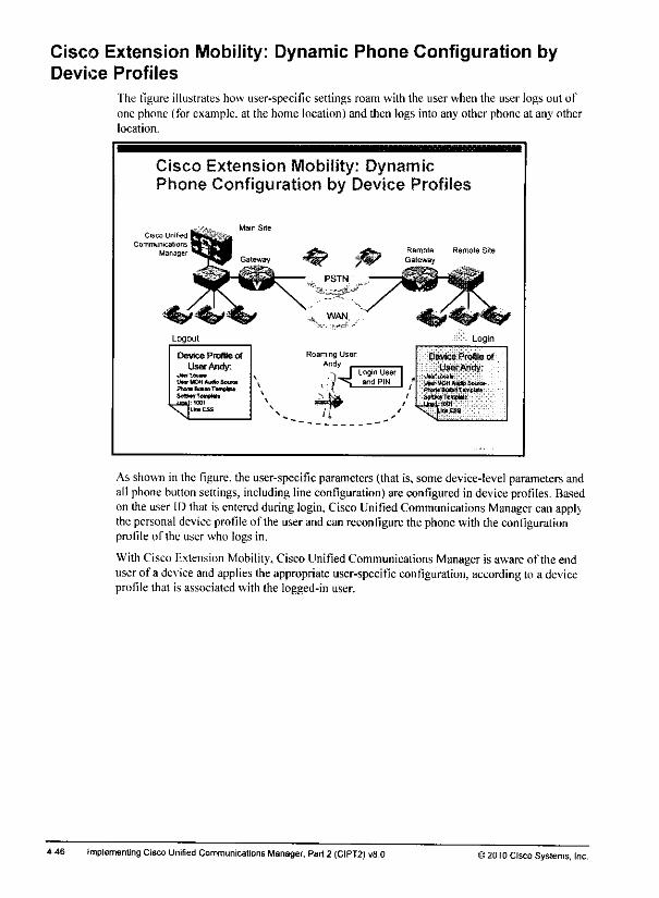
Cisco Extension Mobility: Dynamic Phone Configuration byDevice Profiles
The figure illustrates how user-specific settings roam with the user when the user logs out ofone phone (for example, at the home location) and then logs into any other phone at any otherlocation.
Cisco Extension Mobility: DynamicPhone Configuration by Device Profiles
Cisco Unified
Communications
Manager
Logout
Device Profile of
User Andy:UMTUKda
Iter yOHAufe SaraFtcru tUscr, Timvlm
Unicss
NJ
Roaming UserAndy
H[Login Userand PIN
Remote
Gateway
Login
Device Profile of
UserAndy:
UwrMOH AMID Southftm* fcltwt'r«iwl*»SetmTtmme
\limeas
As shownin the figure, the user-specific parameters (that is, some device-level parameters andall phonebutton settings, including line configuration) are configured in deviceprofiles. Basedon the user ID that is enteredduring login,Cisco UniliedCommunications Manager can applythe personaldeviceprofileof the userand can reconfigure the phonewith the configurationprofile of the user who logs in.
With Cisco Extension Mobility, CiscoUnified Communications Manager is aware of theenduserof a device andapplies theappropriate user-specific configuration, according lo a deviceprofile that is associated with the logged-in user.
4-46 Implementing CiscoUnified Communications Manager, Part2 (CIPT2) vfi.O >2010 Cisco Systems, Inc.
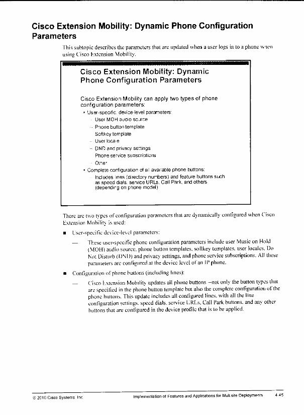
Cisco Extension Mobility: Dynamic Phone ConfigurationParameters
Ihis subtopic describes the parameters that arc updated when a user logs in to a phone wnenusing Cisco Kxtension Mobility,
Cisco Extension Mobility: DynamicPhone Configuration Parameters
Cisco Extension Mobility can apply two types of phoneconfiguration parameters:
• User-specific, device-level parameters-
User MOH audio source
• Phone button template
Softkey template
User locale
-- DND and privacy settings
Phone service subscriptions
• Other
• Complete configuration of all available phone buttons:
Includes lines (directory numbers) and feature buttons suchas speed dials, service URLs, Call Park, and others(depending on phone model)
There arc two types of configuration parameters that aredynamically configured when CiscoExtension Mobility is used:
• User-specific de\ice-le\el parameters:
— fhese user-specific phone configuration parameters include user Music on Hold(MOH) audio source, phone button templates, softkey templates, user locales. DoNot Disturb (DND) andprivacy settings, andphone service subscriptions. All theseparameters are configured at thedevice level of an II' phone.
• Configuration of phonebuttons(including lines):
— Cisco Extension Mobility updates all phone buttons -not only the button types thatare specified inthe phone button template but also the complete configuration of thephone buttons. This update includes all configured lines, with all the lineconfiguration settings, speed dials, service UKUs. Call Park buttons, and any otherbuttons thatare configured in thedevice profile lhal is to be applied.
©2010 Cisco Systems Inc Implementation ofFeatures and Applications for Mullisite Deployments 4-45

Cisco Extension MobilityCharacteristics (Cont.)
At login, the phone configuration is updated with parametersthat are stored in the device profile of the user:
- Ifthe user ID is associated with multiple device profiles,the user must choose the device profile that should beused at login time.
- For duplicate logins, one of the following can beconfigured:
• Allow multiple logins
• Deny login
• Auto-logout
At logout, another device profile (configured logout profile) isapplied, or the standard phone configuration is restored:
- Logout is performed manually by the user or enforcedafter expiration of a configurable maximum login time.
If a user logs in with a user ID that is still logged in at another device, one of the followingoptions can be configured:
• Allow multiple logins: When this method is configured, the user profile is applied to thephone on which the user is logging in. The same configuration remains active at the deviceon which the user logged in before. The line number or numbers become shared linesbecause they are active on multiple devices.
• Deny login: Whenthis optionis configured, the user receivesan error message. Login issuccessful only after the user logs out of the other device on which the user logged inbefore.
• Auto-logout: Likethe preceding option,this optionensuresthat a user can be logged in atonly one deviceat a time. However, this optionallowsthe new loginby automaticallylogging out the user of the other device.
On a phonethat is configured for Cisco Extension Mobility, anotherdeviceprofile (a logoutdevice profile) canbe applied, or theparameters thatare configured on the phone are applied.The logoutcan be triggered by the useror enforced by the system after expiration of amaximum login time.
4-44 Implementing CiscoUnified Communications Manager, Part2 (CIPT2) v8.0 >2010 Cisco Systems, Inc.
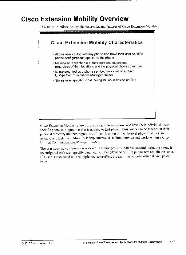
Cisco Extension Mobility OverviewThis topic describes the keycharacteristics and features of Cisco Extension Mobility.
Cisco Extension Mobility Characteristics
- Allows users to log into any phone and have their user-specificphone configurations applied to the phone
• Makes users reachable at their personal extensions,regardless of their locations and the physical phones they use
« Is implemented as a phone service; works within a CiscoUnified Communications Manager cluster
- Stores user-specific phone configuration in device profiles
Cisco Extension Mobility allows users to login to any phone andhave theirindividual, user-specific phone configuration that isapplied tothat phone. Thus, users can be reached at theirpersonal directory number, regardless of their location or the physical phone that they areusing, Cisco Extension Mobility is implemented asa phone service and works within a CiscoUnilied Communications Manager cluster.
The user-specific configuration is stored in device profiles. After successful login, the phone isreconfigured with user-specific parameters; other (device-specific) parameters remain the same.Ifa user isassociated with multiple device profiles, the user must choose which device profileto use.
© 2010 Cisco Systems, Inc. Implementation ofFeaturesand Applications forMultisite Deployments
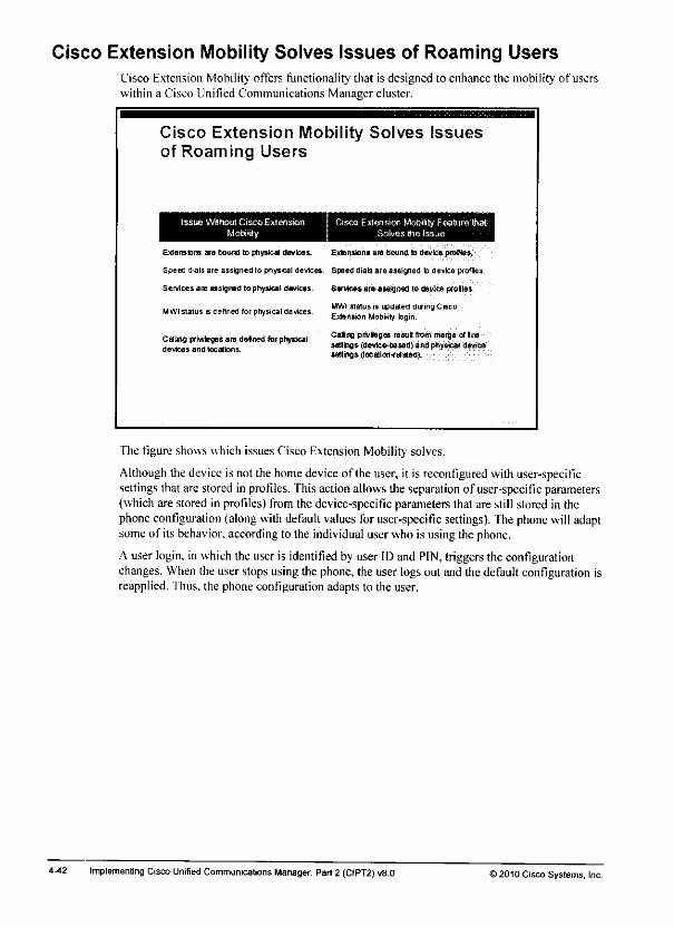
Cisco Extension Mobility Solves Issues of Roaming UsersCisco Extension Mobility offers functionality that is designed to enhance the mobility of userswithin a Cisco Unified Communications Manager cluster.
Cisco Extension Mobility Solves Issuesof Roaming Users
issue Without Cisco Extension Cisco Extension Mobility Feaiure that-Mobiiily Solves the Issue
Extensions are bound to physical devices. Extension* am bound b device profile*.
Speed dials are assigned lo physical devices. Spaed dials are assigned to device profiles.
Services are assigned tophysicai devices. Services are assigned to device prolles.
..,.,... . .,.= .,. •_ - ,j - MWI status is updated during CiscoMWIslaluss defined ror physical devrces. Extension ^ ^
casng privileges are delned for phytic*! ^ »*'*«••'**>* "™ mar9a *lln9devices andlocations tttttoa.* Wevfce-based) Bfldptiyscal deviceoevicej analocaons. umg.s (locatiCKKef*«d).
The figure shows which issues Cisco Extension Mobility solves.
Although the device is not the homedeviceof the user, it is reconfigured with user-specificsettings that are stored in profiles. This actionallows the separation of user-specific parameters(whichare stored in profiles)from the device-specific parameters that are still stored in thephone configuration (along with default values foruser-specific settings). Thephone willadaptsomeof its behavior, according to the individual user who is usingthe phone.
A userlogin, inwhich the useris identified by user IDand PIN, triggers the configurationchanges. When the userstops using the phone, the userlogsout andthedefault configuration isreapplied. Thus, the phone configuration adapts to the user.
4-42 Implementing Cisco Unified Communications Manager, Part 2 (CIPT2) vB.O ) 2010 Cisco Systems, Inc.

Issues of Roaming UsersUsing guest phones at remote sites leads to several issues.
Issues of Roaming Users
Ifa user uses a different phone in a different site:* Extensions are traditionally bound to constant devices.
» User gets the wrong extension on that phone.
* User gets the wrong calling privileges.
• User has no speed dials available.
* User has wrong services assigned.
• MWI status does not work with different extension.
The figure lists the most common issues that arise when users use any available guest phone atsitesto which they have traveled. These issues include wrong extension numbers andcallingprivileges, other speed-dial configuration and phone-sen.'ice assignments, and no MWI statusfor the actual number of the user.
For correct settings, the user requires Cisco Unified Communications Manager to reconfigurethe used phone with user-specific configuration instead ofhaving device-specific settings thatare applied to the phone.
© 2010 Cisco Systems, Inc Implementation otFeatures and Applications for Multisite Deployments 4-41

Issues with Users Roaming Between SitesThis topic describes the issues that can occur when users temporarily change their workplacesand roam between sites.
Roaming Users
Roaming users do not travel with a device(softphone) but use any available phone at thecurrent location.
Cisco Unified
Communications
Manager
Roaming User
----.:-_. u—
Remote
Gateway
Whenusers roambetween sites and do not have their phonewith them(for example, via CiscoIP Communicator), they mightwant to use any available phoneat the site to which they havetraveled.
4-40 Implementing Cisco Unified Communications Manager, Part 2 (CIPT2) v8.0 12010 Cisco Systems. Inc.

m
Lesson 2
Implementing Cisco ExtensionMobility
OverviewSome users roam between office desks or sites on a regular basis. Such users, who use phonesthat are provided at the sites that they visit, would like to (but cannot) use their personalsettings, such as directory number, speed dials, calling privileges, and Message WaitingIndicator (MWI). A professional Cisco Unified Communications solution needs to solve thisproblem.
This lesson describes Cisco Extension Mobility, a feature of Cisco Unified Communicat orisManager. Cisco Extension Mobility allows Cisco Unified Communications Manager us..rs tolog into an IP phone and have their personal profile applied, regardless of the device andphysical location that they are using.
ObjectivesUpon completing this lesson, you will be able to describe how Cisco Extension Mobility worksand how it is implemented. This ability includes being able to meet these objectives:
Identity the issues when users roam between sites
Describe the Cisco Extension Mobility feature
Describe the Cisco Extension Mobility configuration elements and their interaction
Describe Cisco Extension Mobility operation
Implement Cisco Extension Mobility

4-38 Implementing Cisco Unified Communications Manager, Part 2 (CIPT2) v8.0 © 2010 Cisco Systems, Inc.

References
I'or additional infonnation. refer to these resources:
• Cisco Systems. Inc. Cisco Unified Communications System 8.xSRND. April 2010.hup: '.www.cisco.coni en US/doesAoice_ip comm/aicm/srn<l/8,\/uc8x.html
• Cisco Systems. Inc. Cisco Unified Communications Manager Administration GuideRelease 8.0(1). February 2010.hup: 'www.cisco.com en US/docs/\oice ipcoin nv'cuem/admin/8 0 l/ccmcfg/beem-XOIcm.html
)2010 Cisco Systems. Inc Implementation of Features and Applications for Multisite Deployments

Summary
4-36
'ITiis topic summarizes the key points that were discussed in this lesson.
Summary
• Issues with roaming devices include inappropriate region,location, time zone, and SRST reference configuration. PSTNcalls are using the home gateway instead of the local gatewayat the roaming site.
• Device Mobility allows roamingdevices to be identified by theirIP addresses, and configuration settings to be applied that aresuitable for the current physical location of the device.
• Device Mobility configuration elements are device mobilitygroups, physical locations,device pools, and device mobilityinfos.
Summary (Cont.)
• You apply roaming-sensitive settings to devices that roambetween physical locations. In addition, you apply DeviceMobility-related settings to devices that roam within the samedevice mobility group.
1Implementation and operation of Device Mobility are optimizedwhen globalized call routing and localroute groups are used.
Afterconfiguring device mobility groups, physical locations,device pools, and device mobility infos, you must enable DeviceMobility eitherdusterwide as a service parameter or individuallyper phone.
Implementing Cisco Unified Communications Manager, Part2 (CIPT2) v8.0 52010 Cisco Systems, Inc.

Step 5b; Set the Device Mobility Mode for Individual PhonesThe fig jrc shows how to set the Device Mobility mode for each phone.
Step 5b: Set the Device Mobility Modefor Individual Phones
Cisco Unified Communications Manager Administration:Device > Phone
^=^
EH£- SLThis is the home device pool of thephone
Dev :e p™r n(j .|.|>-
There are overlapping settings at thedevice pool and at the phone; theyhave higher prioritythan settings atthe home device pool but arereplaced by settings from the roamngdevice pool r-
"" =•" - s"'" s"» -
Set the phone device mobilitymode:the default applies the serviceparameter setting H
.
In the I'honc Configuration window, you enable ordisable Device Mobility for each phoie bycither setting Device Mobility Mode to On orOff or leaving the default value as Default. IfDevice Mobilitv Mode is setto Default, the Device Mobility mode that issetat theCiscoCallManager serviceparameteris used.
The figure also shows the configuration ofthe overlapping parameters (these arc parametersthat can be configured at the phone and at the device pool). The overlapping parameters forroaming-sensitive settings are Media Resource Group List, Location, and Network Locale. Theoverlapping parameters for the Device Mobility-related settings are Calling Search Space(called Device Mobility Calling Search Space atthe device pool), AAR Group, and AARCalling Search Space. Overlapping parameters that are configured at the phone have hignerprioritv than settings at the home device pool, and lower priority than settings at the roamingdevice pool.
© 2010 Cisco Systems. IncImplementation ofFeatures and Applications for Multisite Deployments 4-35
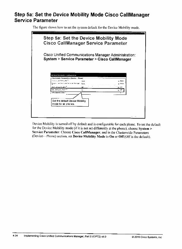
Step 5a: Set the Device Mobility Mode Cisco CallManagerService Parameter
The figure showshow to set the systemdefault for the Device Mobility mode.
4-34
Step 5a: Set the Device Mobility ModeCisco CallManager Service Parameter
Cisco Unified Communications Manager Administration:System >Service Parameter >Cisco CallManager
£( '.'.;-.i,;i[i;: * off u c«
Qt- -s!•;!f.. 1SJ* " n„ ,«|^u^^, A
y\Set the default Device Mobilitymode for all phones.
Device Mobility is turned offby default and is configurable foreachphone. Toset thedefaultfor the Device Mobility mode (if it isnot setdifferently atthe phone), choose System >Service Parameter. ChooseCisco CallManager, and in the Clusterwide Parameters(Device—Phone) section, set Device Mobility Modeto On orOff (OtTis the default).
Implementing Cisco Unified Communications Manager. Part2 (CIPT2) v8.D >2010 Cisco Systems. Inc.
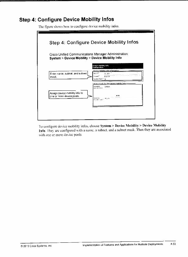
m
Step 4: Configure Device Mobility InfosThe figure showshow to configure devicemobility infos.
Step 4; Configure Device
Cisco Unified Communications Manager Administration:System >DeviceMobility >Device Mobility Info
Enter name, subnet, and subnet |mask.
. I"".. Mobil II, IMd li.f.rm.1".*
Assign device mobilityinfo toone or more device pools w
..I. lnrH.ll wulu Mobility Into-
Ioconfigure device mobility infos, choose System > Device Mobility >Device Mobility-Info. They are configured with aname, a subnet, and a subnet mask. Then they are associatedwith one or more device pools.
© 20'0 Cisco Systems. Inc.Implementation of Features and Applications for Multisite Deployments 4-33
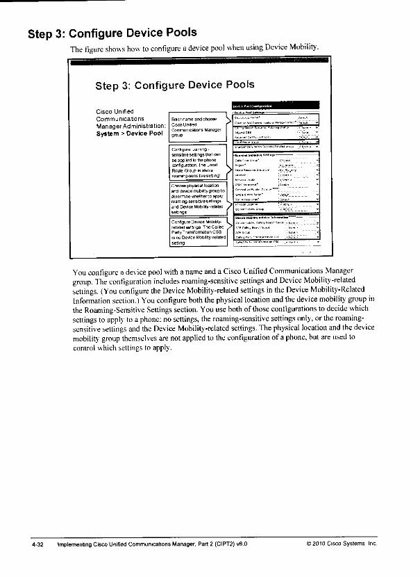
Step 3: Configure Device PoolsThe figure shows how to configure adevice pool when using Device Mobility.
Step 3: Configure Device Pools
Cisco Unified
Communications
Manager Ad ministration:System > Device Pool
ConGguteroaming-sensitive sellings mat <
be applied lo Ihe ptioneconfiguration The LocalRoute QOLp ib also aroaming -sens itiveset! ing'
Choose physical locationana device mobilitygroupto
determine vi»>ettier tc applyroa m mg-sens ilive s etlingsand Device Mobility-relatedsettings
Configure Dev.ce Mobility-related sett ngs The CalledParty Transtormaton CSSis no Device Mobility-relatedselling1
You configure a device pool with aname and a Cisco Unified Communications Managergroup. The configuration includes roaming-sensitive settings and Device Mobility-relatedsettings. (You configure the Device Mobility-related settings in the Device Mobility-RelatedInformation section.) You configure both the physical location and the device mobility group inthe Roaming-Sensitive Settings section. You use both of those configurations todecide whichsettings toapply toa phone: nosettings, the roaming-sensitive settings only, orthe roaming-sensitive settings and the Device Mobility-related settings. Thephysical location and the devicemobility group themselves arenotapplied to the configuration of a phone, butareused tocontrol which settings to apply.
4-32 Implementing Cisco Unified Communicalions Manager, Part 2 (CIPT2) vS.O >2010 Cisco Systems, Inc.
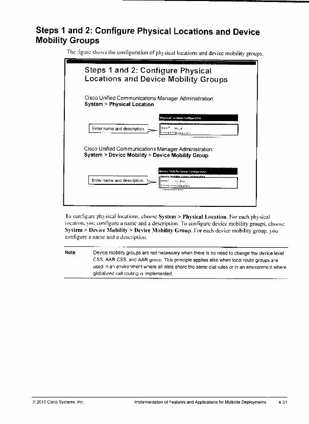
Steps 1 and 2: Configure Physical Locations and DeviceMobility Groups
fhe figure shows the configuration ofphysical locations and device mobility groups.
Steps 1 and 2: Configure PhysicalLocations and Device Mobility Groups
Cisco Unified CommunicationsManager Administration:System > Physical Location
••- • •
Entername arid description. L^_ "'""' "'>-"'
Cisco Unified Communications Manager Administration:System >Device Mobility > Device Mobility Group
Entername and description <~I1»IIU« HiUUh. I:—..,. 1-h.Pm.M—
To configure physical locations, chooseSystem > Physical Location, for each physicallocation, you configure a nameand a description. To configure devicemobility groups, chooseSystem > Device Mobility > Device Mobility Group. Foreach devicemobility group,youconfigure a name and a description.
Note Device mobility groups are not necessary when there is no need to change the device levelCSS, AARCSS, and AARgroup This principleapplies also when local route groups areused in an environment where all sites share the same dial rules or in an environment where
globalized call routing is implemented
© 2010 Cisco Systems, Inc Implementation of Features and Applications for Multisite Deployments
Device Mobility ConfigurationThis topic describes how to configure Device Mobility.
Device Mobility Configuration Steps
1 Configure physical locations.
2 Configure device mobility group.
3 Configure device pools.
4 Configure device mobility infos (IP subnets).
5 Set the Device Mobility mode by using:
a. A Cisco CallManager service parameter to set thedefault for all phones
b The Phone Configuration window for individualconfiguration per phone
"Die figure lists the required steps for implementing Device Mobility. As discussed in theprevious topics, device mobility groups are not required when you implement Device Mobilityin an environment where globalized call routing is used.
4-30 Implementing CiscoUnified Communicalions Manager, Part2 (CIPT2) v8.0 >2010 Cisco Systems. Inc.

m
Example: Globalized Call RoutingThe figure shows an example of Device Mobility in an environment where globalized callrouting is implemented. Also, gateway selection is performed by the local route group feature.
Example: Globalized Cail Routing
HQ Translation Patterns
(Partition HQ, CSS. System:000 ' -> DDI PreDot, Prefix +
00 i -> DDI PreDot. Prefix +49
DDI PreDot, Prefix +4940
Route Pattern \+'
Partition System
Single Route List.Default Local Roule Group
BR Translation Patterns
(Partition BR. CSS. System|91 [2-9)XX[2-9JXXXXXX -> DDI
PreDct, Prefix+19 [2-9]XXXXXX -> DDI PreDot,
Prefix+1408
9011 !-> DDI PreDot. Prefix +
Normalization of localized call ingress is in place
BR user roaming to HQ uses NANPdial rules and uses HQ gateway
Device Pool
HQ
Physical
Location HQ
Local Route
Group >~'j
Device Pool. E
PhysicalLocation BR
CSS BR]Local Route
Group. BR
Theexample in the figure is based on the previous scenario: IIt) is in Europe. BRis in theUnited States. A BR user will roam to Europe.
However, in this example, globalized call routing has been implemented. Therefore, the (line)CSS of BR phones provides access to translation patterns thatconvert localized call ingress atthe phone (NANP formal) to global E.I64 formal. EU phones have access to translationpatterns that cotwert HI] input to global K.164 fonnat.
A single PSTN route pattern (\(!) isconfigured: it is ina partition that isaccessible byalltranslation patterns.
When a BR user roamsto the IIQ. the lineCSS is not modified; no deviceCSS is configured atthe phone or at thedevice pool. Thedevice mobility groups arc alsonotset (or aresetdifferently).
Asa result, there is effectively no change in matching the translation patterns: The BRuserstillusesNANPdial rules (like at home), fhe numberis converted to international format by-translation patterns and matches the (only) PSTN roule pattern. The route pattern refers to aroute listthat isconfigured to use thedefault local route group. The default local route group istaken from the roaming device pool. Therefore, if the phone is physically located in theBRoffice, the local route group is BR; if the phone is roaming to the HQ site, the local route groupis HQ. As a result, the local gateway is always used fora PSTN call.
IfTEHO was configured, there would be aTEHO route pattern inE.I64 format with a leading+sign. The TEHO pattern would refer toasite-specific route list in order toselect the correctgateway for PSTN egress. The backup gateway would then again be selected by the local routegroup feature.
) 2010 Cisco Systems. Inc Implementation of Featuresand Applications for Multisite Deployments 4-29
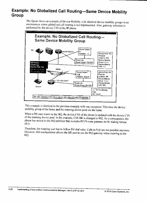
Example: No Globalized Call Routing—Same Device MobilityGroup
The figure shows an example of Device Mobility with identical device mobilitv groups in anenvironment where globalized call routing is not implemented. Also, gateway selection isperformed by the device CSS ofthe IP phone.
4-28
Example: No Globalized Call Routing-Same Device Mobility Group
| BR user roaming to HQ has lo use EU dial rules and uses HQ gateway [
Device Pool HQPhysicalLocation. HQ
Device MobilityGroup; WorldDevice MobilityCSS' HQ
This example is identical to the previous example with one exception: This time the devicemobility group ofthe home and the roaming device pool are the same.
When a BR user roams to the HQ, the device CSS ofthe phone is updated with the device CSSof the roaming device pool. In the example, CSS BR is changed to HQ. As aconsequence thephone has access to the HQ partition that includes PSTN route patterns in EU dialing format
Therefore, the roaming user has to follow EU dial rules. Calls to 9.@ are not possible anymoreHowever, this configuration allows the BR user to use the HQ gateway when roaming to theHQ.
Implemenling Cisco Unified Communications Manager, Part 2(CIPT2) v8.0^2010 Cisco Systems, Inc.
•fe
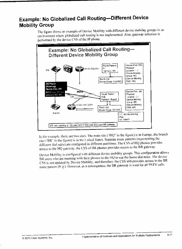
Example: No Globalized Call Routing—Different DeviceMobility Group
The figure shows an example of Device Mobility with dilTerenl device mobility groups in anem ironment where globalized call routing is not implemented. Also, gateway selection isperformed b\ the device CSS ofthe IP phone.
Example: No Globalized Call Routing-Different Device Mobility Group
«49 40 552XXX
Route Pattern
01
Route List
Route Group HQ-GW
Route Pattern
9®Partition Branch
Route List
Roule Group. BR-GW
Device Pool HQ
PhysicalLocation i C
Device Mobility
Group HQ(Device MobilityCSS. HQ)
Device Pool BR
PhysicalLocation1 Lit*Device Mobility
Group. BR(Device MobilityCSS. BR)
| BR user roaming lo HQ uses NANP dial rules and uses BR gateway |
HQ: EU Numbering
Plan
UR. NANP
In the example, there are two sites. The main site ("I IQ" in the figure) is in Europe, the branchsite ("BR"' in the figure) is in the United States. Separate route patterns (representing thedifferent dial rules) are configured in different partitions. The CSS of HQ phones providesaccess to the HQ gateway, the CSS ofBR phones provides access to the RR gateway.Device Mobilitv is configured with different device mobility groups. This configuration allowsBR users who arc roaming with their phones to the HQ to use the home d.al rules. Ihe deviceCSS is not updated by Device Mobility, and therefore, the CSS still provides access to the BRroute pattern (9,ff). Howler, as aconsequence, the BR gateway ,s used tor all PS fN calls.
© 2010 Cisco Systems. Inc.Implementation of Features and Applications for Multisite Deployments
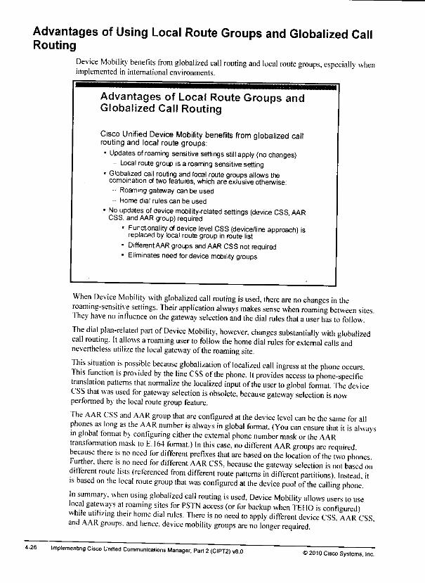
Advantages of Using Local Route Groups and Globalized CallRouting
Device Mobility benefits from globalized call routing and local route groups, especially whenimplemented in international environments.
Advantages of Local Route Groups andGlobalized Call Routing
Cisco Unified Device Mobility benefits from globalized callrouting and local route groups:• Updates ofroaming sensitive settings still apply {no changes)
- Local route group is a roaming sensitive setting• Globalized call routing and local routegroupsallowsthe
combination of two features, which are exlusive otherwise:~ Roaming gateway can be used
- Home dial rules can be used
• No updatesofdevice mobility-related settings (device CSS, AARCSS, and AAR group) required
• Functionality ofdevice level CSS(device/line approach) isreplaced by local route group in route list
• Different AAR groups andAAR CSS not required• Eliminates need fordevice mobility groups
When Device Mobility with globalized call routing is used, there are no changes in theroaming-sensitive settings. Their application always makes sense when roaming between sitesIliey have no influence on the gateway selection and the dial rules that auser has to follow.The dial plan-related part of Device Mobility, however, changes substantially with globalizedcall routing. It allows aroaming user to follow the home dial rules for external calls andnevertheless utilize the local gateway ofthe roaming site.
This situation is possible because globalization of localized call ingress at the phone occurs1his function is provided by the line CSS of the phone. It provides access to phone-specifictranslation patterns that normalize the localized input ofthe user to global format. The deviceCSS that was used for gateway selection is obsolete, because gateway selection is nowperformed bythe local route group feature.
The AAR CSS and AAR group that are configured at the device level can be the same for allphones as long as the AAR number is always in global format. (You can ensure that it is alwaysin global format by configuring either the external phone number mask orthe AARtransformation mask to E. 164 format.) In this case, no different AAR groups arc requiredbecause there is no need for different prefixes that are based on the location of the two phonesFurther, there is no need for different AAR CSS, because the gateway selection is not based ond.fferent route lists (referenced from different route patterns in different partitions) Instead itis based on the local route group that was configured at the device pool of the calling phone.In summary, when using globalized call routing is used, Device Mobility allows users lo uselocal gateways at roaming sites for PSTN access (or for backup when TEHO is configured)while utilizing their home dial rules. There is no need to apply different device CSS AAR CSSand AAR groups, and hence, device mobility groups are no longer required
Implementing Cisco Unified Communications Manager, Part 2(CIPT2) v8.032010 Cisco Systems, Inc.

m*
Note If TEHO isused, there areno suboptimal paths when using Device Mobility with differentdevice mobility groups. However, when local route groups and globalized call routing arenotbeing used, TEHO implementation can be very complex, especially when local PSTNbackup is desired and when TEHO is implemented in international deployments.
In summarv. unless TEHO is used, the implementation ofDevice Mobility without globalizedcall routing leads to this situation: Either the home gateway has to be used (when allowing theuser touse the home dial rules) orthe user is forced touse the dial rules ofthe roaming site (inorderto use the local gateway of theroaming site).
>2010 Cisco Systems, Incimplementation otFeatures and Applications for Multisite Deployments 4-25
Device Mobility Interaction with Globalized CallRouting
This topic describes the interactionsof globalized call routing and local route groups withCisco Unified Device Mobilitv.
Device Mobility Review Without LocalRoute Groups and Globalized Call Routing
As discussed earlier, there are two types of device pool settingsfor Device Mobility:
• Roaming-sensitive settings (location, region, SRST reference, MRGL, etc.)are always updated when device roams to different physical location.
• Device Motility-related settings (device CSS, AAR CSS, and AAR group) areupdated based on device mobility group:
- Different device mobility group:
• Noupdateof devceCSS.AARCSS.artd AARgroup
• No changes to dial odes, but use of home gateway
- Same device mobility group:
• UpdateofdeviceCSS.AARCSS.andAARgroup
• Use of roaming gateway but changes to dial rules
Required only when gateway selection is based on CSS (that is, localmute group and globalzed cal routing are not used)
Local route groups havebeen introduced with Cisco Unified Communications ManagerVersion 7. When local roule groups—and globalized call routing, which utilizes local routegroups—is not used or supported. Device Mobility is typically implemented:
• Roaming-sensitive settings are always updated when the device roams between differentphysical locations. These settings are location, region, SRST reference, MRGL, and otherparameters that do not affect the selection of the PSI'N gateway or the local rules.
• Device Mobility-related settings can be appliedin addition to the roaming-sensitivesettings(which meansthat a phonehas to roambetween differentphysical locations). TheDevice Mobility-related settings are device CSS, AAR CSS, andAAR group. Theconfiguration of the devicemobility groupshoulddetermine your decision about whetherto apph the Device Mobility-related settings.
— If thedevice roams between different device mobility groups, the Device Mobility-related settings arenot updated with the values thatwere configured at the roamingde\ icepool. This configuration hasthe advantage thatusers do nothave to adapttodifferent dial rulesbetweenhomeand roaminglocation (if they exist).Thedisadvantage is that all PS'fN calls will use the homegateway that can leadtosuboptima! routing.
— Ifdie device roams within the same device mobility group, the Device Mobility-related settings areupdated with the values of the roaming device pool. Thisconfiguration has the advantage that all PSTN calls will use the local (roaming)gateway, whichis typically desiredfor roamingusers. However, the userswill haveto use to the local dial rules.
4-24 Implementing CiscoUnified Communications Manager, Part2 (CIPT2) v8.0 >2010 Cisco Systems, Inc.
For the next three scenarios, the assumption is that the home device pool and the roamingdevice pool are assigned to different DMGs. As a result, the Device Mobility-related settingsare not applied. Therefore, calls that are placed from the roaming device are routed in the sameway as when the device is in its home location.
• If the user places a call to a UK PS'fN destination, the call will use the IP WAN to theLondon site and break out to the PSTN at the London gateway with a local or national call.This solution is the optimal one from a toll perspective.
• If the user places a call to a PSTN destination that is close to the roaming location (forexample, a U.S. PSTN number) and TEHO is not configured, the call will use the IP WANfrom the U.S. office to the I .ondon site. It wilt break out to the PSTN at the London
gateway to placean international call back to the United States. From a toll perspeebve,this is the worst possible solution, because the call first goes from the United States toLondon over the IP WAN (consuming bandwidth) and then goes back from London to theUnited States via a costly international call.
• If the user places a call to a PSTN destination that is close lo the roaming location (forexample, a U.S. PSTN number) and TEHO is configured, the U.S. gateway is used for alocal or national call. This event is optimal from a loll perspective.
Note In these three examples, the user has to dial PSTN destinations by following the dial rules ofthe home location (Great Britain).
In summary, when youallow the Device Mobility-related settings to be applied (byusing thesamedevicemobility group), calls to the home location will use a local PS'fN gateway to placea long-distance or international call when not implementing TEI10.Allothercalls areoptimal.
When the Device Mobility-related settingsarc not applied (by usingdifferent devicemobilitygroups) and TEHO is not used, calls to the roaming location will first usethe IP WAN to gofrom the roaming location to the home location, fhe calls then use the home gateway to place along-distance or international callback to the roaming location. Allothercalls areoptimal.
The discussed scenarios assumethat globalized call routingand local routegroupsare not used,fhe impact of globalized call routing and local route groups isdiscussed inthe next topic.
©2010 Cisco Systems, Inc. Implementation ofFeatures and Applications for Multisite Deployments 4-23

Examples of Call-Routing Paths Based on Device MobilityGroups and TEHO
The table shows how calls are routed in different Device Mobility scenarios.
Examples of Different Call-Routing PathsBased on Device Mobility Groups and TEHO
Same device mobity group, call lo PSTNdestination close id dome location, no TEHO.
Same device mobility group, call lo PSTNdestination close D home location, TEHO.
Same device mobity group, call to PSTNdestinalIon close b roamhg location.
Different device motility group, call to PSTNdestination close lo home location.
Different device mobility group, call lo PSTNdestination close Id roaming location, no TEHO.
Different 0evice mobility group, call lo PSTNdestination close to roammg location, TEHO.
Cal use* local PSTN gateway at roaminglocation for a long-distance PSTN cal.
Cal uses IP WAN to gateway at home locationfor a local PSTN call.
Cal uses local PSTN gateway at roaminglocation for a local PSTN call.
Cal uses IP WAN to gateway at dome localonfor a local PSTN call.
Cal uses IP WAN to gateway at home locationtor a king-astance PSTN caK.
CaB uses local PSTN gateway at roaminglocation for a local PSTN call.
Calls are routed differently depending on the configuration of DMGs (whether DeviceMobility-relatedsettings are applied or not), the dialed destination, and the use of tail-end hop-off (TEHO). In some scenarios, calls might take suboptimal paths.
The example in this discussion assumes that a user from London roams to the U.S. office (forsimplicity, it is assumed that there is only one U.S. office). This user uses Cisco IPCommunicator.
Forthe first threescenarios, the assumption is that the home devicepool and the roamingdevicepool are assigned to the samedevicemobility group.Therefore, Device Mobility appliesDevice Mobility-related settings. As a result, PSTN calls that are placed from the roamingdevice are treated like PSTN calls of standard U.S. phones.
• If the user places a call to a PSTN destination that is close to the home location (forexample, a UK PSTN number) and TEHO is not configured, the call will use the local(U.S.) PSTN gateway for an international PSTN call, from a toll perspective, this is asuboptimal solution, because the IP WAN is nol used as much as it could be used whenimplementing TEHO. This factor applies not only to the roaming user, but also to U.S.users who place calls to PSTN destinations in Great Britain.
• If the user placesthe same call (to a UK PSTN number) and TEHO is configured, the callwilluse the IPWAN to the London siteandbreakout to the PSTN at the London gatewaywith a local call. This solution is the optimalone from a toll perspective.
• If the userplaces a call to a U.S. destination number, the U.S. gateway is used fora local ornational call. This event is optimal from a toll perspective.
Note In all ofthe examples thatare shown inthe table, the userhas to dial PSTN destinations byfollowing the U.S. dial rules (North AmericanNumbering Plan [NANP]).
4-22 Implementing Cisco Unified Communicalions Manager, Part 2 (CIPT2) v8.0 © 2010 Cisco Systems, Inc.
The line/device approach is recommended when you are implementing CoS in a multisiteenvironment. Here is a description of the operation of the line/deviceapproach:
• The line CSS implements CoS configuration by permitting internal destinations (otherphone director; numbers, and access to features such as call part and Meet-Meconferences). The line CSS also blocks PSTN destinations. Because the line CSS is notchanged by Device Mobility. CoS settingsof the deviceare kept whenthe device isroaming.
• Ihe de\ice CSS is modified when the device is roaming within the same device mobilitygroup. In this case, the deviceCSS that is usedat the home location is replaced by a de\ iceCSS that is applicable for the roaminglocation. This deviceCSS will refer to the localgateway of the roaming site instead of to the gateway that is usedat the home location.
If the traditional approach is used (only one CSS. combining CoS and gateway choice), thedevice CSS must be used. The reason is that Device Mobility cannot modify the line CSS. andthe line CSS has priority over the deviceCSS (whichcan be modified by Device Mobility).
The AARCSS is configurable only at the device level and therefore is alwayscorrectlyreplaced when the device roams between physical locations within the same device mobilitygroup.
Note When usingglobalizedcall routing and local route groups, there is no need for site-specificdevice-level CSS. More information about the interaction of globalized call routing and
Device Mobility is provided in a later topic of this lesson.
>2010 Cisco Systems. Inc Implementation of Features and Applications for Multisite Deployments 4-21

Device Mobility and Calling Search SpacesThis subtopic describes how CSSs are processed when Device Mobility is used.
Device Mobility and Calling SearchSpaces
• Line CSS is nevermodified byDevice Mobility.• Device CSS is modified only when device roams between
physical locations and within the samedevice mobility group:- Operation when using the line/device CSSapproach
(recommended forCoS implementation);• Line CSSis not modified; CoS settings are kept.• Device CSS is modified; itallows local gateway
selection byapplying CSS ofroaming device pool.- When using the traditional CSS approach (only one CSS
at phone), use the device CSS, instead ofthe line CSS, toallow the CSStobe modified by Device Mobility.
• AAR CSS is configurableonly at the device and therefore isalways correctly modified when the device roams betweenphysical locations and within thesamedevice mobility group.
Review of Line and Device CSS
An IP phone can be configured with a line CSS and adevice CSS. Ifboth CSSs exist, thepartitions ofthe line CSS are considered before the partitions ofthe device CSS when a call isbeing routed.
fhese two CSSs allow the use of the line/device approach for implementing calling privilegesand the choice ofa local gateway for PSTN calls. With the line/device approach, all possiblePS INroute patterns exist once per location and are configured with asite-specific partitionThis partition is included in the device CSS ofthe phones, and therefore itenables the use ofalocal gateway for PSTN calls. To implement class of service (CoS), PSTN route patterns thatshould not be available to all users (for example, international calls, long-distance calls or alltoll calls) are configured as blocked route patterns. These blocked route patterns arc thenassigned to separate partitions. The line CSS ofaphone now will include Ihe partitions of thoseroute patterns that should be blocked for this phone. Because the line CSS has priority over thedevice CSS. the blocked pattern will take precedence over the routed pattern that is found in apartition that is listed at the device CSS.
Device Mobility and CSSs
Device Mobility never modifies the line CSS ofaphone. It does change the device CSS andAAR CSS of aphone when the phone is roaming between different physical locations withinthe same device mobility group.
4-20 Implementing Cisco Unified Communications Manager, Part 2(CIPT2) u8.0©2010 Cisco Systems, Inc.

Gemian users who roam with their softphoncs tothe United Stales might beconfused whenthey obtain their home extensions, but they have to use U.S. dialing rules (access code 9insteadof6. or011 instead of00 for international numbers, and so on). Ifyou want to avoid suchbehavior, vou need to suppress the application ofDevice Mobility-related settings. Yousuppress the settings by assigning device pools that are to be used at sites with different dialingrules into different device mobility groups (and in different physical locations). When a usernow roams with adevice from Germany tothe United States, all the roaming-sensitive settingsare applied to use local media resources and Cisco Unified SRST gateways. Also, codecs andCAC settings are applied correctly, but the Device Mobility-related settings arc not applied.The result is that the phone will use the PSTN gateway and dial rules ofits home location eventhough the user has moved to another site. The user does not have to adapt to the dial rules ofthe local site to which the phone was moved.
Note The preceding statements regarding call routing and dial behavior that are based on DeviceMobility-related settings do not apply when globalized call routing is used. Alater topic inthis lesson presents more information about the interaction of globalized call routing andDevice Mobility
Ho10 Cisco Systems. Inc. Implementation of Features and Applications for Multisite Deployments 4-19

Device Mobility ConsiderationsThis subtopic describes key facts that you need toconsider when implementing DeviceMobility.
4-18
Device Mobility Considerations
• Roaming-sensitive settings:
- Ensure the use of local media resources and SRST references.
- Ensure correct use of codecs and CAC between sites.
- Shouldalways be applied to roaming devices
• Settings relatedto Device Mobility affectcall routing:
- WhatgatewaytouseforPSTNaccessandAAR PSTN calls(device CSSandAAR CSS),and how to composethe AAR number(AAR group)?
- Changes may result indifferent dialing behavior (forexample, differentPSTN accesscodes, different PSTN numbering plans, and so on).
- Users might getconfused byhaving their home extensions and yet beingrequired to follow dial rules of roaming site.
- tfthis is notdesired, suppressapplication of settings related to DeviceMobility by assigningdifferent device mobility groups.
- Not applying settings related to Device Mobility might lead to suboptimalcall-routng paths.
Roaming-sensitive settings ensure that local media resources and SRST references are used bythe roaming device. Inaddition, they ensure thecorrect use ofcodecs and CAC between sites.Typically, this is always desired when adevice roams between different sites. It is not requiredwhen the device moves only between IPsubnets within the same site. Therefore, therecommendation istoassign all device pools that are associated with IPsubnets (devicemobility info) that are used atthe same site tothe same physical location. This action results inphone configuration changes only when the phone roams between sites (physical locations) andnotina situation where a phone ismoved only between different networks of thesame site.
Device Mobility-related settings affect call routing. By the application ofthe device CSS. AARgroup, and AAR. CSS calls can be routed differently depending on the site where the phone hasroamed to. The settings at the roaming device pool determine which gateway will be used forpublic switched telephone network (PSTN) access and AAR PSTN calls (based on the deviceCSS and AAR CSS) and how the number to be used for AAR calls is composed (based on theAAR group).
Such changes can result in different dialing behavior. For instance, when roaming betweendifferent countries, the PSTN access code might be different and PSTN numbering plans (forexample, how to dial international calls) might apply. As an example, in order to dial theAustrian destination +43 699 18900009 from Germany, users dial 0.0043 699 18900009. whileusers in the United States have to dial 9.01143 699 18900009.
Implementing Cisco Unified Communications Manager, Part 2 (CIPT2) v8.0 © 2010 Cisco Systems, Inc.

m*
m
7. The roaming-sensitive settings ofthe chosen device pool (that is. the roaming device pool)arcused to update theconfiguration of thephone.
Note In this case,overlapping settings (that is,settings thatexist at thephone as well as at thedevice pool, namely, MRGL, Location, and Network Locale) ofthe roaming device pool havepriority over the corresponding settings at the phone. This behavior isdifferent from thedefault behavior (see Step 10).
8. Ifthe dev ice mobility groups ofthe chosen device pool and ihe home device pool are thesame, the phone configuration isupdated by applying the Device Mobility-related settings:otherwise continue.
Note In this case, all settings areoverlapping settings (that is, all Device Mobility-related settingsexist atthe phone as well as at the device pool), and the parameters of the roaming devicepool have priority over the corresponding settings atthe phone. This behavior isdifferentfrom the defaultbehavior (see Step 10).
9. Where the phone configuration has been updated (either with the roaming-sensitive settingsonh orwith the roaming-sensitive settings and the Device Mobility-relalcd settings), thephone is reset in order for the updated configuration to be applied to the phone.
Caution This is the end of the process: do not continue to Step 10. Step 10 was directly referencedfrom previous steps in certain conditions and does not apply after Step 9.
10. Here is adescription ofthe default behavior. First, the settings ofthe home device pool(that is. the device pool that is configured at the phone) are applied. Some configurationparameters of the device pool can also be set individually at the phone. These overlappingphone configuration parameters are MRGL Location. Network Locale. Device MobilityCSS (which is called simply CSS at the phone). AAR CSS, and AAR Group. Iftheseparameters are configured at the phone (that is. are not set lo [None]), the phoneconfiguration settings have priority o\er the corresponding setting at the device pool.
^D10 Cisco Systems. Inc implementation of Features and Applications for Mulfsite Deployments 4-17
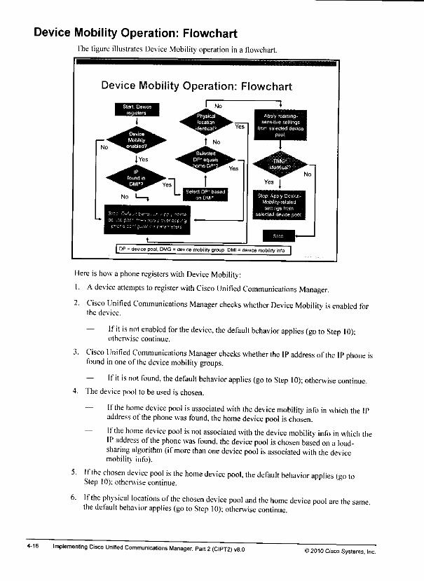
Device Mobility Operation: FlowchartThe figure illustrates Device Mobility operation in a flowchart.
Device Mobility Operation: Flowchart
I No Ihi ^m Apply roamtng-
ssnsttiua sellingsfrom selected device
pool.
Slop- Apply Device-Mobiifty-relatedsettings from
| DP - device pool. DWG =device mobility group, DMI - flevice mobility info |
Here is how a phone registers with Device Mobility:
1. Adevice attempts to register with Cisco Unified Communications Manager.
2. Cisco Unified Communications Manager checks whether Device Mobility is enabled forthe device.
— Ifit is not enabled for the device, the default behavior applies (go to Step 10);otherwise continue.
3. Cisco Unified Communications Manager checks whether the IP address ofthe IP phone isfound inone of the device mobility groups.
— Ifit is not found, the default behavior applies (go toStep 10); otherwise continue.4. The device pool to be used is chosen.
— Ifthe home device pool isassociated with the device mobility info in which the IPaddress of the phone was found, the home device pool ischosen.
— Ifthe home device poo! is not associated wilh the device mobility info in which theIP address ofthe phone was found, the device pool ischosen based on a load-sharing algorithm (ifmore than one device pool is associated with the devicemobility info).
5. Ifthe chosen device pool is the home device pool, the default behavior applies (go toStep 10); otherwise continue.
6. Ifthe physical locations of the chosen device pool and the home device pool are the samethe default behavior applies (goto Step 10); otherwise continue.
Implementing Cisco Unified Communications Manager, Part 2(CIPT2) v8.0)2010 Cisco Systems, Inc.

In summary, the roaming-sensitive parameters are applied when the physical location ofthecurrent device pool is different from the physical location ofthe home device pool (thai .s.when roaming between physical locations). The Device Mobility-related settings are applied inaddition to the roaming-sensitive parameters when the physical locations are different and thedev ice mobility groups are the same (that is, when roaming between physical locations withinthe same device mobility group).
As a result, physical locations and device mobility groups should be used in two ways:
• Physical locations: Configure physical locations in such away that codec choice and CACtruh reflect thecurrent location of the device. Hnsurc thatlocal SRST references and localmedia resources atthe roaming site are used instead ofSRST references and media sourcesthat are located atthe (currently remote) home network. Depending upon the networkstructure andallocation of services, vou may define physical locations thatarebased upona cit\. an enterprise campus, or a building.
• Device mobility groups: Adevice mobility group should define agroup ofsites withsimilar dialing patterns or dialing behavior. Device mobility groups represent the highest-lev el geographic entities in your network. Depending upon ihe network size and scops,your device mobilitv groups could represent countries, regions, states or provinces, c.ties,or other entities. Because Device Mobility-related settings (which areapplied only v henroaming within the same device mobility group) affect call routing, different devicemobilitv groups should be set up whenever roaming users should not be forced to adapttheir dialing behavior. In this case, as in roaming between different device mobility groups,the phone configuration parameters that affect call routing (that is. the Device Mobility-related settings) arc not modified.
Note When using globalized call routing and local route groups, device mobility groups aruirrelevant Thereason isthatthere is no need tochange thedevice-level CSS, theAARCSS, and the device-level AAR group. More information about the interaction of globalizedcall routing and Device Mobility isprovided in a later topic of this lesson.
** ~ 10 C|sco Systems, mc implementation of Features and Applications for Muttisite Deployments 4-15
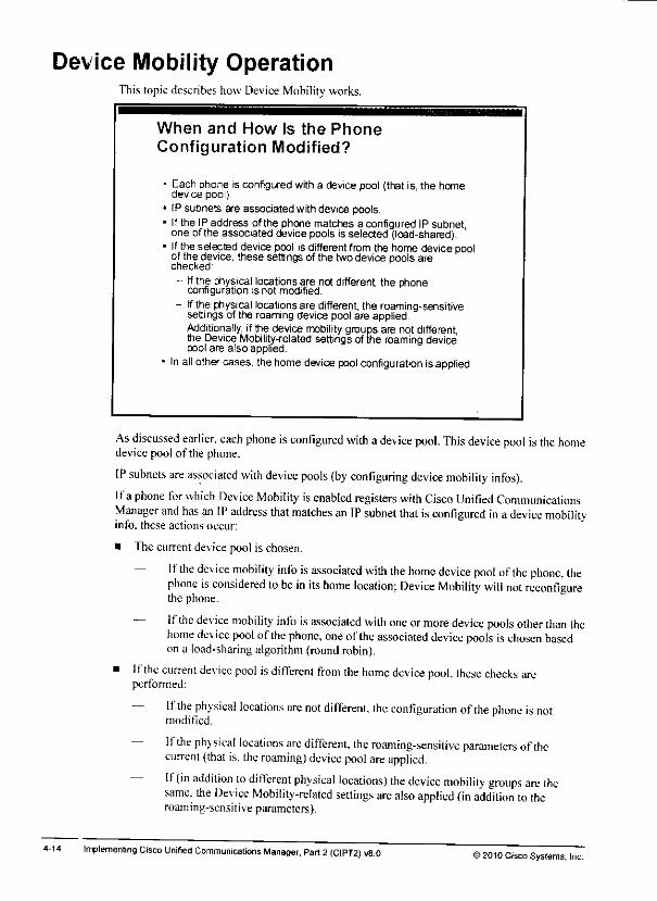
Device Mobility OperationThis topic describes how Device Mobility works.
When and How Is the PhoneConfiguration Modified?
1Each phone is configured with a device pool (that is, the homedevice pool).
IP subnets are associated with device pools,Ifthe IP address of the phone matches a configured IP subnetone ofthe associated devicepools is selected (load-shared).Ifthe selected device pool isdifferent from the home devicepoolof the device, these settings of the two device pools arechecked:
- If the physicallocationsare not different the phoneconfiguration is not modified.
- If the physical locationsare different, the roaming-sensitivesettings of the roaming device pool are applied.
- Additionally, ifthe device mobility groups are notdifferentthe DeviceMobility-related settings of the roaming devicepool are also applied.
In all othercases, the home devicepool configuration isapplied.
As discussed earlier, each phone isconfigured with adevice pool. This device pool isthe homedevice pool of the phone.
IP subnets are associated with device pools (by configuring device mobility infos).
Ifa phone for which Device Mobility isenabled registers with Cisco Unified CommunicationsManager and has an IP address that matches an IP subnet that is configured in adevice mobilityinfo, these actions occur:
• The currentdevicepool is chosen.
— Ifthe device mobility info is associated with the home device pool ofthe phone, thephone is considered to be in its home location; Device Mobility will not reconfigurethe phone.
— Ifthe device mobility info isassociated with one ormore device pools other than thehome device pool ofthe phone, one ofthe associated device pools ischosen basedon a load-sharing algorithm (roundrobin).
• Ifthe current device pool is different from the home device pool, these checks arcperformed:
— Ifthe physical locations are not different, the configuration ofthe phone is notmodified.
— Ifthe physical locations are different, the roaming-sensilive parameters ofthecurrent (that is. the roaming) device pool are applied.
— If(in addition to different physical locations) the device mobility groups are thesame, the Device Mobility-related settings are also applied (in addition to theroaming-sensitive parameters).
Implementing Cisco Unified Communications Manager. Part 2 (CIPT2) v8.0 >2010 Cisco Systems. Inc.
In summarv. the U.S. device mobility group consists oftwo physical locations: San Jose andNew York.'ln San Jose. IP subnets 10.1.1.0/24. 10.1.2.0/24. and 10.1.3.0/24 arc used: NewYork uses IP subnet 10.3.1.0/24. and London is configured with IP subnet 10.10.1.0/24.
Basedon the IP address of an IP phone. Cisco Unified Communications Managercandetermine oneor more associated device pool or pools andthe physical location anddevicemobility group ofthe device pool orpools. Ifan IP phone uses an IP address ofIP subnet10.1.3.6/24. there are two candidates for the device pool. However, inthis example, thephysical location and the device mobility group are the same for these two device pools.
>201D Cisco Systems, Inc. Implementation of Features and Applications for Multisite Deployments 4-13

Relationship of Device Mobility Configuration ElementsThe figure illustrates how the Device Mobility configuration elements relate to each other.
Relationship of Device MobilityConfiguration Elements
N
1 SJ1 dmi
(10 1.1 0/24)SJ_A_ dp
(Building A) c--.^^ ^
i!
SJ2_dmi(10.1.2.0/24)
SJ_B1_ dp(Buiding B)
_.*! SJ_pl j\ i (SJ-campus) Is ,4\ US dmg !
s,,\ 1/ Jr " • ~ii
i
i
SJ3 dmi
(10 1.3.0/24)sU SJ_B2_ dp
(Building B)
* **i
i
NY dmi
(10.3 1.0/24)NY_dp
*
mv r '
j (NY-campus) j
i
W. .> _ •. _ _ _
LON dmi
(10.10.1.0/24)LON_ dp —• LON_pl j
(LON-campus) ji GB_dmg , i
. —
Theexample in the figure shows five device mobility infos. They are configured as follows:
• SJl_dmi: The IPsubnet of this device mobility info is 10.1.1.0/24. This device mobilityinfo is used at Building Aofthe San Jose campus and isassociated with device poolSJ_A_dp.
• SJ2_dmi: The IPsubnet of this device mobility info is 10.1.2.0/24. This device mobility-info is used at Building Bof the San Jose campus and is associated with device poolSJ_Bl^dp.
• SJ3_dmi: The IPsubnet of this device mobility info is 10.1.3.0/24. Like SJ2_dmi, thisdevice mobility info isused at Building Band isassociated with device pool SJ_Bl_dp. Itis also associated with devicepool SJ_B2_dp.
• NY_dmi: The IPsubnet ofthis device mobility info is 10.3.1.0/24. This device mobilityinfo is used at the New York campus and is associated with device pool NY _dp.
• LON_dmi: The IPsubnet of this device mobility info is 10.10.1.0/24. This device mobilityinfo is used atthe London campus and is associated with device pool LON_dp.
Device pools SJ_A_dp. SJ_B1 jjp. and SJ_B2_dp are configured with the same physicallocation (SJ_pl) because they are used for devices that are located at the San Jose campus.
Device pool NY_dp. serving the New York campus, is configured with physical locationNY_pl. and device pool LON_dp, serving the London campus, isconfigured with physicallocation LON_pI.
All device pools that are assigned with a U.S. physical location (that is, SJ_A_dp, SJ_Bl_dp,SJ_B2_dp, and NYjJp) are configured with device mobility group US_dmg. This settingmeans that all U.S. device pools are in the same device mobility group. The London campus isina different device mobility group: GB_dmg.
4-12 Implementing Cisco Unrfied Communications Manager, Part 2 (CIPT2) v8.0 »2010 Cisco Systems, Inc.

Device Mobility Configuration ElementsThis topic describes the configuration elements that arc used by Device Mobility.
Configuration Element Functions
ConfigurationElement Name
Deuce MoNiy Info
Physical Location
Device MoDdKy Group
Configuration Element Functon
Defines a set of common characteristics for devices. The devicepoolcontans onlydevice-andlocation-related information. Onedevice pool has to be assigned to each device.
Specifies an IP subnet and associates itwithone or more devicepools.Multiple device mobility inlos can be associated with onedevice pool
Tliephysical location Isa teg assignedto oneor moredevicepools.It is used io identify whethera deviceIs roaming wiSiin aphysicallocation or between physicallocations.
The device mobility group is a tag assigned to one or moredevice pools. 11 is used lo identify whether a device is roamingwillnna device mobility group or between device mobilitygroups
The table lists the Dev ice Mobility-related configuration elements and describes their function,fhe newlv introduced elements arc device mobility infos, the physical location, andthedevicemobility group.
The dev ice mobilitv info isconfigured with a name and an IP subnet and isassociated with oneormore device pools. Multiple device mobility infos can be associated with the same devicepool.
The physical location and the device mobility group are just lags: they are configured with aname onlv and do not include any other configuration settings. Both arc nonmandatory devicepool configuration parameters: tti3t is. at the device pool, no physical location or one physicallocation and one (or no) device mobility group can be chosen. They are used todeterminewhether two device pools are at the same physical location and in the same device mobilitygroup.
& 20 10 Cisco Systems, IncImplementation ofFeatures and Applications for Multisite Deployments
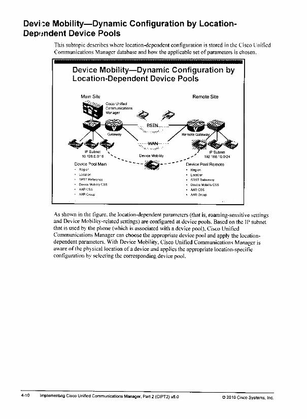
Devi :e Mobility—Dynamic Configuration by Location-Dependent Device Pools
This subtopic describes where location-dependent configuration is stored in the Cisco UnifiedCommunications Manager database and how the applicable set of parameters is chosen.
Device Mobility—Dynamic Configuration byLocation-Dependent Device Pools
Main Site
Local'on
SRST Reference
Device Motility CSS
AAR CSS
MR Group
Remote Site
Device Pool Remote
- Region
• Location
• SRST Reference
• Deuice Mobility CSS
• AAR CSS
• AAR Group
As shown in the figure, the location-dependent parameters (that is, roaming-sensitive settingsand Device Mobility-related settings)are configured at devicepools. Basedon the IP subnetthat is used by the phone(which is associated with a devicepool),Cisco UnifiedCommunications Manager canchoose the appropriate device pooland apply the location-dependent parameters. With Device Mobility, Cisco Unified Communications Manager isaware of the physical location of a device andapplies theappropriate location-specificconfiguration by selectingthe corresponding devicepool.
4-10 Implementing Cisco Unitied Communications Manager, Part2 (CIPT2) v8.0 ) 2010 Cisco Systems, Inc.
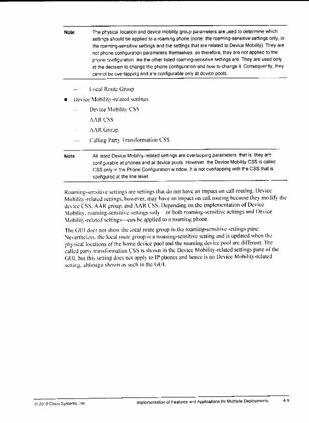
m
m
Note The physical location and device mobility group parameters are used to determine whichsettings should be applied to a roaming phone (none, the roaming-sensitive settings only, orthe roaming-sensitive settings and the settings that are related to DeviceMobility). They arenot phone configuration parameters themselves, so therefore, they are not applied to thephoneconfiguration like the other listed roaming-sensitive settingsare. Theyare used onlyat the decision to change the phone configuration and how to change it. Consequently, theycannot be overlapping and are configurable only at device pools.
Local Route Group
Device Mobilitv -related settings
Device Mobilitv CSS
AAR CSS
— AAR Group
— Calling Party Iransformation CSS
Note All listed DeviceMobility-related settings are overlapping parameters, that is, they areconfigurable at phones and at device pools. However, the Device Mobility CSSis calledCSS only inthe Phone Configuration window. Itis notoverlapping with the CSS that isconfigured at the line level.
Roaming-sensitive settings are settings that do not have an impact oncall routing. DeviceMobilitv -related settings, however, may have animpact on call routing because they modify thedev ice CSS. AAR group, and AAR CSS. Depending onthe implementation of DeviceMobilitv. roaming-sensitive settings only—or bolh roaming-sensitive settings and DeviceMobilitv -related settings—can be appliedto a roaming phone.
TheGUI does not show the local route group in the roaming-sensitive settings pane.Nevertheless, the local roule group is a roaming-sensitive setting and is updated when thephysical locations ofthe home device pool and the roaming device pool are different. Thecalled party transfoniiation CSS is shown in the Device Mobility-related settings pane oftheGUI. but this setting does not apply toIP phones and hence isno Device Mobility-relatedsetting, although shown as such in the GUI.
©2010 Cisco Systems. Inc Implementation otFeatures and Applications for Multisite Deployments
Device Mobility—Dynamic Phone Configuration ParametersThis subtopic shows the two types ofphone configuration parameters that can be dynamicallyassigned by Device Mobility.
Device Mobility—Dynamic PhoneConfiguration Parameters
Two types of phonesettingscan be applied by Device Mobility.• Roaming-sensitive settings:
• Local Roule Group
- Date/Time Group
Region
SRST Reference
Media Resowce Group I iat• Locat-oi!
- Netw:);k Locale
- Physical Locations
Device MobilityGroup
• Device mobility-related settings:•• Dew.e Mobihiy CSS
•V.RCRS
- A/.RGi^ir.
- L?.-ii':n,) Party Ti30»fi.imsai!O!i CSS
Device Mobilitv can reconfigure site-specific phone configuration parameters that are based onthe physical location ofthe phone. Device Mobility does not modify any user-specific phoneparameters or any IPphone button settings such as directory numbers.
The phone configuration parameters that can be dynamically applied todie deviceconfiguration are grouped into twocategories:
• Roaming-sensitive settings:
— Date/Time Group
— Region
— Location
Note The Date/Time Group, Region, and Location are configured at device pools only.
— Network Locale
— SRST Reference
— MRGL
Note The Network Locate, SRST Reference, and MRGL are overlapping parameters. That is, theyareconfigurable at phones and atdevice pools.
— Physical Location
— DeviceMobility Group
Implementing Cisco Unified Communications Manager, Pan 2(CIPT2) v8.0 ©2010CiscoSystems. Inc.
m
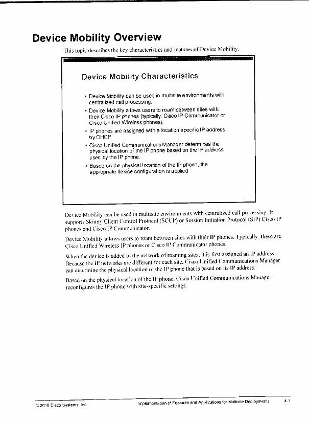
Device Mobility OverviewThis topic describes the key characteristics and Icalures of Device Mobility.
Device Mobility Characteristics
• Device Mobility can be used in multisite environments withcentralized call processing,
• Device Mobility allows users to roam between sites withtheir Cisco IP phones (typically, Cisco IP CommunicatororCisco Unified Wireless phones).
• IP phonesare assigned with a location-specific IPaddressby DHCP.
• Cisco Unified Communications Manager determines thephysical location of theIPphone based on the IP addressused by the IP phone.
• Based on the physical location ofthe IPphone, theappropriate deviceconfiguration is applied.
Dev ice Mobilitv can beused in multisite environments with centralized call processing. Itsupports Skinny Client Control Protocol (SCCP) or Session Initiation Protocol (SIP) Cisco IPphones andCisco IPCommunicator.
Dev ice Mobilitv allows users to roam between sites with their IP phones. Typically, these areCisco Unified Wireless IPphones or Cisco IPCommunicator phones.
When the device is added to the network ofroaming sites, itis first assigned an IP address.Because the IP networks are difTerent for each site. Cisco Unified Communications Managercan detemiine the physical location of(he IP phone that is based on its IP address.Based on the physical location ofthe IP phone. Cisco Unified Communications Manage:reconfigures the IPphone with site-specific settings.
© 2Q10 Cisco Systems, IncImplementation ofFeatures and Applications for Multisite Deployments
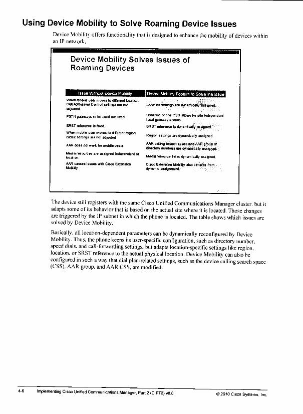
Using Device Mobility to Solve Roaming Device IssuesDevice Mobility offers functionality thatisdesigned to enhance themobility of devices withinan IP network.
4-6
Device Mobility Solves Issues ofRoaming Devices
Issue WithoutDevice Mobility Device Mobility Feature to Solve HieissueWhen mottle user moves to liferent location,Cal Admission Control selings are notadjusted.
PSTN gateways tone used are fixed.
SRST reference is feed.
When mobile user moves to efferent region,codec settings are not adjusted.
AAR does not work for mobile users.
Media rescurces are assigned independent oflocation.
AAR causes Issues wih Cisco ExtensionMobitty.
Location settiigsare dynamical? assigned.
Dynamic phone CSS allows for site-Independentlocal gateway access.
SRST inference is flynamicaBy assigned.
Region settings are dynamicallyassigned.
AAReating search space andAARflroup ofdirectorynumbers are dynamically assigned.
Meda resource listis dynamically assigned.
Cisco Extension Mobtity also benefits fromdynamic assignment.
ITie device stil! registers with the same Cisco Unified Communications Manager cluster, but itadapts some ofits behavior that is based on the actual site where itis located. Those changesaretriggered by the IP subnet inwhich thephone is located. Thetable shows which issues aresolvedby Device Mobility.
Basically, all location-dependent parameters can be dynamically reconfigured by DeviceMobility. Thus, the phone keeps its user-specific configuration, such as directory number,speed dials, and call-forwarding settings, but adapts location-specific settings like region,'location, orSRST reference to the actual physical location. Device Mobility can also beconfigured in such away that dial plan-related settings, such as the device calling search space(CSS), AAR group, and AAR CSS, are modified.
Implementing Cisco Unified Communications Manager, Part 2 (CIPT2) v8.0 »2010 Cisco Systems, Inc.
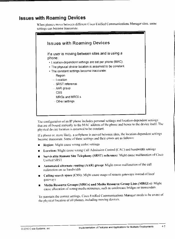
•m
Issues with Roaming DevicesWhen phones move between different Cisco Unified Communications Manager sites, somesettings can become inaccurate.
Issues with Roaming Devices
Ifa user is moving between sites and is using aphone:• Location-dependent settings are set per phone (MAC).• The physical device location is assumed to be constant.• The constant settings become inaccurate:
Region
- Location
SRST reference
AAR group
- CSS
MRGs and MRGLs
Other settings
The configuration ofan IP phone includes personal settings and location-dependent settingsthai are all bound statically to the MAC address ofthe phone and hence to the device itself. Thephv sical dev ice location isassumed tobe constant.
Ifa phone or. more likely, asoftphone is moved between sites, the location-dependent settingsbecome inaccurate. Some of these settings andtheirerrors arcas follows:
• Region: Might cause wrong codec settings• Location: Might cause wrong Call Admission Control (CAC) and bandwidth settings• Survivable Remote Site Telephony (SRST) reference: Might cause malfunction ofCisco
Linified SRS I
• Automated alternate routing (AAR) group: Might cause malfunction ofthe callredirection on no bandwidth
• Calling search spaee (CSS): Might cause usage of remote gateways instead ofloeaigateways
• Media Resource Groups (MRGs) and Media Resource Group Lists (MRGLs): Mightcause allocation ofwrong media resources, such as conference bridges oriranseoders
To maintain the correct settings. Cisco Unitied Communications Manager needs lo be aware ofthe ph> sical location ofall phones, including moving devices.
© 2010 Cisco Systems. IncImplementation ofFeatures and Applications for Multisite Deployments

Issues with Devices Roaming Between SitesThis topic describes issues that occur when users roam between sites with their devices.
4-4
Roaming Devices
Device can be an IP phone or, more likely, a softphone (such asCisco IP Communicator) ofa roaming user.
Cisco
Unified
Communicatj orisManager
•s. WAN
Roaming Device
Remote
Gateway
When users roam between sites, they might take their phones with them. This situationtypically does not apply lo Cisco IP phones, but is very common with softphoncs such as CistIP Communicator orCisco Unified Wireless IP phones.
Implementing Cisco Unified Communications Manager. Part 2(CIPT2) V8.0>2010 Cisco Systems, Inc.

Lesson 11
Implementing Device Mobility
OverviewSt is common in multisite em ironments that some users roam between sites regularly. Whensuch users lake their Cisco Unified Communications endpoints, such as aCisco LnifiedWireless IP Phone or Cisco IP Communicator (a softphone) phone, with them, the standardconfiguration of their endpoints must be adapted to suit the needs ot the current physicalocation. It is important that aprofessional unified communicalions system provides such asolution.
This lesson describes Cisco Unified Communications Manager Device Mobility, afeature ofCisco Unified Communications Manager that allows its endpoints lo be dynamicallyreconfigured based on their actual location as determined by the IP address that is used bv thedevice.
ObjectivesUpon completing this lesson, you will be able to describe how Device Mobility works and howit is implemented. This ability includes being able to meet these objectives:
Identify the issues with devices roaming between sites
Describe the Device Mobility feature
Describe the Device Mobility configuration elements and their interactionsDescribe Device Mobility operation
Describe Device Mobility interaction with globalized call routingContigurc Device Mobility

ttfc
mm
4-2 Implementing Cisco Unified Communications Manager, Part 2(CIPT2) v8.0>20f0 Cisco Systems, Inc.
Module 41
Implementation of Featuresand Applications for MultisiteDeployments
OverviewUsers in multisite environments often roam between sites. They cither take devices (such as aCisco Unified Wireless IP Phone or Cisco IP Communicator) with them or use guest phones atthe siles that they roam to.
This module describes Cisco Unified Communications Manager Device Mobility and CiscoExtension Mobilitv and their implementation. The implementation provides users with thefreedom to roam and still be reachable bv their own extensions, no mailer where they are orwhat dev ice thev use.
Module ObjectivesUpon completing this module, you will be able to implement Device Mobility and CiscoFxtension Mobility. This ability includes being able to meet these objectives:• Dcscnbc how Device Mobilitv works and how il is implemented• Describe how Cisco Extension Mobility works and how il is implemented

Implementing Cisco Unified Communications Manager, Part 2(CIPT2) v8.0)2010 Cisco Systems, Inc.

Monitoring Leamed Routes in Cisco Unified Communications Manager Express 5-57CCD PSTN Backup—CSS jj-58SRST Considerations J"^CCD and Static Routing Integration Considerations £-biCisco IOS SAF Client Considerations When Using Globalized Call Routing 5-b^Solution for PSTN Backup Advertised in E.164 Format Without Leading + 5-63TEHO Considerations ™Trunk Considerations When Using Globalized Call Routing ^Cisco Unified Communications Manager Clusters and CCD Configuration Modes 5-bbOther SAF and CCD Considerations 5-67
„ d-ooSummary _g8References ,„
Module Summary 5]6gReferences ,. -,.
Module Self-Check r~Module Self-Check Answer Key
••c 2010 Cisco Systems. IncImplemenling Cisco Unified Communications Manager, Part 2(CIPT2) v8 0
Step 7b: Subscribe Phone to Cisco Extension Mobility Phone Service 4-67Summary ~
References TroModule Summary 7™
References 71^Module Self-Check Jy
Module Self-Check Answer Key 4"'4
Call Control Discovery . — 5~1Overview
Module Objectives
Implementing SAF and CCD . $£Objectives ^
SAF and CCD Overview 5-4Dial Plan Scalability Issues in Large Networks 5-5Scalable Dial Plan Solution for Large Networks 5"6Call Control Discovery Overview 5-7
SAF Characteristics 5-8SAF Client Types 5"9SAF Message Components 5-10SAF Routing Characteristics 5-11SAF Neighbor Relationships 5"12SAF Client and SAF Forwarder Functions 5-13
CCD Characteristics 5-14CCD Characteristics 5-15CCD Services in Cisco Unified Communications Manager 5-17Processing Received Routes in Cisco Unified Communications Manager 5-19
CCD Operation 5_2|CCD—Propagation of HQ Routes 5"22CCD—Propagation of BR Routes 5-23CCD—Call from HQ to BR 5-24CCD—Link Failure at BR 5"25CCD—Call from HQ to BR During Link Failure 5-26
SAF and CCD Implementation 5-28External SAF Client Configuration Elements 5-3°Relationship ofExternal SAF Client Configuration Elements 5-31Internal SAF Client Configuration Elements 5-32Relationships ofInternal SAF Client Configuration Elements 5-33SAF Forwarder Configuration Procedure 5-34Step1:Configure SAF Forwarder 5-35Step2:Configure SAF Forwarder to Support External SAF Clients 5-36External SAF Client Configuration Procedure 5-37Step1:Configure SAF Security Profile 5-38Step2:Configure SAF Forwarder 5-39Step 3: Configure SAF Trunk 5-40Step 4: Configure Hosted DN Group 5-41Step 5:Configure Hosted DN Pattern 5-42Step6:Configure CCD Advertising Service 5-43Step 7: Configure CCD Requesting Service and Partition 5-44Step 8: Configure CCD Blocked Leamed Patterns 5-45Step 9: Configure CCD FeatureParameters 5-46Internal SAFClient Configuration Procedure 5-48Step 1: Configure Trunk Profile 5-49Step 2: Configure Directory Number Blocks 5-50Step 3: ConfigureCallControl Profile 5-51Step 4: Configure Advertising Service 5-52Step 5: ConfigureRequesting Service 5-53Step 6: ConfigureVoIP Dial Peer 5-54
CCD Considerations 5-55Monitoring Leamed Routes in Cisco Unified CommunicationsManager 5-56
ii ImplementingCisco Unified Communications Manager, Part 2 (CIPT2)v8.0 © 2010 Cisco Systems, Inc.
5-1
5-1
Table of ContentsVolume 2
Implementation ofFeatures and Applications for Multisite Deployments ±1mll Overview
Module Objectives
Implementing Device Mobilitv ___ 4.3Objectives 4 ^
Issues with Devices Roaming Between Sites 4_4m Issues with Roaming Devices 4_5
Using Device Mobility to Solve Roaming Device Issues 4_6Device Mobility Overview 4_7
** Device Mobility—Dynamic PhoneConfiguration Parameters 4-8Device Mobility—Dynamic Configuration byLocation-Dependent Device Pools 4-10
^ Device Mobility Configuration Elements 4_11Relationship of Device Mobility Configuration Elements 4-12
Device Mobility Operation 4_14mm Device Mobility Operation: Flowchart 4_1g
Device Mobility Considerations 4^1 gDevice Mobility and Calling Search Spaces 4_20
**• Examples ofCall-Routing Paths Based on Device Mobility Groups and TEHO 4-22Device Mobility Interaction with Globalized Call Routing 4_24
Advantages ofUsing Local Route Groups and Globalized Call Routing 4-26mm Example: No Globalized Call Routing—Different Device Mobility Group 4-27
Example: No Globalized Call Routing—Same Device Mobility Group 4-28mm Example: Globalized Call Routing 4_29
Device Mobility Configuration 4_30Steps 1 and 2. Configure Physical Locations and Device Mobility Groups 4-31
ww Step 3: Configure Device Pools 4.32Step 4. Configure Device Mobility Infos 4.33Step 5a:Set the Device Mobility Mode Cisco CallManager Service Parameter 4-34
** Step 5b: Set the Device Mobility Mode for Individual Phones 4-35Summary 4_3g
References 4.37
Implementing Cisco Extension Mobilitv 4.39Objectives 4.39
Issues with Users Roaming Between Sites 4-40Issues of Roaming Users 4-41Cisco Extension Mobility Solves Issues of Roaming Users 4-42
Cisco Extension Mobility Overview 4-43Cisco Extension Mobility: Dynamic Phone Configuration Parameters 4-45Cisco Extension Mobility: Dynamic Phone Configuration by DeviceProfiles 4-46
Cisco Extension MobilityConfiguration Elements 4-47Relationship of Cisco Extension Mobility Configuration Elements 4-49
Cisco Extension MobilityOperation 4-50Issues in Environments with Different Phone Models 4-52Default Device Profile and Feature Safe 4-53How Cisco Extension Mobility Handles Phone Model Differences 4-54Cisco Extension Mobility and CSSs 4-56Alternatives for Mismatching Phone Models and CSS Implementations 4-57
Cisco Extension MobilityConfiguration 4-58Step 1: Activate the Cisco Extension MobilityService 4-59Step 2: Set Cisco Extension MobilityService Parameters 4-60Step 3: Add the Cisco Extension MobilityPhone Service 4-61Step 4: Create Default Device Profiles 4-62Step 5a: Creale Device Profiles 4-63Step 5b: Subscribe Device Profile to Cisco Extension Mobility Phone Service 4-64Step 6: Associate Users with Device Profiles 4-65Step 7a: Configure Phones for Cisco Extension Mobility 4-66
m
4-1
4-1

3-110 Implementing CiscoUnified Communications Manager. Part2 (CiPT2) v8.0 ) 2010 Cisco Systems, Inc.
Module Self-Check Answer KeyQD D
Q2) A
Q-D B
Q4) C
05) D
06) B
Q-) Standard locations-based CAC docs nol allow tiic configuration of a dilTerenl limit per pair of locations.
Onh a tola! limit for all calls coming in to or going oul of a location can be configured.
Q8) B
Q9) B. [•
QIO) B
qui A
©2010 Cisco Systems, Inc. Bandwidth Management and CAC Implementation 3-109

3-J08
Q7) What is alimitation of standard locations-based CAC? (Source: Implementing CAC)
Q8) Which statement is false about CAC when using RSVP-enabled locations? (Source:Implementing CAC)
A) CAC adapts to the actual topology and considers network changes.B) RSVP is used for CAC and toprovide QoS for each individual stream.C) The RSVP agent to be used by aphone is determined by the Media Resource
Group Listof the phone.D) The RSVP agent isconfigured as an MTP in Cisco Unified Communications
Manager.
09) AAR reroutes calls to the PSTN for which two types of calls? (Choose two.) (Source:Implementing CAC)
A) calls rejected by an H.323 gatekeeperB) calls rejected by standard location-based CACC) calls placed tounregistered phonesD) calls placed toagateway that isbusyE) callsrejected by RSVP-enabled location-based CACF) calls rejected bySIPprecondition-based CAC
Q10) When using end-to-end RSVP with SIP preconditions, RSVP is used between theoriginating and the terminating phone. (Source: Implementing CAC)A) trueB) false
QII) How can calls that are rejected by an H.323 gatekeeper be rerouted by using adifferentpath? (Source: Implementing CAC)
A) by configuring route lists and route groups with backup devicesB) by putting the gatekeeper-controlled intercluster trunk or H.225 trunk into a
location that is set to unlimited
C) by configuring asecond route pattern in the same partition that refers to abackup device cannot be done, because AAR only supports internal calls
implementing Cisco Unrfied Communications Manager, Part 2(CIPT2) v8.0 ©2010 Cisco Systems, Inc.
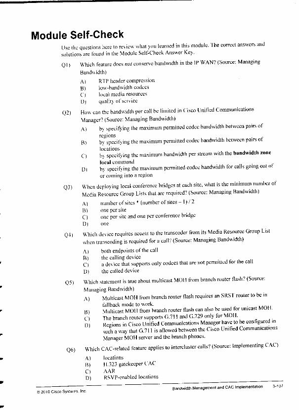
Module Self-CheckUse the questions here to review what you learned in this module. The correct answers andsolutions are found in the Module Self-Check Answer Key.
Ql) Which feature does not conserve bandwidth in the IP WAN? (Source: ManagingBandwidth)
A) RTP headercompressionB) low-bandwidth codecsC) local media resourcesD) quality of service
02) How can the bandwidth per call be limited in Cisco Unitied CommunicationsManager? (Source: Managing Bandwidth)A) b\ specifying the maximum permitted codec bandwidth between pairs of
regionsB) bv specifying the maximum permitted codec bandwidth between pairs ot
locationsC) by specifying the maximum bandwidth per stream with the bandwidth zone
local commandD) by specifying the maximum permitted codec bandwidth tor calls going out ot
or coming into a region
Q3) When dcploving local conference bridges at each site, what is the minimum number ofMedia Resource Group Lists that arc required? (Source: Managing Bandwidth)A) number ofsites *(number ofsites - l)/2B) one per siteC) one per site and one per conference bridgeD) one
Q4> Which device requires access to Ihe transcoder from its Media Resource Group Listwhen transcoding is required for acall? (Source: Managing Bandwidth)A) both endpoinls of thecallB) the callingdeviceC) ade% ice that supports only codecs that are not permitted tor the callD) the called device
Q5) Which statement is true about multicasl MOI 1from branch router flash? (Source:Managing Bandwidth)A) Multicast MOH from branch router flash requires an SRST router to be in
fallback mode to work.B) Multicast MOH from branch router flash can also be used tor unicast MOH.C) The branch router supports G.711 and G.729 only for MOH.D) Regions in Cisco Unified Communications Manager have to be configured in
such away that G.711 is allowed between the Cisco Unified CommunicationsManager MOH server and the branch phones.
Q6) Which CAC-related feature applies to intercluster calls? (Source: Implementing CAC)A) locations
B) H.323gatekeeper CAC
C) AAR
D) RSVP-enabled locations
Bandwidth Management and CAC Implementation) 2010 Cisco Systems. Inc
3-107

3-106 implementing Cisco Unified Communicalions Manager, Par. 2(CIPT2) v8.0 ©2010 Cisco Systems, Inc.
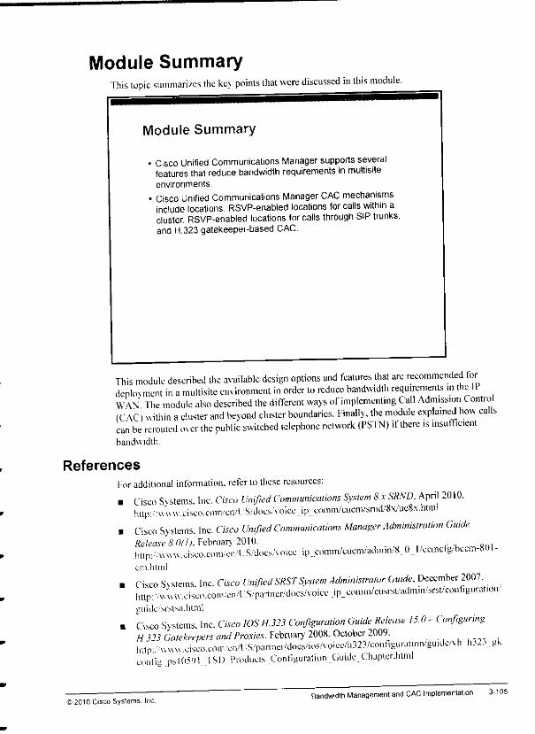
Module SummaryThis topic summarizes the key points that were discussed in this module.
Module Summary
• Cisco Unified Communications Manager supports severalfeatures that reducebandwidth requirements inmultisiteenvironments.
* Cisco Unified Communications Manager CAC mechanismsinclude locations, RSVP-enabled locations for calls within acluster, RSVP-enabled locations for calls through SIP trunks,and H.323 gatekeeper-based CAC.
This module described the available design options and features that are recommended tordeplovment in amultisite environment in order to reduce bandwidth requirements mthe IIWAN The module also described the different ways of implementing Call Admission Contro(C \C) within acluster and beyond cluster boundaries. Finally, the module explained how callscan be rerouted over the public switched telephone network (PSTN) ifthere is insufficientbandwidth.
References
For additional infomiation. refer to these resources:
• Cisco Svstems. Inc. Cisco Unified Communications System 8.x SRMX April 2010.http-,'Uuw.cisco.c<>iii'cii/"US/docs.'\oicejp_.co.nin/cucm/snid/8x/uc8x.htinl
• Cisco Systems. Inc. Cisco Unified Communications Manager Administration GuideRelease 8.0/1). February 2010. _lmp:/^vNu.asco.coni/en.'l.S.'doc>.\oicc_ip_comin/cuem/ailn.m/8 O.J/ecmdg.bccm-801-cm.html
• Cisco Svstems Inc. Cisco Unified SRST System Administrator Guide, December 2007.IUtp:.vw;w.cisco.coni/eivUS/partner/docs/voice ip^onitn/aisrst/adtnin/srst/configurtmc.,..guide srr.lsa.hlml
. Cisco Svstems. Inc. Cisco IOS H.323 Configuration Guide Release 15.0- ConfiguringH3"3 Gatekeepers and Proxies. February 2008. October 2009.lu.p. x,uxv.cisco.co,n.cn/US/partner/docs/.os/voice/l,323/conngu,-at.on/gu,dc.vh.h32, gkconfig psl05'Jt TSD Products Configuration Guide.Chupler.lilm!
) 2010 Cisco Systems. IncBandwidth Management and CAC Implementation 3-105
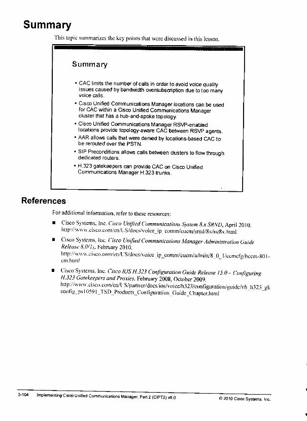
SummaryThis topic summarizes the keypoints that were discussedin this lesson.
Summary
• CAC limits thenumber ofcalls in order to avoid voice qualityissuescausedbybandwidth oversubscription due totoomanyvoice calls.
• Cisco Unified Communications Managerlocations can be usedfor CAC within a Cisco Unified Communications Managercluster that has a hub-and-spoke topology.
1Cisco Unified Communications Manager RSVP-enabledlocations provide topology-aware CAC between RSVP agents.AAR allows calls that were denied by locations-based CAC tobe rerouted over the PSTN.
SIP Preconditions allows calls between clusters toflow throughdedicated routers.
H.323 gatekeepers can provideCACon Cisco UnifiedCommunicationsManager H.323trunks.
References
3-104
For additional information, refer to these resources:
• Cisco Systems, Inc. Cisco Unified Communications System 8.x SRND, April 2010.http:/Avuu.cisco.com/en/US/docs/voice_ip .coinm/cticm/srnd/8N/uc8\.himl
• Cisco Systems, Inc. Cisco Unified Communications Manager Administration GuideRelease 8.0(1), February 2010.
h!tp:/Av\u\.cisco.c(>m/enAJS/doLVvoicc_ip_comnVcucin/admin/8_0_l/ccmcfe/bccni-80I-em.html
• Cisco Systems, Inc. Cisco IOS H.323 Configuration Guide Release 15.0 - ConfiguringH323Gatekeepers and Proxies, February 2008, October 2009.http://\\u^.cisco.com/en/L!S/partner/docs/ios/voicc/h323/coniiguration/guidc/vh_h323 gkcontIg_psl059i_TSD_Products_Connguration_Guide_Chapter.html
Implementing Cisco Unified Communications Manager. Part 2(CIPT2) v8.0©2010 Cisco Systems, Inc.

Note The command syntax and a sample configuration were shown earlier in this topic.
To provide backup paths for the gatekeeper-controlled trunk, perform this step:Step 1 Add PSTN gateways lo route groups, and add these gateways to the route lists that
are using the gatekeeper-controlled trunks.
Note You configured PSTN backup in earlier lab activities ofthis course
© 2010 Cisco Systems. IncBandwidth Management andCAC Implementation 3-103

Configuration Procedure for Implementing H.323 Gatekeeper-Controlled Trunks with CAC
The figure shows the required steps for implementing gatekeeper-controlled trunks for callrouting only. It also shows you how to add gatekeeper CAC functionality and how to provide abackup pathfor thegatekeeper-controlled trunk.
Configuration Procedure forImplementing H.323 Gatekeeper-Controlled Trunks with CAC
Implement gatekeeper-controlled trunks:1 Configure gatekeeper (Cisco IOS router) for call routing.2. Add gatekeeper toCisco Unified Communications Manager.3 Add and configure gatekeeper-controlled trunk (gatekeeper-
controlled intercluster trunk or H.225 trunk) inCisco UnifiedCommunications Manager.
4 Configure route patterns, routelist, and route group pointinq togatekeeper-controlled trunk.
Implement gatekeeper CAC:• Configure gatekeeper (Cisco IOS router) for CAC.
Provide PSTN backup for gatekeeper-controlled trunk;• Modify route list and route groups to provide a PSTN backup
path for the gatekeeper-controlled trunk.
To implement gatekeeper-controlled trunks, perform these steps:Step 1 Enable gatekeeper functionality at aCisco IOS router and configure the gatekeeper
for call routing. This configuration typically includes zones, zone prefixes, and thedefault technology prefix.
Note More information about gatekeeper configuration is provided in the Implementing CiscoVoice Communications and QoS (CVOICE) course.
Step 2 Add the gatekeeper to Cisco Unified Communications Manager.Step 3 Add the gatekeeper-controlled trunk (either agatekeeper-controlled intercluster
trunk or an H.225 trunk) to Cisco Unified Communications Manager, and configurethe trunk. ' &
Step 4 Configure route groups, route lists, and route patterns in order to route calls thatmatch acertain route pattern (for example, 9.5[l2][l2].„ , for the examples thatwere shown earlier in this topic) tothe gatekeeper-controlled trunk.
Note You performed the last three steps of the preceding procedure in earlier lab activities of thiscourse.
To implement gatekeeper-controlled CAC, perform ihis step:Step 1 Configure the Cisco IOS gatekeeper with bandwidth commands to enable bandwidth
limitations (tvniYallv rpni n r**H rmlw frt- :«<^ -~n .^imitations (typically required only for interzone calls).
3-102 Implementing Cisco Unified Communicalions Manager, Part 2(CIPT2) v8.0©2010 Cisco Systems, Inc.
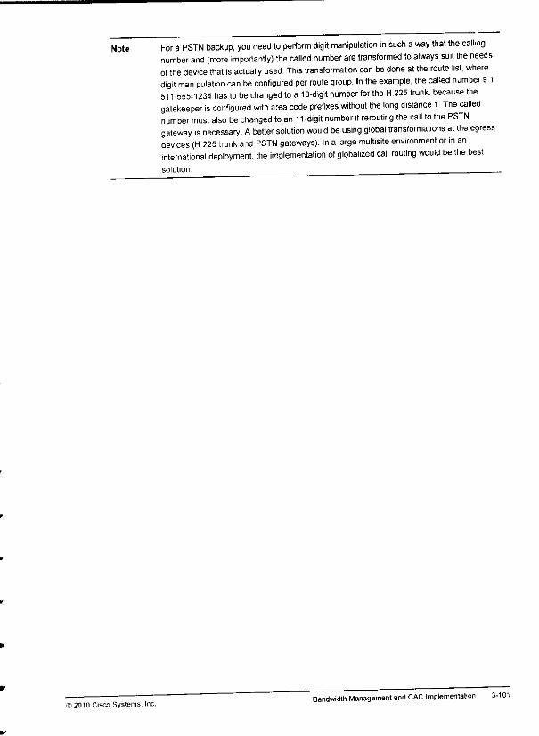
Note For a PSTN backup, you need to perform digit manipulation msuch away that the callingnumber and (more importantly) the called number are transformed to always suit the needsof the device that isactually used. This transformation can be done atthe route list, wheredigit manipulation can be configured per route group. In the example, the called number 91511 555-1234 has to bechanged to a 10-digit number for the H.225 trunk, because thegatekeeper is configured with area code prefixes without the long distance 1 The callednumber must also bechanged to an11 -digit number if rerouting the call to the PSTNgateway is necessary. Abetter solution would be using global transformations atthe egressdevices (H 225 trunk and PSTN gateways). In a large multisite environment or in aninternational deployment, the implementation of globalized call routing would be the bestsolution
© 2010 Cisco Systems, Inc.Bandwidth Management andCAC Implementation 3-101
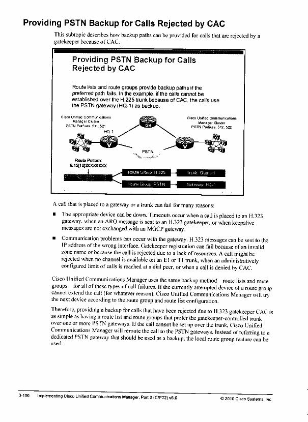
Providing PSTN Backup for Calls Rejected by CACThis subtopic describes how backup paths can beprovided for calls that are rejected by agatekeeper because of CAC.
3-100
Providing PSTN Backup for CallsRejected by CAC
Route lists and route groups provide backup paths if thepreferred path fails. In the example, ifthe calls cannot beestablished over the H.225 trunk because of CAC, the calls usethe PSTN gateway (HQ-1) as backup.
Cisco Unified Ccmmmieaiors
Manager ClusterPSTN Prefixes 511.521
HQ-1
Ci sco Un ified C om mu n ica t ions
Manager ClusterPSTN Prefixes: 512, 522
Route Pattern:
9.15112J2XXXXXXX
Route Group. H.225
Route Group PS I N
Trunk. Clusterl
Gateway HQ-1
A call that is placed to a gateway or a trunk can fail for many reasons:
• The appropriate device can be down. Timeouts occur when acall isplaced toan H.323gateway, when an ARQ message issent toan H.323 gatekeeper, orwhen keepalivemessages are notexchanged with an MGCP gateway.
• Communication problems can occur with the gateway. H.323 messages can be sent totheIPaddress of thewrong interface. Gatekeeper registration can fail because of an invalidzone name orbecause the call isrejected due toa lack ofresources. Acall might berejected when no channel is available on an EI or Tl trunk, when an administrativelyconfigured limit ofcalls isreached atadial peer, orwhen a call isdenied by CAC.
Cisco Unified Communications Manager uses the same backup method—route lists and routegroups—for all ofthese types ofcall failures. Ifthe currently attempted device ofaroute groupcannot extend the call (for whatever reason), Cisco Unified Communications Manager will trythe next device according to the route group and route list configuration.
Therefore, providing abackup for calls that have been rejected due to H.323 gatekeeper CAC isas simple as having aroute list and route groups that prefer the gatekeeper-controlled trunkoveroneor more PSTN gateways. If thecall cannot besetupoverthe trunk, Cisco UnifiedCommunications Manager will reroute the call to the PSTN gateways. Instead ofreferring to adedicated PSTN gateway that should be used as abackup, the local route group feature can beused.
Implementing Cisco Unified Communications Manager, Part 2(CIPT2) v8.052010 Cisco Systems, Inc.
mm
The maximum audio bandwidth is limited to 64 kb/s. Calls requiring more bandwidth {formedia such as wideband audio codecs or video calls with a video call bandwidth of morethan 64 kb/s) are not permitted in any zone.
Thetotal of all calls(interzone andintrazone calls) in zone ClusterB must notexceed 688kb/s. Asanexample, ibis configuration allows three G.729 calls to ClustcrA (three timestwice the codecbandwidth of 8 kb/s)and five G.711 calls withinClusterB (five times twicethe audiocodecbandwidth of 64 kb/s). Intrazone calls in zone ClusterA are unlimited.
Note Some ofthebandwidth commands inthe example are forillustration only andare not usefulinthis scenario. Forexample, youcould change the bandwidth interzone default 64command to bandwidth interzone ClusterA 64 because interzone default appliesonly tozone ClusterA; zone ClusterB is explicitly configured, and nootherzones exist. Furthermore,intrazone limitations have been configured but would never apply inthis scenario. Thereason is that all callsare interzone calls.Thegatekeeper is used only forintercluster calls,and the two clusters are in different zones.
©2C1Q Cisco Systems. IncBandwidth Management andCAC Implementation 3-99
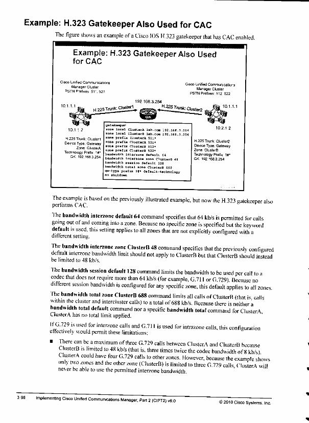
Example: H.323 Gatekeeper Also Used for CACThe figure shows an example ofaCisco IOS H.323 gatekeeper that has CAC enabled.
3-98
Example: H.323 Gatekeeper Also Usedfor CAC
Cisco Unified CommunicationsManager Cluster
PSTN Prefixes 511.521
Cisco Unified CommunicationsManager Cluster
PSTN Prefixes 512,522
10.1 1.1192.168.3.254
pow Trunk: Cluster^ ^mm^ Ji.225 Trunk: CL-^ 10.1.1.1
10.1.1 2
H 225 Trunk'ClusterlDeviceType.Gateway
Zone ClusterATechnology Prefix Mr
GK 192 158 3 254
gatekeeper
ions local ClusterA lab.ccm 192.168.3.254ions local ClusterB lab.cm 192.169.3.254•one prefn ClusterA 511-
lone prefix ClusterA 521"
ions prefin ClusterB 513«
rone prefix ClusterB 522*
bandwidth interzone default a
bandwidth intertone sons CIustsrB IS
bandwidth session default 128
bandw4.dth total zone ClusterB 6889"-type-prefix lt« default- technologyno shutdown
10.2.1 2
H.225 Trunk; Cluster2DeviceType.GatenvayZone1 ClusterBTechnology Prefix: MrGK 192.168 3.254
The example is based on the previously illustrated example, but now the H.323 gatekeeper alsoperforms CAC.
The bandwidth interzone default 64 command specifies that 64 kb/s is permitted for callsgoing out of and coming into azone. Because no specific zone is specified but the keyworddefault is used, this setting applies to all zones that are not explicitly configured with adifferent setting.
The bandwidth interzone zone ClusterB 48 command specifics that the previously configureddefault interzone bandwidth limit should not apply to ClusterB but that ClusterB should insteadbe limited to 48 kb/s.
The bandwidth session default 128 command limits the bandwidth to be used per call to acodec that does not require more than 64 kb/s (for example, G.711 or G729) Because nod.fferent session bandwidth is configured for any specific zone, this default applies to all zones.The bandwidth total zone ClusterB 688 command limits all calls of ClusterB (that is callswithin the cluster and intercluster calls) to atotal of688 kb/s. Because there is neither abandwidth total default command nor aspecific bandwidth total command for ClusterAClusterA has nototal limit applied.
If G.729 is used for inter/one calls and G.711 is used for intrazone calls, this configurationeffectively would permit these limitations:
> There can be amaximum of three G.729 calls between ClusterA and ClusterB becauseCusterB is limited to 48 kb/s (that is, three times twice the codec bandwidth of8kb/s)ClusterA could have four G.729 calls to other zones. However, because the example showsonly two zones and the other zone (ClusterB) is limited to three G.729 calls ClusterA willnever beable to use thepermitted interzone bandwidth.
Implemenling Cisco Unified Communications Manager, Part 2(CIPT2) v8.0©2010 Cisco Systems, Inc.

Bandwidth limitations are configured differently on different Cisco products and for differentfeatures. The table summarizes how to configure bandwidth limitations in Cisco UnifiedCommunications Manager.
Audio-Only CallConfiguration
Example: G 711 Call
Video CallConfiguration
Example 384-kb/sVideo Call
Cisco Unitied
Communications
Manager
Region
Audio codec only
G.711
Audio codec and videocall speed
G.711 and 384 kb/s
Cisco Unified
Communications
Manager
Location
Audio codec bit rate +Layer3 overhead
80 kb/s
Video call speed
384 kb/s
Cisco IOS H.323
Gatekeeper
Twice the audio codec
bit rate
128 kb/s
Twice the video callspeed
768 kb/s
NoteVideo calls have not been discussed in this course but are also shown for completeness.
;010 Cisco Systems, IncBandwidth Management and CAC Implementation 3-97
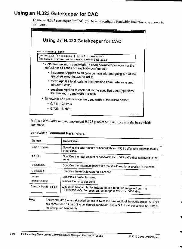
Using an H.323 Gatekeeper for CAC
3-96
To use an H.323 gatekeeper for CAC, you have to configure bandwidth limitations, as shownthe figure.
Using an H.323 Gatekeeper for CAC
router(config-gk)#
bandwidth {interzone | total | session}{default | zone zone-name} bandwidth-size H1Sets the maximum bandwidth (in kb/s) permitted per zone (or the
default for all zones not explicitly configured):• interzone: Applies to all calls coming into and going out of the
specified zone (interzone calls)- total: Applies toall calls in the specified zone (interzone and
intrazone calls)
• session: Applies toeach call in thespecified zone (specifiesthe maximum bandwidth per call)
Bandwidth ofa call is twice the bandwidth ofthe audio codec:- G.711:128 kb/s
• G.729: 16 kb/s
In Cisco IOS Software, you implement H.323 gatekeeper CAC by using the bandwidthcommand.
bandwidth Command Parameters
Syntax Description
interzone Specifies the total amount of bandwidth for H.323 traffic from the zone to anyother zone. '
total Specifies the total amount ofbandwidth for H.323 traffic that isallowed in thezone.
session Specifies the maximum bandwidth that isallowed for a session in the zonedefault Specifies the default value for all zones.
zone
zone-name
Specifies a particular zone.
Names the particular zone
bandwidth-size Maximum bandwidth. For interzone and total, the range isfrom 1to10,000,000 kb/s. For session, therange isfrom 1to 5000 kb/s.
The bandwidth that is calculated per call is twice the bandwidth of the audio codec AG729call consumes 16 kb/s of the configured bandwidth, and a G.711 call consumes 128 kb/s ofthe configured bandwidth.
Implementing Cisco Unified Communicalions Manager, Part 2(CIPT2) vB.O>2010 Cisco Systems, Inc.

Thev all use different H.323 IDs because different trunk names have been contigured in the twoclusters and because Cisco Unified Communications Manager adds the _1 and _2 to the trunkname to uniquely identify the call-processing servers per cluster.
Note If the same trunk name was configured in the two clusters, registrations would fail becauseofduplicate H.323 IDs.
The call-processing servers of ClusterA registered in /one ClusterA. and the call-processingservers of ClusterB registered in zone ClusterB. You can verify this situation by using thecommand show gatekeeper endpoints. All endpoints are registered with the prefix 1# whichis configured to be the default technology prefix. You can verify this situation by using thecommand show gatekeeper gw-type prefix. The output of these two commands is shown mone table in the figure.
Note For more information regarding gatekeeper configuration and operation, refer to theImplementing Cisco Voice Communications and QoS (CVOICE) course. ____
If the gatekeeper receives an Admission Request (ARQ) message from one of the H.323aatewavs (a call-processing Cisco Unified Communications server, in this case), it looks up itscall-routing table (list of configured /one prefixes) to find out in which /.one the requestedprefix canbe found.You can verifv the list of configured prefixes and their /ones by using the command show-gatekeeper zone prefix.
If an ARQ message was sent from 10.1.1.1 to the gatekeeper that requests acall to512555P34 the gatekeeper will determine that the call has to be routed to zone ClusterB. Inconlv prefix that is reg.stered by gateways in this zone is 1#*. which is the default technologyprefix and is registered bv 10.2.1.1 and 10.2.1.2. Therefore, the gatekeeper chooses one of thesetwo eatcwa% s(in round-robin fashion) to be the terminating gateway. It will inform theoriginating gatewav (the call-processing server of ClusterB that sent the ARQ message) to setup an 11.323 call with the determined terminating gateway (10.2.1.1 or 10.2.1.2).
Note At this point, the gatekeeper is configured only to perform call-routing address resolution. Itresolves adialed number to the IP address where the call has to be routed. No CAC isperformed by the gatekeeper in this example
j 2010 Cisco Systems, Inc.Bandwidth Management and CAC Implementation 3-95
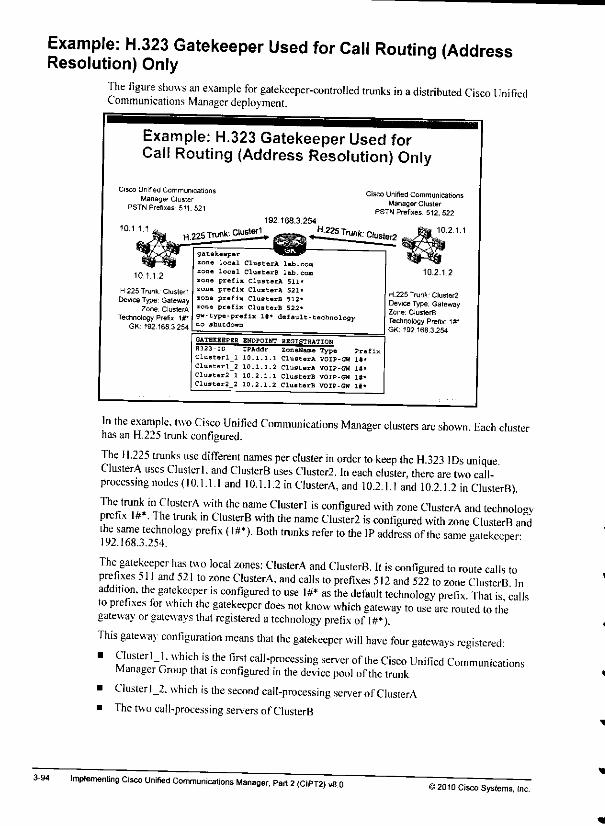
Example: H.323 Gatekeeper Used for Call Routing (AddressResolution) Only
The figure shows an example for gatekeeper-controlled trunks in adistributed Cisco UnifiedCommunications Manager deployment.
3-94
Example: H.323 Gatekeeper Used forCall Routing (Address Resolution) Only
Cisco UnrfiedCommunications i-i,™ 11„-« .. r-u„„,„ r-, . Cisco Unified CommunicationsManager Cluster ,,, „, .
PSTN Pr*« 511.52, PSTN pXe"'512^22192.168.3.254
101 11 -" H.225Trur^Clus^ ^^J^Tn** C,uste/2
10.1.1.2
H 225 Trunk ClusleriDeviceType Galeway
Zone CluslerATechnology Prefix If
GK. 192168.3254
gatekeeper
zone local ClusterA lab.con
zone local ClusterB lab.com
zona prefix ClusterA 511*
zone prefix ClusterA 521-
zone prefix ClusterB 512*
zone prefix CluaterB 522*
g»-type-prefix 1#« default-technologyno shutdown
GATEKEEPER BKDPOINT HEGISTRATIOH
H323-ID IPAddr ZonaName Type PrefiiClusterll 10.1.1.1 ClusterA VOIP-GW 1#*Clusterl_2 10.1.1.2 ClusterA VOIP-GW 1#'Cluster2_l 10.2.1.1 ClusterB VOIP-GW IfClusterJ_2 10.2.1.2 ClusterB VOIP-GW 1#*
10.2.1.1
10.2.1.2
H.225 Trunk: Cluster2DeviceType.GatewayZone: ClusterB
Technology Prefix MTGK. 192 16S.3.254
In the example, two Cisco Unified Communications Manager clusters arc shown Each clusterhasan H.225 trunk configured.
The 11.225 trunks use different names per cluster in order to keep the H323 IDs uniqueClusterA uses Clusterl. and ClusterB uses Cluster2. In each cluster, there are two call-processing nodes (10.1.1.1 and 10.1.1.2 in ClusterA, and 10.2.1.1 and 10.2.1.2 in ClusterB).The trunk in ClusterA with the name Clusterl is configured with zone ClusterA and technologyprefix 1# . The trunk in ClusterB with the name Cluster2 is configured with zone ClusterB and"mVITi6^!??010^ PrCfiX ('**}" B°th tnmks refer t0 **1P address oUhc sa™ gatekeeper:I yl. 168.3.254.
The gatekeeper has two local zones: ClusterA and ClusterB. It is configured to route calls toprefixes 511 and 521 to zone ClusterA, and calls to prefixes 512 and 522 to zone ClusterB Inaddition, the gatekeeper is configured to use 1#* as the default technology prefix 'fhat is callsto prefixes for which the gatekeeper does not know which gateway to use are routed to thegateway orgateways that registered a technology prefix of I#*).
This gateway configuration means that the gatekeeper will have four gateways registered:' MUSterL^* WhiCu fS tHe ^ cal|-Processing server of the Cisco Unified Communications
Manager Group that isconfigured in the device pool ofthe trunk
• Cluster ]_2. which is the second call-processing .server ofClusterA• Thetwocall-processing servers of ClusterB
Implementing Cisco Unified Communications Manager, Part 2(CIPT2) vB.O©2010 CiscoSystems, inc.
Note The H.323 ID has to be unique. Cisco Unified Communications Manager keeps the H.323 IDthat is used by the members of acluster unique by adding the individual ending _xFurthermore because Cisco Unified Communications Manager does not allow multipletrunks to use the same name, no duplicate H.323 IDs can be presented to the gatekeeperfrom aduster However, if the same trunk name is configured in multiple clusters, the call-processing servers of two or more clusters will try to register with the same H.323 ID. Thegatekeeper will not allow these duplicate H.323 IDs to register, so the trunk will not beoperational Therefore, it is important to use unique trunk names across all Cisco UnifiedCommunications Manager clusters that register with a gatekeeper. _
II 323 zone: H323 zones are used to group devices. You perform call routing and CACbased on these /ones. For instance, you could configure aso-called detault technologyprefix per zone that identifies the gateway (or gateways) to which calls should be routedwhen the gatekeeper does not know which gateway to use. Also. CAC can be configureddifferentlv for calls within a zone versus interzone calls.
Note The H323 zone name that is configured at the gatekeeper-controlled trunk is case-sensitiveand hastoexist at the gatekeeper ^ __
• Technology prefix: H.323 gateways (including Cisco Unified Communications Manager)can register prefixes (that is. number ranges that they can route calls to) at the gatekeeper.The prefix can consist onlv of numbers (for example. 511). or it can include atechnologyprefix (such as IM. 2#. and so on). One way of using an H.323 technology prefix is tor a»atewav to indicate the services that it provides by specifying an appropriate technologyprefix ('for instance. 1* for voice services, 2* for fax services, and so on). Calls that includethe technology prefix in their numbers (for example, acall that is placed to 1*5115551000)can be muted'to the gateway in the zone that registered the appropriate technology prefix.
\s mentioned earlier, agatekeeper can be configured to route calls-for which it does notknow which gateway to use-to the gateway or gateways that register with aprefix that isconfigured to be the default technology. For example, if there is only one Cisco UnifiedCommunications Manager cluster registering per zone, you can configure the trunk in eachcluster with atechnology prefix of 1*#. and configure the gatekeeper lo send all calls to thegateway that registered with the configured default technology prefix (1*# in this case).The eat'ekeeper needs onlv aconfiguration ofnumber prefixes (which number to find inwhich /one). When the outgoing zone is determined, the gatekeeper just sends the call toone of the gateuaj s(Cisco Unified Communications Manager systems) that registered inthe zone with thedefault technology prefix.
Note More information about how agatekeeper routes calls is provided in the Implementing CiscoVoice Communications and QoS (CVOICE) course. _
©;010 Cisco Systems. IncBandwidth Management and CAC Implementation 3-93
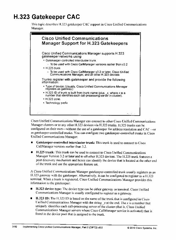
H.323 Gatekeeper CACThis topic describes 11.323 gatekeeper CAC support in Cisco Unified CommunicationsManager.
Cisco Unified Communications
Manager Support for H.323 Gatekeepers
Cisco Unified Communications Manager supports H.323gatekeeper networks using:
• Gatekeeper-controlled intercluster trunk
- To be used with Cisco CallManager versions earlier than v3.2• H.225 trunk
- To be used with Cisco CallManager v3.2 or later, Cisco UnifiedCommunications Manager, and all other H.323 devices
Trunks register with gatekeeper and provide the followinginformation:
• Type of device (Usually, Cisco Unified Communications Managerregisters as gateway.)
• H.323 IDof trunk is built from trunk name (plus _x, where x is anumber that identifies each call-processing server in cluster).
• H.323 zone.
• Technology prefix.
Cisco Unified CommunicationsManager can connect to other Cisco Unified CommunicationsManager clusters or to any other H.323 devices via H.323 trunks. H.323 trunks can beconfigured on theirown—without the use of a gatekeeper for address resolution and CAC—oras gatekeeper-controlled trunks. You can configure two gatekeeper-controlled trunks in CiscoUnified Communications Manager:
• Gatekeeper-controlled intercluster trunk: This trunk is used to connect to CiscoCallManager versions earlier than 3.2.
• H.225 trunk: This trunk can be used to connect to Cisco Unified CommunicationsManager Version 3.2 or later and to all other H.323 devices. The H.225 trunk features apeer discovery mechanism and hence can identify the device that is located at the other endof the trunk and use the appropriate feature set.
A Cisco Unified Communications Manager gatekeeper-controlled trunk usually registers as anH.323 gateway with the gatekeeper. Alternatively, it can beconfigured to register asa H.323terminal. When a trunk isregistered. Cisco Unified Communications Manager provides thisinformation to the gatekeeper:
• H.323 device type: Thedevice typecan beeithergateway or terminal. Cisco UnifiedCommunications Manager isusually configured to register asa gateway.
• H.323 ID: The H.323 ID isbased on the name of the trunk that isconfigured inCiscoUnified Communications Manager with the string jr at theend. Thex isa number thatuniquely identifies each call-processing server of the cluster (that is,Cisco UnifiedCommunications Manager servers where Cisco CallManager service isactivated) that islisted in the devicepool that is assigned to the trunk.
3-92 Implementing Cisco Unitied Communications Manager. Part2 (CIPT2) vB.O 12010 Cisco Systems, Inc.
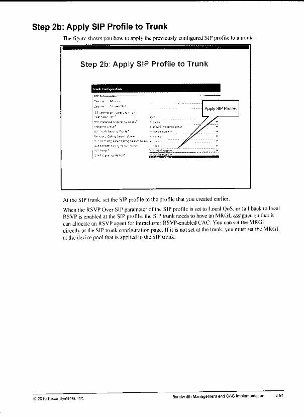
Step 2b: Apply SIP Profile to TrunkThe figure showsyou how to applv the previously configured SIP profile to a trunk.
Step 2b: Apply SIP Profile to Trunk
trunk LonlquHlun ^^^^^B
;tr.-^i;- iOi'tis i-,gApply SIP Profile.
n 4 .L --_
fl--!lei!=;^'.:».C.Jc-.' ':iul«» j jr ":..,ln-(i,-:u5* ii*r3j (1 Ptara g-cw: / r
;:=-Tj-kS«:u--. f-tfw' -- 'IMSele;tM •- /jr V
*-•«!... C*l 'j5M-f5|U ' '.cr- j ^^^ **
-_• 3' ? sl3j ;;'V 13ls-3'«•--* Ipi e . i,™ -. Jf .
5„ =sc=.t£ECa i-j5.»'=-!«:! - •,;-= - y' V
---; ;,-•„.' r~i'j.f"*:oi>dsio'-s , v
^^jr, K-.f-
At the SIP trunk, set the SIP profileto the profilethat you createdearlier.
When the RSVP OverSIPparameter of the SIPprofile is set to Local QoS, or fall back to localRSVP isenabled at the SIP profile, the SIP trunk needs to have anMRGL assigned sothatitcan allocate an RSVP agent for intracluster RSVP-enabled CAC. You can setthe MRGLdirectK at the SIP trunk configuration page. If it is notsetat the trunk, you must set the MRGLat the device pool that is applied to the SIP trunk.
© 2010 Cisco Systems. Inc.Bandwidth Managementand CAC Implementation 3-91
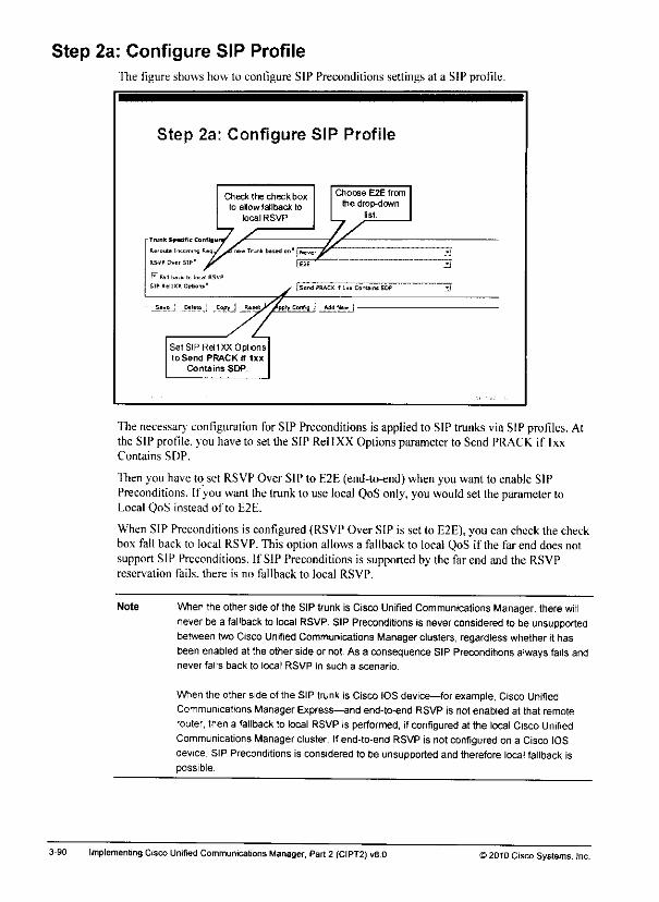
Step 2a: Configure SIP ProfileThe figure shows how to configure SIP Preconditions settings at a SIP profile.
Step 2a: Configure SIP Profile
Tuinl Specific Confi»
Re'mjtt l-KcmiT
RSVP Over SIP"
W Fill back Lclocal B5VPSIP P.ell XX Onboii"
Check the checkbox
to allowfatlbackto
local RSVP
Trjnkbasedon' jpkever
Chocse E2E from
the drop-downlist.
Send PRACK f l.i Contains SDP
SetSIPRellXXOptbnsto Send PRACKif Ixx
Contains SDP
The necessary configuration for SIP Preconditions is applied to SIP trunks via SIP profiles. Atthe SIP profile, you have to set the SIP RellXX Options parameter to Send PRACK if IxxContains SDP.
Thenyou have to set RSVPOver SIP to E2E(end-to-end) whenyou want to enable SIPPreconditions. If you want the trunk to use local QoSonly, you wouldset the parameter toLocal QoS instead of to E2E.
WhenSIP Preconditions is configured (RSVPOver SIP is set to E2E),you can check the checkbox fall back to local RSVP. This option allows a fallback to local QoS if the far end does notsupport SIP Preconditions. If SIP Preconditions is supported by the far end and the RSVPreservation fails, there is no fallback to local RSVP.
Note When the otherside ofthe SIPtrunk is CiscoUnified Communications Manager, there willnever be a fallback to local RSVP. SIP Preconditions is never considered to be unsupportedbetween two Cisco Unified Communications Manager clusters, regardless whether it hasbeen enabled at the other side or not. As a consequence SIP Preconditions always fails andnever falls back to local RSVP in such a scenario.
When the other side of the SIP trunk is Cisco IOS device—for example, Cisco UnifiedCommunications Manager Express—and end-to-end RSVP is not enabled at that remoterouter, then a fallback to local RSVP is performed, ifconfigured at the local Cisco UnifiedCommunications Manager cluster. Ifend-to-end RSVP is not configured on a Cisco IOSdevice, SIP Preconditions is considered to be unsupported and therefore local fallback ispossible.
3-90 Implementing CiscoUnified Communications Manager, Part2 (CIPT2) v8.0 12010 Cisco Systems, Inc.

SIP Preconditions Configuration ProcedureThis subtopic describes the SIP Preconditionsconfiguration procedure.
SIP Preconditions ConfigurationProcedure
! Follow standard procedure of RSVP-enabled locations.
a Configure RSVP service parameters.
b Configure RSVP agents in Cisco IOS Software.
o Add RSVP agents to Cisco Unified CommunicationsManager.
d Enable RSVP between location pairs.
e Configure Media Resource Groups.
f Configure Media Resource Group Lists.
g Assign Media Resource Group Lists to devices.
2 Configure SIP profileand apply SIP profile to trunk.
The configuration for SIP Preconditions is identical to theconfiguration of RSVP-enabledlocations. In addition to thestepsrequired for RSVP-enabled locations, youhave to configurethe SIP trunks that should use SIP Preconditions for end-to-end QoS.
Note TheRSVP agentthatis associated with the IPphone is usedfor the call leg to thefar-endSIP device. IfQoS fallback is not enabled, the SIP trunkwill never allocate an RSVPagent.
IfQoS fallback mode is enabled, two local RSVP agents are required in a fallback scenario:one forthe IPphoneand one forthe SIP trunk. Therefore, the MRGL at the SIP trunk isrequired only for QoS fallback mode orfor when theSIP trunk is not configured for SIPPreconditions at all but is configured to use local QoS.
Thefirst configuration step wasdescribed earlier inthe lesson and is notdescribed again.Refer to the"Configuration Procedure for Implementing RSVP-Enabled Locations-BasedCAC" subtopic inthis lesson fora descriptionofStep 1.
© 2010 Cisco Systems. Inc Bandwidth Management and CAC Implementation

• When preconditions fail on the far end, QoS fallback has no effect. Consequently, the callcontinues without RSVP when the RSVP policy is Optional (Video Desired), and the callfails when the RSVP policy is either Mandatory or Mandatory (Video Desired).
• When receiving an INVITE with no preconditions and QoS fallback is off, the call failswhen the RSVP policy is Mandatory or Mandatory (Video Desired). When the RSVPpolicy is Optional (Video Desired), the call continues without RSVP.
• When receiving an INVITE with no preconditions and QoS fallback is on, the configuredRSVP policy is applied to local RSVP.
• When receiving an INVITE with preconditions, and local QoS (instead of SIPPreconditions) is configured at the receiving SIP trunk, the call fails when the receivedRSVP policy is Mandatory. If the received RSVP policy is Optional and the local policy isNo Reservation, the call proceeds with no RSVP. If the received RSVP policy is Optional,the locally configured policy is applied to local QoS.
If QoS fallback or local QoS configuration, the policies that are applied to local QoS aremanaged the same way that they are managed for intracluster calls with RSVP-enabledlocations.
3-88 lrr.p)ementmg Cisco Unified Communications Manager, Part2 (CIPT2) v8.0 ©2010Cisco Systems, Inc.
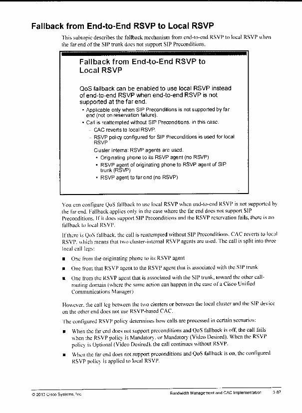
mm
Fallback from End-to-End RSVP to Local RSVP
This subtopic describes the fallback mechanism from end-lo-end RSVP to local RSVP whenthe far end of the SIP trunk does not support SIP Preconditions,
Fallback from End-to-End RSVP to
Local RSVP
QoS fallback can be enabled to use local RSVP insteadof end-to-end RSVP when end-to-end RSVP is notsupported at the far end.• Applicable only when SIP Preconditions is not supported by far
end (not on reservation failure).* Call is reattempted without SIP Preconditions, in this case.
CAC reverts to local RSVP.
- RSVP policy configuredfor SIP Preconditions is used for localRSVP
- Cluster-internal RSVP agents are used.
• Originating phone to its RSVP agent (no RSVP)• RSVP agentoforiginating phoneto RSVP agentofSIP
trunk (RSVP)
• RSVP agent tofarend (no RSVP)
You canconfigure QoS fallback to use local RSVP when end-to-end RSVP is notsupported bythe farend. fallback applies only in thecasewhere the far enddoesnolsupport SIPPreconditions. If il does supportSIP Preconditions and the RSVP reservation fails, there is nofallback to local RSVP.
If there is QoS fallback, thecall is reattempted without SIPPreconditions. CAC reverts to localRSVP. uhich means that two cluster-internal RSVP agents arc used. The call is split into threelocal call legs:
• One from the originating phone to its RSVP agent
• One from that RSVP agent to the RSVP agentthat is associated with theSIPtrunk
• One from the RSVP agent that is associated with the SIP trunk, toward theothercall-routing domain (where the same action con happen inthe ease ofa Cisco UnifiedCommunications Manager)
However, the call leg between the two clusters orbetween the local cluster and the SIP deviceon the other end does not use RSVP-based CAC.
The configured RSVP policy determines how calls areprocessed incertain scenarios:
• When the far end does not support preconditions and QoS fallback isoff, the call failswhen the RSVP policy is Mandatory, or Mandator,' (Video Desired). When the RSVPpolicy is Optional (Video Desired), the call continues without RSVP.
• When the farend does notsupport preconditions and QoS fallback ison, the configuredRSVP policy is applied to local RSVP.
>2013 Cisco Systems, Inc Bandwidth Management and CAC Implementation 3-87
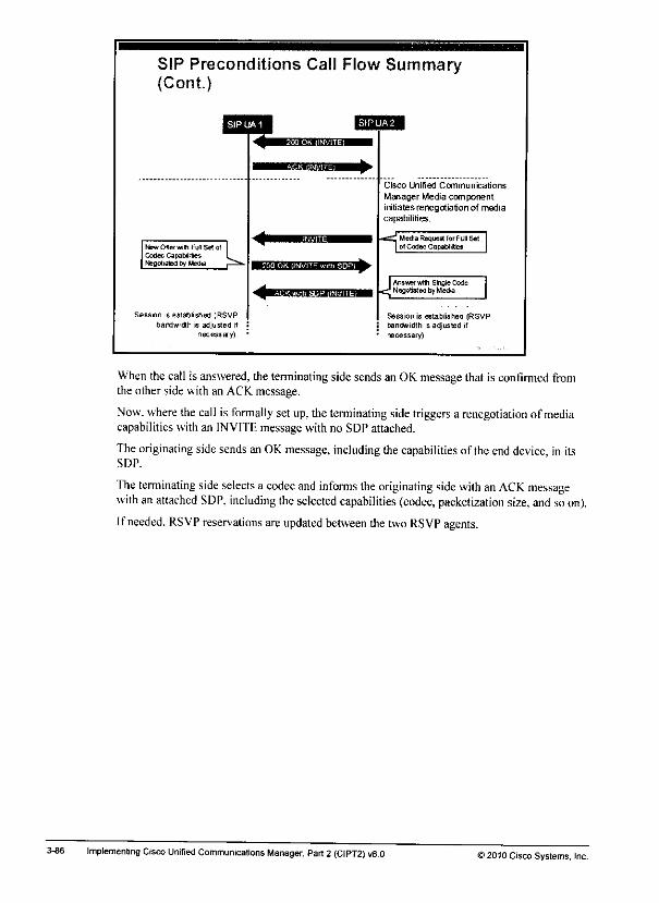
3-86
SIP Preconditions Call Flow Summary(Cont.)
Session is established (RSVPbandwidth is adjusted if
necessary).
Cisco Unified Communications
Manager Media componentinitiates renegotiation of mediacapabilities.
Media Request. forFull Satot Codec Capabilities
Answ3witti SlnflteCodeNegotiatedbyMedia
Session is established (RSVPbanOwidth Is adjusted ifnecessary).
Whenthe call is answered, the terminating side sendsan OK messagethat is confirmed fromthe other side with an ACK message.
Now. where the call is formally set up. the terminating side triggersa renegotiation of mediacapabilities with an INVITE message with no SDP attached.
Theoriginating sidesends an OKmessage, including thecapabilities of theenddevice, in itsSDP.
The terminating side selects a codec and informs the originating side with anACK messagewith anattached SDP, including theselected capabilities (codec, packetization size, and soon).
Ifneeded. RSVP reservations areupdated between the two RSVP agents.
Implementing Cisco Unified Communications Manager, Part2 (CIPT2) vS.O ©2010 Cisco Systems, Inc.
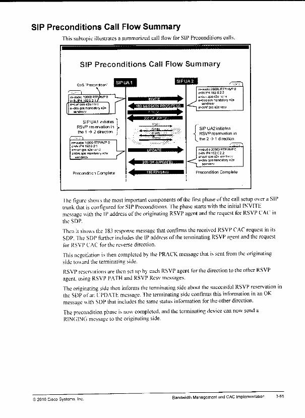
SIP Preconditions Call Flow SummaryThis subtopic illustrates a summarized call flow forSIPPreconditions calls.
SIP Preconditions Call Ffow Summary
QoS "Preconditon"
m=auara10000rtf/wP 0e=MIP4 1920 21
a=currqose2eia=des qos mandatory e2e
flendrecv
>
SIPUA1 initiates
RSVP reservation in
the 1 -» 2 direction
nvauOio 10000 RTPNWP 0c=!NIP4 192021a^currqos s2e';e--.iallies qos mandatory e2e
sendiecv 7
Precondition Complete
^H.II.J.I Ii>Kiaa*gaa^ai
•^f—BJSIfriJt'Jii'lWI
<
m=amJio 20O0G RTPfAVP 00=!NlP4 192022
a=wjrE.flose2e '.vi'-ta=desqos mandatory e2a
sendrecu
a^conl qos e2e recv
SIP UA2 initiates
RSVP reservation in
the 2^1 direction.
m=audio 20000 RTP/AVP 0C=INIP4192 02 2a=curr qtra e2f ser **•;•.•aides' qos mandalory e2e
sendrec*<<iPrecondition Complete
"fhe figure shows the most important components ofthe first phase ofthe call setup over a SIPtrunk that iseonligured for SIP Preconditions. The phase starts with the initial INVITEmessage with the IP address of the originating RSVP agent and the request for RSVP CAC inthe SDP.
Then it show s the 183 response message that confirms the received RSVP CAC request initsSDP. The SDP furtherincludes the IP address of the terminating RSVP agentand the requestfor RSVP CAC for the reverse direction.
This negotiation is then completed by the PRACK message that issent from the originatingside toward the temiinating side.
RSVP reser\ ations arethen setupIn each RSVP agent for thedirection to theother RSVPagent, using RSVP PATH and RSVP Resv messages.
The originating side then informs the temiinating side about the successful RSVP reservation inthe SDP of an UPDATH message. The terminating side confirms this information in anOKmessage with SDP that includes the same status information for the other direction.
The precondition phase is now completed, and the terminating device can now send aRINGING message to the originating side.
© 2010 Cisco Systems. Inc.BandwidthManagement and CAC Implementation 3-85

3-84
SIP Preconditions Operation (Cont.)
After call is answered, terminating Cisco UnifiedCommunicationsManager requests renegotiationof mediacapabilities (INVITE, no SDP).
Originating Cisco Unified Communications Manager sends fullset of supported media capabilities (OKwith SDP).
Receiving Cisco Unified Communications Manager sends ACKwith SDP, including selected codec.
Ifselected codec has different bandwidth requirements, RSVP isupdated accordingly.
Call is established with three call legs:
- Originating phone to originating RSVPagent (no RSVP)
- Orig inating RSVPagent to terminating RSVP agent (RSVP)- Terminating RSVP agent to terminating phone (no RSVP)
6. When the call isanswered, the terminating Cisco Unified Communications Managerrequests a renegotiation of media capabilities by sending a SIPINVITE message withoutSDP.
7. The originating Cisco Unified Communications Manager responds with aSIP OK messagewith SDP. Thecomplete set of supported media capabilities is included in theSDP.
8. Thereceiving CiscoUnified Communications Manager sends a SIPOKwithSDPmessage, including theselected codec. Thiscodec is nowactually usedfor theend-to-endcall.
9. Ifthe selected codec has bandwidth requirements that are different from the requirementsthat were used during the SIP Preconditions phase, the RSVP reservation is updatedaccordingly.
10. The call is now established with three call legs (like with RSVP-enabled locations for callswithin a cluster):
— The call leg between the originating IPphone and its RSVP agent, where noRSVP-based CAC was performed
— The middle call legbetween thetwo RSVP agents, where RSVP-based CAC wasperformed, as described earlier
— The call leg between the terminating IP phone and its associated RSVP agent, whereagainno RSVP-based CAC was performed
Note Standard locations-based CAC isperformed between the IP phones andtheir associatedRSVP agents As a result, thecall leg from theIPphone to itsRSVP agent iscountedagainst themaximum bandwidth thatisconfigured at thelocations thatare applied totheIPphone and to the RSVP agent.
Implementing Cisco Unified Communications Manager, Part 2 (CIPT2) v8.0 ) 2010 Cisco Systems, Inc.
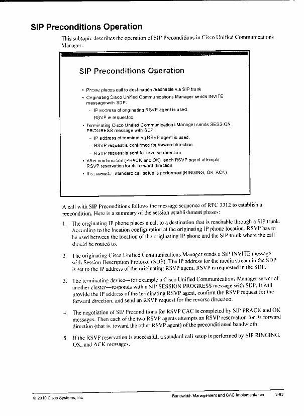
mm
mtw
SIP Preconditions OperationThis subtopic describes the operation ofSIP Preconditions inCisco Unified CommunicationsManager.
SIP Preconditions Operation
Phone places call to destination reachable via SIP trunk.
Originating Cisco Unified Communications Manager sends INVITEmessagewith SDP:
-• IP address of originating RSVP agent is used.
• RSVP is requested.
Terminating CiscoUnified Communications Manager sends SESSIONPROGRESS message with SDP:
IP address of terminating RSVP agent is used.
RSVP request is confirmed for forward direction.
RSVP request is sent for reverse direction
After confirmation (PRACK and OK), each RSVP agent attemptsRSVP reservation for its forward direction.
Ifsuccessful, standard call setup is performed (RINGING, OK, ACK)
A call with SIP Preconditions follows the message sequence of RFC 3312 toestablish aprecondition. Here isasummarv' ofthe session establishment phases:1. The originating IP phone places a call to adestination that isreachable through a SIP trunk.
According to the location configuration at the originating IP phone location, RSVP has tobeused between the location ofthe originating IP phone and the SIP trunk where the callshould be routed to.
2, The originating Cisco Unified Communications Manager sends a SIP INVITE messagewith Session Description Protocol (SDP). The IP address for the media stream in the SDPissetto the IPaddress of the originating RSVP agent. RSVP is requested in the SDP.
3 The tenninating device—for example aCisco Unified Communications Manager server ofanother cluster—responds with a SIP SESSION PROGRESS message with SDP. Itwillprovide the IP address of the terminating RSVP agent, confirm the RSVP request for theforward direction, andsend an RSVP request forthe reverse direction.
4. The negotiation of SIP Preconditions for RSVP CAC is completed by SIP PRACK and OKmessages. Then each of the two RSVP agents attempts an RSVP reservation tor i+s forwarddirection (that is. toward the other RSVP agent) ofthe preconditioned bandwidth.
5. Ifthe RSVP reservation issuccessful, a standard call setup isperformed by SIP RINGING,OK. and ACK messages.
j 2010 Cisco Systems, Inc.Bandwidth Managementand CAC Implementation 3-83
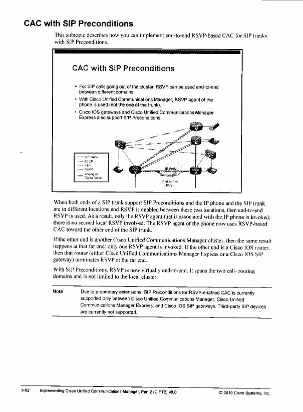
CAC with SIP Preconditions
This subtopic describes how you can implement end-to-end RSVP-based CAC for SIP trunkswith SIP Preconditions.
3-82
CAC with SIP Preconditions
For SIP calls going out of the cluster, RSVP can be used end-to-endbetween different domains.
With Cisco Unified CommunicationsManager, RSVPagent of thephone is used (not the one of the trunk).
Cisco IOS gateways and Cisco Unified Communications ManagerExpress also support SIP Preconditions.
SIP Trunk
SCCP
RTP
• RSVP
_ AnarogorDigital Voice
When both endsof a SIPtrunk support SIPPreconditions andthe IPphone andthe SIPtrunkare in different locations andRSVP is enabled between thesetwolocations, then end-to-endRSVP is used. Asa result, only theRSVP agent thatisassociated with theIP phone is invoked;there isnosecond local RSVP involved. TheRSVP agent of thephone now uses RSVP-basedCAC toward the other end of the SIP trunk.
Iftheother endisanother Cisco Unified Communications Manager cluster, then thesame resulthappens at that farend: only oneRSVP agent is invoked. If theotherend is a CiscoIOS router,then that router (either Cisco Unified Communications Manager Express or a Cisco IOS SIPgateway) terminates RSVP at the far end.
With SIP Preconditions, RSVP is now virtually end-to-end. Itspans the two call- routingdomains and is not limited to the local cluster.
Note Due toproprietary extensions, SIP Preconditions for RSVP-enabled CAC iscurrentlysupported only between Cisco Unified Communications Manager, Cisco UnifiedCommunications Manager Express, andCisco IOS SIP gateways. Third-party SIPdevicesare currently not supported.
Implementing Cisco Unified Communications Manager, Part2 (CIPT2) v8.0 ) 2010 Cisco Systems, Inc.
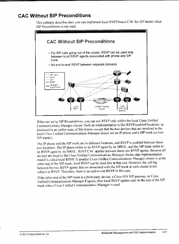
CAC Without SIP PreconditionsThis subtopic describes how you can implement local RSVP-based CAC for SIP trunks whenSIP Preconditions is not used.
CAC Without SIP Preconditions
ForSIP calls going out ofthe cluster, RSVP can be used onlybetween local RSVPagents associated with phone and SIPtrunk.
No end-to-end RSVP between separate domains.
When not using SIP Preconditions, you can use RSVP only within the local Cisco UnifiedCommunications Manager cluster. Such an implementation islike RSVP-enabled locations, asdiscussed in an earlier topic ofthis lesson, except that the two devices that are involved in thelocal Cisco Unified Communications Manager cluster arean IP phone and a SIP trunk (or twoSIP trunks).
The IP phone and the SIP trunk are in different locations, and RSVP is enabled between thesetwo locations. The IP phone refers to its RSVP agent by its MRGL, and the SIP trunk refers toits RSVP agent b> its MRGL. RSVP CAC applies between these two RSVP agents. Because alldevices are local 'to the Cisco Unified Communications Manager cluster, this implementationmodel is called local RSVP. Ifanother Cisco Unified Communications Manager cluster isattheother end of the SIP trunk, local RSVP can beused also at that end. However, the call legbetween the two RSVP agents that are associated with the SIP trunk ateach cluster isnolsubject to RSVP. Therefore, there isno end-to-end RSVP in this ease.If the other end ofthe SIP trunk isa third-party device, a Cisco IOS SIP gateway, orCiscoUnified Communicalions Manager Express, then local RSVP applies only tothe end ofthe SIPtrunk where Cisco UnitiedCommunications Manageris used.
)2O'0 Cisco Systems. IncBandwidthManagement and CAC Implementation
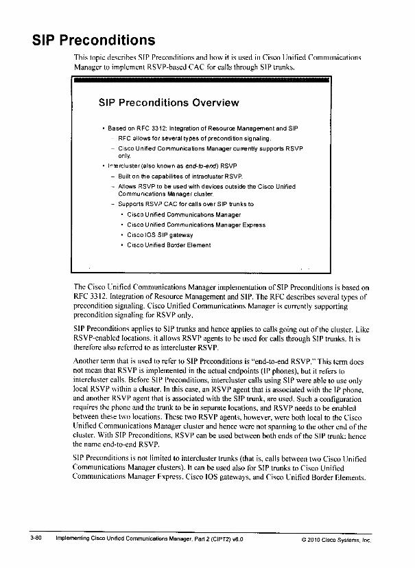
SIP PreconditionsThis topic describes SIP Preconditionsand how it is used in Cisco Unified CommunicationsManager to implement RSVP-based CAC for calls through SIP trunks.
SIP Preconditions Overview
Based on RFC 3312: Integration of Resource Management and SIP
- RFC allows for several types of precondition signaling.
- Cisco Unified Communications Manager currently supports RSVPonly.
lntercluster(also known as end-to-end) RSVP
- Built on the capabilities of intracluster RSVP.
- Allows RSVP to be used with devices outside the Cisco Unified
Communications Manager cluster.
- Supports RSVP CAC for calls over SIP trunks to
• Cisco Unified Communications Manager
• Cisco Unified Communications Manager Express
* Cisco IOS SIP gateway
• Cisco Unified Border Element
The Cisco Unified Communications Manager implementation of SIP Preconditions is based onRFC 3312. Integration of Resource Management and SIP.The RFCdescribes several typesofprecondition signaling. Cisco Unified Communications Manager is currently supportingprecondition signaling for RSVP only.
SIP Preconditions appliesto SIPtrunks and henceappliesto calls goingout of the cluster. LikeRSVP-enabled locations, it allowsRSVPagentsto be used for calls throughSIP trunks. It istherefore also referred to as intercluster RSVP.
Another term that is used to refer to SIP Preconditions is "end-to-end RSVP." This term doesnot meanthat RSVPis implemented in the actualendpoints (IP phones),but it refers tointercluster calls. Before SIPPreconditions, intercluster callsusing SIPwereableto useonlylocal RSVP within a cluster. In thiscase, an RSVP agent that is associated with the IPphone,and another RSVPagent that is associated with the SIP trunk,are used. Sucha configurationrequires the phone and the trunk to be in separate locations, and RSVP needs to be enabledbetweenthesetwo locations. Thesetwo RSVPagents,however, were both local to the CiscoUnified Communications Managerclusterand hencewere not spanningto the other end of thecluster. With SIP Preconditions, RSVP can be used between both ends of the SIP trunk; hencethe name end-to-end RSVP.
SIP Preconditions is not limited to intercluster trunks (that is, calls between two Cisco UnifiedCommunications Manager clusters). It can be used also for SIP trunks to Cisco UnifiedCommunications ManagerExpress. Cisco IOS gateways, and Cisco UnifiedBorderElements.
3-80 Implementing CiscoUnified Communications Manager. Part2 (CIPT2) v8.0 ) 2010 Cisco Systems. Inc.
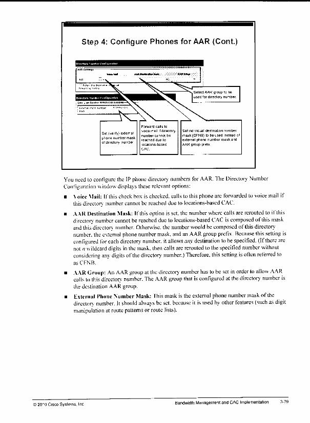
Step 4: Configure Phones for AAR (Cont.
Set (verify) exiemalphone number maskotdireclory numbef
Forward calls to
voce mail if directory
number cannot be
reached due lo
locai ms-based
CAC.
Set individual destination number
mask (CFNB) to be used instead ofexternal phone number mask andAAR group prefix
You need lo configure the IPphone directory numbers forAAR. The Directorv- NumberConfiguration windowdisplays these relevantoptions:
• Voice Mail: If this check box is checked, calls to this phone are forwardedto voice mail ifthis directory numbercannotbe reached due to locations-based CAC.
• AAR Destination Mask: If thisoption is set. the number where callsare rerouted to if thisdirectory number cannot be reached due to locations-based CAC iscomposed of this maskand this director, number. Otherwise, the number would be composed of this directorvnumber, the external phone number mask, and anAAR group prefix. Because 1his setting isconfigured for each directory number, it allows any destination to be specified. (Ifthere arcnot n wildcard digits inthe mask, then calls arererouted to thespecified number withoutconsidering any digits ofthe directorv' number.) Therefore, this setting isoften referred loas CFNB.
• AARGroup: An AAR group at thedirectory number has to beset in orderto allow AARcalls to thisdirector.' number. TheAAR group that is configured at thedirectorv number isthe destination AAR group.
• External Phone Number Mask: This mask is the external phone number mask of thedirectory number. Itshould always be set, because it is used by other features (such as digitmanipulation at routepatternsor route lists).
© 2010 Cisco Systems. Inc BandwidthManagement and CAC Implementation 3-79

Step 4: Configure Phones for AARThe figure shows how to configure phones for AAR.
3-78
Step 4: Configure Phones for AAR
Cisco Unified Communications Manager Administration:Call Routing > Phone
When you enable AAR on a phone, there are two possible settings in the Phone Configurationwindow:
• AAR CSS: This CSS is used ifa call that originated at this phone is rerouted using AAR.
• AAR Group; The AAR group of the phone is the source AAR group, while the AARgroupthat was set at the directory numberis the destination AARgroup. It is important tounderstand this distinction for the configuration of AAR prefixes,becausethey areconfigured separately foreachpairof AAR source anddestination group. If noAAR groupis set at the phone, then the AAR group of the directory number is used as the AAR sourcegroup for this phone.
Implementing Cisco Unified Communications Manager, Part 2 (CIPT2) v8.0 12010 Cisco Systems, Inc.
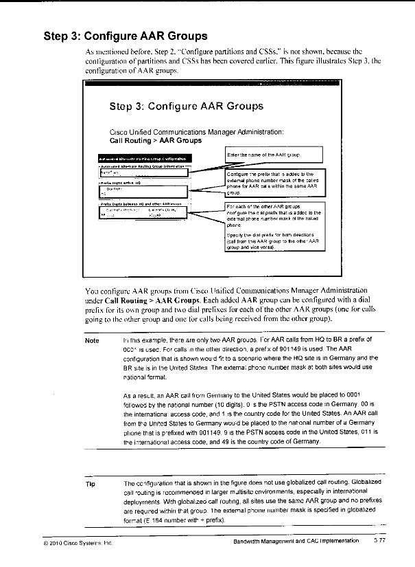
Step 3: Configure AAR GroupsAs mentioned before. Step 2. "Configure partitions and CSSs." is not shown, because theconfigurationof partitions and CSSs has been covered earlier. This figure illustrates Step 3. theconfiguration of AAR groups.
Step 3: Configure AAR Groups
Cisco Unified Communications Manager Administration:Call Routing > AAR Groups
Enler the name of me AAR group.
onfiguie the prefix that is added to theexternal phone number mask of the calleflphone for AAR calls within the same AAR
group
For each of the other AAR groups,
configure the dial prefix that is added to theexternal phone number mask of the calledphone
Specify the dial prefix for bolh directions(call from this AAR group to the other AARgroup and vice versa)
You configure AARgroups from Cisco Unified Communications Manager AdministrationunderCall Routing >AAR Groups. EachaddedAARgroupcan be configured with a dialprefix for itsown group andtwodial prefixes foreachof theotherAARgroups (one forcallsgoing to theothergroup andone forcallsbeingreceived from theothergroup).
Note Inthis example, there are onlytwoAAR groups. For AAR calls from HQto BRa prefix of0001 is used. For calls tn the other direction, a prefix of 901149 is used. The AAR
configuration that is shown would fit to a scenario where the HQsite is in Germany and theBR site is in the United States The external phone number mask at both sites would use
national format.
As a result, an AAR call from Germany to the United States would be placed to 0001
followed by the national number (10 digits). 0 is the PSTNaccess code in Germany, 00 isthe international access code, and 1 is the country code for the United States. An AAR call
from the United States to Germanywould be placed to the national number of a Germanyphonethat is prefixed with 901149. 9 is the PSTN access code inthe United States, 011 isthe international access code, and 49 is the country code of Germany.
Tip The configuration thatisshown in thefigure does not useglobalized call routing. Globalizedcall routing is recommended in larger multisite environments, especially ininternationaldeployments. With globalized call routing, all sitesusethesame AAR group and noprefixesare required within thatgroup Theexternal phone number mask is specified in globalizedformat(E.164 number with + prefix).
) 2010 Cisco Systems. Inc. Bandwidth Management and CAC Implementation 3-77
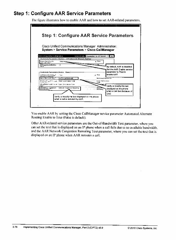
Step 1: Configure AAR Service ParametersThe figure illustrates how to enable AAR and how to set AAR-related parameters.
Step 1: Configure AAR Service Parameters
Cisco Unified Communications Manager Administration:System > Service Parameters > Cisco CallManager
You enable AAR by setting the Cisco CallManager service parameter Automated AlternateRouting Enable to True (False is default).
Other AAR-related service parameters aretheOut-of-Bandwidth Text parameter, where youcan set the text that is displayed on an IP phone when a call fails due to no available bandwidth,and the AAR Network Congestion Rerouting Text parameter, whereyou can set the text that isdisplayed on an IP phone when AAR reroutes a call.
3-76 Implementing CiscoUnified Communications Manager, Part2 (CIPT2) v8.0 >2010 Cisco Systems, Inc.
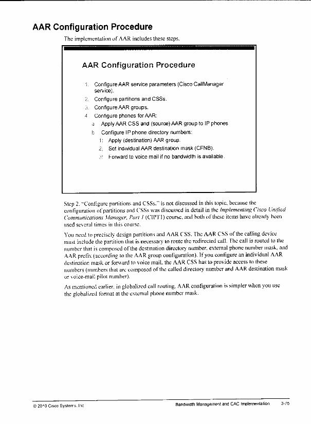
AAR Configuration ProcedureThe implementation of AAR includes these steps.
AAR Configuration Procedure
1 ConfigureAAR service parameters (Cisco CallManagerservice).
2 Configure partitions and CSSs.
3 Configure AAR groups.
A Configure phones for AAR:
a ApplyAARCSS and (source) AARgroup to IP phones.
& Configure IPphone directory numbers:
1) Apply (destination) AAR group.
2) Set individual AAR destination mask (CFNB),
s, Forward to voice mail if no bandwidth is available.
Step 2.-Configure partitions and CSSs." is notdiscussed in this topic, because theconfiguration ofpartitions and CSSs was discussed indetail in the Implementing Cisco UnifiedCommunications Manager, Part 1 (CIP'1'1) course,and both of these itemshave already beenused se\eral limes in this course.
You need toprecisely design partitions and AAR CSS. The AAR CSS of the calling devicemust include the partition that is necessary to route the redirected call. Thecall is routed to thenumber that iscomposed of the destination directory number, external phone number mask, andAAR prefix (according tothe AAR group configuration). Ifyou configure an individual AARdestination mask or forward to voice mail, the AAR CSS has to provide access to thesenumbers (numbers thatarccomposed of thecalled directory number andAAR destination maskor voice-mail pilot number).
As mentioned earlier, inglobalized call routing, AAR configuration issimpler when you usethe globalized format at theexternal phone number mask.
© 2010 Cisco Systems. Inc BandwidthManagement and CAC Implementation

AAR Considerations
3-74
Ihis subtopic discusses important considerations when you are implementing AAR.
AAR Considerations
AAR supports these call scenarios:
- Call originates from an IP phone within one location andterminates at an IP phone within another location.
- Incoming call through a gateway device within one locationterminates at an IP phone within another location.
AAR does not work with SRST:
- AAR is not activated by WAN failure.
- AAR requires CAC failure.
Use of globalized call routing simplifies AAR implementation ininternational deployments.
AARdoes not support CTI route points as the origin or destinationof calls.
AAR does not workto Cisco Extension Mobility users roaming todifferent sites.
AAR supports these call scenarios:
• Call originates from an IPphone within one location andterminates at an IPphone withinanother location.
• Incoming call through a gateway device within one location terminates at an IPphonewithin another location.
AAR does not work with Survivable Remote Site Telephony (SRST). AAR isactivated onlyafter a call is denied by CAC, not by WAN failures.
Using globalized call routing simplifies the implementation of AAR substantially—especiallyin international deployments.
AAR does not support CTI route points as the origin or destination of calls, and AAR is notcompatible with Cisco Extension Mobility for users who roamto different sites.
Note When tail-end hop-off (TEHO) is used, itis important toconfigure AAR in such a way thatthe local gateway is always used for callsbeing rerouted by using AAR. This automaticallyoccurs when you use local routegroups. When youare not using local routegroups, youhave to configure AAR CSS so that the focal gateway is used forAAR calls. Ifthe AAR CSSrefersto the TEHO gateway, AAR callswill fail, because the callleg to the (remote) PSTNgateway again has the same issue that the initial call had: Itneeds to go overthe IPWAN(which typically meansthat itgoesoutofthe location oftheoriginating phone), butdoingthatis not possible becauseno bandwidth is left for the location (which was the reason whythe initial called ended up in a CACfailure).
implementing CiscoUnified Communications Manager, Part2 (CIPT2) v8.0 32010 Cisco Systems, Inc.

In theexample, all phones are in thesame AAR group (System). Noprefix is configured forcallswithin thissingle AAR group. There is a single route pattern in Ii.164 format: (\+!). Theroute pattern refers to theonly configured route list, which is configured to usethe local routegroup. Each gateway is referenced from a site-specific route group. U.S. phones usea U.S.-specific device pool with the local route group setto U.S., and German phones use a devicepool specific to theircountry. where the local route group refers to the DE route group. Theexternal phone number mask in globalized format is +15115222xxx at U.S. phones and+4969125xxxx at Gemian phones. The AAR CSS is the same for bothphonesand providesaccess to the '*+.! route pattern.
When a call from a U.S. phone to a German phone is notadmitted because of noavailablebandwidth, theexternal phone number mask of the German phone is merged withthedirectorynumber ofthe phone (in thiscase, the result is+49691253001). No AAR prefix is added, so acall isplaced to that number. It matches the \+.! route pattern, and the local route group isto beused, fherefore. the call is sent to the U.S. gateway, where the called numbercan be localized,using called-party transformation (that is. the number ischanged lo49691253001 with anumber type of international) settings thatare configured at thegateway.
The same thing happens for calls in the other direction. As a result,+15115552001 is called,and after the callednumberis localized at call egress—again provided by globalIransformations at thegateway—a call with a number typeof international isplaced to15115552001. this time through the Gennan gateway.
©2010 Cisco Systems. Inc Bandwidth Management and CAC Implementation 3-73

AAR Example with Local Route Groups and GlobalizedNumbers
The figure showsan AARexamplewhereglobalized call routingand local routegroupsareused.
AAR Example with Local Route Groupsand Globalized Numbers
,. Sitel
DN" 2001
Ext Phone
Number Mask
+ 15115552XXX
IP WAN
PSTN
Route PaBem;**!
1
Single Roule ListDefault Local Route Group
Single Route Pattern in OnePartition, Single AAR CSS, Single
AAR Group, No Prefixes Within AARGroup
Site 2
DN": 3001
Ext. Phone
Number Mask
+4969125XXXX
' Unified CM = Cisco Unitied Communications Manager, " DN = directory number
If the AAR destination mask is entered in the globalized form, and if every AAR CSS is able toroute calls to destinations in the globalized form, then system administrators can forego theconfiguration of AAR groups, because their sole function is to determine which digits to prefixbased on the local requirements of the PSTN access of the calling phone to reach the specificdestination. With globalized call routing, Cisco Unified Communications Manager can routecalls to the PSTN in E.164 format with a + prefix. When you configure the external phonenumber mask, in this format, no prefixes are required for AAR. To localize the called- andcalling-party numbers, implement global transformations for each egress PSTN gateway (likefor normal PSTN calls).
Without local route groups, the AAR CSS is used to route the call through the colocatedgateway of the calling phone by matching a site-specific route pattern that refers to a site-specific route list, route group, and gateway. When local route groups and globalized callrouting are implemented, the egress gateway does not need to be selected by site-specific AARCSS. because the egress gateway is determined by the local route group feature.
In summary. \\ hen you are using globalized call routing with local route groups, AARimplementation is extremely simple: Only a single AAR CSS and AAR group are required andapplied to all phones, regardless of their location.
3-72 ImplementingCisco Unified Communications Manager, Part 2 (CIPT2)v8.0 >2010 Cisco Systems. Inc.

In the other direction, an AAR call from a German phone to a U.S. phone composes a dialstring of 00015115552001. which is the format that is used for inlemalional calls to the UnitedStates. It matches the 0.! route pattern and is sent out using the German gateway.
In summary, this two-site example requires two route patterns in different partitions, two AARCSSs. and two AAR groups. In a large, worldwide deployment with lots of different numberingplans, the configuration of AAR groups can be relatively complex.
)2010 Cisco Systems, Inc Bandwidth Management andCAC Implementation
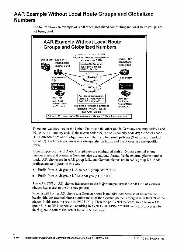
AAR Example Without Local Route Groups and GlobalizedNumbers
The figure shows an example of AAR when globalized call routing and local route groups arenot being used.
AAR Example Without Local RouteGroups and Globalized Numbers
UnifiedCW Site 1 (+1):international
Dialing: 9.011
ON" 2001
E<t Phone
Number Mask:
511S552XXX
Second call fails locations-based CAC
and should use PSTN.
Location ConfigurationHu6_None. UnlimitedBR-LOC 24 kb/s
AAR Group Configuration.Prefix U.S. lo DE. 901149
Prefix DE to U S.. 0001
Two Roule Paltems in Different
Partitions, Two AAR CSSs,
Two AAR Groups
Site 2 (+49):International
Dialing: 0.00
DN": 3001
Ext Phone
Number Mask:
69125XXXX
' Urafied CM - Cisco Unified Communications Manager, " DN = directory number
There are two sites, one in the United States and the other one in Germany (country codes 1 and49). At site 1 (country code 1) the access code is 9, at site 2 (country code 49) the access codeis 0. Both countries use 10-digit numbers. There are two routepatterns(9.@ for site 1and 0.!for site 2). Each route pattern is in a site-specific partition, and the phones use site-specificCSSs.
Fromthe perspective of AAR,U.S.phonesare configured with a 10-digitexternal phonenumber mask, and phones at Germany also use national format for the external phone numbermask. U.S. phones are in AAR group U.S., and German phones are in AAR group DE. AARprefixes are configured in this way:
• Prefix from AAR group U.S. to AAR group DE: 901149
• Prefix from AAR group DE to AAR group U.S.: 0001
The AARCSS of U.S. phones has accessto the 9.@ roulepattern; the AARCSS of Germanphones has access to the 0.! route pattern.
When a call from a U.S. phone to a Gennan phone is not admitted because of no availablebandwidth, the extemal phonenumbermaskof the German phone is merged withthe DN of thephone(in this case, the result is 691253001). Then the prefix901149configured from AARgroup U.S. to DE is appended, resulting in a call to 901149691253001, which is processed bythe 9.(S) route patternthat refersto the U.S. gateway.
3-70 Implementing Cisco Unified Communications Manager, Part 2 (CIPT2) v8.0 ) 2010 Cisco Systems. Inc.
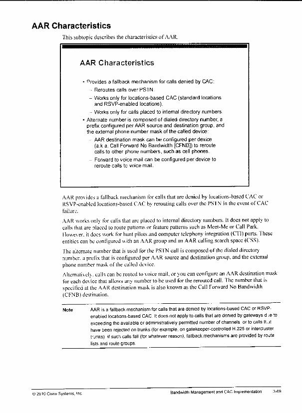
AAR Characteristics
This subtopic describes the characteristics of AAR.
AAR Characteristics
• Provides a fallback mechanism for calls denied by CAC:
- Reroutes calls over PSTN.
- Works only for locations-based CAC (standard locationsand RSVP-enabled locations).
• Works only for cads placed to internal directory numbers.
• Alternate number is composed of dialed directory number, aprefix configured per AAR source and destination group, andthe external phone number mask of the called device:
- AAR destination mask can be configured per device(a.k.a. Call Forward No Bandwidth [CFNB]) to reroutecalls to other phone numbers, such as cell phones.
- Forward to voice mail can be configured per device toreroute calls to voice mail.
AAR pro\idesa fallback mechanism for callsthatare denied by locations-based CAC orRSVP-cnablcd locations-based CAC bv rerouting calls over the PSTN in the event of CACfailure.
AAR works only forcalls that arc placed to internal directory numbers. Itdocsnotapply tocalls that are placed to route patterns or feature patterns such as Meet-Me or Call Park.Ho\\e\ er. it does work forhunt pilots and computertelephony integration (CTI)ports.Theseentities canbeconfigured with an AAR group andan AAR calling search space (CSS).
The alternate number that is used for the PSTN call is composed of the dialed directorynumber, a prefix that isconfigured perAAR source and destination group, and theexternalphone number mask of the called device.
Alternatively, calls can berouted tovoice mail, oryou can configure an AAR destination maskfor each device that allows an> numberto be used for the rerouted call. The numberthat isspecified at the AAR destination mask isalso known as the Call Forward No Bandwidth(CFNB) destination.
Note AAR is a fallback mechanism for calls that are denied by locations-based CAC or RSVP-enabled locations-based CAC. It does not apply to calls that are denied by gateways d le to
exceeding theavailable or administratively permitted number ofchannels, or to calls tuthavebeenrejected on trunks (for example, ongatekeeper-controlled H.225 or interclustertrunks) If suchcalls fail (for whatever reason), fallback mechanisms are provided by routelists and route groups.
) 2010 Cisco Systems, Inc Bandwidth Management and CAC Implementation
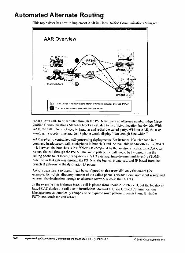
Automated Alternate RoutingThis topic describes howto implement AAR in Cisco Unified Communications Manager.
AAR Overview
Headquarters
Branch B
ys Cisco Unrfied CommunicationsManager CACblocks a call over the IP WAN.
9 The call isautomatically rerouted over thePSTN.
AAR allows calls to be rerouted through the PSTN by using an alternate number when CiscoUnified Communications Manager blocks a call due to insufficient location bandwidth. WithAAR. the caller does not needto hang up and redial the called party. Without AAR, the userwouldget a reordertone and the IP phonewoulddisplay"Not enoughbandwidth."
AAR applies to centralized call-processing deployments. For instance, ifa telephone in acompany headquarters calls a telephone in branch B and the available bandwidth for the WANlinkbetween the branches is insufficient (as computed by the locations mechanism), AAR canreroute the call through the PSTN. The audio path of the call would be IP-based from thecalling phone to its local (headquarters) PSTN gateway, time-division multiplexing (TDM)-based from thatgateway through the PSTN to the branch B gateway, and IP-based from thebranch B gateway to the destination IP phone.
AAR is transparent to users. Itcan beconfigured so that users dial only theon-net (forexample, four-digit) directory number of the called phone. (Noadditional userinput is requiredto reach the destination through an alternate network such as the PSTN.)
In the examplethat is shown here, a call is placed from PhoneA to Phone B, but the locations-based CAC denies the call due to insufficient bandwidth. Cisco Unified CommunicationsManagernow automatically composes the requiredroutepatternto reach Phone B via thePSTN and sends the call off-net.
3-68 Implementing Cisco Unified Communications Manager, Part2 (CIPT2) vfl.O 12010 Cisco Systems, Inc.
Afteryouclick Save,thechanges are displayed in the Location RSVP Settings section of thewindow. Only the locations thatarcnotconfigured touse the system default arelisted.
Note You can also enable RSVP within a location. For the currently configured location, Use
System Default is not an option.Youcan choose only No Reservation,Optional (VideoDesired), Mandatory, or Mandatory (VideoDesired)within a location. The defaultforcalls toown location is No Reservation, and to all other locations, the default is Use System Default.
Note When RSVP-enabled locations are used, it is extremely important that the phones use the
appropriate RSVP agent. Note thattherewill be threecall legs, phone to its RSVP agent;that RSVP agent to another, remote RSVP agent;and finally, that remoteRSVP agent to itsphone.
How does Cisco Unified Communications Manager determine which RSVP agent is the
RSVP agent to be used bya given phone?The selection of the RSVP agent is based solelyon the MRGLs that are assigned to the phones that attempt to establish a call. Errors in theMRGL configuration can resultinsuboptimal traffic flows. Therefore, whenyouimplementRSVP-enabled locations, you must properly assign phones to RSVPagents by usingMRGLs and MRGs. The samplescenarioat the beginning ofthisconfiguration subtopicprovided all the information that is needed for assigning the RSVP agentstothe phonesTheappropriate configuration is notshown herebecausetheconfiguration ofMRGLs andMRGswas covered in detail in the Implementing Cisco Unified Communications Manager.Part 1 (CIPT1) courseand becauseMRGLs and MRGs havealready beendiscussed inthiscourse.
©2010 Cisco Syslems. Inc. Bandwidth Management and CAC Implementation 3-67
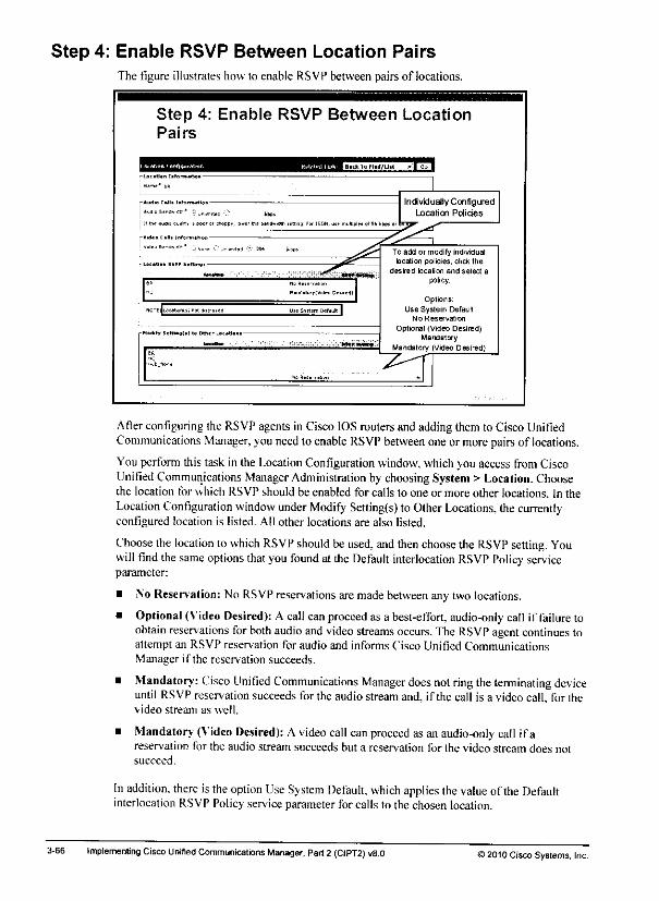
Step 4: Enable RSVP Between Location Pairs
The figure illustrates how to enable RSVP between pairs of locations.
Step 4; Enable RSVP Between LocationPairs
Afterconfiguring the RSVPagentsin Cisco IOSroutersand adding themto Cisco UnifiedCommunications Manager, youneed to enable RSVP between one or morepairsof locations.
Youperformthis task in the Location Configuration window, whichyou access from CiscoUnified Communications Manager Administration by choosing System > Location. Choosethe location for which RSVP should be enabled for calls to one or more other locations. In theLocation Configuration window underModify Setting(s) to OtherLocations, thecurrentlyconfigured location is listed. All other locations are also listed.
Choose the location to which RSVP should be used, andthen choose the RSVP setting. Youwill find thesame options thatyou found at the Default interlocation RSVP Policy serviceparameter:
• \o Reservation: No RSVP reservations are made between any two locations.
• Optional (Video Desired): A callcanproceed as a best-effort, audio-only call if failure toobtain reservations forboth audio andvideo streams occurs. The RSVP agentcontinues toattempt an RSVP reservation for audio and informs Cisco Unified CommunicationsManager if the reservation succeeds.
• Mandatory: Cisco Unified Communications Manager does notringtheterminating deviceuntil RSVP reservation succeeds for theaudiostream and, if the call is a video call, for thevideo stream as well.
• Mandatory (Video Desired): A video call can proceed as anaudio-only call ifareservation for the audio stream succeeds but a reservation for the video stream does notsucceed.
Inaddition, there is theoption Use System Default, which applies thevalue of the Defaultinterlocation RSVP Policy serviceparameter for calls to the chosenlocation.
3-66 Implementing CiscoUnified Communications Manager, Part2 (CIPT2) v8.0 ©2010 Cisco Systems, Inc.
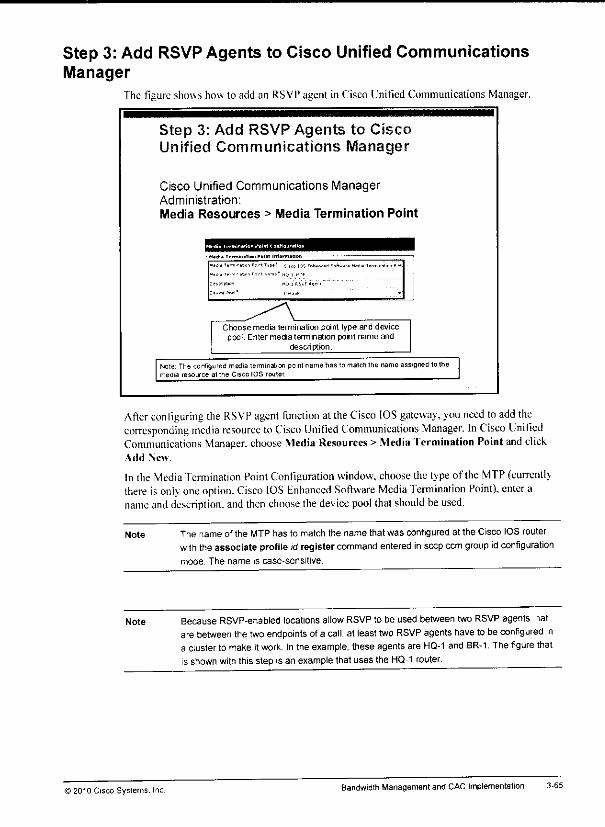
***w
Step 3: Add RSVP Agents to Cisco Unified CommunicationsManager
The figure shows how to add an RSVPagent in Cisco Unitied Communications Manager.
Step 3: Add RSVP Agents to CiscoUnified Communications Manager
Cisco Unified Communications ManagerAdministration:
Media Resources > Media Termination Point
•tAilt-n.-iaoifcrtTrB" ;,SCO105 Fnh.nr.H 5«ft««« PWd.aT.rni.njtion 1.
ttuioaon H« 1 HSiF lot 1 •
^\Choose media termination point type and device
pool. Enter media termination point name anddescription.
Note The configured media termination point name has to matctittie name assignefl lothemedia resource at the Cisco IOS router
After configuring the RSVP agent function at theCisco IOS gateway, youneed toadd thecorresponding media resource toCisco Unified Communications Manager. In Cisco UnitiedCommunications Manager, choose Media Resources > MediaTermination Point and clickAdd New.
Inthe Media Termination Point Configuration window, choose the type of the MTP (currentlythere is only oneoption. Cisco IOS Enhanced Software Media Termination Point), enter aname anddescription, andthen choose thedevice pool thatshould be used.
Note The name of the MTP has to match the name that was configured at the Cisco IOS routerwith the associate profile idregister command entered inseep ccmgroupidconfigurationmode. The name is case-sensitive.
Note Because RSVP-enabled locationsallowRSVPto be used between two RSVPagents latare betweenthe twoendpoints ofa call, at least twoRSVP agents have to be configured ina cluster to make itwork. Inthe example, these agents are HQ-1 and BR-1 The figure thatis shown with this step is an example that uses the HQ-1 router.
© 2010 Cisco Systems. Inc. Bandwidth Management and CAC Implementation 3-65
Note The bandwidth that is reserved for a call depends on the codec that is used. As with
standard (non-RSVP-enabled) locations, it is 80 kb/s for G.711 and 24 kb/s for G.729.
During the call setup, however, the RSVP agent will always request an additional 16 kb/s,
which is released immediately after the RSVP reservation is successful. Therefore, the
interface bandwidth has to be configured in such a way that it can accommodate the desired
number of calls (considering the codec that will be used) plus the extra 16 kb/s. If, for
example, two G.729 calls are permitted on the interface, 64 kb/s must be configured; for two
2 G.711 calls, 176 kb/s is required.
In the example, only one G.729 call is permitted.
Note Because RSVP-enabled locations allow RSVP to be used between two RSVP agents that
are between the two endpoints of a call, you need to configure at least two RSVP agents in
a cluster to make it work. In the example, these agents would be HQ-1 and BR-1, The figure
that is shown with this step is an example that uses the HQ-1 router.
3-64 Implementing Cisco Unified Communications Manager. Part 2 (CIPT2) v8.0 ©2010 Cisco Systems, Inc.

Step 2: Configure RSVP Agents in Cisco IOS SoftwareThe figure shows how to configure a Cisco IOS router to enable RSVP-agent functionality.
Step 2: Configure RSVP Agentsin Cisco IOS Software
:p local FastBtheraetO/C;p ccp 10.1.1.1 identifier 1
;p ccm group 1
SBOciate ecu 1 priority 1
Buociatf profile 1 register hq-1_mtf
interface SerialO/1
description IP-WAN
ip address 10.1.4.101 255.255.255.duplex sutc
speed auto
ip rsvp bandwidth 4C
Pass-through codec isused, which allows a
CiscolOS SoftwareMTP to be used.
MTP is used as RSVP
agent.
Software MTP is used;
no hardware DSPs are
required.
RSVPis enabled on
interface; permittedbandwidth is specified.
As with other mediaresources that arc provided by Cisco IOS Software (conference bridgesandtranscoders). theconfiguration starts with global Skinny Client Control Protocol (SCCP)settings, followed by the Cisco Unified Communications Manager group configuration. Inconfiguring the media resource itself (which you perform indspfarm profile configurationmode). \ou use three commands that arc specificto the implementation of a software MI PRSVP agent:
• codec pass-through: This command specifies that the actual content ofthe RTP stream isnot modified. Mediaresources usually have to interpret and modify the audio stream:examples are transcoders that change the codec ofthe audio stream, orhardware MTPs thatare used to convertout-of-band signaling to in-hand dual tone multifrequency (DTMF).The RSVP agent repackages RTP only at Layer 3 and Layer 4. It terminates the incomingcall leg by dc-encapsulating RTP and then re-encapsulating the identical RTP into a new-call leg. Because this simple repackaging does not require interpreting and modifying theaudio payload (which isrequired with transcoders orhardware MTPs that are used forDTMF). the router can perfonn this function in software.
* rsvp: This command specifics that this MTP isused as an RSVP agent that will be used toset up a call leg toanother RSVP agent where RSVP with IntServ over DiffScrv has to beused.
• maximum sessionssoftware sessions: This command specifies the maximum numberofsessionsfor the mediaresource. Note that the keyword software has been used. Thiskeyword indicates that this RSVP agent should nol use digital signal processors (DSPs) butthat it should perform its function in software. You can use software MTP only when codecpass-through has been configured.
After setting up the Ml"P RSVP agent, you need toenable RSVP on the WAN interface orinterfaces b\ using the ip rsvp bandwidth bandwidth command. The specified bandwidthdetermines how much bandwidth can be reserved by RSVP.
© 2010 Cisco Systems. Inc. Bandwidth Management and CAC Implementation 3-63
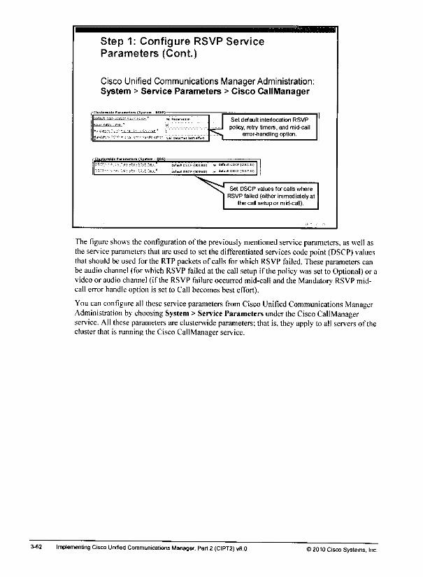
Step 1: Configure RSVP ServiceParameters (Cont.)
Cisco Unified Communications Manager Administration:System > Service Parameters > Cisco CallManager
t "* *.r -l^.. j_f-i^...—K£urj _
»T,Qt b*tt *HM
Set default interlocation RSVP- r- * .«
^Jtfrj
. ••>*, -t .-• . . rr- ,
^:•-•? n-;-j. r.-r^ "i'^sjrti? c*n B*enor-handling option.
_S«tor**,* DSCP<OO00O0l v d6T*ultDS
0c**uK DSCP10CQ00D) * d»<Jult 05
Set DSCP values for calls where
RSVP failed (either immediately atIhe cal setup or m id-call).
The figureshowsthe configuration of the previously mentioned serviceparameters, as well asthe serviceparameters that are used to set the differentiated servicescode point (DSCP) valuesthatshould be used forthe RTP packets of callsforwhich RSVP failed. These parameters canbe audiochannel (for which RSVPfailed at the call setup if the policywas set to Optional) or avideoor audiochannel(if the RSVPfailure occurred mid-call and the Mandatory RSVPmid-call error handle option is set to Call becomes best effort).
Youcanconfigure all these service parameters from Cisco Unified Communications ManagerAdministration bychoosing System> Service Parameters under theCisco CallManagerservice. All these parameters are clusterwide parameters; that is, they apply to all serversof thecluster that is running the Cisco CallManager service.
3-62 Implementing Cisco Unified Communications Manager, Part2 (CIPT2) v8.0 >2010 Cisco Systems, Inc.

The table shows the interactions of these policy settings.
RSVP Policy When Reservation
Failure (Non-Multilevel
Precedence and
Preemption [MLPP])
Occurs
Mandatory
RSVP
Mid-Call Error
Handle
Option
Mandatory
RSVP
Mid-Cail
Retry
Counter
Behavior or Call
Result
Mandatory Audio or video RSVP
failure in initial call setup— —
Call rejected.
Mandatory Audio or video RSVPfailure in mid-call
Call fails
following retrycounter
exceeded
n Call released if
reservation does not
succeed after n retries.
Mandatory Audio or video RSVPfailure in mid-call
Call becomes
best effort
n Call proceeds as besteffort, and reservationis retried infinitely.
Mandatory(Video Desired)
Audio RSVP failure ininitial call setup
— —
Call rejected.
Mandatory(Video Desired)
Video RSVP failure in
initial call setup— ~-
Call proceeds as audio-only call.
Mandatory(Video Desired)
Audio RSVP failure in
mid-call
Call fails
following retrycounter
exceeded
n Call released if
reservation does not
succeed after n retries.
Mandatory(Video Desired)
Video RSVP failure in
initial call setup— —
Call proceeds as audio-only call.
Mandatory(Video Desired)
Audio RSVP failure in
mid-call
Call becomes
best effort
n Call proceeds, audiostream in call becomesbest effort if reservationdoes not succeed aftern retries.
Mandatory(Video Desired)
Video RSVP failure in
mid-call
Call fails
following retrycounter
exceeded
n Call proceeds as audio-only call.
Mandatory(Video Desired)
Video RSVP failure inmid-call
Call becomesbest effort
n Call proceeds; videostream in call becomes
best effort if reservationdoes not succeed aftern retries.
Optional (VideoDesired)
Audio or video RSVPfailure in initial call setup
Call proceeds as audio-only call with besteffort; RSVP is trie.,until reservation
succeeds or call is torn
down
Optional (VideoDesired)
Audio or video RSVPfailure in mid-call
Call proceeds as audio-only call; if audiostream had reservationfailure, it becomes besteffort.
Mandatory Audio or video RSVPfailure in initial call setup
—
~
Call rejected.
) 2010 Cisco Systems, Inc BandwidthManagement and CAC Implementation 3-61

RSVP Retry Timer: This parameter defines the interval (in seconds) after which theRSVP agent will retry the reservation if there is a failure. If you set this parameter to 0, youdisable RSVP retry on the system. If the RSVP policy is optional, the call can still proceedeven if there is RSVP failure during call setup time. An RSVP failure indicates insufficientbandwidth at the time of setup, so the call is likely to begin with poor voice quality.However, this condition may be transient, and the automatic reservation retry capabilitymay succeed during the course of the call, at which point adequate bandwidth will beensured for the remainder of the call. The icon or message that is displayed to the userinitially should convey something like, "Your call is proceeding despite networkcongestion: you may experience impaired audio quality; if this condition persists, you maywant to try your call again later." If reservation retry succeeds, the icon or message shouldbe removed or should be replaced by one that conveys a return to normal networkconditions and ensured audio quality.
Mandatory RSVP Mid-Call Retry Counter: This parameter specifies the RSVP mid-callretry counter when the RSVP policy specifies Mandatory and when the mid-call errorhandle option "call fails following retry counter exceeded" is set. The default valuespecifies one time. If you set the service parameter to-1, retry continues indefinitely untileither the reservation succeeds or the call gets torn down.
Mandatory RSVP Mid-Call Error Handle Option: This parameter specifies how a callshould be processed if the RSVP reservation fails during a call. You can set this serviceparameter to these values:
— Call Becomes Best Effort: If RSVP fails during a call, the call becomes a best-effort call, if retry is enabled, RSVP retry attempts begin simultaneously.
— Call Fails Following Retry Counter Exceeded: If RSVP fails during a call, the callfails after n retries of RSVP if the Mandatory RSVP Mtd-Call Retry Counter serviceparameter specifies n.
3-60 Implementing Cisco Unified Communications Manager, Part 2 (CIPT2) v8.0 ©2010 Cisco Systems, Inc.
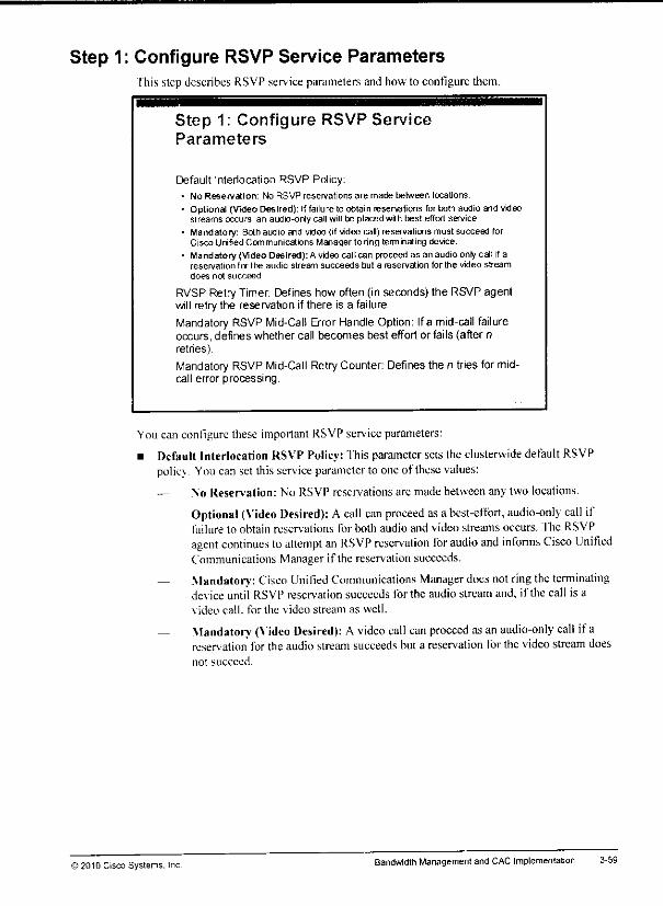
Step 1: Configure RSVP Service ParametersIhis step describes RSVP service parameters and how to configure them.
Step 1: Configure RSVP ServiceParameters
Default Interlocation RSVP Policy:
• No Reservation: No RSVP resen/ations are made between locations.
• Optional (Video Desired): Iffailure to obtain reservations for both audio and videostreams occurs, an audio-only call willbe placed with best-effort service.
• Mandatory: Both audio and video (if wdeo call) reservations must succeed forCisco Unified Communications Manager to ring terminating device.
• Mandatory (Video Desired): A video call can proceed as an audio-only call if areservation (or the audio stream succeeds but a reservation for the video streamdoes not succeed
RVSP Retry Timer: Defines how often (in seconds) the RSVP agentwill retry the reservation if there is a failure.
Mandatory RSVPMid-Call Error Handle Option: Ifa mid-call failureoccurs, defines whether call becomes best effort or fails (after nretries).
Mandatory RSVP Mid-Call RetryCounter: Defines the n tries for mid-call error processing.
You can configure these important RSVP service parameters:
• Default Interlocation RSVP Policy: This parameter sets the clusterwide default RSVPpolic\. You canset thisservice parameter to oneof these values:
— No Reservation: No RSVP reservations arc made between any two locations.
— Optional (Video Desired): Acall can proceed asa best-effort, audio-only call iffailure to obtain reservations for both audio and video streams occurs. The RSVPagent continues toattempt an RSVP reservation Tor audio and informs Cisco UnifiedCommunications Manager if the reservation succeeds.
— Mandatory: Cisco Unified Communications Manager docs notring the terminatingdevice until RSVP reservation succeeds for the audio stream and, if the call is avideo call, for the video stream as well.
— Mandatory (Video Desired): Avideo call can proceed as an audio-only call ifareservation for the audio stream succeeds but a reservation for the video stream doesnot succeed.
© 2010 Cisco Systems. Inc Bandwidth Managementand CAC Implementation 3-59
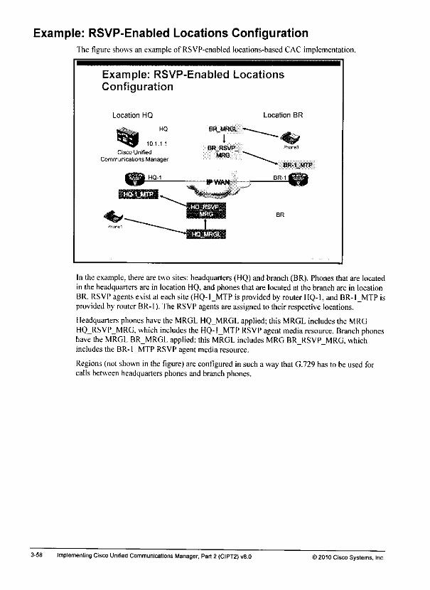
Example: RSVP-Enabled Locations ConfigurationThe figure shows an example of RSVP-enabled locations-based CAC implementation.
Example: RSVP-Enabled LocationsConfiguration
Location HQ
HQ
10.1.1.1
Cisco Unified
Communications Manager
BRMRGL
1BR RSVP
MRG
l^VtfWt
Location BR
BR
In the example, there are two sites: headquarters (HQ) and branch (BR). Phones that are locatedin the headquarters are in location HQ, and phones that are located at the branch are in locationBR. RSVPagentsexist at eachsite (HQ-1_MTP is provided by router HQ-1, and BR-1_MTP isprovided by router BR-1). The RSVPagentsare assigned to their respective locations.
Headquarters phones have the MRGL HQ MRGL applied; this MRGL includes the MRGHQ RSVP_MRG, which includes the HQ-1MTP RSVP agent media resource. Branch phoneshave the MRGL BR MRGL applied; this MRGL includes MRG BR RSVP_MRG, whichincludes the BR-1_MTP RSVP agent media resource.
Regions (not shown in the figure) are configured in such a way that G.729 has to be used forcalls between headquarters phones and branch phones.
3-58 Implementing CiscoUnified Communications Manager, Part2 (CIPT2) v8.0 ©2010 Cisco Systems, Inc.
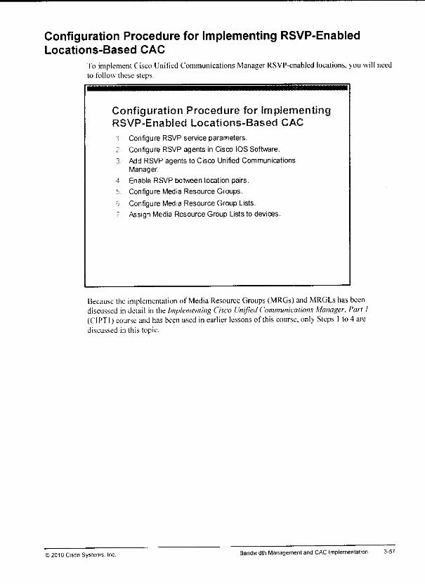
Configuration Procedure for Implementing RSVP-EnabledLocations-Based CAC
To implement Cisco Unified Communications ManagerRSVP-enabled locations, you will needto follow these steps.
Configuration Procedure for implementingRSVP-Enabled Locations-Based CAC
1 Configure RSVP service parameters.
2 Configure RSVP agents in Cisco IOS Software.
3 Add RSVP agents to Cisco Unified CommunicationsManager,
4 Enable RSVP between location pairs.
5 Configure Media Resource Groups.
6 Configure Media Resource Group Lists.
r Assign Media Resource Group Lists to devices.
Because the implementation of Media Resource Groups (MRGs) and MRGLs has beendiscussed in detail in the Implementing Cisco Unified Communications Manager, Part I(CIPT1) course andhas been used in earlier lessons of this course, only Steps 1lo 4 arediscussed in this topic.
) 2010 Cisco Systems, Inc Bandwidth Management and CAC Implementation
Here are other RSVP messages:
• Krror and confirmation messages: Reservation-request acknowledgment messagesaresent as the result of the appearance of a reservation-confirmation object in a reservation-requestmessage. This acknowledgment messagecontainsa copy of the reservationconfirmation. An acknowledgment message is sent to the unicast address of a receiver host,and the address is obtained from the reservation-confirmation object. A reservation-requestacknowledgment messageis forwarded to the receiverhop by hop to accommodate thehop-by-hop integrity-check mechanism.
— Path-errormessages result from Path messages, and they travel toward senders.Path-error messages are routed hop by hop using the path state. At each hop, the IPdestination address is the unicast address of the previous hop.
— Reservation-request errormessages result from reservation-request messages andtra\ cl toward the receiver. Reservation-request error messages are routed hop by hopusing the reservation state. At each hop, the IP destination address is the unicastaddress of the next-hop node. Here is some of the information that can be carried inerror messages:
• Admission failure
• Bandwidth unavailable
• Service not supported
• Bad flow specification
• Ambiguous path
• Teardown messages: RSVP teardownmessages remove the path and reservation statewithout waiting for the cleanup timeout period. Teardown messages can be initiated by anapplication in an end system (sender or receiver) or a router as the result of state timeout.RSVP supports two types of teardown messages:
— Path-teardown: Path-teardown messages delete the path state (which deletes thereservation state), travel toward all receivers downstream from the point ofinitiation, and are routed like Path messages.
— Reservation-request teardown: Reservation-request teardown messages delete thereservation state, travel toward all matching senders upstream from the point ofteardown initiation, and are routed like corresponding reservation-request messages.
3-56 Implementing CiscoUnified Communications Manager, Part2 (CIPT2) v8.0 ©2010CiscoSystems, Inc.
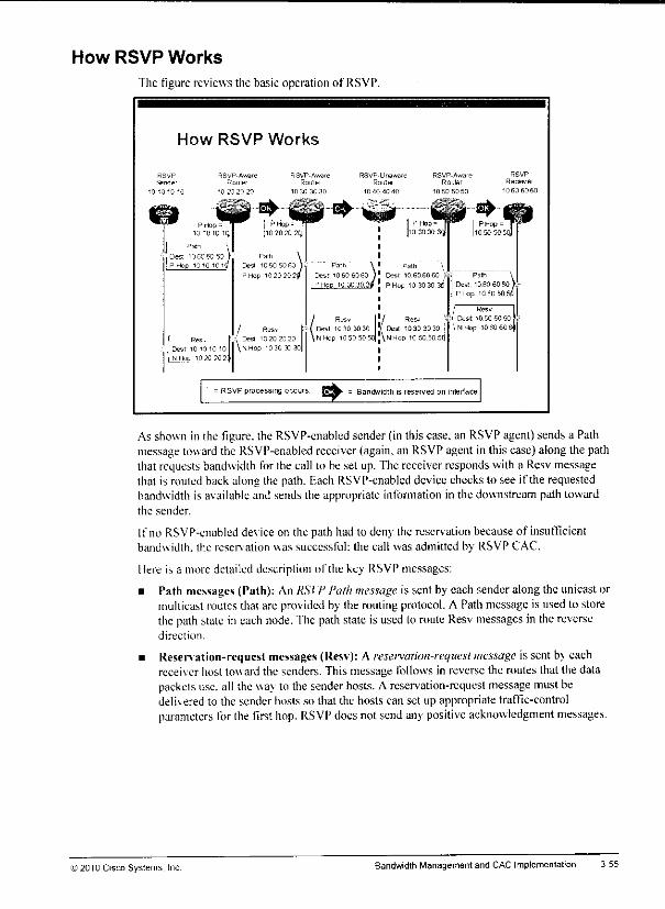
How RSVP Works
The figure reviews the basic operation of RSVP.
How RSVP Works
! Res.
3est 10 10 10 10
In Hot. 1020202\
/ Res*; Dea '.320 20 20
\MHap '330 33 30
= RSVP processing occurs
Res
Dest 10 30 30 30„.„. ,„„ . Desl 10 30 30 30 .
NHop 10 50 50 5o]!\NHop 10 SOSOSrJ
Resv
•; ( Dest 10505050!!\NHop 10 SO 60 8'
= BanAwitltti is reserved on interface
As shown in the figure, the RSVP-enabled sender (in this case, an RSVPagent)sends a Pathmessage towardthe RSVP-enabled receiver(again,an RSVPagent in this case)along the paththat requests bandwidth for the call to be set up.The receiverresponds with a Resv messagethat is routed back along the path. Each RSVP-enabled device cheeks to see if the requestedbandwidth is available and sends the appropriate information in the downstream path towardthe sender.
If no RSVP-enabled device on the path had lo deny the reservation because of insufficientbandwidth, the reservation was successful: the call was admitted by RSVP CAC.
Here is a more detailed description of the key RSVP messages:
• Path messages (Path): An RSVP Path message is sent by eachsenderalongthe unicast ormulticast routesthat are provided by the routing protocol. A Path messageis used to storethe pathstate in each node. Thepathstateis used to route Resv messages in thereversedirection.
• Reservation-request messages(Resv): A reservation-request message is sent by eachreceiver host toward the senders. This message follows in reverse the routes that the datapackets use. all the way to the sender hosts. A reservation-request message must bedelivered to the sender hosts so that the hosts can setup appropriate traffic-controlparameters forthe first hop. RSVP does notsend any positive acknowledgment messages.
) 2010 Cisco Systems. Inc Bandwidth Management and CAC Implementation 3-55
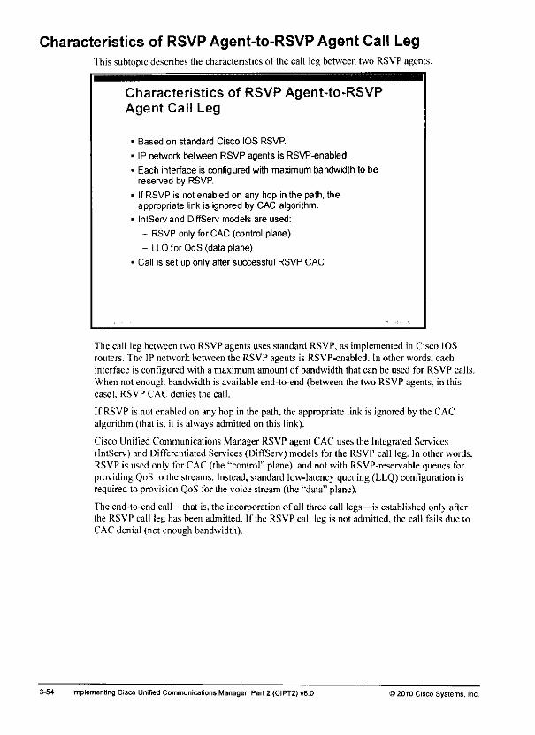
Characteristics of RSVP Agent-to-RSVP Agent Call LegThis subtopic describes the characteristics of the call leg between two RSVP agents.
Characteristics of RSVP Agent-to-RSVPAgent Call Leg
• Based on standard Cisco IOS RSVP.
• IP network between RSVP agents is RSVP-enabled.
• Each interface is configured with maximum bandwidth to bereserved by RSVP.
- IfRSVP is not enabled on any hop in the path, theappropriate link is ignored by CAC algorithm.
• IntServ and DiffServ models are used:
- RSVP only for CAC (control plane)
- LLQ for QoS (data plane)
• Call is set up only after successful RSVP CAC.
The call leg between two RSVP agenLs uses standard RSVP, as implemented in Cisco IOSrouters. The IP network between the RSVP agents is RSVP-enabled. In other words, eachinterface is configured with a maximum amount of bandwidth that can be used for RSVP calls.When not enough bandwidth is available end-to-end (between the two RSVP agents, in thiscase). RSVP CAC denies the call,
If RSVP is not enabled on any hop in the path, the appropriate link is ignored by the CACalgorithm {that is. it is always admitted on this link).
Cisco Unified Communications Manager RSVP agent CAC uses the Integrated Services(IntServ) and Differentiated Services (DiffServ) models for the RSVP call leg. In other words.RSVP is used only for CAC (the "control" plane), and not with RSVP-reservable queues forproviding QoS to the streams. Instead, standard low-latency queuing (LLQ) configuration isrequired to provision QoS for the voice stream (the "data" plane).
The end-to-end call—that is, the incorporation of all three call legs—is established only afterthe RSVP call leg has been admitted. If the RSVP call leg is not admitted, the call fails due toCAC denial (not enough bandwidth).
3-54 ImplementingCisco Unrfied CommunicationsManager, Part 2 (CIPT2)v8.0 )2010 Cisco Systems, Inc.

Characteristics of Phone-to-RSVP Agent Call LegsThis subtopic describes the characteristics of the call legs between phones and RSVP agents.
Characteristics of Phone-to-RSVP
Agent Call Legs
* Based on Cisco Unified Communications Manager locations:
- Usually phones and their RSVP agents are in the samelocation.
If phone and its RSVP agent are in separate locations,standard location-based CAC is performed for this call leg.
• Phones have to use their RSVP agent:
- RSVP agent that is used by a certain phone should be as closeas possible to the phone,
- RSVP agent to be used by a certain phone is determined bythe Media Resource Group List of the phone.
• RSVP agent is an MTP:
- Pass-through codec is supported:
• No changes to RTP payload
• Allows secure RTP to be used
Standard locations algorithms apply lo the call leg between an IP phone and its RSVP agent,which are usually in the same location. If they are in separate locations, standard locations-based CAC is performed for this call leg (phone to RSVP agent) first. The two RSVP agentswill tr> to set up their call leg by using RSVP only if enough bandwidth is available for the IPphones to reach their RSVP agents.
An RSVP agent registers with Cisco Unified Communications Manager as a special MTPdevice. Cisco Unified Communications Manager uses the Media Resource Group List (MRGL)of the IP phone to determine which RSVP agent is to be used by which IP phone. Theassociation of a phone to its RSVP agent does notoccur as the result of a search for an RSVPagent in the same location of the phone. As mentioned earlier, the IP phone and its RSVP agentcan be in separate locations. Only MRGLs arc used to identify the RSVP agent to be used by anIP phone.
From a designperspective, the RSVPagent that is used by a certain IPphoneor groupofphones should be as close as possible to the IPphone or phones. Such a design ensures thatthereare optimal pathswhere the phones ideallydo not use the IP WANto accesstheir RSVPagents. Thisdesign alsoensuresthat RSVPis usedat the IP WANand that the call legs that donot use RSVP utilize only LAN infrastructure.
1he RSVP agent supports pass-through codec configuration, whichallowsany codec to be used(the codecdocs not have to be known or supported by the RSVP agent). Pass-through codecconfiguration includes Secure Real-Time Transport Protocol (SRTP), where the RTP payload isencrypted.
) 2010 Cisco Systems, Inc Bandwidth Management and CAC Implementation 3-53
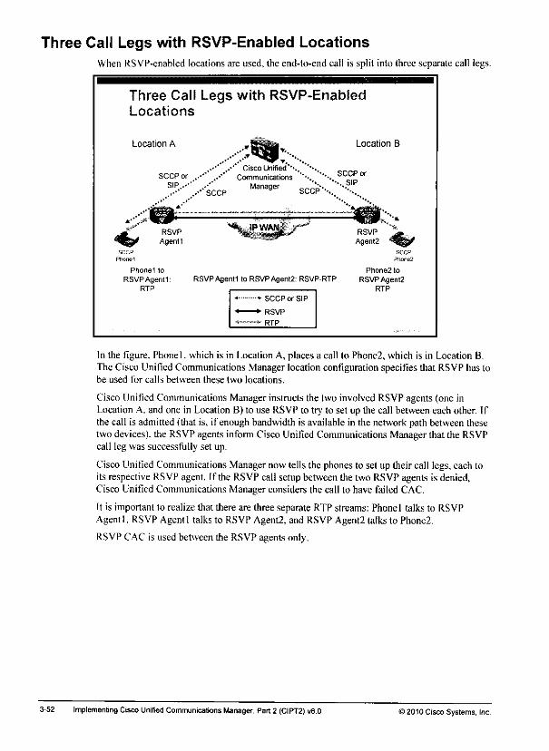
Three Call Legs with RSVP-Enabled LocationsWhen RSVP-enabled locations are used, the end-to-end call is split into three separate call legs.
Three Call Legs with RSVP-EnabledLocations
Location A Location B
.••' ..-' Cisco Unified''-.. ""•..SCCP orSCCP or ..•''*..-•*' Communications ''''..''••-._ SCCP
'--'"..-•SCCP Mana9er SCCP-C'V
RSVPAgentl to RSVPAgent2: RSVP-RTP
— SCCP or SIP
•*• RSVP
** RTP
In the figure, Phonel. which is in Location A, places a call to Phone2, which is in Location B.The Cisco Unified Communications Manager location configuration specifies that RSVP has tobe used for calls between these two locations.
Cisco Unified CommunicationsManager instructs the two involved RSVP agents (one inLocation A. and one in Location B) to use RSVP to try to set up the call between each other. Ifthe call is admitted (that is, if enough bandwidth is available in the network path between thesetwo devices), the RSVP agents inform Cisco Unified Communications Manager that the RSVPcall leg was successfully set up.
Cisco UnifiedCommunications Managernowtells the phonesto set up their call legs,each toits respective RSVP agent. If the RSVP call setup between the two RSVP agents is denied,Cisco Unified Communications Manager considers the call to have failed CAC.
It is important to realize that there are three separate RTP streams: Phonel talks to RSVPAgentl. RSVP Agentl talks to RSVP Agent2, and RSVP Agent2 talks to Phone2.
RSVP CAC is used between the RSVP agents only.
3-52 Implementing Cisco Unified Communications Manager, Part 2 (CIPT2) v8.D >2010 Cisco Systems, Inc.

'-•^b*
RSVP-Enabled Locations"Ihis topic describes RSVP-enabled locations in Cisco Unified Communications Manager.
RSVP-Enabled Locations
Characteristics
• Based on Cisco Unified Communications Manager locations
• Allows RSVP to be enabled selectively between pairs of locations
• Uses RSVP agents:
Devices (MTPs) through which call has to flow
• RSVP used between RSVP agents
• Topology-aware:
- Works well with all topologies (full mesh, partial mesh, huband spoke)
- Adapts to network changes; considers actual topology:
• Link failures?
• Backup links?
• Load-share paths?
RSVP-enabled locations are based on Cisco Unified Communications Manager (standard)locations. RSVP-cnahled locations differ from standard locations in two ways. First. RSVP canbe enabled selectively between pairsof locations. Because endpoints such as Cisco IP phonesdo not supportRSVP. the solution uses so-calledRSVP agents.
An RSVP agent is a Media Temiination Point (MTP) through which the call hasto flow. RSVPis then used only betueen the two RSVP agents, while the Real-Time Transport Protocol (RTP)stream from IP phone to RSVP agent does not use RSVP.
Thesecond andmostimportant difference between RSVP-enabled locations andstandardlocations is that the use of RSVP makes the location-based CAC mechanism topology-aware. Itworkswell with all topologies (full mesh,partialmesh,andhub and spoke)and adapts tonetwork changes by considering theactual topology. Theadvantages include theseconsiderations:
• Link failures: If one link in the IP network goes down and packets are routed on differentpaths. RSVP is aware of the change and considers the bandwidth thatis now available atthe path that is actually routed.
• Backup links: Ifbackup links are added after link failures, orifbandwidth ondemand isused to adddial-on-demand circuits. RSVP again is fully awareof the routingpath that iscurrently used andthebandwidth that is available oneach link along thatpath.
• Load-share paths: If load sharing is used. RSVP isaware of the overall bandwidth thatisprovided by multiple load-sharing links.
Using RSVP for CAC allows admitting ordenying calls that are based onactualoversubscriptions. The result is always based onthe currently available bandwidth andinterfaces, not on a logical configuration that ignores the physical topology.
© 2010 Cisco Systems. Inc Bandwidth Management and CAC Implementation
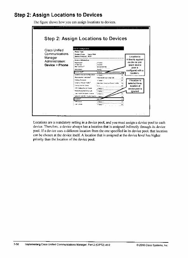
Step 2: Assign Locations to DevicesThe figure shows how you can assign locations to devices.
Step 2: Assic
Cisco Unified
n Locat ons to Device s
Communications
ManagerProduct Tr»»: tltt*
OtvHe Proton 1 SCCP Location is
indirectly appliedvia device pool(each device
pool Is
Administration:
Device > PhoneBBQi[tr*(*n ur-tnown
H"*"™'1 cm* —= Tlocation).
Itisr-f &L*ron Tarrtpl&U*
j If location is1 selectedhere.
J location ofdevice pool is
1 ignored
N„„*m0w«om.u*.s
1—• w**^ ..}
' """• - •"
Locations are a mandatory setting in a device pool, and you must assign a device pool to eachdevice. Therefore, a device always has a location that is assigned indirectly through its devicepool. If a device uses a different location from the one specified in its device pool, that locationcan be chosenat the device itself. A location that is assigned at the device levelhas higherpriority than the location of the device pool.
3-50 Implementing Cisco Unified Communications Manager, Part 2 (CIPT2) v8.0 12010 Cisco Systems, Inc.
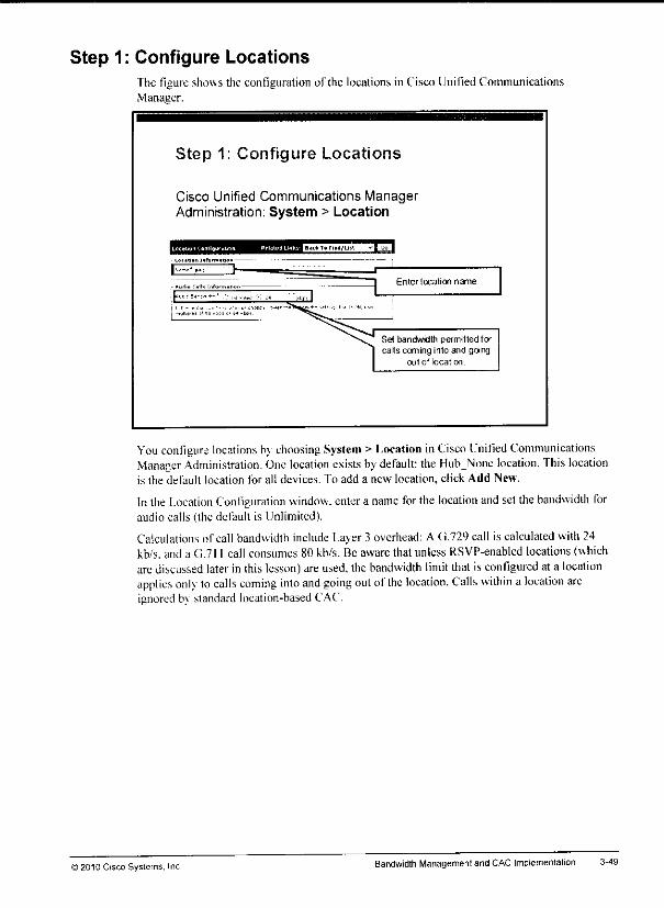
Step 1: Configure LocationsThe figure shows the configuration of the locations in Cisco Unified CommunicationsManager.
Step 1: Configure Locations
Cisco Unified Communications ManagerAdministration: System > Location
Enter location name.
Set bandwidth permitted forcals coming into and going
out of location
You configure locations b\ choosing System> Location inCisco Unified CommunicationsManager Administration. One location exists bydefault: the HubNone location. This locationis the default location for all devices. To add a new location, click Add New.
In the Location Coniiguration window, entera name forthe location andset the bandwidth foraudio calls (the default is Unlimited).
Calculations of call bandwidth include Layer3 overhead: A G.729 call is calculated with 24kb/s. and a G.711 call consumes 80 kb/s. Be aware that unless RSVP-enabled locations (whichare discussedlater in this lesson)are used, the bandwidth limit that is configured at a locationapplies only to calls coming into and going out ofthe location. Calls within a location areignored b\ standard location-basedCAC.
© 201C Cisco Systems, Inc BandwidthManagement and CAC Implementation 3-49

Locations Configuration Example: Hub-and-Spoke TopologyThe figure showsan exampleof a hub-and-spoke locations-based CAC implementation.
Locations Configuration Example:Hub-and-Spoke Topology
Location HQ 96 kb/s
Location BR1: 24 kb/sLocation BR2:72 kb/s
There are three sites: the headquarters and two branches. Each site has its own location (IIQ,BR I. and BR2). The physical topology is a hub-and-spoke topology (headquarters is the hub).
The link between branch I and the headquarters should not carry more than one G.729 call, andthe link between branch 2 and the headquarters should not carry more than three G.729 calls.
The next two subtopics describe how to implement locations-based CAC for this scenario.
3-48 Implementing Cisco Unified Communications Manager, Part 2 (CIPT2) v8,D >2010Cisco Systems, Inc.

Configuration Procedure for Implementing Locations-BasedCAC
To implement Cisco Unified Communications Manager locations-based CAC. you need tofollow two steps.
Configuration Procedure forImplementing Locations-Based CAC
Add locations and configure CAC bandwidth limit.
2 Assign locations to devices.
Note To know how much bandwidth you need to calculate per call, you should design and
configure regions before implementing locations
© 2010 Cisco Systems, inc Bandwidth Management and CAC Implementation 3-47
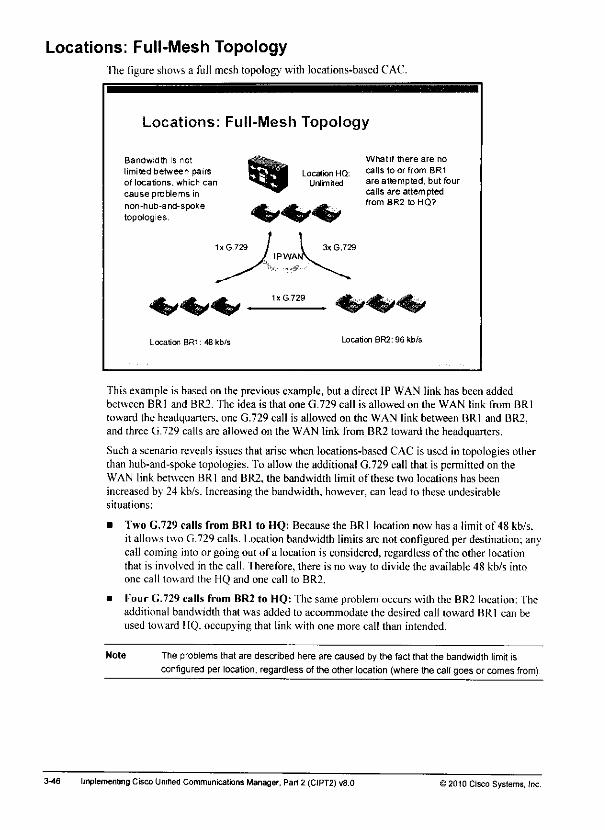
Locations: Full-Mesh TopologyThe figure showsa full mesh topology with locations-based CAC.
Locations: Full-Mesh Topology
Bandwidth is not
limited between pairsof locations, which can
causeprobtems innon-hub-and-spoke
topologies.
Location HQ:Urtmited
What if there are no
calls to or from BR1
are attempted, but fourcalls are attemptedfrom 8R2 toHQ?
Location BRl: 48 kb/s Location BR2:96kb/s
This example is based on the previous example, but a direct IP WAN link has been addedbetween BRl and BR2. The idea is that one G.729 call is allowed on the WAN link from BRl
toward the headquarters, one G.729 call is allowed on the WAN link between BRl and BR2,and three G.729 calls are allowed on the WAN link from BR2 toward the headquarters.
Such a scenario reveals issues that arise when locations-based CAC is used in topologies otherthan hub-and-spoke topologies. To allow the additional G.729 call that is permitted on theWAN link between BRl and BR2, the bandwidth limit of these two locations has beenincreased by 24 kb/s. Increasing the bandwidth, however, can lead to these undesirablesituations:
• Two G.729 calls from BRl to HQ: Because the BRl location now has a limit of 48 kb/s.it allows two G.729 calls. Location bandwidth limits are not configured per destination; anycall coming into or going out of a location is considered, regardless of the other locationthat is involved in the call. Therefore, there is no way to divide the available 48 kb/s intoone call toward the HQ and one call to BR2.
• Kour G.729 calls from BR2 to HQ: The same problem occurs with the BR2 location: Theadditional bandwidth that was added to accommodate the desired call toward BRl can be
used toward IIQ. occupying that link with one more call than intended.
Note The problems that are described here are caused by the fact that the bandwidth limit isconfigured per location, regardless of the other location (where the call goes or comes from)
3-46 Implementing Cisco Unitied Communications Manager, Part 2 (CIPT2) v8.0 12010 Cisco Systems, Inc.
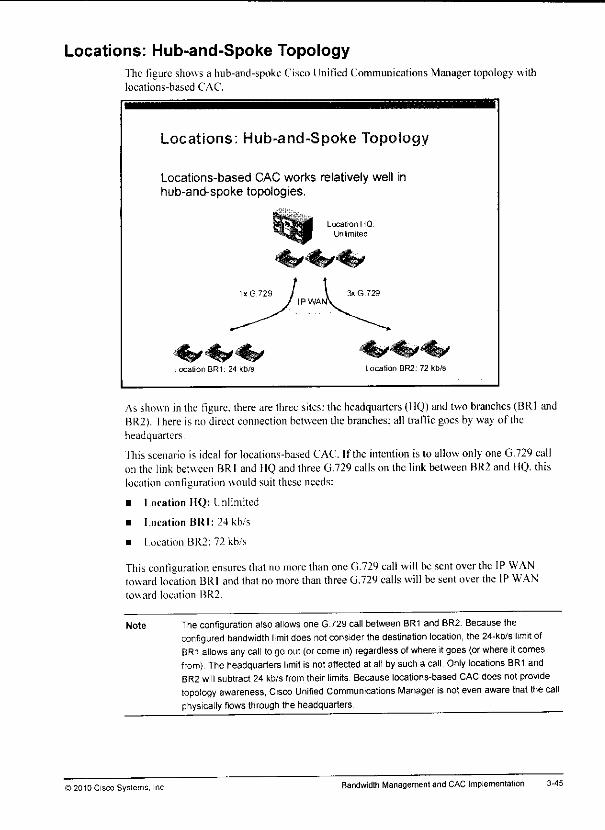
Locations: Hub-and-Spoke Topology"fhe figure shows a hub-and-spokeCisco Unified Communications Manager topology withlocations-based CAC.
Locations: Hub-and-Spoke Topolo*
Locations-based CAC works relatively well inhub-and-spoke topologies.
Location BRl: 24 kb/s
i tjkt™ Location HQ.idlBaB Unlimited
lxG.729 I \ 3xG729IPWANV
Location BR2: 72 kb/s
Asshown in the figure, there are three sites: the headquarters (HQ) andtwobranches (BRl andBR2). There is no direct connection between the branches; all trafficgoes by way of theheadquarters.
Ihis scenario is ideal for locations-based CAC If the intention is lo allow only one G.729 callon the link between BRl and HQ and three G.729 calls on the link between BR2 and HQ. thislocation configuration would suit these needs:
• Location HQ: Unlimited
• Location BRl: 24 kb/s
• location BR2: 72 kb/s
This coniiguration ensures thatno more than oneG.729 call willbesentoverthe IP WANtoward location BRl and that no more than three G.729 calls will be sent over the IP WANtoward location BR2.
Note
©2010 Cisco Systems, Inc
The configuration also allows one G.729 call betweenBR1 and BR2. Because theconfigured bandwidth limit does notconsider thedestination location, the 24-kb/s limit ofBR1 allows any call to go out (orcome in) regardlessof where itgoes (orwhere itcomesfrom) Theheadquarters limit is not affected at all bysucha call. Only locations BR1 andBR2 will subtract 24 kb/s from their limits. Because locations-based CAC does not providetopology awareness, Cisco Unified Communications Manager isnot even aware that thecallphysically flows through the headquarters. ^^
BandwidthManagement and CACImplementation 3-45

Standard LocationsThis topic describes how to implement CAC in Cisco Unified Communications Manager byusing standard locations.
Locations Characteristics
Each device has one location assigned.
You limit calls by permitting a certain bandwidth for calls coming inand going out of a location:
- Audio bandwidth is calculated by actual codec plus IPoverhead (assuming 20 ms packetization period).
• Examples: 80 kb/s for G.711, 24 kb/s for G.729.
- Calls within a location are unlimited.
- Bandwidth limit of source and of destination location are
checked individually.
Works within a Cisco Unified Communications Manager cluster(including exit points):
- Trunks and gateways can be put into a location, allowing somecontrol for calls leaving the cluster.
Locations-based CAC is unaware of topology
Each device has one location assigned. The assignment can be direct or via a device pool. Ifboth types of assignment are used, the device configuration has higher priority.
You limit calls by permitting a certain bandwidth for all calls coming into and going out of alocation. Cisco Unified Communications Manager calculates the actual audio codec bandwidthplus IP overhead (assuming a packetization period of 20 ms). This means that each G.711 callreduces the bandwidth that is configured for a location by 80 kb/s, while a G.729 call reducesthe available bandwidth by 24 kb/s.
Note Calls withina location do not decrease the bandwidth limit; they are unlimited. Only calls thatgo out of a location or that are received from outside the location are considered by thelocations-based CAC algorithm.
The bandwidth limitsthat are configured at the location of the originating device(the sourcelocation) as well as at the location of the terminating device (the destination location) arechecked individually. Unlike with regionconfiguration, where the maximum permittedcodec isconfigured perpairofregions, the bandwidth limitof a location applies to all (both placed andreceived) interlocation calls. If the bandwidth limit of the source or of the destination location(or of both) is exceeded, the call is not admitted. Locations provideCAC for calls withinclusters; however, because locations canalsobe configured forgateways andtrunks, locationsdo allow some control for calls leaving the cluster.
Locations-based CAC in Cisco Unified Communications Manager is completely unaware of thetopology of the network. It is a purely logical assignment and does not reflect the actualtopology or the actual bandwidth available.
3-44 Implementing Cisco Unified Communications Manager, Part 2 (CIPT2) v8.0 ) 2010 Cisco Systems, Inc.

CAC in Cisco Unified Communications ManagerCisco Unified Communications Manager supports various CAC methods.
CAC in Cisco Unified Communications
Manager
Cisco Unified CommunicationsManager supports the followingCAC features:
• CAC within a cluster:
RSVP-enabled locations
If CAC denies call, automated
alternate routing (AAR) can beused lo reroute call over PSTN
CAC for calls leaving a cluster.
H.323 gatekeeper or SIPPreconditions
If CAC denies call and no other
entnes in route list are left to
try. call fails.
H.323 Gatekeeper or SIP«_CAC-K
Locations
. CAC
i LocationsI CAC „,
In centralized call-processing deployments, you can use standard locations and ResourceReservation Protocol (RSVP)-enabled locations lo provide CAC within a Cisco UnifiedCommunications Manager cluster. If a call is not admitted by one of thesetwo CAC methodsdue to bandwidth limitations, you can use AARto reroutethe call over the PSTN (off-net)instead of denying thecall. AAR provides a service like PSTN backup, except thatthe reasonfor call backup is not that the call failedon the on-ncl path,but that there is no availablebandwidth from a CAC point of view.
In distributed call-processing environments, you canuse H.323 gatekeeper CAC with H.323trunks (gatekeeper-controlled intercluster trunks and H.225 trunks). If Session InitiationProtocol (SIP)trunks, you can use SIP Preconditions, whichallowsRSVP-based CAC.
If calls are not admitted by the H.323 gatekeeper, standardbackup functionalitv of route listsand route groups is applied, for example, to route calls thathave not been admitted by thegatekeeper to be sent over the trunk, you can configure one ormore PSI'N gateways inanother(lower-priority) route group of the same route list. In this way, the gatekeeper-controlled trunkispreferred over the PSTN aslong ascalls are admitted; after admission isrejected, calls aresentoverthe PSTN. Thesame principle applies to callsthatarc placed through SIPtrunks thatare configured for SIP Preconditions.
) 2010 Cisco Systems. Inc Bandwidth Management and CAC Implementation
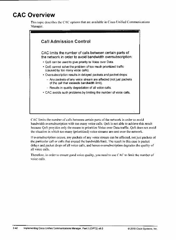
CAC OverviewThis topicdescribes the CACoptionsthat are available in Cisco Unified CommunicationsManager.
Call Admission Control
CAC limits the number of calls between certain parts ofthe network in order to avoid bandwidth oversubscription:
• QoS can be used to give priority to Voice over Data.
• QoS cannot solve the problem of too much prioritized traffic(caused by too many voice calls).
• Oversubscription results in delayed packets and packet drops:
- Any packets of any voice stream are affected (not just packetsof the call that exceeds bandwidth limit).
- Results in quality degradation of all voice calls.
• CAC avoids such problems by limiting the number of voice calls.
CAC limits the number of calls between certain parts of the network in order to avoidbandwidth oversubscription with too many voice calls. QoS is not able to achieve this resultbecause QoS provides only the means to prioritize Voice over Data traffic. QoS does not avoidthe situation in which too many (prioritized) voice streams are sent over the network.
If oversubscription occurs, any packets of any voice stream can be affected, not just packets ofthe particular call or calls that exceed the bandwidth limit. The result in this case is packetdelays and packet drops of all voice calls, and hence oversubscription degrades the quality ofall voice calls.
Therefore, in order to ensure good voice quality, you need to use CAC to limit the number ofvoice calls.
3-42 ImplementingCisco Unified Communications Manager, Part 2 (CIPT2)v8.0 >2010 Cisco Systems. Inc.
Lesson 2
Implementing CAC
OverviewImplementing multisite IP telephony deployments over an IP WAN requires additionalplanning to ensure the quality and availability of voice calls.
When an IP WAN connects multiple sites in a Cisco Unified Communications deployment.quality of sen. ice(QoS) hasto be implemented inorderto prioritise voice packets overdatapackets. Ilow ever, to avoid an oversubscription that is caused by toomany voice calls, amechanism is necessary to limit the numberof calls that are allowed at the sametime betweencertain locations. Call Admission Control (CAC) is the mechanism that ensures that voice callsdo not oversubscribe the IP WAN bandwidth and thus impact voice quality.
This lesson describes how to implement CAC mechanisms that are provided by Cisco UnifiedCommunications Manager, andexplains howautomated alternate routing (AAR) canbe used insome scenarios lo reroute calls that were denied by CAC over the public switched telephonenetwork (PSTN).
ObjectivesUpon completing this lesson, you will be able todescribe and configure CAC mechanisms andAAR in Cisco Unified Communications Manager and in gatekeepers. Ihis ability includesbeing able to meet these objectives:
,^M u Describe the CAC options that are provided by Cisco Unified Communications Manager
• Implement locations-based CAC in Cisco Unified Communications Manager
• Implement RSVP-enabled locations-based CAC in Cisco Unified Communications*•* Manager
• Implement AAR inorder to reroute intracluster calls over the PSI'N if notenoughbandwidth is available for an on-net call
• Implement SIP Preconditions onSIP trunks inCisco Unified Communications Manager
• Implement 11.323 gatckceper-based CAC inCisco Unified Communications Manager

3-40 Implementing Cisco Unified Communications Manager, Part2 (CIPT2) v8.0 ©2010 Cisco Systems, Inc.

SummaryThis topic summarizes the key points that were discussed in this lesson.
Summary
References
Bandwidth management methods include techniques that reducerequired bandwidth of voice streams, techniques that keep voicestreams off the IP WAN, and other techniques such as deployingtranscoders.
The highest bandwidth-consuming codec for a call betweentwo devices is determined by the Cisco Unified CommunicationsManager region configuration of the two involved devices.
When you are deploying local conference bridges at multiplesites, use Media Resource Groups and Media Resource GroupLists to control which conference bridge is used by which device.
Transcoders allow low-bandwidth codecs to be used over theIP WAN when low-bandwidth codecs are not supported by bothendpoints.
Multicast MOH from branch router flash is a feature that allowsMOH streams to be generated locallyat the remote site insteadof being sent across the IP WAN from the main site.
for additional infonnation. refer to these resources:
• CiscoSvstems. Inc. Cisco Unified Communications System 8.x SRND. April 2010.litip:.,',www.ci,bCo.com/en.llS'/docs/\oicc ip eomm/cucm/srnd/8\/ue8\.htm)
• Cisco S\ stems. Inc. Cisco Unified Communications Manager Administration GuideRelease 8.0(1). February' 2010.iilip:';www.cisc(XC<)m;cn;US^docs^(iiec_ip_coniin/cucni/admin/8_0_l/ecnicfg''1iccm-801-cm.him]
• Cisco Systems. Inc. Cisco Unified SRST System Administrator Guide. December 2007.hup:.' www,cisco.eoni/en'US/pji'lner'docs/voice ip conim/cusrst/admiii/srst/coiifiguratioii.'sjuide.-'srstsa.html
>2O10Cisco Systems, Inc BandwidthManagement and CACImplementation 3-39
Step 4c: Disable Multicast Routing on IP WAN Router InterfaceThe figure shows how to configure a Cisco IOS router to disable multicast routing at the IPWAN interface.
Step 4c: Disable Multicast Routing onIP WAN Router Interface
ip multicast-routing
interface FastEthernetO/0
description HO-Voice-Serversip address 10.1.1.101 355.255.255.0ip pim sparse-dense-mode
interface FastEthsrnatO/0
description HQ-Phones
ip address 10.1.2.101 255.255.255.0ip pim sparse-dense-mode
interface SerialO/l
description ip wan 1Disable multicastip address 10.1.4.101 255.255.255.0 .. ,.,».," . , , , _J routing on WAN
no ip pim sparse-dense-mode .^___ D-! interface.
If no other multicast applications are used over the IP WAN, the simplest way of preventing themulticast MOH packets from being sent to the WAN is to disable multicast routing at the WANinterface.
3-38 Implementing Cisco Unified Communications Manager, Part 2 (CIPT2) v8.0 ) 2010 Cisco Systems, Inc.
Step 4b: Use IP ACL at IP WAN Router InterfaceThe figure shows how you can use an IP ACL to configure a Cisco IOS router to drop multicastMOI I packets.
Step 4b: Use IP ACL at IP WAN RouterInterface
ip multicast-routing
ip access-list extended drop-mohdeny ip any host 239.1.1.1 range 16384 163B5
permit ip any any
interface PastEtoernetO/0 ^^"-description HQ-Volce-Servers
ip address 10,1.1.101 255.255.255.0ip pim sparse-dense-mode
IPACL Filtering MOHMulticast Packets
interface FastEthernetO/1
description HO-Phones
ip address 10,1.2.101 255.255.255.0ip pim sparse-dense-mode
interface SeriolO/1
description IP MAN
ip address 10.1.4.101 255.255.255.0 ["ip access-group drop-moti out ^___ 1ip pim sparse-dense-mode i
PACLAppliedtoWANnterface
The ACL matches the MOH group address and port numbers that are used by the MOII serverfor the MOH RTPand RTCT packets. The ACL is appliedto the IP WAN interface in theoutgoing direction andtherefore doesnot allow multicast MOH packets to besentouton the IPWAN.
Note As stated earlier in this lesson, the multicast address and port range that must be filtered
depend on several parameters, such as the audiosource number, the enabledcodecs, andthe increment method.
)2O10 Cisco Systems, Inc Bandwidth Management and CAC Implementation
Step 4a: Configure the Maximum Hops to Be Used for MOHRTP Packets
Continue the multicast MOH server configuration by setting the maximum hop value, as shownin the figure.
Step 4a: Configure the Maximum Hopsto Be Used for MOH RTP Packets
Cisco Unified Communications Manager Administration:
Media Resources > Music on Hold Server
* tr.*hl* >**«UI* L.M &*urcol 6" P%ri NOtiSVW
(Utdroi*
&*u»U&t4U»Brt 16SW
*""*" numbn null)ta™.»tau ^ hnHfan*,. ' if Mai it
Selected *utoc««r Avdvsaortct-
Set maximum hops (time tolive) value for each audio
source for multicast packets.
All MOH audio sources that have been configured for multicasting are listed in the SelectedMulticast Audio Sources section of the MOH Server Configuration screen. You can set theMax Hops value for each audio source; the default is 2. This parameter sets the TTL value inthe IP header of themulticast MOH RTP packets to thespecified value. TTLin an IPpacketindicates the maximum numberof routersthat an audio source is allowedto cross. If Max Hopsis set to 1. the multicast MOH RTP packets remain in the subnet of the multicast MOH server.
Whenyou use multicast MOHfrom branch router flash, you can set Max Hopsto a value thatis lower than the actual hop count from the MOI1server toward the WAN interface of the mainsite router. This value, however, might conflict with the needs within the main site when IPphonenetworkshave the sameor a higherdistance—that is, a higherhop count—to the MOHserverthan the WAN network. In such a case,one of the other possible methodsof preventingthe multicast MOH packets thataregenerated bythe MOH server have to be used. Theyareshown on the following pages.
3-36 Implementing CiscoUnified Communications Manager, Part2 (C1PT2) v8.0 >2010 Cisco Systems, Inc.
Step 3: Enable Multicast MOH from Branch Router Flash at theBranch Router
The figure showshow to configure a Cisco IOS routerfor multicast MOI I from branch roi terflash.
Step 3: Enable Multicast MOH from BranchRouter Flash at the Branch Router
call-manager-fallbackmai-epbones 1
nax-dn 1
ip source-address 10.1.5.102nob mob-file.au
multicast mob 239.1.1.1 port 16364
interface FastEtharnatO/0
description BF-Phonesip address 10.1.5.102 255.255.255.0
interface SerlalO/1
description IP WXNip address 10.1.4.102 255.255.255.0
Multicast MOH from branch router flash is part of the SRST feature. Therefore, SRST mustalready beconfigured before youcan enable multicast MOII from branch router flash.
Note SRSTconfiguration options are discussed inthe module "Centralized Call -ProcessingRedundancy Implementation."
Rased onanexisting SRST configuration, you need only two commands toenable multicastMOH from branch router Hash:
• moh file-name: fhis command specifies the MOH audio source file. The specified file hasto be stored in flash memor> of the SRST gateway.
• multicast moh multicast-group-address portport: This command specifies themulticastaddress and port that are used for the multicast MOH packets. The specified address andport have toexactly match the values that have been configured at the MOH server inStep 2b.
Note TheSRST gateway will permanently streamMOH, regardless ofan IPWAN failure or IPphones being registered with the SRSTgateway. ^^
You can configure an additional five MOH streams using MOH group configuration. Refer tothe module "Centralized Call-Processing Redundancy Implementation" for more informationabout MOII group configuration.
i 2010 Cisco Systems. Inc. BandwidthManagement and CACImplementation 3-36

Step 2c: Enabling Multicast MOH at the Media ResourceGroups
This figure shows that the configuration of a Multicast is enabled at the Media Resource Group(MRG).
Step 2c; Enabling Multicast MOH at theMedia Resource Group(s)
Cisco Unified Communications Manager Administration: MediaResources > Media Resource Group
Multicast MOH only works if the multicast enabled MOH server is assigned to a multicastenabled MRG. This MRG will be configured to be a member of an MRGL. The MRGL willthen be associated with devices such as phones.
3-34 ImplemenlingCisco Unified CommunicationsManager, Part 2 (CIPT2)v8.0 >2010 Cisco Systems, Inc.
%m*
«*»
Step 2b: Configure Multicast MOH in Cisco UnifiedCommunications Manager
After allowing multicast MOH on audio sources, you must enable the MOH server formulticast MOH. as shown in the figure.
Step 2b: Configure MulticastCisco Unified Communications ManagerCisco Unified Communications Manager Administration:
Media Resources > Music on Hold Server
r^ttmtlkijvltvtr InlwnilMn-
•iaMtMHfcWiiliwi.in rmm itniifD J
Enable multicast MOH on the
MOH server.
'.ferine**'
«Lttte4 HuKKuf AvrfiD 4
Configure multicastparameters.
fhe figure showshow to enablemulticastMOH on a MOH server: In the Multicast AudioSource Infonnation section of the MOH server configuration screen, check the finableMulticast Audio Sources on this MOH Server check box. 'fhe Base Multicast IP Address, JaseMulticast Port Number, and Increment Multicast On parameters are automatically populatedwhen youenable multicast MOH on theserver. You can modify these values as desired.
Note To avoid network saturation in firewall situations, it is recommended that you choose to
increment multicast MOH on the IP address instead of on the port number. Choosing this
option means that each multicastaudio source will have a unique IP address, and helps toavoid network saturation Ifmultiplecodecs are enabled for the MOH server, additional IPaddresses will be in use (one per codec and per audio source).
>2010 Cisco Systems, Inc. Bandwidth Management and CAC Implementation 3-33

Step 2a: Configure MOH Audio Sources for Multicast MOHTo enable multicast MOH. you first have to allow multicast MOH on MOH audio sources, asshown in the figure.
Step 2a: Configure MOH Audio Sourcesfor Multicast MOH
Cisco Unified Communications
ManagerAdministration: MediaResources > Music On Hold
Audio Source
Cisco Unified Communications
ManagerAdministration: MediaResources > Fixed MOH Audio
Source
-Nuikh WdlrmrhAtbVfl l**W1**Oan-
-*OH *j*e 5ff»«*n*fc*r**r' E vO-.-X-*
$«.,..*
Flu * HOH *«»• I l>f> >b
Mm'
("0-T*.( Tr#ftjl»4tfift Coft*l*«
DilfcSjKI-6 Btf«LO-Ctf •T.-i* 11 )I»H J 1 i
tanpi*Audi iSotii ca Lul*- t*a y
|l 'u»Mc«»i| |HemMi (M^jksJ.Ni™ ntouhrd j
\MOH audio sources do not allow multicast
MOH by default.MOH audio sources and fixed MOH audio
sources (if used) must be enabled formulticast MOH.
irra^'udi^i^t* (?28.i««v"
Check the Allow Multicasting check box for each MOH audio that is allowed to be sent as amulticast stream. This instruction applies to MOH audio sources and to fixed MOH audiosources.
Note More information about configuring the MOH server and MOH audio sources is provided in
the ImplementingCisco Unified Communications Manager, Part 1 (CIPT1) course.
3-32 Implementing Cisco Unified Communications Manager, Part 2 (CIPT2) vB.O © 2010 Cisco Systems, Inc.
Step 1: Enable Multicast Routing on Cisco IOS RoutersThe figure shows how to enable multicast routing on Cisco IOS routers at the main site an<: atthe remote site.
Step 1: Enable Multicast Routing inCisco IOS Routers
ip multicast-routing ~ —
interface FaatEthernetQ/O
description HQ-Voice-Servers
ip address 10.1.1.101 255.255.255.0
ip pin sparse-dense-mode
interface FaatEtnernetO/1
description HQ-Phonea
ip address 10.1.3.101 255.255.255.0
ip pim sparse-dense-mode
interface SerialO/l
description IP WAN
ip address 10.1.5.101 255.255.255.0
ip pim sparse-dense-mode
Enable multicast
routing on router.
Enable multicast
routing on interfaces.
You use two commands to enable multicast routing in the network so that multicast MOHstreams can he sent:
• anip multicast-routing: Configure thiscommand in global configuration mode. Thiscommand enables multicast routing on the Cisco IOS router in general.
• ip pim sparse-dense-mode: Configure thiscommand on eachinterface where multicastrouting should he enabled.
Note The configuration that is shown in the example enables multicast routing in the wholenetwork. When multicast MOH from branch router flash is used, multicast streams will not be
sent to the IP WAN They can be blocked based on the maximum hops parameter (TTL fieldin the IP header) or by IP ACLs. You can also block multicast streams by disabling multicastrouting on the interface, butonlyifnoothermulticast routing applications are required inthenetwork.
© 2010 Cisco Systems, Inc
In the example, the maximum hops parametercannotbe used because the HQ-Phonesnetwork and the IP WAN network have the same distance to the HQ-Voice-Servers network
To allow multicast MOH to be sent to the HQ phones, a maximum hop value of 2 is required.
This value, however, will allowthe multicast MOH packets to be sent out on the WANinterface. Therefore, IP ACLs have to be used, or multicast routing has to be disabled at theWAN interface (if multicast routing is not required byotherapplications).
BandwidthManagement and CACImplementation 3-31
Configuration Procedure for Implementing Multicast MOH fromBranch Router Flash
Implementing multicast MOH from branch router Hash includes the following steps.
Configuration Procedure for implementingMulticast MOH from Branch Router Flash
1 Enable multicast routing in the network.
2 Configure multicast MOH in Cisco Unified CommunicationsManager:
a. Configure MOH audio sources for multicast MOH.
b Configure MOH audio server for multicast MOH.
c Enable multicast MOH at the media resource group(s)
3. Enable multicast MOH from branch router flash at thebranch router.
4 Implement a method to prevent multicast MOH streamsfrom being sent over the IP WAN:
a Configure maximum hop value to prevent multicastMOH streams from being sent over the IP WAN.
b Use IP ACL at IP WAN router interface.
c. Disable multicast routing on IP WAN router interface.
The configuration procedure describes the implementation ofmulticast MOH from branchrouter flash by first enabling multicast MOH (steps 1 and 2). Once this works as desired, theconfiguration is modified so that the multicastMOH streamis generated locallyat the branchrouter (Step 3) and the multicast MOH stream that is generated by the MOH server is preventedfrom being sent to the IP WAN.
WhenenablingmulticastMOHat the MOHserver,make sure that you set the maximum hopvalueof the multicast-enabled MOH audiosource(s)to a high enoughvalue to allow themulticast MOH packets to be sent all the way to the remote phones.
When choosing option 4a to preventing the multicast MOH stream of the MOH server frombeingsent to the IP WAN.you have to use a low enoughvalue to ensure that the multicastMOH packets generated by the MOH server do not reach the IP WAN.
Note All IP phones must be able to access to the main site Cisco Unified Communications
Manager MOH server from their MRGL. This access is required as soon as multicast MOHis configured, whether multicast MOH from branch router flash is used. If the remote site IP
phones do not have access to the Cisco Unified Communications Manager MOH serverfrom theirMRGL, CiscoUnified Communications Manager cannot instruct the IPphones tojoin the multicast group and will make the phone use tone on hold instead of MOH.Furthermore, you need to check the Use Multicast for MOH Audio check box at the MRGthat includes the multicast-enabled MOH server (see Step 2c).Finally, make sure that the G.711 codec is used between the MOH server and the branch
phones, because SRST multicast MOH supports only G.711.
3-30 Implementing CiscoUnified Communications Manager, Part2 (CIPT2) v8.0 ©2010 Cisco Systems, Inc.

• Disable multicast routine at the IP WAN interface: By disabling multicast routing at theIP WAN interface, multicast packets are not routed out on that interface.
At the branch router, the multicast MOH stream is sent out on the interface that is specified inthe ip source address command in call-manager-fallback coniiguration mode(or in telephony-server configuration mode, when Cisco Unified Communications Manager Express in SRSTmode is used). Therefore, the multicast MOII stream that is generated at the branch router doesnot have to be blocked at the branch router WAN interface.
©2010 Cisco Systems, Inc Bandwidth Management and CAC Implementation 3-29
Example: Implementing Multicast (VIOHfrom Branch Router Flash (Cont.)
Cisco Unified
Communications
Manager MOHConfigurationDA 239 1 1 1
DP. 16384
(a) Max Hops(TTLV1
Main Site
(b) ip accaaa -liat sirtended drop mob
deny udp16384
any ho16385
3t 239.1 1.1 i ange
per•Bit ip any any
interface serial 0/0
ip access-group drop-moh out
ill-manager-fallback
i-epbones 1
majt-dn 1
ip aouroa-address 10.1.5.102
moh moh-fila.an
multicast moh 239.1.1.1port 16394
The figure shows the configuration of the previously discussed scenario.
It is assumedthat the baseline configuration provides multicast routingin the wholenetworkand that the Cisco Unified Communications ManagerMOHserver is alreadyconfigured formulticast MOH.
Now the multicast MOI1stream that is sent toward the remote site needs to be blocked, andmulticast MOH from branch router flash needs to be implemented at the remote site.
Therefore, the SRST configuration of the remote site router is extended to include multicastMOH. The SRST configuration uses the same multicast IPaddress andportthatare configuredat the Cisco Unified CommunicationsManager MOH server that is located at the main site.
Tostopmulticast MOH generated by themain siteCiscoUnified Communications ManagerMOH server from beingsentoverthe IPWAN, youcanchoose oneof three options:
• Set Time to Live (TTL) to a low enough value at the Cisco Unified CommunicationsManager MOH server: If the TTL valuein the IP headerof the generated multicastMOHpackets is set to a low enough value, the packets will not be routed out to the IP WAN.However, if the IP WAN link is one hop away from the Cisco Unified CommunicationsManager MOII server, andif the main site phones are alsoonehopaway from theserver.this method cannot beused, because themain site IPphones would also be affected by thedropped packets. In the current example, TTL is set to 1, and it is assumed that the IPphones are inthesame VLAN, like the Cisco Unified Communications Manager MOI Iserver.
• Filter the packets by an IP accesscontrol list (ACL): At the main site router, an ACLcan be configured that drops the multicast MOH packets at the IP WAN interface.
Note Make sure thatyou verify theactually used multicast IPaddressesand ports. Asdescribedearlier, itdepends on the base address and portconfiguration, the method that is used toincrement the base number {on IPaddress or port), the codecs that are enabledforMOH,and the audio sources that are multicast-enabled.
3-28 Implementing Cisco Unified Communications Manager, Part2 (CIPT2) v8.0 ©2010 Cisco Systems, Inc.
Example: Implementing Multicast MOH from Branch RouterFlash
The figure shows a sample scenario for implementingmulticast MOH from branch router flash.
Example: Implementing Multicast MOHfrom Branch Router Flash
Multicast MOH packets generated by the Cisco UnifiedCommunications Manager MOH server should not be sent over theIP WAN. Branch router should generate multicast MOH packets.
Cisco Unified
Communicalions
Manager MOH
Wain Site
WAN
SRST MOH Remote Site
In the example, a MOH server is located at themain site. It is configured for multicast MOH.Multicast routing has been enabled in the whole network—including inthe IP WAN link to theremote site.
Themain siterouter, however, should no longer route multicast MOH to the remote site. Theremote site SRSI gateway should instead generate multicast MOII streams to the phones thatare located at the remote site.
Cisco Unified Communications Manager is not aware that the multicast packets that aregenerated by the MOH server atthe main site are filtered onthe IP WAN interface and then arelocally generated by the remote site SRST gateway. Therefore, Cisco Unified CommunicationsManager will instruct the IP phones that are located at the remote site lojoin the multicastgroup IP address that isconfigured at the Cisco Unified Communications Manager MOHserver. To allow the phones to receive MOH for the multicast group IP address that they join,you must configure the SRST gateway touse the same multicast address and port that isusedbvtheCisco Unified Communications Manager MOH server that is located at the main site.
© 2010 Cisco Systems. Inc. Bandwidth Management and CACImplementation 3-27

As you can see from the table, audio sources are incremented in ascending order, starting withaudio source 1 (live audio at source 0 is not multicast-capable and hence is excluded in thecalculation). Codecs are enumerated in the order shown (G.711 mu-law, G.711 a-law, G.729,wideband). For each audio stream, two ports are used: the first one (the even-numbered port)for the actual RTP transmission and the subsequent one (the odd-numbered port) for thecorresponding RTCP.
If you are not sure about the used multicast addresses and ports, you can configure traces forthe Cisco IP Voice Media Streaming Application service. Make sure that you check the ServiceInitialization check box in the trace configuration. Then restart the Cisco IP Voice MediaStreaming Application service.
When analyzing the trace output, you will find this kind of information:
CMOHHgr: :KickStartMultiCastStreaiii {1} Starting Multicaststream, asID = 1, conferencelD = 1, cocleeType = iKtSw,Multicast ip:port - 239.1.1.it 163841<CLID::Cluster><NID::10.1,i,l>
CMOHMgr::KickStartMultiCastStream <1) Starting Multicaststream, asID = 1, conferencelD = 1001, GQdecType = «!#"$,Multicast ip:port - 239.1,1.2il6384|<CLID: :ClusterxHID: :1Q.1.1.1>
Note The output that is shown does not match the example in the figure. It is used only toillustrate which information you will find in the trace output. The number after the
KickStartMultiCastStream identifies the audio source. For each enabled codec, you will find
information about the used multicastIP address and port.The NID(node ID) shows the IPaddress of the MOH server. In this example, only G.711 mu-law and G.711 a-law codecs
are enabled. Onlyone audio source (audio source 1) is multicast-enabled. There is a singleMOH server at 10.1.1 1
Tip It is importantto know the used multicastIPaddresses and ports when you choose theoption to prevent multicast traffic from entering the IP WAN by access lists.
3-26 Implementing Cisco Unified Communications Manager, Part 2(CIPT2) v8.0 ©2010 Cisco Systems, Inc.
Multicast MOH: Address and Port Increment ExampleThe table shows an example of IP address and port increments for multicast MOH.
Multicast MOH: Address and PortIncrement Example
You can verify used IP addresses and ports by using traces:
- Configure trace for the Cisco IP Voice Media StreamingApplicationservice, and check the Service initializationcheck box
Restart Cisco IP Voice Media Streaming Application service.
- Analyze trace output.
Base IP 239.1 1.1
Base Port 16384
Enabled Codecs
G711a-law, G729
Audio Source 1
Audio Source 2
Audio Source 3
Audio Source 4
Audio Source 5
Audio Source 6
No
"Ybs"No
No
Yes
increment on IP Address
239.1.1.2
239.1.1.23
239113
239 1*1 11
239 1 1 23
Increment on Port
16386
1S402 16404
16428
The base multicast group iseonligured for IPaddress 239.1.1.1 and port 16384. G.711 a-lawand G.729 codecs are enabled: audio sources 1. 3. and 6 are multicast-enabled.
The figure slums the IP addresses orports that are used for the actual multicast MOII streams.The next table shows how these numbers were derived.
Note The yellow highlighted numbers mthetable present thevalues thatare used in thefigure.The gray highlighted and bold numbers present theIP address and port number that areactually used in this example.
Audio
Source
Increment on IP Address
{239.1.1.x—Only Last Octet Shown)
Increment on Ports
(163xxx—Only Last Octet Shown)
G.711
mu-law
G.711
a-law
G.729 Wideband G.711
mu-law
G.711
a-law
G.729 Wideband
1 1 2 3 4 364/3B5 386/387 388/389 390/391
2 5 6 7 8 392/393 394/395 396/397 398/399
3 9 10 11 12 400/401 402/403 404/405 406/407
4 13 14 15 16 408/409 410/411 412/413 414/415
5 17 18 19 20 416/417 418/419 420/421 422/423
6 21 22 23 24 424/425 426/427 428/429 430/431
© 2010 Cisco Systems. IncBandwidth Management and CAC Implementation 3-25
Multicast MOH from Branch Router Flash: Address and Port
Considerations
This subtopic describes what you need to consider regarding the multicast group coniigurationof MOH streams.
Multicast MOH from Branch Router
Flash; Address and Port Considerations
You can configure MOH streams to be incremented on IPaddresses or ports.
Increment on IP address is recommended.
For each audio source, four streams are considered (one percodec: G.711 mu-law, G.711 a-law, G.729, and wideband) for theincrement.
- independent of codecs that are actually enabled.
Numbers are incremented differentlyon IP address versus port.
- IP addresses are incremented by one per stream.
- Ports are incremented by two per stream (RTP and RTCP).
When you increment IP address or port, consider audio sourcesthat are not enabled for multicast.
- Appropriate range is reserved for future multicast enablement.
Because a single MOH server canstream multiple multicast MOH files, youhave to specify aninitial multicast address andportthat is used forthe firststream. In addition, youhave tochoose whether to increment the IP address or port on additional streams. It is recommendedthatyou increment on IP addresses instead of on ports. If there aremultiple MOH serverswithin a network, you have to makesure that theydo not use overlapping multicastIPaddresses and ports for their streams.
Foreach audio source, fourstreams are considered for the increment—one per codec: G.711mu-law, G.711 a-law, G.729, and wideband. Thisprinciple always applies, regardless of whichMOH codecs have been enabled in theCiscoIP Voice Media Streaming Application service.
When you are incrementing on IP addresses, each stream consumes one IP address. In otherwords, eachaudio source requires fourIP addresses. When incrementing on ports, youhave toconsiderthe Real-Time Transport Control Protocol (RTCP). Foreach audio stream,twoseparate RTP ports are reserved: one forthe actual audiotransmission andone for(theoptional) RTCP. Therefore, when you areincrementing multicast MOH on ports, each streamconsumes two ports. You have to calculate eight port numbers peraudio source (two ports percodec).
Audio sources that are not enabled for multicast MOH should nevertheless be considered forthe increment ofaddresses orports. Audio source 1,which starts with the configured baseaddress and port, requires four IPaddresses oreight ports. The same principle applies toeachconsecutive audio source (audio source 2,audio source 3, and soon), regardless ofwhetherthese audio sources are multicast-enabled.
3-24 Implementing CiscoUnified Communications Manager, Part2 (CIPT2) v8.0 © 2010 Cisco Systems, Inc.

Multicast MOH from Branch Router Flash: RegionConsiderations
Ihis subtopic discusses how to configure codecs when you are using multicast MOH frombranch router flash.
Multicast MOH from Branch RouterFlash: Region Considerations
* Locally generated MOH streams have to be identical to thestreams that are generated by Cisco Unified CommunicationsManager MOH servers:
Same destination IP address (multicast address).
- Same destination port number.
- Same codec.
- Same packetization period.
* Multicast MOH from branch router flash supports only G.711.
• G.711 must also be used for the stream generated by CiscoUnified Communications Manager MOH servers:
Put Cisco Unified Communications Manager MOH serverinto a dedicated region.
Allow G.711 between the region of the MOH server andthe region used by branch phones.
- Limit all other intersite calls to G.729.
When multicast MOH is used. IPphones andCisco Unified Communications Manager are notaware that the IP phones listen to locally generated MOH streams. From a signalingperspective, the IP phone isinstructed to listen to acertain multicast stream, and the localSRSI gateway has to generate amulticast MOH stream by using identical settings, such asdestination address (multicast group), destination port, codec, and packetization period.
Multicast MOH in SRST gateways and Cisco Unified Communications Manager support onlythe G.711 codec, 'fherefore.G.711 must also be configured between the Cisco UnifiedCommunications Manager MOH server and the branch IPphones. IfCisco UnifiedCommunications Manager signals a codec other than G.711 tothe IP phone, the IP phone couldnot play the locally generated MOH stream because ofacodec mismatch (the signaling wouldbe G.729. but the received RTP stream would be G.711).
Toensure that Cisco Unified Communications Manager sends signaling messages to the phoneand instructs it to listen to a G.711 stream,configure regions in this way:
• Put theCisco Unified Communications Manager MOH server or servers into a dedicatedregion (for example. MOH).
• Putall branch devices intoa site-specific region (forexample. Branch-1).
• Allow G.711 between regions MOH and Branch-1.
• Make sure that region Branch-1 islimited to G.729 for calls loand from all other regions.
© 20i0 Cisco Systems. Inc.Bandwidlh Managementand CAC Implementation 3-23
Each SRST or Cisco Unified Communications Manager Express router can stream up to sixdifferent MOH files. You can configure each of them for multicast MOH or unicast MOH.Therefore, the maximum number of multicast MOH audio sources diat can be used per remotesite is limited to six. By providing different MOH files for each site, site-specific MOH filescan be played for each site. Only G.711 codec is supported by SRST and Cisco UnifiedCommunications Manager Express.
When using multicast MOH also within the main site, you must enable multicast routing inorder to allow the multicast stream to be routed from the Cisco Unified Communications
Manager server network to the phone network or networks. If the MOH server is on the samenetwork that the IP phones are on, multicast routing is not required, but such a scenario is notrecommended, for security reasons (servers should be separated from endpoints).
3-22 Implementing Cisco Unified Communications Manager, Part 2(CIPT2) w8.0 ©2010 Cisco Systems, Inc.

Multicast MOH from Branch Router Flash
Implementation1his topicdescribes how to implement the multicast MOH from branch router flash feature.
Multicast MOH from Branch Router
Flash Characteristics
Works only with multicast MOH.
Based on MOH capabilities of SRST (Cisco IOS router requires featureset that supports SRST)
Cisco Unified Communications Manager must be configured to usemulticast MOH
IP phone is not aware that it listens to locallygenerated MOH.
Stream generated by MOH server is prevented fromreaching the IP WAN.
Identical stream is generated locally at the branch sites.
Branch router can stream up to six MOH files.
Only G.711 is supported.
- Each stream can be selectively enabled for multicast.
• Up to six different MOH sources supported per branch router.
Multicast MOH from branch router flash is a feature that allows multicast MOI I streams to begenerated b\ gateways that are located at remote sites instead ofbeing streamed from the mainsite to the remote site over the IP WAN.
Cisco Unified Communications Manager is configured for standard multicastMOH. NeitherCisco IInilied Communications Manager northe phones thatare located at theremote siteareaware that the stream generated at the centra! site is replaced by a locally generated stream. Themulticast MOH stream that is generated by thecentrally located MOH server is prevented fromtraversing over IPWAN. and the remote site router generates a stream that has the sameattributes (codec, multicast address, and port).
As mentioned earlier, multicast MOII from branch router flash is based on multicast MOH. so\ou must configure Cisco Unified Communications Manager to use multicast MOH instead ofunicast MOH. This configuration is recommended anyway inorder to reduce load at the MOHserver by multicasting one stream that can be received by all devices, instead ofstreamingMOH indi\idually foreach endpoint in separate RIP sessions.
To generate a multicast MOI Istream at the remote site, you use features ofSurvivable RemoteSite Telephom (SRST) orCisco Unified Communications Manager Express, fherefore. theremote site router thatwill generate the multicast MOI I stream forthedevices that are locatedat the remote site has to beconfigured for SRST or Cisco Unified Communications ManagerExpress. SRSI" does not have to be active (there is no need for a fallback scenario), because anSRST gatewaj that is configured for multicast MOH streams MOH all the time, regardless ofits state (standby mode or SRST mode). The same principle applies toCisco UnifiedCommunications Manager Express: Only multicast MOH has tobe enabled, no further featureshave to be enabled,and no phones have to be registered.
; 2010 Cisco Systems. Inc. Bandwidth Managementand CAC Implementation 3-21
• associate profile: To associate a DSP farm profile with a Cisco Unified CommunicationsManagergroup,use the associateprofile command in SCCPCisco UnifiedCommunications Manager configuration mode.
Tip The name that is specified in the Cisco IOS device must match the name in the Cisco
Unified Communications Manager exactly; the names are case-sensitive.
Note When a Cisco IOS Enhanced Media Termination Point is being configured, any name can
be configured with the associate profile command. When a Cisco IOS conference bridge is
being configured, the name cannot be configured; it is MTP(AMC), where (MAC) is the MAC
address of the interface that was specified at the seep local command.
• dspfarm profile: To enter DSP farm profile configuration mode and define a profile forDSP farm services, use the dspfarm profile command in global configuration mode.
• codec (dsp): To specify call density and codec complexity that is based on a particularcodec standard, use the codec command in DSP interface DSP farm configuration mode.
• maximum sessions (DSP farm profile): To specify the maximum number of sessions thatare supported by the profile, use the maximum sessions command in DSP farm profileconfiguration mode.
• associate application seep: To associate SCCP to the DSP farm profile, use the associateapplication seep command in DSP farm profile configuration mode.
• no shutdown: If you fail to use the no shut command for the DSP farm profile, it will bedisplayed in the gateway but will fail to operate.
To verify the Cisco IOS media resource configuration, use fhese show commands:
• show seep: To check whether the Cisco IOS router successfully established a TCPconnection with the configured Cisco UnifiedCommunications Managersystemor systemsin order to exchange SCCP signaling messages, use the show seep command.
• show seep ecm group [group-number]: To see which media resources are registered withthe Cisco Unified Communications Managersystemor systemsthat are configured in thespecified group, use the show seep ccm group / command.
• show dspfarm profile [group-number]: To see the status of the media resource of thespecified profile at the Cisco IOS router, use the show dspfarm profile / command.
3-20 Implementing Cisco Unified Communications Manager, Part 2 (CIPT2) v8.0 ©2010 Cisco Systems, Inc.
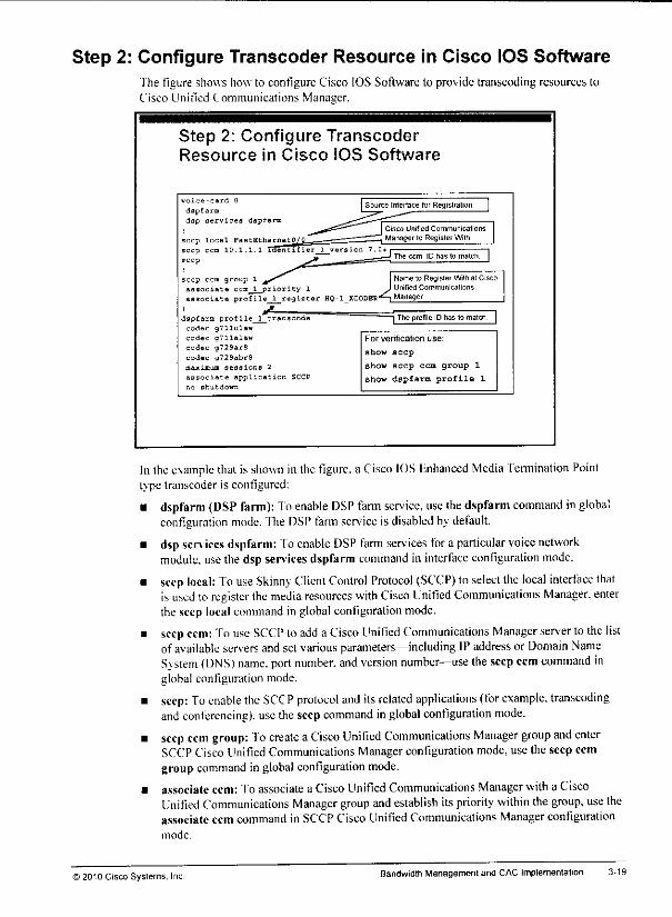
Step 2: Configure Transcoder Resource in Cisco IOS SoftwareThe figure shows how to configure Cisco IOS Software to provide transcoding resources toCisco Unified Communications Manager.
Step 2: Configure TranscoderResource in Cisco IOS Software
cp ccm group 1
^iate ccm 1 priority 1
:iata profile 1 register HQ-1 XCODEB-*^-! Manager
dspfarm profile 1 transcodecodec g711ulaw
codec gTllalaw
codec g729ar8
codec g729abrfl
maximum sessions 2
associate application SCCP
no shutdown
Name lo Register Wilti at CiscoUnitied Communications
~| The profile IDhas to match
For verification use:
show seep
show seep ccm group 1
show dspfarm profile 1
In theexample that is shown in the figure, a Cisco IOS Enhanced Media Termination Pointtype transcoder is configured:
• dspfarm (DSP farm): To enable DSP farm service, use the dspfarm command in globalconfiguration mode. The DSP farm service is disabled by default.
• dsp sen ices dspfarm: Toenable DSP farm services for a particular voice networkmodule, usethe dsp servicesdspfarm command in interface configuration mode.
• seep local: To use Skinny Client Control Protocol (SCCP) to select the local interface thatisused to register the media resources with Cisco Unified Communications Manager, enterthe seep local command in globalconfiguration mode.
• seep ccm: To use SCCP toadd a Cisco Unified Communications Manager server tothe listof available serversand set variousparameters—including IP addressor Domain NameSystem (DNS) name, port number, and version number—use the seep ccm command inglobal configuration mode.
• seep: To enable the SCCP protocol and its related applications (for example, transcodingand conferencing), use theseepcommand inglobal configuration mode.
• seep ccm group: To create aCisco Unified Communicalions Manager group and enterSCCPCisco Unified Communications Managerconfiguration mode, use the seep ccmgroup command in global configuration mode.
• associate ccm: To associate a Cisco UnifiedCommunications Manager with a CiscoUnified Communications Manager group and establish itspnority within the group, use theassociate ccm command in SCCPCisco Unified Communications Managerconfigurationmode.
© 2010 Cisco Systems. Inc. Bandwidth Management and CAC Implementation
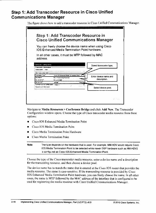
Step 1: Add Transcoder Resource in Cisco UnifiedCommunications Manager
The figure showshowto add a transcoderresourcein Cisco Unified Communications Manager.
Step 1: Add Transcoder Resource inCisco Unified Communications Manager
You can freely choose the device name when using CiscoIOS Enhanced Media Termination Point hardware.
In all other cases, it must be MTP followed by MACaddress.
TrtMWdBi Tip," C'tai (OS Mivad Hnba Ttrmnuliui Punf ^*\DttcVJon HQ-ilEhrtcfbdiisf Dttouro* |_
*>•..« Pwl* DbUJI — i tf 1
ttdqrm*ht)ti
< «tont > V".
Select transcoder type.
Enter device name and
description.
Select device pool.
Navigate to Media Resources > Conference Bridge and click Add New. The TranscoderConfiguration window opens. Choose the type of Cisco transcoder media resource from theseoptions:
• Cisco IOS Enhanced Media Termination Point
• Cisco IOS Media Termination Point
• Cisco Media Termination Point Hardware
• Cisco Media Termination Point
Note The type depends on the hardware that is used. For example, NM-HDV would require CiscoIOS Media Termination Point to be selected while newer DSP hardware such as NM-HDV2
is configured as Cisco IOS Enhanced Media Termination Point.
Choosethe type of the Ciscotranscoder mediaresource, entera devicename and a descriptionfor the transcoding resource, and then choose a device pool.
Thedevicename has to match the namethat is entered at the Cisco IOSrouter thai provides themediaresource. The name is case-sensitive. If the transcoding resource is provided by CiscoIOS Enhanced Media Termination Point hardware, you can freely choose the name. In all othercases,the name is MTPfollowed by ihe MAC addressof the interface that is configured to beused for registering the media resource with Cisco Unified Communications Manager.
3-18 Implementing Cisco Unrfied CommunicationsManager, Part 2 (CIPT2)v8.0 >2010 Cisco Systems, Inc.
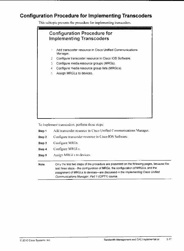
Configuration Procedure for Implementing Transcoders"fhis subtopic presents the procedure for implementing transcoders.
Configuration Procedure forImpiementing Transcoders
• Add transcoder resource in Cisco Unified Communications
Manager.
2 Configure transcoder resource in Cisco IOS Software.
3 Configure media resource groups (MRGs).
4 Configure media resource group lists (MRGLs).
G Assign MRGLs to devices.
To implement transcoders. perfonn these steps:
Step 1 Add transcoder resource in Cisco Unified Communications Manager.
Step 2 Configure transcoder resource in Cisco IOS Software.
Step 3 Configure MRGs.
Step 4 Configure MRGI.s.
Step 5 Assign MRGLs to devices.
Note Only the first two steps of the procedure are presented on the following pages, because thelast three steps—the configuration of MRGs, the configuration of MRGLs, and theassignmentof MRGLs to devices—are discussed inthe Implementing Cisco UnifiedCommunications Manager, Part 1 (CIPT1) course.
©2010 Cisco Systems. Inc Bandwidth Management and CAC Implementation 3-17
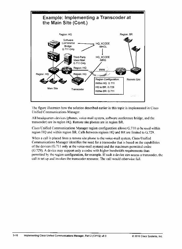
Example: Implementing a Transcoder atthe Main Site (Cont.)
Region: HQ Region: BR
Region: HQ
Main Site Transcoder
Region Configuration:
Within HQ: G.711
HQ to BR: G.729
Within BR: G.711
Remote Site
The figure illustrates how the solution described earlier in this topic is implemented in CiscoUnified Communications Manager.
All headquarters devices (phones, voice-mail system, software conference bridge, and thetranscoder) are in region HQ. Remote site phones are in region BR.
Cisco Unified Communications Manager region configuration allows G.711 to be used withinregion HO and within region BR. Calls between regions HQ and BR are limited to G.729.
When a call is placed from a remote site phone to the voice-mail system, Cisco UnifiedCommunications Manager identifies the need for a transcoder that is based on the capabilitiesof the devices(G.711 only at the voice-mail system)and the maximum permittedcodec(G.729). A device may support only a codec with higher bandwidth requirements thanpermitted by the region configuration, for example. If such a device can access a transcoder. thecall is set up and invokes the transcoder resource. The call would otherwise fail.
3-16 Implementing Cisco Unified Communications Manager. Part 2 (CIPT2) v8.0 ) 2010 Cisco Systems, Inc

Example: Implementing a Transcoder at the Main SiteThe figure illustrates an example of implementinga transcoder at the main site.
Example: Implementing a Transcoder atthe Main Site
G.729 audio streams are transcoded at the main site beforebeing passed on to endpoints supporting only G.711.
Cisco Unified
Communications
Manager
At the mainsite, thereare two devicesthat supportCi.711 only. One device is a Cisco UnifiedCommunications Manager software conference bridge; theother device isa third-party voice-mail application.
Regions are configured in such a way that all voice traffic between the remote site and the mainsite has to use the G.729 codec.
When a user at a remote site needs to be added to a conference via the software conferencebridge, the user cannot be added, because G.729 must be used over the IP WAN but only G.711is supported by the conference bridge.
By adding a transcoder resource at the main site gateway, you enable the remote site user tosend a G.729 voice stream, which is transcoded to G.711 and passed on to the conferencebridge b\ the transcoder that is located at the main site.
The same approach can beused for calls to the voice-mail system from the remote site.
) 2010 Cisco Systems, Inc Bandwidth Management and CAC Implementation

Number of phones at remote site and number of calls that are placed toG.711-onlyphones over the IP WAN: How many phones are located at the remote site? How often dothe phones need to communicate to phones located at the headquarters that support G.711only and hence require a transcoder when G.729 must be used over the IP WAN? Howmany of these calls occur at the same time?
Available bandwidth and cost of additional bandwidth: Is there enough bandwidth (orcan additional bandwidth be provisioned) to allow G.711 for calls to devices that do notsupport G.729? How does the cost of adding bandwidth compare to the cost of deployinglocal DSPs?
3-14 Implementing Cisco Unified Communications Manager, Part 2 (CIPT2) v8.0 ©2010 Cisco Systems, Inc.
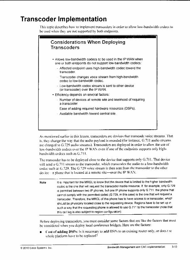
Transcoder ImplementationThis topic describes how to implement transcoders in order to allow low-bandwidth codecs tobe used when they are not supported by both endpoints.
Considerations When DeployingTranscoders
Allows low-bandwidth codecs to be used in the IP WAN whenone or both endpoints do not support low-bandwidth codecs:
Affected endpoint uses high-bandwidth codec toward thetranscoder.
Transcoder changes voice stream from high-bandwidthcodec to low-bandwidth codec.
Low-bandwidth codec stream is sent to other device(or transcoder) over the IP WAN.
Efficiency depends on several factors:
Number of devices at remote site and likelihood of requiringa transcoder
- Ease of adding required hardware resources (DSPs).
Available bandwidth toward central site.
As mentioned earlier in this lesson, transcoders arc devices that transcode voice streams, fhat
is. they changethe way that the audio payload is encoded(for instance, G.711 audio streamsare changed to G.729 audiostreams). Transcoders arc deployedin order to allowthe use oflow-bandwidth codecs over the IP WAN even if one of the endpoints supports only high-bandwidth codecs such as G.711.
Thetranscoder hasto be deployed close to the device thatsupports only G.711. Thatdevicewill send a G.711 stream to the transcoder. which transcodes the audio to a low-bandwidthcodec such as G.729. The G.729 voice stream is then sent from the transcoder to the otherdevice— a phonethat is located at a remotesite—overthe IP WAN.
Note Itis important forthe MRGL to know that the devicethat is limited to the higher bandwidthcodec is the one that will request the transcoder media resource. If, forexample, onlyG 729is permitted between two IPphones, butone IP phone supports only G.711, the phone thatcannotcomply with the permitted codec (G.729, inthiscase) is the one that will requestatranscoder. Therefore, the MRGL of this phone has to have access to a transcoder, whichshould be physically located close to the requesting device. Regions have to be set up insuch a waythat the requesting phoneis allowed to use G.711 to the transcoder(notethatthis call leg is also subject to region configuration).
Refore deploying transcoders. you must consider some factors that are like the factors that mustbe considered when you deploy local conference bridges. Here arethefactors:
• Costof adding DSPs: Is it necessary lo add DSPs to anexisting router only, or docs t lewhole platform have to be replaced?
) 2010 Cisco Systems. Inc Bandwidth Management and CAC Implementation 3-13
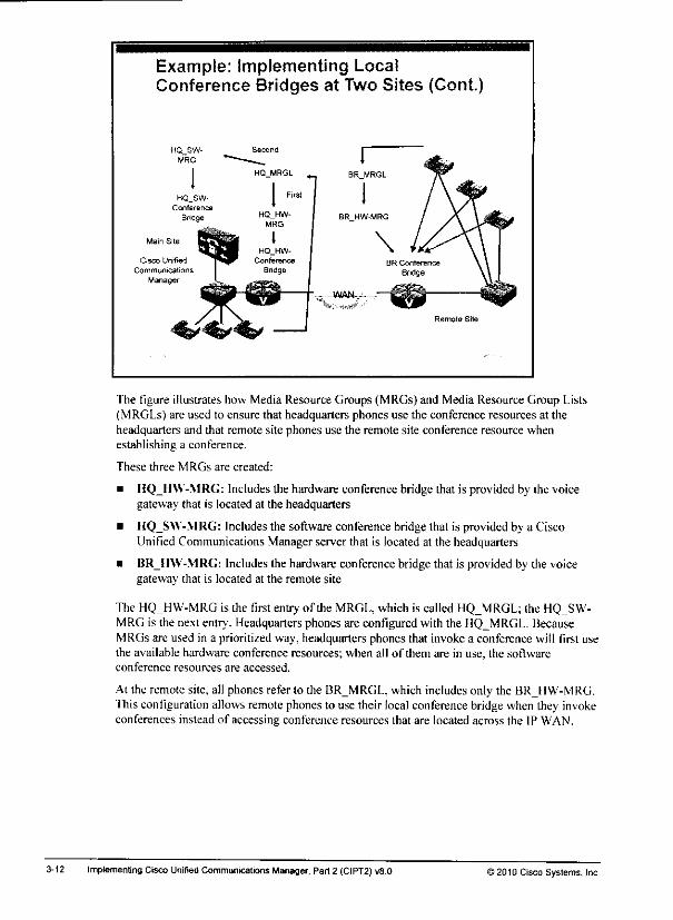
Example: Implementing LocalConference Bridges at Two Sites (Cont.)
HQ_SW-MRG
Main Site
Cisco Unified
Communications
Manager
The figure illustrates how Media Resource Groups (MRGs) and Media Resource Group Lists(MRGLs) are used to ensure that headquarters phones use the conference resources at theheadquarters and that remote site phones use the remote site conference resource whenestablishing a conference.
These three MRGs are created:
• HQ_HW-MRG: Includes the hardware conference bridge that is provided by the voicegateway that is located at the headquarters
• IIQ_SW-MRG: Includes the software conference bridge that is provided by a CiscoUnified Communications Manager server that is located at the headquarters
• BR_H\V-MRG: Includes the hardware conference bridge that is provided by the voicegateway that is located at the remote site
The HQ HW-MRG is the first entry of the MRGL, which is called HQ_MRGL; (he HQ SW-MRG is the next entry. Headquartersphones are configured with the HQ_MRGL. BecauseMRGs arc used in a prioritized way, headquarters phones that invoke a conference will first usethe available hardware conference resources; when all of them are in use, the softwareconference resources are accessed.
At the remote site, all phones refer to the BRMRGL, which includes only the BRJIW-MRG.This configuration allowsremotephonesto use their local conference bridgewhenthey invokeconferences instead of accessing conference resources that are located across the IP WAN.
3-12 Implementing Cisco Unified Communications Manager, Part 2 (CIPT2) v8.0 J2010 Cisco Systems, Inc.
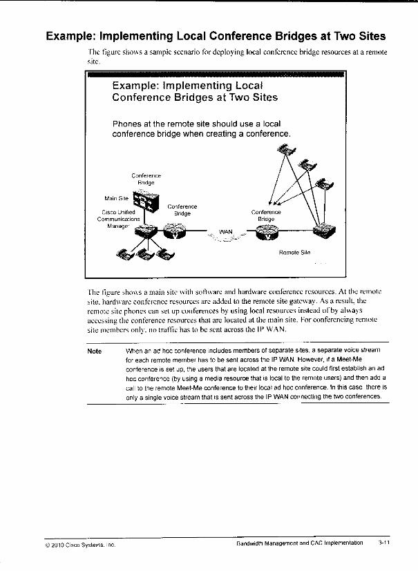
Example: Implementing Local Conference Bridges at Two SitesThe figure shows a sample scenario for deploying local conference bridge resources at a remotesite.
Example: Implementing LocalConference Bridges at Two Sites
Phones at the remote site should use a local
conference bridge when creating a conference.
Main Site
Cisco Unified
Communications
ManagerWAN
Remote Site
The figure shows a mainsite with software and hardware conference resources. At the remotesite, hardware conference resources are added lo the remote site gateway. As a result, theremotesite phones can set up conferences by using local resources insteadof by alwaysaccessing the conference resources that are located at the mainsite. Forconferencing remotesite members onlv. no traffic has to be sent across the IP WAN.
Note When an ad hoc conference includes members of separate sites, a separate voice stream
for each remote member has to be sent across the IP WAN. However, if a Meet-Me
conference is set up, the users that are located at the remote site could firstestablish an adhoc conference (by using a media resource that is localto the remote users) and then add acall to the remote Meet-Me conference to their local ad hoc conference. In this case, there is
onlya single voice stream that is sent across the IP WAN connecting the twoconferences.
©2010 Cisco Systems. Bandwidth Management and CAC Implementation 3-11

Local Conference Bridge Implementation"fhis topic describes howyoucan implement local conference bridges at remote sites inordertokeep voice streams local when all members of the conference are located at thesame site.
Considerations When Deploying LocalMedia Resources at Remote Sites
• Trafficstays off the IP WAN when remote site devices require amedia resource—for example, conference bridges.
- Local media resources require appropriate hardware at remotesite (DSPs in gateway).
« Efficiency depends on several factors:
- Number ofdevices at remote site and likelihood of usinga feature or application requiring the media resource
- Ease of adding required hardware resources (DSPs)
- Available bandwidth toward central site
When local conference bridges or Media Termination Points (MTPs) are deployed at each site,traffic does not have to cross the IP WAN if all endpoints are located at the same site. You canimplement local media resources such as conference bridges and MTPs by providingappropriate hardware (digital signal processors [DSPs]) at the routers that are located at theremote sites.
Whether the extra cost for providing the DSP resources will be worthwhile depends on severalfactors:
• Cost of adding DSPs: Is it necessary to add DSPs to an existing router only, or does thewhole platform have to be replaced?
• Number of devices at remote site and likelihood of using applications or features thatrequire access to the media resource that is considered to be locally deployed: Howmany phones are located at the remote site? How often do the phones use features thatrequire a media resource that is currently available only over the IP WAN? What is themaximum number ofdevices that require access to the media resource at the same time?
• Available bandwidth and cost of additional bandwidth: Is (here enough bandwidth (orcan additional bandwidth be provisioned) to accommodate the requirements that aredetermined by the preceding factors? How does the cost of adding bandwidth compare tothe cost of deploying local DSPs?
3-10 Implementing Cisco Unified Communications Manager, Part 2 (CIPT2) v8.0 J2010 Cisco Systems, Inc.
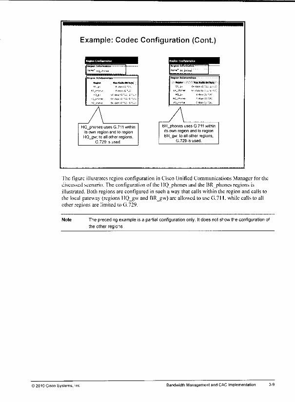
Example: Codec Configu ration (Cont)
Ipffcw OvftfluraJk* Pwk-ti ctrfifteBfaifon
ftevw JnfonmHIon————
flimt E4L_0|.2ftai
•teuton RalBilQn4jiw* - - -
•a_)> s *!>> is':«
M5,si>ii-tt e "til (S :«;
wq_i-<,-« Sites ts'Jf,
*mli*0 Hm,*mm+****t*
5=_J- - .bpif^ -si.
/\HQ_phones uses G.711 within
its own region and to regionHQ_gw; to all other regions,
G.729 is used
BR_phones uses G.711 withinits own region and to regionBR_gw, to all other regions,
G.729 is used.
"fhe figure illustrates region configuration in Cisco Unified Communications Manager for thediscussed scenario. The configuration of the HQ_phones and the BR_phones regions isillustrated. Both regions are configured in such a way that calls within the region and calls tothe local gateway (regions HQ_gw and RR_gw) arc allowed to use (i.7l I. while calls to allother regions are limited to G.729.
Note The preceding example is a partial configuration only. It does not show the configuration of
the other regions.
© 2010 Cisco Systems, Inc. Bandwidth Management and CAC Implementation
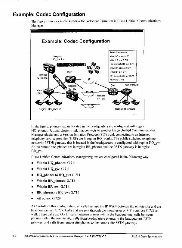
Example: Codec ConfigurationThe figure showsa sample scenario for codecconfiguration in Cisco UnitiedCommunicationsManager.
Example: Codec Configuration
Region: HQ_phones
Region Configuration
Within MQ_phorie9 G 711
WitntnHQ_gw G711
HQ_ptionestoHQ_gw G.711
Within BR_pnonee G 711
Within BRjuf G 711
BR_phones to BR_gv/ G.711
All others G 729
Remote Site
Region BR_phones
In the figure, phones that are located in the headquarters are configured with regionHQ_phones. An intercluster trunk that connects to another Cisco Unified CommunicationsManager cluster and a Session Initiation Protocol (SIP) trunk connecting to an Internettelephony service provider (ITSP) are in region HQ_trunks. The public switched telephonenetwork (PSTN) gateway that is located in the headquarters is configured with region HQ_gw.At the remote site, phones are in region BR_phones and the PSTN gateway is in regionBR_gw.
Cisco Unified Communications Manager regions are configured in the following way:
Within HQ_phones: G.711
Within IIQ_gw: G.711
HQ_phones to HQ_£w: G.711
Within BR_phones: G.711
Within BR_gw: G.711
BR_phones to BR_gw: G.711
All others: G.729
As a result, of this configuration, all calls that use the IP WAN between the remote site and theheadquarters use G.729. Calls that are sent through the intercluster or SIP trunk use G.729 aswell. These calls use G.711: calls between phones within the headquarters, calls betweenphones within the remote site, calls from headquarters phones to the headquarters PS'fNgateway, and calls from remote site phones to the remote site PSTN gateway.
Implementing Cisco Unified Communications Manager, Part 2 (CIPT2) v8.0 >2010 Cisco Systems, Inc.
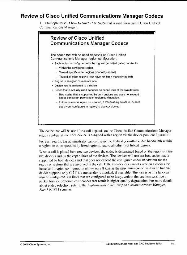
Review of Cisco Unified Communications Manager CodecsThis subtopic reviews how to control the codec that is used for a call in Cisco UnifiedCommunications Manager.
Review of Cisco Unified
Communications Manager Codecs
The codec that will be used depends on Cisco UnifiedCommunications Manager region configuration:
• Each region is configured with the highest permitted codec bandwidth
- Within the configured region.
Toward specific other regions (manually added).
Toward all other regions (that have not been manually added)
• Region is assigned to a device pool.
• Device pool is assigned to a device.
• Codec that is actually used depends on capabilities of the two devices:
Best codec that is supported by both devices and does not exceedcodec bandwidth permitted in region configuration.
If devices cannot agree on a codec, a transcoding device is invoked.
Loss type (configured in region) is also considered.
The codec that will be used for a call depends on the Cisco Unified Communications Managerregion configuration. Eachdevice is assigned with a regionvia the devicepool configuration.
Foreach region, the administrator can configure the highestpermitted codecbandwidth withina region, to other specifically listed regions, and to all other (not listed)regions.
Whena call is placedbetween two devices, the codec is determined basedon the regionsof thetwo devices andon the capabilities of the devices: The devices will use the bestcodec that issupported byboth devices andthatdoesnotexceed theconfigured codec bandwidth fortheregion or regions that are involved in the call. If the two devicescannotagreeon a codec(forinstance, if region configuration allowsonly 8 kb/s as the maximum codecbandwidth but onedevice supports only G.711). a transcoder is invoked, if available. The losstypeof a linkcanalsobe configured. On links thatare configured to be lossy, codecs thatare lesssensitive topacket lossarepreferred overcodecs thatresult inhigher-quality degradation. Formore detailsabout codec selection, refer to the Implementing Cisco Unified Communications Manager,Part / (CIPTI) course.
)2010 Cisco Systems, Inc. Bandwidth Management and CAC Implementation
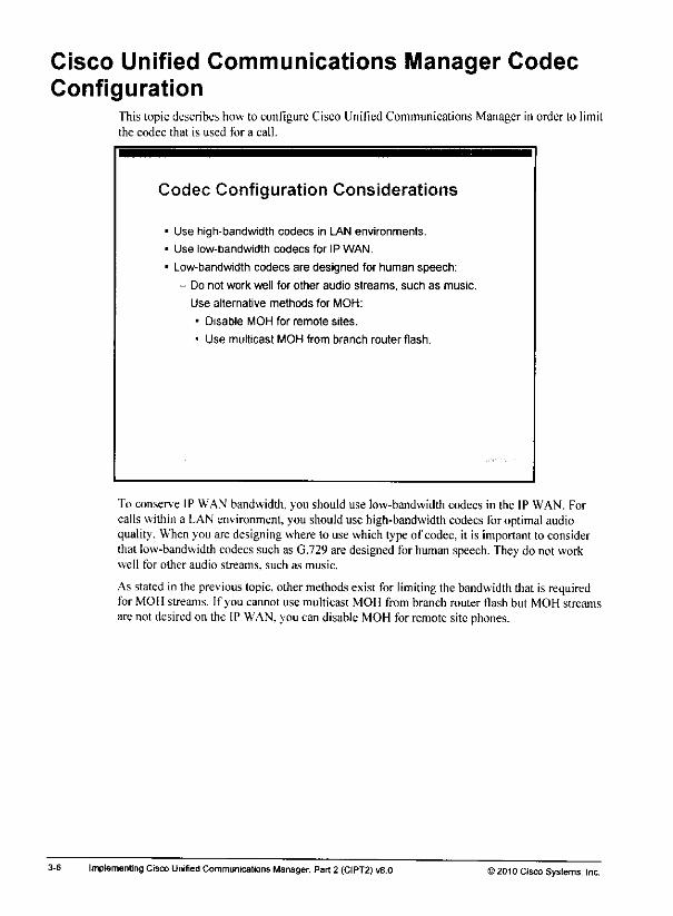
Cisco Unified Communications Manager CodecConfiguration
This topic describes how to configure Cisco Unified Communications Manager in order to limitthe codec that is used for a call.
Codec Configuration Considerations
• Use high-bandwidth codecs in LAN environments,
• Use low-bandwidth codecs for IP WAN.
* Low-bandwidth codecs are designed for human speech:
- Do not work well for other audio streams, such as music.
- Use alternative methods for MOH:
• Disable MOH for remote sites.
• Use multicast MOH from branch router flash.
To conserve IP WAN bandwidth, you should use low-bandwidth codecs in the IP WAN. Forcalls within a LAN environment, you should use high-bandwidth codecs for optimal audioquality. Whenyou are designing where to use which type of codec, it is important to considerthat low-bandwidth codecssuch as G.729are designed for humanspeech. Theydo not workwell for other audio streams, such as music.
As stated in the previous topic,other methods exist for limiting the bandwidth that is requiredfor MOH streams. If you cannot use multicast MOH from branch router flash but MOH streamsare not desiredon the IP WAN. you can disable MOHfor remotesite phones.
3-6 Implemenling CiscoUnified Communications Manager, Part2 (CIPT2) v8,0 ) 2010 Cisco Systems, Inc.

Other bandwidth management solutions includethe use of transcoders or the implementation ofspecial features such as multicast MOH from branch router flash. Transcoders are devicesthatcan transcode voice streams. That is. they change the way that the audio payload is encoded(for instance, a G.711 audio stream is changed to a G.729 audio stream). Transcoders allow theuse of low-bandwidth codecs over the IP WAN even if one of the endpoinls is limited to ahigh-bandwidth codecsuch as G.711. Multicast MOII frombranchrouter Hash allowsamulticast MOH stream lo be generated by a Cisco IOS router that is located at the remote site,instead of being sent over the IP WAN from a centralized MOH server.
©2010 Cisco Systems. Inc. Bandwidth Management and CAC Imptementation

Bandwidth Management Overviewfhis topic describes bandwidth management options in a Cisco Unified CommunicationsManager deployment.
Examples of Bandwidth ManagementOptions
Bandwidth in the IP WAN can be conserved by:
• Techniques that reduce required bandwidth of voice streams:
- RTP header compression (as part of QoS link efficiencymechanisms)
- Low-bandwidth codecs
• Techniques that influence the flow of voice streams:
- Local media resources such as conference bridges
• Other solutions:
- Transcoders
- Multicast MOH from branch router flash
Youcan use varioustechniques to conserve valuable IP WANbandwidth. One technique is toreducethe requiredbandwidth of voice streamsby using Real-Time Transport Protocol (RTP)header compression (whichis a qualityof service [QoS]linkefficiency mechanism), Anothertechnique is to use low-bandwidth audio codecs. You can also use a combination of these twosolutions.
Note Refer to the "Quality of Service"moduleof the Implementing Cisco Voice Communicationsand QoS (CVOICE) course for more detailed discussion about QoS.
Otheroptions formanaging IP WANbandwidth are techniques that influence wherevoicestreams are sent. If three phones, all located at a remotesite, establishan ad hoc conference,there is a greatdifference in bandwidth usage if the conference bridge is located at that remotesite—local to the phones that are members of the conference—or if the conference is located atthe main site and has to be accessed over the IP WAN. Inthe latter case, all three phones aresending their voice stream tothe conference bridge over the IP WAN. The conference bridge ismixing thereceived audio and is then streaming it back toall conference members (in threeseparate streams). Although the call appears to be local to the remote site—because allconference members are located atthat site—due tothe remotely located conference bridge, theIP WAN is occupied by three calls.
3-4 Implementing Cisco Unified Communications Manager, Part2 (CIPT2) v8.0 © 2010 Cisco Systems, Inc.

Lesson 1
Managing Bandwidth
OverviewWhen an IP WAN connects various sites in a Cisco Unified Communications network,bandwidth consumption at the IP WAN should beminimized. Several techniques can helpconserve bandwidth on the IP WAN in a multisite deployment;
• Reducing the required bandwidth of voice streams
• Keeping some \oice streams (such as local media resources) away from theIP WAN
• Employing special features like multicast music on hold (MOH) from branch router flash(or the use of transcoders).
"fhis lessondescribes all these techniques and features and their implementation.
ObjectivesUpon completing this lesson, you will be able to describe techniques to reduce bandwidthrequirements on IP WAN links in Cisco Unified Communications Manager multisitedeployments. This ability includes being able tomeet these objectives:• Describe methods to minimize bandwidth requirements for Cisco Unilied Communications
• Configure Cisco Unified Communications Manager in order tocontrol the codec that isused for a call
• Implement local conference bridges in order to avoid accessing conference bridges over theIP WAN even if all participants are local
• Implemeni transcoders in order to allow low-bandwidth codecs to be used iflow-bandwidthcodecsare not supported by both endpoints
• Implement multicast MOH from branch router flash to avoid MOH streams over the IPWAN

3-2 Implementing Cisco Unrfied Communications Manager, Part 2(CIPT2) v8.0 ©2010 Cisco Systems, inc.
Module 3
Bandwidth Management andCAC Implementation
OverviewIndividual sites of a multisite deployment are usually interconnected by an IP WAN insituations inwhich bandwidth is relatively costly andbandwidth consumption should beminimized. Call Admission Control (CAC) is alsoimportant in a multisite environment in orderto avoid bandwidth oversubscription by too many voice calls.
This module describes methods of reducing bandwidth requirements andexplainshow todesign and implement those methods so that the IP WAN bandwidth can be used as efficientlyas possible. It also describes CAC options for intrasile calls and intersite calls and how toimplemeni them in amultisite Cisco Unified Communications Manager deployment. Themodule also describes automated alternate routing (AAR), which allows the public switchedtelephone network (PSTN) to be used as a backup for calls that CAC denies due to insufficientbandwidth.
Module ObjectivesUpon completing this module, you will be able to implement bandwidth management and CACto prevent oversubscription ofthe IP WAN. This ability includes being able to meet theseobjectives:
• Describe techniques to reduce bandwidth requirements on IP WAN links in Cisco UnifiedCommunications Manager multisite deployments
• Describe and configure CAC mechanisms and AAR in Cisco Unified CommunicationsManager and in gatekeepers

Module Self-Check Answer KeyQD C
02) B. C
03) voice service voip
h323
no h225 timeout keepalive
Q4) A,D
05) D
06) B
Q7) B
Q8) D
09) D
010) A
Qll) D
Q12) B.C
Q13) A,D
Q14) B.C
Q15) A
2-102 Impiementing Cisco Unified Communications Manager, Part 2 (CIPT2) vB.O ©2010 Cisco Systems, Inc.

Q12) Which two statements about Cisco Unified Communications Manager Express aretrue? (Choose two.) (Source: Implementing Cisco Unified Communications Manager
Express in SRST Mode)
A) IP phonesregisterwith Cisco Unified Communications Manager Express instandalone mode when Cisco Unified Communications Manager Express ispartof theCisco Unified Communications Manager group (hat is specified inthe device pool of the phone.
B) During SRST fallback. IP phonesregisterwith Cisco Unified CommunicationsManagerExpress in SRSTmode whenCisco Unified CommunicationsManagerExpress is configured as the SRSTreference for the IP phone.
C) Cisco Unified Communications Manager Express in SRSTmodeprovidesmore features than standard SRST.
D) The sameplatform can servemore phones whenrunning Cisco UnifiedCommunications Manager Express in SRST mode versus running standardSRST,
E) Standalone Cisco Unified Communications Manager Express routerscan beclustered for redundancy.
013) Which two features have been added in Cisco Unified Communications ManagerExpress Release 8.0? (Choose two.) (Source: implementing Cisco UnitiedCommunications Manager Express in SRST Mode)
A) fi\ e additional MOI 1sourcesB) presence with BLE statusC) \ideo supportD) demote argument of the dialplan pattern commandE) local MOII
014) Whichtwo commands are notconfigured in telephony-service configuration mode?(Choose two.) (Source: Implementing Cisco Unified Communications Manager
Express in SRST Mode)
A) create cnf-files
B) ephoneC) ephonc-dnD) max-ephoncsE) max-dn
F) ip source-address
Q15) Which statement about Cisco Unified Communications Manager Express in SRSTmode is not true? (Source: Implementing CiscoUnified Communications ManagerExpress in SRST Mode)
A) Ifonly the ephone is preconfigured, only the ephone-dn is learned by SNAP.B) Ifonly the ephone-dn is preconfigured, only theephone is learned bySNAP.C) Ifephone and ephone-dn arepreconfigured, SNAP isnotused.D) Ifneither ephone norephone-dn areprcconfigured, ephone and ephone-dn are
learned bv SNAP.
>2010 Cisco Systems, Inc Centralized Call-Processing Redundancy Implementalion 2-101
Q6) When implementing MGCP Fallback and SRSf, which configuration is not performed
at Cisco Unified Communications Manager? (Source: Implementing SRST and MGCP
Fallback)
A) adding SRST referencesB) enabling MGCP fallback at the MGCP gateway configuration pageC) configuring CFUR to reach remote-site phones during SRST modeD) applying SRST reference to phones
Q7) The SRST reference is configured under System > Enterprise Phone Parameters.(Source: Implementing SRST and MGCP Fallback)
A) true
B) false
Q8) Which command is used for SRST configuration at the Cisco IOS router? (Source:Implementing SRST and MGCP Fallback)
A) telephony-serverB) ccm-manager fallbackC) service alternate defaultD) call-manager-fallback
Q9) Which command is not used for MGCP Fallback configuration? (Source:Implementing SRST and MGCP Fallback)
A) ccm-manager fallback-mgcpB) applicationC) globalD) telephony-serverE) service alternate default
QIO) Wheredo you configure the maximumnumberofhops that can be used by CFUR?(Source: Implementing SRST and MGCP Fallback)
A) service parameterB) enterprise parameterC) SRST gateway configurationD) phone configuration
Q1I) How cancalling privileges be implemented for SRST individual phones? (Source:Implementing SRST and MGCP Fallback)
A) only whenusingCisco Unified Communications ManagerExpress in SRSTmode
B) by preconfiguring the phonesthat need callingprivileges assignedC) by configuring an ephone-dn templateD) by configuring COR lists for directory numbers
2-100 Implementing Cisco Unified Communications Manager, Part 2 (CIPT2) v8.0 ©2010 Cisco Systems, Inc.

Module Self-CheckUse the questions hereto review whatyoulearned in this module. Thecorrect answers andsolutions are found in the Module Self-Check Answer Key.
Q1) Which of these provides redundancy for MGCT-controlledgateways? (Source:
Examining Remote Site RedundancyOptions)
A) MGCP SRSTB) SRST fallbackC) MGCP fallbackD) MGCP in SRST mode
Q2) Which two typesof calls arc notpreserved duringswitchover of an SRSf gateway?(Choose two.) (Source: Examining Remote Site Redundancy Options)
A) calls between IP phones that are located at the remote siteB) conference calls of remote-site phones usinga conference bridge that is located
at the main site
C) calls between IP phones that arc located at the remotesite and at the main siteD) calls between IP phones that are located at the main siteE) calls from main-site phonesthat wereplacedto a remote-site phoneand then
transferred from the remote-site phone to another main-site phone
Q3) Which configuration is required lo allow calls lobepreserved during switchback fromH.323 to MGCP? (Source: Examining Remote Site Redundancy Options)
Q4) What are the twocorrect statements of supported phones in SRST for thegivenplatform? (Choose two.) (Source; Examining Remote Site Redundancy Options)
A) 800:4
B) 2801:500
C) 2851:350
D) 3825:350
E) 3845:1024
Q5) What can you use toconfigure the dial plan ata remote-site gateway insuch a way thatbranch users can still reach the headquarters when dialing internal directory numbersduring fallback? (Source: Examining Remote Site Redundancy Options)A) Ihis is notpossible. Users have to dial headquarters users by their PSTN
numbers while in fallback mode.
B) Use translation profilesmodifying the callingnumber.C) Issue the dialplan-pattern command.D) Use translation profiles modifying the called number.
i2010 Cisco Systems. Inc. Centralized Call-Processing Redundancy Implementation
Cisco Systems. Inc. Number Translation Using Voice Translation Profiles, February 2006,http://w\\w.cisco.coni,'eii/US/tech/tk652/lky()/technolo«ies configuration__exantpld)9IS6a00803f818a.shtml
Cisco Systems. Inc. Voice Translation Rules, November 2006.http:/.''www,eisco,com/en/IJS/lcch/tk652/lk90/lechnologies_tech_note09l86a0080325e8e.shtml
Cisco Systems. Inc. Cisco Unified Communications Manager Express SystemAdministrator Guide, November 2007 with updates 2010.hup://ww w,cisco.com/en/US/docs/voice ip comm/cucme/admiii/coiifiguration/guide/cmeadm.html
2-9S Implementing Cisco Unified Communications Manager, Part 2 (CIPT2) v8.0 ©2010 Cisco Systems, Inc.
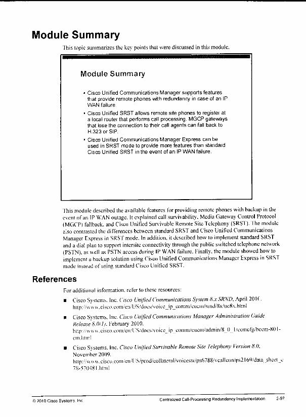
Module SummaryThis topic summarizes the key points that were discussed in this module.
Module Summary
Cisco Unified Communications Manager supports featuresthat provide remote phones with redundancy in case of an IPWAN failure.
Cisco Unified SRST allows remote site phones to register ata local router that performs call processing. MGCP gatewaysthat lose the connection to their call agents can fall back toH.323 or SIP.
Cisco Unified Communications Manager Express can beused in SRST mode to provide more features than standardCisco Unified SRST in the event of an IP WAN failure.
Ihis module described the available features for providing remotephones withbackup in theevent of an IP WAN outage. It explained call survivability. Media Gateway Control Protocol(MGCP) fallback, andCisco Unified Survivable Remote Site Telephony (SRS'f). fhe modulealso contrasted the differences between standard SRST and Cisco Unified CommunicationsManager Express inSRST mode. In addition, itdescribed how to implement standard SRSTand a dial plan tosupport intersite connectivity through the public switched telephone network(PSTN), as well as PSTN access during IP WAN failure. Finally, the module showed how toimplement a backup solution using Cisco Unified Communications Manager Express in SRSTmode instead of using standard Cisco Unified SRST.
References
For additional information, refer to these resources:
• Cisco Systems. Inc. Cisco Unified Communications System 8.x SRND, April 20IC.hup://\\\\w,cisco.com •'en.TJS/d()cs/voicejp_comni/ciiein/snid/8x/uc8x.hlinl
• Cisco Systems. Inc. Cisco Unified Communications Manager Administration GuideRelease 8.011). February 2010.http://www.cisco.coni/cn/t'S/docs/v()icejp_coinm/cLicni/admin/8J) l/ecmcfg/bccm-KOI-cm.html
• Cisco Systems. Inc. Cisco Unified Survivable Remote Site Telephony Version 8.0.November 2009,lntp://w\\w.cisco.eoni/en/US/prod/collateral/voicesxv/ps6788/vcallcon/ps2l69/daUi .sheet_>78-570481.html
©2010 Cisco Systems, Inc. Centralized CalI-Processing Redundancy Implementation 2-97

2-96 Implementing Cisco Unified Communications Manager, Part 2(CIPT2) v8,0 ©2010 Cisco Systems, Inc.
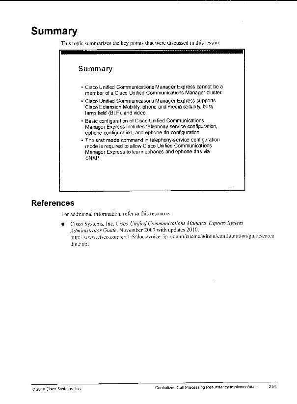
SummaryThis topicsummarizes the key points that were discussed in this lesson.
Summary
References
Cisco Unified Communications Manager Express cannot be amember of a Cisco Unified Communications Manager cluster.
Cisco Unified Communications Manager Express supportsCisco Extension Mobility, phone and media security, busylamp field (BLF), and video.
Basic configuration of Cisco Unified CommunicationsManager Express includes telephony-service configuration,ephone configuration, and ephone-dn configuration.
The srst mode command in telephony-service configurationmode is required to allow Cisco Unified CommunicationsManager Express to learn ephones and ephone-dns viaSNAP
For additional information, refer to this resource:
• Cisco Systems. Inc. Cisco Unified Communications Manager Express SystemAdministrator Guide. November 2007 with updates 2010.http:'•'www.cisco.coiTt/en.-rS/docs.'Voice ip coiiim-'ciiciiie/adniin/cunliguration/guide/cnicadm.html
) 2010 Cisco Systems. Inc Centralized Call-Processing RedundancyImplementation 2-95
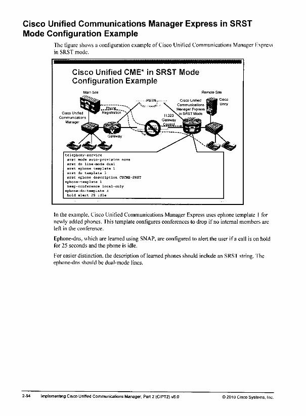
Cisco Unified Communications Manager Express in SRSTMode Configuration Example
The figure shows a configuration example of Cisco Unified Communications Manager Expressin SRST mode.
Cisco Unified CME* in SRST Mode
Configuration Example
Cisco
Unity
Cisco Unified
Communications
Manager
telephony-service
erst mode Auto-provision none
srst dn line-mode dual
srst aphone templata 1
srst dn template 3
srst ephone description CUCME-SRST
ephone-template 1
keep-conference local-oQlyephone-dn-template 3
hold-alert 25 idle
In the example. Cisco Unified Communications Manager Express uses ephone template 1 fornewly added phones. This template configures conferences to drop if no internal members areleft in the conference.
Ephone-dns, which are learned using SNAP, are configured to alert the user if a call is on holdfor 25 seconds and the phone is idle.
For easier distinction, the description of learned phones should include an SRS'f string. Theephone-dns should be dual-mode lines.
2-94 Implementing Cisco Unified Communications Manager, Part 2 (CIPT2) w8.0 ) 2010 Cisco Systems, Inc.
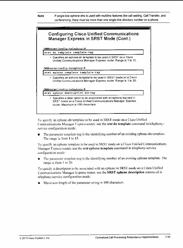
Note Ifsingle-line ephone-dns is used with multiline features likecall waiting, Call Transfer, andconferencing, there must be more than one single-line directory number on a phone.
Configuring Cisco Unified CommunicationsManager Express in SRST Mode (Cont)
CHERouter(confia-telephonv)#
srst dn template template-tag
• Specifies an ephone-dn template to be used in SRST on a CiscoUnified Communications Manager Express router. Range is 1 to 15.
CHERouter(config-telephony)#
srst ephone template template-tag
• Specifies an ephone template to be used in SRST mode on a CiscoUnified Communications Manager Express router. Range is 1 to 20.
CHERouter (conf id-telephonv) tt
srst ephone description string
• Specifies a description to be associated with an ephone learned inSRST mode on a Cisco Unified Communications Manager Express
router Maximum is 100 characters
To specify an ephone-dn template to be used in SRST mode on a Cisco UnifiedCommunications Manager Express router, use the srst dn template command in telephony-service configuration mode:
• Theparameter template-tag is the identifying number of an existing ephone-dn template.The range is from I to 15.
Tospecifv anephone template to beused inSRS'f mode ona Cisco Unified CommunicationsManager Express router, use the srst ephone template command intelephony-serviceconfiguration mode:
• The parameter template-tag is the identifying number of anexisting ephone template. Therange is from 1 to 20.
Tospecifv a description tobe associated with anephone in SRST mode ona Cisco UnifiedCommunications Manager Express router, use the SRST ephonedescription comma.id intelephony-service configuration mode:
• Maximum length of the parameter string is 100characters.
© 2010 Cisco Systems. Inc Centralized Call-Processing Redundancy Implementation
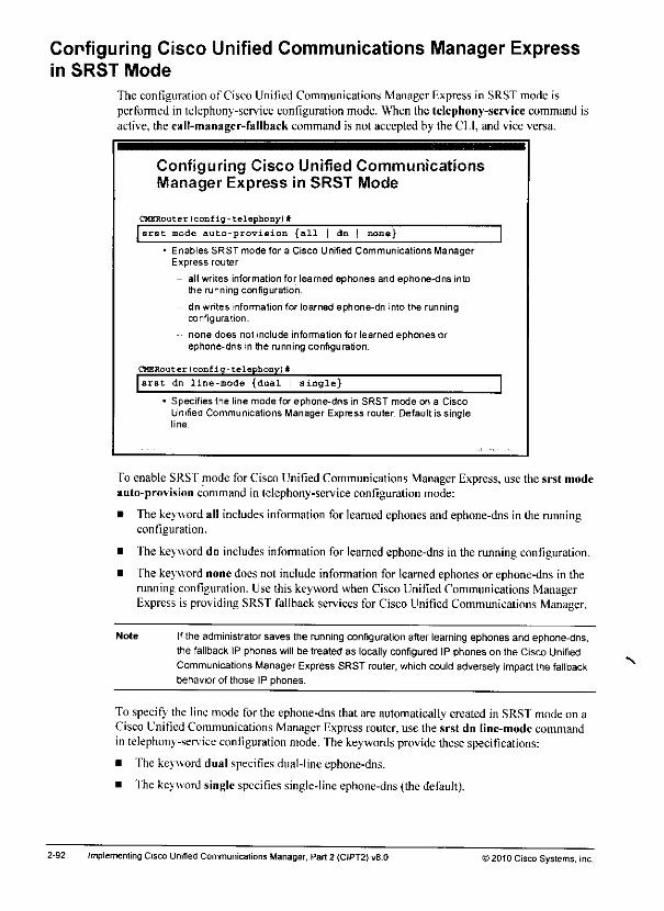
Configuring Cisco Unified Communications Manager Expressin SRST Mode
The configuration of Cisco Unified Communications Manager Express in SRST mode isperformed in telephony-service configuration mode. When the telephony-service command isactive, the call-manager-fallback command is not accepted by the CI,I, and vice versa.
Configuring Cisco Unified CommunicationsManager Express in SRST Mode
CHERouter(config-telephony)#
srst mode auto-provision {all | dn | none}
• Enables SRST mode for a Cisco Unified Communications ManagerExpress router
- all writes information for leamed ephones and ephone-dns intothe running configuration.
- dn writes information for learned ephone-dn into the runningconfiguration.
- none does not include information for learned ephones orephone-dns in the running configuration.
CHERouter(confiq-telephony)#
srst dn line-mode {dual | single}
• Specifies the line mode for ephone-dns in SRST mode on a CiscoUnified Communications Manager Express router. Default is singleline
To enable SRS'f mode for Cisco Unified Communications Manager Express, use the srst modeauto-provision command in telephony-serviceconfiguration mode:
• The keywordall includes information for leamedephonesandephone-dns in the runningconfiguration.
• The keyword dn includes information for learnedephone-dns in the runningconfiguration.
• The keyword none does not include information for learnedephonesor ephone-dns in therunning configuration. Use this keyword whenCisco UnifiedCommunications ManagerExpress is providing SRSTfallback services for Cisco Unified Communications Manager,
Note Ifthe administrator saves the running configuration after learning ephones and ephone-dns,the fallback IP phones will be treated as locally configured IP phones on the Cisco Unified
Communications Manager Express SRST router,whichcould adversely impact the fallbackbehavior of those IP phones.
To specify the line mode for the ephone-dns that are automatically created in SRST mode on aCisco Unified Communications ManagerExpress router,use the srst dn line-mode commandin telephony-service configuration mode. Thekeywords provide these specifications:
• The keyword dual specifies dual-line ephone-dns.
• The keywordsingle specifies single-line ephone-dns (the default).
2-92 Implementing Cisco Unified Communications Manager,Part 2 (CIPT2) vB.O >2010 Cisco Systems, Inc.
N

Phone Registration ProcessThis section describes the phone registration process.
Phone Registration Process
When an IP phone registers to Cisco UnifiedCommunications Manager Express in SRST mode duringfallback:
• The router searches for an existing ephone with the MAC address ofthe phone.
tf found, tho ephone must be configured with a directory number(button command), or automatjcassignmentmust be enabled.
If not found, the router searches for an existing ephone-dn thatmatches the IP phone directory number (learned by SNAP).
• Iffound, an ephone is added that refers to the matchedephone-dn
• If not found, an ephone is added that refers to a newlycreated ephone-dn autoconfigured by SNAP.
• Whenever an ephone is added by Cisco Unified SRST, the srstephone template is applied.
• Whenever an ephone-dn is added by Cisco Unified SRST, the srstephone-dn template is applied.
When a phone loses connectivity to the Cisco Unified Communications Manager, it registers toits configured SRST reference.
If that SRST reference is Cisco Unified Communications Manager Express in SRS'f mode, theCisco Unified Communications Manager Express router firstsearches for anexisting(preconfigured) ephone with the MAC address ofthe registering phone. Ifthe router finds anephone. the stored ephone configuration isused. No phone configuration settings that arcpro\ ided b> SNAP are applied, and no ephone template is applied. Ifthe configured ephone isconfigured with one ormore ephone-dns. the stored configuration isused for the ephone-dn orephone-dns ofthe phone. Neither the information that is provided by SNAP nor the ephonetemplate thai isconfigured under telephony-service isapplied. Ifthe configured ephone isnotconfigured with an ephone-dn. automatic assignment has tobe enabled for the phone tobecomeassociated with an ephone-dn. SNAPis no option in this case.
Ifno ephone is found for the MAC address ofthe registering phone. Cisco UnifiedCommunications Manager Express adds the ephone (and applies the ephone template, ifconfigured), using SNAP. Ifthe directory number exists, it is bound tothe added phone:otherwise, the directory number islearned using SNAP. Ifconfigured, the ephone-dn templateis applied.
© 2010 Cisco Systems, IncCentralized Call-Processing Redundancy Implementation 2-91
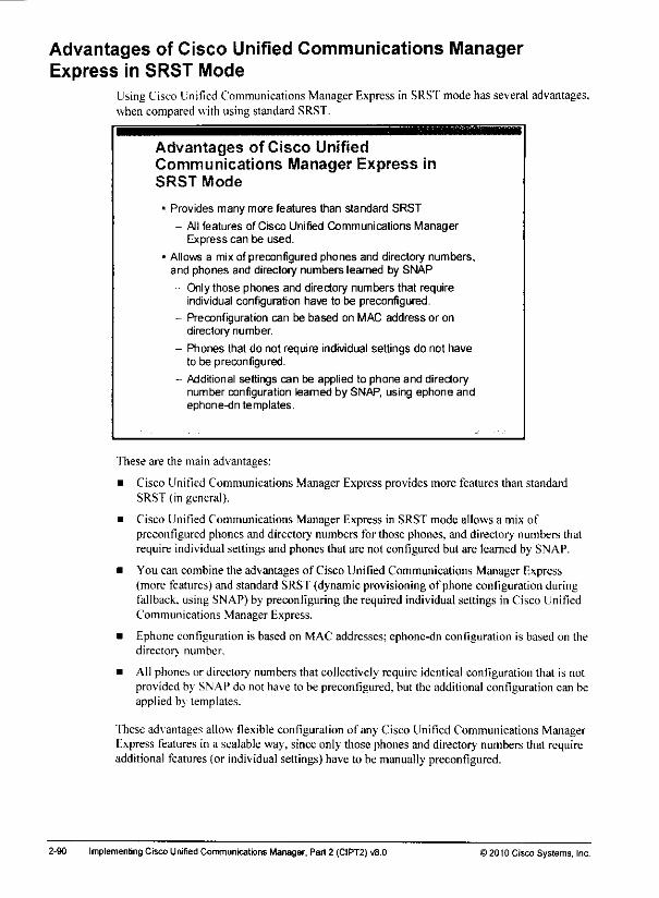
Advantages of Cisco Unified Communications ManagerExpress in SRST Mode
UsingCisco Unified Communications ManagerExpress in SRSTmodehas several advantages,when compared with using standard SRST.
Advantages of Cisco UnifiedCommunications Manager Express inSRST Mode
• Provides many more features than standard SRST
- Allfeatures of Cisco Unified Communications ManagerExpress can be used.
* Allows a mix of preconfigured phones and directory numbers,and phones and directory numbers learned by SNAP
- Only those phones and directory numbers that requireindividual configuration have to be preconfigured.
- Pre configuration can be based on MAC address or ondirectory number.
- Phones that do not require individual settings do not haveto be preconfigured.
- Additional settings can be applied to phone and directorynumber configuration leamed by SNAP, using ephone andephone-dn templates.
These are the main advantages:
• Cisco Unified Communications Manager Express provides more features than standardSRST (in general).
• Cisco Unified Communications Manager Express in SRST mode allows a mix ofpreconfigured phones and directory numbers for those phones, and directory numbers thatrequire individual settings and phones that are not configured but are leamed by SNAP.
• You can combine the advantages of Cisco Unified Communications Manager Express(more features) and standard SRST (dynamic provisioning ofphone configuration duringfallback, using SNAP) by preconfiguring the required individual settings in Cisco UnifiedCommunications Manager Express.
• Ephone configuration is based on MAC addresses; ephone-dn configuration is based on thedirectory number.
• All phones or directory numbers that collectively require identical configuration that is notprovided by SNAP do not have to be preconfigured, but the additional configuration can beapplied by templates.
These advantages allow flexible configuration of any Cisco Unified Communications ManagerExpress features in a scalable way, since only those phones and directory numbers that requireadditional features (or individual settings) have to be manually preconfigured.
2-90 ImplementingCisco Unified Communications Manager, Part 2 (CIPT2)v8.0 ) 2010 Cisco Systems, Inc.

Phone Provisioning OptionsThe table summarizes the phone provisioning options and shows the relevant configurationparts.
Phone Provisioning Options
Cisco IOS
Configuration
ResultingDirectory NumberConfiguration
Resulting PhoneConfiguration
gpftone andEphone-dri
ephone 1mac-address.type 7960button 1:6
ephone-dn 6number 3001
ExistingUnited CME'
con fig u rat ion
ExistingUnited CME*
configuration
Ephoneand Ephone.dr, and Complete5RST*f„„„„„ SRST Provisioning Provisioning
ephone 1mac-address...
type 7960(no button...)
telephony- serviceauto assign..
United CME"
ephone-dnconfigurationreferenced by
automatic
assignment
Existingunited CME'ccrifiguration
ephone-dn 6number 3001
lelephony-seryicesrst mode
auto-
provieion...
United CME*
ephone-dnconfiguration ofmatching phonedirectory number
telephory-sarmcesrst mode
auto-
provision. •
Phone directorynumber
configurationplus Unified CME'SRST ephone-dntemplate (If used)
united CME' United CME*ephone template (ft ephone template (if
used) used)
-Urified CME = Cisco Unified Communications Manager Express
As shown in the table, if an ephone and ephone-dn are configured in Cisco UnifiedCommunications Manager Express, a phone that registers with the configured MAC addresswillget the complete configuration (phoneand director;' number) appliedas configured inCisco Unified Communications Manager Express.Cisco Unilied Communications ManagerExpressdoes not use SNAP at all to configure the phone.
If an ephone is configured but is notassociated with an ephone-dn, automatic assignment hastobe enabled. Otherwise, the phonewill not have a line and cannotplaceor receive calls.Theephone-dn configuration isdetermined based on the arguments of theauto-assign command.SNAP is not used (for learning phone settings or director,' number configuration parameters).
If only ephone-dns are configured, theephone configuration is learned by SNAP, while theephone-dn configuration that is configured in Cisco Unified Communications Manager Expressis used instead of the phone directory number configuration that is provided by SNAP. Ephonetemplates (if configured) areapplied to the learned ephone configuration.
If neitheran ephone (MACaddress) nor a directory numberexists for the registering phone.Cisco Unified Communications Manager Express will learneverything(ephone and ephonc-dnconfiguration) from SNAP. Ephone and ephone-dn templates are applied, if configured.
i 2010 Cisco Syslems. Inc Centralized Call-Processing Redundancy Implementation
Note This combination is not very common because it combines the need for specific phone
configuration parameters with the dynamic assignment of directory numbers.
• Manually configured ephone-dn: An ephone-dn is not associated with an ephone. Thereason to configure the ephone-dn but not the ephone is that only individual ephone-dnconfiguration is required, but default settings or a single template can be used for theephone (uhich is added once the phone is registered).
• No manual configuration: In this case, the ephone-dn and the ephone are learned bySNAP. You can apply configuration settings that are not supported by SNAP to such newlyadded phones and directory numbers by configuring the appropriate templates.
2-88 Implementing Cisco Unrfied Communications Manager, Part 2 (CIPT2) v8.0 © 2010 CiscoSystems. Inc
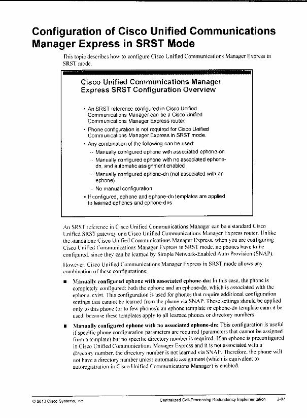
Configuration of Cisco Unified CommunicationsManager Express in SRST Mode
This topicdescribes how to configure Cisco Unified Communications Manager Express inSRST mode.
Cisco Unified Communications ManagerExpress SRST Configuration Overview
• An SRST reference configured in Cisco UnifiedCommunications Manager can be a Cisco UnifiedCommunications Manager Express router.
• Phone configuration is not required for Cisco UnifiedCommunications Manager Express in SRST mode.
* Any combination of the following can be used:
- Manually configured ephone with associated ephone-dn
Manuallyconfigured ephone with no associated ephone-dn. and automatic assignment enabled
- Manuallyconfigured ephone-dn (not associated with anephone)
- No manual configuration
• If configured,ephone and ephone-dn templates are appliedto leamed ephones and ephone-dns
An SRST reference in Cisco Unified Communications Manager can be a standard CiscoUnified SRSTgateway or a Cisco Unified Communications Manager Express router. Unlikethe standalone Cisco Unified Communications Manager Express, when you are configuringCisco Unified Communications ManagerExpress in SRSTmode, no phoneshave to beconfigured, since they can be learned by Simple Network-Enabled Auto Provision (SNAP).
Houc\ cr. Cisco Unified Communications Manager Express in SRST mode allows an>combination of these configurations:
• Manually configured ephonewith associated cphone-dn: In thiscase, thephone iscompletely configured: both the ephone and anephone-dn, which isassociated with theephone. exist, fhis configuration isused for phones that require additional configurationsettings that cannot be learned from the phone via SNAP. These settings should be appliedonly tothis phone (or to few phones); an ephone template orephone-dn template cann.il beused, because these templates apply to all learned phonesor directory numbers.
• Manually configured ephone with no associated ephone-dn: This configuration is usefulifspecific phone configuration parameters are required (parameters that cannot be assignedfrom a template) but no specific directory number isrequired. Ifan ephone ispreconfiguredin Cisco UnifiedCommunications Manager Express and it is not associated with adirectory number, thedirectory number isnotlearned viaSNAP. Therefore, the phone willnot have a directory number unless automatic assignment (which isequivalent toautoresistralion in Cisco Unified Communications Manager) is enabled.
)2010Cisco Systems, Inc. Centralized Call-Processing Redundancy Implementation 2-87
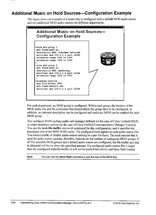
Additional Music on Hold Sources—Configuration ExampleThe figure shows an example of a router that is configured with a default MOH audio sourceand two additional MOH audio sources for different departments.
Additional Music on Hold Sources-
Configuration Example
voice moh-group 1
moh Elashimohl.au
description HOH: customer services
multicast moh 239.1.1.1 port 16381
extension-range 1000 Co 1099
extension-range 1300 to 1399
I
voice moh-group 2moh flashimoh2.au
description HOB: marketing
multicast moh 239.1.1.2 port 16384extension-range 3000 to 3099
I
telephony - service
moh-file-buffer 5000
moh flashidefault.wav
multicast moh 239.1.1.3 port 163 64
For each department, an MOH group is configured. Within each group, the location of theMOH audio file and the extensions that should utilize the group have to be configured. Inaddition, an optional description can be configured and multicast MOH can be enabled for eachMOH group.
You configure RAM caching under call-manager-fallback (in the case ofCisco Unified SRST)or under telephony-service (in the case of Cisco Unified Communications Manager Express).You use the moh-file-buffer size-in-kb command for this configuration, and it specifies themaximum size of the MOH RAM cache, 'fhe configured limit applies to each audio source file.You cannot enable or disable audio source caching on a per-file basis. The total amount that isusedfor audio sourcecaching, therefore, dependson the numberof configured MOI 1groups. Ifall five possible MOH groups and a default audio source are configured, the file buffer size thatis allocated will be six times the specifiedamount. Ifa configured audiosource file is largerthan the configured moh-file-buffer, it will not be cached but will be read from flash instead.
Note You can use the show flash command to see the size of the MOH files.
2-86 Implementing Cisco Unified Communications Manager. Part 2 (CIPT2) v8.0 >201u Cisco Systems, Inc.
•r
*m»

•Mr
_*^^_
^^hr
Additional MOH Sources
Cisco Unified Communications Manager Express Version 8 introduces the capability ofconfiguring up to five MOH sources in addition to the default MOH source.
Additional Music on Hold Sources
• Up to five additional MOH sources can be configured.
- Used oniy by SCCP phones that put call on hold.
- RAM caching of MOH file can be enabled.
• Less CPU utilization because of reduced flash reads
• Higher memory consumption
• Supported by Cisco Unified Communications Manager Express,Cisco Unified Communications Manager Express in SRST mode,and Cisco Unrfied SRST.
• Supported on Cisco Unified Communications 500 series and Cisco1800, 2800. 2900. 3800, and 3900 Series Routers,
• Only au or .wavfiles in G 711 8-bit mono format are supported.
Minimum size 100 Kb.
• Default flash dnve should be used to store MOH files.
• Configuration is based on MOH groups.
• Phones not configured to use one of these groups use the defaultMOH source.
These additional MOH sources can be utilized by SCCP phones that put calls on hold. Anyother entities thai putcallson hold (such as basicautomatic calldistribution [B-ACD] or SIPphones) will use the default MOH source. If live audio feed is used, it can beconfigured onlyas the default MOH source.
Cisco Unified Communications Manager Express can be configured to cache files in RAM.This configuration reduces CPU utilization because flash reads areessentially eliminated afterthe audio fileshave been loadedto RAM. However, cachingaudio files in RAM can drasticallyincrease memory consumption. Memory requirements depend onthenumber of MOI I files andtheir size (there is no limitation on the maximum size of an audio file).
Multiple MOH sources arc supported by Cisco Unified Communications Manager Express.Cisco Unified Communications Manager Express in SRSTmode,and Cisco Unified SRST.Multiple MOH sources arc supported onthese platforms: Cisco Unified Communications 500Series and Cisco 1800. 2800. 2900, 3800. and 3900 Series Integrated Services Routers.
The audio files have to be .au or .wav files in G.711 8-bit mono format, and their minimum sizeis 100 kb. Ifmultiple flash devices are present inthe router, the default flash drive should beutilized.
The configuration ofmultiple MOH sources isbased on MOH groups. Endpoints that do notsupport MOH groups orthat are not configured to use an MOH group will use the default MOHsource.
Note The MOH source is selected based on the configuration of the holder (thatis, the phonethatputs the call on hold).
) 2010 Cisco Systems, Inc Centralized CalI-Processing Redundancy Implementation 2-85
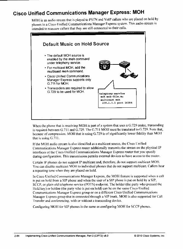
Cisco Unified Communications Manager Express: MOHMOH is an audio stream that isplayed to PSTN and VoIP callers who are placed on hold byphones in aCisco Unified Communications Manager Express system. This audio stream isintended to reassure callers that they are stillconnected to theircalls.
Default Music on Hold Source
The default MOH source isenabled by the moh commandunder telephony service.
For multicast MOH, add themulticast moh command.
Cisco Unified CommunicationsManager Express supports onlyG.711 for MOH.
Transcoders are required to allowG.729 to be used for MOH.
telephony-servicemoh moh-file.au
multicast moh
239.1.1.1 port 16384
When thephone thatis receiving MOH is part of a system thatuses a G.729 codec, transcodingis required between G.711 and G.729. TheG.711 MOH must betranslated toG.729. Note that,because of compression. MOH that is using G.729 is of significantly lower fidelity than MOIIthat is using G.711.
If the MOH audio stream is also identified as a multicast source, the Cisco UnifiedCommunications ManagerExpress router additionally transmits the streamon the physical IPinterfaces of the Cisco Unified Communications Manager Express router that you specifyduringconfiguration. This transmission permitsexternal devices lo have accessto the router.
Certain IPphones do notsupport IPmulticast and, therefore, do notsupport multicast MOI I.You can disable multicast MOII to individual phones that do not support multicast. Callers heara repeating tone when they are placed on hold.
In Cisco Unified Communicalions Manager Express, the MOH feature is supported when a callis put on hold from a SIP phoneand whenthe userof a SIP phoneis put on hold by a SIP,SCCP. or plain old telephone service (POTS) endpoint. The holder (the party who pressed theHold key) or holdee (the party who is put on hold) can be on the same Cisco UnifiedCommunications Manager Express group or on a different Cisco Unified CommunicationsManager Expressgroup that is connected through a SIP trunk. MOH is also supported for CallTransfer and conferencing, with or without a transcoding device.
Configuring MOH for SIP phones is the same as configuring MOH for SCCP phones.
2-84 Implemenling Cisco Unified Communications Manager, Pan 2 (CIPT2) v8.0 ) 2010 Cisco Systems, Inc
-km*
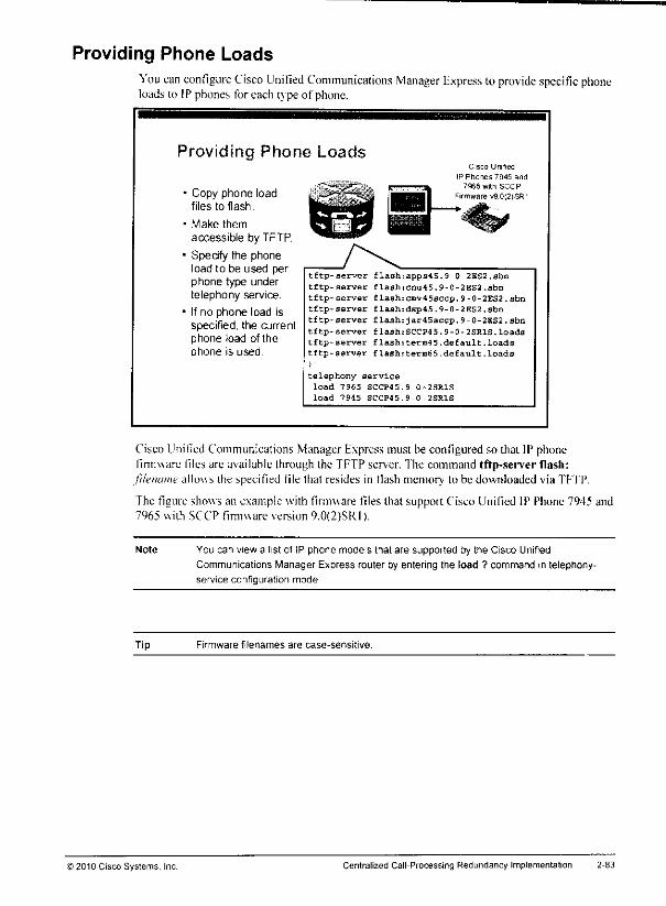
Providing Phone LoadsYou can configure Cisco Unified Communications Manager Express to provide specific phoneloads to IP phones for each type of phone.
Providing Phone Loads
Copy phone loadfiles to flash.
Make them
accessible by TFTP.
Specify the phoneload to be used perphone type undertelephony service.
If no phone load isspecified, the currentphone load of thephone is used.
tftp-aerver flash;
tftp-server flash;
tftp-server flash;
tftp-server flash:
tftp-server flash:tftp-server flash:tftp-server flash:tftp-aerver flash:
I
telephony-serviceload 7965 SCCP45.
load 7945 SCCP45.
Cisco Unified
IP Phones 7945 and
7S65witti SCCP
Firmware v9.0(2)SR1
apps4S.9-Q-2ES2.sbn
cnu 4 5.9 - 0 - 2 ES2.sbn
cmv45sccp.9-0-2ES2.sbndsp45.9-0-2ES2.sbn
jar45sccp.9-0-2BS2.sbn
SCCP4 5.9-0-2SR1S.loads
term45.default.loads
termS5.default.loads
9-0-2SR1S
9-0-2SR1S
Cisco Unified Communications Manager Express must be configured so that IP phonefirmware files are available through the TFTP server. The command tftp-server flash:
filename allows the specified tile that resides in fiash memory to be downloaded via TFTP.
The figure shows an example with finnuare files that support Cisco Unified IP Phone 7945 and7965 with SCCP finnuare version 9.0(2)SR1).
Note You can view a list of IP phone models that are supported by the Cisco Unified
Communications Manager Express router by entering the load ? command in telephony-
service configuration mode
Tip Firmware filenames are case-sensitive.
© 2010 Cisco Systems, Inc. Centralized Call-Processing Redundancy Implementation
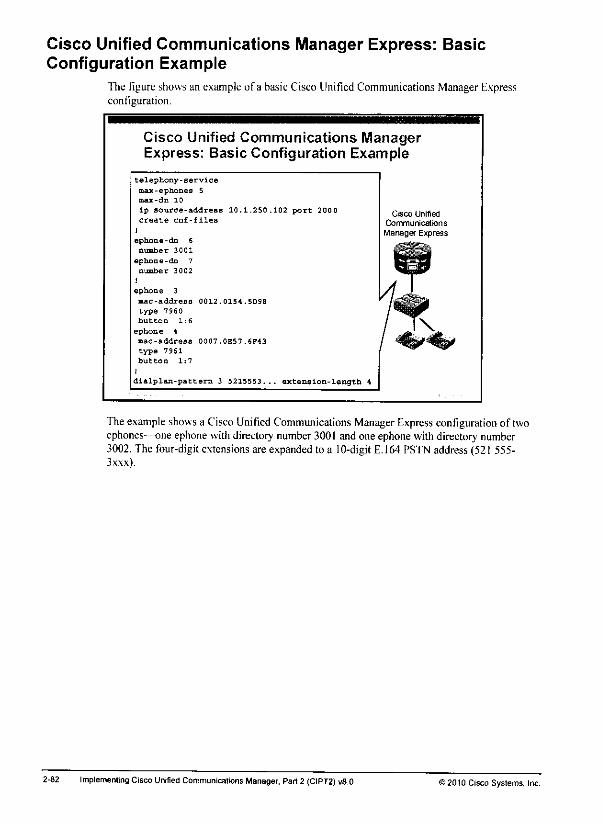
Cisco Unified Communications Manager Express: BasicConfiguration Example
The figure shows an example of a basic Cisco Unified Communications Manager Expressconfiguration.
Cisco Unified Communications ManagerExpress: Basic Configuration Example
telephony-service
max-e phone s 5max-dn 10
lp source-address 10.1.250.102 port 2000create cnf-files
I
ephone-dn 6
number 3001
ephone-dn 7
number 3002
1
ephone 3
mac-address 0012.0154.5D98
type 7 96 0
button 1:6
ephone 4
mac-address 0007.0E5 7.6F43
type 7961
button 1:7
1
dlalplan-pattern 3 5215553... extension-length 4
Cisco UnifiedCommunications
Manager Express
Theexampleshowsa Cisco Unified Communications ManagerExpress configuration of twoephones—one ephonewithdirectory number3001 and one ephonewithdirectorynumber3002. The four-digit extensions are expanded to a 10-digitE.164 PSTN address (521 555-3xxx).
2-82 Implementing CiscoUnrfied Communicalions Manager, Part2 (CIPT2) v8.0 J2010 Cisco Systems, Inc.

number: Use this command lo define a directory number for an ephone-dn (extension),which then can be assigned to an IP phone.
ephone: Use thiscommand inglobal configuration mode to create a phone in CiscoUnified Communications Manager Express.
mac-address: Use this command in ephone configuration mode to specify the device ID ofan ephone. Whena phoneregisters with Cisco Unified Communications ManagerExpress,it has to providea device ID (which is basedon the MAC addressof the phone) that isconfigured in Cisco Unified Communications ManagerExpress.
type: Use this command inephone configuration mode lospecify the phone type of thisephone.
button: Use this command in ephoneconfiguration mode to assignone or moreephor>dnsto an ephone.
dialpian-pattem: Use thiscommand in telephony-serviceconfiguration mode to mapE. 164 PSTN numbers to internal extension numbers.
©2010 Cisco Systems. Inc Centralized Call-Processing Redundancy Implementation 2-81

General Configuration of Cisco UnifiedCommunications Manager Express
This topic describes general Cisco Unified Communications Manager Express coniigurationparameters and their functions.
Basic Cisco Unified Communications
Manager Express Commands
• telephony-service: Enters Cisco Unified Communications ManagerExpress configuration mode
- max-ephones: Defines maximum number of IP phones
- max-dn: Defines maximum number of directory numbers
- ip source-address: IP address used by Cisco UnifiedCommunications Manager Express
- create cnf-files: Generates XML configuration files for phones
• ephone-dn: Enters ephone-dn configuration mode
- number: Sets the extension of the ephone-dn
• ephone: Entersephoneconfiguration mode
- mac-address: Specifies the MAC address of the IP phone
- type: Sets the IP phone model type
- button: Applies an ephone-dn to an IP phone line
• dialplan-pattern: Maps E.164 numbers to extensions
Todeploj a Cisco Unified Communications Manager Express system, youmust configurethese commands:'
• telephony-service: Usethis command to enter the telephony-service configuration mode,where youcanconfigure theglobal settings of Cisco Unified Communications ManagerExpress
• max-ephones: Usethis command in telephony-service configuration mode to configureCisco Unified Communications Manager Express with the maximum number of ephones.
• max-dn: Usethis command in telephony-service configuration mode to configure themaximum numberof extension numbers (ephone-dns) in Cisco Unified CommunicationsManager Express.
Note The default values of max-ephones and max-dn are 0. These defaults have to be modifiedinorderforyouto configure ephones and ephone-dns. The maximum numberofsupportedephones and ephone-dns is version-specific and platform-specific. The number that isdisplayed in Cisco IPS Software Help files does not always reflect the actual limit.
• ip source-address: Usethis command in telephony-service configuration mode to definetheIPaddress to which Cisco Unified Communications Manager Express is bound.
• create cnf-files: Use this command intelephony-service configuration mode to generateXML configuration files for phones.
• ephone-dn: Use this command, a global configuration command, tocreate a directorynumber. After you enter this command, the router is inephone-dn subconfiguration mode.
2-80 Implementing Cisco Unrfied Communications Manager, Part 2 (CIPT2) v8.0 >2010 Cisco Systems, Inc.
-#
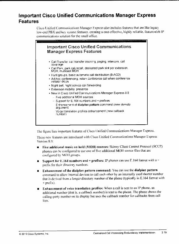
Important Cisco Unified Communications Manager ExpressFeatures
Cisco Unilied Communications Manager Express also includes features that are like legacylow-end PBXand key system features, creatinga cost-effective, highly reliable, feature-richcommunications solution for the small office.
Important Cisco Unified CommunicationsManager Express Features
Call Transfer, call transfer blocking, paging, intercom, callcoverage
Call Park, park call recall, dedicated park slot per extension,MOH, multicast MOH
Hunt groups, basic automatic call distribution (B-ACD)Ad-hoc conferencing, retain conference call when conferenceinitiator drops
Night bell, night service call forwardingExtension mobility, presenceNew in Cisco Unified Communications Manager Express 8.0:
Five additional MOH sources
Support for E.164 numbers and + prefixes- Enhancement of dialplan pattern command (new demote
argument)- Voice translation profiles enhancement (new callback
number)
Ihe figure lists important features of Cisco Unified Communications Manager Express.
fhese new features are introduced with Cisco Unified Communications Manager ExpressVersion 8.0:
• Kive additional music on hold (MOH) sources: SkinnyClientControl Protocol (SCCP)phones can beconfigured to use oneof five additional MOII source files thatarcconfigured by MOH groups.
• Support for fc.164 numbers and + prefixes: IP phones can use E.164 format with a +prefix for their directory numbers.
• Enhancement of the dialplan pattern command: Youcan use the dialplan patterncommand to allow internal devices to call each other by an internally used shorter numberthat isderived from a longer directory number of the phone {typically inE.164 format with+ prefix).
• Enhancement of voice translation profiles: Whena cal! is sent to an IP phone,anadditional number (that is. a callback number) is sent to thephone. The phone shows thecalling-party number on its display but uses the callback number for callbacks from calllists.
© 2010 Cisco Systems. Inc Centralized Call-Processing Redundancy Implementation 2-79
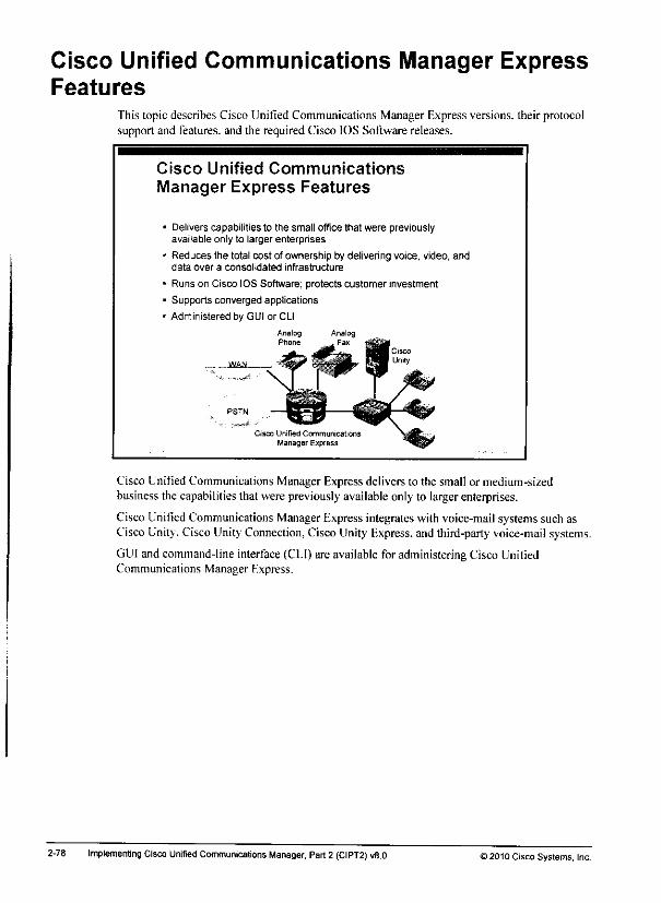
Cisco Unified Communications Manager ExpressFeatures
This topic describes Cisco Unified Communications Manager Express versions, their protocolsupport and features, and the required Cisco IOS Software releases.
Cisco Unified Communications
Manager Express Features
Delivers capabilities to the small office that were previouslyavailable only to larger enterprises
Reduces the total cost of ownership by delivering voice, video, anddata over a consolidated infrastructure
Runs on Cisco IOS Software; protects customer investment
Supports converged applications
Administered by GUI or CLI
Cisco Unified Communications
Manager Express
Cisco Unified Communications Manager Express delivers to the small or medium-sizedbusiness the capabilities that were previously available only to largerenterprises.
Cisco Unified Communications ManagerExpressintegrates with voice-mail systemssuch asCisco Unity, Cisco UnityConnection, Cisco Unity Express, and third-party voice-mail systems.
GUI and command-line interface (CLI)are available for administering Cisco UnifiedCommunications Manager Express.
2-78 Implementing Cisco Unified Communications Manager, Part2 (CIPT2) v8.0 J2010 Cisco Systems, Inc.

In summary, use Cisco Unified Communications ManagerwhenCisco UnifiedCommunications Manager Expressdoes not scale to the number of endpoints or does notprovide all therequired features. If youuseCisco Unified Communications Manager andthestandard Cisco Unified SRST featuresdo not meet the requirements for backup scenarios, youshould use Cisco Unified Communications Manager Express in SRST mode.
©2010 Cisco Systems Inc. Centralized Call-Processing Redundancy Implementation 2-77
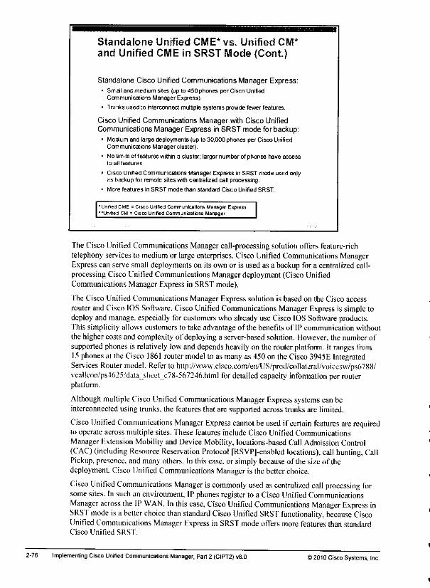
Standalone Unified CME* vs. Unified CM*and Unified CME in SRST Mode (Cont)
Standalone Cisco Unified Communications Manager Express:• Small and medium sites (up to 450phones per Cisco Unified
Communications Manager Express).
• Trunks used to interconnect multiple systems provide fewer features.
Cisco Unified Communications Manager with Cisco UnifiedCommunications Manager Express inSRST mode for backup:
• Medium and large deployments (up to 30,000 phones per Cisco UnifiedCommunications Managerclusler).
* No limitsof features withn a cluster; larger number of phones have accessto all features.
• Cisco Unitied Communications Manager Express in SRST mode used onlyas backup for remote sites with centralized cal processing.
• More features in SRST mode than standard Cisco Unified SRST.
"Unified CME = Cisco Unified Co mmuneat ions Manager Express'"Unified CM = Cisco Unified Communications Manager
The Cisco Unified Communications Manager call-processing solution offers feature-richtelephony services to medium or largeenterprises. Cisco Unified Communications ManagerExpresscan serve small deployments on its own or is used as a backup for a centralized call-processing Cisco Unified Communications Manager deployment (Cisco UnifiedCommunications Manager Express in SRST mode).
The Cisco Unified Communications Manager Express solution is based on the Cisco accessrouter and Cisco IOS Software. Cisco Unified Communications Manager Express is simple todeploy and manage, especially for customers who already use Cisco IOSSoftware products.This simplicity allows customers to take advantage of the benefits of IP communication withoutthe higher costs and complexity of deploying a server-based solution. However, the number ofsupported phones is relatively lowand depends heavilyon the routerplatform. It ranges from15phones at the Cisco 1861 routermodel to as many as 450 on the Cisco3945E IntegratedServices Router model. Refer to http://www.cisco.com/en/US/prod/collatcral/voicesw/ps6788/vca!lcon/ps4625/dataj>heet_c78-567246.html for detailedcapacity information per routerplatform.
Although multiple Cisco Unified Communications Manager Express systems canbeinterconnected using trunks, the features that are supported across trunks arc limited.
Cisco Unified Communications Manager Express cannot beused if certain features arerequiredto operate across multiple sites. These features include Cisco Unified CommunicationsManager Fxtension Mobility and Device Mobility, locations-based Call Admission Control{CAC) (including Resource Reservation Protocol [RSVPJ-enabled locations), call hunting, CallPickup, presence, andmany others. In this case, or simplybecauseof the size of thedeployment Cisco Unified Communications Manageris the betterchoice.
Cisco Unified Communications Manager iscommonly used ascentralized call processing forsomesites. In such an environment, IP phonesregister to a Cisco UnifiedCommunicationsManager across the IP WAN. Inthis case. Cisco Unified Communications Manager Express inSRST mode isa better choice than standard Cisco Unified SRST functionality, because CiscoUnified Communications Manager Express in SRST mode offers more features than standardCisco Unified SRST.
2-76 Implementing CiscoUnified Communications Manager, Part2 (CIPT2) v8.0 >2010 Cisco Systems, Inc.
Becauseof the centralized architecture of Cisco Unified Communications Manager, remote sitesurvivability isextremely important. As discussed earlier. Cisco Unified SRST can be used toprovide survivability. However, it is quite limited in terms of telephony features.
To provide a richer feature that issettoIPphones that are in fallback mode, you can use CiscoUnified Communications Manager Express in SRST mode. Such a deployment combines theadvantages ofCisco Unified Communications Manager—centralized configuration and theavailability offeatures toall phones, with the better feature support dial isprovided by CiscoUnified Communications Manager Express versus standard Cisco Unified SRST incasethesiteis disconnected from the centralized Cisco Unilied Communications Manager cluster.
)2010 Cisco Systems, Inc Centralized Call-Processing Redundancy Implementation 2-75
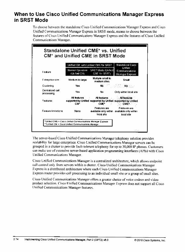
When to Use Cisco Unified Communications Manager Expressin SRST Mode
To choose between the standalone Cisco Unified Communications Manager Express and CiscoUnified Communications Manager Express in SRST mode, means to choose between thefeatures of Cisco Unified Communications Manager Express and the features of Cisco UnifiedCommunications Manager.
Standalone Unified CME* vs. Unified
CM* and Unified CME in SRST Mode
Feature
Unilied CM with Unified CME for SRST Standalone Cisco'Unified
Normal Operation SRST Mode (United Communications(Unified CM) CME foi SRST) Manager Express
Enterprise size Medium to large
Clustering Yes
Centralized callYes
processfig
Features
All featuressupported by Unite
CM*
Feature limitations None
Multiple smal lomedium sites
No
No
Smal
No
Only within local site
AI features
supported fayUnified siCME* CME'
Features are Features are
available only within available only withinlocal site local site
•Unified CME = Cisco Unified Communications Manager Express"Unrfied CM = Cisco Unified Communications Manager
The server-based Cisco Unified Communications Manager telephony solutionprovidesscalability for largeenterprises. Cisco Unified Communications Manager servers can begroupedin a cluster to provide fault-tolerant telephony for up to 30,000IP phones. Customerscan makeuse of extensive server-based application programming interfaces (APIs)with CiscoUnified Communications Manager.
Cisco Unified Communications Manageris a centralized architecture, whichallowsendpointcall controlonly from serverswithina cluster.Cisco Unified Communicalions ManagerExpress is a distributed architecture where eachCiscoUnified Communications ManagerExpress router provides callprocessing to an individual small siteor a group of small sites.
Cisco Unified Communications Manager offers a greater choice of voice codecs and videoproduct selection. Cisco Unified Communications Manager Express doesnot support all CiscoUnified Communications Manager features.
2-74 Implementing CiscoUnified Communications Manager, Part 2 (CIPT2) v8.0 © 2010 Cisco Systems, Inc.
-:-«*
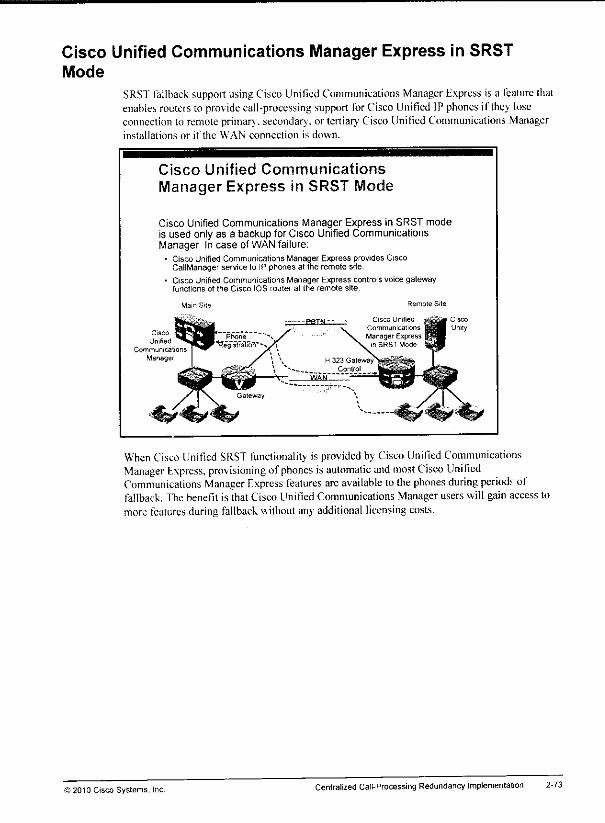
Cisco Unified Communications Manager Express in SRSTMode
SRSTfallback supportusingCisco Unified Communications ManagerExpress is a leaturethatenablesrouters to providecall-processing support forCisco Unified IP phones if they loseconnection to remote primary, secondary-, or tertiary Cisco Unified Communications Managerinstallations or if the WAN connection is down.
Cisco Unified CommunicationsManager Express in SRST Mode
Cisco Unified Communications Manager Express in SRST modeis used only as a backup for Cisco Unified CommunicationsManager. In case of WANfailure;
• Cisco Unified Communications Manager Express provides CiscoCallManager service to IP phones at the remote site,
• Cisco Unified Communications Manager Express controls voice gatewayfunctions of trie Cisco IOS router at the remote site.
Cisco
Unity
When Cisco Unified SRST functionality is provided by Cisco Unilied CommunicationsManager Express, provisioning ofphones isautomatic and most Cisco UnifiedCommunications Manager Express features arcavailable to thephones during periodr offallback. The benefit is that Cisco Unified Communications Manager users will gain access tomore features during fallback withoutany additional licensing costs.
) 2010 Cisco Systems, IncCentralized Call-Processing RedundancyImplementation 2-73

Cisco Unified Communications Manager ExpressOverview
This topic describes Cisco Unified Communications Manager Express and the modes in whichit can be used.
Standalone Cisco Unified
Communications Manager Express
Standalone Cisco Unified Communications Manager Expressoperates independently:
• Remote site IP phones register with Cisco Unified CommunicationsManagerExpress.
• Remote site IP phones send signaling messages to Cisco UnifiedCommunications Manager Express,
• Calls between main site cluster and remote site use standard PSTNconnections or VoIP trunks.
RegislrafoonandSignaling,' J
H 323 or SIP
Trunk Connection
Cisco UnifiedCommunications
Manager
The figure shows a deployment of a Cisco Unified Communications Manager Express routerwith several phones and devices that are connected to it. The Cisco Unified CommunicationsManager Express router is connected to thepublic switched telephone network (PSTN) andWAN.
Cisco Unified Communications Manager Express is a feature-rich, entry-level IPtelephony-solution that is integrated directly into Cisco IOS Software. Cisco Unified CommunicationsManager Express allows small-business customers and autonomous small-enterprise branchoffices to deploy voice, data, andIP telephony on a single platform forsmalloffices, whichstreamlines operations and reduces network costs.
Cisco UnifiedCommunications ManagerExpress is ideal for customers who havedataconnectivity requirements and need a telephony solution in the same office. Whether offeredthrough a managed serv ices offering of a service provider or purchased directly byacorporation. Cisco Unified Communications Manager Express provides mostof thecoretelephony features thatarerequired ina small office. It also provides many advanced featuresthat are not available with traditional telephony solutions. Being able todeliver IP telephonyand data routing using a single, converged solution allows customers tooptimize theiroperations and maintenance costs, resultingin a very cost-effective solution that meetsofficeneeds.
ACisco Unified Communications Manager Express system isextremely flexible because it ismodular. It comprises a router thatserves asa PSTN gateway and supports oneor moreVLANs that connectIP phones and phonedevices,as well as PCs, to the router.
2-72 Implementing Cisco Unified Communications Manager, Part 2 (CIPT2) v8.0 >2010Cisco Systems, Inc
*9
Lesson 3
Implementing Cisco UnifiedCommunications ManagerExpress in SRST Mode
OverviewThis lesson begins with a description ofkey Cisco Unified Communications Manager Expressfeatures, benefits, and limitations. It also explains the processof registering IP phoneswithCisco Unified Communications Manager Express, fhis lesson discusses the basic telephonvsen.ice commands for configuring ephones and ephone-dns.
ObjectivesUpon completing this lesson, you will be able to configure Cisco Unified CommunicationsManager Express to provide telephony services lo IP phones ifthe connection to the centralizedcall agent islost. This ability includes being able tomeet these objectives:
• Describe Cisco Unified Communications Manager Express and the modesin whichit canbe used
• Describe Cisco Unified Communications Manager Express versions, their protocol support,their features, and the required Cisco IOS Software releases
• Describe general Cisco Unified Communications Manager Express configurationparameters and their functions
• Describe how to configure Cisco Unified Communications Manager Express to supportSRSI fallback
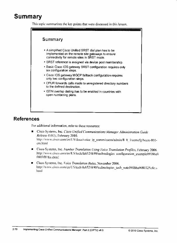
SummaryThis topic summarizes the key points that were discussed in this lesson.
Summary
A simplified Cisco Unified SRST dial plan has to beimplemented on the remote site gateways to ensureconnectivity for remote sites in SRST mode.
SRST reference is assigned via device pool membership.
Basic Cisco IOS gateway SRST configuration requires onlysix configuration steps.
Cisco IOS gateway MGCPfallback configuration requiresonly two configuration steps.
CFUR forwards calls made to unregistered directory numbersto the defined destination.
ISDN overlap dialing has to be enabled in countries withopen numbering plans.
References
2-70
For additional information, refer to these resources:
• Cisco Systems. Inc. Cisco Unified Communications Manager Administration GuideRelease 8.0(1), February 2010.
hftp://vvA\w.CMscii.coni/cn/lJS/does/voiee_ip_comm/cucin/admin/8_0_i/ecmefg,'lKem-80I-cm.html
• Cisco Systems. Inc. Number Translation Using Voice Translation Profiles, February 2006.http://\vw u.cisco.com,'en/US/teclL/tk652/lk90/teehnoloaies configuration e\ample()9186a00803f818a.shtmi
• Cisco Systems. Inc. Voice Translation Rules, November 2006.http://ww\v.cisco.com/cn/[i.S/tcch/tk652/tk90/techiK)logies_tech_note09186a008()325e8e.shtml
Implementing Cisco Unified Communications Manager, Part2 (CIPT2) v8.0 ) 2010 Cisco Systems, Inc.

km*
Cisco Unified SRST Dial Plan Example(Cont)
dial-peer voice 1 pots
incoming called-numberdirect-in»ard-dial
]
dial-peer voice 911 potsdestination-pattern 911
port 1/3:33
1
dial-peer voice 9 pots
corlist outgoing local-ntldestination-pattern 9
port 1/0:23prefix Oil
1
dial-peer voice 91 potacorlist outgoing local-ntldestination-pattern 91
port 1/0:23
dial-peer voice 9011 potscorlist outgoing intldestination-pattern 9011T
port 1/0:23
prefix Oil
I
dial-peer voice 2000 potstranslation-profile outgoing to-HQ
destination-pattern 2...port 1/0:23
[
voice translation-rule 1
rule 1 /*2/ /151155S2/1
voice translation-profile to-HQ
translate called 1
Outgoing COR lists are applied to the outbound dial peers. Note that all dial peers that shouldbe available to all phones (that is. dial peer 911 for emergency and dial peer 2000 for intersitecalls)are nol configured with an outgoingCOR list.
Local and national PSI'N destinations areprotected by outgoing COR listlocal-ntl. This CORhas one member, pstn-local-ntl. and this member is listed only in the incoming COR list ofPhonc2. not in the incoming COR listof Phone3. Dial peer 9011, which is used forinternational calls, is configured with an outgoing COR list intl, and the only member ofthailist, pstn-intl. is not included in the incoming COR lists ofPhone2 and Phone3.One dial peer is configured with ihe incoming ealled-numbcr . command, "fhis dial peer isused as an incoming POTS dial peer, fhe dial peer isconfigured tosupport direct inwarddialing.
The called numbers of inbound PSTN calls (521 555-3xxx) are mapped to four-digit extensionsbecause ofthe dialplan-pattern command that is configured in call-manager-fallbackconfiguration mode (see earlier in this subtopic). As aresult, incoming PSTN calls are sent tothe four-digit extensions.
Outgoing calls to phones that are located at the main site (calls to 2...) match the destinationpattern in dial peer 2000. That dial peer sends calls to port 1/0:23 after performing digitmanipulation using the to-HQ voice translation profile, 'fhis profile translates the four-digitcalling number to an Il-digit E.164 PSTN number, which means that during SRST fallback,users canstill dial 4-digit extensions to reach the headquarters.
)20:0 Cisco Systems.Centralized Call-Processing Redundancy Implementation 2-69
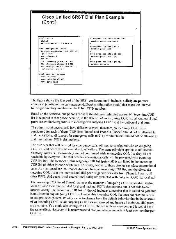
Cisco Unified SRST Dial Plan Example(Cont.)
application
global
service alternate defa ult
call-nanager- fallback
ip source-address 10.1 .250.101
port 2000
man-ephonss 3
mai-dn 3
cor incoming phone! 2 3002
cor incoming phone3 3 3003
dialplan-pattern 1 5215553.,.
extension-length \
disl-peer cor custom
name no-pstn
name pstn-local-ntl
name pstn-intl
dial-pe sr cor list local-ntl
mentoet pstn- local ntl
dial-pe r cor list intl
member pstn- intl
dial-peer cor list phone2
member pfltn- local ntl
dial-peer cor list phone3member no-pstn
Thefigure shows the first part of the SRST configuration. It includes a dialplan-patterncommand (configured in call-manager-fallback configuration mode) thatmaps the internalfour-digit directory numbers to the E.164 PSTN number.
Based on the scenario, one phone (Phonel) should have unlimited access. No incoming CORlist is required at that phone because, in theabsence of an incoming CORlist,all outbound dialpeers areavailable regardless of a configured outgoing COR listat theoutbound dial peer.
The other two phpnes should have difTerent classes; therefore, anincoming COR listisconfigured for each of them(COR lists Phone2 and Phone3). Phone3 shouldnot be allowed todial the PSTN at all (exceptforemergency calls to 911), while Phone2 shouldnot be allowedtodial international PSTN destinations.
The dial peer that will be used for emergency calls will not be configured with an outgoingCOR list, and hence will beavailable toall callers. Thesame principle applies to all internaldirectory numbers. Because they are not configured with anoutgoing COR list, they all arereachable by everyone. The dial peer for international calls will be protected with outgoingCOR list intl. The member ofthis outgoing COR list (pstn-intl) isnot listed in the incomingCOR list ofeither Phone2 or Phone3. This way, neither ofthese phones can place internationalcalls. Asmentioned earlier. Phonel does nothave an incoming COR list, and therefore, theoutgoing COR list at the international dial peer isignored for calls from Phone 1, Finally, allother PSTN dial peers (local and national calls) are protected with outgoing COR list local-ntl.
The incoming COR list ofPhone2 includes the member ofoutgoing COR list local-ntl (pstn-local-ntl) and therefore can dial local and national PSTN destinations but is not able to dialinternationally. The incoming COR list ofPhone3 includes a member that iscalled no-pstn thatisnot listed in any outgoing COR list. Ilence, this incoming COR list does not provide accessto any protected pattern. Its only use is to change from the defaultbehaviorthat in the absenceofan incoming COR list all outgoing COR lists are ignored and hence all outbound dial peersare available. You could also configure COR list Phone3 with no member, and itwould havethe same effect. Ilow ever, it isrecommended that you always include at least one member nerCOR list.
2-68 Implementing Cisco Unified Communications Manager, Part 2(CIPT2) v8.0 >2010 Cisco Systems, Inc.

Cisco Unified SRST Dial Plan ExampleThe figure shows an example ofa standalone dial plan configuration for a Cisco IOS router thatis enabled with Cisco Unified SRST.
Cisco Unified SRST Dial Plan Example
Requirements for external calls during SRST mode:• Phonel (3001) should have unlimited access.
• Phone2 (3002)should not be allowedto place international calls.
• Phone3(3003) should be allowed to dial only headquartersphones(2 .) and emergency (911)
Cisco
Unified
Communications
Manager
Mam Site Remote Site
Phonel
Phone2
Phone3
The example shows aheadquarters site with a PSI'N number of511 555-2xxx, and a remotesite witha PSTN number of 521 555-3xxx. four digits are used for internal calls(includingcalls between the main site and remote site).
There are three phones atthe remote site. During SRS'f fallback. Phonel (using directorynumber 3001) should have unlimited access. Phone2 (directory number 3002) should not beallowed toplace international calls, and Phonc3 (directory number 3003) should be allowed toplace only internal calls. Four-digit dialing to the headquarters should work: the calls should besent to the main site over the PSTN.
) 20'0 Cisco Systems, IncCentralized Call-Processing RedundancyImplementation 2-67
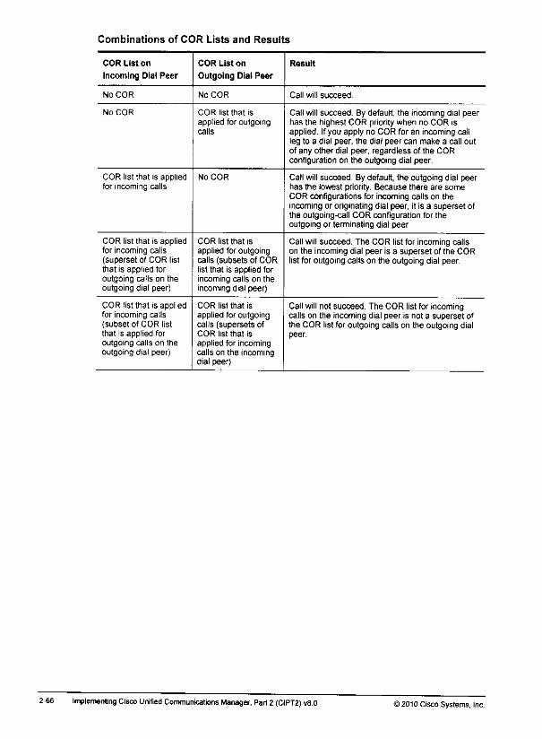
Combinations of COR Lists and Results
COR List on
Incoming Dial Peer
COR List on
Outgoing Dial Peer
Result
No COR No COR Call will succeed.
No COR COR list that is
applied for outgoingcalls
Call will succeed. By default, the incoming dial peerhas the highest COR priority when no COR isapplied. Ifyou apply no COR for an incoming callleg to a dial peer, the dial peer can make a call outof any other dial peer, regardless of the CORconfiguration on the outgoing dial peer.
COR list that is appliedfor incoming calls
No COR Call will succeed By default, the outgoing dial peerhas the lowest priority. Because there are someCOR configurations for incoming calls on theincoming or originating dial peer, it is a superset ofthe outgoing-call COR configuration for theoutgoing or terminating dial peer.
COR list that is appliedfor incoming calls(superset of COR listthat is applied foroutgoing calls on theoutgoing dial peer)
COR list that Is
applied for outgoingcalls (subsets of CORlist that is applied forincoming calls on theincoming dial peer)
Call will succeed. The COR list for incoming callson the incoming dial peer is a superset of the CORlist for outgoing calls on the outgoing dial peer
COR list that is appliedfor incoming calls(subset of COR listthat is applied foroutgoing calls on theoutgoing dial peer)
COR list that isapplied for outgoingcalls (supersets ofCOR list that isapplied for incomingcalls on the incomingdial peer)
Call will not succeed. The COR list for incomingcalls on the incoming dial peer is not a superset ofthe COR list for outgoing calls on the outgoing dialpeer.
2-66 Implementing Cisco Unified Communications Manager, Part2 (CIPT2) v8.0 )2010 Cisco Systems, Inc.
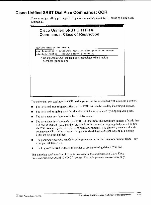
Cisco Unified SRST Dial Plan Commands: CORYou canassign calling privileges to IPphones when they are in SRS'fmode byusing CORcommands.
Cisco Unified SRST Dial PlanCommands: Class of Restriction
router(config-cm-fallback)#
cor {incoming I outgoing} cor-list-name [cor-list-numberstarting-number - ending-number | default]
• Configures a COR ondialpeers associated with directorynumbers (ephone-dn)
The command corconfigures a COR ondial peers that are associated with directory numbers.
• The keyword, incoming specifies that the COR list is tobe used by incoming dial peers.
• The keyword outgoing specifies that the COR list is tobe used by outgoing dial pers.
• The parameter cor-list-name is the COR list name.
• The parameter cor-list-number is a COR list identifier. The maximum number ofCOR liststhatcanbecreated is 20.andthe listsconsist of incoming or outgoing dial peers. The firstsix COR lists are applied to a range ofdirectory numbers, 'fhedirectory numbers that donot ha\e a COR configuration arc assigned lo the default COR list, as long asa defaultCOR list has been defined.
• The parameters starting-number - ending-number define the director- number range—forexample. 2000 to 2025.
• fhe ke\ worddefault instructs the routerto use an existingdefaultCOR list.
fhe complete configuration ofCOR is discussed in the Implementing Cisco VoiceCommunications and QoS (CVOICF) course. The table presents an overview only.
i 2010 Cisco Systems. IncCentralized CalI-Processing RedundancyImplementation 2-65

Cisco Unified SRST Dial Plan Commands: Number Modification
(Profile Activation)Voice translation profiles can be bound to dial peers, source groups, trunk groups, voice ports,and the voice service POTS.
SRST Dial Plan Commands: Number
Modification (Profile Activation)
router(config-volcaport)#
translation-profile {incoming | outgoing} name
* Assigns a translation profile to a voice port
router(config-cm-fallback>#
I translation-profile {incoming | outgoing} name
' Assigns a translation profile to the call-manager-fallbackCisco IOS service
In this example, the voice translation profile is bound to a voice port.
To assigna translation profileto a voiceport, you use the translation-profile command invoice-port configuration mode.
• The keyword incoming specifies that this translation profileprocessesincoming calls.
• The keywordoutgoing specifies that this translation profileprocessesoutgoingcalls.
• The parameter name is the nameof the translation profile.
The voice translation profiles can also be bound to call-manager-fallback Cisco IOS service.The structure of the command is identical.
Note The incoming direction ofthe voice translation profile that is boundto the CiscoCallManagerfallback Cisco IOSservice processes the calls comingfrom IP phones that are registeredwith the router.
For more information about voice translation profiles, refer to Cisco TechNotes NumberTranslation Using Ioice Translation Profilesathttp:/^vww,cisco.coni/en/[;S/tech/tk652/tk90/technologies^ci)nfiguration_examplc()9l86a()08().5fS18a.shtml and TechNotes Voice Translation Rules at
http://wwu.cisco.com/en/L;S/tech/tk652/lk90/iechnologies_tech..nole09186a0080325e8c.shlm!.
2-64 Implementing CiscoUnified Communications Manager, Part2 (CIPT2) v8.0 12010 Cisco Systems. Inc
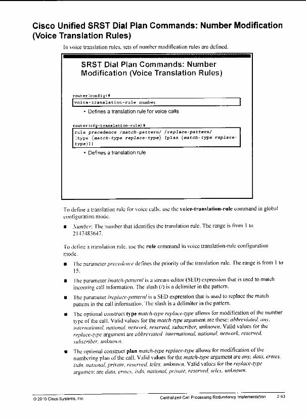
Cisco Unified SRST Dial Plan Commands: Number Modification
(Voice Translation Rules)In voice translation rules, sets of number modification rules are defined.
SRST Diaf Plan Commands: Number
Modification (Voice Translation Rules)
router (confi gl #
voice-translation-rule number
• Defines a translation rule for voice calls
router(cfq-translation-rulel#
rule precedence /match-pattern/ /replace-pattern/[type {match-type replace-type} [plan {match-type replace-type}]]
* Defines a translation rule
To define a translation rule for voice calls, use the voice-translalion-rulc command in global
configuration mode.
• Number: The number that identifies the translation rule. The range is from 1 lo2147483647.
To define a translation rule, use the rule command in voice translation-rule configurationmode.
• The parameter precedence defines thepriority of the translation rule, fhe range is from I to15.
• The parameter Imatch-patternl is a stream editor (SED) expression thatis used to matchincoming call information, fhe slash (/) is a delimiter in thepattern.
• The parameter Ireplace-patternl isa SED expression that isused toreplace the matchpattern in thecall infonnation. Theslash is a delimiter in the pattern.
• The optional construct type match-type replace-type allows for modification ofthe numbertype ofthe call. Valid values for the match-type argument are these: abbreviated, any,international, national, network, reserved, subscriber, unknown. Valid values for thereplace-type argument are abbreviated, international, national, network, reserved,subscriber, unknown.
• The optional construct plan match-type replace-type allows for modification ofthenumbering plan of the call. Valid values for the match-type argument are any, data, ermes.isdn, national, private, resen-ed, telex, unknown. Valid values for thereplace-typeargument are data, ermes. isdn. national, private, reserved, telex, unknown.
© 2010 Cisco Systems. Inc Centralized Call-Processing Redundancy Implementation 2-63
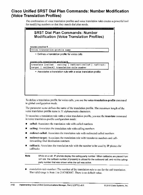
Cisco Unified SRST Dial Plan Commands: Number Modification
(Voice Translation Profiles)The combination of voice translation profiles and voice translation rules creates a powerful toolfor modifying numbers so that they match dial plan needs.
SRST Dial Plan Commands: Number
Modification (Voice Translation Profiles)
router(config)#
I voice-translation-profile name
Defines a translation profile for voice calls
router(cfq-translation-profile)#
translate {called | calling | redirect-called | redirect-target | callback} translation-rule-number
Associates a translation rule with a voice translation profile
To define a translation profile for voice calls, you use the voice-translation-profile commandin global configuration mode.
The parametername definesthe nameof the translation profile. The maximum lengthof thevoice translation profile name is 31 alphanumeric characters.
To associate a translation rule with a voice translation profile, you use the translate commandin voice translation-profile configuration mode:
• called: Associates the translation rule with called numbers
• calling: Associates the translation rule with calling numbers
• redirect-called: Associates the translation rule with redirected called numbers
• redirect-target: Associates the translation rule with transfer-to numbers and call-forwarding final destination numbers
• callback: Associates the translation rule with the numberto be used by IP phonesforcallbacks
Note While ona call, IPphones display thecalling-party number. When callbacks are placed fromcall lists, the callback number {if present) is utilized for theoutbound call, and notthe calling-party number that was shown while the call was active.
• translation-rule-number: The number of the translation rule to use for the call translation.The valid range is from 1 to 2147483647. There is no default value.
2-62 Implementing Cisco Unified Communications Manager, Part 2 (CIPT2) u8.0 >2010 Cisco Systems, Inc.

• The keyword extension-length sets the number of extension digits that will appear as acaller ID followed by the parameter length, whichis the numberof extension digits. Theextension length must match the setting for IP phones in Cisco Unified CommunicationsManager mode, 'fhe range is from I to 32.
• The optional keyword evtension-pattern sets the leadingdigit patternof an extensionnumberwhenthe patternis difTerent from the leadingdigits that are defined in the pat.jmvariableof the F.164 telephone number, such as whensite codesare used. The parameterextension-pattern that follows defines the leading digit patternof the extension number. Itcomprises one or more digits and wildcard markers or dots (.). For example, 5.. wouldinclude extensions 500 to 599: and 5... would include extensions 5000 to 5999. The
extension pattern configuration shouldmatchthe mappingof internal to external numbersin Cisco Unified Communications Manager.
• Theoptional keyword no-reg prevents the I7..164 numbers in thedial peerfrom registeringwith the gatekeeper.
fhe example for thedialplan-pattcrn command shows how locreate a dial plan pattern fordirectory numbers 500 lo599that ismapped loa DID range of 408 555-5000 to 5099. Iftherouter receives an inbound call to 408 555-5044, then the dial plan pattern command is matchedand the extension of the called I7,. 164 number. 408 555-5000, is changed lo directory number544. If an outbound calling-party extension number (544) matches thedial plan pattern, thecalling-part) extension will beconverted to the appropriate L.I64 number (408 555-5044). TheF..I64 calling-party number will appear as the caller ID:
Router (config)# call-manager-fallback
Router(config-cm-fallback)# dialplan-pattern 1 40855550..extension-length 3 extension-pattern 5..
Since Cisco Unified SRST 8.0. thedialplan-pattcrn command has been used in theoppositeway with the addition of the keyword demote tothe end ofthe command. In this case itdemotes IF phone directory numbers thatarespecified in F.I64 format with a + prefix toshorter extensions, which are to be used internally. Extemal callers place calls to the phones,using E.164 format with a-f prefix. If the calls are not natively received in this format from thePSTN (which they rarely are), you have to transform the called number accordingly. Internalusers.howe\er. can dial each other by usingshorterextensions, which arc set up by thedialplan-pattern command with the demote argument:
Router(config)# call-manager-fallback
Router(config-cm-fallback)# dialplan-pattern 1 +415526....extension-length 5 demote
In this example, phones are configured with directory numbers+415526.... and have tobecalled that way from the outside. Internal users, however, can call each other by using the lastfive digits (6....).
Note Thedialplan pattern command with thedemote argument isalso available in Cisco UnifiedCommunications Manager Expressand hence can also be used forCisco Unified SRSTwhen Cisco Unified Communications Manager Express is used in SRST mode.
)2010 Cisco Systems, Inc Centralized Call-Processing Redundancy Implementation 2-61
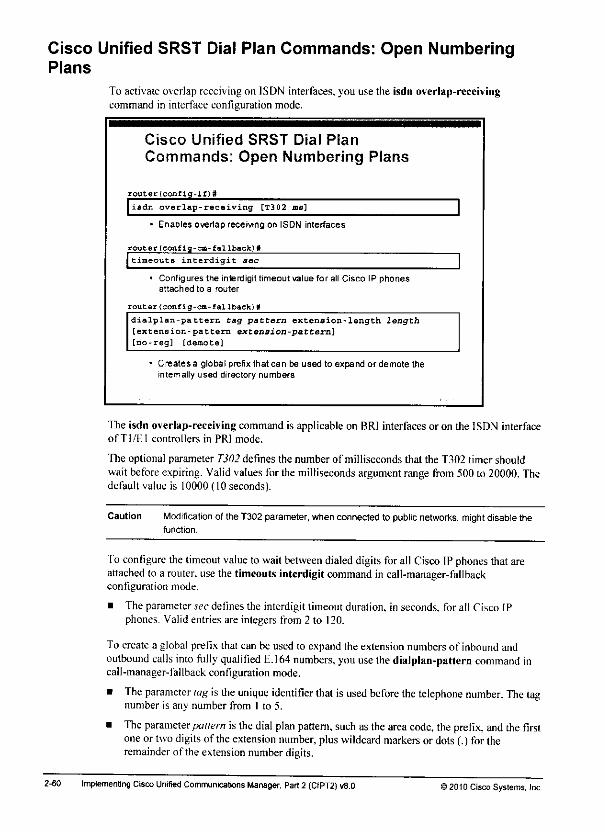
Cisco Unified SRST Dial Plan Commands: Open NumberingPlans
To activate overlap receiving on ISDN interfaces, you use the isdn overlap-receivingcommand in interface configuration mode.
Cisco Unified SRST Dial Plan
Commands: Open Numbering Plans
router(conflq-if)#
isdn overlap-receiving [T302 ms]
• Enables overlap receiving on ISDN interfaces
router(conflq-cm-fallback)#
timeouts interdigit aec
• Configures the interdigit timeout value for all Cisco IP phonesattached to a router
router(config-cm-fallback)#
dialplan-pattern tag pattern extension-length length[extension-pattern extension-pattern][no-reg] [demote]
• Creates a global prefix that can be used to expand or demote theintemally used directory numbers
The isdn overlap-receiving command is applicable on BRl interfaces or on the ISDN interfaceofTl/El controllers in PRI mode.
The optional parameter T302 defines the number of milliseconds that the T302 timer shouldwait beforeexpiring. Validvalues for the milliseconds argumentrange from 500 to 20000.Thedefault value is 10000 (lOseconds).
Caution Modification of the T302parameter, whenconnectedto public networks, might disablethefunction.
Toconfigure the timeout value to waitbetween dialed digits forall Cisco IPphones thatareattached to a router, usethe timeouts interdigit command in call-manager-fallbackconfiguration mode.
• The parameter sec defines the interdigit timeout duration, in seconds, for all Cisco IPphones. Valid entries are integers from 2 to 120.
To create a global prefix that can be used to expand the extension numbers of inbound andoutbound calls into fully qualified E.164 numbers, youuse thedialplan-pattern command incall-manager-fallback configuration mode.
• The parameter tag is the unique identifier that is used before the telephone number. The tagnumber is any number from I to 5.
• The parameter pattern is the dial plan pattern, such as the area code, theprefix, and the firstoneor twodigitsof theextension number, pluswildcard markers or dots(.) for theremainder of the extension number digits.
2-60 Implementing CiscoUnified Communications Manager, Pari2 (CIPT2) v8.0 ) 2010 Cisco Systems, Inc.

dial-peer voice 5 pots
description PSTN-emergency
destination-pattern 911
port 0/1/0
forward-digits all
>2010 Cisco Systems, inc Centralized Call-Processing Redundancy Implementation 2-59

Cisco Unified SRST Dial PlanCommands: Dial Peer (Cont)
This table contains common classesofPSTN calls in the NANPand lists the pattern that is used for each class. An access codeof9 should be used to indicate a PSTN call.These patternshave to be reachable in SRST mode:
Call Type
Emergency
Services
Local
Long distance or national
International
Toll-free
Premium
911
[2-8)11
[2~9]xx-xxxx
1[2-9]xx [2-9]xx-xxxx
011+countrycode+number
1[800,866,877,8 88]xxx-xxxx
1 900xxx-xxxx
976-xxxx
The table represents the most common classes ofPSTN calls in the Nortli AmericanNumbering Plan (NANP) and lists the pattern that is used for each class.An access codeof 9 should be usedto indicate a PSTN call.
The patterns in the table are the minimum patterns that must be reachable in SRST mode. Thisexample lists the configuration of dial peers that would be needed to reach all the numbers thatare indicated.
dial-peer voice 1 pots
description PSTN-LD
destination-pattern 91 [2-9] .. [2-9]
port 0/1/0
forward-digits 11
dial-peer voice 2 pots
description PSTN-local
destination-pattern 9 [2-9]
port 0/1/0
dial-peer voice 3 pots
description PSTN-international
destination-pattern 9011T
port 0/1/0
prefix 011
i
dial-peer voice 4 pots
description PSTN-emergency
destination-pattern 9911
port 0/1/0
forward-digits 3
2-58 Implementing CiscoUnified Communications Manager, Part2 (CIPT2) v8.0 >2010 Cisco Systems, Inc.
*f
*^**
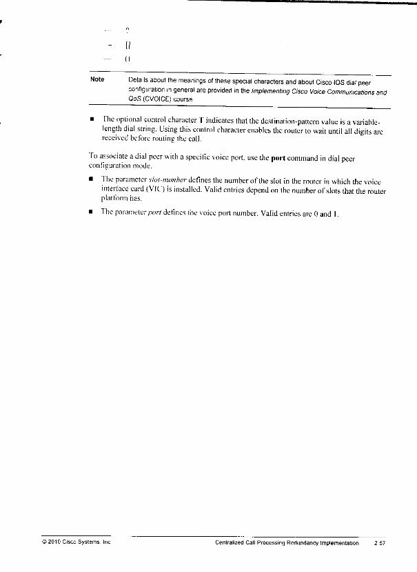
Ju
mm
m»
Note Details about the meanings of these special characters and about Cisco IOS dial peerconfiguration in general are provided in the Implementing Cisco Voice Communications andQoS (CVOICE) course.
• The optional control character T indicates that the dcslination-pattcrn value is avariable-length dial string. Using this control character enables the router to wait until all digits arcreceived before routing the call.
To associate adial peer with aspecific voice port, use the port command in dial peerconfiguration mode.
• The parameter slot-number defines the number of iheslot in the router inwhich the voiceinterface card (VIC) is installed. Valid entries depend onthe number ofslots that the routerplatform has.
• The parameter/jo/7 defines the voiceport number. Validentries are 0 and I.
)2010 CiscoSystems. Inc Centralized Call-Processing RedundancyImplementation 2-57
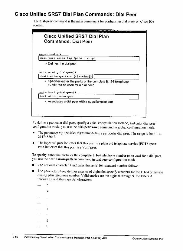
Cisco Unified SRST Dial Plan Commands: Dial Peer
The dial-peer command is the main component for configuring dial planson Cisco IOSrouters.
Cisco Unified SRST Dial PlanCommands: Dial Peer
router(config)M
| dial-peer voice tag [pots | voipj
- Defines the dial peer
router(config-dial-peer) #
|destination-pattern [+]Btring[T]Specifies either the prefix or the complete E.164 telephonenumbertobeused tbradial peer
router(conflg-dlal-peer)B
I port slot-number/port
• Associates a dial peer with a specificvoice port
3
To define a particular dial peer, specify a voice encapsulation method, and enter dial peerconfiguration mode, you use the dial-peer voice command in global configuration mode.
• The parameter tag specifies digits that define a particular dial peer. The range is from 1to2147483647.
• The keyword pots indicates that this peer isa plain old telephone service (POTS) peer;voip indicates that this peer is a VoIPpeer.
To specif; either the prelix orthe complete E. 164 telephone number tobe used for a dial peer,you use the destination-pattern command indial peer configuration mode.
• The optional character+ indicates that an E.164 standard numberfollows.
• The parameter string defines aseries ofdigits that specify apattern for the E. 164 orprivatedialing plan telephone number. Valid entries are the digits 0 through 9, the letters Athrough D. and these special characters:
2-56 implementing Cisco Unified Communications Manager, Part 2 (CIPT2) vS.O >2010 Cisco Systems, Inc.

Additional Cisco Unified SRST Dial PlarRequirements (Cont.)
• Preservation of calling privileges
Cisco Unified Communications Manager CoS should betaken over into SRST dial plan.
- Requires appropriate COR configuration at SRSTgateway.
» Preservation ofdialing behavioron variable-length numbers
Tuning of interdigit timeout,
Use of # key to terminate dialing.
Use of overlap sending if supported by PSTN.
Ifthe calling privileges (which in normal mode are controlled by Cisco UnifiedCommunications Manager) have tobe preserved in SRS'f mode, class ofrestriction (COR)configuration has to be used.
fhe handling ofvariable-length numbers should also be preserved in SRST mode, fhisincludes tuning ofthe interdigit timeout, the possibility to use the #key toterminate dialing:and the implementation of overlapsending.
)2010 Cisco Systems, IncCentralized Call-Processing Redundancy Implementation 2-55

Additional SRST Dial Plan RequirementsThe goal of Cisco Unified SRS'f dial plan design should be to reach the largest degree ofanalogy between usability in normal mode and in SRST mode. The telephony service shouldhave the same design for the user, regardless of the mode that the system is in.
Additional Cisco Unified SRST Dial Plan
Requirements
Preservation of calling-party number presentation on inboundPSTN calls
- Includes international and national access codes
- Includes PSTN access codes to enable one-click callback
from lists
Preservation of on-net dial plan
- Internally used numbers for remote sites have to betransformed to their PSTN format.
- Applies to calling-party numbers of inbound calls andcalled-party numbers of outbound calls.
Ideally, the numbers in call lists (such as missed calls) have the correct format (PSI'N accesscode plus PSTN phone number) that is required for callback so that users do not have to editthe number manually. In this case, the calling party ID of incoming calls from the PSTN needsto be modified by voice translation profiles and voice translation rules.
Abbreviated dialing between sites of the site code plus the extension number is possible inSRST mode. Voice translation profiles have to be used to expand the called numbers to PSTNformat for intersite dialing.
2-54 ImplementingCisco Unified CommunicationsManager, Part 2 (CIPT2)v8.0 >2010 Cisco Systems, Inc.
Cisco IOS Gateway MGCP Fallback and CiscoUnified SRST Dial Plan Configuration
This topic describes the minimum dial pian configuration steps that are needed forcommunication between phones in SRST mode and the PSTN.
Minimum SRST Dial Plan to Enabl
Calls Between PSTN and Remote
Dial peer configuration must have destination patterns thatcorrespond to the PSTN access code.
ISDN overlap receiving has to be enabled if PSTN usesoverlap sending.
Transformation between internally used directory numbersand externally used PSTN numbers has to be configured.
Dial plan pattern command allows automatictransformation.
Voice translation profiles can be used when more featuresand granularity are required.
• Use of ISDN type of number
• Use of different internal and external DID ranges
The minimum requirement for a dial plan in SRST mode is that it must enable the remote siteusers to place and receive calls from the PSTN.
At least one dial peer must be configured lo enable calls to the PSTN. The destination patternof that dial peer has to correspond to the PS IN access code (for example, 9T). 'fhe moreelegant wa\ is to configure several dedicated dial peers with destination patterns that match thenumber patterns in a closed numbering plan, such as 91 (91 followed by 10 dots).
In countries that have open numbering plans, the only destination pattern that is needed is 9T.Because of the variablelength of dialednumbers, the router is waitingfor the interdigittimeout(1302) or for a hash (#) sign to indicate the end of the dial string.Cisco Unified SRSTversion4.1 and Cisco Unified Communications Manager F.xpress Version 4.1 do not support theoverlap sending feature to the PSI'N. fhe receiving of ISDN overlap dialing from PSTN issupported but has lo be enabledon the interlaces. To shortenthe wail time forusers after the;complete thedial string, it is possible to reduce the inlerdigit timeout from thedefault of 15seconds.
Dial plan pattern configuration is a powerful tool forthe modification of incoming callednumbers to match remote site extensions.
© 2010 Cisco Systems. Inc. Centralized Call-Processing Redundancy Implementation 2-!

If different sites requiredifferent dialingpatterns(for example, an international deploymentwhere each country has different PSTN access codes and international access codes), it isrecommended that you specify the PSTN number to be used for CFUR in H.I64 format with a+ prefix. The CFUR CSS should match a \+! router pattern and refer to a route list, which isconfigured to use the Standard LocalRouteGroupof the callingdevice.At the egress gateway,after path selection has been performed using the local route group, the called number can bemodified by global transformations (via a called-party transformation CSS configured at theegress gateway), based on the individual requirements of the selected egress gateway.
2-52 Implementing Cisco Unified Communications Manager, Part 2(CIPT2) v8.0 ©2010 Cisco Systems, Inc
Step 3: Configuring CFUR"fheCFUR feature is a way to reroutecalls placedto a temporarily unregistered destinationphone. Theconfiguration of CFUR consists of twomain elements: destination selection andCSS.
Step 3: Configuring CFUR
Setting CFUR on phone lines:• Can pointloaPSTNdesttnation
• Can point to \oice mail
Cisco Unified Communications ManagerAdministration >Call Routing :Directory Number
When the directory number isunregistered, calls can be rerouted to the voice mail that isassociated with theextension or to a directory number that is used to reach the phone throughthe PSTN. The latter approach ispreferable when a phone islocated within a site whose VANlink isdown. Ifthesite isequipped with SRST. thephone (and itseolocated PS'fN gateway)will reregister with the eolocated SRST router. The phone isthen able to receive calls placed toits PSI'N direct inward dialing (DID) number.
In this case, the appropriate CFUR destination isthe corresponding PSTN DID number oftheoriginal destination directory number. Configure this PSTN DID in the destination field, alongwith applicable access codes and prefixes (for example. 9 1415 555-1234).
Cisco Unified Communications Manager attempts toroute the call tothe configured destinationnumber b\ using the CFUR CSS ofthe called directory number. The CFUR CSS is configuredon the target phone and is used by all devices that are calling the unregistered phone.
As a result, all calling devices will use the same route pattern, route list, and route group toplace the call. Ifaspecific route group is defined in the route list, all CFUR calls to agivenunregistered device will be routed through the same unique gateway, regardless ofthe locationofthe calling phone. In this case, it is often recommended that you select acentralized gatewayas the egress point to the PSTN for CFUR calls and configure the CFUR CSS to route calls tothe CFUR destination through this centralized gateway.
Abetter solution istouse the local route group feature. When you use this feature, the route listdoes not refer to a specific route group, but "Standard Local Route Group" is added to the routelist instead, fhe route group that isto be used for the calls is then determined by the local routegroup that is configured at the device pool ofthe calling device. In this case, phones at differentsitescan refer to different route groups viatheirdevice pool configuration.
>2010 Cisco Systems IncCentralized Call-Processing RedundancyImplementation 2-51
Step 2: Setting Max Forward Unregistered Hops to DNThe Cisco CallManager service parameter Max Forward Unregistered Hops to DN in CiscoUnified Communications Manager reduces the impact thaiiscaused byCFUR routing loops.
Step 2: Setting Max ForwardUnregistered Hops to DN
Max Forward Unregistered Hops to DN service parameter:• Default is 0 (counter disabled).
• A reasonable value is 2.
Cisco Unified Communications ManagerAdministration >System >Service Parameter > Cisco CallManager
; r,-.^l!J-i-E'™' ,; '-1
,F4jsf
'.-^e^.!-^-*^' -ata :»;Fal"
.-,*«• >-V*i-« >*lrT W.I-.- r.V Trn- W:T-UC
' 1-ti. - 1 » • -" - 1 •'* '•.' or\i VI'' me liriTdr^eriiai' v^ Onlyafter the FtrBl ihueiMicnjO^LC^-^i^_^ _ ^ o
This parameter specifics the maximum number offorward unregistered hops that are allowedfora director, numberat one time. It limitsthe numberof times that the call can be forwardedbecause of the unregistered directory number when a forwarding loop occurs. Use this count tostop forward loops for external calls that have been forwarded by CFUR, such asintercluster IPphone calls and IP phonc-to-PSTN phone calls that are forwarded toeach other. Cisco UnifiedCommunications Manager terminates thecallwhen the value that is specified in thisparameteris exceeded, fhe default 0 disables the counter but not the CFUR feature. The allowed range isfrom 0 to 60.
2-50 Implementing Cisco Unified Communications Manager, Part 2 (CIPT2) v8.0 ©2010 Cisco Systems, Inc
Cisco Unified Communications Manager DialPlan Configuration for SRST Support
This topic describes theconfiguration that isnecessary for adjusting the Cisco UnifiedCommunications Manager dial plan to work with Cisco Unilied SRST.
SRST Dial Plan Configuration Procedure inCisco Unified Communications
Define a CSS for CFUR.
Set the Max Forward Unregistered Hops to DN parameter.
Configure CFUR at directory numbers of remote phones.
Step 1: Define a CSS for CFUR
You must adjust the Cisco Unified Communications Managerdial plan to ensure thereachability of remote site phones by their extensions even if the remote site runs in SRS'fmode. The parameter that enables this adjustment is the CFUR destination setting, which has tobe defined on even' line of an SRS'f-enabled remote site phone. This parameter was introducedin Cisco Unified Communications Manager Version 4.2.
Ihe CFUR feature forwards calls to unregistered (disconnected or logged out) director;'numbers for the defined destination, "fhedestination might be the PSTN number of a phone at aremote site or the voice mail for a user in a Cisco Unified Communications Manager ExtensionMobility setting.
Cisco Unified Communications Manager attempts to route the call to the configured destinationnumber by using the CFUR calling search space (CSS) of the directory number that was called.
CFUR causes routing loops whenever there is a single disconnected SRST phone in which theremote location is not in SRST mode. Internal calls to that directory number will be forwardedlo the CFUR (PSTN) destination and will be received by the remote site gateway in normalmode. This gateway will process the call as usual, sending the signaling lo its Cisco UnifiedCommunications Manager subscriber. Then Cisco Unified Communications Manager willagain fonvard the call to the PSTN, causing an inevitable routing loop.
To limit the impact of these routing loops, Cisco introduced a Cisco CallManager serviceparameter: Max Fonvard Unregistered I lops to DN. When activated, this counter limits thecalls thai arc fon\arded lo one CFUR destination.
©2010 Cisco Systems, Inc. Centralized Call-Processing Redundancy Implementation
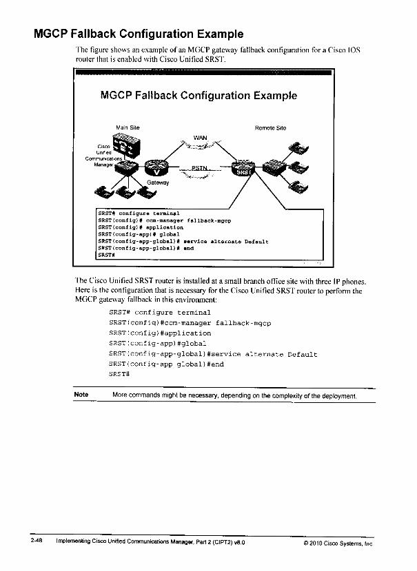
MGCP Fallback Configuration ExampleThe figure shows an example of an MGCP gateway fallback configuration for a Cisco IOSrouter that is enabled with Cisco Unified SRST.
MGCP Fallback Configuration Example
Main Site Remote Site
SRST# configure terminal
SRST(config)# ccm-manager fallback-mgcpSRST(config)# applicationSRST(config-app)# global
SRSTfconfig-app-global)# service alternate DefaultSRSTIconfig-app-global)# end
SRST#
TheCisco Unified SRST router is installed at a small branch officesitewith three IPphones.Here is the configuration that is necessary forthe Cisco Unified SRST routerto perform theMGCP gateway fallback in this environment:
SRST# configure terminal
SRST(config)#ccm-manager fallback-mgcp
SRST(config)#application
SRST(config-app)#global
SRST(config-app-global)#service alternate Default
SRST(config-app-global)#end
SRST#
Note More commaindsmight be necessary,depending on the complexity of the deployment.
2-48 Implementing Cisco Unified Communications Manager, Part 2 (CIPT2) v8.0 ) 2010 Cisco Systems, Inc
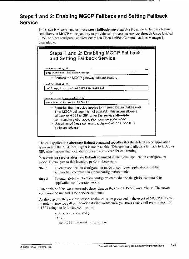
Steps 1 and 2: Enabling MGCP Fallback and Setting FallbackService
The Cisco IOS command ccm-manager fallback-mgcp enables the gateway fallback featureand allows an MGCP voice gateway to provide call-processing services through Cisco UnifiedSRST or other configured applications when Cisco Unified Communications Manager isunavailable.
Steps 1 and 2: Enabling MGCP Fallbackand Setting Fallback Service
router (config)#
ccm-manager fallback-mgcp
Enables the MGCP gateway fallback feature.
router (config) #
call application alternate Default
or
router Iconfig-app-global)W
service alternate Default
Specifies that the voice application named Defaulttakes overifthe MGCP call agent is not available; this action allows afallback to H.323 or SIP. Enter the service alternatecommand in global application configuration mode.Use either of these commands, depending on Cisco IOSSoftware release.
The call application alternate Default command specifies that the default voice applicationtakes o\er if the MGCP call agent is not available, fhiscommand allows a fallback to H.323 orSIP.whichmeans that local dial peersare considered for call routing.
You enter the sen ice alternate Default command in the global application configurationmode. To na\igate to this location, perfonn these steps:
Step1 Toenterapplication configuration mode to configure applications, use theapplication command inglobal configuration mode.
Step 2 To enter global application configuration mode, use the global command inapplication configuration mode.
Enter eitherof the twocommands, depending on theCisco IOSSoftware release. Thenewerconfiguration method is theservicecommand.
As discussed in the previous lesson, analog calls are preserved in the event ofMGCP fallback.In order toprovide call preservation during switchback, you must enable call preservation forH.323 using the following commands:
voice service voip
h323
no h225 timeout keepalive
© 2010 Cisco Syslems. Inc. Centralized Call-Processing Redundancy Implementation
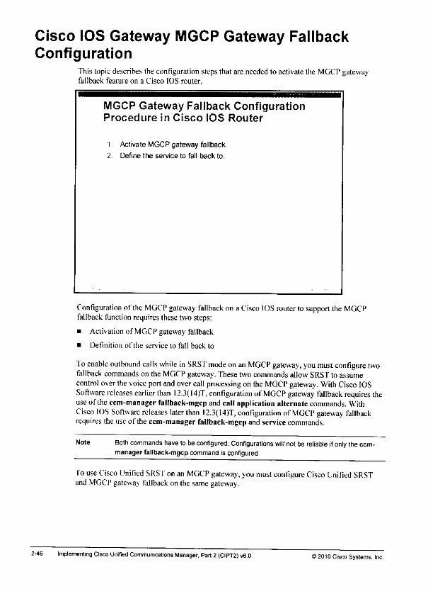
Cisco IOS Gateway MGCP Gateway FallbackConfiguration
This topic describes the configuration steps that are needed to activate the MGCP gatewayfallback feature on a Cisco IOS router.
MGCP Gateway Fallback ConfigurationProcedure in Cisco IOS Router
1 Activate MGCP gateway fallback.
2 Define the service to fall back to.
Configuration of the MGCP gateway fallback on a Cisco IOS router to support the MGCPfallback function requires these two steps:
• Activation of MGCP gateway fallback
• Definition of the service to fall back to
Toenable outbound calls while inSRST mode onan MGCP gateway, youmust configure twofallback commands on the MGCP gateway. These two commands allow SRSTto assumecontrol overthevoice portandovercallprocessing on the MGCP gateway. With CiscoIOSSoftware releases earlier than 12.3(14)T, configuration of MGCP gateway fallback requires theuse of theccm-manager fallback-mgcp andcallapplication alternatecommands. WithCisco IOS Software releases later than I2.3(I4)T, configuration of MGCP gateway fallbackrequires the use of the ccm-manager fallback-mgcp and service commands.
Note Both commands have to beconfigured. Configurations will not be reliable if only theccm-manager fallback-mgcp command is configured.
To use CiscoUnified SRST on an MGCP gateway, youmustconfigure CiscoUnified SRSTand MGCP gateway fallback on the samegateway.
2-46 Implementing Cisco Unified Communications Manager. Part2 (CIPT2) v8.0 >20IOCisco Systems, Inc.
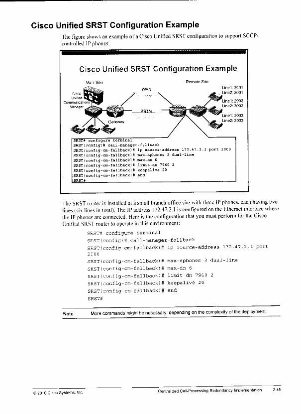
Cisco Unified SRST Configuration Examplefhe figure shows anexample of a Cisco Unified SRST configuration to support SCCP-controlled IP phones.
Cisco Unified SRST Configuration Example
Main Site
SRST# configure terminal
SRST(config)# call-manager-fallbackSRST(config-cm-fallback)# ip source-address 172.47.2.1 port 2000SRST(config-an-fallback! tt max-ephones 3 dual-lineSRST(config-cm-fallback]# max-dn 6SRST(config-cm-fallback)# limit-dn 7960 2SRST(config-cm-fallback)# keepalive 20SRSTlconfig-cm-fallback)# endSRST#
Remote Site
"fhe SRST router is installed at a small branch office site with three IP phones, each having twolines (six lines intotal). The IP address 172.47.2.1 isconfigured onthe Fthemct interface wherethe IP phones are connected. Here isthe configuration thai you must perform for the CiscoUnified SRST router to operate in this environment:
SRSTtt configure terminal
SRST(config)# call-manager-fallback
SRST(config-cm-fallback)# ip source-address 172.47.2.1 port
2C00
SRST(config-cm-fallback)# max-ephones 3 dual-line
SRST(config-cm-fallback)# max-dn 6
SRST(config-cm-fallback)# limit-dn 7960 2
SRST(config-cm-fallback)# keepalive 20
SRST(config-cm-fallback)# end
SRST#
Note More commands might be necessary, depending on the complexity ofthedeployment
) 20'0 Cisco Systems. IncCentralized CalI-Processing RedundancyImplementation 2-46
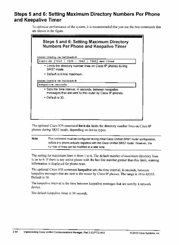
Steps 5 and 6: Setting Maximum Directory Numbers Per Phoneand Keepalive Timer
To optimize perfonnance of the system, it is recommended that you use the two commands thatare shown in the figure.
Steps 5 and 6: Setting Maximum DirectoryNumbers Per Phone and Keepalive Timer
router(config-cm-fallback)#
|limic-dn (7910 / 7335 / 7940 / 7960} max-lines* Limitsthe directory number lines on Cisco IP phones during
SRST mode.
* Default is 6-line maximum.
router(config-cm-fallback} #Ikeepalive oecondg
* Sets the time interval, in seconds, between keepalivemessages that are sent to the router by Cisco IP phones.
• Default is 30.
The optional Cisco IOScommand limit-dn limitsthe directory number lineson Cisco IPphones during SRSTmode, depending on device types.
Note This command mustbe configured during initial CiscoUnified SRST router configuration,before any phone actually registers with the Cisco Unified SRST router. However, thenumber of lines can be modified at a later time.
The setting for maximum lines is from 1to6.The default number ofmaximum directory linesissetto 6. Ifthere isany active phone with the lastline number greater than this limit, warninginfonnation is displayed for phone reset.
TheoptionalCisco IOS command keepalive sets the time interval, in seconds, betweenkeepalive messages thataresent to therouter byCisco IPphones. Therange is 10 to 65535.Default is 30.
The keepalive interval is the lime between keepalive messages that aresentby a networkdevice.
The default keepalive timer is 30 seconds.
2-44 Implementing Cisco Unified Communicalions Manager, Part2{CIPT2) v8.0 12010 Cisco Systems, Inc.

Steps 3 and 4: Setting Maximum Directory Numbers andTelephones
"fhe ne\t two commands, max-dn and max-ephone. are mandatory because the defaultvalue?for both commands are defined as 0.
Steps 3 and 4: Setting MaximumDirectory Numbers and Telephones
rouCer(conflg-cm-fallback)W
max-dn max-directory-numbers [dual-line] [preferencepreference-order]
• Sets the maximum number of directory numbers or virtualvoice ports that can be supported by the Cisco Unified SRSTrouter and activates the dual-line mode
router (config-cm-fallback) # __^_
Imax-ephones max-phones
Configures the maximum number ofCisco IP phones that canbe supported by the Cisco Unified SRST router
The Cisco IOScommand max-dn sets the maximum numberof directory numbers or virtualvoice ports that can be supported by the router, and activates the dual-line mode. The maximumnumberis platform-dependent. The default is 0.
The dual-line keyword isoptional. Itallows IP phones in SRS'f mode tohave a virtual voiceport with two channels.
Note Thedual-line keyword facilitates call waiting. Call Transfer, and conference functions byallowing two calls tooccur onone line simultaneously. In dual-line mode, all IP phones onthe Cisco Unified SRST router support two channels per virtualvoice port.
The optional parameter preference sets the global preference for creating the dial peers for alldirector) numbers that are associated with the primary number. The range is from 0to 10. Thedefault is 0. which is the highest preference.
Note The router must berebooted in order toreduce thelimit ofthedirectory numbers orvirtualvoice ports after the maximum allowable number is configured,
To configure the maximum number ofCisco IP phones that can be supported by aCiscoUnified SRS'f router, use the max-ephones command incall-manager-fallback configurationmode. The default is0. and the maximum configurable number is platform-dependent.
Note The router must be rebooted in order toreduce thelimit ofCisco IP phones after themaximum allowable number is configured.
©20-0 Cisco Syslems. IncCentralized Call-Processing RedundancyImplementation 2-43
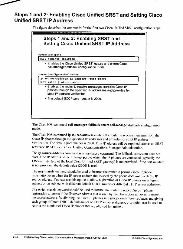
Steps 1 and 2: Enabling Cisco Unified SRST and Setting CiscoUnified SRST IP Address
The figure describes thecommands for the first twoCisco Unified SRST configuration steps.
Steps 1 and 2: Enabling SRST andSetting Cisco Unified SRST iP Address
router (confiq)#
call-manager-fallback
• Enables the Cisco Unified SRST feature and enters Ciscocall-manager-fallback configuration mode.
router (config-cm-fallback)#
ip source-address ip-address [port port][any-match strict-match]
• Enables the router to receive messages from the Cisco IPphones through the specified IP addresses and provides forstrict IP address verification.
• The default SCCP port number is 2000.
The Cisco IOS command call-manager-fallback enters call-manager-fallback configurationmode.
The Cisco IOS command ip source-address enables therouter to receive messages from theCisco IP phones through thespecified IPaddresses andprovides forstrictIPaddressverification. The default port number is 2000. This IPaddress will besupplied later asan SRSTreference IP address in Cisco Unified Communications ManagerAdministration.
The ip source-address command is a mandatory command. Thefallback subsystem does notstart if the IP address ofthe Ethernet port towhich the IPphones are connected (typically theEthemet interface of the local Cisco Unified SRST gateway) isnot provided. Ifthe port numberis not provided, the default value (2000) is used.
The any-match keyword should beused to instruct the router topermit Cisco IP phoneregistration even when the IPserver address that is used by the phone doesnot match the IPsource address. You can use this option to allow registration of Cisco IPphones ondifferentsubnetsor on subnetswithdifferent default DHCProutersor different TFTP serveraddresses.
The strict-match keyword should beused to instruct the router to reject Cisco IPphoneregistration attempts if the IP server address that isused by the phone does not exactly matchthe source address. By dividing the Cisco IP phones into groups on different subnets and givingeach group difTerent DHCP default-router orTFTP server addresses, this option can beused torestrict thenumber of Cisco IP phones that areallowed to register.
2-42 Implementing Cisco Unified Communications Manager. Part 2 (CIPT2) v8.0 >2010 Cisco Systems, Jnc.
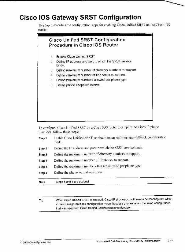
Cisco IOS Gateway SRST ConfigurationThis topicdescribes the configuration steps forenablingCisco Unified SRSTon the Cisco IOSrouter.
Cisco Unified SRST ConfigurationProcedure in Cisco IOS Router
: Enable Cisco Unified SRST
2 Define IP address and port to which the SRST servicebinds.
;; Define maximum number of directory numbers to support.
a Define maximum number of IP phones to support.
•:: Define maximum numbers allowed per phone type.
6 Define phone keepalive interval.
To configure Cisco Unified SRST on aCisco IOS router tosupport the Cisco IP phonefunctions, follow these steps:
Step 1 Fnable Cisco Unified SRST. sothat itenters call-manager-fallback configurationmode.
Step 2 Define the IP address and port to which the SRS'f service binds.
Step3 Define the maximum number of directory numbers to support.
Step 4 Define the maximum number of IP phones to support.
Step5 Define the maximum numbers thatare allowed perphone tjpe.
Step 6 Definethe phonekeepalive interval.
Note Steps 5 and 6 are optional.
Tip When Cisco Unified SRST is enabled, Cisco IP phones do not have to be reconfigured whilein catl-manager-fallback configuration mode, because phones retain the same configurationthat was used with Cisco Unified Communications Manager.
© 2010 Cisco Systems. Inc.Centralized Call-Processing Redundancy Implementation 2-41
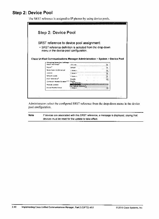
Step 2: Device PoolThe SRST reference is assigned to IP phones by using device pools.
Step 2: Device Pool
SRST reference to device pool assignment:• SRST reference definition is selected from the drop-down
menu in the device-pool configuration.
Cisco Unified Communications ManagerAdministration > System > Device Pool
— Roaming Sai»rttv« bettings -
Dftte/Ti-nc Grouo'
Pe jion *
Media Resource Grcup Us*
Locator
Nefwort Locale
BkST Reference*
Connection Monitor Duration***
Physical Location
Ctv^e MabiJjty Group
Administrators select the configured SRST reference from the drop-down menu in the devicepool configuration.
Note Ifdevices are associated with this SRST reference, a message is displayed, saying that
devices must be reset for the update to take effect.
2-40 implemenbng Cisco Unified Communications Manager, Part 2 (CJPT2) v8.0 >201DCisco Systems, inc.
«&
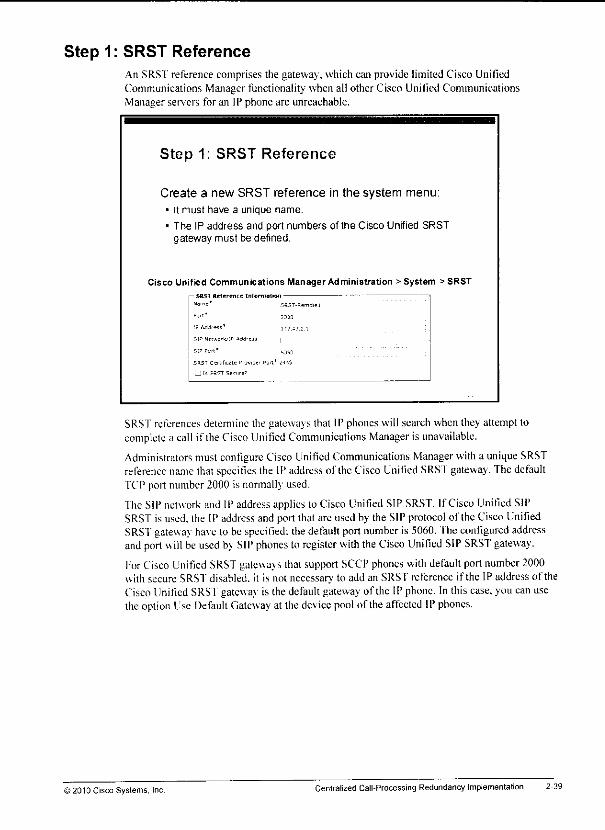
mm
Step 1: SRST ReferenceAn SRST reference comprises the gateway, which can provide limited Cisco UnifiedCommunications Manager functionality when all other Cisco Unilied CommunicationsManager servers for an IP phone are unreachable.
Step 1: SRST Reference
Create a new SRST reference in the system menu:
• It must have a unique name.
• The IP address and port numbers of the Cisco Unified SRSTgateway must be defined.
Cisco Unified Communications ManagerAdministration > System > SRST
i— SftSI Reference Information
"amf * SRST-Hemcltl
IF i^ddr-5G" ]•;;•;!
SIP NtVAC'k IP ASd-csi |
5H5T CtrafiMte P'wJf Pjri' ;-i35
_j [s SSFT Sccurr'
SRST references detemiine the gateways that IP phones will search when (hey attempt tocomplete a call if theCisco Unified Communications Manager is unavailable.
Administrators must configure Cisco Unified Communications Manager with a uniqueSRSTreference name thatspecifies the IPaddress of (he CiscoUnilied SRSf gateway. ThedefaultTCP port number 2000 is normally used.
The SIP network and IP address applies to Cisco Unified SIP SRST. If Cisco Unified SIPSRSTis used, the IP address and port that are used by the SIP protocol of the Cisco UnifiedSRSf gateway have lo be specified: thedefault portnumber is 5060. Theconfigured addressand port will be used by SIP phones to register with theCisco Unified SIP SRST gateway.
ForCisco Unified SRSTgateways that supportSCCPphones with defaultport number2000with secure SRST disabled, it is not necessary to add an SRST rclcrcncc if the IP address of theCisco Unified SRSTgateway is the defaultgateway of the IP phone. In this case,you can usetheoption Use Default Gateway at the device pool of theaffected IPphones.
>2010 Cisco Systems, Inc. Centralized Call-Processing Redundancy Implementation 2-39
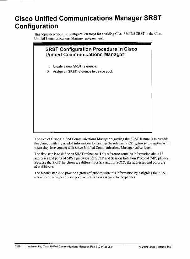
Cisco Unified Communications Manager SRSTConfiguration
This topic describes theconfiguration stepsforenabling CiscoUnified SRST in the CiscoUnified Communications Manager environment.
SRST Configuration Procedure in CiscoUnified Communications Manager
1. Create a new SRST reference.
2 Assign an SRST reference to device pool.
The role of Cisco Unified Communications Manager regarding the SRST feature is to providethe phones with the needed information for finding the relevant SRST gateway to register withwhen they lose contact with Cisco Unified Communications Manager subscribers.
The first step is to define an SRST reference. This reference contains information about IPaddresses and ports of SRST gateways for SCCP and Session Initiation Protocol (SIP) phones.Because the SRST functions are different for SIP and for SCCP, the addresses and ports arealso different.
The second step is to provide a group of phones with this information by assigning the SRSTreference to a proper device pool, which is then assigned to the phones.
2-38 Implementing Cisco Unified Communications Manager, Part 2 (CIPT2) v8.0 >2010 Cisco Systems, Inc.
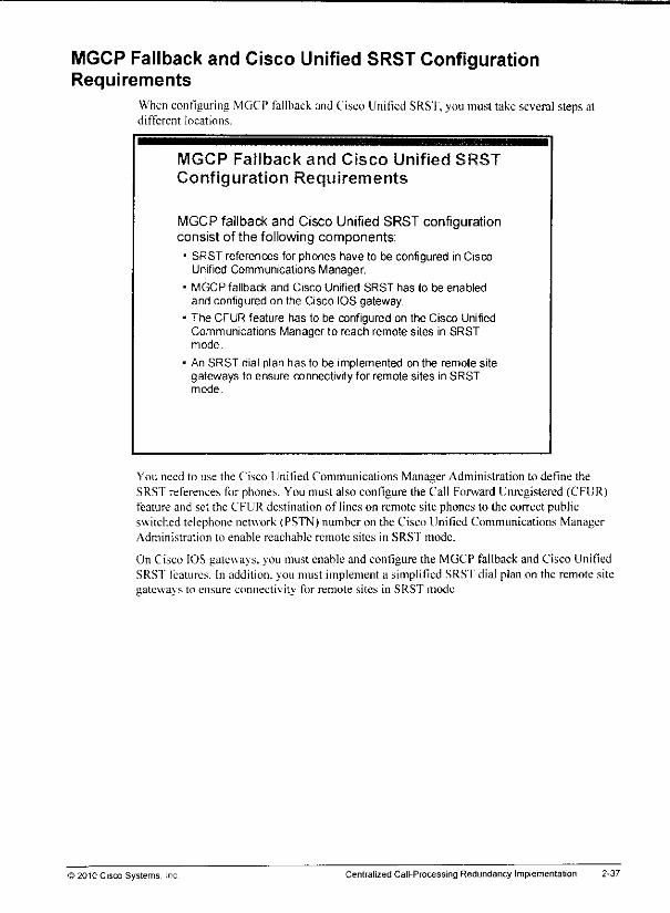
MGCP Fallback and Cisco Unified SRST ConfigurationRequirements
When configuring MGCP fallback and Cisco Unified SRST,you must take several stepsatdifferent locations.
MGCP Fallback and Cisco Unified SRST
Configuration Requirements
MGCP fallback and Cisco Unified SRST configurationconsist of the following components:
• SRST references for phones have to be configured in CiscoUnified Communications Manager.
• MGCP fallback and Cisco Unified SRST has to be enabledand configured on the Cisco IOS gateway.
• The CFUR feature has to be configured on the Cisco UnifiedCommunications Manager to reach remote sites in SRSTmode.
• An SRST dial plan has to be implemented on the remote sitegateways to ensure connectivity for remote sites in SRSTmode.
You need to use the Cisco Unified Communications Manager Administration to define theSRST references for phones. You must also configure (he Call Forward Unregistered (CFUR)feature and set the CFUR destination of lines on remote site phones to the correct publicswitched telephone network (PSTN) number on the Cisco Unified Communications ManagerAdministration to enable reachable remote sites in SRS'f mode.
On Cisco IOS gateways, you must enable and configure the MGCP fallback and Cisco UnifiedSRSf features. In addition, you must implement a simplified SRST dial plan on the remote sitegateways to ensure connectivity for remote sites in SRST mode.
© 2010 Cisco Systems, Inc. Centralized Call-Processing Redundancy Implementation 2-37
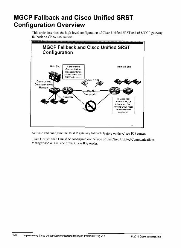
MGCP Fallback and Cisco Unified SRST
Configuration OverviewThis topicdescribes the high-level configuration of Cisco Unified SRSTand of MGCP gatewayfallback on Cisco IOS routers.
MGCP Fallback and Cisco Unified SRSTConfiguration
Main Site
Cisco Unified
Communications
Manager
Remote Site
In Cisco IOS
Software, MGCP
fallback and Crsco
Unified SRST must
be enabled and
configured.
Activate and configure the MGCP gateway fallback feature on the Cisco IOS router.
Cisco Unified SRST must be configured on the side of the Cisco Unified CommunicationsManager and on the side of the Cisco IOS router.
2-36 Implementing Cisco Unified Communications Manager, Part2 (CIPT2) v8.0 >2010 Cisco Systems, Inc.
-**»
m+
•mm
Lesson 2
Implementing SRST andMGCP Fallback
Overviewfhis lesson describes how to configure CiscoUnified Survivable Remote SiteTelephony(SRST) onCisco IOS routers to provide redundancy toCisco Skinny Client Control Protocol(SCCP) phones. Italso describes how toconfigure the Media Gateway Control Protocol(MGCP) gateway fallback feature. In addition, this lesson illustrates how toconfigure featureslike musicon hold (MOH)and voice-mail integration for Cisco Unified SRST.
ObjectivesUpon completing this lesson. \ouwill be able to configure Cisco Unified SRST to provide callsurvivability for IPphones, and MGCP fallback for gateway survivability, fhis ability includesbeingable to meet theseobjectives:
• Describe the configuration requirements at Cisco Unified Communications Manager and atthe SRST gateway
• Describe how loconfigure Cisco Unified Communicalions Manager toenable SRSI forremote phones
• Describe howto configure a Cisco IOS router forSRS'f
a Describe how to configure a Cisco IOS router to support MGCP fallback
• Describe how toconfigure Cisco Unified Communications Manager to route calls tounregistereddevices via the PSTN
• Describe how toconfigure a Cisco IOS router with a dial plan for SRST operation
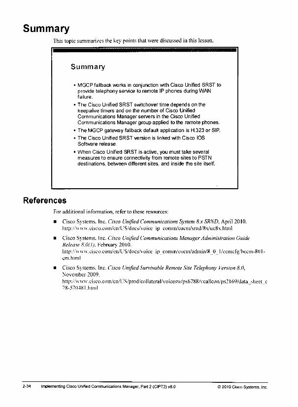
SummaryThis topic summarizes the key points that were discussed in this lesson.
References
Summary
MGCP fallback works in conjunction with Cisco Unified SRST toprovide telephony service to remote IP phones during WANfailure.
The Cisco Unified SRST switchover time depends on thekeepalive timers and on the number of Cisco UnifiedCommunications Manager servers in the Cisco UnifiedCommunications Manager group applied to the remote phones.
The MGCP gateway fallback default application is H.323 or SIP.
The Cisco Unified SRST version is linked with Cisco IOS
Software release.
When Cisco Unified SRST is active, you must take severalmeasures to ensure connectivity from remote sites to PSTNdestinations, between different sites, and inside the site itself.
For additional information, refer to these resources:
• Cisco Svstems. Inc. Cisco UnifiedCommunications System8.x SRND, April 2010.http://'\vw\v.eiseo.com/cn/L^S/docs/voiee_ip_comm/ciiem/srnd/8x/uc8x.html
• Cisco Systems. Inc. Cisco UnifiedCommunications ManagerAdministration GuideRelease 8.0(1). February 2010.hltp://«ww.cisco.com/en/US/docs/voice ip comin/cucm/admin/8 0 l/ccmcfg/'bccm-801-cm.html
• Cisco Systems. Inc. Cisco UnifiedSurvivable RemoteSite Telephony Version 8.0,November 2009.
http:.;V\\w'w,eisc().com/en/l!S/pmd/'collateral/voiccsvv/ps6788/Vcallcon/ps2l6Wdata^heet e78-57048l.html
2-34 Implementing Cisco Unified Communications Manager, Part 2 (CIPT2) v8.0 © 2010 Cisco Systems, Inc.

Cisco Unified SRST Dial Plan Requirements ExampleCall-routing components on Cisco IOS routers and Cisco Unified Communications Managerarc necessary before a dial plan will work in SRS'f mode.
Cisco Unified SRST Diaf Plan
Requirements Example
The dial plan enabled by Cisco Unified SRST has toinclude the following components:
• CFUR on the Cisco Unified Communications Manager side
• Dial peers, COR, dial plan pattern, and voice translationprofiles on the Cisco IOS router site
Cisco
Unified
Communications
Manager
Dial peer with destination pattern.?.T (MIntsto_PSTN
COR lists deny access for900-services dial jjeer
Remole Site
Configuration includesdial plan pattern and voicetranslation profiles to allow
extension-only dialing.
CFUR must be defined on the Cisco Unified Communications Manager side. Configuring theCisco IOS router is a little more complex when vou use dial peers, COR. dial plan pattern, and\oice translation profiles to define the simplified Cisco Unified SRST dial plan.
© 2010 Cisco Systems. Inc Centralized Call-Processing Redundancy Implementation
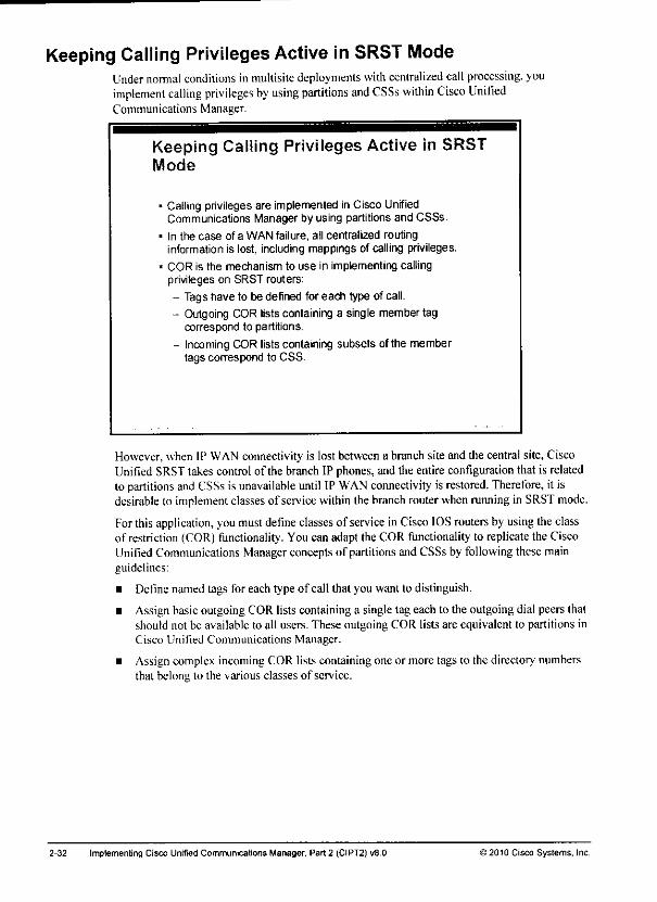
Keeping Calling Privileges Active in SRST ModeUndernormal conditions in multisite deployments with centralized call processing, youimplement calling privileges by using partitions and CSSs within Cisco UnifiedCommunications Manager.
Keeping Calling Privileges Active in SRSTMode
Calling privilegesare implemented in Cisco UnifiedCommunications Manager by using partitions and CSSs.
In the case of a WAN failure, all centralized routinginformation is lost, including mappings of calling privileges.
COR is the mechanism to use in implementing callingprivileges on SRST routers:
- Tags have to be defined for each type of call.
- Outgoing COR lists containing a single member tagcorrespond to partitions.
- Incoming COR lists containing subsets ofthe membertags correspond to CSS.
However, when IP WAN connectivity is lostbetweena branch site and the central site, CiscoUnified SRSTtakes controlof the branchIP phones,and the entireconfiguration that is relatedto partitions andCSSs is unavailable until IP WAN connectivity is restored. Therefore, it isdesirable to implement classes of service within the branch router when running in SRST mode.
Forthis application, youmustdefine classes of service in Cisco IOSrouters by using theclassof restriction (COR)functionality. Youcan adapt the COR functionality to replicate the CiscoUnified Communications Manager concepts of partitionsand CSSsby following these mainguidelines:
• Define named tags for each type of call that you want to distinguish.
• Assign basic outgoing COR listscontaining a single tageachto theoutgoing dial peersthatshould not be available to all users. These outgoing COR lists are equivalent to partitions inCisco Unified Communications Manager.
• Assigncomplexincoming COR lists containing oneor more tags to the directory numbersthat belong to the various classes of service.
2-32 Implementing Cisco Unified Communications Manager, Part 2 (CIPT2) v9.Q >2010 Cisco Systems, Inc.
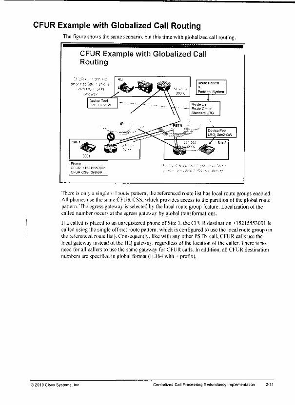
CFUR Example with Globalized Call RoutingThe figure shows thesame scenario, but thistimewith globalized call routing.
CFUR Example with Globalized CalRouting
3001
Phone
CFUR *152155530O1
CFUR CSS System
Route Pattern
Partition. System
Device Pool
LRG Site2-GW
There is only a single \+! route pattern, the referenced route list has local route groups enabled.All phones use the same CFUR CSS. which provides access to the partition of the global routepattern, fhe egress gatewa; is selected by the local route group feature. Localizationof thecalled number occurs at the egress gateway by global transformations.
Ifa called is placed to an unregistered phone of Site l, die CFUR destination+152I5553001 iscalled using the single off-net route pattern, which is configured to use the local route group (inthe referenced route list). Consequently, like with any other PSTN call, CFUR calls use thelocal gateway instead of the HQ gateway, regardless of the location of the caller. There is noneed for all callers to use the same gateway for CFUR calls. In addition, all CFUR destinationnumbers are specified in global format (E. 164 with +- prefix).
'2010 Cisco Systems, Inc. Centralized Call-Processing Redundancy Impfementation 2-31
CFUR Example Without Globalized Call Routing"Hie example illustrates the call flow with CFUR without local route groups.
CFUR Example Without Globalized CallRouting
CFUR caii from HQ
phone to Stie 1 phoneuses MO PSTN
galeway
Route List
Route Group: HQ-GW
Ptione
CFUR 915215553001
CFUR CSS HQ
JP ;.,)!: K)ir> hiic;2 ph:*^; tc '~Wt ' pSn">si<; t;;K-.s HG
Thereare three sites: HQ, Site I, and Site 2. The remotesites are backed up by SRS'f gateways.If IPconnectivity between site 1 andthe HQfails, Site 1phones will failover to SRST mode.They can still call the HQ and Site 2 viathe PSTN. When an HQ phone attempts to call a phoneat Site 1—which is unregistered in Cisco Unified Communications Manager—the call is placedto theCFUR destination configured at the Site 1phone (915215553001 in thisexample). TheCFURCSSof the Site 1 phoneensuresthat a route pattern9.@—which refers to the HQgateway—can be accessed. Therefore, thecall is redirected to the PSTN number of thecalledphone and sent to the HQ gateway.
When a user at Site 2 attempts to call a phone at Site 1, the same thing happens. The CFURdestination 915215553001 is called using the CFUR CSS configured at the Site 1 phone andtherefore matches the 9.@ route pattern that is referring to the HQgateway andnot to a 9.fyroute pattern referring to a Site2 gateway. Therefore, the callwillutilize the IP WAN to getfrom Site 2 to the HQ and from there it will break out to the PSTN towardsSite 1.
If there were more sites, they would all use the HQ gateway for CFUR calls to Site 1. This canlead to suboptimal routing. In addition, differentroute patterns may be neededdepending onthe destination of the CFUR call. In an international deployments, the CFUR destinationnumbermay be a mixof national and international numbers. Each destination numberhas to bespecified in a way that it can be routed by the CFURCSS. There is no common format for allCFUR destinations—some may be specified in national format, others in international format.
2-30 Implementing Cisco Unified Communications Manager, Part 2 (CIPT2) v8.0 © 2010 Cisco Systems, Inc.
CFUR Interaction with Globalized CallRouting (Cont.)
Optimized gateway selection with multiplesites:• Without using local route groups the CFUR CSS determines
the gateway used for the CFUR call
* The CFUR CSS is set at the phone that is unregistered {inSRST mode)
- All callers use the same CFUR CSS to reach such anunregistered phone
• Ifcallers are at different sites, they all have to use the samegateway (typically the main site gateway is used)
- With local route groups each spoke site can use its localgateway for CFUR calls
• CFUR number is the same for all callers regardless of theoriginating site
Without usinglocal routegroups, the CFURCSS determines the gateway that is used for theCFUR call. The CFURCSS of the phonethat is unregistered is used not the one of the phonethat tries to reach the unregistered phone. This means that all callers use the same CFUR CSSwhencallingan unregistered phone(the CFURCSS configured at the destination phone).Consequently, if callers arc located at different sites, they will all use the same gateway for theCFUR call. Usually the main site gateway is used for that purpose; that means that the CFURCSS (applied to all phones) provides access lo PSTN route patterns that use the main sitegateway (via the referenced route list and route group).
With local route groups, each caller can use its local gateway for CFUR calls; there is no needto use the IP WAN touards the main site and then break out to the PS'FN with the CFUR call at
the main site gateway. Dependingon the deployment this can be a huge improvement forreaching sites that lost IP connectivity to Cisco Unified Communications Manager.
© 2010 Cisco Systems. Inc Centralized Call-Processing Redundancy Implementation 2-29
CFUR Interaction with Globalized Call RoutingCFUR canbenefit from globalized call routing in multisite deployments, especially when aCisco Unified Communications Managercluster servesmultiplecountries.
CFUR Interaction with Globalized Cal!Routing
CFUR can benefit from globalized call routing:- Ifglobalized number is used as CFUR destination number
- CFUR calls are placed to global number
- Single route pattern (\+!) sufficient for all CFUR calls
- Same route pattern can be used for AARand PSTNaccess
- Route pattern refers to single route list
- Route list includes only "Standard Local Route Group"
- CFUR CSS can be the same for all phones
If globalized numbers arc usedas CFURdestinations, callsto unregistered phones(forexample, phones that lost IP connectivity to Cisco Unified Communications Manager andwhich are in SRST mode) are using the only configured off-net route pattern \+! for CFUR. Allcalling devices will use the same route pattern, route list, and route group to place the call, "fhisroute pattern is a general off-net route pattern and is used for PSTN calls, AAR calls, as well asby CFUR calls, 'fhe CFUR CSS can be the same for all phones and the local gateway will beused for the CFUR call because local route groups are configured.
2-28 Implementing Cisco Unified Communications Manager, Part 2 (CIPT2) v8.0 >2010 Cisco Systems, Inc.
a director;' numberwhose CFURsetting is configured for voicemail. At the same time, thisconfiguration would alsolimit potential loops to two fordirectory numbers whose CFURconfiguration sends calls through the PSTN.
Note Cisco Unified Communications Manager Extension Mobility directory numbers should not beconfigured to send CFUR calls to the PSTN DID that is associated withthe directorynumber. The directory numbers of Cisco Unified Communications Manager ExtensionMobility profiles in the logged-out state are deemed to be unregistered; therefore, any callsto the PSTN DID number of a logged-out directory number would trigger a routing loop Toensure that calls made to Cisco Unified Communications Manager Extension Mobilitydirectory numbers in the logged-out state are sent to voice mail, you must configure their
corresponding CFUR parameters to send calls to voice mail.
)2010 Cisco Systems, Inc Centralized Call-Processing Redundancy Implementation 2-27
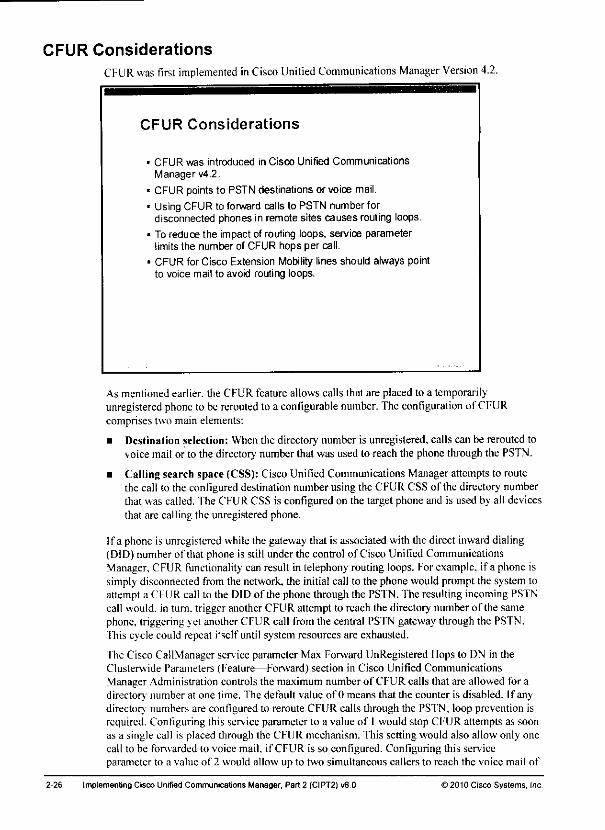
CFUR Considerations
CFUR was first implemented inCisco Unified Communications Manager Version 4.2.
CFUR Considerations
CFUR was introduced in Cisco Unified CommunicationsManager v4.2.
CFUR points to PSTN destinations or voice mail.
Using CFUR to forward calls to PSTN number fordisconnected phones in remote sites causes routing loops.
To reduce the impact of routing loops, service parameterlimits the number of CFUR hops per call.
CFUR for Cisco Extension Mobility lines should always pointto voice mail to avoid routing loops.
As mentioned earlier, the CFUR feature allows calls that are placed to a temporarilyunregistered phoneto be rerouted to a configurable number.The configuration of CFURcomprises two main elements;
• Destination selection: When the directory number is unregistered, calls can be rerouted tovoicemail or to the directory numberthat was used to reach the phonethrough the PSTN.
• Calling search space (CSS): Cisco Unified Communications Manager attempts to routethe call to the configured destination number using the CFUR CSS of the directory numberthat was called. The CFUR CSS is configured on the target phone and is used by all devicesthat are calling the unregistered phone.
If a phone is unregistered while the gateway that is associated with the direct inward dialing(DID) number of that phone is still under the control of Cisco Unified CommunicationsManager, CFUR functionality can result in telephony routing loops. For example, if a phone issimply disconnected from the network, the initial call to the phone would prompt the system toattempt a CFUR call to the DID of the phone through the PSTN. The resulting incoming PSTNcall would, in turn, trigger another CFUR attempt to reach the directory number of the samephone, triggering yet another CFUR call from the central PSTN gateway through the PSTN.This cycle could repeat i'sclf until system resources are exhausted.
'fhe Cisco CallManager service parameter Max Forward UnRegistered Hops to DN in theClusterwide Parameters (Feature—Forward) section in Cisco Unified CommunicationsManager Administration controls the maximum number of CFUR calls that are allowed for adirectory number at one time. The default value of 0 means that the counter is disabled. If anydirectory numbers are configured to reroute CFUR calls through the PSTN, loop prevention isrequired. Configuring this service parameter to a value of 1 would stop CFUR attempts as soonas a single call is placed through ihe CFUR mechanism. This setting would also allow only onecall to be forwarded to voice mail, if CFUR is so configured. Configuring this serviceparameter to a value of 2 would allow up to two simultaneous callers to reach the voice mail of
2-26 Implementing Cisco Unified Communications Manager, Part 2 (CIPT2) v8.0 ) 2010 Cisco Systems, Inc.
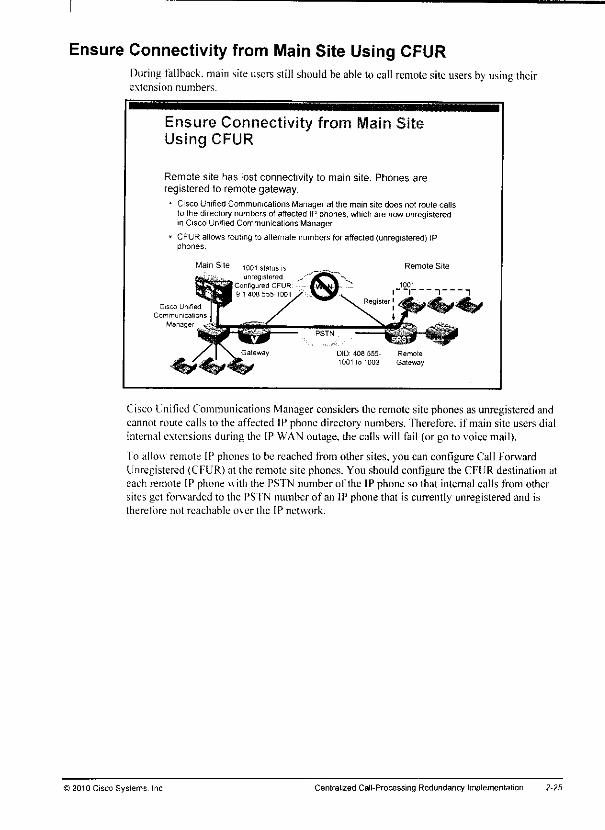
Ensure Connectivity from Main Site Using CFURDuring fallback, main site users still should be able locall remote site users by using theirextension numbers.
Ensure Connectivity fromUsing CFUR
in
Remote site has lost connectivity to main site. Phones areregistered to remote gateway.
• Cisco Unified Communications Manager at the main site does not roule callsto the directory numbers of affected IP phones, which are now unregisteredin Cisco Unified Communications Manager.
• CFURallows routingto alternate numbers for affecled (unregistered) IPphones.
Main Site
Communications
Manage
1001 status is
unregisteredConfigured CFUR9 1 408 555-1001
Remote Site
DID' 408 555- Remote
100110 1003 Gateway
Cisco Unified Communications Manager considers the remote site phones as unregisteredandcannot route calls to the affected IP phone directorv' numbers. Therefore, if main site users dialinternal extensions during the IP WAN outage, the calls will fail (or go to voice mail).
To allow remote IP phones to be reached from other sites, you can configure Call ForwardUnregistered (CFUR) at the remote site phones. You should contigurc the CFUR destination ateach remote IP phone with the PSTN number of the IP phone so that internal calls from othersites get forwarded to the PSTN number of an IP phone that is currently unregistered and istherefore not reachable over the IP network.
©2010 Cisco Systems. Inc Centralized Cal I-Processing Redundancy Implementation 2-25
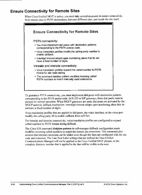
Ensure Connectivity for Remote SitesWhen Cisco Unified SRST is active, youmusttakeseveral measures to ensure connectivityfromremotesites to PSTN destinations, betweendifferentsites, and insidethe site itself.
Ensure Connectivity for Remote Sites
PSTN connectivity:* You must implement dial peers with destination patterns
corresponding to the PSTN access code.
• Voice translation profiles modify the calling-party number toenable callback.
* Interdigittimeout adopts open numbering plans that do nothave a fixed number of digits.
Intrasite and intersite connectivity:
• Voice translation profiles expand the called number to PSTNformat for site code dialing.
* The command dialplan pattern modifies incoming calledPSTN numbers to match internally used extensions.
To guarantee PSTN connectivity, you must implement dial peers with destination patternscorresponding to the PSTN access code. In H.323or SIP gateways, these dial peers must bepresentfor normal operation. When MGCP gateways are used,dial peers are activated by theMGCP gateway fallback mechanism. Interdigit timeout adopts open numbering plans that donot have a fixed number of digits.
Voicetranslation profilesthat are appliedto dial peers, the voice interface, or the voiceportmodify the calling party ID to enable callback from call lists.
For intrasite and intersite connectivity, voice translation profiles are configured to expandcalled numbers to PSTN format during fallback.
The Cisco IOS command dialplan-pattern in call-manager-fallback configuration modemodifies incoming called numbers to match the remote site extensions, 'fhis command alsoensures that internal extensions can be dialed even though the lines are configured with the sitecode and extension, "fhe Line Text Label settings that are defined in Cisco UnifiedCommunications Manager will not be applied to the Cisco Unified SRST phones, so thecomplete directory number that is applied to the line will be visible to the user.
2-24 Implementing Cisco Unified Communications Manager, Pan 2 (CIPT2) v8.0 12010 Cisco Systems, Inc.
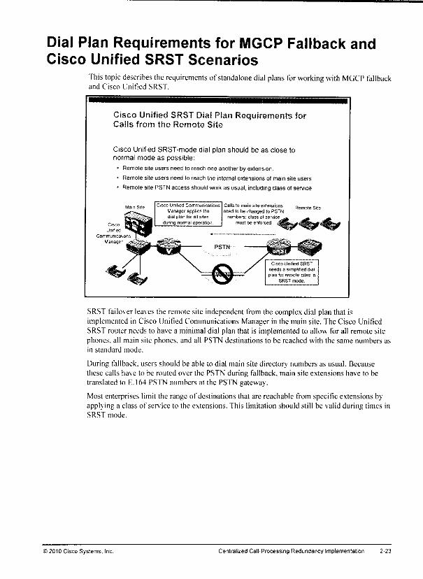
Dial Plan Requirements for MGCP Fallback andCisco Unified SRST Scenarios
Thistopic describes therequirements of standalone dial plans forworking with MGCP fallbackand Cisco Unified SRST.
Cisco Unified SRST Dial Plan Requirements farCalls from the Remote Site
Cisco Unified SRST-mode dial plan should be as close tonormal mode as possible:
• Remote site users need to reach one another by extension.
• Remote site users need to reach the internal extensions of main site users.
* Remote site PSTN access should workas usual, includingclass of service.
Unified
Communicalions
Manager
isco Unified Communicalions
Manager applies thedial plan for all sites
during normal operation
Calls to main sile extensions
need to be changed to PSTNnumbers; class ol service
must be enforced
Cisco Unified SRST
needs a simplified dial
plan for remote sites inSRST mode
SRST failo\er lea\es the remote site independent from the complex dial plan that isimplemented in Cisco Unified Communications Manager in the main site. The Cisco UnifiedSRST router needs to have a minimal dial plan that is implemented lo allow for all remote sitephones, all main site phones, and all PSTN destinations to be reached with the same numbers asin standard mode.
During fallback, users should be able to dial main site directorv' numbers as usual. Becausethese calls have to be routed over the PSTN during fallback, main site extensions have to betranslated to E.164 PSTN numbers at the PSTN gateway.
Most enterprises limit the range of destinations that are reachable from specific extensions byapplying a class of service to the extensions, fhis limitation should still be valid during times inSRST mode.
>2010 Cisco Systems, Inc. Centralized Cal I-Processing Redundancy Implementation 2-23
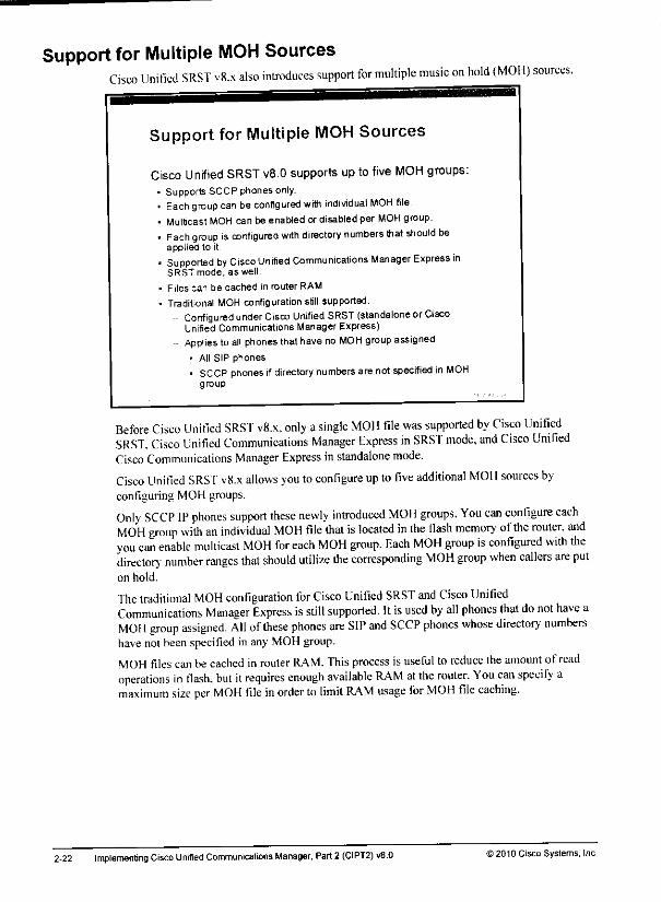
Support for Multiple MOH SourcesCisco Unified SRST v8.x also introduces support for multiple music on hold (MOH) sources.
Support for Multiple MOH Sources
Cisco Unified SRST v8.0 supports up to five MOH groups:• Supports SCCP phones only.• Each group canbe configured with individual MOH file.• Multicast MOH can be enabled or disabled per MOH group.« Each group isconfigured with directory numbers that should be
applied to it.• Supported by Cisco Unified Communications Manager Express in
SRST mode, as well.
• Files can be cached in router RAM.
• Traditional MOH configuration still supported,- Configured under Cisco Unified SRST (standalone or Cisco
Unified Communications Manager Express)- Applies toall phones thathave no MOH group assigned
* All SIP phones
• SCCP phones if directory numbers are not specified in MOHgroup
Before Cisco Unified SRST v8.x. only asingle MOH file was supported by Cisco UnifiedSRST. Cisco Unified Communications Manager Express in SRST mode, and Cisco UnifiedCisco Communications Manager Express instandalone mode.
Cisco Unitied SRST v8.x allows you toconfigure up tofive additional MOH sources byconfiguring MOH groups.
Only SCCP IP phones support these newly introduced MOH groups. You can configure eachMOH group with an individual MOH file that is located in the flash memory of the router, andyou can enable multicast MOH for each MOH group. Each MOH group is configured with thedirectory' number ranges that should utilize the corresponding MOH group when callers are puton hold.
The traditional MOH configuration for Cisco Unified SRST and Cisco UnifiedCommunications Manager Express is still supported. Itisused by all phones that do not have aMOH group assigned. All of these phones are SIP and SCCP phones whose directory numbershave not been specified in any MOH group.
MOH files can becached inrouter RAM. This process isuseful toreduce the amount of readoperations in flash, but it requires enough available RAM at the router. You can specify amaximum size per MOH file in order to limit RAM usage for MOH file caching.
2-22 Implementing Cisco Unified Communications Manager, Part2 (CIPT2) v8.0 ) 2010 Cisco Systems. Inc.
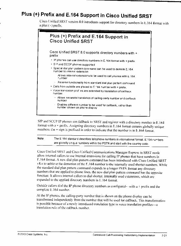
Plus (+) Prefix and E.164 Support in Cisco Unified SRSTCisco Unified SRST version 8.0 introduces support for directory numbers in E. 164 format witha plus (-t-) prefix.
Plus (+) Prefix and E.164 Support inCisco Unified SRST
Cisco Unified SRST8.0supports directory numbers with +prefix:
• IP phones canusedirectory numbers in E.164 format with +prefix.* SIP and SCCP phones supported• Special dialplan pattern command can be used to demote E.164
number to internal extension.
- Allows internal extensions to be used to callphones with E 164number
Reversefunctionality from standarddialplanpattern command• Calls from outside are placed to E164 numberwith +prefix.« Voicetranslationprofiles are extended by translationofcallback
number
- Allows separate translation of calling-party numberand callbacknumber
Enables different number to be used for callback rather thannumbershown on phone display
SIP and SCCP IP phones can fallback to SRST and register with adirectory number in E. 164format with a+prefix. Assigning directory numbers in E. 164 format ensures globally uniquenumbers: the + sign is prefixed inorderto indicate thatthe number is in E. ]64 format.
Note TheE 164standard describes telephone numbers in international format. E164numbersare globally unique numbers within the PSTN and startwith thecountry code.
Cisco Unified SRST and Cisco Unified Communications Manager Express in SRST modeallow internal callers to use internal extensions for calling IPphones that have numbers inE.164 format. A new dial plan pattern command hasbeen introduced with Cisco Unified SRSTv8.x to achieve the demotion of the I:. 164 number to the internally used shorter numbers. Whilethe standard dial plan pattern command expands to a longer PSTN format any directorynumbers that are applied tophone lines, the new dial plan pattern command has the oppositefunction: Itallows internal callers todial shorter, internally used extensions, which areexpanded to the applied directory numbers in E.164 format.
Outside callers dial the IP phone directory numbers as configured—with a 4 prefix and thecomplete E.164 number.
At the IPphones, the calling-party number that isshown on the phone display can betransformed independently from the numberthat will be used forcallback. This transformationis possible because ofa newly introduced translation type in voice translation profiles—atranslation rule of the callback number.
© 2010 Cisco Systems, Inc. Centralized Call-Processing Redundancy Implementation 2-21
Lesson 4
Implementing a Dial Plan forInternational Multisite
Deployments
OverviewMultisite dial plans have to addressspecial issues,such as overlapping and nonconsecutivedirector;'numbers, publicswitchedtelephone network(PSTN)access, PSTN backup,and tail-end hop-off(TEHO). This lessondescribes how to buildmultisitedial plans usingCiscoUnified Communications Managerand Cisco IOSgatewayconfiguration. The lessonalsodescribes the conceptof globalized call routing—a new way of buildingdial plans ininternational multisite deployments.
ObjectivesUponcompleting this lesson,you will be able to implement a dial plan to supportinbound andoutbound PSTN dialing, site-code dialing, and TEHO in an international environment. Thisability includes being able to meet these objectives:
• List dial plan issues and possible solutions
• Describe how site codes and transformation masks solve issues that are caused byoverlapping directory numbers
• Describe how to implement PSTN access in a multisite deployment
• Describe how to implement selective PSTN breakout
• Describe how to use the PSTN as a backup for calls to other VoIP domains
• Describe how to implement TEHO
• Describe the concept of globalized call routing and how it simplifies dial plans ininternational multisite deployments with centralized call processing
• Explain special considerations for implementing globalized call routing
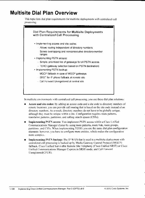
Multisite Dial Plan OverviewThis topic lists dial plan requirements for multisite deployments with centralized callprocessing.
Dial Plan Requirements for Multisite Deploymentswith Centralized Call Processing
Implementing access and site codes;
- Allows routing independent of directory numbers
Solves overlapping and nonconsecutive directory-numberranges
Implementing PSTN access:
- Simple, prioritized list of gateways forall PSTN access
TEHO (gateway selection based on PSTN destination)
Implementing PSTN backup:
MGCP fallback in case of MGCP gateways
- SRST for IP phone fallback at remote site
- Call Forward Unregistered at central site
In multisite environments with centralized call processing, you use these dial plan solutions:
• Access and site codes: By adding an access code and a site code lo director},' numbers ofremote locations, you can provide call routing that is based on the site code instead of ondirectory numbers. As a result, directory numbers do nol have to be globally unique,although they must be unique within a site. Configuration requires route patterns,translation patterns, partitions, and calling search spaces (CSSs).
• Implementing PSTN access: You implement PSTN access within a Cisco UnifiedCommunications Manager cluster by using route patterns, route lists, route groups,partitions, and CSSs. When implementing TEHO. you use the same dial plan configurationelements: however. \ou have lo configure more entities, which makes the configurationmore complex.
• Implementing PSTN backup: The IP WAN that is used in a multisite deployment withcentralized call processing is backed up by Media Gateway Control Protocol (MGCP)fallback. Cisco Unified Survivable Remote Site Telephony (Cisco Unified SRST) or CiscoUnified Communications Manager Express in SRS'f mode, and Call ForwardUnregistered(CFUR).
1-108 ImplementingCisco Unified Communications Manager, Part 2 (CIPT2)v8 0 12010 Cisco Systems, Inc
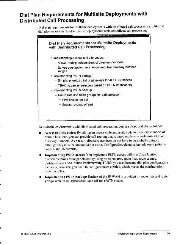
Dial Plan Requirements for Multisite Deployments withDistributed Call Processing
Dial plan requirements for multisite deployments with distributed call processing are like thedial plan requirements ofmultisite deployments with centralized call processing.
Dial Plan Requirements for Multisite Deploymentswith Distributed Call Processing
Implementing access and site codes:- Allows routing independent ofdirectory numbers
- Solves overlapping and nonconsecutive directorynumberranges
Implementing PSTN access:
- Simple, prioritized listofgateways forall PSTNaccess
- TEHO (gateway selection based on PSTN destination)Implementing PSTN backup:
- Route lists and route groups for path selection:
• First choice: on-net
• Second choice: off-net
In multisite environments with distributed call processing, you use these dial plan solutions:
• Access and site codes: Byadding an access codeanda sitecodeto directory numbers ofremote locations, you can provide call routing thatis based on thesite code instead of ondirectory' numbers. As a result, directory numbers donothave tobe globally unique,although they must be unique within a site. Configuration elements include route patternsand translation patterns.
• Implementing PSTN access: You implement PSTN access within a Cisco UnifiedCommunications Manager cluster byusingroute patterns, route lists, routegroups,partitions, and CSSs. When implementing TEHO, you use thesame dial plan configurationelements; however, youhave to configure more entities, which makes the configurationmore complex.
• ImplementingPSTN backup: Backup of the IP WAN is provided by route listsandroutegroups with on-net (prioritized) and off-net (PSTN)paths.
) 2010 Cisco Systems, Inc Implementing Multisite Deployments 1-109

Dial Plan Scalability SolutionsDial plan requirements for multisite deployments with distributed call processing are like thedial plan requirements of multisite deployments with centralized call processing.
Dial Plan Scalability Solutions
Ca IASeni CallAgent
aH Agent
Call Agent
CallAgent CallAgent
Dialplan scalability issues can be solved by Call Control Discovery (CCD)CCD allows dynamic exchange of call routing information utilizinga SAF-enablednetwork
In large networks with severalcall agents—such as Cisco Unified Communications ManagerExpress. Cisco Unified Communications Manager, Cisco Unified Border Element, CiscoUnified SRST.and Cisco IOSgateways—the implementation and maintenance of dial planscan be very complex.
Without centralized services (such as H.323 gatekeepers or SIP network services), a full-meshconfiguration is required. In other words, each call control domain has to be configured withcall-routing information toward all other call-routing domains, fhis implementationmodel doesnot scale at all and therefore is suitable only for smaller deployments.
In a hub-and-spoke deployment model, call-routing infonnation for each call-routing domain isconfigured onh once at the centralized call-routing entity. This centralized call-routing entitycan be a SIP network service or an H.323 gatekeeper. Such a solution scales better than lull-mesh topologies: however, it introduces a single point of failure and therefore requiresredundant deployment of the centralized service. In addition, the centralized call routing stillhas to be manually configured. For example, if telephone number ranges or prefixes arechanged at one of the call-routing domains, these changes also have to be manually perfonnedat the centralized call-routing service. Further. PSTN backup has to be implementedindependent!; ai each call-routing domain.
With Call Control Discovery (CCD). a new feature that was introduced with Cisco UnitiedCommunications Manager Version 8. each call-routing domain advertises locally knowntelephone numbers or number ranges. Because local numbers are typically used by internalpatterns (using VoIP) as well as via the PSTN, each call-routing domain advertises both theinternally used numbers and the corresponding external PSTN numbers.
1-110 Implementing Cisco Unified Communications Manager, Part 2 (CIPT2] uB.O © 2010 Cisco Systems. Inc.
r
mm
CCD solvesdial plan scalability issues by allowingCisco Unified BorderElement, CiscoUnified SRST.Cisco Unified Communications Manager, Cisco Unified CommunicationsManager Express, andCisco IOS gateways to advertise and learn call-routing information inthe form of internal directory numbers and PSTN numbers or prefixes.
CCD utilizes the Cisco ServiceAdvertisement Framework (SAF).SAF is a network-based,scalable,bandwidth-efficient, real-time approach to service advertisement and discovery.
Note CCD is described in more detail in a later lesson of this course.
>2010 Cisco Systems. Inc Implementing Multisite Deployments 1-111
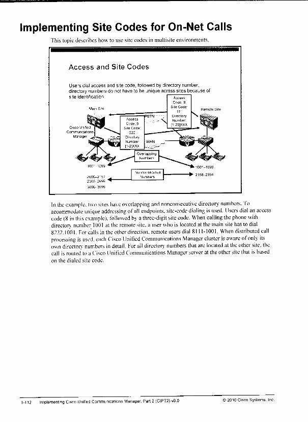
Implementing Site Codes for On-Net CallsThis topic describes how to use site codes in multisite environments.
Access and Site Codes
Users dial access and site code, followed by directory number;directory numbers do not have to be unique across sites because ofsite identification
Cisco Unified
Communication;]Manager
£000-2157
2365-2999 "♦"
Nonconsecutive
Numbers
In the example, two sites have overlapping and nonconsecutive directory' numbers. Toaccommodate unique addressing of all endpoinls. site-code dialing is used. Users dial anaccesscode (8 in this example), followed bya three-digit site code. When calling thephone withdirectory number 1001 at the remote site, a user who islocated atthe main site has todial8222.1001. For calls in the otherdirection, remoteusersdial 8111-1001. Whendistributed callprocessing is used, each Cisco Unified Communications Manager cluster isaware ofonly itsown director) numbers indetail. For all directory numbers that are located at the other site, thecall is routed to a Cisco linified Communications Manager serverat the other site that is basedon the dialed site code.
1-112 Implementing Cisco Unified Communications Manager. Part 2 (CIPT2) v8.0 ) 2010 Cisco Systems. Inc
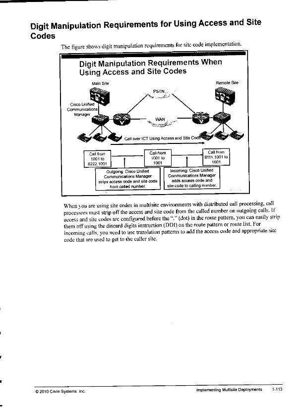
Mm
tow
Digit Manipulation Requirements for Using Access and SiteCodes
The figure shows digit manipulation requirements for site code implementation.
Digit Manipulation Requirements WhenUsing Access and Site Codes
Main Site
Cisco Unified
Communications
Manager
Outgoing: Cisco UnifiedCommunications Manager
strips access code and site codefrom called number.
Remote Site
Incoming: Cisco UnifiedCommunicalions Manager
adds access code andsite code to calling number.
When you are using site codes in mullisite environments with distributed call processing, callprocessors must strip off the access and site code from the called number on outgoing calls. Ifaccess and site codes are configured before the "." (dot) in the route pattern, you can easily stripthem offusing the discard digits instruction (DDI) on the route pattern orroute list. Forincoming calls, you need to use translation patterns to add the access code and appropriate sitecode that are used to get to ihe callersite.
i 2010 Cisco Systems, Inc. Implementing Multisite Deployments 1-113

Centralized Call-Processing Deployments: Access and SiteCodes
Ifoverlapping director) numbers exist in acentralized call-processing deployment, access andsite codes are implemented in adifTerent way. as shown in the figure.
Centralized Call-ProcessingDeployments: Access and Site Codes
Cisco Unified
CommunicationsManager
The example shows two sites with centralized call processing. Directory numbers in the mainsite("headquarters." or "HO" in the figure) andthe remote site(-'branch." or "BR'" in thefigure) partially overlap. Again, access and site codes are used losolve the problem ofoverlapping directory numbers.
However, in this case, partitions and CSSs need lobedeployed ina way that phones at theremote sitedo notseedirector) numbers of main-site phones, andviceversa. Then a translationpattern is added per site.
The translation pattern of each site includes the access and site code of the respective site.Phones ateach site have a CSS assigned, which provides access tothe directory numbers of thelocal site and the translation pattern for the other site orsites, fhetranslation patterns areconfigured witha transformation mask that stripsoff the accesscode and site code. Further,each translation pattern must have a CSS. which provides access toonly those director)numbers that are located at the target site ofthe respective translation pattern, fhis way., allphones can dial local directory numbers and site-code translation patterns for accessing othersites. After a userdials an intersite number(composed of the accesscode,site code, anddirector)' number), thecorresponding translation pattern ismatched. The translation patlernstrips thesite code and access code sothat only the directory number remains. This directorynumber is matched again in thecall-routing tableusing a CSS thathasaccess only to thedirectory numbers of the site, which was identified bv the site code.
1-114 Implementing Cisco Unified Communications Manager. Part 2 (CIPT2) v8 0 12010 Cisco Systems. Inc.
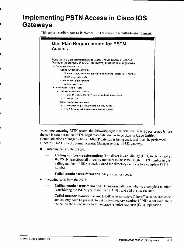
Implementing PSTN Access in Cisco IOSGateways
This topic describes how to implement PSTN access in a multisiteenvironment.
Dial Plan Requirements for PSTNAccess
Perform this digit manipulation at Cisco Unified CommunicationsManager (in the case of MGCPgateways) or at the H.323 gateway:
• Outgoing calls (to PSTN).
- Calling number transfix maIion
• Ifno DD range, transformalldirectorynumbers to (single)PSTN number.
• If DID range, add prefix
- Called number t"an storm at ion
* Strip access code
• Incoming calls (from PSTN).
- Calling number transformation
• Transform to complete PSTN number and add access code.
• ConsiderTON.
- Called number transformation
• If DIDrange, stnp PSTN prefix to directory number.
• Ifno DO, route call to attendant or IVR application.
When implementing PSTN access, the following digit manipulation has tobe performed b:forethecall is sent outto thePSTN. Digit manipulation has tobedone inCisco UnifiedCommunications Manager when anMGCP gateway isbeing used, and it can beperformedeither in Cisco Unified Communications Manager oratan H.323 gateway.
• Outgoing calls to the PSTN:
— Calling number transformation: Ifno direct inward dialing (DID) range isused atthe PSTN, transform alldirectory numbers to thesame, single PSTN number in thecalling number. If DID is used, extend the directory numbers toa complete PSTNnumber.
— Called number transformation: Strip the access code.
• Incoming calls from the PSTN:
— Calling number transformation: Transform calling number loa complete number{considering the ISDN typeof number [TON]), andaddtheaccess code.
— Called number transformation: If DID isused, strip offthe office code, area code,and country- code (ifpresent) to getto thedirectory number. If DID isnotused, routethe call tothe attendant ortothe interactive voice response (IVR) application.
>2010 Cisco Systems, Inc Implementing Multisite Deployments 1-115

PSTN Access ExampleThe figure illustrates an example ofdigit manipulation that isperformed for incoming andoutgoing PSTN calls.
PSTN Access Example
408 555-
DID XXXX
Call from 1001 to
9 1 714 555-2222
Call from 408 555-
1001 to 1 714 555-
2222
Call from PSTN
Incoming Cisco Unifed CommunicationsManager or gateway adds access code and
longdistance 1 to calling number. CiscoUnified Communications Manager or gateway
stnps PSTN prefixfrom called number.
Call from 9.1-
714 555-2222
to 1001
714 555-2222
PSTN
Outgoing Cisco UnifiedCommunications Manager or H 323
gateway strips access code fromcalled number.
Cisco Unified Communications
Manager or H.323 gateway addsPSTN prefix to called number.
Call from 714
555-2222 to 408555-1001
As shown in the example, internal numbers have to be represented as valid PSTN numbers, andPS'fN numbers shouldbe shown with the accesscode9 internally.
Note Adding the access code (and changing 10-digit PSTN numbers to 11-digit PSTN numbers,including the long-distance "1" digit) tothe calling number ofincoming calls isnot required.Adding it. however allows users to call back the number from call lists (such as receivedcalls or missed calls) without having toedit thenumber by adding therequired accesscode
1-116 Implementing Cisco Unifed Communications Manager, Part 2 (CIPT2) v8.0 © 2010 Cisco Systems. Inc
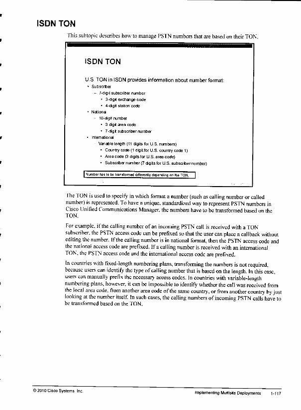
ISDN TON
fhis subtopicdescribes how to manage PSTN numbers that are basedon theirTON.
ISDN TON
U.S. TON in ISDN provides infonnation about number format:• Subscriber
- 7-digit subscriber number
- 3-dig* exchange code
• 4-digit station code
- National
10-dgrt number
• 3-digt area code
• 7-digit subscriber number
• International
Variablelength (11 digitsfor U.S. numbers)• Country code (1 digitfor U.S. country code 1)
* Area coders digits for U.S. area code)
• Subscribernumber (7 digitsfor U.S.subscribernumber)
| Number has lobe transformed differently depending onthe TON.
The TON isused tospecify in which format anumber (such as calling number orcallednumber) isrepresented. Tohave a unique, standardized way to represent PSTN numbers inCisco UnifiedCommunications Manager, the numbers have to be transformed basedon theTON.
For example, if thecalling number of an incoming PSTN call is received with a TONsubscriber, the PSTN access code can be prefixed so that the user can place a callback withoutediting thenumber. Ifthecalling number is innational format, then thePSTN access code andthe national access code areprefixed. Ifa calling number is received with an internationalTON. the PSTN access code and the international access code are prefixed.
In countries with fixed-length numbering plans, transforming the numbers is not required,because users can identify the type ofcalling number that isbased on the length. In this case,users can manually prefix the necessary access codes. In countries with variable-lengthnumbering plans, however, it can be impossible to identify whether thecallwas received fromthe local area code, from another area code ofthe same country, orfrom another country by justlooking atthe number itself. In such cases, the calling numbers ofincoming PSTN calls have tobe transformed based on the TON.
>2010Cisco Systems, Inc. implementingMultisite Deployments 1-117
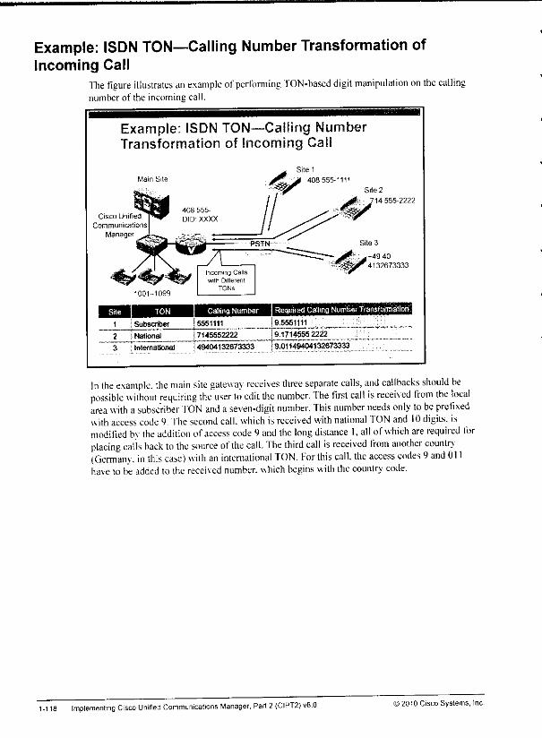
Example: ISDN TON—Calling Number Transformation ofIncoming Call
The figure illustrates an example ofperforming TON-based digit manipulation on the callingnumber of the incoming call.
Example: ISDN TON—Caliing NumberTransformation of Incoming Gall
Mam Site
Cisco Unified
Communications
Manager
408 555-
DIDXXXX
PSTW
Site 1
403 555-1111
Site 2
14 555-2222
Incoming Callswith Different
TONS
^^1^4132673333
1001-1099
Site TON Calling Number Required Catling Number Transformation/
1 I Subscr&er 5551111 9.5551111
2 National I7145552222 19.1714555 2222
~3 International j49404132673333 }9.011464O4132673333
In the example, the main site gateway receives three separate calls, and callbacks should bepossible without requiring the user to edit the number. The first call is received from the localarea with a subscriber "ION and a seven-digit number. This number needs only to beprefixedwith access code9. Thesecond call,which is received with national TON and 10digits, ismodified by the addition ofaccess code 9and the long distance I, all ofwhich are required forplacing calls back to the source ofthe call. The third call is received from another country(Germany, in this case) with an international TON. For this calk the access codes 9and 011ha\c to be added to the received number, which begins with thecountry code.
1-118 Implementing Cisco Unrfied Communications Manager, Part 2 (CIPT2) v8.0 >2010 Cisco Systems, Inc.

Implementing Selective PSTN BreakoutThis topic describes how to implement selective PSTN breakout in a multisite environment.
Selective PSTN Breakout ConfigurationOptions
• Gateway selection by CSS
- Each site uses a device-specific CSS.- Site-specific route pattern is matched.
- Route pattern refers to site-specific route list.
- Route list includes site-specific route group,- Route group refers to site-specific gateways.
• Gateway selection by local route group feature- Matched route pattern refers to systemwide route list.
- Route list refers to Standard Local Route Group.
- Device poolof calling device is configured with route groupto be used.
- Eliminates the need for multiple (site-specific) route lists,route patterns, partitions, and CSS.
- Preferred option since the introduction of local route groups(Cisco UnifiedCommunications Manager \fersion 7).
"ITiere aretwoways to select the local gateway forPSTN calls. Oneway is to configure a site-specific set of route pattern, partition, CSS, route list,androutegroup. Ifyouapply a site-specific CSS at theend.a site-specific routegroup is used. This implementation model wastheonlyoneavailable before Cisco Unilied Communications Manager version 7.
With Cisco Unified Communications Manager version 7, thelocal route group feature wasintroduced. With local route groups, all sites that share the same PSTN dial rules can use oneand the same route pattern (orsetof route patterns). Theroute pattern (orsetof route patterns)isput into a systemwide route list, and this route list includes the local route group. Atthedevice pool of thecalling device, oneof theconfigured route groups is configured to betheStandard Local Route Group for thiscaller. Inthismodel, the routegroupthat is used isdetermined bythedevice pool of thecalling device and notbyits CSS. Thelocal route groupfeature simplifies dial plans because iteliminates the need for duplicate CSS, partitions, routepatterns, and route lists. Since local route groups have been introduced, they arethepreferredmethod for local gateway selection.
>2010Cisco Systems, Inc. Implementing Multisite Deployments 1-119

Configuring IP Phones to Use Local PSTN GatewayIna multisite deployment, there typically aremultiple PS'fN gateways (usually one persite).Selective PSTN breakout ensures that local gateways are used to access the PSI'N.
Configuring IP Phones to Use LocalPSTN Gateway
IPphones located in the main site use the main-site gatewayforPSTN access. Remote phones use their local gateway:
• Single 9.@ route pattern.
• Route list configured to use local route group
• Phone device pool configured with route group to be used by phone.
- Mamsite device pool and remote site device pool refer to differentroute groups.
Main SitePSTN
470 555-
1234Cisco Unified
Communications
Manager
Remote Site
From adial plan perspecti\ c.you create one 9Ar route pattern (assuming that the NorthAmerican Numbering Plan [NAN PIis used). This route pattern is ina partition that is part of aglobal CSS that is used by all phones, fhe route pattern refers lo asystemwide route list that isconfigured to use the local route group. At the site-specific device pools, the standard localroute group isset to the route group thai includes the site-specific gateway.
In the example, there would be adevice pool for the main site and adevice pool for the remote-site. There would bea main site route group, including themain site gateway, and a remote siteroute group, including the remote site gateway. IP phones at the main site and at the remote sitecan now be configured with the same CSS. They all will match the same route pattern andhence willuse thesame roule list. Based on the local route group feature, however, they willalwavs use their local PSTN gateway for PSTN breakout.
Note The local route group is configured with NANP PreDot digit stripping, by default. If the H.323gateway expects calls that arereceived from Cisco Unified Communications Manager andthat would be routed to the PSTNto includethe PSTNprefix 9, appropriate digitmanipulation has tobeconfigured in Cisco Unified Communications Manager. In this case,the best solutionwould be to configure the called-partytransformation patterns and applygateway-specific called-party transformation CSS at the gateways.
1-120 Implementing Cisco Unified Communications Manager, Part 2 (CIPT2) v8.0 !) 2010 Cisco Systems, Inc

Implementing PSTN Backup for On-Net IntersiteCalls
"Ihis topic describes how to use the PSTN as a backup for on-net intersite calls.
PSTN Backup
Ifthe IP WAN (ICT) fails, calls are rerouted over the PSTN:• 8 (site code).XXXX route pattern per site.
• Route pattern points to route lists (first option: ICT; second option:Local Route Group).
Main Site
Cisco Unified
Communications
Manager
1001-1099
Remote Site
1001-1099
The figure shows a multisite deployment with two sites. Each site has its own Cisco UnifiedCommunications Manager cluster. Intersite calls should use the intercluster trunk (ICT) overthe IP WAN. However, what if the IP WAN is down? Since both sites have access to the
PSTN, the PS'fN should be used as a backup for intersite calls.
To ensure that phones at different sites always use their local gateway for PSTN backup, aroute list is configured that includes the ICTas the firstoptionand the local route groupas thesecond option. This way. there is no need to have multiple, site-specific route lists with adifTerent.site-specific route group as second entry.
) 2010 Cisco Systems. Inc. Implementing Multisite Deployments 1-121
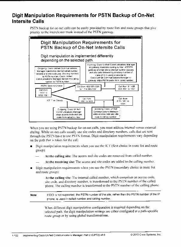
Digit Manipulation Requirements for PSTN Backup of On-NetIntersite Calls
PSTN backup for on-net calls can be easily provided by route lists and route groups that givepriority lo the intercluster trunk instead of the PSTN gateway.
Digit Manipulation Requirements forPSTN Backup of On-Net intersite Cal
Digit manipulation is implemented differentlydepending on the selected path.
Outgoing Cisco Unified CommunicationsManager transforms internal called number
(access and site code plus directory number)Id PSTN number Cisco Unified
Communications Manager Iransterms calling
number to PSTN number.
Incoming Cisco Unifed Communications Manageror gateway translates calling number of PSTN
gateway of other site to internal number (accessand site code followed by directory number of
caller |if DID used] or attendant);Cisco Unified Communcations Manager or
gateway strips PSTN prefix from called number
ICT First Cho.ceCall from
1001 to 1001
Call from
8111 1001 to
1001
Outgoing Cisco UnifiedCommunications ManagersSips access code and suecode from called number
Incoming Cisco UnifiedCommunications Manageraofls access code and site
code to calling number
When youareusing PSTN backup foron-net calls,youmust address internal versus externaldialing. While on-netcalls usual!) use site codesand directory numbers, calls that arc sentthrough the PS'fN haveto use PSI'N fonnal. Digit manipulation requirements vary dependingon the path that i> taken for the call:
• Digit manipulation requirements when youuse the ICT{first choice in route listandroutegroup):
— At the calling site: The accessand site codesare removed from called number.
— At the receiving site: The access and site codes are added to the calling number.
• Digit manipulation requirements when youuse the PS'fN (secondary choice in roule listand route group):
— At the calling site: The internal called number, whichcomprises an accesscode,site code,and director} number, is transformed to the PSI'N numberof the calledphone. The calling number is transformed to thePSTN number of the calling phone.
Note IfDID is not supported, the PSTNnumber of the site, rather than the PSTN number of the IPphone, is used in called number and calling number.
When difTerent digit manipulation configuration is required depending on theselected path, thedigit manipulation settings areeither eonligured at a path-specificroute groupor by usingglobal transformations.
1-122 Implementing Cisco Unified Communicalions Manager, Part 2 (CIPT2) «8.0 '2010 Cisco Systems, Inc
At the receiving site: The PSTN callingnumberis recognized as a PSTN numberofan on-net connected site and transformed to the internal number: access and site
code, followed by the directory numberof the callingphone (if DID is usedat thecalling site)or of theattendant of the calling site (if DID is not used at thecallingsite), The callednumberis transformed to an internal directory numberand routed tothe IP phone(if DID is used at the receivingsite) or to an attendant(if DID is notused at the receiving site).
)2010 Cisco Systems, Inc ImplementingMultisite Deployments 1-123

Implementing TEHOThis topic describes how to implement TKMO in a multisite environment.
Implementing TEHO
PSTN breakout occurs at gateway located closest to the PSTNdestination.
* Route partem for each area that can be reached at different costs, one persite, indifferent partition
• Route patterns point to route lists (with different priorities of gateways;cheapest gateway first, local gateway next).
• Phone CSS or local route group for correct route-pattern selection.
.470
406 555- I'. . RSIN„
DID XXXX L' ,- ""t470 555-1234Cisco Unified
Communications
Manager
Remote
Phones
Local Path
Whenyou implement 11:HO. PSTN breakout occurs at the gateway that is closest to the dialedPS1N destination. Basically, this action occurs because you create a route pattern for eachdestination area that can be reached at dilTerentcosts, 'fhese route patterns refer to route liststhat include a route group for the TF.HO gateway first and the local route group as the secondentry so that the local gateway can be usedas a backupwhenthe IP WAN cannotbe used.
Note The use of TEHO might not be permitted in your country or by your provider. There can alsobe issues withemergency calls Therefore, ensure that your planned deployment complies
with legal requirements
1-124 Implementing Cisco UnifedCommunications Manager. Part 2 (CIPT2) v8 0 © 2010 Cisco Systems, Inc.
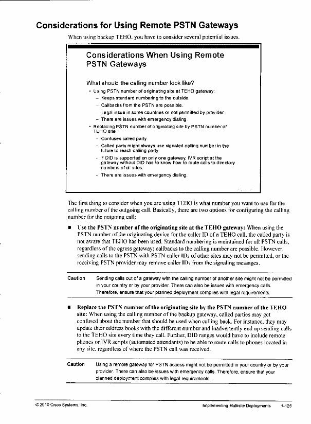
Considerations for Using Remote PSTN GatewaysWhen using backup TEHO. you have to consider several potential issues.
Considerations When Using RemotePSTN Gateways
What should the calling number look like?• Using PSTN number of originating site at TEHO gateway:
- Keeps standard numbering to the outside.
- Callbacks from the PSTN are possible.
- Legal issue in some countries or not permitted by provider.
- There are issues with emergency dialing.
• Replacing PSTN number of originating site by PSTN number ofTEHO site;
- Confuses called party.
- Called party might always use signaled calling number in thefuture to reach calling party.
- If DID is supported on only one gateway, IVR script at thegateway without DID has to know how to route calls to directorynumbers of all sites.
- There are issues with emergency dialing.
The first thing to consider when you are using TEi 10 is what number you want to use for thecalling number of the outgoing call. Basically, there are two options for configuring the callingnumber for the outgoing call:
• Use the PSTN number of the originating site at the TEHO gateway: When using thePSTN number of the originating device for the caller ID of a TEHO call, the called party isnot aware that TEHO has been used. Standard numbering is maintained tor all PSTN calls,regardless of the egress gateway; callbacks to the calling number are possible. Ilowcver,sending calls lo the PSTN with PSTN caller IDs of other sites may not be permitted, or thereceiving PSTN provider may remove caller IDs from the signaling messages.
Caution Sending calls out of a gateway with the calling number of another site might not be permitted
in your country or by your provider. There can also be issues with emergency calls.
Therefore, ensure that your planned deployment complies with legal requirements.
• Replace the PSTN number of the originating site by the PSTN number of the TEHOsite: Whenusingthe callingnumberof the backupgateway, called partiesmay getconfused about the number that should be used when calling back. For instance, they mayupdatetheir address books with the differentnumberand inadvertently end up sendingcallsto the TEHO site every lime ihey call. Further, DID ranges would have to include remotephones or IVR scripts (automated attendants) to be able to route calls to phones located inany site, regardless of where the PSTN call was received.
Caution Using a remote gateway for PSTNaccess mightnot be permittedin yourcountry or by yourprovider. There can also be issues withemergency calls. Therefore, ensure that yourplanned deployment complies with legal requirements.
) 2010 Cisco Systems, Inc. Implementing Multisite Deployments 1-125

In general, it is highly recommended that you use the local route group feature whenimplementingTEHO. In order to provide a local backup for TEHO calls, call processing mustroute all calls ditTerentlv. based on the source (physical location) and on the dialed number,when the TEHO path cannot be used. When you are not using local route groups, this approachcan require a huge amount of route patterns, partitions. CSS. and route lists, resulting incomplex dial plans. Suchdial plansare difficult to maintain and troubleshoot.
Note You must also consider Call Admission Control (CAC) when implementing TEHO. When the
primary (TEHO) path is not admitted, the local gateway should be used instead. More
information about CAC is provided in a separate module of this course.
1-126 Implementing Cisco Unified Communications Manager. Pari 2 (CIPT2) v8.0 ©2010 Cisco Systems, Inc.

TEHO Example Without Local Route GroupsThissubtopic illustrates thedial plan requirements when youare implementing TEHO withoutlocal route groups.
TEHO Example Without Local RouteGroups
Eacfi site has a different mute pattern androute ist tor each ol the other sites.
Each site has one additional route patternana route list for generic PSTN access (tonon-TEHO PSTN destnations|.
T1T
L I =j_
In the example, there are five sites in a centralized call-processing deployment. Each site usesidentical call-routing policies and numbering plans, but the site-specific details of those policiesprevent customers from provisioning a single set of route pattern and route list that works forall sites. This principle applies when no local route groups are used (as it was the case beforeCisco Unified Communications Manager Version 7).
Although the primary path for a given TEHO PSTN destination is always the same (theappropriate TEHO gateway), the backup path is different for each site (the local gateway of thesite where the call has been placed). Without a backup path, TEI10 would require only oneroute pattern per TEHO destination number and would refer to only the corresponding TEHOgateway from its route list and route group. However, as the IP WAN is used for TEHO calls, itis not recommended that you configure a single path only. Therefore, TEHO configurationseasily end up in huge dial plans: Each site requires a different route pattern and route list foreach of the other sites. In addition, each site has one generic route pattern for non-TEHO PSTNdestinations (using the local gateway).
Note Some route patterns in the figure include the character"." multiple times (for example,
9.1 703.XXX.XXXX). In this case, theV character is used to illustrate the different
components of the number patterns in order to make it easier to interpret the patterns. In
reality, the"." in route patterns is used only once when being referenced by a corresponding
DDI, for example the PreDot DDI.
i 2010 Cisco Systems, Inc. Implementing Multisite Deployments J-127

TEHO Example Without Local Route
Groups (Cont.)
• For each TEHO route pattern, the first entry in the route list is theTEHO location: the second entry is the local gateway.
• For non-TEHO destinations, there is only one entry (local gateway)in the route list
* Forn sites, n ' n route patterns and route lists are required.
Sit J PwfltioiB s™-ch, PanemsSpacn
Route
Lists
ha fir ITS lBo„u« p.6ia, css-bui 1 19.tiMJj]«.)ax)» \'"^ |
IstSTJIKJXXlLf |fHaT'| K.-M*4ttft 1
|*1*1).XKX.XKXXI I*1 »'"'' 1hi . |BL" MpTltP"--!
[asTrrni'
-SliUBIIIUCMl 1' »» | |MUmr**l |RL 'B\ «I4, SJ !
F« IB BI4. 1\>B'fW,
In the example, the configuration for one site (Boulder) is illustrated. There is a TEHO routepattern for area code 703 (Hemdon) that refers to the route list RE-Bldr-I Irdn. This route listsuses the Hemdon gateway first and the (local) Boulder gateway as a backup. There is also aroute pattern for area code 972 (Richardson), again using a dedicated route list for calls fromBoulder to Richardson (with the Richardson gateway preferred over the local Bouldergateway). 'fhere are tuo more such constructs for the other two sites. Finally, there is a genericPSI'N route pattern (9/d) for all other PSTN (that is. non-TEHO) calls. The generic PSTNroute pattern refers to a route list that contains only the local gateway. All five route patternsare in the Boulder partition (P-Bldr) so that they can be accessed only by Boulder phones(using the Boulder CSS "CSS-Bldr").
In summan. for each TEHO destination there is a route pattern per originating site that refers toa dedicated route list utilizing the appropriate TEHO gateway before the local gateway. For nsites, there are n * (n - \) of these patterns. In addition, each site has a generic route patternreferring lo a dedicated route list containing the local gateway only. This generic route patternincreases the total number of route patterns and route lists to n * n. In large TEHOdeployments, this approach does not scale.
Note Some route patterns in the figure include the character"" multiple times (for example,
9.1.703 XXX XXXX) In this case, the "." character is used to illustrate the different
components of the number patterns in order to make it easier to interpret the patterns In
reality, the "." m route patterns is used only once when being referenced by a corresponding
DDI, for example the PreDot DDI
1-128 Implementing Cisco Unified Communications Manager, Part 2 (CIPT2) wB.O ) 2010 Cisco Systems. Inc.
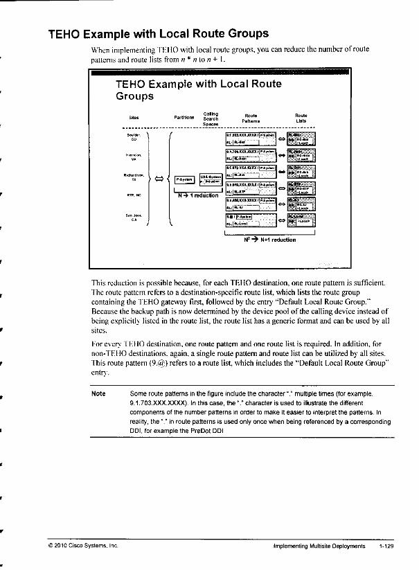
TEHO Example with Local Route GroupsWhen implementing TEHO with local route groups, youcanreduce thenumber ofroutepatterns and route lists from n * n lo n + I.
TEHO Example with Local RouteGroups
Bouklo. '
> <=><
CalingSearch
Spaces
.; «— |IP-4y**m |
IN •* 1 reduction
Route
Patterns
>.i*<a.xxxjatxi{'*i'Hn,
M.7W.XXXJM* *|P«!«-»
t.i.lTs.sxjjaice lln^am
l.tWWXXJDIUt[H|>hn>
B.l*M,x««jaxx ffp
Roule
Lists
M»-..•*><••-•
"WW
***!!*«(. I
N2 -> N+1 reduction
This reduction is possible because, for each TEHO destination, one route pattern is sufficient.The route pattern refers to a destination-specific route list, which lists the route groupcontaining the TEHO gateway first, followed by the entry "Default Local Route Group."Because the backup path is now determined by the device pool of the calling device instead ofbeing explicitly listed in the route list, the route list has a generic format and can be used by allsites.
For every TEHO destination, one route pattern and one route list is required. In addition, fornon-TFHO destinations, again, a single route pattern and route list can be utilized by all sites.This route pattern (9.@) refers to a route list, which includes the "Default Local Route Group"entry.
Note Some route patterns in the figure include the character V multiple times (for example,
9.1.703.XXX.XXXX). In this case, the "." character is used to illustrate the different
components of the number patterns in order to make it easier to interpret the patterns. In
reality, the "." in route patterns is used only once when being referenced by a corresponding
DDI, for example the PreDot DDI.
) 2010 Cisco Systems. Inc. implementing Multisite Deployments 1-129
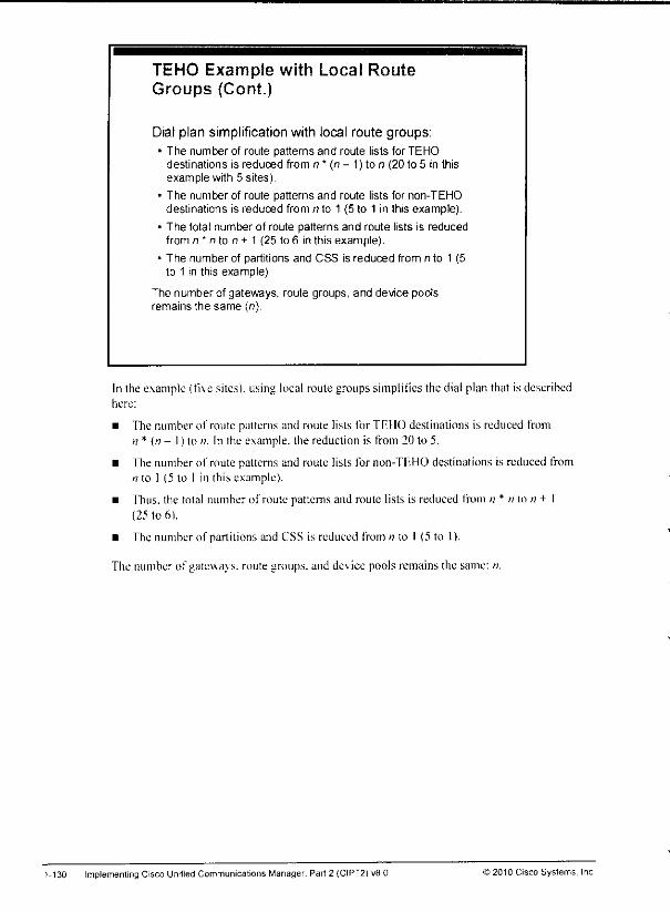
TEHO Example with Local RouteGroups (Cont.)
Dial plan simplification with local route groups:• The number of route patterns and route lists for TEHO
destinations is reduced from n* (n- 1) ton (20to5 in thisexample with 5 sites).
* The number of route patterns and route lists for non-TEHOdestinations is reduced from n to 1 (5 to 1 in ihis example).
* The total number of route patterns and route lists is reducedfrom n " n to n + 1 (25 to 6 in this example).
* The number of partitions and CSS is reduced from n to 1 (5to 1 in this example).
The number of gateways, route groups, and device poolsremains the same (n).
In the example (five sites), using local roule groups simpliiies the dial plan that is describedhere:
• The number of route patterns and route lists for TEHO destinations is reduced fromn * In - 1) to n. In the example, the reduction is from 20 to 5.
• fhe number of route patterns and route lists for non-TEHO destinations is reduced fromn to 1 (5 to 1 in this example).
• Thus, the total number of route patterns and route lists is reduced from n * n to n + 1(25 to 6).
• The number of partitions and CSS is reduced from n to I (5 to 1).
The number of gateways. route groups, and de\ ice pools remains the same: ti.
1-130 Implementing Cisco Unified Communications Manager, Part 2 (CIPT2) v8 0 © 2010 Cisco Systems, Inc
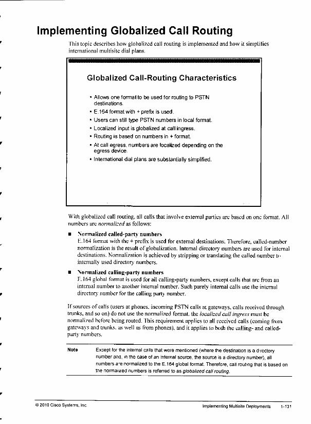
Implementing Globalized Call RoutingThis topic describes how globalized call routing is implemented and how it simplifiesinternational multisite dial plans.
Globalized Call-Routing Characteristics
Allows one format to be used for routing to PSTNdestinations.
E.164 format with + prefix is used.
Users can still type PSTN numbers in local format.
Localized input is globalized at call ingress.
Routing is based on numbers in + format.
At call egress, numbers are localized depending on theegress device.
International dial plans are substantially simplified.
With globalized call routing, all calls that involve extemal parties are based on one format. Allnumbers are normalized as follows:
• Normalized called-party numbersE.164 format with the + prefix is used for external destinations. Therefore, called-numbernormalization is the resultof globalization. Internal directory numbersare used for internaldestinations. Normalization is achievedby strippingor translating the callednumberininternally used directory numbers.
• Normalized calling-party numbersE.164 global format is used for all calling-party numbers, except calls that are from aninternal number to another internal number. Such purely internal calls use the internaldirectory' number for the calling party number.
If sources of calls (users at phones, incoming PSTN calls at gateways, calls received throughtrunks, and so on) do not use the normalized format, the localized call ingress must benormalized before being routed, fhis requirement applies to all received calls(coming fromgateways and trunks, as well as from phones), and it appliesto both the calling-and called-party numbers.
Note
>2010 Cisco Systems, Inc.
Except for the internal calls that were mentioned (where the destination is a directorynumber and, inthe case of an internal source, the source is a directorynumber), allnumbers are normalized to the E.164 global format. Therefore, call routing that is based onthe normalized numbers is referred to as globalizedcall routing.
Implementing Multisite Deployments 1-131

After the call has been routed and path selection (if applicable) has been perfonned. the egressdevice typically must change the nomialized numbers lo the local fonnat. fhis situation isreferred to as localized call egress.
focalized call egress applies to these situations:
• Calling- and called-party numbers for calls that arc routed to gateways and trunks: Ifthe PSTN or the telephony system on the other side of a trunk docs not support globalizedcall routing, the called- and calling-party numbers must be localized from the globalformat. For example, the called-party number +494012345 would have to be changed to011494012345 before the call could be sent out lo the PSTN in (he United States.
• Calling-party numbers for calls that are routed from gateways or trunks to phones:This situation applies lo the phone user who does not want to sec caller IDs in a globalformat. For example, ifa user at a U.S. phone wants to seethe numbers of PSTN callerswho arc in the same area code, that user may want to see each number as a seven-digitnumber and not in the+1 XXXXXXXXXX fonnat.
Localized call egress is not needed for the called-party number of calls that arc routed tophones, because internal directory numbers are the standard (normalized) fonnat for internaldestinations (regardless of the source of the call), fhese numbers might have been dialeddifferenth initialK. however: in that case, this localized call ingress was nomialized before callrouting.
Localized call egress is also not required for the calling-party numberof internal calls (internalto internal)because, again, the standard for the calling-party number of such calls is to useinternal director, numbers.
Globalized call routing simplifies international dial plans because thecorecall-routing decisionis alwaysbased on the same fonnat. regardless of how the numberwas initially dialedandregardless of how the number looks at the egress device.
1-132 Implementing Cisco Unified Communications Manager, Part 2 (CIPT2) vB.O ©2010 Cisco Systems, Inc
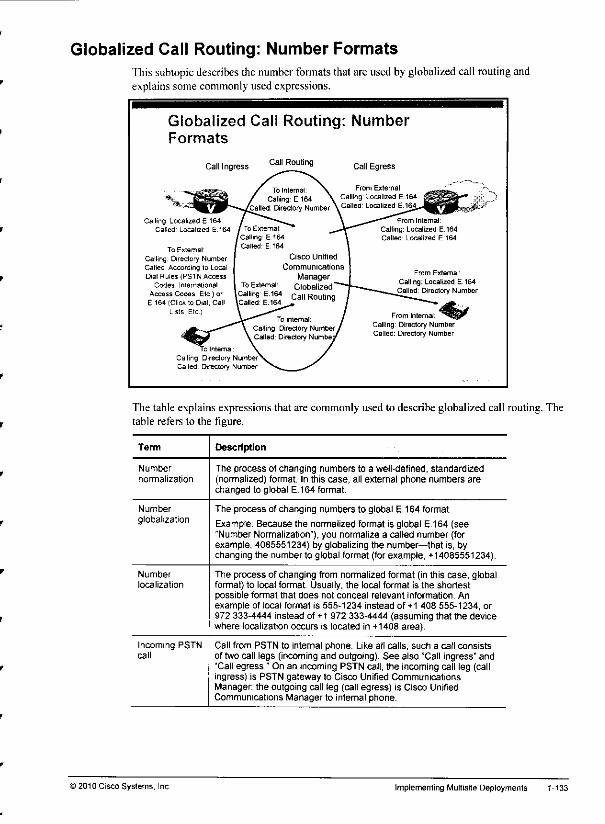
Globalized Call Routing: Number FormatsThis subtopicdescribes the numberformats that are used by globalized call routingandexplains some commonly used expressions.
Globalized Call Routing: NumberFormats
Call Ingress
Calling Localized E 164Called Localized E.164
To External
Calling. Directory NumberCalled According lo LocaDal Rules (PSTN Access
Codes. International
Access Codes, Etc ) orE 164 (Click to Dial, Call
Lists, Etc
To Interna
Calling DirectoryCalled. Directory
Call Routing Call Egress
From Extemal:
Calling: Localized E.164Called: Directory Number
From Internal: ^^SgCalling Directory NumberCalled: Directory Number
The table explains expressions that are commonly used to describe globalized call routing. Thetable refers to the figure.
Term Description
Number
normalization
The process of changing numbers to a well-defined, standardized(normalized) format. In this case, all external phone numbers arechanged to global E.164 format.
Number
globalizationThe process of changing numbers to global E.164 format.
Exampte: Because the normalized format is global E.164 (see"Number Normalization"), you normalize a called number (forexample, 4085551234) by globalizing the number—that is, bychanging the number to global format (for example, +14085551234).
Number
localization
The process of changing from normalized format (in this case, globalformat) to local format. Usually, the local format is the shortestpossible format that does not conceal relevant information. Anexample of local format is 555-1234 instead of +1 408 555-1234, or972 333-4444 instead of +1 972 333-4444 (assuming that the devicewhere localization occurs is located in +1408 area).
Incoming PSTNcall
Call from PSTN to internal phone. Like all calls, such a call consistsof two call legs (incoming and outgoing). See also "Call ingress" and"Call egress." On an incoming PSTN call, the incoming call leg (callingress) is PSTN gateway to Cisco Unified CommunicationsManager; the outgoing call leg (call egress) is Cisco UnifiedCommunications Manager to internal phone.
) 2010 Cisco Systems, Inc Implementing Multisite Deployments 1-133
Term Description
Outgoing PSTNcall
Call from internal phone to PSTN Like all calls, such a call consistsof two call legs (incoming and outgoing). See also "Call ingress" and"Call egress." On an outgoing PSTN call, the incoming call leg (callingress) is internal phone to Cisco Unified Communications Manager;the outgoing call leg (call egress) is Cisco Unified CommunicationsManager to PSTN gateway.
Call ingress Incoming call leg—call received by Cisco Unified CommunicationsManager
Call egress Outgoing call leg—call routed to destination by Cisco UnifiedCommunications Manager.
Localized
E 164 (number)PSTN number in partial (subscriber, national, international) E.164format. See "Number localization."
E.164 (number] PSTN number in complete E.164 format with + prefix.
On the left side of the figure, call ingress is illustrated by two types of call sources:
• External callers: Their calls are received by Cisco Unified Communications Managerthrough a gateway or trunk. In the case of a PSTN gateway, calling- and called-partynumbers are usually provided in localized E.164 format.
• Internal callers: Their calls are received from internal phones, in the case of calls tointernal destinations (for example, phone to phone), calling- and called-party numbers aretypically provided as internal directory numbers. In the case of calls to external destinations(for example, phone to PS'fN). the calling number is the directory number (at call ingresstime) and the called number depends on the local dial rules for PS 1N access. These dialrules can differ significantly for each location.
The center of the figure illustrates the standards that are detlned for normalized call routing. Asmentioned earlier, because most calls use global E.164 format, this type of call routing is alsoreferred to as globalized call routing. Ilere are the defined standards:
• External to internal:
— Calling-party number: h. 164
— Called-party number: directorv' number
• External to external (if applicable):
— Calling-party number: F.164
— Called-party number: E.164
• Internal to internal:
- Calling-party number: directorv number
Called-party number: directory number
• Internal to external:
— Calling-party number: E.I64
— Called-party number: E.164
1-134 ImplementingCisco Unified Communications Manager, Part 2 (CIPT2)v8.0 © 2010 Cisco Systems. Inc

At the right side of the figure, call egress is illustrated by two types of call targets:
• Gateways: When sending calls to the PSTN, localized E.164 format is used for both thecalling- and called-party numbers. The format of these numbers (especially of the called-party number) can significantly differ based on the location of the gateway. For example,the international access code in the United States is 011, and in most European countries, itis 00.
• Phones: When a call from an internal phone is sent to another internal phone, the callshould be received at the phone with both the calling and called number using internaldirectory numbers. Because this format is the same format that is used by globalized callrouting, there is no need for localized call egress in this case. When a call from an externalcaller is sent to an internal phone,most users (especially users in the United States)preferto see the calling number in localized format (for example, national and local calls shouldbe displayedwith 10digits). The called numberis the directorynumberand usuallyis notdisplayed on the phone.
It is evident from the figure that there are several situations where the numbers that areprovided at call ingress do not conform to the normalized format to be usedforcall routing.These situations applyalso to call egress, wherethe normalized format is not alwaysusedwhenthe call is delivered. Therefore, localized call ingresshas to be normalized (that is. globalized)and globalized fonnat has to be localizedat call egress.
)2010 Cisco Systems, Inc. Implementing Multisite Deployments 1-135
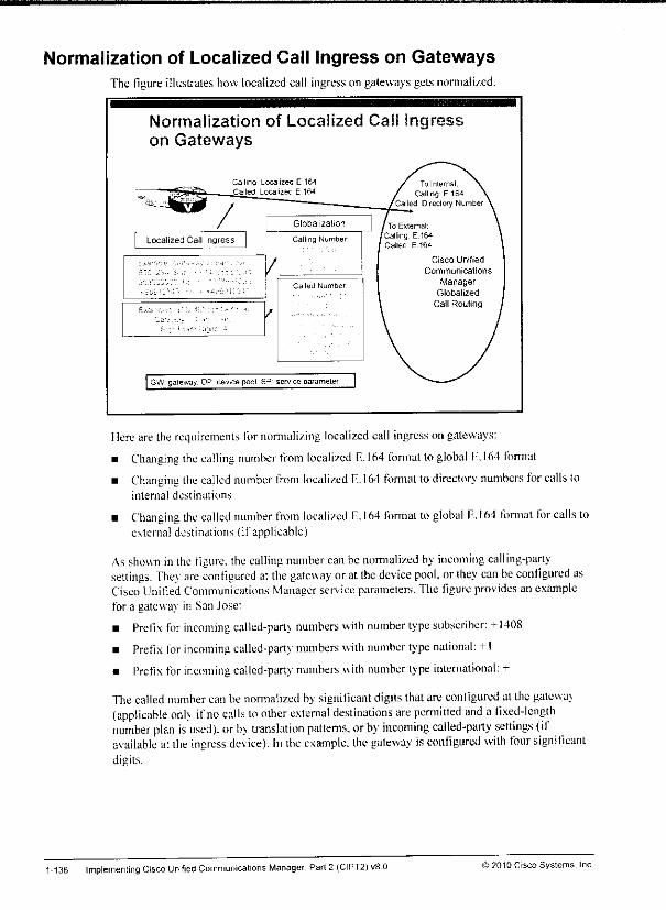
Normalization of Localized Call Ingress on GatewaysThe figure illustrates how localized call ingress ongateways getsnormalized.
Normalization of Localized Call Ingon Gateways
Called Number
GW gateway DP device pool SP service parameter
Cisco Unified
Communicalions
ManagerGlobalized
Call Routing
Ilere are the requirements for normalizing localized call ingresson gateways:
• Changing the calling number from localized E.164 fonnat toglobal E.164 fonnat
• Changing the called number from localized E.164 fonnat todirectory numbers for calls tointernal destinations
• Changing the called number from localized E.164 formal toglobal E.164 fonnat for calls toexternal destinations (if applicable)
Asshovsn in the figure, thecalling number canbe normalized by incoming calling-partysettings. Thev are configured at the gateway oralthe device pool, orthey can be configured asCiscoUnified Communications Manager serviceparameters. The figure provides an examplefor a gateway in San Jose:
• Prefix for incoming called-party numbers with number typesubscriber: +1408
• Prefix for incoming called-party numbers with number type national: +1
• Prefix for incoming called-party numbers with number type international: +
The callednumbercan be normalized bv significant digits that are configured al the gatewav(applicable onlv ifno calls lo other external destinations are permitted and a fixed-lengthnumber plan is used), or bv translation patterns, orby incoming called-party settings (ifavailable at the ingress dev ice). In the example, the gateway is configured with four significantdigits.
1-136 Implementing Cisco Unified Communications Manager, Part2 (CIPT2) vS.O >2010 Cisco Systems, Inc
Normalization of Localized Call Ingress from PhonesThe figure illustrates how localized call ingress on phones gets normalized.
Normalization of Localized Call
from Phones
Ingress
»"\ar-£B= Pt-z.r-es If- Sur- Joss;- ;E*;:e:-a: -rice N^shdk M35k i
-^OoSSEixXX •
YLocalzed Call Ingress
To External.
Calling Directory Number
Caled According iq Local
Dial Rules (PSTN Access
Codes. International Access
Codes. Etc
Globalization
Calling Number torExternal Destinations
External Phone
Number MasK
(Translation Pattern!
Examffi {Phones -n &an Josei9011 '•> DDIPifcQot Prefix \-
91 ::-SjXX{2-9!XXXXXX -' UDIPieOa, Psefis* • \
9[2-9]XX/XXX •> DDI PreD?!.P:e:ix '1W3
Cisco Unified
Communicalions
Managert CJ , GlobalizedToExternal:
Call)ng:E.l64 CallRoutngCalled: E.164
To Internal.
Calling. Directory NumberCalled Directory Nimber
£,<3niple if'hooes ir= HarriDu'c,}C0O'-> DDI Pr~DM Prefi* ->•
DO •-:> DDIPieDoi Prefi* +49
Here are the requirements for normalizing localized call ingress on phones:
• For calls to external destinations: Changing the calling number from an internal director}number to FT 64 fonnat. Changing the called number to K.164format if any other formatwas used (according to local dial rules).
• For calls to internal destinations: No normalization is required.
As shown in the example, you can normalize the calling-party number for calls to externaldestinations by configuring an extemal phone number mask (in E.164 format) at the phone.You can normalize the called-party number by using translation patterns where you would alsoapply the extemal phone number mask to the calling-party number. In the figure, examples forphones that are located in Hamburg, Germany, and SanJose, California, are given.
>2010 Cisco Systems, Inc. Implementing Multisite Deployments 1-137
Localized Call Egress at GatewaysThe figure illustrates how you can implement localized call egress at gateways.
Localized Call Egress at Gateways
Cisco Unified
Communications
ManagerGlobalized
Call Routing
GW gateway. DP device pool
Calling Localized E 164Called. Localized E 164*
Localized Call Egress
Called Number
Called ParlyTransformation CSS
(GW. DP)
Calling NumberCalling Party
Trans form a lion CSS
(GW. OP)
The only requirement is to change the calling and called number from global F.164 format tolocalized F., 164 fonnat.
You can change the format by configuring called- and calling-party transformation patterns,puttingthem into partitions, and assigning the appropriate called-and calling-partytransformation CSS to gateways. You can configure called- and calling-party transformationCSS at the de\ice (gateway or trunk) and al the device pool.
The tables that are presented in this section refer to the example that is provided by the figure.Hie first table shows the configuration ofthe called-party transfoniiation patterns that areapplicable to theSanJosegateway (based on partition andcalled-party transformation CSS).
Transformation Pattern Performed Transformation
\+.! DDI PreDot, Prefix 011
\+.1 XXXXXXXXXX DDI PreDot
\+1408.XXXXXXX DDI PreDot
Note In this example, the San Jose gateway does not use number types. Therefore, 011 has tobe prefixed on international calls, and the 1 of national calls is conserved. Forlocal calls,only the last seven digits are used.
1-138 Implementing Cisco Unified Communications Manager. Part 2 (CIPT2)v8 0 © 2010 Cisco Systems, Inc.
Thenext table shows how youwould configure the called-party transformation patterns thatareapplicable to a gateway in Hamburg, Germany (based on partition and called-partytransformation CSS).
Transformation Pattern Performed Transformation
\+ ! DDI PreDot, number type: international
\+49.1 DDI PreDot, number type: national
\+4940 ! DDI PreDot. number type: subscriber
Note In this example, the Hamburg gateway is using number types instead of international (00) ornational (0) access codes (in contrast to the San Jose gateway, which does not use number
types).
The next table shows how you would configure calling-party transformation patterns that areapplicable to the SanJose gateway (basedon partitionand calling-party transformation CSS).
Transformation Pattern Perfonned Transformation
\+ i DDI PreDot; number type: international
\+1. XXXXXXXXXX DDI PreDot; number type: national
VH408.XXXXXXX DDI PreDot; number type: subscriber
Note In the example, subscriber, national, and international number types are used at the San
Jose gateway for the calling-party number. If no number types were used, due to the fixed-
length numbering plan, the number type could also be determined by its length (seven-digit
numbers when the source of the call is local, 10-digit numbers when the source of the call is
national, or more than 10 digits when the source of the call is international). In reality,
however, countries that use the NANP typically use 10-digit caller IDs for both national and
local callers
Having nonlocal calling-party numbers implies the use of TEHO or PSTN backup over the IP
WAN. This scenario is not permitted in some countries or by some PSTN providers. Some
providers verify that the calling-party number on PSTN calls that they receive matches the
locally configured PSTN number. If a different PSTN number is set for the caller ID, eit.ier
the call is rejected or the calling-party number is removed or replaced by the locally
assigned PSTN number
The final table shows how you would configure calling-party transformation patterns that areapplicable to a gateway in Hamburg, Germany (based on partition and calling-partytransformation CSS).
Transformation Pattern Performed Transformation
\+.! DDI PreDot, number type: international
\+49.l DDI PreDot, number type; national
\+4940.! DDI PreDot, number type: subscriber
©2010 Cisco Systems, Inc. Implementing Multisite Deployments 1-139

Localized Call Egress at Phonesfhe figure illustrates how \ou can implement localized call egress at phones.
Localized Call Egress at Phones
Localzed Call Egress
The only requirement is that you change the calling number from global li. 164 fonnat tolocalized F.164 fonnat.
You can change the fonnat by configuring calling-party transformation patterns, putting theminto partitions, and assigning the appropriate calling-parly transformation CSS to IP phones. Asmentioned earlier in this lesson, you can configure calling-party translomialion CSS at thephone and at the de\ ice pool.
The two tables that are presented in this subtopic arc in reference to the example that isprovided by the figure. The first table shows how you would contigurc the calling-partytransformationpatterns that are applicable to a phone that is located in San Jose (based onpartition and calling-part} transformation CSS).
Transformation Pattern Performed Transformation
VM.XXXXXXXXXX DDI PreDot
VH408XXXXXXX DDI PreDot
Note In this example, international calls are shown in standard normalized format (E 164 format
with + prefix) because there is no W calling-party transformation pattern. National calls are
shown with 10-digit caller IDs, and local calls are shown with 7-digit caller IDs.
1-140 Implementing Cisco Unified Communications Manager, Part 2 (CIPT2)v8 0 © 2010 Cisco Systems, Inc
The next table shows how you would configure the calling-party transformation patterns thatarc applicable to a phonethat is located in Hamburg, Germany (basedon partitionand calling-party transformation CSS).
Transformation Pattern Performed Transformation
\+49 ! DDI PreDot, Prefix 0
\+4940.l DDI PreDot
Note Because there is no \+! calling- party transformation pattern, international calls are
preserved in normalized format (E.164 with + prefix). As opposed to the San Jose example,
phones that are located in Hamburg do prefix the national access code (using 0, which is
equivalent to the long-distance 1 in the NANP). The reason is that, in Germany, variable-
length PSTN numbering plans are used and therefore national and local numbers cannot be
distinguished based on their length (like in the United States, with 7- and 10-digit numbers).
When the national access code 0 is prefixed to numbers that are used by national callers, a
user can identify national calls by their leading 0.
Note When users call back PSTN callers, the globalized number is used for the outgoing call.
Therefore, there is no need to edit the localized number from a call list and add PSTN
access codes and national or international access codes.
)2010 Cisco Systems, Inc. Implementing Multisite Deployments 1-141
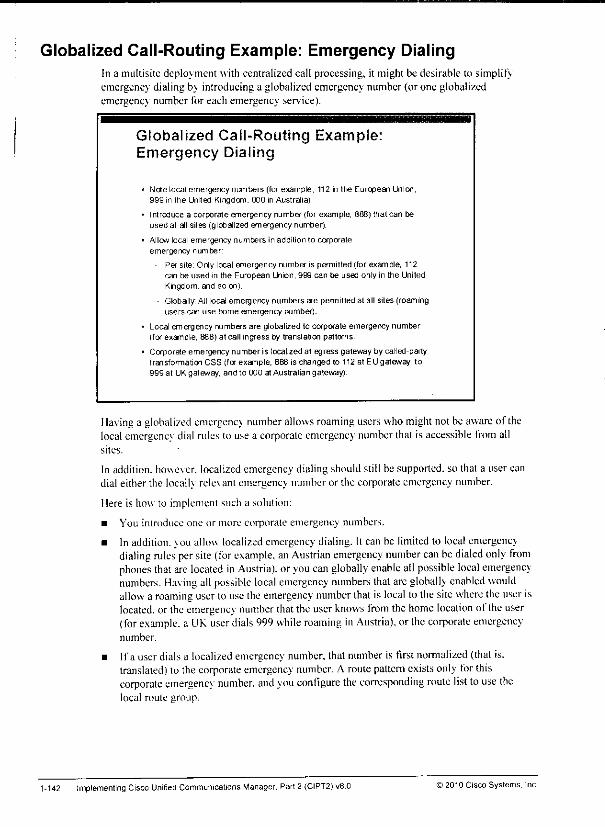
Globalized Call-Routing Example: Emergency DialingIn a multisite deployment with centralized call processing, it might be desirable to simplifyemergency dialing b\ introducing a globalized emergency number (or one globalizedemergency number for each emergency service).
Globalized Call-Routing Example:Emergency Dialing
Note local emergency numbers (for example, 112 in the European Union,999 in the United Kingdom. 000 in Australia).
Introduce a corporate emergency number (for example, 888) that can beused at all sites (globalized emergency number).
Allow local emergency numbers in addition to corporateemergency number:
Per site. Only local emergency number is permitted (for example, 112can be used m the European Union, 999 can be used only in the UnitedKngdom. and soon|.
Globally All local emergency numbers are permitted at all sites (roamingusers can use home emergency number).
Local emergency numbers are globalized to corporate emergency number(for example, 888) at call ingress by translation patterns.
Corporate emergency number is localized at egress gateway by called-partytransformation CSS (for example, 868 is changed to 112 at EU gateway, to999 at UK gateway, and to 000 at Australian gateway].
Having a globalized emergency numberallowsroamingusers whomightnot be awareof thelocal emergencv dial rulesto use a corporate emergency number that is accessible from allsites.
In addition, however, localized emergency dialing should still be supported, so that a user candial eitherthe locally rele\ ant emergency numberor the corporate emergency number.
Here is how to implement such a solution;
• You introduce one or more corporate emergency numbers.
• In addition. \ou allow localized emergency dialing. It can he limited to local emergencydialing rules persite (for example, anAustrian emergency number can be dialed only fromphones that are located inAustria), or you can globally enable all possible local emergencynumbers. Having all possible local emergency numbers thatare globally enabled wouldallow a roaming user touse the emergency number that is local to thesite where theuser islocated, or theemergency number thatthe userknows from the home location of the user(forexample, a UK userdials 999 while roaming in Austria), or thecorporate emergencynumber.
• Ifa userdials a localized emergency number, that numberis firstnormalized (that is.translated) to thecorporate emergency number. A route pattern exists only forthiscorporate emergency number, and you configure the corresponditig route listto use thelocal route group.
1-142 Implementing Cisco Unified Communications Manager, Part 2 (CIPT2) v8.0 © 2010 Cisco Systems, Inc.
• At the gateway that is used to process the call, you localize the corporate emergencynumber (the globalized emergency number) by using called-party number transfonnationsat the gateway. This localization ensures that, regardless ofwhich emergency number wasdialed, the gateway that sends out the emergency call uses the correct number as expectedat this site.
Note In deployments with more complex emergency calls, like in the United States with E911,
such a solution is not applicable because there are other requirements for emergency calls.
In such a scenario, the emergency call is routed via a dedicated appliance (Cisco
Emergency Responder) that is reached via a computer telephony integration (CTI) route
point.
)2010Cisco Systems.Inc. Implementing Multisite Deployments 1-143
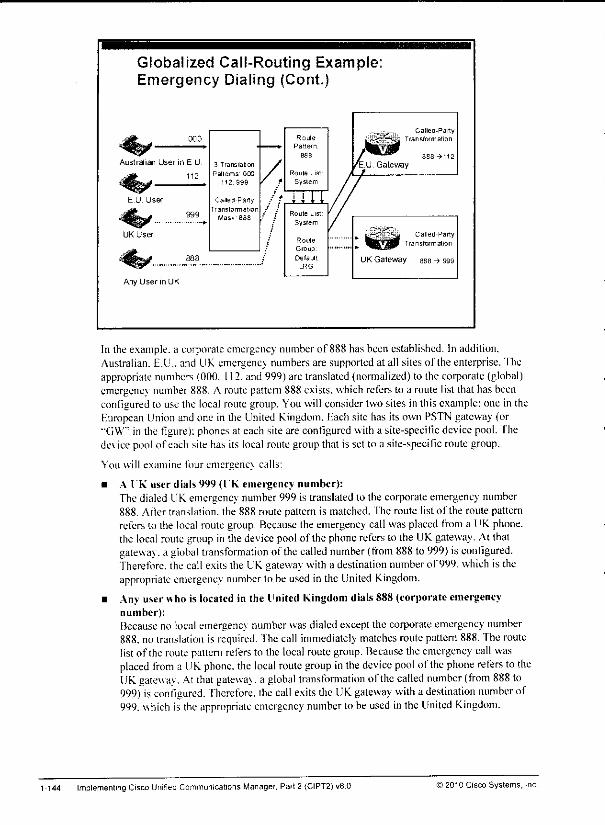
Globalized Call-Routing Example:Emergency Dialing (Cont.)
000
Australian User in E U
112
Any User in UK
3 Translation
Patlems 000
112 999 / f
Cailed-Party / *
Transformation -' :'Mask BBS
Route
Pattern
Route List
Syslem
nnRoute Lisl
Syslem
Roule
Group
Default
LRG
•33
UK Gateway 8B8 ^ 999
Called-PartyTransformation
Called-Party
Transformation
In the example, a corporate emergency number of 888 has been established. In addition.Australian. E.U.. and UK emergene; numbers are supported at all sites oflhe enterprise. Theappropriate numbers (000. 112. and 999) are translated (normalized) to the corporate (global)emergency number 888. A routepattern888 exists,whichrefersto a roule lisl that has beenconfigured to use the local routegroup. Youwill considertwo sites in this example: one in theEuropean Union and one in the United Kingdom. Hach site has its own PSTN gateway (or"GW" in the figure): phonesat each site are configured with a site-specific device pool. Thede\ icepool of each site has its local routegroupthat is set to a site-specilic route group.
You will examine fouremergenc} calls:
• A IK user dials 999 (IK emergency number):Thedialed UKemergency number999 is translated lo the corporate emergency number888. After translation, the 888 route pattern is matched. The route list of the route patternrefers to the local routegroup. Because the emergency call was placed from a UKphone,the local routegroup in the devicepool of the phonerefers to the UKgateway. At thaigateway, a global transformation of the called number (from 888 to999) isconfigured.Therefore, the call exits the UKgateway with a destination numberof 999, which is theappropriate emergency number to be used in the United Kingdom.
• Any user who is located in the United Kingdom dials888(corporate emergencynumber):Because no local emergency numberwasdialedexceptthe corporate emergency number888. no translation is required. Thecall immediately matches routepattern 888. Theroutelistof the route pattern refers to the local route group. Because theemergency call wasplaced from a UK phone, the local route group in the device pool of the phone refers to theUKgate\sa\. Atthat galewa\. a global transformation of the called number (from 888 to999) isconfigured, "fherefore. the call exits the UK gateway with a destination number of999. uhich is the appropriate emergency numberto be used in the United Kingdom.
1-144 ImplementingCisco Unified Communications Manager. Part 2 (CIPT2)v8.0 © 2010 Cisco Systems, Inc
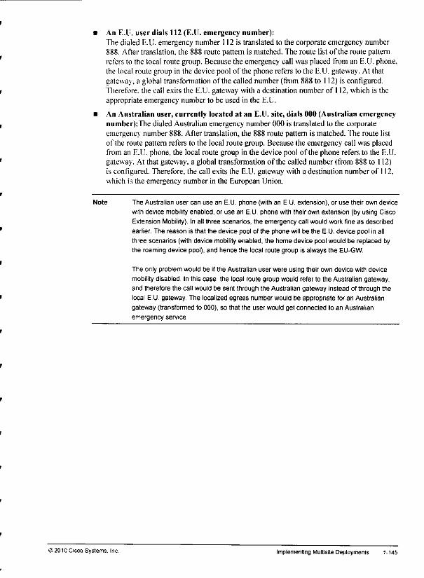
• An E.l. user dials 112 (E.U. emergency number):The dialed E.U. emergency number 112 is translated to the corporate emergency number888. After translation, the 888 route pattern is matched. The route list of the route patternrefers to the local route group. Because the emergency call was placed from an E.U. phone,the local route group in the device pool of the phone refers to the E.U. gateway. At thatgateway, a global transformation of the called number (from 888 to 112) is configured.Therefore, the call exits the E.U. gateway with a destination number of 112, which is theappropriate emergency number to be used in the E.U.
• An Australian user, currently located at an E.U. site, dials 000 (Australian emergencynumber):The dialed Australian emergency number 000 is translated to the corporateemergency number 888. After translation, the 888 route pattern is matched. The route listof the route pattern refers to the local route group. Because the emergency call was placedfrom an E.U. phone, the local route group in the device pool of the phone refers to the E.U.gateway. At that gateway, a global transformation of the called number (from 888 to 112)is configured. Therefore, the call exits the E.U. gateway with a destination number of 112,which is the emergency number in the European Union.
Note The Australian user can use an E.U. phone (with an E.U. extension), or use their own device
with device mobilityenabled, or use an E.U. phone with their own extension (by using Cisco
Extension Mobility). In all three scenarios, the emergency call would work fine as described
earlier. The reason is that the device pool of the phone will be the E.U. device pool in all
three scenarios (with device mobility enabled, the home device pool would be replaced by
the roaming device pool), and hence the local route group is always the EU-GW.
The only problem would be if the Australian user were using their own device with device
mobility disabled. In this case, the local route group would refer to the Australian gateway,and therefore the call would be sent through the Australian gateway instead of through the
local E.U. gateway. The localized egress number would be appropriate for an Australian
gateway (transformed to 000), so that the user would get connected to an Australian
emergency service.
)2010 Cisco Systems. Inc. Implementing Multisite Deployments 1-145
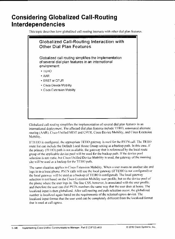
Considering Globalized Call-RoutingInterdependencies
This topic describes how globalized call routing interacts with other dial plan features.
Globalized Call-Routing Interaction with
Other Dial Plan Features
Globalized call routing simplifies the implementationof several dial plan features in an internationalenvironment:
•TEHO
•AAR
• SRST or CFUR
• Cisco Device Mobility
• Cisco Extension Mobility
Globalized call routingsimplifies the implementation of severaldial plan features in aninternational deployment, fhe affected dial planfeatures include TEHO, automated alternaterouting (AAR). Cisco Unified SRST andCEUR. Cisco Device Mobility, andCisco ExtensionMobility.
If TEHO is configured, the appropriate TEHO gateway is used for the PSTN call.The TEHOroute list can include the Default Local Route Groupsettingas a backup path. In this case, ifthe priman. (TEHO) path is nota\ailable.the gateway that is referenced by the local routegroup of the applicable device pool will be used for the backup path. I(The device poolselection is not static, but Cisco Unified Device Mobility is used, the gateway olThe roamingsite will be used as a backup for the TEHO path.
Thesame situation applies lo Cisco Extension Mobility. When a user roams to another siteandlogs in toa local phone. PSTN calls will use the local gateway (ifTEHO isnot configured) orthe local gateway uill be used as a backup (if TEHO is configured). The local gatewayselection is not based on the Cisco Extension Mobility user profile, but on the device pool otthe phone where the user logs in. fhe line CSS. however, isassociated with the user profile,and therefore the user can dial PSTN numbers the same way that the user does at home, fhelocalized input is then globalized. After call routing and path selection occur, the globalizednumber is localized again based ontherequirements of theselected egress device. Thelocalized input fonnat that theuser used can be completely different from the localized formatthat is used at call egress.
1-146 Implementing Cisco Unifed Communications Manager. Part 2 (CIPT2)v8.0 ) 2010 Cisco Systems, Inc.
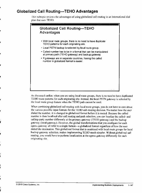
Globalized Call Routing—TEHO Advantagesfhis subtopic reviews the advantages of using globalized call routing in an international dialplan that uses TEHO.
Globalized Cal! Routing—TEHOAdvantages
• With local route groups, there is no need to have duplicateTEHO patterns for each originating site.
• Local PSTN backup is selected by local route group.
• Called number has to be in a format that can be manipulatedat primary path (TEHO gateway) and backup gateway.
• Ifgateways are in separate countries, having the callednumber in globalized format is easier.
As discussed earlier,whenyou are using localroute groups, there is no need to haveduplicatedTEHO routepatternsforeach originating site. Instead, the local PS'fN gateway is selectedbythe local route group feature when the TEHO path cannot be used.
Whencombining globalized call routingwith localroute groups,you do not have to care aboutthe variouspossible input formats for the TEHO call-routing decision. No matterhow the userdialed the number, it is changed to globalized format before it is routed. Because the callednumber is then localized after call routing and path selection, you can localize the called- andcalling-party number differently at the primary gateway (TEHO gateway) andthe backupgateway(localgateway). However, the global transformations that you configure for eachegress gateway all refer to a single format—a globalized format regardless of how the userdialed the destination. This globalized format that is combined with localroute groupsfor localbackup gateway selection, makes implementing TEHO much simpler. Without globalized callrouting, youwould haveto perform localization at theegress gateway differently foreachoriginating site.
)2010Cisco Systems, Inc Implementing Multisite Deployments 1-147
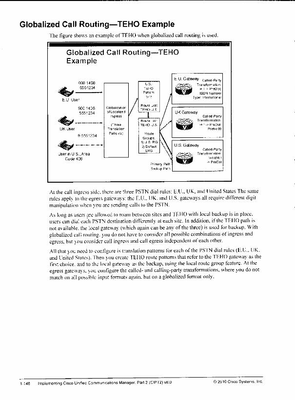
Globalized Call Routing—TEHO ExampleThe figure shows an exampleof TEHOwhenglobalized call routingis used.
Globalized Call Routing—TEHOExample
000 1406-
5551234
E U User
900 1408-
5551234
9 5551234
User n U S .Area
Code 408
Globalization
• (Localized
Ingress
(ThreeTranslalion
Patterns)
US-
TEHO-
Pattem
Roule Ust
TEHO-U S
Roule Ust
TEHO-U S
Route
Groups1)U S RG2) Default
LRG
Primary Path
Backup Path
EU. Gateway Called_Par!
| \* i ->PreDot,ISDN Number
Type1 International
UK GatewayCalled-Party
-j^|&! Transformation
U.S. GatewayCalled-Party
.s3*2T* Transformation
At the call ingress side, thereare three PSTN dial rules: E.U.. UK,and United StatesThe samerules applv to theegress gateways: the E.U.. UK, and U.S. gateways all require dilTerent digitmanipulation when you are sending calls to the PSTN.
Aslong as users areallowed to roam between sites and TEHO with local backup is inplace,users can dial each PSTN destination differently at each site. In addition, if the TEHO path isnotavailable, the local gateway (which again can beanyof the three) is used for backup. Withglobalized call routing, vou do not have toconsider all possible combinations of ingress andegress, butyou consider call ingress and call egress independent of each other.
All that vou needto configure is translation patterns foreach of the PSTN dial rules (E.U.. UK.and United States), "fhenvou create TEI10 route patterns that refer to the TEHO gateway as thefirst choice, and to the local gateway as the backup, using the local route group feature. At theegress gatewavs. vou configure the called- and calling-party transfonnations, where you do notmatch on all possible input formats again, buton a globalized format only.
1-148 Implementing Cisco Unified Communications Manager. Part 2 (CIPT2) v8.0 © 2010 Cisco Systems, Inc
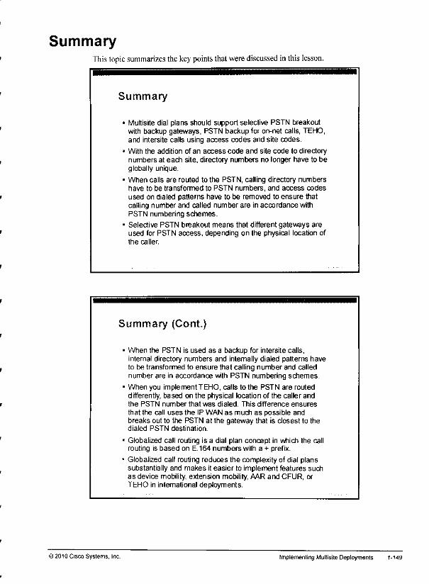
Summaryfhis topic summarizes the keypoints thatwerediscussed in this lesson.
Summary
• Multisite dial plans should support selective PSTN breakoutwith backup gateways, PSTN backup for on-net calls, TEHO,and intersite calls using access codes and site codes.
* With the addition of an access code and site code to directorynumbers at each site, directory numbers no longer have to beglobally unique.
• When calls are routed to the PSTN, calling directory numbershave to be transformed to PSTN numbers, and access codesused on dialed patterns have to be removed to ensure thatcalling number and called number are in accordance withPSTN numbering schemes.
• Selective PSTN breakout means that different gateways areused for PSTN access, depending on the physical location ofthe caller.
Summary (Cont.)
12010 Cisco Systems, Inc.
When the PSTN is used as a backup for intersite calls,internal directory numbers and internally dialed patterns haveto be transformed to ensure that calling number and callednumber are in accordance with PSTN numbering schemes.
When you implement TEHO, calls to the PSTN are routeddifferently, based on the physical location of the caller andthe PSTN number that was dialed. This difference ensures
that the call uses the IP WAN as much as possible andbreaks out to the PSTN at the gateway that is closest to thedialed PSTN destination.
Globalized call routing is a dial plan concept in which the callrouting is based on E. 164 numbers with a + prefix.
Globalized call routing reduces the complexity of dial planssubstantially and makes it easier to implement features suchas device mobility, extension mobility, AAR and CFUR, orTEHO in international deployments.
Implementing Multisite Deployments 1-149
References
For additional information, refer to these resources:
• Cisco Svstems. Inc. Cisco UnifiedCommunications System 8.x SRND,April 2010.http:/.•''www.cisco.coni'en'US'VJoes'voice ip comm/cuem/srnd/Xx.'uc8x.html
• Cisco Systems, Inc. Cisco Unified ( ommunications Manager Administration GuideRelease'8.0(1/. Eebruary 2010.http:"'www cisco.com.civI'S'docs'voice ip comm/cuem/admin/8 0 |/ccmdg/hccin-80l-cm.htinl
• Cisco Svstems. Inc. Cisco IOS Voice Configuration Library (with Cisco IOS Release 15.0updates). July 2007.http:;\\v\vv.cisco.coni'cnT'S'doc.s/ios'!2 .Vvvf c'cisco ios voice configuration librarv £lossarv/vcl.htm
1-150 Implementing Cisco Unified Communications Manager, Part 2 (CIPT2) vS.O ©2010 Cisco Systems. Inc

Module Summarylliis topic summarizes the key points that were discussed in this module.
Module Summary
Specific issues apply to Cisco Unified CommunicationsManager multisite deployments. These issues includebandwidth consumption in the IP WAN, IP WAN reliance,suboptimal call routing, and NAT or security issues.
Special solutions can solve issues that apply to multisitedeployments. These solutions include the use of variouscodecs, SRST and MGCP fallback, selective PSTN breakout,and the use of Cisco Unified Border Element.
Connection options for multisitedeployments include varioustypes of trunks and gateways.
A multisite dial plan should support site-code dialing, PSTNbackup, and TEHO. Globalized call routing simplifiesinternational multisite dial plans.
This module discussed the issues thatapply to Cisco Unified Communications Managermultisite deployments and their possible solutions. Itdescribed thevarious connection optionsfor muitisite deployments and how they are implemented. It then described how to implement amultisite dial planthatcovers site-code dialing, public switched telephone network (PSTN)backup, and tail-end hop-off (TEHO).
References
For additional information, refer to these resources:
• Cisco Systems. Inc. Cisco Unified Communications System 8.xSRND, April 2010.http:.'7'vvvvw.cisco.com/en/US/docs/voice_ip_c()mm/cucm/snid/8x/uc8x.htnil
• CiscoSystems, Inc. Cisco Unified Communications Manager Administration GuideRelease 8.0(1). February 2010.
hitp:/.'vv-w-w.cisco.com/cn/US/docs/voice_ip_comm/cucm/adinin/8 0_l/ccmcfg/bccm-80l-cm.html
• Cisco Systems. Inc. Cisco IOS Voice Configuration Library (with Cisco IOS Release 15.0updates). July 2007.
hup; 7ww w.cisco.com/'en/US/does/ios/l2..3/vvf_c/cisco. ios_voice...configuration librarv_glossaryvcl.htm
>2010Cisco Systems, inc. Multisite Deployment Implementation 1-151

1-152 Implementing Cisco Unified Communications Manager, Part 2(CIPT2) v8 0 ©2010 Cisco Systems, Inc
tmm
Module Self-CheckUse the questions here to reviewwhatyou learnedin this module. The correctanswersandsolutions are found in the Module Self-Check Answer Key.
01) Which of the following is not an issue in Cisco Unified Communications Managermultisite deployments? (Source: Identifying Issues in a Multisite Deployment)
A) availabilityD) qualityC) bandwidthD) securityE) Call Admission Control
Q2) Which of these statements does not apply to IP networks? (Source: Identifying Issues
in a Multisite Deployment)
A) IP packets can be delivered in incorrect order.B) Buffering results in variable delays.C) Tail drops result in constant delays.D) Bandwidth is shared by multiple streams.
Q3) Which statement most accurately describes overhead for packetized voice? (Source:
Identifying Issues in a Multisite Deployment)
A) VoIP packets are large and sent at a high rate.B) The Layer 3 overhead of a voice packet is not significant.C) Voice packets have small payload size and are sent at high packet rates.D) Packetized voice has the same overhead as circuit-based voice.
Q4) In a multisite deployment, IP phone and packets are affected by WANfailures. (Source: Identifying Issues in a Multisite Deployment)
A) data, videoB) signaling, dataC) data, mediaD) signaling, media
Q5) Which two of the following are dial plan issues in multisite deployments? (Choose
two.) (Source: Identifying Issues in a Multisite Deployment)
A) overlapping directory numbersB) overlapping E.164 numbersC) variable-length addressingD) centralized call processingF) centralized phone configuration
Q6) Which of these is a requirement for performing address translation for Cisco IPphones? (Source: Identifying Issues in a Multisite Deployment)
A) use DHCP instead of fixed IP addresses
B) exchange media streams with the outside worldC) use DNSinsteadof hostnames in Cisco UnifiedCommunications ManagerD) exchange signaling information with the outside world
>2010CiscoSystems.Inc. Multisite Deployment Implementation 1-153
Q7) Which of the following is not a solution for multisite environments? (Source:
Identifying Multisite Deployment Solutions)
A) QoS
B) site codesC) SRSTD) MGCP
Q8) When implementing QoS. how is the quality of voice streams provided? (Source:
Identifying Multisite Deployment Solutions)
Q9) Which two statements are tme about bandwidth solutions in a multisite deployment?
(Choose two.) (Source: Identifying Multisite Deployment Solutions)
A) RTP-header compression compresses the RTP header to 2 bytes.B) WAN bandwidth can be conserved by using low-bandwidth codecs within a
remote site.
C) WAN bandwidth can be conserved by deploying local media resources.D) Voice compression is part of RTP-header compression.E) Multicast MOH from branch router flash totally eliminates the need to send
MOH over the WAN.
QIO) Which tuo statements are tme about availability? (Choose two.) (Source: Identifying
Multisite Deployment Solutions)
A) CFNB is required to enable main-site phones to call remote-site phones duringSRST fallback.
B) SRS'f provides a fallback for Cisco IP phones.C) MGCP fallback allows the gateway to use local dial peers when the call agent
is not reachable.
D) AAR is required to enable phones to reroute calls over the PS'fN when the IPWAN is down.
F) MGCP fallback and SRS'f cannot be implemented at the same device.
Ql 1) Whichof the following are notdial-plan solutions formultisite Cisco UniliedCommunications Managerdeployments? (Choose two.) (Source: Identifying MultisiteDeplovment Solutions)
A) access and site codesB) TEHOC) globalized call routingD) shared lines
E) overlap signaling
QI2) Which Cisco IOS feature provides signalingand mediaproxy functionality in order toeliminate the need for NAT? (Source: Identifying Mullisite DeploymentSolutions)
A) Cisco Unilied Border Element in flow-through modeB) Cisco PIX FirewallC) Cisco Unitied IP-to-Proxy GatewayD) Cisco Unilied BorderElement in flow-around mode
1-154 implementing Cisco Unified Communications Manager. Pari 2 (CIPT2) v8.0 ©2010 Cisco Systems, Inc.
Q13) Whichofthe following is nota connection option for a multisiteCisco UnifiedCommunications Managerdeployment? (Source: Implementing Multisite Connections)
A) SIP trunk
B) SIP gatewayC) H.323 gatewayD) H.225 trunk
Q14) Which two commands are required to enable MGCP at a gateway when using the
configuration server feature? (Choose two.) (Source: Implementing MultisiteConnections)
A) mgcpB) seepC) ccm-manager config server ip-addressD) ccm-manager configE) ccm-manager seep
Q15) Which parameter is set in the H.323 gateway configuration window in order to strip thecalled party number to a certain number of digits? (Source: Implementing Multisite
Connections)
A) Called Party Digits MaskB) Significant DigitsC) Calling Party Transformation MaskD) Number-LengthF) Discard Digit Instruction
QI6) Which two tmnks are not configured with the IP address ofthe next signaling device inthe path? (Choose two.) (Source: Implementing Multisite Connections)
A) H.225 trunk
B) nongatekeeper-controlled intercluster trunkC) SIP trunk
D) gatekeeper-controlled intercluster tmnkE) MGCP trunk
Q17) Where do you configure SIP timers and features for an SIP trunk? (Source:Implementing Multisite Connections)
A) SIP profileB) SIP security profileC) SIP tmnk security profileD) common trunk profile
Q18) Which ofthe following needs to be specified in the gatekeeper configuration windowwhen adding a gatekeeper to Cisco Unified Communications Manager? (Source:Implementing Multisite Connections)
A) H.323 ID of the gatekeeperB) IP address ofthe gatekeeperC) zone name
D) technology prefix
>2010 CiscoSystems, Inc Multisite Deployment Implementation 1-155
QI9) Which statement about implementing PSTN backup for the IP WAN is true? (Source:
Implementing a Dial Plan for International Multisite Deployments)
A) In distributed deployments. PSTN backup for intersite calls requires CFUR.B) PSTN backup requires a signaling proxy at each site.C) The on- and oft-net paths are required in route groups for PSTN backup in a
centralized deplovment.D) CFUR allows remote-site phones to use the PSTN for calls to the main site.
Q20) What is required for implementing access and site codes in a centralized deployment?
(Source: Implementing a Dial Plan for International Mullisite Deployments)
A) a separate translation pattern per destination site, which is configured with aCSS that prov ides access to the destination site
B) a separate translation pattern per source site, which is configured with a CSSthat provides access to the source site
C) a separate translation pattern per source site, which is configured with thepartition ofthe destination site
D) a separate translation pattern per destination site, which is configured wfth thepartition ofthe destination site
Q2I) Which ofthe following is not a valid type of number code for incoming ISDN PSTN
calls? (Source: Implementing a Dial Plan for International Multisite Deployments)
A) internationalB) national
C) subscriberD) directorv- number
Q22) fhe PSTN egress gateway can be selected in which two of these ways? (Choose two.)(Source: Implementing a Dial Plan for International Multisite Deployments)
A) by the partition ofthe calling deviceB) based on the CSS ofthe gatewayC) bv the local route group featureD) based on the matched roule pattern when route patterns exist once per siteF) by the standard local routegroupthat is configured at the gateway devicepool
Q23) Where can digit manipulation be performed when digit manipulation requirements varyfor the on- and off-net paths? (Source: Implemenlinga Dial Plan for InternationalMultisite Deployments)
A) per route group ofthe route listB) route patternC) directorv numberD) translation pattern
Q24) When implementingTEHO for national calls and using the local PSTN gateway as abackup, how many route patterns arerequired fora cluster with three siteslocated indifferent area codes?(Source: Implementing a Dial Plan for International MultisiteDeplov ments)
A) 3. when not using the local route group featureB) 6. when using the local route group featureC) 9. when not using the local route group featureD) 4. when using the local route group feature
1-156 Implementing Cisco Unitied Communications Manager. Part2 (CIPT2) v8 0 ©2010 Cisco Systems, Inc.
Q25) Which of these is used to globalize the callingparty number of inbound PSTN calls?(Source: Implementing a Dial Plan for International Multisite Deployments)
A) globalization typeB) called number
C) inbound gateway identifierD) number type
Q26) The implementation of globalized call routing does not simplify the deployment of
which two of these features? (Choose two.) {Source: Implementing a Dial Plan for
International Multisite Deployments)
A) TEHO
B) Device MobilityC) AAR
D) MOH
E) Cisco Extension MobilityF) SRST
G) local conference bridges
©2010 Cisco Systems. Inc. Multisite Deployment Implementation 1-157

Module Self-Check Answer Keyon E
02) C
Q3i C
O-ti D
05) A.C
061 B
Q7) D
OS) Voice packets are given absolute pnority over other traffic
Q9) C. V:
QIO) B.C
qui I).)-.
012) A
013) B
014) C. D
Q15> B
016) A. D
017) A
Q18) B
019) C
Q20) A
0^1) D
022) c. n
02?) A
024) D
025) D
Q26) D.G
1-158 Implementing Cisco Unified Communications Manager. Part 2 (CIPT2) v8 0 ©2010 Cisco Systems, Inc

Module 2
Centralized Call-ProcessingRedundancy Implementation
OverviewThe capability to use centralized call-processing devices that are located at remote sitesdepends on the availability of Cisco Unified Communications Manager at the main site. Toprovide these devices with a backup, you can use Media Gateway Control Protocol (MGCP)fallback and Cisco Unified Survivable Remote Site Telephony (SRST).
This module describes the mechanisms for providing call survivability and device failover inremote sites. It describes how to configure Cisco IOS routers as Cisco Unified SRST gatewaysand how to use Cisco Unified Communications Manager Express in Cisco Unified SRST mode.
Module ObjectivesUpon completing this module, you will be able to implement call-processing resiliency inremote sites by using Cisco Unified SRST, MGCP fallback, and Cisco UnifiedCommunications Manager Express in Cisco Unified SRST mode. This ability includes beingable to meet these objectives:
• Describe the mechanisms for providing call survivability and device failover in remotesites, including the functions, operation, and limitations of each mechanism
• Configure Cisco Unified SRST to provide call survivability for IP phones, and MGCPfallback for gateway survivability
• Configure Cisco Unified Communications Manager Express to provide telephony servicesto IP phones if the connection to the centralized call agent is lost

2-2 Implementing Cisco Unified Communications Manager, Part 2 (CIPT2) v80 ©2010Cisco Systems, Inc.
Lesson 1
Examining Remote SiteRedundancy Options
Overview"fhis lesson provides an overview ofthevarieties ofremote site redundancy inCisco UnifiedCommunications Manager multisite installations, 'fhese various mechanisms areillustrated togive you an understanding ofhow the technologies interact todeliver reliable communicationsen.ices. Theremote siteredundancy mechanisms include the Media Gateway Control Protocol(MGCP)and Cisco Unilied Survivable Remote Site Telephony (SRST).
ObjectivesUpon completing this lesson, youwillbeable to describe the mechanisms forproviding callsurvivability and device failover inremote sites, including thefunctions, operation, andlimitations of each mechanism. This ability includes being able to meet these objectives:
• Describe remotesite redundancy optionsand comparetheir characteristics
• Describe how Cisco Unified SRST works
• Describe how MGCP fallback works
• Describe Cisco Unified SRST versions, their protocol support, their features, and therequired Cisco IOS Software releases
• Describe dial plan requirements for MGCPfallback and Cisco UnifiedSRST
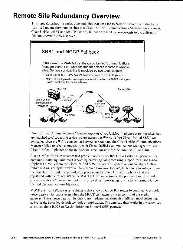
Remote Site Redundancy OverviewThis topic describes the various technologies that are used toprovide remote site redundancyfor small and medium remote sites ina Cisco Unified Communications Manager environment.Cisco Unified SRS'f and MGCP gatewav fallback are the key components to the delivery offail-safe communication services.
SRST and MGCP Fallback
In the case of a WAN failure, the Cisco Unified CommunicationsManager servers are unreachable for devices located in remotesites. Service survivability is provided by two technologies:
* Cisco Unified SRST provides call control services to remote IP phones.
• MGCP fallback provides voice gateway functions when the MGCP call agentis not in control of the media gateway
Cisco Unifed
Communications
Manager
Main Site Remote Site
RSIN
Cisco Unified Communications Manager supports Cisco Unitied IP phones at remote sites thatare attached to Cisco multiservice routers across the WAN. Before Cisco Unified SRST was
available, when the WAN connection between a router and the Cisco Unified Communications
Manager failed or when connectivity with Cisco Unified Communications Manager was lost.Cisco Unified IP phones on the network became unusable for the duration ofthe failure.
Cisco Unified SRST overcomes this problem and ensures that Cisco Unified IP phones offercontinuous (although minimal) service by providing call-processing support for Cisco UnifiedIP phones directly from the Cisco Unified SRS'f router. The system automatically detects afailure and uses Simple Network-Enabled Auto Provision (SNAP) technology to autoconfigurethe branch office router to provide call processing for Cisco Unified IP phones that areregistered with the router. When the WAN link or connection to the primary Cisco UnitiedCommunications Manager subscriber is restored, call processing reverts lo the primary CiscoUnified Communications Manager.
MGCP gatewav fallback is a mechanism that allows a Cisco IOS router to continue to providevoice gateway functions even when the MGCP call agent is not in control ofthe mediagateway, fhese voice gatewav functions are implemented through a fallback mechanism thatactivates the so-called default technology application. The gateway then works in the same wayas a standalone H.323 or Session Initiation Protocol (SIP) gateway.
Implementing Cisco Unified Communications Manager, Part 2 (CIPT2) v8.0 ©2010 Cisco Systems. Inc
Remote Site Redundancy Technologies'fhe table lists the capabilities ofdifferent remote site redundancy technologies.
Remote Site Redundancy Technologies
Cisco Umfied SRST
Cisco UnifiedMGCP Cisco Communications
Fallback Unified Unified ManagerSRST SIP SRST Express in
Provides
SRST Mode
dGCP-eontrolled SCCP SIP SCCP
redundancy for gateways phones phones phones
Faitoack toBasic
telephonyservice
BasicSIP proxy
service
Cisco UnifiedDeivered
service
Cisco IOS
defauttechnology
CommunicationsManagerExpress
ISDN cal Yes Yes Yes
preservation (no MGCP) (no MGCP) (no MGCP)
Analog/CAS Yes Yescall preservation
Maximum
number of (NA) 1500 450
phones
To use Cisco UnifiedSRSTas your fallback modeon an MGCP gateway, you must configureCisco Unified SRST and MGCP fallback on the same gateway. MGCP and Cisco UnifiedSRSThave had the capability to be configured on the samegateway since Cisco IOS SoftwareRelease 12.2(11)T.
Cisco Unified SRSTalso provides a basic set of featuresto SIP-based IP phones. This set ofCisco Unified SRST basic features is also known as Cisco Unified SIP SRST. Cisco UnifiedSIP SRSThas to be enabledand configured separately on Cisco IOSrouters. Cisco UnifiedSRST versions 3.3 and earlier provide a SIP Redirect Server function; in subsequent versions,this function acts as a back-to-back user agent (B2BUA).
Cisco Unilied Communications Manager Express in Cisco Unified SRST mode provides morefeatures to a smaller maximum number of IP phones by falling back to Cisco UnifiedCommunications Manager Express mode. The main feature enhancements include presence,Cisco Extension Mobility, and support of local voice-mail integrations.
VoIP call preservation sustains connectivity for topologies in which signaling is managed by anentity (such as Cisco Unified Communications Manager) that is different from the otherendpoint and that brokers signaling between the two connected parties.
Call preservation is useful when a gateway and the other endpoint (typically a Cisco Unifi ;d IPphone) are eolocated at the same site and the call agent is remote. In such a scenario, the callagent, the gateway with the remote endpoint, will more likely experience connectivity failures.
Cisco Unified Communications Manager Express version 8.0 supports a maximum of 450 IPphones (Cisco IOS 3945E router) while Cisco Unified SRST version 8.0 supports up to 1500 IPphones on the same platform. Refer to "Cisco Unified Communications Manager Express 8.0"(http://v\^^v.eisco.coni/en.TJS/prod/collatcral/voiccsvv/ps6788/vcallcon/ps4625/data_shcct_c78-567246.html) for more details about the supported number of phones.
i 2010 Cisco Systems. Inc. Centralized Call-Processing Redundancy Implementation 2-5
When to Use MGCP Fallback
MGCP gateway fallback that is configured as an individual feature canbe used by a publicswitched telephone network (PSTN) gateway if H.323 (orsome other voice application Iisconfigured as a backup service. Cisco Unified SRST and MGCP fallback must be configuredon the samegateway if this singlegateway shouldprovide Cisco Unified SRSI' fallback serviceto phones and MGCP gateway fallback.
When to Use MGCP Fallback
MGCP fallback allows MGCP-controlled gateways tofall back to a default telephony application like H.323orSIP:
• Might be used as a standalone feature to provide analogphones locally attached to a Cisco IOS router withsurvivability
• Is most often used together with Cisco Unified SRST, whichhas been supported on the same Cisco IOS router sinceCisco IOS Software Release 12.2(11)T
• Provides gateway functionality to Cisco Unified IP phonesin SRST mode
• No call preservation for ISDN PRI or BRl interfaces
Although MGCP gatewav fallback is most often used together with Cisco Unified SRST toprovide gateway functions to IP phones in Cisco Unified SRS'f mode, it can also be used as astandalone feature. One example is that for a fax application server that uses a PRI ISDNinterface that is controlled by MGCP, connectivity to the PSTN can be preserved by MGCPgateway fallback. Another example of an MGCP-fallback standalone configuration is amechanism that allows analog interfaces that arc controlled by Skinny Client Control Protocol(SCCP) to stay in service even when the WAN connection to the Cisco linifiedCommunications Manager is down.
MGCP gatewav fallback preserves active calls from remote site IP phones lo the PSTN whenanalog or channel associated signaling (CAS) protocols are used, for ISDN protocols, callpreservation is impossible, because Layer 3 ofthe ISDN stack is disconnected from the MGCPcall agent and is restarted on the local Cisco IOS gateway. Consequently, for active ISDN calls,all call-state infonnation is lost in cases of switchover to fallback operation.
Implementing Cisco Unified Communications Manager, Part 2 (CIPT2) v8.0 ©2010 Cisco Systems. Inc
When to Use Cisco Unified SRSTCisco Unified SRST provides Cisco Unified Communicalions Manager with fallback supportfor Cisco Unified IP phones that are attached toa Cisco router ona local network.
When to Use Cisco Unified SRST
Cisco Unified SRST provides limited call controlservice to SCCP and SIP phones in remote sitesduring WAN outage:» Supports up to 1500 IP phones during fallback service
• Supports secure voice fallback (ifsecurity is enabled)
• Allows simple, one-time configuration for SRST fallbackservice
• Only basic telephony feature support
- No message-waiting indication
- No advanced features such as Cisco Extension Mobility orpresence
Cisco Unified SRST enables routers to provide basic call-processing support for Cisco UnifiedIP phones when they loseconnection to remote primary, secondary, andtertiary Cisco UnifiedCommunications Manager installations or when the WAN connection is down.
Cisco UnifiedSRSf also supportssecurity features. If IP phonesare configured with securitymode authenticated or encrypted in Cisco Unified Communications Manager and secure CiscoUnified SRSTis deployed, securityfeatures of Cisco IP phonesare preservedduring fallback.
Cisco Unified SRSTcan supportSIP phoneswith the standardRFC3261 feature locallyandacross SIP WAN networks. With Cisco Unified SIP SRST, SIP phones can place calls acrossSIP networks in the same way that SCCP phones do.
Cisco Unified SIP SRST supports the following call combinations: SIP phone to SIP phone,SIP phone to PSTN or router voice port, SIP phone to SCCP phone, and SIP phone to WANVoIP using SIP.
SIP proxy, registrar, and B2BUA servers are key components of a SIP VoIP network. Theseservers are usually located in the core of a VoIP network. If SIP phones that are located atremote sites at the edge ofthe VoIP network lose connectivity to the network core (because of aWAN outage), they may be unable lo make or receive calls. Cisco Unified SIP SRSTfunctionality on a SIP PSTN gateway provides service reliability for SIP-based IP phones in theevent of a WAN outage. Cisco Unified SIP SRST enables the SIP IP phones to continue tomake and receive calls to and from the PSTN and also to make and receive calls to and from
other SIP IP phones.
When the IP WAN is up. the SIP phone registers with the SIP proxy server and establishes aconnection to the B2BUA SIP registrar (B2BUA router). But any calls from the SIP phone goto the SIP proxy server through the WAN and out to the PSTN.
) 2010 Cisco Systems. Inc. Centralized Call-Processing Redundancy Implementation 2-7
When the IP WAN has failed or the SIPproxy server hasgonedown, the call from the SIPphone cannot getto the SIP proxy server. The SIP phone instead goes through the B2BUArouter and out to the PS'fN.
Note The B2BUA acts as a user agent to both ends ofa SIP call. The B2BUA is responsible formanaging all SIP signaling between both ends of the call, from call establishment to
termination Each call is tracked from beginning to end, allowing the operators of the B2BUAto offervalue-added features to the call. To SIP clients, the B2BUA acts as a user agentserver on one side and as a user agent client on the other (back-to-back) side. The basteimplementation of a B2BUA is defined in RFC 3261.
Cisco Unified SRSTdoes not supportenhanced features such as presence or Cisco ExtensionMobility. Message Waiting Indicator (MWI) is also not supported in fallbackmode.
2-8 Implementing Cisco Unified Communications Manager, Part 2 (CIPT2) v8.0 © 2010 Cisco Systems, Inc
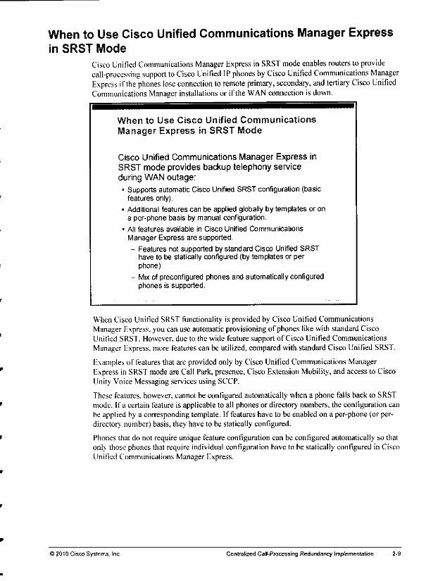
When to Use Cisco Unified Communications Manager Expressin SRST Mode
Cisco Unified Communications Manager Express in SRST mode enables routers to providecall-processing support toCisco Unified IP phones byCisco Unified Communications ManagerExpress if the phones lose connection toremote primary, secondary, and tertiary Cisco UnifiedCommunications Manager installations or if the WAN connection is down.
When to Use Cisco Unified Communications
Manager Express in SRST Mode
Cisco Unified Communications Manager Express inSRST mode provides backup telephony serviceduring WAN outage:- Supports automatic Cisco Unified SRST configuration (basic
features only).
• Additional features can be applied globally by templates or ona per-phone basis by manual configuration.
• All features available in Cisco Unified CommunicationsManager Express are supported.
- Features not supported by standard Cisco Unified SRSThave to be statically configured (by templates or perphone).
- Mix of preconfigured phones and automatically configuredphones is supported.
When Cisco Unified SRST functionality is provided by Cisco Unified CommunicationsManager Express, you can use automatic provisioning of phones like with standard CiscoUnified SRST. However, due to the wide feature support of Cisco Unified CommunicationsManager Express, more features can be utilized, compared with standard Cisco Unified SRS'f.
Examples of features that are provided only by Cisco Unified Communications ManagerExpress in SRSTmodeare Call Park,presence,Cisco Extension Mobility, and accessto CiscoUnity Voice Messaging services using SCCP.
These features, however, cannot be configured automatically when a phone falls back to SRSTmode. If a certain feature is applicable to all phones or directory numbers, the configuration canbe applied by a corresponding template. If features have to be enabled on a per-phone (or per-directory number) basis, they have to be statically configured.
Phones that do not require unique feature coniiguration can be configured automatically so thatonly those phones that require individual configuration have to be statically configured in CiscoUnified Communications Manager Express.
>2010 Cisco Systems, Inc. Centralized Call-Processing Redundancy Implementation
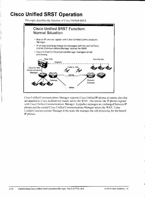
Cisco Unified SRST OperationThis topic describes die function of Cisco Unified SRST.
Cisco Unified SRST Function;Normal Situation
• Branch IP phones register with Cisco Unified CommunicationsManager
• IP phones exchange keepalive messages with the central CiscoUnified Communications Manager across the WAN.
• Cisco Unified Communications Manager manages all callprocessing
Cisco Unified
Communications
Manager
Main Site
-W.N
Cisco Unified Communications Manager supports Cisco Unified IP phones al remote sites thatare attached to Cisco multiserv ice routers across the WAN. fhe remote site IP phones registerwith Cisco Unitied Communications Manager. Keepalive messages are exchanged between IPphones and the central Cisco Unified Communications Manager across the WAN. CiscoUnified Communications Manager at the main site manages the call processing for the branchIP phones.
2-10 Implementing Cisco Unified Communications Manager, Part 2 (C1PT2) v8.0 ©2010 Cisco Systems, Inc
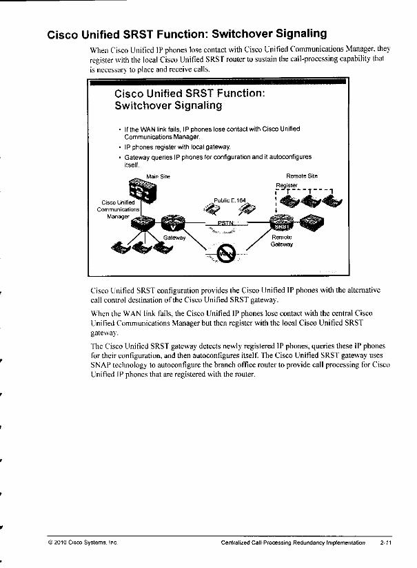
Cisco Unified SRST Function: Switchover SignalingWhen Cisco Unified IP phones lose contact with Cisco Unified Communications Manager, theyregister with the local Cisco Unified SRST router tosustain the call-processing capability thatis necessary to place and receive calls.
Cisco Unified SRST Function:Switchover Signaling
• Ifthe WAN linkfails, IP phones lose contact with Cisco UnifiedCommunications Manager
• IP phones register with local gateway.
• Gateway queries IP phones forconfiguration and it autoconfiguresitself.
Cisco Unified
Communications
Manager
Main Site Remote Site
Register~T T1
Cisco Unified SRST configuration provides the Cisco Unified IP phones with the alternativecall control destination ofthe Cisco Unified SRST gateway.
When the WAN link fails, the Cisco Unified IP phones lose contact with the central CiscoUnified Communications Manager but then register with the local Cisco Unified SRSTgateway.
The Cisco Unified SRST gateway detects newly registered IP phones, queries these IP phonesfor their configuration, and then autoconfigures itself. The Cisco Unified SRST gateway usesSNAP technology to autoconfigure the branch office router to provide call processing for CiscoUnified IP phones that are registered with the router.
) 2010 Cisco Systems, Inc Centralized Cal I-Processing Redundancy Implementation
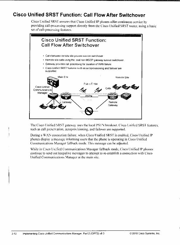
Cisco Unified SRST Function: Call Flow After Switchover
Cisco Unified SRS'fensures thatCisco Unified IPphones offercontinuous service byproviding call-processing support directly from theCiscoUnified SRST router, using a basicset of call-processing features.
Cisco Unified SRST Function:
Cal! Flow After Switchover
• Calls between remote site phones survive switchover.
• Remote site calls using the local non-MGCP gateway survive switchover.
- Gateway provides call processing for duration of WAN failure.
Cisco Unified SRST features such as autoprovisioning and failover aresupported
Cisco Unifed
Communications
Manager
Main Site
Public E.164
"£L* j£- Calls ~*q|S
Remote Site
The Cisco Unified SRST gateway uses the local PSI'N breakout. Cisco Unified SRST features,such as call preservation, autoprov isioning. and failover are supported.
During a WAN connection failure, when Cisco Unified SRST is enabled, Cisco Unified IPphones display a message informing users that ihe phone is operating in Cisco UnifiedCommunications Manager fallback mode. This message can be adjusted.
While in Cisco Unified Communications Manager fallback mode, Cisco Unified IP phonescontinue to send out keepalive messages to attempt to re-establish a connection with CiscoUnified Communications Manager at the main site.
2-12 implementing Cisco Unified Communications Manager, Part 2 (CIPT2) v8.0 >2010 Cisco Systems, Inc

Cisco Unified SRST Function: SwitchbackCisco Unified IP phones attempt to re-establish aconnection with Cisco UnifiedCommunications Manager at the main site periodically when they are registered with aCiscoUnified SRST gateway.
Cisco Unified SRST Function:Switchback
• WAN link isrestored, and IPphones areable tore-establish contact withCisco Unified Communications Manager.
• Cisco IP Phones re-register with their primary Cisco Unified CommunicationsManager
• Call processing reverts tothe primary Cisco Unified CommunicationsManager
Main Site RemoteSiteReregister
Public E 164
Cisco Unified \**r ^ _ j&.^. CallsCommunications
Manager
The default time that Cisco Unified IP phones wait before attempting to re-establish aconnection to aremote Cisco Unified Communications Manager is generally up to 120seconds.
When the WAN link or connection to the primary Cisco Unified Communications Manager isrestored, after aconfigured waiting behavior, the Cisco Unified IP phones reregister with theirprimary Cisco Unified Communications Manager. Three switchback methods are available onthe Cisco IOS router: immediate switchback, graceful switchback (after all outgoing calls onthe gatewav are completed), or switchback after aconfigured delay. Once switchback iscompleted.'call processing reverts to the primary Cisco Unified Communications Manager, andSRST returns to standby mode.
>2010 Cisco Systems. Inc. Centralized CalI-Processing Redundancy Implementation 2-13
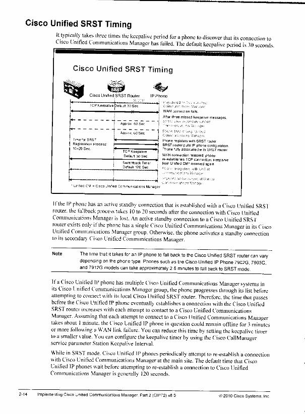
Cisco Unified SRST TimingIt typically takes three times the keepalive period for aphone lo discover that its connection toCisco Unified Communications Manager has failed. The default keepalive period is 3(1 seconds.
Cisco Unified SRST Timi
Cisco Unifed SRST Router
' ii i —•"••'TCPKeepalrvepelault30Sec
; h
i Apprai 60 Sec
i Aopror, 60 Sec
E Time for SRST
j Registration ProcessI 10-20 Sec
LTCP KeepaliveDetault 30 Sec
Switchback TimerDefault 120 Sec
WAN connection fails
Afterthree missed keepalive messages,
Phone regrsters with SRST ruuler*i SRST router pulls IPphone coniiguration
•*j Phone fully associatedwith SRST rouler: WANconnection restored phone
—ti re establishesTCPconnector keepalivej from Unified CM* received agan
• Unified CM - Cisco Unrfied CommunicationsManager
Ifthe IP phone has an active standby connection that is established with aCisco Unilied SRSTrouter, the fallback process takes 10 to20seconds after the connection with Cisco UnifiedCommunications Manager is lost. An active standby connection toa Cisco Unified SRS'frouter exists onlv- ifthe phone has a single Cisco Unified Communications Manager in its CiscoUnified Communications Manager group. Otherwise, the phone activates astandby connectionto its secondary Cisco Unified Communications Manager.
Note The time that it takes for an IP phone to fall back to the Cisco Unified SRST router can varydepending on the phone type Phones suchas the Cisco Unified IPPhone 7902G, 7905G.and 7912G models can take approximately 2 5 minutes to fatl back to SRST mode.
Ifa Cisco Unified IP phone has multiple Cisco Unified Communications Manager systems inits Cisco Unified Communications Manager group. Ihe phone progresses through its list beforeattempting to connect with its local Cisco Unified SRST router. Therefore, the time that passesbefore theCisco Unified IPphone eventually establishes a connection with theCisco UnifiedSRSTrouter increases witheach attempt to contact to a Cisco Unified CommunicationsManager. Assuming that each attempt to connect to aCisco Unified Communications Managertakes about 1minute, the Cisco Unified IPphone inquestion could remain offline for 3 minutesormore following a WAN link failure. You can reduce this time by setting the keepalive timertoa smaller value. You can configure the keepalive timer by using the Cisco CallManagerservice parameter Station Keepalive Interval.
While inSRST mode. Cisco Unified IP phones periodically attempt to re-establish a connectionwith Cisco Unified Communications Manager at the mainsite. The defaulttime that CiscoUnified IP phones waitbeforeattempting to re-establish a connection to Cisco UnifiedCommunications Manager is generally 120 seconds.
2-14 Implementing CiscoUnified Communications Manager, Part2 (CIPT2) v8.0 )2010 Cisco Systems. Inc
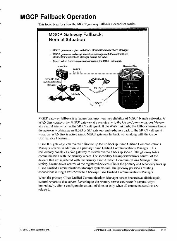
MGCP Fallback OperationThis topic describes howthe MGCP gateway fallback mechanism works.
MGCP Gateway Fallback:Normal Situation
MGCP gateways register with Cisco Unified Communications Manager.
MGCP gateways exchange keepalive messages with the central CiscoUnified Communications Manager across the WAN.
Cisco Unified Communications Manager is the MGCP call agent.
Main Site
Cisco Unified
Communications
Manager
Remote Site
MGCP gateway fallback is a feature that improves the reliability of MGCP branch networks. AWAN link connects the MGCP gateway at a remote site to the Cisco Communications Managerat a central site, which is the MGCP call agent. If the WAN link fails, the fallback feature keepsthe gateway working as an H.323 or SIP gateway and re-homes back to the MGCP call agentwhen the WAN link is active again. MGCP gateway fallback works along with the CiscoUnified SRST feature.
Cisco IOS gateways can maintain links to up to two backup Cisco Unified CommunicationsManager servers in addition to a primary Cisco Unified Communications Manager. Thisredundancy enables a voice gateway to switch over to a backup server if the gateway losescommunication with the primary server. The secondary backup server takes control ofthedevices that are registered with the primary Cisco Unified Communications Manager. Thetertiary backup takes control ofthe registered devices if both the primary and secondary backupCisco Unified Communications Manager systems fail. The gateway preserves existingconnections during a switchover to a backup Cisco Unified Communications Manager.
When the primary Cisco Unified Communications Manager server becomes available again,control reverts to that server. Reverting to the primary server can occur in several ways:immediately, after a configurable amount of time, or only when all connected sessions arereleased.
) 2010 Cisco Systems. Inc Centralized Call-Processing Redundancy Implementation 2-15
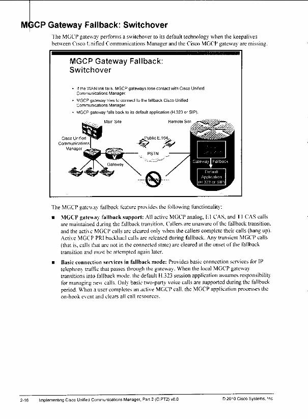
MJ3CP Gateway Fallback: SwitchoverThe MGCP gateway performs a switchover to its default technology when the keepalivesbetween Cisco Unified Communications Manager and the Cisco MGCP gateway are missing.
MGCP Gateway Fallback:Switchover
If the WAN link (ails. MGCP gateways lose contact with Cisco UnifiedCommunications Manager.
MGCP gateway tnes to connect to the fallback Cisco UnifiedCommunications Manager.
MGCP gateway falls back to its default application (H.323 or SIP).
Cisco Unified
Communicati
Manager
Mam Site Remote Siti
The MGCP gatewav fallback feature provides the following functionality:
• MGCP gateway fallback support: All active MGCP analog, F.l CAS, and Tl CAS callsare maintained during the fallback transition. Callers are unaware ofthe fallback transition,and the active MGCP calls are cleared only when the callers complete their calls (hang up).Active MGCP PRI backhaul calls are released during fallback. Any transient MGCP calls(that is. calls that are not in the connected state) are cleared at the onset ofthe fallbacktransition and must be attempted again later.
• Basic connection services in fallback mode: Provides basic connection services for IP
telephony traffic that passes through the gateway. When the local MGCP gatewaytransitions into fallback mode, the default H.323 session application assumes responsibilityfor managing new calls. Onlv basictwo-party voice calls are supported during the fallbackperiod. When a usercompletes an active MGCP call,the MGCP application processes theon-hook event and clears all call resources.
2-16 Implementing Cisco Unified Communications Manager, Part 2 (CIPT2) v8.0 ©2010 Cisco Systems. Inc
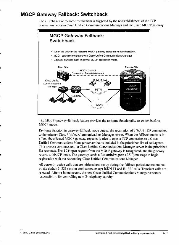
MGCP Gateway Fallback: SwitchbackThe switchback or re-home mechanism is triggered by the re-establishment ofthe TCPconnection between Cisco Unified Communications Manager and the Cisco MGCP gateway.
MGCP Gateway Fallback:Switchback
When the WAN link is restored, MGCP gateway starts the re-home function.
MGCP gateway reregisters with Cisco Unified Communications Manager.
Gateway switches back lo nomial MGCP application mode.
Main Site
Cisco Unified
Communications
Manager
Remote Site
ITic MGCP-gateway-fallback feature provides the re-home functionality to switch back toMGCP mode.
Re-home function in gateway-fallback mode detects the restoration of a WAN TCP connectionto the primary Cisco Unified Communications Manager server. When the fallback mode is ineffect, the affected MGCP gateway repeatedly tries to open a TCP connection to a CiscoUnified Communications Manager server that is included in the prioritized list of call agents.This process continues until a Cisco Unified Communications Manager server in the prioritizedlist responds. The TCP open request from the MGCP gateway is recognized, and the gatewayreverts to MGCP mode. The gateway sends a RestartlnProgress (RSIP) message to beginregistration with the responding Cisco Unified Communications Manager.
All currently active calls that are initiated and set up during the fallback period are maintainedby the default H.323 session application, except ISDN Tl and EI PRI calls. Transient calls arereleased. After re-home occurs, the new Cisco Unified Communications Manager assumesresponsibility for controlling new IP telephony activity.
)2010 Cisco Systems. Inc Centralized CalI-Processing Redundancy Implementation 2-17
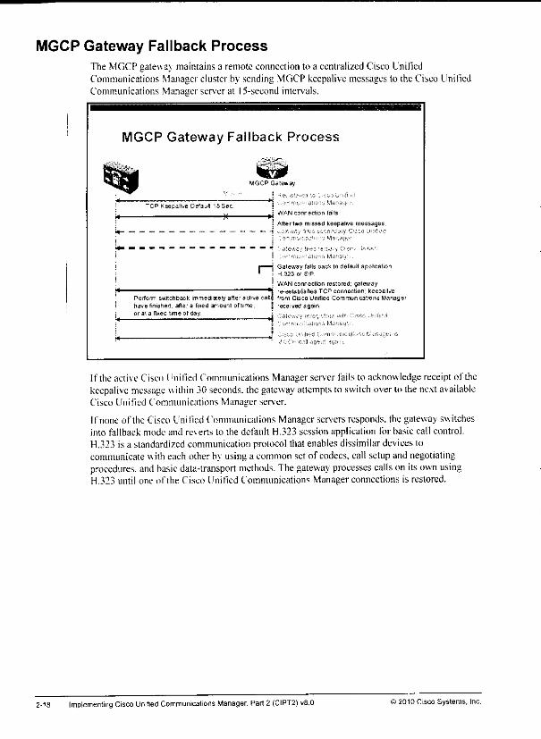
MGCP Gateway Fallback ProcessThe MGCP gateway maintains a remote connection to a centralized Cisco UnifiedCommunicalions Manager cluster by sending MGCP keepalive messages to the Cisco UniliedCommunications Manager server at 15-second intervals.
MGCP Gateway Fallback Process
TCP Keepalive Detault 15 Sec
M—
MGCP Gateway
! He- .si;-j -.. •rv-.,-. alien:, yar-j :••;
J WAN connection fails
: After two missed keepalive messages.
Perform switchback immediately after active canhave finished, after a fixed amount of time,
or al a fixed tune of day
; .->'niu.>','jli(,rri MdrSs!'. •
Gateway falls back to default applicationH 323 or SIP
WAN connection restored, gatewayre-establishes TCP connection; keepalivefrom Csco Unified Communications Manager
rece ved again
If the active Cisco Unified Communications Manager server fails to acknowledge receipt ofthekeepalive message within 30 seconds, thegateway attempts to switch over lo thenextavailableCisco Unified Communications Manager server.
If none ofthe Cisco LinifiedCommunications Manager servers responds, the gateway switchesinto fallback mode and reverts to the default H.323 session application tor basic call control.H.323 is a standardized communication protocol that enables dissimilar devices tocommunicatewith each other by using a common set of codecs, call setup and negotiatingprocedures, and basic data-transport methods. Thegateway processes calls on itsown usingH.323 until one ofthe Cisco Unified Communications Manager connections is restored.
2-18 ImplementingCisco Unitied Communications Manager, Part 2 (CIPT2)vB.O ) 2010 Cisco Systems, Inc.
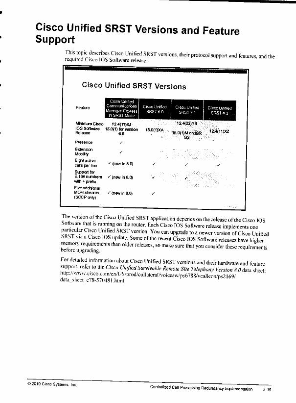
Cisco Unified SRST Versions and FeatureSupport
This topic describes Cisco Unified SRST versions, their protocol support and features and therequired Cisco IOS Software release.
Cisco Unified SRST Versions
Feature
Cisco Unified
Communications Cisco Unified Cisco Unified Cisco Unified^o/.T,658 SRS?e.O SRST 71 SRST 43il SRST Mode
Minimum Cisco 12.4(11)XJIOS Software 15.0{1) forversionRelease &0
15.0(1)XA
124(22)YB
15.0<1)Mon ISRG2
12,4(11JXZ
Presence
ExtensionMobiity
Eight activecats per line
Support forE.164 numberswith + prefix
Five additionalMOH streams(SCCP only)
/
^ (new in 8.0)
"' (new in ad)
(new in 8.0)
The version ofthe Cisco Unified SRST application depends on the release ofthe Cisco IOSSoftware that is running on the router. Each Cisco IOS Software release implements oneparticular Cisco Unified SRST version. You can upgrade to anewer version of Cisco UnifiedSRST via aCisco IOS update. Some ofthe recent Cisco IOS Software releases have highermemory requirements than older releases, so make sure that you consider these requirementsbefore upgrading. n
For detailed information about Cisco Unified SRST versions and their hardware and featuresupport, refer to the Cisco Unified Survivable Remote Site Telephony Version 8.0 data sheet"http://w^vv.cisco.com/cn/LlS/prod/collatcraI/voicesw/ps6788/vcallcon/ps2l69/data_shect c78-57048i.html.
>2010 Cisco Systems, Inc.Centralized CalI-Processing Redundancy Implementation 2-19
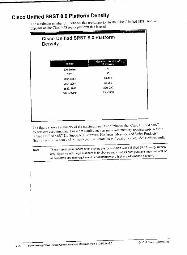
Cisco Unified SRST 8.0 Platform DensityThe maximum number of IP phones that are supported by the Cisco Unified SRST featuredepends on the Cisco IOS router platform that is used.
2-20
Cisco Unified SRST 8.0 PlatformDensity
Platformj Maximum Number of"
IP Phones
800 Series 4
1861 15
2801-2851 25-100
2901-2951 35-250
3825, 3845 350, 730
3925-394 5E 730-1500
The figure shows asummarv ofthe maximum number of phones that Cisco Umtied SRSTrouters can accommodate. For more details, such as minimum memory requirements, refer to-Cisco Unified SRST 8.0 Supported Firmware. Platforms, Memory, and Voice Products(imp'/.'vvwvvci^co.coni.ctTU'S./docs/voice ipeomm/cusrst/rcquircmcnts/guidc/srsXOspc.himl)
NoteThese maximum numbers of IP phones are for common Cisco Unified SRST configurationsonly Systems with large numbers of IP phones and complex configurations may not work onall platforms and can require additional memory or ahigher performance platform.
implementing Cisco Unified Communications Manager, Part 2(CIPT2) v8 0 © 2010 Cisco Systems. Inc

1-106 Implementing Cisco Unified Communications Manager, Part 2 (CIPT2) vS.O © 2010 Cisco Systems, Inc.
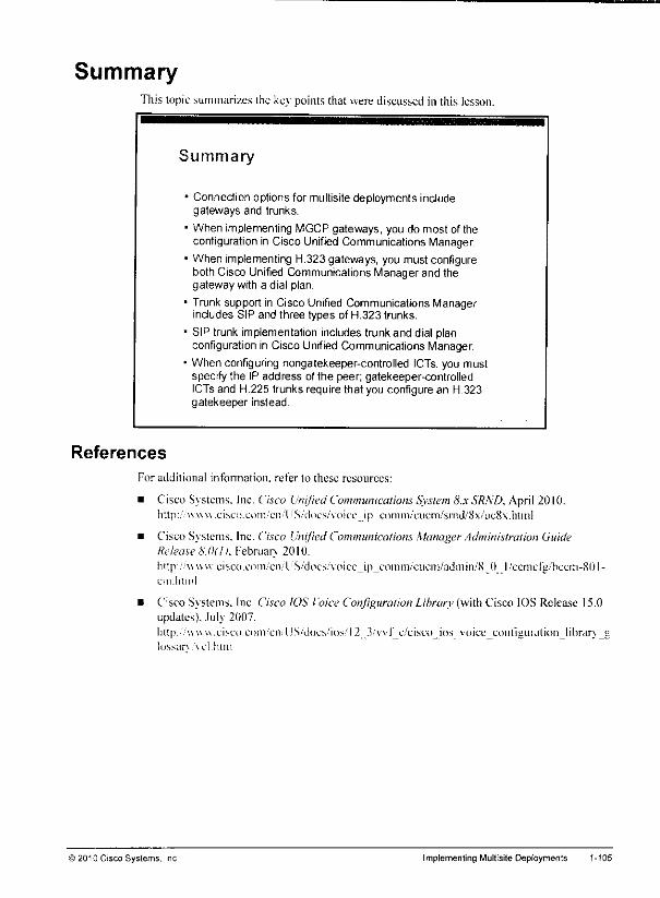
SummaryThis topic summarizes the key points that were discussed in this lesson.
Summary
References
1Connection options for multisite deployments includegateways and trunks.
When implementing MGCP gateways, you do most of theconfiguration in Cisco Unified Communications Manager.
When implementing H.323 gateways, you must configureboth Cisco Unified Communicalions Manager and thegateway with a dial plan.
Trunk support in Cisco Unified Communications Managerincludes SIP and three types of H.323 trunks.
SIP trunk implementation includes trunk and dial planconfiguration in Cisco Unrfied Communications Manager.
When configuring nongatekeeper-controlled ICTs, you mustspecify the IP address ofthe peer; gatekeeper-controlledICTs and H.225 trunks require that you configure an H.323gatekeeper instead
For additional infonnation. refer to these resources:
• Cisco Sv stems. Inc. Cisco Unified Communications System 8.x SRND, April 2010.http:/ www.cisco.com'cn'l 'S/does/voice ip comni/'cucm/smd/oVucSvlitmi
• Cisco Svstems. Inc. Cisco UnifiedCommunications ManagerAdministration GuideRelease 8.0(1>. Februarv 2010.
http:/';vuv wxisco.com/cn/1 :S.;docs.'\oicc_iji_coinm/cucm/admin/S I) l/ccmefg/hccm-80!-cin.litinl
• Cisco Systems. Inc. Cisco IOS Voice Configuration Library (with Cisco IOS Release 15.0updates}. July 2007.hltp:/v\v\v\.ciM.'o.coni,'cn.'US/'docs/iosT2 3/vvf_c/cisco_ios voice_conf!giii'ation_librarv_tiossarv \cl.htm
© 2010 Cisco Systems, Inc. Implementing Multisite Deployments 1-105

Unified CM* Gatekeeper-Controlled ICTand H.225 Trunk Configuration (Cont.)
Enter the gatekeeper zone ilwhich the trunk should be
registered.
Choose previouslyconfigured gatekeeper.
Trunks can register asterminal or gateway with the
gatekeeper. ChooseGateway as the terminal
a^
Enter the prefix that shouldbe registered with the
gatekeeper.
* Unified CM - Cisco Unified Communications Manager
Finally, you need to provide the gatekeeper information. Fromthe drop-down list, choose thegatekeeper that this trunk should register to, and then choose the terminal type. Cisco UnifiedCommunications Manager can register trunks as terminals or gateways with an H.323gatekeeper. Usually die terminal type is set to Gateway.
In the Technology Prefix field, enter the prefix, which should be registered with the gatekeeper.
Note The prefix that you enter is the prefix that the trunk will register with the gatekeeper. It can,
but does not have to, include a technology prefix. In the example, a prefix of 408 is used.
More information about prefixes and technology prefixes is provided in the Implementing
Cisco Voice Communications and QoS (CVOICE) course.
Then enter the zone in which the trunk should be registered.
Tip The H.323 zone name is case-sensitive. Make sure that it matches the zone name that has
been configured at the gatekeeper.
1-104 Implementing Cisco Unified Communications Manager, Part 2 (CIPT2) vS.O >2010 Cisco Systems, Inc.
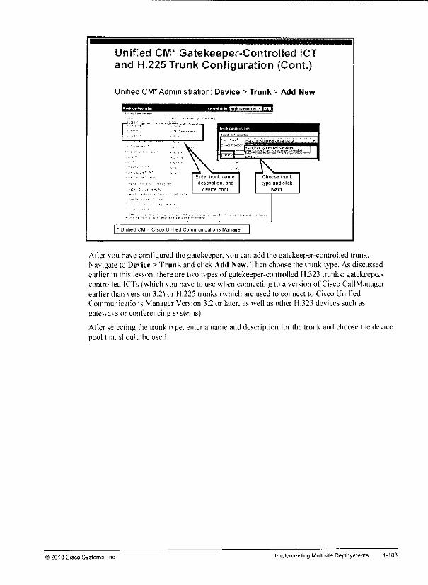
Unified CM* Gatekeeper-Controlled ICTand H.225 Trunk Configuration (Cont.)
Unified CM* Administration: Device > Trunk > Add New
i.flaiKi.f^j.jijiWiMifiSffi'Mx '̂
Enter trunk name,
descnpiion. and
device pool
| ' Unrfied CM - Cisco Unified Communications Manager |
Choose trunk
type and clickNext
After vou have configured the gatekeeper, you can add the gatekeeper-controlled trunk.Navigate to Dc\ice > Trunk and click Add New. fhen choose the trunk type. As discussedearlier in this lesson, there are two tvpes of gatekeeper-controlled 11.323 trunks: gatekccpei-controlled ICTs (which vou have to use when connecting to a version of Cisco CallManagerearlier than version 3.2) or 11.225 trunks (which are used to connect to Cisco UnifiedCommunications Manager Version 3.2 or later, as well as other H.323 devices such asgateways or conferencing svstems).
After selecting the trunk tvpe. enter a name and description for the trunk and choose the devicepool that should be used.
)2010 Cisco Systems. Inc Implemenling Multisite Deployments 1-103
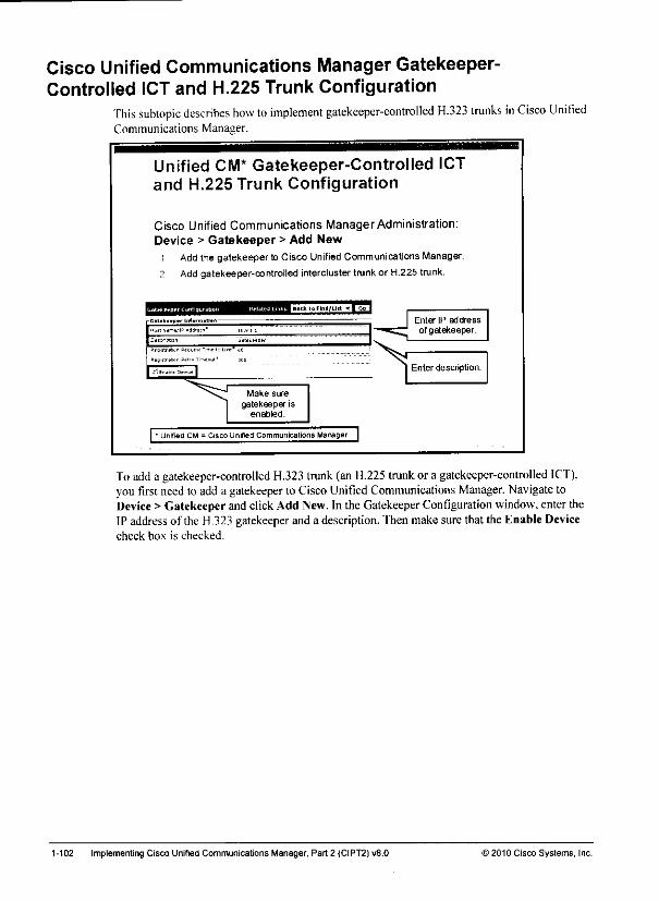
Cisco Unified Communications Manager Gatekeeper-Controlled ICT and H.225 Trunk Configuration
This subtopic describes how to implement gatekeeper-controlled H.323 trunks in Cisco UnifiedCommunications Manager.
Unified CM* Gatekeeper-Controlled ICTand H.225 Trunk Configuration
Cisco Unified Communications ManagerAdministration:Device > Gatekeeper > Add New
i Add the gatekeeper to Cisco Unified Communications Manager.
? Add gatekeeper-controfled intercluster trunk or H.225 trunk.
Catek«*pT IiJ»i
Make sure
gatekeeper isenabled.
| • Unified CM =Cisco Unifed Communicalions Manager |
Enter IP addressgatekeeper.
Enter description.
To adda gatekeeper-controlled H.323 trunk (an H.225 trunkor a gatekeeper-controlled ICT),you first need toadd a gatekeeper to Cisco Unified Communications Manager. Navigate toDevice >Gatekeeper andclickAdd New. In the Gatekeeper Configuration window, entertheIP address ofthe H.323 gatekeeper and a description, 'fhen makesure that the Enable Devicecheck box is checked.
1-102 Implementing Cisco Unified Communications Manager, Part 2 (CIPT2) v8.0 ) 2010 Cisco Systems, Inc.

Cisco Unified CommunicationsManager Nongatekeeper-ControtledICT Configuration (Cont.)
• tritlsl^-.l-.,!™^
^'•^•msammmtm
^ Enter IP address
of device on other side.
Then enter the II* address or addresses ofthe Cisco Unified Communications Managerserversofthe other cluster.
Note Because the nongatekeeper-control led ICT does not use a gatekeeper for address
resolution, you must manually enter the IP addresses of the devices on the other side.
) 2010 Cisco Systems,' Implementing Multisite Deployments 1-101
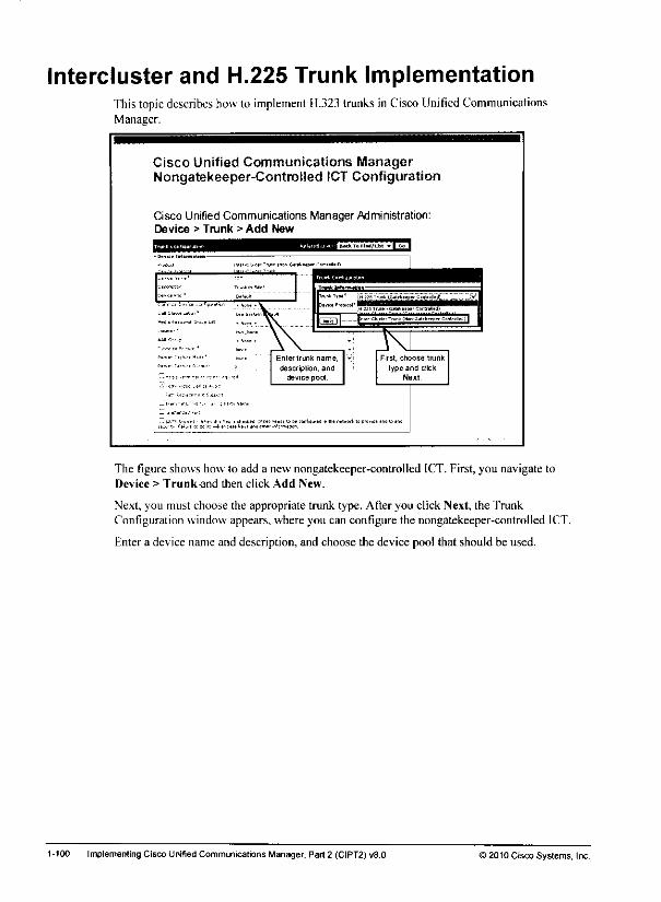
Intercluster and H.225 Trunk ImplementationThistopic describes how to implement H.323 trunks inCiscoUnitied CommunicationsManager.
Cisco Unified Communications ManagerNongatekeeper-controlled iCT Configuration
Cisco Unified Communications Manager Administration:Device > Trunk > Add New
E3BMkTaFlnd/Ua
Enter trunk name,
description, anddevice pod
First, crioose trunk
type and dickNext
The figure shows how to add a new nongatekeeper-controlled ICT. First, you navigate toDevice > Trunk-and then click Add New.
Next, you must choose the appropriate trunk type. After you click Next, the TrunkConfiguration window appears, where you can configure the nongatekeeper-controlled ICT.
Enter a device name and description, and choose the device pool that should be used.
1-100 Implementing Cisco Unified Communications Manager, Part 2 (CIPT2) vS.O >2010 Cisco Systems, Inc.
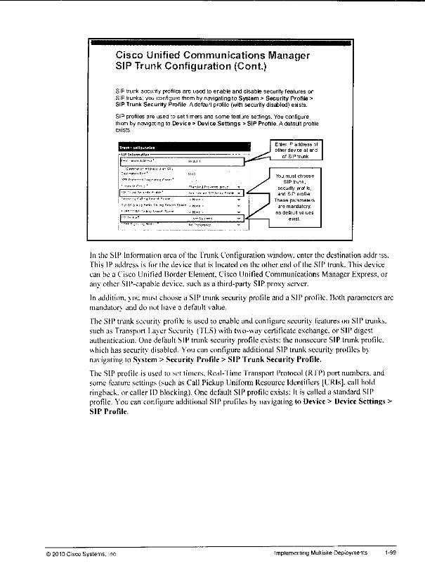
Cisco Unified CommunicationsSIP Trunk Configuration (Cont.)
SIP trunk security profiles are used to enable and disable security features onSIP trunks; you configure them by navigatingto System > Security Profile >SIP Trunk Security Profile Adefauft profile (with security disabled) exists.
SIP profiles are used to set timers and some feature settings. You configurethem by navigating to Device > Device Settings > SIP Profile. A default profileexists
Enter IP address of
other device at end
of SIPtrimk
You must choose
SIP trunk,
security profile,and SIP profile
These parametersare mandatory.
no default values
exist
In the SIP Information area of the Trunk Configuration window, enter the destination addr:ss.This IP address is for the dev ice that is located on the other end ofthe SIP trunk. This device
can be a Cisco Unified Border Element, Cisco Unified Communications Manager Express, orany other SlP-capable device, such as a third-party SIP proxy server.
In addition, you must choose a SIP trunk security profile and a SIP profile. Both parameters aremandator, and do not have a default value.
The SIP trunk security profile is used to enable and configure security features on SIP trunks,such as Transport Layer Security (TLS) with two-way certificate exchange, or SIP digestauthentication. One default SIP trunk security profile exists: the nonsecure SIP trunk profile,which has security disabled. You can configure additional SIP trunk security profiles bynav igating to System > Security Profile > SIP Trunk Security Profile.
The SIP profile is used to set timers, Real-Time Transport Protocol (RIP) port numbers, andsome feature settings (such as Call Pickup Uniform Resource Identifiers [URIs], call holdringback. or caller ID blocking). One default SIP profile exists: It is called a standard SIPprofile. You can configure additional SIP profiles by navigating to Device > Device Settings >SIP Profile.
) 2010 Cisco Systems, Inc Implementing Multisite Deployments

SIP Trunk ImplementationThistopic describes how10 implement SIPtrunks in CiscoUnified Communications Manager.
Cisco Unified CommunicationsManager SIP Trunk Configuration
Cisco Unified Communications Manager Administration: Device> Trunk > Add New
».?d.n SIB In,nl
Dev>u P'Mo col SIP
DHJfiDnjr, T^kU„3
Vt.v.™ »«J" Drtult . *scommon :=.,.=. C»n*,u. '»- . N3ne - Vcadi cl«u*i^o;n" .» Sr.- ™ D"Uk,ll V
HUHBSJ-.M...1 .N=r« -
LOC.OT ' -cc.Ncr -
AAA Ofou; < Non« V
PicHtCiCiur,.,;,,' •,00, ,
B.3.«C.Cn,r.;U-mor C
3*4,T>n. t4.*J.n.d
yln^^T '.idio ~ii is aj
:t™„l-..i.,u 1, 'it, Nim
!*«-«« .ot
To add a SIP trunk in Cisco Unified Communications Manager, navigate to Device > Trunkand click Add New. Then, in the Trunk Type drop-down list, choose SIP Trunk and clickNext.
In the Trunk Configuration window, enter a name and description for the SIP tmnk and choosethe device pool that should be used.
1-98 Implementing Cisco Unified Communications Manager, Part 2 (CIPT2) v8.0 ©2010 Cisco Systems, Inc.

Trunk Types Used by Special ApplicationsThis subtopic describes additional trunk types that can be configured in Cisco UnifiedCommunications Manager.
Trunk Types Used by SpecialApplications
You can configure additional trunk types in CiscoUnifiedlCommunications Manager that are used byspecialjapplications.
• Cisco: Extension Mobility Cross Clusters:
Special trunks configured between Cisco UnifiedCommunications Manager clusters that should allowCi^co EMCC logins
- Orly SIP supported
• Call Qontrol Discovery:
- Spbcial trunks configured in Cisco UnifiedCcjnmunications Manager clusters that refer to anSAF-enabled network providing Call Control Discovery featuresH.323 and SIP supported
Some applications require special trunk types to be configured.
For example, when implemenlingCisco Fxtension Mobility Cross Clusters (FMCC) adedicated trunk has to be configured between the Cisco Unified Communications Managerclusters that allow users ofthe remote cluster to log in locally using Cisco FMCC. Thesetrunks, which are exclusivelv configured for Cisco EMCC. have to use the SIP protocol; 11.323is not supported bv Cisco FMCC. Another application that requires special trunks to beconfigured is Call Control Discovery (CCD). Whenyou use CCD. internal directorv' numbersas well as the associated external PS'fN numbers are advertised and learned from a ServiceAdvertisement Framework (SAF)-enabled network, fhese trunks can be cither SIP or 11.323and must be explicitly enabled for SAF.
Note More information about Cisco EMCC and SAF trunks will be provided in the corresponding
lessons of this course.
© 2010 Cisco Systems. Inc Implementing Multisite Deployments
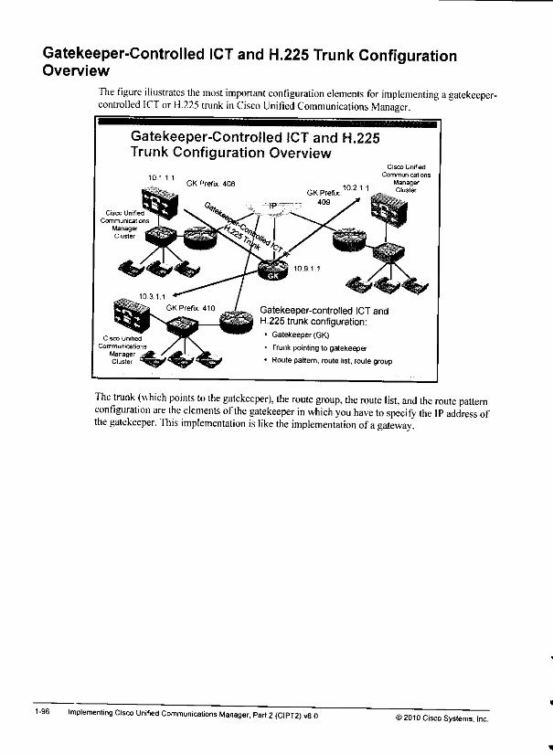
Gatekeeper-Controlled ICT and H.225 Trunk ConfigurationOverview
The figure illustrates the most important configuration elements for implementing agatekeeper-controlled ICT or H.225 trunk inCisco Unilied Communications Manager.
1-96
Gatekeeper-Controlled ICT and H.225Trunk Configuration Overview
Cisco Unified
Communicat ions
ManagerCluster
10.1.1 1
Cisco Unified
Communications
ManagerCluster
GK Prefix. 408
GK Prefix:
409
10.2.1.1
Cisco Unified
Communications
ManagerCluster
Gatekeeper-controlled ICT andH.225 trunk configuration:
* Gatekeeper (GK)
• Trunkpointingto gatekeeper
• Route pattern, route list, route group
The trunk (which points to the gatekeeper), the route group, the route list, and the route patternconfiguration are the elements ofthe gatekeeper in which you have to specify the IP address ofthe gatekeeper. This implementation is like the implementation ofagateway.
Implementing Cisco Unified Communications Manager, Part 2(CIPT2) v8.0 © 2010 Cisco Systems. Inc.
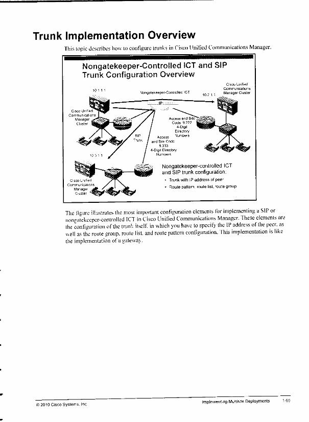
Trunk Implementation OverviewThis topic describes how toconfigure trunks inCisco Unified Communications Manager.
Nongatekeeper-Controlled ICT and SIPTrunk Configuration Overview
Cisco Unified
Communica
ManagerCluster
Cisco Unified
Communicalions
ManageCluster
Nongalekeeper-Conlrolled :CT
Access and Site
Code. 9 222
4- DigitDirectoryNumbers
Cisco Unifed
Communications
102 1 1 Manager Cluster
Nongatekeeper-controlled ICTand SIP trunk configuration:
- Trunk with IP address of peer
• Route pattern, route list, route group
The figure illustrates the most important configuration elements for implementing aSIP ornongatekeeper-controlled ICT in Cisco Unified Communications Manager, "fhese elements arcthe configuration ofdie trunk itself, in which you have to specify the IP address ofthe peer, aswell as the route group, route list, and route pattern configuration, fhis implementation is likethe implementation of a gatewav.
'2010 Cisco Systems. IncImplementingMultisite Deployments

Cisco IOS H.323 Gateway ConfigurationThis subtopic describes how to configure a Cisco IOS router as an H.323 gateway.
Cisco IOS H.323 Gateway Configuration
10-digit numbers are sent to Cisco Unrfied Communications Manager onincoming PSTN calls in this configuration.
Digit manipulation on gateway or in Cisco Unified Communications Manageris required to get to 4-digit directory numbers.
interface FastEthernet0/0
ip address 10.1.1.101 255.255.255.0h323-gateway voip interface
h323-gateway voip bind ercaddr 10.1.1.101
1
dial-peer voice 11 voipdestination-pattern 511555....
session target ipv4:10.1.1.1
incoming called-number 9T
codec gTllulaw
1
dial-peer voice 21 pots
destination-pattern 9T
direct-inward-dial
port 0/0/0:23
When configuring an H.323 gateway, the first task is to enable H.323 at one IP interface. Ifmultiple IP interfaces are present it is recommended that you use a loopback interface.Otherwise, if the interface that has been selected for H.323 is down, the H.323 application willnot work, even if-other interfaces could be used to route the IP packets. In this example, there isonly one Ethernet interface, and H.323 has been enabled on that interface, using the h323-gateway voip interface and h323 gateway voip bind srcaddr IP address commands.
In contrast to MGCP gateways in which the call agent takes care of call routing, H.323gateways require local dial plan configuration. In the example, the H.323 gateway is configuredwith a VoIP dial peer that routes calls that are placed to the PSTN number 511555... ofthegateway toward Cisco Unified Communications Manager. The gateway receives these callsfrom the PSTN because 511555 1001-1003 is the direct inward dialing (DID) range ofthePSTN interface (port 0/0/0:23). In addition, the PSTN gateway is configured with a POTS dialpeer that routes all calls starting with 9 out to the PSTN, using the ISDN PRI (port 0/0/0:23).
Note that the configured digits of a destination pattern in a POTS dial peer are automaticallystripped off. Therefore, the 9 is not sent out to the PSTN. In the other direction, the gatewaydoes not perform any digit manipulation because VoIP dial peers do not strip off any digitsautomatically. Cisco Unified Communications Manager receives H.323 call setup messages forcalls that were received from the PSTN in their entire length (usually 10digits). Because theinternal directorv numbers arc four digits, either Cisco Unified Communications Manager orthe H.323gatewav need to be configured to strip the leadingdigits so that the remaining fourdigits can be used to route the call to internal directory numbers.
Note More informationon how to implement digit manipulation is provided in the next lesson ofthis module.
1-94 Implementing Cisco Unified Communications Manager, Part 2 (CIPT2) v8.0 J2010 Cisco Systems, Inc.
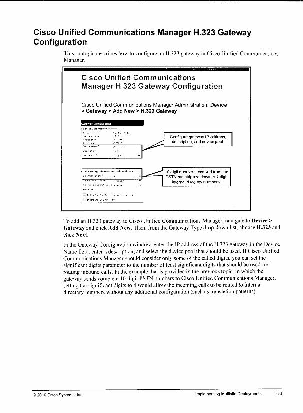
Cisco Unified Communications Manager H.323 GatewayConfiguration
This subtopic describes how to configure an 11.323 gateway in Cisco Unified CommunicationsManager.
Cisco Unified Communications
Manager H.323 Gateway Configuration
Cisco Unified Communications ManagerAdministration: Device> Gateway > Add New > H.323 Gateway
:c.;:::
-""•- -
•tlon - inbiund (•<•<-
..^--,r, ;,,-,•- -
-s ">o -"•" -'" < NO"! > •
*:j Is •<. •-.••- l1.! , «,,. , v
-•:•• zm
Hi.i-.-,•,] N,™ ., I, i„ .,- :-,-,, ,d
'JE-.ll.;rt..t,Lr >•:•>•,
Configure gateway IP address,desenption, and device pool.
10-digit numbers recei\ed from thePSTN are stripped down to 4-digit
internal directory numbers.
To add an H.323 gateway to Cisco Unified Communications Manager, navigate to Device >Gateway and click Add New. fhen, from the Gateway Typedrop-down list, chooseH.323 andclick Next.
In the tiateway Configuration window, enter the IP address ofthe 11.323 gateway in the DeviceName field, enter a description, and select the device pool that should be used. If Cisco UnifiedCommunications Manager should consider only some ofthe called digits, you can set thesignificant digits parameter to the numberof least significant digits that shouldbe used forroutinginbound calls. In the example that is provided in the previous topic, in which thegateway sends complete 10-digit PSTN numbers to Cisco Unified Communications Manager,settingthe significant digits to 4 wouldallowthe incoming calls lo be routed to internaldirector; numbers without any additional configuration (suchas translation patterns).
© 2010 Cisco Systems. Inc Implementing Multisite Deployments 1-93

Step2 Configure oneor more VoIP dial peerspointing to Cisco Unified CommunicationsManager.
Step 3 Configure one or moredial peers pointingto the PSTN.
1-92 Implementing Cisco Unified Communications Manager, Part 2 (CIPT2) vS.O © 2010 CiscoSystems, Inc.
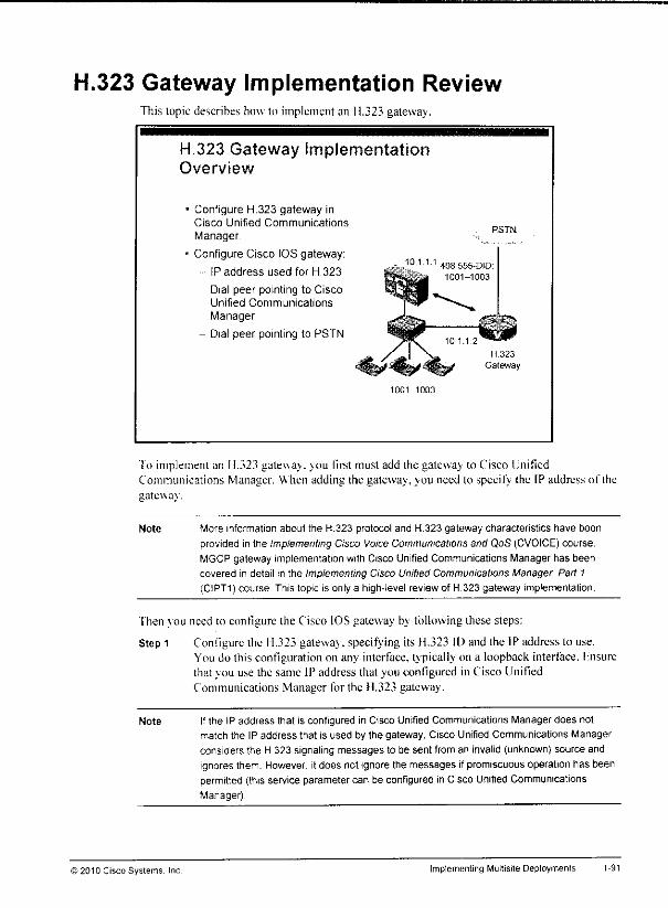
H.323 Gateway Implementation ReviewThis topic describes how to implement an H.323 gateway.
H.323 Gateway ImplementationOverview
Configure H.323 gateway inCisco Unified Communications
Manager.
Configure Cisco IOS gateway:
IP address used for H.323
Dial peer pointing to CiscoUnified Communications
Manager
- Dial peer pointing to PSTN
10.1.1.1
1001-1003
PSTN
To implement an H.323 gatewav. you first must add the gatewav to Cisco UnifiedCommunications Manager. When adding the gateway, you need lo specify the IP address ofthegateway.
Note More information about the H.323 protocol and H.323 gateway characteristics have been
provided in the ImplementingCisco Voice Communications and QoS (CVOICE) course.
MGCP gateway implementation with Cisco Unified Communications Manager has been
covered in detail in the Implementing Cisco Unified Communications Manager Part 1
(CIPT1) course This topic is only a high-level review of H 323 gateway implementation.
Then vou need to configure the Cisco IOS gateway by following these steps:
Step 1 Configure the H.323 gateway, specifying its H.323 ID and the IP address to use.You do this configuration on any interface, typically on a loopback interface, Fnsurethat you use the same IP address that you configured in Cisco UnifiedCommunications Manager for the H.323 gateway.
Note Ifthe IP address that is configured in Cisco Unified Communications Manager does not
match the IP address that is used by the gateway, Cisco Unified Communications Manager
considers the H 323 signaling messages to be sent from an invalid (unknown) source andignores them. However, itdoes not ignore the messages ifpromiscuousoperation has beenpermitted (thisservice parameter can be configured in Cisco Unified CommunicationsManager)
© 201D Cisco Syslems. Inc. Implementing Multisite Deployments 1-91

mgcp
mgcp call-agent 10.1.1.1 2427 service-type mgcp version 0.1
mgcp rtp unreachable timeout 1000 action notify
mgcp modem passthrough voip mode nse
mgcp package-capability rtp-package
mgcp package-capability sst-package
mgcp package-capability pre-package
no mgcp package-capability res-package
no mgcp package-capability fxr-package
no mgcp timer receive-rtcp
mgcp sdp simple
mgcp rtp payload-type g726rl6 static
1-90 Implementing Cisco Unified Communications Manager, Part 2 (CIPT2) v8.0 © 2010 Cisco Systems, Inc.
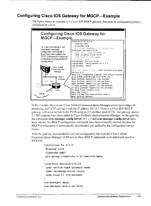
Configuring Cisco IOS Gateway for MGCP—ExampleThe figure showsan example of a Cisco IOS MGCP gateway that pulls its configuration from aconfiguration server.
Configuring Cisco IOS Gateway forMGCP—Example
Only the commands in redhave been manuallyconfigured. Commands inblack have been added via
TFTP Commands in blue are
mandatory for manual MGCPconfiguration.
controller El 0/1/0
framing bdb3
linecode crc4
y. i -r.-yp EiirealoTS S U -,hvi,~! a:-.. -
interface SerialQ/1/0:15
isdn incoming-voice voice
1,tJ" i!'•''••-'' l5 ••'"r-r^^-r
ccm-manager music-on-hold
ccm-manager config server 10.1,1,1
ccm-manager config
:-<;. j. '.H\i-*<u>,il ::. ..: : 2427 service-type mgcp
version 0.1
mgcp rtp unreachable timeout 1000 action notify
mgcp modem passthrough voip mode nee
mgcp package-capability rtp-packagemgcp package-capability sat-package
mgcp package-capability pre-package
no mgcp package-capability res-package
no mgcp package-capability fxr-package
no mgcp timer receive-rtcp
mgcp sdp simple
mgcp rtp payload-type g726rl6 staticmgcp profile default
In the example, there is one Cisco Unified Communications Manager server (providing callprocessing and TFTP services) with the IP address 10.1.1.1. 'fhere is a Cisco IOS MGCPgateway with a connection to the PSTN using an Fl interface (port 0/1/0). The gateway and itsHI PRI endpoint have been added to Cisco Unified Communications Manager. At the gatewav.the commands ccm-manager config server 10.1.1.1 and ccm-manager config server havebeen entered. No MGCP configuration commands have been manually entered, because theMGCP configuration is automatically downloaded and applied by the configuration serverfeature.
After the gatewav downloaded its cnf.xml configuration file from the Cisco UnifiedCommunications Manager TFTP server, these MGCP commands were added and saved toNVRAM:
controller SI 0/1/0
framing crc4
linecode hdb3
pri-group timeslots 1-31 service mgcp
!
interface Serial0/l/0:15
isdn switch-type primary-4ess
isdn incoming-voice voice
isdn bind-13 ccm-manager
i
ccm-manager mgcp
ccm-manager music-on-hold
© 2010 Cisco Systems, Inc Implementing Multisite Deployments
— If Foreign Exchange Station (FXS)or Foreign Exchange Office (FXO) interfaces areto be MGCP-controlled, enable MGCP on thecorresponding plain old telephoneservice (POTS) dial peersbyusingthe servicempepapp command.
— Enable MGCP.
Note More information about manual configuration of MGCP gatewaysis provided inthe CVOICEcourse.
• Mixed use of configuration server and manual configuration:
— Follow the same procedure asfor the MGCP gateway configuration, using theconfiguration server.
— Disable theconfiguration server, using theccm-managerconfigcommand,
— Manually remove configuration that is received from the configuration server, oradd more configuration to it.
Note Be aware that, as long as the configuration server isactive onthe Cisco IOS gateway, everytime the MGCP endpoint is resetfrom Cisco Unified Communications Manager, the CiscoIOS configuration also will be rewritten. In addition, when you reload theMGCP gateway,the MGCP configuration will be rewritten as long as the configuration server is enabled.Therefore, itis common practice to use the configuration only for initial configuration when
L
manual changesare required. After you modify thedownloaded configuration, you Mdeactivate the configuration serverso thatthe manually addedchangesare preserved '••»
Also, whenyou reset an MGCP gatewayor MGCP endpoint inCiscoUnifiedCommunications Manager, thegateway orendpoint isnot automatically resetat therouter. XTherefore, when the configuration server feature is not enabled on the Cisco IOS gateway, ^>*you need to follow the nextprocedure inorder to reset an MGCP gatewayor MGCPendpoint. -+
m,
L
L
L
I
L
I
First, reset the MGCP gatewayor MGCP endpoint inCisco Unified CommunicationsManager. Then enterthe no mgcp command, followed by the mgcp command inconfiguration at the Cisco IOS gateway.
Implementing Cisco Unified Communications Manager, Part 2(CIPT2) v8.0 ©2010 Cisco Systems, Inc

Cisco IOS Gateway MGCP Configuration Methods ReviewThis subtopic reviews how toconfigure a Cisco IOS MGCP gateway to integrate with CiscoUnified Communications Manager.
Cisco IOS Gateway MGCPConfiguration Methods Review
Various ways exist to configure MGCP on the CiscoIOS gateway:
• Configuration server
Cisco IOS configuration will be downloaded automatically.Recommended and easiest way.
• Manual configuration
Cisco IOSconfiguration for controller and MGCP must beentered manually.
- Fast way to configure fractional T1/E1.
• Mixed
Initial configuration received by configuration server.
Configuration server will be disabled, and configurationcan be altered manually.
Ailer adding the MGCP gatewav in the Cisco Unified Communications Manager webadministration, vou need toconfigure the Cisco IOS MGCP gateway to register it tothe CiscoUnified Communications Manager, 'fhere are three methods for configuring aCisco IOSSoftware-based gateway to register it to Cisco Unified Communications Manager via MGCP:• Cisco IOS MGCP gateway configuration with theuse ofaconfiguration server:
— Specifv the IP address ofthe configuration server (Cisco Unified CommunicationsManager TFTP server).
— If more than one Cisco Unified Communications Manager TFTP server is deployedinthe Cisco Unified Communications Manager cluster, configure the gateway withall Cisco Unified Communications Manager TFTP server IPaddresses.
— Fnable the configuration server feature.
• Manual Cisco IOS MGCP gateway configuration:
— Specify the IP address ofthe MGCP call agent (Cisco Unified CommunicationsManager server).
— Ifmore than one Cisco Unified Communications Manager server is used for callprocessing (that is. running the Cisco CallManager service), configure the gatewaywith aprimary and redundant call agent by specifying the IP addresses oftwo CiscoUnified Communications Manager call-processing servers.
— Configure global MGCP parameters.
Examples ofglobal MGCP configuration commands arc mgcp packet and mgcprtp commands.
)2010 Cisco Systems. IncImplementing Multisite Deployments
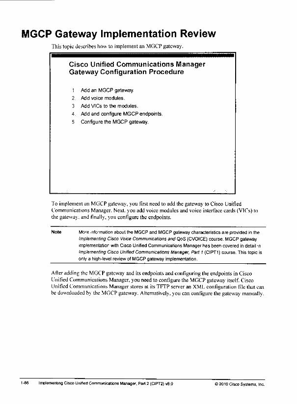
MGCP Gateway Implementation ReviewThis topic describes how to implement an MGCP gateway.
Cisco Unified Communications ManagerGateway Configuration Procedure
1 Add an MGCP gateway.
2 Add voice modules.
3 Add VICs to the modules.
4 Add and configure MGCP endpoints.
5 Configure the MGCP gateway.
To implement an MGCP gateway, you first need to add the gateway to Cisco UnifiedCommunications Manager. Next, you add voice modules and voice interface cards (VICs) tothe gatewav. and finally, you configure the endpoints.
Note More informationabout the MGCP and MGCP gateway characteristics are provided in theImplementingCisco Voice Communications and QoS (CVOICE) course. MGCP gateway
implementation with Cisco Unified Communications Manager has been covered in detail in
Implementing Cisco Unitied Communications Manager, Part1 (CIPT1) course. This topic isonly a high-level review of MGCP gateway implementation.
After adding the MGCP gateway and its endpointsand configuring the endpoints in CiscoUnified Communications Manager,you need to configure the MGCP gateway itself. CiscoUnified Communications Manager stores at its TFTPserveran XMLconfiguration file that canbe downloaded by the MGCP gateway. Alternatively, you can configure the gatewaymanually.
1-86 Implementing Cisco Unified Communications Manager, Part 2 (C1PT2) v8.0 )2010 Cisco Systems, Inc.
L
L
L
L
L
L
L
L
L
L
L
L
With a gatekeeper-controlled ICT. you configure only one trunk. That trunk then communicatesvia the gatekeeper with all other clusters that are registered to the gatekeeper. If a cluster orsubscriber becomes unreachable, the gatekeeper automatically directs the call to anothersubscriber in the cluster or rejects the call if no other possibilities exist, fhis action allows thecall to be rerouted over the PSTN (if required) with little incurred delay. With a single Ciscogatekeeper, it is possible to have 100 clusters that arc registering a single trunk each, with allclusters able to call each other. With nongatekeeper-controlled trunks, this same topologywould require 99 trunks to be configured in each cluster. The gatekeeper-controlled ICT shouldbe used for communicating only with other Cisco Unified Communications Managers,becausethe use of this trunk with other 11.323 devices might cause problems with supplementaryservices. In addition, a gatekeeper-controlled ICT must be used for backward compatibilitywith Cisco Unified Communications Manager versions earlier than Version 3.2 (referred lo asCisco CallManager).
Ihe H.225 trunk is essentially the same as the gatekeeper-controlled IC'1. except that't has thecapability of working with Cisco Unified Communications Manager clusters (Version 3.2 andlater), as well as other 11.323 devices, such as Cisco IOS gateways (including Cisco UnifiedCommunications Manager Express), conferencing systems, and clients. This capability isachieved through a discovery mechanism on a call-by-call basis. This type of trunk is therecommended H.323 tmnk if all Cisco Unified Communications Manager clusters are at least
Version 3.2.
© 2010 Cisco Systems. Inc. Implementing Multisite Deployments 1-85
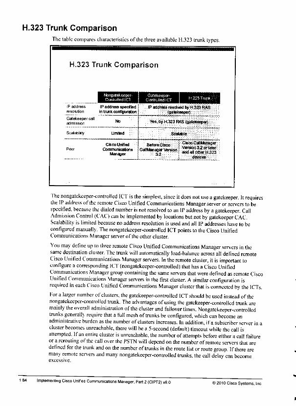
H.323 Trunk ComparisonThetable compares characteristics ofthe three available H.323 trunk types.
1-84
H.323 Trunk Comparison
Nongaiefteeper-ControlledlCT
IP address IP address specifiedresolution in trunk configuration
Gatekeeper calladmission
Scalabiity
Peer
NO
Limited
Cisco Unified
CommunicationsManager
Gatekeeper-ControBedlCT
IP address resolved by H.323 RAS{gatekeeper)
Yes,byH3Z3RflS (gatekeeper)
Scalable
eJS^jESiSSS
The nongatekeeper-controlled ICT is the simplest, since itdoes not use agatekeeper. Itrequiresthe IPaddress ofthe remote Cisco Unified Communications Manager server or servers tobespecified, because the dialed number isnot resolved toan IP address by a gatekeeper. CallAdmission Control (CAC) can be implemented by locations but not by gatekeeper CAC.Scalability is limited because no address resolution is used andall IPaddresses have to beconfigured manually. The nongatekeeper-controlled ICT points to theCisco UnifiedCommunications Manager server ofthe other cluster.
You may define up to three remote Cisco Unified Communications Manager servers in thesame destination cluster. The trunk will automatically load-balance across all defined remoteCisco Unified Communications Manager servers. In the remote cluster, it is important toconfigure a corresponding ICT (nongatekeeper-controlled) thathas a Cisco UnifiedCommunications Manager group containing thesame servers that were defined as remote CiscoUnified Communications Manager servers in the first cluster. Asimilar configuration isrequired in each Cisco Unified Communications Manager cluster that isconnected by the ICTs.Fora larger number of clusters, the gatekeeper-controlled ICT should be used instead ofthenongatekeeper-controlled trunk. The advantages ofusing the gatekeeper-controlled tmnk aremainly the overall administration ofthe cluster and failover times. Nongatekeeper-controlledtrunks generally require that a full mesh oftrunks be configured, which can become anadministrative burden asthe number ofclusters increases. In addition, ifa subscriber server inacluster becomes unreachable, there will be a5-second (default) timeout while the call isattempted. Ifan entire cluster isunreachable, the number ofattempts before either a call failureora rerouting ofthe call over the PSTN will depend onthe number of remote servers that aredefined for the tmnk and on the number oftrunks in the route list or route group. Ifthere aremany remote servers and many nongatekeeper-controlled trunks, the call delay can becomeexcessive.
Implementing Cisco Unified Communications Manager, Part 2(CIPT2) v8.0 ©2010 Cisco Systems, Inc.
*
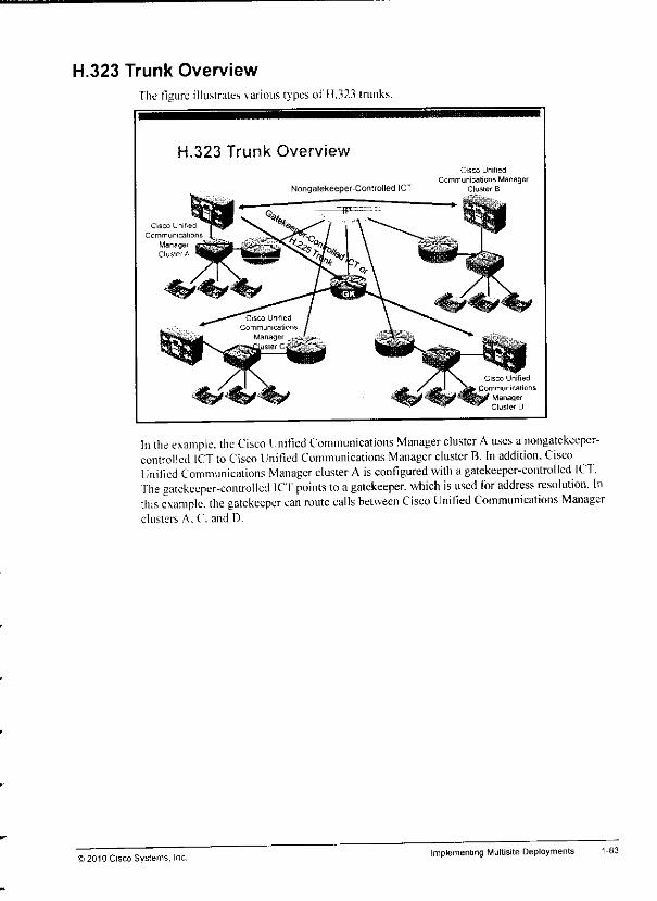
H.323 Trunk Overview
The figure illustrates varioustypesolT1.323 trunks.
H.323 Trunk Overview
Cisco Unified
Communications
ManagerCluster A
Nongatekeeper-Controlled ICT
Cisco Unified
Communications ManagerCluster B
Cisco Unified
Commu nica tionsManagerCluster D
In the example, the Cisco linified Communications Manager cluster Auses anongatekeeper-controlled ICT to Cisco Unified Communications Manager cluster B. In addition. CiscoUnified Communications Manager cluster A isconfigured with a gatekeeper-controlled ICT .The gatekeeper-controlled ICf points to agatekeeper, which is used for address resolution. Inthis example, the gatekeeper can route calls between Cisco Unified Communications Managerclusters A. C. and D.
© 2010 Cisco Systems, Inc.implementing Multisite Deployments 1-83

SIP Trunk Characteristics
This subtopic describes the characteristics of a SIP trunk.
SIP Trunk Characteristics
Main
Site
Distributed dial plan
Can be connected to any device supporting SIP, including Cisco IOSgateways, Cisco Unified Border Element, remote Cisco UnifiedCommunications Manager dusters. SIP network servers (proxy), and others
Simple, customizable protocol; rapidly evolving feature set
SIP uses the distributed call-processing model, so a SIP gateway or proxy has its own local dialplan and performs call processing on its own. A Cisco Unified Communications Manager SIPtmnk can connect to Cisco IOS gateways, a Cisco Unified Border Element, other Cisco UnifiedCommunications Manager clusters, or a SIP implementation with network servers (such as aSIP proxy).
SIP is a simple, customizable protocol with a rapidly evolving feature set.
Note When you use SIP trunks, Media Termination Points (MTPs) might be required if the
endpoints cannot agree on a common method of dual tone multifrequency (DTMF)
exchange.
1-82 ImplementingCisco Unified CommunicationsManager, Part 2 (CIPT2)vS.O >2010 Cisco Systems, Inc.

Cisco IOS Gateway Protocol Comparison Reviewfhe figure reviews the advantages and disadvantages of 11.323 gateways. MGCP-controIlcdgateways, and SIP gateways.
Cisco IOS Gateway ProtocolComparison Review
Pros
Dial plan drectty onthe gateway
Translations defined
per gateway
Regionalrequrements that canbe met
More specific calrouting
Advanced tax support
Cons Complex configuration
Centrafzed dial planconfiguration
Centralzed gatewayconfiguration
Simple gatewayconfiguration
Easy implementation
Support of QSIGsupplementary services
Extra cal I-routingconfiguration for survivability
Dal plan directly on thegateway
Translations defined
per gateway
Third-party telephonysystem support
Third-party gatewayinleroperablity
Third-partyend-device support
Lessfeaturesupport
fach ofthe three gateway protocols has advantages and disadvantages when compared witheach other. There is no generally "best" gateway protocol. You should select the mostappropriate protocol, depending on the individual needs and demands in a Cisco UnifiedCommunications Manager environment.
Note The Implementing Cisco Voice Communications and QoS (CVOICE) course provides
detailed information on functions and features ofthe H.323, MGCP, and SIP.
© 2010 Cisco Systems, Inc. Implementing Multisite Deployments
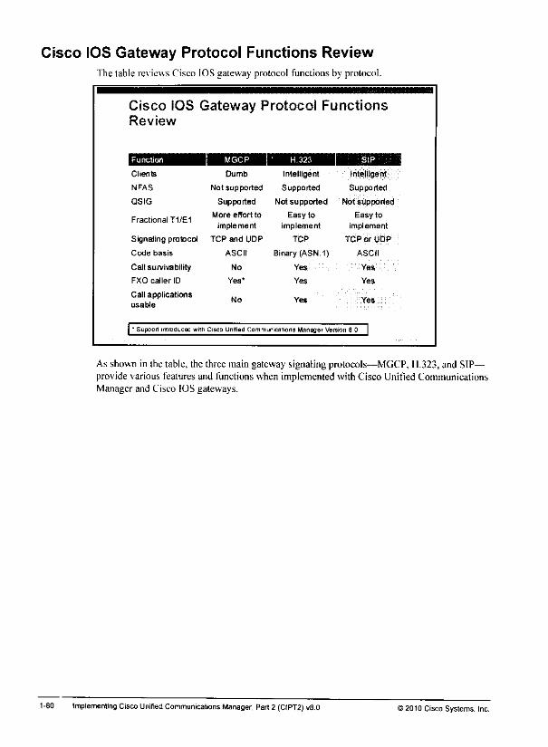
Cisco IOS Gateway Protocol Functions ReviewThe table reviews Cisco IOS gateway protocol functions by protocol.
Cisco IOS Gateway Protocol FunctionsReview
^^^^H Function MGCP H.323 sip ^^H
Clients Dumb Intelligent Intelligent'
NFAS Not supported Supported Supported
QSIG Supported Not supported Not supported
Fractional T1/E1More effort to
implementEasy to
implementEasy to
implement
Signaling protocol TCP and UDP TCP TCP or UDP
Code basis ASCII Binary (ASN.1) ASCII
Call survivability No Yes Yes
FXO caller ID Yes' Yes Yes
Call applicationsusable
No Yes Yes
I' Support irtroQuced with Cisco Unrfied Communications Manager Version 8.0 |
As shown in the table, the three main gateway signaling protocols—MGCP, H.323, and SIP—provide various features and functions when implemented with Cisco Unified CommunicationsManager and Cisco IOS gateways.
1-80 Implementing Cisco Unified Communications Manager, Part 2 (CIPT2) vS.O >2010 Cisco Systems, Inc.

Cisco Unified Communications Manager Connection OptionsOverview j
In Cisco Unified Communications Manager, you can configure gateways and trunks forconnections to the public switched telephone network (PSTN) or to other VoIP domains.
Cisco Unified Communications
Manager Connection Options Overview
• Gateways
- H.323 (any H 323 device when not using a gatekeeper)
- MGCP
Skinny Client Control Protocol
• Trunks
H.323
• Direct connection to another Cisco UnifiedCommunications Manager cluster
• Connection to any H.323 device via a gatekeeper
SIP
* Connection to any SIP device
Gateways areconfigured bv the VoIP protocol (hat they use. Cisco Unified CommunicationsManager supports H.323 gateways. Media Gateway Control Protocol (MGCP) gatewavs. andSkinny Client Control Protocol (SCCP) gatewavs. Trunks canbe configured as H.323 trunks(three types are available) or SIP trunks.
Trunks and gatewavs arcconfigured when connecting to devices that allow access tomultipleendpoints. If thedestination is a single endpoint. phones areconfigured. Phones canbeconfigured as SCCP. SIP. or 11.323.
When Cisco Unified Communications Manager routes calls lo a device that is using MGCP.SCCP. or SIP. it is obvious which type of deviceto add.becausethese protocols can beconfigured onlv with either a gateway or a trunk. In the case of 11.323. however, an H.323gateway aswell as an H.323 trunk can be configured, and it is important to know whether touse the gateway or the trunk. You use H.323 trunks only when connecting toanother CiscoUnified Communications Managerserver (eithera clusteror a standalone Cisco UnifiedCommunications Manager server, in thecaseof Cisco Unified Communications ManagerBusiness fdition) or when using an H.323 gatekeeper.
H.323 gatewavs are configured when connecting toany other H.323 device that isnot anendpoint. Such dev ices can be Cisco IOS H.323 gateways or11.323 gateways ofother vendors.
© 2010 Cisco Systems. Inc Implementing Multisite Deployments 1-79
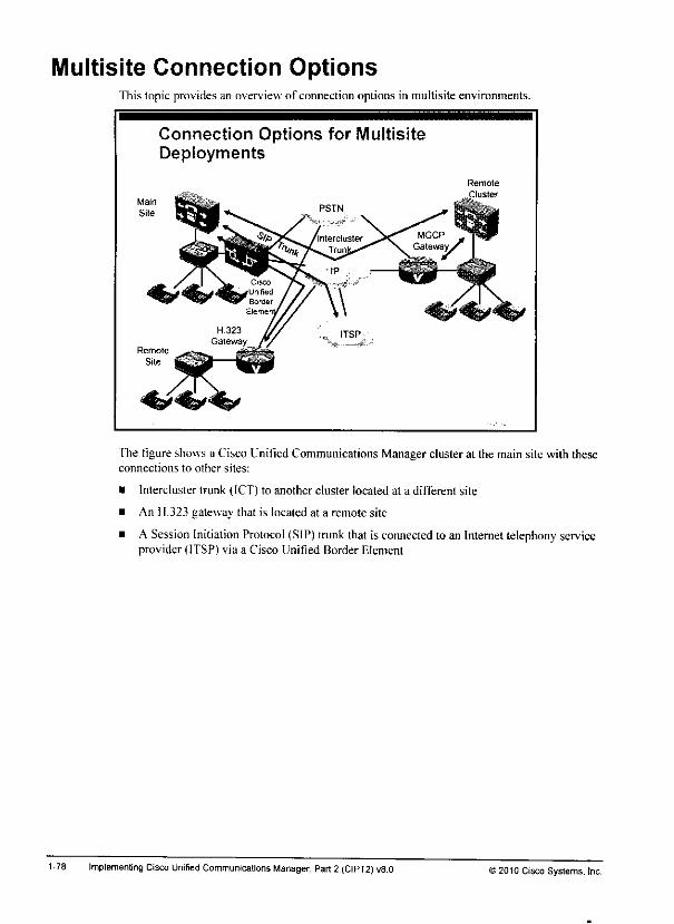
Multisite Connection OptionsThis topic provides an overview of connection options in multisite environments.
Connection Options for MultisiteDeployments
Main
Site
The figure shows a Cisco Unified Communications Manager cluster at the main site with theseconnections to other sites:
• Intercluster trunk (ICT) to another cluster located at a different site
• An H.323 gateway that is located at a remote site
• A Session Initiation Protocol (SIP) trunk that is connected to an Internettelephony serviceprovider (ITSP) via a Cisco Unified Border Element
1-78 Implementing Cisco Unified Communications Manager, Part2 (CIPT2) v8.0 12010 Cisco Systems, tnc.
Lesson 3
Implementing MultisiteConnections
OverviewCisco Unified Communications Manager multisite deployments can use various connectionoptions between sites. Ihis lesson describes connection options and explains how toconfigurethem.
ObjectivesUpon completing this lesson, you will be able toconfigure gateways and trunks inmultisitenvironmenls. This ability includes being able to meet these objectives:
Identify thecharacteristics ofthe trunk and gateway types that aresupported by CiscoUnified Communications Manager
Describe how lo implement MGCP gateways
Describe bow to implement 11.323 gateways
Describe various types of trunks that aresupported byCisco Unified CommunicationsManager
Describe how to implement SIPtrunks in Cisco Unitied Communications Manager
Describe how to implemeni intercluster and H.225 trunks in Cisco UnitiedCommunications Manager

1-76 Implementing Cisco Unified Communications Manager, Part2 (CIPT2) vS.O © 2010 Cisco Systems; Inc.

References
for additional information, refer to these resources:
• Cisco Svstems. Inc. Cisco Unified Communicalions System 8.x SRND, April 2010.lutp: Asww.cisco.com/en/US/docs.voice ip comm/cucm/^rnd/8\/uc8\.h(inl
• Cisco Svstems. Inc. ('isco (Unified Communications Manager Administration GuideRelease 8.0(1). February 2010.
Imp: 'wwu,ciscn.com/eiiT,S/doev\oice_ip_comm/cucm/admin/8 OJ/cemciU/bccm-801cm.him!
©20)0 Cisco Systems. Inc Multisite Deployment Implementation 1-75
Summary
1-74
This topic summarizes the key points that were discussed in this lesson.
Summary
• Multisite deployment solutions include QoS, efficient use ofIP WAN bandwidth, backup scenarios in caseof WAN failureaccess and site codes, and the use ofthe Cisco UnifiedBorder Element.
•QoS allows certain communication flows to be processedwith higher priority than others.
You can conserve bandwidth by using low-bandwidth codecsdeploying mixed conference bridges or transcoders using 'RTP-header compression, and deploying local mediaresources.
Summary (Cont.)
• Cisco Unified Communications Manager availability featuresinclude fallback for IP phones, CFUR, AAR, and CFNB andmobility features such asCisco Device Mobility, Cisco 'Extension Mobility, and Cisco Unified Mobility.
•You can build multisite dial plan solutions by using Cisco IOSgateway and Cisco Unified Communications Manaqer dialplan tools.
ACisco Unified Border Element in flow-through modecompletely hides internal devices, such as Cisco UnifiedCommunications Manager and IP phones, from the outside
Implementing Cisco Unified Communications Manager, Part 2(CIPT2) v8.0'2010 Cisco Systems. Inc.
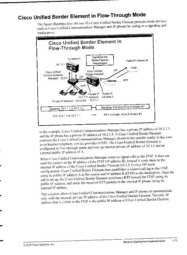
Cisco Unified Border Element in Flow-Through ModeThe figure illustrates how the use ofaCisco Unified Border Element protects inside devicessuch afasco Unified Communications Manager and IP phones by acting as asignaling andmedia proxy.
Cisco Unified Border Element inFlow-Through Mode
10.1 1 1
Cisco UnifiedCommunications
Manager SCCP
Company ASignaling andMedia Packets
Repackaged
Private IP Public IP10.2.1.5 Address: AddressA
Private IP Network' 1000.0/8 10.3.1.1
Public IP Address B
ITSP
..1.1.110 10 31.1 |~| Signaling: A(Public IP) to B(Public IP) |Signaling: 10.
RTP-1Q2.1.5.O10311 — RTP: A(Public IP) to B(Public IP)
In the example. Cisco Unilied Communications Manager has aprivate IP addrcs of 10.1.1.1.and the IP phone has aprivate IP address of 10.2.1.5. ACisco Unified Border Elemento , t the Cisco Unified Communications Manager cluster to the outside world, in this case.^ ninternet telephony service provider (ITSP,. The Cisco Uinfie Border hcment isconfigured in flou-through mode and uses an internal private IP address ot 10... Iand anexternal public IP address of A.When Cisco Unified Communications Manager wants to signal calls to the ITSP. it does notTend he packets to the IP address ofthe ITSP (IP address D). Instead it sends them to the
ternalkddressoHhe^configuration Cisco Unified Border Element then establishes asecond cal leg to the 1ISP.unCi blic IP address Aas the source and IP address B(ITSP) as the desUr.Uo^Occ thecall is set up the Cisco Unified Border Element terminates Rl Ptoward the ITSP. using itspX II' address, and sends the received RTP packets to the internal IP phone, using itsinternal IP address.
This solution allows Cisco Unified Communications Manager and IP phones to communicateon v htne ntemal. priv ate IP address ofthe Cisco Unified Border Element, he onlv IP
dre h sible to the ITSP is the public IP address ofCisco Unified Border f.lcment.
2010 Cisco Systems, incMultisite Deployment implementation 1-73
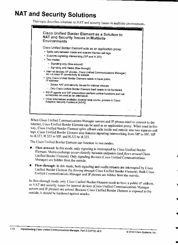
NAT and Security Solutions
1-72
This topic describes solutions to NAT and security issues in multisiteenvironments.
CiscoUnified Border Element as a Solution toNAT and Security Issues in MultisiteEnvironments
Cisco Unified Border Element acts as an application proxy:• Splits calls between inside and outside into two call legs.• Supports signaling interworking{SIPand H.323).• Two modes:
- Signaingonly(flow-around)- Signaling andmedia (flow-through)
*h?!6^,31 £!?ms (IP phores- Cisco Unified Communications Manager)do not need IPconnectivity to outside.
" &nl*,Fisco ^"'^ Bordw dement needs tohave publicIP address ^
- Solves NAT andsecurity issuesforinternal devices.- Only Cisco Unified Border Element itself needs to behardened.
" ?SJ^-a9en? and flp P^ndition perform similar functions and cansometimes be used as an alternative.
" °!lnert;alte™fives avaiable (trusted relay points, proxies in CiscoAdaptive SecuntyApptance [ASA])..
When Ctsco Unified Communications Manager servers and IP phones need to connect lo theInternet. Cisco Unified Border Element can be used as an application proxy. When used in thisway, Cisco Unified Border Element splits off-net calls inside and outside into two separate call
,,'.-!f° °rder Element also features signaling interworking from SIP to SIP SIPto 11.323, H.323 to SIP.and H.323 to H.323.
The Cisco Unified Border Element can function in two modes:
• Flow-around: In this mode, only signaling is intercepted by Cisco Unified BorderElement Media exchange occurs directly between endpoints (and>*M around CiscoUnified Border Element). Only signaling devices (Cisco Unified CommunicationsManager) are hidden from the outside.
' ,Fi°r"?M0U?h: In thiS m0dc" both siSnalinS **media slr<*ms are intercepted by CiscoUnified Border Element (byflowing through Cisco Unified Border Element). Both CiscoUnified Communications Manager and IP phones are hidden from the outside.
In flow-through mode, only Cisco Unified Border Element needs to have apublic IP addressso NAT and security issues for internal devices (Cisco Unified Communicalions Manager 'ouZe it sh tTu 7 I"'-B£CaUSe CiSC° Unified B0nler Hlement is "P""" ^theoutside, it should be hardened against attacks.
Implementing Cisco Unitied Communications Manager, Part 2(CIPT2) vS.O©2010 Cisco Systems. Inc.

Localization of callingparty numbers a. phones: Caller IDs sPl yed at phon nalso be localized so that the end users are not lim.ted to seeing all callers ,n W»A™*fonnat Again, global transfonnations (ofthe calling-party number only in this case) canTsed sothat caller 1Ds. which might be different at each site. -™^^^'^format Similarh. the globalized calling-party number is also maintained in call lists so thatusers can place callbacks to globalized numbers without needing lo edit the number.
Substantial simplification of dial plans: With local route groups and globaltransfonnations. globalized call routing drastically reduces the s™^™^™%£*ld]plans Features such as TEHO. AAK. SKST. CEUR. Cisco Device Mobil, y. and CiscoExtension Mobilitv can be implemented much more easily in international deployments.
© 2010 Cisco Systems. IncMultisite Deployment Implementation 1-71
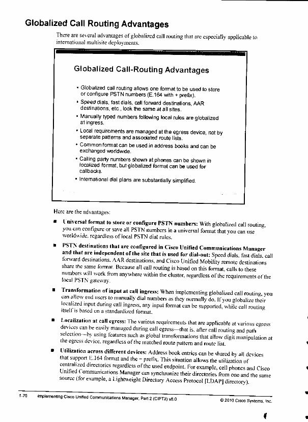
Globalized Call Routing Advantages
1-70
There are several advantages ofglobalized call routing that are especially applicable tointernational multisite deployments.
Globalized Call-Routing Advantages
• Globalized call routing allows one format to be used to storeorconfigure PSTN numbers (E.164 with +prefix).
• Speed dials, fastdials, call forward destinations, AARdestinations, etc., look the same at all sites.
• Manually typed numbers following local rules areglobalizedat ingress.
• Local requirements are managed atthe egress device, not byseparate patterns and associated route lists.
• Common format can be used inaddress books and can beexchanged worldwide.
• Calling party numbers shown at phonescan be shown inlocalized format, but globalizedformatcan be used forcallbacks.
• International dial plans aresubstantially simplified.
Hereare the advantages:
• Universal format to store or configure PSTN numbers: With globalized call routingyou can configure or save all PSTN numbers in auniversal format that you can useworldwide, regardless of local PSTN dial rules.
• PSTN destinations that are configured in Cisco Unified Communications Managerand that are independent ofthe site that is used for dial-out: Speed dials fast dials callforward destinations. AAR destinations, and Cisco Unified Mobility remote destinationsshare the same format. Because all call routing is based on this format, calls to thesenumbers will work from anywhere within the cluster, regardless ofthe requirements ofthelocal PSTN gateway.
• Transformation of input at call ingress: When implementing globalized call routing voucan allow end users to manually dial numbers as they normally do. Ifyou globalize theirlocalized input during call ingress, any input format can be supported, while call routineitself is based on a standardized format.
• Localization at call egress: The various requirements that are applicable at various egressdevices can be easily managed during call egress—that is, atler call routing and pathselection-^ using features such as global transformations that allow digit manipulation atthe egress device, regardless ofthe matched route pattern and route list.
• Utilization across different devices: Address book entries can be shared by all devicesthat support E.164 format and the +prefix. This situation allows the utilization ofcentralized directories regardless ofthe used endpoint. For example, cell phones and CiscoUnified Communications Manager can synchronize their directories from one and the samesource (tor example, aLightweight Directory Access Protocol [LDAP] directory)
Implementing Cisco Unified Communications Manager, Part 2(CIPT2) v8.0©2010 CiscoSystems, Inc.
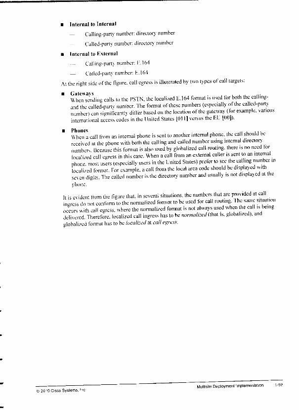
• Internal to Internal
— Calling-party number: directorv' number
— Called-party number: directorv' number
• Internal to External
Calling-part} number: f.164
— Called-party number: H.164
At the right side ofthe figure, call egress is illustrated by two types of call targets:
• Gateways ...When sending calls to the PSTN, the localized E.164 format is used tor both the callmg-and the called-partv number. The fonnat of these numbers (especially ofthe called-partynumber) can significant differ based on the location ofthe gateway (for example, variousinternational access codes in the United States [0111 versus the LTJ [00]).
• Phones , , , „ , ,,,When acall from an internal phone is sent to another internal phone, the call should bereceived at the phone with both the calling and called number using internal director}numbers Because this fonnat is also used by globalized call routing, there ,s no need iorlocalized call egress in this case. When acall from an external caller is sent to an internalphone! most users (especially users in the United States) prefer lo see the calhng number ,nlocalized fonnat. For example, acall from the local area code should be displayed withsev en digits. The called number is the director}' number and usually is not displayed al thephone.
It is evident from the figure that, in several situations, the numbers that are provided at callingress do not conform to the normalized format to be used for call routing. 1he same situationoccurs with cal! egress, where the normalized fonnat is not always used when the call is beingdelivered. Therefore, localized call ingress has to be normalized (that is. globalized), andglobalized fonnat has to be localized at call egress.
® 2010 Cisco Systems. IncMultisite DeploymentImplementation 1-69

Globalized Call Routing—Three Phases
1-68
The figure provides an overview about the three phases that are involved in globalized callrouting.
On the left side ofthe figure, call ingress is illustrated by two types ofcall sources:• External callers: Their calls are received by Cisco Unified Communications Manager
through agateway or tmnk. In aPSTN gateway, calling- and called-party number areusuallv provided in localized E.164 format.
• Internal callers: Their calls are received from internal phones. Ifcalls to internaldestinations (for example, phone to phone), calling- and called-party numbers are typicallyprovided as internal directory numbers. Ifcalls to extemal destinations (for example, phoneto PSTN), the calling number is the directory number (at call ingress time) and the callednumber depends onthe local dial rules for PSTN access. These dial rules can differsignificantly per location.
The center ofthe figure illustrates the standards that are defined for normalized call routing Asmentioned earlier, because most calls use global E.164 format, this process is also referred to asglobalized call routing. Here arethedefined standards:
• External to internal
— Calling-party number: E.164
— Called-party number: directory number
• External to external (if applicable)
— Calling-party number: E.164
Called-party number: E.164
Implementing Cisco Unified Communications Manager, Part 2(CIPT2) v8.0©2010 Cisco Systems, Inc
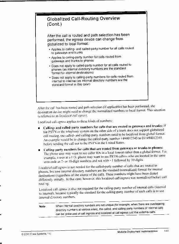
Globalized Call-Routing Overview(Cont.)
Afterthe call is routed and path selection has beenperformed, theegress device can change fromglobalized to local format;• Applies to calling- and called-party number for all calls routed
to gateways and trunks• Applies to calling-party number for calls routed from
gateways and trunksto phones* Does not apply to called-party number for all calls routed to
phones (as internal directory numbers are the standardformatfor internal destinations)
• Does not apply to calling-party numbers for calls routed frominternal to internal (as internal directory numbers are thestandard format in this case)
Alter the call has been routed and path selection (ifapplicable) has been performed, thedestination dev ice might need to change the nomialized numbers lo local format. 1his situationis referred to as localized cal! egress.
Localized call egress applies tothese kinds ofnumbers:• Calling- and called-partv numbers for calls that are routed to gateways and trunks: If
the PSTN or the telephonv svstem on the other side of atrunk docs not support globalizedcall routine the called- and calling-party numbers need lo be localized from global format.An example would be to change the called-party number +494012345 to 011494012345before sending the call out tothe PSTN in the United Slates.
• Calling-party numbers for calls that are routed from gateways or trunks to phones:fhe nhone user mav want to see caller IDs in alocal format rather than aglobal format, forexample, auser at aU.S. phone may want to see PSTN callers who are located in the samearea code as 7- or 10-digil numbers and not with »1 followed by 10 digits.
1ocalized call egress is not needed for the called-party number of calls that are routed tophones because internal director}' numbers are the standard (normalized) formal for internaldestinations (regardless ofthe source ofthe call). These numbers might have been dialedditTerentlv initially. In that case, however, this localized call ingress was normalized before callrouting.
Localized call egress is also not required for the calling-party number of internal calls (internalto internal), because typically the standard for ihe calling-parly number ot such calls is lo useinternal directory numbers.
Note
12010 Cisco Systems. Inc
When internal directory numbers are not unique (for example, when there are overlappingdirectory numbers at various sites), the called- and calling-party numbers of internal callscan be globalized at call mgress and localized at call egress just like external calls.
Multisite Deployment Implementation 1-67
1-66
Assuming that all internal directory numbers are unique, this format is the most common:• Normalized called-party numbers: K. 164 global format with a+prefix is used for
extemal destinations. Therefore, called-number normalization is achieved by globalizationInternal directory numbers are used for internal destinations. Normalization is achieved bv'stripping or translating the called number to internally used directory numbers.
• Normalized calling-party numbers: E.164 global format with a+prefix is used for allcalling-party numbers, except for those formats ofcalls from internal to internal Suchpurely internal calls use the internal directory number for the calling-party number.
If sources of calls (users at phones, incoming PSTN calls at gateways, calls received throughtmnks. and so on) do not use normalized format, the localized call ingress needs to benormalized before being routed. This principle applies to all received calls (coming fromgateways and tmnks as well as from phones), and it applies to both the calling- and called-partv
Note Except for the mentioned internal calls (where the destination is adirectory number and inthe case of an internal source, the source is a directory number), all numbers are normalizedto E.164 global format. Therefore, this call-routing implementation model is referred to asglobalized callrouting.
implementing Cisco Unified Communications Manager, Pari 2(CIPT2) v8.0 " ©2010 Cisco Systems, Inc.
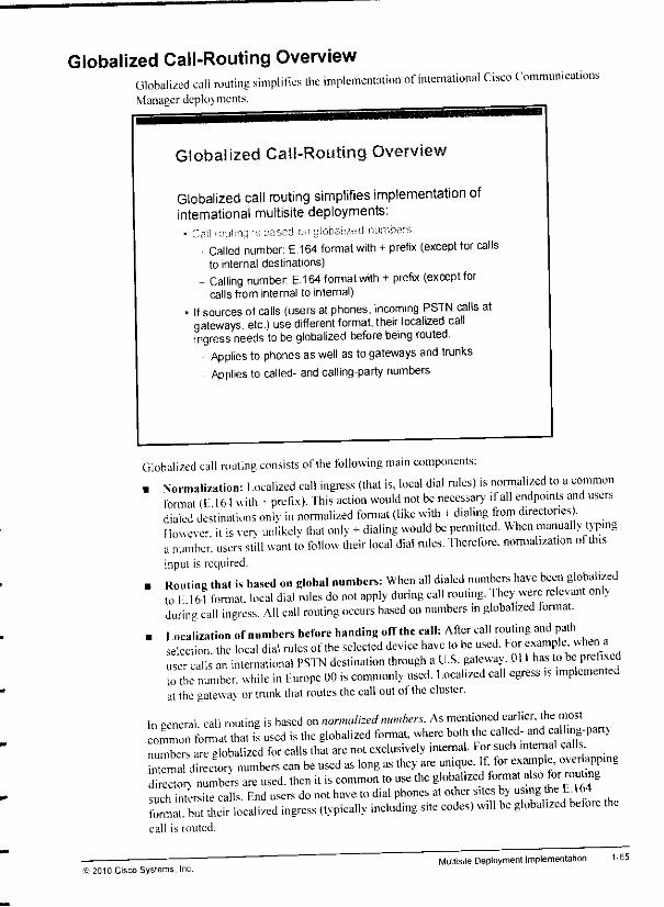
Globalized Call-Routing OverviewGlobalized call routing simplifies the implementation of international Cisco CommunicationsManager depknments.
Globalized Call-Routing Overview
Globalized call routing simplifies implementation ofInternational multisite deployments:• Gail routing ss based on globalised nnmDers
• Called number: E.164 format with + prefix (except for callsto internal destinations)
- Calling number E.164 format with +prefix (except forcalls from internal to internal)
• If sources ofcalls (users at phones, incoming PSTN calls atgateways, etc.) use different format, their localized callingress needs to be globalized before being routed.
Applies to phones aswell asto gateways and trunksApplies to called- and calling-party numbers
Globalized call routing consists ofihe following main components:. Normalization: Localized call ingress (that is, local dial rules) is normalized to acommon
fonnat (E 164 with +prefix). This action would not be necessary if all endpoints and usersdialed destinations onlv in normalized format (like with 4dialing from directories).However it is serv unlikelv that only +dialing would be pennilted. When manually typinganumber, users still want to follow their local dial rules. Therefore, normalization of tinsinput is required.
. Routing that is based on global numbers: When all dialed numbers have been globalizedto L164 format, local dial rules do not apply during call routing. They were relevant onlyduring call ingress. All call routing occurs based on numbers in globalized format.
. Ioealization of numbers before handing off the call: After call routing and pathselection, the local dial rules ofthe selected device have to be used, for example when auser calls an international PSTN destination through aU.S. gateway 011 has to be prefixedto the number, while in Europe 00 is commonly used. Localized call egress ,s implementedat the gatewav or tmnk that routes the call out oi the cluster.
In general, call routing is based on normalized numbers. As mentioned earlier, the mostLion format that if used is the globalized format, where both the called- and caling.part}
numbers are globalized for calls that are not exclusively internal. For such internal calls^8^00 numbers can be used as long as they are unique. If, for example, over appingdie'on numbers are used, then it is common to use the globalized format also or rouingsuch int'ersite calls. End users do not have to dial phones at other sites by using the ET 64formal, but their localized ingress (typically including site codes) will be globalized before thecall is routed.
© 2010 Cisco Systems, Inc.Multisite Deployment Implementation 1-65
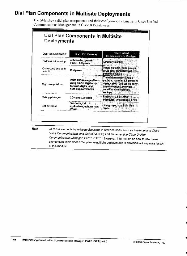
Dial Plan Components in Multisite DeploymentsThe table shows dial plan components and their configuration elements inCisco UnifiedCommunications Manager and inCisco IOS gateways.
1-64
Note
Dial Plan Components in MultisiteDeployments
Dial Plan Component Cisco IOS Gateway
Endpoint addressing SilSS6^"' <**"Mnic* POTS,dialpeers
Cal routing and path „ ,selection Dialpeers
Digit manipulation
Caling privieges
Cal coverage
Voicetranslation profilesusing prefix, dlgjt-«trlp.forward-digit*, andnum-exp commands
COR and COR Hats
raalpeers/catr""" " ~~appicaa'ons, ephone huntgroups
Cisco UnitiedCommunications Manager
Dfrectorynumtter
Routepatterns,routegroups,route Isfs, translationpatterns,partitions. CSSs
Translationpatterns, routepatterns, route lists, significantdigits, catted-amicaMhg-parfytransformations, fccomingcaibd-artdcailng-pafty
Partitions, CSSs, limeschedules, time periods, FACs
Line groups, hunt lists, hunt
Alt these elements have been discussed in other courses, such asImplementing CiscoVoice Communications and QoS (CVOICE) and Implementing Cisco UnifiedCommunications Manager, Part 1(CIPT1). However, information onhow touse theseelements to implement a dial plan in multisite deployments is provided in a separate lessonof this module.
Implementing Cisco Unified Communications Manager, Part 2(CIPT2) v8.0'2010 Cisco Systems. Inc.

Least Cost Routing, tail-end hop-off (TEHO), and PSTN backup: Can be implementedb> appropriate call routing and path selection that is based on priorities.Globalized call routing: In this dial plan implementation, all received calls arc normalizedtoward a standardized fonnal. fhe formal that isused in call routing isglobalized format,because all numbers are represented in E. 164 format with a4 prefix, 'fhe process ofnomializine the numbers as dialed by end users (localized ingress) istherefore also referredto as globaUzation. Once the localized input has been globalized during ingress, the call isrouted based on globalized numbers. After call routing and path selection, the callednumber is localized during call egress, depending on the selected egress device.
©2010 Cisco Systems, IncMultisite Deploymenl Implementation 1-63
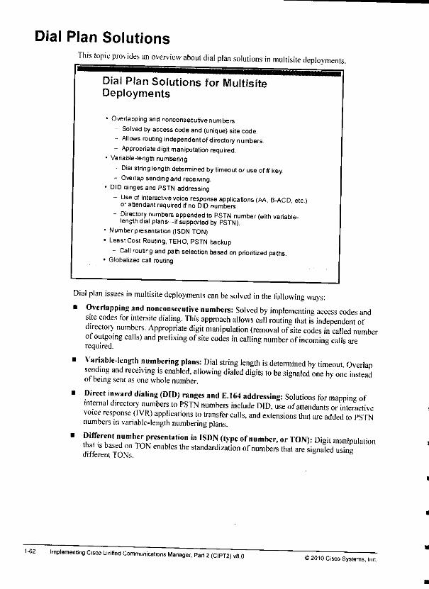
Dial Plan SolutionsThis topic provides an overview about dial plan solutions in multisite deployments
1-62
Dial Plan Solutions for MultisiteDeployments
• Overlapping and nonconsecutivenumbers- Solved by access codeand (unique) sitecode.- Allows routing independent directory numbers.- Appropriate digit manipulation required.
• Variable -length numbering
- Dial string length determined by timeout oruse of# key.- Overlapsendingand receiving.
* DID ranges and PSTN addressing- Use ofinteractive voice response applications (AA B-ACD etc
or attendant required rfno DID numbers.
- Directory numbers appended toPSTN number (with variable-length dial plans—if supported by PSTN).
• Numberpresentation (ISDN TON)• LeastCost Routing, TEHO, PSTN backup
- Call routing and path selection based on prioritized paths.• Globalized call routing
Dial plan issues in multisite deployments can be solved in the following ways:• Overlapping and nonconsecutive numbers: Solved by implementing access codes and
site codes tor intersite dialing. This approach allows call routing that is independent ofdirectorv numbers. Appropriate digit manipulation (removal ofsite codes in called numberof outgoing calls) and prefixing ofsite codes in calling number ofincoming calls arerequired.
• Variable-length numbering plans: Dial string length is determined by timeout Overlapsending and receiving is enabled, allowing dialed digits to be signaled one by one insteadof being sent as one whole number.
• Direct inward dialing (DID) ranges and E.164 addressing: Solutions for mapping ofinternal directory numbers to PSTN numbers include DID, use ofattendants or interactivevoice response (IVR) applications to transfer calls, and extensions that are added to PSTNnumbers invariable-length numbering plans.
' 5ITT1 TmbT^reSeu!aIi0n '" 'SDN (,ype °f number'or T0N>: Di8jt manipulationthat ,s based on TON enables the standardization of numbers that are signaled usingdifferent TONs.
Implementing Cisco Unified Communications Manager, Part 2(CIPT2) vS.OS2010 Cisco Systems, Inc.

Mobility SolutionsThis subtopic provides an overv iew about mobility solutions that solve issues that are the resultof roaming users and devices, and multiple telephones (office phone, cell phone, home phone,and so on).
Mobility Solutions
When users or devices roam, the resulting limitations infeatures can be solved by mobilitysolutions:
• Cisco Device Mobility- Solves issuesthat result from roaming devices (region, location,
SRST reference, AAR group, CSS. etc.)- Makes Cisco Unified Communications Manager aware of
physical location of IP phone (usually software phone such asCisco IP Communicator)
• Cisco Extension MobilitySolves issueofmissing personal IPphone setting that resultsfrom using a different IPphone in another office (directorynumber. CSS, etc.)
- Allows users to log in to IP phone and get personal configurationapplied to currently used IP phone
» Cisco Unified MobilitySolves issuesofhaving different phones (office IP phone, cellphone, home officephone, etc )Allows usersto be reached by a single number, independent ofthephonethat is actually used
When users or de\ ices roam between sites, issues arise that can be solved by these mobilitysolutions:
• Cisco De* ice Mobilitv: Solves issues that arc caused by roaming devices, includinginvalid device configuration settings such as regions, locations, SRST reference. AARgroups, calling search spaces (CSSs). and so on. The Cisco Device Mobility feature of _Cisco Unitied Communications Manager allows device settings that depend on the physicallocation ofthe device to be automatically overwritten ifthe device appears in adifferentphvsical location.
. Cisco Extension Mobilitv: Solves issues that are the result of roaming users using sharedguest IP phones that are located in other offices. Issues include wrong directory number,missing IP Phone Services subscriptions. CSS. and so on. Cisco Extension Mobility allowsusers to log in to guest phones and to replace the configuration ot the IP phone with the IIphone configuration ofthe logged-in user.
• Cisco I'nified Mobilitv: Solves issues of having multiple phones and consequentlymultiple phone numbers, such as an office phone, cell phone, home (office) phone, and soon. Cisco Unitied Mobility allows users to be reached by asingle number, regardless ot thephone that isactually used.
Note Cisco Device Mobility and Cisco Extension Mobility will be discussed in detail in laterlessons of this course. Cisco Unified Mobility has been discussed in detail in theImplementing Cisco Unified Communications Manager, Part 1(CIPT1) course
© 2010 Cisco Systems. IncMultisite Deploymenl Implementation 1-61
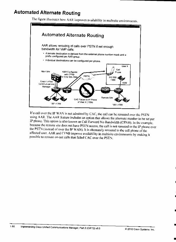
Automated Alternate RoutingThe figure illustrates how AAR improves availability in multisite environments.
1-60
Automated Alternate Routing
AAR allows rerouting of calls over PSTN if not enoughbandwidth for VoIP calls:
• Alternate destination isderived from theextemal phone number mask and ,prefix configured per AAR group.
• Individual destinations canbe configured perphone.
Cisco Unified
CommunicationsManager
CAC Failure lo IP Phoneof User X (1009)
Ifa call over the IP WAN is not admitted by CAC, the call can be rerouted over the PSTNusing AAR. The AAR feature includes an option that allows the alternate number to be set perIP phone. This option is also known as Call Forward No Bandwidth (CFNB) In the examplebecause the remote site does not have PSTN access, the call is not rerouted to the IP phone overthe PSTN (instead of over the IP WAN). It is alternately rerouted to the cell phone oftheaffected user. AAR and CFNB improve availability in multisite environments by making itpossible to reroute on-net calls thatfailed CAC overthe PSTN.
Implemenling Cisco Unrfied Communications Manager, Part 2(CIPT2) v8.0©2010 Cisco Systems, Inc.
m
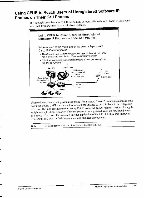
Using CFUR to Reach Users of Unregistered Software IPPhones on Their Cell Phones
This subtopic describes how CFUR can be used to route calls lo the cell phones of users whohave shut down PCs that have asoftphone installed.
Using CFUR to Reach Users ofUnregisteredSoftware IP Phones on Theif Cell Phones
When a user at the main site shuts down a laptop withCisco IP Communicator:• The Cisco Unified Communications Manager ofthemain site does
not route callstothe affected IPphone directory number.- CFUR allows routing toalternate numbers ofuser (for example, a
cell phone number)
Main Site Communicator
PC Shutdown
1007 UnregisteredCFUR
9 1512 555-1999
_y
Cell
Phone
E12 555-1999
If amobile user has alaptop with asoftphone (for instance, Cisco IP Communicator) and shutsdown the laptop. CFUR can be used to forward calls placed to the softphone to the cell phoneof auser The user docs not have to set up Call Forward All (Cl'A) manually before closing thesoftphone application. However, if the softphone is not registered, calls are forwarded to thecell phone ofthe user. This action is another application ofthe CFUR feature that improvesavailabilitv in Cisco Unified Communications Manager deployments.
Note This application isfor CFUR, which isnot related to SRST.
© 2010 Cisco Systems. Inc.Multisite Deployment Implementation 1-59
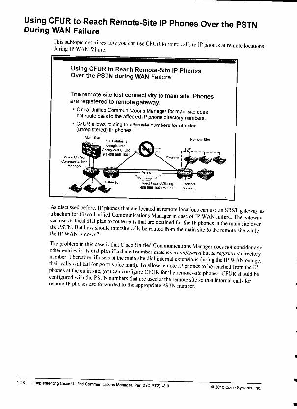
Using CFUR to Reach Remote-Site IP Phones Over the PSTNDuring WAN Failure
This subtopic describes how you can use CFUR to route calls to IP phones at remote locationsduring IP WAN failure.
1-58
Using CFUR to Reach Remote-Site IP PhonesOver the PSTN during WAN Failure
The remote site lost connectivity to main site. Phonesare registered to remotegateway:• Cisco Unified Communications Manager for main site does
not route calls tothe affected IP phone directory numbers.- CFUR allows routing to alternate numbers for affected
(unregistered) IP phones.
As discussed before, IP phones that are located at remote locations can use an SRST gateway asabackup for Cisco Unified Communications Manager in case of IP WAN failure The gateway-can use its local dial plan to route calls that are destined for the IP phones in the main site overthe PSTN. But how should intersite calls be routed from the main site to the remote site whilethe IP WAN is down?
The problem in this case is that Cisco Unified Communicalions Manager does not consider anvother entries in its dial plan ifadialed number matches aconfigured but unregistered directory'number. Therefore, if users al the main site dial internal extensions during the IP WAN outagetheir calls will fail (or go to voice mail). To allow remote IP phones to be reached from the IP 'phones at the main site, you can configure CFUR for the remote-site phones CFUR should beconfigured with the PSTN numbers that are used at the remote site so that internal calls forremote IPphones are forwarded to the appropriate PSTN number.
Implementing Cisco Unified Communications Manager, Part 2(CIPT2) v8.052010 Cisco Systems. Inc.
1
J
J
J
J
J
J
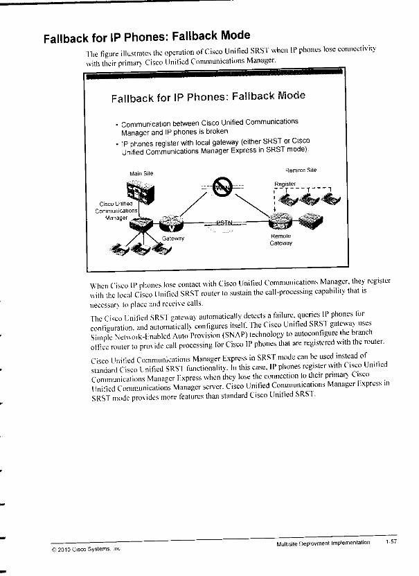
Fallback for IP Phones: Fallback Modefhe figure illustrates the operation of Cisco Unified SRST when IP phones lose connectiv.htvith their primary- Cisco Unified Communications Manager.
Fallback for IP Phones: Fallback Mode
• Communication between Cisco Unified CommunicationsManager and IP phonesis broken.
• IP phones register with local gateway (either SRST or CiscoUnified Communications Manager Express in SRST mode).
Main Sile
Cisco Unified
Communications
Manager
Remote Site
Register
Remote
Gateway
When Cisco IP phones lose contact with Cisco Unified Communications Manager, they registerwith the local Cisco Unified SRST router lo sustain the calI-processing capability that isnecessary toplace and receive calls.The Cisco Unified SRST gatewav automatically detects afailure, queries IP phones forconfiguration, and automaticallv configures itself. The Cisco Unified SRST gateway usesSimple Netuork-lnablcd Auto Provision (SNAP) technology to autoconfigure the branchoffice router to prm ide call processing for Cisco IP phones that are registered with the router.Cisco Unified Communications Manager Express in SRST mode can be used instead ofstandard Cisco Unified SRST functionality. In this case. IP phones register with Cisco UnifiedCommunications Manager F.xpress when they lose the connection to their primary CiscoUnified Communications Manager server. Cisco Unified Communications Manager F.xpress mSRST mode provides more features than standard Cisco Unified SRSI.
© 2010 Cisco Systems. IncMultisite Deployment Implementation 1-57
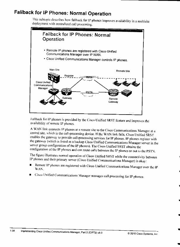
Fallback for IP Phones: Normal OperationThis subtopic describes how fallback for IP phones improves availability in amultisitedeployment with centralized call processing.
1-56
Fallback for IP Phones: NormalOperation
• Remote IPphones are registeredwith Cisco UnifiedCommunications Managerover IPWAN.
• Cisco Unified Communications Manager controls IP phones.
Main Site
Cisco Unified
CommunicationsManager
Remote
Gateway
Fallback for IP phones is provided by the Cisco Unified SRST feature and improves theavailability of remote IPphones.
AWAN link connects IP phones at aremote site to the Cisco Communications Manager at acentral site, which is the call-processing device. Ifthe WAN link fails, Cisco Unified SRSTenables the gateway to provide call-processing services for IP phones. IP phones register withthe gateway (which is listed as abackup Cisco Unified Communications Manager server in theserver group configuration ofthe IP phones). The Cisco Unified SRST obtains theconfiguration ofthe IP phones and can route calls between the IP phones or out to ihe PSTN.The figure illustrates normal operation of Cisco Unified SRST while the connectivity betweenIP phones and their primary server (Cisco Unified Communications Manager) is okay:' «f!T?e 'Pph°nes ^ reSis,ered with Cisco lJn'ted Communications Manager over the IP
WAN.
• Cisco Unified Communications Manager manages call processing for IP phones.
Implementing Cisco Unified Communications Manager, Part 2(CIPT2) v8.0©2010 Cisco Systems, Inc
L
L
L
L
I
1
£
1
1
1
J
J
J
J
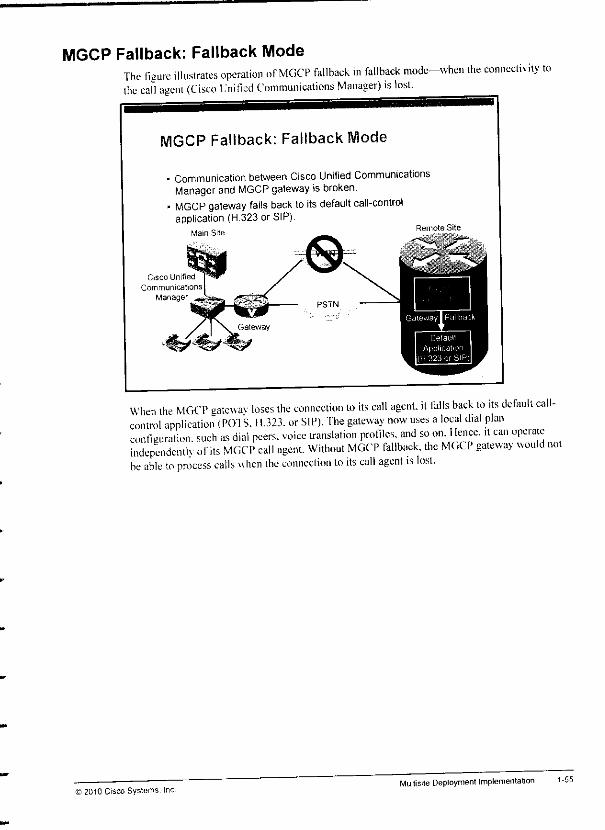
MGCP Fallback: Fallback ModeThe figure illustrates operation of MGCP fallback in fallback mode-when the connectivitythe call agent (Cisco Unified Communications Manager) is lost.
MGCP Fallback: Fallback tVlode
• Communication between Cisco Unified CommunicationsManager and MGCP gateway is broken.
• MGCP gateway falls back toits default call-controlapplication (H.323 or SIP).
Main Site
to
When the MGCP gatewav loses the connection to its call agent, it falls back to its detault call-control application (POTS. H.323. or SIP). The gateway now uses alocal dial planconfiguration, such as dial peers, voice translation profiles, and so on. Ilence. .1 can operateindependent ofits MGCP call agent. Without MGCP fallback, the MGCP gateway would notbe able to process calls when the connection to its call agent is lost.
© ?010 Cisco Systems.Multisite Deployment Implementation 1-55

MGCP Fallback: Normal OperationThis subtopic describes how MGCP fallback improves availability in amultisite
1-54
MGCP Fallback: Normal Operation
• MGCP gateway isregistered with Cisco Unified CommunicationsManager over IP WAN.
• Cisco Unified Communications Manager isthe MGCP call aqentcontrolling the MGCP gateway.
environment.
MGCP gateway fallback is afeature that improves the availability of remote MGCP gateways.AWAN link connects the MGCP gateway ataremote site to the Cisco UnifiedCommunications Manager at acentral site, which is the MGCP call agent. Ifthe WAN linkfails, the fallback feature keeps the gateway working as an H.323 or SIP gateway and re-homesback to the MGCP call agent when the WAN link becomes active again.The figure illustrates normal operation of MGCP fallback while the connectivity lo the callagent (Cisco Unified Communications Manager) is okay:
• The MGCP gateway is registered with Cisco Unified Communications Manager over the IPWAN.
• Cisco Unified Communications Manager is the call agent ofthe MGCP gateway that iscontrolling its interfaces. The gateway does not have (or does not use) alocal dial planbecause all call-routing intelligence is at the call agent.
Implementing Cisco Unified Communications Manager, Pari 2(CIPT2) v8.0>2010 Cisco Systems, Inc.
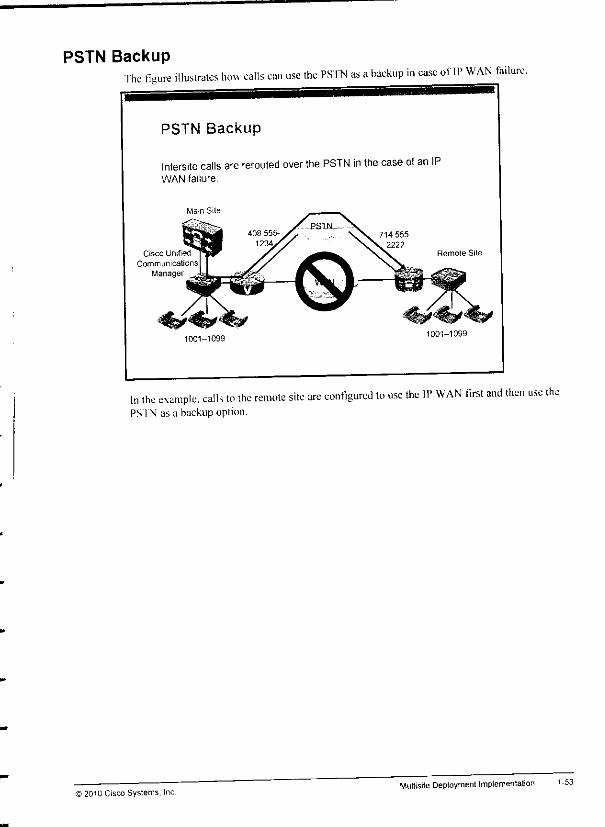
PSTN BackupThe figure illustrates how calls can use the PSTN as abackup in case oflP WAN failure.
PSTN Backup
Intersite calls are rerouted over the PSTN in the case of an IPWAN failure.
Main Site
Cisco Unified
Communications
Manager
1001-10991001-1099
In the example, calls to the remote site arc configured to use the IP WAN first and then use thePS 1N as a backup option.
i 2010 Cisco Systems, IncMultisite Deployment Implementation 1-53
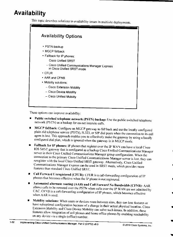
Availability
1-52
This topic describes solutions to availability issues in multisite deployments.
Availability Options
1 PSTN backup
1 MGCP fallback
1Fallback for IP phones:
- Cisco Unified SRST
- Cisco Unified Communications Manager Expressin Cisco Unified SRST mode
CFUR
AAR and CFNB
Mobilitysolutions:
- Cisco Extension Mobility- Cisco Device Mobility- Cisco Unified Mobility
These options can improve availability:
• Public switched telephone network (PSTN) backup: Use the public switched telephonenetwork (PSTN) as a backup foron-net intersite calls.
B ^GCP fallback: Configure an MGCP gateway to fall back and use the locally configuredplain old telephone service (POTS), H.323, or SIP dial peers when the connection to its callagent .s lost. This approach enables you to effectively make the gateway by using alocallvconfigured dial plan, which is ignored when the gateway is in MGCP mode.
' !?i,bcaCk f°r IP phonCS: IP Phones thal reSister °ver the IP WAN can have alocal CiscoIOS SRST gateway that is configured as abackup Cisco Unified Communications Managerserver mtheir Cisco Unified Communications Manager group configuration When theconnection to the primary Cisco Unified Communications Manager server is lost thev canreregister wuh the local Cisco Unified SRST gateway. Alternatively, Cisco Unified 'Communications Manager Express can be used in SRST mode, which provides morefeatures than standard Cisco Unified SRST.
• Call Forward Unregistered (CFUR): CFUR is acall-forwarding configuration of IPphones that becomes effective when the IP phone is not registered.
• Automated alternate routing (AAR) and Call Forward No Bandwidth (CFNB)- AARcacSrFvp • T?Cd°Ver thC PS™ When calls over the IP WAN are »ot admi«ed by£ ,J1 1S a;al|-forwardin8 configuration of IP phones, which becomes effectivewhen AAR is used.
• Mobility solutions: When users or devices roam between sites, they can lose features orFx^lnPrh l^ ^ati°nr,beCaUSe °f' Change " th£ir actUal ^sicaI loc*ion. CiscoExtension Mobility and Cisco Dev.ce Mobility can solve such issues. In addition thesefeatures allow integration of cell phones and home office phones by enabling reachabilityon any device via a single (office) number. «-^»auimy
Implementing Cisco Unified Communications Manager, Part 2(CIPT2) vS.O©2010 Cisco Systems, Inc.

Preventing Too Many Calls by CACThis subtopic describes different methods of limiting the number of concurrent calls by CAC.
Preventing Too Many Calls by CaiAdmission Control
CAC is used to limit the number of calls:• Locations
Bandwidth limit applicable tocomponents within a cluster.Includes calls to and from gateways and trunks.
• RSVP-enabled locations
- Special implementation oflocations.Allows calls to flow through two routers (RSVP agents).
- Call leg between routers uses RSVP to limit bandwidth.• SIP precondition
Like RSVP-enabled locations but between SIPdomains(e.g., two clusters interconnected via a SIP trunk).
« Gatekeepers- Bandwidth control for calls between H.323 gatekeeper
zones.
Cisco Unified Communications Manager allows the number of calls to be limited by theseCAC mechanisms:
• 1ocations' Cisco Unified Communications Manager location-based CAC is applicable tocalls between two entities thai arc configured in Cisco Unified Communications Manager.These entities can be endpoints such as phones or devices that connect to other call-routingdomains such as trunks or gateways. However. CAC applies to the devices that are part othe Cisco Unified Communications Manager cluster, even ifthey represent an external callrouting domain (in case of trunks). If ingress and egress device are in different locations,the maximum bandwidth that is configured per location is checked at both ends, t allswithin a location arc not subject tothe bandwidth limit.
. Resource Reservation Protocol (RSVP)-cnabled locations: RSVP is aspecial way ,iconfigure locations. When RSVP is configured to be used bclween apair ol locations, theaudio streams fious through two routers, so-called RSVP agents. The cal eg between thet«o RSVP agents is subject to Cisco IOS RSVP CAC. Like with standard locations, ingressand egress devices arc both part ofthe Cisco Unified Communications Manager cluster.
. Session Initiation Protocol (SIP) Preconditions: SIP Preconditions ««»lut«jn HkeRSVP-enabled locations except that it is designed for SIP trunks on y With SHPreconditions, calls through aSIP trunk flow through alocal Cisco IOSrouter at each endofthe SIP trunk splitting the call into three call legs-just like with RSVP-enabledlocations. However, in this case the call is not within acluster but bclween clusters.
. Gatekeepers- Gatekeepers arc used in the 11.323 world and provide address resolution andCAC funSs HI 323 gatekeepers can be configured lo limit the number of calls betweenH.323 zones.
© 2010 Cisco Systems.Mullisite Deployment Implementation 1-51
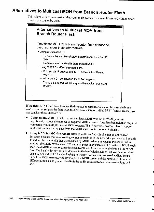
Alternatives to Multicast MOH from Branch Router FlashThis subtopic shows alternatives that you should consider when multicast MOH from branchrouter flash cannot be used.
1-50
Alternatives to Multicast MOH fromBranch Router Flash
If multicast MOH from branch router flash cannot beused, consider these alternatives;- Using multicast MOH:
- Reduces the number ofMOH streamssentoverthe IPWAN,
- Requires less bandwidththan unicast MOH.• Using G.729 for MOH to remote sites:
- Putremote IP phones and MOH server into differentregions.
- Allow only G.729 between these two regions.- These actions reduce the required bandwidth per MOH
stream.
Ifmulticast MOH from branch router fiash cannot be used (for instance, because the branchrouter does not support the feature or does not have aCisco Unified SRST feature license) voucan consider these alternatives:
• Using multicast MOH: When using multicast MOH over the IP WAN you cansignificantly reduce the number of required MOH streams. Thus, less bandwidth is requiredcompared with multiple unicast MOH streams. The IP network, however, has to supportmulticast routing for the path from the MOH server to the remote IP phones.
• Using G.729 for MOH to remote sites: If multicast MOH is also not an option (forinstance, because multicast routing cannot be enabled in the network), you may still be ableto reduce the bandwidth that is consumed by MOH. When you change the codec that isused for the MOH streams to G.729 and you potentially enable cRTP on the IP WAN eachindividual MOH stream requires less bandwidth and hence reduces the load on the WANlink. The bandwidth savings are identical to the bandwidth savings that you achieve when"f'y/29 and cRTP for standard audio streams, which was discussed earlier To useU729 for MOH streams, you have to put the MOH server and the remote IP phones intodifferent reg.ons. and you need to limit the audio codec between these two regions to 8
Implementing Cisco Unified Communications Manager, Pari 2(CIPT2) v8.0©2010 Cisco Systems, Inc.
Multicast MOH from Branch Router Flash: Cisco IOSConfiguration Example
This subtopic shous the required Cisco IOS commands to enable multicast MOH from branchrouter flash.
Multicast MOH from Branch Router Flash:Cisco IOS Configuration Example
Cisco UnifiedCommuni cation s
ManagerMOH
Configuration
DA 239 1 1 1
DP 16334
Ma" Hops
TTL 1
Main Site
_._ WAM.
call manager-£a llbJ ck
max ephone
dn 1
a 1
ip source-add ess 10.2 .2.2
moh moh-f. le.
multicast moh 239 1.1. 1 port 16384
Remote Site
In the example, the name ofthe audio file on the branch router Hash is moh-lile.au. and theconfigured multicast address and port number are 239.1.1.1 and 16384. respectively. Iheoptional route command can be used to specify asource interface address lor the multicaststream If no route option is specified, the multicast stream will be sourced from the configuredCisco Unified SRST default address as specified by the ip source-address command under theCisco I'nificd SRST configuration (10.2.2.2 in this example). Note that you can stream only asingle audio file from flash and that you can use only asingle multicast address and portnumber per router.
ACisco Unified SRST license is required regardless of whether the SRST functionality willactually be used. The license is required because the configuration for streaming multicastMOH from branch router flash is done in the SRST configuration mode and, even ,tSRSIfunctionality will not be used, at least one IP phone (using the max-ephones command) andone extension (using the max-dn command) must be configured.
© 2010 Cisco Systems. IncMultisite Deployment Implementation 1-49
1-48
5. The router at the remote site is configured as an SRST gateway. In its Cisco Unified SRSTconfiguration, multicast MOH is enabled with destination address 239 11Iand port16384. The Cisco Unified SRST gateway streams MOH all the time (even if not in fallbackmode).
6. The IP phone listens to the multicast MOH stream that was sent from the Cisco UnifiedSRST gateway to IP address 239.1.1.1, port 16384, and plays the received MOH stream.
At no time do MOH packets cross the IPWAN.
implementing Cisco Unrfied Communications Manager, Part 2(CIPT2) .8.0 ©20,0 Cisco Systems, Inc.
Multicast MOH from Branch Router Flash ExampleThe figure illustrates how multicast MOH from branch router Hash works.
Multicast MOH from Branch RouterFlash Example
When remote phone is put on hold Clko Unified Communicate Manager signals phoneto listen to DA 2391 1 1 DP 16384 andplay thereceived stream
Unified
CommunicationsManager MOHConfiguralion
DA 239 1 1 1DP 163B4
Max Hops
TTL 1
Unified
Communicalions
Manager MOHPacketsDropped Here (TTL
Exceeded)
Identical MOHPackets Created
Here by SRST MOH
In the example the Cisco Unified Communications Manager MOH server is configured formulticast MOH with adestination (multicast group) address of239.1.1.1. the destination port16384. anda max-hops TTI.value of 1.The Cisco Unilied SRST gateway that is located at the remote silc is configured with the samedestination IP address and port number as the Cisco Unified Communications Manager MOHserver.
When a remote phone is put on hold, here iswhat happens:1, According to the MRGL ofthe remote phone, the Cisco Unified Communications Manager
MOH server is used as the media resource forMOH.
2. Cisco Unified Communications Manager signals the IP phone to receive MOH on IPaddress 239.1.1.1-port 16384.
} The Cisco Unified Communications Manager MOH server sends multicast MOH packetstoIP address 239.1.1.1. port 16384. with aTTL value of 1.
4 The router that is located at the central site drops the multicast MOH packet that is sent outby the Cisco Unified Communications Manager MOH sewer because TTL has beenexceeded.
© 2010 Cisco Systems, IncMultisite Deployment Implementation 1-47
Instead of setting the max-hops parameter forMOH packets to 1,youcanuseone of thesemethods:
• Configure an access control list (ACL) on the WAN interface: Configure an ACL ontheWAN interface at the centralsite to disallowpacketsthat are destined to the multicastgroup address or addresses from being sent out the interface.
Note Depending on the configuration of MOH in CiscoUnified Communications Manager, aseparate MOH stream for each enabled codec is sent per multicast MOH audio source Thestreams are incrementedeither based on IP addresses or based on port numbers(recommendation is per IP address). Assuming that one multicast MOH audio source and
G.711 a-law, G.711 mu-law, G.729, and the wideband codec are enabled, there will be fourmulticast streams Makesure that allof them are included in the ACL to prevent MOHpackets from being sent to the IP WAN.
• Disable multicast routing on the WAN interface: Donotconfigure multicast routing onthe WAN interface, to ensure that multicast streams are not forwarded into the WAN.
When you use multicast MOH from branch router flash. G.711 has to be enabled between theCisco Unified Communications Manager MOH serverandthe remote IPphones. Thisaction isnecessary because the branchSRSTMOHfeature supportsonly G.711. Therefore, the streamthat isset upbyCisco Unified Communications Manager in thesignaling messages also has tobe G.711. Because the packets arenot sentacross the WAN, configuring the high-bandwidthG.711 codec is not a problem as long as it is enabledonly for MOH. All other audio streams(such as calls between phones) that are sent over the WAN should use the low-bandwidthG.729 codec.
1-46 Implementing Cisco Unified Communications Manager, Part 2(CIPT2) v8.0 ©2010 Cisco Systems, Inc.
Multicast MOH from Branch Router FlashThis subtopic explains how you can use multicast MOH from branch router fiash toreduce thebandwidth that is required on the IP WAN.
Multicast MOH from Branch Router
Flash
Multicast MOH from branch router flash is a feature for multisitedeployments with centralized call processing:
• Mworks only with multicast MOH
• It is based on MOH capabilities of SRST
• Cisco IOS SRST gateway is configured lor multicast MOH
MOH stream is sent independent of SRST stalus (even if no failover scenario)
• Cisco United Communications Manager and IP phone are not aware that SRSTgateway is invoked
IPphone is configured lo use Cisco United CommunicationsManager multicastMOH server
Cisco Unified Communications Manager MOH server is configured for max-hops 1
Cisco Unilied Communications Manager MOH server and branch router use samemulticast adoress arx) port number
Cisco UnifiedCommunications Manager signals its MOH server address and portnurnberto IPphone
Cisco UnifiedComniumcat ons Manager MOHserver packets are dropped at WANrouter Because max-hops value TTLin IP packet header has bean exceeded
SRSTrouter generates multicast MOH stream with same multicast address andportthai was used by Cisco Unified Communications Manager MOH
IP prwne listens lo signaled address and portand plays received stream
Multicast MOH from branch router fiash is a feature for multisite deployments that usecentralized call processing.
Ihe feature works only with multicast MOI 1and isbased on MOH capabilities ofCiscoUnified SRST. The Cisco IOS SRSTgateway is configured for multicast MOH andcontinuously sends a MOH stream, regardless ofitsSRST mode (standby orfallback mode).
In fact, neitherCisco Unified Communications Manager nor the remoteIP phonesare awarethat the Cisco Unified SRST gateway isinvolved. To them, itappears asthough a multicastMOH stream has been generated by the Cisco Unified Communications Manager MOH serverand has been receded by the remote IP phones.
Therefore, the remote IPphones are configured to use the centralized Cisco UnifiedCommunications Manager MOII server astheir MOH source, fhe Cisco UnifiedCommunications Manager MOH server isconfigured for multicast MOH (mandatory), and themax-hops \alue in the MOI Iserver configuration is set to 1for the affected audio sources. Themax-hops parameter specifies the Time to Live (TTL) value that isused in the IP header oftheRTP packets, "fhe Cisco Uni lied Communications Manager MOI 1server and the Cisco IOSSRST gatewav that is located at the remote site have to use the same multicast address and portnumber for their streams. This way, MOH packets that are generated bythe Cisco UnifiedCommunications Manager MOH server atthe central site are dropped by the central-site routerbecause ITI.has been exceeded. As a consequence, the MOII packets donotcross the IPWAN. The SRST gateway permanently generates amulticast MOH stream with an identicalmulticast IP address and port number. The IP phone simply listens tothis stream as it appearsto becoming from the Cisco Unified Communications Manager MOH server.
© 2010 Cisco Systems, IncMultisite Deployment Implementation 1-45
Mixed Conference Bridge
1-44
The figure shows how ahardware conference bridge in mixed mode can be used to reduce thebandwidth that is requiredon the IP WAN.
Mixed Conference Bridge
Mixed (hardware) conference bridoes enable low-bandwidthcodecs to beused by remote conference participants.
Hardware
Conference Bridge(Mixed)
Cisco Unified
CommunicationsManager
-WAN-
Remote Site
In this example, ahardware conference bridge is deployed at the main site. The hardwareconference bndge is configured to support mixed conferences, in which members use variouscodecs. Headquarters IP phones that join the conference can use G.711, while remote IP phonescanjoin the conference using a low-bandwidth codec.
Implementing Cisco Unified Communications Manager, Part 2(CIPT2) v8.0>2010 Cisco Systems, Inc.
Note Calls between IP phones at headquarters and remote IP phones do not require atranscoder. They simply use the best allowed codec that is supported on both ends. G.729.
Atranscoder is invoked only when the two endpoints of acall cannot find acommon codecthat is permitted by region configuration. This principle is illustrated in this example. Theremote IP phones (which support G.711 and G.729) are not allowed to use GV11 over theIP WAN and the headquarters voice-mail system and software conference bridge do notsupport G729 Cisco Unified Communications Manager detects this problem that is basedon its region configurations, and the capability negotiation that is performed during call setupsignaling identifies the need for a transcoder. .
Bandwidth 8kb/s between BR and XCODER: This bandwidth ensures that the RTFstreams between remote IP phones and the transcoder. which are sent over the IP WAN. donot use (J.711.
Bandwidth 64 kb/s between headquarters and XCODER: This bandwidth is required inorder for the G.711 -onh devices at headquarters lo be allowed to send G.711 to thetranscoder.
© 2010 Cisco Systems, IncMultisite Deployment Implementation 1-43
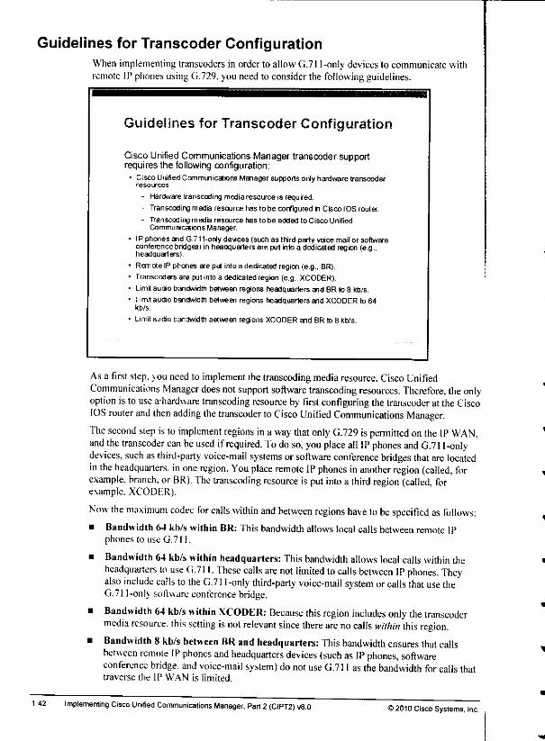
Guidelines for Transcoder Configuration
1-42
When implementing transcoders in order to allow G.711-only devices to communicate withremote IP phones using G.729. you need to consider the following guidelines.
Guidelines for Transcoder Configuration
Cisco Unified CommunicationsManager transcoder supportrequires the following configuration:
• Cisco Unified Communicalions Manager supports only hardware transcoderresources.
- Hardware transcoding media resource is requred.
- Transcoding media resource has lo be configured h Cisco IOS router.
- Transcoding media resource has to be added to Cisco UnifiedCommunications Manager.
• IP phones and G.711-only devices (such as third-party voice mail or softwareconference bridges) in headquarters are pui intoa dedicated region (e.g.,headquarters).
- Remote IP phones are put intoa dedicated region (e.g., BR).• Transcoders are put into a dedicated region (e.g., XCODER).• Limitaudio bandwidth between regions headquarters and BR to 8 kb/s.
• Limitaudio bandwidth between regions headquarters and XCODER to 64kb/s.
• Limitaudio bandwidth between regions XCODER and BR to 8 kb/s.
Asa first step, jou need to implement the transcoding media resource. CiscoUnifiedCommunications Manager does not support software transcoding resources. Therefore, the onlyoption is to use a-hardware transcoding resource byfirst configuring the transcoder at theCiscoIOS router and then adding the transcoder toCisco Unified Communications Manager.
The second step isto implement regions in a way that only G.729 ispermitted onthe IP WAN,and the transcoder can be used ifrequired. To do so, you place all IPphones and G.711-onlydevices, such as third-party voice-mail systems orsoftware conference bridges that are locatedin the headquarters, in one region. You place remote IPphones in another region (called, forexample, branch, or BR). Thetranscoding resource isputinto a third region (called forexample. XCODER).
Now the maximum codec for calls within and between regions have tobe specified as follows:• Bandwidth 64 kb/s within BR: This bandwidth allows local calls between remote IP
phones to use G.711.
• Bandwidth64 kb/s within headquarters: Thisbandwidth allows local callswithin theheadquarters to use 0.711. These calls are not limited to calls between IP phones. Theyalso include calls to the G.711-only third-party voice-mail syslem orcalls that use theG.711-only softwareconference bridge.
• Bandwidth 64 kb/s within XCODER: Because this region includes only the transcodermedia resource, this setting isnot relevant since there are no calls within this region.
• Bandwidth 8 kb/s between BR and headquarters: Thisbandwidth ensures that callsbetween remote IP phones and headquarters devices (such as IP phones, softwareconference bridge, and voice-mail system) do not use G.711 as the bandwidth for calls thattraverse the IP WAN is limited.
Implementing Cisco Unified Communications Manager, Part 2 (CIPT2) u8.0 52010 Cisco Systems, Inc.

Transcoders
The figure illustrates how you can use transcoders to reduce the bandwidth that isrequired onthe IP WAN.
Transcoders
Ifa device supports G 711 only, transcoders enable low-bandwidthcodecs to be used over the IP WAN
In the example, a third-part; voice-mail system that supports only G.711 is deployed atthemain site. One Cisco UnifiedCommunications Manager server is providing a softwareconference bridge (which also supports G.711 only). Ifremote phones are configured lo useG.729 over the IPWAN. they cannot join conferences oraccess the voice-mail system. Toallow these IP phones touse G.729 and toaccess the G.711-only services, you deploy ahardware transcoder at the main site.
Remote IP phones now send G.729 voice streams to the transcoder over the IP WAN. Thetranscoder changes the stream to G.711 and then passes iton to the conference bridge orvoice-mail sNStem.
)2010 Cisco Systems, IncMultisite Deployment Implementation 1-41
Codec Configuration in Cisco Unified CommunicationsManager
The codec that is used for a call isdetermined by the region configuration in Cisco UnifiedCommunications Manager.
1-38
Codec Configuration in Cisco UnrfiedCommunications Manager
Thecodec thatwill be used depends on the regionconfiguration in Cisco Unified Communications Manager;• Each region is configured with a maximum audiobandwidth per call:
- Within the configured region
- Toward specific other regions (manually added)Toward all otherregions (which havenotbeen manually added)
• Region is assigned to a device pool.• Device pool is assigned to a device.
• Whichcodec actuallygets used depends on the capabilitiesof thetwo devices:
- Best codec is the one that is supported by both devices anddoes not exceed bandwidth requirements of codec that ispermitted in the region configuration.
- If devicescannotagree on a codec,a transcoding deviceisinvoked.
Each region in Cisco Unified Communications Manager isconfigured with the maximum audiobandwidth requirements to be used per call:
• Within the configured region
• Toward a specific other region (manually configured)
• Toward all other regions (not manually configured)
Regions are assigned to device pools (one region per device pool), and adevice pool isassigned to each device. Which codec isactually used depends on the capabilities ofthe twodevices that are involved in the call. The assigned codec is the one that is supported by bothdevices and does not exceed the bandwidth requirements ofthe codec that is permitted inregion configuration. If devices cannot agree on a codec, a transcoder is invoked.
Implementing Cisco Unrfied Communications Manager, Part 2(CIPT2) v8.0 >2010 Cisco Systems, Inc.
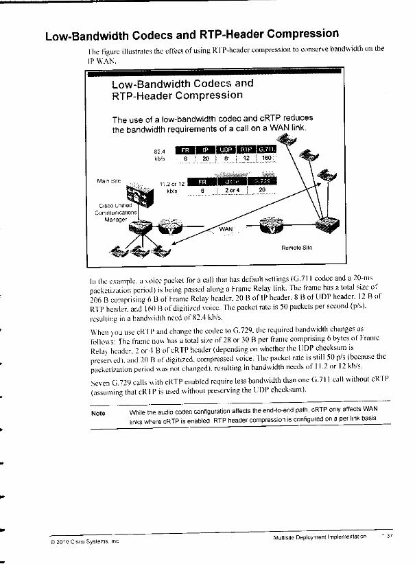
Low-Bandwidth Codecs and RTP-Header CompressionThe figure illustrates the effect of using RTP-header compression to conserve bandwidth on theIP WAN.
Low-Bandwidth Codecs andRTP-Header Compression
The use of a low-bandwidth codec and cRTP reducesthe bandwidth requirements of a call on a WAN link.
Cisco Unified
Communications
Manager
82.4 EuHaiEIS2IuilE5Z3kb/s 6 1 20 I 8 I 12 1 ieo
Remote Site
In the example, a \oice packet for a call that has default settings (G.711 codec and a20-mspacketization period) is being passed along aFrame Relay link. The frame has atotal size ot206 Bcomprising 6Bof frame Relay header. 20 Bof IP header. 811 of UDP header. 12 BofRTP header, and 160 Bofdigitized voice, fhe packet rate is50 packets per second (p/s).resulting ina bandwidth need of 82.4 kb/s.
When %ou use cRTP and change the codec toG.729. the required bandwidth changes asfollows: The frame now has a total size of28 or30 Bper frame comprising 6bytes ofFrameRelay header. 2or 4Bof cRTP header (depending on whether the UDP checksum ispreserved), and 20 Bof digitized, compressed voice. The packet rate is still 50 p/s (because thepacketization period was not changed), resulting in bandwidth needs of 11.2 or 12 kb/s.Seven G.729 calls with cRTP enabled require less bandwidth than one G.711 call without cRl'P(assuming that cRTP is used without preserving the UDP checksum).
Note While the audio codec configuration affects the end-to-end path, cRTP only affects WANlinks where cRTP isenabled RTP header compression isconfigured on a per link basis.
© 2010 Cisco Systems. IncMultisite Deployment Implementation 1-37
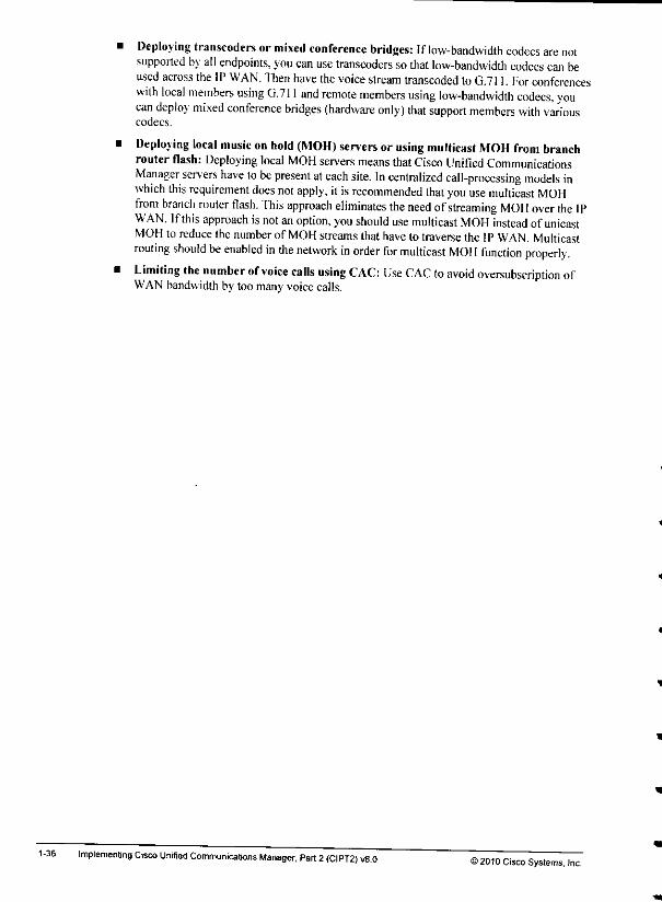
Deploying transcoders or mixed conference bridges: If low-bandwidth codecs are notsupported by all endpoints, you can use transcoders sothat low-bandwidth codecs can beused across the IPWAN. Then have the voice stream transcoded toG.711. For conferenceswith local members using G.711 and remote members using low-bandwidth codecs, youcan deploy mixed conference bridges (hardware only) that support members with variouscodecs.
Deploying local music onhold (MOH) servers orusing multicast MOH from branchrouter flash: Deploying local MOH servers means thatCisco Unified CommunicationsManager servers have to be present at each site. In centralized call-processing models inwhich this requirement does not apply, itisrecommended that you use multicast MOHfrom branch router flash. This approach eliminates the need ofstreaming MOH over the IPWAN. Ifthis approach isnot an option, you should use multicast MOH instead ofunicastMOH to reduce the number of MOH streams that have to traverse theIPWAN. Multicastrouting should be enabled in the network in order for multicast MOH function properly.Limiting the number ofvoice calls using CAC: Use CAC to avoid oversubscription ofWAN bandwidth by too manyvoicecalls.
1-36 Implementing Cisco Unified Communications Manager, Pari 2(CIPT2) v8.0 ©2010 Cisco Systems. Inc.
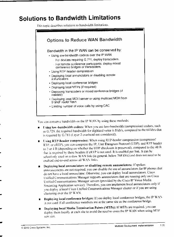
Solutions to Bandwidth Limitations"fhis topic describes solutions tobandwidth limitations.
Options to Reduce WAN Bandwidth
Bandwidth in the IP WAN can be conserved by:• Using low-bandwidth codecs over the IP WAN
Fordevices requiring G.711, deploytranscoders.For remote conference participants, deploy mixedconference bridges or transcoders.
• Using RTP-header compression• Deploying local annunciators or disabling remote
annunciators
• Deploying local conference bridges• Deploying local MTPs (ifrequired)• Deploying transcoders ormixed conference bridges (if
needed)• Deploying local MOH server or using multicast MOH from
branch router flash
• Limiting numberofvoice calls by using CAC
You canconserve bandwidth on the IP WAN by using these methods:
• Using low-bandwidth codecs: When you use low-bandwidth (compression) codecs, suchas G.729. the required bandwidth for digitized voice is 8kb/s. compared to the 64 kb/s thatis required b\ G.71! (Layer 2overhead not considered).
• I. sing RTP-header compression: When using RIP-header compression (compressedRTP. orcRTP). vou can compress the IP. User Datagram Protocol (UDP). and RTP headerto 2or 4B(depending on whether the UDP checksum is preserved), compared lo the 40 Bthat Urequired bv these headers ifcRTP is not used. It is enabled per link. It can beselecmeh used on aslim WAN link (in general, below 768 kb/s) and does nol need lobeenabled end-to-end across all WAN links.
• Deploying local annunciators or disabling remote annunciators: Ifspokenannouncements are not required, you can disable the use ofannunciators for IP phones thatdo not have a local annunciator. Otherwise, you can deploy local annunciators. CiscoUnilied Communications Manager supports annunciators that are running only on CiscoUnilied Communications Manager servers (provided by the Cisco IP Voice MediaStreaming Application service). Therefore, you can implement local annunciators only if\ou deploy alocal Cisco Unified Communications Manager cluster or ifyou are usingclustering o\er the IP WAN.
• Deploving local conference bridges: If you deploy local conference bridges, the IP WANis not used ifall conference members are at the same site as the conference bridge.
m Deploving local Media Termination Points (MTPs): If MTPs are required, you candeploy them locally at each site to avoid the need lo cross the IP WAN when using Ml Pservices.
© 2010 Cisco Systems. Inc.Multisite Deployment Implementation
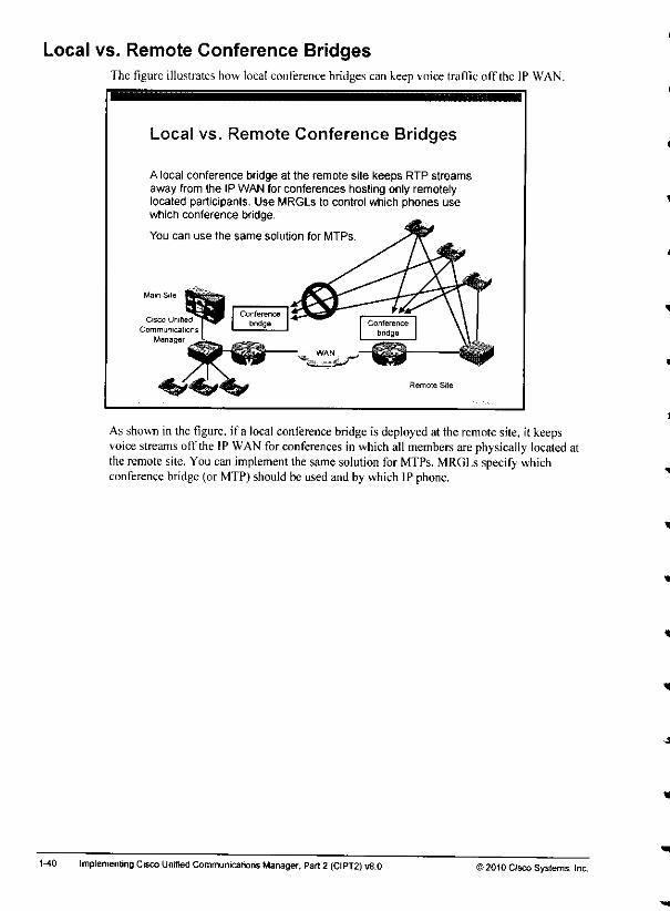
Local vs. Remote Conference BridgesThe figure illustrates how local conference bridges can keep voice traflic oft*the IP WAN.
Local vs. Remote Conference Bridges
A local conference bridge at the remote site keeps RTP streamsaway from the IP WAN for conferences hosting only remotelylocated participants. Use MRGLs to control which phones usewhich conference bridge.
You can use the same solution for MTPs.
Cisco Unified
Communicationa
Manager
As shownin the figure, if a local conference bridge is deployedat the remotesite, it keepsvoicestreams off the IP WANfor conferences in whichall members are physically located atthe remote site. You can implement thesame solution for MTPs. MRGLs specify whichconference bridge(or MTP)should be usedand by which IP phone.
1-40 Implementing Cisco Unified Communications Manager, Part2 (CIPT2) v8.0 ©2010 Cisco Systems, Inc.

Disabled Annunciator
The figure shous howyou can conserve bandwidth on the IP WAN by sendingdisablingannunciator streams to remote phones.
Disabled Annunciator
In multisitedeployments withcentralized call processing, MRGLscanbe used to disable annunciator streams to the remote site.
In multisitedeployments withdistributed call processing, localannunciators can be used at each site
C'Sco Unified
Communicalions
Manager
If announcements should not be sent over the IP WAN, Media Resource Group Lists (MRGLs)canbe used so thatremote phones do nothave access lo theannunciator media resource.
Note Because not every call requires annunciator messages, and because the messages areusually rathershort, the bandwidth that should be preserved bydisabling the annunciator ismarginal.
©2010 Cisco Systems. IncMultisite Deployment Implementation
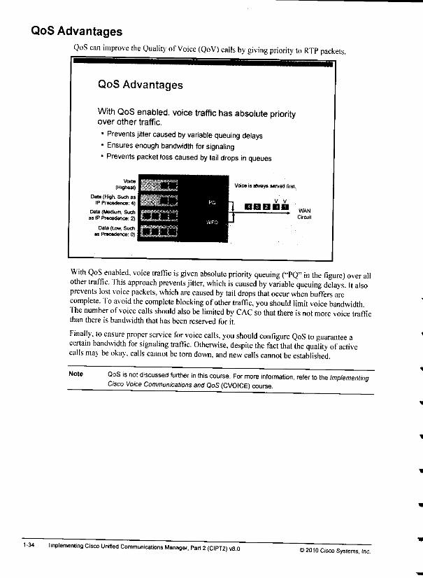
QoS Advantages
1-34
QoS can improve the Quality of Voice (QoV) calls by giving priority to RTP packets.
QoS Advantages
With QoS enabled, voice traffic hasabsolute priorityover other traffic.
• Prevents jitter caused by variable queuing delays• Ensures enough bandwidth for signaling• Prevents packetloss caused bytail dropsinqueues
Voice
(Highest)
Data [High, Such asIP Precedence: 4)
Data (Medium, Suchas IP Precedence: 2)
Data (Low, Suchas Precedence: 0}
Voice is always served first
With QoS enabled, voice traffic is given absolute priority queuing ("PQ" in the figure) over allother traffic. This approach prevents jitter, which is caused by variable queuing delays. It alsoprevents lost voice packets, which are caused by tail drops that occur when buffers arecomplete. To avoid the complete blocking ofother traffic, you should limit voice bandwidth.The number ofvoice calls should also be limited by CAC so that there isnot more voice trafficthan there is bandwidth that has been reserved for it.
Finally, to ensure proper service for voice calls, you should configure QoS to guarantee acertain bandwidth for signaling traffic. Otherwise, despite the fact that the quality ofactivecalls may be okay, calls cannot betorn down, and new calls cannot beestablished.
Note QoS is not discussed further in this course. For more information, refer to the ImplementingCisco Voice Communications and QoS (CVOICE) course.
Implementing Cisco Unified Communications Manager. Part 2(CIPT2) v8.0) 2010 Cisco Systems, Inc.
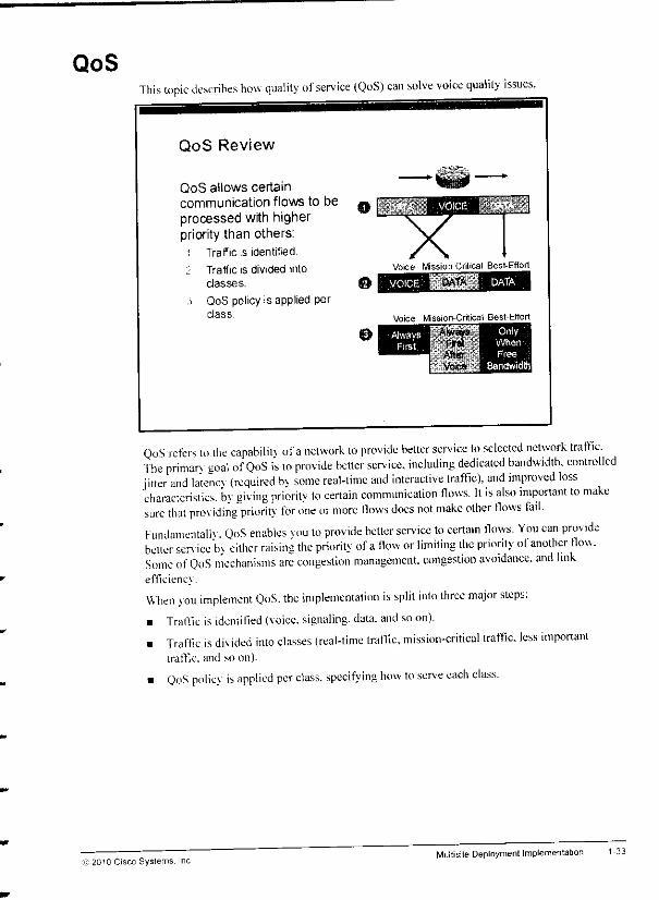
QoSThis topic describes how quality of service (QoS) can solve voice quality issues.
QoS Review
QoS allows certaincommunication flows to beprocessed with higherpriority than others:
i Traffic is identified.
'.-. Traffic is divided intoclasses.
,;> QoS policy is applied perclass.
Voice Mission-Critical Best-Effort
Voice M_• • il Best-EffortAway* Laaaa^
irst
QoS refers to the capabilit\ ofanetwork lo provide belter service to selected network traffic.The primarv goal of QoS is 10 provide better service, including dedicated bandwidth, controlledjitter and latency {required bv some real-lime and interactive traffic), and improved losscharacteristics, by giving priority lo certain communication flows. It is also important to makesure that providing priority for one or more flows docs not make other flows fail.Fundamental. QoS enables vou to provide better service to certain flows. You can providebetter sen ice bv cither raising the priority ofaflow or limiting the priority ol another flow.Some of QoS mechanisms are congestion management, congestion avoidance, and linkefficiencv
When you implement QoS. the implementation is split into three major steps:• Traffic is identified (voice, signaling, data, and so on).
• Traffic is div ided into classes (real-time traffic, mission-critical traffic, less importanttraffic, and soon).
• QoS policy is applied per class, specifying how to serve each class.
1-33
© 2010 Cisco Systems. IncMultisite Deployment Implementatii
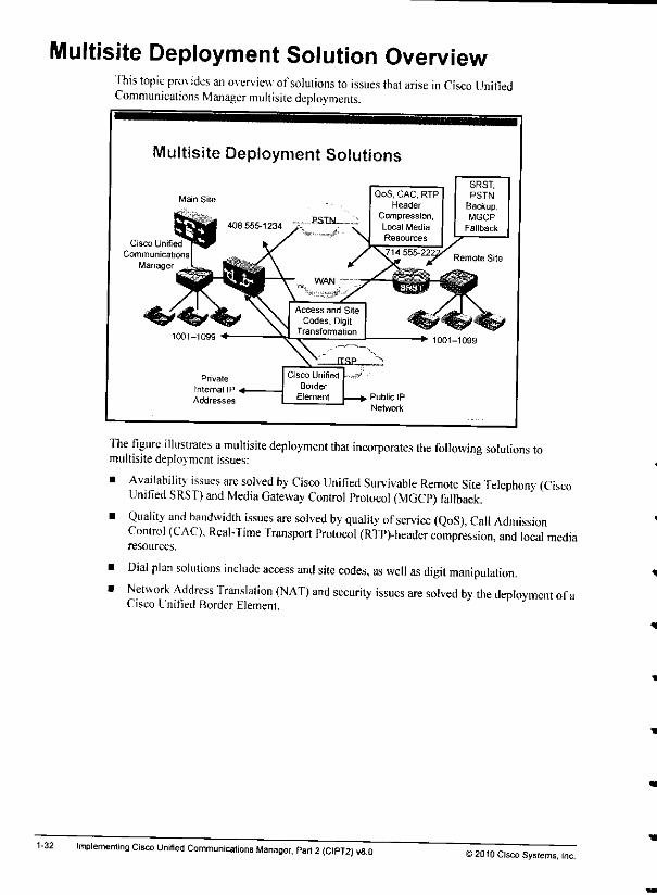
Multisite Deployment Solution OverviewThis topic provides an overview ofsolutions to issues that arise in Cisco UnifiedCommunications Manager multisite deployments.
1-32
Multisite Deployment Solutions
Main Site
Cisco Unrfied
Communications
Manager
QoS, CAC, RTPHeader
Compression,Local Media
Resources
SRST.PSTN
Backup,MGCP
Fallback
Remote Site
The figure illustrates amultisite deployment that incorporates the following solutions tomultisite deployment issues:
• Availability issues are solved by Cisco Unified Survivable Remote Site Telephony (CiscoUnified SRST) and Media Gateway Control Protocol (MGCP) fallback.
• Quality and bandwidth issues are solved by quality ofservice (QoS), Call AdmissionControl (CAC). Real-Time Transport Protocol (RTP)-header compression, and local mediaresources.
• Dial plan solutions include access and site codes, as well as digit manipulation.• Network Address Translation (NAT) and security issues are solved by the deployment ofa
Cisco Unified Border Element.
Implementing Cisco Unified Communications Manager, Part 2(CIPT2) 1/8.O>2010 Cisco Systems, Inc.
Lesson 2
Identifying MultisiteDeplovment Solutions
OverviewAmultisite deplounent introduces several issues that do not apply lo single-site deployments.When implementing Cisco Unified Communications Manager in amultisite environment, youneed to address these issues, fhis lesson provides information on how lo solve issues that ariseneei
in multisite deployments.
ObjectivesUpon completing this lesson, you will be able to describe solutions for multisite deplovmentissues.
Thisabilitv includes beingableto meet these objectives:
Describe solutions lo mullisite deployment issues
Describe how QoS solves quality issues inmultisite deployments
Describe solutions to bandwidth limitations inmultisite deployments
Describe survivability and availability features in multisite deployments
Describe solutions for dial plan issues inmullisite deployments
Describe how aCisco Unified Border Element can solve NAT and security solutions inmullisite deployments
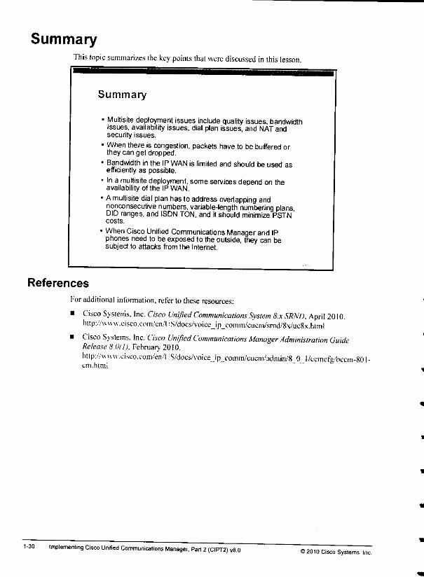
SummaryThis topic summarizes the keypoints thatwerediscussed in this lesson.
Summary
• Multisite deployment issues include quality issues, bandwidthissues, availability issues, dial plan issues, and NAT andsecurity issues.
- When there is congestion, packets have to be bufferedorthey can get dropped.
• Bandwidth in the IPWAN is limited and should be used asefficiently as possible.
• In a multisite deployment, some services depend on theavailability ofthe IP WAN.
1Amultisite dial plan has to addressoverlapping andnonconsecutive numbers, variable-length numbering plansDID ranges, and ISDN TON, and itshould minimize PSTNcosts.
When CiscoUnified Communications Manager and IPphonesneed to beexposedto theoutside, they can besubject to attacks from the Internet.
References
1-30
For additional information, refer to these resources:
• Cisco Systems. Inc. Cisco Unified Communications System 8.x SRND, April 2010.hup://\vww.eisco.C(>m/en/US/docs/voice_ip_comm/cucni/srnd/8x/uc8x.html
• Cisco Systems. Inc. Cisco Unified Communications Manager Administration GuideRelease 8.0(1). February 2010.http://uv\u .cisco.com/en/US/docs/voice.._ip_.comm/cucm/admm/8 0 l/ccmcfg/bccm-801cm.himl
implementing Cisco Unified Communications Manager, Pari 2(CIPT2) v8.0©2010 Cisco Systems, Inc.
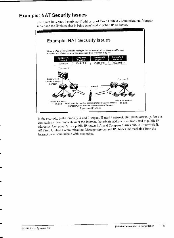
Example: NAT Security Issuesfhe figure illustrates the private IP addresses ofCisco Unified Communications Managerserver and the IP phone that isbeing translated to public IP addresses.
Example: NAT Security Issues
Cisco Unilied Communications Manager, orCisco Unified Communicalions ManagerExpress, and IPphones aremade accessible from theInternet by NAT
Company APnvate IP
Company APublic IP
10.0.0.0(8 ' Public IP A
Company A
Cisco Unified
Communications
Manager
Company BPublic fP
Company 8Pnvate IP
vateIP Network """ Private IPNetwork10000 Attacks canbedirected against Unified Communications 1000O
Manager/Cisco Unified Communications ManagerExpress and IP phones
In the example, both Companv Aand Company Buse IP network 10.0.0.0/8 internally. For thecompanies to communicate over the Internet, the private addresses are translated to public IPaddresses. Companv Auses public IP network A. and Company Buses public IP network B.All Cisco Unified Communications Manager servers and IP phones arc reachable from theInternet and communicate with each other.
© 2010 Cisco Systems.Multisite Deployment Implementation 1-29

NAT and Security Issues
1-28
This topic describes NAT and security issues in Cisco Unified Communications Managermultisite environments.
NAT and Security Issues in MultisiteEnvironments
• In single-site deployments, Cisco Unified Communications Managerand IPphonesusually do notrequire access to public IPnetworks:
- NATis not required.
- Not reachablefrom theoutside,
- Notsubjectto attacksfromoutside.
1 In multisitedeployments, VPN tunnels can be used:- Requires gateway configuration ateach site.- Allows only intersitecommunication.
- Blocks accessto and from outside (unless traffic istunneled).VPNs cannot be used in some cases:
- Connections to ITSPsor domains underdifferent administration.- NAT required: Cisco Unified Communications (Manager and IP
phones exposed to the outside.
- Cisco Unified Communications Manager and IP phones aresubject to attacks.
In single-site deployments. Cisco Unified Communications Manager servers and IP phonesusually use private IP addresses, since there is no need to communicate to the outside IP worldNA Tis not configured, and attacks from the outside are not possible at all.In multisite deployments. IP Security (IPsec) virtual private network (VPN) tunnels can be usedbetween sites. The VPN tunnels allow only intersite communication; access to the protectedinternal networks is not possible from the outside, but only from the other site (through thetunnel). Therefore, attacks from the outside are blocked at the gateway. To configure IPsecVPNs, you must configure gateways at each site. Sometimes this configuration is not possiblesuch as when the two sites are under separate administration, and security policies do not allowthe configuration of IPsec VPNs.
In these cases, or when connecting to apublic service such as an ITSP, you must configureNAT tor Cisco Unified Communications Manager servers and IP phones. Once Cisco UnifiedCommunications Manager servers and IP phones are reachable with public IP addresses thevwill be subject to attacks from the outside world, which introduces potential securitv issues '
Implementing Cisco Unrfied Communications Manager, Part 2(CIPT2) v8.0©2010 Cisco Systems, Inc.

The ideal solution for a large deployment would allow an automatic recognition ofroutes.Internal as well as external (for PSTN backup) numbers should be advertised and learned bycall-routing entities. Adynamic routing protocol for call-routing targets would addressscalabilit} issues in large deployments.
Call control discovcrv (CCD). a feature that is based on the Cisco Service AdvertisementFramework (SAF) provides such functionality. CCD and Cisco SAF are explained in moredetail in a later module of this course.
C 2010 Cisco Systems. IncMultisite Deployment Implementation