knowledge management framework based on an
TRANSCRIPT
UNIVERSIDAD POLITÉCNICA DE MADRID
ESCUELA TÉCNICA SUPERIOR DE
INGENIEROS INDUSTRIALES
Knowledge Management framework based on an Agents Network to support Continuous Improvement in Manufacturing integrating Case-Based Reasoning
and Product Lifecycle Management
Tesis Doctoral
Alvaro Camarillo
Ingeniero Industrial
Universidad Politécnica de Madrid
2019

INGENIERÍA MECÁNICA Y FABRICACIÓN
ESCUELA TÉCNICA SUPERIOR DE
INGENIEROS INDUSTRIALES
Knowledge Management framework based on an Agents Network to support Continuous Improvement in Manufacturing integrating Case-Based Reasoning
and Product Lifecycle Management
Autor: Alvaro Camarillo
Ingeniero Industrial
Director: Dr. José Ríos Chueco
Doctor Ingeniero Industrial
Co-Director: Prof. Dr. Klaus-Dieter Althoff
Prof. Dr. rer. nat. habil. Informatik
2019

V
LECTURA DE TESIS
Tribunal nombrado por el Magnífico y Excelentísimo Sr. Rector de la Universidad Politécnica de Ma-drid, el día _______ de ______________________ de 201_.
Presidente _______________________________________________________________
Secretario _______________________________________________________________
Vocal ___________________________________________________________________
Vocal ___________________________________________________________________
Vocal ___________________________________________________________________
Realizado el acto de defensa y lectura de la Tesis.
Madrid, día _____ de _______________ de 201_.
Los miembros del Tribunal han decidido otorgar la calificación de:
_________________________________________
El Presidente El Secretario
Los Vocales

VII
Acknowledgement
First of all I would like to thank to José Rios, much more than a supervisor; a reference in my life. José helped me to find my way in my professional life in a couple of critical times, and his great dedication and flexibility was the key to go through the long PhD path until the end.
Also to thank to Klaus-Dieter Althoff, who helped me to get into the CBR community and its research thematic. He also gave me the opportunity to collaborate with him and his team in Hildesheim, al-lowing me to engage in very constructive discussions and gain knowledge about the CBR framework.
To Jesús Ibáñez, for the great time together in Robert Bosch Portugal and India. Together we have spent long hours discussing about Continuous Improvement and the different methodologies, tools and strategies to implement it in the plants where we were working. He was a big inspiration and source of ideas, and those nice discussions lie in the foundation of this Thesis.
Not to forget the support of the team of the Departamento de Ingeniería Mecánica y Fabricación, especially Antonio Vizán and Jesús Pérez, and the team of the Institut für Informatik in Bereich Intel-ligente Informationssysteme, especially Viktor Ayzenshtadt and Pascal Reuss.
To thank of course Exide Technologies for the support in my PhD work and for letting me to use the company as case study. Especially thanks to Bad Lauterberg plant and La Cartuja plant, where I im-plemented the prototype of my Thesis, and to Christian Walther for his great support during the in-stallation of Aras.
To Julian Anaya, my young assistant collecting cases from the lines.
And last but most important to my family, who gives sense to my life day after day, and from whom this Thesis has taken away so many hours of my dedication. This Thesis started not so far away in the time, but far away in the “content” of our lives: one son ago, three countries ago, one company ago… It was a tough time full of experiences and challenges that I would not have been able to manage without their full support.


IX
To Cristina

XI
Index
LECTURA DE TESIS .............................................................................................................................. V
Acknowledgement ........................................................................................................................... VII
Index .................................................................................................................................................XI
List of Figures ................................................................................................................................... XV
List of Tables .................................................................................................................................. XVII
List of Equations ..............................................................................................................................XIX
List of Abbreviations ........................................................................................................................XXI
Abstract ......................................................................................................................................... XXIII
1 Introduction .............................................................................................................................. 25
1.1 Application Domain of the Thesis....................................................................................... 25
1.2 Research Goals .................................................................................................................. 26
1.3 Proposed Approach ........................................................................................................... 26
1.4 Innovative Aspects of the Thesis ........................................................................................ 27
1.5 Development Plan ............................................................................................................. 27
1.6 Means Used in the Thesis .................................................................................................. 28
1.7 Structure of the Thesis ....................................................................................................... 29
2 Foundations and State of the Art ............................................................................................... 31
2.1 Introduction ...................................................................................................................... 31
2.2 Context: Manufacturing and the Case Study Company ....................................................... 31
2.3 Continuous Improvement Process in Manufacturing.......................................................... 32
2.3.1 Manufacturing Problem Solving ................................................................................. 35
2.3.2 Problem Prevention: Process Failure Mode and Effect Analysis .................................. 40
2.4 Knowledge Management and Representation ................................................................... 41
2.4.1 Knowledge Management ........................................................................................... 41
2.4.2 Knowledge Representation ........................................................................................ 44
2.5 Case-Based Reasoning ....................................................................................................... 46
2.5.1 SEASALT Architecture and JADE ................................................................................. 48
2.6 Product Lifecycle Management Systems ............................................................................ 54
XII
Index
2.7 Industry 4.0 and Strategic Technological Trends ................................................................ 55
2.8 Summary ........................................................................................................................... 56
3 Developed Models .................................................................................................................... 57
3.1 Introduction ...................................................................................................................... 57
3.2 Process Model ................................................................................................................... 58
3.3 Knowledge Model.............................................................................................................. 62
3.4 Information Model in the PLM System ............................................................................... 76
3.5 Information Model in the CBR Application ......................................................................... 79
3.6 IT Infrastructure ................................................................................................................ 81
3.7 Summary ........................................................................................................................... 83
4 Development of the Application Prototype ............................................................................... 85
4.1 Introduction ...................................................................................................................... 85
4.2 Development Environment ................................................................................................ 85
4.3 Development Methodology ............................................................................................... 89
4.4 Development of the Prototype .......................................................................................... 90
4.4.1 Customization of Aras Innovator ................................................................................ 90
4.4.2 Customization of myCBR ............................................................................................ 99
4.4.3 Programming of Agents ........................................................................................... 109
4.4.3.1 IndividualizedKAgent............................................................................................ 116
4.4.3.2 CoordinationAgent ............................................................................................... 122
4.4.3.3 TopicAgent ........................................................................................................... 123
4.5 Working Environment of the Application Prototype ......................................................... 125
4.6 Summary ......................................................................................................................... 129
5 Application of the Model ......................................................................................................... 131
5.1 Introduction .................................................................................................................... 131
5.2 Population of PLM Aras Innovator ................................................................................... 131
5.3 Population of myCBR Case Bases ..................................................................................... 136
5.3.1 Information from PFMEA ......................................................................................... 143
5.3.2 Information from the Field ....................................................................................... 146
5.4 Case Study 1: Wet Filling in German Manufacturing Plant ................................................ 146
5.5 Case Study 2: Wet Filling in Spanish Manufacturing Plant ................................................ 146
5.6 Case Study 3: Casting in German Manufacturing Plant ..................................................... 146
5.7 Setup Improvement of Similarity Parameters and Final Results from Cases...................... 147
5.8 Summary ......................................................................................................................... 150
XIII
Index
6 Results, Conclusions, and Future Work .................................................................................... 151
6.1 Introduction .................................................................................................................... 151
6.2 Results ............................................................................................................................. 151
6.3 Conclusions ..................................................................................................................... 152
6.4 Main Contributions .......................................................................................................... 153
6.5 Future Work .................................................................................................................... 154
References ...................................................................................................................................... 157
Appendix ........................................................................................................................................ 165
Appendix 1: Software source code .............................................................................................. 165
ContainerController ................................................................................................................ 165
CoordinationAgent .................................................................................................................. 168
TopicAgent .............................................................................................................................. 173
TopicAgent_WL ....................................................................................................................... 175
IndividualizedKAgent ............................................................................................................... 185
Booster8D_GUI ....................................................................................................................... 189
PLMrequest_Manager ............................................................................................................. 207
Configuration Text File ............................................................................................................ 223
Appendix 2: Template for data collection at shopfloor ................................................................ 225
Appendix 3: Published Papers ..................................................................................................... 228
Paper 1 ................................................................................................................................... 228
Paper 2 ................................................................................................................................... 232
Paper 3 ................................................................................................................................... 241
Paper 4 ................................................................................................................................... 255
Paper 5 ................................................................................................................................... 269

List of Figures Figure 1: Toyota’s improvement process in brief (Rother 2010) ........................................................ 34 Figure 2: Path to target condition through consecutive PDCAs (Rother 2010) .................................... 34 Figure 3: OEE (Afefy 2013) ................................................................................................................ 35 Figure 4: Mapping between MPS methods and information slots (Jabrouni et al. 2011) .................... 38 Figure 5: Example of Problem Solving Sheet template ....................................................................... 39 Figure 6: Example of PFMEA ............................................................................................................. 41 Figure 7: Example of tree analysis done with the software PROACT® ................................................ 43 Figure 8: Main concepts and relations in the model of Dittman et al. (2004) ..................................... 46 Figure 9: CBR Cycle (Aamodt and Plaza 1994) .................................................................................... 47 Figure 10: JADE run-time environment. Example from the developed prototype............................... 49 Figure 11: Communication between agents. Example from the developed prototype ....................... 50 Figure 12: Agent thread path of execution (Bellifemine et al. 2007) .................................................. 51 Figure 13: The SEASALT architecture (Bach 2012) .............................................................................. 53 Figure 14: Proposed Continuous Improvement Process model (Camarillo et al. 2018a) ..................... 59 Figure 15: Conversational loop process – Interaction between user and system................................ 61 Figure 16: Conversational loop process – Relations among problems, cases and levels ..................... 62 Figure 17: Structure of main classes in the ontology.......................................................................... 63 Figure 18: Functional relationships between classes in the Ontology ................................................ 66 Figure 19: Taxonomy of class Component ......................................................................................... 67 Figure 20: Taxonomy of class Function .............................................................................................. 68 Figure 21: Possible failure extension values of class Failure ............................................................... 69 Figure 22: Taxonomy of class Context ............................................................................................... 70 Figure 23: Ontology with classes, taxonomies, attributes and allowed values.................................... 71 Figure 24: Ontology represented in a UML class diagram (Camarillo et al. 2018a) ............................. 74 Figure 25: Relationships between the ontology and each of the rest of elements in the System ........ 75 Figure 26: Structure of elements in the PLM system (Camarillo et al. 2018b) .................................... 77 Figure 27: Example of structure of elements in the PLM system (Camarillo et al 2018b) .................... 79 Figure 28: Adaptation of SEASALT architecture ................................................................................. 82 Figure 29: Example of compilation and launch of JADE from windows command prompt.................. 86 Figure 30:Development environment Eclipse – Programming view ................................................... 87 Figure 31: Development environment Eclipse – Design view ............................................................. 88 Figure 32: AML Studio – Example of information request .................................................................. 89 Figure 33: Example of item Part in Aras ............................................................................................. 92 Figure 34: ItemType configuration window of Part in Aras ................................................................ 93 Figure 35: Form configuration window of Part in Aras ....................................................................... 94 Figure 36: RelationshipType window of the Part BOM in Aras ........................................................... 95 Figure 37: List in Aras containing the taxonomy of Context ............................................................... 97 Figure 38: ItemType Manufacturing Process in Aras .......................................................................... 98 Figure 39: Defined RelationshipTypes of the ItemType Manufacturing Process in Aras ...................... 98 Figure 40: Configuration of RelationshipType for Methods in Manufacturing Process ....................... 99 Figure 41: Form in Aras associated to the Item Manufacturing Process ............................................. 99 Figure 42: Attribute types in myCBR ................................................................................................ 100 Figure 43: Example of SMF for attribute integer .............................................................................. 101
XVI
List of Figures
Figure 44: Example of similarity table with weights per attribute in myCBR ..................................... 102 Figure 45: Example of retrieval with myCBR .................................................................................... 103 Figure 46: Modelling and Case Bases working areas in myCBR ........................................................ 104 Figure 47: Modelling view of project Booster8D in myCBR .............................................................. 105 Figure 48: Example of query to calculate similarity .......................................................................... 106 Figure 49: Similarity attributes in the ontology ................................................................................ 107 Figure 50: Weights for global similarity calculation (Camarillo et al. 2018b) .................................... 108 Figure 51: Example individual similarity – Numeric attribute ........................................................... 108 Figure 52: Example individual similarity – Taxonomy attribute (Camarillo et al. 2018b) ................... 109 Figure 53: UML sequence diagram – Agents communication in Booster8D ...................................... 110 Figure 54: UML activity diagram – Booster 8D global process .......................................................... 111 Figure 55: UML class diagram – Booster 8D global system ............................................................... 115 Figure 56: UML class diagram – IndividualizedKAgent ..................................................................... 117 Figure 57: UML activity diagram – PLMrequest_Manager ............................................................... 118 Figure 58: UML class diagram – CoordinationAgent ........................................................................ 123 Figure 59: UML class diagram – TopicAgent .................................................................................... 125 Figure 60: Booster8D – Application user interface with the shape of a PSS ...................................... 127 Figure 61: Information match between application user interface and the knowledge model (Camarillo et al. 2018b) ................................................................................................................... 128 Figure 62: Example of window in Aras to introduce data into an Item of type Part .......................... 136 Figure 63: Example of parameters associated to a Manufacturing Method in Aras .......................... 136 Figure 64: Case base of prototype application ................................................................................. 143 Figure 65: Information match between PFMEA and the knowledge model ...................................... 145
List of Tables Table 1: Comparison of MPS Methods (Camarillo et al. 2017a) ......................................................... 37 Table 2: Attributes of the developed ontology .................................................................................. 72 Table 3: Example of a problem case recorded with the developed ontology...................................... 76 Table 4: Example of parameters for Item of type Material .............................................................. 133 Table 5: Example of parameters for Item of type Process ................................................................ 134 Table 6: Example of parameters for Item of type Machine .............................................................. 134 Table 7: Example of parameters for Item of type Man..................................................................... 135 Table 8: Example of parameters for users ....................................................................................... 135 Table 9: Case base of prototype application .................................................................................... 143 Table 10: Results of Case Study 1, 2 and 3 (Camarillo et al. 2018a) .................................................. 148

XVIII
List of Tables

List of Equations Global similarity (1) ......................................................................................................................... 100 Similarity for numerical attributes (2) ............................................................................................. 100 Similarity for taxonomy attributes (3) ............................................................................................. 101

XX
List of Equations
List of Abbreviations
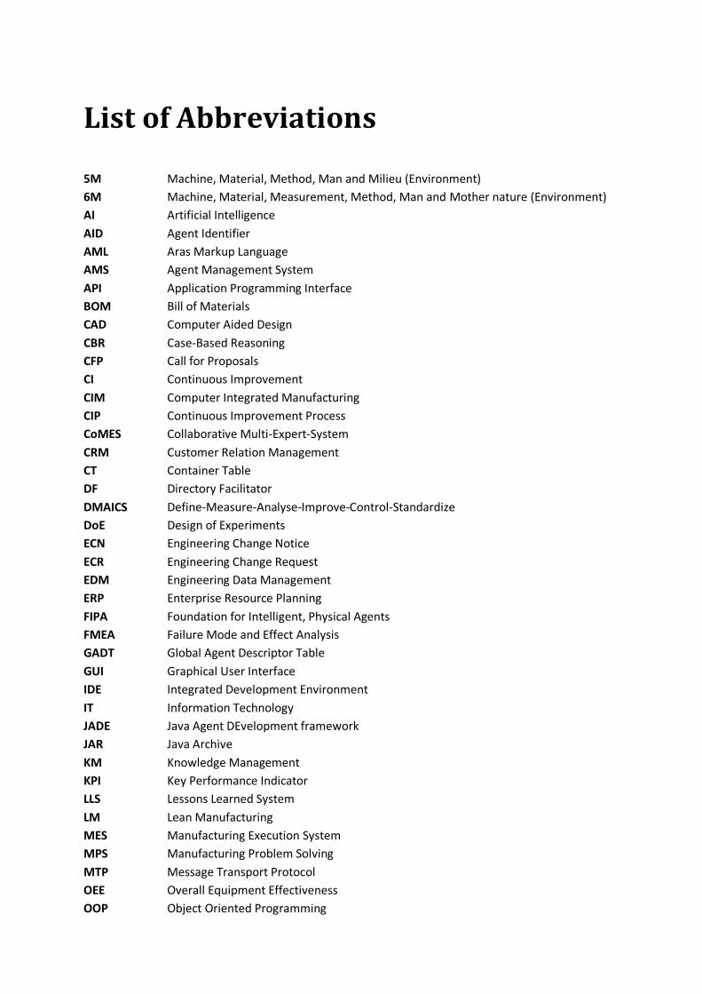
5M Machine, Material, Method, Man and Milieu (Environment) 6M Machine, Material, Measurement, Method, Man and Mother nature (Environment) AI Artificial Intelligence AID Agent Identifier AML Aras Markup Language AMS Agent Management System API Application Programming Interface BOM Bill of Materials CAD Computer Aided Design CBR Case-Based Reasoning CFP Call for Proposals CI Continuous Improvement CIM Computer Integrated Manufacturing CIP Continuous Improvement Process CoMES Collaborative Multi-Expert-System CRM Customer Relation Management CT Container Table DF Directory Facilitator DMAICS Define-Measure-Analyse-Improve-Control-Standardize DoE Design of Experiments ECN Engineering Change Notice ECR Engineering Change Request EDM Engineering Data Management ERP Enterprise Resource Planning FIPA Foundation for Intelligent, Physical Agents FMEA Failure Mode and Effect Analysis GADT Global Agent Descriptor Table GUI Graphical User Interface IDE Integrated Development Environment IT Information Technology JADE Java Agent DEvelopment framework JAR Java Archive KM Knowledge Management KPI Key Performance Indicator LLS Lessons Learned System LM Lean Manufacturing MES Manufacturing Execution System MPS Manufacturing Problem Solving MTP Message Transport Protocol OEE Overall Equipment Effectiveness OOP Object Oriented Programming
XXII
List of Abbreviations
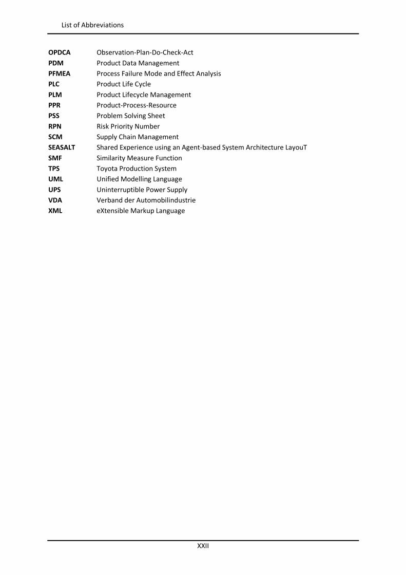
OPDCA Observation-Plan-Do-Check-Act PDM Product Data Management PFMEA Process Failure Mode and Effect Analysis PLC Product Life Cycle PLM Product Lifecycle Management PPR Product-Process-Resource PSS Problem Solving Sheet RPN Risk Priority Number SCM Supply Chain Management SEASALT Shared Experience using an Agent-based System Architecture LayouT SMF Similarity Measure Function TPS Toyota Production System UML Unified Modelling Language UPS Uninterruptible Power Supply VDA Verband der Automobilindustrie XML eXtensible Markup Language
XXIII
Abstract
Keywords: Continuous Improvement Process (CIP), Manufacturing Problem Solving (MPS), Industry 4.0, Knowledge Management (KM), Ontology, Case-Based Reasoning (CBR), Java Agent Development framework (JADE), Shared Experience using an Agent-based System Architecture LayouT (SEASALT), Process Failure Mode and Effect Analysis (PFMEA), Product Lifecycle Management (PLM)
Manufacturing processes have problems that have to be solved systematically to reach and exceed the defined production targets. These problems use to be analyzed and solved by teams with the support of different methodologies working directly in the shopfloor. This Thesis proposes a system to support the Continuous Improvement Process (CIP) at shopfloor level of manufacturing plants in multinational companies by capturing and reusing easily the knowledge generated in the process of Manufacturing Problem Solving (MPS).
This Thesis presents a novel ontology to represent knowledge generated during the resolution of Overall Equipment Effectiveness (OEE) problems at shopfloor level of any kind of manufacturing pro-duction plants. This ontology has been used to build a Knowledge Management (KM) system that supports CIP in multinational companies by capturing and reusing the knowledge generated in the process of MPS. The architecture of this system integrates the 8D method, as structured method to guide the resolution of problems step by step, Case-Based Reasoning (CBR) on an agent-based dis-tributed architecture, as repository of cases and artificial intelligence application to search for similar manufacturing problem cases collected previously in multiple locations, and a Product Lifecycle Management (PLM) system, as automatic source of extended problem context information (i.e. Products, Processes and Resources (PPR)) that will enrich the similarity calculation of the CBR appli-cation. Process Failure Mode and Effect Analysis (PFMEA) is used both as root model to create an ontology, on which the system is built, and as source of the initial set of cases to feed the CBR appli-cation.
A prototype of this system was developed and tested in Exide Technologies, a manufacturing multi-national company provider of electrical energy storage solutions for transportation and industrial markets. The results collected in two different manufacturing plants of this company show the feasi-bility and validate the conceptual proposal presented in this Thesis. The development proposed in this Thesis allows also setting the foundation to carry out further works to extend and improve the presented conceptual framework.

25
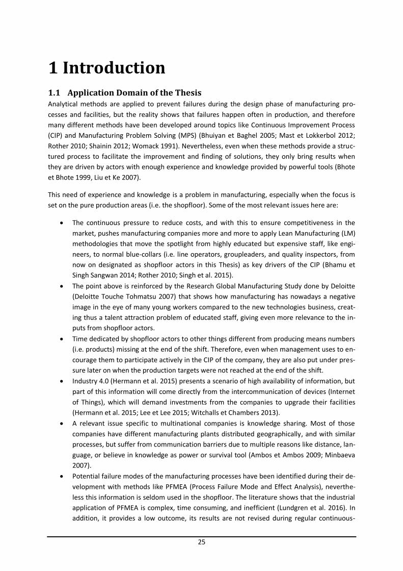
1 Introduction 1.1 Application Domain of the Thesis Analytical methods are applied to prevent failures during the design phase of manufacturing pro-cesses and facilities, but the reality shows that failures happen often in production, and therefore many different methods have been developed around topics like Continuous Improvement Process (CIP) and Manufacturing Problem Solving (MPS) (Bhuiyan et Baghel 2005; Mast et Lokkerbol 2012; Rother 2010; Shainin 2012; Womack 1991). Nevertheless, even when these methods provide a struc-tured process to facilitate the improvement and finding of solutions, they only bring results when they are driven by actors with enough experience and knowledge provided by powerful tools (Bhote et Bhote 1999, Liu et Ke 2007).
This need of experience and knowledge is a problem in manufacturing, especially when the focus is set on the pure production areas (i.e. the shopfloor). Some of the most relevant issues here are:
The continuous pressure to reduce costs, and with this to ensure competitiveness in the market, pushes manufacturing companies more and more to apply Lean Manufacturing (LM) methodologies that move the spotlight from highly educated but expensive staff, like engi-neers, to normal blue-collars (i.e. line operators, groupleaders, and quality inspectors, from now on designated as shopfloor actors in this Thesis) as key drivers of the CIP (Bhamu et Singh Sangwan 2014; Rother 2010; Singh et al. 2015).
The point above is reinforced by the Research Global Manufacturing Study done by Deloitte (Deloitte Touche Tohmatsu 2007) that shows how manufacturing has nowadays a negative image in the eye of many young workers compared to the new technologies business, creat-ing thus a talent attraction problem of educated staff, giving even more relevance to the in-puts from shopfloor actors.
Time dedicated by shopfloor actors to other things different from producing means numbers (i.e. products) missing at the end of the shift. Therefore, even when management uses to en-courage them to participate actively in the CIP of the company, they are also put under pres-sure later on when the production targets were not reached at the end of the shift.
Industry 4.0 (Hermann et al. 2015) presents a scenario of high availability of information, but part of this information will come directly from the intercommunication of devices (Internet of Things), which will demand investments from the companies to upgrade their facilities (Hermann et al. 2015; Lee et Lee 2015; Witchalls et Chambers 2013).
A relevant issue specific to multinational companies is knowledge sharing. Most of those companies have different manufacturing plants distributed geographically, and with similar processes, but suffer from communication barriers due to multiple reasons like distance, lan-guage, or believe in knowledge as power or survival tool (Ambos et Ambos 2009; Minbaeva 2007).
Potential failure modes of the manufacturing processes have been identified during their de-velopment with methods like PFMEA (Process Failure Mode and Effect Analysis), neverthe-less this information is seldom used in the shopfloor. The literature shows that the industrial application of PFMEA is complex, time consuming, and inefficient (Lundgren et al. 2016). In addition, it provides a low outcome, its results are not revised during regular continuous-
26
Research Goals
improvement activities, and there are issues to keep an efficient feedback. Part of the prob-lem with PFMEA relates to the fact that very often it is based on a spreadsheet approach, which makes it difficult to reuse results and identify similarities.
The company that is able to solve these issues, or at least to mitigate their consequences, would have an important competitive advantage in front of its competitors.
1.2 Research Goals The goal of this Thesis is to create a model (Camarillo 2015, Camarillo et al. 2017a; Camarillo et al. 2017b; Camarillo et al. 2018a; Camarillo et al. 2018b) that supports the efficient capture and reuse of knowledge across multiple locations in the application environment of manufacturing at shopfloor level. This model should support the knowledge share independently of the user (i.e. it can be used even by users with very low skills), the location (i.e. anyone around the world), and the manufactur-ing process where it will be used. The specific knowledge to be managed by this model is the one recorded in the PFMEA during the process development phase, as well as the knowledge generated during the daily CIP activities linked to the Overall Equipment Effectiveness (OEE) improvement. Among the different topics considered by OEE, the focus is set on quality issues with product and processes (i.e. quality claims and scrap), abnormal production speed, and breakdowns. This model can use the information in the available containers of the company (Product Lifecycle Management system) to improve the efficiency in the knowledge sharing.
1.3 Proposed Approach The new technological vision Industry 4.0 proposes a new scenario with high availability of data and connectivity between devices and systems (Beecham Research 2015; Hermann et al. 2015) that of-fers new possibilities to approach the introduced Knowledge Management (KM) issue around CIP and MPS in production. Even when current trends in the research field pay more attention on terms like Machine Learning and the automatic analysis of data collected from multiple sensors distributed along the lines, this Thesis wants to contribute to this vision Industry 4.0, but exploring a different area, without the need of making relevant investments in the facilities of the company (Internet of the Things). It wants to profit from this interconnectivity and Artificial Intelligence (AI) capabilities, but based on the great availability of structured information already existing today in many compa-nies. This available information has the form of analysis of problems done following MPS methods or Process Failure Mode and Effect Analysis (PFMEA), and the information stored in Product Lifecycle Management (PLM) systems. This approach allows companies to get quick profit from their existing knowledge, but with a very low initial investment (no need of installation of sensors and complex data networks in the shopfloor).
From this perspective, this Thesis proposes to apply the model introduced in the section 1.2 in a KM software system with following characteristics:
The software application is to be used directly at shopfloor level. It has to propose possible solutions to problems that are identified during daily CIP activities
linked to the OEE improvement. It has to collect information related solutions applied to the identified problems that, after
analysis (i.e. filter) done by an expert, could be included in the knowledge base of the sys-tem.

27
Innovative Aspects of the Thesis
Target users are shopfloor actors (i.e. not highly educated staff), so the tool should be intui-tive and easy to use.
Users need just to introduce very few information about manufacturing problem to compen-sate their lack of time and knowledge.
The software application has to follow any kind of MPS methodology to guide the user in the resolution of the problems identified during the CIP activity.
Easy access to reuse the knowledge stored in existing PFMEA documents of the company should be ensured.
The application should be used simultaneously by multiple users from different plants, sup-porting in this way the share of knowledge inside of the company.
1.4 Innovative Aspects of the Thesis The main contribution of this work is its innovative production-oriented approach to CIP by combin-ing classic MPS methods, with CBR on an agent-based distributed architecture, and with a PLM sys-tem. This novel approach had not been proposed in the reviewed literature. The proposed approach integrates 8D, PFMEA (Process Failure Mode and Effect Analysis), Case-Based Reasoning (CBR), and Product Lifecycle Management (PLM). 8D is chosen as the MPS method, and PFMEA as a preventive technique to create an initial set of potential manufacturing knowledge base. A CBR application, on an agent-based distributed architecture, is chosen as the artificial intelligence tool for searching for similar manufacturing problem cases. Finally, a PLM application contains extended context infor-mation to enrich the similarity calculation within the CBR application. And all this, considering low level staff like operators or quality inspectors as main target users of this methodology. Some other works already considered the combined approach of MPS with capture and reuse of knowledge (Foguema et al. 2008, Jabrouni et al. 2011), and even by proposing a PLM system as source of infor-mation (Bertin et al. 2010, Bertin et al. 2012, Bertin 2012), but all of them are focused on engineering process, missing the global CIP perspective of this Thesis, and its specific support to operators and low level staff at shopfloor. In addition none of them has a multilocation strategy with a concrete architecture and artificial intelligence tool.
The application of the SEASALT architecture (Shared Experience using an Agent-based System Archi-tecture LayouT) (Bach 2012) to an industrial environment of production can also be considered as a contribution.
Another relevant contribution of this work is the ontological approach. It combines and extends ex-isting ontologies from the PFMEA (Dittmann et al. 2004) and manufacturing (Chungoora et al. 2013) environments to create a new more comprehensive ontology able to represent manufacturing prob-lems linked to production lines. The proposed ontology supports at the same time the reuse of PFMEA analysis results.
1.5 Development Plan The development plan defined for this Thesis is divided into following steps:
Analysis and research of the state of the art around main topics of the Thesis. Books, papers, lectures at the university, and congresses were used as source of information.
Collaboration with the University of Hildesheim to get deeper knowledge around CBR and the agent-based programming.
28
Means Used in the Thesis
Development of process, knowledge, and information models, as well as defining the IT in-frastructure.
Development and implementation of the software system. Case studies. Analysis of results and conclusions.
A specific production area of a manufacturing plant is to be selected as first case study to validate the concepts of this Thesis. In this production area, the knowledge stored in the existing PFMEAs has to be recorded, and it has to be extended with MPS knowledge collected during several months. Then the developed system has to be tested based on ten problems happening in this production area. This will allow testing the feasibility of the system.
The second case study is to test the system with the knowledge coming from the first case study, but now in a similar production area of a different manufacturing plant located in a different country. Then again ten problems from this similar area are to be analyzed with the help of the system. This will allow checking the utility and performance of the system when it is used by different users in a different cultural environment, and with processes and machinery not completely the same.
Finally a different production area in the first manufacturing plant is to be selected for the third case study. Again ten problems are to be analyzed with the help of the system. This will allow checking the utility and performance of the system in an area from which no knowledge was previously extracted.
In all the three defined case studies the way to measure the performance of the system is by com-paring the output of the system with the solutions applied by the experts of each area.
1.6 Means Used in the Thesis During the initial phase of researching around the concepts of the Thesis following software were tested and analyzed:
CBR software tools:
myCBR version 3 jColibri2 CBR Works 4
Knowledge representation software tools:
Protégé 3.1 Protégé 5
FMEA software tools:
QSYS FMEA APIS IQ Software
PLM systems:
OpenPLM 1.2 Aras Innovator 11.0
29
Structure of the Thesis
Software development environment:
Eclipse IDE for Java Developers – Version: Luna Service Release 2
JADE (Java Agent DEvelopment framework) Platform:
JADE 4.4.0
Problem solving software:
PROACTOnDemand v1
Finally the tools selected for this Thesis were:
MyCBR as artificial intelligence engine. Aras Innovator as PLM. Eclipse as development environment. JADE as agent-based platform.
1.7 Structure of the Thesis This Thesis has been divided in the following sections:
Introduction
This section presents the application domain and research goals of the Thesis as well as its proposed approach. The innovative aspects of the Thesis are summarized, and finally the development plan and the means used during the development of the Thesis are explained.
Foundations and State of the Art
This section makes a review of the state of the art of all strategies, methodologies, or tools relevant for this Thesis. The main topics presented are CIP, MPS methods, PFMEA, KM, Knowledge represen-tation, CBR, the architecture SEASALT (Shared Experience using an Agent-based System Architecture LayouT), PLM systems, and the technological vision Industry 4.0.
Developed Models
This section introduces the different models developed to create the proposed system. These are:
The process model, where the global process followed by users and system is modelled. The knowledge model, used to represent the knowledge that has to be stored and shared
among users and computers. The application of this knowledge model to the PLM system and to the CBR system. The IT (Information Technology) infrastructure developed for the proposed system.
Development of the Application Prototype
This part of the Thesis presents the concrete application of the presented models to the application prototype created to justify and validate the theories of this Thesis. This includes the customization of PLM and CBR systems, and the programing of the SEASALT based software on the JADE platform.
30
Structure of the Thesis
Application of the Model
This section explains how the developed application prototype has been tested in the real life, start-ing by the population with data of the PLM system, the collection of initial cases from the PFMEA and the shopfloor, their introduction into the CBR system, and finishing with the collection of results in three different cases: a defined process 1 in a plant placed in a country A, the same process 1 but in a plant located in a country B, and finally a process 2 in the original plant of the country A.
Results, Conclusions, and Future Work
This section presents and analyses the results of the Thesis, taking out several conclusions. Some possible future research paths are proposed at the end of the section.
References
Appendix
In the appendix are presented the complete software source code of the developed prototype appli-cation, the template used to collect information about problems at the lines, and all publications done during the development of this Thesis.
31
2 Foundations and State of the Art 2.1 Introduction This section makes a review of the state of the art of all strategies, methodologies, or tools relevant to this Thesis.
At the beginning, Manufacturing is presented as context of the Thesis, and Exide Technologies as company where the case study was implemented. This introduces some existing issues in the indus-try and its influence on CIP, which is the methodology that is analyzed after that, together with the MPS methods and the PFMEA. All this analysis drives to conclude that knowledge is the key contribu-tor for success in the resolution of problems.
In the next section, the focus is set on knowledge: how it can be managed, and more important, how it can be represented to be stored and used as common language for human beings and machines.
Following sections get into Artificial Intelligence (AI) and its CBR technique, presenting the architec-ture SEASALT as a distributed platform to share knowledge. PLM systems are presented right after.
Finally, it is explained that the result of the four presented main elements (i.e. MPS, CBR, SEASALT and PLM), working together to support the CIP, emerges as a concept that can be included within the frame of the technological vision Industry 4.0, which is also introduced in the last section of the state of the art.
2.2 Context: Manufacturing and the Case Study Company The context of this Thesis is manufacturing, with focus on the industrial production, in which raw materials are transformed into finished goods on a large scale. Other typical areas like Engineering, Process Development, Supply Chain or Quality Assurance are out of the scope of the Thesis.
Bhamu et Singh Sangwan (2014) explained how the advent of recession at the beginning of twenty-first century forced many organizations worldwide to reduce cost and to be more responsive to cus-tomer demands. Lean Manufacturing (LM) was widely perceived by industry as an answer to these requirements, because LM aims to the systematic removal of waste at any point of the company, which is actually the same goal of CIP (Bhuiyan et Baghel 2005). In the literature, depending on the authors, both terms can be found as synonymous many times. For example in the extended literature review done by Bhamu et Singh Sangwan (2014) they speak about LM and consider CIP as a tool of LM, but another extended review done by Shing et Shing (2015) puts the focus on CIP and they speak about LM techniques associated to the CIP strategy. This Thesis considers both terms equivalent.
A relevant characteristic of LM and CIP philosophies is the focus on shopfloor actors instead of on highly educated staff (Bhamu et Singh Sangwan 2014; Rother 2010; Singh et Singh 2015). This ap-proach fits actually very well with the current situation in the market, where manufacturing has nowadays a negative image in the eye of many young workers compared to the new technologies business, creating thus a talent attraction problem (Deloitte Touche Tohmatsu 2007).
Another typical issue in the industry nowadays, specific to multinational companies, is knowledge sharing across the company. Most of those companies have different manufacturing plants distribut-
32
Continuous Improvement Process in Manufacturing
ed geographically and with similar processes, but they suffer from communication barriers due to multiple reasons like distance, language, or believe in knowledge as power or survival tool (Ambos et al Ambos 2009; Minbaeva 2007).
All this together creates a global scenario of lack of talent and resistance to share knowledge that puts in troubles the proper deployment and effectiveness of the CIP strategies in the industry, some-thing that this Thesis pretends to mitigate up to certain level.
To validate the concepts proposed by this Thesis Exide, Technologies was selected as case study company, in which it was implemented a demonstrator of the proposed model. Exide Technologies (www.exide.com) is a global provider of stored electrical energy solutions, batteries and associated equipment and services for transportation and industrial markets. With 130 years of industry experi-ence and operating in more than 80 countries, Exide produces and recycles a broad range of prod-ucts that keep customers and their businesses powering forward. Leading car, truck and lift truck manufacturers trust Exide as an original equipment supplier, and Exide serves the transportation and industrial aftermarket through a comprehensive portfolio of products and services. The Company’s extensive sales, distribution and service network provides flexibility and quality for an exceptional customer experience.
Exide manufactures and sells products around the world under different brands. Some of the most famous ones in Europe for the automotive market are Exide, Tudor, Fulmen, Sonnak, Centra or DETA. And for the industrial market are Sonnenschein, Hagen, Marathon, Classic, Tensor, or Sprinter.
The Exide Transportation business manufactures and markets starting, deep-cycle, and micro-hybrid batteries for automotive, light and heavy-duty truck, agricultural, marine, military, powersport, and other specialty applications. Exide serves the global transportation market place with successful and well-known product offerings and brands, along with battery diagnostic equipment and charging systems.
At the other side, the other business unit of Exide serves the Industrial Power markets with its GNB®-branded efficient energy storage systems for both Motive Power and Network Power customers. Motive Power applications include materials handling (power for lift trucks, airside assistance vehi-cles, and automatic guided vehicles); cleaning machines; railroads; military and mining vehicles; and other commercial electric vehicles. Network Power installations include standby power for electric utilities; telecommunications systems; alarm/security systems; renewable energy systems; railway systems; uninterruptible power supply (UPS); and defence industry equipment.
Exide’s innovative technologies and advanced/premium products include Absorbed Glass Mat (AGM) and Enhanced Flooded Batteries (EFB) for start-stop and energy recuperation in automotive applica-tions, along with flooded and VRLA (AGM and GEL) products, market leading motive power tubular products and smart charging systems for industrial applications.
2.3 Continuous Improvement Process in Manufacturing Continuous Improvement (CI), also called Continuous Improvement Process (CIP), is a philosophy that Deming described simply as consisting of “Improvement initiatives that increase successes and reduce failures” (Juergensen 2000). Another definition of CI is “a company-wide process of focused and continuous incremental innovation” (Bessant et al. 1994). A more general definition states that “CI is a culture of sustained improvement targeting the elimination of waste in all systems and pro-
33
Continuous Improvement Process in Manufacturing
cesses of an organization. It involves everyone working together to make improvements without necessarily making huge capital investments. Often, major improvements take place over time as a result of numerous incremental improvements. On any scale, improvement is achieved through the use of a number of tools and techniques dedicated to searching for sources of problems, waste, and variation, and finding ways to minimize them” (Bhuiyan et al. 2005). And finally Singh et al. (2015) defines CI as “a culture of sustained improvement aimed at eliminating waste in all organizational systems and processes, and involving all organizational participants”.
Based on the previous definitions, and focusing only on the manufacturing environment, this Thesis defines CIP as the system that supports the recognition of problems and improvement opportunities in the process, and challenges the team to sort them out in a continuous way.
Asiedu et Gu (1998) estimate that over 70% of the total life cycle cost of a product is committed at the early design stage. Designers have developed methodologies such as design for manufacturabil-ity, design for assembly, design for maintainability, or design for quality, to try to increase the profit-ability of the products from the design point of view. Even though, these methodologies have helped to reduce the cost of the product, there is still big gap for improvement in the manufacturing step of the Product Life Cycle (PLC). The CIP turns the perfect tool to avoid losing competitiveness in front of other market competitors in this phase where the product and manufacturing process are already defined and released, and where there are no specific requirements from the market or the custom-ers to be reached.
In the history and evolution of CIP there are three different steps (Bhuiyan et al. 2005):
1800s: management encouraged employee-driven improvements, and incentive programs were set in place to reward employees that brought about positive changes in the organiza-tion.
Late 1800s and early 1900s: developing methods to help managers to analyze and to solve production problems using scientific methods based on tightly controlled time-trials to achieve proper piece rates and labor standards.
After Second World War: management experts like Deming, Juran, and Gilbreth introduced in Japan the US trends around CI. The Japanese developed their own ideas and quality con-trols, which were used initially in the manufacturing process, but they evolved into a much broader term, growing into a management tool for ongoing improvement involving everyone in an organization.
This Thesis is based on this last CIP trend grounded in Japan, and more specifically on the Toyota Production System (TPS) developed by Toyota, one of the pioneers in the development of CIP, and probably the most spread and known production system in the manufacturing environment nowa-days (Bhamu et al. 2014; Ohno 1988; Rother 2010; Womack et al. 1991).
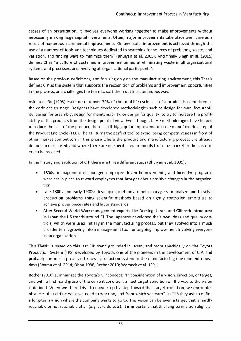
Rother (2010) summarizes the Toyota’s CIP concept: “In consideration of a vision, direction, or target, and with a first-hand grasp of the current condition, a next target condition on the way to the vision is defined. When we then strive to move step by step toward that target condition, we encounter obstacles that define what we need to work on, and from which we learn”. In TPS they ask to define a long-term vision where the company wants to go to. This vision can be even a target that is hardly reachable or not reachable at all (e.g. cero defects). It is important that this long-term vision aligns all
34
Continuous Improvement Process in Manufacturing
actions in the company. Then they define target conditions, which are a description of a state that the company wants to have reached at some future point in time, on the way toward a longer-term vision (see Figure 1).
Figure 1: Toyota’s improvement process in brief (Rother 2010)
The revolution around target conditions is that they are no simple targets or performance measures. A target is an isolated measure and it can be reached in many ways. For example inventory can be drastically reduced, but then the lines could start stopping very often due to lack of material. A target condition defines a target, but it focuses mainly on the means by which we achieve those targets. It focuses on the obstacle which doesn’t allow reaching the target, in the real root causes of the barri-ers. In the previous example the obstacle could be maybe that the lines are not flexible enough to work with very small lot-sizes. Then the focus has to be placed on how to make the changeovers much faster, and not on reducing inventory.
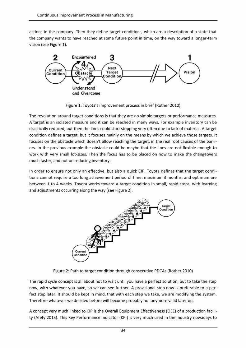
In order to ensure not only an effective, but also a quick CIP, Toyota defines that the target condi-tions cannot require a too long achievement period of time: maximum 3 months, and optimum are between 1 to 4 weeks. Toyota works toward a target condition in small, rapid steps, with learning and adjustments occurring along the way (see Figure 2).
Figure 2: Path to target condition through consecutive PDCAs (Rother 2010)
The rapid cycle concept is all about not to wait until you have a perfect solution, but to take the step now, with whatever you have, so we can see further. A provisional step now is preferable to a per-fect step later. It should be kept in mind, that with each step we take, we are modifying the system. Therefore whatever we decided before will become probably not anymore valid later on.
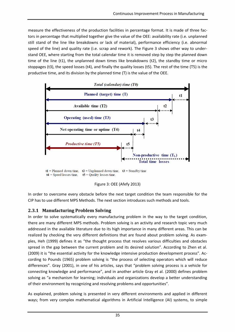
A concept very much linked to CIP is the Overall Equipment Effectiveness (OEE) of a production facili-ty (Afefy 2013). This Key Performance Indicator (KPI) is very much used in the industry nowadays to
35
Continuous Improvement Process in Manufacturing
measure the effectiveness of the production facilities in percentage format. It is made of three fac-tors in percentage that multiplied together give the value of the OEE: availability rate (i.e. unplanned still stand of the line like breakdowns or lack of material), performance efficiency (i.e. abnormal speed of the line) and quality rate (i.e. scrap and rework). The Figure 3 shows other way to under-stand OEE, where starting from the total calendar time it is removed step by step the planned down time of the line (t1), the unplanned down times like breakdowns (t2), the standby time or micro stoppages (t3), the speed losses (t4), and finally the quality losses (t5). The rest of the time (T5) is the productive time, and its division by the planned time (T) is the value of the OEE.
Figure 3: OEE (Afefy 2013)
In order to overcome every obstacle before the next target condition the team responsible for the CIP has to use different MPS Methods. The next section introduces such methods and tools.
2.3.1 Manufacturing Problem Solving In order to solve systematically every manufacturing problem in the way to the target condition, there are many different MPS methods. Problem solving is an activity and research topic very much addressed in the available literature due to its high importance in many different areas. This can be realized by checking the very different definitions that are found about problem solving. As exam-ples, Heh (1999) defines it as “the thought process that resolves various difficulties and obstacles spread in the gap between the current problem and its desired solution”. According to Zhen et al. (2009) it is “the essential activity for the knowledge intensive production development process”. Ac-cording to Pounds (1965) problem solving is “the process of selecting operators which will reduce differences”. Gray (2001), in one of his articles, says that “problem solving process is a vehicle for connecting knowledge and performance”, and in another article Gray et al. (2000) defines problem solving as “a mechanism for learning; individuals and organizations develop a better understanding of their environment by recognizing and resolving problems and opportunities”.
As explained, problem solving is presented in very different environments and applied in different ways; from very complex mathematical algorithms in Artificial Intelligence (AI) systems, to simple
36
Continuous Improvement Process in Manufacturing
decisions to solve daily issues faced by any person. This Thesis focuses on problem solving from the perspective of CIP in the Manufacturing environment, and it is here where the definition of Bertin et al. (2012) fits perfectly: “Problem Solving is a Continuous Improvement Process ensuring the pro-cessing and the resolution of negative events”.
Some of the most relevant MPS methods are presented below:
PDCA (Rother 2010): PDCA may have been introduced to the Japanese in the 1950s via lec-ture courses given in Japan by W. Edwards Deming. It is a version of the Shewhart cycle, which is a scientific method consisting of formulating hypotheses and then testing them with information obtained from direct observation. It defines the steps Plan, Do, Check, and Act. An interesting variation of this is the OPDCA. The added "O" stands for Observation or "Grasp the current condition".
DMAIC (Mast et al. 2012): this is part of the Six Sigma methodology. Originally described as a method for variation reduction, DMAIC is applied in practice as a generic problem solving and improvement approach. The name is the acronym of Define, Measure, Analyse, Improve and Control. An additional step is usually set at the end: Standardize or Sustain.
8D (Dennies 2002, Riesenberg et al. 2010): developed by Ford Motor Company in the early 1990’s it was introduced to support their plants and suppliers in the problem solving activity. Nowadays it is the standard template used to present any quality claim in the automotive sector. The 8D methodology involves teams working together in order to solve problems, us-ing a structured eight step approach to help focus on facts, instead of opinions.
Shainin (Bhote et Bhote 1999, Shainin 2012, Steiner et al. 2008): this method was developed by Dorian Shainin and offered by the company Shainin LCC under the trademarked name Red X®. Due to this commercial approach very few articles or books are available around, and the main source is the book World Class Quality of Bhote et Bhote (1999). The author was only allowed by Motorola to write about the method because Motorola won the Malcolm Baldrige National Quality Award, which stipulates that its methods have to be shared with other U.S. companies. The Shainin Method was developed for problem solving on operating, medium to high volume processes where data are cheaply available (most of the tools implic-itly assume that many parts are available for analysis), statistical methods are widely used, and intervention into the process is difficult. This method strongly relies on some specific sta-tistical tools developed by Shainin.
Kepner-Tregoe (Kepner et al. 2008, Marquis 2010a): Charles H. Kepner and Benjamin B. Tre-goe developed what they called the Problem Solving and Decision Making method. This method is divided in 4 parts: Situation Appraisal, Problem Analysis, Decision Analysis, and Po-tential Problem and Potential Opportunity Analysis, and they propose specific Tools for each part. Kepner-Tregoe method was used by NASA to troubleshoot Apollo XIII.
PROACT (Hammond et al. 1999, Latino 2007): this is a method developed by J.S. Hammond, R.L. Keeney, and H. Raiffa and presented in their book Smart Choices. It pretends to cover the gap between how people actually do make decisions and what researchers discovered over the last 50 years about how they should make decisions. The term PROACT® is an acro-nym of the five core elements of the Problem Solving Method: Problem, Objectives, Alterna-tives, Consequences, and Trade-offs. The essence of PROACT® approach is to divide and con-quer: breaking the decision into its key elements; identifying those most relevant to the deci-sion; applying some hard, systematic thinking; and making the decision. This approach is
37
Continuous Improvement Process in Manufacturing
proactive, encouraging seeking out decision-making opportunities rather than waiting for problems to present themselves.
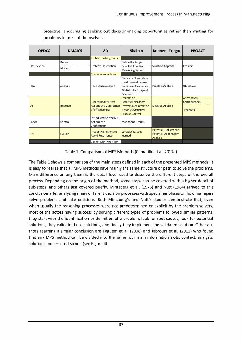
Table 1: Comparison of MPS Methods (Camarillo et al. 2017a)
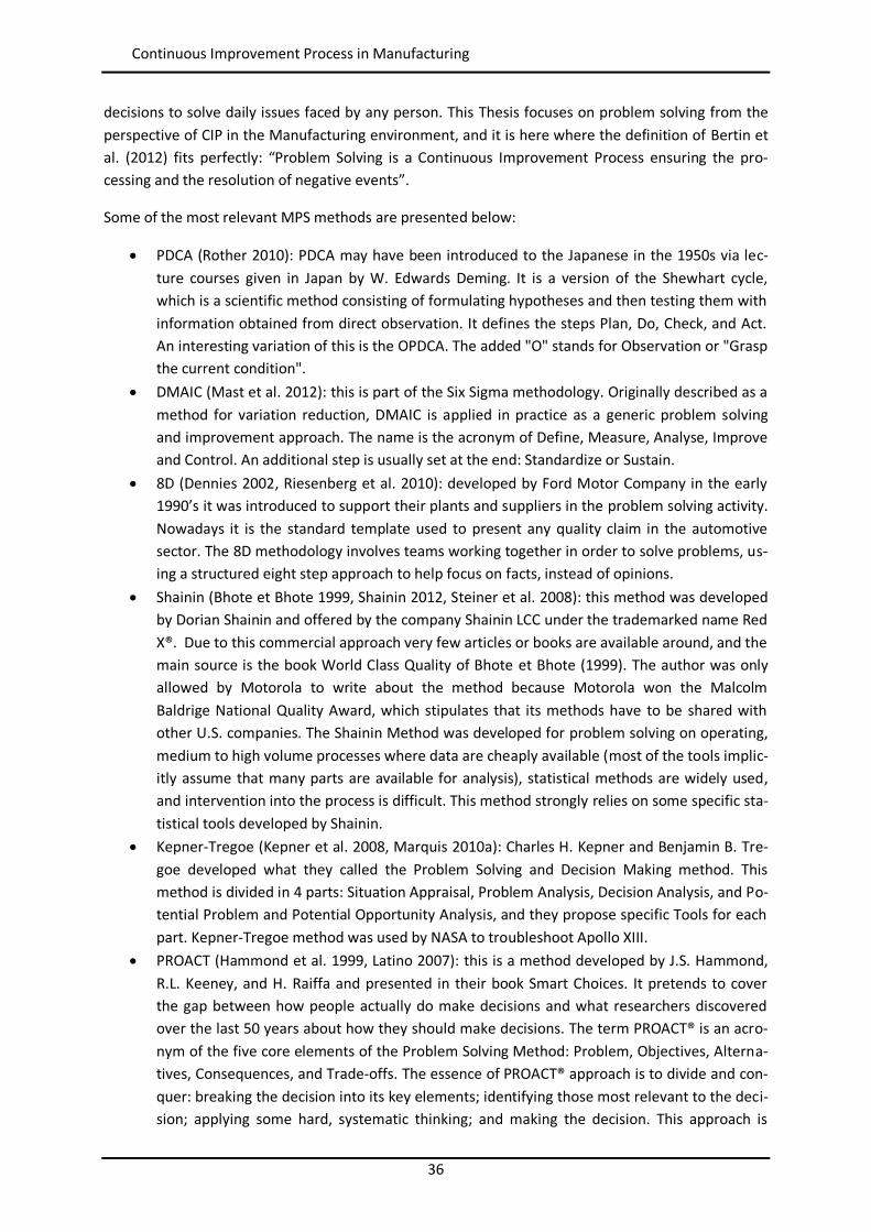
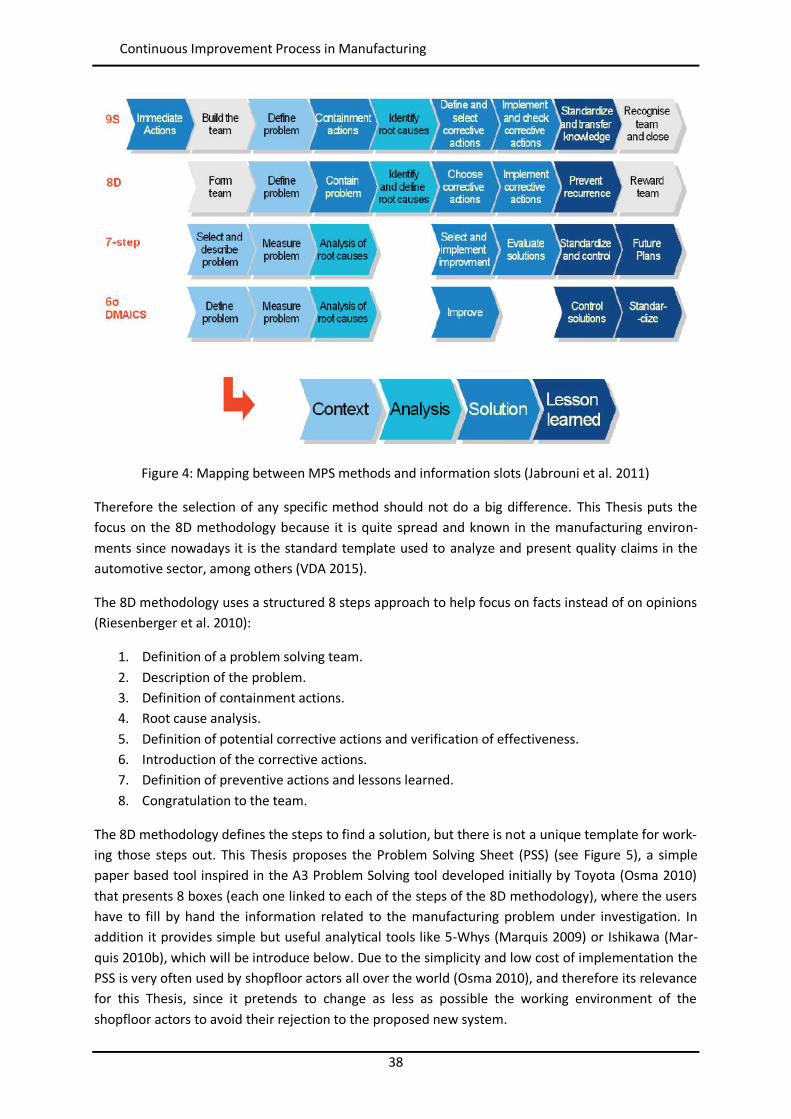
The Table 1 shows a comparison of the main steps defined in each of the presented MPS methods. It is easy to realize that all MPS methods have mainly the same structure or path to solve the problems. Main difference among them is the detail level used to describe the different steps of the overall process. Depending on the origin of the method, some steps can be covered with a higher detail of sub-steps, and others just covered briefly. Mintzberg et al. (1976) and Nutt (1984) arrived to this conclusion after analyzing many different decision processes with special emphasis on how managers solve problems and take decisions. Both Mintzberg’s and Nutt’s studies demonstrate that, even when usually the reasoning processes were not predetermined or explicit by the problem solvers, most of the actors having success by solving different types of problems followed similar patterns: they start with the identification or definition of a problem, look for root causes, look for potential solutions, they validate these solutions, and finally they implement the validated solution. Other au-thors reaching a similar conclusion are Foguem et al. (2008) and Jabrouni et al. (2011) who found that any MPS method can be divided into the same four main information slots: context, analysis, solution, and lessons learned (see Figure 4).
OPDCA DMAICS 8D Shainin Kepner - Tregoe PROACT
Problem Solving TeamDefine Define the Project
Measure Establish Effective Measuring System
Containment actionsGenerate Clues (about the dominant cause)List Suspect Variables Statistically Designed ExperimentsInteraction AlternativesRealistic Tolerances ConsequencesIrreversible Corrective Action vs Statistical Process Control
Tradeoffs
Check ControlIntroduced Corrective Actions and Verifications
Monitoring Results
Act SustainPreventive Actions to Avoid Recurrence
Leverage lessons learned
Potential Problem and Potential Opportunity Analysis
Congratulate the Team
Problem
Plan Analyze
Situation AppraisalProblem Description
Root Cause Analysis Problem Analysis Objectives
Do ImprovePotential Corrective Actions and Verification of Effectiveness
Decision Analysis
Observation
38
Continuous Improvement Process in Manufacturing
Figure 4: Mapping between MPS methods and information slots (Jabrouni et al. 2011)
Therefore the selection of any specific method should not do a big difference. This Thesis puts the focus on the 8D methodology because it is quite spread and known in the manufacturing environ-ments since nowadays it is the standard template used to analyze and present quality claims in the automotive sector, among others (VDA 2015).
The 8D methodology uses a structured 8 steps approach to help focus on facts instead of on opinions (Riesenberger et al. 2010):
1. Definition of a problem solving team. 2. Description of the problem. 3. Definition of containment actions. 4. Root cause analysis. 5. Definition of potential corrective actions and verification of effectiveness. 6. Introduction of the corrective actions. 7. Definition of preventive actions and lessons learned. 8. Congratulation to the team.
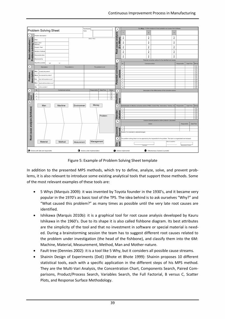
The 8D methodology defines the steps to find a solution, but there is not a unique template for work-ing those steps out. This Thesis proposes the Problem Solving Sheet (PSS) (see Figure 5), a simple paper based tool inspired in the A3 Problem Solving tool developed initially by Toyota (Osma 2010) that presents 8 boxes (each one linked to each of the steps of the 8D methodology), where the users have to fill by hand the information related to the manufacturing problem under investigation. In addition it provides simple but useful analytical tools like 5-Whys (Marquis 2009) or Ishikawa (Mar-quis 2010b), which will be introduce below. Due to the simplicity and low cost of implementation the PSS is very often used by shopfloor actors all over the world (Osma 2010), and therefore its relevance for this Thesis, since it pretends to change as less as possible the working environment of the shopfloor actors to avoid their rejection to the proposed new system.
39
Continuous Improvement Process in Manufacturing
Figure 5: Example of Problem Solving Sheet template
In addition to the presented MPS methods, which try to define, analyze, solve, and prevent prob-lems, it is also relevant to introduce some existing analytical tools that support those methods. Some of the most relevant examples of these tools are:
5 Whys (Marquis 2009): it was invented by Toyota founder in the 1930’s, and it became very popular in the 1970’s as basic tool of the TPS. The idea behind is to ask ourselves “Why?” and “What caused this problem?” as many times as possible until the very late root causes are identified.
Ishikawa (Marquis 2010b): it is a graphical tool for root cause analysis developed by Kauru Ishikawa in the 1960’s. Due to its shape it is also called fishbone diagram. Its best attributes are the simplicity of the tool and that no investment in software or special material is need-ed. During a brainstorming session the team has to suggest different root causes related to the problem under investigation (the head of the fishbone), and classify them into the 6M: Machine, Material, Measurement, Method, Man and Mother-nature.
Fault tree (Dennies 2002): it is a tool like 5 Why, but it considers all possible cause streams. Shainin Design of Experiments (DoE) (Bhote et Bhote 1999): Shainin proposes 10 different
statistical tools, each with a specific application in the different steps of his MPS method. They are the Multi-Vari Analysis, the Concentration Chart, Components Search, Paired Com-parisons, Product/Process Search, Variables Search, the Full Factorial, B versus C, Scatter Plots, and Response Surface Methodology.
Teamleader:Team:
Date of completion:
Teamleader Responsible for Problem
Actions with date and responsible Actions under implementation Actions implemented Effectiveness of actions is proofed
Problem description:
PlantSketch / Photo
Why
?W
hy?
Why
?
Roo
t cau
se a
naly
sis
(5 x
Why
s)
Root
cau
se a
naly
sis
(Ishi
kaw
a)
Nr.
Stan
dar-
disa
tion
10
7
1
3
2
Problem Solving SheetBa
sic
info
rmat
ion
/ Pr
oble
m s
olvi
ng te
am
Discovered by
Pote
ntia
l cor
rect
ive
actio
ns
6
4
How
3
Why
?
Why
?W
hy?
Why
?
Nr.
often did the problem occur?
has detected the problem?
Repetitive problem yes no
What
Area / Line / Machine
Product / Part
Number of defects
Discovered when
Prob
lem
desc
riptio
nC
onta
in-
men
tac
tions
3
exactly did the problem occur?
Why is this a problem?
Where
1
is exactly the problem?
Description
Effe
ctiv
e-ne
ss
9
The problem is notThe problem is
When
ResponsibleContainment actions
2
Date/Time
Clo-
sure
Status
Less
ons
lear
ned
Potential corrective actions for the identified root causes
Why
?
Reason if no standard is altered/changed:
Status
5
Why
?
2
Why
?
Why
?W
hy?
Why
?
Standardisation of effective corrective actions (FMEA, Control Plan, Instructions, Training, etc.)
1
Date/TimeResponsible
2
Description of the effectiveness of the corrective actions
Lessons learned passed on other products / processes
5
1
The problem solving sheet is to be approved by the responsible for the problem. The team is congratulated and released.
3
4
Date/TimeResponsibleAction
8
Responsible Date/TimeCorrective action
2
5 x Whys - Further analysis of most probable root causes from Ishikawa
1
Why
?
Status
Why
?
1
2
7a
7b
8
4a
5
3 6
4
Problem:
Man Machine
Method
Environmen
MeasurementMaterial
Money
Management
40
Continuous Improvement Process in Manufacturing
Kepner-Tregoe Tools (Kepner et al. 2008, Marquis 2010a): they propose specific tools for each part of their method. Some of them are the problem definition by What-Where-When-Extend, development of possible causes from Distinction and Changes, or classification of ob-jectives into MUSTs and WANTs.
PROACT Logic tree (Hammond et al. 1999, Latino 2007): this tool is a logic tree that shows the relationships between an event (i.e. the least acceptable consequence that triggered the need for a root cause analysis), and the modes (i.e. the manifestations of the failure). In the tree it is looked for how each mode could happen. When asking “how could?,” all the possi-bilities (not only the most likely) are sought, as well as evidence to back up what did and did not occur. Questioning process is reiterative as the cause-and-effect chain follows backwards through the physical root causes. At certain point the human roots are uncovered. Then the tree goes for the last step which is the Latent Root Cause, which is found with the question “why the person thought the decision was the correct one at that time?”.
2.3.2 Problem Prevention: Process Failure Mode and Effect Analysis On top of the already introduced MPS methods, there are proactive preventive techniques to help in the identification of problems to avoid their occurrence. Failure Mode and Effect Analysis (FMEA) (Mikulak el al. 2008, VDA 2015) is a systematic method for identifying and preventing product and process problems before they occur. It focuses on preventing defects, enhancing safety, and increas-ing customer satisfaction. This Thesis focuses on the PFMEA, which is the type of FMEA to analyze manufacturing processes.
PFMEA guides the users to create a structure of components. These components represent processes at the higher levels of the structure, and the 5M (i.e. Man, Material, Machine, Method, and Milieu or Environment) (VDA 2015) at the lower levels. Each of these components fulfils one or more specific functions in the manufacturing process, and each of those functions have possible failure modes. Failure modes are the different ways in which a function of a component can fail. That provides mul-tiple lines of chained failure modes, which act at the same time as effects of the next failure mode and as cause of the previous one. The very last failure mode in the line should be very simple and specific, so easy to understand it deeply, being the root cause of all the previous ones, and the one on which the preventive actions have to be planned.
In the PFMEA method all the identified failure modes are evaluated according to three factors:
Severity: the consequence of the failure should it occur. Occurrence: the probability or frequency of the failure occurring. Detection: the probability of the failure being detected before the impact of the effect is re-
alized.
Using data and knowledge of the manufacturing process or product, each potential failure mode is rated in each of the three factors on a scale ranging from one to ten. By multiplying the three ratings a Risk Priority Number (RPN) is determined. The RPN is used to rank the need for corrective actions to eliminate or to reduce potential failure modes.
41
Knowledge Management and Representation
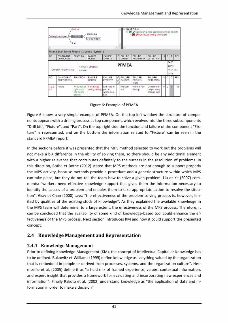
Figure 6: Example of PFMEA
Figure 6 shows a very simple example of PFMEA. On the top left window the structure of compo-nents appears with a drilling process as top component, which evolves into the three subcomponents “Drill bit”, “Fixture”, and “Part”. On the top right side the function and failure of the component “Fix-ture” is represented, and on the bottom the information related to “Fixture” can be seen in the standard PFMEA report.
In the sections before it was presented that the MPS method selected to work out the problems will not make a big difference in the ability of solving them, so there should be any additional element with a higher relevance that contributes definitely to the success in the resolution of problems. In this direction, Bothe et Bothe (2012) stated that MPS methods are not enough to support properly the MPS activity, because methods provide a procedure and a generic structure within which MPS can take place, but they do not tell the team how to solve a given problem. Liu et Ke (2007) com-ments: “workers need effective knowledge support that gives them the information necessary to identify the causes of a problem and enables them to take appropriate action to resolve the situa-tion”. Gray et Chan (2000) says: “the effectiveness of the problem-solving process is, however, lim-ited by qualities of the existing stock of knowledge”. As they explained the available knowledge in the MPS team will determine, to a large extent, the effectiveness of the MPS process. Therefore, it can be concluded that the availability of some kind of knowledge-based tool could enhance the ef-fectiveness of the MPS process. Next section introduces KM and how it could support the presented concept.
2.4 Knowledge Management and Representation
2.4.1 Knowledge Management Prior to defining Knowledge Management (KM), the concept of Intellectual Capital or Knowledge has to be defined. Bukowitz et Williams (1999) define knowledge as “anything valued by the organization that is embedded in people or derived from processes, systems, and the organization culture”. Her-mosillo et al. (2005) define it as “a fluid mix of framed experience, values, contextual information, and expert insight that provides a framework for evaluating and incorporating new experiences and information”. Finally Rakoto et al. (2002) understand knowledge as “the application of data and in-formation in order to make a decision”.
42
Knowledge Management and Representation
Different definitions are also found for KM. For Nemati (2002) KM is “a discipline that promotes an integrated approach to identifying, managing, and sharing all of enterprise´s information assets, which can include databases, documents, policies and procedures, as well as previously unarticulated expertise and experience existing in individual workers”. In case of Bukowitz et Williams (1999) KM is “the process by which the organization generates wealth from its knowledge or intellectual capital”. KM is an increasingly important source of competitive advantage for organizations (Foguem et al. 2008), therefore most of the companies try today to find the best way to capture and reuse the knowledge generated during their processes.
Bukowitz et Williams (1999) present many different approaches and strategies around KM: from very sophisticated and technology intensive systems which look for knowledge automatically inside of any type of documents, to more social approaches trying to facilitate the communication of employees through open space offices. This Thesis tries to find a middle point between these two extreme op-tions by combining the social approach of the 8D methodology (Riesenberg et Sousa 2010), where people sit down together to interchange experience and knowledge in a structured way, and some Artificial Intelligence (AI) tools that can support humans by providing them easily with knowledge previously captured.
In the sense of this proposed AI tool to support KM is where the PFMEA methodology, presented above, takes its role in this Thesis. PFMEA is a mandatory methodology in many industrial sectors, like the automotive one for example (VDA 2015), which means that for many manufacturing pro-cesses a huge collection of analyzed failures (i.e. manufacturing problems) already exists. Neverthe-less, this information is rarely used by production on a daily basis due to difficulties in managing this complex document (Ebrahimipour et al. 2010; Lundgren et al. 2016). As part of the targets of this Thesis it is proposed to find the way to exploit this great set of available information by providing production with easy access and reuse of solutions to problems already identified in the PFMEA.
The software PROACT® Logic Tree Knowledge Management Templates (Hammond et al. 1999; Latino 2007) is an example of a commercial approach to this idea. This software provides hundreds of tem-plates for the medical and industrial maintenance environments. The templates show relationships between events (i.e. the least acceptable consequence that triggered the need for a root cause anal-ysis), and their modes (i.e. the manifestations of the failure). Figure 7 shows an example of a tree analysis done with this software to test its application potential. It is based on a specific manufactur-ing problem happen in an assembly line of an automotive manufacturing plant.
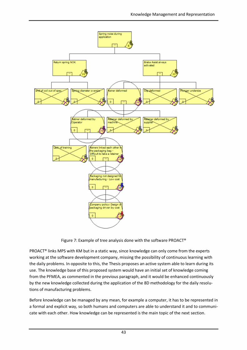
43
Knowledge Management and Representation
Figure 7: Example of tree analysis done with the software PROACT®
PROACT® links MPS with KM but in a static way, since knowledge can only come from the experts working at the software development company, missing the possibility of continuous learning with the daily problems. In opposite to this, the Thesis proposes an active system able to learn during its use. The knowledge base of this proposed system would have an initial set of knowledge coming from the PFMEA, as commented in the previous paragraph, and it would be enhanced continuously by the new knowledge collected during the application of the 8D methodology for the daily resolu-tions of manufacturing problems.
Before knowledge can be managed by any mean, for example a computer, it has to be represented in a formal and explicit way, so both humans and computers are able to understand it and to communi-cate with each other. How knowledge can be represented is the main topic of the next section.
44
Knowledge Management and Representation
2.4.2 Knowledge Representation According to Sowa (2000) knowledge representation is “the application of logic and ontology to the task of constructing computable models for some domain”. Logic provides the formal structure and rules of inference, ontology defines the kind of things that exist in the application domain, and the computation supports the applications that distinguish knowledge representation from pure philoso-phy.
The objectives of developing an ontology are (Ebrahimipour et al. 2010):
To facilitate sharing/exchange of information and knowledge. To support integration of tools. To provide the same perspectives with collaborating teams and tools. To create a common vocabulary. To describe unambiguous definitions that both computers and teams can understand.
Noy et McGuinness (2001) published a useful guide to create an ontology considering the following key steps:
Defining classes or concepts. Arranging the classes in a taxonomic hierarchy. Defining the various features and attributes of the concepts (also known as slots). Describing the allowed values and restrictions for these slots. Filling in the values for slots for instances of the classes.
This Thesis is focused on manufacturing as application domain. In the literature there are many ex-amples of ontologies applied to manufacturing. Putnik et Cruz-Cunha (2013) present a concept based on the IDEF0 functional modelling method with the elements process, input, output, control and mechanism. Lemaignan et al. (2006) develop an ontology in the project MASON with entities, opera-tions and resources as key elements. Borgo et Leitão (2007), in the project ADACOR, use a bigger list of upper elements like product, raw material, customer, operation, or work order. Solano et al. (2014) present their ontology PPDRC. Chungoora et al. (2013) propose a manufacturing core ontolo-gy, with a manufacturing planning orientation, comprising concepts related to product design and manufacturing processes and resources. The main concepts are: PartFamily, DesignFunction, Fea-ture, ProcessPlan, ManufacturingMethod, ManufacturingProcess, Manufactur-ingResource and ManufacturingFacility. All of them are different approaches to represent the manufacturing reality, but they miss the focus on manufacturing problems that is the main topic of this research.
When considering the representation of concepts dealing with MPS and PFMEA, Foguem et al. (2008) propose an ontology based on conceptual graphs to formalize knowledge in an experience feedback process, but PFMEA concepts are not supported. Experience feedback is considered a relevant ap-proach to support MPS with lessons learned formalized knowledge. The ontology comprises the fol-lowing main concepts: feedback_object, experience_element, experience, action and attributes; and their corresponding specializations, e.g.: activity, product, process, resource, competency, solution, context, analysis, event, positive_event and negative_event. Scippacercola et al. (2015) propose the use of SysML to create a system model, where artifacts contain FMEA related information. The FMEA information is represented as a description of the logical states of the input flows and blocks and their corresponding constraints, a transformation translates the annotated FMEA SysML model ele-
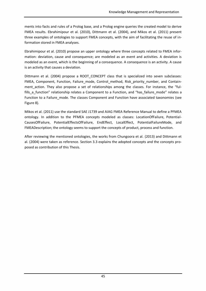
45
Knowledge Management and Representation
ments into facts and rules of a Prolog base, and a Prolog engine queries the created model to derive FMEA results. Ebrahimipour et al. (2010), Dittmann et al. (2004), and Mikos et al. (2011) present three examples of ontologies to support FMEA concepts, with the aim of facilitating the reuse of in-formation stored in FMEA analyses.
Ebrahimipour et al. (2010) propose an upper ontology where three concepts related to FMEA infor-mation: deviation, cause and consequence; are modeled as an event and activities. A deviation is modeled as an event, which is the beginning of a consequence. A consequence is an activity. A cause is an activity that causes a deviation.
Dittmann et al. (2004) propose a ROOT_CONCEPT class that is specialized into seven subclasses: FMEA, Component, Function, Failure_mode, Control_method, Risk_priority_number, and Contain-ment_action. They also propose a set of relationships among the classes. For instance, the “ful-fills_a_function” relationship relates a Component to a Function, and “has_failure_mode” relates a Function to a Failure_mode. The classes Component and Function have associated taxonomies (see Figure 8).
Mikos et al. (2011) use the standard SAE J1739 and AIAG FMEA Reference Manual to define a PFMEA ontology. In addition to the PFMEA concepts modeled as classes: LocationOfFailure, Potential-CausesOfFailure, PotentialEffectsOfFailure, EndEffect, LocalEffect, PotentialFailureMode, and FMEADescription; the ontology seems to support the concepts of product, process and function.
After reviewing the mentioned ontologies, the works from Chungoora et al. (2013) and Dittmann et al. (2004) were taken as reference. Section 3.3 explains the adopted concepts and the concepts pro-posed as contribution of this Thesis.
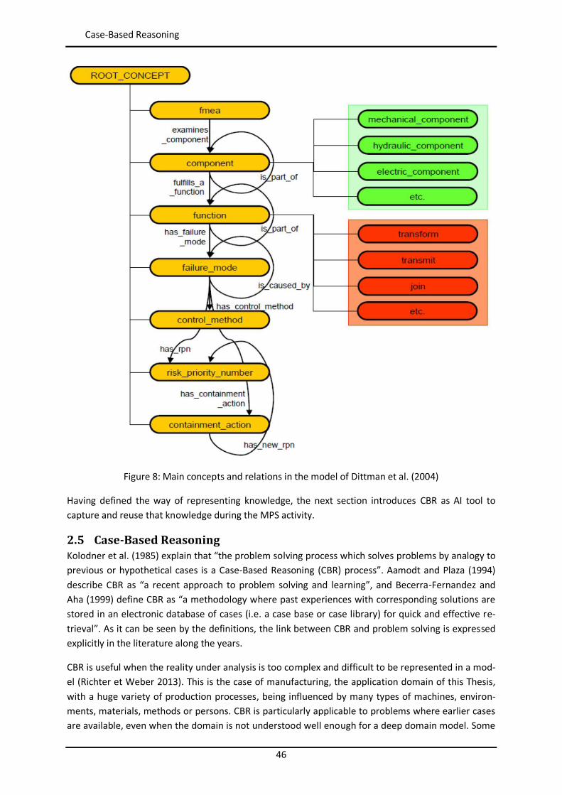
46
Case-Based Reasoning
Figure 8: Main concepts and relations in the model of Dittman et al. (2004)
Having defined the way of representing knowledge, the next section introduces CBR as AI tool to capture and reuse that knowledge during the MPS activity.
2.5 Case-Based Reasoning Kolodner et al. (1985) explain that “the problem solving process which solves problems by analogy to previous or hypothetical cases is a Case-Based Reasoning (CBR) process”. Aamodt and Plaza (1994) describe CBR as “a recent approach to problem solving and learning”, and Becerra-Fernandez and Aha (1999) define CBR as “a methodology where past experiences with corresponding solutions are stored in an electronic database of cases (i.e. a case base or case library) for quick and effective re-trieval”. As it can be seen by the definitions, the link between CBR and problem solving is expressed explicitly in the literature along the years.
CBR is useful when the reality under analysis is too complex and difficult to be represented in a mod-el (Richter et Weber 2013). This is the case of manufacturing, the application domain of this Thesis, with a huge variety of production processes, being influenced by many types of machines, environ-ments, materials, methods or persons. CBR is particularly applicable to problems where earlier cases are available, even when the domain is not understood well enough for a deep domain model. Some
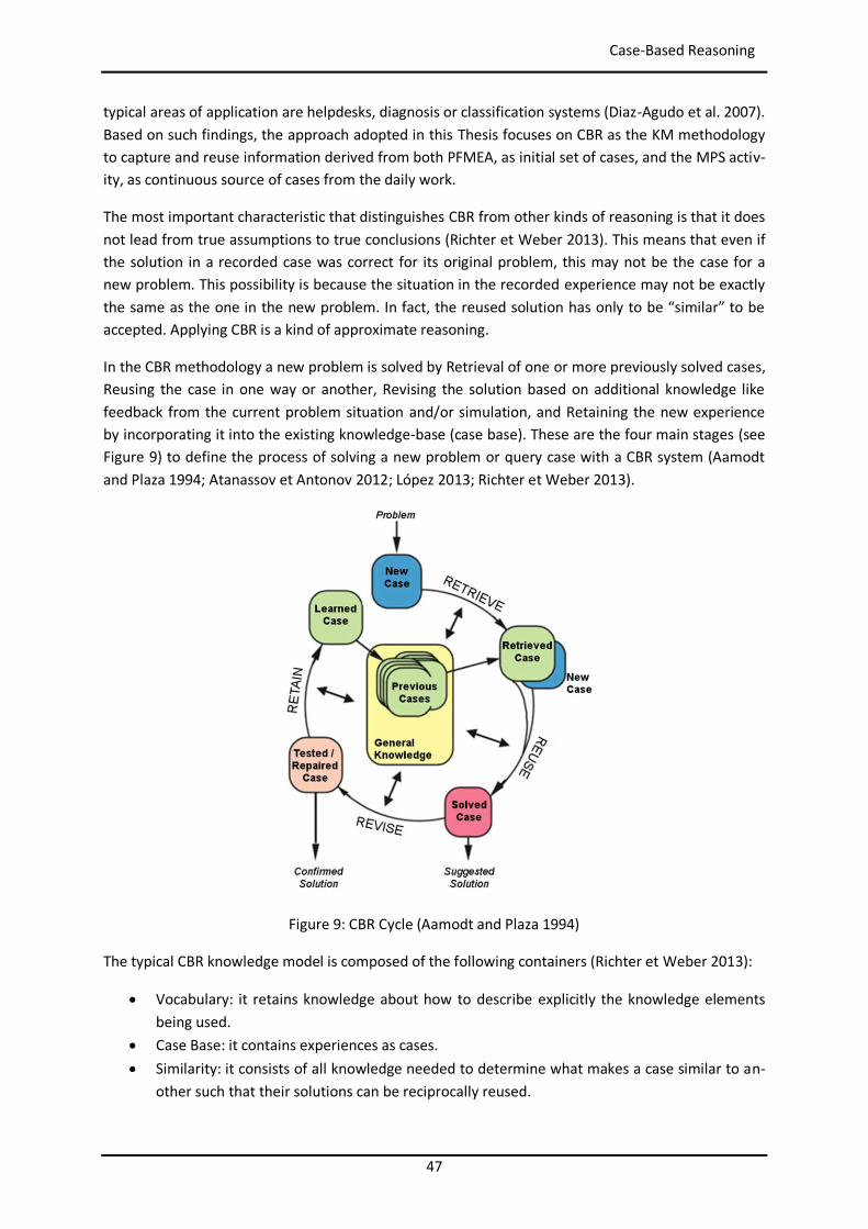
47
Case-Based Reasoning
typical areas of application are helpdesks, diagnosis or classification systems (Diaz-Agudo et al. 2007). Based on such findings, the approach adopted in this Thesis focuses on CBR as the KM methodology to capture and reuse information derived from both PFMEA, as initial set of cases, and the MPS activ-ity, as continuous source of cases from the daily work.
The most important characteristic that distinguishes CBR from other kinds of reasoning is that it does not lead from true assumptions to true conclusions (Richter et Weber 2013). This means that even if the solution in a recorded case was correct for its original problem, this may not be the case for a new problem. This possibility is because the situation in the recorded experience may not be exactly the same as the one in the new problem. In fact, the reused solution has only to be “similar” to be accepted. Applying CBR is a kind of approximate reasoning.
In the CBR methodology a new problem is solved by Retrieval of one or more previously solved cases, Reusing the case in one way or another, Revising the solution based on additional knowledge like feedback from the current problem situation and/or simulation, and Retaining the new experience by incorporating it into the existing knowledge-base (case base). These are the four main stages (see Figure 9) to define the process of solving a new problem or query case with a CBR system (Aamodt and Plaza 1994; Atanassov et Antonov 2012; López 2013; Richter et Weber 2013).
Figure 9: CBR Cycle (Aamodt and Plaza 1994)
The typical CBR knowledge model is composed of the following containers (Richter et Weber 2013):
Vocabulary: it retains knowledge about how to describe explicitly the knowledge elements being used.
Case Base: it contains experiences as cases. Similarity: it consists of all knowledge needed to determine what makes a case similar to an-
other such that their solutions can be reciprocally reused.
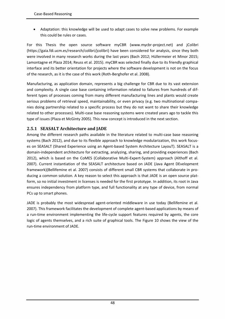
48
Case-Based Reasoning
Adaptation: this knowledge will be used to adapt cases to solve new problems. For example this could be rules or cases.
For this Thesis the open source software myCBR (www.mycbr-project.net) and jColibri (https://gaia.fdi.ucm.es/research/colibri/jcolibri) have been considered for analysis, since they both were involved in many research works during the last years (Bach 2012; Hüllermeier et Minor 2015; Lamontagne et Plaza 2014; Reuss et al. 2015). myCBR was selected finally due to its friendly graphical interface and its better orientation for projects where the software development is not on the focus of the research, as it is the case of this work (Roth-Berghofer et al. 2008).
Manufacturing, as application domain, represents a big challenge for CBR due to its vast extension and complexity. A single case base containing information related to failures from hundreds of dif-ferent types of processes coming from many different manufacturing lines and plants would create serious problems of retrieval speed, maintainability, or even privacy (e.g. two multinational compa-nies doing partnership related to a specific process but they do not want to share their knowledge related to other processes). Multi-case base reasoning systems were created years ago to tackle this type of issues (Plaza et McGinty 2005). This new concept is introduced in the next section.
2.5.1 SEASALT Architecture and JADE Among the different research paths available in the literature related to multi-case base reasoning systems (Bach 2012), and due to its flexible approach to knowledge modularization, this work focus-es on SEASALT (Shared Experience using an Agent-based System Architecture LayouT). SEASALT is a domain-independent architecture for extracting, analyzing, sharing, and providing experiences (Bach 2012), which is based on the CoMES (Collaborative Multi-Expert-System) approach (Althoff et al. 2007). Current instantiation of the SEASALT architecture based on JADE (Java Agent DEvelopment framework)(Bellifemine et al. 2007) consists of different small CBR systems that collaborate in pro-ducing a common solution. A key reason to select this approach is that JADE is an open source plat-form, so no initial investment in licenses is needed for the first prototype. In addition, its root in Java ensures independency from platform type, and full functionality at any type of device, from normal PCs up to smart phones.
JADE is probably the most widespread agent-oriented middleware in use today (Bellifemine et al. 2007). This framework facilitates the development of complete agent-based applications by means of a run-time environment implementing the life-cycle support features required by agents, the core logic of agents themselves, and a rich suite of graphical tools. The Figure 10 shows the view of the run-time environment of JADE.
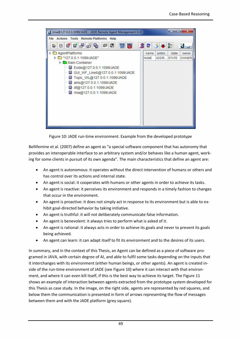
49
Case-Based Reasoning
Figure 10: JADE run-time environment. Example from the developed prototype
Bellifemine et al. (2007) define an agent as “a special software component that has autonomy that provides an interoperable interface to an arbitrary system and/or behaves like a human agent, work-ing for some clients in pursuit of its own agenda”. The main characteristics that define an agent are:
An agent is autonomous: it operates without the direct intervention of humans or others and has control over its actions and internal state.
An agent is social: it cooperates with humans or other agents in order to achieve its tasks. An agent is reactive: it perceives its environment and responds in a timely fashion to changes
that occur in the environment. An agent is proactive: it does not simply act in response to its environment but is able to ex-
hibit goal-directed behavior by taking initiative. An agent is truthful: it will not deliberately communicate false information. An agent is benevolent: it always tries to perform what is asked of it. An agent is rational: it always acts in order to achieve its goals and never to prevent its goals
being achieved. An agent can learn: it can adapt itself to fit its environment and to the desires of its users.
In summary, and in the context of this Thesis, an Agent can be defined as a piece of software pro-gramed in JAVA, with certain degree of AI, and able to fulfil some tasks depending on the inputs that it interchanges with its environment (either human beings, or other agents). An agent is created in-side of the run-time environment of JADE (see Figure 10) where it can interact with that environ-ment, and where it can even kill itself, if this is the best way to achieve its target. The Figure 11 shows an example of interaction between agents extracted from the prototype system developed for this Thesis as case study. In the image, on the right side, agents are represented by red squares, and below them the communication is presented in form of arrows representing the flow of messages between them and with the JADE platform (grey square).
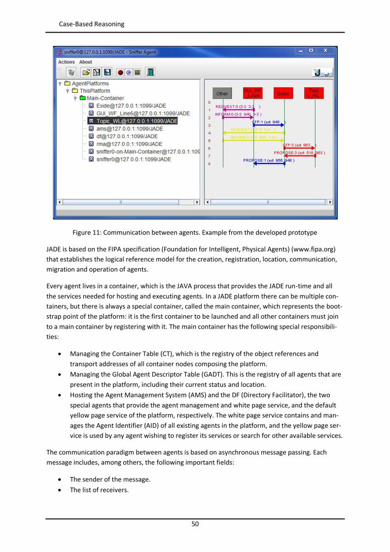
50
Case-Based Reasoning
Figure 11: Communication between agents. Example from the developed prototype
JADE is based on the FIPA specification (Foundation for Intelligent, Physical Agents) (www.fipa.org) that establishes the logical reference model for the creation, registration, location, communication, migration and operation of agents.
Every agent lives in a container, which is the JAVA process that provides the JADE run-time and all the services needed for hosting and executing agents. In a JADE platform there can be multiple con-tainers, but there is always a special container, called the main container, which represents the boot-strap point of the platform: it is the first container to be launched and all other containers must join to a main container by registering with it. The main container has the following special responsibili-ties:
Managing the Container Table (CT), which is the registry of the object references and transport addresses of all container nodes composing the platform.
Managing the Global Agent Descriptor Table (GADT). This is the registry of all agents that are present in the platform, including their current status and location.
Hosting the Agent Management System (AMS) and the DF (Directory Facilitator), the two special agents that provide the agent management and white page service, and the default yellow page service of the platform, respectively. The white page service contains and man-ages the Agent Identifier (AID) of all existing agents in the platform, and the yellow page ser-vice is used by any agent wishing to register its services or search for other available services.
The communication paradigm between agents is based on asynchronous message passing. Each message includes, among others, the following important fields:
The sender of the message. The list of receivers.
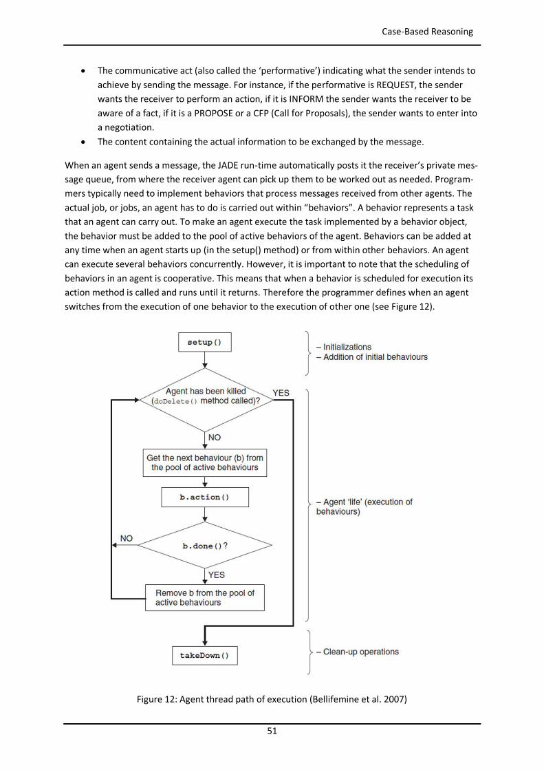
51
Case-Based Reasoning
The communicative act (also called the ‘performative’) indicating what the sender intends to achieve by sending the message. For instance, if the performative is REQUEST, the sender wants the receiver to perform an action, if it is INFORM the sender wants the receiver to be aware of a fact, if it is a PROPOSE or a CFP (Call for Proposals), the sender wants to enter into a negotiation.
The content containing the actual information to be exchanged by the message.
When an agent sends a message, the JADE run-time automatically posts it the receiver’s private mes-sage queue, from where the receiver agent can pick up them to be worked out as needed. Program-mers typically need to implement behaviors that process messages received from other agents. The actual job, or jobs, an agent has to do is carried out within “behaviors”. A behavior represents a task that an agent can carry out. To make an agent execute the task implemented by a behavior object, the behavior must be added to the pool of active behaviors of the agent. Behaviors can be added at any time when an agent starts up (in the setup() method) or from within other behaviors. An agent can execute several behaviors concurrently. However, it is important to note that the scheduling of behaviors in an agent is cooperative. This means that when a behavior is scheduled for execution its action method is called and runs until it returns. Therefore the programmer defines when an agent switches from the execution of one behavior to the execution of other one (see Figure 12).
Figure 12: Agent thread path of execution (Bellifemine et al. 2007)
52
Case-Based Reasoning
There are three types of behaviours:
One-Shot: they are designed to complete their tasks in one execution phase. Cyclic: they are designed to never complete. Their action method executes the same opera-
tions each time it is called. Generic: they embed a status trigger and execute different operations depending on the sta-
tus value. They complete when a given condition is met.
Back to the SEASALT architecture, it was developed on JADE as already said, and it is made of five components represented in the Figure 13 (Bach 2012):
Knowledge sources, responsible for capturing experiential knowledge from different sources. Knowledge formalization, responsible for formalizing textual representation into a more
modular, structured representation. The Apprentice Agent is responsible for parts of this task, trained by a Knowledge Engineer.
Knowledge provision, the most relevant component for this work. It contains the Knowledge Line, which is responsible for providing a diagnosis for a given failure. The Knowledge Line consists of several topic agents with underlying CBR systems. The topic agents use the knowledge of their CBR systems to provide a part of the diagnosis. A coordination agent is responsible for coordinating the agent teams, distributing a query, and combining the team's solutions. To determine which topic agents of a team should be requested, a so-called Knowledge Map is used. This Knowledge Map contains information about existing agents and their dependencies and underlying CBR systems. The task to determine a so-called retrieval path (the topic agents to be requested and the sequence of retrievals) is done by a knowledge map agent.
Knowledge representation that includes the rules, vocabulary, ontologies, and taxonomies used by the different types of agents.
Individualized knowledge that is the interface with the users.
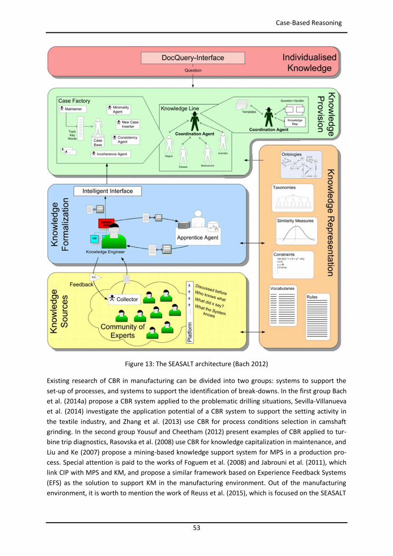
53
Case-Based Reasoning
Figure 13: The SEASALT architecture (Bach 2012)
Existing research of CBR in manufacturing can be divided into two groups: systems to support the set-up of processes, and systems to support the identification of break-downs. In the first group Bach et al. (2014a) propose a CBR system applied to the problematic drilling situations, Sevilla-Villanueva et al. (2014) investigate the application potential of a CBR system to support the setting activity in the textile industry, and Zhang et al. (2013) use CBR for process conditions selection in camshaft grinding. In the second group Yousuf and Cheetham (2012) present examples of CBR applied to tur-bine trip diagnostics, Rasovska et al. (2008) use CBR for knowledge capitalization in maintenance, and Liu and Ke (2007) propose a mining-based knowledge support system for MPS in a production pro-cess. Special attention is paid to the works of Foguem et al. (2008) and Jabrouni et al. (2011), which link CIP with MPS and KM, and propose a similar framework based on Experience Feedback Systems (EFS) as the solution to support KM in the manufacturing environment. Out of the manufacturing environment, it is worth to mention the work of Reuss et al. (2015), which is focused on the SEASALT
54
Product Lifecycle Management Systems
architecture to provide the civilian aeronautic branch with precise diagnoses and maintenance sug-gestions.
A CBR system uses different attributes to calculate similarity between the query case and the existing cases in the case base. In the introduction, the shopfloor actors were defined as target user group of the presented approach, and the time constraints of these persons were commented. In order to reduce the time to fill out questionnaires during the queries a Product Lifecycle Management (PLM) system is proposed in the next section as automatic source of extended information about the con-text (i.e. processes, products, machines, users and environment) of the problem under analysis. This context information will enrich the similarity calculation of the CBR application without taking addi-tional time of the user. The use of the PLM system as source of true information is based on the as-sumption that the information contained in the PLM system represents the as-built view of the phys-ical manufacturing facility.
2.6 Product Lifecycle Management Systems PLM is a systematic concept for the integrated management of all Products, Processes, and Re-sources (PPR) related information across the extended enterprise through the entire Product Life Cycle (PLC), from concept and design, to production, distribution, maintenance, and retirement (Liu et al. 2009; Stark 2015). It emerged in late 1990’s after nearly twenty years of technological evolution from Computer Aided Design (CAD) and Engineering Data Management (EDM), to Computer Inte-grated Manufacturing (CIM) and Product Data Management (PDM). Compared with other enterprise solutions PLM focuses on product and supports innovation, while Enterprise Resource Planning (ERP) focuses on achieving the best use of enterprise resources, Supply Chain Management (SCM) focuses on the supply chain, and Customer Relation Management (CRM) focuses on the customer.
PLM solutions can improve business efficiency by providing (Amann 2002):
Dramatic reduction in time and cost of product changes. Significantly shorter product cycle and lead times. Decreased scrap and rework during production. Improved productivity in design engineering.
The PLC considers following main steps in the life of any product: Development, Manufacture, Distri-bution, Use, Maintenance, and Retirement.
Examples of PLM solutions in the market are TeamCenter from Siemens PLM, Enovia from Dassault Systémes, Agile PLM from Oracle, Windchill from PTC, and SAP PLM from SAP. There are also open source solutions such as OpenPLM, and license free software such as Aras Innovator. Every PLM sys-tem provides an Application Programming Interface (API) to extend the core functionalities of the software.
The case study company didn’t have its own PLM solution, so part of the state of the art research was to find an appropriate PLM system. Different open source solutions were analyzed to avoid too high implementation costs in this pilot phase. Finally the commercial software Aras Innovator (www.aras.com) was selected because it can be installed free of charge (business model of Aras is focus on consultancy, and therefore license is free), and also because opposite to most of the open source PLM software, which are developed in Linux environment, Aras Innovator is developed on Microsoft standards being compatible easily with all the systems and infrastructures available in the
55
Industry 4.0 and Strategic Technological Trends
selected case study company. Finally, and most important, Aras Innovator offers a communication tool based on AML (Aras Markup Language) that allows easy extraction of any type of information from the PLM database. The AML is the XML dialect and language that drives the Aras Innovator server. Clients submit AML documents to the Aras Innovator server via HTTP, and the server returns an AML document containing the requested information (Aras Corporation 2015).
In the introduction it was said that the knowledge stored in existing PFMEA documents is to be used as initial source of knowledge, and therefore the research around existing ontologies was centered on ontologies able to represent PFMEA knowledge. Nevertheless it has to be taken into account that the document resulting from applying the PFMEA method is a detailed analysis of a specific process, so any information inside is restricted to the components of that process. In the approach of this work this link with a specific process disappears, because the selected application domain is manu-facturing. This means that the framework has to deal with problems coming from any type of manu-facturing processes at any place. Therefore it is needed an additional input of information that sets clear differences among problems: the context of the problem. PLM raises here as natural and logical source of this context, since it is developed to contain all PPR information of the company.
The work of Chungoora et al. (2013), introduced in the section 2.4.2, proposes a manufacturing core ontology to be used to support the interchange of knowledge between different PLM systems, and at the same time to collect constrains related design that can be used to detect automatically errors during the product or process definition. They propose this ontology, with a manufacturing planning orientation, comprising concepts related to product design and manufacturing processes and re-sources. The main concepts are: PartFamily, DesignFunction, Feature, ProcessPlan, Manufacturing-Method, ManufacturingProcess, ManufacturingResource and ManufacturingFacility.
This work of Chungoora et al. represents an approach to help in the prevention of failures, but out of the production environment. The works of Bertin (Bertin et al. 2010, Bertin et al. 2012, Bertin 2012), following a similar approach of Foguem et al. (2008) and Jabrouni et al. (2011), who were presented in the previous section, are very relevant for this paper because they propose also the use of a PLM system as central repository of data inside of a Lessons Learned System (LLS). They focus on the cap-ture and reuse of knowledge along the Engineering Change Request (ECR) process. This paper con-verges with those three authors, but enhances their approach by proposing CBR as a concrete tool to manage the Experience Feedback, and the PFMEA method as tool to formalize the manufacturing related problems definition and to populate the initial CBR database of cases.
The result of the four presented main elements (i.e. MPS, CBR, SEASALT and PLM) working together to support the CIP emerges as a concept that can be included within the frame of the technological vision Industry 4.0 that is introduced in the last section of the state of the art.
2.7 Industry 4.0 and Strategic Technological Trends The term Industry 4.0 became publicly known in 2011 when an initiative named “Industrie 4.0”, managed by an association of representatives from business, politics, and academia, promoted the idea as an approach to strengthening the competitiveness of the German manufacturing industry (Hermann et al. 2015). Similar concepts are currently under active development in other countries. Some examples are “Industrial Internet” promoted by General Electric (Bungart 2014; Evans et An-nunziata 2012), “Integrated Industry” (Bürger et Tragl 2014), “Smart Industry” or “Smart Manufactur-ing” (Dais 2014; Davis et al. 2012; Wiesmüller 2014). Also cooperation among them is starting to tak-
56
Summary
ing place, as for example the partnership agreement between the initiatives of the Platform Industrie 4.0 and the Industrial Internet Consortium (Platform Industrie 4.0 2016).
Even when Industry 4.0 is a priority for many companies, research centers, and universities, there is not a generally accepted definition of it. This Thesis takes the work of Hermann et al. (2015) as one of the latest summary of the state of the art. Their work presents 4 key components of the Industry 4.0:
1. Cyber-Physical Systems: every physical system has an associated digital model that describes it, not only in its shape, but also in its behavior (i.e. rules, position, constraints, relation-ships…).
2. Internet of Things: all devices are interconnected and able to communicate to each other in order to organize themselves.
3. Internet of Services: the systematic use of Internet to create additional business associated to the products in the services sector.
4. Smart Factory: a factory that context-aware assists people and machines in execution of their tasks (Zuehlke 2010).
Focusing in the last component, Smart Factory, a typical approach is the deployment of smart arti-facts along the value streams that are able to collect a large quantity of data from their environment and to communicate with each other (Internet of Things). This approach implies large investments, which prevents some companies from taking their first steps into Industry 4.0 (Lee et Lee 2015; Witchalls et Chambers 2013). This work presents an approach that aims to contribute to the techno-logical vision of a Smart Factory but observing the constraints of being based on existing facilities, existing company data repositories, and with low investment. The aim is to try to extract all currently available information to help in the decision taken, without doing the required investments from the Internet of Things. The relevance of the Smart Factory nowadays is also justified in the report about the top 10 strategic technology trends for 2016 (Cearley et al. 2015) published by the information technology research and advisory company Gartner.
2.8 Summary All introduced strategies, methodologies and tools build the bases to define and develop the pro-posed system that has to support the CIP process during the daily analysis of problems affecting the OEE of the lines. This system will combine the 8D manufacturing problem solving method, as struc-tured method to guide the resolution of problems step by step, CBR on the SEASALT architecture, as artificial intelligence application to search for similar manufacturing problem cases collected previ-ously in multiple locations, and a PLM system, as source of extended information about PPR that will enrich the similarity calculation of the CBR application. PFMEA is used both as root model to create an ontology, on which the system is built, and as source of the initial set of cases to feed the CBR application.
57
3 Developed Models 3.1 Introduction This section describes the different models needed to build the application system able to fulfil the research goals defined in the introduction of the Thesis. A long the presentation of the foundations, in the section before, it was introduced the 8D method as an appropriate method to support the MPS activity in the CIP of any manufacturing company, but it was highlighted the relevance of the knowledge availability as key contributor for success in the resolution of problems. Then it was pre-sented CBR as the right artificial intelligence tool able to collect and contribute with knowledge relat-ed to complex problems, which perfectly fits with the application domain of this Thesis (i.e. manufac-turing). Since this application domain is extremely wide (any industry in any country), it was also ex-plained the limitations of CBR in terms of retrieval speed and maintainability when all information is stored in a single case base. For this reason, the SEASALT architecture was presented as appropriate solution, where the information is distributed along many different small CBR systems located at any location and managed by agents. It was also explained that it is needed a context information that allows the differentiation among cases, and the PLM systems arose as the proper source of that PPR information, from which the context of the problem can be extracted automatically. Finally the PFMEA was proposed as the initial source of cases (i.e. problems with their solutions) for the case bases of the CBR systems. Later on, this initial information will be continuously extended by the reso-lution of new problems.
All these different systems, methods and technologies will work together to fulfil the research goals of the Thesis in the shape of a software application distributed among different manufacturing plants and production areas. Each unit of the software will contain knowledge about problems of its own manufacturing environment, and will communicate with the rest of units to interchange information. In this way the software will guide the users along the 8D method, getting from them a basic descrip-tion of the problem. This basic description will be extended automatically by the software by using the PPR information from a PLM system. And this global description of the problem will be sent to the different locations to collect from them possible solutions that will be presented to the users.
To build this software application the following models were developed (Camarillo et al. 2017a; Camarillo et al. 2017b; Camarillo et al. 2018a; Camarillo et al. 2018b):
Process model: it shows the global process of solving manufacturing problems by using this application software. This includes the trigger of the process from the CIP cycle, the commu-nication between user and software along the 8D method, and the internal communications between the Graphical User Interface (GUI) of the software at each location, the PLM sys-tem, and the network of CBR systems managed by agents.
Knowledge model: it presents the developed ontology to represent any type of manufactur-ing problems in a compatible form with the PFMEA methodology, since the initial set of cases will come from the available PFMEA documents.
Information model in the PLM system: it describes the needed customization of a PLM sys-tem to fit into the proposed ontology.
58
Process Model
Information model in the CBR application: it describes the needed customization of the CBR system to fit into the proposed ontology.
IT infrastructure: it presents the adaptation of the SEASALT architecture to the software ap-plication of the Thesis.
3.2 Process Model As explained in the introduction, the central target of this work is to find the best way to support shopfloor actors during the CIP activity, ensuring that they need to invest as less time as possible. During the presentation of the state of the art of this Thesis it was justified that the selection of one or another MPS method will not play a major role in the achievement of a solution, but that the knowledge of the people involved in the solving process is the key for the success. This Thesis pre-sents a CIP model based on the 8D methodology as core MPS method, but with a process of knowledge contribution and retention fully integrated inside of it.
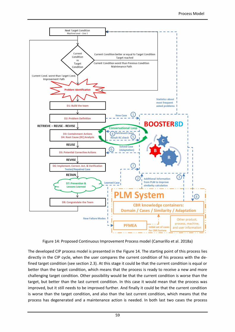
59
Process Model
Figure 14: Proposed Continuous Improvement Process model (Camarillo et al. 2018a)
The developed CIP process model is presented in the Figure 14. The starting point of this process lies directly in the CIP cycle, when the user compares the current condition of his process with the de-fined target condition (see section 2.3). At this stage it could be that the current condition is equal or better than the target condition, which means that the process is ready to receive a new and more challenging target condition. Other possibility would be that the current condition is worse than the target, but better than the last current condition. In this case it would mean that the process was improved, but it still needs to be improved further. And finally it could be that the current condition is worse than the target condition, and also than the last current condition, which means that the process has degenerated and a maintenance action is needed. In both last two cases the process
60
Process Model
arrives to the point of identifying a problem that prevents it from reaching the defined target condi-tion.
As soon as a problem has been identified, a team sits down together to analyze it and to look for a solution. The proposed CIP process defines the following steps:
1. Users introduce very basic description of the manufacturing problem. The main target here is to ensure that the user does not need more than one minute, to avoid that production re-mains unattended long time.
2. The proposed model has a system (in the Figure 14 called Booster8D, which is the application prototype developed for this Thesis that will be presented later on) in charge of collecting ex-tended information related to the problem from the PLM system. Without support system, this extended information should be provided by the user, who could not know all the details of the process (e.g. new worker), and who would need time to fill it out. Therefore one of the key advantages of the proposed model is here.
3. This system puts together the information provided by the user and the extended infor-mation from the PLM, in order to make a global query that will be used to search for possible solutions. For this searching task CBR is used as artificial intelligence tool to look for similar manufacturing problem cases collected previously, not only in that area, but also in different locations and processes.
4. Then the system proposes possible causes to the users (i.e. failure modes in the FMEA termi-nology) and containment actions out of its knowledge repositories.
5. The users have to check those failure modes at their manufacturing line or station and to give feed-back to the system about either any of them is similar to the problem found at the line/station or not. For this, the conversational CBR method (Becerra-Fernandez et Aha 1999) is selected, and it is explained with detail below.
6. The system provides the stored corrective and preventive actions for the identified root causes, and the users check it and decide either to apply, or to adapt it, or to reject it. This in-itial model does not consider an automatic adaptation process done by the system, leaving this complex step of the CBR cycle (Aamodt et Plaza 1994; Richter et Weber 2013) for future research.
7. User gives feedback to be analyzed by the Knowledge Engineer. 8. The Knowledge Engineer updates the CBR knowledge containers if needed.
The conversational method introduced in the step 5 of this process model plays a central role in the identification of the final root cause of the problem under analysis. To avoid confusion it is important to clarify the terminology used in the Thesis:
Problem is used to designate any failure found in manufacturing. Query is the description of a problem (user + PLM information) that is sent to the CBR sys-
tems. Level is a set of a problem description + a solution + a link to a different level that originates
this problem. Case is a set of levels describing the whole chain of problems from the visible one to the real
root cause. This concept is explained with great detail in the section of the Knowledge Mod-el.
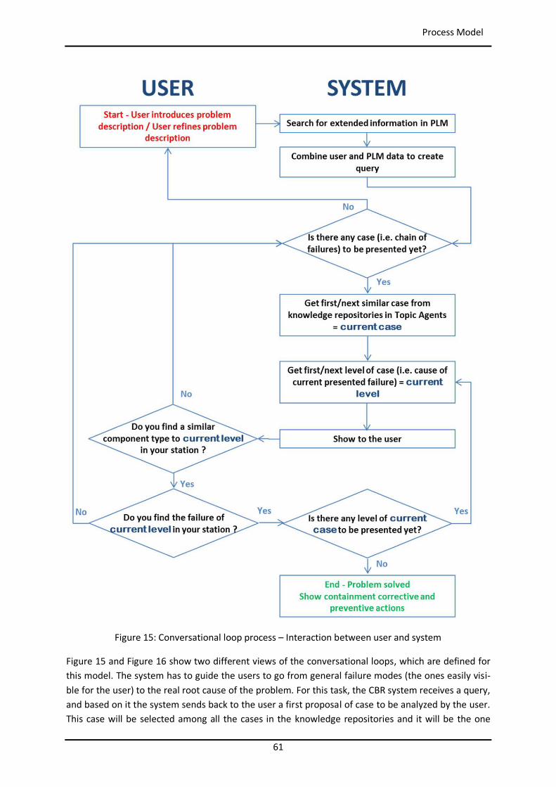
61
Process Model
Figure 15: Conversational loop process – Interaction between user and system
Figure 15 and Figure 16 show two different views of the conversational loops, which are defined for this model. The system has to guide the users to go from general failure modes (the ones easily visi-ble for the user) to the real root cause of the problem. For this task, the CBR system receives a query, and based on it the system sends back to the user a first proposal of case to be analyzed by the user. This case will be selected among all the cases in the knowledge repositories and it will be the one
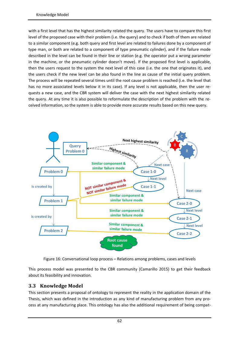
62
Knowledge Model
with a first level that has the highest similarity related the query. The users have to compare this first level of the proposed case with their problem (i.e. the query) and to check if both of them are related to a similar component (e.g. both query and first level are related to failures done by a component of type man, or both are related to a component of type pneumatic cylinder), and if the failure mode described in the level can be found in their line or station (e.g. the operator put a wrong parameter in the machine, or the pneumatic cylinder doesn’t move). If the proposed first level is applicable, then the users request to the system the next level of this case (i.e. the one that originates it), and the users check if the new level can be also found in the line as cause of the initial query problem. The process will be repeated several times until the root cause problem is reached (i.e. the level that has no more associated levels below it in its case). If any level is not applicable, then the user re-quests a new case, and the CBR system will deliver the case with the next highest similarity related the query. At any time it is also possible to reformulate the description of the problem with the re-ceived information, so the system is able to provide more accurate results based on this new query.
Figure 16: Conversational loop process – Relations among problems, cases and levels
This process model was presented to the CBR community (Camarillo 2015) to get their feedback about its feasibility and innovation.
3.3 Knowledge Model This section presents a proposal of ontology to represent the reality in the application domain of the Thesis, which was defined in the introduction as any kind of manufacturing problem from any pro-cess at any manufacturing place. This ontology has also the additional requirement of being compat-
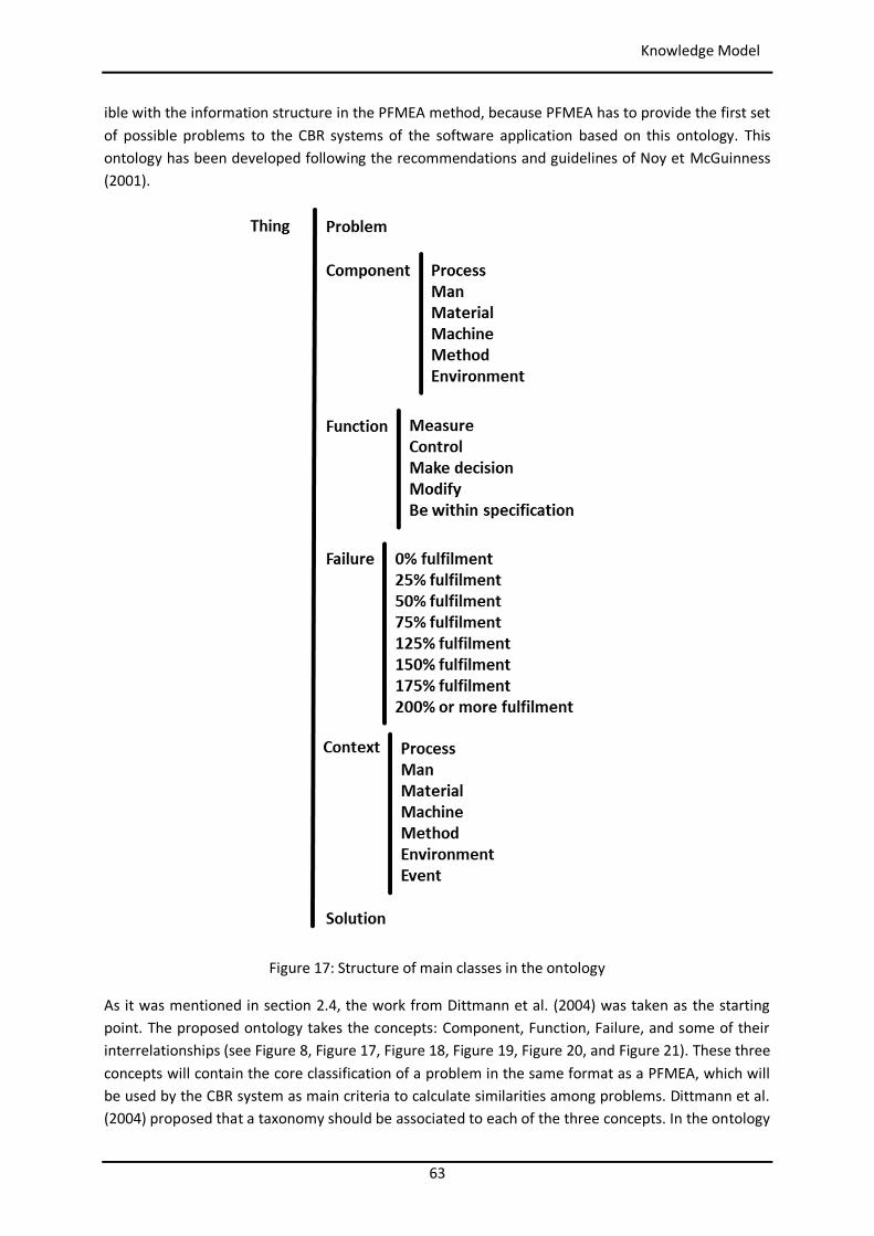
63
Knowledge Model
ible with the information structure in the PFMEA method, because PFMEA has to provide the first set of possible problems to the CBR systems of the software application based on this ontology. This ontology has been developed following the recommendations and guidelines of Noy et McGuinness (2001).
Figure 17: Structure of main classes in the ontology
As it was mentioned in section 2.4, the work from Dittmann et al. (2004) was taken as the starting point. The proposed ontology takes the concepts: Component, Function, Failure, and some of their interrelationships (see Figure 8, Figure 17, Figure 18, Figure 19, Figure 20, and Figure 21). These three concepts will contain the core classification of a problem in the same format as a PFMEA, which will be used by the CBR system as main criteria to calculate similarities among problems. Dittmann et al. (2004) proposed that a taxonomy should be associated to each of the three concepts. In the ontology
64
Knowledge Model
proposed in this work, only the concepts of Component and Function have associated taxonomies, and both taxonomies correspond to the concepts defined by the PFMEA method. The main differ-ences with the approach from Dittmann et al. [22] are:
The taxonomy of Component is flat and comprises six elements: Process, Man, Machine, Ma-terial, Method, and Environment.
The taxonomy of Function has at its first level five elements representing the main functions that a component can fulfil: Measure, Control, Make decision, Modify, and Be within specifi-cation. Each of these five functions is extended into lower levels. The last element “Be within specification” is needed as type of function because the PFMEA method considers everything as components that fulfil functions, and then it helps to analyze the different ways in which a function can fail. In this sense, the requirement of being within a defined specification is con-sidered from a functional point of view.
The concept of Failure is modeled differently. A failure has the attribute ‘Fulfilment rate’, which represents the grade of fulfilment of the associated function that the associated com-ponent is able to deliver in the problem under analysis. This attribute can get a value from a list of predefined values that starts at 0% and goes up to 200%.
The concept Problem was added to the ontology to provide the link to a unique trio of Com-ponent, Function and Failure.
The concept Context was added to consider the environment of the problem.
The work of Chungoora et al. (2013), as mentioned in section 2.4, was taken as the reference for the ontological definition of Context. In particular, the classes Method and Process, and three subclasses that specialize the class Resource: Man, Material, and Machine (see Figure 17, Figure 18, and Figure 22).
The explanation of this ontology will start by the first three classes (i.e. Component, Function and Failure) that contain the core description of the problem in the same format of the PFMEA. At this point it is important to explain the differences of approach between FMEA and MPS. Following the FMEA method a global structure of components and associated functions is created, which repre-sents the reality under analysis. Based on it, all possible failure modes of the simplest components and functions are identified. It is done so because the failure modes of these simple components and functions are quite intuitive and easy to be recognized (e.g. a screw keeping together two parts can just fail by not keeping the parts together because it becomes broken or loose). After this, and start-ing by these simple failures, their consequences in the functions of the components above are identi-fied level after level. Therefore the process starts by simple failures in simple components and it tries to identify their consequences on the most complex components. The approach of MPS is exactly the opposite. It is detected a problem in a complex component (e.g. the machine doesn’t move), and it is tried to understand which is its root cause (e.g. the screw fixing together the terminal and the cable of the electric relay commanding the main switch of the motor that moves the machine is loose and therefore the electricity does not flow). Focusing on the core elements of FMEA (i.e. failure modes) and MPS (i.e. problems) all this means that meanwhile each failure mode can belong to different functions that at the same time can belong to different components, the presented framework un-derstands a problem as a specific and unique failure happening in a specific and unique function that belongs to a specific and unique component. This creates the need of extending the initial set of clas-ses with the additional class Problem (see Figure 17) that will have the link to the specific and unique
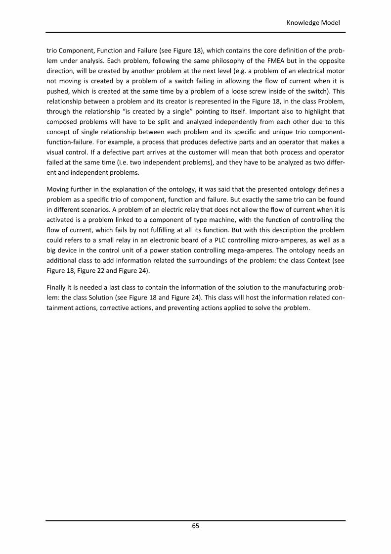
65
Knowledge Model
trio Component, Function and Failure (see Figure 18), which contains the core definition of the prob-lem under analysis. Each problem, following the same philosophy of the FMEA but in the opposite direction, will be created by another problem at the next level (e.g. a problem of an electrical motor not moving is created by a problem of a switch failing in allowing the flow of current when it is pushed, which is created at the same time by a problem of a loose screw inside of the switch). This relationship between a problem and its creator is represented in the Figure 18, in the class Problem, through the relationship “is created by a single” pointing to itself. Important also to highlight that composed problems will have to be split and analyzed independently from each other due to this concept of single relationship between each problem and its specific and unique trio component-function-failure. For example, a process that produces defective parts and an operator that makes a visual control. If a defective part arrives at the customer will mean that both process and operator failed at the same time (i.e. two independent problems), and they have to be analyzed as two differ-ent and independent problems.
Moving further in the explanation of the ontology, it was said that the presented ontology defines a problem as a specific trio of component, function and failure. But exactly the same trio can be found in different scenarios. A problem of an electric relay that does not allow the flow of current when it is activated is a problem linked to a component of type machine, with the function of controlling the flow of current, which fails by not fulfilling at all its function. But with this description the problem could refers to a small relay in an electronic board of a PLC controlling micro-amperes, as well as a big device in the control unit of a power station controlling mega-amperes. The ontology needs an additional class to add information related the surroundings of the problem: the class Context (see Figure 18, Figure 22 and Figure 24).
Finally it is needed a last class to contain the information of the solution to the manufacturing prob-lem: the class Solution (see Figure 18 and Figure 24). This class will host the information related con-tainment actions, corrective actions, and preventing actions applied to solve the problem.
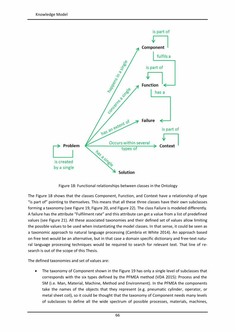
66
Knowledge Model
Figure 18: Functional relationships between classes in the Ontology
The Figure 18 shows that the classes Component, Function, and Context have a relationship of type “is part of” pointing to themselves. This means that all these three classes have their own subclasses forming a taxonomy (see Figure 19, Figure 20, and Figure 22). The class Failure is modeled differently. A failure has the attribute “Fulfilment rate” and this attribute can get a value from a list of predefined values (see Figure 21). All these associated taxonomies and their defined set of values allow limiting the possible values to be used when instantiating the model classes. In that sense, it could be seen as a taxonomic approach to natural language processing (Cambria et White 2014). An approach based on free text would be an alternative, but in that case a domain specific dictionary and free-text natu-ral language processing techniques would be required to search for relevant text. That line of re-search is out of the scope of this Thesis.
The defined taxonomies and set of values are:
The taxonomy of Component shown in the Figure 19 has only a single level of subclasses that corresponds with the six types defined by the PFMEA method (VDA 2015): Process and the 5M (i.e. Man, Material, Machine, Method and Environment). In the PFMEA the components take the names of the objects that they represent (e.g. pneumatic cylinder, operator, or metal sheet coil), so it could be thought that the taxonomy of Component needs many levels of subclasses to define all the wide spectrum of possible processes, materials, machines,
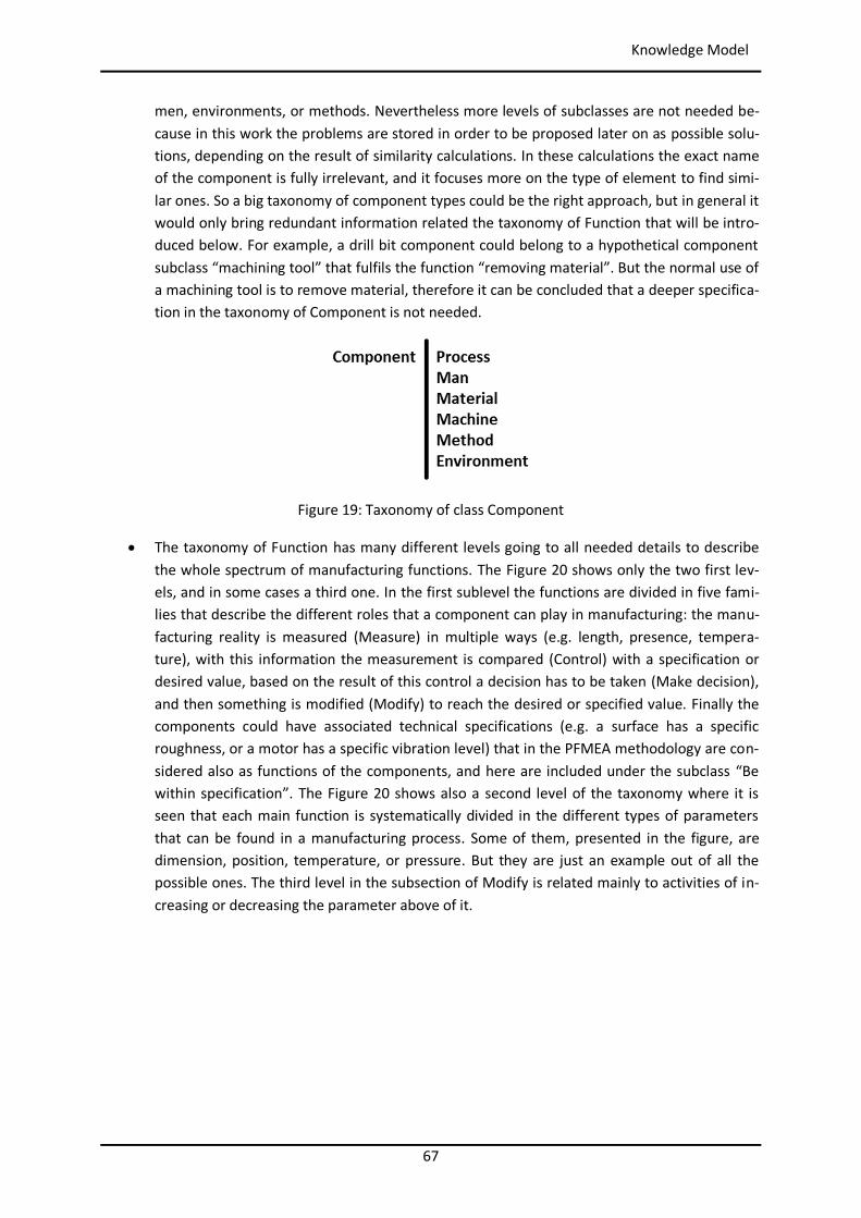
67
Knowledge Model
men, environments, or methods. Nevertheless more levels of subclasses are not needed be-cause in this work the problems are stored in order to be proposed later on as possible solu-tions, depending on the result of similarity calculations. In these calculations the exact name of the component is fully irrelevant, and it focuses more on the type of element to find simi-lar ones. So a big taxonomy of component types could be the right approach, but in general it would only bring redundant information related the taxonomy of Function that will be intro-duced below. For example, a drill bit component could belong to a hypothetical component subclass “machining tool” that fulfils the function “removing material”. But the normal use of a machining tool is to remove material, therefore it can be concluded that a deeper specifica-tion in the taxonomy of Component is not needed.
Figure 19: Taxonomy of class Component
The taxonomy of Function has many different levels going to all needed details to describe the whole spectrum of manufacturing functions. The Figure 20 shows only the two first lev-els, and in some cases a third one. In the first sublevel the functions are divided in five fami-lies that describe the different roles that a component can play in manufacturing: the manu-facturing reality is measured (Measure) in multiple ways (e.g. length, presence, tempera-ture), with this information the measurement is compared (Control) with a specification or desired value, based on the result of this control a decision has to be taken (Make decision), and then something is modified (Modify) to reach the desired or specified value. Finally the components could have associated technical specifications (e.g. a surface has a specific roughness, or a motor has a specific vibration level) that in the PFMEA methodology are con-sidered also as functions of the components, and here are included under the subclass “Be within specification”. The Figure 20 shows also a second level of the taxonomy where it is seen that each main function is systematically divided in the different types of parameters that can be found in a manufacturing process. Some of them, presented in the figure, are dimension, position, temperature, or pressure. But they are just an example out of all the possible ones. The third level in the subsection of Modify is related mainly to activities of in-creasing or decreasing the parameter above of it.
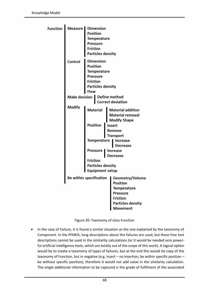
68
Knowledge Model
Figure 20: Taxonomy of class Function
In the case of Failure, it is found a similar situation as the one explained by the taxonomy of Component. In the PFMEA, long descriptions about the failures are used, but these free text descriptions cannot be used in the similarity calculations (or it would be needed very power-ful artificial intelligence tools, which are totally out of the scope of this work). A logical option would be to create a taxonomy of types of failures, but at the end this would be copy of the taxonomy of Function, but in negative (e.g. insert – no insertion, be within specific position – be without specific position), therefore it would not add value in the similarity calculation. The single additional information to be captured is the grade of fulfilment of the associated
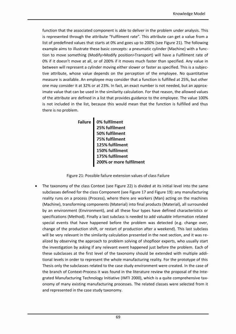
69
Knowledge Model
function that the associated component is able to deliver in the problem under analysis. This is represented through the attribute “Fulfilment rate”. This attribute can get a value from a list of predefined values that starts at 0% and goes up to 200% (see Figure 21). The following example aims to illustrate these basic concepts: a pneumatic cylinder (Machine) with a func-tion to move something (Modify>Modify position>Transport) will have a Fulfilment rate of 0% if it doesn’t move at all, or of 200% if it moves much faster than specified. Any value in between will represent a cylinder moving either slower or faster as specified. This is a subjec-tive attribute, whose value depends on the perception of the employee. No quantitative measure is available. An employee may consider that a function is fulfilled at 25%, but other one may consider it at 32% or at 23%. In fact, an exact number is not needed, but an approx-imate value that can be used in the similarity calculation. For that reason, the allowed values of the attribute are defined in a list that provides guidance to the employee. The value 100% is not included in the list, because this would mean that the function is fulfilled and thus there is no problem.
Figure 21: Possible failure extension values of class Failure
The taxonomy of the class Context (see Figure 22) is divided at its initial level into the same subclasses defined for the class Component (see Figure 17 and Figure 19): any manufacturing reality runs on a process (Process), where there are workers (Man) acting on the machines (Machine), transforming components (Material) into final products (Material), all surrounded by an environment (Environment), and all these four types have defined characteristics or specifications (Method). Finally a last subclass is needed to add valuable information related special events that have happened before the problem was detected (e.g. change over, change of the production shift, or restart of production after a weekend). This last subclass will be very relevant in the similarity calculation presented in the next section, and it was re-alized by observing the approach to problem solving of shopfloor experts, who usually start the investigation by asking if any relevant event happened just before the problem. Each of these subclasses at the first level of the taxonomy should be extended with multiple addi-tional levels in order to represent the whole manufacturing reality. For the prototype of this Thesis only the subclasses related to the case study environment were created. In the case of the branch of Context-Process it was found in the literature review the proposal of the Inte-grated Manufacturing Technology Initiative (IMTI 2000), which is a quite comprehensive tax-onomy of many existing manufacturing processes. The related classes were selected from it and represented in the case study taxonomy.
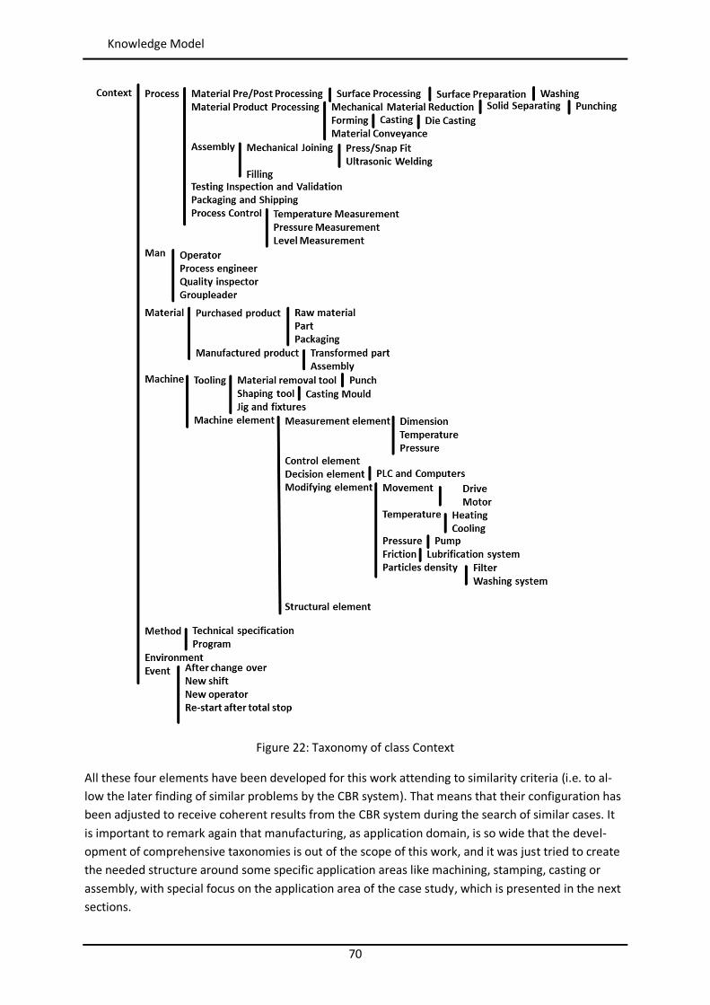
70
Knowledge Model
Figure 22: Taxonomy of class Context
All these four elements have been developed for this work attending to similarity criteria (i.e. to al-low the later finding of similar problems by the CBR system). That means that their configuration has been adjusted to receive coherent results from the CBR system during the search of similar cases. It is important to remark again that manufacturing, as application domain, is so wide that the devel-opment of comprehensive taxonomies is out of the scope of this work, and it was just tried to create the needed structure around some specific application areas like machining, stamping, casting or assembly, with special focus on the application area of the case study, which is presented in the next sections.
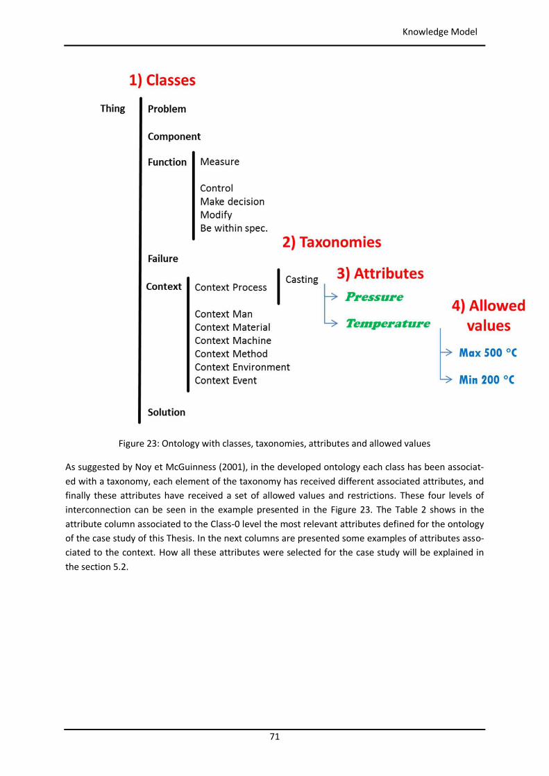
71
Knowledge Model
Figure 23: Ontology with classes, taxonomies, attributes and allowed values
As suggested by Noy et McGuinness (2001), in the developed ontology each class has been associat-ed with a taxonomy, each element of the taxonomy has received different associated attributes, and finally these attributes have received a set of allowed values and restrictions. These four levels of interconnection can be seen in the example presented in the Figure 23. The Table 2 shows in the attribute column associated to the Class-0 level the most relevant attributes defined for the ontology of the case study of this Thesis. In the next columns are presented some examples of attributes asso-ciated to the context. How all these attributes were selected for the case study will be explained in the section 5.2.
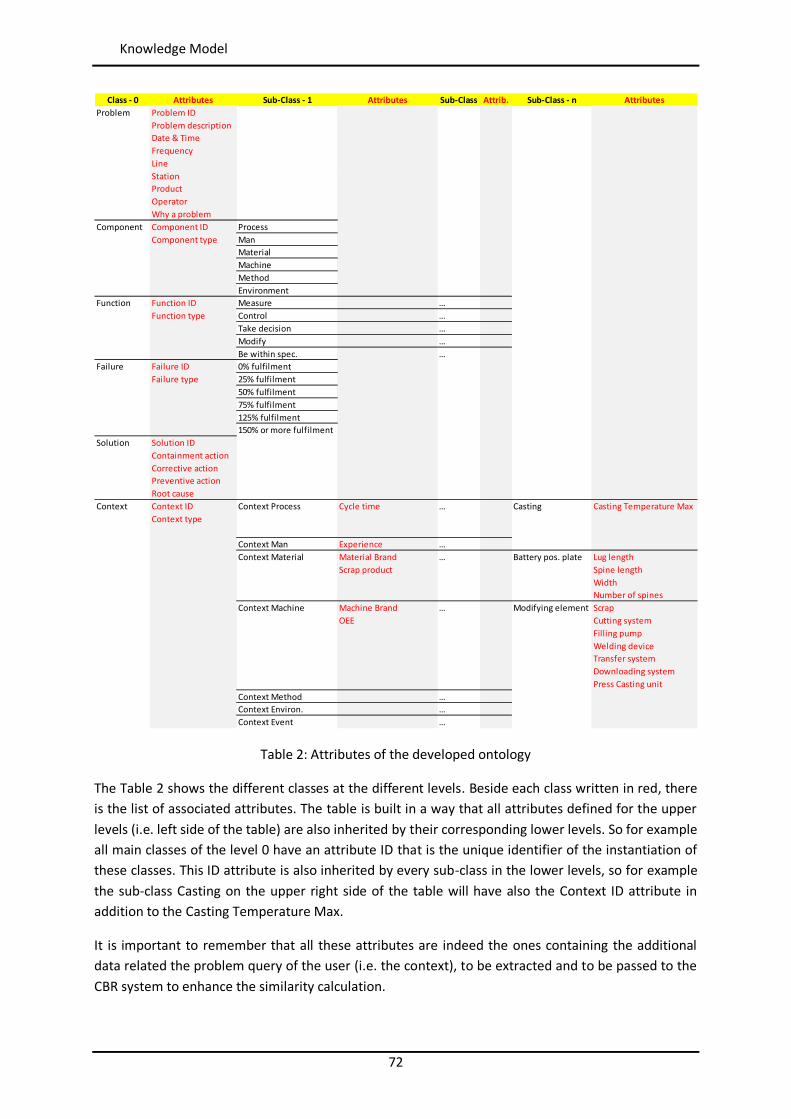
72
Knowledge Model
Table 2: Attributes of the developed ontology
The Table 2 shows the different classes at the different levels. Beside each class written in red, there is the list of associated attributes. The table is built in a way that all attributes defined for the upper levels (i.e. left side of the table) are also inherited by their corresponding lower levels. So for example all main classes of the level 0 have an attribute ID that is the unique identifier of the instantiation of these classes. This ID attribute is also inherited by every sub-class in the lower levels, so for example the sub-class Casting on the upper right side of the table will have also the Context ID attribute in addition to the Casting Temperature Max.
It is important to remember that all these attributes are indeed the ones containing the additional data related the problem query of the user (i.e. the context), to be extracted and to be passed to the CBR system to enhance the similarity calculation.
Class - 0 Attributes Sub-Class - 1 Attributes Sub-Class Attrib. Sub-Class - n AttributesProblem Problem ID
Problem descriptionDate & TimeFrequencyLineStationProductOperatorWhy a problem
Component Component ID ProcessComponent type Man
MaterialMachineMethodEnvironment
Function Function ID Measure …Function type Control …
Take decision …Modify …Be within spec. …
Failure Failure ID 0% fulfilmentFailure type 25% fulfilment
50% fulfilment75% fulfilment125% fulfilment150% or more fulfilment
Solution Solution IDContainment actionCorrective actionPreventive actionRoot cause
Context Context ID Context Process Cycle time … Casting Casting Temperature MaxContext type
Context Man Experience …Context Material Material Brand … Battery pos. plate Lug length
Scrap product Spine lengthWidthNumber of spines
Context Machine Machine Brand … Modifying element ScrapOEE Cutting system
Filling pumpWelding deviceTransfer systemDownloading systemPress Casting unit
Context Method …Context Environ. …Context Event …
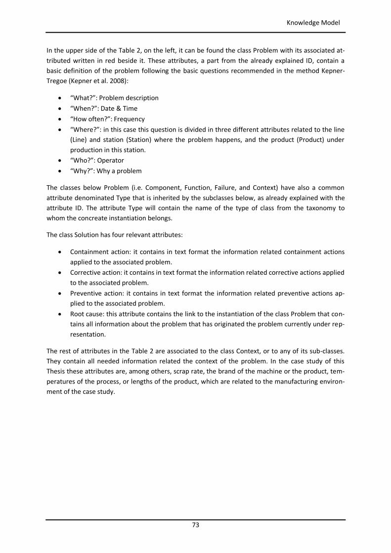
73
Knowledge Model
In the upper side of the Table 2, on the left, it can be found the class Problem with its associated at-tributed written in red beside it. These attributes, a part from the already explained ID, contain a basic definition of the problem following the basic questions recommended in the method Kepner-Tregoe (Kepner et al. 2008):
“What?”: Problem description “When?”: Date & Time “How often?”: Frequency “Where?”: in this case this question is divided in three different attributes related to the line
(Line) and station (Station) where the problem happens, and the product (Product) under production in this station.
“Who?”: Operator “Why?”: Why a problem
The classes below Problem (i.e. Component, Function, Failure, and Context) have also a common attribute denominated Type that is inherited by the subclasses below, as already explained with the attribute ID. The attribute Type will contain the name of the type of class from the taxonomy to whom the concreate instantiation belongs.
The class Solution has four relevant attributes:
Containment action: it contains in text format the information related containment actions applied to the associated problem.
Corrective action: it contains in text format the information related corrective actions applied to the associated problem.
Preventive action: it contains in text format the information related preventive actions ap-plied to the associated problem.
Root cause: this attribute contains the link to the instantiation of the class Problem that con-tains all information about the problem that has originated the problem currently under rep-resentation.
The rest of attributes in the Table 2 are associated to the class Context, or to any of its sub-classes. They contain all needed information related the context of the problem. In the case study of this Thesis these attributes are, among others, scrap rate, the brand of the machine or the product, tem-peratures of the process, or lengths of the product, which are related to the manufacturing environ-ment of the case study.
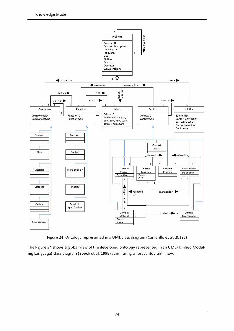
74
Knowledge Model
Figure 24: Ontology represented in a UML class diagram (Camarillo et al. 2018a)
The Figure 24 shows a global view of the developed ontology represented in an UML (Unified Model-ing Language) class diagram (Booch et al. 1999) summering all presented until now.
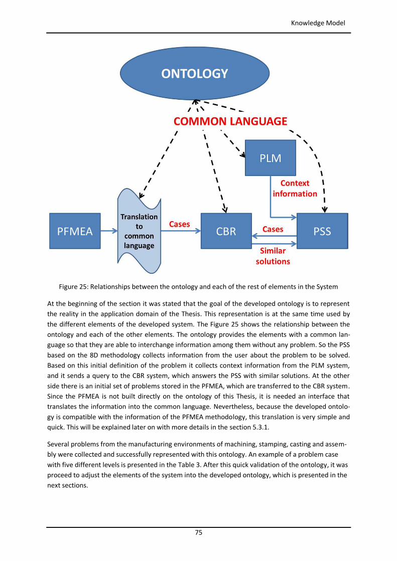
75
Knowledge Model
Figure 25: Relationships between the ontology and each of the rest of elements in the System
At the beginning of the section it was stated that the goal of the developed ontology is to represent the reality in the application domain of the Thesis. This representation is at the same time used by the different elements of the developed system. The Figure 25 shows the relationship between the ontology and each of the other elements. The ontology provides the elements with a common lan-guage so that they are able to interchange information among them without any problem. So the PSS based on the 8D methodology collects information from the user about the problem to be solved. Based on this initial definition of the problem it collects context information from the PLM system, and it sends a query to the CBR system, which answers the PSS with similar solutions. At the other side there is an initial set of problems stored in the PFMEA, which are transferred to the CBR system. Since the PFMEA is not built directly on the ontology of this Thesis, it is needed an interface that translates the information into the common language. Nevertheless, because the developed ontolo-gy is compatible with the information of the PFMEA methodology, this translation is very simple and quick. This will be explained later on with more details in the section 5.3.1.
Several problems from the manufacturing environments of machining, stamping, casting and assem-bly were collected and successfully represented with this ontology. An example of a problem case with five different levels is presented in the Table 3. After this quick validation of the ontology, it was proceed to adjust the elements of the system into the developed ontology, which is presented in the next sections.
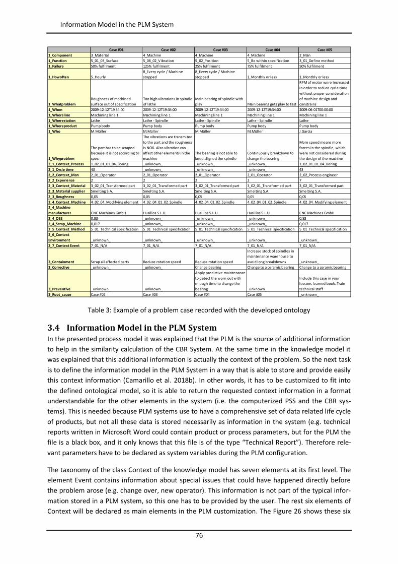
76
Information Model in the PLM System
Table 3: Example of a problem case recorded with the developed ontology
3.4 Information Model in the PLM System In the presented process model it was explained that the PLM is the source of additional information to help in the similarity calculation of the CBR System. At the same time in the knowledge model it was explained that this additional information is actually the context of the problem. So the next task is to define the information model in the PLM System in a way that is able to store and provide easily this context information (Camarillo et al. 2018b). In other words, it has to be customized to fit into the defined ontological model, so it is able to return the requested context information in a format understandable for the other elements in the system (i.e. the computerized PSS and the CBR sys-tems). This is needed because PLM systems use to have a comprehensive set of data related life cycle of products, but not all these data is stored necessarily as information in the system (e.g. technical reports written in Microsoft Word could contain product or process parameters, but for the PLM the file is a black box, and it only knows that this file is of the type “Technical Report”). Therefore rele-vant parameters have to be declared as system variables during the PLM configuration.
The taxonomy of the class Context of the knowledge model has seven elements at its first level. The element Event contains information about special issues that could have happened directly before the problem arose (e.g. change over, new operator). This information is not part of the typical infor-mation stored in a PLM system, so this one has to be provided by the user. The rest six elements of Context will be declared as main elements in the PLM customization. The Figure 26 shows these six
Case #01 Case #02 Case #03 Case #04 Case #051_Component 3_Material 4_Machine 4_Machine 4_Machine 2_Man1_Function 5_01_03_Surface 5_08_02_Vibration 5_02_Position 5_Be within specification 3_01_Define method1_Failure 50% fulfilment 125% fulfilment 25% fulfilment 75% fulfilment 50% fulfilment
1_Howoften 5_Hourly8_Every cycle / Machine stopped
8_Every cycle / Machine stopped 1_Monthly or less 1_Monthly or less
1_WhatproblemRoughness of machined surface out of specification
Too high vibrations in spindle of lathe
Main bearing of spindle with play Main bearing gets play to fast
RPM of motor were increased in order to reduce cycle time without proper consideration of machine design and constrains
1_When 2009-12-12T19:34:00 2009-12-12T19:34:00 2009-12-12T19:34:00 2009-12-12T19:34:00 2009-06-01T00:00:001_Whereline Machining line 1 Machining line 1 Machining line 1 Machining line 1 Machining line 11_Wherestation Lathe Lathe - Spindle Lathe - Spindle Lathe - Spindle Lathe1_Whereproduct Pump body Pump body Pump body Pump body Pump body1_Who M.Müller M.Müller M.Müller M.Müller J.Garcia
1_Whyproblem
The part has to be scraped because it is not according to spec
The vibrations are transmited to the part and the roughness is NOK. Also vibration can affect other elements in the machine
The bearing is not able to keep aligned the spindle
Continuously breakdown to change the bearing
More speed means more forces in the spindle, which were not considered during the design of the machine
2_1_Context_Process 1_02_01_01_04_Boring _unknown_ _unknown_ _unknown_ 1_02_01_01_04_Boring2_1_Cycle time 43 _unknown_ _unknown_ _unknown_ 432_2_Context_Man 2_01_Operator 2_01_Operator 2_01_Operator 2_01_Operator 2_02_Process engineer2_2_Experience 2 2 2 2 72_3_Context_Material 3_02_01_Transformed part 3_02_01_Transformed part 3_02_01_Transformed part 3_02_01_Transformed part 3_02_01_Transformed part2_3_Material supplier Smelting S.A. Smelting S.A. Smelting S.A. Smelting S.A. Smelting S.A.2_3_Roughness 0,05 0,05 0,05 0,05 0,052_4_Context_Machine 4_02_04_Modifying element 4_02_04_01_02_Spindle 4_02_04_01_02_Spindle 4_02_04_01_02_Spindle 4_02_04_Modifying element2_4_Machine manufacturer CNC Machines GmbH Husillos S.L.U. Husillos S.L.U. Husillos S.L.U. CNC Machines GmbH2_4_OEE 0,83 _unknown_ _unknown_ _unknown_ 0,832_4_Scrap_Machine 0,017 _unknown_ _unknown_ _unknown_ 0,0172_5_Context_Method 5_01_Technical specification 5_01_Technical specification 5_01_Technical specification 5_01_Technical specification 5_01_Technical specification2_6_Context Environment _unknown_ _unknown_ _unknown_ _unknown_ _unknown_2_7_Context Event 7_01_N/A 7_01_N/A 7_01_N/A 7_01_N/A 7_01_N/A
3_Containment Scrap all affected parts Reduce rotation speed Reduce rotation speed
Increase stock of spindles in maintenance warehouse to avoid long breakdowns _unknown_
3_Corrective _unknown_ _unknown_ Change bearing Change to a ceramic bearing Change to a ceramic bearing
3_Preventive _unknown_ _unknown_
Apply predictive maintenance to detect the worn out with enough time to change the bearing _unknown_
Include this case in your lessons learned book. Train technical staff
3_Root_cause Case #02 Case #03 Case #04 Case #05 _unknown_
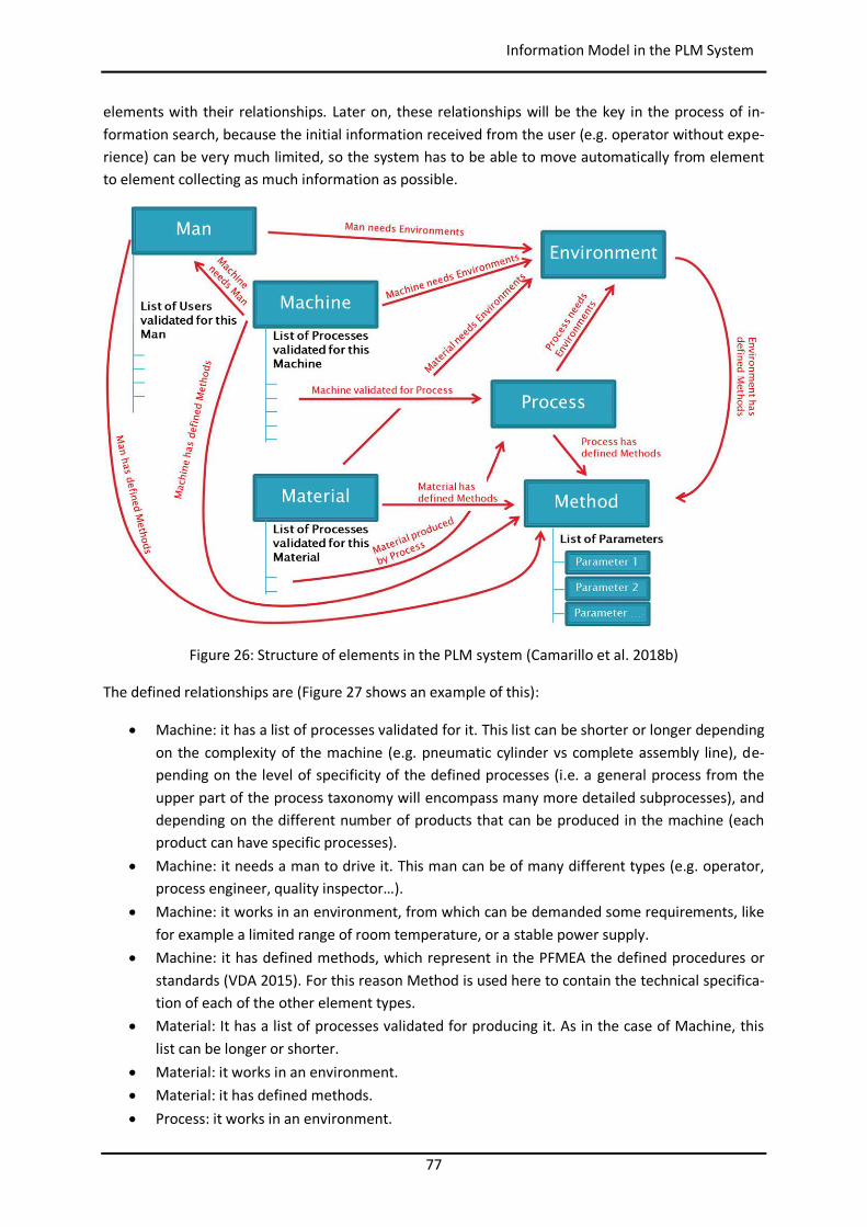
77
Information Model in the PLM System
elements with their relationships. Later on, these relationships will be the key in the process of in-formation search, because the initial information received from the user (e.g. operator without expe-rience) can be very much limited, so the system has to be able to move automatically from element to element collecting as much information as possible.
Figure 26: Structure of elements in the PLM system (Camarillo et al. 2018b)
The defined relationships are (Figure 27 shows an example of this):
Machine: it has a list of processes validated for it. This list can be shorter or longer depending on the complexity of the machine (e.g. pneumatic cylinder vs complete assembly line), de-pending on the level of specificity of the defined processes (i.e. a general process from the upper part of the process taxonomy will encompass many more detailed subprocesses), and depending on the different number of products that can be produced in the machine (each product can have specific processes).
Machine: it needs a man to drive it. This man can be of many different types (e.g. operator, process engineer, quality inspector…).
Machine: it works in an environment, from which can be demanded some requirements, like for example a limited range of room temperature, or a stable power supply.
Machine: it has defined methods, which represent in the PFMEA the defined procedures or standards (VDA 2015). For this reason Method is used here to contain the technical specifica-tion of each of the other element types.
Material: It has a list of processes validated for producing it. As in the case of Machine, this list can be longer or shorter.
Material: it works in an environment. Material: it has defined methods. Process: it works in an environment.
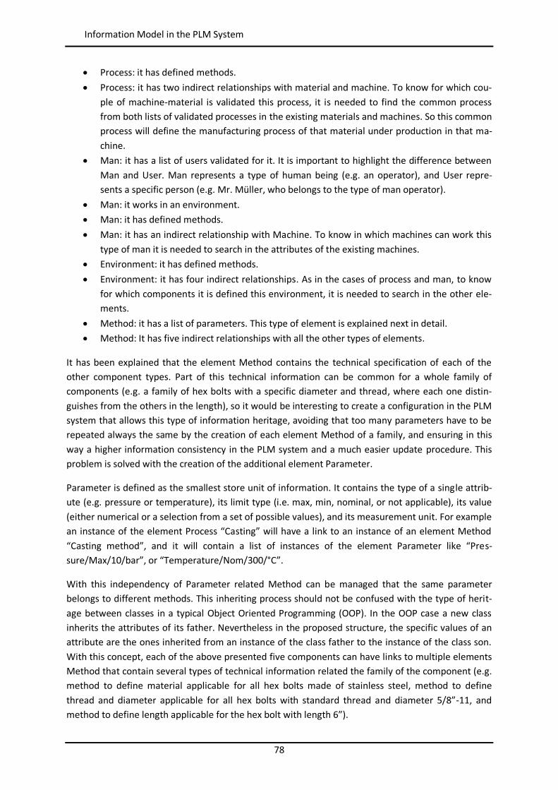
78
Information Model in the PLM System
Process: it has defined methods. Process: it has two indirect relationships with material and machine. To know for which cou-
ple of machine-material is validated this process, it is needed to find the common process from both lists of validated processes in the existing materials and machines. So this common process will define the manufacturing process of that material under production in that ma-chine.
Man: it has a list of users validated for it. It is important to highlight the difference between Man and User. Man represents a type of human being (e.g. an operator), and User repre-sents a specific person (e.g. Mr. Müller, who belongs to the type of man operator).
Man: it works in an environment. Man: it has defined methods. Man: it has an indirect relationship with Machine. To know in which machines can work this
type of man it is needed to search in the attributes of the existing machines. Environment: it has defined methods. Environment: it has four indirect relationships. As in the cases of process and man, to know
for which components it is defined this environment, it is needed to search in the other ele-ments.
Method: it has a list of parameters. This type of element is explained next in detail. Method: It has five indirect relationships with all the other types of elements.
It has been explained that the element Method contains the technical specification of each of the other component types. Part of this technical information can be common for a whole family of components (e.g. a family of hex bolts with a specific diameter and thread, where each one distin-guishes from the others in the length), so it would be interesting to create a configuration in the PLM system that allows this type of information heritage, avoiding that too many parameters have to be repeated always the same by the creation of each element Method of a family, and ensuring in this way a higher information consistency in the PLM system and a much easier update procedure. This problem is solved with the creation of the additional element Parameter.
Parameter is defined as the smallest store unit of information. It contains the type of a single attrib-ute (e.g. pressure or temperature), its limit type (i.e. max, min, nominal, or not applicable), its value (either numerical or a selection from a set of possible values), and its measurement unit. For example an instance of the element Process “Casting” will have a link to an instance of an element Method “Casting method”, and it will contain a list of instances of the element Parameter like “Pres-sure/Max/10/bar”, or “Temperature/Nom/300/°C”.
With this independency of Parameter related Method can be managed that the same parameter belongs to different methods. This inheriting process should not be confused with the type of herit-age between classes in a typical Object Oriented Programming (OOP). In the OOP case a new class inherits the attributes of its father. Nevertheless in the proposed structure, the specific values of an attribute are the ones inherited from an instance of the class father to the instance of the class son. With this concept, each of the above presented five components can have links to multiple elements Method that contain several types of technical information related the family of the component (e.g. method to define material applicable for all hex bolts made of stainless steel, method to define thread and diameter applicable for all hex bolts with standard thread and diameter 5/8”-11, and method to define length applicable for the hex bolt with length 6”).
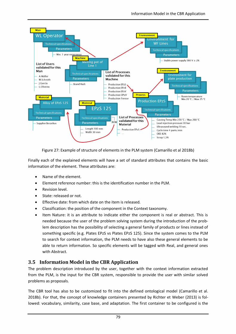
79
Information Model in the CBR Application
Figure 27: Example of structure of elements in the PLM system (Camarillo et al 2018b)
Finally each of the explained elements will have a set of standard attributes that contains the basic information of the element. These attributes are:
Name of the element. Element reference number: this is the identification number in the PLM. Revision level. State: released or not. Effective date: from which date on the item is released. Classification: the position of the component in the Context taxonomy. Item Nature: it is an attribute to indicate either the component is real or abstract. This is
needed because the user of the problem solving system during the introduction of the prob-lem description has the possibility of selecting a general family of products or lines instead of something specific (e.g. Plates EPzS vs Plates EPzS 125). Since the system comes to the PLM to search for context information, the PLM needs to have also these general elements to be able to return information. So specific elements will be tagged with Real, and general ones with Abstract.
3.5 Information Model in the CBR Application The problem description introduced by the user, together with the context information extracted from the PLM, is the input for the CBR system, responsible to provide the user with similar solved problems as proposals.
The CBR tool has also to be customized to fit into the defined ontological model (Camarillo et al. 2018b). For that, the concept of knowledge containers presented by Richter et Weber (2013) is fol-lowed: vocabulary, similarity, case base, and adaptation. The first container to be configured is the
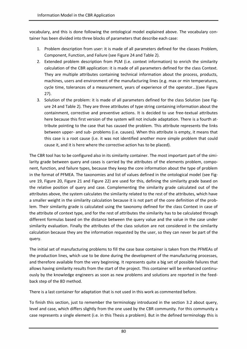
80
Information Model in the CBR Application
vocabulary, and this is done following the ontological model explained above. The vocabulary con-tainer has been divided into three blocks of parameters that describe each case:
1. Problem description from user: it is made of all parameters defined for the classes Problem, Component, Function, and Failure (see Figure 24 and Table 2).
2. Extended problem description from PLM (i.e. context information) to enrich the similarity calculation of the CBR application: it is made of all parameters defined for the class Context. They are multiple attributes containing technical information about the process, products, machines, users and environment of the manufacturing lines (e.g. max or min temperatures, cycle time, tolerances of a measurement, years of experience of the operator…)(see Figure 27).
3. Solution of the problem: it is made of all parameters defined for the class Solution (see Fig-ure 24 and Table 2). They are three attributes of type string containing information about the containment, corrective and preventive actions. It is decided to use free-textual attributes here because this first version of the system will not include adaptation. There is a fourth at-tribute pointing to the case that has caused the problem. This attribute represents the links between upper- and sub- problems (i.e. causes). When this attribute is empty, it means that this case is a root cause (i.e. it was not identified another more simple problem that could cause it, and it is here where the corrective action has to be placed).
The CBR tool has to be configured also in its similarity container. The most important part of the simi-larity grade between query and cases is carried by the attributes of the elements problem, compo-nent, function, and failure types, because they keep the core information about the type of problem in the format of PFMEA. The taxonomies and list of values defined in the ontological model (see Fig-ure 19, Figure 20, Figure 21 and Figure 22) are used for this, defining the similarity grade based on the relative position of query and case. Complementing the similarity grade calculated out of the attributes above, the system calculates the similarity related to the rest of the attributes, which have a smaller weight in the similarity calculation because it is not part of the core definition of the prob-lem. Their similarity grade is calculated using the taxonomy defined for the class Context in case of the attribute of context type, and for the rest of attributes the similarity has to be calculated through different formulas based on the distance between the query value and the value in the case under similarity evaluation. Finally the attributes of the class solution are not considered in the similarity calculation because they are the information requested by the user, so they can never be part of the query.
The initial set of manufacturing problems to fill the case base container is taken from the PFMEAs of the production lines, which use to be done during the development of the manufacturing processes, and therefore available from the very beginning. It represents quite a big set of possible failures that allows having similarity results from the start of the project. This container will be enhanced continu-ously by the knowledge engineers as soon as new problems and solutions are reported in the feed-back step of the 8D method.
There is a last container for adaptation that is not used in this work as commented before.
To finish this section, just to remember the terminology introduced in the section 3.2 about query, level and case, which differs slightly from the one used by the CBR community. For this community a case represents a single element (i.e. in this Thesis a problem). But in the defined terminology this is
81
IT Infrastructure
equal to a level. A collection of levels, which are the causes from each other, is denominated as case. The decision of dividing a global case (i.e. the whole chain of causes) into levels is justified because the probability of finding two cause chains that are similar is much lower than if the similarity calcu-lation is done based on levels. So the system will provide the similarity value of the first level of the case, and it will send together the next linked levels until the root cause (i.e. the level without other associated under-level). In this way it could happen that during the analysis, the first levels from a certain case are taken because they match with issues found in the line, but from a certain level on the problem description does not match anymore with the problems in the line. Then with a new description, which is based on the last found problem level, the system can provide a new case, from which the user can take the next levels for his analysis. This is also justified by the fact that it was considered as definition in the section 3.3 that each problem can be created just by another single problem, and that in case of composed problems each one should be analyzed as independent one. Therefore it is important to have access to the internal levels of a case and to make the similarity calculation based on them.
3.6 IT Infrastructure As introduced in the state of the art, the shopfloor actors of many factories meet every day to ana-lyze the OEE problems. They use to call some colleagues with the right expertise and knowledge to open a paper based PSS and to start the analysis of the problem. This Thesis proposes to substitute the paper PSS by a digital PSS to be worked out in computers located at production lines, following the same 8 steps of the 8D method. Since the shape of the tool (i.e. PSS) and method (i.e. 8D) does not change significantly, low refusal from shopfloor actors' side is expected.
The storage of information in digital format opens a great range of opportunities for capture and reuse of knowledge. This Thesis pretends to explore this opportunities through the process model presented in the section 3.2. From an IT perspective this process model will lie on the SEASALT archi-tecture introduced in the section 2.5.1. Figure 28 shows the application of this software architecture to this Thesis.
The different agents are deployed across the different manufacturing plants of the company (from now on denominated locations), and, inside of each location, across the areas with different manu-facturing processes (from now on denominated production units). In this way, each agent hosted in a specific production unit of a specific location will be able to communicate and to interchange infor-mation with all the other agents hosted in different production units and locations. This communica-tion will take place through the intranet of the company by sending HTTP-based MTP (Message Transport Protocol) messages (Bellifemine et al. 2007). In this Thesis the SEASALT architecture has been simplified, taking only the parts relevant for this research. It is made of three different types of agents:
Individualized Knowledge Agent: located in the Individualized Knowledge module of SEASALT it is responsible for capturing and showing information to the user through the digital PSS, and also for collecting the context information from the PLM (in the case study of the Thesis the selected PLM system is Aras Innovator, as it is shown in the figure). There are so many agents of this type as users, and they are hosted in the devices located directly at the pro-duction lines (e.g. PC, smart touchscreen, or even a smart phone).
Topic Agent: located in the Knowledge Provision module of SEASALT, it is responsible for cal-culating similarities through a CBR application, and proposing the best solution out of its spe-
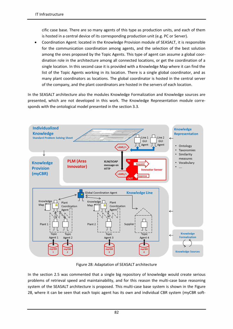
82
IT Infrastructure
cific case base. There are so many agents of this type as production units, and each of them is hosted in a central device of its corresponding production unit (e.g. PC or Server).
Coordination Agent: located in the Knowledge Provision module of SEASALT, it is responsible for the communication coordination among agents, and the selection of the best solution among the ones proposed by the Topic Agents. This type of agent can assume a global coor-dination role in the architecture among all connected locations, or get the coordination of a single location. In this second case it is provided with a Knowledge Map where it can find the list of the Topic Agents working in its location. There is a single global coordinator, and as many plant coordinators as locations. The global coordinator is hosted in the central server of the company, and the plant coordinators are hosted in the servers of each location.
In the SEASALT architecture also the modules Knowledge Formalization and Knowledge sources are presented, which are not developed in this work. The Knowledge Representation module corre-sponds with the ontological model presented in the section 3.3.
Figure 28: Adaptation of SEASALT architecture
In the section 2.5 was commented that a single big repository of knowledge would create serious problems of retrieval speed and maintainability, and for this reason the multi-case base reasoning system of the SEASALT architecture is proposed. This multi-case base system is shown in the Figure 28, where it can be seen that each topic agent has its own and individual CBR system (myCBR soft-
83
Summary
ware in the case study of the Thesis). This specialization of the topic agents brings solution to the next issues:
The case base of each topic agent is small enough to ensure retrieval speed and an easy maintainability.
It was explained that each individualized knowledge agent looks for additional information in the PLM database to fill the context attributes. Since the system proposed in this Thesis is open to an undefined number of possible processes, the quantity of attributes needed to represent the whole spectrum of different characteristics in a hypothetical single CBR system would be so huge that the weight of the relevant attributes for each specific case would be lost among all the others. By specializing it is ensured that each small CBR system will take from the whole query only the relevant attributes for it, supporting an efficient similarity cal-culation.
In a first searching loop, the communication can be kept inside of the location asking only the topic agents of the affected production unit. This avoids overloading the net with inter-location communications, which are usually quite slow. Only when the topic agents of the af-fected production unit are not able to provide the user with a satisfactory solution the query will be sent to all the other topic agents in the net.
The process knowledge that is to be shared can be easily separated from the one that has to be protected for any reason (e.g. share with suppliers or customers), ensuring an easy con-figuration of privacy.
3.7 Summary This section has presented the main models used to develop the proposed system. It has started in-troducing the process model that shows how the system will work, and defines the main interactions between users and system. Next it was presented the knowledge model, proposing a concrete ontol-ogy able to represent any kind of problem from any type of manufacturing process. Based on this ontology the following sections introduced the application of the knowledge model to the PLM and CBR systems used by the central system. Finally the IT infrastructure based on SEASALT and its agents was commented.

84
Summary
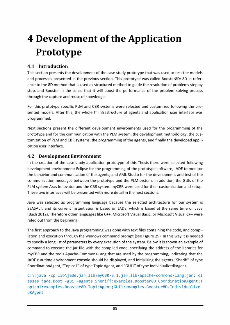
85
4 Development of the Application Prototype
4.1 Introduction This section presents the development of the case study prototype that was used to test the models and processes presented in the previous section. This prototype was called Booster8D: 8D in refer-ence to the 8D method that is used as structured method to guide the resolution of problems step by step, and Booster in the sense that it will boost the performance of the problem solving process through the capture and reuse of knowledge.
For this prototype specific PLM and CBR systems were selected and customized following the pre-sented models. After this, the whole IT infrastructure of agents and application user interface was programmed.
Next sections present the different development environments used for the programming of the prototype and for the communication with the PLM system, the development methodology, the cus-tomization of PLM and CBR systems, the programming of the agents, and finally the developed appli-cation user interface.
4.2 Development Environment In the creation of the case study application prototype of this Thesis there were selected following development environment: Eclipse for the programming of the prototype software, JADE to monitor the behavior and communication of the agents, and AML Studio for the development and test of the communication messages between the prototype and the PLM system. In addition, the GUIs of the PLM system Aras Innovator and the CBR system myCBR were used for their customization and setup. These two interfaces will be presented with more detail in the next sections.
Java was selected as programming language because the selected architecture for our system is SEASALT, and its current instantiation is based on JADE, which is based at the same time on Java (Bach 2012). Therefore other languages like C++, Microsoft Visual Basic, or Microsoft Visual C++ were ruled out from the beginning.
The first approach to the Java programming was done with text files containing the code, and compi-lation and execution through the windows command prompt (see Figure 29). In this way it is needed to specify a long list of parameters by every execution of the system. Below it is shown an example of command to execute the jar file with the compiled code, specifying the address of the libraries for myCBR and the tools Apache-Commons-Lang that are used by the programming, indicating that the JADE run-time environment console should be displayed, and initializing the agents “Sheriff” of type CoordinationAgent, “Topico1” of type Topic Agent, and “GUI1” of type IndividualizedkAgent.
C:\>java -cp lib\jade.jar;lib\myCBR-3.1.jar;lib\apache-commons-lang.jar; cl asses jade.Boot -gui –agents Sheriff:examples.Booster8D.CoordinationAgent;T opico1:examples.Booster8D.TopicAgent;GUI1:examples.Booster8D.Individualize dKAgent
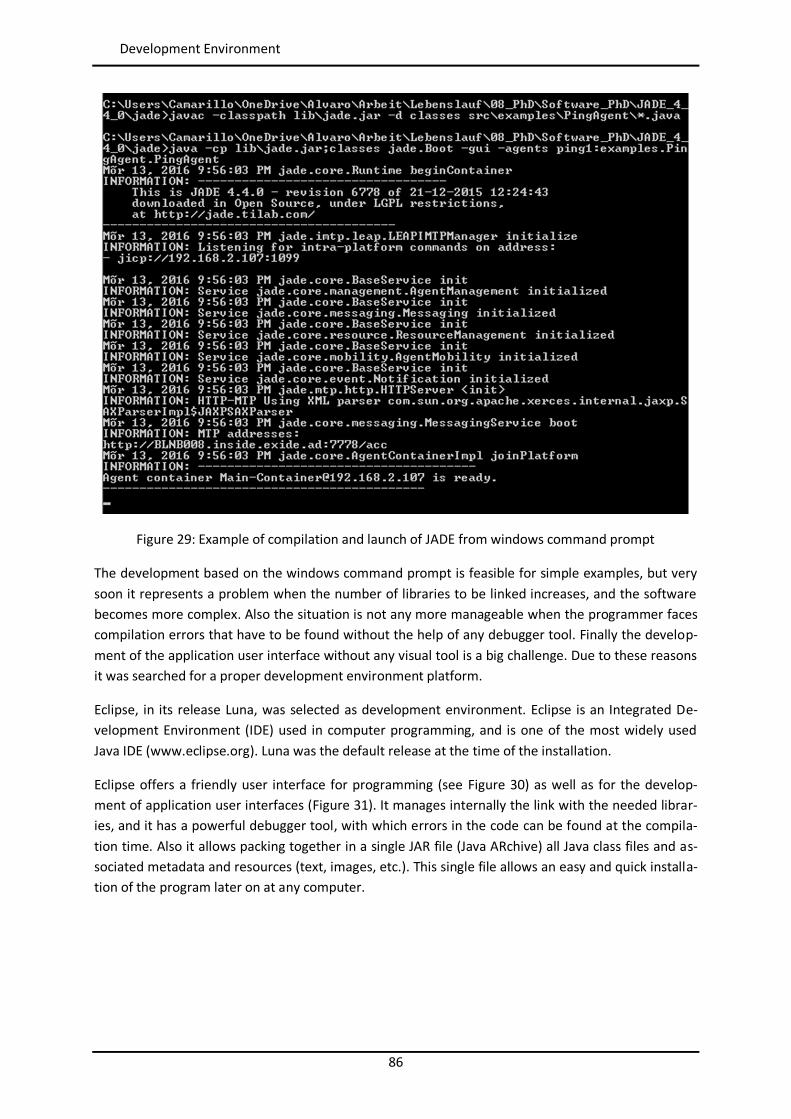
86
Development Environment
Figure 29: Example of compilation and launch of JADE from windows command prompt
The development based on the windows command prompt is feasible for simple examples, but very soon it represents a problem when the number of libraries to be linked increases, and the software becomes more complex. Also the situation is not any more manageable when the programmer faces compilation errors that have to be found without the help of any debugger tool. Finally the develop-ment of the application user interface without any visual tool is a big challenge. Due to these reasons it was searched for a proper development environment platform.
Eclipse, in its release Luna, was selected as development environment. Eclipse is an Integrated De-velopment Environment (IDE) used in computer programming, and is one of the most widely used Java IDE (www.eclipse.org). Luna was the default release at the time of the installation.
Eclipse offers a friendly user interface for programming (see Figure 30) as well as for the develop-ment of application user interfaces (Figure 31). It manages internally the link with the needed librar-ies, and it has a powerful debugger tool, with which errors in the code can be found at the compila-tion time. Also it allows packing together in a single JAR file (Java ARchive) all Java class files and as-sociated metadata and resources (text, images, etc.). This single file allows an easy and quick installa-tion of the program later on at any computer.
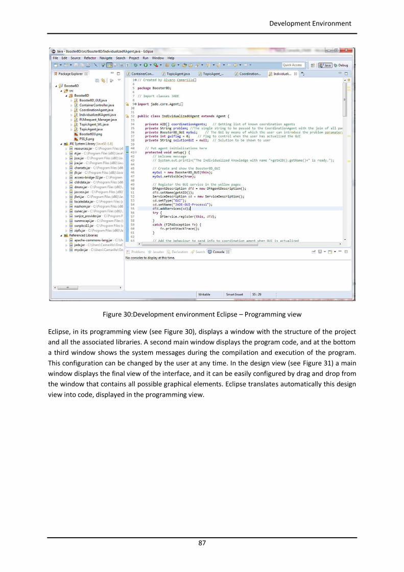
87
Development Environment
Figure 30:Development environment Eclipse – Programming view
Eclipse, in its programming view (see Figure 30), displays a window with the structure of the project and all the associated libraries. A second main window displays the program code, and at the bottom a third window shows the system messages during the compilation and execution of the program. This configuration can be changed by the user at any time. In the design view (see Figure 31) a main window displays the final view of the interface, and it can be easily configured by drag and drop from the window that contains all possible graphical elements. Eclipse translates automatically this design view into code, displayed in the programming view.
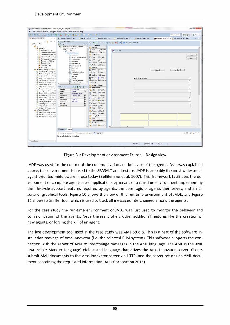
88
Development Environment
Figure 31: Development environment Eclipse – Design view
JADE was used for the control of the communication and behavior of the agents. As it was explained above, this environment is linked to the SEASALT architecture. JADE is probably the most widespread agent-oriented middleware in use today (Bellifemine et al. 2007). This framework facilitates the de-velopment of complete agent-based applications by means of a run-time environment implementing the life-cycle support features required by agents, the core logic of agents themselves, and a rich suite of graphical tools. Figure 10 shows the view of this run-time environment of JADE, and Figure 11 shows its Sniffer tool, which is used to track all messages interchanged among the agents.
For the case study the run-time environment of JADE was just used to monitor the behavior and communication of the agents. Nevertheless it offers other additional features like the creation of new agents, or forcing the kill of an agent.
The last development tool used in the case study was AML Studio. This is a part of the software in-stallation package of Aras Innovator (i.e. the selected PLM system). This software supports the con-nection with the server of Aras to interchange messages in the AML language. The AML is the XML (eXtensible Markup Language) dialect and language that drives the Aras Innovator server. Clients submit AML documents to the Aras Innovator server via HTTP, and the server returns an AML docu-ment containing the requested information (Aras Corporation 2015).
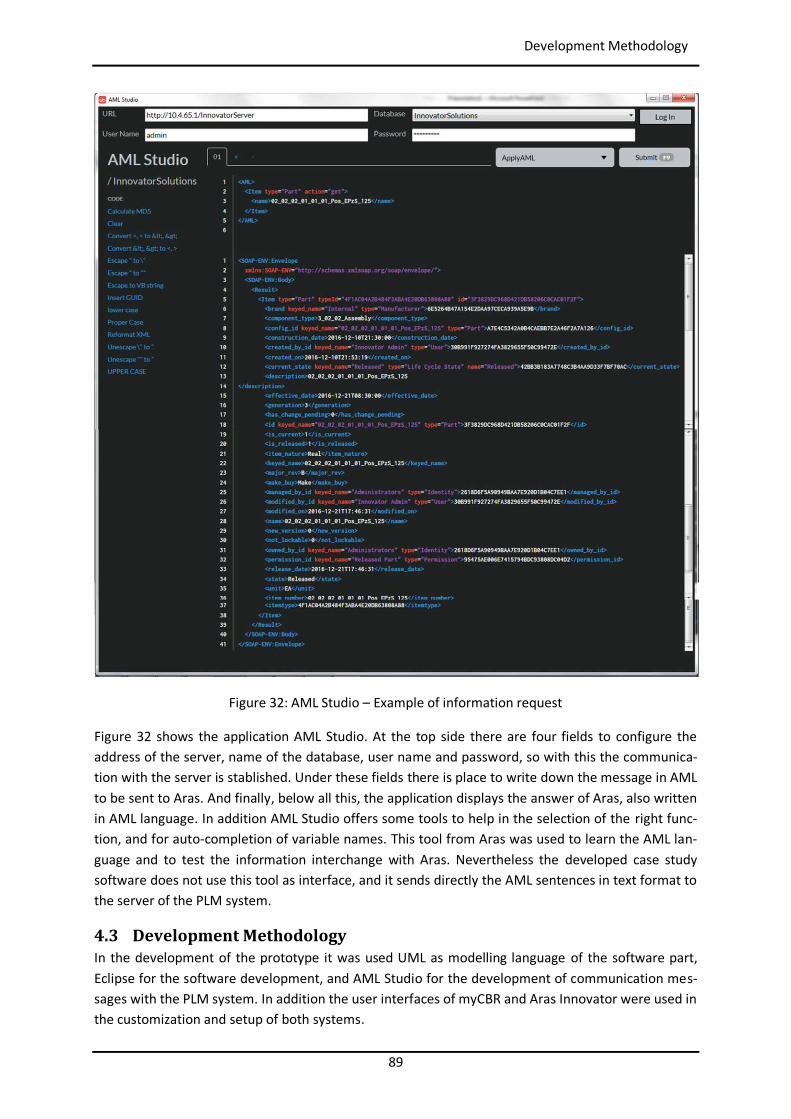
89
Development Methodology
Figure 32: AML Studio – Example of information request
Figure 32 shows the application AML Studio. At the top side there are four fields to configure the address of the server, name of the database, user name and password, so with this the communica-tion with the server is stablished. Under these fields there is place to write down the message in AML to be sent to Aras. And finally, below all this, the application displays the answer of Aras, also written in AML language. In addition AML Studio offers some tools to help in the selection of the right func-tion, and for auto-completion of variable names. This tool from Aras was used to learn the AML lan-guage and to test the information interchange with Aras. Nevertheless the developed case study software does not use this tool as interface, and it sends directly the AML sentences in text format to the server of the PLM system.
4.3 Development Methodology In the development of the prototype it was used UML as modelling language of the software part, Eclipse for the software development, and AML Studio for the development of communication mes-sages with the PLM system. In addition the user interfaces of myCBR and Aras Innovator were used in the customization and setup of both systems.
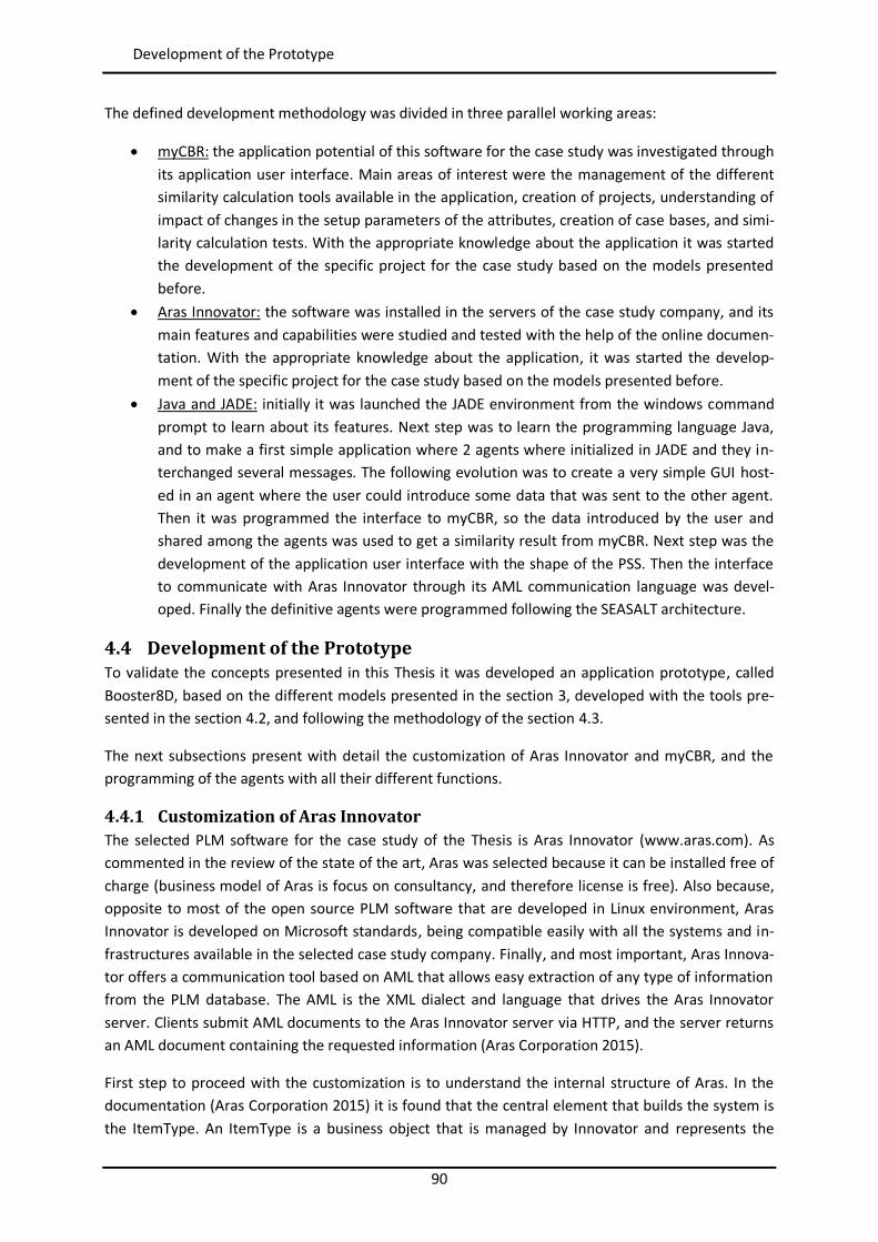
90
Development of the Prototype
The defined development methodology was divided in three parallel working areas:
myCBR: the application potential of this software for the case study was investigated through its application user interface. Main areas of interest were the management of the different similarity calculation tools available in the application, creation of projects, understanding of impact of changes in the setup parameters of the attributes, creation of case bases, and simi-larity calculation tests. With the appropriate knowledge about the application it was started the development of the specific project for the case study based on the models presented before.
Aras Innovator: the software was installed in the servers of the case study company, and its main features and capabilities were studied and tested with the help of the online documen-tation. With the appropriate knowledge about the application, it was started the develop-ment of the specific project for the case study based on the models presented before.
Java and JADE: initially it was launched the JADE environment from the windows command prompt to learn about its features. Next step was to learn the programming language Java, and to make a first simple application where 2 agents where initialized in JADE and they in-terchanged several messages. The following evolution was to create a very simple GUI host-ed in an agent where the user could introduce some data that was sent to the other agent. Then it was programmed the interface to myCBR, so the data introduced by the user and shared among the agents was used to get a similarity result from myCBR. Next step was the development of the application user interface with the shape of the PSS. Then the interface to communicate with Aras Innovator through its AML communication language was devel-oped. Finally the definitive agents were programmed following the SEASALT architecture.
4.4 Development of the Prototype To validate the concepts presented in this Thesis it was developed an application prototype, called Booster8D, based on the different models presented in the section 3, developed with the tools pre-sented in the section 4.2, and following the methodology of the section 4.3.
The next subsections present with detail the customization of Aras Innovator and myCBR, and the programming of the agents with all their different functions.
4.4.1 Customization of Aras Innovator The selected PLM software for the case study of the Thesis is Aras Innovator (www.aras.com). As commented in the review of the state of the art, Aras was selected because it can be installed free of charge (business model of Aras is focus on consultancy, and therefore license is free). Also because, opposite to most of the open source PLM software that are developed in Linux environment, Aras Innovator is developed on Microsoft standards, being compatible easily with all the systems and in-frastructures available in the selected case study company. Finally, and most important, Aras Innova-tor offers a communication tool based on AML that allows easy extraction of any type of information from the PLM database. The AML is the XML dialect and language that drives the Aras Innovator server. Clients submit AML documents to the Aras Innovator server via HTTP, and the server returns an AML document containing the requested information (Aras Corporation 2015).
First step to proceed with the customization is to understand the internal structure of Aras. In the documentation (Aras Corporation 2015) it is found that the central element that builds the system is the ItemType. An ItemType is a business object that is managed by Innovator and represents the
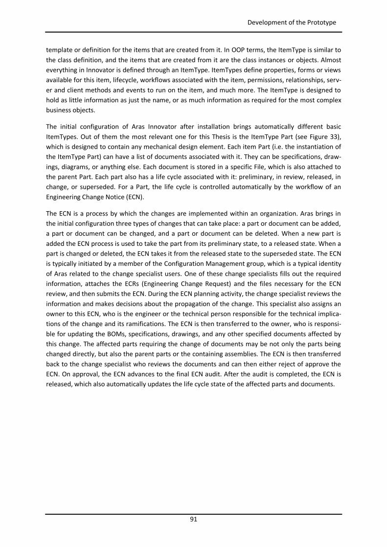
91
Development of the Prototype
template or definition for the items that are created from it. In OOP terms, the ItemType is similar to the class definition, and the items that are created from it are the class instances or objects. Almost everything in Innovator is defined through an ItemType. ItemTypes define properties, forms or views available for this item, lifecycle, workflows associated with the item, permissions, relationships, serv-er and client methods and events to run on the item, and much more. The ItemType is designed to hold as little information as just the name, or as much information as required for the most complex business objects.
The initial configuration of Aras Innovator after installation brings automatically different basic ItemTypes. Out of them the most relevant one for this Thesis is the ItemType Part (see Figure 33), which is designed to contain any mechanical design element. Each item Part (i.e. the instantiation of the ItemType Part) can have a list of documents associated with it. They can be specifications, draw-ings, diagrams, or anything else. Each document is stored in a specific File, which is also attached to the parent Part. Each part also has a life cycle associated with it: preliminary, in review, released, in change, or superseded. For a Part, the life cycle is controlled automatically by the workflow of an Engineering Change Notice (ECN).
The ECN is a process by which the changes are implemented within an organization. Aras brings in the initial configuration three types of changes that can take place: a part or document can be added, a part or document can be changed, and a part or document can be deleted. When a new part is added the ECN process is used to take the part from its preliminary state, to a released state. When a part is changed or deleted, the ECN takes it from the released state to the superseded state. The ECN is typically initiated by a member of the Configuration Management group, which is a typical identity of Aras related to the change specialist users. One of these change specialists fills out the required information, attaches the ECRs (Engineering Change Request) and the files necessary for the ECN review, and then submits the ECN. During the ECN planning activity, the change specialist reviews the information and makes decisions about the propagation of the change. This specialist also assigns an owner to this ECN, who is the engineer or the technical person responsible for the technical implica-tions of the change and its ramifications. The ECN is then transferred to the owner, who is responsi-ble for updating the BOMs, specifications, drawings, and any other specified documents affected by this change. The affected parts requiring the change of documents may be not only the parts being changed directly, but also the parent parts or the containing assemblies. The ECN is then transferred back to the change specialist who reviews the documents and can then either reject of approve the ECN. On approval, the ECN advances to the final ECN audit. After the audit is completed, the ECN is released, which also automatically updates the life cycle state of the affected parts and documents.
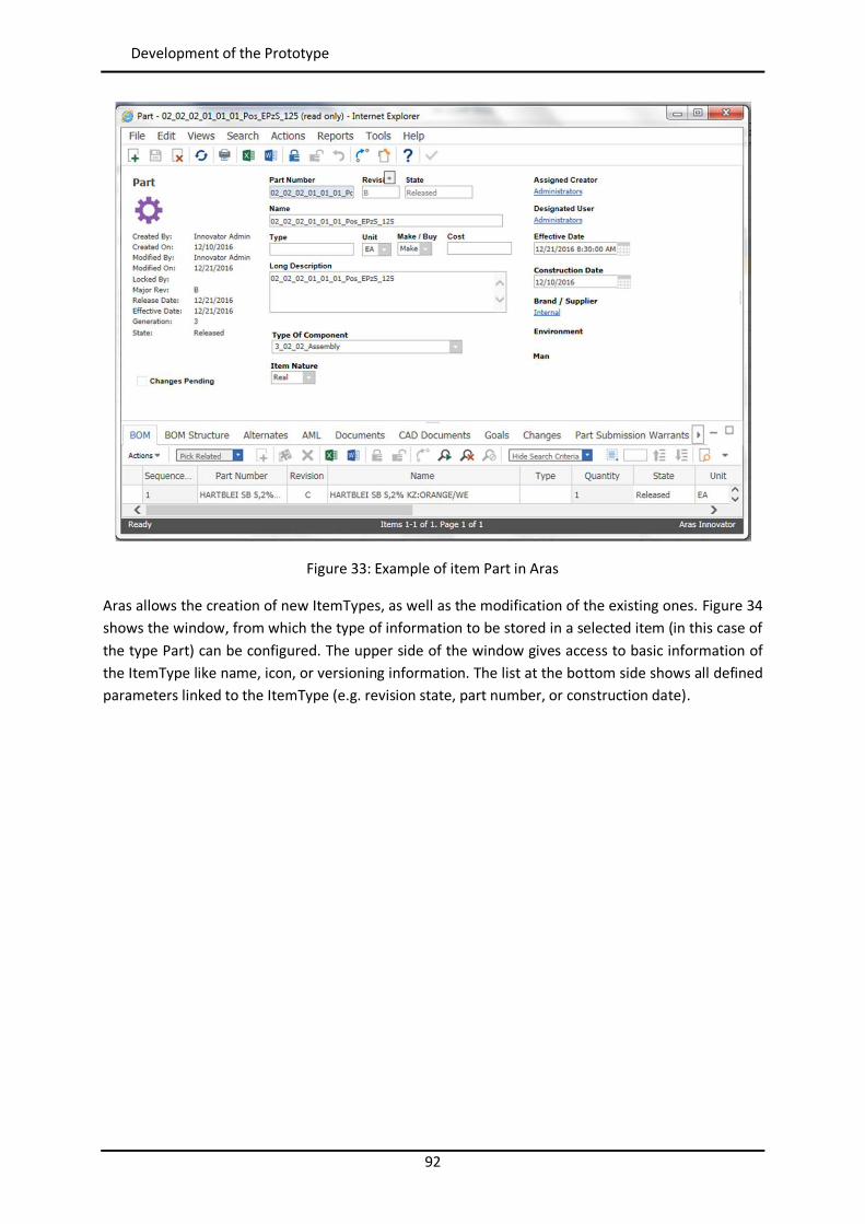
92
Development of the Prototype
Figure 33: Example of item Part in Aras
Aras allows the creation of new ItemTypes, as well as the modification of the existing ones. Figure 34 shows the window, from which the type of information to be stored in a selected item (in this case of the type Part) can be configured. The upper side of the window gives access to basic information of the ItemType like name, icon, or versioning information. The list at the bottom side shows all defined parameters linked to the ItemType (e.g. revision state, part number, or construction date).
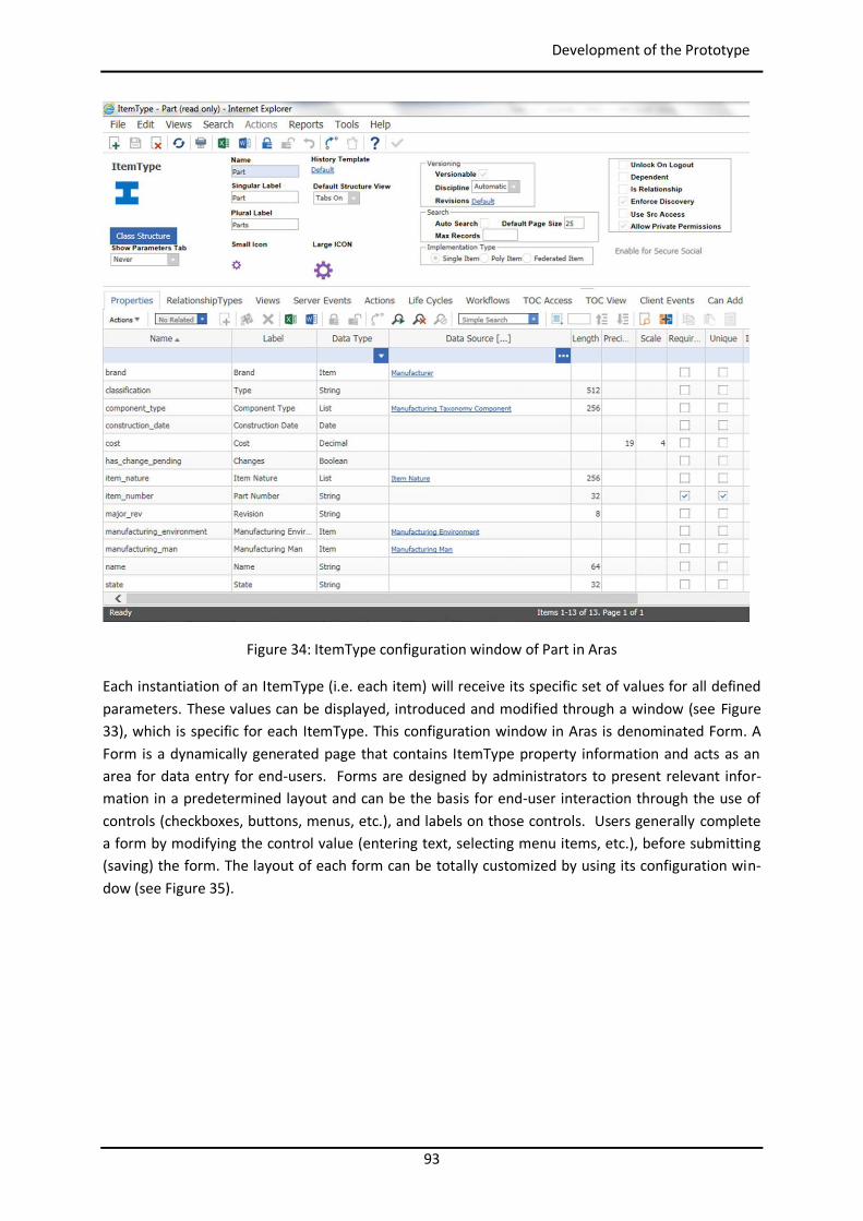
93
Development of the Prototype
Figure 34: ItemType configuration window of Part in Aras
Each instantiation of an ItemType (i.e. each item) will receive its specific set of values for all defined parameters. These values can be displayed, introduced and modified through a window (see Figure 33), which is specific for each ItemType. This configuration window in Aras is denominated Form. A Form is a dynamically generated page that contains ItemType property information and acts as an area for data entry for end-users. Forms are designed by administrators to present relevant infor-mation in a predetermined layout and can be the basis for end-user interaction through the use of controls (checkboxes, buttons, menus, etc.), and labels on those controls. Users generally complete a form by modifying the control value (entering text, selecting menu items, etc.), before submitting (saving) the form. The layout of each form can be totally customized by using its configuration win-dow (see Figure 35).
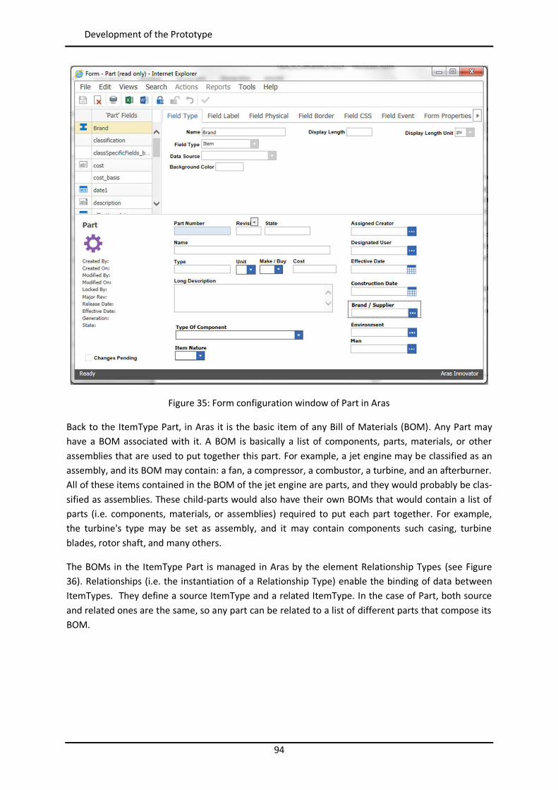
94
Development of the Prototype
Figure 35: Form configuration window of Part in Aras
Back to the ItemType Part, in Aras it is the basic item of any Bill of Materials (BOM). Any Part may have a BOM associated with it. A BOM is basically a list of components, parts, materials, or other assemblies that are used to put together this part. For example, a jet engine may be classified as an assembly, and its BOM may contain: a fan, a compressor, a combustor, a turbine, and an afterburner. All of these items contained in the BOM of the jet engine are parts, and they would probably be clas-sified as assemblies. These child-parts would also have their own BOMs that would contain a list of parts (i.e. components, materials, or assemblies) required to put each part together. For example, the turbine's type may be set as assembly, and it may contain components such casing, turbine blades, rotor shaft, and many others.
The BOMs in the ItemType Part is managed in Aras by the element Relationship Types (see Figure 36). Relationships (i.e. the instantiation of a Relationship Type) enable the binding of data between ItemTypes. They define a source ItemType and a related ItemType. In the case of Part, both source and related ones are the same, so any part can be related to a list of different parts that compose its BOM.
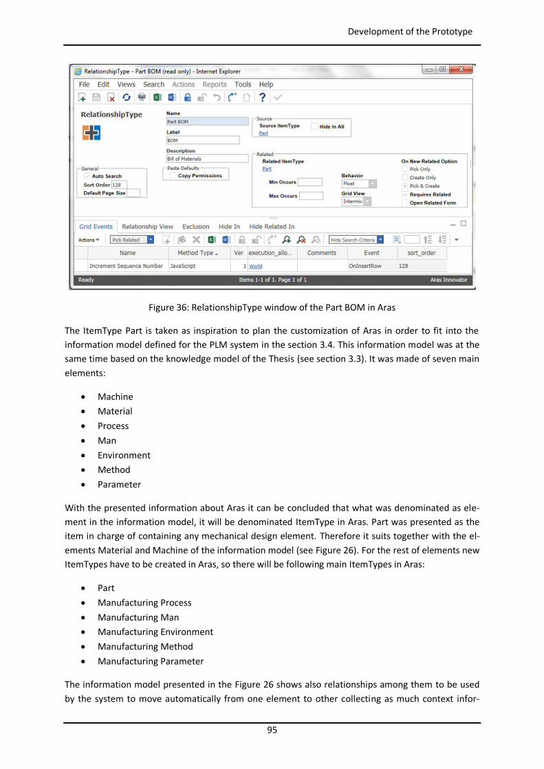
95
Development of the Prototype
Figure 36: RelationshipType window of the Part BOM in Aras
The ItemType Part is taken as inspiration to plan the customization of Aras in order to fit into the information model defined for the PLM system in the section 3.4. This information model was at the same time based on the knowledge model of the Thesis (see section 3.3). It was made of seven main elements:
Machine Material Process Man Environment Method Parameter
With the presented information about Aras it can be concluded that what was denominated as ele-ment in the information model, it will be denominated ItemType in Aras. Part was presented as the item in charge of containing any mechanical design element. Therefore it suits together with the el-ements Material and Machine of the information model (see Figure 26). For the rest of elements new ItemTypes have to be created in Aras, so there will be following main ItemTypes in Aras:
Part Manufacturing Process Manufacturing Man Manufacturing Environment Manufacturing Method Manufacturing Parameter
The information model presented in the Figure 26 shows also relationships among them to be used by the system to move automatically from one element to other collecting as much context infor-
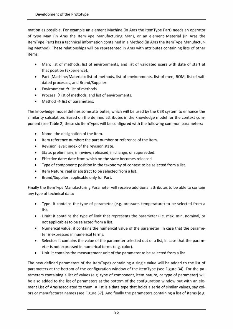
96
Development of the Prototype
mation as possible. For example an element Machine (in Aras the ItemType Part) needs an operator of type Man (in Aras the ItemType Manufacturing Man), or an element Material (in Aras the ItemType Part) has a technical information contained in a Method (in Aras the ItemType Manufactur-ing Method). These relationships will be represented in Aras with attributes containing lists of other items:
Man: list of methods, list of environments, and list of validated users with date of start at that position (Experience).
Part (Machine/Material): list of methods, list of environments, list of men, BOM, list of vali-dated processes, and Brand/Supplier.
Environment list of methods. Process list of methods, and list of environments. Method list of parameters.
The knowledge model defines some attributes, which will be used by the CBR system to enhance the similarity calculation. Based on the defined attributes in the knowledge model for the context com-ponent (see Table 2) these six ItemTypes will be configured with the following common parameters:
Name: the designation of the item. Item reference number: the part number or reference of the item. Revision level: index of the revision state. State: preliminary, in review, released, in change, or superseded. Effective date: date from which on the state becomes released. Type of component: position in the taxonomy of context to be selected from a list. Item Nature: real or abstract to be selected from a list. Brand/Supplier: applicable only for Part.
Finally the ItemType Manufacturing Parameter will receive additional attributes to be able to contain any type of technical data:
Type: it contains the type of parameter (e.g. pressure, temperature) to be selected from a list.
Limit: it contains the type of limit that represents the parameter (i.e. max, min, nominal, or not applicable) to be selected from a list.
Numerical value: it contains the numerical value of the parameter, in case that the parame-ter is expressed in numerical terms.
Selector: it contains the value of the parameter selected out of a list, in case that the param-eter is not expressed in numerical terms (e.g. color).
Unit: it contains the measurement unit of the parameter to be selected from a list.
The new defined parameters of the ItemTypes containing a single value will be added to the list of parameters at the bottom of the configuration window of the ItemType (see Figure 34). For the pa-rameters containing a list of values (e.g. type of component, item nature, or type of parameter) will be also added to the list of parameters at the bottom of the configuration window but with an ele-ment List of Aras associated to them. A list is a data type that holds a serie of similar values, say col-ors or manufacturer names (see Figure 37). And finally the parameters containing a list of items (e.g.
97
Development of the Prototype
list of methods or list of validated processes) will be managed through relationship types added to the ItemType in the corresponding tab (see Figure 39).
Figure 37: List in Aras containing the taxonomy of Context
The Figure 38, Figure 39, Figure 40 and Figure 41 show examples of the whole configuration of the ItemType Manufacturing Process. It starts with the configuration of its parameters, its relationship with the ItemType Method, and it finishes with the form for the later creation and modification by the user.
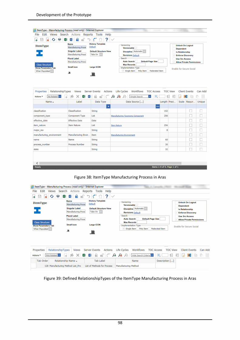
98
Development of the Prototype
Figure 38: ItemType Manufacturing Process in Aras
Figure 39: Defined RelationshipTypes of the ItemType Manufacturing Process in Aras
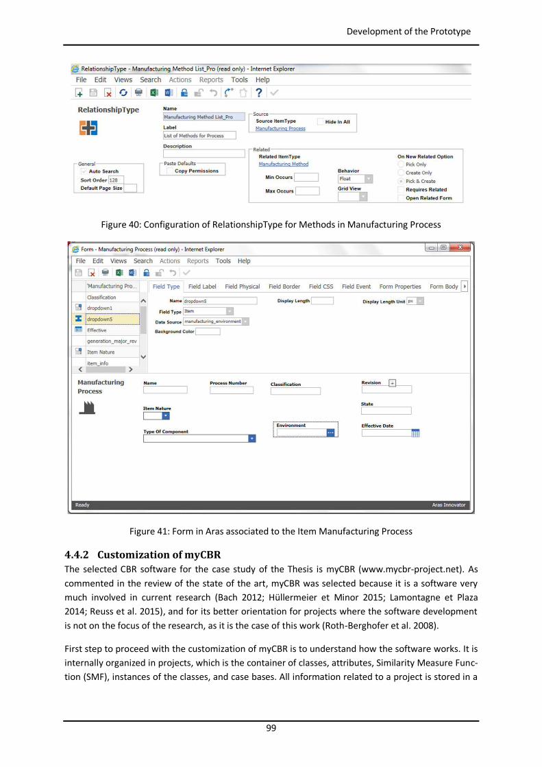
99
Development of the Prototype
Figure 40: Configuration of RelationshipType for Methods in Manufacturing Process
Figure 41: Form in Aras associated to the Item Manufacturing Process
4.4.2 Customization of myCBR The selected CBR software for the case study of the Thesis is myCBR (www.mycbr-project.net). As commented in the review of the state of the art, myCBR was selected because it is a software very much involved in current research (Bach 2012; Hüllermeier et Minor 2015; Lamontagne et Plaza 2014; Reuss et al. 2015), and for its better orientation for projects where the software development is not on the focus of the research, as it is the case of this work (Roth-Berghofer et al. 2008).
First step to proceed with the customization of myCBR is to understand how the software works. It is internally organized in projects, which is the container of classes, attributes, Similarity Measure Func-tion (SMF), instances of the classes, and case bases. All information related to a project is stored in a
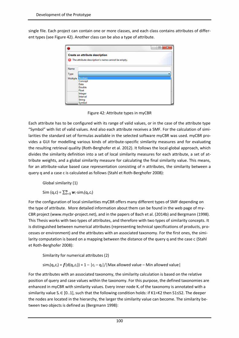
100
Development of the Prototype
single file. Each project can contain one or more classes, and each class contains attributes of differ-ent types (see Figure 42). Another class can be also a type of attribute.
Figure 42: Attribute types in myCBR
Each attribute has to be configured with its range of valid values, or in the case of the attribute type “Symbol” with list of valid values. And also each attribute receives a SMF. For the calculation of simi-larities the standard set of formulas available in the selected software myCBR was used. myCBR pro-vides a GUI for modelling various kinds of attribute-specific similarity measures and for evaluating the resulting retrieval quality (Roth-Berghofer et al. 2012). It follows the local-global approach, which divides the similarity definition into a set of local similarity measures for each attribute, a set of at-tribute weights, and a global similarity measure for calculating the final similarity value. This means, for an attribute-value based case representation consisting of n attributes, the similarity between a query q and a case c is calculated as follows (Stahl et Roth-Berghofer 2008):
Global similarity (1)
Sim (q,c) = ∑ i·simi(qi,ci)
For the configuration of local similarities myCBR offers many different types of SMF depending on the type of attribute. More detailed information about them can be found in the web page of my-CBR project (www.mycbr-project.net), and in the papers of Bach et al. (2014b) and Bergmann (1998). This Thesis works with two types of attributes, and therefore with two types of similarity concepts. It is distinguished between numerical attributes (representing technical specifications of products, pro-cesses or environment) and the attributes with an associated taxonomy. For the first ones, the simi-larity computation is based on a mapping between the distance of the query q and the case c (Stahl et Roth-Berghofer 2008):
Similarity for numerical attributes (2)
simi(qi,ci) = (d(qi,ci)) = 1 – |ci – qi|/|Max allowed value – Min allowed value|
For the attributes with an associated taxonomy, the similarity calculation is based on the relative position of query and case values within the taxonomy. For this purpose, the defined taxonomies are enhanced in myCBR with similarity values. Every inner node Ki of the taxonomy is annotated with a similarity value Si ∈ [0..1], such that the following condition holds: if K1>K2 then S1≤S2. The deeper the nodes are located in the hierarchy, the larger the similarity value can become. The similarity be-tween two objects is defined as (Bergmann 1998):
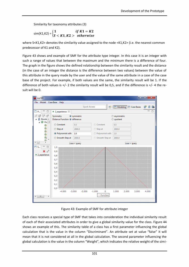
101
Development of the Prototype
Similarity for taxonomy attributes (3)
sim(K1,K2) = =< , >
where S<K1,K2> denotes the similarity value assigned to the node <K1,K2> (i.e. the nearest common predecessor of K1 and K2).
Figure 43 shows and example of SMF for the attribute type integer. In this case it is an integer with such a range of values that between the maximum and the minimum there is a difference of four. The graph in the figure shows the defined relationship between the similarity result and the distance (in the case of an integer the distance is the difference between two values) between the value of this attribute in the query made by the user and the value of the same attribute in a case of the case base of the project. For example, if both values are the same, the similarity result will be 1. If the difference of both values is +/- 2 the similarity result will be 0,5, and if the difference is +/- 4 the re-sult will be 0.
Figure 43: Example of SMF for attribute integer
Each class receives a special type of SMF that takes into consideration the individual similarity result of each of their associated attributes in order to give a global similarity value for the class. Figure 44 shows an example of this. The similarity table of a class has a first parameter influencing the global calculation that is the value in the column “Discriminant”. An attribute set at value “false” it will mean that it is not considered at all in the global calculation. The second parameter influencing the global calculation is the value in the column “Weight”, which indicates the relative weight of the simi-
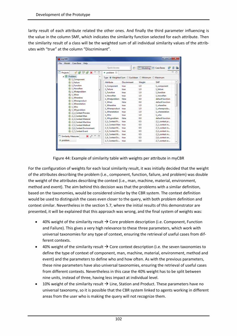
102
Development of the Prototype
larity result of each attribute related the other ones. And finally the third parameter influencing is the value in the column SMF, which indicates the similarity function selected for each attribute. Then the similarity result of a class will be the weighted sum of all individual similarity values of the attrib-utes with “true” at the column “Discriminant”.
Figure 44: Example of similarity table with weights per attribute in myCBR
For the configuration of weights for each local similarity result, it was initially decided that the weight of the attributes describing the problem (i.e., component, function, failure, and problem) was double the weight of the attributes describing the context (i.e., man, machine, material, environment, method and event). The aim behind this decision was that the problems with a similar definition, based on the taxonomies, would be considered similar by the CBR system. The context definition would be used to distinguish the cases even closer to the query, with both problem definition and context similar. Nevertheless in the section 5.7, where the initial results of this demonstrator are presented, it will be explained that this approach was wrong, and the final system of weights was:
40% weight of the similarity result Core problem description (i.e. Component, Function and Failure). This gives a very high relevance to these three parameters, which work with universal taxonomies for any type of context, ensuring the retrieval of useful cases from dif-ferent contexts.
40% weight of the similarity result Core context description (i.e. the seven taxonomies to define the type of context of component, man, machine, material, environment, method and event) and the parameters to define who and how often. As with the previous parameters, these nine parameters have also universal taxonomies, ensuring the retrieval of useful cases from different contexts. Nevertheless in this case the 40% weight has to be split between nine units, instead of three, having less impact at individual level.
10% weight of the similarity result Line, Station and Product. These parameters have no universal taxonomy, so it is possible that the CBR system linked to agents working in different areas from the user who is making the query will not recognize them.
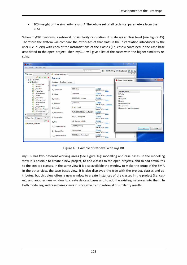
103
Development of the Prototype
10% weight of the similarity result The whole set of all technical parameters from the PLM.
When myCBR performs a retrieval, or similarity calculation, it is always at class level (see Figure 45). Therefore the system will compare the attributes of that class in the instantiation introduced by the user (i.e. query) with each of the instantiations of the classes (i.e. cases) contained in the case base associated to the open project. Then myCBR will give a list of the cases with the higher similarity re-sults.
Figure 45: Example of retrieval with myCBR
myCBR has two different working areas (see Figure 46): modelling and case bases. In the modelling view it is possible to create a new project, to add classes to the open projects, and to add attributes to the created classes. In the same view it is also available the window to make the setup of the SMF. In the other view, the case bases view, it is also displayed the tree with the project, classes and at-tributes, but this view offers a new window to create instances of the classes in the project (i.e. cas-es), and another new window to create de case bases and to add the existing instances into them. In both modelling and case bases views it is possible to run retrieval of similarity results.
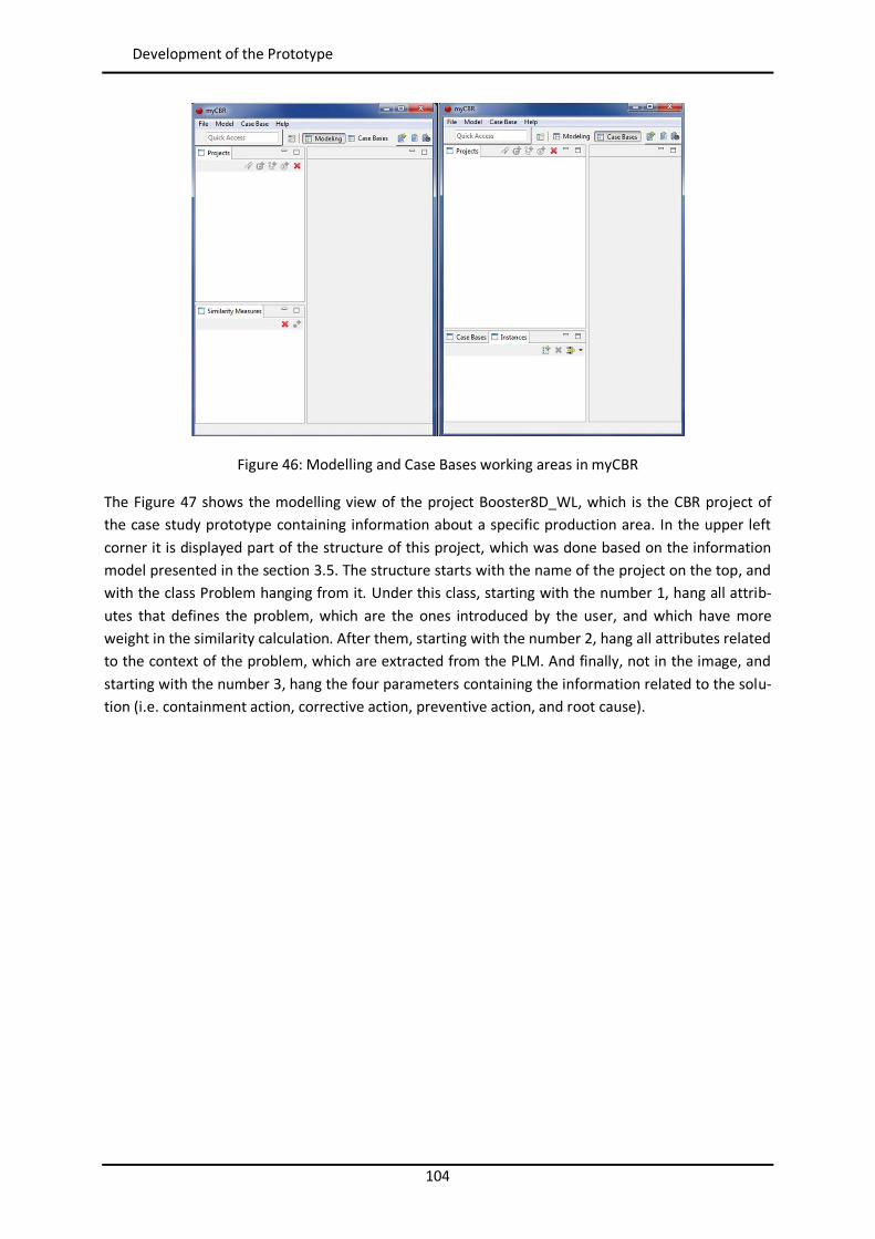
104
Development of the Prototype
Figure 46: Modelling and Case Bases working areas in myCBR
The Figure 47 shows the modelling view of the project Booster8D_WL, which is the CBR project of the case study prototype containing information about a specific production area. In the upper left corner it is displayed part of the structure of this project, which was done based on the information model presented in the section 3.5. The structure starts with the name of the project on the top, and with the class Problem hanging from it. Under this class, starting with the number 1, hang all attrib-utes that defines the problem, which are the ones introduced by the user, and which have more weight in the similarity calculation. After them, starting with the number 2, hang all attributes related to the context of the problem, which are extracted from the PLM. And finally, not in the image, and starting with the number 3, hang the four parameters containing the information related to the solu-tion (i.e. containment action, corrective action, preventive action, and root cause).
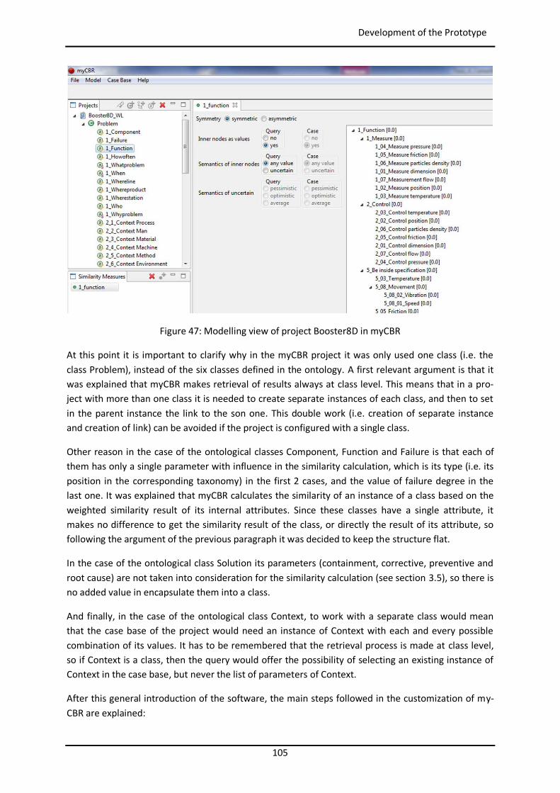
105
Development of the Prototype
Figure 47: Modelling view of project Booster8D in myCBR
At this point it is important to clarify why in the myCBR project it was only used one class (i.e. the class Problem), instead of the six classes defined in the ontology. A first relevant argument is that it was explained that myCBR makes retrieval of results always at class level. This means that in a pro-ject with more than one class it is needed to create separate instances of each class, and then to set in the parent instance the link to the son one. This double work (i.e. creation of separate instance and creation of link) can be avoided if the project is configured with a single class.
Other reason in the case of the ontological classes Component, Function and Failure is that each of them has only a single parameter with influence in the similarity calculation, which is its type (i.e. its position in the corresponding taxonomy) in the first 2 cases, and the value of failure degree in the last one. It was explained that myCBR calculates the similarity of an instance of a class based on the weighted similarity result of its internal attributes. Since these classes have a single attribute, it makes no difference to get the similarity result of the class, or directly the result of its attribute, so following the argument of the previous paragraph it was decided to keep the structure flat.
In the case of the ontological class Solution its parameters (containment, corrective, preventive and root cause) are not taken into consideration for the similarity calculation (see section 3.5), so there is no added value in encapsulate them into a class.
And finally, in the case of the ontological class Context, to work with a separate class would mean that the case base of the project would need an instance of Context with each and every possible combination of its values. It has to be remembered that the retrieval process is made at class level, so if Context is a class, then the query would offer the possibility of selecting an existing instance of Context in the case base, but never the list of parameters of Context.
After this general introduction of the software, the main steps followed in the customization of my-CBR are explained:
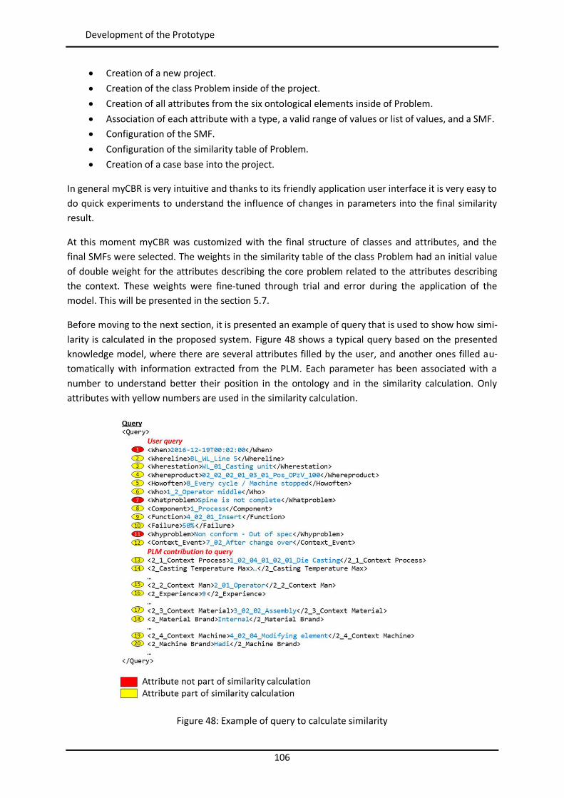
106
Development of the Prototype
Creation of a new project. Creation of the class Problem inside of the project. Creation of all attributes from the six ontological elements inside of Problem. Association of each attribute with a type, a valid range of values or list of values, and a SMF. Configuration of the SMF. Configuration of the similarity table of Problem. Creation of a case base into the project.
In general myCBR is very intuitive and thanks to its friendly application user interface it is very easy to do quick experiments to understand the influence of changes in parameters into the final similarity result.
At this moment myCBR was customized with the final structure of classes and attributes, and the final SMFs were selected. The weights in the similarity table of the class Problem had an initial value of double weight for the attributes describing the core problem related to the attributes describing the context. These weights were fine-tuned through trial and error during the application of the model. This will be presented in the section 5.7.
Before moving to the next section, it is presented an example of query that is used to show how simi-larity is calculated in the proposed system. Figure 48 shows a typical query based on the presented knowledge model, where there are several attributes filled by the user, and another ones filled au-tomatically with information extracted from the PLM. Each parameter has been associated with a number to understand better their position in the ontology and in the similarity calculation. Only attributes with yellow numbers are used in the similarity calculation.
Figure 48: Example of query to calculate similarity
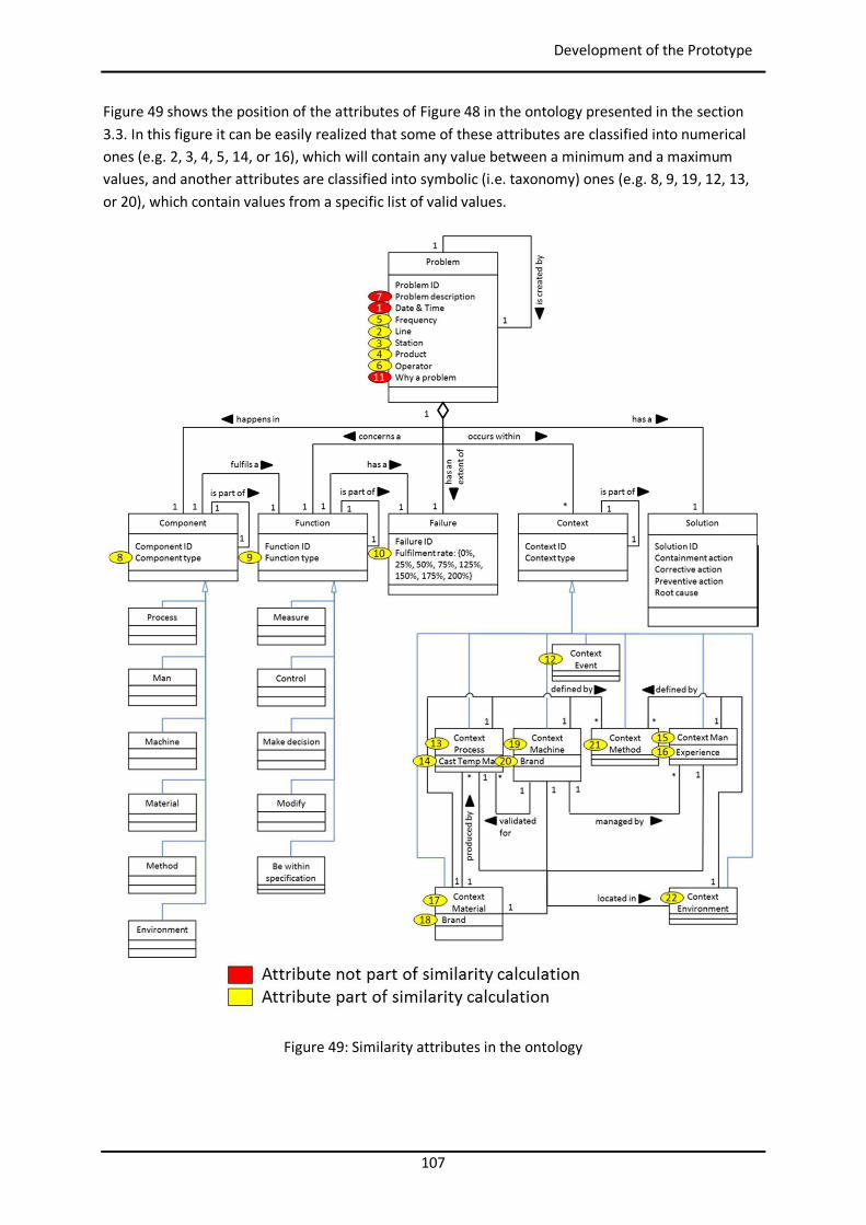
107
Development of the Prototype
Figure 49 shows the position of the attributes of Figure 48 in the ontology presented in the section 3.3. In this figure it can be easily realized that some of these attributes are classified into numerical ones (e.g. 2, 3, 4, 5, 14, or 16), which will contain any value between a minimum and a maximum values, and another attributes are classified into symbolic (i.e. taxonomy) ones (e.g. 8, 9, 19, 12, 13, or 20), which contain values from a specific list of valid values.
Figure 49: Similarity attributes in the ontology
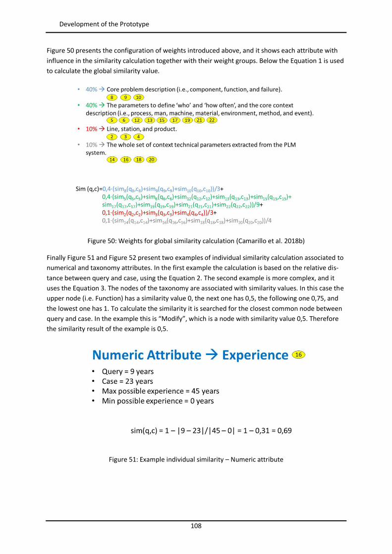
108
Development of the Prototype
Figure 50 presents the configuration of weights introduced above, and it shows each attribute with influence in the similarity calculation together with their weight groups. Below the Equation 1 is used to calculate the global similarity value.
Figure 50: Weights for global similarity calculation (Camarillo et al. 2018b)
Finally Figure 51 and Figure 52 present two examples of individual similarity calculation associated to numerical and taxonomy attributes. In the first example the calculation is based on the relative dis-tance between query and case, using the Equation 2. The second example is more complex, and it uses the Equation 3. The nodes of the taxonomy are associated with similarity values. In this case the upper node (i.e. Function) has a similarity value 0, the next one has 0,5, the following one 0,75, and the lowest one has 1. To calculate the similarity it is searched for the closest common node between query and case. In the example this is “Modify”, which is a node with similarity value 0,5. Therefore the similarity result of the example is 0,5.
Figure 51: Example individual similarity – Numeric attribute
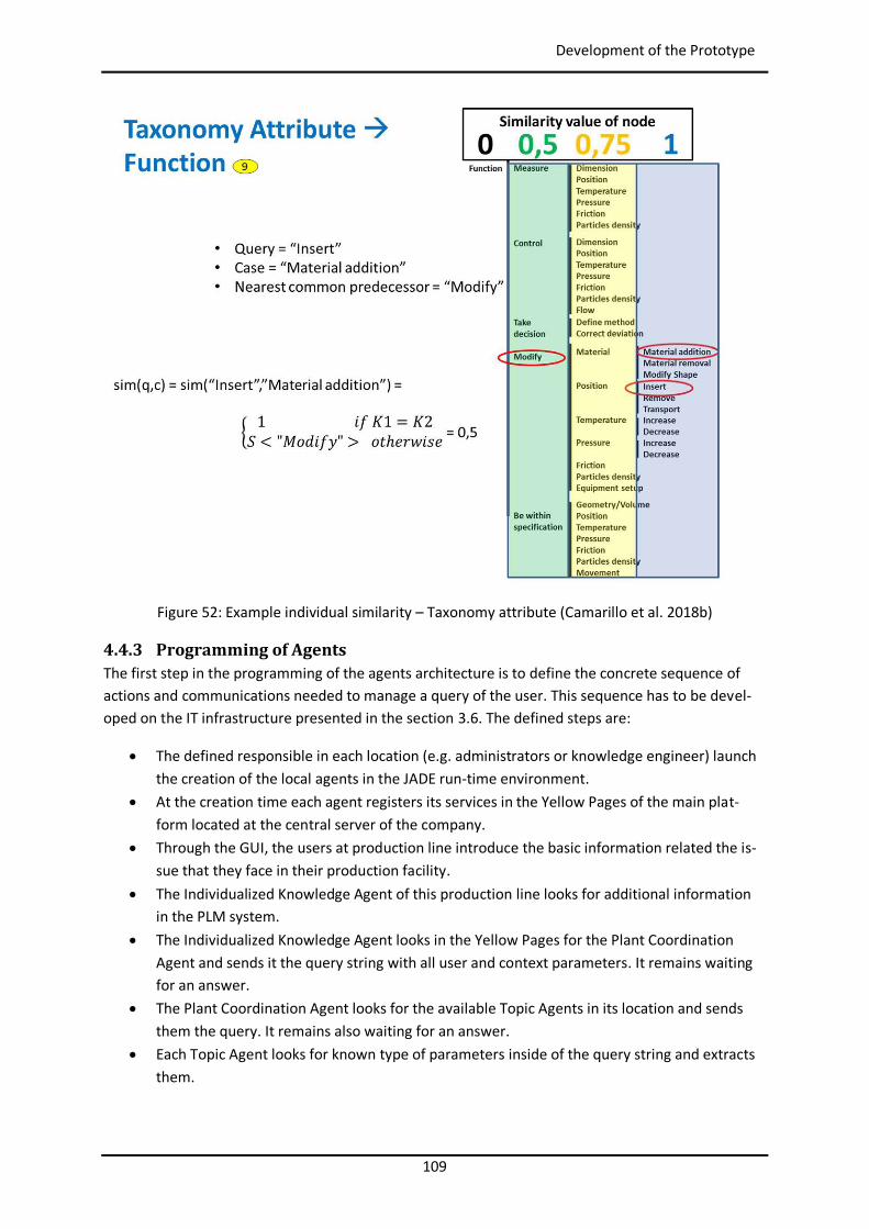
109
Development of the Prototype
Figure 52: Example individual similarity – Taxonomy attribute (Camarillo et al. 2018b)
4.4.3 Programming of Agents The first step in the programming of the agents architecture is to define the concrete sequence of actions and communications needed to manage a query of the user. This sequence has to be devel-oped on the IT infrastructure presented in the section 3.6. The defined steps are:
The defined responsible in each location (e.g. administrators or knowledge engineer) launch the creation of the local agents in the JADE run-time environment.
At the creation time each agent registers its services in the Yellow Pages of the main plat-form located at the central server of the company.
Through the GUI, the users at production line introduce the basic information related the is-sue that they face in their production facility.
The Individualized Knowledge Agent of this production line looks for additional information in the PLM system.
The Individualized Knowledge Agent looks in the Yellow Pages for the Plant Coordination Agent and sends it the query string with all user and context parameters. It remains waiting for an answer.
The Plant Coordination Agent looks for the available Topic Agents in its location and sends them the query. It remains also waiting for an answer.
Each Topic Agent looks for known type of parameters inside of the query string and extracts them.
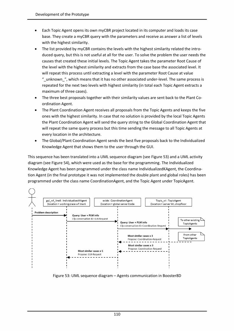
110
Development of the Prototype
Each Topic Agent opens its own myCBR project located in its computer and loads its case base. They create a myCBR query with the parameters and receive as answer a list of levels with the highest similarity.
The list provided by myCBR contains the levels with the highest similarity related the intro-duced query, but this is not useful at all for the user. To solve the problem the user needs the causes that created these initial levels. The Topic Agent takes the parameter Root Cause of the level with the highest similarity and extracts from the case base the associated level. It will repeat this process until extracting a level with the parameter Root Cause at value “_unknown_”, which means that it has no other associated under-level. The same process is repeated for the next two levels with highest similarity (in total each Topic Agent extracts a maximum of three cases).
The three best proposals together with their similarity values are sent back to the Plant Co-ordination Agent.
The Plant Coordination Agent receives all proposals from the Topic Agents and keeps the five ones with the highest similarity. In case that no solution is provided by the local Topic Agents the Plant Coordination Agent will send the query string to the Global Coordination Agent that will repeat the same query process but this time sending the message to all Topic Agents at every location in the architecture.
The Global/Plant Coordination Agent sends the best five proposals back to the Individualized Knowledge Agent that shows them to the user through the GUI.
This sequence has been translated into a UML sequence diagram (see Figure 53) and a UML activity diagram (see Figure 54), which were used as the base for the programming. The Individualized Knowledge Agent has been programmed under the class name IndividualizedKAgent, the Coordina-tion Agent (in the final prototype it was not implemented the double plant and global roles) has been programmed under the class name CoordinationAgent, and the Topic Agent under TopicAgent.
Figure 53: UML sequence diagram – Agents communication in Booster8D
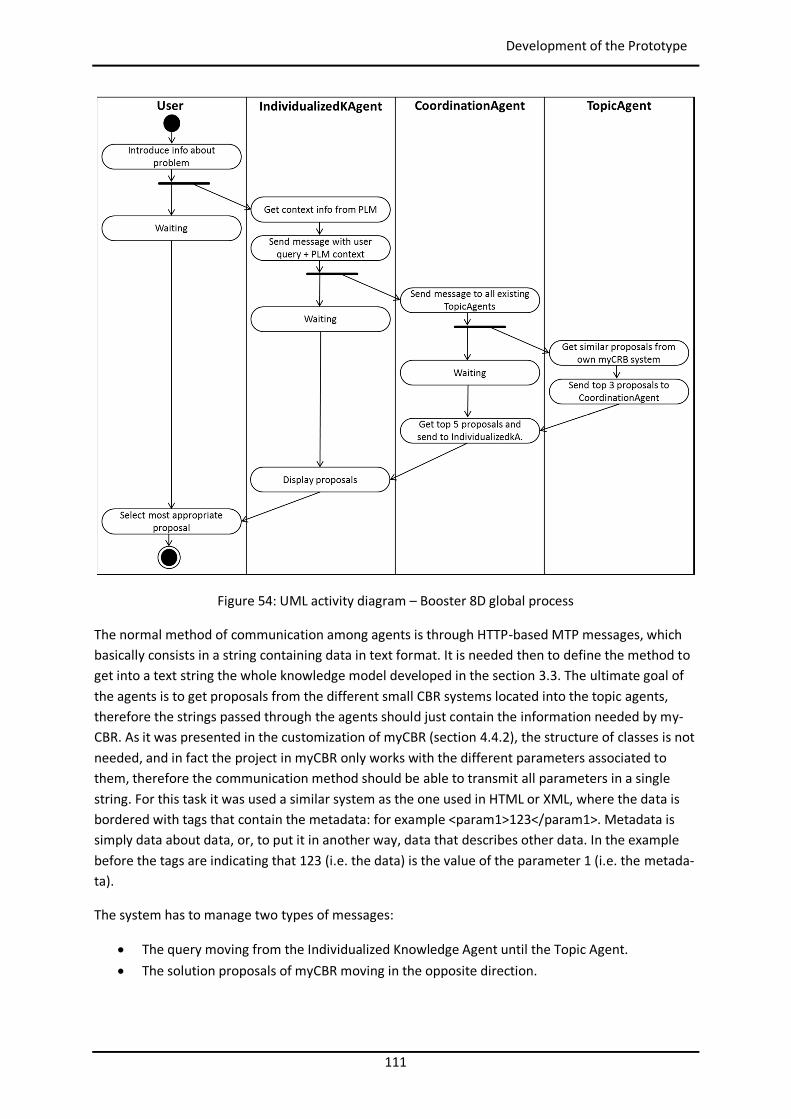
111
Development of the Prototype
Figure 54: UML activity diagram – Booster 8D global process
The normal method of communication among agents is through HTTP-based MTP messages, which basically consists in a string containing data in text format. It is needed then to define the method to get into a text string the whole knowledge model developed in the section 3.3. The ultimate goal of the agents is to get proposals from the different small CBR systems located into the topic agents, therefore the strings passed through the agents should just contain the information needed by my-CBR. As it was presented in the customization of myCBR (section 4.4.2), the structure of classes is not needed, and in fact the project in myCBR only works with the different parameters associated to them, therefore the communication method should be able to transmit all parameters in a single string. For this task it was used a similar system as the one used in HTML or XML, where the data is bordered with tags that contain the metadata: for example <param1>123</param1>. Metadata is simply data about data, or, to put it in another way, data that describes other data. In the example before the tags are indicating that 123 (i.e. the data) is the value of the parameter 1 (i.e. the metada-ta).
The system has to manage two types of messages:
The query moving from the Individualized Knowledge Agent until the Topic Agent. The solution proposals of myCBR moving in the opposite direction.
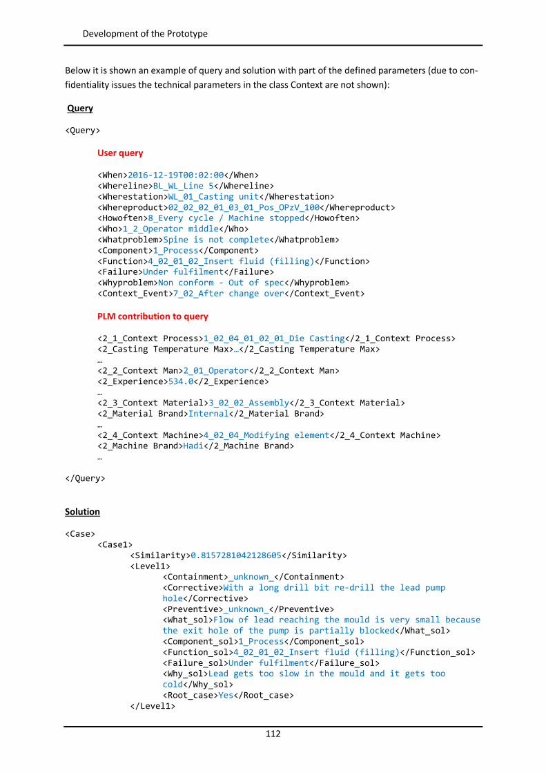
112
Development of the Prototype
Below it is shown an example of query and solution with part of the defined parameters (due to con-fidentiality issues the technical parameters in the class Context are not shown):
Query
<Query>
User query
<When>2016-12-19T00:02:00</When> <Whereline>BL_WL_Line 5</Whereline> <Wherestation>WL_01_Casting unit</Wherestation> <Whereproduct>02_02_02_01_03_01_Pos_OPzV_100</Whereproduct> <Howoften>8_Every cycle / Machine stopped</Howoften> <Who>1_2_Operator middle</Who> <Whatproblem>Spine is not complete</Whatproblem> <Component>1_Process</Component> <Function>4_02_01_02_Insert fluid (filling)</Function> <Failure>Under fulfilment</Failure> <Whyproblem>Non conform - Out of spec</Whyproblem> <Context_Event>7_02_After change over</Context_Event> PLM contribution to query
<2_1_Context Process>1_02_04_01_02_01_Die Casting</2_1_Context Process> <2_Casting Temperature Max>…</2_Casting Temperature Max> … <2_2_Context Man>2_01_Operator</2_2_Context Man> <2_Experience>534.0</2_Experience> … <2_3_Context Material>3_02_02_Assembly</2_3_Context Material> <2_Material Brand>Internal</2_Material Brand> … <2_4_Context Machine>4_02_04_Modifying element</2_4_Context Machine> <2_Machine Brand>Hadi</2_Machine Brand> …
</Query> Solution
<Case> <Case1>
<Similarity>0.8157281042128605</Similarity> <Level1>
<Containment>_unknown_</Containment> <Corrective>With a long drill bit re-drill the lead pump hole</Corrective> <Preventive>_unknown_</Preventive> <What_sol>Flow of lead reaching the mould is very small because the exit hole of the pump is partially blocked</What_sol> <Component_sol>1_Process</Component_sol> <Function_sol>4_02_01_02_Insert fluid (filling)</Function_sol> <Failure_sol>Under fulfilment</Failure_sol> <Why_sol>Lead gets too slow in the mould and it gets too cold</Why_sol> <Root_case>Yes</Root_case>
</Level1>
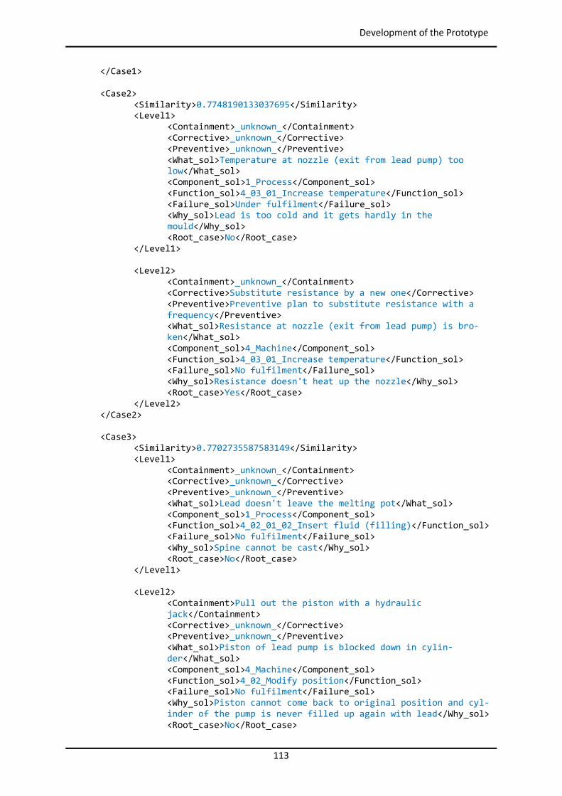
113
Development of the Prototype
</Case1> <Case2>
<Similarity>0.7748190133037695</Similarity> <Level1>
<Containment>_unknown_</Containment> <Corrective>_unknown_</Corrective> <Preventive>_unknown_</Preventive> <What_sol>Temperature at nozzle (exit from lead pump) too low</What_sol> <Component_sol>1_Process</Component_sol> <Function_sol>4_03_01_Increase temperature</Function_sol> <Failure_sol>Under fulfilment</Failure_sol> <Why_sol>Lead is too cold and it gets hardly in the mould</Why_sol> <Root_case>No</Root_case>
</Level1> <Level2>
<Containment>_unknown_</Containment> <Corrective>Substitute resistance by a new one</Corrective> <Preventive>Preventive plan to substitute resistance with a frequency</Preventive> <What_sol>Resistance at nozzle (exit from lead pump) is bro-ken</What_sol> <Component_sol>4_Machine</Component_sol> <Function_sol>4_03_01_Increase temperature</Function_sol> <Failure_sol>No fulfilment</Failure_sol> <Why_sol>Resistance doesn't heat up the nozzle</Why_sol> <Root_case>Yes</Root_case>
</Level2> </Case2> <Case3>
<Similarity>0.7702735587583149</Similarity> <Level1>
<Containment>_unknown_</Containment> <Corrective>_unknown_</Corrective> <Preventive>_unknown_</Preventive> <What_sol>Lead doesn't leave the melting pot</What_sol> <Component_sol>1_Process</Component_sol> <Function_sol>4_02_01_02_Insert fluid (filling)</Function_sol> <Failure_sol>No fulfilment</Failure_sol> <Why_sol>Spine cannot be cast</Why_sol> <Root_case>No</Root_case>
</Level1> <Level2>
<Containment>Pull out the piston with a hydraulic jack</Containment> <Corrective>_unknown_</Corrective> <Preventive>_unknown_</Preventive> <What_sol>Piston of lead pump is blocked down in cylin-der</What_sol> <Component_sol>4_Machine</Component_sol> <Function_sol>4_02_Modify position</Function_sol> <Failure_sol>No fulfilment</Failure_sol> <Why_sol>Piston cannot come back to original position and cyl-inder of the pump is never filled up again with lead</Why_sol> <Root_case>No</Root_case>
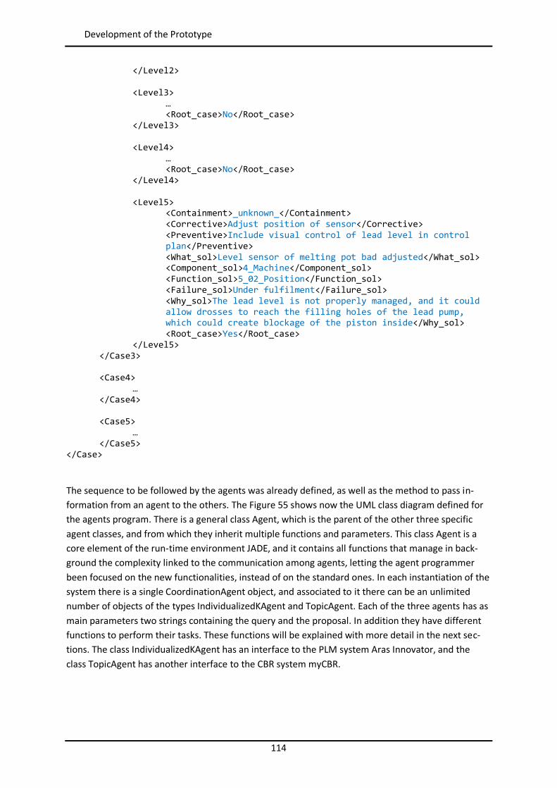
114
Development of the Prototype
</Level2> <Level3>
… <Root_case>No</Root_case>
</Level3> <Level4>
… <Root_case>No</Root_case>
</Level4> <Level5>
<Containment>_unknown_</Containment> <Corrective>Adjust position of sensor</Corrective> <Preventive>Include visual control of lead level in control plan</Preventive> <What_sol>Level sensor of melting pot bad adjusted</What_sol> <Component_sol>4_Machine</Component_sol> <Function_sol>5_02_Position</Function_sol> <Failure_sol>Under fulfilment</Failure_sol> <Why_sol>The lead level is not properly managed, and it could allow drosses to reach the filling holes of the lead pump, which could create blockage of the piston inside</Why_sol> <Root_case>Yes</Root_case>
</Level5> </Case3> <Case4> … </Case4> <Case5> … </Case5>
</Case>
The sequence to be followed by the agents was already defined, as well as the method to pass in-formation from an agent to the others. The Figure 55 shows now the UML class diagram defined for the agents program. There is a general class Agent, which is the parent of the other three specific agent classes, and from which they inherit multiple functions and parameters. This class Agent is a core element of the run-time environment JADE, and it contains all functions that manage in back-ground the complexity linked to the communication among agents, letting the agent programmer been focused on the new functionalities, instead of on the standard ones. In each instantiation of the system there is a single CoordinationAgent object, and associated to it there can be an unlimited number of objects of the types IndividualizedKAgent and TopicAgent. Each of the three agents has as main parameters two strings containing the query and the proposal. In addition they have different functions to perform their tasks. These functions will be explained with more detail in the next sec-tions. The class IndividualizedKAgent has an interface to the PLM system Aras Innovator, and the class TopicAgent has another interface to the CBR system myCBR.
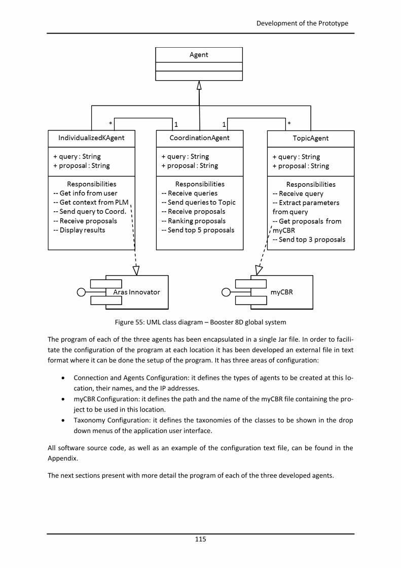
115
Development of the Prototype
Figure 55: UML class diagram – Booster 8D global system
The program of each of the three agents has been encapsulated in a single Jar file. In order to facili-tate the configuration of the program at each location it has been developed an external file in text format where it can be done the setup of the program. It has three areas of configuration:
Connection and Agents Configuration: it defines the types of agents to be created at this lo-cation, their names, and the IP addresses.
myCBR Configuration: it defines the path and the name of the myCBR file containing the pro-ject to be used in this location.
Taxonomy Configuration: it defines the taxonomies of the classes to be shown in the drop down menus of the application user interface.
All software source code, as well as an example of the configuration text file, can be found in the Appendix.
The next sections present with more detail the program of each of the three developed agents.
116
Development of the Prototype
4.4.3.1 IndividualizedKAgent The IndividualizedKAgent is in charge of managing the interactions with the users through its GUI, and with the PLM Aras Innovator through the interface based on HTTP messages written in AML lan-guage.
The Figure 56 presents the UML class diagram of the IndividualizedKAgent, which inherits parameters and functions from its class parent Agent. It owns the class SimilarityRequestGUI, and has relation-ships with the classes PLMrequest_Manager and Booster8D_GUI. In each running system there is a single instantiation of each of the four classes.
The class IndividualizedKAgent has two relevant parameters of type String: the query and the pro-posal. Query contains the query introduced by the user plus the context information extracted from the PLM. The query string is sent to the coordination agent. The proposal, which is received back from the coordination agent, contains the proposals from the Topic Agents.
The class IndividualizedKAgent has following responsibilities:
To register its services in the yellow pages of the JADE platform. To instantiate the object of the class SimilarityRequestGUI that will manage the communica-
tion with the coordination agent. To instantiate the object of the class Booster8D_GUI that will manage the GUI with the shape
of a PSS to communicate with the user. To instantiate the object of the class PLMrequest_Manager that will manage the communica-
tion with the PLM system extracting the context information related the user’s query. To send the global query containing both user and PLM information to the instantiated ob-
ject of the class SimilarityRequestGUI.
The class Booster8D_GUI inherits from the class JFrame all graphical functionalities associated to a normal window of any application, and the class CyclicBehaviour (see section 2.5.1) is used as parent of SimilarityRequestGUI because when it sends the cfd message with the global query to the coordi-nation agent has to remain waiting for an answer.
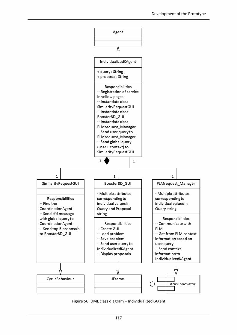
117
Development of the Prototype
Figure 56: UML class diagram – IndividualizedKAgent
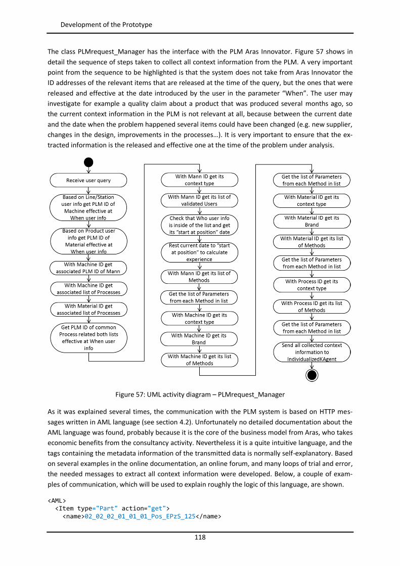
118
Development of the Prototype
The class PLMrequest_Manager has the interface with the PLM Aras Innovator. Figure 57 shows in detail the sequence of steps taken to collect all context information from the PLM. A very important point from the sequence to be highlighted is that the system does not take from Aras Innovator the ID addresses of the relevant items that are released at the time of the query, but the ones that were released and effective at the date introduced by the user in the parameter “When”. The user may investigate for example a quality claim about a product that was produced several months ago, so the current context information in the PLM is not relevant at all, because between the current date and the date when the problem happened several items could have been changed (e.g. new supplier, changes in the design, improvements in the processes…). It is very important to ensure that the ex-tracted information is the released and effective one at the time of the problem under analysis.
Figure 57: UML activity diagram – PLMrequest_Manager
As it was explained several times, the communication with the PLM system is based on HTTP mes-sages written in AML language (see section 4.2). Unfortunately no detailed documentation about the AML language was found, probably because it is the core of the business model from Aras, who takes economic benefits from the consultancy activity. Nevertheless it is a quite intuitive language, and the tags containing the metadata information of the transmitted data is normally self-explanatory. Based on several examples in the online documentation, an online forum, and many loops of trial and error, the needed messages to extract all context information were developed. Below, a couple of exam-ples of communication, which will be used to explain roughly the logic of this language, are shown.
<AML> <Item type="Part" action="get"> <name>02_02_02_01_01_01_Pos_EPzS_125</name>
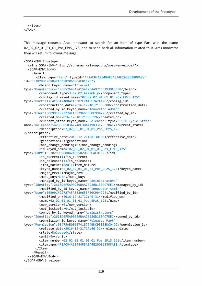
119
Development of the Prototype
</Item> </AML>
This message requests Aras Innovator to search for an item of type Part with the name 02_02_02_01_01_01_Pos_EPzS_125, and to send back all information related to it. Aras Innovator then will return following message:
<SOAP-ENV:Envelope xmlns:SOAP-ENV="http://schemas.xmlsoap.org/soap/envelope/"> <SOAP-ENV:Body> <Result>
<Item type="Part" typeId="4F1AC04A2B484F3ABA4E20DB63808A88" id="3F3829DC968D421DB58206C0CAC01F2F"> <brand keyed_name="Internal" type="Manufacturer">6E5264B47A154E2DAA97CECA939A5E9B</brand> <component_type>3_02_02_Assembly</component_type> <config_id keyed_name="02_02_02_01_01_01_Pos_EPzS_125" type="Part">A7E4C5342A0B4CAEBB7E2A46F2A7A126</config_id> <construction_date>2016-12-10T21:30:00</construction_date> <created_by_id keyed_name="Innovator Admin" type="User">30B991F927274FA3829655F50C99472E</created_by_id> <created_on>2016-12-10T21:53:19</created_on> <current_state keyed_name="Released" type="Life Cycle State" name="Released">42BB3B183A7748C3B4AA9D33F7BF70AC</current_state> <description>02_02_02_01_01_01_Pos_EPzS_125 </description> <effective_date>2016-12-21T08:30:00</effective_date> <generation>3</generation> <has_change_pending>0</has_change_pending> <id keyed_name="02_02_02_01_01_01_Pos_EPzS_125" type="Part">3F3829DC968D421DB58206C0CAC01F2F</id> <is_current>1</is_current> <is_released>1</is_released> <item_nature>Real</item_nature> <keyed_name>02_02_02_01_01_01_Pos_EPzS_125</keyed_name> <major_rev>B</major_rev> <make_buy>Make</make_buy> <managed_by_id keyed_name="Administrators" type="Identity">2618D6F5A90949BAA7E920D1B04C7EE1</managed_by_id> <modified_by_id keyed_name="Innovator Admin" type="User">30B991F927274FA3829655F50C99472E</modified_by_id> <modified_on>2016-12-21T17:46:31</modified_on> <name>02_02_02_01_01_01_Pos_EPzS_125</name> <new_version>0</new_version> <not_lockable>0</not_lockable> <owned_by_id keyed_name="Administrators" type="Identity">2618D6F5A90949BAA7E920D1B04C7EE1</owned_by_id> <permission_id keyed_name="Released Part" type="Permission">95475AE006E7415794BDC93808DC04D2</permission_id> <release_date>2016-12-21T17:46:31</release_date> <state>Released</state> <unit>EA</unit> <item_number>02_02_02_01_01_01_Pos_EPzS_125</item_number> <itemtype>4F1AC04A2B484F3ABA4E20DB63808A88</itemtype> </Item> </Result> </SOAP-ENV:Body> </SOAP-ENV:Envelope>
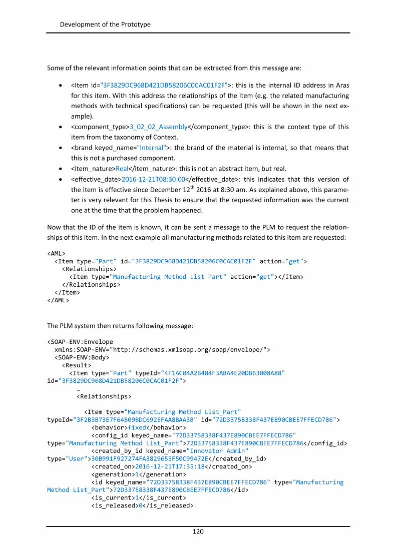
120
Development of the Prototype
Some of the relevant information points that can be extracted from this message are:
<Item id="3F3829DC968D421DB58206C0CAC01F2F">: this is the internal ID address in Aras for this item. With this address the relationships of the item (e.g. the related manufacturing methods with technical specifications) can be requested (this will be shown in the next ex-ample).
<component_type>3_02_02_Assembly</component_type>: this is the context type of this item from the taxonomy of Context.
<brand keyed_name="Internal">: the brand of the material is internal, so that means that this is not a purchased component.
<item_nature>Real</item_nature>: this is not an abstract item, but real. <effective_date>2016-12-21T08:30:00</effective_date>: this indicates that this version of
the item is effective since December 12th 2016 at 8:30 am. As explained above, this parame-ter is very relevant for this Thesis to ensure that the requested information was the current one at the time that the problem happened.
Now that the ID of the item is known, it can be sent a message to the PLM to request the relation-ships of this item. In the next example all manufacturing methods related to this item are requested:
<AML> <Item type="Part" id="3F3829DC968D421DB58206C0CAC01F2F" action="get"> <Relationships> <Item type="Manufacturing Method List_Part" action="get"></Item> </Relationships> </Item> </AML>
The PLM system then returns following message:
<SOAP-ENV:Envelope xmlns:SOAP-ENV="http://schemas.xmlsoap.org/soap/envelope/"> <SOAP-ENV:Body> <Result> <Item type="Part" typeId="4F1AC04A2B484F3ABA4E20DB63808A88" id="3F3829DC968D421DB58206C0CAC01F2F"> … <Relationships> <Item type="Manufacturing Method List_Part" typeId="3F2B3B73E7F64B09BDC692EFAA8BAA3B" id="72D33758338F437E890CBEE7FFECD786"> <behavior>fixed</behavior> <config_id keyed_name="72D33758338F437E890CBEE7FFECD786" type="Manufacturing Method List_Part">72D33758338F437E890CBEE7FFECD786</config_id> <created_by_id keyed_name="Innovator Admin" type="User">30B991F927274FA3829655F50C99472E</created_by_id> <created_on>2016-12-21T17:35:18</created_on> <generation>1</generation> <id keyed_name="72D33758338F437E890CBEE7FFECD786" type="Manufacturing Method List_Part">72D33758338F437E890CBEE7FFECD786</id> <is_current>1</is_current> <is_released>0</is_released>
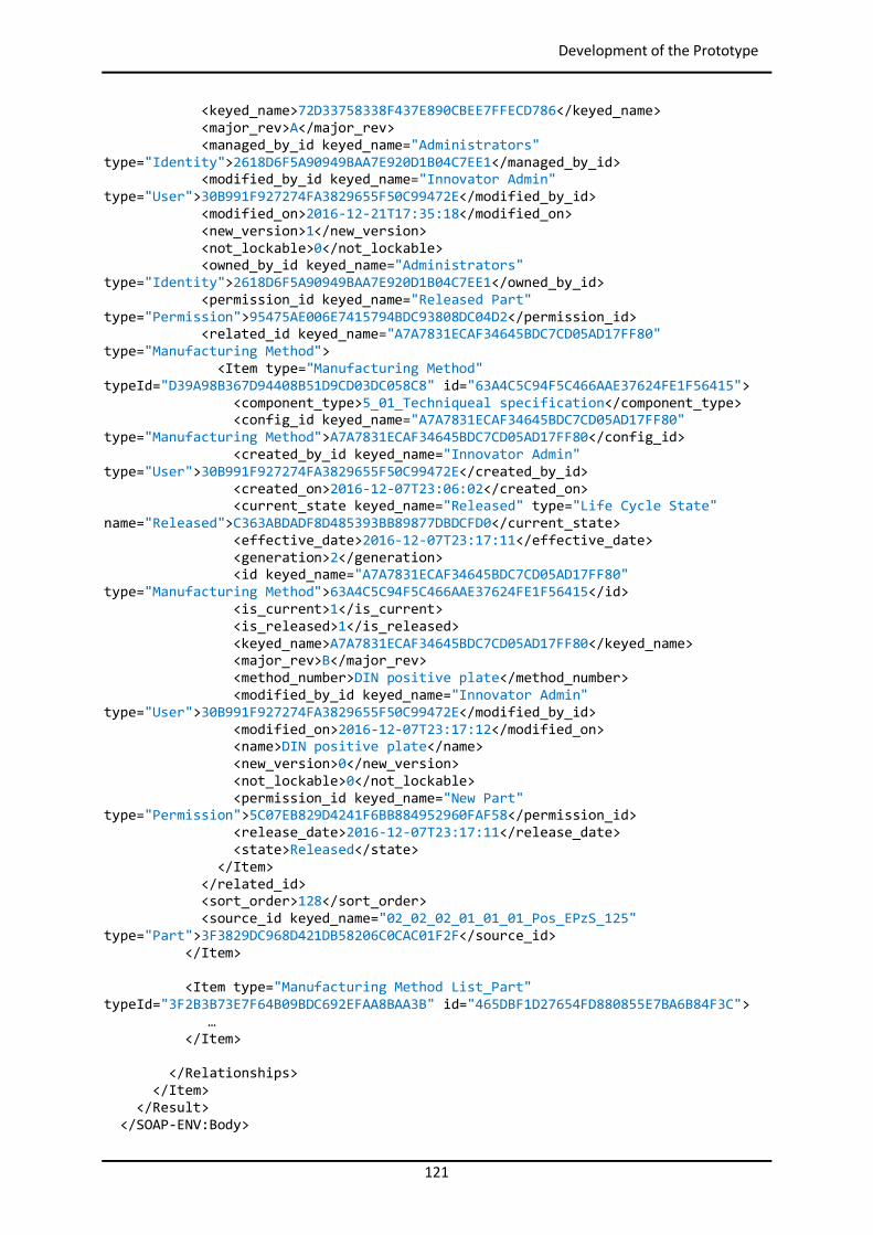
121
Development of the Prototype
<keyed_name>72D33758338F437E890CBEE7FFECD786</keyed_name> <major_rev>A</major_rev> <managed_by_id keyed_name="Administrators" type="Identity">2618D6F5A90949BAA7E920D1B04C7EE1</managed_by_id> <modified_by_id keyed_name="Innovator Admin" type="User">30B991F927274FA3829655F50C99472E</modified_by_id> <modified_on>2016-12-21T17:35:18</modified_on> <new_version>1</new_version> <not_lockable>0</not_lockable> <owned_by_id keyed_name="Administrators" type="Identity">2618D6F5A90949BAA7E920D1B04C7EE1</owned_by_id> <permission_id keyed_name="Released Part" type="Permission">95475AE006E7415794BDC93808DC04D2</permission_id> <related_id keyed_name="A7A7831ECAF34645BDC7CD05AD17FF80" type="Manufacturing Method"> <Item type="Manufacturing Method" typeId="D39A98B367D94408B51D9CD03DC058C8" id="63A4C5C94F5C466AAE37624FE1F56415"> <component_type>5_01_Techniqueal specification</component_type> <config_id keyed_name="A7A7831ECAF34645BDC7CD05AD17FF80" type="Manufacturing Method">A7A7831ECAF34645BDC7CD05AD17FF80</config_id> <created_by_id keyed_name="Innovator Admin" type="User">30B991F927274FA3829655F50C99472E</created_by_id> <created_on>2016-12-07T23:06:02</created_on> <current_state keyed_name="Released" type="Life Cycle State" name="Released">C363ABDADF8D485393BB89877DBDCFD0</current_state> <effective_date>2016-12-07T23:17:11</effective_date> <generation>2</generation> <id keyed_name="A7A7831ECAF34645BDC7CD05AD17FF80" type="Manufacturing Method">63A4C5C94F5C466AAE37624FE1F56415</id> <is_current>1</is_current> <is_released>1</is_released> <keyed_name>A7A7831ECAF34645BDC7CD05AD17FF80</keyed_name> <major_rev>B</major_rev> <method_number>DIN positive plate</method_number> <modified_by_id keyed_name="Innovator Admin" type="User">30B991F927274FA3829655F50C99472E</modified_by_id> <modified_on>2016-12-07T23:17:12</modified_on> <name>DIN positive plate</name> <new_version>0</new_version> <not_lockable>0</not_lockable> <permission_id keyed_name="New Part" type="Permission">5C07EB829D4241F6BB884952960FAF58</permission_id> <release_date>2016-12-07T23:17:11</release_date> <state>Released</state> </Item> </related_id> <sort_order>128</sort_order> <source_id keyed_name="02_02_02_01_01_01_Pos_EPzS_125" type="Part">3F3829DC968D421DB58206C0CAC01F2F</source_id> </Item> <Item type="Manufacturing Method List_Part" typeId="3F2B3B73E7F64B09BDC692EFAA8BAA3B" id="465DBF1D27654FD880855E7BA6B84F3C"> … </Item> </Relationships> </Item> </Result> </SOAP-ENV:Body>
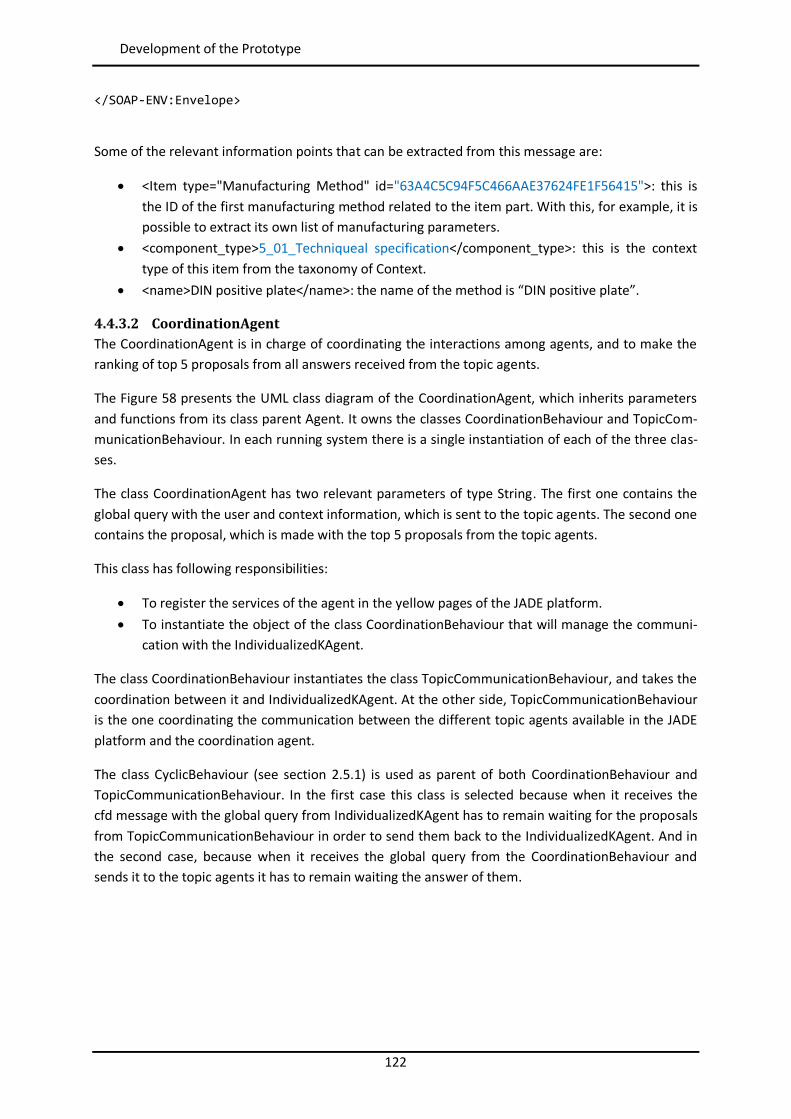
122
Development of the Prototype
</SOAP-ENV:Envelope>
Some of the relevant information points that can be extracted from this message are:
<Item type="Manufacturing Method" id="63A4C5C94F5C466AAE37624FE1F56415">: this is the ID of the first manufacturing method related to the item part. With this, for example, it is possible to extract its own list of manufacturing parameters.
<component_type>5_01_Techniqueal specification</component_type>: this is the context type of this item from the taxonomy of Context.
<name>DIN positive plate</name>: the name of the method is “DIN positive plate”.
4.4.3.2 CoordinationAgent The CoordinationAgent is in charge of coordinating the interactions among agents, and to make the ranking of top 5 proposals from all answers received from the topic agents.
The Figure 58 presents the UML class diagram of the CoordinationAgent, which inherits parameters and functions from its class parent Agent. It owns the classes CoordinationBehaviour and TopicCom-municationBehaviour. In each running system there is a single instantiation of each of the three clas-ses.
The class CoordinationAgent has two relevant parameters of type String. The first one contains the global query with the user and context information, which is sent to the topic agents. The second one contains the proposal, which is made with the top 5 proposals from the topic agents.
This class has following responsibilities:
To register the services of the agent in the yellow pages of the JADE platform. To instantiate the object of the class CoordinationBehaviour that will manage the communi-
cation with the IndividualizedKAgent.
The class CoordinationBehaviour instantiates the class TopicCommunicationBehaviour, and takes the coordination between it and IndividualizedKAgent. At the other side, TopicCommunicationBehaviour is the one coordinating the communication between the different topic agents available in the JADE platform and the coordination agent.
The class CyclicBehaviour (see section 2.5.1) is used as parent of both CoordinationBehaviour and TopicCommunicationBehaviour. In the first case this class is selected because when it receives the cfd message with the global query from IndividualizedKAgent has to remain waiting for the proposals from TopicCommunicationBehaviour in order to send them back to the IndividualizedKAgent. And in the second case, because when it receives the global query from the CoordinationBehaviour and sends it to the topic agents it has to remain waiting the answer of them.
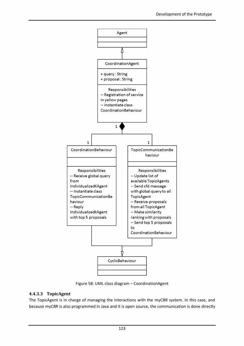
123
Development of the Prototype
Figure 58: UML class diagram – CoordinationAgent
4.4.3.3 TopicAgent The TopicAgent is in charge of managing the interactions with the myCBR system. In this case, and because myCBR is also programmed in Java and it is open source, the communication is done directly
124
Development of the Prototype
through internal Java communication between objects, since the classes of myCBR are instantiated in the source code of the agent.
The Figure 59 presents the UML class diagram of the TopicAgent, and as in the two previous cases, this class inherits also parameters and functions from its class parent Agent. It owns the class Similar-ityRequestTopic, and has relationships with the classes containing the specific myCBR system that is configured for the production area of its topic agent. In the case of this prototype, this is Topi-cAgent_WL, the class with the myCBR system for the Wet Filling Lines area. In each running system there is a single instantiation of each of the classes.
As with the previous classes, the class TopicAgent has query and proposal as relevant parameters of type String. Query contains the global query with the user and context information, which is received from the CoordinationAgent, and proposal that is made with the top 3 proposals of myCBR and it is sent back to the CoordinationAgent.
This class has following responsibilities:
To register the services of the agent in the yellow pages of the JADE platform. To instantiate the object of the class SimilarityRequestTopic that will manage the communi-
cation with the coordination agent, and it will instantiate the object of the class Topi-cAgent_WL.
The class TopicAgent_WL in the case of this prototype is in fact the one providing information about possible solutions to the system, which is received from myCBR. Its main responsibilities are:
To extract all parameters from the global query. To send the order to load the project of that production area in myCBR. This project will con-
tain the general parameters to describe the problems plus the specific context parameters of that area.
To send the order to get the concept “Problem” in the myCBR project for the retrieval pro-cess.
To send the order to get the case base of the project. To launch the retrieval based on the taken concept and case base. To specify the retrieval method, to create the query instance in which are loaded all query
values, and to perform the retrieval. To get the top 3 proposals out of the open myCBR project. To send these top 3 proposals back to SimilarityRequestTopic
The class CyclicBehaviour (see section 2.5.1) is used as parent of SimilarityRequestTopic because, when it receives the cfd message with the global query from the coordination agent, it has to remain waiting for an answer from the topic agent specific of the production area, in order to send it back to the coordination agent.
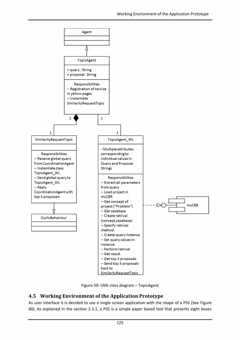
125
Working Environment of the Application Prototype
Figure 59: UML class diagram – TopicAgent
4.5 Working Environment of the Application Prototype As user interface it is decided to use a single screen application with the shape of a PSS (See Figure 60). As explained in the section 2.3.1, a PSS is a simple paper based tool that presents eight boxes
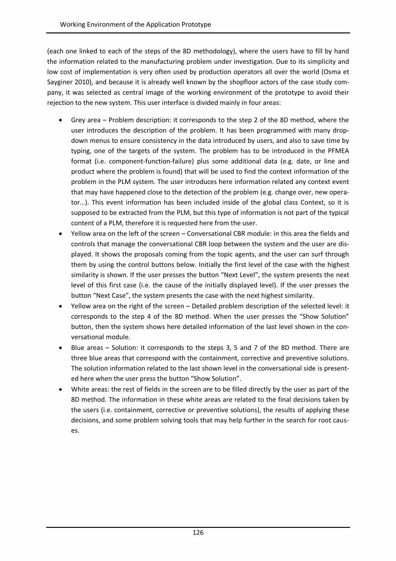
126
Working Environment of the Application Prototype
(each one linked to each of the steps of the 8D methodology), where the users have to fill by hand the information related to the manufacturing problem under investigation. Due to its simplicity and low cost of implementation is very often used by production operators all over the world (Osma et Sayginer 2010), and because it is already well known by the shopfloor actors of the case study com-pany, it was selected as central image of the working environment of the prototype to avoid their rejection to the new system. This user interface is divided mainly in four areas:
Grey area – Problem description: it corresponds to the step 2 of the 8D method, where the user introduces the description of the problem. It has been programmed with many drop-down menus to ensure consistency in the data introduced by users, and also to save time by typing, one of the targets of the system. The problem has to be introduced in the PFMEA format (i.e. component-function-failure) plus some additional data (e.g. date, or line and product where the problem is found) that will be used to find the context information of the problem in the PLM system. The user introduces here information related any context event that may have happened close to the detection of the problem (e.g. change over, new opera-tor…). This event information has been included inside of the global class Context, so it is supposed to be extracted from the PLM, but this type of information is not part of the typical content of a PLM, therefore it is requested here from the user.
Yellow area on the left of the screen – Conversational CBR module: in this area the fields and controls that manage the conversational CBR loop between the system and the user are dis-played. It shows the proposals coming from the topic agents, and the user can surf through them by using the control buttons below. Initially the first level of the case with the highest similarity is shown. If the user presses the button “Next Level”, the system presents the next level of this first case (i.e. the cause of the initially displayed level). If the user presses the button “Next Case”, the system presents the case with the next highest similarity.
Yellow area on the right of the screen – Detailed problem description of the selected level: it corresponds to the step 4 of the 8D method. When the user presses the “Show Solution” button, then the system shows here detailed information of the last level shown in the con-versational module.
Blue areas – Solution: it corresponds to the steps 3, 5 and 7 of the 8D method. There are three blue areas that correspond with the containment, corrective and preventive solutions. The solution information related to the last shown level in the conversational side is present-ed here when the user press the button “Show Solution”.
White areas: the rest of fields in the screen are to be filled directly by the user as part of the 8D method. The information in these white areas are related to the final decisions taken by the users (i.e. containment, corrective or preventive solutions), the results of applying these decisions, and some problem solving tools that may help further in the search for root caus-es.
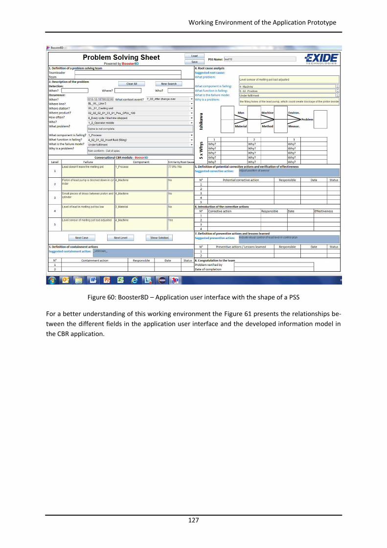
127
Working Environment of the Application Prototype
Figure 60: Booster8D – Application user interface with the shape of a PSS
For a better understanding of this working environment the Figure 61 presents the relationships be-tween the different fields in the application user interface and the developed information model in the CBR application.
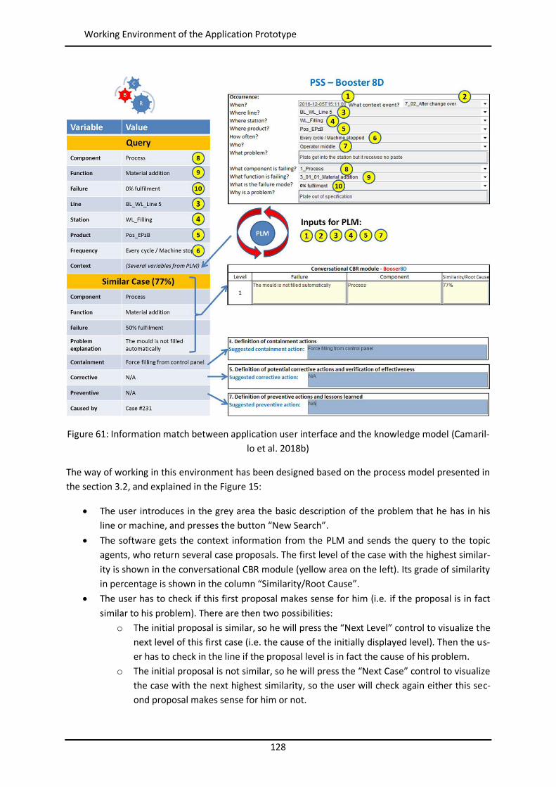
128
Working Environment of the Application Prototype
Figure 61: Information match between application user interface and the knowledge model (Camaril-lo et al. 2018b)
The way of working in this environment has been designed based on the process model presented in the section 3.2, and explained in the Figure 15:
The user introduces in the grey area the basic description of the problem that he has in his line or machine, and presses the button “New Search”.
The software gets the context information from the PLM and sends the query to the topic agents, who return several case proposals. The first level of the case with the highest similar-ity is shown in the conversational CBR module (yellow area on the left). Its grade of similarity in percentage is shown in the column “Similarity/Root Cause”.
The user has to check if this first proposal makes sense for him (i.e. if the proposal is in fact similar to his problem). There are then two possibilities:
o The initial proposal is similar, so he will press the “Next Level” control to visualize the next level of this first case (i.e. the cause of the initially displayed level). Then the us-er has to check in the line if the proposal level is in fact the cause of his problem.
o The initial proposal is not similar, so he will press the “Next Case” control to visualize the case with the next highest similarity, so the user will check again either this sec-ond proposal makes sense for him or not.
129
Summary
The process above is repeated systematically getting down level after level until the point that the problem proposed in the last level either it cannot be found in the machine or sta-tion as cause of the user’s problem, or the level is displayed with a “Yes” in the “Similari-ty/Root Cause” column of the matrix (i.e. it has no more related under levels). At this stage there are three possibilities:
o The user is satisfied with this last level as root cause, and then he presses the button “Show Solution” to see the detailed description of the root cause and the proposals of solution.
o The user is not satisfied with this root cause, and the system has still more cases as proposal. In this case the user presses the button “Next Case”, and starts the process from the beginning.
o The user is not satisfied with this root cause, but the system has no more cases as proposal. The user has to reformulate his problem description in the grey area and starts a new search process. This time the description will not be again the descrip-tion of the originally found problem, but the description of the last level that was found in the line or station.
The information shown when button “Show Solution” is pressed is used by the user as orien-tation to write down in the digital PSS the possible corrective actions (i.e. step 3), root causes (i.e. step 4), possible corrective actions (i.e. step 5), and the preventive actions (i.e. step 7).
The working environment offers also the possibility of saving in a file the current status of the PSS, and after that to reload that file. This feature is very important because certain steps in the 8D meth-od could take days or even weeks (e.g. the verification of the effectiveness of a possible corrective action), so it is needed that the team can save their work and be able to continue with it later on.
4.6 Summary This section has presented the development of the application prototype to be used for the valida-tion of the theories presented in this Thesis. This prototype integrates all models presented in the previous section and it gives details about the customization of the CBR and PLM system, the pro-gramming of the IT infrastructure with its agents, and the working environment associated to the prototype.

130
Summary
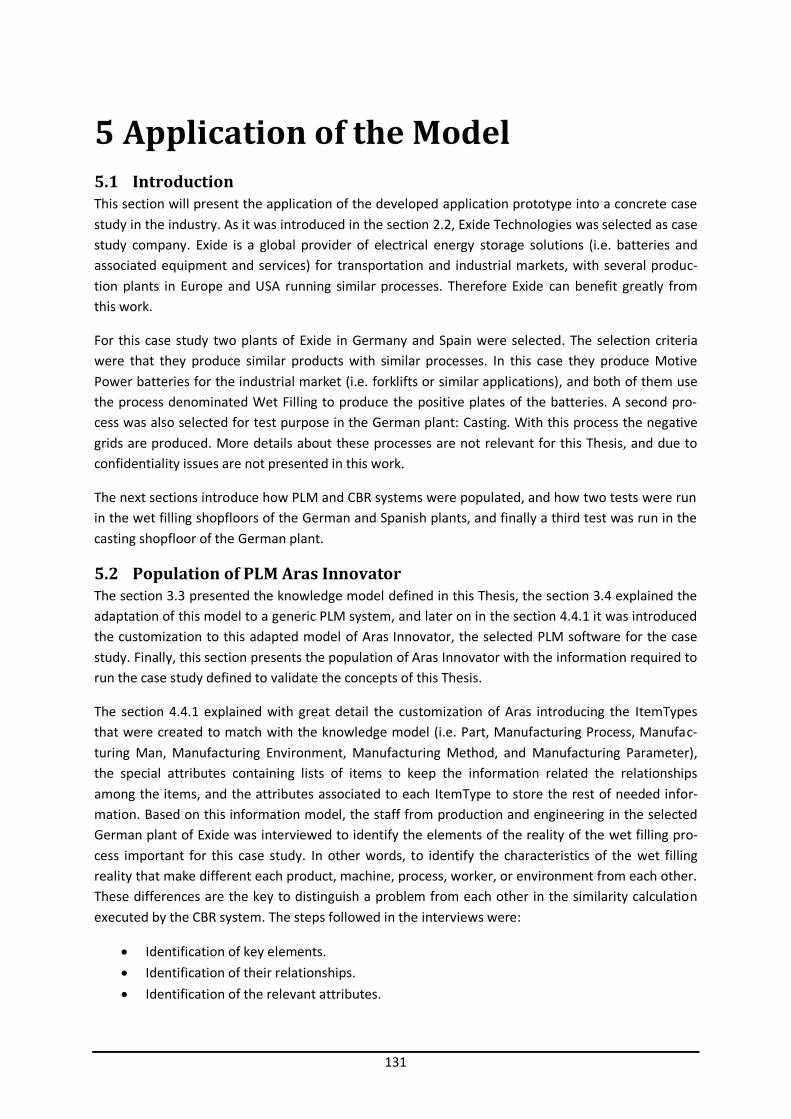
131
5 Application of the Model 5.1 Introduction This section will present the application of the developed application prototype into a concrete case study in the industry. As it was introduced in the section 2.2, Exide Technologies was selected as case study company. Exide is a global provider of electrical energy storage solutions (i.e. batteries and associated equipment and services) for transportation and industrial markets, with several produc-tion plants in Europe and USA running similar processes. Therefore Exide can benefit greatly from this work.
For this case study two plants of Exide in Germany and Spain were selected. The selection criteria were that they produce similar products with similar processes. In this case they produce Motive Power batteries for the industrial market (i.e. forklifts or similar applications), and both of them use the process denominated Wet Filling to produce the positive plates of the batteries. A second pro-cess was also selected for test purpose in the German plant: Casting. With this process the negative grids are produced. More details about these processes are not relevant for this Thesis, and due to confidentiality issues are not presented in this work.
The next sections introduce how PLM and CBR systems were populated, and how two tests were run in the wet filling shopfloors of the German and Spanish plants, and finally a third test was run in the casting shopfloor of the German plant.
5.2 Population of PLM Aras Innovator The section 3.3 presented the knowledge model defined in this Thesis, the section 3.4 explained the adaptation of this model to a generic PLM system, and later on in the section 4.4.1 it was introduced the customization to this adapted model of Aras Innovator, the selected PLM software for the case study. Finally, this section presents the population of Aras Innovator with the information required to run the case study defined to validate the concepts of this Thesis.
The section 4.4.1 explained with great detail the customization of Aras introducing the ItemTypes that were created to match with the knowledge model (i.e. Part, Manufacturing Process, Manufac-turing Man, Manufacturing Environment, Manufacturing Method, and Manufacturing Parameter), the special attributes containing lists of items to keep the information related the relationships among the items, and the attributes associated to each ItemType to store the rest of needed infor-mation. Based on this information model, the staff from production and engineering in the selected German plant of Exide was interviewed to identify the elements of the reality of the wet filling pro-cess important for this case study. In other words, to identify the characteristics of the wet filling reality that make different each product, machine, process, worker, or environment from each other. These differences are the key to distinguish a problem from each other in the similarity calculation executed by the CBR system. The steps followed in the interviews were:
Identification of key elements. Identification of their relationships. Identification of the relevant attributes.
132
Population of PLM Aras Innovator
The result of these interviews can be partially seen in the Table 4 (parameters for items of type Ma-terial), Table 5 (parameters for items of type Process), Table 6 (parameters for items of type Ma-chine), and Table 7 (parameters for items of type Man). During the interview no relevant characteris-tic associated to the environment was found, so there is no table for Manufacturing Environment, and as consequence there is no environment information in the PLM of the case study. To highlight that due to confidentiality issues it was not allowed to show all the identified parameters with their values, and the tables show just some examples without confidential relevancy.
These tables were the basis to fill the PLM, and their columns are built in the following way:
Type: it indicates the type of element from the knowledge model. Item type: it indicates the ItemType from the information model of the PLM. When there is a
single ItemType means that the item described in that row has no technical information (i.e. no Manufacturing Parameters), and when there are two ItemTypes means that the item has technical information, therefore the item of type part, process or man will have an associat-ed Manufacturing Method, and this method several associated Manufacturing Parameters.
Name: the name of the item for the PLM. Item_Nature: either abstract or real. List of Methods: similar to the heritage process proposed for the Manufacturing Parameters,
the proposed structure of the PLM allows also that the items inherit technical information contained in multiple Manufacturing Methods. The tables show how each item real inherits the methods of its upper abstract parents.
List of processes (only machine and material): it shows in the case of a material the different processes involved in its production, and in the case of a machine all processes that the ma-chine is able to carry out.
Man (only machine): it shows the type human being associated to the machine. Context: the position of the item in the taxonomy of Context. Technical parameters: the rest of columns contain the technical value of the defined charac-
teristics of the wet filling area. One the cell is grey means that this parameter is not applica-ble for that item.
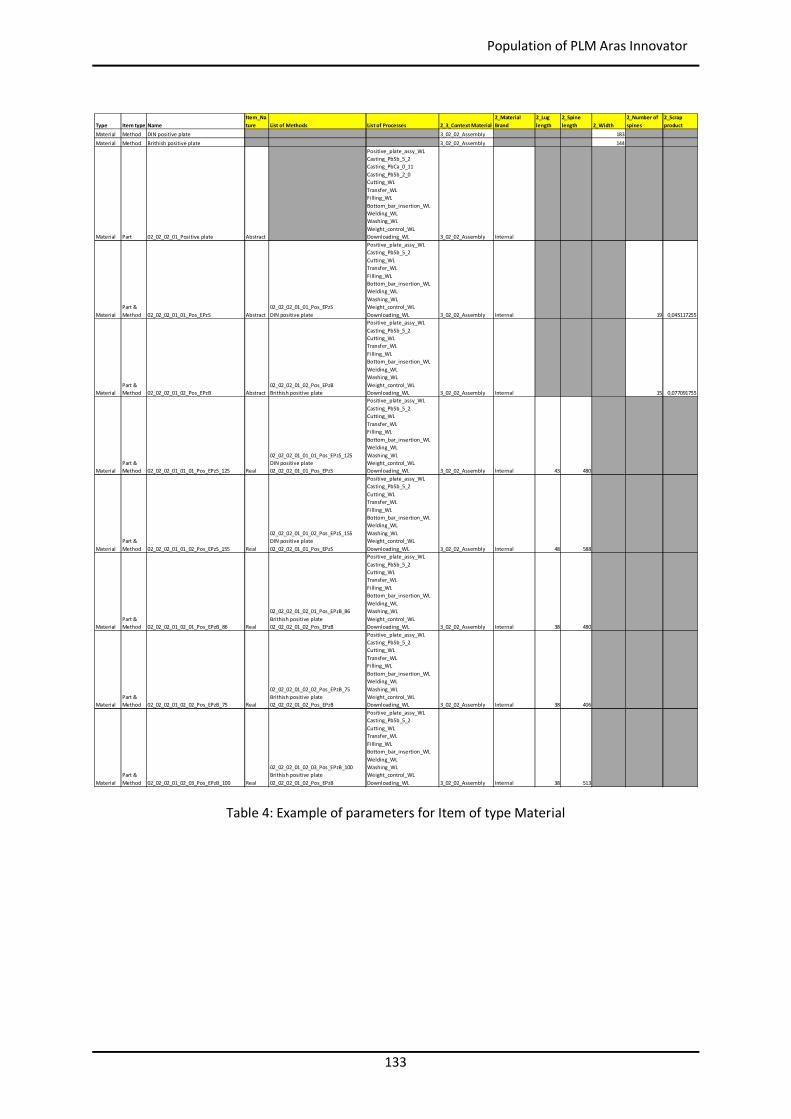
133
Population of PLM Aras Innovator
Table 4: Example of parameters for Item of type Material
Type Item type NameItem_Nature List of Methods List of Processes 2_3_Context Material
2_Material Brand
2_Lug length
2_Spine length 2_Width
2_Number of spines
2_Scrap product
Material Method DIN positive plate 3_02_02_Assembly 183Material Method Brithish positive plate 3_02_02_Assembly 144
Material Part 02_02_02_01_Positive plate Abstract
Positive_plate_assy_WLCasting_PbSb_5_2Casting_PbCa_0_11Casting_PbSb_2_0Cutting_WLTransfer_WLFilling_WLBottom_bar_insertion_WLWelding_WLWashing_WLWeight_control_WLDownloading_WL 3_02_02_Assembly Internal
MaterialPart & Method 02_02_02_01_01_Pos_EPzS Abstract
02_02_02_01_01_Pos_EPzSDIN positive plate
Positive_plate_assy_WLCasting_PbSb_5_2Cutting_WLTransfer_WLFilling_WLBottom_bar_insertion_WLWelding_WLWashing_WLWeight_control_WLDownloading_WL 3_02_02_Assembly Internal 19 0,045117255
MaterialPart & Method 02_02_02_01_02_Pos_EPzB Abstract
02_02_02_01_02_Pos_EPzBBrithish positive plate
Positive_plate_assy_WLCasting_PbSb_5_2Cutting_WLTransfer_WLFilling_WLBottom_bar_insertion_WLWelding_WLWashing_WLWeight_control_WLDownloading_WL 3_02_02_Assembly Internal 15 0,077091755
MaterialPart & Method 02_02_02_01_01_01_Pos_EPzS_125 Real
02_02_02_01_01_01_Pos_EPzS_125DIN positive plate02_02_02_01_01_Pos_EPzS
Positive_plate_assy_WLCasting_PbSb_5_2Cutting_WLTransfer_WLFilling_WLBottom_bar_insertion_WLWelding_WLWashing_WLWeight_control_WLDownloading_WL 3_02_02_Assembly Internal 43 480
MaterialPart & Method 02_02_02_01_01_02_Pos_EPzS_155 Real
02_02_02_01_01_02_Pos_EPzS_155DIN positive plate02_02_02_01_01_Pos_EPzS
Positive_plate_assy_WLCasting_PbSb_5_2Cutting_WLTransfer_WLFilling_WLBottom_bar_insertion_WLWelding_WLWashing_WLWeight_control_WLDownloading_WL 3_02_02_Assembly Internal 48 588
MaterialPart & Method 02_02_02_01_02_01_Pos_EPzB_86 Real
02_02_02_01_02_01_Pos_EPzB_86Brithish positive plate02_02_02_01_02_Pos_EPzB
Positive_plate_assy_WLCasting_PbSb_5_2Cutting_WLTransfer_WLFilling_WLBottom_bar_insertion_WLWelding_WLWashing_WLWeight_control_WLDownloading_WL 3_02_02_Assembly Internal 38 480
MaterialPart & Method 02_02_02_01_02_02_Pos_EPzB_75 Real
02_02_02_01_02_02_Pos_EPzB_75Brithish positive plate02_02_02_01_02_Pos_EPzB
Positive_plate_assy_WLCasting_PbSb_5_2Cutting_WLTransfer_WLFilling_WLBottom_bar_insertion_WLWelding_WLWashing_WLWeight_control_WLDownloading_WL 3_02_02_Assembly Internal 38 406
MaterialPart & Method 02_02_02_01_02_03_Pos_EPzB_100 Real
02_02_02_01_02_03_Pos_EPzB_100Brithish positive plate02_02_02_01_02_Pos_EPzB
Positive_plate_assy_WLCasting_PbSb_5_2Cutting_WLTransfer_WLFilling_WLBottom_bar_insertion_WLWelding_WLWashing_WLWeight_control_WLDownloading_WL 3_02_02_Assembly Internal 38 513
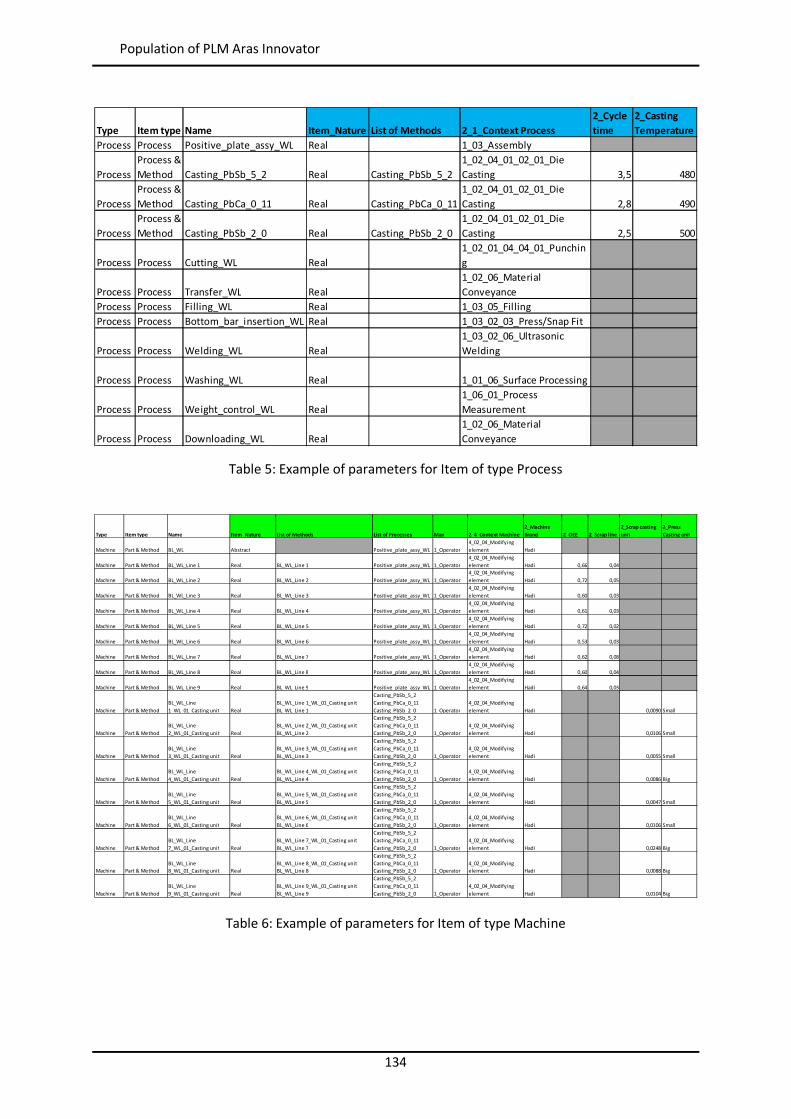
134
Population of PLM Aras Innovator
Table 5: Example of parameters for Item of type Process
Table 6: Example of parameters for Item of type Machine
Type Item type Name Item_Nature List of Methods 2_1_Context Process2_Cycle time
2_Casting Temperature
Process Process Positive_plate_assy_WL Real 1_03_Assembly
ProcessProcess & Method Casting_PbSb_5_2 Real Casting_PbSb_5_2
1_02_04_01_02_01_Die Casting 3,5 480
ProcessProcess & Method Casting_PbCa_0_11 Real Casting_PbCa_0_11
1_02_04_01_02_01_Die Casting 2,8 490
ProcessProcess & Method Casting_PbSb_2_0 Real Casting_PbSb_2_0
1_02_04_01_02_01_Die Casting 2,5 500
Process Process Cutting_WL Real1_02_01_04_04_01_Punching
Process Process Transfer_WL Real1_02_06_Material Conveyance
Process Process Filling_WL Real 1_03_05_FillingProcess Process Bottom_bar_insertion_WL Real 1_03_02_03_Press/Snap Fit
Process Process Welding_WL Real1_03_02_06_Ultrasonic Welding
Process Process Washing_WL Real 1_01_06_Surface Processing
Process Process Weight_control_WL Real1_06_01_Process Measurement
Process Process Downloading_WL Real1_02_06_Material Conveyance
Type Item type Name Item_Nature List of Methods List of Processes Man 2_4_Context Machine2_Machine Brand 2_OEE 2_Scrap line
2_Scrap casting unit
2_Press Casting unit
Machine Part & Method BL_WL Abstract Positive_plate_assy_WL 1_Operator4_02_04_Modifying element Hadi
Machine Part & Method BL_WL_Line 1 Real BL_WL_Line 1 Positive_plate_assy_WL 1_Operator4_02_04_Modifying element Hadi 0,66 0,04
Machine Part & Method BL_WL_Line 2 Real BL_WL_Line 2 Positive_plate_assy_WL 1_Operator4_02_04_Modifying element Hadi 0,72 0,05
Machine Part & Method BL_WL_Line 3 Real BL_WL_Line 3 Positive_plate_assy_WL 1_Operator4_02_04_Modifying element Hadi 0,60 0,03
Machine Part & Method BL_WL_Line 4 Real BL_WL_Line 4 Positive_plate_assy_WL 1_Operator4_02_04_Modifying element Hadi 0,61 0,03
Machine Part & Method BL_WL_Line 5 Real BL_WL_Line 5 Positive_plate_assy_WL 1_Operator4_02_04_Modifying element Hadi 0,72 0,02
Machine Part & Method BL_WL_Line 6 Real BL_WL_Line 6 Positive_plate_assy_WL 1_Operator4_02_04_Modifying element Hadi 0,53 0,03
Machine Part & Method BL_WL_Line 7 Real BL_WL_Line 7 Positive_plate_assy_WL 1_Operator4_02_04_Modifying element Hadi 0,62 0,08
Machine Part & Method BL_WL_Line 8 Real BL_WL_Line 8 Positive_plate_assy_WL 1_Operator4_02_04_Modifying element Hadi 0,60 0,04
Machine Part & Method BL_WL_Line 9 Real BL_WL_Line 9 Positive_plate_assy_WL 1_Operator4_02_04_Modifying element Hadi 0,64 0,03
Machine Part & MethodBL_WL_Line 1_WL_01_Casting unit Real
BL_WL_Line 1_WL_01_Casting unitBL_WL_Line 1
Casting_PbSb_5_2Casting_PbCa_0_11Casting_PbSb_2_0 1_Operator
4_02_04_Modifying element Hadi 0,0090 Small
Machine Part & MethodBL_WL_Line 2_WL_01_Casting unit Real
BL_WL_Line 2_WL_01_Casting unitBL_WL_Line 2
Casting_PbSb_5_2Casting_PbCa_0_11Casting_PbSb_2_0 1_Operator
4_02_04_Modifying element Hadi 0,0106 Small
Machine Part & MethodBL_WL_Line 3_WL_01_Casting unit Real
BL_WL_Line 3_WL_01_Casting unitBL_WL_Line 3
Casting_PbSb_5_2Casting_PbCa_0_11Casting_PbSb_2_0 1_Operator
4_02_04_Modifying element Hadi 0,0055 Small
Machine Part & MethodBL_WL_Line 4_WL_01_Casting unit Real
BL_WL_Line 4_WL_01_Casting unitBL_WL_Line 4
Casting_PbSb_5_2Casting_PbCa_0_11Casting_PbSb_2_0 1_Operator
4_02_04_Modifying element Hadi 0,0086 Big
Machine Part & MethodBL_WL_Line 5_WL_01_Casting unit Real
BL_WL_Line 5_WL_01_Casting unitBL_WL_Line 5
Casting_PbSb_5_2Casting_PbCa_0_11Casting_PbSb_2_0 1_Operator
4_02_04_Modifying element Hadi 0,0047 Small
Machine Part & MethodBL_WL_Line 6_WL_01_Casting unit Real
BL_WL_Line 6_WL_01_Casting unitBL_WL_Line 6
Casting_PbSb_5_2Casting_PbCa_0_11Casting_PbSb_2_0 1_Operator
4_02_04_Modifying element Hadi 0,0106 Small
Machine Part & MethodBL_WL_Line 7_WL_01_Casting unit Real
BL_WL_Line 7_WL_01_Casting unitBL_WL_Line 7
Casting_PbSb_5_2Casting_PbCa_0_11Casting_PbSb_2_0 1_Operator
4_02_04_Modifying element Hadi 0,0248 Big
Machine Part & MethodBL_WL_Line 8_WL_01_Casting unit Real
BL_WL_Line 8_WL_01_Casting unitBL_WL_Line 8
Casting_PbSb_5_2Casting_PbCa_0_11Casting_PbSb_2_0 1_Operator
4_02_04_Modifying element Hadi 0,0088 Big
Machine Part & MethodBL_WL_Line 9_WL_01_Casting unit Real
BL_WL_Line 9_WL_01_Casting unitBL_WL_Line 9
Casting_PbSb_5_2Casting_PbCa_0_11Casting_PbSb_2_0 1_Operator
4_02_04_Modifying element Hadi 0,0104 Big
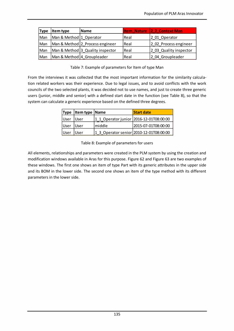
135
Population of PLM Aras Innovator
Table 7: Example of parameters for Item of type Man
From the interviews it was collected that the most important information for the similarity calcula-tion related workers was their experience. Due to legal issues, and to avoid conflicts with the work councils of the two selected plants, it was decided not to use names, and just to create three generic users (junior, middle and senior) with a defined start date in the function (see Table 8), so that the system can calculate a generic experience based on the defined three degrees.
Table 8: Example of parameters for users
All elements, relationships and parameters were created in the PLM system by using the creation and modification windows available in Aras for this purpose. Figure 62 and Figure 63 are two examples of these windows. The first one shows an item of type Part with its generic attributes in the upper side and its BOM in the lower side. The second one shows an item of the type method with its different parameters in the lower side.
Type Item type Name Item_Nature 2_2_Context ManMan Man & Method 1_Operator Real 2_01_OperatorMan Man & Method 2_Process engineer Real 2_02_Process engineerMan Man & Method 3_Quality inspector Real 2_03_Quality inspectorMan Man & Method 4_Groupleader Real 2_04_Groupleader
Type Item type Name Start dateUser User 1_1_Operator junior 2016-12-01T08:00:00User User
1_2_Operator middle 2015-07-01T08:00:00
User User 1_3_Operator senior 2010-12-01T08:00:00
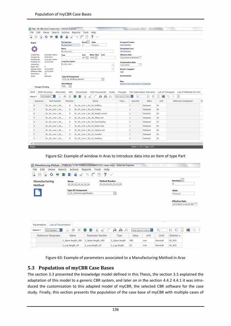
136
Population of myCBR Case Bases
Figure 62: Example of window in Aras to introduce data into an Item of type Part
Figure 63: Example of parameters associated to a Manufacturing Method in Aras
5.3 Population of myCBR Case Bases The section 3.3 presented the knowledge model defined in this Thesis, the section 3.5 explained the adaptation of this model to a generic CBR system, and later on in the section 4.4.2 4.4.1 it was intro-duced the customization to this adapted model of myCBR, the selected CBR software for the case study. Finally, this section presents the population of the case base of myCBR with multiple cases of
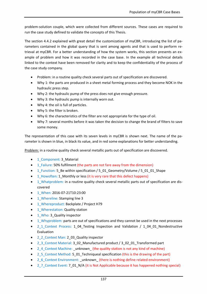
137
Population of myCBR Case Bases
problem-solution couple, which were collected from different sources. These cases are required to run the case study defined to validate the concepts of this Thesis.
The section 4.4.2 explained with great detail the customization of myCBR, introducing the list of pa-rameters contained in the global query that is sent among agents and that is used to perform re-trieval at myCBR. For a better understanding of how the system works, this section presents an ex-ample of problem and how it was recorded in the case base. In the example all technical details linked to the context have been removed for clarity and to keep the confidentiality of the process of the case study company.
Problem: in a routine quality check several parts out of specification are discovered. Why 1: the parts are produced in a sheet metal forming process and they become NOK in the
hydraulic press step. Why 2: the hydraulic pump of the press does not give enough pressure. Why 3: the hydraulic pump is internally worn out. Why 4: the oil is full of particles. Why 5: the filter is broken. Why 6: the characteristics of the filter are not appropriate for the type of oil. Why 7: several months before it was taken the decision to change the brand of filters to save
some money.
The representation of this case with its seven levels in myCBR is shown next. The name of the pa-rameter is shown in blue, in black its value, and in red some explanations for better understanding.
Problem: in a routine quality check several metallic parts out of specification are discovered.
1_Component: 3_Material 1_Failure: 50% fulfilment (the parts are not fare away from the dimension) 1_Function: 5_Be within specification / 5_01_Geometry/Volume / 5_01_01_Shape 1_Howoften: 1_Monthly or less (it is very rare that this defect happens) 1_Whatproblem: in a routine quality check several metallic parts out of specification are dis-
covered 1_When: 2016-07-21T10:23:00 1_Whereline: Stamping line 3 1_Whereproduct: Backplate / Project H79 1_Wherestation: Quality station 1_Who: 3_Quality inspector 1_Whyproblem: parts are out of specifications and they cannot be used in the next processes 2_1_Context Process: 1_04_Testing Inspection and Validation / 1_04_01_Nondestructive
Evaluation 2_2_Context Man: 2_03_Quality inspector 2_3_Context Material: 3_02_Manufactured product / 3_02_01_Transformed part 2_4_Context Machine: _unknown_ (the quality station is not any kind of machine) 2_5_Context Method: 5_01_Techniqueal specification (this is the drawing of the part) 2_6_Context Environment: _unknown_ (there is nothing define related environment) 2_7_Context Event: 7_01_N/A (it is Not Applicable because it has happened nothing special)
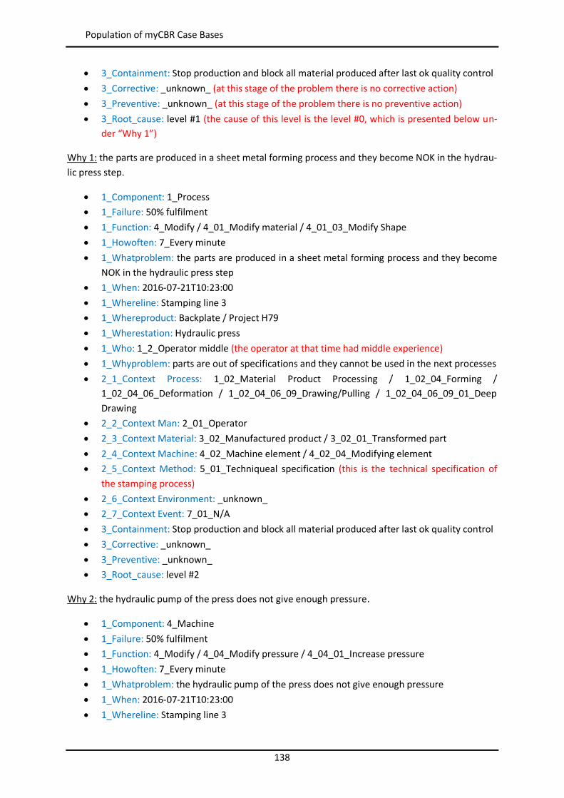
138
Population of myCBR Case Bases
3_Containment: Stop production and block all material produced after last ok quality control 3_Corrective: _unknown_ (at this stage of the problem there is no corrective action) 3_Preventive: _unknown_ (at this stage of the problem there is no preventive action) 3_Root_cause: level #1 (the cause of this level is the level #0, which is presented below un-
der “Why 1”)
Why 1: the parts are produced in a sheet metal forming process and they become NOK in the hydrau-lic press step.
1_Component: 1_Process 1_Failure: 50% fulfilment 1_Function: 4_Modify / 4_01_Modify material / 4_01_03_Modify Shape 1_Howoften: 7_Every minute 1_Whatproblem: the parts are produced in a sheet metal forming process and they become
NOK in the hydraulic press step 1_When: 2016-07-21T10:23:00 1_Whereline: Stamping line 3 1_Whereproduct: Backplate / Project H79 1_Wherestation: Hydraulic press 1_Who: 1_2_Operator middle (the operator at that time had middle experience) 1_Whyproblem: parts are out of specifications and they cannot be used in the next processes 2_1_Context Process: 1_02_Material Product Processing / 1_02_04_Forming /
1_02_04_06_Deformation / 1_02_04_06_09_Drawing/Pulling / 1_02_04_06_09_01_Deep Drawing
2_2_Context Man: 2_01_Operator 2_3_Context Material: 3_02_Manufactured product / 3_02_01_Transformed part 2_4_Context Machine: 4_02_Machine element / 4_02_04_Modifying element 2_5_Context Method: 5_01_Techniqueal specification (this is the technical specification of
the stamping process) 2_6_Context Environment: _unknown_ 2_7_Context Event: 7_01_N/A 3_Containment: Stop production and block all material produced after last ok quality control 3_Corrective: _unknown_ 3_Preventive: _unknown_ 3_Root_cause: level #2
Why 2: the hydraulic pump of the press does not give enough pressure.
1_Component: 4_Machine 1_Failure: 50% fulfilment 1_Function: 4_Modify / 4_04_Modify pressure / 4_04_01_Increase pressure 1_Howoften: 7_Every minute 1_Whatproblem: the hydraulic pump of the press does not give enough pressure 1_When: 2016-07-21T10:23:00 1_Whereline: Stamping line 3
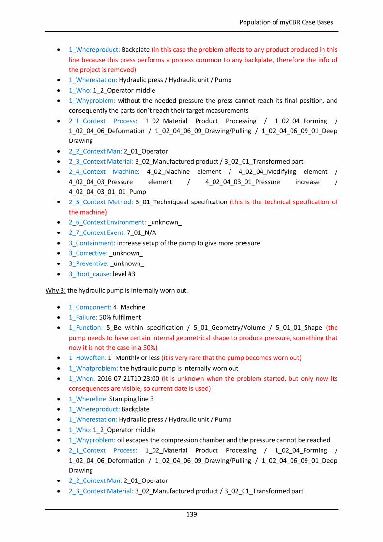
139
Population of myCBR Case Bases
1_Whereproduct: Backplate (in this case the problem affects to any product produced in this line because this press performs a process common to any backplate, therefore the info of the project is removed)
1_Wherestation: Hydraulic press / Hydraulic unit / Pump 1_Who: 1_2_Operator middle 1_Whyproblem: without the needed pressure the press cannot reach its final position, and
consequently the parts don’t reach their target measurements 2_1_Context Process: 1_02_Material Product Processing / 1_02_04_Forming /
1_02_04_06_Deformation / 1_02_04_06_09_Drawing/Pulling / 1_02_04_06_09_01_Deep Drawing
2_2_Context Man: 2_01_Operator 2_3_Context Material: 3_02_Manufactured product / 3_02_01_Transformed part 2_4_Context Machine: 4_02_Machine element / 4_02_04_Modifying element /
4_02_04_03_Pressure element / 4_02_04_03_01_Pressure increase / 4_02_04_03_01_01_Pump
2_5_Context Method: 5_01_Techniqueal specification (this is the technical specification of the machine)
2_6_Context Environment: _unknown_ 2_7_Context Event: 7_01_N/A 3_Containment: increase setup of the pump to give more pressure 3_Corrective: _unknown_ 3_Preventive: _unknown_ 3_Root_cause: level #3
Why 3: the hydraulic pump is internally worn out.
1_Component: 4_Machine 1_Failure: 50% fulfilment 1_Function: 5_Be within specification / 5_01_Geometry/Volume / 5_01_01_Shape (the
pump needs to have certain internal geometrical shape to produce pressure, something that now it is not the case in a 50%)
1_Howoften: 1_Monthly or less (it is very rare that the pump becomes worn out) 1_Whatproblem: the hydraulic pump is internally worn out 1_When: 2016-07-21T10:23:00 (it is unknown when the problem started, but only now its
consequences are visible, so current date is used) 1_Whereline: Stamping line 3 1_Whereproduct: Backplate 1_Wherestation: Hydraulic press / Hydraulic unit / Pump 1_Who: 1_2_Operator middle 1_Whyproblem: oil escapes the compression chamber and the pressure cannot be reached 2_1_Context Process: 1_02_Material Product Processing / 1_02_04_Forming /
1_02_04_06_Deformation / 1_02_04_06_09_Drawing/Pulling / 1_02_04_06_09_01_Deep Drawing
2_2_Context Man: 2_01_Operator 2_3_Context Material: 3_02_Manufactured product / 3_02_01_Transformed part
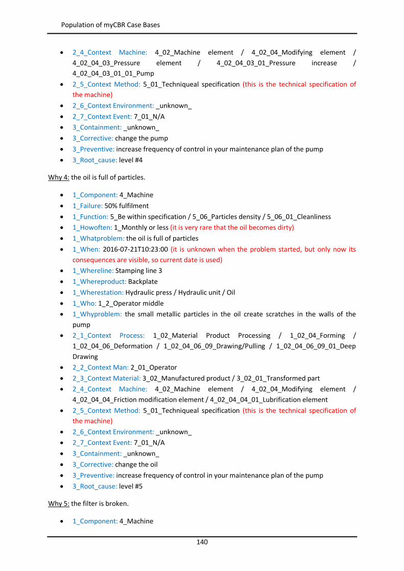
140
Population of myCBR Case Bases
2_4_Context Machine: 4_02_Machine element / 4_02_04_Modifying element / 4_02_04_03_Pressure element / 4_02_04_03_01_Pressure increase / 4_02_04_03_01_01_Pump
2_5_Context Method: 5_01_Techniqueal specification (this is the technical specification of the machine)
2_6_Context Environment: _unknown_ 2_7_Context Event: 7_01_N/A 3_Containment: _unknown_ 3_Corrective: change the pump 3_Preventive: increase frequency of control in your maintenance plan of the pump 3_Root_cause: level #4
Why 4: the oil is full of particles.
1_Component: 4_Machine 1_Failure: 50% fulfilment 1_Function: 5_Be within specification / 5_06_Particles density / 5_06_01_Cleanliness 1_Howoften: 1_Monthly or less (it is very rare that the oil becomes dirty) 1_Whatproblem: the oil is full of particles 1_When: 2016-07-21T10:23:00 (it is unknown when the problem started, but only now its
consequences are visible, so current date is used) 1_Whereline: Stamping line 3 1_Whereproduct: Backplate 1_Wherestation: Hydraulic press / Hydraulic unit / Oil 1_Who: 1_2_Operator middle 1_Whyproblem: the small metallic particles in the oil create scratches in the walls of the
pump 2_1_Context Process: 1_02_Material Product Processing / 1_02_04_Forming /
1_02_04_06_Deformation / 1_02_04_06_09_Drawing/Pulling / 1_02_04_06_09_01_Deep Drawing
2_2_Context Man: 2_01_Operator 2_3_Context Material: 3_02_Manufactured product / 3_02_01_Transformed part 2_4_Context Machine: 4_02_Machine element / 4_02_04_Modifying element /
4_02_04_04_Friction modification element / 4_02_04_04_01_Lubrification element 2_5_Context Method: 5_01_Techniqueal specification (this is the technical specification of
the machine) 2_6_Context Environment: _unknown_ 2_7_Context Event: 7_01_N/A 3_Containment: _unknown_ 3_Corrective: change the oil 3_Preventive: increase frequency of control in your maintenance plan of the pump 3_Root_cause: level #5
Why 5: the filter is broken.
1_Component: 4_Machine
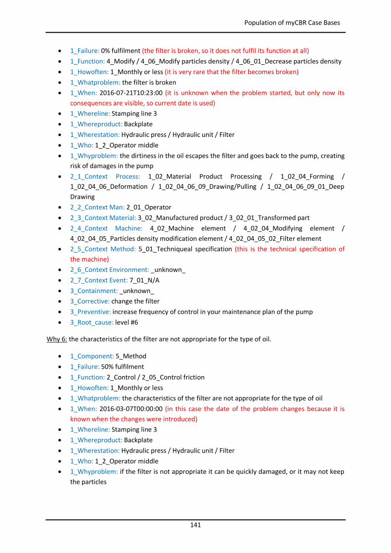
141
Population of myCBR Case Bases
1_Failure: 0% fulfilment (the filter is broken, so it does not fulfil its function at all) 1_Function: 4_Modify / 4_06_Modify particles density / 4_06_01_Decrease particles density 1_Howoften: 1_Monthly or less (it is very rare that the filter becomes broken) 1_Whatproblem: the filter is broken 1_When: 2016-07-21T10:23:00 (it is unknown when the problem started, but only now its
consequences are visible, so current date is used) 1_Whereline: Stamping line 3 1_Whereproduct: Backplate 1_Wherestation: Hydraulic press / Hydraulic unit / Filter 1_Who: 1_2_Operator middle 1_Whyproblem: the dirtiness in the oil escapes the filter and goes back to the pump, creating
risk of damages in the pump 2_1_Context Process: 1_02_Material Product Processing / 1_02_04_Forming /
1_02_04_06_Deformation / 1_02_04_06_09_Drawing/Pulling / 1_02_04_06_09_01_Deep Drawing
2_2_Context Man: 2_01_Operator 2_3_Context Material: 3_02_Manufactured product / 3_02_01_Transformed part 2_4_Context Machine: 4_02_Machine element / 4_02_04_Modifying element /
4_02_04_05_Particles density modification element / 4_02_04_05_02_Filter element 2_5_Context Method: 5_01_Techniqueal specification (this is the technical specification of
the machine) 2_6_Context Environment: _unknown_ 2_7_Context Event: 7_01_N/A 3_Containment: _unknown_ 3_Corrective: change the filter 3_Preventive: increase frequency of control in your maintenance plan of the pump 3_Root_cause: level #6
Why 6: the characteristics of the filter are not appropriate for the type of oil.
1_Component: 5_Method 1_Failure: 50% fulfilment 1_Function: 2_Control / 2_05_Control friction 1_Howoften: 1_Monthly or less 1_Whatproblem: the characteristics of the filter are not appropriate for the type of oil 1_When: 2016-03-07T00:00:00 (in this case the date of the problem changes because it is
known when the changes were introduced) 1_Whereline: Stamping line 3 1_Whereproduct: Backplate 1_Wherestation: Hydraulic press / Hydraulic unit / Filter 1_Who: 1_2_Operator middle 1_Whyproblem: if the filter is not appropriate it can be quickly damaged, or it may not keep
the particles
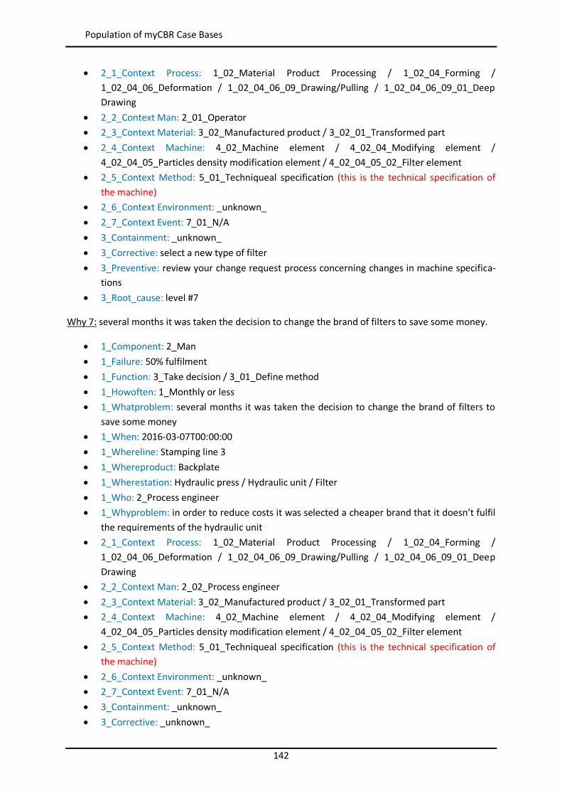
142
Population of myCBR Case Bases
2_1_Context Process: 1_02_Material Product Processing / 1_02_04_Forming / 1_02_04_06_Deformation / 1_02_04_06_09_Drawing/Pulling / 1_02_04_06_09_01_Deep Drawing
2_2_Context Man: 2_01_Operator 2_3_Context Material: 3_02_Manufactured product / 3_02_01_Transformed part 2_4_Context Machine: 4_02_Machine element / 4_02_04_Modifying element /
4_02_04_05_Particles density modification element / 4_02_04_05_02_Filter element 2_5_Context Method: 5_01_Techniqueal specification (this is the technical specification of
the machine) 2_6_Context Environment: _unknown_ 2_7_Context Event: 7_01_N/A 3_Containment: _unknown_ 3_Corrective: select a new type of filter 3_Preventive: review your change request process concerning changes in machine specifica-
tions 3_Root_cause: level #7
Why 7: several months it was taken the decision to change the brand of filters to save some money.
1_Component: 2_Man 1_Failure: 50% fulfilment 1_Function: 3_Take decision / 3_01_Define method 1_Howoften: 1_Monthly or less 1_Whatproblem: several months it was taken the decision to change the brand of filters to
save some money 1_When: 2016-03-07T00:00:00 1_Whereline: Stamping line 3 1_Whereproduct: Backplate 1_Wherestation: Hydraulic press / Hydraulic unit / Filter 1_Who: 2_Process engineer 1_Whyproblem: in order to reduce costs it was selected a cheaper brand that it doesn’t fulfil
the requirements of the hydraulic unit 2_1_Context Process: 1_02_Material Product Processing / 1_02_04_Forming /
1_02_04_06_Deformation / 1_02_04_06_09_Drawing/Pulling / 1_02_04_06_09_01_Deep Drawing
2_2_Context Man: 2_02_Process engineer 2_3_Context Material: 3_02_Manufactured product / 3_02_01_Transformed part 2_4_Context Machine: 4_02_Machine element / 4_02_04_Modifying element /
4_02_04_05_Particles density modification element / 4_02_04_05_02_Filter element 2_5_Context Method: 5_01_Techniqueal specification (this is the technical specification of
the machine) 2_6_Context Environment: _unknown_ 2_7_Context Event: 7_01_N/A 3_Containment: _unknown_ 3_Corrective: _unknown_
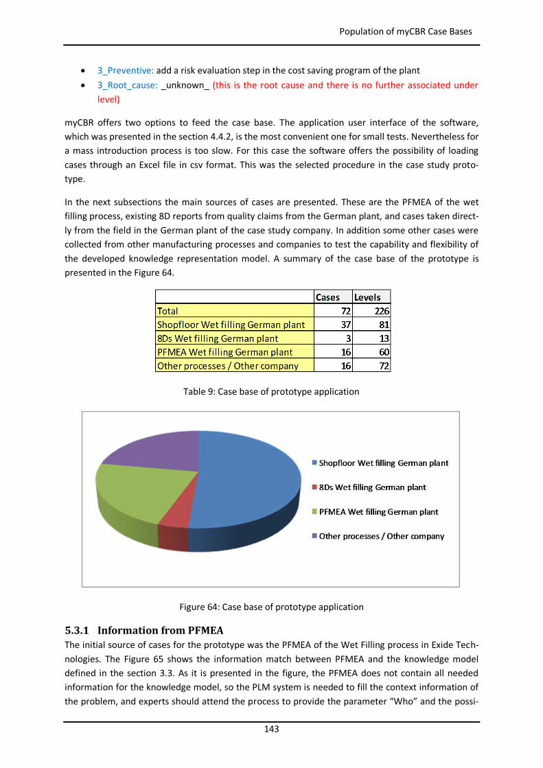
143
Population of myCBR Case Bases
3_Preventive: add a risk evaluation step in the cost saving program of the plant 3_Root_cause: _unknown_ (this is the root cause and there is no further associated under
level)
myCBR offers two options to feed the case base. The application user interface of the software, which was presented in the section 4.4.2, is the most convenient one for small tests. Nevertheless for a mass introduction process is too slow. For this case the software offers the possibility of loading cases through an Excel file in csv format. This was the selected procedure in the case study proto-type.
In the next subsections the main sources of cases are presented. These are the PFMEA of the wet filling process, existing 8D reports from quality claims from the German plant, and cases taken direct-ly from the field in the German plant of the case study company. In addition some other cases were collected from other manufacturing processes and companies to test the capability and flexibility of the developed knowledge representation model. A summary of the case base of the prototype is presented in the Figure 64.
Table 9: Case base of prototype application
Figure 64: Case base of prototype application
5.3.1 Information from PFMEA The initial source of cases for the prototype was the PFMEA of the Wet Filling process in Exide Tech-nologies. The Figure 65 shows the information match between PFMEA and the knowledge model defined in the section 3.3. As it is presented in the figure, the PFMEA does not contain all needed information for the knowledge model, so the PLM system is needed to fill the context information of the problem, and experts should attend the process to provide the parameter “Who” and the possi-

144
Population of myCBR Case Bases
ble containment and corrective actions, since the PFMEA only considers possible preventive actions to minimize the impact of the failures. The figure only presents the parameters with impact in the similarity calculation. Other parameters like “When” (used to collect context information from PLM), “Whatproblem” or “Whyproblem” are removed for clarity.
The fields in the PFMEA matrix marked with 1, 2, 3 and 4 are used as input for the PLM to get the context information. The fields 4, 5, and 6 represent the core of the problem definition (i.e. Compo-nent, Function, and Failure). After this, field 9 defines the frequency of the problem, 7 the preventive action, and finally the field 8 indicates the failure that causes the problem. The same process it is repeated systematically with every new failure. This process was presented in the paper of Camarillo et al. (2018b).
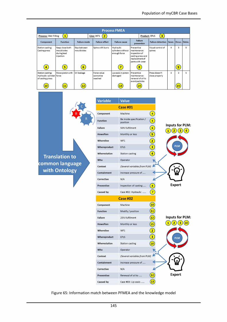
145
Population of myCBR Case Bases
Figure 65: Information match between PFMEA and the knowledge model
146
Case Study 1: Wet Filling in German Manufacturing Plant
5.3.2 Information from the Field In this case study it was only considered the wet filling production area of the German plant of Exide Technologies as source of cases from the field, leaving other production areas and the Spanish plant for validation purposes.
Three different methods were selected for this collection of information from the field:
Interviews with experts to collect the most typical failures in the lines. Quality issues extracted from the existing 8D documents from the lines. Failures documented directly on the shopfloor as long as they happened. For this task a 17
years old student from a school without any kind of industrial background was engaged dur-ing two weeks. The friendly interface and easy use of the system was tested in this way.
The template used at the lines for data collection can be found in the Appendix 2: Template for data collection at shopfloor.
5.4 Case Study 1: Wet Filling in German Manufacturing Plant For the first validation step of the prototype system it was selected the wet filling production area in the German plant of Exide Technologies. This should represent the easiest level of complexity for the system, since the cases in the prototype were all collected in this process and plant.
The groupleader of the area was trained in the prototype system and he used it together with other operators to solve ten problems from the lines. Since the cases in the prototype were recorded in English, the support of a translator was needed.
The queries introduced by the users, the applicability results of the proposals coming out of the sys-tem, and the real solutions of the problems were all recorded.
5.5 Case Study 2: Wet Filling in Spanish Manufacturing Plant For the second validation step of the prototype system it was selected the wet filling production ar-ea, but in the Spanish plant of Exide Technologies. This should represent a higher level of complexity for the system, since it is possible that the types of problems in both plants are quite different (e.g. not all machines are the same, materials bought at local suppliers, different levels of training and experience…).
As in the Case 1 the groupleader of the area was trained in the prototype system and he used it to-gether with other operators to solve ten problems. In this case the translator was also needed, and the queries introduced by the users, the applicability results of the proposals coming out of the sys-tem, and the real solutions of the problems were all recorded.
5.6 Case Study 3: Casting in German Manufacturing Plant For the third validation step of the prototype system it was selected the casting production area back in the German plant of Exide Technologies. This should represent the highest level of complexity for the system, because it was not fed with any kind of problem out of this area.
Once again the groupleader of the area was trained, a translator was supporting the operation, and query, results and real solutions were recorded.
147
Setup Improvement of Similarity Parameters and Final Results from Cases
5.7 Setup Improvement of Similarity Parameters and Final Results from Cases
The Table 10 shows the results extracted from the case studies above. The table is divided horizontal-ly in three blocks corresponding to the case study 1 (wet filling in German manufacturing plant), case study 2 (wet filling in Spanish manufacturing plant), and case study 3 (casting in German manufactur-ing plant). At the same time the table is divided vertically into three blocks corresponding each of them to the three consecutives improvements done with the similarity parameters. Finally the table shows for each problem the similarity percentage of the proposal given by the system related to the user query, and the code to classify the result. This code means:
-1 = The system has proposed some solutions but none of them were useful because the case base has no useful cases inside. This represents a failure of the system due to lack of knowledge.
0 = The system has proposed some solutions but none of them were useful. Nevertheless in the case base there is at least a suitable case. This represents a failure of the system in the similarity calculation.
1 = The system has proposed at least one solution that could be used by the user directly without any major adaptation (i.e. the proposal comes from an identical context).
2 = The system has proposed at least one solution that could be used by the user after an ad-aptation process done by him.
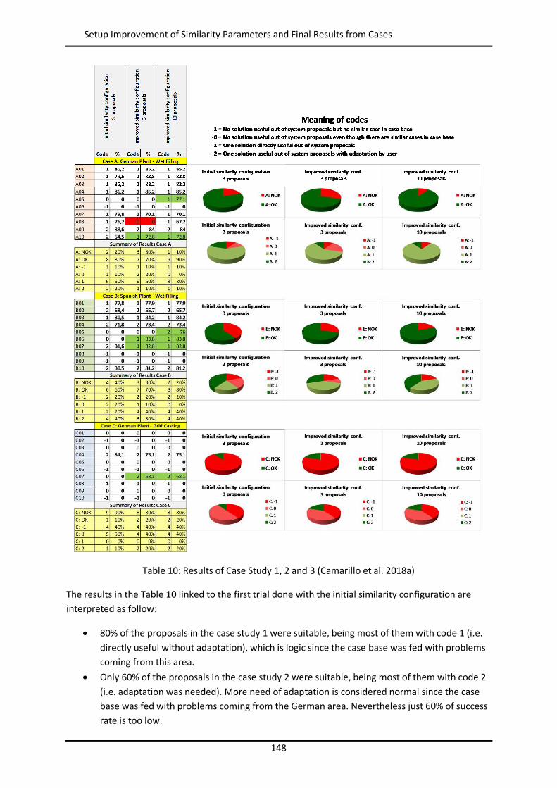
148
Setup Improvement of Similarity Parameters and Final Results from Cases
Table 10: Results of Case Study 1, 2 and 3 (Camarillo et al. 2018a)
The results in the Table 10 linked to the first trial done with the initial similarity configuration are interpreted as follow:
80% of the proposals in the case study 1 were suitable, being most of them with code 1 (i.e. directly useful without adaptation), which is logic since the case base was fed with problems coming from this area.
Only 60% of the proposals in the case study 2 were suitable, being most of them with code 2 (i.e. adaptation was needed). More need of adaptation is considered normal since the case base was fed with problems coming from the German area. Nevertheless just 60% of success rate is too low.
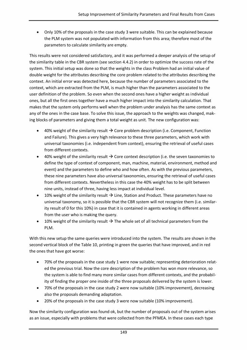
149
Setup Improvement of Similarity Parameters and Final Results from Cases
Only 10% of the proposals in the case study 3 were suitable. This can be explained because the PLM system was not populated with information from this area; therefore most of the parameters to calculate similarity are empty.
This results were not considered satisfactory, and it was performed a deeper analysis of the setup of the similarity table in the CBR system (see section 4.4.2) in order to optimize the success rate of the system. This initial setup was done so that the weights in the class Problem had an initial value of double weight for the attributes describing the core problem related to the attributes describing the context. An initial error was detected here, because the number of parameters associated to the context, which are extracted from the PLM, is much higher than the parameters associated to the user definition of the problem. So even when the second ones have a higher weight as individual ones, but all the first ones together have a much higher impact into the similarity calculation. That makes that the system only performs well when the problem under analysis has the same context as any of the ones in the case base. To solve this issue, the approach to the weights was changed, mak-ing blocks of parameters and giving them a total weight as unit. The new configuration was:
40% weight of the similarity result Core problem description (i.e. Component, Function and Failure). This gives a very high relevance to these three parameters, which work with universal taxonomies (i.e. independent from context), ensuring the retrieval of useful cases from different contexts.
40% weight of the similarity result Core context description (i.e. the seven taxonomies to define the type of context of component, man, machine, material, environment, method and event) and the parameters to define who and how often. As with the previous parameters, these nine parameters have also universal taxonomies, ensuring the retrieval of useful cases from different contexts. Nevertheless in this case the 40% weight has to be split between nine units, instead of three, having less impact at individual level.
10% weight of the similarity result Line, Station and Product. These parameters have no universal taxonomy, so it is possible that the CBR system will not recognize them (i.e. similar-ity result of 0 for this 10%) in case that it is contained in agents working in different areas from the user who is making the query.
10% weight of the similarity result The whole set of all technical parameters from the PLM.
With this new setup the same queries were introduced into the system. The results are shown in the second vertical block of the Table 10, printing in green the queries that have improved, and in red the ones that have got worse:
70% of the proposals in the case study 1 were now suitable; representing deterioration relat-ed the previous trial. Now the core description of the problem has won more relevance, so the system is able to find many more similar cases from different contexts, and the probabil-ity of finding the proper one inside of the three proposals delivered by the system is lower.
70% of the proposals in the case study 2 were now suitable (10% improvement), decreasing also the proposals demanding adaptation.
20% of the proposals in the case study 3 were now suitable (10% improvement).
Now the similarity configuration was found ok, but the number of proposals out of the system arises as an issue, especially with problems that were collected from the PFMEA. In these cases each type
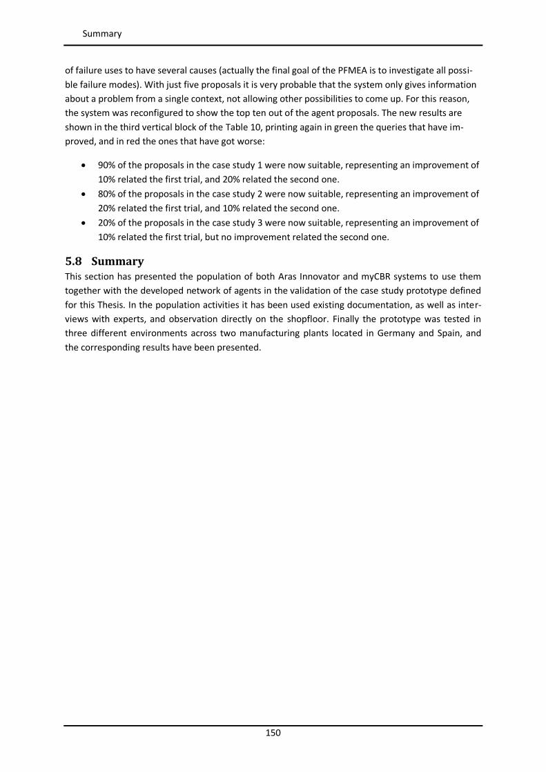
150
Summary
of failure uses to have several causes (actually the final goal of the PFMEA is to investigate all possi-ble failure modes). With just five proposals it is very probable that the system only gives information about a problem from a single context, not allowing other possibilities to come up. For this reason, the system was reconfigured to show the top ten out of the agent proposals. The new results are shown in the third vertical block of the Table 10, printing again in green the queries that have im-proved, and in red the ones that have got worse:
90% of the proposals in the case study 1 were now suitable, representing an improvement of 10% related the first trial, and 20% related the second one.
80% of the proposals in the case study 2 were now suitable, representing an improvement of 20% related the first trial, and 10% related the second one.
20% of the proposals in the case study 3 were now suitable, representing an improvement of 10% related the first trial, but no improvement related the second one.
5.8 Summary This section has presented the population of both Aras Innovator and myCBR systems to use them together with the developed network of agents in the validation of the case study prototype defined for this Thesis. In the population activities it has been used existing documentation, as well as inter-views with experts, and observation directly on the shopfloor. Finally the prototype was tested in three different environments across two manufacturing plants located in Germany and Spain, and the corresponding results have been presented.
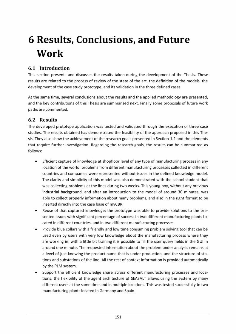
151
6 Results, Conclusions, and Future Work
6.1 Introduction This section presents and discusses the results taken during the development of the Thesis. These results are related to the process of review of the state of the art, the definition of the models, the development of the case study prototype, and its validation in the three defined cases.
At the same time, several conclusions about the results and the applied methodology are presented, and the key contributions of this Thesis are summarized next. Finally some proposals of future work paths are commented.
6.2 Results The developed prototype application was tested and validated through the execution of three case studies. The results obtained has demonstrated the feasibility of the approach proposed in this The-sis. They also show the achievement of the research goals presented in Section 1.2 and the elements that require further investigation. Regarding the research goals, the results can be summarized as follows:
Efficient capture of knowledge at shopfloor level of any type of manufacturing process in any location of the world: problems from different manufacturing processes collected in different countries and companies were represented without issues in the defined knowledge model. The clarity and simplicity of this model was also demonstrated with the school student that was collecting problems at the lines during two weeks. This young boy, without any previous industrial background, and after an introduction to the model of around 30 minutes, was able to collect properly information about many problems, and also in the right format to be inserted directly into the case base of myCBR.
Reuse of that captured knowledge: the prototype was able to provide solutions to the pre-sented issues with significant percentage of success in two different manufacturing plants lo-cated in different countries, and in two different manufacturing processes.
Provide blue collars with a friendly and low time consuming problem solving tool that can be used even by users with very low knowledge about the manufacturing process where they are working in: with a little bit training it is possible to fill the user query fields in the GUI in around one minute. The requested information about the problem under analysis remains at a level of just knowing the product name that is under production, and the structure of sta-tions and substations of the line. All the rest of context information is provided automatically by the PLM system.
Support the efficient knowledge share across different manufacturing processes and loca-tions: the flexibility of the agent architecture of SEASALT allows using the system by many different users at the same time and in multiple locations. This was tested successfully in two manufacturing plants located in Germany and Spain.
152
Conclusions
6.3 Conclusions The conclusions realized during the development of this Thesis are divided in following blocks:
Conclusions about the defined process to collect knowledge:
During this first phase of the project several peculiar behaviors in the operators have been observed that can create difficulties in the future collection of additional knowledge related problems. When operators or technicians in the shopfloor try to ex-plain how they have solved a problem, very often they give a list of different things that they did or changed in the machines, but they do not know which of them had real im-pact in the solution of the problem. Also it has been often observed that, even when operators fill the PSS following the 8 steps of the method, in reality they have figured out previously a solution, and then they follow the MPS method from the beginning but just looking for the arguments that justify their initial assumptions and solutions in their heads.
PFMEA has been considered as the initial source of information for the system. Never-theless the PFMEA document needs to have certain depth of detail to be useful. A very generic document only focused on processes, not bringing the analysis down to other components like machine or man, will be of very little help. The same consideration can be done for other documents, from which problems and solutions can be extracted. For example 8Ds with very poor problem descriptions or generic corrective actions do not add value.
For the representation of a problem it is recommended to start writing down the infor-mation about “Whatproblem” and “Whyproblem”, which helps to settle down the rea-soning about the problem, and then to proceed to fill up the rest of parameters.
In the chain of problems it is possible to make very detailed steps (e.g. the tool machin-ing is broken, then not enough coolant, then valves don’t open properly, then valves are dirty), or to jump quickly to the root causes (e.g. the machining tool is broken, then coolant valves don’t open properly because they are dirty). The more defined steps, the easier it will be to reuse them in the future. More specific and detailed steps give the possibility to reuse any of the levels included in the case by a bigger variety of problems under analysis. A good practice to ensure this during the representation of a case it is to get as component of the first level “Material”, if it is about a quality issue found in the product, or “Process”, for any other case. In the industry, problems are identified rather in produces with poor quality (i.e. Material) or processes performing wrong (i.e. Pro-cess). Then in the following levels the rest of types of components can be selected. In this way it is avoided to jump directly into conclusions and to generate at least two or three levels in each case.
Possible rejection or even blockage from the side of operators or work council to use the proposed system and to share knowledge if the name of the user of the system is explic-itly recorded in the digital PSS, under the belief that this can be used by the firma as a performance control tool.
The context event information is not always properly filled because for an operator to put as event “New operator” or “New shift” is like recognizing the own guilt.
Conclusions about the use of the system Booster8D:
153
Main Contributions
The application of this model to unstable or very new processes, where their technical parameters are either not well defined or with extremely large tolerances, is very diffi-cult because the characteristics of a process running on a product type related to the same process but running on another product type can be so much overlapped that it is very difficult to set the similarity rules to define what is similar and what is not.
In the developed prototype system the PLM system Aras Innovator was populated through its application user interface, which is extremely time consuming and errors can happen at any time. And even worst, every small change in any item means to update manually all its related items. For a broader application test it is very much recommend-ed to develop macros to load automatically the data into the PLM from Excel or csv files.
The prototype system developed to proof the theories of this Thesis is most probably not very useful for maintenance, since the PLM was only configured until the level of the sta-tions. For operators it will work because they use to ask about things that they see di-rectly in the line. But when somebody from maintenance starts the search from a very specific component of a substation, the PLM will not deliver any context information, and this makes the calculation of similarity poorer.
An expected barrier to apply this framework is the fact that it assumes the pre-existence of computers at shopfloor level and a PLM system fed with the PRR information of the company. Nevertheless the current trend of digitalization in the industry nowadays (Cearley et al. 2015) shows that this will be more and more the standard in the near fu-ture.
Another expected barrier is the fact that this system needs to translate all existing com-pany information stored in old formats (e.g. PFMEA, paper PSS, 8Ds, minutes of meet-ings) into the new format based on the developed knowledge model, and this process could consume many resources and time at the beginning. For example in the installation of a new CAD system in a company all old designs remain in the old format and they are only brought to the new format when they are involved either in a modification or used in a new project. Therefore the new CAD system does not bring any initial work load. Nevertheless, in the presented system, if the PLM of the company is not adapted some-how to the new knowledge model, and the existing documented manufacturing prob-lems are not translated, the system will not be able to provide the users with any solu-tion proposal.
6.4 Main Contributions As it was already presented in the section 1.4, the main contribution of this Thesis is its innovative approach to CIP by combining classic MPS methods, CBR on an agent-based distributed architecture, and a PLM system. Some other works already considered the combined approach of MPS with cap-ture and reuse of knowledge (Foguem et al. 2008, Jabrouni et al. 2011), and even by proposing a PLM system as source of information (Bertin et al. 2010, Bertin et al. 2012, Bertin 2012), but all them are focused on engineering process, missing the global CIP perspective of this Thesis and its specific sup-port to operators and low level staff at shopfloor. In addition none of them has a multi-location strategy with a concrete architecture and artificial intelligence tool.
Another relevant contribution of this Thesis is the ontological approach. It combines and extends existing ontologies from the PFMEA (Dittmann et al. 2004) and manufacturing (Chungoora et al. 2013) environments to create a new ontology able to represent manufacturing problems linked to
154
Future Work
production lines. The proposed ontology supports at the same time the reuse of PFMEA analysis re-sults.
An additional advantage of the proposed architecture, which has been realized during the tests in the first developed prototype, is the easy access and reuse by operators of solutions to problems already identified in the PFMEA of their lines, something that in normal conditions, without any support tool, rarely happens, mainly because of the difficulties in finding and analyzing information in the complex document of a PFMEA (Ebrahimipour et al. 2010; Lundgren et al. 2016).
The application of SEASALT to the industrial environment can be also consider as a novel aspect of this Thesis.
In parallel, it has been realized that the developed system Booster8D places the basis for two part-nership models. At one side knowledge share among companies of the same sector doing partner-ship for common development and production of a product (e.g. Daimler and Renault with common platform for the Smart Forfour and the Renault Twingo), and at the other side knowledge share among product manufacturers (e.g. Exide Technologies as manufacturer of batteries), suppliers of production lines (e.g. Hadi Accumaschinen as manufacturer of casting machines for grids), and manu-facturers of machine elements (e.g. Bosch Rexroth as manufacturer of hydraulic units), where the first ones capture and reuse their own knowledge with the system; with the appropriate access rights they can also use the knowledge of second ones related their lines, and also the knowledge of the third ones related the problems with specific machine elements. This knowledge share should be understood in two directions: knowledge from second and third ones about how to solve problems to support the product manufacturers, and knowledge about the most typical failure modes in the other direction to be used for future improvement of the production lines and machine elements. The relevance of this type of partnerships among different companies is presented by Chen et al. (2009), who propose a mechanism to integrate automatically all ontology-based product lifecycle knowledge hold by different companies. They also point the support to Problem Solving as one of the key benefits of the knowledge integration. Further justification of the relevance of this model is found in the component Industry of Services (vision Industry 4.0 presented in section 2.7). This aims, among other things, for the interconnection of value chains, and for offering additional services linked to the core products to generate new revenue flows and surpass customer expectation (Avi-dan 2016; Beecham Research 2015; Ferrario 2016; Tiboldi 2016).
Finally this Thesis presents a low investment proposal to contribute to the concept Smart Factory of the technological vision Industry 4.0 that, instead of basing on the Internet of Things, which pushes to install sensors to collect data from the machines, it maximizes the use of all existing structured information already available in many companies nowadays.
6.5 Future Work Following research and development paths have been identified for the future:
The development of the Knowledge Source and the Knowledge Formalization modules (SEASALT) to extract automatically knowledge from PFMEAs. Today PFMEAs are built on semi-structured format, with information about meta-data (i.e. what type of information is contained in each field), but concrete knowledge introduced in natural language, requiring the intervention of humans to put it in a structured format, understandable for the comput-
155
Future Work
er. In that direction, some research works propose the use of SysML to create a system mod-el where artifacts contain FMEA information, and the use of Prolog engine to query the cre-ated model to derive FMEA results (Scippacercola et al 2015).
The extension of Booster8D with a connection to the Manufacturing Execution System (MES) of the company to extract automatically context event information like change overs, starts of shifts, or change of operators at the line.
An application test of the partnership model among suppliers, manufacturers and customers presented in the previous section.
The development of the adaptation container in myCBR to have automatic adaptation of the solutions proposed by Booster8D to the specific context of the user query.
Photos of the issues displayed in the GUI of Booster8D would help very much to understand the proposed solutions. It would also support to remove the language barriers. As negative effect, it would mean a lot of work to prepare the documentation. A solution could be to run the software in tablets, and then the photos could be taken directly live by pointing the prob-lems with the fingers.
The systematic record of manufacturing problems in Booster8D opens the door for develop-ment of parallel systems that used the stored information to create statistics of different types. Some examples are number of failures related to specific components, number of fail-ures where a specific supplier is involved, number of failure of a type of machine compo-nent…
Development of a multilanguage dictionary with all technical terminology to support the parallel use of the system by different users in different countries. With such a dictionary the system could translate automatically issues captured in a language A into a different lan-guage B.

156
Future Work
157
References 1. Aamodt, Agnar; Plaza, Enric (1994). Case-Based Reasoning: Foundational Issues, Methodo-
logical Variations, and System Approaches. AI Communications, Vol. 7, No. 1, pp. 39-59. 2. Afefy, Islam H. (2013). Implementation of total productive maintenance and overall equip-
ment effectiveness evaluation. International Journal of Mechanical & Mechatronics Engi-neering, Vol. 13, No. 1, pp. 69-75.
3. Althoff , K.D.; Bach, K.; Deutsch, J.O.; Hanft, A.; Mänz, J.; Müller, T.; Newo, R.; Reichle, M.; Schaaf, M.; Weis, K.H. (2007). Collaborative multi-expert-systems - Realizing knowledge-product-lines with case factories and distributed learning systems. Proceedings on the 3rd Workshop on Knowledge Engineering and Software Engineering (KESE 2007), University of Osnabrück, Eds: Baumeister, Joachim, and Seipel, Dietmar, September 2007.
4. Amann, K. (2002). Product lifecycle management: empowering the future of business. CIM-data, Inc.
5. Ambos, Tina C.; Ambos, Björn (2009). The impact of distance on knowledge transfer effec-tiveness in multinational corporations. Journal of International Management, 15(1), 1-14.
6. Aras Corporation (2015). Aras Innovator 11 – Programmer’s Guide. http://www.aras.com/support/documentation/11.0%20SP5/Other%20Documentation/Aras%20Innovator%2011.0%20-%20Programmers%20Guide.pdf. Accessed May 22nd 2016.
7. Asiedu, Y.; Gu, P. (1998). Product life cycle cost analysis: state of the art review. Interna-tional Journal of Production Research, Vol. 36, No. 4, pp. 883-908.
8. Atanassov, A.; Antonov, L. (2012). Comparative Analysis of Case Based Reasoning Software Frameworks jCOLIBRI and myCBR. Journal of the University of Chemical Technology and Metallurgy, Vol. 47, No. 1, pp. 83-90.
9. Avidan, Rami (2016). IoT – A Strategy Game Changer. The Internet of Manufacturing Con-gress April 2016 (Munich, Germany).
10. Bach, K. (2012). Knowledge Acquisition for Case-Based Reasoning Systems. Ph.D. thesis, University of Hildesheim.
11. Bach, Kerstin; Gundersen, Odd Eric; Knappskog, Christian; Öztürk, Pinar (2014a). Automatic Case Capturing for Problematic Drilling Situations. International Conference on Case-Based Reasoning. Springer International Publishing, pp. 48-62.
12. Bach, Kerstin; Sauer, Christian; Althoff, Klaus Dieter; Roth-Berghofer, Thomas (2014b). Knowledge modelling with the open source tool myCBR. In: Proceedings of the 10th Work-shop on Knowledge Engineering and Software Engineering (KESE10, located at 21st Europe-an Conference on Artificial Intelligence) , August 2014, CEUR Workshop Proceedings, Eds: Nalepa, G. J., Baumeister, J. and Kaczor, K.
13. Becerra-Fernandez, Irma; Aha, David W. (1999). Case-Based Problem Solving for Knowledge Management Systems. Twelfth International FLAIRS Conference.
14. Beecham Research (2015). The Internet of Manufacturing – Executive Summary. http://www.theinternetofbusiness.co.uk/wp-content/uploads/2015/11/The-Internet-of-Manufacturing-Executive-Summary-2015.pdf. Accessed May 29th 2016.
15. Bellifemine, F. L.; Caire, G.; Greenwood, D. (2007). Developing multi-agent systems with JADE. Wiley series in agent technology - John Wiley & Sons.
158
References
16. Bergmann, R. (1998). On the Use of Taxonomies for Representing Case Features and Local Similarity Measures. Proceedings of the 6th German Workshop on Case-Based Reasoning (GWCBR'98).
17. Bertin, A. (2012). Intégration d'un système de Retour d'Expériences à un PLM. Doctoral dis-sertation - Laboratoire Génie Production (LGP) - Ecole Nationale d'Ingénieurs deTarbes - Université de Toulouse.
18. Bertin, A.; Noyes, D. ; Sanchez, P. (2010). Lessons learned system integration into a PLM tool. International Conference on Product Lifecycle Management, pp. 577-589.
19. Bertin, Aurelie; Noyes, Daniel; Clermont, Philippe (2012): Problem solving methods as Les-sons Learned System instrumentation into a PLM tool. 14th IFAC Symposium on Infor-mation ontrol Problems in Manufacturing, Bucarest, Roumanie, Vol. May 23-25, ISBN Id: hal-01005542.
20. Bessant, J.; Caffyn, S.; Gilbert, J.; Harding, R.; Webb, S. (1994). Rediscovering continuous improvement. Technovation, Vol. 14, No. 1, pp. 17-29.
21. Bhamu, Jaiprakash; Singh Sangwan, Kuldip (2014). Lean manufacturing: literature review and research issues. In: International Journal of Operations & Production Management, Vol. 34, No. 7, pp. 876-940.
22. Bhote, Keki R.; Bhote, Adi K. (1999). World Class Quality - Using Design of Experiments to Make it Happen. AMACOM - American Management Association.
23. Bhuiyan, Nadia; Baghel, Amit (2005). An overview of continuous improvement: from the past to the present. Management Decision, Vol. 43, No. 5, pp. 761-771.
24. Booch, G.; Rumbaugh, J.; Jacobson, I. (1999). The Unified Modeling Language User Guide; Addison Wesley, ISBN 0-201-57168-4.
25. Borgo, S.; Leitão, P. (2007). Foundations for a core ontology of manufacturing. Ontolo-gies, Springer US, pp. 751-775.
26. Bukowitz, W.R.; Williams, R.L. (1999). The Knowledge Management Fieldbook. Financial Times Prentice Hall.
27. Bungart, S. (2014). Industrial Internet versus Industrie 4.0. Produktion – Technik und Wirtschaft für die deutsche Industrie. http://www.produktion.de/automatisierung/industrial-internet-versus-industrie-4-0/print. Accessed December 1st 2014.
28. Bürger, T.; Tragl, K. (2014). SPS-Automatisierung mit den Technologien der IT-Welt verbinden. In Bauernhansl, T, ten Hompel, M., Vogel-Heuser, B., Industrie 4.0 in Produk-tion, Automatisierung und Logistik. Springer Fachmedien Wiesbaden, pp. 559–569.
29. Camarillo, A. (2015). Support to Continuous Improvement in industrial manufacturing plants through Problem Solving methods and Case-Based Reasoning integrated within a Product Lifecycle Management infrastructure. In: Workshop Proceedings - 23rd Interna-tional Conference on Case-Based Reasoning (ICCBR 2015), pp. 259-261
30. Camarillo, A.; Ríos, J.; Althoff, KD. (2017a). CBR and PLM applied to diagnosis and technical support during problem solving in the Continuous Improvement Process of manufacturing plants. Procedia Manufacturing 2017, Vol. 13, pp. 987-994.
31. Camarillo, Alvaro; Rios-Chueco, Jose; Althoff, Klaus-Dieter (2017b). Agent Based Framework to support Manufacturing Problem Solving integrating Product Lifecycle Management and Case-Based Reasoning. Product Lifecycle Management and the Industry of the Future. PLM 2017. IFIP Advances in Information and Communication Technology, 517, 116-128.
159
References
32. Camarillo, Alvaro; Rios-Chueco, Jose; Althoff, Klaus-Dieter (2018a): Knowledge-based multi-agent system for manufacturing problem solving process in production plants. Journal of Manufacturing Systems, Vol. 47, pp. 115-127.
33. Camarillo, Alvaro; Rios-Chueco, Jose; Althoff, Klaus-Dieter (2018b): Product Lifecycle Man-agement as Data Repository for Manufacturing Problem Solving. Materials, Vol. 11, No. 1469.
34. Cambria, E.; White, B. (2014). Jumping NLP curves: A review of natural language processing research. IEEE Computational intelligence magazine, Vol. 9, No. 2, pp. 48-57.
35. Cearley, David W.; Walker, Mike J.; Burke, Brian (2015). Top 10 Strategic Technology Trends for 2016: At a Glance. Gartner.
36. Chen, Y. J.; Chen, Y. M.; Chu, H. C. (2009). Development of a mechanism for ontology-based product lifecycle knowledge integration. Expert Systems with Applications, Vol. 36, No. 2, pp. 2759-2779.
37. Chungoora, Nitishal; Young, Robert; Gunendran, George; Palmer, Claire; Usman, Zahid; Anjum, Najam; Cutting-Decelle, Anne-Françoise; Harding, Jennifer; Case, Keith (2013). A model-driven ontology approach for manufacturing system interoperability and knowledge sharing. Computers in Industry, Vol. 64, No. 4, pp. 392-401.
38. Dais, S. (2014). Industrie 4.0 – Anstoß, Vision, Vorgehen. In Bauernhansl, T, ten Hompel, M., Vogel-Heuser, B., Industrie 4.0 in Produktion, Automatisierung und Logistik. Anwendung, Technologien und Migration, pp. 625–634.
39. Davis, J.; Edgar, T.; Porter, J.; Bernaden, J.; Sarli, M. (2012). Smart manufacturing, manufac-turing intelligence and demand-dynamic performance. Computers & Chemical Engineering, pp. 47.
40. Deloitte Touche Tohmatsu (2007). Managing the talent crisis in global manufacturing: strat-egies to attract and engage Generation Y. Deloitte Touche Tohmatsu.
41. Dennies, Daniel P. (2002): Practical Failure Analysis. Methodology, Vol. 2, No. 3. 42. Dıaz-Agudo, Belen; Gonzalez-Calero, Pedro A.; Recio-Garcia, Juan A.; Sanchez-Ruiz-
Granados, Antonio A. (2007). Building CBR systems with jCOLIBRI. Science of Computer Pro-gramming, Vol. 69, No. 1, pp. 68-75.
43. Dittmann, L.; Rademacher, T.; Zelewski, S. (2004). Performing FMEA using ontologies. 18th International Workshop on Qualitative Reasoning. Evanston USA, pp. 209-216.
44. Ebrahimipour, V.; Rezaie, K.; Shokravi, S. (2010). An ontology approach to support FMEA studies. Expert Systems with Applications, Vol. 37, No. 1, pp. 671-677.
45. Evans, P. C.; Annunziata, M. (2012). Industrial Internet: Pushing the Boundaries of Minds and Machines. http://www.ge.com/docs/chapters/Industrial_Internet.pdf. Accessed No-vember 6th 2014.
46. Ferrario, Ernesto (2016). Electrolux Group Digital Manufacturing Roadmap. The Internet of Manufacturing Congress April 2016 (Munich, Germany).
47. Foguem, B. Kamsu; Couderta, T.; Bélera, C.; Genestea, L. (2008). Knowledge Formalization in Experience Feedback Processes: An Ontology-Based Approach. Computers in Industry, Vol. 59, No. 7, pp. 694-710.
48. Gray, P.H.; Chan, Y.E. (2000). Integrating Knowledge Management Practices Through a Problem Solving Framework. Communications of the AIS, Vol. 4, No. 12.
49. Gray, Peter H. (2001). A Problem-Solving Perspective on Knowledge Management Practices. Decision Support Systems.
160
References
50. Hammond, J.S.; Keeney, R.L.; Raiffa, H. (1999). Smart Choices: A practical Guide to Making Better Decisions. Harvard Business School Press.
51. Heh, J.S. (1999). Evaluation model of problem solving. Mathematical and Computer Model-ling, Vol. 30, No. 11-12, pp. 197-211.
52. Hermann, M., Pentek, T., & Otto, B. (2015). Design Principles for Industrie 4.0 Scenarios: A Literature Review. Technische Universität Dortmund - Fakultät Maschinenbau - Audi Stiftungslehrstuhl Supply Net Order Management: Working Paper, 01.
53. Hermosillo Worley, Jorge; Rakoto, Holitiana; Grabot, Bernard; Geneste, Laurent (2005). A Competence Approach in the Experience Feedback Process. Springer US, pp. 253-266.
54. Hüllermeier, Eyke; Minor, Mirjam (2015). Case-Based Reasoning Research and Devel-opment – 23rd International Conference, ICCBR 2015 – Frankfurt am Main, Germany, Sep-tember 28-30, 2015 – Proceedings. Springer, Vol. 9343.
55. IMTI - Integrated Manufacturing Technology Initiative (2000). 21st Century Manufacturing Taxonomy: A Framework Manufacturing Technology Knowledge Management. V1.0.Dec 2000, http://www.IMTI21.org.
56. Jabrouni, Hicham; Kamsu-Foguem, Bernard; Geneste, Laurent; Vaysse, Christophe (2011). Continuous Improvement Through Knowledge-Guided Analysis in Experience Feedback. En-gineering Applications of Artificial Intelligence, Vol. 24, No. 8, pp. 1419-1431, ISBN ISSN 0952-1976.
57. Juergensen, T. (2000). Continuous Improvement: Mindsets, Capability, Process, Tools and Results. The Juergensen Consulting Group, Inc., Indianapolis.
58. Kepner, Charles H.; Tregoe, Benjamin B. (2008). The New Rational Manager - An Updated Edition for a New World. Princeton Research Press.
59. Kolodner, Janet L.; Simpson, Robert L.; Sycara-Cyranski, Katia (1985). A Process Model of Cased-Based Reasoning in Problem Solving. International Joint Conference on Artificial In-telligence, Vol. 85, pp. 284-290.
60. Lamontagne, Luc; Plaza, Enric (2014). Case-Based Reasoning Research and Development – 22nd International Conference, ICCBR 2014 – Cork, Ireland, September 29 – Oc-tober 1, 2014 – Proceedings. Springer.
61. Latino, Robert J. (2007): Root Cause Analysis vs. Shallow Cause Analysis. Industrial Mainte-nance & Plant Operation.
62. Lee, I.; Lee, K. (2015). The Internet of Things (IoT): Applications, investments, and challeng-es for enterprises. Bus. Horiz., 58, 431–440.
63. Lemaignan, S.; Siadat, A.; Dantan, J. Y.; Semenenko, A. (2006). MASON: A proposal for an ontology of manufacturing domain. IEEE Workshop on Distributed Intelligent Sys-tems: Col-lective Intelligence and Its Applications, DIS 2006, pp. 195-200.
64. Liu, Duen-Ren; Ke, Chih-Kun (2007). Knowledge support for problem-solving in a production process: A hybrid of knowledge discovery and case-based reasoning. Expert Systems with Applications, Vol. 33, pp. 147-161.
65. Liu, W.; Zeng, Y.; Maletz, M.; Brisson, D. (2009). Product lifecycle management: a review. Proceedings of the ASME 2009 International Design Engineering Techniqueal Con-ferences & Computers and Information in Engineering Conference IDETC/CIE.
66. López, Beatriz (2013). Case-Based Reasoning - A Concise Introduction. Synthesis Lectures on Artificial Intelligence and Machine Learning, Vol. 7, No. 1, pp. 1-103.
161
References
67. Lundgren, M.; Hedlind, M.; Kjellberg, T. (2016). Model Driven Manufacturing Process Design and Managing Quality. Procedia CIRP, Vol. 50, pp. 299-304.
68. Marquis, Hank (2009). 5 Whys to Solve Problems. DITY Weekly Newsletter, Vol. 5, No. 39. 69. Marquis, Hank (2010a): Thinking About Problems: Kepner-Tregoe®. DITY Weekly Newslet-
ter, Vol. 6, No. 19. 70. Marquis, Hank (2010b): Fishing For Solutions: Ishikawa. DITY Weekly Newsletter, Vol. 5, No.
42. 71. Mast, Jeroen de; Lokkerbol, Joran (2012). An analysis of the Six Sigma DMAIC method from
the perspective of problem solving. International Journal Production Economics, Vol. 139, pp. 604-614.
72. Mikos, WL; Ferreira, JCE; Botura, PEA; Freitas, LS (2011). A system for distributed sharing and reuse of design and manufacturing knowledge in the PFMEA domain using a descrip-tion logics-based ontology. Journal of Manufacturing Systems, Vol. 30, pp. 133-143.
73. Mikulak, Raymond J.; McDermott, Robin E.; Beauregard, Michael R. (2008). The Basics of FMEA. CRC Press.
74. Minbaeva, Dana B. (2007). Knowledge transfer in multinational corporations. Management International Review, Vol. 47, No. 4, pp. 567-593.
75. Mintzberg, Henry; Raisinghani, Duru; Théorêt, André (1976). The Structure of "Unstruc-tured" Decision Processes. Administrative Science Quarterly, Vol. 21, No. 2, pp. 246-275.
76. Nemati, H.R. (2002). Global Knowledge Management: Exploring a Framework for Research. Journal of Global Information Technology Management, Vol. 5, No. 3, pp. 1 (2002).
77. Noy, N. F.; McGuinness, D. L. (2001). Ontology development 101: A guide to creating your first ontology. Techniqueal Report KSL-01-05, Stanford Medical Informatics, Stanford.
78. Nutt, Paul C. (1984). Types of Organizational Decision Processes. Administrative Science Quarterly, Vol. 29, No. 3, pp. 414-450.
79. Ohno, Taiichi (1988). Toyota Production System - Beyond Large-Scale Production. Produc-tivity Press, ISBN 978-0915299140.
80. Osma, A.; Sayginer, A. (2010). An Assessment on Problem Solving Approaches in Automo-tive Industry: Illustrative Templates, Similarities and Differences. SAE Techniqueal Paper 2010-01-0698, doi:10.4271/2010-01-0698.
81. Platform Industrie 4.0 (2016). Plattform Industrie 4.0 und das Industrial Internet Consorti-um vereinbaren Kooperation. https://www.plattform-i40.de/I40/Redaktion/DE/Pressemitteilungen/2016/2016-03-02-kooperation-iic.html. Ac-cessed May 20th 2016.
82. Plaza, Enric; McGinty, Lorraine (2005). Distributed case-based reasoning. The Knowledge Engineering Review, Vol. 20, No. 3, pp. 261-265.
83. Pounds, William F. (1965). The Process of Problem Finding. Massachusetts Institute of Technology Libraries.
84. Putnik, Goran D.; Cruz-Cunha, Maria Manuela (2013). A Contribution to a Virtual Enterprise Taxonomy. Procedia Technology, Vol. 9, pp. 22-32.
85. Rakoto, H.; Hermosillo, M.; Rueti, M. (2002). Integration of experience based decision sup-port in industrial processes. Systems, Man and Cybernetics, 2002 IEEE International Confer-ence, Vol. 7
86. Rasovska, I.; Chebel-Morello, B.; Zerhouni, N. (2008). A mix method of knowledge capitali-zation in maintenance. Journal of Intelligent Manufacturing, Vol. 19, No. 3, pp. 347-359.
162
References
87. Reuss, Pascal; Althoff, Klaus-Dieter; Hundt, Alexander; Henkel, Wolfram; Pfeiffer, Matthias(2015). Multi-Agent Case-Based Diagnosis in the Aircraft Domain. Workshop Proceedings -23rd International Conference on Case-Based Reasoning (ICCBR 2015), pp. 43-52.
88. Richter, Michael M.; Weber, Rosina O. (2013). Case-Based Reasoning: A Textbook. Springer,Heidelberg, ISBN 978-3-642-40167-1.
89. Riesenberger, Carlos A.; Sousa, Sérgio D. (2010). The 8D Methodology: An Effective Way toReduce Recurrence of Customer Complaints?. World Congress on Engineering 2010 (Lon-don, UK), Vol. 3.
90. Roth-Berghofer, T.; Sauer, C.; Garcia, J. A. R.; Bach, K.; Althoff, K. D.; Agudo, B. D. (2008).Building Case-based Reasoning Applications with myCBR and COLIBRI Studio. Proceedingsof the UKCBR 2012 Workshop.
91. Rother, Mike (2010). Toyota kata: Managing people for improvement, adaptiveness, andsuperior results. McGraw Hill, ISBN 978-0071635233.
92. Scippacercola, F.; Pietrantuono, R.; Russo, S.; Silva, N.P. (2015). SysML-based and Prolog-supported FMEA. In Software Reliability Engineering Workshops (ISSREW), 2015 IEEE Inter-national Symposium, IEEE, pp. 174-181.
93. Sevilla-Villanueva, Beatriz; Sanchez-Marre, Miquel; Fischer, Thomas V. (2014). Estimation ofMachine Settings for Spinning of Yarns – New Algorithms for Comparing Complex Struc-tures. International Conference on Case-Based Reasoning. Springer International Publish-ing, pp. 435-449.
94. Shainin, Richard D. (2012). Statistical Engineering: Six Decades of Improved Process and Sys-tems Performance. Quality Engineering, Vol. 24, No. 2, pp. 171-183.
95. Singh, Jagdeep; Singh, Harwinder (2015). Continuous improvement philosophy – literaturereview and directions. Benchmarking: An International Journal, Vol. 22, No. 1, pp. 75-119.
96. Solano, L.; Rosado, P.; Romero, F. (2014). Knowledge representation for product and pro-cesses development planning in collaborative environments. International Journal of Com-puter Integrated Manufacturing, Vol. 27, No. 8, pp. 787-801.
97. Sowa, John F. (2000). Knowledge Representation - Logical, Philosophical and Computa-tional Foundations. Brooks/Cole, ISBN 0 534-94965-7.
98. Stahl, A.; Roth-Berghofer, T. R. (2008). Rapid prototyping of CBR applications with the opensource tool myCBR. Advances in Case-Based Reasoning, pp. 615-629.
99. Stark, J. (2015). Product lifecycle management. Springer International Publishing, ISBN 978-3-319-17440-2.
100. Steiner, Stefan H.; MacKay, R. Jock; Ramberg, John S. (2008). An Overview of the Shainin SystemTM for Quality Improvement. Quality Engineering, Vol. 20, pp. 6-19.
101. Tiboldi, Kalman (2016). IoT Enabled Intelligent Fleet Management. The Internet of Man-ufacturing Congress April 2016 (Munich, Germany).
102. VDA (2015). Qualitätsmanagement in der Automobilindustrie – Qualitätsmanagement-Methoden Assessments. Verband der Autoindustrie (VDA).
103. Wiesmüller, M. (2014). Industrie 4.0: surfing the wave?. Elektrotechnik und Informations-technik, Vol. 131, No. 7.
104. Witchalls, C.; Chambers, J. (2013). The Internet of Things Business Index: A Quiet Revolution Gathers Pace. The Economist Intelligence Unit. 2013 Available online: http://www.economistinsights.com/analysis/internet-things-business-index (accessed on March 1st, 2018).
163
References
105. Womack, J.P.; Jones, D.T.; Roos, D. (1991). The Machine that Changed the World - The Story of Lean Production. Productivity Press, ISBN 978-0060974176.
106. Yousuf, Aisha; Cheetham, William (2012). Case-Based Reasoning for Turbine Trip Diagnos-tics. Case-Based Reasoning Research and Development. Springer Berlin Heidel-berg, pp. 458-468.
107. Zhang, X. H.; Deng, Z. H.; Liu, W.; Cao, H. (2013). Combining rough set and case based rea-soning for process conditions selection in camshaft grinding. Journal of Intelligent Manufac-turing, Vol. 24, No. 2, pp. 211-224.
108. Zhen, Lu; Jiang, Zuhua; Liang, Jun (2009). Knowledge grid-based problem-solving platform. International Journal Advanced Manufacturing Technology, Vol. 42, pp. 1229.
109. Zuehlke, Detlef (2010). Smart Factory - Towards a factory-of-things. Annual Reviews in Con-trol, Elsevier, Vol. 34, pp. 129-138.

164
References
165
Appendix 1: Software source code
Appendix Appendix 1: Software source code This appendix shows the source code of the software developed for the case study. It was developed on Java and it is made of following classes:
ContainerController: this class is in charge of starting the runtime environment of JADE and to initialize the agents according to the configuration taken from the configuration txt file.
CoordinationAgent: this class contains the code of the coordination agent, who coordinates the communication between the indivudualized knowledge agents and the topic agents.
TopicAgent: this class contains the code of the topic agent, responsible for providing the plat-form with possible answers about the problems under analysis.
TopicAgent_WL: this class is called by the topic agent in case that this one is initialized in a Wet Filling production area (i.e. the agent contains information about the wet filling pro-cess). It manages the whole communication with the myCBR application.
IndividualizedKAgent: this class contains the code of the individualized knowledge agent, who is the GUI of the system.
Booster_GUI: this class is called by the individualized knowledge agent, and it is in charge of creating and managing the window that displays the information. It contains also functions to load and to save in an external file the data related the search in progress.
PLMrequest_Manager: this class is called by the individualized knowledge agent, and it is in charge of managing the communication with the PLM system Aras Innovator, and also to ex-tract the required context information from the text blocks sent by the PLM system as reply of each request.
ContainerController // Created by Alvaro Camarillo package Booster8D; import java.io.IOException; import java.nio.file.Files; import java.nio.file.Paths; import org.apache.commons.lang.StringUtils; import jade.core.Profile; import jade.core.ProfileImpl; import jade.core.Runtime; import jade.wrapper.AgentContainer; import jade.wrapper.AgentController; import jade.wrapper.StaleProxyException; public class ContainerController { // Starts the main container. // @throws StaleProxyException // Program to start Container with JADE GUI in case of Main Container private static void startAgents() throws StaleProxyException { Runtime runtime = jade.core.Runtime.instance(); runtime.setCloseVM(true);
166
Appendix 1: Software source code
Profile profile = new ProfileImpl(StringUtils.substringBetween(readConfig(), "<IP>", "</IP>"), 1099, null); AgentContainer Container = null; AgentController sheriff = null; AgentController topico = null; AgentController gui1 = null; if (StringUtils.equals(StringUtils.substringBetween(readConfig(), "<Coordinator>", "</Coordinator>"), "1")) { profile.setParameter(Profile.GUI, "true"); Container = runtime.createMainContainer(profile); sheriff = Container.createNewAgent(StringUtils.substringBetween(readConfig(), "<Coordinator_Name>", "</Coordinator_Name>"), CoordinationAgent.class.getName(), new Object[0]); sheriff.start(); } else { profile.setParameter(Profile.GUI, "false"); Container = runtime.createAgentContainer(profile); } if (StringUtils.equals(StringUtils.substringBetween(readConfig(), "<Topic>", "</Topic>"), "1")) { topico = Container.createNewAgent(StringUtils.substringBetween(readConfig(), "<Topic_Name>", "</Topic_Name>"), TopicAgent.class.getName(), new Object[0]); topico.start(); } if (StringUtils.equals(StringUtils.substringBetween(readConfig(), "<Gui>", "</Gui>"), "1")) { gui1 = Container.createNewAgent(StringUtils.substringBetween(readConfig(), "<Gui_Name>", "</Gui_Name>"), IndividualizedKAgent.class.getName(), new Object[0]); gui1.start(); } } // Function to load connection and agents configuration from file public static String readConfig() { String loadstring; try { loadstring = new String(Files.readAllBytes(Paths.get("Booster8D_config.txt"))); return loadstring; } catch (IOException e) { // TODO Auto-generated catch block e.printStackTrace(); } return ""; } // * @param args // * @throws StaleProxyException public static void main(String[] args) { try {

167
Appendix 1: Software source code
startAgents(); } catch (StaleProxyException e) { System.out.println("Container could not be started."); e.printStackTrace(); } } }
168
Appendix 1: Software source code
CoordinationAgent // Created by Alvaro Camarillo // Coordination Agent responsible to coordinate communication between User request and the topic agents package Booster8D; // Import classes JADE import jade.core.Agent; import jade.core.AID; import jade.core.behaviours.*; import jade.lang.acl.ACLMessage; import jade.lang.acl.MessageTemplate; import jade.domain.DFService; import jade.domain.FIPAException; import jade.domain.FIPAAgentManagement.DFAgentDescription; import jade.domain.FIPAAgentManagement.ServiceDescription; // Import classes JAVA import java.lang.Math; // Import classes apache (management of Strings with tags) import org.apache.commons.lang.StringUtils; public class CoordinationAgent extends Agent { // Getting list of known topic agents private AID[] topicAgents; private String[] vproblem = new String[3]; // Variable for the problem private String replaytoGUI = null; // Variable for the solution // flag to alert CoordinationBehaviour that the bestsimilarity is already calculated private int flagsim = 0; // Initialization of the agent protected void setup() { // Welcome message // System.out.println("The Coordinator with name "+getAID().getName()+" is ready."); // Register the Coordination service in the yellow pages DFAgentDescription dfd = new DFAgentDescription(); dfd.setName(getAID()); ServiceDescription sd = new ServiceDescription(); sd.setType("Coordination"); sd.setName("JADE-Coordination"); dfd.addServices(sd); try { DFService.register(this, dfd); } catch (FIPAException fe) { fe.printStackTrace(); } // Launch behaviour to receive Problems from the IndividualizedKAgents addBehaviour(new CoordinationBehaviour()); }
169
Appendix 1: Software source code
// Inner class CoordinationBehaviour. This behaviour catch the paramaters of the problem from the IndividualizedKAgent and calls the TopicCommunicationBehaviour to asks for similarity to Topic Agents, and returns answer to IndividualizedKAgents private class CoordinationBehaviour extends CyclicBehaviour { private MessageTemplate mt1; // The template to receive replies from GUI private ACLMessage replyGUI; // The message back to IndividualizedKAgent private int step1 = 0; public void action() { switch (step1){ case 0: // Getting the message from GUI mt1 = MessageTemplate.MatchPerformative(ACLMessage.CFP); ACLMessage msg = myAgent.receive(mt1); if (msg != null) { // CFP Message received. Process it vproblem[0] = msg.getContent(); //System.out.println("The passed parameter to CoordinationAgent is: "+vproblem[0]); // Prepare for the answer to GUI replyGUI = msg.createReply(); // Request to calculate similarity with TopicCommunicationBehaviour addBehaviour(new TopicCommunicationBehaviour()); step1 = 1; } else{ block(); } break; case 1: if (flagsim == 1){ System.out.println("The best solution to be sent from Coordinator to Individualized: "+replaytoGUI); replyGUI.setPerformative(ACLMessage.PROPOSE); replyGUI.setContent(replaytoGUI); myAgent.send(replyGUI); // Return to 0 both flags flagsim = 0; step1 = 0; replaytoGUI = ""; } break; } } } // Inner class TopicCommunicationBehaviour. This behaviour asks for similarity to Topic Agents, and returns answer to CoordinationBehaviour
170
Appendix 1: Software source code
private class TopicCommunicationBehaviour extends Behaviour { //private AID bestTopic; // The agent who provides the best solution private int repliesCnt = 0; // The counter of replies from topic agents private MessageTemplate mt2; // The template to receive replies from Topics private double[] sim_array = new double[5]; private String[] Case_array = new String[5]; // Variable for the solution private double moveSimilarity = 0; // Variable to move similarities inside of the array private String moveSolution = null; // Variable to move Solutions inside of the array private int step2 = 0; public void action() { switch (step2) { case 0: // Updating the list of topic agents DFAgentDescription template = new DFAgentDescription(); ServiceDescription sd = new ServiceDescription(); sd.setType("Topic"); template.addServices(sd); try { DFAgentDescription[] result = DFService.search(myAgent, template); // System.out.println("Found the following topic agents:"); topicAgents = new AID[result.length]; for (int i = 0; i < result.length; ++i) { topicAgents[i] = result[i].getName(); // System.out.println(topicAgents[i].getName()); } } catch (FIPAException fe) { fe.printStackTrace(); } // Send the cfp to all topic agents ACLMessage cfp = new ACLMessage(ACLMessage.CFP); for (int i = 0; i < topicAgents.length; ++i) { cfp.addReceiver(topicAgents[i]); } // System.out.println("About to send to Topics: "+vproblem[0]); cfp.setContent(vproblem[0]); cfp.setConversationId("Coordination-Request"); cfp.setReplyWith("cfp"+System.currentTimeMillis()); // Unique value myAgent.send(cfp); // Prepare the template to get proposals mt2 = MessageTemplate.and(MessageTemplate.MatchConversationId("Coordination-Request"), MessageTemplate.MatchInReplyTo(cfp.getReplyWith())); step2 = 1; break; case 1: // Receive all proposals/refusals from topic agents ACLMessage replyTopic = myAgent.receive(mt2); if (replyTopic != null) {
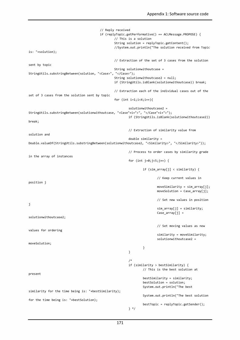
171
Appendix 1: Software source code
// Reply received if (replyTopic.getPerformative() == ACLMessage.PROPOSE) { // This is a solution String solution = replyTopic.getContent(); //System.out.println("The solution received from Topic is: "+solution); // Extraction of the set of 3 cases from the solution sent by topic String solutionwithoutcase = StringUtils.substringBetween(solution, "<Case>", "</Case>"); String solutionwithoutcase2 = null; if (StringUtils.isBlank(solutionwithoutcase)) break; // Extraction each of the individual cases out of the set of 3 cases from the solution sent by topic for (int i=1;i<4;i++){ solutionwithoutcase2 = StringUtils.substringBetween(solutionwithoutcase, "<Case"+i+">", "</Case"+i+">"); if (StringUtils.isBlank(solutionwithoutcase2)) break; // Extraction of similarity value from solution and double similarity = Double.valueOf(StringUtils.substringBetween(solutionwithoutcase2, "<Similarity>", "</Similarity>")); // Process to order cases by similarity grade in the array of instances for (int j=0;j<5;j++) { if (sim_array[j] < similarity) { // Keep current values in position j moveSimilarity = sim_array[j]; moveSolution = Case_array[j]; // Set new values in position j sim_array[j] = similarity; Case_array[j] = solutionwithoutcase2; // Set moving values as new values for ordering similarity = moveSimilarity; solutionwithoutcase2 = moveSolution; } } /* if (similarity > bestSimilarity) { // This is the best solution at present bestSimilarity = similarity; bestSolution = solution; System.out.println("The best similarity for the time being is: "+bestSimilarity); System.out.println("The best solution for the time being is: "+bestSolution); bestTopic = replyTopic.getSender(); } */
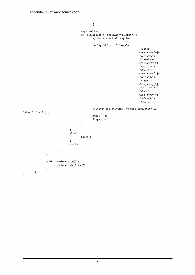
172
Appendix 1: Software source code
} } repliesCnt++; if (repliesCnt >= topicAgents.length) { // We received all replies replaytoGUI = "<Case>"+ "<Case1>"+ Case_array[0]+ "</Case1>"+ "<Case2>"+ Case_array[1]+ "</Case2>"+ "<Case3>"+ Case_array[2]+ "</Case3>"+ "<Case4>"+ Case_array[3]+ "</Case4>"+ "<Case5>"+ Case_array[4]+ "</Case5>"+ "</Case>"; //System.out.println("The best similarity is: "+bestSimilarity); step2 = 2; flagsim = 1; } } else{ block(); } break; } } public boolean done() { return (step2 == 2); } } }
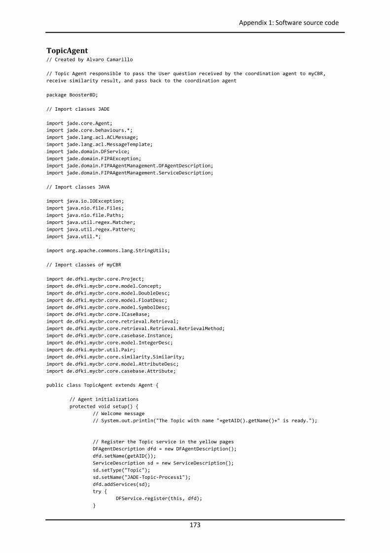
173
Appendix 1: Software source code
TopicAgent // Created by Alvaro Camarillo // Topic Agent responsible to pass the User question received by the coordination agent to myCBR, receive similarity result, and pass back to the coordination agent package Booster8D; // Import classes JADE import jade.core.Agent; import jade.core.behaviours.*; import jade.lang.acl.ACLMessage; import jade.lang.acl.MessageTemplate; import jade.domain.DFService; import jade.domain.FIPAException; import jade.domain.FIPAAgentManagement.DFAgentDescription; import jade.domain.FIPAAgentManagement.ServiceDescription; // Import classes JAVA import java.io.IOException; import java.nio.file.Files; import java.nio.file.Paths; import java.util.regex.Matcher; import java.util.regex.Pattern; import java.util.*; import org.apache.commons.lang.StringUtils; // Import classes of myCBR import de.dfki.mycbr.core.Project; import de.dfki.mycbr.core.model.Concept; import de.dfki.mycbr.core.model.DoubleDesc; import de.dfki.mycbr.core.model.FloatDesc; import de.dfki.mycbr.core.model.SymbolDesc; import de.dfki.mycbr.core.ICaseBase; import de.dfki.mycbr.core.retrieval.Retrieval; import de.dfki.mycbr.core.retrieval.Retrieval.RetrievalMethod; import de.dfki.mycbr.core.casebase.Instance; import de.dfki.mycbr.core.model.IntegerDesc; import de.dfki.mycbr.util.Pair; import de.dfki.mycbr.core.similarity.Similarity; import de.dfki.mycbr.core.model.AttributeDesc; import de.dfki.mycbr.core.casebase.Attribute; public class TopicAgent extends Agent { // Agent initializations protected void setup() { // Welcome message // System.out.println("The Topic with name "+getAID().getName()+" is ready."); // Register the Topic service in the yellow pages DFAgentDescription dfd = new DFAgentDescription(); dfd.setName(getAID()); ServiceDescription sd = new ServiceDescription(); sd.setType("Topic"); sd.setName("JADE-Topic-Process1"); dfd.addServices(sd); try { DFService.register(this, dfd); }
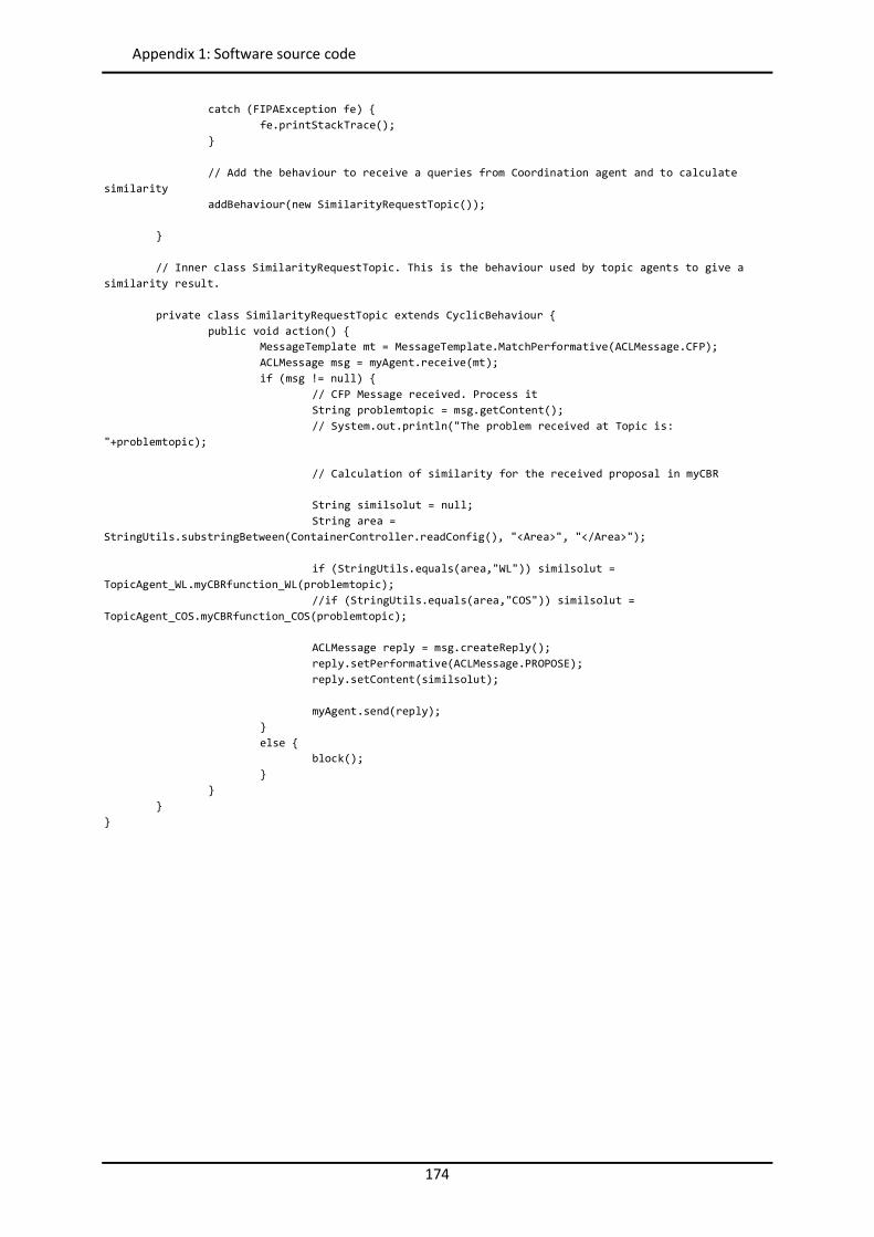
174
Appendix 1: Software source code
catch (FIPAException fe) { fe.printStackTrace(); } // Add the behaviour to receive a queries from Coordination agent and to calculate similarity addBehaviour(new SimilarityRequestTopic()); } // Inner class SimilarityRequestTopic. This is the behaviour used by topic agents to give a similarity result. private class SimilarityRequestTopic extends CyclicBehaviour { public void action() { MessageTemplate mt = MessageTemplate.MatchPerformative(ACLMessage.CFP); ACLMessage msg = myAgent.receive(mt); if (msg != null) { // CFP Message received. Process it String problemtopic = msg.getContent(); // System.out.println("The problem received at Topic is: "+problemtopic); // Calculation of similarity for the received proposal in myCBR String similsolut = null; String area = StringUtils.substringBetween(ContainerController.readConfig(), "<Area>", "</Area>"); if (StringUtils.equals(area,"WL")) similsolut = TopicAgent_WL.myCBRfunction_WL(problemtopic); //if (StringUtils.equals(area,"COS")) similsolut = TopicAgent_COS.myCBRfunction_COS(problemtopic); ACLMessage reply = msg.createReply(); reply.setPerformative(ACLMessage.PROPOSE); reply.setContent(similsolut); myAgent.send(reply); } else { block(); } } } }
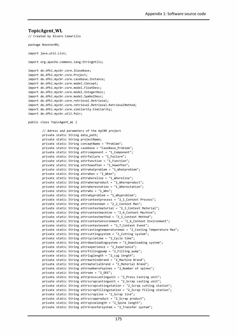
175
Appendix 1: Software source code
TopicAgent_WL // Created by Alvaro Camarillo package Booster8D; import java.util.List; import org.apache.commons.lang.StringUtils; import de.dfki.mycbr.core.ICaseBase; import de.dfki.mycbr.core.Project; import de.dfki.mycbr.core.casebase.Instance; import de.dfki.mycbr.core.model.Concept; import de.dfki.mycbr.core.model.FloatDesc; import de.dfki.mycbr.core.model.IntegerDesc; import de.dfki.mycbr.core.model.SymbolDesc; import de.dfki.mycbr.core.retrieval.Retrieval; import de.dfki.mycbr.core.retrieval.Retrieval.RetrievalMethod; import de.dfki.mycbr.core.similarity.Similarity; import de.dfki.mycbr.util.Pair; public class TopicAgent_WL { // Adress and parameters of the myCBR project private static String data_path; private static String projectName; private static String conceptName = "Problem"; private static String casebase = "CaseBase_Problem"; private static String attrcomponent = "1_Component"; private static String attrfailure = "1_Failure"; private static String attrfunction = "1_Function"; private static String attrhowoften = "1_Howoften"; private static String attrwhatproblem = "1_Whatproblem"; private static String attrwhen = "1_When"; private static String attrwhereline = "1_Whereline"; private static String attrwhereproduct = "1_Whereproduct"; private static String attrwherestation = "1_Wherestation"; private static String attrwho = "1_Who"; private static String attrwhyproblem = "1_Whyproblem"; private static String attrcontextprocess = "2_1_Context Process"; private static String attrcontextman = "2_2_Context Man"; private static String attrcontextmaterial = "2_3_Context Material"; private static String attrcontextmachine = "2_4_Context Machine"; private static String attrcontextmethod = "2_5_Context Method"; private static String attrcontextenvironment = "2_6_Context Environment"; private static String attrcontextevent = "2_7_Context Event"; private static String attrcastingtemperaturemax = "2_Casting Temperature Max"; private static String attrcuttingsystem = "2_Cutting system"; private static String attrcycletime = "2_Cycle time"; private static String attrdownloadingsystem = "2_Downloading system"; private static String attrexperience = "2_Experience"; private static String attrfillingpump = "2_Filling pump"; private static String attrluglength = "2_Lug length"; private static String attrmachinebrand = "2_Machine Brand"; private static String attrmaterialbrand = "2_Material Brand"; private static String attrnumberofspines = "2_Number of spines"; private static String attroee = "2_OEE"; private static String attrpresscastingunit = "2_Press Casting unit"; private static String attrscrapcastingunit = "2_Scrap casting unit"; private static String attrscrapcuttingstation = "2_Scrap cutting station"; private static String attrscrapfillingstation = "2_Scrap filling station"; private static String attrscrapline = "2_Scrap line"; private static String attrscrapproduct = "2_Scrap product"; private static String attrspinelength = "2_Spine length"; private static String attrtransfersystem = "2_Transfer system";
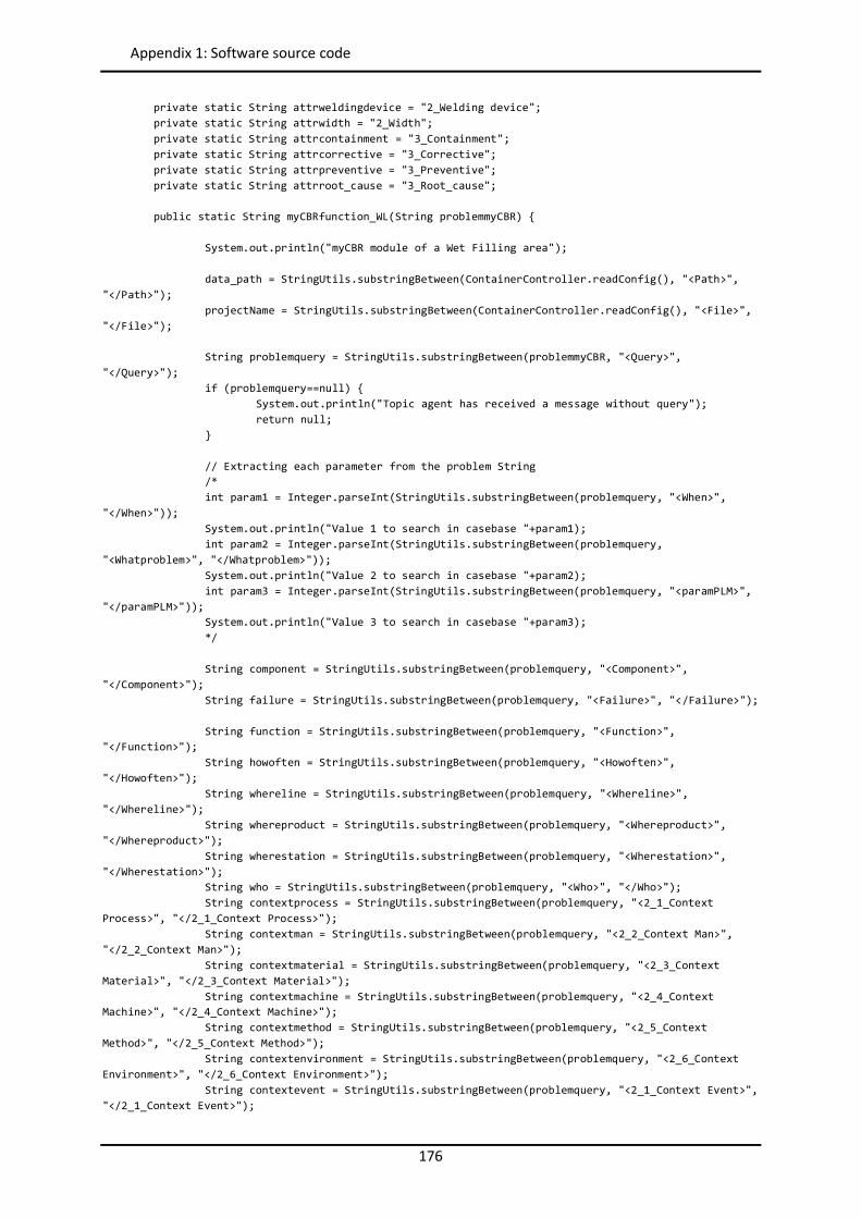
176
Appendix 1: Software source code
private static String attrweldingdevice = "2_Welding device"; private static String attrwidth = "2_Width"; private static String attrcontainment = "3_Containment"; private static String attrcorrective = "3_Corrective"; private static String attrpreventive = "3_Preventive"; private static String attrroot_cause = "3_Root_cause"; public static String myCBRfunction_WL(String problemmyCBR) { System.out.println("myCBR module of a Wet Filling area"); data_path = StringUtils.substringBetween(ContainerController.readConfig(), "<Path>", "</Path>"); projectName = StringUtils.substringBetween(ContainerController.readConfig(), "<File>", "</File>"); String problemquery = StringUtils.substringBetween(problemmyCBR, "<Query>", "</Query>"); if (problemquery==null) { System.out.println("Topic agent has received a message without query"); return null; } // Extracting each parameter from the problem String /* int param1 = Integer.parseInt(StringUtils.substringBetween(problemquery, "<When>", "</When>")); System.out.println("Value 1 to search in casebase "+param1); int param2 = Integer.parseInt(StringUtils.substringBetween(problemquery, "<Whatproblem>", "</Whatproblem>")); System.out.println("Value 2 to search in casebase "+param2); int param3 = Integer.parseInt(StringUtils.substringBetween(problemquery, "<paramPLM>", "</paramPLM>")); System.out.println("Value 3 to search in casebase "+param3); */ String component = StringUtils.substringBetween(problemquery, "<Component>", "</Component>"); String failure = StringUtils.substringBetween(problemquery, "<Failure>", "</Failure>"); String function = StringUtils.substringBetween(problemquery, "<Function>", "</Function>"); String howoften = StringUtils.substringBetween(problemquery, "<Howoften>", "</Howoften>"); String whereline = StringUtils.substringBetween(problemquery, "<Whereline>", "</Whereline>"); String whereproduct = StringUtils.substringBetween(problemquery, "<Whereproduct>", "</Whereproduct>"); String wherestation = StringUtils.substringBetween(problemquery, "<Wherestation>", "</Wherestation>"); String who = StringUtils.substringBetween(problemquery, "<Who>", "</Who>"); String contextprocess = StringUtils.substringBetween(problemquery, "<2_1_Context Process>", "</2_1_Context Process>"); String contextman = StringUtils.substringBetween(problemquery, "<2_2_Context Man>", "</2_2_Context Man>"); String contextmaterial = StringUtils.substringBetween(problemquery, "<2_3_Context Material>", "</2_3_Context Material>"); String contextmachine = StringUtils.substringBetween(problemquery, "<2_4_Context Machine>", "</2_4_Context Machine>"); String contextmethod = StringUtils.substringBetween(problemquery, "<2_5_Context Method>", "</2_5_Context Method>"); String contextenvironment = StringUtils.substringBetween(problemquery, "<2_6_Context Environment>", "</2_6_Context Environment>"); String contextevent = StringUtils.substringBetween(problemquery, "<2_1_Context Event>", "</2_1_Context Event>");
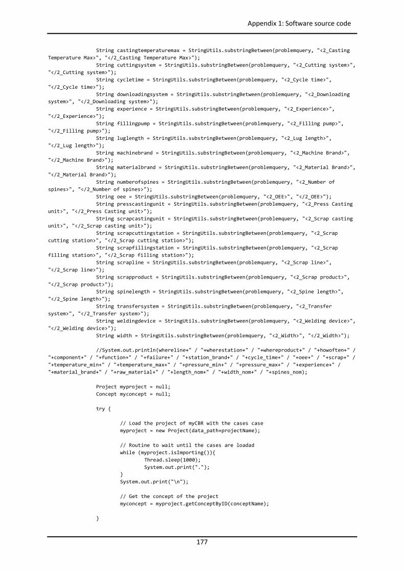
177
Appendix 1: Software source code
String castingtemperaturemax = StringUtils.substringBetween(problemquery, "<2_Casting Temperature Max>", "</2_Casting Temperature Max>"); String cuttingsystem = StringUtils.substringBetween(problemquery, "<2_Cutting system>", "</2_Cutting system>"); String cycletime = StringUtils.substringBetween(problemquery, "<2_Cycle time>", "</2_Cycle time>"); String downloadingsystem = StringUtils.substringBetween(problemquery, "<2_Downloading system>", "</2_Downloading system>"); String experience = StringUtils.substringBetween(problemquery, "<2_Experience>", "</2_Experience>"); String fillingpump = StringUtils.substringBetween(problemquery, "<2_Filling pump>", "</2_Filling pump>"); String luglength = StringUtils.substringBetween(problemquery, "<2_Lug length>", "</2_Lug length>"); String machinebrand = StringUtils.substringBetween(problemquery, "<2_Machine Brand>", "</2_Machine Brand>"); String materialbrand = StringUtils.substringBetween(problemquery, "<2_Material Brand>", "</2_Material Brand>"); String numberofspines = StringUtils.substringBetween(problemquery, "<2_Number of spines>", "</2_Number of spines>"); String oee = StringUtils.substringBetween(problemquery, "<2_OEE>", "</2_OEE>"); String presscastingunit = StringUtils.substringBetween(problemquery, "<2_Press Casting unit>", "</2_Press Casting unit>"); String scrapcastingunit = StringUtils.substringBetween(problemquery, "<2_Scrap casting unit>", "</2_Scrap casting unit>"); String scrapcuttingstation = StringUtils.substringBetween(problemquery, "<2_Scrap cutting station>", "</2_Scrap cutting station>"); String scrapfillingstation = StringUtils.substringBetween(problemquery, "<2_Scrap filling station>", "</2_Scrap filling station>"); String scrapline = StringUtils.substringBetween(problemquery, "<2_Scrap line>", "</2_Scrap line>"); String scrapproduct = StringUtils.substringBetween(problemquery, "<2_Scrap product>", "</2_Scrap product>"); String spinelength = StringUtils.substringBetween(problemquery, "<2_Spine length>", "</2_Spine length>"); String transfersystem = StringUtils.substringBetween(problemquery, "<2_Transfer system>", "</2_Transfer system>"); String weldingdevice = StringUtils.substringBetween(problemquery, "<2_Welding device>", "</2_Welding device>"); String width = StringUtils.substringBetween(problemquery, "<2_Width>", "</2_Width>"); //System.out.println(whereline+" / "+wherestation+" / "+whereproduct+" / "+howoften+" / "+component+" / "+function+" / "+failure+" / "+station_brand+" / "+cycle_time+" / "+oee+" / "+scrap+" / "+temperature_min+" / "+temperature_max+" / "+pressure_min+" / "+pressure_max+" / "+experience+" / "+material_brand+" / "+raw_material+" / "+length_nom+" / "+width_nom+" / "+spines_nom); Project myproject = null; Concept myconcept = null; try { // Load the project of myCBR with the cases case myproject = new Project(data_path+projectName); // Routine to wait until the cases are loadad while (myproject.isImporting()){ Thread.sleep(1000); System.out.print("."); } System.out.print("\n"); // Get the concept of the project myconcept = myproject.getConceptByID(conceptName); }
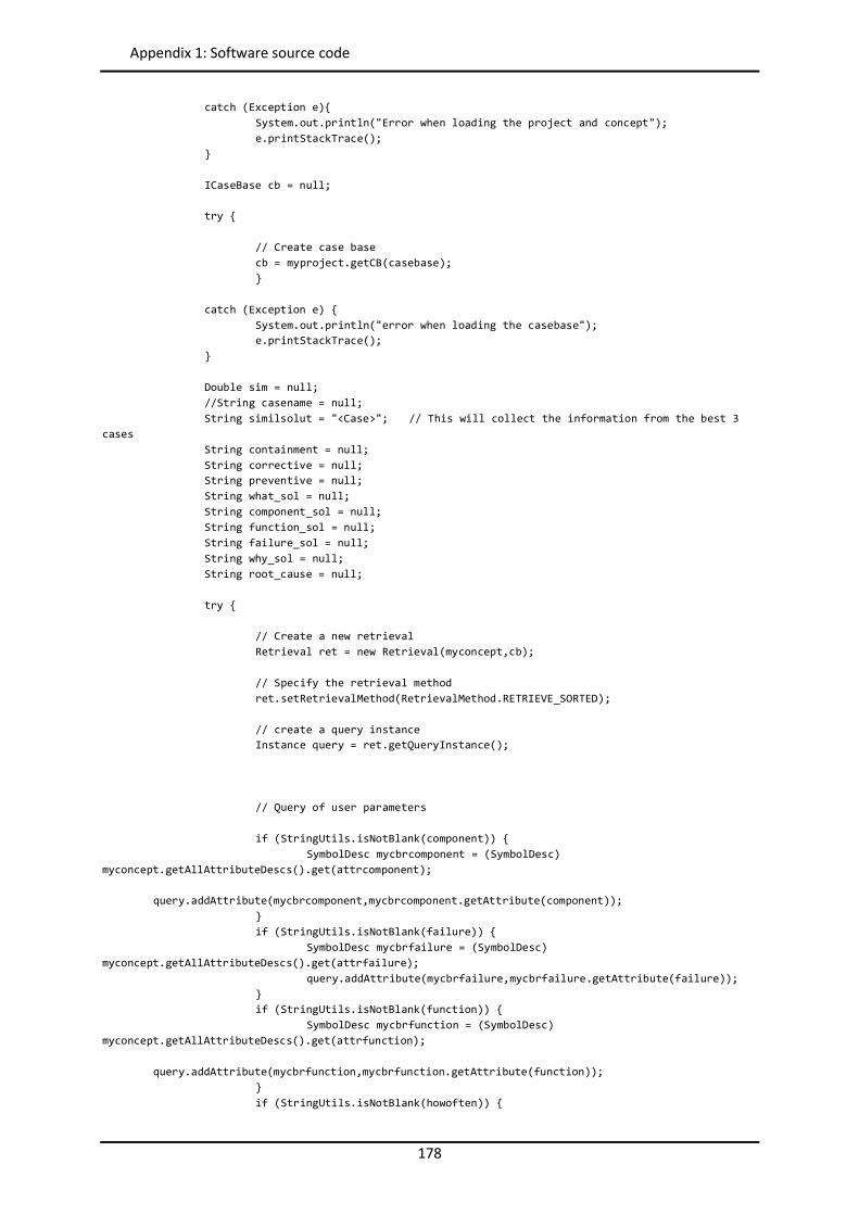
178
Appendix 1: Software source code
catch (Exception e){ System.out.println("Error when loading the project and concept"); e.printStackTrace(); } ICaseBase cb = null; try { // Create case base cb = myproject.getCB(casebase); } catch (Exception e) { System.out.println("error when loading the casebase"); e.printStackTrace(); } Double sim = null; //String casename = null; String similsolut = "<Case>"; // This will collect the information from the best 3 cases String containment = null; String corrective = null; String preventive = null; String what_sol = null; String component_sol = null; String function_sol = null; String failure_sol = null; String why_sol = null; String root_cause = null; try { // Create a new retrieval Retrieval ret = new Retrieval(myconcept,cb); // Specify the retrieval method ret.setRetrievalMethod(RetrievalMethod.RETRIEVE_SORTED); // create a query instance Instance query = ret.getQueryInstance(); // Query of user parameters if (StringUtils.isNotBlank(component)) { SymbolDesc mycbrcomponent = (SymbolDesc) myconcept.getAllAttributeDescs().get(attrcomponent); query.addAttribute(mycbrcomponent,mycbrcomponent.getAttribute(component)); } if (StringUtils.isNotBlank(failure)) { SymbolDesc mycbrfailure = (SymbolDesc) myconcept.getAllAttributeDescs().get(attrfailure); query.addAttribute(mycbrfailure,mycbrfailure.getAttribute(failure)); } if (StringUtils.isNotBlank(function)) { SymbolDesc mycbrfunction = (SymbolDesc) myconcept.getAllAttributeDescs().get(attrfunction); query.addAttribute(mycbrfunction,mycbrfunction.getAttribute(function)); } if (StringUtils.isNotBlank(howoften)) {
179
Appendix 1: Software source code
SymbolDesc mycbrhowoften = (SymbolDesc) myconcept.getAllAttributeDescs().get(attrhowoften); query.addAttribute(mycbrhowoften,mycbrhowoften.getAttribute(howoften)); } if (StringUtils.isNotBlank(who)) { SymbolDesc mycbrwho = (SymbolDesc) myconcept.getAllAttributeDescs().get(attrwho); query.addAttribute(mycbrwho,mycbrwho.getAttribute(who)); } if (StringUtils.isNotBlank(whereline)) { SymbolDesc mycbrwhereline = (SymbolDesc) myconcept.getAllAttributeDescs().get(attrwhereline); query.addAttribute(mycbrwhereline,mycbrwhereline.getAttribute(whereline)); } if (StringUtils.isNotBlank(whereproduct)) { SymbolDesc mycbrwhereproduct = (SymbolDesc) myconcept.getAllAttributeDescs().get(attrwhereproduct); query.addAttribute(mycbrwhereproduct,mycbrwhereproduct.getAttribute(whereproduct)); } if (StringUtils.isNotBlank(wherestation)) { SymbolDesc mycbrwherestation = (SymbolDesc) myconcept.getAllAttributeDescs().get(attrwherestation); query.addAttribute(mycbrwherestation,mycbrwherestation.getAttribute(wherestation)); } // Query of PLM parameters if (StringUtils.isNotBlank(contextprocess)) { SymbolDesc mycbrcontextprocess = (SymbolDesc) myconcept.getAllAttributeDescs().get(attrcontextprocess); query.addAttribute(mycbrcontextprocess,mycbrcontextprocess.getAttribute(contextprocess)); } if (StringUtils.isNotBlank(contextman)) { SymbolDesc mycbrcontextman = (SymbolDesc) myconcept.getAllAttributeDescs().get(attrcontextman); query.addAttribute(mycbrcontextman,mycbrcontextman.getAttribute(contextman)); } if (StringUtils.isNotBlank(contextmaterial)) { SymbolDesc mycbrcontextmaterial = (SymbolDesc) myconcept.getAllAttributeDescs().get(attrcontextmaterial); query.addAttribute(mycbrcontextmaterial,mycbrcontextmaterial.getAttribute(contextmaterial)); } if (StringUtils.isNotBlank(contextmachine)) { SymbolDesc mycbrcontextmachine = (SymbolDesc) myconcept.getAllAttributeDescs().get(attrcontextmachine); query.addAttribute(mycbrcontextmachine,mycbrcontextmachine.getAttribute(contextmachine)); } if (StringUtils.isNotBlank(contextmethod)) { SymbolDesc mycbrcontextmethod = (SymbolDesc) myconcept.getAllAttributeDescs().get(attrcontextmethod); query.addAttribute(mycbrcontextmethod,mycbrcontextmethod.getAttribute(contextmethod)); } if (StringUtils.isNotBlank(contextenvironment)) { SymbolDesc mycbrcontextenvironment = (SymbolDesc) myconcept.getAllAttributeDescs().get(attrcontextenvironment);
180
Appendix 1: Software source code
query.addAttribute(mycbrcontextenvironment,mycbrcontextenvironment.getAttribute(contextenvironment)); } if (StringUtils.isNotBlank(contextevent)) { SymbolDesc mycbrcontextevent = (SymbolDesc) myconcept.getAllAttributeDescs().get(attrcontextevent); query.addAttribute(mycbrcontextevent,mycbrcontextevent.getAttribute(contextevent)); } if (StringUtils.isNotBlank(castingtemperaturemax)) { FloatDesc mycbrcastingtemperaturemax = (FloatDesc) myconcept.getAllAttributeDescs().get(attrcastingtemperaturemax); query.addAttribute(mycbrcastingtemperaturemax,mycbrcastingtemperaturemax.getAttribute(Float.parseFloat(castingtemperaturemax))); } if (StringUtils.isNotBlank(cuttingsystem)) { SymbolDesc mycbrcuttingsystem = (SymbolDesc) myconcept.getAllAttributeDescs().get(attrcuttingsystem); query.addAttribute(mycbrcuttingsystem,mycbrcuttingsystem.getAttribute(cuttingsystem)); } if (StringUtils.isNotBlank(cycletime)) { FloatDesc mycbrcycletime = (FloatDesc) myconcept.getAllAttributeDescs().get(attrcycletime); query.addAttribute(mycbrcycletime,mycbrcycletime.getAttribute(Float.parseFloat(cycletime))); } if (StringUtils.isNotBlank(downloadingsystem)) { SymbolDesc mycbrdownloadingsystem = (SymbolDesc) myconcept.getAllAttributeDescs().get(attrdownloadingsystem); query.addAttribute(mycbrdownloadingsystem,mycbrdownloadingsystem.getAttribute(downloadingsystem)); } if (StringUtils.isNotBlank(experience)) { FloatDesc mycbrexperience = (FloatDesc) myconcept.getAllAttributeDescs().get(attrexperience); query.addAttribute(mycbrexperience,mycbrexperience.getAttribute(Float.parseFloat(experience))); } if (StringUtils.isNotBlank(fillingpump)) { SymbolDesc mycbrfillingpump = (SymbolDesc) myconcept.getAllAttributeDescs().get(attrfillingpump); query.addAttribute(mycbrfillingpump,mycbrfillingpump.getAttribute(fillingpump)); } if (StringUtils.isNotBlank(luglength)) { FloatDesc mycbrluglength = (FloatDesc) myconcept.getAllAttributeDescs().get(attrluglength); query.addAttribute(mycbrluglength,mycbrluglength.getAttribute(Float.parseFloat(luglength))); } if (StringUtils.isNotBlank(machinebrand)) { SymbolDesc mycbrmachinebrand = (SymbolDesc) myconcept.getAllAttributeDescs().get(attrmachinebrand); query.addAttribute(mycbrmachinebrand,mycbrmachinebrand.getAttribute(machinebrand)); } if (StringUtils.isNotBlank(materialbrand)) { SymbolDesc mycbrmaterialbrand = (SymbolDesc) myconcept.getAllAttributeDescs().get(attrmaterialbrand); query.addAttribute(mycbrmaterialbrand,mycbrmaterialbrand.getAttribute(materialbrand));
181
Appendix 1: Software source code
} if (StringUtils.isNotBlank(numberofspines)) { IntegerDesc mycbrnumberofspines = (IntegerDesc) myconcept.getAllAttributeDescs().get(attrnumberofspines); query.addAttribute(mycbrnumberofspines,mycbrnumberofspines.getAttribute(Integer.parseInt(numberofspines))); } if (StringUtils.isNotBlank(oee)) { FloatDesc mycbroee = (FloatDesc) myconcept.getAllAttributeDescs().get(attroee); query.addAttribute(mycbroee,mycbroee.getAttribute(Float.parseFloat(oee))); } if (StringUtils.isNotBlank(presscastingunit)) { SymbolDesc mycbrpresscastingunit = (SymbolDesc) myconcept.getAllAttributeDescs().get(attrpresscastingunit); query.addAttribute(mycbrpresscastingunit,mycbrpresscastingunit.getAttribute(presscastingunit)); } if (StringUtils.isNotBlank(scrapcastingunit)) { FloatDesc mycbrscrapcastingunit = (FloatDesc) myconcept.getAllAttributeDescs().get(attrscrapcastingunit); query.addAttribute(mycbrscrapcastingunit,mycbrscrapcastingunit.getAttribute(Float.parseFloat(scrapcastingunit))); } if (StringUtils.isNotBlank(scrapcuttingstation)) { FloatDesc mycbrscrapcuttingstation = (FloatDesc) myconcept.getAllAttributeDescs().get(attrscrapcuttingstation); query.addAttribute(mycbrscrapcuttingstation,mycbrscrapcuttingstation.getAttribute(Float.parseFloat(scrapcuttingstation))); } if (StringUtils.isNotBlank(scrapfillingstation)) { FloatDesc mycbrscrapfillingstation = (FloatDesc) myconcept.getAllAttributeDescs().get(attrscrapfillingstation); query.addAttribute(mycbrscrapfillingstation,mycbrscrapfillingstation.getAttribute(Float.parseFloat(scrapfillingstation))); } if (StringUtils.isNotBlank(scrapline)) { FloatDesc mycbrscrapline = (FloatDesc) myconcept.getAllAttributeDescs().get(attrscrapline); query.addAttribute(mycbrscrapline,mycbrscrapline.getAttribute(Float.parseFloat(scrapline))); } if (StringUtils.isNotBlank(scrapproduct)) { FloatDesc mycbrscrapproduct = (FloatDesc) myconcept.getAllAttributeDescs().get(attrscrapproduct); query.addAttribute(mycbrscrapproduct,mycbrscrapproduct.getAttribute(Float.parseFloat(scrapproduct))); } if (StringUtils.isNotBlank(spinelength)) { FloatDesc mycbrspinelength = (FloatDesc) myconcept.getAllAttributeDescs().get(attrspinelength); query.addAttribute(mycbrspinelength,mycbrspinelength.getAttribute(Float.parseFloat(spinelength))); } if (StringUtils.isNotBlank(transfersystem)) { SymbolDesc mycbrtransfersystem = (SymbolDesc) myconcept.getAllAttributeDescs().get(attrtransfersystem);
182
Appendix 1: Software source code
query.addAttribute(mycbrtransfersystem,mycbrtransfersystem.getAttribute(transfersystem)); } if (StringUtils.isNotBlank(weldingdevice)) { SymbolDesc mycbrweldingdevice = (SymbolDesc) myconcept.getAllAttributeDescs().get(attrweldingdevice); query.addAttribute(mycbrweldingdevice,mycbrweldingdevice.getAttribute(weldingdevice)); } if (StringUtils.isNotBlank(width)) { FloatDesc mycbrwidth = (FloatDesc) myconcept.getAllAttributeDescs().get(attrwidth); query.addAttribute(mycbrwidth,mycbrwidth.getAttribute(Float.parseFloat(width))); } // perform retrieval ret.start(); // get the retrieval result List <Pair<Instance, Similarity>> result = ret.getResult(); // get the case name if(result.size()>0){ int k = 0; // Counter for the chain of failures Instance root_case_instance; // Object Instance to get the chain of failures for (int i=0 , j=1; i<3 ;i++ , j++) { if (i==result.size()) break; similsolut = similsolut + "<Case"+j+">"; // Get first failure of this case root_case_instance = result.get(i).getFirst(); // get the similarity value of this case sim = result.get(i).getSecond().getValue(); //System.out.println("I found "+casename+" with a similarity of "+sim+" as the best match."); System.out.println("I found the case number "+i+" with a similarity of "+sim); similsolut = similsolut + "<Similarity>"+String.valueOf(sim.doubleValue())+"</Similarity>"; // Get the chain of failures until root cause do { k++; similsolut = similsolut + "<Failure"+k+">"; // get the parameters containment = root_case_instance.getAttForDesc(myconcept.getAllAttributeDescs().get(attrcontainment)).getValueAsString(); corrective = root_case_instance.getAttForDesc(myconcept.getAllAttributeDescs().get(attrcorrective)).getValueAsString(); preventive = root_case_instance.getAttForDesc(myconcept.getAllAttributeDescs().get(attrpreventive)).getValueAsString();
183
Appendix 1: Software source code
what_sol = root_case_instance.getAttForDesc(myconcept.getAllAttributeDescs().get(attrwhatproblem)).getValueAsString(); component_sol = root_case_instance.getAttForDesc(myconcept.getAllAttributeDescs().get(attrcomponent)).getValueAsString(); function_sol = root_case_instance.getAttForDesc(myconcept.getAllAttributeDescs().get(attrfunction)).getValueAsString(); failure_sol = root_case_instance.getAttForDesc(myconcept.getAllAttributeDescs().get(attrfailure)).getValueAsString(); why_sol = root_case_instance.getAttForDesc(myconcept.getAllAttributeDescs().get(attrwhyproblem)).getValueAsString(); root_cause = root_case_instance.getAttForDesc(myconcept.getAllAttributeDescs().get(attrroot_cause)).getValueAsString(); // System.out.println("El root_cause es: " + root_cause); similsolut = similsolut + "<Containment>"+containment+"</Containment>"+ "<Corrective>"+corrective+"</Corrective>"+ "<Preventive>"+preventive+"</Preventive>"+ "<What_sol>"+what_sol+"</What_sol>"+ "<Component_sol>"+component_sol+"</Component_sol>"+ "<Function_sol>"+function_sol+"</Function_sol>"+ "<Failure_sol>"+failure_sol+"</Failure_sol>"+ "<Why_sol>"+why_sol+"</Why_sol>"; root_case_instance = cb.containsCase(root_cause); // Next failure is got in this variable similsolut = similsolut + "<Root_case>"; if (root_cause != "_unknown_") { similsolut = similsolut + "No"; } else { similsolut = similsolut + "Yes"; } similsolut = similsolut + "</Root_case>"; similsolut = similsolut + "</Failure"+k+">"; } while (root_cause != "_unknown_"); similsolut = similsolut + "</Case"+j+">"; k = 0; } } } catch (Exception e) { System.out.println("Error during retrival"); e.printStackTrace(); } // Close the String with tag </Case> similsolut = similsolut + "</Case>";

184
Appendix 1: Software source code
// System.out.println("The result from myCBR is: "+similsolut); return similsolut; } }
185
Appendix 1: Software source code
IndividualizedKAgent // Created by Alvaro Camarillo // Sends the User request to the coordination agent package Booster8D; // Import classes JADE import jade.core.Agent; import jade.core.AID; import jade.core.behaviours.*; import jade.lang.acl.ACLMessage; import jade.lang.acl.MessageTemplate; import jade.domain.DFService; import jade.domain.FIPAException; import jade.domain.FIPAAgentManagement.DFAgentDescription; import jade.domain.FIPAAgentManagement.ServiceDescription; // Import classes JAVA import java.util.*; import java.net.*; import java.io.*; import java.security.*; import java.math.*; // Import classes apache (management of Strings with tags) import org.apache.commons.lang.StringUtils; public class IndividualizedKAgent extends Agent { private AID[] coordinationAgents; // Getting list of known coordination agents private String problem; //The single string to be passed to the CoordinationAgent with the join of all parameters received from GUI (Problem Solving Sheet), and from the PLM (Aras) private Booster8D_GUI myGui; // The GUI by means of which the user can introduce the problem paramaters private int guiflag = 0; // Flag to control when the user has actualized the GUI private String solutionGUI = null; // Solution to be shown to user // Put agent initializations here protected void setup() { // Welcome message // System.out.println("The Individualized Knowledge with name "+getAID().getName()+" is ready."); // Create and show the Booster8D_GUI myGui = new Booster8D_GUI(this); myGui.setVisible(true); // Register the GUI service in the yellow pages DFAgentDescription dfd = new DFAgentDescription(); dfd.setName(getAID()); ServiceDescription sd = new ServiceDescription(); sd.setType("GUI"); sd.setName("JADE-GUI-Process1"); dfd.addServices(sd); try { DFService.register(this, dfd); } catch (FIPAException fe) { fe.printStackTrace(); }
186
Appendix 1: Software source code
// Add the behaviour to send info to coordination agent when GUI is actualized addBehaviour(new SimilarityRequestGUI()); } // Put agent clean-up operations here protected void takeDown() { // Deregister from the yellow pages try { DFService.deregister(this); } catch (FIPAException fe) { fe.printStackTrace(); } // Close the GUI myGui.dispose(); // Printout a dismissal message // System.out.println("IndividualizedKAgent "+getAID().getName()+" terminating."); } // This is invoked by the GUI when the user adds a new problem. It takes the information from the user, sends a call to the PLM and receives back additional information (through the function "AML_Communicator", and send it all together to the CoordinationAgent public void updateVector(final String querystring) { addBehaviour(new OneShotBehaviour() { public void action() { // Get information from PLM through the function PLMrequest_Manager of the class PLMrequest_Manager String PLMreturn = PLMrequest_Manager.PLMrequest_Manager(querystring); // Create the full query with the information from the user and from the PLM if (StringUtils.isNotBlank(PLMreturn)) { problem = ("<Query>"+querystring+PLMreturn+"</Query>"); } else { problem = ("<Query>"+querystring+"</Query>"); } System.out.println("Problem to be solved at IndividualizedKAgent: "+problem); // Activation of guiflag to alert that the problem string has been actualized guiflag = 1; } } ); } // Inner class SimilarityRequestGUI. This is the behaviour used by GUI to send info to coordination agent when GUI is actualized. private class SimilarityRequestGUI extends CyclicBehaviour { private MessageTemplate mt; // The template to receive replies private int step = 0; public void action() { switch (step) { case 0: // Case 0 --> Sending info when the GUI was actulized if (guiflag == 1) {
187
Appendix 1: Software source code
// Sending the String with the problem information to the CoordinationAgent DFAgentDescription template = new DFAgentDescription(); ServiceDescription sd = new ServiceDescription(); sd.setType("Coordination"); template.addServices(sd); try { DFAgentDescription[] result = DFService.search(myAgent, template); // System.out.println("Found the following coordination agents:"); coordinationAgents = new AID[result.length]; if (result.length != 1) { System.out.println("There are more than one CoordinationAgent. Error!!!"); doDelete(); } else { coordinationAgents[0] = result[0].getName(); // System.out.println(coordinationAgents[0].getName()); } } catch (FIPAException fe) { fe.printStackTrace(); } // Send the cfp to Coordination agents ACLMessage cfp = new ACLMessage(ACLMessage.CFP); cfp.addReceiver(coordinationAgents[0]); cfp.setConversationId("GUI-Request"); cfp.setContent(problem); cfp.setReplyWith("cfp"+System.currentTimeMillis()); // Unique value myAgent.send(cfp); // Prepare the template to get proposals mt = MessageTemplate.and(MessageTemplate.MatchConversationId("GUI-Request"), MessageTemplate.MatchInReplyTo(cfp.getReplyWith())); step = 1; } break; case 1: // Case 1 --> Receiving the solution from Coordination Agent ACLMessage reply = myAgent.receive(mt); if (reply != null) { // Reply received if (reply.getPerformative() == ACLMessage.PROPOSE) { // This is a solution solutionGUI = reply.getContent(); } // System.out.println("The best similarity at GUI is: "+StringUtils.substringBetween(solutionGUI, "<Similarity>", "</Similarity>")); // System.out.println("The best solution at GUI is: "+StringUtils.substringBetween(solutionGUI, "<Corrective>", "</Corrective>")); System.out.println("The solution arrived at IndividualizedKAgent is: "+solutionGUI); // Show result through GUI myGui.showResults(solutionGUI);

188
Appendix 1: Software source code
step = 0; // Return to 0 flag to control update of GUI guiflag = 0; } else { block(); } break; } } } }
189
Appendix 1: Software source code
Booster8D_GUI // Created by Alvaro Camarillo package Booster8D; //Import classes JADE import jade.core.AID; //Import classes JAVA import java.awt.*; import java.awt.event.*; import javax.swing.*; import java.awt.BorderLayout; import java.awt.EventQueue; import javax.swing.JFrame; import javax.swing.JPanel; import javax.swing.border.EmptyBorder; import javax.swing.border.TitledBorder; import java.awt.Toolkit; import java.awt.Color; import javax.swing.ImageIcon; import javax.swing.JButton; import javax.swing.JTextField; import java.awt.SystemColor; import javax.swing.JTextPane; import java.awt.event.ActionListener; import java.awt.event.ActionEvent; import java.io.File; import java.io.FileNotFoundException; import java.io.PrintWriter; import java.io.IOException; import java.nio.file.Files; import java.nio.file.Paths; //Import classes apache (management of Strings with tags) import org.apache.commons.lang.StringUtils; class Booster8D_GUI extends JFrame { private IndividualizedKAgent myAgent; private int i = 0; // Counter for the presentation of results. It manage the Case number private int j = 0; // Counter for the presentation of results. It manage the Failure number private int k = 0; // Counter for the line to be displayed results in conversational loop private String solutionwithoutcase_8D = null; private String solutioncase_8D = null; private String solutionfailure_8D = null; private final JScrollPane scrollPane; private final JPanel contentPane; private final JButton btnLoad = new JButton("Load"); private final JButton btnSave = new JButton("Save"); private final JButton btnClearAll = new JButton("Clear All"); private final JButton btnNewSearch = new JButton("New Search"); private final JButton btnNextCase = new JButton("Next Case"); private final JButton btnNextLevel = new JButton("Next Level"); private final JButton btnRootCauseOk = new JButton("Show Solution"); private final JTextField pss_name = new JTextField(); private final JTextField when = new JTextField(); private final Choice contextevent = new Choice(); private final Choice whereline = new Choice(); private final Choice wherestation = new Choice(); private final Choice whereproduct = new Choice(); private final Choice howoften = new Choice();

190
Appendix 1: Software source code
private final Choice who = new Choice(); private final JTextField whatproblem = new JTextField(); private final JScrollPane scrollwhatproblem = new JScrollPane(); private final Choice component = new Choice(); private final Choice function = new Choice(); private final Choice failure = new Choice(); private final JTextField whyproblem = new JTextField(); private final JScrollPane scrollwhyproblem = new JScrollPane(); private final JTextArea conver11 = new JTextArea(); private final JScrollPane scrollconver11 = new JScrollPane(); private final JTextArea conver12 = new JTextArea(); private final JScrollPane scrollconver12 = new JScrollPane(); private final JTextArea conver13 = new JTextArea(); private final JScrollPane scrollconver13 = new JScrollPane(); private final JTextArea conver21 = new JTextArea(); private final JScrollPane scrollconver21 = new JScrollPane(); private final JTextArea conver22 = new JTextArea(); private final JScrollPane scrollconver22 = new JScrollPane(); private final JTextArea conver23 = new JTextArea(); private final JScrollPane scrollconver23 = new JScrollPane(); private final JTextArea conver31 = new JTextArea(); private final JScrollPane scrollconver31 = new JScrollPane(); private final JTextArea conver32 = new JTextArea(); private final JScrollPane scrollconver32 = new JScrollPane(); private final JTextArea conver33 = new JTextArea(); private final JScrollPane scrollconver33 = new JScrollPane(); private final JTextArea conver41 = new JTextArea(); private final JScrollPane scrollconver41 = new JScrollPane(); private final JTextArea conver42 = new JTextArea(); private final JScrollPane scrollconver42 = new JScrollPane(); private final JTextArea conver43 = new JTextArea(); private final JScrollPane scrollconver43 = new JScrollPane(); private final JTextArea conver51 = new JTextArea(); private final JScrollPane scrollconver51 = new JScrollPane(); private final JTextArea conver52 = new JTextArea(); private final JScrollPane scrollconver52 = new JScrollPane(); private final JTextArea conver53 = new JTextArea(); private final JScrollPane scrollconver53 = new JScrollPane(); private final JTextArea containment = new JTextArea(); private final JScrollPane scrollcontainment = new JScrollPane(); private final JTextField what_sol = new JTextField(); private final JScrollPane scrollwhat_sol = new JScrollPane(); private final JTextField component_sol = new JTextField(); private final JScrollPane scrollcomponent_sol = new JScrollPane(); private final JTextField function_sol = new JTextField(); private final JScrollPane scrollfunction_sol = new JScrollPane(); private final JTextField failure_sol = new JTextField(); private final JScrollPane scrollfailure_sol = new JScrollPane(); private final JTextField why_sol = new JTextField(); private final JScrollPane scrollwhy_sol = new JScrollPane(); private final JTextArea corrective = new JTextArea(); private final JScrollPane scrollcorrective = new JScrollPane(); private final JTextArea preventive = new JTextArea(); private final JScrollPane scrollpreventive = new JScrollPane(); /** * Create the frame. */ public Booster8D_GUI(IndividualizedKAgent a) { setTitle("Booster8D"); myAgent = a;
191
Appendix 1: Software source code
setIconImage(Toolkit.getDefaultToolkit().getImage(Booster8D_GUI.class.getResource("/Booster8D/Booster8D3.png"))); setDefaultCloseOperation(JFrame.EXIT_ON_CLOSE); //setBounds(100, 100, 700, 600); Dimension screenSize = Toolkit.getDefaultToolkit().getScreenSize(); double width = screenSize.getWidth(); double height = screenSize.getHeight(); setBounds(0, 0, (int)width, ((int)height-40)); getContentPane().setLayout(null); getContentPane().setLayout(null); scrollPane = new JScrollPane(); scrollPane.setBounds(0, 0, ((int)width-10), ((int)height-50)); getContentPane().add(scrollPane); // The class JPanel is overriden to set the image of the PSS as background image of the Panel final Image image = Toolkit.getDefaultToolkit().getImage(Booster8D_GUI.class.getResource("/Booster8D/PSS_6.png")); contentPane = new JPanel() { @Override protected void paintComponent(Graphics g) { super.paintComponent(g); g.drawImage(image, 0, 0, null); } }; contentPane.setForeground(Color.WHITE); contentPane.setPreferredSize(new Dimension(1330, 1000)); scrollPane.setViewportView(contentPane); contentPane.setLayout(null); // Definition of TextFields pss_name.setBackground(SystemColor.menu); pss_name.setBounds(803, 28, 326, 22); contentPane.add(pss_name); pss_name.setColumns(10); when.setBackground(SystemColor.menu); when.setBounds(185, 210, 120, 17); contentPane.add(when); when.setColumns(10); when.setText("2000-01-01T00:00:00"); contextevent.setForeground(SystemColor.desktop); contextevent.setBackground(SystemColor.menu); contextevent.setBounds(450, 208, 215, 20); contentPane.add(contextevent); // Load taxonomy from taxonomy_config file String[] contexteventtaxonomyArray = StringUtils.substringBetween(ContainerController.readConfig(), "<Context_Event>", "</Context_Event>").split(","); for(String taxo : contexteventtaxonomyArray){ contextevent.add(taxo); } whereline.setForeground(SystemColor.desktop); whereline.setBackground(SystemColor.menu); whereline.setBounds(185, 229, 480, 20); contentPane.add(whereline); // Load taxonomy from taxonomy_config file
192
Appendix 1: Software source code
String[] wherelinetaxonomyArray = StringUtils.substringBetween(ContainerController.readConfig(), "<Whereline>", "</Whereline>").split(","); for(String taxo : wherelinetaxonomyArray){ whereline.add(taxo); } wherestation.setForeground(SystemColor.desktop); wherestation.setBackground(SystemColor.menu); wherestation.setBounds(185, 250, 480, 20); contentPane.add(wherestation); // Load taxonomy from taxonomy_config file String[] wherestationtaxonomyArray = StringUtils.substringBetween(ContainerController.readConfig(), "<Wherestation>", "</Wherestation>").split(","); for(String taxo : wherestationtaxonomyArray){ wherestation.add(taxo); } whereproduct.setForeground(SystemColor.desktop); whereproduct.setBackground(SystemColor.menu); whereproduct.setBounds(185, 272, 480, 17); contentPane.add(whereproduct); // Load taxonomy from taxonomy_config file String[] whereproducttaxonomyArray = StringUtils.substringBetween(ContainerController.readConfig(), "<Whereproduct>", "</Whereproduct>").split(","); for(String taxo : whereproducttaxonomyArray){ whereproduct.add(taxo); } howoften.setForeground(SystemColor.desktop); howoften.setBackground(SystemColor.menu); howoften.setBounds(185, 294, 480, 20); contentPane.add(howoften); // Load taxonomy from taxonomy_config file String[] howoftentaxonomyArray = StringUtils.substringBetween(ContainerController.readConfig(), "<Howoften>", "</Howoften>").split(","); for(String taxo : howoftentaxonomyArray){ howoften.add(taxo); } who.setForeground(SystemColor.desktop); who.setBackground(SystemColor.menu); who.setBounds(185, 316, 480, 20); contentPane.add(who); // Load taxonomy from taxonomy_config file String[] whotaxonomyArray = StringUtils.substringBetween(ContainerController.readConfig(), "<Who>", "</Who>").split(","); for(String taxo : whotaxonomyArray){ who.add(taxo); } scrollwhatproblem.setBounds(185, 337, 480, 34); contentPane.add(scrollwhatproblem); scrollwhatproblem.setViewportView(whatproblem); whatproblem.setBackground(SystemColor.menu); whatproblem.setColumns(10); component.setForeground(SystemColor.desktop); component.setBackground(SystemColor.menu); component.setBounds(185, 372, 480, 20); contentPane.add(component); // Load taxonomy from taxonomy_config file
193
Appendix 1: Software source code
String[] componentArray = StringUtils.substringBetween(ContainerController.readConfig(), "<Component>", "</Component>").split(","); for(String taxo : componentArray){ component.add(taxo); } function.setForeground(SystemColor.desktop); function.setBackground(SystemColor.menu); function.setBounds(185, 393, 480, 20); contentPane.add(function); // Load taxonomy from taxonomy_config file String[] functionArray = StringUtils.substringBetween(ContainerController.readConfig(), "<Function>", "</Function>").split(","); for(String taxo : functionArray){ function.add(taxo); } failure.setForeground(SystemColor.desktop); failure.setBackground(SystemColor.menu); failure.setBounds(185, 415, 480, 20); contentPane.add(failure); // Load taxonomy from taxonomy_config file String[] failureArray = StringUtils.substringBetween(ContainerController.readConfig(), "<Failure>", "</Failure>").split(","); for(String taxo : failureArray){ failure.add(taxo); } scrollwhyproblem.setBounds(185, 436, 480, 34); contentPane.add(scrollwhyproblem); scrollwhyproblem.setViewportView(whyproblem); whyproblem.setBackground(SystemColor.menu); whyproblem.setColumns(10); // Definition of TextAreas scrollconver11.setBounds(70, 515, 237, 57); contentPane.add(scrollconver11); conver11.setLineWrap(true); scrollconver11.setViewportView(conver11); conver11.setBackground(SystemColor.info); scrollconver12.setBounds(310, 515, 237, 57); contentPane.add(scrollconver12); conver12.setLineWrap(true); scrollconver12.setViewportView(conver12); conver12.setBackground(SystemColor.info); scrollconver13.setBounds(550, 515, 116, 57); contentPane.add(scrollconver13); conver13.setLineWrap(true); scrollconver13.setViewportView(conver13); conver13.setBackground(SystemColor.info); scrollconver21.setBounds(70, 575, 237, 57); contentPane.add(scrollconver21); conver21.setLineWrap(true); scrollconver21.setViewportView(conver21); conver21.setBackground(SystemColor.info); scrollconver22.setBounds(310, 575, 237, 57); contentPane.add(scrollconver22); conver22.setLineWrap(true);
194
Appendix 1: Software source code
scrollconver22.setViewportView(conver22); conver22.setBackground(SystemColor.info); scrollconver23.setBounds(550, 575, 116, 57); contentPane.add(scrollconver23); conver23.setLineWrap(true); scrollconver23.setViewportView(conver23); conver23.setBackground(SystemColor.info); scrollconver31.setBounds(70, 636, 237, 57); contentPane.add(scrollconver31); conver31.setLineWrap(true); scrollconver31.setViewportView(conver31); conver31.setBackground(SystemColor.info); scrollconver32.setBounds(310, 636, 237, 57); contentPane.add(scrollconver32); conver32.setLineWrap(true); scrollconver32.setViewportView(conver32); conver32.setBackground(SystemColor.info); scrollconver33.setBounds(550, 636, 116, 57); contentPane.add(scrollconver33); conver33.setLineWrap(true); scrollconver33.setViewportView(conver33); conver33.setBackground(SystemColor.info); scrollconver41.setBounds(70, 696, 237, 57); contentPane.add(scrollconver41); conver41.setLineWrap(true); scrollconver41.setViewportView(conver41); conver41.setBackground(SystemColor.info); scrollconver42.setBounds(310, 696, 237, 57); contentPane.add(scrollconver42); conver42.setLineWrap(true); scrollconver42.setViewportView(conver42); conver42.setBackground(SystemColor.info); scrollconver43.setBounds(550, 696, 116, 57); contentPane.add(scrollconver43); conver43.setLineWrap(true); scrollconver43.setViewportView(conver43); conver43.setBackground(SystemColor.info); scrollconver51.setBounds(70, 756, 237, 57); contentPane.add(scrollconver51); conver51.setLineWrap(true); scrollconver51.setViewportView(conver51); conver51.setBackground(SystemColor.info); scrollconver52.setBounds(310, 756, 237, 57); contentPane.add(scrollconver52); conver52.setLineWrap(true); scrollconver52.setViewportView(conver52); conver52.setBackground(SystemColor.info); scrollconver53.setBounds(550, 756, 116, 57); contentPane.add(scrollconver53); conver53.setLineWrap(true); scrollconver53.setViewportView(conver53); conver53.setBackground(SystemColor.info); scrollcontainment.setBounds(210, 895, 455, 38); contentPane.add(scrollcontainment);
195
Appendix 1: Software source code
containment.setLineWrap(true); scrollcontainment.setViewportView(containment); containment.setBackground(SystemColor.activeCaption); scrollwhat_sol.setBounds(870, 113, 455, 38); contentPane.add(scrollwhat_sol); scrollwhat_sol.setViewportView(what_sol); what_sol.setBackground(SystemColor.info); what_sol.setColumns(10); scrollcomponent_sol.setBounds(870, 152, 455, 19); contentPane.add(scrollcomponent_sol); scrollcomponent_sol.setViewportView(component_sol); component_sol.setBackground(SystemColor.info); component_sol.setColumns(10); scrollfunction_sol.setBounds(870, 172, 455, 19); contentPane.add(scrollfunction_sol); scrollfunction_sol.setViewportView(function_sol); function_sol.setBackground(SystemColor.info); function_sol.setColumns(10); scrollfailure_sol.setBounds(870, 192, 455, 19); contentPane.add(scrollfailure_sol); scrollfailure_sol.setViewportView(failure_sol); failure_sol.setBackground(SystemColor.info); failure_sol.setColumns(10); scrollwhy_sol.setBounds(870, 212, 455, 38); contentPane.add(scrollwhy_sol); scrollwhy_sol.setViewportView(why_sol); why_sol.setBackground(SystemColor.info); why_sol.setColumns(10); scrollcorrective.setBounds(870, 532, 455, 38); contentPane.add(scrollcorrective); corrective.setLineWrap(true); scrollcorrective.setViewportView(corrective); corrective.setBackground(SystemColor.activeCaption); scrollpreventive.setBounds(870, 834, 455, 38); contentPane.add(scrollpreventive); preventive.setLineWrap(true); scrollpreventive.setViewportView(preventive); preventive.setBackground(SystemColor.activeCaption); // Definition of buttons // Load btnLoad.setBounds(625, 13, 89, 23); contentPane.add(btnLoad); btnLoad.addActionListener(new ActionListener() { public void actionPerformed(ActionEvent arg0) { String filename = pss_name.getText().trim(); filename = filename + ".pss"; // System.out.println(filename); String loadstring = readFile(filename); System.out.println("This is the String to be loaded in PSS: "+loadstring); when.setText(StringUtils.substringBetween(loadstring, "<When>", "</When>"));
196
Appendix 1: Software source code
contextevent.select(StringUtils.substringBetween(loadstring, "<Context_Event>", "</Context_Event>")); whereline.select(StringUtils.substringBetween(loadstring, "<Whereline>", "</Whereline>")); wherestation.select(StringUtils.substringBetween(loadstring, "<Wherestation>", "</Wherestation>")); whereproduct.select(StringUtils.substringBetween(loadstring, "<Whereproduct>", "</Whereproduct>")); howoften.select(StringUtils.substringBetween(loadstring, "<Howoften>", "</Howoften>")); who.select(StringUtils.substringBetween(loadstring, "<Who>", "</Who>")); whatproblem.setText(StringUtils.substringBetween(loadstring, "<Whatproblem>", "</Whatproblem>")); component.select(StringUtils.substringBetween(loadstring, "<Component>", "</Component>")); function.select(StringUtils.substringBetween(loadstring, "<Function>", "</Function>")); failure.select(StringUtils.substringBetween(loadstring, "<Failure>", "</Failure>")); whyproblem.setText(StringUtils.substringBetween(loadstring, "<Whyproblem>", "</Whyproblem>")); conver11.setText(StringUtils.substringBetween(loadstring, "<Conver11>", "</Conver11>")); conver12.setText(StringUtils.substringBetween(loadstring, "<Conver12>", "</Conver12>")); conver13.setText(StringUtils.substringBetween(loadstring, "<Conver13>", "</Conver13>")); conver21.setText(StringUtils.substringBetween(loadstring, "<Conver21>", "</Conver21>")); conver22.setText(StringUtils.substringBetween(loadstring, "<Conver22>", "</Conver22>")); conver23.setText(StringUtils.substringBetween(loadstring, "<Conver23>", "</Conver23>")); conver31.setText(StringUtils.substringBetween(loadstring, "<Conver31>", "</Conver31>")); conver32.setText(StringUtils.substringBetween(loadstring, "<Conver32>", "</Conver32>")); conver33.setText(StringUtils.substringBetween(loadstring, "<Conver33>", "</Conver33>")); conver41.setText(StringUtils.substringBetween(loadstring, "<Conver41>", "</Conver41>")); conver42.setText(StringUtils.substringBetween(loadstring, "<Conver42>", "</Conver42>")); conver43.setText(StringUtils.substringBetween(loadstring, "<Conver43>", "</Conver43>")); conver51.setText(StringUtils.substringBetween(loadstring, "<Conver51>", "</Conver51>")); conver52.setText(StringUtils.substringBetween(loadstring, "<Conver52>", "</Conver52>")); conver53.setText(StringUtils.substringBetween(loadstring, "<Conver53>", "</Conver53>")); containment.setText(StringUtils.substringBetween(loadstring, "<Containment>", "</Containment>")); what_sol.setText(StringUtils.substringBetween(loadstring, "<What_sol>", "</What_sol>")); component_sol.setText(StringUtils.substringBetween(loadstring, "<Component_sol>", "</Component_sol>")); function_sol.setText(StringUtils.substringBetween(loadstring, "<Function_sol>", "</Function_sol>")); failure_sol.setText(StringUtils.substringBetween(loadstring, "<Failure_sol>", "</Failure_sol>")); why_sol.setText(StringUtils.substringBetween(loadstring, "<Why_sol>", "</Why_sol>"));
197
Appendix 1: Software source code
corrective.setText(StringUtils.substringBetween(loadstring, "<Corrective>", "</Corrective>")); preventive.setText(StringUtils.substringBetween(loadstring, "<Preventive>", "</Preventive>")); } }); // Save btnSave.setBounds(625, 40, 89, 23); contentPane.add(btnSave); btnSave.addActionListener(new ActionListener() { public void actionPerformed(ActionEvent arg0) { String filename = pss_name.getText().trim(); if (filename=="") {} else { filename = filename + ".pss"; String savestring = pssStringsave(); try( PrintWriter out = new PrintWriter(filename)){ out.println(savestring); } catch ( IOException e) { } } } }); // Clear all btnClearAll.setBounds(325, 139, 120, 23); contentPane.add(btnClearAll); btnClearAll.addActionListener(new ActionListener() { public void actionPerformed(ActionEvent arg0) { try { when.setText("2000-01-01T00:00:00"); contextevent.select(0); whereline.select(0); wherestation.select(0); whereproduct.select(0); howoften.select(0); who.select(0); whatproblem.setText(""); component.select(0); function.select(0); failure.select(0); whyproblem.setText(""); conver11.setText(""); conver12.setText(""); conver13.setText(""); conver21.setText(""); conver22.setText(""); conver23.setText(""); conver31.setText(""); conver32.setText(""); conver33.setText(""); conver41.setText(""); conver42.setText(""); conver43.setText(""); conver51.setText(""); conver52.setText(""); conver53.setText(""); containment.setText(""); what_sol.setText("");
198
Appendix 1: Software source code
component_sol.setText(""); function_sol.setText(""); failure_sol.setText(""); why_sol.setText(""); corrective.setText(""); preventive.setText(""); // Reset parameters of solution output i = 0; j = 0; k = 0; solutionwithoutcase_8D = ""; solutioncase_8D = ""; solutionfailure_8D = ""; } catch (Exception e) { JOptionPane.showMessageDialog(Booster8D_GUI.this, "Invalid values. "+e.getMessage(), "Error", JOptionPane.ERROR_MESSAGE); } } }); // New Search btnNewSearch.setBounds(493, 139, 120, 23); contentPane.add(btnNewSearch); btnNewSearch.addActionListener(new ActionListener() { public void actionPerformed(ActionEvent arg0) { try { //String param1 = when.getText().trim(); //String param2 = whatproblem.getText().trim(); //String param3 = whyproblem.getText().trim(); //myAgent.updateVector(param1, param2, param3); myAgent.updateVector(pssString()); } catch (Exception e) { JOptionPane.showMessageDialog(Booster8D_GUI.this, "Invalid values. "+e.getMessage(), "Error", JOptionPane.ERROR_MESSAGE); } } }); // Next Case btnNextCase.setBounds(100, 830, 120, 30); contentPane.add(btnNextCase); btnNextCase.addActionListener(new ActionListener() { public void actionPerformed(ActionEvent arg0) { j=1; k=1; conver11.setText(""); conver12.setText(""); conver13.setText(""); conver21.setText(""); conver22.setText(""); conver23.setText(""); conver31.setText(""); conver32.setText(""); conver33.setText(""); conver41.setText(""); conver42.setText(""); conver43.setText(""); conver51.setText("");
199
Appendix 1: Software source code
conver52.setText(""); conver53.setText(""); solutioncase_8D = StringUtils.substringBetween(solutionwithoutcase_8D, "<Case"+i+">", "</Case"+i+">"); if (StringUtils.isBlank(solutioncase_8D)) { conver11.setText(""); conver11.insert("No more cases delivered by topic agents!!!",0); } else { i++; solutionfailure_8D = StringUtils.substringBetween(solutioncase_8D, "<Failure"+j+">", "</Failure"+j+">"); if (StringUtils.isBlank(solutionfailure_8D)) { conver11.setText(""); conver11.insert("No solution delivered by topic agents!!!",0); } else { j++; conver11.setText(""); conver11.insert(StringUtils.substringBetween(solutionfailure_8D, "<What_sol>", "</What_sol>"),0); conver12.setText(""); conver12.insert(StringUtils.substringBetween(solutionfailure_8D, "<Component_sol>", "</Component_sol>"),0); conver13.setText(""); double bestSimilarity_8D = Double.valueOf(StringUtils.substringBetween(solutioncase_8D, "<Similarity>", "</Similarity>")); double roundbestSim = (double)Math.round(bestSimilarity_8D*100*10)/10; //Round result to one decimal place String root_causeSim = StringUtils.substringBetween(solutionfailure_8D, "<Root_case>", "</Root_case>"); conver13.insert((roundbestSim+"% / "+root_causeSim),0); k++; } } } }); // Next Level btnNextLevel.setBounds(275, 830, 120, 30); contentPane.add(btnNextLevel); btnNextLevel.addActionListener(new ActionListener() { public void actionPerformed(ActionEvent arg0) {
200
Appendix 1: Software source code
solutionfailure_8D = StringUtils.substringBetween(solutioncase_8D, "<Failure"+j+">", "</Failure"+j+">"); //System.out.println("El solutionfailure_8D es: "+solutionfailure_8D); if (StringUtils.isBlank(solutionfailure_8D)) { switch (k) { case 1: conver11.setText(""); conver11.insert("No more failure levels in this case!!!",0); break; case 2: conver21.setText(""); conver21.insert("No more failure levels in this case!!!",0); break; case 3: conver31.setText(""); conver31.insert("No more failure levels in this case!!!",0); break; case 4: conver41.setText(""); conver41.insert("No more failure levels in this case!!!",0); break; case 5: conver51.setText(""); conver51.insert("No more failure levels in this case!!!",0); break; case 6: conver11.setText(conver21.getText().trim()); conver12.setText(conver22.getText().trim()); conver13.setText(conver23.getText().trim()); conver21.setText(conver31.getText().trim()); conver22.setText(conver32.getText().trim()); conver23.setText(conver33.getText().trim()); conver31.setText(conver41.getText().trim()); conver32.setText(conver42.getText().trim()); conver33.setText(conver43.getText().trim()); conver41.setText(conver51.getText().trim()); conver42.setText(conver52.getText().trim()); conver43.setText(conver53.getText().trim()); conver51.setText(""); conver52.setText(""); conver53.setText(""); conver51.insert("No more failure levels in this case!!!",0); break; } } else {
201
Appendix 1: Software source code
j++; String root_causeSim = StringUtils.substringBetween(solutionfailure_8D, "<Root_case>", "</Root_case>"); switch (k) { case 1: conver11.setText(""); conver11.insert(StringUtils.substringBetween(solutionfailure_8D, "<What_sol>", "</What_sol>"),0); conver12.setText(""); conver12.insert(StringUtils.substringBetween(solutionfailure_8D, "<Component_sol>", "</Component_sol>"),0); conver13.setText(""); conver13.insert(root_causeSim,0); k++; break; case 2: conver21.setText(""); conver21.insert(StringUtils.substringBetween(solutionfailure_8D, "<What_sol>", "</What_sol>"),0); conver22.setText(""); conver22.insert(StringUtils.substringBetween(solutionfailure_8D, "<Component_sol>", "</Component_sol>"),0); conver23.setText(""); conver23.insert(root_causeSim,0); k++; break; case 3: conver31.setText(""); conver31.insert(StringUtils.substringBetween(solutionfailure_8D, "<What_sol>", "</What_sol>"),0); conver32.setText(""); conver32.insert(StringUtils.substringBetween(solutionfailure_8D, "<Component_sol>", "</Component_sol>"),0); conver33.setText(""); conver33.insert(root_causeSim,0); k++; break; case 4:
202
Appendix 1: Software source code
conver41.setText(""); conver41.insert(StringUtils.substringBetween(solutionfailure_8D, "<What_sol>", "</What_sol>"),0); conver42.setText(""); conver42.insert(StringUtils.substringBetween(solutionfailure_8D, "<Component_sol>", "</Component_sol>"),0); conver43.setText(""); conver43.insert(root_causeSim,0); k++; break; case 5: conver51.setText(""); conver51.insert(StringUtils.substringBetween(solutionfailure_8D, "<What_sol>", "</What_sol>"),0); conver52.setText(""); conver52.insert(StringUtils.substringBetween(solutionfailure_8D, "<Component_sol>", "</Component_sol>"),0); conver53.setText(""); conver53.insert(root_causeSim,0); k++; break; case 6: conver11.setText(conver21.getText().trim()); conver12.setText(conver22.getText().trim()); conver13.setText(conver23.getText().trim()); conver21.setText(conver31.getText().trim()); conver22.setText(conver32.getText().trim()); conver23.setText(conver33.getText().trim()); conver31.setText(conver41.getText().trim()); conver32.setText(conver42.getText().trim()); conver33.setText(conver43.getText().trim()); conver41.setText(conver51.getText().trim()); conver42.setText(conver52.getText().trim()); conver43.setText(conver53.getText().trim()); conver51.setText(""); conver51.insert(StringUtils.substringBetween(solutionfailure_8D, "<What_sol>", "</What_sol>"),0); conver52.setText(""); conver52.insert(StringUtils.substringBetween(solutionfailure_8D, "<Component_sol>", "</Component_sol>"),0); conver53.setText(""); conver53.insert(root_causeSim,0);
203
Appendix 1: Software source code
break; } } } }); // Root Cause OK btnRootCauseOk.setBounds(450, 830, 120, 30); contentPane.add(btnRootCauseOk); btnRootCauseOk.addActionListener(new ActionListener() { public void actionPerformed(ActionEvent arg0) { //System.out.println("solutionfinal after pressing Root Cause OK: "+solutionfailure_8D); containment.setText(""); containment.insert(StringUtils.substringBetween(solutionfailure_8D, "<Containment>", "</Containment>"),0); what_sol.setText(""); what_sol.setText(StringUtils.substringBetween(solutionfailure_8D, "<What_sol>", "</What_sol>")); component_sol.setText(""); component_sol.setText(StringUtils.substringBetween(solutionfailure_8D, "<Component_sol>", "</Component_sol>")); function_sol.setText(""); function_sol.setText(StringUtils.substringBetween(solutionfailure_8D, "<Function_sol>", "</Function_sol>")); failure_sol.setText(""); failure_sol.setText(StringUtils.substringBetween(solutionfailure_8D, "<Failure_sol>", "</Failure_sol>")); why_sol.setText(""); why_sol.setText(StringUtils.substringBetween(solutionfailure_8D, "<Why_sol>", "</Why_sol>")); corrective.setText(""); corrective.insert(StringUtils.substringBetween(solutionfailure_8D, "<Corrective>", "</Corrective>"),0); preventive.setText(""); preventive.insert(StringUtils.substringBetween(solutionfailure_8D, "<Preventive>", "</Preventive>"),0); } }); // Make the agent terminate when the user closes // the GUI using the button on the upper right corner addWindowListener(new WindowAdapter() { public void windowClosing(WindowEvent e) { myAgent.doDelete(); } } ); } // Function to show results
204
Appendix 1: Software source code
public void showResults(String solution_8D) { System.out.println("String received at Booster8D_GUI: "+solution_8D); i = 1; j = 1; k = 1; solutionwithoutcase_8D = StringUtils.substringBetween(solution_8D, "<Case>", "</Case>"); if (StringUtils.isBlank(solutionwithoutcase_8D)) { conver11.setText(""); conver11.insert("No solution delivered by topic agents!!!",0); } else { solutioncase_8D = StringUtils.substringBetween(solutionwithoutcase_8D, "<Case"+i+">", "</Case"+i+">"); if (StringUtils.isBlank(solutioncase_8D)) { conver11.setText(""); conver11.insert("No solution delivered by topic agents!!!",0); } else { i++; solutionfailure_8D = StringUtils.substringBetween(solutioncase_8D, "<Failure"+j+">", "</Failure"+j+">"); if (StringUtils.isBlank(solutionfailure_8D)) { conver11.setText(""); conver11.insert("No solution delivered by topic agents!!!",0); } else { j++; conver11.setText(""); conver11.insert(StringUtils.substringBetween(solutionfailure_8D, "<What_sol>", "</What_sol>"),0); conver12.setText(""); conver12.insert(StringUtils.substringBetween(solutionfailure_8D, "<Component_sol>", "</Component_sol>"),0); conver13.setText(""); double bestSimilarity_8D = Double.valueOf(StringUtils.substringBetween(solutionwithoutcase_8D, "<Similarity>", "</Similarity>")); double roundbestSim = (double)Math.round(bestSimilarity_8D*100*10)/10; //Round result to one decimal place String root_causeSim = StringUtils.substringBetween(solutionfailure_8D, "<Root_case>", "</Root_case>"); conver13.insert((roundbestSim+"% / "+root_causeSim),0); k++;
205
Appendix 1: Software source code
} } } } // Function to create pss String for search public String pssString(){ String savestring = ( "<When>" + when.getText().trim() + "</When>" + "<Context_Event>" + contextevent.getSelectedItem().trim() + "</Context_Event>" + "<Whereline>" + whereline.getSelectedItem().trim() + "</Whereline>" + "<Wherestation>" + wherestation.getSelectedItem().trim() + "</Wherestation>" + "<Whereproduct>" + whereproduct.getSelectedItem().trim() + "</Whereproduct>" + "<Howoften>" + howoften.getSelectedItem().trim() + "</Howoften>" + "<Who>" + who.getSelectedItem().trim() + "</Who>" + "<Component>" + component.getSelectedItem().trim() + "</Component>" + "<Function>" + function.getSelectedItem().trim() + "</Function>" + "<Failure>" + failure.getSelectedItem().trim() + "</Failure>" ); return savestring; } // Function to create pss String for file saving public String pssStringsave(){ String savestring = ( "<When>" + when.getText().trim() + "</When>" + "<Context_Event>" + contextevent.getSelectedItem().trim() + "</Context_Event>" + "<Whereline>" + whereline.getSelectedItem().trim() + "</Whereline>" + "<Wherestation>" + wherestation.getSelectedItem().trim() + "</Wherestation>" + "<Whereproduct>" + whereproduct.getSelectedItem().trim() + "</Whereproduct>" + "<Howoften>" + howoften.getSelectedItem().trim() + "</Howoften>" + "<Who>" + who.getSelectedItem().trim() + "</Who>" + "<Whatproblem>" + whatproblem.getText().trim() + "</Whatproblem>" + "<Component>" + component.getSelectedItem().trim() + "</Component>" + "<Function>" + function.getSelectedItem().trim() + "</Function>" + "<Failure>" + failure.getSelectedItem().trim() + "</Failure>" + "<Whyproblem>" + whyproblem.getText().trim() + "</Whyproblem>" + "<Conver11>" + conver11.getText().trim() + "</Conver11>" + "<Conver12>" + conver12.getText().trim() + "</Conver12>" + "<Conver13>" + conver13.getText().trim() + "</Conver13>" + "<Conver21>" + conver21.getText().trim() + "</Conver21>" + "<Conver22>" + conver22.getText().trim() + "</Conver22>" + "<Conver23>" + conver23.getText().trim() + "</Conver23>" + "<Conver31>" + conver31.getText().trim() + "</Conver31>" + "<Conver32>" + conver32.getText().trim() + "</Conver32>" + "<Conver33>" + conver33.getText().trim() + "</Conver33>" +
206
Appendix 1: Software source code
"<Conver41>" + conver41.getText().trim() + "</Conver41>" + "<Conver42>" + conver42.getText().trim() + "</Conver42>" + "<Conver43>" + conver43.getText().trim() + "</Conver43>" + "<Conver51>" + conver51.getText().trim() + "</Conver51>" + "<Conver52>" + conver52.getText().trim() + "</Conver52>" + "<Conver53>" + conver53.getText().trim() + "</Conver53>" + "<Containment>" + containment.getText().trim() + "</Containment>" + "<What_sol>" + what_sol.getText().trim() + "</What_sol>" + "<Component_sol>" + component_sol.getText().trim() + "</Component_sol>" + "<Function_sol>" + function_sol.getText().trim() + "</Function_sol>" + "<Failure_sol>" + failure_sol.getText().trim() + "</Failure_sol>" + "<Corrective>" + corrective.getText().trim() + "</Corrective>" + "<Why_sol>" + why_sol.getText().trim() + "</Why_sol>" + "<Preventive>" + preventive.getText().trim() + "</Preventive>" ); return savestring; } // Function to load pss String from file public String readFile(String filename) { String loadstring; try { loadstring = new String(Files.readAllBytes(Paths.get(filename))); return loadstring; } catch (IOException e) { // TODO Auto-generated catch block e.printStackTrace(); } return ""; } }
207
Appendix 1: Software source code
PLMrequest_Manager // Created by Alvaro Camarillo package Booster8D; import java.io.IOException; import java.nio.file.Files; import java.nio.file.Paths; import java.security.NoSuchAlgorithmException; import java.util.Vector; import org.apache.commons.lang.StringUtils; public class PLMrequest_Manager { public static String PLMrequest_Manager(String query) { if (StringUtils.isBlank(query)) return null; // Get information from user query String when = StringUtils.substringBetween(query, "<When>", "</When>"); String whereline = StringUtils.substringBetween(query, "<Whereline>", "</Whereline>"); String wherestation = whereline+"_"+StringUtils.substringBetween(query, "<Wherestation>", "</Wherestation>"); String whereproduct = StringUtils.substringBetween(query, "<Whereproduct>", "</Whereproduct>"); String who = StringUtils.substringBetween(query, "<Who>", "</Who>"); String PLMreturn = null; String PLMcommunica = null; String machineid = null; String materialid = null; String manid = null; double experience = 0; String processid = null; String Commonprocess = null; Vector listProcessmachine = null; Vector listProcessmaterial = null; String methodid = null; Vector listMethod = null; Vector listParam = null; String paramValue = null; String paramText = null; String paramType = null; // Get PLM id of related items to the problem // Machine PLMcommunica = null; if (StringUtils.equals(wherestation,"Other")) { // There is no station defined PLMcommunica = geteffectiveItem (whereline,"Part",when); //System.out.println("geteffectiveItem returns: "+PLMcommunica); if (StringUtils.isNotBlank(PLMcommunica)) {
208
Appendix 1: Software source code
// Get the id of the Machine machineid = StringUtils.substringBetween(PLMcommunica,"id=\"","\">"); //System.out.println("line id is: "+machineid); } } else { PLMcommunica = geteffectiveItem (wherestation,"Part",when); //System.out.println("geteffectiveItem returns: "+PLMcommunica); if (StringUtils.isNotBlank(PLMcommunica)) { // Get the id of the Machine machineid = StringUtils.substringBetween(PLMcommunica,"id=\"","\">"); //System.out.println("station id is: "+machineid); } } // Material PLMcommunica = null; PLMcommunica = geteffectiveItem (whereproduct,"Part",when); //System.out.println("geteffectiveItem returns: "+PLMcommunica); if (StringUtils.isNotBlank(PLMcommunica)) { // Get the id of the Machine materialid = StringUtils.substringBetween(PLMcommunica,"id=\"","\">"); //System.out.println("material id is: "+materialid); } // Who PLMcommunica = null; PLMcommunica = getItemfromId (machineid,"Part"); //System.out.println("geteffectiveItem returns: "+PLMcommunica); if (StringUtils.isNotBlank(PLMcommunica)) { // The id of the Man is already the released and effective one. Therefore no point to call in this case geteffectiveItem manid = StringUtils.substringBetween(PLMcommunica, "type=\"Manufacturing Man\">", "</manufacturing_man>"); //System.out.println("man id is: "+manid); } // Process listProcessmachine = getrelatedItemlist (machineid,"Part","Manufacturing Process List"); //System.out.println("Number of Items in Process list of material: "+listProcessmachine.size()); //System.out.println(listProcessmachine.elementAt(0)); //System.out.println(listProcessmachine.elementAt(1)); listProcessmaterial = getrelatedItemlist (materialid,"Part","Manufacturing Process List"); //System.out.println("Number of Items in Process list of material: "+listProcessmaterial.size()); //System.out.println(listProcessmaterial.elementAt(0)); if ((StringUtils.isNotBlank((String)listProcessmachine.elementAt(0)) && StringUtils.isNotBlank((String)listProcessmaterial.elementAt(0)))) { for (int i=0;i<listProcessmachine.size();i++) { Commonprocess = StringUtils.substringBetween(String.valueOf(listProcessmachine.elementAt(i)),"<name>","</name>"); //System.out.println(Commonprocess); for (int j=0;j<listProcessmaterial.size();j++) {
209
Appendix 1: Software source code
//System.out.println(StringUtils.substringBetween(String.valueOf(listProcessmaterial.elementAt(j)),"<name>","</name>")); if (StringUtils.equals(Commonprocess,StringUtils.substringBetween(String.valueOf(listProcessmaterial.elementAt(j)),"<name>","</name>"))) { i = listProcessmachine.size(); } else Commonprocess = null; } } } //System.out.println ("Process is: "+Commonprocess); PLMcommunica = null; PLMcommunica = geteffectiveItem (Commonprocess,"Manufacturing Process",when); //System.out.println("geteffectiveItem returns: "+PLMcommunica); if (StringUtils.isNotBlank(PLMcommunica)) { // Get the id of the Machine processid = StringUtils.substringBetween(PLMcommunica,"id=\"","\">"); //System.out.println("Process id is: "+processid); } // Get information related Man PLMcommunica = null; PLMcommunica = getItemfromId (manid,"Manufacturing Man"); //System.out.println("geteffectiveItem returns: "+PLMcommunica); if (StringUtils.isNotBlank(PLMcommunica)) { PLMcommunica = StringUtils.substringBetween(PLMcommunica,"<component_type>","</component_type>"); //System.out.println("Brand of Station: "+PLMcommunica); if (StringUtils.isBlank(PLMreturn)) PLMreturn = "<2_2_Context Man>"+PLMcommunica+"</2_2_Context Man>"; else PLMreturn = PLMreturn+"<2_2_Context Man>"+PLMcommunica+"</2_2_Context Man>"; } PLMcommunica = null; PLMcommunica = getrelatedItem (manid,"Manufacturing Man","Manufacturing User List","last_name",who, null, null); //System.out.println("getrelatedItem returns: "+PLMcommunica); if (StringUtils.isNotBlank(PLMcommunica)) { PLMcommunica = StringUtils.substringBetween(PLMcommunica,"<start_at_position>","</start_at_position>"); //System.out.println("Start at position: "+PLMcommunica); } if (StringUtils.isNotBlank(PLMcommunica)) { experience = daysbetweenDates (when,PLMcommunica); if (StringUtils.isBlank(PLMreturn)) PLMreturn = "<2_Experience>"+experience+"</2_Experience>"; else PLMreturn = PLMreturn+"<2_Experience>"+experience+"</2_Experience>"; } listMethod = null; listMethod = getrelatedItemlist (manid,"Manufacturing Man","Manufacturing Method List_Man"); //System.out.println("Number of Items in Method list of material: "+listMethod.size());
210
Appendix 1: Software source code
if (listMethod == null); else { if (StringUtils.isNotBlank((String)listMethod.elementAt(0))) { for (int i=0;i<listMethod.size();i++) { //System.out.println(listMethod.elementAt(i)); methodid = null; PLMcommunica = null; PLMcommunica = StringUtils.substringBetween((String)listMethod.elementAt(i),"<Item type=\"Manufacturing Method\" typeId=",">"); //System.out.println(PLMcommunica); methodid = StringUtils.substringBetween(PLMcommunica,"id=\"","\""); //System.out.println("Method id is: "+methodid); listParam = null; listParam = getrelatedItemlist (methodid,"Manufacturing Method","Manufacturing Parameter List"); //System.out.println("Number of Items in Parameter list of material: "+listParam.size()); if (StringUtils.isNotBlank((String)listParam.elementAt(0))) { for (int j=0;j<listParam.size();j++) { //System.out.println(listParam.elementAt(j)); paramType = null; paramText = null; paramValue = null; paramType = StringUtils.substringBetween((String)listParam.elementAt(j),"<type>","</type>"); paramText = StringUtils.substringBetween((String)listParam.elementAt(j),"<selector>","</selector>"); paramValue = StringUtils.substringBetween((String)listParam.elementAt(j),"<value>","</value>"); if (StringUtils.equals(paramText,"00_N/A")) { if (StringUtils.isBlank(PLMreturn)) PLMreturn = "<"+paramType+">"+paramValue+"</"+paramType+">"; else PLMreturn = PLMreturn+"<"+paramType+">"+paramValue+"</"+paramType+">"; } else { if (StringUtils.isBlank(PLMreturn)) PLMreturn = "<"+paramType+">"+paramText+"</"+paramType+">"; else PLMreturn = PLMreturn+"<"+paramType+">"+paramText+"</"+paramType+">"; } } } } } } // Get information related Machine PLMcommunica = null; PLMcommunica = getItemfromId (machineid,"Part");
211
Appendix 1: Software source code
//System.out.println("geteffectiveItem returns: "+PLMcommunica); if (StringUtils.isNotBlank(PLMcommunica)) { PLMcommunica = StringUtils.substringBetween(PLMcommunica,"<component_type>","</component_type>"); //System.out.println("Brand of Station: "+PLMcommunica); if (StringUtils.isBlank(PLMreturn)) PLMreturn = "<2_4_Context Machine>"+PLMcommunica+"</2_4_Context Machine>"; else PLMreturn = PLMreturn+"<2_Context Machine>"+PLMcommunica+"</2_Context Machine>"; } PLMcommunica = null; PLMcommunica = getItemfromId (machineid,"Part"); //System.out.println("geteffectiveItem returns: "+PLMcommunica); if (StringUtils.isNotBlank(PLMcommunica)) { PLMcommunica = StringUtils.substringBetween(PLMcommunica,"<brand keyed_name=\"","\""); //System.out.println("Brand of Station: "+PLMcommunica); if (StringUtils.isBlank(PLMreturn)) PLMreturn = "<2_Machine Brand>"+PLMcommunica+"</2_Machine Brand>"; else PLMreturn = PLMreturn+"<2_Machine Brand>"+PLMcommunica+"</2_Machine Brand>"; } listMethod = null; listMethod = getrelatedItemlist (machineid,"Part","Manufacturing Method List_Part"); //System.out.println("Number of Items in Method list of material: "+listMethod.size()); if (listMethod == null); else { if (StringUtils.isNotBlank((String)listMethod.elementAt(0))) { for (int i=0;i<listMethod.size();i++) { //System.out.println(listMethod.elementAt(i)); methodid = null; PLMcommunica = null; PLMcommunica = StringUtils.substringBetween((String)listMethod.elementAt(i),"<Item type=\"Manufacturing Method\" typeId=",">"); //System.out.println(PLMcommunica); methodid = StringUtils.substringBetween(PLMcommunica,"id=\"","\""); //System.out.println("Method id is: "+methodid); listParam = null; listParam = getrelatedItemlist (methodid,"Manufacturing Method","Manufacturing Parameter List"); //System.out.println("Number of Items in Parameter list of material: "+listParam.size()); if (StringUtils.isNotBlank((String)listParam.elementAt(0))) { for (int j=0;j<listParam.size();j++) { //System.out.println(listParam.elementAt(j)); paramType = null; paramText = null; paramValue = null;
212
Appendix 1: Software source code
paramType = StringUtils.substringBetween((String)listParam.elementAt(j),"<type>","</type>"); paramText = StringUtils.substringBetween((String)listParam.elementAt(j),"<selector>","</selector>"); paramValue = StringUtils.substringBetween((String)listParam.elementAt(j),"<value>","</value>"); if (StringUtils.equals(paramText,"00_N/A")) { if (StringUtils.isBlank(PLMreturn)) PLMreturn = "<"+paramType+">"+paramValue+"</"+paramType+">"; else PLMreturn = PLMreturn+"<"+paramType+">"+paramValue+"</"+paramType+">"; } else { if (StringUtils.isBlank(PLMreturn)) PLMreturn = "<"+paramType+">"+paramText+"</"+paramType+">"; else PLMreturn = PLMreturn+"<"+paramType+">"+paramText+"</"+paramType+">"; } } } } } } // Get information related Material PLMcommunica = null; PLMcommunica = getItemfromId (materialid,"Part"); //System.out.println("geteffectiveItem returns: "+PLMcommunica); if (StringUtils.isNotBlank(PLMcommunica)) { PLMcommunica = StringUtils.substringBetween(PLMcommunica,"<component_type>","</component_type>"); //System.out.println("Brand of Station: "+PLMcommunica); if (StringUtils.isBlank(PLMreturn)) PLMreturn = "<2_3_Context Material>"+PLMcommunica+"</2_3_Context Material>"; else PLMreturn = PLMreturn+"<2_3_Context Material>"+PLMcommunica+"</2_3_Context Material>"; } PLMcommunica = null; PLMcommunica = getItemfromId (materialid,"Part"); //System.out.println("geteffectiveItem returns: "+PLMcommunica); if (StringUtils.isNotBlank(PLMcommunica)) { PLMcommunica = StringUtils.substringBetween(PLMcommunica,"<brand keyed_name=\"","\""); //System.out.println("Brand of Material: "+PLMcommunica); if (StringUtils.isBlank(PLMreturn)) PLMreturn = "<2_Material Brand>"+PLMcommunica+"</2_Material Brand>"; else PLMreturn = PLMreturn+"<2_Material Brand>"+PLMcommunica+"</2_Material Brand>"; } listMethod = null; listMethod = getrelatedItemlist (materialid,"Part","Manufacturing Method List_Part"); //System.out.println("Number of Items in Method list of material: "+listMethod.size()); if (listMethod == null); else {
213
Appendix 1: Software source code
if (StringUtils.isNotBlank((String)listMethod.elementAt(0))) { for (int i=0;i<listMethod.size();i++) { //System.out.println(listMethod.elementAt(i)); methodid = null; PLMcommunica = null; PLMcommunica = StringUtils.substringBetween((String)listMethod.elementAt(i),"<Item type=\"Manufacturing Method\" typeId=",">"); //System.out.println(PLMcommunica); methodid = StringUtils.substringBetween(PLMcommunica,"id=\"","\""); //System.out.println("Method id is: "+methodid); listParam = null; listParam = getrelatedItemlist (methodid,"Manufacturing Method","Manufacturing Parameter List"); //System.out.println("Number of Items in Parameter list of material: "+listParam.size()); if (StringUtils.isNotBlank((String)listParam.elementAt(0))) { for (int j=0;j<listParam.size();j++) { //System.out.println(listParam.elementAt(j)); paramType = null; paramText = null; paramValue = null; paramType = StringUtils.substringBetween((String)listParam.elementAt(j),"<type>","</type>"); paramText = StringUtils.substringBetween((String)listParam.elementAt(j),"<selector>","</selector>"); paramValue = StringUtils.substringBetween((String)listParam.elementAt(j),"<value>","</value>"); if (StringUtils.equals(paramText,"00_N/A")) { if (StringUtils.isBlank(PLMreturn)) PLMreturn = "<"+paramType+">"+paramValue+"</"+paramType+">"; else PLMreturn = PLMreturn+"<"+paramType+">"+paramValue+"</"+paramType+">"; } else { if (StringUtils.isBlank(PLMreturn)) PLMreturn = "<"+paramType+">"+paramText+"</"+paramType+">"; else PLMreturn = PLMreturn+"<"+paramType+">"+paramText+"</"+paramType+">"; } } } } } } // Get information related Process PLMcommunica = null; PLMcommunica = getItemfromId (processid,"Manufacturing Process"); //System.out.println("geteffectiveItem returns: "+PLMcommunica); if (StringUtils.isNotBlank(PLMcommunica)) {
214
Appendix 1: Software source code
PLMcommunica = StringUtils.substringBetween(PLMcommunica,"<component_type>","</component_type>"); //System.out.println("Brand of Station: "+PLMcommunica); if (StringUtils.isBlank(PLMreturn)) PLMreturn = "<2_1_Context Process>"+PLMcommunica+"</2_1_Context Process>"; else PLMreturn = PLMreturn+"<2_1_Context Process>"+PLMcommunica+"</2_1_Context Process>"; } listMethod = null; listMethod = getrelatedItemlist (processid,"Manufacturing Process","Manufacturing Method List_Pro"); //System.out.println("Number of Items in Method list of material: "+listMethod.size()); if (listMethod == null); else { if (StringUtils.isNotBlank((String)listMethod.elementAt(0))) { for (int i=0;i<listMethod.size();i++) { //System.out.println(listMethod.elementAt(i)); methodid = null; PLMcommunica = null; PLMcommunica = StringUtils.substringBetween((String)listMethod.elementAt(i),"<Item type=\"Manufacturing Method\" typeId=",">"); //System.out.println(PLMcommunica); methodid = StringUtils.substringBetween(PLMcommunica,"id=\"","\""); //System.out.println("Method id is: "+methodid); listParam = null; listParam = getrelatedItemlist (methodid,"Manufacturing Method","Manufacturing Parameter List"); //System.out.println("Number of Items in Parameter list of material: "+listParam.size()); if (StringUtils.isNotBlank((String)listParam.elementAt(0))) { for (int j=0;j<listParam.size();j++) { //System.out.println(listParam.elementAt(j)); paramType = null; paramText = null; paramValue = null; paramType = StringUtils.substringBetween((String)listParam.elementAt(j),"<type>","</type>"); paramText = StringUtils.substringBetween((String)listParam.elementAt(j),"<selector>","</selector>"); paramValue = StringUtils.substringBetween((String)listParam.elementAt(j),"<value>","</value>"); if (StringUtils.equals(paramText,"00_N/A")) { if (StringUtils.isBlank(PLMreturn)) PLMreturn = "<"+paramType+">"+paramValue+"</"+paramType+">";
215
Appendix 1: Software source code
else PLMreturn = PLMreturn+"<"+paramType+">"+paramValue+"</"+paramType+">"; } else { if (StringUtils.isBlank(PLMreturn)) PLMreturn = "<"+paramType+">"+paramText+"</"+paramType+">"; else PLMreturn = PLMreturn+"<"+paramType+">"+paramText+"</"+paramType+">"; } } } } } } return PLMreturn; } /* * * * * * */ // Method to get from PLM the Item released at when date, when item name is known public static String geteffectiveItem (String name, String item_Type, String when) { String PLM_String = null; String PLM_String_Item = null; String effectivedate = null; String effectiveItem = null; String request = "<AML> <Item type='"+item_Type+"' action='get'> <name>"+name+"</name> </Item> </AML>"; // Call to the method to extract information from PLM Aras Innovaror PLM_String = AML_Communicator(request); //System.out.println("AML_Communicator returns: "+PLM_String); // Extract id to proceed to call all versions of this Item PLM_String = StringUtils.substringBetween(PLM_String,"id=\"","\""); //System.out.println("id is: "+PLM_String); request = "<AML> <Item type='"+item_Type+"' id='"+PLM_String+"' action='getItemAllVersions'> <name>"+name+"</name> </Item> </AML>"; //System.out.println("All versions: "+request); PLM_String = AML_Communicator(request); //System.out.println("Output of PLM with all versions: "+PLM_String); // Get each Item one after each other to check its effective date and to compare it with the date "When" provided by the user PLM_String = StringUtils.substringAfter(PLM_String,"<Item "); // System.out.println(PLM_String); while (StringUtils.isNotBlank(PLM_String)) { PLM_String_Item = StringUtils.substringBefore(PLM_String,"</Item>"); //System.out.println("PLM String Item in while loop: "+PLM_String_Item);
216
Appendix 1: Software source code
if (StringUtils.equals(StringUtils.substringBetween(PLM_String_Item,"<is_released>","</is_released>"),"1")) { effectivedate = StringUtils.substringBetween(PLM_String_Item,"<effective_date>","</effective_date>"); //System.out.println("Effectivedate is: "+effectivedate); if (isBeforeof(when,effectivedate)) { //System.out.println(when+" is before "+effectivedate); return effectiveItem; } else { //System.out.println(when+" is afer "+effectivedate); effectiveItem = PLM_String_Item; } } //else System.out.println("It is not released"); PLM_String = StringUtils.substringAfter(PLM_String,"<Item "); // System.out.println(PLM_String); } return effectiveItem; } /* * * * * * */ // Method to get an specific Item from its id public static String getItemfromId (String id, String item_Type) { String request = "<AML> <Item type='"+item_Type+"' id='"+id+"' action='get'> </Item> </AML>"; // Call to the method to extract information from PLM Aras Innovaror String PLM_String = AML_Communicator(request); //System.out.println("AML_Communicator returns: "+PLM_String); return PLM_String; } /* * * * * * * */ // Method to get an specific related Item out of the list of relationships of another Item public static String getrelatedItem (String manid,String item_Type,String relationship_Type,String search_Field, String tobefound,String search_Field2, String tobefound2) {
217
Appendix 1: Software source code
String PLM_String_Item = null; String relatedItem = null; String request = "<AML> <Item type='"+item_Type+"' id='"+manid+"' action='get'> <Relationships> <Item type='"+relationship_Type+"' action='get'> </Item> </Relationships> </Item> </AML>"; //System.out.println("Request to PLM with id for relatatives: "+request); // Call to the method to extract information from PLM Aras Innovaror String PLM_String = AML_Communicator(request); //System.out.println(PLM_String); PLM_String = StringUtils.substringBetween(PLM_String, "<Relationships>", "</Relationships>"); //System.out.println(PLM_String); while (StringUtils.isNotBlank(PLM_String)) { PLM_String_Item = betweenTags(PLM_String,"Item"); //System.out.println("PLM String Item in while loop: "+PLM_String_Item); // Selector when search is with 1 single searching criteria (last 2 input variables are null), or with 2 searching criteria if (StringUtils.isBlank(search_Field2) || StringUtils.isBlank(tobefound2)) { if (StringUtils.equals(StringUtils.substringBetween(PLM_String_Item,("<"+search_Field+">"),("</"+search_Field+">")),tobefound)) { //System.out.println("Related Item is: "+PLM_String_Item); return PLM_String_Item; } //else System.out.println("It is not released"); } else { if ((StringUtils.equals(StringUtils.substringBetween(PLM_String_Item,("<"+search_Field+">"),("</"+search_Field+">")),tobefound)) && (StringUtils.equals(StringUtils.substringBetween(PLM_String_Item,("<"+search_Field2+">"),("</"+search_Field2+">")),tobefound2))) { //System.out.println("Related Item is: "+PLM_String_Item); return PLM_String_Item; } //else System.out.println("It is not released"); } PLM_String = StringUtils.substringAfter(PLM_String,PLM_String_Item); } return relatedItem; } /* * * * * */
218
Appendix 1: Software source code
// Method to get the list of related Items out of the list of relationships of another Item public static Vector getrelatedItemlist (String id,String item_Type,String relationship_Type) { String PLM_String_Item = null; Vector relatedItemlist = new Vector(); String request = "<AML> <Item type='"+item_Type+"' id='"+id+"' action='get'> <Relationships> <Item type='"+relationship_Type+"' action='get'> </Item> </Relationships> </Item> </AML>"; //System.out.println("Request to PLM with id for relatatives: "+request); // Call to the method to extract information from PLM Aras Innovaror String PLM_String = AML_Communicator(request); // System.out.println(PLM_String); if (StringUtils.isNotBlank(PLM_String)) { PLM_String = StringUtils.substringBetween(PLM_String, "<Relationships>", "</Relationships>"); } if (StringUtils.isBlank(PLM_String)) return null; while (StringUtils.isNotBlank(PLM_String)) { PLM_String_Item = betweenTags(PLM_String,"Item"); //System.out.println("PLM String Item in while loop: "+PLM_String_Item); relatedItemlist.add(PLM_String_Item); PLM_String = StringUtils.substringAfter(PLM_String,PLM_String_Item); } return relatedItemlist; } /* * * * * */ // Method to check dates in Aras format. It returns true if date1 is before date2 public static boolean isBeforeof(String date1,String date2) { String date11 = null; String date21 = null; date11 = StringUtils.substringBefore(date1,"-"); date1 = StringUtils.substringAfter(date1,"-"); date21 = StringUtils.substringBefore(date2,"-"); date2 = StringUtils.substringAfter(date2,"-"); if (Double.valueOf(date11) < Double.valueOf(date21)) return true; else { if (Double.valueOf(date11) > Double.valueOf(date21)) return false; } date11 = StringUtils.substringBefore(date1,"-"); date1 = StringUtils.substringAfter(date1,"-");
219
Appendix 1: Software source code
date21 = StringUtils.substringBefore(date2,"-"); date2 = StringUtils.substringAfter(date2,"-"); if (Double.valueOf(date11) < Double.valueOf(date21)) return true; else { if (Double.valueOf(date11) > Double.valueOf(date21)) return false; } date11 = StringUtils.substringBefore(date1,"T"); date1 = StringUtils.substringAfter(date1,"T"); date21 = StringUtils.substringBefore(date2,"T"); date2 = StringUtils.substringAfter(date2,"T"); if (Double.valueOf(date11) < Double.valueOf(date21)) return true; else { if (Double.valueOf(date11) > Double.valueOf(date21)) return false; } date11 = StringUtils.substringBefore(date1,":"); date1 = StringUtils.substringAfter(date1,":"); date21 = StringUtils.substringBefore(date2,":"); date2 = StringUtils.substringAfter(date2,":"); if (Double.valueOf(date11) < Double.valueOf(date21)) return true; else { if (Double.valueOf(date11) > Double.valueOf(date21)) return false; } date11 = StringUtils.substringBefore(date1,":"); date1 = StringUtils.substringAfter(date1,":"); date21 = StringUtils.substringBefore(date2,":"); date2 = StringUtils.substringAfter(date2,":"); if (Double.valueOf(date11) < Double.valueOf(date21)) return true; else { if (Double.valueOf(date11) > Double.valueOf(date21)) return false; } if (Double.valueOf(date1) <= Double.valueOf(date2)) return true; else return false; } /* * * * * */ // Method to get the number of day between two dates public static double daysbetweenDates (String date1, String date2) { String date11 = null; String date21 = null; double daysbetween = 0; date11 = StringUtils.substringBefore(date1,"-"); date1 = StringUtils.substringAfter(date1,"-"); date21 = StringUtils.substringBefore(date2,"-"); date2 = StringUtils.substringAfter(date2,"-"); daysbetween = daysbetween + (Double.valueOf(date11)-Double.valueOf(date21))*365;
220
Appendix 1: Software source code
date11 = StringUtils.substringBefore(date1,"-"); date1 = StringUtils.substringAfter(date1,"-"); date21 = StringUtils.substringBefore(date2,"-"); date2 = StringUtils.substringAfter(date2,"-"); daysbetween = daysbetween + (Double.valueOf(date11)-Double.valueOf(date21))*30; date11 = StringUtils.substringBefore(date1,"T"); date1 = StringUtils.substringAfter(date1,"T"); date21 = StringUtils.substringBefore(date2,"T"); date2 = StringUtils.substringAfter(date2,"T"); daysbetween = daysbetween + (Double.valueOf(date11)-Double.valueOf(date21)); //System.out.println("The number of days between dates is: "+daysbetween); return daysbetween; } /* * * * * * * */ // Method to get the text between 2 tags, taking into consideration that inside there could be sub-blocks with the same type of tags public static String betweenTags(String blockString, String tag_Type) { String StringbetweenTags = null; String Stringtemporal = null; String openString = null; String closeString = null; String closeTag = "</"+tag_Type+">"; String openTag = null; if (tag_Type == "Item") openTag = "<"+tag_Type+" "; //An space it is added after "<Item" in order to distinguish it from <item_number, or <itemtype...) else openTag = "<"+tag_Type; Stringtemporal = StringUtils.substringAfter(blockString,openTag); if (StringUtils.isBlank(Stringtemporal)) return null; else { int level = 1; // Counter to know in which level of Tag the software is StringbetweenTags = openTag; while (level > 0) { openString = StringUtils.substringBefore(Stringtemporal,openTag); closeString = StringUtils.substringBefore(Stringtemporal,closeTag); //System.out.println("openString: "+openString); //System.out.println("closeString: "+closeString); if (StringUtils.length(openString)>StringUtils.length(closeString)) { StringbetweenTags = StringbetweenTags+closeString+closeTag;

221
Appendix 1: Software source code
Stringtemporal = StringUtils.substringAfter(Stringtemporal,closeTag); level = level -1; //System.out.println("Stringtemporal closeTag is: "+Stringtemporal+" - "+level); } else { StringbetweenTags = StringbetweenTags+openString+openTag; Stringtemporal = StringUtils.substringAfter(Stringtemporal,openTag); level = level +1; //System.out.println("Stringtemporal openTag is: "+Stringtemporal+" - "+level); } } } //System.out.println("The text between tags is: "+StringbetweenTags); return StringbetweenTags; } // Method to send request to ARAS and to receive information about Items in the PLM public static String AML_Communicator(String request) { String PLM_String = null; try { String innovatorServer = "http://10.4.65.1/InnovatorServer/Server/InnovatorServer.aspx"; String database = "InnovatorSolutions"; String userName = "admin"; String password = "innovator"; String nameSpace = "http://www.aras-corp.com/"; String remoteMethod = "ApplyAML"; String characterEncoding = "UTF-8"; String SOAPmessage = "<SOAP-ENV:Envelope xmlns:SOAP-ENV='http://schemas.xmlsoap.org/soap/envelope/' encodingStyle='http://schemas.xmlsoap.org/soap/encoding/'><SOAP-ENV:Body><"+remoteMethod+" xmlns:m='"+nameSpace+"'>" + request + "</"+remoteMethod+"></SOAP-ENV:Body></SOAP-ENV:Envelope>"; // Create new URL object and HttpURLConnection object java.net.URL url = new java.net.URL(innovatorServer); java.net.HttpURLConnection httpConnection = (java.net.HttpURLConnection) url.openConnection(); // Convert the message to a byte array byte[] messageBytes = SOAPmessage.getBytes(); // Set headers httpConnection.setRequestProperty("Content-Length", String.valueOf(messageBytes.length)); httpConnection.setRequestProperty("Content-Type","text/xml; charset=" + characterEncoding + "\""); httpConnection.setRequestProperty("SOAPAction", remoteMethod); httpConnection.setRequestMethod("POST"); httpConnection.setRequestProperty("AUTHUSER", userName); httpConnection.setRequestProperty("AUTHPASSWORD", MD5(password)); httpConnection.setRequestProperty("DATABASE", database); httpConnection.setDoInput(true);
222
Appendix 1: Software source code
httpConnection.setDoOutput(true); // Write and send the SOAP message java.io.OutputStream out = httpConnection.getOutputStream(); out.write(messageBytes); out.close(); // Read server response java.io.BufferedReader in = new java.io.BufferedReader(new java.io.InputStreamReader(httpConnection.getInputStream())); String inputLine; while ((inputLine = in.readLine()) != null) { //System.out.println(inputLine); PLM_String +=inputLine; } } catch (IOException e) { e.printStackTrace(); System.err.println(e); } // System.out.println("PLM_String is: "+PLM_String); return PLM_String; } // Method to encrypt the password with MD5 format public static String MD5(String s) { java.security.MessageDigest m = null; try { m = java.security.MessageDigest.getInstance("MD5"); m.update(s.getBytes(),0,s.length()); } catch (NoSuchAlgorithmException e) { System.err.println("Invalid algorithm"); System.exit(-1); } return new java.math.BigInteger(1,m.digest()).toString(16); } }
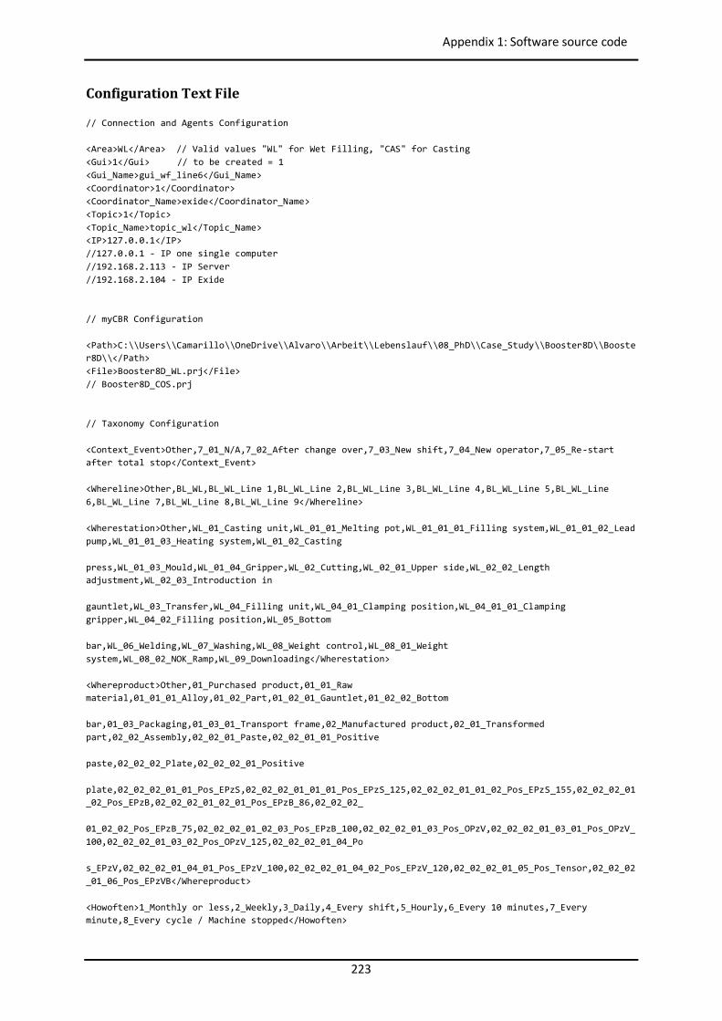
223
Appendix 1: Software source code
Configuration Text File // Connection and Agents Configuration <Area>WL</Area> // Valid values "WL" for Wet Filling, "CAS" for Casting <Gui>1</Gui> // to be created = 1 <Gui_Name>gui_wf_line6</Gui_Name> <Coordinator>1</Coordinator> <Coordinator_Name>exide</Coordinator_Name> <Topic>1</Topic> <Topic_Name>topic_wl</Topic_Name> <IP>127.0.0.1</IP> //127.0.0.1 - IP one single computer //192.168.2.113 - IP Server //192.168.2.104 - IP Exide // myCBR Configuration <Path>C:\\Users\\Camarillo\\OneDrive\\Alvaro\\Arbeit\\Lebenslauf\\08_PhD\\Case_Study\\Booster8D\\Booster8D\\</Path> <File>Booster8D_WL.prj</File> // Booster8D_COS.prj // Taxonomy Configuration <Context_Event>Other,7_01_N/A,7_02_After change over,7_03_New shift,7_04_New operator,7_05_Re-start after total stop</Context_Event> <Whereline>Other,BL_WL,BL_WL_Line 1,BL_WL_Line 2,BL_WL_Line 3,BL_WL_Line 4,BL_WL_Line 5,BL_WL_Line 6,BL_WL_Line 7,BL_WL_Line 8,BL_WL_Line 9</Whereline> <Wherestation>Other,WL_01_Casting unit,WL_01_01_Melting pot,WL_01_01_01_Filling system,WL_01_01_02_Lead pump,WL_01_01_03_Heating system,WL_01_02_Casting press,WL_01_03_Mould,WL_01_04_Gripper,WL_02_Cutting,WL_02_01_Upper side,WL_02_02_Length adjustment,WL_02_03_Introduction in gauntlet,WL_03_Transfer,WL_04_Filling unit,WL_04_01_Clamping position,WL_04_01_01_Clamping gripper,WL_04_02_Filling position,WL_05_Bottom bar,WL_06_Welding,WL_07_Washing,WL_08_Weight control,WL_08_01_Weight system,WL_08_02_NOK_Ramp,WL_09_Downloading</Wherestation> <Whereproduct>Other,01_Purchased product,01_01_Raw material,01_01_01_Alloy,01_02_Part,01_02_01_Gauntlet,01_02_02_Bottom bar,01_03_Packaging,01_03_01_Transport frame,02_Manufactured product,02_01_Transformed part,02_02_Assembly,02_02_01_Paste,02_02_01_01_Positive paste,02_02_02_Plate,02_02_02_01_Positive plate,02_02_02_01_01_Pos_EPzS,02_02_02_01_01_01_Pos_EPzS_125,02_02_02_01_01_02_Pos_EPzS_155,02_02_02_01_02_Pos_EPzB,02_02_02_01_02_01_Pos_EPzB_86,02_02_02_ 01_02_02_Pos_EPzB_75,02_02_02_01_02_03_Pos_EPzB_100,02_02_02_01_03_Pos_OPzV,02_02_02_01_03_01_Pos_OPzV_100,02_02_02_01_03_02_Pos_OPzV_125,02_02_02_01_04_Po s_EPzV,02_02_02_01_04_01_Pos_EPzV_100,02_02_02_01_04_02_Pos_EPzV_120,02_02_02_01_05_Pos_Tensor,02_02_02_01_06_Pos_EPzVB</Whereproduct> <Howoften>1_Monthly or less,2_Weekly,3_Daily,4_Every shift,5_Hourly,6_Every 10 minutes,7_Every minute,8_Every cycle / Machine stopped</Howoften>
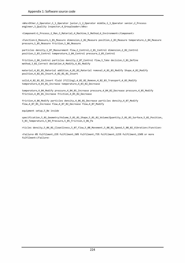
224
Appendix 1: Software source code
<Who>Other,1_Operator,1_1_Operator junior,1_2_Operator middle,1_3_Operator senior,2_Process engineer,3_Quality inspector,4_Groupleader</Who> <Component>1_Process,2_Man,3_Material,4_Machine,5_Method,6_Environment</Component> <Function>1_Measure,1_01_Measure dimension,1_02_Measure position,1_03_Measure temperature,1_04_Measure pressure,1_05_Measure friction,1_06_Measure particles density,1_07_Measurement flow,2_Control,2_01_Control dimension,2_02_Control position,2_03_Control temperature,2_04_Control pressure,2_05_Control friction,2_06_Control particles density,2_07_Control flow,3_Take decision,3_01_Define method,3_02_Correct deviation,4_Modify,4_01_Modify material,4_01_01_Material addition,4_01_02_Material removal,4_01_03_Modify Shape,4_02_Modify position,4_02_01_Insert,4_02_01_01_Insert solid,4_02_01_02_Insert fluid (filling),4_02_02_Remove,4_02_03_Transport,4_03_Modify temperature,4_03_01_Increase temperature,4_03_02_Decrease temperature,4_04_Modify pressure,4_04_01_Increase pressure,4_04_02_Decrease pressure,4_05_Modify friction,4_05_01_Increase friction,4_05_02_Decrease friction,4_06_Modify particles density,4_06_01_Decrease particles density,4_07_Modify flow,4_07_01_Increase flow,4_07_02_Decrease flow,4_07_Modify equipment setup,5_Be inside specification,5_01_Geometry/Volume,5_01_01_Shape,5_01_02_Volume/Quantity,5_01_03_Surface,5_02_Position,5_03_Temperature,5_04_Pressure,5_05_Friction,5_06_Pa rticles density,5_06_01_Cleanliness,5_07_Flow,5_08_Movement,5_08_01_Speed,5_08_02_Vibration</Function> <Failure> 0% fulfilment,25% fulfilment,50% fulfilment,75% fulfilment,125% fulfilment,150% or more fulfilment</Failure>
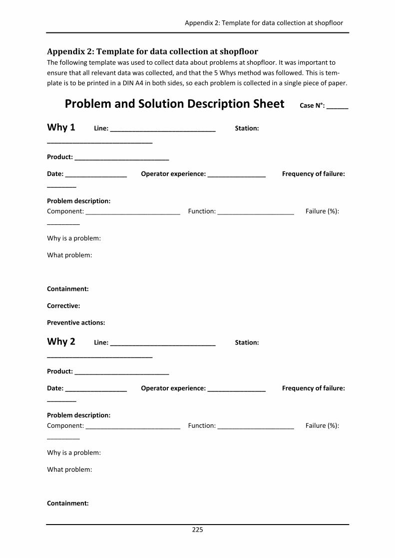
225
Appendix 2: Template for data collection at shopfloor
Appendix 2: Template for data collection at shopfloor The following template was used to collect data about problems at shopfloor. It was important to ensure that all relevant data was collected, and that the 5 Whys method was followed. This is tem-plate is to be printed in a DIN A4 in both sides, so each problem is collected in a single piece of paper.
Problem and Solution Description Sheet Case N°: ______
Why 1 Line: _____________________________ Station:
_____________________________
Product: __________________________
Date: _________________ Operator experience: ________________ Frequency of failure: ________
Problem description: Component: __________________________ Function: _____________________ Failure (%): _________
Why is a problem:
What problem:
Containment:
Corrective:
Preventive actions:
Why 2 Line: _____________________________ Station:
_____________________________
Product: __________________________
Date: _________________ Operator experience: ________________ Frequency of failure: ________
Problem description: Component: __________________________ Function: _____________________ Failure (%): _________
Why is a problem:
What problem:
Containment:
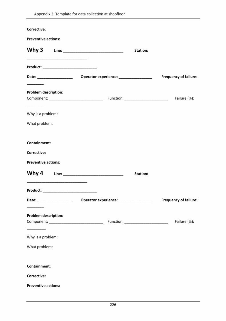
226
Appendix 2: Template for data collection at shopfloor
Corrective:
Preventive actions:
Why 3 Line: _____________________________ Station:
_____________________________
Product: __________________________
Date: _________________ Operator experience: ________________ Frequency of failure: ________
Problem description: Component: __________________________ Function: _____________________ Failure (%): _________
Why is a problem:
What problem:
Containment:
Corrective:
Preventive actions:
Why 4 Line: _____________________________ Station:
_____________________________
Product: __________________________
Date: _________________ Operator experience: ________________ Frequency of failure: ________
Problem description: Component: __________________________ Function: _____________________ Failure (%): _________
Why is a problem:
What problem:
Containment:
Corrective:
Preventive actions:
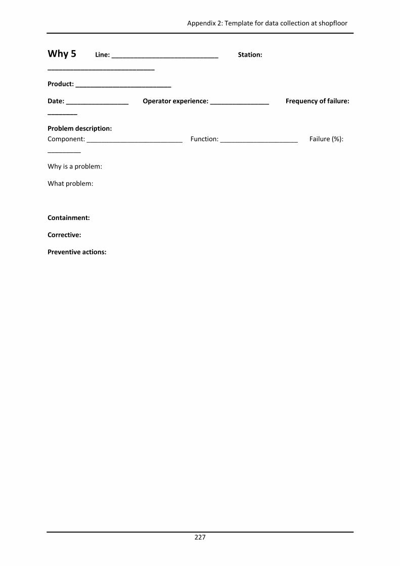
227
Appendix 2: Template for data collection at shopfloor
Why 5 Line: _____________________________ Station:
_____________________________
Product: __________________________
Date: _________________ Operator experience: ________________ Frequency of failure: ________
Problem description: Component: __________________________ Function: _____________________ Failure (%): _________
Why is a problem:
What problem:
Containment:
Corrective:
Preventive actions:

228
Appendix 3: Published Papers
Appendix 3: Published Papers
Paper 1
Camarillo, A. (2015). Support to Continuous Improvement in industrial manufacturing plants through Problem Solving methods and Case-Based Reasoning integrated within a Product Lifecycle Manage-ment infrastructure. In: Workshop Proceedings - 23rd International Conference on Case-Based Rea-soning (ICCBR 2015), pp. 259-261
adfa, p. 1, 2011. © Springer-Verlag Berlin Heidelberg 2011
Support to Continuous Improvement Process in manufacturing plants of multinational companies
through Problem Solving methods and Case-Based Reasoning integrated within a Product Lifecycle
Management infrastructure
Alvaro Camarillo
Mechanical Engineering Department, Universidad Politécnica de Madrid [email protected]
1 Introduction to problems addressed by research
The aim of this research is to capture and reuse efficiently knowledge at shop floor level of multinational companies during the resolution of manufacturing daily prob-lems (e.g. scrap rate, quality issues, breakdowns, and in general any Continuous Im-provement Process (CIP) activity). We want to provide production technicians and operators with a friendly and low time consuming Knowledge Management (KM) tool to get their engagement and collaboration, avoiding negative impact in productiv-ity, and promoting the knowledge share across plants overtaking language, nationali-ties, and competition barriers. We propose the Problem Solving (PS) method 8D as structured process to guide the knowledge share. A Product Lifecycle Management (PLM) system will be the logical infrastructure to store all product, process, machinery, and users information. This PLM system will host also the database of a Case-Based Reasoning (CBR) system. This CBR system will be the KM tool in charge of capturing and reusing the knowledge [1],[4],[5],[6]. FMEAs of Design, Process and Machinery will be used to populate initially the CBR System [3]. The CBR cycle [1] would be though as follow:
─ User introduces basic description of de problem (new case). ─ Based on this description the CBR system collects additional information related
product, process, machinery or users from the PLM. It proceeds to calculate to find similar cases.
─ The system proposes containment actions and different root causes (retrieved cas-es). The user checks these root causes in the line and gives feedback to system.
─ Based on the corrected list of most similar cases the system performs adaptation and proposes a solution (solved case).
─ Solution is tested by user (tested/repaired case) and implemented together with its associated preventive actions.
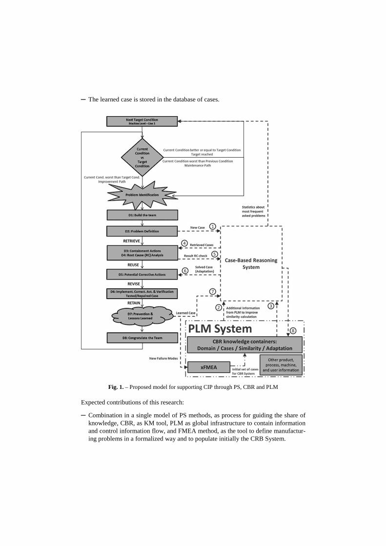
─ The learned case is stored in the database of cases.
Fig. 1. – Proposed model for supporting CIP through PS, CBR and PLM
Expected contributions of this research:
─ Combination in a single model of PS methods, as process for guiding the share of knowledge, CBR, as KM tool, PLM as global infrastructure to contain information and control information flow, and FMEA method, as the tool to define manufactur-ing problems in a formalized way and to populate initially the CRB System.
─ Based on minimal data introduced by the user (low time consumed) we propose to get from the PLM extended information that will be used to calculate similarity.
─ Bring this type of KM tool not only to designers or to engineers, but direct to blue-collar associates working at production lines.
2 Description of progress to date
Currently we are developing the Model that has to support the knowledge capture and reuse (see fig. 1). For the case study, two open source applications have been selected: Aras as PLM software (www.aras.com), and myCBR as CBR software (www.mycbr-project.net) [2]. For the implementation, a multinational company of the electrical batteries branch was selected. To get the benefits of knowledge sharing between two teams with very low interaction until now the system will be installed in two manu-facturing plants located in two different countries. It will focus only on one of the production steps of batteries in order to get consistent results in a limited period of time.
3 Proposed plan for research
After the review of the state of the art in the fields of CIP, PS, CBR, and PLM, we are currently designing the initial knowledge containers of domain, similarity and adapta-tion of the CBR system [6] that will be used to test our concept initially in a single production line. This task has to be finished by the end of May 2016. The experience from this initial test will be used to improve our KM tool in order to do a second test loop at whole plant level. Finally a third test loop will be performed between the two plants until end of 2016. The presentation of the PhD Thesis is planned in May 2017.
References
1. Aamodt, A., Plaza, E.: Case-Based Reasoning: Foundational Issues, Methodological Var-iations, and System Approaches. In: AI Communications, vol. 7, no. 1, pp. 39-59 (1994)
2. Atanassov, A., Antonov, L.: Comparative Analysis of Case Based Reasoning Software Frameworks jCOLIBRI and myCBR. In: Journal of the University of Chemical Technolo-gy and Metallurgy, vol. 47, no. 1, pp. 83-90 (2012)
3. Atamer, A.: Comparison of FMEA and field-experience for a turbofan engine with appli-cation to case based reasoning. In: Aerospace Conference, 2004. Proceedings. 2004 IEEE, Vol. 5, pp. 3354-3360 (2014)
4. Jabrouni, H., Kamsu-Foguem, B., Geneste, L., Vaysse, C.: Continuous Improvement Through Knowledge-Guided Analysis in Experience Feedback. In: Engineering Applica-tions of Artificial Intelligence, vol. 24, no. 8, pp. 1419-1431 (2011)
5. Kamsu-Foguem, B., Couderta, T., Bélera, C., Genestea, L.: Knowledge Formalization in Experience Feedback Processes: An Ontology-Based Approach. In: Computers in Indus-try, vol. 59, no. 7, pp. 694-710 (2008)
6. Richter, M., Weber, R.: Case-Based Reasoning: A Textbook. Springer, Heidelberg (2013)

232
Appendix 3: Published Papers
Paper 2
Camarillo, A.; Ríos, J.; Althoff, KD. (2017a). CBR and PLM applied to diagnosis and technical support during problem solving in the Continuous Improvement Process of manufacturing plants. Procedia Manufacturing 2017, Vol. 13, pp. 987-994.
Available online at www.sciencedirect.com
ScienceDirect Procedia Manufacturing 00 (2017) 000–000
www.elsevier.com/locate/procedia
2351-9789 © 2017 The Authors. Published by Elsevier B.V. Peer-review under responsibility of the scientific committee of the Manufacturing Engineering Society International Conference 2017.
Manufacturing Engineering Society International Conference 2017, MESIC 2017, 28-30 June 2017, Vigo (Pontevedra), Spain
CBR and PLM applied to diagnosis and technical support during problem solving in the Continuous Improvement Process of
manufacturing plants Alvaro Camarilloa,b,*, José Ríosb, Klaus-Dieter Althoffc
aExide Technologies GmbH, Odertal 35, 37431 Bad Lauterberg, Germany bMechanical Engineering Department, Universidad Politécnica de Madrid, José Gutiérrez Abascal 2, 2800, Madrid, Spain
cGerman Research Center for Artificial Intelligence (DFKI), Trippstadter Straße 122, 67663, Kaiserslautern, Germany / University of Hildesheim, Universitätsplatz 1, 31141 Hildesheim, Germany
Abstract
Currently many multinational companies have manufacturing plants with similar processes, but they suffer from barriers to share knowledge. Knowledge Management (KM) techniques may help to capture and reuse knowledge generated during processes execution. Literature shows Case-Based Reasoning (CBR) as a technique for implementing KM, and Product Lifecycle Management Systems (PLM) as the main data repository of Product-Processes-Resources data. This paper proposes a Continuous Improvement Process (CIP) approach to facilitate the capture and reuse of knowledge, integrating CBR and PLM technologies. It aims supporting production technicians during the resolution of manufacturing daily problems directly at shop floor level. © 2017 The Authors. Published by Elsevier B.V. Peer-review under responsibility of the scientific committee of the Manufacturing Engineering Society International Conference 2017.
Keywords: Case-Based Reasoning (CBR); Product Lifecycle Management (PLM); Continuous Improvement (CIP); Manufacturing Problem Solving; Process Failure Mode and Effect Analysis (PFMEA)
* Corresponding author. Tel.: +49-5524-82-216; fax: +49-5524-82-209.
E-mail address: [email protected]
2 Author name / Procedia Manufacturing 00 (2017) 000–000
1. Introduction
Today globalization pushes companies towards a strong competition among them. Companies need to be better and better every day if they want to survive in an always challenging and changing market. In the manufacturing environment that means a strong focus on Knowledge Management (KM), among other topics. A well-known KM issue in multinational companies is that they have different manufacturing plants distributed geographically and with similar processes, but they suffer from communication barriers to share knowledge [1]. This paper proposes a Continuous Improvement Process (CIP) approach to facilitate the capture and reuse of knowledge, in multinational companies, directly at shop floor level, with the objective of supporting production technicians and operators during the resolution of daily manufacturing problems. To demonstrate the feasibility of the proposed approach, an initial proof of concept prototype application has been developed.
The CIP approach adopted in this work is based on the 8D methodology [2] as structured manufacturing Problem Solving (PS) method to guide the resolution of problems step by step. It comprises Case-Based Reasoning (CBR) [3][4] as a technique for implementing KM [3][5], and Product Lifecycle Management Systems (PLM) as the main data repository of Product-Processes-Resources (PPR) data [6] used to define the context of a problem. The adopted approach is divided into:
Definition of an ontology of manufacturing problems. Description of manufacturing context of the problem under analysis by means of a PPR structure
automatically extracted from the PLM system. Representation of manufacturing problems by using Process Failure Mode and Effect Analysis (PFMEA) to
create an initial case base. Definition of a reasoning method based on CBR to identify similar cases to the defined problem. The paper starts with a general review of the state of the art. Then, the proposed CIP approach and the proof of
concept application are presented. The paper ends with a summary of the work contributions and future work proposals.
2. State of the Art
2.1. Continuous Improvement Process and Manufacturing Problem Solving Methods
It is estimated that over 70% of the total life cycle cost of a product is committed at the early design stage [7]. Designers have developed methodologies such as design for manufacturing, design for assembly, design for maintenance, or design for quality to enhance the product development process and to increase the profitability of the products. Even though these methodologies have helped to reduce the cost of the product, there is still a large space for improvement in the manufacturing step of the Product Life Cycle (PLC). This paper proposes CIP as the tool to achieve this improvement [8].
The example of Toyota with its TPS (Toyota Production System) [8] is a fundamental reference of the current CIP philosophy in the manufacturing environment. TPS requires defining a long-term vision, which the company wants to achieve. Such vision should align all actions in the company and be deployed along plants, processes and production lines. Then Target Conditions need to be defined. A Target Condition is the description of a state that the company wants to reach at some future point in time, in the way toward the long-term vision. The company works toward those Target Conditions in small, rapid steps, with learning and adjustments occurring along the way. In each of these steps, the main problems preventing the company from reaching the defined Target Condition are analyzed and solved with the help of PS methods.
Table 1 shows some of the most relevant PS methods in the industry today, and it presents a comparison of the main steps defined in each of them. As it can be observed, all the methods have mainly the same structure or path to solve a problem. The main difference among them is the level of detail used to describe the different steps of the overall process. Other authors reaching a similar conclusion are Foguem et al. [9] and Jabrouni et al. [10]. Based on this observation, it can be concluded that the selection of the PS Method will not make a big difference in the ability of solving problems, and that some additional element is needed to support this activity. In this direction, Bothe and Bothe [11] stated that PS methods are not enough to support properly the manufacturing PS activity, because
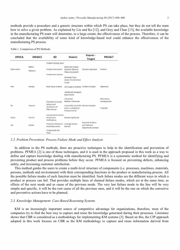
Author name / Procedia Manufacturing 00 (2017) 000–000 3
methods provide a procedure and a generic structure within which PS can take place, but they do not tell the team how to solve a given problem. As explained by Liu and Ke [12], and Grey and Chan [13], the available knowledge in the manufacturing PS team will determine, to a large extent, the effectiveness of the process. Therefore, it can be concluded that the availability of some kind of knowledge-based tool could enhance the effectiveness of the manufacturing PS process.
Table 1. Comparison of PS Methods.
2.2. Problem Prevention: Process Failure Mode and Effect Analysis
In addition to the PS methods, there are proactive techniques to help in the identification and prevention of problems. PFMEA [2] is one of those techniques, and it is used in the approach proposed in this work as a way to define and capture knowledge dealing with manufacturing PS. PFMEA is a systematic method for identifying and preventing product and process problems before they occur. PFMEA is focused on preventing defects, enhancing safety, and increasing customer satisfaction.
This method guides the users to create a multi-level structure of components (i.e. processes, machines, materials, persons, methods and environment) with their corresponding functions in the product or manufacturing process. All the possible failure modes of each function must be identified. Such failure modes are the different ways in which a product or process can fail. That provides multiple lines of chained failure modes, which act at the same time, as effects of the next mode and as cause of the previous mode. The very last failure mode in the line will be very simple and specific, it will be the root cause of all the previous ones, and it will be the one on which the corrective and preventive actions have to be planned.
2.3. Knowledge Management: Case-Based Reasoning Systems
KM is an increasingly important source of competitive advantage for organizations, therefore, most of the companies try to find the best way to capture and reuse the knowledge generated during their processes. Literature shows that CBR is considered as a methodology for implementing KM systems [3]. Based on this, the CIP approach adopted in this work focuses on CBR as the KM methodology to capture and reuse information derived from
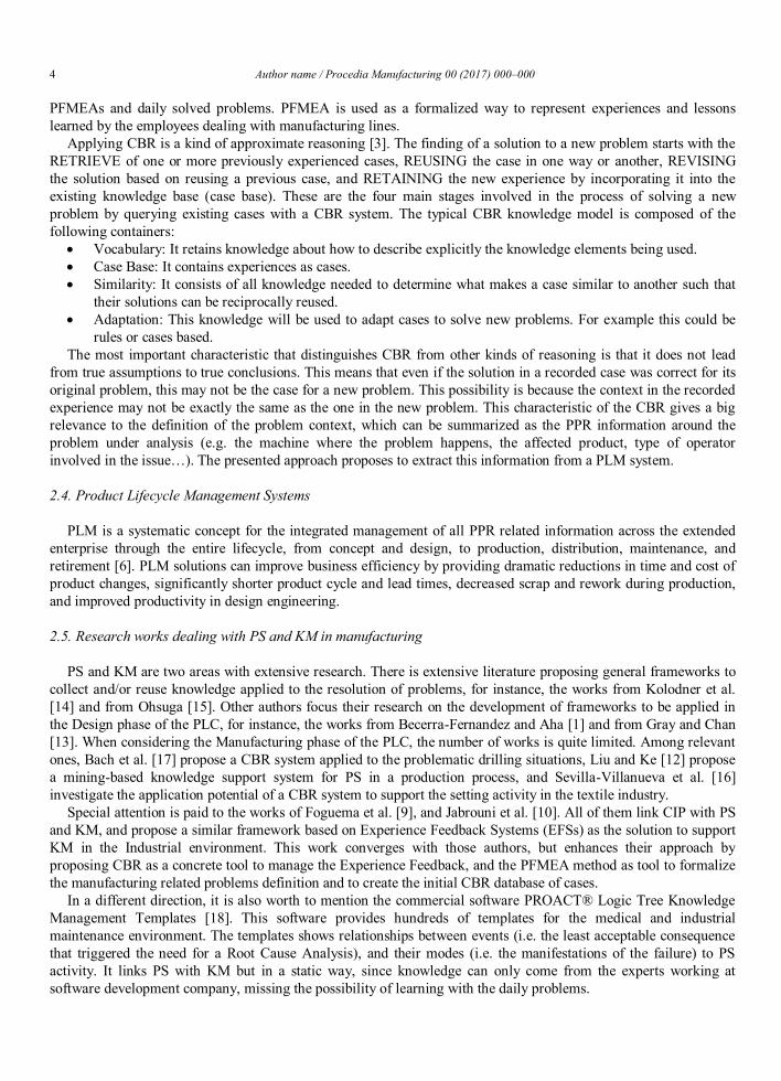
4 Author name / Procedia Manufacturing 00 (2017) 000–000
PFMEAs and daily solved problems. PFMEA is used as a formalized way to represent experiences and lessons learned by the employees dealing with manufacturing lines.
Applying CBR is a kind of approximate reasoning [3]. The finding of a solution to a new problem starts with the RETRIEVE of one or more previously experienced cases, REUSING the case in one way or another, REVISING the solution based on reusing a previous case, and RETAINING the new experience by incorporating it into the existing knowledge base (case base). These are the four main stages involved in the process of solving a new problem by querying existing cases with a CBR system. The typical CBR knowledge model is composed of the following containers:
Vocabulary: It retains knowledge about how to describe explicitly the knowledge elements being used. Case Base: It contains experiences as cases. Similarity: It consists of all knowledge needed to determine what makes a case similar to another such that
their solutions can be reciprocally reused. Adaptation: This knowledge will be used to adapt cases to solve new problems. For example this could be
rules or cases based. The most important characteristic that distinguishes CBR from other kinds of reasoning is that it does not lead
from true assumptions to true conclusions. This means that even if the solution in a recorded case was correct for its original problem, this may not be the case for a new problem. This possibility is because the context in the recorded experience may not be exactly the same as the one in the new problem. This characteristic of the CBR gives a big relevance to the definition of the problem context, which can be summarized as the PPR information around the problem under analysis (e.g. the machine where the problem happens, the affected product, type of operator involved in the issue…). The presented approach proposes to extract this information from a PLM system.
2.4. Product Lifecycle Management Systems
PLM is a systematic concept for the integrated management of all PPR related information across the extended enterprise through the entire lifecycle, from concept and design, to production, distribution, maintenance, and retirement [6]. PLM solutions can improve business efficiency by providing dramatic reductions in time and cost of product changes, significantly shorter product cycle and lead times, decreased scrap and rework during production, and improved productivity in design engineering.
2.5. Research works dealing with PS and KM in manufacturing
PS and KM are two areas with extensive research. There is extensive literature proposing general frameworks to collect and/or reuse knowledge applied to the resolution of problems, for instance, the works from Kolodner et al. [14] and from Ohsuga [15]. Other authors focus their research on the development of frameworks to be applied in the Design phase of the PLC, for instance, the works from Becerra-Fernandez and Aha [1] and from Gray and Chan [13]. When considering the Manufacturing phase of the PLC, the number of works is quite limited. Among relevant ones, Bach et al. [17] propose a CBR system applied to the problematic drilling situations, Liu and Ke [12] propose a mining-based knowledge support system for PS in a production process, and Sevilla-Villanueva et al. [16] investigate the application potential of a CBR system to support the setting activity in the textile industry.
Special attention is paid to the works of Foguema et al. [9], and Jabrouni et al. [10]. All of them link CIP with PS and KM, and propose a similar framework based on Experience Feedback Systems (EFSs) as the solution to support KM in the Industrial environment. This work converges with those authors, but enhances their approach by proposing CBR as a concrete tool to manage the Experience Feedback, and the PFMEA method as tool to formalize the manufacturing related problems definition and to create the initial CBR database of cases.
In a different direction, it is also worth to mention the commercial software PROACT® Logic Tree Knowledge Management Templates [18]. This software provides hundreds of templates for the medical and industrial maintenance environment. The templates shows relationships between events (i.e. the least acceptable consequence that triggered the need for a Root Cause Analysis), and their modes (i.e. the manifestations of the failure) to PS activity. It links PS with KM but in a static way, since knowledge can only come from the experts working at software development company, missing the possibility of learning with the daily problems.
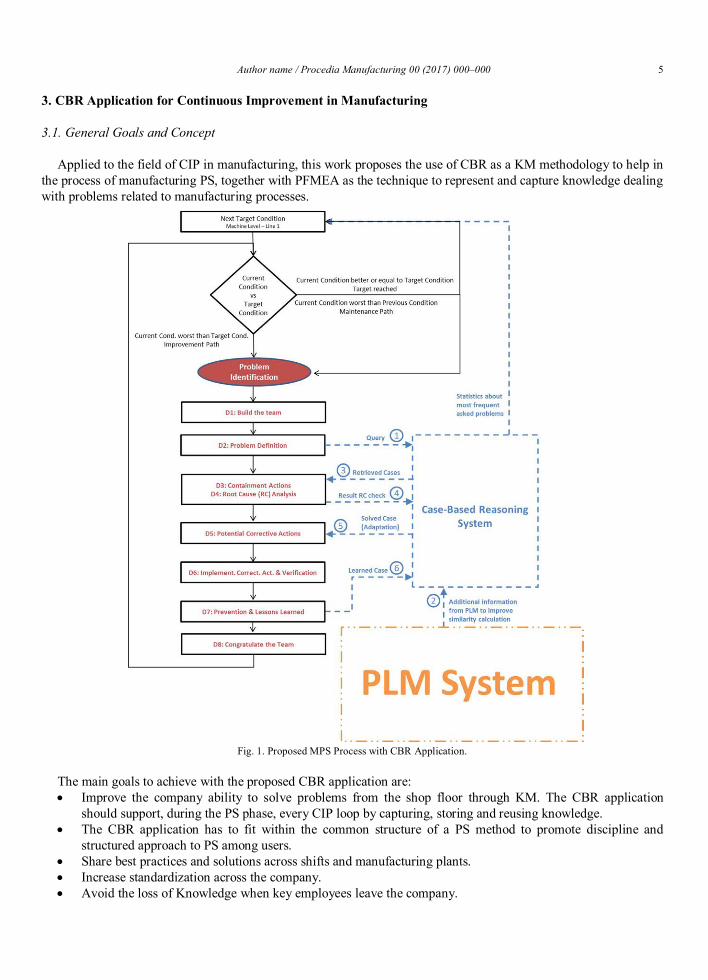
Author name / Procedia Manufacturing 00 (2017) 000–000 5
3. CBR Application for Continuous Improvement in Manufacturing
3.1. General Goals and Concept
Applied to the field of CIP in manufacturing, this work proposes the use of CBR as a KM methodology to help in the process of manufacturing PS, together with PFMEA as the technique to represent and capture knowledge dealing with problems related to manufacturing processes.
Fig. 1. Proposed MPS Process with CBR Application.
The main goals to achieve with the proposed CBR application are: Improve the company ability to solve problems from the shop floor through KM. The CBR application
should support, during the PS phase, every CIP loop by capturing, storing and reusing knowledge. The CBR application has to fit within the common structure of a PS method to promote discipline and
structured approach to PS among users. Share best practices and solutions across shifts and manufacturing plants. Increase standardization across the company. Avoid the loss of Knowledge when key employees leave the company.
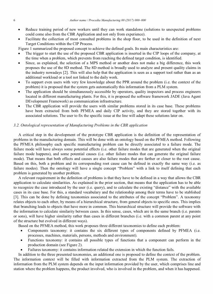
6 Author name / Procedia Manufacturing 00 (2017) 000–000
Reduce training period of new workers until they can work standalone (solutions to unexpected problems could come also from the CBR Application and not only from experience).
Facilitate the collection of most consulted problems in the shop floor, to be used in the definition of next Target Conditions within the CIP Process.
Figure 1 summarized the proposed concept to achieve the defined goals. Its main characteristics are: The trigger to start the use of the proposed CBR application is inserted in the CIP loops of the company, at
the time when a problem, which prevents from reaching the defined target condition, is identified. Since, as explained, the selection of a MPS method or another does not make a big difference, this work
proposes the use of the 8D method. The 8D method is broadly used to analyze and present quality claims in the industry nowadays [2]. This will also help that the application is seen as a support tool rather than as an additional workload or a tool not linked to the daily work.
To support even users with very few knowledge about the PPR around the problem (i.e. the context of the problem) it is proposed that the system gets automatically this information from a PLM system.
The application should be simultaneously accessible by operators, quality inspectors and process engineers located in different manufacturing plants. For this, it is proposed the software framework JADE (Java Agent DEvelopment Framework) as communication infrastructure.
The CBR application will provide the users with similar problems stored in its case base. These problems have been extracted from both PFMEA and daily CIP activity, and they are stored together with its associated solutions. The user to fix the specific issue at the line will adapt these solutions later on.
3.2. Ontological representation of Manufacturing Problems in the CBR application
A critical step in the development of the prototype CBR application is the definition of the representation of problems in the manufacturing domain. This will be done with an ontology based on the PFMEA method. Following the PFMEA philosophy each specific manufacturing problem can be directly associated to a failure mode. The failure mode will have always some potential effects (i.e. other failure modes that are generated when the original failure mode happens), and some potential causes (i.e. other failure modes that can generate the original failure mode). That means that both effects and causes are also failure modes that are farther or closer to the root cause. Based on this, both a problem and its corresponding root cause can be defined in exactly the same way (i.e. as failure modes). Then the ontology will have a single concept “Problem” with a link to itself defining that each problem is generated by another problem.
A relevant requirement in the definition of problems is that they have to be defined in a way that allows the CBR application to calculate similarities. As explained in the prior section, that means that the application has to be able to recognize the case introduced by the user (i.e. query), and to calculate the existing “distance” with the available cases in its case base. For this, a standard vocabulary and the relationship among their terms have to be stablished [3]. This can be done by defining taxonomies associated to the attributes of the concept “Problem”. A taxonomy relates objects to each other, by means of a hierarchical structure, from general objects to specific ones. This implies that branching leads to objects that have more in common. This hierarchical structure will provide the software with the information to calculate similarity between cases. In this sense, cases, which are in the same branch (i.e. parents or sons), will have higher similarity rather than cases in different branches (i.e. with a common parent at any point of the structure but evolved in different ways).
Based on the PFMEA method, this work proposes three different taxonomies to define each problem: Components taxonomy: it contains the six different types of components defined by PFMEA (i.e.
processes, machines, materials, persons, methods and environment). Functions taxonomy: it contains all possible types of functions that a component can perform in the
production domain (see Figure 2). Failures taxonomy: it contains information related the extension in which the function fails.
In addition to the three presented taxonomies, an additional one is proposed to define the context of the problem. The information context will be filled with information extracted from the PLM system. The extraction of information from the PLM system depends on the input information provided by the user, which comprises line and station where the problem happens, the product involved, who is involved in the problem, and when it has happened.
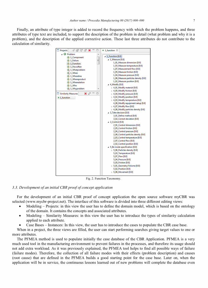
Author name / Procedia Manufacturing 00 (2017) 000–000 7
Finally, an attribute of type integer is added to record the frequency with which the problem happens, and three attributes of type text are included, to support the description of the problem in detail (what problem and why it is a problem), and the description of the applied corrective action. These last three attributes do not contribute to the calculation of similarity.
Fig. 2. Function Taxonomy.
3.3. Development of an initial CBR proof of concept application
For the development of an initial CBR proof of concept application the open source software myCBR was selected (www.mycbr-project.net). The interface of this software is divided into three different editing views:
Modeling – Projects: in this view the user has to define the domain model, which is based on the ontology of the domain. It contains the concepts and associated attributes.
Modeling – Similarity Measures: in this view the user has to introduce the types of similarity calculation applied to each attribute.
Case Bases – Instances: In this view, the user has to introduce the cases to populate the CBR case base. When in a project, the three views are filled, the user can start performing searches giving target values to one or
more attributes. The PFMEA method is used to populate initially the case database of the CBR Application. PFMEA is a very
much used tool in the manufacturing environment to prevent failures in the processes, and therefore its usage should not add extra workload. As it was previously explained, the PFMEA tool helps to find all possible ways of failure (failure modes). Therefore, the collection of all failure modes with their effects (problem description) and causes (root cause) that are defined in the PFMEA builds a good starting point for the case base. Later on, when the application will be in service, the continuous lessons learned out of new problems will complete the database even
8 Author name / Procedia Manufacturing 00 (2017) 000–000
more, but this is a very slow process that could take months until a reasonable number of cases are collected, that is the reason to start with the collection of failures from the PFMEA.
4. Conclusions and Future Work
This paper presented a proposal for the development of software system with the aim of supporting the CIP of any company at the shop floor level. It combines PS with CBR, as KM tool, PLM, as source of problem context information, and the PFMEA method, as the tool to define manufacturing problems in a formalized way, and to populate initially the CBR system. A proof-of-concept of CBR application was developed to demonstrate the feasibility of the approach adopted. An initial case base of forty different cases was defined and the results of the system were compared against the decisions taken by experts. The results show that the system and experts answered a reasonable number of queries in a similar way.
As explained along the paper, there is quite a lot of research about the topics CIP, PS, and KM, but very few works combine all of them in a single environment, and even less works place the focus on the manufacturing phase. Among the different activities linked with manufacturing, this work focuses directly at production lines on the shop floor, where manufacturing PS research is even more limited.
A relevant characteristic of CBR Applications is the adaptation. This complex task of adapting the solution of a problem in a specific machine to the solution in a different one has been left to the operator. Implement adaptation to the prototype application is an issue to be investigated next.
The current implementation of the CBR prototype application is standalone. Ultimately as case study, this CBR application should be installed at least in two different manufacturing plants of a multinational company. Considering the feasibility of the adopted approach, this has been planned as a next step. To do so, the software framework JADE (Java Agent DEvelopment framework) as communication infrastructure has been selected.
References
[1] T.C. Ambos, B. Ambos, The impact of distance on knowledge transfer effectiveness in multinational corporations, Journal of International Management 2009; 15; 1: 1-14.
[2] VDA, Qualitätsmanagement in der Automobilindustrie – Qualitätsmanagement-Methoden Assessments, VDA 2015. [3] M.M. Richter, R.O. Weber, Case-Based Reasoning: A Textbook. Heidelberg: Springer; 2013. [4] K.D. Althoff, K. Bach, J.O. Deutsch, A. Hanft, J. Mänz, T. Müller, R. Newo, M. Reichle, Collaborative multi-expert-systems - realizing
knowledge-product-lines with case factories and distributed learning systems, Proceedings of 3rd Workshop on KE and Soft. Eng. 2007. [5] I. Watson, Knowledge management and case-based reasoning: a perfect match? Proceedings of the Fourteenth Annual Conference of the
International Florida Artificial Intelligence Re-search Society 2001. [6] J. Stark, Product lifecycle management. Switzerland: Springer Intl. Pub. AG; 2015. [7] Y. Asiedu, P. Gu, Product life cycle cost analysis: state of the art review, International Journal of Production Research 1998; 36; 4: 883-908. [8] M. Rother, Toyota Kata: Managing People for Improvement, Adaptiveness, and Superior Results. McGraw Hill; 2010. [9] B.K. Foguem, T. Coudert, C. Béler, L. Geneste, Knowledge Formalization in Experience Feedback Processes: An Ontology-Based Approach,
Computers in Industry 2008; 59; 7: 694-710. [10] H. Jabrouni, B.K. Foguem, L. Geneste, C. Vaysse, Continuous Improvement Through Knowledge-Guided Analysis in Experience Feedback,
Engineering Applications of Artificial Intelligence 2011; 24; 8: 1419-31. [11] K.R. Bhote, A.K. Bhote, World Class Quality – Using Design of Experiments to Make it Happen. AMACOM – American Management
Association; 1999. [12] D. Liu, C. Ke, Knowledge Support for Problem-Solving in a Production Process: a Hybrid of Knowledge Discovery and Case-Based
Reasoning, Expert Systems with Applications 2007; 33: 147-61. [13] P.H. Gray, Y.E. Chan, Integrating Knowledge Management Practices Through a PS Framework, Communications of the AIS 2000 4; 12. [14] J.L. Kolodner, R.L. Simpson, K. Sycara-Cyranski, A Process Model of Cased-Based Reasoning in Problem Solving, International Joint
Conference on Artificial Intelligence 1985; 85: 284-90. [15] S. Ohsuga, How can Knowledge-Based Systems Solve Large-Scale Problems?: Model-Based Decomposition and Problem Solving,
Knowledge-Based Systems 1993; 6; 1: 38-62. [16] B. Sevilla-Villanueva, M. Sanchez-Marre, T.V. Fischer, Estimation of Machine Settings for Spinning of Yarns – New Algorithms for
Comparing Complex Structures, Proceedings of International Conference on Case-Based Reasoning (ICCBR 2014) 2014. [17] K. Bach, K.D. Althoff, R. Newo, A. Stahl, A case-based reasoning approach for providing machine diagnosis from service reports,
Proceedings of International Conference on Case-Based Reasoning (ICCBR 2011) 2011. [18] R.J. Latino, Root Cause Analysis vs. Shallow Cause Analysis, Industrial Maintenance & Plant Operation 2007.

241
Appendix 3: Published Papers
Paper 3
Camarillo, Alvaro; Rios-Chueco, Jose; Althoff, Klaus-Dieter (2017b). Agent Based Framework to sup-port Manufacturing Problem Solving integrating Product Lifecycle Management and Case-Based Rea-soning. Product Lifecycle Management and the Industry of the Future. PLM 2017. IFIP Advances in Information and Communication Technology, 517, 116-128.
Agent Based Framework to support Manufacturing Problem Solving integrating Product Lifecycle
Management and Case-Based Reasoning
Alvaro Camarillo1,2, José Ríos2, Klaus-Dieter Althoff3
1 Exide Technologies GmbH, Odertal 35, 37431 Bad Lauterberg, Germany [email protected]
2 Mechanical Engineering Department, Universidad Politécnica de Madrid, Jose Gutierrez
Abascal 2, 2800 Madrid, Spain [email protected], [email protected]
3 German Research Center for Artificial Intelligence (DFKI), Trippstadter Straße 122, 67663 Kaiserslautern, Germany / University of Hildesheim, Universitätsplatz 1, 31141 Hildesheim,
Germany [email protected]
Abstract. During the execution of manufacturing processes, problems arise and they have to be solved systematically to reach and exceed production targets. Normally, a production team analyzes and solves these problems, with the sup-port of different methodologies and working directly on the shop floor. This pa-per presents an ontology-based approach to easily capture and reuse the knowledge generated in such a process of Manufacturing Problem Solving (MPS). The proposed ontology is used as basis in an ad-hoc MPS software sys-tem. The architecture of the MPS system is based on the integration of three technologies: PLM (Product Lifecycle Management), CBR (Case-Based Rea-soning) and software agents. The PLM system is used as an automatic source of the problem context information. The CBR system is used as repository of cases and artificial intelligence tool to support the efficient reuse of knowledge during the resolution of new problems. A software agent platform allows developing an integrated prototype of an ad-hoc software system. This paper shows the ar-chitecture of the MPS system prototype.
Keywords: Ontology · Product Lifecycle Management (PLM) · Case-Based Reasoning (CBR) · Process Failure Mode and Effect Analysis (PFMEA) · Manufacturing Problem Solving (MPS)
1 Introduction
Analytical methods are applied to prevent failures during the design phase of manu-facturing processes and facilities, but the reality shows that the defined production targets are often not reached due to the arise of problems. Aiming to solve them in a
systematic way, different methods have been developed. Continuous Improvement Process (CIP) and Manufacturing Problem Solving (MPS) embrace these methods [1]. A relevant example of them is the 8D methodology, which is quite spread and known in manufacturing since nowadays it is the standard method used to analyze and pre-sent quality claims in important industrial sectors such as the automotive one [2]. The 8D method, similarly to other CIP or MPS methods, provides a structured process to facilitate finding and improving solutions, but it only brings results when actors with enough experience and knowledge drive it [3]. This paper proposes a software system to compensate the possible lack of experience and knowledge of some team members. One of the key requirements for such a system is the capability to collect and reuse knowledge created during the application of the 8D method in the resolution of pro-duction problems at the shop floor level. In that way, the system would be linked to the daily MPS activity of the manufacturing plant. To address this global aim, the proposed approach is structured into:
1. Manufacturing problems have to be described in a consistent and systematic way to allow a common understanding by the MPS personnel and their processing by means of a software system. The definition of an ontology is the alternative to ad-dress this aspect [4]. This requires reviewing two main methods. Firstly, how the 8D method allows defining a manufacturing problem. Secondly, how Process Fail-ure Mode and Effect Analysis (PFMEA) [2], as preventive method, allows defining manufacturing problems, effects and solutions and how this method could be used to create an initial set of cases of potential problems.
2. The ontological approach is the basis to create two repositories of manufacturing-related knowledge. Manufacturing is an extremely wide context. Therefore, it is necessary to distinguish among different problems and to connect them with previ-ously found solutions; this can be achieved by means of context data. A PLM (Product Lifecycle Management) application [5] can be used as a logical source of extended information of Product-Process-Resource (PPR) related to each problem, and therefore, to describe the context of each manufacturing problem. This will al-low enriching automatically the initial problem description given by the MPS per-sonnel. A CBR system [6] can be used as the logical source of manufacturing prob-lems and solutions, where the initial PFMEA case base of potential problems is stored and extended continuously with the resolution of new problems.
3. To assist the MPS personnel, it is needed a systematic reasoning method to connect each problem with similar cases already solved. Case-Based Reasoning (CBR) [6] is proposed as an artificial intelligence tool to support the efficient reuse of collect-ed knowledge in new problems and to assist in the problem solving process.
The paper starts with a general introduction to the main topics and a review of ex-isting similar research works. Section 3 shows the developed ontology to represent a manufacturing problem. Section 4 presents the ontological model implementation in a MPS process flow and the MPS system architecture of the prototype application. The prototype application is implemented as case study in the company Exide Technolo-gies, a multinational company that produces stored electrical energy solutions. The paper ends with some results, conclusions and future work proposals.
2 State of the Art
2.1 Knowledge Representation based on Ontology
A fundamental aspect of this work is the representation of manufacturing knowledge and problems. One way to address it is by means of an ontology. In the literature, there are examples of ontologies applied to the context of MPS. Foguem et al. [7] create an ontology based on conceptual graphs for Feedback Experience Systems (FES). This approach relates to the topic MPS, however its structure it is not compati-ble with the PFMEA method, which is considered as the main initial source of solved cases. Dittmann et al. [8] and Ebrahimipour et al. [9] present two examples of ontolo-gies for the FMEA environment developed to ensure the easy reuse of the information stored in the FMEA analyses. The work of Dittmann et al. is selected as basis for the knowledge representation model of this work due to its focus on FMEA and the clari-ty and simplicity of its model. It proposes a ROOT_CONCEPT class that has as sub-classes FMEA, Component, Function, Failure_mode, Control_method, Risk_priority_number, and Containment_action. It also defines relationships among the different concepts, for example “fulfills_a_function” that relates Component to Function, or “has_failure_mode” that relates Function to Failure_mode. In parallel, the classes Component and Function have associated taxonomies. The associated taxonomies allow limiting the possible values to be used when instantiating the model classes, in that sense, it could be seen as a taxonomic approach to natural language processing [10]. An approach based on free text would be an alternative, but in that case a domain specific dictionary and free-text natural language processing tech-niques would be required to search for relevant text. That line of research is out of the scope of this work.
Having introduced the way of representing knowledge, the next subsection pre-sents PLM systems as the logical source of extended PPR information related to the manufacturing problem under analysis.
2.2 Product Lifecycle Management Systems
As explained in the introduction, the application domain of manufacturing is extreme-ly wide. The ontology selected above allows representing a problem following the PFMEA method. However, it has to be taken into account that the document resulting from applying the PFMEA method is a detailed analysis of a specific process, there-fore the specified information is restricted to the scope of the components of that pro-cess. In the approach of this work, that limited scope must be cut, the proposed framework should allow dealing with problems coming from any type of manufactur-ing processes at any place. To do so, it is needed an additional input of information that sets clear differences among problems, and that is the context of the problem. A PLM system [5] arises here as the natural and logical source of this context, since it aims facilitating the storage of all the PPR information of a company.
The work of Bertin et al. [11, 12] is very relevant for this work because they also proposes the use of a PLM system as central repository of data for a Lessons Learned
System (LLS). They focus on the capture and reuse of knowledge along the Engineer-ing Change Request (ECR) process of the company. This approach sets the focus on the technical staff of the company, which is the typical group of users leading ECR. By contrast, the framework presented in this paper sets the focus on the operators working directly on the line, being this group much less used to computer system, and with less technical background. This puts some additional requirements for develop-ing intuitive and simple interfaces. Additionally, it is proposed the use of the PFMEA method as an initial set of possible problems, so the system should be able to provide the users with some solutions from the very beginning.
Having defined the way of representing knowledge, and the system to retrieve structured information needed to describe the context of the manufacturing problem, the next section introduces CBR as the artificial intelligence tool to support the stor-age of cases and the finding of solutions during the MPS activity.
2.3 Case-Based Reasoning
CBR is useful when the reality under analysis is too complex and difficult to be repre-sented in a model [6]. This is the case of manufacturing, the application domain of this work, with a huge variety of production processes being influenced by many types of machines, environments, materials, methods or persons. CBR is particularly applicable to problems where earlier cases are available, even when the domain is not understood well enough to create a deep domain model. The approach adopted in this work focuses on CBR as the artificial intelligence tool to support the storage of cases and the reasoning to find solutions during the MPS activity.
Manufacturing, as application domain, represents a big challenge for CBR due to its vast extension and complexity. A single case base, containing information related to failures from hundreds of different types of processes, coming from many different manufacturing lines and plants would create serious problems of retrieval speed, and maintainability. Multi-case base reasoning systems were created years ago to tackle this type of issues. Among the different research paths available in the literature relat-ed to this type of systems, and due to its flexible approach to knowledge modulariza-tion, this work focuses on SEASALT (Shared Experience using an Agent-based Sys-tem Architecture LayouT). SEASALT is a domain-independent architecture for ex-tracting, analyzing, sharing, and providing experiences [13]. The work of Reuss et al. [14] is an application example of SEASALT linked to Problem Solving in aircraft diagnosis and maintenance, where the system provides maintenance solutions to known failures.
Based on the introduced theoretical background, the next section presents a con-crete proposal of ontology to represent manufacturing problems in a generic way.
3 Manufacturing Problem Solving Ontology
This section presents a proposal of ontology to represent any kind of manufacturing problem from any process at any manufacturing place. This ontology has also the
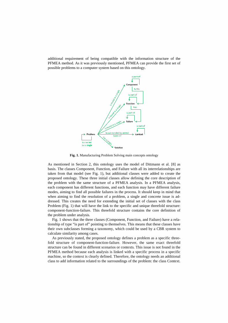
additional requirement of being compatible with the information structure of the PFMEA method. As it was previously mentioned, PFMEA can provide the first set of possible problems to a computer system based on this ontology.
Fig. 1. Manufacturing Problem Solving main concepts ontology
As mentioned in Section 2, this ontology uses the model of Dittmann et al. [8] as basis. The classes Component, Function, and Failure with all its interrelationships are taken from that model (see Fig. 1), but additional classes were added to create the proposed ontology. These three initial classes allow defining the core description of the problem with the same structure of a PFMEA analysis. In a PFMEA analysis, each component has different functions, and each function may have different failure modes, aiming to find all possible failures in the process. It should keep in mind that when aiming to find the resolution of a problem, a single and concrete issue is ad-dressed. This creates the need for extending the initial set of classes with the class Problem (Fig. 1) that will have the link to the specific and unique threefold structure: component-function-failure. This threefold structure contains the core definition of the problem under analysis.
Fig. 1 shows that the three classes (Component, Function, and Failure) have a rela-tionship of type “is part of” pointing to themselves. This means that these classes have their own subclasses forming a taxonomy, which could be used by a CBR system to calculate similarity among cases.
As previously stated, the proposed ontology defines a problem as a specific three-fold structure of component-function-failure. However, the same exact threefold structure can be found in different scenarios or contexts. This issue is not found in the PFMEA method because each analysis is linked with a specific process in a specific machine, so the context is clearly defined. Therefore, the ontology needs an additional class to add information related to the surroundings of the problem: the class Context.
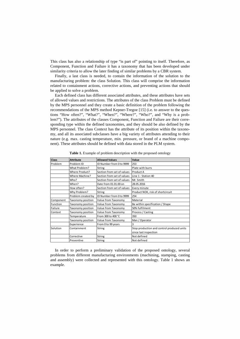
This class has also a relationship of type “is part of” pointing to itself. Therefore, as Component, Function and Failure it has a taxonomy that has been developed under similarity criteria to allow the later finding of similar problems by a CBR system.
Finally, a last class is needed, to contain the information of the solution to the manufacturing problem: the class Solution. This class will comprise the information related to containment actions, corrective actions, and preventing actions that should be applied to solve a problem.
Each defined class has different associated attributes, and these attributes have sets of allowed values and restrictions. The attributes of the class Problem must be defined by the MPS personnel and they create a basic definition of the problem following the recommendations of the MPS method Kepner-Tregoe [15] (i.e. to answer to the ques-tions “How often?”, “What?”, “When?”, “Where?”, “Who?”, and “Why is a prob-lem?”). The attributes of the classes Component, Function and Failure are their corre-sponding type within the defined taxonomies, and they should be also defined by the MPS personnel. The class Context has the attribute of its position within the taxono-my, and all its associated subclasses have a big variety of attributes attending to their nature (e.g. max. casting temperature, min. pressure, or brand of a machine compo-nent). These attributes should be defined with data stored in the PLM system.
Table 1. Example of problem description with the proposed ontology
In order to perform a preliminary validation of the proposed ontology, several problems from different manufacturing environments (machining, stamping, casting and assembly) were collected and represented with this ontology. Table 1 shows an example.
Class Attribute Allowed Values ValueProblem Problem ID ID Number from 0 to 9999 253
What Problem? String Plate with burrsWhere Product? Section from set of values Product AWhere Machine? Section from set of values Line 1 - Station 40Who? Section from set of values Mr. SmithWhen? Date from 01.01.00 on 28.05.2016How often? Section from set of values Every minuteWhy Problem? String Product NOK, risk of shortcircuitProblem created by ID Number from 0 to 9999 254
Component Taxonomy position Value from Taxonomy MaterialFunction Taxonomy position Value from Taxonomy Be within specification / ShapeFailure Taxonomy position Value from Taxonomy 50% fulfilmentContext Taxonomy position Value from Taxonomy Process / Casting
Temperature From 300 to 400 °C 350Taxonomy position Value from Taxonomy Man / OperatorExperience From 0 to 99 years 3
Solution Containment String Stop production and control produced units since last inspection
Corrective String Not definedPreventive String Not defined
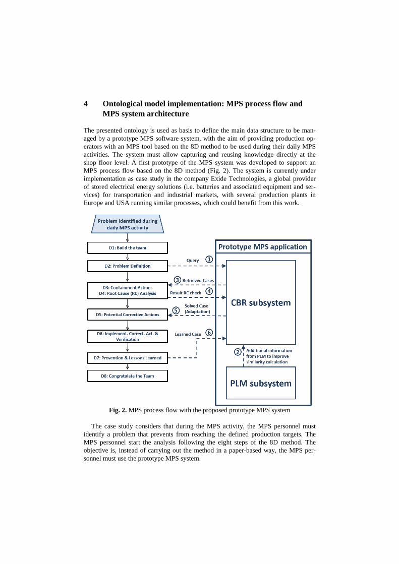
4 Ontological model implementation: MPS process flow and MPS system architecture
The presented ontology is used as basis to define the main data structure to be man-aged by a prototype MPS software system, with the aim of providing production op-erators with an MPS tool based on the 8D method to be used during their daily MPS activities. The system must allow capturing and reusing knowledge directly at the shop floor level. A first prototype of the MPS system was developed to support an MPS process flow based on the 8D method (Fig. 2). The system is currently under implementation as case study in the company Exide Technologies, a global provider of stored electrical energy solutions (i.e. batteries and associated equipment and ser-vices) for transportation and industrial markets, with several production plants in Europe and USA running similar processes, which could benefit from this work.
Fig. 2. MPS process flow with the proposed prototype MPS system
The case study considers that during the MPS activity, the MPS personnel must
identify a problem that prevents from reaching the defined production targets. The MPS personnel start the analysis following the eight steps of the 8D method. The objective is, instead of carrying out the method in a paper-based way, the MPS per-sonnel must use the prototype MPS system.
The main characteristic of the targeted users for this software system (i.e. opera-tors) is their lack of deep knowledge about the processes and products. In some cases, the operators are temporary workers, due to seasonal increases of production volumes, and they have no knowledge at all about the production process and/or resources. This profile of the future users of the prototype MPS system means that the application must be able to provide automatically as much information as possible to compensate their lack of knowledge. The user must be able to create a problem query, input the data associated to it (i.e. component-function-failure plus some additional basic in-formation such as date, line, or product, where the problem is found), and the system should connect with the PLM system to extract automatically all existing context information of the problem.
The PLM solution selected for the development of the prototype was Aras Innova-tor. This PLM application provides an Application Programming Interface named AML (Aras Markup Language) that allows extracting data from the PLM database.
The PLM system has to be customized to fit into the defined ontological model, and it has to be configured to retrieve the requested information in a format under-standable by the CBR system. According to the PFMEA methodology [2], used as basis in the proposed ontology, there are six types of components: process, machine, material, man environment and method. The initial configuration of Aras Innovator provides an item type called “Parts” to contain any mechanical design element, so the components of type material and machine can be of that type. The PLM main types has to be extended with four additional items called “Manufacturing Process”, “Man-ufacturing Man”, “Manufacturing Method”, and “Manufacturing Environment” to contain the rest of component types. Both the part type and the new types need to be created or extended with the following general attributes:
• Name. • Component number. It represents the reference number in the PLM system. • Revision number. • State. It has two alternatives ‘released’ or ‘not released’. • Effective date. From which date on the item has the state released. • Classification. Represents the position of the component in the Context taxonomy. • List of Methods. It contains links to items of type Manufacturing Method. • Item Nature. It is an attribute to indicate if the component where the problem occur
is real or abstract. The ‘abstract’ alternative allows indicating a general family of products or production lines instead of a specific one. Therefore, specific elements will be tagged with “Real”, and general ones with “Abstract”. This attribute is used when searching for the problem context data in the PLM application.
The item Manufacturing Method is associated to the PFMEA component Method, which represents the defined procedures or standards. In the proposed model, Manu-facturing Method contains the technical specification associated to an item (e.g. Part or Manufacturing Process). Part of this technical information can be common for a whole family of components (e.g. a family of hex bolts with a specific diameter and thread where each one distinguishes from the others in the length). Since the Manu-facturing Method is the container of technical data, each of the other five items (com-
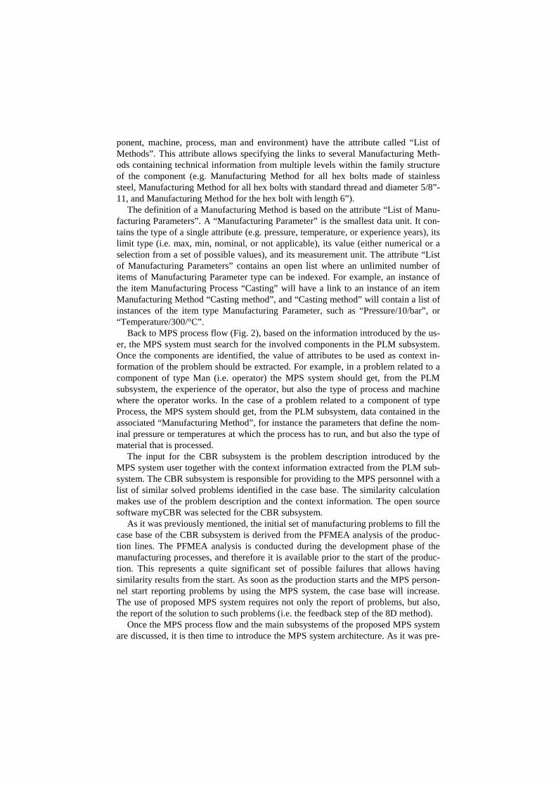
ponent, machine, process, man and environment) have the attribute called “List of Methods”. This attribute allows specifying the links to several Manufacturing Meth-ods containing technical information from multiple levels within the family structure of the component (e.g. Manufacturing Method for all hex bolts made of stainless steel, Manufacturing Method for all hex bolts with standard thread and diameter 5/8”-11, and Manufacturing Method for the hex bolt with length 6”).
The definition of a Manufacturing Method is based on the attribute “List of Manu-facturing Parameters”. A “Manufacturing Parameter” is the smallest data unit. It con-tains the type of a single attribute (e.g. pressure, temperature, or experience years), its limit type (i.e. max, min, nominal, or not applicable), its value (either numerical or a selection from a set of possible values), and its measurement unit. The attribute “List of Manufacturing Parameters” contains an open list where an unlimited number of items of Manufacturing Parameter type can be indexed. For example, an instance of the item Manufacturing Process “Casting” will have a link to an instance of an item Manufacturing Method “Casting method”, and “Casting method” will contain a list of instances of the item type Manufacturing Parameter, such as “Pressure/10/bar”, or “Temperature/300/°C”.
Back to MPS process flow (Fig. 2), based on the information introduced by the us-er, the MPS system must search for the involved components in the PLM subsystem. Once the components are identified, the value of attributes to be used as context in-formation of the problem should be extracted. For example, in a problem related to a component of type Man (i.e. operator) the MPS system should get, from the PLM subsystem, the experience of the operator, but also the type of process and machine where the operator works. In the case of a problem related to a component of type Process, the MPS system should get, from the PLM subsystem, data contained in the associated “Manufacturing Method”, for instance the parameters that define the nom-inal pressure or temperatures at which the process has to run, and but also the type of material that is processed.
The input for the CBR subsystem is the problem description introduced by the MPS system user together with the context information extracted from the PLM sub-system. The CBR subsystem is responsible for providing to the MPS personnel with a list of similar solved problems identified in the case base. The similarity calculation makes use of the problem description and the context information. The open source software myCBR was selected for the CBR subsystem.
As it was previously mentioned, the initial set of manufacturing problems to fill the case base of the CBR subsystem is derived from the PFMEA analysis of the produc-tion lines. The PFMEA analysis is conducted during the development phase of the manufacturing processes, and therefore it is available prior to the start of the produc-tion. This represents a quite significant set of possible failures that allows having similarity results from the start. As soon as the production starts and the MPS person-nel start reporting problems by using the MPS system, the case base will increase. The use of proposed MPS system requires not only the report of problems, but also, the report of the solution to such problems (i.e. the feedback step of the 8D method).
Once the MPS process flow and the main subsystems of the proposed MPS system are discussed, it is then time to introduce the MPS system architecture. As it was pre-
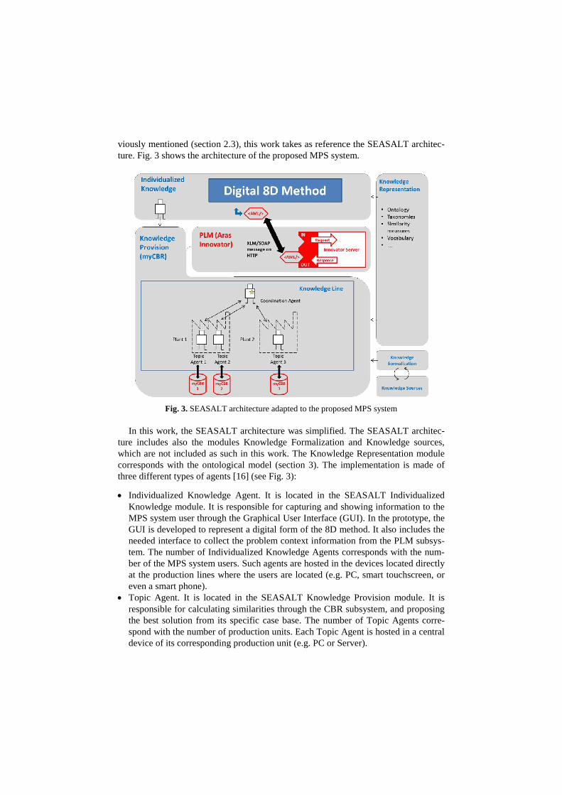
viously mentioned (section 2.3), this work takes as reference the SEASALT architec-ture. Fig. 3 shows the architecture of the proposed MPS system.
Fig. 3. SEASALT architecture adapted to the proposed MPS system
In this work, the SEASALT architecture was simplified. The SEASALT architec-ture includes also the modules Knowledge Formalization and Knowledge sources, which are not included as such in this work. The Knowledge Representation module corresponds with the ontological model (section 3). The implementation is made of three different types of agents [16] (see Fig. 3):
• Individualized Knowledge Agent. It is located in the SEASALT Individualized Knowledge module. It is responsible for capturing and showing information to the MPS system user through the Graphical User Interface (GUI). In the prototype, the GUI is developed to represent a digital form of the 8D method. It also includes the needed interface to collect the problem context information from the PLM subsys-tem. The number of Individualized Knowledge Agents corresponds with the num-ber of the MPS system users. Such agents are hosted in the devices located directly at the production lines where the users are located (e.g. PC, smart touchscreen, or even a smart phone).
• Topic Agent. It is located in the SEASALT Knowledge Provision module. It is responsible for calculating similarities through the CBR subsystem, and proposing the best solution from its specific case base. The number of Topic Agents corre-spond with the number of production units. Each Topic Agent is hosted in a central device of its corresponding production unit (e.g. PC or Server).
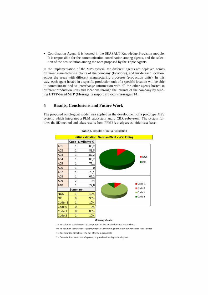
• Coordination Agent. It is located in the SEASALT Knowledge Provision module. It is responsible for the communication coordination among agents, and the selec-tion of the best solution among the ones proposed by the Topic Agents.
In the implementation of the MPS system, the different agents are deployed across different manufacturing plants of the company (locations), and inside each location, across the areas with different manufacturing processes (production units). In this way, each agent hosted in a specific production unit of a specific location will be able to communicate and to interchange information with all the other agents hosted in different production units and locations through the intranet of the company by send-ing HTTP-based MTP (Message Transport Protocol) messages [14].
5 Results, Conclusions and Future Work
The proposed ontological model was applied in the development of a prototype MPS system, which integrates a PLM subsystem and a CBR subsystem. The system fol-lows the 8D method and takes results from PFMEA analyses as initial case base.
Table 2. Results of initial validation
Code Similarity %A01 1 85,2A02 1 83,8A03 1 82,2A04 1 85,2A05 1 77,1A06 -1 0A07 1 70,1A08 1 67,2A09 2 84A10 1 72,8
NOK 1 10%OK 9 90%Code -1 1 10%Code 0 0 0%Code 1 8 80%Code 2 1 10%
-1 = No solution useful out of system proposals but no similar case in case base
-0 = No solution useful out of system proposals even though there are similar cases in case base
-1 = One solution directly useful out of system proposals
-2 = One solution useful out of system proposals with adaptation by user
Summary
Initial validation: German Plant - Wet Filling
Meaning of codes
NOK
OK
Code -1
Code 0
Code 1
Code 2
The developed prototype has been tested in the company Exide Technologies with an initial case base containing 72 cases. A single process and a single production plant have been selected for this first validation step, which represents the easiest level of complexity for the system, since the cases in the prototype were all collected in the same process and plant. 10 problems found on the shop floor have been analyzed in parallel by the system and experts. As it is showed in the Table 2, 80% of the results obtained for the queries were similar to the answer provided by experts, and an addi-tional 10% could guide to the solution by adapting the proposal of the system to the context of the problem under analysis. The results obtained showed the importance of the problem context information, defined in the PLM subsystem, in the case similarity calculation. A second version of the prototype MPS system is currently under devel-opment to be tested in different processes and production plants in parallel.
An advantage of the proposed MPS system, which has been realized during the ex-ecution of the tests, is the access and reuse by operators of solutions to problems al-ready identified in the PFMEA analyses of their lines. This is significant, because without the support of the prototype MPS system, such reuse rarely happens, mainly because of the difficulties in finding and analyzing information in the complex docu-ment of a PFMEA analysis. The population and maintenance of the system is con-ducted by a role named Knowledge Engineer. The current version of the application allows uploading cases by means of a csv format file.
Two possible barriers were identified during the implementation of the first proto-type of the MPS system. The first one is the requirement of having a PLM system, where information of the products, their processes and resources (PPR) of the compa-ny should be stored. The second one is the need of having access to the MPS system at the shop floor level. Nevertheless, the current trend of digitalization in the industry (e.g. Industry 4.0 initiative) [17] should help to overcome these possible barriers.
A possible future work is the development of the Knowledge Source and the Knowledge Formalization modules, defined in the SEASALT architecture, to extract automatically knowledge from PFMEA analyses. In that direction, some research works propose the use of SysML, to create a system model, where artifacts contain FMEA information, and the use of Prolog engine to query the created model to derive FMEA results [18].
References
1. Bhuiyan, N., Baghel, A.: An overview of continuous improvement: from the past to thepresent. Management Decision, 43, 5, pp. 761-771 (2005). doi:http://dx.doi.org/10.1108/00251740510597761.
2. VDA: Qualitätsmanagement in der Automobilindustrie – Qualitätsmanagement-MethodenAssessments. Verband der Autoindustrie (VDA) (2015).
3. Liu, D.R., Ke, C.K.: Knowledge support for problem-solving in a production process: Ahybrid of knowledge discovery and case-based reasoning. Expert Systems with Applica-tions, 33, pp. 147-161 (2007). doi:10.1016/j.eswa.2006.04.026.
4. Sowa, J.F.: Knowledge Representation - Logical, Philosophical and Computational Foun-dations. Brooks Cole Publishing Co., Pacific Grove, CA (2000). ISBN 0 534-94965-7.
5. Stark, J.: Product lifecycle management. Springer International Publishing, Switzerland(2015). ISBN 978-3-319-17440-2.
6. Richter, M.M., Weber, Rosina O.: Case-Based Reasoning: A Textbook. Springer, Heidel-berg (2013). ISBN 978-3-642-40167-1.
7. Foguem, B.K., Coudert, T., Béler, C., Geneste, L.: Knowledge Formalization in Experi-ence Feedback Processes: An Ontology-Based Approach. Computers in Industry, 59, 7,pp. 694-710 (2008). doi: 10.1016/j.compind.2007.12.014.
8. Dittmann, L., Rademacher, T., Zelewski, S.: Performing FMEA using ontologies. 18th In-ternational Workshop on Qualitative Reasoning. Evanston USA, pp. 209-216 (2004).
9. Ebrahimipour, V., Rezaie, K., Shokravi, S.: An ontology approach to support FMEA stud-ies. Expert Systems with Applications, 37, 1, pp. 671-677 (2010). doi:10.1109/RAMS.2009.4914711.
10. Cambria, E., & White, B. (2014). Jumping NLP curves: A review of natural language pro-cessing research. IEEE Computational intelligence magazine, 9(2), 48-57.
11. Bertin, A.: Intégration d'un système de Retour d'Expériences à un PLM. Doctoral disserta-tion - Laboratoire Génie Production (LGP) - Ecole Nationale d'Ingénieurs deTarbes - Uni-versité de Toulouse (2012).
12. Bertin, A., Noyes, D., Clermont, P.: Problem solving methods as Lessons Learned Systeminstrumentation into a PLM tool. In: 14th IFAC Symposium on Information Control Prob-lems in Manufacturing, Bucarest, Roumanie, May 23-25 (2012). ISBN Id: hal-01005542.
13. Bach, K.: Knowledge Acquisition for Case-Based Reasoning Systems. Ph.D. thesis, Uni-versity of Hildesheim (2012).
14. Reuss, P., Althoff, K.D., Hundt, A., Henkel, W., Pfeiffer, M.: Multi-Agent Case-Based Di-agnosis in the Aircraft Domain. In: Workshop Proceedings - 23rd International Conferenceon Case-Based Reasoning (ICCBR 2015), pp. 43-52 (2015).
15. Kepner, C.H., Tregoe, B.B.: The New Rational Manager - An Updated Edition for a NewWorld. Princeton Research Press, New Jersey (2008). ISBN 978-0-9715627-1-4.
16. Bellifemine, F.L., Caire, G., Greenwood, D.: Developing multi-agent systems with JADE.Wiley series in agent technology - John Wiley & Sons, England (2007).
17. Cearley, D.W., Walker, M.J., Burke, B.: Top 10 Strategic Technology Trends for 2016: Ata Glance. Gartner (2015).
18. Scippacercola, F., Pietrantuono, R., Russo, S., & Silva, N. P. (2015, November). SysML-based and Prolog-supported FMEA. In Software Reliability Engineering Workshops(ISSREW), 2015 IEEE International Symposium on (pp. 174-181). IEEE.

255
Appendix 3: Published Papers
Paper 4
Camarillo, Alvaro; Rios-Chueco, Jose; Althoff, Klaus-Dieter (2018a): Knowledge-based multi-agent system for manufacturing problem solving process in production plants. Journal of Manufacturing Systems, Vol. 47, pp. 115-127.
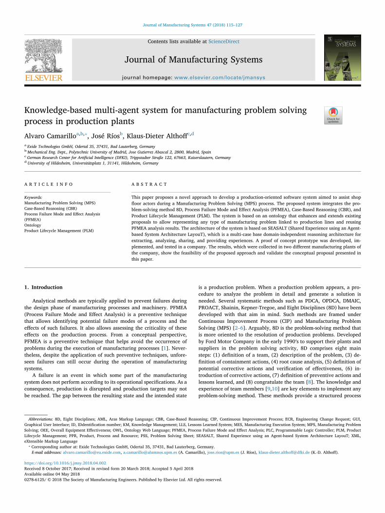
Contents lists available at ScienceDirect
Journal of Manufacturing Systems
journal homepage: www.elsevier.com/locate/jmansys
Knowledge-based multi-agent system for manufacturing problem solvingprocess in production plants
Alvaro Camarilloa,b,⁎, José Ríosb, Klaus-Dieter Althoffc,d
a Exide Technologies GmbH, Odertal 35, 37431, Bad Lauterberg, GermanybMechanical Eng. Dept., Polytechnic University of Madrid, Jose Gutierrez Abascal 2, 2800, Madrid, SpaincGerman Research Center for Artificial Intelligence (DFKI), Trippstadter Straße 122, 67663, Kaiserslautern, GermanydUniversity of Hildesheim, Universitätsplatz 1, 31141, Hildesheim, Germany
A R T I C L E I N F O
Keywords:Manufacturing Problem Solving (MPS)Case-Based Reasoning (CBR)Process Failure Mode and Effect Analysis(PFMEA)OntologyProduct Lifecycle Management (PLM)
A B S T R A C T
This paper proposes a novel approach to develop a production-oriented software system aimed to assist shopfloor actors during a Manufacturing Problem Solving (MPS) process. The proposed system integrates the pro-blem-solving method 8D, Process Failure Mode and Effect Analysis (PFMEA), Case-Based Reasoning (CBR), andProduct Lifecycle Management (PLM). The system is based on an ontology that enhances and extends existingproposals to allow representing any type of manufacturing problem linked to production lines and reusingPFMEA analysis results. The architecture of the system is based on SEASALT (Shared Experience using an Agent-based System Architecture LayouT), which is a multi-case base domain-independent reasoning architecture forextracting, analyzing, sharing, and providing experiences. A proof of concept prototype was developed, im-plemented, and tested in a company. The results, which were collected in two different manufacturing plants ofthe company, show the feasibility of the proposed approach and validate the conceptual proposal presented inthis paper.
1. Introduction
Analytical methods are typically applied to prevent failures duringthe design phase of manufacturing processes and machinery. PFMEA(Process Failure Mode and Effect Analysis) is a preventive techniquethat allows identifying potential failure modes of a process and theeffects of such failures. It also allows assessing the criticality of theseeffects on the production process. From a conceptual perspective,PFMEA is a preventive technique that helps avoid the occurrence ofproblems during the execution of manufacturing processes [1]. Never-theless, despite the application of such preventive techniques, unfore-seen failures can still occur during the operation of manufacturingsystems.
A failure is an event in which some part of the manufacturingsystem does not perform according to its operational specifications. As aconsequence, production is disrupted and production targets may notbe reached. The gap between the resulting state and the intended state
is a production problem. When a production problem appears, a pro-cedure to analyze the problem in detail and generate a solution isneeded. Several systematic methods such as PDCA, OPDCA, DMAIC,PROACT, Shainin, Kepner-Tregoe, and Eight Disciplines (8D) have beendeveloped with that aim in mind. Such methods are framed underContinuous Improvement Process (CIP) and Manufacturing ProblemSolving (MPS) [2–6]. Arguably, 8D is the problem-solving method thatis more oriented to the resolution of production problems. Developedby Ford Motor Company in the early 1990′s to support their plants andsuppliers in the problem solving activity, 8D comprises eight mainsteps: (1) definition of a team, (2) description of the problem, (3) de-finition of containment actions, (4) root cause analysis, (5) definition ofpotential corrective actions and verification of effectiveness, (6) in-troduction of corrective actions, (7) definition of preventive actions andlessons learned, and (8) congratulate the team [8]. The knowledge andexperience of team members [9,10] are key elements to implement anyproblem-solving method. These methods provide a structured process
https://doi.org/10.1016/j.jmsy.2018.04.002Received 8 October 2017; Received in revised form 20 March 2018; Accepted 5 April 2018
⁎ Corresponding author at: Exide Technologies GmbH, Odertal 35, 37431, Bad Lauterberg, Germany.E-mail addresses: [email protected], [email protected] (A. Camarillo), [email protected] (J. Ríos), [email protected] (K.-D. Althoff).
Abbreviations: 8D, Eight Disciplines; AML, Aras Markup Language; CBR, Case-Based Reasoning; CIP, Continuous Improvement Process; ECR, Engineering Change Request; GUI,Graphical User Interface; ID, IDdentification number; KM, Knowledge Management; LLS, Lessons Learned System; MES, Manufacturing Execution System; MPS, Manufacturing ProblemSolving; OEE, Overall Equipment Effectiveness; OWL, Ontology Web Language; PFMEA, Process Failure Mode and Effect Analysis; PLC, Programmable Logic Controller; PLM, ProductLifecycle Management; PPR, Product, Process and Resource; PSS, Problem Solving Sheet; SEASALT, Shared Experience using an Agent-based System Architecture LayouT; XML,eXtensible Markup Language
Journal of Manufacturing Systems 47 (2018) 115–127
Available online 04 May 20180278-6125/ © 2018 The Society of Manufacturing Engineers. Published by Elsevier Ltd. All rights reserved.
T

to facilitate the improvement and finding of solutions. Nevertheless,although training is generally provided to team members, thesemethods only bring good results when they are driven by actors withenough experience who get additional support knowledge (e.g., pro-vided by a software tool [9,10]). The literature also shows that theindustrial application of PFMEA is complex, time consuming, and in-efficient [11]. In addition, it provides a low outcome, its results are notrevised during regular continuous-improvement activities, and thereare issues to keep an efficient feedback [11]. Part of the problem withPFMEA relates to the fact that it is based on a spreadsheet approach,which makes it difficult to reuse results and identify similarities [11].
This paper proposes a Knowledge Management (KM) approach thataims to:
• Facilitate the reuse of PFMEA analysis results.
• Facilitate the capture and reuse of data and knowledge of manu-facturing processes, at shop floor level, in any manufacturing plant,during daily MPS activities linked to the Overall EquipmentEffectiveness (OEE) improvement. Among the different topics con-sidered by OEE, the focus is set on quality issues with product andprocesses (i.e. quality claims and scrap), abnormal productionspeed, and breakdowns.
• Provide shop floor actors with a problem-solving software toolbased on the 8D method, which can be used even by users with verylow knowledge of the manufacturing system with which they work.
• Support manufacturing knowledge sharing and integration acrossdifferent manufacturing plants.
The proposed KM approach comprises the integration of the 8D MPSmethod [8] with Case-Based Reasoning (CBR) [12,13] on an agent-based distributed architecture with a Product Lifecycle Management(PLM) system [14,15] and PFMEA [1]. The 8D method provides astructured way to guide the resolution of problems step by step. CBR isused as an artificial intelligence tool to search for similar manufacturingproblem cases collected previously in multiple locations. PLM is used asa source of extended context information about Product-Process-Re-sources (PPR) that will enrich the similarity calculation of the CBRapplication. PFMEA is used as source of the initial set of cases to feedthe CBR application. One main contribution of this work is the in-tegration of these four techniques: 8D method, CBR, PLM, and PFMEA.
The reminder of this paper is structured as follows. Section 2 con-tains a literature review of the main topics related to this work: man-ufacturing problem knowledge representation, PLM and CBR. Section 3discusses the created models, which are the basis of the ontologicalapproach adopted to define the data structures needed to managemanufacturing problem knowledge. Section 4 describes the developedprototype application and its validation. The paper ends with theconclusions and future works.
2. State of the art
2.1. Representation of manufacturing problems and PFMEA
Manufacturing problems need to be described in a consistent andsystematic way in order to allow for a common understanding by theMPS personnel and an appropriate processing by a software system.One way to address this need is by means of an ontology [16]. Litera-ture shows proposals of different ontologies focused on manufacturingrelated issues [17,18]. Manufacturing is a very wide domain and, de-pending on the specific area of interest, ontologies comprise a variety ofmanufacturing related concepts.
Chungoora et al. [18] propose a manufacturing core ontology with amanufacturing planning orientation, which comprises concepts relatedto product design and manufacturing processes and resources. The mainconcepts are: PartFamily, DesignFunction, Feature, ProcessPlan, Man-ufacturingMethod, ManufacturingProcess, ManufacturingResource, and
ManufacturingFacility.When considering the representation of concepts dealing with MPS
and PFMEA, Kamsu-Foguem et al. [19] propose an ontology based onconceptual graphs to formalize knowledge in an experience feedbackprocess. However, PFMEA concepts are not supported. Experiencefeedback is considered a relevant approach to support MPS with lessonslearned formalized knowledge. The ontology comprises the followingmain concepts: feedback_object, experience_element, experience, actionand attributes. The ontology also includes their corresponding specia-lizations: activity, product, process, resource, competency, solution,context, analysis, event, positive_event, and negative_event. Scippa-cercola et al. [20] propose the use of SysML to create a system modelwhere artifacts contain FMEA related information. The FMEA in-formation is represented as a description of the logical states of theinput flows, blocks, and their corresponding constraints. A transfor-mation translates the annotated FMEA SysML model elements into factsand rules of a Prolog base. A Prolog engine queries the created model toderive FMEA results. Ebrahimipour et al. [21], Dittmann et al. [22], andMikos et al. [23] present three examples of ontologies to support FMEAconcepts, with the aim of facilitating the reuse of information stored inFMEA analyses.
Ebrahimipour et al. [21] propose an upper ontology where threeconcepts related to FMEA information (i.e., deviation, cause and con-sequence) are modeled as an event and activities. A deviation is mod-eled as an event, which is the beginning of a consequence. A con-sequence is an activity. A cause is an activity that causes a deviation.
Dittmann et al. [22] propose a ROOT_CONCEPT class that is spe-cialized into seven subclasses: FMEA, Component, Function, Fail-ure_mode, Control_method, Risk_priority_number, and Contain-ment_action. They also propose a set of relationships among the classes.For instance, the “fulfills_a_function” relationship relates a Componentto a Function, and “has_failure_mode” relates a Function to a Fail-ure_mode. The classes Component and Function have associated taxo-nomies.
Mikos et al. [23] use the standard SAE J1739 and AIAG FMEA Re-ference Manual to define a PFMEA ontology. In addition to the PFMEAconcepts modeled as classes (LocationOfFailure, PotentialCausesOfFai-lure, PotentialEffectsOfFailure, EndEffect, LocalEffect, PotentialFailur-eMode, and FMEADescription), the ontology seems to support theconcepts of product, process, and function.
After reviewing the mentioned ontologies, the works fromChungoora et al. [18] and Dittmann et al. [22] were taken as reference.Section 3.2 explains the selected concepts that were adopted and thenew concepts that are proposed, which are part of the contribution ofthis work.
When analyzing a manufacturing problem, it is important to knowthe context where it happens. The context information can be struc-tured into three main areas: product, process and resource (PPR). PLMsystems are considered the main source of PPR information. Therefore,the ontology must consider concepts managed by such systems.
2.2. Product lifecycle management as data repository for manufacturingproblem solving
A PFMEA analysis is performed in a specific process and, thus, theinformation to be used is restricted to the components of that process.The identified potential failure modes relate to a specific manufacturingcontext, i.e. process, process step, machine, tooling, process parameters,and product manufacturing feature. Therefore, it is necessary to com-pare the context where a manufacturing problem occurs with the con-text of each existing PFMEA analysis in order to evaluate their simi-larity. In that way, PFMEA knowledge can be reused to assist in thesolution of a specific manufacturing problem. The context of the pro-blem can be described in the form of PPR data, which sets clear dif-ferences among problems. Lundgren et al. [11] consider PFMEA as partof the quality assurance activities and end up using a similar approach.
A. Camarillo et al. Journal of Manufacturing Systems 47 (2018) 115–127
116
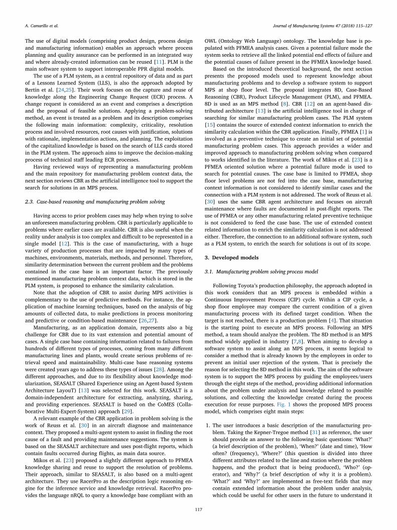
The use of digital models (comprising product design, process designand manufacturing information) enables an approach where processplanning and quality assurance can be performed in an integrated wayand where already-created information can be reused [11]. PLM is themain software system to support interoperable PPR digital models.
The use of a PLM system, as a central repository of data and as partof a Lessons Learned System (LLS), is also the approach adopted byBertin et al. [24,25]. Their work focuses on the capture and reuse ofknowledge along the Engineering Change Request (ECR) process. Achange request is considered as an event and comprises a descriptionand the proposal of feasible solutions. Applying a problem-solvingmethod, an event is treated as a problem and its description comprisesthe following main information: complexity, criticality, resolutionprocess and involved resources, root causes with justification, solutionswith rationale, implementation actions, and planning. The exploitationof the capitalized knowledge is based on the search of LLS cards storedin the PLM system. The approach aims to improve the decision-makingprocess of technical staff leading ECR processes.
Having reviewed ways of representing a manufacturing problemand the main repository for manufacturing problem context data, thenext section reviews CBR as the artificial intelligence tool to support thesearch for solutions in an MPS process.
2.3. Case-based reasoning and manufacturing problem solving
Having access to prior problem cases may help when trying to solvean unforeseen manufacturing problem. CBR is particularly applicable toproblems where earlier cases are available. CBR is also useful when thereality under analysis is too complex and difficult to be represented in asingle model [12]. This is the case of manufacturing, with a hugevariety of production processes that are impacted by many types ofmachines, environments, materials, methods, and personnel. Therefore,similarity determination between the current problem and the problemscontained in the case base is an important factor. The previouslymentioned manufacturing problem context data, which is stored in thePLM system, is proposed to enhance the similarity calculation.
Note that the adoption of CBR to assist during MPS activities iscomplementary to the use of predictive methods. For instance, the ap-plication of machine learning techniques, based on the analysis of bigamounts of collected data, to make predictions in process monitoringand predictive or condition-based maintenance [26,27].
Manufacturing, as an application domain, represents also a bigchallenge for CBR due to its vast extension and potential amount ofcases. A single case base containing information related to failures fromhundreds of different types of processes, coming from many differentmanufacturing lines and plants, would create serious problems of re-trieval speed and maintainability. Multi-case base reasoning systemswere created years ago to address these types of issues [28]. Among thedifferent approaches, and due to its flexibility about knowledge mod-ularization, SEASALT (Shared Experience using an Agent-based SystemArchitecture LayouT) [13] was selected for this work. SEASALT is adomain-independent architecture for extracting, analyzing, sharing,and providing experiences. SEASALT is based on the CoMES (Colla-borative Multi-Expert-System) approach [29].
A relevant example of the CBR application in problem solving is thework of Reuss et al. [30] in an aircraft diagnose and maintenancecontext. They proposed a multi-agent system to assist in finding the rootcause of a fault and providing maintenance suggestions. The system isbased on the SEASALT architecture and uses post-flight reports, whichcontain faults occurred during flights, as main data source.
Mikos et al. [23] proposed a slightly different approach to PFMEAknowledge sharing and reuse to support the resolution of problems.Their approach, similar to SEASALT, is also based on a multi-agentarchitecture. They use RacerPro as the description logic reasoning en-gine for the inference service and knowledge retrieval. RacerPro pro-vides the language nRQL to query a knowledge base compliant with an
OWL (Ontology Web Language) ontology. The knowledge base is po-pulated with PFMEA analysis cases. Given a potential failure mode thesystem seeks to retrieve all the linked potential end effects of failure andthe potential causes of failure present in the PFMEA knowledge based.
Based on the introduced theoretical background, the next sectionpresents the proposed models used to represent knowledge aboutmanufacturing problems and to develop a software system to supportMPS at shop floor level. The proposal integrates 8D, Case-BasedReasoning (CBR), Product Lifecycle Management (PLM), and PFMEA.8D is used as an MPS method [8]. CBR [12] on an agent-based dis-tributed architecture [13] is the artificial intelligence tool in charge ofsearching for similar manufacturing problem cases. The PLM system[15] contains the source of extended context information to enrich thesimilarity calculation within the CBR application. Finally, PFMEA [1] isinvolved as a preventive technique to create an initial set of potentialmanufacturing problem cases. This approach provides a wider andimproved approach to manufacturing problem solving when comparedto works identified in the literature. The work of Mikos et al. [23] is aPFMEA oriented solution where a potential failure mode is used tosearch for potential causes. The case base is limited to PFMEA, shopfloor level problems are not fed into the case base, manufacturingcontext information is not considered to identify similar cases and theconnection with a PLM system is not addressed. The work of Reuss et al.[30] uses the same CBR agent architecture and focuses on aircraftmaintenance where faults are documented in post-flight reports. Theuse of PFMEA or any other manufacturing related preventive techniqueis not considered to feed the case base. The use of extended contextrelated information to enrich the similarity calculation is not addressedeither. Therefore, the connection to an additional software system, suchas a PLM system, to enrich the search for solutions is out of its scope.
3. Developed models
3.1. Manufacturing problem solving process model
Following Toyota’s production philosophy, the approach adopted inthis work considers that an MPS process is embedded within aContinuous Improvement Process (CIP) cycle. Within a CIP cycle, ashop floor employee may compare the current condition of a givenmanufacturing process with its defined target condition. When thetarget is not reached, there is a production problem [4]. That situationis the starting point to execute an MPS process. Following an MPSmethod, a team should analyze the problem. The 8D method is an MPSmethod widely applied in industry [7,8]. When aiming to develop asoftware system to assist along an MPS process, it seems logical toconsider a method that is already known by the employees in order toprevent an initial user rejection of the system. That is precisely thereason for selecting the 8D method in this work. The aim of the softwaresystem is to support the MPS process by guiding the employees/usersthrough the eight steps of the method, providing additional informationabout the problem under analysis and knowledge related to possiblesolutions, and collecting the knowledge created during the processexecution for reuse purposes. Fig. 1 shows the proposed MPS processmodel, which comprises eight main steps:
1. The user introduces a basic description of the manufacturing pro-blem. Taking the Kepner-Tregoe method [31] as reference, the usershould provide an answer to the following basic questions: ‘What?’(a brief description of the problem), ‘When?’ (date and time), ‘Howoften? (frequency), ‘Where?’ (this question is divided into threedifferent attributes related to the line and station where the problemhappens, and the product that is being produced), ‘Who?’ (op-erator), and ‘Why?’ (a brief description of why it is a problem).‘What?’ and ‘Why?’ are implemented as free-text fields that maycontain extended information about the problem under analysis,which could be useful for other users in the future to understand it
A. Camarillo et al. Journal of Manufacturing Systems 47 (2018) 115–127
117
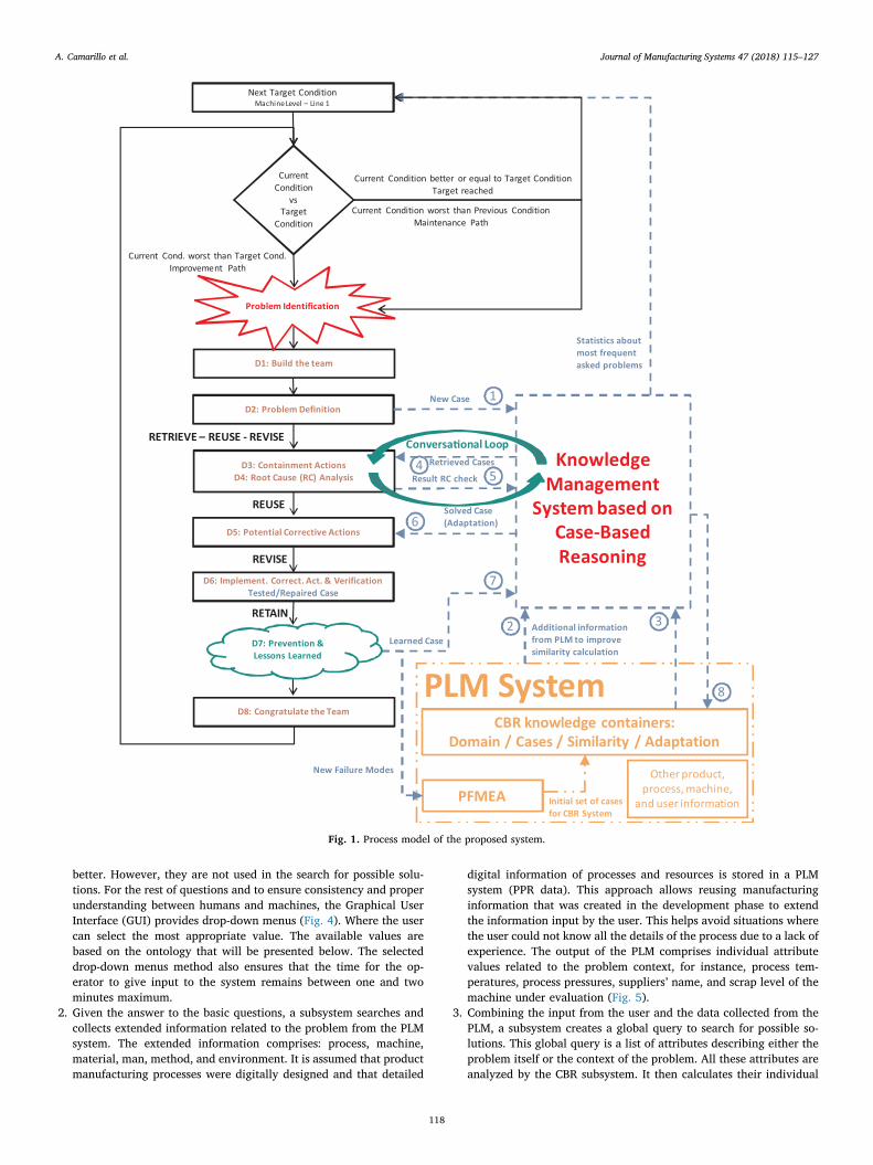
better. However, they are not used in the search for possible solu-tions. For the rest of questions and to ensure consistency and properunderstanding between humans and machines, the Graphical UserInterface (GUI) provides drop-down menus (Fig. 4). Where the usercan select the most appropriate value. The available values arebased on the ontology that will be presented below. The selecteddrop-down menus method also ensures that the time for the op-erator to give input to the system remains between one and twominutes maximum.
2. Given the answer to the basic questions, a subsystem searches andcollects extended information related to the problem from the PLMsystem. The extended information comprises: process, machine,material, man, method, and environment. It is assumed that productmanufacturing processes were digitally designed and that detailed
digital information of processes and resources is stored in a PLMsystem (PPR data). This approach allows reusing manufacturinginformation that was created in the development phase to extendthe information input by the user. This helps avoid situations wherethe user could not know all the details of the process due to a lack ofexperience. The output of the PLM comprises individual attributevalues related to the problem context, for instance, process tem-peratures, process pressures, suppliers’ name, and scrap level of themachine under evaluation (Fig. 5).
3. Combining the input from the user and the data collected from thePLM, a subsystem creates a global query to search for possible so-lutions. This global query is a list of attributes describing either theproblem itself or the context of the problem. All these attributes areanalyzed by the CBR subsystem. It then calculates their individual
Fig. 1. Process model of the proposed system.
A. Camarillo et al. Journal of Manufacturing Systems 47 (2018) 115–127
118
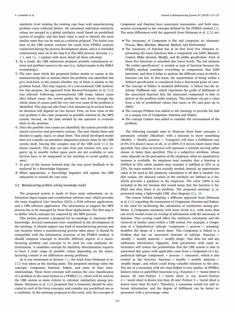
similarity level relating the existing case base with manufacturingproblem cases collected before. All calculated individual similarityvalues are merged in a global similarity result based on predefinedsystem of weights, and this final value is used to identify the mostsimilar cases that can be used as a solution proposal. The initial casebase of the CBR system contains the result from PFMEA analysisconducted during the process development phase, and it is extendedcontinuously later on in the step 8 of this MPS process. Sections 4.2,4.3, and Fig. 6 explain with more detail all these sub-steps.
4. As a result, the CBR subsystem proposes possible containment ac-tions and problem causes to the user (i.e., failure modes in the FMEAterminology).
5. The user must check the proposed failure modes or causes at themanufacturing line or station where the problem was identified andgive feed-back to the system whether any of them is similar to theproblem found. This step requires of a conversational CBR method.For this purpose, the approach from Becerra-Fernandez et al. [32]was selected. Following conversational CBR loops, failure causeafter failure cause, the system guides the user down through thewhole chain of causes until the very last root cause of the problem isidentified. This step can take from a few minutes up to several hours.Its duration will depend on two factors. First, on how close to thereal problem is the cases proposed as possible solution by the MPSsystem. Second, on the time needed by the operator to evaluatethem in the machine.
6. Once the possible root causes are identified, the system provides thestored corrective and preventive actions. The user checks them anddecides to apply, reject, or adapt them. This initial developed modeldoes not consider an automatic adaptation process done by the CBRsystem itself, leaving this complex step of the CBR cycle [12] forfuture research. This step can take from just minutes (for easy re-pairs) up to months (when spare parts are not available or newdevices have to be integrated in the machine to avoid quality is-sues).
7. As part of the lessons learned step, the user gives feedback to beanalyzed by a Knowledge Engineer.
8. When appropriate, a Knowledge Engineer will update the CBRsubsystem to extend the case base.
3.2. Manufacturing problem solving knowledge model
The proposed system is made of three main subsystems: an in-formation input/output and coordination software unit, which providesthe main Graphical User Interface (GUI), a PLM software application,and a CBR software application. The information to support the MPSprocess has to be managed by these three applications. The first step isto define which concepts are required by the MPS process.
This section presents a proposal for an ontology to represent MPSknowledge. Several constraints were considered in the development ofthe ontology. It should support any kind of manufacturing process andany location where a manufacturing process takes place. It should becompatible with the information structure of the PFMEA method. Itshould comprise concepts to describe different aspects of a manu-facturing problem and concepts to be used for case similarity de-termination. A candidate concept for similarity determination requiresto have a wide range of possible values depending on the manu-facturing context to set differences among problems.
As it was mentioned in Section 2.1, the work from Dittmann et al.[22] was taken as the starting point. The proposed ontology takes theconcepts: Component, Function, Failure, and some of their inter-relationships. These three concepts will contain the core classificationof a problem in the same format as a PFMEA [1], which will be used bythe CBR system as main criteria to calculate similarities among pro-blems. Dittmann et al. [22] proposed that a taxonomy should be asso-ciated to each of the three concepts, and consider any predefined one asa candidate. In the ontology proposed in this work, only the concepts of
Component and Function have associated taxonomies, and both taxo-nomies correspond to the concepts defined by the PFMEA method [1].The main differences with the approach from Dittmann et al. [22] are:
• The taxonomy of Component is flat and comprises six elements:Process, Man, Machine, Material, Method, and Environment.
• The taxonomy of Function has at its first level five elements re-presenting the main functions that a component can fulfil: Measure,Control, Make decision, Modify, and Be within specification. Each ofthese five functions is extended into lower levels. The last element“Be within specification” is needed as type of function because thePFMEA method considers everything as components that fulfilfunctions, and then it helps to analyze the different ways in which afunction can fail. In this sense, the requirement of being within adefined specification is considered from a functional point of view.
• The concept of Failure is modeled differently. A failure has the at-tribute ‘Fulfilment rate’, which represents the grade of fulfilment ofthe associated function that the associated component is able todeliver in the problem under analysis. This attribute can get a valuefrom a list of predefined values that starts at 0% and goes up to200%.
• The concept Problem was added to the ontology to provide the linkto a unique trio of Component, Function and Failure.
• The concept Context was added to consider the environment of theproblem.
The following example aims to illustrate these basic concepts: apneumatic cylinder (Machine) with a function to move something(Modify > Modify position > Transport) will have a Fulfilment rateof 0% if it doesn’t move at all, or of 200% if it moves much faster thanspecified. Any value in between will represent a cylinder moving eitherslower or faster than specified. This is a subjective attribute, whosevalue depends on the perception of the employee when no quantitativemeasure is available. An employee may consider that a function isfulfilled at 25% while another may consider it fulfilled at 32% or at23%. An exact number is not actually needed; instead, an approximatevalue to be used in the similarity calculation is all that is needed. Forthat reason, the allowed values of the attribute are defined as a list,which provides a guidance to the employee. The value 100% is notincluded in the list because this would mean that the function is ful-filled and thus there is no problem. The proposed ontology is re-presented using a lightweight UML class diagram (Fig. 2).
The reason behind adopting a different approach from Dittmannet al. [22] regarding the taxonomies of Component, Function and Failure,is the need for facilitating the calculation of similarities among pro-blems. A Component taxonomy with more levels (i.e., with more thanone level) would create an overlap of information with the taxonomy ofFunction. That overlap could affect the similarity calculation and theretrieval of similar cases within a CBR system. For example, a Compo-nent of a hypothetical subtype ‘component > process > stamping’modifies the shape of a metal sheet. This Component is linked to aProblem that has an associated Function of subtype ‘function >modify > modify material > modify shape’, that does not add anyadditional information. Opposite, both parameters with same in-formation will reduce the probabilities that the CBR system is able toassociated this query with applicable cases from a Component of a hy-pothetical subtype ‘component > process > extrusion’, which is alsorelated to the function ‘function > modify > modify material >modify shape’, and which could bring valuable solutions to the user.The use of a taxonomy with the class Failure is very similar. In PFMEA,failures relate to unfulfilled functions (e.g.: Function 1= ‘metal sheet isdrawn 20 mm’/Failure 1= ‘metal sheet is not drawn’/Failure2= ‘metal sheet is drawn less than 20 mm’/Failure 3= ‘metal sheet isdrawn more than 20 mm’). Therefore, a taxonomy would not add re-levant information, and the degree of fulfilment can be better re-presented with a percentage value.
A. Camarillo et al. Journal of Manufacturing Systems 47 (2018) 115–127
119
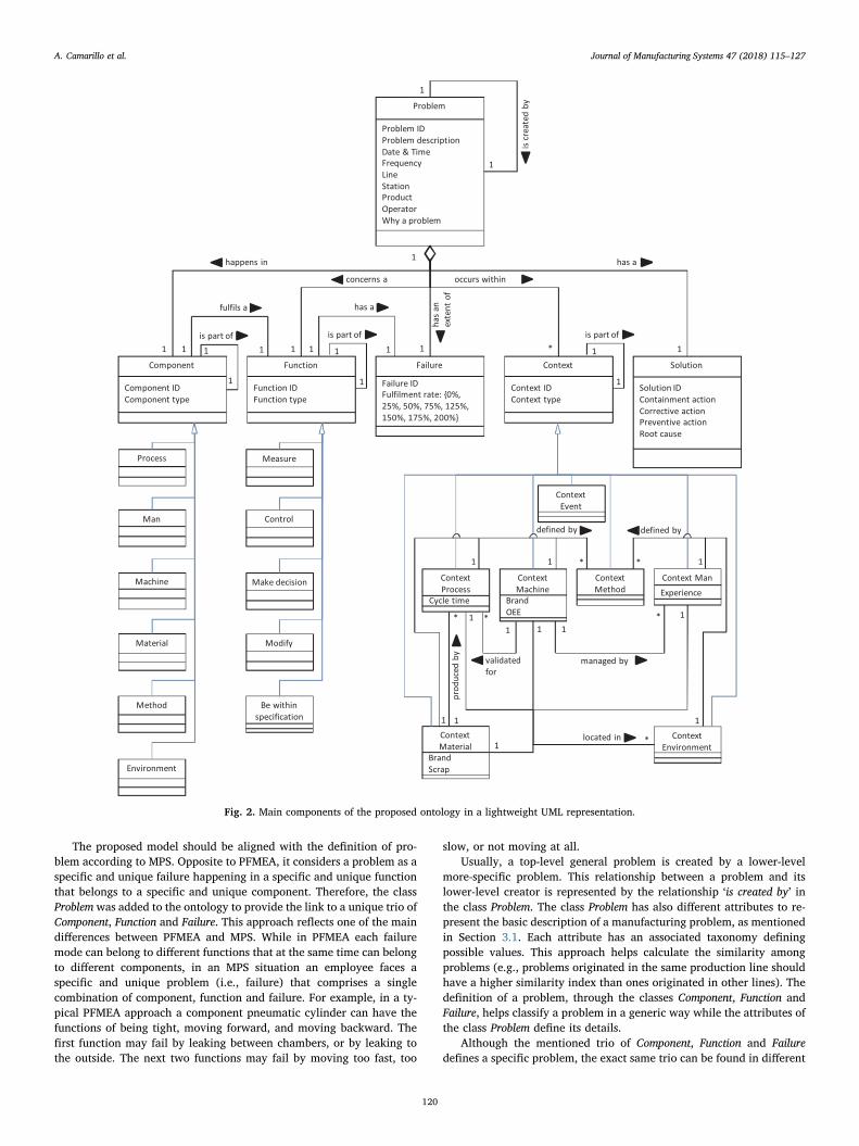
The proposed model should be aligned with the definition of pro-blem according to MPS. Opposite to PFMEA, it considers a problem as aspecific and unique failure happening in a specific and unique functionthat belongs to a specific and unique component. Therefore, the classProblem was added to the ontology to provide the link to a unique trio ofComponent, Function and Failure. This approach reflects one of the maindifferences between PFMEA and MPS. While in PFMEA each failuremode can belong to different functions that at the same time can belongto different components, in an MPS situation an employee faces aspecific and unique problem (i.e., failure) that comprises a singlecombination of component, function and failure. For example, in a ty-pical PFMEA approach a component pneumatic cylinder can have thefunctions of being tight, moving forward, and moving backward. Thefirst function may fail by leaking between chambers, or by leaking tothe outside. The next two functions may fail by moving too fast, too
slow, or not moving at all.Usually, a top-level general problem is created by a lower-level
more-specific problem. This relationship between a problem and itslower-level creator is represented by the relationship ‘is created by’ inthe class Problem. The class Problem has also different attributes to re-present the basic description of a manufacturing problem, as mentionedin Section 3.1. Each attribute has an associated taxonomy definingpossible values. This approach helps calculate the similarity amongproblems (e.g., problems originated in the same production line shouldhave a higher similarity index than ones originated in other lines). Thedefinition of a problem, through the classes Component, Function andFailure, helps classify a problem in a generic way while the attributes ofthe class Problem define its details.
Although the mentioned trio of Component, Function and Failuredefines a specific problem, the exact same trio can be found in different
Fig. 2. Main components of the proposed ontology in a lightweight UML representation.
A. Camarillo et al. Journal of Manufacturing Systems 47 (2018) 115–127
120
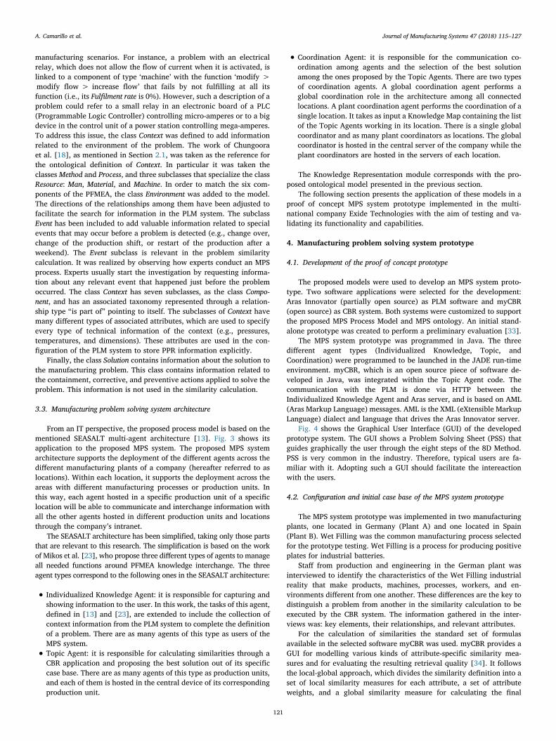
manufacturing scenarios. For instance, a problem with an electricalrelay, which does not allow the flow of current when it is activated, islinked to a component of type ‘machine’ with the function ‘modify >modify flow > increase flow’ that fails by not fulfilling at all itsfunction (i.e., its Fulfilment rate is 0%). However, such a description of aproblem could refer to a small relay in an electronic board of a PLC(Programmable Logic Controller) controlling micro-amperes or to a bigdevice in the control unit of a power station controlling mega-amperes.To address this issue, the class Context was defined to add informationrelated to the environment of the problem. The work of Chungooraet al. [18], as mentioned in Section 2.1, was taken as the reference forthe ontological definition of Context. In particular it was taken theclasses Method and Process, and three subclasses that specialize the classResource: Man, Material, and Machine. In order to match the six com-ponents of the PFMEA, the class Environment was added to the model.The directions of the relationships among them have been adjusted tofacilitate the search for information in the PLM system. The subclassEvent has been included to add valuable information related to specialevents that may occur before a problem is detected (e.g., change over,change of the production shift, or restart of the production after aweekend). The Event subclass is relevant in the problem similaritycalculation. It was realized by observing how experts conduct an MPSprocess. Experts usually start the investigation by requesting informa-tion about any relevant event that happened just before the problemoccurred. The class Context has seven subclasses, as the class Compo-nent, and has an associated taxonomy represented through a relation-ship type “is part of” pointing to itself. The subclasses of Context havemany different types of associated attributes, which are used to specifyevery type of technical information of the context (e.g., pressures,temperatures, and dimensions). These attributes are used in the con-figuration of the PLM system to store PPR information explicitly.
Finally, the class Solution contains information about the solution tothe manufacturing problem. This class contains information related tothe containment, corrective, and preventive actions applied to solve theproblem. This information is not used in the similarity calculation.
3.3. Manufacturing problem solving system architecture
From an IT perspective, the proposed process model is based on thementioned SEASALT multi-agent architecture [13]. Fig. 3 shows itsapplication to the proposed MPS system. The proposed MPS systemarchitecture supports the deployment of the different agents across thedifferent manufacturing plants of a company (hereafter referred to aslocations). Within each location, it supports the deployment across theareas with different manufacturing processes or production units. Inthis way, each agent hosted in a specific production unit of a specificlocation will be able to communicate and interchange information withall the other agents hosted in different production units and locationsthrough the company’s intranet.
The SEASALT architecture has been simplified, taking only those partsthat are relevant to this research. The simplification is based on the workof Mikos et al. [23], who propose three different types of agents to manageall needed functions around PFMEA knowledge interchange. The threeagent types correspond to the following ones in the SEASALT architecture:
• Individualized Knowledge Agent: it is responsible for capturing andshowing information to the user. In this work, the tasks of this agent,defined in [13] and [23], are extended to include the collection ofcontext information from the PLM system to complete the definitionof a problem. There are as many agents of this type as users of theMPS system.
• Topic Agent: it is responsible for calculating similarities through aCBR application and proposing the best solution out of its specificcase base. There are as many agents of this type as production units,and each of them is hosted in the central device of its correspondingproduction unit.
• Coordination Agent: it is responsible for the communication co-ordination among agents and the selection of the best solutionamong the ones proposed by the Topic Agents. There are two typesof coordination agents. A global coordination agent performs aglobal coordination role in the architecture among all connectedlocations. A plant coordination agent performs the coordination of asingle location. It takes as input a Knowledge Map containing the listof the Topic Agents working in its location. There is a single globalcoordinator and as many plant coordinators as locations. The globalcoordinator is hosted in the central server of the company while theplant coordinators are hosted in the servers of each location.
The Knowledge Representation module corresponds with the pro-posed ontological model presented in the previous section.
The following section presents the application of these models in aproof of concept MPS system prototype implemented in the multi-national company Exide Technologies with the aim of testing and va-lidating its functionality and capabilities.
4. Manufacturing problem solving system prototype
4.1. Development of the proof of concept prototype
The proposed models were used to develop an MPS system proto-type. Two software applications were selected for the development:Aras Innovator (partially open source) as PLM software and myCBR(open source) as CBR system. Both systems were customized to supportthe proposed MPS Process Model and MPS ontology. An initial stand-alone prototype was created to perform a preliminary evaluation [33].
The MPS system prototype was programmed in Java. The threedifferent agent types (Individualized Knowledge, Topic, andCoordination) were programmed to be launched in the JADE run-timeenvironment. myCBR, which is an open source piece of software de-veloped in Java, was integrated within the Topic Agent code. Thecommunication with the PLM is done via HTTP between theIndividualized Knowledge Agent and Aras server, and is based on AML(Aras Markup Language) messages. AML is the XML (eXtensible MarkupLanguage) dialect and language that drives the Aras Innovator server.
Fig. 4 shows the Graphical User Interface (GUI) of the developedprototype system. The GUI shows a Problem Solving Sheet (PSS) thatguides graphically the user through the eight steps of the 8D Method.PSS is very common in the industry. Therefore, typical users are fa-miliar with it. Adopting such a GUI should facilitate the intereactionwith the users.
4.2. Configuration and initial case base of the MPS system prototype
The MPS system prototype was implemented in two manufacturingplants, one located in Germany (Plant A) and one located in Spain(Plant B). Wet Filling was the common manufacturing process selectedfor the prototype testing. Wet Filling is a process for producing positiveplates for industrial batteries.
Staff from production and engineering in the German plant wasinterviewed to identify the characteristics of the Wet Filling industrialreality that make products, machines, processes, workers, and en-vironments different from one another. These differences are the key todistinguish a problem from another in the similarity calculation to beexecuted by the CBR system. The information gathered in the inter-views was: key elements, their relationships, and relevant attributes.
For the calculation of similarities the standard set of formulasavailable in the selected software myCBR was used. myCBR provides aGUI for modelling various kinds of attribute-specific similarity mea-sures and for evaluating the resulting retrieval quality [34]. It followsthe local-global approach, which divides the similarity definition into aset of local similarity measures for each attribute, a set of attributeweights, and a global similarity measure for calculating the final
A. Camarillo et al. Journal of Manufacturing Systems 47 (2018) 115–127
121
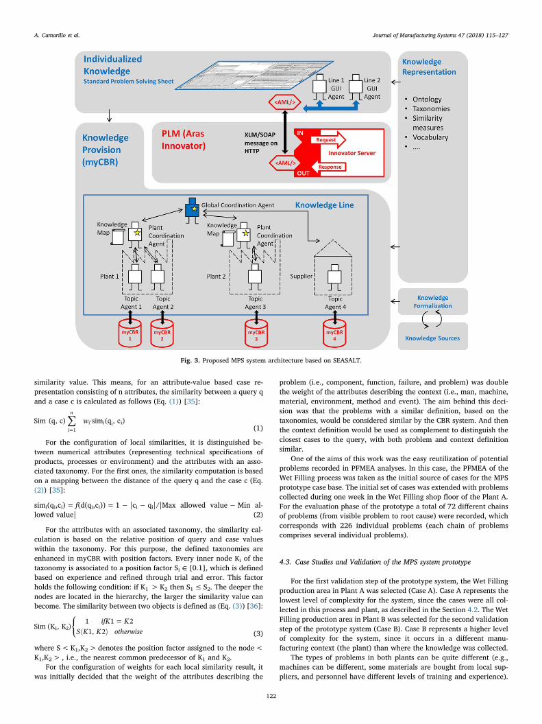
similarity value. This means, for an attribute-value based case re-presentation consisting of n attributes, the similarity between a query qand a case c is calculated as follows (Eq. (1)) [35]:
∑ ⋅=
wSim (q, c) sim (q , c )i
n
1i i i i
(1)
For the configuration of local similarities, it is distinguished be-tween numerical attributes (representing technical specifications ofproducts, processes or environment) and the attributes with an asso-ciated taxonomy. For the first ones, the similarity computation is basedon a mapping between the distance of the query q and the case c (Eq.(2)) [35]:
simi(qi,ci)= f(d(qi,ci))= 1− |ci− qi|/|Max allowed value−Min al-lowed value| (2)
For the attributes with an associated taxonomy, the similarity cal-culation is based on the relative position of query and case valueswithin the taxonomy. For this purpose, the defined taxonomies areenhanced in myCBR with position factors. Every inner node Ki of thetaxonomy is associated to a position factor Si ∈ [0.1], which is definedbased on experience and refined through trial and error. This factorholds the following condition: if K1 >K2 then S1≤ S2. The deeper thenodes are located in the hierarchy, the larger the similarity value canbecome. The similarity between two objects is defined as (Eq. (3)) [36]:
⎧⎨⎩
=ifK KS K K otherwise
Sim (K , K )1 1 21, 21 2
(3)
where S<K1,K2>denotes the position factor assigned to the node<K1,K2> , i.e., the nearest common predecessor of K1 and K2.
For the configuration of weights for each local similarity result, itwas initially decided that the weight of the attributes describing the
problem (i.e., component, function, failure, and problem) was doublethe weight of the attributes describing the context (i.e., man, machine,material, environment, method and event). The aim behind this deci-sion was that the problems with a similar definition, based on thetaxonomies, would be considered similar by the CBR system. And thenthe context definition would be used as complement to distinguish theclosest cases to the query, with both problem and context definitionsimilar.
One of the aims of this work was the easy reutilization of potentialproblems recorded in PFMEA analyses. In this case, the PFMEA of theWet Filling process was taken as the initial source of cases for the MPSprototype case base. The initial set of cases was extended with problemscollected during one week in the Wet Filling shop floor of the Plant A.For the evaluation phase of the prototype a total of 72 different chainsof problems (from visible problem to root cause) were recorded, whichcorresponds with 226 individual problems (each chain of problemscomprises several individual problems).
4.3. Case Studies and Validation of the MPS system prototype
For the first validation step of the prototype system, the Wet Fillingproduction area in Plant A was selected (Case A). Case A represents thelowest level of complexity for the system, since the cases were all col-lected in this process and plant, as described in the Section 4.2. The WetFilling production area in Plant B was selected for the second validationstep of the prototype system (Case B). Case B represents a higher levelof complexity for the system, since it occurs in a different manu-facturing context (the plant) than where the knowledge was collected.
The types of problems in both plants can be quite different (e.g.,machines can be different, some materials are bought from local sup-pliers, and personnel have different levels of training and experience).
Fig. 3. Proposed MPS system architecture based on SEASALT.
A. Camarillo et al. Journal of Manufacturing Systems 47 (2018) 115–127
122
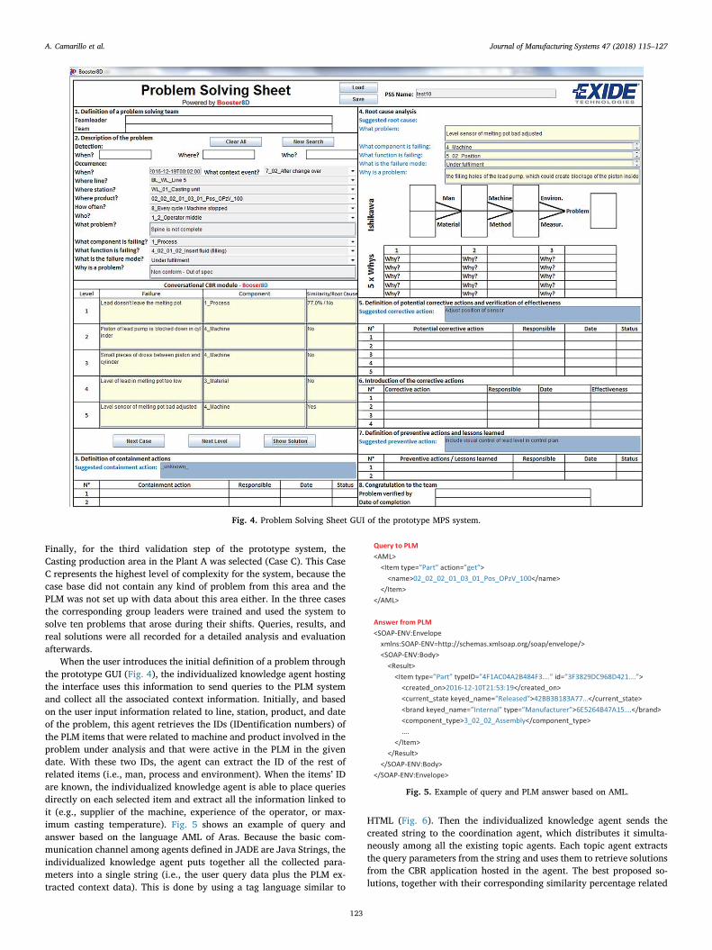
Finally, for the third validation step of the prototype system, theCasting production area in the Plant A was selected (Case C). This CaseC represents the highest level of complexity for the system, because thecase base did not contain any kind of problem from this area and thePLM was not set up with data about this area either. In the three casesthe corresponding group leaders were trained and used the system tosolve ten problems that arose during their shifts. Queries, results, andreal solutions were all recorded for a detailed analysis and evaluationafterwards.
When the user introduces the initial definition of a problem throughthe prototype GUI (Fig. 4), the individualized knowledge agent hostingthe interface uses this information to send queries to the PLM systemand collect all the associated context information. Initially, and basedon the user input information related to line, station, product, and dateof the problem, this agent retrieves the IDs (IDentification numbers) ofthe PLM items that were related to machine and product involved in theproblem under analysis and that were active in the PLM in the givendate. With these two IDs, the agent can extract the ID of the rest ofrelated items (i.e., man, process and environment). When the items’ IDare known, the individualized knowledge agent is able to place queriesdirectly on each selected item and extract all the information linked toit (e.g., supplier of the machine, experience of the operator, or max-imum casting temperature). Fig. 5 shows an example of query andanswer based on the language AML of Aras. Because the basic com-munication channel among agents defined in JADE are Java Strings, theindividualized knowledge agent puts together all the collected para-meters into a single string (i.e., the user query data plus the PLM ex-tracted context data). This is done by using a tag language similar to
HTML (Fig. 6). Then the individualized knowledge agent sends thecreated string to the coordination agent, which distributes it simulta-neously among all the existing topic agents. Each topic agent extractsthe query parameters from the string and uses them to retrieve solutionsfrom the CBR application hosted in the agent. The best proposed so-lutions, together with their corresponding similarity percentage related
Fig. 4. Problem Solving Sheet GUI of the prototype MPS system.
Fig. 5. Example of query and PLM answer based on AML.
A. Camarillo et al. Journal of Manufacturing Systems 47 (2018) 115–127
123
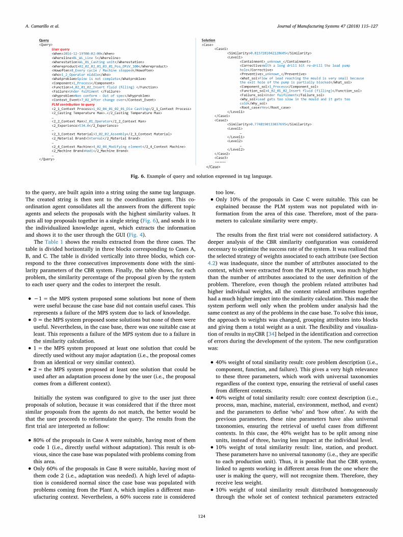
to the query, are built again into a string using the same tag language.The created string is then sent to the coordination agent. This co-ordination agent consolidates all the answers from the different topicagents and selects the proposals with the highest similarity values. Itputs all top proposals together in a single string (Fig. 6), and sends it tothe individualized knowledge agent, which extracts the informationand shows it to the user through the GUI (Fig. 4).
The Table 1 shows the results extracted from the three cases. Thetable is divided horizontally in three blocks corresponding to Cases A,B, and C. The table is divided vertically into three blocks, which cor-respond to the three consecutives improvements done with the simi-larity parameters of the CBR system. Finally, the table shows, for eachproblem, the similarity percentage of the proposal given by the systemto each user query and the codes to interpret the result.
• −1= the MPS system proposed some solutions but none of themwere useful because the case base did not contain useful cases. Thisrepresents a failure of the MPS system due to lack of knowledge.
• 0= the MPS system proposed some solutions but none of them wereuseful. Nevertheless, in the case base, there was one suitable case atleast. This represents a failure of the MPS system due to a failure inthe similarity calculation.
• 1= the MPS system proposed at least one solution that could bedirectly used without any major adaptation (i.e., the proposal comesfrom an identical or very similar context).
• 2= the MPS system proposed at least one solution that could beused after an adaptation process done by the user (i.e., the proposalcomes from a different context).
Initially the system was configured to give to the user just threeproposals of solution, because it was considered that if the three mostsimilar proposals from the agents do not match, the better would bethat the user proceeds to reformulate the query. The results from thefirst trial are interpreted as follow:
• 80% of the proposals in Case A were suitable, having most of themcode 1 (i.e., directly useful without adaptation). This result is ob-vious, since the case base was populated with problems coming fromthis area.
• Only 60% of the proposals in Case B were suitable, having most ofthem code 2 (i.e., adaptation was needed). A high level of adapta-tion is considered normal since the case base was populated withproblems coming from the Plant A, which implies a different man-ufacturing context. Nevertheless, a 60% success rate is considered
too low.
• Only 10% of the proposals in Case C were suitable. This can beexplained because the PLM system was not populated with in-formation from the area of this case. Therefore, most of the para-meters to calculate similarity were empty.
The results from the first trial were not considered satisfactory. Adeeper analysis of the CBR similarity configuration was considerednecessary to optimize the success rate of the system. It was realized thatthe selected strategy of weights associated to each attribute (see Section4.2) was inadequate, since the number of attributes associated to thecontext, which were extracted from the PLM system, was much higherthan the number of attributes associated to the user definition of theproblem. Therefore, even though the problem related attributes hadhigher individual weights, all the context related attributes togetherhad a much higher impact into the similarity calculation. This made thesystem perform well only when the problem under analysis had thesame context as any of the problems in the case base. To solve this issue,the approach to weights was changed, grouping attributes into blocksand giving them a total weight as a unit. The flexibility and visualiza-tion of results in myCBR [34] helped in the identification and correctionof errors during the development of the system. The new configurationwas:
• 40% weight of total similarity result: core problem description (i.e.,component, function, and failure). This gives a very high relevanceto these three parameters, which work with universal taxonomiesregardless of the context type, ensuring the retrieval of useful casesfrom different contexts.
• 40% weight of total similarity result: core context description (i.e.,process, man, machine, material, environment, method, and event)and the parameters to define ‘who’ and ‘how often’. As with theprevious parameters, these nine parameters have also universaltaxonomies, ensuring the retrieval of useful cases from differentcontexts. In this case, the 40% weight has to be split among nineunits, instead of three, having less impact at the individual level.
• 10% weight of total similarity result: line, station, and product.These parameters have no universal taxonomy (i.e., they are specificto each production unit). Thus, it is possible that the CBR system,linked to agents working in different areas from the one where theuser is making the query, will not recognize them. Therefore, theyreceive less weight.
• 10% weight of total similarity result distributed homogeneouslythrough the whole set of context technical parameters extracted
Fig. 6. Example of query and solution expressed in tag language.
A. Camarillo et al. Journal of Manufacturing Systems 47 (2018) 115–127
124
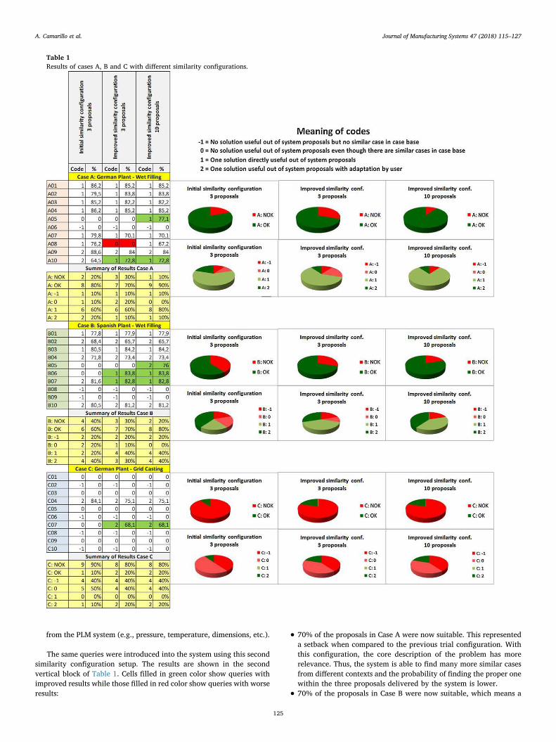
from the PLM system (e.g., pressure, temperature, dimensions, etc.).
The same queries were introduced into the system using this secondsimilarity configuration setup. The results are shown in the secondvertical block of Table 1. Cells filled in green color show queries withimproved results while those filled in red color show queries with worseresults:
• 70% of the proposals in Case A were now suitable. This representeda setback when compared to the previous trial configuration. Withthis configuration, the core description of the problem has morerelevance. Thus, the system is able to find many more similar casesfrom different contexts and the probability of finding the proper onewithin the three proposals delivered by the system is lower.
• 70% of the proposals in Case B were now suitable, which means a
Table 1Results of cases A, B and C with different similarity configurations.
A. Camarillo et al. Journal of Manufacturing Systems 47 (2018) 115–127
125
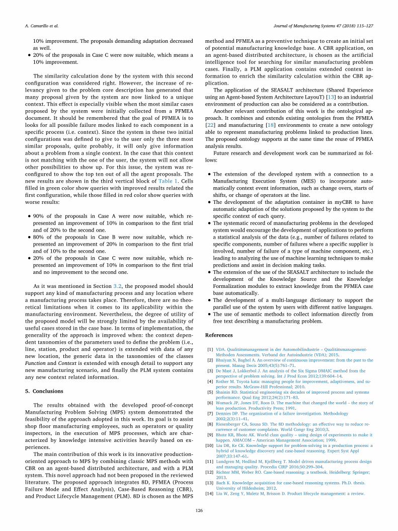
10% improvement. The proposals demanding adaptation decreasedas well.
• 20% of the proposals in Case C were now suitable, which means a10% improvement.
The similarity calculation done by the system with this secondconfiguration was considered right. However, the increase of re-levancy given to the problem core description has generated thatmany proposal given by the system are now linked to a uniquecontext. This effect is especially visible when the most similar casesproposed by the system were initially collected from a PFMEAdocument. It should be remembered that the goal of PFMEA is tolooks for all possible failure modes linked to each component in aspecific process (i.e. context). Since the system in these two initialconfigurations was defined to give to the user only the three mostsimilar proposals, quite probably, it will only give informationabout a problem from a single context. In the case that this contextis not matching with the one of the user, the system will not allowother possibilities to show up. For this issue, the system was re-configured to show the top ten out of all the agent proposals. Thenew results are shown in the third vertical block of Table 1. Cellsfilled in green color show queries with improved results related thefirst configuration, while those filled in red color show queries withworse results:
• 90% of the proposals in Case A were now suitable, which re-presented an improvement of 10% in comparison to the first trialand of 20% to the second one.
• 80% of the proposals in Case B were now suitable, which re-presented an improvement of 20% in comparison to the first trialand of 10% to the second one.
• 20% of the proposals in Case C were now suitable, which re-presented an improvement of 10% in comparison to the first trialand no improvement to the second one.
As it was mentioned in Section 3.2, the proposed model shouldsupport any kind of manufacturing process and any location wherea manufacturing process takes place. Therefore, there are no theo-retical limitations when it comes to its applicability within themanufacturing environment. Nevertheless, the degree of utility ofthe proposed model will be strongly limited by the availability ofuseful cases stored in the case base. In terms of implementation, thegenerality of the approach is improved when: the context depen-dent taxonomies of the parameters used to define the problem (i.e.,line, station, product and operator) is extended with data of anynew location, the generic data in the taxonomies of the classesFunction and Context is extended with enough detail to support anynew manufacturing scenario, and finally the PLM system containsany new context related information.
5. Conclusions
The results obtained with the developed proof-of-conceptManufacturing Problem Solving (MPS) system demonstrated thefeasibility of the approach adopted in this work. Its goal is to assistshop floor manufacturing employees, such as operators or qualityinspectors, in the execution of MPS processes, which are char-acterized by knowledge intensive activities heavily based on ex-periences.
The main contribution of this work is its innovative production-oriented approach to MPS by combining classic MPS methods withCBR on an agent-based distributed architecture, and with a PLMsystem. This novel approach had not been proposed in the reviewedliterature. The proposed approach integrates 8D, PFMEA (ProcessFailure Mode and Effect Analysis), Case-Based Reasoning (CBR),and Product Lifecycle Management (PLM). 8D is chosen as the MPS
method and PFMEA as a preventive technique to create an initial setof potential manufacturing knowledge base. A CBR application, onan agent-based distributed architecture, is chosen as the artificialintelligence tool for searching for similar manufacturing problemcases. Finally, a PLM application contains extended context in-formation to enrich the similarity calculation within the CBR ap-plication.
The application of the SEASALT architecture (Shared Experienceusing an Agent-based System Architecture LayouT) [13] to an industrialenvironment of production can also be considered as a contribution.
Another relevant contribution of this work is the ontological ap-proach. It combines and extends existing ontologies from the PFMEA[22] and manufacturing [18] environments to create a new ontologyable to represent manufacturing problems linked to production lines.The proposed ontology supports at the same time the reuse of PFMEAanalysis results.
Future research and development work can be summarized as fol-lows:
• The extension of the developed system with a connection to aManufacturing Execution System (MES) to incorporate auto-matically context event information, such as change overs, starts ofshifts, or change of operators at the line.
• The development of the adaptation container in myCBR to haveautomatic adaptation of the solutions proposed by the system to thespecific context of each query.
• The systematic record of manufacturing problems in the developedsystem would encourage the development of applications to performa statistical analysis of the data (e.g., number of failures related tospecific components, number of failures where a specific supplier isinvolved, number of failure of a type of machine component, etc.)leading to analyzing the use of machine learning techniques to makepredictions and assist in decision making tasks.
• The extension of the use of the SEASALT architecture to include thedevelopment of the Knowledge Source and the KnowledgeFormalization modules to extract knowledge from the PFMEA casebase automatically.
• The development of a multi-language dictionary to support theparallel use of the system by users with different native languages.
• The use of semantic methods to collect information directly fromfree text describing a manufacturing problem.
References
[1] VDA. Qualitätsmanagement in der Automobilindustrie – Qualitätsmanagement-Methoden Assessments. Verband der Autoindustrie (VDA); 2015.
[2] Bhuiyan N, Baghel A. An overview of continuous improvement: from the past to thepresent. Manag Decis 2005;43(5):761–71.
[3] De Mast J, Lokkerbol J. An analysis of the Six Sigma DMAIC method from theperspective of problem solving. Int J Prod Econ 2012;139:604–14.
[4] Rother M. Toyota kata: managing people for improvement, adaptiveness, and su-perior results. McGraw-Hill Professional; 2010.
[5] Shainin RD. Statistical engineering six decades of improved process and systemsperformance. Qual Eng 2012;24(2):171–83.
[6] Womack JP, Jones DT, Roos D. The machine that changed the world – the story oflean production. Productivity Press; 1991.
[7] Dennies DP. The organization of a failure investigation. Methodology2002;2(3):11–41.
[8] Riesenberger CA, Sousa SD. The 8D methodology: an effective way to reduce re-currence of customer complaints. World Congr Eng 2010;3.
[9] Bhote KR, Bhote AK. World class quality – using design of experiments to make ithappen. AMACOM – American Management Association; 1999.
[10] Liu DR, Ke CK. Knowledge support for problem-solving in a production process: ahybrid of knowledge discovery and case-based reasoning. Expert Syst Appl2007;33:147–61.
[11] Lundgren M, Hedlind M, Kjellberg T. Model driven manufacturing process designand managing quality. Procedia CIRP 2016;50:299–304.
[12] Richter MM, Weber RO. Case-based reasoning: a textbook. Heidelberg: Springer;2013.
[13] Bach K. Knowledge acquisition for case-based reasoning systems. Ph.D. thesis.University of Hildesheim; 2012.
[14] Liu W, Zeng Y, Maletz M, Brisson D. Product lifecycle management: a review.
A. Camarillo et al. Journal of Manufacturing Systems 47 (2018) 115–127
126
Proceedings of the ASME 2009 International Design Engineering TechnicalConferences & Computers and Information in Engineering Conference IDETC/CIE2009.
[15] Stark J. Product lifecycle management. Springer International Publishing; 2015.[16] Chandrasekaran B, Josephson JR, Benjamins VR. What are ontologies, and why do
we need them? IEEE Intell Syst 1999;14(1):20–6.[17] Lemaignan S, Siadat A, Dantan JY, Semenenko A. MASON: a proposal for an on-
tology of manufacturing domain. IEEE workshop on distributed intelligent systems:collective intelligence and its applications, DIS 2006:195–200.
[18] Chungoora N, Young R, Gunendran G, Palmer C, Usman Z, Anjum N, et al. A model-driven ontology approach for manufacturing system interoperability and knowl-edge sharing. Comput Ind 2013;64(4):392–401.
[19] Kamsu-Foguem B, Couderta T, Bélera C, Genestea L. Knowledge formalization inexperience feedback processes: an ontology-based approach. Comput Ind2008;59(7):694–710.
[20] Scippacercola F, Pietrantuono R, Russo S, Silva NP. SysML-based and prolog-sup-ported FMEA. In Software Reliability Engineering Workshops (ISSREW), 2015 IEEEInternational Symposium 2015:174–81.
[21] Ebrahimipour V, Rezaie K, Shokravi S. An ontology approach to support FMEAstudies. Expert Syst Appl 2010;37(1):671–7.
[22] Dittmann L, Rademacher T, Zelewski S. Performing FMEA using ontologies. 18thinternational workshop on qualitative reasoning 2004:209–16.
[23] Mikos WL, Ferreira JCE, Botura PEA, Freitas LS. A system for distributed sharingand reuse of design and manufacturing knowledge in the PFMEA domain using adescription logics-based ontology. J Manuf Syst 2011;30:133–43.
[24] Bertin A, Noyes D, Sanchez P. Lessons learned system integration into a PLM tool.International conference on product lifecycle management 2010:577–89.
[25] Bertin A, Noyes D, Clermont P. Problem solving methods as Lessons Learned Systeminstrumentation into a PLM tool. 14th IFAC symposium on information control
problems in manufacturing 2012.[26] Wuest T, Weimer D, Irgens C, Thoben KD. Machine learning in manufacturing:
advantages, challenges, and applications. Prod Manuf Res 2016;4(1):23–45.[27] Susto GA, Schirru A, Pampuri S, McLoone S, Beghi A. Machine learning for pre-
dictive maintenance: a multiple classifier approach. IEEE Trans Ind Inf2015;11(3):812–20.
[28] Plaza E, McGinty L. Distributed case-based reasoning. Knowl Eng Rev2005;20(3):261–5.
[29] Althoff KD, Bach K, Deutsch JO, Hanft A, Mänz J, Müller T, et al. Collaborativemulti-expert-systems. Proceedings of the 16th UK workshop on case-based rea-soning 2012:13.
[30] Reuss P, Althoff KD, Hundt A, Henkel W, Pfeiffer M. Multi-Agent case-based diag-nosis in the aircraft domain. Workshop proceedings – 23rd international conferenceon case-based reasoning 2015:43–52.
[31] Kepner CH, Tregoe BB. The new rational manager – an updated edition for a NewWorld. Princeton Research Press; 2008.
[32] Becerra-Fernandez I, Aha DW. Case-based problem solving for knowledge man-agement systems. 12th International FLAIRS Conference 1999.
[33] Camarillo A, Ríos J, Althoff KD. CBR and PLM applied to diagnosis and technicalsupport during problem solving in the continuous improvement process of manu-facturing plants. Procedia Manuf 2017;13:987–94.
[34] Roth-Berghofer T, Sauer C, Garcia JAR, Bach K, Althoff KD, Agudo BD. Buildingcase-based reasoning applications with myCBR and COLIBRI studio. Proceedings ofthe UKCBR 2012.
[35] Stahl A, Roth-Berghofer TR. Rapid prototyping of CBR applications with the opensource tool myCBR. Adv Case-Based Reason 2008:615–29.
[36] Bergmann R. On the use of taxonomies for representing case features and localsimilarity measures. Proceedings of the 6th German Workshop on case-based rea-soning 1998.
A. Camarillo et al. Journal of Manufacturing Systems 47 (2018) 115–127
127

269
Appendix 3: Published Papers
Paper 5
Camarillo, Alvaro; Rios-Chueco, Jose; Althoff, Klaus-Dieter (2018b): Product Lifecycle Man-agement as Data Repository for Manufacturing Problem Solving. Materials, Vol. 11, No. 1469.
materials
Article
Product Lifecycle Management as Data Repository forManufacturing Problem Solving
Alvaro Camarillo 1,2,* ID , José Ríos 2 ID and Klaus-Dieter Althoff 3,4
1 Exide Technologies SAS, 5 allée des Pierres Mayettes, 92636 Gennevilliers, France2 Mechanical Engineering Department, Polytechnic University of Madrid,
Jose Gutierrez Abascal 2, 2800 Madrid, Spain; [email protected] German Research Center for Artificial Intelligence (DFKI), Trippstadter Straße 122,
67663 Kaiserslautern, Germany; [email protected] Institut für Informatik, University of Hildesheim, Universitätsplatz 1, 31141 Hildesheim, Germany* Correspondence: [email protected]; Tel.: +33-141-21-23-67
Received: 2 July 2018; Accepted: 14 August 2018; Published: 18 August 2018�����������������
Abstract: Fault diagnosis presents a considerable difficulty to human operators in supervisorycontrol of manufacturing systems. Implementing Internet of Things (IoT) technologies in existingmanufacturing facilities implies an investment, since it requires upgrading them with sensors,connectivity capabilities, and IoT software platforms. Aligned with the technological vision ofIndustry 4.0 and based on currently existing information databases in the industry, this work proposesa lower-investment alternative solution for fault diagnosis and problem solving. This paper presentsthe details of the information and communication models of an application prototype oriented toproduction. It aims at assisting shop-floor actors during a Manufacturing Problem Solving (MPS)process. It captures and shares knowledge, taking existing Process Failure Mode and Effect Analysis(PFMEA) documents as an initial source of information related to potential manufacturing problems.It uses a Product Lifecycle Management (PLM) system as source of manufacturing context informationrelated to the problems under investigation and integrates Case-Based Reasoning (CBR) technologyto provide information about similar manufacturing problems.
Keywords: product lifecycle management (PLM); manufacturing problem solving (MPS);fault diagnosis; smart factory; process failure mode and effect analysis (PFMEA); case-basedreasoning (CBR)
1. Introduction
A manufacturing failure is an event in which some part of a manufacturing system does notperform according to its operational specifications and therefore it occurs in a specific manufacturingcontext. Due to such a failure, production is disturbed to a certain extent. The consequence is thatproduction targets may not be achieved. The gap between the resulting production state and theintended production state is thus a problem. A Manufacturing Problem Solving (MPS) procedure startswhen such a situation arises. The first step in an MPS procedure is the fault diagnosis, which presentsconsiderable difficulty to human operators in supervisory control of manufacturing systems [1,2].Providing support to these operators, by means of knowledge-based software applications, has beenidentified as essential to achieve good results from the solving procedure [3–5].
The characterization of the manufacturing context, where a failure might occur, can be set bymeans of processes, process steps, machines, tooling, process parameters, and product manufacturingfeatures. Therefore, the context of the failure can be described by means of Process-Product-Resource(PPR) data. When looking at data, historical failure data could be used to assist in the MPS
Materials 2018, 11, 1469; doi:10.3390/ma11081469 www.mdpi.com/journal/materials
Materials 2018, 11, 1469 2 of 19
process. The use of such historical data would require identifying similar failures, which, in turn,requires making use of manufacturing context data. Product Lifecycle Management (PLM) systemsare considered the main source of PPR digital information, and therefore their use would facilitate anyattempt to develop a knowledge-based solution to support an MPS process [5,6]. PLM systems are oneof the main components of the digital manufacturing and Industry 4.0 strategy [7,8].
The technological vision of a Smart Factory [9,10] is also included in the strategy Industry 4.0 [8],and eventually aims to develop a factory model that is context-aware and assists people and machinesin the execution of their tasks. Fault diagnosis can be considered as one of these tasks to be supported.
A typical approach to a Smart Factory [9] is the deployment of smart artifacts, along the valuestreams, that are able to collect a large quantity of data from their environment and to communicatewith each other (Internet of Things) [8]. This approach implies large investments, which prevents somecompanies from taking their first steps into Industry 4.0 [11,12]. This work presents an approach thataims to contribute to the technological vision of a Smart Factory but observing the constraints of beingbased on existing facilities, existing company data repositories, and with low investment.
The proposed approach is a knowledge-based development that integrates two main types ofsoftware applications: PLM and Case-Based Reasoning (CBR) [5]. The developed prototype assistshuman operators during an MPS process. It guides the user through the MPS activity based on theproblem-solving method 8D [13]. The user introduces a query describing a problem that occurs in aproduction line, and the developed prototype software proposes several potential causes to be checkedin the line. Based on the user feedback related to these first proposed causes, the system will proposethe next lower level of causes. The process is repeated until the root cause of the problem is identified.More detailed information can be found in Camarillo et al. [5].
As sources of information, the prototype integrates two repositories. First, the existing companyProcess Failure Mode and Effect Analysis (PFMEA) records [14] are stored in the case base of theCase-Based Reasoning (CBR) system [15]. Second, the company’s Product Lifecycle Management(PLM) repository contains the PPR data. The Case-Based Reasoning (CBR) system is used tosearch for and retrieve information concerning similar problems. The similarity determinationbetween the current problem and the problems contained in the case base depends on the PPRdata stored in the PLM repository. The architecture of the system is based on SEASALT (SharedExperience using an Agent-based System Architecture LayouT) [16], which is a multi-case-based,domain-independent reasoning architecture for extracting, analyzing, sharing, and providingexperiences. Camarillo et al. [17,18] show a description of a first prototype and initial results.Camarillo et al. [5] shows the MPS process model, the architecture of the developed prototype, the mainontology to support the MPS process, and the validation of the prototype. This paper provides aninsight into the information and communication models of the developed prototype.
The next sections of this paper are structured as follows. Section 2 contains a review of researchworks with similar approaches. Sections 3 and 4 discuss the created information and communicationmodels, which are implemented in the developed prototype. Section 5 describes the configuration ofthe developed system. Section 6 provides a brief description of an application case. The paper endswith the conclusions.
2. Related Works
The developed approach is grounded on three basic models: an MPS process model, an MPSknowledge representation model, and an MPS system architecture model [5].
The MPS process model defines the steps to be taken by the user to solve a problem with thesupport of the proposed system. This process model basically follows the steps defined in the 8Dmethod [13] and specifies the kind of interaction expected at each step between the user and thesystem. The left side of Figure 1 shows the developed Graphical User Interface (GUI), the center partof Figure 1 shows the main steps of the MPS process, and the right side of Figure 1 shows the main
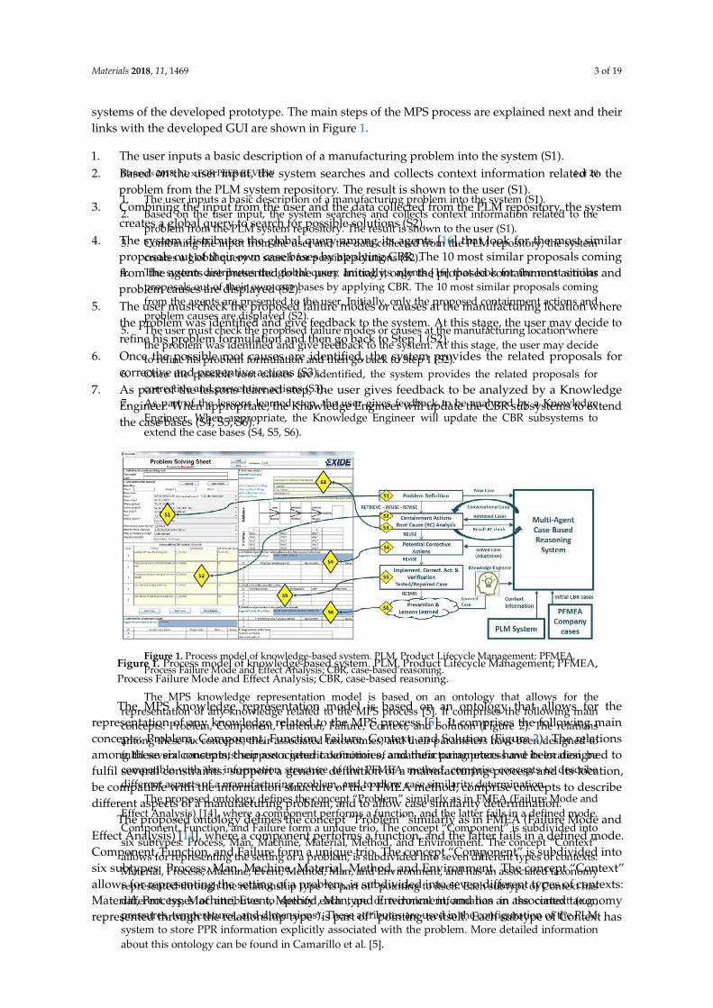
Materials 2018, 11, 1469 3 of 19
systems of the developed prototype. The main steps of the MPS process are explained next and theirlinks with the developed GUI are shown in Figure 1.
1. The user inputs a basic description of a manufacturing problem into the system (S1).2. Based on the user input, the system searches and collects context information related to the
problem from the PLM system repository. The result is shown to the user (S1).3. Combining the input from the user and the data collected from the PLM repository, the system
creates a global query to search for possible solutions (S2).4. The system distributes the global query among its agents [16] that look for the most similar
proposals out of their own case bases by applying CBR. The 10 most similar proposals comingfrom the agents are presented to the user. Initially, only the proposed containment actions andproblem causes are displayed (S2).
5. The user must check the proposed failure modes or causes at the manufacturing location wherethe problem was identified and give feedback to the system. At this stage, the user may decide torefine his problem formulation and then go back to Step 1 (S2).
6. Once the possible root causes are identified, the system provides the related proposals forcorrective and preventive actions (S3).
7. As part of the lessons learned step, the user gives feedback to be analyzed by a KnowledgeEngineer. When appropriate, the Knowledge Engineer will update the CBR subsystems to extendthe case bases (S4, S5, S6).
Materials 2018, 11, x FOR PEER REVIEW 4 of 20
1. The user inputs a basic description of a manufacturing problem into the system (S1).
2. Based on the user input, the system searches and collects context information related to the
problem from the PLM system repository. The result is shown to the user (S1).
3. Combining the input from the user and the data collected from the PLM repository, the system
creates a global query to search for possible solutions (S2).
4. The system distributes the global query among its agents [16] that look for the most similar
proposals out of their own case bases by applying CBR. The 10 most similar proposals coming
from the agents are presented to the user. Initially, only the proposed containment actions and
problem causes are displayed (S2).
5. The user must check the proposed failure modes or causes at the manufacturing location where
the problem was identified and give feedback to the system. At this stage, the user may decide
to refine his problem formulation and then go back to Step 1 (S2).
6. Once the possible root causes are identified, the system provides the related proposals for
corrective and preventive actions (S3).
7. As part of the lessons learned step, the user gives feedback to be analyzed by a Knowledge
Engineer. When appropriate, the Knowledge Engineer will update the CBR subsystems to
extend the case bases (S4, S5, S6).
Figure 1. Process model of knowledge-based system. PLM, Product Lifecycle Management; PFMEA,
Process Failure Mode and Effect Analysis; CBR, case-based reasoning.
The MPS knowledge representation model is based on an ontology that allows for the
representation of any knowledge related to the MPS process [5]. It comprises the following main
concepts: Problem, Component, Function, Failure, Context, and Solution (Figure 2). The relations
among these six concepts, their associated taxonomies, and their parameters have been designed to
fulfil several constraints: support a generic definition of a manufacturing process and its location, be
compatible with the information structure of the PFMEA method, comprise concepts to describe
different aspects of a manufacturing problem, and to allow case similarity determination.
The proposed ontology defines the concept “Problem” similarly as in FMEA (Failure Mode and
Effect Analysis) [14], where a component performs a function, and the latter fails in a defined mode.
Component, Function, and Failure form a unique trio. The concept “Component” is subdivided into
six subtypes: Process, Man, Machine, Material, Method, and Environment. The concept “Context”
allows for representing the setting of a problem, is subdivided into seven different types of contexts:
Material, Process, Machine, Event, Method, Man, and Environment, and has an associated taxonomy
represented through the relationship type “is part of” pointing to itself. Each subtype of Context has
different types of attributes to specify each type of technical information in the context (e.g.,
pressures, temperatures, and dimensions). These attributes are used in the configuration of the PLM
system to store PPR information explicitly associated with the problem. More detailed information
about this ontology can be found in Camarillo et al. [5].
Figure 1. Process model of knowledge-based system. PLM, Product Lifecycle Management; PFMEA,Process Failure Mode and Effect Analysis; CBR, case-based reasoning.
The MPS knowledge representation model is based on an ontology that allows for therepresentation of any knowledge related to the MPS process [5]. It comprises the following mainconcepts: Problem, Component, Function, Failure, Context, and Solution (Figure 2). The relationsamong these six concepts, their associated taxonomies, and their parameters have been designed tofulfil several constraints: support a generic definition of a manufacturing process and its location,be compatible with the information structure of the PFMEA method, comprise concepts to describedifferent aspects of a manufacturing problem, and to allow case similarity determination.
The proposed ontology defines the concept “Problem” similarly as in FMEA (Failure Mode andEffect Analysis) [14], where a component performs a function, and the latter fails in a defined mode.Component, Function, and Failure form a unique trio. The concept “Component” is subdivided intosix subtypes: Process, Man, Machine, Material, Method, and Environment. The concept “Context”allows for representing the setting of a problem, is subdivided into seven different types of contexts:Material, Process, Machine, Event, Method, Man, and Environment, and has an associated taxonomyrepresented through the relationship type “is part of” pointing to itself. Each subtype of Context has
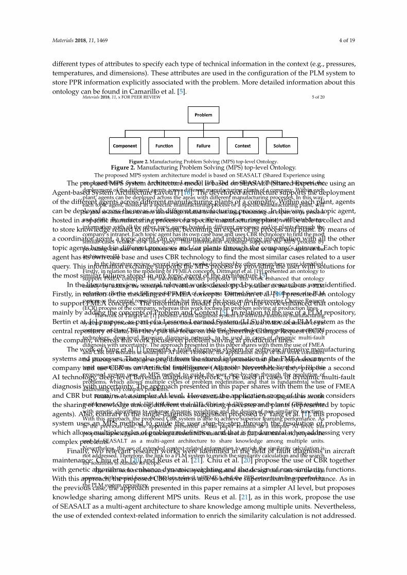
Materials 2018, 11, 1469 4 of 19
different types of attributes to specify each type of technical information in the context (e.g., pressures,temperatures, and dimensions). These attributes are used in the configuration of the PLM system tostore PPR information explicitly associated with the problem. More detailed information about thisontology can be found in Camarillo et al. [5].
Materials 2018, 11, x FOR PEER REVIEW 5 of 20
Figure 2. Manufacturing Problem Solving (MPS) top-level Ontology.
The proposed MPS system architecture model is based on SEASALT (Shared Experience using
an Agent-based System Architecture LayouT) [16]. The developed architecture supports the
deployment of the different agents across different manufacturing plants of a company. Within each
plant, agents can be deployed across the areas with different manufacturing processes. In this way,
each topic agent, hosted in a specific manufacturing process of a specific manufacturing plant, will
be able to collect and to store knowledge related to its own area, becoming an expert of its process
and plant. By means of a coordinator agent, a topic agent can communicate and interchange
information with all the other topic agents hosted in different processes and/or plants through the
company’s intranet. Each topic agent has its own case base and uses CBR technology to find the most
similar cases related to a user query. This information exchange supports the MPS process by
providing the user with solutions for the most similar failures stored in any topic agent of the
architecture [5].
In the literature review, several relevant works developed by other researchers were identified.
Firstly, in relation to the modeling of PFMEA concepts. Dittmann et al. [19] presented an ontology to
support FMEA concepts. The information model proposed in this work enhanced that ontology
mainly by adding the concepts of Problem and Context [5]. In relation to the use of a PLM
repository, Bertin et at. [6] propose, as part of a Lessons Learned System (LLS), the use of a PLM
system as the central repository of data, but they put the focus on the Engineering Change Request
(ECR) process of the company, whereas this work focuses on problem solving at production lines.
The work of Yang et al. [1] presents a fault diagnosis system for software intensive manufacturing
systems and processes. They also profit from the stored information in the FMEA documents of the
company and use CBR as an Artificial Intelligence (AI) tool. Nevertheless, they propose a second AI
technology, deep-level Bayesian diagnosis network, to be used in cases of dynamic multi-fault
diagnosis with uncertainty. The approach presented in this paper shares with them the use of FMEA
and CBR but remains at a simpler AI level. However, the application scope of this work considers
the sharing of knowledge among different manufacturing processes and plants (represented by
topic agents). Also, contrary to the single-diagnosis suggestion proposed by Yang et al. [1], this
proposed system uses an MPS method to guide the user step-by-step through the resolution of
problems, which allows multiple cycles of problem redefinition, and that is fundamental when
addressing very complex problems.
Finally, two relevant research works were identified in the field of fault diagnosis in aircraft
maintenance: Chiu et al. [20] and Reus et al. [21]. Chiu et al. [20] propose the use of CBR together
with genetic algorithms to enhance dynamic weighting and the design of non-similarity functions.
With this approach, the proposed CBR system is able to achieve superior learning performance. As
in the previous case, the approach presented in this paper remains at a simpler AI level, but
proposes knowledge sharing among different MPS units. Reus et al. [21], as in this work, propose the
use of SEASALT as a multi-agent architecture to share knowledge among multiple units.
Nevertheless, the use of extended context-related information to enrich the similarity calculation is
not addressed. Therefore, the link to a PLM system to enrich the similarity calculation and the search
for solutions is outside its scope.
The next section introduces the developed information models and their link to the data
sources, with special focus on the data related to PFMEA and the PPR concepts to be supported by
the PLM system repository.
Figure 2. Manufacturing Problem Solving (MPS) top-level Ontology.
The proposed MPS system architecture model is based on SEASALT (Shared Experience using anAgent-based System Architecture LayouT) [16]. The developed architecture supports the deploymentof the different agents across different manufacturing plants of a company. Within each plant, agentscan be deployed across the areas with different manufacturing processes. In this way, each topic agent,hosted in a specific manufacturing process of a specific manufacturing plant, will be able to collect andto store knowledge related to its own area, becoming an expert of its process and plant. By means ofa coordinator agent, a topic agent can communicate and interchange information with all the othertopic agents hosted in different processes and/or plants through the company’s intranet. Each topicagent has its own case base and uses CBR technology to find the most similar cases related to a userquery. This information exchange supports the MPS process by providing the user with solutions forthe most similar failures stored in any topic agent of the architecture [5].
In the literature review, several relevant works developed by other researchers were identified.Firstly, in relation to the modeling of PFMEA concepts. Dittmann et al. [19] presented an ontologyto support FMEA concepts. The information model proposed in this work enhanced that ontologymainly by adding the concepts of Problem and Context [5]. In relation to the use of a PLM repository,Bertin et at. [6] propose, as part of a Lessons Learned System (LLS), the use of a PLM system as thecentral repository of data, but they put the focus on the Engineering Change Request (ECR) process ofthe company, whereas this work focuses on problem solving at production lines.
The work of Yang et al. [1] presents a fault diagnosis system for software intensive manufacturingsystems and processes. They also profit from the stored information in the FMEA documents of thecompany and use CBR as an Artificial Intelligence (AI) tool. Nevertheless, they propose a secondAI technology, deep-level Bayesian diagnosis network, to be used in cases of dynamic multi-faultdiagnosis with uncertainty. The approach presented in this paper shares with them the use of FMEAand CBR but remains at a simpler AI level. However, the application scope of this work considersthe sharing of knowledge among different manufacturing processes and plants (represented by topicagents). Also, contrary to the single-diagnosis suggestion proposed by Yang et al. [1], this proposedsystem uses an MPS method to guide the user step-by-step through the resolution of problems,which allows multiple cycles of problem redefinition, and that is fundamental when addressing verycomplex problems.
Finally, two relevant research works were identified in the field of fault diagnosis in aircraftmaintenance: Chiu et al. [20] and Reus et al. [21]. Chiu et al. [20] propose the use of CBR togetherwith genetic algorithms to enhance dynamic weighting and the design of non-similarity functions.With this approach, the proposed CBR system is able to achieve superior learning performance. As inthe previous case, the approach presented in this paper remains at a simpler AI level, but proposesknowledge sharing among different MPS units. Reus et al. [21], as in this work, propose the useof SEASALT as a multi-agent architecture to share knowledge among multiple units. Nevertheless,the use of extended context-related information to enrich the similarity calculation is not addressed.
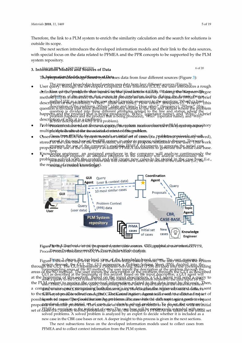
Materials 2018, 11, 1469 5 of 19
Therefore, the link to a PLM system to enrich the similarity calculation and the search for solutions isoutside its scope.
The next section introduces the developed information models and their link to the data sources,with special focus on the data related to PFMEA and the PPR concepts to be supported by the PLMsystem repository.
3. Information Models and Sources of Data
The proposed knowledge-based system uses data from four different sources (Figure 3):
• User query: through the developed Graphical User Interface (GUI), the user introduces a roughdefinition of the problem that occurs in the production facility. Taking the Kepner–Tregoemethod [22] as a reference, the user should provide an answer to the questions ‘What?’ (a briefdescription of the problem), ‘When?’ (date and time), ‘How often?’ (frequency), ‘Where?’ (thisquestion is divided into three different attributes related to the line and station where the problemhappens and the product that is being produced), ‘Who?’ (operator name), and ‘Why?’ (a briefdescription of why it is a problem).
• Problem context: based on the user query, the system receives from the PLM system repositorymultiple details about the associated context of the problem.
• Cases from PFMEA: the system needs an initial set of cases (i.e., problems previously solved),stored in the case base of the CBR system, in order to propose solutions to the user. This workproposes the use of the company’s available PFMEA documents to generate the initial case base.
• Knowledge engineer: an assigned employee in the company will analyze continuously theproblems solved with the system and will create new cases to be stored in the case base (i.e.,the reusing of created knowledge).
Materials 2018, 11, x FOR PEER REVIEW 6 of 20
3. Information Models and Sources of Data
The proposed knowledge-based system uses data from four different sources (Figure 3):
User query: through the developed Graphical User Interface (GUI), the user introduces a rough
definition of the problem that occurs in the production facility. Taking the Kepner–Tregoe
method [22] as a reference, the user should provide an answer to the questions ‘What?’ (a brief
description of the problem), ‘When?’ (date and time), ‘How often?’ (frequency), ‘Where?’ (this
question is divided into three different attributes related to the line and station where the
problem happens and the product that is being produced), ‘Who?’ (operator name), and ‘Why?’
(a brief description of why it is a problem).
Problem context: based on the user query, the system receives from the PLM system repository
multiple details about the associated context of the problem.
Cases from PFMEA: the system needs an initial set of cases (i.e., problems previously solved),
stored in the case base of the CBR system, in order to propose solutions to the user. This work
proposes the use of the company’s available PFMEA documents to generate the initial case
base.
Knowledge engineer: an assigned employee in the company will analyze continuously the
problems solved with the system and will create new cases to be stored in the case base (i.e., the
reusing of created knowledge).
Figure 3. Top-level view of the proposed system data sources. GUI, graphical user interface; PPR,
Process-Product-Resource; PFMA, Process Failure Mode Analysis.
Figure 3 shows the top-level view of the knowledge-based system. The user manages the
system through the GUI. The GUI represents a Problem-Solving Sheet (PSS) divided into the
corresponding areas of the 8D method. The user inputs the description of the problem through the
GUI as described at the beginning of this section. Based on the input description, a GUI agent will
send a query to the PLM system to receive the contextual information related to the data input by the
user. Then, a comprehensive query, comprising both the user’s input data plus the retrieved context
data, is sent to the CBR system (Coordination Agent). The Coordination Agent will need to collect a
first set of possible solved cases. The Coordination Agent communicates with the different topic
agents to request proposals for similar problems. The case base of each topic agent needs to be
populated with an initial set of cases (i.e., already solved problems). To do so, the company’s
PFMEAs are taken as the initial set of cases. The case base will be continuously extended with new
solved problems. A solved problem is analyzed by an expert to decide whether it is included as a
new case in the CBR case bases or not. A deeper insight to this process is given in the next sections.
The next subsections focus on the developed information models used to collect cases from
PFMEA and to collect context information from the PLM system.
Figure 3. Top-level view of the proposed system data sources. GUI, graphical user interface; PPR,Process-Product-Resource; PFMA, Process Failure Mode Analysis.
Figure 3 shows the top-level view of the knowledge-based system. The user manages the systemthrough the GUI. The GUI represents a Problem-Solving Sheet (PSS) divided into the correspondingareas of the 8D method. The user inputs the description of the problem through the GUI as describedat the beginning of this section. Based on the input description, a GUI agent will send a query tothe PLM system to receive the contextual information related to the data input by the user. Then,a comprehensive query, comprising both the user’s input data plus the retrieved context data, is sentto the CBR system (Coordination Agent). The Coordination Agent will need to collect a first set ofpossible solved cases. The Coordination Agent communicates with the different topic agents to requestproposals for similar problems. The case base of each topic agent needs to be populated with an initialset of cases (i.e., already solved problems). To do so, the company’s PFMEAs are taken as the initial set
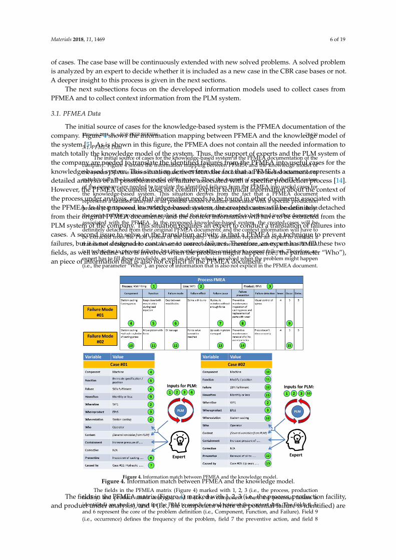
Materials 2018, 11, 1469 6 of 19
of cases. The case base will be continuously extended with new solved problems. A solved problemis analyzed by an expert to decide whether it is included as a new case in the CBR case bases or not.A deeper insight to this process is given in the next sections.
The next subsections focus on the developed information models used to collect cases fromPFMEA and to collect context information from the PLM system.
3.1. PFMEA Data
The initial source of cases for the knowledge-based system is the PFMEA documentation of thecompany. Figure 4 shows the information mapping between PFMEA and the knowledge model ofthe system [5]. As is shown in this figure, the PFMEA does not contain all the needed information tomatch totally the knowledge model of the system. Thus, the support of experts and the PLM system ofthe company are needed to translate the identified failures from the PFMEA into useful cases for theknowledge-based system. This situation derives from the fact that a PFMEA document represents adetailed analysis of all possible modes of failure associated with a specific production process [14].However, the PFMEA document does not contain explicit technical information about the context ofthe process under analysis, and that information needs to be found in other documents associated withthe PFMEA. In the proposed knowledge-based system, the created cases will be definitely detachedfrom their original PFMEA documents, and the context information will have to be extracted from thePLM system of the company. This situation requires an expert to conduct a translation of failures intocases. A second issue to solve, in the translation activity, is that a PFMEA is a technique to preventfailures, but it is not designed to contain or to correct failures. Therefore, an expert has to fill these twofields, as well as define who is involved when the problem might happen (i.e., the parameter “Who”),an piece of information that is also not explicit in the PFMEA document.
Materials 2018, 11, x FOR PEER REVIEW 7 of 20
3.1. PFMEA Data
The initial source of cases for the knowledge-based system is the PFMEA documentation of the
company. Figure 4 shows the information mapping between PFMEA and the knowledge model of
the system [5]. As is shown in this figure, the PFMEA does not contain all the needed information to
match totally the knowledge model of the system. Thus, the support of experts and the PLM system
of the company are needed to translate the identified failures from the PFMEA into useful cases for
the knowledge-based system. This situation derives from the fact that a PFMEA document
represents a detailed analysis of all possible modes of failure associated with a specific production
process [14]. However, the PFMEA document does not contain explicit technical information about
the context of the process under analysis, and that information needs to be found in other documents
associated with the PFMEA. In the proposed knowledge-based system, the created cases will be
definitely detached from their original PFMEA documents, and the context information will have to
be extracted from the PLM system of the company. This situation requires an expert to conduct a
translation of failures into cases. A second issue to solve, in the translation activity, is that a PFMEA
is a technique to prevent failures, but it is not designed to contain or to correct failures. Therefore, an
expert has to fill these two fields, as well as define who is involved when the problem might happen
(i.e., the parameter “Who”), an piece of information that is also not explicit in the PFMEA document.
Figure 4. Information match between PFMEA and the knowledge model.
The fields in the PFMEA matrix (Figure 4) marked with 1, 2, 3 (i.e., the process, production
facility, and product under analysis), and 4 (i.e., the component where the potential failure is
identified) are used as input for the PLM to search for and retrieve the context data. The fields 4, 5,
and 6 represent the core of the problem definition (i.e., Component, Function, and Failure). Field 9
(i.e., occurrence) defines the frequency of the problem, field 7 the preventive action, and field 8
Figure 4. Information match between PFMEA and the knowledge model.
The fields in the PFMEA matrix (Figure 4) marked with 1, 2, 3 (i.e., the process, production facility,and product under analysis), and 4 (i.e., the component where the potential failure is identified) are
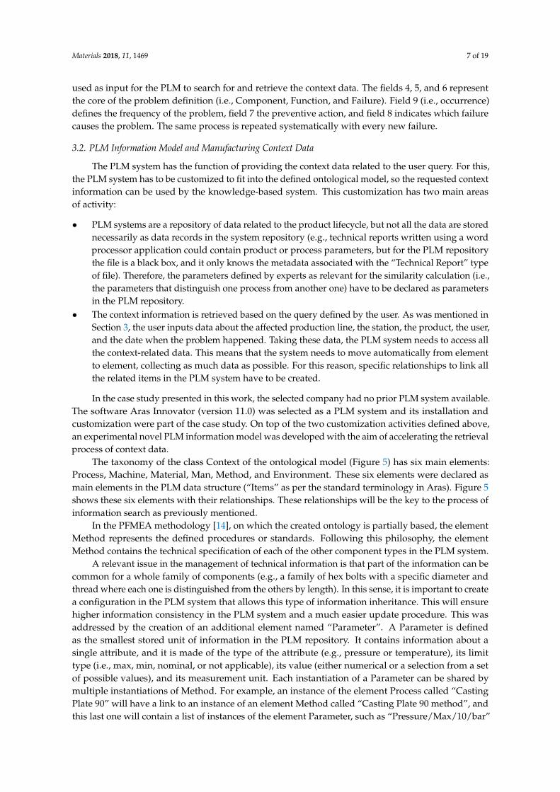
Materials 2018, 11, 1469 7 of 19
used as input for the PLM to search for and retrieve the context data. The fields 4, 5, and 6 representthe core of the problem definition (i.e., Component, Function, and Failure). Field 9 (i.e., occurrence)defines the frequency of the problem, field 7 the preventive action, and field 8 indicates which failurecauses the problem. The same process is repeated systematically with every new failure.
3.2. PLM Information Model and Manufacturing Context Data
The PLM system has the function of providing the context data related to the user query. For this,the PLM system has to be customized to fit into the defined ontological model, so the requested contextinformation can be used by the knowledge-based system. This customization has two main areasof activity:
• PLM systems are a repository of data related to the product lifecycle, but not all the data are storednecessarily as data records in the system repository (e.g., technical reports written using a wordprocessor application could contain product or process parameters, but for the PLM repositorythe file is a black box, and it only knows the metadata associated with the “Technical Report” typeof file). Therefore, the parameters defined by experts as relevant for the similarity calculation (i.e.,the parameters that distinguish one process from another one) have to be declared as parametersin the PLM repository.
• The context information is retrieved based on the query defined by the user. As was mentioned inSection 3, the user inputs data about the affected production line, the station, the product, the user,and the date when the problem happened. Taking these data, the PLM system needs to access allthe context-related data. This means that the system needs to move automatically from elementto element, collecting as much data as possible. For this reason, specific relationships to link allthe related items in the PLM system have to be created.
In the case study presented in this work, the selected company had no prior PLM system available.The software Aras Innovator (version 11.0) was selected as a PLM system and its installation andcustomization were part of the case study. On top of the two customization activities defined above,an experimental novel PLM information model was developed with the aim of accelerating the retrievalprocess of context data.
The taxonomy of the class Context of the ontological model (Figure 5) has six main elements:Process, Machine, Material, Man, Method, and Environment. These six elements were declared asmain elements in the PLM data structure (“Items” as per the standard terminology in Aras). Figure 5shows these six elements with their relationships. These relationships will be the key to the process ofinformation search as previously mentioned.
In the PFMEA methodology [14], on which the created ontology is partially based, the elementMethod represents the defined procedures or standards. Following this philosophy, the elementMethod contains the technical specification of each of the other component types in the PLM system.
A relevant issue in the management of technical information is that part of the information can becommon for a whole family of components (e.g., a family of hex bolts with a specific diameter andthread where each one is distinguished from the others by length). In this sense, it is important to createa configuration in the PLM system that allows this type of information inheritance. This will ensurehigher information consistency in the PLM system and a much easier update procedure. This wasaddressed by the creation of an additional element named “Parameter”. A Parameter is definedas the smallest stored unit of information in the PLM repository. It contains information about asingle attribute, and it is made of the type of the attribute (e.g., pressure or temperature), its limittype (i.e., max, min, nominal, or not applicable), its value (either numerical or a selection from a setof possible values), and its measurement unit. Each instantiation of a Parameter can be shared bymultiple instantiations of Method. For example, an instance of the element Process called “CastingPlate 90” will have a link to an instance of an element Method called “Casting Plate 90 method”, andthis last one will contain a list of instances of the element Parameter, such as “Pressure/Max/10/bar”
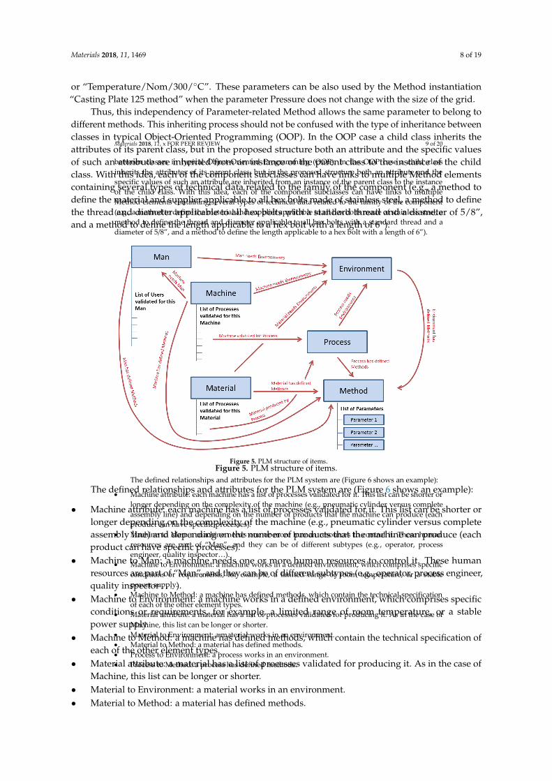
Materials 2018, 11, 1469 8 of 19
or “Temperature/Nom/300/◦C”. These parameters can be also used by the Method instantiation“Casting Plate 125 method” when the parameter Pressure does not change with the size of the grid.
Thus, this independency of Parameter-related Method allows the same parameter to belong todifferent methods. This inheriting process should not be confused with the type of inheritance betweenclasses in typical Object-Oriented Programming (OOP). In the OOP case a child class inherits theattributes of its parent class, but in the proposed structure both an attribute and the specific valuesof such an attribute are inherited from an instance of the parent class to the instance of the childclass. With this idea, each of the component subclasses can have links to multiple Method elementscontaining several types of technical data related to the family of the component (e.g., a method todefine the material and supplier applicable to all hex bolts made of stainless steel, a method to definethe thread and diameter applicable to all hex bolts with a standard thread and a diameter of 5/8”,and a method to define the length applicable to a hex bolt with a length of 6”).
Materials 2018, 11, x FOR PEER REVIEW 9 of 20
between classes in typical Object-Oriented Programming (OOP). In the OOP case a child class
inherits the attributes of its parent class, but in the proposed structure both an attribute and the
specific values of such an attribute are inherited from an instance of the parent class to the instance
of the child class. With this idea, each of the component subclasses can have links to multiple
Method elements containing several types of technical data related to the family of the component
(e.g., a method to define the material and supplier applicable to all hex bolts made of stainless steel, a
method to define the thread and diameter applicable to all hex bolts with a standard thread and a
diameter of 5/8”, and a method to define the length applicable to a hex bolt with a length of 6”).
Figure 5. PLM structure of items.
The defined relationships and attributes for the PLM system are (Figure 6 shows an example):
Machine attribute: each machine has a list of processes validated for it. This list can be shorter or
longer depending on the complexity of the machine (e.g., pneumatic cylinder versus complete
assembly line) and depending on the number of products that the machine can produce (each
product can have specific processes).
Machine to Man: a machine needs one or more human resources to control it. These human
resources are part of “Man”, and they can be of different subtypes (e.g., operator, process
engineer, quality inspector…).
Machine to Environment: a machine works in a defined environment, which comprises specific
conditions or requirements, for example, a limited range of room temperature, or a stable
power supply.
Machine to Method: a machine has defined methods, which contain the technical specification
of each of the other element types.
Material attribute: a material has a list of processes validated for producing it. As in the case of
Machine, this list can be longer or shorter.
Material to Environment: a material works in an environment.
Material to Method: a material has defined methods.
Process to Environment: a process works in an environment.
Process to Method: a process has defined methods.
Figure 5. PLM structure of items.
The defined relationships and attributes for the PLM system are (Figure 6 shows an example):
• Machine attribute: each machine has a list of processes validated for it. This list can be shorter orlonger depending on the complexity of the machine (e.g., pneumatic cylinder versus completeassembly line) and depending on the number of products that the machine can produce (eachproduct can have specific processes).
• Machine to Man: a machine needs one or more human resources to control it. These humanresources are part of “Man”, and they can be of different subtypes (e.g., operator, process engineer,quality inspector . . . ).
• Machine to Environment: a machine works in a defined environment, which comprises specificconditions or requirements, for example, a limited range of room temperature, or a stablepower supply.
• Machine to Method: a machine has defined methods, which contain the technical specification ofeach of the other element types.
• Material attribute: a material has a list of processes validated for producing it. As in the case ofMachine, this list can be longer or shorter.
• Material to Environment: a material works in an environment.• Material to Method: a material has defined methods.
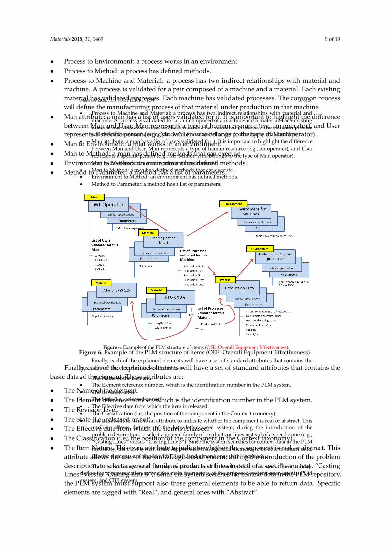
Materials 2018, 11, 1469 9 of 19
• Process to Environment: a process works in an environment.• Process to Method: a process has defined methods.• Process to Machine and Material: a process has two indirect relationships with material and
machine. A process is validated for a pair composed of a machine and a material. Each existingmaterial has validated processes. Each machine has validated processes. The common processwill define the manufacturing process of that material under production in that machine.
• Man attribute: a man has a list of users validated for it. It is important to highlight the differencebetween Man and User. Man represents a type of human resource (e.g., an operator), and Userrepresents a specific person (e.g., Mr. Müller, who belongs to the type of Man operator).
• Man to Environment: a man works in an environment.• Man to Method: a man has defined methods that can execute.• Environment to Method: an environment has defined methods.• Method to Parameter: a method has a list of parameters.
Materials 2018, 11, x FOR PEER REVIEW 10 of 20
Process to Machine and Material: a process has two indirect relationships with material and
machine. A process is validated for a pair composed of a machine and a material. Each existing
material has validated processes. Each machine has validated processes. The common process
will define the manufacturing process of that material under production in that machine.
Man attribute: a man has a list of users validated for it. It is important to highlight the difference
between Man and User. Man represents a type of human resource (e.g., an operator), and User
represents a specific person (e.g., Mr. Müller, who belongs to the type of Man operator).
Man to Environment: a man works in an environment.
Man to Method: a man has defined methods that can execute.
Environment to Method: an environment has defined methods.
Method to Parameter: a method has a list of parameters.
Figure 6. Example of the PLM structure of items (OEE: Overall Equipment Effectiveness).
Finally, each of the explained elements will have a set of standard attributes that contains the
basic data of the element. These attributes are:
The Name of the element.
The Element reference number, which is the identification number in the PLM system.
The Revision level.
The State (i.e., released or not).
The Effective date from which the item is released.
The Classification (i.e., the position of the component in the Context taxonomy).
The Item Nature. This is an attribute to indicate whether the component is real or abstract. This
attribute allows the user of the knowledge-based system, during the introduction of the
problem description, to select a general family of products or lines instead of a specific one (e.g.,
“Casting Lines” versus “Casting Line 3”). Since the system searches for context data in the PLM
repository, the PLM system must support also these general elements to be able to return data.
Specific elements are tagged with “Real”, and general ones with “Abstract”.
The next section presents the communication models developed for this work. These models
define the communication among the main four actors of the proposed system: user, agents, PLM
system, and CBR system.
Figure 6. Example of the PLM structure of items (OEE: Overall Equipment Effectiveness).
Finally, each of the explained elements will have a set of standard attributes that contains thebasic data of the element. These attributes are:
• The Name of the element.• The Element reference number, which is the identification number in the PLM system.• The Revision level.• The State (i.e., released or not).• The Effective date from which the item is released.• The Classification (i.e., the position of the component in the Context taxonomy).• The Item Nature. This is an attribute to indicate whether the component is real or abstract. This
attribute allows the user of the knowledge-based system, during the introduction of the problemdescription, to select a general family of products or lines instead of a specific one (e.g., “CastingLines” versus “Casting Line 3”). Since the system searches for context data in the PLM repository,the PLM system must support also these general elements to be able to return data. Specificelements are tagged with “Real”, and general ones with “Abstract”.
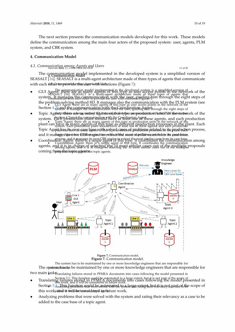
Materials 2018, 11, 1469 10 of 19
The next section presents the communication models developed for this work. These modelsdefine the communication among the main four actors of the proposed system: user, agents, PLMsystem, and CBR system.
4. Communication Model
4.1. Communication among Agents and Users
The communication model implemented in the developed system is a simplified version ofSEASALT [16]. SEASALT is a multi-agent architecture made of three types of agents that communicatewith each other to provide the user with solutions (Figure 7):
• GUI Agent: there are as many agents of this type as user access points in the network of thesystem. It manages the communication with the user, guiding him through the eight steps ofthe problem-solving method 8D. It manages also the communication with the PLM system (seeSection 4.2) and the communication with the Coordination Agent.
• Topic Agent: there are as many agents of this type as production units in the network of thesystem. Each production plant should have at least one of these agents, and each productionplant can have as many agents of this type as different production processes in the plant. EachTopic Agent has its own case base with solved cases of problems related to its production process,and it manages its own CBR engine to extract the most similar cases from its case base.
• Coordination Agent: there is a single agent of this type. It coordinates the communication amongagents, and it is in charge of selecting the 10 most similar cases out of the multiple proposalscoming from the topic agents.
Materials 2018, 11, x FOR PEER REVIEW 11 of 20
4. Communication Model
4.1. Communication among Agents and Users
The communication model implemented in the developed system is a simplified version of
SEASALT [16]. SEASALT is a multi-agent architecture made of three types of agents that
communicate with each other to provide the user with solutions (Figure 7):
GUI Agent: there are as many agents of this type as user access points in the network of the
system. It manages the communication with the user, guiding him through the eight steps of
the problem-solving method 8D. It manages also the communication with the PLM system (see
Section 4.2) and the communication with the Coordination Agent.
Topic Agent: there are as many agents of this type as production units in the network of the
system. Each production plant should have at least one of these agents, and each production
plant can have as many agents of this type as different production processes in the plant. Each
Topic Agent has its own case base with solved cases of problems related to its production
process, and it manages its own CBR engine to extract the most similar cases from its case base.
Coordination Agent: there is a single agent of this type. It coordinates the communication
among agents, and it is in charge of selecting the 10 most similar cases out of the multiple
proposals coming from the topic agents.
Figure 7. Communication model.
The system has to be maintained by one or more knowledge engineers that are responsible for
two main tasks:
Translating failures stored in PFMEA documents into cases following the model presented in
Section 3.1. This function could be automated to a large extent, but it is not part of the scope of
this work, and it will be considered in future work.
Analyzing problems that were solved with the system and rating their relevancy as a case to be
added to the case base of a topic agent.
Figure 7. Communication model.
The system has to be maintained by one or more knowledge engineers that are responsible fortwo main tasks:
• Translating failures stored in PFMEA documents into cases following the model presented inSection 3.1. This function could be automated to a large extent, but it is not part of the scope ofthis work, and it will be considered in future work.
• Analyzing problems that were solved with the system and rating their relevancy as a case to beadded to the case base of a topic agent.
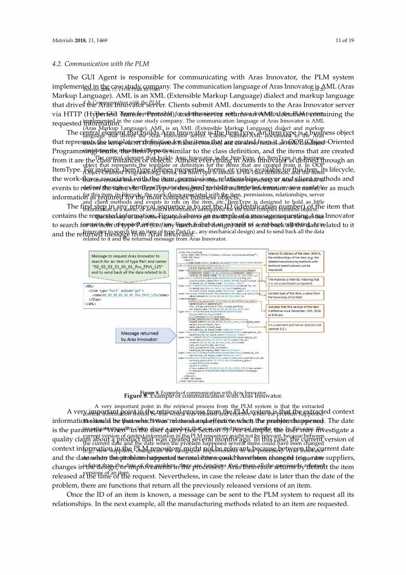
Materials 2018, 11, 1469 11 of 19
4.2. Communication with the PLM
The GUI Agent is responsible for communicating with Aras Innovator, the PLM systemimplemented in the case study company. The communication language of Aras Innovator is AML (ArasMarkup Language). AML is an XML (Extensible Markup Language) dialect and markup languagethat drives the Aras Innovator server. Clients submit AML documents to the Aras Innovator servervia HTTP (Hypertext Transfer Protocol), and the server returns an AML document containing therequested information.
The central element that builds Aras Innovator is the ItemType. An ItemType is a business objectthat represents the template or definition for the items that are created from it. In OOP (Object-OrientedProgramming) terms, the ItemType is similar to the class definition, and the items that are createdfrom it are the class instances or objects. Almost everything in Aras Innovator is defined through anItemType. For instance, ItemType defines properties, forms, or views available for this item, its lifecycle,the work-flows associated with the item, permissions, relationships, server and client methods andevents to run on the item, etc. ItemType is designed to hold as little information as a name, or as muchinformation as required for the most complex business objects.
The first step in any retrieval sequence is to get the ID (identification number) of the item thatcontains the requested information. Figure 8 shows an example of a message requesting Aras Innovatorto search for an item of type Part (i.e., any mechanical design) and to send back all the data related to itand the returned message from Aras Innovator.
Materials 2018, 11, x FOR PEER REVIEW 12 of 20
4.2. Communication with the PLM
The GUI Agent is responsible for communicating with Aras Innovator, the PLM system
implemented in the case study company. The communication language of Aras Innovator is AML
(Aras Markup Language). AML is an XML (Extensible Markup Language) dialect and markup
language that drives the Aras Innovator server. Clients submit AML documents to the Aras
Innovator server via HTTP (Hypertext Transfer Protocol), and the server returns an AML document
containing the requested information.
The central element that builds Aras Innovator is the ItemType. An ItemType is a business
object that represents the template or definition for the items that are created from it. In OOP
(Object-Oriented Programming) terms, the ItemType is similar to the class definition, and the items
that are created from it are the class instances or objects. Almost everything in Aras Innovator is
defined through an ItemType. For instance, ItemType defines properties, forms, or views available
for this item, its lifecycle, the work-flows associated with the item, permissions, relationships, server
and client methods and events to run on the item, etc. ItemType is designed to hold as little
information as a name, or as much information as required for the most complex business objects.
The first step in any retrieval sequence is to get the ID (identification number) of the item that
contains the requested information. Figure 8 shows an example of a message requesting Aras
Innovator to search for an item of type Part (i.e., any mechanical design) and to send back all the data
related to it and the returned message from Aras Innovator.
Figure 8. Example of communication with Aras Innovator.
A very important point in the retrieval process from the PLM system is that the extracted
context information should be that which was released and effective when the problem happened.
The date is the parameter “When” in the user query (see Section 3). For example, the user may
investigate a quality claim about a product that was created several months ago. In this case, the
current version of context information in the PLM repository might not be relevant, because between
the current date and the date when the problem happened several items could have been changed
(e.g., new suppliers, changes in the design, or improvements in the processes). Aras Innovator
returns by default the item released at the time of the request. Nevertheless, in case the release date
is later than the date of the problem, there are functions that return all the previously released
versions of an item.
Figure 8. Example of communication with Aras Innovator.
A very important point in the retrieval process from the PLM system is that the extracted contextinformation should be that which was released and effective when the problem happened. The dateis the parameter “When” in the user query (see Section 3). For example, the user may investigate aquality claim about a product that was created several months ago. In this case, the current version ofcontext information in the PLM repository might not be relevant, because between the current dateand the date when the problem happened several items could have been changed (e.g., new suppliers,changes in the design, or improvements in the processes). Aras Innovator returns by default the itemreleased at the time of the request. Nevertheless, in case the release date is later than the date of theproblem, there are functions that return all the previously released versions of an item.
Once the ID of an item is known, a message can be sent to the PLM system to request all itsrelationships. In the next example, all the manufacturing methods related to an item are requested.
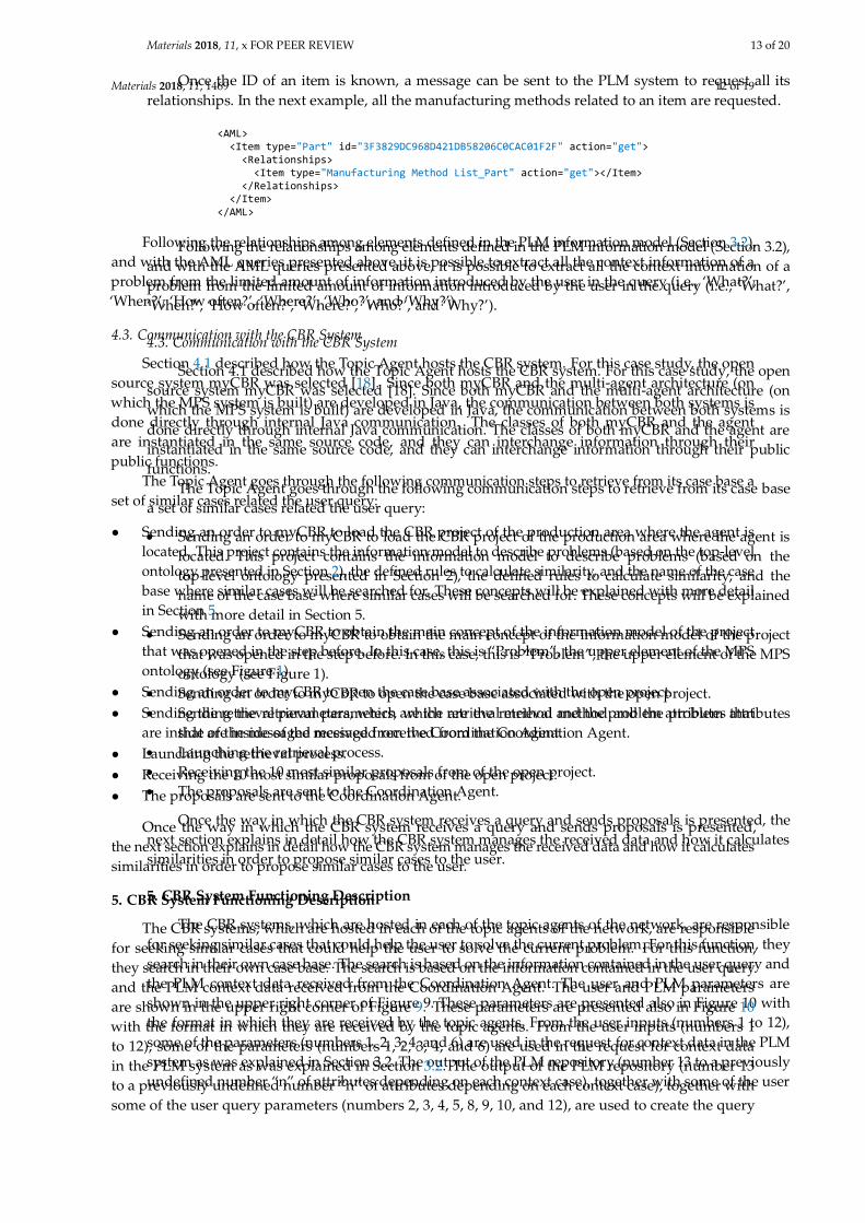
Materials 2018, 11, 1469 12 of 19
Materials 2018, 11, x FOR PEER REVIEW 13 of 20
Once the ID of an item is known, a message can be sent to the PLM system to request all its
relationships. In the next example, all the manufacturing methods related to an item are requested.
Following the relationships among elements defined in the PLM information model (Section 3.2),
and with the AML queries presented above, it is possible to extract all the context information of a
problem from the limited amount of information introduced by the user in the query (i.e., ‘What?’,
‘When?’, ‘How often?’, ‘Where?’, ‘Who?’, and ‘Why?’).
4.3. Communication with the CBR System
Section 4.1 described how the Topic Agent hosts the CBR system. For this case study, the open
source system myCBR was selected [18]. Since both myCBR and the multi-agent architecture (on
which the MPS system is built) are developed in Java, the communication between both systems is
done directly through internal Java communication. The classes of both myCBR and the agent are
instantiated in the same source code, and they can interchange information through their public
functions.
The Topic Agent goes through the following communication steps to retrieve from its case base
a set of similar cases related the user query:
Sending an order to myCBR to load the CBR project of the production area where the agent is
located. This project contains the information model to describe problems (based on the
top-level ontology presented in Section 2), the defined rules to calculate similarity, and the
name of the case base where similar cases will be searched for. These concepts will be explained
with more detail in Section 5.
Sending an order to myCBR to obtain the main concept of the information model of the project
that was opened in the step before. In this case, this is “Problem”, the upper element of the MPS
ontology (see Figure 1).
Sending an order to myCBR to open the case base associated with the open project.
Sending the retrieval parameters, which are the retrieval method and the problem attributes
that are inside of the messaged received from the Coordination Agent.
Launching the retrieval process.
Receiving the 10 most similar proposals from of the open project.
The proposals are sent to the Coordination Agent.
Once the way in which the CBR system receives a query and sends proposals is presented, the
next section explains in detail how the CBR system manages the received data and how it calculates
similarities in order to propose similar cases to the user.
5. CBR System Functioning Description
The CBR systems, which are hosted in each of the topic agents of the network, are responsible
for seeking similar cases that could help the user to solve the current problem. For this function, they
search in their own case base. The search is based on the information contained in the user query and
the PLM context data received from the Coordination Agent. The user and PLM parameters are
shown in the upper right corner of Figure 9. These parameters are presented also in Figure 10 with
the format in which they are received by the topic agents. From the user inputs (numbers 1 to 12),
some of the parameters (numbers 1, 2, 3, 4, and 6) are used in the request for context data in the PLM
system as was explained in Section 3.2. The output of the PLM repository (number 13 to a previously
undefined number “n” of attributes depending on each context case), together with some of the user
<AML> <Item type="Part" id="3F3829DC968D421DB58206C0CAC01F2F" action="get"> <Relationships> <Item type="Manufacturing Method List_Part" action="get"></Item> </Relationships> </Item> </AML>
Following the relationships among elements defined in the PLM information model (Section 3.2),and with the AML queries presented above, it is possible to extract all the context information of aproblem from the limited amount of information introduced by the user in the query (i.e., ‘What?’,‘When?’, ‘How often?’, ‘Where?’, ‘Who?’, and ‘Why?’).
4.3. Communication with the CBR System
Section 4.1 described how the Topic Agent hosts the CBR system. For this case study, the opensource system myCBR was selected [18]. Since both myCBR and the multi-agent architecture (onwhich the MPS system is built) are developed in Java, the communication between both systems isdone directly through internal Java communication. The classes of both myCBR and the agentare instantiated in the same source code, and they can interchange information through theirpublic functions.
The Topic Agent goes through the following communication steps to retrieve from its case base aset of similar cases related the user query:
• Sending an order to myCBR to load the CBR project of the production area where the agent islocated. This project contains the information model to describe problems (based on the top-levelontology presented in Section 2), the defined rules to calculate similarity, and the name of the casebase where similar cases will be searched for. These concepts will be explained with more detailin Section 5.
• Sending an order to myCBR to obtain the main concept of the information model of the projectthat was opened in the step before. In this case, this is “Problem”, the upper element of the MPSontology (see Figure 1).
• Sending an order to myCBR to open the case base associated with the open project.• Sending the retrieval parameters, which are the retrieval method and the problem attributes that
are inside of the messaged received from the Coordination Agent.• Launching the retrieval process.• Receiving the 10 most similar proposals from of the open project.• The proposals are sent to the Coordination Agent.
Once the way in which the CBR system receives a query and sends proposals is presented,the next section explains in detail how the CBR system manages the received data and how it calculatessimilarities in order to propose similar cases to the user.
5. CBR System Functioning Description
The CBR systems, which are hosted in each of the topic agents of the network, are responsiblefor seeking similar cases that could help the user to solve the current problem. For this function,they search in their own case base. The search is based on the information contained in the user queryand the PLM context data received from the Coordination Agent. The user and PLM parametersare shown in the upper right corner of Figure 9. These parameters are presented also in Figure 10with the format in which they are received by the topic agents. From the user inputs (numbers 1to 12), some of the parameters (numbers 1, 2, 3, 4, and 6) are used in the request for context datain the PLM system as was explained in Section 3.2. The output of the PLM repository (number 13to a previously undefined number “n” of attributes depending on each context case), together withsome of the user query parameters (numbers 2, 3, 4, 5, 8, 9, 10, and 12), are used to create the query
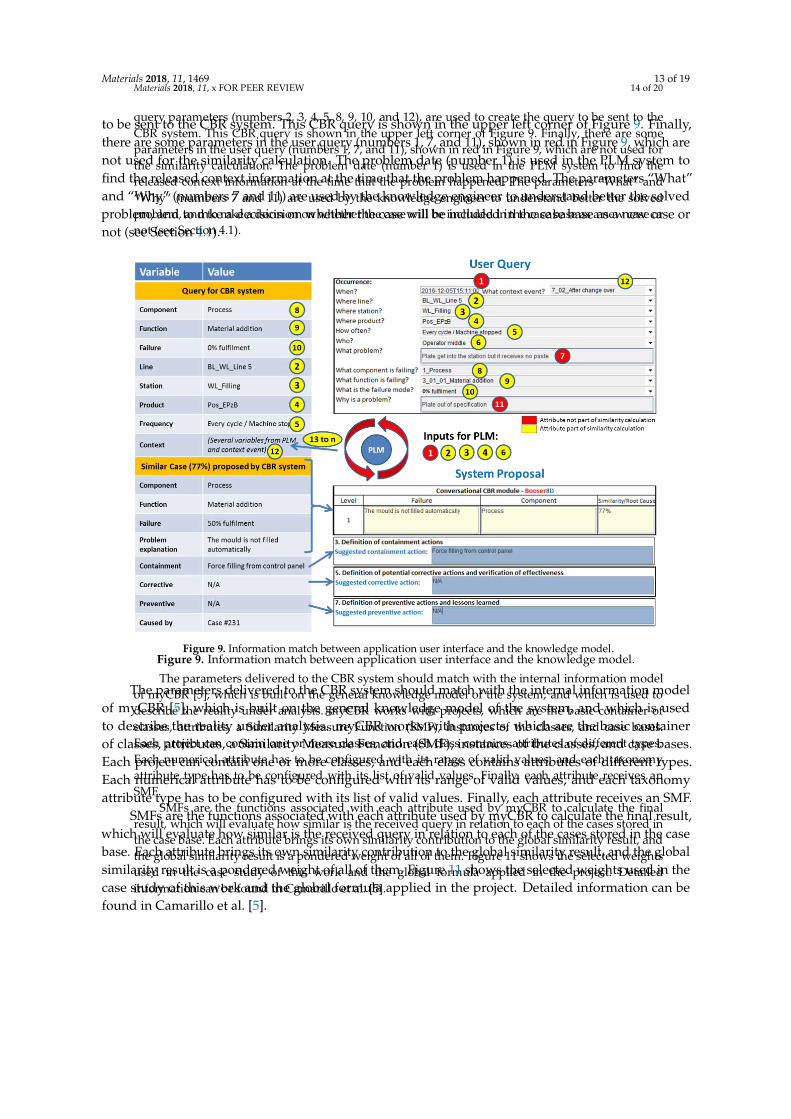
Materials 2018, 11, 1469 13 of 19
to be sent to the CBR system. This CBR query is shown in the upper left corner of Figure 9. Finally,there are some parameters in the user query (numbers 1, 7, and 11), shown in red in Figure 9, which arenot used for the similarity calculation. The problem date (number 1) is used in the PLM system tofind the released context information at the time that the problem happened. The parameters “What”and “Why” (numbers 7 and 11) are used by the knowledge engineer to understand better the solvedproblem, and to mke a decision on whether the case will be included in the case base as a new case ornot (see Section 4.1).
Materials 2018, 11, x FOR PEER REVIEW 14 of 20
query parameters (numbers 2, 3, 4, 5, 8, 9, 10, and 12), are used to create the query to be sent to the
CBR system. This CBR query is shown in the upper left corner of Figure 9. Finally, there are some
parameters in the user query (numbers 1, 7, and 11), shown in red in Figure 9, which are not used for
the similarity calculation. The problem date (number 1) is used in the PLM system to find the
released context information at the time that the problem happened. The parameters “What” and
“Why” (numbers 7 and 11) are used by the knowledge engineer to understand better the solved
problem, and to mke a decision on whether the case will be included in the case base as a new case or
not (see Section 4.1).
Figure 9. Information match between application user interface and the knowledge model.
The parameters delivered to the CBR system should match with the internal information model
of myCBR [5], which is built on the general knowledge model of the system, and which is used to
describe the reality under analysis. myCBR works with projects, which are the basic container of
classes, attributes, a Similarity Measure Function (SMF), instances of the classes, and case bases.
Each project can contain one or more classes, and each class contains attributes of different types.
Each numerical attribute has to be configured with its range of valid values, and each taxonomy
attribute type has to be configured with its list of valid values. Finally, each attribute receives an
SMF.
SMFs are the functions associated with each attribute used by myCBR to calculate the final
result, which will evaluate how similar is the received query in relation to each of the cases stored in
the case base. Each attribute brings its own similarity contribution to the global similarity result, and
the global similarity result is a pondered weight of all of them. Figure 11 shows the selected weights
used in the case study of this work and the global formula applied in the project. Detailed
information can be found in Camarillo et al. [5].
Figure 9. Information match between application user interface and the knowledge model.
The parameters delivered to the CBR system should match with the internal information modelof myCBR [5], which is built on the general knowledge model of the system, and which is usedto describe the reality under analysis. myCBR works with projects, which are the basic containerof classes, attributes, a Similarity Measure Function (SMF), instances of the classes, and case bases.Each project can contain one or more classes, and each class contains attributes of different types.Each numerical attribute has to be configured with its range of valid values, and each taxonomyattribute type has to be configured with its list of valid values. Finally, each attribute receives an SMF.
SMFs are the functions associated with each attribute used by myCBR to calculate the final result,which will evaluate how similar is the received query in relation to each of the cases stored in the casebase. Each attribute brings its own similarity contribution to the global similarity result, and the globalsimilarity result is a pondered weight of all of them. Figure 11 shows the selected weights used in thecase study of this work and the global formula applied in the project. Detailed information can befound in Camarillo et al. [5].
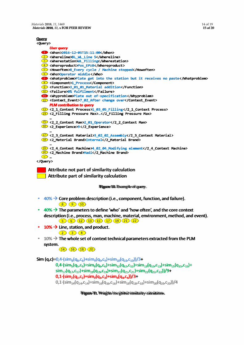
Materials 2018, 11, 1469 14 of 19Materials 2018, 11, x FOR PEER REVIEW 15 of 20
Figure 10. Example of query.
Figure 11. Weights for global similarity calculation.
Figure 10. Example of query.
Materials 2018, 11, x FOR PEER REVIEW 15 of 20
Figure 10. Example of query.
Figure 11. Weights for global similarity calculation.
Figure 11. Weights for global similarity calculation.
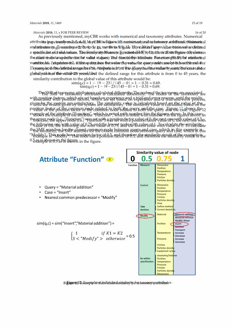
Materials 2018, 11, 1469 15 of 19
As previously mentioned, myCBR works with numerical and taxonomy attributes. Numericalattributes (e.g., numbers 2, 3, 4, 5, 14, or 16 in Figure 10) contain any value between a defined minimumand maximum. Taxonomy attributes (e.g., numbers 8, 9, 12, 13, or 20 in Figure 10) contain values froma specific list of valid values. The Similarity Measure Function (SMF) of numerical attributes calculatesthe relative distance between the value at query and case of this attribute. For example, in the attributenumber 16, “experience”, if the query has the value 9 years, the case under analysis has the value23 years, and the defined range for this attribute is from 0 to 45 years, the similarity contribution to theglobal value of this attribute would be:
sim(q,c) = 1 − |9 − 23|/|45 − 0| = 1 − 0.31 = 0.69.
The SMF of taxonomy attributes is calculated differently. The nodes of the taxonomy are associatedwith position factors, which are set based on experience and a trial-and-error process, until the resultsgiven by the system are satisfactory. The similarity value is calculated based on the value of theposition factor of the common node related to both the query and the case. Figure 12 shows theexample of the attribute “Function”, which is noted with number 9 in the figures above. In this case,the upper node (i.e., “Function”) was set with a position factor value of 0, the next one with value of 0.5,the following one with value of 0.75, and the lowest node with value of 1. To calculate the similarity,the SMF searches for the closest common node between query and case, which in this example is“Modify”. This node has a position factor of 0.5, and therefore the similarity result of the example is0.5 as is shown in the figure.
Materials 2018, 11, x FOR PEER REVIEW 16 of 20
As previously mentioned, myCBR works with numerical and taxonomy attributes. Numerical
attributes (e.g., numbers 2, 3, 4, 5, 14, or 16 in Figure 10) contain any value between a defined
minimum and maximum. Taxonomy attributes (e.g., numbers 8, 9, 12, 13, or 20 in Figure 10) contain
values from a specific list of valid values. The Similarity Measure Function (SMF) of numerical
attributes calculates the relative distance between the value at query and case of this attribute. For
example, in the attribute number 16, “experience”, if the query has the value 9 years, the case under
analysis has the value 23 years, and the defined range for this attribute is from 0 to 45 years, the
similarity contribution to the global value of this attribute would be:
sim(q,c) = 1 − |9 − 23|/|45 − 0| = 1 − 0.31 = 0.69.
The SMF of taxonomy attributes is calculated differently. The nodes of the taxonomy are
associated with position factors, which are set based on experience and a trial-and-error process,
until the results given by the system are satisfactory. The similarity value is calculated based on the
value of the position factor of the common node related to both the query and the case. Figure 12
shows the example of the attribute “Function”, which is noted with number 9 in the figures above. In
this case, the upper node (i.e., “Function”) was set with a position factor value of 0, the next one with
value of 0.5, the following one with value of 0.75, and the lowest node with value of 1. To calculate
the similarity, the SMF searches for the closest common node between query and case, which in this
example is “Modify”. This node has a position factor of 0.5, and therefore the similarity result of the
example is 0.5 as is shown in the figure.
Figure 12. Example of individual similarity for taxonomy attributes. Figure 12. Example of individual similarity for taxonomy attributes.
Materials 2018, 11, 1469 16 of 19
A last relevant point related to similarity calculation is the range of supported manufacturingprocesses. In that sense, the developed system was designed to work for any kind of manufacturingprocess. Therefore, in the case of the context parameters, which are extracted from the PLM repository,a very wide range of possible parameter types should be expected. For some processes, a parameterof pressure might be relevant, but for other processes the relevant parameter could be a temperature.In the presented multi-agent architecture, each topic agent is specialized to the process where it islocated. Therefore, when a topic agent receives a query, it will look for the parameters that it knows.Thus, all context parameters that are unknown by the topic agent will be ignored (i.e., no contributionin terms of similarity). It could also happen that not all of the parameters associated with its processare included in the query. In that case, the parameters that are not found will be assigned a null value,reducing the similarity result. In this way, cases from the same process will have always the highestsimilarity values followed by the cases from similar processes (i.e., processes with similar contextparameters). The cases from very different processes will have the lowest similarity value.
Once the global similarity is calculated, the system displays the corresponding results. The bottompart of Figure 9 shows how the output in the system looks. In this case, the similarity value is 77%,and the proposal for the containment, corrective, and preventive actions is displayed to the userthrough the GUI.
The next section presents the details of the implementation of the developed system prototype ina case study company from the battery manufacturing sector.
6. Case Study in Battery Manufacturing
The developed system prototype was implemented as a case study in the company ExideTechnologies, a global provider of stored electrical energy solutions (i.e., batteries and associatedequipment and services) for transportation and industrial markets. Exide Technologies has severalproduction plants running similar processes in Europe and the USA. For this reason, Exide couldbenefit from this research work.
For this case study, two plants of the company were selected: one located in Germany, and anotherone in Spain; both plants produce similar products with similar processes. They produce powerbatteries for the industrial market (i.e., forklifts or similar applications) with the process denominatedWet Filling to produce the positive plates. Gravity casting, with which the negative grids are produced,was also selected to test the performance of the system with a second manufacturing process.
The implementation of the case study can be divided in three phases: the definition of key PPR(Product-Process-Resource) attributes to ensure proper similarity calculation within the CBR systems,the collection of cases for the CBR case bases, and the test of the system on the shop floor.
As presented in Section 5, the similarity calculation is done based on a set of attributes that areselected out of the whole range of attributes that define the PPR reality of the case study. The selectioncriteria, and their individual weight in the similarity calculation, are related to the possible variationrange of each attribute. For example, in a defined PPR scenario where the height of the productnever changes across all existing part numbers, height would be a very bad candidate for similaritycalculation, because it is not going to help to distinguish among cases. On the contrary, if the keydifferentiating characteristic of a range of products is the color, and there is a variety of colors, then colorwould be an excellent candidate for similarity calculation. To identify these key attributes for similarity,staff from production and engineering in the German plant of Exide were interviewed with a focuson the wet-filling process. The steps followed in these interviews were the identification of keyPPR elements, the identification of the relationships among them, and finally the identification oftheir relevant attributes and their corresponding variability range. This information was used in thecustomization of both the PLM and CBR systems.
The next step in the case study was to collect enough cases to fill the CBR case bases of the topicagents. This activity was focused only on the wet filling production area of the German plant, leavingthe Spanish plant for validation purposes. Four sources were used: the PFMEA of the wet-filling
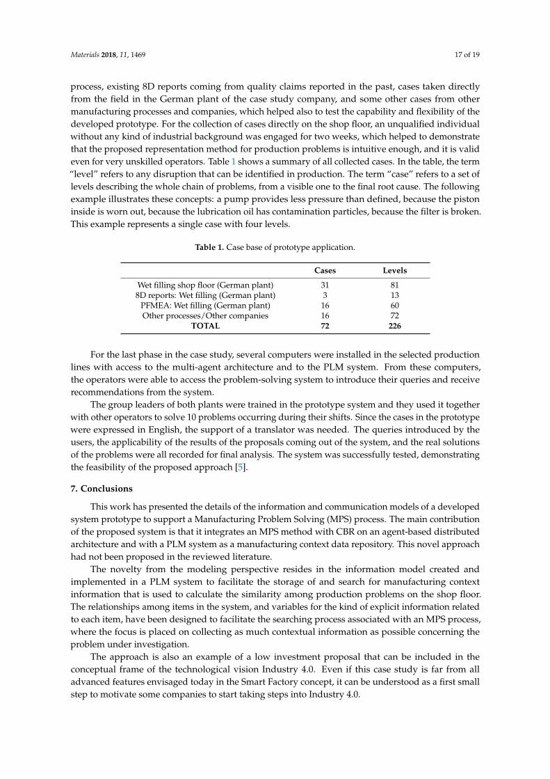
Materials 2018, 11, 1469 17 of 19
process, existing 8D reports coming from quality claims reported in the past, cases taken directlyfrom the field in the German plant of the case study company, and some other cases from othermanufacturing processes and companies, which helped also to test the capability and flexibility of thedeveloped prototype. For the collection of cases directly on the shop floor, an unqualified individualwithout any kind of industrial background was engaged for two weeks, which helped to demonstratethat the proposed representation method for production problems is intuitive enough, and it is valideven for very unskilled operators. Table 1 shows a summary of all collected cases. In the table, the term“level” refers to any disruption that can be identified in production. The term “case” refers to a set oflevels describing the whole chain of problems, from a visible one to the final root cause. The followingexample illustrates these concepts: a pump provides less pressure than defined, because the pistoninside is worn out, because the lubrication oil has contamination particles, because the filter is broken.This example represents a single case with four levels.
Table 1. Case base of prototype application.
Cases Levels
Wet filling shop floor (German plant) 31 818D reports: Wet filling (German plant) 3 13
PFMEA: Wet filling (German plant) 16 60Other processes/Other companies 16 72
TOTAL 72 226
For the last phase in the case study, several computers were installed in the selected productionlines with access to the multi-agent architecture and to the PLM system. From these computers,the operators were able to access the problem-solving system to introduce their queries and receiverecommendations from the system.
The group leaders of both plants were trained in the prototype system and they used it togetherwith other operators to solve 10 problems occurring during their shifts. Since the cases in the prototypewere expressed in English, the support of a translator was needed. The queries introduced by theusers, the applicability of the results of the proposals coming out of the system, and the real solutionsof the problems were all recorded for final analysis. The system was successfully tested, demonstratingthe feasibility of the proposed approach [5].
7. Conclusions
This work has presented the details of the information and communication models of a developedsystem prototype to support a Manufacturing Problem Solving (MPS) process. The main contributionof the proposed system is that it integrates an MPS method with CBR on an agent-based distributedarchitecture and with a PLM system as a manufacturing context data repository. This novel approachhad not been proposed in the reviewed literature.
The novelty from the modeling perspective resides in the information model created andimplemented in a PLM system to facilitate the storage of and search for manufacturing contextinformation that is used to calculate the similarity among production problems on the shop floor.The relationships among items in the system, and variables for the kind of explicit information relatedto each item, have been designed to facilitate the searching process associated with an MPS process,where the focus is placed on collecting as much contextual information as possible concerning theproblem under investigation.
The approach is also an example of a low investment proposal that can be included in theconceptual frame of the technological vision Industry 4.0. Even if this case study is far from alladvanced features envisaged today in the Smart Factory concept, it can be understood as a first smallstep to motivate some companies to start taking steps into Industry 4.0.
Materials 2018, 11, 1469 18 of 19
Author Contributions: Conceptualization, A.C., J.R., and K.-D.A.; Methodology, A.C.; Software, A.C.; Validation,A.C.; Supervision, J.R. and K.-D.A.; Writing (Original Draft Preparation), A.C. and J.R.; Writing (Review & Editing,J.R. and K.-D.A.
Funding: This research received no external funding.
Conflicts of Interest: The authors declare no conflict of interest.
References
1. Yang, S.; Bian, C.; Li, X.; Tan, L.; Tang, D. Optimized fault diagnosis based on FMEA-style CBR and BN forembedded software system. Int. J. Adv. Manuf. Technol. 2018, 94, 3441–3453. [CrossRef]
2. Ye, N.; Zhao, B.; Salvendy, G. Neural-networks-aided fault diagnosis in supervisory control of advancedmanufacturing systems. Int. J. Adv. Manuf. Technol. 1993, 8, 200–209. [CrossRef]
3. Liu, D.R.; Ke, C.K. Knowledge support for problem-solving in a production process: A hybrid of knowledgediscovery and case-based reasoning. Expert Syst. Appl. 2007, 33, 147–161. [CrossRef]
4. Lundgren, M.; Hedlind, M.; Kjellberg, T. Model driven manufacturing process design and managing quality.Procedia CIRP 2016, 50, 299–304. [CrossRef]
5. Camarillo, A.; Ríos, J.; Althoff, K.D. Knowledge-based multi-agent system for manufacturing problemsolving process in production plants. J. Manuf. Syst. 2018, 47, 115–127. [CrossRef]
6. Bertin, A.; Noyes, D.; Clermont, P. Problem solving methods as Lessons Learned System instrumentation intoa PLM tool. In Proceedings of the 14th IFAC Symposium on Information Control Problems in Manufacturing,Bucarest, Romania, 23–25 May 2012.
7. Stark, J. Product Lifecycle Management; Springer International Publishing: Cham, Switzerland, 2015.8. Hermann, M.; Pentek, T.; Otto, B. Design Principles for Industrie 4.0 Scenarios: A Literature Review;
Working Paper; Technische Universität Dortmund—Fakultät Maschinenbau—Audi StiftungslehrstuhlSupply Net Order Management: Dortmunt, Germany, 2015.
9. Wang, S.; Wan, J.; Li, D.; Zhang, C. Implementing smart factory of industrie 4.0: An outlook. Int. J. Distrib.Sens. Netw. 2016, 12, 3159805. [CrossRef]
10. Zuehlke, D. Smart Factory—Towards a factory-of-things. Annu. Rev. Control 2010, 34, 129–138. [CrossRef]11. Witchalls, C.; Chambers, J. The Internet of Things Business Index: A Quiet Revolution Gathers Pace.
The Economist Intelligence Unit. 2013. Available online: http://www.economistinsights.com/analysis/internet-things-business-index (accessed on 3 August 2018).
12. Lee, I.; Lee, K. The Internet of Things (IoT): Applications, investments, and challenges for enterprises.Bus. Horiz. 2015, 58, 431–440. [CrossRef]
13. Riesenberger, C.A.; Sousa, S.D. The 8D Methodology: An Effective Way to Reduce Recurrence of CustomerComplaints. In Proceedings of the World Congress on Engineering, London, UK, 30 June–2 July 2010;Volume 3.
14. VDA. Qualitätsmanagement in der Automobilindustrie—Qualitätsmanagement-Methoden Assessments;Verband der Autoindustrie (VDA): Berlin, Germany, 2015.
15. Richter, M.M.; Weber, R.O. Case-Based Reasoning: A Textbook; Springer: Heidelberg, Germany, 2013.16. Bach, K. Knowledge Acquisition for Case-Based Reasoning Systems. Ph.D. Thesis, University of Hildesheim,
Hildesheim, Germany, 2012.17. Camarillo, A.; Ríos, J.; Althoff, K.D. CBR and PLM applied to diagnosis and technical support during
problem solving in the Continuous Improvement Process of manufacturing plants. Procedia Manuf. 2017, 13,987–994. [CrossRef]
18. Camarillo, A.; Ríos, J.; Althoff, K.D. Agent Based Framework to support Manufacturing Problem Solvingintegrating Product Lifecycle Management and Case-Based Reasoning. In Proceedings of the IFIP 14thInternational Conference on Product Lifecycle Management, Seville, Spain, 10–12 July 2017; Springer: Cham,Switzerland; Volume 517, pp. 116–128.
19. Dittmann, L.; Rademacher, T.; Zelewski, S. Performing FMEA using ontologies. In Proceedings of the 18thInternational Workshop on Qualitative Reasoning, Evanston, IL, USA, 2–4 August 2004.
20. Chiu, C.; Chiu, N.H.; Hsu, C.I. Intelligent aircraft maintenance support system using genetic algorithms andcase-based reasoning. Int. J. Adv. Manuf. Technol. 2004, 24, 440–446. [CrossRef]

Materials 2018, 11, 1469 19 of 19
21. Reuss, P.; Althoff, K.D.; Hundt, A.; Henkel, W.; Pfeiffer, M. Multi-Agent Case-Based Diagnosis in the AircraftDomain. In Proceedings of the 23rd International Conference on Case-Based Reasoning Workshop, Frankfurt,Germany, 28–30 September 2015; pp. 43–52.
22. Kepner, C.H.; Tregoe, B.B. The New Rational Manager—An Updated Edition for a New World; Princeton ResearchPress: Princeton, NY, USA, 2008.
© 2018 by the authors. Licensee MDPI, Basel, Switzerland. This article is an open accessarticle distributed under the terms and conditions of the Creative Commons Attribution(CC BY) license (http://creativecommons.org/licenses/by/4.0/).