kinematics and inertial effects in locust flapping wings
TRANSCRIPT

Due to copyright issues, only title page, abstract and introduction
have been displayed. This paper can be downloaded from the journal
website from given link.
Or
Please message me or email me at [email protected], I’ll mail a copy of the publication.
Please Cite it as:
Sergey Shkarayev and Rajeev Kumar. Kinematics and inertial effects in locust flapping wings. Experimental Mechanics, pp. 1-14, http://dx.doi.org/10.1007/s11340-015-0093-2, Springer US, 2015.

1 23
Experimental MechanicsAn International Journal ISSN 0014-4851 Exp MechDOI 10.1007/s11340-015-0093-2
Kinematics and Inertial Effects in LocustFlapping Wings
S. Shkarayev & R. Kumar

1 23
Your article is protected by copyright and
all rights are held exclusively by Society for
Experimental Mechanics. This e-offprint is
for personal use only and shall not be self-
archived in electronic repositories. If you wish
to self-archive your article, please use the
accepted manuscript version for posting on
your own website. You may further deposit
the accepted manuscript version in any
repository, provided it is only made publicly
available 12 months after official publication
or later and provided acknowledgement is
given to the original source of publication
and a link is inserted to the published article
on Springer's website. The link must be
accompanied by the following text: "The final
publication is available at link.springer.com”.

Kinematics and Inertial Effects in Locust Flapping Wings
S. Shkarayev1 & R. Kumar1
Received: 29 July 2014 /Accepted: 7 September 2015# Society for Experimental Mechanics 2015
Abstract In the present study, inertial forces and kinematicsof wings of locusts, Schistocerca americana, were investigat-ed experimentally. The developed experimental setup includesfreshly extracted hindwings and forewings, a mechanicaltransmission producing pitching and flapping, a vacuumchamber, and a high-speed video system. Flapping angle am-plitudes determined at the middle section are practically thesame in air and in vacuum in both forewings and hindwings.Pitching amplitudes in the root and in the middle section ofhindwing differ by up to 50 % due to torsional deformation ortwist. In air, the average twist angles are 3° and 17° in fore-wings and hindwings, respectively. Amplitudes of twist angleare higher in vacuum, especially at relatively high flappingfrequencies. Inertial forces are calculated based on a rigid-body model of a wing with prescribed displacements. The 5-segment mesh for hindwings and 2-segment mesh for fore-wings provide accurate determination of inertial forces.Amplitudes of the fifth harmonic in accelerations in air aresubstantially smaller than in vacuum and, therefore, inertialforces in air are about 30 % smaller than those in vacuum.Thus, aerodynamic loads suppressed high-frequency compo-nent in wing oscillations resulting in substantially smaller in-ertial forces in air.
Keywords Locust .Wings . Flapping . Air . Vacuum .
Pitching . Inertial force
NomenclatureAik,Bik Coefficients in Fourier series
approximationsc Wing chordFx, Fz Components of aerodynamic forcef Flapping frequencyfc Cutoff frequencyK Number of terms retained in Fourier series
approximationi,j,k Indicesl Wing lengthm Wing massN Number of segments in rigid-body
model of wingT Time period of one flapping cyclet TimeRx,Rz Components of instantaneous reaction forceQx,Qz Components of instantaneous inertia forceΔw Out-of-plane deformations in forewingsxyz Ground-fixed coordinate systemxϕyϕzϕ Wing-fixed coordinate systemxCM ; yCM Nondimensional coordinates of wing
center of massβ Pitching angleΔβ Peak-to-peak pitching amplitudeϕ Flapping angleΔϕ Peak-to-peak flapping amplitudeη Point on leading edge of wingΔω Twist angle
Introduction
Insects dating roughly back to 350 million years ago [1, 2]have been an extraordinary evolutionary success largely due
* S. [email protected]
1 Department of Aerospace and Mechanical Engineering, Universityof Arizona, 1130 N. Mountain Ave., Tucson, AZ 85721, USA
Experimental MechanicsDOI 10.1007/s11340-015-0093-2
Author's personal copy

to their flight capabilities. Highly skillful and sophisticatedinteraction of their flapping wings with unsteady air flowsnot only provided them survival advantage, but also helpsthem possess incredible maneuverability, range, endurance,and flight speeds. The smallest flying insects that have beenstudied weigh 20–30 μg and the largest approximately 2–3 gwith large moths and locusts at the higher end [3]. Locustsattracted great amount of research interest due to their remark-able flying and collision avoidance capabilities.
The force and power production in flapping wings is a resultof complex dynamic interactions among aerodynamic, elastic,and inertial loads. In the process of flapping motion wingsundergo significant bending and pitching deformations due tothese loads. They dramatically change the instantaneous shapeof the wings and that, in turn, affects aerodynamic pressuredistribution over the wing surface. The sum of the total instan-taneous reaction force, when measured at the base of a flappingwing, and of the resultant aerodynamic force is equal to a sumof the products of mass and acceleration of particles comprisingthe body. The negative of the latter term is also called an inertialforce. An accurate assessment of the aerodynamic forces inflapping wings requires quantification of the dynamic wingdeformations and assessment of inertial forces.
Live insects have been extensively used in experimentalstudies of flapping wing kinematics and aerodynamics.Weis-Fogh and Jensen [4–6] were among the first to measureaerodynamic forces on locusts in a wind tunnel. The standardSchistocerca was defined in a study by Weis-Fogh [5] as alocust of average size and of 2.08 g weight before flight.Tethered locusts were tested under steady flight conditions,which were defined as the average thrust force produced byflapping wings being balanced by drag due to the body andlegs. The balanced speed of horizontal flight was found in therange 3.5–4.2 m/s. It was observed that the forewings are onlyrotated by active movements in the wing base, whereas thehindwings are additionally deformed by applied loads.Averaged flapping angle amplitudes were found to be 67° and109° in forewings and hindwings‚ respectively. Larger varia-tions in angular motions were found in forewings. Based onthese results, Weis-Fogh postulated that forewings are respon-sible for flight control. The importance of both aerodynamicand inertial terms for force and power analysis was emphasized.The inertial torque about the wing base was calculated in [5]based on the assumption of rigidity of locust wings. However,no validation was provided to support this assumption.
Jensen [6] conducted empirical and analytical studies ofdesert locust flight. He measured the stroke-averaged aerody-namic forces produced by locusts in tethered flight in a windtunnel. Simultaneous time-resolved wing tip displacementswere recorded by stroboscopic slow-motion filming and usedin inertial force calculations. Jensen [6] also measured forceson isolated wings installed inside a tunnel boundary layer atvarious postures cinematographically recorded during a
flapping cycle. He calculated quasi-steady aerodynamic forcesusing steady lift and drag measurements on these wings at 15–20 of these postures spanning a flapping cycle. The stroke-averaged quasi-steady aerodynamic forces were then com-pared with the lift and thrust measured in tethered flight.These quasi-steady analyses did not account for the unsteadyeffects and used very limited kinematic information.
For a locust weighing 2.04 g installed at a body angle of 7°and at a speed of 3.6 m/s, the relative lift and thrust as aproportion of locust weight were found by Jensen [6] to be1.11 (1.19) and 0.047 (0.078) respectively. The numbers out-side the parentheses are from direct measurements and thoseinside the parentheses are results from the quasi-steady anal-ysis. It was also concluded that the inertial torques about thewing fulcrum were of the same order of magnitude as theaerodynamic torques.
Cloupeau et al. [7], in a later study carried out wind tunnelexperiments on locusts Schistocerca gregaria in order to ver-ify the forces obtained by Jensen [6] in his quasi-steady anal-ysis. They used piezo-electric probe with the insect mountedon the free end of it. They recorded much greater amplitude oflift variation through a cycle than obtained by Jensen [6], whoobtained lift cycle by adding quasi-steady lift values for thefore and the hindwings. The amplitude differences were attrib-uted to the unsteady effects Jensen [6] did not account for.
Cloupeau et al. [7] also tracked reference markers placed atthe wing tip of the forewings and at four points along thetrailing edge of the hindwings using high-speed camerasplaced downstream in order to record wing deformations.The wings were removed from the body after the tests andthe hindwings were cut into four triangular segments with thereference marks at the midpoints of the sides formed by thetrailing edge. Assuming wing to be rigid, the vertical move-ment of the center of gravity of the triangular wing segmentsas the function of time was calculated using the high-speedvideos. A Fourier approximation curve using five harmonicsof the flapping frequency was used to get a smooth analyticexpression for these displacements. Force data from the probewas also filtered at about 120 Hz to keep the five harmonics.Product of the mass and the second derivative of the verticaldisplacement were summed over all the wing segments inorder to get total inertial force. Aerodynamic lift was obtainedby subtracting this inertial force from the total force.
Note that due to the high flexibility of hindwings, calcula-tions of displacements using a rigid-body assumption mayresult in significant errors; however, these were not quantifiedin the study [7]. The accuracy of the inertial force determina-tion procedure was investigated for the forewing only. Theforewing was cut into four segments, allowing accountingfor bending effects of the wing. Movements of the centers ofmass of the segments were tracked using natural features ofthe wing in previously recorded films. Then inertial forceswere calculated and compared against values obtained using
Exp Mech
Author's personal copy

the wing tip as a reference point. Errors of 50 % and higherwere found near wing reversal at the topmost position of thewing. These results stressed the importance of accounting forwing flexibility in the inertial force determination in bothforewings and hindwings.
Wilkin [8] recorded lift forces on locust Schistocercagregaria in a wind tunnel. Note that the locust Schistocercagregaria is morphologically similar to Schistocercaamericana. The procedure for the determination of inertialforces was based on two assumptions: (1) the mass of the wingis concentrated in 10 points along a straight line from the rootto the tip; (2) the wing is rigid along this line and, therefore,acceleration at each point can be derived from measurementsof displacements of a wing tip. Forewing and hindwing iner-tial forces were calculated; however, these results are approx-imate since neither the wing’s bending nor pitching deforma-tions are accounted for in the developed procedure of theinertial force determination. Therefore, there is a need to re-examine approaches presented in studies [6–8].
Walker et al. [9, 10] applied photogrammetric methods andhigh-speed videography to obtain accurate instantaneous wingkinematic and other topographic details of tethered locusts andfree-flying hoverflies. A positive twist (i.e., the pitching angleincrease from root to tip) was observed in the forewings dur-ing upstroke and almost no twist during downstroke.Hindwings, however, showed prominent spanwise twist onboth the upstroke and the downstroke, positive twist throughthe upstroke and negative through the entire downstroke.
Modern numerical methods and software are powerfultools that can be applied in studies of motion and deformationsin complex structures. In particular, these methods can beemployed for the determination of inertial forces in flappingwings actuated by mechanisms or insects. Lack of data anduncertainties in mechanical properties of wing materials, andtheir complex structural arrangements, in the past limited theusefulness of computational modeling. Recently however,Song et al. [11] in a computational work, incorporated realisticwing kinematics reconstructed from high-speed videos and theaerodynamic effect from a previous 3D simulation to analyze thepitching dynamics of the Ruby-throated hummingbird in hover-ing flight. They found that likemany insects, pitch reversal of thehummingbird is, to a large degree, caused by the wing inertia.
Combes [12] recorded oscillating wings of a moth usinghigh-speed videography in a chamber filled with either air orhelium. It was found that insect wings have overall quite similarshapes, despite an 85 % difference in the density of the gases.
Apart from experiments on live insects, there have alsobeen studies of the aerodynamics of mechanical models offlapping wings. A few direct measurements of inertia forceson mechanical models of flapping wings have been reported.Singh and Chopra [13] developed a flapping wing device witharticulated flapping and pitching rotations in the wing base.Forces acting on the wings were measured using load cells
built into the wing base. In order to determine inertial forces,experiments were conducted in a vacuum chamber. The re-sults showed that variations of inertial forces are of the sameorder of magnitude as the total forces.
Wu et al. [14, 15] developed a digital image correlationmethod for tracking the motion of membrane flapping wings.The wing shape data were acquired using stereo cameras trig-gered by a strobe light. A force-and-torque load cell was usedto measure instantaneous forces produced by the flapping ac-tion of the wings. This method was applied in [15] to study thekinematics and aerodynamics in wings with four reinforce-ment layouts. Obtained results are important for design opti-mization of mechanical flapping wings.
Proper measurement of aerodynamic forces generated bythe flapping wings not only requires understanding of wingkinematics, but also requires accurate assessment of the iner-tial forces due to wings. Inertial forces must be subtractedfrom the gross measured forces in order to determine the aero-dynamic forces generated by the flapping wings.Aforementioned works, due to various reasons partially ad-dressed these requirements. While inertial calculations by [4,5] were very preliminary in nature, Jensen’s pioneering work[6] based on quasi-steady approach, neither measured instan-taneous forces nor did he investigate wing kinematics.Cloupeau et al. [7] importantly found that the amplitude ofinstantaneous lift variation over a flapping cycle is much larg-er than obtained by Jensen, thus underlining the role of un-steady effects that were not accounted for in Jensen’s experi-ments [6]. They although carried out limited inertial forcemeasurements (only in lift) using relatively less reliable tech-nique to record the wing kinematics required to compute in-ertial forces. Wilkin [8] calculated forewing and hindwinginertial forces on locust wings, however, these results wereapproximate since neither the wing’s bending nor pitchingdeformations are accounted for in the developed procedureof the inertial force determination. Studies by Walker et al.[9, 10] were oriented towards capturing wing kinematics andsurface topographies accurately (without any focus on mea-suring forces). Song’s work [11] demonstrated the usefulnessof computational techniques in determining the pitching dy-namics of a hummingbird by incorporating realistic wing ki-nematic data and 3D aerodynamic results. Singh and Chopra[13] measured forces on mechanical wings with simultaneousflapping and pitching. Measurements were also carried out invacuum chamber in order to determine inertial forces.
This paper based on recently published works [16, 17]presents accurate inertial forces computed using reliable wingkinematics data recorded employing high speed videographyon the locust Schistocerca americana wings. The experimen-tal technique is developed including wings of locust installedon the flapping and pitching transmission, a vacuum chamber,and a high-speed videography system. Flapping and pitchingangle oscillations are studied in air and in vacuum. Using
Exp Mech
Author's personal copy
time-resolved kinematic data and a dynamic model of a flap-ping wing, inertial forces were calculated. The effects of air,vacuum, and flapping frequency on time variations of kine-matic parameters and deformations in flapping wings are thor-oughly discussed. The present study provides a valuable dataand is a precursor to the investigations to follow, on under-standing aerodynamics and fluid dynamics in locust wingsand flapping wings in general.
Mass Properties of Locust Wings
In order to determine inertial forces produced by acceleratinglocust wings, mass distribution and center of mass location oftheir parts are needed. The location of the center of mass of anonhomogeneous and flexible body may change during itsmotion. In this case, the segmentation method to assess massproperties of a flexible body is useful. It involves division ofthe stretched wing into segments and determination of indi-vidual mass and the center of mass location for each segment.
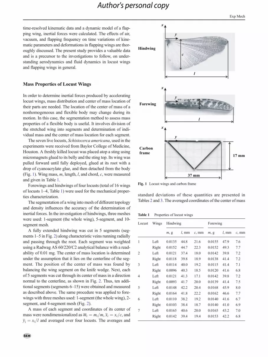
The seven live locusts, Schistocerca americana, used in theexperiments were received from Baylor College of Medicine,Houston. A freshly killed locust was placed atop a sting usingmicromagnets glued to its belly and the sting top. Its wing waspulled forward until fully deployed, glued at its root with adrop of cyanoacrylate glue, and then detached from the body(Fig. 1). Wing mass,m, length, l, and chord, c, were measuredand given in Table 1.
Forewings and hindwings of four locusts (total of 16 wingsof locusts 1–4, Table 1) were used for the mechanical proper-ties characterization.
The segmentation of a wing into mesh of different topologyand density influences the accuracy of the determination ofinertial forces. In the investigation of hindwings, three mesheswere used: 1-segment (the whole wing), 5-segment, and 10-segment mesh.
A fully extended hindwing was cut in 5 segments (seg-ments 1–5 in Fig. 2) along characteristic veins running radiallyand passing through the root. Each segment was weightedusing a Radwag AS 60/220/C2 analytical balance with a read-ability of 0.01 mg. The center of mass location is determinedunder the assumption that it lies on the centerline of the seg-ment. The position of the center of mass was found bybalancing the wing segment on the knife wedge. Next, eachof 5 segments was cut through its center of mass in a directionnormal to the centerline, as shown in Fig. 2. Thus, ten addi-tional segments (segments 6–15) were obtained and measuredas described above. The same procedure was applied to fore-wings with three meshes used: 1-segment (the whole wing), 2-segment, and 4-segment mesh (Fig. 2).
A mass of each segment and coordinates of its center ofmass were nondimensionalized as mi ¼ mi=m, xi ¼ xi=c, andyi ¼ xi=l and averaged over four locusts. The averages and
standard deviations of these quantities are presented inTables 2 and 3. The averaged coordinates of the center of mass
Fig. 1 Locust wings and carbon frame
Table 1 Properties of locust wings
Locust Wings Hindwing Forewing
m, g l, mm c, mm m, g l, mm c, mm
1 Left 0.0135 44.8 21.6 0.0155 47.9 7.6
Right 0.0152 44.7 22.3 0.0152 49.3 7.7
2 Left 0.0121 37.4 18.0 0.0142 39.8 7.2
Right 0.0118 39.8 18.9 0.0138 41.4 7.2
3 Left 0.0114 40.0 19.2 0.0115 41.4 7.1
Right 0.0096 40.3 18.5 0.0120 41.6 6.8
4 Left 0.0121 41.3 17.1 0.0142 39.8 7.2
Right 0.0093 41.7 20.0 0.0139 41.4 7.5
5 Left 0.0148 42.2 20.4 0.0168 45.9 8.0
Right 0.0164 41.8 22.2 0.0162 46.6 7.7
6 Left 0.0110 38.2 19.2 0.0140 41.6 6.7
Right 0.0103 38.4 18.7 0.0140 41.0 6.9
7 Left 0.0165 40.6 20.0 0.0165 43.2 7.0
Right 0.0142 39.4 19.4 0.0153 42.2 6.8
Exp Mech
Author's personal copy