joint waterproofing for watertight concrete systems & white
TRANSCRIPT
joint waterproofingfor watertight ConCrete SyStemS & white Box ConCeptS

joint waterproofing for watertight ConCrete SyStemS and white Box ConCeptS
The authordr rainer hohmann is professor of Building physics at the University of applied Sciences in dortmund, germany. he is a member of the "Building and roof waterproofing" Committee of experts for the diBt¹, the din² Committee for din 18197 "Sealing of joints in concrete with waterstops" and din 18541 "thermoplastic waterstops for sealing joints in in-situ concrete", the dafStb³ Committee "water-im-permeable structures made from concrete" and the dBV4 working groups for "injection hose systems and swellable profiles for construction joints" plus "high-quality base-ment construction". 1 diBt = german Centre of Competence in Civil engineering2 din = german institute for Standardisation 3 dafStb = german Committee for reinforced Concrete4 dBV = german Society for Concrete and Construction technology
editorSika Services agtüffenwies 16Ch-8048 Zurüch
LayoutSika Services agCorporate marketing Service
© 2014 by Sika agall rights reserved
edition 2014
Disclaimer: the information, and, in particular, the recommendations relating to the application and end-use of Sika products, are given in good faith based on Sika's current knowledge and experience of the products when properly stored, handled and installed under normal conditions in accordance with Sika's recommenda-tions. in practice, the differences in materials, substrates and actual site conditions are such that no warranty in respect of merchantability or of fitness for a particular purpose, nor any liability arising out of any legal relationship whatsoever, can be inferred either from this information, or from any written recommendations, or from any other advice offered. the user of the product must confirm the product's suitability for the intended application and purpose. Sika reserves the right to change the properties of its products. the proprietary rights of third parties must be observed. all orders are accepted subject to our current terms and conditions of sale and delivery. Users must always refer to the most recent local product data Sheet for the product concerned, copies of which will be supplied on request.
Additional information from the authorthe solutions and examples described in this book are carefully researched, but no warranty on the part of the author in respect of use of the solutions presented can be inferred. the constraints are so variable that the reader must carefully examine whether examples and solutions shown can also be applied to their project. in the event of damage, use of the solutions presented is not a basis for any right of recourse against the author. this book also contains extracts from drawings, tables and graphics from the publication "hohmann, r.: joint Sealing in watertight Concrete Structures. Stuttgart, fraunhofer irB Verlag, 2011“. these extracts are not necessarily or specifically marked.
3joint waterproofing
watertight ConCrete SyStemS & white Box ConCeptS
foreword
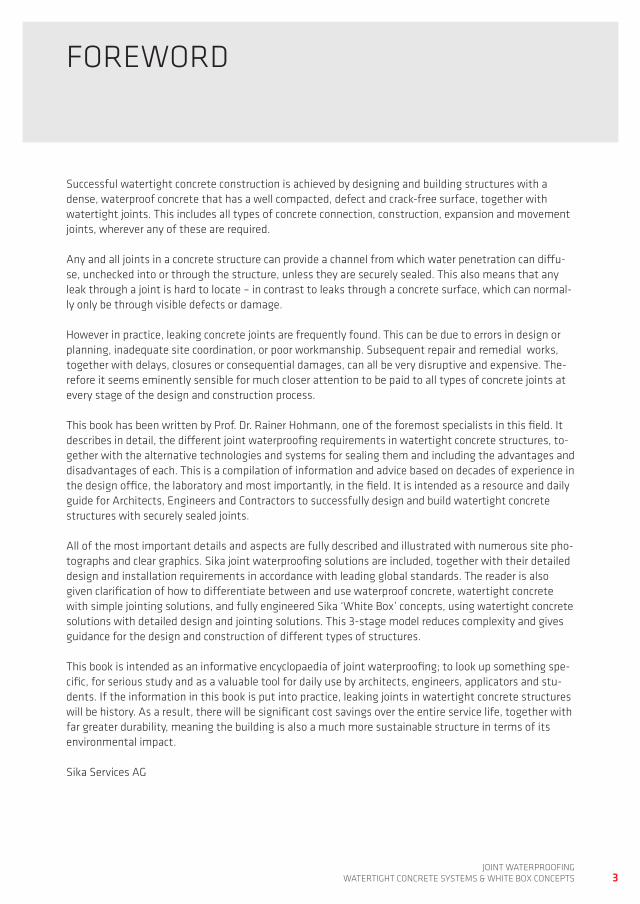
Successful watertight concrete construction is achieved by designing and building structures with a dense, waterproof concrete that has a well compacted, defect and crack-free surface, together with watertight joints. this includes all types of concrete connection, construction, expansion and movement joints, wherever any of these are required.
any and all joints in a concrete structure can provide a channel from which water penetration can diffu-se, unchecked into or through the structure, unless they are securely sealed. this also means that any leak through a joint is hard to locate – in contrast to leaks through a concrete surface, which can normal-ly only be through visible defects or damage.
however in practice, leaking concrete joints are frequently found. this can be due to errors in design or planning, inadequate site coordination, or poor workmanship. Subsequent repair and remedial works, together with delays, closures or consequential damages, can all be very disruptive and expensive. the-refore it seems eminently sensible for much closer attention to be paid to all types of concrete joints at every stage of the design and construction process.
this book has been written by prof. dr. rainer hohmann, one of the foremost specialists in this field. it describes in detail, the different joint waterproofing requirements in watertight concrete structures, to-gether with the alternative technologies and systems for sealing them and including the advantages and disadvantages of each. this is a compilation of information and advice based on decades of experience in the design office, the laboratory and most importantly, in the field. it is intended as a resource and daily guide for architects, engineers and Contractors to successfully design and build watertight concrete structures with securely sealed joints.
all of the most important details and aspects are fully described and illustrated with numerous site pho-tographs and clear graphics. Sika joint waterproofing solutions are included, together with their detailed design and installation requirements in accordance with leading global standards. the reader is also given clarification of how to differentiate between and use waterproof concrete, watertight concrete with simple jointing solutions, and fully engineered Sika ‘white Box’ concepts, using watertight concrete solutions with detailed design and jointing solutions. this 3-stage model reduces complexity and gives guidance for the design and construction of different types of structures.
this book is intended as an informative encyclopaedia of joint waterproofing; to look up something spe-cific, for serious study and as a valuable tool for daily use by architects, engineers, applicators and stu-dents. if the information in this book is put into practice, leaking joints in watertight concrete structures will be history. as a result, there will be significant cost savings over the entire service life, together with far greater durability, meaning the building is also a much more sustainable structure in terms of its environmental impact.
Sika Services ag
4joint waterproofingwatertight ConCrete SyStemS & white Box ConCeptS
Content
Foreword 3
Content 4
1 Introduction 7
2 Terminology, definitions and principles 9
2.1 Sika waterproof Concrete 102.2 Sika watertight Concrete Systems 132.2.1 what is a Sika watertight Concrete System? 132.2.2 design with Sika watertight Concrete Systems 142.3 the Sika white Box Concept 182.3.1 what is the Sika white Box Concept? 182.2.3 Construction with Sika watertight Concrete Systems 182.3.2 design with the Sika white Box Concept 202.3.2.1 design considerations 202.3.2.2 Crack management and design 202.3.2.3 Structural design principles 242.3.3 joints and penetrations 262.4 Construction with Sika watertight concrete systems and Sika white box concepts 27
3 Joint waterproofing for concrete structures 31
3.1 Concrete joint types and basic rules for joint design 313.1.1 Construction joints and concrete sections 333.1.2 movement or expansion joints 333.1.3 Connection joints 343.1.4 Controlled crack induced joints in walls 353.2 guidelines for joint design and waterproofing 36
4 Review of joint waterproofing systems for concrete structures 39
4.1 waterproofing movement / expansion joints 404.2 waterproofing of construction joints 414.3 waterproofing of connection joints 424.4 waterproofing of controlled crack induced joints 43
5 Waterstops / waterbars 44
5.1 waterstopping waterbar materials 515.1.1 pVC-p waterbars 515.1.2 pVC-p/nBr waterbars 535.1.3 thermoplastic polyolefine tpo waterstops 555.1.3.1 westec® polyethylene (pe) waterbars 555.1.3.2 ethylene Vinyl acetate (eVa) waterbars for drinking water contact 57
5joint waterproofing
watertight ConCrete SyStemS & white Box ConCeptS
5.2 waterbar forms and profiles 605.3 design principles for joint waterproofing with waterbars 655.4 waterbar - type, form and dimension selection 745.4.1 Selection of pVC-p and pVC-p/nBr expansion and construction joint waterbars 745.4.1.1 Selecting pVC-p waterbars using Sika selection tables 745.4.1.2 Selecting Sika pVC-p waterbars using Crd 775.4.1.3 Selecting pVC-p/nBr waterbars using din 18197 795.4.2 Selecting elastomer waterbars using din 18197 855.5 waterbar jointing and welding technology 915.5.1 general - prefabricated profiles and site produced joints 915.5.2 joint welding technology for thermoplastic waterbars 965.5.2.1 forming a butt joint with a thermostatically controlled welding blade and a simple jig 975.5.2.2 forming a butt joint with the Sg 320 L automatic welding machine 995.5.2.3 forming a weld with a welding axe 1005.5.2.4 Quality assurance for thermoplastic waterbar welding 1015.5.3 jointing technology for tricosal elastomer waterbars 1045.6 handling of waterbar systems on site 1065.6.1 transport and storage of waterbars 1065.6.2 installation of the waterbars / waterstop system 1075.6.3 Concreting and concrete compaction 1105.6.4 protection of waterbars after installation 1105.6.5 inspection and documentation 113
6 Uncoated metal sheet joint waterstops 114
7 Combined construction joint waterbars (KAB) 116
7.1 waterproofing principle, materials and scope of application 1167.2 jointing technology for KaB profiles and joints on site 1207.2.1 jointing technology and forms for KaB profile 1207.2.2 joints and connections of KaB profiles on site 1207.3 jointing technology for KaB profiles and joints on site 123
8 Swellable profiles and sealants for joint waterproofing 125
8.1 Swellable joint sealing products and their uses 1258.2 requirements for swellable products 1308.3 installation and handling on site 1328.3.1 Storage of swellable products 1328.3.2 installation of swellable profiles 1328.3.3 protection against premature swelling 1338.3.4 inspection before concreting 1348.3.5 Casting-in of swellable profiles 134
9 Injection hose systems 135
9.1 injection hose systems and their uses 1359.2 Structure and function of the Sikafuko®Vt and Sikafuko®eco-1 injection hose systems 1379.2.1 Sikafuko® Vt 1379.2.2 Sikafuko® eco-1 1399.3 injection materials for grouting injection hoses 1409.4 installation and handling on site 1419.5 grouting injection hose systems 1449.6 documentation 145
6joint waterproofingwatertight ConCrete SyStemS & white Box ConCeptS
10 Over-banding joint sealing systems 146
10.1 Sikadur-Combiflex® Sg system – materials, properties and applications 14610.2 Storage of Sikadur-Combiflex®Sg system 14810.3 jointing technology for the Sikadur-Combiflex® membrane 14810.4 installation of Sikadur-Combiflex®Sg 149
11 Crack inducing sealing tubes 151
12 Crack inducing bars 154
13 Clamped flange expansion joint seals 155
14 Joint waterproofing in bunds and secondary containment structures 160
15 Repair of cracks and leaking joints 164
15.1 Sealing of cracks 16415.1.1 Crack grouting through injection ports / packers 16415.1.2 Sealing of cracks with Sikadur-Combiflex® Sg 16515.2 repair of leaking construction joints 16615.2.1 repair of leaking construction joints by injection through packers 16615.2.2 grouting leaking construction joints through an injection hose system 16715.2.3 Sealing of leaking construction joints with an over-banding membrane system 16715.3 repairing leaking expansion joints 168
16 Bibliography 173
7joint waterproofing
watertight ConCrete SyStemS & white Box ConCeptS
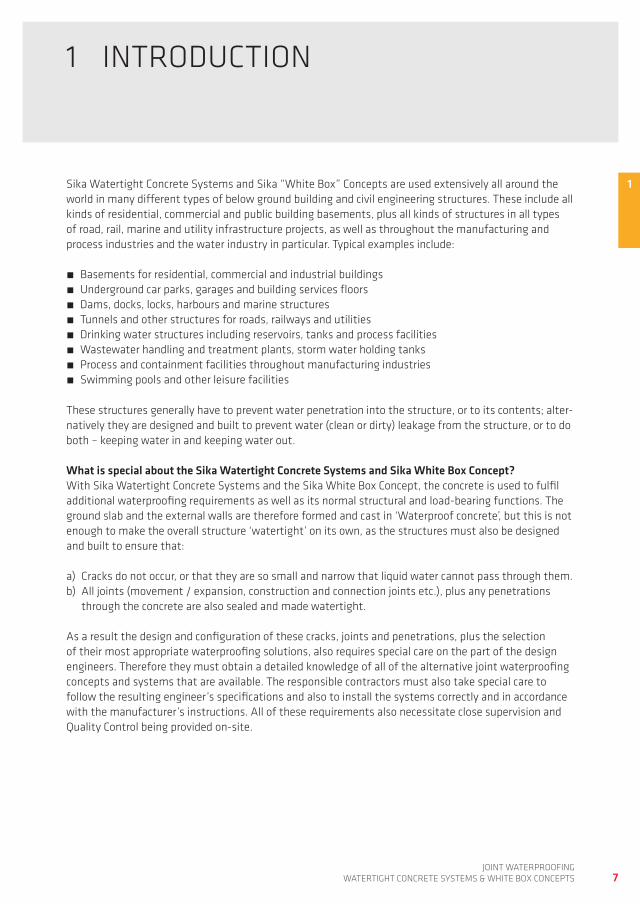
1Sika watertight Concrete Systems and Sika “white Box” Concepts are used extensively all around the world in many different types of below ground building and civil engineering structures. these include all kinds of residential, commercial and public building basements, plus all kinds of structures in all types of road, rail, marine and utility infrastructure projects, as well as throughout the manufacturing and process industries and the water industry in particular. typical examples include:
Basements for residential, commercial and industrial buildings Underground car parks, garages and building services floors dams, docks, locks, harbours and marine structures tunnels and other structures for roads, railways and utilities drinking water structures including reservoirs, tanks and process facilities wastewater handling and treatment plants, storm water holding tanks process and containment facilities throughout manufacturing industries Swimming pools and other leisure facilities
these structures generally have to prevent water penetration into the structure, or to its contents; alter-natively they are designed and built to prevent water (clean or dirty) leakage from the structure, or to do both – keeping water in and keeping water out.
What is special about the Sika Watertight Concrete Systems and Sika White Box Concept?with Sika watertight Concrete Systems and the Sika white Box Concept, the concrete is used to fulfil additional waterproofing requirements as well as its normal structural and load-bearing functions. the ground slab and the external walls are therefore formed and cast in ‘waterproof concrete’, but this is not enough to make the overall structure ‘watertight’ on its own, as the structures must also be designed and built to ensure that: a) Cracks do not occur, or that they are so small and narrow that liquid water cannot pass through them. b) all joints (movement / expansion, construction and connection joints etc.), plus any penetrations
through the concrete are also sealed and made watertight.
as a result the design and configuration of these cracks, joints and penetrations, plus the selection of their most appropriate waterproofing solutions, also requires special care on the part of the design engineers. therefore they must obtain a detailed knowledge of all of the alternative joint waterproofing concepts and systems that are available. the responsible contractors must also take special care to follow the resulting engineer’s specifications and also to install the systems correctly and in accordance with the manufacturer’s instructions. all of these requirements also necessitate close supervision and Quality Control being provided on-site.
1 introdUCtion
8joint waterproofingwatertight ConCrete SyStemS & white Box ConCeptS
the alternative joint waterproofing systems that are available for use with Sika watertight Concrete Systems and the Sika white Box Concept are discussed in more detail later in this book particularly with reference to the most important considerations of:
how do these different types of joint waterproofing concepts and systems work? what performance requirements must they meet and what limitations do they have? what criteria must be considered when selecting and dimensioning these joint waterproofing systems? what specific considerations and detailing solutions are required during the design and the overall construction works, in order to correctly and safely accommodate the joint waterproofing systems?
how are the joint waterproofing systems installed correctly?
initially the reader is therefore also given a brief overview of watertight concrete construction including the nature and use of Sika waterproof Concrete, Sika watertight Concrete Systems and the Sika white Box Concept, in order to achieve this objective in all types of structures.
Sika WhiteBox Concept
(Crack Management)Full Range Joint
Systems, Design, CostEngineering
Sika Watertight Concrete System(Basic Joint Solutions,
Simple Rules for Construction)
Waterproof Concrete(Concrete Mix, Design, Quality, Aggregates,
Additives, Admixtures, w/c-Ratio)
All Typs ofBasement,Tanks, etc.
Simply, rectangular,
1-storeyBasement
Performance / Application
Com
lexi
ty /
Saf
ety
/ W
ater
tigh
tnes
s
Concrete with high Water Penetrating-
resistance
9joint waterproofing
watertight ConCrete SyStemS & white Box ConCeptS
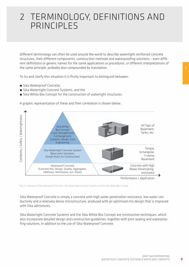
different terminology can often be used around the world to describe watertight reinforced concrete structures, their different components, construction methods and waterproofing solutions – even diffe-rent definitions or generic names for the same applications or procedures, or different interpretations of the same principle, probably also compounded by translation.
to try and clarify this situation it is firstly important to distinguish between:
Sika waterproof Concrete, Sika watertight Concrete Systems, and the Sika white Box Concept for the construction of watertight structures.
a graphic representation of these and their correlation is shown below:.
2 terminoLogy, definitionS and prinCipLeS
Sika waterproof Concrete is simply a concrete with high water penetration resistance, low water con-ductivity and a relatively dense microstructure, produced with an optimised mix design that is improved with Sika admixtures.
Sika watertight Concrete Systems and the Sika white Box Concept are construction techniques, which also incorporate detailed design and construction guidelines, together with joint sealing and waterproo-fing solutions, in addition to the use of Sika waterproof Concrete.
fig. 2.1: overview of Sika waterproof Concrete, Sika watertight Concrete Systems and the Sika white Box Concept
2
10joint waterproofingwatertight ConCrete SyStemS & white Box ConCeptS
Sika watertight Concrete Systems and Sika white Box Concepts differ primarily in their suitability for use in structures with different levels of design complexity and the level of watertightness required:
- typically the standardised Sika watertight Concrete Systems provide solutions and approaches for relatively simple structures such as rectangular tanks and single-storey basements;
- the Sika white Box Concept is principally used to produce more complex watertight concrete structures, which must also be fully designed to international Standards with fully optimised and engineered waterproofing.
Sika waterproof Concrete, Sika watertight Concrete Systems and the Sika white Box Concept are dis-cussed in more detail in Chapters 2.1 – 2.3 of this book.
2.1 SiKa waterproof ConCrete
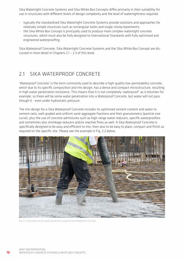
‘waterproof Concrete’ is the term commonly used to describe a high-quality low-permeability concrete, which due to its specific composition and mix design, has a dense and compact microstructure, resulting in high water penetration resistance. this means that it is not completely ‘waterproof’ as is bitumen for example, so there will be some water penetration into a waterproof Concrete, but water will not pass though it - even under hydrostatic pressure. the mix design for a Sika waterproof Concrete includes its optimised cement content and water to cement ratio, well-graded and uniform sand-aggregate fractions and their granulometry (particle size curve), plus the use of concrete admixtures such as high-range water reducers, specific waterproofers and sometimes also shrinkage reducers and/or reactive fines as well. a Sika waterproof Concrete is specifically designed to be easy and efficient to mix, then also to be easy to place, compact and finish as required on the specific site. please see the example in fig. 2.2 below.
fig. 2.2: Concreting with an easily placed and compacted Sika waterproof Concrete
11joint waterproofing
watertight ConCrete SyStemS & white Box ConCeptS
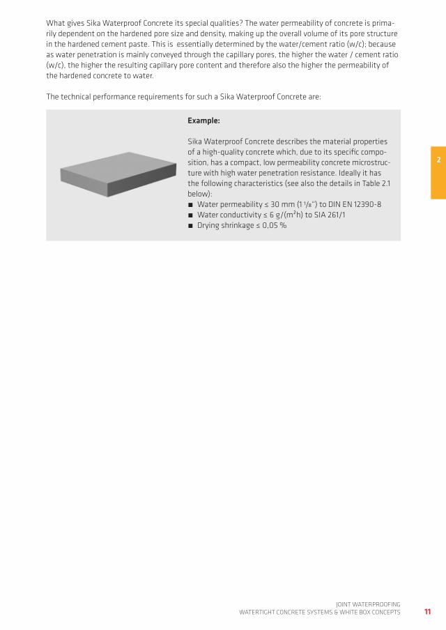
what gives Sika waterproof Concrete its special qualities? the water permeability of concrete is prima-rily dependent on the hardened pore size and density, making up the overall volume of its pore structure in the hardened cement paste. this is essentially determined by the water/cement ratio (w/c); because as water penetration is mainly conveyed through the capillary pores, the higher the water / cement ratio (w/c), the higher the resulting capillary pore content and therefore also the higher the permeability of the hardened concrete to water.
Example:
Sika waterproof Concrete describes the material properties of a high-quality concrete which, due to its specific compo-sition, has a compact, low permeability concrete microstruc-ture with high water penetration resistance. ideally it has the following characteristics (see also the details in table 2.1 below):
water permeability ≤ 30 mm (1 1/8“) to din en 12390-8 water conductivity ≤ 6 g/(m²h) to Sia 261/1 drying shrinkage ≤ 0,05 %
the technical performance requirements for such a Sika waterproof Concrete are:
2
Water pressure(5 bar, 72 h)
Max. water penetrationdepth
24 h
3 mm
Sika Recommendation
Maximum Water Penetration Depth for Watertight Concrete and White Boxes
0.55 0.650.600.30 0.35 0.40 0.45 0.50
50
40
30
20
10
70
60
Wat
er p
enet
rati
on d
epth
[mm
]
w/c-ratio30 6040 50 70 80 90
40
30
20
10
0
qw range
Relative air humidity [%]
Air
tem
pera
ture
[°C]
q d = 50 g/(m
2 x h)
30
20
10
6
Sika Recommendation
12joint waterproofingwatertight ConCrete SyStemS & white Box ConCeptS
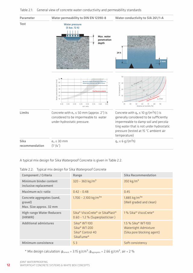
table 2.1: general view of concrete water conductivity and permeability standards
Parameter Water permeability to DIN EN 12390-8 Water conductivity to SIA 261/1-A
Test
Limits Concrete with ew ≤ 50 mm (approx. 2“) is considered to be impermeable to water under hydrostatic pressure.
Concrete with qw ≤ 10 g/(m²h) ) is generally considered to be sufficiently impermeable to damp soil and percola-ting water that is not under hydrostatic pressure (tested at 15 °C ambient air temperature)
Sika recommendation
ew ≤ 30 mm (1 1/8“)
qw ≤ 6 g/(m²h)
a typical mix design for Sika waterproof Concrete is given in table 2.2.
table 2.2: typical mix design for Sika waterproof Concrete
Component / Criteria Range Sika Recommendation
Minimum binder content inclusive replacement
320 – 360 kg/m³ 350 kg/m³
Maximum w/c-ratio 0.42 – 0.48 0.45
Concrete aggregates (sand, gravel)Max. Size approx. 32 mm
1,700 – 2,100 kg/m³* 1,885 kg/m³* (well graded and clean)
High-range Water Reducers (HRWR)
Sika® ViscoCrete® or Sikaplast® 0.60 – 1.2 % (Superplasticiser )
1 % Sika® ViscoCrete®
Additional admixtures Sika® wt-100 Sika® wt-200 Sika® Control 40 Sikafume®
1.5 % Sika® wt-100watertight admixture (Sika pore blocking agent)
Minimum consistence S 3 Soft consistency
* mix design calculation: ρcement = 3.15 g/cm³; ρaggregates = 2.66 g/cm³, air = 2 %
13joint waterproofing
watertight ConCrete SyStemS & white Box ConCeptS
to reduce restraint stresses and therefore the risk of resultant cracking in a structure, it also makes sen-se to use other relevant concrete technologies, techniques and practise. therefore in addition to using an optimised water : cement ratio, particle size / aggregate grading curve, together with permeability reducing concrete admixtures and additives (such as high-range water reducers, waterproofing admixtu-res, shrinkage reducers and reactive fines), it can also be helpful to:
Use cements with low hydration heat development Limit the total cement paste volume (with cement replacement material) Use optimised / low fresh concrete temperatures
to give the concrete optimum workability, placing and compaction characteristics, the fresh consistency should also generally be en 12350-2 Class S3 or softer.
note: further information on all aspects of concrete technology can be found in the Sika Concrete hand-book [9].
2.2 SiKa watertight ConCrete SyStemS
2.2.1 WHAT IS A SIKA WATERTIgHT CONCRETE SySTEM?
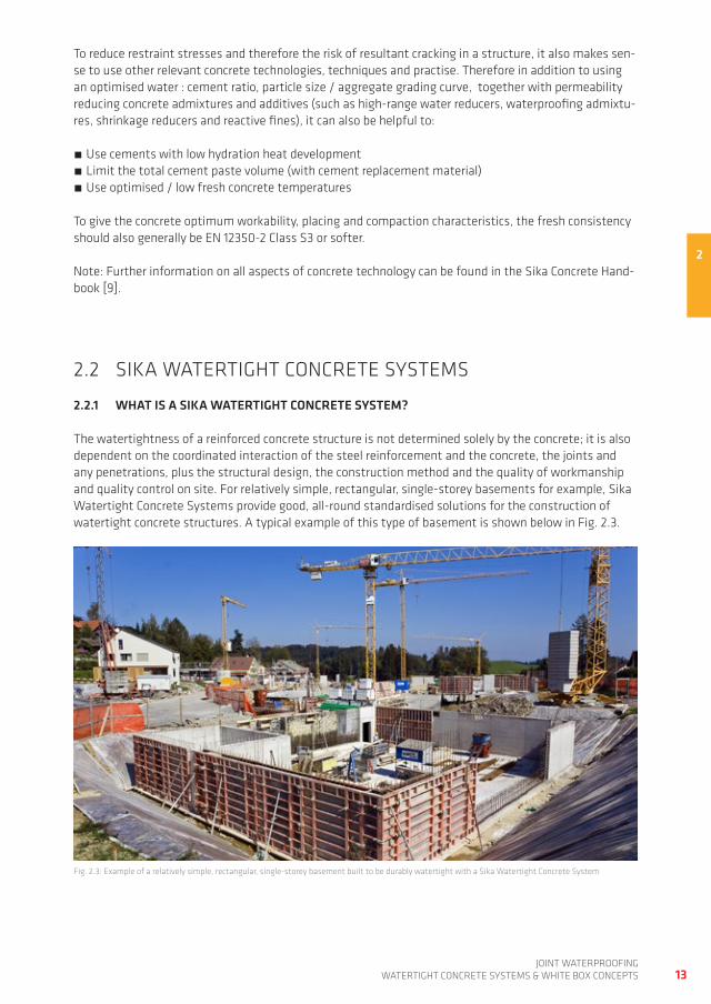
the watertightness of a reinforced concrete structure is not determined solely by the concrete; it is also dependent on the coordinated interaction of the steel reinforcement and the concrete, the joints and any penetrations, plus the structural design, the construction method and the quality of workmanship and quality control on site. for relatively simple, rectangular, single-storey basements for example, Sika watertight Concrete Systems provide good, all-round standardised solutions for the construction of watertight concrete structures. a typical example of this type of basement is shown below in fig. 2.3.
fig. 2.3: example of a relatively simple, rectangular, single-storey basement built to be durably watertight with a Sika watertight Concrete System
2
14joint waterproofingwatertight ConCrete SyStemS & white Box ConCeptS
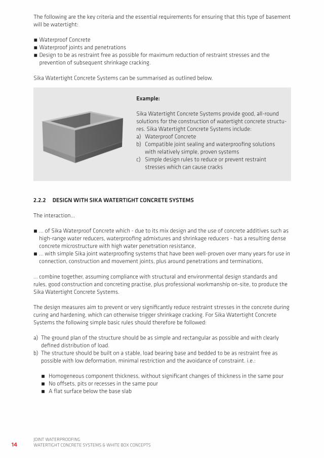
Example:
Sika watertight Concrete Systems provide good, all-round solutions for the construction of watertight concrete structu-res. Sika watertight Concrete Systems include:a) waterproof Concreteb) Compatible joint sealing and waterproofing solutions with relatively simple, proven systems c) Simple design rules to reduce or prevent restraint stresses which can cause cracks
2.2.2 DESIgN WITH SIKA WATERTIgHT CONCRETE SySTEMS
the interaction…
... of Sika waterproof Concrete which - due to its mix design and the use of concrete additives such as high-range water reducers, waterproofing admixtures and shrinkage reducers - has a resulting dense concrete microstructure with high water penetration resistance,
… with simple Sika joint waterproofing systems that have been well-proven over many years for use in connection, construction and movement joints, plus around penetrations and terminations,
... combine together, assuming compliance with structural and environmental design standards and rules, good construction and concreting practise, plus professional workmanship on-site, to produce the Sika watertight Concrete Systems.
the design measures aim to prevent or very significantly reduce restraint stresses in the concrete during curing and hardening, which can otherwise trigger shrinkage cracking. for Sika watertight Concrete Systems the following simple basic rules should therefore be followed:
a) the ground plan of the structure should be as simple and rectangular as possible and with clearly defined distribution of load.
b) the structure should be built on a stable, load bearing base and bedded to be as restraint free as possible with low deformation, minimal restriction and the avoidance of constraint. i.e.:
homogeneous component thickness, without significant changes of thickness in the same pour no offsets, pits or recesses in the same pour a flat surface below the base slab
the following are the key criteria and the essential requirements for ensuring that this type of basement will be watertight:
waterproof Concrete waterproof joints and penetrations design to be as restraint free as possible for maximum reduction of restraint stresses and the prevention of subsequent shrinkage cracking.
Sika watertight Concrete Systems can be summarised as outlined below.
15joint waterproofing
watertight ConCrete SyStemS & white Box ConCeptS
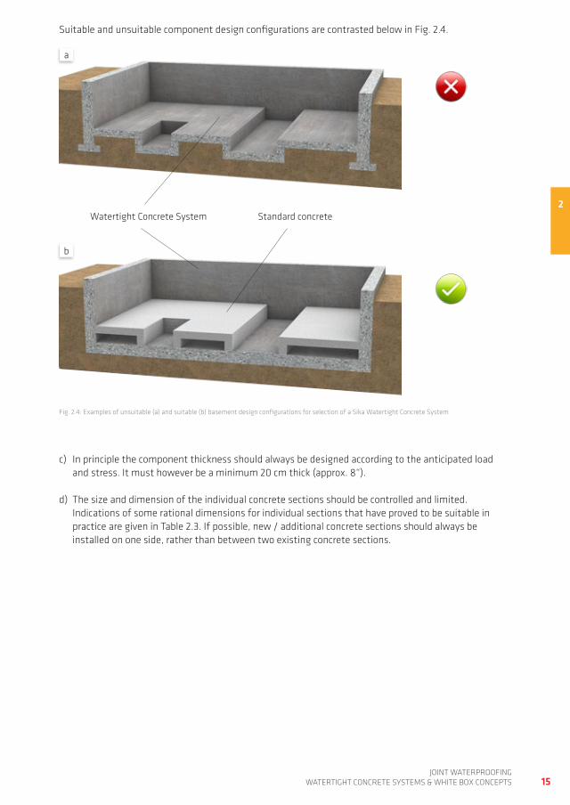
fig. 2.4: examples of unsuitable (a) and suitable (b) basement design configurations for selection of a Sika watertight Concrete System
Suitable and unsuitable component design configurations are contrasted below in fig. 2.4.
c) in principle the component thickness should always be designed according to the anticipated load and stress. it must however be a minimum 20 cm thick (approx. 8“).
d) the size and dimension of the individual concrete sections should be controlled and limited. indications of some rational dimensions for individual sections that have proved to be suitable in practice are given in table 2.3. if possible, new / additional concrete sections should always be installed on one side, rather than between two existing concrete sections.
2
a
b
watertight Concrete System Standard concrete
≤ 100 m²(approx. 1100 ft²)
≤ 100 m²(approx. 1100 ft²)
≤ 100 m²(approx. 1100 ft²)
≤ 100 m²(approx. 1100 ft²)
≤ 100 m²(approx. 1100 ft²)
16joint waterproofingwatertight ConCrete SyStemS & white Box ConCeptS
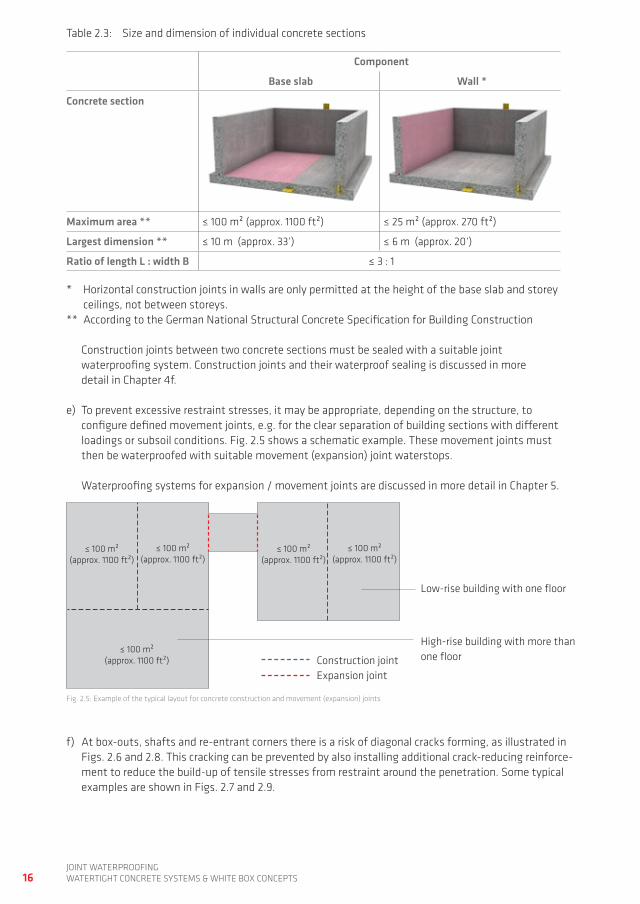
fig. 2.5: example of the typical layout for concrete construction and movement (expansion) joints
Construction joints between two concrete sections must be sealed with a suitable joint waterproofing system. Construction joints and their waterproof sealing is discussed in more detail in Chapter 4f.
e) to prevent excessive restraint stresses, it may be appropriate, depending on the structure, to configure defined movement joints, e.g. for the clear separation of building sections with different loadings or subsoil conditions. fig. 2.5 shows a schematic example. these movement joints must then be waterproofed with suitable movement (expansion) joint waterstops. waterproofing systems for expansion / movement joints are discussed in more detail in Chapter 5.
Construction jointexpansion joint
high-rise building with more than one floor
Low-rise building with one floor
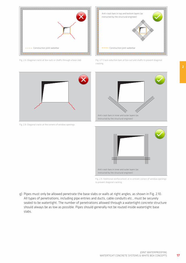
f) at box-outs, shafts and re-entrant corners there is a risk of diagonal cracks forming, as illustrated in figs. 2.6 and 2.8. this cracking can be prevented by also installing additional crack-reducing reinforce-ment to reduce the build-up of tensile stresses from restraint around the penetration. Some typical examples are shown in figs. 2.7 and 2.9.
table 2.3: Size and dimension of individual concrete sections
Component
Base slab Wall *
Concrete section
Maximum area ** ≤ 100 m² (approx. 1100 ft²) ≤ 25 m² (approx. 270 ft²)
Largest dimension ** ≤ 10 m (approx. 33‘) ≤ 6 m (approx. 20‘)
Ratio of length L : width B ≤ 3 : 1
* horizontal construction joints in walls are only permitted at the height of the base slab and storey ceilings, not between storeys.** according to the german national Structural Concrete Specification for Building Construction
17joint waterproofing
watertight ConCrete SyStemS & white Box ConCeptS
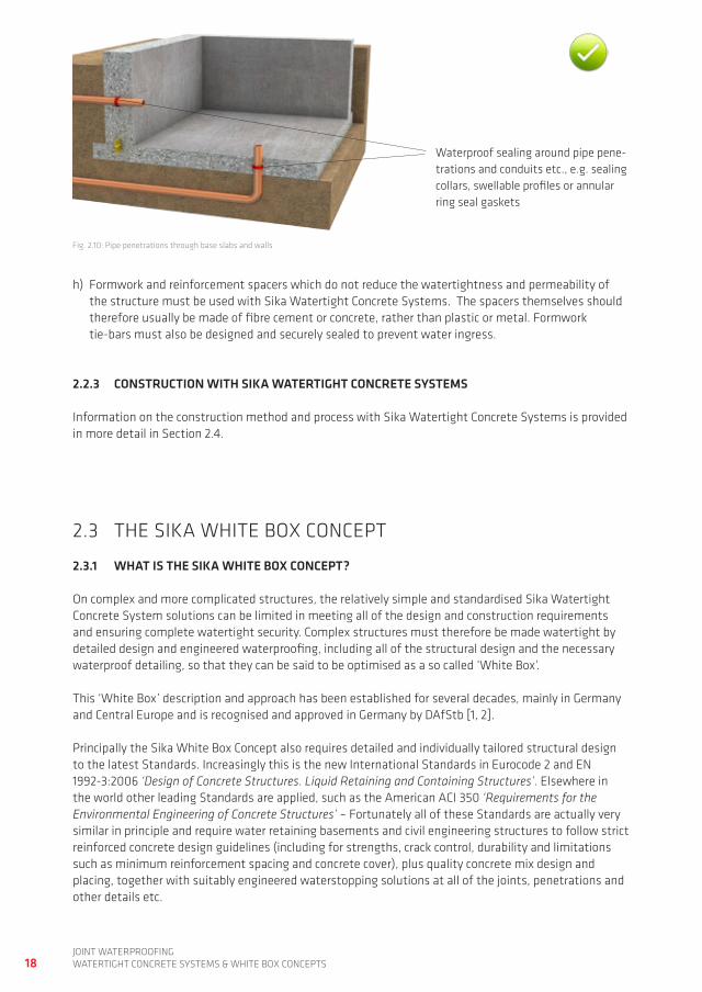
g) pipes must only be allowed penetrate the base slabs or walls at right angles, as shown in fig. 2.10. all types of penetrations, including pipe entries and ducts, cable conduits etc., must be securely sealed to be watertight. the number of penetrations allowed through a watertight concrete structure should always be as low as possible. pipes should generally not be routed inside watertight base slabs.
fig. 2.6: diagonal cracks at box-outs or shafts through a base slab fig. 2.7: Crack reduction bars at box-out and shafts to prevent diagonal cracking
fig. 2.8: diagonal cracks at the corners of window openings
fig. 2.9: additional reinforcement at re-entrant corners of window openings to prevent diagonal cracking
2
Construction joint waterbar Construction joint waterbar
anti-crack bars in top and bottom layers (as instructed by the structural engineer)
anti-crack bars in inner and outer layers (as instructed by the structural engineer)
anti-crack bars in inner and outer layers (as instructed by the structural engineer)
18joint waterproofingwatertight ConCrete SyStemS & white Box ConCeptS
2.3 the SiKa white Box ConCept
2.3.1 WHAT IS THE SIKA WHITE BOx CONCEPT?
on complex and more complicated structures, the relatively simple and standardised Sika watertight Concrete System solutions can be limited in meeting all of the design and construction requirements and ensuring complete watertight security. Complex structures must therefore be made watertight by detailed design and engineered waterproofing, including all of the structural design and the necessary waterproof detailing, so that they can be said to be optimised as a so called ‘white Box’.
this ‘white Box’ description and approach has been established for several decades, mainly in germany and Central europe and is recognised and approved in germany by dafStb [1, 2].
principally the Sika white Box Concept also requires detailed and individually tailored structural design to the latest Standards. increasingly this is the new international Standards in eurocode 2 and en 1992-3:2006 ‘Design of Concrete Structures. Liquid Retaining and Containing Structures’. elsewhere in the world other leading Standards are applied, such as the american aCi 350 ‘Requirements for the Environmental Engineering of Concrete Structures’ – fortunately all of these Standards are actually very similar in principle and require water retaining basements and civil engineering structures to follow strict reinforced concrete design guidelines (including for strengths, crack control, durability and limitations such as minimum reinforcement spacing and concrete cover), plus quality concrete mix design and placing, together with suitably engineered waterstopping solutions at all of the joints, penetrations and other details etc.
2.2.3 CONSTRUCTION WITH SIKA WATERTIgHT CONCRETE SySTEMS
information on the construction method and process with Sika watertight Concrete Systems is provided in more detail in Section 2.4.
h) formwork and reinforcement spacers which do not reduce the watertightness and permeability of the structure must be used with Sika watertight Concrete Systems. the spacers themselves should therefore usually be made of fibre cement or concrete, rather than plastic or metal. formwork tie-bars must also be designed and securely sealed to prevent water ingress.
fig. 2.10: pipe penetrations through base slabs and walls
waterproof sealing around pipe pene-trations and conduits etc., e.g. sealing collars, swellable profiles or annular ring seal gaskets
19joint waterproofing
watertight ConCrete SyStemS & white Box ConCeptS
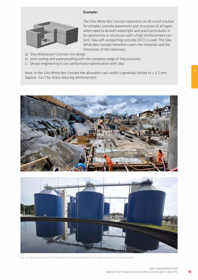
Example:
the Sika white Box Concept represents an all-round solution for complex concrete basements and structures of all types, which need to be both watertight and practical to build i.e. for geometries or structures with a high reinforcement con-tent, Sika self-compacting concrete (SCC) is used. the Sika white Box Concept therefore covers the materials and the interaction of the necessary:
a) Sika waterproof Concrete mix design b) joint sealing and waterproofing with the complete range of Sika solutions c) design engineering & cost performance optimisation with Sika
note: in the Sika white Box Concept the allowable crack width is generally limited to < 0.2 mm (approx. 1/128“) by stress reducing reinforcement.
fig. 2.11: typical examples of the Sika white Box Concept being used for watertight construction on major projects
2
20joint waterproofingwatertight ConCrete SyStemS & white Box ConCeptS
2.3.2 DESIgN WITH THE SIKA WHITE BOx CONCEPT
2.3.2.1 deSign ConSiderationS
professional design and construction of high quality watertight concrete structures is a challenge which requires the engineer to have in-depth technical knowledge and experience. design for the Sika white Box Concept must always include:
defining the structural design (minimum joints, avoiding restraint and shrinkage cracks, limiting required crack widths or using induced cracks and engineering waterproofing) and the waterproofing concept (internal / external barriers or integral etc.).
Selecting and optimising the concrete mix design, placement method, compaction and finishing techniques.
Selecting and specifying the concrete components sizes and their reinforcement dimensions, plus its spacing, pattern and positioning, so that this will also allow the correct installation of the specified joint waterproofing systems and the specified concrete mix and consistence.
defining the concrete pour schedule, including the precise positioning and dimensions of the construc-tion joints.
defining all of the other joint details (movement / expansion, connection / isolation and including the use of controlled crack inducement sections), plus all penetrations and their waterproofing solutions, including at joints and other details within the joint waterproofing systems themselves.
Cracks are a normal feature in the construction of reinforced concrete structures and can be hard to pre-vent even with careful design, planning and workmanship. good crack management is therefore a critical requirement to ensure the watertightness of Sika white Box structures. Crack width must therefore be restricted to a dimension at which water inflow cannot occur. most of the relevant Standards stipulate 0.2 mm (approx. 1/128“) as the maximum width to be permitted. if wider cracks or water-bearing separa-tion cracks occur for any reason, then they must also be professionally and durably sealed.
2.3.2.2 CraCK management and deSign
the design engineer has the option of several design approaches with the Sika white Box Concept. these include:
a) preventing shrinkage cracks by avoiding or reducing restraint stresses (design principle: preventing shrinkage cracks)
b) Limiting shrinkage cracks to a dimension which does not allow water inflow or to crack sizes which can close by autogenous self-healing (design principle: allowing shrinkage cracks of limited width)
c) allowing crack widths which can subsequently be sealed to meet the watertightness requirements
with post-construction treatment with Sika surface sealing / crack sealing solutions (design principle: allowing shrinkage cracks and engineering their subsequent waterproofing)
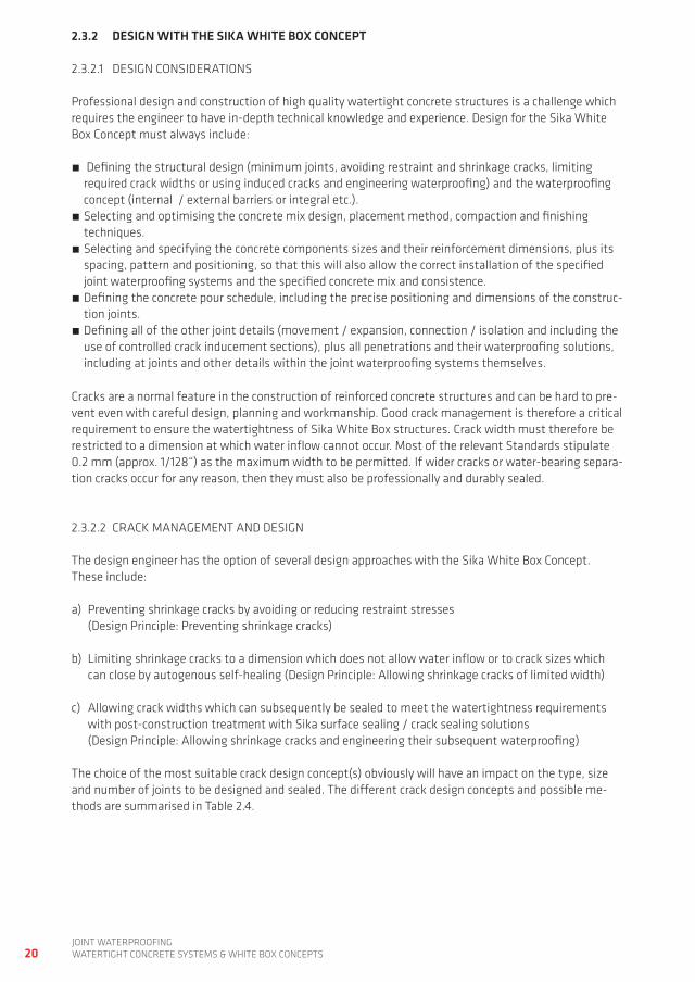
the choice of the most suitable crack design concept(s) obviously will have an impact on the type, size and number of joints to be designed and sealed. the different crack design concepts and possible me-thods are summarised in table 2.4.
21joint waterproofing
watertight ConCrete SyStemS & white Box ConCeptS
table 2.4: Crack design principles for the Sika white Box Concept
Design principle Methods
a Avoiding shrinkage cracks
Structural methods – ground conditions / substructure conditions with
low settlement, i.e. components as free from movement and restraint as possible
– Configuration of controlled crack inducement sections
– Configuration of defined movement / expansion joints
minimum reinforce-ment, multiple joints
Concrete technology methods – Cement and concrete mix with low heat develop-
ment – Controlling the fresh concrete temperature
installation methods – definition of suitable concrete sections – weather-dependent choice of protective measures
and curing methods
b Allowing shrinkage cracks of limited width 1), 2), 3)
– full restraint but allowing shrinkage cracking with crack width control
– additional closely aligned reinforcement against restraint
– Crack width control
additional reinforce-ment, minimum joints
c Allowing shrinkage cracks and enginee-ring post-sealing to waterproof them 3)
– no additional non-structural reinforcement for restraint and no additional joints
– water-penetrable shrinkage cracks are post-sea-led to waterproof them, e.g. by surface filling or crack injection
minimum reinforce-ment, minimum joints
1) Before opening for use or before the start of any fit-out2) if atmospheric Co2 cannot enter the crack (e.g. due to protective coatings), or if lime-dissolving carbo-
nic acid (i.e. from soft water – low ph < 6) is present in the water, or if there is a significant change in crack width, the self-healing process may be disrupted or prevented.
3) the means of post-sealing the cracks, e.g. by surface filling or crack injection, must always be pre-planned and scheduled as part of the normal works to complete the project. this method also requi-res ensuring long-term access to the relevant surfaces.
2
22joint waterproofingwatertight ConCrete SyStemS & white Box ConCeptS
it is particularly important that two engineering terms are fully and correctly understood in relation to the design and crack management required for the Sika white Box Concept:
a) Crack width control generally additional closely aligned crack prevention reinforcement against restraint is a design element of the Sika white Box Concept. this is in order to limit shrinkage crack widths to a maximum size, which means that any cracks that do occur will not negatively affect either the structures water impermeability, or the overall durability of the structure. therefore the structure will normally be designed and built so that the maximum crack width is ≤ 0.2 mm (approx. 1/128“). this additional steel makes the reinforcement content higher than is structurally necessary and therefore the total reinforcement pattern and content have to be carefully optimised by the responsible Structural engineer. for specific structures or members, the design principles "avoiding shrinkage cracks" or "allowing shrinkage cracks and engineering their waterproofing by surface filling / crack injection" can be an alternative to the concept "allowing shrinkage cracks of limited width". the autogenous self-healing of any cracks that do form is also important for this concept.
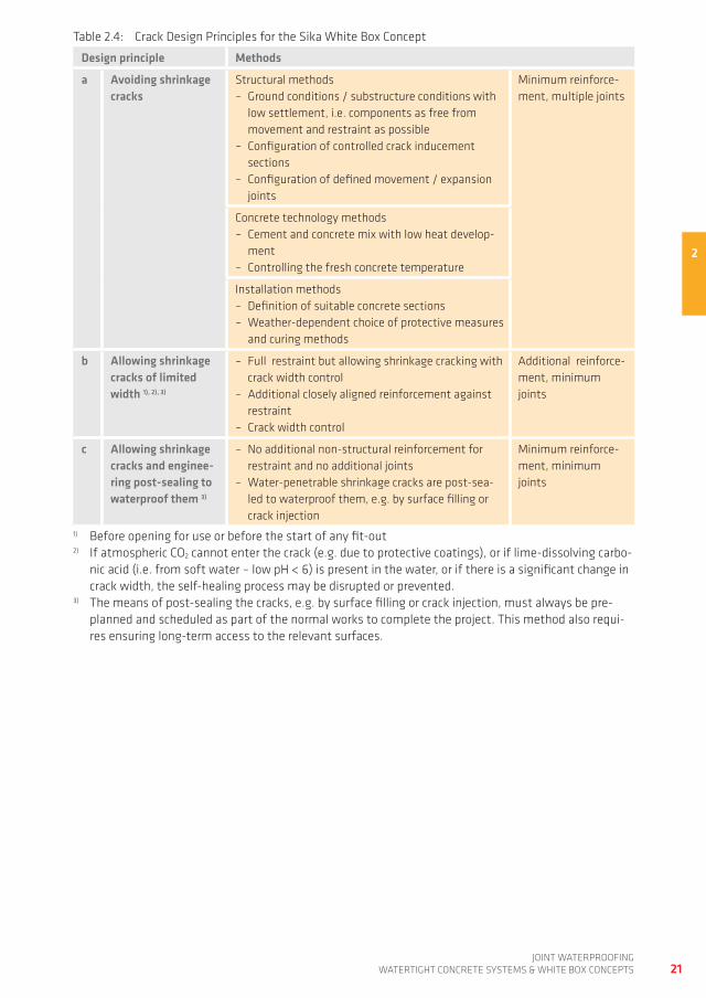
b) Self-healing of cracks Under certain conditions self-healing (also known as autogenous healing) can take place in cracks of limited size in which pore-water is present, which also effectively seals the crack, provided there is an absence of tensile stresses. this self-healing is based on the following process:
the crack fills with very fine loose particles from the concrete matrix and soluble materials dissol-ved in the pore water
Crystalline calcium carbonate (CaCo3) is then formed and deposited from the pore liquid as a solid in the crack, eventually this process can seal the crack very effectively. fig. 2.12 shows an example of a crack sealed by this self-healing process.
fig. 2.12: Self-healing of limited sized cracks in concrete
23joint waterproofing
watertight ConCrete SyStemS & white Box ConCeptS
2
the key question then is “when can cracks be expected to self-heal by this process?” the conditions required for this to take place are summarised as:
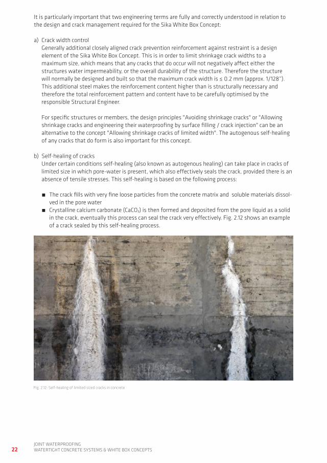
Limited crack width. dependent on the water pressure, the crack widths in table 2.5 below must not be exceeded if water ingress is to be stopped and the cracks sealed by the self-healing process.
no tensile stresses should be imposed on the area, so that there is no movement in the cracks. the water flow rate in the crack is low (pressure gradient limited, see also the information in table 2.5 below).
the groundwater must contain no acidic lime dissolving materials e.g. not containing humic acid from soft water, or carbonic acid (h2Co3) from dissolved salts, dissolved material content ≤ 40 mg/l and ph ≥ 5.5.
Carbon dioxide (Co2) in the atmosphere must be able to reach the crack.
in addition to the conditions listed above, this self-healing effect can also be promoted by using so-cal-led ‘active’ crystalline growth type of concrete waterproofing admixtures such as Sika® wt 200.
table 2.5: permitted shrinkage crack widths wcal, if water ingress is to be stopped by self-healing (according to [1, 2])
Pressure gradient
Calculated crack widthwcal
≤ 10 0.20 mm 0.008“
> 10 to ≤ 20 0.15 mm 0.006“
> 15 to ≤ 25 0.10 mm 0.004“
the example in fig. 2.13 shows how to determine the maximum permitted crack width wcal to utilise the self-healing approach for any cracks that do occur:
hb
hw
hb = 0.3 m(approx. 1.64") hw = 4.0 m
(approx. 13.1")
Example:
from the water pressure hw = 4.0 m (approx. 13.1‘) and the concrete component thickness hb = 0.5 m (approx. 1.64‘), the pressure gradient i can be calculated:
i =4,00 m
= 8 or i =13,1‘
= 80,50 m 1,64‘
this gives the mathematical value of the crack width wcal from table 2.5.wcal = 0.20 mm or wcal = 0.008”
fig. 2.13: determination of the maximum permitted shrinkage crack widths at which self-healing can still take place (typical example)
i =hw
hb
24joint waterproofingwatertight ConCrete SyStemS & white Box ConCeptS
2.3.2.3 StrUCtUraL deSign prinCipLeS
to prevent restraint stresses and the resultant shrinkage cracks as far as possible, certain design princip-les have to be followed with the Sika white Box Concept, including:
a) the concrete element’s thickness specification must always meet the structural requirements and in general this should be a minimum of 25 cm (approx. 10“). it is important to note that restraint stress grows as this thickness increases and more reinforcement will be required to limit the crack widths.
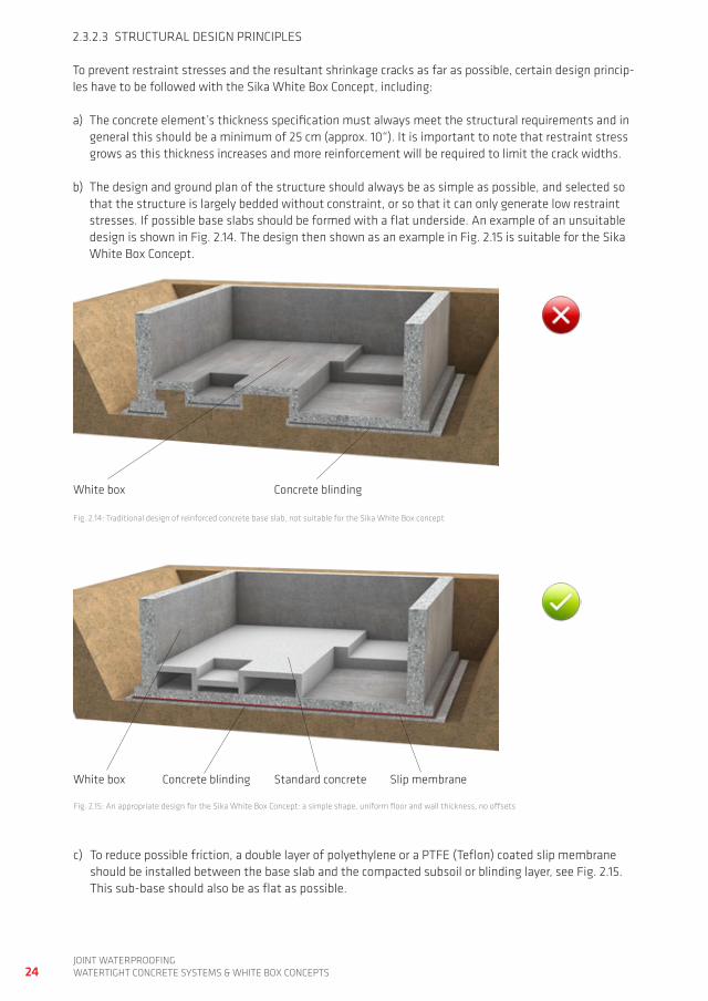
b) the design and ground plan of the structure should always be as simple as possible, and selected so that the structure is largely bedded without constraint, or so that it can only generate low restraint stresses. if possible base slabs should be formed with a flat underside. an example of an unsuitable design is shown in fig. 2.14. the design then shown as an example in fig. 2.15 is suitable for the Sika white Box Concept.
fig. 2.14: traditional design of reinforced concrete base slab, not suitable for the Sika white Box concept
fig. 2.15: an appropriate design for the Sika white Box Concept: a simple shape, uniform floor and wall thickness, no offsets
c) to reduce possible friction, a double layer of polyethylene or a ptfe (teflon) coated slip membrane should be installed between the base slab and the compacted subsoil or blinding layer, see fig. 2.15. this sub-base should also be as flat as possible.
white box
white box Concrete blinding Slip membraneStandard concrete
Concrete blinding
25joint waterproofing
watertight ConCrete SyStemS & white Box ConCeptS
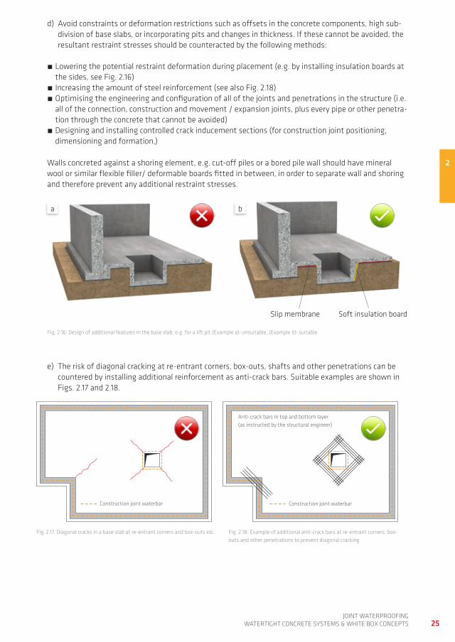
fig. 2.16: design of additional features in the base slab, e.g. for a lift pit (example a): unsuitable, (example b): suitable
2
e) the risk of diagonal cracking at re-entrant corners, box-outs, shafts and other penetrations can be countered by installing additional reinforcement as anti-crack bars. Suitable examples are shown in figs. 2.17 and 2.18.
fig. 2.17: diagonal cracks in a base slab at re-entrant corners and box-outs etc. fig. 2.18: example of additional anti-crack bars at re-entrant corners, box-outs and other penetrations to prevent diagonal cracking
Slip membrane Soft insulation board
Construction joint waterbar
anti-crack bars in top and bottom layer (as instructed by the structural engineer)
Construction joint waterbar
d) avoid constraints or deformation restrictions such as offsets in the concrete components, high sub-division of base slabs, or incorporating pits and changes in thickness. if these cannot be avoided, the resultant restraint stresses should be counteracted by the following methods:
Lowering the potential restraint deformation during placement (e.g. by installing insulation boards at the sides, see fig. 2.16)
increasing the amount of steel reinforcement (see also fig. 2.18) optimising the engineering and configuration of all of the joints and penetrations in the structure (i.e. all of the connection, construction and movement / expansion joints, plus every pipe or other penetra-tion through the concrete that cannot be avoided)
designing and installing controlled crack inducement sections (for construction joint positioning, dimensioning and formation,)
walls concreted against a shoring element, e.g. cut-off piles or a bored pile wall should have mineral wool or similar flexible filler/ deformable boards fitted in between, in order to separate wall and shoring and therefore prevent any additional restraint stresses.
a b
26joint waterproofingwatertight ConCrete SyStemS & white Box ConCeptS
2.3.3 JOINTS AND PENETRATIONS
the position and dimension of joints must be defined and specified as early as possible in the design process by the responsible structural engineer. in principle, all joints should be straight, clean and without offsets. the subdivision of the structure and the necessary joint positioning and dimensions should be as simple as possible. in summary it is necessary to define and specify where all of the:
construction joints movement or expansion joints controlled crack inducement sections connection joints (to dissimilar materials or existing/future structures etc.) penetrations
…..should logically be located. information on each of these different types of joint and their characteri-stics are discussed in detail in Chapter 3 of this book. all of these joints and penetrations must be sealed and made waterproof. joint waterproofing and the different systems available for this purpose are also covered in detail in this book from Chapters 4 – 14.
27joint waterproofing
watertight ConCrete SyStemS & white Box ConCeptS
2.4 ConStrUCtion with SiKa watertight ConCrete SyStemS and SiKa white Box ConCeptS
errors in construction, mainly during concreting, are the most common cause of leaks in concrete struc-tures. therefore special care is always required when placing, compacting and finishing the concrete. the following must be considered during the construction of watertight structures:
a) the reinforcement pattern or layout must be suitable for practical and correct installation and then full compaction of the concrete. with high reinforcement content, it is also advised to incorporate concrete placement holes and vibration gaps so that the concrete can be professionally installed and compacted.
b) to ensure good durability of the reinforced concrete and bond between the concrete and the steel reinforcement, adequate concrete cover over the reinforcement is necessary. in general the minimum cover in watertight construction is ≥ 30 mm (11/8“).
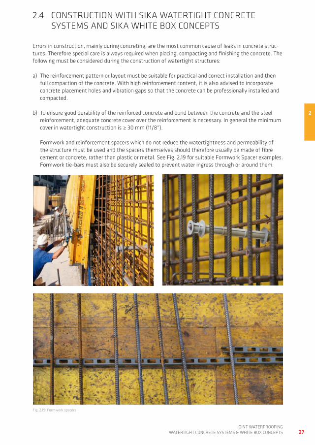
formwork and reinforcement spacers which do not reduce the watertightness and permeability of the structure must be used and the spacers themselves should therefore usually be made of fibre cement or concrete, rather than plastic or metal. See fig. 2.19 for suitable formwork Spacer examples. formwork tie-bars must also be securely sealed to prevent water ingress through or around them.
2
fig. 2.19: formwork spacers
28joint waterproofingwatertight ConCrete SyStemS & white Box ConCeptS
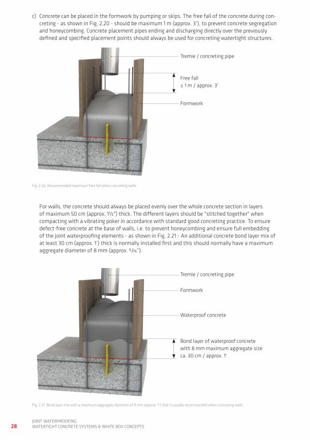
fig. 2.20: recommended maximum free fall when concreting walls
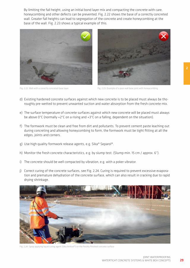
fig. 2.21: Bond layer mix with a maximum aggregate diameter of 8 mm (approx. 1‘) that is usually recommended when concreting walls
for walls, the concrete should always be placed evenly over the whole concrete section in layers of maximum 50 cm (approx. 1½") thick. the different layers should be "stitched together" when compacting with a vibrating poker in accordance with standard good concreting practice. to ensure defect-free concrete at the base of walls, i.e. to prevent honeycombing and ensure full embedding of the joint waterproofing elements - as shown in fig. 2.21 - an additional concrete bond layer mix of at least 30 cm (approx. 1‘) thick is normally installed first and this should normally have a maximum aggregate diameter of 8 mm (approx. 5/16“).
tremie / concreting pipe
formwork
free fall ≤ 1 m / approx. 3'
tremie / concreting pipe
formwork
Bond layer of waterproof concrete with 8 mm maximum aggregate sizeca. 30 cm / approx. 1'
waterproof concrete
c) Concrete can be placed in the formwork by pumping or skips. the free fall of the concrete during con-creting - as shown in fig. 2.20 - should be maximum 1 m (approx. 3‘), to prevent concrete segregation and honeycombing. Concrete placement pipes ending and discharging directly over the previously defined and specified placement points should always be used for concreting watertight structures.
29joint waterproofing
watertight ConCrete SyStemS & white Box ConCeptS
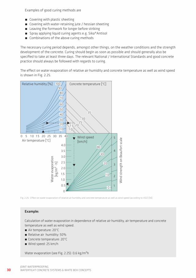
By limiting the fall height, using an initial bond layer mix and compacting the concrete with care, honeycombing and other defects can be prevented. fig. 2.22 shows the base of a correctly concreted wall. greater fall heights can lead to segregation of the concrete and create honeycombing at the base of the wall. fig. 2.23 shows a typical example of this.
fig. 2.22: wall with a correctly concreted base layer fig. 2.23: example of a poor wall base joint with honeycombing
d) existing hardened concrete surfaces against which new concrete is to be placed must always be tho-roughly pre-wetted to prevent unwanted suction and water absorption from the fresh concrete mix.
e) the surface temperature of concrete surfaces against which new concrete will be placed must always be above 0°C (normally +2°C on a rising and +3°C on a falling, dependent on the situation).
f) the formwork must be clean and free from dirt and pollutants. to prevent cement paste leaching out during concreting and allowing honeycombing to form, the formwork must be tight fitting at all the edges, joints and corners.
g) Use high quality formwork release agents, e.g. Sika® Separol®.
h) monitor the fresh concrete characteristics, e.g. by slump test. (Slump min. 15 cm / approx. 6“).
i) the concrete should be well compacted by vibration, e.g. with a poker vibrator.
j) Correct curing of the concrete surfaces, see fig. 2.24. Curing is required to prevent excessive evapora-tion and premature dehydration of the concrete surface, which can also result in cracking due to rapid drying shrinkage.
2
fig. 2.24: Spray applying liquid curing agent (Sika antisol®) on the freshly finished concrete surface
Relative humidity [%] Concrete temperature [°C]
Air temperature [°C]
Wat
er e
vapo
rati
on
[kg/
m²
· h]
Win
d st
reng
th o
n Be
aufo
rt s
cale
9080
70
60
50
40
3020
1 0
100
1 01 5 20
2530
35
40
40
30
0.5
20
1 0
00
4.0
3.5
3.0
2.5
2.0
1.5
1.0
50 1 0 1 5 20 25 30 35
1
2
3
4
5Wind speed [km/h]
30joint waterproofingwatertight ConCrete SyStemS & white Box ConCeptS
examples of good curing methods are
Covering with plastic sheeting Covering with water-retaining jute / hessian sheeting Leaving the formwork for longer before striking Spray applying liquid curing agents e.g. Sika®antisol Combinations of the above curing methods
the necessary curing period depends, amongst other things, on the weather conditions and the strength development of the concrete. Curing should begin as soon as possible and should generally also be specified to take at least three days. the relevant national / international Standards and good concrete practice should always be followed with regards to curing.
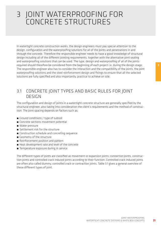
the effect on water evaporation of relative air humidity and concrete temperature as well as wind speed is shown in fig. 2.25.
fig. 2.25: effect on water evaporation of relative air humidity and concrete temperature as well as wind speed (according to VdZ) [10]
Example:
Calculation of water evaporation in dependence of relative air humidity, air temperature and concrete temperature as well as wind speed.
air temperature: 20°C relative air humidity: 50% Concrete temperature: 20°C wind speed: 25 km/h
water evaporation (see fig. 2.25): 0,6 kg/m²h
31joint waterproofing
watertight ConCrete SyStemS & white Box ConCeptS
3 joint waterproofing for ConCrete StrUCtUreS
in watertight concrete construction works, the design engineers must pay special attention to the design, configuration and the waterproofing solutions for all of the joints and penetrations in and through the concrete. therefore the responsible engineer needs to have a good knowledge of structural design including all of the different jointing requirements, together with the alternative joint sealing and waterproofing solutions that can be used. the type, design and waterproofing of all of the joints required should therefore be considered from the beginning of each project i.e. during the design stage. the responsible engineer also has to consider the interaction and the compatibility of the joints, the joint waterproofing solutions and the steel reinforcement design and fixings to ensure that all the selected solutions are fully specified and also importantly, practical to achieve on site.
3.1 ConCrete joint typeS and BaSiC rULeS for joint deSignthe configuration and design of joints in a watertight concrete structure are generally specified by the structural engineer, also taking into consideration the client’s requirements and the method of construc-tion. the joint spacing depends on factors such as:
ground conditions / type of subsoil Concrete sections movement potential water pressure Settlement risk for the structure Construction schedule and concreting sequence geometry of the structure reinforcement position and pattern heat development rate and level of the concrete temperature exposure during in service
the different types of joints are classified as movement or expansion joints, connection joints, construc-tion joints and controlled crack induced joints according to their function. Controlled crack induced joints are often also called dummy, controlled crack or contraction joints. table 3.1 gives a general overview of these different types of joint.
3
32joint waterproofingwatertight ConCrete SyStemS & white Box ConCeptS
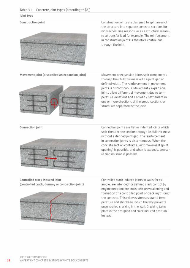
table 3.1: Concrete joint types (according to [8])
Joint type
Construction joint Construction joints are designed to split areas of the structure into separate concrete sections for work scheduling reasons, or as a structural measu-re to transfer load for example. the reinforcement in construction joints is therefore continuous through the joint.
Movement joint (also called an expansion joint) movement or expansion joints split components through their full thickness with a joint gap of defined width. the reinforcement in movement joints is discontinuous. movement / expansion joints allow differential movement due to tem-perature variations and / or load / settlement in one or more directions of the areas, sections or structures separated by the joint.
Connection joint Connection joints are flat or indented joints which split the concrete section through its full thickness without a defined joint gap. the reinforcement in connection joints is discontinuous. when the concrete section contracts, joint movement (joint opening) is possible, and when it expands, pressu-re transmission is possible.
Controlled crack induced joint(controlled crack, dummy or contraction joint)
Controlled crack induced joints in walls for ex-ample, are intended for defined crack control by engineered concrete cross-section weakening and formation of a controlled point of cracking through the concrete. this relieves stresses due to tem-perature and shrinkage, which thereby prevents uncontrolled cracking in the wall. Cracking takes place in the designed and crack induced position instead.
33joint waterproofing
watertight ConCrete SyStemS & white Box ConCeptS
3.1.1 CONSTRUCTION JOINTS AND CONCRETE SECTIONS
Construction joint locations must be specified and these should be in areas under minimal stress. Con-struction joints are engineered to divide longer sections into smaller and separate sections for concrete work scheduling reasons, or as a structural measure to transfer load. Square concrete sections are appropriate. a length to width ratio of the individual concrete sections of L:w < 3:1 (L: length, w: width) should not be exceeded. for walls, concrete sections 6 – 8 m (approx. 20‘– 26‘) in length have proved most suitable. horizontal construction joints in the walls of watertight structures are only permitted at the level of the base slab and storey ceiling, not between storeys. the reinforcement in a construction joint is therefore continuous into the next concrete section.
to counteract restraint stresses as far as possible, the designer should take into account that new concrete sections should be installed on one side of an existing section if possible, and not between two existing sections. restraint on two sides is then replaced by one restraining point without restricting deformation of the concrete section in the other directions. a construction joint between two concrete sections must always be sealed with a suitable joint waterproofing system.
3.1.2 MOvEMENT OR ExPANSION JOINTS
movement joints, which are also known as expansion joints, are designed and positioned to counteract the formation of stresses which could otherwise trigger cracks in the structure. a movement joint divi-des the structure into separate sections, components or structures so that different levels of movement can be absorbed without cracking and damage is prevented. the steel reinforcement is therefore discon-tinuous through a movement joint.
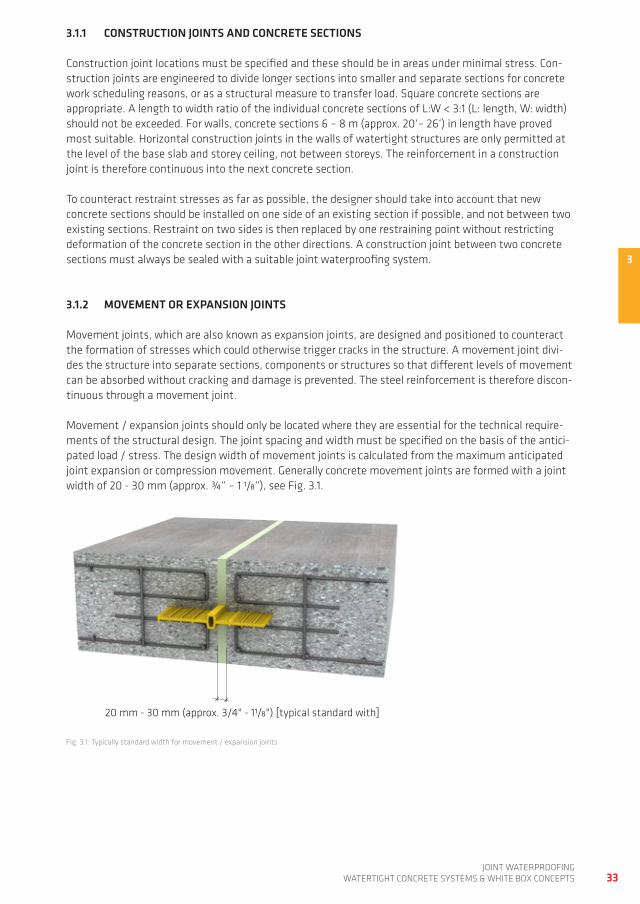
movement / expansion joints should only be located where they are essential for the technical require-ments of the structural design. the joint spacing and width must be specified on the basis of the antici-pated load / stress. the design width of movement joints is calculated from the maximum anticipated joint expansion or compression movement. generally concrete movement joints are formed with a joint width of 20 - 30 mm (approx. ¾“ – 1 1/8“), see fig. 3.1.
fig. 3.1: typically standard width for movement / expansion joints
20 mm - 30 mm (approx. 3/4" - 11/8") [typical standard with]
3
1
234
1
234
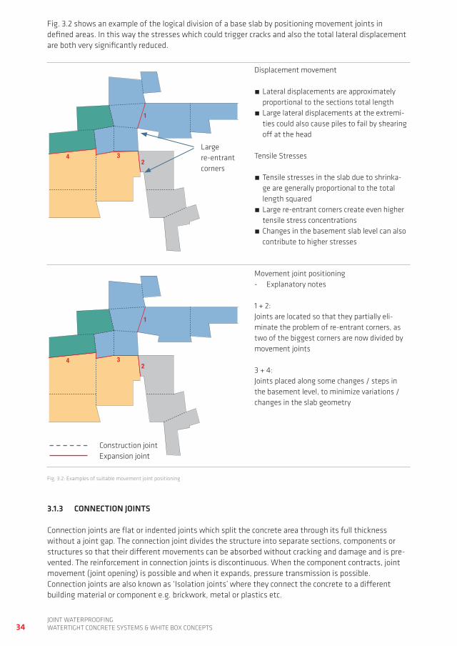
fig. 3.2: examples of suitable movement joint positioning
34joint waterproofingwatertight ConCrete SyStemS & white Box ConCeptS
3.1.3 CONNECTION JOINTS
Connection joints are flat or indented joints which split the concrete area through its full thickness without a joint gap. the connection joint divides the structure into separate sections, components or structures so that their different movements can be absorbed without cracking and damage and is pre-vented. the reinforcement in connection joints is discontinuous. when the component contracts, joint movement (joint opening) is possible and when it expands, pressure transmission is possible. Connection joints are also known as ‘isolation joints’ where they connect the concrete to a different building material or component e.g. brickwork, metal or plastics etc.
fig. 3.2 shows an example of the logical division of a base slab by positioning movement joints in defined areas. in this way the stresses which could trigger cracks and also the total lateral displacement are both very significantly reduced.
Large re-entrant corners
displacement movement
Lateral displacements are approximately proportional to the sections total length
Large lateral displacements at the extremi-ties could also cause piles to fail by shearing off at the head
tensile Stresses
tensile stresses in the slab due to shrinka-ge are generally proportional to the total length squared
Large re-entrant corners create even higher tensile stress concentrations
Changes in the basement slab level can also contribute to higher stresses
Construction joint expansion joint
movement joint positioning- explanatory notes 1 + 2: joints are located so that they partially eli-minate the problem of re-entrant corners, as two of the biggest corners are now divided by movement joints 3 + 4: joints placed along some changes / steps in the basement level, to minimize variations / changes in the slab geometry
35joint waterproofing
watertight ConCrete SyStemS & white Box ConCeptS
3.1.4 CONTROLLED CRACK INDUCED JOINTS IN WALLS
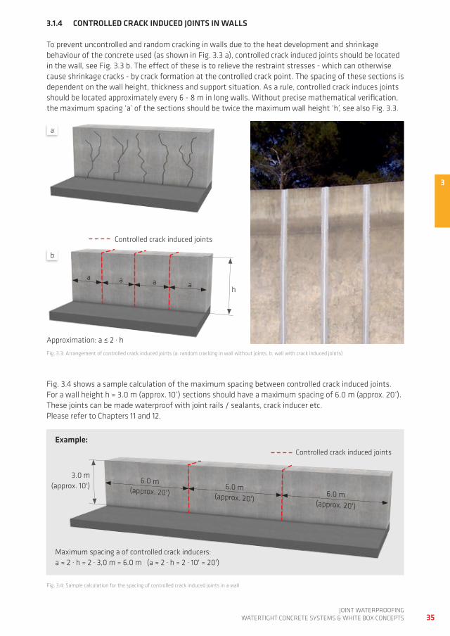
to prevent uncontrolled and random cracking in walls due to the heat development and shrinkage behaviour of the concrete used (as shown in fig. 3.3 a), controlled crack induced joints should be located in the wall, see fig. 3.3 b. the effect of these is to relieve the restraint stresses - which can otherwise cause shrinkage cracks - by crack formation at the controlled crack point. the spacing of these sections is dependent on the wall height, thickness and support situation. as a rule, controlled crack induces joints should be located approximately every 6 - 8 m in long walls. without precise mathematical verification, the maximum spacing ‘a’ of the sections should be twice the maximum wall height ‘h’, see also fig. 3.3.
fig. 3.3: arrangement of controlled crack induced joints (a: random cracking in wall without joints, b: wall with crack induced joints)
fig. 3.4: Sample calculation for the spacing of controlled crack induced joints in a wall
maximum spacing a of controlled crack inducers:a ≈ 2 · h = 2 · 3,0 m = 6.0 m (a ≈ 2 · h = 2 · 10' = 20')
Controlled crack induced joints
3.0 m(approx. 10')
6.0 m(approx. 20')
6.0 m(approx. 20')
6.0 m(approx. 20')
Controlled crack induced joints
h
a a a a
approximation: a ≤ 2 · h
3
fig. 3.4 shows a sample calculation of the maximum spacing between controlled crack induced joints. for a wall height h = 3.0 m (approx. 10‘) sections should have a maximum spacing of 6.0 m (approx. 20‘). these joints can be made waterproof with joint rails / sealants, crack inducer etc. please refer to Chapters 11 and 12.
a
b
Example:
36joint waterproofingwatertight ConCrete SyStemS & white Box ConCeptS
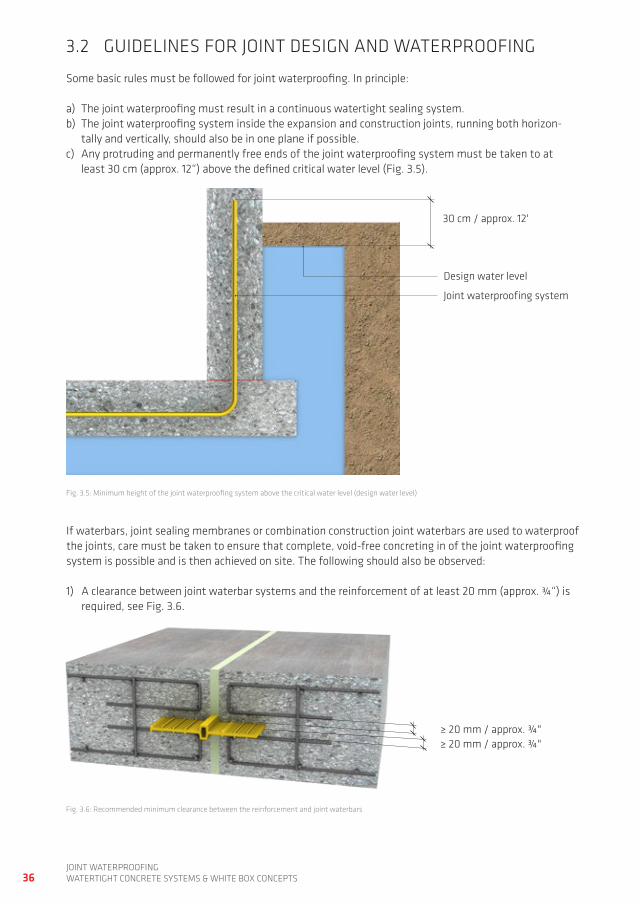
3.2 gUideLineS for joint deSign and waterproofing
Some basic rules must be followed for joint waterproofing. in principle:
a) the joint waterproofing must result in a continuous watertight sealing system. b) the joint waterproofing system inside the expansion and construction joints, running both horizon-
tally and vertically, should also be in one plane if possible. c) any protruding and permanently free ends of the joint waterproofing system must be taken to at
least 30 cm (approx. 12“) above the defined critical water level (fig. 3.5).
fig. 3.5: minimum height of the joint waterproofing system above the critical water level (design water level)
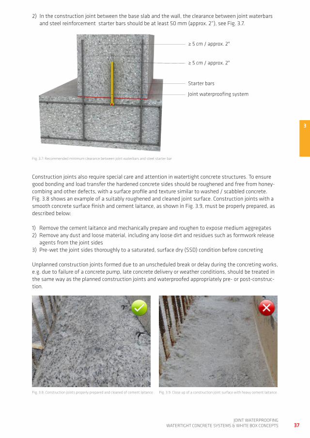
fig. 3.6: recommended minimum clearance between the reinforcement and joint waterbars
if waterbars, joint sealing membranes or combination construction joint waterbars are used to waterproof the joints, care must be taken to ensure that complete, void-free concreting in of the joint waterproofing system is possible and is then achieved on site. the following should also be observed:
1) a clearance between joint waterbar systems and the reinforcement of at least 20 mm (approx. ¾“) is required, see fig. 3.6.
30 cm / approx. 12'
≥ 20 mm / approx. ¾"≥ 20 mm / approx. ¾"
joint waterproofing system
design water level
37joint waterproofing
watertight ConCrete SyStemS & white Box ConCeptS
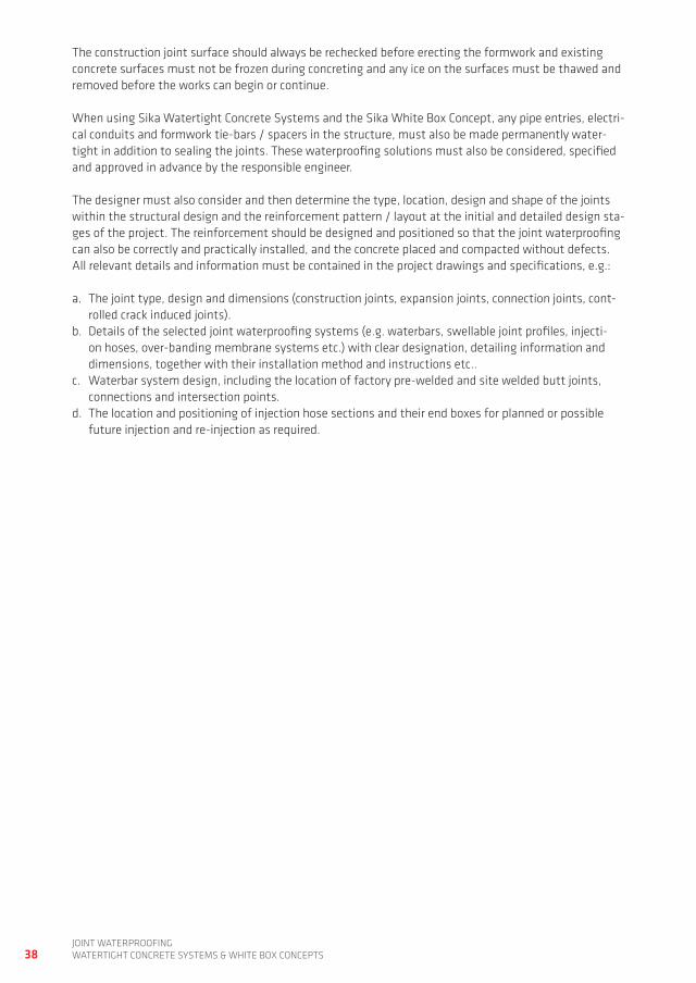
fig. 3.7: recommended minimum clearance between joint waterbars and steel starter bar
Construction joints also require special care and attention in watertight concrete structures. to ensure good bonding and load transfer the hardened concrete sides should be roughened and free from honey-combing and other defects, with a surface profile and texture similar to washed / scabbled concrete. fig. 3.8 shows an example of a suitably roughened and cleaned joint surface. Construction joints with a smooth concrete surface finish and cement laitance, as shown in fig. 3.9, must be properly prepared, as described below:
1) remove the cement laitance and mechanically prepare and roughen to expose medium aggregates2) remove any dust and loose material, including any loose dirt and residues such as formwork release
agents from the joint sides3) pre-wet the joint sides thoroughly to a saturated, surface dry (SSd) condition before concreting
Unplanned construction joints formed due to an unscheduled break or delay during the concreting works, e.g. due to failure of a concrete pump, late concrete delivery or weather conditions, should be treated in the same way as the planned construction joints and waterproofed appropriately pre- or post-construc-tion.
fig. 3.8: Construction joints properly prepared and cleaned of cement laitance
2) in the construction joint between the base slab and the wall, the clearance between joint waterbars and steel reinforcement starter bars should be at least 50 mm (approx. 2“), see fig. 3.7.
fig. 3.9: Close up of a construction joint surface with heavy cement laitance
3
≥ 5 cm / approx. 2"
≥ 5 cm / approx. 2"
Starter bars
joint waterproofing system
38joint waterproofingwatertight ConCrete SyStemS & white Box ConCeptS
the construction joint surface should always be rechecked before erecting the formwork and existing concrete surfaces must not be frozen during concreting and any ice on the surfaces must be thawed and removed before the works can begin or continue.
when using Sika watertight Concrete Systems and the Sika white Box Concept, any pipe entries, electri-cal conduits and formwork tie-bars / spacers in the structure, must also be made permanently water-tight in addition to sealing the joints. these waterproofing solutions must also be considered, specified and approved in advance by the responsible engineer.
the designer must also consider and then determine the type, location, design and shape of the joints within the structural design and the reinforcement pattern / layout at the initial and detailed design sta-ges of the project. the reinforcement should be designed and positioned so that the joint waterproofing can also be correctly and practically installed, and the concrete placed and compacted without defects. all relevant details and information must be contained in the project drawings and specifications, e.g.:
a. the joint type, design and dimensions (construction joints, expansion joints, connection joints, cont-rolled crack induced joints).
b. details of the selected joint waterproofing systems (e.g. waterbars, swellable joint profiles, injecti-on hoses, over-banding membrane systems etc.) with clear designation, detailing information and dimensions, together with their installation method and instructions etc..
c. waterbar system design, including the location of factory pre-welded and site welded butt joints, connections and intersection points.
d. the location and positioning of injection hose sections and their end boxes for planned or possible future injection and re-injection as required.
39joint waterproofing
watertight ConCrete SyStemS & white Box ConCeptS
4 reView of joint waterproofing SyStemS for ConCrete StrUCtUreS
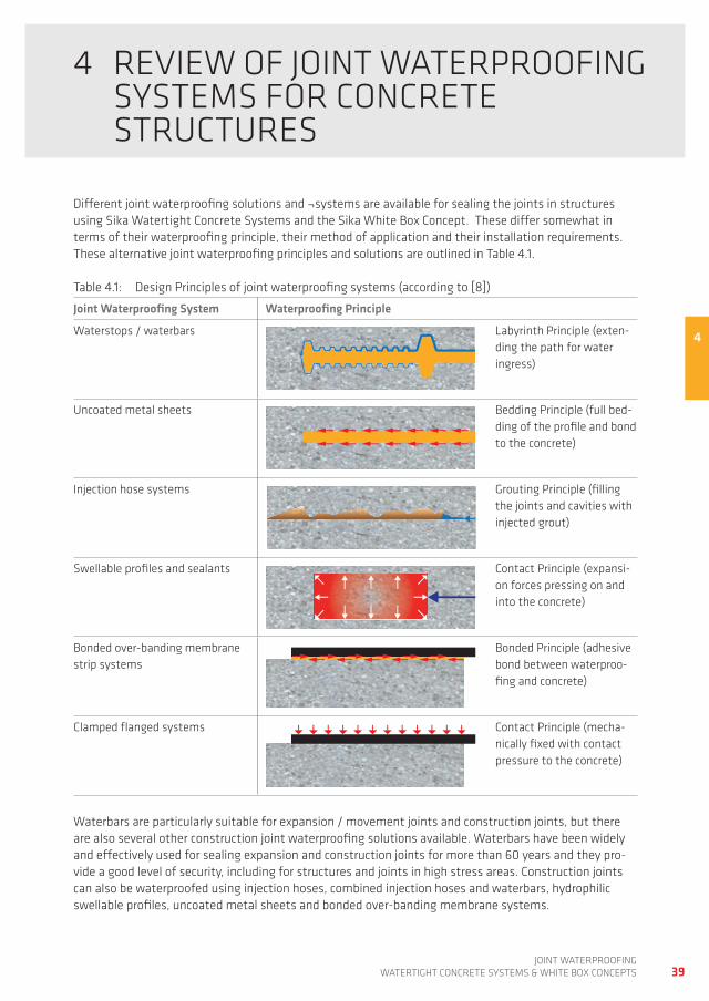
different joint waterproofing solutions and ¬systems are available for sealing the joints in structures using Sika watertight Concrete Systems and the Sika white Box Concept. these differ somewhat in terms of their waterproofing principle, their method of application and their installation requirements. these alternative joint waterproofing principles and solutions are outlined in table 4.1.
table 4.1: design principles of joint waterproofing systems (according to [8])
Joint Waterproofing System Waterproofing Principle
waterstops / waterbars Labyrinth principle (exten-ding the path for water ingress)
Uncoated metal sheets Bedding principle (full bed-ding of the profile and bond to the concrete)
injection hose systems grouting principle (filling the joints and cavities with injected grout)
Swellable profiles and sealants Contact principle (expansi-on forces pressing on and into the concrete)
Bonded over-banding membrane strip systems
Bonded principle (adhesive bond between waterproo-fing and concrete)
Clamped flanged systems Contact principle (mecha-nically fixed with contact pressure to the concrete)
waterbars are particularly suitable for expansion / movement joints and construction joints, but there are also several other construction joint waterproofing solutions available. waterbars have been widely and effectively used for sealing expansion and construction joints for more than 60 years and they pro-vide a good level of security, including for structures and joints in high stress areas. Construction joints can also be waterproofed using injection hoses, combined injection hoses and waterbars, hydrophilic swellable profiles, uncoated metal sheets and bonded over-banding membrane systems.
4
40joint waterproofingwatertight ConCrete SyStemS & white Box ConCeptS
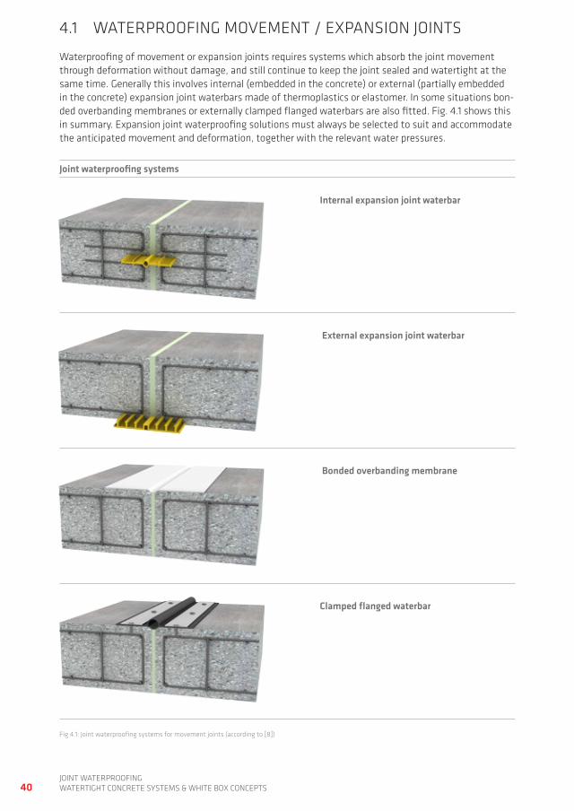
4.1 waterproofing moVement / expanSion jointS
waterproofing of movement or expansion joints requires systems which absorb the joint movement through deformation without damage, and still continue to keep the joint sealed and watertight at the same time. generally this involves internal (embedded in the concrete) or external (partially embedded in the concrete) expansion joint waterbars made of thermoplastics or elastomer. in some situations bon-ded overbanding membranes or externally clamped flanged waterbars are also fitted. fig. 4.1 shows this in summary. expansion joint waterproofing solutions must always be selected to suit and accommodate the anticipated movement and deformation, together with the relevant water pressures.
Joint waterproofing systems
Internal expansion joint waterbar
External expansion joint waterbar
Bonded overbanding membrane
Clamped flanged waterbar
fig 4.1: joint waterproofing systems for movement joints (according to [8])
41joint waterproofing
watertight ConCrete SyStemS & white Box ConCeptS
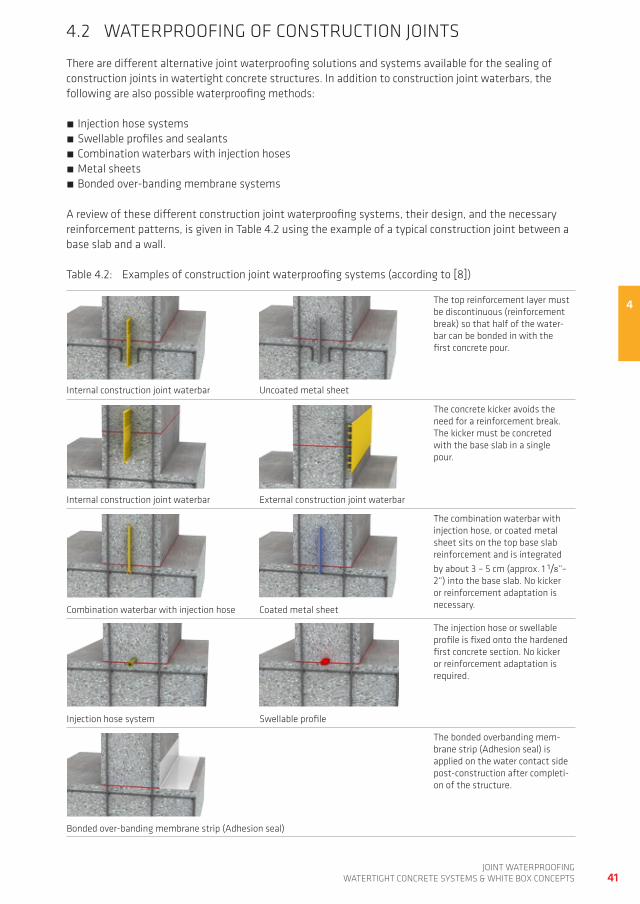
4.2 waterproofing of ConStrUCtion jointS
there are different alternative joint waterproofing solutions and systems available for the sealing of construction joints in watertight concrete structures. in addition to construction joint waterbars, the following are also possible waterproofing methods:
injection hose systems Swellable profiles and sealants Combination waterbars with injection hoses metal sheets Bonded over-banding membrane systems
a review of these different construction joint waterproofing systems, their design, and the necessary reinforcement patterns, is given in table 4.2 using the example of a typical construction joint between a base slab and a wall.
table 4.2: examples of construction joint waterproofing systems (according to [8])
4the top reinforcement layer must be discontinuous (reinforcement break) so that half of the water-bar can be bonded in with the first concrete pour.
the concrete kicker avoids the need for a reinforcement break. the kicker must be concreted with the base slab in a single pour.
the combination waterbar with injection hose, or coated metal sheet sits on the top base slab reinforcement and is integrated by about 3 – 5 cm (approx. 1 1/8“– 2“) into the base slab. no kicker or reinforcement adaptation is necessary.
the injection hose or swellable profile is fixed onto the hardened first concrete section. no kicker or reinforcement adaptation is required.
the bonded overbanding mem-brane strip (adhesion seal) is applied on the water contact side post-construction after completi-on of the structure.
external construction joint waterbar
internal construction joint waterbar Uncoated metal sheet
internal construction joint waterbar
Combination waterbar with injection hose Coated metal sheet
injection hose system Swellable profile
Bonded over-banding membrane strip (adhesion seal)
42joint waterproofingwatertight ConCrete SyStemS & white Box ConCeptS
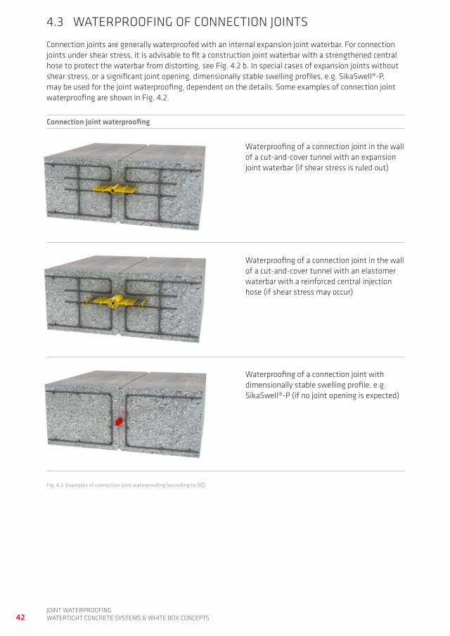
4.3 waterproofing of ConneCtion jointS
Connection joints are generally waterproofed with an internal expansion joint waterbar. for connection joints under shear stress, it is advisable to fit a construction joint waterbar with a strengthened central hose to protect the waterbar from distorting, see fig. 4.2 b. in special cases of expansion joints without shear stress, or a significant joint opening, dimensionally stable swelling profiles, e.g. SikaSwell®-p, may be used for the joint waterproofing, dependent on the details. Some examples of connection joint waterproofing are shown in fig. 4.2.
Connection joint waterproofing
waterproofing of a connection joint in the wall of a cut-and-cover tunnel with an expansion joint waterbar (if shear stress is ruled out)
waterproofing of a connection joint in the wall of a cut-and-cover tunnel with an elastomer waterbar with a reinforced central injection hose (if shear stress may occur)
waterproofing of a connection joint with dimensionally stable swelling profile, e.g. SikaSwell®-p (if no joint opening is expected)
fig. 4.2: examples of connection joint waterproofing (according to [8])
43joint waterproofing
watertight ConCrete SyStemS & white Box ConCeptS
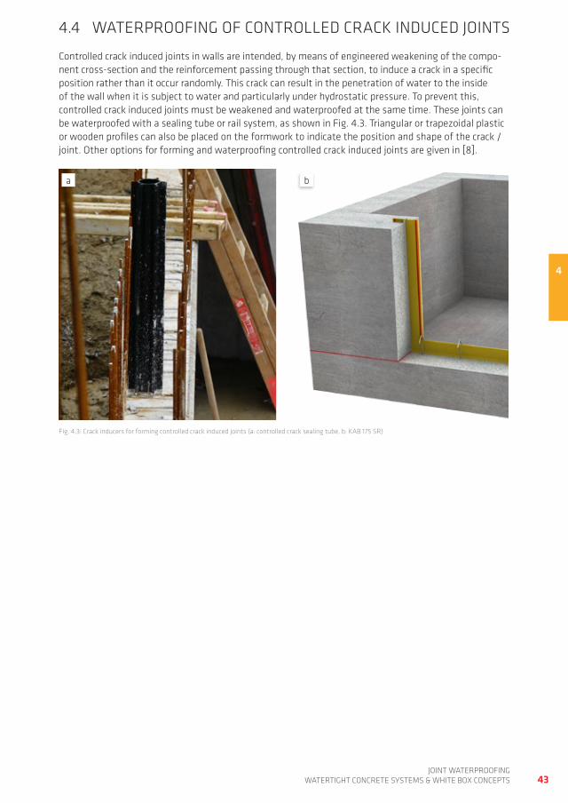
4.4 waterproofing of ControLLed CraCK indUCed jointS
Controlled crack induced joints in walls are intended, by means of engineered weakening of the compo-nent cross-section and the reinforcement passing through that section, to induce a crack in a specific position rather than it occur randomly. this crack can result in the penetration of water to the inside of the wall when it is subject to water and particularly under hydrostatic pressure. to prevent this, controlled crack induced joints must be weakened and waterproofed at the same time. these joints can be waterproofed with a sealing tube or rail system, as shown in fig. 4.3. triangular or trapezoidal plastic or wooden profiles can also be placed on the formwork to indicate the position and shape of the crack / joint. other options for forming and waterproofing controlled crack induced joints are given in [8].
fig. 4.3: Crack inducers for forming controlled crack induced joints (a: controlled crack sealing tube, b: KaB 175 Sr)
4
a b
44joint waterproofingwatertight ConCrete SyStemS & white Box ConCeptS
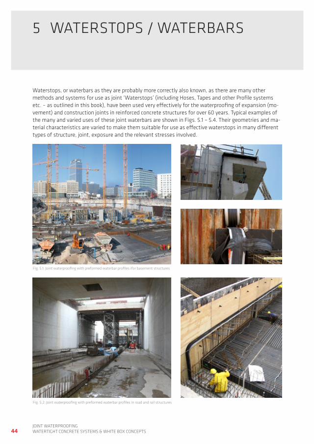
5 waterStopS / waterBarS
waterstops, or waterbars as they are probably more correctly also known, as there are many other methods and systems for use as joint ‘waterstops’ (including hoses, tapes and other profile systems etc. – as outlined in this book), have been used very effectively for the waterproofing of expansion (mo-vement) and construction joints in reinforced concrete structures for over 60 years. typical examples of the many and varied uses of these joint waterbars are shown in figs. 5.1 – 5.4. their geometries and ma-terial characteristics are varied to make them suitable for use as effective waterstops in many different types of structure, joint, exposure and the relevant stresses involved.
fig. 5.1: joint waterproofing with preformed waterbar profiles ifor basement structures
fig. 5.2: joint waterproofing with preformed waterbar profiles in road and rail structures
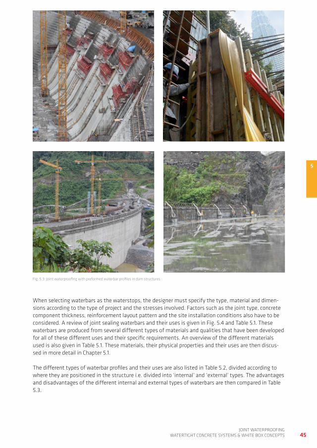
5
45joint waterproofing
watertight ConCrete SyStemS & white Box ConCeptS
when selecting waterbars as the waterstops, the designer must specify the type, material and dimen-sions according to the type of project and the stresses involved. factors such as the joint type, concrete component thickness, reinforcement layout pattern and the site installation conditions also have to be considered. a review of joint sealing waterbars and their uses is given in fig. 5.4 and table 5.1. these waterbars are produced from several different types of materials and qualities that have been developed for all of these different uses and their specific requirements. an overview of the different materials used is also given in table 5.1. these materials, their physical properties and their uses are then discus-sed in more detail in Chapter 5.1.
the different types of waterbar profiles and their uses are also listed in table 5.2, divided according to where they are positioned in the structure i.e. divided into ‘internal’ and ‘external’ types. the advantages and disadvantages of the different internal and external types of waterbars are then compared in table 5.3.
fig. 5.3: joint waterproofing with preformed waterbar profiles in dam structures
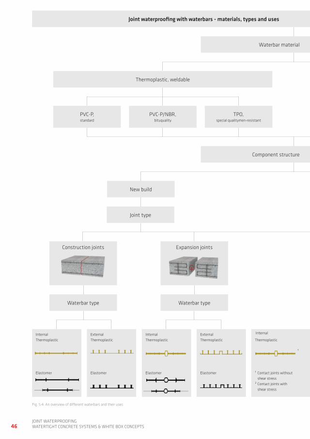
46joint waterproofingwatertight ConCrete SyStemS & white Box ConCeptS
fig. 5.4: an overview of different waterbars and their uses
Joint waterproofing with waterbars - materials, types and uses Joint waterproofing with waterbars - materials, types and uses
waterbar material waterbar material
thermoplastic, weldable
pVC-p, standard
pVC-p/nBr, bituquality
tpo,special qualitymen-resistant
new build
Component structure Component structure
Construction joints expansion joints
internal thermoplastic
elastomer
external thermoplastic
elastomer
internal thermoplastic
elastomer
external thermoplastic
elastomer
thermoplastic
¹
¹ Contact joints without shear stress² Contact joints with shear stress
waterbar type waterbar type
joint type
internal internal
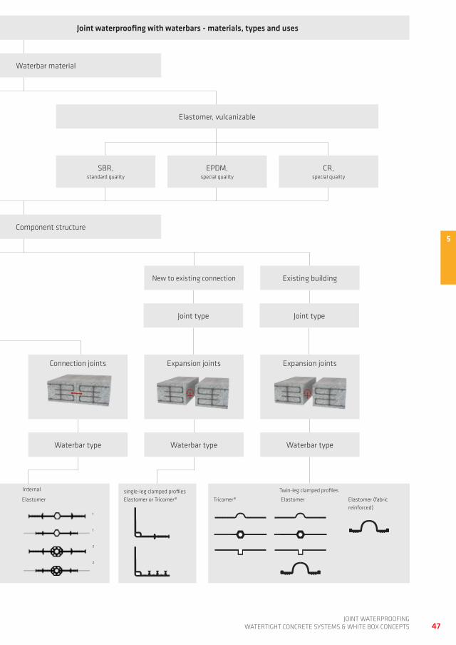
5
47joint waterproofing
watertight ConCrete SyStemS & white Box ConCeptS
Joint waterproofing with waterbars - materials, types and uses Joint waterproofing with waterbars - materials, types and uses
waterbar material waterbar material
elastomer, vulcanizable
Component structure Component structure
new to existing connection
SBr, standard quality
epdm, special quality
Cr, special quality
existing building
tricomer® elastomer elastomer (fabric reinforced)
single-leg clamped profileselastomer or tricomer®thermoplastic
¹
¹ Contact joints without shear stress² Contact joints with shear stress
elastomer
¹
¹
²
²
expansion joints expansion jointsConnection joints
waterbar type waterbar type waterbar type
joint type joint type
twin-leg clamped profilesinternal internal
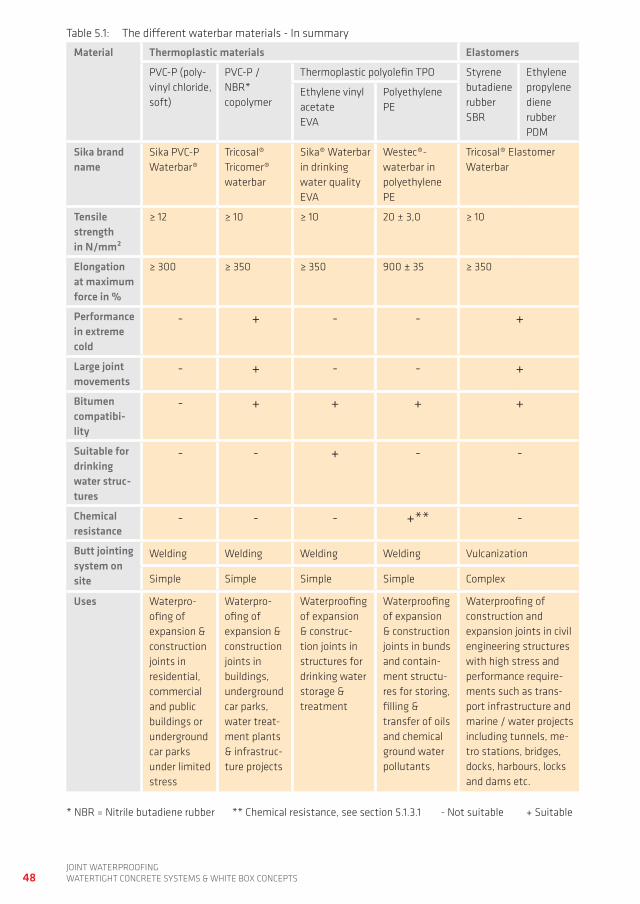
48joint waterproofingwatertight ConCrete SyStemS & white Box ConCeptS
table 5.1: the different waterbar materials - in summary
Material Thermoplastic materials Elastomers
pVC-p (poly-vinyl chloride, soft)
pVC-p / nBr* copolymer
thermoplastic polyolefin tpo Styrene butadiene rubber SBr
ethylene propylene diene rubber pdm
ethylene vinyl acetate eVa
polyethylene pe
Sika brand name
Sika pVC-p waterbar®
tricosal® tricomer® waterbar
Sika® waterbar in drinking water quality eVa
westec®- waterbar in polyethylene pe
tricosal® elastomer waterbar
Tensile strength in N/mm²
≥ 12 ≥ 10 ≥ 10 20 ± 3,0 ≥ 10
Elongation at maximum force in %
≥ 300 ≥ 350 ≥ 350 900 ± 35 ≥ 350
Performance in extreme cold
- + - - +
Large joint movements
- + - - +
Bitumen compatibi-lity
- + + + +
Suitable for drinking water struc-tures
- - + - -
Chemical resistance
- - - +** -
Butt jointing system on site
welding welding welding welding Vulcanization
Simple Simple Simple Simple Complex
Uses waterpro-ofing of expansion & construction joints in residential, commercial and public buildings or underground car parks under limited stress
waterpro-ofing of expansion & construction joints in buildings, underground car parks, water treat-ment plants & infrastruc-ture projects
waterproofing of expansion & construc-tion joints in structures for drinking water storage & treatment
waterproofing of expansion & construction joints in bunds and contain-ment structu-res for storing, filling & transfer of oils and chemical ground water pollutants
waterproofing of construction and expansion joints in civil engineering structures with high stress and performance require-ments such as trans-port infrastructure and marine / water projects including tunnels, me-tro stations, bridges, docks, harbours, locks and dams etc.
* nBr = nitrile butadiene rubber ** Chemical resistance, see section 5.1.3.1 - not suitable + Suitable
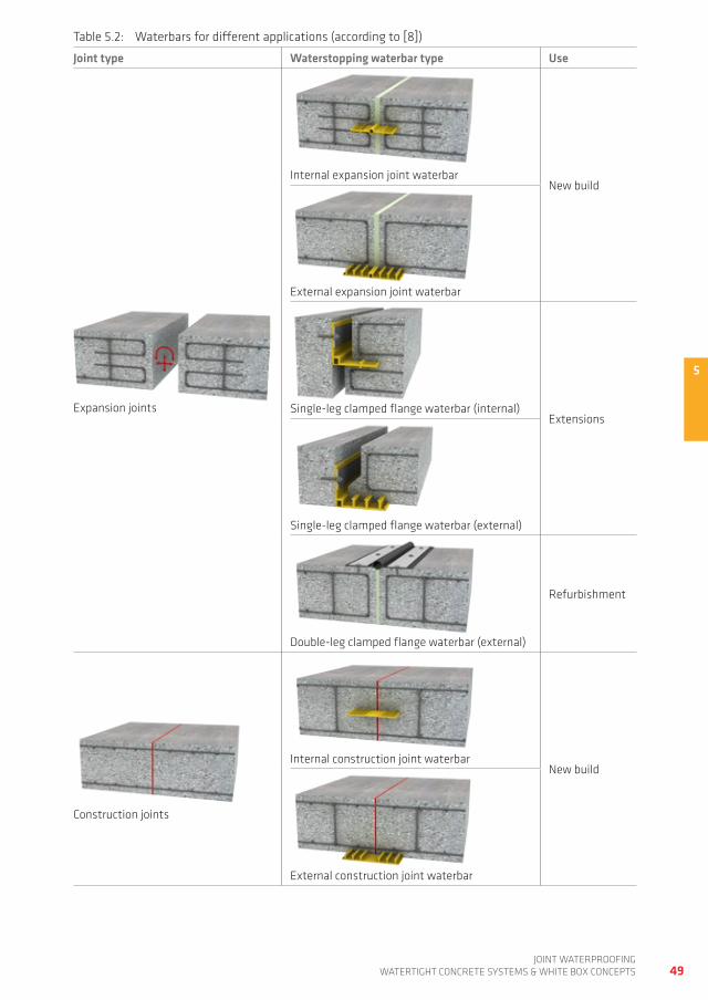
5
49joint waterproofing
watertight ConCrete SyStemS & white Box ConCeptS
table 5.2: waterbars for different applications (according to [8])
Joint type Waterstopping waterbar type Use
expansion joints
internal expansion joint waterbarnew build
external expansion joint waterbar
Single-leg clamped flange waterbar (internal)extensions
Single-leg clamped flange waterbar (external)
double-leg clamped flange waterbar (external)
refurbishment
Construction joints
internal construction joint waterbarnew build
external construction joint waterbar
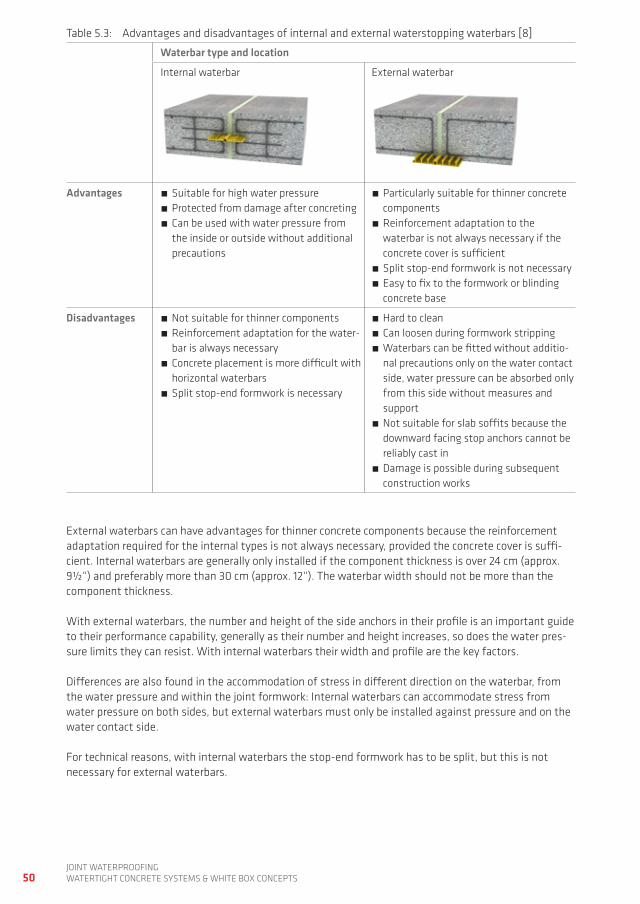
50joint waterproofingwatertight ConCrete SyStemS & white Box ConCeptS
table 5.3: advantages and disadvantages of internal and external waterstopping waterbars [8]
Waterbar type and location
internal waterbar external waterbar
Advantages Suitable for high water pressure protected from damage after concreting Can be used with water pressure from the inside or outside without additional precautions
particularly suitable for thinner concrete components
reinforcement adaptation to the waterbar is not always necessary if the concrete cover is sufficient
Split stop-end formwork is not necessary easy to fix to the formwork or blinding concrete base
Disadvantages not suitable for thinner components reinforcement adaptation for the water-bar is always necessary
Concrete placement is more difficult with horizontal waterbars
Split stop-end formwork is necessary
hard to clean Can loosen during formwork stripping waterbars can be fitted without additio-nal precautions only on the water contact side, water pressure can be absorbed only from this side without measures and support
not suitable for slab soffits because the downward facing stop anchors cannot be reliably cast in
damage is possible during subsequent construction works
external waterbars can have advantages for thinner concrete components because the reinforcement adaptation required for the internal types is not always necessary, provided the concrete cover is suffi-cient. internal waterbars are generally only installed if the component thickness is over 24 cm (approx. 9½“) and preferably more than 30 cm (approx. 12“). the waterbar width should not be more than the component thickness.
with external waterbars, the number and height of the side anchors in their profile is an important guide to their performance capability, generally as their number and height increases, so does the water pres-sure limits they can resist. with internal waterbars their width and profile are the key factors.
differences are also found in the accommodation of stress in different direction on the waterbar, from the water pressure and within the joint formwork: internal waterbars can accommodate stress from water pressure on both sides, but external waterbars must only be installed against pressure and on the water contact side.
for technical reasons, with internal waterbars the stop-end formwork has to be split, but this is not necessary for external waterbars.

5
51joint waterproofing
watertight ConCrete SyStemS & white Box ConCeptS
5.1 waterStopping waterBar materiaLS
joint sealing and waterstopping waterbars are produced in several different materials and qualities developed and optimised for their different uses and specific requirements. thermoplastic waterbars merit special mention here. their physical properties and ease of handling and use for installation on site make them very versatile. thermoplastic waterbars that are suitable for the majority of different joint waterproofing applications and requirements are based on:
pVC-p (polyvinyl chloride - plasticised), e.g. Sika® waterbars pVC-p/nBr copolymer, e.g. tricosal® tricomer® waterbars thermoplatic polyolefin (tpo) waterstops westec® pe (polyethylene) waterbars have also been developed for the special requirements specified for bunds and containment areas for the storage, filling and transfer of oils and other chemicals that are ground water pollutants. they therefore have very high chemical resistance. in general, drinking water quality waterbars are made with special, flexible, thermoplastic ethylene vinyl acetate (eVa) and are used in structures for the storage and treatment of drinking water. due to the special material composition of these thermoplastic eVa waterbars, they also comply with the strict regulations for plastics in contact with foodstuffs and so they are also used in agriculture and the food industry. alongside these thermoplastic waterstops, other special elastomer waterstops are produced for some other specific applications, mainly in civil engineering.
thermoplastics and elastomers for waterbars differ in their physical properties and also fundamentally in their on-site jointing process. thermoplastic waterbars can easily be heat welded, but the joints in elastomer based waterbars must be formed by the more complex process of vulcanization.
the type of waterbar and the most suitable material to use must be defined in accordance with each specific project’s requirements. this selection should be made in collaboration with the waterbar ma-nufacturer, and is based on the type of structure, anticipated exposure, water pressure and any other performance requirements.
Sika® waterbars meet the requirements of the german institute for Standardisation (din), in addition to the performance specifications of many other national and international Standards including:
american Society for testing and materials (aStm) U.S. army Corps of engineers (Crd-C 572-74) British Standards institute (BSi)
5.1.1 PvC-P WATERBARS
pVC-p (polyvinyl chloride - plasticised) is particularly suitable for waterstopping waterbars and it is also extremely economic. plasticised pVC (pVC-p) is a thermoplastic material that is produced by the poly-merization of vinyl chloride and is flexible at normal temperatures. pVC-p fuses to itself when heated to 200°C – 240°C. to obtain a polyvinyl chloride with the desired properties for a waterbar, stabilisers, plasticizers, and fillers are added to it. the addition of plasticizers gives pVC-p its flexibility. Stabilisers improve the resistance of pVC-p to the effects of UV light and weathering. fillers such as chalk, graphite and carbon black are often used as extenders which make the plastic itself go further and cheaper to produce. this filler content can therefore have a significant influence on the physical properties, workabi-lity and weldability of pVC-p. high filler content will have a negative effect on workability, weldability and physical properties such as elongation.
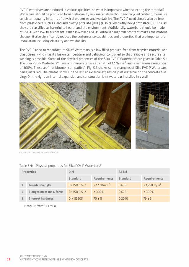
52joint waterproofingwatertight ConCrete SyStemS & white Box ConCeptS
pVC-p waterbars are produced in various qualities, so what is important when selecting the material? waterbars should be produced from high-quality raw materials without any recycled content, to ensure consistent quality in terms of physical properties and weldability. the pVC-p used should also be free from plasticizers such as lead and dioctyl phtalate (dop) (also called diethylhexyl phthalate (dehp)), as they are classified as harmful to health and the environment. additionally, waterbars should be made of pVC-p with low filler content, called low-filled pVC-p. although high filler content makes the material cheaper, it also significantly reduces the performance capabilities and properties that are important for installation including elasticity and weldability.
the pVC-p used to manufacture Sika® waterbars is a low filled product, free from recycled material and plasticizers, which has its fusion temperature and behaviour controlled so that reliable and secure site welding is possible. Some of the physical properties of the Sika pVC-p waterbars® are given in table 5.4. the Sika pVC-p waterbars® have a minimum tensile strength of 12 n/mm² and a minimum elongation of 300%. these are "not bitumen compatible". fig. 5.5 shows some examples of Sika pVC-p waterbars being installed. the photos show: on the left an external expansion joint waterbar on the concrete blin-ding; on the right an internal expansion and construction joint waterbar installed in a wall.
fig. 5.5: Sika® waterbars made of pVC-p
table 5.4: physical properties for Sika pCV-p waterbars®
Properties DIN ASTM
Standard Requirements Standard Requirements
1 Tensile strength en iSo 527-2 ≥ 12 n/mm² d 638 ≥ 1,750 lb/in²
2 Elongation at max. force en iSo 527-2 ≥ 300% d 638 ≥ 300%
3 Shore-A hardness din 53505 70 ± 5 d 2240 79 ± 3
note: 1 n/mm² = 1 mpa

5
53joint waterproofing
watertight ConCrete SyStemS & white Box ConCeptS
5.1.2 PvC-P/NBR WATERBARS
Sika® tricosal® tricomer® waterbars are highly flexible and elastic products made from a pVC-p/nBr copolymer, which is a special polymer consisting of high-quality raw materials that give the tricosal® tricomer® polymer permanent elasticity, similar to that of true elastomers, plus outstanding ageing resistance. the physical properties of tricosal® tricomer® are given in table 5.5. it has higher elasticity, elongation, tear strength and better performance in cold than pVC-p. tricosal® tricomer® also has an elongation capability of over 350% with a tensile strength of >10 n/mm² minimum. Sika® tricosal® tricomer® waterbars are also "bitumen compatible" for applications where direct or indirect bitumen contact is possible. fig. 5.6 shows some examples of Sika® tricosal® tricomer® waterbar installations.
fig. 5.6: installing Sika® tricosal® tricomer® waterbars
Sika® tricosal® tricomer® meets the strict requirements of din 18541 [6] issued by the german institute for Standardisation. it can be heat welded and has now been used to produce high performance water-bars for over 35 years. Sika® tricosal® tricomer® waterbars are used for the waterproofing of expansion and construction joints in building basements, underground garages, water treatment plants etc. the permanently elastic properties of the tricosal® tricomer® material and its high elastic recovery capability compared with pVC-p, also make it suitable for the production of clamped flange waterbars. these are used very successfully for post-sealing construction joints and for the repair of joints during refurbish-ment works, particularly in major civil engineering projects and structures..
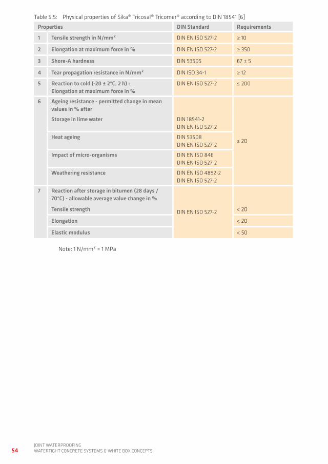
54joint waterproofingwatertight ConCrete SyStemS & white Box ConCeptS
table 5.5: physical properties of Sika® tricosal® tricomer® according to din 18541 [6]
Properties DIN Standard Requirements
1 Tensile strength in N/mm² din en iSo 527-2 ≥ 10
2 Elongation at maximum force in % din en iSo 527-2 ≥ 350
3 Shore-A hardness din 53505 67 ± 5
4 Tear propagation resistance in N/mm² din iSo 34-1 ≥ 12
5 Reaction to cold (-20 ± 2°C, 2 h) : Elongation at maximum force in %
din en iSo 527-2 ≤ 200
6 Ageing resistance - permitted change in mean values in % after
≤ 20
Storage in lime water din 18541-2din en iSo 527-2
Heat ageing din 53508din en iSo 527-2
Impact of micro-organisms din en iSo 846din en iSo 527-2
Weathering resistance din en iSo 4892-2din en iSo 527-2
7 Reaction after storage in bitumen (28 days / 70°C) - allowable average value change in %
din en iSo 527-2Tensile strength < 20
Elongation < 20
Elastic modulus < 50
note: 1 n/mm² = 1 mpa
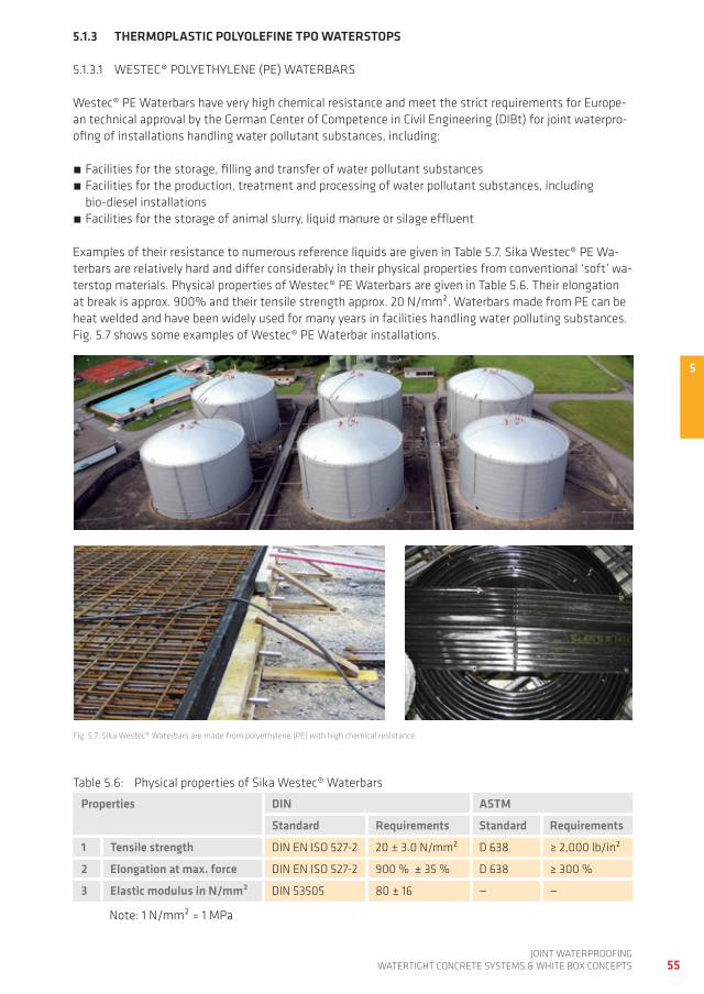
5
55joint waterproofing
watertight ConCrete SyStemS & white Box ConCeptS
5.1.3 THERMOPLASTIC POLyOLEFINE TPO WATERSTOPS
5.1.3.1 weSteC® poLyethyLene (pe) waterBarS
westec® pe waterbars have very high chemical resistance and meet the strict requirements for europe-an technical approval by the german Center of Competence in Civil engineering (diBt) for joint waterpro-ofing of installations handling water pollutant substances, including:
facilities for the storage, filling and transfer of water pollutant substances facilities for the production, treatment and processing of water pollutant substances, including bio-diesel installations
facilities for the storage of animal slurry, liquid manure or silage effluent
examples of their resistance to numerous reference liquids are given in table 5.7. Sika westec® pe wa-terbars are relatively hard and differ considerably in their physical properties from conventional ‘soft’ wa-terstop materials. physical properties of westec® pe waterbars are given in table 5.6. their elongation at break is approx. 900% and their tensile strength approx. 20 n/mm². waterbars made from pe can be heat welded and have been widely used for many years in facilities handling water polluting substances. fig. 5.7 shows some examples of westec® pe waterbar installations.
table 5.6: physical properties of Sika westec® waterbars
Properties DIN ASTM
Standard Requirements Standard Requirements
1 Tensile strength din en iSo 527-2 20 ± 3.0 n/mm² d 638 ≥ 2,000 lb/in²
2 Elongation at max. force din en iSo 527-2 900 % ± 35 % d 638 ≥ 300 %
3 Elastic modulus in N/mm² din 53505 80 ± 16 — —
note: 1 n/mm² = 1 mpa
fig. 5.7: Sika westec® waterbars are made from polyethylene (pe) with high chemical resistance
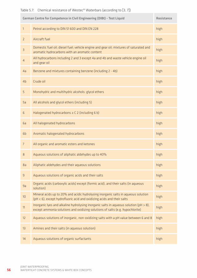
56joint waterproofingwatertight ConCrete SyStemS & white Box ConCeptS
table 5.7: Chemical resistance of westec® waterbars (according to [3, 7])
german Centre for Competence in Civil Engineering (DIBt) - Test Liquid Resistance
1 petrol according to din 51 600 and din en 228 high
2 aircraft fuel high
3domestic fuel oil; diesel fuel; vehicle engine and gear oil; mixtures of saturated and aromatic hydrocarbons with an aromatic content
high
4all hydrocarbons including 2 and 3 except 4a and 4b and waste vehicle engine oil and gear oil
high
4a Benzene and mixtures containing benzene (including 2 - 4b) high
4b Crude oil high
5 monohydric and multihydric alcohols: glycol ethers high
5a all alcohols and glycol ethers (including 5) high
6 halogenated hydrocarbons ≥ C 2 (including 6 b) high
6a all halogenated hydrocarbons high
6b aromatic halogenated hydrocarbons high
7 all organic and aromatic esters and ketones high
8 aqueous solutions of aliphatic aldehydes up to 40% high
8a aliphatic aldehydes and their aqueous solutions high
9 aqueous solutions of organic acids and their salts high
9aorganic acids (carboxylic acids) except (formic acid), and their salts (in aqueous solution)
high
10mineral acids up to 20% and acidic hydrolysing inorganic salts in aqueous solution (ph < 6), except hydrofluoric acid and oxidizing acids and their salts
high
11inorganic lyes and alkaline hydrolysing inorganic salts in aqueous solution (ph > 8), except ammonia solutions and oxidizing solutions of salts (e.g. hypochlorite)
high
12 aqueous solutions of inorganic, non-oxidizing salts with a ph value between 6 and 8 high
13 amines and their salts (in aqueous solution) high
14 aqueous solutions of organic surfactants high
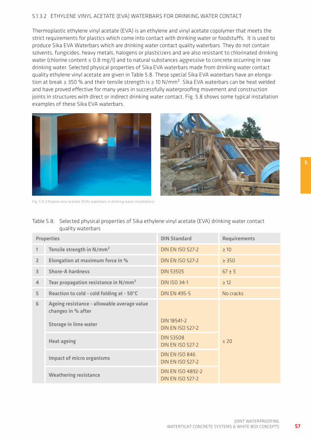
5
57joint waterproofing
watertight ConCrete SyStemS & white Box ConCeptS
5.1.3.2 ethyLene VinyL aCetate (eVa) waterBarS for drinKing water ContaCt
thermoplastic ethylene vinyl acetate (eVa) is an ethylene and vinyl acetate copolymer that meets the strict requirements for plastics which come into contact with drinking water or foodstuffs. it is used to produce Sika eVa waterbars which are drinking water contact quality waterbars. they do not contain solvents, fungicides, heavy metals, halogens or plasticizers and are also resistant to chlorinated drinking water (chlorine content ≤ 0.8 mg/l) and to natural substances aggressive to concrete occurring in raw drinking water. Selected physical properties of Sika eVa waterbars made from drinking water contact quality ethylene vinyl acetate are given in table 5.8. these special Sika eVa waterbars have an elonga-tion at break ≥ 350 % and their tensile strength is ≥ 10 n/mm². Sika eVa waterbars can be heat welded and have proved effective for many years in successfully waterproofing movement and construction joints in structures with direct or indirect drinking water contact. fig. 5.8 shows some typical installation examples of these Sika eVa waterbars.
fig. 5.8: ethylene vinyl acetate (eVa) waterbars in drinking water installations
table 5.8: Selected physical properties of Sika ethylene vinyl acetate (eVa) drinking water contact quality waterbars
Properties DIN Standard Requirements
1 Tensile strength in N/mm² din en iSo 527-2 ≥ 10
2 Elongation at maximum force in % din en iSo 527-2 ≥ 350
3 Shore-A hardness din 53505 67 ± 5
4 Tear propagation resistance in N/mm² din iSo 34-1 ≥ 12
5 Reaction to cold - cold folding at - 50°C din en 495-5 no cracks
6 Ageing resistance - allowable average value changes in % after
Storage in lime waterdin 18541-2din en iSo 527-2
Heat ageingdin 53508din en iSo 527-2
≤ 20
Impact of micro organismsdin en iSo 846din en iSo 527-2
Weathering resistancedin en iSo 4892-2din en iSo 527-2
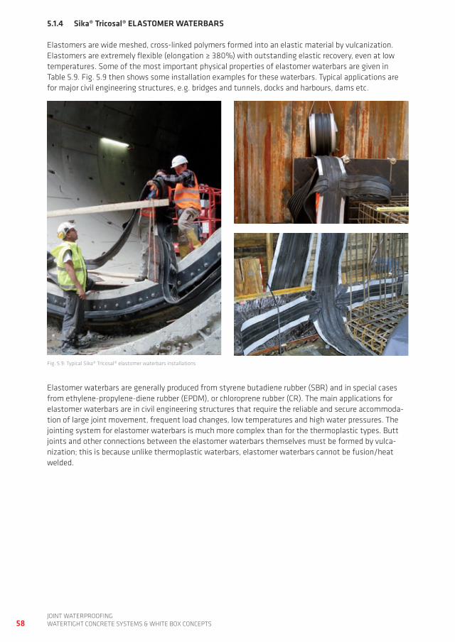
58joint waterproofingwatertight ConCrete SyStemS & white Box ConCeptS
5.1.4 Sika® Tricosal® ELASTOMER WATERBARS
elastomers are wide meshed, cross-linked polymers formed into an elastic material by vulcanization. elastomers are extremely flexible (elongation ≥ 380%) with outstanding elastic recovery, even at low temperatures. Some of the most important physical properties of elastomer waterbars are given in table 5.9. fig. 5.9 then shows some installation examples for these waterbars. typical applications are for major civil engineering structures, e.g. bridges and tunnels, docks and harbours, dams etc.
fig. 5.9: typical Sika® tricosal® elastomer waterbars installations
elastomer waterbars are generally produced from styrene butadiene rubber (SBr) and in special cases from ethylene-propylene-diene rubber (epdm), or chloroprene rubber (Cr). the main applications for elastomer waterbars are in civil engineering structures that require the reliable and secure accommoda-tion of large joint movement, frequent load changes, low temperatures and high water pressures. the jointing system for elastomer waterbars is much more complex than for the thermoplastic types. Butt joints and other connections between the elastomer waterbars themselves must be formed by vulca-nization; this is because unlike thermoplastic waterbars, elastomer waterbars cannot be fusion/heat welded.
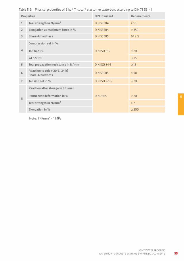
5
59joint waterproofing
watertight ConCrete SyStemS & white Box ConCeptS
table 5.9: physical properties of Sika® tricosal® elastomer waterbars according to din 7865 [4]
Properties DIN Standard Requirements
1 Tear strength in N/mm² din 53504 ≥ 10
2 Elongation at maximum force in % din 53504 ≥ 350
3 Shore-A hardness din 53505 67 ± 5
4
Compression set in %
168 h/23°C din iSo 815 ≤ 20
24 h/70°C ≤ 35
5 Tear propagation resistance in N/mm² din iSo 34-1 ≥ 12
6Reaction to cold (-20°C, 24 h)Shore-A hardness
din 53505 ≤ 90
7 Tension set in % din iSo 2285 ≤ 20
8
Reaction after storage in bitumen
Permanent deformation in % din 7865 < 20
Tear strength in N/mm² ≥ 7
Elongation in % ≥ 300
note: 1 n/mm² = 1 mpa
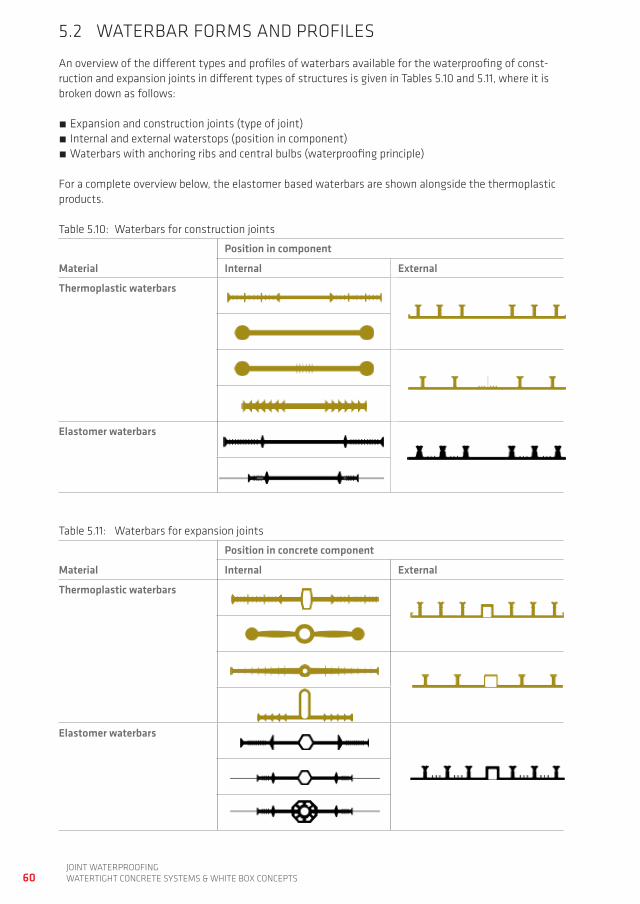
60joint waterproofingwatertight ConCrete SyStemS & white Box ConCeptS
5.2 waterBar formS and profiLeS
an overview of the different types and profiles of waterbars available for the waterproofing of const-ruction and expansion joints in different types of structures is given in tables 5.10 and 5.11, where it is broken down as follows:
expansion and construction joints (type of joint) internal and external waterstops (position in component) waterbars with anchoring ribs and central bulbs (waterproofing principle)
for a complete overview below, the elastomer based waterbars are shown alongside the thermoplastic products.
table 5.10: waterbars for construction joints
Position in component
Material Internal External
Thermoplastic waterbars
Elastomer waterbars
table 5.11: waterbars for expansion joints
Position in concrete component
Material Internal External
Thermoplastic waterbars
Elastomer waterbars
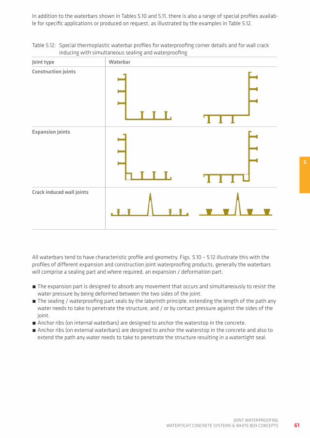
5
61joint waterproofing
watertight ConCrete SyStemS & white Box ConCeptS
in addition to the waterbars shown in tables 5.10 and 5.11, there is also a range of special profiles availab-le for specific applications or produced on request, as illustrated by the examples in table 5.12.
table 5.12: Special thermoplastic waterbar profiles for waterproofing corner details and for wall crack inducing with simultaneous sealing and waterproofing
Joint type Waterbar
Construction joints
Expansion joints
Crack induced wall joints
all waterbars tend to have characteristic profile and geometry. figs. 5.10 – 5.12 illustrate this with the profiles of different expansion and construction joint waterproofing products, generally the waterbars will comprise a sealing part and where required, an expansion / deformation part.
the expansion part is designed to absorb any movement that occurs and simultaneously to resist the water pressure by being deformed between the two sides of the joint.
the sealing / waterproofing part seals by the labyrinth principle, extending the length of the path any water needs to take to penetrate the structure, and / or by contact pressure against the sides of the joint.
anchor ribs (on internal waterbars) are designed to anchor the waterstop in the concrete. anchor ribs (on external waterbars) are designed to anchor the waterstop in the concrete and also to extend the path any water needs to take to penetrate the structure resulting in a watertight seal.
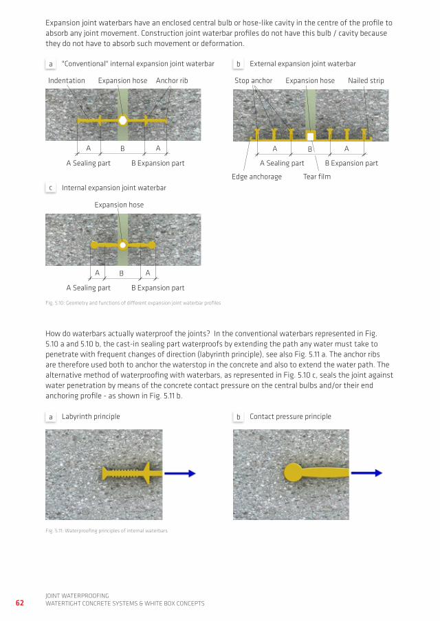
62joint waterproofingwatertight ConCrete SyStemS & white Box ConCeptS
"Conventional" internal expansion joint waterbar external expansion joint waterbar
internal expansion joint waterbar
expansion joint waterbars have an enclosed central bulb or hose-like cavity in the centre of the profile to absorb any joint movement. Construction joint waterbar profiles do not have this bulb / cavity because they do not have to absorb such movement or deformation.
how do waterbars actually waterproof the joints? in the conventional waterbars represented in fig. 5.10 a and 5.10 b, the cast-in sealing part waterproofs by extending the path any water must take to penetrate with frequent changes of direction (labyrinth principle), see also fig. 5.11 a. the anchor ribs are therefore used both to anchor the waterstop in the concrete and also to extend the water path. the alternative method of waterproofing with waterbars, as represented in fig. 5.10 c, seals the joint against water penetration by means of the concrete contact pressure on the central bulbs and/or their end anchoring profile - as shown in fig. 5.11 b.
Labyrinth principle Contact pressure principle
fig. 5.10: geometry and functions of different expansion joint waterbar profiles
fig. 5.11: waterproofing principles of internal waterbars
B aa
anchor ribexpansion hoseindentation
B expansion parta Sealing part
B aa
expansion hose
tear filmedge anchorage
nailed stripStop anchor
B expansion parta Sealing part
expansion hose
B aa
a b
c
a b
B expansion parta Sealing part
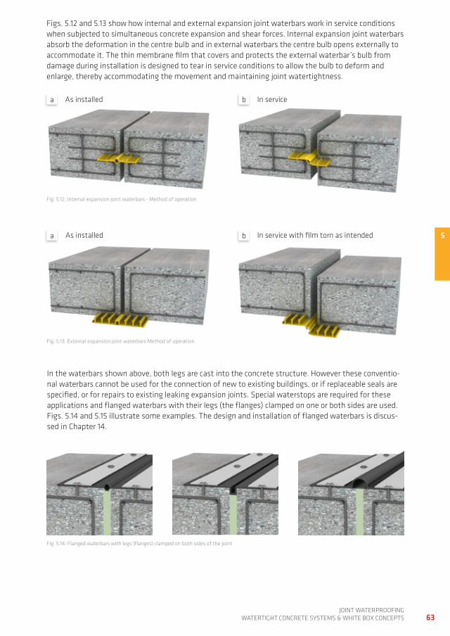
5
63joint waterproofing
watertight ConCrete SyStemS & white Box ConCeptS
figs. 5.12 and 5.13 show how internal and external expansion joint waterbars work in service conditions when subjected to simultaneous concrete expansion and shear forces. internal expansion joint waterbars absorb the deformation in the centre bulb and in external waterbars the centre bulb opens externally to accommodate it. the thin membrane film that covers and protects the external waterbar’s bulb from damage during installation is designed to tear in service conditions to allow the bulb to deform and enlarge, thereby accommodating the movement and maintaining joint watertightness.
as installed in service
fig. 5.12: internal expansion joint waterbars - method of operation
as installed in service with film torn as intended
in the waterbars shown above, both legs are cast into the concrete structure. however these conventio-nal waterbars cannot be used for the connection of new to existing buildings, or if replaceable seals are specified, or for repairs to existing leaking expansion joints. Special waterstops are required for these applications and flanged waterbars with their legs (the flanges) clamped on one or both sides are used. figs. 5.14 and 5.15 illustrate some examples. the design and installation of flanged waterbars is discus-sed in Chapter 14.
fig. 5.13: external expansion joint waterbars method of operation
fig. 5.14: flanged waterbars with legs (flanges) clamped on both sides of the joint
a b
a b
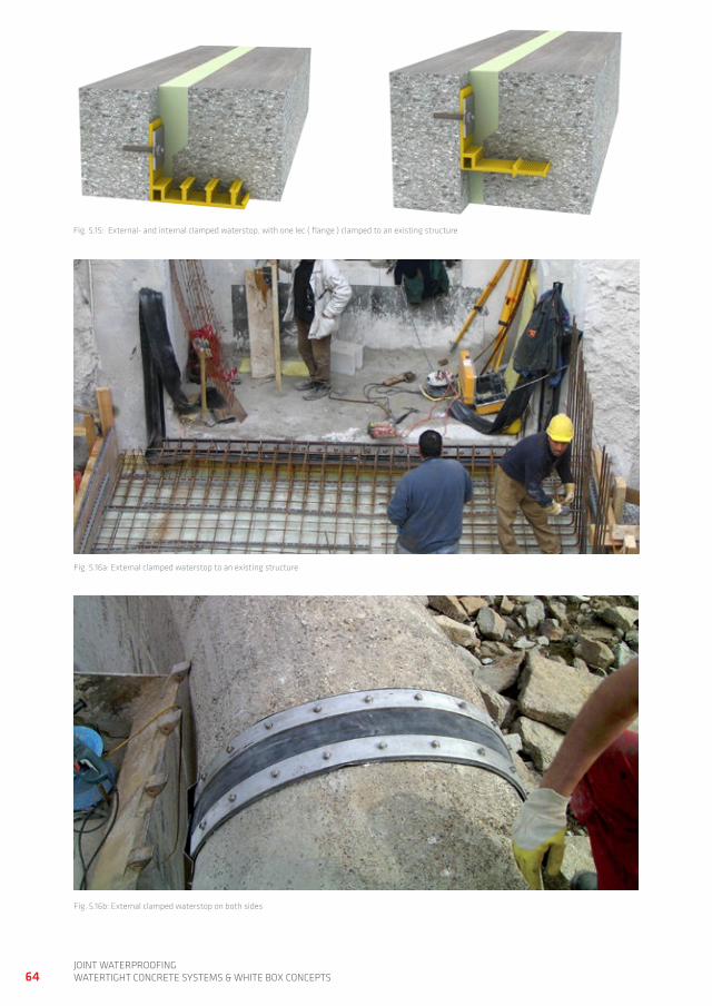
64joint waterproofingwatertight ConCrete SyStemS & white Box ConCeptS
fig. 5.15: external- and internal clamped waterstop, with one lec ( flange ) clamped to an existing structure
fig. 5.16a: external clamped waterstop to an existing structure
fig. 5.16b: external clamped waterstop on both sides
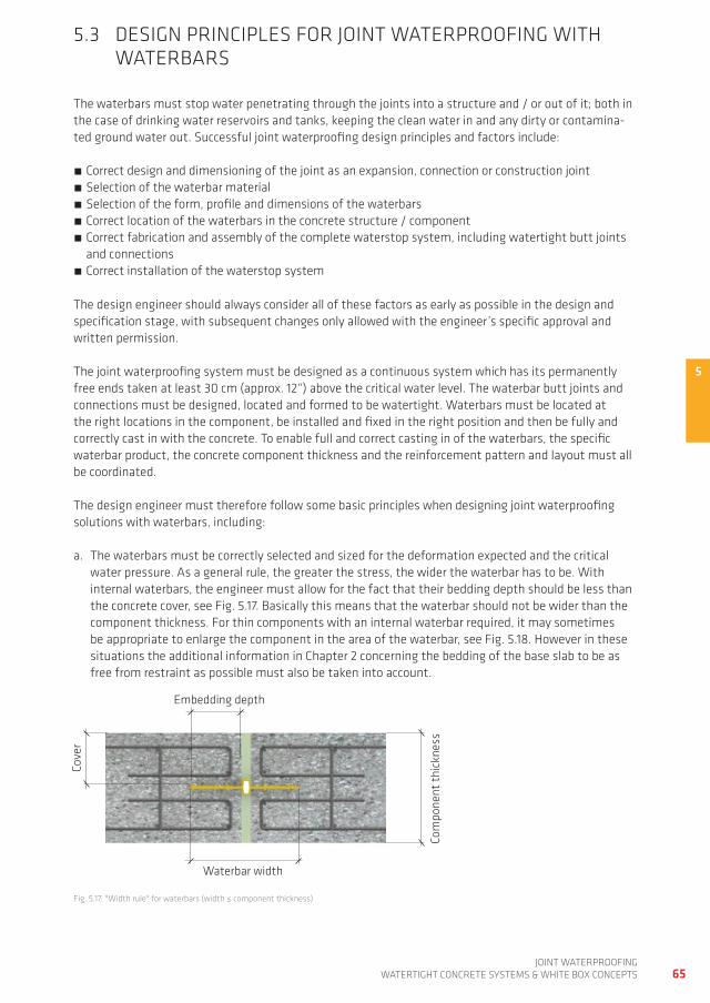
5
65joint waterproofing
watertight ConCrete SyStemS & white Box ConCeptS
5.3 deSign prinCipLeS for joint waterproofing with waterBarS
the waterbars must stop water penetrating through the joints into a structure and / or out of it; both in the case of drinking water reservoirs and tanks, keeping the clean water in and any dirty or contamina-ted ground water out. Successful joint waterproofing design principles and factors include:
Correct design and dimensioning of the joint as an expansion, connection or construction joint Selection of the waterbar material Selection of the form, profile and dimensions of the waterbars Correct location of the waterbars in the concrete structure / component Correct fabrication and assembly of the complete waterstop system, including watertight butt joints and connections
Correct installation of the waterstop system
the design engineer should always consider all of these factors as early as possible in the design and specification stage, with subsequent changes only allowed with the engineer’s specific approval and written permission.
the joint waterproofing system must be designed as a continuous system which has its permanently free ends taken at least 30 cm (approx. 12“) above the critical water level. the waterbar butt joints and connections must be designed, located and formed to be watertight. waterbars must be located at the right locations in the component, be installed and fixed in the right position and then be fully and correctly cast in with the concrete. to enable full and correct casting in of the waterbars, the specific waterbar product, the concrete component thickness and the reinforcement pattern and layout must all be coordinated.
the design engineer must therefore follow some basic principles when designing joint waterproofing solutions with waterbars, including:
a. the waterbars must be correctly selected and sized for the deformation expected and the critical water pressure. as a general rule, the greater the stress, the wider the waterbar has to be. with internal waterbars, the engineer must allow for the fact that their bedding depth should be less than the concrete cover, see fig. 5.17. Basically this means that the waterbar should not be wider than the component thickness. for thin components with an internal waterbar required, it may sometimes be appropriate to enlarge the component in the area of the waterbar, see fig. 5.18. however in these situations the additional information in Chapter 2 concerning the bedding of the base slab to be as free from restraint as possible must also be taken into account.
fig. 5.17: "width rule" for waterbars (width ≤ component thickness)
embedding depth
waterbar width
Com
pone
nt th
ickn
ess
Cove
r
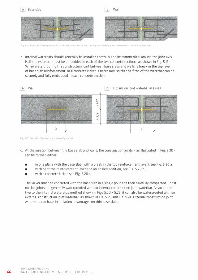
66joint waterproofingwatertight ConCrete SyStemS & white Box ConCeptS
b. internal waterbars should generally be installed centrally and be symmetrical around the joint axis. half the waterbar must be embedded in each of the two concrete sections, as shown in fig. 5.19. when waterproofing the construction joint between base slabs and walls, a break in the top layer of base slab reinforcement, or a concrete kicker is necessary, so that half the of the waterbar can be securely and fully embedded in each concrete section.
fig. 5.18: example of enlargement of a thin component to maintain the required thickness over the waterbar in its immediate area
fig. 5.19: examples of correct waterbar configuration
Base slab wall
c. at the junction between the base slab and walls, the construction joints – as illustrated in fig. 5.20 - can be formed either: in one plane with the base slab (with a break in the top reinforcement layer), see fig. 5.20 a with bent top reinforcement layer and an angled addition, see fig. 5.20 b with a concrete kicker, see fig. 5.20 c the kicker must be concreted with the base slab in a single pour and then carefully compacted. Const-ruction joints are generally waterproofed with an internal construction joint waterbar. as an alterna-tive to the internal waterstop method shown in figs 5.20 – 5.22, it can also be waterproofed with an external construction joint waterbar, as shown in fig. 5.23 and fig. 5.24. external construction joint waterbars can have installation advantages on thin base slabs.
≥ a/
2
a a
wall expansion joint waterbar in a wall
a b
a b
≥ a/
2
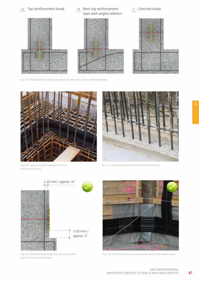
5
67joint waterproofing
watertight ConCrete SyStemS & white Box ConCeptS
fig. 5.20: waterproofing of base slab-wall construction joint with an internal waterbar
top reinforcement break
fig. 5.21: Construction joint waterbar with top reinforcement break
Bent top reinforcement layer with angled addition
Concrete kicker
fig. 5.22: Construction joint waterbar with concrete kicker
fig. 5.23: waterproofing of base slab wall-construction joint with an external waterbar
≥ 20 mm / approx. ¾"
≥ 50 mm / approx. 2"
a b c
fig. 5.24: external construction joint waterbar fixed to the wall formwork
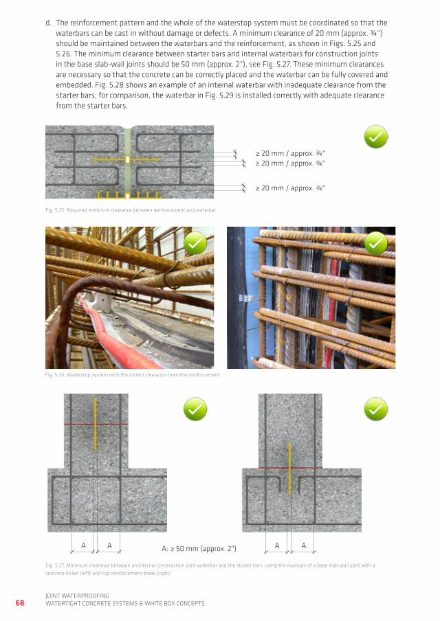
68joint waterproofingwatertight ConCrete SyStemS & white Box ConCeptS
d. the reinforcement pattern and the whole of the waterstop system must be coordinated so that the waterbars can be cast in without damage or defects. a minimum clearance of 20 mm (approx. ¾“) should be maintained between the waterbars and the reinforcement, as shown in figs. 5.25 and 5.26. the minimum clearance between starter bars and internal waterbars for construction joints in the base slab-wall joints should be 50 mm (approx. 2“), see fig. 5.27. these minimum clearances are necessary so that the concrete can be correctly placed and the waterbar can be fully covered and embedded. fig. 5.28 shows an example of an internal waterbar with inadequate clearance from the starter bars; for comparison, the waterbar in fig. 5.29 is installed correctly with adequate clearance from the starter bars.
fig. 5.25: required minimum clearance between reinforcement and waterbar
fig. 5.27: minimum clearance between an internal construction joint waterbar and the starter bars, using the example of a base slab-wall joint with a concrete kicker (left) and top reinforcement break (right)
fig. 5.26: waterstop system with the correct clearance from the reinforcement
≥ 20 mm / approx. ¾"≥ 20 mm / approx. ¾"
≥ 20 mm / approx. ¾"
a a: ≥ 50 mm (approx. 2")a a a
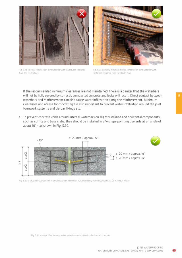
5
69joint waterproofing
watertight ConCrete SyStemS & white Box ConCeptS
if the recommended minimum clearances are not maintained, there is a danger that the waterbars will not be fully covered by correctly compacted concrete and leaks will result. direct contact between waterbars and reinforcement can also cause water infiltration along the reinforcement. minimum clearances and access for concreting are also important to prevent water infiltration around the joint formwork systems and tie-bar fixings etc.
e. to prevent concrete voids around internal waterbars on slightly inclined and horizontal components such as soffits and base slabs, they should be installed in a V-shape pointing upwards at an angle of about 10° – as shown in fig. 5.30.
fig. 5.28: internal construction joint waterbar with inadequate clearance from the starter bars
fig. 5.29: Correctly installed internal construction joint waterbar with sufficient clearance from the starter bars
fig. 5.30: V-shaped installation of internal waterbars in horizon¬tal and slightly inclined components (a: waterbar width)
fig. 5.31: V-shape of an internal waterbar waterstop solution in a horizontal component
≥ a
≥ 20 mm / approx. ¾"
≥ a/
2≥
a/2
≥ 20 mm / approx. ¾"≥ 20 mm / approx. ¾"
≥ 10°
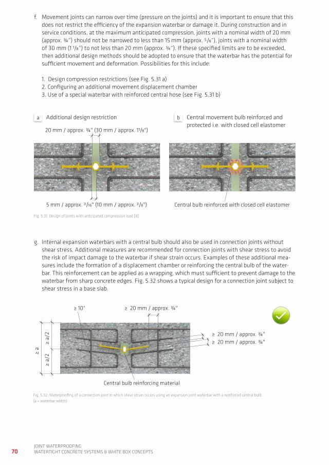
70joint waterproofingwatertight ConCrete SyStemS & white Box ConCeptS
g. internal expansion waterbars with a central bulb should also be used in connection joints without shear stress. additional measures are recommended for connection joints with shear stress to avoid the risk of impact damage to the waterbar if shear strain occurs. examples of these additional mea-sures include the formation of a displacement chamber or reinforcing the central bulb of the water-bar. this reinforcement can be applied as a wrapping, which must sufficient to prevent damage to the waterbar from sharp concrete edges. fig. 5.32 shows a typical design for a connection joint subject to shear stress in a base slab.
f. movement joints can narrow over time (pressure on the joints) and it is important to ensure that this does not restrict the efficiency of the expansion waterbar or damage it. during construction and in service conditions, at the maximum anticipated compression, joints with a nominal width of 20 mm (approx. ¾“) should not be narrowed to less than 15 mm (approx. 5/8“), joints with a nominal width of 30 mm (1 1/8“) to not less than 20 mm (approx. ¾“). if these specified limits are to be exceeded, then additional design methods should be adopted to ensure that the waterbar has the potential for sufficient movement and deformation. possibilities for this include: 1. design compression restrictions (see fig. 5.31 a) 2. Configuring an additional movement displacement chamber 3. Use of a special waterbar with reinforced central hose (see fig. 5.31 b)
fig. 5.32: waterproofing of a connection joint in which shear strain occurs using an expansion joint waterbar with a reinforced central bulb (a = waterbar width)
20 mm / approx. ¾" (30 mm / approx. 11/8")
Central bulb reinforced with closed cell elastomer5 mm / approx. 3/16" (10 mm / approx. 3/8")
additional design restriction Central movement bulb reinforced and protected i.e. with closed cell elastomer
fig. 5.31: design of joints with anticipated compression load [8]
≥ a
≥ 20 mm / approx. ¾"
≥ a/
2≥
a/2
≥ 20 mm / approx. ¾"≥ 20 mm / approx. ¾"
≥ 10°
Central bulb reinforcing material
a b
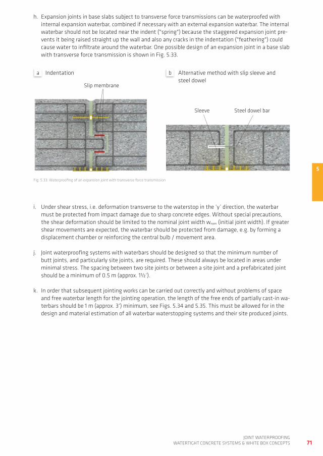
5
71joint waterproofing
watertight ConCrete SyStemS & white Box ConCeptS
h. expansion joints in base slabs subject to transverse force transmissions can be waterproofed with internal expansion waterbar, combined if necessary with an external expansion waterbar. the internal waterbar should not be located near the indent ("spring") because the staggered expansion joint pre-vents it being raised straight up the wall and also any cracks in the indentation ("feathering") could cause water to infiltrate around the waterbar. one possible design of an expansion joint in a base slab with transverse force transmission is shown in fig. 5.33.
fig. 5.33: waterproofing of an expansion joint with transverse force transmission
indentation alternative method with slip sleeve and steel dowel
i. Under shear stress, i.e. deformation transverse to the waterstop in the ‘y’ direction, the waterbar must be protected from impact damage due to sharp concrete edges. without special precautions, the shear deformation should be limited to the nominal joint width wnom (initial joint width). if greater shear movements are expected, the waterbar should be protected from damage, e.g. by forming a displacement chamber or reinforcing the central bulb / movement area.
j. joint waterproofing systems with waterbars should be designed so that the minimum number of butt joints, and particularly site joints, are required. these should always be located in areas under minimal stress. the spacing between two site joints or between a site joint and a prefabricated joint should be a minimum of 0.5 m (approx. 1½‘).
k. in order that subsequent jointing works can be carried out correctly and without problems of space and free waterbar length for the jointing operation, the length of the free ends of partially cast-in wa-terbars should be 1 m (approx. 3‘) minimum, see figs. 5.34 and 5.35. this must be allowed for in the design and material estimation of all waterbar waterstopping systems and their site produced joints.
a b
Slip membrane
Sleeve Steel dowel bar
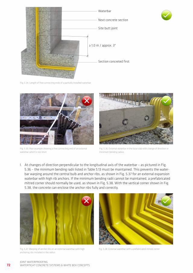
72joint waterproofingwatertight ConCrete SyStemS & white Box ConCeptS
fig. 5.34: Length of free connecting ends of a partially installed waterbar
l. at changes of direction perpendicular to the longitudinal axis of the waterbar – as pictured in fig. 5.36 – the minimum bending radii listed in table 5.13 must be maintained. this prevents the water-bar warping around the central bulb and anchor ribs, as shown in fig. 5.37 for an external expansion waterbar with high rib anchors. if the minimum bending radii cannot be maintained, a prefabricated mitred corner should normally be used, as shown in fig. 5.38. with the vertical corner shown in fig. 5.38, the concrete can enclose the anchor ribs fully and correctly.
fig. 5.35: poor example showing a free connecting end of an external waterbar which is too short
fig. 5.36: external waterbar in the base slab with change of direction in minimum bending radius
≥ 1.0 m / approx. 3"
waterbar
next concrete section
Site butt joint
Section concreted first
fig. 5.37: warping of anchor ribs on an external waterbar with high anchoring ribs installed in the radius
fig. 5.38: external waterbar with a prefabricated mitred corner
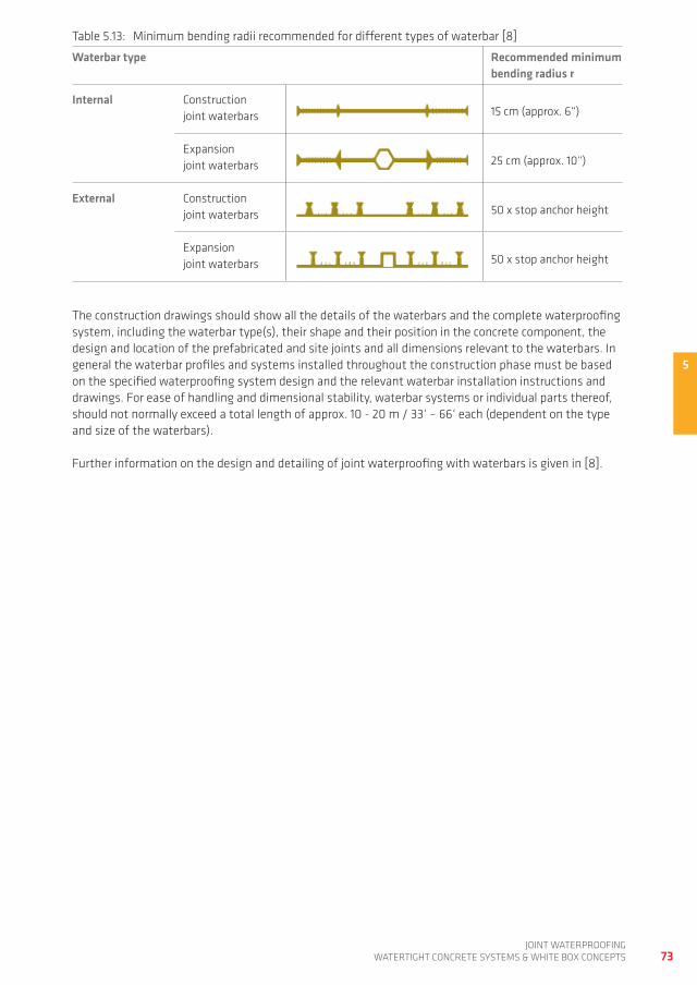
5
73joint waterproofing
watertight ConCrete SyStemS & white Box ConCeptS
table 5.13: minimum bending radii recommended for different types of waterbar [8]
Waterbar type Recommended minimum bending radius r
Internal Construction joint waterbars 15 cm (approx. 6“)
expansion joint waterbars 25 cm (approx. 10“)
External Construction joint waterbars 50 x stop anchor height
expansion joint waterbars 50 x stop anchor height
the construction drawings should show all the details of the waterbars and the complete waterproofing system, including the waterbar type(s), their shape and their position in the concrete component, the design and location of the prefabricated and site joints and all dimensions relevant to the waterbars. in general the waterbar profiles and systems installed throughout the construction phase must be based on the specified waterproofing system design and the relevant waterbar installation instructions and drawings. for ease of handling and dimensional stability, waterbar systems or individual parts thereof, should not normally exceed a total length of approx. 10 - 20 m / 33‘ – 66‘ each (dependent on the type and size of the waterbars).
further information on the design and detailing of joint waterproofing with waterbars is given in [8].
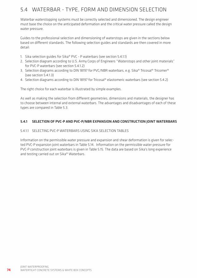
74joint waterproofingwatertight ConCrete SyStemS & white Box ConCeptS
5.4 waterBar - type, form and dimenSion SeLeCtion
waterbar waterstopping systems must be correctly selected and dimensioned. the design engineer must base the choice on the anticipated deformation and the critical water pressure called the design water pressure.
guides to the professional selection and dimensioning of waterstops are given in the sections below based on different standards. the following selection guides and standards are then covered in more detail:
1. Sika selection guides for Sika® pVC - p waterbars (see section 5.4.1.1)2. Selection diagram according to U.S. army Corps of engineers “waterstops and other joint materials”
for pVC-p waterbars (see section 5.4.1.2)3. Selection diagrams according to din 18197 for pVC/nBr waterbars, e.g. Sika® tricosal® tricomer®
(see section 5.4.1.3)4. Selection diagrams according to din 18197 for tricosal® elastomeric waterbars (see section 5.4.2)
the right choice for each waterbar is illustrated by simple examples.
as well as making the selection from different geometries, dimensions and materials, the designer has to choose between internal and external waterbars. the advantages and disadvantages of each of these types are compared in table 5.3.
5.4.1 SELECTION OF PvC-P AND PvC-P/NBR ExPANSION AND CONSTRUCTION JOINT WATERBARS
5.4.1.1 SeLeCting pVC-p waterBarS USing SiKa SeLeCtion taBLeS
information on the permissible water pressure and expansion and shear deformation is given for selec-ted pVC-p expansion joint waterbars in table 5.14. information on the permissible water pressure for pVC-p construction joint waterbars is given in table 5.15. the data are based on Sika's long experience and testing carried out on Sika® waterbars.
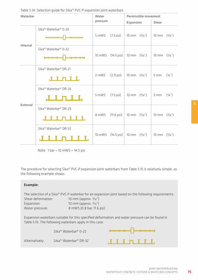
5
75joint waterproofing
watertight ConCrete SyStemS & white Box ConCeptS
Example:
the selection of a Sika® pVC-p waterbar for an expansion joint based on the following requirements:Shear deformation: 10 mm (approx. 3/8“)expansion: 10 mm (approx. 3/8“)water pressure: 8 mwS (0.8 bar, 11.6 psi)
expansion waterbars suitable for this specified deformation and water pressure can be found in table 5.15. the following waterbars apply in this case:
Sika® waterbar® 0-22
alternatively: Sika® waterbar® dr-32
table 5.14: Selection guide for Sika® pVC-p expansion joint waterbars
Waterbar Water pressure
Permissible movement
Expansion Shear
Internal
Sika® waterbar® 0-20
5 mwS (7.3 psi) 10 mm (3/8“) 10 mm (3/8“)
Sika® waterbar® 0-22
10 mwS (14.5 psi) 10 mm (3/8“) 10 mm (3/8“)
External
Sika® waterbar® dr-21
2 mwS (2.9 psi) 10 mm (3/8“) 5 mm (¼“)
Sika® waterbar® dr-26
5 mwS (7.3 psi) 10 mm (3/8“) 5 mm (¼“)
Sika® waterbar® dr-29
8 mwS (11.6 psi) 10 mm (3/8“) 10 mm (3/8“)
Sika® waterbar® dr-32
10 mwS (14.5 psi) 10 mm (3/8“) 10 mm (3/8“)
note: 1 bar = 10 mwS = 14.5 psi
the procedure for selecting Sika® pVC-p expansion joint waterbars from table 5.15 is relatively simple, as the following example shows:
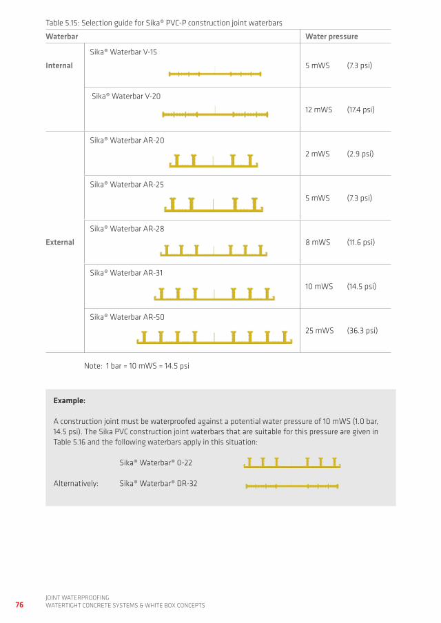
76joint waterproofingwatertight ConCrete SyStemS & white Box ConCeptS
Example:
a construction joint must be waterproofed against a potential water pressure of 10 mwS (1.0 bar, 14.5 psi). the Sika pVC construction joint waterbars that are suitable for this pressure are given in table 5.16 and the following waterbars apply in this situation:
Sika® waterbar® 0-22
alternatively: Sika® waterbar® dr-32
table 5.15: Selection guide for Sika® pVC-p construction joint waterbars
Waterbar Water pressure
Internal
Sika® waterbar V-15
5 mwS (7.3 psi)
Sika® waterbar V-20
12 mwS (17.4 psi)
External
Sika® waterbar ar-20
2 mwS (2.9 psi)
Sika® waterbar ar-25
5 mwS (7.3 psi)
Sika® waterbar ar-28
8 mwS (11.6 psi)
Sika® waterbar ar-31
10 mwS (14.5 psi)
Sika® waterbar ar-50
25 mwS (36.3 psi)
note: 1 bar = 10 mwS = 14.5 psi
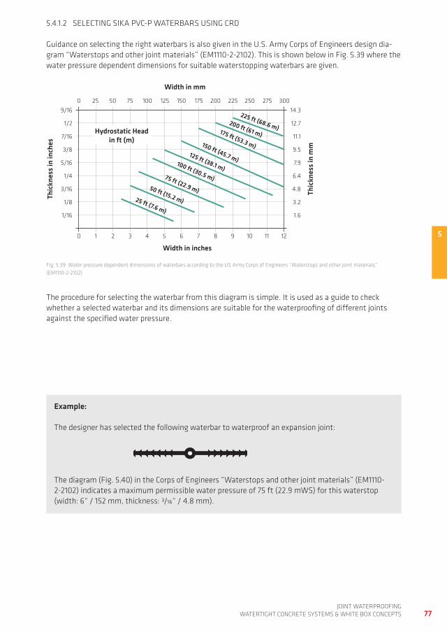
50 1 2 3 4 5 6 7 8 9 10 11 12
0 25 50 75 100 125 150 175 200 225 250 275 30014.3
12.7
11.1
9.5
7.9
6.4
4.8
3.2
1.6
9/16
1/2
7/16
3/8
5/16
1/4
3/16
1/8
1/16
Width in inches
Thic
knes
s in
inch
es
Thic
knes
s in
mm
Width in mm
Hydrostatic Headin ft (m)
175 ft (53.3 m)
225 ft (68.6 m)200 ft (61 m)
150 ft (45.7 m)125 ft (38.1 m)
100 ft (30.5 m)75 ft (22.9 m)50 ft (15.2 m)25 ft (7.6 m)
77joint waterproofing
watertight ConCrete SyStemS & white Box ConCeptS
5.4.1.2 SeLeCting SiKa pVC-p waterBarS USing Crd
guidance on selecting the right waterbars is also given in the U.S. army Corps of engineers design dia-gram “waterstops and other joint materials” (em1110-2-2102). this is shown below in fig. 5.39 where the water pressure dependent dimensions for suitable waterstopping waterbars are given.
fig. 5.39: water pressure dependent dimensions of waterbars according to the US army Corps of engineers “waterstops and other joint materials” (em1110-2-2102)
Example:
the designer has selected the following waterbar to waterproof an expansion joint:
the diagram (fig. 5.40) in the Corps of engineers “waterstops and other joint materials” (em1110-2-2102) indicates a maximum permissible water pressure of 75 ft (22.9 mwS) for this waterstop (width: 6“ / 152 mm, thickness: 3/16“ / 4.8 mm).
the procedure for selecting the waterbar from this diagram is simple. it is used as a guide to check whether a selected waterbar and its dimensions are suitable for the waterproofing of different joints against the specified water pressure.
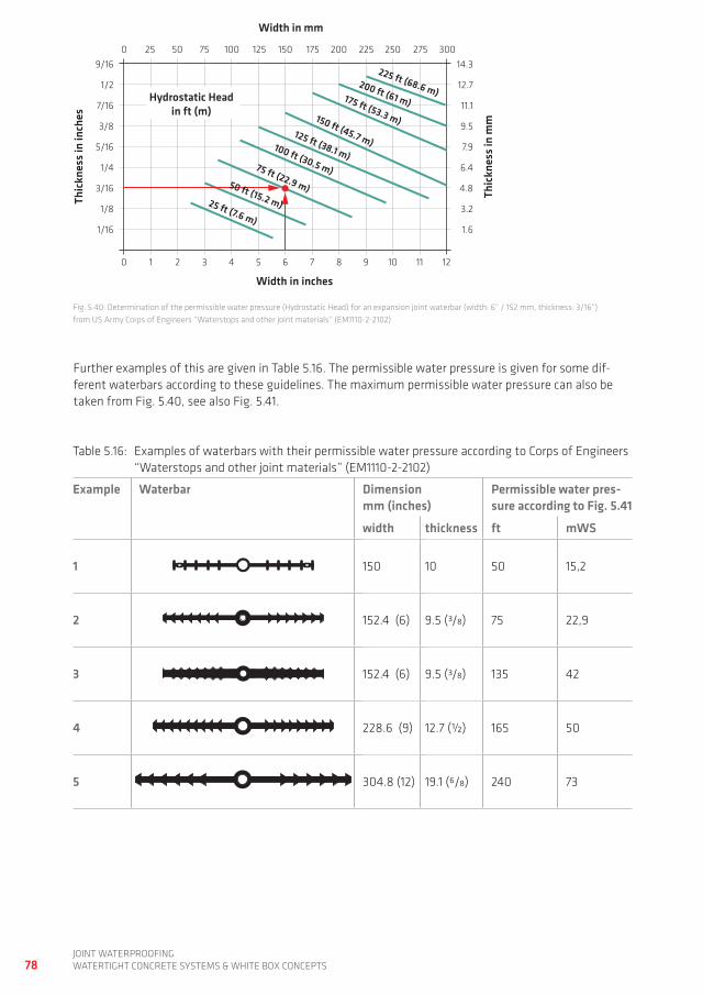
0 1 2 3 4 5 6 7 8 9 10 11 12
0 25 50 75 100 125 150 175 200 225 250 275 30014.3
12.7
11.1
9.5
7.9
6.4
4.8
3.2
1.6
9/16
1/2
7/16
3/8
5/16
1/4
3/16
1/8
1/16
Width in inches
Thic
knes
s in
inch
es
Thic
knes
s in
mm
Width in mm
Hydrostatic Headin ft (m)
175 ft (53.3 m)
225 ft (68.6 m)200 ft (61 m)
150 ft (45.7 m)125 ft (38.1 m)
100 ft (30.5 m)75 ft (22.9 m)50 ft (15.2 m)25 ft (7.6 m)
78joint waterproofingwatertight ConCrete SyStemS & white Box ConCeptS
table 5.16: examples of waterbars with their permissible water pressure according to Corps of engineers “waterstops and other joint materials” (em1110-2-2102)
Example Waterbar Dimension mm (inches)
Permissible water pres-sure according to Fig. 5.41
width thickness ft mWS
1 150 10 50 15,2
2 152.4 (6) 9.5 (3/8) 75 22,9
3 152.4 (6) 9.5 (3/8) 135 42
4 228.6 (9) 12.7 (½) 165 50
5 304.8 (12) 19.1 (6/8) 240 73
fig. 5.40: determination of the permissible water pressure (hydrostatic head) for an expansion joint waterbar (width: 6“ / 152 mm, thickness: 3/16“) from US army Corps of engineers “waterstops and other joint materials” (em1110-2-2102)
further examples of this are given in table 5.16. the permissible water pressure is given for some dif-ferent waterbars according to these guidelines. the maximum permissible water pressure can also be taken from fig. 5.40, see also fig. 5.41.
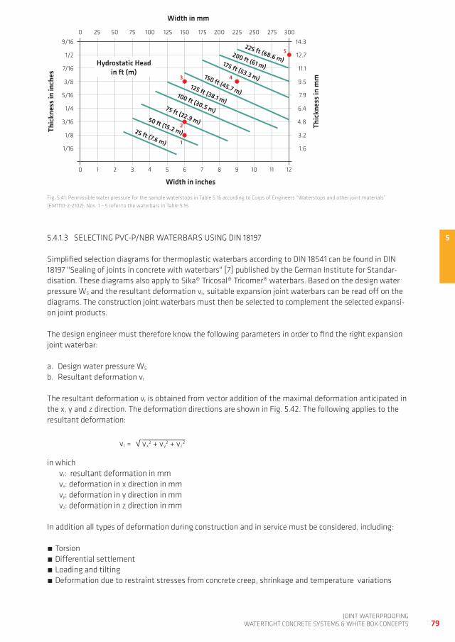
5
3
5
2
4
1
0 1 2 3 4 5 6 7 8 9 10 11 12
0 25 50 75 100 125 150 175 200 225 250 275 30014.3
12.7
11.1
9.5
7.9
6.4
4.8
3.2
1.6
9/16
1/2
7/16
3/8
5/16
1/4
3/16
1/8
1/16
Width in inches
Thic
knes
s in
inch
es
Thic
knes
s in
mm
Width in mm
Hydrostatic Headin ft (m)
175 ft (53.3 m)
225 ft (68.6 m)200 ft (61 m)
150 ft (45.7 m)125 ft (38.1 m)
100 ft (30.5 m)75 ft (22.9 m)50 ft (15.2 m)25 ft (7.6 m)
79joint waterproofing
watertight ConCrete SyStemS & white Box ConCeptS
5.4.1.3 SeLeCting pVC-p/nBr waterBarS USing din 18197
Simplified selection diagrams for thermoplastic waterbars according to din 18541 can be found in din 18197 "Sealing of joints in concrete with waterbars" [7] published by the german institute for Standar-disation. these diagrams also apply to Sika® tricosal® tricomer® waterbars. Based on the design water pressure wS and the resultant deformation vr, suitable expansion joint waterbars can be read off on the diagrams. the construction joint waterbars must then be selected to complement the selected expansi-on joint products.
the design engineer must therefore know the following parameters in order to find the right expansion joint waterbar:
a. design water pressure wS b. resultant deformation vr
the resultant deformation vr is obtained from vector addition of the maximal deformation anticipated in the x, y and z direction. the deformation directions are shown in fig. 5.42. the following applies to the resultant deformation:
√vr = vx2 + vy
2 + vz2
in which vr: resultant deformation in mm vx: deformation in x direction in mm vy: deformation in y direction in mm vz: deformation in z direction in mm
in addition all types of deformation during construction and in service must be considered, including:
torsion differential settlement Loading and tilting deformation due to restraint stresses from concrete creep, shrinkage and temperature variations
fig. 5.41: permissible water pressure for the sample waterstops in table 5.16 according to Corps of engineers “waterstops and other joint materials” (em1110-2-2102). nos. 1 – 5 refer to the waterbars in table 5.16.
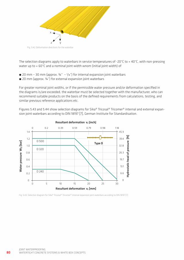
00
5 10 15 20 30
0 0.2 0.39 0.59 0.79 0.98 1.1845.9
39.4
32.8
26.3
19.7
13.1
6.6
0
1.4
1.2
1.0
0.8
0.6
0.4
0.2
Resultant deformation vr [mm]
Wat
er p
ress
ure
WS [
bar]
Hydr
osta
tic h
ead
of p
ress
ure
[ft]
Resultant deformation vr [inch]
Type D
25
D 240
D 320
D 500
80joint waterproofingwatertight ConCrete SyStemS & white Box ConCeptS
the selection diagrams apply to waterbars in service temperatures of -20°C to + 40°C, with non-pressing water up to + 60°C and a nominal joint width wnom (initial joint width) of
20 mm – 30 mm (approx. ¾“ – 1/8“) for internal expansion joint waterbars 20 mm (approx. ¾“) for external expansion joint waterbars
for greater nominal joint widths, or if the permissible water pressure and/or deformation specified in the diagrams is/are exceeded, the waterbar must be selected together with the manufacturer, who can recommend suitable products on the basis of the defined requirements from calculations, testing, and similar previous reference applications etc.
figures 5.43 and 5.44 show selection diagrams for Sika® tricosal® tricomer® internal and external expan-sion joint waterbars according to din 18197 [7], german institute for Standardisation.
fig. 5.42: deformation directions for the waterbar
fig. 5.43: Selection diagram for Sika® tricosal® tricomer® internal expansion joint waterbars according to din 18197 [7]
x
yz

50
05 10 20 25 30
0 0.2 0.4 0.8 1.0 1.4
45
40
35
15
10
5
0
1.4
1.2
1.0
0.8
0.6
0.4
0.2
Resultant deformation vr [mm]
Wat
er p
ress
ure
WS [
bar]
Hydr
osta
tic h
ead
of p
ress
ure
[ft]
Resultant deformation vr [inch]
Type DA
35
DA 240 *
DA 500 **
0.6 1.2
15
30
25
20
DA 320 *
DA 320 **
Stop anchor height* >25 mm (approx. 1“)** >30 mm (approx. 11/8“)
81joint waterproofing
watertight ConCrete SyStemS & white Box ConCeptS
Example 1:
in this example, selection of the waterbar for an expansion joint is based on the following service requirements:
deformation: vx = 14 mm, vy = 7 mm, vz = 4 mm water pressure: wS = 0.8 bar (= 8 mwS, approx. 26.2’)
the resultant deformation can be calculated from the individual deformation components.
√ √vr = vx2 + vy
2 + vz2 = 142 + 72 + 42 = 16.2 mm
at wS = 0.8 bar (approx. 26.2’) and vr = 16.2 mm (approx. 0.64“) the diagram shows the product required is a 50 cm wide Sika® tricosal® tricomer® external expansion joint waterbar according to din 18541 (designation: da 500), see fig. 5.45.
fig. 5.44: Selection diagram for Sika® tricosal® tricomer® external expansion joint waterbar according to din 18197 [7]
the procedure for waterbar selection using these diagrams is therefore also relatively simple and can be illustrated by the examples below:
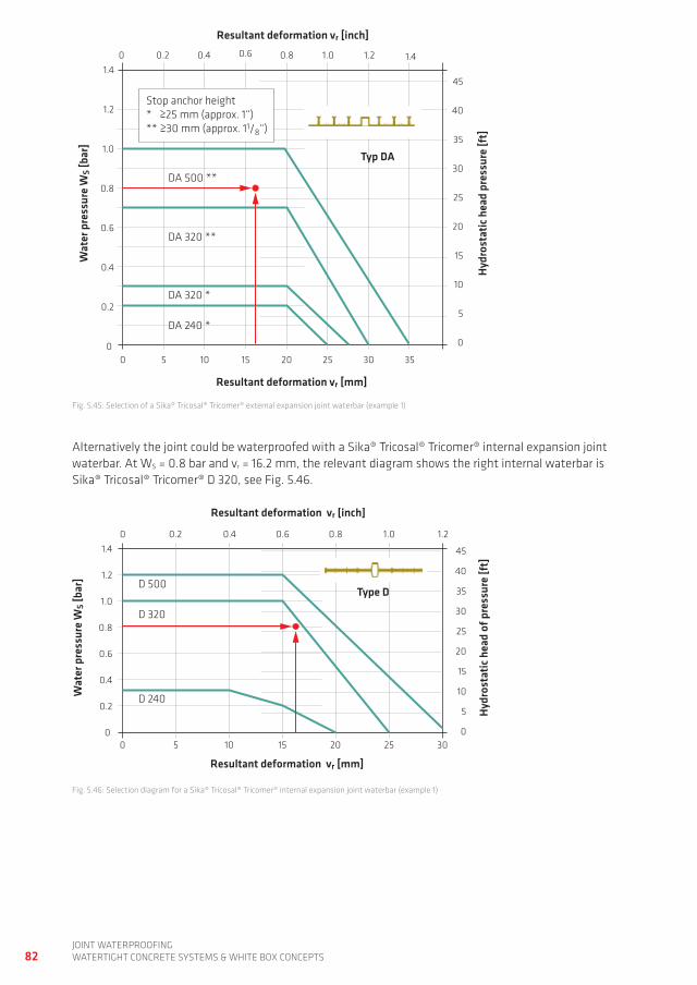
00
5 10 20 25 30
0 0.2 0.4 0.8 1.0 1.4
45
40
35
15
10
5
0
1.4
1.2
1.0
0.8
0.6
0.4
0.2
Resultant deformation vr [mm]
Wat
er p
ress
ure
WS [
bar]
Hydr
osta
tic h
ead
pres
sure
[ft]
Resultant deformation vr [inch]
Typ DA
35
DA 240 *
DA 500 **
0.6 1.2
15
30
25
20
DA 320 *
DA 320 **
Stop anchor height* >25 mm (approx. 1“)** >30 mm (approx. 11/8“)
00
5 10 15 20 30
0 0.2 0.4 0.6 0.8 1.0 1.21.4
1.2
1.0
0.8
0.6
0.4
0.2
Resultant deformation vr [mm]
Wat
er p
ress
ure
WS [
bar]
Hydr
osta
tic h
ead
of p
ress
ure
[ft]
Resultant deformation vr [inch]
Type D
25
D 240
D 320
D 500
45
40
35
15
10
5
0
30
25
20
82joint waterproofingwatertight ConCrete SyStemS & white Box ConCeptS
alternatively the joint could be waterproofed with a Sika® tricosal® tricomer® internal expansion joint waterbar. at wS = 0.8 bar and vr = 16.2 mm, the relevant diagram shows the right internal waterbar is Sika® tricosal® tricomer® d 320, see fig. 5.46.
fig. 5.45: Selection of a Sika® tricosal® tricomer® external expansion joint waterbar (example 1)
fig. 5.46: Selection diagram for a Sika® tricosal® tricomer® internal expansion joint waterbar (example 1)
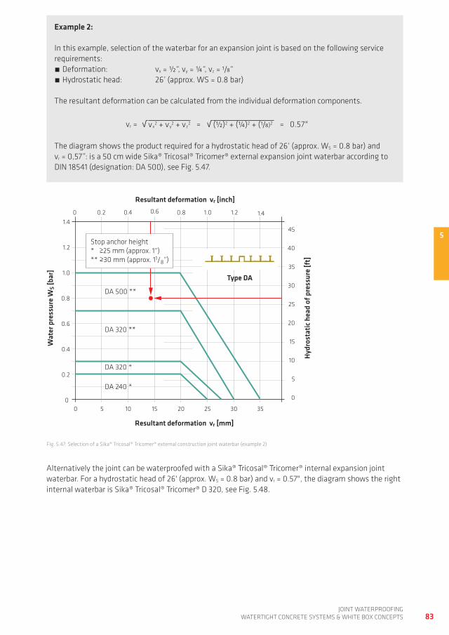
5
00
5 10 20 25 30
0 0.2 0.4 0.8 1.0 1.4
45
40
35
15
10
5
0
1.4
1.2
1.0
0.8
0.6
0.4
0.2
Resultant deformation vr [mm]
Wat
er p
ress
ure
WS [
bar]
Hydr
osta
tic h
ead
of p
ress
ure
[ft]
Resultant deformation vr [inch]
Type DA
35
DA 240 *
DA 500 **
0.6 1.2
15
30
25
20
DA 320 *
DA 320 **
Stop anchor height* >25 mm (approx. 1“)** >30 mm (approx. 11/8“)
83joint waterproofing
watertight ConCrete SyStemS & white Box ConCeptS
alternatively the joint can be waterproofed with a Sika® tricosal® tricomer® internal expansion joint waterbar. for a hydrostatic head of 26' (approx. wS = 0.8 bar) and vr = 0.57", the diagram shows the right internal waterbar is Sika® tricosal® tricomer® d 320, see fig. 5.48.
Example 2:
in this example, selection of the waterbar for an expansion joint is based on the following service requirements:
deformation: vx = ½“, vy = ¼“, vz = 1/8“ hydrostatic head: 26’ (approx. wS = 0.8 bar)
the resultant deformation can be calculated from the individual deformation components.
√ √vr = vx2 + vy
2 + vz2 = (½)2 + (¼)2 + (1/8)2 = 0.57"
the diagram shows the product required for a hydrostatic head of 26‘ (approx. wS = 0.8 bar) and vr = 0,57”: is a 50 cm wide Sika® tricosal® tricomer® external expansion joint waterbar according to din 18541 (designation: da 500), see fig. 5.47.
fig. 5.47: Selection of a Sika® tricosal® tricomer® external construction joint waterbar (example 2)
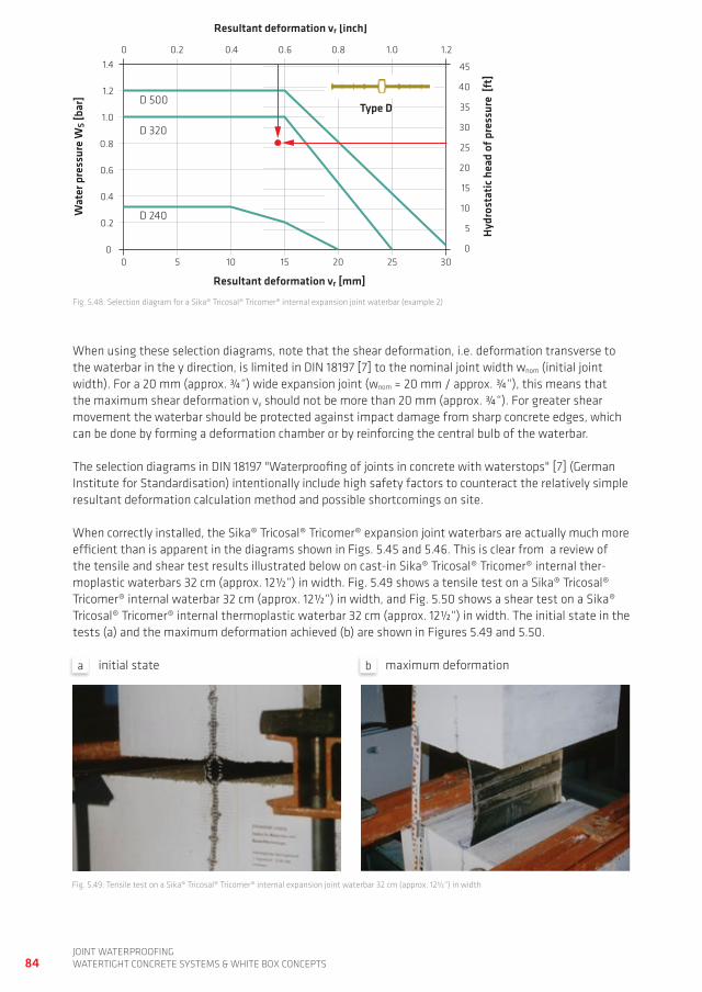
00
5 10 15 20 30
0 0.2 0.4 0.6 0.8 1.0 1.21.4
1.2
1.0
0.8
0.6
0.4
0.2
Resultant deformation vr [mm]
Wat
er p
ress
ure
WS [
bar]
Hydr
osta
tic h
ead
of p
ress
ure
[ft]
Resultant deformation vr [inch]
Type D
25
D 240
D 320
D 500
45
40
35
15
10
5
0
30
25
20
84joint waterproofingwatertight ConCrete SyStemS & white Box ConCeptS
when using these selection diagrams, note that the shear deformation, i.e. deformation transverse to the waterbar in the y direction, is limited in din 18197 [7] to the nominal joint width wnom (initial joint width). for a 20 mm (approx. ¾“) wide expansion joint (wnom = 20 mm / approx. ¾“), this means that the maximum shear deformation vy should not be more than 20 mm (approx. ¾“). for greater shear movement the waterbar should be protected against impact damage from sharp concrete edges, which can be done by forming a deformation chamber or by reinforcing the central bulb of the waterbar.
the selection diagrams in din 18197 "waterproofing of joints in concrete with waterstops" [7] (german institute for Standardisation) intentionally include high safety factors to counteract the relatively simple resultant deformation calculation method and possible shortcomings on site.
when correctly installed, the Sika® tricosal® tricomer® expansion joint waterbars are actually much more efficient than is apparent in the diagrams shown in figs. 5.45 and 5.46. this is clear from a review of the tensile and shear test results illustrated below on cast-in Sika® tricosal® tricomer® internal ther-moplastic waterbars 32 cm (approx. 12½“) in width. fig. 5.49 shows a tensile test on a Sika® tricosal® tricomer® internal waterbar 32 cm (approx. 12½“) in width, and fig. 5.50 shows a shear test on a Sika® tricosal® tricomer® internal thermoplastic waterbar 32 cm (approx. 12½“) in width. the initial state in the tests (a) and the maximum deformation achieved (b) are shown in figures 5.49 and 5.50.
fig. 5.49: tensile test on a Sika® tricosal® tricomer® internal expansion joint waterbar 32 cm (approx. 12½“) in width
fig. 5.48: Selection diagram for a Sika® tricosal® tricomer® internal expansion joint waterbar (example 2)
initial state maximum deformationa b
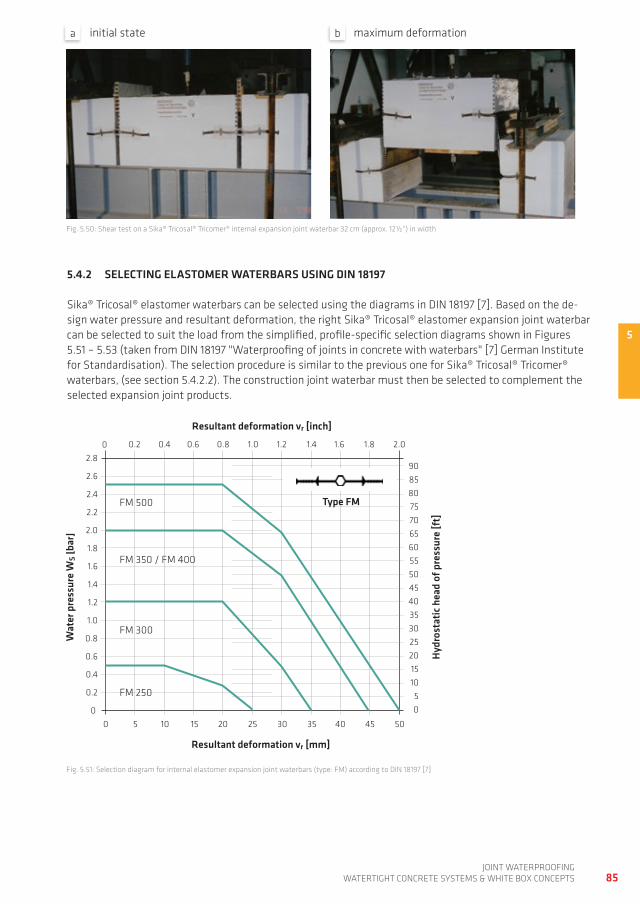
5
00
5 10 20 25 30
0 0.2 0.4 0.8 1.0 1.4
454035
151050
2.8
1.2
1.0
0.8
0.6
0.4
0.2
Resultant deformation vr [mm]
Wat
er p
ress
ure
WS [
bar]
Hydr
osta
tic h
ead
of p
ress
ure
[ft]
Resultant deformation vr [inch]
Type FM
35
FM 250
FM 500
0.6 1.2
15
302520
FM 300
FM 350 / FM 400
40 45 50
2.4
2.2
2.0
1.8
1.6
1.4
2.6
1.8 2.01.6
9085
65605550
807570
85joint waterproofing
watertight ConCrete SyStemS & white Box ConCeptS
5.4.2 SELECTINg ELASTOMER WATERBARS USINg DIN 18197
Sika® tricosal® elastomer waterbars can be selected using the diagrams in din 18197 [7]. Based on the de-sign water pressure and resultant deformation, the right Sika® tricosal® elastomer expansion joint waterbar can be selected to suit the load from the simplified, profile-specific selection diagrams shown in figures 5.51 – 5.53 (taken from din 18197 "waterproofing of joints in concrete with waterbars" [7] german institute for Standardisation). the selection procedure is similar to the previous one for Sika® tricosal® tricomer® waterbars, (see section 5.4.2.2). the construction joint waterbar must then be selected to complement the selected expansion joint products.
fig. 5.51: Selection diagram for internal elastomer expansion joint waterbars (type: fm) according to din 18197 [7]
fig. 5.50: Shear test on a Sika® tricosal® tricomer® internal expansion joint waterbar 32 cm (approx. 12½“) in width
initial state maximum deformationa b
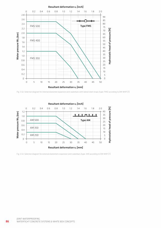
00
5 10 20 25 30
0 0.2 0.4 0.8 1.0 1.4
454035
151050
2.8
1.2
1.0
0.8
0.6
0.4
0.2
Resultant deformation vr [mm]
Wat
er p
ress
ure
WS [
bar]
Hydr
osta
tic h
ead
of p
ress
ure
[ft]
Resultant deformation vr [inch]
Type FMS
35
FMS 500
0.6 1.2
15
302520
FMS 350
FMS 400
40 45 50
2.4
2.2
2.0
1.8
1.6
1.4
2.6
1.8 2.01.6
9085
65605550
807570
00
5 10 20 25 30
0 0.2 0.4 0.8 1.0 1.44035
151050
1.2
1.0
0.8
0.6
0.4
0.2
Resultant deformation vr [mm]
Wat
er p
ress
ure
WS [
bar]
Hydr
osta
tic h
ead
of p
ress
ure
[ft]
Resultant deformation vr [inch]
35
AM 250
0.6 1.2
15
302520
AM 350
AM 500
40 45 50
1.8 2.01.6
Type AM
86joint waterproofingwatertight ConCrete SyStemS & white Box ConCeptS
fig. 5.53: Selection diagram for external elastomeric expansion joint waterbars (type: am) according to din 18197 [7]
fig. 5.52: Selection diagram for internal elastomer expansion joint waterbars with lateral steel straps (type: fmS) according to din 18197 [7]
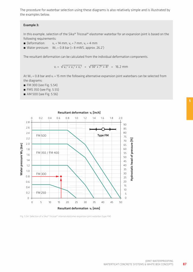
5
00
5 10 20 25 30
0 0.2 0.4 0.8 1.0 1.4
454035
151050
2.8
1.2
1.0
0.8
0.6
0.4
0.2
Resultant deformation vr [mm]
Wat
er p
ress
ure
WS [
bar]
Hydr
osta
tic h
ead
of p
ress
ure
[ft]
Resultant deformation vr [inch]
Type FM
35
FM 250
FM 500
0.6 1.2
15
302520
FM 300
FM 350 / FM 400
40 45 50
2.4
2.2
2.0
1.8
1.6
1.4
2.6
1.8 2.01.6
9085
65605550
807570
87joint waterproofing
watertight ConCrete SyStemS & white Box ConCeptS
the procedure for waterbar selection using these diagrams is also relatively simple and is illustrated by the examples below.
Example 3:
in this example, selection of the Sika® tricosal® elastomer waterbar for an expansion joint is based on the following requirements:
deformation: vx = 14 mm, vy = 7 mm, vz = 4 mm water pressure: wS = 0.8 bar (= 8 mwS, approx. 26.2’)
the resultant deformation can be calculated from the individual deformation components.
√ √vr = vx2 + vy
2 + vz2 = 142 + 72 + 42 = 16.2 mm
at wS = 0.8 bar and vr = 15 mm the following alternative expansion joint waterbars can be selected from the diagrams:
fm 300 (see fig. 5.54) fmS 350 (see fig. 5.55) am 500 (see fig. 5.56)
fig. 5.54: Selection of a Sika® tricosal® internal elastomer expansion joint waterbar (type fm)
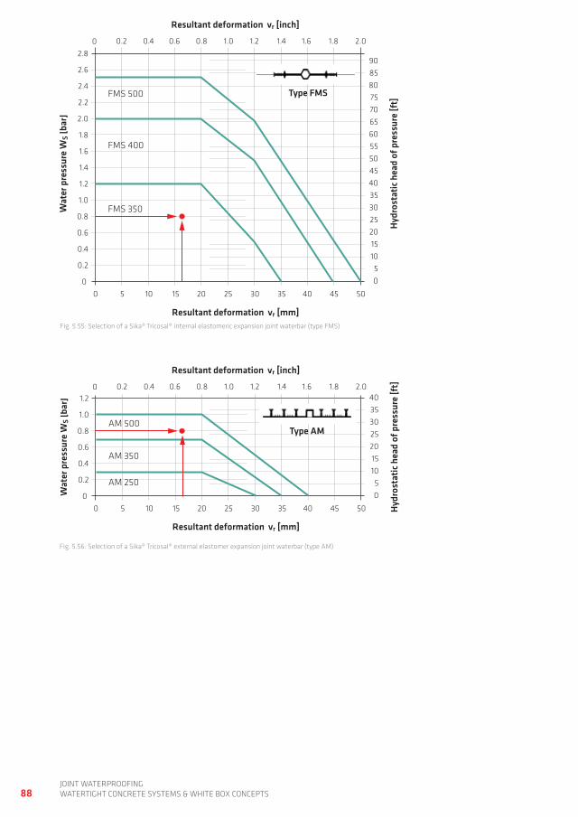
00
5 10 20 25 30
0 0.2 0.4 0.8 1.0 1.4
454035
151050
2.8
1.2
1.0
0.8
0.6
0.4
0.2
Resultant deformation vr [mm]
Wat
er p
ress
ure
WS [
bar]
Hydr
osta
tic h
ead
of p
ress
ure
[ft]
Resultant deformation vr [inch]
Type FMS
35
FMS 500
0.6 1.2
15
302520
FMS 350
FMS 400
40 45 50
2.4
2.2
2.0
1.8
1.6
1.4
2.6
1.8 2.01.6
9085
65605550
807570
00
5 10 20 25 30
0 0.2 0.4 0.8 1.0 1.44035
151050
1.2
1.0
0.8
0.6
0.4
0.2
Resultant deformation vr [mm]
Wat
er p
ress
ure
WS [
bar]
Hydr
osta
tic h
ead
of p
ress
ure
[ft]
Resultant deformation vr [inch]
35
AM 250
0.6 1.2
15
302520
AM 350
AM 500
40 45 50
1.8 2.01.6
Type AM
88joint waterproofingwatertight ConCrete SyStemS & white Box ConCeptS
fig. 5.55: Selection of a Sika® tricosal® internal elastomeric expansion joint waterbar (type fmS)
fig. 5.56: Selection of a Sika® tricosal® external elastomer expansion joint waterbar (type am)
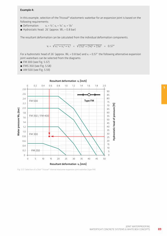
5
00
5 10 20 25 30
0 0.2 0.4 0.8 1.0 1.4
454035
151050
2.8
1.2
1.0
0.8
0.6
0.4
0.2
Resultant deformation vr [mm]
Wat
er p
ress
ure
WS [
bar]
Hydr
osta
tic h
ead
of p
ress
ure
[ft]
Resultant deformation vr [inch]
Type FM
35
FM 250
FM 500
0.6 1.2
15
302520
FM 300
FM 350 / FM 400
40 45 50
2.4
2.2
2.0
1.8
1.6
1.4
2.6
1.8 2.01.6
9085
65605550
807570
89joint waterproofing
watertight ConCrete SyStemS & white Box ConCeptS
Example 4:
in this example, selection of the tricosal® elastomeric waterbar for an expansion joint is based on the following requirements:
deformation: vx = ½“, vy = ¼“, vz = 1/8“ hydrostatic head: 26’ (approx. wS = 0.8 bar)
the resultant deformation can be calculated from the individual deformation components.
√ √vr = vx2 + vy
2 + vz2 = (½)2 + (¼)2 + (1/8)2 = 0.57"
for a hydrostatic head of 26‘ (approx. wS = 0.8 bar) and vr = 0,57” the following alternative expansion joint waterbars can be selected from the diagrams:
fm 300 (see fig. 5.57) fmS 350 (see fig. 5.58) am 500 (see fig. 5.59)
fig. 5.57: Selection of a Sika® tricosal® internal elastomer expansion joint waterbar (type fm)
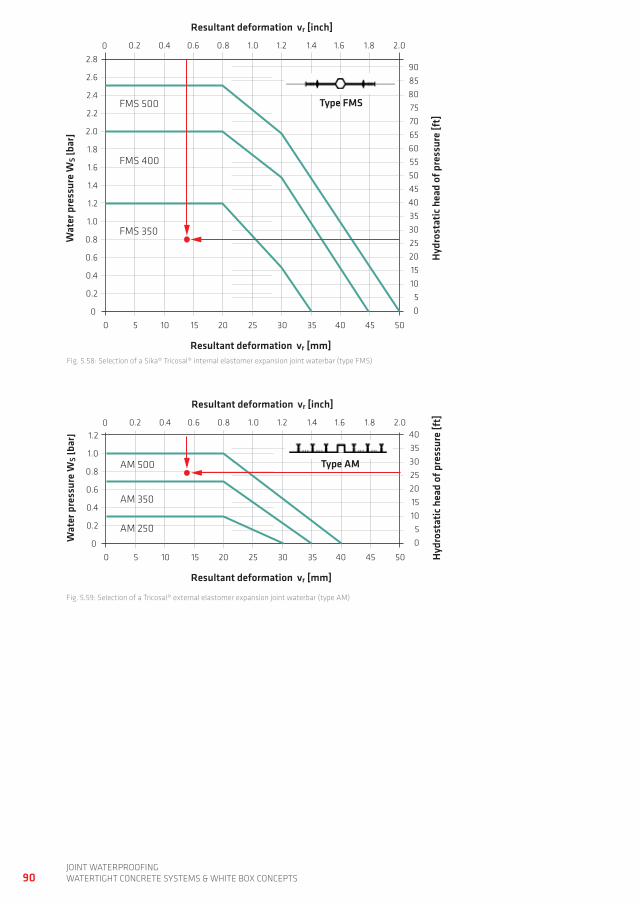
00
5 10 20 25 30
0 0.2 0.4 0.8 1.0 1.4
454035
151050
2.8
1.2
1.0
0.8
0.6
0.4
0.2
Resultant deformation vr [mm]
Wat
er p
ress
ure
WS [
bar]
Hydr
osta
tic h
ead
of p
ress
ure
[ft]
Resultant deformation vr [inch]
Type FMS
35
FMS 500
0.6 1.2
15
302520
FMS 350
FMS 400
40 45 50
2.4
2.2
2.0
1.8
1.6
1.4
2.6
1.8 2.01.6
9085
65605550
807570
00
5 10 20 25 30
0 0.2 0.4 0.8 1.0 1.44035
151050
1.2
1.0
0.8
0.6
0.4
0.2
Resultant deformation vr [mm]
Wat
er p
ress
ure
WS [
bar]
Hydr
osta
tic h
ead
of p
ress
ure
[ft]
Resultant deformation vr [inch]
35
AM 250
0.6 1.2
15
302520
AM 350
AM 500
40 45 50
1.8 2.01.6
Type AM
90joint waterproofingwatertight ConCrete SyStemS & white Box ConCeptS
fig. 5.58: Selection of a Sika® tricosal® internal elastomer expansion joint waterbar (type fmS)
fig. 5.59: Selection of a tricosal® external elastomer expansion joint waterbar (type am)
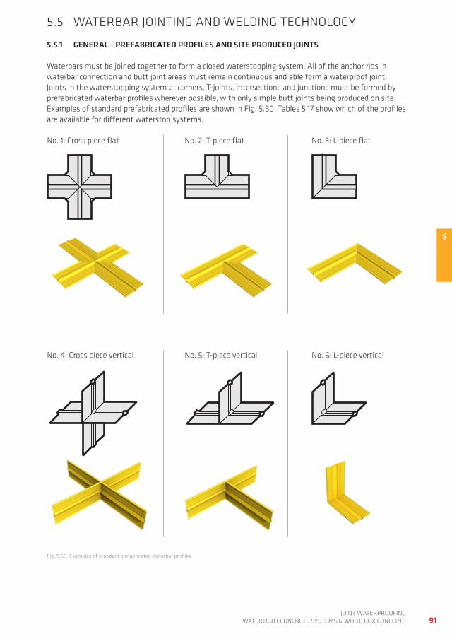
5
91joint waterproofing
watertight ConCrete SyStemS & white Box ConCeptS
5.5 waterBar jointing and weLding teChnoLogy
5.5.1 gENERAL - PREFABRICATED PROFILES AND SITE PRODUCED JOINTS
waterbars must be joined together to form a closed waterstopping system. all of the anchor ribs in waterbar connection and butt joint areas must remain continuous and able form a waterproof joint. joints in the waterstopping system at corners, t-joints, intersections and junctions must be formed by prefabricated waterbar profiles wherever possible, with only simple butt joints being produced on site. examples of standard prefabricated profiles are shown in fig. 5.60. tables 5.17 show which of the profiles are available for different waterstop systems.
no. 1: Cross piece flat
fig. 5.60: examples of standard prefabricated waterbar profiles
no. 2: t-piece flat no. 3: L-piece flat
no. 4: Cross piece vertical no. 5: t-piece vertical no. 6: L-piece vertical
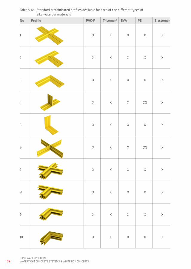
92joint waterproofingwatertight ConCrete SyStemS & white Box ConCeptS
table 5.17: Standard prefabricated profiles available for each of the different types of Sika waterbar materials
No Profile PvC-P Tricomer® EvA PE Elastomer
1 x x x x x
2 x x x x x
3 x x x x x
4 x x x (x) x
5 x x x x x
6 x x x (x) x
7 x x x x x
8 x x x x x
9 x x x x x
10 x x x x x
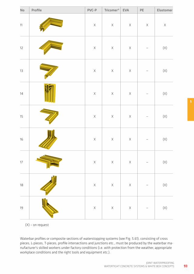
5
93joint waterproofing
watertight ConCrete SyStemS & white Box ConCeptS
No Profile PvC-P Tricomer® EvA PE Elastomer
11 x x x x x
12 x x x — (x)
13 x x x — (x)
14 x x x — (x)
15 x x x — (x)
16 x x x — (x)
17 x x x — (x)
18 x x x — (x)
19 x x x — (x)
(x) – on request
waterbar profiles or composite sections of waterstopping systems (see fig. 5.61), consisting of cross pieces, L-pieces, t-pieces, profile intersections and junctions etc., must be produced by the waterbar ma-nufacturer's skilled workers under factory conditions (i.e. with protection from the weather, appropriate workplace conditions and the right tools and equipment etc.).
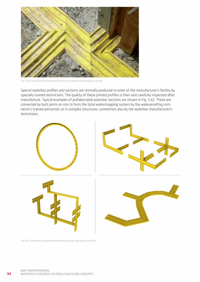
94joint waterproofingwatertight ConCrete SyStemS & white Box ConCeptS
fig. 5.61: example of a prefabricated section of a waterbar waterstopping system
Special waterbar profiles and sections are normally produced to order at the manufacturer's facility by specially trained technicians. the quality of these jointed profiles is then also carefully inspected after manufacture. typical examples of prefabricated waterbar sections are shown in fig. 5.62. these are connected by butt joints on site to form the total waterstopping system by the waterproofing cont-ractor's trained personnel, or in complex structures, sometimes also by the waterbar manufacturer's technicians.
fig. 5.62: examples of prefabricated waterbar profiles and system sections
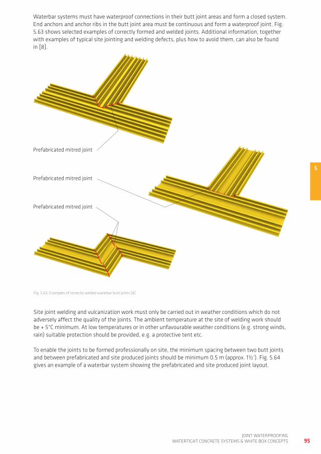
5
95joint waterproofing
watertight ConCrete SyStemS & white Box ConCeptS
waterbar systems must have waterproof connections in their butt joint areas and form a closed system. end anchors and anchor ribs in the butt joint area must be continuous and form a waterproof joint. fig. 5.63 shows selected examples of correctly formed and welded joints. additional information, together with examples of typical site jointing and welding defects, plus how to avoid them, can also be found in [8].
fig. 5.63: examples of correctly welded waterbar butt joints [8]
Site joint welding and vulcanization work must only be carried out in weather conditions which do not adversely affect the quality of the joints. the ambient temperature at the site of welding work should be + 5°C minimum. at low temperatures or in other unfavourable weather conditions (e.g. strong winds, rain) suitable protection should be provided, e.g. a protective tent etc.
to enable the joints to be formed professionally on site, the minimum spacing between two butt joints and between prefabricated and site produced joints should be minimum 0.5 m (approx. 1½‘). fig. 5.64 gives an example of a waterbar system showing the prefabricated and site produced joint layout.
prefabricated mitred joint
prefabricated mitred joint
prefabricated mitred joint
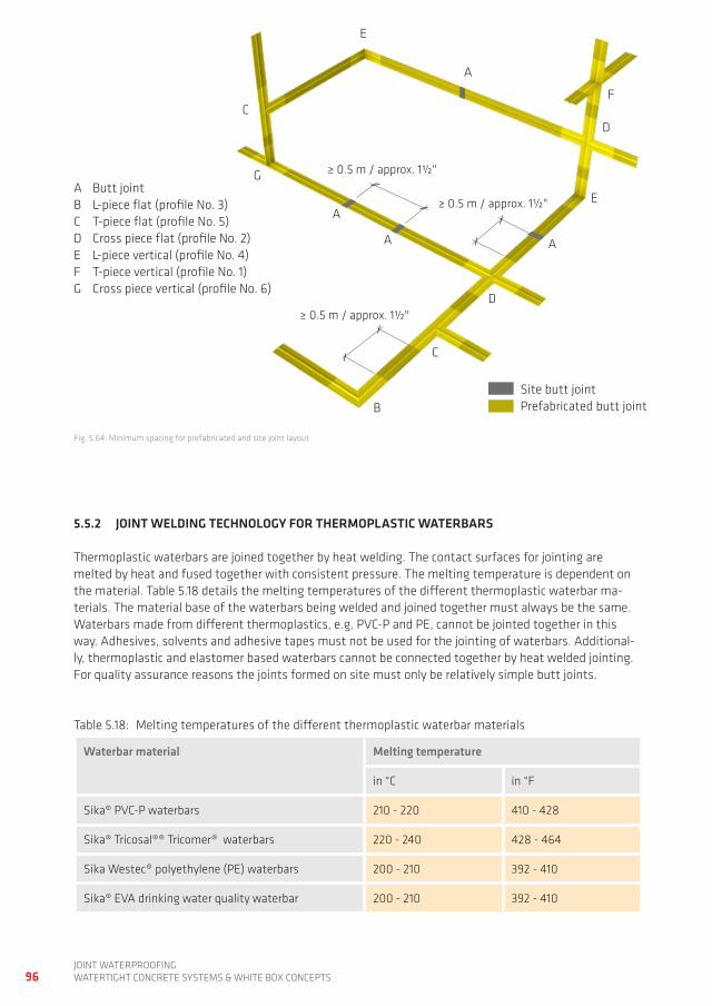
96joint waterproofingwatertight ConCrete SyStemS & white Box ConCeptS
fig. 5.64: minimum spacing for prefabricated and site joint layout
a Butt jointB L-piece flat (profile no. 3)C t-piece flat (profile no. 5)d Cross piece flat (profile no. 2)e L-piece vertical (profile no. 4)f t-piece vertical (profile no. 1)g Cross piece vertical (profile no. 6)
Site butt jointprefabricated butt joint
5.5.2 JOINT WELDINg TECHNOLOgy FOR THERMOPLASTIC WATERBARS
thermoplastic waterbars are joined together by heat welding. the contact surfaces for jointing are melted by heat and fused together with consistent pressure. the melting temperature is dependent on the material. table 5.18 details the melting temperatures of the different thermoplastic waterbar ma-terials. the material base of the waterbars being welded and joined together must always be the same. waterbars made from different thermoplastics, e.g. pVC-p and pe, cannot be jointed together in this way. adhesives, solvents and adhesive tapes must not be used for the jointing of waterbars. additional-ly, thermoplastic and elastomer based waterbars cannot be connected together by heat welded jointing. for quality assurance reasons the joints formed on site must only be relatively simple butt joints.
table 5.18: melting temperatures of the different thermoplastic waterbar materials
Waterbar material Melting temperature
in °C in °f
Sika® pVC-p waterbars 210 - 220 410 - 428
Sika® tricosal®® tricomer® waterbars 220 - 240 428 - 464
Sika westec® polyethylene (pe) waterbars 200 - 210 392 - 410
Sika® eVa drinking water quality waterbar 200 - 210 392 - 410
a
a
a
a
B
C
C
d
d
e
e
f
g ≥ 0.5 m / approx. 1½"
≥ 0.5 m / approx. 1½"
≥ 0.5 m / approx. 1½"
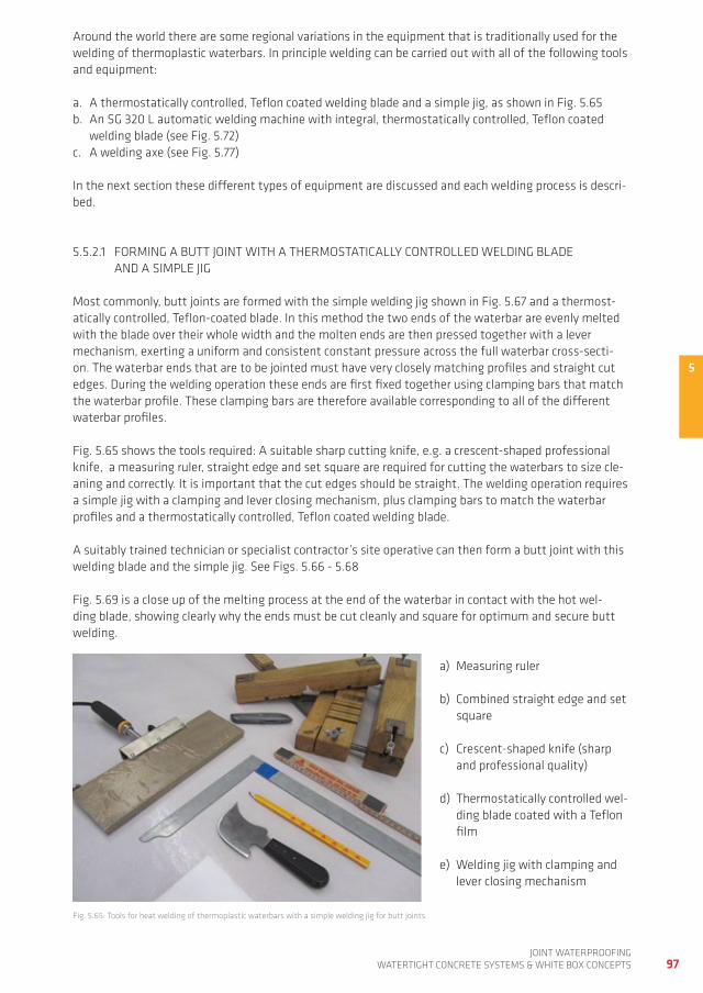
5
97joint waterproofing
watertight ConCrete SyStemS & white Box ConCeptS
prefabricated butt joint
around the world there are some regional variations in the equipment that is traditionally used for the welding of thermoplastic waterbars. in principle welding can be carried out with all of the following tools and equipment:
a. a thermostatically controlled, teflon coated welding blade and a simple jig, as shown in fig. 5.65 b. an Sg 320 L automatic welding machine with integral, thermostatically controlled, teflon coated
welding blade (see fig. 5.72)c. a welding axe (see fig. 5.77)
in the next section these different types of equipment are discussed and each welding process is descri-bed.
5.5.2.1 forming a BUtt joint with a thermoStatiCaLLy ControLLed weLding BLade and a SimpLe jig
most commonly, butt joints are formed with the simple welding jig shown in fig. 5.67 and a thermost-atically controlled, teflon-coated blade. in this method the two ends of the waterbar are evenly melted with the blade over their whole width and the molten ends are then pressed together with a lever mechanism, exerting a uniform and consistent constant pressure across the full waterbar cross-secti-on. the waterbar ends that are to be jointed must have very closely matching profiles and straight cut edges. during the welding operation these ends are first fixed together using clamping bars that match the waterbar profile. these clamping bars are therefore available corresponding to all of the different waterbar profiles.
fig. 5.65 shows the tools required: a suitable sharp cutting knife, e.g. a crescent-shaped professional knife, a measuring ruler, straight edge and set square are required for cutting the waterbars to size cle-aning and correctly. it is important that the cut edges should be straight. the welding operation requires a simple jig with a clamping and lever closing mechanism, plus clamping bars to match the waterbar profiles and a thermostatically controlled, teflon coated welding blade.
a suitably trained technician or specialist contractor’s site operative can then form a butt joint with this welding blade and the simple jig. See figs. 5.66 - 5.68
fig. 5.69 is a close up of the melting process at the end of the waterbar in contact with the hot wel-ding blade, showing clearly why the ends must be cut cleanly and square for optimum and secure butt welding.
fig. 5.65: tools for heat welding of thermoplastic waterbars with a simple welding jig for butt joints
a) measuring ruler
b) Combined straight edge and set square
c) Crescent-shaped knife (sharp and professional quality)
d) thermostatically controlled wel-ding blade coated with a teflon film
e) welding jig with clamping and lever closing mechanism
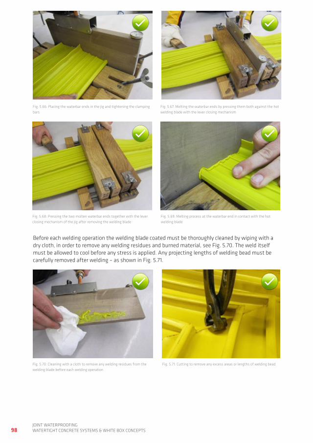
98joint waterproofingwatertight ConCrete SyStemS & white Box ConCeptS
fig. 5.66: placing the waterbar ends in the jig and tightening the clamping bars
fig. 5.67: melting the waterbar ends by pressing them both against the hot welding blade with the lever closing mechanism
fig. 5.68: pressing the two molten waterbar ends together with the lever closing mechanism of the jig after removing the welding blade
fig. 5.69: melting process at the waterbar end in contact with the hot welding blade
Before each welding operation the welding blade coated must be thoroughly cleaned by wiping with a dry cloth, in order to remove any welding residues and burned material, see fig. 5.70. the weld itself must be allowed to cool before any stress is applied. any projecting lengths of welding bead must be carefully removed after welding – as shown in fig. 5.71.
fig. 5.71: Cutting to remove any excess areas or lengths of welding beadfig. 5.70: Cleaning with a cloth to remove any welding residues from the welding blade before each welding operation
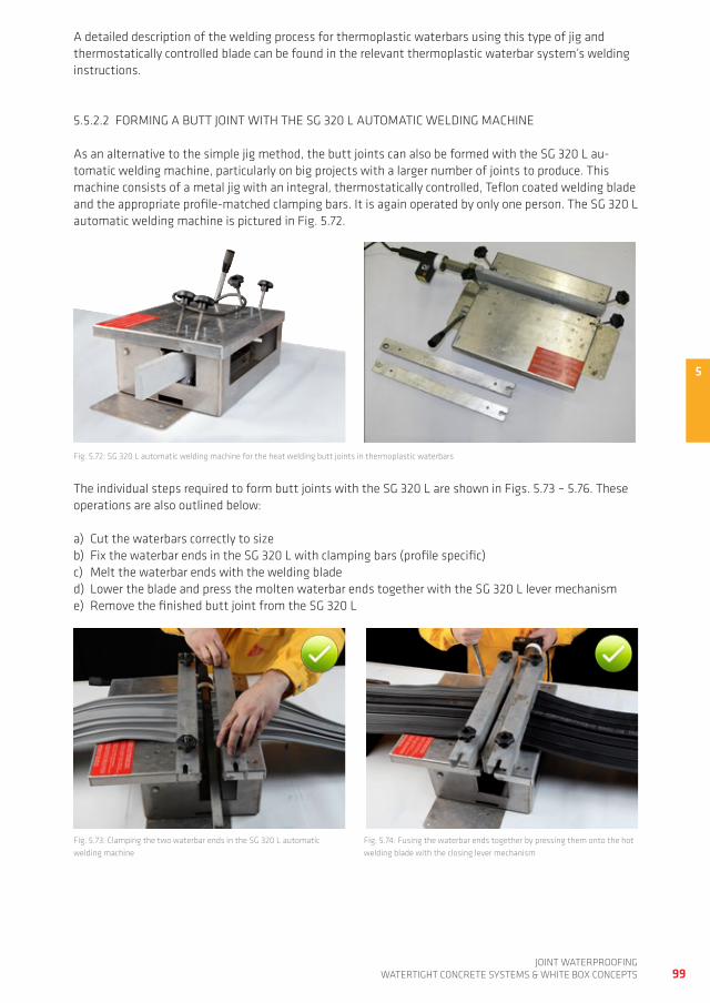
5
99joint waterproofing
watertight ConCrete SyStemS & white Box ConCeptS
a detailed description of the welding process for thermoplastic waterbars using this type of jig and thermostatically controlled blade can be found in the relevant thermoplastic waterbar system’s welding instructions.
5.5.2.2 forming a BUtt joint with the Sg 320 L aUtomatiC weLding maChine
as an alternative to the simple jig method, the butt joints can also be formed with the Sg 320 L au-tomatic welding machine, particularly on big projects with a larger number of joints to produce. this machine consists of a metal jig with an integral, thermostatically controlled, teflon coated welding blade and the appropriate profile-matched clamping bars. it is again operated by only one person. the Sg 320 L automatic welding machine is pictured in fig. 5.72.
fig. 5.72: Sg 320 L automatic welding machine for the heat welding butt joints in thermoplastic waterbars
the individual steps required to form butt joints with the Sg 320 L are shown in figs. 5.73 – 5.76. these operations are also outlined below: a) Cut the waterbars correctly to sizeb) fix the waterbar ends in the Sg 320 L with clamping bars (profile specific)c) melt the waterbar ends with the welding bladed) Lower the blade and press the molten waterbar ends together with the Sg 320 L lever mechanisme) remove the finished butt joint from the Sg 320 L
fig. 5.73: Clamping the two waterbar ends in the Sg 320 L automatic welding machine
fig. 5.74: fusing the waterbar ends together by pressing them onto the hot welding blade with the closing lever mechanism
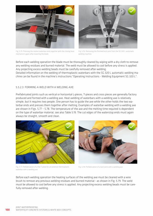
100joint waterproofingwatertight ConCrete SyStemS & white Box ConCeptS
fig. 5.75: pressing the molten waterbar ends together with the closing lever mechanism again after lowering the blade
fig. 5.76: removing the finished butt joint from the Sg 320 L automatic welding machine
Before each welding operation the blade must be thoroughly cleaned by wiping with a dry cloth to remove any welding residues and burned material. the weld must be allowed to cool before any stress is applied. any projecting excess welding beads must be carefully removed after welding. detailed information on the welding of thermoplastic waterbars with the Sg 320 L automatic welding ma-chine can be found in the machine’s instructions "operating instructions - welding equipment Sg 320 L".
5.5.2.3 forming a weLd with a weLding axe
prefabricated joints such as vertical or horizontal L-pieces, t-pieces and cross pieces are generally factory produced and formed with a welding axe. heat welding of waterbars with a welding axe is relatively simple, but it requires two people. one person has to guide the axe while the other holds the two wa-terbar ends and presses them together after melting. examples of waterbar welding with a welding axe are shown in figs. 5.77 – 5.78. the temperature of the axe and the melting time required is dependent on the type of waterbar material, see also table 5.19. the cut edges of the waterstop ends must again always be straight, smooth and clean.
fig. 5.77: prefabrication of a flat t-piece for an external thermoplastic waterbar with a welding axe
fig. 5.78: prefabrication of a butt joint with a welding axe
Before each welding operation the heating surfaces of the welding axe must be cleaned with a wire brush to remove any previous welding residues and burned material - as shown in fig. 5.79. the weld must be allowed to cool before any stress is applied. any projecting excess welding beads must be care-fully removed after welding.
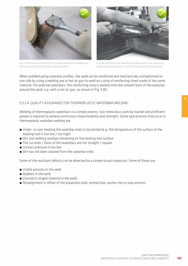
5
101joint waterproofing
watertight ConCrete SyStemS & white Box ConCeptS
when prefabricating waterbar profiles, the weld can be reinforced and mechanically strengthened on one side by using a welding axe or hot air gun to weld on a strip of reinforcing sheet made of the same material. for external waterbars, this reinforcing strip is welded onto the smooth back of the waterbar around the weld, e.g. with a hot air gun, as shown in fig. 5.80.
fig. 5.79: removing residues from the heating surfaces of a welding axe with a wire brush before the next welding operation
fig. 5.80: reinforcing the weld during prefabrication of the waterbar by using a hot air gun to weld on a reinforcing strip of the same material
5.5.2.4 QUaLity aSSUranCe for thermopLaStiC waterBar weLding
welding of thermoplastic waterbars is a simple process, but meticulous work by trained and proficient people is required to achieve continuous impermeability and strength. Some typical errors that occur in thermoplastic waterbar welding are:
Under- or over-heating the waterbar ends to be jointed (e.g. the temperature of the surface of the heating tool is too low / too high)
dirt and welding residues remaining on the heating tool surface the cut ends / faces of the waterbars are not straight / square Contact pressure is too low dirt has not been cleaned from the waterbar ends
Some of the resultant defects can be detected by a simple visual inspection. Some of these are:
Visible porosity in the weld Bubbles in the weld Charred or singed material in the weld misalignment or offset of the expansion bulb, central loop, anchor ribs or stop anchors
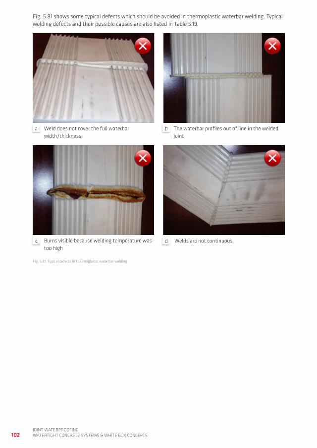
102joint waterproofingwatertight ConCrete SyStemS & white Box ConCeptS
fig. 5.81 shows some typical defects which should be avoided in thermoplastic waterbar welding. typical welding defects and their possible causes are also listed in table 5.19.
fig. 5.81: typical defects in thermoplastic waterbar welding
weld does not cover the full waterbar width/thickness
the waterbar profiles out of line in the welded joint
Burns visible because welding temperature was too high
welds are not continuous
a b
c d
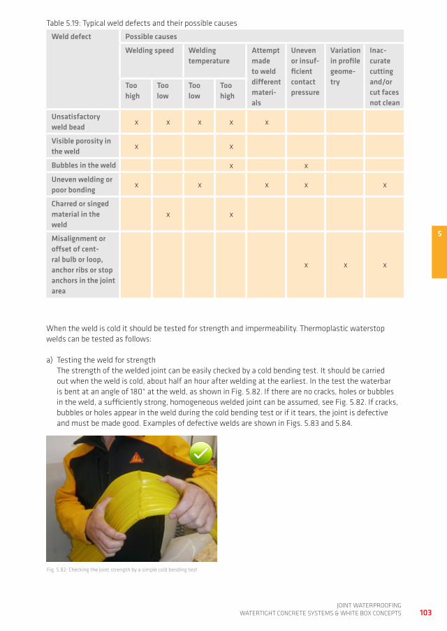
5
103joint waterproofing
watertight ConCrete SyStemS & white Box ConCeptS
table 5.19: typical weld defects and their possible causes
Weld defect Possible causes
Welding speed Welding temperature
Attempt made to weld different materi-als
Uneven or insuf-ficient contact pressure
variation in profile geome-try
Inac-curate cutting and/or cut faces not clean
Too high
Too low
Too low
Too high
Unsatisfactory weld bead x x x x x
visible porosity in the weld x x
Bubbles in the weld x x
Uneven welding or poor bonding x x x x x
Charred or singed material in the weld
x x
Misalignment or offset of cent-ral bulb or loop, anchor ribs or stop anchors in the joint area
x x x
when the weld is cold it should be tested for strength and impermeability. thermoplastic waterstop welds can be tested as follows:
a) testing the weld for strength the strength of the welded joint can be easily checked by a cold bending test. it should be carried out when the weld is cold, about half an hour after welding at the earliest. in the test the waterbar is bent at an angle of 180° at the weld, as shown in fig. 5.82. if there are no cracks, holes or bubbles in the weld, a sufficiently strong, homogeneous welded joint can be assumed, see fig. 5.82. if cracks, bubbles or holes appear in the weld during the cold bending test or if it tears, the joint is defective and must be made good. examples of defective welds are shown in figs. 5.83 and 5.84.
fig. 5.82: Checking the joint strength by a simple cold bending test
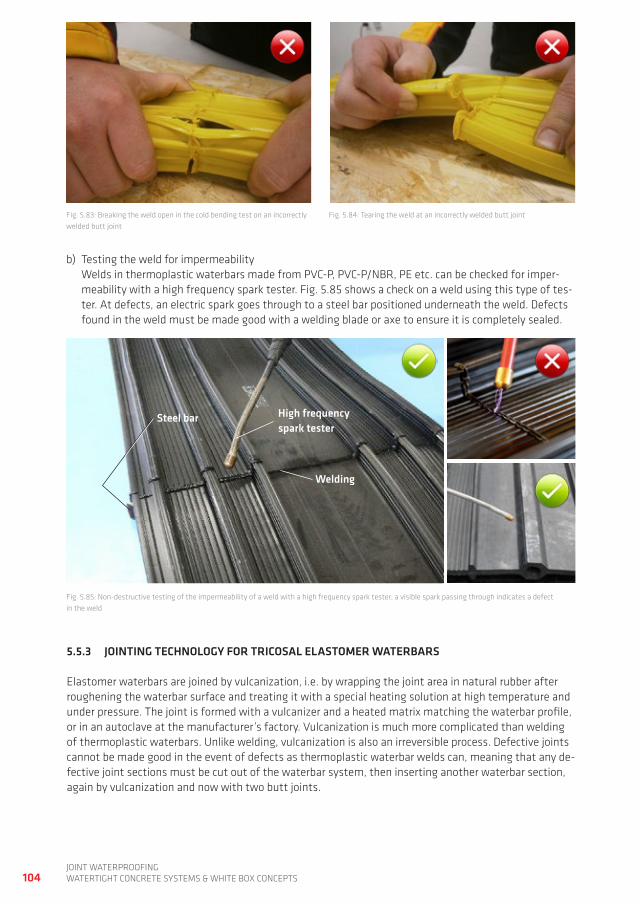
104joint waterproofingwatertight ConCrete SyStemS & white Box ConCeptS
b) testing the weld for impermeability welds in thermoplastic waterbars made from pVC-p, pVC-p/nBr, pe etc. can be checked for imper-meability with a high frequency spark tester. fig. 5.85 shows a check on a weld using this type of tes-ter. at defects, an electric spark goes through to a steel bar positioned underneath the weld. defects found in the weld must be made good with a welding blade or axe to ensure it is completely sealed.
fig. 5.83: Breaking the weld open in the cold bending test on an incorrectly welded butt joint
fig. 5.84: tearing the weld at an incorrectly welded butt joint
fig. 5.85: non-destructive testing of the impermeability of a weld with a high frequency spark tester; a visible spark passing through indicates a defect in the weld
5.5.3 JOINTINg TECHNOLOgy FOR TRICOSAL ELASTOMER WATERBARS
elastomer waterbars are joined by vulcanization, i.e. by wrapping the joint area in natural rubber after roughening the waterbar surface and treating it with a special heating solution at high temperature and under pressure. the joint is formed with a vulcanizer and a heated matrix matching the waterbar profile, or in an autoclave at the manufacturer’s factory. Vulcanization is much more complicated than welding of thermoplastic waterbars. Unlike welding, vulcanization is also an irreversible process. defective joints cannot be made good in the event of defects as thermoplastic waterbar welds can, meaning that any de-fective joint sections must be cut out of the waterbar system, then inserting another waterbar section, again by vulcanization and now with two butt joints.
High frequency spark tester
Welding
Steel bar
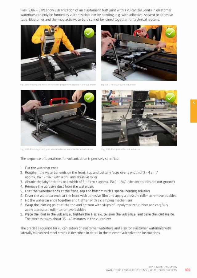
5
105joint waterproofing
watertight ConCrete SyStemS & white Box ConCeptS
fig. 5.86: placing the waterbar with the prepared butt joint in the vulcanizer fig. 5.87: tensioning the vulcanizer
fig. 5.88: forming a butt joint in an elastomer waterbar with a vulcanizer
figs. 5.86 – 5.89 show vulcanization of an elastomeric butt joint with a vulcanizer. joints in elastomer waterbars can only be formed by vulcanization, not by bonding, e.g. with adhesive, solvent or adhesive tape. elastomer and thermoplastic waterbars cannot be joined together for technical reasons.
the sequence of operations for vulcanization is precisely specified:
1. Cut the waterbar ends2. roughen the waterbar ends on the front, top and bottom faces over a width of 3 - 4 cm /
approx. 11/8“ – 15/8“ with a drill and abrasive roller 3. abrade the labyrinth ribs to a width of 3 - 4 cm / approx. 11/8“ – 15/8“ (the anchor ribs are not ground)4. remove the abrasive dust from the waterbars 5. Coat the waterbar ends at the front, top and bottom with a special heating solution 6. Cover the waterbar ends at the front with adhesive film and apply a pressure roller to remove bubbles 7. fit the waterbar ends together and tighten with a clamping mechanism 8. wrap the jointing point at the top and bottom with strips of unpolymerized rubber and carefully
apply a pressure roller to remove bubbles 9. place the joint in the vulcanizer, tighten the t-screw, tension the vulcanizer and bake the joint inside.
the process takes about 35 - 45 minutes in the vulcanizer.
the precise sequence for vulcanization of elastomer waterbars and also for elastomer waterbars with laterally vulcanized steel straps is described in detail in the relevant vulcanization instructions.
fig. 5.89: Butt joint after vulcanisation
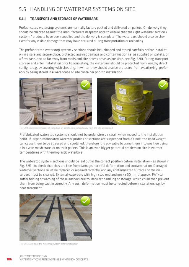
106joint waterproofingwatertight ConCrete SyStemS & white Box ConCeptS
5.6 handLing of waterBar SyStemS on Site
5.6.1 TRANSPORT AND STORAgE OF WATERBARS
prefabricated waterstop systems are normally factory packed and delivered on pallets. on delivery they should be checked against the manufacturers despatch note to ensure that the right waterbar section / system / products have been supplied and the delivery is complete. the waterbars should also be che-cked for any visible damage that may have occurred during transportation or unloading.
the prefabricated waterstop system / sections should be unloaded and stored carefully before installati-on in a safe and secure place, protected against damage and contamination i.e. as supplied on pallets, on a firm base, and as far away from roads and site access areas as possible, see fig. 5.90. during transport, storage and after installation prior to concreting, the waterbars should be protected from lengthy direct sunlight, e.g. by covering with sheeting. in winter they should also be protected from weathering, prefer-ably by being stored in a warehouse or site container prior to installation.
fig. 5.90: Correct site storage of waterbars on pallets, covered and away from the site access road
prefabricated waterstop systems should not be under stress / strain when moved to the installation point. if large prefabricated waterbar profiles or sections are suspended from a crane, the dead weight can cause them to be stressed and stretched, therefore it is advisable to crane them into position using a in a wire mesh crate, or on their pallets. this is an even bigger potential problem on site in warmer temperatures with thermoplastic waterbars.
the waterstop system sections should be laid out in the correct position before installation - as shown in fig. 5.91 - to check that they are free from damage, harmful deformation and contamination. damaged waterbar sections must be replaced or repaired correctly, and any contaminated surfaces of the wa-terbars must be cleaned. external waterbars with high stop end anchors (≥ 30 mm / approx. 11/8“) can suffer folding or warping of these anchors due to incorrect handling or storage, which could then prevent them from being cast in correctly. any such deformation must be corrected before installation, e.g. by heat treatment.
fig. 5.91: Laying out the waterstop system before installation
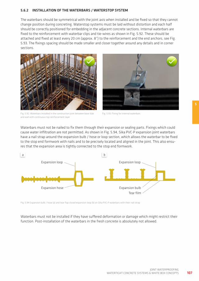
5
107joint waterproofing
watertight ConCrete SyStemS & white Box ConCeptS
5.6.2 INSTALLATION OF THE WATERBARS / WATERSTOP SySTEM
the waterbars should be symmetrical with the joint axis when installed and be fixed so that they cannot change position during concreting. waterstop systems must be laid without distortion and each half should be correctly positioned for embedding in the adjacent concrete sections. internal waterbars are fixed to the reinforcement with waterbar clips and tie-wires as shown in fig. 5.92. these should be attached and fixed at least every 20 cm (approx. 8“) to the reinforcement and the end anchors, see fig. 5.93. the fixings spacing should be made smaller and closer together around any details and in corner sections.
fig. 5.92: waterbars installed in the construction joint between base slab and wall with continuous top reinforcement layer
fig. 5.93: fixing for internal waterbars
waterbars must not be nailed to fix them through their expansion or sealing parts. fixings which could cause water infiltration are not permitted. as shown in fig. 5.94, Sika pVC-p expansion joint waterbars have a nail strap around the expansion bulb / hose or loop section, which allows the waterbar to be fixed to the stop end formwork with nails and to be precisely located and aligned in the joint. this also ensu-res that the expansion area is tightly connected to the stop end formwork.
waterbars must not be installed if they have suffered deformation or damage which might restrict their function. post-installation of the waterbars in the fresh concrete is absolutely not allowed.
fig. 5.94 expansion bulb / hose (a) and tear flap closed expansion loop (b) on Sika pVC-p waterbars with their nail strap
expansion loop expansion loop
expansion bulbexpansion hosetear film
a b
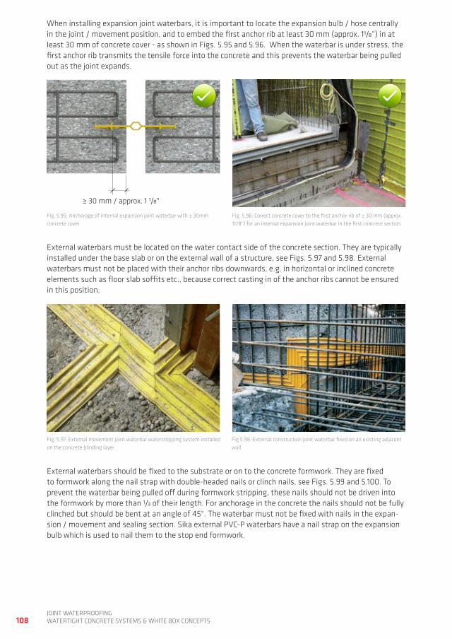
108joint waterproofingwatertight ConCrete SyStemS & white Box ConCeptS
when installing expansion joint waterbars, it is important to locate the expansion bulb / hose centrally in the joint / movement position, and to embed the first anchor rib at least 30 mm (approx. 11/8“) in at least 30 mm of concrete cover - as shown in figs. 5.95 and 5.96. when the waterbar is under stress, the first anchor rib transmits the tensile force into the concrete and this prevents the waterbar being pulled out as the joint expands.
fig. 5.97: external movement joint waterbar waterstopping system installed on the concrete blinding layer
fig 5.98: external construction joint waterbar fixed on an existing adjacent wall
external waterbars must be located on the water contact side of the concrete section. they are typically installed under the base slab or on the external wall of a structure, see figs. 5.97 and 5.98. external waterbars must not be placed with their anchor ribs downwards, e.g. in horizontal or inclined concrete elements such as floor slab soffits etc., because correct casting in of the anchor ribs cannot be ensured in this position.
external waterbars should be fixed to the substrate or on to the concrete formwork. they are fixed to formwork along the nail strap with double-headed nails or clinch nails, see figs. 5.99 and 5.100. to prevent the waterbar being pulled off during formwork stripping, these nails should not be driven into the formwork by more than 1/3 of their length. for anchorage in the concrete the nails should not be fully clinched but should be bent at an angle of 45°. the waterbar must not be fixed with nails in the expan-sion / movement and sealing section. Sika external pVC-p waterbars have a nail strap on the expansion bulb which is used to nail them to the stop end formwork.
fig. 5.95: anchorage of internal expansion joint waterbar with ≥ 30mm concrete cover
fig. 5.96: Correct concrete cover to the first anchor rib of ≥ 30 mm (approx. 11/8“) for an internal expansion joint waterbar in the first concrete section
≥ 30 mm / approx. 1 1/8"
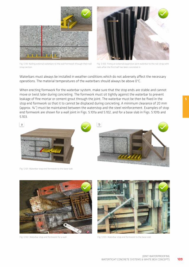
5
109joint waterproofing
watertight ConCrete SyStemS & white Box ConCeptS
fig. 5.99: nailing external waterbars to the wall formwork through their nail strap section
fig. 5.100: fixing an external expansion joint waterbar to the nail strap with nails after the first half has been concreted in
waterbars must always be installed in weather conditions which do not adversely affect the necessary operations. the material temperatures of the waterbars should always be above 0°C.
when erecting formwork for the waterbar system, make sure that the stop ends are stable and cannot move or twist later during concreting. the formwork must sit tightly against the waterbar to prevent leakage of fine mortar or cement grout through the joint. the waterbar must be then be fixed in the stop end formwork so that it to cannot be displaced during concreting. a minimum clearance of 20 mm (approx. ¾“) must be maintained between the waterstop and the steel reinforcement. examples of stop end formwork are shown for a wall joint in figs. 5.101a and 5.102, and for a base slab in figs. 5.101b and 5.103.
fig. 5.101: waterbar stop end formwork to the base slab
fig. 5.102: waterbar stop end formwork for a wall fig. 5.103: waterbar stop end formwork to the base slab
a b
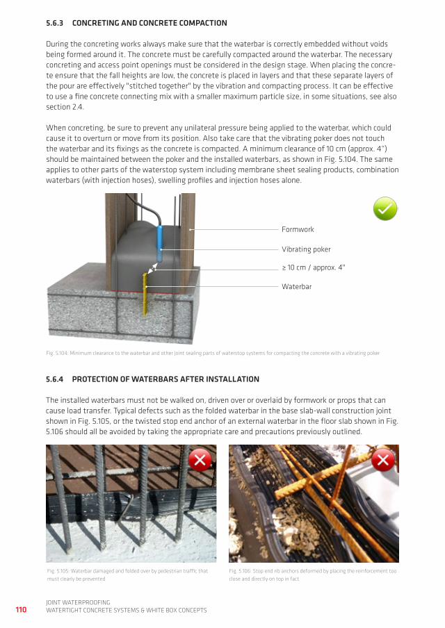
110joint waterproofingwatertight ConCrete SyStemS & white Box ConCeptS
5.6.3 CONCRETINg AND CONCRETE COMPACTION
during the concreting works always make sure that the waterbar is correctly embedded without voids being formed around it. the concrete must be carefully compacted around the waterbar. the necessary concreting and access point openings must be considered in the design stage. when placing the concre-te ensure that the fall heights are low, the concrete is placed in layers and that these separate layers of the pour are effectively "stitched together" by the vibration and compacting process. it can be effective to use a fine concrete connecting mix with a smaller maximum particle size, in some situations, see also section 2.4.
when concreting, be sure to prevent any unilateral pressure being applied to the waterbar, which could cause it to overturn or move from its position. also take care that the vibrating poker does not touch the waterbar and its fixings as the concrete is compacted. a minimum clearance of 10 cm (approx. 4“) should be maintained between the poker and the installed waterbars, as shown in fig. 5.104. the same applies to other parts of the waterstop system including membrane sheet sealing products, combination waterbars (with injection hoses), swelling profiles and injection hoses alone.
fig. 5.104: minimum clearance to the waterbar and other joint sealing parts of waterstop systems for compacting the concrete with a vibrating poker
5.6.4 PROTECTION OF WATERBARS AFTER INSTALLATION
the installed waterbars must not be walked on, driven over or overlaid by formwork or props that can cause load transfer. typical defects such as the folded waterbar in the base slab-wall construction joint shown in fig. 5.105, or the twisted stop end anchor of an external waterbar in the floor slab shown in fig. 5.106 should all be avoided by taking the appropriate care and precautions previously outlined.
fig. 5.105: waterbar damaged and folded over by pedestrian traffic that must clearly be prevented
fig. 5.106: Stop end rib anchors deformed by placing the reinforcement too close and directly on top in fact
formwork
≥ 10 cm / approx. 4"
Vibrating poker
waterbar
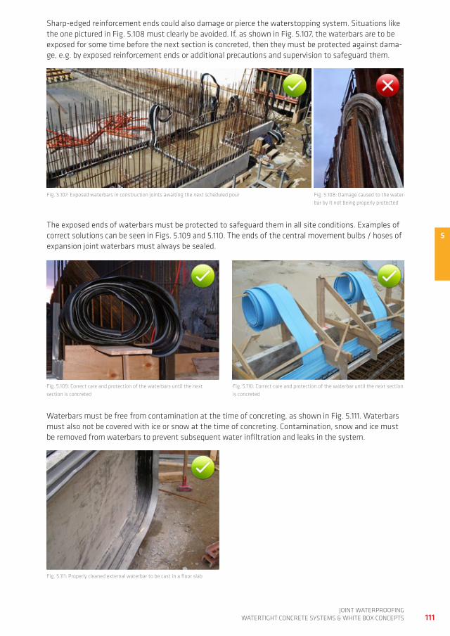
5
111joint waterproofing
watertight ConCrete SyStemS & white Box ConCeptS
Sharp-edged reinforcement ends could also damage or pierce the waterstopping system. Situations like the one pictured in fig. 5.108 must clearly be avoided. if, as shown in fig. 5.107, the waterbars are to be exposed for some time before the next section is concreted, then they must be protected against dama-ge, e.g. by exposed reinforcement ends or additional precautions and supervision to safeguard them.
fig. 5.108: damage caused to the water-bar by it not being properly protected
fig. 5.107: exposed waterbars in construction joints awaiting the next scheduled pour
the exposed ends of waterbars must be protected to safeguard them in all site conditions. examples of correct solutions can be seen in figs. 5.109 and 5.110. the ends of the central movement bulbs / hoses of expansion joint waterbars must always be sealed.
fig. 5.109: Correct care and protection of the waterbars until the next section is concreted
fig. 5.110: Correct care and protection of the waterbar until the next section is concreted
waterbars must be free from contamination at the time of concreting, as shown in fig. 5.111. waterbars must also not be covered with ice or snow at the time of concreting. Contamination, snow and ice must be removed from waterbars to prevent subsequent water infiltration and leaks in the system.
fig. 5.111: properly cleaned external waterbar to be cast in a floor slab
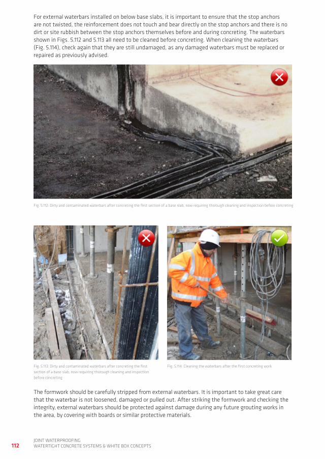
112joint waterproofingwatertight ConCrete SyStemS & white Box ConCeptS
for external waterbars installed on below base slabs, it is important to ensure that the stop anchors are not twisted, the reinforcement does not touch and bear directly on the stop anchors and there is no dirt or site rubbish between the stop anchors themselves before and during concreting. the waterbars shown in figs. 5.112 and 5.113 all need to be cleaned before concreting. when cleaning the waterbars (fig. 5.114), check again that they are still undamaged, as any damaged waterbars must be replaced or repaired as previously advised.
fig. 5.114: Cleaning the waterbars after the first concreting work
the formwork should be carefully stripped from external waterbars. it is important to take great care that the waterbar is not loosened, damaged or pulled out. after striking the formwork and checking the integrity, external waterbars should be protected against damage during any future grouting works in the area, by covering with boards or similar protective materials.
fig. 5.112: dirty and contaminated waterbars after concreting the first section of a base slab, now requiring thorough cleaning and inspection before concreting
fig. 5.113: dirty and contaminated waterbars after concreting the first section of a base slab, now requiring thorough cleaning and inspection before concreting
5
113joint waterproofing
watertight ConCrete SyStemS & white Box ConCeptS
5.6.5 INSPECTION AND DOCUMENTATION
the installed waterbars should be inspected before concreting. the following require particular attention:
a. have the waterbars been installed in the correct position and without folding or warping?b. have the waterbars been fixed so that they cannot turn over or be displaced during concreting?c. are the joints and connections on expansion joint waterbars waterproof?d. has the minimum clearance of 50 mm (approx. 2“) between waterbar and starter bars at the floor
slab - wall construction joint been maintained?e. is the minimum clearance of 20 mm (approx. ¾“) between waterbar and reinforcement maintained?f. does the stop end formwork sit tightly against the waterbar?g. is the installed waterbar free from contamination and damage?h. are exposed ends of cast-in waterbars properly protected against damage until they are to be fully
cast in later?
if defects or damage are found during the inspection, they must be made good before concreting.after striking the component formwork, the visible parts of the waterbars must be examined for dama-ge. this is particularly important on external waterbars. damage and defects must be documented and professionally rectified.further details on how to design and plan the joint waterproofing system with waterbars and how to handle complex waterstop systems on site, together with many practical examples, are given in [8].
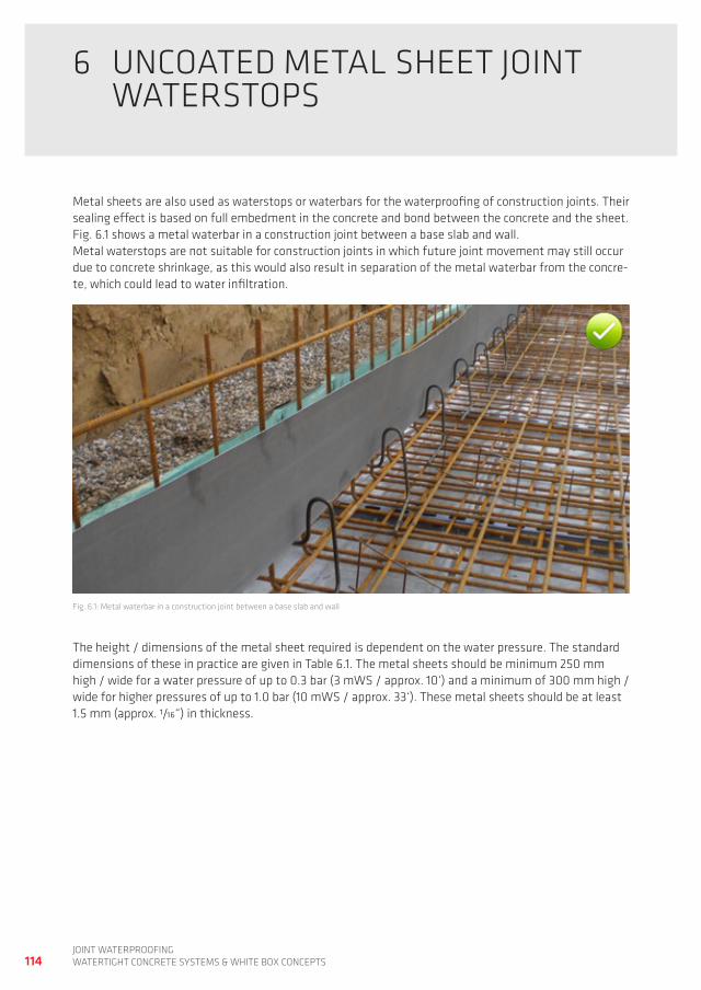
114joint waterproofingwatertight ConCrete SyStemS & white Box ConCeptS
6 UnCoated metaL Sheet joint waterStopS
metal sheets are also used as waterstops or waterbars for the waterproofing of construction joints. their sealing effect is based on full embedment in the concrete and bond between the concrete and the sheet. fig. 6.1 shows a metal waterbar in a construction joint between a base slab and wall.metal waterstops are not suitable for construction joints in which future joint movement may still occur due to concrete shrinkage, as this would also result in separation of the metal waterbar from the concre-te, which could lead to water infiltration.
fig. 6.1: metal waterbar in a construction joint between a base slab and wall
the height / dimensions of the metal sheet required is dependent on the water pressure. the standard dimensions of these in practice are given in table 6.1. the metal sheets should be minimum 250 mm high / wide for a water pressure of up to 0.3 bar (3 mwS / approx. 10‘) and a minimum of 300 mm high / wide for higher pressures of up to 1.0 bar (10 mwS / approx. 33‘). these metal sheets should be at least 1.5 mm (approx. 1/16“) in thickness.
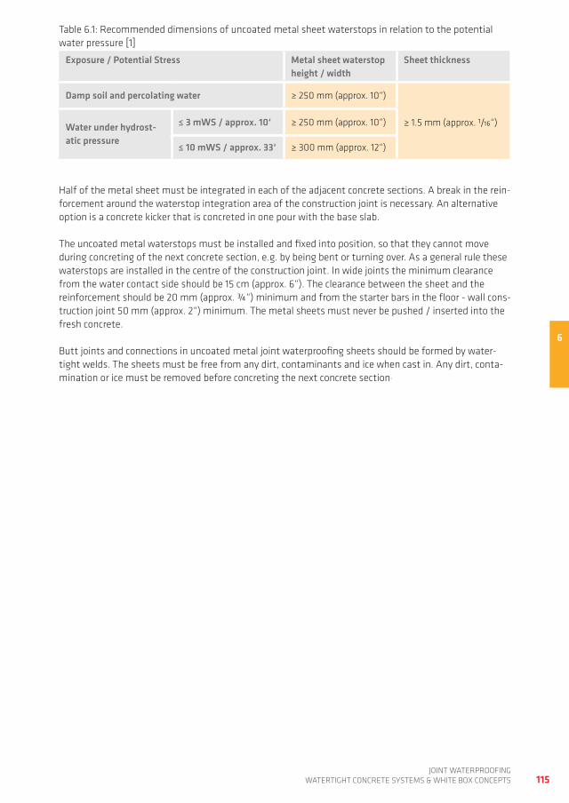
6
115joint waterproofing
watertight ConCrete SyStemS & white Box ConCeptS
table 6.1: recommended dimensions of uncoated metal sheet waterstops in relation to the potential water pressure [1]
Exposure / Potential Stress Metal sheet waterstop height / width
Sheet thickness
Damp soil and percolating water ≥ 250 mm (approx. 10“)
Water under hydrost-atic pressure
≤ 3 mWS / approx. 10‘ ≥ 250 mm (approx. 10“) ≥ 1.5 mm (approx. 1/16“)
≤ 10 mWS / approx. 33‘ ≥ 300 mm (approx. 12“)
half of the metal sheet must be integrated in each of the adjacent concrete sections. a break in the rein-forcement around the waterstop integration area of the construction joint is necessary. an alternative option is a concrete kicker that is concreted in one pour with the base slab.
the uncoated metal waterstops must be installed and fixed into position, so that they cannot move during concreting of the next concrete section, e.g. by being bent or turning over. as a general rule these waterstops are installed in the centre of the construction joint. in wide joints the minimum clearance from the water contact side should be 15 cm (approx. 6“). the clearance between the sheet and the reinforcement should be 20 mm (approx. ¾“) minimum and from the starter bars in the floor - wall cons-truction joint 50 mm (approx. 2“) minimum. the metal sheets must never be pushed / inserted into the fresh concrete.
Butt joints and connections in uncoated metal joint waterproofing sheets should be formed by water-tight welds. the sheets must be free from any dirt, contaminants and ice when cast in. any dirt, conta-mination or ice must be removed before concreting the next concrete section.
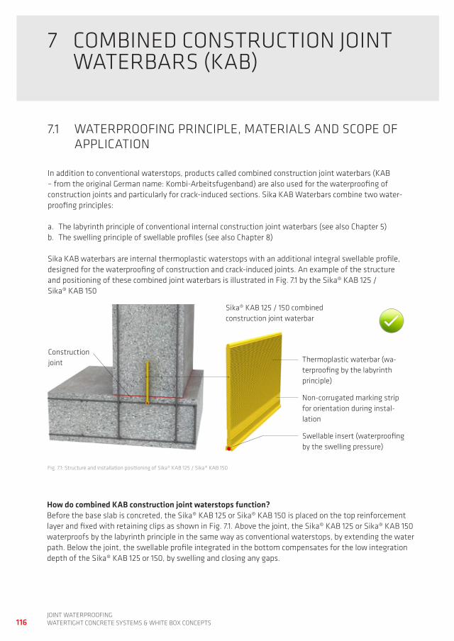
116joint waterproofingwatertight ConCrete SyStemS & white Box ConCeptS
7 ComBined ConStrUCtion joint waterBarS (KaB)
7.1 waterproofing prinCipLe, materiaLS and SCope of appLiCation
in addition to conventional waterstops, products called combined construction joint waterbars (KaB – from the original german name: Kombi-arbeitsfugenband) are also used for the waterproofing of construction joints and particularly for crack-induced sections. Sika KaB waterbars combine two water-proofing principles:
a. the labyrinth principle of conventional internal construction joint waterbars (see also Chapter 5)b. the swelling principle of swellable profiles (see also Chapter 8)
Sika KaB waterbars are internal thermoplastic waterstops with an additional integral swellable profile, designed for the waterproofing of construction and crack-induced joints. an example of the structure and positioning of these combined joint waterbars is illustrated in fig. 7.1 by the Sika® KaB 125 / Sika® KaB 150
fig. 7.1: Structure and installation positioning of Sika® KaB 125 / Sika® KaB 150
Construction joint
Swellable insert (waterproofing by the swelling pressure)
non-corrugated marking strip for orientation during instal-lation
thermoplastic waterbar (wa-terproofing by the labyrinth principle)
Sika® KaB 125 / 150 combined construction joint waterbar
How do combined KAB construction joint waterstops function?Before the base slab is concreted, the Sika® KaB 125 or Sika® KaB 150 is placed on the top reinforcement layer and fixed with retaining clips as shown in fig. 7.1. above the joint, the Sika® KaB 125 or Sika® KaB 150 waterproofs by the labyrinth principle in the same way as conventional waterstops, by extending the water path. Below the joint, the swellable profile integrated in the bottom compensates for the low integration depth of the Sika® KaB 125 or 150, by swelling and closing any gaps.
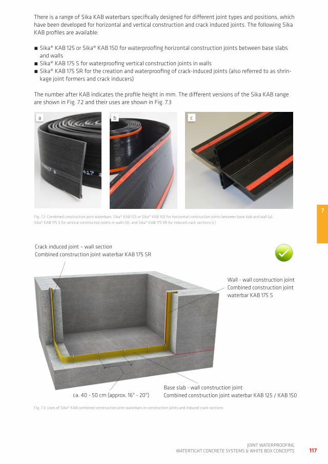
7
117joint waterproofing
watertight ConCrete SyStemS & white Box ConCeptS
there is a range of Sika KaB waterbars specifically designed for different joint types and positions, which have been developed for horizontal and vertical construction and crack induced joints. the following Sika KaB profiles are available:
Sika® KaB 125 or Sika® KaB 150 for waterproofing horizontal construction joints between base slabs and walls
Sika® KaB 175 S for waterproofing vertical construction joints in walls Sika® KaB 175 Sr for the creation and waterproofing of crack-induced joints (also referred to as shrin-kage joint formers and crack inducers)
the number after KaB indicates the profile height in mm. the different versions of the Sika KaB range are shown in fig. 7.2 and their uses are shown in fig. 7.3
fig. 7.2: Combined construction joint waterbars: Sika® KaB 125 or Sika® KaB 150 for horizontal construction joints between base slab and wall (a), Sika® KaB 175 S for vertical construction joints in walls (b), and Sika® KaB 175 Sr for induced crack sections (c)
fig. 7.3: Uses of Sika® KaB combined construction joint waterbars in construction joints and induced crack sections
Crack induced joint – wall sectionCombined construction joint waterbar KaB 175 Sr
Base slab - wall construction joint Combined construction joint waterbar KaB 125 / KaB 150ca. 40 - 50 cm (approx. 16" - 20")
a cb
wall - wall construction joint Combined construction joint waterbar KaB 175 S
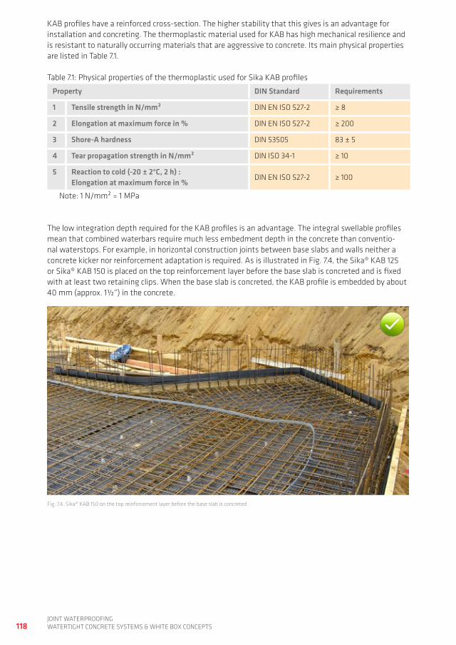
118joint waterproofingwatertight ConCrete SyStemS & white Box ConCeptS
KaB profiles have a reinforced cross-section. the higher stability that this gives is an advantage for installation and concreting. the thermoplastic material used for KaB has high mechanical resilience and is resistant to naturally occurring materials that are aggressive to concrete. its main physical properties are listed in table 7.1.
table 7.1: physical properties of the thermoplastic used for Sika KaB profiles
Property DIN Standard Requirements
1 Tensile strength in N/mm² din en iSo 527-2 ≥ 8
2 Elongation at maximum force in % din en iSo 527-2 ≥ 200
3 Shore-A hardness din 53505 83 ± 5
4 Tear propagation strength in N/mm² din iSo 34-1 ≥ 10
5 Reaction to cold (-20 ± 2°C, 2 h) :Elongation at maximum force in %
din en iSo 527-2 ≥ 100
note: 1 n/mm² = 1 mpa
the low integration depth required for the KaB profiles is an advantage. the integral swellable profiles mean that combined waterbars require much less embedment depth in the concrete than conventio-nal waterstops. for example, in horizontal construction joints between base slabs and walls neither a concrete kicker nor reinforcement adaptation is required. as is illustrated in fig. 7.4, the Sika® KaB 125 or Sika® KaB 150 is placed on the top reinforcement layer before the base slab is concreted and is fixed with at least two retaining clips. when the base slab is concreted, the KaB profile is embedded by about 40 mm (approx. 1½“) in the concrete.
fig. 7.4: Sika® KaB 150 on the top reinforcement layer before the base slab is concreted
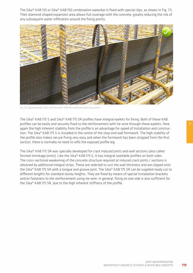
7
119joint waterproofing
watertight ConCrete SyStemS & white Box ConCeptS
the Sika® KaB 125 or Sika® KaB 150 combination waterbar is fixed with special clips, as shown in fig. 7.5. their diamond shaped expansion area allows full coverage with the concrete, greatly reducing the risk of any subsequent water infiltration around the fixing points.
the Sika® KaB 175 S and Sika® KaB 175 Sr profiles have integral eyelets for fixing. Both of these KaB profiles can be easily and securely fixed to the reinforcement with tie-wire through these eyelets. here again the high inherent stability from the profile is an advantage for speed of installation and construc-tion. the Sika® KaB 175 S is installed in the centre of the stop-end wall formwork. the high stability of the profile also makes secure fixing very easy and when the formwork has been stripped from the first section, there is normally no need to refix the exposed profile leg.
the Sika® KaB 175 Sr was specially developed for crack induced joints and wall sections (also called formed shrinkage joints). Like the Sika® KaB 175 S, it has integral swellable profiles on both sides. the cross-sectional weakening of the concrete structure required at induced crack joints / sections is obtained by additional integral strips. these are selected to suit the wall thickness and are clipped onto the Sika® KaB 175 Sr with a tongue and groove joint. the Sika® KaB 175 Sr can be supplied ready cut to different lengths for standard storey heights. they are fixed by means of special installation brackets and/or fasteners to the reinforcement using tie-wire. in general, fixing on one side is also sufficient for the Sika® KaB 175 Sr, due to the high inherent stiffness of the profile.
fig. 7.5: Special rhombic clips to fix the Sika® KaB 150 combined waterstop system
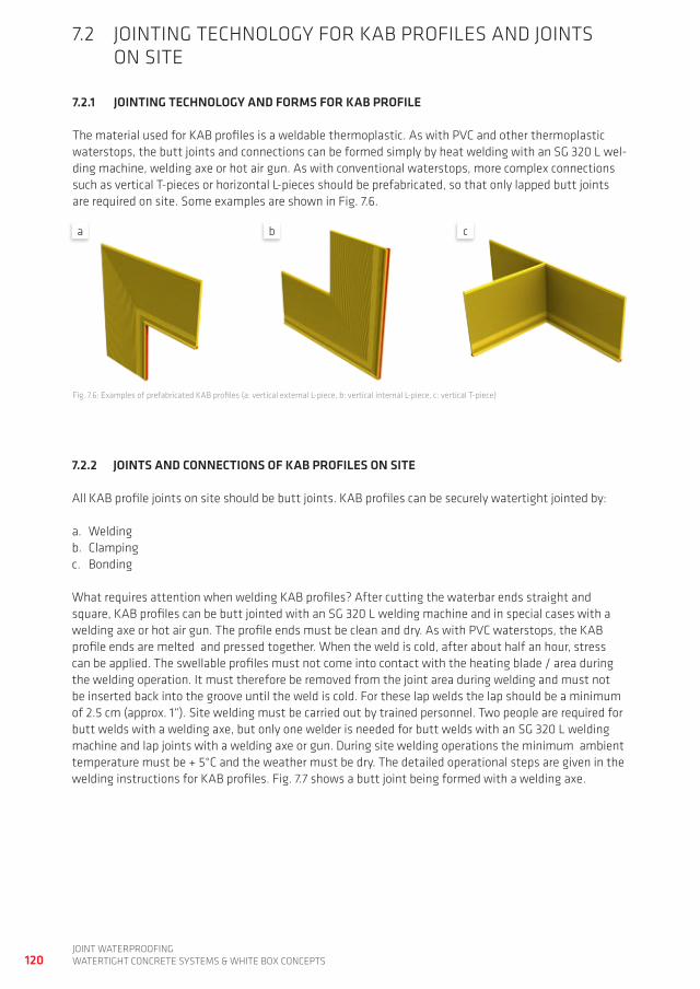
120joint waterproofingwatertight ConCrete SyStemS & white Box ConCeptS
7.2 jointing teChnoLogy for KaB profiLeS and jointS on Site
7.2.1 JOINTINg TECHNOLOgy AND FORMS FOR KAB PROFILE
the material used for KaB profiles is a weldable thermoplastic. as with pVC and other thermoplastic waterstops, the butt joints and connections can be formed simply by heat welding with an Sg 320 L wel-ding machine, welding axe or hot air gun. as with conventional waterstops, more complex connections such as vertical t-pieces or horizontal L-pieces should be prefabricated, so that only lapped butt joints are required on site. Some examples are shown in fig. 7.6.
fig. 7.6: examples of prefabricated KaB profiles (a: vertical external L-piece, b: vertical internal L-piece, c: vertical t-piece)
7.2.2 JOINTS AND CONNECTIONS OF KAB PROFILES ON SITE
all KaB profile joints on site should be butt joints. KaB profiles can be securely watertight jointed by:
a. weldingb. Clampingc. Bonding
what requires attention when welding KaB profiles? after cutting the waterbar ends straight and square, KaB profiles can be butt jointed with an Sg 320 L welding machine and in special cases with a welding axe or hot air gun. the profile ends must be clean and dry. as with pVC waterstops, the KaB profile ends are melted and pressed together. when the weld is cold, after about half an hour, stress can be applied. the swellable profiles must not come into contact with the heating blade / area during the welding operation. it must therefore be removed from the joint area during welding and must not be inserted back into the groove until the weld is cold. for these lap welds the lap should be a minimum of 2.5 cm (approx. 1“). Site welding must be carried out by trained personnel. two people are required for butt welds with a welding axe, but only one welder is needed for butt welds with an Sg 320 L welding machine and lap joints with a welding axe or gun. during site welding operations the minimum ambient temperature must be + 5°C and the weather must be dry. the detailed operational steps are given in the welding instructions for KaB profiles. fig. 7.7 shows a butt joint being formed with a welding axe.
a cb
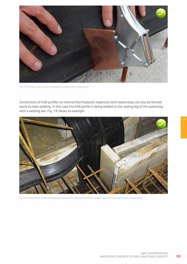
7
121joint waterproofing
watertight ConCrete SyStemS & white Box ConCeptS
fig. 7.7: forming a butt joint by thermoplastic welding with a welding axe
Connections of KaB profiles to internal thermoplastic expansion joint waterstops can also be formed easily by heat welding. in this case the KaB profile is being welded to the sealing leg of the waterstop with a welding axe. fig. 7.8 shows an example.
fig. 7.8: Connection of a KaB combined construction joint waterbar to a thermo¬plastic expansion joint waterstop by heat welding
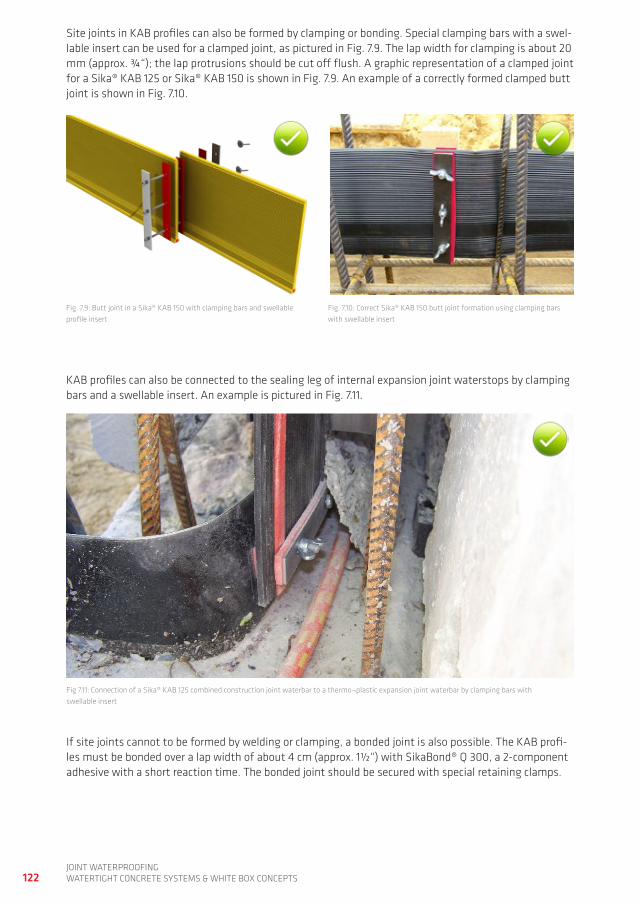
122joint waterproofingwatertight ConCrete SyStemS & white Box ConCeptS
fig. 7.9: Butt joint in a Sika® KaB 150 with clamping bars and swellable profile insert
fig. 7.10: Correct Sika® KaB 150 butt joint formation using clamping bars with swellable insert
fig 7.11: Connection of a Sika® KaB 125 combined construction joint waterbar to a thermo¬plastic expansion joint waterbar by clamping bars with swellable insert
Site joints in KaB profiles can also be formed by clamping or bonding. Special clamping bars with a swel-lable insert can be used for a clamped joint, as pictured in fig. 7.9. the lap width for clamping is about 20 mm (approx. ¾“); the lap protrusions should be cut off flush. a graphic representation of a clamped joint for a Sika® KaB 125 or Sika® KaB 150 is shown in fig. 7.9. an example of a correctly formed clamped butt joint is shown in fig. 7.10.
KaB profiles can also be connected to the sealing leg of internal expansion joint waterstops by clamping bars and a swellable insert. an example is pictured in fig. 7.11.
if site joints cannot to be formed by welding or clamping, a bonded joint is also possible. the KaB profi-les must be bonded over a lap width of about 4 cm (approx. 1½“) with SikaBond® Q 300, a 2-component adhesive with a short reaction time. the bonded joint should be secured with special retaining clamps.
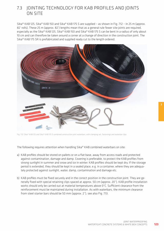
7
123joint waterproofing
watertight ConCrete SyStemS & white Box ConCeptS
7.3 jointing teChnoLogy for KaB profiLeS and jointS on Site
Sika® KaB 125, Sika® KaB 150 and Sika® KaB 175 S are supplied – as shown in fig. 7.12 – in 25 m (approx. 82‘ rolls). these 25 m (approx. 82‘) lengths mean that as a general rule fewer site joints are required, especially as the Sika® KaB 125, Sika® KaB 150 and Sika® KaB 175 S can be bent in a radius of only about 10 cm and can therefore be taken around a corner at a change of direction in the construction joint. the Sika® KaB 175 Sr is prefabricated and supplied ready cut to the length ordered.
fig. 7.12: Sika® KaB 125 and Sika® KaB 175 S combined construction joint waterbars, with clamping set, fastenings and waterbar clips
the following requires attention when handling Sika® KaB combined waterbars on site:
a) KaB profiles should be stored on pallets or on a flat base, away from access roads and protected against contamination, damage and damp. Covering is preferable, to protect the KaB profiles from strong sunlight in summer and snow and ice in winter. KaB profiles should be kept dry. if the storage period is extended, they should be kept in a sealed place, e.g. in a container, where they are adequa-tely protected against sunlight, water, damp, contamination and damage etc.
b) KaB profiles must be fixed securely and in the correct position in the construction joint. they are ge-nerally fixed with special retaining clips spaced at approx. 50 cm (approx. 20“). KaB profile installation works should only be carried out at material temperatures above 0°C. Sufficient clearance from the reinforcement must be maintained during installation. as with waterbars, the minimum clearance from steel starter bars should be 50 mm (approx. 2“), see also fig. 7.13.
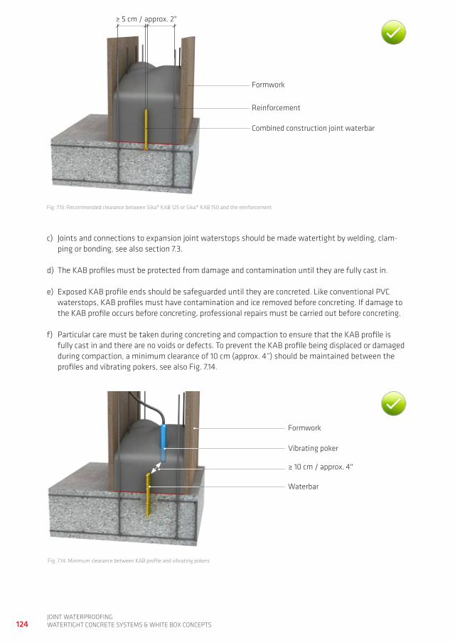
124joint waterproofingwatertight ConCrete SyStemS & white Box ConCeptS
fig. 7.13: recommended clearance between Sika® KaB 125 or Sika® KaB 150 and the reinforcement
c) joints and connections to expansion joint waterstops should be made watertight by welding, clam-ping or bonding, see also section 7.3.
d) the KaB profiles must be protected from damage and contamination until they are fully cast in.
e) exposed KaB profile ends should be safeguarded until they are concreted. Like conventional pVC waterstops, KaB profiles must have contamination and ice removed before concreting. if damage to the KaB profile occurs before concreting, professional repairs must be carried out before concreting.
f) particular care must be taken during concreting and compaction to ensure that the KaB profile is fully cast in and there are no voids or defects. to prevent the KaB profile being displaced or damaged during compaction, a minimum clearance of 10 cm (approx. 4“) should be maintained between the profiles and vibrating pokers, see also fig. 7.14.
fig. 7.14: minimum clearance between KaB profile and vibrating pokers
formwork
reinforcement
Combined construction joint waterbar
≥ 5 cm / approx. 2"
formwork
≥ 10 cm / approx. 4"
Vibrating poker
waterbar
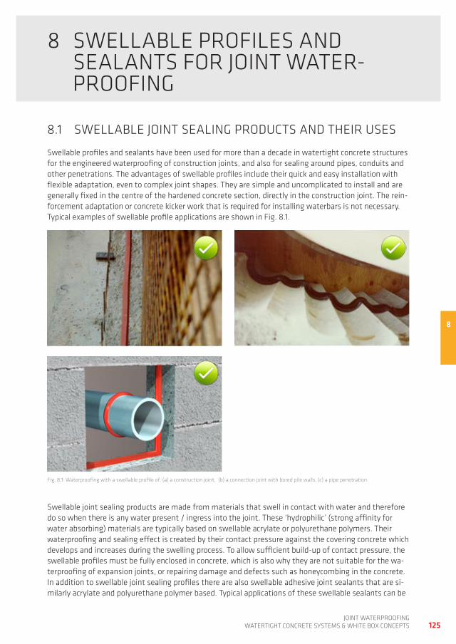
8
125joint waterproofing
watertight ConCrete SyStemS & white Box ConCeptS
8 SweLLaBLe profiLeS and SeaLantS for joint water- proofing
8.1 SweLLaBLe joint SeaLing prodUCtS and their USeS
Swellable profiles and sealants have been used for more than a decade in watertight concrete structures for the engineered waterproofing of construction joints, and also for sealing around pipes, conduits and other penetrations. the advantages of swellable profiles include their quick and easy installation with flexible adaptation, even to complex joint shapes. they are simple and uncomplicated to install and are generally fixed in the centre of the hardened concrete section, directly in the construction joint. the rein-forcement adaptation or concrete kicker work that is required for installing waterbars is not necessary. typical examples of swellable profile applications are shown in fig. 8.1.
fig. 8.1: waterproofing with a swellable profile of: (a) a construction joint, (b) a connection joint with bored pile walls, (c) a pipe penetration
Swellable joint sealing products are made from materials that swell in contact with water and therefore do so when there is any water present / ingress into the joint. these ‘hydrophilic’ (strong affinity for water absorbing) materials are typically based on swellable acrylate or polyurethane polymers. their waterproofing and sealing effect is created by their contact pressure against the covering concrete which develops and increases during the swelling process. to allow sufficient build-up of contact pressure, the swellable profiles must be fully enclosed in concrete, which is also why they are not suitable for the wa-terproofing of expansion joints, or repairing damage and defects such as honeycombing in the concrete. in addition to swellable joint sealing profiles there are also swellable adhesive joint sealants that are si-milarly acrylate and polyurethane polymer based. typical applications of these swellable sealants can be
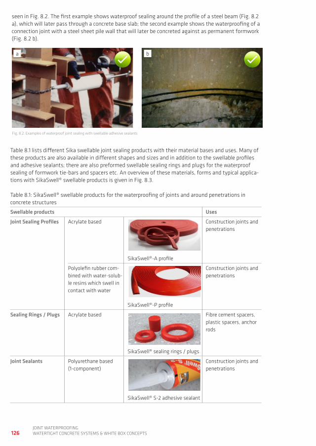
126joint waterproofingwatertight ConCrete SyStemS & white Box ConCeptS
seen in fig. 8.2. the first example shows waterproof sealing around the profile of a steel beam (fig. 8.2 a), which will later pass through a concrete base slab; the second example shows the waterproofing of a connection joint with a steel sheet pile wall that will later be concreted against as permanent formwork (fig. 8.2 b).
fig. 8.2: examples of waterproof joint sealing with swellable adhesive sealants
table 8.1 lists different Sika swellable joint sealing products with their material bases and uses. many of these products are also available in different shapes and sizes and in addition to the swellable profiles and adhesive sealants; there are also preformed swellable sealing rings and plugs for the waterproof sealing of formwork tie-bars and spacers etc. an overview of these materials, forms and typical applica-tions with SikaSwell® swellable products is given in fig. 8.3.
table 8.1: SikaSwell® swellable products for the waterproofing of joints and around penetrations in concrete structures
Swellable products Uses
Joint Sealing Profiles acrylate based
SikaSwell®-a profile
Construction joints and penetrations
polyolefin rubber com-bined with water-solub-le resins which swell in contact with water
SikaSwell®-p profile
Construction joints and penetrations
Sealing Rings / Plugs acrylate based
SikaSwell® sealing rings / plugs
fibre cement spacers, plastic spacers, anchor rods
Joint Sealants polyurethane based(1-component)
SikaSwell® S-2 adhesive sealant
Construction joints and penetrations
a b
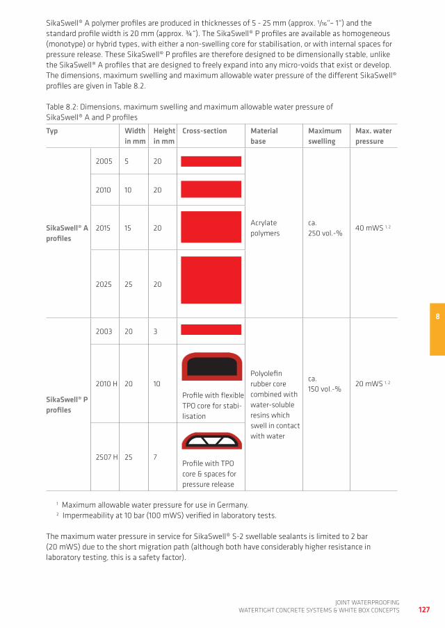
8
127joint waterproofing
watertight ConCrete SyStemS & white Box ConCeptS
SikaSwell® a polymer profiles are produced in thicknesses of 5 - 25 mm (approx. 1/16“– 1“) and the standard profile width is 20 mm (approx. ¾“). the SikaSwell® p profiles are available as homogeneous (monotype) or hybrid types, with either a non-swelling core for stabilisation, or with internal spaces for pressure release. these SikaSwell® p profiles are therefore designed to be dimensionally stable, unlike the SikaSwell® a profiles that are designed to freely expand into any micro-voids that exist or develop. the dimensions, maximum swelling and maximum allowable water pressure of the different SikaSwell® profiles are given in table 8.2.
table 8.2: dimensions, maximum swelling and maximum allowable water pressure of SikaSwell® a and p profiles
Typ Widthin mm
Height in mm
Cross-section Material base
Maximumswelling
Max. water pressure
SikaSwell® A profiles
2005 5 20
2010 10 20
2015 15 20acrylate polymers
ca. 250 vol.-%
40 mwS 1, 2
2025 25 20
SikaSwell® P profiles
2003 20 3
polyolefin rubber core combined with water-soluble resins which swell in contact with water
2010 h 20 10profile with flexible tpo core for stabi-lisation
ca. 150 vol.-%
20 mwS 1, 2
2507 h 25 7profile with tpo core & spaces for pressure release
1 maximum allowable water pressure for use in germany. 2 impermeability at 10 bar (100 mwS) verified in laboratory tests.
the maximum water pressure in service for SikaSwell® S-2 swellable sealants is limited to 2 bar (20 mwS) due to the short migration path (although both have considerably higher resistance in laboratory testing, this is a safety factor).
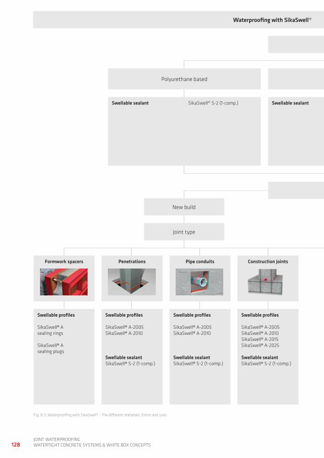
128joint waterproofingwatertight ConCrete SyStemS & white Box ConCeptS
fig. 8.3: waterproofing with SikaSwell® - the different materials, forms and uses
Waterproofing with SikaSwell® Materials, types and uses
material
new build
Component structure
Formwork spacers Penetrations
Swellable profiles
SikaSwell© asealing rings
SikaSwell© asealing plugs
Swellable profiles
SikaSwell© a-2005SikaSwell© a-2010
Swellable sealantSikaSwell© S-2 (1-comp.)
Swellable profiles
SikaSwell© a-2005SikaSwell© a-2010
Swellable sealantSikaSwell© S-2 (1-comp.)
Swellable profiles
SikaSwell© a-2005SikaSwell© a-2010SikaSwell© a-2015SikaSwell© a-2025
Swellable sealantSikaSwell© S-2 (1-comp.)
joint type
Pipe conduits Construction joints
acrylate polymer basedpolyurethane based
Swellable sealant SikaSwell® a-2005
SikaSwell® a-2010
SikaSwell® a-2015
SikaSwell® a-2025
Swellable sealant SikaSwell® S-2 (1-comp.)
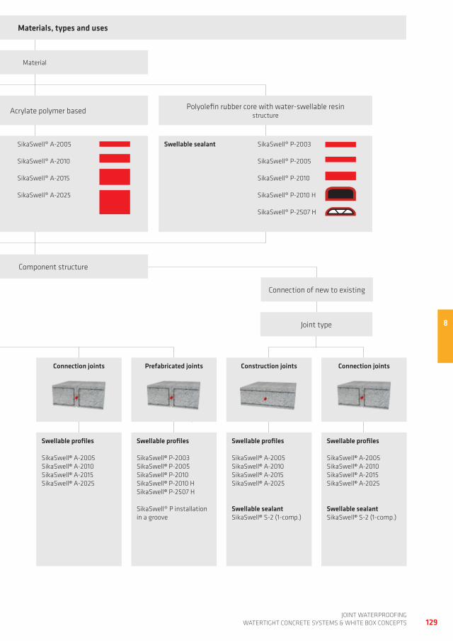
8
129joint waterproofing
watertight ConCrete SyStemS & white Box ConCeptS
Waterproofing with SikaSwell® Materials, types and uses
material
Component structure
Connection of new to existing
Construction joints Connection jointsPrefabricated joints
joint type
Swellable profiles
SikaSwell© a-2005SikaSwell© a-2010SikaSwell© a-2015SikaSwell© a-2025
Swellable profiles
SikaSwell© p-2003SikaSwell© p-2005SikaSwell© p-2010SikaSwell© p-2010 hSikaSwell© p-2507 h
SikaSwell® p installation in a groove
Swellable profiles
SikaSwell© a-2005SikaSwell© a-2010SikaSwell© a-2015SikaSwell© a-2025
Swellable sealantSikaSwell© S-2 (1-comp.)
Swellable profiles
SikaSwell© a-2005SikaSwell© a-2010SikaSwell© a-2015SikaSwell© a-2025
Swellable sealantSikaSwell© S-2 (1-comp.)
Connection joints
acrylate polymer based polyolefin rubber core with water-swellable resin structure
Swellable sealant SikaSwell® a-2005
SikaSwell® a-2010
SikaSwell® a-2015
SikaSwell® a-2025
Swellable sealant SikaSwell® p-2003
SikaSwell® p-2005
SikaSwell® p-2010
SikaSwell® p-2010 h
SikaSwell® p-2507 h
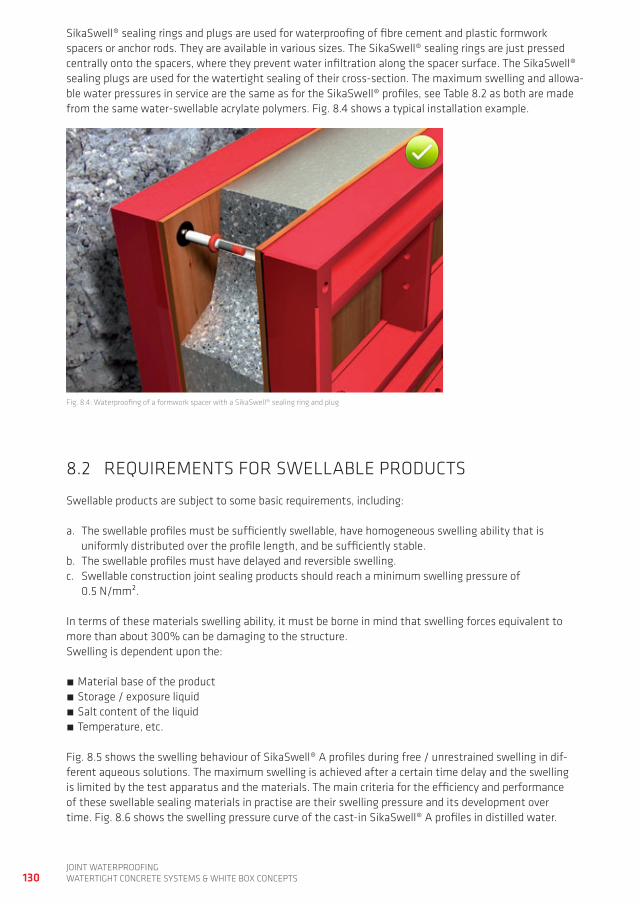
130joint waterproofingwatertight ConCrete SyStemS & white Box ConCeptS
SikaSwell® sealing rings and plugs are used for waterproofing of fibre cement and plastic formwork spacers or anchor rods. they are available in various sizes. the SikaSwell® sealing rings are just pressed centrally onto the spacers, where they prevent water infiltration along the spacer surface. the SikaSwell® sealing plugs are used for the watertight sealing of their cross-section. the maximum swelling and allowa-ble water pressures in service are the same as for the SikaSwell® profiles, see table 8.2 as both are made from the same water-swellable acrylate polymers. fig. 8.4 shows a typical installation example.
fig. 8.4: waterproofing of a formwork spacer with a SikaSwell® sealing ring and plug
8.2 reQUirementS for SweLLaBLe prodUCtS
Swellable products are subject to some basic requirements, including:
a. the swellable profiles must be sufficiently swellable, have homogeneous swelling ability that is uniformly distributed over the profile length, and be sufficiently stable.
b. the swellable profiles must have delayed and reversible swelling.c. Swellable construction joint sealing products should reach a minimum swelling pressure of
0.5 n/mm².
in terms of these materials swelling ability, it must be borne in mind that swelling forces equivalent to more than about 300% can be damaging to the structure. Swelling is dependent upon the:
material base of the product Storage / exposure liquid Salt content of the liquid temperature, etc.
fig. 8.5 shows the swelling behaviour of SikaSwell® a profiles during free / unrestrained swelling in dif-ferent aqueous solutions. the maximum swelling is achieved after a certain time delay and the swelling is limited by the test apparatus and the materials. the main criteria for the efficiency and performance of these swellable sealing materials in practise are their swelling pressure and its development over time. fig. 8.6 shows the swelling pressure curve of the cast-in SikaSwell® a profiles in distilled water.
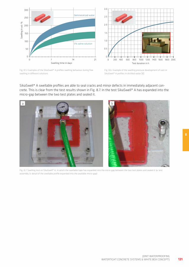
8
0 600 1600
2.0
1.5
1.0
0.5
3.0
2.5
Mea
n sw
ellin
g pr
essu
re in
N/m
m²
Test duration in h
01800200 1000 2000800 1200400 1400
Demineralized water
210 7 14
200
150
100
50
300
250
Swel
ling
in v
ol.-%
Swelling time in days
0
5% saline solution
131joint waterproofing
watertight ConCrete SyStemS & white Box ConCeptS
SikaSwell® a swellable profiles are able to seal cracks and minor defects in immediately adjacent con-crete. this is clear from the test results shown in fig. 8.7. in the test SikaSwell® a has expanded into the micro-gap between the two test plates and sealed it.
fig. 8.7: Swelling test on SikaSwell® a, in which the swellable tape has expanded into the micro-gap between the two test plates and sealed it (a: test assembly, b: detail of the swellable profile expanded into the available micro-gap)
a b
fig. 8.6: example of the swelling pressure development of cast-in SikaSwell® a profiles in distilled water [8]
fig. 8.5: examples of the SikaSwell® a profiles swelling behaviour during free swelling in different solutions
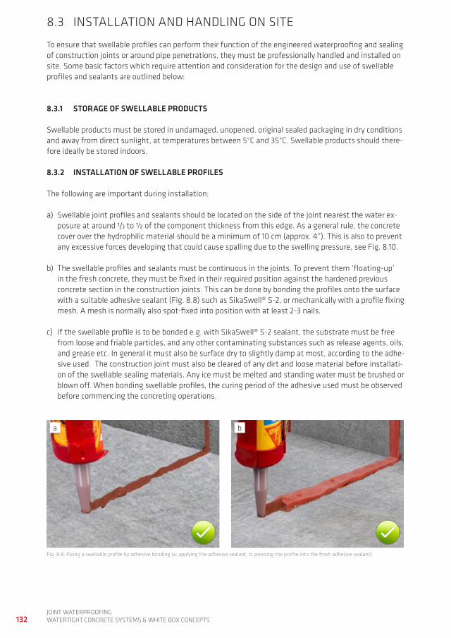
132joint waterproofingwatertight ConCrete SyStemS & white Box ConCeptS
8.3 inStaLLation and handLing on Site
to ensure that swellable profiles can perform their function of the engineered waterproofing and sealing of construction joints or around pipe penetrations, they must be professionally handled and installed on site. Some basic factors which require attention and consideration for the design and use of swellable profiles and sealants are outlined below:
8.3.1 STORAgE OF SWELLABLE PRODUCTS
Swellable products must be stored in undamaged, unopened, original sealed packaging in dry conditions and away from direct sunlight, at temperatures between 5°C and 35°C. Swellable products should there-fore ideally be stored indoors.
8.3.2 INSTALLATION OF SWELLABLE PROFILES
the following are important during installation:
a) Swellable joint profiles and sealants should be located on the side of the joint nearest the water ex-posure at around 1/3 to ½ of the component thickness from this edge. as a general rule, the concrete cover over the hydrophilic material should be a minimum of 10 cm (approx. 4“). this is also to prevent any excessive forces developing that could cause spalling due to the swelling pressure, see fig. 8.10.
b) the swellable profiles and sealants must be continuous in the joints. to prevent them ‘floating-up’ in the fresh concrete, they must be fixed in their required position against the hardened previous concrete section in the construction joints. this can be done by bonding the profiles onto the surface with a suitable adhesive sealant (fig. 8.8) such as SikaSwell® S-2, or mechanically with a profile fixing mesh. a mesh is normally also spot-fixed into position with at least 2-3 nails.
c) if the swellable profile is to be bonded e.g. with SikaSwell® S-2 sealant, the substrate must be free from loose and friable particles, and any other contaminating substances such as release agents, oils, and grease etc. in general it must also be surface dry to slightly damp at most, according to the adhe-sive used. the construction joint must also be cleared of any dirt and loose material before installati-on of the swellable sealing materials. any ice must be melted and standing water must be brushed or blown off. when bonding swellable profiles, the curing period of the adhesive used must be observed before commencing the concreting operations.
fig. 8.8: fixing a swellable profile by adhesive bonding (a: applying the adhesive sealant, b: pressing the profile into the fresh adhesive sealant)
a b
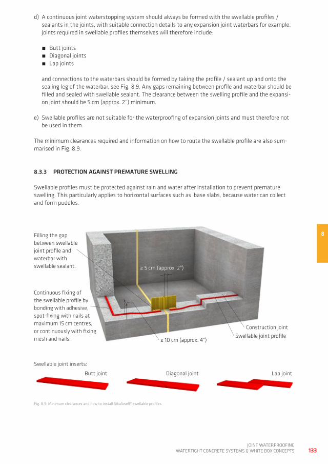
8
133joint waterproofing
watertight ConCrete SyStemS & white Box ConCeptS
fig. 8.9: minimum clearances and how to install SikaSwell® swellable profiles
Swellable joint profile
Construction joint
Continuous fixing of the swellable profile by bonding with adhesive, spot-fixing with nails at maximum 15 cm centres, or continuously with fixing mesh and nails.
filling the gap between swellable joint profile and waterbar with swellable sealant.
Butt joint diagonal joint Lap joint
Swellable joint inserts:
≥ 5 cm (approx. 2")
≥ 10 cm (approx. 4")
d) a continuous joint waterstopping system should always be formed with the swellable profiles / sealants in the joints, with suitable connection details to any expansion joint waterbars for example. joints required in swellable profiles themselves will therefore include:
Butt joints diagonal joints Lap joints
and connections to the waterbars should be formed by taking the profile / sealant up and onto the sealing leg of the waterbar, see fig. 8.9. any gaps remaining between profile and waterbar should be filled and sealed with swellable sealant. the clearance between the swelling profile and the expansi-on joint should be 5 cm (approx. 2“) minimum.
e) Swellable profiles are not suitable for the waterproofing of expansion joints and must therefore not be used in them.
the minimum clearances required and information on how to route the swellable profile are also sum-marised in fig. 8.9.
8.3.3 PROTECTION AgAINST PREMATURE SWELLINg
Swellable profiles must be protected against rain and water after installation to prevent premature swelling. this particularly applies to horizontal surfaces such as base slabs, because water can collect and form puddles.
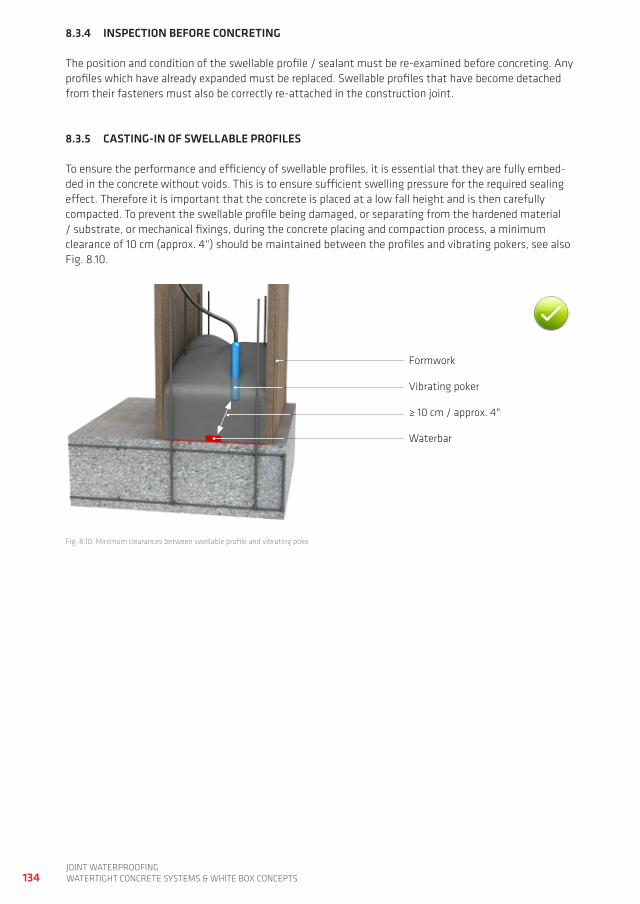
134joint waterproofingwatertight ConCrete SyStemS & white Box ConCeptS
8.3.4 INSPECTION BEFORE CONCRETINg
the position and condition of the swellable profile / sealant must be re-examined before concreting. any profiles which have already expanded must be replaced. Swellable profiles that have become detached from their fasteners must also be correctly re-attached in the construction joint.
8.3.5 CASTINg-IN OF SWELLABLE PROFILES
to ensure the performance and efficiency of swellable profiles, it is essential that they are fully embed-ded in the concrete without voids. this is to ensure sufficient swelling pressure for the required sealing effect. therefore it is important that the concrete is placed at a low fall height and is then carefully compacted. to prevent the swellable profile being damaged, or separating from the hardened material / substrate, or mechanical fixings, during the concrete placing and compaction process, a minimum clearance of 10 cm (approx. 4“) should be maintained between the profiles and vibrating pokers, see also fig. 8.10.
formwork
≥ 10 cm / approx. 4"
Vibrating poker
waterbar
fig. 8.10: minimum clearances between swellable profile and vibrating poke
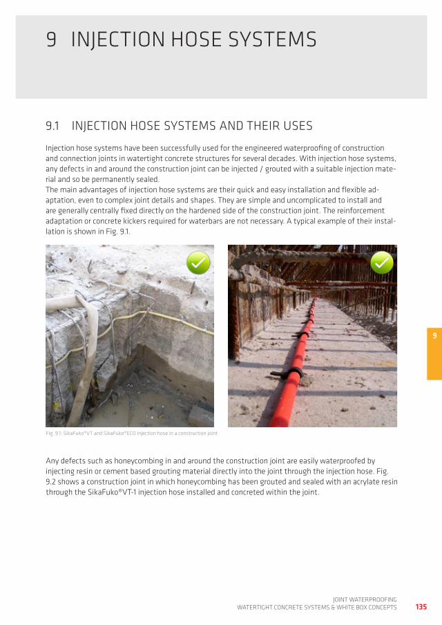
9
135joint waterproofing
watertight ConCrete SyStemS & white Box ConCeptS
9 injeCtion hoSe SyStemS
9.1 injeCtion hoSe SyStemS and their USeS
injection hose systems have been successfully used for the engineered waterproofing of construction and connection joints in watertight concrete structures for several decades. with injection hose systems, any defects in and around the construction joint can be injected / grouted with a suitable injection mate-rial and so be permanently sealed. the main advantages of injection hose systems are their quick and easy installation and flexible ad-aptation, even to complex joint details and shapes. they are simple and uncomplicated to install and are generally centrally fixed directly on the hardened side of the construction joint. the reinforcement adaptation or concrete kickers required for waterbars are not necessary. a typical example of their instal-lation is shown in fig. 9.1.
fig. 9.1: Sikafuko®Vt and Sikafuko®eCo injection hose in a construction joint
any defects such as honeycombing in and around the construction joint are easily waterproofed by injecting resin or cement based grouting material directly into the joint through the injection hose. fig. 9.2 shows a construction joint in which honeycombing has been grouted and sealed with an acrylate resin through the Sikafuko®Vt-1 injection hose installed and concreted within the joint.
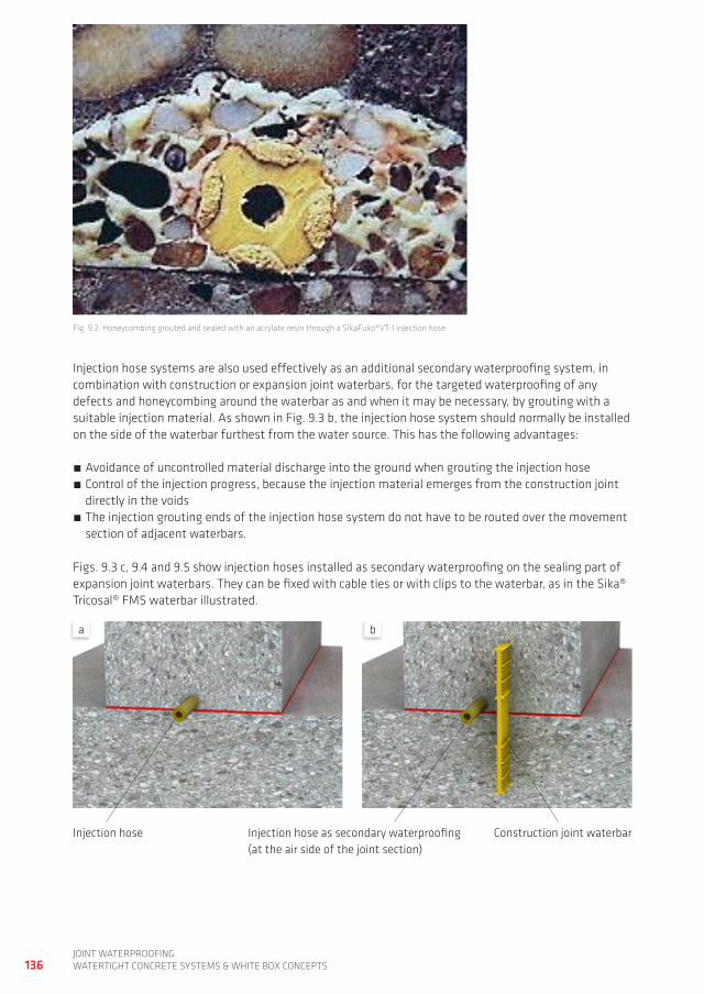
136joint waterproofingwatertight ConCrete SyStemS & white Box ConCeptS
fig. 9.2: honeycombing grouted and sealed with an acrylate resin through a Sikafuko®Vt-1 injection hose
injection hose systems are also used effectively as an additional secondary waterproofing system, in combination with construction or expansion joint waterbars, for the targeted waterproofing of any defects and honeycombing around the waterbar as and when it may be necessary, by grouting with a suitable injection material. as shown in fig. 9.3 b, the injection hose system should normally be installed on the side of the waterbar furthest from the water source. this has the following advantages:
avoidance of uncontrolled material discharge into the ground when grouting the injection hose Control of the injection progress, because the injection material emerges from the construction joint directly in the voids
the injection grouting ends of the injection hose system do not have to be routed over the movement section of adjacent waterbars.
figs. 9.3 c, 9.4 and 9.5 show injection hoses installed as secondary waterproofing on the sealing part of expansion joint waterbars. they can be fixed with cable ties or with clips to the waterbar, as in the Sika® tricosal® fmS waterbar illustrated.
injection hose injection hose as secondary waterproofing(at the air side of the joint section)
Construction joint waterbar
a b
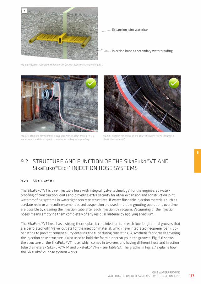
9
137joint waterproofing
watertight ConCrete SyStemS & white Box ConCeptS
fig. 9.3: injection hose systems for primary (a) and secondary waterproofing (b, c)
fig. 9.4: Stop-end formwork for a base slab with an Sika® tricosal® fmS waterbar and additional injection hose for secondary waterproofing
fig. 9.5: injection hose fixed on the Sika® tricosal® fmS waterbar with plastic ties (to be cut)
9.2 StrUCtUre and fUnCtion of the Sikafuko®Vt and Sikafuko®eco-1 injeCtion hoSe SyStemS
9.2.1 SikaFuko® vT
the Sikafuko®Vt is a re-injectable hose with integral ´valve technology´ for the engineered water-proofing of construction joints and providing extra security for other expansion and construction joint waterproofing systems in watertight concrete structures. if water flushable injection materials such as acrylate resin or a microfine-cement based suspension are used, multiple grouting operations overtime are possible by cleaning the injection tube after each injection by vacuum. Vacuuming of the injection hoses means emptying them completely of any residual material by applying a vacuum.
the Sikafuko®Vt hose has a strong thermoplastic core injection tube with four longitudinal grooves that are perforated with ‘valve’ outlets for the injection material, which have integrated neoprene foam rub-ber strips to prevent cement slurry entering the tube during concreting. a synthetic fabric mesh covering the injection hose structure is also used to hold the foam rubber strips in the grooves. fig. 9.6 shows the structure of the Sikafuko®Vt hose, which comes in two versions having different hose and injection tube diameters - Sikafuko®Vt-1 and Sikafuko®Vt-2 - see table 9.1. the graphic in fig. 9.7 explains how the Sikafuko®Vt hose system works.
injection hose as secondary waterproofing
expansion joint waterbar
c
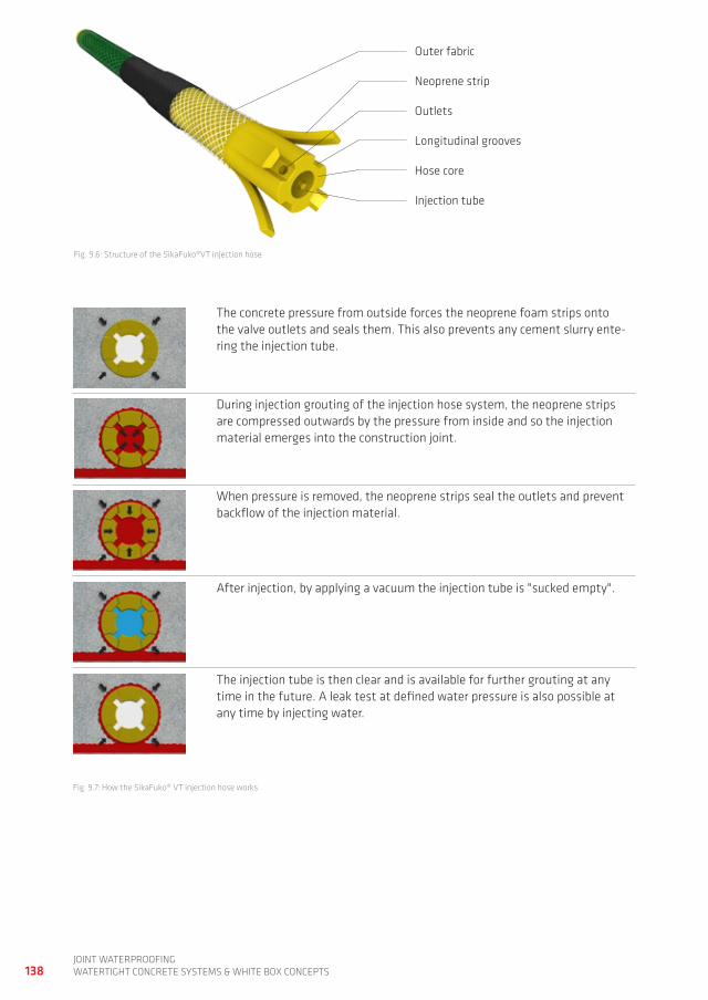
138joint waterproofingwatertight ConCrete SyStemS & white Box ConCeptS
fig. 9.6: Structure of the Sikafuko®Vt injection hose
outer fabric
outlets
neoprene strip
Longitudinal grooves
hose core
injection tube
fig. 9.7: how the Sikafuko® Vt injection hose works
the concrete pressure from outside forces the neoprene foam strips onto the valve outlets and seals them. this also prevents any cement slurry ente-ring the injection tube.
during injection grouting of the injection hose system, the neoprene strips are compressed outwards by the pressure from inside and so the injection material emerges into the construction joint.
when pressure is removed, the neoprene strips seal the outlets and prevent backflow of the injection material.
after injection, by applying a vacuum the injection tube is "sucked empty".
the injection tube is then clear and is available for further grouting at any time in the future. a leak test at defined water pressure is also possible at any time by injecting water.
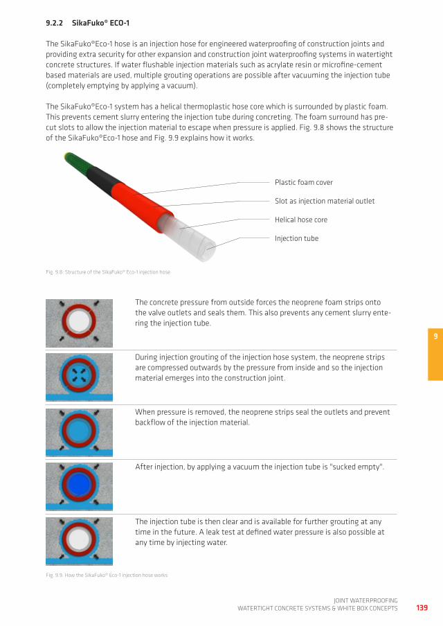
9
139joint waterproofing
watertight ConCrete SyStemS & white Box ConCeptS
9.2.2 SikaFuko® ECO-1
the Sikafuko®eco-1 hose is an injection hose for engineered waterproofing of construction joints and providing extra security for other expansion and construction joint waterproofing systems in watertight concrete structures. if water flushable injection materials such as acrylate resin or microfine-cement based materials are used, multiple grouting operations are possible after vacuuming the injection tube (completely emptying by applying a vacuum).
the Sikafuko®eco-1 system has a helical thermoplastic hose core which is surrounded by plastic foam. this prevents cement slurry entering the injection tube during concreting. the foam surround has pre-cut slots to allow the injection material to escape when pressure is applied. fig. 9.8 shows the structure of the Sikafuko®eco-1 hose and fig. 9.9 explains how it works.
fig. 9.8: Structure of the Sikafuko® eco-1 injection hose
fig. 9.9: how the Sikafuko® eco-1 injection hose works
Slot as injection material outlet
plastic foam cover
helical hose core
injection tube
the concrete pressure from outside forces the neoprene foam strips onto the valve outlets and seals them. this also prevents any cement slurry ente-ring the injection tube.
during injection grouting of the injection hose system, the neoprene strips are compressed outwards by the pressure from inside and so the injection material emerges into the construction joint.
when pressure is removed, the neoprene strips seal the outlets and prevent backflow of the injection material.
after injection, by applying a vacuum the injection tube is "sucked empty".
the injection tube is then clear and is available for further grouting at any time in the future. a leak test at defined water pressure is also possible at any time by injecting water.
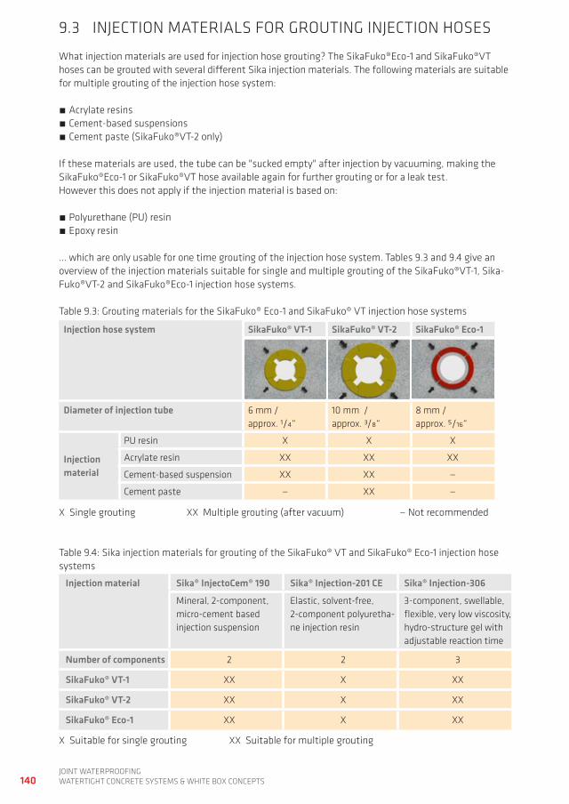
9
140joint waterproofingwatertight ConCrete SyStemS & white Box ConCeptS
9.3 injeCtion materiaLS for groUting injeCtion hoSeS
what injection materials are used for injection hose grouting? the Sikafuko®eco-1 and Sikafuko®Vt hoses can be grouted with several different Sika injection materials. the following materials are suitable for multiple grouting of the injection hose system:
acrylate resins Cement-based suspensions Cement paste (Sikafuko®Vt-2 only)
if these materials are used, the tube can be "sucked empty" after injection by vacuuming, making the Sikafuko®eco-1 or Sikafuko®Vt hose available again for further grouting or for a leak test. however this does not apply if the injection material is based on:
polyurethane (pU) resin epoxy resin
... which are only usable for one time grouting of the injection hose system. tables 9.3 and 9.4 give an overview of the injection materials suitable for single and multiple grouting of the Sikafuko®Vt-1, Sika-fuko®Vt-2 and Sikafuko®eco-1 injection hose systems.
table 9.3: grouting materials for the Sikafuko® eco-1 and Sikafuko® Vt injection hose systems
Injection hose system SikaFuko® vT-1 SikaFuko® vT-2 SikaFuko® Eco-1
Diameter of injection tube 6 mm / approx. 1/4“
10 mm / approx. 3/8“
8 mm / approx. 5/16“
Injection material
pU resin x x x
acrylate resin xx xx xx
Cement-based suspension xx xx —
Cement paste — xx —
x Single grouting xx multiple grouting (after vacuum) — not recommended
table 9.4: Sika injection materials for grouting of the Sikafuko® Vt and Sikafuko® eco-1 injection hose systems
Injection material Sika® InjectoCem® 190 Sika® Injection-201 CE Sika® Injection-306
mineral, 2-component, micro-cement based injection suspension
elastic, solvent-free, 2-component polyuretha-ne injection resin
3-component, swellable, flexible, very low viscosity, hydro-structure gel with adjustable reaction time
Number of components 2 2 3
SikaFuko® vT-1 xx x xx
SikaFuko® vT-2 xx x xx
SikaFuko® Eco-1 xx x xx
x Suitable for single grouting xx Suitable for multiple grouting
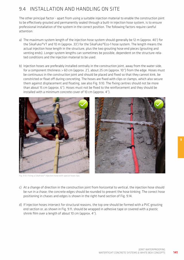
9
141joint waterproofing
watertight ConCrete SyStemS & white Box ConCeptS
9.4 inStaLLation and handLing on Site
the other principal factor - apart from using a suitable injection material to enable the construction joint to be effectively grouted and permanently sealed through a built-in injection hose system, is to ensure professional installation of the system in the correct position. the following factors require careful attention:
a) the maximum system length of the injection hose system should generally be 12 m (approx. 40‘) for the Sikafuko®Vt and 10 m (approx. 33‘) for the Sikafuko®eco-1 hose system. the length means the actual injection hose length in the structure, plus the two grouting hose end pieces (grouting and venting ends). Longer system lengths can sometimes be possible, dependent on the structure-rela-ted conditions and the injection material to be used.
b) injection hoses are preferably installed centrally in the construction joint, away from the water side, for a component thickness > 60 cm (approx. 2‘), about 25 cm (approx. 10“) from the edge. hoses must be continuous in the construction joint and should be placed and fixed so that they cannot kink, be constricted or float off during concreting. the hoses are fixed with clips or clamps, which also secure them against displacement and floating, see also fig. 9.10. the fixing centres should not be more than about 15 cm (approx. 6“). hoses must not be fixed to the reinforcement and they should be installed with a minimum concrete cover of 10 cm (approx. 4“).
fig. 9.10: fixing a Sikafuko® injection hose with special hose clips
c) at a change of direction in the construction joint from horizontal to vertical, the injection hose should be run in a chase; the concrete edges should be rounded to prevent the hose kinking. the correct hose positioning in chases and edges is shown in the right-hand section of fig. 9.14.
d) if injection hoses intersect for structural reasons, the top one should be formed with a pVC grouting end section or, as shown in fig. 9.11, should be wrapped in adhesive tape or covered with a plastic shrink film over a length of about 10 cm (approx. 4“).
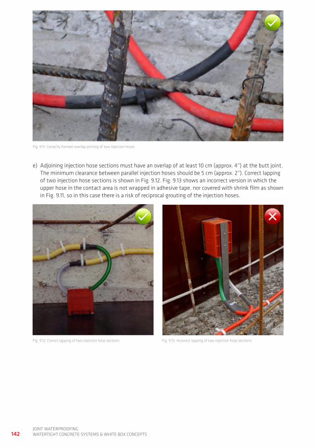
142joint waterproofingwatertight ConCrete SyStemS & white Box ConCeptS
fig. 9.11: Correctly formed overlap jointing of two injection hoses
e) adjoining injection hose sections must have an overlap of at least 10 cm (approx. 4“) at the butt joint. the minimum clearance between parallel injection hoses should be 5 cm (approx. 2“). Correct lapping of two injection hose sections is shown in fig. 9.12. fig. 9.13 shows an incorrect version in which the upper hose in the contact area is not wrapped in adhesive tape, nor covered with shrink film as shown in fig. 9.11, so in this case there is a risk of reciprocal grouting of the injection hoses.
fig. 9.12: Correct lapping of two injection hose sections fig. 9.13: incorrect lapping of two injection hose sections
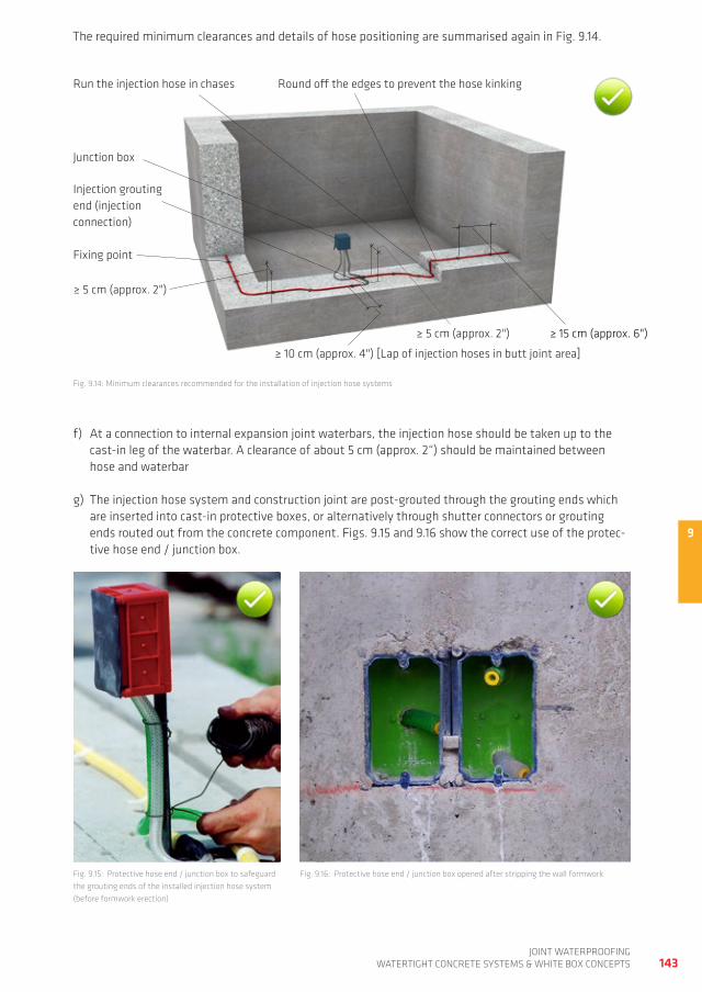
9
143joint waterproofing
watertight ConCrete SyStemS & white Box ConCeptS
the required minimum clearances and details of hose positioning are summarised again in fig. 9.14.
fig. 9.14: minimum clearances recommended for the installation of injection hose systems
run the injection hose in chases
≥ 15 cm (approx. 6")
injection grouting end (injection connection)
round off the edges to prevent the hose kinking
fixing point
junction box
≥ 10 cm (approx. 4") [Lap of injection hoses in butt joint area]
≥ 5 cm (approx. 2")
≥ 5 cm (approx. 2")
f) at a connection to internal expansion joint waterbars, the injection hose should be taken up to the cast-in leg of the waterbar. a clearance of about 5 cm (approx. 2“) should be maintained between hose and waterbar
g) the injection hose system and construction joint are post-grouted through the grouting ends which are inserted into cast-in protective boxes, or alternatively through shutter connectors or grouting ends routed out from the concrete component. figs. 9.15 and 9.16 show the correct use of the protec-tive hose end / junction box.
fig. 9.15: protective hose end / junction box to safeguard the grouting ends of the installed injection hose system (before formwork erection)
fig. 9.16: protective hose end / junction box opened after stripping the wall formwork
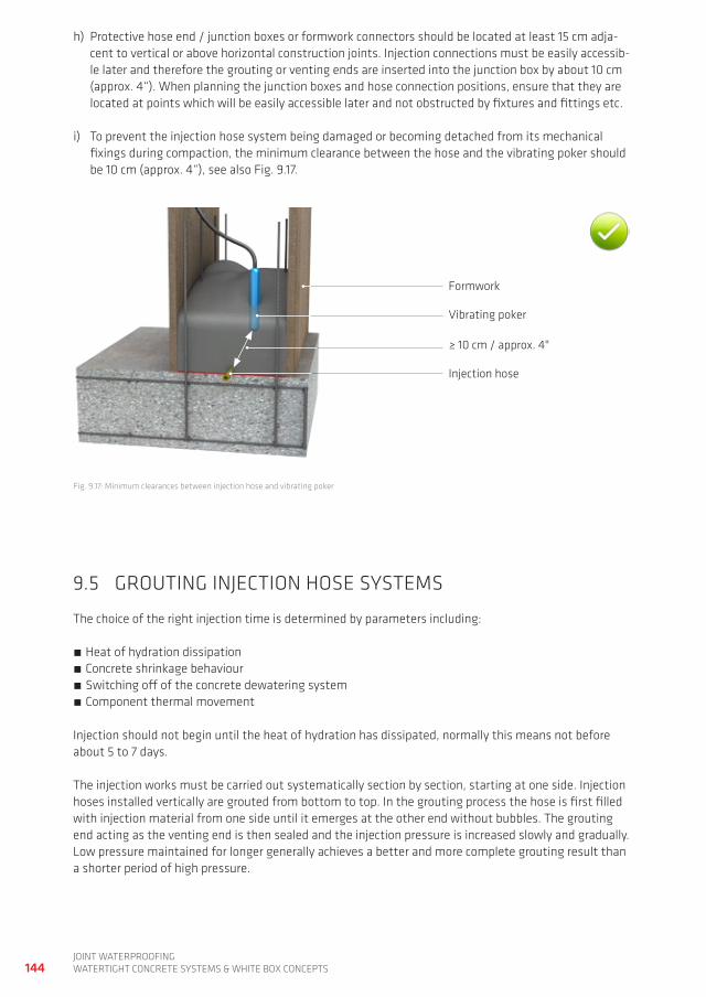
144joint waterproofingwatertight ConCrete SyStemS & white Box ConCeptS
h) protective hose end / junction boxes or formwork connectors should be located at least 15 cm adja-cent to vertical or above horizontal construction joints. injection connections must be easily accessib-le later and therefore the grouting or venting ends are inserted into the junction box by about 10 cm (approx. 4“). when planning the junction boxes and hose connection positions, ensure that they are located at points which will be easily accessible later and not obstructed by fixtures and fittings etc.
i) to prevent the injection hose system being damaged or becoming detached from its mechanical fixings during compaction, the minimum clearance between the hose and the vibrating poker should be 10 cm (approx. 4“), see also fig. 9.17.
formwork
≥ 10 cm / approx. 4"
Vibrating poker
injection hose
fig. 9.17: minimum clearances between injection hose and vibrating poker
9.5 groUting injeCtion hoSe SyStemS
the choice of the right injection time is determined by parameters including:
heat of hydration dissipation Concrete shrinkage behaviour Switching off of the concrete dewatering system Component thermal movement
injection should not begin until the heat of hydration has dissipated, normally this means not before about 5 to 7 days.
the injection works must be carried out systematically section by section, starting at one side. injection hoses installed vertically are grouted from bottom to top. in the grouting process the hose is first filled with injection material from one side until it emerges at the other end without bubbles. the grouting end acting as the venting end is then sealed and the injection pressure is increased slowly and gradually. Low pressure maintained for longer generally achieves a better and more complete grouting result than a shorter period of high pressure.
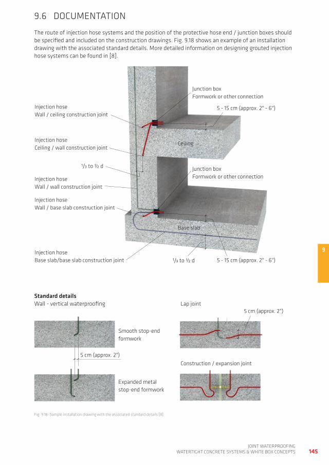
9
145joint waterproofing
watertight ConCrete SyStemS & white Box ConCeptS
9.6 doCUmentation
the route of injection hose systems and the position of the protective hose end / junction boxes should be specified and included on the construction drawings. fig. 9.18 shows an example of an installation drawing with the associated standard details. more detailed information on designing grouted injection hose systems can be found in [8].
fig. 9.18: Sample installation drawing with the associated standard details [8]
Standard detailswall - vertical waterproofing
injection hosewall / ceiling construction joint
injection hoseCeiling / wall construction joint
injection hosewall / wall construction joint
injection hosewall / base slab construction joint
injection hose Base slab/base slab construction joint
Ceiling
5 - 15 cm (approx. 2" - 6")
Base slab
1/3 to ½ d
junction boxformwork or other connection
junction boxformwork or other connection
5 - 15 cm (approx. 2" - 6")
5 cm (approx. 2")
5 cm (approx. 2")
Smooth stop-end formwork
expanded metal stop-end formwork
Lap joint
Construction / expansion joint
1/3 to ½ d
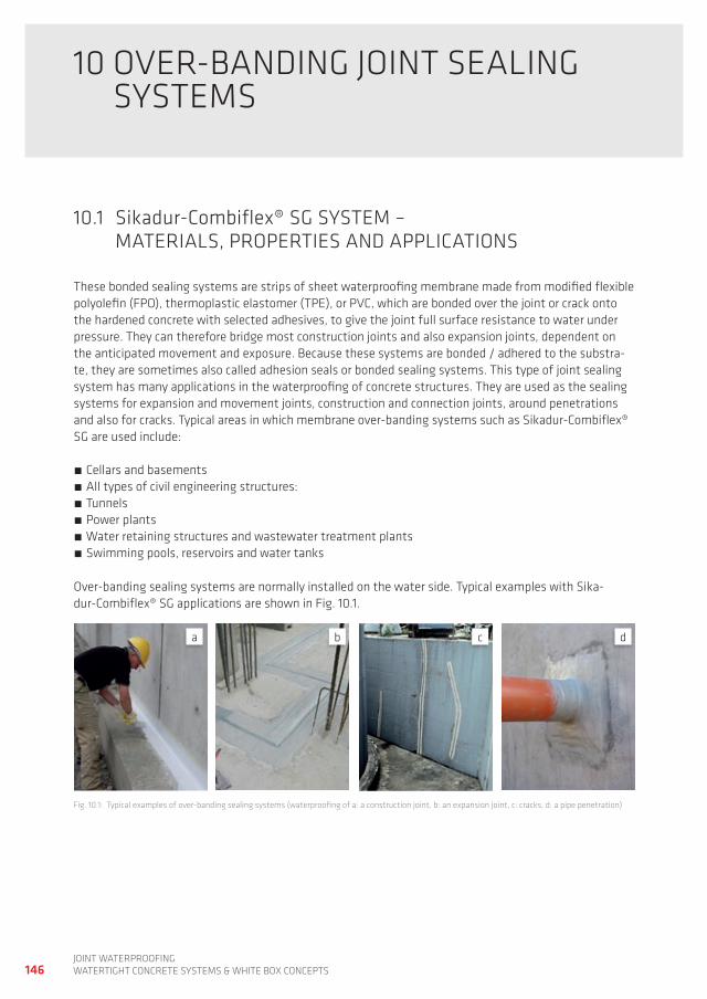
146joint waterproofingwatertight ConCrete SyStemS & white Box ConCeptS
10 oVer-Banding joint SeaLing SyStemS
10.1 Sikadur-Combiflex® Sg SyStem – materiaLS, propertieS and appLiCationS
these bonded sealing systems are strips of sheet waterproofing membrane made from modified flexible polyolefin (fpo), thermoplastic elastomer (tpe), or pVC, which are bonded over the joint or crack onto the hardened concrete with selected adhesives, to give the joint full surface resistance to water under pressure. they can therefore bridge most construction joints and also expansion joints, dependent on the anticipated movement and exposure. Because these systems are bonded / adhered to the substra-te, they are sometimes also called adhesion seals or bonded sealing systems. this type of joint sealing system has many applications in the waterproofing of concrete structures. they are used as the sealing systems for expansion and movement joints, construction and connection joints, around penetrations and also for cracks. typical areas in which membrane over-banding systems such as Sikadur-Combiflex® Sg are used include:
Cellars and basements all types of civil engineering structures: tunnels power plants water retaining structures and wastewater treatment plants Swimming pools, reservoirs and water tanks
over-banding sealing systems are normally installed on the water side. typical examples with Sika-dur-Combiflex® Sg applications are shown in fig. 10.1.
fig. 10.1: typical examples of over-banding sealing systems (waterproofing of a: a construction joint, b: an expansion joint, c: cracks, d: a pipe penetration)
a b c d
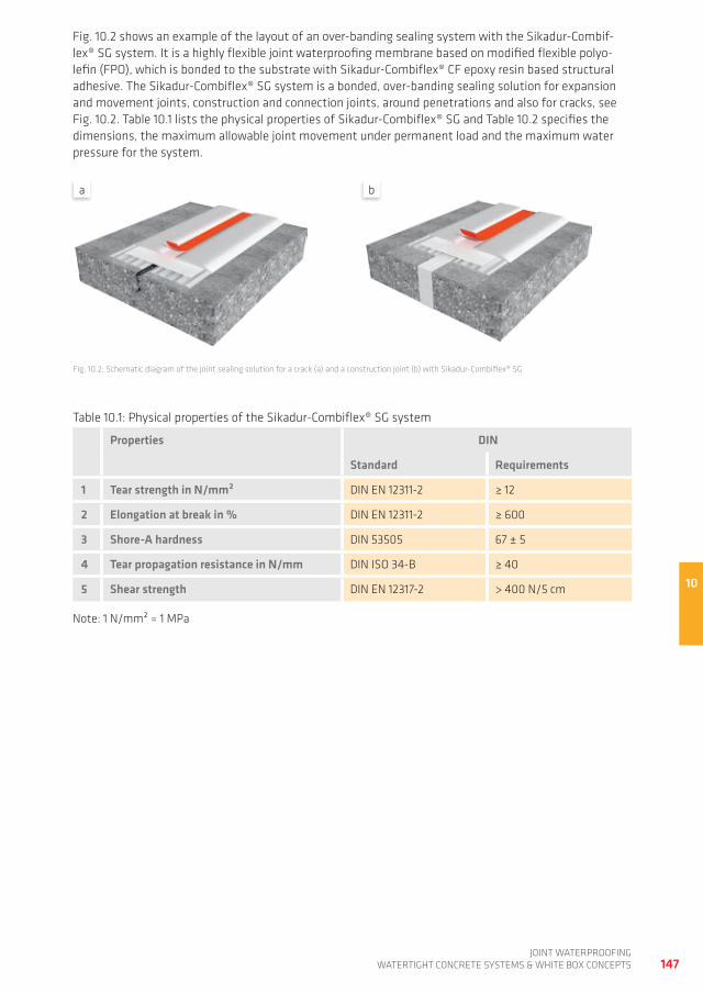
10
147joint waterproofing
watertight ConCrete SyStemS & white Box ConCeptS
fig. 10.2 shows an example of the layout of an over-banding sealing system with the Sikadur-Combif-lex® Sg system. it is a highly flexible joint waterproofing membrane based on modified flexible polyo-lefin (fpo), which is bonded to the substrate with Sikadur-Combiflex® Cf epoxy resin based structural adhesive. the Sikadur-Combiflex® Sg system is a bonded, over-banding sealing solution for expansion and movement joints, construction and connection joints, around penetrations and also for cracks, see fig. 10.2. table 10.1 lists the physical properties of Sikadur-Combiflex® Sg and table 10.2 specifies the dimensions, the maximum allowable joint movement under permanent load and the maximum water pressure for the system.
fig. 10.2: Schematic diagram of the joint sealing solution for a crack (a) and a construction joint (b) with Sikadur-Combiflex® Sg
table 10.1: physical properties of the Sikadur-Combiflex® Sg system
Properties DIN
Standard Requirements
1 Tear strength in N/mm² din en 12311-2 ≥ 12
2 Elongation at break in % din en 12311-2 ≥ 600
3 Shore-A hardness din 53505 67 ± 5
4 Tear propagation resistance in N/mm din iSo 34-B ≥ 40
5 Shear strength din en 12317-2 > 400 n/5 cm
note: 1 n/mm² = 1 mpa
a b
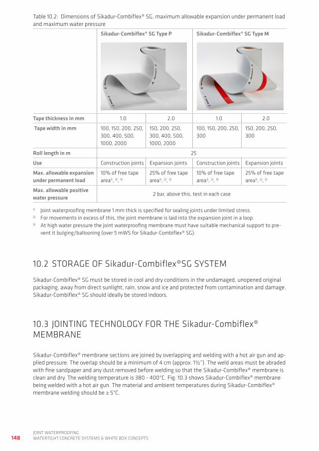
148joint waterproofingwatertight ConCrete SyStemS & white Box ConCeptS
10.2 Storage of Sikadur-Combiflex®Sg SyStem
Sikadur-Combiflex® Sg must be stored in cool and dry conditions in the undamaged, unopened original packaging, away from direct sunlight, rain, snow and ice and protected from contamination and damage. Sikadur-Combiflex® Sg should ideally be stored indoors.
10.3 jointing teChnoLogy for the Sikadur-Combiflex® memBrane
Sikadur-Combiflex® membrane sections are joined by overlapping and welding with a hot air gun and ap-plied pressure. the overlap should be a minimum of 4 cm (approx. 1½“). the weld areas must be abraded with fine sandpaper and any dust removed before welding so that the Sikadur-Combiflex® membrane is clean and dry. the welding temperature is 380 - 400°C. fig. 10.3 shows Sikadur-Combiflex® membrane being welded with a hot air gun. the material and ambient temperatures during Sikadur-Combiflex® membrane welding should be ≥ 5°C.
table 10.2: dimensions of Sikadur-Combiflex® Sg, maximum allowable expansion under permanent load and maximum water pressure
Sikadur-Combiflex® Sg Type P Sikadur-Combiflex® Sg Type M
Tape thickness in mm 1.0 2.0 1.0 2.0
Tape width in mm 100, 150, 200, 250, 300, 400, 500, 1000, 2000
150, 200, 250, 300, 400, 500, 1000, 2000
100, 150, 200, 250, 300
150, 200, 250, 300
Roll length in m 25
Use Construction joints expansion joints Construction joints expansion joints
Max. allowable expansion under permanent load
10% of free tape area1), 2), 3)
25% of free tape area1), 2), 3)
10% of free tape area1), 2), 3)
25% of free tape area1), 2), 3)
Max. allowable positivewater pressure
2 bar, above this, test in each case
1) joint waterproofing membrane 1 mm thick is specified for sealing joints under limited stress.2) for movements in excess of this, the joint membrane is laid into the expansion joint in a loop.3) at high water pressure the joint waterproofing membrane must have suitable mechanical support to pre-
vent it bulging/ballooning (over 5 mwS for Sikadur-Combiflex® Sg).
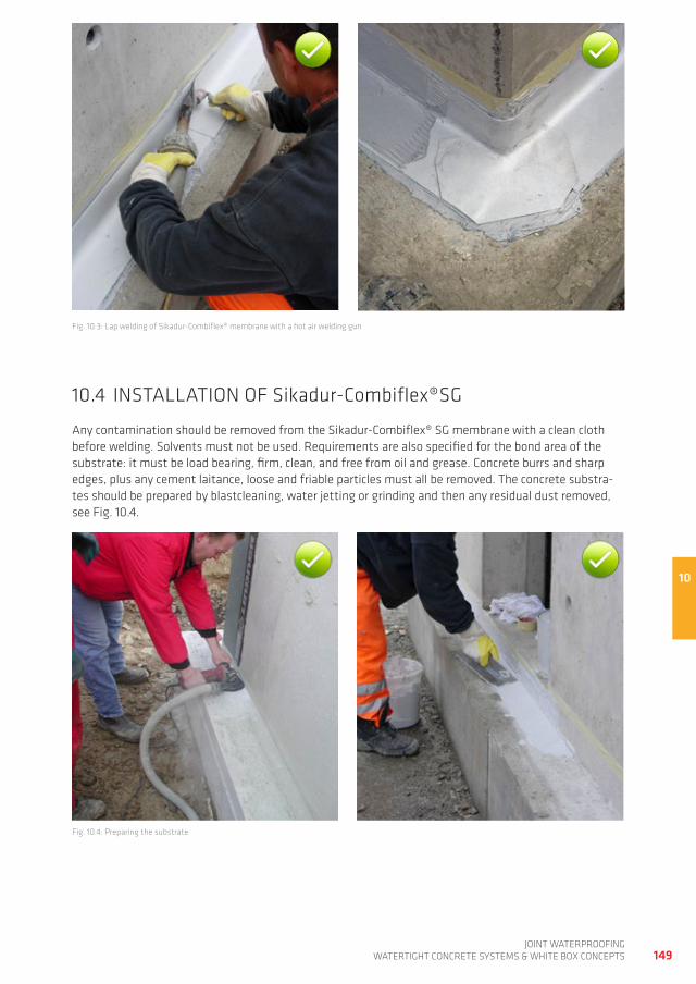
10
149joint waterproofing
watertight ConCrete SyStemS & white Box ConCeptS
fig. 10.3: Lap welding of Sikadur-Combiflex® membrane with a hot air welding gun
10.4 inStaLLation of Sikadur-Combiflex®Sg
any contamination should be removed from the Sikadur-Combiflex® Sg membrane with a clean cloth before welding. Solvents must not be used. requirements are also specified for the bond area of the substrate: it must be load bearing, firm, clean, and free from oil and grease. Concrete burrs and sharp edges, plus any cement laitance, loose and friable particles must all be removed. the concrete substra-tes should be prepared by blastcleaning, water jetting or grinding and then any residual dust removed, see fig. 10.4.
fig. 10.4: preparing the substrate
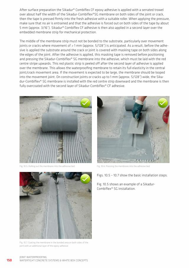
150joint waterproofingwatertight ConCrete SyStemS & white Box ConCeptS
fig. 10.5: rolling out the membrane into the adhesive bed fig. 10.6: pressing the membrane into the adhesive bed
fig. 10.7: Coating the membrane in the bonded area on both sides of the joint with an additional layer of the epoxy adhesive
after surface preparation the Sikadur® Combiflex Cf epoxy adhesive is applied with a serrated trowel over about half the width of the Sikadur-Combiflex®Sg membrane on both sides of the joint or crack, then the tape is pressed firmly into the fresh adhesive with a suitable roller. when applying the pressure, make sure that no air is entrained and that the adhesive is forced out on both sides of the tape by about 5 mm (approx. 3/16“). Sikadur® Combiflex Cf adhesive is then also applied in a second layer over the embedded membrane strip for mechanical protection.
the middle of the membrane strip must not be bonded to the substrate, particularly over movement joints or cracks where movement of > 1 mm (approx. 5/128“) is anticipated. as a result, before the adhe-sive is applied the substrate around the crack or joint is covered with masking tape on both sides along the edges of the joint. after the adhesive is applied, this masking tape is removed before positioning and pressing the Sikadur-Combiflex® Sg membrane into the adhesive, which must be laid with the red centre stripe upwards. this red plastic strip is peeled off after the second layer of adhesive is applied over the membrane. this allows the waterproofing membrane to retain its full elasticity in the central joint/crack movement area. if the movement is expected to be large, the membrane should be looped into the movement joint. on construction joints or cracks up to 1 mm (approx. 5/128“) wide, the Sika-dur-Combiflex® Sg membrane is installed with the red centre strip downward and the membrane is then fully overcoated with the second layer of Sikadur-Combiflex® Cf adhesive.
figs. 10.5 – 10.7 show the basic installation steps.
fig. 10.5 shows an example of a Sikadur- Combiflex® Sg installation.
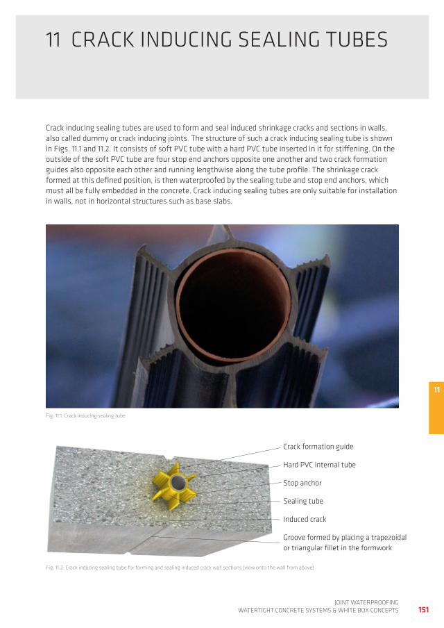
11
151joint waterproofing
watertight ConCrete SyStemS & white Box ConCeptS
11 CraCK indUCing SeaLing tUBeS
Crack inducing sealing tubes are used to form and seal induced shrinkage cracks and sections in walls, also called dummy or crack inducing joints. the structure of such a crack inducing sealing tube is shown in figs. 11.1 and 11.2. it consists of soft pVC tube with a hard pVC tube inserted in it for stiffening. on the outside of the soft pVC tube are four stop end anchors opposite one another and two crack formation guides also opposite each other and running lengthwise along the tube profile. the shrinkage crack formed at this defined position, is then waterproofed by the sealing tube and stop end anchors, which must all be fully embedded in the concrete. Crack inducing sealing tubes are only suitable for installation in walls, not in horizontal structures such as base slabs.
fig. 11.1: Crack inducing sealing tube
fig. 11.2: Crack inducing sealing tube for forming and sealing induced crack wall sections (view onto the wall from above)
induced crack
groove formed by placing a trapezoidal or triangular fillet in the formwork
Stop anchor
Crack formation guide
Sealing tube
hard pVC internal tube
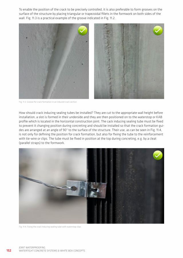
152joint waterproofingwatertight ConCrete SyStemS & white Box ConCeptS
to enable the position of the crack to be precisely controlled, it is also preferable to form grooves on the surface of the structure by placing triangular or trapezoidal fillets in the formwork on both sides of the wall. fig. 11.3 is a practical example of the groove indicated in fig. 11.2.
fig. 11.3: groove for crack formation in an induced crack section
how should crack inducing sealing tubes be installed? they are cut to the appropriate wall height before installation, a slot is formed in their underside and they are then positioned on to the waterstop or KaB profile which is located in the horizontal construction joint. the cack inducing sealing tube must be fixed to prevent it changing position during concreting and should be installed so that the crack formation gui-des are arranged at an angle of 90° to the surface of the structure. their use, as can be seen in fig. 11.4, is not only for defining the position for crack formation, but also for fixing the tube to the reinforcement with tie-wire or clips. the tube must be fixed in position at the top during concreting, e.g. by a cleat (parallel straps) to the formwork.
fig. 11.4: fixing the crack inducing sealing tube with waterstop clips
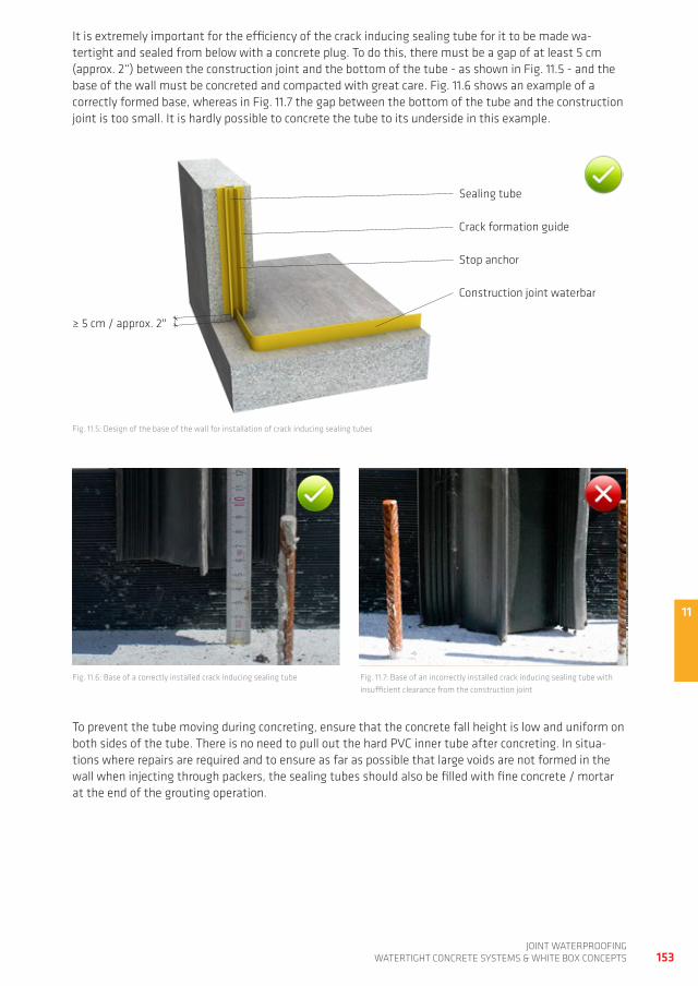
11
153joint waterproofing
watertight ConCrete SyStemS & white Box ConCeptS
it is extremely important for the efficiency of the crack inducing sealing tube for it to be made wa-tertight and sealed from below with a concrete plug. to do this, there must be a gap of at least 5 cm (approx. 2“) between the construction joint and the bottom of the tube - as shown in fig. 11.5 - and the base of the wall must be concreted and compacted with great care. fig. 11.6 shows an example of a correctly formed base, whereas in fig. 11.7 the gap between the bottom of the tube and the construction joint is too small. it is hardly possible to concrete the tube to its underside in this example.
fig. 11.5: design of the base of the wall for installation of crack inducing sealing tubes
fig. 11.6: Base of a correctly installed crack inducing sealing tube fig. 11.7: Base of an incorrectly installed crack inducing sealing tube with insufficient clearance from the construction joint
to prevent the tube moving during concreting, ensure that the concrete fall height is low and uniform on both sides of the tube. there is no need to pull out the hard pVC inner tube after concreting. in situa-tions where repairs are required and to ensure as far as possible that large voids are not formed in the wall when injecting through packers, the sealing tubes should also be filled with fine concrete / mortar at the end of the grouting operation.
Stop anchor
Construction joint waterbar
Sealing tube
Crack formation guide
≥ 5 cm / approx. 2"
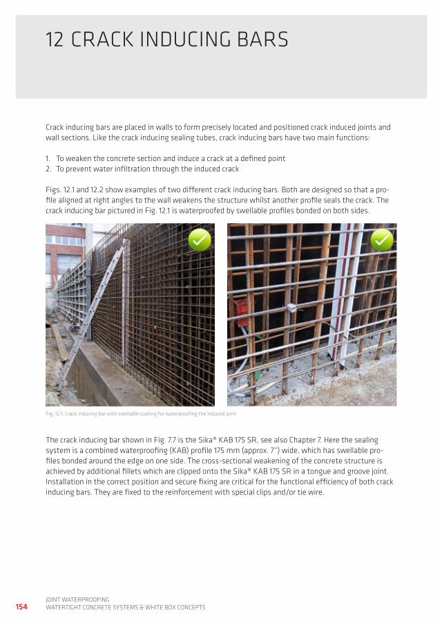
154joint waterproofingwatertight ConCrete SyStemS & white Box ConCeptS
12 CraCK indUCing BarS
Crack inducing bars are placed in walls to form precisely located and positioned crack induced joints and wall sections. Like the crack inducing sealing tubes, crack inducing bars have two main functions:
1. to weaken the concrete section and induce a crack at a defined point2. to prevent water infiltration through the induced crack
figs. 12.1 and 12.2 show examples of two different crack inducing bars. Both are designed so that a pro-file aligned at right angles to the wall weakens the structure whilst another profile seals the crack. the crack inducing bar pictured in fig. 12.1 is waterproofed by swellable profiles bonded on both sides.
fig. 12.1: Crack inducing bar with swellable coating for waterproofing the induced joint
the crack inducing bar shown in fig. 7.7 is the Sika® KaB 175 Sr, see also Chapter 7. here the sealing system is a combined waterproofing (KaB) profile 175 mm (approx. 7“) wide, which has swellable pro-files bonded around the edge on one side. the cross-sectional weakening of the concrete structure is achieved by additional fillets which are clipped onto the Sika® KaB 175 Sr in a tongue and groove joint. installation in the correct position and secure fixing are critical for the functional efficiency of both crack inducing bars. they are fixed to the reinforcement with special clips and/or tie wire.
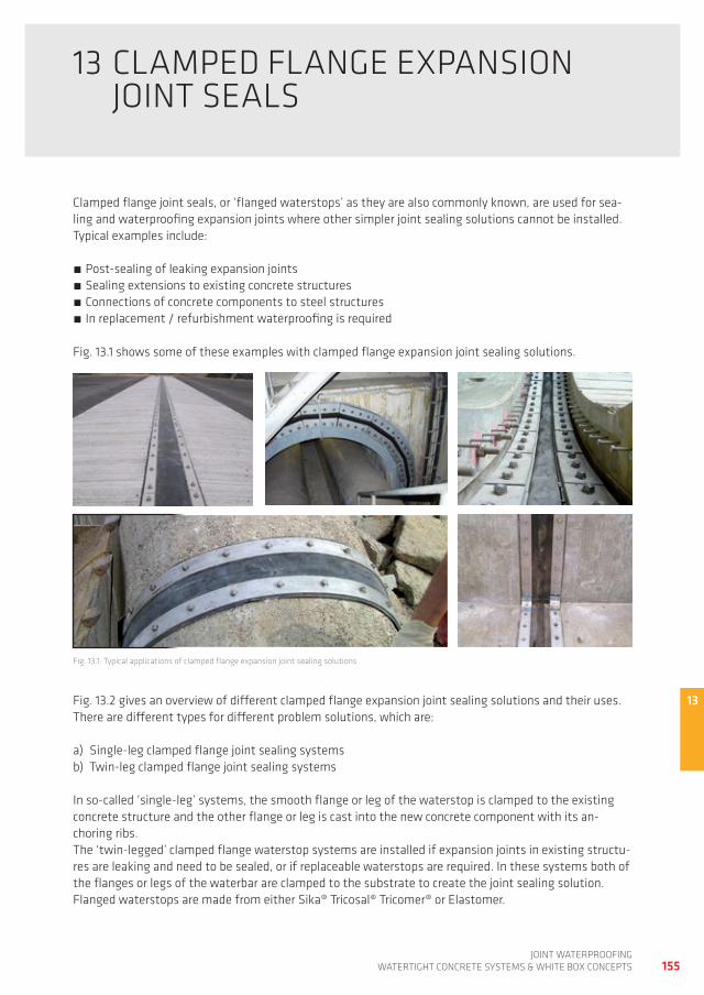
13
155joint waterproofing
watertight ConCrete SyStemS & white Box ConCeptS
13 CLamped fLange expanSion joint SeaLS
Clamped flange joint seals, or ‘flanged waterstops’ as they are also commonly known, are used for sea-ling and waterproofing expansion joints where other simpler joint sealing solutions cannot be installed. typical examples include:
post-sealing of leaking expansion joints Sealing extensions to existing concrete structures Connections of concrete components to steel structures in replacement / refurbishment waterproofing is required
fig. 13.1 shows some of these examples with clamped flange expansion joint sealing solutions.
fig. 13.1: typical applications of clamped flange expansion joint sealing solutions
fig. 13.2 gives an overview of different clamped flange expansion joint sealing solutions and their uses. there are different types for different problem solutions, which are:
a) Single-leg clamped flange joint sealing systemsb) twin-leg clamped flange joint sealing systems
in so-called ‘single-leg’ systems, the smooth flange or leg of the waterstop is clamped to the existing concrete structure and the other flange or leg is cast into the new concrete component with its an-choring ribs. the ‘twin-legged’ clamped flange waterstop systems are installed if expansion joints in existing structu-res are leaking and need to be sealed, or if replaceable waterstops are required. in these systems both of the flanges or legs of the waterbar are clamped to the substrate to create the joint sealing solution. flanged waterstops are made from either Sika® tricosal® tricomer® or elastomer.
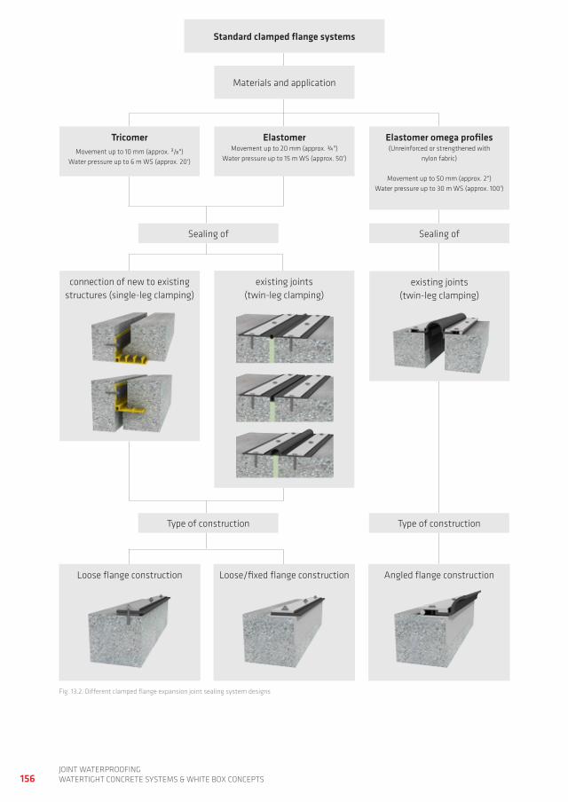
156joint waterproofingwatertight ConCrete SyStemS & white Box ConCeptS
fig. 13.2: different clamped flange expansion joint sealing system designs
Standard clamped flange systems
materials and application
Tricomermovement up to 10 mm (approx. 3/8")
water pressure up to 6 m wS (approx. 20')
Elastomermovement up to 20 mm (approx. ¾")
water pressure up to 15 m wS (approx. 50')
Elastomer omega profiles(Unreinforced or strengthened with
nylon fabric)
movement up to 50 mm (approx. 2")water pressure up to 30 m wS (approx. 100')
Sealing ofSealing of
connection of new to existing structures (single-leg clamping)
existing joints (twin-leg clamping)
existing joints (twin-leg clamping)
type of constructiontype of construction
Loose flange construction Loose/fixed flange construction angled flange construction
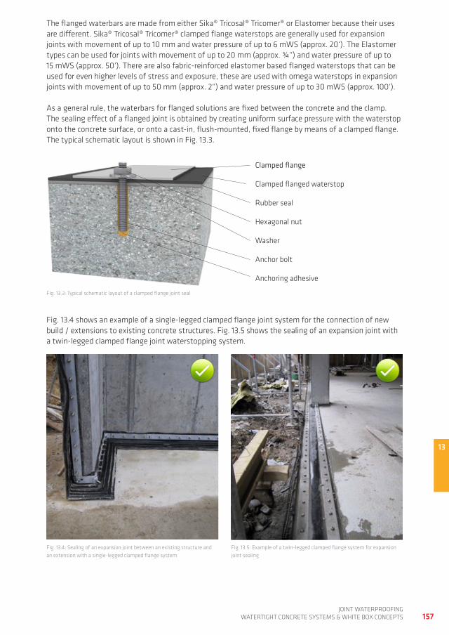
13
157joint waterproofing
watertight ConCrete SyStemS & white Box ConCeptS
the flanged waterbars are made from either Sika® tricosal® tricomer® or elastomer because their uses are different. Sika® tricosal® tricomer® clamped flange waterstops are generally used for expansion joints with movement of up to 10 mm and water pressure of up to 6 mwS (approx. 20‘). the elastomer types can be used for joints with movement of up to 20 mm (approx. ¾“) and water pressure of up to 15 mwS (approx. 50‘). there are also fabric-reinforced elastomer based flanged waterstops that can be used for even higher levels of stress and exposure, these are used with omega waterstops in expansion joints with movement of up to 50 mm (approx. 2“) and water pressure of up to 30 mwS (approx. 100‘).
as a general rule, the waterbars for flanged solutions are fixed between the concrete and the clamp. the sealing effect of a flanged joint is obtained by creating uniform surface pressure with the waterstop onto the concrete surface, or onto a cast-in, flush-mounted, fixed flange by means of a clamped flange. the typical schematic layout is shown in fig. 13.3.
fig. 13.3: typical schematic layout of a clamped flange joint seal
fig. 13.4 shows an example of a single-legged clamped flange joint system for the connection of new build / extensions to existing concrete structures. fig. 13.5 shows the sealing of an expansion joint with a twin-legged clamped flange joint waterstopping system.
fig. 13.4: Sealing of an expansion joint between an existing structure and an extension with a single-legged clamped flange system
rubber seal
hexagonal nut
Clamped flange
Clamped flanged waterstop
anchor bolt
anchoring adhesive
washer
fig. 13.5: example of a twin-legged clamped flange system for expansion joint sealing
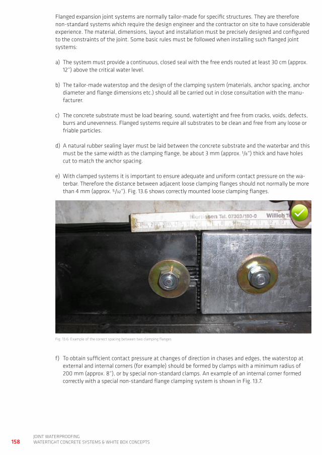
158joint waterproofingwatertight ConCrete SyStemS & white Box ConCeptS
flanged expansion joint systems are normally tailor-made for specific structures. they are therefore non-standard systems which require the design engineer and the contractor on site to have considerable experience. the material, dimensions, layout and installation must be precisely designed and configured to the constraints of the joint. Some basic rules must be followed when installing such flanged joint systems:
a) the system must provide a continuous, closed seal with the free ends routed at least 30 cm (approx. 12“) above the critical water level.
b) the tailor-made waterstop and the design of the clamping system (materials, anchor spacing, anchor diameter and flange dimensions etc.) should all be carried out in close consultation with the manu-facturer.
c) the concrete substrate must be load bearing, sound, watertight and free from cracks, voids, defects, burrs and unevenness. flanged systems require all substrates to be clean and free from any loose or friable particles.
d) a natural rubber sealing layer must be laid between the concrete substrate and the waterbar and this must be the same width as the clamping flange, be about 3 mm (approx. 1/8“) thick and have holes cut to match the anchor spacing.
e) with clamped systems it is important to ensure adequate and uniform contact pressure on the wa-terbar. therefore the distance between adjacent loose clamping flanges should not normally be more than 4 mm (approx. 5/32“). fig. 13.6 shows correctly mounted loose clamping flanges.
fig. 13.6: example of the correct spacing between two clamping flanges
f) to obtain sufficient contact pressure at changes of direction in chases and edges, the waterstop at external and internal corners (for example) should be formed by clamps with a minimum radius of 200 mm (approx. 8“), or by special non-standard clamps. an example of an internal corner formed correctly with a special non-standard flange clamping system is shown in fig. 13.7.
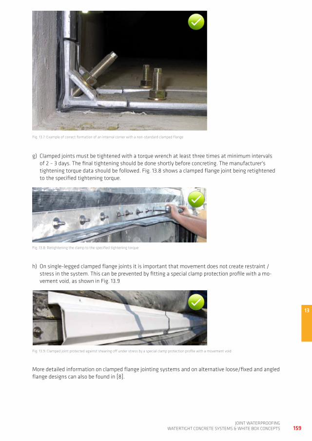
13
159joint waterproofing
watertight ConCrete SyStemS & white Box ConCeptS
fig. 13.7: example of correct formation of an internal corner with a non-standard clamped flange
g) Clamped joints must be tightened with a torque wrench at least three times at minimum intervals of 2 – 3 days. the final tightening should be done shortly before concreting. the manufacturer's tightening torque data should be followed. fig. 13.8 shows a clamped flange joint being retightened to the specified tightening torque.
fig. 13.9: Clamped joint protected against shearing off under stress by a special clamp protection profile with a movement void
h) on single-legged clamped flange joints it is important that movement does not create restraint / stress in the system. this can be prevented by fitting a special clamp protection profile with a mo-vement void, as shown in fig. 13.9
fig. 13.8: retightening the clamp to the specified tightening torque
more detailed information on clamped flange jointing systems and on alternative loose/fixed and angled flange designs can also be found in [8].
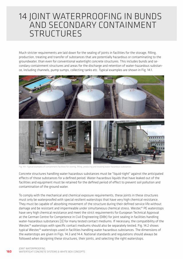
160joint waterproofingwatertight ConCrete SyStemS & white Box ConCeptS
14 joint waterproofing in BUndS and SeCondary Containment StrUCtUreS
much stricter requirements are laid down for the sealing of joints in facilities for the storage, filling, production, treating and transfer of substances that are potentially hazardous or contaminating to the groundwater, than even for conventional watertight concrete structures. this includes bunds and se-condary containment structures and areas for the discharge and retention of water-hazardous substan-ce, including channels, pump sumps, collecting tanks etc. typical examples are shown in fig. 14.1.
fig. 14.1: typical examples of containment facilities for storing, filling, producing and treating water hazardous substances
Concrete structures handling water hazardous substances must be "liquid-tight" against the anticipated effects of those substances for a defined period. water-hazardous liquids that have leaked out of the facilities and equipment must be retained for the defined period of effect to prevent soil pollution and contamination of the ground water.
to comply with the mechanical and chemical exposure requirements, these joints in these structures must only be waterproofed with special resilient waterstops that have very high chemical resistance. they must be capable of absorbing movement of the structure during their defined service life without damage and be resistant and impermeable under simultaneous chemical stress. westec® pe waterstops have very high chemical resistance and meet the strict requirements for european technical approval at the german Centre for Competence in Civil engineering (diBt) for joint sealing in facilities handling water-hazardous substances [3] for many tested contact mediums. if necessary, the compatibility of the westec® waterstops with specific contact mediums should also be separately tested. fig. 14.2 shows typical westec® waterstops used in facilities handling water hazardous substances. the dimensions of the waterstops are given in figs. 14.3 and 14.4. national standards and regulations should always be followed when designing these structures, their joints, and selecting the right waterstops.
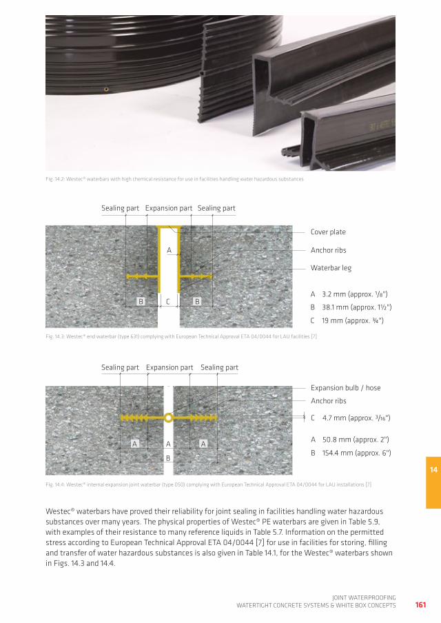
14
161joint waterproofing
watertight ConCrete SyStemS & white Box ConCeptS
fig. 14.2: westec® waterbars with high chemical resistance for use in facilities handling water hazardous substances
fig. 14.3: westec® end waterbar (type 631) complying with european technical approval eta 04/0044 for LaU facilities [7]
fig. 14.4: westec® internal expansion joint waterbar (type 050) complying with european technical approval eta 04/0044 for LaU installations [7]
westec® waterbars have proved their reliability for joint sealing in facilities handling water hazardous substances over many years. the physical properties of westec® pe waterbars are given in table 5.9, with examples of their resistance to many reference liquids in table 5.7. information on the permitted stress according to european technical approval eta 04/0044 [7] for use in facilities for storing, filling and transfer of water hazardous substances is also given in table 14.1, for the westec® waterbars shown in figs. 14.3 and 14.4.
waterbar leg
Cover plate
anchor ribs
expansion partSealing part
a 3.2 mm (approx. 1/8")
B 38.1 mm (approx. 1½")
C 19 mm (approx. ¾")
a
B BC
Sealing part
expansion partSealing part Sealing part
anchor ribs
expansion bulb / hose
a aa
B
a 50.8 mm (approx. 2")
B 154.4 mm (approx. 6")
C 4.7 mm (approx. 3/16")
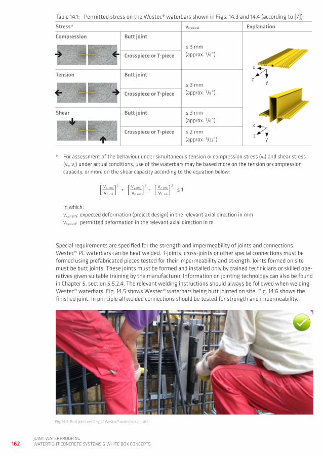
162joint waterproofingwatertight ConCrete SyStemS & white Box ConCeptS
table 14.1: permitted stress on the westec® waterbars shown in figs. 14.3 and 14.4 (according to [7])
Stress1) vx;y;z,zul Explanation
Compression Butt joint
≤ 3 mm(approx. 1/8“)Crosspiece or T-piece
Tension Butt joint
≤ 3 mm(approx. 1/8“)Crosspiece or T-piece
Shear Butt joint ≤ 3 mm(approx. 1/8“)
Crosspiece or T-piece ≤ 2 mm(approx. 3/32“)
1) for assessment of the behaviour under simultaneous tension or compression stress (vx) and shear stress (vy, vz) under actual conditions, use of the waterbars may be based more on the tension or compression capacity, or more on the shear capacity according to the equation below:
[ vx, proj]2
+ [ vy, proj]2
+ [ vz, proj]2
≤ 1vx, zul vy, zul vz, zul
in which: vx;y;z,proj: expected deformation (project design) in the relevant axial direction in mm vx;y;z,zul: permitted deformation in the relevant axial direction in m
Special requirements are specified for the strength and impermeability of joints and connections. westec® pe waterbars can be heat welded. t-joints, cross-joints or other special connections must be formed using prefabricated pieces tested for their impermeability and strength. joints formed on site must be butt joints. these joints must be formed and installed only by trained technicians or skilled ope-ratives given suitable training by the manufacturer. information on jointing technology can also be found in Chapter 5, section 5.5.2.4. the relevant welding instructions should always be followed when welding westec® waterbars. fig. 14.5 shows westec® waterbars being butt jointed on site. fig. 14.6 shows the finished joint. in principle all welded connections should be tested for strength and impermeability.
fig. 14.5: Butt joint welding of westec® waterbars on site
x
yz
x
yz
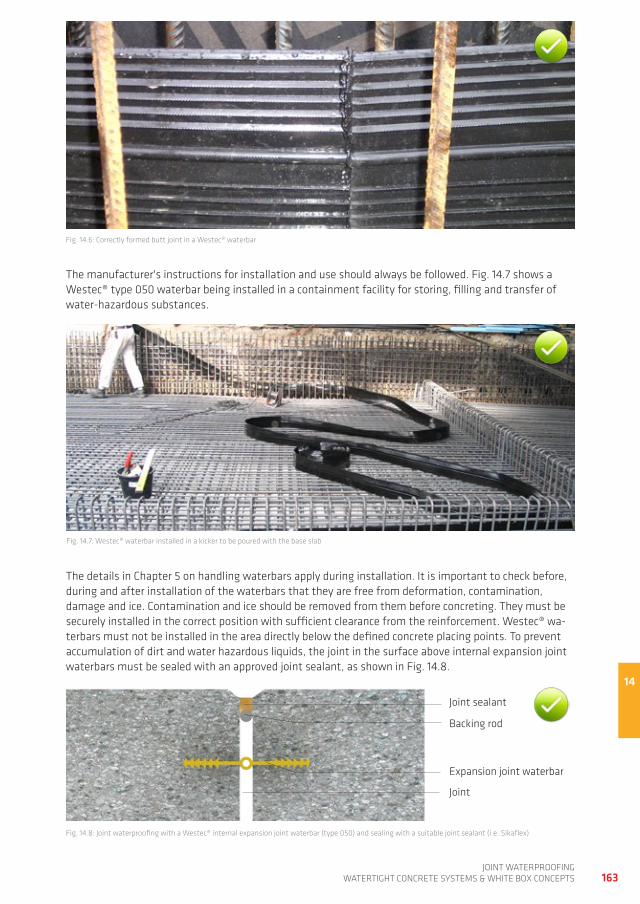
14
163joint waterproofing
watertight ConCrete SyStemS & white Box ConCeptS
fig. 14.6: Correctly formed butt joint in a westec® waterbar
the manufacturer's instructions for installation and use should always be followed. fig. 14.7 shows a westec® type 050 waterbar being installed in a containment facility for storing, filling and transfer of water-hazardous substances.
fig. 14.7: westec® waterbar installed in a kicker to be poured with the base slab
the details in Chapter 5 on handling waterbars apply during installation. it is important to check before, during and after installation of the waterbars that they are free from deformation, contamination, damage and ice. Contamination and ice should be removed from them before concreting. they must be securely installed in the correct position with sufficient clearance from the reinforcement. westec® wa-terbars must not be installed in the area directly below the defined concrete placing points. to prevent accumulation of dirt and water hazardous liquids, the joint in the surface above internal expansion joint waterbars must be sealed with an approved joint sealant, as shown in fig. 14.8.
fig. 14.8: joint waterproofing with a westec® internal expansion joint waterbar (type 050) and sealing with a suitable joint sealant (i.e. Sikaflex)
Backing rod
joint sealant
expansion joint waterbar
joint
164joint waterproofingwatertight ConCrete SyStemS & white Box ConCeptS
15 repair of CraCKS and LeaKing jointS
typically damage in watertight concrete structures involves leaks due to:
a. Cracks in the concrete allowing water penetrationb. inadequately sealed joints c. inadequately sealed pipe penetrations or formwork spacers that have led to water infiltrationd. water infiltration through un-cracked concrete around defects such as honeycombing
the root causes of these leaks are generally defects during concreting and concrete compaction, but can also be design and installation defects in the joint waterproofing. there are many examples of defects in the joint sealing of watertight concrete structures, but tips on avoiding them are also given in [8]. this Chapter gives a brief summary of the different ways of repairing leaking cracks, and inadequately sealed joints and penetrations, plus concreting defects such as honeycombing. further information is also available in [8].
15.1 SeaLing of CraCKS
Cracks are a factor in reinforced concrete construction and cannot be avoided even with careful design and construction. But not every crack is a defect. however water-bearing cracks and shrinkage cracks > 0.2 mm (approx. 1/128“) must be sealed post-construction. this is normally done by crack injection and in other situations by covering the crack with an over-banding bonded waterproofing membrane, e.g. the Sikadur-Combiflex® Sg system.
15.1.1 CRACK gROUTINg THROUgH INJECTION PORTS / PACKERS
water bearing cracks in watertight concrete structures can be sealed by injection through ports / packers fixed on the surface. holes are drilled in the structure, which are normally designed to intersect the crack at an angle of 45° and injection ports, also known as ‘packers’, are inserted and fixed into / onto them. the alternating arrangement of the packers shown in fig. 15.1 means that cracks originating inside the structure can also be covered. the crack is then injection grouted through the packers with a suitable injection resin or cement based grout. the maximum injection pressure should not exceed 1/3 of the specified nominal concrete compressive strength as detailed below:
max. injection pressure p [n/mm²]= 1/3 x concrete compressive strength [n/mm²] or in bar: max. injection pressure p [bar]= 1/3 x concrete compressive strength [n/mm²] x 10
the material input and flow during injection is controlled by the emergence of the material from the adjacent open packers. Vertical cracks are grouted working upwards from the bottom to the top. when injection is completed, the packers are removed and the holes are sealed with a waterproof, non-shrink cement or epoxy mortar.
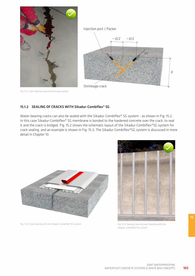
15
165joint waterproofing
watertight ConCrete SyStemS & white Box ConCeptS
15.1.2 SEALINg OF CRACKS WITH Sikadur-Combiflex® Sg
water-bearing cracks can also be sealed with the Sikadur-Combiflex® Sg system - as shown in fig. 15.2. in this case Sikadur-Combiflex® Sg membrane is bonded to the hardened concrete over the crack, to seal it and the crack is bridged. fig. 15.2 shows the schematic layout of the Sikadur-Combiflex®Sg system for crack sealing, and an example is shown in fig. 15.3. the Sikadur-Combiflex®Sg system is discussed in more detail in Chapter 10.
fig. 15.1: Crack injection grouting through packers
fig. 15.3: Sealing cracks by over-banding with the Sikadur-Combiflex®Sg system
d
~ d/2 ~ d/2
45°
Shrinkage crack
injection port / packer
fig. 15.2: Crack sealing with the Sikadur-Combiflex®Sg system
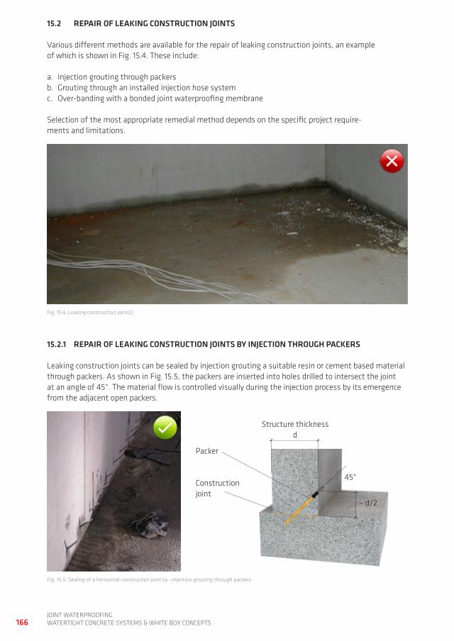
166joint waterproofingwatertight ConCrete SyStemS & white Box ConCeptS
15.2 REPAIR OF LEAKINg CONSTRUCTION JOINTS
Various different methods are available for the repair of leaking construction joints, an example of which is shown in fig. 15.4. these include:
a. injection grouting through packersb. grouting through an installed injection hose systemc. over-banding with a bonded joint waterproofing membrane
Selection of the most appropriate remedial method depends on the specific project require-ments and limitations.
15.2.1 REPAIR OF LEAKINg CONSTRUCTION JOINTS By INJECTION THROUgH PACKERS
Leaking construction joints can be sealed by injection grouting a suitable resin or cement based material through packers. as shown in fig. 15.5, the packers are inserted into holes drilled to intersect the joint at an angle of 45°. the material flow is controlled visually during the injection process by its emergence from the adjacent open packers.
fig. 15.4: Leaking construction joint(s)
fig. 15.5: Sealing of a horizontal construction joint by ¬injection grouting through packers
Structure thickness d
45°Construction joint
packer
~ d/2
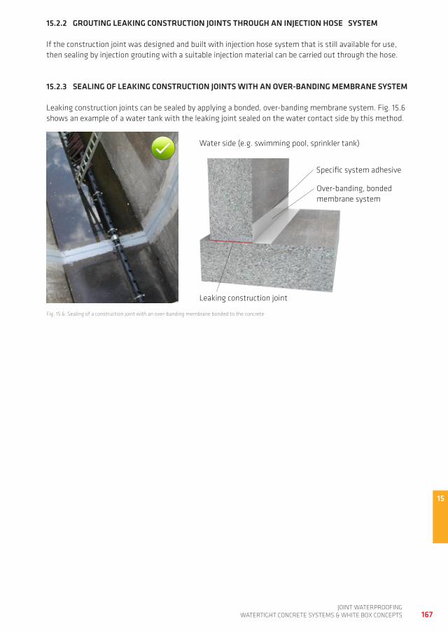
15
167joint waterproofing
watertight ConCrete SyStemS & white Box ConCeptS
fig. 15.6: Sealing of a construction joint with an over-banding membrane bonded to the concrete
15.2.2 gROUTINg LEAKINg CONSTRUCTION JOINTS THROUgH AN INJECTION HOSE SySTEM
if the construction joint was designed and built with injection hose system that is still available for use, then sealing by injection grouting with a suitable injection material can be carried out through the hose.
15.2.3 SEALINg OF LEAKINg CONSTRUCTION JOINTS WITH AN OvER-BANDINg MEMBRANE SySTEM
Leaking construction joints can be sealed by applying a bonded, over-banding membrane system. fig. 15.6 shows an example of a water tank with the leaking joint sealed on the water contact side by this method.
water side (e.g. swimming pool, sprinkler tank)
Leaking construction joint
Specific system adhesive
over-banding, bonded membrane system
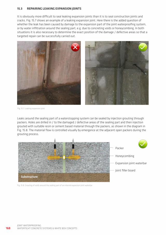
168joint waterproofingwatertight ConCrete SyStemS & white Box ConCeptS
Leaks around the sealing part of a waterstopping system can be sealed by injection grouting through packers. holes are drilled in / to the damaged / defective areas of the sealing part and then injection grouted with suitable resin or cement based material through the packers, as shown in the diagram in fig. 15.8. the material flow is controlled visually by emergence at the adjacent open packers during the grouting process.
fig. 15.8: grouting of voids around the sealing part of an internal expansion joint waterbar
Substructure
honeycombing
packer
expansion joint waterbar
joint filler board
15.3 REPAIRINg LEAKINg ExPANSION JOINTS
it is obviously more difficult to seal leaking expansion joints than it is to seal construction joints and cracks. fig. 15.7 shows an example of a leaking expansion joint. here there is the added question of whether the leak has been caused by damage to the expansion part of the joint waterproofing system, or by water infiltration around the sealing part, e.g. due to concreting voids or honeycombing. in both situations it is also necessary to determine the exact position of the damage / defective areas so that a targeted repair can be successfully carried out.
fig. 15.7: Leaking expansion joint
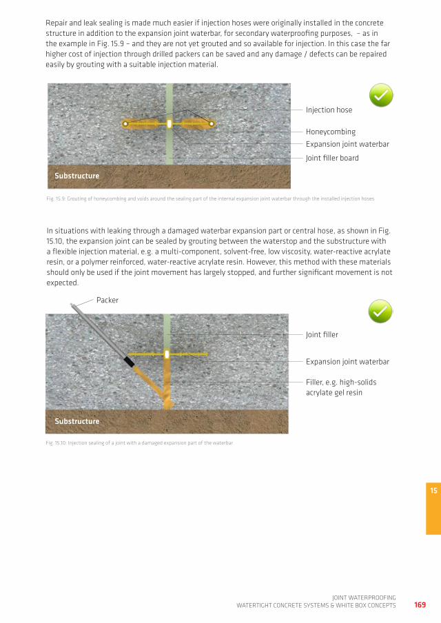
15
169joint waterproofing
watertight ConCrete SyStemS & white Box ConCeptS
repair and leak sealing is made much easier if injection hoses were originally installed in the concrete structure in addition to the expansion joint waterbar, for secondary waterproofing purposes, – as in the example in fig. 15.9 – and they are not yet grouted and so available for injection. in this case the far higher cost of injection through drilled packers can be saved and any damage / defects can be repaired easily by grouting with a suitable injection material.
fig. 15.9: grouting of honeycombing and voids around the sealing part of the internal expansion joint waterbar through the installed injection hoses
fig. 15.10: injection sealing of a joint with a damaged expansion part of the waterbar
in situations with leaking through a damaged waterbar expansion part or central hose, as shown in fig. 15.10, the expansion joint can be sealed by grouting between the waterstop and the substructure with a flexible injection material, e.g. a multi-component, solvent-free, low viscosity, water-reactive acrylate resin, or a polymer reinforced, water-reactive acrylate resin. however, this method with these materials should only be used if the joint movement has largely stopped, and further significant movement is not expected.
Substructure
injection hose
honeycombing
expansion joint waterbar
joint filler board
Substructure
joint filler
expansion joint waterbar
filler, e.g. high-solids acrylate gel resin
packer

170joint waterproofingwatertight ConCrete SyStemS & white Box ConCeptS
fig. 15.12: example of post-sealing of a leaking expansion joint with a clamped waterstop
fig. 15.11: post-sealing of a leaking expansion joint with a clamped waterstop
Clamped waterstop
defective expansion joint waterbar
Substructure
joint filler board
if significant movement is still expected in the expansion joint, it usually has to be waterproofed with a clamped flanged waterstop. the leaking joint is sealed with a special waterbar fixed to the concrete on both sides of the joint by steel flanges, see fig. 15.11. the clamped waterstopping assembly must be compatible with the anticipated stress due to deformation and water pressure and must be suitably designed in terms of the waterbar thickness and material type. fig. 15.12 shows an example of a joint repaired with a clamped flange. more detailed information on using clamped flange waterbars can be found in Chapter 13 or in [8].
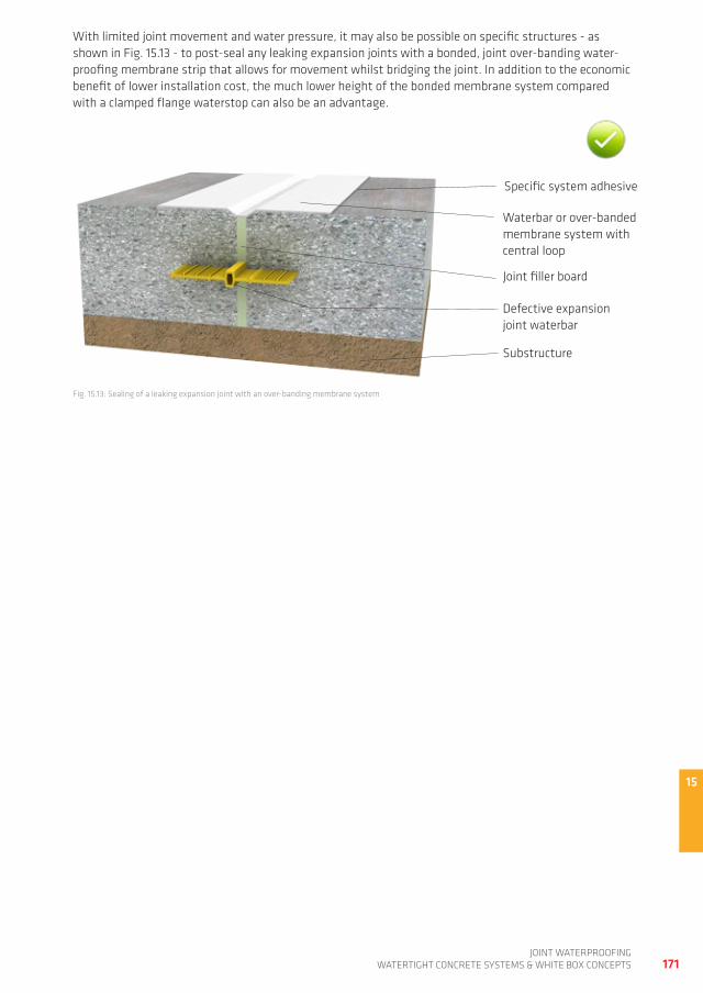
15
171joint waterproofing
watertight ConCrete SyStemS & white Box ConCeptS
fig. 15.13: Sealing of a leaking expansion joint with an over-banding membrane system
with limited joint movement and water pressure, it may also be possible on specific structures - as shown in fig. 15.13 - to post-seal any leaking expansion joints with a bonded, joint over-banding water-proofing membrane strip that allows for movement whilst bridging the joint. in addition to the economic benefit of lower installation cost, the much lower height of the bonded membrane system compared with a clamped flange waterstop can also be an advantage.
waterbar or over-banded membrane system with central loop
defective expansion joint waterbar
Substructure
joint filler board
Specific system adhesive

172joint waterproofingwatertight ConCrete SyStemS & white Box ConCeptS
16
173joint waterproofing
watertight ConCrete SyStemS & white Box ConCeptS
16 BiBLiography
[1] german Committee for reinforced Concrete -dafStb-, Berlin (publisher): technical regulations, dafStb directive - watertightproof concrete structures (wU directive). Berlin: Beuth Verlag 2003
[2] german Committee for reinforced Concrete -dafStb-, Berlin (publisher): notes on dafStb directive - watertightproof concrete structures. Berlin: Beuth Verlag 2006 (german Committee for reinforced Concrete; vol. 555)
[3] german Center of Competence in Civil engineering -diBt- (publisher.): "LaUanlfugenbänderZul-grds", approval principles - joint sealing systems in LaU facilities, pt. 2: waterstops. 5th ed., 2001. Berlin: 2001. (diBt publications)
[4] din 7865, standard, edition: 2008-02: elastomeric waterbarstops for sealing of joints in concrete, Beuth Verlag, Berlin
[5] din 18197, standard, edition: 2011-04: Sealing of joints in concrete with waterbarstops, Beuth Verlag, Berlin
[6] din 18541, standard, edition: 2006-09: thermoplastic waterbarstops for sealing joints in in-situ concrete, Beuth Verlag, Berlin
[7] european technical approval eta 04/0044: westec® pe waterbarstops for use in containment structures for the storageing, filling and transfer of water-hazardous substances. diBt: 2004
[8] hohmann, r.: joint sealing in watertight concrete structures. Stuttgart, fraunhofer irB Verlag, 2011
[9] Schlumpf, j.; Bicher, B.; Schwoon, o. (publisher: Sika Services ag, Zurich): Sika Concrete handbook. Zurich, 2012
[10] Zement-taschenbuch; 51.ausgabe 2008; Verein deutscher Zementwerke (publisher); Verlag Bau+technik, düsseldorf

174joint waterproofingwatertight ConCrete SyStemS & white Box ConCeptS

175joint waterproofing
watertight ConCrete SyStemS & white Box ConCeptS

176joint waterproofingwatertight ConCrete SyStemS & white Box ConCeptS

Sika ServiceS aGTüffenwies 16CH-8048 ZürichSwitzerland
contactPhone +41 58 436 4040Fax +41 58 436 4150www.sika.com
for more waterproofing information
WHO WE ARESika ag, Switzerland, is a globally active specialty chemicals company. Sika supplies the building and construction industry as well as manufacturing industries (automotive, bus, truck, rail, solar and wind power plants, facades). Sika is a leader in processing ma-terials used in sealing, bonding, damping, reinforcing and protecting loadbearing structures. Sika’s product lines feature high quality concrete admixtures, specialty mor-tars, sealants and adhesives, damping and reinforcing materials, structural strengthen-ing systems, industrial flooring as well as roofing and waterproofing systems.
our most current general Sales Conditions shall apply. please consult the most current local product data Sheet prior to any use.
© S
ika
Serv
ices
ag
/ w
ater
proo
fing
/ C
md
L /
join
t w
ater
proo
fing
/ 0
1.201
4