jaguar 23kw combi boiler.pdf
TRANSCRIPT

,
I
'" ~guarL;:;£
23kW wall hung~combinatio~ b~i!er~ "'~' ""' ~ ~':4) £~.
- p ~~ ~~
~... ~ ~""~~
:I
~ I<? ~"
~""
>-=~~-~
~ ~"~ 'I,~ ~~
'=11~'"
- ~
j'"
~. ., lJ,,§~r, InslalZan~';R0) ... ~.' .
!~" ..~~ a" . . . alld Servicing Insrruc'G. "III.~
~::~;;. ~'"I ~~~ "",,~,,~~f>""'~-4'k <"- .~ ~
'( ,E ~~i~;Sa ca~.h:~appa-a"'" .~~. ~
MaTiujacturetjexclusively jor Plumb~l£t..bJ H~r"'i!"I8ma'~'--:rion~ - ..~
~~:!-=-
ot
'"
GUARANTEEco~~nnONS
This appliance is guaranteed for a period of 12 months from :k ~ ~ ~~<:incF£ 0("18 months from the date of despatch from our warehouse ~!::::::r ~ - ;h= ~..,..=- ~ ;:;;..~
manufacturing defecrs ool}.
The Manufacturer undertakes to repair or replace parts, free of charge.. - ~ &!'::-.:c s;:.~by us to be of faulty manufacture, if necessary, after return to our facror: .-~;::---&.. 0::.condition that:
~'
1) The appliance was installed by a qualified gas installer in ~~ -"..;h i=llariooinstructions, and all the relevant codes of practice, slalldani5;:!::Io. ~ ~ m fon:e..The appliance has,!;Jeen used for norma] domestic pDIpOS;::S...d ..;:.~ -fib TIieManufacturers operating and maintenance instructions.
The appliance has not been serviced, maintained, repaireQ m-.:.nL~ IJC~ed withduring the quaraqtee period by anyone other than an engineer appo-u-~ ~ :lieManufacturer.
The appliance is still in the possession of the original user -.. ~- ..f~, in theform of a receipt or invoice, is shown to the service engineer (8. ~~
2)
3)
4)
Tile repair or replacement of parts during the guarantee period ~... ~e:;b= ~eC" ~=- _extending the period.
='"This quarantee does not cover:a)". Any defecrs or damage resulting from incorrect or poor jn<a~..J" "::.
or maladjustment of the gas or water used.b) Any defects in the sysrem to wbich !be appliance is = "="- ~c) Any deterioration or maladjnstment following c~ '" ~ ?_-
or the water used, or a change in me characteristics - ::10::.~ "'- ~--
.m..;.e.- <:r.::~
-... - .;e gas
- ~
Nqtifica!ion of any fault should be made to the appliance ~ c-
~ No repairs should be undertaken up~theIlPplia!}ce, in1ending ~ ~ ;:e ro-ered by the productquarantee withoJ}t.;p,vor';afitlfo:'tisation from The Manufactura
;;;
IMPORTANT: The appliance serial number must bequ~-' made with The Manufacturer.
.. ""',~ . .. !€ ..~:~~~ ",.t., .
This guarantee IS In additIOn to your statutory and other oC'- ..;. ":.,xcluded or diminished by the return of this card.
--~ :;. ~~-De
FOR SERVICEoENQUIRIES C():'-T-\.Cf:
~'
..~..R'EilTE~LL~ ~.~~~~
O.N
O177J~-Z8100
~c' "§
--
JaguarI
1 -
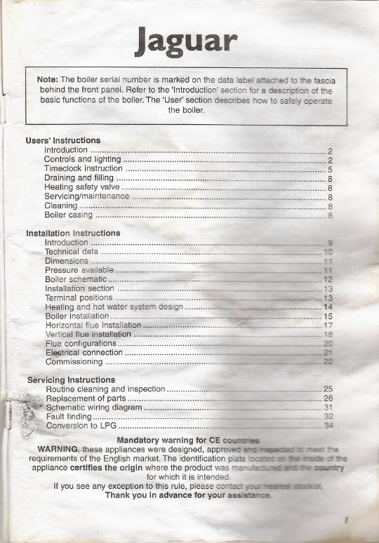
Note: The boiler serial number is marked on the data label attached to the fascia
behind the front panel. Refer to the 'Introduction' section fora description of thebasic functions of the boiler. The 'User' section describes how to safely opemie
the boiler.
Users' InstructionsIntroduction """""""' n---nn"""""" n 2Controlsandlighting """""""""""""""""""""" n n 2Timeciock instruction """ """""""""""n 5Draining and filling """"""""""""""""""--""""""""'" 8Heating safety valve... 8Servicing/maintenance """"""'n""""_, 8Cleaning.. _._~ 8Boiler casing 8
.~-
Installation InstructionsIntroduction ",""""'..n....--__.-..--
~ Technical data """"""""""""""""""""""""' n-
Dimensions """"""""""""""""""""'" ...........-
Pressure available ,,"'.n-
Boiler schematic ~.~.n.- - ~2Installation section - 13
Terminal positions -_n---""'" 13Ijeating and hot water system design 14Boiler installation 15rlorizontal flue installation """""""""""""""""""'-= n" 17Vertical flue installCjtion --- - 18
Fllie. configurations z:
~~~:~i~~~n~e~~i.~.~.:::::::::::::::::::::::::::::::::::::::::= .. - ~
-v
.",
.,.
S~rvicing InstructionsRoutine cleaning and inspection ........................J}eplacement of parts n....
hematic wiring diagram ................................-auIt finding ......-.:qnversionto LPG ............................................~
25_.nm 26
--- 31_32
3-=-
Mandatory warning for CE ~-'> WARNING;",these appliances were designed, approvoo a:"': '"'~.~,' """€IS-erequirementS-ofthe English market.The identification plate 'X3'!!!,: -.", -:!:':E ':" ~appliance certifies the origin where the product was I112!'U13::' - :: r.:.-.,; ::a zoy
for which it is intended.If you see any exception to this rule, please cor.t.c:c -::--' --: '
Thank you in advance for your assis::a..-oe.~'.s
--
USERSINSTRucnONS
The Jaguar is a wall mounted combination boiler providing central heating and Instanta-neous domestic hot water. .
These instructions should be carefully followad for thG safe and economical use of yourboiler. .
~as leak or faultIf a gas leakor faultexistsor Is 81J..p~(;lftcJ,turn IIlraboilernnd QlHI supplyoff andconsult the local gas company or YOUl1i"lh'tIl~I/~'C'1lvlof)provld~r
10 0009 of power supply falluronUl boiler no longer operatGs.A. lIoon as power supply Is rGotorml,1111 111,111'11 will ",.1", I lIutom~llIoCllly.
In Onll(l of 1088 of water in the aYltcl11lCAUTION: The boiler is Instnlh,1I fl' 1"11I III " Icg,lied system which must only bedrained and filled by a compehml pi'll 111ftIf the pressure LED diad (?) fla911""IIIII /l1t1."uni Inm I system is less than 0.8 barand the system must be filled up 1rIlIlIfJ(II~lijly.
Important notice: A central heatlnu IVIoIIIIII(1~llItO' operate satisfactorily unless it isproperly filled with water and unlesil 111(1 1iI1, Initially contained in the piping systems.has been properly bled oft.elf theso ~:ol1dltlons are not satisfied, air noise will occurwithinthe system and the boiler may 1111110operate.
Air 111thu hOfltlng system .I 'tlI ,.11111:11I' Air In the heatingsy.'mn 111I1Y Indicate leaks in the system or corrosionhlklfllJ pIIH"'. (;",11your Installl'l'1"1'11 vh~ provld€Jr.
Overheating safetyIn the event of problem, the overht~"'f IIII..t. ,!twit It 111'11111111<I:Itlfuly shutdown of th
. boiler. If this 'happens, call your InJlII11111f 11'11vll't! pll/vldnl "\~:,J.
CONTROLS AND LIGHTING "-jIII', oontrol panel Is located at the low"" II"ftl IIf IIln IUJlltil',j1IjII1Ulilt! ('(mlll)l. Ol1lh/~prtf1~llllIow the boiler to 121:)started, 'Il1l1lllown, lionlrolltJcJemufrlonltof'(,ddurIn' ".tm dillwam 1.""
The following Information is displayodl. Actual heating temperature (OC)- LED (~I)IIUIlI" on
displayed during standby. Actual domestic hot water temrmf"lllllli'l ("0) . LED (5) lights
displayed during hot wat&rdlnmllJd .
. System pressure (bar) - LED (2) IIgl1tsfor 25 sec after Bar/Mode button Is pressed
. Diagnostic messages - displayed letter F and numbers from 0 to 4
~. I"'~
~{ ,II.,
j i2
I n;;;jriiJL~ttlilr. LYJ
I
[ I I J
[:::,)[ ~ 118 OJ r \~ ) [""'J]t t t
9 1/ 7 (I
[ 1JI(l"I(I'n~
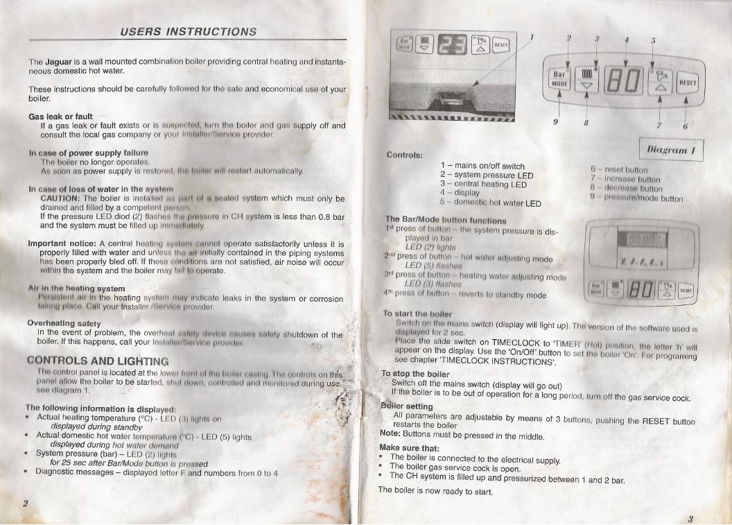
6 maul billion7 Inl),'Qtlll"hullon8 dOtJf~l4l1f1button9 prl11!Iwll/modebutton
Controls:1 - mains on/off switch2 - system pressure LED3 - central heating LED4 - displAY5 .domostlc hot water LED
The Bar/Modo button runotlono
1stpress 01 bllllwi tl1ollyatem pressure is dis-playod In 11mLED (2) IIfJhIt.
2ndpress of button flol WPllmtltJJIIAtinp modeLED (h) f/11,.lImi
3'd press 01 bUlinn hOMlnQ WltlrH AdjustingmodoLf:D (tJ) flllSIWB
4th presti of 111111011rovnrl. 10 "I'6Inclby mode
~~~i~.~
I:,~:,'II WU'iiBOJ [1;J ~;i
I )I
II
!I
u.
I,Toatart thA bollor ,
8wltul1 on lilt! mains switch (display will light up). Tho version of the sottwflre used Isdlllp/uYc9d tor 2 sec.
Pillce the slide switch on TIMECLOCK to 'TIMER' (1101)pO/ll/tlon, IlIU /QlttJr 'I,. willappear on the display. Use the 'On/Off' button to selll1o bollor 'On'. "'or programingsee chapter 'TIMECLOCK INSTRUCTIONS'.
J.9istop the boilerit !t?'Switch off the mains switch (display will go out)
~'the boiler is to be out of operation for a long period, turn off the gas service cock.~ersetting
"All parameters are adjustable by means of 3 buttons, pushing the RESET buttonrestarts the boiler
'Note: Buttons must be pressed in the middle.
Make sure that:
. The boiler is connected to the electrical supply.
. The boiler gas service cock is open.
. The CH system is filled up and pressurized between 1 and 2 bar.
The boiler is now ready to start.
II')1!'
I~!I
3
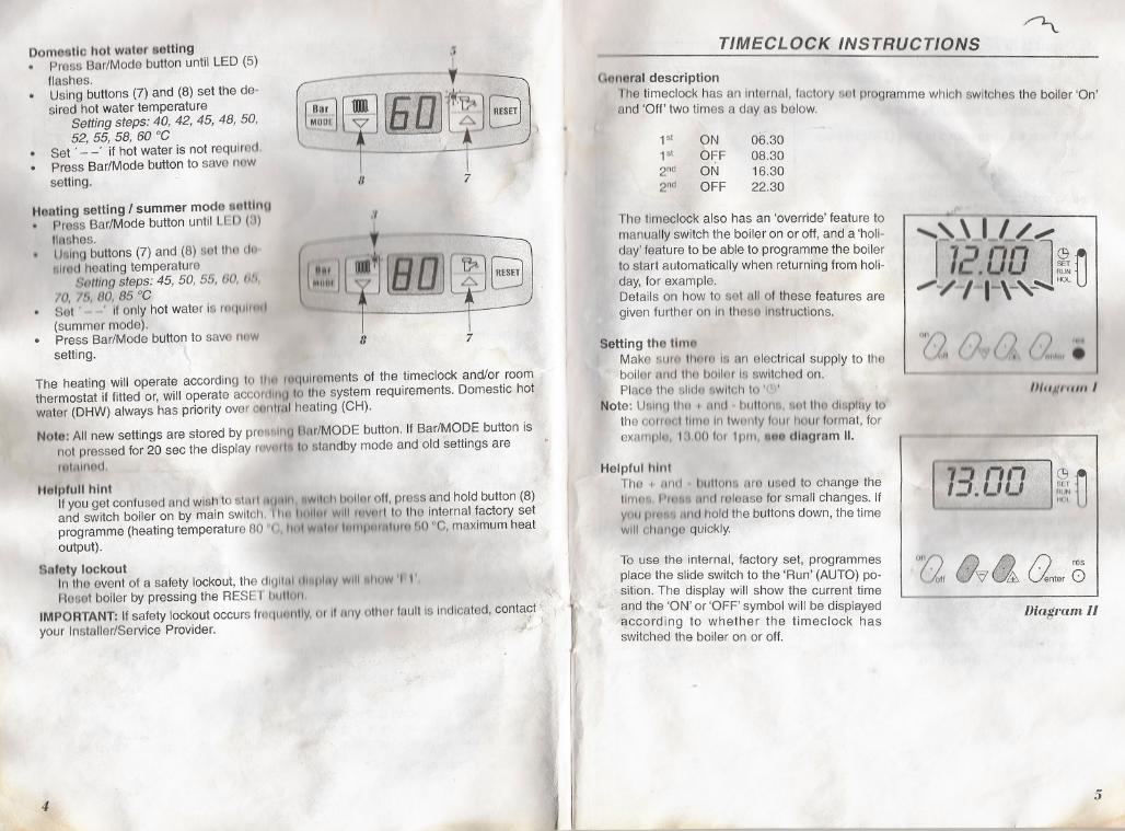
Dom...tlo hot wfttor lu,ttlng. Press Bar/Mode button until LED (5)
flashes.. Using buttons (7) and (8) set the de-
sired hot water temperatureSetting steps: 40, 42, 45, 48, 50,52, 55, 58, 60 °0
. Set' - -' if hot water is not requlrad.
. Press Bar/Mode button to sava nowsetting.
Hontlng setting / summer mode e8ttlnl.lPrass Bar/Mode button until LH) (3)IIl'IShes.lifting buttons(7)and(8) sellho elel..Imt! heating temperature
Botting steps: 45, 50, 55, 60, Oh,10, /b, 80, 85 °0Sat' I' only hot water Is ruqulrml(summer mode).Press Bar/Mode button to save I1t1W
setting.
!J
- ..~r~]
n 7
:1
+
(I :,::, II t' lEUlJ8 7
The heating will operate according to tilt! le~qulraments of the timeclock and/or roomthermostat if fitted or, will operate accorcUIIU 10 the system requirements. Domestic hotwater (DHW) always has priority over olmlral heating (CH).
Noto: All new settings are stored by pre...lnu Bar/MODE button. If Bar/MODE button is
not pressed for 20 sec the display rovfJl'I\ 10slandby mode and old settings areIl1tnlnod,
Holpfull hintIf you get confused and wiSh to slllHlllqult I, IIwl\! ,II hollur off, press and hold button (8)and switch boiler on by main switch. 111I~ \t1l11t:~1will Invenl 10the Internal factory setprogramme (heating temperature 80 "( Itlll will'" ItllllpurAllI,1I bO °C, maximum heatoutput).
Safety lockoutIn the event of a safety lockout, the dlglllll,ll..pII1Vwlll'llulw 'I I'Rosatboilerbypressingthe RES!;" blllll)II, :'?'
IMPORTANT: If safety lockout occursfrof\urmtly,or II flnyothGrfault Is Indlcflted, contC!9f'...iyour Installer/Service Provider.;/~ .~
4
TIMECLOCK INSTRUCTIONS~
("'moral descriptionfhe timeclock has an Internal, factory lat programme which switches the boiler 'On'and 'Off' two times a day as below.
1st
1st
2nd
2nd
ONOFFONOFF
06.3008.3016.3022.30
The tlmeclock also has an 'override' feature to
manually switch the boiler on or off, and a 'holi-day' feature to be able to programme the boilerto start automatically when returning from holi-day, for example.Details on how to set nil of these features are
given further on In thoSQ Instructions.
Setting the tlmelMake "111mIl1oreIs an electrical supply to theboiler I1mJ tho bollor Is switched on.Placo the 611do8wltol, 10 '(I)'
Note: Ualnn tl1o I llI1U bullonli, Rut 1110display tothe cOrlCH,llIlI1u In Iwonty 10111hour format, forexamplel, \'100 lor 1pm, ...e, ding ram II.
Helpful hlnlThe I' /'Inel l)uUons aro used to change thetlrnwI, "'ll.'" 1In(;1mlease for small changes. If
Villi pIC"'" 11I1dhold the buttons down, the timewill c:lwnge quickly.
To use the internal, factory set, programmesplace the slide switch to the 'Run' (AUTO) po-sition. The display will show the current timeand the 'ON' or 'OFF' symbol will be displayedaccording to whether the timeclock hasswitched the boiler on or off.
fI
- -- --
. 1-,.\ ...I_~,.112.00 ],~~
,-/ l t..\L'~HOl -U
"'1)( ~," (
"'., l ""IH'.
m"M""IIII
[ 73.OOl~D
°ry) if]) JitJ n res(/0" ~'f/.& Unter 0
Diagram II
5
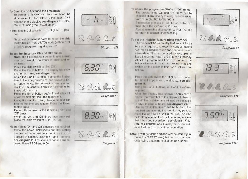
To OvCtrrldoor Advance the timeclock10 permanently override place and keep theslide switch to 'Hol' (TIMER), the letter 'h' will
appear on the display, see diagram III. SelectOn or Off using the On/Off button.
Note: keep the slide switch to 'Hol' (TIMER) posi-tion.
To ooncol permanent override, raverl ttw .lIdw!Iwlleh',"ck In 'Run'(AUTO) mode (w11l10111'11111'
(IIMI 11)programming: display 'h')
1o."1 tho tlmeclock ON ond OH I""""Noh~,rhetimeclockcan bo l1ullll Ul~ I 11111111111111101one and a maximum 01 Inll 1111 1IId 11111
11111111111",
1'lnGt' 1110..lido switch to '<:"111(I (JPress tho '[ ,ntor'button. nUl dl' '111,I' ,viII Ihowthe first on time, see diagram IVUsing the + and - buttons, channo lII~ fl"" 011time to the time you require then prn,.,.lIlu" nter' button once.This stores the now 1111111 unddisplays it to confirm it has been IIIOryd In thetlmeclock memory.Pross the 'Enter' button again. Tho dl"pIIlY willIII,uw tho first off time, see diagram V"..IIIU Ih" I find - button, chanlj(.llliu IIrnl 'Off'
limn 10Ill., limo you require.prm IIw 'I ,nlm'button once.Repeat the above for the reml1lnlr'~1'( 'II ifill'Off' times.Whenthe 'On'and'Off' timesh~lvu III:m1ltml,place the slide switch to 'Run' (AUI{))
Nato: 'fsome 'On' and 'Off' times are nol rllt (LlIIIH "
follow the above instructions but flllnr",llIngthe desired times, set the other tlmofl 10.howa series of dashes, using the + and bullt",lII,see diagram VI. The series of dashes AfIt bu.tween times 23.59 and 0.00.
6
r h ., J~D-
ory) ( ) I') /) res
( ;.;" (& lfenter 0
IJlagram III
,- j JON
o.~L"<~
Cg
eSETRUNHal
°(2 0'7 a (Inter0
Diagmm IV
[ 8.30""~
eRUNHal
my) I) /) A res(~" U'7 U&. ~nter b
Diagram V
,I
~
I
J
hI .h!'lck tho programme 'On' and 'Off'timesIlw programmed 'On' and 'Off' times can be111I'd~,,(t 'It AnY tlma by moving the slide switchllill)) 'HIIII' (AlIIO) to 'Sot' (C1).thlCl10NhivII prmmUfi of the 'Enter' button willIIH'" "'ww 111(1 'On' ond 'Off' times.
AlwrlY' ,nlllllll110 'Jlldeswitch to 'Run' (AUTO)10 (ulm" 10 "olmHI timed working.
fa 80t the 'Holiday' feature (time override)rhe tlmoclock has a holiday feature which can
be sol, If required, to keep the central heating'Off' for a period between one hour and twentyseven days. This can be used, for example, tokeep the central heating 'Off' during a holiday.After the programmed time has elapsed, theboliAr will rAlum 10It') normal programmes andIlwllt:11Oil lI,u lIullltr In timefor a returnfromIHiIIe1J1~
11
Phil I 11111/1In Iwlloh to'Hal'(TIMER),thelet.h. 11evlll I1ppUIIr on the display, see dla-UI 'UII III
11111111111111I .lnrl IIuIICHH., 1111tho 'Holldny'lltne1f'1I"1'\lrI
1\11111 II" rlhplllY 11"'1..lIow"'twenty three1111111"'11 'lI,ymbol ol1l1w Clillpl.,ywillchangeIi I ,I 'eI' I hI' '1IollcJny' 11r11l~willnow bo displayedI" CI51V' II,c,tnl1e1 of 1111111"', ton diagram VII.
I hili 111\1'( )"f( If' 1",IIUIl10set the boiler to themtJullrlll opetrullon during the 'Holiday' period.I'111011Ills ~lIdeswitchto 'Run'(AUTO).The 'ON'or 'OFF symbol will flash on the display to showthat It has been overriden, see diagram VIII.After the programmed 'Holiday' time, the boil-er will return to normal timed operation.
/
Note: If you get confused and wish to start againpress the 'RESET' (res) button for a few sec-onds using a pointed tool, such as a pencil.
[ -.--'o~:
J"" ~eRUN
Hal
°(2, 0'7 & Qnter0}
Diagram VI
fB':1 "dl,rr ~
o::J "II'",
III~,'. ~ J". '~'" ," G', ( 'Nil loll C)
m"!/f"(UIl VII
---
[ 7. 50>\< I~~
°z, 0'7 a Unter0Diagram VIII
7
DF1AINING AND FILLING(AUTION: Tile boiler is installed 88 part of a sealed system which must only bedmlnu(J find filled by a competent person.II tl1o praeaure drops to 0.0 bElr the pressure LED on the Bar/MODE button starts to1111811.Tho boiler will continue to work, but the LED warns that pressure in the CH.y,turn Is on tho low limit and CH system must be filled. To fill the system, open theIlip on tho fllllnDloop bcalowthe boiler. Press the Bar/MODE button to read the systempnUu.luro. Whcmthl) pressure is between 1 And 2 bar, close the tap.
Notll II tll".,u I" persistent loss of system pruflBLJrG,you must consult your Installer/Ser-vie11 I'llIvldl!lr.
III AfiNG SAFETY VALVE{ AUTION: A IUlfoty ve\lvQwltll t~ (1I~(,II"'UtI IIlpnlli IllIud 10 tlll8 bollar.III~ Wllv,t MUST NOT 01 roUCt It II U"' 1111'I I,v 1'1cl)mpl.lltlnl parson, II 111&valvedl.dlMIUClfI tli nny tlmQ, 8wltoh 11111,,"lItI! "" '"HI hmlnlu It Irom the olectrlcal supply.1 ,llIlltlll Y"IH InslAlior/Survleu "111\111111
SERVICING/MAINTENANC: ITo ensure the continued efficient 111111 "Ih:l "l'u,~tlOI1 01 the boiler, it is recommendedthat it is checked and serviced at rnUllh~1",t",vl'Il. n,o frequency of servicing willdepend uponthe installationconcllthl/It ,lIId 1111/1(jPIJlII,In (lonarel, once a year shouldbe enough.
CLEANING11111 holler casing can be cleaned willi,' dlllllll (jlolh followed by a d.ry cloth to polish.IIII 11.)111.11nbrasive or solvent CIOI1lII1I
BOILER CASINGCAUTION: Do not remove or adJUtillllitl 1 I"IIHI III tlflY wny,as incorrect fitting mayresult in faulty operation.If in doubt, contact your Installer/Servhll 1'1IIvld",
{
8
'I.,
INSTALLATION INSTRUCTIONS
INIIIOIJLJCTION
11111hUJIUIi I, "willi Inl)ul1lod combination bollGr providing central heating and instanta-11111111"dO11l1 1111 hot wllior.
1111;11,"11111 I 111111t1I1~Halcl1tegory for use with Naturfll gas (G20) as distributed in theI Jflllttlll\IIIUdolll, or with ButMe or Propane gas (G30/031) with the appropriate con-Vlllllloll 1111 '
Convttr81on kit:( lonvorL!lonNAlurAl gas (G20) to G30/G31
Modification must only be carried out by a suitably qualified anQlnGor.
[)ollC'r.. hurnlng LPU or ulmllftr gases MUST NOT be fitted In bnsements or belowI,Jttllllld luvltl
1I1IIIIt 1111111111111111~11t",ld ho carefully followed for tho 'nllel "l1et uCillllumll",III"" Ilf t'lIllfbolllli
rl1~ 1'"11111111111r1 Irlll Msislad, balanced, flue whlcl1lJ(111I III", ,II IIUI:III 11111pilldll'" 11'1 11111
bill/I"" I III .11I!I drAw. IIIu (1omhuNtion nlr from tho outllirtu III 11111lJulldltlU
At)!',..,"'111....
" '11111'IIf lliUl!lMOI'lufI,lrn flvAIiAble including, VUIII"III Ih/l' (11111111"11UI118.For further11111111"'111111111)11111(,1you rlfll'H11hl Plumb Center branoll
~nfl1tl1""V (1rllllnllAtlon nod U88) Regulations111tht! '"1"'11-.11 ~lIld 111/.11of gas safety, it is the law thai All QCIIIFlpplillnOU8 t1fl:lln"UIIIII(1/lncl "r:tlvlll~rt111by II competent person in accordal1oo will I IIIn ..hov', muulutlonll,
~ '
(jag IAOkor faultIf a gas leak or fault exists or is suspected, turn the boilul und gas supply off and consultthe local gas company or your Installer/Service Provldm.
Boiler controlsThe control panel, located at the lower front of the boller, allows the boiler to be started,~hut down, controlled and monitored during use, refer to 'Users Instructions'.
9
TECHNICAL DATAUIMHNSIONS AND PRESSURE AVAILABLE
CECertification "". n° 0063BL3573
~?~~::::::::::::::::::::::::::::;;~i:::::::::::::.::;;~:.::::::.::~;:.:g~Max. / min. Heat Input " kW .".."""" 25.0/ 11.4 25.8 J 11.4 ."... 25.8/ 11.4Max. / min. Heat Output kW """"".23.0/9.4 ..." 23.0 / 9.4 , 23.0/9.4
EFFICIENCY (PCI)Nornlnlll ""Iolancy % "."".UflollIIlIUVul 30% load % ..""
In ,AIINCiIlImpliralure range .." " "". °C "I MpllI'lJlonvessel " ".""..""." II ~pllll"lon vessel pressure ..".""."" hI\[MilK worKingpressure "" b'JIfM-'M 'VII'"mlamperature".". "e.,MIIX, IIV.IGm onpaclty """."", I
HOT WATERFlow rate at 30°C temperature rise I/mlnFlow rate at 35°C temperature rise I/mlnMin. water flow """"", IImln "Max. / min. supply pressure bill "Temperature range °C
10
.~IIO.'~
I :"~'";:" Jl1 ~. iIii dTiI
, II , ~" J.:L",-"",..." " 81
"..." ".".." "" 76
"."..".."..."" "'" "".45 86" """""", """."",."""""".5
".. ""."...""..."."". """.1"""",.." "..."""""""""""""""...3
""", " " " 85". "" 100
~
\
I""." 11.2
..." 9.6"." 2""".""""..." 6 / 1".".".." 40 - 60
.. 7b 1-
J -'lj"~'I
.
;~
).2 ~
l~~
~ ~ .. 'I~
~ 1 t,." ,.. , -230/500.6
.."." 135IP 44 rHC>N'1 VII'W
I II I .
I
i '/1'1
I . IIn ..II ,1'".
/Jiagram 2
"" 410/740/320." : 35
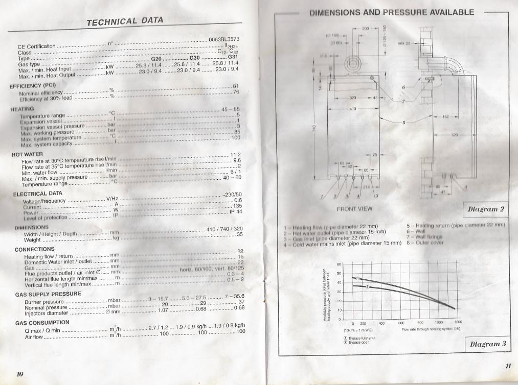
1 IhuIIIIIU flllw (pip" 11111111111111'22 mm) 5 - I-lrll1l1ngmlllrn (plpl'l rllllll1NIClI './1' I1l1n)
2 11111Wllt"u 1111111:11(1)11'11 diameter 15 mm) 6 WIoIIi'1 (ulllllllni (plpl3diameter 22 mm) 7 WMIIII~ItIU".1 (jQlcJwall3rmains inlet (pipe diameter 15 mm) 8 Olllnl 11111111
""""" 22
..." 15" " ",22
1101'1,1 tlO/ WO, vnrl. 110/125" " "..."" "..."" "..." 0.3 - 4
" "."...".".."".".0.5 -9
~~E~ 50~.§~E 40~ ~a.-
;~ 30~ ~
* -5: 20~ c.c.~<DO>
~.~ 10';;",U
eLECTRICAL DATAVoltage/frequency V/Hz "Current A "l'oWCI!' W..1nVlllul prlltllctlon IP
VIMIIN910NBWidth / Height / Depth 111m
Weight kg ..
CONNECTIONSHeating flow / return mmDomesticWaterinlet/ outlet , mmGas mll1Flue products outlet J air inlet 0 mm....I~orlzontal flue length minImax ..." m "Vertical flue length minImax m ..
GAS SUPPLY PRESSUREBurner pressure mbar " 3 1b.7 5.3 - 27.5 " 7 - 35.6Nominal pressure mbar 20 29 37Injectors diameter 0 mm 1.07 0.68 0.68
GAS CONSUMPTIONQ max / Q min m3/h 2.7/ 1.2 ... 1.9/0.9 kg/h ... 1.9 J0.8 kg/hAir flow m3Jh 100 100 100
60
0 200 400
(10kPa= 1 mWG)
<Y Bypass fully shut@ Bypass open
600 800 1000 1200
Flow rate through heetlng system (Uh)
Diagram 3
11
mln20
II ;"
(I
1";4 1
.I
7 I I"
II
-r ,1;'0
BOILER SCHr:MAf'lC
1r :L[l-"
It'":~OIl -
11'" ,r
~7
24
v~
~/
018
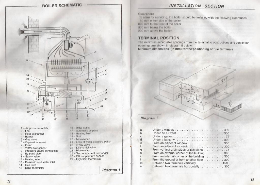
1 - Air pressure switch2 - Fan3 - Heat exchanger4 - Burner5 - Gas valve6 - Expansion vessel7 - Pump8 - Water flow sensor9 - Pressure gauge connection
10 - By-pass pipe11 - Safety valve
, 12 - Heating return13 - Domestic cold water inlet14 - Gas inlet15 - DHW thermistor
12
INSTALLATION SECTION
( It."."""...
III IIIi oW fill ""1vlcllnu, 1110 bailor should be Installed with the following clearances:II ""III~IIII!I' 1,lflu 1111I1~bailor
111111111'" 111111111111111011110boiler11111"II" II 11Ii oW lilt! Imllm'1111 "1111 11111111I II11' tJuliur
TLI~MINAL POSITIONIllu minimum f1cceptable spacings from the terminal 10obstruotlons and ventilationopol1lngll liTO tSl10wnIn diagram 5 below:Minimum dimensions (In mm) for the positioning of flue terminals
I:J
\. :/
./
:;
01:J
.'
r mll~/""" ,j I
~If! IHIWlluU,,1t, AllltJlIll1t1I'IIVIU'1MIIt" Hlill!lnl/llow19 Drain~O Mlcroswltch111 l.olB 01wntlll prossureswitch22 S.wayvalvo23 - Differential valve24 - Microswitch25 - Secondary heat exchanger26 - CH temperature sensor27 - High limit thermostat
Diagram 4
abcdefgh
Under a window. . . . . . . . . . . . . . . . . . . . . ., ,. .. 300Under an air vent. . . . . . . . . . . . . . . . . . , , . . . . 300Undera gutter. . . . . . . . . . . . . . . . . . . . . . , , . , . , 75Under a balcony. . . . . . . . . . . . . . . . . . . . " " 300From an adjacent window.. . . . . . . . . . . . ., ,..., 300From an adjacent air vent. . . . . . . . . . . . . , . . , . , . . . 300From vertical drain pipes or soil pipes. . . . . . , . . . . . . 75From an external corner of the building. , . . . . . . . . . 300From an internal corner of the building. . . . . . . . . . . 300From the ground or from another floor. . . . . . . . . . . . 300Between two terminals vertically. . . . . . . . . . . . . . . 1500Between two terminals horizontally. . . . . . . . . . . . . . 300
mn
13
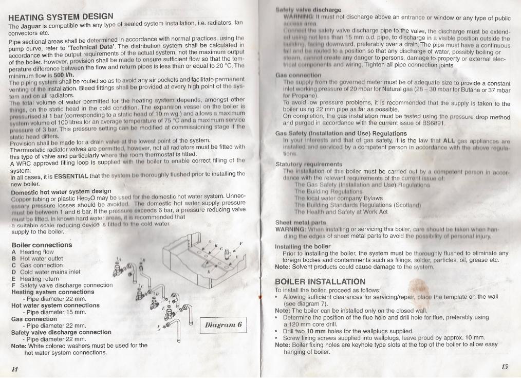
HEATING SYSTEM DESIGNThe Jaguar is compatible with any type 01 sealed system Installation, Le. radiators, fanconvectors etc.
Pipe sectional areas shall be determined in accordance with normal practices, using thepump curve, refer to 'Technical Data'. The distribution system shall be calculated inaccordance with the output requirements of the actual system, not the maximum outputof the boiler. However, provision shall be made to ensure sufficient flow so that the tem.
perature difference between the flow and return pipes is less than or equal to 20 °e. Thominimum flow Is 600 I/h.The piping system shall be routed so as to avoid any air pockets and facilitate permanentvanllno of Ihu Installation. Bleed fittings shall be provided at every high point of the sys.torn tint! on all radiators.II1R loltll volume of water permitted for the heating system depends, amongst other
1111111.11, on the static head in the cold condition. Tho expansion vessel on the boiler IsIIlIullurhlGd at 1 bar (corresponding to a stntlc Imfld 01 10m w",.) nnd allows a maximum"Y""~11I volume of 100 litres for an avera'JotompOrtlturBof tb "e nnd a muxlmurn /;IorvlceP"'lullIrClof 3 bar.This pressure selllnQ OM b{) modified at commissioning stage If theetntlo tlOf1d differs.Provision shall be made for a drain Vfllvn tit the 10WQstpoint of the system.Thermostatic radiator valves are permlttud, 11OwGver,not all radiators must be fitted withthis type of valve and particularly whom 1110room thermostat is fitted.A WRe approved filling loop is supplied with 1110I)oller to enable correct filling of thesystem.In all cases, it is ESSENTIAL that the syalllllllmll1oroughly lIushed prior to installing thenew boiler.
Domestic hot water system designCopper tubing or plastic HeP20 may be uSCJdlor tha domestic hot water system. Unnec-d'lIlIlrY prossure losses should be avoldod I'hf,Jdomestichot watersupplypressure11111111tin tmlw~~n 1 and 6 bar. If the prel!l8t1111I.)(ceeds6 bar, a pressure reducing valveII1UIIII hu flllod. In known hardwater amm., 11111r~commendedthata suitablescalereducingdeviceIs 11111:111III 11113cold water
supply to the boiler. . .;-111Boiler connections .,,/ F
A Heating flow
r
' . J>/' C (ii].../B Hot water outlet I,I!" j (, D / \;{' " f1
C Gas connection /DI &, ,to! 'J j. J
D Cold,water mains inlet jt.t'J If ~ 1 ~ ' /I If '/ {E Heating return W /F Safety valve diSC
,
harge connection ' I, 11 '
~
I JtHeating system connections
{jjP<:I ~1
I
P.
d' Q II
~- Ipe lameterJ22mm. . 0 ,_0'-Hot water system connections ~- ,~
U- Pipe diameter 15 mm. IJ&,~
Gas connection ~-Pipe diameter 22 mm. F1 I Diagram 6 ISafety valve discharge connection ..-
- Pipe diameter 22 mm.Note: White colored washers must be used for the
hot water system connections.
14
'1I1"'y ",.Ivu fll.ohnrge
Wl\ttNINU' It must not discharge above an entrance or window or any type of publicI' 111111
1 111111111IIIU '1IIInlyvAlvedischarge pipe to the valve, the discharge must be extend-III' ,IiIlJ 11111111"" 111/1/1 Ib mm o.d. pipe, to discharge in a visible position outside the
1II Ilh 111111!tlliltllJ dowl1wurd, preferablyovera drain.Thepipemusthovea continuousfilII 11111111 ,.lIlll3d 10/I position so that any discharge of water, possibly boiling or,11111111I 111111111:11:1,110fillY danger to persons, damage to property or external elec-lIlt 11IIIIIIIIIIIIO/lII!I 'tnll wiring. Tighten all pipe connection joints.
U"" (1mlnfUlion
11m I1l1pply from tile governed meter must be of adequate size to provide a constantInllli worl\II I'J pmssure of 20 mbar for Natural gas (28 30 mbar for Butane or 37 mbar101 Propane).To avoid low pressure problems, it is recommended that the supply is taken to theboiler using 22 mm pipe as far as possible.On completion, the gas installation must be tested using the pressure drop methodand purged in accordance with the current issue of BS6891.
Gn. Bnfoly (In.tallatlon nnd Use) Regulations111YOII' 111\111""1;, IIllet that of gas safety, it is the law that ALL gas flppllflnQQfI 11m1,"IRlltll] IIIld IOtHvlcod by F.Icompetent person in accorcJIlnQO wllh 111t1 'lhllvr.1 I/lUIII..110""
Statutur V 'nqulrol118nts
1111=1111'-'1"IIIIlIonof this boiler must be carried Ollt by II I'OIIIP"1I1I11 pnl 111/1111I1worcI~IIHJIIwith the relevFlI1troqulromants of the curml1t 1111111/101
II1t1 Gas Sl1felty(1I1"llIlIl1l1onund Use) R0gul/lllonllI 1mBulldln,! 118(/uII1I1011i111111loonl wElter oompany Bylaws1/1/"1 !llIlIdlng Standards Regulations (SCOIiMII)1110 Iioulll, and Safety III Work Act
Sh..t motul pnrt.WARNINU:W!1(11111f1&lflllingorservicingJhisboiler,CIHI~IIhnuhllm 1,,~uf1Wlltllll1nll
dlillu 1110!!dges of sheet metal parts to avoid tho ptll"llIllIlIv III II'" IlIfltllln/LJIy
Instolilng the boiler . .Prior to installing the boiler, the system must be thorougt11y flushed to eliminate anyforeign bodies and contaminents such as filings, solclor, particles, oil, grease etc.
Note: Solvent products could cause damage to the syeltnn.
!BOllER INSTAllATIONto install the boiler, proceed as follows~. Allowing sufficient clearances for servicing/repair, place the template on the wall
(see diagram 7).Note: The boiler can be installed only on the closed wall.. Determine the position of the flue hole and drill hole for flue, preferably using
a 120 mm core drill.. Drill two 10 mm holes for the wallplugs supplied.. Screw fixing screws supplied into wallplugs, leave proud by approx. 10 mm.Note: Boiler fixing holes are keyhole type slots at the top of the boiler to allow easy
hanging of boiler.
15
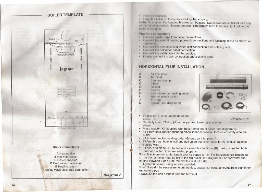
BOilER TEMPLATE
-:"~:~~rL,," _!'J,-~,G G--!~ HOlI:S~1Q.../"'!
t ~~~~":it
~
I Jaguar
A."'A"N',""
j,,-"'" "11" "'""C.O,""'" IO
.
-COlO 'AI
.
" """'. "IO"E-N"""" '" 11,"11
'-sm"",":_"',C'~HGE
110
89.5 6D .I~i nh:1:1 41.6
I I I I TA /I ( /I I I
L 1 1 1BOIIUM II' 111111nl
Boiler conn..ctlona. ".,
A Heating flowB Hot water outlet
~ C Gas connection'if D Cold water mains inlet11\1. -iL, E Heating return
\f Safety valve discharge connection~
'1,
16
~~
1"'"1""11 lumplflte.11111111 IIIU "lllIfIt on the screws and tighten screws.
NII'I' ", ,1 lip lion Iha hanging bracket can be used, Twoscrews IIrQsufflclontfor flxlnQ..1111 IIIII'I)ItH) IlIflLkul I lunging bracket fixing screws have to bo fully 11,,111bQforn lilt!I 0111"Ii 1111111)IIn
1'11""""11 h HlnllPI flail"""'"" , 1IIII01ih1111p.lrom boiler connections.
. (1111111,111I1I1111I111111trH1t1ntJplpework connections and isolating cocks as shown on111111)1 1111 11. (,\111111111 Iltl~ domtlsllc cold water inlet connection and Isolating cock.
. (;Ollllt:ll,111111hot water outlet connection.
. (,OtIlIl:1I,llha safetyvalvedischargepipe.
. 11t",lIy.connect the gas connection and isolating cock.
HORIZONTAL FLUE INSTAllATION
~
AEJ~DEfoGIJK
Air 1111111 plpfJ1mII1hllll'II$~I"'liefolttrnpI l!tow( Il1lkolnO/flW,I ),h~lIlnl rubbol MIIIIIIIlg collarIlIlnll\lll pllllilll oollcuI()' l'h1(J"Ijp,lC)tjf (sQa diagram 9)
Q)lf(l.)Q ~ ~
~
----
~h... . " iii
o(t~,. ( >lJ)U
Diagram 7
. Fit gas kat (E) onto underside of flueelbow (D).
. Carefully Insert '0' rirl9 ,(J) ,into upper and lower pMrhl 01 "1I1~'elbow. "~;,;.
.' Place spacer (K) (supplied with boiler) onto top 01boiler (see diagram 9).. Fit elbow onto spacer ensuring elbow inner connflctlon locates correctly onto fan,pullet.' ,
. ';Fit external rubber sealing collar (G) onto air inlet plpo (A).
..fitflue through hole in wall and pull up so that external collar(G) is flush against~ o'utsidewall.
. Fit seal and clamp (C) to flue and assemble into elbow (D) making sure that bothInner and outer pipes are sealed properly,
Note: Maximum horizontal length with no bends is 4 m. For horizontal flue lengths upto 1 m the restrictor must be left in the fan outlet, see diagram 9. For horizontal fluelengths between 1 and 4 m, remove the restrictor (R).. Tighten up clamp using screws provided.Note: Should it be necessary to cut the flue, always cut equal amounts from both innerand outer pipes.Always cut the end furthestfrom the terminal.
,
Ij
'\
'1,
r lII'fR""III 1/ I
/
'.
17~
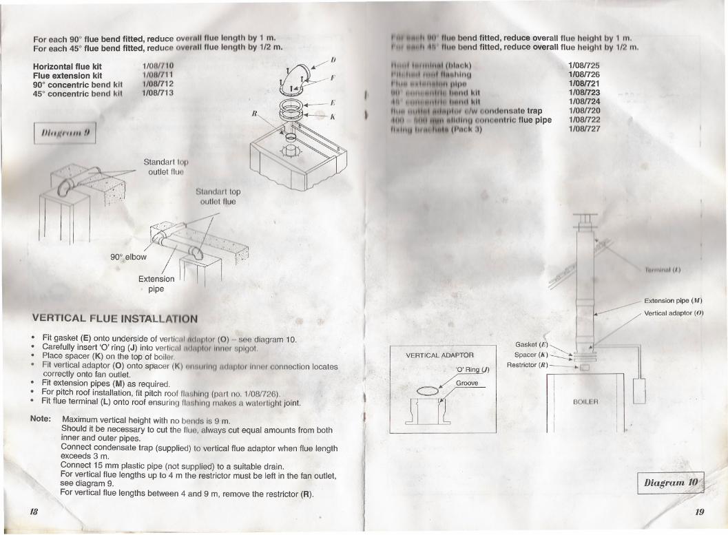
Foreach90°flue bend fitted,reduce ovorttllfluo length by 1 m.For each 45° flue bend fitted, reduco oVQr11lfluo length by 1/2 m.
Horizontal flue kit 1/00(1'10
Q ;;IJFlue extension kit 1/0Uf711 I I,'90° concentric bend kit 1108/712 I45° concentric bend kit 1/08/713 I
~--II'~-h
l /JI"i,(n"" II 1
r {).'v
~
. 'i11
Standart lopoutlet flue
~.~~'.,.,..:..:.'. ,"
'...
90°, elbow IExtension f r. pipe
VERTICAL FLUE INSTAllATION
Slnndarl topoutlet flue
;-
R
,.~
. Fit gasket (E) onto underside of verticIIIMflplor (0) see diagram 10.
. Carefully insert '0' ring (J) into vertiCAl/l(llIplor Innar splQot.. Place spacer (K) on the top of boller,
. Fit vertical adaptor (0) onto spacer (K) tllUtUthl(J luJtlplOrInnor connection locatescorrectly onto fan outlet.. Fit extension pipes (M) as required.
. For pitch roof installation, fit pitch roof flashing (part no. 1/08/726).
. Fit flue terminal (L) onto roof ensuring lIelehlng makes a walertight joint.
Note: Maximum vertical height with no bends Is 9 m.Should it be necessary to cut the flue, always cut equal amounts from bothinner and outer pipes.Connect condensate trap (supplied) to vertical flue adaptor when flue lengthexceeds 3 m.
Connect 15 mm plastic pipe (not supplied) to a suitable drain.For vertical flue lengths up to 4 m the restrictor must be left in the faD outlet,see diagram 9.
For vertical flue lengths between 4 and 9 m, remove the restrictor (R).
l18
--
I ,,' "UII lIu. bond fitted, reduce overall flue holght by 1 m.I H' It ,'It rh,. bond fitted, reduce overallflue holghtby 1/2m.
11.." I..,"111..11 (hlnak)I II, ,...01."..III hlnuII".. ..-1""8hll' 1)1,)1'1IItI I"'" ..,."h. IlItllel kitih . "", .."I,h I.It,"III\I
III... ",.11101,"1111"'" .,/w (,ondonoote trapilill fttlll "tI" .UIIIIIU (jlJno8ntrlc flue pipefI.llttJ ", ,h (P.wk J)
I
!
-~
VERTICAL Aq'APTOR
'O'Ring (J)
IfctGro~
,.
\
~
1/08/7251/08/7261/08/7211/08/7231/08/7241/08/7201/08/7221/08/727
1T~~.<y
~
Gasket (~~ \ ...1'Spacer(K)~~
Restrictor (R) - ~ r J
BOILER
lutlilimil (I,)
Extension pipe (.ff)
/ Vertical adaptor (0)
I DiaIJram!,O1k//f/~
19
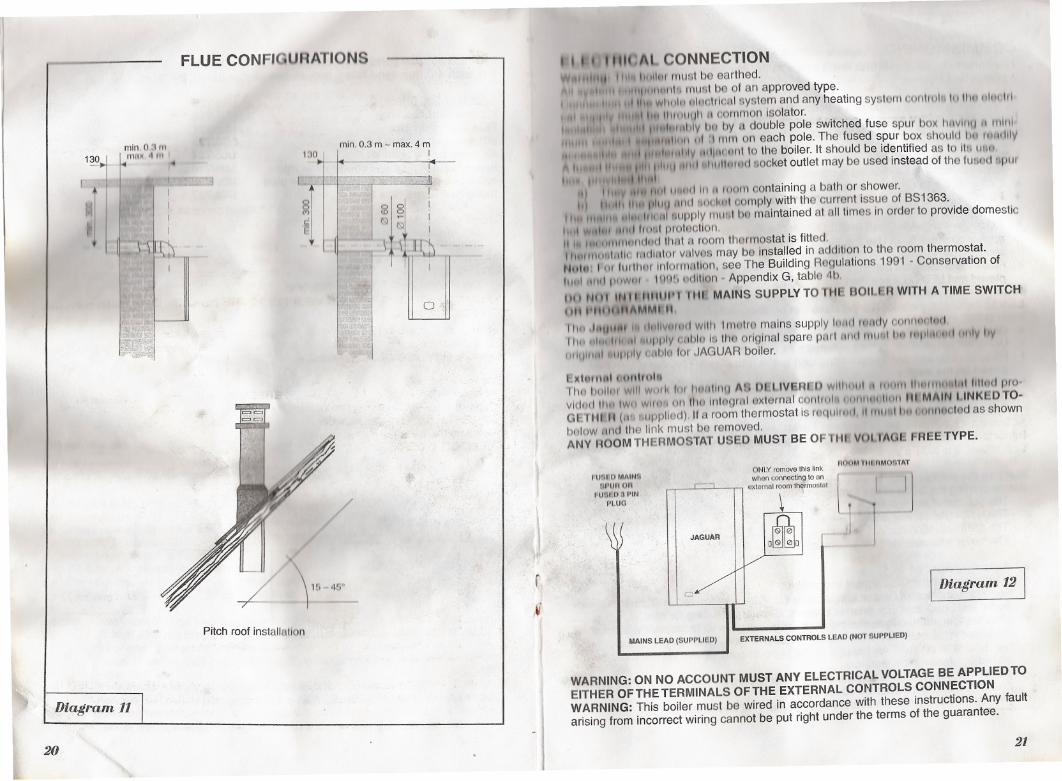
FLUE CONFIClURATIONS
130min. 0.3 m - max. 4 m
I~
mln.Q.:J1II
1~
1
mllM
.
~ III ~.
r t '
1
:
'II I.' "I" , . I
j [ 1,- j . ~~I
l
)1('> 45"
Pitch roof installeltlon
.f)iag,.am 11
20
i1
j,
I
! j
I~ 8 .
~ ~ I~
Q
. I " HUt: AI CONNECTION0H.llltttt tll' 111.111:11mustbeearthed.
"1""11""1111must be of an approved type.,1111'wl1l1ll:1l.I~r.lrlafll ~ystem and any heating syslem oonltOl. IIIIII~ Isll1lhl
I I', ""..I In 111111111.11111oornmon Isolator.., I "" 1.".I<tllltlv 1111by 11double pole switched fuse spur box l1t1vlnu II mill'.I; I E"I"II.IIIIIII III '111moneachpole.The fusedspurboxsl,oulcliltl IC~lIdIlV
, .. ,. "",I I"""" .,1III J1dltU,tmllo the boiler. It should be identified as to It~Uln"', . III. ""'1,11'1'1111111111,t"'lInlC1t1"ocketoutletmaybeusedinste~dofthelu"odllpllrI I' 1.1",1 IIIIII
'II ,,"'\' '"lIlIllt lI..nd 11111 Illom containing a bath or shower.1'1 1".11, till' pluy r1lltl'lodllll comply with the current issue of B81363.
'I", "1'1111' ..It" lillii'll lIupply nlll.1 blil maintained at all times In order to provide domestic11,.11/",11111'111111111111protection.III', "".""'lIIlInlllld lhal f1 room thormostat is fitted."'llIlIllIlIlrlll< rrtdlfllor vnlvQs may be Installed in addilion to the room thermostat.NUl": I 01 1111111m Inlorrnutlon, see The Building Regulations 1991 - Conservation ofIlInl HId pIIW"1 1'llIb I1dlllon-Appendix G, tabla 4b.1)11Nil' INII tit IIIP1 'Ill MAINSSUPPLYTOnn~ 130lLLRWITHATIMESWITCHIII' "'"luHI\MMt II111t!I"UII'" I' dlJlI\Jllluli wltll I I1H~tromains supply ImHlltalidy ()OIII1t1(!c:1(1lilt! Pllli " II 11 .lIpply Imbh, 11\IhB original spare pm I ~lIlti 111111,1IIn 1'IJlIIII .11I ,,"I~ I,v
tIIIUI( 1111 .lIpply (111b1O 101' JAGUAR boiler.
LlCtortu81 f untrnl,.Thohollt' will willi. 101111.u1l1lUAMUl'LIVRRE'[)w11l1lH11~ ItIIllIl IIII:IIIIIIII,II,IIIII.'ctpro-vlclod 11111IWIIwlr.1', Oil 11101J1logrull:Jxlernal COlillol.. "'llIlIlJItIiOIi ru MAIN LINKI:!DTO-OF 1'Htlt (III ',upplled).11a room thermostat Is requlrlHl 111111'111ht!llIlIllooled as shownbolow nl1d the link must be removed.ANY HOOMTHERMOSTAT USED MUST BE OFnn VOlIAal flREETYPE.
I
,,.\"
rI Diagram 12 Ic.)
t~'
MAINSLEAD(SUPPLIED) EXTERNALSCONTROLSLEAD(NOTSUPPLIEDI
WARNING: ON NO ACCOUNT MUST ANY ELECTRICAL VOLTAGEBE APPLIED TOEITHER OFTHETERMINALS OFTHE EXTERNAL CONTROLS CONNECTIONWARNING: This boiler must be wired in accordance with these instructions. Any faultarising from incorrect wiring cannot be put right under the terms of the guarantee.
-I21
u..o MAINIONLYremovethis link
II(')UM'lltllnMOITAT
,,"Ullon r " whonconnectingto an
lj IjU8nD a PIN n n externelrrm thrmo.I.1
IPLUG
1JAGUAR I I Ii] L0 is) 00
. l~o..lart boiler and operate until a maximum temperature is reachad, SI1Utdown boiler",nd vent air from heating system. If necessary, top up heating system and make sureIl1l1ta pressure at least of 1 bar is indicated on the display when system Is COLD.
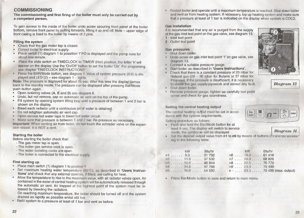
Gas installationIt Is recommended that any air is purged from the supplyfill the gas inlet test point on the gas valve, see diagram 13.1 - Inlettestpoint .2 -Outlet test point
...
COMMISSIONINGThe commissioning and first firing of the boiler must only be carried out bya competent person.
To gain access to the inside of the boiler undo screw securing front panel at the boilerbottom, remove front panel by pulling forwards, lifting it up and off. Note - upper edge offrontcssingjs fixed to the boiler by means of 2 pins.
Filling the system. Check that the gas meter tap is closed.. Conect boiler to electrical supply.. Place switch (1)'di§lgram 1 to possition 'I' FO is displayed and Ihe pump runs for
about one minute.
. Place the slide switch on TIMECLOCK to 'TIMER' (Hol) position, the letter 'h' will
nppear on the display. Use the 'On/Off' button to set the boiler 'On' For programingsee chapter'TIMECLOCK INSTRUCTIONS'
. Press the BAR/Mode button, see diagram 1. Value of system pressure (0.0) is dis-played and LED (2) - see diagram 1 - lights.
Note: The pressure is displayed for about 25 sec. After this time the displa~,;;"qomesback to the standby mode. The pressure can be displayed after pressing BarJModepush button again.. Open isolating valves (A, E and D) see diagram 6.. Undo, but not remove, cap on automatic air vent on the top of the pump.. Fill system by opening system filling loop until a pressure of between 1 and 2 bar is
shown on the display.. Bleed each radiator until a continuous jet of water is obtained.. Do not retighten automatic air vent cap. .1I!r. Open various hot water taps to bleed hol waler circuit.. Milke aure that pressure is between 1 And 2 bar. Re-pressure as necessary.Importnnt: When venting air from boiler, do not louch the schrader valve on the expan-sion vessel, It Is NOT a vent. \
Starting the boilerBefore starting the boiler check that:
- The gas meter tap is open.- The boiler gas service cock is open.- The water isolating cocks are open.- The boiler is connected to the electrical 8upply,
Gas pressures. Shut down boiler.. Undo screw on gas inlet test point '1' on gas valve, see
cJltlgram 13.. Connect a suitable pressure gauge.. Start boiler as described in 'Users Instructions',. Check that there is a constant pressure of 20 mbar for
Natural gas (28 - 30 mbar for Butane or 37 mbar forPropFlno). If tllQ prGlssure is insufficient, it is necessaryto ol1nol<thu f]fllil rJupply/pipework and correct any fault.. Shutdownbollar.
. RarnovtJ prossure gauge, tighten up carefully test point!lCrGWand check for gas soundness.
I Diagram 13 j
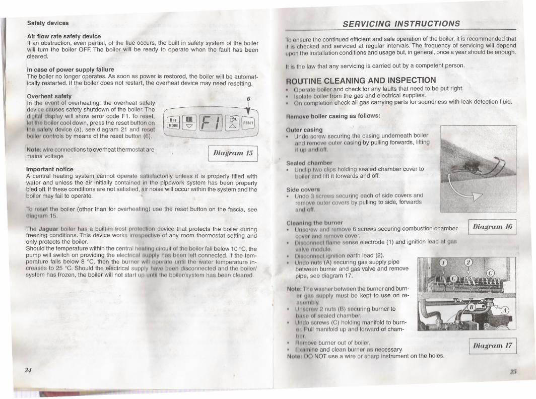
Setting the central hoatlng output ,The contretlheating output must be set in accor-danco with thGlsystem requirements.Sotllng procedure as follows:. Push and hold the Bar/Mode button for at
least 8 sac. ThGl display will switch to service J . I
modI),tha aymboln. will bedisplayed Dza!fl"am 14. Rol tltll doslred output value from n1 to n9 by means of butlons ( /1>IIIU \°/tll,;vultr
In'l to thGJfollowing table:
~:,][~ J[n:
First starting up. Place main switch (1) diagram 1 to position 'I' .. Set maximum heating water temperaturo (8G"C), as described in 'Users Instruc-tions' and check that any external controls, If IItlGld,are calling for heat. .
. Allow the temperature to rise to the maximum value, with all radiator valves open. Aircontained in the water of central heating system will be automatically released throughthe automatic air vent. Air trapped at the hlghtest point of the system must be re-leased by bleeding the radiators.On reaching maximum temperature, the boiler should be turned off and the systemdrained as rapidly as possible whilst still hot.
. Refill system to a pressure at least of 1 bar and vent as before.
. Pmss Bar/Mode button to save and return to main menu.
22 2.1
kW Btu/hr RW Btu/hrn1 ...... 9.3...... 31732 n6 .... 18.0..... 61 416n2 . . . . .. 11.0 . . . .. 37 532 n7 .... 20.0..... 68 828n3 . . . . " 12.0 . . . .. 40 944 n8 .... 22.5..... 76 770n4 ...... 14.0 ..... 47768 n9 .... 23.3..... 79 499nb . . . . .. 16.0 . . . .. 54 592 n - . . .. 23.3..... 79 499 (max. output)
j'II
Safety devices
Air flow rate safety deviceIf an obstruction, even partial, of the flue occurs, the built in safety system of the boilerwill turn the boiler OFF.The boiler will be ready to operate when the fault has beencleared.
In case of power supply failureThe boiler no longer operates. As soon as power is restored, the boiler will be automat-ically restarted. If the boiler does not restart, the overheat device may need resetting.
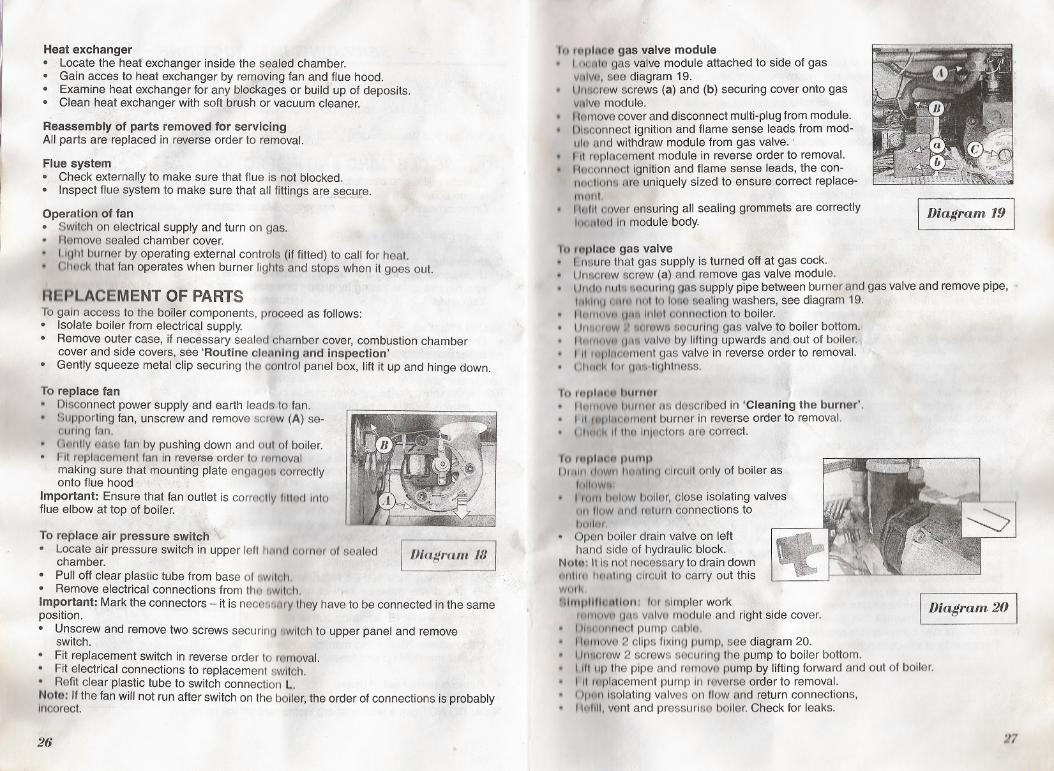
Overheat safetyIn the event of overheating, the overheat safetydevlco causes safety shutdown of the boiler. Thedlullnl display will show error code F1. To reset,1111 tho boiler cool down, press the reset button onIIltl dl1fety device (a), see diagram 21 and reset!»nllar controls by means of the reset button (6).
6
ru;l[if) rt'll / rE..GRESET
~ @J lC-1J lEJ
Nato: wire connections to overheat thermostat aremains voltage
I Diagram 151
Important noticeA central heating system cannot operate satisfactorily unless it is properly filled withwater and unless the air initially contained In the pipework system has been properlybled off. If these conditions are not satisfied, air noise will occur within the system and theboiler may fail to operate.
10 roeet the boiler (other than for overheating) use the reset button on the fascia, seertll1Qtr1m 15.
Tha Jaguar bollGr has a built-in wost proluc;lIondevice that protects the boiler duringfreezing conditions. This device works Irmapectlve of any room thermostat setting andonly protects the boiler.Should the temp~rature within the central houtlnu c;lrcult of the boiler fall below 10 ce, thepump will switch on providing the electrlolJl ,uf1ply I1OS been left connected. If the tem-perature falls below 8 ce, then the burnor will opCH..tn until the water temperature in-creases to 25 ce. Should the electrical supply I"IVII Imun disconnected and the boiler/system has frozen, the boiler will not start up 1J[lIIIII1o boller/system has been cleared.
24
- -
SERVICING INSTRUCTIONS
to ensure the continued efficient and safe operation of the boiler, it is recommended thatIlls checked and serviced at regular intervals:The frequency of servicing will dependupon the installation conditions and usage but, in general, once a year should be enough.
Ills the law that any servicing is carried out by a competent person.
ROUTINE CLEANING AND INSPECTION. Operate boiler and check for any faults that need to be put right.. I/lolate boiler from the gas and electrical supplies.. On completion check all gas carrying parts for soundness with leak detection fluid.
nnmovo boiler casing as follows:
Outer casing ,. Undo screw securing the casing underneath boiler
'H1d mmovo olliar casing by pulling forwards, lifting11lip 11IHInil
Senlod ohnmbctr. Uncllp Iwo clips holding sealed chamber cover to
bailor and lift it forwards and off.
Side covltra. Undo "IGrnws ..ecurlng each of side covers and
rort1ovnolltor covers by pulling to side, forwardswId oil
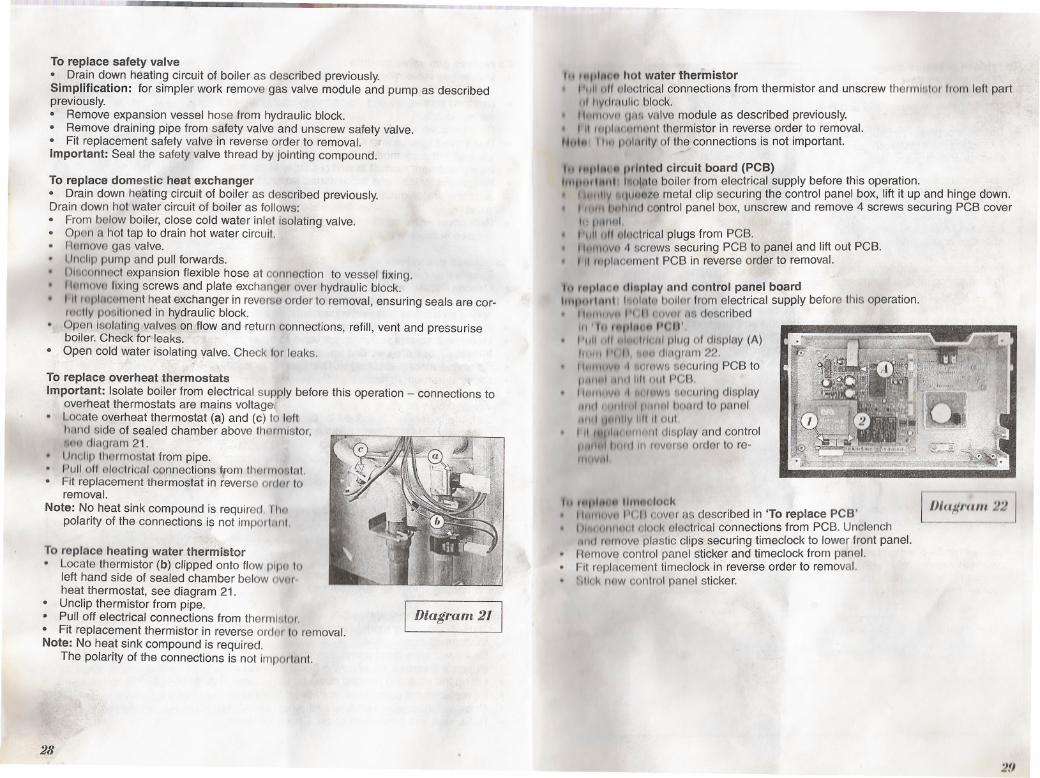
CIMning the burner. Un.crow!lntl romove 6 screws securing combustion chamberc;oVIIf ,",,1 wmovo cover.
. I )lhlitlf1fWLI flAmesense electrode (1) and ignition lead tit glIBvulvtl modulo.
. III.connuct Ignition earth lead (2).
. Undo nuts (A) securing gas supply pipebetween burner and gas valve and removepipe, see diagram 17.
Not..: rho washer between the burner and burn-IH UM lIupply must be kept to use on re-""ul11bly
. IIn,u,rflw 2 nuts (B) lIoourlng burner to111111(;1 01aealed chf\fnbor.
. Undo screws (C) holdlnq manifold to burn-nr Pull manifold up and forward of cham-IIIJI
. 1IIIIIIove burner out of bailor.
. I ~lIIl1lne and clean burner as necessary.Nultl' DO NOT use a wire or sharp Instrument on the holes.
~iagram 16 J
IIJkt#ram 171
~J.\
Heat exchanger. Locatethe heafexchanger inside the sealed chamber.. Gain acces to heat exchanger by removing fan and flue hood.. Examine heat exchanger for any blockages or build up of deposits.. Clean ,h(3at exchanger with soft brush or vacuum cleaner.
Reassembly 91 partsremovedJor servicingAll parts are replaced in reverseorder to removal.
Flue system. Check externally to make sure that flue is not blocked.. Inspect flue system to make sure that all fittings are s~cuJ;e.
Operation of fan. Switch on electrical supply and turn on gas.. Removesealed chamber cover.. LIght burner by operating external controls (if fitted) to call for heat.. Chock that fan operates when burner lights and stops when it goes out.
REPLACEMENT OF PARTSTo gain access to the boiler components, proceed as follows:. Isolate boiler from electrical supply.. Remove outer case, if necessary sealed chamber cover, combustion chamber
cover and side covers, se~ 'Routine cleaning and Inspection'. Gently squeeze metal clip securing the control panel box, lift it up and hinge down.
To replace fan. Disconnect power supply and earth leads to fan.. Supporting fan, unscrew and remove screw (A) se-
ourlng fan.. Oontly U&SGfan by pushing down and out of boiler.. Fit replacement fan in reverseorder to romoval
making sure that m<?untingplate engafJei}correctlyonto flue hood .
Important: Ensure that fan outlet is correotly fllted Intoflue elbow at top ofbo/ler.
To replace air pressure switch. Locate air pressure switch in upper left 11'"111 cornerof sealed
chamber.. Pulloff clearplastictubefrombase01.wllt.Il,. RemoveelectricalconnectionsfromttlO ..wltoh,Important: Mark the connectors - it is nece81111rythey have to be connected in the sameposition.. Unscrew and remove two screws securln" ",witch to upper panel and remove
switch.. Fit replacement switch in reverseorder to r<ilmoval.. Fit electrical connections to replacement switch.. Refit clear plastic tube to switch connection L.
Note: If the fan will not run after switch on the boller, the order of connections is probablyIncorect.
/Jlagram 18
26
In tdplnoQ gas valve module. loof.llo gas valve module attached to side ,of gaswllvll, see diagram 19.
. Un80rewscrews (a) and (b) securing cover onto gasvfllve module.
0 Hemove cover and disconnect multi-plug from module.0 Dloconnect ignition and flame sense leads from mod-
ule and withdraw module from gas valve. .0 I'lt replacement module in reverse order to removal.. 11f;1connoctignition and flame sense leads, the con-
ntt(Jllonl\ are uniquely sized to ensure correct replace-II1lml.. .Inlll cover ensuring all sealing grommets are correctlyloof.lh,d In module body. lDiagram 191
I() t.place gas valve. f.neure that gas supply is turned off at gas cock.0 Un~crewscrew (8) and remove gas valve module.0 Ul1dn nlJll'1l1"curlnggas supply pipe between burner and gas valve and removepipe, ~
Inl(II1U HHI~ iloilo 1080 sealing washers, see diagram 19.0 IIHII\flVf1 UII. IlIhJI oonnQctlon to boiler.. LJ/1"I'I1W;' "WUWII 8ocurlng gas valve to boiler bottom.0 Htllllllvn 0'" vEllveby lifting upwards and out of boiler.. I II l!.pl/'ICornentgas valve in reverse order to removal.0 (,1111/11\ for tjFlflotightness.
To rltlJltlWI burtlQr. H~II\lIv~ IJIIFI1~Has described In 'Cleaning the burner',. III'lfplllotHtw/11burner in reverse order to removal.. (,lltldl 111111.InJGctors are correct.
fo r~ph1(111pumpUI'NIII unWIII'fmllll~J dlroult only of boiler as
hl\lflWII
. 110111hillow boller, close isolating valves11/1lIow fmetrltturn connections tobo\lo r.. Open boiler drain valve on lefthand side of hydraulic block.
Noto: It is not necessary to drain down~/1l1ln 110ftllne circuit to carry out thiswmll!)hI1IJllllmlllon:for simpler work
f1l1l11lV11UUI!Ivfllvo module and rightsidecover.. I)111(101111<'01pump ol!lblo.. 111Itf\ov/iI 2 clips flxlt", pump, see diagram 20.. Un.oraw 2 screws securing the pump to boiler bottom.0 IllIup the pipe and removo pump by lifting forward and out of boiler.. I 'It roplacement pump In mVGrse order to removal.. ()pfm Isolating valves on Ilowand return connections,0 11"/111,vent and pressurle0 boiler. Check for leaks.
I Diagram. 2°1
:J7
To replace safety valve. Drain down heating circuit of boiler as described previously.Simplification: for simpler work remove gas valve module and pump as describedpreviously.. Remove expansion vessel hose from hydraulic block.. Remove draining pipe from safety valve and unscrew safety valve.. Fit replacement safety valve in reverse order to removal.Important: Seal the safety valve thread by jointing compound.
To replace domestic heat exchanger. Drain down heating circuit of boiler as described previously.Drain down hot water circuit of boiler as follows:. From below boiler, close cold water inlet isolating valve.. Open a hot tap to drain hot water circuit.. Romove gas valve.. Uncllp pump and pull forwards.
. IJllcJonnect expansion flexible hose at connection to vessel fixing.
. II~rnovo fixing screws and plate exchanger over hydraulic block.. III '"pl"cCiment heat exchanger in reverse order to removal, ensuring seals are cor-/CIolly positioned in hydraulic block.. Open Isolating valves on flow and return connections, refill, vent and pressuriseboiler. Check for'leaks.. Open cold water isolating yalve. Check for leaks.
To replace overheat thermostatsImportant: Isolate boiler from electrical supply before this operation - connections to
overheat thermostats are mains voltage,. Locate overheat thermostat (a) and (c) to left
hand side of sealed chamber above thermistor,,.~tOdiagram 21.
. lJl1cllpthermostat from pipe.
. Pull off electrical connections ffom thermostat.. Fit replacement thermostat in reverseordor toremoval.
Note: No heat sink compound is required. 1110polarity of the connections is not impol\1II11
To replace heating water thermistor. Locate thermistor (b) clipped onto flow plpo 10
left hand side of sealed chamber below ovmheat thermostat, see diagram 21.
. Unclip thermistor from pipe.. Pull off electrical connections from thermlotor.. Fit replacement thermistor in reverse ordor to removal.Note: No heat sink compound is required.
The polarity of the connections is not important.
I Diagram 21 I
28
1'1f"llhlnl hot water thermistor"1111011 olGctrical connections from thermistor and unscrew thermistor Irom left partII/ l1yrJrflulic block.
. IlulI1ovn ".Uivalve module as described previously.. I II IlIpll\cltll1()nt thermistor in reverse order to removal.Nfll.. I lilt pol"rlly of the connections is not important.
It. "'1""". I)rlnlod circuit board (PCB)""I"" 1.."1 !!Ioillteboiler from electrical supply before this operation.. I "'IIIIV "'IIII/Ai'e metal clip securing the control panel box, lift it up and hinge down.. , ",tlll".hlnd control panel box, unscrew and remove 4 screws securing PCB cover
1t1l1'1111111. "IIIIIIJlctl!Jctrlcal plugs from PCB.. I '"",CIVet 4 screws securing PCB to panel and lift out PCB.. I II '11plncement PCB in reverse order to removal.
In fdl)IIIOndllploy and control panel boardh""urlnnl "'nl"h~ bOllc1r from electrical supply before this operation.. 1\(;"" .lIp 1'1 II 1:1)VIIf tift described
111 It. ,.."I,u" 1'(;1)'I'IIIIIIIJ FIIIILIIII'111plu~ 01 dl8plny (A)Itill" 1'111,1111dlf"Jlwn 22.1\11"'1l1li11 'l!/rc'Wf,securing PCB toI'I.IIul 11111111111)111PCB.Ilnlllil" .1",'I~WfJIt(~ourlngdisplay1/111, 1111111111"111"" hottrLJ 10 panel
JlIIII l)lIl1l/y 111111!)ut. III 1111,lilt 1111111/11display and control
1"111,,11111111111rr/VCjP4Q ordGr to re-fI\lI",,1
lJIa!(I'alll 22 -'
"I "'1,111"11IllIlIteJlook ,. I 'h11111WI1'(" I covor as described in 'To replace PCB'. 1)"'!I)fult,,1 c:lock I3lectrlcal connections from PCB. Unclench
11111/rttrnoveplastic clJpssecuring timeclock to lower front panel.. HGmove control panel sticker and timeclock from panel.. Fit replacement timeclock in reverse order to removal.. 'itlokflQW control panel sticker.
2!J
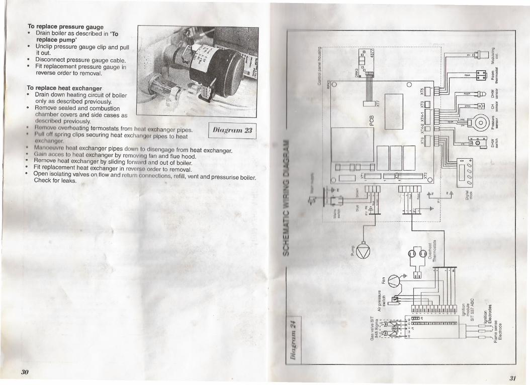
To replace pressure gauge. Drain boiler as described in 'Toreplace pump'
. Unclip pressure gauge clip and pullit out.. Disconnect pressure gauge cable.
. Fit replacement pressure gauge inreverse order to removal.
30
Diagram 23
:8-tIt'
~~'-It')~..
IT--
()
II
~:IUrh
~
§,~
w-
i'l
'~J ~IO
~,,.
[J
.,l
I
, II'N'
I ~.~1
H
To replace heat exchanger. Drain down heating circuit of boileronly as described previously.
. Remove sealed and combustionchamber covers and side cases asdoscrlbed previously.
. f h~move overheating termostats from ho.., exchanger pipes.
. 1'1111011spring clips securing heat exchan(JGr pipes to heatoxchnrlQer.. Mnno(luvro heat exchanger pipes down to disengage from heat exchanger.. Gain acces to heat exchanger by removing fan and flue hood.. Remove heat exchanger by sliding forward and out of boiler.. Fit replacement heat exchanger in reverse order to removal.. Open isolating valves on, flow and return connections, refill, vent and pressurise boiler.Check for leaks.
~ .gj~~!;; <=~
~~ ~~'" ~.-.. . en .!2'w w"- <="
::~: ",. !I:x~ .!!!w:~ LL
I,~
,
0~[JSO~
D
-..t~
~D
~~J
IJU ~DDD] ~~~-
D~
III()CL
~Q. II
"Ql<=
tf
!!?::JW""",0"",~~:0:
f~::;;
;:gI<=D~
Ig0<=
»:
;:""
i§~
l
., -I~
31
.," ; FAULT FINDING
Before fault finding, make sure that:All gas cocks are open and there is an inlet gas pressure of 20 mbar (G 20)The heating system pressure is at least 1 bar.There is a permanent mains supply to the boilerThe fuses on the PCB are intact.
All external controls are correctly wired and calling for heat.
WARNING: Always isolate the boiler from the electrical supply before carrying out anyelectrical replacement work. Always check for gas soundness after any service work.
Digital display shows:CH temperature (no decimal point displayed)DHW temperature (decimal point displayed)(liogn08tlc error messagesprnl!l'Iure In CH systemtwllt,r output setting
Ad soon E\8the mains switch is on the display shows for a very short time the versionof software used. It has no importance for boiler operation.
Diagnostic error messages I
In the event of a fault the following diagnostic error messages will be displayed:
Message Fault Action Comments
FO Loss of system water Refill systemCheck for leaks
Pump runs for oneminute.
Boiler is restarted byswitching of mainswitch.
Air lock in boilerPressure sensor failure
Bleed bailor IJIndsystemCheck the pmssura sensor(Sensing Inlol must not be clogged)
Check flamo lonl!Q QIBclrodeand connectlt1tJ ol'lbloCheck Ignition electrodt3Check ignillon unit on gas valveCheck fan operallonReset overhoat thermostats Ifoverheat Thermo-Check the pump revolution stats are blocked,
boiler does not ignitewhen starting
F1 No flame detected
Overheating of the boiler
32
.
r; c,"IIIII/.Ill1otlllng thermistor Check if flow thermistor is not1111111111 disconnected or short-circuited
Sensor Ohm resistance10 kQ by 25°C, 12,7 kQ by 20°C,16 kQ by 15°CCheck if system is not frozenUII WfAI()rtGrnperature
billow :J"G
t ~ lirml ()(ollflngerblockage Check main heat exchangerCheck domestic heatexchanger
Boiler shuts down and
pump runs
H J)tJlllrt.tlc hot water1t1tllllll..torfaulty
Check thermistor/leadsSensor Ohm resistance:10 kQ by 25°C12,7 kQ by 20°C16 kQ by 15°C
Domestic hot water isavailable bur poor
Ait fI"'II."'" .wltoh f,,!luro:II IIIii Itlll "'lid 11\11pump I.. running but the boiler doesn't light, check the air pressure..vII.,II
1'1
841ow II ,"'.."If IIIIt 1I1f,11I~wllnh I.. on and display does not light check the FUSE (1) T80mA, seeIlinUlrllIt 1'1If 11.11 dl.,,111Y IIIJilttl LJlIItllfJ pump, the fan and the ignition module don't work check theI I' il m lIlIA, '1130 diagram 22.
W"""IIU nut.llngs:11111111"0114"11111111 CH systom drops to 0.8 bar the LED on the Bar/MODE button starts to11111111 'hllll ulvl1 you Information that CH pressure is on the low limit and must be pres-'1IId","1 f..jtlVIII 111111111'11IhGboiler works until the pressure drops to 0.6 bar - then boiler111111'tlltWtl ~lItil () I. displayed.
III tW flow I. poorIII " IW lIoor Is poor or boiler does not start when hot water tap is open, check following:unlcl water supply pressure is at least 1 bar.CMok If the cold water filter or flow regulator (plastic '0' ring) is not clogged.
a:/
JAGUAR - CONVERSION TO LPGNote: Conversion must oniy be carried out by a competent person. Isolate boiler from the gas and electrical supplies.. Remove boiler casing, sealed chamber and combustion chamber 00IIef"as .:ES::'i:e: ....
Instailation/Servicing Instructions.. Disconnect flame sense electrode.. Disconnect ignition lead at gas valve module.. Disconnect ignition earth lead.. Undo nuts securing gas supply pipe between burner and gas valve and remOll'e;:ipe... Undo two locking nuts securing burner to base of sealed chamber.. Pull main burner up and forward out of boiler.Note: The washer between the burner and burner gas supply must be kept to use in reassemb I. Unscrew and remove two injector bars retaining screws and separate injector bar from
burner.. Fit new injector bar with marked diameter of injector 0 0,68 mm to the boiler in reverseorder to removal.. Readjust the gas valve.
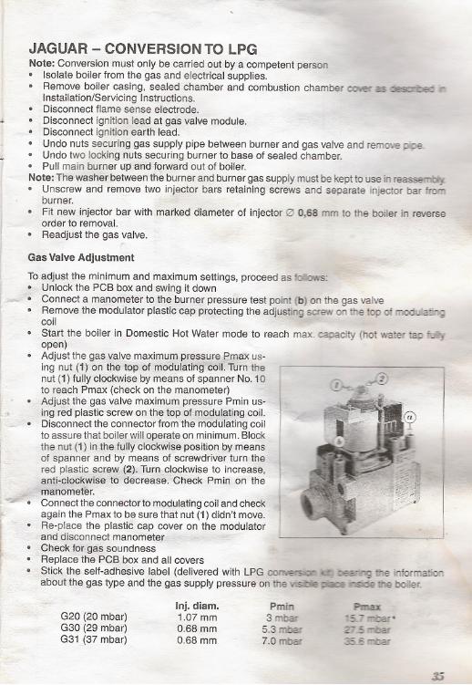
Gas Valve Adjustment
To adjust the minimum and maximum settings, proceed as !DIav1S:. Unlock the PCB box and swing it down~ . Connect a manometer to th~.,;burner pressure test point (b) on the gas valve. Remove the modulator plastic cap protecting the adjusting screw on the top of ~
coil -. Start the boiler in Domestic Hot Water mode to reach max. capacity (hot water tap '!...~open)
. Adjust the gas valve maximuIT1pr~~sure:~x us-ing nut (1) on the'top,of modulatlng'!cOlI.Turn'ihenut (1) fullyclockwise by means of spanner No. 10to reach Pmax (check on the manometer). Adjust the gas valve maximum pressure Pmin us-ing red plastic screw on the top ohT1<;.dul~ting coil.
'... . Disconnect the connector from the modulating coilto assure that boiler will operate on minimum. Blockthe nut (1) in the fully clockwi~e position by m'E!ansof spanner and by means of screwdriver turn thered plastic screw (2), Turr:t.clockwise to increase,anti-clpckwise,'td decrea~. 'Clfeck Pmin on the
. ~'rrlandme~r.~~. Connect the connector to modulating coil and check~ again the Pmax to be sure that nut (1) didn't move.. "". . Re-placethe plastic cap cover on the modulator
and qisconnect manometer!¥ i;;:. Check for gas soundness. Replace the PCB box and all covers. ptick the self-adhesive label (delivered with LPG ~O'". ~ tt'.e inforITJa.lion
aboutthe gas type and the gas supply pressure on the vishe ::.a:E ~--oe ihe boIer.
..
~
~".
I,.~
35
Inj.diam. Pmin PmiD:G20 (20 mbar) 1.07 mm 3 mbar -5 '""..ba!'G30 (29 mbar) 0.68 mm 5.3 rr-.bar Z" .5 ...-oarG31 (37 mbar) 0.68 mm 7.0 mbar 35 5 ""'Dar