jaeri-research 97-064 study on hydrogen
TRANSCRIPT
JAERI-Research--97-064
JAERI-Research97-064 JP9711005
STUDY ON HYDROGEN PRODUCTIONBY HIGH TEMPERATURE ELECTROLYSIS OF STEAM
September 1 8 9 7
Ryutaro HINO, Hideki AITA, Kenji SEKITAKatsuhiro HAGA and Tomo-o IWATA*
d B ̂ M ¥ 23 ®f %flfrJapan Atomic Energy Research Institute

*°- Hi,
(T319-11 3?*!H»|5IifJ|5K[*ttH*K^*W5SBfrt) Ta^J= J: 5
This report is issued irregularly.
Inquiries about availability of the reports should be addressed to Research Information
Division, Department of Intellectual Resources, Japan Atomic Energy Research Institute,
Tokai-mura, Naka-gun, Ibaraki-ken, 319-11, Japan.
© Japan Atomic Energy Research Institute, 1997
JAERI-Research 97-064
Study on Hydrogen Production
by High Temperature Electrolysis of Steam
Ryutaro HINO, Hideki AITA, Kenji SEKITA
Katsuhiro HAGA and Tomo-o IWATA*
Department of Advanced Nuclear Heat Technology
Oarai Research Establishment
Japan Atomic Energy Research Institute
Oarai-machi, Higashiibaraki-gun, Ibaraki-ken
(Received August 29, 1997)
In JAERI, design and R&D works on hydrogen production process havebeen conducted for connecting to the HTTR under construction at the OaraiResearch Establishment of JAERI as a nuclear heat utilization system. As fora hydrogen production process by high-temperature electrolysis of steam, labo-ratory-scale experiments were carried out with a practical electrolysis tubewith 12 cells connected in series. Hydrogen was produced at a maximumdensity of 44Nml/cm2h at 950 T), and know-how of operational procedures andoperational experience were also accumulated. Thereafter, a planar electrolysiscell supported by a metallic plate was fabricated in order to improve hydrogenproduction performance and durability against thermal cycles. In the prelimi-nary test with the planar cell, hydrogen has been produced continuously at amaximum density of 33.6 Nml/cm2h at an electrolysis temperature of 950 t .This report presents typical test results mentioned above, a review of previousstudies conducted in the world and R&D items required for connecting to theHTTR.
Keywords: Hydrogen Production, HTTR, Nuclear Heat Utilization, High-
temperature Electrolysis, Steam, Laboratory-scale Experiment, Electrolysis
Tube, Planar Cell, Review
+ Center for Neutron Science* Fuji Electric Corporate Research and Development, Ltd.

JAERI- Research 97-064
mm
(1997^8^29
33.6Nml/cm2h
R&D tl
: T 311-13
JAERI- Research 97-064
Contents
1. Introduction 1
2. Reaction Scheme in High-temperature Electrolysis of Steam 4
3. R&D Status on High-temperature Electrolysis of Steam 9
3.1 Cell Structure 9
3.2 Typical Test Results Obtained in the Past 13
4. High-temperature Electrolysis Tests with Tubular and Planar Cells 20
4.1 Test Apparatus and Test Conditions for Electrolysis Tube 20
4.2 Test Results Obtained by Electrolysis Tube 21
4.3 Preliminary Test Results Obtained by Planar Cell 23
5. Future Works 39
5.1 Improvement of Electrolysis Cell 39
5.2 Bench-scale Test by Electrolysis Module 41
5.3 System Optimization 42
5.4 Outline of Demonstration Tests 43
6. Concluding Remarks 46
Acknowledgments 46
References 47

JAERI-Research 97-064
1
2. M&*M%mMKfc 43. &u*m%mm&<?>mmm%<vmwi 9
3.1 mmmm 93.2 nsu&M%,mM&m<nmtfi 13
4. P)®MR tf^uw.mmmm izxz M^^m^.mm^m 204.1 H®mnmmmmmmmm t m.m&& 204.2 wffi$mm%mtzzzu^wt 214.3 ^WLmmmm^Kxz>^ffiu.m&W: 23
5. ztifrhomftm® 395.1 s^^^^acs. 395.2 mm^'y^-^^mum 415.3 "s*i-M><DWt.mi\: 42
5.4 ^ ! E § ^ 43
6. afe<b^§ 46
ai- n 4647
IV

JAERI- Research 97-064
1. Introduction
Nuclear heat generated by LWR has already used to commercial power generation.
If nuclear heat is applied to the nonelectric field such as chemical and steel industries,
nuclear energy will contribute to greatly reduce an amount of CO2 discharged to the
atmosphere. High-temperature gas-cooled reactors (HTGRs) have high potential for
application to nonelectric fields as well as the electric power generation as high-
temperature heat sources up to lOOO'C.
The High-Temperature Engineering Test Reactor (HTTR), the first HTGR in Japan,
is now constructing at the site of the Oarai Research Establishment of Japan Atomic
Energy Research Institute (JAERI). One of the key objectives of the HTTR is to
demonstrate effectiveness of high-temperature nuclear heat utilization. The first heat
utilization system is planned to be connected to the HTTR in about five years after the
first criticality of the HTTR to be achieved in 1998. Of the HTTR thermal output of
30MW, 10MW is transferred to the heat utilization system through a helium-to-helium
intermediate heat exchanger.
The following design and/or R&D works focused on hydrogen production have
been carried out in JAERI:
1) Design and experimental works for hydrogen and methanol coproduction system:
steam/methane reforming process coupled with methanol synthesis process,
2) Laboratory-scale experiments for a thermochemical water splitting by Iodine-Sulfur
(IS) process,
3) Laboratory-scale experiments for a high-temperature electrolysis of steam using
ceramic electrolysis cells.
As for hydrogen production, almost the total hydrogen demand is presently met by
hydrogen made from fossil fuels, by steam reforming and partial oxidation of natural gas
or oil fractions, although hydrogen could be simply produced from water by electrolysis.
Electrolysis of water to provide hydrogen for chemical processes plays only a minor role
today because its hydrogen production cost is much higher than that from fossil fuels; less
than 1% of worldwide hydrogen demand is produced electrolytically.
In the water electrolysis, there is no commercial large scale units except the
conventional alkaline electrolysis unit which have rather low current efficiency of 80% or
less. Many advanced concepts of electrolytic hydrogen production have been proposed
to improve hydrogen production efficiency and to reach high hydrogen production
density from the viewpoint of saving electricity. A water electrolysis using solid
1

JAERI-Research 97-064
polymer membranes (solid polymer electrolysis, SPE) and the high-temperature
electrolysis of steam (HTES) using ceramic electrolysis cells are representative of new
advanced technologies. Current efficiency of the SPE is of the order of 85-90% in the
laboratory-scale and prototype experiments, and that of the HTES is around 100% in the
laboratory-scale experiments.
Figure 1.1 shows an energy demand for water and steam electrolysis. Total
energy demand (AH) for water and steam decomposition is the sum of the Gibbs energy
(AG) and the heat energy (TAS). The electrical energy demand, AG, decreases with
increasing temperature as shown in the figure; the ratio of AG to AH is about 93% at
100X) and about 70% at 1000°C. On the other hand, higher temperature favor
electrode reaction and helps in lowering cathodic and anodic overvoltages: it is possible
to increase current density at higher temperature. Thus, the HTES is favored from both
thermodynamic and kinetic standpoints. Lower cell voltage and higher current density
are simultaneously achievable in high-temperature operation. Furthermore, there is
almost no corrosion problem on the ceramic electrolyte of the electrolysis cell.
The HTES, however, is at a very early stage of technology, and thus, significant
development effort is required to solve severe materials and fabrication problems due to
high-temperature operation. We are now conducting laboratory-scale experiments to
improve and upgrade the HTES technology. This report presents a reaction scheme,
our typical test results and future works as well as an outline of the state-of-the-art of
electrolysis cell fabrication and HTES test results obtained using practical electrolysis
cells in the past.
- 2 -

JAERI-Research 97-064
(kWh/m3H2) (MJ/kg)16
o
UJ
3.5 r
3.0
2.5
2.0
1.5
1.0
0.5
0
14
12
10
8
0
\\
1 I I T
AH (Total energy demand)
Liquid
AG (Electrical energy demand)*
Gaseous
Q = TAS(Heat demand)
0.1 MPaJ I
0 200 400 600 800 1000 1200
Temperature (°C)
Fig. 1.1 Energy demand for water and steam electrolysis
- 3 -
JAERI-Research 97-064
2. Reaction Scheme in High-Temperature Electrolysis of Steam
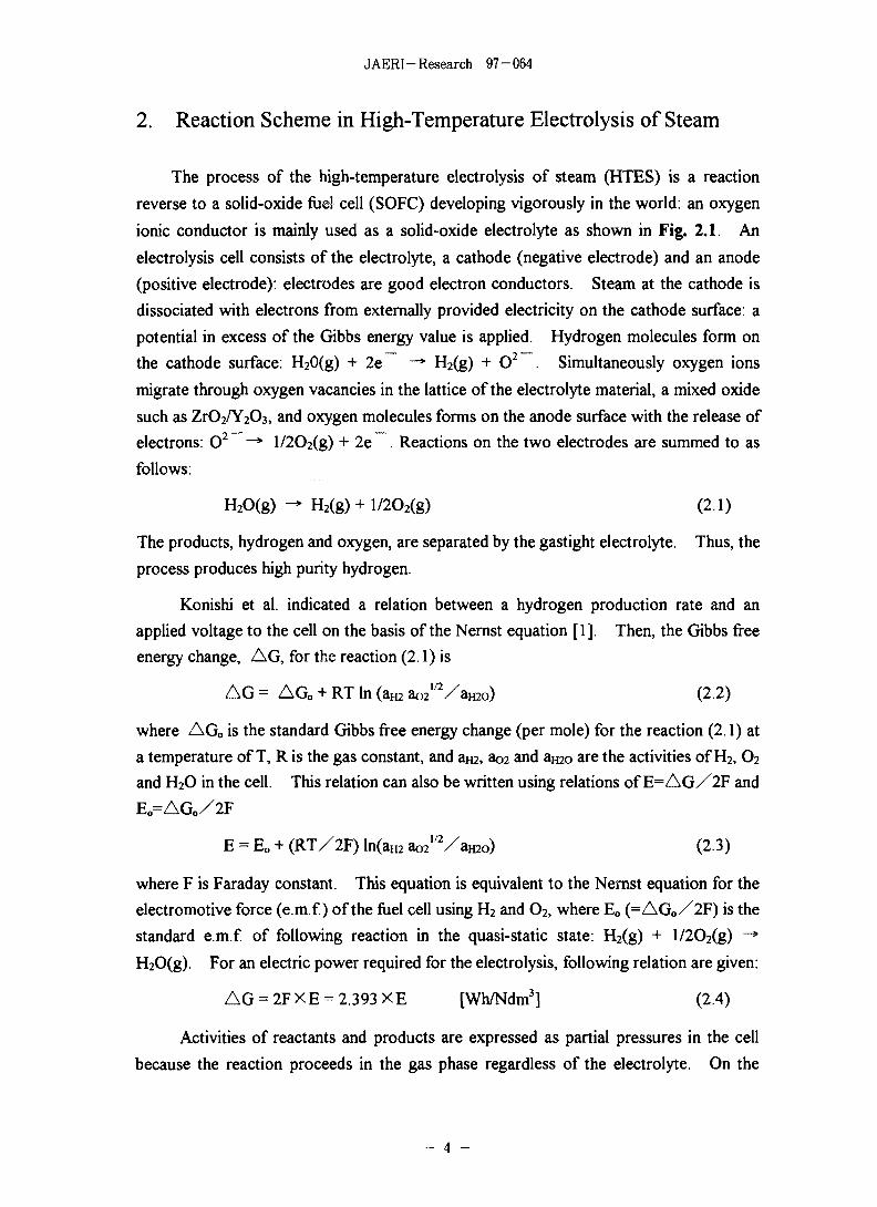
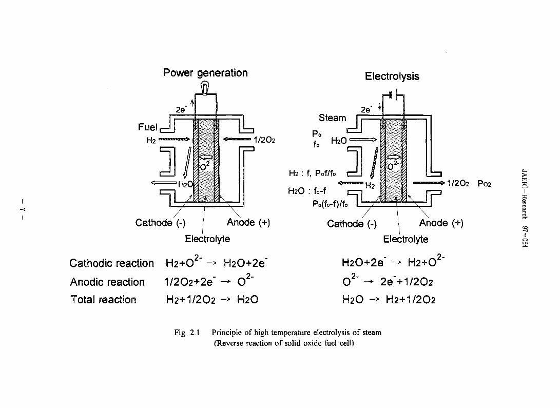
The process of the high-temperature electrolysis of steam (HTES) is a reaction
reverse to a solid-oxide fuel cell (SOFC) developing vigorously in the world: an oxygen
ionic conductor is mainly used as a solid-oxide electrolyte as shown in Fig. 2.1. An
electrolysis cell consists of the electrolyte, a cathode (negative electrode) and an anode
(positive electrode): electrodes are good electron conductors. Steam at the cathode is
dissociated with electrons from externally provided electricity on the cathode surface: a
potential in excess of the Gibbs energy value is applied. Hydrogen molecules form on
the cathode surface: H20(g) + 2e -* H2(g) + O2 . Simultaneously oxygen ions
migrate through oxygen vacancies in the lattice of the electrolyte material, a mixed oxide
such as ZrO2/Y2C)3, and oxygen molecules forms on the anode surface with the release of
electrons: O2 —* l/2O2(g) + 2e . Reactions on the two electrodes are summed to as
follows:
H2O(g) - H2(g) + l/2O2(g) (2.1)
The products, hydrogen and oxygen, are separated by the gastight electrolyte. Thus, the
process produces high purity hydrogen.
Konishi et al. indicated a relation between a hydrogen production rate and an
applied voltage to the cell on the basis of the Nernst equation [1]. Then, the Gibbs free
energy change, AG, for the reaction (2.1) is
A G = AG0 + RT In (am W V a m o ) (2.2)
where AG0 is the standard Gibbs free energy change (per mole) for the reaction (2.1) at
a temperature of T, R is the gas constant, and am, ao2 and amo are the activities of H2, O2
and H2O in the cell. This relation can also be written using relations of E = A G / 2 F and
EO=AGO/2F
E = Eo + (RT/2F) ln(aH2 te'Vamo) (2.3)
where F is Faraday constant. This equation is equivalent to the Nernst equation for the
electromotive force (e.m.f.) of the fuel cell using H2 and O2, where Eo (=AG 0 /2F) is the
standard e.m.f of following reaction in the quasi-static state: H2(g) + l/2O2(g) —*•
H2O(g). For an electric power required for the electrolysis, following relation are given:
AG = 2F X E = 2.393 X E [Wh/Ndm3] (2.4)
Activities of reactants and products are expressed as partial pressures in the cell
because the reaction proceeds in the gas phase regardless of the electrolyte. On the
JAERI-Research 97-064
other hand, applied voltage shall increase with polarization in operating the cell.
Increment of voltage, 7], is called an overvoltage, which consists of an activation
overvoltage by electrode reaction, a concentration overvoltage by disturbance of steam
supply at the cathode and a resistance overvoltage by electrical resistance including
electrical leads, interconnections and others. Then equation (2.3) is rewritten as
follows:
E = Eo + (RT/2F) ln(PH2 P O 2 1 V P H 2 O ) + V (2.5)
where PH2 and Pmo are the partial pressures of H2 and H2O at the cathode, respectively,
and P02 the partial pressure of O2 at the anode.
In the model cell shown in Fig. 2.1, steam of molar flow rate £, and pressure Po is
reduced to hydrogen gas of flow rate fo - f and partial pressure Po(fo - f) /fo in the cathode
compartment: (fo - f)/£, is a conversion rate from steam to hydrogen (steam conversion
rate). The partial pressure of oxygen at the anode, P02, is assumed to be unity: the
number of molecules does not change in the reaction at the cathode. Gaseous reactants
and products are assumed to be mixed well so that almost all the molecules are carried to
the reaction point on the cathode surface. In this condition, the gases in the cell are
related to the applied voltage on the cathode, and the composition of the gas at the outlet
of the cell in the steady state is expressed by equation (2.5). Using the molar flow rates,
equation (2.5) can be written as follows:
E - n = Eo + (RT/2F) In {(fo - f ) / f} (2.6)
In terms of currents, I=2F(fo - f) and I0=2Ffo, equation (2.6) can also be written
E - 7] = Eo + (RT/2F) In { i / f t , -1)} (2.7)
and using the steam conversion rate, x=(f<, - Q/fo, equation (2.6) can also be written
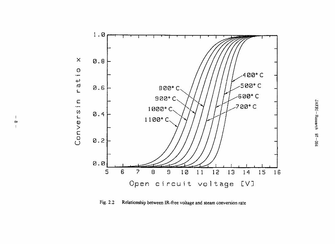
E - 7? = Eo + (RT/2F) In { x / ( l - x)} (2.8)
The values of E - 7] are the open circuit voltage or the IR-free voltage of the cell
which is related to the composition of the product. It should be noted that the steam
conversion rate x depends on the IR-free voltage and is not affected by the pressure or
flow rate of the reactant. Figure 2.2 shows the results calculated from eq.(2.8). As
seen in the figure, the steam conversion rate rises to 99.9% at about 1.3 V of the IR-free
voltage and approaches to unity at higher voltage. The values of Eo at each temperature
corresponds to the points of x=0.5. Because of the endothermic nature of the reaction,
the IR-free voltage decreases with increasing temperature. Due to the temperature
dependence of the logarithmic term in eq.(2.9), however, this effect decreases with the
- 5 -
JAERI-Research 97-064
value of x.
In the electrolysis, various kinds of cell efficiencies are evaluated using applied
voltage E, applied current I, and hydrogen production rate Q [Ndm3/h] evaluated at
O.lMPa (latm) and 273K (0^) , and so forth: electrolysis efficiencies for the practical
electrolysis units had better be evaluated on the basis of the applied power.
Faraday efficiency £ f is a ratio of the Gibbs free energy change AG and the
applied power, IX E: AG is related to the IR-free voltage. Then, Faraday efficiency is
e f = A G / ( I X E )
= 2.393 X ( E - 77 ) X Q / ( I X E) (2.9)
On the other hand, energy efficiency e e is a ratio of combustion heat of
hydrogen AH along the reaction (H2(g) + l/2O2(g)->H2O(g)) and applied power, which
is defined as follows:
£ e = A H X Q / 2 2 . 4 / ( I X E ) (2.10)
where Q/22.4 [Ndm3/h] is a mole number of produced hydrogen. The lower heating
value (L.H.V.) without the latent heat of water is used as the enthalpy of formation in
above equation. The value of AH [kJ/mol] at temperature of T[K] is given as follows:
TA H = AHo+ JCpdT
298
T= AHo+ J" {(- 11.8+4.9X10~3XT+0.35X 10~5XT~2)/1000) dT
298
(2.11)
where AH» is the lower heating value of hydrogen (L.H.V.) at 298K (25°C), -241.8
kJ/mol.
- 6 -
Power generation
Fuel
Electrolysis
1/202
Steam
Po
2e
fo H2O
H2 : f, Pof/fo
H2O : fo-f
Po(fo-f)/fo
'H2 1/2O2 P02 ST
Cathode (-) / Anode (+)
Electrolyte
Cathodic reaction H2+O2" -» H2O+2e"
Anodic reaction 1/2O2+2e" -» 0 "
Total reaction H2+I/2O2 -> H2O
Cathode (-) I Anode (+)
Electrolyte
k 2 -
o
2
H2O+2e~2-
H2O
•>'H2+O
2e"+1/2O2
H2+I/2O2
Fig. 2.1 Principle of high temperature electrolysis of steam(Reverse reaction of solid oxide fuel cell)
I00
X
o•r—•
•P
>
Cou
0 .8
0.G
0 .4
0 .2
0 . 0
800° C. II900°C, A /
1 100OC. / 7 /
— / I l l
. , . ^ ^ ^ / /
////////
- ^ L ^ < 1 , 1 , 1 , 1 ,
5 6 7 8 9 10 11 12 13 14 15 1G
O p e n c i r c u i t v o l t a g e [ V ]
>m
TS3
II
o
2
Fig. 2.2 Relationship between IR-free voltage and steam conversion rate
JAERI-Research 97-064
3. R&D Status of High-Temperature Electrolysis of Steam
Fabrication of the electrolysis cell is one of key technologies on the HTES. The
electrolysis cell has the same structure as the SOFC. Almost all of materials composed
of the SOFC are ceramics, and thus the SOFC is called a ceramic fuel cell. Several types
of ceramic fuel cell structures have been proposed and fabricated. In this chapter, we
will outline features of representative cell structures and show typical test results of the
HTES using practical cells except ours.
3.1 Cell structure
At present, three common cell structures have been proposed and fabricated for the
SOFC: tubular, planar and monolithic cell structures. Tubular and planar cell structures
are popular in the SOFC and have been used in the laboratory-scale experiments of the
HTES; but the monolithic cell structure is an advanced one at a very early stage of
development.
We will outline features of tubular and planar cell structures on the basis of reviews
[2,3]. In this section, the anode is defined as the positive electrode, and the cathode as
the negative electrode.
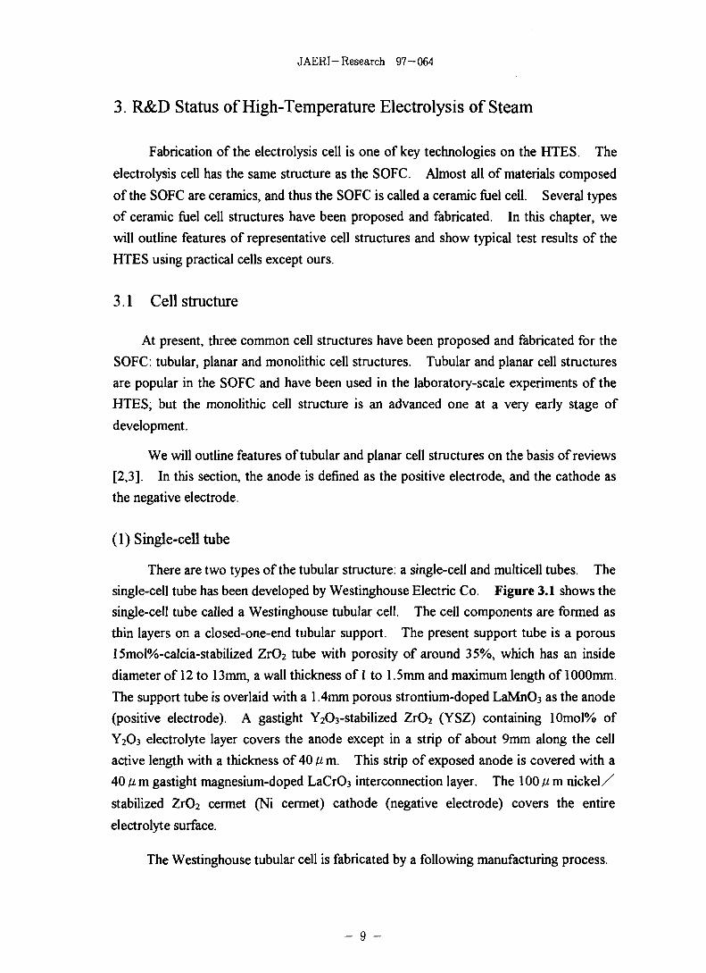
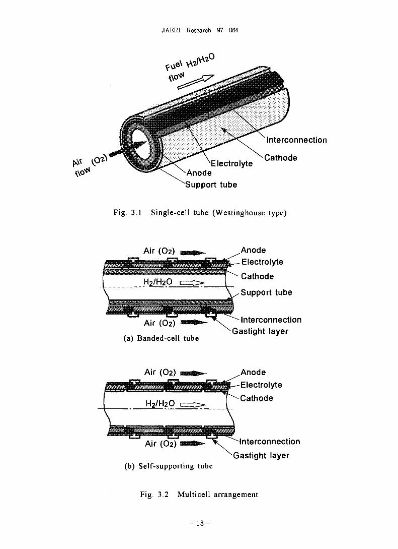
(1) Single-cell tube
There are two types of the tubular structure: a single-cell and multicell tubes. The
single-cell tube has been developed by Westinghouse Electric Co. Figure 3.1 shows the
single-cell tube called a Westinghouse tubular cell. The cell components are formed as
thin layers on a closed-one-end tubular support. The present support tube is a porous
15mol%-calcia-stabilized Z1O2 tube with porosity of around 35%, which has an inside
diameter of 12 to 13mm, a wall thickness of 1 to 1.5mm and maximum length of 1000mm.
The support tube is overlaid with a 1 4mm porous strontium-doped LaMnO3 as the anode
(positive electrode). A gastight Y2O3-stabilized ZrO2 (YSZ) containing 10mol% of
Y2O3 electrolyte layer covers the anode except in a strip of about 9mm along the cell
active length with a thickness of 40 fi m. This strip of exposed anode is covered with a
40 ft m gastight magnesium-doped LaCrO3 interconnection layer. The 100 p. m nickel/
stabilized ZrO2 cermet (Ni cermet) cathode (negative electrode) covers the entire
electrolyte surface.
The Westinghouse tubular cell is fabricated by a following manufacturing process.
- 9 -
JAERI-Research 97-064
(1) The support tube is fabricated by extrusion of a plastic mixture of calcia-stabilized
Zr(>2 (CSZ) powder plus cellulose and starch as pore forms, followed by sintering in
air at about 1550X): the extrusion process is the preferred low-cost method of
forming large quantities of support tube.
(ii) The anode is fabricated by depositing a slurry of doped LaMnO3 on the support tube
and sintering in air at about 1400t . The interconnection is made by the EVD
(Electrochemical Vapor Deposition) technique. Then masking is used to limit the
deposition of interconnection into the narrow strip along the length of the cathode.
(iii) The electrolyte is also made by the EVD. The electrolyte is deposited over the
entire active area of the cell, including overlap regions of about 0.5mm on all side of
the interconnection.
(iv) The cathode is applied by dipping the cell in a nickel slurry. The anode covers the
entire electrolyte surface, but not in contact with the interconnection, to avoid internal
cell shorting. The anode is then fixed by the EVD of doped ZrC«2 in the nickel matrix.
This ZrO2 acts as a sintering inhibitor and maintains the porous and structurally stable
anode.
The EVD process is the key fabrication technique in the Westinghouse tubular cell.
The principle is shown in Minn's review [3]. The Westinghouse tubular cell has been
fabricated in a number of different sizes; they have exhibited stable performance.
Modules stacked cells have also constructed and demonstrated, which have different
power output. For example, the module containing 576 cells has been operated at the
output power of around 16.5kW for about 4,300h at Rokko New Energy Research
Center in Japan [4].
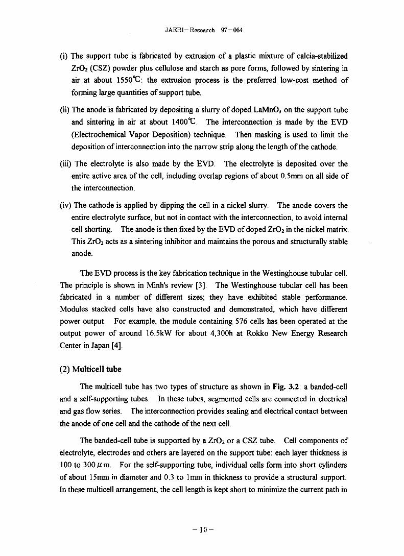
(2) Multicell tube
The multicell tube has two types of structure as shown in Fig. 3.2: a banded-cell
and a self-supporting tubes. In these tubes, segmented cells are connected in electrical
and gas flow series. The interconnection provides sealing and electrical contact between
the anode of one cell and the cathode of the next cell.
The banded-cell tube is supported by a ZrO2 or a CSZ tube. Cell components of
electrolyte, electrodes and others are layered on the support tube: each layer thickness is
100 to 300 jKra. For the self-supporting tube, individual cells form into short cylinders
of about 15mm in diameter and 0.3 to lmm in thickness to provide a structural support.
In these multicell arrangement, the cell length is kept short to minimize the current path in
- 1 0 -
JAERI-Research 97-064
the electrodes so as to realize uniform current density. The multicell tube are fabricated
as follows:
(i) Banded-cell tube
The support tube is formed by the almost same method as that the single-cell tube,
which has a porosity of 34 to 38%, the outside diameter of around 21mm, the wall
thickness of 2 to 3mm, and the length of around 710mm. Gastight AI2O3 layers are first
applied on the support tube by a plasma spraying. The function of thin AI2O3 layers is to
provide sealing at interconnecting areas. Thin copper tapes are used for masking to
make the required pattern on the support tube. During spraying, the support tube
rotates around its axis while the spray gun traverses along the support tube length. The
porous cathode of Ni cermet is coated on the support tube by an acetylene flame spraying
with thickness of 80 to 110 fi m. Then, the electrolyte of Y2O3-stabilized (8mol%) ZrO2
is plasma sprayed on the cathode after masking: 100 to 150 fim in thickness. The
electrolyte layer is required to achieve gastightness without pinholes. The gastightness
of the electrolyte has been improved by applying a low-pressure plasma spraying [5],
Recently, a coating technique based on a CO2 laser has been developed for making
electrolyte layers at the Electrotechnical Laboratory in Japan.
The interconnection, NiAl layer of less than 250 fi m in thickness, is fabricated by
the plasma spraying. The interconnection at the both ends of the support tube works as
electric leads and is covered with an AI2O3 coating of about 100jC/m thick to prevent
oxidation during cell operation. The anode is deposited on the electrolyte and
interconnection layers up to 200 fi m thick by the acetylene flame spraying. Calcium-
or strontium- doped LaCoCh or strontium-doped LaMnC>3 is usually used for the anode.
At present, development works on the multicell tube are focused on improving
assembling techniques of the banded-cell tubes in order to fabricate the module as module
as well as increasing the durability of the tubes. The banded-cell tubes with 12 and 15
cells have been fabricated, and furthermore, a lkW module containing 48 tubes with 12
cells have been constructed and operated for l,000h continuously [6]. As for increasing
the durability of the tube, a new type support tube made of porous metallic tube is now
developing [7].
(ii) Self-supporting tube
The self-supporting tube have been developed at Domier System GmbH in
Germany [8]. The self-supporting tube was fabricated as follows [9].
- 1 1 -
J AERI - Research 97-064
1) Tubular structure was formed to connect electrolysis cylinders with interconnection
rings in series by a diffusion welding to provide electric path and to keep
gastightness.
2) Electrodes were prepared inside and outside of the tube structure by the spraying
technique using a suitable masking procedure.
3) The tubular structure coated electrodes was sintered in high- temperature conditions
to complete the electrolysis tube.
The gastight electrolyte cylinder is made of YSZ of 0.3mm thick. The electrodes are
LaMnCb for the anode and Ni cermet for the cathode: thickness of each electrode is up to
500 Aim. Active dimensions of the segmented cells are around 10mm in length and
14mm in diameter.
Dornier System GmbH fabricated a module containing 10 ten-cell tubes and used it
to the HTES experiments.
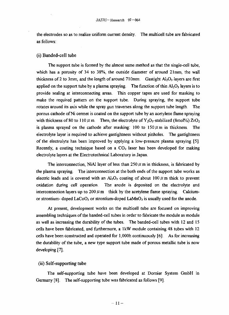
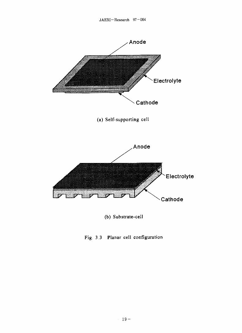
(3) Planar cell
There are two types of the planar cell configuration as shown in Fig. 3.3: a self-
supporting and a substrate-supporting cells. The self-supporting cell supported by an
electrolyte plate is a popular configuration; its fabrication cost is estimated at the lowest
among other SOFC structures because of the simplest fabrication [10]. The electrodes
are coated on the electrolyte YSZ plate by the slurry coating, a screen printing, or a tape
casting. Porous Ni cermet is used for the cathode and strontium-doped LaMnC>3 for the
cathode: each electrode thickness is more than 30fim. A lkW module containing 94
cells has been demonstrated with a power density of 0.14 W/cm2: each cell has an 100cm2
active electrode area [11].
As for the substrate-supporting cell, the substrate made of anode materials such as
LaMnC>3 is generally used. This type cell has better abilities than the self-supporting
cell: it is possible to enlarge an active area and to make thinner the electrolyte to reduce
electrical resistance so as to increase cell power density. The electrolyte and the
cathode is coated on the substrate of the anode by the plasma-spraying. Materials of the
cathode, the anode and the electrolyte are the almost same as those of the tubular cell
described above. The substrate has the thickness of 2 to 3 mm, and thickness of coated
layers of the anode and the electrolyte is less than 150#m. The cell active area of
200cm2 has been fabricated and is being improved the substrate to enlarge cell size to
300cm2 [12],
- 1 2 -
JAERI-Research 97-064
Internal resistance losses of the planar cell are independent of cell area because of in-plane
electrical conduction, so that the planar cell offers improved power density in comparison
with the tubular multicell structure.
The planar cell, however, requires high-temperature seals at the edges of the
electrolyte plates or the substrata. High-temperature seal is especially important in
fabricating the module stacked number of cells. Compressive seals, cement seals, glass
seals and glass- ceramic seals have been proposed. The compressive seal - a simpler seal
- can lead to a nonuniform stress distribution on the plate and thus, is liable to make
cracks in the cell. Cements and glasses tend to react with cell materials at 1000°C
operating temperature.
3.2 Typical test results obtained in the past
In this section, we will show typical test results which have obtained with practical
electrolysis cells until now in the world. Our test results are shown in the next chapter.
(1) Germany
In Germany, the HTES development had been performed by Dornier- system
GmbH and Lurgi GmbH in cooperation with Robert Bosch GmbH since the middle of
70's, which had been sponsored by the German Government, in order to demonstrate the
HTES process using a pilot plant; the demonstration test program including R&D on cell
components and module technologies is called the HOTELLY (High Operating
Iemperature Electrolysis) program. The HOTELLY program focused on the HTES
initially has included investigation of the SOFC application since 1987. Experimental
results on the HTES have not been reported recently.
Cells and electrolysis modules had been practically developed by Dornier-system
GmbH. Dornier-system GmbH had fabricated self-supporting electrolysis tubes
connected up to 20 cells in series and had accumulated extensive experiences on
operation of the HTES using 10-cell electrolysis tubes. Cell specifications were as
follows [8,9,13];
Active cell length
Active cell diameter
Thickness of electrolyte
Thickness of anode
: 10mm: 14mm
: 0.3mm
: less than 0.25mm
- 1 3 -
JAER1- Research 97-064
Thickness of cathode : less than 0.1 mm
Electrolyte : YSZ (Y2O3 containment 8 to 12mol%)
Cathode : Ni cermet
Anode : LaMnC«3 (probably)
Interconnection : dimensions and material are not clear.
Typical hydrogen production test with the 10-cell electrolysis tube was conducted
under following conditions [13]:
Electrolysis temperature : 9 9 7 ^
Pressure : near atmospheric pressure
Inlet gas flow rate : 17Nml/min(H2)/l36Nml/min(H2O)
(at standard conditions of latm and 0°C)
Applied voltage : max. 13.3 V
Current density : max. 0.37 A/cm2
Under this condition, an outlet hydrogen content increased to 85%. From this test
results, maximum DC current, electrical resistance, hydrogen production rate and others
were calculated as follows:
max. DC current 0.37[A/cm2] x (1.4[cm] X n X l[cm]: active cell area)
= 1.63 [A]
max. applied power 1.63[A] x 13.3[V] = 21.7 [W]
max. electrical resistance 13.3[V]/l.63[A] = 8.2 [Q]
Hydrogen production rate ( a )
(17[Nml/min(H2)]+ a)/ {(136[Nml/min(H2O)] - a)+ ( a + 17[Nml/min(H2)]}
= 0.85
a = 113 [Nml/min] = 6.78 [Ndm3/h (H2)]
Hydrogen production density of a cell
6780[Nml/h(H2)] x (1.4[cm] X n X l[cm] X lOcells)
= 154[Nml/cm2h(H2)]
Hydrogen production rate per applied power
6780[Nml/h(H2)] /21.7[W]
= 312[Nml/W(H2)]
Conversion rate from steam to hydrogen (stem conversion rate)
- 14
JAERI-Research 97-064
113[Nml/min(H2)] /l36[Nml/min(H2O)]
= 0.83
In the case where the HTES plant is added onto an existing electric power plant, steam
conversion rate more than 50% is preferable in order to keep overall thermal efficiency
[14]. Sensible and latent heats of unconverted steam can be recovered effectively by a
condenser working as a heat exchanger.
Faraday efficiency is can be given by eq.(2.10) as follows:
£ f = A G / ( I X E )
= 2.393X(E- 7?)XQ/(IXE)
= 2.393 X 1.006[V]X6.78[Ndm3/h]/21.7[W]
= 0.75
where 1.006 [V] is the IR-free voltage per cell derived from eq.(2.9) using steam
conversion rate.
Using the L.H. V. at 25"C, AHo, energy efficiency is given by eq.(2.12) as follows:
£ e = AHo/ ( IXE)
= (241.84/3.6[W/mol] X 6.78[Ndm3/h]/22.4[Ndm3/mol])/21.7[W]
= 0.94
If we use the L.H.V. at temperature of 997°C instead of AH,,, - 249.5kJ/mol, then £ e
is 0.97.
Dornier-system GmbH had integrated the HTES module assembled 10-cell
electrolysis tubes on a support box made of an electrical insulation material of Alumina.
The box was called a register and worked as a manifold to supply steam into the each
tube and to collect produced hydrogen from the tubes. The electrolysis tubes were
connected on the register by special joining techniques (not clear) to ensure gastightness
against thermal expansion difference between the tube and the register. The Electrolysis
tubes within the register were connected electrically in series. Ten modules had been
assembled to a stack consisting of 1,000 cells, by which hydrogen could be produced at a
maximum rate of 0.6 [Nm3/h] [15].
(2) United States
Westinghouse Electric. Co. had conducted the HTES test using the Westinghouse
- 1 5 -
JAERI-Research 97-064
type tubular cell [16]. Typical test conditions and test results were as follows.
Electrolysis temperature
Pressure
Inlet gas flow rate
Active cell area
Applied voltage
Applied current
Current density
Applied power
Electrical resistance
Hydrogen content at outlet
Steam conversion rate
Hydrogen production rate
Hydrogen production density
1000 °C
near atmospheric pressure
183 Nml/min (H2)/538 Nml/min (H2O)
(at standard conditions of latm and 0°C)
75 cm2
1.31V
30 A
0.4 A/cm2
30[A]xl.31[V] = 39.3W
1.31[V]/30[A] = 0.044 Q
66%
54%
17.6Ndm3/h
234 Nml/cm2h
Hydrogen production rate per applied power : 448 Nml/W (H2)
Faraday efficiency is
e f = A G / ( I X E )
= 2.393 X (E- 77) X Q / ( I X E)
= 2.393 X0.93[V] X 17.6[Ndm3/h]/39.3[W]
= 0.997
where 0.93 [V] is the IR-free voltage per cell derived from eq.(2.9) using steam
conversion rate. Energy efficiency is
£ e = A H o / ( I X E )
= (241.84/3.6 [W/mol] X 17.6[Ndm3/h]/22.4[Ndm3/mol])/39.3[W]
= 1.34
This energy efficiency shows very low ohmic loss in the cell. We, however, think that
applied voltages presented in the paper might not be a proper terminal voltage between
electrodes of the cell and/or a precise hydrogen content measured at outlet.
(3) Japan
Konishi et al. of the JAERI conducted the HTES tests using a tubular cell [1]. The
- 1 6 -
JAERI-Research 97-064
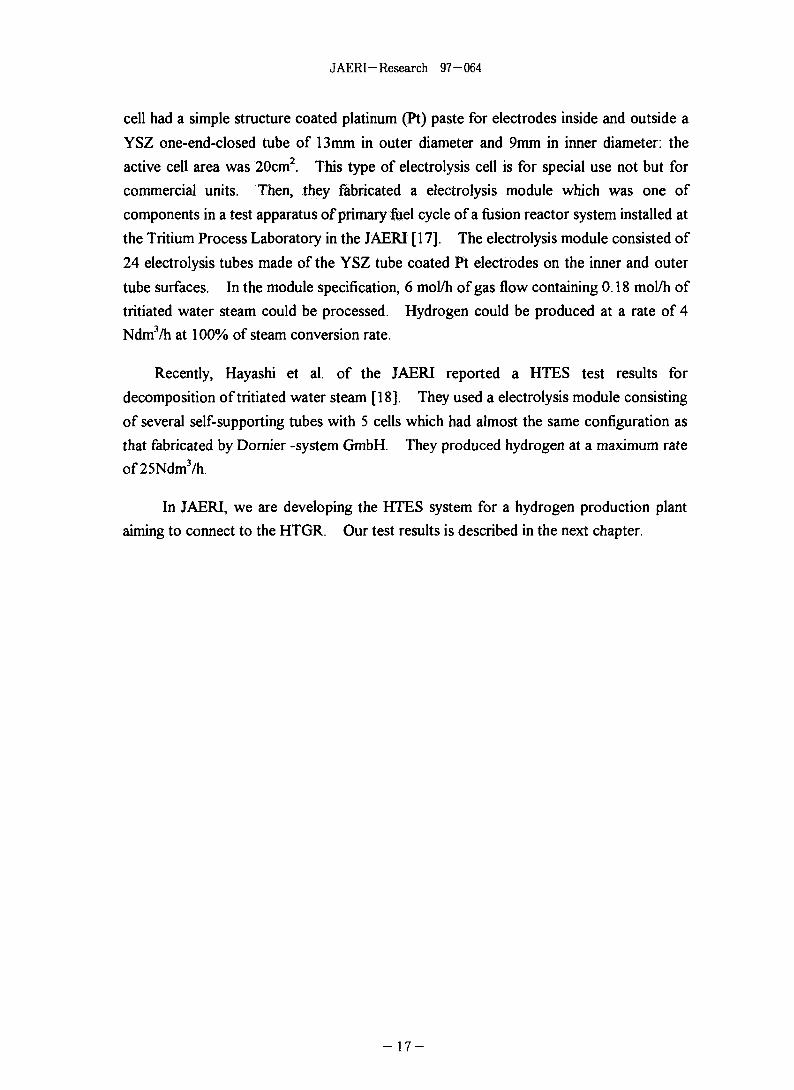
cell had a simple structure coated platinum (Pt) paste for electrodes inside and outside a
YSZ one-end-closed tube of 13 mm in outer diameter and 9mm in inner diameter: the
active cell area was 20cm2. This type of electrolysis cell is for special use not but for
commercial units. Then, they fabricated a electrolysis module which was one of
components in a test apparatus of primary fuel cycle of a fusion reactor system installed at
the Tritium Process Laboratory in the JAERI [17]. The electrolysis module consisted of
24 electrolysis tubes made of the YSZ tube coated Pt electrodes on the inner and outer
tube surfaces. In the module specification, 6 mol/h of gas flow containing 0.18 mol/h of
tritiated water steam could be processed. Hydrogen could be produced at a rate of 4
Ndm3/h at 100% of steam conversion rate.
Recently, Hayashi et al. of the JAERI reported a HTES test results for
decomposition of tritiated water steam [18]. They used a electrolysis module consisting
of several self-supporting tubes with 5 cells which had almost the same configuration as
that fabricated by Dornier -system GmbH. They produced hydrogen at a maximum rate
of25Ndm3/h.
In JAERI, we are developing the HTES system for a hydrogen production plant
aiming to connect to the HTGR. Our test results is described in the next chapter.
- 1 7 -
JAERI-Research 97-064
ElectrolyteAnodeSupport tube
Interconnection
Cathode
Fig. 3.1 Single-cell tube (Westinghouse type)
Air (O2)
Air (O2)
(a) Banded-cell tube
AnodeElectrolyte
Cathode
Support tube
InterconnectionGastight layer
Air (O2)
Air (O2)
(b) Self-supporting tube
AnodeElectrolyte
Cathode
Interconnection
Gastight layer
Fig. 3.2 Multicell arrangement
- 1 8 -
JAERI-Research 97-064
Anode
Electrolyte
Cathode
(a) Self-supporting cell
Anode
Electrolyte
Cathode
(b) Substrate-cell
Fig. 3.3 Planar cell configuration
- 1 9 -

JAERI-Research 97-064
4. High-Temperature Electrolysis Tests with Tubularand Planar Cells
This chapter describes typical test results obtained by the electrolysis tube with
12 cells [19] and preliminary test results obtained by the planar cell conducted at the
Nuclear Heat Utilization Engineering Laboratory in the JAERI.
4.1 Test apparatus and test conditions for electrolysis tube
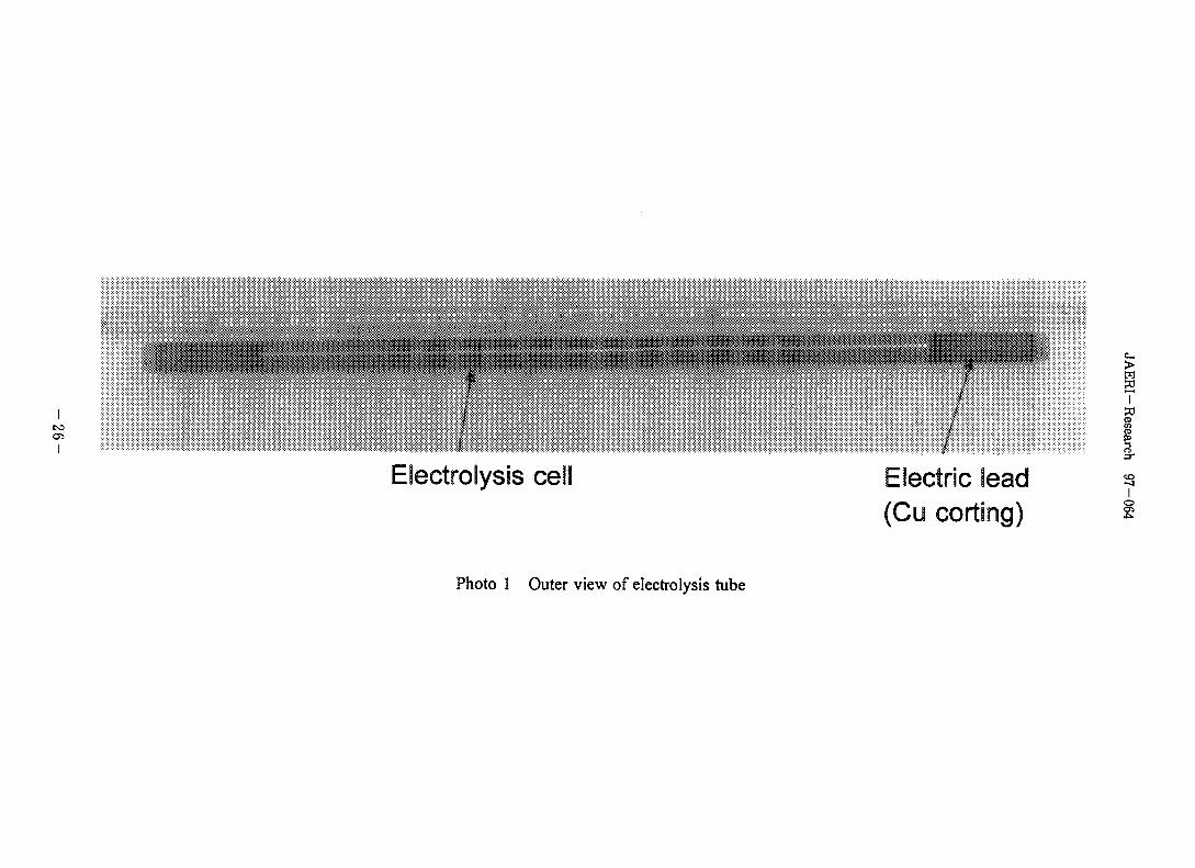
Figure 4.1 illustrates a structural drawing of the electrolysis tube of the banded-
cell structure, and Photo 1 shows an outer view of the tube. The electrolysis tube
was composed of 12 electrolysis cells of 19mm in length. These cells were
connected in series electrically. Electrolyte of the cell was zirconia stabilized with 8
mol% yttria (YSZ) which is popular material in the SOFC as described before. The
electrolyte layer was sandwiched between the porous cathode and anode layers: Ni
cermet for the cathode and LaCoCb for the anode. At both ends of the electrolysis
tube, platinum (Pt) wires for electric leads were welded on copper coating layers. Pt
wires were connected with a DC power supply. The copper coating layers were
connected with thin layers of electric conductors. Outside of the electrolysis tube
was coated by thin gastight layers without the cells and the copper coatings. These
layers were formed on a porous calcia-stabilized ZrC»2 (CSZ) tube (support tube or
ceramic tube) of 22mm in outer diameter and 3mm in thickness by the plasma
spraying. Thickness of each layers was in a range from 0.1mm to 0.25mm.
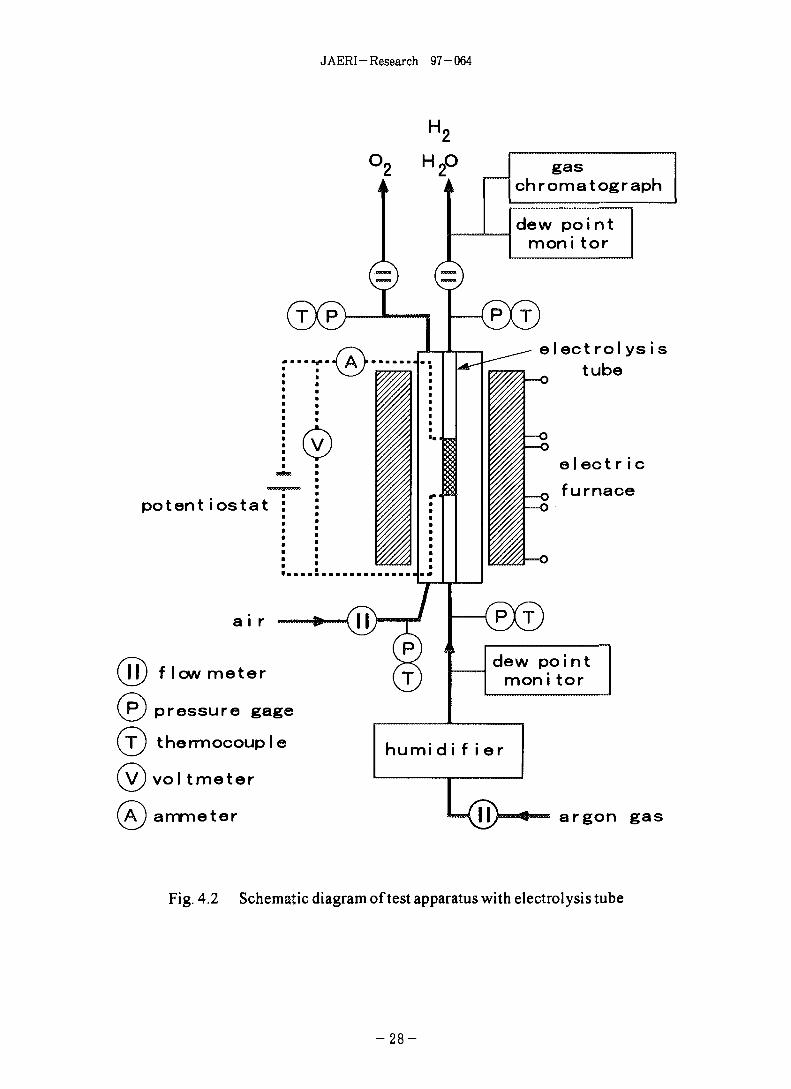
Figure 4.2 shows a schematic diagram of the test apparatus. Argon carrier gas
from gas cylinders flowed into a humidifier at a constant flow rate and was mixed with
steam at specific partial pressure through the humidifier where carrier gas bubbled
through water controlled at a constant temperature. Mixed gas was supplied inside
the electrolysis tube. Steam concentration was detected by dew point monitors both
at the inlet and the outlet of the test section. Dry air from an air compressor was
supplied outside the electrolysis tube at a constant flow rate in order not to decompose
anode compound of LaCoCh under less oxygen partial pressure. Hydrogen
concentration was measured by a gas chromatograph. Electrolysis voltage was
applied by the DC power supply, and then, electrolysis current was measured through
a standard resistor of 1 fi.
Figure 4.3 shows a schematic drawing of the test section. The electrolysis tube
was installed in a metallic tube (Inconel 600) of 50mm in inner diameter and was
- 2 0 -

JAERI- Research 97-064
heated up to lOOO'C in a three-zone electric furnace. The electrolysis tube was fixed
at the copper coatings with a metal tube by ground packing rings. Temperature of
mixed gas, steam/ argon carrier gas, was regulated to the test temperature by a sheath
heater inserted in the electrolysis tube. Hydrogen produced inside the electrolysis
tube (cathode side), unconverted steam and argon gas were cooled down to around
6 0 ^ by a cooling pipe and then, were discharged to the atmosphere. High-
temperature air mixed with oxygen produced in the anode side was cooled down to
around 60 X) at the outlet of the metal tube and was also discharged to the
atmosphere.
Tests were carried out under electrolysis temperatures of 850°C, 900°C, and
950°C. Other test conditions were as follows:
Argon flow rate : 2.2 NdmVmin
Dew point at the inlet of the electrolysis tube : 4 0 1 ~56X)
Steam content at the inlet of the electrolysis tube: 0.13~0.32 g/min
Air flow rate : 4 ~ 5 Ndm3/min (dew point is less than-20*C)
Inlet pressure : 0.11 MPa (1.1 bar(abs))
In start-up and shut-down of the test section, increasing and decreasing rates of the
furnace temperature were set at below 20^/11 in order not to generate large thermal
expansion difference among the electrolysis tube components. Before applying
electrolysis voltage, the cathode material, Ni cermet, was reduced with hydrogen
mixed with argon carrier gas.
4.2 Test results obtained by electrolysis tube
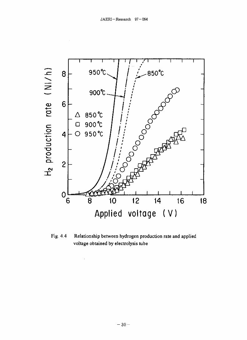
Figure 4.4 shows a relationship between the hydrogen production rate and the
applied voltage. Hydrogen production rate increased with the applied voltage and
the electrolysis temperature. The maximum production rate was 3.9 NdmVh at
15.7V, 1.42A and 850^ , 4.4 NdmVh at 16.3V, 1.38A and 9 0 0 ^ , and 7.0 Ndm3/h at
15.6V, 1.72A and 950°C, respectively. Apparent electrical resistances including
resistances of electrical leads and interconnections were around 11 Q at 8 5 0 t and
900°C, and around 9 Q at 950*£. Lines in the figure express the hydrogen
production rate calculated from eq.(2.8). Differences between experimental values
of the applied voltage and each lines indicate overvoltages. As seen in the figure, the
overvoltage increases with the hydrogen production rate. This overvoltage affects
Faraday efficiency. In the case of 950°C, Faraday efficiency was
2 1 -
JAERI-Research 97-064
£ f = 2.393 X0.89[V]X7[Ndm3/h]/(15.6[V]X1.72[A])
= 0.556
where 0.89V is the IR-free voltage derived from eq.(2.9) using steam conversion rate.
This low Faraday efficiency was considered to be caused by following reasons:
• Ohmic loss was high at interconnections and electric lead layers,
• Concentration overvoltage increased, since steam could not supply enough to the
cathode through support tube, and hydrogen produced at the cathode was not
fully discharged into the main flow through the support tube.
In these tests, the steam conversion rate meaning an efficiency of steam
utilization was less than 40%. The reason of low steam conversion rate was
considered that steam could not permeate easily through the support tube to the
cathode since the support tube had rather low porosity of around 38%. If steam
reached to the cathode sufficiently, hydrogen production rate could increase more than
the present results. The self-supporting cell structure, therefore, is considered to be
better in the HTES than the banded-cell structure supported by the ceramic tube.
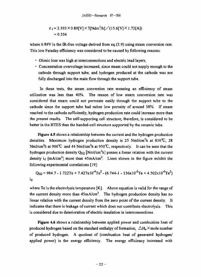
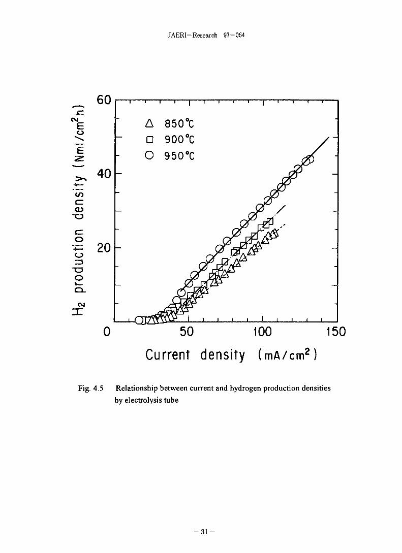
Figure 4.5 shows a relationship between the current and the hydrogen production
densities. Maximum hydrogen production density is 25 Nml/cm2h at 850°C, 28
Nml/cm2h at 900°C and 44 Nml/cm2h at 950°C, respectively. It can be seen that the
hydrogen production density QH2 [Nml/cm2h] posses a linear relation with the current
density id [mA/cm2] more than 45mA/cm2. Lines shown in the figure exhibit the
following experimental correlations [19]:
Qm= 984.7 - 1.722Te + 7.427x1 O^Te2- (6.744-1 - 136xl0"2Te + 4.502xl0"6Te2)
where Te is the electrolysis temperature [K]. Above equation is valid for the range of
the current density more than 45mA/cm2. The hydrogen production density has no
linear relation with the current density from the zero point of the current density. It
indicates that there is leakage of current which does not contribute electrolysis. This
is considered due to deterioration of electric insulation in interconnections.
Figure 4.6 shows a relationship between applied power and combustion heat of
produced hydrogen based on the standard enthalpy of formation, AH« X mole number
of produced hydrogen. A quotient of (combustion heat of generated hydrogen/
applied power) is the energy efficiency. The energy efficiency increased with
- 2 2

JAERI-Research 97-064
electrolysis temperature as shown in the figure. The energy efficiency in the case of
7 Ndm3/h at 9 5 0 ^ was, however, only about 80%. When high-temperature process
heat and steam are supplied from the HTGR to a hydrogen production plant of the
HTES, a plant operation temperature will be 900°C at highest. From the view point,
new better electrolytes working below 900 X^ should be searched. One of candidates
is ytterbia stabilized zirconia.
Figure 4.7 expresses a relationship between the current density and the energy
efficiency. As seen in the figure, high energy efficiency can be realized a range of the
current density from 80 to lOOmA/cm . An electrolysis module in which this type of
electrolysis tubes are installed should be designed with the experimental correlation of
QH2 in under the above the current density range.
After the test, It was observed that large part of anode layers was detached from
the electrolyte layers, though the electrolysis tube was served only one thermal cycle
of increasing to electrolysis temperatures and then, decreasing down to the room
temperature. Since the durability of the cell against thermal cycles is one of the key
performance for the HTES, the plasma spraying technique should be improved so as
to raise adhesion of the anode layer on the electrolyte layer against thermal expansion
difference of these layers. Dornier-system GmbH, Westinghouse Co. and Konishi
et al., however, have not reported the durability of the cell against thermal cycles.
4.3 Preliminary test results obtained by planar cell
On the basis of test results described above, we have tried to fabricate the self-
supporting electrolysis tube. Its yield, however, was very low, and fabrication cost
was much higher than that of the banded-cell tube, because it was very difficult to
manufacture electrolysis cylinders of 0.3mm thick and to connect segmented cells in
series with gastight interconnections.
Then, we have focused on the planar cells, particularly self-supporting planar
cell, from the viewpoint of mass production of the cell: quality control in the course of
its production is much easier than the banded-cell tube, and its production
technologies has been greatly progressed by the SOFC development. Present
production cost of the self-supporting planar cell is 1/7 or less lower than that of the
banded-cell tube shown in Fig. 4.1 and will be reduced further by mass production.
In progressing the HTES technology, especially the electrolysis cell technology,
- 2 3 -

JAERI-Research 97-064
cooperation with cell-production companies is indispensable for the development of
high-performance cells. So, we have started to cooperate with Fuji Electric Co. who
is making good results in the planar type SOFC research field.
Figure 4.8 shows a structural drawing of the self-supporting planar cell. The
cell consists of the electrolyte plate of YSZ and porous electrodes. The YSZ plate is
a 100mm square plate with thickness of 0.3mm, and electrodes are coated on the area
of 80 x 80mm with thickness of less than 0.03mm. Material of the cathode is Ni
cermet, and that of anode is strontium-doped LaMnO3. Though this type of cell
showed very high performance of H2 production, the cell was liable to make cracks in
sandwiching between metal housings made of SUS-310S and in heating to the
electrolysis temperature; Photo 2 shows an outer view of the cell after the test.
To improve cell strength, new type planar cell supported by a metallic plate was
fabricated as shown in Fig.4.9. The cell consisting of YSZ electrolyte and electrodes
made of Ni cermet and LaMnC>3 is layered on a porous metallic plate made of Ni
which serves as an electrode and an support of the cell. The cell sandwiched with
metal housings made of SUS-310S. Each housings have a metal rod for the electric
lead, an inlet and an outlet pipings for gases, and Pt sheet of 0.1mm thick was welded
on inner surface of each housings opposite to the electrodes of the cell. Metal rods
and pipings are also made of SUS-310S. DC power supplies through the metal rods,
housings, Pt sheets and wavy electrical lead plates to the cell. The wavy electrical
lead plate made of Pt mesh was installed in each electrode compartment to work as
the electric lead. Compression seals were done at the edge of the cell plate:
compression load was up to 20kg. Then, an alumina sheet of 0.3mm thick was
inserted between the cell plate and the housing in the anode side (air supplying side)
to prevent from current leak through the cell plate edge, and an Au sheet inserted in
the cathode side (steam supplying side) to prevent from H2 leak.
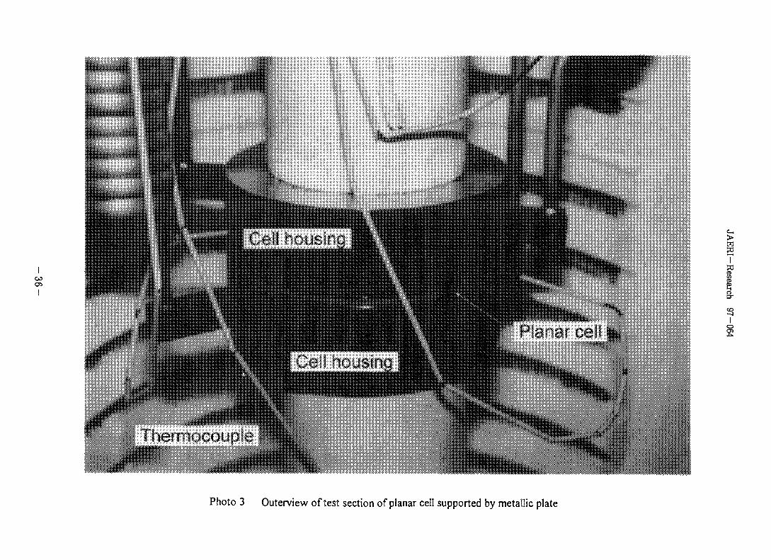
The cell coupled with housings was installed in a electric furnace as shown in
Photo 3 and was heated to the test temperature. Steam was supplied to the cathode
compartment, which was mixed with argon and hydrogen gases through a steam
generator instead of the humidifier shown in Fig.4.2. Argon gas was the carrier gas
of steam, and hydrogen a reduced gas to keep Ni of the cathode material from
oxidation. Dry air was supplied to the anode compartment. Steam flow rate was
controlled by water flow rate to the steam generator, and flow rates of other gases
were controlled by mass flow controllers. Hydrogen concentration was measured at
the outlet of the cathode compartment by the gas chromatograph. Electrolysis
- 2 4 -
JAERI- Research 97-064
voltage was applied by the DC power supply.
A preliminary test was conducted under following conditions.
Electrolysis temperature : 850^ , 900^ , 9 5 0 ^
Inlet gas flow rate : 0.2 NdmVmin (argon gas)
0.1 NdmVmin (H2)
Steam flow rate : 0.4 g/min
Air flow rate : 0.5 NdmVmin (dew point is less than-20^)
Inlet pressure : ~0.11 MPa ( ~ 1.1 bar(abs))
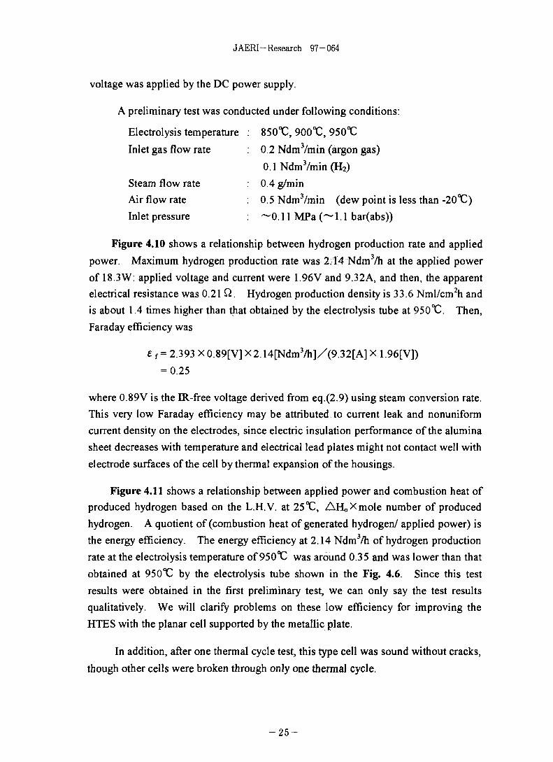
Figure 4.10 shows a relationship between hydrogen production rate and applied
power. Maximum hydrogen production rate was 2.14 Ndm3/h at the applied power
of 18.3W: applied voltage and current were 1.96V and 9.32A, and then, the apparent
electrical resistance was 0.21 Q. Hydrogen production density is 33.6 Nml/cm2h and
is about 1.4 times higher than that obtained by the electrolysis tube at 950^ . Then,
Faraday efficiency was
e {= 2.393 X0.89[V] X2.14[Ndm3/h]/(9.32[A]X 1.96[V])
= 0.25
where 0.89V is the IR-free voltage derived from eq.(2.9) using steam conversion rate.
This very low Faraday efficiency may be attributed to current leak and nonuniform
current density on the electrodes, since electric insulation performance of the alumina
sheet decreases with temperature and electrical lead plates might not contact well with
electrode surfaces of the cell by thermal expansion of the housings.
Figure 4.11 shows a relationship between applied power and combustion heat of
produced hydrogen based on the L.H.V. at 25 °C, AHoXmole number of produced
hydrogen. A quotient of (combustion heat of generated hydrogen/ applied power) is
the energy efficiency. The energy efficiency at 2.14 Ndm3/h of hydrogen production
rate at the electrolysis temperature of 950°C was around 0.35 and was lower than that
obtained at 950X! by the electrolysis tube shown in the Fig. 4.6. Since this test
results were obtained in the first preliminary test, we can only say the test results
qualitatively. We will clarify problems on these low efficiency for improving the
HTES with the planar cell supported by the metallic plate.
In addition, after one thermal cycle test, this type cell was sound without cracks,
though other cells were broken through only one thermal cycle.
- 2 5 -
COCTs
Electrolysis cell Electric lead(Cu coiling)
Io2
Photo 1 Outer view of electrolysis tube

19
Ito
protectivecoating
electrolysiscell
9
electriclead interconnector
.gas tight
gas tight
electric conductoranode (LaCo03)
electrolyte (YSZ)
cathode (Ni+YSZ)
support tube
copper coatingcopper coating
steam
sT
iO
2
uni t (mm)
Fig. 4.1 Structural drawing of electrolysis tube with 12 cells (tubular type cell)
JAERI-Research 97-064
potent iostat
a i r
2
(M) f low meter
\P) pressure gage
( T ) thermocouple
vol tmeter
A) ammeter
H2O gaschromatograph
dew pointmon i tor
electrolys i stube
elect r ic
furnace
dew pointmoni tor
argon gas
Fig. 4.2 Schematic diagram of test apparatus with electrolysis tube
- 2 8 -

JAERI-Research 97-064
hot water
Ar+H2+H20
hot water (~60°C)
stopper
grand-packing
Air + 02 o^EE
water cooling pipe
heating furnace( - 1 0 0 0 °C)
insulator
AirAr + H,0 «=s>-F
water cooler
metal tube
electrolysis tube
sheath heater
DC electrode
0 ring
thermocouple
Fig. 4.3 Schematic drawing of test section with electrolysis tube
- 2 9 -
J AERI - Research 97-064
o
o
CM
A 850 °C• 900 °CO 950°C
10 12 14 16
A p p l i e d v o l t a g e ( V )18
Fig. 4.4 Relationship between hydrogen production rate and applied
voltage obtained by electrolysis tube
- 3 0 -
J AERI - Research 97 - 064
CM
O
CO
CD
o
o
CM
40
20
1 V
AD
o
-
II
I.
, rjrftf
850°900°950°
A
ccc
J2T,
i i i i
I ' 1 I l
(7y
—
1 i i i i
0 50 100 150
Current density (mA/cm2)
Fig. 4.5 Relationship between current and hydrogen production densities
by electrolysis tube
3 1 -

JAERI-Research 97-064
CVJ
czo
en
Eoo
10 20A p p l i e d p o w e r ( W )
30
Fig. 4.6 Relationship between applied power and combustion heat
of generated hydrogen obtained by electrolysis tube
3 2 -

JAERI-Research 97-064
100
_. 80 -
60 -
O>
UJ
40 -
20
_
_
—
i
Or
1 1 I 1
o
: A
orOcX>
nT-U-Lrt,
^ ^
AD
O
, i I
i i l i
Vv ~
850 °C900°C950°C
i i i i
0 50 100 150
Current density (mA/cm2)
Fig. 4.7 Relationship between current density and energy efficiency
- 3 3 -

JAERI-Research 97-064
Electric insulation
Stean
lOOrm
AirQcygen electrode
Hydrogen/IInterconnection Fuel Sol id electrolyte(current pass) electrode (Yttria-stabi I ized
zirconia plate)
Fig.4.8 Structural drawing of self-supporting planar cell
crack
Photo. 2 Outerview of self-supporting planar cell after one thermal cycle
- 3 4 -

JAERI-Research 97-064
<t> 120mm
Steam (H2O)
Air electrode(LaSrMnO3, t=0.05mm)
Electrolyte (YSZ, 0.15mm)
Fuel electrode(NiO+YSZ, 0.045mm)
Metallic porous electrode(NiCr, 1.85mm)
H2 ,H2O
O2 enriched air
Silica stopper ring\
Interconnection (Pt net)
Fig. 4.9 Schematic drawing of new planar cell supported by porous metallic plate
- 3 5 -
O5
>
1
Photo 3 Outerview of test section of planar cell supported by metallic plate

JAERI-Research 97-064
sC
o
C<D
O
2.5
2.0
1.5
1.0
0.5
0.05 10 15 20
Applied power (W)25
Fig. 4.10 Relationship between applied power and hydrogen production rate
- 3 7 -

JAERI-Research 97-064
20
15
050
C
2
10
OO
0 *
— 845°C-_ f"4 f*\ ^% O^^
—B~~ i"jy ^y ^j \^
A Qff̂ ^0 w^
/
V
/
V *
0 5 10 15Applied power (W)
20
Fig. 4.11 Relationship between applied power and combustion heatof generated hydrogen obtained by planar cell
- 3 8 -

J AERI - Research 97 - 064
5. Future Works
Many severe problems common to all high-temperature designs and operations are
inherent in the HTES technology. This chapter presents the outline of technological
issues to improve electrolysis cells and to fabricate the electrolysis module. In addition,
I will suggest the thinking way of optimization of the HTES system and the
demonstration test plan using large-scale modules (electrolysis units) for finally
connecting to the HTTR as a nuclear process heat utilization system.
5.1 Improvement of electrolysis cell
The HTES is an innovative concept at an early stage of electrolysis technology. It
has been only shown a feasibility to produce hydrogen continuously by the HTES as
described in the former chapters. The HTES technology progress requires continuous
efforts to improve existing electrolysis cells to suitable cells for the HTES.
Improvements of electrolysis cells are:
• to reduce current leak and ohmic loss of the cell to raise the energy efficiency, and
• to increase the cell durability against thermal cycles for demonstration units.
If it is possible to operate the cell at low temperature below 900T) with high energy
efficiency by reducing current leak and ohmic loss of the cell, the HTES system will be
suitable for the nuclear process heat application.
(1) Cell materials
The characteristics of cell materials required for minimum ohmic loss of the cell are
as follows:
• Electrolyte of minimal thickness with gastightness and suitable ionic conductivity:
Ytterbia stabilized zirconia has higher ionic conductivity than that of YSZ, but is more
expensive than YSZ.
• Electrodes with much higher electron conductivity than that of presently used
materials such as LaCoC>3 or LaMnO3 for the anode and Ni cermet for the cathode;
- They should be stable against the respective oxidation and reduction reactions in the
hydrogen/steam and oxygen environments and must permit ready diffusion of gases
and steam;
- The interconnection, the electric lead layer, and the electric plate are required for the
same performance as that of the electrode;
- 3 9 -

JAERI-Research 97-064
- Those materials are to be inexpensive.
As for the planar cell, the ohmic loss of electric paths excluding the cell can
decrease with contact electrical resistance of the electrical lead plates against the cell.
Hence, the electrical lead plate requires large contact area with electric surfaces of the
housings and electrodes of the cell as well as its own low electrical resistance.
Furthermore, we have to develop inexpensive and high-performance sealant
materials without leakage of current and hydrogen under high-temperature and high-
pressure conditions and with resistance to steam corrosion and air oxidization: the sealant
material, then, should function as an electrical insulator and an absorber of thermal
expansion in order to keep from current leak and to improve the cell durability.
In parallel to above technological improvements, we should take efforts to elucidate
electrochemical reaction mechanisms and kinetics on and around electrode surfaces and
to investigate effects of heat and mass transfer rates around electrodes and in the
electrolyte on overvoltages and ohmic losses.
(2) Cell strength and durability against thermal cycles
Selecting cell materials, we should take into consideration maintaining cell
mechanical strength, and increasing durability of the cell against heat cycles. On
mechanical strength of the cell, supporting structure cells such as the single-cell tube, the
banded-cell tube or the substrate-supporting planar cell described in chapter 3 are much
better than the self-supporting cell.
The self-supporting planar cell, however, may be possible to keep the cell
mechanical strength by the electrical lead plates and interconnections mentioned in the
next section. These components work as a support of the cell as well as the electric lead.
The electrical lead plates must be designed:
• to provide large contact area with electric surfaces such as electrodes in order to
achieve uniform current density on the electrode;
• to keep high electron conductivity under high-temperature condition; and
• to permeate gases and steam smoothly into the electrode.
On the other hand, adhesion of electrodes' layers to the electrolyte is the key
parameter of the cell durability against thermal cycles. CVD, EVD or the plasma
spraying are better techniques to make electrode layers with high adhesion, but are not
for mass production because of their high cost and rather low yield. The slurry coating
- 4 0 -
JAERI-Research 97-064
applied in fabricating the self-supporting planar cells mentioned in former chapters,
however, is the lowest-cost and higher-yield technique, which are suitable for mass
production. In addition, it is possible to improve adhesion of electrodes' layers by
changing sintering temperature up to HOO'C after coating electrode slurries on the
electrolyte. We have to improve electrode coating techniques further to increase
adhesion and yield, and to lower the coating cost for mass production.
In parallel to improve the cell strength and the cell durability, we have to take
efforts to scale-up cell sizes for electrolysis units: long electrolysis tubes with large
diameter and large planar cells with rectangular or circular shape. Since yield of the cell
usually lower with enlarging cell size, fabrication techniques - mainly coating techniques
- have to be improved further.
5.2 Bench-scale test by electrolysis module
In the course of improving the electrolysis cell, we will be able to fabricate lower-
cost electrolysis tubes or planar cells with higher electrolysis performance. Then, we
will design and fabricate the electrolysis module containing several electrolysis tubes or
planar cells. In designing the module, we have to make better contrivance of following
parts:
• Electrical connections working under a high-temperature condition.
• Manifold distributing steam to each cell uniformly.
• Seal configuration working without leakage of steam/hydrogen and air under
high-pressure operation; and with a function of electrical insulation and of absorber
for thermal expansion in the module.
In addition, we have to design the special parts of the interconnection with
appropriate configurations to achieve uniform steam concentration on the cathode surface
in stacking planar cell for the module. Figure 5.1 shows a concept of planar cell module.
In this module, the interconnection is inserted between the cells to separate
steam/hydrogen and air paths as well as to keep electric path as electric collectors. Thus,
the interconnection is required for combined characteristics of low gas permeability, low
ohmic resistance, high mechanical strength, long life in a oxidation and reduction
environment, and durability against heat cycles, to say noting of inexpensive. We
consider that it will be better to insert the wavy electrical lead plate made of a meshed
noble metal between the interconnection and the cell as a buffer against thermal stresses.
- 4 1

JAERI- Research 97-064
After designing, the small-sized module containing several electrolysis tubes or
planar cells should be fabricated to obtain following design data for demonstration units
with hydrogen production of 10 Nm3/h mentioned in the next section.
• Long-term stability of module operation: for more than 5000h at a
temperature of 700 to 900^ and pressure up to IMPa.
• Hydrogen production efficiency (energy efficiency).
• An amount of leakage of hydrogen from the seals.
• Applied power distribution and cell ohmic losses.
• Concentration distributions of steam/hydrogen.
• Flow rate distribution and pressure loss.
• Pressure difference controlability: below 4.9KPa (500mmH2O).
• Applied power controlability against change of steam flow rate.
• Durability against heat cycles etc.
5.3 System optimization
System optimization calls for an analysis of an integrated system consisting of the
electrolysis units and all the ancillary equipment such as steam generators, steam super
heaters, and heat exchangers. Then, high-temperature heat will supply from the HTGR
through a intermediate heat exchanger. The integrated system of the HTES using
nuclear process heat will be more complicated than that for the conventional water
electrolysis
In developing an analysis code, the code should provide functions to be capable of
accounting for the effects of all major operating variables such as flow rate, pressure and
temperature on the hydrogen production efficiency; and for the effects of the emergency
shut-down of the HTGR to the HTES system. From the analysis, we will be able to
determine capacities of installing equipments and an optimum flowsheet of a
demonstration system connected to the helium gas loop (HGL) for a steam-reforming
demonstration test which will be completed at the Oarai Research Establishment of
JAERI until 2000.
In designing a system constitution, heat exchangers to recover heat content of the
product gases with the feed steam should be installed at the outlet of the electrolysis units
in order to reduce the net energy input required. The feed steam could then be heated to
cell operating temperature by a high-temperature heat from the HGL.
- 4 2 -
JAERI-Research 97-064
In addition, small amount of hydrogen should be supplied to the electrolysis units
to prevent oxidation of the cathode material. This requirement leads to the inclusion of
a hydrogen recycle stream in the flowsheet. Use of oxidation-resistant cathodes such as
platinum could eliminate the hydrogen recycle stream.
Through the analysis, we should also determine procedures coping with the
abnormal states as follows:
• decreasing steam and air flow rate rapidly,
• increasing pressure difference between anode and cathode compartments.
When steam flow rate decreases rapidly, applied power to electrolysis units should be
decreased immediately to prevent increasing cell temperature by Joule heating. Lack of
steam at the cathode makes the overvolatge increase. Delicate control of pressure
difference between anode and cathode compartments is indispensable for preventing
failure of electrolysis cells under high-pressure operation.
In parallel to analysis, following ancillary equipments and systems have to be
developed:
• a steam super heater which can heat steam up to 900 °C,
• the heat exchanger recovering heat content of the product gases with the feed
steam,
• a control system of pressure difference between anode and cathode compartments,
which consists of high-speed valves, pressure dampers and so forth.
5.4 Outline of demonstration tests
We would like to suggest a plan to perform demonstration tests of the HTES with
the HGL for connecting to the HTTR. The flowsheets for demonstration tests will be
determined by the above analysis. Simulated process heat of high-temperature and
high-pressure helium gas of up to 950°C and 4MPa will be supplied from the HGL.
Demonstration tests will be performed at two stages. The first stage is an
engineering demonstration of the HTES system using electrolysis units of which
hydrogen production rate will be 10Nm3/h. Using this system,
• the analysis results of the system mentioned above will be verified,
• long-term stability and durability of the electrolysis units will be demonstrated, and
- 4 3 -

JAERI-Research 97-064
• operational procedures will be established: the start-up, the shut-down, and the
emergency operation at the abnormal states such as decrease of steam flow rate
and temperature, and increase of pressure difference on the cells.
On the basis of the test results obtained by above demonstration test, the system
will be rearranged and be enlarged to a prototype system of 100NmJ/h of hydrogen
production rate as a second stage. Tests in the second stage will be performed to obtain
demonstration data for safety review of the HTTR heat utilization system.
- 4 4

JAERI-Research 97-064
H2O
Electrolyte
CathodeAir
(a) Self-supporting structure
H2O
(b) Substrate structure
Manifold
(c) Cell stack
Fig.5.1 Schematic drawing of planar cell module
- 4 5 -

JAERI-Research 97-064
6. Concluding Remarks
Hydrogen production by using nuclear heat is important in enlarging fields of
nuclear heat utilization which is now limited in the field of electric generation. The
high-temperature electrolysis of steam (HTES) is one of innovative hydrogen production
systems, which posses high energy conversion efficiency theoretically. We introduced
present status of the HTES in the world and our test results. The HTES, however, is at
a very early stage of technology, and thus, significant development effort is required to
solve severe materials and fabrication problems due to high-temperature operation. We
would like to describe our sincere expectation to the future positive research of the HTES
for broadening fields of nuclear heat utilization. We are looking forward to realizing a
demonstration test of the HTES connected with a helium gas loop for developing the
HTTR heat utilization system.
Acknowledgments
I will express my gratitude to Mr. Y. Miyamoto, the director of the Department of
the Advanced Nuclear Heat Technology, and Dr. S. Shiozawa, the depuity director of
this department who gave us useful advise on contents of this report. We will thanks to
Mr. F. Okamoto of Fuji Electric Co. for supporting planar cell tests.
- 4 6 -

JAERI-Research 97-064
References
[I] S. Konishi et al., "Solid Oxide Electrolysis Cell for Decomposition of Tritiated
Water", Int. J. Hydrogen Energy, 11, 507-512(1986).
[2] B. C. H. Steele, "Properties and Performance of Materials Incorporated in SOFC
Systems", Proc. International Symp. on SOFC, Nagoya, 136-147(1989).
[3] N. Q. Minh, "Ceramic Fuel cells", J. Am. Soc, 76, 563-588(1993).
[4] A. Kusunoki et al. "A 25kW SOFC Generation System Verification Test SOFC
(written in Japanese)", Extended abst. of 2nd Symp. SOFC in Japan, 19-22(1993).
[5] F. Umemura et al., "Development of Solid Oxide Fuel Cell", Proc. International
Symp. on SOFC, Nagoya, 25-32(1989).
[6] N. Murakami et al., "Development of Solid Oxide Fuel Cells (written in Japanese)",
MHI Technical Report, 29, 182-187(1992).
[7] T. Okuo et al., "Studies on SOFC Components for Low Temperature Operation
System - Development of Metallic Porous Tube and Its Application (written in
Japanese)", Extended abst. of 2nd Symp. SOFC in Japan, 49-56(1993).
[8] W. Doenitz et al., "Electrochemical High Temperature Technology for Hydrogen
Production or Direct Electricity Generation", Int. J. Hydrogen Energy, 13, 283-
287(1988).
[9] W. Doenitz et al., "Concepts and Design for Scaling Up High-Temperature Water
Vapor Electrolysis", Int. J. Hydrogen Energy, 7, 321-330(1982).
[10] H. Itoh et al., "Development of Solid Oxide Fuel Cells - Producing Cost Estimation
(written in Japanese)", Central Research Institute of Electric Power Industry,
Yokosuka Research Laboratory Report, No.W92028(1993).
[II] T. Nakanishi et al., "Planar Solid Oxide Fuel Cell Technology preliminary Cell
Performance and Stack Configuration", Proc. International Symp. on SOFC, Nagoya,
43-49(1989).
[12] T. Iwata et al., "Development of Substrata Type Planar SOFC at Fuji Electric
(written in Japanese)", Extended abst. of 2nd Symp. SOFC in Japan, 1-4(1993).
[13] W. Doenitz et al., "High-temperature Electrolysis of Water Vapor Status of
Development and Perspective for Application", Int. J. Hydrogen Energy, 10, 291-
295(1985).
[14] F. J. Salzano et al., "Water Vapor Electrolysis at High Temperature: Systems
Consideration and Benefits", Int. J. Hydrogen Energy, 10, 801-809(1985).
[15] W. Doenitz et al., "Recent Advances in the Development of High-temperature
Electrolysis Technology in Germany", 7th World Hydrogen Energy Conf, Moscow,
Sept. (1988).
- 4 7 -

JAERI- Research 97-064
[16] N. J. Maskalick, "High Temperature Electrolysis Cell Performance Characterization",
Int. J. Hydrogen Energy,, 563-570(1986).
[17] S. Konishi et al., "Experimental Apparatus for the Fuel Cleanup Process in the
Tritium Process Laboratory", Fusion Technology, 14, 596-601(1988).
[18] T. Hayashi et al., "Joint operation of the TSTA under the Collaboration between
JAERI and US-DOE - TSTA extended loop operation with 100 grams of tritium
on Apr-May 1992 ", JAERI-M 93-083 (1993).
[18] R. Hino et al., "Hydrogen Production by High-temperature Electrolysis of Water
Vapor Steam - Test Results Obtained with an Electrolysis tube (written in
Japanese)", J. Atomic Energy Society of Japan, 37, 1042-1049(1995).
- 4 8
X I
ft
ftft
At
ft
ft
issan
K ft*
S ft(* ft
+
T
T
*
*
7
7,
- h
y ^
yi/ t '
y x
>> r
X7^T
yl,
A
Ty
IV
7
y
y
id ^
m
kg
s
A
K
tnol
cd
rad
s r
S 3
m•
S. tl ,3Lif.IV
X ^
« S
Sffi.
in*3 y
-f y-fe IV
ft
ia»
m
. sg ,
*
%9 9
%
9 9•y -?
l-i
K
ft
ft
fr, figk « *
% ftfi {a
•? y x
9 V X
x S I
«
« ftS ft
—
>?
7
7
t•J
X
-x
• b ;
yu
-y
yi/
i - h
7. iii -
— •
IV
r 7-
- y yi -
7.
y IJ
u> •? x- t
9
9 \s
— s< IV
V
V
IV
IV
hy
KA
X
7
-
y
x
yu
-f
Hz
N
Pa
J
W
cV
F
ns
Wb
T
H
•clm
lx
Bq
GySv
s -mkg/s2
N/m2
N-m
J / s
A s
W/A
C/V
V/A
A/V
V.sWb/m2
Wb/A
cdsr
ltn/m2
s-'
J/kg
J/kg
•CJ 1*^
7J , Drf , t i
Ij .., |- /U
h y
K^RftWCi
ia %
min, h, d
1. L
t
eV
u
* 5
leV = 1.60218xl0-"J
1 u= 1.66054x10"" kg
* 4
X y ?"x h D — A
•>< - y
>< — yl/
if iv
+ ^ U -u y h y y
7 Klx A
12 ^
A
b
bar
Gal
Ci
R
rad
rem
A=0.1 nm=10-'°m
b=100fmJ=10-"m2
bar=0.1MPa=10sPa
Ci=3.7xlO'°Bq
R=2.S8xlO"C/kg
1 0 "
10's
1012
10'
10'
10J
102
10'
10"'
io-
io-]
10*
io-io-2
io-'s
io—
ftX
X
* '
/I
+
T '
T '
•fc
J-7
rt"
7
T
BJU§
? *
9
7
D
9 h
•y
y x
'J
f ^ D
j
3
i A h
ad n
E
P
T
G
M
k
h
da
d
c
m
M
n
Pf
a
ftt)
1985«PflJ57lCj;4o Ai/i'U leV
fc-ct O' 1 u Oiltt CODATA © 1986^«»!|
2.
3. barli.
rem=lcSv=10 2Sv
, barnfcj;
N( = 10sdyn)
1
9.80665
4.44822
kgf
0.101972
1
0.453592
lbf
0.224809
2.20462
1
tt J* 1 Pa-s(N-s/m!)=10P(*TX)(g/(cm-s))
- ? x)(cmVs)
E
^J
MPa( = 10bar)
1
0.0980665
0.101325
1.33322 x 10"'
6.89476 x 10'1
kgf / cm '
10.1972
1
1.03323
1.35951 x 10⁻³
7.03070 x 1 0 -
a t m
9.86923
0.967841
1
1.31579 x 1 0 "
6.80460 x 1 0 -
mmHg(Torr)
7.50062 x 10"
735.559
760
1
51.7149
Ibf/in2(psi)
145.038
14.2233
14.6959
1.93368 x 10"2
1
X
yi/* '1
tt
J( = 107erg)
1
9.80665
3.6 x 10'
4.18605
1055.06
1.35582
1.60218x10"
kgf'm
0.101972
1
3.67098x10'
0.426858
107.586
0.138255
1.63377 x 10"!0
k W - h
2.77778 x 10 ' '
2.72407 x 1 0 -
1
1.16279x10-
2.93072x10"'
3.76616x10-
4.45050 x 10-*
cal(itftffi)
0.238889
2.34270
8.59999 x 10'
1
252.042
0.323890
3.82743 x 10-"
Btu
9.47813x10-
9.29487 x 10-
3412.13
3.96759x10-'
1
1.28506x10-
1.51857xl0-2
ft • Ibf
0.737562
7.23301
2.65522 x 10'
3.08747
778.172
1
1.18171 x 10""
eV
6.24150x10"
6.12082x 10"
2.24694 x 10"
2.61272x10"
6.58515 x lO 2 1
8 .46233x10"
1
Bq
1
3.7 x 10"
Ci
2.70270 x 10"
1
Gy
1
0.01
rad
100
1
C/kg
2.58 x 1 0 -
3876
I
4.18605J(ttftft)
4.184j mnit)
4.1855 J (15-C)
75 kgfm/s
735.499 W
m Sv
1
0.01
rem
100
1
(86 Hf 12

STUDY ON HYDROGEN PRODUCTION BY HIGH TEMPERATURE ELECTROLYSIS OF STEAM