it8500 electronic load user's guide - itech
TRANSCRIPT

DC Programmable Electronic Loads
Series IT8700 User Manual
Model: IT8722/IT8723/IT8731/IT8732/IT8733/ IT8722B/IT8732B/IT8733B/IT8701/IT8702/IT8703 Version: 4.2
Notices © Itech Electronic, Co., Ltd. 2019 No part of this manual may be reproduced in any form or by any means (including electronic storage and retrieval or translation into a foreign language) without prior permission and written consent from Itech Electronic, Co., Ltd. as governed by international copyright laws.
Manual Part Number
IT8700-402216
Revision
Fourth Edition, Jan. 21,
2019
Itech Electronic, Co., Ltd.
Trademarks
Pentium is U.S. registered trademarks
of Intel Corporation.
Microsoft, Visual Studio, Windows and
MS Windows are registered trademarks
of Microsoft Corporation in the United
States and/or other countries and
regions.
Warranty
The materials contained in this document are provided “as is”, and is subject to change, without prior notice, in future editions. Further, to the maximum extent permitted by applicable laws, ITECH disclaims all warrants, either express or implied, with regard to this manual and any information contained herein, including but not limited to the implied warranties of merchantability and fitness for a particular purpose. ITECH shall not be held liable for errors or for incidental or indirect damages in connection with the furnishing, use or application of this document or of any information contained herein. Should ITECH and the user enter into a separate written agreement with warranty terms covering the materials in this document that conflict with these terms, the warranty terms in the separate agreement shall prevail. Technology Licenses
The hardware and/or software
described herein are furnished under a
license and may be used or copied only
in accordance with the terms of such
license.
Restricted Rights Legend
Restricted permissions of the U.S.
government. Permissions for software
and technical data which are authorized
to the U.S. Government only include
those for custom provision to end users.
ITECH follows FAR 12.211 (technical
data), 12.212 (computer software).
DFARS 252.227-7015 (technical
data--commercial products) for national
defense and DFARS 227.7202-3
(permissions for commercial computer
software or computer software
documents) while providing the
customized business licenses of
software and technical data.
Safety Notices
A CAUTION sign denotes a hazard. It calls attention to an operating procedure or practice that, if not correctly performed or adhered to, could result in damage to the product or loss of important data. Do not proceed beyond a CAUTION sign until the indicated conditions are fully understood and met.
A WARNING sign denotes a hazard. It calls attention to an operating procedure or practice that, if not correctly performed or adhered to, could result in personal injury or death. Do not proceed beyond a WARNING sign until the indicated conditions are fully understood and met.
NOTE
A NOTE sign denotes important hint. It calls attention to tips or supplementary information that is essential for users to refer to.

IT8700 User Manual
Copyright © Itech Electronic Co., Ltd. i
Quality Certification and Assurance We certify that series IT8700 electronic load meets all the published specifications at time of shipment from the factory.
Warranty ITECH warrants that the product will be free from defects in material and workmanship under normal use for a period of one (1) year from the date of delivery (except those described in the Limitation of Warranty below).
For warranty service or repair, the product must be returned to a service center designated by ITECH.
The product returned to ITECH for warranty service must be shipped PREPAID. And ITECH will pay for return of the product to customer.
If the product is returned to ITECH for warranty service from overseas, all the freights, duties and other taxes shall be on the account of customer.
Limitation of Warranty This Warranty will be rendered invalid in case of the following:
Damage caused by circuit installed by customer or using customer own products or accessories;
Modified or repaired by customer without authorization;
Damage caused by circuit installed by customer or not operating our products under designated environment;
The product model or serial number is altered, deleted, removed or made illegible by customer;
Damaged as a result of accidents, including but not limited to lightning, moisture, fire, improper use or negligence.
Safety Symbols
Direct current
ON (power on)
Alternating current
OFF (power off)
Both direct and alternating current
Power-on state
Protective conductor terminal
Power-off state
Earth (ground) terminal
Reference terminal
Caution, risk of electric shock
Positive terminal
Warning, risk of danger (refer to this manual for specific Warning or Caution information)
Negative terminal
Frame or chassis terminal - -

IT8700 User Manual
Copyright © Itech Electronic Co., Ltd. ii
Safety Precautions The following safety precautions must be observed during all phases of operation of this instrument. Failure to comply with these precautions or specific warnings elsewhere in this manual will constitute a default under safety standards of design, manufacture and intended use of the instrument. ITECH assumes no liability for the customer’s failure to comply with these precautions.
Do not use the instrument if it is damaged. Before operation, check the casing to see whether it cracks. Do not operate the instrument in the presence of inflammable gasses, vapors or dusts.
The electronic load is provided with a three-core power line during delivery and should be connected to a three-core junction box. Before operation, be sure that the instrument is well grounded.
Make sure to use the power cord supplied by ITECH.
Check all marks on the instrument before connecting the instrument to power supply.
Use electric wires of appropriate load. All loading wires should be capable of bearing maximum short-circuit current of electronic load without overheating. If there are multiple electronic loads, each pair of the power cord must be capable of bearing the full-loaded rated short-circuit output current
Ensure the voltage fluctuation of mains supply is less than 10% of the working voltage range in order to reduce risks of fire and electric shock.
Do not install alternative parts on the instrument or perform any unauthorized modification.
Do not use the instrument if the detachable cover is removed or loosen.
To prevent the possibility of accidental injuries, be sure to use the power adapter supplied by the manufacturer only.
We do not accept responsibility for any direct or indirect financial damage or loss of profit that might occur when using the instrument.
This instrument is used for industrial purposes, do not apply this product to IT power supply system.
Never use the instrument with a life-support system or any other equipment subject to safety requirements.
Failure to use the instrument as directed by the manufacturer may render its protective features void.
Always clean the casing with a dry cloth. Do not clean the internals.
Make sure the vent hole is always unblocked.

IT8700 User Manual
Copyright © Itech Electronic Co., Ltd. iii
Environmental Conditions The instrument is designed for indoor use and an area with low condensation. The table below shows the general environmental requirements for the instrument. The speed of fan will change intelligently by the temperature of radiator. When the temperature is up to 40°C, the fan will be on and adjust intelligently when temperature changes.
Environmental Conditions Requirements
Operating temperature 0°C to 40°C Operating humidity 20%-80% (non-condensation) Storage temperature -20°C to 70 °C Altitude Operating up to 2,000 meters Pollution degree Pollution degree 2 Installation category II
Note
To make accurate measurements, allow the instrument to warm up for 30 min before operation.
Regulatory Markings
The CE mark indicates that the product complies with all the relevant European legal directives. The specific year (if any) affixed refers to the year when the design was approved.
The instrument complies with the WEEE Directive (2002/96/EC) marking requirement. This affixed product label indicates that you must not discard the electrical/electronic product in domestic household waste.
This symbol indicates the time period during which no hazardous or toxic substances are expected to leak or deteriorate during normal use. The expected service life of the product is 10 years. The product can be used safely during the 10-year Environment Friendly Use Period (EFUP). Upon expiration of the EFUP, the product must be immediately recycled.
Waste Electrical and Electronic Equipment (WEEE) Directive
2002/96/EC Waste Electrical and Electronic Equipment (WEEE) Directive
This product complies with the WEEE Directive (2002/96/EC) marking requirement. This affix product label indicates that you must not discard the electrical/electronic product in domestic household waste. Product Category

IT8700 User Manual
Copyright © Itech Electronic Co., Ltd. iv
With reference to the equipment classifications described in the Annex I of the WEEE Directive, this instrument is classified as a “Monitoring and Control Instrument”. To return this unwanted instrument, contact your nearest ITECH office.

IT8700 User Manual
Copyright © Itech Electronic Co., Ltd. v
Compliance Information Complies with the essential requirements of the following applicable European Directives, and carries the CE marking accordingly:
Electromagnetic Compatibility (EMC) Directive 2014/30/EU Low-Voltage Directive (Safety) 2014/35/EU
Conforms with the following product standards:
EMC Standard
IEC 61326-1:2012/ EN 61326-1:2013 ¹²³ Reference Standards CISPR 11:2009+A1:2010/ EN 55011:2009+A1:2010 (Group 1, Class A) IEC 61000-4-2:2008/ EN 61000-4-2:2009 IEC 61000-4-3:2006+A1:2007+A2:2010/ EN 61000-4-3:2006+A1:2008+A2:2010 IEC 61000-4-4:2004+A1:2010/ EN 61000-4-4:2004+A1:2010 IEC 61000-4-5:2005/ EN 61000-4-5:2006 IEC 61000-4-6:2008/ EN 61000-4-6:2009 IEC 61000-4-11:2004/ EN 61000-4-11:2004
1. The product is intended for use in non-residential/non-domestic environments. Use of the
product in residential/domestic environments may cause electromagnetic interference. 2. Connection of the instrument to a test object may produce radiations beyond the specified
limit. 3. Use high-performance shielded interface cable to ensure conformity with the EMC standards
listed above.
Safety Standard
IEC 61010-1:2010/ EN 61010-1:2010

IT8700 User Manual
Copyright © Itech Electronic Co., Ltd. vi
Content DC Programmable Electronic Loads ......................................................................................................... 1
Quality Certification and Assurance .......................................................................................................... 1 Warranty .................................................................................................................................................... 1 Limitation of Warranty ................................................................................................................................ 1 Safety Symbols .......................................................................................................................................... 1 Safety Precautions .................................................................................................................................... 2 Environmental Conditions .......................................................................................................................... 3 Regulatory Markings .................................................................................................................................. 3 Waste Electrical and Electronic Equipment (WEEE) Directive .................................................................. 3 Compliance Information ............................................................................................................................. 5
Chapter1 Inspection and Installation .................................................................................................. 1
1.1 Verifying the Shipment ......................................................................................................................... 1 1.2 Module installation ............................................................................................................................... 1
1.2.1 Channel number ........................................................................................................................... 2 1.3 Mainframe installation .......................................................................................................................... 3
1.3.1 Installation Size Introduction ......................................................................................................... 3 1.4 Connecting the Power Cord ................................................................................................................ 7
Chapter2 Quick Start............................................................................................................................. 9
2.1 Brief Introduction ................................................................................................................................. 9 2.2 Introduction ........................................................................................................................................ 10 2.3 Front Pannel Introduction .................................................................................................................. 11 2.4 Rear panel description ....................................................................................................................... 11 2.5 Power-on Selftest .............................................................................................................................. 12
Chapter3 Panel function introduction ............................................................................................... 14
3.1 Mainframe operation .......................................................................................................................... 14 3.1.1 Mainframe keyboard functions introduction ................................................................................ 14 3.1.2 Menu list...................................................................................................................................... 15 3.1.3 Channel option ............................................................................................................................ 20 3.1.4 Save and recall ........................................................................................................................... 20 3.1.5 Configuration menu introduction ................................................................................................. 20 3.1.6 Module keyboard lock ................................................................................................................. 20
3.2 Module operation ............................................................................................................................... 21 3.2.1 Single channel module panel...................................................................................................... 21 3.2.2 Dual channel module panel ........................................................................................................ 21
3.3 VFD indicator function description ..................................................................................................... 22 3.4 8-pin control connector ...................................................................................................................... 23
3.4.1 External trigger connections ....................................................................................................... 24 3.4.2 External ON/OFF control connection .......................................................................................... 24
3.5 Extended frame connections ............................................................................................................. 25 3.6 Controlling link ................................................................................................................................... 25
3.6.1 Voltage failure indication ............................................................................................................. 26 3.6.2 Current monitoring ...................................................................................................................... 26 3.6.3 Digital I/O .................................................................................................................................... 26 3.6.4 Remote measurement connection .............................................................................................. 26 3.6.5 External analogue control ........................................................................................................... 27
3.7 Load connection ................................................................................................................................ 27 3.8 Parallel connections .......................................................................................................................... 28
Chapter4 Operations introduction ..................................................................................................... 29
4.1 Local/remote operation ...................................................................................................................... 29 4.2 PC control connection ....................................................................................................................... 29 4.3 Operating modes ............................................................................................................................... 29
4.3.1 Constant current (CC) mode....................................................................................................... 30 4.3.2 Constant resistance (CR) mode ................................................................................................. 31 4.3.3 Constant voltage (CV) mode ...................................................................................................... 31 4.3.4 Constant power (CW) mode ....................................................................................................... 32 4.3.5 Operations .................................................................................................................................. 33
4.4 Transient operation ............................................................................................................................ 34 4.4.1 Continuous .................................................................................................................................. 35

IT8700 User Manual
Copyright © Itech Electronic Co., Ltd. vii
4.4.2 Pulsed ......................................................................................................................................... 35 4.4.3 Toggled ....................................................................................................................................... 35 4.4.4 A/B transient operations .............................................................................................................. 36
4.5 List operation ..................................................................................................................................... 37 4.6 Triggered operation ........................................................................................................................... 40
4.6.1 Trigger function ........................................................................................................................... 40 4.6.2 Trigger source ............................................................................................................................. 40
4.7 Short operation .................................................................................................................................. 40 4.8 Input on/off operation ......................................................................................................................... 40 4.9 Synchronous load .............................................................................................................................. 41 4.10 Von operation .................................................................................................................................. 41 4.11 Protection functions ......................................................................................................................... 43
4.11.1 Over voltage protection (OVP) .................................................................................................. 43 4.11.2 Over current protection (OCP) .................................................................................................. 43 4.11.3 Over power protection (OPP) .................................................................................................... 43 4.11.4 Over temperature protection (OTP) .......................................................................................... 44 4.11.5 Reverse voltage protection (LRV/RRV) .................................................................................... 44
4.12 Save and recall operation ................................................................................................................ 44 4.13 Automatic test .................................................................................................................................. 44 4.14 CR-LED Test Function ..................................................................................................................... 48
Chapter5 Specifications ..................................................................................................................... 49
5.1 Main technical parameters ................................................................................................................ 49 5.2 Supplementary characteristics .......................................................................................................... 57
Chapter6 Remote operation ............................................................................................................... 59
6.1 RS232 interface ................................................................................................................................. 59 6.2 Ether Net interface ............................................................................................................................. 61 6.3 GPIB interface ................................................................................................................................... 61 6.4 USB interface .................................................................................................................................... 61
Appendix .................................................................................................................................................... 63
Specifications of Red and Black Test Lines ............................................................................................. 63

Inspection and Installation
Copyright © Itech Electronic Co., Ltd. 1
Chapter1 Inspection and Installation
This chapter mainly explains to the customer how to do the inspection after receiving the package, and introduces the installation size and steps for the mainframe and modules.
1.1 Verifying the Shipment Unpack the box and check the contents before operating the instrument. If wrong items have been delivered, if items are missing, or if there is a defect with the appearance of the items, contact the dealer from which you purchased the instrument immediately.
The package contents include:
Item Qty.
Model Remarks
Electronic Load x1 IT8700 series
The IT8700 series include: IT8722/IT8723/IT8731/IT8732/IT8733 /IT8722B/IT8732B/IT8733B/IT8701 /IT8702/IT8703
Power cord x1 IT-E171/IT-E172/ IT-E173/IT-E174
User may select an appropriate power cord that matches the specifications of power socket used in the area. See the Section Connecting the Power Cord for details.
CD x1 - It contains IT8700 electronic load User’s Manual, Programming Guide and other user documentations.
USB x1 - -
Ex-factory Test Report
x1 - It is the test report of the instrument before delivery.
NOTE
Upon verification of the shipment, keep the package and relevant contents thereof in a safe place. When returning the instrument for warranty service or repair, the specified packing requirements shall be met.
IT8700 series electronic Load have optional accessory which individual sales: IT-E153 Rack Mount Kit.
1.2 Module installation Two load modules (IT8731/ IT8732/ IT8722B/ IT8732B/ IT8733/ IT8733B/ IT8722/ IT8723) can be installed into IT8701 mainframe, and four load modules can be installed into IT8702 mainframe. If the modules installed all have double channels, the load will have eight channels at maximum. Load modules can be installed at any sequence into the mainframe. IT8703 extended frame can also contain four load modules. The installation steps of extended frame are the same as single mainframe, which just need screwdriver.
Installation steps:
1. Turn off the power switch and disconnect the 110V/220V power cord.
2. Take off any packing materials around the mainframe.
3. Push the module into the slot(as shown in figure 1-1)

Inspection and Installation
Copyright © Itech Electronic Co., Ltd. 2
4. Fix the module with a screwdriver, the position of the screw is in the upside and backside of the machine frame.
5. Install other modules one by one
Figure 1-1 module installation
NOTE
Franklinism will damage the module. Please install the module according to standard electrostatic prevention operation style. Avoid touching the circuit board and connectors.
1.2.1 Channel number To IT8700, the channel number for all modules is determined by the location of the modules in relation to right side of the mainframe. To IT8702 mainframe, the total channel number is 8. The 1st & 2nd channel are always next to the right mainframe while 7, 8 channels are always next to the left side. Load channel number is fixed even if the location isn’t occupied. Load module could have one or two channels. The channel number of single channel model from right to left according to the slot position should be: 1th channel, 3th channel, 5th channel…. For module with dual channels, such as IT8722, the channel number should be: 1th and 2th channels, 3th and 4th channels, 5th and 6th channels… The figure below displays the rule of the module channel number. IT8701 mainframe and IT8703 extended mainframe can be understood in the same way.
Fig 1-2 channel number distribution
For example:If IT8702 mainframe contains two single channel modules IT8731
and two double channels modules IT8722, channel number is automatically
Channel number sequentially are: 8,7,6,5,4,3,2,1
Module Mainframe

Inspection and Installation
Copyright © Itech Electronic Co., Ltd. 3
assigned to every channel at the sequence from right to left: 1,3,5,6,7,8. Now channel number 2,4 aren’t occupied. IT8722 is double channels module. (If the installation location of two IT8722 modules is close to the left of the mainframe, the channel number is 5,6,7,8 in sequence.) Modules including single channel modules: IT8731,IT8732,IT8732B,IT8733,IT8733B and double channel modules: IT8722,IT8723,IT8722B can be installed into IT8701, IT8702 mainframe or IT8703 extended frame according to your need.
1.3 Mainframe installation The operating temperature of IT8700 series electronic load is 0 to 40℃. A fan
cools the electronic load by drawing air through the top and sides and exhausting it out by the rear side. The electronic load must be installed in a location that allows sufficient space at the sides and back of the unit for adequate air circulation. Minimum clearances for bench operation are 3cm on the top. If there are radiator fan in your cabinet, please avoid installing the load near the fan for cabinet fan because it will limit air circulation of load. If you are installing equipment on top of your electronic load in the cabinet, use a filler panel above the unit to ensure adequate for air circulation.
IT8702 and IT8703 can be mounted in a standard 19-inch rack panel cabinet. When it’s mounted, there’s no need to remove the bottom studs. You can achieve it using IT-E153B (optional).
NOTE
Do not block the fan exhaust at the rear of the Load. When the load uses on the desk, make sure there enough space on the bottom of the equipment for air circulation.
1.3.1 Installation Size Introduction The instrument should be installed at well-ventilated and rational-sized space. Please select appropriate space for installation based on the electronic load size.
单通道编号的例子
Channel 1Channel 7 Channel 3Channel 5
单通道编号的例子
Channel 1Channel 7 Channel 3Channel 5
Fig1-3 channel number order while installing 4single-channel unit

Inspection and Installation
Copyright © Itech Electronic Co., Ltd. 4
the dimensions of IT8701
IT8701 Mainframe size
Detailed Dimension Drawing
IT8701 Installation figure

Inspection and Installation
Copyright © Itech Electronic Co., Ltd. 5
the dimensions of IT8702/IT8703
Detailed Dimension Drawing
IT8702 Mainframe size
Detailed Dimension Drawing

Inspection and Installation
Copyright © Itech Electronic Co., Ltd. 6
the dimensions of Module IT8722/IT8723/IT8731/IT8732//IT8722B IT8732B/IT8733B/IT8733
IT8702 Installation figure
Detailed Dimension Drawing
IT8703 Extended mainframe installation figure(dimension is the same as IT8702)

Inspection and Installation
Copyright © Itech Electronic Co., Ltd. 7
1.4 Connecting the Power Cord
Connect the power cord after checking that the power switch of the instrument is turned OFF.
AC power input level
IT8700 series electronic load support 110V/220V AC input. Please pay attention to the AC level setup before provide AC power. (The AC line switch is located at the rear of the unit.) Option Opt.1: 220V ±10% 50Hz/60Hz
Option Opt.2: 110V ±10% 50Hz/60Hz
Input voltage selection
The load can work under 110/220V±10%AC input, as the label shown on the
rear(refer to figure 1-4). If the default value on the label doesn’t match your
region’s, please switch the black key to choose input line voltage, and then insert power cord. Choose the right linear voltage as following.
IT8700 Module
Detailed Dimension Drawing

Inspection and Installation
Copyright © Itech Electronic Co., Ltd. 8
NOTE
There’s no need to change fuse when linear voltage changes. The fuse can protect the electronic load at any setting voltage specified.
Figure 1-4 power switching keys
Types of power cord
Select from the following schedule of Power Cord Specifications an appropriate power cord that matches the voltage for the area in which you use the instrument. If the power cord included in the instrument you purchased does not match the voltage, contact the dealer or manufacturer for change.
China
IT-E171
United States & Canada
IT-E172
Europe
IT-E173
England
IT-E174
Figure 1-5 types of power cord
(L:Live or Active Conductor(also called “live” or “hot”; N:Neutral or identified
conductor; E:Earth or Safety Ground)
Connecting AC Input
Connect standard power cord to the power supply input terminal.
Figure 1-6 Connecting AC Input
Connecting AC Input
电源转换开关电源转换开关放大图
电源转换开关电源转换开关放大图
110V110V110V110V110V110V110V
220V220V220V220V220V220V220V
Power switch

Quick Start
Copyright © Itech Electronic Co., Ltd. 9
Chapter2 Quick Start
This chapter introduces the front panel and the rear panel of the electronic load, make sure that you can quickly know the appearance, instruction and the key function before you operate the load, Help you make better use of this series of electronic load.
2.1 Brief Introduction IT8700 series DC electronic loads are multi-channel programmable electronic loads which can provide multiple solutions according to the requirements of your design and test. This series have international advanced functions and features. IT8700 series DC electronic loads has four standard communication interfaces: RS232, USB, GPIB and Ether Net.
Removable modules for easy system configurability
Dynamic power distribution function for dual channels, save your cost
Dual-channel module displays every channel information simultaneously
Measure short-circuit peak current value
Up to 25KHZ transient mode and 100KHZ list mode
Measurement resolution: 0.1mV,0.01mA (10uA)
Measurement speed: up to 50KHZ
Auto-test function, with automatic judgment whether the test result exceeds the set specification
Adjustable up/down slope of current
Support several electronic loads working at the same time
Support up to 16 channels with mainframe extension
Output resolution up to 16 bits, voltmeter and ammeter reach 5 1/2 bits
CC/CV/CR/CW mode
Highlight VFD display for both mainframe and modules
Support SCPI communication protocol
Output terminals on the rear panel
Simulate the transient response and export measured values in time
Built-in waveform generator and LIST mode
Built-in Ether Net/GPIB/USB/RS232 interfaces
Model Voltage Current Power
IT8731 80V 40A 200W
IT8732 80V 60A 400W
IT8732B 500V 20A 300W
IT8733 80V 120A 600W
IT8733B 500V 30A 500W
IT8722 80V 20A 250W
80V 20A 250W
IT8723 80V 45A 300W
80V 45A 300W
IT8722B 500V 15A 250W
500V 15A 250W

Quick Start
Copyright © Itech Electronic Co., Ltd. 10
*IT8722, IT8723 and IT8722B are dual channel modules
2.2 Introduction This user’s manual introduces the specifications, installation, operation and programming of IT8700 series DC electronic loads. There’re two parts in IT8700 DC electronic loads, mainframe/ extended frame and modules. The frames mentioned are IT8701, IT8702 mainframe and IT8703 extended frame. The modules mentioned are divided into two kinds: single channel module (IT8731, IT8732, IT8732B, IT8733, IT8733B) and double channels module (IT8722, IT8723, IT8722B). Each module should be installed into frame to work. The range of every module’s specific voltage, current and power will be introduced in the Chapter 5: specifications in detail.
There are up to 4 channels in IT8701 mainframe. After extended with IT8703 mainframe, it can be up to 12 channels. The dimension of IT8702 is the same with IT8703. The difference is that IT8702 is main control frame while IT8703 is an extended unit. There are up to 8 channels in IT8702 mainframe. After extended with IT8703 mainframe, it can be up to 16 channels. All panel operation and programming are also carried on the IT8701 or IT8702 main panel.
One module could have one or two channels, each module will have its own channel number according to the slot position. In the case of IT8702 mainframe, there are 4 slot locations and each slot location has 2 channels, thus there are 8 channels in total and the channel number ranges from right to left in sequence. if each slot has one channel, then the channel number from right to left should be:1th channel,3th channel,5th channel….For module with dual channels, the channel number should be:1th and 2th channels,3th and 4th channels,5th and 6th channels….IT8703 extended mainframe can be understood in the same way.
The technical parameters of each module such as voltage, current and power are different. (Refer to Chapter5 Specifications for more details). The menu functions of module IT8731, IT8732, IT8732B, IT8733, IT8733B, IT8722, IT8723 and IT8722B are similar. The main functions are described as follows:
Module IT8731, IT8732, IT8732B, IT8733, IT8733B, IT8722, IT8723, IT8722B
Working functions: constant current(CC),constant resistance(CR),constant voltage(CV),constant power(CW)
Enable you to set the rising slope and falling slope of current in dynamic mode, dynamic functions has one mode: CC
Dynamic mode: up to 25KHZ,list mode: up to 100KHZ
Voltage measuring resolution:0.1mV, Current measuring resolution 0.01mA(10 uA), measuring speed could reach 50KHZ
With remote sense function
Short-circuit function
Storage capacity:101 sets, used to save customer’s setting parameters
List mode: enable you to edit a list file in CC mode. Number of list steps: 2-84, each step time: 0.000020~3600s.You can save seven list files.
Auto test function, up to 10 test files or 100 test items

Quick Start
Copyright © Itech Electronic Co., Ltd. 11
2.3 Front Pannel Introduction There’re two parts in front panel, which are main panel and module panel. Refer to figure 2-1. Main panel and module panel keys’ function will be introduced below.
Figure 2-1 IT8700 front panel (take example of IT8702)
1. VFD display 2. Module keyboard: <A/B>,<Short>,<Tran>,<Mode>,<On/Off> and direction
keys. 3. Knob, change parameters 4. Mainframe function keyboard: control each channel’s operating status. Control
input status: On/Off. Specific buttons: <Chan>, <Save>, <Recall>, <Setup>, <On/Off>, <Trig>, <Start>, <Pause>, <Enter>, <Shift>, <▲>, <▼>.
5. Mainframe compound button((numeric keys):1.set parameters 2.assembled
menu function. detailed buttons:<1>,<2>,<3>,<4> plus function keys to enter the system menu,<5> plus function keys to enter the config menu, <6> plus function keys to enter program menu,<7> plus function keys to select local operation,<8> plus function keys to select lock function, <9>, <0>,<.>, <Esc>.
6. Power switch ON/OFF
2.4 Rear panel description The part introduces the location of terminals and interfaces on the rear panel. Refer to figure 2-2 for more details.
Figure 2-2 IT8700 rear panel (take example of IT8702)
① ② ③
④
⑤
⑥
Module Mainframe
⑪ ⑫
① ③ ② ⑤ ④ ⑦ ⑥
⑧
⑨
⑩
⑬ ⑭

Quick Start
Copyright © Itech Electronic Co., Ltd. 12
1. Current monitoring terminal 2. Remote sense and external input control terminal 3. Digital I/O and VF output signal terminal 4. Power input socket 5. Extended module interface 6. USB communication cable interface
7. Input voltage level switch(110V/220V)
8. Trigger input /output and ON/OFF input/output interface 9. Network interface
10. 9-pin COM port interface connector(RS232 communication cable interface)
11. 9-pin COM serial port connector(extended keyboard interface )
12. GPIB interface
13. Positive input terminal of module (if module is dual-channel, there is one positive terminal and one negative terminal)
14. Negative input terminal of module (if module is dual-channel, there is one positive terminal and one negative terminal)
2.5 Power-on Selftest A successful test process indicates that the instrument meets the factory specifications and can be operated well. Before operation, please confirm that you have fully understood the safety instructions.
To avoid burning out, be sure to confirm that power voltage matches with
supply voltage.
Be sure to connect the main power socket to the power outlet of protective grounding. Do not use terminal board without protective grounding. Before operation, be sure that the power supply is well grounded.
To avoid burning out, pay attention to marks of positive and negative polarities before wiring.
Selftest steps
The procedures of the self-test are as follows:
1. Correctly connect the power cord. Press [Power] key to start up. VFD display
software version “BOIS Ver X.XX”.
2. About 1S later ,system self-check “SYSTEM SELF TEST”。
3. About 1S later, detect all modules installed. VFD displays the following
information.
CH1/2/3/4/5/6/7/8 SCAN… □7□5□3□1
4. About 1S later, display information of channel 1 or the most left channel. Use up and down key to select other channels.
Such as:CH01 CV OFF
Vdc=0.0000V Adc=0.0000A Wdc= 0.00W
Exception handling
If the electronic load cannot start normally, please check and take measures by reference to steps below. 1. Check whether the power line is correctly connected and confirm whether
the electronic load is powered.

Quick Start
Copyright © Itech Electronic Co., Ltd. 13
Correct wiring of power line => 2 Incorrect wiring of power line => Re-connect the power line and check whether the exception is removed.
2. Check whether the power in On.[ Power ] key is under “ ” On status. Yes => 3 No => Please check the [ Power ] key to start power and check whether the exception is removed.
3. Check whether set power voltage of electronic load is larger than the power supply voltage. If set power voltage is 220 V and the supply voltage is 110V, the electronic load cannot start.
4. Check whether the fuse of electronic fuse is burned out. If yes, change fuse. Detailed steps: 1) Pull out power line and take out the fuse box at power line jack with a
small screw driver. As shown below.
2) If the fuse is fused, please change fuse of same specification based on machine model. See the table blow for matching information of fuse and machine model.
Model Fuse specification (110VAC)
Fuse specification (220VAC)
IT8701 T5A 250V T3.15A 250V
IT8702 T5A 250V T3.15A 250V
IT8703 T5A 250V T3.15A 250V
3) After replacement, install the fuse box back to original position, as
shown below.
Fig 2-3 fuse location (take example of IT8702)
Fuse

Panel function introduction
Copyright © Itech Electronic Co., Ltd. 14
Chapter3 Panel function introduction
This chapter mainly introduces the functions and operations of front panel keys. It mainly describes the main frame’s front panel keyboard operation, single /dual channel module keyboard operation and VFD display.
3.1 Mainframe operation The front panel keys are effective only in the local mode. When the load is powered on, it works in local mode automatically, and then you can select channel number and set parameters such as voltage, current via the front panel keys. When the load is repowered on, the mainframe will scan all the installed modules once again, and can recall the parameters of the last power off.
3.1.1 Mainframe keyboard functions introduction The keyboards of IT8701 and IT8702 are the same. Take example of IT8702, the keyboard introduction is as follows.
Fig 3-1 IT8702 mainframe front panel
1. Power switch: Turn the electronic load on and off. Connect the load with
110/220V voltage correctly. Press the POWER button, all the front panel will light up briefly while all the channels perform the power-on self-test.
2. VFD display: press the POWER key, the VFD screen lit, and shows the version number of this instrument’s BOIS software, about 1S later, the system begin to self-test, after about 1S, check all the installed modules of the load, and display every channel’s number, voltage and current measurements. The operation of setting and editing parameters of each channel referred below are on the mainframe front panel.
3. Function keys:The following are the detailed description about the
functions and specific operations achievable of all the keys.
Chan Save Recall Trig On/Off Start
Setup Pause
Enter
▲
Shift
▼
IT8702 Electronic load mainframe
1 2 3
4 6 5
8 7 9
0 Esc .
System Config Program
Local Lock
2
3
4
1
Chan Save Recall Trig On/Off Start
Setup Pause
Enter
▲
Shift
▼
mainframe
1 2 3
4 6 5
8 7 9
0 Esc .
System Config Program
Local Lock
2
3
4
1

Panel function introduction
Copyright © Itech Electronic Co., Ltd. 15
4) Switch channel via key:IT 8700 is a muti-load, one main frame
controls all modules. Every module has its own channel number, select the channel to be edited on the main frame panel first, then start to edit,
e.g. if you want to edit the 5th channel, press key first, the VFD will show all the installed channels, press number key 5 directly to switch to 5 channel, now the channel can be edited .
5) key is used to save data:After selecting the channel, edit its
parameters, set work mode, voltage, current, Slope, the dynamic
parameters and so on. Press key to save, up to 101 groups of parameters can be saved. All the parameters are saved in the Non-volatile memory, support power-off saving.
6) key is used to recall data: key can be used to fast recall the saved 101goups parameters. All the used parameters only need to be edited and saved for one time and they will be always saved in the EPROM. You just need to recall them if necessary. It brings great convenience to the users, and save time.
7) key is used to enter the specific channel’s menu:press this key,
you can achieve A/B transient mode, CC/CV/CR mode and so on, this menu has been introduced in detail in the menu list.
8) key is used to control module’s input state on/off: when you enabled the synchronization function in the menu of a channel, the key can correspondly control the on/off state of the channel.
9) key is used to trigger: when you edit the auto test file or the transient output, you should select the triggering source, this load have 5 kinds triggering mode, panel triggering is only one of them. It will be introduced in detail in the front panel triggering operation chapter.
10) key is used to start automatic test:after recalling the edited
automatic test file, press up and down to select , press key to start automatic test.
11) key is used to pause:only press key to pause when
running a automatic test, at this time the VFD will display pausing at a
step, press key once again to test the file continuously.
4. Comprehensive key+ ~ number keys: ~ are number input
keys; + / / key will respectively enter 3 menu, it has been
introduced in detail in the menu list; if the load is in remote sense mode,
press + key can switch to local mode; + key can lock
module’s panel keyboard and knob, repress them can unlock it; exit
key, can be used to exit any working state; key means a point;
key is used to move up, select the menu; key is used to
move down, select the menu; key is used to confirm; key is a comprehensive key.
3.1.2 Menu list Different modules of IT8700 series electronic loads have different setting and configuration menu according to different working modes.
Press key to enter menu setting, view the menu in VFD and use
and to scroll through the completely menu list as following. Press
key to enter the selected menu function, use and to
scroll through the VFD screen, press key to enter the under submenu,
ChanChan
ChanChan
SaveSave
SaveSave
RecallRecall RecallRecall
SetupSetup
On/OffOn/Off
TrigTrig
StartStart
StartStart StartStart
PausePause PausePause
PausePause
00 99 00 99
ShiftShift 44 55 66
Shift 77 ShiftShift 88
EscEsc
..
▲▲ ▼▼
EnterEnter ShiftShift
SetupSetup ▲▲
▼▼
EnterEnter ▲▲ ▼▼
EnterEnter

Panel function introduction
Copyright © Itech Electronic Co., Ltd. 16
press back to the previous menu selection page.
Setting menu
Press key to enter menu setting.
Setup menu list of IT8732B/IT8733/IT8733B/IT8731/IT8732:
SET UP
MODE Select working mode
CONST CURRENT Load works in CC mode
CONST VOLTAGE Load works in CV mode
CONST RESISTANCE Load works in CR mode
CONST POWER Load works in CW mode
CC/CV RANGE Switch the range HIGH RANGE
LOW RANGE
I / V / R /W SET Set the working current/voltage/resistance value Vmax/Amax Setup the maximum voltage value/maximum current value Vmin/Amin Setup the minimum voltage value/minimum current value
Vd=0.000V Set the break-over voltage value( Only for CR-LED mode) ∫=2.500A/uS Set the up slope (only CC mode available)
∫=2.500A/uS Set the down slope(only CC mode available) TRAN A=0.00A Setup level A value Ta=0.0005S Setup level A width TRAN B=0.00A Setup level B value Tb=0.0005S Setup level B width T MODE Setup the transient mode CONTINUOUS Continuous mode
PULSE Pulse mode
TOGGLE Toggle mode
Setup menu list of IT8722/IT8723/IT8722B module:
SET UP
MODE Select working mode
CONST CURRENT Load works in CC mode
CONST VOLTAGE Load works in CV mode
CONST RESISTANCE Load works in CR mode
CONST POWER Load works in CW mode
CC/CV RANGE Switch the range HIGH RANGE
LOW RANGE
I / V / R /W SET Set the working current/voltage/resistance value Vmax/Amax Setup the maximum voltage value/maximum current value Vmin/Amin Setup the minimum voltage value/minimum current value ∫=2.500A/uS Set the up slope (only CC mode available) ∫=2.500A/uS Set the down slope(only CC mode available) TRAN A=0.00A Setup level A value Ta=0.0005S Setup level A width TRAN B=0.00A Setup level B value
Tb=0.0005S Setup level B width T MODE Setup the transient mode CONTINUOUS Continuous mode
PULSE Pulse mode
TOGGLE Toggle mode
EscEsc
SetupSetup

Panel function introduction
Copyright © Itech Electronic Co., Ltd. 17
Configuration menu
Press + key to enter the channel configuration menu
Configure menu list of IT8732B/IT8733/IT8733B/IT8731/IT8732 module:
MENU
SYNC ON SET Setup Synchronization ON / OFF function
ON〈DEFAULT〉 Turn on synchronization function
OFF Turn off synchronization function
VON
VON POINT Set the load’s von point VON LATCH Von point latch state, ON /OFF
EXIT AVERAGE COUNT Average count set(2^2-16)
V AUTORAGE Auto switching voltage range ON<DEFAULT> Enable this function
OFF Disable this function
PROTECT Load protecting function
MAX POWER SET Setup hardware power protecting
ALIMIT STATE Setup software current protecting state
ON Put on
OFF〈DEFAULT〉 Put off
ALIMIT POINT Setup software current protecting value ALIMIT DELAY Setup software current protecting delay
PLIMIT POINT Setup software power protecting value PLIMIT DELAY Setup software power protecting delay ON TIMER STATE Setup Load ON timer state ON TIMER SET Setup Load ON timer time EXIT
LIST FUNCTION MODE Select Mode
FIXED Choose fixed operation mode
LIST Choose list operation mode
RECALL LIST Recall list operation file EDIT LIST Edit list operation file
HIGH RANGE In CC mode ,Edit high range of list
LOW RANGE In CV mode ,Edit low range of list
EXIT
CR-LED Simulate the LED light to test LED power drive(in CR mode)
ON Enable the function(in CR mode, press “setup” to
set Vd level)
OFF Disable this function
EXT. CTR 1 SET External analog control function
ON Turn on external analog control function
OFF〈DEFAULT〉 Turn off external analog control function
REM SENSE SET Remote measuring
ON Enable remote sense function
OFF<DEFAULT> Disable remote sense function
ABOUT Module production information
IT87XX Channel production model
VER: X.XX Channel software version
SN: XXXXXXXXXXXXX
Channel production serial number
EXIT
ShiftShift 55

Panel function introduction
Copyright © Itech Electronic Co., Ltd. 18
Configure menu list of IT8722/IT8723/IT8722B module:
MENU
SYNC ON SET Setup Synchronization ON / OFF function
ON〈DEFAULT〉 Turn on synchronization function
OFF Turn off synchronization function
VON VON POINT Set the load’s von point VON LATCH Von point latch state, ON /OFF
EXIT AVERAGE COUNT
Average count set(2^2-16)
V AUTORAGE Auto switching voltage range ON<DEFAULT> Enable this function
OFF Disable this function
PROTECT Load protecting function
MAX POWER SET Setup hardware power protecting
ALIMIT STATE Setup software current protecting state
ON Put on
OFF〈DEFAULT〉 Put off
ALIMIT POINT Setup software current protecting value ALIMIT DELAY Setup software current protecting delay PLIMIT POINT Setup software power protecting value PLIMIT DELAY Setup software power protecting delay
ON TIMER STATE Setup Load ON timer state ON TIMER SET Setup Load ON timer time EXIT
LIST FUNCTION MODE Select Mode
FIXED Choose fixed operation mode
LIST Choose list operation mode
RECALL LIST Recall list operation file EDIT LIST Edit list operation file
HIGH RANGE In CC mode ,Edit high range of list
LOW RANGE In CV mode ,Edit low range of list
CR-LED Simulate the LED light to test LED power drive(in CR mode)
ON Enable the function(in CR mode, press “setup” to set Vd
level)
OFF Disable this function
EXT. CTR 1 SET External analog control function
ON Turn on external analog control function
OFF〈DEFAULT〉 Turn off external analog control function
REM SENSE SET Remote measuring
ON Enable remote sense function
OFF<DEFAULT> Disable remote sense function
ABOUT Module production information
IT87XX Channel production model
VER: X.XX Channel software version
SN: XXXXXXXXXXXXX Channel production serial number
EXIT
System menu
Press + key to enter system menu function ShiftShift 44
Panel function introduction
Copyright © Itech Electronic Co., Ltd. 19
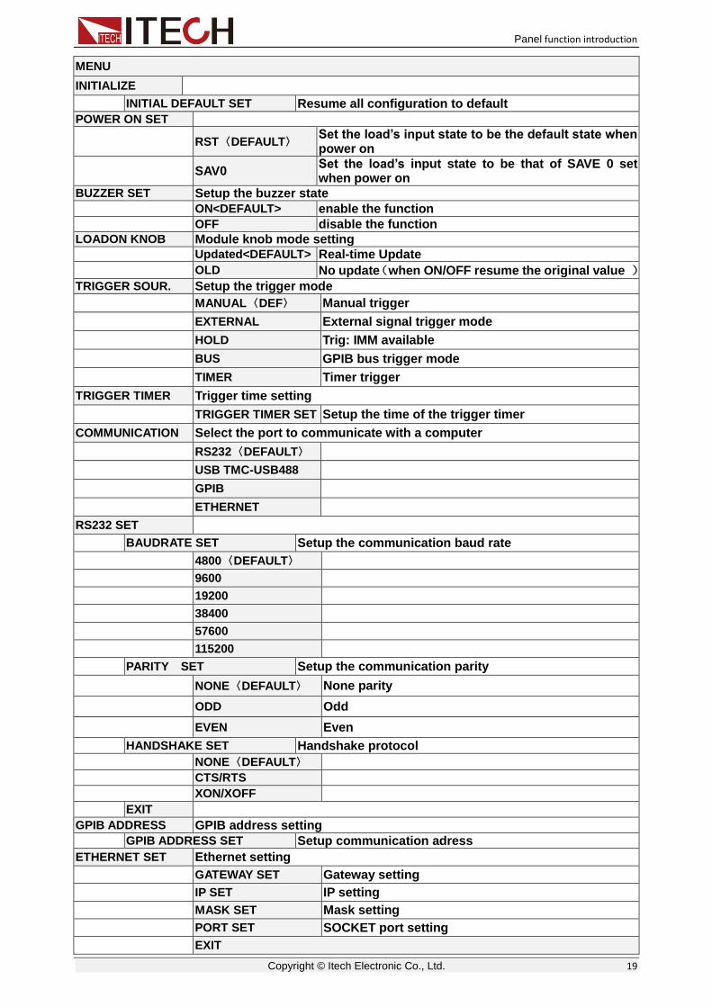
MENU
INITIALIZE
INITIAL DEFAULT SET Resume all configuration to default
POWER ON SET
RST〈DEFAULT〉 Set the load’s input state to be the default state when power on
SAV0 Set the load’s input state to be that of SAVE 0 set when power on
BUZZER SET Setup the buzzer state
ON<DEFAULT> enable the function
OFF disable the function
LOADON KNOB Module knob mode setting Updated<DEFAULT> Real-time Update
OLD No update(when ON/OFF resume the original value )
TRIGGER SOUR. Setup the trigger mode
MANUAL〈DEF〉 Manual trigger
EXTERNAL External signal trigger mode
HOLD Trig: IMM available
BUS GPIB bus trigger mode
TIMER Timer trigger
TRIGGER TIMER Trigger time setting
TRIGGER TIMER SET Setup the time of the trigger timer
COMMUNICATION Select the port to communicate with a computer
RS232〈DEFAULT〉
USB TMC-USB488
GPIB
ETHERNET
RS232 SET
BAUDRATE SET Setup the communication baud rate
4800〈DEFAULT〉
9600
19200
38400
57600
115200
PARITY SET Setup the communication parity
NONE〈DEFAULT〉 None parity
ODD Odd
EVEN Even
HANDSHAKE SET Handshake protocol
NONE〈DEFAULT〉
CTS/RTS
XON/XOFF
EXIT
GPIB ADDRESS GPIB address setting
GPIB ADDRESS SET Setup communication adress
ETHERNET SET Ethernet setting
GATEWAY SET Gateway setting
IP SET IP setting
MASK SET Mask setting
PORT SET SOCKET port setting
EXIT

Panel function introduction
Copyright © Itech Electronic Co., Ltd. 20
EAPAND MODULE
ON Enable this function
OFF<DEFAULT> Disable this function
LANGUAGE SET Production protocol
SCPI〈DEFAULT〉 SCPI protocol
EXTEND TABLE Expand SCPI protocol, compatible with others
ABOUT Main module production information
IT8700 Main frame production model number
VER: X.XX Main frame software version
SN: XXXXXXXXXXXXX Main frame production serial number
EXIT
Automatic test menu
Press + key to enter the menu function.
PROGRAM
RUN PROGRAM Run the testing flie
RECALL PROG Recall the testing file
EDIT PROGRAM Edit the testing file
EXIT
3.1.3 Channel option IT8701 and IT8702 can switch the channel. There’re 3 ways to switch channel:
+number key to switch channel.
Press / key to switch.
When in SETUP menu, you can directly press the number keys to switch.
3.1.4 Save and recall First select the channel to be edited at the main frame front panel, after having
edited, press key to save, press 1 numeric key to save to the first group
in location 1. Press key to recall, and then press key 1 to recall the file saved earlier
3.1.5 Configuration menu introduction Details on each channel menu function. For example, if you don’t want the 3 channel to work with other channels synchronously, you can switch to channel
3 on the main frame, press + key to enter module configuration menu,
VFD views <SYNC ON SET> ,press key to enter, setup OFF state. In
the same method to setup other functions in the configuration menu.
3.1.6 Module keyboard lock
Press + key to lock the Short、Tran、Mode、On/Off operation keyboard
and knobs of the current channel panel, press + key again to unlock.
ShiftShift 66
ChanChan
ChanChan ▼▼
SaveSave
RecallRecall
ShiftShift 55
EnterEnter
Shift 88
ShiftShift 88

Panel function introduction
Copyright © Itech Electronic Co., Ltd. 21
3.2 Module operation IT8700 modules have 2 kinds input: one is single input module and the other is dual-input module. There are 6 keys and a knob on the front panel for each module. Below are the detail introduction of module panel keys and functions.
3.2.1 Single channel module panel
Fig 3-2 single channel module panel
1. Module’s panel view:high-brightness VFD display show module ‘s
working mode.
2. Module’s panel keyboard:
Button Description
Switch A/B transient preset value
Realize short testing, allows the load to simulate a short-circuit at the input
Switch the work mode
Move the cursor position. Press key to move the cursor to the position you want to edit, and then use the rotary knob to adjust value.
Select the transient mode, press key first to enable transient mode before running A/B transient operation, and then send the triggering signal to run program.
Control module’s input state: on/off
Rotary knob, used to change the setting parameter values
3. Module’s air inlet
3.2.2 Dual channel module panel Dual channel module means a module have two channels. Each channel is isolated with the other. Setting of the module keyboard can control two channels. The left cannel is channel L, the right channel is channel R.
A/B
Short Tran
Mode On/Off
IT8711 Electronic load
0-80V/40A/200W
1
2
3
A/BA/B
ShortShort TranTran
ModeMode On/OffOn/Off
IT8711 Electronic load
0-80V/40A/200W
1
2
3
A/BA/B
ShortShort
ModeMode
TranTran TranTran
On/OffOn/Off

Panel function introduction
Copyright © Itech Electronic Co., Ltd. 22
Fig 3-3 dual-channel module front panel
1. Module’s panel view:highlight VFD which display the working state,
upper display voltage and current information for channel L; lower displays information for channel R.
2. Module’s panel keyboard:
Button Description
Switch the left/right channels.
Realize short testing, allows the load to simulate a short-circuit at the input
Switch work mode
Move the cursor position. Press key to move the cursor to the position you want to edit, and then use the rotary knob to adjust value.
Select the transient mode, press key first to enable transient mode before running A/B transient program, and then send trigger signal to run the program
Control module’s input state: on/off
Rotary knob, used to change the setting parameter values
3. Module’s air inlet
3.3 VFD indicator function description The detailed introduction of VFD’s all indicator functions are as bellow:
ShortShort
ModeMode
TranTran TranTran
On/OffOn/Off
L/R L/R
Short Short Tran Tran
Mode Mode On/Off On/Off
①
②
③

Panel function introduction
Copyright © Itech Electronic Co., Ltd. 23
3-4 load module VFD panel
1. L/R is the indicator of dual channel module’s left/right channel, if you want to edit left/right channel parameters, first select the cannel, L is the left channel; R is the right channel. Single channel module will always display R.
2. OFF indicates that the module input is off, when enable the module input, OFF will turn off.
3. CC, CV, CR and CW are module’s 4 work modes.
4. VFD display screen has 4 lines of number show, the first line shows the current actual voltage value, the second line shows the actual current value, the third line shows the actual circuit’s power value, the fourth line shows the setup value, users can set A/V/Ω/W value.
5. Short is lit up, when the module enables short-circuit function.
6. TRAN is lit up, when the module enables transient mode.
7. LIST is lit up, when select the LIST mode at the configuration.
8. SENSE is enabled in remote meter function.
3.4 8-pin control connector IT8700 electronic load 8-pin connector on rear panel(figure 3-5):
Figure 3-5 IT8700 rear panel 8-pin control connector (take example of IT8702)
1 Trigger IN trigger signal input
2 Trigger OUT trigger signal output
3 ON/OFF IN synchronization ON/OFF control signal input
4 ON/OFF OUT synchronization ON/OFF signal output
5 NC -
6 NC -
7 GND Ground
8 GND Ground
4
3
2
5
6
8
7
1
44
33
22
55
66
88
77
111111111
4
3
2
5
6
8
7
44
33
22
55
66
88
77
44
33
22
55
66
88
77
44
33
2
55
66
88
77
4
3
2
5
6
8
7
1
44
33
22
55
66
88
77
11
44
33
22
55
66
88
77
11
44
33
22
55
66
88
77
1111111111
44
33
22
55
66
88
77
44
33
22
55
66
88
77
44
33
22
55
66
88
77
44
33
2
55
66
88
77
端子介绍
2
Terminal introduction

Panel function introduction
Copyright © Itech Electronic Co., Ltd. 24
3.4.1 External trigger connections There’re five kinds of trigger mode:
front panel TRIG trigger mode
rear panel trigger mode
BUS trigger mode
Timer trigger mode
trigger HOLD mode
Front panel TRIG trigger mode
When select front panel trigger mode, first set the trigger source as MANUAL,
press to start panel trigger mode.
Rear panel trigger mode
When select rear panel trigger mode, first set the trigger source as EXTERNAL, trigger signal input from the 1st pin of 8-pin terminal on the rear panel.
When select external trigger mode, the 1st and 8th send out trigger signal (low pulse is effective), e.g. refer to the below connection figure:
The figure just show one way to produce trigger signal. When press the button, it produce a trigger to change setting value (voltage, current, resistance, etc.), e.g. switch in transient mode, or create pulse in dynamic pulse mode. At the same time, it can output trigger signal in pin 2.
BUS trigger mode
When select bus trigger mode, first set the trigger source as BUS, connect the electronic load by GPIB or USB or GPIB communication interface, then if get the *TRG command, the load will produce a trigger signal.
Timer trigger mode
When select timer trigger mode, first set the trigger source as TIMER, set the TIGGER TIMER's time, the load will produce a signal from time to time.
Trigger HOLD mode
When select hold trigger mode, first set trigger source as HOLD, the load will produce signal when get the TREG: IMM command.
NOTE
Pin 2 will output corresponding trigger signal whatever trigger mode you choose.
3.4.2 External ON/OFF control connection
Figure 3-6
ON/OFF IN is used to control the multi-channel to take load or unload synchronously. When ON/OFF IN pin receives a low pulse, ON/OFF state of load will reverse. If SYNC ON SET of a specific channel is set ON, then you can use figure 3-6 connection to control its ON/OFF state.
ON/OFF OUT indicates ON/OFF state of multi channels electronic load. If SYNC ON SET of any specific channel is set on, and the channel’s input state
TrigTrig
1 8 1 1 1 8 3

Panel function introduction
Copyright © Itech Electronic Co., Ltd. 25
is on, the pin 4 output low level, otherwise it output high level
3.5 Extended frame connections The following section introduces extended function of IT8701 and IT8702 mainframe. Take example of IT8702, the introduction is as follows.
Figure 3-7 Expand interface
This interface can be used to connect extended frame. IT8701 can take up to 12 channels with extended frame and IT8702 can take up to 16 channels with extended frame.
Procedure:
Take example of IT8702, use expanded cable to connect mainframe and expand interface of extended frame. Enable expand function in the menu of
IT8702 mainframe by pressing + , select “Expand module”, choose ON.
Figure 3-8 Expand connections
3.6 Controlling link There is an 8-pin connector on every module’s rear panel. The following will introduce in detail the 8 pins’ specific functions.
ShiftShift 44
Extended mainframe interface
IT8703
IT8702

Panel function introduction
Copyright © Itech Electronic Co., Ltd. 26
Fig 3-9 terminals on single-channel module rear panel
1 GND Ground
2 VF Voltage fault indication terminal
3 DI Digital input terminal
4 DO Digital output terminal
I OUT Current monitoring output
5 SENSE + Voltage remote measuring terminal(+)
6 SENSE - Voltage remote measuring terminal(-)
7 IN+ External analog controlling terminal(+)
8 IN- External analog controlling terminal(-)
3.6.1 Voltage failure indication When the load is under OVP or reverse protection condition, pin 2 VF will output low level signal.
3.6.2 Current monitoring Current monitoring terminal will output 0-10V analog signal to accordingly on behalf of 0 - full range of input current. You can connect an external voltmeter or an oscilloscope to display the input current’s changing.
3.6.3 Digital I/O Digital I/O is the pin 3 and pin 4 shown in Chapter 3.4, only used in remote control. Pin 4 digital output terminal can output TTL high/low level. It is a universal output terminal and can be used in controlling an external instrument, for example, the relay used in power testing. DI is used to detect the external level state.
3.6.4 Remote measurement connection Remote Sensing: SENSE (+) and SENSE (–) are the remote sensing inputs. By eliminating the effect of the inevitable voltage drop in the load leads, remote sensing provides greater accuracy by allowing the load to regulate directly at the source's output terminals.
When load is at CV、CV or CR mode, lead length are relatively long or load
regulation is critical, or load consumes high-current, there will be voltage drop

Panel function introduction
Copyright © Itech Electronic Co., Ltd. 27
in the leads connected between load and measured object which affect the accuracy of measurement, then the sense connection can be applied. Fig 3-10 illustrates a typical connection between module and device for remote sense operation.
Take single channel module for example, there’re two input connectors. One is load input measurement terminal; the other is Vsense measurement terminal. You should enable the remote sense function in the configure menu and then connect the remote sense lines. The front panel of the module shows “sense”.
NOTE
The electric potential on the positive terminal of Vsense connector must be higher than negative one.
Figure 3-10 Remote sense connection
3.6.5 External analogue control You can control the voltage and current setting of the electronic load by the analogue terminals: pin 7 and pin 8. 0-10V adjustable analogue simulate the
0-fullscale to regulate the input voltage and current of the electronic load(10V
indicate the full range of load voltage or current value)
3.7 Load connection Before connect object to be measured to load, please remove the cover on the output terminals of the load, and cover it after finishing the connection. Connect the wiring to the positive/negative terminal on the rear panel of the module. Please pay attention to the size, length and polarity when wiring. Please avoid using wires of minimum specification of anti superheating which cannot supply good load regulation. Generally speaking, if the wires are short enough, they can control voltage drop less than 0.5V. In addition, bonding them together can reduce induction and noise. Please lead wire from positive terminal on the rear panel of module to positive terminal of object. Similarly, connect the corresponding negative terminal. Figure 3-11 illustrates a typical connection of the module with the device to be measured.
+ -
待测物
++ --
待测物
+ -
待测物
++ --
待测物
++ --
待测物
++ --
Object
+ -
待测物
++ --
待测物
++ --
待测物
++ --
待测物
++ --
待测物
++ --
待测物
++ --
待测物
++ --
Object

Panel function introduction
Copyright © Itech Electronic Co., Ltd. 28
Figure 3-11 connection of load and object
There’re two positive terminals and two negative terminals on the rear panel of every module. Single terminal connection is adequate when the input current is less than 30A.
NOTE
For safety requirements, load wires between the electronic load and the object to be measured should be heavy enough not to overheat while carrying the short-circuit output current. To prevent shock hazard, you must install the terminal cover correctly after wiring. Each terminal can carry up to 30A current, double-terminal connection is needed when the input current if more than 30A. (Double-terminal connection refers to the above picture.)
3.8 Parallel connections Parallel connection can be applied between same model modules to increase current and power dissipation, but it can’t be applied between different modules. Modules can be paralleled in CC/CR mode, but can’t be in CV mode. Each module will dissipate the power it has been programmed for. For example, after being paralleled, two single channel modules (80V/40A/300W) can dissipate up to 80V/80A/600W. The following picture 3-12 illustrates the paralleled connection of two same models for increased power dissipation.
fig 3-12 module parallel connection
+ -
待测物
++ --
待测物
+ -
待测物
++ --
待测物
++ --
待测物
++ --
Object
+ -
待测物
++ --
待测物
++ --
待测物
++ --
待测物
++ --
待测物
++ --
待测物
++ --
待测物
++ --
Object

Operations introduction
Copyright © Itech Electronic Co., Ltd. 29
Chapter4 Operations introduction
This chapter will mainly introduce IT8700’s menu operation function.
4.1 Local/remote operation The front panel has keyboard controls for setting voltage, current, resistance and power. Local operation means control the electronic load via the keys on the front panel and the menu operation. Remote operation means control the
electronic load through computer via the GPIB、RS232、USB or Ethernet
interface. You can press + key to switch into local control.
4.2 PC control connection IT8700 series electronic load can achieve remote control via GPIB /RS232 /USB /ETHERNET, but only one interface can be used at one time. choose the
interface via the system key(SYSTEM). Connect Communication cable before
power on. Do not support hot plug, as it may damage communication interface of electronic load. The following picture shows how to connect RS232 cable between electronic load and PC and show the specific configuration.
Procedure:
1. Connect RS232 cable.
2. Power on the electronic load
3. Select channel number via key, such as channel1
4. Enter system menu via + key, use to choose
<communication>, press key to enter, use key to choose
RS232, press key to confirm.
RS232 USB TMC-USB488 GPIB ETHERNET
5. Now Display return to main menu, use key to choose <RS232>
menu, press key to enter. First set <Baudrate Set>, use +
key to choose and enter;use key to choose<Parity Set>,use
+ key to choose <none> and confirm;Use key to
choose<Handshake Set>, use + key to choose<None> and confirm.
BAUDRATE SET PARITY SET HANDSHAKE SET EXIT
Note: means to press this key to choose.
4.3 Operating modes The electronic load can work in the following 4 modes:
ShiftShift 77
▼▼
ShiftShift 44 ▼▼
EnterEnter ▼▼
EnterEnter
▼▼
EnterEnter ▼▼
EnterEnter ▼▼
▼▼ EnterEnter ▼▼
▼▼ EnterEnter
▼▼

Operations introduction
Copyright © Itech Electronic Co., Ltd. 30
Constant current operation mode (CC)
Constant voltage operation mode (CV)
Constant resistance operation mode (CR)
Constant power operation mode (CW)
4.3.1 Constant current (CC) mode In this mode, the electronic load will sink a current in accordance with the programmed value regardless of the input voltage. See figure 4-1.
Fig 4-1 CC mode
Ranges
When work in CC mode, you can press key to enter the menu, when it show RANGE, you can select either of the two overlapping ranges: <LOW RANGE> or <HIGH RANGE>. Current can be edited in either of the two ranges. Low range will supply higher accuracy and better resolution when you set lower current. If any value you set is outside the maximum value of the LOW RANGE, you should select HIGH RANGE. If the electronic load work in remote control
mode(USB / RS232 / GPIB / Ether-net), you can use CURR:RANG command
to switch current range.
Immediate Current value
Set the current level via front panel or sending command (CURR <n>), if the load is in CC mode, the new setting current level immediately changes the input at a rate determined by the slew rate. If the load is not in CC mode, the setting current level will be saved for use, until switch to CC mode.
Triggered current level
This function only can be used in remote control mode, when the load is in the CC mode, after receive the CURR:TRIG <NRF+> command, subsequent triggers will have no effect on the input unless another triggering signal is sent. CURR command will cover the CURR:TRIG <NRF+> value, this function is used to synchronize Multi-channel input load changes.
Transient current level
Set A/B transient current level on front panel or by remote operation, the load can continuously toggle between the two levels when transient operation is turned on.
Set slew rate
The current slew rate determines the rate at which the input current to a module changes to a new programmed value. You can set current level’s rise/fall slew rate on the front panel or by remote operation. The slew rate programmed act in
LOAD
CURRENT
LOAD INPUT
VOLTAGE
I
V
CURRENT
SETTING
CONSTANTCURRENT MODE
SetupSetup

Operations introduction
Copyright © Itech Electronic Co., Ltd. 31
effect to the immediate, triggered and transient current level changes.
4.3.2 Constant resistance (CR) mode In this mode, the electronic load was equivalent to a constant resistance, as shown below; the electronic load will linearly change the current according to the input voltage. See figure 4-2.
Fig 4-2 CR mode
Ranges
You can select the lower or higher range for CR mode too. When it shows RANGE, you can select either of the two overlapping ranges: <LOW RANGE> or <HIGH RANGE>. Resistance can be edited in either of the two ranges. Low range will supply higher accuracy and better resolution when you set lower resistance. If any value you set is outside the maximum value of the LOW RANGE, you should select HIGH RANGE. If the electronic load work in remote
control mode(USB / RS232 / GPIB / Ether-net), you can use RES:RANG
command to resistance range.
Immediate resistance level
Set the resistance level via front panel or sending command (RES <n>), if the load is in CR mode, the new setting resistance level immediately changes the input at a rate determined by the slew rate. If the load is not in CR mode, the setting resistance level will be saved for use, until switch to CR mode.
Triggered voltage level
This function only can be used in remote control mode, when the load is in the CR mode, after receive the RES:TRIG <NRF+> command, subsequent triggers will have no effect on the input unless another triggering signal is sent. RES command will cover the RES:TRIG <NRF+> value, this function is used to synchronize Multi-channel input load changes.
Transient resistance level
Set A/B transient resistance level on front panel or by remote operation, the load can continuously toggle between the two levels when transient operation is turned on.
4.3.3 Constant voltage (CV) mode In this mode, the electronic load will attempt to sink enough current to control the source voltage to the programmed value. See figure 4-3.
LOAD
CURRENT
LOAD INPUT
VOLTAGE
I
V
SLOPE
RESISTANCE
SETTING
CONSTANT RESISTANCE MODE

Operations introduction
Copyright © Itech Electronic Co., Ltd. 32
Fig 4-3 CV mode
Ranges
You can select the lower or higher range for CV mode too. Voltage can be edited in either of the two ranges. Low range will supply higher accuracy and better resolution when you set lower range. If any value you set is outside the maximum value of the low range, you should select high range. If the electronic
load work in remote control mode(USB / RS232 / GPIB / Ether-net), you can
use VOLT:RANG command to voltage range.
Voltage level
Set the voltage level on front panel or by sending SCPI command(VOLT <n),
if the load is in CV mode, the new setting immediately changes the input at a rate determined by the voltage slew rate. If the load is not in CV mode, the set voltage level will be saved in the instrument for use, until switch to CV mode.
Triggered voltage level
This function only can be used in remote control mode, when the load is in the CV mode, after receive the VOLT:TRIG <NRF+> command, subsequent triggers will have no effect on the input unless another triggering signal is sent. VOLT command will cover the VOLT:TRIG <NRF+> value, this function is used to synchronize Multi-channel input load changes.
Transient resistance level
Set A/B transient voltage level on front panel or by remote operation, the load can continuously toggle between the two levels when transient operation is turned on.
4.3.4 Constant power (CW) mode In CW mode, electronic load will consume a constant power. As shown in fig4-4, when input voltage increase, the input current will decrease, while power will remain the same. P=(V*I).
LOAD CURRENT
LOAD INPUT
VOLTAGE
I
V
VOLT
SETTING
CONSTANT VOLTAGE MODE

Operations introduction
Copyright © Itech Electronic Co., Ltd. 33
Ranges
You can select the lower or higher range for CW mode too. Power can be edited in either of the two ranges. Low range will supply higher accuracy and better resolution when you set lower power. Any value you set is outside the maximum value of the LOW RANGE, you should select HIGH RANGE.
Immediate power level
You could set the power level via front panel. If the load is in CW mode, the new setting power level immediately changes the input at a rate determined by the slew rate. If the load is not in CW mode, the setting power level will be saved for use until switch to CR mode.
Transient power level
Set A/B transient power level on front panel or by remote operation, the load can continuously toggle between the two levels when transient operation is turned on.
4.3.5 Operations The following will show you how to set operation mode on front panel. Take CC mode as an example:
1. Power on the electronic load
2. Press or keys to select the channel to be edited, such as channel 1
CH01 CC OFF Vdc=0.0000V Adc=0.0000A Wdc=0.00W
3. Press key to enter the channel setup menu, press key to
enter the mode selection menu <Mode>, press key to select the
mode CC/CV/CR/CW,such as CC,press key to confirm
CH01 Mode=CC RANGE=HIGH Iset=9.000A
4. Press key to enter range selection menu <Range>, press
key to enter the mode selection menu <Mode>, press key to select,
such as <low range>, press key to confirm.
CH01
▲▲ ▼▼
SetupSetup Enter
▼▼
Enter
▼▼ Enter
▼▼
Enter
Fig4-4

Operations introduction
Copyright © Itech Electronic Co., Ltd. 34
>High Range Low Range
5. Press key to enter the current setting <Iset>, such as set the current
to be 1.25A,press key to confirm. If any error, press Esc to back.
CH01 Const Current Set= 1.25A Enter Esc
6. Press key to enter the maximum voltage value setting, press . Press numeric key to set the maximum voltage value. CH01 Voltage Upper Limit=82.000V
Enter Esc
7. Press key to enter the minimum voltage value setting, press . Press numeric key to set the minimum voltage value. CH01 Voltage Lower Limit=0.000V
Enter Esc
8. Press key to enter the rise slope setting, such as set the rise slope
to be 1A/uS. Press key to confirm
CH01 Rise Speed Set = 1.00A/Us Enter Esc
9. Press key to enter the fall slope setting, such as set the fall slope
to be 2A/uS. Press key to confirm
CH01 Fall Speed Set = 2.00A/Us Enter Esc
10. Press key to exit
11. Press to open the load’s input
CH1 CC ON Vdc=0.0000V Adc=0.0000A Wdc=0.00W
4.4 Transient operation Transient operation enables the module to periodically switch between two load levels, as might be required for testing power supplies. Transient operation can
be turned on and off at the front panel ( and keys), before you turn on the operation, you should set the parameters associated with transient
operation ( ). The parameters include: A level, A width, B level, B width, and transient testing modes.
The transient testing modes have 3 kinds: continuous, pulsed, or toggled.
Continuous: Generates a respective pulse stream the toggles between two load levels
Pulse: Generates a load change that returns to its original state after some
▼▼
Enter
▼▼ Enter
▼▼ Enter
▼▼
Enter
▼▼
Enter
EscEsc
On/OffOn/Off
TranTran TrigTrig
SetupSetup

Operations introduction
Copyright © Itech Electronic Co., Ltd. 35
time period
Toggled: Generates a repetitive pulse stream that toggles between two load levels. Similar to continuous mode except that the transient points are controlled by explicit triggers instead of an internal transient generator.
4.4.1 Continuous In CC mode, transient testing can be used to check the stability of the source voltage. Transient function has two current levels (A level, B level), which should be in the same range (high range or low range). You can set the A/B level delay time and the rise/fall slew via the main frame keyboard. The slew
rate determines the rate which the level changes at. Press key, the load will continuously switch between the A/B levels preset. Transient load are usually used to test the power supply’s performance under load continuous changing conditions. Figure 4-6 shows the current waveform of continuous transient operation mode.
Fig 4-6 continuous transient operation current waveform
4.4.2 Pulsed In pulsed mode, you can set A/B value via mainframe keyboard or remote control. A/B rise/fall rate and delay time should be the same. The electronic load will automatically switch to A level, after maintaining A width time, switch to B level, it won’t switch to A level until the instrument receive the pulse signal. The following picture shows the current waveform in pulse transient operation.
Fig 4-7 pulsed mode current waveform
4.4.3 Toggled In toggle mode, the electronic load will switch between A level and B level when receiving a triggering signal after the transient operation is enabled. The following picture shows the current waveform in toggle transient operation.
TrigTrig
10A
2A
Continuous Transient Operation
3.0ms 2.0ms
A
B
“A/B”A B
10A
2A
Continuous Transient Operation
3.0ms 2.0ms
A
B
“A/B”A B
10A
2A
Continuous Transient Operation
3.0ms 2.0ms
A
B
“A/B”A B
10A
2A
Continuous Transient Operation
3.0ms 2.0ms
A
B
“A/B”A B
10A
5A
Pulsed Transient Operation
10msTWD
10msTWD
TRIG TRIG
10A
5A
Pulsed Transient Operation
10msTWD
10msTWD
TRIG TRIG

Operations introduction
Copyright © Itech Electronic Co., Ltd. 36
Fig 4-8 toggled mode current waveform
4.4.4 A/B transient operations The following will show you how to set operation mode on front panel. Take CC mode as an example:
1. Power on the electronic load
2. Press 、 keys to select the channel to be edited, such as
channel 1
CH01 CC OFF Vdc=0.0000V Adc=0.0000A Wdc=0.00W
3. Press key to enter the channel setup menu, press key to
enter the mode selection menu <Mode>, press key to select the
mode CC/CV/CR/CW,such as CC,press key to confirm
CH01 Mode=CC RANGE=HIGH Iset=9.000A
4. Press key to enter range setting <Range>, press key to
enter the mode selection menu <Mode>, press key to select, such
as <low range>, press key to confirm.
CH01 High Range Low Range
5. Press key to enter the rise slope <∫>, such as set the current to be
1A/uS,press key to confirm
CH01 Rise Speed Set = 1.00A/Us
6. Press key to enter the fall slope setting <∫>, such as set the rise
slope to be 2A/uS. Press key to confirm
CH01 Fall Speed Set = 2.00A/Us
7. Press key to enter A LEVEL setting <TRANa>,such as 10.00A,
press key to confirm
Transition A Level = 10.00A
10A
5A
TRG TRG
Toggled Transient Operation
10A
5A
TRG TRG
Toggled Transient Operation
▲▲ ▼▼
SetupSetup Enter
▼▼
Enter
▼▼ Enter
▼▼
Enter
▼▼
Enter
▼▼
Enter
▼▼
Enter

Operations introduction
Copyright © Itech Electronic Co., Ltd. 37
8. Press key to enter A level width setting <Ta>,such as 0.003S,
press key to confirm
Tran A Width 0.003S
9. Press key to enter B level setting <TRANb>,such as 2.00A,press
key to confirm
Transition B
Level = 2.00A
10. Press key to enter B level width setting <Tb>,such as 0.002S,
press key to confirm
Tran. B Width=
0.002S
11. Press key to set transient operation mode <Tmode>,such as
continuous mode, press key to confirm
CH01 >Continuous Pulse
Toggle
12. Press key to exit
13. Press + keys to enter system menu function, press key
to select <Trigger source>,such as select <Manual> on the front panel,
press key to confirm
Manual External Hold Bus
Timer
14. press key to confirm
15. Press to open the load’s input
16. Press to enable transient operation
17. Press key to trigger
If in the remote control mode(USB / RS232 / GPIB / Ether-net),you can refer
to the following example to edit transient operation(refer to IT8700 programming guide to get more).
CURRent:TRANsient:MODE CONTinous
CURRent:TRANsient:ALEVel 5
CURRent:TRANsient:AWIDth 0.6mS
CURRent:TRANsent:BLEVel 10
CURRent:TRANsient:BWIDth 0.7mS
TRANsient ON
TRIGger:IMMediate
4.5 List operation List mode lets you generate complex sequences of input changes with rapid, precise timing, which may be synchronized with internal or external signals.
▼▼
Enter
▼▼
Enter
▼▼
Enter
▼▼
Enter
EscEsc
Shift 44 ▼▼
Enter
EscEsc
On/OffOn/Off
TranTran
TrigTrig

Operations introduction
Copyright © Itech Electronic Co., Ltd. 38
This is useful when running test sequences with a minimum amount of overhead.
Generate complex sequences to complete complex tests by editing LIST: Select different trigger resource, editing the step value, width time and slew rate of every step. The parameters of List operation include the name, number of steps (2-84 for all the modules), single step width time (0.000020s~3600s for all the modules) and every step’s set value and slew rate. The list file can be saved in non-volatile memory, used to fast recall. And the modules can edit up to 7 groups list files
In list operation mode, the load begin to enable the list operation once receive the trigger signal, until the list operation is completed or the instrument receive another trigger signal.
Fig 4-9 List mode current waveform
LIST operation mode
The following will show you how to set operation mode on front panel. Take IT8732 as an example:
1. Power on the electronic load
2. Press 、 keys to select the channel to be edited, such as
channel 1
CH01 CC OFF Vdc=0.0000V Adc=0.0000A Wdc=0.00W
3. Press + (System) keys to enter system menu function, press
key to select <Trigger Source>, such as select <Manual>on the
front panel, press key to confirm
Manual External Hold Bus Timer
4. Press to close the load’s input
5. Press +5,press key to select <list>, press key to
confirm, press key to select List<Edit list>, press key to confirm
Function Mode Recall List Edit List
Trigger
10 2 3 4 5
List count=1 List count=2
List sequence
▲▲ ▼▼
Shift 44
▼▼
Enter
On/OffOn/Off
ShiftShift ▼▼ Enter
▼▼ Enter

Operations introduction
Copyright © Itech Electronic Co., Ltd. 39
6. Select high/low ranges, such as low range, press to confirm
High range Low range
7. Select Lists steps,such as 5 steps,press to confirm
List file step = 5
8. Set the first step’s current, such as 1A, press key to confirm
Step 001 level = 1A
9. Set the first step’s rise slew rate, such as 1A/uS press key to confirm
Step 001 rate = 1A/uS
10. Set the first step’s time, such as 6S. press key to confirm
Step 001 width = 6S
11. Set the second step’s current, such as 0A. press key to confirm
Step 002 level = 0A
12. Set the second step’s rise slew rate, such as 1A/uS. Press to confirm
Step 002 rate = 1A/uS
13. Set the second step’s time, such as 5S. press to confirm
Step 002 width=5S 14. Set the 3rd to 5th steps in same procedure as 0.5A/ 1A/us /4S, 0A/ 1A/us
/2S, 2A/ 1A/us /3S.
15. Select repeat running times, such as 1, press to confirm
Repeat count= 1
16. Select the position to save file, such as 1, press to confirm
CH01 Save list file = 1
17. Press key to select <function mode>, press key to confirm,
press key to select <list>,press to confirm
Fixed List
18. Press to exit
19. Press ,open the load’s input
20. Press to trigger
If in the remote control mode(USB / RS232 / GPIB / Ether-net),you can refer
to the following example to edit list operation (refer to IT8700 programming guide to get more).
LIST:MODE CURRent
LIST:RANGe 40
LIST:COUNT 10000
LIST:STEP 4
Enter
Enter
Enter
Enter
Enter
Enter
Enter
Enter
Enter
Enter
▲▲ Enter
▲▲ Enter
EscEsc
On/OffOn/Off
TrigTrig

Operations introduction
Copyright © Itech Electronic Co., Ltd. 40
LIST:LEVEL 1,5
LIST:SLEW 1,2
LIST:WIDTH 1,1
LIST:LEVEL 2,1
LIST:SLEW 2,2
LIST:WIDTH 2,2
FUNCTION:MODE LIST
TRIGger:IMMidiate
4.6 Triggered operation
4.6.1 Trigger function Trigger operation can be used in the following operations: transient pulse output, triggered output and list output. The electronic load have 5 kinds of trigger modes to Synchronously trigger the tested instrument, before enable the trigger function, users should first select trigger source.
4.6.2 Trigger source Keyboard ( key) trigger:when the keyboard trigger mode is active,
press ,will enable a trigger operation.
External trigger signal(TTL level):the 1st pin of the 8 pins connector on the
rear panel of the main frame is trigger input terminal, when external trigger signal is available, input a low pulse(>10uS) to the internal, the load will enable a trigger operation.
Bus trigger: when bus trigger is available, as soon as the load receive a trigger command (*TRG) from the communication port, the load will enable a trigger operation.
Timer trigger: when timer trigger is available, the main frame will enable a trigger operation periodically.
Trigger maintenance: when trigger maintenance is available, only when the load receive the trigger command (TRIG:IMM) from the communication port, the load will enable a trigger operation.
4.7 Short operation The load can simulate a short circuit at its input. During front panel operation,
you can press key to switch short on/off states. Short operation won’t affect the present setting. When turn off the short state, the load returns to the original set state.
The actual value of the electronic in short operation depends on the mode and range active when the short is turned on. In CC, CR mode, the maximum short current is 120% of the current range. In CV mode, short means setting the load’s constant voltage to be 0V.
When in remote control mode(USB / RS232 / GPIB / Ether-net), you can send
SCPI command INPut:SHORt ON to enable the short operation
4.8 Input on/off operation In front panel operation conditions, press key to switch to on/off state.
TrigTrig
TrigTrig
ShortShort
On/OffOn/Off

Operations introduction
Copyright © Itech Electronic Co., Ltd. 41
Input on/off operation won’t affect the present settings. The load/unload speed of On/off operation is not dependent on the rise/fall slew rate.
When in the remote control mode(USB / RS232 / GPIB / Ether-net), you can
send SCPI command INPut ON to open input.
4.9 Synchronous load To any channels, press + key to enter configuration menu, set
SYNC ON SET to be ON. When turn on this function, key can control the input state of the correspondent module synchronously.
When in remote control mode(USB / RS232 / GPIB / Ether-net), you can send
SCPI command INPut:ALL ON to synchronously load all channels.
4.10 Von operation You can set voltage value Von/Voff to control the input state on/off for electronic load. When the input voltage reaches the Von value, the load’s input state is on. When the input voltage reaches the Voff value, the load’s input state is off.
This function can protect the power supply when the rise/fall speed of it is very low. For example, when you test a power supply’s discharging, you can set the start discharge voltage and the end discharge voltage of the power supply.
IT8700 series electronic loads offer Von loading voltage and Von loading mode.
When disable Von LATCH, voltage rise and is higher than the Von loading voltage, input of electronic load is turned on. When the power supply’s voltage fall and is lower than Von unload value, input is turned off.
Fig 4-10 VON LATCH load’s working range
When enable Von LATCH, voltage rise and is higher than the Von loading voltage, input of electronic load is turned on. When the power supply’s voltage fall and is lower than Von unload value, input won’t be turned off.
Shift Config
On/OffOn/Off

Operations introduction
Copyright © Itech Electronic Co., Ltd. 42
Fig 4-11 VON LATCH load’s working range
Von function panel operations
1. Power on the electronic load
2. Select a channel, such as channel 1
CH01 CC OFF Vdc=0.0000V Adc=0.0000A Wdc=0.00W
3. Press + to enter configuration menu
Sync On Set Von Average Count
4. Press to select <Von>, press to enter. First set <Von point>,
press key to enter, input the programmed value, such as 1V, press
key to confirm
Von point Von Latch Exit
5. Press to select <Von Latch>, press key to enter, select
Latch to enable on/off state, such as On, press key to confirm
6. Press key to exit
7. Open the load’s input
When in remote control mode (USB / RS232 / GPIB / Ether-net),you can send
SCPI command VOLT:ON <n> to set Von value; send VOLT:LATch ON to enable Von LATCH function.
ShiftShift 55
▼▼ EnterEnter
EnterEnter
EnterEnter
▼▼ EnterEnter
EnterEnter
EscEsc

Operations introduction
Copyright © Itech Electronic Co., Ltd. 43
4.11 Protection functions Load has the following protection functions: over voltage protection(OVP),over
current protection(OCP), over power protection(OPP), over temperature
protection(OTP), reverse voltage protection(LRV/RRV).
The mainframe will act appropriately once any of the above protection is active. You can press any button on front panel to restore the protection function. For example, the electronic load come into over temperature protection, the buzzer will alarm, the input will automatically shut down and Main frame VFD will display OTP.
4.11.1 Over voltage protection (OVP) If the OVP circuit has triggered, buzzer alarm, the main frame screen will displays (OVP), the condition will remain until they are reset.
Operations to clear the OVP state:
Check whether the input voltage is in the load’s rated voltage or the programmed protecting voltage ranges. If it is outside of the range, please disconnect the instrument under test. Press any key on the front panel (or send commandPROTection:CLEar), the (OVP) displayed on the front panel will disappear, load exits OVP protection state.
4.11.2 Over current protection (OCP) The electronic load includes both hardware and software over current protection features.
Hardware OVP: load’s maximum input current will be limited at about 110% of the current range, once the hardware OCP is triggered, the status register’s OC bit will be set; when the hardware OCP is removed, the status register’s OC bit will be reset. Hardware over current protection won’t affect load’s on/off state.
Software OCP: users can set load’s software OCP value, steps: +
>Protect>Alimit set ON, Apoint set OCP current value, Adelay set delay time before alarm. When the software OCP function is active, if the load current value is over the over current protection set value, load will automatically off, VFD displays OCP. At the same time, the OC and PS bits in the status register will be set and they will remain until they are reset.
Operations to clear the OCP state:
Check whether the input current is within the load’s rated current or the programmed protecting current ranges, if it is outside the range, please disconnect the instrument under test. Press any key on the front panel (or send commandPROTection:CLEar), the (OVP) displayed on the front panel will disappear, load exits OCP protection state.
4.11.3 Over power protection (OPP) The electronic load includes both hardware and software OPP features.
Hardware OPP: the electronic load allows user to set a power protection limit in hardware which will limit the power in the range you set when the OPP condition occur. Hardware OPP will not change the load ON/OFF state.
Software OPP: users can set load’s software OPP value, steps: Shift+5>Protect>Point set OPP power value, Plimit set alarm delay. If the load power value is OPP delay time, load will automatically turned off, VFD will display OPP. At the same time, the OP and PS bits in the status register
ShiftShift
55

Operations introduction
Copyright © Itech Electronic Co., Ltd. 44
will be set and they will remain until they are reset.
Operations to clear the OPP state:
Check whether the input power is in the rated power range or the programmed protecting ranges. If it is outside the range, please disconnect the instrument under test. Press any key on the front panel (or send commandPROTection:CLEar), the (OPP) displayed on the front panel will disappear, load exits OPP protection state.
4.11.4 Over temperature protection (OTP) When load’s internal circuit temperature is over 85℃, load will enable OTP.
Input will automatically turned off, VFD display OTP. At the same time the OT and PS bits in the status register will be set, they will remain until they are reset.
Operations to clear the OTP state:
when load temperature dropped to the protecting point, press any key on the front panel(or send command PROTection:CLEar), the (OTP) displayed on the front panel will disappear, load exits OTP protection state.
4.11.5 Reverse voltage protection (LRV/RRV) Once in reverse connection condition, input will be immediately turned off, buzzer alarm, status register’s (RV/RRV) and (VF) bits will be set, main frame screen displays (LRV/RRV), they will remain until they are reset.
In this condition, the 8 pins connector’s VF pin will output a low level, which can disconnect the external DUT.
Operations to clear the reverse voltage state:
Check whether the connection is reversed. If so, disconnect the object to be measured.
4.12 Save and recall operation The stored setting of all channels can be recalled, the stored parameters includes working mode, voltage/ current value, slew rate, transient setting and so on. It can save up to 101 groups of setting parameters. The 0th group can be used as boot parameters. The 1st to 100th groups can be used as automatic testing parameters. All the parameters are saved in the nonvolatile memory, won’t lose even in power down state. You can use SAVE key to save parameters, press RECALL key to fast recall.
Save and recall operations
1. After setting the parameters, press key to save, press number 9,
press to confirm
Save Group 0
2. Press key , press , to recall the saved data
Recall Group 0
4.13 Automatic test Automatic test function of IT8700 series electronic load is very powerful, it can simulate various tests. It can edit up to 10 groups of testing files, each file has 10 steps, it can edit up to 100 files which can be saved in EEPROM (address).
SaveSave
EnterEnter
RecallRecall 99

Operations introduction
Copyright © Itech Electronic Co., Ltd. 45
Edit testing files
1. Power on the electronic load
2. Press + key to enter the menu
Run Program Recall Prog Edit Program Exit
3. Press key to move menu to ﹥EDIT PROGRAM to edit testing files
4. Press key to enter the next menu.
Take example of IT8702, IT8702 can be max extended to be 16 channels, 0 represent the number of IT8702 main frame, 1 stands for the number of the extended main frame. □7 □5 □3 □1 indicate 1/3/5/7 channels have been equipped with loads, next to the main frame is channel 1, the others followed are numbered in order. Press numeric keys to select the channel
to be tested, □7□5□3□1changes to □7□Y□Y□1,it stands for 3/5 is selected
to be edited. Press to confirm. Active Channel
0:□□□□□□□□
1:□7 □5 □3 □ 1
5. Select the steps needed to test, if you want to test 4 steps, please press in order 1/2/3/4, 0 stands for the tenth step. If you want to cancel a step,
press again the numeric keys you want to cancel. Press to confirm。
Active SEQ. 0 9 8 7 6 5 Y Y Y Y
6. In the 4 steps, if you want to suspend, e.g. you want to suspend step 2,
press numeric key 2, press to confirm
Pause Sequence □□□□□□ 4 3 Y 1
7. Edit the 1st step of the 4 steps: determine whether need short circuit testing in channel 3 and 5, for example, channel 3 need short circuit testing, press
number 3. press to confirm
SEQ01 Short CH
0:□□□□□□□□
1:□□□ 5□Y □□
8. Set with-load time, if you want to load 2S, press numeric key 2, then press
to confirm
SEQ01 On Time = 2.0 S
9. Set unloading time, if you need 2S, press numeric key 2, then press
to confirm
SEQ01 Off Time = 2.0 S
10. Set testing delay time, e.g. 1S, press numeric key 1. Tpf is testing delay time.
SEQ01 P/F Delay Time = 1.0 S
ShiftShift 66
▼▼
EnterEnter
EnterEnter
EnterEnter
EnterEnter
EnterEnter
EnterEnter
EnterEnter

Operations introduction
Copyright © Itech Electronic Co., Ltd. 46
Tpf is testing delay time
11. Repeat 7)~10),set the rest 3 steps’ loading/unloading time
12. Set the condition when stop testing, COMPLETE mean stop test When all the steps are completed, FAILURE mean stop test when the testing fails.
Press 、 keys to select, such as <complete>, press
key to confirm.
Stop Condition﹥
Complete Failure
13. Whether you need to link to the next file to be tested, if you need to link to group 2, press number key 2, 0 stands for not linking to other files. Press
key to confirm.
Program Chain NO: 1
Program 1 Sequence 1 2 3 4 5 6 7 8 9 10
Save Group 1 2 3 4 5 6 7 8 9 10
Program 2 Sequence 1 2 3 4 5 6 7 8 9 10
Save Group 11 12 13 14 15 16 17 18 19 20
:
:
Program 10 Sequence 1 2 3 4 5 6 7 8 9 10
Save Group 91 92 93 94 95 96 97 98 99 100
14. Save the edited files in EEPROM, you can save up to 10 groups of files,
e.g please press numeric key to save the edited file in group 1, and
then press to confirm.
Save Program NO: 1
15. Press key twice to exit.
16. Select the channel you want to edit, then edit every group’s every step, we
select channel 3 and channel 5 in above, press 、 keys to
switch channels, after selecting channel 3.
17. Press key
﹥Mode =CC
Range=HIGH
▲▲ ▼▼ EnterEnter
EnterEnter
11
EnterEnter
EscEsc
▼▼ ▲▲
SetupSetup

Operations introduction
Copyright © Itech Electronic Co., Ltd. 47
ISet =1.00 A
18. You can edit every step’s mode, ﹥MODE =CC, press key to enter
the menu, press 、 key to select mode, for example, select
﹥Const Current, press to confirm. Press to select range,
for example, RANGE=HIGH, press to enter the menu.
﹥Const Current
Const Voltage Const Resis.
19. Press key, move the cursor to ﹥I SET =1.00 A, press to
enter the menu, set the working current, for example, set 1A, press
numeric key , then press to confirm.
Const Current Set = 1.000A
20. Press to move the cursor to VMAX=82.000V, you need to set the
high limit of testing voltage, press to enter the menu.
In this example, the first step is 5.8V, press 、 、 keys, then
press key to confirm. Voltage Upper
Limit = 5.800V
21. Press key to move the cursor to VMIN=0.000V, you need to set the
low limit of testing voltage, press key to enter the menu.
In this example, the first step is 0.15V, press 、 、 、 keys,
then press key to confirm. After editing the first step of channel 3,
press key to exit. VOLTAGE LOWER
LIMIT = 0.150V
22. Press keys to select channel 5, in order to select the first
step of channel 5, repeat 16)~19)steps, after editing the menu, press
key to exit.
23. Then save the edited first step of channel 3 and channel 5, press and numeric key 1 to save step 1 in the same way, you can edit the rest 3
steps of channel 3 and channel 5. After saving, press to confirm.
SAVE GROUP 0
Recall testing files and Run testing files
The following way can make you fast recall the edited testing files from EEPROM after re-powering.
1. Press + to enter the menu
Run Program Recall Prog Edit Program Exit
EnterEnter
▼▼ ▲▲
EnterEnter ▼▼
EnterEnter
▼▼ EnterEnter
11 EnterEnter
▼▼
EnterEnter
55 .. 88
EnterEnter
▼▼
EnterEnter
00 .. 11 55
EnterEnter
EscEsc
▼▼ ▲▲
EscEsc
Save
EnterEnter
ShiftShift 66

Operations introduction
Copyright © Itech Electronic Co., Ltd. 48
2. Press to move to <RECALL PROGRAM> to recall the saved testing files.
3. Press to move to <Run Program>.
4. Press key to start automatic testing, if you need to pause, press
key, then press key to continue test by one step. press
key to continue the test until the test is finished.
4.14 CR-LED Test Function IT873X, IT8722, IT8723 and IT8722B modules provide CR-LED function, which can simulate the real characteristics of LED light to test LED constant current source. LED light tends to consist of diodes. The break-over voltage of diode and the current ripple of the constant current source make former CR mode which could cause unstable test voltage and current unable to satisfy the test of LED constant current source. The CR-LED function of IT873X, IT8722, IT8723 and IT8722B modules can simulate all characteristics of LED light. You can simulate the break-over voltage value of diode by setting the Vd value to make the test accurate.
Operating steps
1. Power on the electronic load. 2. Select the channel.
3. Press + to enter configuration menu
SYNC ON SET
4. Press key to move to CR-LED. Press key to confirm. ON
OFF(Default)
5. Press key to exit.
6. Press key to enter the setup menu. MODE= CC
7. Press key to enter the mode selection menu <Mode>, press
key to select the mode CR, press key to confirm. Const Current Const Voltage
>Const Resis
8. Press key to move to Rset=7500.0. You need to set the constant resistance. Const Resis Set=7500.0
Enter Esc
9. Press key to move to Vd= 0.000V. Press key to confirm. You need to set the Vd value. CR-LED Vdorp= 0.000V
Enter Esc
10. Press key to exit
▼▼
▼▼
StartStart
PausePause ▼▼
PausePause
ShiftShift 55
▼▼ EnterEnter
EscEsc
SetupSetup
EnterEnter ▼▼
Enter
▼▼
▼▼ EnterEnter
EscEsc

Specifications
Copyright © Itech Electronic Co., Ltd. 49
Chapter5 Specifications
5.1 Main technical parameters IT8722 is double channels module which dynamically allocates power and the specification of each channel is the same.
Model IT8722
Rated value
( 0~40 ℃)
Input voltage 0~80V
Input current 0~20A
Input power 250W *1 Min operation
voltage 0.15V/3A 1.0V/20A
CV mode
Range 0~18V 0~80V
Resolution 1mV 10mV
Accuracy ±(0.05%+0.025%FS) ±(0.05%+0.025%FS)
CC mode
Range 0~3A 0~20A
Resolution 0.1mA 1mA
Accuracy ±(0.05%+0.05%FS) ±(0.05%+0.05%FS)
CR mode
*2
Range 0.05Ω~10Ω 10Ω~7.5KΩ
Resolution 16bit
Accuracy 0.01%+0.08S *3 0.01%+0.0008S
CP mode
*5
Range 250W *4
Resolution 10mW
Accuracy ±(0.2%+0.2%FS)
Dynamic mode
Dynamic mode
CC Mode
T1&T2 20uS~3600S/Res:1uS
Accuracy 5uS±100ppm
Rising/falling
slope *6 0.0001~0.2A/uS 0.001~1.6A/uS
Min Rising time
*7 ≒10uS ≒10uS
Measuring range
Readback voltage
Range 0~18V 0~80V
Resolution 0.1 mV 1 mV
Accuracy ±(0.025%+0.025%FS) ±(0.025%+0.025%FS)
Readback current
Range 0~3A 0~20A
Resolution 0. 01mA 0.1mA
Accuracy ±(0.05%+0.05%FS)
Readback power
Range 250W
Resolution 10mW
Accuracy ±(0.2%+0.2%FS)
Protection range
OPP ≒250W
OCP ≒3.3A ≒22A
OVP ≒82V
OTP ≒85℃
Specification
Short-circuit
Current(CC) ≒3.3/3A ≒22/20A
Voltage(CV) 0V
Resistance
(CR) ≒50mΩ

Specifications
Copyright © Itech Electronic Co., Ltd. 50
Input impedance 300KΩ
dimension W*H*D (mm)
82*183*573
weight 5KG
*1 Dynamically allocate power. The maximum power of single channel is 250W. The total power of both channels is less than or equal to 300W. The average power of each channel is 150W.
*2 The voltage/current input is no less than 10% FS (FS= Full Scale) *3 The scope of read-back resistance is ( 1/(1/R+(1/R)*0.01%+0.08),1/(1/R-(1/R)*0.01%-0.08) ) *4 Dynamically allocate power. The maximum power of single channel is 250W. The total power of both channels is less than or equal to 300W. *5 The voltage/current input is no less than 10% FS *6 Ascending/descending slope: 10%-90% current ascending slope from 0 to maximum current *7 Minimum rise time: 10%-90% current rise time
IT8723 is double channels module which dynamically allocates power and the specification of each channel is the same.
Model IT8723
Rated value
( 0~40 ℃)
Input voltage 0~80V
Input current 0~45A
Input power 300W Min operation
voltage 0.14V at 4.5A 1.4V at 45A
CV mode
Range 0~18V 0~80V
Resolution 1mV 10mV
Accuracy ±(0.05%+0.025%FS) ±(0.05%+0.025%FS)
CC mode
Range 0~4.5A 0~45A
Resolution 0.1mA 1mA
Accuracy ±(0.05%+0.05%FS) ±(0.05%+0.05%FS)
CR mode *1
Range 0.05Ω~10Ω 10Ω~7.5KΩ
Resolution 16bit
Accuracy 0.01%+0.08S *2 0.01%+0.0008S
CP mode *3
Input voltage 300W
Input current 10mW
Input power ±(0.2%+0.2%FS)
Dynamic mode
Dynamic mode
CC mode
T1&T2 20uS~3600S/Res:1uS
Accuracy 5uS+100ppm
Rising/falling slope
*4 0.0001~0.25A/uS 0.001~2.5A/uS
Min Rising time *5
≒12uS ≒12uS
Measuring range
Readback voltage
Range 0~18V 0~80V
Resolution 0.1 mV 1 mV
Accuracy ±(0.025%+0.025%FS) ±(0.025%+0.025%FS)
Readback current
Range 0~4.5A 0~45A
Resolution 0.1mA 1mA
Accuracy ±(0.05%+0.05%FS)
Readback power
Range 300W
Resolution 10mV
Accuracy ±(0.2%+0.2%FS)
Protection range
OPP ≒310W

Specifications
Copyright © Itech Electronic Co., Ltd. 51
OCP ≒5A ≒50A
OVP ≒82V
OTP ≒85℃
Specification
Short-circuit
Current(CC) ≒5/4.5A ≒50/45A
Voltage(CV) 0V
Resistance
(CR) ≒30mΩ
dimension 82*183*573mm
Weight 5KG
*1 The voltage/current input is no less than 10% FS *2 The scope of read-back resistance is:
( 1/(1/R+(1/R)*0.01%+0.08),1/(1/R-(1/R)*0.01%-0.08) )
*3 The voltage/current input is no less than 10% FS *4 Ascending/descending slope: 10%-90% current ascending slope from 0 to maximum current *5 Minimum rise time: 10%-90% current rise time
Model IT8731
Rated value
( 0~40 ℃)
Input voltage 0~80V
Input current 0~40A
Input power 200 W Min operation
voltage 0.12V at 4A 1.2V at 40A
CV mode
Range 0~18V 0~80V
Resolution 1mV 10mV
Accuracy ±(0.05%+0.025%FS) ±(0.05%+0.025%FS)
CC mode
Range 0~4A 0~40A
Resolution 0.1mA 1mA
Accuracy ±(0.05%+0.05%FS) ±(0.05%+0.05%FS)
CR mode *1
Range 0.05Ω~10Ω 10Ω~7.5KΩ
Resolution 16bit
Accuracy 0.01%+0.08S *2 0.01%+0.0008S
CP mode *3
Range 200W
Resolution 10mW
Accuracy ±(0.2%+0.2%FS)
Dynamic mode
Dynamic mode
CC mode
T1&T2 20uS~3600S /Res:1u S
Accuracy 5uS+100ppm
Rising/falling slope
*4 0.0001~0.2A/uS 0.001~2A/uS
Min Rising time *5
≒15uS ≒15uS
Measuring range
Readback voltage
Range 0~18V 0~80V
Resolution 0.1 mV 1 mV
Accuracy ±(0.025%+0.025%FS) ±(0.025%+0.025%FS)
Readback current
Range 0~4A 0~40A
Resolution 0.1mA 1mA
Accuracy ±(0.05%+0.05%FS)
Readback power
Range 200W
Resolution 10mW
Accuracy ±(0.2%+0.2%FS)
Protection range

Specifications
Copyright © Itech Electronic Co., Ltd. 52
OPP ≒210W
OCP ≒4.4A ≒44A
OVP ≒82V
OTP ≒85℃
Specification
Short-circuit
Current(CC) ≒4.4/4A ≒44/40A
Voltage(CV) 0V
Resistance(CR) ≒30mΩ
Input impedance 300KΩ
dimension 82*183*573
weight 5KG
safety CE
*1 The voltage/current input is no less than 10% FS *2 The scope of read-back resistance is:
( 1/(1/R+(1/R)*0.01%+0.08),1/(1/R-(1/R)*0.01%-0.08) )
*3 The voltage/current input is no less than 10% FS *4 Ascending/descending slope: 10%-90% current ascending slope from 0 to maximum current *5 Minimum rise time: 10%-90% current rise time
Model IT8732
Rated value
( 0~40 ℃)
Input voltage
0~80V
Input current
0~60A
Input power 400W Min
operation voltage
0.15V at 6A 1.5V at 60A
CV mode
Range 0~18V 0~80V
Resolution 1mV 10mV
Accuracy ±(0.05%+0.025%FS) ±(0.05%+0.025%FS)
CC mode
Range 0~6A 0~60A
Resolution 0.1mA 1mA
Accuracy ±(0.05%+0.05%FS) ±(0.05%+0.05%FS)
CR mode *1
Range 0.05Ω~10Ω 10Ω~7.5KΩ
Resolution 16bit
Accuracy 0.01%+0.08S *2 0.01%+0.0008S
CP mode *3
Range 400W
Resolution 10mW
Accuracy ±(0.2%+0.2%FS)
Dynamic mode
Dynamic mode
CC mode
T1&T2 20uS~3600S /Res:1u S
Accuracy 5uS+100ppm
Rising/falling slope
*4 0.0001~0.25A/uS 0.001~2.5A/uS
Min Rising
time *5
≒15uS ≒15uS
Measuring range
Readback voltage
Range 0~18V 0~80V
Resolution 0.1 mV 1 mV
Accuracy ±(0.025%+0.025%FS) ±(0.025%+0.025%FS)
Readback current
Range 0~6A 0~60A
Resolution 0.1mA 1mA

Specifications
Copyright © Itech Electronic Co., Ltd. 53
Accuracy ±(0.05%+0.05%FS)
Readback power
Range 400W
Resolution 10mW
Accuracy ±(0.2%+0.2%FS)
Protection range
OPP ≒400W
OCP ≒6.6A ≒66A
OVP ≒82V
OTP ≒85℃
Specification
Short-circuit
Current
(CC) ≒6.6/6A ≒66/60A
Voltage
(CV) 0V
Resistance
(CR) ≒25mΩ
Input impedance 300KΩ
dimension 82*183*573
weight 5KG
safety CE
*1 The voltage/current input is no less than 10% FS *2 The scope of read-back resistance is:
( 1/(1/R+(1/R)*0.01%+0.08),1/(1/R-(1/R)*0.01%-0.08) )
*3 The voltage/current input is no less than 10% FS *4 Ascending/descending slope: 10%-90% current ascending slope from 0 to maximum current *5 Minimum rise time: 10%-90% current rise time
Model IT8733
Rated value
( 0~40 ℃)
Input voltage 0~80V
Input current 0~120A
Input power 600W Min operation
voltage 0.24V at 12A 2.4V at 120A
CV mode
Range 0~18V 0~80V
Resolution 1mV 10mV
Accuracy ±(0.05%+0.025%FS) ±(0.05%+0.025%FS)
CC mode
Range 0~12A 0~120A
Resolution 1mA 10mA
Accuracy ±(0.05%+0.05%FS) ±(0.1%+0.05%FS)
CR mode *1
Range 0.2Ω~10Ω 10Ω~7.5KΩ
Resolution 16bit
Accuracy 0.01%+0.08S *2 0.01%+0.0008S
CP mode *3
Input voltage 600W
Input current 10mW
Input power ±(0.2%+0.2%FS)
Dynamic mode
Dynamic mode
CC mode
T1&T2 20uS~3600S /Res:1u S
Accuracy 5uS+100ppm
Rising/falling slope
*4 0.0001~0.25A/uS 0.001~2.5A/uS
Min Rising time *5
≒35uS ≒35uS
Measuring range

Specifications
Copyright © Itech Electronic Co., Ltd. 54
Readback voltage
Range 0~18V 0~80V
Resolution 0.1 mV 1 mV
Accuracy ±(0.025%+0.025%FS) ±(0.025%+0.025%FS)
Readback current
Range 0~12A 0~120A
Resolution 0.1mA 1mA
Accuracy ±(0.05%+0.05%FS)
Readback power
Range 600W
Resolution 10mW
Accuracy ±(0.2%+0.2%FS)
Protection range
OPP ≒600W
OCP ≒13.2A ≒132A
OVP ≒82V
OTP ≒85℃
Specification
Short-circuit
Current(CC) ≒13.2/12A ≒132/120A
Voltage(CV) 0V
Resistance(CR) ≒15mΩ Input
impedance ≒300KΩ
dimension 82*183*573mm
weight 5KG
safety CE
*1 The voltage/current input is no less than 10% FS *2 The scope of read-back resistance is:
( 1/(1/R+(1/R)*0.01%+0.08),1/(1/R-(1/R)*0.01%-0.08) )
*3 The voltage/current input is no less than 10% FS *4 Ascending/descending slope: 10%-90% current ascending slope from 0 to maximum current *5 Minimum rise time: 10%-90% current rise time
IT8722B is double channels module which dynamically allocates power and the specification of each channel is the same.
Model IT8722B
Rated value
( 0~40 ℃)
Input voltage 0~500V
Input current 0~15A
Input power 250W *1 Min operation
voltage 0.8V/3A 4.0V/15A
CV mode
Range 0.1~50V 0.1~500V
Resolution 1mV 10mV
Accuracy ±(0.05%+0.05%FS) ±(0.05%+0.05%FS)
CC mode
Range 0~3A 0~15A
Resolution 0.1mA 1mA
Accuracy ±(0.05%+0.05%FS) ±(0.05%+0.05%FS)
CR mode
*2
Range 0.3Ω~10Ω 10Ω~7.5KΩ
Resolution 16bit
Accuracy 0.01%+0.08S *3 0.01%+0.0008S
CP mode
*5
Range 250W *4
Resolution 10mW
Accuracy ±(0.2%+0.2%FS)
Dynamic mode
Dynamic mode
CC Mode
T1&T2 20uS~3600S/Res:1uS
Accuracy 5uS±100ppm
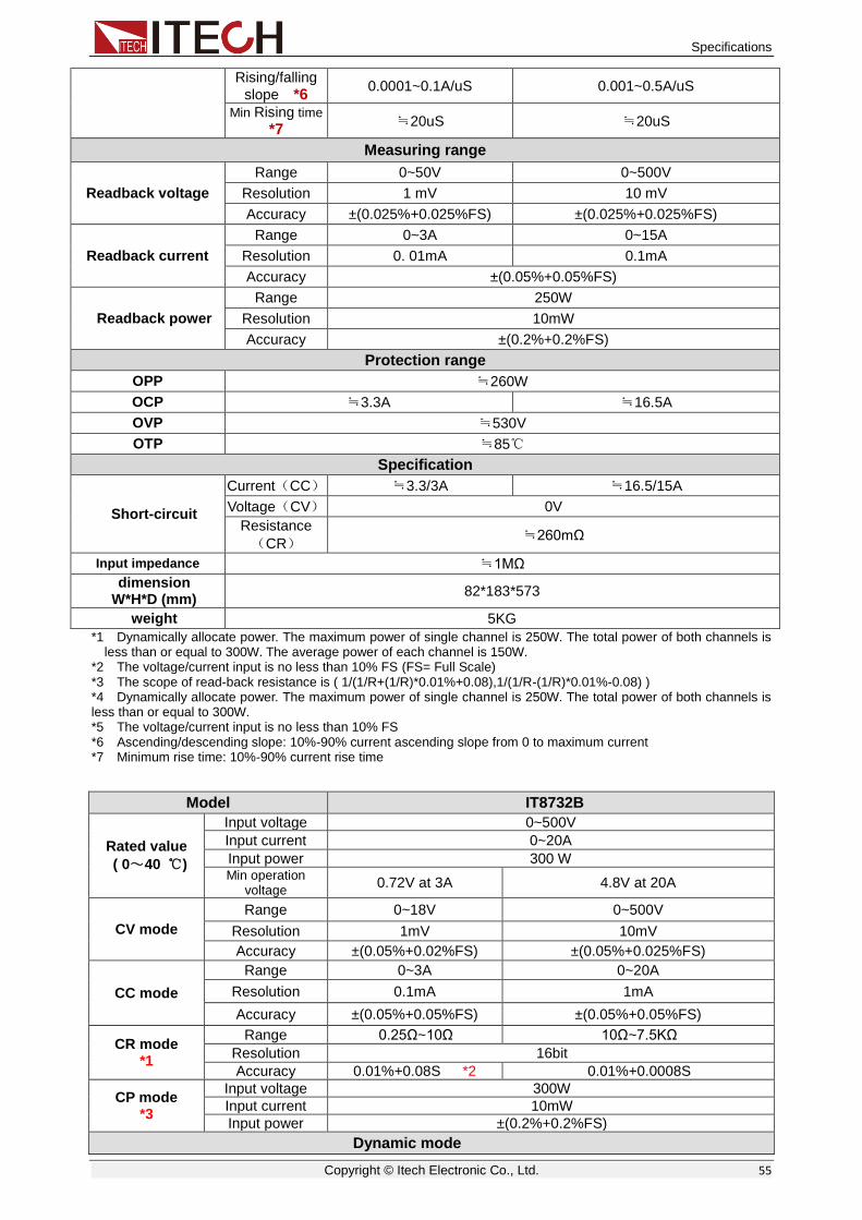
Specifications
Copyright © Itech Electronic Co., Ltd. 55
Rising/falling
slope *6 0.0001~0.1A/uS 0.001~0.5A/uS
Min Rising time
*7 ≒20uS ≒20uS
Measuring range
Readback voltage
Range 0~50V 0~500V
Resolution 1 mV 10 mV
Accuracy ±(0.025%+0.025%FS) ±(0.025%+0.025%FS)
Readback current
Range 0~3A 0~15A
Resolution 0. 01mA 0.1mA
Accuracy ±(0.05%+0.05%FS)
Readback power
Range 250W
Resolution 10mW
Accuracy ±(0.2%+0.2%FS)
Protection range
OPP ≒260W
OCP ≒3.3A ≒16.5A
OVP ≒530V
OTP ≒85℃
Specification
Short-circuit
Current(CC) ≒3.3/3A ≒16.5/15A
Voltage(CV) 0V
Resistance
(CR) ≒260mΩ
Input impedance ≒1MΩ
dimension W*H*D (mm)
82*183*573
weight 5KG
*1 Dynamically allocate power. The maximum power of single channel is 250W. The total power of both channels is less than or equal to 300W. The average power of each channel is 150W.
*2 The voltage/current input is no less than 10% FS (FS= Full Scale) *3 The scope of read-back resistance is ( 1/(1/R+(1/R)*0.01%+0.08),1/(1/R-(1/R)*0.01%-0.08) ) *4 Dynamically allocate power. The maximum power of single channel is 250W. The total power of both channels is less than or equal to 300W. *5 The voltage/current input is no less than 10% FS *6 Ascending/descending slope: 10%-90% current ascending slope from 0 to maximum current *7 Minimum rise time: 10%-90% current rise time
Model IT8732B
Rated value
( 0~40 ℃)
Input voltage 0~500V
Input current 0~20A
Input power 300 W Min operation
voltage 0.72V at 3A 4.8V at 20A
CV mode
Range 0~18V 0~500V
Resolution 1mV 10mV
Accuracy ±(0.05%+0.02%FS) ±(0.05%+0.025%FS)
CC mode
Range 0~3A 0~20A
Resolution 0.1mA 1mA
Accuracy ±(0.05%+0.05%FS) ±(0.05%+0.05%FS)
CR mode *1
Range 0.25Ω~10Ω 10Ω~7.5KΩ
Resolution 16bit
Accuracy 0.01%+0.08S *2 0.01%+0.0008S
CP mode *3
Input voltage 300W
Input current 10mW
Input power ±(0.2%+0.2%FS)
Dynamic mode

Specifications
Copyright © Itech Electronic Co., Ltd. 56
Dynamic mode
CC mode
T1&T2 20uS~3600S /Res:1u S
Accuracy 5uS+100ppm
Rising/falling slope
*4 0.0001~0.1A/uS 0.001~0.8A/uS
Min Rising time
*5 ≒20uS ≒20uS
Measuring range
Readback voltage
Range 0~18V 0~500V
Resolution 1 mV 10 mV
Accuracy ±(0.025%+0.025%FS) ±(0.025%+0.025%FS)
Readback current
Range 0~3A 0~20A
Resolution 0.01mA 0.1mA
Accuracy ±(0.05%+0.05%FS)
Readback power
Range 300W
Resolution 10mW
Accuracy ±(0.2%+0.2%FS)
Protection range
OPP ≒310W
OCP ≒3.3A ≒22A
OVP ≒530V
OTP ≒85℃
Specification
Short-circuit
Current(CC) ≒3.3/3A ≒22/20A
Voltage(CV) 0V
Resistance(CR) ≒240mΩ
Input impedance ≒1MΩ
dimension 82*183*573mm
weight 5KG
safety CE
*1 The voltage/current input is no less than 10% FS *2 The scope of read-back resistance is:
( 1/(1/R+(1/R)*0.01%+0.08),1/(1/R-(1/R)*0.01%-0.08) )
*3 The voltage/current input is no less than 10% FS *4 Ascending/descending slope: 10%-90% current ascending slope from 0 to maximum current *5 Minimum rise time: 10%-90% current rise time
Model IT8733B
Rated value
( 0~40 ℃)
Input voltage 0~500V
Input current 0~30A
Input power 500 W Min operation
voltage 0.54V/3A 5.4V/30A
CV mode
Range 0~18V 0~500V
Resolution 1mV 10mV
Accuracy ±(0.05%+0.025%FS) ±(0.05%+0.025%FS)
CC mode
Range 0~3A 0~30A
Resolution 0.1mA 1mA
Accuracy ±(0.05%+0.05%FS) ±(0.05%+0.05%FS)
CR mode *1
Range 0.2Ω~10Ω 10Ω~7.5KΩ
Resolution 16bit
Accuracy 0.01%+0.08S *2 0.01%+0.0008S
CP mode Range 500W

Specifications
Copyright © Itech Electronic Co., Ltd. 57
*3 Resolution 10mW
Accuracy ±(0.2%+0.2%FS)
Dynamic mode
Dynamic mode
CC mode
T1&T2 20uS~3600S/Res:1uS
Accuracy 5uS+100ppm
Rising/falling slope
*4 0.0001~0.08A/uS 0.001~0.8A/uS
Min Rising time
*5 ≒25uS ≒25uS
Measuring range
Readback voltage
Range 0~18V 0~500V
Resolution 1 mV 10mV
Accuracy ±(0.025%+0.025%FS) ±(0.025%+0.025%FS)
Readback current
Range 0~3A 0~30A
Resolution 0.01mA 0.1mA
Accuracy ±(0.05%+0.05%FS)
Readback power
Range 500W
Resolution 10mW
Accuracy ±(0.2%+0.2%FS)
Protection range
OPP ≒510W
OCP ≒3.3A ≒33A
OVP ≒530V
OTP ≒85℃
Specification
Short-circuit
Current(CC) ≒3.3/3A ≒33/30A
Voltage(CV) 0V
Resistance
(CR) 180mΩ
Input impedance 1MΩ
dimension 82*183*573mm
weight 5KG
safety CE
*1 The voltage/current input is no less than 10% FS *2 The scope of read-back resistance is:
( 1/(1/R+(1/R)*0.01%+0.08),1/(1/R-(1/R)*0.01%-0.08) )
*3 The voltage/current input is no less than 10% FS *4 Ascending/descending slope: 10%-90% current ascending slope from 0 to maximum current *5 Minimum rise time: 10%-90% current rise time * The above specifications may be subject to change without prior notice.
5.2 Supplementary characteristics Storage capacity: 101 sets
Suggested calibration frequency: one time each year
Cooling style: fan
Fans control temperature:
Temperature 35°C 50°C 70°C 85°C
Fans status The first grade The second grade The third grade OTP

Specifications
Copyright © Itech Electronic Co., Ltd. 58

Remote operation
Copyright © Itech Electronic Co., Ltd. 59
Chapter6 Remote operation
There are four kinds of communication interfaces: Ether Net、GPIB、USB、RS232. The user can choose any one of them to communicate with PC.
Figure 7-1IT8700 rear panel communication interface (take example of IT8702)
6.1 RS232 interface RS232 interface:use a cable with two COM interface(DB9)to connect load
and PC. It can be activated by <Shift> + <System> key on the front panel.
NOTE: There’re two COM interface on the rear panel of IT8700:the left 9-pin
COM interface is RS232 communication interface;the right 9-pin COM serial
port connection(extended keyboard interface). All SCPI commands are
available through RS-232 programming. The EIA RS-232 standard defines the
interconnections between data terminal equipment ( DTE ) and data
communications equipment(DCE). The electronic load is designed to be a DTE.
It can be connected to another DTE such as a PC COM port through a null modem cable
NOTE
The RS-232 settings in your program must match the settings specified in the front panel system menu. Press <Shift> + <System>key if you need to change the settings. You can break data transmissions by sending a ^C or ^X character string to the multimeter. This clears any pending operation and discards any pending output.
RS-232 data format
The RS-232 data is a 10-bit word with one start bit and one stop bit. The number of start and stop bits is not programmable. However, the following parity options are selectable using the front panel<Shift> + <System> key. Parity options are stored in non-volatile memory.
Baud rate
The front panel <Shift> + <System> key allows the user to select one of the following baud rates, which is stored in non-volatile memory: 4800 9600 19200 38400 57600 115200.
RS - 232
GPIB
Ether - Net
USB

Remote operation
Copyright © Itech Electronic Co., Ltd. 60
RS-232 flow control
The RS-232 interface supports the following flow control options that are selected using the front panel <Shift> + <System>key. For each case, the electronic load will send a maximum of five characters after hold-off is asserted by the controller. The electronic load is capable of receiving up to fifteen additional characters after it asserts hold-off.
The electronic load asserts its Request to Send (RTS) line to signal hold-off when its input buffer is almost full, and it interprets its Clear to Send (CTS) line as a hold-off signal from the controller.
When the input queue of the electronic load becomes more than 3/4full, the instrument will send an X-OFF command. The control program should respond to this and stop sending characters until the electronic load issues the X-ON, which it will do once its input buffer has dropped below half-full. The electronic load recognizes X_ON and X_OFF sent from the controller. An X-OFF will cause the electronic load to stop outputting characters until it sees an X-ON.
NONE there’s no flow control.
Flow control options are stored in non-volatile memory.
RS-232 connections
The RS-232 serial port can be connected to the serial port of a controller (i.e., personal computer) using a straight through RS-232 cable terminated with DB-9 connectors. Do not use a null modem cable. The table below shows the pinout for the connector.
If your computer uses a DB-25connector for the RS-232interface, you will need a cable or adapter with a DB-25 connector on one end and a DB-9 connector on the other, wired straight through (not null modem).
RS-232 connector pinout
pin number
description
1 no connection
2 TXD, transmit data
3 RXD, receive data
4 no connection
5 GND, signal ground
6 no connection
7 CTS, clear to send
8 RTS, ready to send
9 no connection
RS-232 troubleshooting:
If you are having trouble communicating over the RS-232 interface, check the following:
The computer and the electronic load must be configured for the same baud rate, parity, number of data bits, and flow control options. Note that the electronic load is configured for 1 start bit and 1stop bit (these values are fixed).
The correct interface cables or adapters must be used, as described under RS-232 connector. Note that even if the cable has the proper connectors for your system, the internal wiring may be incorrect.
The interface cable must be connected to the correct serial port on your computer (COM1, COM2.etc.).

Remote operation
Copyright © Itech Electronic Co., Ltd. 61
Communication setting
Before communication operation, please make sure that the following parameters of electronic load match that of PC.
Baud rate :9600(4800、9600、19200、38400、57600、115200). You can
enter system menu through panel to set communication baud rate.
Data bit :8
Stop bit :1
Parity :(none, even, odd)
EVEN: eight data bits with even parity ODD: eight data bits with odd parity NONE: eight data bits without parity
Local address :(0 ~31,default setting is 0)
Parity=None Start Bit 8 Data Bits Stop Bit
6.2 Ether Net interface Use a network cable to connect PC through Ether-net interface of load. Then
press + on the front panel to enter menu, choose <Ether-net>in <communication> item, then set gateway address<Gateway Set>, IP address <IP Set>,mask address <Mask set>,and port< port set> in Ether-net.
6.3 GPIB interface
Firstly, connect GPIB port of load to GPIB card of PC. Please ensure that the screws have been screwed down in order to have a full connection. And then
set address. The address can be set from 0 to 31. Press + key to
enter system menu, press key to find GPIB address set ,then enter the
address, and use to confirm. The GPIB address is stored in non-volatile memory.
6.4 USB interface Use cables with double USB interface to connect load and PC. All electronic load functions are programmable over the USB.
The USB488 interface capabilities of the electronic load are described below:
The interface is 488.2 USB488 interface
The interface accepts REN_CONTROL, GO_TO_LOCAL, and LOCAL_LOCKOUT requests.
The interface accepts MsgID = TRIGGER USBTMC command message and forwards TRIGGER requests to the function layer.
The USB488 device capabilities of the electronic load are described below:
The device understands all mandatory SCPI commands.
The device is SR1 capable.
The device is RL1 capable.
The device is DT1 capable.
ShiftShift System
ShiftShift System
▼▼
EnterEnter

Remote operation
Copyright © Itech Electronic Co., Ltd. 62
NOTE
When communicating with PC, you can just select one method of all the communication methods above.

Appendix
Copyright © Itech Electronic Co., Ltd. 63
Appendix
Specifications of Red and Black Test Lines ITECH provides you with optional red and black test lines, which individual sales and you can select for test. For specifications of ITECH test lines and maximum current values, refer to the table below.
Model Specification Cross Section Length
IT-E301/10A 10A - 1m
IT-E301/30A 30A 6mm2 1.2m
IT-E301/30A 30A 6mm2 2m
IT-E301/60A 60A 20mm2 1.5m
IT-E301/120A 120A 50mm2 2m
IT-E301/240A 240A 70mm2 1m
IT-E301/240A 240A 70mm2 2m
IT-E301/360A 360A 95mm2 2m
For maximum current of AWG copper wire, refer to table blow.
AWG 10 12 14 16 18 20 22 24 26 28
The Maximum Current Value( A)
40 25 20 13 10 7 5 3.5 2.5 1.7
Note: AWG (American Wire Gage), it means X wire (marked on the wire). The table above lists current capacity of single wire at working temperature of 30°C. For reference only

Contact Us Thanks for purchasing ITECH products. In case of any doubts, please contact us as follows: 1. Refer to accompanying data disk and relevant manual. 2. Visit ITECH website: www.itechate.com. 3. Select the most convenient contact method for further information.