is 62 (2006): graphite for paints - public.resource.org
TRANSCRIPT

Disclosure to Promote the Right To Information
Whereas the Parliament of India has set out to provide a practical regime of right to information for citizens to secure access to information under the control of public authorities, in order to promote transparency and accountability in the working of every public authority, and whereas the attached publication of the Bureau of Indian Standards is of particular interest to the public, particularly disadvantaged communities and those engaged in the pursuit of education and knowledge, the attached public safety standard is made available to promote the timely dissemination of this information in an accurate manner to the public.
इंटरनेट मानक
“!ान $ एक न' भारत का +नम-ण”Satyanarayan Gangaram Pitroda
“Invent a New India Using Knowledge”
“प0रा1 को छोड न' 5 तरफ”Jawaharlal Nehru
“Step Out From the Old to the New”
“जान1 का अ+धकार, जी1 का अ+धकार”Mazdoor Kisan Shakti Sangathan
“The Right to Information, The Right to Live”
“!ान एक ऐसा खजाना > जो कभी च0राया नहB जा सकता है”Bhartṛhari—Nītiśatakam
“Knowledge is such a treasure which cannot be stolen”
“Invent a New India Using Knowledge”
है”ह”ह
IS 62 (2006): Graphite for paints [CHD 20: Paints,Varnishes and Related Products]


HANDBOOK ON
BUILDING CONSTRUCTION PRACTICES (Excluding Electrical Work)
HANDBOOK ON
BUILDING CONSTRUCTION PRACTICES (Excluding Electrical Work)
B U R E A U O F I N D I A N S T A N D A R D S MANAK BHAVAN, 9 BAHADUR SHAH ZAFAR MARG
NEW DELHI 110002
SP 62 (S & T) : 1997
FIRST PUBLISHED SEPTEMBER 1997
FIRST REPRINTED JANUARY 2001
© BUREAU OF INDIAN STANDARDS
ICS 91 010 01
ISBN 81 7061-048-6
PRICE : RS. 2150.00
Typeset by Paragon Enterprises, New Delhi-110002
Printed in India
at Central Electric Press, New Delhi 110028
Published by
Bureau of Indian Standards, New Delhi 110002
SP62(S
PRICE :
FOREWORD
Users of various civil engineering codes have been feeling the need for explanatory handbooks and other compilations based on Indian Standards. The need has been further emphasized in view of the first publication of the National Building Code of India in 1970 (which has since been revised in 1983) and its implementation The Expert Group set up in 1972 by the Department of Science and Technology, Government of India carried out in-depth studies in various areas of civil engineering and construction practices. During the preparation of the Fifth Five-Year Plan in 1975, the Group was assigned the task of producing a Science and Technology Plan for research, development and extension work in the sectors of housing and construction technology. One of the items of this plan was the formulation of design handbooks, explanatory handbooks and design aids based on the National Building Code and related Indian Standards and other activities in the promotion of the National Building Code. The Expert Group gave high priority to this item and on the recommendation of the Department of Science and Technology, the Planning Commission approved the following two projects which were assigned to the Bureau of Indian Standards (erstwhile Indian Standards Institution):
a) Development programme on code implementation for building and civil engineering construction, and
b) Typitication for industrial buildings.
A Special Committee for Implementation of Science and Technology Projects (SCIP) consisting of experts connected with different aspects was set up in 1974 to advise the BIS Directorate General in identifying and for guiding the development of the work. Under the first project, the Committee has identified several subjects for preparing explanatory handbooks/compilations covering appropriate Indian Standards/ Codes and Specifications which include the following:
*Handbooks Published:
1. 2.
3.
4.
5.
6.
7.
8.
9.
10.
11.
12.
13.
14.
15.
16.
Design Aids for Reinforced Concrete to IS 456 : 1978 (SP 16 : 1980)
Handbook on Masonry Design and Construction (First Revision) (SP 20 : 1991)
Summaries of Indian Standards for Building Materials (SP 21 . 1983)
Explanatory Handbook on Codes of Earthquake Engineering (IS 1893: 1975 and IS 4326 : 1976) (SP22: 1982)
Handbook on Concrete Mixes (Based on Indian Standards) (SP 23 : 1982)
Explanatory Handbook on Indian Standard Code of Practice for Plain and Reinforced Concrete (IS 456: 1978) (SP 24 1983)
Handbook on Causes and Prevention of Cracks in Buildings (SP 25 . 1984)
Handbook on Functional Requirements of Industrial Buildings (Lighting and Ventilation) (SP 32 : 1986)
Handbook on Timber Engineering (SP 33 : 1986)
Handbook on Concrete Reinforcement and Detailing (SP 34 : 1987)
Handbook on Water Supply and Drainage with Special Emphasis on Plumbing (SP 35 : 1987)
Handbook on Typified Designs for Structures with Steel Roof Trusses (with and without Cranes) (Based on IS Codes) (SP 38: 1987)
Handbook on Structures with Steel Portal Frames (without Cranes) (SP40 : 1987)
Handbook on Functional Requirements of Buildings (other than Industrial Buildings) (SP 41 : 1987)
Handbook on Structures with Reinforced Concrete Portal Frames (without Cranes) (SP 43 : 1987)
Handbook on Structures with Steel Lattice Portal Frames (without Cranes) (SP 47 : 1987)
Subjects Under Programme:
— Foundation of Buildings
*Handbooks published are available for sale from BIS Headquarters, and from all Branches and Regional Offices of BIS
(v)
– Construction Safety Practices
– Explanatory Handbook on IS 875 (Part 3) : 1987
Fire Protection
– Form Work
– Tall Buildings
This Handbook has been written with a view to unifying the constructional practices being followed by various organizations engaged in construction of residential, commercial and industrial buildings and is mainly based on various Indian Standards published in the respective areas of construction. The Handbook provides information regarding methods of construction of any particular element of the building using different materials so that a designer/site engineer can choose the most appropriate material(s) and method(s) of construction as per his needs. Besides, it is hoped that this Handbook would be of great help to students of Civil Engineering.
It may be noted that the Handbook does not form part of any Indian Standard on the subject and does not have the status of an Indian Standard. Wherever, there is any dispute about the interpretation or opinion expressed in this Handbook, the provisions of the codes only shall apply; the provisions of this Handbook should be considered as only supplementary and informative.
The Handbook is based on the first draft prepared by Shri D. Ajitha Simha, former Deputy Director General of Bureau of Indian Standards with Shri P. Krishnan, Director General CPWD (Retd) as the co-author. The draft handbook was circulated for review to Structural Engineering Research Centre, Chennai; Central Building Research Institute, Roorkee; Department of Science and Technology, New Delhi; Central Public Works Department, New Delhi; Metallurgical and Engineering Consultants (India) Ltd. Ranchi; Planning Commission, New Delhi; Engineers India Ltd, New Delhi; Hindustan Construction Co Ltd, Mumbai; Asia Foundation and Construction Ltd, Mumbai; Cemindia Co Ltd, Mumbai, Engineer-in-Chief, Army Headquarters, New Delhi; Housing and Urban Development Corporation, New Delhi; Howe India (Pvt) Ltd, New Delhi; National Institute of Construction Management and Research, Mumbai; M/s Ansal Properties and Industries Ltd, New Delhi, Building Material and Technology Promotion Council, New Delhi; Chief Engineer (R&B). Hyderabad; Public Works Department, Itanagar; Road and Building Department, Gandhi Nagar; Public Works Department, Mumbai; Chief Engineer (Blds, PWD, B&R), Chandigarh; Public Works Department, Shimla; Chief Engineer (Communication and Buildings), Bangalore; Chief Engineer (Building and Local Works), Trivandrum; Public Works Department, Patna; Public Works Department, Calcutta; Public Works Department (Buildings),Shillong: Chief Engineer (Building Projects), Aizawal; Chief Engineer, Housing, Kohima, Works Department, Bhubaneshwar. Public Works Department, Chennai; Public Works Department, Jaipur: Public Works Depart ment, Lucknow, Institution of Engineers, New Delhi; Gammons India Ltd, Mumbai and views expressed were taken into consideration while finalizing the Handbook.
(vi)
CONTENTS
Chapter 1
Chapter 2
Chapter 3
Chapter 4
Chapter 5
Chapter 6
Chapter 7
Chapter 8
Chapter.9
Chapter 10
Chapter 11
Chapter 12
Chapter 13
Chapter 14
Chapter 15
Chapter 16
Chapter 17
Chapter 18
Introduction
Construction Planning and Storage of Materials
Earthwork
Foundations
Masonry
Plain and Reinforced Concrete
Anti-termite Measures
Doors and Windows (Wood and Metal)
Steel Construction
Floors and Floor Coverings
Wall and Ceiling Finishes and Coverings and Walling
Roots and Roofing
Damp Proofing and Waterproofing
Joints in Buildings (Control of Cracks in Buildings)
Whitewashing, Colour Washing and Painting ol Masonry, Concrete and Plaster Surfaces (Calcareous Surfaces)
Painting, Varnishing and Allied Finishes (Wood and Metals)
Water Supply and Dramage
Special Construction Procedures Earthquake Effects, etc
Demolition of Buildings
List of Referred Indian Standards
Page
IX
1
11
25
43
91
123
135
165
177
239
277
323
361
377
391
409
433
455
466
(vii)
COMPOSITION OF THE SPECIAL COMMITTEE FOR IMPLEMENTATION OF SCIENCE & TECHNOLOGY PROJECTS (SCIP)
CHAIRMAN
PADMASHRI DR H. C. VISVESVARAYA
Vice-chancellor University or Roorkee
Roorkee
MEMBERS DR T V. S. R. APPA RAO
DIRECTOR
SHRI V. RAO AIYAGARI
DIRECTOR GENERAL
ADDITIONAL DIRECTOR GENERAL (Alternate)
SHRI M. L. MEHTA
SHRI S. K. DATTA (Alternate)
SHRI B. D. JETHRA
SHRI P. D. MAYEE (Alternate)
REPRESENTING Structural Engineering Research Centre (CSIR), Madras Central Building Research Institute, Roorkee Department of Science & Technology, New Delhi Central Public Works Department, New Delhi
Metallurgical and Engineering Consultants (India) Ltd, Ranchi
Planning Commission, New Delhi
Secretaries SHRI K. K. SHARMA
Director (S & T), BIS
SHRIMATI NEETA SHARMA
Deputy Director (S & T), BIS
(viii)
INTRODUCTION
The National Building Code of India, 1983 (NBC) covers all the aspects of buildings. These aspects include building byelaws, development control rules, building materials and fire protection which are covered in Part I to Part V; Part VI covers the design of buildings using the building materials. Part VII is a compendium of Indian Standards on Construction Practices generally described as codes of good practices. Part VIII deals with building services, Part IX with plumbing services and Part X, the last part, deals with signs and outdoor display structures.
For implementation of the NBC, a broad decision was taken by all state governments and the central and public sector departments to incorporate the appropriate parts of the NBC into the relevant technical documents, such as, municipal building byelaws, PWD specifications, specifications of construction departments, etc
Simultaneously it was felt that for easy understanding and implementation of various Parts of the NBC, handbooks be brought out on various Parts/Sections as relevant. In the light of this, S & T project was launched by BIS, the Bureau of Indian Standards to prepare such handbooks. This handbook on constructional practices is one of them. Some handbooks have been already prepared and reference is made to them as found necessary
This handbook has been on the anvil for some time now. The NBC has broadly classified buildings into 9 groups based on use and occupancy; for convenience of this handbook, they have been grouped into three, namely, residential, commercial and industrial buildings. Therefore, a study was made of available Indian Standards on constructional practices of these three groups of buildings.
Within the BIS this work of standardization of the construction sector is spread over more than one technical division. Departmental programmes of civil, mechanical, metallurgical, chemical, river valley had to be checked up in this context
Normally PWDs and other construction department largely cover the constructional practices relevant to residential and to some extent office buildings. Constructional practices relevant to commercial buildings and industrial buildings are not generally dealt with. Thus this handbook has a much wider coverage in dealing with constructional practices for residential, commercial and industrial buildings, than normal departmental specifications.
The approach to the handbook is to attempt to cover the 'how' of constructional practice with the 'why' of it. The current departmental specifications generally specify as to how an item of work has to be done. They do not explain the rationale for such specifications and therefore the user is not given enough information to decide, for the same work, use of alternate or more appropriate specifications among others available in the country For example a number of specifications for flooring are available; the choice of any of them according to the end use is not mentioned Therefore the reasons or 'why' of a particular specification helps in choosing one of the many specifications available for an appropriate end use. Such information, it is hoped, would lead to a reasonably good decision on choice or selection of construction procedure in relation to its end use or performance on site.
A holistic approach to buildings bring out the interrelationship among building materials, design and construction of buildings using these materials Therefore, construction practices have to be viewed in the light of quality of materials and appropriate designs. The BIS have already brought out a summary of Indian Standards on building materials; handbooks on design; and handbooks on some services. This handbook would therefore have to be looked at as filling a gap in the series of handbooks on the building as a whole. It is therefore felt that a close co-ordination be established between the design of an item/element and its construction in the field so that the intention of the designer is fully understood in the field.
To demarcate the contents of the handbook into individual chapters available PWD handbooks have been studied; these include among others the CPWD specifications of 1991-92 and Tamil Nadu Building Practice 1983/1985. The main basis are the Indian Standands available up to March 1994. From a study of
(ix)
these, the chapters have been identified and arranged according to the sequence of construction as closely as possible, namely, planning of work, collection of materials, earthwork and related termite treatment, foundations, superstructure of masonry; wood, concrete and steel, flooring, wall finishes and roofing and then followed by water proofing and damp-proofing. Finishing of surfaces, such as, masonry, concrete and plaster ate then covered, finishes of wood and metal construction is also covered. Finally water supply and drainage systems ate covered. Emphasis is then laid on special construction procedure particularly for earthquake forces. The last chapter deals with demolition of buildings.
For the use of materials not covered by Indian Standard Codes of Practice, the construction practices would be based on the principles enumerated in each section. For example in painting, the preparation of surface and application should be based partly on manufacturers recommendations and broadly on the principles of preparing a clean, dry surface to receive the paint; the actual finishing should be preceeded by filling, staining where applicable and sealing particularly with respect to wood surfaces. Similar procedure could be worked out for other items of work using new materials, such as, for doors, roofing sheets and so on.
For economies in construction, planning of the entire work as covered in Chapter 1, is of importance. Crack control in buildings as covered in Chapter 13 which could be of use in planning of buildings is also of great importance.
For specialized construction work reference has been made to ISS wherever available.
It is therefore reasonable to assume that careful planning and meticulous observance of all the constructional practices elaborated herein would lead to a high quality building.
For ease of reading, each chapter is preceded by a table of contents List of standards used and referred to are given at the end of the handbook. A summary of each chapter is given below to indicate its broad coverage.
CHAPTER 1
Construction Planning and Storage of Materials
This chapter deals with the need for planning of construction before commencement of work. Attention is drawn to the use of networking techniques like Programme Evaluation and Review Techniques (PERT) and Critical Path Method (CPM) to draw up a sequence of operations in a given time frame taking into account various elements of such operations. Such planning techniques are likely to help in proper monitoring of the work and avoid time overruns and finish the project in time. That is why at the very beginning of this handbook this aspect of planning has been brought in.
Stocking and storage of materials, before commencing the construction is an important activity as part of planning. Safe storage and stacking would avoid hazards of breakage, etc. Details of storage of most of the materials of construction are given.
The chapter is divided into two Parts; Part 1 deals with construction planning, and Part 2 deals with storage of materials
CHAPTER 2
Earthwork
Soils are classified for excavation work. Reference is also made to appropriate Indian Standard on soil classification. Excavation for various end uses, different depths and different areas are described. Information on excavation in soft soil, hard soil, soft rock and hard rock is given. Shoring and limbering details are elaborated. Excavation in mud, water and foul positions is covered.
Immediately after excavation, the anti termite treatment of soil for different situations, is elaborated The site preparation, chemicals to be used, etc. for treatment at various locations are given. Information on treatment of masonry, concrete foundations, masonry up to ground level, etc, is given. Treatment of soils around pipes, conduits, etc, is also given for protection against termites. Statutory authorities may be consulted in hazards related to use of these chemicals.
(x)
CHAPTER 3
Foundations
This chapter covers the construction of shallow, deep, spread and strip foundations and pile foundations. Details of different types of piles, namely cast m-situ, precast and timber piles are given; in this bored and driven piles are elaborated Reference is made to machine foundations and special foundations.
Information on choice of foundations is given in Annex A Guidelines for improvement of weak soils to carry more loads are given in Annex B.
CHAPTER 4
Masonry
This chapter is divided into three parts, namely, mortars, brickwork and blolkwork and stonework.
Part 1 deals with mortars. Types of mortars such as cement mortal, cement-lime mortar and lime mortars are described in detail, such as, selection of mortars, preparation of mortars, etc. Emphasis is laid on the use of composite mortars which have an edge over plain cement mortars Optimum mortar mixes in relation to masonry strengths are also indicated.
Part 2 deals with brick and block units, brickwork, blockwork and in-situ walls with soil cement
Section 1 gives information on various types of bricks available in the country and some of their properties. Information on various types of blocks made in the country is given. This could help in deciding on the type of buck of block to be chosen for a given condition of loading so that economies can be achieved in construction.
Section 2 deals with brickwork Various types of bonds are illustrated and explained including the end uses I aying of brickwork for different components of building is indicated Thickness of joints, preparatory work, etc, are also covered.
Section 3 deals with blockwork. Careful consideration has to be given for avoidance of crack formation due to structural movements of supporting structural elements Remedial measures for such crack formation are mentioned Laying of blocks is dealt with in detail. Provisions for openings, roof and intersecting walls are covered. The use of hollow, light weight and autoclaved concrete blocks is covered
Section 4 deals with construction of walls in-situ with soil cement. The quality of soil, amount of cement to be mixed depending on type of walls, etc, are covered. To cany roof loads through trusses, beams, etc, bed blocks are recommended. Plastering with cement plasters suggested. Mud plaster with addition of cut back bitumen is also provided. The building is limited to one storey only.
Part 3 deals with stone masonry Types of stones and their properties such as durability, strength and sizes are described Preparatory work such as dressing, handling, etc, are detailed. Various types of stone masonry and the general requirements of laying are covered; construction of these types of stone masonry is covered in detail with illustrations
CHAPTER 5
Plain and Reinforced Concrete
This chapter deals with plain and reinforced concrete work in buildings using cement; use of lime and lime pozzolana concrete is also covered Shotcreting of work is also dealt with.
Part 1 deals with the common requirements of plain and reinforced cement concrete. This includes materials to be used, grades of concrete, production, transportation and mixing of concrete. Concreting under special conditions, such as, hot weather, cold weather, underwater, in sea water and aggressive soils is also covered Reference is made to ready mixed concrete and non-destructive testing of concrete. Accelerated curing for testing of concrete is also covered apart from determination of particle size and surface moisture on aggregate
(xi)
Part 2 deals with additional requirements of reinforced concrete work over and above the general requirements covered in Part 1. Details of form work, striking of form work, etc, are dealt with. Placing of reinforcement, welding of plain and deformed bars are also covered. Cover to reinforcement shall be as per drawings subject to IS 456 . 1978.
Part 3 deals with the use of lime concrete and lime pozzolana mixture concrete.
Section 1 deals with lime concrete including materials, mixing and placing of concrete. Details of laying lime concrete in foundations, arches, etc, are covered.
Section 2 deals with laying of lime pozzolana mixture concrete.
Part 4 covers use of shotcreting methods when employed. Both dry mix and wet mix processes are covered. Details of application of shotcrete for certain elements and locations are given.
CHAPTER 6
Anti-termite Measures
This chapter covers anti-termite measures by constructional means for new buildings and also the anti-termite treatment of existing buildings. This chapter is brought in immediately after Chapters 3, 4 and 5 dealing with foundations, masonry and concrete to highlight the need to take these measures at the time of construction of these items of work. The chemical methods of anti-termite treatment are already covered in Chapter 2 on earthwork.
Design criteria, internal and external anti-termite measures and termite shields are dealt with in Part 1 dealing with constructional measures.
Part 2 deals with post constructional methods for protection of existing buildings; including inspection of the structure, elimination of termites and perventive measures Statutory authorities may be consulted on the hazards of use of chemicals.
CHAPTER 7
Doors and Windows (Wood and Metal)
This chapter covers installation of doors and windows and ventilators made of wood, steel and aluminium; the chapter is divided into two parts accordingly.
Part 1 dealing with wooden doors, etc, gives detailed information on classification of timber in the country for construction and furniture making; in this portion all relevant information on various characteristics is given; this would help in deciding on use of various species of timber for making of wooden doors, etc. Moisture content is another important aspect governing woodwork and zoning of the country based on maximum permissible moisture content is also given
Installation of wooden frames, pressed steel frames, panelled shutters, ledged, braced and battened doors and windows, battened and framed door and windows, timber panelled and glazed shutters; louvred shutters; glazing and fittings are covered in some detail.
There are many hardware fittings and a number oi figures are given to illustrate them; reference to Indian Standards for both wood based products and builders hardware is given for ease of use.
Part 2 deals with the installation of steel and aluminium doors, windows and ventilators; details of installing single and composite units are covered.
CHAPTER 8
Steel Construction
This chapter deals with the construction using hot rolled sections including tubular sections and cold formed light gauge sections. For this purpose the chapter is divided into two Parts.
(xii)
Fabrication of sections and their connections are the two major facets of steel construction In each Part therefore fabrication details such as straightening, machining, cutting, holing, etc, are dealt with.
In dealing with hot rolled sections use of rivets, bolts, high strength friction grip bolts and welding is elaborated. Shop erection, site erection, shop painting and site painting are dealt with. Special precautions for members not meeting at a joint, packing of materials, inspection, etc, are also dealt with.
Special requirements of fabrication for design of hot rolled sections by plastic theory are mentioned.
For construction of tubular structures, use of rivets, close tolerance bolts and welding is dealt with A list of standards and handbooks relating to steel construction is given in Annex A
Reference is made to good construction practice by resistance spot welding for cold formed light gauge sections.
CHAPTER 9
Floors and Floor Coverings
This chapter deals with floors and floor coverings extensively. For this purpose the chapter is divided into five Parts
Part 1 deals with brickfloors and details of their construction. It includes quality of bricks, preparatory work, construction and finish.
Part 2 deals with laying of cement concrete floors It includes in-situ concrete flooring, in situ granolithic flooring, in-situ terrazzo finish and cement concrete tiles.
Part 3 covers construction of industrial floor finishes including dairy floor finishes
Part 4 deals with special floors and floor coverings. It includes magnesium o???ychloride finish, rubber floors, bitumen mastic floor finish, linoleum floors, epoxy resin floors, PVC floors, use of chemical resistant mortals and parquet flooring.
Part 5 covers construction of timber floors using joists and planks.
CHAPTER 10
Wall and Ceiling Finishes and Coverings and Walling
This chapter is divided into two Parts. Part 1 deals with construction of wall finishes, ceiling finishes, wall coverings and ceiling coverings It covers The details of materials, prepatatory work and construction of the following finishes on walls and ceilings and their coverings.
— Lime plaster finish; cement and cement-lime plaster finish external rendered finishes for different backgrounds.
— External facing and veneers using stone, cement concrete, tiles and mosaics, including the special requirements of using devices like cramps to fix the veneers to the background wall.
— Wall coverings using various woodbased products, asbestos cement boards, etc, is dealt with. Similarly ceiling coverings using different materials is also dealt with.
— Information on backgrounds with sulphate content is also given.
Part 2 deals with the construction of walls using reeds suitable for earthquake prone areas, gypsum light weight partitions and the use of no fines in-situ concrete in walls and foundations.
CHAPTER 11
Roots and Roofing
This chapter deals with various types of roofs and roofing. Roofing materials differ and for this purpose, the chapter is divided into five Parts, namely, five parts, sloping roofs, shell roofs, thatched root, and flat root finish.
(xiii)
Part 1 covers considerable amount of information on jack-arch type roof, Madras terrace, stone over joint construction. Use of various types of precast roofing elements in combination with different types of blocks, such as, hollow and solid made from concrete or clay materials are described. A careful study of these combinations in flat roofs may lead to savings in cement and steel.
Part 2 covers use of wooden shingles in sloping roofs of hilly regions. Use of slates is also indicated Use of AC sheets both corrugated and semi-corrugated is extensively covered in the form of figures. Similarly use of plain and corrugated galvanized steel sheets is also covered.
Part 3 is only an introduction to shell roofs; since it is a specialized job expert guidance both in design and construction is needed.
Part 4 covers one of the traditional roof finishes, namely, use of mud Phuska which is economical as well as a good insulating material easy to construct.
Part 5 deals with protection against hazards of fire of thatched roofing.
CHAPTER 12
Damp-Proofing and Waterproofing This chapter covers in detail damp-proofing materials and damp-proofing of various elements of structures; it also deals with waterproofing materials and their various uses in different elements of structures. Information on use of water repelling agents is also given.
General details governing the preparation of surfaces to receive either damp-proofing treatment or waterproofing application, to make these treatments effective, is of importance. These details are given in the beginning of the chapter itself, applicable both to damp-proofing treatment and waterproofing treatment.
Part 1 deals with various materials for damp-proofing and their use. Normal, heavy and extra heavy treatments are listed, as per conditions at site. The materials include, bitumen felt, bitumen mastic, etc.
Part 2 deals with various materials for waterproofing and their use. Normal, heavy and extra heavy treatments are covered, as per conditions at site. The materials include bitumen felt, mastic, etc.
Precautions in the use of glass fibre tissue reinforced bitumen, polyethylene film, etc, are mentioned.
CHAPTER 13
Joints in Buildings (Control of Cracks in Buildings)
This chapter deals with various details of construction of joints to prevent initiation of cracks and their control. That is why this chapter is also called control of cracks in buildings. Various types of joints are described; the main joints are expansion and contraction joints. Some basic information on causes of cracking, namely, moisture movement and thermal effects on building materials is given. Other aspects of long term creep of materials, differential expansion/contraction of composite construction, like brick and plaster, are also covered. Basic details, illustrative in nature of various types of joints and their locations in walls, roofs, floors and junctions of such elements are also covered. The drawings are indicative of the principles involved in preventing and controlling cracks in buildings. Attention is also drawn to an important handbook already published by BIS on Causes and Prevention of Cracks in Buildings.
CHAPTER 14
Whitewashing, Colour Washing and Painting of Masonry, Concrete and Plaster Surfaces (Calcareous Surfaces)
This chapter deals with whitewashing, colour washing and painting of calcareous surfaces like masonry, concrete, plaster and asbestos cement surfaces. For convenience the chapter is split into two Parts; Part 1 deals with whitewashing and colour washing and Part 2 deals with painting of calcareous surfaces.
(xiv)
Emphasis is laid on preparation of surfaces to as dry a condition as possible and for painting to take care of alkalinity of these surfaces. Painting of new and old surfaces are covered. Characteristics of calcareous surfaces which have to be considered for painting have been listed. Schedules of painting of these surfaces like type of paints for primer coat, undercoat and finishing coats are given. Problems of efflorescence, fungus growth, suction, etc, are highlighted with some recommendations for treatment. Maintenance schedule of painting of surfaces is also given. Some tests to determine fitness of plaster for painting through determination of dryness of background before painting, alkalinity and efflorescence are given.
CHAPTER 15
Painting, Varnishing and Allied Finishes (Wood and Metals)
This chapter covers the painting of wood and wood based materials, ferrous and non-ferrous metals in buildings. For convenience it is divided into three Parts.
Part 1 deals with finishing of wood and wood based materials and gives the general characteristics of timber in relation to painting. It deals in detail with priming of timber joinery before painting followed by selection of coating materials. Surface preparation of timber is important to ensure proper adhesion of paint. Details of stopping, filling, staining and finishing are elaborated. Clear finishes, french polish, etc, are also coveted. A schedule of painting is listed in tabular form. Mention is also made of finishing wood based products similar to solid wood. Some details regarding finishing of wood products with nitrocellulose and cold catalysed crystals are given.
Part 2 covers the pretreatment of ferrous metals, either in factory or at site before final painting. Factory pretreatment is recommended for durable results The importance of preparing surface before treatment like removal of oil. grease, rust, etc. is emphasized A schedule of application of paints is given. Mention is also made for maintenance painting.
Part 3 covers the pretreatment, preparation of surfaces and finish of non-ferrous metals in buildings
CHAPTER 16
Water Supply and Drainage
This chapter is divided into three Parts dealing with water supply, drainage and plumbing system including that in high altitude and/or sub-zero regions
Part 1 on water supply deals with the piping system from the municipal water mains to the building and internal distribution also. Appurtenant structures in relation to water supply are also covered. The basic principles of supplying potable water, general requirements of pipe work, laying and jointing of pipes are elaborated. Reference is made to testing, inspection, disinfection, storage tanks, etc.
Part 2 on drainage covers the conveyance of waste water, sewage, surface water and subsoil water. Laying of pipes, pipe joints and disposal are dealt with; emphasis is laid on separation of storm water drainage and sullage.
Part 3 deals with special requirements of water supply and drainage of high altitudes and/or sub-zero temperatures. The effects on physical, chemical and biological properties of wastes, equipment, etc, are brought out and corresponding provisions given.
CHAPTER 17
Special Construction Procedures — Earthquake Effects, etc
This chapter deals with construction procedures for buildings when subjected to earthquake forces. Buildings constructed with weaker materials and strengthening of earthen buildings are also covered. The general requirements of design of course should be according to the basic code IS 1893 . 1984.
(xv)
Emphasis is laid on categorisation of buildings based on importance of the building, zone of seismic map of India and the soil foundation factor. Special construction procedures are listed for each of the five categories of buildings.
The general principles for earthquake resistance of buildings are enumerated. The main thrust of these principles is to make the building rigid in both the horizontal directions through continuity of structural elements.
Details of such treatment are given for masonry and timber buildings. The ductility of joints in reinforced concrete construction is covered by an Indian Standard to which reference is made. Use of precast elements and their strengthening is also covered.
Some information on improving earthquake resistance of buildings using weaker building materials including mud/earth is covered. Repair and seismic strengthening of buildings is mentioned giving reference to an Indian Standard.
The title envisages covering construction for effects of blast and similar instantaneous forces on buildings.
CHAPTER 18
Demolition of Buildings
This chapter covers the safety requirements of the general public and the workers at site during demolition. Emphasis is laid on planning of the work of demolition so as to avoid any accidents or damage to adjacent structures. The need is therefore to consider sequence of demolition of elements of a structure starting from top storey and working downwards.
Special requirements for demolition of masonry arches, precast elements, steel elements, beams, columns, etc, are elaborated. Demoltion by hand, mechanical means or explosives is also mentioned. Protective equipment for workers during demolition is listed. Continuous removal of debris throughout the operation is recommended so as to avoid overloading of structures below the storey under demolition; chutes and openings for this purpose are recommended.
In line with the National Building Code, the word Authority having jurisdiction, is used as merely Authority in various chapters. The Authority always refers to the concerned department who has jurisdiction over the matter or subject under jurisdiction
(xvi)

CHAPTER 1
CONSTRUCTION PLANNING AND STORAGE OF MATERIALS
CONTENTS
PART 1 CONSTRUCTION PLANNING
1
2
GENERAL
CONSTRUCTION PLANNING
2 1 Planning Techniques 2.2 Advantages 2.3 Networking Technique
PART 2 STORAGE OF MATERIALS
1
2
3
4
5
6
7
8
9
GENERAL
CEMENT
LIME
BRICKS
AGGREGATE
FLY ASH
TIMBER
STEEL
DOORS, WINDOWS AND VENTILATORS
10
11
12
13
14
15
16
17
18
19
20
21
22
23
24
25
ROOFING SHEETS
BOARDS
PLASTIC AND RUBBER SHEETS
GLASS SHEETS
A S B E S I O S C E M E N T P I P E S A N D F ? ? ?
POEYETHYIENE PIPES
U N P L A S H I Z E D P V C PIPES
BITUMEN, ROAD TAR AND ASPHALT
WATER
FLAT TILES
OIL PAINTS
SANHARI APPLIANCES
PILLS
OTHER MATERIALS
SPECIAL CONSIDERATIONS
ELECTRICAL MATERIALS
SP 6 2 ( S & T ) : 1997
CHAPTER 1
CONSTRUCTION PLANNING AND STORAGE OF MATERIALS
PART 1 CONSTRUCTION PLANNING
1 GENERAL
1.1 Planning and scheduling of a construction project, be it a building, bridge. or drainage work, consists of defining all the tasks that must be performed and laying them out in logical sequence necessary for the completion of the project. There is a link between quality of preparation that goes into the formulation of a work plan and the efficiency of management and control in the execution and operation phases. This calls for effective co-ordination of the efforts of all the participants and identification of the tasks which are likely to constrain the completion of project in time. If not done, it might lead to time and cost overrun of the project. Thus there is a need for application of modern and scientific techniques in the planning, management and control of construction. This would essentially mean a dedicated attempt to identify criti cal tasks and then attempt at backward integration of these, both in time and cost along with other non-critical tasks
1.2 One of the conventional methods that have been in use for construction planning is the bar chart How-ever, all the required in formation cannot be shown on a simple bar chart For instance the chart cannot indicate the effect of some work being behind or ahead of schedule on the completion of project This is because the bar chart does not show the interdependence of each item of work (activity) on the other. It cannot also project the effect of delay (time overrun) in one item of work on another, It is this lack of knowledge of the inter-relationships of various items of work that results in the lack of co-ordination or appreciation of the sequential or logical role of each item of work to the total construction project. The bar chart also does not identify those tasks which are critical to the completion of construction. Thus the attention to be paid to critical areas of work gets diverted resulting in loss of time and resources.
2 CONSTRUCTION PLANNING
2.1 Planning Techniques
Construction planning techniques have emerged in the recent past abroad. These are being propagated in our country over a decade or more. These are commonly
known as Network Techniques comprising of both Programme Evaluation and Review Techniques (PERT) and Critical Path Method (CPM). Both are modern techniques suitable for any organized activity; the basic aim being to tie up all loose ends involved in any project and put them in a proper sequence and time frame These techniques can also be applied to construction industry.
2.2 Advantages
Networking overcomes some of the lacunae in Bar Chart System. The advantages of it are as below.
a) Results in a logical appreciation of the project from conception to completion
b) Enables project completion to be forecast more accurately.
c) Identifies critical activities that have great bearing on the efficient progress of the construction project.
d) Forecasts potential delays ahead of their actual occurrence.
e) Provides a slack to permit rescheduling of resources for efficient deployment. f) Identifies interdependent activities to focus on importance of co-ordination.
g) Provides an effective tool for management to locate slippages and plug them
h) Above all provides a basis for more dynamic and quick reporting system to take corrective action during different stages of constiuction
2.3 Networking Technique
2.3.1 Before launching on preparing a schedule the following basic questions have to be answered.
— What activity should precede the one that is being considered?
— What activity can follow this activity immedi ately?
— What activities can proceed concurrently ?
2.3.2 Some of the ground rules to answer these three basic questions are.
— No event can occur until every activity preced ing it has been completed;
— Similarly no activity, succeeding an event, can be started until that event has occurred;
3
SP 62 (S&T) : 1997
— Bach activity must terminate in an event;
— An event can occur twice; and
— Finally every activity must be completed to reach the end objective.
2.4 The above introductory information is only to indicate the practical aspect of the approach of Network techniques. The purpose in introducing at this stage in this very first chapter is to highlight the impor
tance of understanding and application of this technique to construction. A considerable amount of literature has been generated on this and these may be referred to for any given project for preparation of planning schedules.
2.5 One of the activities is to procure and store building materials taking into account sequence of operations. Some information on storage of materials is given in Part 2 of this Chapter.
PART 2 STORAGE OF MATERIALS
1 GENERAL
1.1 Materials shall be so stored as to prevent deterioration or intrusion of foreign matter and to ensure the preservation of their quality and fitness for use in the work. Materials shall also be stored to protect against atmospheric agencies, fire and other hazards.
1.2 Materials like timber, coal, paints, etc, shall be stored in such a way that there may not be any tire hazards. Inflammable materials like kerosene, petrol, etc, shall be stored in accordance with the relevant rules and regulations in force prescribed by the Authority, so as to ensure safety during storage (see also IS 7969: 1975).
Explosives like detonators shall be stored in accordance with the rules and regulations in force.
Materials which are likely to be affected by subsidence of soil, like precast elements, large size timber sections, etc, shall be provided with unyielding supports
In areas, likely to be affected by floods, the materials shall be suitably stored to prevent their being washed away or damaged by floods.
During construction, stairways, passageways and gangways shall not be obstructed due to storage of materials, tools or rubbish.
2 CEMENT
Cement shall be stored at the work site in a building or shed which is dry, leakproof and as moisture proof as possible. The building shall have minimum number of windows and close fitting doors which shall be kept closed as far as possible.
Cement stored in bags shall be stacked and shall be kept free from the possibility of any dampness or moisture coming in contact with the bags Cement bags shall be stored/stacked off the floor on wooden planks in such a way as to be clear above the floor by 150 mm to 200 mm and a space of 450 mm minimum
alround between the bags and external walls In the stacks, cement bags shall be kept close together to reduce circulation of air as much as possible Owing to pressure on the bottom layer of bags warehouse pack' is developed in these bags. This can be removed easily by rolling the bags when the cement is taken for use.
The height of the stack shall be not more than 15 bags to prevent the possibility of lumping up under pressure. The width of the stack shall not be more than four bags length or 3 m. In stacks more than 8 bags high, the cement bags shall be arranged alternately lengthwise and crosswise so as to the the stacks together and minimize the danger of toppling over Cement bags shall be stacked in a manner to facilitate their removal and use in the order in which they are received
During the monsoon or when it is expected to be stored for a long period, the stack shall be completely enclosed by a waterproofing membrane, such as, polyethylene sheet. Care shall be taken to see that the membrane is not damaged any time during use
Different types of cements shall be stored separately
Cement stored in drums may be arranged vertically with closures on top. After partial use of cement in drums when it occurs, the closure should be timly fastened to prevent ingress of moisture. A maximum of 3 drums can be stacked in height.
3 LIME
Quick lime deteriorates rapidly on exposure by taking up moisture and carbon dioxide from atmosphere. Therefore, it should be stacked as soon as possible before deterioration sets in If unavoidable, quicklime may be stored in compact heaps having only minimum of exposed area. The heaps shall be stored on a suitable platform and covered to avoid direct contact with moisture/rain of being blown away by wind. In case it is stored in a covered shed, a minimum space of 300 mm should be provided alround the heaps to avoid bulging of walls.
4
SP 62 (S&T) : 1997
5
SP 62 (S&T) : 1997
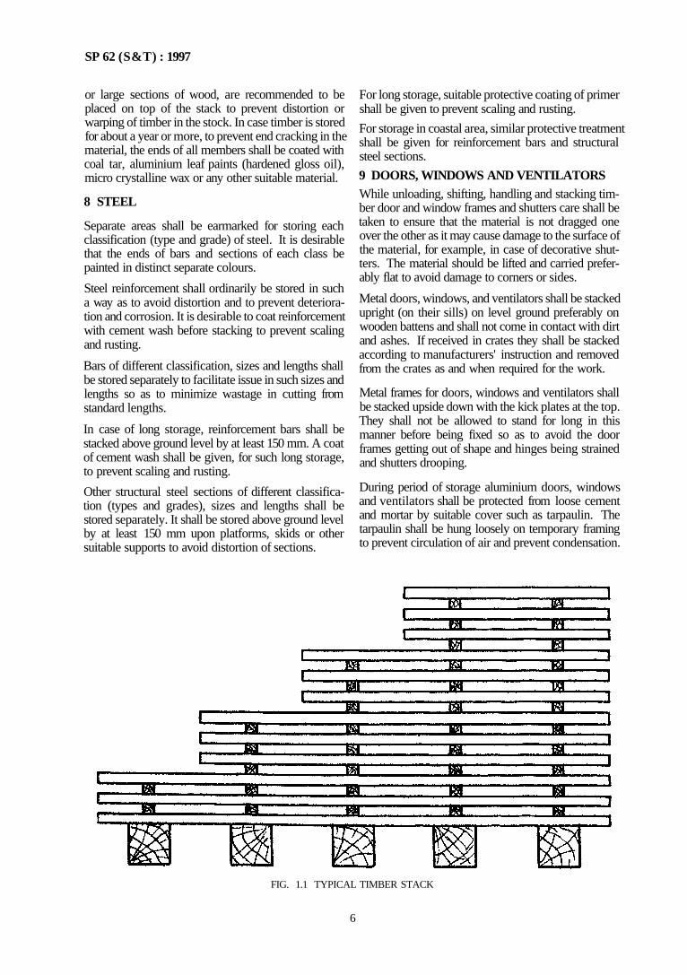
or large sections of wood, are recommended to be placed on top of the stack to prevent distortion or warping of timber in the stock. In case timber is stored for about a year or more, to prevent end cracking in the material, the ends of all members shall be coated with coal tar, aluminium leaf paints (hardened gloss oil), micro crystalline wax or any other suitable material.
8 STEEL
Separate areas shall be earmarked for storing each classification (type and grade) of steel. It is desirable that the ends of bars and sections of each class be painted in distinct separate colours.
Steel reinforcement shall ordinarily be stored in such a way as to avoid distortion and to prevent deterioration and corrosion. It is desirable to coat reinforcement with cement wash before stacking to prevent scaling and rusting.
Bars of different classification, sizes and lengths shall be stored separately to facilitate issue in such sizes and lengths so as to minimize wastage in cutting from standard lengths.
In case of long storage, reinforcement bars shall be stacked above ground level by at least 150 mm. A coat of cement wash shall be given, for such long storage, to prevent scaling and rusting.
Other structural steel sections of different classification (types and grades), sizes and lengths shall be stored separately. It shall be stored above ground level by at least 150 mm upon platforms, skids or other suitable supports to avoid distortion of sections.
For long storage, suitable protective coating of primer shall be given to prevent scaling and rusting.
For storage in coastal area, similar protective treatment shall be given for reinforcement bars and structural steel sections.
9 DOORS, WINDOWS AND VENTILATORS While unloading, shifting, handling and stacking timber door and window frames and shutters care shall be taken to ensure that the material is not dragged one over the other as it may cause damage to the surface of the material, for example, in case of decorative shutters. The material should be lifted and carried preferably flat to avoid damage to corners or sides.
Metal doors, windows, and ventilators shall be stacked upright (on their sills) on level ground preferably on wooden battens and shall not come in contact with dirt and ashes. If received in crates they shall be stacked according to manufacturers' instruction and removed from the crates as and when required for the work.
Metal frames for doors, windows and ventilators shall be stacked upside down with the kick plates at the top. They shall not be allowed to stand for long in this manner before being fixed so as to avoid the door frames getting out of shape and hinges being strained and shutters drooping.
During period of storage aluminium doors, windows and ventilators shall be protected from loose cement and mortar by suitable cover such as tarpaulin. The tarpaulin shall be hung loosely on temporary framing to prevent circulation of air and prevent condensation.
FIG. 1.1 TYPICAL TIMBER STACK
6
SP 6 2 ( S & T ) : 1997
All wooden frames and shutters shall be stored in dry and clean covered space away from any infestation and dampness. The storage shall be preferably in well ventilated dry rooms. The frames shall be stacked one over the other in vertical stacks with cross battens at regular distances to keep the stack vertical and straight. The cross battens should be of uniform thickness and placed vertically one above the other. The door shutters shall be stacked in the form of clean vertical stacks one over the other and at least 80 mm above ground on pallets or suitable beams or rafters. The top of the stack shall be covered by a protecting cover and weighed down by means of scantlings or other suitable weights. The shutter stack shall rest on hard and level ground.
Separate stacks shall be built for each size, each grade and each type of material. When materials of different sizes, grades and types are to be stacked together for want of space, the bigger size shall be stacked in the lower portion of the stacks. Suitable pallets or separating battens shall be kept in between two types of material.
If any wooden frame or shutter becomes wet during transit, it shall be kept separate from undamaged material. The wet material may be dried by stacking in shade with battens in between adjacent boards with tree access of dry air generally following the guidance laid down in IS 1141 : 1993.
10 ROOFING SHEETS
Roofing sheets shall be stored in such a way as not to damage them in any way.
Asbestos cement sheets shall be stacked to a height of not more than one metre on a firm and level ground with timber or other packing beneath them. If stacked in exposed position, they shall be protected from damage by wind.
Asbestos cement sheets of the same variety and size shall be stacked together. Damaged sheets shall not be stacked with sound materials. All damaged sheets shall be salvaged as early as possible.
11 BOARDS
Gypsum boards shall be stored flat in a clean covered and dry place.
Boards shall not be stored in the open and exposed to sun and rain, particularly if they are woodbased boards, such as plywood, fibre board, particle board, block board, etc.
The boards shall be stacked on a flat dunnage, on top of which a wooden frame shall be constructed with
50 mm × 25 mm battens in such a way that it will give support to all the four edges and corners of the boards with intermediate battens placed at suitable intervals to avoid warping.
The boards shall be stacked in a solid block in a clear vertical alignment. The top sheet of each stack shall be suitably weighed down to prevent warping.
The boards shall be unloaded and stacked with utmost care avoiding damage to corners and surface. In case of decorative plywood and decorative boards the surfaces of which are likely to get damaged by dragging one over the other it is advisable that these boards are lifted in pairs facing each other as far as possible.
12 PLASTIC AND RUBBER SHEETS
Plastic and rubber sheets have a tendency to breakdown during storage. These shall be stored according to manufacturers' instructions.
The coolest room available shall be utilized for the storage of rubber and plastic sheets. The store rooms where plastic and rubber sheets are stored shall be well ventilated and kept as dark as possible. Though complete darkness is not necessary, direct light should not be allowed to fall on the plastic and rubber sheets.
Contamination with vegetable and mineral oils, greases, organic solvents, acids and their fumes, alkalis, dust and grit, shall be prevented. When greasy contamination occurs this shall be removed immediately with petrol and the sheet thoroughly wiped dry and dusted with French chalk. Rubber and plastic sheets shall be stored away from electric generators, motors, switchgear and other such electrical equipment as they produce harmful odour in their vicinity.
Undue stretch and strain, kink, sharp bends or folds shall be avoided. In case of long storage, the sheets shall be turned over periodically and treated with French chalk, if necessary.
13 GLASS SHEETS
It is important that all sheets whether stored in crates or not shall be kept dry. Suitable covered storage space shall be provided for the safe storage of glass sheets. In removing glass sheets from crates great care shall be taken to avoid damage to glass. The glass sheets shall be lifted and stored on its long edges and shall be put into stacks not more than 25 panes, sup ported at two points by fillets of wood at 300 mm from each end. The first pane laid in each stack shall be so placed that its bottom edge is about 25 mm from the base of the wall or other support against which the stack rests. The whole stack shall be as close and as upright as possible.
7
SP 62 (S & T) : 1997
14. ASBESTOS CEMENT, PIPES AND FITTINGS
The pipes shall be unloaded where they are required, when the trenches are ready to receive them.
The pipes shall be stored on firm, level and clear ground and wedges shall be provided at the bottom layer to keep the stack stable.
The stack should be in pyramid shape or the pipes be arranged lengthwise and crosswise in alternate layers. The pyramid stack is advisable for smaller diameter pipes for conserving space in the store room. The height of the stack shall not exceed 1.5 m.
Each stack shall contain only pipes of same class and size, with consignment or batch number marked on it with particulars of suppliers wherever possible.
Cast iron detachable joints and fittings shall be stacked under cover and separated from asbestos cement pipes and fittings.
Rubber rings shall be kept clean, away from grease, oil. heat and light.
15 POLYETHYLENE PIPES
Black polyethylene pipes are suitably protected from ageing due to sunlight by the addition of appropriate quantity and type of carbon black during manufacture. Therefore they may be stored even in the open; however, it is preferable that they are stored under cover
Natural polyethylene pipes, however, shall be stored under cover and protected from direct sun.
Pipe coils may be stored either on edge or stacked flat one on top of another, but in either case they should not be allowed to come in contact with heat, such as, through hot water or steam pipes. They should also be kept away from hot surfaces.
Straight lengths of pipes should be stored on horizontal racks giving continuous support to prevent the pipe getting a permanent set if allowed to sag. Storage of pipes in heated areas exceeding 27°C shall be avoided.
16 UNPLASTICTZED PVC PIPES
These pipes shall be given support at all times. Pipes should be stored on a reasonably flat surface free from stones and sharp projections so that the pipe is supported all along its length. Pipes should not be stored on racks.
Pipes should not be stacked in large piles especially under warm temperature conditions as the bottom pipes may be distorted, thus creating problems in jointing. Socket and spigot pipes should be stacked in layers with sockets placed at alternate ends of the stacks to avoid lopsided stacks. Stacks shall not be
more than 1.5 m high. Avoid storing one pipe in another.
Pipes of different sizes and classes should be stacked separately.
On no account should pipes stored in a stressed or bent condition. The ends of pipes should be protected from abrasion particularly those specially prepared for jointing.
In tropical conditions, pipes should be stored in shade. In wintry conditions or cold weather the impact strength of PVC is reduced making it brittle; therefore more care shall be exercised in handling of the pipes.
If due to improper storage or handling, a pipe becomes kinked, the damaged portion should be cut out completely. Kinking is likely to occur in thin walled pipes.
17 BITUMEN, ROAD TAR AND ASPHALT
All types of bitumen, road tar, asphalt, etc, in drums or containers shall be stacked vertically on their bottoms up to 3 tiers, Leaky drums should be seggregated. Empty drums shall be stored in pyramidical stacks neatly in rows,
18 WATER
Wherever water is to be stored for construction purposes, it shall be done in proper storage tanks to prevent any organic impurities polluting the water.
19 FLAT TILES
Mat tiles shall be stacked on well treated and hard surface. Tiles shall be stacked at site in proper layers and tiers and they shall not be dumped in heaps In a stack, the tiles shall be so placed that the mould surface of one faces another. The height of the stack shall not be more than 1 m.
Tiles when supplied in packed boxes/crates shall be stored as such. They shall be opened only at the time of use.
20 OIL PAINTS
All containers of paints, thinners and allied materials shall preferably be stored on floors with sand cushions in a separate room which is well ventilated and free from excessive heat, sparks of flame and direct rays of the sun. The containers of paint shall be kept covered or properly fitted with lid and shall not be kept open except when in use.
21 SANITARY APPLIANCES
All sanitary appliances shall be carefully stored under cover to protect from damage. When accepting and
8
SP 62 (S & T) : 1997
storing appliances consideration shall be given to sequence of removal from the store to the asssembly positions. Proper stacking to assist the later stage will be advantageous. As nearly all assemblage have need for separating brackets, these shall be readily accessible as they will be required at an early stage.
22 PILES
Pile shall be stored on firm ground free from liability to unequal subsidence of settlement under the weight of the stack of piles. The piles shall be placed on timber supports which are truly level and spaced so as to avoid undue bending in the piles. The supports shall be left around the piles to enable them to be lifted without difficulty. The order of stacking shall be such that the older piles can be withdrawn for driving without disturbing the newer piles. Separate stacks shall be provided for different lengths of piles. Whenever curing is needed during storage, arrangements shall be made to enable the piles to be watered it (he weather conditions so require.
Care shall be taken at all stages of transportating, lifting and handling of piles to see that they are not damaged or cracked during handling. during transportation the piles shall be supported at ap propriate lifting holes provided for the purpose If piles are put down temporarily after being lifted, they shall be placed on trestles or blocks located at the lifting points.
23 OTHER MATERIALS
Small articles like screws, bolts, nuts, door and win dow fittings, polishing stones, protective clothing, spare parts of machinery, linings and packings, water supply and sanitary fittings, etc, shall be kept in a suitable and properly protected store rooms. Valuable small material shall be kept under lock and key.
24 SPECIAL CONSIDERATIONS
Material constantly in use shall be relatively nearer the place of use.
Heavy units like precast concrete members shall be stacked near the hoist and the ramp.
Materials which normally deteriorate during storage shall be kept constantly moving, by replacing old materials with new stocks.
Freshly arrived materials shall never be placed over materials which had arrived earlier
Fire extinguishers and Fire buckets shall be provided wherever necessary for safety.
25 ELECTRICAL MATERIALS
Storage of electrical materials such as, cables, conductors, switch gear, etc, shall conform to National Electric Code, 1983 [see also the supplementary 'Handbook on electrical installation in buildings' (under preparation)]
9


CHAPTER 2
EARTHWORK
CONTENTS
1
2
4
4
5
6
7
8
9
10
CLASSIFCATION OF SOILS
GENERAL PRECAUTIONS
SURFACE EXCAVATION
3.1 General 3.2 Setting Out and Making Profiles
ROUGH EXCAVATION
4 1 General 4.2 Cutting 4 3 Filling EXCAVATION OVER AREA IN SOFT/HARD SOIL
5 1 General 5 2 Setting Out and Making Profiles 5 3 Cutting EXCAVATION OVER AREA IN ORDINARY/HARD
ROCK
6.1 General 6.2 Blasting Operations 6 3 Precautions During Blasting
EXACAVATION IN FOUNDATION TRENCHES OR
DRAINS (SOFT/HARD SOIL)
E X C A T I O N IN FOUNDATION TRENCHES OR
DRAINS (ORDINARY ROCK)
EXCAVATION IN FOUNDATION TRENCHES OR
DRAINS (HARD ROCK)
EXCAVATION IN TRENCHES FOR PIPES, CABLES,
ETC, AND REFILLING
10 1 General 10 2 Width of Trench
11
12
13
14
15
16
10.3 Filling
SHORING, AND TIMBERING
EXCAVATION IN MUD, WATER OR FOUL POSITION
FILLING IN TRENCHES, UNDER FLOORS. ETC
SAND FILLING IN PLINIH
SURFACE DRESSING
ANTI ILRMITE TREATMENT
(CHEMICAL TREAEMENT)
16.1 General 16.2 Site Preparation 16.3 Treatment Beneath the Building 16.4 Time of Application 16.5 Treatment of Masonry Foundations and
Basements 16.6 Treatment of RCC Foundations and Base
ments 16.7 Treatment of Top Surface of Plinth Filling 16.8 Treatment at Junction of the Wall and the
Floor 16.9 Treatment of Soil Along External Perimeter
oF the Building 16 10 Treatment of Soil Apton Along Externa
Perimeter of Building 16.11 Treatment of Walls Retaining Soil Above
Ground Level 16 12 Treatment of Soil Surrounding Pipes
Conduits, etc 16.13 Treatment of Expansion Joints
SP 62 ( S & T) : 1997
CHAPTER 2
EARTHWORK
1 CLASSIFICATION OF SOILS
1.1 For the purpose of this chapter regarding earthwork soils may be classified as below:
a) Soft/Loose Soil - Generally any soil which yields to the ordinary application of pick and shovel or to a spade, rake or other ordinary digging tools, examples: 1) Sand, gravel, loam, clay, mud, black
cotton soil. 2) Vegetable or organic soil, turf, peat, soft
shale or loose murrum. 3) Mud concrete below ground level. 4) Any mixture of soils mentioned above.
b) Hard/Dense Soil - -Generally any soil which requires the close application of picks or jumpers or scarifiers and rippers to loosen the same, examples: 1) Still heavy clay, hard shale or compact
murrum requiring grafting tool and/or pick and shovel.
2) Shingle and river or nallah bed boulders 3) Soling of roads, paths, etc, and hard core.
4) Macadam surface of any description (water bound, grouted tarmac, etc).
5) Lime concrete, stone masonry in lime or cement mortal below ground level.
6) Soft conglomerate or soft laterite when the stone can be detached from matrix with picks .
c) Ordinary Rock (not requiring blasting, wedg-ing, or similar means)—This may be quarried or split with crow bars or picks, such as, limestone, hard laterite, hard conglomerate and unreinforced cement concrete below ground level
NOTE - If required light blasting may be resorted to for loosening the materials but this does not in any way entitle the material to be classified as 'Hard Rock'.
d) Hard Rock (requiring blasting) — Any rock or boulder for the excavation of which blasting is required such as quartzite, granite, basalt, reinforced cement concrete (reinforcement to be cut through but not separated from concrete), etc, below ground level.
e) Hard Rock (blasting prohibited) — In hard rock where blasting is prohibited for any reason, excavation has to be carried out by chiselling, wedging or any other agreed method.
1.2 IS 1498 . 1970 may be seen for classification of soils for general engineering purposes.
2 GENERAL PRECAUTIONS
Excavating shall not be carried out below foundation level of adjacent buildings, until underpinning, shoring, etc, is done. Adequate precautions shall be taken to see that the excavation operations do not affect adjacent buildings.
Trenches and foundation pits shall be securely fenced and posted with proper precautionary signs. They shall be marked with red lights at night to avoid accidents. Public safety shall be ensured at all times.
2.1 Site Clearance
Before the earthwork is started, the site shall be cleared of vegetation, brushwood, trees, saplings, etc, of ??? up to 30 cm measured at a height of 1m above ground level and rubbish remained up to a distance of 50m outside the periphery of area under clearance The roots of trees shall be removed to depth of at least 60 cm below ground level or 30 cm below foundation level and the hollows filled up with earth, levelled and rammed.
The trees of girth above 30 cm measured at a height of 1 m above ground level shall be cut only after permission of the Engineer-in-charge. The roots of trees shall be removed as specified in above para
Existing structures, such as, old buildings, culverts, pipe line, sewers, etc, within the site, shall be dis-mantled; if necessary, with appropriate permission. structures adjacent to the site may be dismantled.
Archaeological monuments, structures, etc, should be dealt with appropriately in consultation with the con cerned Authority, similarly felling of trees should be done is consultation with the concerned Authority.
3 SURFACE EXCAVATION
3.1 General
Excavation exceeding 1.5 m width and 10m2 on plan but not exceeding 30 cm in depth shall be called 'surface excavation'.
3.2 Setting Out and Making Profiles
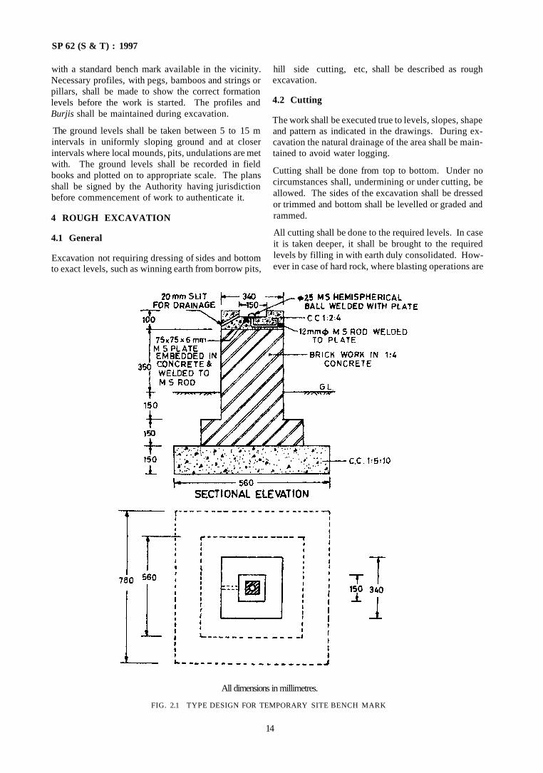
A masonry pillar shall be erected at a suitable point in the area which would be visible from most points in the area to serve as a benchmark for the execution of work. A typical construction of the bench mark is shown in Fig. 2.1 This bench mark shall be connected
13
SP 62 (S & T) : 1997
with a standard bench mark available in the vicinity. Necessary profiles, with pegs, bamboos and strings or pillars, shall be made to show the correct formation levels before the work is started. The profiles and Burjis shall be maintained during excavation.
The ground levels shall be taken between 5 to 15 m intervals in uniformly sloping ground and at closer intervals where local mounds, pits, undulations are met with. The ground levels shall be recorded in field books and plotted on to appropriate scale. The plans shall be signed by the Authority having jurisdiction before commencement of work to authenticate it.
4 ROUGH EXCAVATION
4.1 General
Excavation not requiring dressing of sides and bottom to exact levels, such as winning earth from borrow pits,
hill side cutting, etc, shall be described as rough excavation.
4.2 Cutting
The work shall be executed true to levels, slopes, shape and pattern as indicated in the drawings. During excavation the natural drainage of the area shall be maintained to avoid water logging.
Cutting shall be done from top to bottom. Under no circumstances shall, undermining or under cutting, be allowed. The sides of the excavation shall be dressed or trimmed and bottom shall be levelled or graded and rammed.
All cutting shall be done to the required levels. In case it is taken deeper, it shall be brought to the required levels by filling in with earth duly consolidated. However in case of hard rock, where blasting operations are
All dimensions in millimetres.
FIG. 2.1 TYPE DESIGN FOR TEMPORARY SITE BENCH MARK
14
SP 62 ( S & T) : 1997
resorted to, cutting shall be left as it is and made up during construction.
4.3 Filling
The earth from cutting shall be directly used for filling. Filling of earth shall be done in regular horizontal layers, each not exceeding 20 cm thick. The earth shall be free of all roots, grass, rubbish; and lumps and clods exceeding 8 cm in any direction shall be broken. Each layer shall be consolidated by ramming. Watering of each layer may be done if required. The top surface of the finally finished area be neatly dressed. The finished formation levels, in case of filling, shall be kept higher than the required levels, by making an allowance of 10 percent of depth of filling for future settlement in case of ordinary consolidated fills. The allowance shall be 5 percent if consolidation is done by machinery. No allowance shall be made if con-solidation is done by heavy mechanical equipment under optimum moisture conditions.
5 EXCAVATION OVER AREA IN SOFT/HARD SOIL
5.1 General
This shall include:
a) Excavation exceeding 1.5 m in width and 10 m2 on plan and exceeding 30 cm in depth;
b) Excavation in basements, water tanks, etc; and c) Excavation in trenches for foundations exceed-
ing 1.5 m width and 10 m2 on plan.
Excavation shall be carried out to the required depths and profiles.
5.2 Setting Out and Making Profiles (see 3.2)
5.3 Cutting
In firm soils, the sides of the trench shall be kept vertical up to a depth of 2 m from the bottom. For greater depth, the excavation profiles shall be widened by allowing steps of 50 cm on either side after every 2 m from the bottom. Alternatively, the excavation may be done to give a side slope of 1 :4. Where the soil is soft, loose or slushy, the width of steps shall be suitably increased or side sloped or the soil shored up. The bed excavation shall be made to the correct level or slope and consolidated by watering and ramming. Soft and weak spots shall be dug out and filled with levelling concrete. Excess depth, if any, also shall be made good with the same concrete.
6 EXCAVATION OVER AREA IN ORDINARY/HARD ROCK
6.1 General
This shall include:
a) Excavation exceeding 1.5 m in width and 10 m2 on plan and exceeding 30 cm depth;
b) Excavation for basement, water tanks, etc; and
c) Excavation in trenches for foundations exceeding 1.5 m in width and 10 m2 on plan.
Excavation shall be carried out to the required depths and profiles.
6.2 Blasting Operations
Where blasting operations are necessary as in hard rock, prior permission shall be obtained from the Authority. In ordinary rock, blasting operations shall not be generally adopted.
6.3 Precautions During Blasting
During blasting operations proper precautions shall be taken for the safety of persons. Blasting operations shall not be done within 200 m of existing structures. All operations shall conform to Rules and Regulations of Indian Explosive Act, 1940 as amended from time to time. In addition precautions laid down in IS 4081 : 1986 [see also IS 5878 (Part 2/Sec 1) : 1970].
7 EXCAVATION IN FOUNDATION TRENCHES OR DRAINS (SOFT/HARD SOIL)
7.1 Excavation in trenches for foundations shall not exceed 1.5 m in width or 10 m2 or plan to any depth (excluding trenches for pipes, cables, etc).
7.2 The excavation operation shall include excavation and removal of the earth. The excavated earth shall be thrown at least at half the depth of excavation, clear of the edge of excavation. The earth shall be disposed off as directed by the Authority.
While carrying out at the excavation work for drains, care shall be taken to cut the sides and bottom to the required shape, slope and gradient. The surface shall be properly dressed. If the excavation is done to a greater depth than shown on drawings, the excess depth shall be made good with stiff clay puddle at places where the drains are requited to be pitched. The excess depth shall he made good with ordinary earth and properly watered and rammed where the drain is not required to be pitched. The back filing with clay puddle shall be done side by side as the pitching work proceeds. Brick pitched storm water drain shall be avoided as far as possible in filled up areas.
8 EXCAVATION IN FOUNDATION TRENCHES OR DRAINS (ORDINARY ROCK)
8.1 Excavation not exceeding 1.5 m in width or 10 m2
on plan to any depth in trenches (excluding trenches for pipes, cables, etc) shall be described as excavation in trenches for foundations.
15
SP 62 (S&T) : 1997
8.2 Excavation in ordinary rock shall be carried out by crow bars, pick axes, or pneumatic drills. Blasting operations are not generally required in this case.
9 EXCAVATION IN FOUNDATION TRENCHES OR DRAINS (HARD ROCK) 9.1 Excavation not exceeding 1.5 m in width or 10 m2
on plan to any depth in trenches (excluding trenches for pipes, cables, etc) shall be described as excavation in trenches for foundation.
9.2 Excavation in hard rock shall be done by chisell-ing, where blasting operations are prohibited or are not practicable. In trenches and drains, where blasting is not otherwise prohibited, excavation shall be carried out by blasting in the first instance and finally by chiselling to obtain the correct section of the trench as per drawings.
10 EXCAVATION IN TRENCHES FOR PIPES, CABLES, ETC, AND REFILLING
10.1 General
Excavation not exceeding 1.5 m in width or 10 m2 in plan to any depth in trenches shall be described as trenches for pipes, cables, etc. Returning, filling and ramming (after pipes and cables are laid) and removal of surplus soil shall form part of this work. 10.2 Width of Trench
a) For depth up to 1 m, the width of the trench shall be arrived at by adding 25 cm to the external diameter of the pipe (not socket), cable, conduit, etc. When the pipe is laid on a concrete bed/cushioning layer, the width shall be pipe diameter plus 25 cm or the width of concrete bed/cushioning layer whichever is more.
b) For depths exceeding 1 m, an additional width of 5 cm/m depth for each side of trench shall be taken to arrive at the width, that is, external diameter of pipe + 25 cm + 2 × 5 cm. This shall apply to the entire depth of trench.
c) When more than one pipe, cable, conduit are laid, the diameter to be taken shall be the horizontal distance from outside to outside of outermost pipe, cable, conduit, etc.
10.3 Filling Normally excavated earth shall be used for filling. In case such earth contains deleterious salts, it shall not be used. All clods of earth shall be broken or removed. Where excavated material is mostly rock, the boulders shall be broken into pieces not bigger than 15 cm in any direction and be mixed with fine materials of decomposed rock, murrum or earth as available so as to fill up the voids as far as possible; this shall be used for filling.
10.3.1 Filling the trenches for pipes, cables, etc shall be commenced immediately after the joints of pipes, etc, are tested and passed. Where the trenches are excavated in soil, the filling shall be done with earth on the sides and top of pipes in layers not exceeding 20 cm, watered, rammed and consolidated ensuring that the pipes are not damaged.
In case of excavation of trenches in rock the filling up to a depth of 30 cm above the crown of the pipe, shall be done with fine material such as earth, murrum or pulverized decomposed rock as available. The remaining depth shall be done with rock filling or boulders of size not exceeding 15 cm mixed with fine material as available to fill up the voids; and then watered, rammed and consolidated in layers not ex-ceeding 30 cm.
11 SHORING AND TIMBERING
11.1 All trenches exceeding 2.0 m in depth shall be securely shored and timbered as determined by the Engineer-in-charge.
NOTES
1 The above requirements do not apply in cases where the sides of the trenches are sloped to within 1 5 in of the bottom The slope that is provided for such purposes shall be inspected and declared as stable
2 Notwithstanding anything said above, it shall be understood that the need for shoring is a matter which shall receive careful consideration even in trenches less than 2 0 m of depth where there is a doubt as to the safety of work
11.2 Where sides of trenches are sloped (see Note 1 of 11.1) the vertical sides shall be shored and the shoring shall extend at least 30 cm above the vertical sides. When open spaced sheathing is provided, a toe board shall be provided to prevent material rolling down the slope and falling into the part of the trench with vertical walls.
11.3 Shoring and timbering shall be carried out along with the opening of a trench but when conditions permit protection of work, such as sheet piling may be done before the excavation commences.
11.4 Approved quality of SAL wood shall be used for shoring and timbering a trench. Any other structural material having strength not less than that of SAL may be used for the purpose (see IS 883 : 1970). The stress values of species for design of members shall be taken as 2/3 of the values given in Table 2 of IS 883 : 1970.
11.5 Erection of Shoring and Timbering
Provisions detailed as in 11.5.1 to 11.5.4 shall be followed while erecting shoring and timbering (see Fig. 2.2).
16
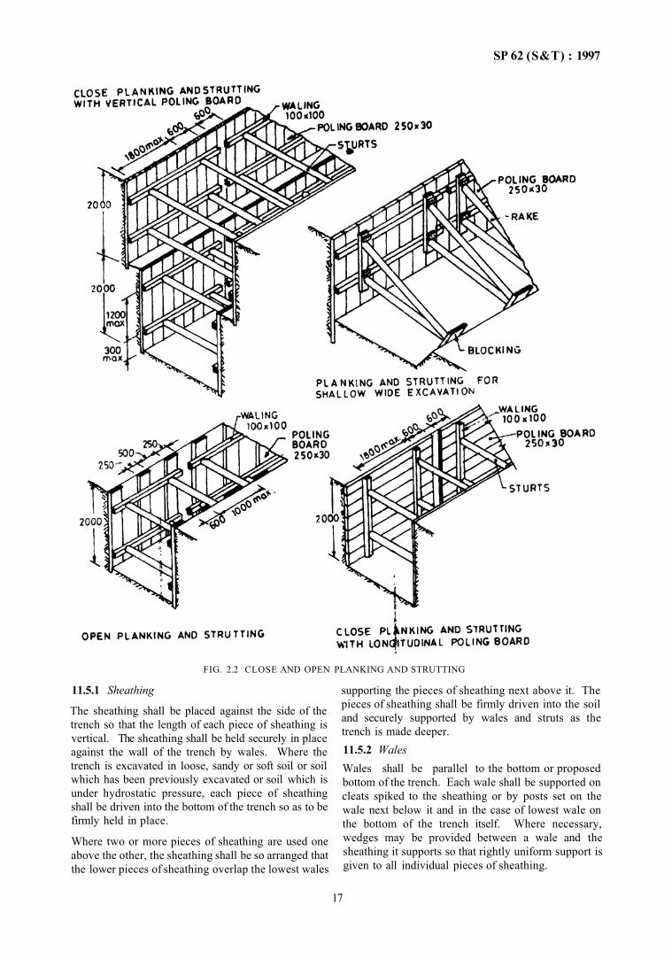
SP 62 (S&T) : 1997
FIG. 2.2 CLOSE AND OPEN PLANKING AND STRUTTING
11.5.1 Sheathing
The sheathing shall be placed against the side of the trench so that the length of each piece of sheathing is vertical. The sheathing shall be held securely in place against the wall of the trench by wales. Where the trench is excavated in loose, sandy or soft soil or soil which has been previously excavated or soil which is under hydrostatic pressure, each piece of sheathing shall be driven into the bottom of the trench so as to be firmly held in place.
Where two or more pieces of sheathing are used one above the other, the sheathing shall be so arranged that the lower pieces of sheathing overlap the lowest wales
supporting the pieces of sheathing next above it. The pieces of sheathing shall be firmly driven into the soil and securely supported by wales and struts as the trench is made deeper. 11.5.2 Wales Wales shall be parallel to the bottom or proposed bottom of the trench. Each wale shall be supported on cleats spiked to the sheathing or by posts set on the wale next below it and in the case of lowest wale on the bottom of the trench itself. Where necessary, wedges may be provided between a wale and the sheathing it supports so that rightly uniform support is given to all individual pieces of sheathing.
17
SP 62 (S&T) : 1997
11.5.3 Struts. Struts shall be horizontal and at right angles to the wales or sheathing supported thereby. Struts shall be cut to the proper length required to fit in tightly be-tween the wales. Where necessary, the struts shall be held securely in place by wedges, driven between struts and the wales.
11.5.4 Struts shall be placed on cleats spiked or bolted to posts supporting wales.
11.6 Sizes and Spacing of Members
11.6.1 The sizes and spacing of sheathing, wales and struts used for shoring and timbering for different trenches shall be as given in Tables 2.1 to 2.4. Table 2.1 for hard soil, Table 2.2 for soil which may crack or crumble, Table 2.3 for loose sandy or soft soil which has been previously excavated and Table 2.4 for soil under hydro-static pressure. Where the section of the wale or strut is rectangular, the longer side shall be kept vertical. Where distinctly different types of strata en-countered, each strata shall be treated separately as is required by its characteristics.
11.6.2 Where a wedge is used in shoring and timber-ing of a trench, the thick end of the wedge shall be at least 5 cm wide.
11.7 Removal of timber members shall be done care-fully to prevent collapse of the trench.
12 EXCAVATION IN MUD, WATER OR FOUL POSITION
12.1 When water is met with in excavation due to stream flow, seepage, springs, rain or other reasons, adequate measures shall be taken to bail out water by pumping or other means to keep the foundation trench dry. Excavation shall be done within shored and tim-bered area in a similar manner.
12.2 Trial pits shall be dug in the area where excava-tion is required to be done. The steady water level in the trial pits, before the pumping operation is started, shall be considered as the subsoil water level in that area.
13 FILLING IN TRENCHES, UNDER FLOORS, ETC
13.1 Earth used for filling shall be free from stone, shingle or boulder not larger than 75 mm in any direc-tion; it shall also be free from salts, organic matter or other foreign matter.
13.2 In trenches the space around the foundations, pipes, drains, etc, shall be cleared of all debris, brick-bats, etc. The filling shall be done in layers not exceed-ing 20 cm in each layer. Each layer must be watered and rammed for consolidation.
In case of filling under floors, the finished level of the filling shall be kept to the slope to be given to the floor. 14 SAND FILLING IN PLINTH 14.1 Sand shall conform to grading zone V or IV, and it shall be free from dust, organic and foreign matter (see Chapter 4). 14.2 Sand filling shall be done in a manner similar to earth filling in plinths as specified in 13, except that consolidation shall be done by flooding with water. The surface of the consolidated sand shall be dressed to the level or slope required. 15 SURFACE DRESSING 15.1 Surface dressing shall include removal of vegetation, cutting and filling up to depth of 15 cm and dressing the area. 15.2 Dressing High portions of ground shall be cut down and hollows and depressions filled up to the required level with the excavated earth so as to give an even, neat and tidy look to the site.
16 ANTI-TERMITE TREATMENT (CHEMICAL TREATMENT) 16.1 General Termites are divided into two types on the basis of their habitat, namely (a) Subterannean or ground-nesting termites, and (b) Non-subterranean or wood-nesting termites having no contact with soil. The former are more destructive. Treating the soil with chemicals beneath the building and around the foundation with a chemical soil insecticide is a good preventive measure. The purpose of the treatment is to create a chemical barrier between the ground and woodwork. Of course, timber used in the building shall be natural, durable, heartwood, treated and seasoned.
Anti-termite treatment can also be given, through con-structional measures, to existing buildings. These are covered elsewhere (see Chapter 6). 16.2 Site Preparation 16.2.1 Remove trees, stumps, logs or roots which may be harbouring the termites. 16.2.2 On clays and other heavy soils where penetra-tion is likely to be slow and on sloping sites where run off of the treating solution is likely to occur, the surface of the soil should be scarified to a depth of at least 75 mm. 16.2.3 On loose and porous or sandy soils where loss of treating solution through piping or excessive per-colation is likely to occur, preliminary moistening to fill capillary spaces in the soil is recommended. 16.2.4 All subfloor levelling and grading shall be completed. All cuttings, trenches and excavations
18
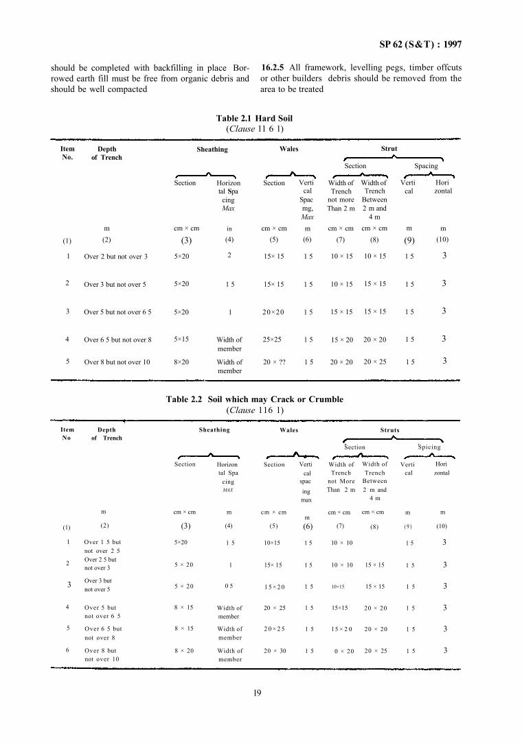
SP 62 (S&T) : 1997
should be completed with backfilling in place Bor-rowed earth fill must be free from organic debris and should be well compacted
16.2.5 All framework, levelling pegs, timber offcuts or other builders debris should be removed from the area to be treated
Table 2.1 Hard Soil (Clause 11 6 1)
Item No.
(1)
Depth of Trench
m
Max
(2)
Sheathing
Section
cm × cm
(3)
Horizon tal Spa
cing
in
(4)
Wales
Section
cm × cm (5)
Verti cal
Spac mg, Max
m (6)
Strut
Section
Width of Trench
not more Than 2 m
cm × cm (7)
Width of Trench
Between 2 m and
4 m cm × cm
(8)
Spacing
Verti cal
m
(9)
Hori zontal
m (10)
1
2
3
4
5
Over 2 but not over 3
Over 3 but not over 5
Over 5 but not over 6 5
Over 6 5 but not over 8
Over 8 but not over 10
5×20
5×20
5×20
5×15
8×20
2
1 5
1
Width of member
Width of member
15× 15
15× 15
20×20
25×25
20 × ??
1 5
1 5
1 5
1 5
1 5
10 × 15
10 × 15
15 × 15
15 × 20
20 × 20
10 × 15
15 × 15
15 × 15
20 × 20
20 × 25
1 5
1 5
1 5
1 5
1 5
3
3
3
3
3
Table 2.2 Soil which may Crack or Crumble (Clause 116 1)
Item No
(1)
Depth of Trench
m
(2)
Sheathing
Section
cm × cm
(3)
Horizon tal Spa
cing MAX
m
(4)
Wales
Section
cm × cm
(5)
Verti cal
spac ing max
m (6)
Struts
Section
Width of Trench
not More Than 2 m
cm × cm
(7)
Width of Trench
Between 2 m and
4 m
cm × cm
(8)
Spicing
Verti cal
m
( 9 )
Hori zontal
m
(10)
1
2
3
4
5
6
Over 1 5 but not over 2 5 Over 2 5 but not over 3
Over 3 but not over 5
Over 5 but not over 6 5
Over 6 5 but not over 8
Over 8 but not over 10
5×20
5 × 20
5 × 20
8 × 15
8 × 15
8 × 20
1 5
1
0 5
Width of member
Width of member
Width of member
10×15
15× 15
1 5 × 2 0
20 × 25
2 0 × 2 5
20 × 30
1 5
1 5
1 5
1 5
1 5
1 5
10 × 10
10 × 10
10×15
15×15
l 5 × 2 0
0 × 20
15 × 15
15 × 15
20 × 20
20 × 20
20 × 25
1 5
1 5
1 5
1 5
1 5
1 5
3
3
3
3
3
3
19
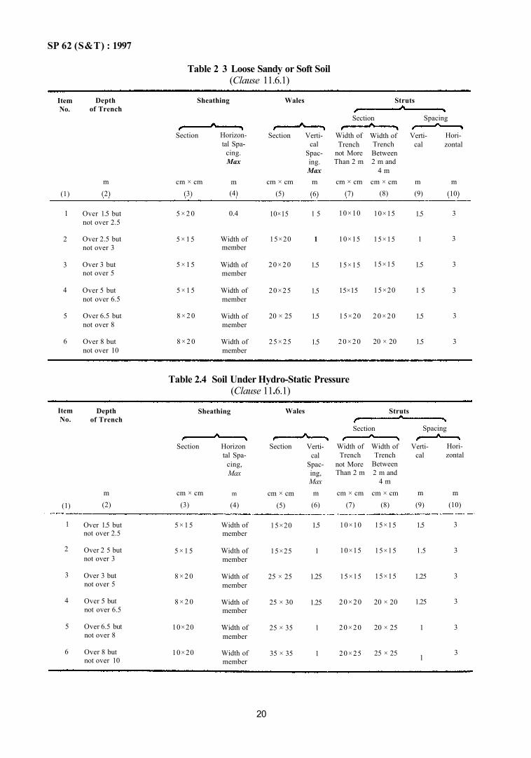
SP 62 (S&T) : 1997
Table 2 3 Loose Sandy or Soft Soil (Clause 11.6.1)
Item No.
(1)
Depth of Trench
m (2)
Sheathing
Section
cm × cm (3)
Horizon-tal Spa-
cing. Max
m (4)
Wales
Section
cm × cm (5)
Verti-cal
Spac-ing. Max
m (6)
Struts
Section
Width of Trench
not More Than 2 m
cm × cm (7)
Width of Trench Between 2 m and
4 m cm × cm
(8)
Spacing
Verti-cal
m (9)
Hori-zontal
m (10)
1
2
3
4
5
6
Over 1.5 but not over 2.5
Over 2.5 but not over 3
Over 3 but not over 5
Over 5 but not over 6.5
Over 6.5 but not over 8
Over 8 but not over 10
5 × 2 0
5 × 1 5
5 × 1 5
5 × 1 5
8 × 2 0
8 × 2 0
0.4
Width of member
Width of member
Width of member
Width of member
Width of member
10×15
15×20
20×20
20×25
20 × 25
25×25
1 5
1
1.5
1.5
1.5
1.5
10×10
10×15
15×15
15×15
15×20
20×20
10×15
15×15
15×15
15×20
20×20
20 × 20
1.5
1
1.5
1 5
1.5
1.5
3
3
3
3
3
3
Table 2.4 Soil Under Hydro-Static Pressure (Clause 11.6.1)
Item No.
(1)
Depth of Trench
m (2)
Sheathing
Section
cm × cm (3)
Horizon tal Spa-
cing, Max
m
(4)
Wales
Section
cm × cm (5)
Verti-cal
Spac-ing, Max
m (6)
Struts
Section
Width of Trench
not More Than 2 m
cm × cm (7)
Width of Trench
Between 2 m and
4 m cm × cm
(8)
Spacing
Verti-cal
m (9)
Hori-zontal
m (10)
1
2
3
4
5
6
Over 1.5 but not over 2.5
Over 2 5 but not over 3
Over 3 but not over 5
Over 5 but not over 6.5
Over 6.5 but not over 8
Over 8 but not over 10
5 × 1 5
5 × 1 5
8 × 2 0
8 × 2 0
10×20
10×20
Width of member
Width of member
Width of member
Width of member
Width of member
Width of member
15×20
15×25
25 × 25
25 × 30
25 × 35
35 × 35
1.5
1
1.25
1.25
1
1
10×10
10×15
15×15
20×20
20×20
20×25
15×15
15×15
15×15
20 × 20
20 × 25
25 × 25
1.5
1.5
1.25
1.25
1
1
3
3
3
3
3
3
20
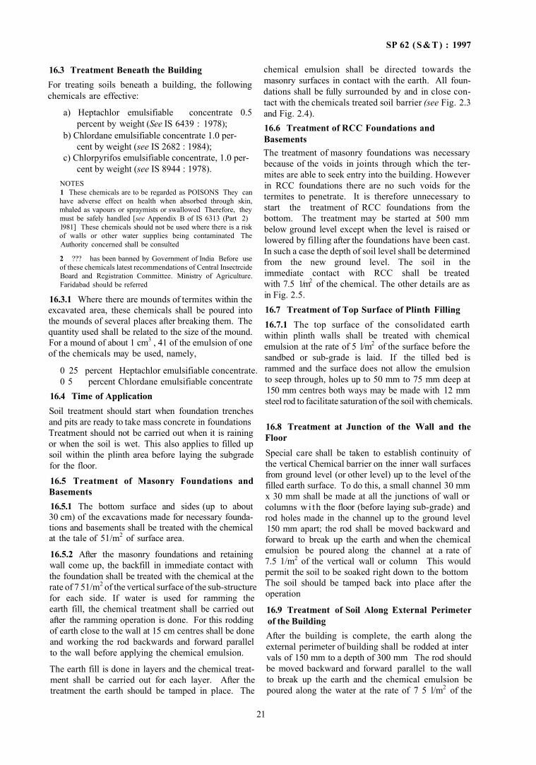
SP 62 (S&T) : 1997
16.3 Treatment Beneath the Building For treating soils beneath a building, the following chemicals are effective:
a) Heptachlor emulsifiable concentrate 0.5 percent by weight (See IS 6439 : 1978);
b) Chlordane emulsifiable concentrate 1.0 per- cent by weight (see IS 2682 : 1984);
c) Chlorpyrifos emulsifiable concentrate, 1.0 per- cent by weight (see IS 8944 : 1978).
NOTES 1 These chemicals are to be regarded as POISONS They can have adverse effect on health when absorbed through skin, mhaled as vapours or spraymists or swallowed Therefore, they must be safely handled [see Appendix B of IS 6313 (Part 2) l981] These chemicals should not be used where there is a risk of walls or other water supplies being contaminated The Authority concerned shall be consulted
2 ??? has been banned by Government of India Before use of these chemicals latest recommendations of Central Insectrcide Board and Registration Committee. Ministry of Agriculture. Faridabad should be referred
16.3.1 Where there are mounds of termites within the excavated area, these chemicals shall be poured into the mounds of several places after breaking them. The quantity used shall be related to the size of the mound. For a mound of about 1 cm3 , 41 of the emulsion of one of the chemicals may be used, namely,
0 25 percent Heptachlor emulsifiable concentrate. 0 5 percent Chlordane emulsifiable concentrate
16.4 Time of Application Soil treatment should start when foundation trenches and pits are ready to take mass concrete in foundations Treatment should not be carried out when it is raining or when the soil is wet. This also applies to filled up soil within the plinth area before laying the subgrade for the floor. 16.5 Treatment of Masonry Foundations and Basements 16.5.1 The bottom surface and sides (up to about 30 cm) of the excavations made for necessary foundations and basements shall be treated with the chemical at the tale of 51/m2 of surface area.
16.5.2 After the masonry foundations and retaining wall come up, the backfill in immediate contact with the foundation shall be treated with the chemical at the rate of 7 51/m2 of the vertical surface of the sub-structure for each side. If water is used for ramming the earth fill, the chemical treatment shall be carried out after the ramming operation is done. For this rodding of earth close to the wall at 15 cm centres shall be done and working the rod backwards and forward parallel to the wall before applying the chemical emulsion.
The earth fill is done in layers and the chemical treatment shall be carried out for each layer. After the treatment the earth should be tamped in place. The
chemical emulsion shall be directed towards the masonry surfaces in contact with the earth. All foundations shall be fully surrounded by and in close contact with the chemicals treated soil barrier (see Fig. 2.3 and Fig. 2.4). 16.6 Treatment of RCC Foundations and Basements The treatment of masonry foundations was necessary because of the voids in joints through which the termites are able to seek entry into the building. However in RCC foundations there are no such voids for the termites to penetrate. It is therefore unnecessary to start the treatment of RCC foundations from the bottom. The treatment may be started at 500 mm below ground level except when the level is raised or lowered by filling after the foundations have been cast. In such a case the depth of soil level shall be determined from the new ground level. The soil in the immediate contact with RCC shall be treated with 7.5 1/m2 of the chemical. The other details are as in Fig. 2.5. 16.7 Treatment of Top Surface of Plinth Filling 16.7.1 The top surface of the consolidated earth within plinth walls shall be treated with chemical emulsion at the rate of 5 l/m2 of the surface before the sandbed or sub-grade is laid. If the tilled bed is rammed and the surface does not allow the emulsion to seep through, holes up to 50 mm to 75 mm deep at 150 mm centres both ways may be made with 12 mm steel rod to facilitate saturation of the soil with chemicals.
16.8 Treatment at Junction of the Wall and the Floor Special care shall be taken to establish continuity of the vertical Chemical barrier on the inner wall surfaces from ground level (or other level) up to the level of the filled earth surface. To do this, a small channel 30 mm x 30 mm shall be made at all the junctions of wall or columns w i th the floor (before laying sub-grade) and rod holes made in the channel up to the ground level 150 mm apart; the rod shall be moved backward and forward to break up the earth and when the chemical emulsion be poured along the channel at a rate of 7.5 1/m2 of the vertical wall or column This would permit the soil to be soaked right down to the bottom The soil should be tamped back into place after the operation
16.9 Treatment of Soil Along External Perimeter of the Building After the building is complete, the earth along the external perimeter of building shall be rodded at inter vals of 150 mm to a depth of 300 mm The rod should be moved backward and forward parallel to the wall to break up the earth and the chemical emulsion be poured along the water at the rate of 7 5 l/m2 of the
21
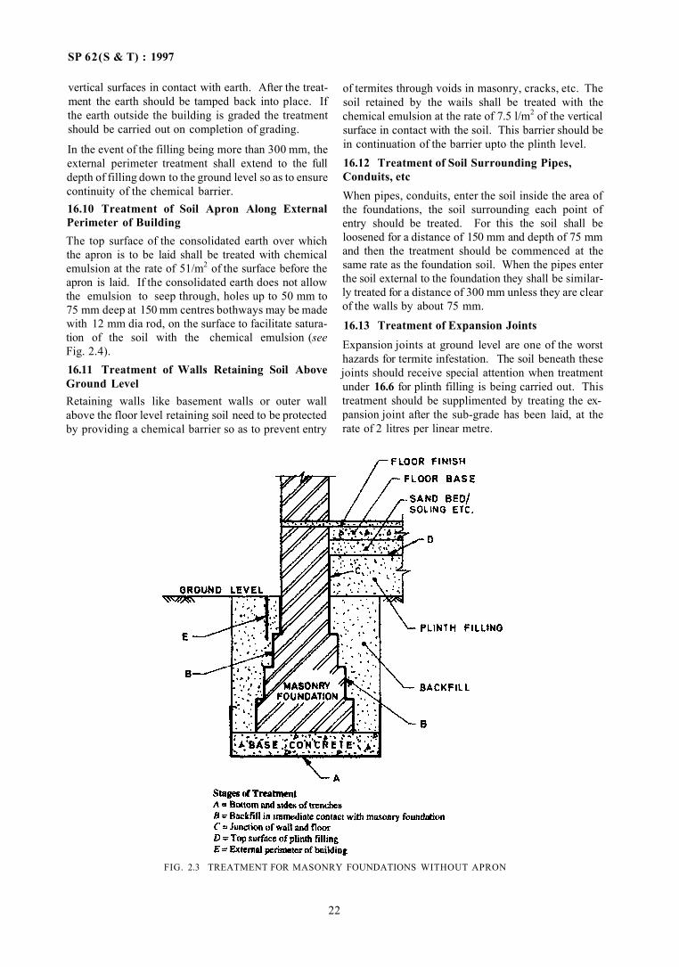
SP 62(S & T) : 1997
vertical surfaces in contact with earth. After the treatment the earth should be tamped back into place. If the earth outside the building is graded the treatment should be carried out on completion of grading.
In the event of the filling being more than 300 mm, the external perimeter treatment shall extend to the full depth of filling down to the ground level so as to ensure continuity of the chemical barrier. 16.10 Treatment of Soil Apron Along External Perimeter of Building The top surface of the consolidated earth over which the apron is to be laid shall be treated with chemical emulsion at the rate of 51/m2 of the surface before the apron is laid. If the consolidated earth does not allow the emulsion to seep through, holes up to 50 mm to 75 mm deep at 150 mm centres bothways may be made with 12 mm dia rod, on the surface to facilitate saturation of the soil with the chemical emulsion (see Fig. 2.4). 16.11 Treatment of Walls Retaining Soil Above Ground Level Retaining walls like basement walls or outer wall above the floor level retaining soil need to be protected by providing a chemical barrier so as to prevent entry
of termites through voids in masonry, cracks, etc. The soil retained by the wails shall be treated with the chemical emulsion at the rate of 7.5 l/m2 of the vertical surface in contact with the soil. This barrier should be in continuation of the barrier upto the plinth level. 16.12 Treatment of Soil Surrounding Pipes, Conduits, etc When pipes, conduits, enter the soil inside the area of the foundations, the soil surrounding each point of entry should be treated. For this the soil shall be loosened for a distance of 150 mm and depth of 75 mm and then the treatment should be commenced at the same rate as the foundation soil. When the pipes enter the soil external to the foundation they shall be similarly treated for a distance of 300 mm unless they are clear of the walls by about 75 mm.
16.13 Treatment of Expansion Joints Expansion joints at ground level are one of the worst hazards for termite infestation. The soil beneath these joints should receive special attention when treatment under 16.6 for plinth filling is being carried out. This treatment should be supplimented by treating the expansion joint after the sub-grade has been laid, at the rate of 2 litres per linear metre.
FIG. 2.3 TREATMENT FOR MASONRY FOUNDATIONS WITHOUT APRON
22
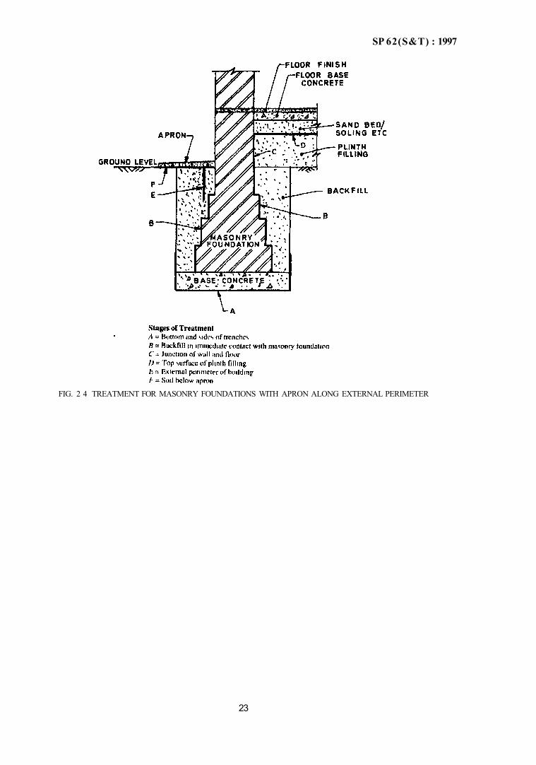
SP 62(S&T) : 1997
FIG. 2 4 TREATMENT FOR MASONRY FOUNDATIONS WITH APRON ALONG EXTERNAL PERIMETER
23
SP 62 (S&T) : 1997
FIG 2.5 TREATMENT FOR RCC FOUNDATIONS
24

CHAPTER 3
FOUNDATIONS
CONTENTS
1 GENERAL
1.1 Pro-construction 1.2 Drainage 1.3 Setting Out 1.4 Protection of Excavation
2 TYPES OF FOUNDATIONS
2 1 Shallow Foundations 2.2 Deep Foundations 2.3 Foundations for Special Structures
3 CONSTRUCTION OF FOUNDATIONS
3.1 Shallow Foundations 3.2 Pile Foundations 3.3 Under Reamed Foundations 3.4 Precast Piles
3.5 Cast in-situ Piles 3.6 Timber Piles 3.7 Load Test on Piles
4 MACHINE FOUNDATIONS
4.1 General 4.2 Criteria for Construction
5 MISCELLANEOUS
6 SPECIAL STRUCTURES
ANNEX A—INFORMATION ON CHOICE AND CHARACTERISTICS OF CERTAIN TYPES OF FOUNDATIONS
ANNEX B—GUIDELINES FOR GROUND IMPROVEMENT FOR FOUNDATIONS IN WEAK SOILS
SP 62 (S & T) : 1997
CHAPTER 3
FOUNDATIONS 1 GENERAL
1.1 Pre-construction
After the excavation is done, as per Chapter 2, con struction of foundations should be undertaken. How ever, certain pre-construction activities should be completed before commencement of work. These are described below.
1.2 Drainage
If the site of the building is such that water would drain towards it, land may be dressed or drains laid to divert the water away from the site.
1.3 Setting Out
1.3.1 Generally the site shall be levelled before the layout of foundations are set out. In case of sloping terrain, care shall be taken to ensure that the dimensions should be set out with theodolites in case of important and intricate structures where the length of site exceeds 16 m. In other cases these should be set out by measurement of sides. In rectangular or square setting out, diagonals shall be checked to ensure accuracy.
The setting out of wall shall be facilitated by permanent row of pillars, parallel to and at a suitable distance beyond the periphery of the building The pillars shall be located at junctions of cross walls with the peripheral line of pillars. The centre lines of the cross walls shall be extended and permanently connected to the tops of corresponding pillars.
The datum lines parallel to and at a known distance fixed from the centre lines of external walls, should also be permanently set on the rows of pillars to serve as checks on the accuracy of the work as it proceeds.
The tops of pillars shall be at the same level and preferably at plinth or floor level The pillars shall be of sizes not less than one brick wide and shall be embedded sufficiently deep into the ground so that they are not disturbed.
1.4 Protection of Excavation
a) Protection of excavation during construction of shoring, timbering, dewatering operations. etc, shall be ensured.
b) After excavation, the bottom of the trench shall be cleared of loose soil and rubbish and shall be levelled, where necessary.
c) Excavations, in clay or other soils, that are likely to be effected by exposure of atmosphere, shall be concreted as soon they are dug
Alternatively, the bottom of the excavation shall be protected immediately by 8 cm thick layer of cement concrete not leaner than mix 1.5: 10; the foundation concrete should then be placed on this. Or in order to obtain a dry hard bottom, the last stretch of excavation of about 10 cm shall be removed just before concreting.
d) The refilling of excavation shall be done with care so as not to disturb the just constructed foundation. The backfill should be carried out evenly on both sides of the wall. The fill shall be compacted in layers not exceeding 20 cm thick, with sprinkling of just enough water necessary for proper compaction.
2 TYPES OF FOUNDATIONS 2.1 Shallow Foundations
These cover such types of foundations in which load transfer is primarily through shear reistance to the soil and are normally laid to a depth of 3 m.
2.1.1 The various types of shallow foundations are as under.
a) Spread or Pad (see IS 1080 : 1986), b) Strip(see IS 1080: 1986), c) Raft [ see IS 2950 (Part 1) . 1981], and d) Ring and Shell (see IS 11089 . 1984 and IS
9456 1980). 2.2 Deep Foundations These foundations are generally in the form of piles, carssons, diaphragm walls, used separately or in com bination to transmit the loads to a deeper load bearing strata. The transfer of load may be through friction, end bearing or a combination of both.
2.2.1 The various types of deep foundations are as under.
a) Pile Foundations 1) Driven cast in-situ see IS 2911 (Part
1/Sec 1): 1979 2) Bored cast in-situ — see IS 2911 (Part
1/Sec 2) . 1979 3) Driven precast — see IS 2911 (Part 1/Sec
3): 1979 4) Bored precast — see IS 2911 (Part 1 /Sec
4):1984 5) Timber — see IS 2911 (Part 2) : 1980 6) Under-reamed — see IS 2911 (Part 3)
1980 b) Diaphram Walls — see IS 9556 : 1980 c) Combined Foundations — Two or more of the
above.
27
SP 62(S & T) : 1997
2.3 Foundations for Special Structures These include foundations for machines, towers, etc.
2.3.1 Machine foundations are subject to vibrations. Manufacturer's instructions, if any, may be followed. Indian Standards cover machinery foundations for Reciprocating type [see IS 2974 (Part 1) : 1982]; Impact type [see IS 2974 (Part 2): 1980]: Rotary type [see IS 2974 (Part 3) : 1992 and IS 2974 (Part 4) : 1979]; Impact type (other than Hammer) [see IS 2974 (Part 5): 1987]
Tower foundations are covered by IS 4091 : 1979 for steel towers and by IS [1233 : 1985 for Radar, Antenna, Microwave and TV towers. 3 CONSTRUCTION OF FOUNDATIONS 3.1 Shallow Foundations In shallow foundations, generally, masonry and/or concrete, plain and reinforced, are used. The procedure for masonry and concrete foundations shall be the same as described in masonry and concrete work (see Chapters 4 and 5).
3.2 Pile Foundations
Under-reamed piles, though listed under deep foundations also are used for foundations up to 3 m depth. 3.3 Under-Reamed Foundations Under-reamed piles are of bored cast in-situ and bored compaction concrete types having one or more bulbs formed by suitably enlarging the bore hole of the pile stem. With the provision of bulbs, substantial bearing or anchorage is available.
These piles find application in widely varying situations in different types of soils where foundations are required to be taken to a certain depth in view of considerations like the need
a) to avoid the undesirable effect of seasonal moisture content changes as in expansive soils;
b) to reach firm strata; c) to obtain adequate capacity for downward, up
ward and lateral loads and moments; and d) to take the foundations below scour level.
Under-reamed piles may also be used in situations where vibration and noise caused during construction of piles are to be avoided.
The provision of bulbs is of advantage in under-reamed piles to resist uplift as they can be used as anchors; increased bearing surface also becomes available 3.3.1 Materials
a) Cement—The cement used shall conform to the requirements of IS 269 : 1989 or IS 455 : 1989 or IS 8041 : 1990 or IS 6909 : 1990 or IS 1489 (Parts 1 and 2): 1991; or IS 12269:1987.
b) Steel—Reinforcement steel shall conform to IS 432 (Part 1): 1982; or IS 1786 : 1985; or IS 2062: 1992. For under-reamed bored compaction piles, the reinforcement cage shall be prepared by welding the hoop bars to withstand the stresses during compaction process.
c) Concrete 1) Consistency of concrete for cast in-situ
piles shall be suitable to the method of installation of piles.
2) Concrete shall be so designed or chosen as to have a homogeneous mix.
3) Slump of concrete shall range between 100 mm and 150 mm for concreting in water-free unlined bore holes. For concreting by tremie, a slump of 150 mm to 200 mm shall be used.
4) In case of tremie concreting of piles of smaller diameter and depth up to 10 m, the minimum cement content should be 350 kg/m3 of concrete. For piles of larger diameter and/or deeper piles, the minimum cement content should be 400 kg/m3
of concrete.
In case the piles are subsequently exposed to water or in case piling is done under water or drilling mud is used in methods other than tremie, 10 percent extra cement shall be used over and above that required for the grade of concrete at specified slump.
For making concrete, aggregate as described in IS 456 : 1978 shall be used. For tremie concreting, aggregates having nominal size more than 20 mm should not be used.
For bored compaction piles Rapid Hardening Cement to IS 8041:1990 shall not be used.
3.3.2 Equipment
Normally the equipment required for manual operations are:
a) auger; b) under-reamer; c) boring guide; and d) acccsories.
For piles of deeper and larger size greater than 30 cm and a portable tripod hoist with manually operated winch is required.
For piles in high ground water table and unstable soil conditions, boring and under-reaming shall be carried out using suitable equipment. Tremie pipe shall be used for concreting.
For compact piles, the additional equipment required are drop weight for driving the core assembly and pipe or solid core.
28
SP 62 (S & T) : 1997
3.3.3 Construction
a) Bore holes may be made by earth augers In case of manual boring an auger boring guide shall be used to keep the bores vertical or at the desued inclination and in position After the bore is made to the required depth enlarging of the bore shall be carried out by means of an under reaming tool
b) Drilling mud may be used for boring and under-teaming in a site with high water table Bentonite may be used
C) TO avoid regular shape and widening of bore hole in a very loose strata at top, a casing pipe of suitable length may be temporarily used
d) For better under reamed piles the ??? ment cage should be placed guiding it by a chute or any other means
e) In order to achieve proper under reamed bulb the depth of bore hole should be checked before starting under reaming It should also be checked during under-reaming any extra soil at the bottom of bore hole shall be removed by auger before re inserting the under reaming tool
f) The completion of the desired under reamed bulb is ascertained by vertical movement of the handle and when no further soil is cut
g) In multi under reamed piles the boring is first completed to the depth required for the first (top) bulb only and after completing under reaming bulb the boring is extended further down to the second bulb and so on
h) The piles shall be installed as correctly as pos sible both at the correct location and truly vertical (or at the specified batter) Piles shall not deviate by more than 75 mm or one quarter the stem diameter whichever is less, for piles of diameter more than 600 mm the deviation may be 75 mm or 10 percent of the stem diameter
j) Concreting shall be done as soon as possible after completing the bore The bore hole full of dulling mud should be concreted between 12 to 24 h depending on the stability of the hole
k) The method of concreting should be such that the entire volume of the pile bore is filled up without formation of voids and/or mixing of soil and drilling fluid in the concrete 1 or plac ing concrete in pile bores funnel should be used In the empty bore holes for under teamed piles a small quantity of concrete is poured to give about a 100 mm layer of concrete at the bottom Remforcement is lowered next and positioned correctly The concrete is poured to fill the
bore hole Care shall be taken that soil is not scrapped from sides if rodding is done for compaction Vibrators shall not be used If the subsoil water level is confined to the bucket length portion at the toe the seepage is low and the water should be barled out before commencing concreting In case the pile bore is stabilized with drilling mud or by maintaining water head within the bote hole the bottom of bore hole shall be carefully cleaned by flushing it with fresh dull mg mud and the pile bore be checked before concreting Concreting shall be done by the tremre method The tremre should have a valve at the bottom and lowered with the valve closed at the start and filled up with concrete The valve is then opened to permit oncrete which permits the upward displacement of dulling mud The pouring should be continuous and the tremre is graduatly lifted up such that the pipe opening remains always tn the concrete In the final stage the quantity of concrete shall be enough so that on the final withdrawal some concrete spills on the ground (see Notes 1 to 5)
NOTES 1 All tremic tubes should be ??? before and after use 2 The tremic pipe should ??? well into the concrete with in ??? ??? of srfety ??? with ??? of the pipe 3 The tremic methed shall not be changed ??? given pile to prevent in ??? in the pile 4 In the ??? of ??? of ??? pile ??? of to remove ??? choke the tremic in ??? be remtroduced in ??? ??? to prevent ??? of ??? or ??? ??? the top of the ??? ??? deposited ??? in the bore 5 In the ??? case of inteiruption of ??? which can be resumed in one or two hours the tremic shall not be taken out of concrete Instead it shall be ??? used or lowered slowly from ??? to ??? to prevent the concrete around the tremic from setting Concreting should be resumed by introducing ??? little ??? of concrete with a slump of about 200 mm for easy displace ment of the partly set concrete If the concreting ??? be resumed before the final set of concrete the pile may be ??? or used with ???
m) In inclined piles, concreting should be done through a chute or by treme method
n) A bored compaction pile is one in which the compaction of surrounding ground as well as fresh concrete in the bore is simultaneously accomplished In under teamed bore compae tion piles the pile shall be filled up with con crete, without placing reinforcement Immediately, the core assembly shall be driven
29
SP 62 (S & T) : 1997
and extra concrete shall be poured in simultaneously to keep the level of concrete up to ground level. If a hollow driving pump is used in core assembly, the pipe shall be withdrawn after filling it with fresh concrete. In these compaction piles it shall be ensured that concreting should be done uninterruptedly. Accidental withdrawal should be completely avoided.
p) The top of the concrete pile shall be brought above the cut-off level to permit removal of all laitance and weak concrete before capping and to ensure good concrete at the cut-off level for proper embedment into the pile cap.
q) Where cut-off level is less than 1.5 m below working level, concrete shall be cast to minimum of 300 mm above cut-off level, for every excess of 0.3 m over 1.5 m, additional of 50 mm shall be cast over and above 300 mm. When tremie method is employed, it shall be cast to the piling platform level to permit over-flow of concrete for visual inspection or to a minimum of 1 m above cut-off level. When the cut-off level is below the ground water level, there is a need to maintain a pressure on the unset concrete equal to or greater than the water-pressure and a length of extra concrete above the cut-off level may be per
mitted to provide this. r) When defective piles are formed, they shall be
removed or left in place whichever is convenient, without effecting the performance of
adjacent piles or the cap as a whole. Any deviation beyond permissible limits from the designed location, alignment or load capacity of any pile shall be noted and adequate measures be taken well before the concreting of the pile cap and plinth beam. The pile should project 50 mm into the cap concrete.
3.4 Precast Piles
3.4.1 Bored Precast Piles
Bored precast concrete piles are constructed in a casting yard and subsequently lowered into prebored holes and the space grouted.
a) As far as possible, in-situ extensions shall be avoided.
b) The casting yard should be well drained. c) As far as possible, longitudinal reinforcement
shall be in one length. In case joints are needed, they should be staggered.
d) The hoops and links for reinforcement shall fit tightly against the longitudinal bars and be bound to them by welding or by tying with
binding wire, the free ends of which should be turned into the interior of the pile. The longitudinal bars may be held apart by temporary or permanent spreader forks not more than 1.5 m apart. The reinforcement shall be checked for tightness and position immediately before concreting.
e) After casting the piles, they shall be stored as described in Chapter 1.
f) Bored precast piles shall be constructed by suitable choice of boring and installation techniques depending on detailed information about the subsoil conditions. The bottom end of the pile shall have proper arrangements for cleaning and grouting. Piles shall be installed as vertically as possible according to the drawings, or to the specified batter. The deviation from specified alignment shall be as permitted for under-reamed piles in
g) Cement and sand (1:2) grout mixed with water in a high speed colloidal mixer is fed to the pile with grout pump of suitable capacity to the central duct through a manifold. Temporary casing used here shall be removed in stages with the rise of level of grout. The grout should be levelled off at the top. The strength of the grout shall be at least equal to the strength of the surrounding soil.
h) Where a pile is to have another length cast on to it before or during placing, the longitudinal reinforcement should be welded with full penetration butt welding, after the concrete at the top of the pile should be cut-off to expose not less than 200 mm of the bars. Bars may be lapped if it is not possible to undertake butt welding with an overlap of 40 times the dia of bar.
3.4.2 Driven Precast Piles Driven precast piles transmit the load of the structure by resistance developed either at the tip or by end bearing or along the shaft by friction or by both. They are cast in a yard and subsequently driven into the ground with or without jetting. These piles find wide application for structures, such as, wharves, jetties, etc, or where conditions are unfavourable for use of cast in-situ piles.
a) Pile foundations shall be designed in such a way that the load of supports can be transmitted to the soil without any soil failure and without causing settlement as may result in structural damage. It shall withstand all loads (vertical, axial, or otherwise) and moments to be transmitted to the soil.
b) When working near existing structures care shall be taken to avoid damage to such struc-
30
SP 62 (S & T) : 1997
tures. In case of deep excavations adjacent to piles, proper shoring or other suitable arrangements be provided against lateral movement of soil stratum or releasing the confined soil stress. [For guidance, see IS 2974 (Part 1) : 1982 for effect of vibrations due to reciprocating machines.]
c) The casting yard for all concrete piles shall be so arranged that they can be lifted directly into the piling area. The yard shall have a well drained surface to prevent excessive or uneven settlement during manufacturing and curing.
d) As far as possible longitudional reinforcement shall be in one length. In case joints are needed they shall be buttwelded and staggered.
e) The hoops and links reinforcement shall fit tightly against the longitudional bar and bound to them by mild steel wire or by welding The bars may be held apart by spreader forks not more than 1.5 m apart. The reinforcement shall be checked for tightness and position before concreting.
f) After casting the piles, it shall be cured and stored as described in Chapter 1.
g) The piles may be driven by any type of hammer, provided they penetrate to the prescribed depth or attain the specific resistance without being damaged. Any change in the rate of penetration which cannot be ascribed to nor-mal changes in the nature of the ground should be noted and cause ascertained if possible before driving is continued.
h) The head of the precast pile should be protected with packing of resilient material.
j) Piles should be installed as accurately as possible in a pile group. The sequence of installation of piles shall be from centre to the periphery of the group or one side to the other.
k) For details of manufacture of piles. pile driving, etc, reference may be made to IS 2911 (Part 1/Sec 3) : 1979.
3.5 Cast in-situ Piles 3.5.1 Cast in-situ driven piles transmit load to the soil by resistance developed by the toe of the pile or by end bearing or by friction along their surface or by both.
a) Materials — (see in 3.3.1) b) Equipment — Among the commonly used
plants, tools and accessories, the suitability depends on subsoil conditions, manner of operation, etc. Some commonly used equipment are: 1) Dolly — A cushion of hardwood or
suitable material placed on top of the casing to receive hammer blows;
2) Drop hammer — Hammer (ram or monkey) raised by a winch and allowed to fall under gravity;
3) Single or double-acting hammer — A hammer operated by steam or compressed air;
4) Kentledge — Dead weight used for applying a test load to a pile; and
5) Pile rig — A fabricated movable steel frame.
c) Construction 1) Concrete — The minimum slump should
be 100 mm when the concrete in the pile is not compacted, and shall not in any case be more than 180 mm.
2) Control of alignment — Piles shall be installed as accurately as possible according to the drawings. Permitted deviations shall be as per 3.3.3.
3) Sequence of piling — In a pile group, the sequence of installation of piles shall normally be from centre to the periphery of the group.
No adjacent pile should be driven until the concrete in the pile under construction has set; otherwise the pile may be damaged. The damage is greater in piles driven in compact soils than in loose soils. In loose sandy soils compaction will increase as the piles are driven. Therefore the order of installing such a pile should be so chosen as to avoid creating a compacted block in the ground, which would prevent further piles being driven.
Similar precautions should be taken in stiff clayey soils and compact sand layers; this can be done by driving the piles from centre outwards.
However in very soft soils, the driving of piles should be from outside to centre, so that soil is prevented from floating out during driving of piles.
The casing may be jetted out by means of water without imparing the bearing capacity of the pile, stability of the soil and safety of adjoining structure.
The cut-off level, formation of latiance, etc shall be dealt with as in 3.3.3.
Defective piles shall be dealt with as in 3.3.3.
3.5.2 Bored Piles
The bored cast in-situ piles, of less than 2 500 mm transmit the load to soil by resistance developed either at the tip by end bearing or along the shaft by friction or by both.
a) Bored cast in-situ piles may be driven by suitable choice of installation techniques; the manner of soil stabilization, that is, using of casing and/or use of drilling mud; manner of concreting, etc. Sufficient information on sub-
31
SP 62 (S & T) : 1997
soil conditions is essential to predetermine the details of installation techniques.
b) Piles shall he installed as accurately as possible as per drawings. Great care shall be taken in installing single pile or a group of two piles. Any deviation from designed location, alignment or load capacity of any pile shall be noted and adequate measures taken well before the concreting of the pile cap and plinth beam.
c) A minimum length of 1 m of temporary casing shall he inserted in each bored pile. Additional length of temporary casing may be used depending on the conditions of strata, ground water level, etc. Drilling mud of suitable consistency may be used instead of temporary casings to stabilize sides of holes. For marine locations, the piles may be formed with permanent casing (liner).
d) In case the bored pile is stabilized by drilling mud or by maintaining water heads in the hole, the bottom of the hole shall be cleaned carefully before concreting work is taken up. Flushing of holes before concreting with fresh drilling fluid/mud is preferred.
e) The specific gravity of the drilling mud shall be consistent. For this periodic samples shall be taken and tested. Concreting shall not be taken up when the specific gravity is more than 1.2. Concreting shall be done by tremie method in all such cases. The slurry should be maintained at 1.5 m above ground water level if casing is not used.
f) Concreting may be done by tremie method or by the use of specially designed underwater placer to permit deposition of concrete in successive layers without permitting the concrete to fall through free water.
g) Convenience of installation may be taken into account while determining the sequence of piling in a group.
h) The top of concrete in a pile shall be brought above cut-off level to permit removal of laitance and weak concrete before capping and to ensure good concrete at the cut-off level for proper embedment into the pile cap.
j) In case defective piles are formed, they shall be removed or left in place whichever is convenient affecting the performance of the adjacent piles or the cap as a whole. Additional piles shall replace them.
k) Pneumatic tools shall not be used for chipping until seven days after pile casting. Manual chipping of pile top may be permitted after 3 days of casting the pile.
m) After concreting the actual quantity of concrete shall be compared with the average obtained
from actual observations in the case of few piles cast initially. If the quantity is found to be considerably less, special investigations shall be conducted and appropriate measures taken.
3.6 Timber Piles
Timber piles find extensive use for compaction of soils and also for supporting as well as protecting waterfront structures. The choice of use of timber piles shall be mainly governed by the site conditions, particularly water table conditions. They are comparatively light for their strength and are easily handled. However, they will not withstand as hard driving as steel or concrete piles. Timber has to be selected carefully and treated as durability and performance would considerably depend upon the quality of the material and freedom from natural defects.
3.6.1 Class of Piles
Depending upon the use, piles shall be classified as Class A and Class B.
a) Class A — For railway and highway bridges, trestles, docks and warehouses. The butt diameter or sides of square shall not be less than 30 cm.
b) Class B — For foundation work other than specified in Class A and temporary work. Piles used for compaction of ground shall not be less than 100 mm in diameter or side in case of square piles.
3.6.2 Timber Species
The species of timber shall conform to IS 3629 : 1986 The length of the individual pile shall be specified length ± 30 cm for 12 m long and ± 60 cm for lengths above 12 m. In case of round piles, the ratio of heartwood diameter to the pile butt diameter shall not be less than 0.8. Both the ends shall be sawn at right angles to the length of the pile and surface shall be made flush by trimming the knots and limbs. The timber shall be treated as per IS 401 : 1982 on timber preservation.
3.6 3 Control of Pile Driving
a) The piles in each bent of a pile shall be selected for uniformity in size to facilitate placing of bracing members.
b) The pile tip shall be pointed (unless driving is in wholly soft strata) in the form of truncated cone or a pyramid having the end 25 cm2 to 40 cm2 in area and the length shall be 1½ to 2 times the diameter or side of a square.
c) If the driving is to be done in hard material such as stiff clay, gravels, etc, metal shoes of approved design shall be attached to the tip.
32
SP 62 (S & T) : 1997
d) To prevent splitting and reduce brooming, the head of the pile should be hooped with a suitable ring or wrapped with wires. The heads of piles shall be further protected by the provision of cushion blocks.
c) If the piles are required to be formed from two or more lengths, the butting surfaces shall be cut square to ensure contact over the whole cross section of the pile. A thin steel plate placed between the butting surfaces will reduce the tendency to brooming. The pieces should also be secured with steel tubes or steel flats. Splices in the middle of the pile should be avoided. If it is necessary to obtain increase in size and length of pile by building up sections, the joints should be staggered and the timber members connected by means of bolts or screws.
f) Piles shall be installed as accurately as possible according to drawings.
g) In a pile group, the sequence of installation of piles shall normally be from centre to periphery of the group or from one side to the other. Adjacent piles shall not be damaged when driving a pile; the danger is greater in compact soils than in loose soils. Driving piles in loose sand tends to compact the sand which in turn increases the skin friction tor friction piles. Therefore the order of installing of such a pile group should avoid creating a compact block of sand pile into which further piles cannot be driven. Similar precautions have to be taken in case piles have to be driven into stiff clay or compact sand layers. This may be overcome by driving piles from the centre to the periphery or by beginning at a selected edge or working across the group. In case of very soft soils, driving may have to proceed from outside to inside, so that soil is retained from flowing and during operation.
h) Jetting of cases by means of water shall be carried out if required in such a manner as not to impair the bearing capacity of piles already in place, the stability of the soil or the safety or any adjacent buildings.
j) Defective piles shall either be removed or left in place as is convenient without affecting the performance of the adjacent piles or the cap as a whole. Additional piles shall be provided to replace the defective piles.
k) Any sudden change in the rate of penetration which cannot be ascribed to the nature of ground shall be noted and its cause ascertained, if possible, before driving is continued.
3.6.4 Handling of Piles
a) Care shall be taken to see that the piles are sufficient number of points, properly located to prevent damage due to excessive bending.
b) Treated piles shall be handled with hemp or manila rope slings or other means of support that will not damage the surface of the wood.
c) Dropping, brushing, breaking of fibres and penetrating the surface shall be avoided.
d) Sharp pointed tools shall not be used for handling or turning them in leads.
e) Minor abrasions of the surface of treated piles below cut-off level in the portions which are to remain permanently under water shall be permitted
f) Surface of treated piles below cut-off shall not be disturbed by boring holes or driving nails to support temporary material or stagging.
3.7 Load Test on Piles
Shall be done as prescribed in IS 2911 (Part 4) : 1985.
4 MACHINE FOUNDATIONS
4.1 General
Machine foundations are specialized structures, according to type of machines, namely, rotary, impact, reciprocating, etc. However, a few criteria for construction are listed below.
4.2 Criteria for Construction
4.2.1 Concrete
The concrete used shall be controlled concrete The grade of concrete shall be between M 15 to M 20 for block foundations and M 20 for formed foundations, A slump of 50 mm to 80 mm is allowable. The concrete used shall be of plastic consistency without excessive water. The water cement ratio shall not exceed 0.45 which shall be maintained throughout the concreting of foundation.
4.2.2 Continuous concreting shall be done as far as possible for the entire block, leaving provisions for grouting.
4.2.3 All areas under and adjacent to the foundation shall be well cleaned prior to pouring of concrete. The surfaces except the pockets for grout, shall be made rough so as to secure good bond with fresh cement. Cement grout with non-shrinkable additive shall be used where structurally required.
4.2.4 All elements of foundation shall be provided both at top and bottom by two way reinforcement. Reinforcement shall be provided along the surface in case of block foundations. The amount of reinforcement shall vary between 25 to 50 kg/m3 of concrete as the case may be. The minimum dia shall be 12 mm
33
SP 62 (S & T) : 1997
and maximum shall be 20 mm in order to take care of shrinkage. Concrete cover shall be 75 mm at bottom, 50 mm on sides and 40 mm on top.
4.2.5 The finished surface of the foundation shall be levelled before installing the machine.
4.2.6 The foundation bolts shall be properly anchored.
4.2.7 Construction joints should be avoided. If needed the plane of the joint shall be horizontal.
The requirements of a construction joint are: a) Embed dowels of 12 mm to 16 mm dia at
60 mm centres to a depth of at least 30 cm depth; and
b) Before laying fresh concrete, the previously laid surfaces shall be cleaned and roughened
and covered by a rich layer of 1:2 cement grout 20 mm thick, concrete should be placed not later than 2 h after the grout is laid.
5 MISCELLANEOUS 5.1 For field testing of soils reference may be made to SP 36 (Part 2) : 1988. 5.2 Some information on choice and characteristics of foundations is given in Annex A. Information on improvement of weak soils to carry more load is given in Annex B. 6 SPECIAL STRUCTURES 6.1 Requirements of foundations for special structures shall be as per design and drawings and any requirements specified. By and large IS 456:1978 may be followed.
ANNEX A (Clause 5.2)
INFORMATION ON CHOICE AND CHARACTERISTICS OF CERTAIN TYPES OF FOUNDATIONS
A-1 GENERAL A-1.1 The design of foundation, superstructure and the characteristics of the soil are inter-related. In order to obtain maximum economy, the supporting soil, foundation and the superstructure should be studied as a whole. The geo-technical aspects of the soil determines the type and design of foundation; whereas the materials and properties of these materials determine the design of superstructure. In effect it may appear that an inelastic foundation should support a superstructure constructed out of elastic materials. The general aim of foundation choice and design is to ensure that the loading intensity imposed on the soil does not exceed the safe bearing capacity of the soil. In addition the materials of foundation, such as, masonry, concrete, etc, should not be stressed for more than the limits specified in appropriate codes governing the structural design of such elements. The construction procedures should enable the aim of design in office to be realised in the field.
A-2 SPREAD FOUNDATIONS
A-2.1 In spread foundations transfer of load is primarily through shear resistance of the bearing soil and they are normally laid to a depth of 3 m. Strip foundations provide continuous and longitudinal bearing of toads, such as, wall elements, beams and the like. The soil bearing capacity is limited for choice of such foundation.
A-2.2 These foundations could be used for medium high structures of residential and commercial occupancy with uniform distribution of loads. A-3 RING FOUNDATION A-3.1 Ring foundation is a substructure supporting an arrangement of columns or walls and transmitting loads to the soil by means of a continuous slab. Generally, these foundations could be used for tall structures, such as, silos, chimneys, water tanks, etc, which have a non-uniform distributed loads. A-3.2 For fairly small and uniform column spacing and when the supporting soil is not too compressible, a flat concrete slab of uniform thickness is most suitable. Under the effect of dead load, the soil is subjected to uniform pressure; but under live loads like wind or earthquake the pressure on the soil is nonuniform. If there is sufficient bending due to lateral loads it is more economical to adopt a annular raft. Annular circular slab with a ring beam type of raft is likely to be more economical for large column spacing. A-4 RAFT FOUNDATION A-4.1 Raft foundation is a substructure supporting an arrangement of columns or walls in a row and transmitting the loads to the soil by means of a continuous slab with or without openings or depressions. The foundations are useful where the soil has low bearing capacity.
34
SP 62 (S & T) : 1997
A-4.2 A raft (mat) foundation slab of uniform thickness is suitable for fairly small and uniform column spacing and when the supporting soil is not too compressible.
The slab may be thickened for heavily loaded columns to provide adequate strength for shear and negative moment.
A slab and beam type of raft is likely to be more economical for large column and unequal spacing of columns; particularly when the supporting soil is compressible.
For heavy structures, provision of cellular raft or rigid frames consisting of slabs and basement walls may be considered. A-5 PILE FOUNDATION A-5.1 The load transfer mechanism from a pile to the surrounding soil is complicated and has not yet been fully determined, although application of pile foundation has been in vogue for many decades.
Broadly speaking, piles transfer axial load either by friction along its shaft and/or subsequently by end bearing
Construction of pile foundations requires careful choice of piling system, depending on the subsoil conditions, the load characteristics, limitations of total settlement, differential settlement, etc. It requires careful control of alignment, position and depth and involves specialized skill and experience. A-5.2 Bored Precast Concrete Pile These piles find wide application in chemically agres-sive soils and in high ground water conditions. These piles are protected even in such conditions because they are made by using dense, vibrated matured concrete.
They are also useful where artesian conditions exist or where local obstructions are encountered above the foundation level. They also can be protected by appropriate coatings.
A-5.3 Driven Cast in-situ Concrete Pile
Driven cast in-situ piles are formed by driving a casing and filling it in the hole with plain or reinforced concrete. The casing may be temporary or permanent. The concrete may be rammed, vibrated or just poured. These piles find wide application where the pile required is taken to a greater depth to find adequate bearing strata or to develop adequate skin friction; and also when the length of individual piles cannot be pre-determined.
A-5.4 Bored Cast in-situ and Driven Precast Pile
Their application is similar to A-5.3 and A-5.2 respectively.
A-5.5 Under-Reamed Piles
Under-reamed piles find wide application under the following conditions:
a) When the site consists of expansive soils, like black cotton soil, the bulb provides additional anchorage against uplift due to swelling pressure impart from the increased bearing.
b) In filled or otherwise weak strata overlying firm strata, enlarged base in the form of under-reamed bulb provides larger bearing area and therefore piles of greater bearing capacity can be constructed.
c) In loose to medium pervious sandy and silty strata, the process of compaction increases the bearing capacity of the pile.
ANNEX B
(Clause 5.2) GUIDELINES FOR GROUND IMPROVEMENT FOR
FOUNDATIONS IN WEAK SOILS
B-1 GENERAL
B-1.1 In poor and weak subsoils, the design of conventional shallow foundations for structures may present problems with respect to both size of foundation and control of settlements. Traditionally pile foundations have been employed at very high costs. A recent approach is to improve the soil itself to the extent that would result in adequate bearing capacity and settlements within acceptable limits.
B-2 METHODS
B-2.1 Need The need for ground improvement should be established by collection of soil data. If the bearing capacity is less than that specified in IS 6403 1981 for shallow foundations than the need for ground improvement arises; also if the settlements exceed those specified by IS 8009 (Part 1) : 1976 and IS 8009 (Part 2) : 1980 for shallow and deep foundations. Soils subject to
35
SP 62 (S & T) : 1997
liquefaction particularly during earthquakes under high water table conditions also need strengthening.
B-2.2 SOIL DENSIFICATION
a) Soil structure improvement from in a loose to medium dense or dense state is by application of shock and vibration. This technique, is applicable only to cohesionless soils under high water table conditions.
b) Vibroflotation, vibrocompaction, compaction piles, blasting and dynamic consolidation are some of the methods suitable to undertake this treatment.
B-2.3 Preconsolidation
a) Increase in shear strength with substantially reduced values of settlement result by expulsion of water from the pores of the soil causing consolidation. This consolidation is achieved by subjecting it to a preload. Preload can be soil itself or any suitable material.
b) Preloading is generally carried at in stages to allow gradual build up of strength enabling it to safely support further stages of preload.
c) For poorly draining soils precompression is accelerated by provision of vertical drainage in soils.
d) Removal of water from pore spaces can also be done by application of electric current to subsoil. This process is known as 'Electro Osmosis.'
e) This technique is applicable to fine ground soils such as silts and clays. Subsoils requiring high secondary consolidation characteristics may not be amenable to improvement by the preload method.
B-2.4 Injection and Grouting
a) Injecting of chemicals, lime, cement, etc, into subsoils to improve subsoil by formation of bonds between soil particles. Mechanical compression of subsoil is also achieved under certain conditions provided grout is pumped in under high pressure.
b) This method is suitable for sands as well as fine grained soils.
B-2.5 Soil Reinforcement
a) Reinforcement introduced into the soil mass causes marked improvement in stiffness and consequently load carrying capacity and stability of soil mass. Reinforcement may be in the dense granular materials like stone chips. These are used primarily to increase load bearing capacity of the soil mass.
b) Reinforcements may be in the form of horizontal or vertical membranes. These membranes serve significantly to increase the capacity of the soil to withstand tensile, shear and compression loads and contribute towards stability of mass.
B-2.6 Other Methods
Other methods include heating and drying and by fusion at high temperatures; replacement of poor subsoil by competent fill. However, these have certain limitations.
B-3 CHOICE OF METHOD
B-3.1 For more information on soil improvement techniques, choice, etc, is given in IS 13094 : 1992. Table 3.1 may be taken as a guide for selection of the various methods along with principles applicable to various soil conditions, equipments required, results likely to be activised and limitations.
36
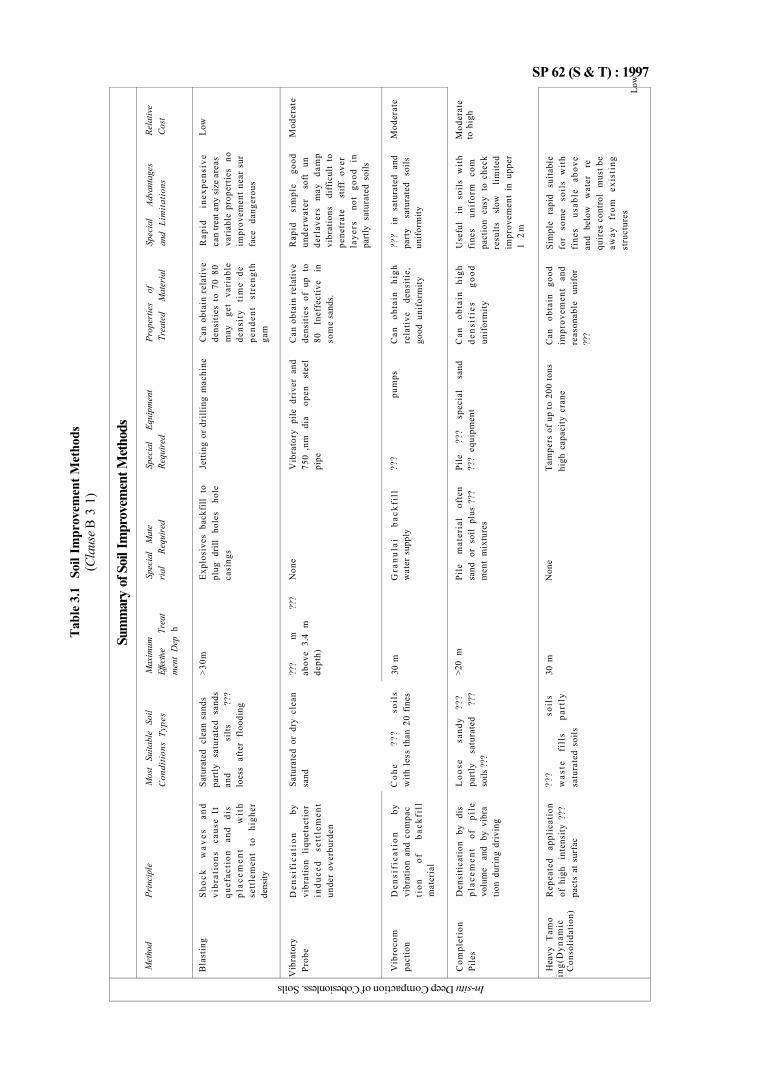
SP 62 (S & T) : 1997 Ta
ble
3.1
Soil
Impr
ovem
ent M
etho
ds
(Cla
use B
3 1
) In-situ Deep Compaction of Cobesionless. Soils
Sum
mar
y of
Soi
l Im
prov
emen
t Met
hods
Met
hod
Bla
stin
g
Vib
rato
ry
Prob
e
Vib
roco
m
pact
ion
Com
plet
ion
Pile
s
Hea
vy T
amo
ing(
Dyn
amic
C
onso
lidat
ion)
Prin
cipl
e
Sho
ck
wav
es
and
vibr
atio
ns
caus
e It
qu
efac
tion
an
d di
s pl
acem
ent
wit
h se
ttle
men
t to
hi
gher
de
nsity
Den
sifi
cati
on
by
vibr
atio
n li
quet
acti
or
indu
ced
sett
lem
ent
unde
r ov
erbu
rden
Den
sifi
cati
on
by
vibr
atio
n an
d co
mpa
c ti
on
of
back
fill
m
ater
ial
Den
siti
cati
on
by
dis
plac
emen
t of
pi
le
volu
me
and
by v
ibra
tio
n du
ring
dri
ving
Rep
eate
d ap
plic
atio
n of
hig
h in
tens
ity ?
??
pact
s at
sur
fac
Mos
t Su
itabl
e So
il C
ondi
tions
Typ
es
Satu
rate
d cl
ean
sand
s pa
rtly
sa
tura
ted
sand
s an
d si
lts
???
loes
s af
ter
floo
ding
Satu
rate
d or
dry
cle
an
sand
Coh
e ??
? so
ils
with
les
s th
an 2
0 fi
nes
Loo
se
sand
y ??
? pa
rtly
sa
tura
ted
???
soils
???
???
soil
s w
aste
fi
lls
part
ly
satu
rate
d so
ils
Max
imum
Ef
fectiv
e Tr
eat
men
t D
ep h
>30m
???
m
???
abov
e 3.
4 m
de
pth)
30 m
>20
m
30 m
Spec
ial
Mat
e ria
l Re
quire
d
Exp
losi
ves
back
fill
to
plug
dri
ll ho
les
hole
ca
sing
s
Non
e
Gra
nula
i ba
ckfi
ll
wat
er s
uppl
y
Pile
m
ater
ial
ofte
n sa
nd o
r so
il pl
us ?
??
men
t m
ixtu
res
Non
e
Spec
ial
Equi
pmen
t Re
quire
d
Jetti
ng o
r dri
lling
mac
hine
Vib
rato
ry p
ile d
rive
r an
d 75
0 ,n
m
dia
open
st
eel
pipe
???
pum
ps
Pile
??
? sp
ecia
l sa
nd
???
equi
pmen
t
Tam
pers
of u
p to
200
ton
s hi
gh c
apac
ity c
rane
Prop
ertie
s of
Tr
eate
d M
ater
ial
Can
obt
ain
rela
tive
dens
ities
to
70 8
0 m
ay
get
vari
able
de
nsit
y ti
me
de
pend
ent
stre
ngth
ga
m
Can
obt
ain
rela
tive
dens
ities
of
up t
o 80
In
effe
ctiv
e in
so
me
sand
s.
Can
ob
tain
hi
gh
rela
tive
de
nsit
ie,
good
uni
form
ity
Can
ob
tain
hi
gh
dens
itie
s go
od
unif
orm
ity
Can
ob
tain
go
od
impr
ovem
ent
and
reas
onab
le
unif
or
???
Spec
ial
Adva
ntag
es
and
Lim
itatio
ns
Rap
id
inex
pens
ive
can
treat
any
siz
e ar
eas
vari
able
pro
pert
ies
no
impr
ovem
ent
near
sur
fa
ce
dang
erou
s
Rap
id
sim
ple
good
un
derw
ater
so
ft un
de
rlav
ers
may
da
mp
vibr
atio
ns
diff
icul
t to
pe
netr
ate
stif
f ov
er
laye
rs
not
good
in
pa
rtly
satu
rate
d so
ils
???
in
satu
rate
d an
d pa
rty
satu
rate
d so
ils
unif
orm
ity
Use
ful
in
soil
s w
ith
fine
s un
ifor
m
com
pa
ctio
n ea
sy t
o ch
eck
resu
lts
slow
lim
ited
impr
ovem
ent
in u
pper
1
2m
Sim
ple
rapi
d su
itabl
e fo
r so
me
soil
s w
ith
fine
s us
able
ab
ove
and
belo
w
wat
er
re
quir
es c
ontr
ol
mus
t be
away
fr
om
exis
ting
st
ruct
ures
Rela
tive
Cost
Low
Mod
erat
e
Mod
erat
e
Mod
erat
e to
hig
h
Low
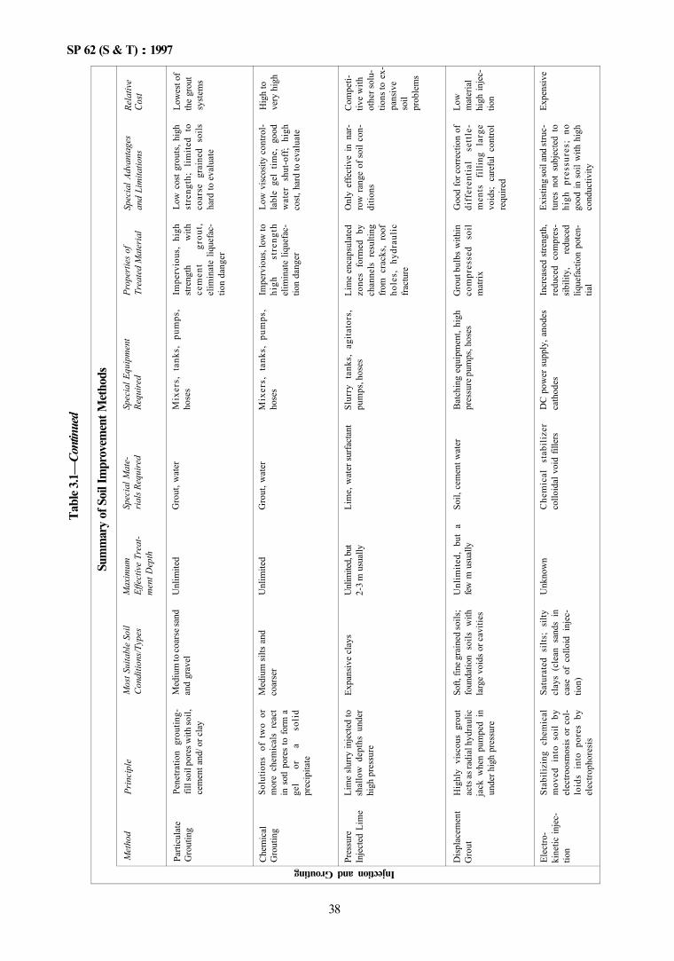
SP 62 (S & T) : 1997
Tabl
e 3.1—
Cont
inue
d
Sum
mar
y of
Soi
l Im
prov
emen
t Met
hods
Injection and Grouting
Met
hod
Parti
cula
te
Gro
utin
g
Che
mic
al
Gro
utin
g
Pres
sure
In
ject
ed L
ime
Dis
plac
emen
t G
rout
Elec
tro-
kine
tic in
jec
tion
Prin
cipl
e
Pene
tratio
n gr
outin
g-fil
l soi
l por
es w
ith so
il,
cem
ent a
nd/ o
r cla
y
Solu
tions
of
tw
o or
m
ore
chem
ical
s re
act
in s
otl p
ores
to fo
rm a
ge
l or
a
soli
d pr
ecip
itate
Lim
e slu
rry in
ject
ed to
sh
allo
w d
epth
s un
der
high
pre
ssur
e
Hig
hly
visc
ous
grou
t ac
ts as
radi
al h
ydra
ulic
ja
ck w
hen
pum
ped
in
unde
r hig
h pr
essu
re
Stab
ilizi
ng c
hem
ical
m
oved
int
o so
il by
el
ectro
osm
osis
or
col
loid
s in
to p
ores
by
elec
troph
ores
is
Mos
t Sui
tabl
e So
il C
ondi
tions
/Typ
es
Med
ium
to co
arse
sand
an
d gr
avel
Med
ium
silts
and
co
arse
r
Expa
nsiv
e cl
ays
Soft,
fine
gra
ined
soils
; fo
unda
tion
soils
with
la
rge
void
s or c
aviti
es
Satu
rate
d si
lts;
silty
cl
ays
(cle
an s
ands
in
case
of
collo
id i
njec
tio
n)
Max
imum
Ef
fect
ive
Trea
tm
ent D
epth
Unl
imite
d
Unl
imite
d
Unl
imite
d, bu
t 2-
3 m
usu
ally
Unl
imite
d, b
ut a
fe
w m
usu
ally
Unk
now
n
Spec
ial M
ate
rials
Requ
ired
Gro
ut, w
ater
Gro
ut, w
ater
Lim
e, w
ater
surfa
ctan
t
Soil,
cem
ent w
ater
Che
mic
al
stab
iliz
er
collo
idal
voi
d fil
lers
Spec
ial E
quip
men
t Re
quire
d
Mix
ers,
tan
ks,
pum
ps,
hose
s
Mix
ers,
ta
nks,
pum
ps,
hose
s
Slur
ry t
anks
, ag
itato
rs,
pum
ps, h
oses
Bat
chin
g eq
uipm
ent,
high
pr
essu
re p
umps
, hos
es
DC
pow
er s
uppl
y, a
node
s ca
thod
es
Prop
ertie
s of
Trea
ted
Mat
eria
l
Impe
rvio
us,
high
st
reng
th
with
ce
men
t gr
out,
elim
inat
e liq
uefa
ctio
n da
nger
Impe
rvio
us, l
ow to
hi
gh
stre
ngth
el
imin
ate
lique
fac
tion
dang
er
Lim
e en
caps
ulat
ed
zone
s fo
rmed
by
chan
nels
res
ultin
g fro
m c
rack
s, ro
of
hole
s,
hydr
auli
c fra
ctur
e
Gro
ut b
ulbs
with
in
com
pres
sed
soil
mat
rix
Incr
ease
d st
reng
th,
redu
ced
com
pres
si
bilit
y,
redu
ced
lique
fact
ion
pote
ntia
l
Spec
ial A
dvan
tage
s an
d Li
mita
tions
Low
cos
t gro
uts,
high
st
reng
th;
limite
d to
co
arse
gr
aine
d so
ils
hard
to e
valu
ate
Low
visc
osity
con
trol
labl
e ge
l tim
e, g
ood
wat
er
shut
-off
; hi
gh
cost
, har
d to
eva
luat
e
Onl
y ef
fect
ive
in n
ar
row
ran
ge o
f soi
l con
di
tions
Goo
d fo
r cor
rect
ion
of
diff
eren
tial
se
ttle
m
ents
fi
lling
la
rge
void
s; c
aref
ul c
ontro
l re
quire
d
Exis
ting
soil
and
stru
ctu
res
not
subj
ecte
d to
hi
gh
pres
sure
s; n
o go
od in
soi
l with
hig
h co
nduc
tivity
Rela
tive
Cost
Low
est o
f th
e gr
out
syst
ems
Hig
h to
ve
ry h
igh
Com
peti
tive
with
ot
her s
olu
tions
to e
x-pa
nsiv
e so
il pr
oble
ms
Low
m
ater
ial
high
inje
ctio
n
Expe
nsiv
e
38
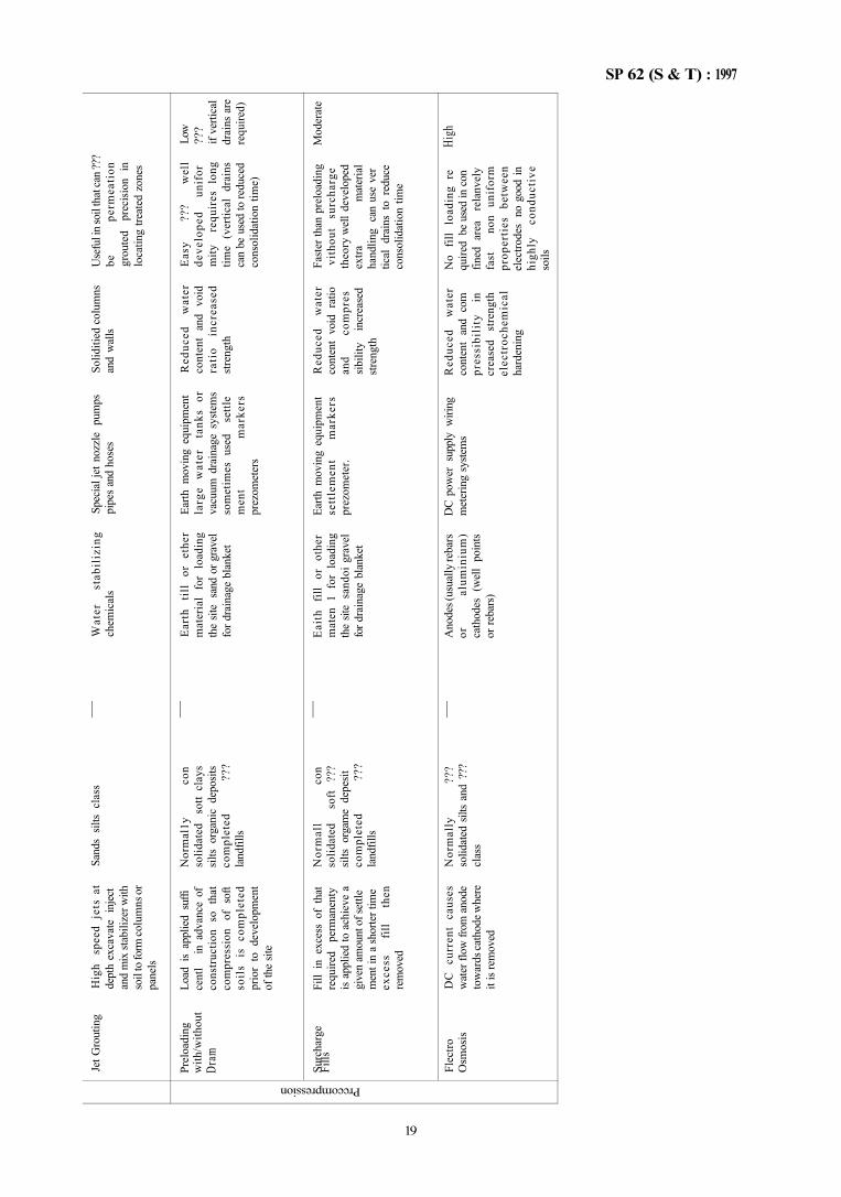
SP 62 (S & T) : 1997 Prccompression
Jet G
rout
ing
Prel
oadi
ng
with
/with
out
Dram
Surc
harg
e Fi
lls
Flec
tro
Osm
osis
Hig
h sp
eed
jets
at
dept
h ex
cava
te i
njec
t an
d m
ix st
abili
zer w
ith
soil
to fo
rm co
lum
ns o
r pa
nels
Load
is
appl
ied
suffi
ce
ntl
in a
dvan
ce o
f co
nstr
uctio
n so
tha
t co
mpr
essi
on
of s
oft
soil
s is
co
mpl
eted
pr
ior
to d
evel
opm
ent
of th
e sit
e
Fill
in e
xces
s of
tha
t re
quire
d pe
rman
enty
is
appl
ied
to a
chie
ve a
gi
ven
amou
nt o
f set
tle
men
t in
a sh
orte
r tim
e ex
cess
fil
l th
en
rem
oved
DC
cu
rren
t ca
uses
w
ater
flow
from
ano
de
tow
ards
cath
ode w
here
it
is re
mov
ed
Sand
s sil
ts cl
ass
Nor
mal
1y
con
solid
ated
so
tt cl
ays
silts
orga
nic
depo
sits
com
plet
ed
???
land
fills
Nor
mal
l co
n so
lidat
ed
soft
???
silts
orga
me
depe
sit
com
plet
ed
???
land
fills
Nor
mal
ly
???
solid
ated
silt
s an
d ??
? cl
ass
—
—
—
—
Wat
er
stab
iliz
ing
chem
ical
s
Ear
th
till
or
ethe
r m
ater
ial
for
load
ing
the
site
sand
or g
rave
l fo
r dra
inag
e bl
anke
t
Eai
th
fill
or
othe
r m
aten
1 f
or l
oadi
ng
the
site
sand
oi g
rave
l fo
r dra
inag
e bl
anke
t
Ano
des (
usua
lly re
bars
or
al
umin
ium
) ca
thod
es (
wel
l po
ints
or re
bars
)
Spec
ial j
et n
ozzl
e pu
mps
pi
pes
and
hose
s
Earth
mov
ing
equi
pmen
t la
rge
wat
er
tank
s or
va
cuum
dra
inag
e sy
stem
s so
met
imes
use
d se
ttle
men
t m
arke
rs
prez
omet
ers
Earth
mov
ing
equi
pmen
t se
ttle
men
t m
arke
rs
prez
omet
er.
DC
pow
er s
uppl
y w
iring
m
eter
ing
syste
ms
Solid
itied
col
umns
an
d w
alls
Red
uced
w
ater
co
nten
t an
d vo
id
rati
o in
crea
sed
stre
ngth
Red
uced
w
ater
co
nten
t vo
id r
atio
an
d co
mpr
es
sibili
ty
incr
ease
d str
engt
h
Red
uced
w
ater
co
nten
t an
d co
m
pres
sibi
lity
in
cr
ease
d st
reng
th
elec
troc
hem
ical
ha
rden
ing
Use
ful i
n so
il th
at ca
n ??
? be
pe
rmea
tion
gr
oute
d pr
ecisi
on i
n lo
catin
g tre
ated
zon
es
Eas
y ??
? w
ell
deve
lope
d un
ifor
m
ity
requ
ires
lon
g tim
e (v
ertic
al d
rain
s ca
n be
use
d to
redu
ced
cons
olid
atio
n tim
e)
Fast
er th
an p
relo
adin
g vi
thou
t su
rcha
rge
theo
ry w
ell d
evel
oped
ex
tra
mat
eria
l ha
ndlin
g ca
n us
e ve
r tic
al d
rain
s to
red
uce
cons
olid
atio
n tim
e
No
fill
load
ing
re
quire
d be
use
d in
con
fin
ed a
rea
rela
nvel
y fa
st
non
unif
orm
pr
oper
ties
be
twee
n el
ectro
des
no g
ood
in
high
ly
cond
ucti
ve
soils
Low
??
? if
verti
cal
drai
ns a
re
requ
ired)
Mod
erat
e
High
19
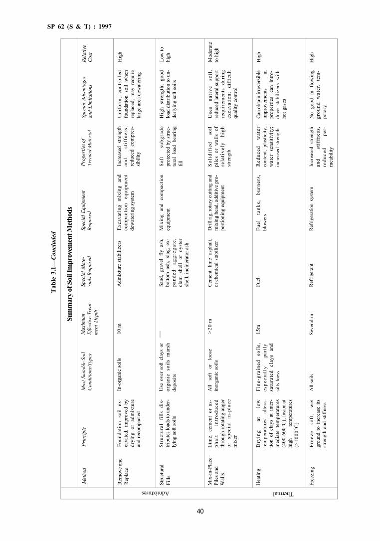
SP 62 (S & T) : 1997
Tabl
e 3.
1—Co
nclu
ded
Admixtures Thermal
Sum
mar
y of
Soi
l Im
prov
emen
t Met
hods
Met
hod
Rem
ove
and
Rep
lace
Stru
ctur
al
Fills
Mix
-in-P
lace
Pi
les a
nd
Wal
ls
Hea
ting
Free
zing
Prin
cipl
e
Foun
datio
n so
il ex
ca
vate
d, i
mpr
oved
by
dryi
ng o
r ad
mix
ture
an
d re
com
pact
ed
Stru
ctur
al
fills
di
stri
bute
s loa
ds to
und
er
lyin
g so
ft so
ils
Lim
e, c
emen
t or
as
phal
t in
trod
uced
th
roug
h ro
tatin
g au
ger
or
spec
ial
in-p
lace
m
ixer
Dry
ing
at
low
te
mpe
ratu
res'
alte
ra
tion
of c
lays
at
inte
rm
edia
te t
empe
ratu
res
(400
-600
°C);
fusio
n at
hi
gh
tem
pera
ture
s (>
1000
°C)
Free
ze
soft
, w
et
grou
nd t
o in
crea
se i
ts
stre
ngth
and
stif
fnes
s
Mos
t Sui
tabl
e So
il C
ondi
tions
/Typ
es
In-o
rgan
ic s
oils
Use
ove
r so
ft cl
ays
or
orga
nic
soils
mar
sh
depo
sits
All
soft
or
loos
e in
orga
nic
soils
Fine
-gra
ined
so
ils,
es
peci
ally
pa
rtly
sa
tura
ted
clay
s an
d si
lts lo
ess
All
soils
Max
imum
Ef
fect
ive
Trea
tm
ent D
epth
10 m
— >20
m
15m
Seve
ral m
Spec
ial M
ate
rials
Requ
ired
Adm
ixtu
re s
tabi
lizer
s
Sand
, gr
avel
fly
ash
, bo
ttom
ash
, sl
ag,
ex
pand
ed
aggr
egat
e,
clam
she
ll or
oys
ter
shel
l, in
cine
rato
r ash
Cem
ent
lime
asph
alt,
or ch
emic
al s
tabi
lizer
Fuel
Refri
gera
nt
Spec
ial E
quip
men
t Re
quire
d
Exca
vatin
g m
ixin
g an
d co
mpa
ctio
n eq
uipm
ent
dew
ater
ing
syste
m
Mix
ing
and
com
pact
ion
equi
pmen
t
Dril
l rig
, rot
ary
cutti
ng an
d m
ixin
g he
ad, a
dditi
ve p
ro
porti
onin
g eq
uipm
ent
Fuel
ta
nks,
bu
rner
s,
blow
ers
Refri
gera
tion
syste
m
Prop
ertie
s of
Trea
ted
Mat
eria
l
Incr
ease
d st
reng
th
and
stif
fnes
s,
redu
ced
com
pres
si
bilit
y
Soft
subg
rade
pr
otec
ted
by s
truc
tura
l lo
ad b
earin
g fil
l
Soli
difi
ed
soil
pile
s or
wal
ls o
f re
lati
vely
hi
gh
stre
ngth
Red
uced
w
ater
co
nten
t, pl
astic
ity,
wat
er s
ensi
tivity
; in
crea
sed
stre
ngth
Incr
ease
d str
engt
h an
d st
iffn
ess,
re
duce
d pe
rm
eabi
lity
Spec
ial A
dvan
tage
s an
d Li
mita
tions
Uni
form
, co
ntro
lled
foun
datio
n so
il w
hen
repl
aced
; m
ay r
equi
re
larg
e ar
ea d
ewat
erin
g
Hig
h st
reng
th,
good
lo
ad d
istri
butio
n to
un
derly
ing
soft
soils
Use
s na
tive
so
il,
redu
ced
late
ral s
uppo
rt re
quir
emen
ts
duri
ng
exca
vatio
n;
diff
icul
t qu
ality
con
trol
Can
obt
ain
irrev
ersi
ble
impr
ovem
ents
in
pr
oper
ties:
can
int
ro
duce
sta
biliz
ers
with
ho
t gas
es
No
good
in
flow
ing
grou
nd w
ater
, te
m
pora
ry
Rela
tive
Cos
t
Hig
h
Low
to
high
Mod
erat
e to
hig
h
Hig
h
Hig
h
40
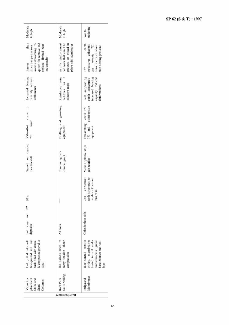
SP 62 (S & T) : 1997
Reinforcement V
ibro
Re-
plac
emen
t St
one
and
Stan
d C
olum
ns
Root
Pile
s So
ils N
ailin
g
Strip
s and
M
embr
anes
Hol
e je
tted
into
sof
t fin
e-gr
aine
d so
il an
d ba
ck fi
lled
with
den
se
ly co
mpa
cted
gra
vel o
r sa
nd
Incl
usio
ns
used
to
ca
rry
tens
ion
shea
r, co
mpr
essi
on
Hor
izon
tal
tens
ile
stri
ps,
mem
bran
es
burie
d in
soi
l un
der
emba
nkm
ents
gr
avel
ba
se c
ours
es a
nd to
ol
ings
Solt
clay
s an
d ??
? de
posit
s
All
soils
Cohe
sionl
ess s
oils
20 m
—
Can
co
nstr
uct
earth
stru
ctur
es t
o he
ight
s of
sev
eral
to
ns o
f m
Gra
vel
or
crus
hed
rock
bac
kfill
Rem
torc
ing
bars
ce
men
t gro
ut
Met
al o
r pla
stic
strip
s ge
o te
xtile
s
Vib
rotl
ot
cran
e or
??
? w
ater
Dri
llin
g an
d gr
outi
ng
equi
pmen
t
Exca
vatin
g ea
rth
???
???
and
com
pact
ion
equi
pmen
t
Incr
ease
d be
arin
g ca
paci
ty,
redu
ced
settl
emen
ts
Rei
nfor
ced
zone
be
have
s as
a
cohe
rent
mas
s
Self
supp
orti
ng
eart
h st
ruct
ures
in
crea
sed
bear
ing
capa
city
re
duce
d de
form
atio
ns
Fast
er
than
pr
ecom
pres
sion
av
oids
dew
ater
ing
re
quire
d fo
r re
mov
e an
d re
plac
e lim
ited
bear
in
g ca
paci
ty
In s
itu r
einf
orce
men
t fo
r so
ils t
hat
can
I be
gr
oute
d or
mix
ed i
n pl
ace
with
adm
ixtu
res
???
eart
h st
ruct
ures
co
here
nt
can
tole
rate
??
? tio
ns i
ncre
ased
allo
w
able
bea
ring
pres
sure
Mod
erat
e to
hig
h
Mod
erat
e to
hig
h
Low
to
mod
erat
e
41


CHAPTER 4
MASONRY
CONTENTS
1 GENERAL
PART 1 MORTARS 1 TYPE OF MORTARS
1.1 General 1.2 Cement Mortars 1.3 Lime Mortars 1.4 Cement-Lime Mortars 1.5 Mix Proportions
2 SELECTION OF MORTARS
2.1 Cement Mortar 2.2 Composite Mortar 2.3 Lime Based Mortars 2.4 Optimum Mortar Mixes
3 PREPARATION OF MORTARS
3.1 Materials 3.2 Slaking of Lime 3.3 Preparation of Mortars
ANNEX A SIEVE ANALYSIS
ANNEX B FIELD TEST FOR SILT CONTENT
PART 2 BRICKWORK AND BLOCKWORK Section 1 Brick and Block Units
1 GENERAL
1.1 Introduction 1.2 Types of Bricks
2 BRICKS
2.1 General 2.2 Information on Bricks 2.3 Classification of Bricks 2.4 Size of Bricks 2.5 Sand Lime Bricks 2.6 References
3 BLOCKS
3.1 General 3.2 Types of Blocks 3.3 Concrete Blocks 3.4 Lime Based Blocks 3.5 Soil Based Blocks
4 SUMMARY OF PROPERTIES OF MASONRY UNITS
ANNEX C SAMPLING AND TESTING OF COMMON BURNT CLAY BRICKS
Section 2 Construction Practices — Brickwork
1 GENERAL
1.1 Introduction 1.2 Setting Out
2 TYPES OF BONDS
2.1 General 2.2 English Bond 2.3 Double Flemish Bond 2.4 Single Flemish Bond 2.5 Garden Wall Bond 2.6 American Bond 2.7 Stretcher Bond 2.8 Header Bond 2.9 Other Bonds
3 THICKNESS OF JOINT
3.1 General 3.2 Finishing of Joints 3.3 Mortars
4 PREPARATORY WORK
4.1 Scaffolding 4.2 Soaking of Bricks
5 LAYING OF BRICKWORK
5.1 General 5.2 Walls 5.3 Plasters 5.4 Openings 5.5 Partitions 5.6 Half Brick Masonry 5.7 Arches 5.8 Brick Tile Work 5.9 Honey Comb Brickwork
5.10 Brickwork in Openings 5.11 Parapets and Copings 5.12 Cavity Walls 5.13 Curing 5.14 Service Installation 5.15 Moulding and Cornices
5.16 Jointing Old Brickwork with New Brickwork
Section 3 Construction Practice — Blockwork
1 GENERAL
1.1 Introduction
2 MORTAR
2.1 Hollow Concrete Blocks 2.2 Light Weight Blocks
3 CONCRETE
4 THICKNESS
5 LATERAL SUPPORT
6 AVOIDANCE OF CRACK FORMATION
6.1 General 6.2 Bonded Beams and Studs Used on
Structural Members
7 PREPARATORY WORK
7.1 Wetting of Blocks 7.2 Scaffolding
8 LAYING OF CONCRETE BLOCKS
8.1 First Course 8.2 Construction 8.3 Closure Block
9 PROVISION FOR DOOR AND WINDOW FRAMES
10 PROVISION FOR ROOF
11 INTERSECTING WALL
12 RENDERINGS AND OTHER FINISHES
Section 4 In-situ Walls with Soil Cement
1 GENERAL
2 SOIL
3 WALL CONSIRUCTION
3.1 Preparation of Soil 3.2 Compaction 3.3 Curing 3.4 Joints 3.5 Fixing Frames 3.6 Bearing of Roof 3.7 Lintels 3.8 Parapet 3.9 Plastering
4 PREPARATION OF MUD PLASTER
PART 3 STONEWORK
1 GENERAL
1.1 Introduction 1.2 Types of Stones
2 PROPERTIES OF STONES
2.1 Strength 2.2 Durability 2.3 Sizes
3 MORTARS
4 SELECTION OF STONE
5 PREPARATORY WORK
5.1 Dressing of Stone 5.2 Scaffolding 5.3 Handling 5.4 Tools 5.5 Wetting
6 TYPES OF MASONRY
7 RANDOM RUBBLE
7 1 Uncoursed 7.2 Brought to Courses
8 SQUARED RUBBLE
8.1 Uncoursed 8.2 Brought to Courses
9 POLYGONAL RUBBLE MATCHING
10 PLAIN ASHLAR
11 LAYING OF STONES — GENERAL REQUIREMENTS
12 LAYING OF DIFFERENT TYPES OF MASONRY
12.1 General 12.2 Random Rubble (Uncoursed and Brought
to Course) 12.3 Coursed Rubble Masonry—First Sort 12.4 Coursed Rubble Masonry—Second Sort 12.5 Plain Ashlar Masonry 12.6 Ashlar Sunk or Moulded 12.7 Ashlar Rock Faced 12.8 Ashlar Rough Tooled 12.9 Ashlar Chamfered
12.10 Ashlar Block in Course 12.11 Ashlar Masonry for Special Works 12.12 Laterite Stone Masonry 12.13 Stone Veneering

SP 62(S&T) : 1997
CHAPTER 4
MASONRY 1 GENERAL
1.1 The chapter on masonry will cover the fol-lowing:
Part 1 Mortars Part 2 Brickwork and Block work Part 3 Stonework
PART 1 MORTARS
1 TYPE OF MORTARS
1.1 General
Mortars for use in masonry work are many. Mortar strength in general shall not be greater than that of the masonry units; nor greater than necessary in any application.
IS 2250 : 1981 covers the requirements of various mortars. Mortars could be classified as cement mor-tars, lime mortars, and cement-lime mortars The main characteristics of these mortars are as under.
1.2 Cement Mortars
These consist of cement and sand, varying in propor-tions from 1:8 to 1:3; the strength and workability improving with the increase in proportion of cement.
Mortars richer than 1:3 are not used in masonry be-cause of high shrinkage and no appreciable gain in the strength of masonry.
Mortars leaner than 1:5 tend to become harsh and unworkable.
1.3 Lime Mortars
These consist of intimate mixtures of lime as a binder and sand, burnt clay/SURKHI, cinder as fine aggregate in the proportion of 1.2 or 1:3.
As a general rule lime mortars gain strength slowly and have low ultimate strength. Mortars using hydraulic lime gain somewhat better strength than those using fat lime. Lime mortars using fat lime do not harden at all in wet locations. Properties of mortar using semi-hydraulic lime is intermediate betwen those of hydraulic lime and tat lime mortars.
When only fat lime is used, it is necessary to use some pozzolanic material, such as, burnt clay/SURKHI or cinder to improve the strength of the mortar.
The main advantage of lime mortar lies in its good workability, good water retentivity and low shrinkage.
Mortar with workability will hang from trowel and spread easily. Good water retentivity will enable mortar to develop good bond with masonry units.
Masonry in lime mortar has better resistance to rain penetration and is less liable to cracking; but its strength is less than that of cement mortar.
1.4 Cement-Lime Mortars
These have good qualities of cement as well as that of lime; that is, medium strength alongwith good workability and good water retentivity, freedom from cracks and good resistance against penetration. Com-monly adopted proportions are (cement lime and sand) 1:1:6, 1:2:9 and 1:3:12. Mix proportion of binder to sand (cement plus lime) is kept as 1:3. This gives a very dense mortar, since voids of sand are fully filled.
1.5 Mix Proportions
The mix proportions and compressive strength of some of the commonly used mortars are given in Table 4.1
2 SELECTION OF MORTARS
2.1 Cement Mortar
Cement mortar is needed, when
a) masonry units of high strength are used, b) early strength is necessary, and c) in wet condition, as in foundation below plinth
level where a dense mortar being less pervious can better resist the effect of soluble salts.
2.2 Composite Mortar
Unnecessarily strong mortar, concentrate the effect of any differential movement of masonry in a fewer and wider cracks; whereas a weak mortar (mortar having more lime and less cement) will accommodate move-ments and cracks are distributed. Thus, when strong mortars (cement mortar) are not required from strength, wet locations, or other considerations, it is preferable to use composite mortars.
47
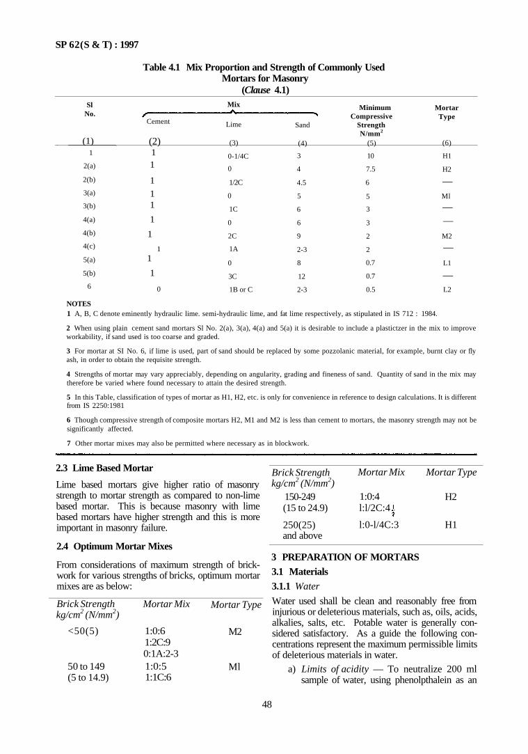
SP 62(S & T) : 1997
Table 4.1 Mix Proportion and Strength of Commonly Used Mortars for Masonry
(Clause 4.1) Sl
No.
(1) 1
2(a)
2(b)
3(a)
3(b)
4(a)
4(b)
4(c)
5(a)
5(b)
6
Mix
Cement
(2) 1 1
1
1 1
1
1
1 1
1
0
Lime
(3)
0-1/4C
0
1/2C
0
1C
0
2C
1A
0
3C
1B or C
Sand
(4)
3
4
4.5
5
6
6
9
2-3
8
12
2-3
Minimum Compressive
Strength N/mm2
(5)
10
7.5
6
5
3
3
2
2
0.7
0.7
0.5
Mortar Type
(6)
H1
H2
— Ml
— —
M2
—
L1
— L2
NOTES 1 A, B, C denote eminently hydraulic lime. semi-hydraulic lime, and fat lime respectively, as stipulated in IS 712 : 1984.
2 When using plain cement sand mortars Sl No. 2(a), 3(a), 4(a) and 5(a) it is desirable to include a plastictzer in the mix to improve workability, if sand used is too coarse and graded.
3 For mortar at SI No. 6, if lime is used, part of sand should be replaced by some pozzolanic material, for example, burnt clay or fly ash, in order to obtain the requisite strength.
4 Strengths of mortar may vary appreciably, depending on angularity, grading and fineness of sand. Quantity of sand in the mix may therefore be varied where found necessary to attain the desired strength.
5 In this Table, classification of types of mortar as H1, H2, etc. is only for convenience in reference to design calculations. It is different from IS 2250:1981
6 Though compressive strength of composite mortars H2, M1 and M2 is less than cement to mortars, the masonry strength may not be significantly affected.
7 Other mortar mixes may also be permitted where necessary as in blockwork.
2.3 Lime Based Mortar
Lime based mortars give higher ratio of masonry strength to mortar strength as compared to non-lime based mortar. This is because masonry with lime based mortars have higher strength and this is more important in masonry failure.
2.4 Optimum Mortar Mixes
From considerations of maximum strength of brick-work for various strengths of bricks, optimum mortar mixes are as below:
Brick Strength kg/cm2 (N/mm2)
<50(5)
50 to 149 (5 to 14.9)
Mortar Mix
1:0:6 1:2C:9 0:1A:2-3 1:0:5 1:1C:6
Mortar Type
M2
Ml
Brick Strength kg/cm2 (N/mm2)
150-249 (15 to 24.9)
250(25) and above
Mortar Mix
1:0:4 l:l/2C:4
l:0-l/4C:3
Mortar Type
H2
H1
3 PREPARATION OF MORTARS 3.1 Materials 3.1.1 Water
Water used shall be clean and reasonably free from injurious or deleterious materials, such as, oils, acids, alkalies, salts, etc. Potable water is generally con-sidered satisfactory. As a guide the following con-centrations represent the maximum permissible limits of deleterious materials in water.
a) Limits of acidity — To neutralize 200 ml sample of water, using phenolpthalein as an
48
SP 62 (S & T) : 1997
indicator, it should not require more than 2 ml of 0.l normal NaOH.
b) Limits of alkalinity — To neutralize 200 ml sample of water, using methyl orange as an indicator, it should not require more than 10 ml of 0.l normal HC1.
c) Permissible limits of solids shall not exceed as given below:
Organic 200 mg/1 Inorganic 3 000 mg/1 Sulphates (as SO4) 500 mg/1 Chlorides (as C1) 2 000 mg/1 Suspended matter 2 000 mg/1
d) The pH value of water shall generally be not less than 6.
e) Sea water is not recommended, because of presence of harmful salts in sea water. Under unavoidable circumstances sea water may be used for under sea constructions.
3.1.2 Cement
Cement shall conform to any of the following: a) 33 Grade ordinary Portland cement conform
ing to IS 269 . 1989, b) Portland slag cement contorming to IS 455 : 1989, c) Portland pozzolana cement conforming to
IS 1489 (Parts 1 and 2) : 1991, d) Rapid hardening Portland cement conforming
to IS 8041 : 1990, c) Hydrophobic Portland cement conforming to
IS 8043 : 1991, f) 43 Grade ordinary Portland cement conform
ing to IS 8112 : 1989, g) 53 Grade ordinary Portland cement contorm-
ing to IS 12269 : 1987, and h) Low heat Portland cement conforming to
IS 12600 : 1989. High alumina cement,conforming to IS 6452 : 1989 may be used under special circumstances as permitted by the Authority; sinrimlarly supersulphated cement conforming to IS 6909 : 1990 may also be used in special cases. Specialist literature may be consulted for use of these types of cements.
3.1.3 Lime
Lime shall conform to IS 712 1984. Building lime shall be classified as follows:
Class A — Eminently hydraulic lime used for structural purposes.
Class B — Semi-hydraulic lime for masonry purpose. Class C — Fat lime used for finishing coat; it can be
used for masonry mortar with addition of pozzolanic material.
Class D — Magnesium lime used for finishing coat. Class E — Kankar lime used for mortar.
3.1.3.1 Carbide lime Carbide lime is obtained as a by-product in the manufacture of acetylene. It shall be procured fresh in
the form of paste and used before it dries up. This is comparable to Class C lime. It may be used for mortar and plaster work, but not for white washing.
3.1.3.2 Hydrated lime
It shall be in the form of dry fine powder produced by treating quick lime in any suitable form with sufficient water so as to produce a completely hydrated but dry and sound product. It shall be brought from approved manulacturers and shall be used within 3 to 4 months from the date of manufacture.
3.1.4 Lime Pozzolana Mixture
It shall conform to IS 4098 : 1983. Only LP 40 type lime pozzolana mixture shall be used. Class C lime shall be ground with burnt clay pozzolana to IS 1344 : 1981 to obtain the mixture; burnt clay pozzolana with a minimum lime reactivity of 80, 60, 40 kg/cm2 shall be used.
3.1.5 Fine Aggregate
Aggregate most of which passes 4.75 mm IS sieve is known as fine aggregate. The aggregate shall conform to the requirements of IS 383 : 1970. It shall not contain harmful organic impurities in such form or quantities to affect adversely the strength of mortar. Fine aggregate, when used in places using reinforce-ment, shall not contain any material acidic in character which is likely to attack reinforcement.
Fine aggregate shall be either sand or crushed stone dust. Sand is of two types, namely, coarse and fine sand.
3.1.5.1 Fine sand
This shall be natural river sand. Its grading, as per Annex A, shall be within the limits of Grading Zone IV (see Table 4.2). When the grading falls outside the percentage limits prescribed for sieves other than 600 micron, 300 micron and 150 micron IS sieves by not more than 5 percent it shall be regarded as falling within the zone. This 5 percent can be split up among the different sieves, for example, it could be one per-cent for each of the three sieves and 2 percent on another.
The maximum quantity of silt as determined by Annex B, shall not exceed 8 percent
3.1.5.2 Stone dust
This shall be obtained by crushing hard stones. Its grading, as per Annex A, shall be within the limit of Grading Zone III (see Table 4.2). When the grading ??? outside the percentage limits prescribed for sieves other than 600 micron and 300 micron IS sieves by not more than 5 percent and on 150 micron sieve by not more than 20 percent, it shall be regarded falling within the limits of this zone. The 5 percent can be split up; for example, it could be one percent in each of the three sieves and 2 percent on another.
49
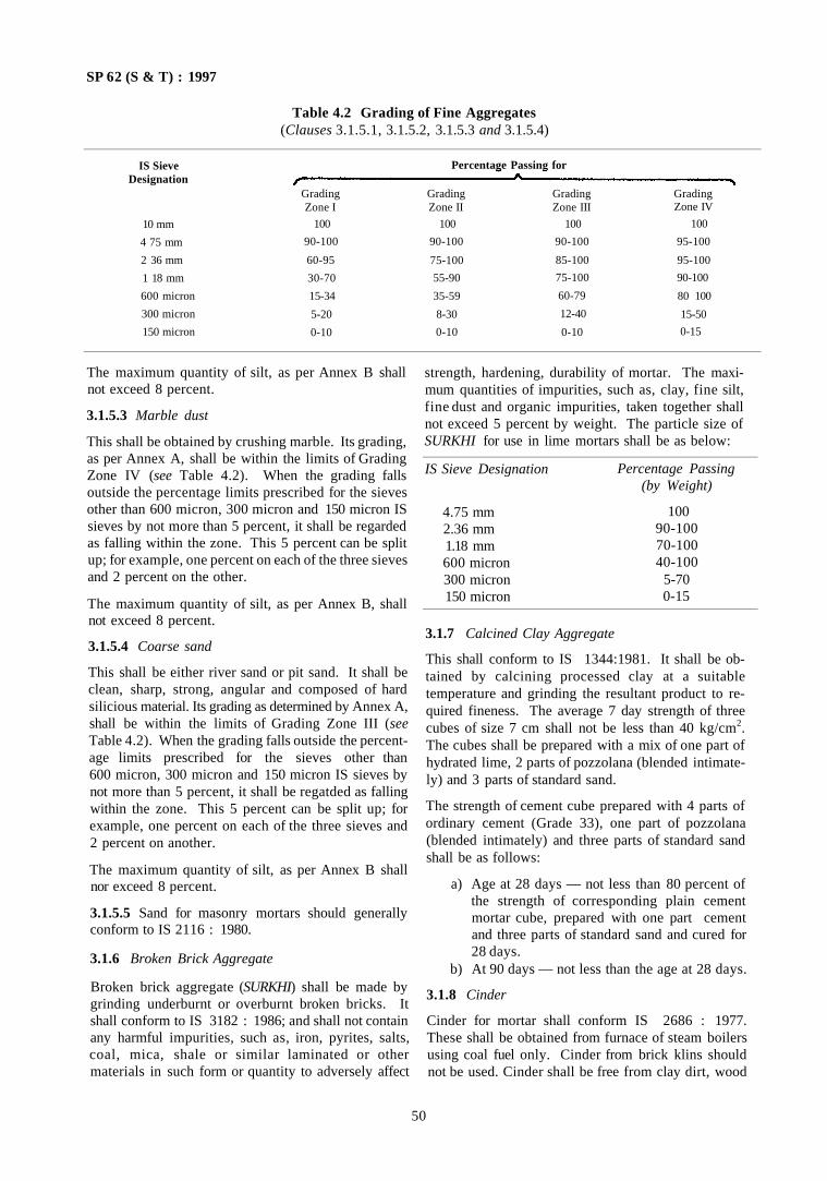
SP 62 (S & T) : 1997
Table 4.2 Grading of Fine Aggregates (Clauses 3.1.5.1, 3.1.5.2, 3.1.5.3 and 3.1.5.4)
IS Sieve Designation
10 mm
4 75 mm
2 36 mm
1 18 mm
600 micron
300 micron
150 micron
Percentage Passing for
Grading Zone I
100
90-100
60-95
30-70
15-34
5-20
0-10
Grading Zone II
100
90-100
75-100
55-90
35-59
8-30
0-10
Grading Zone III
100
90-100
85-100
75-100
60-79
12-40
0-10
Grading Zone IV
100
95-100
95-100
90-100
80 100
15-50
0-15
The maximum quantity of silt, as per Annex B shall not exceed 8 percent.
3.1.5.3 Marble dust
This shall be obtained by crushing marble. Its grading, as per Annex A, shall be within the limits of Grading Zone IV (see Table 4.2). When the grading falls outside the percentage limits prescribed for the sieves other than 600 micron, 300 micron and 150 micron IS sieves by not more than 5 percent, it shall be regarded as falling within the zone. This 5 percent can be split up; for example, one percent on each of the three sieves and 2 percent on the other.
The maximum quantity of silt, as per Annex B, shall not exceed 8 percent.
3.1.5.4 Coarse sand
This shall be either river sand or pit sand. It shall be clean, sharp, strong, angular and composed of hard silicious material. Its grading as determined by Annex A, shall be within the limits of Grading Zone III (see Table 4.2). When the grading falls outside the percent-age limits prescribed for the sieves other than 600 micron, 300 micron and 150 micron IS sieves by not more than 5 percent, it shall be regatded as falling within the zone. This 5 percent can be split up; for example, one percent on each of the three sieves and 2 percent on another.
The maximum quantity of silt, as per Annex B shall nor exceed 8 percent.
3.1.5.5 Sand for masonry mortars should generally conform to IS 2116 : 1980.
3.1.6 Broken Brick Aggregate
Broken brick aggregate (SURKHI) shall be made by grinding underburnt or overburnt broken bricks. It shall conform to IS 3182 : 1986; and shall not contain any harmful impurities, such as, iron, pyrites, salts, coal, mica, shale or similar laminated or other materials in such form or quantity to adversely affect
strength, hardening, durability of mortar. The maxi-mum quantities of impurities, such as, clay, fine silt, fine dust and organic impurities, taken together shall not exceed 5 percent by weight. The particle size of SURKHI for use in lime mortars shall be as below:
IS Sieve Designation
4.75 mm 2.36 mm 1.18 mm 600 micron 300 micron 150 micron
Percentage Passing (by Weight)
100 90-100 70-100 40-100
5-70 0-15
3.1.7 Calcined Clay Aggregate
This shall conform to IS 1344:1981. It shall be ob-tained by calcining processed clay at a suitable temperature and grinding the resultant product to re-quired fineness. The average 7 day strength of three cubes of size 7 cm shall not be less than 40 kg/cm2. The cubes shall be prepared with a mix of one part of hydrated lime, 2 parts of pozzolana (blended intimate-ly) and 3 parts of standard sand.
The strength of cement cube prepared with 4 parts of ordinary cement (Grade 33), one part of pozzolana (blended intimately) and three parts of standard sand shall be as follows:
a) Age at 28 days — not less than 80 percent of the strength of corresponding plain cement mortar cube, prepared with one part cement and three parts of standard sand and cured for 28 days.
b) At 90 days — not less than the age at 28 days.
3.1.8 Cinder
Cinder for mortar shall conform IS 2686 : 1977. These shall be obtained from furnace of steam boilers using coal fuel only. Cinder from brick klins should not be used. Cinder shall be free from clay dirt, wood
50
SP 62 (S & T) : 1997
ashes and other deleterious materials. It shall pass through IS sieve 3.35 mm with at least 50 percent of it passing through IS sieve 1.70 mm. The allowable percentage of unburnt carbon, for use in mortars, shall be up to 20 percent and acid soluble sulphate (expressed as SO3) shall be one percent.
3.1.9 Fly Ash
Fly ash to be used as pozzolana for mortars shall conform to IS 3812 : 1981. It shall be free from any contamination of bottom ash, grit or small pieces of pebbles. This fly ash can be used as part replacement of fine aggregate in mortar and concrete. With a view to improve the grading, the recommended extent of replacement is up to 20 percent.
3.1.10 Soils
Soils for making mud mortar shall have suitable plasticity. The soil shall be free from vegetable roots, stone gravel greater than 2 mm in particle size, Kankar, coarse sand and harmful and efforescent salts. Soil shall not be collected from locality affected by white ants.
The plasticity index of the soil shall be between 6 and 10. For large and important projects it shall be between 12 and 15. The sulphate content shall not extend 0.1 percent. Coarse materials, coarser than 3.55 mm, shall not exceed 10 percent by weight (see IS 13077:1991).
3.1.11 Properties of Materials
The chemical and physical properties of materials referred to in 3.1 and its subparas shall be as listed in SP 21 : 1983. The original Indian Standard Specifications may also be referred to.
3.2 Slaking of Lime Slaking of lime shall conform to IS 1635 : 1992.
3.2.1 Platform
Lime, before slaking, shall be quite fresh and generally in the form of lumps. Slaking shall be carried out on a masonry platform by sprinkling water gradually till lime is slaked and reduced to powdery form. Slaked lime shall be screened through IS Sieve 3.35 mm and the residue retained on the sieve shall be rejected. Slaked lime shall then be run to putty before use in mortar.
3.2.2 Preparation of Lime Putty
Three sufficiently large slaking vessels or tanks shall be made; one 50 cm deep at a higher level, the remaining 80 cm deep at a lower level such the contents of upper tank flow into the next by gravity.
The upper tank shall be filled with water to half the depth; sufficient quick lime be added gradually to fill up the tank to half of water depth. Lime shall be added to water and not water to lime.
The mix shall be stirred continuously ensuring that lime does not get exposed above water.
The stirring may be stopped 5 min after the boiling has stopped. As the mix thickens more water shall be added.
The mix shall then be allowed to pass through IS Sieve 3.55 mm and flow into a tank at the lower level where it shall kept standing for 72 h before use. Water will evaporate partly and the surplus water at top shall be removed, leaving lime putty in the form of paste.
Lime putty shall be kept wet till it is completely used. It can be stored for a fortnight without getting spoilt.
3.3 Preparation of Mortars
As already mentioned in 1.1 mortars shall be prepared and tested as for IS 2250 : 1981, except mud mortar. Some important points to be noted are given below.
3.3.1 Cement Mortar
Mixing shall be done in a mechanical mixer. If done by hand, the operation shall be carried out on a clean watertight platform. It shall be used as soon as possible after mixing and before it has begun to set. in any case within 2 h, after water is added to the dry mixture. Mortar unused for more than 2 h shall be rejected.
3.3.2 Cement Lime Mortar
It shall be used as soon as possible after mixing and within 2 h. Mortals unused for more than 2 h shall be rejected. For class B lime, lime putty and sand can be kept for 72 h for preparation of cement lime mortar.
Cement fly ash mortar shall also conform to requirement as mentioned herein.
3.3.3 Lime Mortar
Lime mortar shall be used as soon as possible after mixing and grinding. As a rule the mortar should be used the day it is made. It Class A is present as an ingredient, the mortar shall be used within 4 h after mixing or grinding. Lime mortar with Class B lime shall be used within 36 h; the same applies to use of Class C lime; with pozzolana lime mortar with Class C lime and shall be used within 72 h. Lime mortars shall be kept damp with wet sack or other means and shall not be allowed to dry.
Similar precautions shall be taken for mortars with pozzolana mixture as mentioned herein.
3.3.4 Mud Mortar
Soil as chosen in 3.1.10 shall be broken up into fine powdery form and then shall be mixed with clean water and matured at least for 2 days. The mortar shall then be trodden with man's feet and spades, turning over and over again to make it a homogeneous mass of working consistency.
Reference may also be made to IS 13077 : 1991.
51
SP 62 (S & T) : 1997
ANNEX A
(Clauses 3.1.5.1, 3.1.5.2, 3.1.5.3 and 3.1.5.4)
SIEVE ANALYSIS
A-1 EQUIPMENT
Perforated plate sieves of designation 10 mm, 4.75 mm and fine mesh sieves of designation 2.36 mm. 1.18 mm, 600 micron, 300 micron and 150 micron shall be used.
A-2 SAMPLE
The weight of the sample available shall not be less than the weight as given below. The sample for sieving shall be prepared from the larger sample by quartering or by sample divider.
Particle Size, mm, Max
Weight of Sample kg, Min
60
50
50
35
40
15
25
5
20
2
16
2
12.5
1
10
0.5
6.3
0.2
4.75
0.2
2.36
0.1
A-3 SIEVING
The sample shall be brought to air-dry condition before sieving. The sieves shall be clean before use. Sieving shall be done on successive sieves stalling from the largest. Light brushing is permitted on finer sieves.
On completion of sieving, the material retained on each sieve shall be weighed.
A-4 REPORT
The results shall be calculated and reported as:
a) Cumulative percentage by weight of the total sample passing each sieve to the nearest whole number; or
b) Percentage by weight of the total sample passing one sieve and retained on the next small sieve to nearest 0.1 percent.
ANNEX B
(Clauses 3.1.5.1, 3.1.5.2, 3.1.5.3 and 3.1.5.4)
FIELD TEST FOR SILT CONTENT
B-1 PROCEDURE
A sample of sand to be tested shall be placed without drying in a 200 ml measuring cylinder. The volume of sand shall fill up to 100 ml mark.
Clean water shall be added up to 150 ml mark. One tea spoon of salt shall be dissolved in a half litre of water before adding. Shake the mixture vigorously,
ensuring that some sidewise shaking is also done. Allow the mix to settle for 3 h.
The height of the silt layer visible above the sand shall be expressed as percentage of the height of sand below.
Sand containing more silt than permitted shall be washed as to bring the silt content to acceptable levels.
52
SP 62 (S & T) : 1997
PART 2 BRICKWORK AND BLOCKWORK
Section 1 Brick and Block Units
1 GENERAL 1.1 Introduction There are several types of masonry units, such as, clay bricks, concrete blocks, lime based blocks, stones, etc. Therefore the choice of masonry unit becomes relevant. Generally, the choice is governed by local availability; compressive strength; durability; impermeability in heavy monsoon areas; fire resistance; cost; ease of construction; etc.
Generally brick has the advantage over stone as it lends itself to easy construction and requires less labour for laying. Thus the first choice is any place would be brick if it is available at reasonable cost, has required strength and is of good quality.
Stone masonry, because of practical limitations of dressing to shape and size, usually has to be thicker and results in unnecessary extra cost. In hills and certain plains, where soil is unsuitable for brick burning, and stone is locally available, the choice naturally is on stone. However if the type and quality of stone is unsuitable for dressing and shaping, recourse may be taken to using blocks particularly when the construction is not more than two storeys high. For example, precast stone masonry work to IS 12440:1988 may be considered. With these blocks, the thickness of walls could be kept within economical limits.
In places where brick and stone of suitable quality is not available, and concrete blocks cannot be manufactured at reasonable cost, sand lime bricks could be considered. However the cost of equipment for sand lime bricks is high and hence these bricks have not yet become popular.
1.2 Types of Bricks
The following Indian Standards cover various bricks:
a) IS 1077 : 1992; IS 2180 : 1988; IS 2222 : 1991; IS 2691 : 1988; IS 3952 : 1988; IS 6165 : 1992 for clay bricks.
b) IS 4139 : 1989 for calcium silicate (sand lime) bricks.
c) IS 12894 : 1990 for sand lime bricks and fly ash lime bricks
2 BRICKS
2.1 General
Bricks shall be handmade or machine moulded. Reference may be made to IS 2117 : 1991 for guide on manufacture of handmade common burntclay building
bricks. For semi-mechanized process of manufacture of common burntclay building bricks, reference may be made to IS 11650 : 1991.
2.2 Information on Bricks
The following information of availability, strength, etc. of different types of bricks in the country would be of use.
a) Strength of Bricks — Strength of bricks in India varies from region to region depending upon the nature of available soil and technique adopted for moulding and burning. Some research has been done for manufacture of bricks of improved quality from inferior soils, such as, black cotton and moorum, which ordinarily give bricks of very low strength.
According to some survey done, the average strength of bricks manufactured in India, employing commonly known methods for moulding and burning, is as given below: Delhi, Punjab and Haryana Uttar Pradesh Madhya Pradesh Maharashtra Gujarat Rajasthan West Bengal Andhra Pradesh Assam
70-100 kgf/cm2 (7-10 N/mm2)
100-200 kgf/cm2 (10-20 N/mm2) 35-50 kgf/cm2 (3.5-5 N/mm2) 50 kgf/cm2 (5 N/mm2) 30-100 kgf/cm2(3-10 N/mm2) 30 kgf/cm2 (3 N/mm2) 100-200 kgf/cm2 (10-20 N/mm2) 30 kgf/cm2 (3 N/mm2) 35 kgf/cm2 (3.5 N/mm2)
In some cities like Delhi, Calcutta and Madras, machine made bricks have become available, with high compressive strengths ranging from 175-250 kgf/cm2 (17 5-25 N/mm2).
b) Strength of Masonry — Apart from strength of bricks and grade of mortar, as a general rule, the strength of masonry depends on surface characteristics and uniformity of size and shape of units. Units which are true in shape and size, can be laid with thinner mortar joints, thereby resulting in higher strength. Therefore, for the same brick strength, higher masonry strength can be obtained by better shaped bricks with true edges. For this very reason, ashlar stone masonry, with uses accurately dressed and shaped stones, is much stronger (nearly double) than ordinary coarsed stone masonry.
2.3 Classification of Bricks
Common burnt clay bricks are classified on the basis
53
SP 62 (S & T) : 1997
of compressive strength as given below:
Class Designation 35
Average Compressive Strengths
N/mm2
kgf/cm2 35
350
30
30 300
25
25 250
20
20 200
17.5
17.5 175
15
15 150
12.5
12.5 125
10
10 100
7.5
7.5 75
5
5 50
3.5
3.5 35
IS 2180 : 1988 covers burnt clay bricks of higher strength 40 and above, for heavy duty.
The bricks shall be free from cracks and flaws and nodules of free lime. They shall have smooth rectangular faces with sharp corners and shall be uniform in colour. Tolerance on brick dimensions shall be ± 3 percent for designation 100 and above; ± 8 percent for lower designations.
The requirements of bricks to IS 1077 : 1992 are summarized in SP 21 : 1983. Sampling and testing shall be as per IS 5454 : 1978 and IS 3495 : 1992 respectively. However sampling and tests for properties of bricks are given in Annex C.
2.4 Size of Bricks Bricks shall have the following dimensions:
Modular bricks
Non-modular bricks
Length mm 190 190 230 230
Width mm 90 90 110 110
Height mm 90 40 70 30
For obtaining proper bond between modular and non-modular bricks the following size of bricks may also be used:
Length mm 70
Width mm
110
Height mm
1/3 length of brick
2.5 Sand Lime Bricks Sand lime bricks, also called 'Calcium Silicate' bricks consist essentially of an intimate mixture of siliceous sand or crushed siliceous rock and lime combined by action of saturated steam under pressure. Coloured sand lime bricks also can be made by adding fast pigments to the raw mix before pressure casting. 2.5.1 Classes Sand lime bricks shall be of 4 classes as given below:
Class
Class 75 Class 100 Class 150 Class 200
Average Compressive Strength N/mm2 (kgf/cm2) 7.5 to 10.0 (75 to 100) 10.0 to 15.0 (100 to 150) 15.0 to 20.0 (150 to 200) 20.0 and above (200 and above).
2.5.2 Sizes
Sand lime bricks shall have the same size as clay bricks to IS 1077 : 1992.
2.5.3 The physical properties, sampling, etc shall be as per IS 4139 : 1989.
2.6 References
For information on other bricks, refer to SP 20 : 1991 These include bricks to IS 2222 : 1990, IS 3952 : 1988 and brick shapes to IS 6165 : 1992. Also for information on IS 12894 : 1990 for fly ash lime bricks refer to SP 20 : 1991.
3 BLOCKS
3.1 General
Blocks have several advantages, such as, durability, strength, structural stability, fire resistance, sound absorption, heat insulation, etc. They are also economical because of the following reasons:
a) The units are relatively large and true in size and shape. This ensures rapid construction so that more wall is laid per man than in other types of wall construction.
b) Fewer joints result in considerable saving in mortar as compared to normal masonry construction; it also increases the strength of masonry [see 2.2 (b)].
c) The true plane surfaces obtained obviate necessity to plaster for unimportant buildings situated in low rainfall areas; even when plaster is used for any reason, the quantity required for satisfactory coverage is significantly small.
3.2 Types of Blocks
Concrete blocks may be solid or hollow. The following Indian Standards covers various types of blocks:
a) Concrete masonry units: IS 2185 (Part 1) : 1979 Hollow and solid concrete blocks; IS 2185 (Part 2) : 1983 Hollow and solid light weight concrete blocks; and IS 2185 (Part 3): 1984 Autoclaved cellular aerated concrete blocks.
b) Lime based blocks: IS 3115 : 1992. c) Soil based blocks: IS 1725 : 1982.
3.3 Concrete Blocks
They shall be handmade or machine made.
54
SP 62 (S & T) : 1997
3.3.1 Manufacture
a) Materials — Cement shall conform to either of the following:
IS 269 : 1989; IS 455 : 1989; IS 1489 (Parts 1 and 2) : 1991; IS 6452 : 1989; IS 6909 : 1990; IS 8112 : 1989; IS 8041 : 1990; IS 8042 : 1989; IS 8043 : 1991; IS 12269 : 1987; IS 12600 : 1989.
Aggregates shall conform to IS 383 : 1970. Fly ash conforming to IS 3812 : 1981 may be used as a replacement for fine aggregate up to 20 percent.
Water used in the manufacture of blocks shall be free from harmful matter and shall not cause efflorescence. It shall conform to the requirements laid down in IS 456 . 1978.
Admixtures may be added and they shall be either: 1) Accelerating, water reducing and air
entraining admixtures conforming to IS 9103 : 1979; or
2) Waterproofing agents conforming to IS 2645 : 1975.
b) Concrete Mix — The concrete mix used for blocks shall not be richer than one cement to six combined aggregates (by volume). Combined aggregates shall be graded as near as possible to IS 383 : 1970. The fineness modulus of combined aggregate shall be between 3.6 and 4.
c) Hand Moulding — For hand moulding compaction is done manually. Concrete mix should be of Sufficient consistency to enable demoulding immediately after casting. The consistency should be such that it may be cohere when compressed by hand without free water being visible.
d) Machine Moulding — In machine moulding. the web markings on the units give a good indication as to whether proper consistency of concrete has been used.
e) Curing — The blocks shall be cured in water tor 14 days. Steam curing also may be adopted instead of curing in water. The blocks shall then be dried for 28 days before using on work. The blocks shall be stacked with voids horizontal to permit free flow of air. They shall be allowed to complete their initial shrinkage before using on site.
3.3.2 Sizes
The nominal dimensions are as below:
Length: 400 mm. 500 mm or 600 mm.
Width: 50 mm, 75 mm, 100 mm. 150 mm, 200 mm, 250 mm, or 300 mm.
Height: 200 mm or 100 mm.
For other dimensional details see IS 2185 (Part 1) : 1979.
3.3.3 Classification of Blocks
a) Hollow (open and closed cavity) concrete blocks — Hollow blocks shall conform to the following three grades: 1) Grade A — Load bearing units with a
minimum block density of 1 500 kgf/m3. Average compressive strength shall be 3.5, 4.5, 5.5 and 7.0 N/mm2 (or 35, 45, 55 and 70 kgf/cm2). The thickness of face shell and web shall not be less than 25 mm.
2) Grade B — Load bearing units with a block density between 1 000 kgf/m3 to 1 500 kgf/m3. The average compressive strength shall be 2.0, 3.0 and 5.0 N/mm2
(20, 30 or 50 kgf/cm2).
3) Grade C — Non-load bearing units with block density between 1 000 kgf/m3 to 1 500 kgf/m3. The average compressive strength shall be not less than 1.5 N/mm2
(15 kgf/cm2). b) Solid concrete blocks — Load bearing units
with a block density not less than 1 800 kgf/m3. The average compressive strength shall be between 4.0 to 5.0 N/mm2 (40 to 50 kgf/cm2).
3.3.4 The physical properties, sampling criteria for conformity and testing shall be as per IS 2185 (Part 1): 1979 or SP 21 : 1983 which summarizes properties of various masonry elements. Some important properties are:
a) Water (absorption — not more than 10 percent by mass;
b) Dryingshrinkage — not more than 0.1 percent; and
c) Moisure movement — not more than 0.09 percent.
3.4 Lime Based Blocks
3.4.1 Manufacture
Sevrral individual process of manufacture are available.
a) Materials — Lime shall conform to IS 712 : 1084. Cement shall be as per IS 269 : 1989 or IS 455 : 1989 or IS 1489 (Parts 1 and 2) : 1991. Burnt clay pozzolana shall conform to IS 1344 : 1981. Lime pozzolana mixture to IS 4098 1983 and fly ash to IS 3812 : 1981.
Aggregate shall be as per IS 383 : 1970; or IS 3068 : 1986; or IS 2686 : 1977. Water shall be as per IS 456 : 1978.
55
SP 62 (S & T) : 1997
b) Sizes — The sizes of blocks shall be as below:
Length: Width: Height:
390 mm. 100 mm, 200 mm, 300 mm. 90 mm, 190 mm.
3.4.2 For other physical properties, sampling, tests, etc, see IS 3115 : 1992 or SP 21 : 1983 which summarizes properties of various masonry elements. Some important properties are:
a) Bulk density — not less than 1 000 kgf/m3; b) Compressive strength — not less than 3.5
N/mm2 (35 kgf/cm2); c) Drying shrinkage — not more than 0.1 percent;
and d) Moisture movement — not more than 0.05
percent.
3.5 Soil Based Blocks 3.5.1 General
Experience has shown that most soils can be satisfactorily stablized with cement-lime. It is, however, necessary to conduct comprehensive tests on soils in a laboratory in order to determine optimum requirements to give the specified properties. Soil based blocks can generally be used in low cost structures; they can substitute bricks except in case of isolated heavy load bearing columns, piers, etc.
3.5.2 Manufacture Soil based blocks shall be manufactured from a mixture of suitable soil and cement, thoroughly mixed preferably in a mechanical mixer. The mixture is cast into blocks.
3.5.3 Classification
The blocks shall be of two classes, class 20 and class 35.
3.5.4 Sizes
The sizes of soil based blocks shall be : 19 cm × 9 cm × 9 cm or 19 cm × 9 cm × 4 cm or
29 cm × 19 cm × 9 cm.
3.5.5 The physical properties, sampling, testing, etc, shall be as per IS 1725 : 1982 or SP 21 : 1983 which summarizes properties of various masonry elements. Some important properties are:
a) Compressive strength — Not less than 2 N/mm2 (20 kgf/cm2) for Class 20. Not less than 3 N/mm2 (30 kgf/cm2) for Class 30.
b) Water absorption — Not more than 15 percent. c) Weathering — Not more than 5 percent.
4 SUMMARY OF PROPERTIES OF MASONRY UNITS
4.1 So far several masonry units have been covered. For the purpose of design it would be useful to have a look at the compressive strengths of these masonry units since this is an important characteristic for choice ofunit(see Table 4.3).
4.2 From this it is clear that in building construction, high strength masonry units and lower strength units are also available. For load-bearing construction, so far buildings up to 6 storeys have gone up. In many places abroad, even 14 storeys have been built only with masonry.
This is possible by combining vertically high strength bricks in lower storeys (heavier loads) and lighter masonry units (blocks) in upper storeys.
That is why, this aspect should be decided at planning and design stages, so that, higher buildings can be done with masonry units only; thus load bearing masonry construction is possible. Very light blocks can be used for partition, filler walls, etc, as non-load bearing elements.
Thus an attempt on these lines would result in savings in construction. As already mentioned there is a need to correlate strength of mortar with the masonry unit and finally arrive at an ascending order of load bearing capacity.
Table 4.3 Compressive Strength of Masonry Units (Clause 4.1)
IS No.
2180. 1988
1077 • 1992
4139 : 1989
2185 (Part 1). 1979
2222 : 1991
3115 : 1992 and 3952.1988
1725 : 1982
Compressive Strength N/mm2 (kgf/cm2)
45 (450), 40 (400)
35 (350), 30 (300), 25 (250), 20 (200). 17.5 (175), 15 (150), 12 5 (125), 10 (100), 7 5 (75), 5.0 (50), 3 5 (35)
20 (200), 15 (150), 10 (100), 7.5 (75)
7.0 (70), 5.5 (55), 5.0 (50), 4.5 (45), 3.5 (35), 3.0 (30), 2.0 (20), 1.5 (15)
7.0 (70), Min
3.5 (35)
3.0 (30). 2.0 (20)
56
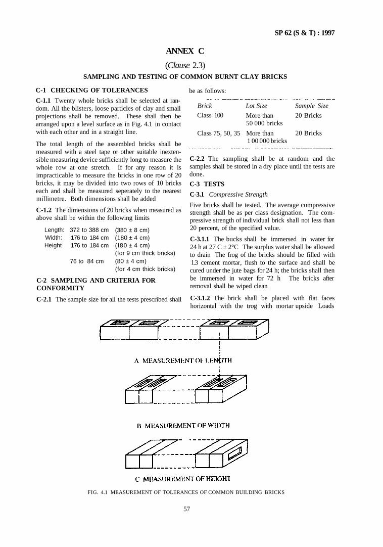
SP 62 (S & T) : 1997
ANNEX C
(Clause 2.3) SAMPLING AND TESTING OF COMMON BURNT CLAY BRICKS
C-1 CHECKING OF TOLERANCES
C-1.1 Twenty whole bricks shall be selected at random. All the blisters, loose particles of clay and small projections shall be removed. These shall then be arranged upon a level surface as in Fig. 4.1 in contact with each other and in a straight line.
The total length of the assembled bricks shall be measured with a steel tape or other suitable inexten-sible measuring device sufficiently long to measure the whole row at one stretch. If for any reason it is impracticable to measure the bricks in one row of 20 bricks, it may be divided into two rows of 10 bricks each and shall be measured seperately to the nearest millimetre. Both dimensions shall be added
C-1.2 The dimensions of 20 bricks when measured as above shall be within the following limits
Length: Width: Height
372 to 388 cm 176 to 184 cm 176 to 184 cm
76 to 84 cm
(380 ± 8 cm) (180 ± 4 cm) (I80 ± 4 cm) (for 9 cm thick bricks) (80 ± 4 cm) (for 4 cm thick bricks)
C-2 SAMPLING AND CRITERIA FOR CONFORMITY
C-2.1 The sample size for all the tests prescribed shall
FIG. 4.1 MEASUREMENT OF TOLERANCES OF COMMON BUILDING BRICKS
be as follows:
Brick
Class 100
Class 75, 50, 35
Lot Size
More than 50 000 bricks
More than 1 00 000 bricks
Sample Size
20 Bricks
20 Bricks
C-2.2 The sampling shall be at random and the samples shall be stored in a dry place until the tests are done.
C-3 TESTS
C-3.1 Compressive Strength
Five bricks shall be tested. The average compressive strength shall be as per class designation. The compressive strength of individual brick shall not less than 20 percent, of the specified value.
C-3.1.1 The bucks shall be immersed in water for 24 h at 27 C ± 2°C The surplus water shall be allowed to drain The frog of the bricks should be filled with 1.3 cement mortar, flush to the surface and shall be cured under the jute bags for 24 h; the bricks shall then be immersed in water for 72 h The bricks after removal shall be wiped clean
C-3.1.2 The brick shall be placed with flat faces horizontal with the trog with mortar upside Loads
57
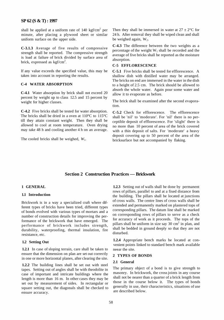
SP 62 (S & T) : 1997
shall be applied at a uniform rate of 140 kgf/cm2 per minute, after placing a plywood sheet or similar uniform surface on the upper side.
C-3.1.3 Average of five results of compressive strength shall be reported. The compressive strength is load at failure of brick divided by surface area of brick, expressed as kgf/cm2.
If any value exceeds the specified value, this may be taken into account in reporting the results.
C-4 WATER ABSORPTION
C-4.1 Water absorption by brick shall not exceed 20 percent by weight up to class 12.5 and 15 percent by weight for higher classes.
C-4.2 Five bricks shall be tested for water absorption. The bricks shall be dried in a oven at 110°C to 115°C till they attain constant weight. Then they shall be allowed to cool at room temperature. Oven drying may take 48 h and cooling another 4 h on an average.
The cooled bricks shall be weighed, W1.
Then they shall be immersed in water at 27 ± 2°C for 24 h. After removal they shall be wiped clean and shall be weighed again, W2.
C-4.3 The difference between the two weights as a percentage of the weight W1 shall be recorded and the average of five bricks shall be reported as the moisture absorption.
C-5 EFFLORESCENCE
C-5.1 Five bricks shall be tested for efflorescence. A shallow dish with distilled water may be arranged. The bricks on end are immersed in the water in the dish to a height of 2.5 cm. The brick should be allowed to absorb the whole water. Again pour some water and allow it to evaporate as before.
The brick shall be examined after the second evaporation.
C-5.2 Check for efflorescence. The efflorescence shall be 'nil' to 'moderate'. For 'nil' there is no perceptible deposit of efflorescence. For 'slight' there is no more than 10 percent of area of the brick covered with a thin deposit of salts. For 'moderate' a heavy deposit covering up to 50 percent of the area of the bricksurface but not accompanied by flaking.
Section 2 Construction Practices — Brickwork
1 GENERAL
1.1 Introduction
Brickwork is in a way a specialized craft where different types of bricks have been tried, different types of bonds evolved with various types of mortars and a number of construction details for improving the performance of the brickwork that have emerged. The performance of brickwork includes strength, durability, waterproofing, thermal insulation, fire resistance, etc.
1.2 Setting Out
1.2.1 In case of sloping terrain, care shall be taken to ensure that the dimension on plan are set out correctly in one or more horizontal planes, after clearing the site.
1.2.2 The building lines shall be set out with steel tapes. Setting out of angles shall be with theodolite in case of important and intricate buildings where the length is more than 16 m. In other cases they may be set out by measurement of sides. In rectangular or square setting out, the diagonals shall be checked to ensure accuracy.
1.2.3 Setting out of walls shall be done by permanent rows of pillars, parallel to and at a fixed distance from the building. The pillars shall be located at junctions of cross walls. The centre lines of cross walls shall be extended and permanently marked on plastered tops of corresponding pillars. The datum line shall be marked on corresponding rows of pillars to serve as a check for accuracy of work as it proceeds. The tops of the pillars shall be uniform in size say 30 cm2 in plan, and shall be bedded in ground deeply so that they are not disturbed.
1.2.4 Appropriate bench marks be located at convenient points linked to standard bench mark available neear the site.
2 TYPES OF BONDS
2.1 General
The primary object of a bond is to give strength to masonry. In brickwork, the cross joints in any course shall not be nearer than a quarter of a brick length from those in the course below it. The types of bonds generally in use, their characteristics, situations of use are described below.
58
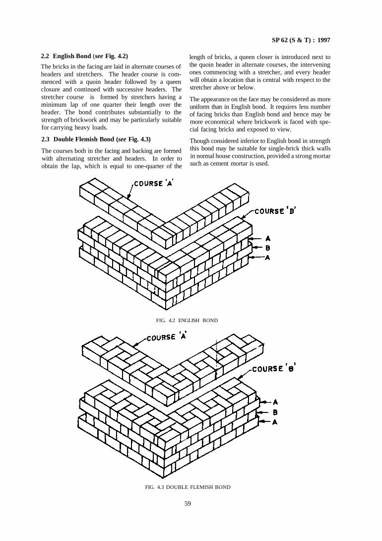
SP 62 (S & T) : 1997
2.2 English Bond (see Fig. 4.2)
The bricks in the facing are laid in alternate courses of headers and stretchers. The header course is commenced with a quoin header followed by a queen closure and continued with successive headers. The stretcher course is formed by stretchers having a minimum lap of one quarter their length over the header. The bond contributes substantially to the strength of brickwork and may be particularly suitable for carrying heavy loads.
2.3 Double Flemish Bond (see Fig. 4.3)
The courses both in the facing and backing are formed with alternating stretcher and headers. In order to obtain the lap, which is equal to one-quarter of the
length of bricks, a queen closer is introduced next to the quoin header in alternate courses, the intervening ones commencing with a stretcher, and every header will obtain a location that is central with respect to the stretcher above or below.
The appearance on the face may be considered as more uniform than in English bond. It requires less number of facing bricks than English bond and hence may be more economical where brickwork is faced with special facing bricks and exposed to view.
Though considered inferior to English bond in strength this bond may be suitable for single-brick thick walls in normal house construction, provided a strong mortar such as cement mortar is used.
FIG. 4.2 ENGLISH BOND
FIG. 4.3 DOUBLE FLEMISH BOND
59
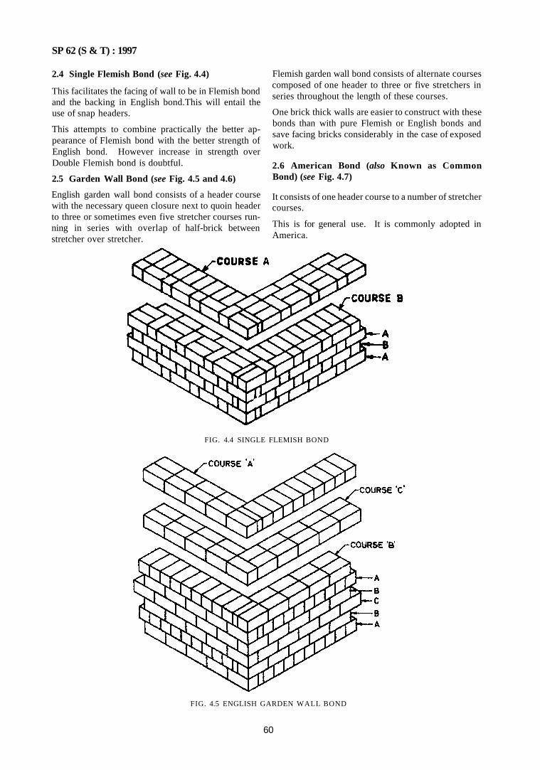
SP 62 (S & T) : 1997
2.4 Single Flemish Bond (see Fig. 4.4)
This facilitates the facing of wall to be in Flemish bond and the backing in English bond.This will entail the use of snap headers.
This attempts to combine practically the better appearance of Flemish bond with the better strength of English bond. However increase in strength over Double Flemish bond is doubtful.
2.5 Garden Wall Bond (see Fig. 4.5 and 4.6)
English garden wall bond consists of a header course with the necessary queen closure next to quoin header to three or sometimes even five stretcher courses running in series with overlap of half-brick between stretcher over stretcher.
Flemish garden wall bond consists of alternate courses composed of one header to three or five stretchers in series throughout the length of these courses.
One brick thick walls are easier to construct with these bonds than with pure Flemish or English bonds and save facing bricks considerably in the case of exposed work.
2.6 American Bond (also Known as Common Bond) (see Fig. 4.7)
It consists of one header course to a number of stretcher courses.
This is for general use. It is commonly adopted in America.
FIG. 4.4 SINGLE FLEMISH BOND
FIG. 4.5 ENGLISH GARDEN WALL BOND
60
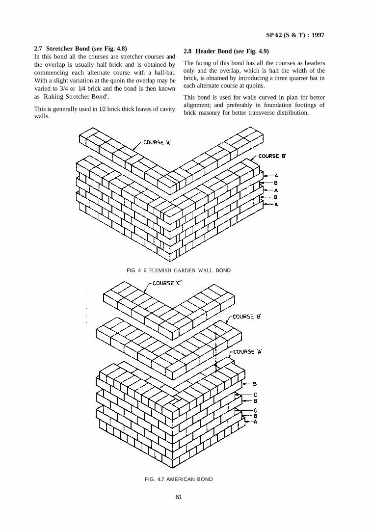
SP 62 (S & T) : 1997
2.7 Stretcher Bond (see Fig. 4.8) In this bond all the courses are stretcher courses and the overlap is usually half brick and is obtained by commencing each alternate course with a half-bat. With a slight variation at the quoin the overlap may be varied to 3/4 or 1/4 brick and the bond is then known as 'Raking Stretcher Bond'.
This is generally used in 1/2 brick thick leaves of cavity walls.
2.8 Header Bond (see Fig. 4.9)
The facing of this bond has all the courses as headers only and the overlap, which is half the width of the brick, is obtained by introducing a three quarter bat in each alternate course at quoins.
This bond is used for walls curved in plan for better alignment; and preferably in foundation footings of brick masonry for better transverse distribution.
FIG 4 6 FLEMISH GARDEN WALL BOND
FIG. 4.7 AMERICAN BOND
61
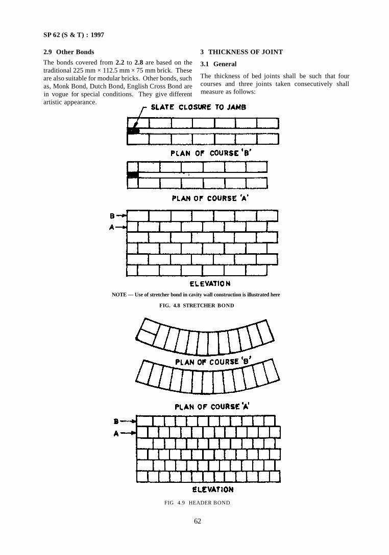
SP 62 (S & T) : 1997
2.9 Other Bonds
The bonds covered from 2.2 to 2.8 are based on the traditional 225 mm × 112.5 mm × 75 mm brick. These are also suitable for modular bricks. Other bonds, such as, Monk Bond, Dutch Bond, English Cross Bond are in vogue for special conditions. They give different artistic appearance.
3 THICKNESS OF JOINT
3.1 General
The thickness of bed joints shall be such that four courses and three joints taken consecutively shall measure as follows:
NOTE — Use of stretcher bond in cavity wall construction is illustrated here
FIG. 4.8 STRETCHER BOND
FIG 4.9 HEADER BOND
62
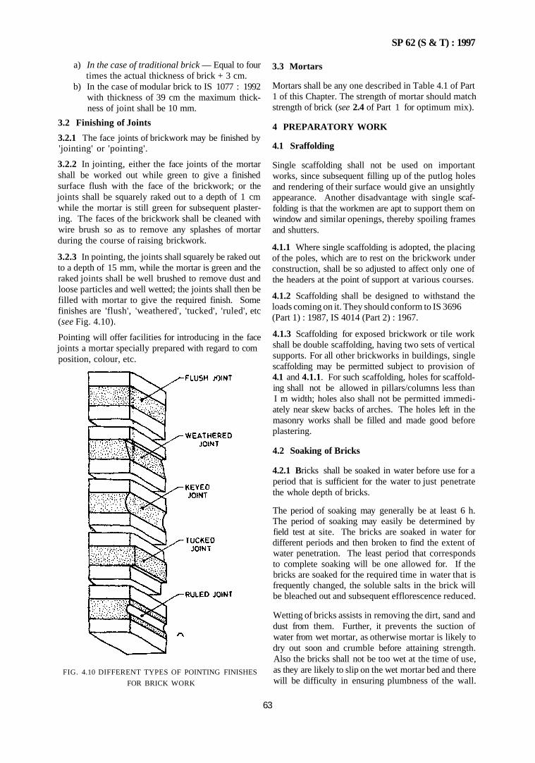
SP 62 (S & T) : 1997
a) In the case of traditional brick — Equal to four times the actual thickness of brick + 3 cm.
b) In the case of modular brick to IS 1077 : 1992 with thickness of 39 cm the maximum thickness of joint shall be 10 mm.
3.2 Finishing of Joints
3.2.1 The face joints of brickwork may be finished by 'jointing' or 'pointing'.
3.2.2 In jointing, either the face joints of the mortar shall be worked out while green to give a finished surface flush with the face of the brickwork; or the joints shall be squarely raked out to a depth of 1 cm while the mortar is still green for subsequent plastering. The faces of the brickwork shall be cleaned with wire brush so as to remove any splashes of mortar during the course of raising brickwork.
3.2.3 In pointing, the joints shall squarely be raked out to a depth of 15 mm, while the mortar is green and the raked joints shall be well brushed to remove dust and loose particles and well wetted; the joints shall then be filled with mortar to give the required finish. Some finishes are 'flush', 'weathered', 'tucked', 'ruled', etc (see Fig. 4.10).
Pointing will offer facilities for introducing in the face joints a mortar specially prepared with regard to com position, colour, etc.
FIG. 4.10 DIFFERENT TYPES OF POINTING FINISHES
FOR BRICK WORK
3.3 Mortars
Mortars shall be any one described in Table 4.1 of Part 1 of this Chapter. The strength of mortar should match strength of brick (see 2.4 of Part 1 for optimum mix).
4 PREPARATORY WORK
4.1 Sraffolding
Single scaffolding shall not be used on important works, since subsequent filling up of the putlog holes and rendering of their surface would give an unsightly appearance. Another disadvantage with single scaffolding is that the workmen are apt to support them on window and similar openings, thereby spoiling frames and shutters.
4.1.1 Where single scaffolding is adopted, the placing of the poles, which are to rest on the brickwork under construction, shall be so adjusted to affect only one of the headers at the point of support at various courses.
4.1.2 Scaffolding shall be designed to withstand the loads coming on it. They should conform to IS 3696 (Part 1) : 1987, IS 4014 (Part 2) : 1967.
4.1.3 Scaffolding for exposed brickwork or tile work shall be double scaffolding, having two sets of vertical supports. For all other brickworks in buildings, single scaffolding may be permitted subject to provision of 4.1 and 4.1.1. For such scaffolding, holes for scaffold-ing shall not be allowed in pillars/columns less than I m width; holes also shall not be permitted immediately near skew backs of arches. The holes left in the masonry works shall be filled and made good before plastering.
4.2 Soaking of Bricks
4.2.1 Bricks shall be soaked in water before use for a period that is sufficient for the water to just penetrate the whole depth of bricks.
The period of soaking may generally be at least 6 h. The period of soaking may easily be determined by field test at site. The bricks are soaked in water for different periods and then broken to find the extent of water penetration. The least period that corresponds to complete soaking will be one allowed for. If the bricks are soaked for the required time in water that is frequently changed, the soluble salts in the brick will be bleached out and subsequent efflorescence reduced.
Wetting of bricks assists in removing the dirt, sand and dust from them. Further, it prevents the suction of water from wet mortar, as otherwise mortar is likely to dry out soon and crumble before attaining strength. Also the bricks shall not be too wet at the time of use, as they are likely to slip on the wet mortar bed and there will be difficulty in ensuring plumbness of the wall.
63
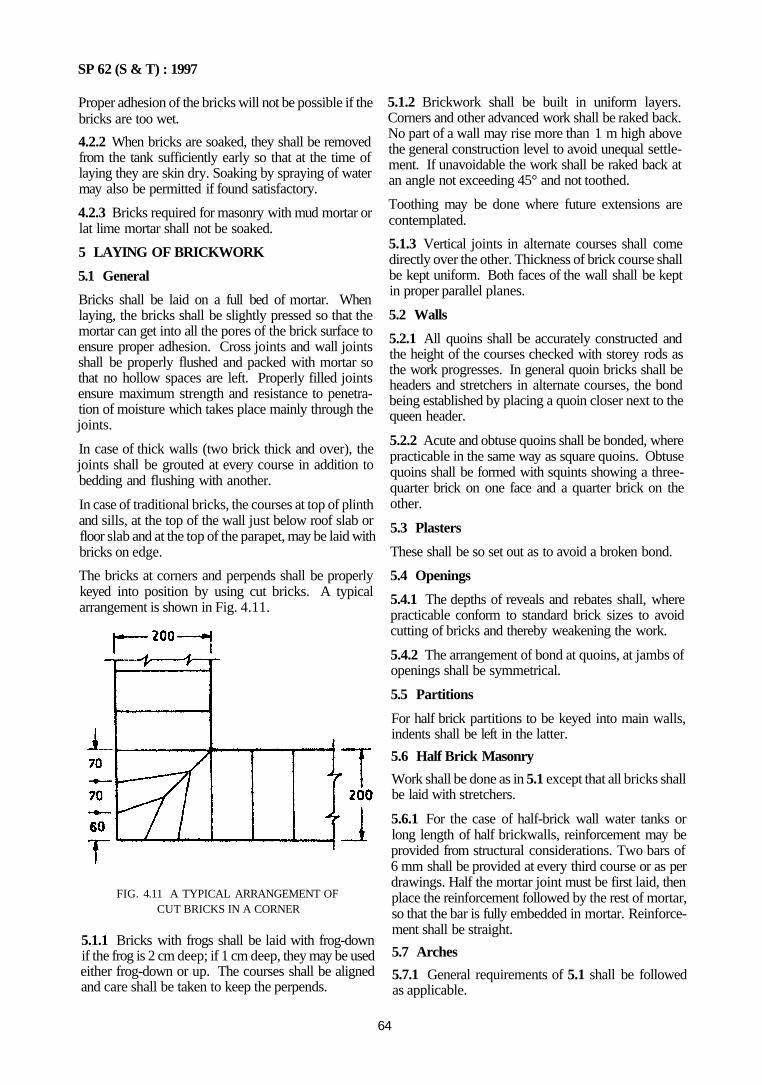
SP 62 (S & T) : 1997
Proper adhesion of the bricks will not be possible if the bricks are too wet.
4.2.2 When bricks are soaked, they shall be removed from the tank sufficiently early so that at the time of laying they are skin dry. Soaking by spraying of water may also be permitted if found satisfactory.
4.2.3 Bricks required for masonry with mud mortar or lat lime mortar shall not be soaked.
5 LAYING OF BRICKWORK
5.1 General
Bricks shall be laid on a full bed of mortar. When laying, the bricks shall be slightly pressed so that the mortar can get into all the pores of the brick surface to ensure proper adhesion. Cross joints and wall joints shall be properly flushed and packed with mortar so that no hollow spaces are left. Properly filled joints ensure maximum strength and resistance to penetration of moisture which takes place mainly through the joints.
In case of thick walls (two brick thick and over), the joints shall be grouted at every course in addition to bedding and flushing with another.
In case of traditional bricks, the courses at top of plinth and sills, at the top of the wall just below roof slab or floor slab and at the top of the parapet, may be laid with bricks on edge.
The bricks at corners and perpends shall be properly keyed into position by using cut bricks. A typical arrangement is shown in Fig. 4.11.
FIG. 4.11 A TYPICAL ARRANGEMENT OF CUT BRICKS IN A CORNER
5.1.1 Bricks with frogs shall be laid with frog-down if the frog is 2 cm deep; if 1 cm deep, they may be used either frog-down or up. The courses shall be aligned and care shall be taken to keep the perpends.
5.1.2 Brickwork shall be built in uniform layers. Corners and other advanced work shall be raked back. No part of a wall may rise more than 1 m high above the general construction level to avoid unequal settlement. If unavoidable the work shall be raked back at an angle not exceeding 45° and not toothed.
Toothing may be done where future extensions are contemplated.
5.1.3 Vertical joints in alternate courses shall come directly over the other. Thickness of brick course shall be kept uniform. Both faces of the wall shall be kept in proper parallel planes.
5.2 Walls
5.2.1 All quoins shall be accurately constructed and the height of the courses checked with storey rods as the work progresses. In general quoin bricks shall be headers and stretchers in alternate courses, the bond being established by placing a quoin closer next to the queen header.
5.2.2 Acute and obtuse quoins shall be bonded, where practicable in the same way as square quoins. Obtuse quoins shall be formed with squints showing a three-quarter brick on one face and a quarter brick on the other.
5.3 Plasters
These shall be so set out as to avoid a broken bond.
5.4 Openings
5.4.1 The depths of reveals and rebates shall, where practicable conform to standard brick sizes to avoid cutting of bricks and thereby weakening the work.
5.4.2 The arrangement of bond at quoins, at jambs of openings shall be symmetrical.
5.5 Partitions
For half brick partitions to be keyed into main walls, indents shall be left in the latter.
5.6 Half Brick Masonry
Work shall be done as in 5.1 except that all bricks shall be laid with stretchers.
5.6.1 For the case of half-brick wall water tanks or long length of half brickwalls, reinforcement may be provided from structural considerations. Two bars of 6 mm shall be provided at every third course or as per drawings. Half the mortar joint must be first laid, then place the reinforcement followed by the rest of mortar, so that the bar is fully embedded in mortar. Reinforcement shall be straight.
5.7 Arches
5.7.1 General requirements of 5.1 shall be followed as applicable.
64
SP 62 (S & T) : 1997
Both plain and gauged arches are covered. In plain arches, uncut bricks shall be used. In gauged arches moulded bricks shall be used.
Bricks forming skewbacks shall be dressed or cut so as to give proper radial bearing to the end voussoirs. Defects in dressing up bricks shall not be covered by extra use of mortar, nor use of chips be permitted.
The bricks of the spandrel wall at their junctions with extrados of arch shall be cut to fit the curvature of the arch.
5.7.2 Circular A rches
They shall be either (a) plain arches and shall be built with half brick concentric rings with break joints, or (b) gauged arches with bricks cut to or moulded to proper shape. The arch work shall be carried out from both ends and keyed in the centre. The bricks shall be flush with mortar and well pressed into their positions as to squeeze out a part of their mortar and leave the joints thin and compact All joints shall be full of mortar and thickness of joints shall not be less than 5 mm and not more than 15 mm.
After the arch is completed, the haunches shall be loaded by filling up sprandrels up to the crown level of the arch. Care shall be taken to load the haunches on two sides of the sprandrels.
When the arch face has to be pointed, the face bricks shall be cut to proper shape or moulded as to have joints not more than 5 mm thick. These shall be laid to the full depth of the arch The voussoirs shall break joints to the full depth of the arch.
5.7.3 Flat Arches
These shall be gauged arches of cut brick or moulded brick to proper shape. The extrados shall be kept horizontal and the intrados shall be given a slight camber of 1 in 100 of the span. The centre of the arch from which joints shall radiate shall be determined by the point of intersection of the two lines drawn from the ends of the arch at the springing level and at 60° to horizontal.
In flat arches, bricks shall be laid with radial joints to the full depth of the arch and voussoirs breaking joints with each other. The arch work shall be carried out from both the ends simultaneously and keyed in the centre. The thickness of joints shall not exceed 15 mm.
5.7.4 Centering and Shuttering
The centering and shuttering for the arches shall be got approved by the Authority. It shall carry the dead and live loads without any appreciable deflection.
The shuttering shall be tightened with hardwood wedges or sand boxes, so that the shuttering can be eased out without any jerks being transmitted to the
arch. The sequence of easing the shuttering shall be carefully worked out. The shuttering shall be struck between 24 to 48 h of the completion of the arch. This shall be done after the sprandrel has been filled in and the arch loaded.
5.8 Brick Tile Work
It shall be done in the same way as brickwork as in 5.1.
5.9 Honey Comb Brickwork
The honey comb brickwork shall be done with specified class of brick, laid in specified mortar. All joints and edges shall be struck flush to give an even surface. The thickness shall be half-brick only, unless otherwise specified. Openings shall be equal and alternate with half-brick laid with a bearing of 2 cm on either side.
5.10 Brickwork in Openings
Openings shall be of such size and so spaced in walls as to reduce the cutting of bricks to minimum. The width of openings shall, as far as possible, be a multiple of width of brick.
In the external walls, it is desirable to rebate the sills, jambs and heads of openings so as to form a barrier for rainwater. The sill may be sloped slightly to allow the rain water to drain off.
5.11 Parapets and Copings
5.11.1 The parapets and copings shall be of thickness such that their base covers the junction of roof slab and wall which shall be further effectively treated against possible leakage of rain water. Normally a cement lime mortar gold or fillet is done (see SP 25 : 1984) Fig. 4.12.
5.11.2 Coping may be of stone, concrete, brick or terraccota; it is throated underside of the projection. The top of the coping shall be slightly sloped to allow water to drain off.
5.12 Cavity Walls
5.12.1 in building cavity walls of half-brick thickness, only stretcher bond shall be used, unless purpose made snap headers are available. When header bricks are cut and used, they are either likely to protrude into ??? cavity and form a ledger for mortar droppings to collect or they may be so short as to weaken the structure. The cavity shall not be less than 5 cm.
The outer and inner leaves shall be tied by means of wall ties. The wall ties shall preferably be bedded with a slight fall towards the exterior part of the wall.
65
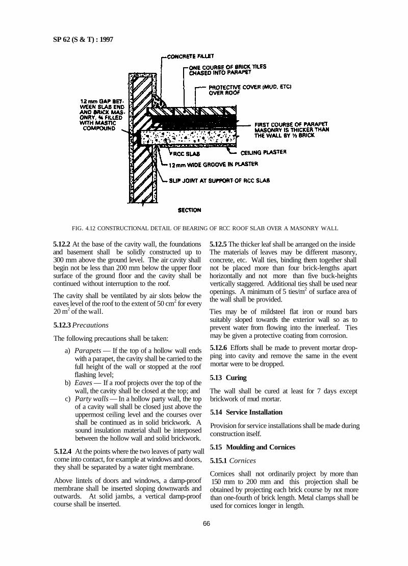
SP 62 (S & T) : 1997
FIG. 4.12 CONSTRUCTIONAL DETAIL OF BEARING OF RCC ROOF SLAB OVER A MASONRY WALL
5.12.2 At the base of the cavity wall, the foundations and basement shall be solidly constructed up to 300 mm above the ground level. The air cavity shall begin not be less than 200 mm below the upper floor surface of the ground floor and the cavity shall be continued without interruption to the roof.
The cavity shall be ventilated by air slots below the eaves level of the roof to the extent of 50 cm2 for every 20 m2 of the wall.
5.12.3 Precautions
The following precautions shall be taken:
a) Parapets — If the top of a hollow wall ends with a parapet, the cavity shall be carried to the full height of the wall or stopped at the roof flashing level;
b) Eaves — If a roof projects over the top of the wall, the cavity shall be closed at the top; and
c) Party walls — In a hollow party wall, the top of a cavity wall shall be closed just above the uppermost ceiling level and the courses over shall be continued as in solid brickwork. A sound insulation material shall be interposed between the hollow wall and solid brickwork.
5.12.4 At the points where the two leaves of party wall come into contact, for example at windows and doors, they shall be separated by a water tight membrane.
Above lintels of doors and windows, a damp-proof membrane shall be inserted sloping downwards and outwards. At solid jambs, a vertical damp-proof course shall be inserted.
5.12.5 The thicker leaf shall be arranged on the inside The materials of leaves may be different masonry, concrete, etc. Wall ties, binding them together shall not be placed more than four brick-lengths apart horizontally and not more than five buck-heights vertically staggered. Additional ties shall be used near openings. A minimum of 5 ties/m2 of surface area of the wall shall be provided.
Ties may be of mildsteel flat iron or round bars suitably sloped towards the exterior wall so as to prevent water from flowing into the innerleaf. Ties may be given a protective coating from corrosion.
5.12.6 Efforts shall be made to prevent mortar dropping into cavity and remove the same in the event mortar were to be dropped.
5.13 Curing
The wall shall be cured at least for 7 days except brickwork of mud mortar.
5.14 Service Installation
Provision for service installations shall be made during construction itself.
5.15 Moulding and Cornices
5.15.1 Cornices
Cornices shall not ordinarily project by more than 150 mm to 200 mm and this projection shall be obtained by projecting each brick course by not more than one-fourth of brick length. Metal clamps shall be used for cornices longer in length.
66
SP 62 (S & T) : 1997
5.15.2 Corbelling
Corbelling shall be brought roughly to shape by plastering with specified mortar. When the mortar is green, the mouldings shall be finished straight and trace with the help of metal template. The mouldings and cornices shall be cured for seven days. They shall be protected during construction from sun and rain.
5.16 Jointing Old Brickwork with New Brickwork
The old brickwork shall be proper cleaned of dust, loose mortar, etc. Bricks of the same size shall be used. The surfaces of old work shall be thoroughly wetted before commencing the work.
Section 3 Construction Practice — Blockwork
1 GENERAL
1.1 Introduction
Blocks are either hollow or solid. Generally they are of light weight compared to bricks. Concrete blocks to IS 2185 (Part 1) : 1979 may be used for both load bearing and non-load bearing walls. The wall thickness will vary.
For high thermal insulation, cavity walls having inner leaf of light weight concrete blocks to IS 2185 (Part 2) : 1983 may be used. Each leaf of cavity shall not be less than 100 mm.
Autoclave cellular concrete blocks to IS 2185 (Part 3): 1984 shall not be used for foundations and for masonry below damp-proof course.
2 MORTAR
2.1 Hollow Concrete Blocks
Hollow concrete blocks shall be embedded with a mortar which is relatively weaker than the mix used for making blocks in order to avoid iormation of cracks. A rich or strong mortar tends to make a wall too rigid thus localizing the effects of movements due to temperature and moisture variations, resulting in cracking of blocks. The recommended proportion of mortar measured by volume is given in Table 4.4.
Table 4.4 Mix Proportions of Mortar for Hollow Concrete Blocks
(Clauses 2.1 and 2.2)
Sl No.
1 2
3.
Type of Work
Normal work
Exposed to severe conditions; high intensity of loads; plasters; heavily loaded lintels and beams
Partitions of 10 cm
Normal Masonry (Cement:Lime:Sand)
1 : 1 • 9 to 10
1 • 1 : 6 to 7
1 • l • 7 to 8
Reinforced Masonry < Cement: Sand)
1 • 7 to 8
1 . 4 to 5
1 • 5 to 6
NOTE — All mortars shall have a slump of 75 mm.
2.2 Light Weight Blocks
Light weight blocks shall be embedded with a mortar mix, the strength of which is lower than mix for making blocks, to avoid formation of cracks. A 1:2:9 cement, lime, sand mortar may generally be used; for high intensity of load it shall be 1:1:6. Autoclaved blocks shall be embedded in mortar as specified in Table 4.4.
3 CONCRETE
3.1 Concrete used for filling hollow concrete block masonry when reinforced shall be I cement, 2½ sand and 3 coarse aggregate of size ranging from 4.75 mm to 10 mm. The water cement ratio shall not exceed 0.6. When cells exceed, 100 mm on the narrower side, the proportion of mix shall be 1 cement, 2½ sand, 3½ coarse aggregate for reinforced concrete and 1:3:6 for plain concrete.
4 THICKNESS
4.1 For load bearing masonry built with hollow concrete blocks, the thickness of walls shall not be less than the valuesas obtained from IS 1905:1987.
4.2 Light weight block in load bearing masonry for external walls in framed construction shall not be less than 200 mm. However, if they are suitably braced by lateral or vertical supports, the thickness can be 100 mm. Non-load bearing hollow block walls shall be not less than 100 mm.
4.3 Autoclaved block walls in framed construction shall also be as per 4.2; except that for load bearing work, the minimum thickness shall be 200 mm; however it can be reduced to 150 mm if properly braced.
5 LATERAL SUPPORT
Walls made of blocks shall have vertical or horizontal lateral supports at right angles to the face of the wall. Cross walls, plasters or buttress walls shall provide the lateral support.
67
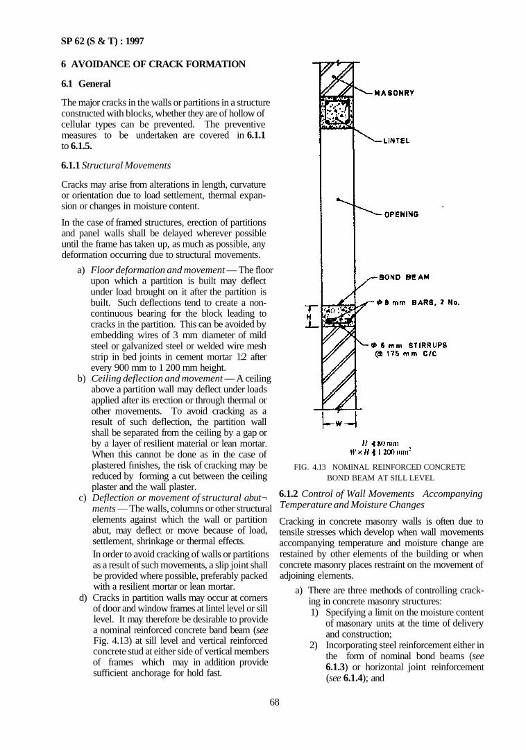
SP 62 (S & T) : 1997
6 AVOIDANCE OF CRACK FORMATION
6.1 General
The major cracks in the walls or partitions in a structure constructed with blocks, whether they are of hollow of cellular types can be prevented. The preventive measures to be undertaken are covered in 6.1.1 to 6.1.5.
6.1.1 Structural Movements
Cracks may arise from alterations in length, curvature or orientation due to load settlement, thermal expansion or changes in moisture content.
In the case of framed structures, erection of partitions and panel walls shall be delayed wherever possible until the frame has taken up, as much as possible, any deformation occurring due to structural movements.
a) Floor deformation and movement — The floor upon which a partition is built may deflect under load brought on it after the partition is built. Such deflections tend to create a non-continuous bearing for the block leading to cracks in the partition. This can be avoided by embedding wires of 3 mm diameter of mild steel or galvanized steel or welded wire mesh strip in bed joints in cement mortar 1:2 after every 900 mm to 1 200 mm height.
b) Ceiling deflection and movement — A ceiling above a partition wall may deflect under loads applied after its erection or through thermal or other movements. To avoid cracking as a result of such deflection, the partition wall shall be separated from the ceiling by a gap or by a layer of resilient material or lean mortar. When this cannot be done as in the case of plastered finishes, the risk of cracking may be reduced by forming a cut between the ceiling plaster and the wall plaster.
c) Deflection or movement of structural abut¬ ments — The walls, columns or other structural elements against which the wall or partition abut, may deflect or move because of load, settlement, shrinkage or thermal effects. In order to avoid cracking of walls or partitions as a result of such movements, a slip joint shall be provided where possible, preferably packed with a resilient mortar or lean mortar.
d) Cracks in partition walls may occur at corners of door and window frames at lintel level or sill level. It may therefore be desirable to provide a nominal reinforced concrete band beam (see Fig. 4.13) at sill level and vertical reinforced concrete stud at either side of vertical members of frames which may in addition provide sufficient anchorage for hold fast.
FIG. 4.13 NOMINAL REINFORCED CONCRETE BOND BEAM AT SILL LEVEL
6.1.2 Control of Wall Movements Accompanying Temperature and Moisture Changes
Cracking in concrete masonry walls is often due to tensile stresses which develop when wall movements accompanying temperature and moisture change are restained by other elements of the building or when concrete masonry places restraint on the movement of adjoining elements.
a) There are three methods of controlling cracking in concrete masonry structures: 1) Specifying a limit on the moisture content
of masonary units at the time of delivery and construction;
2) Incorporating steel reinforcement either in the form of nominal bond beams (see 6.1.3) or horizontal joint reinforcement (see 6.1.4); and
68
SP 62 (S & T) : 1997
3) Providing control joints to accommodate the movement of masonry (see 6.1.5). For control joints (see Chapter 13).
In all concrete masonry construction, it is essential to employ only moisture controlled units. Their use, combined with the provision of control joints is generally adequate to prevent cracking in concrete masonry walls.
However, bond beams or joint reinforcement, or both in different locations as considered suitable may also be used in addition to the above
6.1.3 Nominal Bond Beams
Bond beams, the use of which as structural members have been referred to in 6.2, shall also serve as a means to crack control, Normal bond beams shall be built in the same manner as the structural bond beams with a minimum reinforcement of two 8 mm dia mild steel bars or two 6 mm dia high strength deformed bars. Their value for this purpose is due to increased strength and stiffness they provide to a masonry wall. As a means of crack control, the area of influence of bond beam shall generally be assumed to be extend 600 mm above and below its location in the wall. In walls without openings, they shall be placed at 1 200 mm apart and may be of any length up to a maximum of IS m (see Table 4 5).
Nominal bond beams shall be discontinuous at control joints, but practice here varies depending on the structural requirements. Dummy joints shall be formed when a bond beam is continuous at a control joint.
6.1.4 Joint Reinforcement
Horizontal joint reinforcement serves much the same purpose as bond beams in crack control It increases stresses to cracking Due to closer spaciny adopted, joint reinforcement may be more effective m crack control than bond beams.
a) Joint reinforcement shall be prelerably be fabricated from galvanized steel to IS 280. 1978 and shall consist of two or more smooth or deformed longitudinal wires 3 mm dia or larger weld connected with 2.8 mm dia or larger cross wires. The out-to-out spacing of longitudinal wires shall be 30 mm less than the width of masonry units. Cross wires shall be welded at a pacing of 150 mm for smooth wires and 400 mm for deformed wires. Where splice in wires is necessary, it shall be lapped to a length of at least 300 mm.
b) The reinforcement shall be embedded in horizontal joints at intervals of 900 mm to 1 200 mm depending on panel length, height and the number and type of wall openings. Table 4.5 gives. general guidance in this regard.
c) Joint reinforcement shall be used in conjunction with cement mortar not weaker than 1 : 2
mix. In walls exposed to action of weather, the reinforcement shall have a mortar cover of not
less than 15 mm. d) Notwithstanding the above, location of joint reinforcement shall be as follows:
1) Place the joint reinforcement in the first and second bed joints immediately above and below wall openings;
2) It shall not extend less than 600 mm beyond the openings to end of the panel whichever is smaller;
3) Place joint reinforcement within two or three courses immediately below the top of the wall;
4) Joint reinforcement shall not be located closer to a bond beam than 600 mm; and
5) Joint reinforcement shall be interrupted at control joints.
Table 4.5 Recommended Length to Height Ratios for Concrete Block Masonry
(Clause 6 1.3)
SI No.
Wall Panel Vertical Spacing of Joint Reinforcement
1
2.
Length of panel (L) irrespective of height (H), Max
Ratio L/H, Max a) 200 mm thick wall b) 300 mm thick wall
900 mm 18 m
30 2 25
1 000 mm 15 m
2 75 2 00
1 200 mm 12 m
2 50 1 75
NOTES 1 When bond beams spaced at 1 200 mm are used in place of joint reinforcement, control joints shall be spaced at 18 in 2 Where reinforcement has not been provided, the ratio L /H of wall panel shall conform to IS 1905 1987
6.1.5 Control Joints
Control joints are employed to reduce restraint by accommodating movement of masonry wall or movement of structual elements adjacent to the wall, and thus to control cracking. They are in fact vertical separations built into the wall at locations where cracking is likely due to excessive horizontal stresses. The spacing along the wall length depends upon:
a) expected movements of the wall and other elements;
b) resistance of the wall to horizontal stresses; and c) the extent and location in the wall of doors,
windows, recesses, chases and other causes of stress concentration.
Some typical methods of control joints are shown in Fig. 4.14 and Fig. 4.15.
6.2 Bonded Beams and Studs Used on Structural Members
6.2.1 Reinforced concrete structural bond beams may be used in concrete block masonry to meet the
69
SP 62 (S & T) : 1997
FIG. 4.14 CONTROL JOINTS IN CONCRETE BLOCK MASONRY CONSTRUCTION
FIG. 4.15 PLASTERS WITH CONTROL JOINTS IN CONCRETE BLOCK MASONRY CONSTRUCTION — Continued
70
SP 62 (S & T) : 1997
FIG. 4.15 PLASTERS WITH CONTROL JOINTS IN CONCRETE BLOCK MASONRY CONSTRUCTION—Continued
71
SP 62 (S & T) : 1997
FIG. 4.15 PLASTERS WITH CONTROL JOINTS IN CONCRETE BLOCK MASONRY CONSTRUCTION — Concluded
requirements of unusual stress conditions. Examples are as below:
a) In buildings in earth-quake regions; b) In buildings in areas where severe wind storms
occur; c) In buildings in areas where unfavourable soil
movements and soil subsidence occur; and d) In buildings where walls are subjected to
excessive vibration or to heavy loads.
In all such cases, it is necessary to provide more than nominal stability for all types of masonry walls.
6.2.2 Bond beams, shall be built integrally with block masonry or with special U-shaped lintel blocks slung together with reinforcing steel placed in the core of hollow of blocks filled with M15 concrete. The reinforcement shall conform to IS 456 : 1978; but in no case shall be less than two 12 mm dia mild steel bars. The beams are discontinuous at control joints; but the joints should be designed to transfer forces along the wall.
6.2.3 Bond beams may be provided at any of the following locations depending on the conditions described in 6.2.1.
a) At floor level; b) At top of all door and window openings (in
which case they serve as lintels over them); c) Below the sill in all window openings; and d) At plinth level.
6.2.4 Apart from the horizontal bond beams, vertical reinforced concrete studs may also be provided at corners, at wall openings and at regular intervals between wall openings. The studs shall be tied in with bond beams.
Non-structural use of bond beams is already covered in 6.1.3.
7 PREPARATORY WORK
7.1 Wetting of Blocks
The blocks need not be wetted before or during the laying of the blocks. In case the climatic conditions so require, the top and sides of the blocks may be slightly
72
SP 62 (S & T) : 1997
moistured so as to prevent absorption of water from the mortar and ensure development of the required bond with the mortar.
7.2 Scaffolding
Scaffolding shall be on the same lines as brickwork, suitably modified where necessary.
8 LAYING OF CONCRETE BLOCKS 8.1 First Course
The first course of concrete block shall be laid with great care, making sure that it is properly levelled. aligned and plumbed, to assist in obtaining a straight and truly vertical wall.
Before laying the first course, the alignment of the wall shall be marked on the d.p.c. The blocks for this course shall be laid dry, that is, without mortar along a string stretched between properly located corners of the wall in order to determine the correct position of blocks including those of the cross walls jointing it and also adjust their spacing.
When the blocks are in proper position, the two corner blocks shall be removed, a mortar bed spread and these blocks relaid back in place truly level and plumb. The string shall then be stretched tightly along the faces of two corner blocks and the faces of the intermediate blocks adjusted to coincide with the line. Thereafter each block shall be removed and relaid over a bed of mortar. After every three or four blocks are laid the correct alignment and vertically be checked.
8.2 Construction
The construction of walls may be started either at the corners first or staged from one end preceding to the other end.
If the corners are built first, they shall be built four or five courses higher than the centre of the wall. As each course is laid at the centre, it shall be checked for alignment and level and for being plumb.
Each block shall be carefully checked for alignment with a straight-edge to make sure that the faces of the blocks are in the same plane.
8.2.1 Each course, in building the corners, shall be stepped back by a half-block and the horizontal spacing of block shall be checked by placing a mason's level diagonally across the corners of the blocks.
A storey rod or course pole, suitably marked provides an accurate method of finding the top of the masonry for each course.
8.2.2 When filling in the wall between corners, a mason's line shall be stretched from corner to corner for each course and the top outside edge shall be laid true to this line. The manner of handling or gripping the block shall be such as to position the block properly with minimum adjustment.
8.2.3 To ensure satisfactory bond, mortar shall not be spread too far ahead of actual laying of the block as it will stiffen and lose its plasticity.
As each block is laid, excess mortar extruding from the joints shall be cut off with a trowel and thrown back on the mortar board to be reworked into fresh mortar.
If the work is proceeding rapidly, the extruded mortar cut from the joints may be applied to vertical face shells of the blocks just laid. If there be any delay long enough for the mortar to stiffen on the block, the mortar shall be lemoved to the mortar board and reworked. Dead mortar that has been picked up from the scaffold or from the floor shall not be used.
8.3 Closure Block
When installing a closure block, all edges of the openings and all four edges of the closure block shall be buttered with mortar.
The closure block shall be carefully lowered into place. If any mortar falls leaving an open joint, the closure block shall be removed, fresh mortar applied and the operation repeated.
9 PROVISION FOR DOOR AND WINDOW FRAMES 9.1 Door and window frames shall be attached to the surrounding masonry either by conventional method or by 200 mm flooring nails with screwed ends fixed directly into the block, after the frame has been edged into the opening at every nailing position. The number of nails depends on the dimensions of the frames. The nails shall be spaced at a maximum of 400 mm apart and the first nail shall not be farther than 200 mm from the corner.
Frames may be attached to the masonry by holdfasts anchored in the vertical reinforced concrete studs provided to the frames (see 6.2).
10 PROVISION FOR ROOF
10.1 The top of the roof course shall be finished smooth with a thin layer of 1:3 cement mortar and covered with a coat of crude oil or craft paper or oil paper to ensure free movement of the roof.
11 INTERSECTING WALL
11.1 Load Hearing Walls When two load bearing walls intersect and courses are to be laid up at the same time, a true masonry bond between 50 percent of the units at the intersection is necessary. When such walls are laid up seperately. pockets with maximum 200 mm vertical spacings shall be left in the first wall laid. The corresponding course of the second wall shall be built into these pockets.
11.2 For non-load bearing walls same bonding methods as for load bearing walls may be used.
12 RENDERINGS AND OTHER FINISHES
12.1 All finishes shall be as described in Chapter 10 on wall finishes as the case may be.
73
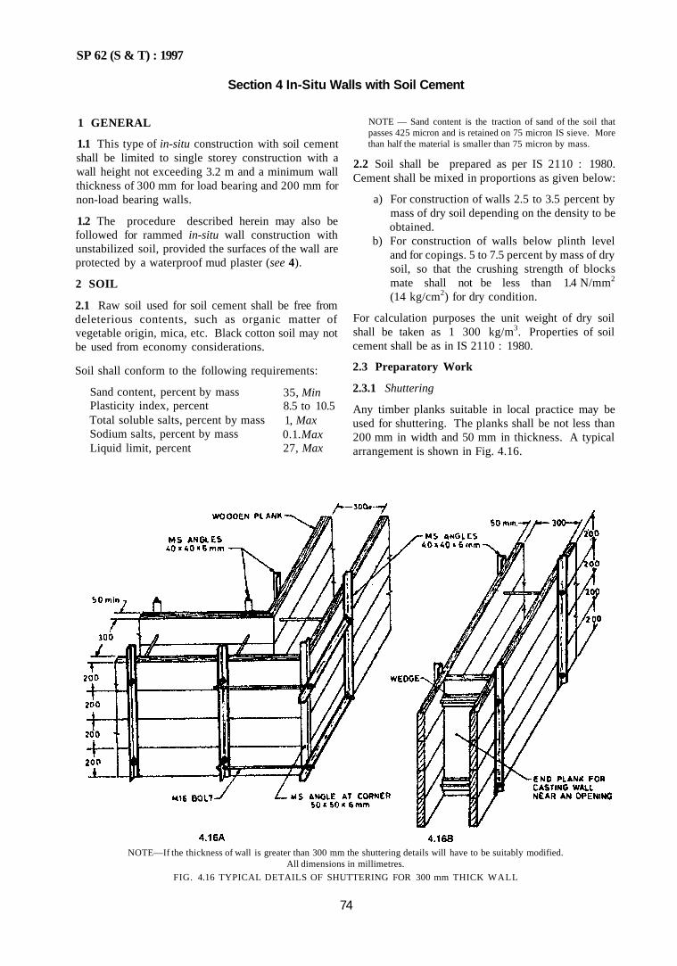
SP 62 (S & T) : 1997
Section 4 In-Situ Walls with Soil Cement
1 GENERAL
1.1 This type of in-situ construction with soil cement shall be limited to single storey construction with a wall height not exceeding 3.2 m and a minimum wall thickness of 300 mm for load bearing and 200 mm for non-load bearing walls.
1.2 The procedure described herein may also be followed for rammed in-situ wall construction with unstabilized soil, provided the surfaces of the wall are protected by a waterproof mud plaster (see 4).
2 SOIL
2.1 Raw soil used for soil cement shall be free from deleterious contents, such as organic matter of vegetable origin, mica, etc. Black cotton soil may not be used from economy considerations.
Soil shall conform to the following requirements:
Sand content, percent by mass Plasticity index, percent Total soluble salts, percent by mass Sodium salts, percent by mass Liquid limit, percent
35, Min 8.5 to 10.5 1, Max 0.1.Max 27, Max
NOTE — Sand content is the traction of sand of the soil that passes 425 micron and is retained on 75 micron IS sieve. More than half the material is smaller than 75 micron by mass.
2.2 Soil shall be prepared as per IS 2110 : 1980. Cement shall be mixed in proportions as given below:
a) For construction of walls 2.5 to 3.5 percent by mass of dry soil depending on the density to be obtained.
b) For construction of walls below plinth level and for copings. 5 to 7.5 percent by mass of dry soil, so that the crushing strength of blocks mate shall not be less than 1.4 N/mm2
(14 kg/cm2) for dry condition.
For calculation purposes the unit weight of dry soil shall be taken as 1 300 kg/m3. Properties of soil cement shall be as in IS 2110 : 1980.
2.3 Preparatory Work
2.3.1 Shuttering
Any timber planks suitable in local practice may be used for shuttering. The planks shall be not less than 200 mm in width and 50 mm in thickness. A typical arrangement is shown in Fig. 4.16.
NOTE—If the thickness of wall is greater than 300 mm the shuttering details will have to be suitably modified. All dimensions in millimetres.
FIG. 4.16 TYPICAL DETAILS OF SHUTTERING FOR 300 mm THICK WALL
74
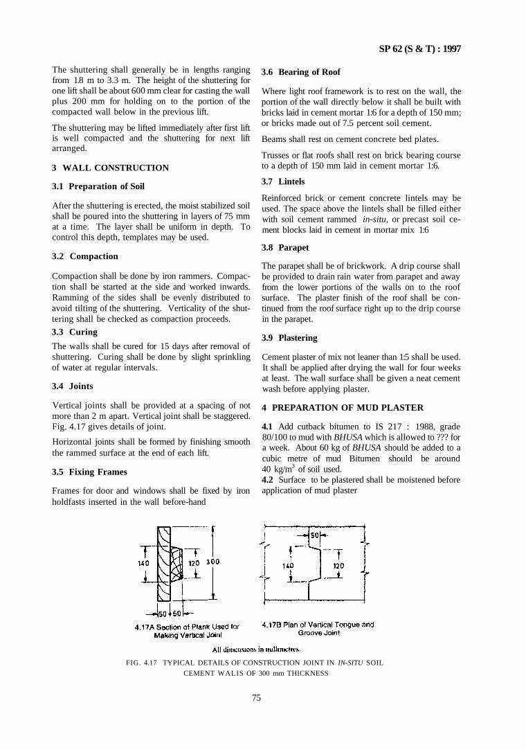
SP 62 (S & T) : 1997
The shuttering shall generally be in lengths ranging from 1.8 m to 3.3 m. The height of the shuttering for one lift shall be about 600 mm clear for casting the wall plus 200 mm for holding on to the portion of the compacted wall below in the previous lift.
The shuttering may be lifted immediately after first lift is well compacted and the shuttering for next lift arranged.
3 WALL CONSTRUCTION
3.1 Preparation of Soil
After the shuttering is erected, the moist stabilized soil shall be poured into the shuttering in layers of 75 mm at a time. The layer shall be uniform in depth. To control this depth, templates may be used.
3.2 Compaction
Compaction shall be done by iron rammers. Compaction shall be started at the side and worked inwards. Ramming of the sides shall be evenly distributed to avoid tilting of the shuttering. Verticality of the shuttering shall be checked as compaction proceeds.
3.3 Curing
The walls shall be cured for 15 days after removal of shuttering. Curing shall be done by slight sprinkling of water at regular intervals.
3.4 Joints
Vertical joints shall be provided at a spacing of not more than 2 m apart. Vertical joint shall be staggered. Fig. 4.17 gives details of joint.
Horizontal joints shall be formed by finishing smooth the rammed surface at the end of each lift.
3.5 Fixing Frames
Frames for door and windows shall be fixed by iron holdfasts inserted in the wall before-hand
3.6 Bearing of Roof
Where light roof framework is to rest on the wall, the portion of the wall directly below it shall be built with bricks laid in cement mortar 1:6 for a depth of 150 mm; or bricks made out of 7.5 percent soil cement.
Beams shall rest on cement concrete bed plates.
Trusses or flat roofs shall rest on brick bearing course to a depth of 150 mm laid in cement mortar 1:6.
3.7 Lintels
Reinforced brick or cement concrete lintels may be used. The space above the lintels shall be filled either with soil cement rammed in-situ, or precast soil cement blocks laid in cement in mortar mix 1:6
3.8 Parapet
The parapet shall be of brickwork. A drip course shall be provided to drain rain water from parapet and away from the lower portions of the walls on to the roof surface. The plaster finish of the roof shall be continued from the roof surface right up to the drip course in the parapet.
3.9 Plastering
Cement plaster of mix not leaner than 1:5 shall be used. It shall be applied after drying the wall for four weeks at least. The wall surface shall be given a neat cement wash before applying plaster.
4 PREPARATION OF MUD PLASTER
4.1 Add cutback bitumen to IS 217 : 1988, grade 80/100 to mud with BHUSA which is allowed to ??? for a week. About 60 kg of BHUSA should be added to a cubic metre of mud Bitumen should be around 40 kg/m3 of soil used. 4.2 Surface to be plastered shall be moistened before application of mud plaster
FIG. 4.17 TYPICAL DETAILS OF CONSTRUCTION JOINT IN IN-SITU SOIL
CEMENT WALIS OF 300 mm THICKNESS
75
SP 62 (S&T) : 1997
PART 3 STONEWORK
1 GENERAL
1.1 Introduction
Use of stone masonry work is practised from earlier days and natural building stone is available extensively in many parts of the country. The types of stone masonry construction depends on local factors, such as, physical characteristics of the stone, climatic conditions, workmanship, etc. Certain broad principles of laying, bonding, breaking of joints and finish should be complied with in order that masonry develops adequate strength and presents a neat appearance.
1.2 Types of Stones
The following Indian Standards on different types of stones used for stone masonry:
a) IS 1127 : 1970 for Natural building stones. b) IS 1128 : 1974 for Lime stone (slab and tiles). c) IS 3316: 1974 for Structural granite. d) IS 1130: 1969 for Marble (blocks, slabs, tiles). e) IS 3622 : 1977 for Sandstone (slabs and tiles). 0 IS 12440 : 1988 for Precast concrete stone
masonry blocks. g) IS 3620: 1979 for Laterite stone brick.
2 PROPERTIES OF STONES
2.1 Strength
The strength of building stones shall be adequate to carry the loads imposed. For ashlar and coursed rubble masonry, the strength shall be worked as in IS 1905 : 1987, taking into account appropriate crushing strength of stones as given in Table 4.6.
Table 4.6 Crushing Strength of Stones (Clause 2.1)
Type of Stone
Granite Basalt Limestone (except very soft stone) Sandstone Marble Laterate
Minimum Crushing Strength N/mm2 (kgf/cm2)
100 (1 000) 40 (400) 20 (200)
30 (300) 50 (500) 3 (30)
flaws, sandholes, veins, patches of soft or loose materials, etc. The stone should not contain crypto crystalline silica or chert, mica or any other deleterious materials, like iron oxide, organic impurities, etc. Petrographic examination of stones may be done as per IS 1123 : 1975 which helps in identifying natural building stones.
2.3 Sizes
Normally stones used in stone masonry work shall be as described below:
2.2 Durability
Stone shall be free from defects like cavities, cracks,
Dimension of other natural stones for sills, lintels, arches, domes, coping stones and other stones, such as, lime stone, structural granite, laterite, marble, etc, are summarized in SP 21 : 1983.
Other physical properties like water absorption, transverse strength, durability, etc. as applicable to different types of stones are also covered in SP 21 : 1983. If not covered by SP 21 : 1983 for other stones, reference may be made to the appropriate Indian Standards.
3 MORTARS
Mortars shall conform to IS 2250 : 1981.
4 SELECTION OF STONE
4.1 In selection of stone, the situation where it is to be used shall be considered. Table 4.7 gives the recommended use of common types of stones.
Table 4.7 Recommended Use of Common Types of Stones (Clause 4.1)
76
1
2 3 4.
Type of Stone Dense stone like granite, gneiss
Granite, quartzite Sandstone Soft stone like marble, sandstone
Use a) Masonry work submerged in water b) Masonry below plinth level or in contact with soil Masonry work exposed to smoke or chemical fumes Fite resistant masonry For carved ornamental work, arches, veneers, etc
Length mm
a) Ashlar masonry 597 based on 3 mm joint 697 thickness 797
b)Block in course 394 based on 6 mm joint 494 thickness
Breadth mm 297 347 397
194 244
Height mm 297 347 397 194 244
c) Squared rubble, Length — 90, 140 mm in based on 10 mm increments of 50 mm joint thickness Breadth — 90, 140. 290 mm
in increments of 50 mm d) Random rubble May be any shape and size
but not less than 150 mm in any direction
SP 62 (S & T) : 1997
5 PREPARATORY WORK
5.1 Dressing of Stone
The dressing of stones shall be as specified for individual types of masonry work, it shall also conform to the general requirements of dressing of stone covered in IS 1129 : 1972.
5.2 Scaffolding
5.2.1 Single scaffolding, except as in 5.2.2, having one set of vertical supports shall be used and the other end of the horizontal scaffolding member shall rest in a hole provided in the masonry. The holes shall not be left in pillars under 1 in in height or immediately near the skew backs and arches. Planks should be laid over the horizontal pieces. The holes in masonry shall be made good before plastering.
Double scaffolding having two vertical supports shall be provided tor pillars less than 1 m wide or for a building having more than two storeys.
Scaffolding shall conform to IS 3696 (Part 1) : 1987.
5.3 Handling
The use of grips in the tops of stones is preferable to any method of holding the stone at the end because it enables the stone to be set in final position before the tackle is released. Due care shall be taken to protect the work done against any danger during handling.
Various methods of handling for lifting of stone is shown in Fig.4.18.
5.4 Tools
Tools, such as, plumb bob and line, straight edges, masons square, spirit level and trowel as described in IS 1630. 1984 and various types of mason's hammer and chisels as in IS 1129 : 1972 shall be used.
5.5 Wetting
Stones shall be sufficiently wetted before laying to prevent absorption of water from mortar.
PIN LEWIS
FIG. 4.18 TYPICAL DETAILS OF LIFTING APPLIANCES OF STONES
77
SP 62 ( S & T ) : 1997
6 TYPES OF MASONRY 8 SQUARED RUBBLE
6.1 The following types of masonry are dealt with:
a) Random rubble masonry — Uncoursed and brought to courses;
b) Squared rubble; c) Ashlar, plain; d) Ashlar, punched; e) Special ashlar: and f) Stone veneering.
7 RANDOM RUBBLE
7.1 Uncoursed (see Fig. 4.19)
This type of masonry is constructed of stones as they come from the quarry.
Blocks of all shapes and sizes are selected more or less at random, and placed in position to obtain a good bond while restricting the cutting of stones to the removal of inconvenient corners with a scabbling or spalling hammer.
7.2 Brought to Courses (see Fig. 4.20)
This masonry is similar to uncoursed random rubble except that the work is roughly levelled up to courses at intervals varying from 300 mm to 900 mm, according to the locality and type of stone used.
The course heights usually correspond with the heights of quoin and joint stones.
8.1 Uncoursed (see Fig. 4.21)
In this type, the stones are roughly squared as risers or jumpers and stretches with varying heights, and are laid uncoursed.
8.2 Brought to Courses (see Fig. 4.22)
The stones are similar to those used for uncoursed rubble but the worked is levelled up to courses of varying depth from 300 mm to 900 mm according to the the type of stone used.
8.3 Coursed (First and Second Sort) (see Fig. 4.23) Coursed masonry is built in courses which may vary in height from 100 mm to 300 mm but the stones in any one course arc roughly squared to the same height. The faces of the stones may be pitched to give a rockface appearance or may be dressed smooth. A variant of this type of masonry may be formed by the introduction of pinnings, that is, similar stones in the same courses, at intervals, producing a chequered effect.
9 POLYGONAL RUBBLE MATCHING (see Fig. 4.24)
9.1 Stone with no pronounced stratification is roughly hammer pitched into irregular shapes, and bedded to show face joints running irregularly in all directions.
78
FIG. 4.19 RANDOM RUBBLE UNCOURSED MASONRY
FIG. 4.20 RANDOM RUBBLE MASONRY BROUGHT TO COURSES
SP 62 ( S & T ) : 1997
FIG. 4 .21 S Q U A R I D RUBBER UNCOURSED MASONRY
FIG. 4.23 SQUARID RUBBER COURSED MASONRY
FIG 4 24 POL YGONAL RUBBER WALLING
10 PLAIN ASHLAR 10.1 Every stone shall be cut to required size and shape and chisel dressed on all beds and joints so as to be free from bushing
Dressing of exposed face of stone shall be done to suit the type of ashlar masonry to be adopted, namely, plain ashlar sunk or moulded ashlar punched or tooled ashlar rock-faced ashlar or block in course ashlai Bond stones (see 12.1) shall be provided between 15 m to 18 in a part in every course Heights of stones shall be such that masonry has regular courses In width it shall be at least twice the height
11 LAYING OF STONES — GENERAL REQUIREMENTS
11.1 In all types of masonty the particulars given below shall be compiled with
79
FIG. 4.23 SQUARID RUBBER COURSED MASONRY
SP 62 ( S & T ) : 1997
11.2 The stone should be laid so that the pressure is always perpendicular to the bed. The courses shall be built perpendicular to the pressure which the masonry will bear. In case of battered walls, the base stone and the plane courses shall be at right angles to the batter.
11.3 In the case of coursed rubble masonry, if the heights of the courses vary, the largest stone shall be placed in the lowest course; the thickness of courses shall also decrease gradually to the top. Vertical joints shall be staggered as far as possible. Bell shaped bond stones or headers shall not be used. All the necessary chases for joggles, dowels and cramps should be formed in the stones before hand.
11.4 Sufficient transverse bonds should be provided by the use of bond stone extended from the front to the back of the wall and from outside wall to the interior of thick wall and in the latter case bond stones shall be overlap each other in their arrangement.
At all angular junctions, the stones at each alternate course shall be well bonded into the respective courses of adjacent wall.
11.5 Where there is break in the masonry work, the masonry shall be raked in sufficiently long steps for facilitating jointing of old and new work. The stepping of the raking shall not be more than 45°C to the horizontal. Walls and pillars shall be carried up truly plumb as to the specified batter.
11.6 Fixing of Frames
Where door or window frames fixed in the openings, holdfasts may be used (see Fig. 4.25).
11.7 Bearing of Floors, Roofs and Joists
Corbels or brackets shall be provided for resting of joists. Beams carrying heavy loads shall be supported by templates of concrete or stone.
11.8 Jointing and Pointing
All joints shall be full of mortar. Pointing may be avoided. If unavoidable, raking is done and types of pointing shall be as per Fig. 4.10 for brickwork.
80
FIG. 4.25 POSITION OF HOLDFASTS TO DOOR FRAME
SP 62 ( S & T) : 1997
11.9 Protection
All green work shall be protected suitably from rain, and dust, etc. All faces shall be kept moist for seven days. The top of the masonry shall be flooded with water.
12 LAYING OF DIFFERENT TYPES OF MASONRY
12.1 General
General details of laying shall be as per 11.
12.2 Random Rubble (Uncoursed and Brought to Course)
a) Normally stones shall be small enough to be lifted by hand. The length of stone shall not exceed three times the height; and breadth on the base shall not exceed three fourth the thickness of wall not less than 150 mm. The height of stone may be up to 300 mm.
b) Stone shall be hammer dressed on the face, sides and beds to enable it to be in close proximity with the neighbouring stone The bushing in the face shall not project more than 40 mm on the exposed face, and 10 mm on a face to be plastered.
c) Bond shall be obtained by fitting closely the adjacent stones and by using a bond stone. Face stones shall extend beyond the bond well into the backing. These shall be arranged to break joints and to avoid long vertical lines as much as possible.
d) The hearting or interior of the wall shall consist of rubble stones which may be ot any shape, but shall not pass through a circular ring of 150 mm inner diameter. Thickness ot stone in any direction shall not be lesser than 100 mm.
e) Every stone shall be carefully fitted to the adjacent stone so as to form a neat and close joint. They shall be carefully laid, hammered down with a wooden mallet into proper position and solidly bedded in mortar: chips and spawls of stone may be used wherever necessary, to avoid thick mortar joints It shall be ensured that there are no hollow spaces felt anywhere in the masonry.
The hearting shall be laid nearly level with facing and backing, except that about 1 m intervals, vertical 'plumb' projecting about 150 mm to 200 mm shall be firmly embedded to form a bond between successive courses.
Stones may be brought to level courses at plinth, window sill and roof level. Levelling for this purpose shall be done with a mix of one part of mortar and two parts of graded aggregate 20 mm size.
Chips shall not be used below the heartening to bring these up to the level of face stones.
The use of chips shall be restricted to filling of the interstices between adjacent stones in hearting and shall not exceed 20 percent of the masonry.
When masonry is interrupted, it shall be raked to 45°C for continuing later on.
f) Bond Stones — Bond stones shall be provided in walls up to 600 mm thick; in case of thicker walls two or more bond stones shall be provided overlapping each other by at least 150 mm, in a line from face to back. Bond stones or through stones run right through the thickness of masonry.
In case of highly absorbent bond stones, such as, porous lime stone, sand stone, etc, the bond stone should extend only about two-third into the wall. Through stones in such cases may give rise to dampness. Therefore for all such thickwalls, a set of two or more bond stones overlapping each other by at least 150 mm shall be provided.
When bond stones of suitable length are not available, cement concrete blocks of 1 : 3 : 6 cement, sand, 20 mm graded aggregate mix shall be used.
At least one bond stone for every 0.5 m2 of the wall surface shall be provided. All the bond stones shall be suitably marked.
g) Quoins shall be selected stones neatly dressed with hammer or chisel to form the required angle and laid as stretcher and header alternately.
h) Face joints, shall not be more than 20 mm thick. When pointing or plastering is not required to be done, the joints shall be struck flush and finished at the time of laying. Otherwise, the joints shall be raked back to a minimum depth of 20 mm by raking tool while the mortar is green.
12.3 Coursed Rubble Masonry — First Sort
a) Faces shall be hammer dressed on all beds, so as to give them approximately rectangular block shape. These shall be squared on all joints and beds. The bed joints shall be rough chisel dressed for at least 40 mm back from the face and for at least 40 mm for side joints so that no portion of the dressed surface is more than 6 mm away from a straight edge placed on it. The bushing on the face shall not project more than 40 mm as an exposed face and 10 mm on face to be plastered. The hammer dressed stone shall have a rough tooling for a minimum width of 25 mm along the edges of the face of the stone, when stone work is exposed.
81
SP 62 ( S & T ) : 1997
b) All courses shall be laid truly horizontal and all vertical joints shall be truly vertical. The height of each course shall be not less than 150 mm and not more than 300 mm.
Face stones shall be laid alternate headers and stretchers. No pinning shall be allowed on the face. No face stone shall be less in breadth than its height and at least one-third of the stones shall tail into the work not less than twice their height.
c) Hearting or the interior filling of the wall shall consist of stones carefully laid on their proper beds in mortar. Chips and spawls of stone may be used where necessary to avoid thick bed joints of mortar and at the same time ensuring that no hollow spaces are left anywhere in the masonry. The chips shall not be used below the hearting stone to bring these up to the level of face stones. The use of chips shall be restricted to the filling of the interstices between the adjacent stones in hearting and these shall not exceed 10 percent of quantity of stone masonry.
The masonry shall be carried on continuously; but when breaks are unavoidable, the joints shall be raked by at an angle not steeper than 45°C Toothing shall not be allowed.
d) Bond stones shall be the same as in 12.1; bond stones shall be inserted 1.5 m to 1.8 m apart, in every course.
e) Quoins shall be of the same height as the course in which they occur. These shall be at least 450 mm long and shall be laid stretchers and headers alternately. These shall be laid square on the beds, which shall be roughly chisel dressed to a depth of at least 100 mm. In case of exposed work, these stones have a minimum of 25 mm wide chisel drafts at four edges; all the edges shall be in the same plane.
f) Face joints shall not be more than 10 mm thick. When plastering or pointing is not required to be done, the joints shall be struck flush and finished at the time of laying. Otherwise the joints shall be raked to a minimum depth of 20 mm by raking tool during work when the mortar is still green.
12.4 Coursed Rubble Masonry – Second Sort
a) Dressing shall be as in 11 except but no portion of dressed surface shall exceed 10 mm from a straight edge placed on it.
b) Laying shall be as in 11 except that the use of chips shall not exceed 15 percent of the quantity of stone masonry. The stone in each course need not be of the same height, but more than
82
two stones shall not be used in the height ot a course.
c) Face joints shall not be more than 20 mm thick. When plastering or pointing is not required to be done, the joints shall be struck flush and finished at the time of laying. Otherwise joints shall be raked to a minimum depth of 20 mm by raking tool during the progress of work, when the mortar is green.
12.5 Plain Ashlar Masonry (see Fig. 4.26)
a) Every stone shall be cut to the required size and shape, so as to be free from any waviness and to give truly vertical and horizontal joints.
In exposed masonry, the faces are to remain exposed in the final position and the adjoining faces to a depth of 6 mm shall be tine chisel dressed so that when checked with a straight edge, no point varies from it by more than I mm. The top and bottom faces, that are to form bed joints, shall be chisel dressed so that the variation from a 60 cm straight edge at no point exceeds 3 mm. Faces, which are to form the vertical joints, should be chisel dressed so that variation at any point with straight edge does not exceed 6 mm. Any vertical face which has to come against backing of masonry shall be dressed such that variation from the straight edge does not exceed 10 mm.
All angles and edges of masonry that are to be exposed in the final position shall be true, square and free from chippings.
A sample of dressed stone shall be prepared for approval of the Authority.
b) In case of ashlar work wihout backing ot brick work or coursed rubble masonry, face stone shall be laid headers and stretchers alternately unless otherwise specified, the headers shall be arranged to come as nearly as possible in the middle of stretchers above and below. Stone shall be laid out in regular courses of not less than 150 mm in height and all courses shall be of the same height unless otherwise specified.
For ashlar work with backing of brick work or coursed rubble masonry, face stone shall be laid in alternate courses of headers and stretchers, unless otherwise directed. Face stone and bond stone courses shall break joint on the face for at least half the height of the standard course and the bond be carefully maintained through out. All the connected masonry in the structure shall be carried up nearly at the uniform level through out; but where breaks are unavoidable, the joint shall be made in good long steps so as to prevent cracks developing between new and old work.

SP 62 ( S & T ) : 1997
When necessary, jib crane or other mechanical appliances shall be used to hoist heavy pieces of stones, to place these in correct position; care shall be taken to see that corners of stones are not damaged. Stone shall be covered with gunny bag before a chain or rope for tying is passed over it and shall be handled carefully. No piece which has been damaged shall he used in the work.
c) Joints shall not be more than 5 mm thick. Face joints shall be uniform throughout and a uniform recess of 20 mm depth from face shall be left with the help of a steel plate during the progress of work.
d) All exposed joints shall be pointed with mortar as specified. The pointing when finished shall be sunk from stone face by 5 mm or as specified. The depth of mortar in pointing work shall not be less than 15 mm.
12.6 Ashlar Sunk or Moulded (see Fig. 4.27)
The faces shall then be gauged, cut, grooved, rebated, sunk or plain moulded as required. For this purpose a full size layout of the moulding shall be prepared on platforms for which sheet templates shall be cut and the stone dressed to the templates to a uniform and fine finish. The dressed surface shall not be more than 3 mm from the straight edge placed on it.
All visible angles and edges shall be true and free from clippings. The joints, 6 mm from the face shall also be fine tooled so that a straight edge placed on it is in contact with every point. It shall be finest surface that can be given to a stone with the chisel and without rubbing. Other requirements shall be as in 12.5
12.7 Ashlar Rock Faced (see Fig. 4.28)
Dressing shall be as per 12.5; except that the exposed faces of the stone between the drafts shall be left rough as the stone corners from the quarry; but no rock face
or bushing shall project more than 75 mm from plane of drafts.
12.8 Ashlar Rough Tooled (see Fig. 4.29)
a) The dressing of the stone shall be similar to plain ashlar as in 12.4 except that the face exposed to view shall have a fine chisel draft 25 mm wide round the edges and shall be rough tooled between the draft such that the dressed surface shall not deviate more than 3 mm from the straight edge placed over it.
b) Other requirements shall be as in 12.5.
12.9 Ashlar Chamfered (see Fig. 4.30)
a) The dressing shall be as in 12.5 except that the levelled off to 45°C for a depth of about 25 mm or more as specified.
b) Other requirements shall be as per 12.5.
12.10 Ashlar Block in Course (see Fig. 4.31)
a) The stones are dressed all squared and laid to fine joints; the faces being usually hammer dressed. The stones selected may be larger size than plain ashlar.
b) The other requirements are as in 12.5; except that the courses vary between 200-250 mm in thickness. This type of masonry is therefore superior to coursed rubble masonry.
12.11 Ashlar Masonry for Special Works
a) Special works include arch dome, circular moulded works, moulded and carved columns, etc.
b) The dressing of the stone shall be as in 12.5 except giving the appropriate shape to the stones as required in each specialized work.
FIG. 4.26 PLAIN ASHLAR
83
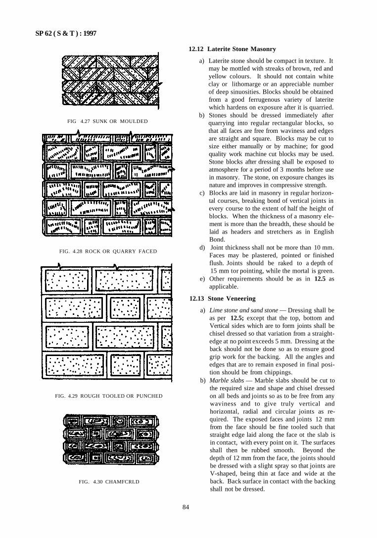
SP 62 ( S & T ) : 1997
FIG 4.27 SUNK OR MOULDED
FIG. 4.28 ROCK OR QUARRY FACED
FIG. 4.29 ROUGH TOOLED OR PUNCHED
FIG. 4.30 CHAMFCRLD
12.12 Laterite Stone Masonry
a) Laterite stone should be compact in texture. It may be mottled with streaks of brown, red and yellow colours. It should not contain white clay or lithomarge or an appreciable number of deep sinuosities. Blocks should be obtained from a good ferrugenous variety of laterite which hardens on exposure after it is quarried.
b) Stones should be dressed immediately after quarrying into regular rectangular blocks, so that all faces are free from waviness and edges are straight and square. Blocks may be cut to size either manually or by machine; for good quality work machine cut blocks may be used. Stone blocks after dressing shall be exposed to atmosphere for a period of 3 months before use in masonry. The stone, on exposure changes its nature and improves in compressive strength.
c) Blocks are laid in masonry in regular horizontal courses, breaking bond of vertical joints in every course to the extent of half the height of blocks. When the thickness of a masonry element is more than the breadth, these should be laid as headers and stretchers as in English Bond.
d) Joint thickness shall not be more than 10 mm. Faces may be plastered, pointed or finished flush. Joints should be raked to a depth of 15 mm tor pointing, while the mortal is green.
e) Other requirements should be as in 12.5 as applicable.
12.13 Stone Veneering
a) Lime stone and sand stone — Dressing shall be as per 12.5; except that the top, bottom and Vertical sides which are to form joints shall be chisel dressed so that variation from a straightedge at no point exceeds 5 mm. Dressing at the back should not be done so as to ensure good grip work for the backing. All the angles and edges that are to remain exposed in final position should be from chippings.
b) Marble slabs — Marble slabs should be cut to the required size and shape and chisel dressed on all beds and joints so as to be free from any waviness and to give truly vertical and horizontal, radial and circular joints as required. The exposed faces and joints 12 mm from the face should be fine tooled such that straight edge laid along the face ot the slab is in contact, with every point on it. The surfaces shall then be rubbed smooth. Beyond the depth of 12 mm from the face, the joints should be dressed with a slight spray so that joints are V-shaped, being thin at face and wide at the back. Back surface in contact with the backing shall not be dressed.
84
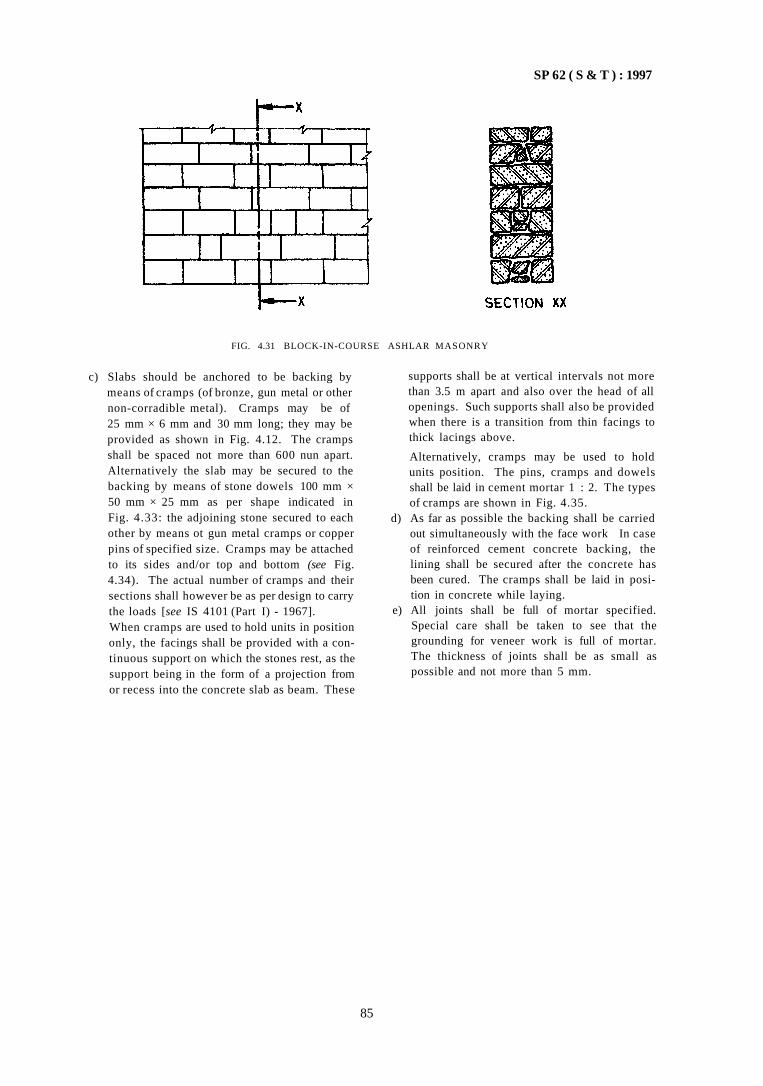
SP 62 ( S & T ) : 1997
FIG. 4.31 BLOCK-IN-COURSE ASHLAR MASONRY
c) Slabs should be anchored to be backing by means of cramps (of bronze, gun metal or other non-corradible metal). Cramps may be of 25 mm × 6 mm and 30 mm long; they may be provided as shown in Fig. 4.12. The cramps shall be spaced not more than 600 nun apart. Alternatively the slab may be secured to the backing by means of stone dowels 100 mm × 50 mm × 25 mm as per shape indicated in Fig. 4.33: the adjoining stone secured to each other by means ot gun metal cramps or copper pins of specified size. Cramps may be attached to its sides and/or top and bottom (see Fig. 4.34). The actual number of cramps and their sections shall however be as per design to carry the loads [see IS 4101 (Part I) - 1967]. When cramps are used to hold units in position only, the facings shall be provided with a continuous support on which the stones rest, as the support being in the form of a projection from or recess into the concrete slab as beam. These
supports shall be at vertical intervals not more than 3.5 m apart and also over the head of all openings. Such supports shall also be provided when there is a transition from thin facings to thick lacings above.
Alternatively, cramps may be used to hold units position. The pins, cramps and dowels shall be laid in cement mortar 1 : 2. The types of cramps are shown in Fig. 4.35.
d) As far as possible the backing shall be carried out simultaneously with the face work In case of reinforced cement concrete backing, the lining shall be secured after the concrete has been cured. The cramps shall be laid in position in concrete while laying.
e) All joints shall be full of mortar specified. Special care shall be taken to see that the grounding for veneer work is full of mortar. The thickness of joints shall be as small as possible and not more than 5 mm.
85
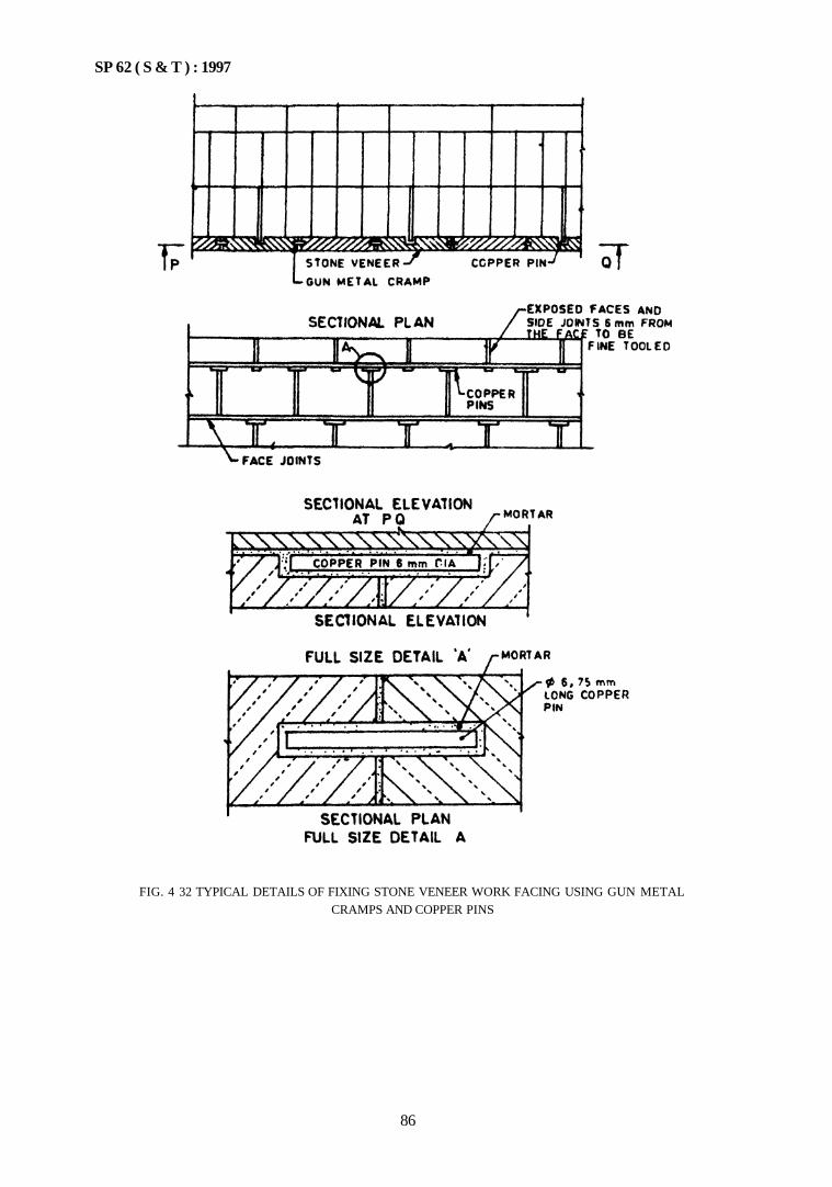
SP 62 ( S & T ) : 1997
FIG. 4 32 TYPICAL DETAILS OF FIXING STONE VENEER WORK FACING USING GUN METAL CRAMPS AND COPPER PINS
86
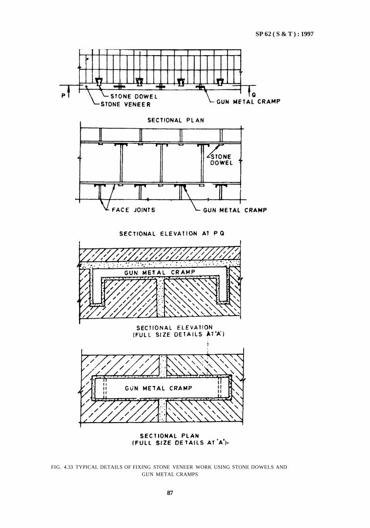
SP 62 ( S & T ) : 1997
FIG. 4.33 TYPICAL DETAILS OF FIXING STONE VENEER WORK USING STONE DOWELS AND GUN METAL CRAMPS
87
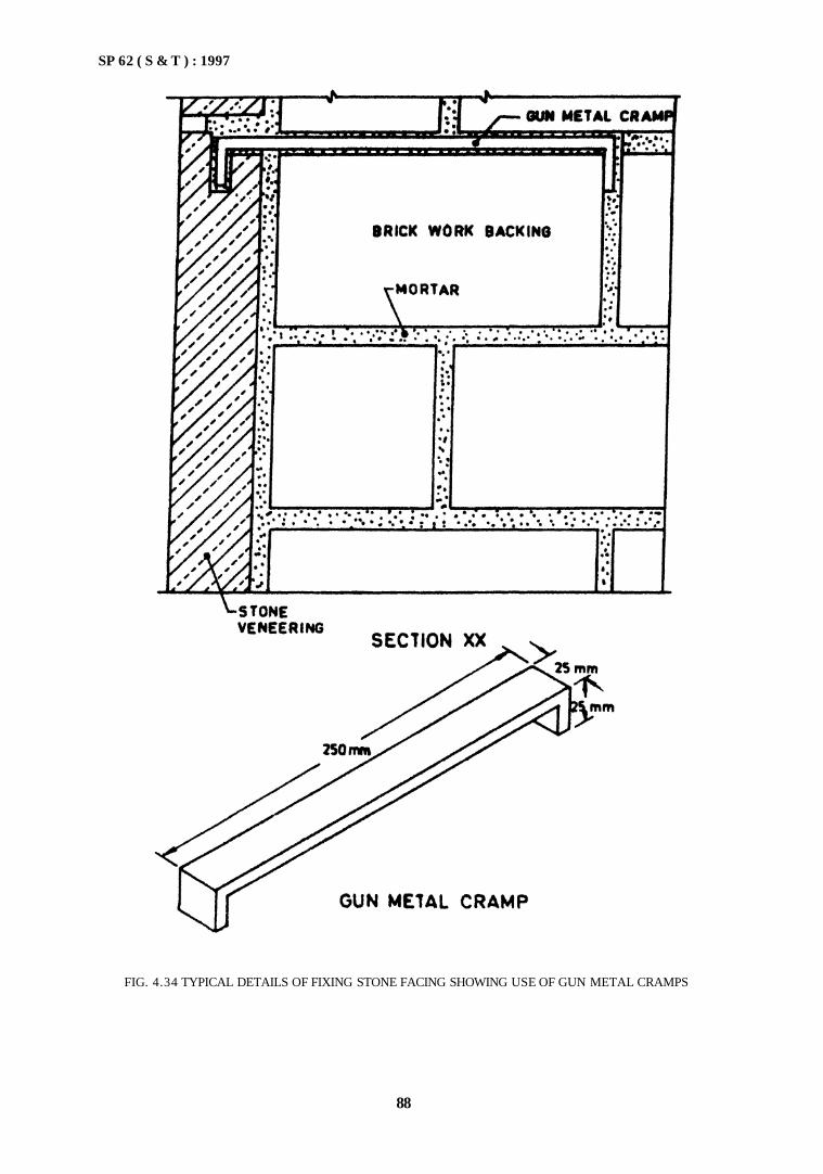
SP 62 ( S & T ) : 1997
FIG. 4.34 TYPICAL DETAILS OF FIXING STONE FACING SHOWING USE OF GUN METAL CRAMPS
88
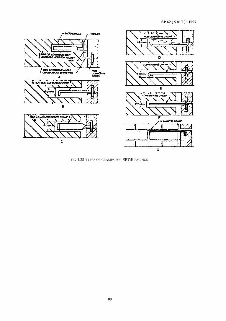
SP 62 ( S & T ) : 1997
FIG 4.35 TYPES OF CRAMPS FOR STONE FACINGS
89

CHAPTER 5
PLAIN AND REINFORCED CONCRETE
CONTENTS
PART 1 COMMON REQUIREMENTS FOR PLAIN AND REINFORCED CEMENT
CONCRETE
1 GENERAL
2 MATERIALS
2.1 Cement 2.2 Aggregates 2.3 Water 2.4 Admixtures 2.5 Pozzolanas 2.6 Reinforcement
3 GRADES OF CEMENT CONCRETE
3.1 General 3.2 Design Mix Concrete 3.3 Nominal Mix Concrete
4 PRODUCTION AND CONTROL OF CONCRETE
4.1 General 4.2 Batching
5 MIXING
5.1 General 5.2 Machine Mixing 5.3 Hand Mixing
6 TRANSPORTING, PLACING, COMPACTING AND
CURING
6.1 Transporting 6.2 Placing 6.3 Compaction 6.4 Construction Joints 6.5 Curing 6.6 Supervision
7 CONCRETING UNDER SPECIAL CONDITIONS
7.1 Work in Extreme Weather Conditions 7.2 Hot Weather Concreting 7.3 Cold Weather Concreting 7.4 Under-Water Concreting 7.5 Concrete in Sea-Water 7.6 Concrete in Aggressive Soils and Water
8 READY MIXED CONCRETE
8.1 General
8.2 Centrally Mixed Concrete 8.3 Truck Mixed Concrete
9 NON-DESTRUCTIVE TESTS
ANNEX A PARTICLE SIZE AND SHAPE OF COARSE
AGGREGATE
ANNEX B TEST FOR SURFACE MOISTURE
ANNEX C ACCELERATED CURING FOR DETERMINA
TION OF COMPRESSIVE STRENGTH OF CONCRETE
PART 2 REQUIREMENTS OF REINFORCED CONCRETE
1 GENERAL
2 FORM WORK
2.1 General 2.2 Materials of Formwork 2.3 Reinforcement
PART 3 LIME AND LIME POZZOLANA MIXTURE CONCRETE
Section 1 Lime Concrete
1 GENERAL
2 MATERIALS
2.1 Lime 2.2 Cement 2.3 Pozzolana 2.4 Coarse Aggregate 2.5 Fine Aggregate 2.6 Water
3 PROPERTIES OF LIME CONCRETE
3.1 Workability 3.2 Rate of Hardening and Setting Time 3.3 Strength
4 MIXING
4.1 General 4.2 Hand Mixing 4.3 Machine Mixing
5 LAYING OF LIME CONCRETE
5.1 General

5.2 In Foundations and Under Floors 5.3 In Haunches of Arches
Section 2 Lime Pozzolana Mixture Concrete
1 GENERAL
1 GENERAL
2 MATERIALS
3 SHOTCRETING PROCESS
3.1 General 3.2 Dry-Mix Process 3.3 Wet-Mix Process
4 PROPORTIES OF SHOTCRETE
5 PRE-CONSTRUCTION TESTING
6 MIXING
6.1 Dry-Mix Process 6.2 Wet-Mix Process
2 MATERIALS
3 MIXING
4 LAYING
PART 4 SHOTCRETE
7 APPLICATION OF SHOTCRETE
7.1 Surface Preparation 7.2 Formwork 7.3 Reinforcement 7.4 Alignment Control 7.5 Placing of Shotcrete 7.6 Rebound 7.7 Preparation for Succeeding Layers 7.8 Construction Joints 7.9 Finishing
7.10 Suspension of Work 7.11 Curing

SP 62 ( S & T ) : 1997
CHAPTER 5
PLAIN AND REINFORCED CONCRETE
PART 1 COMMON REQUIREMENTS FOR PLAIN AND REINFORCED CEMENT CONCRETE
1 GENERAL
1.1 Concrete mix proportions shall be selected to ensure that the workability of fresh concrete is suitable for the conditions of handling and placing, so that after completion it surrounds all reinforcements and com-pletely fills the formwork. When concrete is hardened, it shall have the required strength, durability and surface finish.
1.2 The strength of concrete depends on the mix proportions of cement, aggregates, and water. Concrete mixes can be designed and this is called 'Design Mix'; otherwise 'Nominal Mix' is generally adopted. Design mix concrete is preferred to nominal mix. It design mix cannot be used for any teason, nominal mixes may be used; however this is likely to increase cement content than by design mix.
1.3 The durability of concrete depends on its resistance to deterioration and the environment in which it
is placed. The resistance of concrete to weathering, chemical attack, abrasion, frost and fire depends largely upon the quality and constituent materials. Susceptibility of corrosion of steel is governed by the cover provided and the preamibility of concrete.
One of the main characteristics influencing durability of any concrete is its permeability With strong and dense aggregates, a suitably low permeability is achieved; by having a sufficiently low water-cement ratio, by ensuring as thorough a compaction as possible and by achieving sufficient hydration of cement through proper curing methods. Therefore, for given aggregates, the cement content should be sufficient to provide adequate workability with low water-cement ratio so that concrete can be completely compacted with the means available The cube-crushing strength alone is not a reliable guide to the quality and durability of concrete; it must also have an adequate cement content and a low water cement ratio as indicated below:
Exposure
(1) Mild --- For example, completely protected against weather, or aggressive conditions, except for a brief period of exposure to normal weather conditions during construction Moderate — For example, sheketed from heavy and wind driven ram and against freezing, whilst saturated with water; buried concrete in soil and concrete continuously under water Severe — For example, exposed to sea water, alternate wetting and drying and to freezing whilst wet, subject to heavy condensation of water or corrosive fumes
Plain Concrete
Minimum Maximum Cement Water Content Cement Ratio kg/m3
(2) (3)
220 0.7
Reinforced
Minimum Cement Content kg/m3
(4)
250
Concrete
Maximum Water
Cement Ratio
(5)
0.65
250
310
0 6
0.5
290
360
0 55
0 45
NOTES
1 When the maximum water-cement ratio can be strictly controlled, the cement content may be reduced by 10 percent
2 The minimum cement content is based on 20 mm aggregate For 40 mm aggregate, it should be reduced by about 10 percent, for 12 5 mm aggregate, it should be increased by about 10 percent
2 MATERIALS 2.1 Cement
Any of the following cements may be used as required a) IS 269 : 1989 Ordinary Portland cement, 33
grade;
b) IS 8041 . 1990 Rapid hardening Portland cement;
c) IS 455 1989 Portland slag cement; d) IS 1489 (Parts 1 & 2) : 1991 Portland poz-
zolana cement,
95
SP 62 ( S & T ) : 1997
e) IS 8112 : 1989 43 Grade ordinary Portland cement;
f) IS 8043: 1991 Hydrophobic Portland cement; g) IS 269 : 1987 53 Grade ordinary Portland
cement; h) IS 12600 : 1989 Low heat Portland cement; j) IS 6452 : 1989 High alumina cement and
IS 6909 : 1991. Supersulphated cement may be used only under special circumstances.
2.1.1 Recommended Uses of These Cements
The type of cement selected shall be suitable for the intended use. Some guidelines are as below:
a) Ordinary portland cement may be used for most of the works; it has a 28 days strength of 33 MPa (33 kg/cm2).
b) Grade 43 ordinary portland cement can be used in works where grade 33 is used and where the spaces are longer.
c) For higher strength requirements of works or for specialized works, such as, prestressed concrete work, higher grades of cement such as 53 grade ordinary portland cement may be used.
d) Rapid hardening portland cement gains strength more rapidly at early ages, but has a strength comparable to ordinary portland cement. Therefore, it can be used where early strength is required.
e) Slag cement has a low heat of hydration and has better resistance to soils and water containing excessive amounts of sulphates as well as to acidic waters. Therefore it may be used for marine works. However manufacturers' recommendations should be followed.
f) Pozzolana cement produces less heat on hydration and offers greater resistance to the attack of agressive waters than ordinary portland cement. It is useful in marine structures and mass concrete work. It does not develop strength in early ages. It can be used in works where ordinary portland cement is used
g) The other special cements shall be used as per manufacturers' recommendations.
2.2 Aggregates
2.2.1 Coarse and fine aggregates obtained from natural sources shall conform to IS 383 : 1970. The aggregates may be tested as per IS 2386 (Parts 1 to 8) : 1963.
2.2.2 Other aggregates such as slag and crushed over-burnt brick or tile, which may be found suitable with regard to strength, durability and freedom from harm
ful effects may be used for secondary members; but such aggregates should not contain more than 1 percent of sulphates and should not absorb more than 10 percent of their own mass of water.
2.2.3 Heavy weight aggregates or light weight aggregates such as bloated clay aggregates may also be used provided sufficient data on the properties of concrete made with them is available.
2.2.4 Fly ash conforming to IS 3812 : 1981 may be used as part replacement up to 20 percent of fine aggregate. It shall be ensured that cement is thoroughly intermixed with fly ash.
2.2.5 Aggregates should be free from deleterious materials, such as, iron pyrites, coal, mica, slate, clay, alkali, soft fragments, sea shells and other organic impurities. IS 383 : 1970 gives limits of such deleterious impurities passing 75 micron IS sieve.
Aggregates containing reactive silica, such as, chert and chacendony shall not be used.
Soft lime stone, soft sand stone or other porous or weak aggregates shall not be used for concrete in sea water.
Inadequate washing of aggregates leaves clay or dust films over the surface of the aggregates; this prevents adhesion of cement to aggregate and results in weak concrete.
2.2.6 The following tests in the field may be done based on IS 2386 (Parts 1 to 8) : 1963.
a) Particle size and shape (see Annex A). b) Determination of surface moisture (see
Annex B).
2.2.7 Grading and Sizes
2.2.7.1 Grading
a) Fine aggregate is defined as aggregate mainly passing 4.75 mm IS sieve and coarse aggregate as that mainly retained on this sieve.
b) Fine aggregates are divided into four zones (see Chapter 4, Part 1 on mortars also). Most of the natural sands found in the country have gradings corresponding to one or the other of these zones. Typical good sands fall in Zone II grading. However, finer or coarser sand may be used with suitable adjustments in the ratio of quantities of coarse to fine aggregates. Very fine sands as included in Zone IV grading should not be used except when the concrete is closely controlled by the use of design mixes.
96
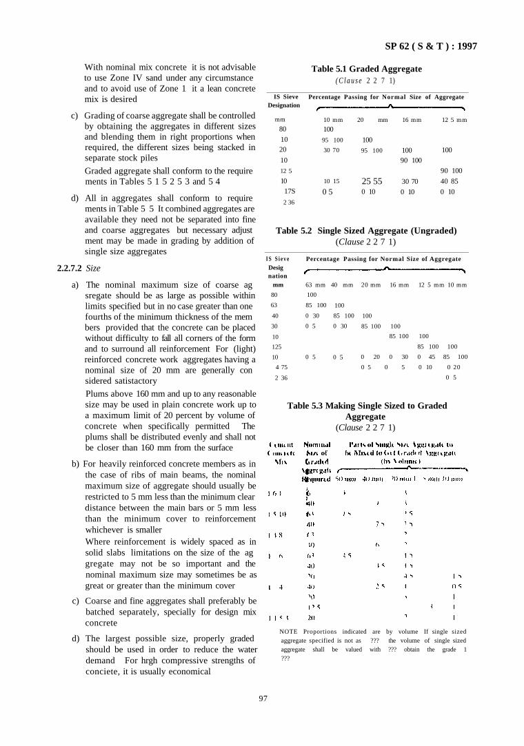
SP 62 ( S & T ) : 1997
With nominal mix concrete it is not advisable to use Zone IV sand under any circumstance and to avoid use of Zone 1 it a lean concrete mix is desired
c) Grading of coarse aggregate shall be controlled by obtaining the aggregates in different sizes and blending them in right proportions when required, the different sizes being stacked in separate stock piles
Graded aggregate shall conform to the require ments in Tables 5 1 5 2 5 3 and 5 4
d) All in aggregates shall conform to require ments in Table 5 5 It combined aggregates are available they need not be separated into fine and coarse aggregates but necessary adjust ment may be made in grading by addition of single size aggregates
2.2.7.2 Size
a) The nominal maximum size of coarse ag sregate should be as large as possible within limits specified but in no case greater than one fourths of the minimum thickness of the mem bers provided that the concrete can be placed without difficulty to fall all corners of the form and to surround all reinforcement For (light) reinforced concrete work aggregates having a nominal size of 20 mm are generally con sidered satistactory
Plums above 160 mm and up to any reasonable size may be used in plain concrete work up to a maximum limit of 20 percent by volume of concrete when specifically permitted The plums shall be distributed evenly and shall not be closer than 160 mm from the surface
b) For heavily reinforced concrete members as in the case of ribs of main beams, the nominal maximum size of aggregate should usually be restricted to 5 mm less than the minimum clear distance between the main bars or 5 mm less than the minimum cover to reinforcement whichever is smaller Where reinforcement is widely spaced as in solid slabs limitations on the size of the ag gregate may not be so important and the nominal maximum size may sometimes be as great or greater than the minimum cover
c) Coarse and fine aggregates shall preferably be batched separately, specially for design mix concrete
d) The largest possible size, properly graded should be used in order to reduce the water demand For hrgh compressive strengths of conciete, it is usually economical
Table 5.1 Graded Aggregate ( C l a u s e 2 2 7 1)
IS Sieve Designation
mm
80
10 20
10
12 5
10 17S
2 36
Percentage Passing for Normal Size of Aggregate
10 mm 20 mm 16 mm 12 5 mm
100
95 100
30 70
10 15
0 5
100
95 100
25 55 0 10
100 90 100
30 70
0 10
100
90 100
40 85
0 10
Table 5.2 Single Sized Aggregate (Ungraded) (Clause 2 2 7 1)
I S S i e v e Desig nation
mm
80
63
40
30
10
125
10
4 75
2 36
Percentage Passing for Normal Size of Aggregate
63 mm 40 mm 20 mm 16 mm 12 5 mm 10 mm
100
85 100
0 30
0 5
0 5
100
85 100
0 30
0 5
100
85 100 100
85 100 100
85 100 100
0 20 0 30 0 45 85 100
0 5 0 5 0 10 0 20
0 5
NOTE Proportions indicated are by volume If single sized aggregate specified is not as ??? the volume of single sized aggregate shall be valued with ??? obtain the grade 1 ???
97
Table 5.3 Making Single Sized to Graded Aggregate
(Clause 2 2 7 1)
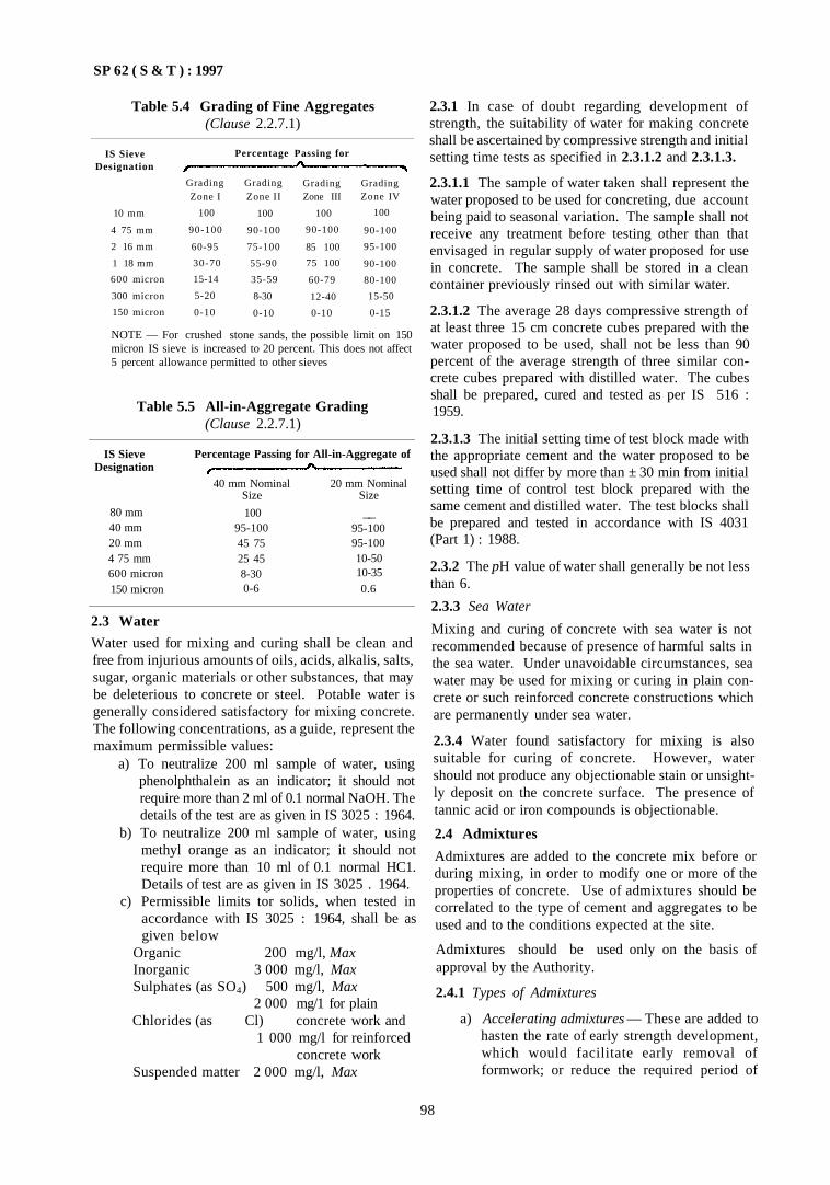
SP 62 ( S & T ) : 1997
Table 5.4 Grading of Fine Aggregates (Clause 2.2.7.1)
IS Sieve Designation
10 mm
4 75 mm
2 16 mm
1 18 mm
600 micron
300 micron
150 micron
Percentage Passing for
Grading Zone I
100
90-100
60-95
30-70
15-14
5-20
0-10
Grading Zone II
100
90-100
75-100
55-90
35-59
8-30
0-10
Grading Zone III
100
90-100
85 100
75 100
60-79
12-40
0-10
Grading Zone IV
100
90-100
95-100
90-100
80-100
15-50
0-15
NOTE — For crushed stone sands, the possible limit on 150 micron IS sieve is increased to 20 percent. This does not affect 5 percent allowance permitted to other sieves
Table 5.5 All-in-Aggregate Grading (Clause 2.2.7.1)
IS Sieve Designation
80 mm 40 mm 20 mm 4 75 mm 600 micron 150 micron
Percentage Passing for All-in-Aggregate of
40 mm Nominal 20 mm Nominal Size
100 95-100 45 75 25 45 8-30 0-6
Size
__ 95-100 95-100 10-50 10-35
0.6
2.3.1 In case of doubt regarding development of strength, the suitability of water for making concrete shall be ascertained by compressive strength and initial setting time tests as specified in 2.3.1.2 and 2.3.1.3.
2.3.1.1 The sample of water taken shall represent the water proposed to be used for concreting, due account being paid to seasonal variation. The sample shall not receive any treatment before testing other than that envisaged in regular supply of water proposed for use in concrete. The sample shall be stored in a clean container previously rinsed out with similar water.
2.3.1.2 The average 28 days compressive strength of at least three 15 cm concrete cubes prepared with the water proposed to be used, shall not be less than 90 percent of the average strength of three similar concrete cubes prepared with distilled water. The cubes shall be prepared, cured and tested as per IS 516 : 1959.
2.3.1.3 The initial setting time of test block made with the appropriate cement and the water proposed to be used shall not differ by more than ± 30 min from initial setting time of control test block prepared with the same cement and distilled water. The test blocks shall be prepared and tested in accordance with IS 4031 (Part 1) : 1988.
2.3.2 The pH value of water shall generally be not less than 6.
2.3.3 Sea Water
Mixing and curing of concrete with sea water is not recommended because of presence of harmful salts in the sea water. Under unavoidable circumstances, sea water may be used for mixing or curing in plain concrete or such reinforced concrete constructions which are permanently under sea water.
2.3.4 Water found satisfactory for mixing is also suitable for curing of concrete. However, water should not produce any objectionable stain or unsightly deposit on the concrete surface. The presence of tannic acid or iron compounds is objectionable.
2.4 Admixtures
Admixtures are added to the concrete mix before or during mixing, in order to modify one or more of the properties of concrete. Use of admixtures should be correlated to the type of cement and aggregates to be used and to the conditions expected at the site.
Admixtures should be used only on the basis of approval by the Authority.
2.4.1 Types of Admixtures
a) Accelerating admixtures — These are added to hasten the rate of early strength development, which would facilitate early removal of formwork; or reduce the required period of
98
2.3 Water
Water used for mixing and curing shall be clean and free from injurious amounts of oils, acids, alkalis, salts, sugar, organic materials or other substances, that may be deleterious to concrete or steel. Potable water is generally considered satisfactory for mixing concrete. The following concentrations, as a guide, represent the maximum permissible values:
a) To neutralize 200 ml sample of water, using phenolphthalein as an indicator; it should not require more than 2 ml of 0.1 normal NaOH. The details of the test are as given in IS 3025 : 1964.
b) To neutralize 200 ml sample of water, using methyl orange as an indicator; it should not require more than 10 ml of 0.1 normal HC1. Details of test are as given in IS 3025 . 1964.
c) Permissible limits tor solids, when tested in accordance with IS 3025 : 1964, shall be as given below
Organic 200 mg/l, Max Inorganic 3 000 mg/l, Max Sulphates (as SO4) 500 mg/l, Max
2 000 mg/1 for plain Chlorides (as Cl) concrete work and
1 000 mg/l for reinforced concrete work
Suspended matter 2 000 mg/l, Max
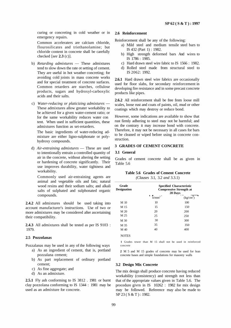
SP 62 ( S & T ) : 1997
curing or concreting in cold weather or in emergency repairs. Common acceleraters are calcium chloride, flourosilicates and triethanolamine; but chloride content in concrete shall be carefully checked [see 2.3 (c)].
b) Retarding admixtures — These admixtures tend to slow down the rate ot setting of cement. They are useful in hot weather concreting; for avoiding cold joints in mass concrete works and for special treatment of concrete surfaces. Common retarders are starches, cellulose products, sugars and hydroxyl-carboxylic acids and their salts.
c) Water-reducing or platicizing admixtures — These admixtures allow greater workability to be achieved for a given water-cement ratio; or for the same workability reduces water con tent. When used in sufficient quantities, these admixtures function as set-retarders. The basic ingredients of water-reducing admixture are either ligno-sulphonate or poly-hydroxy compounds.
d) Air-entraining admixtures — These are used to intentionally entrain a controlled quantity of air in the concrete, without altering the setting or hardening of concrete significantly. Their use improves durability, water tightness and workability. Commonly used air-entraining agents are animal and vegetable oils and fats; natural wood resins and their sodium salts; and alkali salts of sulphated and sulphonated organic compounds.
2.4.2 All admixtures should be used taking into account manufacturer's instructions. Use of two or more admixtures may be considered after ascertaining their compatibility.
2.4.3 All admixtures shall be tested as per IS 9103 : 1979.
2.5 Pozzolanas
Pozzalanas may be used in any of the following ways a) As an ingredient of cement, that is, portland
pozzalana cement; b) As part replacement of ordinary portland
cement; c) As fine aggregate; and d) As an admixture.
2.5.1 Fly ash conforming to IS 3812 . 1981 or burnt clay pozzolana conforming to IS 1344 : 1981 may be used as an admixture for concrete.
2.6 Reinforcement
Reinforcement shall be any of the following: a) Mild steel and medium tensile steel bars to
IS 432 (Part 1) : 1982. b) High strength deformed bars And wires to
IS 1786 : 1985. c) Hard drawn steel wire fabric to IS 1566 : 1982. d) Rolled steel made from structural steel to
IS 2062: 1992.
2.6.1 Hard drawn steel wire fabrics are occasionally used for floor slabs, for secondary reinforcement in developing fire resistance and in some precast concrete products like pipes.
2.6.2 All reinforcement shall be free from loose mill scales, loose rust and coats of paints, oil, mud or other coatings which may destroy or reduce bond.
However, some indications are available to show that rust firmly adhering to steel may not be harmful; and on the contrary it may increase bond with concrete. Therefore, it may not be necessary in all cases for bars to be cleaned or wiped before using in concrete construction.
3 GRADES OF CEMENT CONCRETE
3.1 General
Grades of cement concrete shall be as given in Table 5.6
Table 5.6 Grades of Cement Concrete (Clauses 3.1, 3.2 and 3.3.1)
Grade Designation
M 10 M 15
M 20 M 25
M 30
M 35 M 40
Specified Characteristic Compressive Strength at
28 Days
n/mm2 (kg/cm2)
10
15
20 25 30
35
40
100 150
200
250
300 350
400
NOTES
1 Grades tower than M 15 shall not be used in reinforced concrete
2 M 5 and M 15 grades of concrete may be used for lean concrete bases and simple foundations for masonry walls
3.2 Design Mix Concrete
The mix design shall produce concrete having reduced workability (consistency) and strength not less than that of the appropriate values given in Table 5.6. The procedure givrn in IS 10262 : 1982 for mix design may be followed. Reference may also be made to SP 23 ( S & T ) : 1982.
99
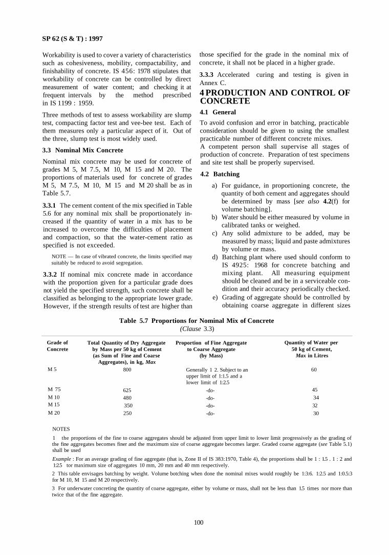
SP 62 (S & T) : 1997
Workability is used to cover a variety of characteristics such as cohesiveness, mobility, compactability, and finishability of concrete. IS 456: 1978 stipulates that workability of concrete can be controlled by direct measurement of water content; and checking it at frequent intervals by the method prescribed in IS 1199 : 1959.
Three methods of test to assess workability are slump test, compacting factor test and vee-bee test. Each of them measures only a particular aspect of it. Out of the three, slump test is most widely used.
3.3 Nominal Mix Concrete
Nominal mix concrete may be used for concrete of grades M 5, M 7.5, M 10, M 15 and M 20. The proportions of materials used for concrete of grades M 5, M 7.5, M 10, M 15 and M 20 shall be as in Table 5.7.
3.3.1 The cement content of the mix specified in Table 5.6 for any nominal mix shall be proportionately increased if the quantity of water in a mix has to be increased to overcome the difficulties of placement and compaction, so that the water-cement ratio as specified is not exceeded.
NOTE — In case of vibrated concrete, the limits specified may suitably be reduced to avoid segregation.
3.3.2 If nominal mix concrete made in accordance with the proportion given for a particular grade does not yield the specified strength, such concrete shall be classified as belonging to the appropriate lower grade. However, if the strength results of test are higher than
those specified for the grade in the nominal mix of concrete, it shall not be placed in a higher grade.
3.3.3 Accelerated curing and testing is given in Annex C.
4 PRODUCTION AND CONTROL OF CONCRETE 4.1 General
To avoid confusion and error in batching, practicable consideration should be given to using the smallest practicable number of different concrete mixes. A competent person shall supervise all stages of production of concrete. Preparation of test specimens and site test shall be properly supervised.
4.2 Batching
a) For guidance, in proportioning concrete, the quantity of both cement and aggregates should be determined by mass [see also 4.2(f) for volume batching].
b) Water should be either measured by volume in calibrated tanks or weighed.
c) Any solid admixture to be added, may be measured by mass; liquid and paste admixtures by volume or mass.
d) Batching plant where used should conform to IS 4925: 1968 for concrete batching and mixing plant. All measuring equipment should be cleaned and be in a serviceable condition and their accuracy periodically checked.
e) Grading of aggregate should be controlled by obtaining coarse aggregate in different sizes
Table 5.7 Proportions for Nominal Mix of Concrete (Clause 3.3)
NOTES
1 the proportions of the fine to coarse aggregates should be adjusted from upper limit to lower limit progressively as the grading of the fine aggregates becomes finer and the maximum size of coarse aggregate becomes larger. Graded coarse aggregate (see Table 5.1) shall be used
Example : For an average grading of fine aggregate (that is, Zone II of IS 383:1970, Table 4), the proportions shall be 1 : 1.5 . 1 : 2 and 1:2.5 tor maximum size of aggregates 10 mm, 20 mm and 40 mm respectively.
2 This table envisages batching by weight. Volume botching when done the nominal mixes would roughly be 1:3:6. 1:2.5 and 1:0.5:3 for M 10, M 15 and M 20 respectively.
3 For underwater concreting the quantity of coarse aggregate, either by volume or mass, shall not be less than 1.5 times nor more than twice that of the fine aggregate.
100
Grade of Concrete
M 5
M 75
M 10 M 15
M 20
Total Quantity of Dry Aggregate by Mass per 50 kg of Cement (as Sum of Fine and Coarse
Aggregates), in kg, Max 800
625 480
350
250
Proportion of Fine Aggregate to Coarse Aggregate
(by Mass)
Generally 1 2. Subject to an upper limit of 1:1.5 and a lower limit of 1:2.5
-do-
-do-
-do-
-do-
Quantity of Water per 50 kg of Cement,
Max in Litres
60
45
34
32
30
SP 62 ( S & T ) : 1997
and blending them in right proportions when required; the different sizes being stacked in separate stock piles. The material shall be stock piled preferably a day before use. The grading of coarse and fine aggregate shall be checked as frequently as possible, frequency being decided by the Authority.
f) In case uniformity of materials used for concrete has been established over a period of time, the proportioning may be done by volume batching, provided periodical checks are made on mass/volume relationship of the material. When weigh batching is not practicable, the quantities of fine and coarse aggregate (not cement) may be determined by volume. If fine aggregate is moist and volume batching is adopted, allowance shall be made for bulking in accordance with IS 2386 (Part 3) : 1963.
g) It is important to maintain water-cement ratio constant at its correct value. To this end, therefore determination of moisture content in both coarse and fine aggregates frequently as possible is necessary. The amount of water added should be adjusted to compensate for any observed variation in moisture contents.
To allow for variation in mass of aggregate due to variation in moisture content, suitable adjustments in masses of aggregates shall also be made. In the absence of exact data, in the case of nominal mixes only, the amount of surface water may be estimated from the values given in Table 5.8.
Table 5.8 Surface Water Carried by Aggregate (Clause 4.2)
Aggregate
(1) Very wet sand
Moderately wet sand
Moist sand Moist gravel1)
or crushed rock
Approximate Quantity of Surface Water
Percent by Mass 1/m3
(2)
7.5
5 0
2.5 1.25 to 2.5
1) Coarser aggregate, less the water it will carry
(3) 120 80
40 20-40
h) No substitution of materials work or alterations in the established proportions, except as permitted in 4.2 (f) and (g) shall be made without additional tests to show quality and strength of concrete.
5 MIXING
5.1 General
Concrete shall be mixed in a mechanical mixer conforming to IS 1791 : 1985. The mixing shall be continued until there is uniform distribution of
materials and the mass is uniform in colour and consistency. If there is seggregation after unloading, the concrete should he remixed.
a) For guidance, mixing time may be 1½ to 2 min; for hydrophobic cement it may be taken as 2½ to 3 min.
b) In exceptional cases hand mixing may be done as approved by the Authority. Hand mixing may be done for work done in cases, such as. remote areas, break down of mechanical mixer, or when quantity of work is small subject to additional 10 percent extra cement When hand mixing is permitted it shall be done on a water-tight platform and care shall be taken to ensure that mixing is continued until concrete is uniform in colour and consistency.
c) Stone aggregate shall be washed with water to remove dirt, dust or any other foreign matter. Brick aggregates shall be well soaked with water for a minimum period of 2 h.
5.2 Machine Mixing
The mixing drum shall be flushed clean with water. Measured quantity of dry coarse aggregate shall be first placed in the hopper. This shall be followed with placing of measured quantities of fine aggregate and then cement. In case damp sand is used add half the quantity of the coarse aggregate, then followed by cement and sand, finally add the balance of coarse aggregate.
The dry materials shall be mixed for at least four turns of the drum, after which the correct quantity of water shall be added gradually while the drum is in motion to ensure even distribution of the dry materials. The total quantity of the water shall be introduced before 25 percent of the mixing time has elapsed. The complete content pf the mixed concrete shall be removed from the drum before recharging.
When the mixer is idle for more than 20 min, the drum shall be flushed clean again.
5.3 Hand Mixing Hand mixing shall be done in a smooth, clean and water-tight platform of suitable size in the following manner:
a) Measured quantity of sand shall be spread evenly.
b) Cement shall be dumped on the sand and distributed evenly.
c) The sand and cement shall be intimately mixed with spade, turning the mixture over and over until it is of even colour throughout and free from streaks.
d) The sand cement mixture shall be spread out and measured quantity of coarse aggregate shall be spread on top. Alternatively, the measured quantity of coarse aggregate shall be
101
SP 62 ( S & T ) : 1997
spread out and the sand and cement mixture shall be spread on its top.
e) This shall be mixed at least three times by shovelling and turning over from centre to side, then back to centre.
f) A hollow shall be made in the middle of the mixed pile.
g) Three-fourths the quantity of the total quantity of water required shall be added while the material is turned in towards the centre with a spade. The remaining water shall be added by a water can slowly turning the whole mixture over and over until a uniform colour and consistency is obtained throughout the pile, The slump as given in Table 5.9 shall be adopted for different kinds of works.
h) The mixing platform shall be washed at the end of the day.
Table 5.9 Slump (Clause 5.3)
6.2 Placing
The concrete shall be deposited as nearly practicable in its final position to avoid rehandling. Concrete shall be placed and compacted before setting commences and should not be subsequently disturbed. Methods of placing should be such as to avoid segregation. Care should be taken to avoid displacement of reinforcement or movement of formwork (see 2 of Part 2). The layers of concrete shall be so placed that the bottom layer does not finally set before the top layer is placed.
6.2.1 During cold weather, concreting shall not be done when the temperature falls below 4.5°C. The concrete placed shall be protected against frost by suitable covering. Concrete damaged by frost shall be removed and work redone. During hot weather, precautions shall be taken to see that the temperature of wet concrete does not exceed 38°C (see 7)
6.3 Compaction
Concrete should be thoroughly compacted and fully worked around the reinforcement, around embedded fixtures and into corners of the formwork.
6.3.1 The use of mechanical vibrators to IS 2505 : 1980, IS 2506 : 1985, IS 2514 : 1963 and IS 4656 : 1968 for compacting concrete is recommended. Over vibration or vibration of very wet mixes is harmful and should be avoided; under vibration is harmful.
The vibrator should penetrate rapidly to the bottom of the layer and at least 15 cm into the preceding layer, if there is any. It should be held (generally 5 to 15 s) until the compaction is considered adequate and then withdrawn slowly at the rate of about 8 cm/s.
Whenever vibration has to be applied externally, the design of formwork and the disposition of vibrators should receive special consideration to ensure efficient compaction and to avoid surface blemishes.
6.4 Construction Joints
Concreting shall be carried out continuously up to construction joints, the position and arrangement of which shall be indicated by the designer (see Chapter 13).
6.4.1 When work has to be resumed on a surface which has hardened, such surface shall be roughened. It shall then be swept clean and thoroughly wetted. For vertical joints, neat cement slurry shall be applied on the surface before it is dry. For horizontal joints, the surface be covered with a layer of mortar about 10 mm to 15 mm thick composed of cement and sand in the same ratio as the cement and sand in the concrete mix. This layer of cement slurry or mortar shall be freshly mixed and applied immediately before placing concrete.
102
Placing Conditions
(1)
Concreting of shallow sections with vibration
Concreting of lightly reinforced sections with vibration
Concreting of lightly reinforced sections without violation, or heavily reinforced section with vibration
Concreting of heavily reinforced sections without vibration
Slump, mm
Degree of Values of Workability Workability
(2)
Very low
Low
Medium
High
1) For smaller aggregate the values
(3)
20-10 seconds, vee-bee time Or
0 75-0.80, compacting factor
10-5 seconds, vee-bee time or
0 80-0 85, compacting factor
5-2 seconds, vee-bee time or
0.85-0,92, compacting factor or
25-75 mm, slump for 20 mm1)
aggregate
Above 0 92, compacting factor or
75 125 mm, slump for 20 mm1)
aggregate
will be lower
6 TRANSPORTING, PLACING, COMPACTING AND CURING 6.1 Transporting Concrete shall be transported from the mixer to the formwork as rapidly as possible which will prevent segregation of or loss of any of the ingredients and maintaining the required workability.
During hot or cold weather, concrete shall be transported in deep containers. Other suitable methods to reduce the loss of water by evaporation in hot weather and heat loss in cold weather may also be adopted.
SP 62 (S & J ) : 1997
6.4.2 When the concrete has not fully hardened, all laitance shall be removed by scrubbing the wet surface with wire or bristle, care being taken to avoid dislodge-ment of particles of aggregate. The surface shall be thoroughly wetted and all free water removed. The surface shall then be coated with neat cement slurry. On this surface, a layer of concrete not exceeding 150 mm thick shall first be placed and shall be well rammed against old work, particular attention being paid to corners and close spots; wotk thereafter shall proceed in the normal way.
6.5 Curing
6.5.1 Moist Curing
After the concrete has begun to harden, that is, 1 to 2 h after laying curing shall be started. Exposed sur faces shall be kept continuously in a damp or wet condition by ponding or by covering with layer of sacks, canvas, hessian or similar materials and kept constantly wet for at least seven days from the date of placing of concrete
6.5.2 Membrane Curing
Approved curing compounds may also be used with the approval of Authority. Such compounds may be applied to all the surfaces of concrete as soon as possible after it has set [see SP 24 (S&T) : 198.3].
6.5.3 Over foundation concrete, masonry work may be started after 48 h of its laying, but the curing of cement concrete shall be continued along with the masonry work for a minimum period of 7 days at least.
6.5.4 When concrete is used as a sub-grade for flooring, the flooring may be commenced before the curing period of sub-grade is over but the curing of sub grade shall be continued along with the top layer of flooring for a minimum period of 7 days.
6.6 Supervision
It is exceedingly difficult and costly to alter concrete once placed. Hence, constant and strict supervision ot all items of the construction is necessary during the progress of work, including the transporting and mixing of concrete. Supervision is also ol extreme importance to check the reinforcement and its placing before being covered.
Before any important operation, such as concreting or stripping of the form work is started, adequate notice shall be given to the construction supervisor.
7 CONCRETING UNDER SPECIAL CONDITIONS
7.1 Work in Extreme Weather Conditions
During hot or cold weather the concreting should be done as per IS 7861 (Part 1) : 1975 for hot weather and IS 7861 (Part 2) : 1981 for cold weather.
7.2 Hot Weather Concreting
The climatic factors affecting concrete in hot weather are high ambient temperature above 40°C and reduced relative humidity, the effects of which may be consid-crably pronounced with increase in wind velocity. The effects of hot weather arc most critical during periods of rising temperature, fall in relative humidity or both. They may occur at any time of the year in warm tropical or arid climates and generally occur during summer season in other climates. Precautionary measures required on a calm humid day will be less strict than those required on a dry, windy day, even if as temperatures are identical.
Damage to concrete caused by hot weather can never be fully alleviated since improvisations at site are rarely successful; easily preventive measures may be applied with the emphasis on materials, advanced planning and co-ordination of all phases of work.
7.2.1 Effects of Hot Weather on Concrete
a) Accelerated setting — High temperature increases the rate of setting of concrete. The duration of time during which the concrete can be handled is reduced Quick stiffening may necessiate considerable retempering by addition of water It may also result in cold joints.
b) Reduction in strength . High temperature results in increase of the quantity of mixing water to maintain the workability with consequent reduction in strength
c) Increased tendency to crack — Either before or after hardening, plastic shrinkage may form in the partially hardened concrete due to rapid evapora t ion of wa te r . C r a c k s may be developed in hardened concrete either by increasing drying shrinkage resulting from greater mixing water used or by cooling of the concrete from its elevated temperature.
d) Rpid evaporation of water during curing period — It is difficult to retain moisture for hydration and maintain reasonably uniform temperature conditions during the curing period
e) Difficulty of control of air content in air-entrained concrete — It is difficult to control air content in air-entrained concrete This adds to the difficulty of controlling workability. For a given amount of air-entraining agent, hot concrete will entrain less air than concrete at normal temperatures.
Procedures to minimize these effects are given in 7.2.2 to 7.2.6.
7.2.2 Temperature Control of Concrete Ingredents
The most direct approach to keep concrete temperature down is by controlling the temperature of its ingredients. The contribution of each ingredient to the
103
SP 62 ( S & T ) : 1991
temperature of concrete is a function of the tempera-ture, specific heat, and quantity used of that ingredient. The aggregates and mixing water exert the most pronounced effect on temperature of concrete. Thus, in hot weather all available means shall be used for maintaining these materials at as low temperature as possible.
a) Aggregates — Any one of the procedures or a combination of the procedures given below may be used for lowering the temperature of aggregates. 1) Shading stock piles from direct rays of the
sun 2) Sprinkling of the stock piles of coarse
aggregate with water and keep them moist; this is effective when relative humidity is low.
3) Successive layers of coarse aggregate should be sprinkled with water as the stock pile is built up.
4) If cold water is available heavy spraying on coarse aggregate immediately before use may also be done to have a direct cooling action.
5) Coarse aggregates may be cooled by circulating refrigerated air through pipes or other suitable methods.
b) Water — Mixing water has the greatest effect on temperature of concrete, since it has a specific heat of about 4.5 to 5 times that of cement and aggregate. The temperature of water is easier to control than that of other ingredients. Even though water used is small in quantity compared to cement and aggregate, the use of cold mixing water will bring about a moderate reduction in concrete placing temperatures.
Tor example, for a nominal mix concrete of 336 kg cement, 170 kg water and 1 850 kg of aggregate per cubic metre of concrete, a change of 2°C in water temperature will bring a change of 0.5°C in the temperature of concrete. Efforts shall be made to obtain cold water, and to keep it cold by protecting pipes, water storage tanks, etc. Tanks or trucks used for transporting water shall be insulated and/or coloured and maintained white or yellow. Under certain circumstances, reduction in water temperature may be most economically obtained by mechanical refrigeration or mixing with crushed ice. Use of ice as a part of mixing water is highly effective in controlling concrete temperature, since on melting alone, it takes up heat at the rate of 80 kcal/kg. To take advantage of this, the ice should be incorporated directly into the concrete as part
of mixing water. It must be ensured that the ice melts by the time mixing is completed.
c) Cement — Temperature has a direct effect on the hydration of cement. Higher the temperature of concrete, higher the rate of hydration, the rate of stiffening and generally it results in increased water demand; and therefore results in reduced strength and plastic shrinkage. Temperature has a definite effect on setting time depending on cement composition. How ever, a change in temperature of cement, produces significantly less change in the temperature of fresh concrete than the other ingredients. Cements shall preferably not be used at temperatures in excess of 77°C.
7.2.3 Proportioning of Concrete Mix Materials and Mix Design
The quantity of cement used in a mix affects the rate of increase in temperature.
a) Therefore cement content may be the least and cements with lower heat of hydration shall be preferred.
b) Admixtures which reduce water demand or retard setting may be used.
7.2.4 Temperature of Concrete as Placed
In hot weather, ingredients of concrete should be cooled to the extent necessary to maintain the temperature of concrete at the time of placing to below 38°C Temperature of the concrete may be ascertained from a sample of the mix or by calculations.
7.2.5 Production and Delivers
a) Temperature of aggregates, water and cement shall be maintained at the lowest practical levels so that the temperature of concrete is below 40°C, at the time of placement.
b) Mixing time shall be held to the minimum which will ensure adequate quality and unifor mity, because the concrete gets warmed up due to mixing, by the air and by the sun. The effect of mixer surface exposed to the hot sun must be minimized by painting and keeping the mixer drum yellow or white and spraying it with cold water.
c) Cement hydration, temperature, loss of workability and loss of entrained air, all these will increase with the passage of time after mixing. Therefore the period of time between mixing and delivery shall be kept to a minimum. Co-ordination of delivery of concrete with the rate of placement should be ensured.
7.2.6 Placement, Protection and Curing
a) Forms, reinforcement and sub-grade shall be sprinkled with cold water just prior to place-
104
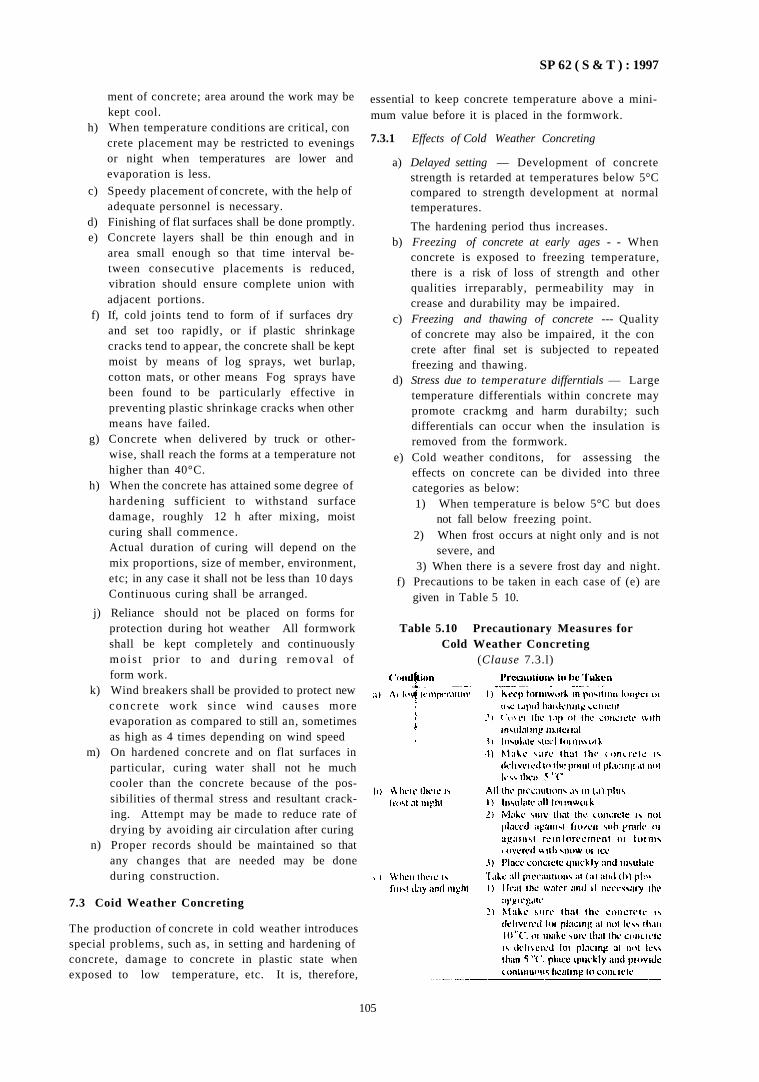
SP 62 ( S & T ) : 1997
ment of concrete; area around the work may be kept cool.
h) When temperature conditions are critical, con crete placement may be restricted to evenings or night when temperatures are lower and evaporation is less.
c) Speedy placement of concrete, with the help of adequate personnel is necessary.
d) Finishing of flat surfaces shall be done promptly. e) Concrete layers shall be thin enough and in
area small enough so that time interval between consecutive placements is reduced, vibration should ensure complete union with adjacent portions.
f) If, cold joints tend to form of if surfaces dry and set too rapidly, or if plastic shrinkage cracks tend to appear, the concrete shall be kept moist by means of log sprays, wet burlap, cotton mats, or other means Fog sprays have been found to be particularly effective in preventing plastic shrinkage cracks when other means have failed.
g) Concrete when delivered by truck or otherwise, shall reach the forms at a temperature not higher than 40°C.
h) When the concrete has attained some degree of hardening sufficient to withstand surface damage, roughly 12 h after mixing, moist curing shall commence. Actual duration of curing will depend on the mix proportions, size of member, environment, etc; in any case it shall not be less than 10 days Continuous curing shall be arranged.
j) Reliance should not be placed on forms for protection during hot weather All formwork shall be kept completely and continuously mois t prior to and dur ing removal of form work.
k) Wind breakers shall be provided to protect new concre te work since wind causes more evaporation as compared to still an, sometimes as high as 4 times depending on wind speed
m) On hardened concrete and on flat surfaces in particular, curing water shall not he much cooler than the concrete because of the possibilities of thermal stress and resultant cracking. Attempt may be made to reduce rate of drying by avoiding air circulation after curing
n) Proper records should be maintained so that any changes that are needed may be done during construction.
7.3 Coid Weather Concreting
The production of concrete in cold weather introduces special problems, such as, in setting and hardening of concrete, damage to concrete in plastic state when exposed to low temperature, etc. It is, therefore,
essential to keep concrete temperature above a minimum value before it is placed in the formwork.
7.3.1 Effects of Cold Weather Concreting
a) Delayed setting — Development of concrete strength is retarded at temperatures below 5°C compared to strength development at normal temperatures.
The hardening period thus increases. b) Freezing of concrete at early ages - - When
concrete is exposed to freezing temperature, there is a risk of loss of strength and other qualities irreparably, permeability may in crease and durability may be impaired.
c) Freezing and thawing of concrete --- Quality of concrete may also be impaired, it the con crete after final set is subjected to repeated freezing and thawing.
d) Stress due to temperature differntials — Large temperature differentials within concrete may promote crackmg and harm durabilty; such differentials can occur when the insulation is removed from the formwork.
e) Cold weather conditons, for assessing the effects on concrete can be divided into three categories as below: 1) When temperature is below 5°C but does
not fall below freezing point. 2) When frost occurs at night only and is not
severe, and 3) When there is a severe frost day and night.
f) Precautions to be taken in each case of (e) are given in Table 5 10.
Table 5.10 Precautionary Measures for Cold Weather Concreting
(Clause 7.3.l)
105
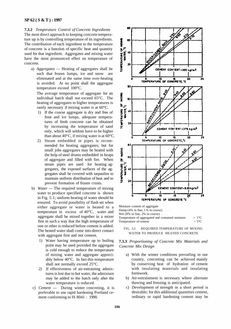
SP 62 ( S & T ) : 1997
7.3.2 Temperature Control of Concrete Ingredients The most direct approach to keeping concrete temperature up is by controlling temperature of its ingredients. The contribution of each ingredient to the temperature of concrete is a function of specific heat and quantity used for that ingredient. Aggregates and mixing water have the most pronounced effect on temperature of concrete.
a) Aggregates — Heating of aggregates shall be such that frozen lumps, ice and snow are eliminated and at the same time over-heating is avoided. At no point shall the aggregate temperature exceed 100°C. The average temperature of aggregate for an individual batch shall not exceed 65°C. The heating of aggregates to higher temperatures is rarely necessary if mixing water is at 60°C. 1) If the coarse aggregate is dry and free of
frost and ice lumps, adequate temperatures of fresh concrete can be obtained by increasing the temperature of sand only, which will seldom have to be higher than about 40°C, if mixing water is at 60°C.
2) Steam embedded in pipes is recommended for heating aggregates; but for small jobs aggregates may be heated with the help of steel drums embedded in heaps of aggregate and filled with fire. When steam pipes are used for heating aggregates, the exposed surfaces of the aggregates shall be covered with tarpaulins to maintain uniform distribution of heat and to prevent formation of frozen crusts.
b) Water — The required temperature of mixing water to produce specified concrete is shown in Fig. 5.1; uniform heating of water should be ensured. To avoid possibility of flash set when either aggregate or water is heated to a temperature in excess of 40°C, water and aggregate shall be mixed together in a mixer first in such a way that the high temperature of one or other is reduced before cement is added. The heated water shall come into direct contact with aggregate first and not cement. 1) Water having temperature up to boiling
point may be used provided the aggregate is cold enough to reduce the temperature of mixing water and aggregate appreciably below 40°C. In fact this temperature shall not normally exceed 25°C.
2) If effectiveness of air-entraining admixtures is lost due to hot water, the admixture may be added to the batch only after the water temperature is reduced.
c) Cement — During winter concreting, it is preferable to use rapid hardening Portland cement conforming to IS 8041 : 1990.
Moisture content of aggregate Damp (4% in fine, 1 % in coarse) Wet (8% in fine, 2% in coarse) Temperature of aggregated and contained moisture = 1°C Temperature of cement = 5°C
FIG. 5.1 REQUIRED TEMPERATURE OF MIXING
WATER TO PRODUCE HEATED CONCRETE
7.3.3 Proportioning of Concrete Mix Materials and Concrete Mix Design
a) With the winter conditions prevailing in our country, concreting can be achieved mainly by conserving heat of hydration of cement with insulating materials and insulating formwork.
b) Air-entrainment is necessary where alternate thawing and freezing is anticipated.
c) Development of strength in a short period is desirable; for this additional quantities cement, ordinary or rapid hardening cement may be
106
SP 62 ( S & T ) : 1997
added or proper admixture in right proportions. This results in saving due to shorter duration of protection, earlier removal of formwork, etc. Cement which gives earlier and higher heat of hydration is preferred. The cement content in the mix shall preferahlv be not less than 3(X) kg/m3.
d) Admixture to be used may be calcium chloride; however it cannot be used under certain conditions listed below; also the stipulated chloride content as per IS 456 : 1978 should be adhered to. The conditions are: 1) When sulphate resistant cement is used. 2) When there are cracks in concrete, 3) When they are exposed to alternate drying
and wetting, 4) When the concrete cover is small, and 5) When the concrete is permeable. Chlorides lead to corrosion of reinforcement and hence every care shall be taken to restrict its content in concrete; for using it as an admixture if need be, specialists may be consulted.
e) Air-entraining agents, if proper amounts are used, increase the resistance of hardened concrete to freezing and thawing and also improves workability of concrete.
7.3.4 Temperature of Concrete as Placed
a) When placing concrete at or near freezing temperature, precautions shall be taken to ensure that concrete at that time of placing has a temperature of at least 5°C and the temperature of concrete after having placed and compacted is maintained at above 20°C until it hardens thoroughly.
b) The temperature of concrete mix may be as-sessed by calculation or by taking a sample of the mix and measuring its temperature by a metal clad thermometer.
7.3.5 Production and Delivery
a) The concrete shall be delivered at not less than 5°C.
b) Suitable precautions be taken during production of concrete against the weather for both machines and materials.
c) It is necessary to place the concrete quickly and cover the top of the concrete with an insulating material.
7.3.6 Placement, Protection and Curing
a) Before any concrete is placed all ice, snow and frost shall be completely removed and the temperature of all surfaces to be in contact with concrete be raised to the temperature of concrete to be placed. When concrete has to be placed over permanently frozenground, sub-grade material
may be thawed deep enough to ensure that it will not freeze back up to the concrete; or it may be covered with dry granular material. Arrangements shall be made to cover and insulate newly placed concrete well in advance.
b) All concrete surfaces shall be covered as soon as the concrete has been placed; clean straw blankets about 50 mm thick, sacks, tarpaulins, expanded polystyrene, plastic sheeting, waterproof paper in conjunction with an air gap may be used. Insulating materials may be used as a protective material for formwork also.
c) Water curing is not necessary during freezing or-near freezing conditions. On removal of formwork and insulation the member shall be immediately covered with plastic shear or tarpaulins properly taped and made wind tight. On no account shall such concrete, released from insulated formwork, be saturated with cold water. Low pressure wet steam provides the best means of both heating enclosures and moist curing of concrete. Later on liquid-membrane forming compounds may be followed on concrete surfaces with heated enclosures In cold weather, curing is not so important, as the protection offered by formwork. Therefore, forms may not be removed until the end ot minimum period ot protection or even later. Table 5.11 gives the minimum time for structural concrete for stripping of formwork; the time for removal of fomwork for sides of beams, columns and walls shall be not less than those in Table 5.12.
Table 5.11 Stripping Time for Structural Concrete
(Clause 7.3 6)
Element Stripping Time
a)
b)
c)
d)
e)
Walts, columns, and vertical faces of all structural members
Beam sotfits' (props left under)
Removal of props under slabs i) Spanning up to 4 5 in
ii) Spanning over to 4 5 in
Slabs (props left under)
Removal of props under beams and arches
i) Spanning up to 6 m ii) Spanning over 6 m
24 to 48 has may be decided
7 days
7 days 1 4 days
3 days
14 days 21 days
For other cements, the stripping time recommended above may be modified.
107
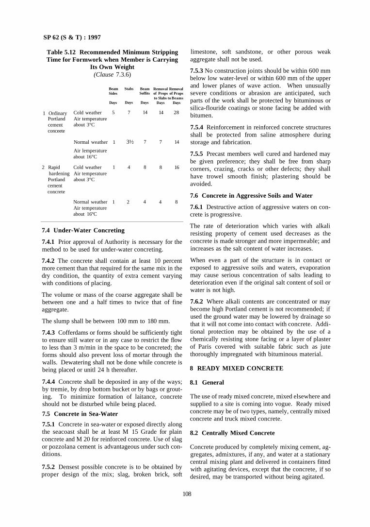
SP 62 (S & T) : 1997
Table 5.12 Recommended Minimum Stripping Time for Formwork when Member is Carrying
Its Own Weight (Clause 7.3.6)
1 Ordinary Portland cement conceete
2 Rapid
Cold weather Air temperature about 3°C
Normal weather
Air lemperature about 16°C
Cold weather hardening Air temperature Portland about 3°C cement concrete
Normal weather Air temperature about 16°C
Beam Sides
Days
5
1
1
1
Stabs
Days
7
4
2
Beam Soffits
Days
14
7
8
4
Removal Removal of Props of Praps to Slabs to Beams
Days Days
14 28
7 14
8 16
4 8
7.4 Under-Water Concreting
7.4.1 Prior approval of Authority is necessary for the method to be used for under-water concreting.
7.4.2 The concrete shall contain at least 10 percent more cement than that required for the same mix in the dry condition, the quantity of extra cement varying with conditions of placing.
The volume or mass of the coarse aggregate shall be between one and a half times to twice that of fine aggregate.
The slump shall be between 100 mm to 180 mm.
7.4.3 Cofferdams or forms should be sufficiently tight to ensure still water or in any case to restrict the flow to less than 3 m/min in the space to be concreted; the forms should also prevent loss of mortar through the walls. Dewatering shall not be done while concrete is being placed or unitl 24 h thereafter.
7.4.4 Concrete shall be deposited in any of the ways; by tremie, by drop bottom bucket or by bags or grouting. To minimize formation of laitance, concrete should not be disturbed while being placed.
7.5 Concrete in Sea-Water
7.5.1 Concrete in sea-water or exposed directly along the seacoast shall be at least M 15 Grade for plain concrete and M 20 for reinforced concrete. Use of slag or pozzolana cement is advantageous under such conditions.
7.5.2 Densest possible concrete is to be obtained by proper design of the mix; slag, broken brick, soft
limestone, soft sandstone, or other porous weak aggregate shall not be used.
7.5.3 No construction joints should be within 600 mm below low water-level or within 600 mm of the upper and lower planes of wave action. When unusually severe conditions or abrasion are anticipated, such parts of the work shall be protected by bituminous or silica-flouride coatings or stone facing be added with bitumen.
7.5.4 Reinforcement in reinforced concrete structures shall be protected from saline atmosphere during storage and fabrication.
7.5.5 Precast members well cured and hardened may be given preference; they shall be free from sharp corners, crazing, cracks or other defects; they shall have trowel smooth finish; plastering should be avoided.
7.6 Concrete in Aggressive Soils and Water
7.6.1 Destructive action of aggressive waters on concrete is progressive.
The rate of deterioration which varies with alkali resisting property of cement used decreases as the concrete is made stronger and more impermeable; and increases as the salt content of water increases.
When even a part of the structure is in contact or exposed to aggressive soils and waters, evaporation may cause serious concentration of salts leading to deterioration even if the original salt content of soil or water is not high.
7.6.2 Where alkali contents are concentrated or may become high Portland cement is not recommended; if used the ground water may be lowered by drainage so that it will not come into contact with concrete. Additional protection may be obtained by the use of a chemically resisting stone facing or a layer of plaster of Paris covered with suitable fabric such as jute thoroughly impregnated with bituminous material.
8 READY MIXED CONCRETE
8.1 General
The use of ready mixed concrete, mixed elsewhere and supplied to a site is coming into vogue. Ready mixed concrete may be of two types, namely, centrally mixed concrete and truck mixed concrete.
8.2 Centrally Mixed Concrete
Concrete produced by completely mixing cement, aggregates, admixtures, if any, and water at a stationary central mixing plant and delivered in containers fitted with agitating devices, except that the concrete, if so desired, may be transported without being agitated.
108
3½
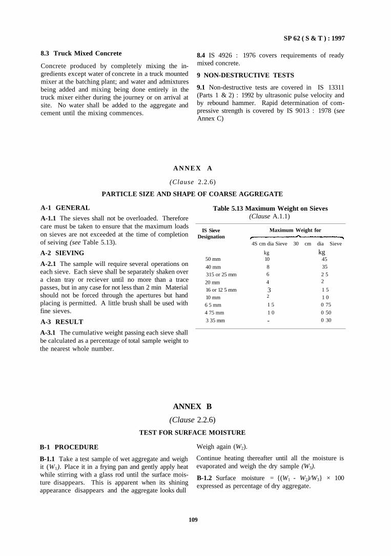
SP 62 ( S & T ) : 1997
8.3 Truck Mixed Concrete
Concrete produced by completely mixing the ingredients except water of concrete in a truck mounted mixer at the batching plant; and water and admixtures being added and mixing being done entirely in the truck mixer either during the journey or on arrival at site. No water shall be added to the aggregate and cement until the mixing commences.
8.4 IS 4926 : 1976 covers requirements of ready mixed concrete.
9 NON-DESTRUCTIVE TESTS
9.1 Non-destructive tests are covered in IS 13311 (Parts 1 & 2) : 1992 by ultrasonic pulse velocity and by rebound hammer. Rapid determination of compressive strength is covered by IS 9013 : 1978 (see Annex C)
A N N E X A
(Clause 2.2.6)
PARTICLE SIZE AND SHAPE OF COARSE AGGREGATE
A-1 GENERAL
A-1.1 The sieves shall not be overloaded. Therefore care must be taken to ensure that the maximum loads on sieves are not exceeded at the time of completion of seiving (see Table 5.13).
A-2 SIEVING
A-2.1 The sample will require several operations on each sieve. Each sieve shall be separately shaken over a clean tray or reciever until no more than a trace passes, but in any case for not less than 2 min Material should not be forced through the apertures but hand placing is permitted. A little brush shall be used with fine sieves.
A-3 RESULT
A-3.1 The cumulative weight passing each sieve shall be calculated as a percentage of total sample weight to the nearest whole number.
Table 5.13 Maximum Weight on Sieves (Clause A.1.1)
IS Sieve Designation
50 mm
40 mm 315 or 25 mm
20 mm 16 or 12 5 mm
10 mm 6 5 mm
4 75 mm
3 35 mm
Maximum Weight for
4S cm dia Sieve 30 cm dia Sieve
kg 10
8 6
4
3 2
1 5
1 0
-
kg 45
35
2 5 2
1 5 1 0 0 75
0 50
0 30
ANNEX B
(Clause 2.2.6)
TEST FOR SURFACE MOISTURE
B-1 PROCEDURE
B-1.1 Take a test sample of wet aggregate and weigh it (W1). Place it in a frying pan and gently apply heat while stirring with a glass rod until the surface moisture disappears. This is apparent when its shining appearance disappears and the aggregate looks dull
Weigh again (W2).
Continue heating thereafter until all the moisture is evaporated and weigh the dry sample (W3).
B-1.2 Surface moisture = {(W1 - W2)/W3} × 100 expressed as percentage of dry aggregate.
109
SP 62 ( S & T ) : 1997
ANNEX C
(Clause 3.3.3)
ACCELARATED CURING FOR DETERMINATION OF COMPRESSIVE STRENGTH OF CONCRETE
C-1 GENERAL
C-1.1 The compressive strength of concrete is expressed as its 28 days strength. The procedure requires 28 days moist curing before testing, which is too long a period to be of any value either for construction control or for applying timely corrective action. If after 28 days, the quality of concrete is suspect, it would have hardened by that time and might have been buried by subsequent construction. Therefore the replacement of that concrete is difficult and impracticable. On the other hand if the concrete is found to be too strong than necessary, cement is wasted due to uneconomical mix proportioning. Hence the standard 28 days strength is not feasible for quality control.
C-1.2 Thus, there is a need for a rapid test which can give results while the concrete is still green so that it can be either removed or modified. A period of 24 h would help in this, that is the test result should be available in a day's time so that corrective actions can be taken successfully. With the assistance of accelerated curing techniques, it is now possible to test the compressive strength of concrete within a short period and thereby it is possible to estimate whether the concrete is likely to reach the 28 days strength.
C-1.3 This is fairly reliable and fast method for evaluating controlled concrete in the field by accelerated curing. Two methods of curing are warm water method and boiling water method. Appropriate correlation curves are available to estimate the quality of concrete at normal ages. Methods of test proposed are readily applicable to the site-testing and to give results of reasonably low variability.
C-1.4 High pressure steam curing is also used as in accelerated-curing method, but has some inherent limitations for application. However this may be used for internal quality control purposes under special circumstances.
C-1.5 For detailed infonnation refer to IS 9013 : 1978.
C-2 ACCELERATED CURING BY WARM WATER METHOD C-2.1 Test specimens, shall be made according to IS 516 : 1959 if correlation curves have to be drawn. If it is for control purposes sampling shall be done as per IS 1199 : 1959.
C-2.2 The test specimens shall be left to stand undisturbed in their moulds in a place free from vibration at a temperature of 27 ± 2°C for at least 1h, prior to
immersion in a curing tank. The time between the addition of water to the ingredients and immersion of the test specimens in the curing tank shall be between l½ h to 3½ h.
C-2.3 The specimens in their moulds shall be gently lowered into the curing tank and shall be totally immersed at 55 ± 2°C for a period of not less than 19 h and 50 min. The specimens shall then be removed from the water, marked for identification, removed from the moulds and immersed in cooling tank at 27 ± 2°C before completion of 20 h and 10 min from the start of immersion in the curing tank. They shall remain in the cooling tank for at least 1 h.
C-3 ACCELERATED CURING BY BOILING WATER METHOD
C-3.1 Test specimens in mould shall be stored in a place free from vibration, in moist air of at least 90 percent relative humidity and at a temperature of 27 ± 2°C for 23 h ± 15 min from the time of addition of water to the ingredients.
C-3.2 The specimens shall be gently lowered into a curing tank and shall remain totally immersed for a period of 3½ h ± 5 min. The temperature of the water
in the curing tank shall be at boiling point (100°C) at sea level. The temperature of the water shall not drop by more than 3()°C after the specimens are placed and shall return to boiling within 15 min. In confined places, the temperature of water may be kept just below the boiling point to avoid excessive evaporation.
C-3.3 After curing for 3½ h ± 5 min in the curing tank,
the specimen shall be removed from the boiling water, removed from the moulds and cooled by the immersing in cooling tank at 27 ± 2°C for a period not less than 1 h.
C-4 TESTING
C-4.1 The specimens shall be tested in accordance with IS 516 : 1959.
C-4.2 The warm water method specimens shall be tested while still wet, not more than 2 h from the time of immersion in the cooling tank.
C-4.3 In the boiling water method, the age at the time of test subsequent to removal of moulds and cooling shall be 28½ h ± 15 min.
110
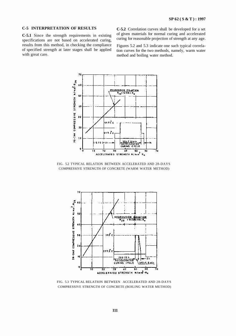
SP 62 ( S & T ) : 1997
C-5 INTERPRETATION OF RESULTS
C-5.1 Since the strength requirements in existing specifications are not based on accelerated curing, results from this method, in checking the compliance of specified strength at later stages shall be applied with great care.
C-5.2 Correlation curves shall be developed for a set of given materials for normal curing and accelerated curing for reasonable projection of strength at any age.
Figures 5.2 and 5.3 indicate one such typical correlation curves for the two methods, namely, warm water method and boiling water method.
FIG. 5.3 TYPICAL RELATION BETWEEN ACCELERATED AND 28-DAYS
COMPRESSIVE STRENGTH OF CONCRETE (BOILING WATER METHOD)
111
FIG. 5.2 TYPICAL RELATION BETWEEN ACCELERATED AND 28-DAYS
COMPRESSIVE STRENGTH OF CONCRETE (WARM WATER METHOD)
SP 62 ( S & T ) : 1997
1 GENERAL
1.1 All the common requirements of Part 1 apply to reinforced concrete work also. These include materials, grades of concrete; production and control of concrete; mixing, transporting, placing, compacting and curing; and concreting under special conditions, as described in detail in Part 1.
1.2 This Part will deal with requirements of reinforced concrete work in addition to those given in Part 1.
2 FORMWORK
2.1 General
The requirements of formwork for reinforced concrete apply to plain concrete work except for information relating to reinforcement. Formwork shall include all temporary or permanent forms or moulds required for forming the concrete which is cast in-situ. Together with all temporary construction required for their support.
Formwork shall be of rigid construction true to shape and dimensions shown in drawings. It shall be able enough to withstand dead, wind and live woods, etc, [as per IS 875 (Parts 1 to 5) : 1987] as applicable. It shall also be designed to resist torces generated during construction, namely, those due to ramming, vibration of concrete and other incidental loads imposed on it. The species of timber and design shall be according to IS 883 : 1970 and SP 33 (S&T) : 1986.
It shall be made sufficiently rigid by use ties and braces. Screw jacks or wedges shall be used when required to take up any settlement in the formwork either before or during the placing of concrete.
Forms shall be removable in sections in desired sequence, without disturbing other sections or damaging the surfaces of concrete. All formwork should be easy to strip after connecting; care shall be taken to see that no piece is keyed into the concrete.
Details of formwork should be carefully worked out and approved by the Authority. The completed formwork shall be inspected before placing reinforcement in position.
2.2 Materials of Formwork
2.2.1 Formwork may be timber, plywood, steel or any other material. IS 4990 : 1981 may be used for plywood shuttering.
Timber used for formwork shall be easily workable, with nails without splitting and of light weight. It shall be stiff and strong enough to avoid undue deflection when loaded; it shall not warp when exposed to sun and rain or wetted during concreting. It shall not be soft and shall withstand easily the normal forces of
usage, such as, erection of forms, fixing of steel, pouring concrete, etc.
2.2.2 Propping and Centering
a) Props for centering may be of steel, timber posts or ballies; brick masonry may also be used as props. Bailies shall rest squarely on wooden base plates or any other load bearing material. Wedges or other devices may be used below the props to ensure tight fitting again to formwork.
b) Props for upper storeys may rest on the floor below. Formwork and concreting of upper floors shall not be done until concrete of lower floor has set for 14 days.
Before concreting is done props and wedges should be checked for alignment.
2.2.3 Shuttering
Shuttering material shall have smooth, and even surface and the joints shall not permit leakage of cement grout. Timber when used shall be seasoned and free from toose knots, splits, etc; nails shall not be projecting from timber pieces. Steel plates when used should have no projections of bolts and nuts. Fixing devices, if any shall be properly provided for (see IS 1946 : 1961).
All surfaces of shuttering, in contact with concrete, shall be treated with a non-staining mineral oil or other approved material to prevent adhesion with concrete and protect reinforcement also. Suitable camber shall be given for horizontal members.
2.2.4 Special formwork, where necessary, may be used, for example for tall structures.
2.2.5 Stripping
The formwork shall be so removed as not to damage, the concrete. In slab and beam construction, sides of beams shall be stripped first and then the underside of the slab and lastly the underside of the beam.
Under no circumstances shall formwork be stripped until concrete attains a strength at least twice the stress to which concrete may be subjected at the time of removal of formwork. When possible, formwork shall be left in place longer as it would assist the curing.
For ordinary Portland cement, forms may be stripped after the expiry of the periods as specified in Table 5.11.
Where the shape of element is such that formwork has re-entrant angles, the formwork shall be removed as soon as possible after the concrete has set to avoid shrinkage cracking due to restraint imposed by the stiff formwork.
PART 2 REQUIREMENTS OF REINFORCED CONCRETE
112
SP 62 ( S & T ) : 1997
2.3 Reinforcement
2.3.1 Straightening, Cutting and Bending
Reinforcement may be bent and fixed in accordance with the procedure indicated in IS 2502 : 1963, and shall not be straightened in a manner injurious to the material. Cold twisted bars shall be bent cold. All bars shall be placed and maintained in the position shown on drawings. Crossing bars should not be tack welded for assembly of reinforcement. Annealed steel wire (0.9 mm dia or over) may be used for tying crossing bars.
2.3.1.1 Tolerance on formwork and placing of reinforcement
a) Formwork tolerance shall be as follows.
— deviation from specified dimensions of cross sections of beams and columns, - 6 mm to 12 mm.
--- deviation from dimensions of footings, in plan - 12 mm to 50 mm eccentricity 0.02 times the width of footing in the direction of footing but not more than 50 mm; thickness ± 0.05 times the specified thickness.
b) Reinforcement tolerance
— for effective depth 200 mm or less, ± 10 mm;
1.2 Lime concrete is found to have many desirable properties and advantages for use in construction. Properly prepared, compacted and laid, lime concrete is durable under normal exposures. Lime concrete possesses considerable resistance for sulphate attack and can be used in foundations and in areas in which soil contains considerable quantities of soluble sulphate or where subsoil water table is high. The effect of temperature fluctuations on the volume change is negligible in lime concrete compared to that due to
— for effective depth more than 200 mm. ± 15 mm.
c) Cover shall not be reduced by more than one-third of specified cover or 5 mm whichever is less.
2.3.2 Welded Joints or Mechanical Connections
Welded joints or mechanical connections in reinforcement may be used; but tests shall be need to prove that the joints arc of full strength of bars connected. For welding of mild steel plain and deformed bars refer to IS 2751 : 1979 [see also SP (S&T) 34 : 1987 on concrete reinforcement].
When reinforcement are bent aside at construction joints and afterwards bent back to their original positions, care should be taken to ensure that at no time is the radius of the bend less than 4 bar diameter for plain mild steel and 6 bar diameters for deformed bars. Care also shall be exercised that when bending the bars back the concrete around the bar is not damaged.
2.3.3 Cover
Cover to reinforcement shall be as per drawings subject to requirements of IS 456 : 1978.
Lime for use in lime concrete shall conform to IS 712: 1984.
2.2 Cement
Cement shall conform to the requirements of 33 grade ordinary Portland cement to IS 269 : 1989.
2.3 Pozzolana
Burnt clay pozzolana shall conform to IS 1344: 1981. Fly ash shall conform to IS 3812 : 1981.
PART 3 LIME AND LIME POZZOLANA MIXTURE CONCRETE
Section 1 Lime Concrete
1 GENERAL
1.1 Lime concrete, inspite of its low strength, may be used in several situations in construction such as in well foundations tor moderately tall buildings, under floor finishes, for fdling haunches over masonry arch work and for roof terracing work.
moisture variations It undergoes negligible volume change after setting and initial shrinkage.
1.3 For detailed information refer to IS 2541 : 1991.
2 MATERIALS
2.1 Lime
113
SP 62 ( S & T ) : 1997
2.4 Coarse Aggregate
Coarse aggregate for use in lime concrete shall be either natural stone aggregate conforming to IS 383 : 1970 or broken brick (burnt clay) aggregate conforming to IS 3068 : 1986 or cinder aggregate to IS 2686 : 1977 depending on the situation of use (see Table 5.14).
2.5 Fine Aggregate
Sand for use in lime concrete shall conform to IS 383 : 1970. Brick aggregate shall conform to IS 3182 : 1986. Fly ash shall conform to IS 3812: 1981.
2.6 Water
Water used for mixing and curing shall be clean and free from injurious amount of deleterious matter. Sea water shall not be used. Potable water is considered satisfactory.
3 PROPERTIES OF LIME CONCRETE
3.1 Workability
Satisfactory workability of lime concrete is obtained by using the proportions recommended in Table 5.14. Workability of lime concrete can be increased further by increasing the proportion of lime mortar, within the limits specified in Table 5.14. Lime concrete with a slump of 50-75 mm will be generally found to be satisfactory.
3.2 Rate of Hardening and Setting Time
3.2.1 Hardening
Hardening of lime concrete is slow compared to cement concrete. Therefore for structural load bearing lime concrete, it should be allowed to harden for a period of seven days before further work is undertaken.
3.2.2 Setting time of lime concrete depends on the class of lime used in the preparation of the mortar. For Class A lime initial set may occur in 2 to 3 h. Final set does not occur in less than 10-12 h. Placing of lime concrete shall be done before the initial set has occurred.
3.3 Strength
The process of strength development in lime concrete is slow and may extend over years. The strength again depends on the class of lime used and the aggregate; proportion and quality of pozzolana used in the preparation of concrete. The compressive strength, for mixes shown in Table 5.14, shall not be less than 1 N/mm2 (10 kg/cm2) at 28 days, and for transverse strength it shall not be less than 0.2 N/mm2 (2 kg/cm2) at 90 days. The compressive strength is expected to rise to 1.2 N/mm2 (12 kg/cm2) in 90 days
4 MIXING
4.1 General
Lime concrete may be hand mixed or machine mixed. For large quantities of concrete, machine mixing is desirable.
4.2 Hand Mixing
The aggregates should be thoroughly washed and drained before use. Mixing shall be done on a clean water-tight platform.
The coarse aggregate shall be stacked on the platform. Lime shall then be evenly spread over it, in the specified proportion, and thoroughly mixed. Water in just sufficient quantity shall be applied with a sprinkler. Mixing shall be done by turning the mix over and over until all particles of aggregate are covered with mortar and concrete of uniform appearance and consistency is obtained.
4.3 Machine Mixing
Clean dry coarse aggregate shall be first laid into a mechanical mixer. Lime mortar is then fed into the mixer. The contents shall then be mixed well. Required quantity of water shall then be added. Mixing shall be continued until there is a uniform distribution of materials. Final adjustment of water, to obtain concrete of required consistency, may be added if necessary and continue mixing.
5 LAYING OF LIME CONCRETE
5.1 General
Only that amount of concrete shall be mixed which can be laid in 2 h after mixing. Laying and compaction of concrete shall be completed within 4 h of adding water.
5.2 In Foundations and Under Floors
a) The soil sub-grade shall be thoroughly wetted and rammed before the concrete is laid.
b) Concrete shall be laid, and not thrown, in layers not thicker than 150 mm, when consolidated.
c) Each layer shall be thoroughly rammed and consolidated before succeeding layers are placed. Where joints in the same layer are unavoidable each layer shall be sloped at an angle of 30° and made to ensure proper bond with the new concrete. The surface of each completed layer shall be cleaned and roughened by wire brushing or other means before the next layer is laid. Where vertical joints occur, they shall be at least 600 mm apart.
d) Vibrators may be used for uniform and good compaction.
114
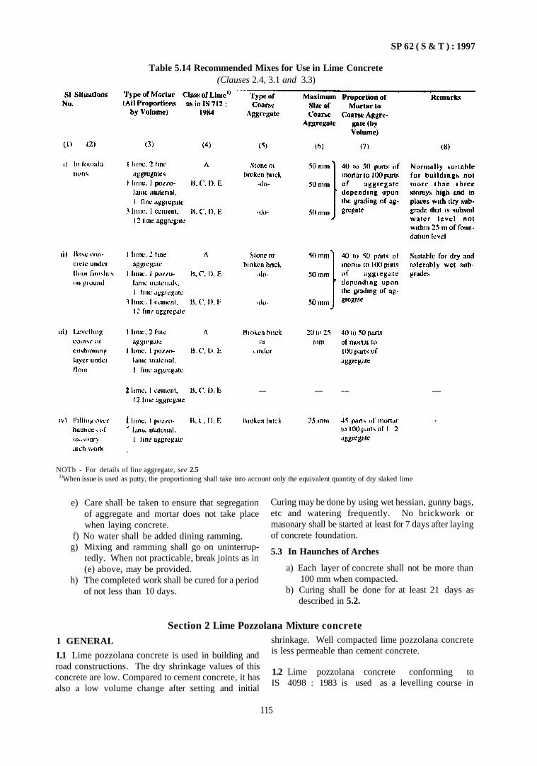
SP 62 ( S & T ) : 1997
Table 5.14 Recommended Mixes for Use in Lime Concrete (Clauses 2.4, 3.1 and 3.3)
NOTb - For details of fine aggregate, see 2.5 1)When issue is used as putty, the proportioning shall take into account only the equivalent quantity of dry slaked lime
e) Care shall be taken to ensure that segregation of aggregate and mortar does not take place when laying concrete.
f) No water shall be added dining ramming. g) Mixing and ramming shall go on uninterrup
tedly. When not practicable, break joints as in (e) above, may be provided.
h) The completed work shall be cured for a period of not less than 10 days.
Curing may be done by using wet hessian, gunny bags, etc and watering frequently. No brickwork or masonary shall be started at least for 7 days after laying of concrete foundation.
5.3 In Haunches of Arches
a) Each layer of concrete shall not be more than 100 mm when compacted.
b) Curing shall be done for at least 21 days as described in 5.2.
1 GENERAL
1.1 Lime pozzolana concrete is used in building and road constructions. The dry shrinkage values of this concrete are low. Compared to cement concrete, it has also a low volume change after setting and initial
shrinkage. Well compacted lime pozzolana concrete is less permeable than cement concrete.
1.2 Lime pozzolana concrete conforming to IS 4098 : 1983 is used as a levelling course in
115
Section 2 Lime Pozzolana Mixture concrete
SP 62 ( S & T ) : 1997
foundation, footing under masonry walls and columns, ordinary base concrete under floor, filling haunches in masonary arches, roof finish, making blocks, etc.
1.3 For more information refer to IS 5817: 1992.
2 MATERIALS
2.1 Lime pozzolana mixture shall conform to IS 4098: 1983.
2.2 Fine and coarse aggregate and water shall be as in Section I.
2.3 Recommended mixes with lime pozzolana mixture are given in Table 5.15.
1 GENERAL
1.1 Shotcrete is mortar or concrete conveyed through a hose and pneumatically projected at high velocity on to a surface. The force of jet impinging on the surface compacts the material. Generally a relatively dry mixture is used, and so the material is capable of supporting itself without sagging or sloughing, even for vertical and overhead applications.
1.2 Shotcrete is generally referred to as gunite, pneumatically applied mortar or concrete, sprayed concrete, airblown mortar and concrete, etc. However, the term 'shotcrete' will be used throughout this part as the term is accepted internationally.
1.3 Shotcrete is suitable for a variety of new construction and repair work, but its properties are to a great extent dependent on the conditions under which it is placed, the capability of the particular equipment selected and in particular on the competence of the operating staff Shotcrete can be either plain or reinforced.
1.4 Shotcrete is done by two processes, namely, dry-mix process and wet-mix process. Pneumatically conveyed shotcrete in which most of the mixing water is added at the nozzle is dry-mix process. Shotcrete wherein all the ingredients, including mixing water, are mixed in the equipment before introduction into the delivery hose in wet-mix process; the shotcrete mix may be conveyed pneumatically or moved by displacement.
2 MATERIALS
2.1 Cement, aggregates, water, admixtures and reinforcement are as per Part 1 except as mentioned in 2.1.1.
3 MIXING
3.1 Both hand mixing and machine mixing are permitted (see Section 1)
4 LAYING
4.1 The methods of laying lime pozzolana concrete are similar to lime concrete laying as per Section 1.
4.2 In Roof Finish
Shall be as per IS 3036 : 1992.
2.1.1 Aggregates
a) Fine aggregate (sand) — Sand for concrete shall comply with the requirements of IS 383 : 1970 and graded evenly from fine to coarse as per Zone II and Zone III grading. Sand failing to satisfy this grading may however be used if pre-construction testing gives good results (see 5). Further sand for finish or flash coats may be finer from the above grading. However, the use of finer sands results in greater drying shrinkage, and coarse sands in more rebound.
b) Coarse aggregate — Coarse aggregates, when used, shall comply with IS 383 : 1970. It shall conform to one of the gradings given in Table 5.16.
3 SHOTCRETING PROCESS
3.1 General
The two basic processes are:
a) Dry-mix process, and b) Wet-mix process.
3.2 Dry-Mix Process
In this process, a mixture of cement and moist sand is conveyed through the delivery hose to a nozzle where most of the mixing water is added, under pressure (see Fig. 5.4). The process consists of the following steps:
a) The cement and moist sand are thoroughly mixed;
b) The cement-sand mixture is fed with a special mechanical feeder or gun;
PART 4 SHOTCRETE
116
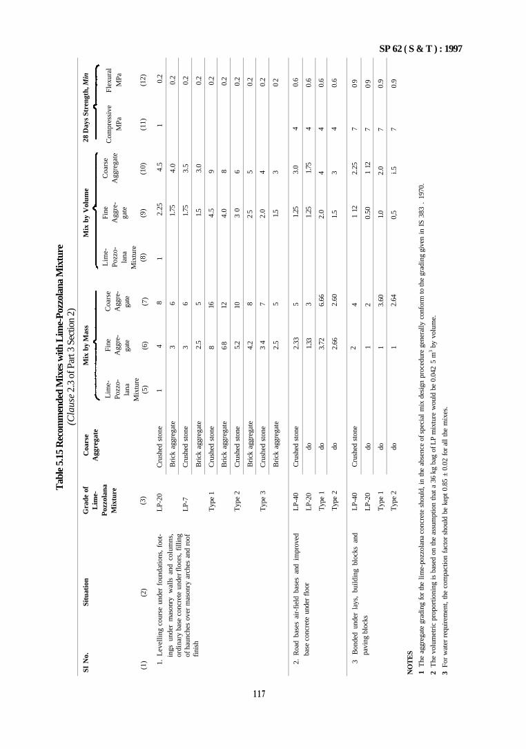
Tab
le 5
.15
Rec
omm
ende
d M
ixes
with
Lim
e-Po
zzol
ana
Mix
ture
(C
laus
e 2.
3 of
Par
t 3 S
ectio
n 2)
SI N
o.
Situ
atio
n
(1)
(2)
1. L
evel
ling
cour
se u
nder
fou
ndat
ions
, fo
ot
ings
und
er m
ason
ry w
alls
and
col
umns
, or
dina
ry b
ase
conc
rete
und
er fl
oors
, fi
lling
of
hau
nche
s ov
er m
ason
ry a
rche
s an
d ro
of
fini
sh
2. R
oad
base
s ai
r-fi
eld
base
s an
d im
prov
ed
base
con
cret
e un
der
floo
r
3 B
onde
d un
der
lays
, bu
ildin
g bl
ocks
and
pa
ving
blo
cks
Gra
de o
f L
ime-
Poz
zola
na
Mix
ture
(3)
LP-
20
LP-
7
Typ
e 1
Typ
e 2
Typ
e 3
LP-
40
LP-
20
Typ
e 1
Typ
e 2
LP-
40
LP-
20
Typ
e 1
Typ
e 2
Coa
rse
Agg
rega
te
Cru
shed
sto
ne
Bri
ck a
ggre
gate
Cru
shed
sto
ne
Bri
ck a
ggre
gate
Cru
shed
sto
ne
Bri
ck a
ggre
gate
Cru
shed
sto
ne
Bri
ck a
ggre
gate
Cru
shed
sto
ne
Bri
ck a
ggre
gate
Cru
shed
sto
ne
do
do
do
Cru
shed
sto
ne
do
do
do
Mix
by
Mas
s
Lim
e-
Fine
C
oars
e Po
zzo-
A
ggre
- A
ggre
-la
na
gate
ga
te
Mix
ture
(5
) (6
) (7
)
1 4
8
3 3 2.5
8 68 5.2
4.2
3 4
2.5
2.33
1.33
3.72
2.66
2 1 1 1
6 6 5 16
12
10 8 7 5 5 3 6.66
2.60
4 2 3.60
2.64
Mix
by
Vol
ume
Lim
e-
Fine
C
oars
e Po
zzo-
A
ggre
- A
ggre
gate
la
na
gate
M
ixtu
re
(8)
(9)
(10)
1 2.
25
4.5
1.75
1.75
1.5
4.5
4.0
3 0
25
2.0
1.5
1.25
1.25
2.0
1.5
1 12
0.50
1.0
0,5
4.0
3.5
3.0
9 8 6 5 4 3 3.0
1.75
4 3 2.25
1 12
2.0
i.5
28 D
ays
Stre
ngth
, Min
Com
pres
sive
Fl
exur
al
MPa
M
Pa
(11)
(1
2)
1 0.
2
4 4 4 4 7 7 7 7
0.2
0.2
0.2
0.2
0.2
0.2
0.2
0.2
02
0.6
0.6
0.6
0.6
09
09
0.9
0.9
NO
TE
S
1 T
he a
ggre
gate
gra
ding
for
the
lime-
pozz
olan
a co
ncre
te s
houl
d, i
n th
e ab
senc
e of
spe
cial
mix
des
ign
proc
edur
e ge
nera
lly c
onfo
rm to
the
grad
ing
give
n in
IS
383
. 19
70.
2 T
he v
olum
etri
c pr
opor
tioni
ng is
bas
ed o
n th
e as
sum
ptio
n th
at a
36
kg b
ag o
f LP
mix
ture
wou
ld b
e 0.
042
5 m
3 by
volu
me.
3 Fo
r w
ater
req
uire
men
t, th
e co
mpa
ctio
n fa
ctor
sho
uld
be k
ept
0.85
± 0
.02
for
all
the
mix
es.
SP 62 ( S & T ) : 1997
1 1 7
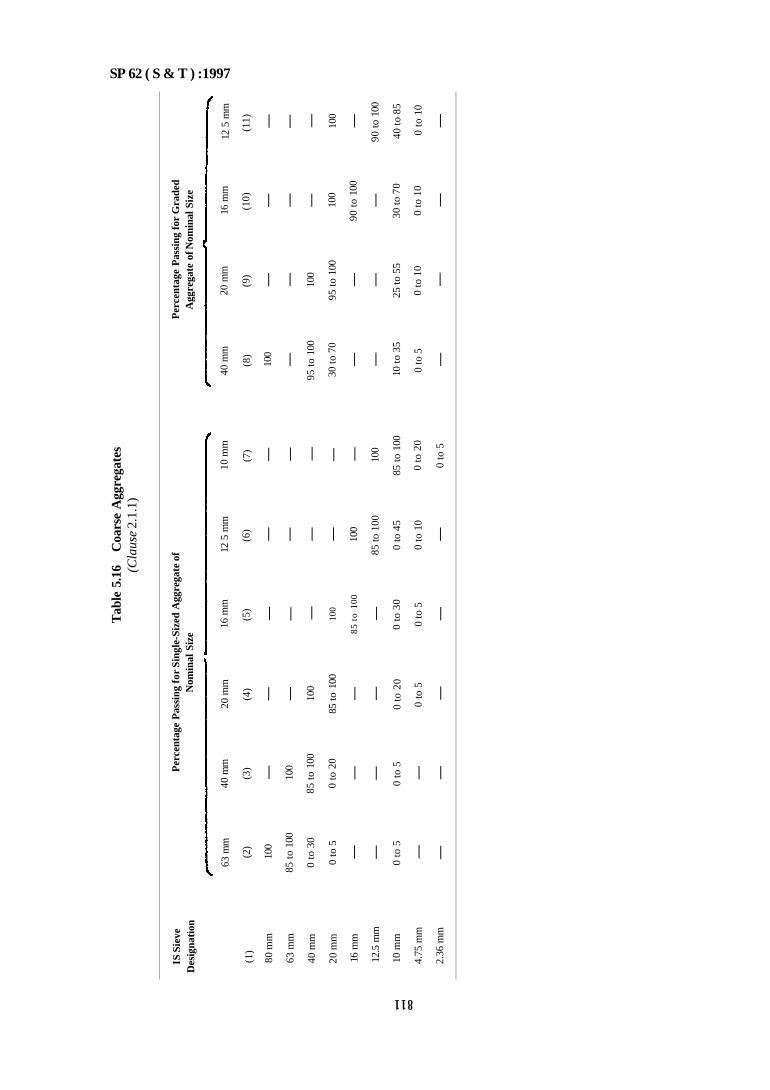
Tab
le 5
.16
Coa
rse
Agg
rega
tes
(Cla
use
2.1.
1)
IS S
ieve
D
esig
nati
on
(1)
80 m
m
63 m
m
40 m
m
20 m
m
16 m
m
12.5
mm
10 m
m
4.75
mm
2.36
mm
63 m
m
(2)
100
85 t
o 10
0
0 to
30
0 to
5
—
—
0 to
5
—
—
Per
cent
age
Pas
sing
for
Sin
gle-
Size
d A
ggre
gate
of
Nom
inal
Siz
e
40 m
m
(3)
—
100
85 t
o 10
0
0 to
20
—
—
0 to
5
—
—
20 m
m
(4)
—
—
100
85 to
100
—
—
0 to
20
0 to
5
—
16 m
m
(5)
—
—
—
100
85 t
o 10
0
—
0 to
30
0 to
5
—
12 5
mm
(6)
—
—
—
—
100
85 to
100
0 to
45
0 to
10
—
10 m
m
(7)
—
—
—
—
—
100
85 t
o 10
0
0 to
20
0 to
5
40 m
m
(8)
100
—
95 t
o 10
0
30 to
70
—
—
10 to
35
0 to
5
—
Per
cent
age
Pas
sing
for
Gra
ded
Agg
rega
te o
f Nom
inal
Siz
e
20 m
m
(9)
—
—
100
95 t
o 10
0
—
—
25 to
55
0 to
10
—
16 m
m
(10)
—
—
—
100
90 t
o 10
0
—
30 to
70
0 to
10
—
12 5
mm
(11)
—
—
—
100
—
90 t
o 10
0
40 to
85
0 to
10
—
SP 62 ( S & T ) :1997 811
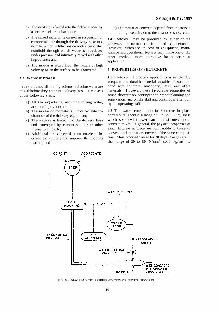
SP 62 ( S & T ) : 1997
c) The mixture is forced into the delivery hose by a feed wheel or a distributor;
d) The mixed material is carried in suspension of compressed air through the delivery hose to a nozzle, which is filled inside with a perforated manifold through which water is introduced under pressure and intimately mixed with other ingredients; and
e) The mortar is jetted from the nozzle at high velocity on to the surface to be shotcreted.
3.3 Wet-Mix Process
In this process, all the ingredients including water are mixed before they enter the delivery hose. It consists of the following steps:
a) All the ingredients, including mixing water, are thoroughly mixed;
b) The mortar or concrete is introduced into the chamber of the delivery equipment;
c) The mixture is forced into the delivery hose and conveyed by compressed air or other means to a nozzle;
d) Additional air is injected at the nozzle to increase the velocity and improve the shooting pattern; and
e) The mortar or concrete is jetted from the nozzle at high velocity on to the area to be shotcreted.
3.4 Shotcrete may be produced by either of the processes for normal constructional requirements. However, difference in cost of equipment, maintenance and operational features may make one or the other method more attractive for a particular application.
4 PROPERTIES OF SHOTCRETE
4.1 Shotcrete, if properly applied, is a structurally adequate and durable material capable of excellent bond with concrete, masonary, steel, and other materials. However, these favourable properties of sound shotcrete are contingent on proper planning and supervision, and on the skill and continuous attention by the operating staff.
4.2 The water cement ratio for shotcrete in place normally falls within a range of 0.35 to 0.50 by mass which is somewhat lower than for most conventional concrete mixes. In general, the physical properties of sand shotcrete in place are comparable to those of conventional mortar or concrete of the same composition. Most reported values for 28 days strength are in the range of 20 to 50 N/mm2 (200 kg/cm2 to
FIG. 5.4 DIAGRAMATIC REPRESENTATION OF GUNITE PROCESS
119
SP 62 ( S & T ) : 1997
500 kg/cm2). It is recommended that strength higher than 25 N/mm2 (250 kg/cm2) be specified only for the most carefully executed shotcrete jobs.
4.3 The drying shrinkage of shotcrete depends, somewhat on the mix proportions used, but generally falls within the range of 0.06 to 0.08 percent. This is rather higher than most low slump conventional concrete, which is generally placed in heavier sections using larger aggregates and leaner mixes. It will tend to give more shrinkage, cracking and may require a closer joint spacing. The durability of shotcrete is good.
4.4 Shotcrete offers advantages over conventional concrete in a variety of new construction and repair works. It is frequently more economical because of lesser forming requirements and because it requires only a small portable plant for manufacture and placement.
5 PRE-CONSTRUCTION TESTING
5.1 Testing shall be done prior to the commencement of the work in order to check the operation of equipment, skill of the operating staff and the quality of shotcrete. The procedure is detailed in 5.2 to 5.7.
5.2 Test panels shall be fabricated, simulating actual job conditions, by the operating staff using the equipment, materials and mix proportions proposed for the job.
5.3 For the dry-mix process, the amount of water added at the nozzle is adjusted so that the inplace shotcrete appears to be adequately compacted and neither sags nor shows excessive rebound. Where justified by the size and importance of the job or lack of previous experience with the materials, it may be advisable to test two or three mixes, generally within the range of 1 part of cement to 3 to 4½ parts of sand,
before deciding on the final mix proportions.
5.4 The procedure for wet-mix process is similar to the dry-mix process (see 5.3), except that the entire concrete mix is premixed to give a workability judged to be appropriate for the work, before it is introduced to the chamber of delivery equipment. Tests on more than one mix design are usually recommended where it is desired to include coarse aggregate in the mix. Normally 20 to 40 percent of coarse aggregate is first tried with subsequent mixes adjusted to reflect the results of the first trial.
5.5 The panels are fabricated by gunning on to a back form of ply wood. A separate panel shall be fabricated for each mix design being considered, and also for each gunning position to be encountered in the structure, that is, slab, vertical and overhead sections. At least part of the panel shall contain the same reinforcement as the structure, to show whether sound shotcrete is obtained behind the reinforcing rods. The panel shall
be large enough to obtain all test specimens needed, and also to indicate what quality and uniformity may be expected in the structure. Generally, the size of the panel shall be not less than 75 cm × 75 cm. The thickness shall be the same as in the structure, except that it shall normally be not less than 7.5 cm.
5.6 Cubes or cores shall be taken from the panels for testing. The cores shall have a minimum diameter of 7.5 cm and length diameter ratio of at least one if possible. The specimens shall be tested in compression at the age of 7 or 28 days or both.
5.7 The cut surfaces of the specimens shall be carefully examined and additional surfaces shall be exposed by saving and breaking of the panel when it is considered necesary to check the soundness and uniformity of the material. All cut and broken surfaces shall be dense and free from laminations and sand pockets.
6 MIXING
6.1 Dry-Mix Process
a) Batching by mass is preferred. b) The moisture content of the sand shall general
ly be within 5 to 6 percent to permit flow at a uniform rate.
c) The mixing equipment shall be capable of thoroughly mixing the sand and cement in sufficient quantity to maintain continuity of placing. The mixing time shall be not less than a minute in a drum type mixer. The mixer shall be thoroughly cleaned to prevent accumulations of batched materials.
d) Supply of clean dry air under pressure should be ensured through an air compressor. The air pressure should be uniformly steady (non-pulsating). The operating pressure shall drive the material from the delivery equipment into the hose.
e) For length of hose up to 30 m, the operating pressure shall be 0.3 N/mm2 ( 3 kg/cm2 ) or more; for each additional 15 m length of hose, pressure may be increased by 0.035 N/mm2
(0.35 kg/cm2) and the same increase allowed for each 7.5 m that the nozzle is raised before the gun.
f) Water under pressure shall be supplied; the water pressure shall be sufficiently greater than the operating air pressure at the discharge nozzle. Water pressure shall also be steady and non-pulsating.
6.2 Wet-Mix Process
a) Batching by mass is preferred. Aggregates may be batched by volume of periodic checks are made to ensure that the masses are maintained within the required tolerance. Water may be batched either by volume or mass.
120
SP 62 ( S & T ) : 1997
b) The mixing time will depend on the mix being used and the efficiency of the mixer.
c) The other details are as per dry-mix.
7 APPLICATION OF SHOTCRETE
7.1 Surface Preparation
a) Shotcrete shall not be placed on any surface which is frozen, spongy or where there is tree-water.
b) Surfaces shall be kept damp for several hours before shotcreting
c) In case of repairs, all existing deteriorated con crete shall be removed. The final cut surface shall be examined to make sure that it is sound and perfectly shaped; all edges shall be tapered. The surface shall be cleaned of all loose and foreign materials.
d) Exposed reinforcement shall be free of rust, scales, etc.
7.2 Formwork
Forms may be plywood sheeting or other material, true to line and dimension. They shall be so constructed as to permit the escape of air and rebound during gunning operations. Forms shall be oiled and dampened just before gunning. Short removable bulkheads may be used at intersections.
Appropriate scaffolding shall be erected to permit suitable positions for holding the nozzle.
7.3 Reinforcement
a) Reinforcement shall be so placed as to cause least interference to gunning operations.
b) Minimum clearance may be 12 mm to 50 mm between formwork and reinforcement for mortar work and concrete mix respectively.
c) Clear spacing between bars shall be not less than 65 mm.
d) As far as possible, bars shall be so arranged as to permit shooting from the opposite side
e) Lapped reinforcing bars shall not be tied together; they shall be separated by at least 50 mm.
f) For repair work, existing work may be fixed with reinforcement by nails.
g) All detailing shall be as per IS 45b : 1978
7.4 Alignment Control
Adequate ground wires shall be installed to ensure thickness and surface planes of shotcrete build up.
7.5 Placing of Shotcrete
a) Shotcrete may be built up in layers. Shotcrete shall be forced behind bars. When bars are closely spaced more than one bar may be shot
from each position of the nozzle. Avoid building up on the front face of the bar.
b) The first layer shall completely embed the bar for walls, columns and beams, beginning at the bottom.
7.6 Rebound
a) Rebound is aggregate and cement paste which ricochets off the surface during the application of shotcrete. Rebound may be as below:
Surface Percentage of Rebound Floors or slabs 5-15 Sloping and vertical walls 15-30 Overhead work 25-50
b) Rebound shall not be worked back into the concrete, it shall not be included in later batches.
7.7 Preparation for Succeeding Layers
The earlier layer shall be allowed to take initial set before the second layer is commenced. Then laitance, loose material and rebound shall be removed. The surface shall be thoroughly sounded with a hammer for drummy areas resulting Iron) rebounding pockets or lack of bond. Drummy areas shall be cut off and replaced with succeeding layers. Surfaces to be shot shall be damp.
7.8 Construction Joints
Construction joints shall generally follow the principles as laid down in Part 1.
7.9 Finishing
The natural gun finish is preferred both from structural and durability considerations Finishing may be difficult for dry-mix work
7.10 Suspension of Work
a) The work shall be suspended when exposure to high wind, breezing or rain is likely.
b) When work is stopped, the shotcrete shall be sloped off to a thin edge and then the work resumed after cleaning the surface
7.11 Curing
The surfaces shall be kept continuously wet for at leas 7 days.
7.12 For more details reference may be made to IS 9012 : 1978 on recommended practice for shotcret ing.
121

CHAPTER 6
ANTI-TERMITE MEASURES
CONTENTS
1 GENERAL
PART 1 CONSTRUCTIONAL MEASURES
1 GENERAL
2 PRELIMINARY WORK
2.1 Presence of Termites 2.2 Clearance of Site 2.3 Elimination of Moisture 2.4 Foundation and Sub-base of Ground Floor 2.5 Selection of Timber
3 DESIGN CRITERIA
4 INTERNAL AND EXTERNAL ANTI-TERMITE
MEASURES
4.1 Construction Methods
5 TERMITE SHIELDS
5.1 Installation 5.2 Termite Caps
PART 2 TREATMENT IN EXISTING BUILDINGS
1 GENERAL
2 POST CONSTRUCTION TREATMENT
2.1 Inspection 2.2 Extermination of Termites in Buildings 2.3 Preventive Measures
3 INSPECTION
ANNEX A GUIDE FOR TERMITE DETECTION
SP 62 ( S & T ) : 1997
CHAPTER 6
ANTI-TERMITE MEASURES 1 GENERAL
1.1 In Chapter 2 on earth work the anti-termite treatment of soil by chemical methods has been dealt with.
This chapter will deal with (a) Anti-termite measures through constructional means: and (b) Anti-termite treatment of existing buildings.
PART 1 CONSTRUCTIONAL MEASURES
1 GENERAL
1.1 Termite control in buildings is very important as damage likely to be caused by the termites is huge. Termites attack both cellulosic and non-cellulosic materials. They also damage materials of organic origin with a cellulosic base. Wood, rubber, leather, plastic, neoprene as well as lead coating used for covering underground cables are damaged by termites. 1.2 There are two types of termites, namely, subterranean or ground nesting termites and non subterranean termites or wood nesting which have no contact with soil. The subterranean termites cause most damage in buildings.
1.3 Prevention of possible invasion by subterranean termites from the ground to the building through external entry or internal attack from under floors should be undertaken. This can be done either by preventive-cum-detection methods, for example, masonry groove or termite shield or string course and cement concrete apron floor; or by internal preventive methods, such as, by providing a solid floor The constructional methods given in this part are based on actual trials in the field but modifications due to local conditions have to be made.
2 PRELIMINARY WORK
2.1 Presence of Termites
The presence of termites at the site may be determined either by experience of local inhabitants or by stake test as described below. A member of stakes 50 mm × 50 mm of timber species which arc suspectible to termites, such as, chir, kail, mango, etc, should be buried at least 150 mm into the ground spaced at 1 m centre-to-centre at the proposed site. After 3-4 months, the stakes may be taken out and infestation of termites observed. Termites, if present, will damage the stakes.
2.2 Clearance of Site
Care shall be taken to sec that all wooden debris, roots, leaves, stumps and other organic matters are not accumulated or buried near the foundation or under floor of the building. Typically termite nests are formed in
a slump or other piece of timber near the site. If the soil is covered by soil rich in decaying matter, the top layer of the soil (about 50-100 mm) shall be removed. The soil shall be graded to maintain drainage around the building.
2.3 Elimination of Moisture
Drainage shall be ensured so that water does not accumulate or stagnate around the building. Access oi water to the underside of the ground floor shall be prevented through proper construction measures, such as, construction ot concrete apron around the building.
2.4 Foundation and Sub-base of Ground Floor
a) Every effort should be made to avoid voids in the construction of foundations.
b) The earth and sand filling around the foundations and in sub-base shall be fully rammed so as to prevent any subsidence in soil.
c) Where jointless sub-base is not possible, precautions may be taken to prevent crack formation and the joints are sealed.
d) If concreting of sub-base has to be resumed on a surface which has hardened, such surfaces shall be toughened, swept clean, thoroughly wetted and covered with a 15 mm layer or mortar composed of cement and sand in the same ratio as in the concrete mix. This layer of mortar shall be freshly mixed and laid immediately before placing of concrete. When concrete has not fully hardened, all laitance shall be removed by scrubbing the wet surface with wire or bristle brushes, care being taken to avoid dislodgement of particles of aggregates. The surface shall be wetted and all free water removed and then coated with neat cement grout. The first layer of concrete to be laid shall not be more than 150 mm in thickness and shall be well rammed against old work, particular attention being paid to corners and close spots.
2.5 Selection of Timber
Seasoned timber which is naturally durable in heartwood and which is treated to withstand the attack
125
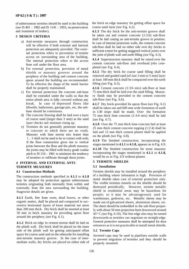
SP 62 ( S & T ) : 1997
of subterranean termites should be used in the building (see IS 401 : 1982 and IS 1141 : 1993, on preservation and treatment of timber).
3 DESIGN CRITERIA
a) Anti-termite measures through construction will be effective if both external and internal protection are adequately provided. The external protection refers to prevention of termite access on surrounding area of the building. The internal protection refers to the access from soil under the floor area.
b) For external protection, provision of metal shields or masonry grooves around the periphery of the building and cement concrete apron around the building are recommended. To be effective the shape of the metal barrier shall be properly maintained.
c) For internal protection the concrete sub-base shall be extended under the walls so that the entire plinth area is fully covered without any break. In case of depressed floors like liftwells, bathrooms, garrage pits, etc, the sub-base should be continuous.
d) The concrete flooring shall be laid over a layer of coarse sand (larger than 3 mm) as the sand layer checks soil moisture rising up.
e) Termites do not generally penetrate masonry or concrete in which there are no voids. Masonry with lime mortar mix leaner than 1 : 3 shall not be used to be in contact with soils. If the floor construction gives rise to vertical joints between the floor and the plinth masonry. the joints may be filled with heavy grade coaltar pitch to IS 216 : 1961 to minimize the tendency of termites to infiltrate through these joints.
4 INTERNAL AND EXTERNAL ANTI-TERMITE MEASURES 4.1 Construction Methods
The construction methods specified in 4.1.1 to 4.1.8 may be adopted for protection against subterranean termites originating both internally from within and externally from the area surrounding the building. Stagewise details are given.
4.1.1 Earth, free from roots, dead leaves, or other organic matter, shall be placed and compacted in successive horizontal layers of loose material not more than 200 mm thick. Dry brick shall be inserted at least 50 mm in brick masonry for providing apron floor around the periphery (see Fig. 6.1).
4.1.2 Brick on edge in cement mortar shall be laid on the plinth wall. Dry brick shall be placed on the inner side of the plinth wall for getting anticipated offset space for coarse sand and on the otherside for installing anti-termite masonry groove. In the case of intermediate walls, dry bricks are placed on either side of
the brick on edge masonry for getting offset space for coarse sand layer (see Fig. 6.2). 4.1.3 The dry brick for the anti-termite groove shall be taken out and cement concrete (1:3:6) sub-floor shall be laid casting an anti-termite groove in position. In case of internal protection walls, the cement concrete sub-floor shall be laid on either side over dry bricks to sufficient extent for getting staggered vertical joints over the joint of plinth wall and earth filling (see Fig. 6.3).
4.1.4 Superstructure masonry shall be raised over the cement concrete sub-floor and overhead jobs completed (see Fig. 6.4). 4.1.5 The dry brick for coarse sand filling shall be removed and graded sand (of size 3 mm to 5 mm) layer at least 100 mm thick shall be compacted over the earth filling (see Fig. 6.5). 4.1.6 Cement concrete (1:3:6 mix) sub-floor at least 75 mm thick shall be laid over the sand filling. Masonry finish may be provided to the cement concrete sub-floor (see Fig. 6.6). 4.1.7 Dry brick provided for apron floor (see Fig. 6.1) shall be taken out and 600 mm wide formation of earth in 1:30 slope shall be made. Over the formation 75 mm thick lime concrete (1:3:6 mix) shall be laid (see Fig. 6.7).
4.1.8 Over the 75 mm thick lime concrete bed at least 25 mm thick cement concrete topping (1:2:4) shall be laid and 12 mm thick cement plaster shall be applied on the plinth (see Fig. 6.8). 4.1.9 The finished construction, incorporating the stages mentioned in 4.1.1 to 4.1.8, appears as in Fig. 6.9. 4.1.10 The finished construction for stone masonry incorporating the stages mentioned in 4.1.1 to 4.1.8, would be as in Fig. 6.9 without plaster.
5 TERMITE SHIELDS
5.1 Installation
Termite shields may be installed around the periphery of a building where infestation is high. Provision of metal shields takes care of external protection only. The visible termites tunnels on the shields should be destroyed periodically. However, termite metallic shield in residential areas may be hazardous for people; so it may be advantageously used for warehouses, godowns, etc. Metallic sheets may be made out of galvanized sheets, aluminium sheets, etc. The sheet should be embedded in the sub-floor properly with about 50 mm projection bent downword around 45° C (see Fig. 6.10). The free edge also may be turned downwards as termites can negotiate on straight edge. General protective measures shall be attempted for door entrances as it is not practicable to install metal shields.
5.2 Termite Caps
Inverted caps may be used in pipelines outside walls to prevent migration of termites and they should be properly mounted.
126
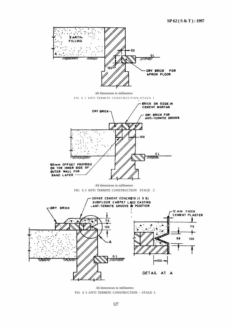
SP 62 ( S & T ) : 1997
All dimensions in millimetres
FIG 6 3 ANTI TERMITE CONSTRUCTION – STAGE 3
127
All dimensions in millimetres
F I G 6 1 A N T I T E R M I T E C O N S T R U C T I O N - S T A G E 1
All dimensions in millimetres
FIG 6 2 ANTI TERMITE CONSTRUCTION STAGE 2
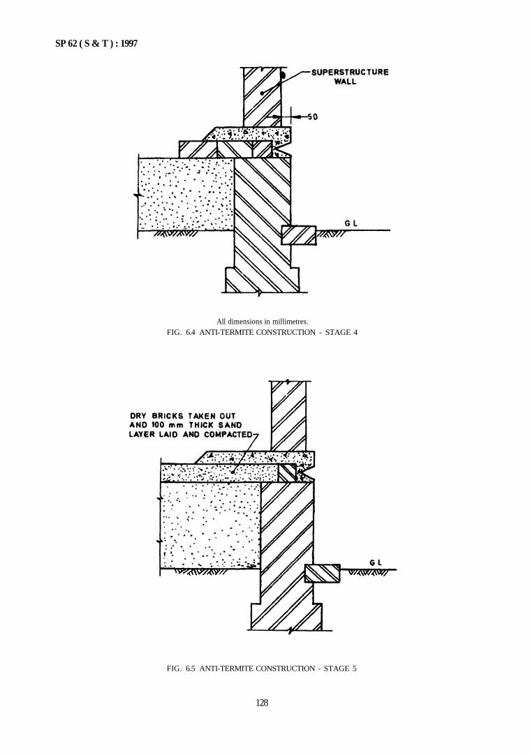
SP 62 ( S & T ) : 1997
FIG. 6.5 ANTI-TERMITE CONSTRUCTION - STAGE 5
128
All dimensions in millimetres FIG. 6.4 ANTI-TERMITE CONSTRUCTION - STAGE 4
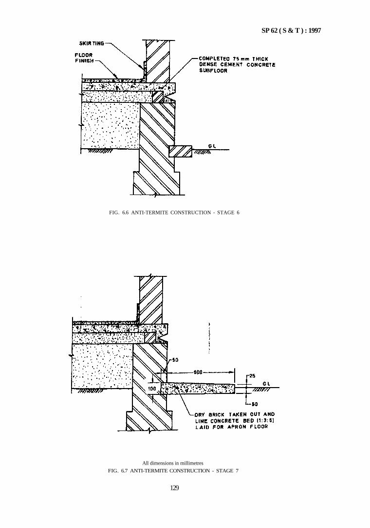
SP 62 ( S & T ) : 1997
FIG. 6.6 ANTI-TERMITE CONSTRUCTION - STAGE 6
All dimensions in millimetres
FIG. 6.7 ANTI-TERMITE CONSTRUCTION - STAGE 7
129
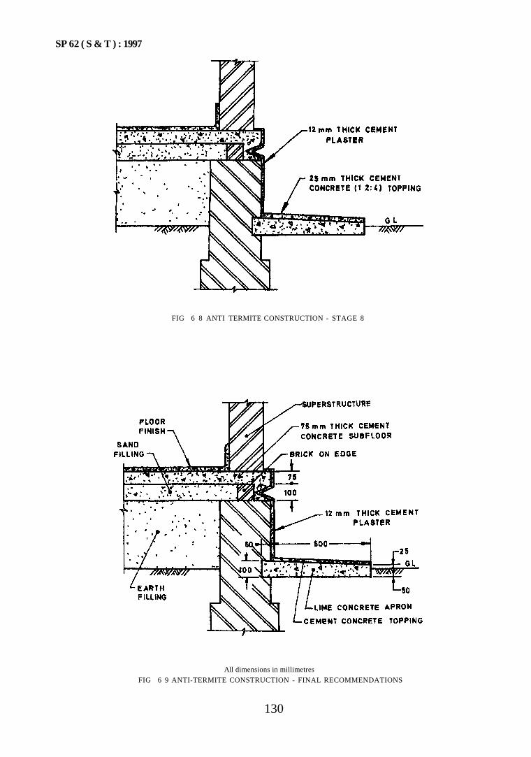
SP 62 ( S & T ) : 1997
FIG 6 8 ANTI TERMITE CONSTRUCTION - STAGE 8
All dimensions in millimetres
FIG 6 9 ANTI-TERMITE CONSTRUCTION - FINAL RECOMMENDATIONS
130
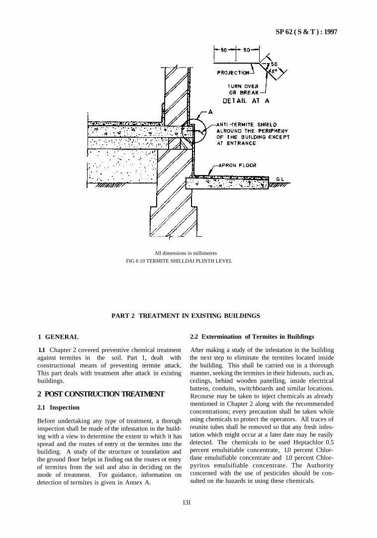
SP 62 ( S & T ) : 1997
All dimensions in millimetres
FIG 6 10 TERMITE SHILLDAI PLINTH LEVEL
PART 2 TREATMENT IN EXISTING BUILDINGS
1 GENERAL
1.1 Chapter 2 covered preventive chemical treatment against termites in the soil. Part 1, dealt with constructional means of preventing termite attack. This part deals with treatment after attack in existing buildings.
2 POST CONSTRUCTION TREATMENT
2.1 Inspection
Before undertaking any type of treatment, a thorogh inspection shall be made of the infestation in the building with a view to determine the extent to which it has spread and the routes of entry ot the termites into the building. A study of the structure ot toundation and the ground floor helps in finding out the routes ot entry of termites from the soil and also in deciding on the mode of treatment. For guidance, information on detection of termites is given in Annex A.
2.2 Extermination of Termites in Buildings
After making a study of the infestation in the building the next step to eliminate the termites located inside the building. This shall be carried out in a thorough manner, seeking the termites in their hideouts, such as, ceilings, behind wooden panelling, inside electrical battens, conduits, switchboards and similar locations. Recourse may be taken to inject chemicals as already mentioned in Chapter 2 along with the recommended concentrations; every precaution shall be taken while using chemicals to protect the operators. All traces of reunite tubes shall be removed so that any fresh infestation which might occur at a later date may be easily detected. The chemicals to be used Heptachlor 0.5 percent emulsitiable concentrate, 1.0 percent Chlor-dane emulsifiable concentrate and 1.0 percent Chlor-pyritos emulsifiable concentrate. The Authority concerned with the use of pesticides should be consulted on the hazards in using these chemicals.
131
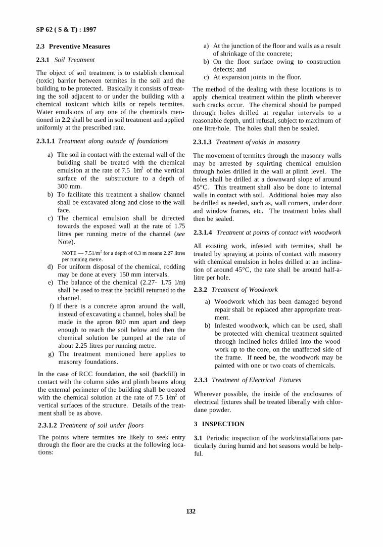
SP 62 ( S & T) : 1997
2.3 Preventive Measures
2.3.1 Soil Treatment
The object of soil treatment is to establish chemical (toxic) barrier between termites in the soil and the building to be protected. Basically it consists of treating the soil adjacent to or under the building with a chemical toxicant which kills or repels termites. Water emulsions of any one of the chemicals mentioned in 2.2 shall be used in soil treatment and applied uniformly at the prescribed rate.
2.3.1.1 Treatment along outside of foundations
a) The soil in contact with the external wall of the building shall be treated with the chemical emulsion at the rate of 7.5 1/m2 of the vertical surface of the substructure to a depth of 300 mm.
b) To facilitate this treatment a shallow channel shall be excavated along and close to the wall face.
c) The chemical emulsion shall be directed towards the exposed wall at the rate of 1.75 litres per running metre of the channel (see Note).
NOTE — 7.51/m2 for a depth of 0.3 m means 2.27 litres per running metre.
d) For uniform disposal of the chemical, rodding may be done at every 150 mm intervals.
e) The balance of the chemical (2.27- 1.75 1/m) shall be used to treat the backfill returned to the channel.
f) If there is a concrete apron around the wall, instead of excavating a channel, holes shall be made in the apron 800 mm apart and deep enough to reach the soil below and then the chemical solution be pumped at the rate of about 2.25 litres per running metre.
g) The treatment mentioned here applies to masonry foundations.
In the case of RCC foundation, the soil (backfill) in contact with the column sides and plinth beams along the external perimeter of the building shall be treated with the chemical solution at the rate of 7.5 1/m2 of vertical surfaces of the structure. Details of the treatment shall be as above.
2.3.1.2 Treatment of soil under floors
The points where termites are likely to seek entry through the floor are the cracks at the following locations:
a) At the junction of the floor and walls as a result of shrinkage of the concrete;
b) On the floor surface owing to construction defects; and
c) At expansion joints in the floor.
The method of the dealing with these locations is to apply chemical treatment within the plinth wherever such cracks occur. The chemical should be pumped through holes drilled at regular intervals to a reasonable depth, until refusal, subject to maximum of one litre/hole. The holes shall then be sealed.
2.3.1.3 Treatment of voids in masonry
The movement of termites through the masonry walls may be arrested by squirting chemical emulsion through holes drilled in the wall at plinth level. The holes shall be drilled at a downward slope of around 45°C. This treatment shall also be done to internal walls in contact with soil. Additional holes may also be drilled as needed, such as, wall corners, under door and window frames, etc. The treatment holes shall then be sealed.
2.3.1.4 Treatment at points of contact with woodwork
All existing work, infested with termites, shall be treated by spraying at points of contact with masonry with chemical emulsion in holes drilled at an inclination of around 45°C, the rate shall be around half-a-litre per hole.
2.3.2 Treatment of Woodwork
a) Woodwork which has been damaged beyond repair shall be replaced after appropriate treatment.
b) Infested woodwork, which can be used, shall be protected with chemical treatment squirted through inclined holes drilled into the woodwork up to the core, on the unaffected side of the frame. If need be, the woodwork may be painted with one or two coats of chemicals.
2.3.3 Treatment of Electrical Fixtures
Wherever possible, the inside of the enclosures of electrical fixtures shall be treated liberally with chlor-dane powder.
3 INSPECTION
3.1 Periodic inspection of the work/installations particularly during humid and hot seasons would be helpful.
132
SP 62 ( S & T ) : 1997
A N N E X A
(Clause 2.1)
GUIDE FOR TERMITE DETECTION
A-1 PROCEDURE
A-1.1 Bright light is essential for termite detection. A bright hand-held electric bulb (in a fixture) or a torch would be necessary.
A-1.2 Portions of the building in contact with or adjacent to soil should be inspected. Damp locations, such as, bathrooms, etc, shall also be inspected. Points where woodwork is embedded in the floor, in particular, shall be examined.
A-1.3 The signs of presence of termites is through the tell tale tubes. Termites travel in these and are supposed to eataway woodwork leaving the film of paint on the surface, making it difficult to locate the termite. Woodwork should be tapped to check hollow sound which would indicate termite attack. The new tubes of termites are moist; the old ones are dry and break easily. These must be gouged out with a knife to destroy the termites.
133


CHAPTER 7
DOORS AND WINDOWS (WOOD AND METAL)
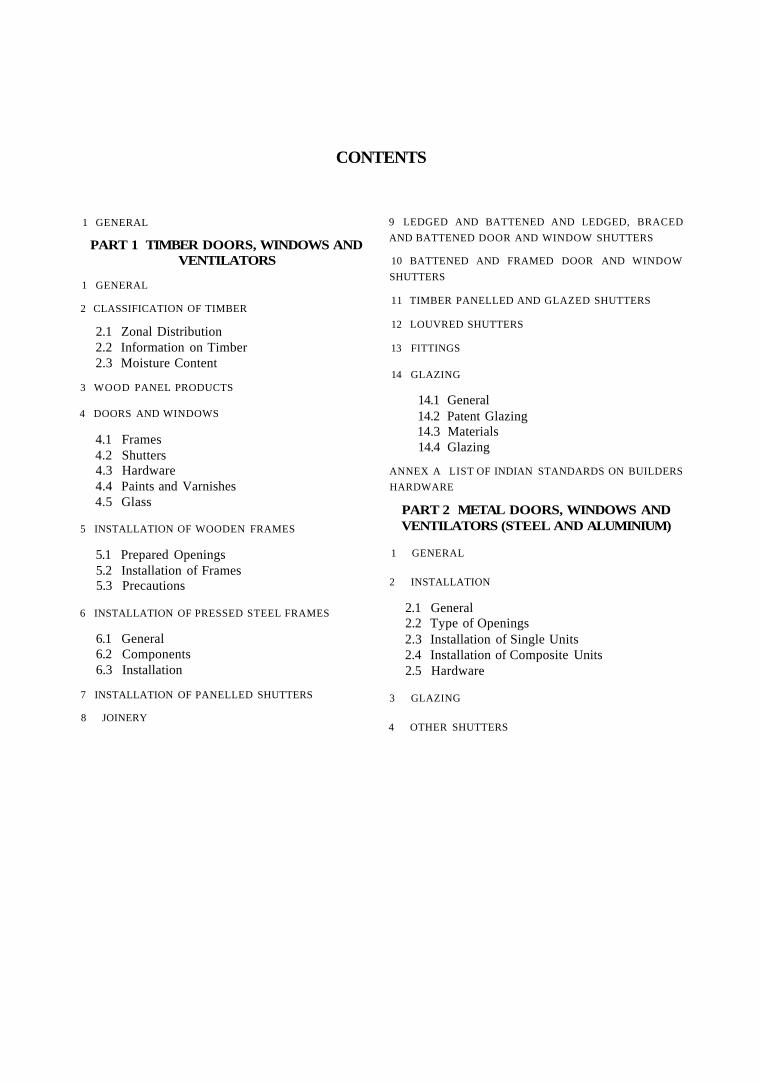
CONTENTS
1 GENERAL
PART 1 TIMBER DOORS, WINDOWS AND VENTILATORS
1 GENERAL
2 CLASSIFICATION OF TIMBER
2.1 Zonal Distribution 2.2 Information on Timber 2.3 Moisture Content
3 WOOD PANEL PRODUCTS
4 DOORS AND WINDOWS
4.1 Frames 4.2 Shutters 4.3 Hardware 4.4 Paints and Varnishes 4.5 Glass
5 INSTALLATION OF WOODEN FRAMES
5.1 Prepared Openings 5.2 Installation of Frames 5.3 Precautions
6 INSTALLATION OF PRESSED STEEL FRAMES
6.1 General 6.2 Components 6.3 Installation
7 INSTALLATION OF PANELLED SHUTTERS
8 JOINERY
9 LEDGED AND BATTENED AND LEDGED, BRACED
AND BATTENED DOOR AND WINDOW SHUTTERS
10 BATTENED AND FRAMED DOOR AND WINDOW
SHUTTERS
11 TIMBER PANELLED AND GLAZED SHUTTERS
12 LOUVRED SHUTTERS
13 FITTINGS
14 GLAZING
14.1 General 14.2 Patent Glazing 14.3 Materials 14.4 Glazing
ANNEX A LIST OF INDIAN STANDARDS ON BUILDERS
HARDWARE
PART 2 METAL DOORS, WINDOWS AND VENTILATORS (STEEL AND ALUMINIUM)
1 GENERAL
2 INSTALLATION
2.1 General 2.2 Type of Openings 2.3 Installation of Single Units 2.4 Installation of Composite Units 2.5 Hardware
3 GLAZING
4 OTHER SHUTTERS
SP 62 ( S & T ) : 1997
CHAPTER 7
DOORS AND WINDOWS (WOOD AND METAL) 1 GENERAL
In this chapter doors and windows made of wood and
metal (steel and aluminium) are dealt with. Pan 1 deals with timber doors and windows. Part 2 deals with metal doors and windows.
PART 1 TIMBER DOORS, WINDOWS AND VENTILATORS
1 GENERAL
1.1 Timber generally used in buildings are either of solid timber or panel products like plywood, particle board, etc. The major use is in door and window frames and their shutters, furniture and the like. It is also used in structures specially in hilly regions where timber is abundantly available and other common building materials like brick are not easy to come by.
1.2 India has around two hundred species of commer cial timber grown in different parts of the country. Tor quite sometime timber was transported over long distances for some specific services even when species suitable for the purpose would be secured from nearby sources. The reason apparently appears to be the misconception that in timber there are primary species (teak) and secondary species. No such classification exists and it is a misnomer. All species can be used, only each species has different end use. Some species are even stronger in cumulative properties than teak IS 399:1963 classifies commercial timber and their distribution in India along with different end uses. Therefore it is necessary to check locally available timber for building purposes before specifying the species for woodwork.
1.3 Moisture content is an important requirement for use of timber in woodwork. Moisture content affects its workability, size, etc. The moisture content ot timber changes from season to season depending on atmospheric humidity. The application of a finish (paint or varnish) reduces the change in moisture content with changes in humidity in the atmosphere. IS 287 : 1993 governs the recommendations for maximum permissible moisture content for timber used for different purposes.
1.4 For actual end use seasoning and treatment of timber are necessary. Seasoning will help in the control of moisture and it should be done as per IS 1141 : 1993; and preservation as per IS 401 : 1982.
2 CLASSIFICATION OF TIMBER
2.1 Zonal Distribution
IS 399 : 1963 details the zonal distribution of common commercial and timber of India, classified according to their various end uses and gives information on availability and on some of the other properties of these timbers. The uses, include:
a) Constructional purposes, including building construction, piles, bridges, poles, railway sleepers, etc; and
b) Furniture and cabinet making.
India is divided into five zones lor convenience in tabulating the information on timber. The zones are:
Zone 1 — Jammu & Kashmir, Punjab, Himachal Pradesh, Uttar Pradesh, Haryana and Rajasthan.
Zone 2 - Assam, Manipur, Tripura, West Bengal. Bihar, Orissa, Mizoram, Arunachal Pradesh, Nagaland, Sikkim, Bhutan, Andamans.
Zone 3 — Madhya Pradesh, Vidharbha areas of Maharashtra and north east part of Andhra Pradesh (Godavari Delta area).
Zone 4 — Maharashtra (except Vidharbha area), Gujarat, and north west part of Kar-nataka.
Zone 5 - Tamil Nadu, Pondicherry, Andhra Pradesh (except Godavari Delta area), Kerala and Karnataka (except north west part)
2.2 Information on Timber
Tables in IS 399 : 1963 give information on the following aspects of timbers available in these zones.
a) Availability — Availability of commercial timber is categorized under three classes as
137
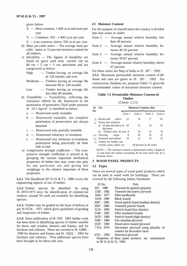
SP 62 (S & T) : 1997
given below: X — Most common, 1 400 cu.m and more per
year Y — Common, 350 - 1 400 cu.m per year Z — Less common, below 350 cu.m per year.
b) Mass per cubic metre — The average mass per cubic metre at 12 percent moisture content for all timbers.
c) Durability — The figures of durability are based on grave yard tests carried out on 60 cm × 5 cm × 5 cm specimens and are categorized as below: High — Timber having, an average life
of 120 months and over Moderate — Timbers having an average life
between 60 to 120 months Low — Timber having an average life
less than 60 months. d) Treatability — Treatability, reflecting the
resistance offered by the heartwood to the penetration of preserativc fluid under pressure of 10.5 kg/cm2 is classified as below: a — Heartwood easily treatable b — Heartwood treatable, but complete
penetration of preservative not always obtained
c — Heartwood only partially treatable d — Heartwood refractory to treatment e — Heartwood very refractory to treatment,
penetration being practically nil from side or end
e) Compressive strength coefficient — The compressive strength coefficient is arrived at by grouping the various important mechanical properties of timber that may come into play for any particular use and giving due weightage to the relative important of these properties.
2.2.1 The Handbook SP 33 (S & T) : 1986 covers the engineering aspects of use of timber.
2.2.2 Timber species be identified by using IS 4970:1973 keys for identification of commercial timbers; around 50 cards are available for identifying species.
2.2.3 Timber may be graded on the basis of defects as per IS 6534 : 1971 which gives guidelines of grading and inspection of timber.
2.2.4 Since publication of IS 399: 1963 further work has been done in identifying species of timber suitable for doors and window shutters and frames; and for furniture and cabinets. These are covered in IS 12896 : 1990 for shutters and frames and IS 13622 : 1993 for furniture and cabinets. Thus additional species have been brought in for these end uses.
23 Moisture Content
For the purpose of classification the country is divided into four zones as under: Zone 1 — Average annual relative humidity less
than 40 percent Zone 2 — Average annual relative humidity be
tween 40-50 percent Zone 3 — Average annual relative humidity be
tween 50-67 percent Zone 4 — Average annual relative humidity above
67 percent. For these zones see Map of India in IS 287 : 1993. 2.3.1 Maximum permissible moisture content of different end uses are given in IS 287 : 1993. For construction, furniture, etc, purposes Table 7.1 gives the recommended values of maximum moisture content.
Table 7.1 Permissible Moisture Content of Timber
(Clause 2.3.1)
NOTE — The moisture content is determined within a depth of 12 mm from the surface excluding 30 cm from each end, by a moisture meter
3 WOOD PANEL PRODUCTS
3.1 Types
There are several types of wood panel products which can be used in wood work for buildings. These are covered by the following Indian Standards:
IS No. Title 303 . 1989 Plywood for general purposes 1328 : 1982 Veneered decorative plywood 1658 : 1977 Fibre hardboards 1659: 1990 Block boards 3087 : 1985 Wood particle board (medium density) 3097 . 1980 Veneered particle boards 3129 : 1985 Particle board (low density) 3348 : 1965 Fibre insulation boards 3478 : 1966 Particle boards (high density) 5509 : 1980 Fire retardant plywood 5539 : 1969 Preservative treated plywood 7316: 1974 Decorative plywood using plurality of
veneers for decorative faces 6701 : 1983 Structural plywood
Properties of these panel products are summarized in SP 21 (S & T) : 1983.
138
Sl No.
i) i i )
iii)
iv)
v)
Use Moisture Content, Max
Zone 1
Beams and rafters 12 Doors and windows a) 50 mm and above in 10
thickness b) Thinner than 50 mm 8 Flooring strips 8 Furniture and cabinet 10 Timber for further conversion, pasts, poles, etc
Zone 2
14
12
10 10 12
Zone 3
17
14
12 10 14
Zone 4
20
16
14 12 15
20 percent in all zones
SP 62 (S & T) : 1997
4 DOORS AND WINDOWS
4.1 Frames
Quite often doors which are factory made have to be adjusted with regard to dimensions of openings. Therefore, co-ordination among dimensions of shutters would he of great use. For larger benefit modular co-ordination is desirable. Installation practices have to be suitably adjusted so as to achieve satisfactory work within the tolerances specified.
4.1.1 Timber frames for doors and windows shall conform to IS 4021 : 1983. For permanent door frames Group 1 Timber shall be used (see IS 12890 : 1990). For temporary frames Group II and 111 can be used. Same species shall be used for rails and stiles; solid wood panels may be of any other specie. Steel door frames to receive wooden shutters shall conform to IS 4351 : 1976.
4.2 Shutters
Shutters can be of several kinds as below:
a) Timber panelled and glazed shutters shall conform to IS 1003 (Part 1) . 1991 for doors and to IS 1003 (Part 2) : 1983 for windows.
b) Wooden flush door shutters shall conform lo IS 2191 (Part 1) . 1983 with plywood face panels (cellular and hollow core) and to IS 2191 (Part 2) : 1983 for particle board and hard board face panels (cellular and hollow core). Wooden flush door shutters shall conform to IS 2202 (Part 1) : 1991 plywood face panels (solid core); and to IS 2202 (Part 2): 1983 tor particle board face panels and hard board face panels (solid core).
c) Wooden sliding doors shall conform to IS 4962: 1968.
d) Ledged, Braced and Battened Doors shall conform to IS 6198 : 1992.
4.3 Hardware
Door and window hardware shall meet the requirements of relevant Indian Standards (see 13).
a) Each wooden door shutter shall have a minimum of three hinges and two fastenings like tower bolt, hasp and staple, mortice lock, etc Floor stoppers, handles, hydraulic door closers, kick plate, etc, are optional.
b) Each window shutter shall have a minimum of three hinges and one fastening like tower bolt and one handle for opening and closing. Additional fastenings or tower bolts may be optional.
c) Selection of hardware shall depend on economy desired and climatic conditions, such as, exposure to sea wind in coastal areas, etc.
d) The material of the hardware may be mild steel, brass, oxidized iron, anodized aluminium, etc.
4.4 Paints and Varnishes
White lead primer paint, aluminium or other primer, wood tiling putty, ready mixed paints, varnishes, polishes and all other materials shall conform to relevant Indian Standards (see Chapter 15).
4.5 Glass
Sheet glass used for glazing shall conform to IS 2835 : 1987 or IS 2553 (Part 1). 1990 or IS 5437 : 1969. Other glasses like frosted glass, coloured glass, etc, may also be used (see 14 for glazing).
5 INSTALLATION OF WOODEN FRAMES
5.1 Prepared Openings
Installation into prepared openings shall be preferred (see 5.3); the advantage being that the frame is less liable to distortion and moisture changes.
5.2 Installation of Frames
Door frame shall be installed at the required place and each door frame shall be provided with three holdfasts on either side; one each at top and bottom 30 cm away from the edge and one in the middle. Masonry or concrete in the wall shall be built after installation of doors so that holdfasts and pins at the bottom are anchored into them. Before construction of masonry, the outside of frames coming in contact with masonry shall be given a thick coat of coal tar or other water proofing paint Suitable arrangements shall be made to hold the frames in rectangular shape during con-struction. Usually one cross batten at the middle and one cross batten at the bottom (no sill for the door) and two cross battens diagonally will be necessary to hold the frame in rectangular shape.
Window frames shall be installed in the same manner as door frames, except that at least two holdfasts shall be provided. The size of the opening shall be checked.
To ensure that the units are set at the appropriate levels a datum line for the sill of the door, window or ventilator shall be taken from a fixed point on the wall or from the finishes of the floor or ceiling.
Alternatively, in a prepared opening, the fixing of the door frame may be flush or rebated as per drawings. The clearence between the frame and opening shall be kept depending on whether the opening is externally rendered or fair faced. The frame shall be checked before fixing in the positions that the same is square and in the proper position. The holdfast openings and the bottom pin shall be grouted. Plastering of the sides
139
SP 62 ( S & T ) : 1997
shall be done and allowed to dry before the door window or ventilator shutters are fixed.
5.3 Precautions
Precautions shall be taken to fix the door frame so as to take care of the final floor level and also the following points:
a) Whether the shutters are inside opening or outside opening, and
b) Whether the frames are for exterior use or interior use.
6 INSTALLATION OF PRESSED STEEL FRAMES
6.1 General
Each door frame shall consist of hinge jamb, lock jamb, head and if required angle thresh hold. The whole shall be welded or rigidly fixed together by mechanical means. Where no threshold is required, temporary base tie shall be screwed to the feet of the frames in order to form a rigid unit.
6.2 Components
Base ties, fittings, such as, hinges, fixing lugs, mortar guards, lock-strike plate and sheet absorbers shall be as per IS 4351 : 1976.
6.3 Installation
Pressed steel door frames are ideally suited for built-in; while fixing the following instructions shall be followed:
1) Place the door in position at correct height from the finished floor level.
2) Plumb to ensure that the frame is upright, square and free from twists.
3) Pressed steel door frames are liable to develop bow in heights or sag in the width either during fixing or during subsequent building work. To aovid this fix temporary struts across the width, preventing sides bulging inwards by weight of wall or partitions.
4) Build the walls up solid or each side and grout each course so as to make solid contact with the frame leaving no voids.
5) Three lugs shall be provided on each jamb and the lugs shall not be placed more than 75 cm apart.
6) Do not remove temporary struts till brickwork is set.
7) In case screwed base tie is provided, leave it in position until floor is laid when it shall be removed.
7 INSTALLATION OF PANELLED SHUTTERS
7.1 Before installation of shutters, it shall be ascertained that the shutters, hardware, etc, are of the right
size and quality. The size of openings and the door frames shall be checked along with the verticality of the side frames, level position of the floor and the wall. Adjustment any, if necessary, shall be done before the installation of the shutters. The shutter shall be installed only after the walls have dried.
7.2 Any defects in storage should be rectified, unless otherwise specified door shutters shall be fixed to the frames with 100 mm (or appropriate) long hinges. In driving screws in hard timbers, pilot holes be driven before fixing the screws. The door shutters shall be checked again after installation.
7.3 All fixtures shall then be fixed on the shutters and checked for preference.
7.4 Glazed panels, where required, should be fixed making sure that the correct size of glass panels are used.
7.5 Flush doors, when used in bathrooms, shall be protected at the bottom (inside) with 15 cm higlrshcet of aluminium or plastic.
7.6 Where combination of doors, windows and ventilators is desired, care shall be taken that the symmetry of combination both as to dimension, colour and fixture is preserved.
7.7 Wooden doors, shutters, etc, shall be finished as given in Chapter 15 on finishes.
8 JOINERY
8.1 Joinery work may be started immediately after commencement of building work. All pieces shall be accurately cut and planed smooth to full dimensions without any patching or plugging of any kind. Rebates, rounding and moulding as shown in drawings shall be made before assembling. The thickness of stiles and rails shall be as specified for the shutters.
8.2 All members of door shutters shall be straight without any warp or bow and shall have smooth well planed faces at right angles to each other. The corners and edges of panels shall be finished as shown in drawings and these shall be feather tongued into stiles and rails. Sash bars shall have mitered joints with stiles. Stiles and rails shall be properly and accurately mortised and tenoned. Rails which are more than 180 mm in width shall have two tenons. Stiles and rails of shutters shall be made out of one piece only. The tenons shall pass through the stiles for at least three-fourths of the width of the stile. When assembling a leaf, stiles shall be left projecting as a horn. The stiles and rails shall have 12 mm groove in panelled portion for the panel to fit in.
8.3 The depth of rebate in frames for housing the shutters shall in all cases be 1.25 cm and the rebate in shutters for closing in double shutter door or window shall be not less than 2 cm. In the case of double leaved
140
SP 62 ( S & T ) : 1997
shutters, the meeting of the styles shall be rebated 20 mm. The rebate shall be splayed.
8.4 The joints shall be pressed and secured by bamboo hardwood pins of about 6 mm diameter. The horn of the stiles shall be sawn off.
8.5 The finished work shall have a tolerance of ± 1 mm in thickness and ± 2 mm in width of stiles and rails.
8.6 The contact surfaces of tenon and mortise joints shall be treated before putting together with bulk type synthetic resin additive. The shutters shall not be painted, oiled or otherwise treated, before these are fixed in position. Mounting and glazing bars shall be sub-tenoned to the maximum depth which the size of the member would permit or to a depth of 25 mm whichever is greater. The thickness of each tenon shall be approximately one-third of the finished thickness of the members and the width of each tenon shall not exceed five times the thickness.
8.7 Beading for panels may be provided on one or both sides for fixing wooden panel products.
8.8 For fixing glass and absestos panels, headings with grooves shall be provided; where beading is provided without grooves, the beading shall be on one
side only. The other side being supported by the rebate from the stiles. For external doors and windows the beading shall be fixed on the outside.
8.9 For fixing glazing, the glass shall be embedded in putty and secured to the rebate by wooden beads of suitable size and shape. Wash leather, ribbon velvet, rubber flannel, felt, abscstos or other similar material may be used in place of putty for internal glazing. The material shall be fitted either as a beading on one side or in such a manner that it covers all parts of the glass which will be covered by beading (sec also 14).
If glazing compound or putty are not to be used recourse may be taken to patent glazing as per IS 10439 : 1983. The term 'patent glazing' is applied to those forms of glazing that rely on their efficiency upon some means of collecting and removing water in channels or grooves incorporated in the glazing bar as distinct from putty or other glazing compounds. For more details refer to IS 10439 : 1983.
8.10 Wooden cleats and blocks, for fixing locks, shall be provided as decided by the Authority.
8.11 Figures 7.1 to 7.4 give typical details of joinery.
FIG. 7.1 TYPICAL ILLUSTRATIONS OF TENON AND HAUNCHED TENON IN JOINERY
141
i
7.1 A Single Tenon In Top Rail 7.1B Haenched Single Tenon in Top Rail
7.1C Double Tenon in Lock Rail 7.1 D Haunchud Double Tenon in Bottom Rail
SP 62 ( S & T ) : 1997
7.2A Single-Haunched Tenon on a Top Rail
7.2B Middle or Lock Rail with Pair of Single Tenon and Haunch in Centre
7.2C Pair of Single-Haunched Tenon on Bottom Rail
FIG. 7.2 TYPICAL ILLUSTRATIONS OF TENON AND HAUNCHED TENON IN JOINERY (ALTERNATE FIGURE)
142
SP 62 ( S & T ) : 1997
FIG. 7.3 COMMON METHODS OF JOINTING PANELS WITH STILLS AND RAILS WITH/WITHOUT BEADING
NOTE - t = Thickness of shutter
FIG. 7.4 MEETING OF STILES FOR DOUBLE-LEAVED DOOR SHUTTERS
9 LEDGED AND BATTENED AND LEDGED, BRACED AND BATTENED DOOR AND WINDOW SHUTTERS
9.1 Timber specified for ledges, bracing and battens should be used and sawn in the direction of grains Sawing shall be fully straight and square. The timber shall be planed smooth and accurate to the full dimensions, rebated, roundings and mouldings as in drawings, before assembly. Patching and plugging shall not be permitted except as provided. The thickness of the doors shall be the thickness of battens only and not the combined thickness of battens and braces.
9.2 Planks shall be 20 mm thick unless otherwise specified and of uniform width of 75 mm to 100 mm.
These shall be planed and made smooth and provided
with minimum 12 mm rebated joints. The finished work with a tolerance of ±1 mm in thickness and ±2 mm in width of battens, ledges, etc. The ends ot battens shall be feather tongued into styles and rails which shall be provided with a 12 mm grove to fit battens.
9.3 The battens shall be fixed together by 25 mm thick ledges and braces to the inside face of door shutters with screws. The ledge shall be 175 mm wide and brace 125 mm wide unless otherwise specified. The braces shall incline down towards the side on which the door is hung as shown in Fig. 7.5. Edges and ends of ledges and braces shall be chamfered. Tee hinges shall be provided in ledges only. The finished work shall be with a tolerance ot ±1 mm in thickness and ± 2 mm in width of battens ledges etc.
143
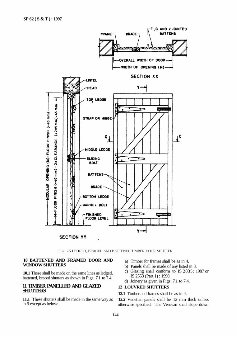
SP 62 ( S & T ) : 1997
FIG. 7.5 LEDGED, BRACED AND BATTENED TIMBER DOOR SHUTTER
10 BATTENED AND FRAMED DOOR AND WINDOW SHUTTERS
10.1 These shall be made on the same lines as ledged, battened, braced shutters as shown in Figs. 7.1 to 7.4.
11 TIMBER PANELLED AND GLAZED SHUTTERS
11.1 These shutters shall be made in the same way as in 9 except as below:
a) Timber for frames shall be as in 4. b) Panels shall be made of any listed in 3. c) Glazing shall conform to IS 2835: 1987 or
IS 2553 (Part 1) : 1990. d) Joinery as given in Figs. 7.1 to 7.4.
12 LOUVRED SHUTTERS 12.1 Timber and frames shall be as in 4. 12.2 Venetian panels shall be 12 mm thick unless otherwise specified. The Venetian shall slope down
144
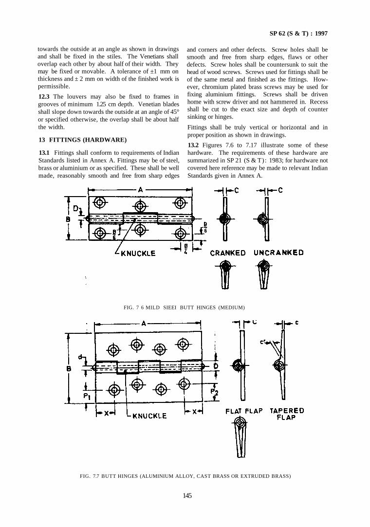
SP 62 (S & T) : 1997
towards the outside at an angle as shown in drawings and shall be fixed in the stiles. The Venetians shall overlap each other by about half of their width. They may be fixed or movable. A tolerance of ±1 mm on thickness and ± 2 mm on width of the finished work is permissible.
12.3 The louvers may also be fixed to frames in grooves of minimum 1.25 cm depth. Venetian blades shall slope down towards the outside at an angle of 45° or specified otherwise, the overlap shall be about half the width.
13 FITTINGS (HARDWARE)
13.1 Fittings shall conform to requirements of Indian Standards listed in Annex A. Fittings may be of steel, brass or aluminium or as specified. These shall be well made, reasonably smooth and free from sharp edges
and corners and other defects. Screw holes shall be smooth and free from sharp edges, flaws or other defects. Screw holes shall be countersunk to suit the head of wood screws. Screws used for fittings shall be of the same metal and finished as the fittings. However, chromium plated brass screws may be used for fixing aluminium fittings. Screws shall be driven home with screw driver and not hammered in. Recess shall be cut to the exact size and depth of counter sinking or hinges.
Fittings shall be truly vertical or horizontal and in proper position as shown in drawings.
13.2 Figures 7.6 to 7.17 illustrate some of these hardware. The requirements of these hardware are summarized in SP 21 (S & T): 1983; for hardware not covered here reference may be made to relevant Indian Standards given in Annex A.
FIG. 7.7 BUTT HINGES (ALUMINIUM ALLOY, CAST BRASS OR EXTRUDED BRASS)
145
FIG. 7 6 MILD SIEEI BUTT HINGES (MEDIUM)
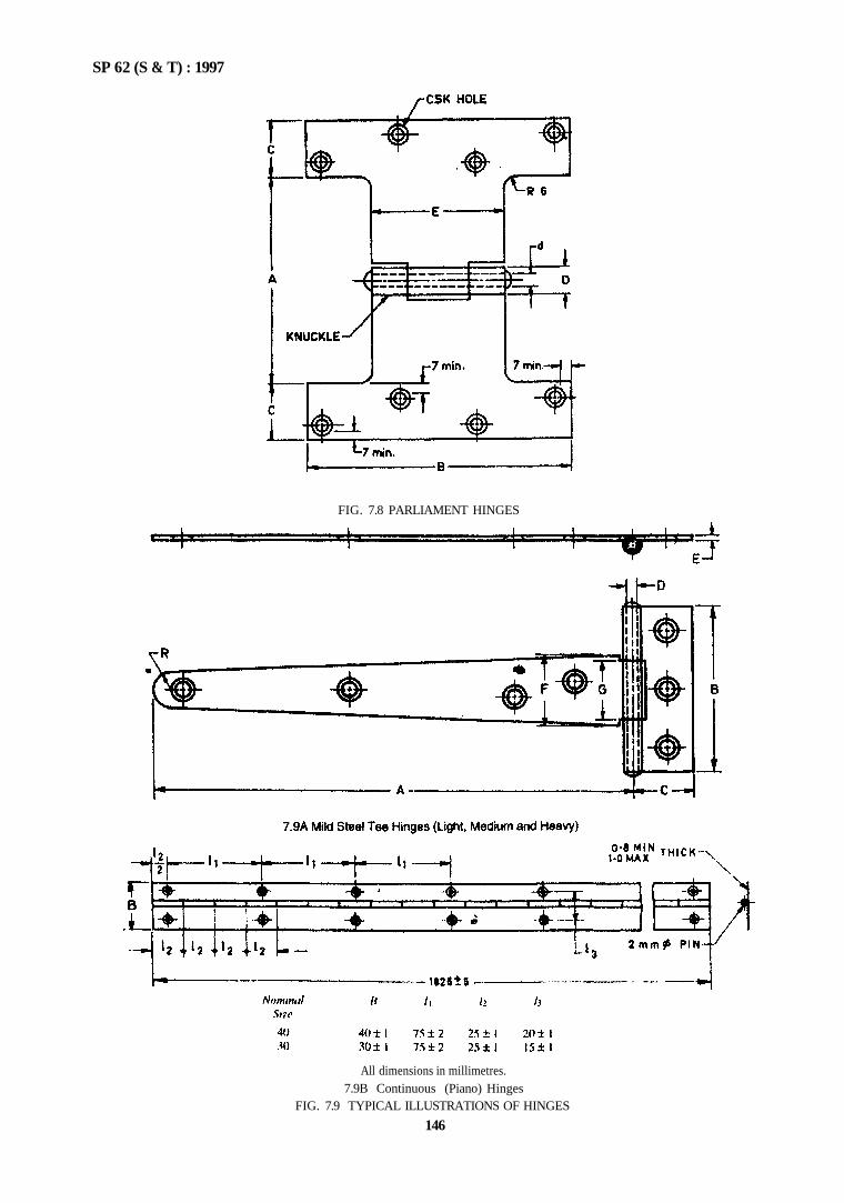
FIG. 7.8 PARLIAMENT HINGES
SP 62 (S & T) : 1997
All dimensions in millimetres. 7.9B Continuous (Piano) Hinges
FIG. 7.9 TYPICAL ILLUSTRATIONS OF HINGES
146
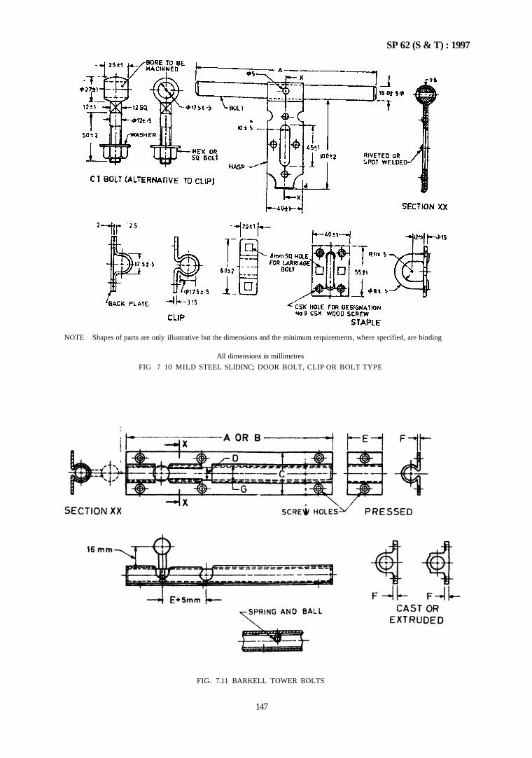
SP 62 (S & T) : 1997
NOTE Shapes of parts are only illustrative but the dimensions and the minimum requirements, where specified, are binding
All dimensions in millimetres
FIG 7 10 MILD STEEL SLIDINC; DOOR BOLT, CLIP OR BOLT TYPE
FIG. 7.11 BARKELL TOWER BOLTS
147
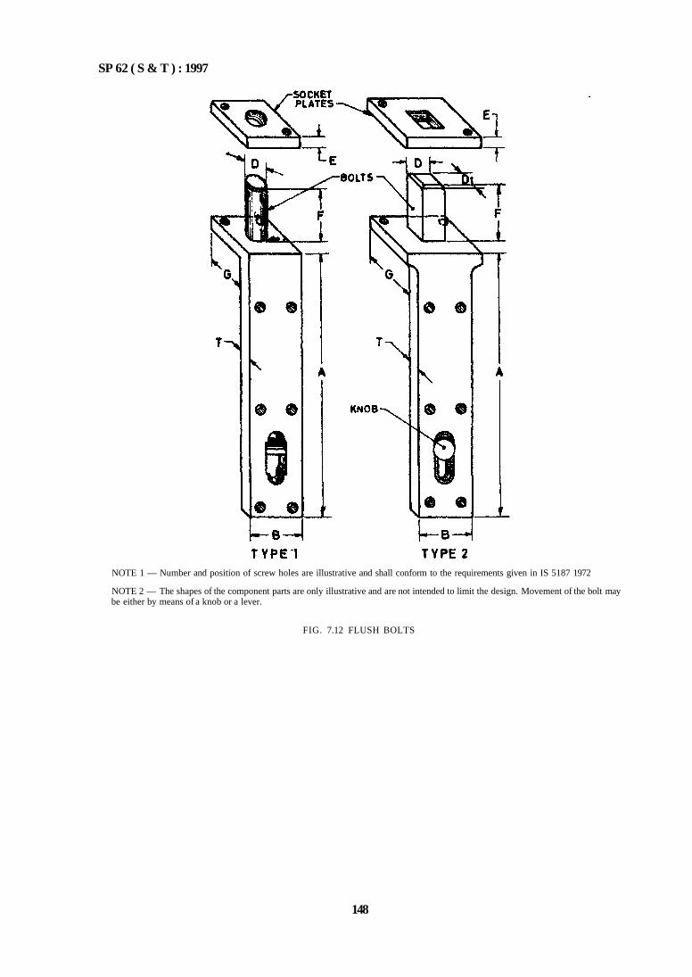
SP 62 ( S & T ) : 1997
NOTE 1 — Number and position of screw holes are illustrative and shall conform to the requirements given in IS 5187 1972
NOTE 2 — The shapes of the component parts are only illustrative and are not intended to limit the design. Movement of the bolt may be either by means of a knob or a lever.
FIG. 7.12 FLUSH BOLTS
148
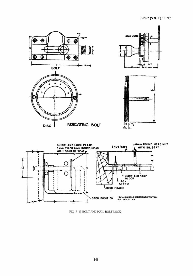
SP 62 (S & T) : 1997
FIG 7 13 BOLT AND PULL BOLT LOCK
149
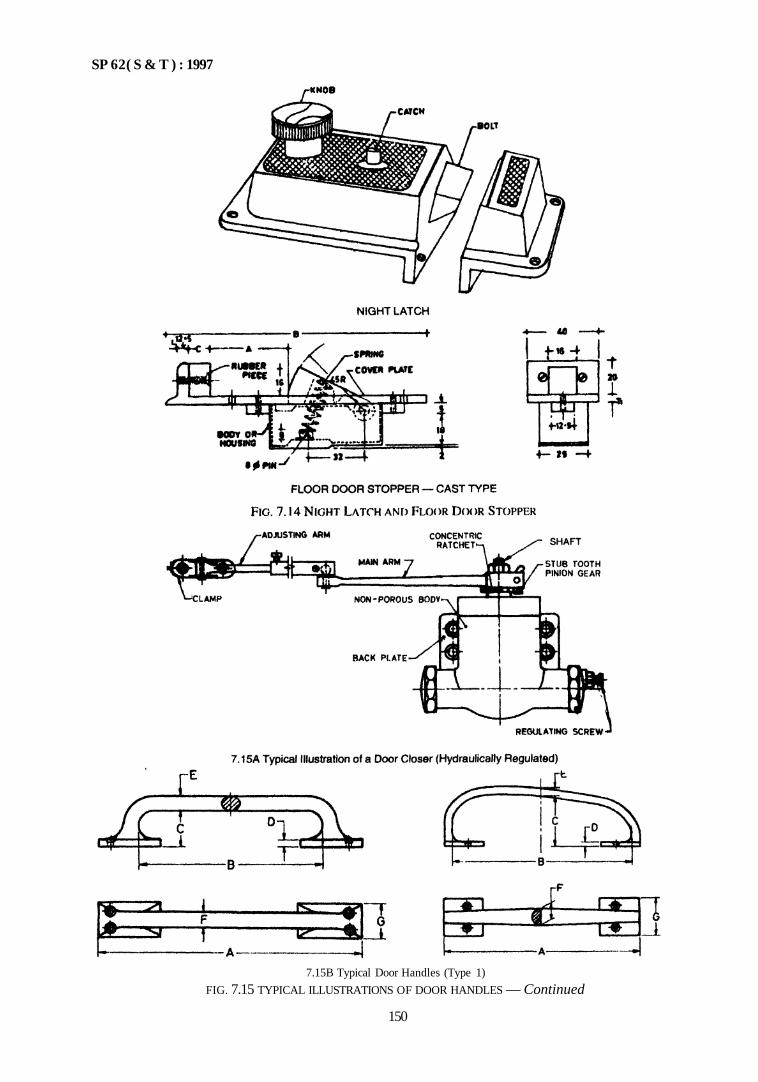
SP 62( S & T ) : 1997
7.15B Typical Door Handles (Type 1)
FIG. 7.15 TYPICAL ILLUSTRATIONS OF DOOR HANDLES — Continued
150
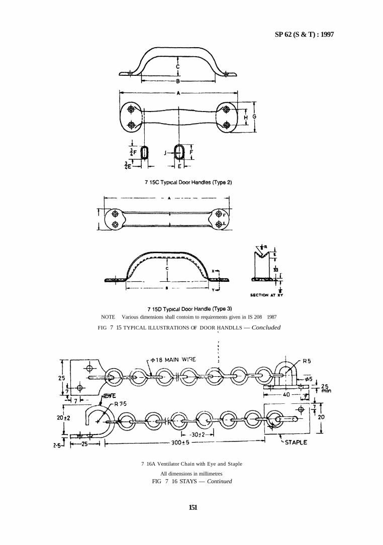
SP 62 (S & T) : 1997
7 16A Ventilator Chain with Eye and Staple
All dimensions in millimetres
FIG 7 16 STAYS — Continued
151
NOTE Various dimensions shall contoim to requirements given in IS 208 1987
FIG 7 15 TYPICAL ILLUSTRATIONS OF DOOR HANDLLS — Concluded
SP 62 (S & T) : 1997
FIG. 7.17 MILD STEEL OR BRASS OR ALUMINIUM ALLOY HASPS AND STAPLES (SAFETY TYPE)
152
FIG. 7.16 STAYS — Concluded
SP 62 (S & T) : 1997
14 GLAZING
14.1 General
Glazing is an important item in building construction and glass has to be selected to cater to several requirements, such as, in multistoreyed buildings, industrial structures, etc. Therefore fixing of glass is a special-ized operation and has to be done carefully; otherwise it will lead to hazards of broken glass Besides the types of glass and exposure conditions have to be taken into account.
14.2 Patent Glazing
As already mentioned, it is covered by IS 10439 1983.
143 Materials
a) The glass shall conform to: 1) IS 2835 : 1977 for sheet glass. 2) IS 2553 : 1990 for safety glass. 3) IS 5437 : 1969 for wired and figured glass.
b) Glazing compound shall conform to: 1) IS 419: 1967 for putty. 2) IS 11433 (Part 1): 1985, IS 11433 (Part 2)
: 1986 for polysulphide based sealants. 3) Compounds for glazing in concrete, stone,
brick or asbestos cement are needed to be sealed to prevent absorption of oil from the glazing compound, unless the compound has been specifically formulated; resistance to alkali is important. A non-setting compound may be used, provided it is pointed.
4) Non-setting compunds are needed for use with colour and heat absorbing glasses which will become hot in sunshine and which are therefore liable to expand and contract much more than ordinary glass. The fact that non-setting compounds are easily finger marked make it undesirable to use them without beads except in rela tively inaccessible situations.
c) The design criteria like thickness, durability, fire resistance, thermal expansion and contraction, light transmission and heat insulation, sound insulation are to be satisfied as per IS 3548 : 1988 on glazing practice.
14.4 Glazing
The size of glass shall allow for a clearance between the edge of glass and surround as specified below
For wood or metal surrounds — 2.5 mm For stone or brick — 3.0 mm
The clearance may be increased, provided the depth of the rebate or groove is sufficient to provide not less than 1.5 mm cover to the glass.
14.4.1 Rebates and Grooves
Rebates shall be rigid and true. The rebates shall be as follows:
— 6 mm for small panes.
— 8 mm for normal panes.
— 10 mm at tops and sides and 12 mm at bottom for large windows, such as, shop windows.
— 16 mm deep for double or multiple glazed seal units, unless otherwise advised by the manufacturer.
- A wider rebate is required for bent glass than for flat glass, rebate for flat glass without beads shall be enough to accommodate the back putty, the glass and front putty stripped at an angle.
- For glazing with beads rebates shall be wide enough to accommodate glass and beads and to allow a minimum clearance of 1.5 mm at both back and front of the glass.
— - Rebates and grooves shall be clean and unobstructed before glazing.
14.4.2 Location of Glass in Frame (see Fig. 7.18)
a) The glass shall rest on two blocks to locate the pane properly within the surround. In case of small panes, the blocks may not be necessary, when glazing in side-hung windows or door, the glass shall be located by blocks so that it bears on the bottom of the surround at a point near the hinge but is not brought into contact with surround and docs not suffer undue stress.
b) When glazing in horizontal hung sashes, which may turn through about 180°, additional blocks shall be placed between the top edge of glass and the surround to prevent movement of the glass when the sash is inverted. When the panes are more than 90 mm high, the glass shall be located at two pivoting points by blocks of suitable material, like chloroprene.
14.4.3 Preparation of Rebates and Grooves in Wood
a) Rebates or grooves should be primed to prevent excessive absorption of oil from the putty. If a shellac varnish or gloss paint is used, the wood may be completely sealed and setting of putty unduly delayed.
b) Absorbent hardwood frames that are not to be painted should either be primed with a medium composed of equal parts of exterior varnish and white spirit and glazed with linseed oil putty; or be completely sealed with a coat of un-thinned exterior quality varnish and glazed with a metal casement putty (which will need to be painted); or with a non-setting compound.
153
SP 62(S & T) : 1997
c) When completely non absorbent hardwoods, such as, teak frames are used, metal-casement putty shall be used.
d) If the wooden frame has been treated with a preservative, preparation of rebates and grooves shall be made as per instructions of the manufacturer of glazing compound.
e) In case of stone, concrete, brick or other materials, the rebates or grooves should be scaled with an alkali resisting sealer and allowed to dry before glazing. The compound shall be metal-casement putty.
14.4.4 Glazing with Compound
This method is suitable for window or door panes where the combined height and width do not exceed the maximum shown in Fig. 7.19 for appropriate exposure grading.
14.4.5 Glazing with Beads
This method should be used for window and door panes where the combined height and width exceed the maximum shown in Fig. 7.19; glazing in unpainted hardwood frames and framed shopfronts for double and multiple glazing units as defined in 14.4.9, and wherever a non-setting compound is used in a position where it is liable to be disturbed.
14.4.6 Glazing with Compound into Rebates
a) Sufficient compound should be applied to the rebate so that, when the glass has been pressed into the rebate, a bed of the compound (known as back putty) not less than 1.5 mm thick will remain between the glass and rebate; there shall be a surplus of compound squeezed out above the rebate which would be stripped at an angle as in Fig. 7.18 B and not undercut to prevent water accumulating.
FIG. 7.18 TYPICAL ILLUSTRATIONS SHOWING GLAZING DETAILS
154
b) The glass should be secured by springs or spring clips spaced not more than 350 mm apart measured around the perimeter of the pane and after words fronted with the com pound to form a trangular fillet stopping 15 mm short of the sight line so that the edge of the compound may be sealed against the glass by painting, without encroaching over the sight line
14.4.7 Glazing with Compound into Grooves
The glass should be pressed into the glazing com pounds previously placed in the groove The space between the glass and sides of the groove should be filled with the compound which should then be stopped at an angle and not undercut (see Fig 718C )
14.4.8 Glazing with Beads Alongwith Compound
Sufficient compound should be applied to the rebate so that when the glass has been pressed into the rebate a bed of compound (known as back putty ) not less than 1 5 mm thick will remain between the glass and the rebate There should also be a surplus of compound squeezed out above the rebate which should be stripped at an angle not undercut, to prevent water accumulating Bends should be bedded with the com
pound against the glass and wood beads should also be bedded against the rebate
a) Care should be taken to see that no voids are left between the glass and the bead for outside glazing hollow beads are undesirable unless they can be completely filled
b) With non setting compound and where there is a risk of glazing compound being dislodged by pressure, front and back distance pieces (to maintain face clearances) should be used Dis lance pieces should be completely embedded in the compound
c) Beads should be secuted to the wooden frame with either panel pins or screws and to metal frames in the way provided for in the frame In securing wooden frames, an adequate number of pins or screws for fixing the beads should be used as to prevent flexing or movement of beads
d) The external glazing should as far as possible be fixed from outside with beads as stated in 14.4.5
e) Where it is not possible to fix the glass from outside, especially in a multistoreyed build ings, it may be fixed from inside with sealing compound as shown in Fig 7 20
155
SP 62 (S & T) : 1997
FIG 7 19 NOMOGRAM FOR DETERMINING THICKNESS OF GLASS PLATT AND SHEFT FOR WINDOW PANTS
SP 62(S & T) : 1997
*Can be fixed prior to or after placing the glass pane as per site conditions.
FIG. 7.20 INSIDE GLAZING
f) Figured glasses are used to avoid direct sunrays and to get diffused light. This can be achieved advantageously by placing rough surface of the glass facing outside. As the surface of the glass from inside is smooth, it will facilitate in pasting colour plastic film on the inside surface, whenever required. In that case, it will be difficult to clean the rough surface of the glass outside, but it can be cleaned by a water jet.
14.4.9 Double and Multiple Glazing
The problems connected with application of double and multiple glazing are briefly as follows:
a) Two separate window frames, each single-glazed — These are preferable for sound insulation. To avoid problems of dirt and moisture in the air space, means of access to the cavity should be provided.
b) One window frame carrying two sashes coupled together, each separately glazed — The glazing may be in separate rebated, one inside glazed and the other outside glazed; or in single wide rebates with spacing beads. The former method has the advantage that either pane can be replaced without disturbing the
other. However carefully such glazing is done, it may be necessary to open the cavity at frequent intervals for the purpose of cleaning.
c) One window frame of sash single-glazed provided with clip to permit attachment of second glass — This system involves no serious cleaning problems since the slipped-on panes can be quickly detached. Their main use is on existing windows which cannot otherwise be modified.
d) Double or multiple factory made hermetically sealed units — Problems of cleaning of inner surfaces do not arise. Adequate rebate shall be provided in accordance with manufacturer's instruction.
14.4.10 Double Glazing other than Factory Made Units
To minimize the entry of moist air from the interior of the building or penetration of rain from outside into the cavity, the glazing should be done carefully. When opening sashes are provided, it is essential that they should fit closely. A small breathing hole should be provided from the bottom of the cavity to the outside to ensure that such breathing vents are kept clear of paint or other obstructions.
Where separate panes are glazed in one sash, it is preferable to use preformed strip of compound for the back putty in glazing the second pane, in order to provide full back putty with a neat finish. Usually it is better to glaze the outer pane first.
14.4.11 Factory-Made Double or Multiple Sealed Units
When ordering factory-made units or multiple units the following points may be taken into account:
a) Both tight size and glazing size (see Fig 7.18) should be specified and not the glazing size.
b) Sealed units should be checked in the opening for edge clearance consistent with the manufacturers' recommendations. It is essential to follow any recommendation given by the manufacturer concerning the correct edge to be glazed at the bottom. Units should be positioned in the compound approximately one quarter of the total length from each end. The width of the blocks should be not less than the thickness of the sealed units and their thickness should be such as to position the units centrally in the opening. The thickness of glazing compound between the glass and the back of the rebate, and between the glass and bead should be about 1 mm.
156
SP 62 (S & T) : 1997
c) Special techniques of glazing are required to protect the seal and reference shall be made to the manufacturer of glazing units.
d) A non-setting glass compound having good adhesion to glass and frame should be used. All absorbent rebates and beads should be treated with a sealer (priming is not sufficient).
e) Glazing with beads should always be used. Hollow beads are not recommended.
f) Where there is a risk of the glazing being dislodged by pressure, front and back distance pieces should be used to maintain face clearance.
14.4.12 Louvred Glazing
This type of fixed glass louvres are recommended for toilets, stores, etc, where permanent ventilation is required.
a) Louvred glazing (horizontal) — Glass strips with rounded edges are inserted from outside into the grooves placed one above the other. The grooves shall be angular preferably at 45° on the frame. The grooves shall overlap each other by at least 20 mm (see Fig 7.21).
b) Louvred glazing (vertical) — Glass strips are placed angularly and vertically, and inserted as described in 14.4.12 (a).
NOTE — The depth of groove may be thrice the thickness of glass and width of the groove may be 1 to 1 5 mm more than the maximum thickness of glass
FIG. 7.21 FIXED GLAZED LOUVERED WINDOW
157
SP 62 (S & T) : 1997
ANNEX A
(Clauses 13.1 and 13.2) LIST OF INDIAN STANDARDS ON BUILDERS HARDWARE
IS No. Title IS No. Title
204 (Part 1) : 1991
204 (Part 2) : 1992
205 : 1992 206 : 1992 208 : 1987 281 : 1991
362 : 1991 363: 1993 364 : 1993 452 : 1973 453 : 1993 729 : 1979
1019 : 1974 1341 : 1992 1823 : 1980 1837 : 1966 2209 : 1976 2681 1993
3564 : 1986 3818 : 1992 3828 : 1966 3843 : 1985 3847 : 1992 4992 : 1975
Tower bolts (ferrous metals)
Tower bolts (non-ferrous metals)
Non-ferrous metal bull hinges Tee and strap hinges Door handles Mild steel sliding door bolts for use with padlocks Parliament hinges Hasps and staples Fanlight catch Doorsprings, rat-tail type Double acting spring hinges Drawer locks, cupboard locks and box locks Rim latches Steel butt hinges Floor door stoppers Fanlight pivots Mortice locks (vertical type) Non-ferrous metal sliding door bolts for use with padlocks Door closer (hydraulically regulated) Continuous (piano) hinges Ventilator chains Steel back flap hinges Mortice night latches Door handles for mortice lock (vertical type)
5187 : 1972 5899 : 1970 5930 : 1970 6315 : 1992
6318 : 1971 6343 : 1982
6607 : 1972 7196 : 1974 7197 : 1974
7534 : 1985
7540 : 1974 8756 : 1978
8760 : 1978
9106 : 1979 9131 : 1979 9460 : 1980 9899 : 1981 10019 : 1981 10342 : 1982 12817 : 1989 12867 : 1989
Flush bolts Bathroom latches Mortice latch Floor springs (hydraulically regulated) for heavy doors Plastic window stays and fasteners Door closers (pneumatically regulated) for light doors weighing up to 40 kg Rebated mortice locks Holdfast Double action floor springs (without oil check) for heavy doors Sliding locking bolts for use with padlocks Mortice dead locks Mortice ball catches for use wooden almirah Mortice sliding door locks, with lever mechanism Rising butt hinges Rim locks Flush drop handles tor drawer Hat, coat and wardrobe hooks Mild steel stays and fasteners Curtain rail system Stainless steel butt hinges PVC hand rail covers
158
SP 62(S & T) : 1997
PART 2 METAL DOORS, WINDOWS AND VENTILATORS (STEEL AND ALUMINIUM)
1 GENERAL
1.1 The dimensions and other details of steel doors, windows and ventilators shall conform to IS 1038 : 1983. The hot rolled steel sections shall conform to IS 7452 : 1990. Fire check doors shall confirm to IS 3614 (Part 1) : 1966 and IS 3614 (Part 2 ) : 1992.
1.2 Fixing of aluminium doors, windows and ventilations is also covered in this Part.
2 INSTALLATION
2.1 General
Fixing and glazing of metal doors, windows and ventilators refer to securing them in structural or masonry surrounds and securing glass to the metal frame. The method adopted should be such that movement of the structure to which the securing is done does not transmit strain to the metallic units. Special requirements of manufacturer shall he taken care of while installing fire check doors.
Every installation presents its own problems and different surround details may require different techniques. Further, doors, large composite windows, bay windows are rather complicated to install and whereever special windows arc being fixed, a careful study of the drawings and specialized training and skill are called for. A trained fitter in metal window fixing knows how to make adjustments to bring window out of wind and to take out any twist or bend in the section.
2.2 Type of Openings
Metal doors windows and ventilators may be required to be fixed to either masonry openings (including brick, concrete, stone and marble) or timber openings or steel work openings.
a) Masonry openings - Masonry openings may either be rebated or flush and in either case. they may have either external rendering applied or be 'fair-faced' (that is, without external rendering). It is usual for stone or marble masonry to be fair-faced.
b) Timber openings — Timber openings are invariably rebated.
c) Steelwork openings — Steelwork openings vary in detailed design but shall be so designed that the outer frame of the door, window or ventilator frame sections overlap a steel surface either externally or internally.
2.2.1 Size of Openings
The overall size of both flush and rebated openings to which the units have to be fixed shall allow a clearance between the frame and opening and the amount of clearance depends on whether the opening is externally rendered or fair-faced.
a) Flush openings — Rendered flush openings shall allow a clearance between frame and opening equal to thickness of rendering (see Fig. 7.22 A and Fig. 7.22 B). Fair-faced flush openings shall allow a clearance of 3 mm between frame and opening (see Fig. 7.23).
159
FIG. 7.22 MASONRY OPENINGS FLUSH WITH RENDERING — Continued
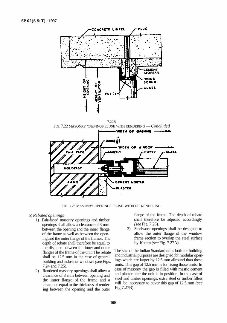
SP 62(S & T) : 1997
FIG. 7.23 MASONRY OPENINGS FLUSH WITHOUT RENDERING
b) Rebated openings 1) Fair-faced masonry openings and timber
openings shall allow a clearance of 3 mm between the opening and the inner flange of the frame as well as between the opening and the outer flange of the frames. The depth of rebate shall therefore be equal to the distance between the inner and outer flanges of the frame of the unit. The rebate shall be 12.5 mm in the case of general building and industrial windows (see Figs. 7.24 and 7.25).
2) Rendered masonry openings shall allow a clearance of 3 mm between opening and the inner flange of the frame and a clearance equal to the thickness of rendering between the opening and the outer
flange of the frame. The depth of rebate shall therefore be adjusted accordingly (see Fig. 7.26).
3) Steelwork openings shall be designed to allow the outer flange of the window frame section to overlap the steel surface by 10 mm (see Fig. 7.27A).
The size of the Indian Standard units both for building and industrial purposes are designed for modular openings which are larger by 12.5 mm allround than these units. This gap of 12.5 mm is for fixing those units. In case of masonry the gap is filled with mastic cement and plaster after the unit is in position. In the case of steel and timber openings, extra steel or timber fillets will be necessary to cover this gap of 12.5 mm (see Fig.7.27B).
160
7.22B FIG. 7.22 MASONRY OPENINGS FLUSH WITH RENDERING — Concluded
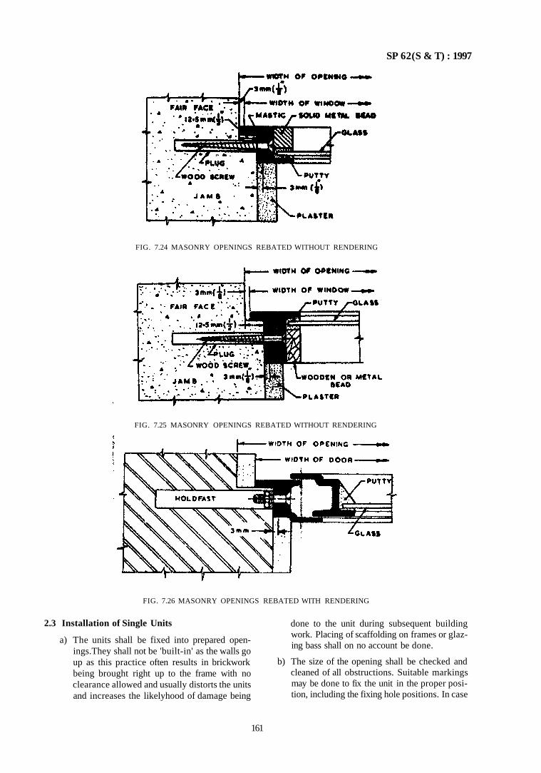
SP 62(S & T) : 1997
FIG. 7.24 MASONRY OPENINGS REBATED WITHOUT RENDERING
FIG. 7.25 MASONRY OPENINGS REBATED WITHOUT RENDERING
2.3 Installation of Single Units
a) The units shall be fixed into prepared open-ings.They shall not be 'built-in' as the walls go up as this practice often results in brickwork being brought right up to the frame with no clearance allowed and usually distorts the units and increases the likelyhood of damage being
done to the unit during subsequent building work. Placing of scaffolding on frames or glazing bass shall on no account be done.
b) The size of the opening shall be checked and cleaned of all obstructions. Suitable markings may be done to fix the unit in the proper position, including the fixing hole positions. In case
161
FIG. 7.26 MASONRY OPENINGS REBATED WITH RENDERING
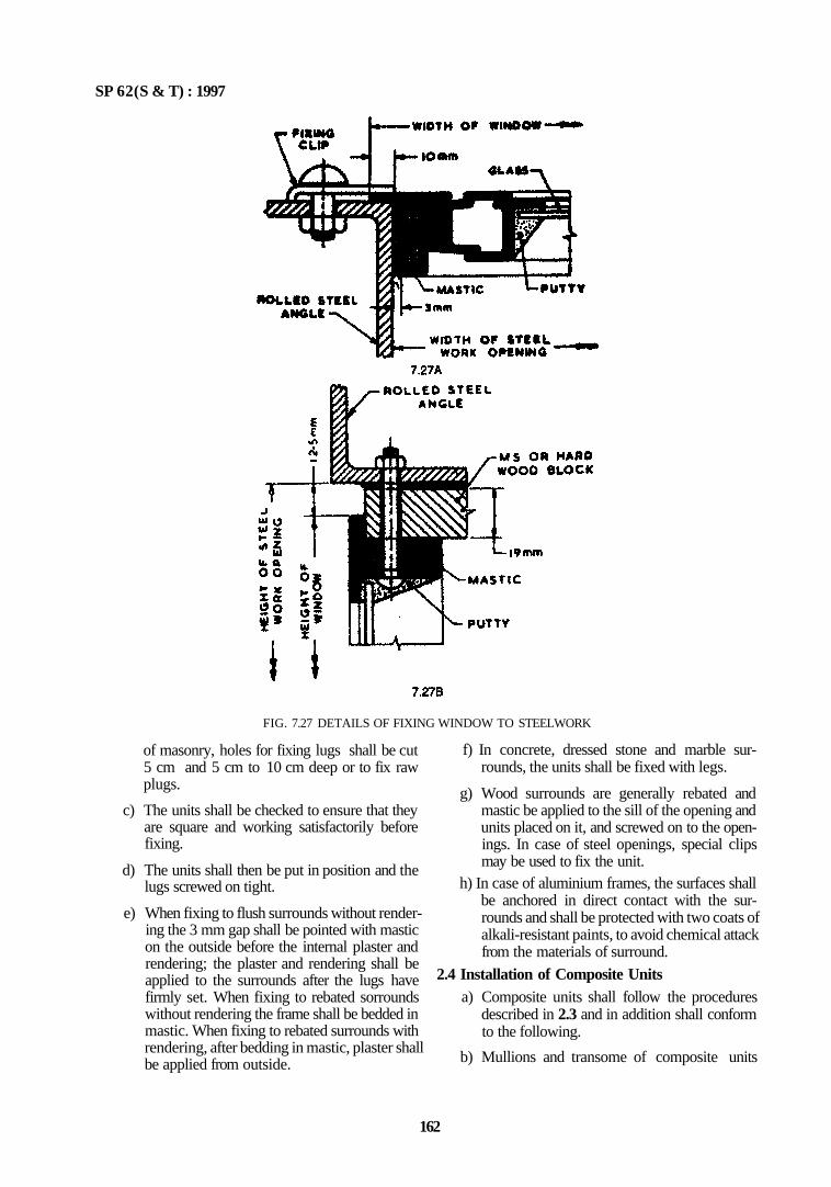
SP 62(S & T) : 1997
FIG. 7.27 DETAILS OF FIXING WINDOW TO STEELWORK
of masonry, holes for fixing lugs shall be cut 5 cm and 5 cm to 10 cm deep or to fix raw plugs.
c) The units shall be checked to ensure that they are square and working satisfactorily before fixing.
d) The units shall then be put in position and the lugs screwed on tight.
e) When fixing to flush surrounds without rendering the 3 mm gap shall be pointed with mastic on the outside before the internal plaster and rendering; the plaster and rendering shall be applied to the surrounds after the lugs have firmly set. When fixing to rebated sorrounds without rendering the frame shall be bedded in mastic. When fixing to rebated surrounds with rendering, after bedding in mastic, plaster shall be applied from outside.
f) In concrete, dressed stone and marble surrounds, the units shall be fixed with legs.
g) Wood surrounds are generally rebated and mastic be applied to the sill of the opening and units placed on it, and screwed on to the open-ings. In case of steel openings, special clips may be used to fix the unit.
h) In case of aluminium frames, the surfaces shall be anchored in direct contact with the surrounds and shall be protected with two coats of alkali-resistant paints, to avoid chemical attack from the materials of surround.
2.4 Installation of Composite Units a) Composite units shall follow the procedures
described in 2.3 and in addition shall conform to the following.
b) Mullions and transome of composite units
162
SP 62 (S & T) : 1997
shall be bedded in mastic to ensure weather tightness. Mastic shall be applied to channels of the outside frame sections before assembly.
c) If their is across joint of mullion and transome, the shorter coupling unit shall run through unbroken.
d) Mullions normally project 2.5 cm at head and sill into the surround; transomes also project 2.5 cm into surround where appropriate they shall be cut.
2.5 Hardware
Hardware shall be fixed as late as possible just before the final coat of paint is applied.
3 GLAZING
3.1 The procedures laid down in 14 of Part 1 may be followed to the extent applicable.
4 OTHER SHUTTERS
4.1 Steel rolling shutters shall conform to IS 6248 : 1979
4.2 Steel collapsible gates shall conform to IS 10521 : 1983.
4.3 Steel sliding shutters shall conform to IS 10451 : 1983.
4.4 Installation of these shutters shall be as per principles laid in 2 except as required during installation to suit local conditions.
163

CHAPTER 8
STEEL CONSTRUCTION
CONTENTS
PART 1 USE OF HOT ROLLED SECTIONS
1 GENERAL
2 MATERIALS
2.1 Structural Steel 2.2 Rivets 2.3 Welding Consumables 2.4 Steel Castings 2.5 Bolts and Nuts 2.6 Washers 2.7 Cement Concrete 2.8 Hot Rolled
3 FABRICATION AND ERECTION
3.1 General 3.2 Fabrication Procedures 3.3 Assembly 3.4 Riveting 3.5 Bolting 3.6 Welding 3.7 Machining of Butts, Caps and Bases 3.8 Solid Round Steel Columns 3.9 Painting
3.10 Marking 3.11 Shop Assembly 3.12 Packing 3.13 Inspection and Testing 3.14 Site Erection 3.15 Field Connections 3.16 Painting after Erection 3.17 Bedding of Stanchion Bases and Bearings of
Beams and Girders on Stone, Brick or Concrete (Plain or Reinforced)
4 CONNECTIONS
4.1 General 4.2 Rivets, Close Tolerance Bolts, High Strength
Friction Grip Fasteners, Black Bolts and Welding
4.3 Composite Connections 4.4 Members Meeting at a Joint 4.5 Bearing Brackets 4.6 Gussets 4.7 Lug Angles 4.8 Pitch of Rivets 4.9 Pitch of Bolts
5 FABRICATION AND CONNECTIONS FOR DESIGN BY
PLASTIC THEORY
5.1 Fabrication 5.2 Connections
6 FABRICATION AND CONNECTIONS FOR TUBULAR
STRUCTURES
6.1 General 6.2 Materials 6.3 Fabrication 6.4 Connections
ANNEX A LIST OF INDIAN STANDARDS AND HAND
BOOKS RELEVANT TO STEEL CONSTRUCTION
PART 2 USE OF COLD FORMED SECTIONS
1 GENERAL
2 MATERIALS
SP 62(S & T) : 1997
CHAPTER 8
STEEL CONSTRUCTION
PART 1 USE OF HOT ROLLED SECTIONS
1 GENERAL
1.1 This Part covers use of hot rolled steel sections including tubes in general building construction, in particular fabrication practices and connections. The requirements do not completely cover those of bridges, chimneys and other special steel structures. This is line with the design codes, one for general building construction and others for individual structures depending loads, service conditions, etc.
1.2 There are three basic methods of connecting steel members through rivets, bolts and welding. Thus, the fabrication practices differ. In addition high strength grip bolts are being used in construction which reduces noise during fabrication on site, and is based on the principle of friction through grip.
2 MATERIALS
2.1 Structural Steel
Structural steel shall conform to IS 1977 : 1975, IS 2062 : 1992 and IS 8500 : 1992 and any other structural steel as specified with minimum guaranteed yield point .
NOTE — IS 22 and IS 961 have been superseded by IS 2062 and IS 8500 respectively.
2.2 Rivets
Rivets shall conform to IS 1929 : 1982 and IS 2155 : 1982 as appropriate. High tensile steel rivet bars shall conform to IS 1149 : 1982. Hot rolled rivet bars shall conform to IS 1148 : 1982.
2.2.1 Friction Grip Bolts
High tensile friction grip bolts shall conform to IS 3757 : 1985; high tensile friction grip nuts shall conform to IS 6623 : 1985 and high tensile friction grip washers shall conform to IS 6649 : 1985.
2.3 Welding Consumables
Covered electrodes shall conform to IS 814 : 1991, or IS 1278 : 1972. Barewire electrodes for submerged arc welding shall conform to IS 7280 : 1974. Combination of wire and flux shall satisfy IS 3613 : 1974. Filler rods and bare electrodes for gas shielded metal arc welding shall conform to IS 6419 : 1971 and to IS 6560 : 1972 as appropriate.
14 Steel Castings
Steel castings shall conform to grade 23-45 of IS 1030 : 1989. 2.5 Bolts and Nuts
Bolts and nuts shall conform to IS 1363 (Parts 1, 2, 3) : 1992, IS 1364 (Parts 1, 2, 3): 1992, IS 1367(Part 3): 1991, and IS 3640:1982 as appropriate.
2.6 Washers
Washers shall conform to IS 5369 : 1975, IS 5370 : 1969, IS 5374 : 1975 and IS 6610 : 1972, as appropriate.
2.7 Cement Concrete Cement concrete used in association with structural steel shall conform to IS 456 : 1978.
2.8 Hot Rolled Hot rolled sections shall conform to Indian Standards listed in Annex A. It also lists other relevant Indian Standards and Handbooks prepared so far in relation to steel construction.
3 FABRICATION AND ERECTION 3.1 General As much fabrication work as is reasonably practicable shall be completed in the shops where steel work is fabricated. Tolerances for fabrication of steel structures shah conform to IS 7215 :1974. Tolerances for erection of steel structures shall conform to IS 12843 : 1989. For general guidance on fabrication by welding reference may be made to IS 9595 : 1980.
3.1.1 Minimum Thickness of Metal — Corrosion Protection
a) Steel work exposed to weather — Where steelwork is directly exposed to weather and is fully accessible for cleaning and repainting, the thickness shall be not less than 6 mm; and where steel is exposed to the weather and is not accessible for cleaning and painting, the thickness shall not be less than 8 mm. This shall not apply to hot rolled sections covered by Indian Standards.
b) Steel work not directly exposed to the weather — The thickness of steel work not directly exposed to the weather shall be not less than 6 mm. The thickness of steel in secondary
167
SP 62(S & T) : 1997
members shall be not less than 4.5 mm. For hot rolled sections to Indian Standards the mean thickness of flange be considered and not the web thickness.
c) These requirements of 3.1.1 (a) and (b) do not apply to light structural work or to scaled box section or to steel work in which special provision against corrosion has been made; also in case of steelwork exposed to highly corrosive industrial fumes or vapour or slaine atmosphere, the minimum thickness shall be as agreed to between the customer and designer.
3.2 Fabrication Procedures
a) Straightening — All material shall be straight and, if necessary, before being worked shall be straightened and/or flattened by pressure, unless required to be curve linear and shall be free from twists.
b) Clearances — The erection clearance of cleated ends of members connecting steel to steel should preferably be not greater than 2.0 mm at each end. The erection clearance at ends of beams without web cleats should be not more than 3 mm at each end, but where, for practical purposes, greater clearance is necessary, suitably designed seatings should be provided.
Where black bolts are used, the diameter of holes, shall be generally 1.5 mm more than the diameter of permanent bolts, and 3 mm more than diameter of erection bolts.
c) Cutting 1) Cutting may be effected by shearing, crop
ping or sawing. Gas cutting by mechanically controlled torch may be permitted for mild steel only. Gas cutting of high tensile steel may also be permitted provided special care is taken to leave sufficient metal to be removed by machining so that all metal that has been hardened by flame is removed. Hand flame cutting may be permitted subject to approval by the Authority.
2) Except where material is to be subsequently joined by welding, no loads shall be transmitted into metal through a gas cut surface.
3) Shearing, cropping and gas cutting, shall be clean, reasonably square, and free from any distortions, and should the Authority find it necessary, the edges shall be ground afterwards.
d) Holding 1) Holes through more than one thickness of
material for members, such as, compound
stanchion and girder flanges shall, where possible, be drilled after the members are assembled and tightly clamped or bolted together. Punching may be permitted before assembly, provided the holes are punched 3 mm less in diameter than the required size and reamed after assembly to the full diameter. The thickness of material punched shall not be greater than 16 mm. For dynamically loaded structures, punching shall be avoided.
2) When holes are drilled in one operation through two or more separable parts, these parts, when so specified, shall be separated after drilling and the burrs removed.
3) Holes in connecting angles and plates other than splices, also in roof members and light framing, may be punched full size through material not over 12 mm thick, except when required for close tolerance bolts or barred bolts.
4) Matching holes for rivets and black bolts shall register with each other so that a gauge of 1.5 mm or 2.0 mm (as the case may be depending on the diameter of rivet or bolt is less than or more than 25 mm) less in diameter than the diameter of the hole will pass freely through the assembled members in the direction at right angle to such members. Finished holes shall be not more than 1.5 mm or 2.0 mm (as the case may be) in diameter larger than the diameter of the rivet or black bolt passing through them, unless otherwise specified.
5) Holes for turned and fitted bolts shall be drilled to a diameter equal to the nominal diameter of the shank or barrel subject to H8 tolerance specified in IS 919 (Part I ) : 1993. Parts to be connected with close tolerance or barrel bolts shall preferably be tightly held together through all the thickness at one operation and subsequently reamed to size. All holes not drilled through all the thickness in one operation shall be drilled to a smaller size and reamed out after assembly. Where this is not practicable, the parts shall be drilled and reamed seperately through hard bushed steel jigs.
6) Holes for rivets or bolts shall not be formed by gas cutting process.
3.3 Assembly
The component parts shall be assembled and aligned in such a manner that they are neither twisted nor
168
SP 62(S & T) : 1997
otherwise damaged, and shall be so prepared that the specified cambers, if any, are provided.
3.4 Riveting
1) Rivets shall be heated uniformly throughout their length without burning or excessive scaling, and shall be of sufficient length to provide a head of standard dimensions. They shall, when driven, completely fill the holes, and it countersunk, the countersigning shall be fully filled by the rivet; any protrusion of the countersunk head being dressed off flush, if required.
2) Riveted members shall have all parts firmly drawn and held together before and during riveting, and special care shall be taken in this respect for all single riveted connections. For multiple riveted connections, a service bolt shall be provided in every third or fourth hole.
3) Wherever practicable, machine riveting shall be carried out by using machines of the steady pressure type.
4) All loose, burned or otherwise defective rivets shall be cut out and replaced before the structure is loaded, and special care shall be taken to inspect all single riveted connections.
5) Special care shall be taken in heating and driving long rivets.
3.5 Bolting
1) Where necessary, washers shall be tapered or otherwise suitably shaped to give the heads and nuts of bolts a satisfactory bearing.
2) The threaded portion of each bolt shall project through the nut by at least one thread.
3) In all cases where full bearing area of the bolt is to be developed, the bolt shall be provided with a washer of sufficient thickness under the nut to avoid any threaded portion of the belt being within the thickness oi the parts bolted together
3.6 Welding
1) Welding shall be in accordance with IS 816 . 1969, IS 819 : 1957, IS 1024 : 1979, IS 1261 . 1959, IS 1323 : 1982 and IS 9595 : 1980 as appropriate.
2) For welding any particular type of joint, welders shall give evidence acceptable to the Authority of having satisfactorily completed appropriate tests as described in any of the Indian Standards, namely, IS 817 (Part 1) . 1992, IS 1393 : 1961, IS 7307 (Part I ) . 1974, IS 7310 (Part 1) : 1974 and IS 7318 (Part 1) 1974 as appropriate.
3.7 Machining of Butts, Caps and Bases
1) Column splices and butt joints of struts and compression members depending on contact for stress transmission shall be accurately machined and close butted over the whole section with a clearance not exceeding 0.2 mm locally at any place. In column caps and bases, the ends of shafts together with attached gussets, angles, channels, etc, after riveting together should be accurately machined so that parts connected butt over entire surfaces of contact. Care should be taken that these gussets, connecting angles or channels, are fixed with such accuracy that they are not reduced in thickness by machining more than 2.0 mm.
2) Where sufficient gussets and rivets or welds arc provided to transmit the entire loading, the column ends need not be machined, the design of column members should cover this.
3) Ends of all bearing stiffness shall be machined or ground to fit tightly both at top and bottom.
4) Slab bases and caps, except when cut from material with true surfaces, shall be accurately machined over the bearing surfaces and shall be in effective contact with the end of the stanchion A bearing surface which is to be grouted direct to a foundation need not be machined if such face is true and parallel to the upper face.
5) To facilitate grouting, holes shall be provided where necessary in stanchion bases for the escape of air.
3.8 Solid Round Steel Columns
1) Solid round steel columns with shouldered ends shall be provided with slab caps and bases machined to fit the shoulder, and shall be tight-ly shrunk or welded in position.
2) The tolerance between the reduced end of the shaft and the hole in case of slabs welded in position, shall not exceed 0.25 mm.
3) Where slabs are welded in position, the reduced end of the shaft shall be kept just sufficiently short to accommodate a fillet weld around the hole without weld metal being proud of the slab. Alternatively, the caps and bases may be directly welded to the column without bearing or shouldering. All bearing surfaces of slabs intended for metal-to-metal contact shall be machined perpendicular to the shaft.
3.9 Painting
Painting shall be done as prescribed in IS 1477 (Parts 1 and 2) . 1971 (see also Chapter 15).
169
SP 62(S & T) : 1997
1) All surfaces to be painted, oiled or otherwise treated shall be dry and thoroughly cleaned to remove ail loose scale and loose rust.
2) Shop contact surfaces need not be painted unless specified. If so specified, they shall be brought together while the paint is still wet.
3) Surfaces not in contact, but inaccessible after shop assembly shall receive the full specified protective treatment before assembly. This does not apply to the interior of hollow sections (see IS 3502: 1981).
4) Chequered plates (see IS 3502:1981) shall be painted but the details of painting shall be specified by the Authority.
5) In case the surfaces are to be welded, the steel shall not be painted or metal coated within a suitable distance of any edges to be welded, if the paint specified or metal coating would be harmful to the welders or impair the quality of welds.
6) Welds and adjacent parent metal shall not be painted prior to de-slugging, inspection and approval.
7) Parts to be encased in concrete shall not be painted or oiled.
3.10 Marking
Each piece of steelwork shall be distinctly marked before delivery, and bear such other marks as in accordance with a marking diagram as well facilitate erection.
3.11 Shop Assembly
1) The steelwork shall temporarily shop assembled complete or as arranged with the Authority so that accuracy of fit may be checked before despatch. The parts shall be shop assembled with sufficient numbers of parallel drifts to bring and keep the parts in place.
2) In case of parts drilled or punched, through steel jigs with bushes resulting in all similar parts being interchangeable the steelwork may be shop erected in such position as arranged with the Authority.
3.12 Packing
All projecting plates or bars and all ends of members at joints shall be stiffened, all straight bars and plates shall be bundled, alt screwed ends and machined surfaces shall be suitably packed; and all rivets, bolts, nuts, washers and small loose parts shall be packed separately in cases so as to prevent damage or distortion during transit.
3.13 Inspection and Testing
1) The Authority shall have free access at all reasonable times to those parts of the
manufacturers' works which are concerned with the fabrication of steelwork and shall be afforded all reasonable facilities to satisfy that the fabriction is being undertaken in accordance with the specifications.
2) Unless specified otherwise, inspection prior to despatch shall not interfere with the operation of the work.
3.14 Site Erection
1) Plant and Equipment — The suitability and capacity of all plant and equipment used for erection shall be to the satisfaction of the Authority.
2) Storing and Handling — All structural steel should be so stored and handled at the site that the members are not subject to excessive stresses and damage.
3) Setting Out — The positioning and levelling of all steelwork, the plumbing of stanchions and the placing of every part of the structure with accuracy shall be in accordance with approved drawings and to the satisfaction of Authority.
4) Security during Erection — Safety precaution during erection shall conform to IS 7205 : 1974. During erection, the steelwork shall be securely botled or otherwise fastened and, when necessary, temporarily braced to provide for all load to be carried by the structure during erection including those due to erection equipment and its operation. No riveting, permanent bolting or welding should be done until proper alignment has been obtained.
3.15 Field Connections
All field assembly by bolts, rivets and welding shall be executed in accordance with the requirements for shop fabrication excepting such as manifestly apply to shop conditions only. Where the steel has been delivered painted, the paint shall be removed before field welding, for a distance of 50 mm at least on either side of the joint.
3.16 Painting after Erection
1) Before painting of such steel which is delivered unpainted is commenced, all surfaces to be painted shall be dry and thoroughly cleaned from all loose scale and rust.
2) The specified protective treatment shall be completed after erection. All rivet and bolt heads and site welds after de-slugging shall be cleaned. Damaged or deteriorated paint surfaces shall be first made good with the same type of paint as the shop coat. Where specified, surfaces which will be in contact alter site assembly shall receive a coat of paint
170
SP 62(S & T) : 1997
(in addition to any shop priming) and shall be brought together while paint is still wet.
3) Where the steel has received a metal coating in the shop, this coating shall be completed on site so as to be continuous over any welds and site rivets and bolts; but subject to the approval of Authority, protection may be completed by painting on site. Bolts which have been galvanized or similarly treated are exempted from this requirement.
4) Surfaces which will be inaccessible after site assembly shall receive the full specified treatment before assembly.
5) Site painting should not be done in frostly or foggy weather, or when humidity is such as to cause condensation on the surfaces to be painted.
3.17 Bedding of Stanchion Bases and Bearings of Beams and Girders on Stone, Brick or Concrete (Plain or Reinforced)
1) Bedding shall be carried out with cement, grout, or mortar or with cement concrete as in IS 456: 1978.
2) For multistorcyed buildings, this operation shall not be carried out until a sufficient number of bottom lengths of stanchions have been properly lined, levelled and plumbed and sufficient floor beams are in position.
3) Whatever method is employed, the operation shall not be carried out, until the steelwork has been finally levelled and plumbed, the stanchion bases being supported meanwhile by steel wedges; and immediately before grouting, the space under the steel shall be thoroughly cleaned.
4) Bedding of structure shall be carried out with grout or mortar which shall be of adequate strength and shall completely fill the space to be grouted and shall either be placed under pressure or by ramming against fixed supports.
4 CONNECTIONS
4.1 General
As much of the work of fabrication as in reasonably practicable shall be completed in the shops where the steel work is fabricated.
4.2 Rivets, Close Tolerance Bolts, High Strength Friction Grip Fasteners, Black Bolts and Welding
Where a connection is subject to impact or vibration or to reversal of stress (unless such reversal is solely due to wind) or where for some special reason, such as continuity in rigid framing or precision in alignment of machinery, rivets or close tolerance bolts, high strength friction grip fasteners or welding shall be used. In all other cases bolts in clearance holes may
be used provided that due allowance is made for any slippage.
4.3 Composite Connections
In any connection which takes a force directly transferred to it and which is made with more than one type of fastening, only rivets and turned and fitted bolts may be considered as acting together to share the load. In all other connections sufficient number of one type of fastening shall be provided to transfer the entire load for which the connection is designed.
4.4 Members Meeting at a Joint
For triangulated frames designed on the assumption of pin jointed connections, members meeting at a joint, shall, where practicable, have their centroidal axes meeting at a point; and wherever practicable the centre of resistance of a connection shall be on the line of action of the load so as to avoid eccentricity moment on the connections.
1) However, where eccentricity of members or if connection is present, the members and the connections shall provide adequate resistance to the induced bending moments.
2) Where the design is based on non-intersecting members at a joint all stresses arising from eccentricity shall be calculated and this stress within limits specified.
4.5 Bearing Brackets
Wherever applicable, connections of beams to columns shall include a bottom bracket and top cleat. Where web cleats are not provided, the bottom bracket shall be capable of carrying the whole of the load.
4.6 Gussets
Gusset plates shall be designed to resist the shear, direct and flexural stresses acting on the weakest or critical section. Re-entrant cuts shall be avoided as far as practicable.
4.7 Lug Angles
Lug angles connecting a channel shaped member, shall as far is possible, be disposed symmetrically with respect to the section of the member.
1) In case of angle members, the lug angles and their connections to gusset or other supporting member shall be capable of developing a strength not less than 20 percent in excess of the force in the outstanding leg of the angle and the attachment of the lug angle to the angle number shall be capable of developing 40 percent in excess of that force.
2) In the case of channel numbers and the like, the lug angles and their connections to the gusset or other supporting member shall be capable of developing a strength of not less than 10 per
171
SP 62(S & T) : 1997
cent in excess of the force not accounted for by direct connection of the member, and the attachment of the lug angles to the member shall be capable of developing 20 percent in excess of that force.
3) In no case shall fewer than two bolts or rivets be used for attaching the lug angle to the gusset or other supporting member.
4) The effective connection of the lug angle shall, as far as possible terminate at the end of the member connected, and the fastening of the lug angle to the member shall preferably start in advance of the direct connection of the member to the gusset or other supporting member.
4.8 Pitch of Rivets
1) Minimum Pitch — The distance between centre of rivets shall not be less than 2.5 times the nominal diameter of the rivet.
2) Maximum Pitch — The maximum pitch for any two adjacent rivets shall not exceed 32 t where t is the thickness of the thinner outside plate or 300 mm.
In tension members the distance between any two adjacent rivets, in a line lying in the direction of stress, shall not exceed 16 t or 200 mm; and 12 t or 200 mm for compression members. In case of butting compression members, the distance shall not exceed 4.5 times the diameter of the rivets for a distance from the abutting faces equal to 1.5 times the width of the member.
The distance between centres of any two consecutive rivets in a line adjacent and parallel to an edge of an outside plate shall not exceed (100 mm + 4 t) or 200 mm; whichever is less in compression or tension members.
When rivets are staggered at equal intervals and the gauge does not exceed 75 mm, the distances specified herein between centres of rivets, may be increased by 50 percent.
3) Edge Distances — The minimum edge distance from the centre of any hole to the edge of the plate shall be not less than as given below:
When two or more parts are connected together, a line of rivets or bolts shall be provided at a distance of not more than (37 mm + 4 t) the nearest edge. In case of work not exposed to weather, this may be increased to 12 t.
4) Tacking Rivets — Tacking rivets not subject to calculated stress shall be used, in case the maximum distances specified in 4.8 (2) is exceeded. The pitch of tacking rivets in line shall not exceed 33 t or 300 mm whichever is less. When the plates are exposed to weather, the pitch in line shall not exceed 16 t or 200 mm, whichever is less. In both cases, the lines of tacking rivets shall not be apart at a distance greater than the pitches.
In tension members composed of two angles, flats, channels or tees in contact back-to-back or seperated back-to-back by a distance not more than the aggregate thickness of the connected parts, tackng rivets shall be at a pitch not exceeding 1 000 mm.
For compression members as above, the pitch shall not exceed 600 mm.
4.9 Pitch of Bolts
They shall be as for rivets including edge distances and tacking bolts.
5 FABRICATION AND CONNECTIONS FOR DESIGN BY PLASTIC THEORY
5.1 Fabrication
All the requirements of fabrication as per 3 shall apply for fabrication for design of steel structures by plastic theory subject to the following:
a) The use of sheared edges shall be avoided in locations subject to plastic hinge rotation at factored loading. If used they shall be finished smooth by grinding, chipping or planning.
b) In locations subject to plastic hinge rotation at factored loading, holes or rivets or bolts in the tension area shall be sub-punched and reamed or drilled full size.
5.2 Connections
a) All connections which are essential to the continuity, assumed as the basis of design analysis shall be capable of resisting the moments, shears and axial loads to which they would be subjected by either full or factored loading.
b) Corner connections (haunches), tapered or curved for architectural reasons shall be so proportioned that the full bending strength of the section adjacent to the connection may be developed.
c) Stiffeners shall be used, as required, to preserve the flange continuity of interrupted
Dia of Hole
mm
Distance to Sheared or Hand Flame Cut Edge
mm 13.5 and below 19 15.5 17.5 19.5 21.5 23.5 25.5 29.6 32 0 35.0
25 29 32 32 38 44 51 57 57
Distance to Rolled, Machine Flame Cut, Sawn or Planed Edge
mm
22 25 29 29 32 38 44 51 51
172
SP 62(S & T) : 1997
members at their junctions with other members in a continuous frame. Such stiffeners shall be placed in pairs on opposite sides of the web of the member which extends continuously through the joint.
6 FABRICATION AND CONNECTIONS FOR TUBULAR STRUCTURES
6.1 General
The use of tubular steel in structural work would result in considerable savings, particularly in case of roof trusses, latticed girders and compression members in general. This clause on fabrication and connections for tubular structures is complimentary to the provisions of 1 to 5. Requirements which are of special application to construction using steel tubes are included here.
6.2 Materials
a) Steel tubes shall be hot rolled finished tubes conforming to IS 1161 : 1979. Tubes made by other than hot finishing processes or which have been subjected to cold working, shall be regarded as hot finished, if they have subsequently been heat-treated and are supplied in normalized conditions.
NOTE - Grade ERW YSt 22 tubes specified in IS 1161 1979 with a carhon content less than 0 30 percent, may be considered as hot finished for this purpose.
b) Electrodes used for welding of steel tubes shall conform to IS 814 : 1991.
c) Minimum Thickness 1) For tubular steelwork painted with one
priming coat of red oxide and zinc chromate paint after fabrication and peri-odically repainted and maintained regularly, the wall thickness of tubes used for construction exposed to weather shall be not less than 4 mm (see 2); for construction not exposed to weather, it shall be not less than 3 2 mm and; where structures are not readily accessible for main-tainance, the minimum thickness shall be 5 mm.
2) Steel tubes used tor construction exposed to weather shall be not less than 3.2 mm thick and for construction not exposed to weather shall be not less than 2.6 mm thick provided that in each case the tube is applied with:
— one coat of zinc primer conforming to IS 104 : 1979, followed by a coat of paint conforming to IS 2074 : 1992; or
— two coats of paint conforming to IS 123 1962.
This painting schedule should be reviewed after every two years in the case of tubes ex
posed to weather. In case some other metallic corrosion protecting material is used, such as aluminium painting, the renewal of coating may be done after longer intervals.
6.3 Fabrication
a) As mentioned in 6.1, provisions of 1 to 5 apply to construction using tubes also. Where welding is adopted provisions of IS 816: 1969 shall apply, as appropriate.
b) The component pails of the structure shall be assembled in such a manner that they are neither twisted nor otherwise damaged and be so prepared that the specified cambers, if any, are maintained.
c) Straightening — All material before assembly shall be straightened, if necessary, unless otherwise required to be a curvilinear form and shall be free from twist.
d) Bolting 1) Washers shall be specially shaped where
necessary, or other means used, to give the nuts and the heads of bolls a satisfactory bearing.
2) In all cases where the full bearing area of the bolt is to be developed, the threaded portion of the bolt shall not be within the thickness of the parts bolted together, and washers of appropriate thickness shall be provided to allow the nut to be completely tightened.
e) Cut Edges — Edges should be dressed to a neat and workman like finish and be free from distortion where parts are to be in contact metal-to metal.
f) Caps and Bases for Columns — The ends of all tubes for columns, transmitting loads through the ends, shall be true and square to the as is of the tube and should be provided with a cap or base accurately fitted to the end of the tube and screwed, welded or shrunk on. The cap or base plate should be true and square to the axis of the columns.
g) Sealing of Tubes — When the end of a tube is not automatically scaled by virtue of its connection by welding to another member, the end shall be properly and completely sealed, Before sealing, the inside of the tube should be dry and free from loose scale.
h) Flattened Ends — In tubular construction, the ends of tubes may be flattened or otherwise formed to provide for welded, riveted or bolted connections, provided that the methods adopted for such flattening do not injure the
173
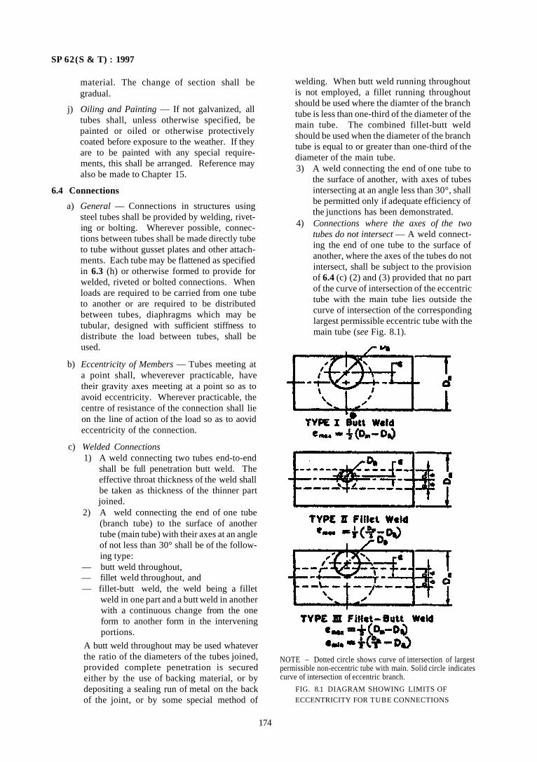
SP 62(S & T) : 1997
material. The change of section shall be gradual.
j) Oiling and Painting — If not galvanized, all tubes shall, unless otherwise specified, be painted or oiled or otherwise protectively coated before exposure to the weather. If they are to be painted with any special requirements, this shall be arranged. Reference may also be made to Chapter 15.
6.4 Connections
a) General — Connections in structures using steel tubes shall be provided by welding, riveting or bolting. Wherever possible, connections between tubes shall be made directly tube to tube without gusset plates and other attachments. Each tube may be flattened as specified in 6.3 (h) or otherwise formed to provide for welded, riveted or bolted connections. When loads are required to be carried from one tube to another or are required to be distributed between tubes, diaphragms which may be tubular, designed with sufficient stiffness to distribute the load between tubes, shall be used.
b) Eccentricity of Members — Tubes meeting at a point shall, wheverever practicable, have their gravity axes meeting at a point so as to avoid eccentricity. Wherever practicable, the centre of resistance of the connection shall lie on the line of action of the load so as to aovid eccentricity of the connection.
c) Welded Connections 1) A weld connecting two tubes end-to-end
shall be full penetration butt weld. The effective throat thickness of the weld shall be taken as thickness of the thinner part joined.
2) A weld connecting the end of one tube (branch tube) to the surface of another tube (main tube) with their axes at an angle of not less than 30° shall be of the following type:
— butt weld throughout, — fillet weld throughout, and — fillet-butt weld, the weld being a fillet
weld in one part and a butt weld in another with a continuous change from the one form to another form in the intervening portions.
A butt weld throughout may be used whatever the ratio of the diameters of the tubes joined, provided complete penetration is secured either by the use of backing material, or by depositing a sealing run of metal on the back of the joint, or by some special method of
welding. When butt weld running throughout is not employed, a fillet running throughout should be used where the diamter of the branch tube is less than one-third of the diameter of the main tube. The combined fillet-butt weld should be used when the diameter of the branch tube is equal to or greater than one-third of the diameter of the main tube. 3) A weld connecting the end of one tube to
the surface of another, with axes of tubes intersecting at an angle less than 30°, shall be permitted only if adequate efficiency of the junctions has been demonstrated.
4) Connections where the axes of the two tubes do not intersect — A weld connecting the end of one tube to the surface of another, where the axes of the tubes do not intersect, shall be subject to the provision of 6.4 (c) (2) and (3) provided that no part of the curve of intersection of the eccentric tube with the main tube lies outside the curve of intersection of the corresponding largest permissible eccentric tube with the main tube (see Fig. 8.1).
174
NOTE – Dotted circle shows curve of intersection of largest permissible non-eccentric tube with main. Solid circle indicates curve of intersection of eccentric branch.
FIG. 8.1 DIAGRAM SHOWING LIMITS OF
ECCENTRICITY FOR TUBE CONNECTIONS
SP 62(S &T ) : 1997
5) Connections of tubes with flattened ends — Where the end of the branch tube is flattened to an elliptical shape, the provisions of 6.4 (c) shall apply and the
diameter of the flattened tube for this purpose shall be measured in a plane perpendicular to the axis of the main tube.
ANNEX A
(Clause 2.8) LIST OF INDIAN STANDARDS AND HANDBOOKS RELEVANT TO STEEL CONSTRUCTION
A-1 HOT ROLLED STEEL SECTIONS
IS No. Title
808 : 1989 Beam, column, channel and angle sections
1161 : 1979 Steel tubes
1730 : 1989 Dimensions of steel plates, sheets, strips and flats for general engineering purposes
1732 : 1989 Dimensions of round and square steel bars for general engineering purposes
1852 : 1985 Rolling and cutting tolerances for hot rolled steel products
3443 : 1980 Crane rail sections
3954 : 1991 Channel sections for general engineering purposes
12778 : 1989 Parallel flange beam and column sections — Dimensions
12779 : 1989 Rolling and cutting tolerances for parallel flange beam and column sections
A-2 DESIGN CODES AND HANDBOOKS
IS No. Title
800 : 1984 Use of steel in general building construction
IS No. Title
806 : 1968 Use of steel tubes in general building construction
4000 : 1992 Assembly of structural joints using high tensile bolts
HANDBOOK FOR STRUCTURAL ENGINEERS
SP 6 (1) : 1964 Steel sections
SP 6 (2) : 1962 Steel beams and plate girders
SP 6 (3) : 1962 Steel columns and struts
SP 6 (4) : 1969 High strength friction grip bolts
SP 6 (6) : 1972 Plastic theory
A-3 WELDING CODES/HANDBOOKS
IS No. Title
10801 : 1984 Recommended procedures for heat treatment of welded fabrication
11991 : 1986 Recommended practice for flash butt welding of tubes, rods and other sections in carbon and alloy steels
SP 6 (7): 1972 Simple welded girders
ISI handbook for manual metal arc welding for welders.
SP 12 : 1975 Handbook for gas welders
175
SP 62 (S & T) : 1997
PART 2 USE OF COLD FORMED SECTIONS
1 GENERAL 1.1 The design of cold formed sections is covered by IS 801 : 1975. The fabrication is largely by resistance spot welding and by site bolting. This is because of extremely thin sections used in cold forming. IS 819 : 1957 for resistance spot welding of light assemblies in mild steel covers the fabrication practices of cold formed sections.
2 MATERIALS
2.1 Cold formed gauge sections shall conform to IS 811 : 1988.
2.2 Design code using cold formed sections shall conform to IS 801 : 1975. SP 6 (5): 1980 is the handbook for cold formed light gauge sections.
176
CHAPTER 9
FLOORS AND FLOOR COVERINGS
CONTENTS
1 GENERAL
PART 1 BRICK FLOORS
1 GENERAL
2 BURNT CLAY BRICK FLOORING
2.1 General 2.2 Preparatory Work 2.3 Bedding 2.4 Laying of Bricks 2.5 Dry Brick Paving
3 REINFORCED BRICK AND BRICK CONCRETE FLOORS
3.1 General 3.2 Preparatory Work 3.3 Construction of RB and RBC Roof or Floor 3.4 Laying of Bricks and Reinforcement 3.5 Curing 3.6 Removal of Form work 3.7 Finishing
PART 2 CEMENT CONCRETE FLOORS
1 IN-SITU CONCRETE FLOORING
1.1 General 1.2 Materials 1.3 Types of Floor Finishes 1.4 Mix Proportions 1.5 Durability 1.6 Resistance to Attack by Chemical Reagents 1.7 Slipperiness 1.8 Surface Hardening Solutions 1.9 Size of Panels
1.10 Protection against Dampness 1.11 Finish over Stairs 1.12 Laying of Concrete Flooring on Ground 1.13 Laying of Bonded Construction (Type II) 1.14 Laying of Floor Topping on Suspended Slabs
2 IN-SITU GRANOLITHIC CONCRETE FOR FLOOR TOPPING
2.1 General 2.2 Materials 2.3 Preparatory Work 2.4 Laying of Floor over Base Concrete 2.5 Laying of Floor Topping on Suspended Slab 2.6 Curing 2.7 Maintenance
3 IN-SITU TERRAZZO FLOOR FINISH
3.1 General 3.2 Materials 3.3 General Construction 3.4 Preparatory Work 3.5 Spreading the Under layer 3.6 Laying Terrazzo Topping 3.7 Curing 3.8 Grinding 3.9 Laying Terrazzo Skirtings and Dados
3.10 Maintenance
4 CEMENT CONCRETE FLOORING TILES
4.1 General 4.2 Materials 4.3 Preparatory Work 4.4 Bedding 4.5 Laying of Tiles 4.6 Grinding and Polishing 4.7 Laying of Rough Tiles 4.8 Tolerance in Laying 4.9 Skirting, Dado Work and Staircase —Tread
Work 4.10 Maintenance
ANNEX A SURFACE TREATMENT TO CEMENT
CONCRETE FLOOR TOPPING
PART 3 INDUSTRIAL FLOOR FINISHES
1 GENERAL
2 TYPES OF INDUSTRIAL FLOOR FINISHES
2.1 Types 2.2 Considerations for Selection of Floor Finish 2.3 Properties of Floor Finishes 2.4 Recommendations for Floor Finish for In
dustrial Buildings 2.5 Bedding and Jointing of Materials
3 DAIRY FLOOR FINISHES
3.1 General 3.2 Floor Finishes for Different Sections of Dairy
Floors 3.3 Waterproofing Membrane for Dairy Floors 3.4 Drainage in Dairies 3.5 Maintenance of Dairy Floor
SP 62(S & T) : 1997
4 BITUMEN MASTIC FLOORING FOR LPG
4.1 General 4.2 Thickness 4.3 Preparatory Work 4.4 Laying
PART 4 SPECIAL FLOORS AND FLOOR COVERINGS
1 GENERAL
2 MAGNESIUM OXYCHLORIDE COMPOSITION FLOORS
2.1 General 2.2 Types 2.3 Materials 2.4 Properties of Magnesium Oxychloride Floors 2.5 Application 2.6 Testing 2.7 Maintenance 2.8 Protection of Metal Work
3 BITUMEN MASTIC FLOORING
3.1 General 3.2 Materials 3.3 Preparatory Work 3.4 Laying
4 RUBBER FLOORS
4.1 General 4.2 Preparatory Work 4.3 Laying and Fixing of Rubber Flooring
5 LINOLEUM FLOORS
5.1 General 5.2 Materials 5.3 Preparatory Work 5.4 Laying
6 EPOXY RESIN FLOOR TOPPINGS
6.1 General 6.2 Materials 6.3 Types of Epoxy Resin Toppings 6.4 Preparatory Work 6.5 Laying 6.6 Maintenance
7 FLEXIBLE PVC SHEET AND TILE FLOORING
7.1 General 7.2 Materials 7.3 Preparatory Work 7.4 Laying
8 CHEMICAL RESISTANT MORTARS
9 SILICATE TYPE CHEMICAL RESISTANT MORTAR
9.1 Material
9.2 Mortar 9.3 Storage 9.4 Mixing 9.5 Application 9.6 Acid-Curing 9.7 Chemical Resistance of Silicate Type Mortars
10 RESIN TYPE CHEMICAL RESISTANT MORTAR
10.1 Material 10.2 Storage 10.3 Safety Precautions 10.4 Mixing 10.5 Handling 10.6 Application 10.7 Acid-Curing 10.8 Chemical Resistance of Resin Type Mortars
11 SULPHUR TYPE CHEMICAL RESISTANT MORTAR
11.1 Material 11.2 Storage 11.3 Safety Precautions 11.4 Melting and Pouring 11.5 Application 11.6 Chemical Resistance of Sulphur Type Mor
tars
12 PARQUET FLOORING
12.1 General 12.2 Materials 12.3 Classes of Mosaic Parquet Flooring 12.4 Parquet Floor Patterns 12.5 Wood Block Flooring Patterns 12.6 Mosaic Parquet Panel 12.7 Dimensions 12.8 Fabrication and Laying
ANNEX B SPECIES OF TIMBER RECOMMENDED FOR SLATS, FLOOR BOARDS AND PARQUEI FLOORS
PART 5 TIMBER FLOORS
1 GENERAL
2 MATERIALS
3 TYPES OF TIMBER FLOORS
4 CONSTRUCTION
4.1 Single Joisted Timber Floor 4.2 Double Joisted Timber Floor 4.3 Triple Joisted Timber Floor 4.4 Solid Timber Floors 4.5 Purpose-Made Floors
5 TIMBER FLOOR BOARDS

SP 62 (S & T) : 1997
CHAPTER 9
FLOORS AND FLOOR COVERINGS
1 GENERAL
1.1 For the purpose of this Handbook floors and floor coverings are grouped as under:
Part 1 Brick floors Part 2 Cement concrete floors
Part 3 Industrial floor finishes Part 4 Special floors and floor coverings Part 5 Timber floors
Indian Standards available for different floor and floor coverings are IS 5766 : 1970 and IS 13074: 1991.
PART 1 BRICK FLOORS
1 GENERAL
1.1 In this Part construction of the floors are considered:
a) Burnt clay brick flooring to IS 5766 : 1970. b) Reinforced brick and RBC floors and roots to
IS 10440 : 1983.
2 BURNT CLAY BRICK FLOORING
2.1 General
The usefulness of burnt clay bricks as flooring material is their wearing quality and facility for quick installation. Generally, common burnt clay bricks to IS 1077 : 1992 can be used for low cost temporary sheds, court yards, footpaths, etc. Heavy duty bricks conforming to IS 2180:1988 and IS 3583 : 1988 could be used for locations of floors subject to heavy wear and tear, such as, stores, godowns and platforms. Generally, bricks laid on edge give better performance than when laid flat.
2.2 Preparatory Work
2.2.1 Base Concrete
Heavy duty floors shall be provided with base concrete; light duty floors may also be provided with base concrete. The concrete used shall generally be lime concrete with brick or stone aggregates prepared as described in Chapter 5. Lean cement concrete mix 1:5:10 may also be used. For heavy duty floors the base concrete shall be 150 mm thick, for light duty floors, base concrete, when provided, shall be 75 mm thick.
a) Lime concrete sub-grade shall be allowed to set for seven days. If the sub-grade is of lean cement concrete, flooring work shall be commenced within 48 h; if not the surface of the sub-grade shall be roughened with steel wire brushes, wetted by sprinkling water and smeared with a coat of cement slurry at 2.75 kg
of cement per square metre so as to get a good bond between sub-grade and flooring.
b) The sub-grade shall be provided with the slope required for the flooring for proper drainage. Where sub-grade is not provided, the earth below shall be properly sloped, watered, rammed and compacted. Before laying the floor it shall be moistened.
c) To prevent subsidence a layer of sand 75 mm thick may be provided under the base concrete.
2.3 Bedding
Before the concrete sub-grade is finally set, lime mortar or lime cement mortar not less than 10 mm thick shall be spread evenly over the base concrete. The proportions of mortar shall be as given below:
Heavy duty floors — 1:4 (cement mortar) or 1:1:6 (cement lime mortar)
Light duty flows — 1:6 (cement mortar) or 1:2:9 (cement lime mortar)
2.4 Laying of Bricks
a) Soaking — To reduce excessive suction, the bricks shall be soaked in clean water, before laying, and then allowed to drain until they are surface dry.
b) The bricks shall be laid in plain, diagonal, herring bone, or other suitable patterns. The brick shall either be laid flat or on edge; laying on edge is preferred. Broken bricks shall not be used in flooring except for closing line.
c) Bricks shall be laid on the mortar bed by gentle topping. The inside faces of bricks shall be smeared with mortar before the next brick is laid and pressed against it. On completion of a portion of flooring, the vertical joints shall be fully filled with mortar from top. The surface of the flooring shall be checked frequently for
181
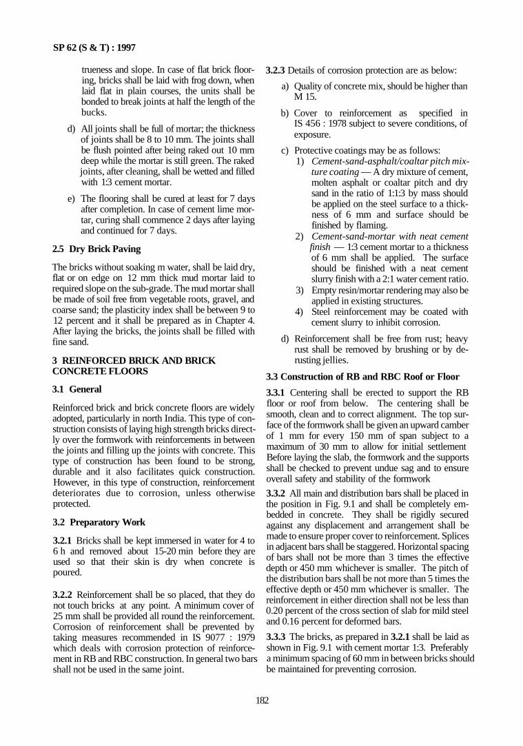
SP 62 (S & T) : 1997
trueness and slope. In case of flat brick flooring, bricks shall be laid with frog down, when laid flat in plain courses, the units shall be bonded to break joints at half the length of the bucks.
d) All joints shall be full of mortar; the thickness of joints shall be 8 to 10 mm. The joints shall be flush pointed after being raked out 10 mm deep while the mortar is still green. The raked joints, after cleaning, shall be wetted and filled with 1:3 cement mortar.
e) The flooring shall be cured at least for 7 days after completion. In case of cement lime mortar, curing shall commence 2 days after laying and continued for 7 days.
2.5 Dry Brick Paving
The bricks without soaking m water, shall be laid dry, flat or on edge on 12 mm thick mud mortar laid to required slope on the sub-grade. The mud mortar shall be made of soil free from vegetable roots, gravel, and coarse sand; the plasticity index shall be between 9 to 12 percent and it shall be prepared as in Chapter 4. After laying the bricks, the joints shall be filled with fine sand.
3 REINFORCED BRICK AND BRICK CONCRETE FLOORS
3.1 General
Reinforced brick and brick concrete floors are widely adopted, particularly in north India. This type of construction consists of laying high strength bricks directly over the formwork with reinforcements in between the joints and filling up the joints with concrete. This type of construction has been found to be strong, durable and it also facilitates quick construction. However, in this type of construction, reinforcement deteriorates due to corrosion, unless otherwise protected.
3.2 Preparatory Work
3.2.1 Bricks shall be kept immersed in water for 4 to 6 h and removed about 15-20 min before they are used so that their skin is dry when concrete is poured.
3.2.2 Reinforcement shall be so placed, that they do not touch bricks at any point. A minimum cover of 25 mm shall be provided all round the reinforcement. Corrosion of reinforcement shall be prevented by taking measures recommended in IS 9077 : 1979 which deals with corrosion protection of reinforcement in RB and RBC construction. In general two bars shall not be used in the same joint.
3.2.3 Details of corrosion protection are as below:
a) Quality of concrete mix, should be higher than M 15.
b) Cover to reinforcement as specified in IS 456 : 1978 subject to severe conditions, of exposure.
c) Protective coatings may be as follows: 1) Cement-sand-asphalt/coaltar pitch mix
ture coating — A dry mixture of cement, molten asphalt or coaltar pitch and dry sand in the ratio of 1:1:3 by mass should be applied on the steel surface to a thickness of 6 mm and surface should be finished by flaming.
2) Cement-sand-mortar with neat cement finish — 1:3 cement mortar to a thickness of 6 mm shall be applied. The surface should be finished with a neat cement slurry finish with a 2:1 water cement ratio.
3) Empty resin/mortar rendering may also be applied in existing structures.
4) Steel reinforcement may be coated with cement slurry to inhibit corrosion.
d) Reinforcement shall be free from rust; heavy rust shall be removed by brushing or by de-rusting jellies.
3.3 Construction of RB and RBC Roof or Floor
3.3.1 Centering shall be erected to support the RB floor or roof from below. The centering shall be smooth, clean and to correct alignment. The top surface of the formwork shall be given an upward camber of 1 mm for every 150 mm of span subject to a maximum of 30 mm to allow for initial settlement Before laying the slab, the formwork and the supports shall be checked to prevent undue sag and to ensure overall safety and stability of the formwork
3.3.2 All main and distribution bars shall be placed in the position in Fig. 9.1 and shall be completely embedded in concrete. They shall be rigidly secured against any displacement and arrangement shall be made to ensure proper cover to reinforcement. Splices in adjacent bars shall be staggered. Horizontal spacing of bars shall not be more than 3 times the effective depth or 450 mm whichever is smaller. The pitch of the distribution bars shall be not more than 5 times the effective depth or 450 mm whichever is smaller. The reinforcement in either direction shall not be less than 0.20 percent of the cross section of slab for mild steel and 0.16 percent for deformed bars.
3.3.3 The bricks, as prepared in 3.2.1 shall be laid as shown in Fig. 9.1 with cement mortar 1:3. Preferably a minimum spacing of 60 mm in between bricks should be maintained for preventing corrosion.
182
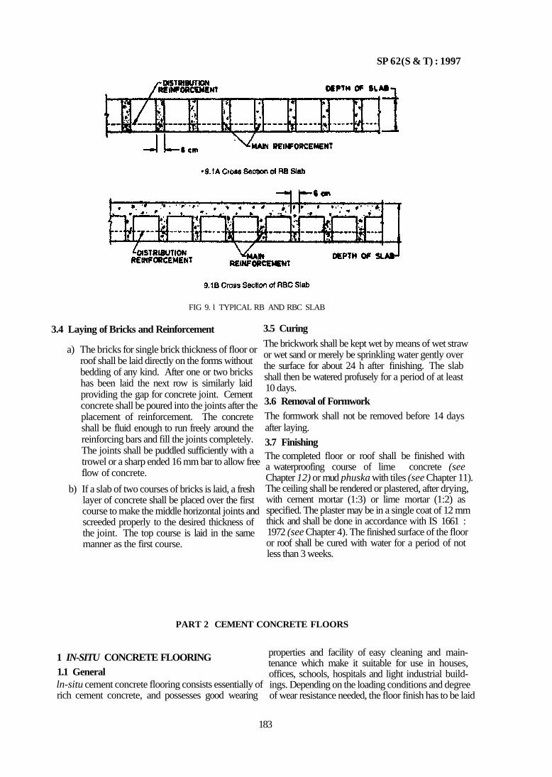
SP 62(S & T) : 1997
FIG 9. l TYPICAL RB AND RBC SLAB
3.4 Laying of Bricks and Reinforcement
a) The bricks for single brick thickness of floor or roof shall be laid directly on the forms without bedding of any kind. After one or two bricks has been laid the next row is similarly laid providing the gap for concrete joint. Cement concrete shall be poured into the joints after the placement of reinforcement. The concrete shall be fluid enough to run freely around the reinforcing bars and fill the joints completely. The joints shall be puddled sufficiently with a trowel or a sharp ended 16 mm bar to allow free flow of concrete.
b) If a slab of two courses of bricks is laid, a fresh layer of concrete shall be placed over the first course to make the middle horizontal joints and screeded properly to the desired thickness of the joint. The top course is laid in the same manner as the first course.
3.5 Curing
The brickwork shall be kept wet by means of wet straw or wet sand or merely be sprinkling water gently over the surface for about 24 h after finishing. The slab shall then be watered profusely for a period of at least 10 days. 3.6 Removal of Formwork The formwork shall not be removed before 14 days after laying.
3.7 Finishing The completed floor or roof shall be finished with a waterproofing course of lime concrete (see Chapter 12) or mud phuska with tiles (see Chapter 11). The ceiling shall be rendered or plastered, after drying, with cement mortar (1:3) or lime mortar (1:2) as specified. The plaster may be in a single coat of 12 mm thick and shall be done in accordance with IS 1661 : 1972 (see Chapter 4). The finished surface of the floor or roof shall be cured with water for a period of not less than 3 weeks.
PART 2 CEMENT CONCRETE FLOORS
1 IN-SITU CONCRETE FLOORING 1.1 General ln-situ cement concrete flooring consists essentially of rich cement concrete, and possesses good wearing
properties and facility of easy cleaning and maintenance which make it suitable for use in houses, offices, schools, hospitals and light industrial build-ings. Depending on the loading conditions and degree of wear resistance needed, the floor finish has to be laid
183
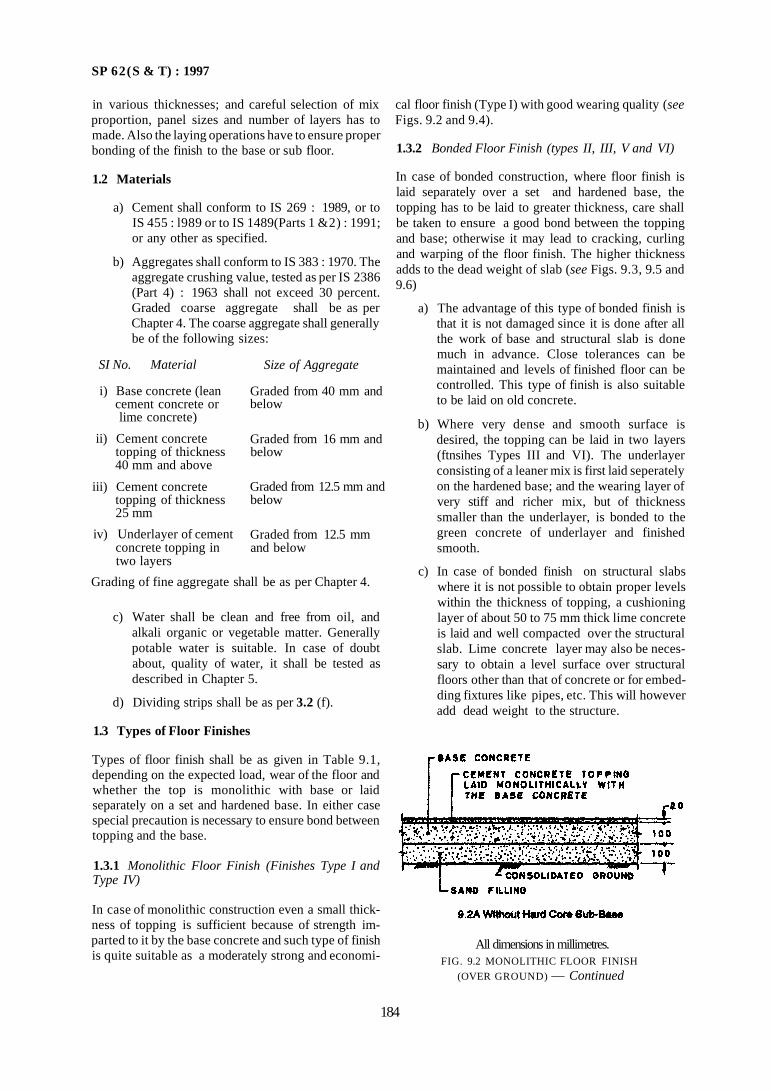
SP 62(S & T) : 1997
in various thicknesses; and careful selection of mix proportion, panel sizes and number of layers has to made. Also the laying operations have to ensure proper bonding of the finish to the base or sub floor.
1.2 Materials
a) Cement shall conform to IS 269 : 1989, or to IS 455 : l989 or to IS 1489(Parts 1 &2) : 1991; or any other as specified.
b) Aggregates shall conform to IS 383 : 1970. The aggregate crushing value, tested as per IS 2386 (Part 4) : 1963 shall not exceed 30 percent. Graded coarse aggregate shall be as per Chapter 4. The coarse aggregate shall generally be of the following sizes:
SI No. Material Size of Aggregate
Graded from 40 mm and below
Graded from 16 mm and below
Graded from 12.5 mm and below
Graded from 12.5 mm and below
i) Base concrete (lean cement concrete or lime concrete)
ii) Cement concrete topping of thickness 40 mm and above
iii) Cement concrete topping of thickness 25 mm
iv) Underlayer of cement concrete topping in two layers
Grading of fine aggregate shall be as per Chapter 4.
c) Water shall be clean and free from oil, and alkali organic or vegetable matter. Generally potable water is suitable. In case of doubt about, quality of water, it shall be tested as described in Chapter 5.
d) Dividing strips shall be as per 3.2 (f).
1.3 Types of Floor Finishes
Types of floor finish shall be as given in Table 9.1, depending on the expected load, wear of the floor and whether the top is monolithic with base or laid separately on a set and hardened base. In either case special precaution is necessary to ensure bond between topping and the base.
1.3.1 Monolithic Floor Finish (Finishes Type I and Type IV)
In case of monolithic construction even a small thick-ness of topping is sufficient because of strength imparted to it by the base concrete and such type of finish is quite suitable as a moderately strong and economi
cal floor finish (Type I) with good wearing quality (see Figs. 9.2 and 9.4).
1.3.2 Bonded Floor Finish (types II, III, V and VI)
In case of bonded construction, where floor finish is laid separately over a set and hardened base, the topping has to be laid to greater thickness, care shall be taken to ensure a good bond between the topping and base; otherwise it may lead to cracking, curling and warping of the floor finish. The higher thickness adds to the dead weight of slab (see Figs. 9.3, 9.5 and 9.6)
a) The advantage of this type of bonded finish is that it is not damaged since it is done after all the work of base and structural slab is done much in advance. Close tolerances can be maintained and levels of finished floor can be controlled. This type of finish is also suitable to be laid on old concrete.
b) Where very dense and smooth surface is desired, the topping can be laid in two layers (ftnsihes Types III and VI). The underlayer consisting of a leaner mix is first laid seperately on the hardened base; and the wearing layer of very stiff and richer mix, but of thickness smaller than the underlayer, is bonded to the green concrete of underlayer and finished smooth.
c) In case of bonded finish on structural slabs where it is not possible to obtain proper levels within the thickness of topping, a cushioning layer of about 50 to 75 mm thick lime concrete is laid and well compacted over the structural slab. Lime concrete layer may also be necessary to obtain a level surface over structural floors other than that of concrete or for embedding fixtures like pipes, etc. This will however add dead weight to the structure.
184
All dimensions in millimetres. FIG. 9.2 MONOLITHIC FLOOR FINISH
(OVER GROUND) — Continued
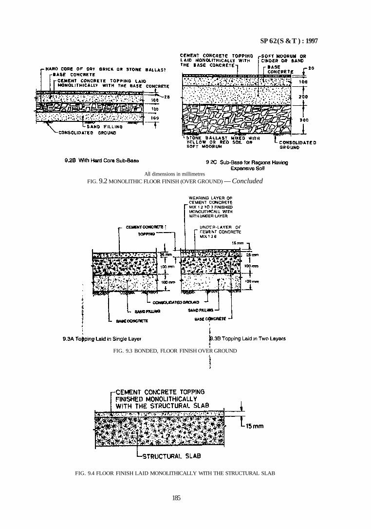
SP 62(S &T ) : 1997
FIG. 9.4 FLOOR FINISH LAID MONOLITHICALLY WITH THE STRUCTURAL SLAB
185
All dimensions in millimetres FIG. 9.2 MONOLITHIC FLOOR FINISH (OVER GROUND) — Concluded
FIG. 9.3 BONDED, FLOOR FINISH OVER GROUND
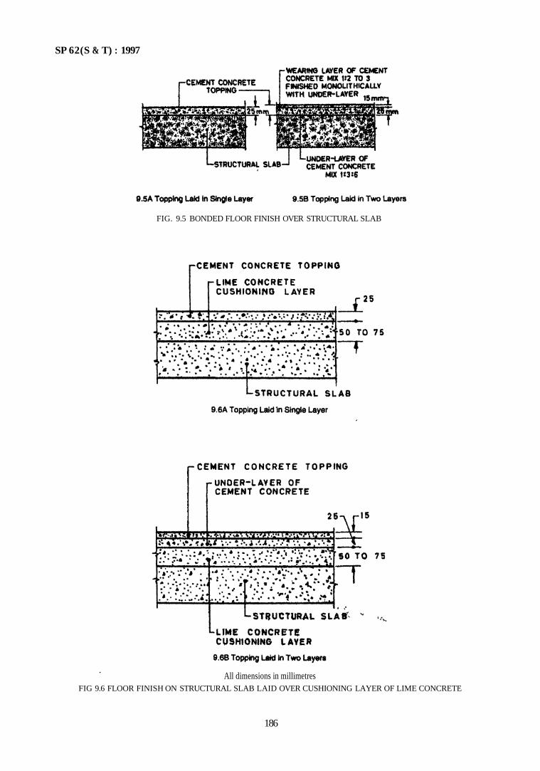
SP 62(S & T) : 1997
186
All dimensions in millimetres FIG 9.6 FLOOR FINISH ON STRUCTURAL SLAB LAID OVER CUSHIONING LAYER OF LIME CONCRETE
FIG. 9.5 BONDED FLOOR FINISH OVER STRUCTURAL SLAB
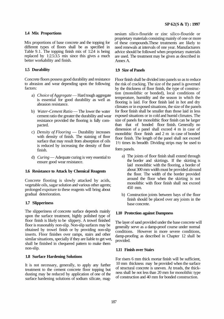
SP 62(S & T) : 1997
1.4 Mix Proportions
Mix proportions of base concrete and the topping for different types of floors shall be as specified in Table 9.1. The topping finish mix of 1:2:4 is being replaced by 1:2.5:3.5 mix since this gives a much better workability and finish.
1.5 Durability
nesium silico-flouride or zinc silico-flouride or proprietary materials consisting mainly of one or more of these compounds.These treatments are likely to need renewals at intervals of one year. Manufacturers advice should be followed when proprietary materials are used. The treatment may be given as described in Annex A.
1.9 Size of Panels
Concrete floors possess good durability and resistance to abrasion and wear depending upon the following factors:
a) Choice of Aggregate — Hard tough aggregate is essential for good durability as well as abrasion resistance.
b) Water-Cement Ratio — The lower the water cement ratio the greater the durability and wear resistance provided the flooring is fully compacted.
c) Density of Flooring — Durability increases with density of finish. The staining of floor surface that may result from absorption of oils is reduced by increasing the density of floor finish.
d) Curing — Adequate curing is very essential to ensure good wear resistance.
1.6 Resistance to Attack by Chemical Reagents
Concrete flooting is slowly attacked by acids, vegetable oils, sagar solution and various other agents; prolonged expoiure to these reagents will bring about gradual deterioration.
1.7 Slipperiness
The slipperiness of concrete surface depends mainly upon the surface treatment, highly polished type of floor finish is likely to be slippery. A trowel finished floor is reasonably non-slip. Non-slip surfaces may be obtained by trowel finish or by providing non-slip inserts. Floor finishes over ramps, stairs and other similar situations, specially if they are liable to get wet, shall be finished in chequered pattern to make them non-slip.
1.8 Surface Hardening Solutions
It is not necessary, generally, to apply any further treatment to the cement concrete floor topping but dusting may be reduced by application of one of the surface hardening solutions of sodium silicate, mag-
Floor finish shall be divided into panels so as to reduce the risk of cracking. The size of the panel is governed by the thickness of floor finish, the type of construction (monolithic or bonded), local conditions of temperature, humidity and the season in which the flooring is laid. For floor finish laid in hot and dry climates or in exposed situations, the size of the panels for floor finish shall be smaller than those laid in less exposed situations or in cold and humid climates. The size of panels for monolithic floor finish can be larger than that of bonded floor finish. Generally no dimension of a panel shall exceed 4 m in case of monolithic floor finish and 2 m in case of bonded floor finish. The length of the panel shall not exceed 1½ times its breadth Dividing strips may be used to
form panels.
a) The joints of floor finish shall extend through the border and skirtings. If the skirting is laid monolithic with the flooring, a border of about 300 mm width must be provided alround the floor. The width of the border provided around the floor when the skirting is not monolithic with floor finish shall not exceed 450 mm.
b) Construction joints between bays of the floor finish should be placed over any joints in the base concrete.
1.10 Protection against Dampness
The layer of sand provided under the base concrete will generally serve as a damp-proof course under normal conditions. However in more severe conditions, damp-proofing as described in Chapter 12 shall be provided.
1.11 Finish over Stairs
For risers 6 mm thick mortar finish will be sufficient, 10 mm thickness may be provided when the surface of structural concrete is uneven. At treads, the thickness shall be not less than 20 mm for monolithic type of construction and 40 mm for bonded construction.
187
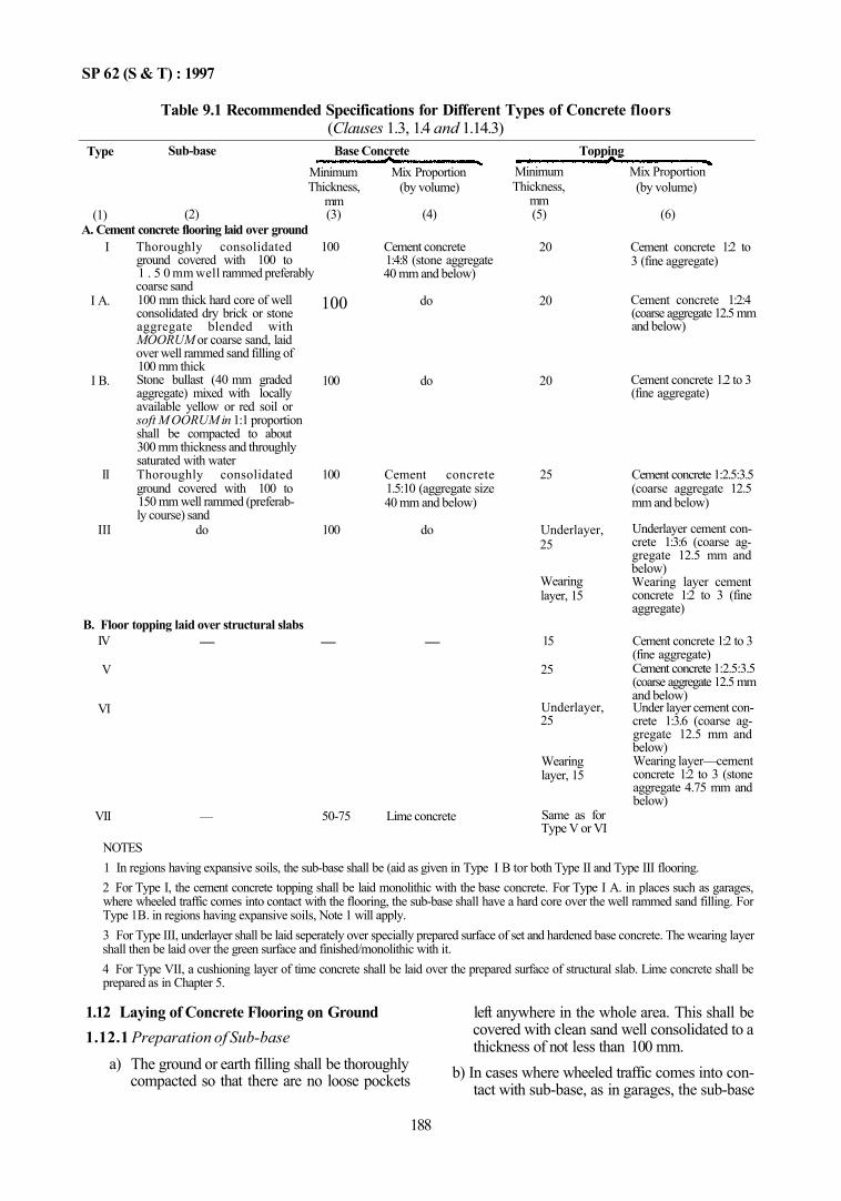
SP 62 (S & T) : 1997
Table 9.1 Recommended Specifications for Different Types of Concrete floors (Clauses 1.3, 1.4 and 1.14.3)
Type
(1)
Sub-base
(2) A. Cement concrete flooring laid over ground
I
I A.
I B.
II
III
Thoroughly consolidated ground covered with 100 to 1 . 5 0 mm well rammed preferably coarse sand 100 mm thick hard core of well consolidated dry brick or stone aggregate blended with MOORUM or coarse sand, laid over well rammed sand filling of 100 mm thick Stone bullast (40 mm graded aggregate) mixed with locally available yellow or red soil or soft M OORUM in 1:1 proportion shall be compacted to about 300 mm thickness and throughly saturated with water Thoroughly consolidated ground covered with 100 to 150 mm well rammed (preferably course) sand
do
B. Floor topping laid over structural slabs IV
V
VI
VII
—
—
Base Concrete Minimum Mix Proportion Thickness,
mm (3)
100
100
100
100
100
—
50-75
(by volume)
(4)
Cement concrete 1:4:8 (stone aggregate 40 mm and below)
do
do
Cement concrete 1.5:10 (aggregate size 40 mm and below)
do
—
Lime concrete
Topping Minimum Mix Proportion Thickness,
mm (5)
20
20
20
25
Underlayer, 25
Wearing layer, 15
15
25
Underlayer, 25
Wearing layer, 15
Same as for Type V or VI
(by volume)
(6)
Cement concrete 1:2 to 3 (fine aggregate)
Cement concrete 1:2:4 (coarse aggregate 12.5 mm and below)
Cement concrete 1.2 to 3 (fine aggregate)
Cement concrete 1:2.5:3.5 (coarse aggregate 12.5 mm and below)
Underlayer cement concrete 1:3:6 (coarse aggregate 12.5 mm and below) Wearing layer cement concrete 1:2 to 3 (fine aggregate)
Cement concrete 1:2 to 3 (fine aggregate) Cement concrete 1:2.5:3.5 (coarse aggregate 12.5 mm and below) Under layer cement concrete 1:3.6 (coarse aggregate 12.5 mm and below) Wearing layer—cement concrete 1:2 to 3 (stone aggregate 4.75 mm and below)
NOTES 1 In regions having expansive soils, the sub-base shall be (aid as given in Type I B tor both Type II and Type III flooring. 2 For Type I, the cement concrete topping shall be laid monolithic with the base concrete. For Type I A. in places such as garages, where wheeled traffic comes into contact with the flooring, the sub-base shall have a hard core over the well rammed sand filling. For Type 1B. in regions having expansive soils, Note 1 will apply. 3 For Type III, underlayer shall be laid seperately over specially prepared surface of set and hardened base concrete. The wearing layer shall then be laid over the green surface and finished/monolithic with it. 4 For Type VII, a cushioning layer of time concrete shall be laid over the prepared surface of structural slab. Lime concrete shall be prepared as in Chapter 5.
1.12 Laying of Concrete Flooring on Ground 1.12.1 Preparation of Sub-base
a) The ground or earth filling shall be thoroughly compacted so that there are no loose pockets
left anywhere in the whole area. This shall be covered with clean sand well consolidated to a thickness of not less than 100 mm.
b) In cases where wheeled traffic comes into contact with sub-base, as in garages, the sub-base
188

SP 62 (S & T) : 1997
shall consist of well compacted sand layer of 100 mm thick and an additional 100 mm thick well compacted hard core of dry brick or stone ballast 40 mm in size blended with Moorum or coarse sand.
c) In the case of expansive soils, after preparing as per Table 9.1, a further cover of 200 mm thick layer of soft MOORUM or cinder or sand be laid and compacted properly before laying the base concrete.
1.12.2 Laying of the Base
The area shall be divided into suitable panels (see 1.9). This shall be done by fixing screed strips, the depth of which shall be equal to combined thickness of the base concrete and the topping. The screed strips may be coated with a thick coat lime wash so as to prevent them sticking to the concrete deposited in the panels. Before placing the base concrete, the sub-base shall be properly wetted. The concrete so placed shall be thoroughly tamped and surface screcded uniformly below the finished grade of flooring to accomodate the required thickness of topping. Any slope desired in the floor finish shall be given in the base concrete. The surface shall be kept rough to receive the topping.
1.12.3 Laying the Topping
On the clean green surface of the base concrete, the topping shall be laid as soon as possible but not later than 2 to 3h of paying the base concrete, depending on the atmospheric conditions. The base concrete shall be still green, but sufficiently firm to enable workmen to walk over it by placing planks on its surface.
a) The concrete mix for topping shall be deposited on the base concrete, thoroughly compacted to the finished thickness. If water or laitance rises to the top when consolidating, the concrete should be scraped and replaced by a fresh mix; the excess water in no case be absorbed by spreading dry cement. The topping should be floated with a wooden float to render the surface even and shall be finished smooth as in 1.12.3 (b), after slight hardening.
b) Finishing the surface — Finishing operations shall start after the compaction of concrete and shall be completed in a period of 6 h depending on the temperature and atmospheric conditions. The surface shall be trowelled (about three times) to produce a uniform or hard surface. The trowellings shall be done at proper intervals; the final trowelling shall be done before the concrete has become too hard.
189
1.12.4 Sequence of Building Up
The base concrete and topping shall be laid in alternate panels if screed stips are used; the intermediate panels being filled after one or two days depending on atmospheric conditions. But if glass or metallic strips are used for effective separation of panels, the base concrete may he laid in all panels simultaneously.
1.13 Laying of Bonded Construction (Type II)
1.13.1 Preparation of sub-base shall be as in 1.12.1.
1.13.2 Iaying of Base Concrete
The base concrete may be deposited over the whole area at a stretch. Before placing the concrete in the sub-base, the whole area shall bt properly wetted and rammed. The concrete so placed shall be thoroughly tamped and the surface finished level with the top edges of the forms. The surface of the base concrete shall be left rough to receive the topping. Two or three hours after the concrete is laid, the surface shall be brushed with a hard brush to remove any laitance or scum and swept clean so that the coarse aggregate is exposed.
1.13.3 Laying of Topping
The surface of base concrete shall be thoroughly cleaned by scrubbing with a coir or steel wire brush. Where the concrete is hardened so that roughening of the surface by wire is not possible, the entire surface shall be roughened by chipping and hacking. The surface shall be soaked with water, before laying the topping, at least for 12 h and surplus water shall be removed by mopping immediately before laying the topping.
a) The screed strips shall be fixed over the base concrete dividing into suitable panels; the screed strips shall be so arranged that joints, if any, in the base concrete shall coincide with the joints in the topping. Neat cement slurry shall be thoroughly brushed into the prepared surface of the base concrete. The topping shall then be laid, very thoroughly tamped, struck-off level and surface floated with a float. Any inequalities in the surface shall be made good immediately. The finish shall be laid in alternate panels as described for monolithic construction.
b) Finishing the surface — The surface shall be finished as given in 1.12.3.
1.13.4 Laying the Topping in Two Layers
Where the topping is to be laid in two layers to obtain very smooth and dense finish (Type III), the sub-base, base concrete and underlayer shall be as described in 1.13.1 to 1.13.3 with the exception that the topping shall not be finished smooth with a trowel but left
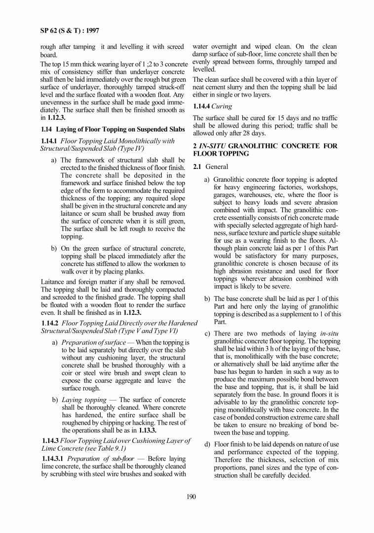
SP 62 (S & T) : 1997
rough after tamping it and levelling it with screed board. The top 15 mm thick wearing layer of 1 ;2 to 3 concrete mix of consistency stiffer than underlayer concrete shall then be laid immediately over the rough but green surface of underlayer, thoroughly tamped struck-off level and the surface floated with a wooden float. Any unevenness in the surface shall be made good immediately. The surface shall then be finished smooth as in 1.12.3. 1.14 Laying of Floor Topping on Suspended Slabs 1.14.1 Floor Topping Laid Monolithically with Structural/Suspended Slab (Type IV)
a) The framework of structural slab shall be erected to the finished thickness of floor finish. The concrete shall be deposited in the framework and surface finished below the top edge of the form to accommodate the required thickness of the topping; any required slope shall be given in the structural concrete and any laitance or scum shall be brushed away from the surface of concrete when it is still green, The surface shall be left rough to receive the topping.
b) On the green surface of structural concrete, topping shall be placed immediately after the concrete has stiffened to allow the workmen to walk over it by placing planks.
Laitance and foreign matter if any shall be removed. The topping shall be laid and thoroughly compacted and screeded to the finished grade. The topping shall be floated with a wooden float to render the surface even. It shall be finished as in 1.12.3. 1.14.2 Floor Topping Laid Directly over the Hardened Structural/Suspended Slab (Type V and Type VI)
a) Preparation of surface — When the topping is to be laid separately but directly over the slab without any cushioning layer, the structural concrete shall be brushed thoroughly with a coir or steel wire brush and swept clean to expose the coarse aggregate and leave the surface rough.
b) Laying topping — The surface of concrete shall be thoroughly cleaned. Where concrete has hardened, the entire surface shall be roughened by chipping or hacking. The rest of the operations shall be as in 1.13.3.
1.14.3 Floor Topping Laid over Cushioning Layer of Lime Concrete (see Table 9.1) 1.14.3.1 Preparation of sub-floor — Before laying lime concrete, the surface shall be thoroughly cleaned by scrubbing with steel wire brushes and soaked with
water overnight and wiped clean. On the clean damp surface of sub-floor, lime concrete shall then be evenly spread between forms, throughly tamped and levelled. The clean surface shall be covered with a thin layer of neat cement slurry and then the topping shall be laid either in single or two layers. 1.14.4 Curing The surface shall be cured for 15 days and no traffic shall be allowed during this period; traffic shall be allowed only after 28 days.
2 IN-SITU GRANOLITHIC CONCRETE FOR FLOOR TOPPING
2.1 General
a) Granolithic concrete floor topping is adopted for heavy engineering factories, workshops, garages, warehouses, etc, where the floor is subject to heavy loads and severe abrasion combined with impact. The granolithic concrete essentially consists of rich concrete made with specially selected aggregate of high hardness, surface texture and particle shape suitable for use as a wearing finish to the floors. Although plain concrete laid as per 1 of this Part would be satisfactory for many purposes, granolithic concrete is chosen because of its high abrasion resistance and used for floor toppings wherever abrasion combined with impact is likely to be severe.
b) The base concrete shall be laid as per 1 of this Part and here only the laying of granolithic topping is described as a supplement to 1 of this Part.
c) There are two methods of laying in-situ granolithic concrete floor topping. The topping shall be laid within 3 h of the laying of the base, that is, monolithically with the base concrete; or alternatively shall be laid anytime after the base has begun to harden in such a way as to produce the maximum possible bond between the base and topping, that is, it shall be laid separately from the base. In ground floors it is advisable to lay the granolithic concrete topping monolithically with base concrete. In the case of bonded construction extreme care shall be taken to ensure no breaking of bond between the base and topping.
d) Floor finish to be laid depends on nature of use and performance expected of the topping. Therefore the thickness, selection of mix proportions, panel sizes and the type of construction shall be carefully decided.
190
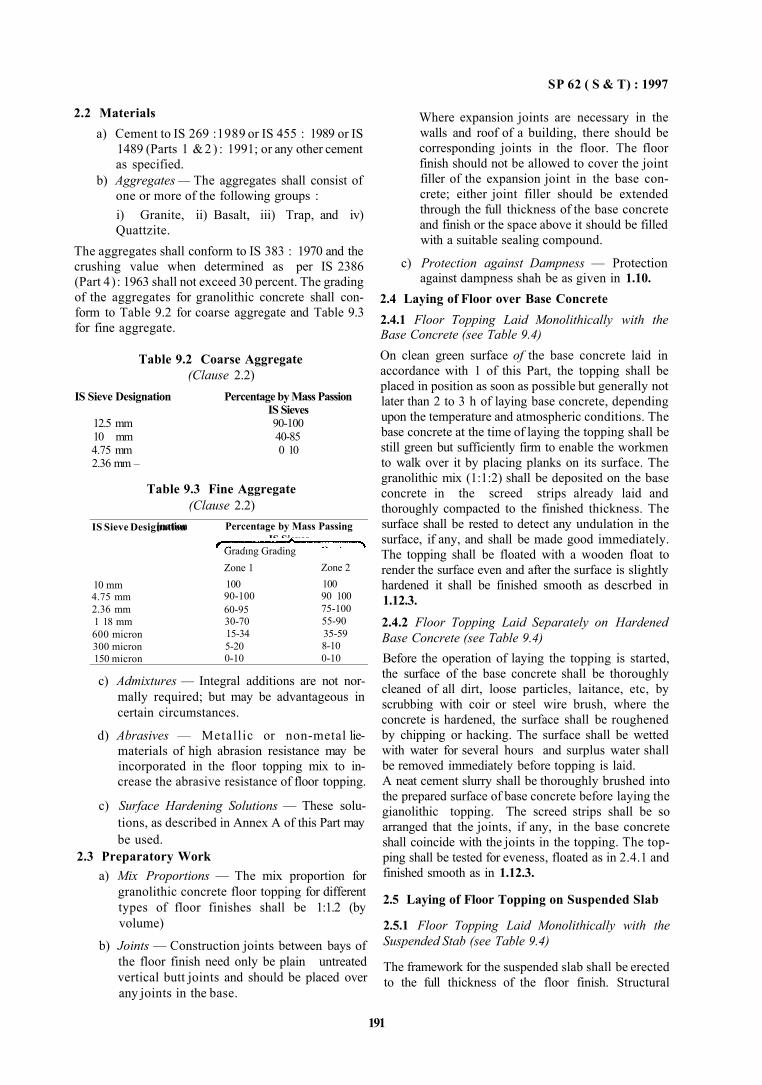
SP 62 ( S & T) : 1997
2.2 Materials a) Cement to IS 269 :1989 or IS 455 : 1989 or IS
1489 (Parts 1 & 2 ) : 1991; or any other cement as specified.
b) Aggregates — The aggregates shall consist of one or more of the following groups : i) Granite, ii) Basalt, iii) Trap, and iv) Quattzite.
The aggregates shall conform to IS 383 : 1970 and the crushing value when determined as per IS 2386 (Part 4): 1963 shall not exceed 30 percent. The grading of the aggregates for granolithic concrete shall conform to Table 9.2 for coarse aggregate and Table 9.3 for fine aggregate.
Table 9.2 Coarse Aggregate (Clause 2.2)
IS Sieve Designation Percentage by Mass Passion IS Sieves
12.5 mm 90-100 10 mm 40-85 4.75 mm 0 10 2.36 mm –
Table 9.3 Fine Aggregate (Clause 2.2)
IS Sieve Designation
10 mm 4.75 mm 2.36 mm 1 18 mm 600 micron 300 micron 150 micron
[nation Percentage by Mass Passing IS Sieves
Grading Grading Zone 1 100 90-100 60-95 30-70 15-34 5-20 0-10
Zone 2 100 90 100 75-100 55-90 35-59 8-10 0-10
c) Admixtures — Integral additions are not normally required; but may be advantageous in certain circumstances.
d) Abrasives — Metallic or non-metal lie-materials of high abrasion resistance may be incorporated in the floor topping mix to increase the abrasive resistance of floor topping.
c) Surface Hardening Solutions — These solutions, as described in Annex A of this Part may be used.
2.3 Preparatory Work a) Mix Proportions — The mix proportion for
granolithic concrete floor topping for different types of floor finishes shall be 1:1.2 (by volume)
b) Joints — Construction joints between bays of the floor finish need only be plain untreated vertical butt joints and should be placed over any joints in the base.
Where expansion joints are necessary in the walls and roof of a building, there should be corresponding joints in the floor. The floor finish should not be allowed to cover the joint filler of the expansion joint in the base concrete; either joint filler should be extended through the full thickness of the base concrete and finish or the space above it should be filled with a suitable sealing compound.
c) Protection against Dampness — Protection against dampness shah be as given in 1.10.
2.4 Laying of Floor over Base Concrete 2.4.1 Floor Topping Laid Monolithically with the Base Concrete (see Table 9.4) On clean green surface of the base concrete laid in accordance with 1 of this Part, the topping shall be placed in position as soon as possible but generally not later than 2 to 3 h of laying base concrete, depending upon the temperature and atmospheric conditions. The base concrete at the time of laying the topping shall be still green but sufficiently firm to enable the workmen to walk over it by placing planks on its surface. The granolithic mix (1:1:2) shall be deposited on the base concrete in the screed strips already laid and thoroughly compacted to the finished thickness. The surface shall be rested to detect any undulation in the surface, if any, and shall be made good immediately. The topping shall be floated with a wooden float to render the surface even and after the surface is slightly hardened it shall be finished smooth as descrbed in 1.12.3. 2.4.2 Floor Topping Laid Separately on Hardened Base Concrete (see Table 9.4) Before the operation of laying the topping is started, the surface of the base concrete shall be thoroughly cleaned of all dirt, loose particles, laitance, etc, by scrubbing with coir or steel wire brush, where the concrete is hardened, the surface shall be roughened by chipping or hacking. The surface shall be wetted with water for several hours and surplus water shall be removed immediately before topping is laid. A neat cement slurry shall be thoroughly brushed into the prepared surface of base concrete before laying the gianolithic topping. The screed strips shall be so arranged that the joints, if any, in the base concrete shall coincide with the joints in the topping. The topping shall be tested for eveness, floated as in 2.4.1 and finished smooth as in 1.12.3.
2.5 Laying of Floor Topping on Suspended Slab
2.5.1 Floor Topping Laid Monolithically with the Suspended Stab (see Table 9.4)
The framework for the suspended slab shall be erected to the full thickness of the floor finish. Structural
191

SP 62 (S & T) : 1997
concrete shall be deposited in the forms thoroughly consolidated and surface finished below the top edge of the form to accomodate the required thickness of the topping. Any .slope required in the floor finish shall be given in the structural concrete itself when it is still green. The surface shall be finished smooth but rough enough to provide an adequate bond for the topping. On the green surface of the structural concrete, granolithic concrete (1:1:2) shall be placed in position immediately after the structural concrete has stiffened enough (but is still plastic) to allow workmen to tread over it by placing planks. Laitance and foreign matter, if any, shall be removed and then granolithic concrete placed in position. The topping shall be thoroughly compacted and screeded to the finished grade. The topping shall be floated with a float to render the surface even. The mix for the structural concrete as well as the topping shall be as stiff as possible consistent with workability so as to prevent accumulation of excess of water or laitance on the surface. After the surface is hardened it shall be finished smooth as in 1.12.3.
NOTES
1 In the monolithic method of construction, the granolithic topping may be regarded as contributing to the structural strength of the suspended slab.
2 The monolithic construction of granolithic concrete floor topping presents certain difficulties in construction due to activities, such as plastering of walls and ceilings, Fixing of joinery, movement of scaffoldings, ladders, etc, which are likely to damage the floor finish.
2.5.2 Floor Topping Laid over the Hardened Suspended Slab (see Table 9.4) The surface of the base concrete shall be thoroughly brushed with a coir or steel wire brush to remove any scum or laitance before the topping is laid; the surface shall be swept clean to expose coarse aggregate. Where the concrete is hardened, the surface shall be roughened by chipping or hacking. The surface shall be wetted with water for several hours and surplus removed by mopping immediately before the topping is laid. A neat cement slurry shall be thoroughly brushed into the surface as per 2.4 before depositing the topping. The surface shall be tested for uneveness and made good immediately. The top surface shall be finished smooth. 2.5.3 Floor Topping Laid over Cushioning Layer (see Table 9.4) The surface of the suspended slab shall be prepared as in 2.5.2. Lime concrete (see Note) shall be spread evenly thoroughly tamped and levelled. Lime concrete shall be prepared as per Chapter 5. The surface of lime concrete shall be prepared as described in 2.4 before laying the topping- The surface
shall be brushed with a layer of neat cement slurry. The granolithic concrete shall be laid and finished smooth as in 2.4.
NOTE — Where lime and good quality of bricks are able 1:4:8 cement concrete may be used.
not avail-
Table 9.4 Different Types of Granolithic Concrete Floor Topping
(Clauses 2.4 and 2.5)
B. Floor Topping Laid over Suspended Slabs iii) Floor topping laid 20
monolithically with suspended slab
iv) Floor topping laid 40 over hardened suspended slab
v) Boor topping laid 40 over cushioning layer
Granolithic concrete topping shall be laid and finished monolithic with the suspended slab The granolithic topping shall be laid separately over the specially prepared surface of set and hardened concrete Cushioning layer of lime concrete of 40 to 50 mm thickness shall be spread over the prepared surface of suspended slab. Topping shall be laid as in Sl No, (iv)
2.6 Curing The surface shall be kept moist at least for 10 days; no traffic shall be permitted on the surface during this period.
2.7 Maintenance Except for oil and grease, frequent washing of the surface with water may be sufficient to maintain the floor finish in a clean condition. Grease stains may be removed by means of sodium metastlicate, caustic soda, some phosphates or other proprietary materials.
3 IN-SITU TERRAZZO FLOOR FINISH
34 General In-situ terrazzo is a popular floor finish in residential and public buildings preferred for its decorative and
192
SI Type of Topping No.
Thickness of Granolithic Concrete Floor
Topping in mm,Min
Remarks
A. Floor Topping Laid over Base Concrete on Ground i) Floor topping laid
monolithically with base concrete
ii) Floor topping laid separately on hardened based concrete
20 i
40
Granolithic concrete floor topping shall be laid monolithic with base concrete Granolithic concrete floor topping shall be laid over separately prepared surface of set and hardened base concrete
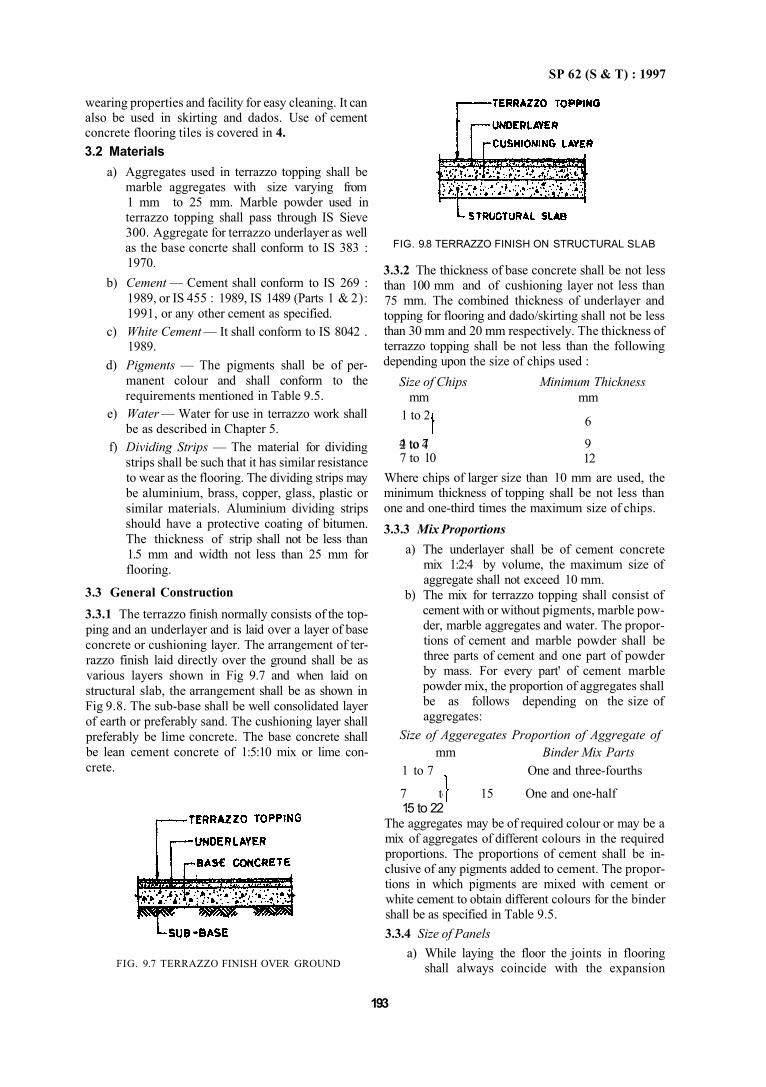
SP 62 (S & T) : 1997
wearing properties and facility for easy cleaning. It can also be used in skirting and dados. Use of cement concrete flooring tiles is covered in 4. 3.2 Materials
a) Aggregates used in terrazzo topping shall be marble aggregates with size varying from 1 mm to 25 mm. Marble powder used in terrazzo topping shall pass through IS Sieve 300. Aggregate for terrazzo underlayer as well as the base concrte shall conform to IS 383 : 1970.
b) Cement — Cement shall conform to IS 269 : 1989, or IS 455 : 1989, IS 1489 (Parts 1 & 2): 1991, or any other cement as specified.
c) White Cement — It shall conform to IS 8042 . 1989.
d) Pigments — The pigments shall be of permanent colour and shall conform to the requirements mentioned in Table 9.5.
e) Water — Water for use in terrazzo work shall be as described in Chapter 5.
f) Dividing Strips — The material for dividing strips shall be such that it has similar resistance to wear as the flooring. The dividing strips may be aluminium, brass, copper, glass, plastic or similar materials. Aluminium dividing strips should have a protective coating of bitumen. The thickness of strip shall not be less than 1.5 mm and width not less than 25 mm for flooring.
3.3 General Construction 3.3.1 The terrazzo finish normally consists of the topping and an underlayer and is laid over a layer of base concrete or cushioning layer. The arrangement of terrazzo finish laid directly over the ground shall be as various layers shown in Fig 9.7 and when laid on structural slab, the arrangement shall be as shown in Fig 9.8. The sub-base shall be well consolidated layer of earth or preferably sand. The cushioning layer shall preferably be lime concrete. The base concrete shall be lean cement concrete of 1:5:10 mix or lime concrete.
193
FIG. 9.7 TERRAZZO FINISH OVER GROUND
FIG. 9.8 TERRAZZO FINISH ON STRUCTURAL SLAB
3.3.2 The thickness of base concrete shall be not less than 100 mm and of cushioning layer not less than 75 mm. The combined thickness of underlayer and topping for flooring and dado/skirting shall not be less than 30 mm and 20 mm respectively. The thickness of terrazzo topping shall be not less than the following depending upon the size of chips used :
Size of Chips mm
1 to 2
2 to 4 4 to 7 7 to 10
Minimum Thickness mm
6
9 12
Where chips of larger size than 10 mm are used, the minimum thickness of topping shall be not less than one and one-third times the maximum size of chips. 3.3.3 Mix Proportions
a) The underlayer shall be of cement concrete mix 1:2:4 by volume, the maximum size of aggregate shall not exceed 10 mm.
b) The mix for terrazzo topping shall consist of cement with or without pigments, marble powder, marble aggregates and water. The proportions of cement and marble powder shall be three parts of cement and one part of powder by mass. For every part' of cement marble powder mix, the proportion of aggregates shall be as follows depending on the size of aggregates:
Size of Aggeregates Proportion of Aggregate of mm Binder Mix Parts
1 to 7 One and three-fourths
7 to 15 One and one-half 15 to 22
The aggregates may be of required colour or may be a mix of aggregates of different colours in the required proportions. The proportions of cement shall be inclusive of any pigments added to cement. The proportions in which pigments are mixed with cement or white cement to obtain different colours for the binder shall be as specified in Table 9.5. 3.3.4 Size of Panels
a) While laying the floor the joints in flooring shall always coincide with the expansion
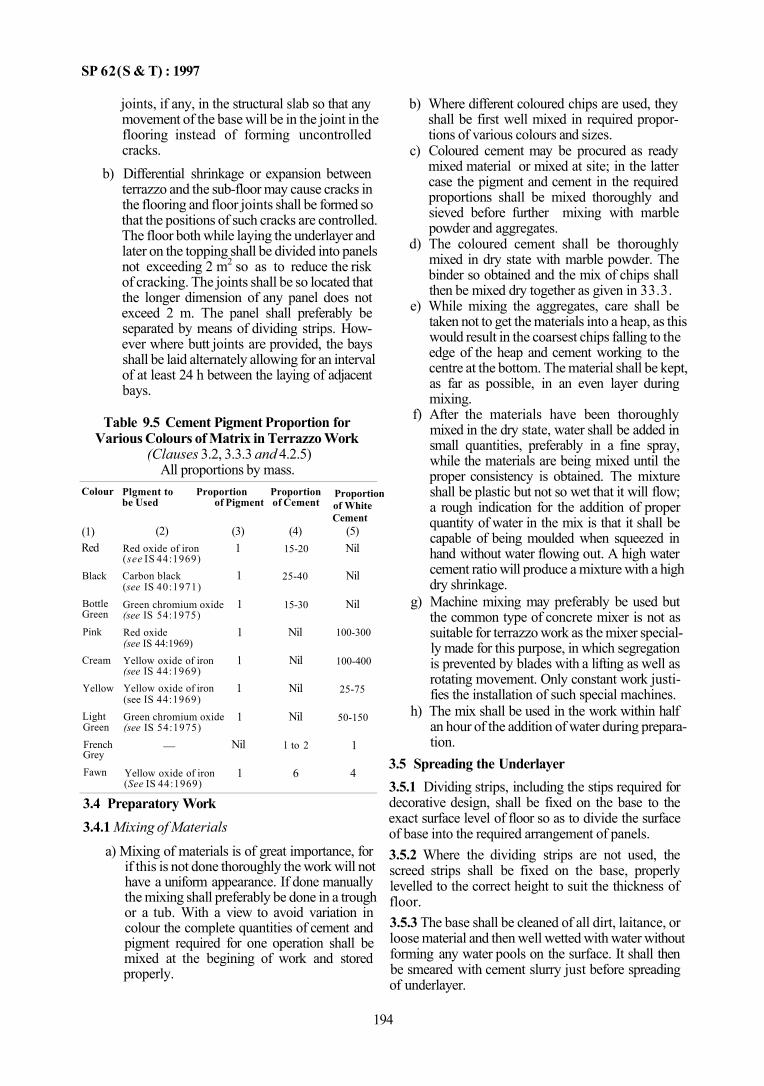
SP 62(S & T) : 1997
joints, if any, in the structural slab so that any movement of the base will be in the joint in the flooring instead of forming uncontrolled cracks.
b) Differential shrinkage or expansion between terrazzo and the sub-floor may cause cracks in the flooring and floor joints shall be formed so that the positions of such cracks are controlled. The floor both while laying the underlayer and later on the topping shall be divided into panels not exceeding 2 m2 so as to reduce the risk of cracking. The joints shall be so located that the longer dimension of any panel does not exceed 2 m. The panel shall preferably be separated by means of dividing strips. However where butt joints are provided, the bays shall be laid alternately allowing for an interval of at least 24 h between the laying of adjacent bays.
Table 9.5 Cement Pigment Proportion for Various Colours of Matrix in Terrazzo Work
(Clauses 3.2, 3.3.3 and 4.2.5) All proportions by mass.
Colour
(1) Red
Black
Bottle Green
Pink
Cream
Yellow
Light Green French Grey Fawn
Plgment to Proportion Proportion be Used of Pigment of Cement
(2) Red oxide of iron (see IS 44:1969) Carbon black (see IS 40:1971)
Green chromium oxide (see IS 54:1975) Red oxide (see IS 44:1969) Yellow oxide of iron (see IS 44:1969) Yellow oxide of iron (see IS 44:1969) Green chromium oxide (see IS 54:1975)
—
Yellow oxide of iron (See IS 44:1969)
(3) 1
1
1
1
1
1
1
Nil
1
(4) 15-20
25-40
15-30
Nil
Nil
Nil
Nil
l to 2
6
Proportion of White Cement
(5) Nil
Nil
Nil
100-300
100-400
25-75
50-150
1
4
3.4 Preparatory Work 3.4.1 Mixing of Materials
a) Mixing of materials is of great importance, for if this is not done thoroughly the work will not have a uniform appearance. If done manually the mixing shall preferably be done in a trough or a tub. With a view to avoid variation in colour the complete quantities of cement and pigment required for one operation shall be mixed at the begining of work and stored properly.
b) Where different coloured chips are used, they shall be first well mixed in required proportions of various colours and sizes.
c) Coloured cement may be procured as ready mixed material or mixed at site; in the latter case the pigment and cement in the required proportions shall be mixed thoroughly and sieved before further mixing with marble powder and aggregates.
d) The coloured cement shall be thoroughly mixed in dry state with marble powder. The binder so obtained and the mix of chips shall then be mixed dry together as given in 33.3.
e) While mixing the aggregates, care shall be taken not to get the materials into a heap, as this would result in the coarsest chips falling to the edge of the heap and cement working to the centre at the bottom. The material shall be kept, as far as possible, in an even layer during mixing.
f) After the materials have been thoroughly mixed in the dry state, water shall be added in small quantities, preferably in a fine spray, while the materials are being mixed until the proper consistency is obtained. The mixture shall be plastic but not so wet that it will flow; a rough indication for the addition of proper quantity of water in the mix is that it shall be capable of being moulded when squeezed in hand without water flowing out. A high water cement ratio will produce a mixture with a high dry shrinkage.
g) Machine mixing may preferably be used but the common type of concrete mixer is not as suitable for terrazzo work as the mixer specially made for this purpose, in which segregation is prevented by blades with a lifting as well as rotating movement. Only constant work justifies the installation of such special machines.
h) The mix shall be used in the work within half an hour of the addition of water during preparation.
3.5 Spreading the Underlayer 3.5.1 Dividing strips, including the stips required for decorative design, shall be fixed on the base to the exact surface level of floor so as to divide the surface of base into the required arrangement of panels. 3.5.2 Where the dividing strips are not used, the screed strips shall be fixed on the base, properly levelled to the correct height to suit the thickness of floor. 3.5.3 The base shall be cleaned of all dirt, laitance, or loose material and then well wetted with water without forming any water pools on the surface. It shall then be smeared with cement slurry just before spreading of underlayer.
194
SP 62(S & T) : 1997
3.5.4 After application of cement slurry, the under-layer shall be spread and levelled with a screeding board. The slightly rough surface left by the screeding board will form a satisfactory key for the terrazzo. 3.6 Laying Terrazzo Topping
3.6.1 Terrazzo topping shall be laid while the under-layer is still plastic, but has hardened to provent cement from rising to the surface which is, normally, achieved between 18 to 24 h after the underlayer has been laid. A cement slurry preferably of the same colour as the topping shall be brushed on to the surface immediately before laying is commenced. If possible, the entire work of laying the topping shall be completed at one stretch. 3.6.2 The terrazzo mix shall be placed on the screed bed and compacted thoroughly by tamping or rolling and trowelled smooth. The time interval allowed between each successive trowelling is important as only that much trowelling, which is sufficient to give a level surface, is needed immediately after layer. Further compacting shall be carried out at intervals, the amount depending upon the temperature and rate of set of the cement. Excessive trowelling or rolling in early stages shall be avoided as this tends to work up cement to the surface producing a finish liable to cracking and also necessitates more grinding of surface to expose the marble chips. 3.6.3 The surface shall then be rammed in order to consolidate the terrazzo; it is not sufficient just to 'float' lightly, as this would cause depressions which have to be filled with mortar. A piece of smooth marble stone of size 150 mm × 150 mm × 25 mm may be advantageously used for ramming. Following the rammer, a trowel may be used. When using the trowel the object should be to make surface level and smooth with as little use of the float as possible relying on pressure rather than upon a trowelling action to achieve this end. Rolling will be easier than tamping and patting but a rolled terrazzo is more likely to crack since the roller would draw cement to the surface unless the mixture is very dry. The best results are obtained by tamping Combined with minimum of trowelling. The compaction shall ensure that the air bubbles are cleared from the mix.
3.6.4 Work on Borders and Decorative Designs Borders and decorative designs shall be laid before the main body of the flooring. They shall be laid and finished in the same manner as flooring, preferably using dividing strips. Where, however, stencils or framework of wood or metal are used instead of dividing strips, they shall be removed before the topping mix commences to harden. The removal shall be effected with as little disturbance to the materials as possible and any ragged edges left after removal of the
stencils or framework shall be rectified with a large trowel, care being taken to consolidate terrazzo to avoid damage to the edges of the design. 3.7 Caring
The surface shall be left dry for air-curing for a duration of 12 to 18 h depending on the atmospheric conditions. It shall then be cured by allowing water to stand in pools over it for a period of not less than 4 days. Precautions shall be taken to prevent the floor from being subjected to extreme temperature.
3.8 Grinding
3.8.1 The grinding and processing of terrazzo may be commenced not less than 2 days from the time of completion of laying for manual grinding and not less than 7 days for machine grinding. The period that should be allowed before the floor is fit for grinding depends upon the materials, their proportions and the weather. The sooner the grinding is done the easier it is; if it is done too soon the grinding may tear out the chips from the matrix,
3.8.2 The filling shall be done with a grout using the same coloured cement (without marble powder) as the original mix for terrazzo topping and a portion of the coloured cement shall be kept for this purpose when the floor is laid; this ensures that the patches do not differ in appearance from the remainder of the floor.
3.8.3 Grinding and polishing may be done either by hand or by machine. The operations shall be as given below:
a) The first grinding shall be done with carborundum stones of 60 grit size.
b) The surface shall then be washed clean and grouted with neat cement mortar of the same colour as matrix grout of cream like consistency. It shall then be allowed to dry for 24 h and wetcured for 4 days in the same manner as specified in 3.7.
c) The second grinding shall be done with carborundum stone of 80 grit size.
d) The surface shall then be prepared once more as in 3.8.3 (b).
e) The third grinding shall be done with carborundum stone of 120 to 150 grit size.
f) The surface shall again be washed clean and allowed to dry for 12 h and wetcured for 4 days in the same manner as in 3.7.
g) The fourth grinding shall be done with carborundum stone of 320 to 400 grit size.
h) The surface shall again be washed clean and rubbed hard with felt and slightly moistened oxalic acid powder: 5 g of oxalic acid powder is adequate for 1 m2 of floor surface.
195
SP 62 (S & T) : 1997
3.8.4 When all constructional and finishing works, namely, painting, distempering, electrical work, plumbing, joinery work, etc, are completed and just before the area is occupied the floor shall be wahsed clean with dilute oxalic acid solution and dried. Floor polishing machine fitted with felt or hessian bobs shall then be run over it until the floor shines. In case wax-polished surface is desired, the wax-polish shall be sparingly applied with soft linen on the clean dry surface. Then the polishing machine fitted with bobs shall be run over it. Clean sawdust shall then be spread over the floor and polishing machine again be applied mopping up surplus wax leaving glossy surface. Care shall be taken to see that the floor is not left slippery. 3.9 Laying Terrazzo Skirtings and Dados 3.9.1 Underlayer For terrazzo finish on vertical surfaces like skirting and dados, the underlayer shall consist of a layer of stiff cement mortar 1:3 (by volume) and finished rough so as to provide adequate key for topping.
3.9.2 Thickness
The combined thickness of underlayer and terrazzo topping shall be not less than 20 mm. The minimum thickness of terrazzo topping shall be not less than 6 mm. 3.9.3 The other operations like laying, curing, grinding, polishing and maintenance shall be similar to those described for in-situ terrazzo flooring except that grinding will be done manually.
3.10 Maintenance
Under normal conditions, the flooring may be kept clean by washing periodically with water and occasionally with a dilute solution of oxalic acid after which it shall be mopped down with cold water and dried. If desired, the floor may be polished using a hard wax-polish or an emulsion polish. Soap in any form shall not be used as it tends to make the terrazzo dangerously slippery; excessive polishing has a similar effect. The surface may also be kept free from oil and grease to avoid slipperiness.
4 CEMENT CONCRETE FLOORING TILES 4.1 General The usefulness of tiles as a flooring material consists mainly in their plesant appearance as it eliminates the possibility of unsightly cracks and facility for quick installation. The appearance and performance of tiled floor will, however, depend not only on the quality of materials used but also on the care taken in bedding, laying and finishing of the tiles.
a) Tile flooring may be laid on most types of reasonably rigid base, provided that the sub-floor is of sufficient strength for the type of flooring proposed and is not liable to settlement at any time. Cement concrete flooring tiles are not recommended for use where they will be exposed to the action of acids and alkalis. However, they give suitable service if exposed to seawater, vegetable oil or fats.
b) For the purpose of selecting tiles, floors are generally classified into the following types: 1) General purpose or light duty floors, that
is, those subject to pedestrian traffic as in offices, domestic buildings, hospitals, colleges, banks etc;
2) Medium duty floors, that is, those subject to heavy pedestrian traffic from trolleys, casts, etc, as in factories, pavements, platforms, railway stations, driveways etc; and
3) Non-slip floors (where chequered tiles are used), that is, footpaths and pavements, special factory floors, platforms, ramps, etc.
4.2 Materials
4.2.1 Sand
The sand to be used for mortar for laying of tiles shall conform to IS 2116 : 1980 and the sand shall have a minimum fineness modulus of 1.5.
4.2.2 Cement
The cement used for laying the tiles and grouting shall conform to IS 269: 1989, or IS 455 : 1989, or IS 1489 (Parts 1 & 2): 1991, or as specified.
4.2.3 Lime
Class B or Class C conforming to IS 712 : 1984.
4.2.4 Tiles
The cement concrete flooring tiles to be used shall conform to IS 1237: 1980.
4.2.5 Pigments
Pigments incorporated in mortar or used for grating shall conform to Table 9.5.
4.2.6 Water
Water used shall conform to requirements laid down Chapter 5, 4.2.7 Oxalic acid used in polishing of tiles shall be such as to give satisfactory performance without detrimental effects.
196
SP 62 (S & T) : 1997
4.3 Preparatory Work
4.3.1 Completion of Work Before Laying of Tiles
a) All the inside walls, ceiling and outside walls shall be plastered and door frames and windows fixed in position.
b) The sub-floor shall be finished to a reasonably true plane surface about 35 to 50 mm below the level of the finished floor, properly graded and free from loose earth, dirt or dust and lumps.
c) Before tiling work is started, all points of level for the finished tile surface shall be marked out. This is particularly necesary in the case of finished staircase landings. Wherever slopes in finished floors are desired points of level and outlets shall be correctly marked and outlet openings made before hand.
d) Where it is feared or suspected that dampness may percolate either from the ground floor or walls, the same shall be damp-proofed or waterproofed as described in Chapter 12.
4.4 Bedding a) Spreading of Cement Mortar—The base shall
be well compacted and the surface shall be rough to form a suitable key. The base shall be cleaned and wetted without allowing any pools of water on the surface. Cement mortar 1:6 for shall be evenly spread over the base for two rows of tiles and about 3 to 5 m in length with thread level fixed at both ends to act as a guide. The top of the mortar shall be kept rough so that cement sturry can be absorbed. The thickness of bedding shall be not less than 10 mm and not more than 30 mm in any one place. Tiles shall then be laid as in 4.5.
b) Spreading of Lime Mortar — After preparing the surface as in (a) above lime mortar 1:1:2 (1 lime: 1 SURKHI: 2 coarse sand) or 1:3 (1 lime: 3 SURKHI) or 1:3 (1 lime: 3 coarse sand) shall be spread evenly limiting the thickness as in (a).
4.5 Laying of Tiles
4.5.1 Laying of tiles should commence next morning by which time the bedding becomes sufficiently hard to offer a rigid cushion for the tile and enable masons to place wooden planks and squat on them. Neat cement slurry of honey like consistency shall be spread over the mortar bed, over such an area at a time as would accomodate 20 tiles. The tiles shall be fixed with grout one after the other, each tile being tapped gently with a wooden mallet till it is properly bedded and in level with the adjoining tiles. The joints shall be kept as close as possible and in straight lines. The joints between the tiles shall normally be 1.5 mm wide.
4.5.2 Surplus cement slurry after the days work shall be cleaned and joints washed fairly deep. 4.5.3 The day after the tiles have been laid, joints shall be filled with cement grout of the same shade as the colour of the matrix of the tile. The freshly laid portion of the tiles shall be prevented from damage by providing suitable barricades. 4.5.4 Tiles which are fixed to the floor adjoining the wall shall go about 10 mm under the plaster, skirting or dado as may be required by the designer. For this purpose the wall plaster may be left unfinished by about 50 mm above the level of the proposed finished flooring and the unfinished strip may be plastered later or after the tiles are fixed. 4.5.5 In odd situations where a full tile cannot be provided, tile shall be cut to size and then fixed. 4.5.6 After fixing the tiles, the floor shall be kept moist and allowed to mature for 7 days so that the bedding and joints set properly. After this, it may be used for light traffic. Heavy traffic shall not be allowed on the floor for at least 14 days after fixing the tiles. 4.5.7 Wherever big areas of floor are to be tiled, the level of the central portion of the floor shall be kept about 10 mm higher than the level marked at walls unless specified otherwise. This is normally done to avoid the optical illusion of a depression in the central portion of the tiled hall. 4.6 Grinding and Polishing 4.6.1 Grinding and polishing of tiles shall commence only after the floor as well as the joints have properly set and in no case earlier than 14 days of laying. 4.6.2 Grinding should preferably done by machine except for skirting. 4.6.3 For grinding terrazzo tile flooring, the first grinding shall be with machine fitted with carborundum stones of 48 to 60 grit. When the floor is rubbed even and chies show uniformity it shall be cleaned with water marking base all pinholes. Grouting in the same shade is then briskly applied so that all pinholes are properly filled in. The grout shall be kept moist for a week for proper setting. Thereafter, the second grinding operation with carborundum of 120 grit is commenced. The floor is grouted again to fill in fine pinholes. After curing, the flooring is left with protective film till other works are completed and all workers quit. Before the final grinding the floor is swept clean.Final grinding is done with carborundum of 220 to 350 grit using plenty of water and taking care that any foreign matter, particles of sand. etc, are prevented. When surface is rendered smooth, it is washed with water. Afterwards oxalic acid powder is vigorously applied with machine fitted with hessian bobs to bring out sheen. Wash the floor clean and apply dry linen to suck in moisture. If desired wax-polish may finally be
197

SP 62 (S &T) : 1997
applied mechanically with clean hessian bobs. Superfluous wax is mopped-up with saw dust till occupation. This will protect the surface and help increase lustre. When saw dust is spread, water should not be spilled as this is likely to give stains on the polished surface. 4.6.4 When hand grinding and polishing has to be adopted, the various processes in the same sequence shall be carried out as in 4.6.3, except that stones with coarser grit may be used. 4.6.5 In the case of plain cement and coloured tiles, the process of polishing shall be the same as in 4.6.3 except that initial grinding with carborundum stone of 48 to 60 grit may not be necessary.
4.6.6 Chequered and Grooved Tiles
These tiles normally do not require polishing. But where polishing is required, the same shall be done as in 4.6.5.
4.7 Laying of Rough Tiles
4.7.1 Where the tiles have been supplied and fixed in rough condition (not ground and filled by the manufacturer), the first grinding shall be done not less than 14 days after fixing the tiles. The initial grinding shall be done with carborundum stones of 36 to 48 grit. The remaining process shall be as in 4.6.3.
4.8 Tolerance in Laying
The permissible deviation from datum depends on the area involved; for a large open area a deviation upto 15 mm may be tolerated. Localized deviation of 3 mm in any 3 m may be accepted in nominally flat floor.
4.9 Skirting, Dado Work and Staircase — Tread Work
4.9.1 Tile skirtings, where required, shall be fixed only after laying the tiles on the floors. If tiles are to be fixed on walls as dados, the portion of the wall to be tiled shall be left unplastered. Also, dado work shall be done only after laying tiles on the floor.
A-1 CLEANING THE SURFACE
A-1.1 The top surface of concrete shall be clean and free from grease or oil to enable the hardening solu-
4.9.2 Before fixing tiles on brick or concrete wall, the wall surface shall first be wetted with clean water. Thereafter, in case of dado the wall surface shall be uniformly and evenly covered with about 10 mm thick backing of cement mortar 1:4 (1 cement: 4 coarse sand). In the case of skirting the tiles shall be directly fixed with cement mortar 1:4 without initial backing. Before the cushioning mortar has hardened, the back of each tile to be fixed shall be covered with a thin layer of neat cement paste and the tile shall then be gently tapped against the wall With a wooden mallet. The fixing shall be done from bottom of wall upwards. Each tile shall be fixed as close as possible to the one adjoining and any difference in thickness of tile shall be evened out in the cushioning mortar or cement paste so that all the tile faces are set in conformity with one another.
4.9.3 Wherever possible, skirtings and dado shall be ground and polished just as for floor work with machine suitable for the purpose. Skirtings and dado may also be polished by hand. 4.9.4 Precast treads and risers for staircases shall be laid and polished as for flooring. 4.9.5 The laying and polishing of tiles for external paving shall be done similar to that of ordinary flooring.
4.10 Maintenance
a) After laying, the floor shall be allowed to remain clean and free from cement, oil, paint, plaster droppings and all materials likely to stain or spoil the tiles. If appliances, such as, trestles, ladders, steps etc, have to be used for electrician's plumber and other light work, it shall be ensured that parts in contact with the flooring are padded and no sliding of the appliances shall be permitted.
b) Subsequent maintenance shall be done by regularly swabbing with clean water followed by rubbing with dry linen.
tions to penetrate. Thorough cleaning of the surface shall be ensured particularly in old surfaces. The top surface shall be wetted with water and scrubbed with coir or steel wire brush and cleaned with water. The
ANNEX A (Clauses 1.8 and 2.2)
SURFACE TREATMENT TO CEMENT CONCRETE FLOOR TOPPING
198
SP 62(S & T) : 1997
floor shall be allowed to dry before applying hardening solution. A-2 TREATMENTS A-2.1 Sodium Silicate
A solution containng one part by volume of sodium silicate and four parts of water should be spread evenly over the concrete top surface with a mop or soft brush. Any excess material shall be wiped off and the floor allowed to dry. After washing the floor with clean water, a second coat, containing one part of sodium silicate to three or four parts of water should be applied and this should be allowed to dry similarly. After drying, a third coat shall be applied after washing the floor if it is still porous. After drying, the floor should be washed with clean hot water. Effective results are obtained if the treatment is applied 7 to 10 days after the end of curing.
1 GENERAL
1.1 In industrial floors finishes the following are covered:
a) Industrial floors to IS 4971 : 1968. b) Dairy floors to IS 7956 : 1975. c) Bitumen mastic flooring for industries han
dling LPG and other light hydrocarbon products to IS 13074: 1991.
1.2 In the selection of industrial floor finishes, special care is required in view of diversity of the requirements to be met with and the different characteristics of individual floor finishes. The strength and stability of finishes will depend on the structural floor, the sub-floor or the foundation. Overloading, thermal expansion and movements due to bad design may cause failure of an otherwise satisfactory floor finish. Spillage of chemical solutions, acids, alkalis, etc, on the floor contribute towards the failure of a floor finish.
2 TYPES OF INDUSTRIAL FLOOR FINISHES
2.1 Types
This will deal with the selection of industrial floor finishes where the floor is subject to heavy abrasion, impact, chemical action; floor finish under special
A-2.2 Silico-Flouride
The crystals of magnesium silico-flouride or of zinc silico-flouride should be dissolved in water at the rate of 0.1 g/cm3 for the first coat and 0.2 g/cm3 for subsequent coats. Three coats are usually applied after 24 h intervals. There is no need to wash the top surface between coats, but it is advisable to wash with clean water after the final treatment.
A-2.3 Drying Oil and Surface Sealers
Drying oils, either neat or thinned with turpentine or white spirit, or surface sealers, may be applied to the top sqrface by brushing. Any excess should be wiped off about 2 h after application. A-2.4 Calcium chloride shall not be used with high alumina cement.
circumstances, such as, non-slippery, dustless, noiseless, non-sparking, anti-static, etc.
2.1.1 A finish for the floor of an industrial building may be generally selected out of the following types to suit the requirements of particular case:
a) Plain concrete — as described in Part 2, b) Granolithic concrete — as described in Part 2, c) Precast concrete tile — as described in Part 2, d) Paviig brick — as described in Part 1, e) Magnesium oxychloride — as described in
Part 4, f ) Bitumen mastic — as descrbied in Part 4, g) Linoleum — as described in Part 4, h) Rubber, PVC sheets — as described in Part 4, j) Epoxy resin — as described in Part 4, k) Fire clay brick — conforming to IS 6727 :
1972, m) Ceramic unglazed vitreous acid resistant tiles
— conforming to IS 4457: 1982, n) Stones, p) Steel or cast iron units — conforming to IS
3502:1981, q) Wooden block with lead lining, and r) Acid resistant brick — conforming to IS 4860 :
1968.
PART 3 INDUSTRIAL FLOOR FINISHES
199
SP 62 (S & T) : 1997
2.2 Considerations for Selection of Floor Finish 2.2.1 The important features that govern the selection of industrial floor finish are durability, incidence of loading, safety, resistance to chemical action, convenience of the user, appearance and overall economy. Table 9.6 gives in general a summary of requirements of floor finishes for various industrial buildings.
a) Durability 1) Wear — The nature of mechanical wear
that a floor has to resist varies considerably. For general information the type of wear may be classified as below:
Type of Wear Examples Very severe abrasion Heavy engineering
together with heavy workshops and places impact where milk cans are being
handled in dairies Very severe abrasion Places where steel-tyred
trucks constantly move Severe abrasion Floors having traffic of
more than 2 000 persons per day in definite traffic lanes
2) Impact — Consideration should be given to impact, as many flooring materials that will stand abrasion may suffer rapid damage under impact.
3) Load carrying capacity — Depending on the nature of loading and type of traffic, such as foot, rubber, tyred, metal wheeled, etc, the flooring should be selected to withstand the severe condition.
b) Safety 1) Resistance to high temperature or fire —
In industrial structures high temperatures occur without spread of fire. Floor finishes do not by themselves add to fire risks, provided the floor superstructure has adequate resistance to fire. In certain special circumstances, however there may be risks arising from the usage of the floor. For example, oil or other flammable liquids spilled on floor will lead to greater fire risks with floors which are absorbent or themselves combustible, such as, timber or bitumen, than with inert dense materials, such as, concrete or tiles.
2) Sparking — In factories or stores where explosives and substances liable to cause explosions are being handled, sparks caused by friction on a floor surface may cause fire or explosion. Therefore, it is assential to use non-sparking floor finishes, such as rubber or special grade of
bitumen mastic or magnesium oxychloride composition. A lead lining may be provided over the base concrete or wooden flooring where explosives are being stored. It may be necessary to use a floor which conducts electricity and thus prevents the accumulation of static electrical charges which may cause a spark.
c) Resistance to chemicals and water — The spillage or splashing of chemical solutions acids, etc, may cause corrosion, deterioration, induce slipperiness or give to other fire or health risks. The possibility of wetting or flooding the floor with water may be taken into account.
2.3 Properties of Floor Finishes 2.3.1 Properties of floor finishes are listed in Table 9.7.
a) Cement concrete finishes — Plain cement concrete is used for a wide variety of industrial floors in-situ form. Portland cement concrete is resistant to a wide variety of chemicals, including mineral oils and greases but is slowly attacked by acids, vegetable oils, fats and sugar solutions. Frequent cleaning reduces the attack, but prolonged exposure will bring about a gradual deterioration of the cement concrete flooring. Granolithic flooring is hard wearing, resists impact and is resistant to alkalis and mineral oils. On the other hand, it is hard to the feet, cold, noisy and susceptible to chemical attack including acids, sulphates and vegetable oils and fats. Concrete tiles have good resistance to wear and chemical attack but cannot withstand heavy impact; where good appearance and cleanliness are required for the floors, concrete tiles may be selected.
b) Brick and tile finishes — They have good resistance to wear and impact. Paving bricks to IS 3583 : 1988 may be used for heavy duty and industrial floors, loading and unloading platforms where the floor is subjected to heavy wear and tear. Fireclay brick to IS 6727 : 1972 may be used in situation where high temperatures are to be met with, such as those around metallurgical furnaces. Acid resistant bricks conforming to IS 4860 : 1968 have good resistance to all acids except hydrofluoric acid and perchloric acid and other chemicals. They are suitable for floorings subject to acid attack and abrasion.
200
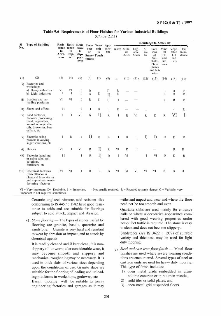
SP 62(S & T) : 1997
Table 9.6 Requirements of Floor Finishes for Various Industrial Buildings (Clause 2.2.1)
Ceramic unglazed vitreous acid resistant tiles conforming to IS 4457 : 1982 have good resistance to acids and are suitable for floorings subject to acid attack, impact and abrasion.
c) Stone flooring — The types of stones useful for flooring are granite, basalt, quartzite and sandstone. Granite is very hard and resistant to wear by abrasion or impact, and to attack by chemical agents. It is readily cleaned and if kept clean, it is non-slippery till unworn; after considerable wear, it may become smooth and slippery and mechanical roughening may be necessary. It is used in thick slabs of various sizes depending upon the conditions of use. Granite slabs are suitable for the flooring of loading and unloading platforms in workshops, godowns, etc Basalt flooring will be suitable for heavy engineering factories and garages as it may
withstand impact and wear and where the floor need not be too smooth and even. Quartzite slabs are used mainly for entrance halls or where a decorative appearance combased with good wearing properties under heavy foot traffic is required. The stone is easy to clean and does not become slippery. Sandstones (see IS 3622 : 1977) of suitable variety and thickness may be used for light duty flooring.
Steel and cast iron floor finish — Metal floor finishes arc used where severe wearing conditions are encountered. Several types of steel or cast iron units are used for heavy duty flooring. This type of finish includes: 1) open metal grids embedded in gran-
nolithic concrete or in bitumen mastic, 2) soild tiles or solid plates, and 3) open metal grid suspended floors.
201
Sl No.
(1)
i)
ii)
ill)
iv)
v)
vi)
vit)
viii)
Type of Building
(2)
Factories and workshops a) Heavy industries b) Light industries
Loading and unloading platforms
Shops and offices
Food factories, factories processing meal, vegetables, animal or vegetable oils, breweries, beer cellars, etc
Factories using process involving sugar solutions, etc
Dairies
Factories handling or using salts, salt solutions, fertilizers, etc
Chemical factories (miscellaneous) chemical laboratories and explosives manu-facturing factores
Resis- Resistance tance
to to Abra. Imp-sion act
(3) (4)
VI VI I I
VI VI
I I
I I
I R
VI I
I I
VI VI
Resistance
to Slip-peri-ness
(5)
I I
I
I
VI
I
VI
I
I
Even- War-ness mth or to
Smoo- Touch thness
(6)
I) I)
R
I
I)
I)
R
R
R
(7)
I)
I)
R
I)
I)
I) I)
R
App-eara-nee
(8)
I) I) I)
I
R
R
R
I)
I)
Resistance to Attack by
Water Mine- Org- Ai- Solu- Mine- Vege- Heat ral anic ka- ions ral table Resi-
Acids Acids lis of Oil Oil stance Sul- and and
phates, Gre Fats Phos- ases phates
and Nitates
(9)
R R
I
R
I
I
VI
I
VI
(10)
—
—
—
I)
R
D
VI
VI
(11)
—
—
—
VI
I
I
VI
(12) (13) (14)
I R
R
_
R D R
I) I) D
—
I VI D
VI VI R
(15)
O O
R
-
VI
D
R
D
R
(16)
R R
R
R
I
R
R
R
O
VI = Very important D= Desirable, I = Important. - Not usually required. R = Rcquired to some degree O = Variable, very important to not required sometimes
d)
SP 62 (S & T) : 1997
Open metal grids embedded in granolithic concrete are suitable for loading platforms subject to impact and wear caused by movements of trollies with iron wheels, under wet or greasy conditions as in the case where bottled milk are handled. Steel tiles with a smaller proportion of open space than the grids embedded in granolithic concrete are suitable for situations subject to heavy abrasion and impact. The open metal grids and steel tiles tend to become slippery when oily and to corrode when wet. Solid faced metal tiles (usually made of cast iron) are highly resitant to wear and impact and to action of oils, fats, salts and alkalis provided the joints are filled with appropriate chemical resistant material (see Part 4). The plain surface types are liable to become slippery if wet or even when dry if polished by wear, and hence special types with patterned surface shall be used under these conditions The solid metal tiles are particularly useful, on loading bays where there is heavy trucking and in dairies where a high standard of cleanliness combined with high resistance to wear and chemical attack is required. Steel or cast iron grid suspended floors are used for elevated platforms or walk ways around large machinery. Floors on which liquids or solids are continuously being spilled may be made of supported steel grids with suitable channels beneath, from which the spilled material may be drained or recovered.
e) Wooden block with lead lining — This provides a non-sparking floor finish and is suitable for floors where explosives are stored.
f) Magnesium oxychloride — The flooring mix gives a fairly strong and durable floor with good appearance. However, the flooring is affected by continued exposure to water, acids, and salt solution. Too wet a mix with excessive magnesium chloride results in sweating of the floor surface. Mineral oils, greases, vegetable, oils, milk products and mild alkalis do not affect the floor.
g) Bitumen mastic flooring — Bitumen mastic flooring is considered suitable for industrial buildings, storage houses, etc, because of its resiliency, wearing quality and ease of maintenance. Bitumen mastic flooring to IS 1196 :1978 is dustless, odourless, jointless and impervious to the transmission of moisture either in liquid or vapour form. The flooring is easily cleaned, quiet under traffic and resilient Bitumen mastic flooring is also durable. While it may carry heavy loads, concentrated loads
may cause indentation. In selecting bitumen mastic flooring consideration may be given to be anticipated service conditions, particularly the type of traffic and possible contact with oils, acids and the like. The surface of bitumen mastic flooring is liable to become slowly softened by prolonged contact with greases, fats and oils. Contamination with such materials shall be avoided.
h) Linoleum flooring — Linoleum provides a clean, dust free and resilient flooring. In light industry, such as, in electronic industry, linoleum flooring may be used as the risk of damage by cutting to which linoleum is vulnerable is small. If linoleum gets wet, it expands, mildews and eventually rots.
j) Rubber flooring — The flooring is resilient and noiseless. The flooring is suitable for electronic industry, computer rooms, etc.
k) Flexible PVC flooring — The PVC flooring provides a clean, dust free and resilient flooring. The flooring may be easily cleaned with wet cloth, as dirt and grime do not penetrate the surface.
m) Epoxy resin floor topping — The use of epoxy resin floor toppings is characterized by its exceptional physical and chemical properties, such as, chemical resistance, hardness, abrasion resistance; compressive, impact and structural strengths; dimensional stability and adhesion to concrete, metal and other surfaces. This is suitable for use on industrial floors, such as, chemical plants manufacturing fertilizers, pharmaceuticals, acids, solvents, etc, in dairies, tanneries, breweries, garages, service stations, warehouses, metal plating and pickling areas.
2.4 Recommendations for Floor Finish for Industrial Buildings (see Table 9.8)
2.4.1 Floors for Heavy Engineering Factories, Workshops and Garages
Floors in heavy engineering factories, workshops and garages shall be resistant to impact, abrasion and attack by lubricating oils. The epoxy resin floor topping is suitable for heavy industrial floors. The extent to which the floors will be subjected to heavy wear and impact will often vary widely in different parts and since the more important type of finishes are more expensive it is advisable to ascertain as far as possible, before laying the finishes, where trucking gangways or processes involving impact will be located and to provide accordingly. Steel or cast iron tiles or plates, embedded in granolithic concrete may be used for areas of heavy abrasion by steel-tyred trucks or where a high resistance to impact is required.
202
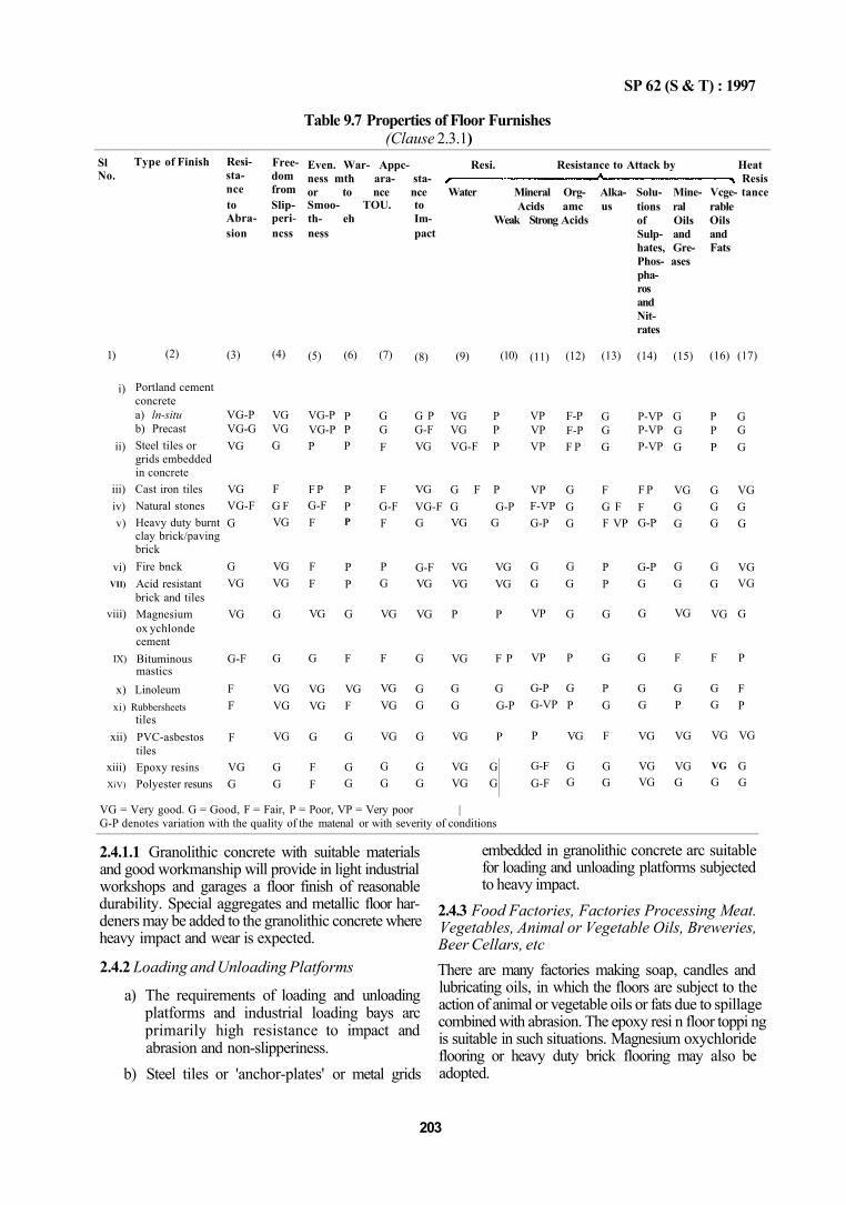
SP 62 (S & T) : 1997
Table 9.7 Properties of Floor Furnishes (Clause 2.3.1)
1)
i)
ii)
iii) iv) v)
vi) VII)
viii)
IX)
x) Linoleumxi) Rubbersheets
xii)
xiii) XiV)
(2)
Portland cement concrete a) ln-situ b) Precast Steel tiles or grids embedded in concrete Cast iron tiles Natural stones Heavy duty burnt clay brick/paving brick Fire bnck Acid resistant brick and tiles Magnesium ox ychlonde cement Bituminous mastics
tiles PVC-asbestos tiles Epoxy resins Polyester resuns
(3)
VG-P VG-G VG
VG VG-F G
G VG
VG
G-F
F F
F
VG G
(4)
VG VG G
F G F VG
VG VG
G
G
VG VG
VG
G G
(5)
VG-P VG-P P
F P G-F F
F F
VG
G
VG VG
G
F F
(6)
P P P
P P P
P P
G
F
VG F
G
G G
(7)
G G F
F G-F F
P G
VG
F
VG VG
VG
G G
(8)
G P G-F VG
VG VG-F G
G-F VG
VG
G
G G
G
G G
(9)
VG P VG P VG-F P
G F P
(10)
G G-P VG G
VG VG VG VG
P P
VG F P
G G G G-P
VG P
VG G VG G
(11)
VP VP VP
VP F-VP G-P
G G
VP
VP
G-P G-VP
P
G-F G-F
(12)
F-P F-P F P
G G G
G G
G
P
G P
VG
G G
(13)
G G G
F G F F VP
P P
G
G
P G
F
G G
(14)
P-VP P-VP P-VP
F P F G-P
G-P G
G
G
G G
VG
VG VG
(15)
G G G
VG G G
G G
VG
F
G P
VG
VG G
(16)
P P P
G G G
G G
VG
F
G G
VG
VG G
VG = Very good. G = Good, F = Fair, P = Poor, VP = Very poor | G-P denotes variation with the quality of the matenal or with severity of conditions
(17)
G G G
VG G G
VG VG
G
P
F P
VG
G G
2.4.1.1 Granolithic concrete with suitable materials and good workmanship will provide in light industrial workshops and garages a floor finish of reasonable durability. Special aggregates and metallic floor hardeners may be added to the granolithic concrete where heavy impact and wear is expected.
2.4.2 Loading and Unloading Platforms
a) The requirements of loading and unloading platforms and industrial loading bays arc primarily high resistance to impact and abrasion and non-slipperiness.
b) Steel tiles or 'anchor-plates' or metal grids
embedded in granolithic concrete arc suitable for loading and unloading platforms subjected to heavy impact.
2.4.3 Food Factories, Factories Processing Meat. Vegetables, Animal or Vegetable Oils, Breweries, Beer Cellars, etc There are many factories making soap, candles and lubricating oils, in which the floors are subject to the action of animal or vegetable oils or fats due to spillage combined with abrasion. The epoxy resi n floor toppi ng is suitable in such situations. Magnesium oxychloride flooring or heavy duty brick flooring may also be adopted.
203
Sl No.
Type of Finish Resistance to Abrasion
Freedom from Slip-peri-ncss
Even. War- Appc- Resi. Resistance to Attack by Heat ness mth ara- sta- Resis or to nce nce Water Mineral Org- Alka- Solu- Mine- Vcge- tance Smoo- TOU. to th- eh Im-ness pact
Acids amc us Weak Strong Acids
tions ral of Oils Sulp- and hates, Gre-Phos- ases pharos and Nitrates
rable Oils and Fats
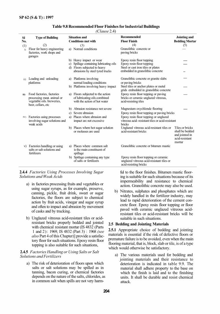
SP 62 (S & T) : 1997
Table 9.8 Recommended Floor Finishes for lndustrial Buildings (Clause 2.4)
Sl No. (1)
I)
ii)
iii)
IV)
v)
Type of Building
(2) Floor for heavy engineering factories, work shops and garages
Loading and unloading platforms
Food factories, factories processing meat. animal or vegetable oils. breweries, beer, cellars, etc
Factories using processes involving sugar solutions and weak acids
Factories handling or using salts or salt solutions and fertilizers
Situation and Conditions met with
(3) a) Normal conditions
b) Heavy impact or wear c) Spillage containing lubricating oils d) Floors subjected to heavy
abrasions by steel tyred trucks
a) Platforms involving normal loading conditions
b) Platforms involving heavy impact
a) Floors subjected to the action of lubricating oils combined with the action of hot water
b) Abrasion resistance not severe c) Severe abrasion a) Places where abrasion and
impact arc not excessive
b) Places where hot sugar solution or molasses are used
a) Places where common salt is the main constituent of spillage
b) Spitlage containing any type of salts or fertilizers
Recommended Floor Finish
(4) Granolithic concrete or —paving bricks
Epoxy resin floor topping Epoxy resin floor topping Steel or cast iron tiles or plates embedded in granolithic concrete
Granolithic concrete or granite slabs or paving bricks Steel tiles or anchor plates or metal grids embedded in granolithic concrete Epoxy resin floor topping or paving bricks or ceramic unglazed vitreous, acid-resisting tiles
Magnesium oxychlonde flooring
Jointing and Bedding Mortar
(5)
— —
–
—
—
—
— Epoxy resin floor topping or paving bricks Epoxy resin floor topping or unglazed vitreous acid- resistant tiles or acid-resistant bricks Unglazed vitreous acid-resistant tiles or acid-resistant bricks
Granolithic concrete or bitumen mastic
Epoxy resin floor topping or ceramic unglazed vitreous acid-resistant tiles or acid-resisting bricks
Tiles or bricks shall be bedded and jointed in acid-resistant mortar
2.4.4 Factories Using Processes Involving Sugar Solutions and Weak Acids
a) in factories processing fruits and vegetables or using sugar syrups, as for example, preserve, canning, pickle, fruit drink, sweet or sugar factories, the floors are subject to chemical action by fruit acids, vinegar and sugar syrup and often to impact and abrasion by movement of casks and by trucking.
b) Unglazed vitreous acid-resistant tiles or acid-resistant bricks properly bedded and jointed with chemical resistant mortar (IS 4832 (Parts 1 and 2): 1969, IS 4832 (Part 3) : 1968 (see also Part 4 of this Chapter)] provide a satisfactory floor for such situations. Epoxy resin floor topping is also suitable for such situations,
2.4.5 Factories Handling or Using Salts or Salt Solutions and Fertilizers
a) The risk of deterioration of floors upon which salts or salt solutions may be spilled as in tanning, bacon curing, or chemical factories depends on the nature of the salts, chlorides, as in common salt when spills are not very harm
ful to the floor finishes. Bitumen mastic flooring is suitable for such situations because of its impermeability and resistance to chemical action. Granolithic concrete may also be used.
b) Nitrates, sulphates and phosphates which are widely handled in the fertilizer industry, may lead to rapid deterioration of the cement concrete floor. Epoxy resin floor topping or floor paved with ceramic unglazed vitreous acid-resistant tiles or acid-resistant bricks will be suitable in such situations.
2.5 Bedding and Jointing Materials 2.5.1 Appropriate choice of bedding and jointing materials is essential if the risk of defective floors or premature failure is to be avoided, even when the main flooring material, that is, block, slab or tile, is of a type which would otherwise be satisfactory.
a) The various materials used for bedding and jointing materials and their resistance to deterioration is indicated in table 9.9. The material shall adhere property to the base on which the finish is laid and to the finishing units. It shall be durable and resist chemical attack.
204
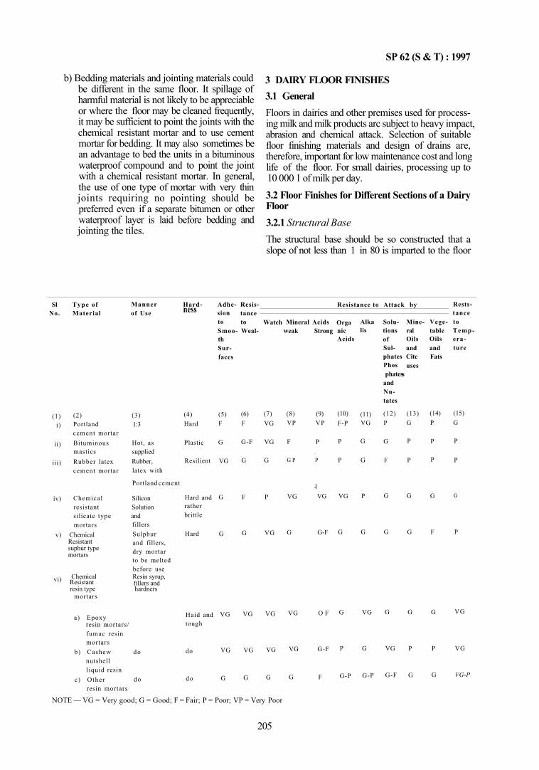
SP 62 (S & T) : 1997
b) Bedding materials and jointing materials could be different in the same floor. It spillage of harmful material is not likely to be appreciable or where the floor may be cleaned frequently, it may be sufficient to point the joints with the chemical resistant mortar and to use cement mortar for bedding. It may also sometimes be an advantage to bed the units in a bituminous waterproof compound and to point the joint with a chemical resistant mortar. In general, the use of one type of mortar with very thin joints requiring no pointing should be preferred even if a separate bitumen or other waterproof layer is laid before bedding and jointing the tiles.
3 DAIRY FLOOR FINISHES 3.1 General Floors in dairies and other premises used for processing milk and milk products arc subject to heavy impact, abrasion and chemical attack. Selection of suitable floor finishing materials and design of drains are, therefore, important for low maintenance cost and long life of the floor. For small dairies, processing up to 10 000 1 of milk per day. 3.2 Floor Finishes for Different Sections of a Dairy Floor 3.2.1 Structural Base The structural base should be so constructed that a slope of not less than 1 in 80 is imparted to the floor
205
NOTE — VG = Very good; G = Good; F = Fair; P = Poor; VP = Very Poor
Sl No.
(1) i)
ii)
iii)
iv)
v) Chemical
vi) resin type hardners
fillers and Resistant Chemical Resin syrup,
mortars suphur type
Resistant
Type of Material
(2) Portland cement mortar Bituminous mastics Rubber latex cement mortar
Chemical Silicon resistant Solution silicate type andmortars
mortars
a) Epoxy
Manner of Use
(3) 1:3
Hot, as supplied Rubber,
latex with
Portland cement
fillers Sulphur and fillers, dry mortar to be melted before use
resin mortars/ fumac resin mortars
b) Cashew nutshell liquid resin
c) Other
do
do resin mortars
Hard-ness
(4) Hard
Plastic
Resilient
Hard and rather brittle
Hard
Haid and tough
do
do
Adhesion to
Resistance to
Smoo- Wealth Surfaces
(5) F
G
VG
G
G
VG
VG
G
(6) F
G-F
G
F
G
VG
VG
G
Watch
(7) VG
VG
G
P
VG
VG
VG
G
Mineral Acids weak Strong
(8) (9) VP VP
F P y
G P P
-1 VG VG
G G-F
VG O F
VG G-F
G F
Resistance to Attack by
Orga nic Acids
(10) F-P
P
P
VG
G
G
P
G-P
Alka lis
(11) VG
G
G
P
G
VG
G
G-P
Solutions of Sul
Mineral Oils and
phates Cite Phos phates
and Nutates
(12) P
G
F
G
G
G
VG
G-F
uses s
(13) G
P
P
G
G
G
P
G
Vegetable Oils and Fats
(14) P
P
P
G
F
G
P
G
Rests-tance to Temperature
(15) G
P
P
G
P
VG
VG
VG-P
SP 62 (S & T) : 1997
surface. This fall should be such that liquid spillage on the floor surface will be drained quickly by the shortest route. It is essential to have a waterproof membrane (see 3.3) between the base and the floor finish. The joints in the structural base shall be provided in accordance with the details given in IS 3414: 1968 covered in Chapter 13. All laitance shall be removed and the surface roughened before laying the floor finish. 3.2.2 Group I This group consists of the following sections:
a) Loading dock or dispatch dock, and
b) Cold storage room. 3.2.2.1 These sections are subject to very heavy impact and abrasion. Spillage of milk and milk products also takes place. Floor finishes recommended for these sections are steel or cast iron tiles or solid steel plates. The floor finish of steel or cast iron tiles may be supported structurally by sub-floor. Solid steel plates may be used as a structural finish supported on a under floor framework.
3.2.3 Group II This group consists of the following sections:
a) Milk can reception room, b) Empty can and bottle reception desk, and c) Empty can and bottle washing room.
3.2.3.1 These sections are subjected to very heavy impact and abrasion, but little spillage of milk and milk products. Floor finishes recommended for these sections are steel or cast iron tiles or metal grids with filling materials, such as, cement concrete, cement-rubber latex, etc. 3.2.3.2 There are two main types of metal tiles used for industrial purposes which are suitable for dairy floors. They withstand impact, abrasion and resist the action of alkalis but are liable to attack by weak acids.
a) One type, called an anchor plate, is in the form of a shallow tray, made of steel. The wearing surface is punched to give twisted anchors or grips which form the key for the bedding and when bedded in the concrete give a floor which is generally 40 mm thick. A typical illustration is given in Fig. 9.9. It is essential for the success of this type of floor finish that tiles are completely filled with concrete. Tiles which are not solid by embedded give continuous trouble because the steel is not strong enough to bridge hollow places and is bent under traffic.
b) Another type of tile is called honeycomb cast iron tile. These types of tiles are manufactured with a taper in honeycomb for better grip with concrete. A typical illustration of such a tile is shown in Fig. 9.10.
3.2.3.3 Metal grids are frequently used as a surface reinforcement to increase the impact resistance. The grids may be of cast iron or steel and hexagonal or square mesh. The usual matrix into which they are laid may be either granolithic concrete (see Part 2) or cement rubber latex. The grid may be supplied either as a roll of interlocking metal trips from which a grid can be formed or as small units. Mats framed on two sides only are best because this avoids the weak joints between sections.
The top edges of the grid form part of wearing surface of the floor and distribute impact and wear. Because of uneven wear between the grid and the material in which it is embedded such floors may become noisy in use.
3.2.4 Group III
This group consists of the following sections : a) Milk drum tank pit; b) Milk storage room; c) Processing hall, milk pasteurization section; d) Butter, ice-cream, cheese and ghee section; e) Milk filling section; f) Roller drier room; g) Toned milk room; h) Corridors; and j) Laboratory rooms.
3.2.4.1 Floor finishes in these sections should be resistant to normal impact and wear, to frequent spillage of milk and milk products, to mild acids, and alkalis and good resistance to hot and cold water as the floors are subject to frequent washing. The general choice may be made from the floor finsihes given in 3.2.4.2 to 3.2.4.5.
3.2.4.2 Portland cement concrete is slowly attacked by milk and milk products particularly by lactic acids and therefore is not suitable for these sections. However in such areas where acidic action is not predominent, cement concrete flooring tiles, as described in Part 2 or stones, such as, Kotah stones may be used.
3.2.4.3 Acid and alkali resistant stones laid with phenolic type resin mortar (as per Part 4) for bedding and jointing
Sandstones of highly siliceous and compact variety containing low quantity of aluminium oxide, calcium oxide and magnesium oxide, etc, have good acid and alkali resisting quality. Such stones are found in places like Dholpur, Gwalior, Rewa, Cuddapah and Mandana, etc. The stones may be tested for acid resistance in accordance with methods of test described in
206
SP 62 (S & T) : 1997
IS 4457 : 1982. However a maximum of 4 percent weight loss during acid treatment may be accepted as adequate acid resistance for the purpose of dairy floors. These floors give long life but become slippery in due course and hence would require periodical roughening.
3.2.4.4 Ceramic unglazed vitreous acid resistant tiles or acid resistant bricks
Vitreous ceramic tiles (IS 4457:1982) or acid resistant bricks (IS 4860 : 1968) could be used for floor finish. These tiles and bricks could provide over a long period, a good resistance against acidic conditions provided by milk and milk products. These materials would also offer adequate resistance against the mild alkaline conditions provided by washing soaps, detergents, etc.
a) The life of a good quality brick or tile floor is largely determined by the material used for bedding and jointing and to some extent by the width of the joints. Hence careful selection shall be made in the choice of bedding and jointing mortar, and the thickness of the joints. Whatever be the choice of mortars these should necessarily show adequate strength when tested according to IS 4456 (Part 1 or 2). 1967 as appropriate.
b) For bedding and jointing mortars, selections may be made from the following : 1) Chemical resistant resin type of mortars
[see IS 4832 (Part 2) : 1969 and also Part 4 of titls Chapter],
2) Rubber latex cement mortars, and 3) Superiulphated cement (see IS 6909 :
1990) or Portland blast furnace slag cement (see IS 455 : 1989).
c) Among the resin based chemical resistant mortars, epoxy resins and phenol formaldehyde type [see IS 4832 (Part 2) : 1969] are quite suitable as joint mortar.
d) Sodiumsilicate or potassium silicate and resistant mortars [see IS 4832 (Part I) : 1969] although have good properties under dry conditions, are not suitable as jointing mortars in these sections of the dairies as these mortars are slowly attacked by cold water and rapidly by hot water. However, these may be used as bedding mortars in conjunction with resin type mortar. For properties of these mortars see Table 9.9.
3.2.4.5 Jointless cement — latex rubber finish This is prepared from a mixture of rubber latex or synthetic rubber and portland cement or portland slag cement. The resistance of these mixes to milk and milk product is generally much higher than that of corresponding mixes without latex. The choice of type of latex will also determine the preporties of the floor,
such as, water-tightness and resistance to oil. The techniques of mixing and laying is different than that of ordinary concrete and therefore advice of an expert, would be required when using these floor finishes.
NOTE — The latex normally takes the form of dispersion in water of natural rubber latex, but for a special circumstance, for example, for oil resistance, synthetic rubber may be used.
a) The latex is stabilized against premature coagulation. It should not contain vulcanizing ingredients. If these are required they should be incorporated at the time of preparing the mixture.
b) The emulsion is diluted with water as required and is then mixed with cement and aggregate to form a mix of the desired rubber latex content. The proportion of the rubber latex used varies 8 to 25 percent by weight of the total mix.
3.2.5 Group IV
This group consists of the following : a) Boiler room, b) Refrigeration room, c) Stores and godowns, and d) Workshops.
3.2.5.1 These sections require good wear resistance and occassionally resistance to alkalis and very mild acidic conditions. 3.2.5.2 The choice of floor finishes for these sections may be made from:
a) Granolithic cement concrete to IS 5491 : 1969 (see Part 2),
b) Power compacted concrete grade M l50 with iron chippings mixed with the aggregates, or
c) Hyiraulic pressed cement concerete tiles to IS 237: 1980 (see Part 2).
3.2.5.3 Wherever slippery conditions prevail, cement concrete tiles with chequered surface finish would be suitable. Where in-situ concrete is provided and non-slip surface finish is desired, a hard abrasive material, such as, silicone carbide or aluminium oxide may be sprinkled evenly on the concrete surface at the rate of 2 kg/m2 and worked into the surface by power floats and finally by steel trowelling. Iron particles may also be used in the same way to increase the wear resistance of the surface.
3.2.6 Group V This group consists of chemical stores for storage of concentrated acid and other chemicals. Cermaic unglazed vitreous acid resistant tiles conforming to IS 4457 : 1982 or acid resistant bricks conforming to IS 4860 : 1968 may be used.
207
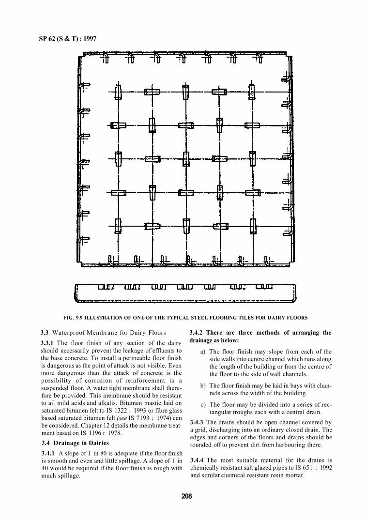
SP 62 (S & T) : 1997
3.3 Waterproof Membrane for Dairy Floors 3.3.1 The floor finish of any section of the dairy should necessarily prevent the leakage of effluents to the base concrete. To install a permeable floor finish is dangerous as the point of attack is not visible. Even more dangerous than the attack of concrete is the possibility of corrosion of reinforcement in a suspended floor. A water tight membrane shall therefore be provided. This membrane should be resistant to ail mild acids and alkalis. Bitumen mastic laid on saturated bitumen felt to IS 1322 : 1993 or fibre glass based saturated bitumen felt (see IS 7193 ; 1974) can be considered. Chapter 12 details the membrane treatment based on IS 1196 r 1978. 3.4 Drainage in Dairies 3.4.1 A slope of 1 in 80 is adequate if the floor finish is smooth and even and little spillage. A slope of 1 in 40 would be required if the floor finish is rough with much spillage.
3.4.2 There are three methods of arranging the drainage as below:
a) The floor finish may slope from each of the side walls into centre channel which runs along the length of the building or from the centre of the floor to the side of wall channels.
b) The floor finish may be laid in bays with channels across the width of the building.
c) The floor may be divided into a series of rectangular troughs each with a central drain.
3.4.3 The drains should be open channel covered by a grid, discharging into an ordinary closed drain. The edges and corners of the floors and drains should be rounded off to prevent dirt from harbouring there.
3.4.4 The most suitable material for the drains is chemically resistant salt glazed pipes to IS 651 : 1992 and similar chemical resistant resin mortar.
208
FIG. 9.9 ILLUSTRATION OF ONE OF THE TYPICAL STEEL FLOORING TILES FOR DAIRY FLOORS
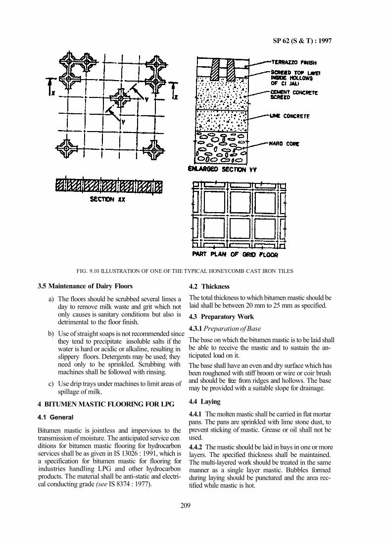
SP 62 (S & T) : 1997
FIG. 9.10 ILLUSTRATION OF ONE OF THE TYPICAL HONEYCOMB CAST IRON TILES
3.5 Maintenance of Dairy Floors
a) The floors should be scrubbed several limes a day to remove milk waste and grit which not only causes is sanitary conditions but also is detrimental to the floor finish.
b) Use of straight soaps is not recommended since they tend to precipitate insoluble salts if the water is hard or acidic or alkaline, resulting in slippery floors. Detergents may be used; they need only to be sprinkled. Scrubbing with machines shall be followed with rinsing.
c) Use drip trays under machines to limit areas of spillage of milk.
4.2 Thickness The total thickness to which bitumen mastic should be laid shall be between 20 mm to 25 mm as specified. 4.3 Preparatory Work 4.3.1 Preparation of Base The base on which the bitumen mastic is to be laid shall be able to receive the mastic and to sustain the anticipated load on it. The base shall have an even and dry surface which has been roughened with stiff broom or wire or coir brush and should be free from ridges and hollows. The base may be provided with a suitable slope for drainage.
4 BITUMEN MASTIC FLOORING FOR LPG
4.1 General
Bitumen mastic is jointless and impervious to the transmission of moisture. The anticipated service con ditions for bitumen mastic flooring for hydrocarbon services shall be as given in IS 13026 : 1991, which is a specification for bitumen mastic for flooring for industries handling LPG and other hydrocarbon products. The material shall be anti-static and electrical conducting grade (see IS 8374 : 1977).
4.4 Laying
4.4.1 The molten mastic shall be carried in flat mortar pans. The pans are sprinkled with lime stone dust, to prevent sticking of mastic. Grease or oil shall not be used. 4.4.2 The mastic should be laid in bays in one or more layers. The specified thickness shall be maintained. The multi-layered work should be treated in the same manner as a single layer mastic. Bubbles formed during laying should be punctured and the area rectified while mastic is hot.
209
SP 62 (S & T) : 1997
4.4.3 The laid surface shall be protected from damage due to movement of heavy loads, spillages, etc during laying. The mastic shall not be opened to traffic until the material has cooled down to ambient temperature.
4.4.4 Damaged areas shall be cut into rectangular strips and replaced with a new mastic. Blow lamp techniques to remove damaged layers are preferred. 4.4.5 Bitumen mastic flooring requires little maintenance. Dirt and dust shall be removed periodically.
PART 4 SPECIAL FLOORS AND FLOOR COVERINGS
1 GENERAL 1.1 The following Indian Standards cover the use of various types of special floors and floor coverings:
a) Mangcnsium oxychloride composition floors — IS 658 : 1982
b) Bitumen mastic flooring — IS 1196 : 1978 c) Rubber floors — IS 1197 : 1970 d) Linoleum floors — IS 1198 : 1982 e) Chemical resistant mortar, Silicate type — IS
4441 : 1980 f) Chemical resistant mortar, Sulphur type — IS
4442 : 1980 g) Chemical resistant mortar. Resin type — IS
4443 : 1980 h) Epoxy resin floor toppings — IS 4631 : 1986 j) Flexible PVC sheet and tile flooring — IS 5318 :
1969 k) Parquet flooring — IS 5389 : 1969 and IS 9472 :
1980
2 MAGNESIUM OXYCHLORIDE COMPOSITION FLOORS
2.1 General
Magnesium oxycholoride composition consisting of mixture of calcined filler and pigments provides a good floor if proper ingredients are mixed in correct proportions and skilled labour is employed in laying the floor. Too wet a mix with excess magnesium chloride results in sweating of the floor surface. Mineral oils, greases or vegetable oils do not affect the floor. The flooring is not seriously affected by alkalis. but strong alkalis, such as, soda or harsh cleaning agents tend to attack the protective dressing and thus exposing the flooring to action of water. However, the finished floor tends to be protected from excessive
water or moisture by periodic applications of wax-polish or oil at regular intervals. Magnesium oxychloride flooring should not be used in any situation where it would be exposed to damp conditions for long periods, unless other suitable protective measures are taken; it should not be used in places where it will be exposed to acids or salts continuously.
2.2 Types a) General Purpose Floor (Trowel Finish) —
This type of floor shall contain an adequate amount of calcined magnensite, fillers such as. talc, saw dust and asbestos; and fine aggregates which with magnesium chloride of suitable strength make a product which may be trowelled to a dense smooth glossy finish. The composition may be applied monolithically. It has wearing properties which make it adaptable for service conditions in offices, ship decking, railway carriages, hospital rooms and wards, residential and industrial floors.
b) Heavy Duty Floor (Trowel Finish)—This type is closely related to the general purpose floor. The principal difference is that the quantity of fillers used is minimum and the proportion of aggregates is increased, the aggregates being of hardness similar to crushed granite. It is adapted for special service conditions in industrial and restaurant kitchens, light industrial plants, corridors, lobbies and business establishment having large usage.
c) Non-spark Static Discharging Floor (Trowel or Ground Finish) — This type of floor is similar to heavy duty floor except that the aggregates used are not siliceous and do not contain materials which will produce a spark when struck with any object. This type of floor is suitable for hospital operation theatre, ammunition and chemical plants or other areas subject to explosion hazards.
210

SP 62 (S & T) : 1997
d) Non-slip Floor (General Purpose) — This type of floor is similar to heavy duty floor except that certain proportion oflhe aggregates is of abrasive type. This floor is specially adaptable to areas, such as, entrance lobbies, ramps, stair treads, landings, etc.
e) Mosaic or Terrazzo Floor (Ground Finish) — The matrix in this case is the same as in general purpose, non-sparking or non-slip floors but the aggregate used is marble chips with each 100 kg of the dry mix, 125 to 200 kg of coarse aggregate is used. The floor is adaptable fin-places where a highly decorative effect coupled with wear resistance is required.
f) Industrial Granolithic Floor — This type of floor is essentially the same as mosaic or terrazzo floor in which the matrix is the same as in the heavy duty floor and the coarse aggregate consists of granite chips or similar hard stone chips. With each 100 kg of dry mix, 200 to 225 kg of coarse aggregate is used. This type of floor is recommended for the most severe and abrasive service conditions.
g) Base Coat — This type has the maximum resilience and is employed as a light-weight base for the types of oxychloride floors mentioned in 2.2 (a) to (f). Two sub-types are generally employed : Sub-type 1 — General purpose base coat, and Sub-type 2 — Heavy duty base coat.
2.3 Materials
a) All the materials used in the manufacture of magnesium oxychloride floor finish should comply with lS 657 : 1982. The test limits for calcined magnesite in this standard are based on a notional mix of calcined magnesite and saw dust gauged with magnesium chloride and do not obviate the need to test the floor finishing mixes in order to check compliance with IS 658 : 1982. Materials for magnesium oxyflouride composition floors shall be supplied in two parts, namely, dry mix and magnesium chloride.
b) Dry Mix 1) Dry mix for all types of floors — The dry
mix shall consist of an intimately mixed composition of dry ingredients. If talc is used as a filler it shall not exceed 5 percent by weight of dry mix.
2) Dry mix for non-spark static discharge floors — The dry mix for non-spark static discahrging floor shall contain only such materials in its composition which are free
from substances capable of producing a spark when struck or abraded with a steel tool.
3) Dry mix for non-slip floor — About 35 percent by weight of the aggregates used in the dry mix for non-slip floors shall consist of abrasive aggregates which shall be of non-rusting natural (emery) or manufactured (fused alumina) product, the particles of which are of irregular shape and of slightly open texture.
2.4 Properties of Magnesium Oxychloride Floors
a) Magnesium oxide floor should not be exposed to action of sea water; and is not recom-meneded where it may be exposed to high humidity or damp conditions; damp proof course should be incorporated if the base is in direct contact with the ground.
b) Floor finish should be selected by sample size of 300 mm × 300 mm × 20 mm which finished work should conform in hardness (as per IS 658 : 1982) near to colour, texture, number and thickness of coats.
c) Resistance to Checmical Attack 1) The floor finish, if not adequately
protected by oiling or waxing gradually disintegrates under continuous exposure to water.
2) The floor finish is not affected by alkalis but strong alkalis such as soda or harsh cleaning agents attack the protective dressing and expose the floor finish to the action of water.
3) The floor finish is subject to attack by acids. Adequate protection against occasional contact with dilute acids may be obtained by oiling or waxing.
4) The floor finish is subject to attack by continuous exposure to salts; under noral conditions of use, some protection may be obtained by oiling or waxing.
5) It should not be slippery when treated as described in 2.5. Special non-slip surfaces may be obtained by incorporating abrasive grit in the floor finish.
6) Sweating of magnesium oxychloride floor finish is characterised by beads of magnesium chloride solution forming on the surface in humid atmospheres and is not merely the result of the condensation of moisture on a cold surface. The tendency to sweat is inherent in the material, since magnesium chloride takes up readily moisture from damp air.
211
SP 62 (S & T) : 1997
7) If the ingredient of the floor finsih mixture comply with IS 657 : 1982, there should be little tendency towards efflorescence.
8) The thickness of floor finish shall be not less than 10 mm.
9) Contamination of the floor finish mixes with free lime tends to cause expansion. The floor finish is likely to crack or lift if laid on light weight concrete base or on a dense screed which is not firmly bonded to the base.
10) Coves and skirtings can be formed with magnesium oxychloride finishing material. Contact between the oxychloride mix and the wall plaster should be avoided by the use of an intervening fillet of wood or other suitable material. A sand cement rendering on the wail surface is desirable as a backing.
11) Metal work, such as, partitions, or gas, water and electrical services in contact with a magnesium oxychloride floor fin ish is liable to corrode and should be isolated from the floor finish, by not less than 25 mm of uncracked dense concrete or protected by a coating of bitumen or coal-tar composition or by a suitable material (see 2.8).
2.5 Application 2.5.1 Preparation of the Base The base shall be rigid, sound, free from rising damp and not unduly porous. Highly absorbent materials, such as, pumice concrete, breeze or clinker concrete and aerated concrete shall not be used unless a layer of damp-proof course is laid between the base and the main floor.
a) New cement concrete base — The base shall be true and even and slightly coarsened by stiff brush or broom. A steel trowel finish is not desirable. The cover to steel of base concrete shall be not less than 25 mm, since the reinforcement would be damaged by magnesium oxychloride compound. New concrete should age for 28 days before receiving the flooring. No lime admixture shall be allowed in concrete.
b) Existing concrete base — The existing concrete base should be roughened to a suitable degree by tooth chislmg, picking or by any other suitable process before oxychloride composition is laid. Absorption may be checked and if porous screed may be spread on thebase.
c) Timber base — A suitable mechanical key should be provided between timber base and
floor finish, such as, dovetailed wooden battens or galvanized wire netting firmly screwed to the base at approximately 200 mm centre. An equal number of galvanized clout nails should be used at 200 mm centres and be left proud of the base.
2.5.2 Preparation of Floor Finish Mixture Magnesium chloride both before and after it is dissolved should not be allowed to came into contact with any floors and walls. The solid chloride should be broken up and dissolved in water tight vessel by covering the same with clean water, that is, clean and free from deleterious acids, alkalis, salts or organic material and stirring the same from time to time. The solution should be allowed to stand over night so that the residue, dust, impurities, etc, may settle to the bottom. The clean concentrated solution shall be well stirred after each dilution. The solution shall be prepared sufficiently early so that it is cooled to room temperature before use. The specific gravity of the solution should be maintained at the value selected from the table given below. This value will depend on the type given of work, the nature of the base and ambient and temperature conditions.
Floor Finish Mix
Single coat and top coat
Baume (BE) Scale
20° to 24°
Bottom coat, 18° to 20° coves and skirtings
Specific Gravity
1.16 to 1.20
1.14 to 1.16
2.5.3 Proportions of Dry Materials The proportions of dry materials may be varied within certain limits in order that the properties of the finished product may be suited to the conditions of use. Proportions shall be by weight and the dry material should be thoroughly mixed by machine.
a) Proportion of chloride solution — A strong floor finishing material may be formed by ad-dition of only sufficient magnesium chloride solution to make the dry mixed materials damp. For single coat and top coat some additional solution is usually required to enable the mix to be placed and brought to a smooth finish. The extra chloride does not improve the strength of the mixture and the use of excessive amount will have harmful effects.
b) The amount of solution required for a given weight of dry mix cannot be stated accurately; however, the following guidelines may be used: 1) Bottom coat floor finish mixes — Bottom
coat finish mixes should be gauged to a
212
SP 62 (S & T) : 1997
damp but not plastic consistency; just sufficient solution should be used to enable the mix to bind together when thoroughly compacted by tamping. As a guide, a mix from which liquid can be squeezed by hand should be considered as suitable.
2) Bottom coat mixes for coves and skirtings — The mixes should be gauged to a consistency just sufficiently plastic to allow the mix to be spread on the wall.
3) Single coat and top coat mixes — These mixes should be gauged with no more solution than is needed to produce a stiff mix which is just sufficiently plastic to be spread with a trowel.
2.5.4 Final Mixing
The mixing of the chloride solution with the dry mix shall be done in a container and not on the floor. The quantity of mix should be sufficient to be laid in one batch before it sets; no solution should be added during laying. If the mix is too stiff it should be discarded.
2.5.5 Laying the Floor Finish
a) Size of bay will depend on the temperature conditions generally; the controlling factor would be the time taken to obtain adequate compaction of the floor finish.
b) Joints shall be provided if the floor dimensions are more than 5 m in either direction. The joints may be mastios nsertions or strips of hardwood, vulcanite, non-ferrous metal or other suitable material, 5 man wide, bedded flush with the surface of the flooring material. These joints should coincide with the joints of the base, if any.
c) The concrete base should be dampened before laying; excessive flooding should be avoided. The dampening should be done either with a solution of magnesium chloride which should not be weaker than 12° BE nor stronger than 14° BE; or a wash composed of a 14° BE magnesium chloride solution and magnesia mixed to the consistence of cream and brushed over the base. 1) If a thickness of 40 mm or more is re
quired, additional coats may be laid, each of which should not be more than 20 mm thick.
2) For skirting on sand cement rendering, the mix may be applied in a single coat not less than 5 mm thick; then the backing is unrendered. The mix should be applied in two coats to a total thickness of not less than 15 mm.
3) Each coat should be throughly compacted ensuring no formation of laitance.
4) When the top coat has hardened sufficiently, its surface shall be felt finished after trowelling. Scraping shall be under-taken on ornamental work such as mottled finishes.
2.5.6 Curing Rapid drying of floor shall be avoided at least for 24 h after laying the floor. It should be allowed to set and harden at least for 3 days before opening it to traffic. It should not be allowed for heavy traffic for some weeks till it is fully dried and hardened. During hardening it should not be exposed to sun or rain. 2.5.7 Surface Treatment The floor finish should be washed with clean warm water changed frequently and wiped dry at regular intervals until the effloroscence has ceased. At this stage the finish may be treated with a mixture of linseed oil (double boiled) (see IS 77 : 1977) and turpentine (see IS 533 : 1973) in equal volumes or with a suitable wax or drying oil. For mottled floor finish, the finish should be laid in two coat work. 2.6 Testing Testing shall be carried out on samples mixes from three different parts of the vessel. The tests should be done as per IS 658: 1982. 2.7 Maintenance The floor surface shall be cleaned with warm water only. A mild house soap free from alkali may be used oceassionally; but strong household cleaning powders, soda, etc, should not be used. 2.8 Protection of Metal Work Metal work may receive anti-corrosive treatment; suitable materials are bituminous coaltar composition with or without added fillers, intended for hot application. For cold application a solution of bitumen or of coaltar in a volatile solvent with or without added fillers hut excluding bituminous paints with drying oils may be used. 3 BITUMEN MASTIC FLOORING 3.1 General Bitumen mastic is adustless, odourless, jointless flooring and impervious to the transmission of moisture, either in liquid or vapour form. The surface is easily cleaned, noiseless under traffic conditions and resilient. While it may carry heavy loads, application of concentrated point loads may cause indentation. Bitumen mastic is, therefore, suitable for a variety of
213
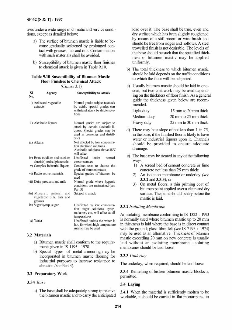
SP 62 (S & T) : 1997
uses under a wide range of climatic and service conditions, except as detailed below;
a) The surface of bitumen mastic is liable to become gradually sofetened by prolonged contact with greases, fats and oils. Contamination with such materials shall be avoided.
b) Susceptibility of bitumen mastic floor finishes to chemical attack is given in Table 9.10.
Table 9.10 Susceptibility of Bitumen Mastic Floor Finishes to Chemical Attack
(Clause 3.1) Sl No.
Agency
i) Acids and vegetable extracts
ii) Alcoholic liquors
iii) Alkalis
iv) Brine (sodium and calcium chroide) and sulphate salts
v) Complex industrial liquors
vi) Radio active materials
vii) Dairy products and milk
vtii) Mineral, animal and vegetable oils, fats and greases
ix) Sugar syrup, sugar
x) Water
Susceptibility to Attack
Normal grades subject to attack by acids; special grades can withstand attack by dilute solutions
Normal grades are subject to attack by certain alocholic liquors. Special grades may be used in breweries and distilleries Not affected by low concentration alcoholic solutions Alcoholic solutions above 38°C will affect Unaffected under normal circumstances Conduct tests to choose the grade of bitumen mastic Special grades of bitumen be used Normal grade where hygenic conditions are maintained (see Part 3) Subject to attack
Unaffected by low concentration sugar solutions syrup, molasses, etc, will affect at all temperatures Unaffected unless the water is hot, for which high temperature mastic may be used
3.2 Materials a) Bitumen mastic shall conform to the require
ments given in IS 1195 : 1978. b) Special types of metal armouring may be
incorporated in bitumen mastic flooring for industrial purposes to increase resistance to abrasion (see Part 3).
3.3 Preparatory Work
3.34 Base
a) The base shall be adequately strong tp receive the bitumen mastic and to carry the anticipated
load over it. The base shall be true, even and dry surface which has been slightly roughened by means of a stiff broom or wire brush and should be free from ridges and hollows. A steel trowelled finish is not desirable. The levels of the base should be such that the specified thickness of bitumen mastic may be applied uniformly.
b) The total thickness to which bitumen mastic should be laid depends on the traffic conditions to which the floor will be subjected.
c) Usually bitumen mastic should be laid in one-coat, but two-coat work may be used depending on the thickness of floor finish. As a general guide the thickness given below are recommended. Light duty Medium duty Heavy duty
15 mm to 20 mm thick 20 mm to 25 mm thick 25 mm to 30 mm thick
3.3.2 Isolating Membrane
An isolating membrane conforming to IS 1322 : 1993 is normally used where bitumen mastic up to 20 mm in thickness is laid where the base is in direct contact with the ground; glass fibre felt (see IS 7193 : 1974) may be used as an alternative. Thickness of bitumen mastic exceeding 20 mm on new concrete is usually laid without an isolating membrane. Isolating membranes should be laid loose.
3.3.3 Underlay
The underlay, when required, should be laid loose.
3.3.4 Remelting of broken bitumen mastic blocks is permitted.
3.4 Laying
3.4.1 When the materia! is sufficiently molten to be workable, it should be carried in flat mortar pans, to
214
d) There may be a slope of not less than 1 in 75, in the base, if the finished floor is likely to have water or industrial liquors upon it. Channels should be provided to ensure adequate drainage.
e) The base may be treated in any of the following ways: 1) A screed bed of cement concrete or lime
concrete not less than 25 mm thick; 2) An isolation membrane or underlay (see
3.3.2 and 3.3.3); or 3) On metal floors, a thin priming coat of
bitumen paint applied over a clean and dry surface. The paint should be dry before the mastic is laid.

SP 62 (S & T) : 1997
the point of laying. To prevent sticking of mastic to the pans, inorganic dust may be sprinkled on the pans. 3.4.2 Bitumen mastic should be generally laid in bays of one coat. It should be spread to the specified thickness by means of hand tools. Bitumen mastic should then be floated to a uniformly level surface by a heavy wooden float and should be free from roughness and imperfection. If 'blowing' occurs, the bubbles should be punctured and the area affected shall be made good while the mastic is still hot.
Two-coat of single-coat work, but care should be taken to arrange that the joints in successive layers are staggered.
3.4.3 Surface Finish
Surface finish could be either matt finish or polished finish, or as desired. Immediately after laying, the bitumen mastic shall be protected from damage till it cools to the surrounding temperature. Bitumen mastic should be allowed for traffic after the material has cooled. Frequent polishing, should be avoided as it will become slippery.
3.4.4 Bedding
Special care shall be taken to effect proper bond between new and old sections of work. The contact edges of the previously laid work should be cleaned and warmed by additional applications of hot mastic. This procedure also should be adopted for joints between the floor finish and skirts and coves or fillets. 3.4.5 Skirtings should be executed in not less than two-coats particular care being taken to ensure proper adhesion of the first coat to the base. Special care shall be taken at external angles to ensure the full thickness of material.
3.4.6 Maintenance
Bitumen mastic surface requires relatively little main-tanance. Superficial dirt may normally be removed by washing with warm water and suitable detergents. After the dirt is removed, the floor should be mopped with clean water.
3.4.7 Repairs
The correct method, to remove damaged area, is to place hot mastic around and over the area concerned and after this has sofetened the area concerned, it should be cut away and made good.
4 RUBBER FLOORS
4.1 General
Rubber floor coverings are mainly suitable for use in domestic buildings and those of a non-industrial character, such as, schools, hospitals, offices, where traffic is expected to be essentially pedestrian and also in
buses and ships. It provides a resilient and noise-free floor surface. The life of rubber floor is related to its thickness, since it is not possible to be specific about wear resistance. Provision o mats will reduce the amount of abrasive grit carried to the floor. The durability of rubber floor is increased if the material is laid correctly and maintained carefully. IS 809:1992 lays down the requirements for rubber flooring materials both in sheet and tile form. Flooring made of natural rubber is not recommended in situations where it may came into contact with fat, grease, oil or petrol, as these substances may cause swelling, softening or other deterioration. To meet such situations, flooring made from various kinds of synthetic rubber may be utilized.
4.2 Preparatory Work
4.2.1 Sub-floor and Base
a) New concrete floors — In the case of newly-laid concrete floors in contact with the ground, a damp-proof membrane or a bitumen mastic layer shall be incorporated in the thickness of the floor and it shall be properly joined with the damp-proof course in the walls. Special precautions, such as, tanking may be necessary against water pressure and to prevent the entry of moisture into floors below ground level.
b) Existing concrete floors — If the floor surface is not smooth and true, it shall be well hacked to provide key for the screeding. It shall then be brought to an even surface with a screeded bed at least 25 mm thick. Concrete floors which are in contact with the ground but have been damp-proofed shall be covered with a bed of at least 15 mm thick bitumen mastic conforming to IS 1195 : 1978. Over the bitumen mastic 40 mm thick cement concrete shall be laid.
c) New limber floor — Timber floors shall be constructed with tongued and grooved boarding and shall be adequately ventilated to prevent dry set. There should not be any gap between the planks which may permit air to penetrate from bottom and affect the bonding of the rubber flooring material with the timber base. Where plywood is used as a base, it shall be of the moistureproof grade.
d) Existing timber floors — Damaged and worn floors should be repaired and brought to an even and smooth surface, an underlay also may be used.
e) Metal floors — The surface of metal floors shall be smooth. Screws, bolts, etc, used in the flooring shall be of counter sunk type. When
215
SP 62 (S & T) : 1997
they project above the surface, the metal floor shall be covered with a base bringing the floor on level before the rubber flooring is laid on, The metal floors should be rust free and a rust proof coating should be applied before the rubber flooring is laid.
4,2.2 Underlay
An underlay shall be used where the base is of timber. It may also be used when it is necessary to make the flooring quieter, warmer and more resilient. Underlay shall be either fibre-based saturated bitumen felt (Type I) conforming to IS 1322:1993 or other suitable material. The underlay shall be butt jointed and so laid that the joints are at 45° to the principal joints in the rubber flooring. The underlay shall be secured by a suitable adhesive except on a timber base in which case it may be nailed.
4.3 Laying and Fixing of Rubber Flooring
a) The sub-floor shall be cleaned with dry cloth.
b) The lay out of the rubber flooring shall be first laid on the sub-floor to be covered and should be marked with guidelines. The rubber flooring shall be first laid for trial without using the adhesive according to the layout.
c) The adhesive shall then be applied by using a notched trowel, to the sub-floor and to the backside of the rubber sheet or tile flooring. When set sufficiently for laying, the adhesive will be tacky to touch, but will not mark fingers. In general, the adhesive will set in about half an hour; but it should not be left for too long a period as the adhesive properties will be lost owing to dust film and other causes. It is preferable to avoid laying the flooring under high humidity conditions so as to prevent condensation. The area of adhesive to be spread depends on the local circumstances; in a small room the area can be covered at one stretch.
d) When the adhesive is tack free, the rubber flooring sheet shall be carefully taken and placed in position from one end onwards slowly so that air will be completely squeezed out between the sheet and the background surface, Then the sheet shall be pressed with suitable roller to develop proper contact with the sub-floor. The next sheet with it backside applied with adhesive shall be laid edge to edge with the sheet already laid so that there is a minimum gap between joints.
e) Alignment should be checked and if not perfect, the sheets may be trimmed.
f) The tiles should be laid in exactly the same manner as the sheet. Any adhesive contaminating the face of the rubber shall be removed as the work proceeds within 24 h. A minimum period of 24 h shall be allowed for proper development of bond and no traffic should be allowed. Thereafter the flooring shall be cleaned with a wet cloth, soaked in warm soap solution (two spoons of soap in 5 1 of warm water).
g) In case of stairs, where rubber nosings arc to be laid as separate units and are of heavier gauge, the difference in thickness shall be made up in design, or by screed or with plywood or bitumen mastic. Rubber in sheet form is not used for coves and skirtings; suitably moulded units should be used.
h) Rubber shall not be cleaned by softsoaps, soaps containing essential oils, soaps with free alkalis, pastes or powders containing coarse abrasives, scrubbing brushes or petrol benzine, naptha and similar solvents.
j) A wax-polish shall be used for polishing rubber floors; polishes containing organic solvents
shall not be used. 5 LINOLEUM FLOORS 5.1 General Linoleum provides a satisfactory floor for residential and public buildings, railway coaches, ships, etc. It is also suitable for most type of non-industrial floors. In light industry, such as, electronic industry linoleum may be used, as the risk of damage by cutting, to which linoleum is vulnerable, is small. However, if it gets wet, it expands and eventually rots. 5.1.1 Linoleum is not suitable for locations subjected to rising damp, external exposure, exposure to traffic with indentations from heels or static loads, and where high polish is required because it becomes slippery. 5.2 Materials
a) Flooring material shall conform to IS 653 : 1992.
b) Underlay shall be as below: For timber — Plywood at least 4 mm thick sub-floors
— Hardboard at least 3 mm thick
— Fibrebased bitumen felt at least 1 mm thick, to IS 1322 : 1993
For concrete — Bitumen mastic to IS 1195 : sub-floors 1978
— BitumentoIS 1580 : 1991. c) Adhesi ves shall be as per recommendations of
the manufacturer.
216
SP 62 (S & T) : 1997
5.3 Preparatory Work
5.3.1 Sub-floor
Sub-floors should be thoroughly dry before laying of linoleum since entrapped moisture cannot escape. It should also be even to ensure thorough bonding with the linoleum.
a) Timber sub-floors — A timber sub-floor should be sound, rigid and dry. It should be well ventilated to discourage fungal attack. In case of new construction, tongued and grooved boarding shall be used. All nails shall be punched down and timber floor made even. In existing floors, when it is not possible to obtain an even surface, use of diagonal boarding is recommended, after removing and replacing badly affected boarding; alternatively plywood may be used to get an even surface.
b) Concrete sub-floor — Concrete sub-floor may be finished as mentioned in Part 2, to give an even and dry surface. Rising damp may be protected by using bitumen mastic, 15 mm thick, conforming to IS 1196 : 1978 as described in 3.
c) Other sub-floors — They should be dry and even.
5.4 Laying
a) Linoleum should be stored at room temperature of not less than 20°C for at least 48 h before unrdling; after unrolling, it shrinks in length and expands in width. When two widths of linoleumfare to meet, they shall be left with an overlap until the expansion has stopped and then cut to fit.
b) The linoleum should be laid cither loose or fixed to the sub-floor by means of suitable adhesives, Any priming coat should be allowed to dry before the adhesive is spread. Adhesives should be spread evenly as per manufacturers' instructions. Naked lights should be avoided, if the adhesi ves having low flash solvent (containing petroleum and naphtha) are used. The area shall be well ventilated and smoking shall be prohibited.
c) The underlay shall be fixed to the sub-floor in such a way that a smooth surface is available. The finished underlay shall be cleaned of all dirt and dust, chemicals, paints, etc. The linoleum shall be firmly pressed into the adhesive spread over the underlay. To ensure good bond, the surface can be rolled with a roller of 70 kg weight, washing from centre to the walls. If necessary, sand bags may be placed at some points.
When laid on concrete floors it is desirable to prime the back of linoleum with the adhesive. Cork tiles should be fixed with the adhesive. Linoleum coving and skirting shall be formed from the sheet material on the job in grades up to 3.2 mm thick. Normally 4.5 and 3.2 mm thick linoleum can be used for commercial and institutional buildings respectively; for domestic buildings 1.6 mm thick linoleum may be used.
d) The surface, after cleaning of all debris, etc, may be wax-polished or a coat of emulsion polish may be applied. No traffic shall be permitted till the completion of all related works.
e) All surfaces shall be swept clean and washed with a cloth dampened with an aqueous solution of neutral detergent.
6 EPOXY RESIN FLOOR TOPPINGS
6.1 General
Epoxy resins are suitable for use on industrial floors, such as, in chemical plants manufacturing fertilizers, pharmaceuticals, acids and solvents, in dairy industry, tanneries, breweries, garages, service stations, warehouses, metal plating and pickling areas. They have good qualities of adhesion and chemical resistance, hardness, abrasion resistance; physical proper-tics, such as, compressive, impact and flexural strength; neglegible shrinkage, dimensional stability and adhesion to cured concrete, metals and other surfaces. 6.2 Materials
a) Epoxy resin shall conform to IS 9197 : 1979, b) Hardeness shall conform to IS 9197 : 1979, c) Accelerator shall conform to IS 9197 : 1979, d) Plasticizers and non-reactive diluents shall
confirm to IS 9197: 1979, e) Liqued coal tar shall conform to IS 9197 : 1979,
and f) Aggregates shall conform to IS 9197 : 1979.
6.3 Types of Epoxy Resin Toppings There are two types of epoxy resin floor toppings:
a) Trowel Type — This is usually heavily filled with sand or other suitable aggregates and the compound is applied by trowel. Such compounds are often referred to as mortars or screeds.
b) Flow Type — This is usually a solventless compound containing filler and pigment and the mixture is poured directly on to the surface when the blend will flow and level itself with little assistance to form a smooth continuous coating.
217
SP 62 (S & T) : 1997
6.3.1 Terrazzo Floors The Portland cement in conventional terrazzo floors is replaced by epoxy resin binder. Such flooring formulations serve the dual purpose of providing a good appearance and chemical resistance. 6.3.2 Non-skid Floors This type of floor may be prepared by sprinkling a suitable grit on an epoxy resin floor topping when the latter is still in a tacky state. 6.3.3 The following minimum thicknesses are recommended :
a) Trowel type — 4 mm for normal use and 6.5 mm in areas of thermal shock and heavy traffic on horizontal surfaces
b) Flow type — 2 mm c) Terrazzo floors — 10 mm.
6.4 Preparatory Work 6.4.1 Concrete surfaces shall be properly cured and driea and kept rough. Laitance shall be removed. All cracks and broken areas of an existing base shall be sealed, fresh concrete applied and cured. Grease and oil shall be removed with solvents, such as, acetone or a suitable detergent.
The concrete surface shall be even.
6.4.2 Mild steel and cast iron surfaces shall be washed with a suitable solvent or detergent solution to remove grease or oil. The surface shall then be sand blasted or abraded with emery cloth, abrasive disc or with wire brushes.
6.5 Laying
6.5.1 Mixing of Epoxy Resin Blend
The mixing shall be carried out at the site as follows : a) The constituents required shall be mixed in the
correct proportions as specified by the formulator.
b) Unless otherwise specified, the order of addition of the constituents shall be resin, hardener and aggregate.
c) Aggregates, when required, shall be added to the blend in a mixer in dry condition.
d) The duration of mixing shall be adequate to ensure thorough mixing; the quantity mixed at one time shall be such that a uniform thickness of epoxy resin topping may be applied over the whole floor.
6.5.2 Application a) The blended epoxy resin mix shall be applied
uniformly, over the area prepared, to a uniform thickness.
b) For some areas where heavily filled trowelling compound is to be applied, the prepared area shall be first covered with a tack coat of unfilled resin-hardner mix applied by brush which shall be allowed to cure to a tacky stage.
c) Where heavily filled trowelling compound is used, it is advisable to apply a seal coat of unfinished resin to ensure that pores, if any, are sealed adequately.
d) As mild steel tools are liable to cause stains on light coloured surfaces, it is recommended that stainless steel, chromium on rigid PVC tools should be used after laying of epoxy resin floor toppings.
e) After application of the epoxy resin topping, the floor shall be allowed to set without disturbance for a minimum period of 24 h. The floor can be brought to normal use after a period of 7 days at a temperature of 20° C and above though light traffic may be permitted after 24 h of laying the floor topping. Below 20°C special hardeners may be used as recommended by the formulator in order to obtain proper setting of the floor topping.
f) Expansion joints to coincide with those in the base concrete should be provided in epoxy resin toppings. The expansion joints in the epoxy topping shall be filled with a flexible putty that shows appropriate water and chemical resistance as recommended by the formulator.
6.5.3 Safety Precautions Epoxy resins cause irritation to persons having sensitive skin. Good ventilation is necessary and the most effective precaution is the use of rubber or polyethelene gloves. It is preferable to wear thin cotton gloves underneath for comfort. Other methods recommended are regular washing hands, arms and face with soap and luke warm water followed by thorough drying with a clean towel and the use of a barrier cream. Splashes on skin should be removed immediately by washing with soap and luke warm water. On no account should a solvent be used for this purpose. 6.5.4 Chemical resistance of epoxy resin flooring mixes to various substances is given in Table 9.11 for general guidance. Table 9.11 shows that systems cured with amines exhibit higher chemical resistance. Polyamide hardeners should be used where floors are
218
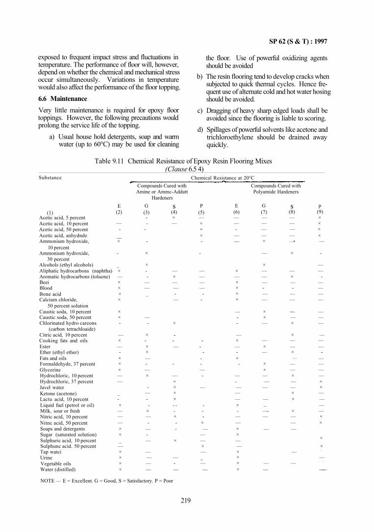
SP 62 (S & T) : 1997
exposed to frequent impact stress and fluctuations in temperature. The performance of floor will, however, depend on whether the chemical and mechanical stress occur simultaneously. Variations in temperature would also affect the performance of the floor topping. 6.6 Maintenance Very little maintenance is required for epoxy floor toppings. However, the following precautions would prolong the service life of the topping.
a) Usual house hold detergents, soap and warm water (up to 60°C) may be used for cleaning
NOTE — E = Excellent. G = Good, S = Satisfactory. P = Poor
the floor. Use of powerful oxidizing agents should be avoided
b) The resin flooring tend to develop cracks when subjected to quick thermal cycles. Hence frequent use of alternate cold and hot water hosing should be avoided.
c) Dragging of heavy sharp edged loads shall be avoided since the flooring is liable to scoring.
d) Spillages of powerful solvents like acetone and trichloroethylene should be drained away quickly.
Table 9.11 Chemical Resistance of Epoxy Resin Flooring Mixes (Clause 6.5 4)
Substance
(1) Acetic acid, 5 percent Acetic acid, 10 percent Acetic acid, 50 percent Acetic acid, anhydnde Ammonium hydroxide,
10 percent Ammonium hydroxide,
30 percent Alcohols (ethyl alcohols) Aliphatic hydrocarbons (naphtha) Aromatic hydrocarbons (toluene) Beei Blood Bone acid Calcium chloride,
50 percent solution Caustic soda, 10 percent Caustic soda, 50 percent Chlorinated hydro careons
(carbon tetrachloaide) Citric acid, 10 percent Cooking fats and oils Ester Ether (ethyl ether) Fats and oils Formaldehyde, 37 percent Glycerine Hydrochloric, 10 percent Hydrochloric, 37 percent Javel water Ketone (acetone) Lactu acid, 10 percent Liquid fuel (petrol or oil) Milk, sour or fresh Nitric acid, 10 percent Nitnc acid, 50 percent Soaps and detergents Sugar (saturated solution) Sulphuric acid, 10 percent Sulphunc acid. 50 percent Tap watci Urine Vegetable oils Water (distilled)
E (2)
— -
__ ×
-
_ × — × × × ×
× × -
— × — -× × × — —
_ -× — — — × × _ — × × × ×
Chemical Resistance at 20°C Compounds Cured with Compounds Cured with Amine or Ammc-Addutt
Hardeners G (3) --
-
-
×
× --
— — _
— -
× -× × — -— ×
-— --
× — -
— -—
— — — —
s (4) × —
— × — — -—
×
--—
-
— × × × × - --× --
×
— -—
P (5) — × × × -
-
— — — —
--
--
---— -
—
---
× —
— — × — _ — —
E (6) — — -— —
× — × × × ×
— --
— × — -× -
— -— — — × -
— — × × — — × × × ×
Polyamide Hardeners
G (7) — — — — ×
—
× — — — -— —
× × —
— × —
× × — —
—
— – —-—
—
— —
s (8) — — — — —•
×
— × — -
— —
~~ — ×
× — — × —
— — × — — × ×
× — — —
—
—
p (9) × × × × —
-
— —
-— — — —
— — —
— — —
-— — — — × × — — — — × ×
× ×
" " ■ " "
— " " " * ■
——
219
SP 62 (S & T) : 1997
7 FLEXIBLE PVC SHEET AND TILE FLOORING 7.1 General PVC flooring material manufactured in different patterns to match and suit any decorating scheme is normally used for covering floors from decorative point of view in residential and office buildings and also in railway coaches. The material gives a resilient and non-porous surface which can be easily cleaned with a wet cloth as dust and grime do not penetrate the surface. Since burning cigarette will damage the neat surface of the PVC sheet, special care should be taken to prevent burning cigarette stumps to come in contact with the PVC flooring material 7.2 Materials
a) Flooring shall comply with IS 3461 : 1980 and IS 3462 : 1986. The thickness depends on service conditions.
b) Underlay for use on concrete sub-floor shall be the screed topping. Underlay for use on an uneven and rough wood sub-floor shall be 3 mm thick BWR grade plywood conforming to IS 303 : 1989.
c) Rubber based adhesives are suitable for fixing PVC sheet and tiles over concrete wood and metal sub-floors. PVA based adhesives may be used for concrete and wood sub-floors. PVA based adhesives are not suitable for metallic surfaces and also for locations where there is a constant spillage of water.
7.3 Preparatory Work a) It is important that the sub-floor and underlay
should be thoroughly dry before the PVC flooring is laid since moisture cannot evaporate once the PVC flooring is laid. The sub-floor should be even since irregular surface creates improper adhesion.
b) In case of new timber construction tongued and grooved boarding construction shall be used. All nail heads shall be punched down and all irregularities planed off and holes filled in. Adequate ventilation should be ensured.
c) In case of existing or damaged timber floor, if it is not possible to obtain an even surface, the use of diagonal boarding is recommended after removing the damaged boarding. Alternatively plywood boarding may be used.
d) Concrete sub-floors shall be finished with a trowel and shall be left long enough to dry out. Concrete sub-floor shall be in two layers. The top of the lower layer shall be painted with two coats of bitumen conforming to IS 1580 : 1991
at the rate of 1.5 kg/mm2 after the concrete has set; or bitumen felt conforming to IS 1322 : 1993 may be sandwiched between the two concrete layers. If dampness is expected from surrounding walls, the same treatment may be extended, up to 150 mm above the floor level, over the walls. The basement floor shall be damp proofed as per IS 1609 : 1991 (see Chapter 12). Before the PVC sheeting is laid ample time shall be allowed for water to dry completely from the concrete floor. In new work the finish shall be produced with a trowel. With old concrete the sub-floor shall be scrapped free of all foreign material and swept clean. The surface shall be kept wet for 24 h by sprinkling water and then a screed topping of 3 mm thickness, shall be provided.
e) Metal floors shall be made free from rust and scale by chipping and or vigorous wire brushing and cleaning. All joints shall be ground smooth. Painting and grease shall be removed by caustic soda. Suitable putty compatible with the adhesive shall be used to fill metal surfaces to obtain a smooth and even surface.
7.4 Laying a) The material shall be brought to the tempera
ture of the area on which it has to be laid by stacking it near the area for 24 h.
b) Where air-conditioning is installed, the flooring shall not be laid for 7 days from commencement of operation of air-conditioning. During this period the temperature shall neither fall below 20°C nor exceed 30°C. These conditions shall be maintained during laying and 48 h thereafter.
c) The layout of PVC flooring shall be marked on the sub-floor. The flooring shall be laid for trial without adhesive according to the layout.
d) The adhesive shall be applied by using a notched trowel to the sub-floor and to the backside of the PVC sheet or tile flooring. In general, the adhesive will take about half an hour for setting; it should not be left too long a period as the adhesive properties will be lost owing to dust films and other causes. Care should be taken while laying under high humidity conditions so that condensation does not take place on the surface of the adhesive. The area of spreading the adhesive at any one time depends on local conditions; in case of a small room the entire area may be spread at one time.
e) When the adhesive is tack free, the PVC flooring shall be placed in position from one end
220
SP 62 (S & T) : 1997
onwards, so that air is squeezed from below the PVC material. Press with a roller to develop proper contact with the adhesive. The sheets shall be laid edge to edge, with minimum gap between joints. The alignment shall be checked after laying each row of sheet is completed.
f) The tiles shall be fixed in the same manner as the sheets. It is preferably to start from the centre of the area. Any adhesive squeezed out between the tiles shall be wiped off immediately with a wet cloth before the adhesive hardens. Hardened adhesive shall be removed by a suitable solvent; a solution of commercial butylacetate and tur-pentile oil (1:3) is a suitable solvent for the purpose.
g) No traffic shall be permitted for 24 h after laying.
h) Where the edges of the PVC sheets are exposed, it is important to protect it by metallic or other edge strips.
j) PVC flooring shall be kept clean by mopping with a soap solution using clean damp cloth. Water shall not be poured on PVC flooring as it may seep through the joints. The flooring may be periodically polished to keep a good appearance and a good wearing surface. A regular brushing, at 4 to 6 weeks interval, shall be given.
8 CHEMICAL RESISTANT MORTARS
8.1 There are thresetypes of chemical resistant mortars for different end uses, covered by the following Indian Standards:
a) Use of Silicate Type by IS 4441 : 1980,
b) Use of Sulphur Type by IS 4442 : 1980, and
c) Use of Resin Type by IS 4443 : 1980. 8.2 A mortar suitable for a particular environment is unsuitable for another.
a) Chemically setting silicate type of mortars are resistant to most acids and have been found to be satisfactory against nitric, chromic, sulphuric and hydrochloric acids. They are used for acid proof bricks or tiles. These mortars are not suitable for hydrofluoric and concentrated orthophosphoric acids. They are also not resistant to alkalis, boiling water or steam and are likely to deteriorate by continuous exposure to water or frequent washing with water. In view of the fact that silicate type of mortars develop
chemical resistance by physical bond formed by the chemical action of the acid with the mortar, the acid should have a pH value of 4 or less. Manufacturer should be consulted regarding usage of these mortars.
b) Sulphur mortars have good resistance against most of the acids except for concentrated oxidizing acids, but have very poor resistance to alkalis. The sulphur mortar shall always be used at less than 90°C, Where conditions are questionable, specific recommendations of the manufacturer shall be obtained.
c) Resin mortars have fairly good resistance to non-oxidizing mineral acids but have a poor resistance to oxidizing mineral acids. They are fairly resistant to inorganic alkalis. Manufacturer should be consulted on the usage of these mortars.
8.3 Clauses 9 to 11 would cover the use of these mortars, namely, silicate type, resin type and sulphur type.
9 SILICATE TYPE CHEMICAL RESISTANT MORTARS
9.1 Material
Silicate type mortar shall conform to IS 4832 (Part 1): l969.
9.2 Mortar
The chemically setting silicate type chemical resistant mortar is an intimate mixture of a chemically inert solid filler, a setting agent usually contained in the filler and a liquid silicate binder. When the filler and binder are mixed at ordinary temperatures. a trowel-able mortar is formed, which subsequently hardens by the chemical reaction between setting agent and the liquid silicate binder.
9.3 Storage
The filler sha11 be protected from water during storage. The filler shall be kept in the containers if it cannot be protected otherwise. The liquid binder shall be protected from freezing during storage until used. Under unavoidable circumstances liquid binder that has frozen may be used, provided the liquid binder is thawed and thoroughly remixed before use and it can be restored to its original consistency,
9.4 Mixing
Unless otherwise specified by the manufacturer, two to three parts by weight of filler to one part by weight of binder may be used. The optimum proportions might vary slightly due to climatic conditions, but it is important to have a mortar that is fluid enough to be workable and sufficiently stiff for the masonry unit to
221
SP 62 (S & T) : 1997
retain its position without slipping or sliding or without the mortar being exuded from the joint after the masonry unit has been placed in position.
a) Weigh the filler and binder in separate containers according to the recommended proportion.
b) Add approximately three-fourths of the filler to the liquid binder in a clean container and mix with a trowel until all the filler has gone into paste. Add the remaining filler to the paste and continue mixing until the mortar is uniform. In any batch only that quantity of mortar that could be used before it starts setting shall be mixed.
c) Mortar that has begun to set shall not be tempered by adding liquid binder or water but shall be discarded before preparing fresh batches.
d) Portland cement or water shall not be added to the silicate type of mortar. Care shall be taken that the mortar does not come into contact with cement concrete surface.
e) Special precautions shall be taken when silicate mortars are exposed to temperatures below 10°C or above 27°C during mixing, application or setting.
9.5 Application
a) Surface Preparation — The surface on which bricks to IS 4860 : 1968 or tiles to IS 4457 : 1982 are to be laid shall be free from dirt and dampness and shall be properly cured and dried.
b) Application of Membrane — A coat of bitumen primer conforming to IS 3384 : 1986 be applied, and then covered with a coat of bitumen conforming to IS 1580 : 1991. If the bedding material is epoxy or polyester resin, the tiles or bricks may be laid directly on the surface without application of bitumen primer. In case of furane, cashewnut shell liquid and phenolic types resins, a coat of bitumen primer conforming to IS 3384:1986 shall be subject to service conditions. Other membranes such as lead, potyisobutane and fibre reinforced plastics may also be used.
c) Mortar Application with the Same Bedding and Jointing Materials 1) For floors — Spread the silicate type of
mortar 6 to 8 mm thick on the back of the tile or brick. Smear two adjacent sides of the unit with 4 to 6 mm thick mortar. Press the unit into the bed and push the unit until the joint in each case is 2 to 3 mm thick. Trim off excess mortar and allow it to
harden fully. Cure the joints as given in 9.6(b).
2) For walls — Spread the silicate mortar 6 to 8 mm thick on the back of the unit. Smear the two adjacent sides of the unit with 4 to 6 mm mortar. Press the unit against the wall until joint in each case is 2 to 3 mm thick. Trim off excess mortar. While carrying out the jointing allow sufficient time to avoid the joints at bottom getting disturbed and sliding of the unit. Only one course of unit shall be laid during the initial setting. Cure joints as given in 9.6 (b).
d) Mortar Application with Different Bedding and Jointing Materials — When the job has to come into contact with water weaker acid solutions and alkalis, silicate type of mortar may be used for bedding and resin type of mortar for jointing. The job shall be carried out with only class I bricks, if used. 1) On floors — Spread on the two adjacent
sides of the tile or brick the silicate type of mortar 6 to 8 mm thick. Press the unit on the bed until the joint in each case is not more than 6 mm. Before the silicate mortar sets completely, remove the mortar in the joints to a depth of 20 mm. Cure the joints as in 9.6 (b) and fill the joints full with jointing mortar taking care to fill up the entire length of the joint. Trim off the excess mortar and make the joints smooth and plane.
2) On walls — Spread on to the back and two adjacent sides of the unit the silicate type of mortar 6 to 8 mm thick. Press the unit against the wall until the joint in each case is not more than 6 mm. Only one course of the unit shall be laid during the initial setting time to avoid the joints at the bottom getting disturbed and sliding of the unit. Cure the joints as given in 9.6 (b) and fill the joints full with the jointing mortar to fill up the entire length of the joint. If sulphur mortar is used, seal the vertical and horizontal joint with a strip of gummed paper 25 mm wide to prevent the flow of sulphur mortar from the joints. Strip off the gummed paper after the mortar has set. Trim off excess mortar to make the joints smooth and plane.
9.6 Acid-Curing
a) Acid-curing shall be carried out as per manufacturer's instructions, using safety precautions normally used when handling such acids. The operators shall be provided with
222
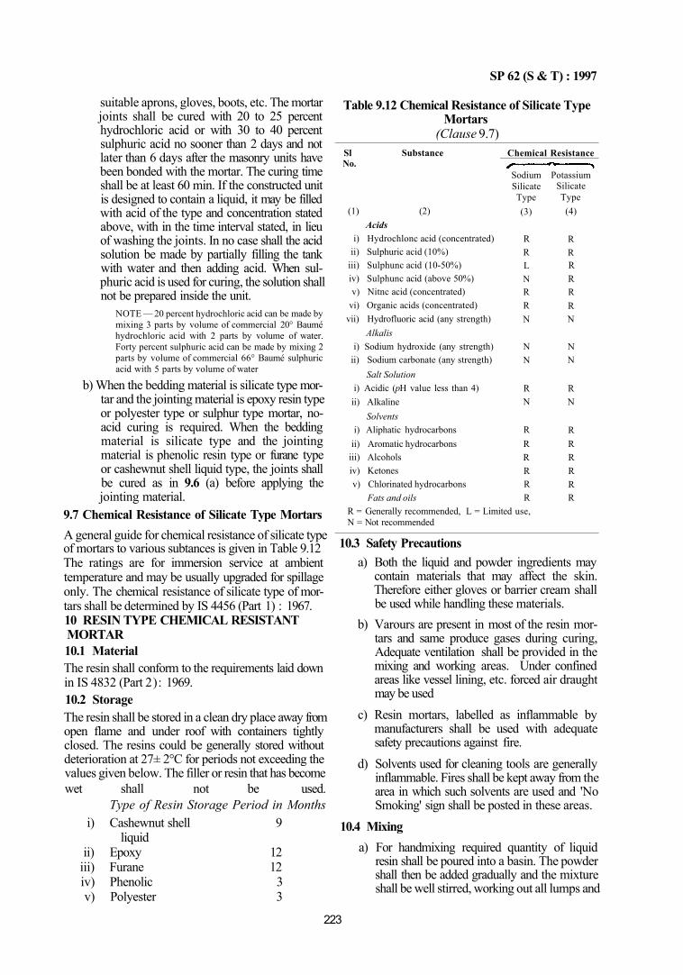
SP 62 (S & T) : 1997
suitable aprons, gloves, boots, etc. The mortar joints shall be cured with 20 to 25 percent hydrochloric acid or with 30 to 40 percent sulphuric acid no sooner than 2 days and not later than 6 days after the masonry units have been bonded with the mortar. The curing time shall be at least 60 min. If the constructed unit is designed to contain a liquid, it may be filled with acid of the type and concentration stated above, with in the time interval stated, in lieu of washing the joints. In no case shall the acid solution be made by partially filling the tank with water and then adding acid. When sulphuric acid is used for curing, the solution shall not be prepared inside the unit.
NOTE — 20 percent hydrochloric acid can be made by mixing 3 parts by volume of commercial 20° Baumé hydrochloric acid with 2 parts by volume of water. Forty percent sulphuric acid can be made by mixing 2 parts by volume of commercial 66° Baumé sulphuric acid with 5 parts by volume of water
b) When the bedding material is silicate type mortar and the jointing material is epoxy resin type or polyester type or sulphur type mortar, no-acid curing is required. When the bedding material is silicate type and the jointing material is phenolic resin type or furane type or cashewnut shell liquid type, the joints shall be cured as in 9.6 (a) before applying the jointing material.
9.7 Chemical Resistance of Silicate Type Mortars A general guide for chemical resistance of silicate type of mortars to various subtances is given in Table 9.12 The ratings are for immersion service at ambient temperature and may be usually upgraded for spillage only. The chemical resistance of silicate type of mortars shall be determined by IS 4456 (Part 1) : 1967. 10 RESIN TYPE CHEMICAL RESISTANT MORTAR 10.1 Material The resin shall conform to the requirements laid down in IS 4832 (Part 2): 1969. 10.2 Storage The resin shall be stored in a clean dry place away from open flame and under roof with containers tightly closed. The resins could be generally stored without deterioration at 27± 2°C for periods not exceeding the values given below. The filler or resin that has become wet shall not be used.
Type of Resin Storage Period in Months i) Cashewnut shell 9
liquid ii) Epoxy 12
iii) Furane 12 iv) Phenolic 3 v) Polyester 3
Table 9.12 Chemical Resistance of Silicate Type Mortars
(Clause 9.7) Sl Substance No.
(1) (2) Acids
i) Hydrochlonc acid (concentrated) ii) Sulphuric acid (10%)
iii) Sulphunc acid (10-50%) iv) Sulphunc acid (above 50%) v) Nitnc acid (concentrated)
vi) Organic acids (concentrated) vii) Hydrofluoric acid (any strength)
Alkalis i) Sodium hydroxide (any strength)
ii) Sodium carbonate (any strength) Salt Solution
i) Acidic (pH value less than 4) ii) Alkaline
Solvents i) Aliphatic hydrocarbons
ii) Aromatic hydrocarbons iii) Alcohols iv) Ketones v) Chlorinated hydrocarbons
Fats and oils
Chemical Resistance
Sodium Silicate Type (3)
R R L N R R N
N N
R N
R R R R R R
R = Generally recommended, L = Limited use, N = Not recommended
Potassium Silicate Type (4)
R R R R R R N
N N
R N
R R R R R R
10.3 Safety Precautions a) Both the liquid and powder ingredients may
contain materials that may affect the skin. Therefore either gloves or barrier cream shall be used while handling these materials.
b) Varours are present in most of the resin mortars and same produce gases during curing, Adequate ventilation shall be provided in the mixing and working areas. Under confined areas like vessel lining, etc. forced air draught may be used
c) Resin mortars, labelled as inflammable by manufacturers shall be used with adequate safety precautions against fire.
d) Solvents used for cleaning tools are generally inflammable. Fires shall be kept away from the area in which such solvents are used and 'No Smoking' sign shall be posted in these areas.
10.4 Mixing a) For handmixing required quantity of liquid
resin shall be poured into a basin. The powder shall then be added gradually and the mixture shall be well stirred, working out all lumps and
223
SP 62 (S & T) : 1997
air bubbles. The mortar shall be mixed to the proportion as specified by the manufacturer for a particular type of job. A stainless steel spatula may be used for mixing purposes.
b) Only such quantity of mortar that could be consumed within 15 to 20 min shall be prepared unless otherwise recommended by the manufacturer.
10.5 Handling a) Resin mortars cure slowly at low temperatures.
If the work is to be carried out at temperature below 15°C, to masonry units should be warmed and the area of work shall be enclosed and heated to above 15°C by using infrared lamp, to obtain proper curing.
b) Mixed mortar, that has become unworkable shall not be re-tempered with liquid resin, but shall be discarded.
10.6 Application a) Surface Preparation — The surface on which
bricks conforming to IS 4860 :1968 or tiles conforming to IS 4457 : 1982 are to be laid shall be tree from dirt and dampness and shall be properly cured and dried.
b) Application of Membrane — A coat of bitumen primer conforming to IS 3384 : 1986 shall be applied on the prepared surface. A uniform coat of bitumen conforming to IS 1580 : 1991 shall then be applied. If the bedding material is epoxy or polyester resin, the tiles or bricks can be laid directly on to the surfaces without application of bitumen primer. In case of furane, cashewnut shell liquid and phenolic resin, a coat of bitumen primer shall be used subject to service conditions. Other membranes, such as, rubber, lead, polyisobutane and fibre-reinforced plastics can be used in place of bitumen primer.
c) Mortar Application with the Same Bedding and Jointing Materials 1) On floors — Spread the resin type of mor
tar 6 to 8 mm thick on the back of the unit. Smear two adjacent sides of the unit with 4 to 6 mm thick mortar. Press the unit into the bed and push against the floor and the unit until the joint tn each case is 2 to 3 mm thick. Trim off excess mortar and allow it to harden hilly. Cure with acid as given in 10.7 axcept for epoxy and polyester resins.
2) On walls — Spread the resin type mortar 6 to 8 mm thick on the back of the unit Smear two adjacent sides of the unit with
4 to 6 mm mortar. Press the unit against the wall until the joint in each case is 2 to 3 mm thick. Trim off excess mortar and allow it to harden fully. While carrying out the jointing allow sufficient time to avoid the joints at the bottom getting disturbed and sliding of the unit. Only one course of tile or brick shall be laid during the initial setting. Cure with acid as in 10.7 except for epoxy and polyester resin.
d) Mortar Application with Different Bedding and Jointing Materials 1) On floors — Spread on to the back and two
adjacent sides of the unit the silicate type mortar 6 to 8 mm thick. Press the unit on the bed until the joint in each case is 3 to 6 mm thick. Before the silicate mortar sets completely, the jointing material is removed to a depth of 20 mm. The material thus removed may be used for bedding providing it is trowelable and has not hardened. After the bedding mortar is properly set cure the joints as given in 10.7 and fill the joints full with resin type mortar taking special care to fill up the entire length of the joint. Trim off excess mortar to make the joints smooth and plane.
2) On walls — Spread to the back and two adjacent sides of the tile or brick the silicate type mortar 6 to 8 mm thick. Press the unit against the wall until the joint in each case is 3 to 6 mm thick. Only one course of the unit shall be laid during the initial setting time to avoid the joints at the bottom getting disturbed and sliding of the unit. Before the silicate mortar sets completely, the jointing material shall be removed to a depth of 20 mm which may be used for bedding provided it is trowel-able and has not hardened. Cure the joints as given in 10.7 and fill the joints full with resin type of mortar taking care to fill the entire length for the joint. Trim off excess mortar to make the joints smooth and plane.
10.7 Acid-Curing Except for epoxy and polyester resins, cure the joints for a minimum period for 72 h with 20 to 25 percent hydrochloric acid or with 30 to 40 percent sulphuric acid before applying the resin type of mortars. After acid-curing, wash the free acid in the joints with clean water and allow sufficient time for thorough drying. Resin mortars shall then be filled into the joints. 10.7.1 Resin mortars are normally self curing and do not generally require an auxilliary curing. They should
224
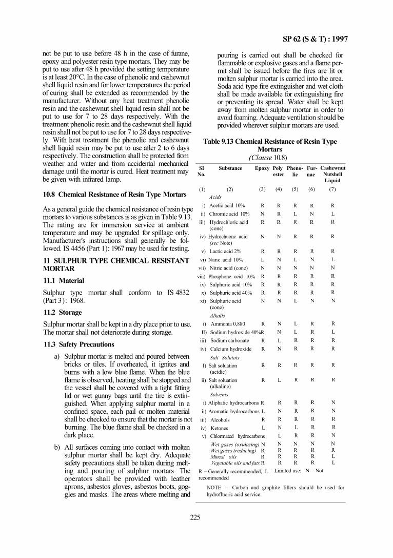
SP 62 (S & T) : 1997
not be put to use before 48 h in the case of furane, epoxy and polyester resin type mortars. They may be put to use after 48 h provided the setting temperature is at least 20°C. In the case of phenolic and cashewnut shell liquid resin and for lower temperatures the period of curing shall be extended as recommended by the manufacturer. Without any heat treatment phenolic resin and the cashewnut shell liquid resin shall not be put to use for 7 to 28 days respectively. With the treatment phenolic resin and the cashewnut shell liquid resin shall not be put to use for 7 to 28 days respectively. With heat treatment the phenolic and cashewnut shell liquid resin may be put to use after 2 to 6 days respectively. The construction shall be protected from weather and water and from accidental mechanical damage until the mortar is cured. Heat treatment may be given with infrared lamp.
10.8 Chemical Resistance of Resin Type Mortars
As a general guide the chemical resistance of resin type mortars to various substances is as given in Table 9.13. The rating are for immersion service at ambient temperature and may be upgraded for spillage only. Manufacturer's instructions shall generally be followed. IS 4456 (Part 1): 1967 may be used for testing. 11 SULPHUR TYPE CHEMICAL RESISTANT MORTAR 11.1 Material Sulphur type mortar shall conform to IS 4832 (Part 3): 1968. 11.2 Storage Sulphur mortar shall be kept in a dry place prior to use. The mortar shall not deteriorate during storage. 11.3 Safety Precautions
a) Sulphur mortar is melted and poured between bricks or tiles. If overheated, it ignites and burns with a low blue flame. When the blue flame is observed, heating shall be stopped and the vessel shall be covered with a tight fitting lid or wet gunny bags until the tire is extinguished. When applying sulphur mortal in a confined space, each pail or molten material shall be checked to ensure that the mortar is not burning. The blue flame shall be checked in a dark place.
b) All surfaces coming into contact with molten sulphur mortar shall be kept dry. Adequate safety precautions shall be taken during melting and pouring of sulphur mortars The operators shall be provided with leather aprons, asbestos gloves, asbestos boots, goggles and masks. The areas where melting and
pouring is carried out shall be checked for flammable or explosive gases and a flame permit shall be issued before the fires are lit or molten sulphur mortar is carried into the area. Soda acid type fire extinguisher and wet cloth shall be made available for extinguishing fire or preventing its spread. Water shall be kept away from molten sulphur mortar in order to avoid foaming. Adequate ventilation should be provided wherever sulphur mortars are used.
Table 9.13 Chemical Resistance of Resin Type Mortars
(Clause 10.8) SI Substance Epoxy Poly
No. ester
(1) (2) Acids
i) Acetic acid 10% ii) Chromic acid 10%
iii) Hydrochloric acid (cone)
iv) Hydrochuonc acid (sec Note)
v) Lactic acid 2% vi) Nanc acid 10%
vii) Nitric acid (cone) viii) Phosphone acid 10%
ix) Sulphuric acid 10% x) Sulphuric acid 40% xi) Sulphuric acid
(cone) Alkalis
i) Ammonia 0,880
(3)
R N R
N
R L N R R R N
R II) Sodium hydroxide 40%R
iii) Sodium carbonate iv) Calcium hydroxide
Salt Solutais I) Salt soluation
(acidic) ii) Salt soluation
(alkaline) Solvents
R R
R
R
i) Aliphatic hydrocarbons R ii) Aromatic hydrocarbons L
iii) Alcohols iv) Ketones
R L
v) Chlormated hydrocarbons Wet gases (oxidazing) N Wet gases (reducing) R Mineal oils R Vegetable oils and fats R
R = Generally recommended, L recommended
(4)
R R R
N
R N N R R R N
N N L N
R
L
R N R N L
Phenolic
(5)
R L R
R
R L N R R R L
L L R R
R
R
R R R L R
N N R R R R R R
= Limited use;
Fur-nae
(6)
R N R
R
R N N R R R N
R R R R
R
R
R R R R R
Cashewnut Nutshell Liquid
(7)
R L R
R
R L N R R R N
R L R R
R
R
N N R R N
N N R R R L R L
N = Not
NOTE – Carbon and graphite fillers should be used for hydrofluoric acid service.
225
SP 62 (S & T) : 1997
11.4 Melting and Pouring
a) The mortar shall be melted in a clean vessel made of cast iron, or steel, or aluminium. It shall be filled with dry sulphur mortar to not more than one half and heated slowly until the mortar has melted to a black, smooth liquid with a mirror bright surface and the liquid is almost as free flowing as water, while stirring frequently with a steel laddle. The sulphur mortar must be dry at the time of use to avoid foaming. The mortar shall be heated to a temperature of about 135°C. Below 130°C some of the liquid will congeal over the top or around the sides of the vessel. If the mortar is heated much above 135°C, the viscosity increases until the mortar thickens and loses its mirror like appearance.
b) If the mortar thickens on overheating, it should be allowed to cool and stirred until thin; then more cold mortar may be added, if necessary, overheating for long periods may permanently damage the mortar. Care shall be taken that water or damp mortar do not get into the heating vessel so as to avoid foaming.
c) The molten sulphur mortar shall be taken in galvanized bucket. The nose of the bucket shall be directed towards the joint and the hot and viscous mortar is poured slowly into the joint without air entrapment. Any entrapped air should be removed while the mortar is hot by poking with a thin mild steel rod.
11.5 Application
a) Surface Preparation — The surface to rec-veive the acid resistant bricks and tiles shall be free from dirt and dampness and shall be cured and dried.
b) Mortar Application with Same Bedding and Jointing Materials 1) On floors — Spacer chips with a surface
area of about 1 cm2 and 6 mm thick and made of sulphur mortar conforming to IS 4832 (Part 3) : 1968 shall be made available. The chemical resistant brick or tile shall be placed on spacer chips, 3 chips being used under each tile. Between the floor and tile or brick 6 mm space shall be provided. The molten sulphur mortar shall be poured in a maximum of two operations in spaces between floor and the units avoiding air pockets till it completely fills the joints. Trim off excess mortar to make the joints smooth and plane using a hot trowel.
2) On walls — The chemically resistant unit shall be placed 6 mm away from the wall and the adjacent unit using spacer chips with a surface area of 1 cm2 and 6 mm thick and made out of sulphur mortar. The vertical and horizontal joints are sealed with gummed strip of paper 25 mm wide to prevent molten sulphur mortar flowing from the joints. The mortar shall be filled leaving a gap of 25 mm from the top and avoid air entrapment. A further course of the unit shall be laid in the same way immediately thereafter. The gummed paper can be stripped off as soon as the sulphur mortar has hardened.
c) Mortar Application with Different Bedding and Jointing Materials 1) On floors—Spread on to the back and two
adjacent sides of the unit the silicate type of mortar 6 to 8 mm thick. Press the unit on the bed and push against the floor and the unit until the joint is not more than 6 mm thick. Before the silicate mortar sets completely, the jointing material is removed to a depth of 20 mm. The material thus removed may be used for bedding provided it is trowelable and has not hardened. Cure the joints with acid for a minimum period of 72 h and dry. If the bedding material silicate mortar, the laying and curing shall be done as per 9.6. Fill up the joint completely to its entire length with sulphur mortar as in 11.4. Trim off excess mortar to make the joints smooth and plane with a hot trowel.
2) On walls — Spread on the back and two adjacent sides of the unit, silicate mortar 6 to 8 mm thick. Press the unit against the wall and with the adjacent unit until the joint in each case is not more than 6 mm thick. Only one course of the unit be laid during initial setting time to avoid the joints at the bottom getting disturbed and the unit getting slided. Before the mortar sets completely remove the jointing material to a depth of 20 mm. The material thus removed may be used for bedding provided it is trowelable and has not hardened. After the bedding mortar has set, cure the joints with resin for a minimum period of 72 h and dry. If the bedding material is silicate type the laying and curing shall be as per 9.6. Seal the vertical and horizontal joints with a strip of gummed paper 25 mm wide to prevent the flow of sulphur mortar from the joints. Fill up the joints completely with molten
226
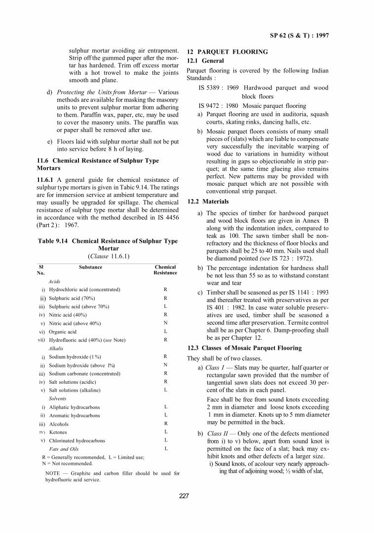
SP 62 (S & T) : 1997
sulphur mortar avoiding air entrapment. Strip off the gummed paper after the mortar has hardened. Trim off excess mortar with a hot trowel to make the joints smooth and plane.
d) Protecting the Units from Mortar — Various methods are available for masking the masonry units to prevent sulphur mortar from adhering to them. Paraffin wax, paper, etc, may be used to cover the masonry units. The paraffin wax or paper shall be removed after use.
e) Floors laid with sulphur mortar shall not be put into service before 8 h of laying.
11.6 Chemical Resistance of Sulphur Type Mortars
11.6.1 A general guide for chemical resistance of sulphur type mortars is given in Tabic 9.14. The ratings are for immersion service at ambient temperature and may usually be upgraded for spillage. The chemical resistance of sulphur type mortar shall be determined in accordance with the method described in IS 4456 (Part 2 ) : 1967.
Table 9.14 Chemical Resistance of Sulphur Type Mortar
(Clause 11.6.1) Sl
No.
i)
ii) iii) iv)
v) vi) vii)
i) ii)
iii) iv) v)
i) ii)
iii) IV)
v)
Substance
Acids Hydrochloric acid (concentrated)
Sulphuric acid (70%) Sulphuric acid (above 70%) Nitric acid (40%) Nitric acid (above 40%) Organic acid Hydrofluoric acid (40%) (see Note) Alkalis Sodium hydroxide (1 %)
Sodium hydroxide (above 1%) Sodium carbonate (concentrated) Salt solutions (acidic) Salt solutions (alkaline) Solvents
Aliphatic hydrocarbons Aromatic hydrocarbons
Alcohols Ketones Chlorinated hydrocarbons Fats and Oils
Chemical Resistance
R
R L R N L R
R N R R L
L L
R L L L
R = Generally recommended, L = Limited use; N = Not recommended.
NOTE — Graphite and carbon filler should be used for hydrofluoric acid service.
12 PARQUET FLOORING 12.1 General Parquet flooring is covered by the following Indian Standards :
IS 5389 : 1969 Hardwood parquet and wood block floors
IS 9472 : 1980 Mosaic parquet flooring a) Parquet flooring are used in auditoria, squash
courts, skating rinks, dancing halls, etc. b) Mosaic parquet floors consists of many small
pieces of (slats) which are liable to compensate very successfully the inevitable warping of wood due to variations in humidity without resulting in gaps so objectionable in strip parquet; at the same time glueing also remains perfect. New patterns may be provided with mosaic parquet which are not possible with conventional strip parquet.
12.2 Materials
a) The species of timber for hardwood parquet and wood block floors are given in Annex B along with the indentation index, compared to teak as 100. The sawn timber shall be non-refractory and the thickness of floor blocks and parquets shall be 25 to 40 mm. Nails used shall be diamond pointed (see IS 723 : 1972).
b) The percentage indentation for hardness shall be not less than 55 so as to withstand constant wear and tear
c) Timber shall be seasoned as per IS 1141 : 1993 and thereafter treated with preservatives as per IS 401 : 1982. In case water soluble preservatives are used, timber shall be seasoned a second time after preservation. Termite control shall be as per Chapter 6. Damp-proofing shall be as per Chapter 12.
12.3 Classes of Mosaic Parquet Flooring They shall be of two classes.
a) Class I — Slats may be quarter, half quarter or rectangular sawn provided that the number of tangential sawn slats does not exceed 30 percent of the slats in each panel. Face shall be free from sound knots exceeding 2 mm in diameter and loose knots exceeding 1 mm in diameter. Knots up to 5 mm diameter may be permitted in the back.
b) Class II — Only one of the defects mentioned from i) to v) below, apart from sound knot is permitted on the face of a slat; back may exhibit knots and other defects of a larger size. i) Sound knots, of acolour very nearly approach
ing that of adjoining wood; ½ width of slat,
227

SP 62 (S & T) : 1997
ii) Loose knots, of a colour contrasting with that of adjoining 1/5 of width of slat,
iii) Cross grain, iv) Waned wood; maximum 1/25 width of
slat, and v) Stains.
228
12.4 Parequet Floor Patterns
They shall be as given in Fig. 9.11 and Fig. 9.12.
FIG. 9.12 PARQUET FLOOR LAID IN PANELS
FIG. 9.11 DIFFERENT DESIGNS OF PANEL FOR PARQUET FLOORING
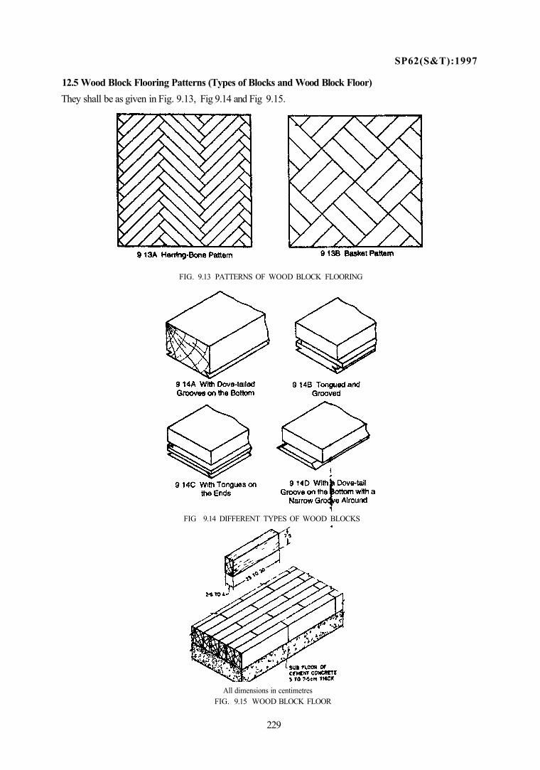
SP62(S&T):1997
12.5 Wood Block Flooring Patterns (Types of Blocks and Wood Block Floor) They shall be as given in Fig. 9.13, Fig 9.14 and Fig 9.15.
FIG. 9.13 PATTERNS OF WOOD BLOCK FLOORING
FIG 9.14 DIFFERENT TYPES OF WOOD BLOCKS
All dimensions in centimetres FIG. 9.15 WOOD BLOCK FLOOR
229
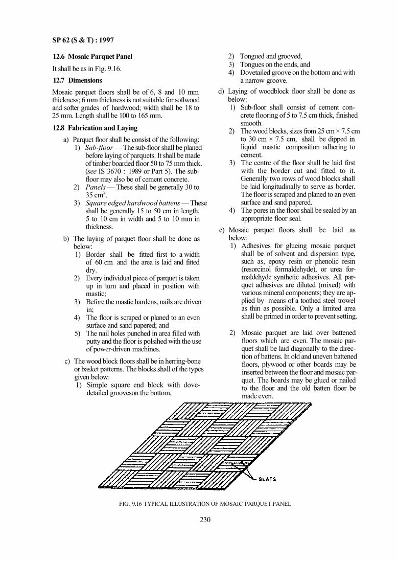
SP 62 (S & T) : 1997
12.6 Mosaic Parquet Panel It shall be as in Fig. 9.16. 12.7 Dimensions Mosaic parquet floors shall be of 6, 8 and 10 mm thickness; 6 mm thickness is not suitable for softwood and softer grades of hardwood; width shall be 18 to 25 mm. Length shall be 100 to 165 mm.
12.8 Fabrication and Laying a) Parquet floor shall be consist of the following:
1) Sub-floor — The sub-floor shall be planed before laying of parquets. It shall be made of timber boarded floor 50 to 75 mm thick. (see IS 3670 : 1989 or Part 5). The sub-floor may also be of cement concrete.
2) Panels — These shall be generally 30 to 35 cm2.
3) Square edged hardwood battens — These shall be generally 15 to 50 cm in length, 5 to 10 cm in width and 5 to 10 mm in thickness.
b) The laying of parquet floor shall be done as below: 1) Border shall be fitted first to a width
of 60 cm and the area is laid and fitted dry.
2) Every individual piece of parquet is taken up in turn and placed in position with mastic;
3) Before the mastic hardens, nails are driven in;
4) The floor is scraped or planed to an even surface and sand papered; and
5) The nail holes punched in area filled with putty and the floor is polsihed with the use of power-driven machines.
c) The wood block floors shall be in herring-bone or basket patterns. The blocks shall of the types given below: 1) Simple square end block with dove-
detailed grooveson the bottom,
2) Tongued and grooved, 3) Tongues on the ends, and 4) Dovetailed groove on the bottom and with
a narrow groove. d) Laying of woodblock floor shall be done as
below: 1) Sub-floor shall consist of cement con
crete flooring of 5 to 7.5 cm thick, finished smooth.
2) The wood blocks, sizes from 25 cm × 7.5 cm to 30 cm × 7.5 cm, shall be dipped in liquid mastic composition adhering to cement.
3) The centre of the floor shall be laid first with the border cut and fitted to it. Generally two rows of wood blocks shall be laid longitudinally to serve as border. The floor is scraped and planed to an even surface and sand papered.
4) The pores in the floor shall be sealed by an appropriate floor seal.
e) Mosaic parquet floors shall be laid as below: 1) Adhesives for glueing mosaic parquet
shall be of solvent and dispersion type, such as, epoxy resin or phenolic resin (resorcinol formaldehyde), or urea formaldehyde synthetic adhesives. All parquet adhesives are diluted (mixed) with various mineral components; they are applied by means of a toothed steel trowel as thin as possible. Only a limited area shall be primed in order to prevent setting.
2) Mosaic parquet are laid over battened floors which are even. The mosaic parquet shall be laid diagonally to the direction of battens. In old and uneven battened floors, plywood or other boards may be inserted between the floor and mosaic parquet. The boards may be glued or nailed to the floor and the old batten floor be made even.
FIG. 9.16 TYPICAL ILLUSTRATION OF MOSAIC PARQUET PANEL
230
SP 62(S & T) : 1997
3) Adhesive shall be applied on the prepared and dry surface and the back of parquet. Apply pressure on the parquet panel to get a good bond. Joints shall be very thin and fine.
4) Mosaic parquet floors shall be finished as in Chapter 15 on finishes of wood work.
ANNEX B (Clause 12.2)
SPECIES OF TIMBER RECOMMENDED FOR SLATS, FLOOR BOARDS AND PARQUET FLOORS
1. 2. 3. 4. 5. 6. 7. 8. 9.
10. 11. 12. 13.
Name Gurjan Rohini Padauk Satinwood Maniawga Axelwood Kala Siris Bijasal Laurel White Chuglam Teak Lendi White Cedar
Hardness 135 130 130 130 125 120 120 100 100 100 100 95 95
14. 15. 16. 17. 18. 19. 20. 21. 22. 23. 24. 25. 26.
Name Kindal Pali Kokko Rosewood Kassi Sissoo Piney Jarul Hollock Anjan Fir Cypress Machillus
Hardness 95 90 90 90 85 85 85 80 75 70 65 60 55
PART 5 TIMBER FLOORS
1 GENERAL
1.1 Timber floors are provided in auditoria, gymnasia, dancing halls, squash courts, public balconies, galleries, skating rinks, etc, for noise retardent floor finish and in hilly areas as thermal insulating floor finish. These floors may also be used in timber framed construction to serve as structural floors.
2 MATERIALS
2.1 The species of timber recommended for floor board shall be as given in Annex B of Part 4 of this Chapter, with their percentage of indentation for hardness, talcing teak as 100.
a) Species of timber selected for girders, binders and projecting joists shall be as given below: 1) For spans of 12 m and greater, all the
species of Group 'Super' specified in IS 3629 : 1986.
2) For spans greater than 6 m but less than 12 m, all the species of Group 'Standard' specified in IS 3629 : 1986.
3) For spans up to and including 6 m, all the species of Group 'Ordinary' specified in IS 3629 : 1986.
b) Timber selected for construction of floor boards and supporting members shall conform to the following:
231
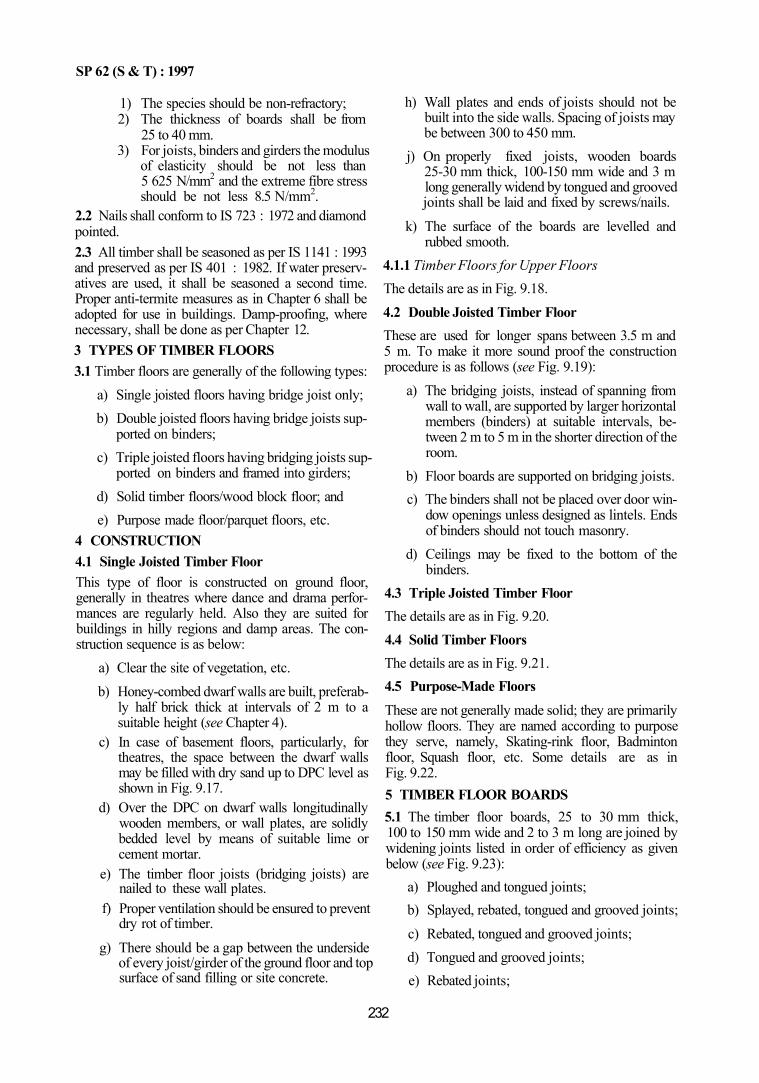
SP 62 (S & T) : 1997
1) The species should be non-refractory; 2) The thickness of boards shall be from
25 to 40 mm. 3) For joists, binders and girders the modulus
of elasticity should be not less than 5 625 N/mm2 and the extreme fibre stress should be not less 8.5 N/mm2.
2.2 Nails shall conform to IS 723 : 1972 and diamond pointed. 2.3 All timber shall be seasoned as per IS 1141 : 1993 and preserved as per IS 401 : 1982. If water preservatives are used, it shall be seasoned a second time. Proper anti-termite measures as in Chapter 6 shall be adopted for use in buildings. Damp-proofing, where necessary, shall be done as per Chapter 12. 3 TYPES OF TIMBER FLOORS 3.1 Timber floors are generally of the following types:
a) Single joisted floors having bridge joist only; b) Double joisted floors having bridge joists sup
ported on binders; c) Triple joisted floors having bridging joists sup
ported on binders and framed into girders; d) Solid timber floors/wood block floor; and e) Purpose made floor/parquet floors, etc.
4 CONSTRUCTION 4.1 Single Joisted Timber Floor This type of floor is constructed on ground floor, generally in theatres where dance and drama performances are regularly held. Also they are suited for buildings in hilly regions and damp areas. The construction sequence is as below:
a) Clear the site of vegetation, etc. b) Honey-combed dwarf walls are built, preferab
ly half brick thick at intervals of 2 m to a suitable height (see Chapter 4).
c) In case of basement floors, particularly, for theatres, the space between the dwarf walls may be filled with dry sand up to DPC level as shown in Fig. 9.17.
d) Over the DPC on dwarf walls longitudinally wooden members, or wall plates, are solidly bedded level by means of suitable lime or cement mortar.
e) The timber floor joists (bridging joists) are nailed to these wall plates.
f) Proper ventilation should be ensured to prevent dry rot of timber.
g) There should be a gap between the underside of every joist/girder of the ground floor and top surface of sand filling or site concrete.
h) Wall plates and ends of joists should not be built into the side walls. Spacing of joists may be between 300 to 450 mm.
j) On properly fixed joists, wooden boards 25-30 mm thick, 100-150 mm wide and 3 m long generally widend by tongued and grooved joints shall be laid and fixed by screws/nails.
k) The surface of the boards are levelled and rubbed smooth.
4.1.1 Timber Floors for Upper Floors The details are as in Fig. 9.18. 4.2 Double Joisted Timber Floor These are used for longer spans between 3.5 m and 5 m. To make it more sound proof the construction procedure is as follows (see Fig. 9.19):
a) The bridging joists, instead of spanning from wall to wall, are supported by larger horizontal members (binders) at suitable intervals, between 2 m to 5 m in the shorter direction of the room.
b) Floor boards are supported on bridging joists. c) The binders shall not be placed over door win
dow openings unless designed as lintels. Ends of binders should not touch masonry.
d) Ceilings may be fixed to the bottom of the binders.
4.3 Triple Joisted Timber Floor The details are as in Fig. 9.20. 4.4 Solid Timber Floors The details are as in Fig. 9.21. 4.5 Purpose-Made Floors These are not generally made solid; they are primarily hollow floors. They are named according to purpose they serve, namely, Skating-rink floor, Badminton floor, Squash floor, etc. Some details are as in Fig. 9.22. 5 TIMBER FLOOR BOARDS 5.1 The timber floor boards, 25 to 30 mm thick, 100 to 150 mm wide and 2 to 3 m long are joined by widening joints listed in order of efficiency as given below (see Fig. 9.23):
a) Ploughed and tongued joints; b) Splayed, rebated, tongued and grooved joints; c) Rebated, tongued and grooved joints; d) Tongued and grooved joints; e) Rebated joints;
232
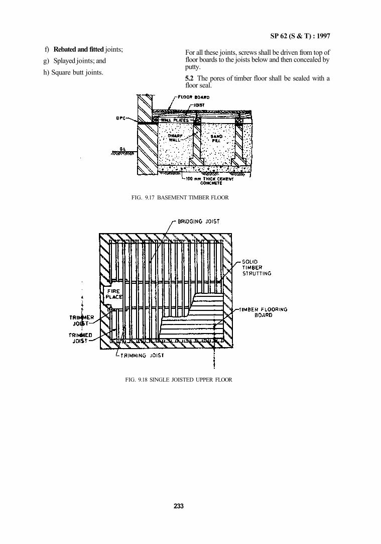
f) Rebated and fitted joints; g) Splayed joints; and h) Square butt joints.
FIG. 9.18 SINGLE JOISTED UPPER FLOOR
233
SP 62 (S & T) : 1997
For all these joints, screws shall be driven from top of floor boards to the joists below and then concealed by putty. 5.2 The pores of timber floor shall be sealed with a floor seal.
FIG. 9.17 BASEMENT TIMBER FLOOR
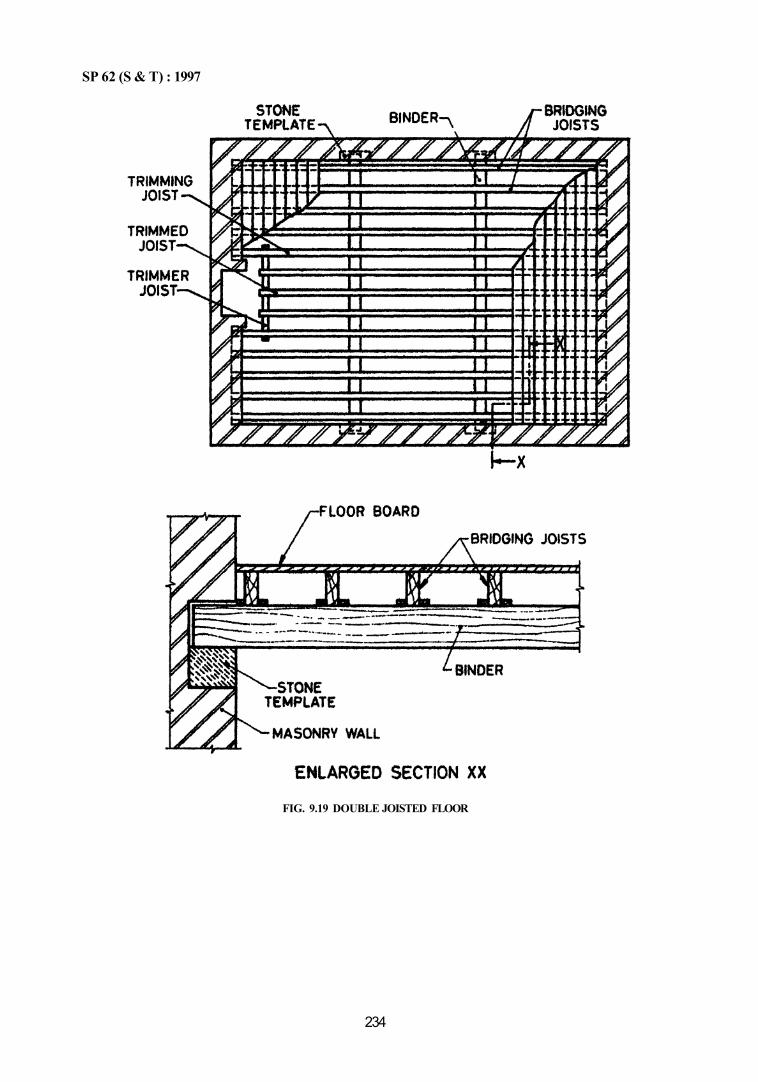
SP 62 (S & T) : 1997
234
FIG. 9.19 DOUBLE JOISTED FLOOR
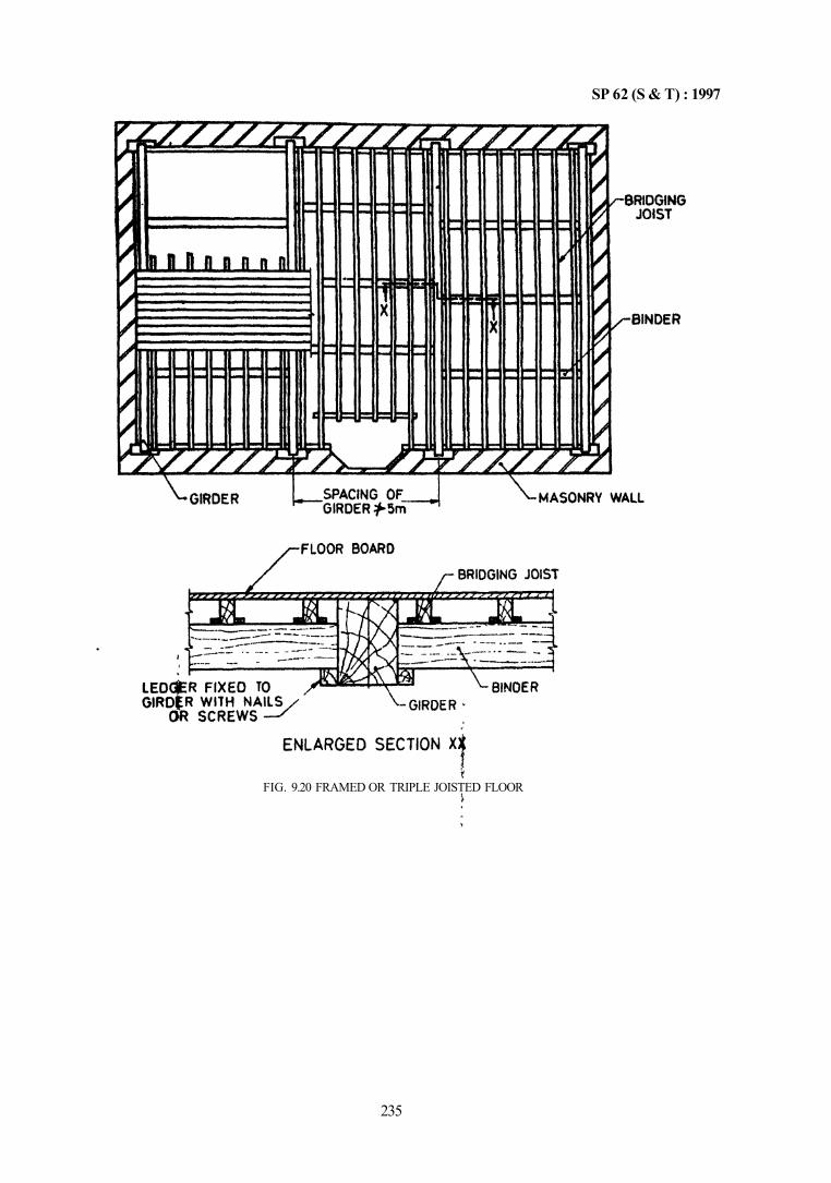
SP 62 (S & T) : 1997
235
FIG. 9.20 FRAMED OR TRIPLE JOISTED FLOOR
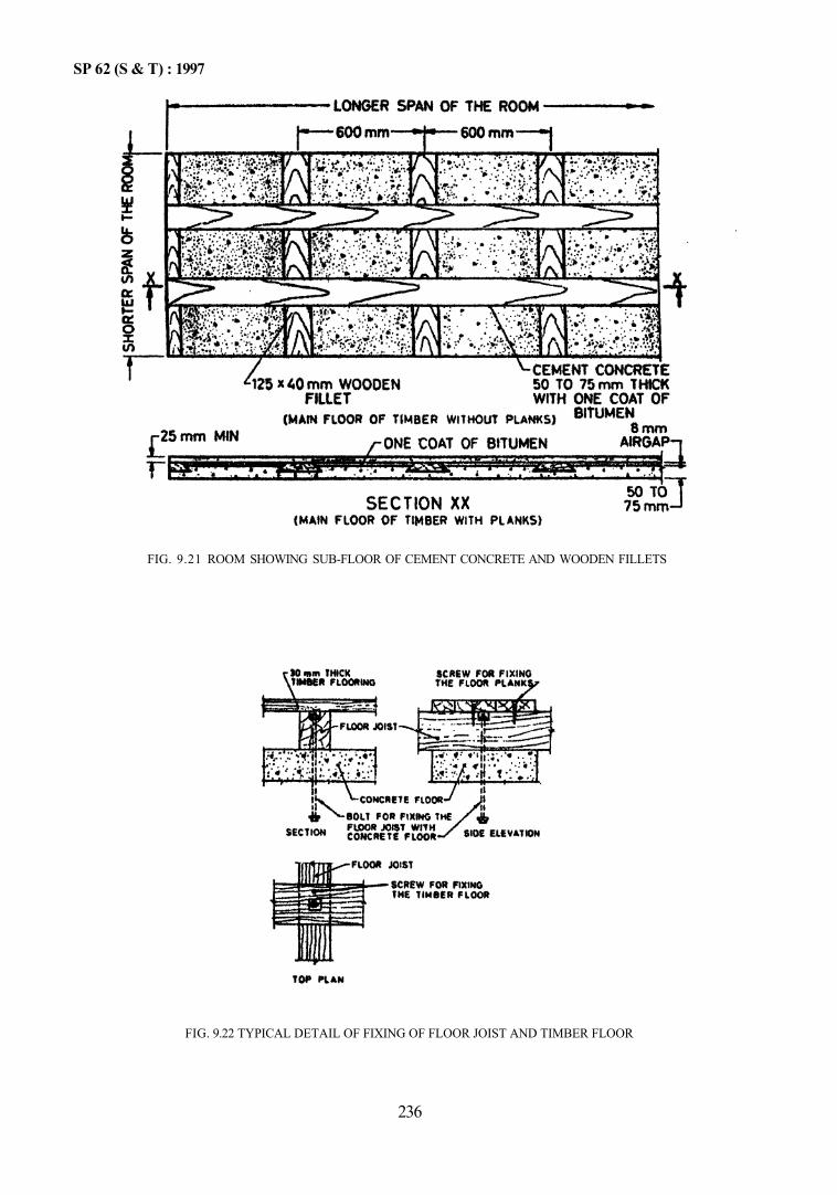
SP 62 (S & T) : 1997
236
FIG. 9.22 TYPICAL DETAIL OF FIXING OF FLOOR JOIST AND TIMBER FLOOR
FIG. 9.21 ROOM SHOWING SUB-FLOOR OF CEMENT CONCRETE AND WOODEN FILLETS
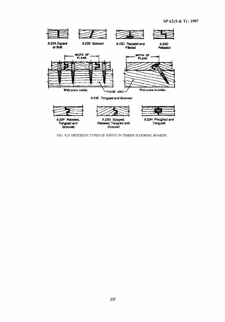
SP 62(S & T) : 1997
237
FIG. 9.23 DIFFERENT TYPES OF JOINTS IN TIMBER FLOORING BOARDS

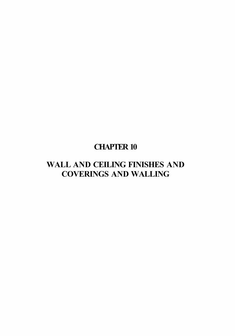
CHAPTER 10
WALL AND CEILING FINISHES AND COVERINGS AND WALLING
CONTENTS
PART 1 WALL AND CEILING FINISHES AND COVERINGS
1 GENERAL
2 LIME PLASTER FINISH
2.1 General 2.2 Materials 2.3 Preparatory Work 2.4 Preparation of Background 2.5 Preparation of Lime Mortars for Plastering 2.6 Application of Lime Plaster 2.7 Curing 2.8 Special Finishes 2.9 Miscellaneous Works
3 CEMENT AND CEMENT-LIME PLASTER FINISH
3.1 General 3.2 Materials 3.3 Preparatory Work 3.4 Sequence of Operations 3.5 Thickness of Plaster 3.6 Number of Coats 3.7 Application of Undercoats 3.8 Curing
4 EXTERNAL RENDERED FINISHES
4.1 General 4.2 Types of Rendered Finishes 4.3 Nature of Background in Relation to Choice of
Rendering 4.4 Recommended Mix Proportions 4.5 Preparatory Work 4.6 Application of Rendering Coats 4.7 Curing
5 EXTERNAL FACING AND VENEERS—STONE FACING
5.1 General 5.2 Materials 5.3 Types of Facings 5.4 Fixing the Facings with Cramps 5.5 Joints 5.6 Fixing of Stone Facings 5.7 Finishing of Joints 5.8 Ashlar Facing 5.9 Control of Alignment
6 EXTERNAL FACINGS AND VENEERS — CEMENT CONCRETE
6.1 General
6.2 Materials 6.3 Types of Facings and Fixing by Cramps 6.4 Supports 6.5 Joints 6.6 Fixing Precast Concrete Slab Facings 6.7 Control of Alignment
7 EXTERNAL FACINGS AND VENEERS — WALL TILING AND MOSAICS
7.1 General 7.2 Materials 7.3 Preparatory Work 7.4 Application of Floated Coat for Tiles and
Mosaics 7.5 Fixing of Tiles 7.6 Fixing of Ceramic Mosaics 7.7 Fixing of Marble Mosaics
8 WALL COVERINGS
8.1 General 8.2 Materials 8.3 Preparatory Work 8.4 Fixing of Boards
9 CEILING COVERINGS
9.1 General 9.2 Preparatory Work 9.3 Fixing of Coverings
10 FIXING DEVICES
10.1 Types 10.2 Fixing
ANNEX A SPECIAL MIXES FOR SULPHATE BACKGROUNDS
ANNEX B FABRICATION AND FIXING OF TIMBER CEILING
PART 2 WALLING 1 GENERAL
2 REED WALLING
2.1 General 2.2 Materials 2.3 Preparatory Work

2.4 Fixing of Reed Board 2.5 Fixing of Reeds for In-situ wall Construction 2.6 Finishing
3 GYPSUM BLOCK PARTITIONS — NON-LOAD BEARING
3.1 General 3.2 Materials 3.3 Laying of Blocks
4 NO-FlNES CONCRETE
4.1 General 4.2 Materials 4.3 Mixes 4.4 Transporting, Placing, Compacting, Curing
and Workmanship

SP 62(S & T) : 1997
CHAPTER 10
WALL AND CEILING FINISHES AND COVERINGS AND WALLING
PART 1 WALL AND CEILING FINISHES AND COVERINGS
1 GENERAL
1.1 Wall and ceiling finishes and coverings are covered by the following Indian Standards:
a) IS 1414 : 1989 Fixing of wall coverings b) IS 1661 : 1972 Cement and cement-lime
plaster finish c) IS 1946 : 1961 Use of fixing devices in walls,
ceilings and floors of solid construction d) IS 2394 : 1984 Lime plaster finish e) IS 2402 : 1963 External rendered finishes f) IS 2441 : 1984 Fixing ceiling coverings g) IS 4101 (Part 1): 1967 External facings and
veneers, stone facing h) IS 4101 (Part 2) : 1967 External facings and
veneers, cement concrete facing j) IS 4101 (Part 3) : 1985 External facings and
veneers, wall tiling and mosaics.
2 LIME PLASTER FINISH
2.1 General
Lime plaster finish and allied finishes are commonly used in the country for internal finishes as well as for external renderings Application of lime plaster finish to walls, ceilings, columns and similar surfaces are covered here.
2.2 Materials
a) Lime shall conform to IS 712: 1984 b) Pozzolana shall conform to IS 1344 : 1981 and
IS 3812 : 1981 c) Sand shall conform to IS 1542 : 1992 d) Cement shall conform to IS 269 : 1989, IS 455 :
1989, IS 1489 (Parts 1 & 2) 1991 and any other as specified
e) Lime putty shall conform to IS 1635 : 1992.
2.3 Preparatory Work
2.3.1 All surfaces to receive lime plaster shall be sufficiently cured and dry; all service pipes, etc, to be embedded in masonry shall be protected against corrosion before plaster work is begun. Plastering work shall be protected from damage during and after the operation; the piaster hardens by drying and recar-bonation which is a slow process and hence susceptible to damage.
If dubbing out is necessary, it should be done in advance so that an adequate time interval may be available before the application of the first undercoat. Plaster work shall not be started until necessary fixtures, such as, door and window frames, etc, are completed and all pipes, etc, are embedded in the wall so that there is no need to cut the plaster.
2.4 Preparation of Background
a) Ensure proper bond between background and the first coat of plaster. For this all joints in back masonry shall be raked out to a depth of not less than 12 mm while the mortar in the joint is still green. Roughening and cleaning of background shall be done; for roughening thin wire brush may be used and the roughened surface moistioned; for cleaning it should be brushed to remove dust, loose particles, etc.
b) Where necessary, dubbing shall be carried out; the need would arise where the background is uneven and it cannot be made up by regular courses of plastering. The dubbing process consists of filling the holes and depressions with mortar of the same mix as the first coat. The patches of plaster are left rough so that subsequent coat of plaster would stick to it.
c) Theimasonry shall be allowed to dry out for sufficient period so that initial drying shriakageis fairly complete and suction adjustment is possible during plastering. Suction is the force by which the plaster is held on the surface after it is laid by the trowel and it has hardened. However, very strong suction would suck all moisture from the plaster making it weak, porous and friable. Therefore, careful adjustment is necessary for good plastering by wetting the backing suitably if it is dry; the wall shall not be soaked but only dampened evenly before applying the plaster since too much water also makes it impossible to keep the plaster in position. It is preferable to do plastering under shady conditions.
d) Differential movements between the background and plaster due to moisture change will cause cracking of plaster. Major part of such movements shall be allowed to set before the plaster is applied, for example, by giving
243
SP 62 (S & T) : 1997
sufficient drying time to the background. However, concrete blocks and foam concrete blocks shall be only lightly wetted before plastering. The reasons for cracking of plaster are as under: 1) Quick drying of the mortar due to hot
weather and low humidity; 2) Strong mix is used on a weak background; 3) Lack of bond with the background; 4) Masonry underneath has not undergone
initial shrinkage; 5) Lack of proper raking of joints; 6) Discontinuity in backgrounds, such as,
change from wall to ceiling, from concrete to brickwork, from clay brickwork to concrete block work, etc. This can be overcome by separating the two portions by a neat cut through the plaster at the junction;
7) Due to roof movement by variation in temperature, cracks may occur in partitions; this can be prevented by isolating the top of partition from roof slab; and
8) When bridging joints in slabs, the plaster will crack due to higher stresses; this can be avoided by reinforcing the plaster at the joint by wire or jute scrim.
2.5 Preparation of Lime Mortars for Plastering This is covered in Chapter 4. 2.6 Application of Lime Plaster
a) General — It is an advantage to plaster the ceiling first and then to plaster the walls starting from top and working downwards. This will permit the removal of scaffolding as easily as possible. 1) The range of coats normally employed for
different backgrounds are as follows: Brickwork (internal and external) Stonework (internal and external) Concrete blocks Wood laths Soffits and ceilings
1 or 2 2 or 3 1 or 2 2 or 3 1 or 2
2) Thickness for plaster work exclusive of key or dubbing out shall generally be as below:
Brick masonry a) Single coat work b) Double coat work
Stone masonry Stone masonry (very rough surface)
First Coat
15 mm 10 mm 15 mm
15 mm
Second Coat
— 10 mm 10 mm
10 mm
Third Coat
— — —
10 mm 3) The plasters shall be finished to a smooth
surface.
4) Metals in contact with plaster are liable to corrosion. However, when a rich mix of cement lime plaster (1:1:6) is used, it would have less corrosive effect on iron and steel.
5) Plastering shall be completed before the setting process for mortar has started. If hydraulic lime is used the mortar shall be used within 4 h after grinding. Lime pozzolana mortar shall be used within 24 h of grinding.
b) To ensure even thickness and a true surface, piaster about 150 mm × 150 mm shall be first laid, horizontally and vertically, at not more than 2 m intervals over the entire surface to serve as gauges; they shall be uniformly thick but slightly more than the specified thickness. These shall be beaten by wooden straight edge and brought to true surface after thoroughly filling the joints. Excessive trowelling or floating should be avoided. During the process a solution of lime putty shall be applied on the surface to make the latter workable. All corners, arrises, angles and junctions shall be truly vertical or horizontal as the case may be. Rounding or chamfering shall be done with proper templates.
c) The plaster shall be left cut clean to line both horizontally and vertically, while stopping work at the end of the day. For recommencing the work, the edge of the old work shall be scrapped clean, wetted with lime putty before plaster is applied to the adjacent areas. The plastering work shall be closed at the end of the day on the body of the wall but not nearer than 150 mm to any corner or arrises. There shall be no horizontal joints in plasterwork on parapet tops and copings. No portion of work initially be left out to be patched later on. In case bailies pierce the wall, the holes shall be made good with brick and plastered.
d) One Coat Plaster Work — The plaster of specified thickness shall be applied to the full length of the wall up to natural breaking points. such as, doors and windows. The mix for ceilings shall be stiffer than that used for walls. On soffits the mortar shall be laid in long even spreads outwards from the operator overlapping each trowel full and using sufficient pressure to ensure intimate contact with the background. On walls, the mortar shall be laid in long even spreads upwards and across, under pressure. On smooth background, the mortar may have to be dashed on to ensure adequate bond.
244
SP 62 (S & T) : 1997
The plaster shall be laid on litile more than the required thickness and levelled with a wooden float. The plaster shall be water cured as described in 2.7.
e) Two Coat Plaster Work 1) First coat—The first coat shall be applied
as in (d) above. Before the first coat hardens, its surface shall be beaten up by the edges of wooden thapis and close dents shall be made on the surface, which serve as a key to the next coat. The next coat shall be applied, after the first coat has set for 3 to 5 days. The surface shall not be allowed to dry during this period.
2) First coat on wooden lath and metal lathing — The mortar shall be stiff enough to cling and hold when laid and shall be applied spreading diagonally across the lath work overlapping each trowel full under pressure. The average thickness shall not be exceeding 10 mm.
3) Second coat — The second coat shall be completed in exactly the same manner as the first coat. The finishing coat shall be laid with a mason's trowel to an average thickness of 5 mm.
4) Curing shall be done as in 2.7. f) Three Coat Plaster Work — The first two coats
shall be applied as in (e); the third coat shall be completed tp the specified thickness in the same manner as the second coat; curing shall be done as is 2.7.
2.7 Curing Curing shall be started 24 h after finishing the plaster. The plaster shall be kept wet tor 7 days; during this period it shall be protected. 2.8 Special Finishes 2.8.1 Madras Plaster This is a special plaster finish applied in three or more coats to obtain a smooth polished surfaces in places where shell lime and fine sand are easily available.
a) The first coat of lime plaster shall be applied as in 2.6 (d). This shall be allowed to set for 2 or 4 days and then the surface scoured thoroughly in diagonal lines crossing each other. The plaster shall be kept constantly watered till it is nearly set and then the second and third coats be applied as in 2.6 (e) and (f)
b) On this coat, a mix specified below about 5 mm thick shall be applied to an exact level surface with long wooden floats or where required by curved moulds. The surace of the undercoat may be watered, if necessary, before applying this coat. Shell lime (slaked) 12 parts by volume Fine white sand 9 parts by volume Powdered marble 1 part by volume
The sand shall be ground fine. The marble also shall be ground fine and filtered through muslin. The materials shall be mixed with water and kept in a heap, well wetted for 2 days.
c) On this coat of (b), the same mix as in (b) shall be ground on flat stone slabs with stone rollers to the consistency of fine river mud and applied to a thickness of 2 mm over the second coat (b) which is wetted before hand.
d) The surface of the third coat (c) shall be polished first with trowels and then with very hard smooth stones. While polishing operation is in progress soap stone powder contained in muslin bags shall be dusted on the surface. The operation shall be continued till a high smooth polish is obtained.
e) Curing shall be done as in 2.7.
2.9 Miscellaneous Works 2.9.1 Repairs
a) Cracked, crumbled or hollow sounding portions of plaster shall be removed to a shape of a square or a rectangle. The edges shall be undercut slightly to provide a key to new plaster.
b) The visible joints shall be raked out to a minimum depth of 12 mm in the case of brick work and 20 mm in the case of stone work. The surface of the masonry shall be scrubbed with wire brushes to remove all mortar; it shall then be washed with water and kept wet before commencing plastering.
c) Plaster shall then be applied as in one coat plaster work [see 2.6 (d)]. The surface shall be finished even and flush with the old surrounding plaster.
2.9.2 Avoidance of Crazing
a) Surface crazing is due to excessive shrinkage caused by drying.
b) In order to prevent this, it is necessary to limit the differences in shrinkage, as below: 1) Use well graded materials; 2) Ensure thorough grinding of mortar and
thorough mixing of constituents; 3) Observe carefully the time intervals
between successive coats so that each coat undergoes a portion of its shrinkage before the next coat is applied; and
4) Avoid quick drying at initial stages. 3 CEMENT AND CEMENT-LIME PLASTER FINISH 3.1 General Cement plaster and cement plaster gauged with lime are widely used in the country for finishing of walls and ceilings.
245
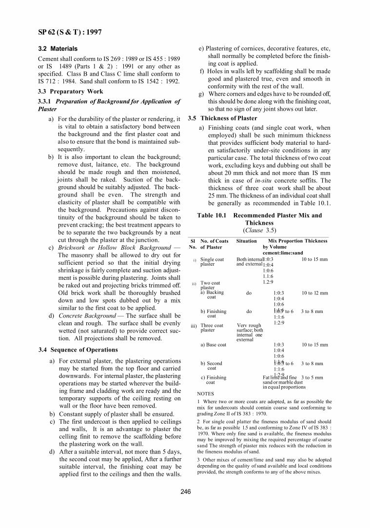
SP 62 (S & T) : 1997
3.2 Materials Cement shall conform to IS 269 : 1989 or IS 455 : 1989 or IS 1489 (Parts 1 & 2) : 1991 or any other as specified. Class B and Class C lime shall conform to IS 712 : 1984. Sand shall conform to IS 1542 : 1992. 3.3 Preparatory Work 3.3.1 Preparation of Background for Application of Plaster
a) For the durability of the plaster or rendering, it is vital to obtain a satisfactory bond between the background and the first plaster coat and also to ensure that the bond is maintained subsequently.
b) It is also important to clean the background; remove dust, laitance, etc. The background should be made rough and then moistened, joints shall be raked. Suction of the background should be suitably adjusted. The background shall be even. The strength and elasticity of plaster shall be compatible with the background. Precautions against discontinuity of the background should be taken to prevent cracking; the best treatment appears to be to separate the two backgrounds by a neat cut through the plaster at the junction.
c) Brickwork or Hollow Block Background — The masonry shall be allowed to dry out for sufficient period so that the initial drying shrinkage is fairly complete and suction adjustment is possible during plastering. Joints shall be raked out and projecting bricks trimmed off. Old brick work shall be thoroughly brushed down and low spots dubbed out by a mix similar to the first coat to be applied.
d) Concrete Background — The surface shall be clean and rough. The surface shall be evenly wetted (not saturated) to provide correct suction. All projections shall be removed.
3.4 Sequence of Operations
a) For external plaster, the plastering operations may be started from the top floor and carried downwards. For internal plaster, the plastering operations may be started wherever the building frame and cladding work are ready and the temporary supports of the ceiling resting on wall or the floor have been removed.
b) Constant supply of plaster shall be ensured. c) The first undercoat is then applied to ceilings
and walls, It is an advantage to plaster the celling finit to remove the scaffolding before the plastering work on the wall.
d) After a suitable interval, not more than 5 days, the second coat may be applied, After a further suitable interval, the finishing coat may be applied first to the ceilings and then the walls.
e) Plastering of cornices, decorative features, etc, shall normally be completed before the finishing coat is applied.
f) Holes in walls left by scaffolding shall be made good and plastered true, even and smooth in conformity with the rest of the wall.
g) Where corners and edges have to be rounded off, this should be done along with the finishing coat, so that no sign of any joint shows out later.
3.5 Thickness of Plaster
Sl No.
i )
i i)
iii)
No. of Coats of Plaster
Single coat plaster
Two coat plaster a) Backing
coat
b) Finishing coat
Three coat plaster
a) Base coat
b) Second coat
c) Finishing coat
Situation
Both internal and external
do
do
Verv rough surface; both internal one external
Mix Proportion by Volume cement:lime:sand 1:0:3 1:0:4 1:0:6 1.1:6 1.2:9
1:0:3 1:0:4 1:0:6 1:1:6 1:0:3 to 6 1:1:6 1:2:9
1:0:3 1:0:4 1:0:6 1:1:6 1:0:3 to 6 1:1:6 1:2:9 Fat lime and fine
sand or marble dust in equal proportions
Thickness
10 to 15 mm
10 to 12 mm
3 to 8 mm
10 to 15 mm
3 to 8 mm
3 to 5 mm
NOTES 1 Where two or more coats are adopted, as far as possible the mix for undercoats should contain coarse sand conforming to grading Zone II of IS 383 : 1970. 2 For single coal platter the fineness modulus of sand should be, as far as possible 1.5 and conforming to Zone IV of IS 383 : 1970. Where only fine sand is available, the fineness modulus may be improved by mixing the required percentage of coarse sand The strength of piaster mix reduces with the reduction in the fineness modulus of sand. 3 Other mixes of cement/lime and sand may also be adopted depending on the quality of sand available and local conditions provided, the strength conforms to any of the above mixes.
a) Finishing coats (and single coat work, when employed) shall be such minimum thickness that provides sufficient body material to harden satisfactorily under-site conditions in any particular case. The total thickness of two coat work, excluding keys and dubbing out shall be about 20 mm thick and not more than IS mm thick in case of in-situ concrete soffits. The thickness of three coat work shall be about 25 mm. The thickness of an individual coat shall be generally as recommended in Table 10.1.
Table 10.1 Recommended Plaster Mix and Thickness
(Clause 3.5)
246
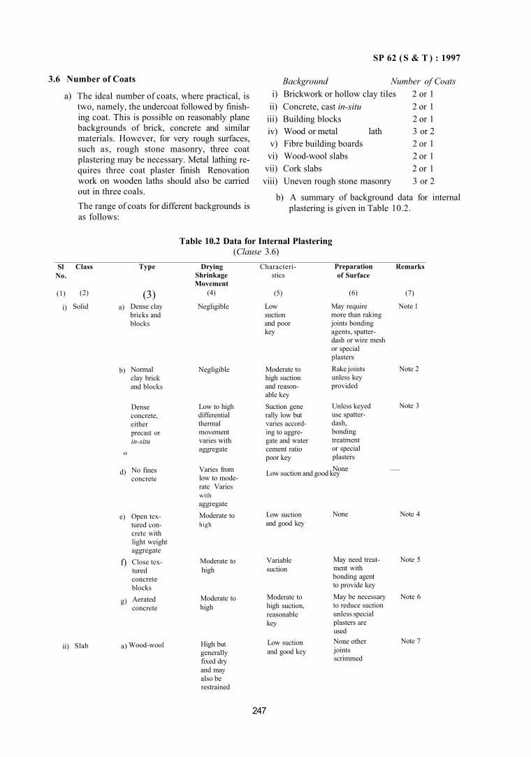
SP 62 (S & T ) : 1997
3.6 Number of Coats
a) The ideal number of coats, where practical, is two, namely, the undercoat followed by finishing coat. This is possible on reasonably plane backgrounds of brick, concrete and similar materials. However, for very rough surfaces, such as, rough stone masonry, three coat plastering may be necessary. Metal lathing requires three coat plaster finish Renovation work on wooden laths should also be carried out in three coals. The range of coats for different backgrounds is as follows:
Background Number of Coats i) Brickwork or hollow clay tiles 2 or 1
ii) Concrete, cast in-situ 2 or 1 iii) Building blocks 2 or 1 iv) Wood or metal lath 3 or 2 v) Fibre building boards 2 or 1
vi) Wood-wool slabs 2 or 1 vii) Cork slabs 2 or 1 viii) Uneven rough stone masonry 3 or 2
b) A summary of background data for internal plastering is given in Table 10.2.
Table 10.2 Data for Internal Plastering (Clause 3.6)
Sl No.
(1)
i)
ii)
Class
(2)
Solid
Slab
a)
b)
c)
d)
e)
f)
g)
a)
Type
(3) Dense clay bricks and blocks
Normal clay brick and blocks
Dense concrete, either precast or in-situ
No fines concrete
Open textured concrete with light weight aggregate Close textured concrete blocks Aerated concrete
Wood-wool
Drying Shrinkage Movement
(4)
Negligible
Negligible
Low to high differential thermal movement varies with aggregate
Varies from low to mode-rate Varies with aggregate Moderate to high
Moderate to high
Moderate to high
High but generally fixed dry and may also be restrained
Characteristics
(5)
Low suction and poor key
Moderate to high suction and reasonable key Suction gene rally low but varies according to aggre-gate and water cement ratio poor key
Low suction and good key
Low suction and good key
Variable suction
Moderate to high suction, reasonable key
Low suction and good key
Preparation of Surface
(6)
May require more than raking joints bonding agents, spatter-dash or wire mesh or special plasters Rake joints unless key provided
Unless keyed use spatter-dash, bonding treatment or special plasters None
None
May need treatment with bonding agent to provide key May be necessary to reduce suction unless special plasters are used None other joints scrimmed
Remarks
(7)
Note 1
Note 2
Note 3
—
Note 4
Note 5
Note 6
Note 7
247
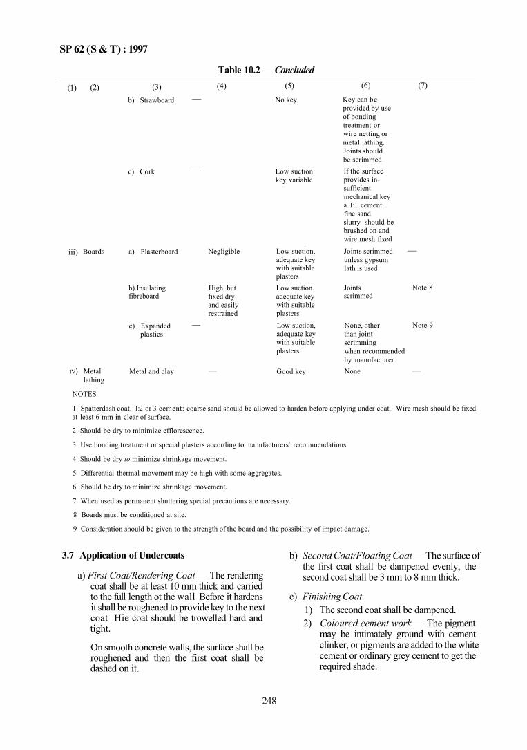
SP 62 (S & T) : 1997
Table 10.2 — Concluded
(1)
iii)
iv)
(2)
Boards
Metal lathing
(3) b) Strawboard
c) Cork
a) Plasterboard
b) Insulating fibreboard
c) Expanded plastics
Metal and clay
(4) —
—
Negligible
High, but fixed dry and easily restrained
—
—
(5)
No key
Low suction key variable
Low suction, adequate key with suitable plasters Low suction. adequate key with suitable plasters Low suction, adequate key with suitable plasters
Good key
(6)
Key can be provided by use of bonding treatment or wire netting or metal lathing. Joints should be scrimmed If the surface provides in-sufficient mechanical key a 1:1 cement fine sand slurry should be brushed on and wire mesh fixed
Joints scrimmed unless gypsum lath is used
Joints scrimmed
None, other than joint scrimming when recommended by manufacturer None
(7)
—
Note 8
Note 9
—
NOTES
1 Spatterdash coat, 1:2 or 3 cement: coarse sand should be allowed to harden before applying under coat. Wire mesh should be fixed at least 6 mm in clear of surface.
2 Should be dry to minimize efflorescence.
3 Use bonding treatment or special plasters according to manufacturers' recommendations.
4 Should be dry to minimize shrinkage movement.
5 Differential thermal movement may be high with some aggregates.
6 Should be dry to minimize shrinkage movement.
7 When used as permanent shuttering special precautions are necessary.
8 Boards must be conditioned at site.
9 Consideration should be given to the strength of the board and the possibility of impact damage.
3.7 Application of Undercoats
a) First Coat/Rendering Coat — The rendering coat shall be at least 10 mm thick and carried to the full length ot the wall Before it hardens it shall be roughened to provide key to the next coat Hie coat should be trowelled hard and tight.
On smooth concrete walls, the surface shall be roughened and then the first coat shall be dashed on it.
b) Second Coat/Floating Coat — The surface of the first coat shall be dampened evenly, the second coat shall be 3 mm to 8 mm thick.
c) Finishing Coat 1) The second coat shall be dampened. 2) Coloured cement work — The pigment
may be intimately ground with cement clinker, or pigments are added to the white cement or ordinary grey cement to get the required shade.
248
SP 62 (S & T) : 1997
3) In case of coloured cement plastering, waterproofing compounds should be added on the undercoats to minimize the risk of efflorescence.
3.8 Curing
a) Each coat shal1 be cured for a maximum period of 7 days and shall be kept damp till the next coat is applied.
b) After completion of the finishing coat, the plaster shall be kept wet at least for 7 days.
4 EXTERNAL RENDERED FINISHES
4.1 General
'Rendering' denotes generally external plaster and allied finishes, plain or textured, applied for the purpose of protection and decoration. Rendered finish can withstand different exposure conditions, such as, severe or moderate exposure to rain; dusty, clear or corrosive atmosphere, or subject to large variations in temperature or other climatic cycles. Rendering increases, durability and ensures better performance.
Plain internal finishes are covered in 2 and 3 of Part 1 of this Chapter.
4.2 Types of Rendered Finishes
4.2.1 Trowelled or Floated Plain Finishes
Steel trowelled finishes are not recommended for external renderings. Plain floated finishes require a high standard of workmanship to minimize the risk of cracking, crazing and irregular discolouration.
4.2.2 Scraped or Textured Finishes, Hand Applied
Scraped or textured finishes are generally less liable to crack or craze than plain finishes and are easier to bring to a uniform appearance; this is specially important when coloured renderings are used. Although rough texture offers more lodgement for dirt, it tends to an evenness of discolouration; rain water is distributed reducing the risk of penetration through the rendering.
4.2.3 Hand-Thrown Finishes, Rough Cast and Dry-Dash etc
These finishes have all the advantages of scraped or textured finish. Under severe conditions of exposure these are more satisfactory from weather proofing, durability, reistance to cracking and crazing than the types as in 4.2.1 and 4.2.2.
4.2.4 Machine Applied Finishes
There are various types, mainly proprietory materials and processes operated by specialists. The types are as follows:
a) Finishes in which the material is thrown at random — These have an open porous structure, behave similarly to hard-applied scraped finishes and are equal to the latter and to hand-thrown finishes in water proofness, durability and resistance to cracking and crazing.
b) Finishes which are applied by gun spray — These give low density porous finishes.
There are other finishes solely applied by means of cement gun under pressure which produce somewhat similar appearance to roughcast but less attractive. They are more dense and therefore give very effective protection.
4.3 Nature of Background in Relation to Choice of Rendering
Broadly the background may be classified under the following types so far as application of rendering is concerned:
a) Dense, strong and smooth materials;
b) Moderately strong and porous materials;
c) Moderately weak and porous materials;
d) No-fines concrete; and
e) Lathing or other similar backing materials, The characteristics of these backgrounds are given in Table 10.3.
4.4 Recommended Mix Proportions
Mixes suitable for different types of renderings are given in Table 10.4. Where alternate mixes are given selection shall be made on the following considerations:
a) The mix for each successive coat shall never be of a type richer in cement than the mix used for the coat to which it is applied; and
b) Richer type of mix shall be preferred in winter conditions.
4.5 Preparatory Work
4.5.1 Independent scaffolding may be used wherever possible to avoid put log holes.
249
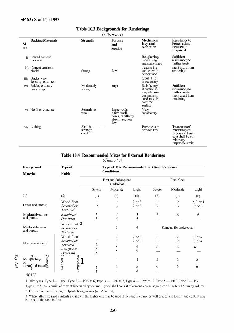
SP 62 (S & T) : 1997
Table 10.3 Backgrounds for Renderings (Claused)
Sl No.
i)
ii)
iii)
iv)
v)
VI)
Backing Materials
Poured cement concrete
Cement concrete blocks
Bricks very dense type, stones Bricks, ordinary porous type
No-fines concrete
Lathing
Strength
Strong
Moderately strong
Sometimes weak
Shall be strengthened
Porosity and Suction
Low
High
Large voids, a few small pores, capillarity absent; suction low
—
Mechanical Key and Adhesion
Roughening, moistening and sometimes treating the surface with cement and grout (1:1) is necessary Satisfactory; if suction is irregular use cement and sand mix 1:1 over the surface Very satisfactory
Purpose is to provide key
Resistance to Penetration, Protection Required
Sufficient resistance; no further treatment apart from rendering
Sufficient resistance, no further treatment apart from rendering
Two coats of rendering are necessary. First coat shall be of relatively impervious mix
Table 10.4 Recommended Mixes for External Renderings (Clause 4.4)
Background
Material
(1)
Dense and strong
Moderately strong and porous
Moderately weak and porous
No-fines concrete
Metal lathing or expanded metal
Type of
Finish
(2)
Wood-float Scraped or Textured Roughcast Dry-dash Wood-float Scraped or Textured Wood-float Scraped or Textured Roughcast Dry-dash W
ood-float
Svaped orr
Textured
Roughcast
Dry-dash
Type of Mix Recommended for Given Exposure Conditions
First and Subsequent Undercoat
Severe
(3) 1 2
5 5
2
1 1 5 5
1 5 5
Moderate
(4)
2 3
5 5
3
2 2 5 5
1
5 5
Light
(5)
2 or 3 2 or 3
5 5
4
2 or 3 2 or 3
5 5
1
5 5
Final Coat
Severe
(6)
1 2
6 —
1 1 6 —
2
6 —
Moderate
(7)
2 3
6 —
Light
(8) 2, 3 or 4
2 or 3
6 —
Same as for undercoats
2 2 6 —
2
6 —
3 or 4 3 or 4 6
—
2
6 —
NOTES
1 Mix types. Type l— 1:0:4. Type 2 — 1:0:5 to 6, type 3 — l:1:6 to 7, Type 4 — l:2:9 to 10, Type 5 — 1:0:3, Type 6 — 1:3 Types 1 to 5 shall consist of cement:lime:sand by volume; Type 6 shall consist of cement, coarse aggregate of size 6 to 12 mm by volume. 2 For special mixes for high sulphate backgrounds (see Annex A). 3 Where alternate sand contents are shown, the higher one may be used if the sand is coarse or well graded and lower sand content may be used of the sand is fine.
250
SP 62 (S & T) : 1997
4.5.2 Preparation of Background
a) The background shall be brushed with a stiff bristle or wire brush. Laitance if any on fresh concrete shall be removed.
b) The background shall be roughened and moistened. Joints in masonry shall be raked to a depth of 1 cm.
c) Adequate time shall be allowed between erection and application of rendering to make the surface suitable for suction adjustment. The backing shall be wetted, if it is dry, for this purpose; it shall not be soaked but dampened evenly.
d) Ensure evenness of background before applying rendering.
e) Differential movements of mixed backgrounds shall be provided for.
4.6 Application of Rendering Coats
a) General — When using high alumina cement, the work shall not be done in hot weather. Between coats, give 24 h interval in hot and dry weather and more in cold weather.
b) First Undercoat— This may be applied either by laying or throwing from the trowel. It shall be as uniform as possible up to a thickness of 8 to 12 mm. It shall be rough and then combed and scratched to provide a key to the next coat.
c) Subsequent undercoat, if necessary, may be laid similarly to (b).
d) Plain Finishing Coats — The finishing coat shall be not less than 3 mm or more than 8 mm thick; the coat shall be laid with a trowel and finished With a wood, felt, cork or other suitably faced float.
e) Scraped or Textured Coats — Various scraped or textured finishes can be obtained by hand or machine application. The thickness ot the final coat is governed by the texture required. For scraped finishes the final coat is ot a thickness of 6 to 12 mm of which about 3 mm is removed in the scraping process. For textural finish the surface skin of the mortar shall be removed to expose the aggregate.
f) Roughcast Finish — The final coat, the mix of which shall be quite wet and plastic, is thrown on by means of a trowel or scoop.
g) Dry-Dash Finish 1) For this finish the undercoat shall be up to
a thickness of 8 mm and slightly pressed.
2) The aggregate used for dashing shall be well washed and drained.
3) To ensure satisfactory bond between the dashing and mortar, the aggregate may be slightly tapped into the mortar with a wood float or to a trowel.
h) Machine-Applied Finishes — All damaged adjacent surfaces shall be masked. The finish shall be applied at such a rate as to ensure the desired texture.
4.7 Curing
The moistening shall commence as soon as the plaster has hardened; the surface shall be kept wet for at least 7 days by using a fine fog spray. Soaking of wall shall be avoided.
5 EXTERNAL FACING AND VENEERS — STONE FACING 5.1 General
Facing with stones of various types like marble, granite, lime stone, etc, is a popular external finish. Therefore, these require careful fixing techniques involving proper preparation, appropriate choice of fixing devices and weather proof construction. Fixing accessories, like cramps, dowels used in facing work are commonly of copper alloys but also of aluminium alloy, plastics, etc.
5.2 Materials
a) Facing Stone — The stone shall be sound, dense and free from defects which impair strength durability and appearance. The facings may be of marble, granite, syenite, basalt, limestone, sand stone or slate. Limestone slabs from Sahabad, Taiduran, Kotah and Yorraguntla of 20 mm thickness and above are used. In case of sandstone, patches or streaks shall not be allowed; however scattered spots of 10 mm diameter may be allowed. Marble facings (blocks, slab and tiles) shall conform to IS 1130 : 1969. The thickness of stone veneer shall not be less than 20 mm.
b) Cramps — The material for cramps shall have high resistance to corrosion under conditions of dampness and chemical action of mortar in which it is embedded. They may be of copper alloyed with zinc, tin, nickel, lead and aluminium or stainless steel. Aluminium H9 alloy in W condition (see IS 737 : 1986) may be used for cramps.
251
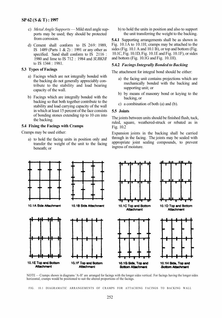
SP 62 (S & T) : 1997
c) Metal Angle Supports — Mild steel angle supports may be used; they should be protected from corrosion.
d) Cement shall conform to IS 269: 1989, IS 1489 (Parts 1 & 2) : 1991 or any other as specified. Sand shall conform to IS 2116 : 1980 and lime to IS 712 : 1984 and SURKHI to IS 1344 : 1981.
5.3 Types of Facings a) Facings which are not integrally bonded with
the backing do not generally appreciably contribute to the stability and load bearing capacity of the wall.
b) Facings which are integrally bonded with the backing so that both together contribute to the stability and load carrying capacity of the wall in which at least 15 percent of the face consists of bonding stones extending tip to 10 cm into the backing.
5.4 Fixing the Facings with Cramps Cramps may be used either:
a) to hold the facing units in position only and transfer the weight of the unit to the facing beneath; or
b) to hold the units in position and also to support the unit transferring the weight to the backing.
5.4.1 Supporting arrangements shall be as shown in Fig. 10.1A to 10.1H; cramps may be attached to the sides (Fig. 10.1 A and 10.1 B), or top and bottom (Fig. 10.1C, Fig. 10.1D, Fig. 10.1E and Fig. 10.1F), or sides and bottom (Fig. 10.1G and Fig. 10.1H). 5.4.2 Facings Integrally Bonded to Backing The attachment for integral bond should be either:
a) the facing unit contains projections which are mechanically bonded with the backing and supporting unit; or
b) by means of masonry bond or keying to the backing, or
c) a combination of both (a) and (b).
5.5 Joints The joints between units should be finished flush, tuck, ruled, square, weathered-struck or rebated as in Fig. 10.2 Expansion joints in the backing shall be carried through in the facing. The joints may be sealed with appropriate joint sealing compounds, to prevent ingress of moisture.
NOTE — Cramps shown in diagrams 'A-H' are arranged for facings with the longer sides vertical. For facings having the longer sides horizontal, cramps would be positioned to suit the altered proportions of the facings.
FIG. 10.1 DIAGRAMATIC ARRANGEMENTS OF CRAMPS FOR ATTACHING FACINGS TO BACKING WALL
252
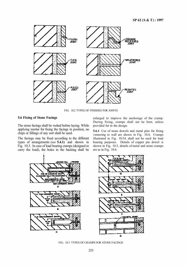
SP 62 (S & T) : 1997
FIG. 10.2 TYPES OF FINISHES FOR JOINTS
5.6 Fixing of Stone Facings
The stone facings shall be wetted before laying. While applying mortar for fixing the facings in position, no chips or fillings of any sort shall be used. The facings may be fixed according to the different types of arrangements (see 5.4.1) and shown in Fig. 10.3. In case of load bearing cramps (designed to carry the load), the holes in the backing shall be
enlarged to improve the anchorage of the cramp. During fixing, cramps shall not be bent, unless provided for in the design. 5.6.1 Use of stone dowels and metal pins for fixing veneering to wall are shown in Fig. 10.4, Cramps illustrated in Fig. 10.5A shall not be used for load bearing purposes. Details of copper pin dowel is shown in Fig. 10.5, details of metal and stone cramps are as in Fig. 10.6.
FIG. 10.3 TYPES OF CRAMPS FOR STONE FACINGS
253
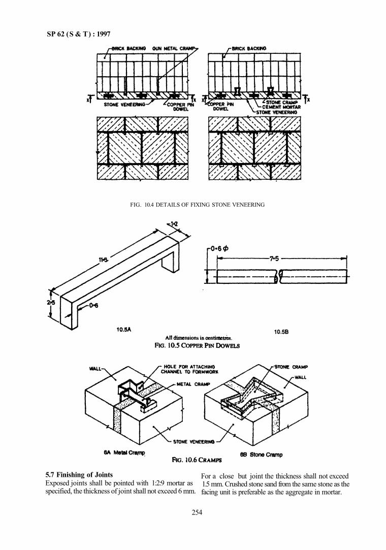
SP 62 (S & T) : 1997
5.7 Finishing of Joints Exposed joints shall be pointed with 1:2:9 mortar as specified, the thickness of joint shall not exceed 6 mm.
For a close but joint the thickness shall not exceed 1.5 mm. Crushed stone sand from the same stone as the facing unit is preferable as the aggregate in mortar.
254
FIG. 10.4 DETAILS OF FIXING STONE VENEERING
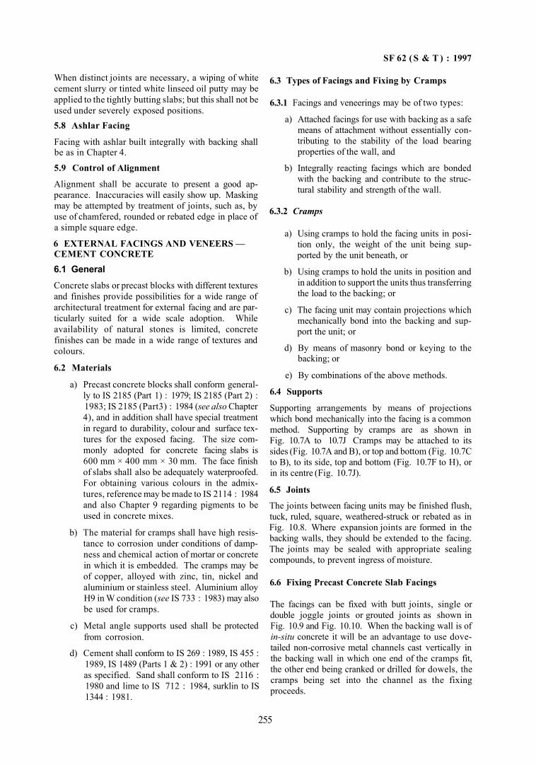
SF 62 ( S & T ) : 1997
When distinct joints are necessary, a wiping of white cement slurry or tinted white linseed oil putty may be applied to the tightly butting slabs; but this shall not be used under severely exposed positions. 5.8 Ashlar Facing
Facing with ashlar built integrally with backing shall be as in Chapter 4.
5.9 Control of Alignment
Alignment shall be accurate to present a good appearance. Inaccuracies will easily show up. Masking may be attempted by treatment of joints, such as, by use of chamfered, rounded or rebated edge in place of a simple square edge.
6 EXTERNAL FACINGS AND VENEERS — CEMENT CONCRETE 6.1 General Concrete slabs or precast blocks with different textures and finishes provide possibilities for a wide range of architectural treatment for external facing and are particularly suited for a wide scale adoption. While availability of natural stones is limited, concrete finishes can be made in a wide range of textures and colours.
6.2 Materials
a) Precast concrete blocks shall conform generally to IS 2185 (Part 1) : 1979; IS 2185 (Part 2) : 1983; IS 2185 (Part3) : 1984 (see also Chapter 4), and in addition shall have special treatment in regard to durability, colour and surface textures for the exposed facing. The size commonly adopted for concrete facing slabs is 600 mm × 400 mm × 30 mm. The face finish of slabs shall also be adequately waterproofed. For obtaining various colours in the admixtures, reference may be made to IS 2114 : 1984 and also Chapter 9 regarding pigments to be used in concrete mixes.
b) The material for cramps shall have high resistance to corrosion under conditions of dampness and chemical action of mortar or concrete in which it is embedded. The cramps may be of copper, alloyed with zinc, tin, nickel and aluminium or stainless steel. Aluminium alloy H9 in W condition (see IS 733 : 1983) may also be used for cramps.
c) Metal angle supports used shall be protected from corrosion.
d) Cement shall conform to IS 269 : 1989, IS 455 : 1989, IS 1489 (Parts 1 & 2) : 1991 or any other as specified. Sand shall conform to IS 2116 : 1980 and lime to IS 712 : 1984, surklin to IS 1344 : 1981.
6.3 Types of Facings and Fixing by Cramps
6.3.1 Facings and veneerings may be of two types:
a) Attached facings for use with backing as a safe means of attachment without essentially contributing to the stability of the load bearing properties of the wall, and
b) Integrally reacting facings which are bonded with the backing and contribute to the struc-tural stability and strength of the wall.
6.3.2 Cramps
a) Using cramps to hold the facing units in position only, the weight of the unit being supported by the unit beneath, or
b) Using cramps to hold the units in position and in addition to support the units thus transferring the load to the backing; or
c) The facing unit may contain projections which mechanically bond into the backing and support the unit; or
d) By means of masonry bond or keying to the backing; or
e) By combinations of the above methods.
6.4 Supports
Supporting arrangements by means of projections which bond mechanically into the facing is a common method. Supporting by cramps are as shown in Fig. 10.7A to 10.7J Cramps may be attached to its sides (Fig. 10.7A and B), or top and bottom (Fig. 10.7C to B), to its side, top and bottom (Fig. 10.7F to H), or in its centre (Fig. 10.7J).
6.5 Joints
The joints between facing units may be finished flush, tuck, ruled, square, weathered-struck or rebated as in Fig. 10.8. Where expansion joints are formed in the backing walls, they should be extended to the facing. The joints may be sealed with appropriate sealing compounds, to prevent ingress of moisture.
6.6 Fixing Precast Concrete Slab Facings
The facings can be fixed with butt joints, single or double joggle joints or grouted joints as shown in Fig. 10.9 and Fig. 10.10. When the backing wall is of in-situ concrete it will be an advantage to use dovetailed non-corrosive metal channels cast vertically in the backing wall in which one end of the cramps fit, the other end being cranked or drilled for dowels, the cramps being set into the channel as the fixing proceeds.
255
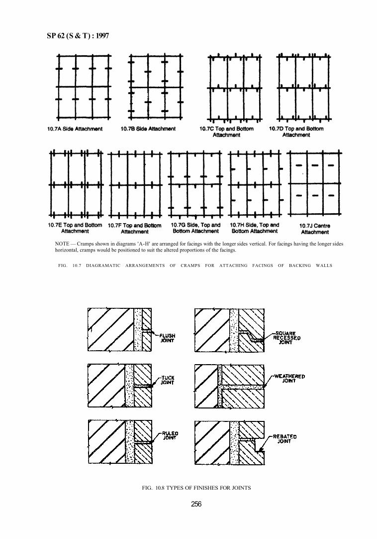
SP 62 (S & T) : 1997
NOTE — Cramps shown in diagrams 'A-H' are arranged for facings with the longer sides vertical. For facings having the longer sides horizontal, cramps would be positioned to suit the altered proportions of the facings.
FIG. 10.7 DIAGRAMATIC ARRANGEMENTS OF CRAMPS FOR ATTACHING FACINGS OF BACKING WALLS
FIG. 10.8 TYPES OF FINISHES FOR JOINTS
256
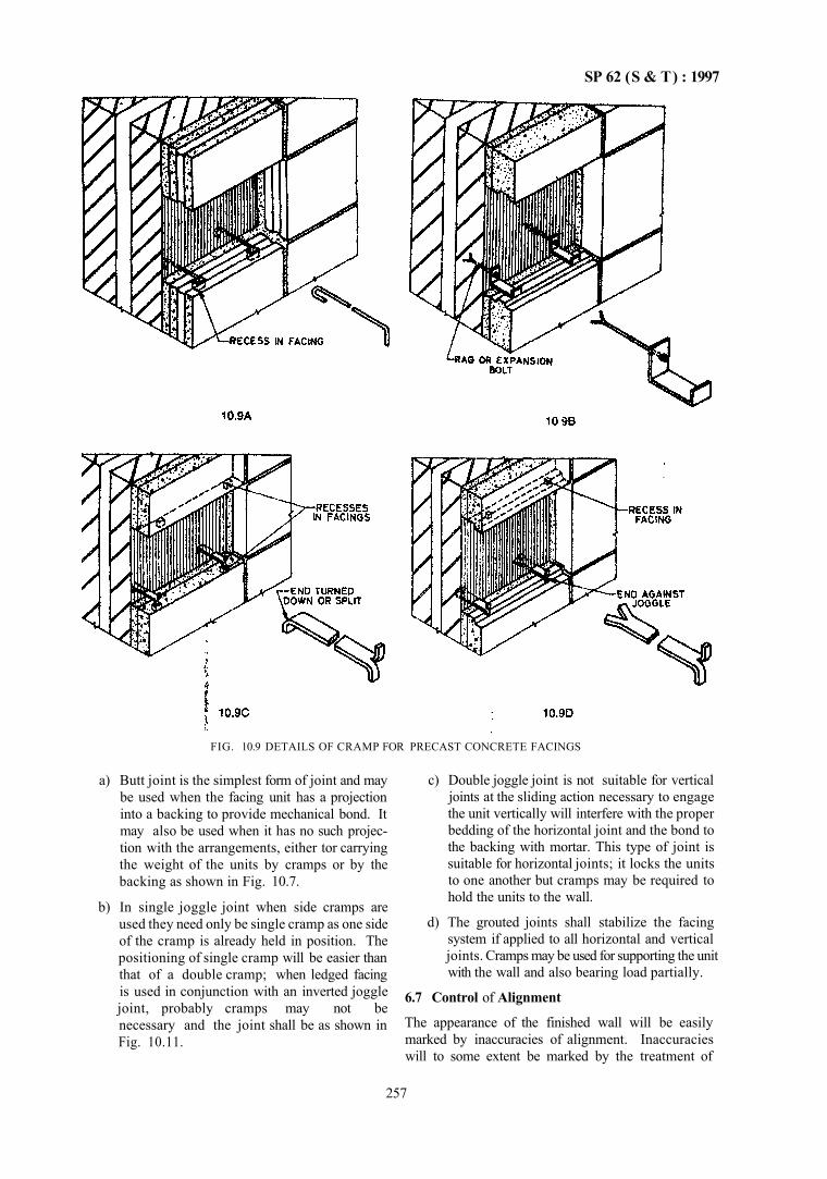
SP 62 (S & T) : 1997
FIG. 10.9 DETAILS OF CRAMP FOR PRECAST CONCRETE FACINGS
a) Butt joint is the simplest form of joint and may be used when the facing unit has a projection into a backing to provide mechanical bond. It may also be used when it has no such projection with the arrangements, either tor carrying the weight of the units by cramps or by the backing as shown in Fig. 10.7.
b) In single joggle joint when side cramps are used they need only be single cramp as one side of the cramp is already held in position. The positioning of single cramp will be easier than that of a double cramp; when ledged facing is used in conjunction with an inverted joggle joint, probably cramps may not be necessary and the joint shall be as shown in Fig. 10.11.
c) Double joggle joint is not suitable for vertical joints at the sliding action necessary to engage the unit vertically will interfere with the proper bedding of the horizontal joint and the bond to the backing with mortar. This type of joint is suitable for horizontal joints; it locks the units to one another but cramps may be required to hold the units to the wall.
d) The grouted joints shall stabilize the facing system if applied to all horizontal and vertical joints. Cramps may be used for supporting the unit with the wall and also bearing load partially.
6.7 Control of Alignment
The appearance of the finished wall will be easily marked by inaccuracies of alignment. Inaccuracies will to some extent be marked by the treatment of
257
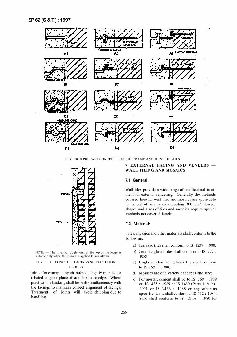
SP 62 (S & T) : 1997
FIG. 10.10 PRECAST CONCRETE FACING CRAMP AND JOINT DETAILS
NOTE — The inverted joggle joint at the top of the ledge is suitable only when the joining is applied to a cavity wall.
FIG. 10.11 CONCRETE FACINGS SUPPORTED ON LEDGES
joints; for example, by chamfered, slightly rounded or rebated edge in place of simple square edge. Where practical the backing shall be built simultaneously with the facings to maintain correct alignment of facings. Treatment of joints will avoid chipping due to handling.
7 EXTERNAL FACING AND VENEERS — WALL TILING AND MOSAICS
7.1 General
Wall tiles provide a wide range of architectural treatment for external rendering. Generally the methods covered here for wall tiles and mosaics are applicable to the unit of an area not exceeding 900 cm2. Larger shapes and sizes of tiles and mosaics require special methods not covered herein.
7.2 Materials
Tiles, mosaics and other materials shall conform to the following:
a) Terrazzo tiles shall conform to IS 1237 : 1980. b) Ceramic glazed tiles shall conform to IS 777 :
1988. c) Unglazed clay facing brick tile shall conform
to IS 2691 : 1988. d) Mosaics are of a variety of shapes and sizes. e) For mortar, cement shall be to IS 269 : 1989
or IS 455 : 1989 or IS 1489 (Parts 1 & 2 ) : 1991 or IS 3466 : 1988 or any other as specific. Lime shall conform to IS 712 : 1984. Sand shall conform to IS 2116 : 1980 for
258
SP 62 (S & T) : 1997
mortar bedding and to IS 1542 : 1992 for floating coat and pointing.
7.3 Preparatory Work
a) Sufficient time should elapse for complete initial drying and shrinkage of the background before application of floating coat. The surface shall be properly cleaned from dust and particles.
b) The surface should not be allowed to dry after wetting before application of the floating coat. The floating should keep pace with wetting and if necessary the surface shall be rcwetted. Efflorescence or laitance shall be removed,
c) To provide an effective key for surfaces contaminated with oil or grease special treatment by fixing a metal lath or wire netting shall be given. At least one-half of any smooth surface shall be removed to a depth of 3 mm either by hand or mechanically. Weak backgrounds, which are unlikely to support a floating coat should be covered with a firmly fixed metal lathing or wire netting
d) Movement of joints due to shrinkage of background and settlement of unit shall be provided for. Normally these joints shall be at the level of every storey height horizontally and every 3 m vertically. They shall coincide with structural material changes, such as, top of slab for horizontal joint. Movement joints shall extend to depth of tile and bed and shall be minimum 6 mm wide. The joints shall be tilled with cement morter with about 15 percent gauging with lime putty.
7.4 Application of Floated Coat for Tiles and Mosaics
a) The purpose of floated coat or rendering is to form a surface suitable for application of tiling when the background is unsuitable for direct fixing of tiles.
b) Mix for the floated coat shall be 1:3 cement mortar (volume) for smooth and moderately strong backgrounds, such as, high density bricks or blocks, precast or in-situ stone, etc. To improve workability and thus to aid application and finishing, a small portion of hydrated lime may be added to the mix; for 1.3 cement mortar by volume, one-fourth lime by volume may be added.
c) Thickness of each floated coat should not be more than 10 mm; the float shall be even and preferably scratched to provide a key for the bedding mortar.
d) The mix for bedding can be sand cement mortar or sand cement mortar with additives; 1:4 mix should be adequate; additives can be plas-ticizer, waterproofing agents, etc.
7.5 Fixing of Tiles
a) Tiles are fixed beginning at the uppermost level working downwards to avoid disfiguring, staining damage and subsequent cleaning. The tiles with non-porous bodies need not be soaked; tiles with porous bodies should be completely immersed in clean water at least for an hour before using. After soaking, the tiles shall be stacked tightly on. a clean surface to dry.
b) The tiles should be fixed on the wetted floated coat, they should be tapped back firmly into position so that the bed is covered entirely by the tile. The thickness of bed should be between 6 to 12 mm after fixing the tile. Uniform spacing between tiles should be obtained by using spacer pegs as the work progresses. Any adjustment of the tile shall be made within about 10 min. Ensure that the surface of tiling shall be true and flat Cleaning shall not be started before 1½ h after fixing.
c) Grouting or pointing of tiles should not be carried out, until the day after the tiles have been fixed. A waterproofing agent may be added to the grouting mix.
The grout should be applied with a squeeze working back and forth over the area until all the joints are completely filled; all the surplus grout should be removed from the tiles and polished.
Pointing would be similar to grouting, except that a small portion of fine sand should be added to the mix.
7.6 Fixing of Ceramic Mosaics
a) Mosaics shall be assembled in the form of sheets or varying mixes, the separate pieces of mosaic glued face down to any suitable material such as, paper, nylon, adhesive strips, etc. The paper strips, etc should be easily removable after fixing has taken place. All dimensions be checked out so that no difficulty would arise in setting it out. Where mosaic has to be applied to a floated coat, the surface shall be slightly scratched and finished with a wood float.
b) The bedding mortar may be 10 mm thick. Before bedding the mosaic, the fixing side of the mosaic sheet shall be grouted with a neat cement slurry.
259
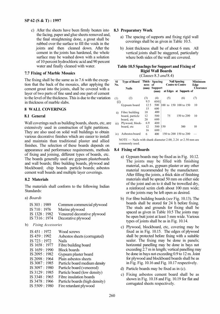
SP 62 (S & T) : 1997
c) After the sheets have been firmly beaten into the facing, paper and glue sheets removed and, the final straightening done, a grout shall be rubbed over the surface to fill the voids in the joints and then cleaned down. After the cement in the joints has hardened, the whole surface may be washed down with a solution of 10 percent hydrochloric acid and 90 percent water and finally cleaned with water.
7.7 Fixing of Marble Mosaics The fixing shall be the same as in 7.6 with the exception that the back of the mosaics, after applying the cement grout into the joints, shall be covered with a layer of two parts of fine sand and one part of cement to the level of the thickness. This is due to the variation in thickness of marble slabs. 8 WALL COVERINGS 8.1 General Wall coverings such as building boards, sheets, etc, are extensively used in construction of light partitions. They are also used on solid wall buildings to obtain various decorative finishes which are easier to install and maintain than traditional plaster and allied finishes. The selection of these boards depends on appearance and performance requirements, methods of fixing and joining, different types of boards, etc. The boards generally used are gypsum plasterboards and wall boards; fibre building boards, plywood and blockboard; chip boards particle boards; asbestos cement wall boards and multiple layer coverings.
8.2 Materials The materials shall conform to the following Indian Standards:
a) Boards IS 303 : 1989 IS 710 : 1976 IS 1328 : 1982 IS 7316 : 1974
Common commercial plywood Marine plywood Veneered decorative plywood Decorative plywood
b) Fixing Accessories
IS 451 : 1972 IS 459 : 1992 IS 723 : 1972 IS 1658 : 1977 IS 1659 : 1990 IS 2095 : 1982 IS 2098 : 1964 IS 3087 : 1985 IS 3097 : 1980 IS 3129 : 1985 IS 3348 : 1965 IS 3478 : 1966 IS 5509 : 1980
Wood screws Asbestos sheets (corrugated) Nails Fibre building board Block boards Gypsum plaster board Plain asbestos sheets Particle board medium density Particle board (veneered) Particle board (low density) Fibre insulation boards Particle boards (high density) Fire retardant plywood
8.3 Preparatory Work a) The spacing of supports and fixing rigid wall
coverings shall be as given in Table 10.5. b) Joint thickness shall be of about 6 mm. All
vertical joints shall be staggered, particularly where both sides of the wall are covered.
Table 10.5 Spaclngs for Support and Fixing of Rigid Wall Boards (Clauses 8.3 and 8.4)
Sl No.
(1) (i)
ii)
iii)
iv)
Type of Board
(2)
Gypsum board
Fibre building board, particle board, etc Plywood, block-board, etc
Asbestos board
Thick-ness (mm)
(3) 9.5 12 5 15
10 12 20 6.9 12 16 6
Spacing of Support
(mm)
(4) 400] 500 600 400 500 600 400 500 600 400
Nail Spacing Centre to Centre
at Edges at Supports
(5)
100 to 150
75
150
150 to 200
(6)
100 to 150
150 to 200
300
150 to 200
Minimum Edge
Clearance of
Nails
(7)
10
10
10
—
NOTE — Nails with shank diameter 2.00, 2.24 or 2.50 mm are commonly used.
8.4 Fixing of Boards a) Gypsum boards may be fixed as in Fig. 10.12.
The joints may be filled with finishing material, such as, gypsum plaster or any other material recommended by the manufacturer. After filling the joints, a thick skin of finishing materials shall be spread 50 mm on either side of the joint and on to it shall be trowelled dry, a reinforced scrim cloth about 100 mm wide; or the joints may be left open as desired.
b) For fibre building boards (see Fig. 10.13). The boards shall be stored for 24 h before fixing. The studs and grounds for fixing shall be spaced as given in Table 10.5 The joints may be open butt joint at least 3 mm wide. Various types of joints shall be as in Fig. 10.14.
c) Plywood, blockboard, etc, covering may be fixed as in Fig. 10.15. The edges of plywood shall be protected before fixing with a suitable sealer. The fixing may be done in panels; horizontal panelling may be done in bays not exceeding 2.7 m in length; vertical panelling may be done in bays not exceeding 0.9 to 12 m. Joint for plywood and blockboard boards shall be as in Fig. Fig. 10.16 and Fig. 10.17 respectively.
d) Particle boards may be fixed as in (c). c) Fixing asbestos cement board shall be as
shown in Fig. 10.18 and Fig. 10.19 for flat and corrugated sheets respectively.
260
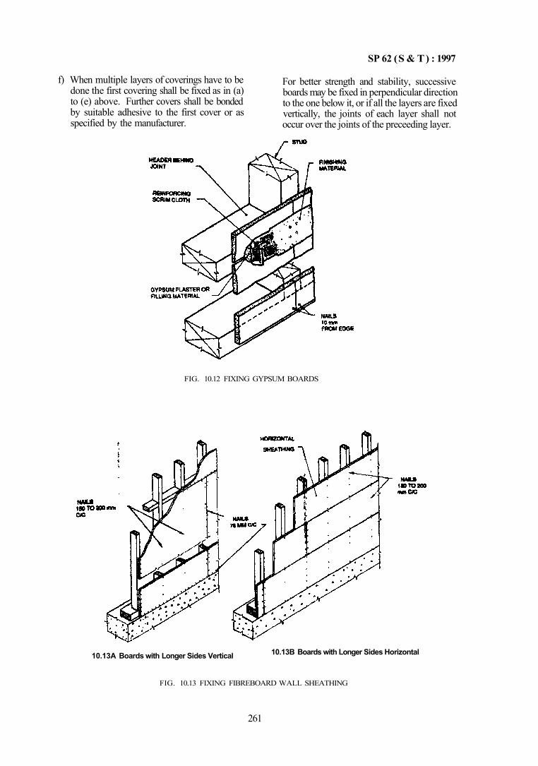
SP 62 (S & T) : 1997
f) When multiple layers of coverings have to be done the first covering shall be fixed as in (a) to (e) above. Further covers shall be bonded by suitable adhesive to the first cover or as specified by the manufacturer.
For better strength and stability, successive boards may be fixed in perpendicular direction to the one below it, or if all the layers are fixed vertically, the joints of each layer shall not occur over the joints of the preceeding layer.
FIG. 10.12 FIXING GYPSUM BOARDS
10.13A Boards with Longer Sides Vertical 10.13B Boards with Longer Sides Horizontal
FIG. 10.13 FIXING FIBREBOARD WALL SHEATHING
261
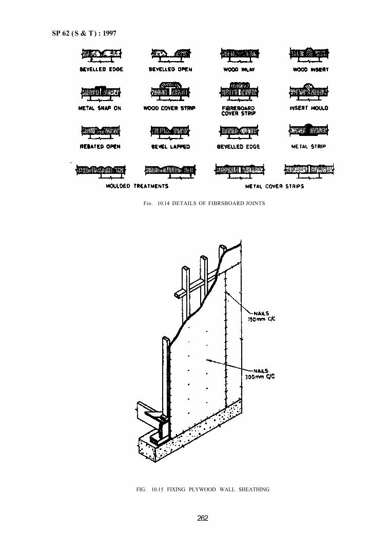
SP 62 (S & T) : 1997
FIG. 10.15 FIXING PLYWOOD WALL SHEATHING
262
Fio. 10.14 DETAILS OF FIBRSBOARD JOINTS
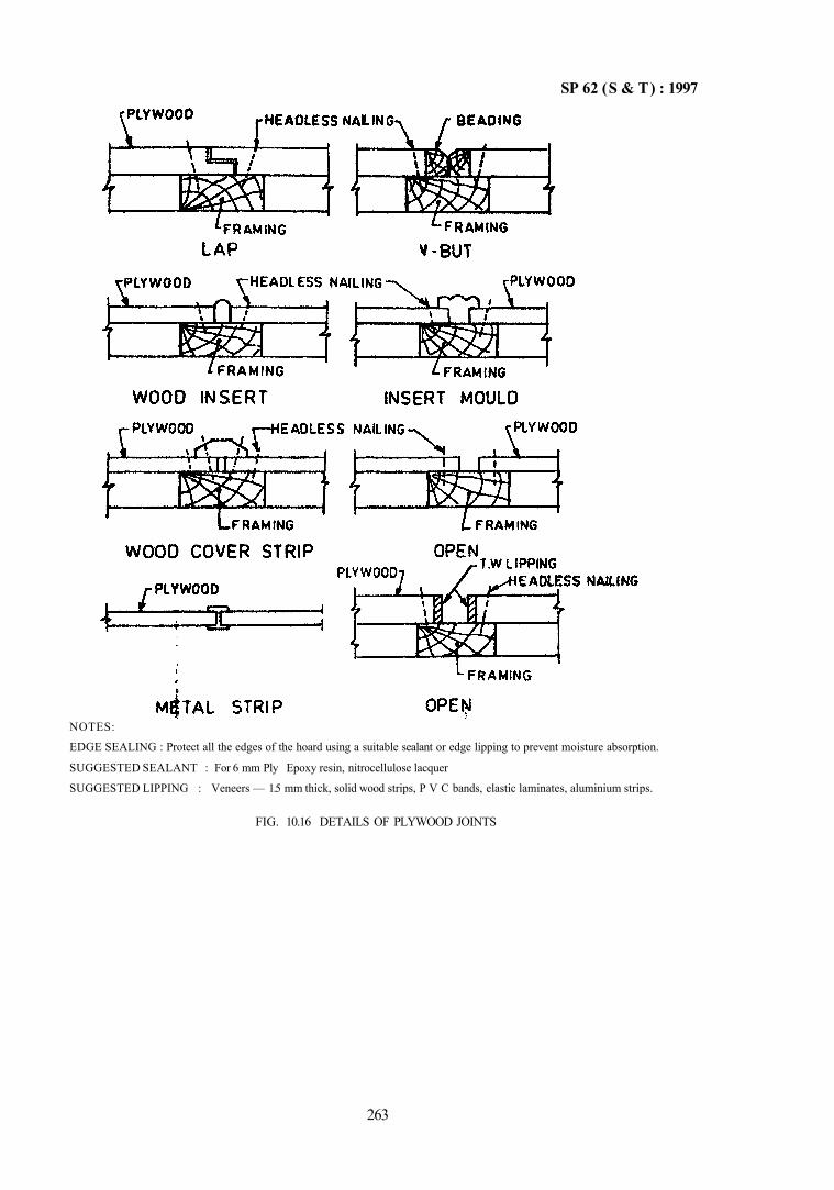
SP 62 (S & T) : 1997
NOTES:
EDGE SEALING : Protect all the edges of the hoard using a suitable sealant or edge lipping to prevent moisture absorption.
SUGGESTED SEALANT : For 6 mm Ply Epoxy resin, nitrocellulose lacquer
SUGGESTED LIPPING : Veneers — 1.5 mm thick, solid wood strips, P V C bands, elastic laminates, aluminium strips.
FIG. 10.16 DETAILS OF PLYWOOD JOINTS
263
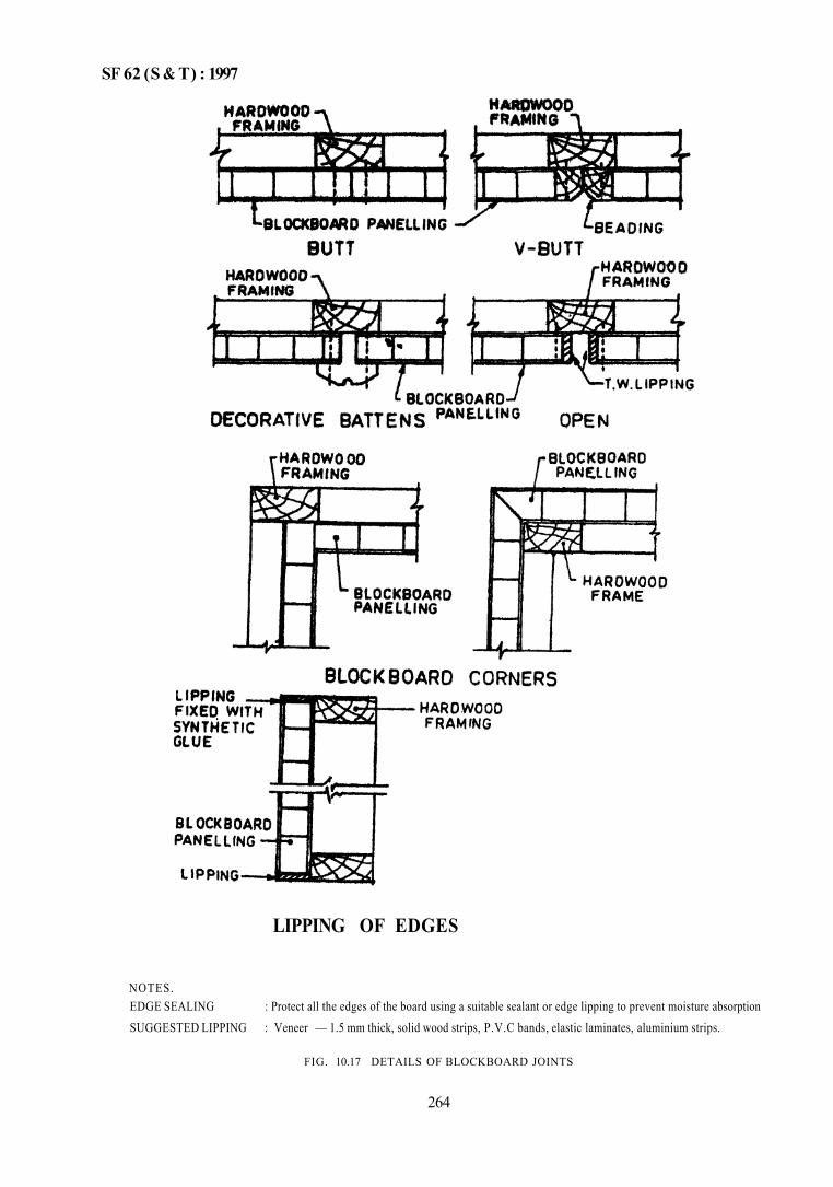
SF 62 (S & T) : 1997
LIPPING OF EDGES
NOTES. EDGE SEALING : Protect all the edges of the board using a suitable sealant or edge lipping to prevent moisture absorption SUGGESTED LIPPING : Veneer — 1.5 mm thick, solid wood strips, P.V.C bands, elastic laminates, aluminium strips.
FIG. 10.17 DETAILS OF BLOCKBOARD JOINTS
264
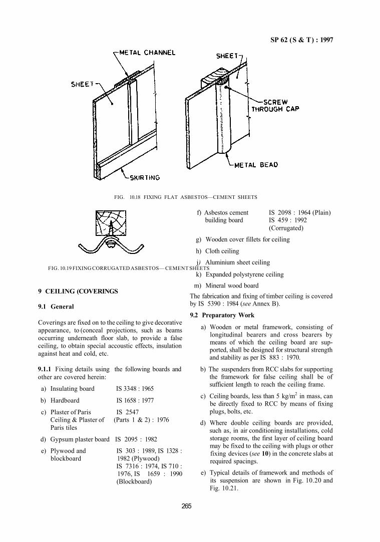
SP 62 (S & T) : 1997
FIG. 10.18 FIXING FLAT ASBESTOS—CEMENT SHEETS
FIG. 10.19 FIXING CORRUGATED ASBESTOS— CEMENT SHEETS
9 CEILING (COVERINGS
9.1 General
Coverings are fixed on to the ceiling to give decorative appearance, to (conceal projections, such as beams occurring underneath floor slab, to provide a false ceiling, to obtain special accoustic effects, insulation against heat and cold, etc.
9.1.1 Fixing details using the following boards and other are covered herein:
a) Insulating board IS 3348 : 1965
b) Hardboard IS 1658 : 1977
c) Plaster of Paris IS 2547 Ceiling & Plaster of (Parts 1 & 2) : 1976 Paris tiles
d) Gypsum plaster board IS 2095 : 1982
e) Plywood and IS 303 : 1989, IS 1328 : blockboard 1982 (Plywood)
IS 7316 : 1974, IS 710 : 1976, IS 1659 : 1990 (Blockboard)
f) Asbestos cement IS 2098 : 1964 (Plain) building board IS 459 : 1992
(Corrugated)
g) Wooden cover fillets for ceiling
h) Cloth ceiling
j) Aluminium sheet ceiling
k) Expanded polystyrene ceiling
m) Mineral wood board The fabrication and fixing of timber ceiling is covered by IS 5390 : 1984 (see Annex B).
9.2 Preparatory Work
a) Wooden or metal framework, consisting of longitudinal bearers and cross bearers by means of which the ceiling board are supported, shall be designed for structural strength and stability as per IS 883 : 1970.
b) The suspenders from RCC slabs for supporting the framework for false ceiling shall be of sufficient length to reach the ceiling frame.
c) Ceiling boards, less than 5 kg/m2 in mass, can be directly fixed to RCC by means of fixing plugs, bolts, etc.
d) Where double ceiling boards are provided, such as, in air conditioning installations, cold storage rooms, the first layer of ceiling board may be fixed to the ceiling with plugs or other fixing devices (see 10) in the concrete slabs at required spacings.
e) Typical details of framework and methods of its suspension are shown in Fig. 10.20 and Fig. 10.21.
265
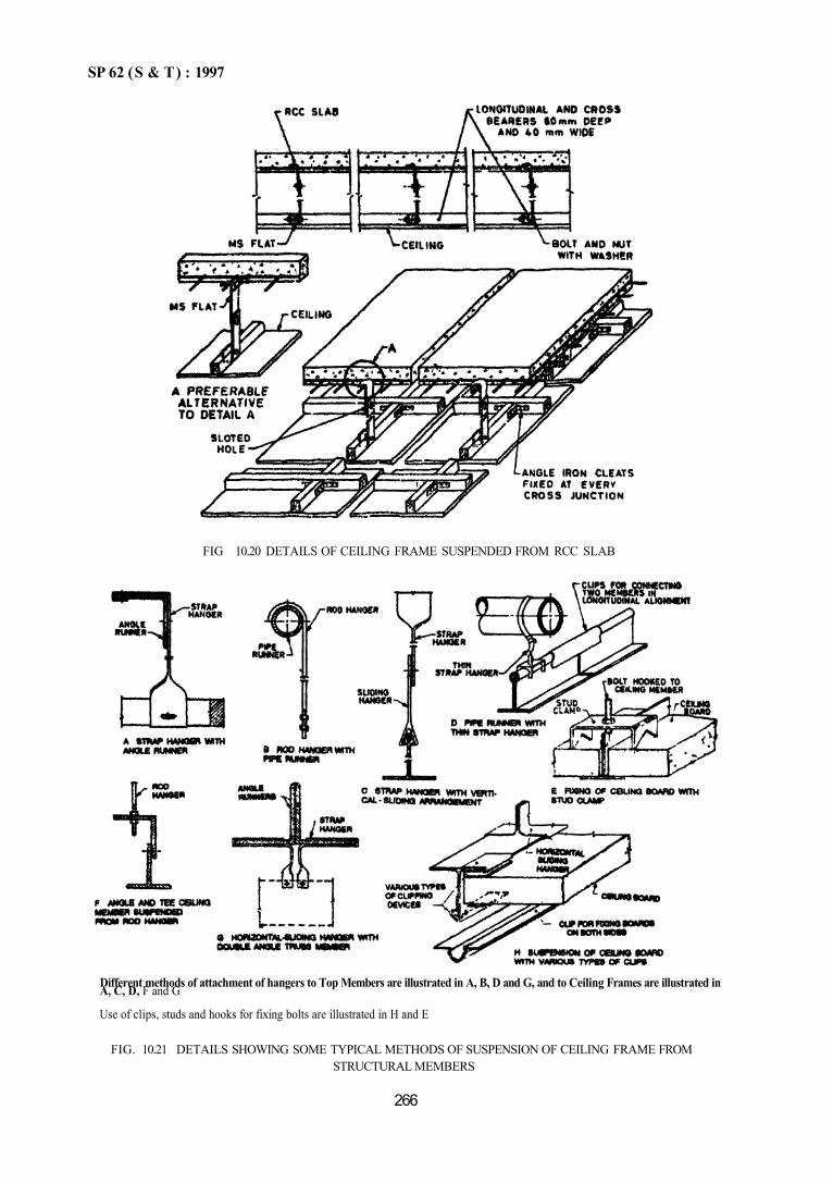
SP 62 (S & T) : 1997
Different methods of attachment of hangers to Top Members are illustrated in A, B, D and G, and to Ceiling Frames are illustrated in A, C, D, F and G
Use of clips, studs and hooks for fixing bolts are illustrated in H and E
FIG. 10.21 DETAILS SHOWING SOME TYPICAL METHODS OF SUSPENSION OF CEILING FRAME FROM STRUCTURAL MEMBERS
266
FIG 10.20 DETAILS OF CEILING FRAME SUSPENDED FROM RCC SLAB
SP 62 (S & T ) : 1997
9.3 Fixing of Coverings
9.3.1 Insulating Building Board
a) Materials — The timber for framework and beading shall be treated and chosen from any of the species in IS 3629:1986. Insulating building boards may be particle boards (low density) to IS 3129 : 1985 or fibre insulating boards to IS 3348 : 1965. Nails, conforming to IS 723 : 1972 shall be long enough to cover the thickness of board plus 25 mm. Galvanized lost head nails to IS 6738 : 1972 of 2,80 mm dia may be used when joints are left exposed. Where joints are to be covered by beading, galvanized felt nails of 2.50 mm dia conforming to IS 6730 : 1972 may be used. Wood screws shall conform to IS 6760 : 1972.
b) Fixing — Cut the boards to the required size. The edges shall be slightly sand papered to make them smooth. The framework with battens, size ranging from 60 to 75 mm shall then be fixed. Aluminium frame may also be used instead of timber frame. The building board shall then be fixed with lengths parallel to all joints centered over the framing members. Where the joints are to be covered the boards shall be spaced 3 to 6 mm apart. Where the joints are to be exposed the sheets shall be butt jointed with their edges abutting each other. The boards are first nailed to intermediate framing member proceeding from the centre of the board outwards, the edges being nailed last. 1) Where joints are exposed, the outer row of
nails shall be at 100 mm centres and about 12 mm from edge of the sheet. The rows in the middle of the sheet shall be at 20 mm centred. Nails in the outer rows on either side shall be paired and not staggered. Nails shall be countersunk in the underside of the board.
2) Where joints are to be covered with headings, the procedure is the same as in (1) above, except that in the outer rows, the nails spaced at 200 mm may be staggered. The headings shall then be fixed over the sheets with screws at 200 mm centres.
3) The exposed side shall be truly level; joints truly parallel and perpendicular to the walls.
9.3.2 Hardboard
a) Materials—Timber shall conform to IS 5390 : 1984. The hardboard shall conform to IS 1658 : 1977. The other materials shall be as per 9.3.1 (a).
b) Fixing 1) The framework and board shall generally
be fixed as in 9.3.1 (b). Wood screws may be used.
2) The joints may be normally filled with plaster. If the hardboard has to be cement plastered the joints shall have a gap of 6 mm covered with scrim and bedded in cement plaster before the finishing coat is applied.
3) The finishing shall be as in 9.3.1(b) (3).
9.3.3 Plaster of Paris
a) Materials—Timber for framing shall conform to IS 5390 : 1984. Plaster of Paris shall conform to IS 2547 (Parts 1 and 2) : 1976. The other materials shall be as in 9.3.1 (a).
b) Fixing 1) In case of sloping roofs, wooden battens
of suitable section (50 mm × 60 mm) shall be firmly fixed as main supports, to the underside of the beams at required centres by means of bolts and nuts. In case of flat roofs, treated battens shall be securely fixed to the walls and pillars by holding down bolts and shall be fastened to the slabs above with iron straps or mild steel bars anchored therein. Cross battens (treated) of 50 mm × 40 mm at about 400 mm centres shall then be fixed at right angles to the main battens. The underside of the framework shall be true to planes and slopes. Aluminium frame may also be used if specified.
2) Wooden strips or laths 25 mm × 6 mm shall be fixed to the cross battens in paral-lel rows with felt nails. The strips shall be butt jointed and joints staggered.
3) Rabbit wire mesh shall be fixed with rails of a pitch of 150 mm to 200 mm to the underside of wooden strips. The wire mesh shall be straight, tight and true to planes and slopes without any sagging and slightly below the underside of the laths
4) Plaster of Paris shall be mixed with water to a workable consistency. The plaster shall be applied to the underside of laths over the rabbit wire mesh in suitable sized panels and finished to a smooth surface by steel trowels. The thickness over the laths shall be as specified but not less than 12 mm. Joints shall be finished flush; the surface shall be smooth and true to plane, slope or curve as required.
267
SP 62 (S & T) : 1997
9.3.4 Plaster of Paris Tiles a) Materials — Timber for making framework
shall be from any species in IS 5390 : 1984. Plaster of Paris shall conform to IS 2547 (Parts 1 and 2) : 1976; thickness of tiles shall be not less than 12 mm. Hessian cloth shall conform to IS 2818 (Part 1) : 1990; hessian cloth shall be of an open webbed texture.
b) Preparation of Tiles — Tiles of plaster of Paris reinforced with hessian cloth shall be prepared to the required size. The maximum size shall be limited to 750 mm in each direction. The tiles may be made on a glass sheet with wooden surrounds; a thin coating of non-staining oil may be given to the glass sheet for easy removal of tiles. Plaster of Paris shall be evenly spread to about half the thickness and then hessian cloth spread over it; on this, plaster of Paris is spread again to the full thickness. Tiles shall be allowed to set for an hour and then removed to dry and harden for about a week. A good tile will give a ringing sound when struck.
c) Fixing — The timber frame shall be so made that each tile has supporting scantlings to fix them. Aluminium frame may also be used. Tiles may be fixed to the cross battens with 40 mm long brass screws to IS 6760 : 1972 at 200 mm centres. Tiles may be laid adjacent to each other without leaving any gap. The screws shall be at least 15 mm away from the edge. Holes for screws shall be drilled. The countersunk heads of screws shall be covered with plaster of Paris and smoothly finished. When unbroken surface is desired, joints shall be filled with plaster of Paris and trowelled smooth.
9.3.5 Gypsum Plaster Board a) Materials — The boards shall conform to IS
2095 : 1982. Nails shall conform to IS 723 : 1972. The length of the nail shall be 30 mm for boards 10 mm thick and 40 mm for 12.5 mm or 16 mm thick boards. Screws shall conform to IS 6730 : 1972. Steel screws without brass or nickel coating shall not be used. Screw sizes shall be 3.10 or 3.45 mm; length shall be 30 mm for 10 mm thick board and 35 or 40 mm for 12.5 mm and 16 mm board.
b) Fixing — The frame work shall be fixed as in 9.3.1(b). Joints may be 6 mm wide. Jointing may be in a decorative pat tern. The joints may be finished with a filling of gypsum plaster or other materials; after filling the joint, a thick skin of the finishing material shall be spread
50 mm on either side and trowelled dry. When metal scrim is used, a stiffer plaster may be necessary. The joints may also be left open if desired.
9.3.6 Plywood and Blockboard a) Materials—Timber for framework shall con
form to IS 5390 : 1984. Plywood shall conform to IS 303 : 1989 or IS 710 : 1976 or IS 7316 : 1974 or IS 1328 : 1982 or IS 5509 : 1980. Blockboaid shall conform to IS 1659 : 1990; screws shall conform to IS 6760 : 1972.
b) Fixing — The fixing shall be as in 93.1(b); except that for boards in thickness 4 to 10 mm the spacings may vary from 450 to 600 mm for longitudinal battens and 600 to 1 200 mm for cross battens; for boards above 10 mm thick, the spacings may be 600 to 900 mm for longitudinal battens and 900 to 1 300 mm for cross battens. The spacing of fixing countersunk screws may be adjusted according to thickness of board. Joints if left open shall be filled with painters putty and brought to level; joints may also be left open. The joints may be rebated or tounge and grooved. The ceiling shall be finished by hand-sanding and waxed or polished or clear varnished or painted as required (see Chapter 15).
9.3.7 Asbestos Cement Building Board a) Materials—Timber for framework can be any
of the species in IS 5390 : 1984; asbestos board shall conform to IS 2098 : 1964; screws shall conform to IS 6730 : 1972.
b) Fixing — Framework shall be fixed as in 9.3.1 (b). The asbestos board shall be laid truly parallel or perpendicular to the walls and shall be fixed to the battens with countersunk screws by using metal channels and clips. Holes shall be drilled at least 12 mm from edge. They should be butt jointed. If a gap of 3 to 6 mm between sheets is given the gap should be covered with wooden beading or similar material. No finishing treatment is necessary.
9.3.8 Wooden Cover Fillets Beading
a) Materials — Timber for framework may be any of the species of IS 5390 : 1984. Screws shall conform to IS 6730 : 1972. Beading shall be planed, smooth and true on the rear surface. It may be 12 mm × 40 mm or as specified.
b) Fixing — The beading shall be fixed centrally over the butt joints between two timber planks with screws in two rows on either side of joint.
268
SP 62 (S & T) : 1997
The junction of beading shall be fully mitred or as specified. The headings shall be finished smooth.
9.3.9 Cloth
a) Material — Timber for framework shall be as per IS 5390 : 1984. Bamboo of good quality may be used for framework. In general thick cloth can be used or as specified. Screws shall conform to IS 6730 : 1972 and nails to IS 723 : 1972.
b) Fixing — The framework shall be securely spiked to the wall plaster/ceiling joints or teams. The cloth shall be wetted, stretched and nailed to the upperside of the framework. In case of bamboo framework, the cloth shall be tied to it without tearing. To prevent the cloth from blowing and flapping, wooden headings shall be fixed. The cloth may be white washed and distempered.
9.3.10 Aluminium Sheet
a) Materials — The framework may be made of aluminium 'T' grid and trays of aluminium alloy sheets 19000 or 31000 of IS 737 : 1986. The grid shall be made of extruded aluminium 'T' section of 63400 Wp of IS 733 : 1983, The fillings shall be made out of aluminium or rust proofed steel.
b) Fixing — The ceiling may be formed as an exposed grid or a concealed grid using the above sections. The aluminium false ceiling may be left as it is if anodized or painted with an acrylic resin paint.
9.3.11 Expanded polystyrene
a) Material — Expanded polystyrene shall conform to IS 4671 : 1984. Screws shall conform to IS 6730 : 1972. The framework may be of wood or metal.
b) Fixing — Adhesive shall be applied to the tiles and fixed to the framework. The white polysterene ceiling may be painted as specified.
9.3.12 Mineral Wood Board
a) Materials — Timber for ceiling shall be from IS 5390 : 1984; nails to IS 723 : 1972, screws to IS 6730 : 1972 and mineral wool to IS 3677 : 1985.
b) Fixing — A metal 'T' grid shall be suspended first and mineral wool board may be cut to size and stuck with suitable adhesive. For timber framework, the mineral wool board shall be stuck with an adhesive. Similar procedure may be followed with local modifications, as necessary, for different ceilings.
10 FIXING DEVICES
10.1 Types
The fixing devices covered are as below:
a) Expansion wall plugs,
b) Expansion shells,
c) Caulked-in anchor devices, and
d) Butt-in devices.
10.2 Fixing
Proper devices and tools ensure a neat fixing work with minimum effort and little damage, and the fixtures will have adequate strength and durability. Special devices are also available for resisting dampness, chemical attack, thermal effects, etc. Details of fixing devices are given in IS 1946 : 1961. Fixing devices, mentioned above are for solid walls. Devices for hollow walls are also coming into vogue.
NOTE —Since the date of publication of this standard several new innovations have been introduced, the trade may be consulted for morc information
ANNEX A (Table 10.4)
SPECIAL MIXES FOR SULPHATE BACKGROUNDS
A-1 GENERAL
A-1.1 A separate support may be provided for the rendering on backgrounds with soluble sulphates. A
cement resistant to sulphate action may be used, namely sulphate resisting cement; or in very severe conditions, high alumina cement or blast furnace slag cement may be used.
269
SP 62 (S & T) : 1997
A-2 MIXES
A-2.1 For sulphate resisting cement the mixes indicated in Table 10.4 may be used. Where alternatives are given, the richer ones shall be used.
A-2.2 For high alumina cement, lime shall not be mixed. The mixes should be as below (see Table 10.4) :
In place of Use 1 part high alumina cement: Type 1 mix 3 parts sand, by volume. In place of Use 1 part high alumina cement: Type 2 mix 1/2 to 3/4 part zinc sulphate pow
der: 4 parts sand, by volume. In place of Use 1 part high alumina cement: Type 3 mix 1 part zinc sulphate: 5 to 6 parts
sand, by volume.
ANNEX B (Clause 9.1)
FABRICATION AND FIXING OF TIMBER CEILING
B-1 CONSTRUCTION OF TIMBER CEILINGS
Timber ceilings are provided to give decorative appearance, to conceal air-conditioning or other service ducts and also to obtain accoustic effects and thermal insulation.
B-1.2 Material
Timber for making planks shall be from any of the species given in Table 10.6 and the ceiling framework and beading shall conform to IS 3629 : 1966 appropriately seasoned and treated. Nails shall conform to IS 723 : 1972 and the wood screws to IS 451 : 1972. Suspenders may be mild steel flats or other material sections. The dimensions of timber units for ceiling may be as below: 1) Timber scantling for
ceiling and framework 2) Timber planks
3) Beading
1)
60-75 mm thick × 50 mm wide 15-20 mm thick × 100-150 mm wide 12 mm thick × 30 mm wide
B-1.3 Types a) Fixing Ceilings — Planks shall be butt and
beading jointed or overlap or half lap or ton-gued and grooved.
b) Sloping Ceilings — The ceiling shall be fixed to the underside of rafters.
c) Closed Ceiling — The ceiling shall be fixed to the underside of the ceiling joists.
d) The planks shall be fixed to the timber frame suspended from the slab. The surface of finished ceiling shall be true and plane.
Table 10.6 Species for Timber Ceilings (Clause B-1.2)
Anjan Axlewood Bijasal Chir Cypress Deodar Fir Gurjan
Jurul Karl Kalasiris Kasi Kindal Kokko Laurel Lendi
Machilus Mantagwa Pali Piney Rohini Rosewood Satinwood Sisoo
Teak While Cedar While Chuglam
PART 2 WALLING
1 GENERAL 1.1 Walls and partitions of the following types are covered herein:
a) Reed walling to IS 4407 : 1967, b) No fines in-situ to IS 12727 : 1989, and c) Gypsum block partitions to IS 3630 : 1992.
2 REED WALLING 2.1 General Reed walling is a traditional construction in certain parts of India; in Assam EKRA and NAL are used; in Punjab SARKANDA reed is used. In addition machine made reed boards are also used. In these boards, reeds are considerably strengthened by binding together
270
B-1.1 General
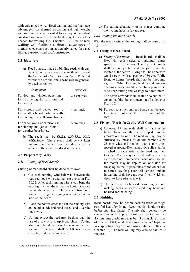
SP 62 (S & T) : 1997
with galvanized wire. Reed walling and roofing have advantages like thermal insulation and light weight and are found specially suited for earthquake resistant construction, where flexible light weight material is needed for walling (see Chapter 17). Use of reed walling will facilitate additional advantages of prefabricated construction particularly suited for panel filling, partitions and roof construction.
2.2 Materials
a) Reed boards, made by binding reeds with galvanized wire, are available in three different thicknesses of 2.5 cm, 4 cm and 5 cm. Preferred widths are 1 m and 2 m. The boards are generally used as below:
Component
For door and window panelling, for wall facing, for partitions and for ceiling
For sloping and gabled roof , for weather board partition walls, for fencing, for wall insulation, etc
For panel walls of exterior use, for sloping and gabled roofs, for weather boards, etc
Thickness
2.5 cm thick
4 cm thick
5 cm thick
b) The reeds may be EKRA, KHASRA, NAL, SARKANDA. These reeds shall be cut from mature plant, which have their sheaths firmly attached; they shall be dried in the sun.
2.3 Preparatory Work
2.3.1 Cutting of Reed Boards
Cutting of reed board shall be done as follows:
a) Cut each running wire half way between the required hook wire and the next one as in Fig. 10.22. After each running wire is cut, bend the ends tightly over the respective hooks. Remove the reeds which are left between two hook wires exposing the running wire on the underside of the board.
b) Place the boards erect and cut the running wire on the other side and bend the cut ends over the hook wire.
c) Cutting across the reed may be done with the use of a saw or a sharp broad chisel. Cutting
. shall not be done near the wire and at least 25 mm of the board shall be left to cover as edge beyond the running wire.
d) For cutting diagonally or in shapes combine the two methods in (a) and (c).
2.3.2 Joining the Reed Boards
With the reeds vertical, the joining shall be done as in Fig. 10.23.
2.4 Fixing of Reed Board
a) Fixing of Partitions — Reed boards shall be fixed with reeds vertical to horizontal runner spaced at 1 m centres. The adjacent boards shall be butt jointed and the joint shall be located at the centre. Fixing shall be done with wood screws with a spacing of 30 cm. While fixing to frames, boards shall not be fixed into a groove. While locating the door and window openings, work should be carefully planned so as to keep cutting and wastage to a minimum. The board of window sill shall be so cut that it covers half the frame runners on all sides (see Fig. 10.24).
b) For roof construction, reed board shall be used for pitched roof as in Fig. 10.25 and not flat roof.
2.5 Fixing of Reeds for In-situ Wall Construction
a) Grooves, 15 mm wide shall be made in the timber frame and the reeds slipped into the grooves one by one. The reed walling may be stiffened by means of double bamboo slips 25 mm wide and not less than 6 mm thick spaced at around 40 cm apart. One slip shall be attached to each side of the reed and tied together. Reeds may be fixed with just sufficient space of 1 cm between each other so that the mortar may be applied on one side for finishing so that it penetrates to the other side to form a key for plaster. All vertical timbers in walling shall have grooves (4 cm × 1.5 cm deep) to force plaster into it.
b) The reeds shall not be used for roofing, without making them into boards. Reed may, however, be used for thatching.
2.6 Finishing Reed boards may be pebble-dash plastered or rough cast finished after fixing. Reed boards should be dry before applying plaster. The mix shall generally be cement mortar 1:6 applied in two coats not more than 15 mm, lime plaster mix may be 1:3 using class C lime of IS 712 : 1984; mud plaster may be as in Chapter 4. Waterproofing may be done using bitumen felts (see Chapter 12). The reed walling may also be painted it required.
1)The spacing of purlins for roof shall not be more than 0.5 m centres.
271
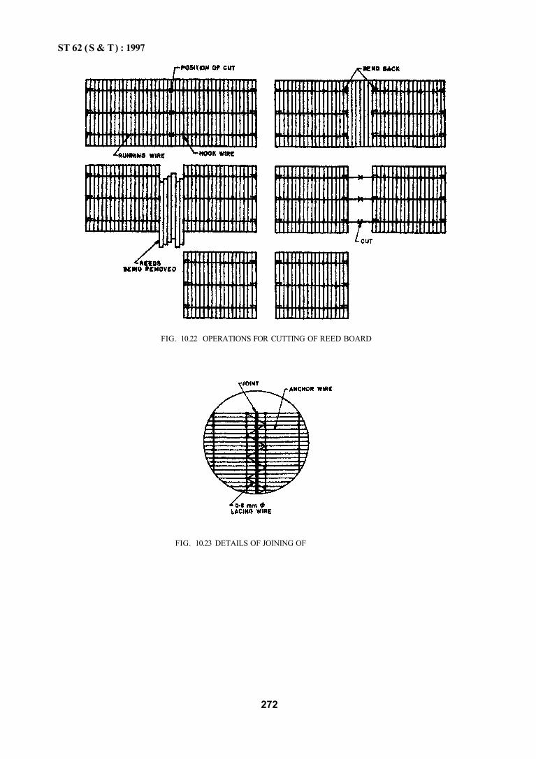
ST 62 (S & T) : 1997
FIG. 10.22 OPERATIONS FOR CUTTING OF REED BOARD
FIG. 10.23 DETAILS OF JOINING OF
272
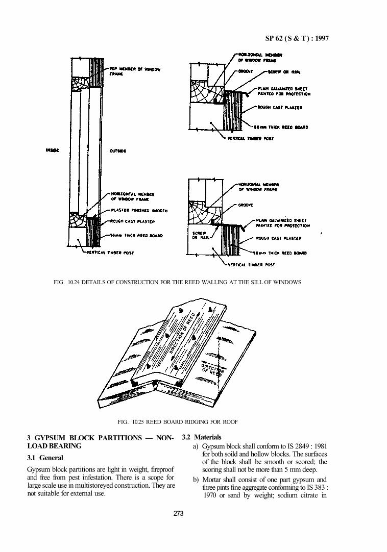
SP 62 (S & T) : 1997
FIG. 10.24 DETAILS OF CONSTRUCTION FOR THE REED WALLING AT THE SILL OF WINDOWS
FIG. 10.25 REED BOARD RIDGING FOR ROOF
3 GYPSUM BLOCK PARTITIONS — NON-LOAD BEARING 3.1 General Gypsum block partitions are light in weight, fireproof and free from pest infestation. There is a scope for large scale use in multistoreyed construction. They are not suitable for external use.
3.2 Materials a) Gypsum block shall conform to IS 2849 : 1981
for both soild and hollow blocks. The surfaces of the block shall be smooth or scored; the scoring shall not be more than 5 mm deep.
b) Mortar shall consist of one part gypsum and three pints fine aggregate conforming to IS 383 : 1970 or sand by weight; sodium citrate in
273
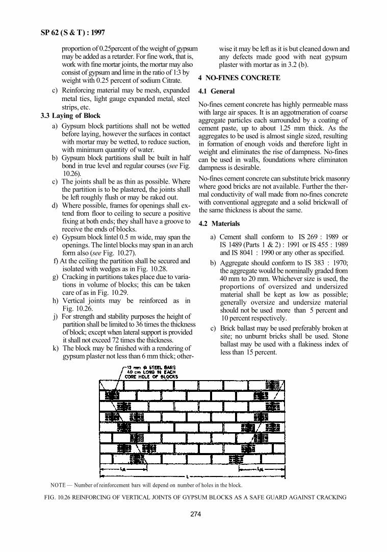
SP 62 (S & T) : 1997
proportion of 0.25percent of the weight of gypsum may be added as a retarder. For fine work, that is, work with fine mortar joints, the mortar may also consist of gypsum and lime in the ratio of 1:3 by weight with 0.25 percent of sodium Citrate.
c) Reinforcing material may be mesh, expanded metal ties, light gauge expanded metal, steel strips, etc.
3.3 Laying of Block a) Gypsum block partitions shall not be wetted
before laying, however the surfaces in contact with mortar may be wetted, to reduce suction, with minimum quantity of water.
b) Gypsum block partitions shall be built in half bond in true level and regular courses (see Fig. 10.26).
c) The joints shall be as thin as possible. Where the partition is to be plastered, the joints shall be left roughly flush or may be raked out.
d) Where possible, frames for openings shall extend from floor to ceiling to secure a positive fixing at both ends; they shall have a groove to receive the ends of blocks.
e) Gypsum block lintel 0.5 m wide, may span the openings. The lintel blocks may span in an arch form also (see Fig. 10.27).
f) At the ceiling the partition shall be secured and isolated with wedges as in Fig. 10.28.
g) Cracking in partitions takes place due to variations in volume of blocks; this can be taken care of as in Fig. 10.29.
h) Vertical joints may be reinforced as in Fig. 10.26.
j) For strength and stability purposes the height of partition shall be limited to 36 times the thickness of block; except when lateral support is provided it shall not exceed 72 times the thickness.
k) The block may be finished with a rendering of gypsum plaster not less than 6 mm thick; other-
wise it may be left as it is but cleaned down and any defects made good with neat gypsum plaster with mortar as in 3.2 (b).
4 NO-FINES CONCRETE
4.1 General
No-fines cement concrete has highly permeable mass with large air spaces. It is an aggotmeration of coarse aggregate particles each surrounded by a coating of cement paste, up to about 1.25 mm thick. As the aggregates to be used is almost single sized, resulting in formation of enough voids and therefore light in weight and eliminates the rise of dampness. No-fines can be used in walls, foundations where eliminaton dampness is desirable. No-fines cement concrete can substitute brick masonry where good bricks are not available. Further the thermal conductivity of wall made from no-fines concrete with conventional aggregate and a solid brickwall of the same thickness is about the same.
4.2 Materials
a) Cement shall conform to IS 269 : 1989 or IS 1489 (Parts 1 & 2) : 1991 or IS 455 : 1989 and IS 8041 : 1990 or any other as specified.
b) Aggregate should conform to IS 383 : 1970; the aggregate would be nominally graded from 40 mm to 20 mm. Whichever size is used, the proportions of oversized and undersized material shall be kept as low as possible; generally oversize and undersize material should not be used more than 5 percent and 10 percent respectively.
c) Brick ballast may be used preferably broken at site; no unburnt bricks shall be used. Stone ballast may be used with a flakiness index of less than 15 percent.
NOTE — Number of reinforcement bars will depend on number of holes in the block.
FIG. 10.26 REINFORCING OF VERTICAL JOINTS OF GYPSUM BLOCKS AS A SAFE GUARD AGAINST CRACKING
274
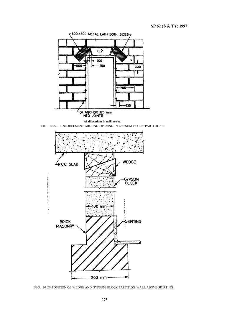
SP 62 (S & T) : 1997
FIG. 10.28 POSITION OF WEDGE AND GYPSUM BLOCK PARTITION WALL ABOVE SKIRTING
275
All dimensions in millimetres. FIG. 10.27 REINFORCEMENT AROUND OPENING IN GYPSUM BLOCK PARTITIONS
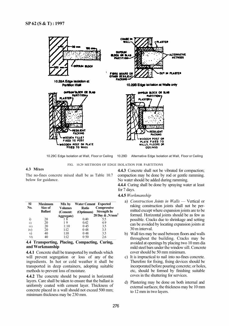
SP 62 (S & T) : 1997
10.29C Edge Isolation at Wall, Floor or Ceiling 10.29D Alternative Edge Isolation at Wall, Floor or Ceiling
FIG. 10.29 METHODS OF EDGE ISOLATION FOR PARTITIONS 4.3 Mixes The no-fines concrete mixed shall be as Table 10.7 below for guidance.
Sl No.
i) ii) iii) iv) v) VI)
Maximum Size of Ballast
20 20 20 20 40 40
Mix by Volumes (Cement:
Aggregate) 1 8 1 9 1:10 1:12 1:10 1:12
Water Cement Ratio
(Optimum)
0.40 0.42 0 45 0 48 0 48 0 50
Expected Compressive Strength In
28 Day & ,N/mm2
5.5 4.9 3.5 3.5 3.5 2.6
4.4 Transporting, Placing, Compacting, Curing, and Workmanship 4.4.1 Concrete shall be transported by methods which will prevent segregation or loss of any of the ingredients. In hot or cold weather it shall be transported in deep containers, adopting suitable methods to prevent loss of moisture. 4.4.2 The concrete should be poured in horizontal layers. Care shall be taken to ensure that the ballast is uniformly coated with cement layer. Thickness of concrete placed in a wall should not exceed 500 mm; minimum thickness may be 230 mm.
4.4.3 Concrete shall not be vibrated for compaction; compaction may be done by rod or gentle ramming. No water should be added during ramming. 4.4.4 Curing shall be done by spraying water at least for 7 days. 4.4.5 Workmanship
a) Construction Joints in Walls — Vertical or raking construction joints shall not be permitted except where expansion joints are to be formed. Horizontal joints should be as few as possible. Cracks due to shrinkage and setting can be avoided by locating expansion joints at 30 m interval.
b) Wall ties may be used between floors and walls throughout the building. Cracks may be avoided at openings by placing two 10 mm dia mild steel bars under the window sill. Concrete cover should be 50 mm minimum.
c) It is impractical to nail into no-fines concrete. Therefore for fixing, fixing devices should be incorporated before pouring concrete; or holes, etc, should be formed by finishing suitable coves in the shuttering for services.
d) Plastering may be done on both internal and external surfaces; the thickness may be 10 mm to 12 mm in two layers.
276
CHAPTER 11
ROOFS AND ROOFING
CONTENTS
1 GENERAL
PART 1 FLAT ROOFS 1 GENERAL
2 JACK-ARCH TYPE ROOF
2.1 General 2.2 Materials 2.3 Typical Details 2.4 Preparatory Work 2.5 Construction of Jack-Arches 2.6 Finish
3 BRICK-CUM-CONCRETE COMPOSITE ROOF (MADRAS TERRACE)
3.1 General 3.2 Materials 3.3 Preparatory Work 3.4 Laying of Terrace Bricks 3.5 Laying of Lime Brick Aggregate Concrete 3.6 Finishing
4 STONE SLAB OVER JOIST FLOOR
4.1 General 4.2 Materials 4.3 Preparatory Work 4.4 Laying of Stone Slabs 4.5 Laying of Concrete Layer over the Stone Slabs 4.6 Finishing
5 ROOFS AND FLOORS WITH JOIST AND FILLER BLOCKS — HOLLOW CONCRETE FILLER BLOCKS
5.1 General 5.2 Materials 5.3 Components of the Roof 5.4 Preparatory Work 5.5 Laying of the Roof 5.6 Finishing
6 ROOFS AND FLOORS WITH JOIST AND FILLER BLOCKS — HOLLOW CLAY FILLER BLOCKS
6.1 General 6.2 Materials 6.3 Components of the Roof 6.4 Preparatory Work 6.5 Laying of the Roof 6.6 Finishing
7 ROOFS AND FLOORS WITH JOISTS AND FILLER BLOCKS — PRECAST HOLLOW CLAY BLOCK JOISTS AND HOLLOW CLAY FILLER BLOCKS
7.1 General 7.2 Materials 7.3 Preparatory Work 7.4 Structural Clay Block Joists 7.5 Structural Clay Block Slab 7.6 Construction of Roof 7.7 Finishing
8 ROOFS AND FLOORS WITH JOISTS AND FILLER BLOCKS—PRECAST HOLLOW CLAY BLOCK SLAB PANELS
8.) General 8.2 Materials 8.3 Preparatory Work 8.4 Slab Panel 8.5 Construction of Roof 8.6 Finishing
ANNEX A SPECIFICATION FOR CRUDE OIL FOR Usn IN MORTARS FOR MADRAS TERRACE WORK
PART 2 SLOPING ROOFS 1 WOODEN SHINGLE ROOF
1.1 General 1.2 Materials 1.3 Preparatory Work

1.4 Laying of Shingles 1.5 Maintenance
2 ROOFING WITH MANGALORE TlLES
2.1 General 2.2 Materials 2.3 Preparatory Work 2.4 Fixing of Reepers 2.5 Laying of Mangalore Tiles
3 SLOPED ROOF COVERING — SLATING
3.1 General 3.2 Materials 3.3 Preparatory Work 3.4 Laying of Slates 3.5 Finishing Around Projections/Junctions
4 SLOPED ROOF USING PLAIN AND CORRUGATED GALVANIZED STEEL SHEETS
4.1 General 4.2 Materials 4.3 Preparatory Work 4.4 Laying and Fixing of Sheets 4.5 Ridges and Hips 4.6 Valleys and Flashings
5 ASBESTOS CEMSNT SHEETS — CORRUGATED
5.1 General 5.2 Materials 5.3 Preparatory Work 5.4 Laying and Fixing of Sheets 5.5 Safety Precautions
6 ASBESTOS CEMENT SHEETS—SEMI-CORRUGATED
6.1 General
ANNEX B TIMBER FOR WOODEN SHINGLES
PART 3 SHELL ROOFS
1 GENERAL
2 REINFORCED CONCRETE SHELL ROOF CAST IN SITU
2.1 Shell Dimensions 2.2 Type of Shells 2.3 Design 2.4 Sequence of Construction
3 PRECAST DOUBLY CURVED SHELL UNITS
PART 4 FLAT ROOF FINISH — MUD PHUSKA
1 GENERAL
2 MATERIALS
3 PREPARATORY WORK
4 LAYING OF MUD PHUSKA
4.1 Preparation 4.2 Laying
4.3 Applying Mud Plaster 4.4 Paving with Brick Tiles 4.5 Maintenance
PART 5 THATCHED ROOFS
1 THATCHING OF ROOF
1.1 General 1.2 Materials 1.3 Fire Retardant Treatment

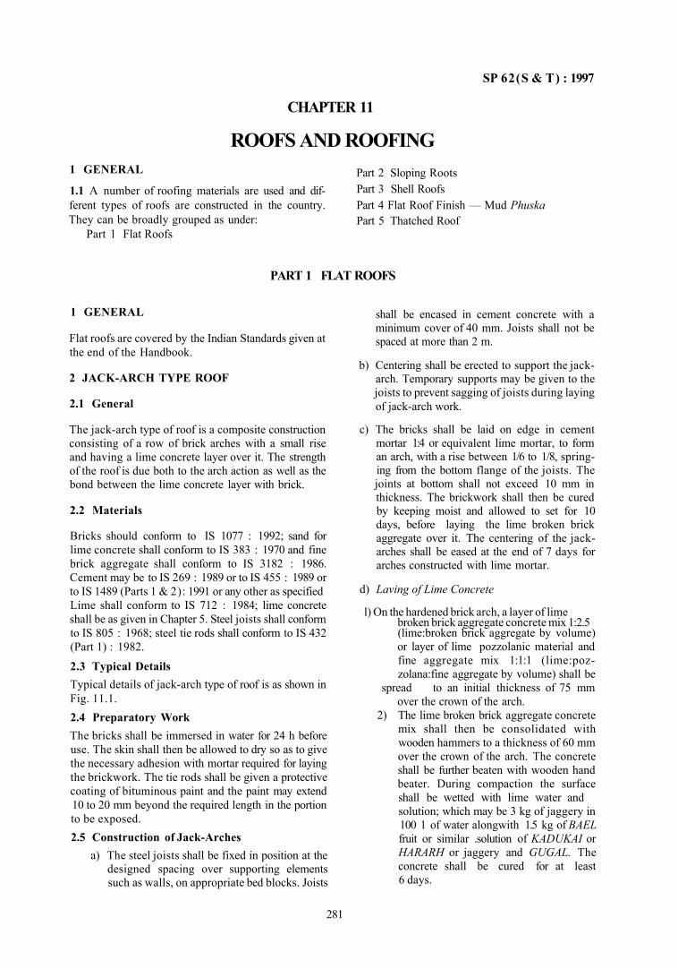
SP 62(S & T) : 1997
CHAPTER 11
ROOFS AND ROOFING 1 GENERAL
1.1 A number of roofing materials are used and different types of roofs are constructed in the country. They can be broadly grouped as under:
Part 1 Flat Roofs
Part 2 Sloping Roots Part 3 Shell Roofs Part 4 Flat Roof Finish — Mud Phuska Part 5 Thatched Roof
PART 1 FLAT ROOFS
1 GENERAL
Flat roofs are covered by the Indian Standards given at the end of the Handbook.
2 JACK-ARCH TYPE ROOF
2.1 General
The jack-arch type of roof is a composite construction consisting of a row of brick arches with a small rise and having a lime concrete layer over it. The strength of the roof is due both to the arch action as well as the bond between the lime concrete layer with brick.
2.2 Materials
Bricks should conform to IS 1077 : 1992; sand for lime concrete shall conform to IS 383 : 1970 and fine brick aggregate shall conform to IS 3182 : 1986. Cement may be to IS 269 : 1989 or to IS 455 : 1989 or to IS 1489 (Parts 1 & 2): 1991 or any other as specified Lime shall conform to IS 712 : 1984; lime concrete shall be as given in Chapter 5. Steel joists shall conform to IS 805 : 1968; steel tie rods shall conform to IS 432 (Part 1) : 1982.
2.3 Typical Details Typical details of jack-arch type of roof is as shown in Fig. 11.1. 2.4 Preparatory Work The bricks shall be immersed in water for 24 h before use. The skin shall then be allowed to dry so as to give the necessary adhesion with mortar required for laying the brickwork. The tie rods shall be given a protective coating of bituminous paint and the paint may extend 10 to 20 mm beyond the required length in the portion to be exposed. 2.5 Construction of Jack-Arches
a) The steel joists shall be fixed in position at the designed spacing over supporting elements such as walls, on appropriate bed blocks. Joists
shall be encased in cement concrete with a minimum cover of 40 mm. Joists shall not be spaced at more than 2 m.
b) Centering shall be erected to support the jack-arch. Temporary supports may be given to the joists to prevent sagging of joists during laying of jack-arch work.
c) The bricks shall be laid on edge in cement mortar 1:4 or equivalent lime mortar, to form an arch, with a rise between 1/6 to 1/8, springing from the bottom flange of the joists. The joints at bottom shall not exceed 10 mm in thickness. The brickwork shall then be cured by keeping moist and allowed to set for 10 days, before laying the lime broken brick aggregate over it. The centering of the jack-arches shall be eased at the end of 7 days for arches constructed with lime mortar.
d) Laving of Lime Concrete
(lime:broken brick aggregate by volume) or layer of lime pozzolanic material and fine aggregate mix 1:1:1 (lime:poz-zolana:fine aggregate by volume) shall be
spread to an initial thickness of 75 mm over the crown of the arch.
2) The lime broken brick aggregate concrete mix shall then be consolidated with wooden hammers to a thickness of 60 mm over the crown of the arch. The concrete shall be further beaten with wooden hand beater. During compaction the surface shall be wetted with lime water and solution; which may be 3 kg of jaggery in 100 1 of water alongwith 1.5 kg of BAEL fruit or similar .solution of KADUKAI or HARARH or jaggery and GUGAL. The concrete shall be cured for at least 6 days.
281
l) On the hardened brick arch, a layer of lime broken brick aggregate concrete mix 1:2.5
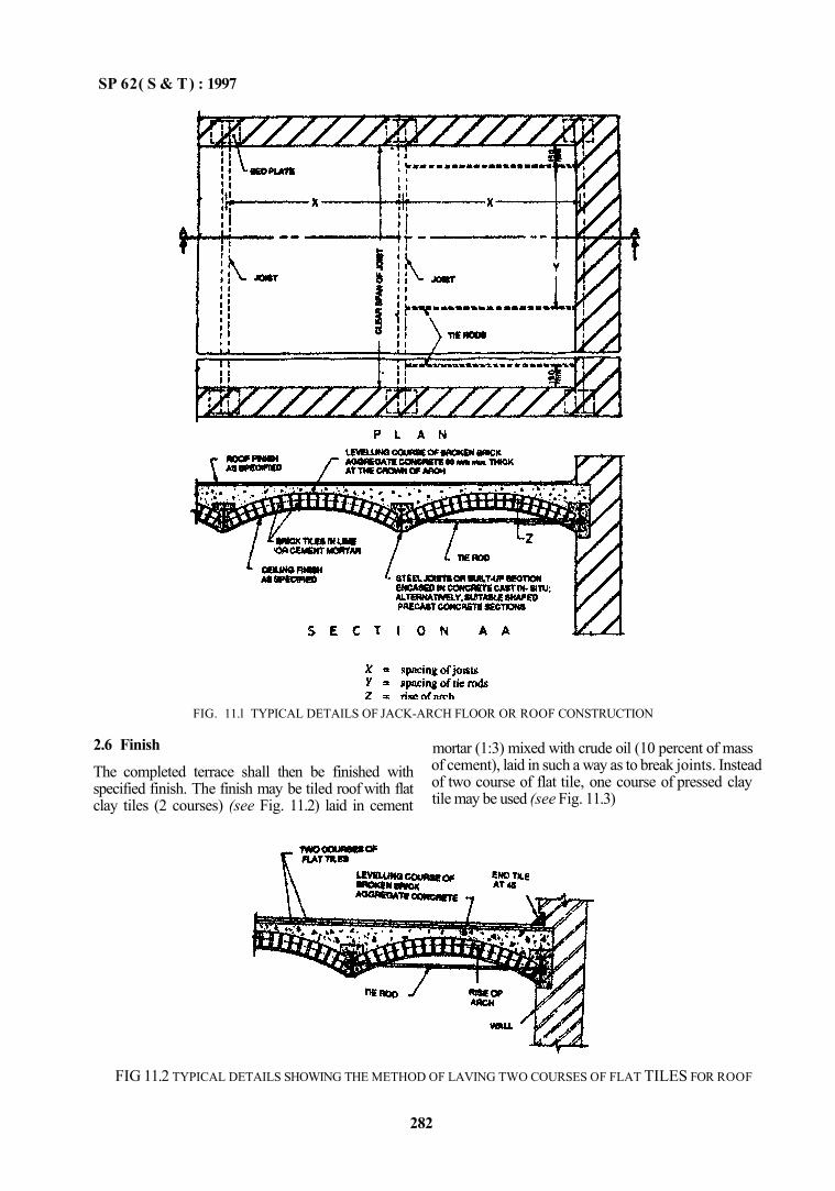
SP 62( S & T) : 1997
2.6 Finish
The completed terrace shall then be finished with specified finish. The finish may be tiled roof with flat clay tiles (2 courses) (see Fig. 11.2) laid in cement
mortar (1:3) mixed with crude oil (10 percent of mass of cement), laid in such a way as to break joints. Instead of two course of flat tile, one course of pressed clay tile may be used (see Fig. 11.3)
FIG 11.2 TYPICAL DETAILS SHOWING THE METHOD OF LAVING TWO COURSES OF FLAT TILES FOR ROOF
282
FIG. 11.l TYPICAL DETAILS OF JACK-ARCH FLOOR OR ROOF CONSTRUCTION
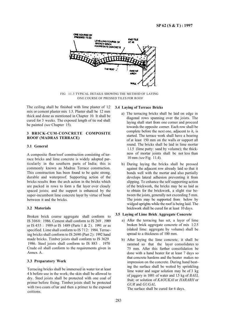
SP 62 (S & T) : 1997
FIG 11.3 TYPICAL DETAILS SHOWING THE METHOD OF LAYING ONE COURSE OF PRESSED TILES FOR ROOF
283
The ceiling shall be finished with lime plaster of 1:2 mix or cement plaster mix 1:3. Plaster shall be 12 mm thick and done as mentioned in Chapter 10. It shall be cured for 3 weeks. The exposed length of tie rod shall be painted (see Chapter 15).
3 BRICK-CUM-CONCRETE COMPOSITE ROOF (MADRAS TERRACE)
3.1 General
A composite floor/roof construction consisting of terrace bricks and lime concrete is widely adopted particularly in the southern parts of India; this is commonly known as Madras Terrace construction. This construction has been found to be quite strong. durable and waterproof. Supporting action of the bricks results from the arch action in the bricks which are packed in rows to form a flat layer over closely spaced joists; and the support is enhanced by the super-incumbent lime concrete layer by virtue of bond between it and the bricks.
3.2 Materials
Broken brick coarse aggregate shall conform to IS 3068: 1986. Cement shall conform to IS 269 . 1989 or IS 455 : 1989 or IS 1489 (Parts 1 & 2) . 1991 or as specified. Lime shall conform to IS 712: 1984. Terracing bricks shall conform to IS 2690 (Part 2): 1992 hand made bricks. Timber joists shall conform to IS 3629 1986. Steel joists shall conform to IS 883 . 1970 Crude oil shall conform to the requirements given in Annex A.
3.3 Preparatory Work
Terracing bricks shall be immersed in water tor at least 4 h before use in the work; the skin shall be allowed to dry. Steel joists shall be protected with one coal of primer before fixing. Timber joists shall be protected with two coats of tar and then a primer to the exposed coitions.
3.4 Laying of Terrace Bricks a) The terracing bricks shall be laid on edge in
diagonal rows spanning over the joists. The laying shall start from one corner and proceed towards the opposite corner. Each row shall be complete before the next one, adjacent to it, is started. The terrace work shall have a bearing of at least 150 mm on the walls or support all round. The bricks shall be laid in lime mortar 1.1.5 (lime putty: sand by volume); the thickness of mortar joints shall be not less than 10 mm (see Fig. 11.4).
b) During laying the bricks shall be pressed against the adjacent row already laid so that it bonds well with the mortar and also partially develops lateral adhesion preventing it from slipping. To enhance the self supporting action of the brickwork, the bricks may be so laid as to obtain for the brickwork, a slight rise between the joists, generally not exceeding 5 mm. The joists may be supported from below by widged uprights while the roof is being laid. The brickwork shall be cured for at least 10 days.
3.5 Laying of Lime Brick Aggregate Concrete a) After the terracing has set, a layer of lime
broken brick aggregate concrete of mix 1:2.5 (slaked lime: aggregate by volume) shall be spread to a thickness of 100 mm.
b) After laying the lime concrete, it shall be rammed so that the layer consolidates to 75 mm. After this further consolidation be done with a hand beater for at least 7 days so that concrete hardens and the beater makes no impression on the concrete. During hand beating the surface shall be wetted by sprinkling lime water and sugar solution may be of 3 kg of jaggery in 1001 of water and 1.5 kg of BAEL fruit; or solution of KAOUKAI or HARARH or GUR and GUGAL. The surface shall be cured for 6 days.
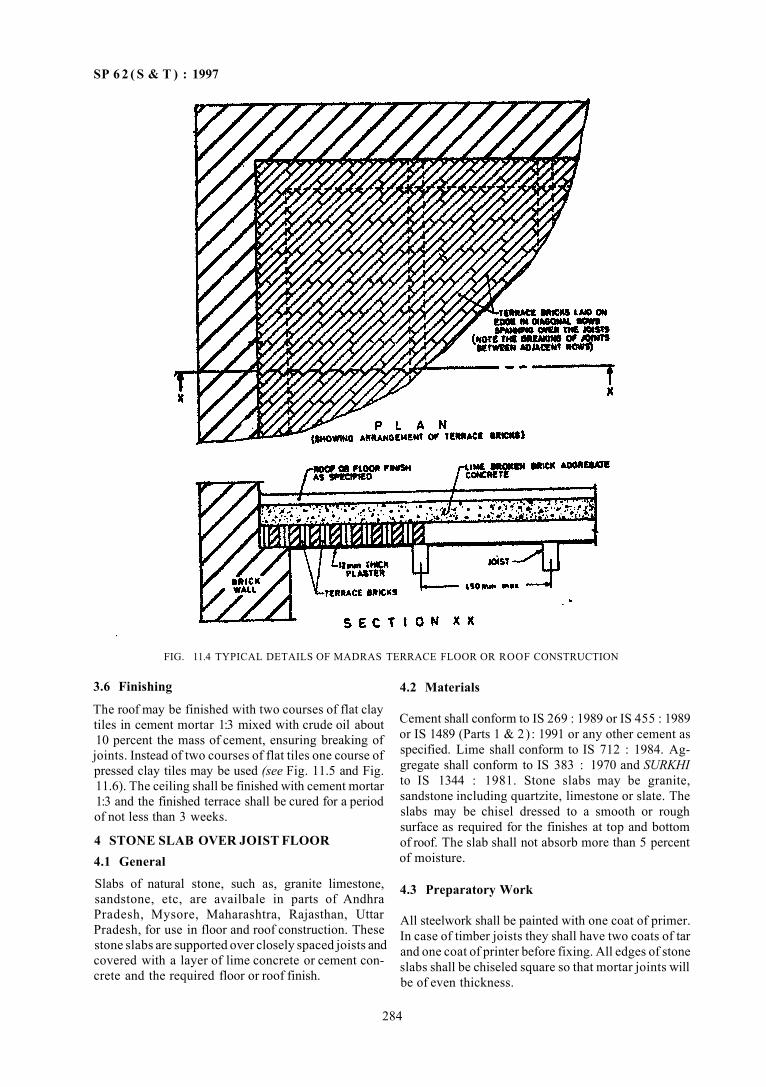
SP 6 2 ( S & T ) : 1997
FIG. 11.4 TYPICAL DETAILS OF MADRAS TERRACE FLOOR OR ROOF CONSTRUCTION
3.6 Finishing
The roof may be finished with two courses of flat clay tiles in cement mortar 1:3 mixed with crude oil about 10 percent the mass of cement, ensuring breaking of joints. Instead of two courses of flat tiles one course of pressed clay tiles may be used (see Fig. 11.5 and Fig. 11.6). The ceiling shall be finished with cement mortar 1:3 and the finished terrace shall be cured for a period of not less than 3 weeks.
4 STONE SLAB OVER JOIST FLOOR 4.1 General Slabs of natural stone, such as, granite limestone, sandstone, etc, are availbale in parts of Andhra Pradesh, Mysore, Maharashtra, Rajasthan, Uttar Pradesh, for use in floor and roof construction. These stone slabs are supported over closely spaced joists and covered with a layer of lime concrete or cement concrete and the required floor or roof finish.
4.2 Materials
Cement shall conform to IS 269 : 1989 or IS 455 : 1989 or IS 1489 (Parts 1 & 2) : 1991 or any other cement as specified. Lime shall conform to IS 712 : 1984. Aggregate shall conform to IS 383 : 1970 and SURKHI to IS 1344 : 1981. Stone slabs may be granite, sandstone including quartzite, limestone or slate. The slabs may be chisel dressed to a smooth or rough surface as required for the finishes at top and bottom of roof. The slab shall not absorb more than 5 percent of moisture.
4.3 Preparatory Work
All steelwork shall be painted with one coat of primer. In case of timber joists they shall have two coats of tar and one coat of printer before fixing. All edges of stone slabs shall be chiseled square so that mortar joints will be of even thickness.
284
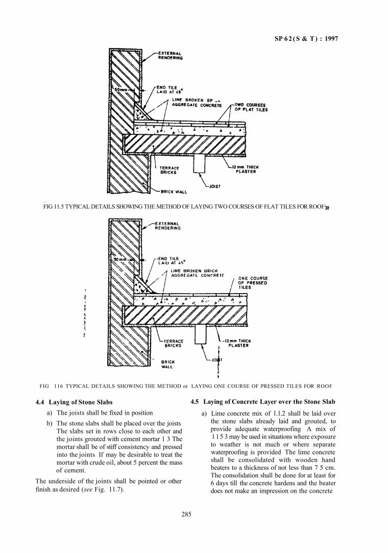
SP 6 2 ( S & T ) : 1997
FIG 116 TYPICAL DETAILS SHOWING THE METHOD or LAYING ONE COURSE OF PRESSED TILES FOR ROOF
4.4 Laying of Stone Slabs a) The joists shall be fixed in position b) The stone slabs shall be placed over the joists
The slabs set in rows close to each other and the joints grouted with cement mortar 1 3 The mortar shall be of stiff consistency and pressed into the joints If may be desirable to treat the mortar with crude oil, about 5 percent the mass of cement.
The underside of the joints shall be pointed or other finish as desired (see Fig. 11.7).
4.5 Laying of Concrete Layer over the Stone Slab
a) Lime concrete mix of 1.1.2 shall be laid over the stone slabs already laid and grouted, to provide adequate waterproofing A mix of 115 3 may be used in situations where exposure to weather is not much or where separate waterproofing is provided The lime concrete shall be consolidated with wooden hand beaters to a thickness of not less than 7 5 cm. The consolidation shall be done for at least for 6 days till the concrete hardens and the beater does not make an impression on the concrete
285
FIG 11.5 TYPICAL DETAILS SHOWING THE METHOD OF LAYING TWO COURSES OF FLAT TILES FOR ROOF
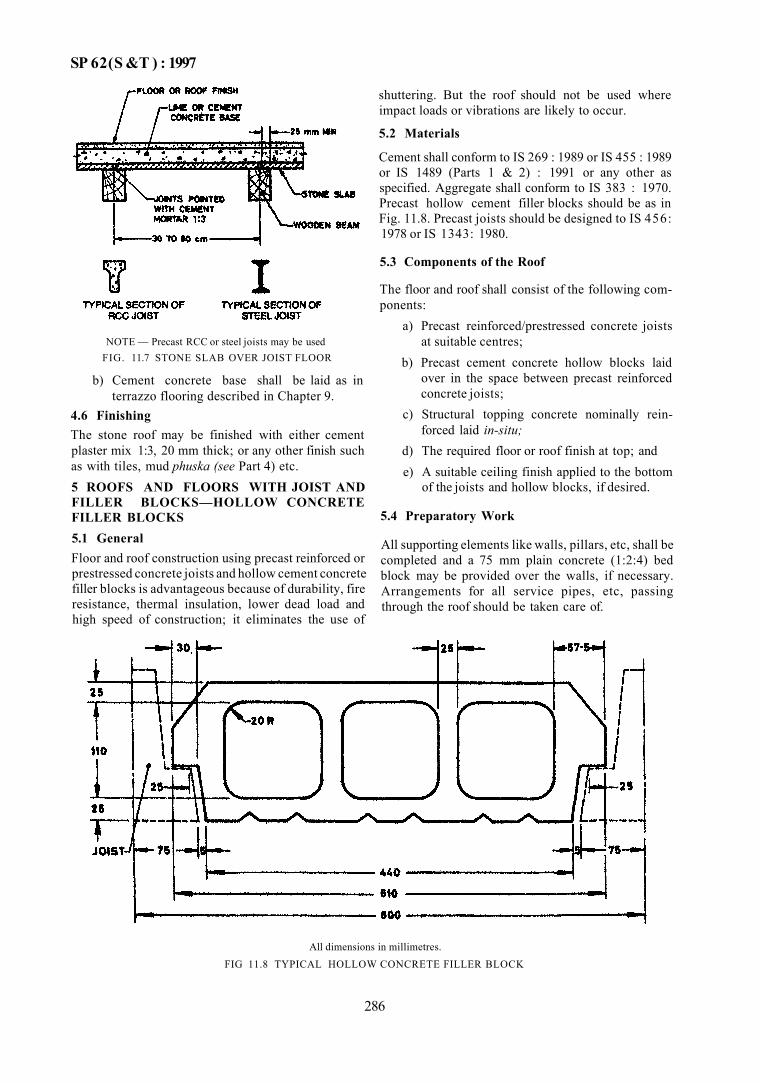
SP 62(S &T ) : 1997
NOTE — Precast RCC or steel joists may be used FIG. 11.7 STONE SLAB OVER JOIST FLOOR
b) Cement concrete base shall be laid as in terrazzo flooring described in Chapter 9.
4.6 Finishing The stone roof may be finished with either cement plaster mix 1:3, 20 mm thick; or any other finish such as with tiles, mud phuska (see Part 4) etc. 5 ROOFS AND FLOORS WITH JOIST AND FILLER BLOCKS—HOLLOW CONCRETE FILLER BLOCKS 5.1 General Floor and roof construction using precast reinforced or prestressed concrete joists and hollow cement concrete filler blocks is advantageous because of durability, fire resistance, thermal insulation, lower dead load and high speed of construction; it eliminates the use of
shuttering. But the roof should not be used where impact loads or vibrations are likely to occur.
5.2 Materials
Cement shall conform to IS 269 : 1989 or IS 455 : 1989 or IS 1489 (Parts 1 & 2) : 1991 or any other as specified. Aggregate shall conform to IS 383 : 1970. Precast hollow cement filler blocks should be as in Fig. 11.8. Precast joists should be designed to IS 456: 1978 or IS 1343: 1980.
5.3 Components of the Roof
The floor and roof shall consist of the following components:
a) Precast reinforced/prestressed concrete joists at suitable centres;
b) Precast cement concrete hollow blocks laid over in the space between precast reinforced concrete joists;
c) Structural topping concrete nominally reinforced laid in-situ;
d) The required floor or roof finish at top; and e) A suitable ceiling finish applied to the bottom
of the joists and hollow blocks, if desired.
5.4 Preparatory Work
All supporting elements like walls, pillars, etc, shall be completed and a 75 mm plain concrete (1:2:4) bed block may be provided over the walls, if necessary. Arrangements for all service pipes, etc, passing through the roof should be taken care of.
All dimensions in millimetres. FIG 11.8 TYPICAL HOLLOW CONCRETE FILLER BLOCK
286
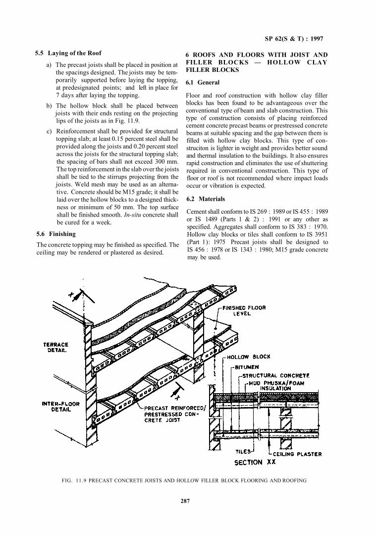
SP 62(S & T) : 1997
6 ROOFS AND FLOORS WITH JOIST AND FILLER BLOCKS — HOLLOW CLAY FILLER BLOCKS
6.1 General
Floor and roof construction with hollow clay filler blocks has been found to be advantageous over the conventional type of beam and slab construction. This type of construction consists of placing reinforced cement concrete precast beams or prestressed concrete beams at suitable spacing and the gap between them is filled with hollow clay blocks. This type of con-struciton is lighter in weight and provides better sound and thermal insulation to the buildings. It also ensures rapid construction and eliminates the use of shuttering required in conventional construction. This type of floor or roof is not recommended where impact loads occur or vibration is expected.
6.2 Materials
Cement shall conform to IS 269 : 1989 or IS 455 : 1989 or IS 1489 (Parts 1 & 2) : 1991 or any other as specified. Aggregates shall conform to IS 383 : 1970. Hollow clay blocks or tiles shall conform to IS 3951 (Part 1): 1975 Precast joists shall be designed to IS 456 : 1978 or IS 1343 : 1980; M15 grade concrete may be used.
FIG. 11.9 PRECAST CONCRETE JOISTS AND HOLLOW FILLER BLOCK FLOORING AND ROOFING
287
5.5 Laying of the Roof
a) The precast joists shall be placed in position at the spacings designed. The joists may be temporarily supported before laying the topping, at predesignated points; and left in place for 7 days after laying the topping.
b) The hollow block shall be placed between joists with their ends resting on the projecting lips of the joists as in Fig. 11.9.
c) Reinforcement shall be provided for structural topping slab; at least 0.15 percent steel shall be provided along the joists and 0.20 percent steel across the joists for the structural topping slab; the spacing of bars shall not exceed 300 mm. The top reinforcement in the slab over the joists shall be tied to the stirrups projecting from the joists. Weld mesh may be used as an alternative. Concrete should be M15 grade; it shall be laid over the hollow blocks to a designed thickness or minimum of 50 mm. The top surface shall be finished smooth. In-situ concrete shall be cured for a week.
5.6 Finishing The concrete topping may be finished as specified. The ceiling may be rendered or plastered as desired.
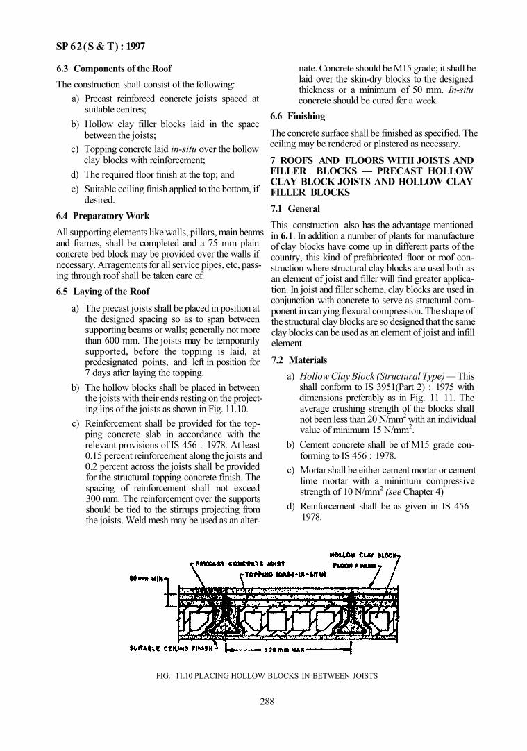
SP 62(S & T) : 1997
6.3 Components of the Roof The construction shall consist of the following:
a) Precast reinforced concrete joists spaced at suitable centres;
b) Hollow clay filler blocks laid in the space between the joists;
c) Topping concrete laid in-situ over the hollow clay blocks with reinforcement;
d) The required floor finish at the top; and e) Suitable ceiling finish applied to the bottom, if
desired. 6.4 Preparatory Work All supporting elements like walls, pillars, main beams and frames, shall be completed and a 75 mm plain concrete bed block may be provided over the walls if necessary. Arragements for all service pipes, etc, passing through roof shall be taken care of. 6.5 Laying of the Roof
a) The precast joists shall be placed in position at the designed spacing so as to span between supporting beams or walls; generally not more than 600 mm. The joists may be temporarily supported, before the topping is laid, at predesignated points, and left in position for 7 days after laying the topping.
b) The hollow blocks shall be placed in between the joists with their ends resting on the projecting lips of the joists as shown in Fig. 11.10.
c) Reinforcement shall be provided for the topping concrete slab in accordance with the relevant provisions of IS 456 : 1978. At least 0.15 percent reinforcement along the joists and 0.2 percent across the joists shall be provided for the structural topping concrete finish. The spacing of reinforcement shall not exceed 300 mm. The reinforcement over the supports should be tied to the stirrups projecting from the joists. Weld mesh may be used as an alter
nate. Concrete should be M15 grade; it shall be laid over the skin-dry blocks to the designed thickness or a minimum of 50 mm. In-situ concrete should be cured for a week.
6.6 Finishing
The concrete surface shall be finished as specified. The ceiling may be rendered or plastered as necessary.
7 ROOFS AND FLOORS WITH JOISTS AND FILLER BLOCKS — PRECAST HOLLOW CLAY BLOCK JOISTS AND HOLLOW CLAY FILLER BLOCKS 7.1 General This construction also has the advantage mentioned in 6.1. In addition a number of plants for manufacture of clay blocks have come up in different parts of the country, this kind of prefabricated floor or roof construction where structural clay blocks are used both as an element of joist and filler will find greater application. In joist and filler scheme, clay blocks are used in conjunction with concrete to serve as structural component in carrying flexural compression. The shape of the structural clay blocks are so designed that the same clay blocks can be used as an element of joist and infill element.
7.2 Materials a) Hollow Clay Block (Structural Type) — This
shall conform to IS 3951(Part 2) : 1975 with dimensions preferably as in Fig. 11 11. The average crushing strength of the blocks shall not been less than 20 N/mm2 with an individual value of minimum 15 N/mm2.
b) Cement concrete shall be of M15 grade conforming to IS 456 : 1978.
c) Mortar shall be either cement mortar or cement lime mortar with a minimum compressive strength of 10 N/mm2 (see Chapter 4)
d) Reinforcement shall be as given in IS 456 1978.
FIG. 11.10 PLACING HOLLOW BLOCKS IN BETWEEN JOISTS
288
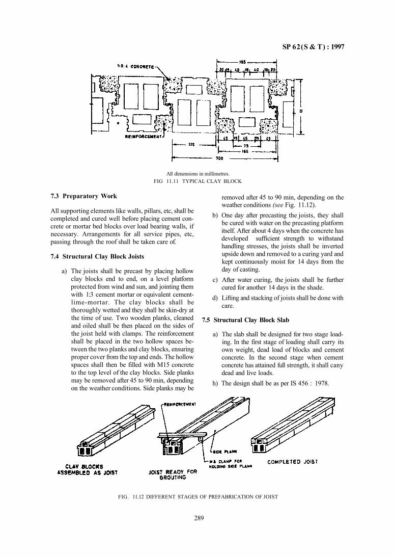
SP 62(S & T) : 1997
All dimensions in millimetres. FIG 11.11 TYPICAL CLAY BLOCK
7.3 Preparatory Work
All supporting elements like walls, pillars, etc, shall be completed and cured well before placing cement concrete or mortar bed blocks over load bearing walls, if necessary. Arrangements for all service pipes, etc, passing through the roof shall be taken care of.
7.4 Structural Clay Block Joists
a) The joists shall be precast by placing hollow clay blocks end to end, on a level platform protected from wind and sun, and jointing them with 1:3 cement mortar or equivalent cement-lime-mortar. The clay blocks shall be thoroughly wetted and they shall be skin-dry at the time of use. Two wooden planks, cleaned and oiled shall be then placed on the sides of the joist held with clamps. The reinforcement shall be placed in the two hollow spaces between the two planks and clay blocks, ensuring proper cover from the top and ends. The hollow spaces shall then be filled with M15 concrete to the top level of the clay blocks. Side planks may be removed after 45 to 90 min, depending on the weather conditions. Side planks may be
removed after 45 to 90 min, depending on the weather conditions (see Fig. 11.12).
b) One day after precasting the joists, they shall be cured with water on the precasting platform itself. After about 4 days when the concrete has developed sufficient strength to withstand handling stresses, the joists shall be inverted upside down and removed to a curing yard and kept continuously moist for 14 days from the day of casting.
c) After water curing, the joists shall be further cured for another 14 days in the shade.
d) Lifting and stacking of joists shall be done with care.
7.5 Structural Clay Block Slab
a) The slab shall be designed for two stage loading. In the first stage of loading shall carry its own weight, dead load of blocks and cement concrete. In the second stage when cement concrete has attained full strength, it shall cany dead and live loads.
h) The design shall be as per IS 456 : 1978.
FIG. 11.12 DIFFERENT STAGES OF PREFABRICATION OF JOIST
289
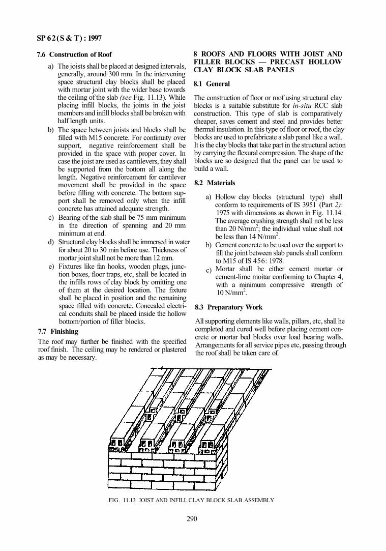
SP 62(S & T) : 1997
7.6 Construction of Roof a) The joists shall be placed at designed intervals,
generally, around 300 mm. In the intervening space structural clay blocks shall be placed with mortar joint with the wider base towards the ceiling of the slab (see Fig. 11.13). While placing infill blocks, the joints in the joist members and infill blocks shall be broken with half length units.
b) The space between joists and blocks shall be filled with M15 concrete. For continuity over support, negative reinforcement shall be provided in the space with proper cover. In case the joist are used as cantilevers, they shall be supported from the bottom all along the length. Negative reinforcement for cantilever movement shall be provided in the space before filling with concrete. The bottom support shall be removed only when the infill concrete has attained adequate strength.
c) Bearing of the slab shall be 75 mm minimum in the direction of spanning and 20 mm minimum at end.
d) Structural clay blocks shall be immersed in water for about 20 to 30 min before use. Thickness of mortar joint shall not be more than 12 mm.
e) Fixtures like fan hooks, wooden plugs, junction boxes, floor traps, etc, shall be located in the infills rows of clay block by omitting one of them at the desired location. The fixture shall be placed in position and the remaining space filled with concrete. Concealed electrical conduits shall be placed inside the hollow bottom/portion of filler blocks.
7.7 Finishing The roof may further be finished with the specified roof finish. The ceiling may be rendered or plastered as may be necessary.
8 ROOFS AND FLOORS WITH JOIST AND FILLER BLOCKS — PRECAST HOLLOW CLAY BLOCK SLAB PANELS
8.1 General
The construction of floor or roof using structural clay blocks is a suitable substitute for in-situ RCC slab construction. This type of slab is comparatively cheaper, saves cement and steel and provides better thermal insulation. In this type of floor or roof, the clay blocks are used to prefabricate a slab panel like a wall. It is the clay blocks that take part in the structural action by carrying the flexural compression. The shape of the blocks are so designed that the panel can be used to build a wall.
8.2 Materials
a) Hollow clay blocks (structural type) shall conform to requirements of IS 3951 (Part 2): 1975 with dimensions as shown in Fig. 11.14. The average crushing strength shall not be less than 20 N/mm2; the individual value shall not be less than 14 N/mm2.
b) Cement concrete to be used over the support to fill the joint between slab panels shall conform to M15 of IS 456: 1978. Mortar shall be either cement mortar or cement-lime moitar conforming to Chapter 4, with a minimum compressive strength of 10 N/mm2.
c)
8.3 Preparatory Work
All supporting elements like walls, pillars, etc, shall he completed and cured well before placing cement concrete or mortar bed blocks over load bearing walls. Arrangements for all service pipes etc, passing through the roof shall be taken care of.
FIG. 11.13 JOIST AND INFILL CLAY BLOCK SLAB ASSEMBLY
290
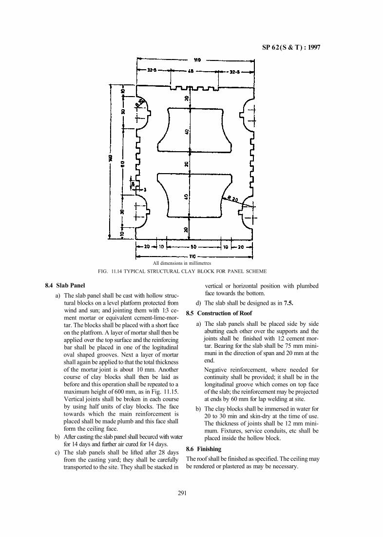
SP 62(S & T) : 1997
All dimensions in millimetres FIG. 11.14 TYPICAL STRUCTURAL CLAY BLOCK FOR PANEL SCHEME
8.4 Slab Panel a) The slab panel shall be cast with hollow struc
tural blocks on a level platform protected from wind and sun; and jointing them with 1:3 cement mortar or equivalent ccment-lime-mor-tar. The blocks shall be placed with a short face on the platfrom. A layer of mortar shall then be applied over the top surface and the reinforcing bar shall be placed in one of the logitudinal oval shaped grooves. Next a layer of mortar shall again be applied to that the total thickness of the mortar joint is about 10 mm. Another course of clay blocks shall then be laid as before and this operation shall be repeated to a maximum height of 600 mm, as in Fig. 11.15. Vertical joints shall be broken in each course by using half units of clay blocks. The face towards which the main reinforcement is placed shall be made plumb and this face shall form the ceiling face.
b) After casting the slab panel shall becurcd with water for 14 days and further air cured for 14 days.
c) The slab panels shall be lifted after 28 days from the casting yard; they shall be carefully transported to the site. They shall be stacked in
vertical or horizontal position with plumbed face towards the bottom.
d) The slab shall be designed as in 7.5. 8.5 Construction of Roof
a) The slab panels shall be placed side by side abutting each other over the supports and the joints shall be finished with 1:2 cement mortar. Bearing for the slab shall be 75 mm mini-muni in the direction of span and 20 mm at the end. Negative reinforcement, where needed for continuity shall be provided; it shall be in the longitudinal groove which comes on top face of the slab; the reinforcement may be projected at ends by 60 mm for lap welding at site.
b) The clay blocks shall be immersed in water for 20 to 30 min and skin-dry at the time of use. The thickness of joints shall be 12 mm minimum. Fixtures, service conduits, etc shall be placed inside the hollow block.
8.6 Finishing The roof shall be finished as specified. The ceiling may be rendered or plastered as may be necessary.
291
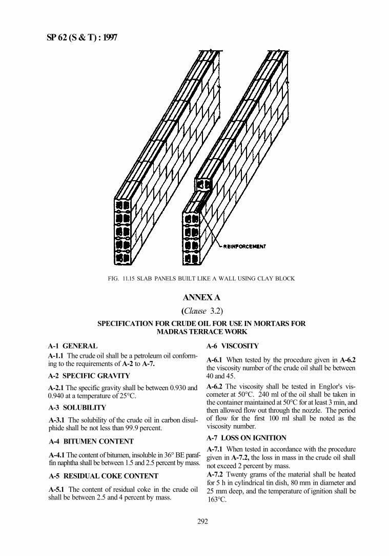
SP 62 (S & T) : 1997
FIG. 11.15 SLAB PANELS BUILT LIKE A WALL USING CLAY BLOCK
ANNEX A (Clause 3.2)
SPECIFICATION FOR CRUDE OIL FOR USE IN MORTARS FOR MADRAS TERRACE WORK
A-1 GENERAL A-1.1 The crude oil shall be a petroleum oil conforming to the requirements of A-2 to A-7. A-2 SPECIFIC GRAVITY A-2.1 The specific gravity shall be between 0.930 and 0.940 at a temperature of 25°C. A-3 SOLUBILITY A-3.1 The solubility of the crude oil in carbon disul-phide shall be not less than 99.9 percent.
A-4 BITUMEN CONTENT
A-4.1 The content of bitumen, insoluble in 36° BE paraffin naphtha shall be between 1.5 and 2.5 percent by mass.
A-5 RESIDUAL COKE CONTENT
A-5.1 The content of residual coke in the crude oil shall be between 2.5 and 4 percent by mass.
A-6 VISCOSITY
A-6.1 When tested by the procedure given in A-6.2 the viscosity number of the crude oil shall be between 40 and 45. A-6.2 The viscosity shall be tested in Englor's viscometer at 50°C. 240 ml of the oil shall be taken in the container maintained at 50°C for at least 3 min, and then allowed flow out through the nozzle. The period of flow for the first 100 ml shall be noted as the viscosity number. A-7 LOSS ON IGNITION A-7.1 When tested in accordance with the procedure given in A-7.2, the loss in mass in the crude oil shall not exceed 2 percent by mass. A-7.2 Twenty grams of the material shall be heated for 5 h in cylindrical tin dish, 80 mm in diameter and 25 mm deep, and the temperature of ignition shall be 163°C.
292
SP 62(S & T) : 1997
1 WOODEN SHINGLE ROOF
1.1 General
Wooden shingles arc used for pitched roofs in some of the Himalayan Regions of India where suitable species of timber are available, such as, in Jammu & Kashmir, North Punjab, Himachal Pradesh, Assam; as also in Andaman and Nicobar Islands.
Wooden shingles are short, thin, rectangular pieces of timber usually tapering in thickness along the grain, used in the same way as tiles for covering roofs of buildings. Thickness of shingles ordinarly reduces from tail (butt) to head. Shingles are nailed to the battens and arranged generally in a number of courses overlapping each other so as to ensure leak proof drainage. 1.2 Materials
a) Wooden shingles shall conform to the species specified in Annex B.
b) Nails shall conform to IS 723 :1972; preferably rust resistant or hot dip galvanized nails shall be used. Nails shall be of 2.00 or 2.24 mm shank diameter and 40 mm in length depending upon the species. Subsidiary battens shall be fixed to main battens by 2.80 mm or 3.15 mm diameter, 60 mm long nails.
c) Timber for fattens and rafters shall conform to structural timber specified in IS 3629 : 1986 properly seasoned and treated (see Fig. 11.16).
1.3 Preparatory Work a) In case of low pitched roofs, particularly in
areas of high winds, it is necessary to have an underlay of roofing sheets or timber roofing boards. In areas of heavy rainfall and in very damp climates, spaced roofing boards may preferably be used to permit quick drying of the underside of shingles. The provision of an undercover for the roof will not only add insulation and waterproofing but also prevent debris from falling in.
b) No gutter or rain water pipe shall discharge from one roof to another.
c) The size and shape of the shingles shall be as in Fig. 11.17
d) Spacing of battens shall be equal to about one-third of the length of shingles, that is. 100 to 130 mm as in Fig. 11.18.
e) The shingle covering shall be at least three courses deep at every section; the minimum overlap shall be one-third of the length of the shingle.
f) The spacing of rafters shall not normally exceed 600 mm or as determined by IS 883 : 1970. The size of battens shall not be less than 50 mm × 25 mm.
g) When ceiling board is adopted, the planking shall not be less than 12 mm and shall preferably be tongued and grooved. The ceiling boards may either be nailed to the rafters or may direcly be fixed to the purlins.
h) Wooden shingles shall be given fire retardant treatment by pressure impregnation with chemicals, such as. ammonium mono-phosphate, ammonium di-phosphate, sodium arsenate, or sodium tetraborate.
1.4 Laying of Shingles
a) Bach wooden shingle shall be fixed to the battens by two nails (see Fig. 11.16 and Fig. 11.18). The distance of nails from the butt end of shingle, shall be equal to the shingle exposure plus 10 to 15 mm, the edge distance of nails from the sides of the shingle shall not be more than 20 mm; the nails may be driven flush.
b) Each course of wooden shingle shall be overlapped by another course such that only one-third of the length of the shingle in the lower course is left uncovered; the remaining two-third length shall be overlapped. Except for the bottom two courses, wooden shingle shall be three course deep throughout the root area.
c) In each horizontal course, the shingles shall be laid 3 to 6 mm apart to allow for swelling when wet. Each horizontal course of wooden shingles shall break joints with two courses above and two courses below it.
d) The gaps between the wooden shingles in each course shall be off set at least 40 mm centre to centre from corresponding gaps between the shingles in the course above. The two courses of shingles at eaves shall also be break-jointed.
e) The first shingle course laid in double should extend 50 mm to 60 mm beyond facia member. in adopted, to prevent the water from backing up underneath the shingles.
293
PART 2 SLOPING ROOFS
SP 62(S & T) : 1997
FIG. 11.17 TYPICAL WOODEN SHINGLE
294
All dimensions in millimetrs.
FIG. 11.16 TYPICAL DETAIL SHOWING ROOFING WITH WOODEN SHINGLES
SP 62( S & T) : 1997
All dimensions in millimetrs. FIG 11.18 TYPICAL DETAIL SHOWING ROOFING WITH WOODEN SHINGLES OVER GI CORRUGATED SHEETS
295
SP 62(S & T) : 1997
1.5 Maintenance Wooden shingle roofing shall be periodically painted (say after every 3 years) by a suitable preservative (see Chapter 7). Any decayed shingle and batten shall be replaced in time. 2 ROOFING WITH MANGALORE TILES 2.1 General Mangalore tiles are machine made burnt-clay tiles widely used for roofing work in the coutnry. Its design incorporates corrugation for drainage and also an efficient interlocking system between the tiles, enabling them when laid to form a leakproof layer. Depending on the degree of protection needed from the roof, Mangalore tiles may be laid as such or with an under-layer of flat tiles or ceiling tiles, etc. A specific advantage of a tiled roof is the ease of maintenance since any broken tile can be easily replaced. The design of Mangalore tile takes into account this aspect and the tile as laid on the roof will be able to carry the weight of a man it is called on to support during such repair. Though originally produced in areas near Mangalore, this tile is now manufactured and used in many parts of the country. 2.2 Materials
a) Mangalore tiles shall conform to IS 654:1992. b) Ridge tiles shall conform to IS 1464 : 1992. c) Mortar shall be composite mortar (cement :
lime: sand) 1:2:9. d) Flat tiles shall have one of the dimensions
equal to the gauge of the Mangalore tile. e) Glass tiles shall preferably be of the same
shape as the Mangalore tile. 0 Ventilating tiles shall be equal in size to one
plain Mangalore tile or two tiles laid side by side after allowing for overlapping. They shall be provided at the rate of two per every 10 m2
area of finished roof surface. g) Ceiling tile shall conform to IS 1464 : 1992. h) Nails shall conform to IS 723:1972; they shall
be plain head nails of size 2.50 mm or 2.24 mm and shall be galvanized.
j) Sheet metal for valley gutters shall be galvanized and at least 1.25 mm thick.
k) Reepers shall be of any of the species given in IS 883 : 1970.
m) Wire for tying down the tiles shall be galvanized and conform to IS 280 : 1978.
2.3 Preparatory Work a) The roof framework shall be completed and the
reepers nailed into position. The pitch of the roof shall neither be less than 24° nor more than 45°.
b) Spacing of reepers shall not normally exceed 600 mm; the size unless otherwise designed, shall be normally 50 mm × 25 mm for Man-galore tiles laid over flat tiles over reepers; and 50 mm × 15 mm for Mangalore tiles laid over reepers or over ceiling tiles laid on reepers.
c) Where ceiling board is adopted, it shall not be less than 12 mm thick and shall be tongued and grooved. The boarding shall be nailed to the rafters first so as to form a continuous surface from ridge to the eaves, and the reepers nailed over them. Alternatively the ceiling boarding may be fixed direct to the purlins. The size of reepers shall not be less than 25 mm × 25 mm fixed at suitable distances apart to suit the tile spacing. The maximum spacing of sleepers shall not exceed 750 mm.
d) Dimensional coordination be done between the various elements of Mangalore tiled roof to avoid cutting of tiles.
e) No gutter on roof drainage shall discharge water from one roof to another, except from the dormer.
f) Glass tiles, of the same shape and size as the Mangalore tiles may be fixed in the same manner as other tiles.
g) While considering the strength of framework the following dead loads shall be taken into account:
Description Rise/Span Dead Laad, kg/m2
Mangalore tiles embedded 1/4 to 1/2 110 in mortar over tiles Mangalore tiles with flat 1/4 to 1/3 80 tiles without mortar for embedment Mangalore tiles alone 1/4 to 1/3 90
h) Flat tiles shall be immersed in water for 2 h and air dried before laying. The underside of the flat tiles, if so specified, shall be dipped in whitewash mixed to a creamy consistency and then the tiles dried.
j) Mangalore tiles shall be first soaked in water for at least 2 h before laying.
2.4 Fixing of Reepers a) The reepers shall be fixed over the rafters at the
specified spacing and nailed. The nails shall penetrate at least 2 cm into the rafters. They shall extend at least three span lengths between rafters; their length may be extended by a butt joint occurring on the rafters. The joints of two adjacent rows of reepers shall not occur on the same rafter. At the eaves a tilting fillet shall be fixed, if necessary (see Fig. 11.19)
296
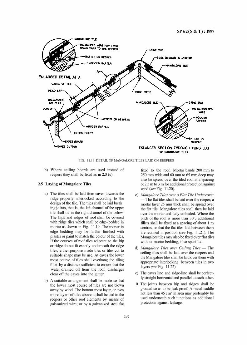
SP 62(S & T) : 1997
FIG. 11.19 DETAIL OF MANGALORE TILES LAID ON REEPERS
b) Where ceiling boards are used instead of reepers they shall be fixed as in 2.3 (c).
2.5 Laying of Mangalore Tiles
a) The tiles shall be laid from eaves towards the ridge properly interlocked according to the design of the tile. The tiles shall be laid break ing joints, that is, the left channel of the upper tile shall tie in the right channel of tile below The hips and ridges of roof shall be covered with ridge tiles which shall be edge- bedded in mortar as shown in Fig. 11.19. The mortar in edge bedding may be further finished with plaster or paint to match the colour of the tiles. If the courses of roof tiles adjacent to the hip or ridge do not fit exactly underneath the ridge tiles, either purpose made tiles or tiles cut to suitable shape may be use. At eaves the lower most course of tiles shall overhang the tiling fillet by a distance sufficient to ensure that the water drained off from the roof, discharges clear off the eaves into the gutter.
b) A suitable arrangement shall be made so that the lower most course of tiles are not blown away by wind. The bottom most layer, or even more layers of tiles above it shall be tied to the reepers or other roof elements by means of galvanized wire; or by a galvanized steel flat
fixed to the roof. Mortar bands 200 mm to 250 mm wide and 60 mm to 65 mm deep may also be spread over the tiled roof at a spacing ot 2.5 m to 3 m for additional protection against wind (see Fig. 11.20).
c) Mangalore Tiles over a Flat Tile Undercover — The flat tiles shall be laid over the reeper; a mortar layer 25 mm thick shall be spread over the flat tile. Mangalore tiles shall then be laid over the mortar and fully embeded. Where the pitch of the roof is more than 30°, additional fillets shall be fixed at a spacing of about 1 m centres, so that the flat tiles laid between them are retained in position (see Fig. 11.21). The Mangalore tiles may also be fixed over flat tiles without mortar bedding, if so specified.
d) Mangalore Tiles over Ceiling Tiles — The ceiling tiles shall be laid over the reepers and the Mangalore tiles shall be laid over them with appropriate interlocking between tiles in two layers (see Fig. 11.22).
e) The eaves line and ridge-line shall be perfectly straight horizontal and parallel to each other.
0 The joints between hip and ridges shall be grouted so as to be leak proof. A metal saddle not less than 45 cm2 in area may preferably be used underneath such junctions as additional protection against leakage.
297
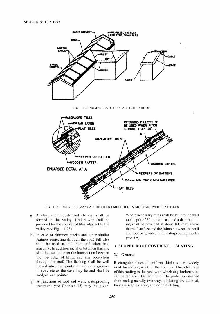
SP 6 2 ( S & T ) : 1997
g) A clear and unobstructed channel shall be formed in the valley. Undercover shall be provided for the courses of tiles adjacent to the valley (see Fig. 11.23).
h) In case of chimney stacks and other similar features projecting through the roof, full tiles shall be used around them and taken into masonry. In addition metal or bitumen flashing shall be used to cover the intersection between the top edge of tiling and any projection through the roof. The flashing shall be well tucked into either joints in masonry or grooves in concrete as the case may be and shall be wedged and pointed.
j) At junctions of roof and wall, waterproofing treatment (see Chapter 12) may be given.
Where necessary, tiles shall be let into the wall to a depth of 50 mm at least and a drip moulding shall be provided at about 100 mm above the roof surface and the joints between the wail and roof be grouted with waterproofing mortar (see 3.5).
3 SLOPED ROOF COVERING — SLATING
3.1 General
Rectangular slates of uniform thickness are widely used for roofing work in the country. The advantage of this roofing is the ease with which any broken slate can be replaced. Depending on the protection needed from roof, generally two ways of slating are adopted, they are single slating and double slating.
298
FIG. 11.21 DETAIL OF MANGALORE TILES EMBEDDED IN MORTAR OVER FLAT TILES
FIG. 11.20 NOMENCLATURE OF A PITCHED ROOF
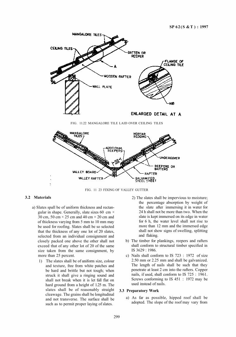
SP 6 2 ( S & T ) : 1997
3.2 Materials
FIG. 11 23 FIXING OF VALLEY GUTTER
a) Slates spall be of uniform thickness and rectangular in shape. Generally, slate sizes 60 cm × 30 cm, 50 cm × 25 cm and 40 cm × 20 cm and of thickness varying from 5 mm to 10 mm may be used for roofing. Slates shall be so selected that the thickness of any one lot of 20 slates, selected from an individual consignment and closely packed one above the other shall not exceed that of any other lot of 20 of the same size taken from the same consignment, by more than 25 percent. 1) The slates shall be of uniform size, colour
and texture, free from white patches and be hard and brittle but not tough; when struck it shall give a ringing sound and shall not break when it is let fall flat on hard ground from a height of 1.25 m. The slates shall be of reasonably straight cleawage. The grains shall be longitudinal and not transverse. The surface shall be such as to permit proper laying of slates.
2) The slates shall be impervious to moisture; the percentage absorption by weight of the slate after immersing it in water for 24 h shall not be more than two. When the slate is kept immersed on its edge in water for 6 h, the water level shall not rise to more than 12 mm and the immersed edge shall not show signs of swelling, splitting and flaking.
b) The timber for plankings, reepers and rafters shall conform to structural timber specified in IS 3629 : 1986.
c) Nails shall conform to IS 723 : 1972 of size 2.50 mm or 2.25 mm and shall be galvanized. The length of nails shall be such that they penetrate at least 2 cm into the rafters. Copper nails, if used, shall conform to IS 725 : 1961. Screws conforming to IS 451 : 1972 may be used instead of nails.
3.3 Preparatory Work
a) As far as possible, hipped roof shall be adopted. The slope of the roof may vary from
299
FIG. 11.22 MANGALORE TILE LAID OVER CEILING TILES
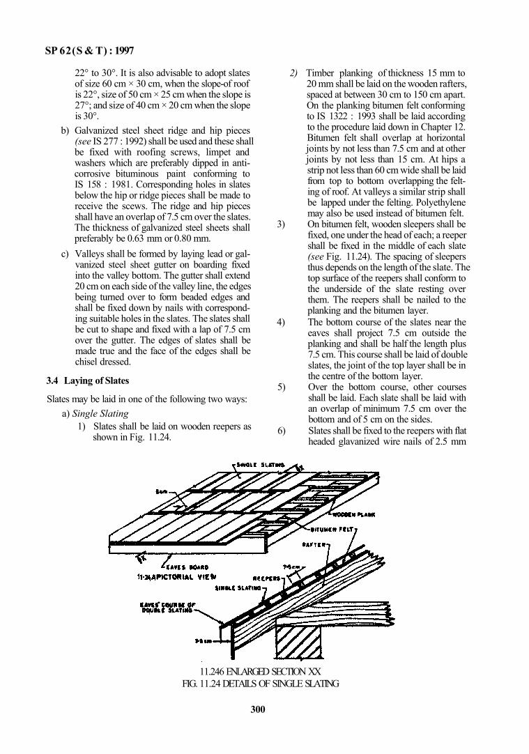
SP 62(S & T) : 1997
22° to 30°. It is also advisable to adopt slates of size 60 cm × 30 cm, when the slope-of roof is 22°, size of 50 cm × 25 cm when the slope is 27°; and size of 40 cm × 20 cm when the slope is 30°.
b) Galvanized steel sheet ridge and hip pieces (see IS 277 : 1992) shall be used and these shall be fixed with roofing screws, limpet and washers which are preferably dipped in anti-corrosive bituminous paint conforming to IS 158 : 1981. Corresponding holes in slates below the hip or ridge pieces shall be made to receive the scews. The ridge and hip pieces shall have an overlap of 7.5 cm over the slates. The thickness of galvanized steel sheets shall preferably be 0.63 mm or 0.80 mm.
c) Valleys shall be formed by laying lead or galvanized steel sheet gutter on boarding fixed into the valley bottom. The gutter shall extend 20 cm on each side of the valley line, the edges being turned over to form beaded edges and shall be fixed down by nails with corresponding suitable holes in the slates. The slates shall be cut to shape and fixed with a lap of 7.5 cm over the gutter. The edges of slates shall be made true and the face of the edges shall be chisel dressed.
3.4 Laying of Slates
Slates may be laid in one of the following two ways: a) Single Slating
1) Slates shall be laid on wooden reepers as shown in Fig. 11.24.
2) Timber planking of thickness 15 mm to 20 mm shall be laid on the wooden rafters, spaced at between 30 cm to 150 cm apart. On the planking bitumen felt conforming to IS 1322 : 1993 shall be laid according to the procedure laid down in Chapter 12. Bitumen felt shall overlap at horizontal joints by not less than 7.5 cm and at other joints by not less than 15 cm. At hips a strip not less than 60 cm wide shall be laid from top to bottom overlapping the felting of roof. At valleys a similar strip shall be lapped under the felting. Polyethylene may also be used instead of bitumen felt.
3) On bitumen felt, wooden sleepers shall be fixed, one under the head of each; a reeper shall be fixed in the middle of each slate (see Fig. 11.24). The spacing of sleepers thus depends on the length of the slate. The top surface of the reepers shall conform to the underside of the slate resting over them. The reepers shall be nailed to the planking and the bitumen layer.
4) The bottom course of the slates near the eaves shall project 7.5 cm outside the planking and shall be half the length plus 7.5 cm. This course shall be laid of double slates, the joint of the top layer shall be in the centre of the bottom layer.
5) Over the bottom course, other courses shall be laid. Each slate shall be laid with an overlap of minimum 7.5 cm over the bottom and of 5 cm on the sides.
6) Slates shall be fixed to the reepers with flat headed glavanized wire nails of 2.5 mm
11.246 ENLARGED SECTION XX FIG. 11.24 DETAILS OF SINGLE SLATING
300
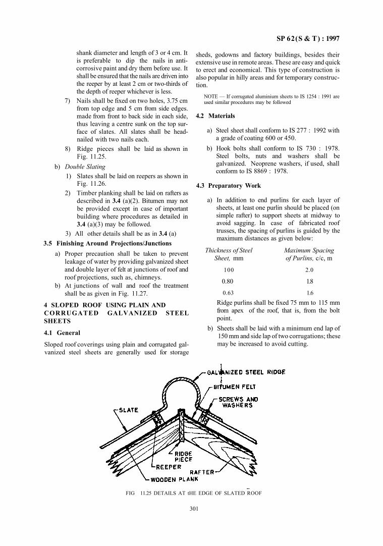
SP 62(S & T) : 1997
shank diameter and length of 3 or 4 cm. It is preferable to dip the nails in anti-corrosive paint and dry them before use. It shall be ensured that the nails are driven into the reeper by at least 2 cm or two-thirds of the depth of reeper whichever is less.
7) Nails shall be fixed on two holes, 3.75 cm from top edge and 5 cm from side edges. made from front to back side in each side, thus leaving a centre sunk on the top surface of slates. All slates shall be head-nailed with two nails each.
8) Ridge pieces shall be laid as shown in Fig. 11.25.
b) Double Slating 1) Slates shall be laid on reepers as shown in
Fig. 11.26. 2) Timber planking shall be laid on rafters as
described in 3.4 (a)(2). Bitumen may not be provided except in case of important building where procedures as detailed in 3.4 (a)(3) may be followed.
3) All other details shall be as in 3.4 (a) 3.5 Finishing Around Projections/Junctions
a) Proper precaution shall be taken to prevent leakage of water by providing galvanized sheet and double layer of felt at junctions of roof and roof projections, such as, chimneys.
b) At junctions of wall and roof the treatment shall be as given in Fig. 11.27.
4 SLOPED ROOF USING PLAIN AND CORRUGATED GALVANIZED STEEL SHEETS
4.1 General
Sloped roof coverings using plain and corrugated galvanized steel sheets are generally used for storage
sheds, godowns and factory buildings, besides their extensive use in remote areas. These are easy and quick to erect and economical. This type of construction is also popular in hilly areas and for temporary construction.
NOTE — If corrugated aluminium sheets to IS 1254 : 1991 are used similar procedures may be followed
4.2 Materials
a) Steel sheet shall conform to IS 277 : 1992 with a grade of coating 600 or 450.
b) Hook bolts shall conform to IS 730 : 1978. Steel bolts, nuts and washers shall be galvanized. Neoprene washers, if used, shall conform to IS 8869 : 1978.
4.3 Preparatory Work
a) In addition to end purlins for each layer of sheets, at least one purlin should be placed (on simple rafter) to support sheets at midway to avoid sagging. In case of fabricated roof trusses, the spacing of purlins is guided by the maximum distances as given below:
Thickness of Steel Maximum Spacing Sheet, mm of Purlins, c/c, m
100 2.0
0.80 1.8
0.63 1.6 Ridge purlins shall be fixed 75 mm to 115 mm from apex of the roof, that is, from the bolt point.
b) Sheets shall be laid with a minimum end lap of 150 mm and side lap of two corrugations; these may be increased to avoid cutting.
301
FIG 11.25 DETAILS AT tHE EDGE OF SLATED ROOF
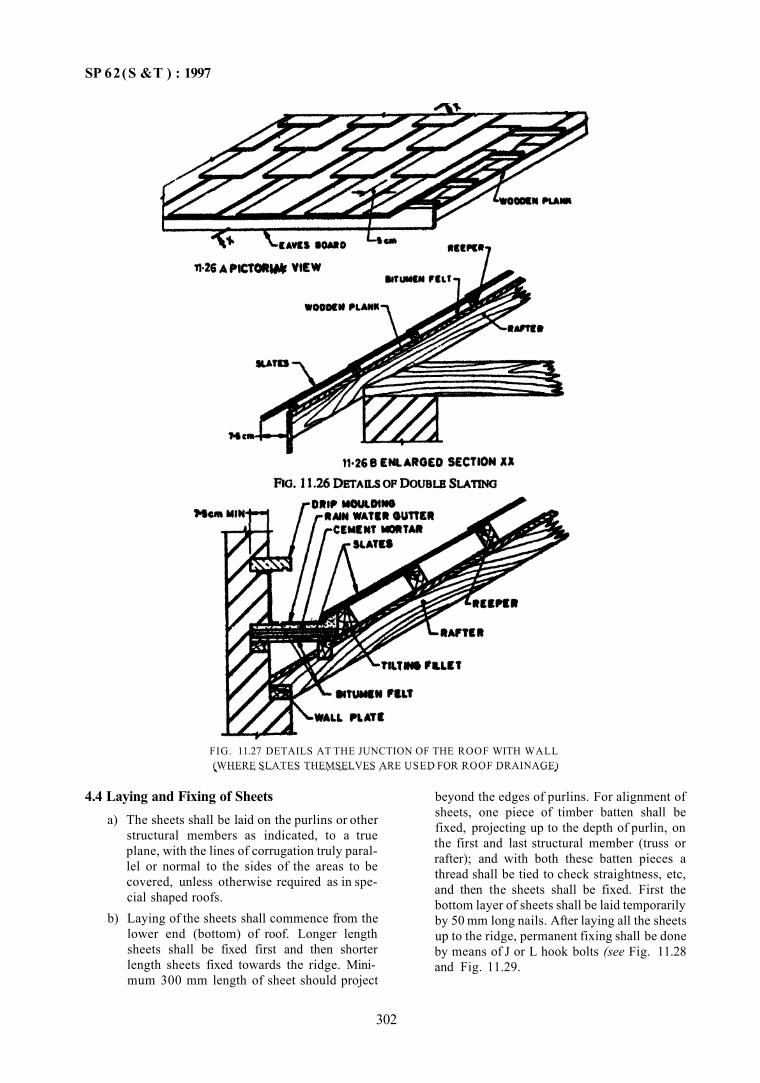
SP 62(S &T ) : 1997
4.4 Laying and Fixing of Sheets a) The sheets shall be laid on the purlins or other
structural members as indicated, to a true plane, with the lines of corrugation truly parallel or normal to the sides of the areas to be covered, unless otherwise required as in special shaped roofs.
b) Laying of the sheets shall commence from the lower end (bottom) of roof. Longer length sheets shall be fixed first and then shorter length sheets fixed towards the ridge. Mini-mum 300 mm length of sheet should project
beyond the edges of purlins. For alignment of sheets, one piece of timber batten shall be fixed, projecting up to the depth of purlin, on the first and last structural member (truss or rafter); and with both these batten pieces a thread shall be tied to check straightness, etc, and then the sheets shall be fixed. First the bottom layer of sheets shall be laid temporarily by 50 mm long nails. After laying all the sheets up to the ridge, permanent fixing shall be done by means of J or L hook bolts (see Fig. 11.28 and Fig. 11.29.
302
FIG. 11.27 DETAILS AT THE JUNCTION OF THE ROOF WITH WALL (WHERE SLATES THEMSELVES ARE USED FOR ROOF DRAINAGE)
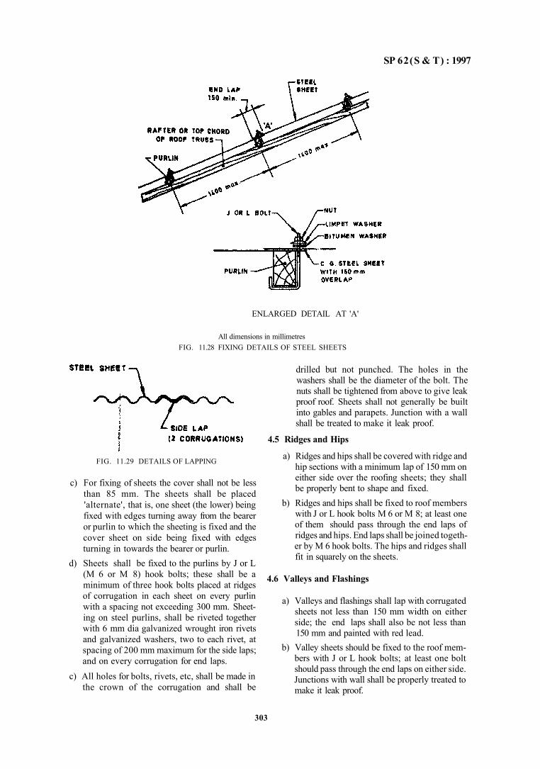
SP 62(S & T) : 1997
ENLARGED DETAIL AT 'A'
All dimensions in millimetres FIG. 11.28 FIXING DETAILS OF STEEL SHEETS
drilled but not punched. The holes in the washers shall be the diameter of the bolt. The nuts shall be tightened from above to give leak proof roof. Sheets shall not generally be built into gables and parapets. Junction with a wall shall be treated to make it leak proof.
4.5 Ridges and Hips
a) Ridges and hips shall be covered with ridge and hip sections with a minimum lap of 150 mm on either side over the roofing sheets; they shall be properly bent to shape and fixed.
b) Ridges and hips shall be fixed to roof members with J or L hook bolts M 6 or M 8; at least one of them should pass through the end laps of ridges and hips. End laps shall be joined together by M 6 hook bolts. The hips and ridges shall fit in squarely on the sheets.
4.6 Valleys and Flashings
a) Valleys and flashings shall lap with corrugated sheets not less than 150 mm width on either side; the end laps shall also be not less than 150 mm and painted with red lead.
b) Valley sheets should be fixed to the roof mem-bers with J or L hook bolts; at least one bolt should pass through the end laps on either side. Junctions with wall shall be properly treated to make it leak proof.
303
FIG. 11.29 DETAILS OF LAPPING
c) For fixing of sheets the cover shall not be less than 85 mm. The sheets shall be placed 'alternate', that is, one sheet (the lower) being fixed with edges turning away from the bearer or purlin to which the sheeting is fixed and the cover sheet on side being fixed with edges turning in towards the bearer or purlin.
d) Sheets shall be fixed to the purlins by J or L (M 6 or M 8) hook bolts; these shall be a minimum of three hook bolts placed at ridges of corrugation in each sheet on every purlin with a spacing not exceeding 300 mm. Sheeting on steel purlins, shall be riveted together with 6 mm dia galvanized wrought iron rivets and galvanized washers, two to each rivet, at spacing of 200 mm maximum for the side laps; and on every corrugation for end laps.
c) All holes for bolts, rivets, etc, shall be made in the crown of the corrugation and shall be
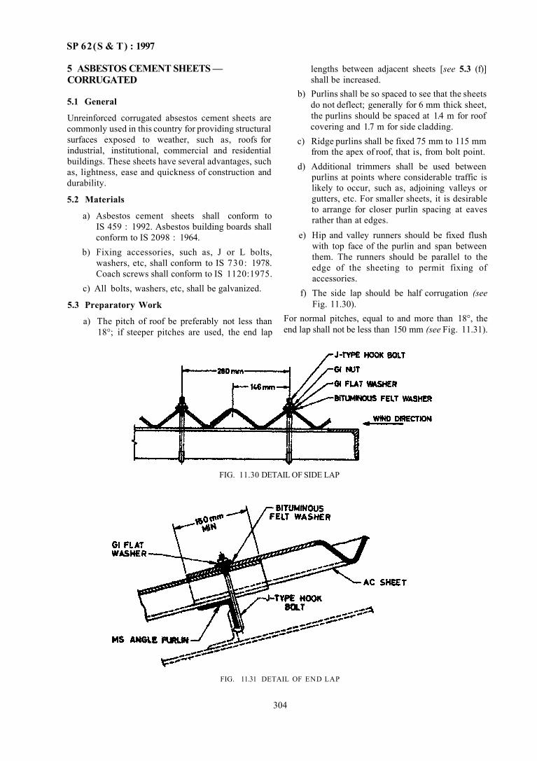
SP 62(S & T) : 1997
5 ASBESTOS CEMENT SHEETS — CORRUGATED
5.1 General
Unreinforced corrugated absestos cement sheets are commonly used in this country for providing structural surfaces exposed to weather, such as, roofs for industrial, institutional, commercial and residential buildings. These sheets have several advantages, such as, lightness, ease and quickness of construction and durability.
5.2 Materials
a) Asbestos cement sheets shall conform to IS 459 : 1992. Asbestos building boards shall conform to IS 2098 : 1964.
b) Fixing accessories, such as, J or L bolts, washers, etc, shall conform to IS 730: 1978. Coach screws shall conform to IS 1120:1975.
c) All bolts, washers, etc, shall be galvanized.
5.3 Preparatory Work
a) The pitch of roof be preferably not less than 18°; if steeper pitches are used, the end lap
lengths between adjacent sheets [see 5.3 (f)] shall be increased.
b) Purlins shall be so spaced to see that the sheets do not deflect; generally for 6 mm thick sheet, the purlins should be spaced at 1.4 m for roof covering and 1.7 m for side cladding.
c) Ridge purlins shall be fixed 75 mm to 115 mm from the apex of roof, that is, from bolt point.
d) Additional trimmers shall be used between purlins at points where considerable traffic is likely to occur, such as, adjoining valleys or gutters, etc. For smaller sheets, it is desirable to arrange for closer purlin spacing at eaves rather than at edges.
e) Hip and valley runners should be fixed flush with top face of the purlin and span between them. The runners should be parallel to the edge of the sheeting to permit fixing of accessories.
f) The side lap should be half corrugation (see Fig. 11.30).
For normal pitches, equal to and more than 18°, the end lap shall not be less than 150 mm (see Fig. 11.31).
FIG. 11.31 DETAIL OF END LAP
304
FIG. 11.30 DETAIL OF SIDE LAP
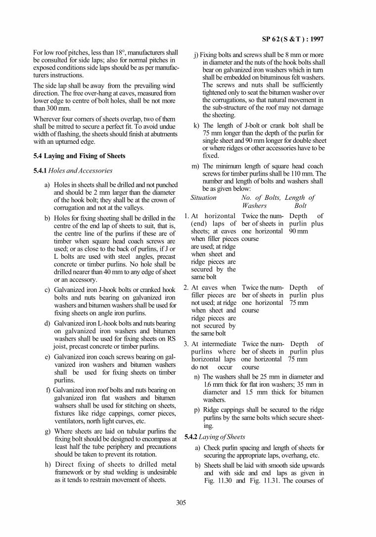
SP 62(S &T ) : 1997
For low roof pitches, less than 18°, manufacturers shall be consulted for side laps; also for normal pitches in exposed conditions side laps should be as per manufacturers instructions. The side lap shall be away from the prevailing wind direction. The free over-hang at eaves, measured from lower edge to centre of bolt holes, shall be not more than 300 mm. Wherever four corners of sheets overlap, two of them shall be mitred to secure a perfect fit. To avoid undue width of flashing, the sheets should finish at abutments with an upturned edge.
5.4 Laying and Fixing of Sheets
5.4.1 Holes and Accessories
a) Holes in sheets shall be drilled and not punched and should be 2 mm larger than the diameter of the hook bolt; they shall be at the crown of corrugation and not at the valleys.
b) Holes for fixing sheeting shall be drilled in the centre of the end lap of sheets to suit, that is, the centre line of the purlins if these are of timber when square head coach screws are used; or as close to the back of purlins, if J or L bolts are used with steel angles, precast concrete or timber purlins. No hole shall be drilled nearer than 40 mm to any edge of sheet or an accessory.
c) Galvanized iron J-hook bolts or cranked hook bolts and nuts bearing on galvanized iron washers and bitumen washers shall be used for fixing sheets on angle iron purlins.
d) Galvanized iron L-hook bolts and nuts bearing on galvanized iron washers and bitumen washers shall be used for fixing sheets on RS joist, precast concrete or timber purlins.
e) Galvanized iron coach screws bearing on galvanized iron washers and bitumen washers shall be used for fixing sheets on timber purlins.
f) Galvanized iron roof bolts and nuts bearing on galvanized iron flat washers and bitumen wahsers shall be used for stitching on sheets, fixtures like ridge cappings, corner pieces, ventilators, north light curves, etc.
g) Where sheets are laid on tubular purlins the fixing bolt should be designed to encompass at least half the tube periphery and precautions should be taken to prevent its rotation.
h) Direct fixing of sheets to drilled metal framework or by stud welding is undesirable as it tends to restrain movement of sheets.
j) Fixing bolts and screws shall be 8 mm or more in diameter and the nuts of the hook bolts shall bear on galvanized iron washers which in turn shall be embedded on bituminous felt washers. The screws and nuts shall be sufficiently tightened only to seat the bitumen washer over the corrugations, so that natural movement in the sub-structure of the roof may not damage the sheeting.
k) The length of J-bolt or crank bolt shall be 75 mm longer than the depth of the purlin for single sheet and 90 mm longer for double sheet or where ridges or other accessories have to be fixed.
m) The minimum length of square head coach screws for timber purlins shall be 110 mm. The number and length of bolts and washers shall be as given below:
Situation No. of Bolts, Length of Washers Bolt
1. At horizontal Twice the num- Depth of (end) laps of ber of sheets in purlin plus sheets; at eaves one horizontal 90 mm when filler pieces course are used; at ridge when sheet and ridge pieces are secured by the same bolt
2. At eaves when Twice the num- Depth of filler pieces are ber of sheets in purlin plus not used; at ridge one horizontal 75 mm when sheet and course ridge pieces are not secured by the same bolt
3. At intermediate Twice the num- Depth of purlins where ber of sheets in purlin plus horizontal laps one horizontal 75 mm do not occur course n) The washers shall be 25 mm in diameter and
1.6 mm thick for flat iron washers; 35 mm in diameter and 1.5 mm thick for bitumen washers.
p) Ridge cappings shall be secured to the ridge purlins by the same bolts which secure sheeting.
5.4.2 Laying of Sheets a) Check purlin spacing and length of sheets for
securing the appropriate laps, overhang, etc. b) Sheets shall be laid with smooth side upwards
and with side and end laps as given in Fig. 11.30 and Fig. 11.31. The courses of
305
SP 6 2 ( S & T) : 1997
sheets shall be so laid that the corrugations run in continuous straight lines. If the building is in exposed position and is subject to driving rain and wind, it is advisable to commence laying of sheets from the end opposite to the direction of wind.
c) The sheets shall be laid starting either from eaves from left to right or right to left depending on direction of prevailing wind, to avoid it. See Fig. 11.32 for laying sheets from left to right, for details.
The sequence for left to right starting from eaves could be as follows:
1) The first sheet is laid uncut. 2) The remaining sheets in the bottom row shall
have top left hand corners cut or mitred.
3) The sheets in the second and other intermediate rows shall have bottom right hand corner and top left hand corner cut; the last sheet shall have only the top left hand comer cut.
4) The last or top row of sheets shall have bottom right hand corner cut with the exception of the last sheet which shall be laid uncut.
5) The whole sequence is reversed if laid from right to left. The mitre is cut from a point 15 cm up the vertical side of the sheet to 4.5 cm along the horizontal edge; this is necessary when four sheets meet at a lap.
d) Nuts and screws shall be tightened lightly at first and then fully tightened when a dozen or more sheets are laid. One bolt or screw shall be used on each side of the lap.
FIG. 11.32 LAYING OF SHEETS (SHEETS LAID FROM LEFT TO RIGHT)
306
SP 62(S & T) : 1997
5.4.3 Asbestos Accessories a) Moulded asbestos accessories should be
selected as far as possible from the range of standard patterns. Special fittings, if required shall be designed to conform closely to the sheet profile. Roofing accessories should generally be secured to the roof or wall cladding by the same bolts which secure the sheets.
b) Ridge capping should be secured to the purlins, as far as possible, by the same bolts which secure the sheets, where this is not possible each wing of the ridge capping should be adequately secured to the sheets by roofing bolts. 1) Close fitting adjustable ridge capping
shall be designed to fit the corrugations of sheets laid with side lap of half corruga
tion and shall be fixed as in Fig. 11.33 and Fig. 11.34. Correct fitting of ridge capping will be automatic, if a template is used when fixing roof sheets.
2) The work shall be started from left hand verge, placing first small roll wing (inner) and positioning it in such a way that the first valley on the right hand side of the ridge fits into the valley at side lap of roof sheeting. In case of large roll wing, it shall be so positioned that the first valley of left hand side of the ridge wing fits into valley of side lap of roof sheeting.
3) Serrated adjustable ridge cappings, supplied in pairs, are as shown in Fig. 11.35.
FIG. 11.34 DETAILS SHOWING METHOD OF FIXING CLOSF FITTING ADJUSTABLE RIDGE PIECES
307
FIG. 11.33 TYPICAL CLOSE FITTING ADJUSTABLE RIDGE
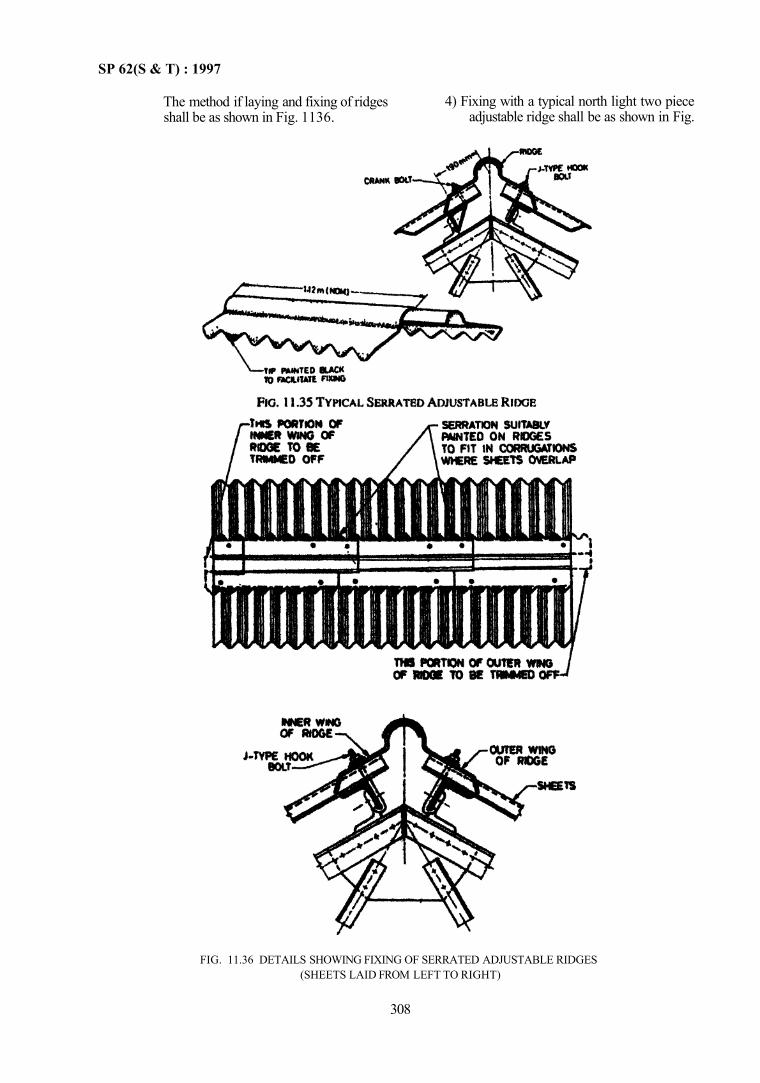
SP 62(S & T) : 1997
The method if laying and fixing of ridges shall be as shown in Fig. 1136.
FIG. 11.36 DETAILS SHOWING FIXING OF SERRATED ADJUSTABLE RIDGES (SHEETS LAID FROM LEFT TO RIGHT)
308
4) Fixing with a typical north light two piece adjustable ridge shall be as shown in Fig.
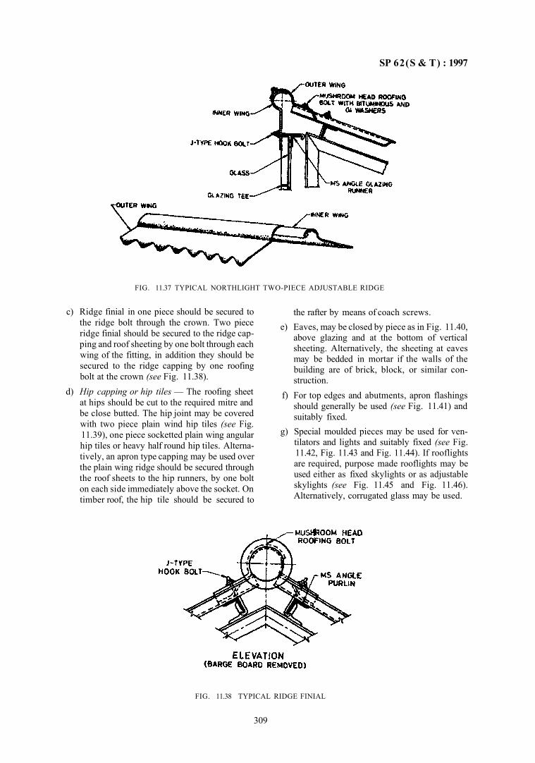
SP 62(S & T) : 1997
FIG. 11.37 TYPICAL NORTHLIGHT TWO-PIECE ADJUSTABLE RIDGE
c) Ridge finial in one piece should be secured to the ridge bolt through the crown. Two piece ridge finial should be secured to the ridge capping and roof sheeting by one bolt through each wing of the fitting, in addition they should be secured to the ridge capping by one roofing bolt at the crown (see Fig. 11.38).
d) Hip capping or hip tiles — The roofing sheet at hips should be cut to the required mitre and be close butted. The hip joint may be covered with two piece plain wind hip tiles (see Fig. 11.39), one piece socketted plain wing angular hip tiles or heavy half round hip tiles. Alternatively, an apron type capping may be used over the plain wing ridge should be secured through the roof sheets to the hip runners, by one bolt on each side immediately above the socket. On timber roof, the hip tile should be secured to
FIG. 11.38 TYPICAL RIDGE FINIAL
the rafter by means of coach screws. e) Eaves, may be closed by piece as in Fig. 11.40,
above glazing and at the bottom of vertical sheeting. Alternatively, the sheeting at eaves may be bedded in mortar if the walls of the building are of brick, block, or similar construction.
f) For top edges and abutments, apron flashings should generally be used (see Fig. 11.41) and suitably fixed.
g) Special moulded pieces may be used for ventilators and lights and suitably fixed (see Fig. 11.42, Fig. 11.43 and Fig. 11.44). If rooflights are required, purpose made rooflights may be used either as fixed skylights or as adjustable skylights (see Fig. 11.45 and Fig. 11.46). Alternatively, corrugated glass may be used.
309
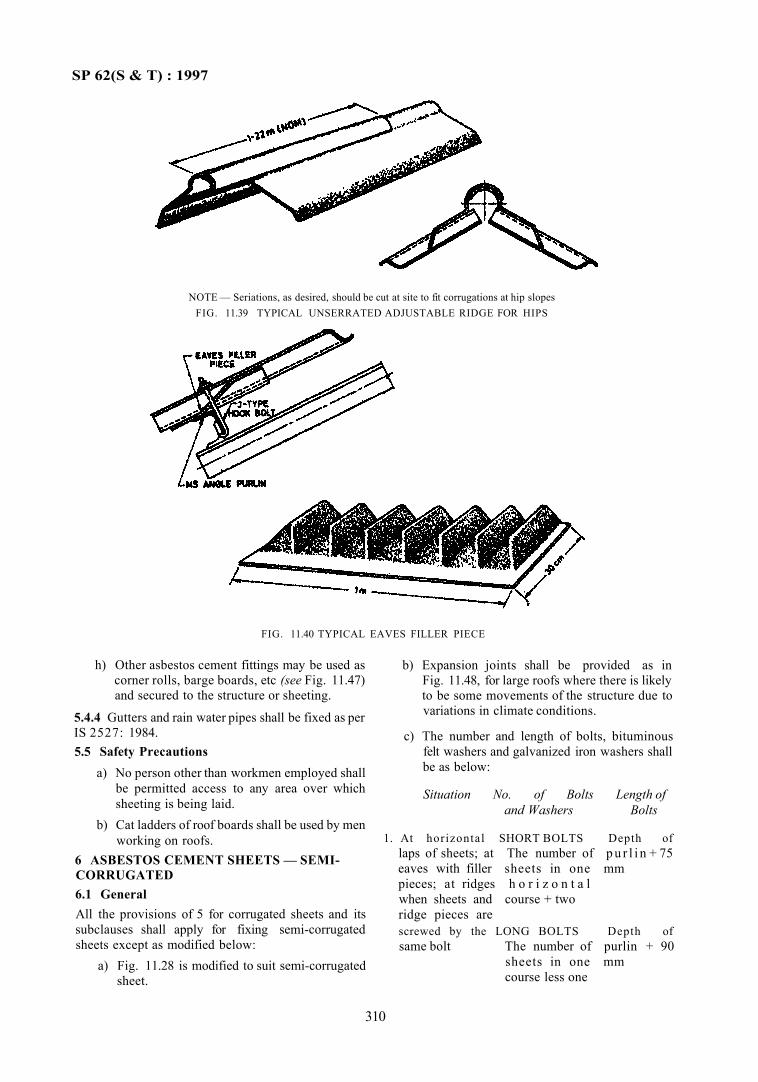
SP 62(S & T) : 1997
NOTE — Seriations, as desired, should be cut at site to fit corrugations at hip slopes FIG. 11.39 TYPICAL UNSERRATED ADJUSTABLE RIDGE FOR HIPS
FIG. 11.40 TYPICAL EAVES FILLER PIECE
h) Other asbestos cement fittings may be used as corner rolls, barge boards, etc (see Fig. 11.47) and secured to the structure or sheeting.
5.4.4 Gutters and rain water pipes shall be fixed as per IS 2527: 1984. 5.5 Safety Precautions
a) No person other than workmen employed shall be permitted access to any area over which sheeting is being laid.
b) Cat ladders of roof boards shall be used by men working on roofs.
6 ASBESTOS CEMENT SHEETS — SEMI-CORRUGATED 6.1 General All the provisions of 5 for corrugated sheets and its subclauses shall apply for fixing semi-corrugated sheets except as modified below:
a) Fig. 11.28 is modified to suit semi-corrugated sheet.
b) Expansion joints shall be provided as in Fig. 11.48, for large roofs where there is likely to be some movements of the structure due to variations in climate conditions.
c) The number and length of bolts, bituminous felt washers and galvanized iron washers shall be as below:
Situation No. of Bolts Length of and Washers Bolts
1. At horizontal SHORT BOLTS Depth of laps of sheets; at The number of p u r l i n + 75 eaves with filler sheets in one mm pieces; at ridges h o r i z o n t a l when sheets and course + two ridge pieces are screwed by the LONG BOLTS Depth of same bolt The number of purlin + 90
sheets in one mm course less one
310
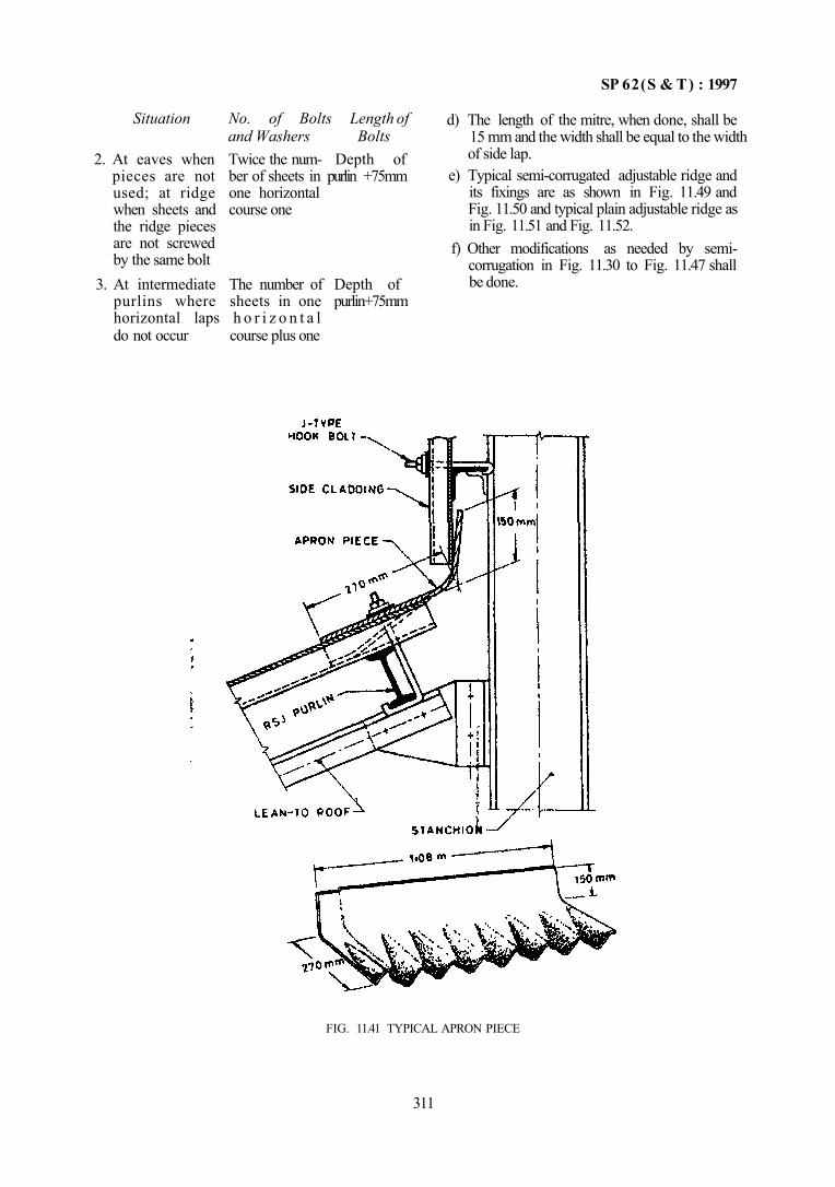
SP 62(S & T) : 1997
d) The length of the mitre, when done, shall be 15 mm and the width shall be equal to the width of side lap.
e) Typical semi-corrugated adjustable ridge and its fixings are as shown in Fig. 11.49 and Fig. 11.50 and typical plain adjustable ridge as in Fig. 11.51 and Fig. 11.52.
f) Other modifications as needed by semi-corrugation in Fig. 11.30 to Fig. 11.47 shall be done.
FIG. 11.41 TYPICAL APRON PIECE
311
Situation No. of Bolts Length of and Washers Bolts
2. At eaves when Twice the num- Depth of pieces are not ber of sheets in purlin +75mm used; at ridge one horizontal when sheets and course one the ridge pieces are not screwed by the same bolt
3. At intermediate The number of Depth of purlins where sheets in one purlin+75mm horizontal laps h o r i z o n t a l do not occur course plus one
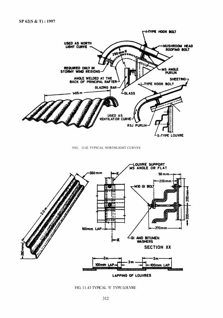
FIG. 11.43 TYPICAL 'S' TYPE LOUVRE
312
SP 62(S & T) : 1997
FIG. 11.42 TYPICAL NORTHLIGHT CURVES
SP 62(S & T) : 1997
FIG 11.45 TYPICAL ROOFLIGHT
313
FIG. 11 44 TYPICAL COWL TYPE VENTILATOR
SP 62(S & T) : 1997
FIG. 11.47 TYPICAL DETAILS OF BARGE BOARD OR CORNER PIECE (VIEW FROM EAVES)
314
FIG. 11.46 TYPICAL ROOFLIGHT USED AS NORTHLIGHT GLAZING
SP 62(S & T) : 1997
FIG. 11.49 TYPICAL SEMI-CORRUGATED ADJUSTABLE RIDGE
315
NOTE — The end lap of expansion joints is the same, as that of the roofing sheets, that is, usually 150 mm. If expansion joints top between purlins they should be stitched by roofing bolts.
FIG. 11.48 TYPICAL EXPANSION JOINT FOR SEMI-CORRUGATED SHEETS
SP 62(S & T) : 1997
316
FIG. 11.51 TYPICAL PLAM WING ADJUSTABLE RIDGE
FIG. 11.50 DETAILS SHOWING FIXING OF SEMI-CORRUGATED ADJUSTABLE RIDGES
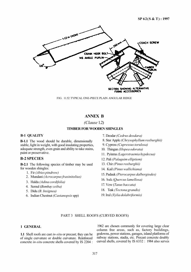
SP 62(S & T) : 1997
FIG. 11.52 TYPICAL ONE-PIECE PLAIN ANGULAR RIDGE
ANNEX B (Clause 1.2)
TIMBER FOR WOODEN SHINGLES
B-1 QUALITY B-1.1 The wood should be durable, dimensionally stable, light in weight, with good insulating properties, adequate strength, even grain and ability to take stains, paint or preservative.
B-2 SPECIES B-2.1 The following species of timber may be used for wooden shingles:
1. Fir (Abies pindrow) 2. Mundani (Acrocarpus fraxinitolius) 3. Haldu (Adina cordifolia) 4. Semul (Bombay ceiba) 5. Didu (B. Insignea) 6. Indian Chestnut (Castanopsis spp)
7. Deodar (Cedrus deodara) 8. Star Apple (Chrysophyllum roxburghii) 9. Cypress (Cupressus torulosa)
10. Thingan (Hopea odorata) 11. Pyinma (Lagerstraemia hypdecua) 12. Pali (Palaquim elliptiem) 13. Chir (Pinus roxburghii) 14. Kail (Pinus wallichiana) 15. Padauk (Pterocarpus dalbergiodes) 16. bak (Quercus lamellosa) 17. Vew (Taxus baccata) 18. Teak (Tectona grandis) 19. Irul (Xylia dolabriformis)
PART 3 SHELL ROOFS (CURVED ROOFS)
1 GENERAL
1.1 Shell roofs are cast in-situ or precast; they can be of single curvature or double curvature. Reinforced concrete in-situ concrete shells covered by IS 2204 :
1962 are chosen commonly for covering large clear column free areas, such as, factory buildings, godowns, power stations, garages, island platforms of railway stations, stadia, etc. Precast concrete doubly curved shells, covered by IS 6332 : 1984 also serves
317
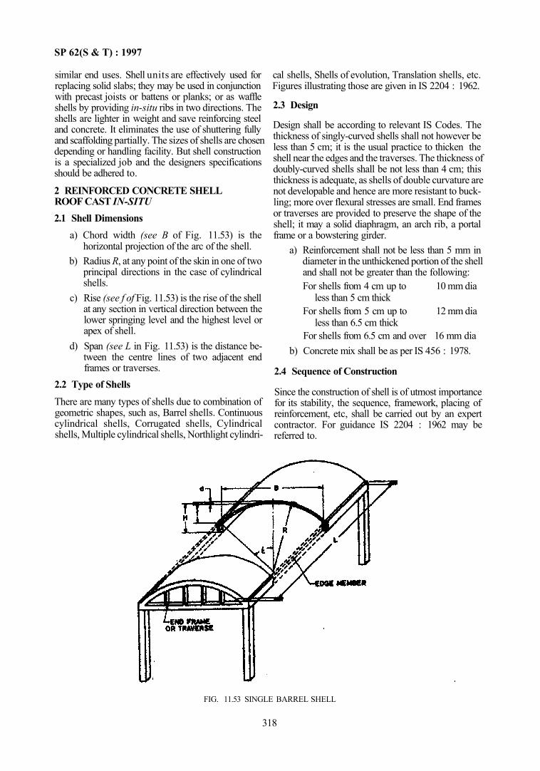
SP 62(S & T) : 1997
similar end uses. Shell units are effectively used for replacing solid slabs; they may be used in conjunction with precast joists or battens or planks; or as waffle shells by providing in-situ ribs in two directions. The shells are lighter in weight and save reinforcing steel and concrete. It eliminates the use of shuttering fully and scaffolding partially. The sizes of shells are chosen depending or handling facility. But shell construction is a specialized job and the designers specifications should be adhered to.
2 REINFORCED CONCRETE SHELL ROOF CAST IN-SITU 2.1 Shell Dimensions
a) Chord width (see B of Fig. 11.53) is the horizontal projection of the arc of the shell.
b) Radius R, at any point of the skin in one of two principal directions in the case of cylindrical shells.
c) Rise (see f of Fig. 11.53) is the rise of the shell at any section in vertical direction between the lower springing level and the highest level or apex of shell.
d) Span (see L in Fig. 11.53) is the distance between the centre lines of two adjacent end frames or traverses.
2.2 Type of Shells There are many types of shells due to combination of geometric shapes, such as, Barrel shells. Continuous cylindrical shells, Corrugated shells, Cylindrical shells, Multiple cylindrical shells, Northlight cylindri
cal shells, Shells of evolution, Translation shells, etc. Figures illustrating those are given in IS 2204 : 1962.
2.3 Design
Design shall be according to relevant IS Codes. The thickness of singly-curved shells shall not however be less than 5 cm; it is the usual practice to thicken the shell near the edges and the traverses. The thickness of doubly-curved shells shall be not less than 4 cm; this thickness is adequate, as shells of double curvature are not developable and hence are more resistant to buckling; more over flexural stresses are small. End frames or traverses are provided to preserve the shape of the shell; it may a solid diaphragm, an arch rib, a portal frame or a bowstering girder.
a) Reinforcement shall not be less than 5 mm in diameter in the unthickened portion of the shell and shall not be greater than the following: For shells from 4 cm up to 10 mm dia
less than 5 cm thick For shells from 5 cm up to 12 mm dia
less than 6.5 cm thick For shells from 6.5 cm and over 16 mm dia
b) Concrete mix shall be as per IS 456 : 1978.
2.4 Sequence of Construction
Since the construction of shell is of utmost importance for its stability, the sequence, framework, placing of reinforcement, etc, shall be carried out by an expert contractor. For guidance IS 2204 : 1962 may be referred to.
318
FIG. 11.53 SINGLE BARREL SHELL
SP 62(S & T) : 1997
3 PRECAST DOUBLY CURVED SHELL UNITS
3.1 Funicular shell units shall be cast as described in IS 6332: 1984.
3.2 Construction
Reference may be made to IS 6332 : 1984. NOTE — Since design and construction of shell structures is a specialized job, reference may be made to specialised literature.
PART 4 FLAT ROOF FINISH — MUD PHUSKA
1 GENERAL
1.1 Mud Phuska is a common type of insulating course in the roof used in hot dry regions of the country, such as in Punjab, UP, Haryana, etc, where rainfall is not heavy. It is cheap, reasonably durable and adds enough thermal insulation for maintaining relatively comfortable temperature in the intrior Of course the reduction in temperature would be less than what can be obtained from using polystyrene and other factory made products.
2 MATERIALS
a) Mud Phuska layer by itself is not sufficiently waterproof for the roof and it may be necessary to provide beneath it a waterproofing layer or membrane to be effective in this respect. Care shall also be taken while doing roof finish work to compact mud Phuska layer to maximum density. 1) Soil mud Phuska shall be iree from gravel
and coarse sand of particle size greater than 2 mm, vegetable matter and KANKAR particles. The coarse material shall not exceed 25 percent by mass. The soil shall also be free from harmful and efflorescent salts. The plasticity index of the soil shall be between 10 to 15 percent.
2) Generally soil suitable for brick making is suitable for mud Phuska also. The plasticity index will indicate a reasonable cohesive soil. Soil infested with white ants shall not be used.
b) Soil for mud plaster and mud mortar shall be free from vegetable roots, gravel and coarse sand of particle size greater than 2 mm. The coarse material shall not exceed 10 percent by mass and the soil shall be free from harmful and efflorescent salts. The plasticity index shall be between 10 to 15 percent.
c) Mud plaster shall be prepared from soil prescribed in 2 (b). The dry soil shall be reduced to fine powder and mixed with water in a pit, adding wheat straw 6 percent by mass and cowdung 12 percent by mass. The mixture
319
shall be allowed to rot for a period of not less than 7 days. During this period it shall be pugged manually to get a homogeneous mass free of lumps and clods. The wheat straw may be of any size since it would be broken to small size during the period. The slump, when tested as per IS 1199 : 1959 shall be about 70 mm. Alternatively, consistency of mortar may be adjusted by taking it in a trowel and observing as to how it slides off the face of the trowel. The mortar shall readily slide off, but at the same time shall not be so wet as to part into large drops before falling.
d) Cutback bitumen shall be prepared by adding 20 parts of kerosene oil and one part of paraffin wax to 80 parts of 800/l00 bitumen (see IS 217 : 1988) melted on gentle fire. The mixture shall be worked to a homogeneous mass.
e) Mud mortar used as bedding under brick tile layer shall be prepared in the same manner as mud plaster but without any addition of fibrous reinforcing material and binding material. The mud mortar may be used immediately without any rotting period. The mortar shall be mixed with 2 percent bitumen cut back by mass of dry soil and worked to a homogeneous mass.
f) LEEPING plaster (GOBRI LEEPING) shall be prepared by mixing soil with equal parts of cowdung and adding the required quantity of water to make a thin paste; soil used shall be tred from coarse sand and gravel. The mixture shall then be worked into a homogeneous mass. Five percent of cutback bitumen by mass of dry soil may be added to improve the water proofing characteristics.
g) Brick tiles shall conform to IS 2690 (Part 1): 1993 and IS 2690 (Part 2) : 1992.
h) Cement shall conform to IS 269 : 1989 or IS 455 : 1989 or IS 1489 (Parts 1 & 2) : 1991 or any other as specified.
j) Sand and fine aggregate shall conform to IS 383: 1970.
k) Burnt clay pozzolana shall conform to IS 1344 : 1981.
SP 62(S & T) : 1997
m) Cement mortar for grouting shall be a 1:3 mix or any richer mortar as may be specified.
3 PREPERATORY WORK 3.1 The slope of terrace shall be such that all rainwater can be drained off; preferably the slope shall be not Jess than 1 to 40. If the slope cannot be given in the mud Phuska layer, part of the slope can be given in the sub-floor itself. 3.2 The durability of the mud Phuska layer depends on how the protective layer, namely, the mud plaster or bricktiles are maintained free of cracks. 3.3 Where there is no rainfall and there is very little variation in temperature, paving with tiles may not be necessary over mud Phuska layer. 3.4 Waterproofing treatment (see Chapter 12) as deemed necessary shpll be done on the sub-floor. 4 LAYING OF MUD PHUSKA 4.1 Preparation The soil as described in 2 (a) shall be stacked in requisite quantities in about 300 mm high stacks over a level ground and the top surface divided into suitable compartments by bunding. The estimated quantity of water corresponding to the optimum moisture content shall be added about 12 h before the use and allowed to soak. The stacks of soil shall then be worked up with spades and hands to ensure proper distribution of moisture at the time of use of soil.
NOTE — Generally soil of this type will require an optimum moisture of about 145 l/m3. Soil suitable for good compaction should contain that much quantity of moisture, which when moulded with hand to me shape of form, just retains its form.
4.2 Laying
a) The mud Phuska shall be laid loose to a thickness of not more than 150 mm. It shall be brought to proper slope and then rammed manually with wooden THAPPIES so as to obtain maximum density. The final thickness should not be less than 100 mm.
b) The surface shall be allowed to dry for a period of not less than 24 h. If any cracks appears, they should be filled with a grout of the binder material that is used in the LEEPING (usually GOBRI)
4.3 Applying Mud Plaster
a) On the mud Phuska, a layer of minimum 25 mm thick mud plaster shall be laid; the plaster may be applied in single coat or two coats of 15 mm and 10 mm; two coats are preferable. Hair cracks if any shall be grouted with the binder material of LEEPING. The surface level shall be checked.
b) When the mud plaster coating has dried, a thin coat, not less than 3 mm, of LEEPING shall be applied. The surface shall be allowed to dry and any hair carcks shall be grouted as before. The LEEPING shall be finished with a trowel or float.
4.4 Paving with Brick Tiles
a) The brick tiles, where necessary, shall be laid flat on a thin layer of mud mortar. The mud mortar shall be used to the minimum extent to give a level surface. Tiles shall be laid close together with a thickness of joint between 6 mm and 15 mm; it shall be ensured that the mud mortar rises in the joints. The brickwork shall be allowed to dry for 24 h before grouting the joints. Care shall be taken at the time of grouting that the tiles are not displaced.
b) While grouting with the 1:3 mix, ensure that all joints are filled. Allow the mortar to set for 12 h before pointing, if it is to be done.
c) Check evenness and desired slope. d) Cure the surface for not less than 7 days. e) The junction between the roof finish and
parapets shall be treated as described in Chapter 12 on waterproofing of flat roofs in buildings.
4.5 Maintenance Annual maintenance is required when the roof is finished only with LEEPING; in such case the LEEPING shall be applied as necessary before monsoon. After monsoon, grass if any shall be removed.
PART 5 THATCHED ROOFS
1 THATCHING OF ROOF
1.1 General
Thatch roof is made of highly combustible and easily ignitable materials. In rural and slum areas people five
in huts and fire occurs very often in huts. It spreads very fast and conflagration results in great loss to life and property. The main thatch materials are reeds, Phoons, palmyrah, coconut, rice paddy. Treatment for rendering thatch fire retartdant is a measure of fire protection.
320
SP 62(S & T) : 1997
1.2 Materials
1.2.1 For Fire Retardant Treatment
a) Cutback bitumen of 80/100 to IS 217 : 1988. b) Cutback made by mixing 80/100 bitumen with
kerosene oil in the ratio of 5:1 (Bitumen:Kerosene). The mixture should be stirred to ensure thorough mixing.
c) Soil shall have a clay content of 25-35 percent 1) Mud shall be made with soil and wheat-
straw or rice paddy, cut to 50 mm length roughly; keep it wet for a week and knead daily. The general proportion of mix is to add about 16 kg of straw to 0.25 cubic metre of soil.
2) To stabilize the mud, add cutback bitumen (about 2 to 4 percent) and mix thoroughly.
d) One part of molten bitumen may be added to 2 parts of kerosene oil and stir it till a homogenous water proof solution is formed.
e) GOBRI shall be made with cowdung and soil mixed in equal proportion and then add cutback bitumen at the rate of 16 kg for 0.25 cubic metre.
f) Lime wash be prepared mixed with animal glue and ultramarine blue for whitening.
1.2.2 For all Types of Thatches
a) Reed/(Phoons) thatch — For an area roughly 9 m2 of roof the following are required: 1) Reeds (Phoons), 130 bundles of 500 g and
1 m long; 2) Bamboo, 20 numbers, 50 mm dia and
33 m long; 3) SUTUI, kg; 4) Bitumen stabilized mud, 0 35 cubic metre; 5) Wheat straw, 25 kg; and 6) Bhind (SARKANDA), 3 bundles, each
300 mm long and 400 mm thick. The average thickness would be 75 mm thatch plus 25 mm mud plaster on top and 10 mm on bottom surface.
b) Palmyrah leaves thatch — This type of thatch requires the following for an area of roof of 9 m2: 1) Palmyrah leaves 90; 2) Bamboos, 20 (3.3 m long and 50 mm in
diameter);
3) SUTU, 1.5 kg; 4) Stabilized mud, 0.35 cubic metre; and 5) Wheat straw 25 kg.
Average thickness is 110 mm, as in Reed thatch, c) Coconut leaves thatch — This type of thatch
requires the following for an area of roof of 9 m2 : 1) Coconut (Cadjan) leaves, 65; 2) Bamboos, 20 (3.3 m long and 25 mm
diameter; 3) SUTLI, 1 kg; 4) Stabilized mud, 0.35 cubic metre; 5) Wheat straw, 25 kg; and 6) One wooden pole 100 mm dia and 3.3 m
long. Average thickness 60 mm, made up of 25 mm each thatch and top mud plaster and 10 mm mud plaster on bottom.
d) Rice paddy thatch — This type of thatch requires the following for a roof area of about 9 m2: 1) Rice paddy, 136 bundles (each bundle of
1 kg); 2) Bamboo, 23 (3.3 m long and 25 mm
diametre); 3) SUTLI 1 kg; 4) Stabilized mud, 0.35 cubic metre; 5) Wheat straw, 25 kg; and 6) A wooden pole, 100 mm in dia and 3.3 m
long. Average thickness would be 150 mm of thatch plus 25 mm mud plaster on top and 10 mm on bottom surface.
1.3 Fire Retardant Treatment
Fire retardant and water repellant treatment is done as below:
a) The stabilized mud is applied on top of the thatch as plaster, in two stages, each 10 mm thick and allowed to dry. For the bottom one coat is enough. Then GOBRI is applied and allowed to dry. Finally two coats of either a lime wash or simple GOBRI is applied. Thus the thatch becomes fire retardant and water repellant.
b) Addition of bitumen makes the thatch rot resistant and durable even up to 10 years.
321

CHAPTER 12
DAMP-PROOFING AND WATERPROOFING
CONTENTS
1 GENERAL
2 GENERAL PREPARATORY WORK FOR DAMP-PROOFING AND WATERPROOFING
2.1 General 2.2 Preparatory Work 2.3 Planning in Relation to Sub-Soil Drainage 2.4 Preparation of Surface
PART 1 DAMP-PROOFING 1 GENERAL
1.1 Preparatory Work
2 BITUMEN FELT TREATMENT
2.1 Materials 2.2 Damp-Proofing Treatment above Ground
Level 2.3 Damp-Proofing Treatment below Ground
Level 2.4 Laying of Damp-Proofing Treatment
3 BITUMEN MASTIC TREATMENT
3.1 Materials 3.2 Damp-Proofing Treatment above Ground
Level 3.3 External Tanking 3.4 Internal Tanking 3.5 Remelting of Mastic 3.6 Thickness and Method of Laying
4 GLASS F I B R E TISSUE REINFORCED BITUMEN TREATMENT
4.1 General 4 2 Materials 4.3 In-situ Damp-Proofing Treatment 4.4 Laying In-situ Treatment
5 WATERPROOFING AND DAMP-PROOFING OF WET AREAS IN BUILDING
5.1 General 5.2 Recommendations
PART 2 WATERPROOFING 1 GENERAL
2 LIME CONCRETE WATERPROOFED FINISH
2.1 General
2.2 Materials 2.3 Lime Concrete 2.4 Laying 2.5 Finish
3 BITUMEN FELT
3.1 General 3.2 Materials 3.3 Waterproofing Treatment 3.4 Concrete and Masonry Roofs, Flat or Sloping 3.5 Timber Roofs, Sloping 3.6 Laying of Felt
4 BITUMEN MASTIC
4.1 Materials 4.2 Preparatory Work 4.3 Number of Coats and Thickness 4.4 Movement of Joints 4.5 Laying of Bitumen Mastic
5 POLYETHYLENE FILM
5.1 General 5.2 Material 5.3 Types of Waterproofing Treatment 5.4 Laying
6 GLASS FIBRE TISSUE REINFORCED BITUMEN
6.1 General 6.2 Materials 6.3 In-situ Waterproofing Treatment of Roofs 6.4 Laying
7 WATERPROOFING OF UNDERGROUND RESERVOIRS AND SWIMMING POOLS
7.1 General 7.2 Design Features 7.3 Materials 7.4 Waterproofing Treatment 7.5 Construction Details
8 SILICONE BASED WATER REPELLENT
8.1 General 8.2 Materials 8.3 Preparation of the Surface 8.4 Application of Repellent
ANNEX A TEST FOR MEASURING OF WATER VAPOUR TRANSMISSION OF POLYETHYLENE FILM
SP 62(S & T) : 1997
CHAPTER 12
DAMP-PROOFING AND WATERPROOFING 1 GENERAL
1.1 Damp-proofing of basements and floors and waterproofing of roofs is necessary for protection against entry of moisture either from ground capillary action or from rain water. These aspects are covered by Indian Standards which can be grouped as below:
a) General Preparatory Work — IS 3067 . 1988 covering general details and preparatory work for damp-proofing and waterproofing of buildings.
b) Damp-Proofing Treatment IS 13182: 1991 Covering waterproofing and
damp-proofing of wet areas in building
IS 1609: 1991 Covering laying of damp-proofing treatment using bitumen felts
IS 7198: 1974 Covering damp-proofing using bitumen mastic
IS 9918: 1981 Covering in-situ waterproofing and damp-proofing treatments with glass fibre tissue reinforced bitumen
c) Waterproofing Treatment IS 3036 : 1992 Covering laying of lime concrete
for a waterproofed roof finish IS 1346 : 1991 Covering waterproofing of roofs
with bitumen felts IS 4365 : 1967 Covering application of bitumen
mastic for waterproofing of roofs IS 7290: 1979 Covering recommendations for
use of polyethylene film for waterproofing of roofs
IS 9918 : 1981 In-situ waterproofing and damp-proofing using glass fibre tissue reinforced bitumen
IS 6494: 1988 Covering waterproofing of underground water reservoirs and swimming pools
IS 12054: 1987 Covering application of silicone based water repellent
1.2 The materials generally used for damp-proofing and waterproofing arc lime concrete, bitumen felts. bitumen mastic, glass fibre reinforced bitumen and polyethylene film; silicone based water repellents are also coming into vogue. However, whatever be the new materials, the construction practices would largely be as reflected in the standards for damp-proofing and waterproofing.
2 GENERAL PREPARATORY WORK FOR DAMP-PROOFING AND WATERPROOFING
2.1 General
Different types of damp-proofing and waterproofing materials are used in the building industry. In order to obtain satisfactory performance, it is essential that prior to the application of these materials for the damp-proofing and waterproofing treatment, special care has to be taken regarding the design details and carefully preparing the building surface (sub-floor) lor receiving the treatment. Thus this is an essential adjunct to construction details of damp-proofing and waterproof-ing treatment dealt with subsequently in this chapter both for Part 1 and Part 2, unless otherwise modified.
2.2 Preparatory Work
a) Damp-proofing and waterproofing shall be taken up only when the sub-soil water level is at its lowest, that is, in the dry season.
b) For efficient design and construction of the treatment the following particulars among others would be of use: 1) Anticipated highest water level; 2) Anticipated water level in rainy season; 3) Shape of roof, that is. flat, sloping or
curved; 4) Type of roof; 5) Type of thermal insulation treatment, that
is, mud Phuska or polystyrene slab, etc; 6) Projections through roofs; 7) Drainage arrangement; 8) Intensity of rainfall; and 9) Drawings as needed.
c) For effective damp-proofing of basements the following be considered: 1) Construction joints, as far as possible,
shall be avoided; 2) In case expansion joints arc necessary,
adequate supports shall be provided at the vertical and horizontal joints to support the damp-proofing treatment from bursting under water pressure;
3) The wall faces, as far as possible, shall be free from obstruction to enable continuous laying of damp-proofing treatment;
4) Damp-proofing shall be external for all new buildings. Sufficient working space shall always be provided which shall in no
325
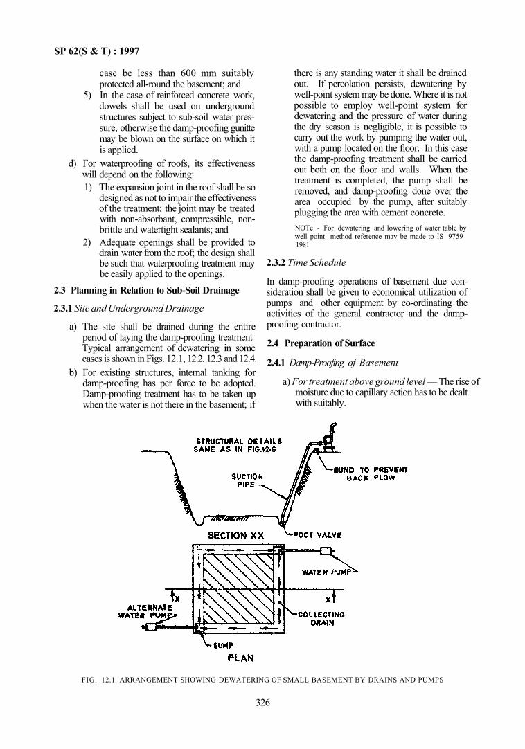
SP 62(S & T) : 1997
case be less than 600 mm suitably protected all-round the basement; and
5) In the case of reinforced concrete work, dowels shall be used on underground structures subject to sub-soil water pressure, otherwise the damp-proofing gunitte may be blown on the surface on which it is applied.
d) For waterproofing of roofs, its effectiveness will depend on the following: 1) The expansion joint in the roof shall be so
designed as not to impair the effectiveness of the treatment; the joint may be treated with non-absorbant, compressible, non-brittle and watertight sealants; and
2) Adequate openings shall be provided to drain water from the roof; the design shall be such that waterproofing treatment may be easily applied to the openings.
2.3 Planning in Relation to Sub-Soil Drainage
2.3.1 Site and Underground Drainage
a) The site shall be drained during the entire period of laying the damp-proofing treatment Typical arrangement of dewatering in some cases is shown in Figs. 12.1, 12.2, 12.3 and 12.4.
b) For existing structures, internal tanking for damp-proofing has per force to be adopted. Damp-proofing treatment has to be taken up when the water is not there in the basement; if
there is any standing water it shall be drained out. If percolation persists, dewatering by well-point system may be done. Where it is not possible to employ well-point system for dewatering and the pressure of water during the dry season is negligible, it is possible to carry out the work by pumping the water out, with a pump located on the floor. In this case the damp-proofing treatment shall be carried out both on the floor and walls. When the treatment is completed, the pump shall be removed, and damp-proofing done over the area occupied by the pump, after suitably plugging the area with cement concrete. NOTe - For dewatering and lowering of water table by well point method reference may be made to IS 9759 1981
2.3.2 Time Schedule
In damp-proofing operations of basement due consideration shall be given to economical utilization of pumps and other equipment by co-ordinating the activities of the general contractor and the damp-proofing contractor.
2.4 Preparation of Surface
2.4.1 Damp-Proofing of Basement
a) For treatment above ground level — The rise of moisture due to capillary action has to be dealt with suitably.
FIG. 12.1 ARRANGEMENT SHOWING DEWATERING OF SMALL BASEMENT BY DRAINS AND PUMPS
326
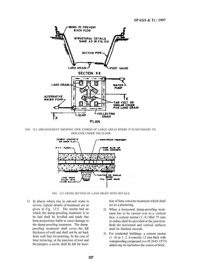
SP 62(S & T) : 1997
FIG. 12.2 ARRANGEMENT SHOWING DEW ATERING OF LARGE AREAS WHERE IT IS NECESSARY TO DEWATER UNDER THE FLOOR
1) In places where rise in sub-soil water is severe, typical details of treatment are as given in Fig. 12.5. The mortar bed on which the damp-proofing treatment is to be laid shall be levelled and made free from projections liable to cause damage to the damp-proofing treatment. The damp proofing treatment shall cover the full thickness of wall and shall not be set back from wall face for pointing. In the case of lime terracing, at the junction of root and the parapet, a cavity shall be left for inser
tion of lime concrete treatment which shall act as a plastering.
2) When a horizontal damp-proofing treatment has to be carried over to a vertical face, a cement mortar (1 :4) fillet 75 mm in radius shall be provided at the junction. Both the horizontal and vertical surfaces shall be finished smooth.
3) For residential buildings, a cement mortar (1 :4) or 1: 2 :4 concrete 12 mm thick with waterproofing compound (see IS 2645:1975) added may be laid below the course of brick.
327
FIG. 12.3 CROSS SECTION OF LAND DRAIN WITH DETAILS
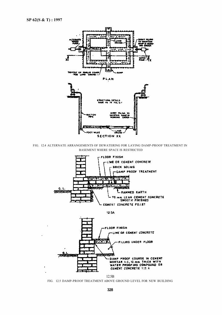
SP 62(S & T) : 1997
12.5B FIG. 12.5 DAMP-PROOF TREATMENT ABOVE GROUND LEVEL FOR NEW BUILDING
328
FIG. 12.4 ALTERNATE ARRANGEMENTS OF DEWATERING FOR LAYING DAMP-PROOF TREATMENT IN BASEMENT WHERE SPACE IS RESTRICTED
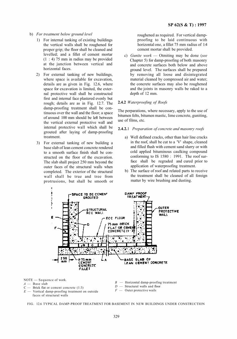
SP 62(S & T) : 1997
b) For treatment below ground level 1) For internal tanking of existing buildings
the vertical walls shall be roughened for proper grip; the floor shall be cleaned and levelled; and a fillet of cement mortar (1 : 4) 75 mm in radius may be provided at the junction between vertical and horizontal faces.
2) For external tanking of new buildings, where space is available for excavation, details are as given in Fig. 12.6, where space for excavation is limited, the external protective wall shall be constructed first and internal face plastered evenly but rough; details are as in Fig. 12.7. The damp-proofing treatment shall be continuous over the wall and the floor; a space of around 100 mm should be left between the vertical external protective wall and internal protective wall which shall be grouted after laying of damp-proofing treatment.
3) For external tanking of new building a base slab of lean cement concrete rendered to a smooth surface finish shall be constructed on the floor of the excavation. The slab shall project 250 mm beyond the outer faces of the structural walls when completed. The exterior of the structural wall shall be true and tree from protrusions, but shall be smooth or
roughened as required. For vertical damp-proofing to be laid continuous with horizontal one, a fillet 75 mm radius of 1:4 cement mortar shall be provided.
c) Gunite work — Otmiting may be done (see Chapter 5) for damp-proofing of both masonry and concrete surfaces both below and above ground level. The surfaces shall be prepared by removing all loose and disintegrated material cleaned by compressed air and water; the concrete surfaces may also be roughened and the joints in masonry walls be raked to a depth of 12 mm.
2.4.2 Waterproofing of Roofs
The perparations, where necessary, apply to the use of bitumen felts, bitumen mastic, lime concrete, guniting, use of films, etc.
2.4.2.1 Preparation of concrete and masonry roofs
a) Well defined cracks, other than hair line cracks in the roof, shall be cut to a 'V' shape, cleaned and filled flush with cement sand slurry or with cold applied bituminous caulking compound conforming to IS 1580 : 1991. The roof surface shall be regraded and cured prior to application of waterproofing treatment.
b) The surface of roof and related parts to receive the treatment shall be cleaned of all foreign matter by wire brushing and dusting.
NOTE — Sequence of work. A — Base slab C — Brick flat or cement concrete (1:3) E — Vertical damp-proofing treatment on outside
faces of structural walls
B — Horizontal damp-proofing treatment D — Structural walls and floor F — Outer protective wails
FIG. 12.6 TYPICAL DAMP-PROOF TREATMENT FOR BASEMENT IN NEW BUILDINGS UNDER CONSTRUCTION
329
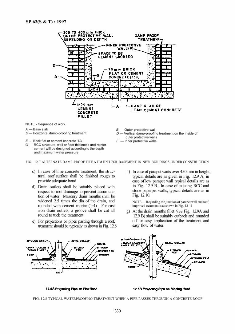
SP 62(S & T) : 1997
NOTE - Sequence of work. A — Base slab C — Horizontal damp-proofing treatment
E – Brick flat or cement concrete 1.3 G — RCC structural wall or floor thickness and reinfor
cement will be designed according to the depth and maximum water pressure
B — Outer protective wall D — Vertical damp-proofing treatment on the inside of
outer protective walls F — Inner protective walls
FIG. 12.7 ALTERNATE DAMP-PROOF T R E A T M E N T FOR BASEMENT IN NEW BUILDINGS UNDER CONSTRUCTION
c) In case of lime concrete treatment, the structural roof surface shall be finished rough to provide adequate bond
d) Drain outlets shall be suitably placed with respect to roof drainage to prevent accumulation of water. Masonry drain mouths shall be widened 2.5 times the dia of the drain, and rounded with cement mortar (1:4). For cast iron drain outlets, a groove shall be cut all round to tuck the treatment.
e) For projections or pipes pasting through a roof, treatment should be typically as shown in Fig. 12.8.
f) In case of parapet waits over 450 mm in height, typical details are as given in Fig. 12.9 A; in case of low parapet wall typical details are as in Fig. 12.9 B. In case of existing RCC and stone paparpet walls, typical details are as in Fig. 12.10. NOTE — Regarding the junction of parapet wall and roof, improved treatment is as shown in Fig. 12 11
g) At the drain mouths fillet (see Fig. 12.9A and 12.9 B) shall be suitably cutback and rounded off for easy application of the treatment and easy flow of water.
FIG. I 2.8 TYPICAL WATERPROOFING TREATMENT WHEN A PIPE PASSES THROUGH A CONCRETE ROOF
330
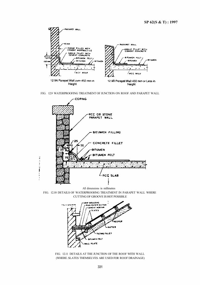
SP 62(S & T) : 1997
All dimensions in millimetres FIG. 12.10 DETAILS OF WATERPROOHNG TREATMENT IN PARAPET WALL WHERE
CUTTING OF GROOVE IS HOT POSSIBLE
FIG. 12.11 DETAILS AT THE JUNCTION OF THE ROOF WITH WALL (WHERE. SLATES THEMSELVES ARE USED FOR ROOF DRAINAGE)
331
FIG. 12.9 WATERPROOFING TREATMENT OF JUNCTION ON ROOF AND PARAPET WALL
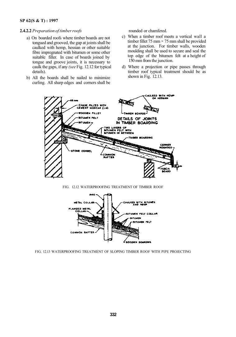
SP 62(S & T) : 1997
2.4.2.2 Preparation of timber roofs a) On boarded roofs where timber boards are not
tongued and grooved, the gap at joints shall be caulked with hemp, hessian or other suitable fibre impregnated with bitumen or some other suitable filler. In case of boards joined by tongue and groove joints, it is necessary to caulk the gaps, if any (see Fig. 12.12 for typical details).
b) All the boards shall be nailed to minimize curling. All sharp edges and corners shall be
rounded or chamfered. c) When a timber roof meets a vertical wall a
timber fillet 75 mm × 75 mm shall be provided at the junction. For timber walls, wooden moulding shall be used to secure and seal the top edge of the bitumen felt at a height of 150 mm from the junction.
d) Where a projection or pipe passes through timber roof typical treatment should be as shown in Fig. 12.13.
FIG. 12.12 WATERPROOFING TREATMENT OF TIMBER ROOF
FIG. 12.13 WATERPROOFING TREATMENT OF SLOPING TIMBER ROOF WITH PIPE PROJECTING
332
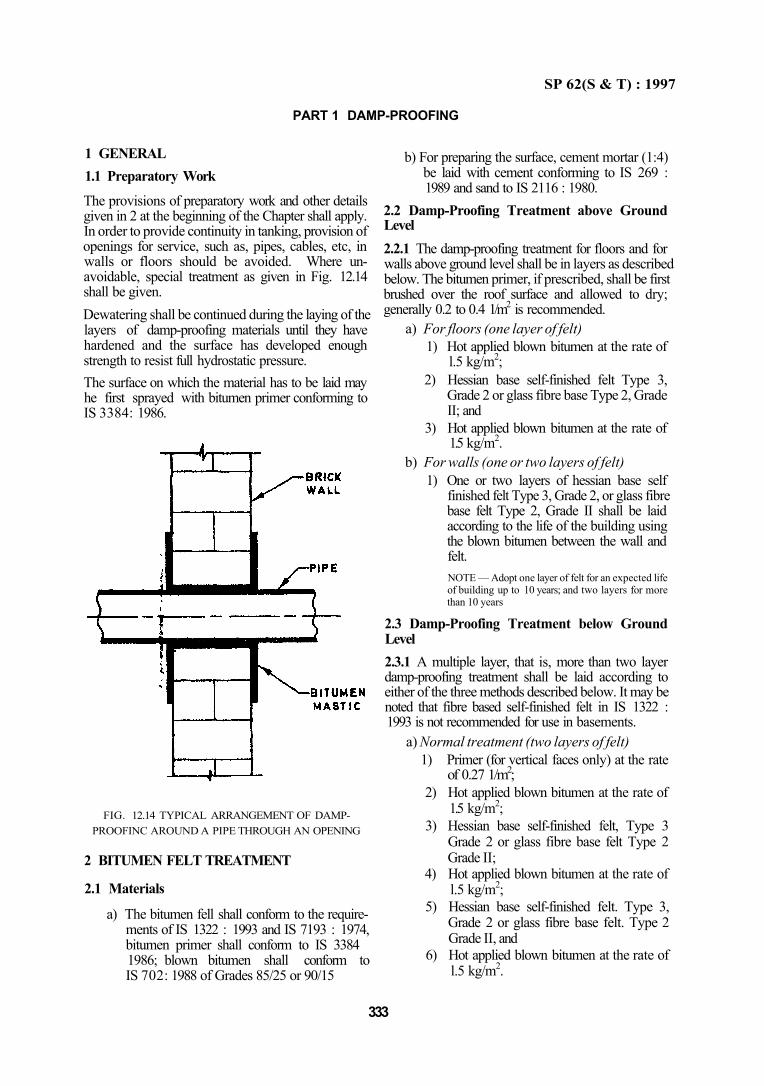
SP 62(S & T) : 1997
PART 1 DAMP-PROOFING
1 GENERAL 1.1 Preparatory Work
The provisions of preparatory work and other details given in 2 at the beginning of the Chapter shall apply. In order to provide continuity in tanking, provision of openings for service, such as, pipes, cables, etc, in walls or floors should be avoided. Where unavoidable, special treatment as given in Fig. 12.14 shall be given. Dewatering shall be continued during the laying of the layers of damp-proofing materials until they have hardened and the surface has developed enough strength to resist full hydrostatic pressure. The surface on which the material has to be laid may he first sprayed with bitumen primer conforming to IS 3384: 1986.
FIG. 12.14 TYPICAL ARRANGEMENT OF DAMP-PROOFINC AROUND A PIPE THROUGH AN OPENING
2 BITUMEN FELT TREATMENT
2.1 Materials
a) The bitumen fell shall conform to the requirements of IS 1322 : 1993 and IS 7193 : 1974, bitumen primer shall conform to IS 3384 1986; blown bitumen shall conform to IS 702: 1988 of Grades 85/25 or 90/15
333
b) For preparing the surface, cement mortar (1:4) be laid with cement conforming to IS 269 : 1989 and sand to IS 2116 : 1980.
2.2 Damp-Proofing Treatment above Ground Level 2.2.1 The damp-proofing treatment for floors and for walls above ground level shall be in layers as described below. The bitumen primer, if prescribed, shall be first brushed over the roof surface and allowed to dry; generally 0.2 to 0.4 1/m2 is recommended.
a) For floors (one layer of felt) 1) Hot applied blown bitumen at the rate of
l.5 kg/m2; 2) Hessian base self-finished felt Type 3,
Grade 2 or glass fibre base Type 2, Grade II; and
3) Hot applied blown bitumen at the rate of 1.5 kg/m2.
b) For walls (one or two layers of felt) 1) One or two layers of hessian base self
finished felt Type 3, Grade 2, or glass fibre base felt Type 2, Grade II shall be laid according to the life of the building using the blown bitumen between the wall and felt. NOTE — Adopt one layer of felt for an expected life of building up to 10 years; and two layers for more than 10 years
2.3 Damp-Proofing Treatment below Ground Level 2.3.1 A multiple layer, that is, more than two layer damp-proofing treatment shall be laid according to either of the three methods described below. It may be noted that fibre based self-finished felt in IS 1322 : 1993 is not recommended for use in basements.
a) Normal treatment (two layers of felt) 1) Primer (for vertical faces only) at the rate
of 0.27 1/m2; 2) Hot applied blown bitumen at the rate of
1.5 kg/m2; 3) Hessian base self-finished felt, Type 3
Grade 2 or glass fibre base felt Type 2 Grade II;
4) Hot applied blown bitumen at the rate of l.5 kg/m2;
5) Hessian base self-finished felt. Type 3, Grade 2 or glass fibre base felt. Type 2 Grade II, and
6) Hot applied blown bitumen at the rate of l.5 kg/m2.
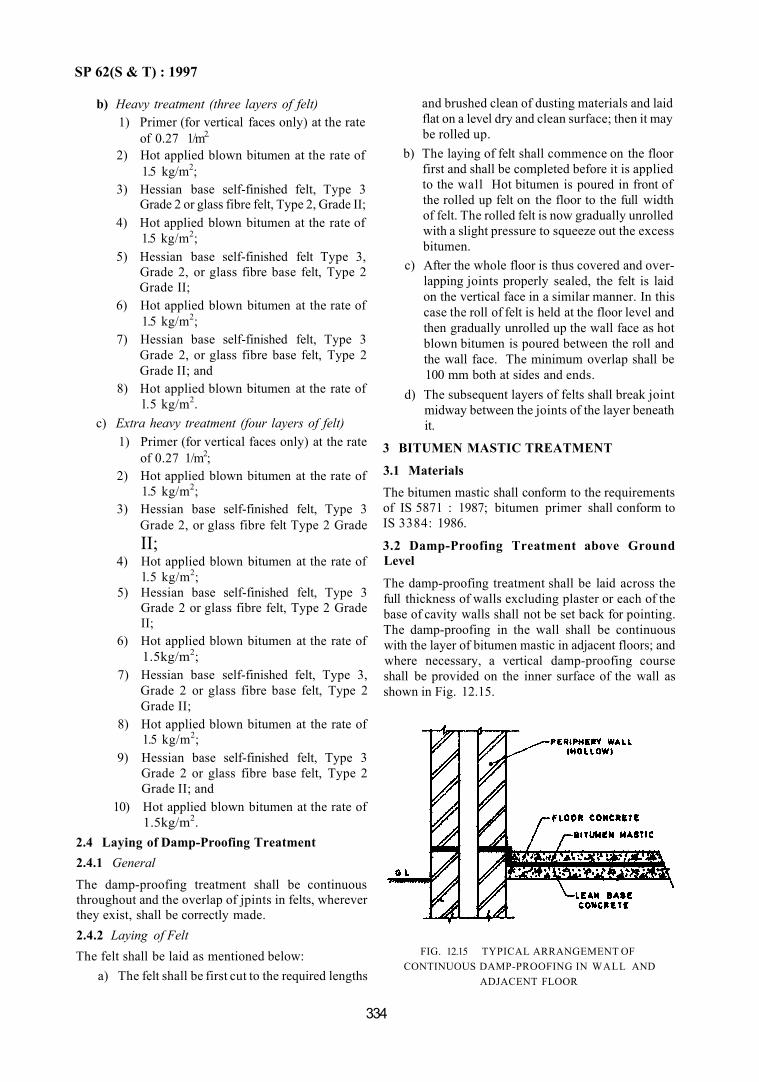
SP 62(S & T) : 1997
b) Heavy treatment (three layers of felt) 1) Primer (for vertical faces only) at the rate
of 0.27 1/m2.
2) Hot applied blown bitumen at the rate of 1.5 kg/m2;
3) Hessian base self-finished felt, Type 3 Grade 2 or glass fibre felt, Type 2, Grade II;
4) Hot applied blown bitumen at the rate of 1.5 kg/m2;
5) Hessian base self-finished felt Type 3, Grade 2, or glass fibre base felt, Type 2 Grade II;
6) Hot applied blown bitumen at the rate of 1.5 kg/m2;
7) Hessian base self-finished felt, Type 3 Grade 2, or glass fibre base felt, Type 2 Grade II; and
8) Hot applied blown bitumen at the rate of l.5 kg/m2.
c) Extra heavy treatment (four layers of felt) 1) Primer (for vertical faces only) at the rate
of 0.27 1/m2; 2) Hot applied blown bitumen at the rate of
1.5 kg/m2; 3) Hessian base self-finished felt, Type 3
Grade 2, or glass fibre felt Type 2 Grade II;
4) Hot applied blown bitumen at the rate of l.5 kg/m2;
5) Hessian base self-finished felt, Type 3 Grade 2 or glass fibre felt, Type 2 Grade II;
6) Hot applied blown bitumen at the rate of 1.5kg/m2;
7) Hessian base self-finished felt, Type 3, Grade 2 or glass fibre base felt, Type 2 Grade II;
8) Hot applied blown bitumen at the rate of 1.5 kg/m2;
9) Hessian base self-finished felt, Type 3 Grade 2 or glass fibre base felt, Type 2 Grade II; and
10) Hot applied blown bitumen at the rate of 1.5kg/m2.
2.4 Laying of Damp-Proofing Treatment 2.4.1 General The damp-proofing treatment shall be continuous throughout and the overlap of jpints in felts, wherever they exist, shall be correctly made. 2.4.2 Laying of Felt The felt shall be laid as mentioned below:
a) The felt shall be first cut to the required lengths
and brushed clean of dusting materials and laid flat on a level dry and clean surface; then it may be rolled up.
b) The laying of felt shall commence on the floor first and shall be completed before it is applied to the wall Hot bitumen is poured in front of the rolled up felt on the floor to the full width of felt. The rolled felt is now gradually unrolled with a slight pressure to squeeze out the excess bitumen.
c) After the whole floor is thus covered and overlapping joints properly sealed, the felt is laid on the vertical face in a similar manner. In this case the roll of felt is held at the floor level and then gradually unrolled up the wall face as hot blown bitumen is poured between the roll and the wall face. The minimum overlap shall be 100 mm both at sides and ends.
d) The subsequent layers of felts shall break joint midway between the joints of the layer beneath it.
3 BITUMEN MASTIC TREATMENT
3.1 Materials The bitumen mastic shall conform to the requirements of IS 5871 : 1987; bitumen primer shall conform to IS 3384: 1986.
3.2 Damp-Proofing Treatment above Ground Level
The damp-proofing treatment shall be laid across the full thickness of walls excluding plaster or each of the base of cavity walls shall not be set back for pointing. The damp-proofing in the wall shall be continuous with the layer of bitumen mastic in adjacent floors; and where necessary, a vertical damp-proofing course shall be provided on the inner surface of the wall as shown in Fig. 12.15.
FIG. 12.15 TYPICAL ARRANGEMENT OF CONTINUOUS DAMP-PROOFING IN WALL AND
ADJACENT FLOOR
334
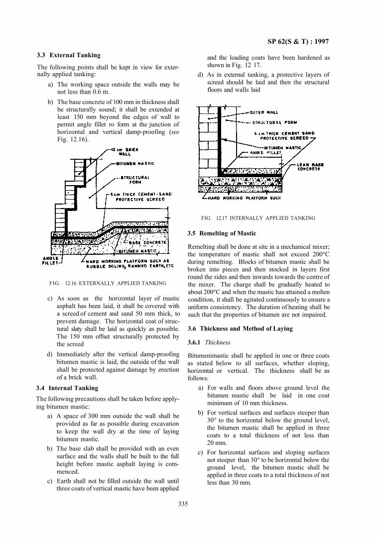
SP 62(S & T) : 1997
3.3 External Tanking
The following points shall be kept in view for externally applied tanking:
a) The working space outside the walls may be not less than 0.6 m.
b) The base concrete of 100 mm in thickness shall be structurally sound; it shall be extended at least 150 mm beyond the edges of wall to permit angle fillet ro form at the junction of horizontal and vertical damp-proofing (see Fig. 12.16).
FIG. 12.16 EXTERNALLY APPLIED TANKING
c) As soon as the horizontal layer of mastic asphalt has been laid, it shall be covered with a screed of cement and sand 50 mm thick, to prevent damage. The horizontal coat of structural slaty shall be laid as quickly as possible. The 150 mm offset structurally protected by the screed
d) Immediately after the vertical damp-proofing bitumen mastic is laid, the outside of the wall shall be protected against damage by erection of a brick wall.
3.4 Internal Tanking The following precautions shall be taken before applying bitumen mastic:
a) A space of 300 mm outside the wall shall be provided as far as possible during excavation to keep the wall dry at the time of laying bitumen mastic.
b) The base slab shall be provided with an even surface and the walls shall be built to the full height before mastic asphalt laying is commenced.
c) Earth shall not be filled outside the wall until three coats of vertical mastic have been applied
and the loading coats have been hardened as shown in Fig. 12 17.
d) As in external tanking, a protective layers of screed should be laid and then the structural floors and walls laid
335
FIG. 12.17 INTERNALLY APPLIED TANKING
3.5 Remelting of Mastic
Remelting shall be done at site in a mechanical mixer; the temperature of mastic shall not exceed 200°C during remelting. Blocks of bitumen mastic shall be broken into pieces and then stocked in layers first round the sides and then inwards towards the centre of the mixer. The charge shall be gradually heated to about 200°C and when the mastic has attained a molten condition, it shall be agitated continuously to ensure a uniform consistency. The duration of heating shall be such that the properties of bitumen are not impaired.
3.6 Thickness and Method of Laying
3.6.1 Thickness
Bitumenimastic shall be applied in one or three coats as stated below to all surfaces, whether sloping, horizontal or vertical. The thickness shall be as follows:
a) For walls and floors above ground level the bitumen mastic shall be laid in one coat minimum of 10 mm thickness.
b) For vertical surfaces and surfaces steeper than 30° to the horizontal below the ground level, the bitumen mastic shall be applied in three coats to a total thickness of not less than 20 mm.
c) For horizontal surfaces and sloping surfaces not steeper than 30° to be horizontal below the ground level, the bitumen mastic shall be applied in three coats to a total thickness of not less than 30 mm.
SP 62(S & T) : 1997
3.6.2 Method of Laying a) Bitumen mastic, shall be applied thinly on any
surface and a first coat in three coat treatment, so that it acts as an adhesive layer and also prevents blowing.
b) While laying a horizontal surface each coat should be spread with a float evenly and uniformly over the previously prepared surface to the recommended thickness. For laying on a vertical surface, the first coat may be plastered with a metal trowel as evenly and uniformly as possible. The second and subsequent coats may be applied with a wooden float to a uniform thickness; these coats should be applied as quickly as possible to prevent accumulation of dust or dirt between layers.
c) Blows entrapped in each coat formed by entrapped air or moisture during the laying shall be punctured and repaired while the asphalt is warm and before the next coat is applied.
3.6.3 Chases The top of the vertical bitumen mastic shall be turned into a chase in the wall not less than 25 mm × 25 mm unless it is being continued horizontally. 3.6.4 Fillet Angle fillet not loss than 50 mm wide shall be applied in two coats at the junction of two planes forming an internal angle. 3.6.5 Construction Joints Edges of the mastic already laid should be warmed with hot asphalt and Chen cut out with a metal trowel to remove any dust or dirt that may have collected. The fresh mastic should be poured before the warmed up surface of the joint cools off. 4 GLASS FIBRE TISSUE REINFORCED BITUMEN TREATMENT 4.1 General Glass fibre is more resistant to weathering and has come into use for waterproofing and damp-proofing of buildings. 42 Materials 4.2.1 Glass Fibre Tissue The glass fibre tissue shall conform to the requirements given in Appendix A of IS 7193:1994. It shall be a thin, flexible, uniformly bonded mat composed of chemically reistant borosilicate staple glass fibres distributed in a random open porous structure, bonded together with a thermosetting resin (phenolic type). The minimum weight of the tissue shall be 40 g/m2 and the nominal thickness shall be 0.5 ± 0.1 mm. 4.2.2 Blown bitumen shall conform to IS 702 : 1988 or residual bitumen conforming to IS 73 : 1992 may
be used as bonding material. The penetration of bitumen shall be not more than 40 when tested in accordance with IS 1203:1978. Bitumen primer shall conform to IS 3384: 1986.
43 In-situ Damp-Proofing Treatment
4.3.1 The following in-situ treatments above ground level is recommended:
a) Normal duty treatment 1) Clean and prime the surface with bitumen
primer at the rate of 0.4 kg/m2; 2) First coat of hot applied bitumen at the rate
of 2.4 kg/m2, Min; 3) First layer of glass fibre tissue; and 4) Second coat of hot applied bitumen at the
rate of 2.4 kg/m2, Min. b) Heavy duty treatment 1 to 4) As for items (1) to (4) of normal duty
treatment of 4.3.1 (a); 5) Second layer of glass fibre tissue. This
layer of glass fibre tissue shall be perpendicular to the first one; and
6) Third coat of hot applied bitumen at the rate of 2.4 kg/m2, Min.
4.3.2 The following in-situ treatment below ground level is recommended:
a) Normal duty treatment 1) Bitumen primer at the rate of 0.4 kg/m2; 2) First coat of hot bitumen at the rate of
2.4 kg/m2, Min; 3) First layer of glass fibre tissue; 4) Second coat of hot applied bitumen at the
rate of 2.4 kg/m2, Min; 5) Second layer of glass fibre tissue; this
layer shall be at right angles to the first layer; and
6) Third coat of hot applied bitumen at the rate of 2.4 kg/m2, Min.
b) Heavy duty treatment 1 to 6) As for items (1) to (6) of normal duly
treatment of 4.3.2 (a); 7) Third layer of glass fibre tissue. This layer
shall be at right angles to the previous layer; and
8) Fourth coat of hot applied bitumen at the rate of 2.4 kg/m2, Min.
c) Extra heavy duty treatment 1 to 8) As for items (1) to (8) of heavy duty treat
ment of 4.3.2 (b); 9) Fourth layer of gtass fibre tissue. This
layer shall be at right angles to the previous layer, and
336
SP 6 2 ( S & T ) : 1997
10) Fifth coat of hot bitumen at the rare of 2.4 kg/m2, Min.
NOTES
1 The treatments (a), (b) and (c) are recommended tor normal, severe and very severe conditions respectively.
2 A 10/15 mm thick coat of ??? asphalt conforming to IS 1195 1978 may be included as an added protection over the basement floor treatment, as deemed necessary
3 The basement wall treatment should be protected with a suitable lining, as may be decided, against any possible damage while backfilling
4.4 Laying In-situ Treatment
a) Cut the required length at glass fibre tissue and roll it.
b) Pour hot bitumen on the surface to the full width of roll and simultaneously embed the glass fibre into it. Proceed in this manner throughout the length of the floor.
c) After the whole floor has been covered, the overlapping joints shall be sealed; the glass fibre is laid on the walls in the same way. The roll of glass fibre is held at floor level, and then gradually unrolled as the hot bitumen is poured between the roll and the wall face.
d) The joints between successive layers of glass fibre tissue shall be staggered.
e) The minimum overlap of joints shall be KM) mm at both sides and ends. All overlaps shall be firmly bonded with bitumen.
5 WATERPROOFING AND DAMP-PROOFING OF WET AREAS IN BUILDING
5.1 General
Bathroom, kitchen, water closet and to lesser extent verandah, balconies and sunshades may be termed as wet areas of buildings which are more vulnerable to water due to their functional requirements. These wet areas are one of the main source of leakage and dampness in a building which leads to unhygienic conditions affecting badly the health and comfort of the inhabitants and seriously deteriorating the stability of the building. The causes of leakage and dampness may be due to defective design, sub-standard material, improper execution and incorrect usage by the occupant. 5.2 Recommendations IS 13182 : 1991 gives detailed recommendations for identifying sources of leakage and dampness and their prevention in a systematic fashion for water closets. bathrooms, kitchen,open verandah, balconies and sunshades, floor traps, pipe work, water tank, sanitary shaft and external wall. These recommendations are copiously illustrated with sketches. Reference may be made to IS 13182: 1991 for details.
PART 2 WATERPROOFING
1 GENERAL
1.1 The preparatory work and general details given in 2 at the beginning of the Chapter shall apply. Waterproofing treatment to be efficient and lasting has to be carefully carried out from the time the surface is prepared to receive the treatment, such as, membrane, film, lime concrete. etc, to the finishing of the treated surface. Special attention and strict supervision has to be paid to proper overlapping of joints, particularly in felts and film, treatment around drainage openings in the roof and treatment of parapets. The sticking of membrane to the root by means of hot bitumen also requires skill if the job is to he done economically and to give good results. For roof finish reference may be made to Chapter 11, after laying the waterproofing treatment. 2 LIME CONCRETE WATERPROOFED FINISH 2.1 General Lime concrete, apart from its use as a structural material in several situations in building construction,
is also used for waterproofed roof finish. The intro duction of pozzolanic materials, such as burnt brick pozzolaia in lime concrete and compaction to maximum density enhances the waterproofing effect.
2.2 Materials a) Lime — As far as possible Class C (fat lime) in
the form of hydrated lime conforming to IS 712 : 1984 shall be used. Quick lime shall be slaked in accordance with IS 1635 1992.
b) Pozzolanic Material — Calcined clay poz-zolana shall conform to LP 40 of IS 4098 1983.
c) Coarse aggregate shall be of broken brick (burnt clay) and conform to IS 3068 . 1986 or natural stone aggregates conforming to IS 383 : 1970.
d) Water shall be clean and free from injurtious amounts of deleterious materials. Sea water shall not be used. Potable water is generally considered satisfactory for use.
337
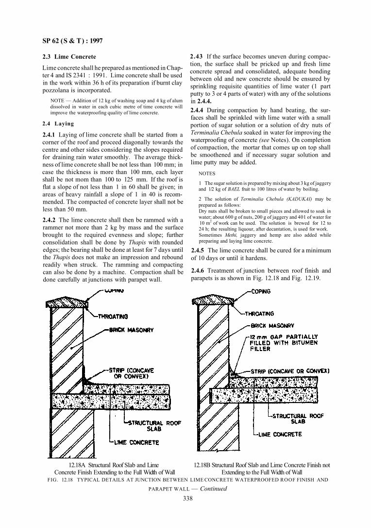
SP 62 (S & T) : 1997
2.3 Lime Concrete
Lime concrete shall he prepared as mentioned in Chapter 4 and IS 2341 : 1991. Lime concrete shall be used in the work within 36 h of its preparation if burnt clay pozzolana is incorporated.
NOTE — Addition of 12 kg of washing soap and 4 kg of alum dissolved in water in each cubic metre of time concrete will improve the waterproofing quality of lime concrete.
2.4 Laying
2.4.1 Laying of lime concrete shall be started from a corner of the roof and proceed diagonally towards the centre and other sides considering the slopes required for draining rain water smoothly. The average thickness of lime concrete shall be not less than 100 mm; in case the thickness is more than 100 mm, each layer shall be not mom than 100 to 125 mm. If the roof is flat a slope of not less than 1 in 60 shall be given; in areas of heavy rainfall a slope of 1 in 40 is recommended. The compacted of concrete layer shall not be less than 50 mm.
2.4.2 The lime concrete shall then be rammed with a rammer not more than 2 kg by mass and the surface brought to the required evenness and slope; further consolidation shall be done by Thapis with rounded edges; the bearing shall be done at least for 7 days until the Thapis does not make an impression and rebound readily when struck. The ramming and compacting can also be done by a machine. Compaction shall be done carefully at junctions with parapet wall.
2.43 If the surface becomes uneven during compaction, the surface shall be pricked up and fresh lime concrete spread and consolidated, adequate bonding between old and new concrete should be ensured by sprinkling requisite quantities of lime water (1 part putty to 3 or 4 parts of water) with any of the solutions in 2.4.4. 2.4.4 During compaction by hand beating, the surfaces shall be sprinkled with lime water with a small portion of sugar solution or a solution of dry nuts of Terminalia Chebula soaked in water for improving the waterproofing of concrete (see Notes). On completion of compaction, the mortar that comes up on top shall be smoothened and if necessary sugar solution and lime putty may be added.
NOTES
1 The sugar solution is prepared by mixing about 3 kg of jaggery and 1/2 kg of BAEL fruit to 100 litres of water by boiling.
2 The solution of Terminalia Chebula (KADUKAI) may be prepared as follows: Dry nuts shall be broken to small pieces and allowed to soak in water; about 600 g of nuts, 200 g of jaggery and 401 of water for 10 m2 of work can be used. The solution is brewed for 12 to 24 h; the resulting liquour, after decantation, is used for work. Sometimes Methi, jaggery and hemp are also added while preparing and laying lime concrete.
2.4.5 The lime concrete shall be cured for a minimum of 10 days or until it hardens.
2.4.6 Treatment of junction between roof finish and parapets is as shown in Fig. 12.18 and Fig. 12.19.
12.18A Structural Roof Slab and Lime 12.18B Structural Roof Slab and Lime Concrete Finish not Concrete Finish Extending to the Full Width of Wall Extending to the Full Width of Wall
FIG. 12.18 TYPICAL DETAILS AT JUNCTION BETWEEN LIME CONCRETE WATERPROOFED ROOF FINISH AND
PARAPET WALL — Continued 338
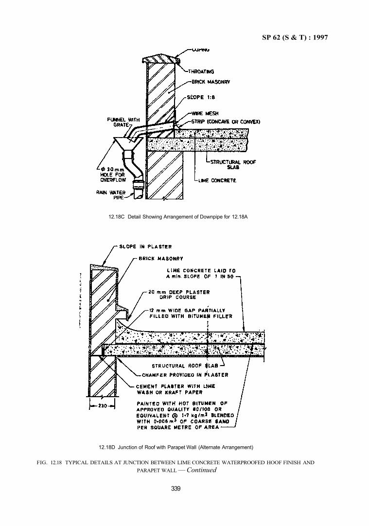
SP 62 (S & T) : 1997
12.18C Detail Showing Arrangement of Downpipe for 12.18A
12.18D Junction of Roof with Parapet Wall (Alternate Arrangement)
FIG. 12.18 TYPICAL DETAILS AT JUNCTION BETWEEN LIME CONCRETE WATERPROOFED HOOF FINISH AND PARAPET WALL — Continued
339
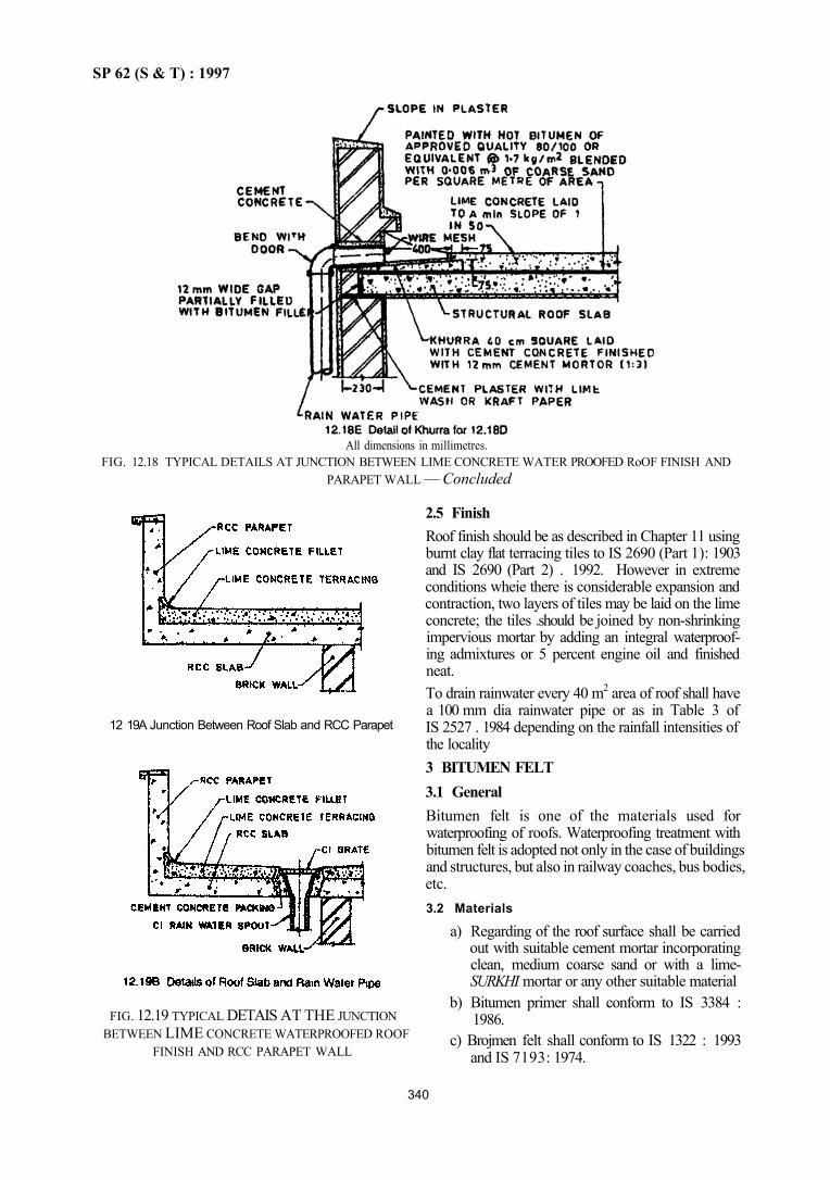
SP 62 (S & T) : 1997
12 19A Junction Between Roof Slab and RCC Parapet
2.5 Finish Roof finish should be as described in Chapter 11 using burnt clay flat terracing tiles to IS 2690 (Part 1): 1903 and IS 2690 (Part 2) . 1992. However in extreme conditions wheie there is considerable expansion and contraction, two layers of tiles may be laid on the lime concrete; the tiles .should be joined by non-shrinking impervious mortar by adding an integral waterproofing admixtures or 5 percent engine oil and finished neat. To drain rainwater every 40 m2 area of roof shall have a 100 mm dia rainwater pipe or as in Table 3 of IS 2527 . 1984 depending on the rainfall intensities of the locality 3 BITUMEN FELT 3.1 General Bitumen felt is one of the materials used for waterproofing of roofs. Waterproofing treatment with bitumen felt is adopted not only in the case of buildings and structures, but also in railway coaches, bus bodies, etc. 3.2 Materials
a) Regarding of the roof surface shall be carried out with suitable cement mortar incorporating clean, medium coarse sand or with a lime-SURKHI mortar or any other suitable material
b) Bitumen primer shall conform to IS 3384 : 1986.
c) Brojmen felt shall conform to IS 1322 : 1993 and IS 7193: 1974.
340
All dimensions in millimetres. FIG. 12.18 TYPICAL DETAILS AT JUNCTION BETWEEN LIME CONCRETE WATER PROOFED RoOF FINISH AND
PARAPET WALL — Concluded
FIG. 12.19 TYPICAL DETAIS AT THE JUNCTION BETWEEN LIME CONCRETE WATERPROOFED ROOF
FINISH AND RCC PARAPET WALL
SP 62 (S & T) : 1997
341
d) Bonding material for use between successive felts and between roof surface and felt shall conform to industrial blown type bitumen of Grade 85/25 or 90/15 conforming to IS 702 : 1988. For top dressing bitumen shall be industrial blown type to IS 702 : 1988 of penetration not more than 40 when tested in accordance with IS 1203 : 1978.
For vertical surfaces up to 1 m in height blown type bitumen to IS 702 : 1988 of Grade 85/25 or 90/15 and above 1 m Grade 115/15 may be used. 3.3 Waterproofing Treatment In selecting a combination of layers and grades of felt to be used, consideration shall be given to the type and construction of buildings, climatic and atmospheric conditions and the degree of permanance required. 3.4 Concrete and Masonry Roofs, Flat or Sloping The following treatments are recommended:
a) Normal Treatment — Five courses for moderate conditions: 1) Primer at the rate of 0.27 1/m2, Min; 2) Hot applied bitumen at the rate of
1.2 kg/m2, Min; 3) Hessian based self-finished felt. Type 3,
Grade 1, or glass fibre base, Type 2, Grade 1:
4) Hot applied bitumen at the rate of 1.2 kg/m2, Min: and
5) Pea-sized gravel or grit devoid of fine sand at the rate of 0.006 m3/m2.
OR Floating Treatment 1) Fibre base felt bitumen saturated under
lay, Type 1: 2) Hot applied bitumen at the rate of
1.2 kg/m2, Min; 3) Fibre base self-finished felt, Type 2 Grade
1 or Grade 2; 4) Hot applied bitumen at the rate of
1.2 kg/m2;and 5) Pea-sized gravel or grit devoid of fine sand
at the rate of 0.008 m3/m2, Min. b) Heavy Treatment — Seven courses for severe
conditions: 1) Primer at the rate of 0.27 1/m2, Min; 2) Hot applied bitumen at the rate of
1.2 kg/m2, Min; 3) Hessian base self-finished felt, Type 3
Grade 1 or glass fibre base felt, Type 2 Grade 1;
4) Hot applied bitumen at the rate of 1.2 kg/m2, Min;
5) Hessian base self-finished felt, Type 3 Grade 1 or glass fibre base felt. Type 2 Grade 1;
6) Hot applied bitumen at the rate of 1.2 kg/m2, Min; and
7) Pea-sized gravel or grit devoid of fine sand at the rate of 0.006 m3/m2.
OR 1) Primer at the rate of 0.27 1/m2, Min; 2) Hot applied bitumen at the rate of
1.2 kg/m2, Min; 3) Fibre base self-finished felt, Type 2 Grade
1 or Grade 2; 4) Hot applied bitumen at the rate of
1.2 kg/m2, Min; 5) Fibre base self- finished felt, Type 2 Grade
1 or Grade 2; 6) Hot applied bitumen at the rate of
2.5 kg/m2, Min; and 7) Pea-sized gravel or grit devoid of fine sand
at the rate of 0.008 m3/m2. OR
Floating Treatment 1) Fibre base bitumen saturated underlay,
Type 1; 2) Hot applied bitumen at the rate of
1.2 kg/m2, Min; 3) Fibre base self-finished felt, Type 2 Grade
1 or Grade 2; 4) Hot applied bitumen at the rate of
1.2 kg/m2, Min; 5) Fibre base self-finished felt, Type 2 Grade
1 or Grade 2; 6) Hot applied bitumen at the rate of
2.5 kg/m2, Min; and 7) Pea-sized gravel or grit devoid of fine sand
at the rate of 0.008 m3/m2. c) Extra Heavy Treatment — Nine courses for
very severe conditions: 1) Primer at the rate of 0.27 1/m2, Min; 2) Hot applied bitumen at the rate of
1.2 kg/m2, Min; 3) Hessian base self-finished felt, Type 3
Grade 1 or glass fibre base felt. Type 2 Grade 1;
4) Hot applied bitumen at the rate of 1.2 kg/m2, Min;
5) Hessian base self-finished felt, Type 3 Grade 1 or glass fibre base felt, Type 2 Grade 1;
6) Hot applied bitumen at the rate of 1.2 kg/m2, Min:
SP 62 (S & T) : 1997
7) Hessian base self-finished felt, Type 3 Grade 1 or glass fibre base felt, Type 2 Grade 1;
8) Hot applied bitumen at the rate of 1.2 kg/m2, Min; and
9) Pea-sized gravel or grit devoid of fine sand at the rate of 0.006 m3/m2.
OR 1) Primer at the rate of 0.27 l/m2, Min; 2) Hot applied bitumen at the rate of
1.2 kg/m2, Min; 3) Fibre base self-finished felt Type 2 Grade
1 or Grade 2; 4) Hot applied bitumen at the rate of
1.2 kg/m2, Min: 5) Fibre base self-finished felt Type 2 Grade
1 or Grade 2; 6) Hot applied bitumen at the rate of
1.2 kg/m2, Min; 7) Fibre base self-finished felt. Type 2 Grade
1 or Grade 2; 8) Hot applied bitumen at the rate of
2.5 kg/m2, Min; and 9) Pea-sized gravel or grit devoid of fine sand
at the rate of 0.008 m3/m2. NOTE — Where pea-sized gravel or grit is not available, coarse sand may be used
3.4.1 Surface finish of pea-sized gravel or grit affords a protection to the treatment and its durability. On the flashings and at the drain mouths, the gravel or grit may be omitted and instead two coats of bituminous paint at the minimum rate of 0.1 l/m2 per coat or a single coat of bituminous emulsion at the rate of 0.5 l/m2 may be applied.
a) Surface finish, when subjected to foot traffic, shall be cement concrete flooring tiles or burnt clay flat terracing tiles as described in Chapter 9.
b) Alternatively, a screeding of 1:4 cement sand mix layer 45 mm thick may be laid over the roofing treatment and marked oft into squares of 600 mm made with expansion joints at a distance of 3 m caulked with bituminous sealing compound (see Grade A of IS 1834 : 1984).
3.5 Timber Roofs, Sloping a) Normal Treatment
1) Fibre base bitumen saturated underlay Type 1, or hessian base felt Type 3 Grade 1 or glass fibre base felt Type 2 Grade 1;
2) Hot applied bitumen at the rate of 1.2 kg/m2, Min; and
3) Fibre base self-finished felt, Type 2 Grade 1, or hessian base felt Type 3 Grade 1, or glass fibre base felt, Type 2 Grade 1.
b) Heavy Treatment 1) Fibre base self-finished felt, Type 2 Grade
1, or hessian base felt, Type 3 Grade 2, or glass fibre base felt, Type 2 Grade 2;
2) Hot applied bitumen at the rate of 1.2 kg/m2, Min;
3) Fibre base self-finished felt, Type 2 Grade 1 or Grade 2, or hessian base felt. Type 3 Grade 2, or glass fibre base felt. Type 2 Grade 2.
3.5.1 Timber roofs shall be finished with hot applied bitumen at the rate of 1.2 kg/m2, Min; or with two coats of bituminous paint at the rate of 0.1 l/m2 per coat or a single coat of bituminous emulsion at the rate of 0.5 l/m2 over it. 3.6 Laying of Felt 3.6.1 Sequence of Operations for all Types of Roofs
a) Preparatory work (see 2 given in the beginning of the Chapter);
b) Cleaning roof surface of foreign matter; c) Treatment of main roof; d) Treatment of flashings and projecting pipes; e) Treatment of gutters and drain mouths; f) Top dressing, that is gravel or grit, fixing and
laying tile or concrete protection or applying paint or emulsion; and
g) Cleaning and removal of surplus materials. 3.6.2 Concrete and Masonry Roofs
a) The felt is normally laid in lengths at right angles to the direction of the run-off gradient, commencing at the lowest level and working up to the crest. In this way, the overlaps of the adjacent layers of felt offers minimum obstruction to the flow-off of water. 1) Bitumen primer shall be brushed over the
roof surface and left to dry after the surface is thoroughly cleaned.
2) The felt shall be cut to the required lengths, brushed clean of dusting materials and laid out flat on the roof and allowed to soften. Bach length of felt shall then be laid in position and rolled up for a distance of half its length. The hot bonding material shall be poured on to the roof across the full length of the rolled felt as the latter is rolled out steadily and pressed down. The excess bonding material is squeezed out at the ends and is removed as the laying proceeds.
3) When the first half of the strip of felt has been bonded to the roof, the other half shall be rolled up and then unrolled on the hot bending material in the same way.
342
SP 62 (S & T) : 1997
3) Two coats of bituminous paint at the rate of 0.1 1/m2 per coat or a single coat of bituminous emulsion at the rate of 0.51/m2
shall be applied.
3.6.3 Timber Roofs Sloping (see Fig. 12.12)
The underlay or first layer of felt shall be secured by nails spaced at 100 to 150 mm centres along overlaps and at 20 mm from the exposed edges. In case of struck on treatment, the felt shall be bonded on timber roof in the same manner as in the case of masonry roof but with nailing strips and back nailing.
1) Where required, additional nailing may be provided between overlaps at 150 mm centres.
2) The second and subsequent layers of felt shall then be applied with bonding materials as in concrete and masonry roofs.
3) In the case of gabled roof, one single strip of felt shall cover from gutter to gutter over the ridge. If the treatment consists of one layer of felt, additional layer of felt shall be provided at the ridge which shall cover a length of slope of 250 mm on both sides of the ridge.
4) Flashings — If the parapet is of masonry construction, the flashings shall be treated in the same way as in 3.6.2 (b). In case the roof butts against a timber wall, the flashings shall be continuously bonded down over the felt turn up and angle fillet. Joints in the felt flashings shall be lapped 100 mm and sealed. The upper end of the flashing shall be firmly secured to the timber wall by screwing down with a timber batten.
3.6.4 Shell Roofs
a) In the case of shell roofs additional layer of felt shall be provided for the valley gutter for nor-mal treatment and for other type of treatment; the number of felts in valley gutters shall be one layer extra. The treatment on the valley should be laid first and the height to which the felt is to be taken shall be at least 150 mm above the anticipated standing water in the gutter. For normal treatment on pent roofs, the felt should be laid parallel to the direction of runoff gradient. The felt in the case of shell roofs shall be laid from one edge of the valley gutter to the other, that is, around the curvature. In case of northtight cylindrical shells, it can cither start from the valley gutter or from the upper edge. The upper edge shall be securely anchored at the edge of the shell.
4) Minimum overlaps of 100 and 75 mm shall be allowed at the end and sides of strips of felt respectively. All overlaps shall be firmly bonded with hot bitumen.
5) The laying of the second layer shall be so arranged that the joints are staggered with those of the layer beneath it.
6) In the case of pent roofs where the type of treatment consists of one layer of felt only as in normal treatment 3.4 (a), an additional layer of felt shall be provided at the ridge which shall cover a minimum length of the slope of 250 mm on both sides of the ridge.
b) Junctions of parapet wall and roof— Pelt shall be laid as a flashing with minimum overlaps of 100 mm. The lower edge of the flashing shall overlap the felt laid on the flat portion of the roof and the upper edge of the flashing shall be tucked into the groove made in the parapet on the vertical face of the wall. Each layer shall be so arranged that the joints are staggered with those of the layer beneath it. After the layers of felt are laid and bonded, the grooves shall be filled with cement mortar (1:4) or lime mortar (1:3) or cement concrete (1:3:6) which when set will satisfactorily secure the treatment to the wall. A fillet of cement mortar (1:4) shall be done at the junction of wall and roof.
c) Drain mouths — Drain mouths with a bell shaped entry shall be fixed and properly set to allow the water to flow into it. Felt shall generally be laid as on the other portion of the roof and the treatment shall be carried inside the drain pipes overlapping at least 100 mm. If possible a grating cap should be provided over the drain mouth to protect choking caused by leaves, stones, etc.
d) Gutter — The treatment to be laid in gutters shall provide for one layer of roofing felt more than is provided on the roof proper. A priming coat shall first be applied. Over this, the first layer of felt shall be bonded with hot bitumen followed by successive layers of felt bonded securely together and finally painted with a coat of hot bitumen at not less than 1.5 kg/m2. 1) The first layer laid separately in the gutters
shall be overlapped with the corresponding layer on the roof proper. The felt layers in the gutter shall be carried down to the outlet pipes to a minimum depth of 100 mm.
2) For gutters in pent roofs the flashings shall be laid separately at the sides and carried well under the caves of the pent roofs.
NOTE — Where inflation is specified, the insulating material shall be applied on top of the shell surface and plastered, if necessary, with cement mortar to provide adequate base for application of waterproofing treatment.
343
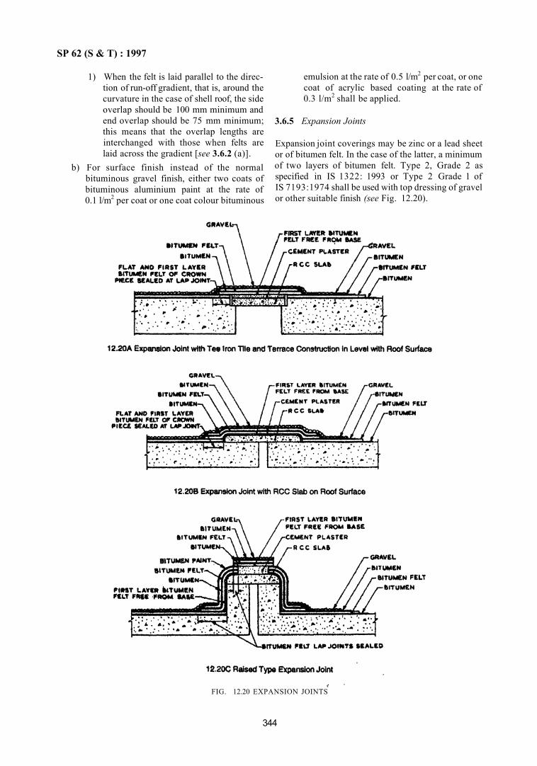
SP 62 (S & T) : 1997
1) When the felt is laid parallel to the direction of run-off gradient, that is, around the curvature in the case of shell roof, the side overlap should be 100 mm minimum and end overlap should be 75 mm minimum; this means that the overlap lengths are interchanged with those when felts are laid across the gradient [see 3.6.2 (a)].
b) For surface finish instead of the normal bituminous gravel finish, either two coats of bituminous aluminium paint at the rate of 0.1 l/m2 per coat or one coat colour bituminous
emulsion at the rate of 0.5 l/m2 per coat, or one coat of acrylic based coating at the rate of 0.3 l/m2 shall be applied.
3.6.5 Expansion Joints
Expansion joint coverings may be zinc or a lead sheet or of bitumen felt. In the case of the latter, a minimum of two layers of bitumen felt. Type 2, Grade 2 as specified in IS 1322: 1993 or Type 2 Grade 1 of IS 7193:1974 shall be used with top dressing of gravel or other suitable finish (see Fig. 12.20).
344
FIG. 12.20 EXPANSION JOINTS

SP 62 (S & T) : 1997
3.6.6 Treatment of Bubble Formation
If balooning occurs, remove the gravel on the balooned surface. Then cut open and squeeze out the trapped vapour by firm pressure applied by hand. Seal the bitumen felt so lifted, back on to the surface by applying additional bitumen. Finally seal the cut with a piece of bitumen felt with bitumen application and re-apply the gravel finish over it to make the surface look uniform with the rest
3.6.7 Roof Gardens
Where it is required to create a roof garden the waterproofing shall be carried out as per the treatment of damp-proofing covered in 2. Part 1 of this Chapter. As far as possible, plants should be planted in containers to avoid roof penetration into the roof below.
4 BITUMEN MASTIC
4.1 Materials
Bitumen mastic shall conform to IS 3037 : 1986. Bonding bitumen shall conform to IS 702 : 1988 or residual bitumen to IS 73 : 1992. The penetration of blown bitumen shall be limited to 45 when tested in accordance with IS 1203 : 1978. Expanded metal
lathing with coating of bitumen my be used for reinforcement for laying bitumen toertical sloping surfaces. The underlay may be betmen felt to IS 1322 : 1993. Vapour barrier should b hassian based Type 3 felt to IS 1322: 1993.
4.2 Preparatory Work
In addition to requirements of 1.1 of this Part, the following points may be considered.
a) Keying — Bitunen maslic will not adhere to vertical and sleeping surfaces unless such surfaces afford ar adquate key. 1) When bitumen mastic is applied to vertical
surface including skirting the top of the mastic shall be tucked into a continuous groove or not less than 25 mm × 25 mm in the mixture and its exposed part shall be fomed with a splay to shed rain water.
2) Horizontal joints in brickwork should not be less than 10 mm wide and the mortar oint shall be raked out and brushed clean
to form a key to the bitumen mastic (see Fig. 12.21)
FIG. 12.21 BITUMEN MASTIC LAID ON CREEDED ROOF AND BITUMEN MASTIC SKIRTING TO BRICK WALL
345
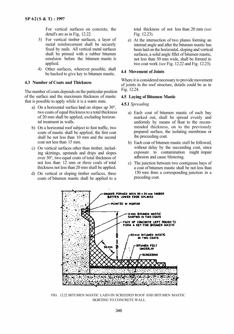
SP 62(S & T) : 1997
For vertical surfaces on concrete, the detail's are as in Fig, 12.22.
3) For vertical timber surfaces, a layer of metal reinforcement shall be securely fixed by nails. All vertical metal surfaces shall be primed with a rubber bitumen emulsion before the bitumen mastic is applied.
4) Other surfaces, wherever possible, shall be hacked to give key to bitumen mastic.
4.3 Number of Coats and Thickness
The number of coats depends on the particular position of the surface and the maximum thickness of mastic that is possible to apply while it is a warm state.
a) On a horizontal surface land on slopes up 30°, two coats of equal thickness to a total thickness of 20 mm shall be applied, excluding horizon-tal treatment in walls.
b) On a horizontal roof subject to foot traffic, two coats of mastic shall be applied; the first coat shall be not less than 10 mm and the second coat not less than 15 mm.
c) On vertical surfaces other than timber, including skirtings, upstands and drips and slopes over 30°, two equal coats of total thickness of not less than 12 mm or three coals of total thickness not less than 20 mm shall be applied.
d) On vertical or sloping timber surfaces, three coats of bitumen mastic shall be applied to a
total thickness of not less than 20 mm (see Fig. 12.23).
e) At the intersection of two planes forming an internal angle and after the bitumen mastic has been laid on the horizontal, sloping and vertical surfaces, a solid angle fillet of bitumen mastic, not less than 50 mm wide, shall be formed in two coat work (see Fig. 12.22 and Fig. 12.23).
4.4 Movement of Joints
Where it is considered necessary to provide movement of joints in the roof structure, details could be as in Fig. 12.24. 4.5 Laying of Bitumen Mastic 4.5.1 Spreading
a) Each coat of bitumen mastic of each bay marked out, shall be spread evenly and uniformly by means of float to the recommended thickness, on to the previously prepared surface, the isolating membrane or the preceeding coat.
b) Each coat of bitumen mastic stall be followed, without delay by the succeeding coat, since exposure to contamination might impair adhesion and cause blistering.
c) The junction between two contiguous bays of a coat of bitumen mastic shall be not less than 150 mm from a corresponding junction in a preceding coat.
FIG. 12.22 BITUMEN MASTIC LAID ON SCREEDED ROOF AND BITUMEN MASTIC SKIRTING TO CONCRETE WALL
346
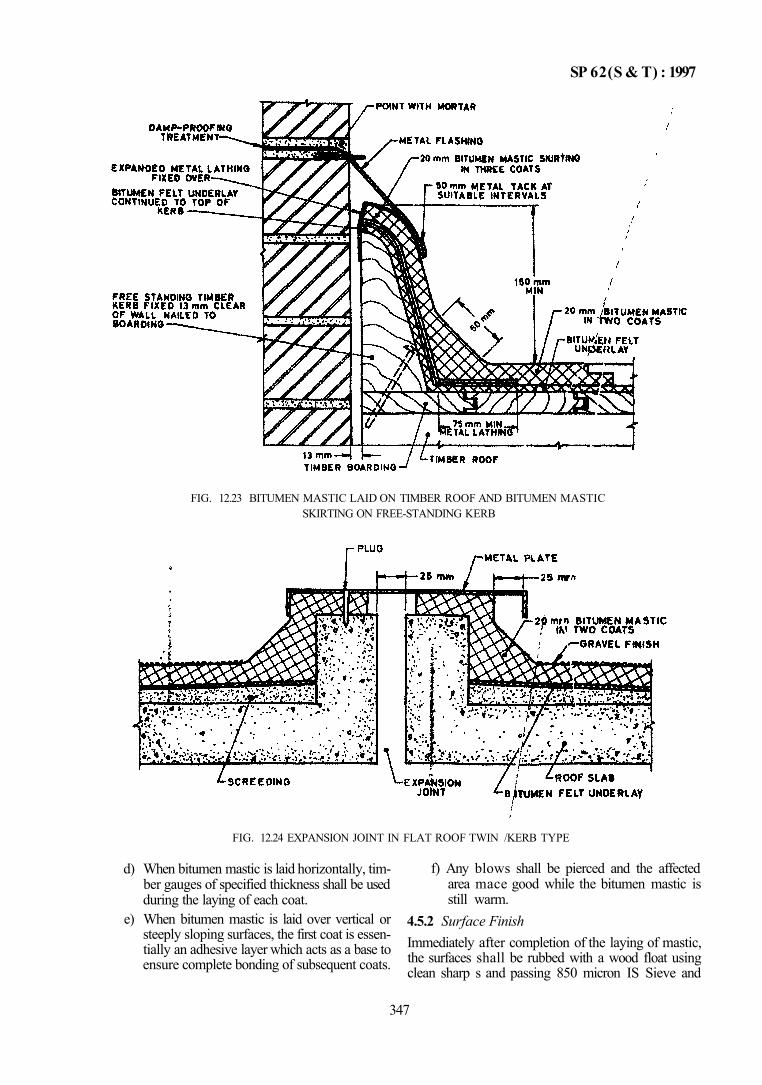
SP 62(S & T) : 1997
FIG. 12.23 BITUMEN MASTIC LAID ON TIMBER ROOF AND BITUMEN MASTIC SKIRTING ON FREE-STANDING KERB
FIG. 12.24 EXPANSION JOINT IN FLAT ROOF TWIN /KERB TYPE
d) When bitumen mastic is laid horizontally, timber gauges of specified thickness shall be used during the laying of each coat.
e) When bitumen mastic is laid over vertical or steeply sloping surfaces, the first coat is essentially an adhesive layer which acts as a base to ensure complete bonding of subsequent coats.
f) Any blows shall be pierced and the affected area mace good while the bitumen mastic is still warm.
4.5.2 Surface Finish Immediately after completion of the laying of mastic, the surfaces shall be rubbed with a wood float using clean sharp s and passing 850 micron IS Sieve and
347
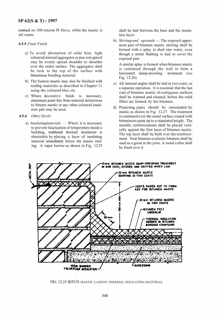
SP 62(S & T) : 1997
routined on 300 micron IS Sieve, while the mastic is stil warm.
4.5.5 Final Finish
a) To avoid absorption of solar heat, light coloured mineral aggregates or pea-size gravef may be evenly spread shoulder to shoulder over the entire surface. The aggregates shall be tuck to the top of the surface with bituminous bonding material.
b) The bumen mastic may also be finished with roofing materials as described in Chapter 11 using the coloured tiles, etc.
c) Where decorative finish is necessary, aluminum paint free from material deleterious to bitumn mastic or any other coloured emulsion pait may be used.
4.5.4 Other Devils
a) Insulatingmaterials — Where it is necessary to prevent fauctuation of temperature inside a building, traditional thermal insulation is obtainable by placing a layer of insulating material immediately below the mastic roofing. A vapor barrier as shown in Fig. 12.25
shall be laid between the base and the insula-tion layer.
b) Skirtingsand upstands — The exposed uppermost part of bitumen mastic skirting shall be formed with a splay to shed rain water, even though a metal flashing is laid to cover the exposed part. A similar splay is formed when bitumen mastic is continued through the wall to form a horizontal damp-proofing treatment (see Fig. 12.26).
c) All internal angles shall be laid in two coats, as a separate operation. It is essential that the last coat of bitumen mastic of contiguous surfaces shall be warmed and cleaned, before the solid fillets are formed, by hot bitumen.
d) Projecting pipes should be surrounded by mastic as shown in Fig. 12.27. The treatment is continued over the metal surface coated with bituminous paint up to a stipulated height. The metallic reinforcements shall be placed vertically against the first layer of bitumen mastic. The top layer shall be built over the reinforcement. Neat bitumen or plastic bitumen shall be used as a grout at the joint. A metal collar shall be fixed over it.
FIG. 12.25 BITUN MASTIC LAIDON THERMAL INSULATING MATERIAL
348
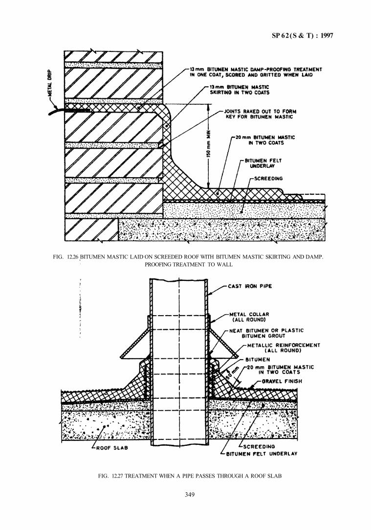
SP 62(S & T) : 1997
FIG. 12.27 TREATMENT WHEN A PIPE PASSES THROUGH A ROOF SLAB
349
FIG. 12.26 BITUMEN MASTIC LAID ON SCREEDED ROOF WITH BITUMEN MASTIC SKIRTING AND DAMP. PROOFING TREATMENT TO WALL
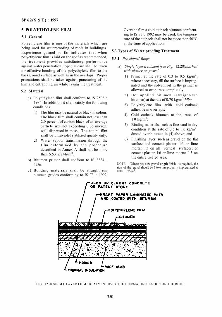
SP 62(S & T ) : 1997
5 POLYETHYLENE FILM 5.1 General
Polyethylene film is one of the materials which are being used for waterproofing of roofs in buildingss. Experience gained so far indicates that when polyethylene film is laid on the roof as recommended, the treatment provides satisfactory performance against water penetration. Special care shall be taken tor effective bonding of the polyethylene film to the background surface as well as in the overlaps. Proper precautions shall be taken against puncturing of the film and entrapping air white laying the treatment.
5.2 Material
a) Polyethylene film shall conform to IS 2508 : 1984. In addition it shall satisfy the following conditions: 1) The film may be natural or black in colour.
The black film shall contain not less than 2.0 percent of carbon black of an average particle size not exceeding 0.06 micron, well dispersed in mass. The natural film shall be ultraviolet stablized quality only.
2) Water vapour transmission through the film determined by the procedure described in Annex A shall not be more than 5.53 g/24h/m2.
b) Bitumen primer shall conform to IS 3384 : 1986.
c) Bonding materials shall be straight run bitumen grades conforming to IS 73 : 1992.
Over the film a cold cutback bitumen conforming to IS 73 : 1992 may be used; the temperature of the cutback shall not be more than 50°C at the time of application.
5.3 Types of Water proofing Treatment
5.3.1 Pre-sloped Roofs
a) Single layer treatment (see Fig. 12.28)finished with plaster or gravel 1) Primer at the rate of 0.3 to 0.5 kg/m2,
where necessary, till the surface is impregnated and the solvent oil in the primer is allowed to evaporate completely;
2) Hot applied bitumen (straight-run bitumen) at the rate of 0.70 kg/m2 Min;
3) Polyethylene film with cold cutback adhesive in overlaps;
4) Cold cutback bitumen at the rate of 1.0 kg/m2;
5) Binding materials, such as fine sand in dry condition at the rate of 0.5 to 1.0 kg/m2
dusted over bitumen in (4) above; and 6) Finishing layer, such as gravel on the flat
surface and cement plaster 1:6 or lime mortar 1:3 on all vertical surfaces; or cement plaster 1:6 or lime mortar 1.3 on the entire treated area.
NOTE — Where pca-size gravel or grit finish is required, the size of the gravel should be 3 to 6 mm properly impregnated at 0.006 m3/m2.
FIG. 12.28 SINGLE LAYER FILM TREATMENT OVER THE THERMAL INSULATION ON THE ROOF
350
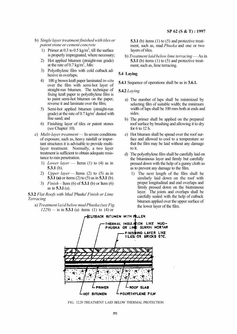
SP 62 (S & T) : 1997
b) Single layer treatment finished with tiles or patent stone or cement concrete 1) Primer at 0.3 to 0.5 kg/m2, till the surface
is properly impregnated, where necessary; 2) Hot applied bitumen (straight-run grade)
at the rate of 0.7 kg/m2, Min; 3) Polyethylene film with cold cutback ad
hesive in overlaps; 4) 100 g brown kraft paper laminated in-situ
over the film with semi-hot layer of straight-run bitumen. The technique of fixing kraft paper to polyethylene film is to paint semi-hot bitumen on the paper, reverse it and laminate over the film;
5) Semi-hot applied bitumen (straight-run grade) at the rate of 0.7 kg/m2 dusted with fine sand; and
6) Finishing layer of tiles or patent stones (see Chapter 10).
c) Multi-layer treatment — In severe conditions of exposure, such as, heavy rainfall or important structures it is advisable to provide multilayer treatment. Normally, a two layer treatment is sufficient to obtain adequate resistance to rain penetration. 1) Lower layer — Items (1) to (4) as in
5.3.1 (b). 2) Upper layer — Items (2) to (5) as in
5.3.1 (a) or items (2) to (5) as in 5.3.1 (b). 3) Finish – Item (6) of 5.3.1 (b) or Item (6)
as in 5.3.l (a). 5.3.2 Flat Roofs with Mud 'Phuska' Finish or Lime Terracing
a) Treatment laid below mud Phuska (see Fig. 1229) – is in 5.3.1 (a) items (1) to (4) or
5.3.1 (b) items (1) to (5) and protective treatment, such as, mud Phuska and one or two layers of tiles.
b) Treatment laid below lime terracing — As in 5.3.1 (b) items (1) to (5) and protective treatment, such as, lime terracing.
5.4 Laying
5.4.1 Sequence of operations shall be as in 3.6.1.
5.4.2 Laying
a) The number of laps shall be minimized by selecting film of suitable width; the minimum width of laps shall be 100 mm both at ends and sides.
b) The primer shall be applied on the prepared roof surface by brushing and allowing it to dry for 6 to 12 h.
c) Hot bitumen shall be spread over the roof surface and allowed to cool to a temperature so that the film may be laid without any damage to it.
d) The polyethylene film shall be carefully laid on the bituminous layer and firmly but carefully pressed down with the help of a gunny cloth so as to prevent any damage to the film. 1) The next length of the film shall be
similarly laid down on the roof with proper longitudinal and end overlaps and firmly pressed down on the biutminous layer. The joints and overlaps shall be carefully sealed with the help of cutback bitumen applied over the upper surface of the lower layer of the film.
FIG. 12.29 TREATMENT LAID BELOW THERMAL PROTECTION
351
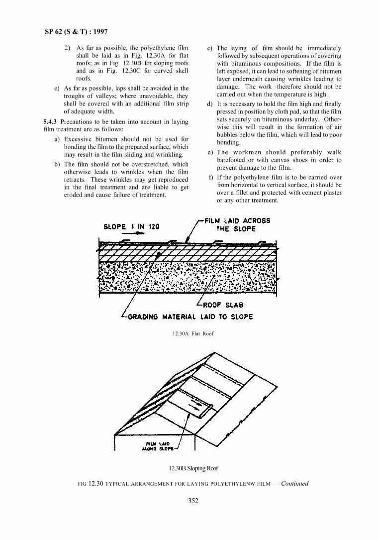
SP 62 (S & T) : 1997
2) As far as possible, the polyethylene film shall be laid as in Fig. 12.30A for flat roofs; as in Fig. 12.30B for sloping roofs and as in Fig. 12.30C for curved shell roofs.
e) As far as possible, laps shall be avoided in the troughs of valleys; where unavoidable, they shall be covered with an additional film strip of adequate width.
5.4.3 Precautions to be taken into account in laying film treatment are as follows:
a) Excessive bitumen should not be used for bonding the film to the prepared surface, which may result in the film sliding and wrinkling.
b) The film should not be overstretched, which otherwise leads to wrinkles when the film retracts. These wrinkles may get reproduced in the final treatment and are liable to get eroded and cause failure of treatment.
c) The laying of film should be immediately followed by subsequent operations of covering with bituminous compositions. If the film is left exposed, it can lead to softening of bitumen layer underneath causing wrinkles leading to damage. The work therefore should not be carried out when the temperature is high.
d) It is necessary to hold the film high and finally pressed in position by cloth pad, so that the film sets securely on bituminous underlay. Otherwise this will result in the formation of air bubbles below the film, which will lead to poor bonding.
e) The workmen should preferably walk barefooted or with canvas shoes in order to prevent damage to the film.
f) If the polyethylene film is to be carried over from horizontal to vertical surface, it should be over a fillet and protected with cement plaster or any other treatment.
12.30A Flat Roof
12.30B Sloping Roof
FIG 12.30 TYPICAL ARRANGEMENT FOR LAYING POLYETHYLENW FILM — Continued
352
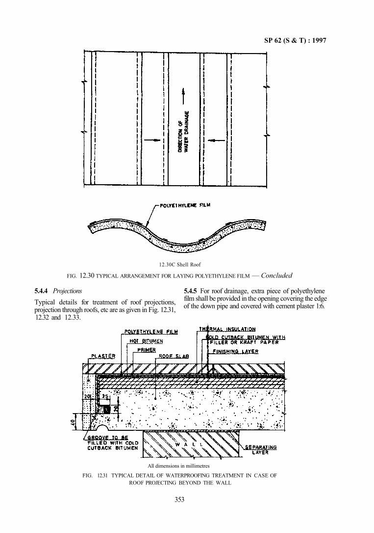
SP 62 (S & T) : 1997
All dimensions in millimetres
FIG. 12.31 TYPICAL DETAIL OF WATERPROOFING TREATMENT IN CASE OF ROOF PROJECTING BEYOND THE WALL
353
12.30C Shell Roof
FIG. 12.30 TYPICAL ARRANGEMENT FOR LAYING POLYETHYLENE FILM — Concluded
5.4.4 Projections Typical details for treatment of roof projections, projection through roofs, etc are as given in Fig. 12.31, 12.32 and 12.33.
5.4.5 For roof drainage, extra piece of polyethylene film shall be provided in the opening covering the edge of the down pipe and covered with cement plaster 1:6.
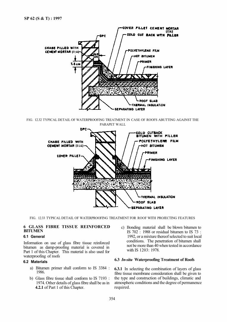
SP 62 (S & T) : 1997
FIG. 12.33 TYPICAL DETAIL OF WATERPROOFING TREATMENT FOR ROOF WITH PROJECTING FEATURES
6 GLASS FIBRE TISSUE REINFORCED BITUMEN 6.1 General Information on use of glass fibre tissue reinforced bitumen as damp-proofing material is covered in Part 1 of this Chapter. This material is also used for waterproofing of roofs 6.2 Materials
a) Bitumen primer shall conform to IS 3384 : 1986.
b) Glass fibre tissue shall conform to IS 7193 : 1974. Other details of glass fibre shall be as in 4.2.1 of Part 1 of this Chapter.
c) Bonding material shall be blown bitumen to IS 702 : 1988 or residual bitumen to IS 73 : 1992, or a mixture thereof selected to suit local conditions. The penetration of bitumen shall not be more than 40 when tested in accordance with IS 1203: 1978.
6.3 In-situ Waterproofing Treatment of Roofs
6.3.1 In selecting the combination of layers of glass fibre tissue membrane consideration shall be given to the type and construction of buildings, climatic and atmospheric conditions and the degree of permanence required.
354
FIG. 12.32 TYPICAL DETAIL OF WATERPROOFING TREATMENT IN CASE OF ROOFS ABUTTING AGAINST THE PARAPET WALL
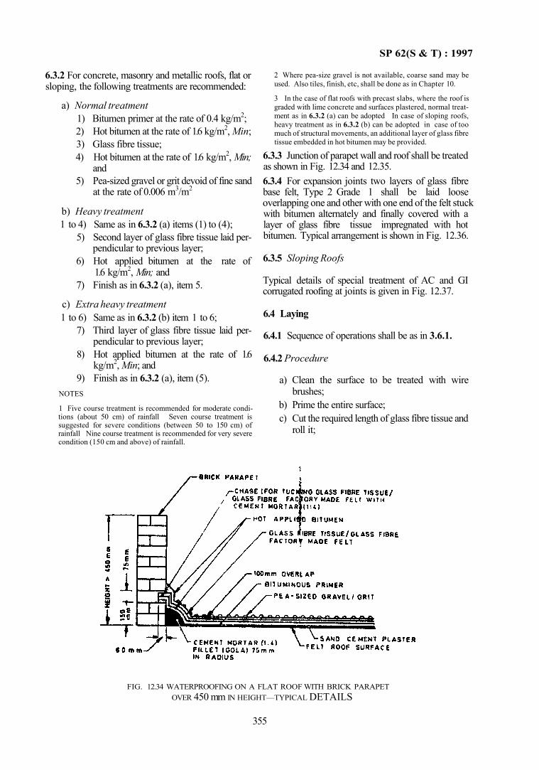
SP 62(S & T) : 1997
2 Where pea-size gravel is not available, coarse sand may be used. Also tiles, finish, etc, shall be done as in Chapter 10.
3 In the case of flat roofs with precast slabs, where the roof is graded with lime concrete and surfaces plastered, normal treatment as in 6.3.2 (a) can be adopted In case of sloping roofs, heavy treatment as in 6.3.2 (b) can be adopted in case of too much of structural movements, an additional layer of glass fibre tissue embedded in hot bitumen may be provided.
6.3.3 Junction of parapet wall and roof shall be treated as shown in Fig. 12.34 and 12.35. 6.3.4 For expansion joints two layers of glass fibre base felt, Type 2 Grade 1 shall be laid loose overlapping one and other with one end of the felt stuck with bitumen alternately and finally covered with a layer of glass fibre tissue impregnated with hot bitumen. Typical arrangement is shown in Fig. 12.36.
6.3.5 Sloping Roofs
Typical details of special treatment of AC and GI corrugated roofing at joints is given in Fig. 12.37.
6.4 Laying
6.4.1 Sequence of operations shall be as in 3.6.1.
6.4.2 Procedure
a) Clean the surface to be treated with wire brushes;
b) Prime the entire surface; c) Cut the required length of glass fibre tissue and
roll it;
FIG. 12.34 WATERPROOFING ON A FLAT ROOF WITH BRICK PARAPET OVER 450 mm IN HEIGHT—TYPICAL DETAILS
355
6.3.2 For concrete, masonry and metallic roofs, flat or sloping, the following treatments are recommended:
a) Normal treatment 1) Bitumen primer at the rate of 0.4 kg/m2; 2) Hot bitumen at the rate of 1.6 kg/m2, Min; 3) Glass fibre tissue; 4) Hot bitumen at the rate of 1.6 kg/m2, Min;
and 5) Pea-sized gravel or grit devoid of fine sand
at the rate of 0.006 m3/m2
b) Heavy treatment 1 to 4) Same as in 6.3.2 (a) items (1) to (4);
5) Second layer of glass fibre tissue laid perpendicular to previous layer;
6) Hot applied bitumen at the rate of 1.6 kg/m2, Min; and
7) Finish as in 6.3.2 (a), item 5.
c) Extra heavy treatment 1 to 6) Same as in 6.3.2 (b) item 1 to 6;
7) Third layer of glass fibre tissue laid perpendicular to previous layer;
8) Hot applied bitumen at the rate of 1.6 kg/m2, Min; and
9) Finish as in 6.3.2 (a), item (5). NOTES
1 Five course treatment is recommended for moderate conditions (about 50 cm) of rainfall Seven course treatment is suggested for severe conditions (between 50 to 150 cm) of rainfall Nine course treatment is recommended for very severe condition (150 cm and above) of rainfall.
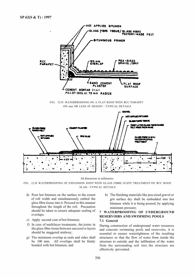
SP 62(S & T) : 1997
All dimensions in millimetres.
FIG. 12.36 WATERPROOFING OF EXPANSION JOINT WITH GLASS FIBRE IN-SITU TREATMENT ON RCC ROOF SLAB—TYPICAL DETAILS
d) Pour hot bitumen on the surface to the extent of roll width and simultaneously embed the glass fibre tissue into it. Proceed in this manner throughout the length of the roil. Precaution should be taken to ensure adequate sealing of overlaps;
c) Apply second coat of hot bitumen; f) In case of multilayer treatments, the joints in
the glass fibre tissue between successive layers should be staggered midway;
g) The minimum overlap at ends and sides shall be 100 mm. All overlaps shall be firmly bonded with hot bitumen; and
h) The finishing materials like pea-sized gravel or grit surface dry shall be embedded into hot bitumen while it is being poured, by applying minimum pressure.
7 WATERPROOFING OF UNDERGROUND RESERVOIRS AND SWIMMING POOLS 7.1 General During construction of underground water resources and concrete swimming pools and reservoirs, it is essential to ensure watertightness of the resulting structures so that the flow of water from inside the structure to outside and the infiltration of the water from the surrounding soil into the structure are effectively prevented.
356
FIG. 12.35 WATERPROOFING ON A FLAT ROOF WITH RCC PARAPET 450 mm OR LESS IN HEIGHT—TYPICAL DETAILS
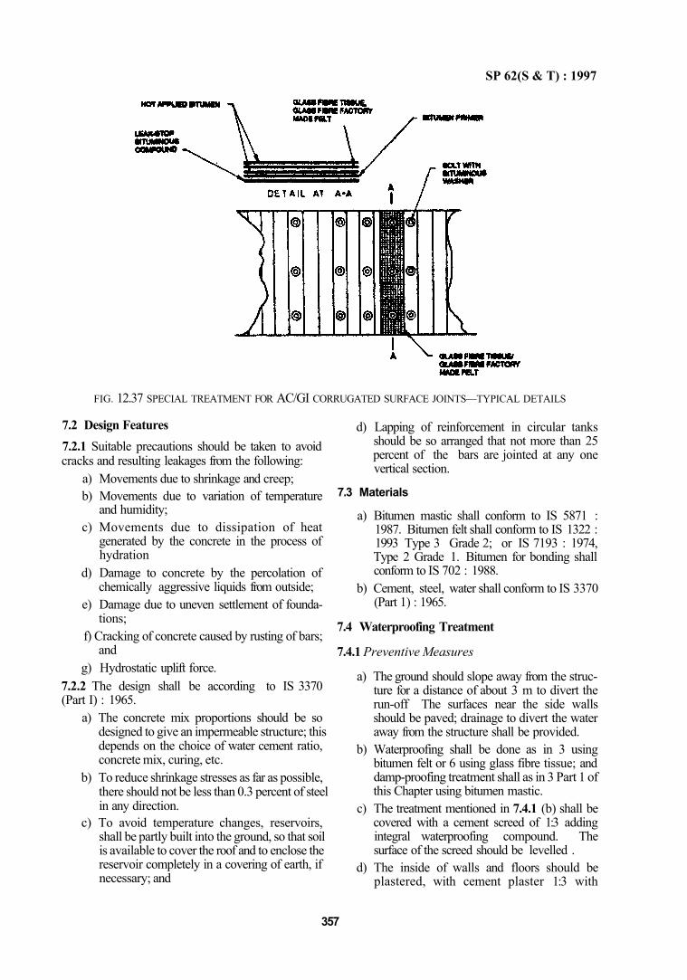
SP 62(S & T) : 1997
FIG. 12.37 SPECIAL TREATMENT FOR AC/GI CORRUGATED SURFACE JOINTS—TYPICAL DETAILS
7.2 Design Features 7.2.1 Suitable precautions should be taken to avoid cracks and resulting leakages from the following:
a) Movements due to shrinkage and creep; b) Movements due to variation of temperature
and humidity; c) Movements due to dissipation of heat
generated by the concrete in the process of hydration
d) Damage to concrete by the percolation of chemically aggressive liquids from outside;
e) Damage due to uneven settlement of foundations;
f) Cracking of concrete caused by rusting of bars; and
g) Hydrostatic uplift force. 7.2.2 The design shall be according to IS 3370 (Part I) : 1965.
a) The concrete mix proportions should be so designed to give an impermeable structure; this depends on the choice of water cement ratio, concrete mix, curing, etc.
b) To reduce shrinkage stresses as far as possible, there should not be less than 0.3 percent of steel in any direction.
c) To avoid temperature changes, reservoirs, shall be partly built into the ground, so that soil is available to cover the roof and to enclose the reservoir completely in a covering of earth, if necessary; and
d) Lapping of reinforcement in circular tanks should be so arranged that not more than 25 percent of the bars are jointed at any one vertical section.
7.3 Materials
a) Bitumen mastic shall conform to IS 5871 : 1987. Bitumen felt shall conform to IS 1322 : 1993 Type 3 Grade 2; or IS 7193 : 1974, Type 2 Grade 1. Bitumen for bonding shall conform to IS 702 : 1988.
b) Cement, steel, water shall conform to IS 3370 (Part 1) : 1965.
7.4 Waterproofing Treatment
7.4.1 Preventive Measures
a) The ground should slope away from the structure for a distance of about 3 m to divert the run-off The surfaces near the side walls should be paved; drainage to divert the water away from the structure shall be provided.
b) Waterproofing shall be done as in 3 using bitumen felt or 6 using glass fibre tissue; and damp-proofing treatment shall as in 3 Part 1 of this Chapter using bitumen mastic.
c) The treatment mentioned in 7.4.1 (b) shall be covered with a cement screed of 1:3 adding integral waterproofing compound. The surface of the screed should be levelled .
d) The inside of walls and floors should be plastered, with cement plaster 1:3 with
357
SP 62(S & T) : 1997
waterproofing compound added in two coats; the first coat being 12 mm thick and the second coat 10 mm thick. The outside surface of walls should be rendered with waterproofing compound added in a similar manner.
e) A coat of hot bitumen shall be applied to the outside wall after the rendening has dried.
7.5 Construction Details
a) In long walls, they may be divided into 15 m sections with a gap of about 30 cm left between sections so that shrinkage in the long sections may occur, as far as possible, before the gap is concreted and the longer this can be deferred the better.
b) Vibrators shall be used wherever possible, for compaction.
c) Construction joints should be perpendicular to the general directidn of the member. As far as possible vertical joints should be avoided.
d) It is not practicable to provide expansion joints in small and medium reservoirs and swimming pools. In large reservoirs expansion joints shall be provided at not more than 35 m for underground structures and not more than 28 m for exposed structures.
e) Pipes and special fixtures should be fixed in position before concreting is done.
f) For testing and remedial treatment reference may be made to IS 6494: 1988.
8 SILICONE BASED WATER REPELLENT
8.1 General
Application of the appropriate class of water repellent to all exterior surfaces free from cracks wider than 0.1 mm above ground level provides protection against absorption of water, salt and dirt. Applied over cement based paints, the repellent preserves the colour, brightness and appearance. Used as primers for oil based paints, the repellents minimize peeling and blistering caused (by damp and salt from the masonry walls. The repellents should be applied to complete masonry rather than to individual units, in order to avoid inadvertent treatment of bedding faces which would be detrimental to bonding of mortar. Normally the repellent does not alter the dry appearance of the surface. Application of water repellent on exposed brickwork surfaces reduce the appearance of efflorescence of soluble sulphates.
8.2 Materials
a) The silicone water repellent shall conform to IS 12027 :1987. They are three classes of the
repellents as below: Class A — Silicone solvent solution for clay brickwork, hydraulic cement-based materials, natural and cast stone masonry for a predominantly siliceous nature. Class B — Silicone solvent solution for natural and cast stone masonry work of predominantly calcareous nature and calcium silicate brickwork. Class C—Aqueous solution of sodium methyl siliconate for clay brickwork, natural and cast stone masonry of a predominantly calcareous nature. NOTE — Where the type of masonry cannot be classified. Class B repellent may be used
8.2.1 Preparation of Water Repellent a) From Class A and Class B materials — The
Class A and Class B material may be diluted with mineral spirit or xylene. The mineral spirit should have minimum flash point of 27°C, boiling range of 135 to 185°C and minimum Kauri-Butanol value of 34. For best results these classes of materials should contain 5 percent solids.
b) From Class C, the material may be diluted with water to a concentration of 3 percent solids just prior to the application.
8.3 Preparation of the Surface a) Cracks wider than 0.1 mm and defective mor
tar joints shall be repaired. Surfaces should be clean and dry. Detergents and wetting agents should not be used.
b) When drying of surface is difficult, Class C material shall be used either as a full treatment or prior to application of Class A or Class B treatment.
c) Efflorescence, if visible, shall be washed with 5 to 10 percent muriatic acid (HC1) solution and then rinse it with clear water. If it reappears in some places after drying, the repellent shall be applied and allowed to cure for 24 h and the surface be again washed with muriatic acid (HCl) and rinsed. Then the surface may be treated with the repellent.
d) The masonry, concrete, cement plaster and cement based painted surfaces shall be allowed to cure for 21 days before applying the repellent. If cement paint surfaces are treated with the repellent on a small area and if water repel-lency has not developed, such surface shall be cured for a longer period.
8.4 Application of Repellent a) Normally a single generous or flood coat by
brush or spray would be sufficient. The
358
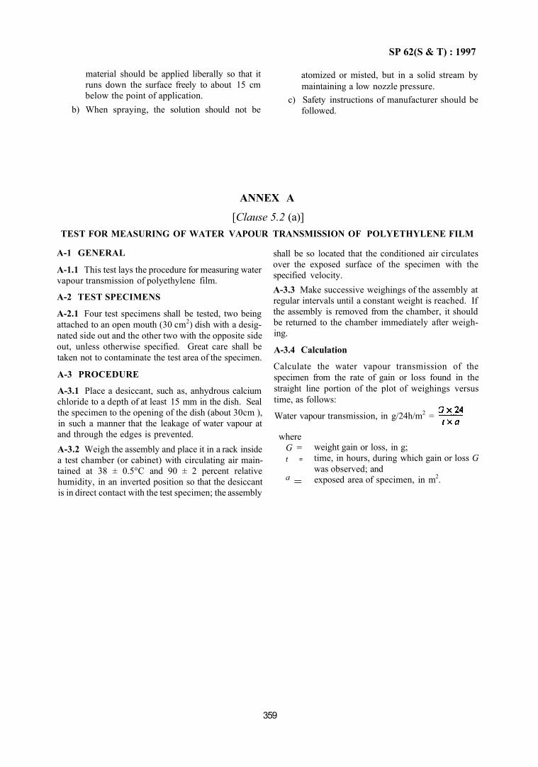
SP 62(S & T) : 1997
material should be applied liberally so that it runs down the surface freely to about 15 cm below the point of application.
b) When spraying, the solution should not be
atomized or misted, but in a solid stream by maintaining a low nozzle pressure.
c) Safety instructions of manufacturer should be followed.
ANNEX A
[Clause 5.2 (a)] TEST FOR MEASURING OF WATER VAPOUR TRANSMISSION OF POLYETHYLENE FILM
A-1 GENERAL
A-1.1 This test lays the procedure for measuring water vapour transmission of polyethylene film.
A-2 TEST SPECIMENS
A-2.1 Four test specimens shall be tested, two being attached to an open mouth (30 cm2) dish with a designated side out and the other two with the opposite side out, unless otherwise specified. Great care shall be taken not to contaminate the test area of the specimen.
A-3 PROCEDURE
A-3.1 Place a desiccant, such as, anhydrous calcium chloride to a depth of at least 15 mm in the dish. Seal the specimen to the opening of the dish (about 30cm ), in such a manner that the leakage of water vapour at and through the edges is prevented. A-3.2 Weigh the assembly and place it in a rack inside a test chamber (or cabinet) with circulating air maintained at 38 ± 0.5°C and 90 ± 2 percent relative humidity, in an inverted position so that the desiccant is in direct contact with the test specimen; the assembly
shall be so located that the conditioned air circulates over the exposed surface of the specimen with the specified velocity. A-3.3 Make successive weighings of the assembly at regular intervals until a constant weight is reached. If the assembly is removed from the chamber, it should be returned to the chamber immediately after weighing.
A-3.4 Calculation
Calculate the water vapour transmission of the specimen from the rate of gain or loss found in the straight line portion of the plot of weighings versus time, as follows:
Water vapour transmission, in g/24h/m2 =
where G = t =
a =
weight gain or loss, in g; time, in hours, during which gain or loss G was observed; and exposed area of specimen, in m2.
359

CHAPTER 13
JOINTS IN BUILDINGS (CONTROL OF CRACKS IN BUILDINGS)

CONTENTS
1 GENERAL
2 TYPES OF JOINTS
2.1 Expansion Joints 2.2 Construction Joints 2.3 Contraction Joints 2.4 Sliding Joints 2.5 Joint Filler 2.6 Sealing Compound 2.7 Waterbar
3 DESIGN FEATURES
3.1 General 3.2 Evaluation of Dimensional Changes 3.3 Deformation 3.4 Spacing of Expansion Joints
3.5 Additional Measures 3.6 Other Defects
4 MATERIALS
4.1 Joint Filler and Sealing Compound 4.2 Waterbar
5 INSTALLATION OF JOINTS
5.1 Expansion Joints in Walls 5.2 Expansion Joints in Roofs and Floors 5.3 Roof or Floor to Wall Joints 5.4 Expansion Joints in Framed Buildings 5.5 Contraction Joints in Roofs
6 MAINTENANCE
7 REFERENCES
SP 62(S & T) : 1997
CHAPTER 13
JOINTS IN BUILDINGS (CONTROL OF CRACKS IN BUILDINGS)
1 GENERAL
1.1 When a material is stressed beyond its tensile or shear strength it cracks. The stresses may be due to external loads or restraint imposed against dimensional changes. Moisture movement and temperature variations cause such stresses which are resisted by the building elements. All building materials expand or contract with change in temperature and variation of moisture content. The magnitude of these changes vary with the type of materials used. Most building materials expand while wetted and shrink while drying. Some materials con-tain moisture at the time of construction and dry out subsequently. Such materials are stone, brick and concrete and major dimensional changes are caused by their contraction.
1.2 If the resulting contraction or expansion are restricted partly or wholly by any means, for example, restraining effect of cross and end walls in large buildings, internal stresses, like tension during contraction and compression during expansion, occur in the structure and their magnitude depends upon:
a) the extent to which such free movement has been prevented due to connection of element to other structural members,
b) the extent to which the movement would have taken place if there were no restraint;
c) the extent to which the material creeps and flows under stress; and
d) the extent to which elastic deformation takes place.
These four factors are interdependent and the movement which actually occurs depends on the restraint to these movements as well as creep. Hence to minimize cracking in buildings, it would be necessary to avoid materials which expand or contract considerably due to thermal and moisture movements and design the structure so as to minimize restraint to expansion or contraction of the material. Use of materials having maximum extensibility, that is, total creep and elastic deformation before cracking and reducing the range of variation in temperature and moisture movement also helps in minimizing the cracking in buildings. 1.3 In tropical country like India, occurrence of large variations in the atmospheric temperature and humidity are to be expected and problems of crack prevention assumes greater importance. The larger the
structure or the number of storeys it has, the greater the extent to which such movements take place. 1.4 There are two ways of dealing with expansion and contraction of structures. The structures may be monolithic and heavy reinforcement may link each section so that all the stresses formed may be accommodated without fracture. Alternatively, the structure may be provided with a number of joints which relieve the stresses by allowing pre-determined sections of the structure to move. In the first method accurate assessment shall be made of all the conditions which are likely to induce stresses in the structure. This is not always possible but nevertheless the method is followed in cases like rigid frame structures and shell structures; in rigid frames provision of joints will interfere with the rigidity of the structure. In the second method where joints are provided reasonable care has to be exercised for design, location, detailing of joints and selecting materials such as joint fillers and waterbars so that large movements may be accommodated without structural failure, disfiguring cracks or penetration of moisture.
2 TYPES OF JOINTS
2.1 Expansion Joints
Joints are provided to accommodate the expansion of adjacent building parts and relieve compressive stresses that may otherwise develop. Expansion joints essentially provide a space between the parts and may sometimes be provided with load transmitting devices between parts and generally filled with expansion joint filler which is compressible enough to accommodate expansion of adjacent parts, and having ability to regain 75 percent of the original thickness, when pressure is reduced.
2.2 Construction Joints
Joints installed in location where construction stops for any reason and when the location of stoppage does not coincide with the planned location of an expansion or contraction joint.
2.3 Contraction Joints
These are essentially separations or planes of weakness introduced in concrete structures to localize shrinkage movements which would otherwise lead to unsightly cracks. They may be of any of the following types:
a) Complete Contraction Joint — In this type of joint the bond between adjacent sections of a
363
SP 62(S & T) : 1997
structure may be broken completely by painting one face with a bituminous material or by setting a layer of waterproof paper or roofing felt against the face of the section before cast-ing the next section up to it.
b) Partial Contracting Joint — When structural stability is required between sections of a reinforced concrete structure separated by a contraction joint, it is sometimes convenient to continue the reinforcement across the joint. Due to the presence of reinforcement, the movement at these partial contaction joints is usually small.
c) Dummy Joints — Dummy joints are used more particularly in thin sections of concrete. In these joints a plane of weakness is created by forming a groove in either or each of surfaces of concrete, the total depth of the groove being one-third to one-fifth of the thickness of the section.
2.4 Sliding Joints When variations in temperature, moisture content or loading result in tendency for one part of a structure to move at right angles to the plane of another part, it is necessary to provide a slip plane between the two parts thus enabling freedom of movement in both the planes. Sliding joints are usually formed by applying a layer of plaster to one of the surfaces and finishing it smooth before the other is cast on it or by any other approved suitable method. 2.5 Joint Filler A strip of compressible material used to form and fill the expansion joints in structure. 2.6 Sealing Compound A material of plastic consistency applied to the joint in the form of liquid or paste. The function of the sealing compound is to prevent the ingress of moisture or foreign matter. 2.7 Waterbar A strip which is placed across the joint during construction so as to form an impervious diaphragm. 3 DESIGN FEATURES 3.1 General The design of a joint will depend on the type of structure, the method of construction and the jointing materials available. The dimensional changes due to moisture and temperature variations have to be accounted for in the design of.a joint. 3.2 Evaluation of Dimensional Changes 3.2.1 Temperature Variations Spacing of expansion joints is determined in relation to the movement which will occur due to temperature
changes. In estimating these movements the temperature at the time of construction may be considered. If concrete is laid in summer the main movement will be contraction and in such cases the expansion joints may be further placed apart provided the design takes care of the tensile stresses caused by contraction. If construction is in winter, the expansion joints may be nearer to avoid excessive compressive stresses. The coefficient of thermal expansion of some of the common building materials is given below:
Material Brick and brick work Cement mortars and concrete Stones: Igneous rocks (granite, etc) Limestones Marbles Sandstones Slates Metals: Aluminium Bronze Copper Lead Steel and iron
Coefficient 5 to 7 × 10⁻⁶ per °C 10 to 14 × l0-6 per °C
8 to 10 × 10-6 per °C 2.4 to 9 × 10⁻⁶ per °C 1.4 to 11 × 10-6 per °C 7 to 16 × 10-6 per°C 6 to 10 × 10-6 per °C
25 × 10-6 per °C 17.6 × 10⁻⁶ per°C 17.3 × 10⁻⁶ per °C 29 × 10-6 per°C 7 to 13 × 10-6 per°C
NOTE — For natural materials like stones, because of moisture movements and the range of temperatures experienced, co efficents of thermal expansion cannot be specified accurately This is only rough data and can be used by the design/ construction agency.
3.2.2 Variation in Moisture Content Brickwork and concrete contract on drying out and expand when wetted again; and the process of contraction may continue even for a long time after construction depending on the external humidity conditions. The degree of moisture immediately after setting or hardening of the mortar or concrete may also vary from part to part during construction. For dense concretes, the contraction due to drying shrinkage may vary from 0.2 to 0.5 mm/m; for light weight blocks the shrinkage may be larger varying from 0.5 to 0.8 mm/m; for autoclaved aerated concrete still greater shrinkage of the order of 3 mm/m may be allowed for. However if care is taken to allow non-aerated concrete, specially precast blocks to dry and thus contract before use, the shrinkage may be considerably reduced and a value of 0.6 mm/m may be allowed.
3.3 Deformation
Deformation may also be caused as a result of loading. Allowance for movement in the joint shall be provided for to accommodate deformation due to loading
364
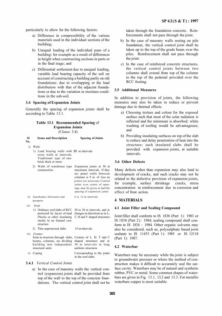
SP 62(S & T) : 1997
3.4.1 Vertical Control Joints a) In the case of masonry walls the vertical con
trol (expansion) joints shall be provided from top of the wall to the top of the concrete foundations. The vertical control joint shall not be
taken through the foundation concrete. Reinforcements shall not pass through the joint.
b) In the case of masonry walls resting on pile foundation, the vertical control joint shall be taken up to the top of the grade beam over the piles. Reinforcement shall not pass through the joint.
c) In the case of reinforced concrete structures, the vertical control joints between two columns shall extend from top of the column to the top of the pedestal provided over the RCC footing.
3.5 Additional Measures
In addition to provision of joints, the following measures may also be taken to reduce or prevent damage due to thermal effects.
a) Choosing texture and colour for the exposed surface such that most of the solar radiation is reflected and the minimum is absorbed; white washing of roofing would be advantageous; and
b) Providing insulating surfaces on top of the slab to reduce and delay penetration of heat into the structure; such insulated slabs shall be provided with expansion joints, at suitable intervals.
3.6 Other Defects
Many defects other than expansion may also lend to development of cracks, and such cracks may not be related to the defective provision of expansion joints, for example, surface shrinkage cracks, stress concentration in reinforcement due to corrosion and effect of frost action.
4 MATERIALS
4.1 Joint Filler and Sealing Compound
Joint filler shall conform to IS 1838 (Part 1): 1983 or IS 1838 (Part 2) : 1984; sealing compound shall conform to IS 1834 : 1984. Other organic solvents may also be considered, such as, polysulphate based joint sealants to IS 11433 (Part 1): 1985 or IS 12118 (Part 1): 1987.
4.2 Waterbar
Waterbars may be necessary while the joint is subject to groundwater pressure or where the method of construction makes it difficult to accurately seal the surface cavity. Waterbars may be of natural and synthetic rubber, PVC or metal. Some common shapes of water-bars are given in Fig. 13.1, 13.2 and 13.3. For metallic waterbars copper is most suitable.
365
Sl Items and Description Spacing of Joints No.
i) Walls 1) Load bearing walls with 30 m intervals
cross walls at intervals. Traditional type of one-brick thick or more
2) Walls of warehouse type Expansion joints at 30 m construction maximum intervals. If they
are panel walls between columns is 9 m of less no jointss are necessary Control joints over centre of open-ings may be given at half the spacing of expansion joints
ii) Sunshades, balconies and 6 to 12 m intervals parapets
in) Roofs 1) Ordinary roof slabs of RCC 20 to 30 ni intervals, and at
protected by layers of mud changes in directions as in L, Phuska or other insulating T, H and V shaped structures media in un framed construction
2) Thin unprotected slabs 15 m intervals
iv) Frames Joint in structure through slabs, Corners of L. H. T and C beams, columns, etc dividing shaped structures and at building into independent 30 m intervals in long structural units uniform structures
v) Coping Corresponding to the joints in the roof slabs
particularly to allow for the following factors: a) Difference in compressibility of the various
materials used in the individual sections of the building;
b) Unequal loading of the individual pans of a building: for example as a result of differences in height when constructing sections in parts or in the final stage; and
c) Differential settlement due to unequal loading, variable load bearing capacity of the soil on account of constructing a building partly on old foundations: due to overlapping ot the load distribution with that of the adjacent foundations or due to the variation in moisture conditions in the sub-soil.
3.4 Spacing of Expansion Joints
Generally the spacing of expansion joints shall be according to Table 13.1.
Table 13.1 Recommended Spacing of Expansion Joints
(Clause 3.4)
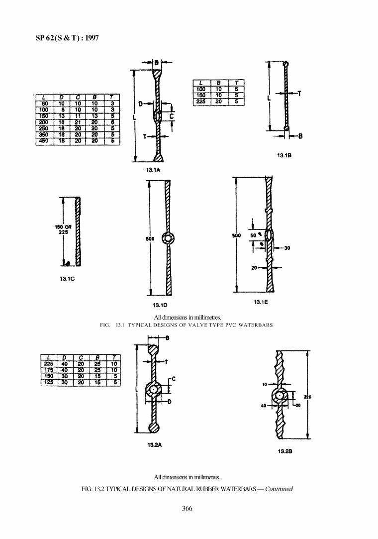
SP 62(S & T) : 1997
All dimensions in millimetres.
FIG. 13.2 TYPICAL DESIGNS OF NATURAL RUBBER WATERBARS — Continued
366
All dimensions in millimetres. FIG. 13.1 TYPICAL DESIGNS OF VALVE TYPE PVC WATERBARS
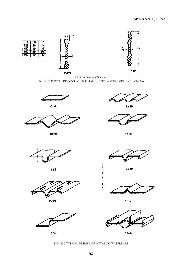
SP 62(S &T ) : 1997
All dimensions in millimetres FIG. 13.2 TYPICAL DESIGNS OF NATURAL RUBBER WATERBARS —Concluded
FIG. 13.3 TYPICAL DESIGNS OF METALLIC WATERBARS
367
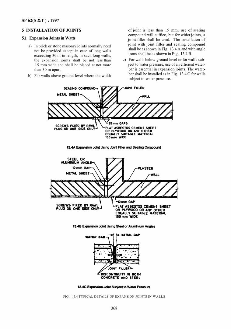
SP 62(S &T ) : 1997
5 INSTALLATION OF JOINTS
5.1 Expansion Joints in Watts
a) In brick or stone masonry joints normally need not be provided except in case of long walls exceeding 30 m in length; in such long walls, the expansion joints shall be not less than 15 mm wide and shall be placed at not more than 30 m apart.
b) For walls above ground level where the width
of joint is less than 15 mm, use of sealing compound will suffice, but for wider joints, a joint filler shall be used. The installation of joint with joint filler and sealing compound shall be as shown in Fig. 13.4 A and with angle irons shall be as shown in Fig. 13.4 B.
c) For walls below ground level or for walls subject to water pressure, use of an efficient water-bar is essential in expansion joints. The water-bar shall be installed as in Fig. 13.4 C for walls subject to water pressure.
368
FIG. 13.4 TYPICAL DETAILS OF EXPANSION JOINTS IN WALLS
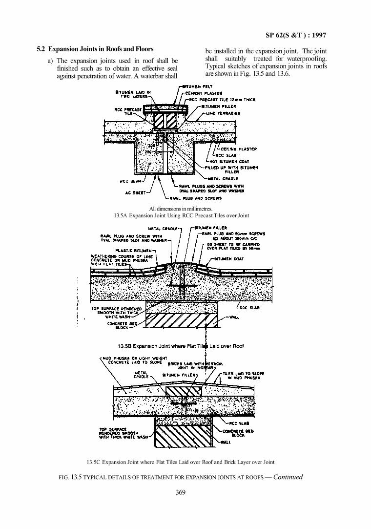
SP 62(S &T ) : 1997
5.2 Expansion Joints in Roofs and Floors a) The expansion joints used in roof shall be
finished such as to obtain an effective seal against penetration of water. A waterbar shall
be installed in the expansion joint. The joint shall suitably treated for waterproofing. Typical sketches of expansion joints in roofs are shown in Fig. 13.5 and 13.6.
All dimensions in millimetres. 13.5A Expansion Joint Using RCC Precast Tiles over Joint
13.5C Expansion Joint where Flat Tiles Laid over Roof and Brick Layer over Joint
FIG. 13.5 TYPICAL DETAILS OF TREATMENT FOR EXPANSION JOINTS AT ROOFS — Continued
369
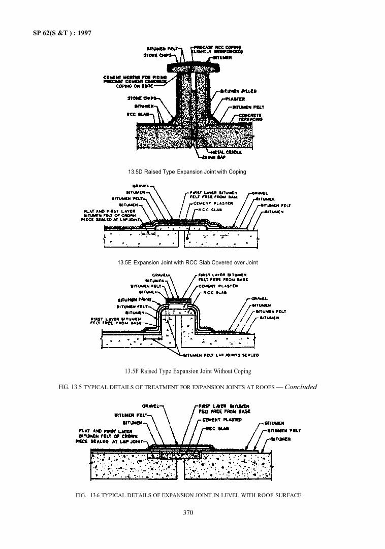
SP 62(S &T ) : 1997
13.5D Raised Type Expansion Joint with Coping
13.5E Expansion Joint with RCC Slab Covered over Joint
FIG. 13.6 TYPICAL DETAILS OF EXPANSION JOINT IN LEVEL WITH ROOF SURFACE
370
13.5F Raised Type Expansion Joint Without Coping
FIG. 13.5 TYPICAL DETAILS OF TREATMENT FOR EXPANSION JOINTS AT ROOFS — Concluded
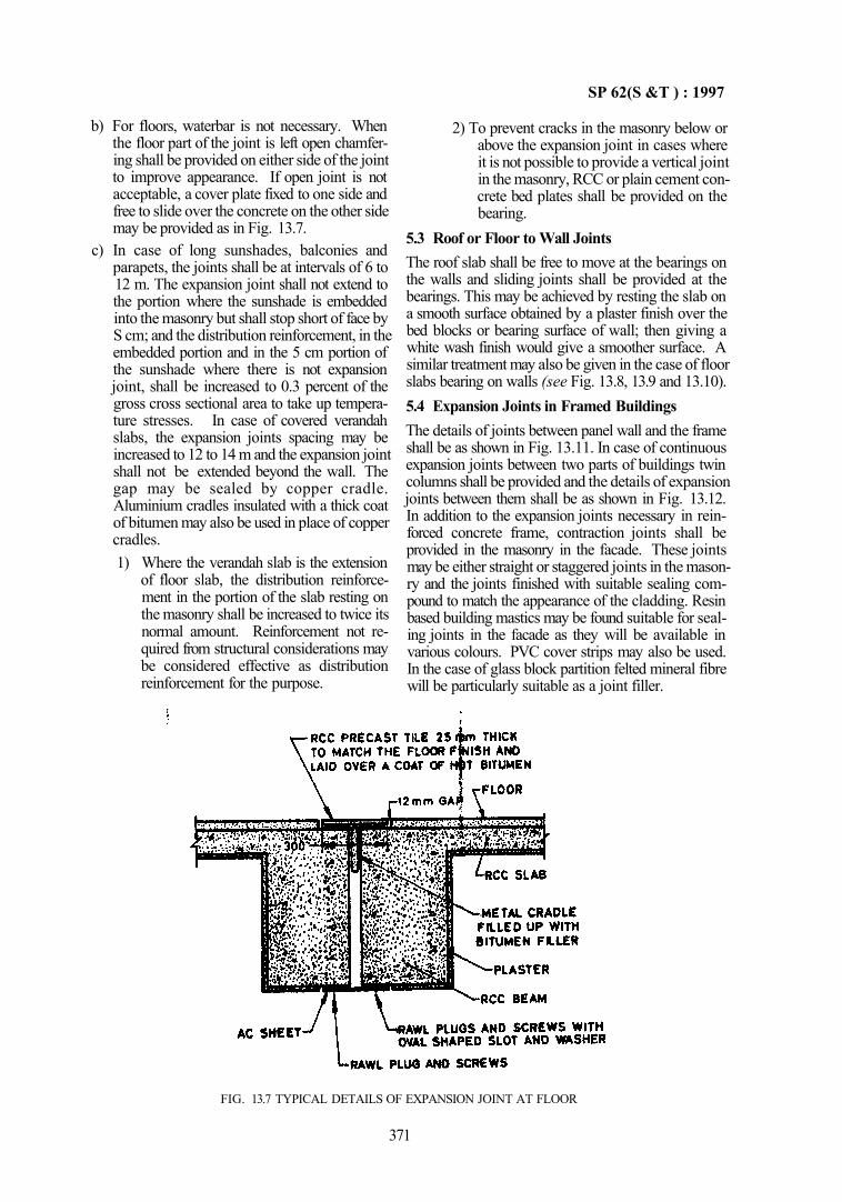
SP 62(S &T ) : 1997
b) For floors, waterbar is not necessary. When the floor part of the joint is left open chamfering shall be provided on either side of the joint to improve appearance. If open joint is not acceptable, a cover plate fixed to one side and free to slide over the concrete on the other side may be provided as in Fig. 13.7.
c) In case of long sunshades, balconies and parapets, the joints shall be at intervals of 6 to 12 m. The expansion joint shall not extend to the portion where the sunshade is embedded into the masonry but shall stop short of face by S cm; and the distribution reinforcement, in the embedded portion and in the 5 cm portion of the sunshade where there is not expansion joint, shall be increased to 0.3 percent of the gross cross sectional area to take up temperature stresses. In case of covered verandah slabs, the expansion joints spacing may be increased to 12 to 14 m and the expansion joint shall not be extended beyond the wall. The gap may be sealed by copper cradle. Aluminium cradles insulated with a thick coat of bitumen may also be used in place of copper cradles. 1) Where the verandah slab is the extension
of floor slab, the distribution reinforcement in the portion of the slab resting on the masonry shall be increased to twice its normal amount. Reinforcement not required from structural considerations may be considered effective as distribution reinforcement for the purpose.
2) To prevent cracks in the masonry below or above the expansion joint in cases where it is not possible to provide a vertical joint in the masonry, RCC or plain cement concrete bed plates shall be provided on the bearing.
5.3 Roof or Floor to Wall Joints The roof slab shall be free to move at the bearings on the walls and sliding joints shall be provided at the bearings. This may be achieved by resting the slab on a smooth surface obtained by a plaster finish over the bed blocks or bearing surface of wall; then giving a white wash finish would give a smoother surface. A similar treatment may also be given in the case of floor slabs bearing on walls (see Fig. 13.8, 13.9 and 13.10). 5.4 Expansion Joints in Framed Buildings The details of joints between panel wall and the frame shall be as shown in Fig. 13.11. In case of continuous expansion joints between two parts of buildings twin columns shall be provided and the details of expansion joints between them shall be as shown in Fig. 13.12. In addition to the expansion joints necessary in reinforced concrete frame, contraction joints shall be provided in the masonry in the facade. These joints may be either straight or staggered joints in the masonry and the joints finished with suitable sealing compound to match the appearance of the cladding. Resin based building mastics may be found suitable for sealing joints in the facade as they will be available in various colours. PVC cover strips may also be used. In the case of glass block partition felted mineral fibre will be particularly suitable as a joint filler.
FIG. 13.7 TYPICAL DETAILS OF EXPANSION JOINT AT FLOOR
371
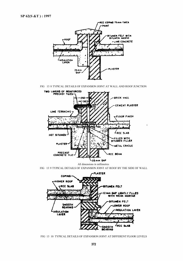
SP 62(S &T ) : 1997
FIG 13 8 TYPICAL DETAILS OF EXPANSION JOINT AT WALL AND ROOF JUNCTION
FIG 13 10 TYPICAL DETAILS OF EXPANSION JOINT AT DIFFERENT FLOOR LEVELS
372
All dimensions in millimetres FIG 13 9 TYPICAL DETAILS OF EXPANSION JOINT AT ROOF BY THE SIDE OF WALL
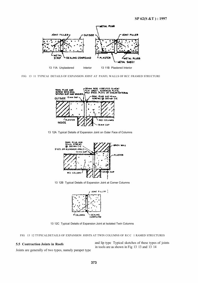
SP 62(S &T ) : 1997
13 11A Unplastered Interior 13 11B Plastered Interior
FIG 13 11 TYPICAI DETAILS OF EXPANSION JOINT AT PANFL WALLS OF RCC FRAMED STRUCTURE
13 12A Typical Details of Expansion Joint on Outer Face of Columns
13 12B Typical Details of Expansion Joint at Corner Columns
13 12C Typical Details of Expansion Joint at Isolated Twin Columns
FIG 13 12 TYPICALDETAILS OF EXPANSION JOINTS AT TWIN COLUMNS OF R C C 1 RAMED STRUCTURES
5.5 Contraction Joints in Roofs
Joints are generally of two types, namely parapet type
and lip type Typical sketches of these types of joints in tools are as shown in Fig 13 13 and 13 14
373
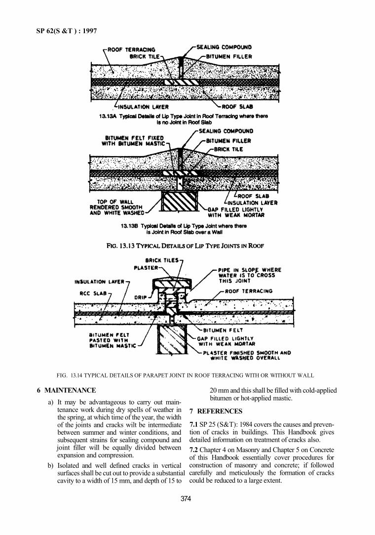
SP 62(S &T ) : 1997
FIG. 13.14 TYPICAL DETAILS OF PARAPET JOINT IN ROOF TERRACING WITH OR WITHOUT WALL
6 MAINTENANCE a) It may be advantageous to carry out main
tenance work during dry spells of weather in the spring, at which time of the year, the width of the joints and cracks wilt be intermediate between summer and winter conditions, and subsequent strains for sealing compound and joint filler will be equally divided between expansion and compression.
b) Isolated and well defined cracks in vertical surfaces shall be cut out to provide a substantial cavity to a width of 15 mm, and depth of 15 to
20 mm and this shall be filled with cold-applied bitumen or hot-applied mastic.
7 REFERENCES
7.1 SP 25 (S&T): 1984 covers the causes and prevention of cracks in buildings. This Handbook gives detailed information on treatment of cracks also. 7.2 Chapter 4 on Masonry and Chapter 5 on Concrete of this Handbook essentially cover procedures for construction of masonry and concrete; if followed carefully and meticulously the formation of cracks could be reduced to a large extent.
374
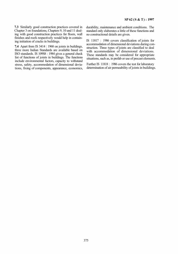
SP 62 (S & T) : 1997
7.3 Similarly good construction practices covered in Chapter 3 on foundations, Chapters 9, 10 and 11 dealing with good construction practices for floors, wall finishes and roofs respectively would help in containing initiation of cracks in buildings. 7.4 Apart from IS 3414 : 1968 on joints in buildings, three more Indian Standards are available based on ISO standards. IS 109S8 : 1984 gives a general check list of functions of joints in buildings. The functions include environmental factors, capacity to withstand stress, safety, accommodation of dimensional deviations, fixing of components, appearance, economics,
durability, maintenance and ambient conditions. The standard only elaborates a little of these functions and no constructional details are given.
IS 11817 : 1986 covers classification of joints for accommodation of dimensional deviations during construction. Three types of joints are classified to deal with accommodation of dimensional deviations. These standards may be considered for appropriate situations, such as, in prefab or use of precast elements. Further IS 11818 : 1986 covers the test for laboratory determination of air permeability of joints in buildings.
375

CHAPTER 14
WHITEWASHING, COLOUR WASHING AND PAINTING OF MASONRY, CONCRETE AND
PLASTER SURFACES (CALCAREOUS SURFACES)
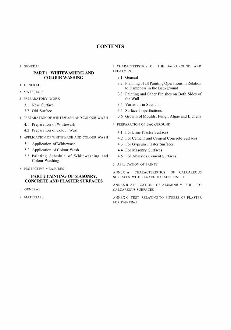
CONTENTS
l GENERAL
PART 1 WHITEWASHING AND COLOUR WASHING
1 GENERAL
2 MATERIALS
3 PREPARATORY WORK
3.1 New Surface 3.2 Old Surface
4 PREPARATION OF WHITEWASH AND COLOUR WASH
4.1 Preparation of Whitewash 4.2 Preparation of Colour Wash
5 APPLICATION OF WHITEWASH AND COLOUR WASH
5.1 Application of Whitewash 5.2 Application of Colour Wash 5.3 Painting Schedule of Whitewashing and
Colour Washing
6 PROTECTIVE MEASURES
PART 2 PAINTING OF MASONRY, CONCRETE AND PLASTER SURFACES
1 GENERAL
2 MATERIALS
3 CHARACTERISTICS OF THE BACKGROUND AND TREATMENT
3.1 General 3.2 Planning of all Painting Operations in Relation
to Dampness in the Background 3.3 Painting and Other Finishes on Both Sides of
the Wall 3.4 Variation in Suction 3.5 Surface Imperfections 3.6 Growth of Moulds, Fungi, Algae and Lichens
4 PREPARATION OF BACKGROUND
4.1 For Lime Plaster Surfaces 4.2 For Cement and Cement Concrete Surfaces 4.3 For Gypsum Plaster Surfaces 4.4 For Masonry Surfaces 4.5 For Absestos Cement Surfaces
5 APPLICATION OF PAINTS
ANNEX A CHARACTERISTICS OF CALCAREOUS SURFACES WITH REGARD TO PAINT FINISH
ANNEX B APPLICATION OF ALUMINIUM FOIL TO CALCAREOUS SURFACES
ANNEX C TEST RELATING TO FITNESS OF PLASTER FOR PAINTING
SP62(S&T):1997
CHAPTER 14
WHITEWASHING, COLOUR WASHING AND PAINTING OF MASONRY, CONCRETE AND PLASTER SURFACES
(CALCAREOUS SURFACES) 1 GENERAL
1.1 Whitewashing and colour washing of surfaces of buildings is necessary for both hygienic and aesthetic reasons. In order to obtain a neat, clean and uniform finish it is necessary to prepare the surfaces, such as, concrete, masonry or plaster.
1.2 Painting of masonry, concrete and plaster and similar calcareous surfaces is carried out not only for hygienic or aesthetic reasons but also for waterproofing and chemical attack from industrial atmospheres contaminated with corrosive fumes. Calcareous surfaces like lime and cement plastered surfaces are highly alkaline in the initial stages, and they retain large quantities of water during construc-
1 GENERAL
1.1 This Part deals with the preparation of surfaces and application of whitewash and colour wash over masonry, conirete and plaster surfaces.
2 MATERIALS
2.1 Lime used shall conform to Class 'C' (fat lime) to IS 712 : 1984 and white in colour. Water shall be clear, free from all organic and suspended impurities; potable water is suitable for this purpose. Sodium chloride shall conform to IS 253 : 1985 or Grade II of IS 797 : 1982. Ultra marine blue or indigo shall conform to IS 55 : 1970. Pigments of yellow and red ochre shall conform to IS 44 : 1991; and pigments of blue vitriol shall be fresh crystals of anhydrous copper sulphate (blue vitriol) and conform to IS 261 : 1982 ground to fine powder.
3 PREPARATORY WORK
3.1 New Surface
The surface shall be thoroughly cleaned of all dirt, dust, mortar drops and other foreign matter before whitewash is to be applied.
tion and it takes a long time for greater part of the water to evaporate even when the atmospheric conditions are favourable. Therefore cognizance of stored up moisture has to be taken while applying a paint system on these surfaces; the alaklinity of the surface is another aspect to be taken note of. These surfaces are porous and present problems, such as, variable suction, surface imperfections, growth of moulds, mosses, lichens and algae. Each of these have adverse effect on most of the surface coating materials and therefore finishing of these surfaces, need special care. 1.3 This Chapter is divided into two Parts, Part I dealing with Whitewashing and colour washing and Part 2 dealing with Painting of masonry, concrete and plaster surfaces.
3.2 Old Surface
a) Surfaces, where the same colour wash is to be repeated, shall be broomed to remove all dust and dirt. All loose scales of lime wash and other foreign matter shall also be removed. Where heavy scaling has taken place the entire surface shall be scraped clean. This will also apply, where a colour wash has to be given on an already whitewashed surface.
b) For surfaces where different colour wash is to be applied, the old colour wash on surfaces shall be entirely removed before whitewash or different colour wash is applied. The surface shall be prepared by brushing or by scraping or by other suitable means to produce a clean surface and shall be broomed to remove dust, dirt, etc.
c) Old surface spoiled by smoke soot shall be scraped with steel wire brushes or steel scrapers. The surface shall be broomed to remove all dust and dirt and shall be washed with clean water.
d) Oil and grease spots shall be removed by a suitable chemical and surfaces rubbed with wire brushes.
PART 1 WHITEWASHING AND COLOUR WASHING
379
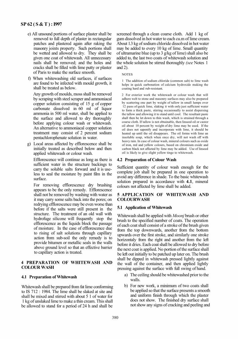
SP 62 ( S & T ) : I997
e) All unsound portions of surface plaster shall be removed to full depth of plaster in rectangular patches and plastered again after raking the masonry joints property. Such portions shall be wetted and allowed to dry. They shall be given one coat of whitewash. All unnecessary nails shall be removed; and the holes and cracks shall be filled with lime putty or plaster of Paris to make the surface smooth.
f) When whitewashing old surfaces, if surfaces are found to be infected with mould growth, it shall be treated as below. Any growth of moulds, moss shall be removed by scraping with steel scraper and ammoniacal copper solution consisting of 15 g of copper carbonate dissolved in 60 ml of liquor ammonia in 500 ml water, shall be applied to the surface and allowed to dry thoroughly before applying colour wash or whitewash. An alternative to ammoniacal copper solution treatment may consist of 2 percent sodium pentachlorophenate solution in water.
g) Local areas affected by efflorescence shall be initially treated as described below and then applied whitewash or colour wash. Efflorescence will continue as long as there is sufficient water in the structure backings to carry the soluble salts forward and it is useless to seal the moisture by paint film in the surface. For removing efflorescence dry brushing appears to be the only remedy. Efflorescence shall not be removed by washing with water as it may carry some salts back into the pores; on redrying efflorescence may be even worse than before if the salts were still present in the structure. The treatment of an old wall with hydrofuge silicone will frequently stop the efflorescence as the liquids block the passage of moisture. In the case of efflorescence due to rising of salt solutions through capillary action from sub-soil the only remedy is to provide bitumen or metallic seals in the walls above ground level so that an effective barrier to capillary action is treated.
4 PREPARATION OF WHITEWASH AND COLOUR WASH
4.1 Preparation of Whitewash
Whitewash shall be prepared from fat lime conforming to IS 712 : 1984. The lime shall be slaked at site and shall be mixed and stirred with about 5 1 of water for 1 kg of unslaked lime to make a thin cream. This shall be allowed to stand for a period of 24 h and shall be
screened through a clean coarse cloth. Add 1 kg of gum dissolved in hot water to each cu.m of lime cream. About 1.3 kg of sodium chloride dissolved in hot water may be added to every 10 kg of lime. Small quantity of ultramarine blue (up to 3 g/kg of lime) shall also be added to, the last two coats of whitewash solution and the whole solution be stirred thoroughly (see Notes 1 and 2).
NOTES
1 The addition of sodium chloride (common salt) to lime wash helps in quick earbonation of calcium hydroxide making the coating hard and rub-resistant.
2 For exterior work the whitewash or colour wash that will adhere welt to stone and masonry surfaces may also be prepared by scattering one part by weight of tallow in small lumps over 12 pans of quick lime, slaking it with only just sufficient water to form a thick paste, stirring occasionally to assist dispersing the tallow and allowing it to stand until cool. The resultant paste shall then be let down to thin wash, which is strained through a coarse cloth. If tallow is not obtainable, then linseed oil or castor oil about 10 percent by weight of dry lime may be used. If the oil does not saponify and incorporate with lime, it should be heated up until the oil disappears. The oil forms with lime an insoluble soap, which when once dry, will not wash off with heavy rain. In case of colour wash, mineral colours such as oxide of iron, red and yellow colours, based on chromium oxide and carbon black not affected by lime may be added. Use of linseed oil is likely to give slight yellow tinge to whitewash.
4.2 Preparation of Colour Wash Sufficient quantity of colour wash enough for the complete job shall be prepared in one operation to avoid any difference in shade. To the basic whitewash solution prepared in accordance with 4.1, mineral colours not affected by lime shall be added.
5 APPLICATION OF WHITEWASH AND COLOURWASH
5.1 Application of Whitewash
Whitewash shall be applied with Moonj brush or other brush to the specified number of coats. The operation of each coat shall consist of a stroke of the brush given from the top downwards, another from the bottom upwards over the first stroke, and similarly one stroke horizontaly from the right and another from the left before it dries. Each coat shall be allowed to dry before the next coat is applied. No portion of the surface shall be left out initially to be patched up later on. The brush shall be dipped in whitewash pressed lightly against the wall of the container, and then applied lightly pressing against the surface with full swing of hand.
a) The ceiling should be whitewashed prior to the walls.
b) For new work, a minimum of two coats shall be applied so that the surface presents a smooth and uniform finish through which the plaster does not show. The finished dry surface shall not show any signs of cracking and peeling and
380
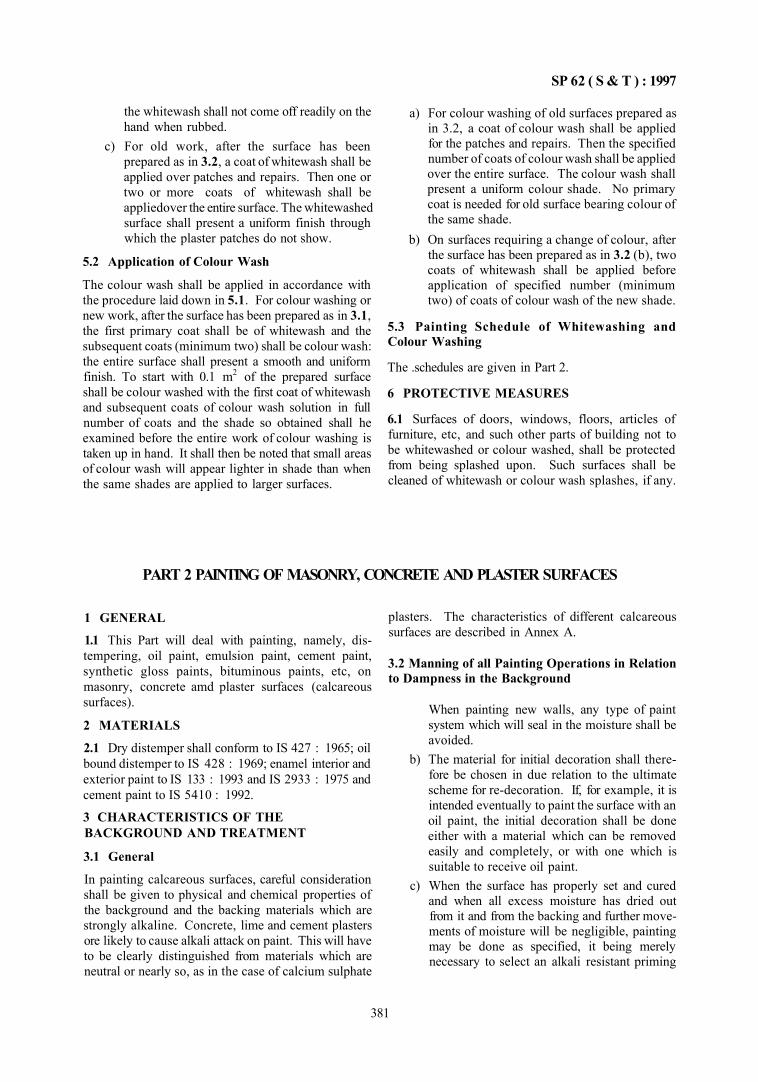
SP 62 ( S & T ) : 1997
the whitewash shall not come off readily on the hand when rubbed.
c) For old work, after the surface has been prepared as in 3.2, a coat of whitewash shall be applied over patches and repairs. Then one or two or more coats of whitewash shall be appliedover the entire surface. The whitewashed surface shall present a uniform finish through which the plaster patches do not show.
5.2 Application of Colour Wash
The colour wash shall be applied in accordance with the procedure laid down in 5.1. For colour washing or new work, after the surface has been prepared as in 3.1, the first primary coat shall be of whitewash and the subsequent coats (minimum two) shall be colour wash: the entire surface shall present a smooth and uniform finish. To start with 0.1 m2 of the prepared surface shall be colour washed with the first coat of whitewash and subsequent coats of colour wash solution in full number of coats and the shade so obtained shall he examined before the entire work of colour washing is taken up in hand. It shall then be noted that small areas of colour wash will appear lighter in shade than when the same shades are applied to larger surfaces.
a) For colour washing of old surfaces prepared as in 3.2, a coat of colour wash shall be applied for the patches and repairs. Then the specified number of coats of colour wash shall be applied over the entire surface. The colour wash shall present a uniform colour shade. No primary coat is needed for old surface bearing colour of the same shade.
b) On surfaces requiring a change of colour, after the surface has been prepared as in 3.2 (b), two coats of whitewash shall be applied before application of specified number (minimum two) of coats of colour wash of the new shade.
5.3 Painting Schedule of Whitewashing and Colour Washing
The .schedules are given in Part 2.
6 PROTECTIVE MEASURES
6.1 Surfaces of doors, windows, floors, articles of furniture, etc, and such other parts of building not to be whitewashed or colour washed, shall be protected from being splashed upon. Such surfaces shall be cleaned of whitewash or colour wash splashes, if any.
PART 2 PAINTING OF MASONRY, CONCRETE AND PLASTER SURFACES
1 GENERAL
1.1 This Part will deal with painting, namely, distempering, oil paint, emulsion paint, cement paint, synthetic gloss paints, bituminous paints, etc, on masonry, concrete amd plaster surfaces (calcareous surfaces).
2 MATERIALS
2.1 Dry distemper shall conform to IS 427 : 1965; oil bound distemper to IS 428 : 1969; enamel interior and exterior paint to IS 133 : 1993 and IS 2933 : 1975 and cement paint to IS 5410 : 1992.
3 CHARACTERISTICS OF THE BACKGROUND AND TREATMENT
3.1 General
In painting calcareous surfaces, careful consideration shall be given to physical and chemical properties of the background and the backing materials which are strongly alkaline. Concrete, lime and cement plasters ore likely to cause alkali attack on paint. This will have to be clearly distinguished from materials which are neutral or nearly so, as in the case of calcium sulphate
plasters. The characteristics of different calcareous surfaces are described in Annex A.
3.2 Manning of all Painting Operations in Relation to Dampness in the Background
When painting new walls, any type of paint system which will seal in the moisture shall be avoided.
b) The material for initial decoration shall there-fore be chosen in due relation to the ultimate scheme for re-decoration. If, for example, it is intended eventually to paint the surface with an oil paint, the initial decoration shall be done either with a material which can be removed easily and completely, or with one which is suitable to receive oil paint.
c) When the surface has properly set and cured and when all excess moisture has dried out from it and from the backing and further movements of moisture will be negligible, painting may be done as specified, it being merely necessary to select an alkali resistant priming
381
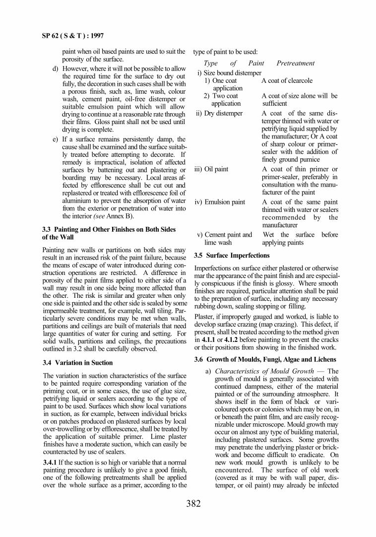
SP 62 ( S & T ) : 1997
paint when oil based paints are used to suit the porosity of the surface.
d) However, where it will not be possible to allow the required time for the surface to dry out fully, the decoration in such cases shall be with a porous finish, such as, lime wash, colour wash, cement paint, oil-free distemper or suitable emulsion paint which will allow drying to continue at a reasonable rate through their films. Gloss paint shall not be used until drying is complete.
e) If a surface remains persistently damp, the cause shall be examined and the surface suitably treated before attempting to decorate. If remedy is impractical, isolation of affected surfaces by battening out and plastering or boarding may be necessary. Local areas affected by efflorescence shall be cut out and replastered or treated with efflorescence foil of aluminium to prevent the absorption of water from the exterior or penetration of water into the interior (see Annex B).
3.3 Painting and Other Finishes on Both Sides of the Wall
Painting new walls or partitions on both sides may result in an increased risk of the paint failure, because the means of escape of water introduced during construction operations are restricted. A difference in porosity of the paint films applied to either side of a wall may result in one side being more affected than the other. The risk is similar and greater when only one side is painted and the other side is sealed by some impermeable treatment, for example, wall tiling. Particularly severe conditions may be met when walls, partitions and ceilings are built of materials that need large quantities of water for curing and setting. For solid walls, partitions and ceilings, the precautions outlined in 3.2 shall be carefully observed.
3.4 Variation in Suction
The variation in suction characteristics of the surface to be painted require corresponding variation of the priming coat, or in some cases, the use of glue size, petrifying liquid or sealers according to the type of paint to be used. Surfaces which show local variations in suction, as for example, between individual bricks or on patches produced on plastered surfaces by local over-trowelling or by efflorescence, shall be treated by the application of suitable primer. Lime plaster finishes have a moderate suction, which can easily be counteracted by use of sealers. 3.4.1 If the suction is so high or variable that a normal painting procedure is unlikely to give a good finish, one of the following pretreatments shall be applied over the whole surface as a primer, according to the
type of paint to be used: Type of Paint Pretreatment
i) Size bound distemper 1) One coat A coat of clearcole
application 2) Two coat A coat of size alone will be
application sufficient ii) Dry distemper A coat of the same dis
temper thinned with water or petrifying liquid supplied by the manufacturer; Or A coat of sharp colour or primer-sealer with the addition of finely ground pumice
iii) Oil paint A coat of thin primer or primer-sealer, preferably in consultation with the manufacturer of the paint
iv) Emulsion paint A coat of the same paint thinned with water or sealers recommended by the manufacturer
v) Cement paint and Wet the surface before lime wash applying paints
3.5 Surface Imperfections
Imperfections on surface either plastered or otherwise mar the appearance of the paint finish and are especially conspicuous if the finish is glossy. Where smooth finishes are required, particular attention shall be paid to the preparation of surface, including any necessary rubbing down, sealing stopping or filling. Plaster, if improperly gauged and worked, is liable to develop surface crazing (map crazing). This defect, if present, shall be treated according to the method given in 4.1.1 or 4.1.2 before painting to prevent the cracks or their positions from showing in the finished work.
3.6 Growth of Moulds, Fungi, Algae and Lichens a) Characteristics of Mould Growth — The
growth of mould is generally associated with continued dampness, either of the material painted or of the surrounding atmosphere. It shows itself in the form of black or varicoloured spots or colonies which may be on, in or beneath the paint film, and are easily recognizable under microscope. Mould growth may occur on almost any type of building material, including plastered surfaces. Some growths may penetrate the underlying plaster or brickwork and become difficult to eradicate. On new work mould growth is unlikely to be encountered. The surface of old work (covered as it may be with wall paper, distemper, or oil paint) may already be infected
382
SP 62 ( S & T ) : 1997
with mould, particularly in premises which have been left unoccupied for sometime or where there has been a persistent damp penetration, and especially where walls have been saturated with water in the course of fire fighting.
b) Precautions — Exterior surface of porous building materials like brick, stone and cement rendering, especially if unpainted, may develop growths of vegetation ranging from thick beds of moss to slimy steaks or patches of algae. Any such growth shall be removed and ammoniacal copper solution (sec Note) shall be applied to the surface and allowed to dry thoroughly before painting. NOTE — A recommended composition and concentiation of the ammoniacal wash shall consist of 7g of copper carbonate dissolved in HO ml of liquor ammonia and diluted to 1 1 with water Alternatively, 2.5 percent magnesium silicofluortdc solution may he used
c) For prevention of recurrence of mould growth the following procedure shall be followed: 1) Remove the source of dampness and dry
out the walls; 2) Improve ventilation, if necessary; 3) Remove the infected paint or paper; and 4) Sterilize the surface by applying an
antiseptic wash, such as, 2 percent sodium pentachlorophenate or any other proprietary material and allowed to dry.
4 PREPARATION OF BACKGROUND 4.1 For Lime Plaster Surfaces In the case of new lime plaster, precautions with regard to the drying of background shall be observed carefully as these will considerably effect the performance of the finish. In case of new lime plaster, the essential principles with respect to drying of background will be the following:
a) If possible lime plaster shall be left unpainted for the first few months so as to allow the plaster to carbonate, harden and dry thoroughly. If the plaster has any tendency to craze or crack owing to shrinkage on drying, the movements shall be allowed to occur before the surface is painted so as to enable provision of suitable proprietary treatment. Heating the rooms, if accompanied by good ventilation, will assist drying, but shall be cautiously adopted. Too rapid a drying may damage the plaster by causing undue shrinkage and separation of the plaster coats.
b) If there is any objection to leaving the plaster bare, a temporary decoration of soft distemper may be applied. This may be removed easily at a later date and replaced by a more per
manent decoration. Other types of paint suitable for early application are cement paints, silicate paints and washable distemper depending on the final decoration in view.
c) If the background of the plaster is one likely to contain large amounts of water, for example, new brickwork, concrete or building blocks, no attempts shall be made to apply oil paint (especially gloss finish) until there is every reason to believe that the walls are thoroughly dry. Some indication of the progress of drying can be obtained by means of tests described in Annex C.
d) If the background is of a dry type, for example, wood or metal lath, oil paints may be applied with safety after a few weeks of dry ing, and oil bound distempers even earlier.
4.1.1 In case of old unpainted plaster surfaces any source of dampness in walls and ceilings shall be removed and painting shal be deferred until the plaster has dried. Any major cracks or defects in the plaster shall be cut out and made good. Cracks may be wetted thoroughly prior to filling or priming paint may be applied to the sides of cracks to avoid undue absorption of water and subsequent shrinkage of the filling. For filling, a retarded hemi-hydrate calcium sulphate plaster gauged with about one-third of its volume of hydrated lime may be used. Prior to painting, fine cracks may be filled with a mixture of oil, putty and white lead or a distemper type of filling composition depending on the finish which is to follow. 4.1.2 In the case previously painted lime plaster surfaces the following precautions shall be observed:
a) Any existing fungus or mould growth shall be completely removed. The surface shall be thoroughly scraped and rubbed down with ???ristle brush and sand paper and then washed down with clean water and allowed to dry. A coat of fungicidal wash shall then be applied and allowed to dry after which a further coat shall be applied and left for sometime to dry thoroughly. The surface shall be kept under observation for sometime during drying out period and if the mould recurs, the treatment and drying shall be repeated before painting. The surface shall be brushed with soft bristle brush to remove any dust particles 24 h after the wash. Painting shall be carried out over the fungicidal wash without removing it with water.
b) Any existing paint showing extensive flaking, bleaching or saponification (as shown by stick-ness or the presence of yellow soapy runs) shall
383
SP 62 ( S & T ) : 1997
he removed by scraping and washing and the surface allowed to dry completely. It may then he repainted as prescribed for new surfaces.
c) Local defective patches shall be Treated individually by removing all loose or softened paint and bringing forward the treated patches with primer and undercoating before applying a fresh coating over the white areas.
d) Dry distempers and lime wash shall be totally removed prior to repainting. It may sometimes be necessary to wet the surface before scraping. This shall not be overdone and all surfaces shall be perfectly dry prior to the application of any priming coats.
e) Certain wall and ceiling surfaces may reveal hairline cracks. After complete removal of the existing paint systems and if the lime plaster has cured and dried completely, use at least two coats of any of the primers for the paint system to be adopted. When oil paint is to be used, the primer at least shall be of alkali resistant type. Lime fast pigments shall be used.
f) Water based paint or washable distemper, if in a clean, sound condition, need not be removed if similar coatings arc to be applied in the new paint system. By using a mild detergent, the surface may be washed and then after a light sanding it will be ready to receive a fresh coat (with spot priming, if required).
4.2 For Cement and Cement Concrete Surfaces For new surface it is preferable that the surface is left unpainted for as long as possible to allow drying. Before painting, the surface shall be thoroughly-brushed to remove all dirt and remains of loose or powdered materials. Treatment of the surface with solution of acids or salts, such as, zinc sulphate is not advisable as the risk of not reducing the alkali attack appreciably and efflorescence may be increased. But on old unpainted surfaces, if there is an extensive growth of vegetable material which cannot be removed by brushing, the growth shall be destroyed by applying a wash of ammoniacal copper solution in accordance with 3.6(b). The dead and dry remains of the growth shall be brushed off prior to painting. Any loose or uneven areas or any major cracks in cement concrete or plaster background shall be cut out and made good and the repairs allowed to dry thoroughly before painting is commenced. Minor repairs may be made with cement mortar. Cement plaster or concrete which is previously painted shall be prepared in the same manner as in 4.1.2. 4.3 For Gypsum Plaster Surfaces Before application of the paint it shall be ensured whether the surface is alkaline or neutral and
the alkalinity may be tested in accordance with Annex C. If the surface of the plaster has a patchy appearance and shows wide variations in suction due to efflorescence or other causes, a paint primer shall be applied before application of a regular paint. For old surfaces, unpainted or previously painted, the preparation of background will be the same as in the case of lime plasters. If it is a neutral surface, the application priming paint may not be necessary. 4.4 For Masonry Surfaces All mortar joints shall be brought to a sound condition before painting operations are started. In the case of new brickwork, painting shall be deferred for at least three months after completion of the masonry work and longer if the weather during this period has become unfavourable for drying. Dirt may be removed by washing with water. In case of old masonry, wherever there is extensive growth of vegetable matter, it shall be treated suitably according to 3.6. Previously painted surfaces of brickwork shall be prepared in the manner given in 4.1.2. 4.5 For Asbestos Cement Surfaces Asbestos cement being based on portland cement will be, specially when new and damp, sufficiently alkaline to attack oil paint. The asbestos cement sheets are porous, permit suction and also fungus growth on them. The necessary precautions in the painting work to overcome there difficulties are as below:
a) The best way, probably, to reduce the risk of alkali attack is to allow the sheets to weather for some months. The alkali become carbonated on exposure to air, and rain will often wash them off the surface to some extent. With long exposure, however, surfaces become powdery and dirty, and offer poor key for paint unless properly cleaned. Although weathering reduces the risk, it may not entirely overcome the danger of alkali attack.
b) Asbestos cement sheets shall not be treated with chemicals like hydrochloric acid or zinc sulphate to neutralize the alkalis. Also the use of chemicals will often leave powdery deposit on the surface which may interfere with adhesion of paint. The use of hydrochloric acid for cleaning will also make the asbestos cement sheet brittle.
c) Asbestos cement sheets are porous in varying degrees and moisture absorbed will often cause failure of the paint system. It is therefore essential that absestos cement sheets are dry when they are painted. To ensure this each sheet shall be left with both sides exposed to good drying conditions for 7 to 10 days before painting.
384
SP 62 ( S & T ) : 1997
d) When there is a danger of moisture entering the sheets from the hack owing to dampness or condensation, 'back painting' shall be done with an alkali-resistant primer conforming to IS 109 : 1968 or bitumen paint conforming to IS 158 : 1981 or a colourless waterproofer. Usually 'back painting' will have to be done before the sheets are fixed and will be particularly necessary where impervious painting system is adopted for painting of the surface. Back painting means coating the back and edges of the sheets with a specified paint to prevent entry of moisture from the back. Whenever impervious paint or paint system is used on the face, 'back painting1 shall be.done When the backs of sheets are inaccessible for back painting, a porous paint shall be chosen. Porous paints will allow the sheets to breathe so that there is less risk of trouble caused by moisture.
e) Glazed patches are often visible on asbestos cement sheets and they have to be roughened to provide a key to the paint. More absorbent patches, which are whiter than the rest on the surface, tend to suck medium out of the paint and this is likely to affect the durability of the paint on these patches. The suction is also high and also variable. To overcome this effect pretreatment with primer as mentioned in the paint schedules (see 5) shall be applied over the whole surface. Application of the primer shall be minimutti two coats.
If the suction is very high and variable that normal painting procedure is unlikely to give a satisfactory finish, suitable pretreatment to the surface shall be given as described in 3.4.1.
f) It is important to remove and kill any existing fungus growth. for this the surface shall be scraped and rubbed down with glasswool and sandpaper and then washed down with clean water and allowed to dry. A coat of fungicidal wash shall then be applied and left for sometime to dry thoroughly (see 3.6 and 4.1.2).
4.5.1 Preparation of Surface The surface shall be cleaned by rubbing with sandpaper. Any glazed area shall be roughened. Loose powdery material after rubbing shall be brushed off. Wire brushes shall be avoided in cleaning operations as they will lead to difficulties from deposited particles of iron causing iron stains. In the case of previously painted surface the preparation of surface shall be as in 4.1.2, as applicable. Before applying the paint finish, sheets shall be given a final sand papering and then washed down with clean water and allowed to dry thoroughly. If the old paint film is sound, one or two coats only of any of the finishing paints may be applied. 5 APPLICATION OF PAINTS 5.1 The application of paints shall generally be as given in Table 14.1 and Table 14.2 along with pretreat-ments where necessary for corresponding types of paints. The painting operations shall be as given in Chapter 15.
Table 14.1 Schedules for Painting New Calcareous Surfaces — Interior ( Clause 5.1 )
SI Final Finish Required No. (1) (2)
i) Whitewash ii) Colour wash
iii) Distemper a) Dry distemper (non-washable)
b) Oil bound distemper
iv) Emulsion paint1)
v) Flat/Semigloss paint1)
vi) Gloss paint1)
vii) Chemical resistant paint1)
viii) Cement paint1)
ix) Bituminous paint1)
Primer Coat
(3) One coat of whitewash One coat of colour wash
Clearcole or size, etc
One coat of alkali resistant primer
One coat of emulsion paint
One coat of alkali resistant primer
do
One coat of the paint
One coat of cement paint
One coat of the paint
1) May be thinned according to manufacturer's recommendation.
"■ T
Under Coat
(4) i
–
Filler to be used, if required
do
do
Undercoat as requi-red, filler, if required
do
Filler, if required
Nil
Nil
Finishing Coats
(5) Whitewash (two coats) Colour wash (two coals)
Dry distemper (two coats) (IS 427 : 1965)
Oil bound distemper (two coats) ( IS 428 .1969 )
Emulsion paint (two coats) [ IS 541] (Part 1) 1974] Flat/Semigloss paint
(two coats) Gloss paint (two coats)
( IS 131 . 1993) Chemical, resistant paint
(two coats) Cement paint (two coats)
(IS 5410 1992) Bituminous paint (two coats)
(IS 9862 . 1981)
385
S P 6 2 ( S & T ) : 1997
Table 14.2 Schedules for Painting New Calcareous Surfaces — Exterior (Clause 5.1)
SI No. (1)
i) ii)
iii)
iv)
v)
vi)
vii)
Final Finish Required
(2) Whitewash Colour wash
Emulsion paint1)
Flat/Semigloss paint1)
Gloss paint1)
Chemical resistant paint
Cement paint1)
Primer Coat
CM One coat ot whitewash One coat of whitewash
One coat of emulsion paint
One coat of alkali resistant primer
do
One coat of the paint
One coat of cement paint
Under Coat
(4) Nil Nil
Filler, if required
Undercoat as required
do
Filler, if required
Nil
Finishing Coats
(5) Whitewash (two coats) Colour wash (two coats)
Emulsion paint (two coats) [IS 5411 (Part 2) 1972]
Flat/Semigloss paint (two coats) (IS 168 : 1973 and IS 1232 1964)
Gloss paint (two coats) (IS 2932 1993 and IS 2913 - I975)
Chemical resistant paint (two coats)
Cement paint (two coats) (IS 5410 1992)
VII) Bituminous paint One coat of the paint
1) May be thinned according to manufacturer's recommendation
Nil Bituminous paint (two coats) (IS 9862 1981 and IS 158 1981)
5-1.1 Normally stopping or filling as required be carried out before any painting is done and care should be taken to see that any cracks between plaster and wood work (for example, skit tings) are securely filled, If such cracks are wide, caulking with hemp or similar material may be necessary to support the tilling and prevent it falling away through the gaps. Minor defects are frequently more apparent once the priming or first coat has been applied, and if any further stop-ping or tilling is done over this first coat the area must be brought forward with appropriate paint to restore even porosity over the surface
5.1.2 In regard to painting of asbestos cement sheets, the following points may be noted
a) Asbestos cement sheets shall be thoroughly dry at the time of painting.
b) Back painting shall be done when an impervious paint system is adopted for the finish, if practicable it shall be done after the face of the sheet has been painted, though, normally back painting will have to be done before the sheets are fixed.
c) For external sheeting an alkali-resistant paint either porous or impervious (with back painting ) may be chosen
d) Where it is desired to tone down the natural colour of the sheets, a wash of green copper (as ferrous sulphate about 0 1 g/ml of water) shall be used. This will give a durable brownish stain, although the finish is unlikely to be uniform.
e) Gutters, downpipes, etc, should receive water-proofing coating ot bitumen on the inside. For outer surfaces alkali-resistant porous paint shall be used.
f) For painting asbestos cement sheets, in choosing a paint system for a particular job, the risk of attack by alkali shall be taken into account. Paints which are by themselves highly resistant to alkali attack may be used. But where paints used are not alkali-resistant, at least two coats of alkali-resistant primer shall be applied. The primer shall not only be resistant but also form an impervious barrier so that alkali cannot get through to attack the paint system above.
5.2 Maintenance
In case of painting relating to maintenance work, the principles given in Table 14.3 should generally be applied.
386
SP 62 ( S & T ) : 1997
Table 14.3 Recommended Practice for Maintenance Painting (Clause 5.2)
Sl No.
Condition of Surface Cleaning and Painting Practice
(see Notes 1 and 2) Blister- Effl- Chal- Crack Flak ing and ores- king ing ing Soften- cence
ing
(1) (2) (3) (4) (5) (6) (7)
i)
ii)
iii)
iv)
v)
Nil
Nil
Yes
Nil
Nil
Nil
Yes
Nil
Nil
Nil
Yes
Yes
Nil
Nil
Nil
Nil
Nil
Nil
Yes
Nil
Nil
Nil
Nil
Nil
Yes
Clean, rub down with abrasrve paper, apply one finishing coat
Rub down the alfccted sursace to bare plaster, allow to dry, touch up with primer coal and then apply required number of coats; and follow by a reviver coat on the entire surface, if required.
Scrap off the soft film, allow the surface to dry completely, touch up with pnmer coal and then apply required number of coats. and follow by reviver coal on the entire surface, if necesary
Rub down and even up die surface with sand paper to remove cracked film Touch up with primer and apply the requried number of coats and follow by reviver coat on the entire surface, it necessary.
Remove the paint from the affected portion completely and follow part of or full schedule of painting as the case may be
NOTES
1 In case of any serious characteristics failure mentioned above (except chalking), the paint shall be completely removed and the lull schedule of painting be followed
2 There is no effective remedy for efflorescence
CHARACTERISTICS OF CALCAREOUS SURFACES WITH REGARD TO PAINT FINISH
A-1 CHARACTERISTICS OF LIME PLASTER
a) Lime plasters are highly alkaline and hence. until they are thoroughly dry and matured, they are likely to cause alkali attack on oil containing paints and distempers and fading of distempers. The severity of the attack vanes with the proportion of soluble alkalis (soda and potash) in lime used, but it is always wise to take full precautions against alkali attack irrespective of the type of lime used.
h) Lime plaster finishes have a moderately high suction. This may be encountered by suitable adjustment of the priming coat.
c) Lime plaster develops efflorescence less quickly than other plaster finishes.
d) Lime plaster, if improperl) gauged and worked, is likely to develop surface crazing. This defect if present, may he reduced by special treatment as described in 4.1.1 or 4.1.2 to prevent cracks or their positions showing in the finished painted surface.
e) Lime plaster, being softer than other plasters, is liable to mechanical damage in certain solutions. The plaster shall, however, be made to harden more quickly by suitable gauging.
387
S P 6 2 ( S & T ) : 1 9 9 7
A-2 CHARACTERISTICS OF GYPSUM plASTER
a) When the plaster is properly set and hardened and the plaster backing and background are dry, gypsum plasters may be painted successfully with almost any type of paint except cement paint.
b) The finishing coat of gypsum plaster can be applied over any type of undercoat; the undercoat does not affect the painting procedure and it is the composition of. the plaster finishing coat that is chiefly to be considered.
c) plaster finishes gauged with lime involve a greater painting risk than other plasters, owing to the possibility of alkali attack. The risk is least with retarded hemi-hydrate gypsum plasters but for practical purposes, it is ad-visable to take precautions against alkali from any plaster to which lime has been added.
d) Neat calcium sulphate plasters have no appreciable chemical action on paint, and the
efflorescent salts.
On anhydrite plaster, patches of efflorescence sometimes develop on areas differing in suction from remainder of the surface and there is a tendency for paint to fail in adhesion at these places. Extra care in priming is needed to secure adequate adhesion and even finish. The technique of griming following the trowel' helps to overcome the difficulty.
e) Retarded herni-hydrate plasters, when exposed continuously to damp conditions, are liable to 'sweet out', a defect characterized by failure to harden or by disintegration. This may occur in various circumstances, for example, when the background of the plaster is permanently damp or when moisture is sealed into the plaster by premature application of an impervious paint film. Care shall be taken to avoid these conditions.
f) Gypsum plasters are liable to a defect known as 'dry out' characterized by friable condition of the plaster surfacing and sometimes affecting the whole thickness of the finishing coat. It occurs when plaster is allowed to dry out too quickly before it had time to combine with all the water needed for setting and hardening processes. A 'dry out' can be caused by application of the plaster finish to a highly absorbant undercoat, by conditions favouring by rapid evaporation or by the premature
application of artificial heat. An impervious backing to a thin plaster finishing coat may be as dangerous as one which is too absorbant. since it holds little or no reserve of water and the finish dries quickly. The condition of 'dry out' is not, usually, apparent at the time the surface is decorated but, if an impervious coat of paint is applied, water from the backing may cause expansion of the partially hydrated plaster producing ridges, blistering and disintegration in the plaster and often causing the paint to loose adhesion.
g) While, it is possible to obtain a satisfactory paint on any type of gypsum plaster, provided the appropriate precautions are observed, it is preferable, from the painters point of view that the plaster surface shall not be too highly trowelled and made non-absorbant. A plaster surface which shows a moderate and uniform degree of suction provides a margin of safety in the matter of paint adhesion. It is particularly desirable to have a surface of this type when emulsion paints, water paints and distempers are to be used, since these adhere less strongly, to impervious surfaces than do oil paints. A gloss paint finish shows up any irregularities in the plaster surface, and hence, in places where such a finish is required, the plaster used shall be one which can readily be brought to a smooth level finish. To some extent, this conflicts with the requirements that the plaster shall be trowelled only to the minimum needed to produce a smooth finish and no attempt shall be made to produce a high polish.
h) Gypsum plasters may conform to IS 2547 (Parts 1 & 2 ) : 1976.
A-3 CHARACTERISTICS OF CEMENT AND RENDERINGS
a) New portland cement concrete and renderings are strongly alkaline, and for this reason oil paints when applied to them are subject for sponification and bleaching. In addition there is a risk of damage by efflorescence.
b) The drying and surface combination cannot be hastened by treatment. Oil paint, therefore, shall not be used on such surfaces until several months have passed; but earlier decoration may be carried out with cement paints or silicate paints.
388
paint defects which occur on them arc generally associated with the action of moisture and of
S P 6 2 ( S & T ) : 1 9 9 7
ANNEX B (Clause 3.2)
APPLICATION OF ALUMINIUM FOIL TO CALCAREOUS SURFACES
B-1 PROCEDURE
B-1.1 The area to be treated shall be cleared of dust and allowed to dry prior to the application by means of a brush of a thin coat of bitumen primer conforming to IS 3384 : l986. Blown bitumen (penetration 10 to 20) conforming to IS 702 : 1988 shall be hot applied by brush at a temperature of I75°C to the surface at the rate of approximately 1.5 kg/m2. The aluminium foil
C-1 TEST FOR ALKALINITY C-1.1 Representative areas ot plaster shall be treated with an oil-gloss paint or other alkali-sensitive paint (tinted with prussran blue) and left for at least a week. If at the end the lime there is no sign of sponification or bleaching, conditions shall be reasonably sate for permanent decoration. It on the other hand, bleaching and sponilication has occuned. turther small areas shall be treated. This shall be repeated until sample areas remain undamaged. C-1.2 Alternative Procedure Alkalinity may also be detected by the use of moistened red litmus paper on the surface. If it turns blue the presence of alkaline background may be inlet red. C-2 TEST FOR EFFLORESCENCE C-2.1 Small areas of plaster where the efflorescence is most conspicious shall be rubbed down with a suitable abrasive followed by the application ol damp (not wet) cloth and left for at least one week. This
(0.025 mm thick) shall immediately be unrolled on the surface applied with hot bitumen. all joints shall have at feast 50 mm overlap and shall be hot sealed. If required the blown type bitumen at 175°C at the rate of 1.5 kg/m2 may be applied over the aluminium foil as a scaler coat. Thereafter, the aluminium toil or the bitumen scaler coat shall be painted with a plastic emulsion paint or water based paint as required.
process shall be repeated, if necessary, until no more salts appear. Conditions shall then be reasonably safe for permanent painting. The test shall be carried out under conditions of warmth and ventilation approximating those of occupational conditions.
C-3 TEST FOR DRYNESS
C-3.1 It shall be noted that those tests covered in C-1 and C-2 are not sufficient since a plastered wall may be neutral and show no signs efflorescence and yet be damp which is liable to cause paint to tail in adhesion. Morsture metre for testing the dryness ot walls may be used in deciding when a surface has reached a condi tion to receive paint. However, no form of test may indicate, the condition of mote than a small area and since plastered wall seldom dries uniformly, the test shall be repeated at a number of places. Again it shall be noted that deep seated moisture which is not always detected by super ficial tests may make its presence felt after the surface is painted.
ANNEX C (Clauses 4.1 and 4.3)
TESTS RELATING TO FITNESS OF PLASTER FOR PAINTING
389

CHAPTER 15
PAINTING, VARNISHING AND ALLIED FINISHES (WOOD AND METALS)
CONTENTS
1 GENERAL
PART 1 FINISHING OF WOOD AND WOOD BASED MATERIALS
1 GENERAL
2 GENERAL CHARACTERISTICS OF WOOD AND WOOD BASED MATERIALS
2.1 General 3 DESIGN CONSIDERATIONS
3.1 Detailing of Timber Joinery 3.2 Selection of Coating Materials
4 PAINTING OF NEW WOODWORK
4.1 Surface Preparation 4.2 Priming 4.3 Stopping and Filling 4.4 Application of Undercoat 4.5 Finishing
5 APPLICATIONS OF CLEAR FINISHES
5.1 General 5.2 Procedure 5.3 Filling 5 4 Staining 5.5 Sealing 5 6 Varnishing
6 FRENCH POLISH
6.1 Preparation of Polish 6.2 Preparation of Surface 6.3 Application of Polish
7 FINISHING OF WOOD BASED MATERIALS
7.1 plywood 7.2 Hardboard 7.3 Particle Board 7.4 Insulation Board 7 5 Wood Treated with Preservative
8 PAINTING SCHEDULE
9 MAINTENANCE
10 FINISHING OF WOOD PRODUCTS WITH NITROCELLULOSE AND COLD CATALYSED MATERIALS
10.1 General 10.2 Finishing 10.3 Pulling Cover
11 BURNISHING
ANNEX A PAINTING CHARACTERISTICS OF TIMBERS
ANNEX B MERGING TYPE GLAZE AND STAINS
PART 2 PAINTING OF FERROUS METALS IN BUILDINGS
1 GENERAL
2 FACTORY PRETREATMENT
2.1 General 2.2 Removal of Oil, Grease, Dirt and Swarf 2.3 Removal of Rust and Scale 2.4 Phosphate Treatment 2.5 Intermediate Protective Pretreatments
3 ON-SITE PRETREATMENT
3.1 Untreated Surface 3.2 Surface with Temporary Protective Treatment 3.3 Surfaces Already Pretreated and/or Primed in
Factory 3.4 Brush Derusting with Phosphoric Acid 3.5 Solvent Cleaning, etc
4 APPLICATION OF PAINTS
4.1 General 4.2 Painting 4.3 Schedule 4 4 Maintenance
PART 3 PAINTING OF NON-FERROUS METALS IN BUILDINGS
1 GENERAL
2 SURFACE PREPARATION AND PRETREATMENT
2 1 General 2.2 Aluminium and Aluminium alloys 2.3 Zinc 2.4 Magnesium 2.5 Cadmium 2.6 Copper and Copper alloys 2.7 Lead 2.8 Lead-Tin 2.9 Tin
3 PAINTING
3.1 General 3.2 Painting Schedule
SP 62 ( S & T ) : 1997
CHAPTER 15
PAINTING, VARNISHING AND ALLIED FINISHES (WOOD AND METALS)
1 GENERAL
1.1 This Chapter deals with painting, varnishing and allied finishes of wood and wood based materials, ferrous metals and non-ferrous metals. For convenience, this Chapter is arranged in three Parts as below:
1 GENERAL 1.1 Wood and wood based materials are finished lor decoration and for protection. The finishes are of two types, namely, opaque and transparent. Opaque (pigmented) coatings or paints conceal the grain and colour of the substrate and substitute in their place a surface of an entirely different colour and texture Transparent finishes on the other hand bring out the grain and colour of the substrate, thereby enhancing its inherent beauty.
1.2 Protection furnished by wood finishes is mainly a matter oi retarding the absorption and subsequent drying out of moisture from the finished surfaces. By retarding the passage of moisture into the wood, the finish minimizes the changes in dimensions and often in shape. The durable film on a surface finish may also provide protection against spotting and discolouration caused by dust, gases, grease or handling. To a limited extent it takes up abrasion resulting from hard usage. Finishes as a rule do not protect wood from biological decay. 1.3 The following Indian Standards are available on wood finishes:
IS No. Title
2338 (Part 1) : Code of practice for finishing of 1967 wood and wood based materials.
Part 1 Operations and workmanship
2338 (Part 2) : Code of practice for finishing of 1967 wood and wood based materials.
Part 2 Schedules 4597 : 1968 Code of practice for finishing of
wood and wood based products with nitrocellulose and cold catalysed materials
Part 1 Covering finishing of wood and wood based materials
Part 2 Covering painting of ferrous metals in buildings
Part 3 Covering painting of non-ferrous metals in buildings
2 GENERAL CHARACTERISTICS OF WOOD AND WOOD BASED MATERIALS
2.1 General
a) There are several species of wood and an increasingly large number of wood based panel products often differing from each other in surface characteristics. They may be hard, soft, resinous or porous in varying degrees.
b) Wood is a hygroscopic material and tries to reach a state of equilibrium with the atmosphere in so far as its moisture content is concerned. Changes in moisture content are accompanied by swelling and shrinkage, pronounced across the grain of the wood. Due to moisture movement, the summerwoods swell to a greater extent than springwoods and this sets up stress concentration at the sharply defined junctions between one year's summer growth at the next year's spring growth and the failure commences about this region. The resulting stresses on the film of finishing material are such as to cause fissures to develop along the grain under adverse circumstances.
c) Before painting the wood shall be properly seasoned as per IS 1141 : 1993 and treated as per IS 401 : 1982 and the moisture content shall be brought to the level as given in Chapter 7 (or IS 287 : 1993) so as to prevent uneven shrinkage during drying which may result in distortion or even in cracks in the paint finish. It is also advisable not to finish excessively drywood. The painting characteristics of some of the softwoods and hardwoods are given in Annex A.
PART 1 FINISHING OF WOOD AND WOOD BASED MATERIALS
393
SP 62 ( S & T ) : 1997
d) The cellular structure of wood has a strong influence on the absorption of liquid components of finishes. Non-uniform absorption of vehicle by the wood upsets pigment-binder ratro; impairing the appearance and life of the coating.
e) plywood, blockboard, hardboard and particle board have greater dimensional stability than solid wood and provide more uniform surface for finishing.
3 DESIGN CONSIDERATIONS
3.1 Detailing of Timber Joinery
Water can find access through unpainted surface or joints and may encourage decay, in all cases where wood surface is in contact with surfaces which are likely to get wet, such as brickwork or concrete; one or two priming coats shall be applied to wood surfaces before fixing to minimize absorption ot water (see also Chapter 7). Special attention is drawn to the follow-ing:
a) Window and door frames, flush with the wall face may allow ingress of moisture between the structural walling and the woodwork, and the paint is then likely to fail unless two prime coats are applied to the surface and allowed to dry before fixing.
b) The rails of gates shall be bevelled to shed water and help to prevent it from entering the joints between vertical and horizontal members,
c) Door posts and sash frames resting on steps or sills are liable to absorb water unless the steps or sills are designed and built as to drain away water. Door posts, sash frames and similar joinery shall be adequately primed all over, taking special care to prime any cut surfaces before fixing.
d) Wherever required, in joinery exposed to weather, tenons and other concealed surfaces shall be primed before assembly. Members shall be assembled when the paint is wet. When surfaces arc to be glued, priming may not be possible and hence the use of waterproof glue is recommended. Any painted beads or steps shall be primed on the underside and fixed in position white paint is wet.
e) In design, consideration shall always be given to the grain direction and effects of shrinkage, swelling and warping which may tend to open joints and break paint film. Wide boards shall be fixed centrally or at one edge only, bearing in mind that movement may be sufficient to rupture the paint film or may cause the board and with it the paint to split if the movement is
unduly restrained in fixing. End grain shall receive special care in painting.
3.2 Selection of Coating Materials
3.2.1 Prime Coat
a) A suitable wood primer shall adhere firmly to the surface, form a sound foundation for further coating and fulfill special functions, such as, acting as a sealer on porous wood and hardboard.
b) Wherever the timber has large pores, a priming with a quick drying varnish of the gold size type conforming to IS 198 : 1978 is desirable. The varnish shall be forced with a brush well into the pores so that the pores are completely filled. The filling of pores shall not be regarded as a substitute for normal priming and shall be followed by a coat of the primer.
c) Pink wood primer (see IS 3536 : 1966) or the mixture of white and red lead primer may be used in painting structures containing a slight excess of moisture as they allow minute quantities of moisture to pass through without disrupting it.
d) Aluminium primer may be used for wood having knots and resinous matter. The primer prevents the resin of the wood from bleeding.
3.2.2 Stoppers and Fillers
For deep holes, plastic wood conforming to IS 423 : 1961 may be used. For high class work filling operations shall be done over the whole surface using fillers conforming to IS 110 : 1983. For clear finishes, appropriate filler shall be used.
3.2.3 Undercoat and Finishing Coat Materials
Before considering application of undercoat and finishing coat it shall be made sure that those selected are compatible with each other. If a non-elastic finishing coat is applied over elastic primer coat it may lead to cracking or alligatering ot the finishing coat and the primer coat may become visible through cracks. If the finishing coat contains a strong solvent, it may attack the primer coat and lead to shrivelling (wrinkling) of the entire paint structure. If is therefore essential to specify and ensure that the various types of paints to be used are compatible with each other and as Indian Standards on paints allow enough latitude for the manufacturer to adjust his materials, it is advisable to consult the paint manufacturer and obtain his guarantee that the paints purchased not only satisfy the specified requirements but are also compatible with each other. As a general rule, it is safer to use primer and finishing paints made by the same manufacturer.
394
SP 62 ( S & T ) : 1997
4 PAINTING NEW WOODWORK
4.1 Surface Preparation
a) Wood that is to be painted should be well seasoned and free from discoloured sapwood and from large resinous or loose knots. If the wood is not properly seasoned, the surface may become uneven on drying and cracks may also develop. Paint applied over discoloured sap-wood is liable to become discoloured; resin from knots tends to exude throagh the paint. Any such unsound portions should, therefore, be cut out and replaced with sound wood.
b) Nails should be punched well below the surface to provide a firm key for stopping
c) Mouldings should be carefully smoothed with abrasive paper and projecting fibres left after machining should be removed. Quirks need particular attention since paint collects on any rough projections and the finished appearance is then marred.
d) Flat portions should be smoothed off with abrasive paper used across the gram prtor to painting and with the grain prtor to staining or if the wood is left in its natural colour. Woodwork which is to be stained is sometimes smoothed by scraping instead of by glass papering.
e) Any knots, resinous streaks or bluish sapwood that are not large enough to justify cutting out should be treated with two coats oi pure shellac knotting, applied thinly and extended about 25 rum beyond the actual area requiring treat merit. Aluminium primer may be used in place of shellac knotting. If the area is small and the wood is not highly resinous, it is permissible. instead of applying two coats of knotting, to apply one coat slightly pigmented with aluminium powder.
4.2 Priming
a) If there is a dirt or any othei extraneous material this shall be removed. If the woodwork is not already primed, a priming coat shall be applied. In case there is a primer coat but an unsatisfactory one, it shall be rubbed down to bare wood and the surface reprimed. Primer shall be applied by brushing.
b) Care shall be taken to primer not only the surface of the wood that will be visible after fixing but also any surface which will be in contact with materials, such as. brickwork or concrete from which the wood may absorb moisture. It would be an advantage to give such surfaces a further coat of primer before fixing.
c) Unless specified otherwise, all joinery work which is intended to be painted shall receive at least two priming coats. It is particularly important that end grains be so treated and, if it is necessary to cut the joinery before fitting, all cut ends shall be painted with two priming coats.
4.3 Stopping and Filling Stopping and filling shall be done after priming. 11 the surface is not first primed, the filler or stopping max shrink and tall away owing to absorption of some of the binder.
a) Stopping is made to the consistency of stiff paste and is used to till holes and cracks while the function of the filler is to level up slight irregularities of the surface. Filler is usually applied with a putty knife and is subsequently rubbed down to a level surface with abtasive paper, pumice stone or other suitable abrasive. For certain work, fillers are mixed to the consistency of thick paint and applied with a brush.
b) The filler coat should be of optimum thickness and should be allowed to fully harden and flatten before subsequent coat is applied. Apply as many layers as necessary allowing the coats to harden and flatten between coats. The primary function of fillers is to fill the opened cells of the wood in the surface layer. This is necessary to prevcnt excessive penetia-tion of the finish that is subsequently applied, and to level off the surface of a porous wood to make a smooth top finish possible.
4.4 Application of Undercoat
Undcrcoat shall be applied after the surface has been primed, stopped, filled and rubbed down to a smooth SURface. Undcrcoat may be brushed or sprayed After drying the coat shall be carefully rubbed down and wiped clean before the next coat is applied.
4.5 Finishing The application of finishing paint varies according to the type of paint employed (see 8). Cleanliness is essential and as far as possible the application should be carried out in normal dry conditions. The finishing coat may be applied either with the brush or sprayed.
5 APPLICATIONS OF CLEAR FINISHES 5.1 General Clear finishes for wood arc generally used for interior surfaces as their durability when used on external surfaces is less than that of pigmented coating. This is mainly because oi the destructive action on the clear finishes by the ultraviolet rays present in the sunlight. The ultraviolet radiation is to a great extent absorbed by pigments present in the coating while it may cause considerable damage to clear finishes.
395
SP 62 ( S & T ) : 1997
5.2 Procedure
For the application of clear finishes, the following procedure shall generally be adopted:
a) Filling, b) Staining, c) Sealing, and d) Finishing.
5.3 Filling
a) On hardwood with large open vessels, a suitable filler may be used.
b) For special stain effects coloured fillers shall be used.
c) A combination of filler and stain may be used for reasons of cost, that is, to eliminate a separate staining operation. However, the result lacks the grain and colour contrast characteristic of wood stains.
d) On fine textured woods having minute pores that do not require filling, unfilled drying oils, thin varnishes, lacquer or shellac may be used.
e) Filler or stain filler shall be heavily applied to the wood surface by hand, using hessian or jute rag across the grain. It may be rubbed down when still wet to get better penetration. After 5 to 10 min it shall be wiped off by hand across the grain followed by light wipe with the grain. Picking out corners and carvings may be done with a rag wrapped around the end of a sharpened wood dowel. The filled surface shall be dried preferably overnight and smoothened with abrasive paper. Wipe with a clean soft rag to remove dust, etc.
5.4 Staining
5.4.1 General
Staining of wood may be resorted to for indoor fittings and even then only for subsequent clear finishes. The object of staining wood is to darken it as a part of a decorative scheme. If skillfully carried out, staining may be used with good effect to enhance the natural grain or figuring of the wood. The depth and colour produced by staining will depend not only on the concentration of the stain but also on the extent to which it is absorbed by the surface. Stain is readily absorbed by soft porous spnngwood but comparatively little by the harder and denser summer-wood. Hardwoods, being less absorbant, will present less difficulty, the stain may be applied liberally and allowed to remain until sufficient quantity is absorbed, the excess being wiped off, if necessary. The effects produced by knots, resinous portions and other markings may be similarly accentuated. The different types of stains, such as, water, spirit and oil stains have
different penetrating properties and therefore, shall be selected to suit the performance required.
a) Water stains — Water stains are made with water soluble dyes. They emphasize the grain, especially of softwoods, since they are readily absorbed by the porous portions but less readily by the dense, more resinous portions. They will raise the grain of wood thus spoiling the smoothness of the finish if a highly polished effect is required; this difficulty can be overcome by first wetting the surface with water to raise the grain and then, after drying, smoothing it with abrasive paper before staining. Where it is necessary to provide a temporary staining treatment on wood, that is, damp or unseasoned, water stain is preferable to other types of stain.
b) Spirit stains — Spirit stains are solutions of spirit soluble dyes in industrial methylated spirit. Like water stains, spirit stains penetrate more into the softer portions of the wood and so accentuate the grain but they do not cause fibres to swell nor raise the grain. They will dry very quickly and shall be applied quickly and skillfully to avoid patchy effects. If applied to damp wood the dyes in the stains are liable to be thrown out of solution. The surface after staining with spirit stains may be finished in the same way as after treating with water stains.
c) Oil stains — Oil stains may be solutions of oil soluble dyes in linseed oil but usually, to give wider range of colours, they consist of insoluble, semi-transparent pigments ground in linseed oil and thinned with turpentine or other solvent. Sometimes wax is added to make the stain less penetrating. Oil stains will give a softer effect than water stains or spirit stains. Generally, they may be finished with glass or fat oil varnish. If wax-polished, the stain shall be first given time to dry hard. If applied to damp wood they are likely to develop a milky effect or bloom. The application of oil stains and varnish will retard the drying of wood. Oil stains do not take on certain resinous or oily woods, such as teak. Sometimes, these woods are penetrated with solvents to remove the greasy matter from the surface prior to oil staining and varnishing.
5.4.2 Wash Coating
If grain raising stains have been employed or if it is desired to reduce to a minimum the risk of stain bleeding into top coats and to prevent discolouration of wood by absorption of oil and stains from the filler, a thin coat of shellac or lacquer shall be applied on the stained surfaces before sanding.
396
SP 62 ( S & T ) : 1997
The stain may also be mixed with varnish to produce the combined effect in one operation; the result will, however, be not as satisfactory as when the 'finishing' follows as a separate operation after staining. Alternatively, the stain may also be mixed with wax so that after the application in one operation the wax may be polished. Here again the results will not be as satisfactory as in two stage system
5.4.3 Preparation of Wood for Staining
a) Surface intended for staining shall be kept scrupulously clean and free from greasy finger marks. It shall be prepared by careful smoothing with fine abrasive paper, used in the direction of grain; scratches across the grain are likely to become stained darker than the rest and so spoil the finished appearance. If water stain is to be used, the surface of the wood shall be wetted with water to raise the grain and then be allowed to dry before finally smoothing
b) Small cracks or nail holes may be stopped with plastic wood, fine plaster of Parts or other suitable stopping, if water stain or spirit slain is to be used. The stopping shall be rubbed down with fine abrasive paper when hard and touched with a little thinned knotting before staining. Where oil stain is to be used, stopping shall preferably be done after staining using tinted putty or wood filler.
c) If necessary, softwood may be treated with hot weak size before staining to prevent undue absorptipn of stain, but an excess ot size should be avoided. To a certain extent the degree of penctration of a stain may be controlled by pretreatment of the absorbant surface with a hot weak size of thinned shellac varnish. Size shall preferably be not used where the stained surfaces are likely to come into contact with water, which may smear it. To control depth of colour, however, diluted stain may be made to soak well into the wood Where size is used the surface shall be allowed to dry thoroughly before staining. In general, flat surfaces shall be treated first and mouldings and edges last, that is, reversing the order recommended when applying paint, the object being to avoid double staining along the edges
5.4.4 Application of Stains
a) Stains may be applied by brushing, and wrping or by spraying. The stain shall be so thinned that it can be applied liberally without over staining. Care shall be taken, especially an absorbant softwoods, to apply stain evenly and without overlapping. Spirit stains, in particular require careful and quick application as they dry quickly.
b) The stained surface shall be varnished, wax-polished or French polished as required after it has dried. For reasons of economy, the surface shall be sized before varnishing, in which case it is important to allow the size to dry thoroughly. Where a more durable finish is required two or three coats of finishing clear varnish is recommended
5.5 Sealing
A suitable sealer shall be applied on the filled and sanded surface to prevent absorption by the wood of the succeeding coats of finish and to seal the stain and filler and thus preclude their bleeding into the finish coat.
a) Sealer may be sprayed on taking care not to flood the surface. It shall be allowed to dry hard
b) A stain (toner may be incorporated with the sealer for special colour.
c) When fully dry the surface shall be sanded taking care not to cut through at corners and edges. Dust shall be blown off and surface wiped with a clean rag.
5.6 Varishing
5.6.1 Preparation of Wood for Varnishing
Surfaces to be varnished shall be prepared to produce a smooth, dry malt surface. Previous coats of paint or slain, if any, should be allowed to dry and be rubbed down lightly, wiped off and allowed to dry.
a) The operation of varnishing calls tor careful attention to cleanliness all dust and dirt should be removed from the surface to be varnished and also from the neighborhood, If the surfaces are dampened to avoid raising of dust, they should be allowed to dry thoroughly before varnishing is commenced. Damp atmosphere and draughts should be avoided. For exterior work, a normal dry day should be chosen. Exposure to extremes of heat or cold ot to damp atmosphere will spoil the work.
b) In handling and applying varnish care shall be taken to avoid forming froth or air bubbles. Brushes and containers should be kept scrupulously clean.
5.6.2 Application The varnish should be applied thoroughly with a brush and spread evenly over a portion of the surface with short light strokes to avoid frothing. It should be allowed to flow out while the next section is being laid-in. Excess varnish should then be scraped out of the brush and the first section be crossed, recrossed and laid-off lightly. Too much or too little varnish left on the surface will mar the appearance of the finish. The
397
SP 62 ( S & T ) : 1997
varnish, once it has begun to set, should not be retouched. If a mistake is made, the varnish should be removed and the work started afresh.
a) Where two coats of varnish are specified, the first should be a hard-drying undercoating or Hatting varnish; this should be allowed to dry hard and then flattened down before applying the finishing coat. If two coats are applied, sufficient time should be allowed between coats.
b) When flat varnish is used for finishing, a preparatory coat of hard drying undcrcoating or flatting varnish should be first applied and should be allowed to harden thoroughly. It should then be lightly rubbed down before the flat varnish is applied. Sections of the work, such as panels, should be cut in clearly, so as to avoid overlapping during application, as this is likely to impart some measure of gloss to partially dried areas, worked up in lapping. On larger areas, the flat varnish should be applied rapidly, and the edges of each patch applied should not be allowed to set, but should be followed up whilst in free working condition.
6 FRENCH POLISH
6.1 Preparation of Polish
Pure shellac varying from pale orange to lemon yellow colour, free from resin or dirt should be dissolved in methylated spirit at the rate of 0.15 kg of shellac per litre of spirit (see IS 348 : 1968). Suitable pigment should be applied to get the required colour.
6.2 Preparation of Surface
all unevenness should be rubbed down to smoothness with a sandpaper and the surface should be well dusted. fill up pores in the wood with a filler made of paste of whiting in water or methylated spirit (with a suitable pigment like burnt sienna or umber, if required) otherwise the French polish will get absorbed and a good gloss will be difficult to obtain.
6.3 Application of Polish
A pad of woolen cloth covered by fine cloth should be used to apply the polish. The pad should be moistened with polish and rubbed hard on the surface in a series of overlapping circles applying the polish sparingly but uniformly over the entire area to give an even surface. A trace of linseed oil on the face of the pad facilitates this application. The surface should be allowed to dry and the remaining coats applied in the same way. To finish off, the pad should be covered with a fresh piece of clean fine cloth, slightly damped with methylated spirit and rubbed lightly and quickly with circular motions. The finished surface should have a uniform texture and high gloss.
7 FINISHING OF WOOD BASED MATERIALS 7.1 plywood
plywood is similar to solid wood in the finishing characteristics,
7.2 Hardboard Hardboard is made up of fibres which are capable of swelling under the influence of oil paints. Tempered hardboard may be varnished or painted, if required. A suitable treatment to prevent swelling under the influence of oil paints is necessary; one such treatment is to use plastic emulsion paint thinned with water, another is shellac varnish as the first coat and when dry, rub down with fine grade gloss paper and follow with required undercoating and finishing coats as for solid wood.
7.3 Particle Board
The surface shall be filled with a thin brushable filler and finished as for solid wood.
7.4 Insulation Board
Two thin coats of water based paints shall be applied by spraying.
7.5 Wood Treated with Preservative
7.5.1 Painting Characteristics Wood treated with commonly used water soluble preservatives may be painted satisfactorily after it is dried. The life of the coating may, in some instances, be slightly less than it would have been on untreated wood, but the loss in durability is not such as to offer any practical objection to the use of treated wood for purposes where preservation against decay is necessary and the appearance of painted wood and protection against weathering are desired. Coal tar creosote or other dark oil preservatives tend to bleed through paint unless the treated wood has been exposed to the weather for many months before it is painted.
7.5.2 Treatment
Fairly satisfactory results may be obtained on creosoted wood with rough surfaces (sawed or weather-beaten surfaces) by applying exterior water thinned paints, such as casein paints or resin emulsion paints.
a) Creosote treated wood shall not be painted with ordinary paint as discolouration of the latter may result. One or two sealing coats of aluminium paint or shellac knotting clear or pigmented with aluminium powder shall be applied before it is finished with other paints.
b) In the case of wood treated with other preserv-at ives, such as , copper napthanate , chlorophenol and zinc silico-fluoride, a high quality aluminium primer is desirable.
398
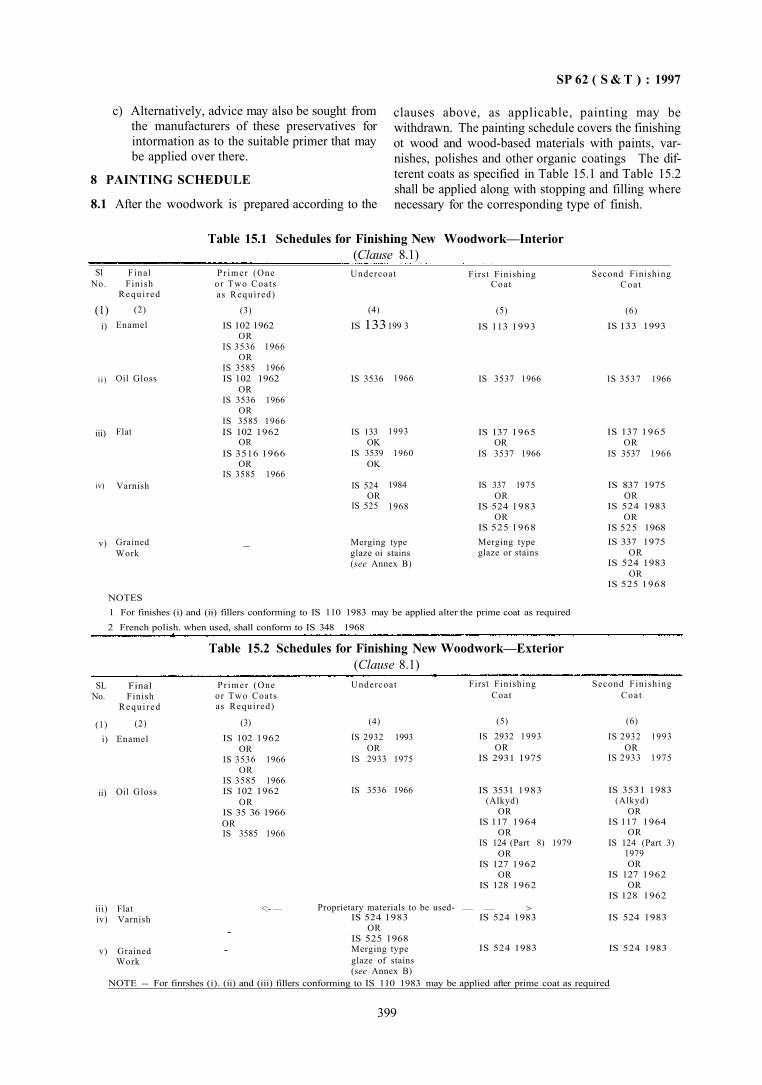
SP 62 ( S & T ) : 1997
c) Alternatively, advice may also be sought from the manufacturers of these preservatives for intormation as to the suitable primer that may be applied over there.
8 PAINTING SCHEDULE
8.1 After the woodwork is prepared according to the
clauses above, as applicable, painting may be withdrawn. The painting schedule covers the finishing ot wood and wood-based materials with paints, varnishes, polishes and other organic coatings The dif-terent coats as specified in Table 15.1 and Table 15.2 shall be applied along with stopping and filling where necessary for the corresponding type of finish.
Table 15.1 Schedules for Finishing New Woodwork—Interior (Clause 8.1)
Sl No.
(1) i)
i i )
iii)
iv)
v)
Final Finish
Requ i red
(2)
Enamel
Oil Gloss
Flat
Varnish
Grained Work
P r imer (One or Two Coats as Required)
(3)
IS 102 1962 OR
IS 3536 1966 OR
IS 3585 1966 IS 102 1962
OR IS 3536 1966
OR IS 3585 1966 IS 102 1962
OR IS 3516 1966
OR IS 3585 1966
_
Undercoat
(4)
IS 133
IS 3536
IS 133 OK
IS 3539 OK
IS 524 OR
IS 525
199 3
1966
1993
1960
1984
1968
Merging type glaze oi stains (see Annex B)
First Finishing Coat
(5)
IS 113 1993
IS 3537 1966
IS 137 1965 OR
IS 3537 1966
IS 337 l975 OR
IS 524 1983 OR
IS 525 1968 Merging type glaze or stains
Second Finishing Coa t
(6)
IS 133 1993
IS 3537 1966
IS 137 1965 OR
IS 3537 1966
IS 837 1975 OR
IS 524 1983 OR
IS 525 1968 IS 337 1975
OR IS 524 1983
OR IS 525 1968
NOTES 1 For finishes (i) and (ii) fillers conforming to IS 110 1983 may be applied alter the prime coat as required 2 French polish. when used, shall conform to IS 348 1968
Table 15.2 Schedules for Finishing New Woodwork—Exterior (Clause 8.1)
SL No.
(1) i)
ii)
Final Finish
Requi red
(2)
Enamel
Oil Gloss
P r imer (One or Two Coats as Required)
(3)
IS 102 1962 OR
IS 3536 1966 OR
IS 3585 1966 IS 102 1962
OR IS 35 36 1966 OR IS 3585 1966
Undercoat
(4)
IS 2932 1993 OR
IS 2933 1975
IS 3536 1966
First Finishing Coat
(5) IS 2932 1993
OR IS 2931 1975
IS 3531 1983 (Alkyd)
OR IS 117 1964
OR IS 124 (Part 8) 1979
OR IS 127 1962
OR IS 128 1962
Second Finishing Coa t
(6)
IS 2932 1993 OR
IS 2933 1975
IS 3531 1983 (Alkyd)
OR IS 117 1964
OR IS 124 (Part 3)
1979 OR
IS 127 1962 OR
IS 128 1962 iii) Flat iv) Varnish
v) Grained Work
<:- —
--
Proprietary materials to be used-IS 524 1983
OR IS 525 1968 Merging type glaze of stains (see Annex B)
— — > IS 524 1983
IS 524 1983
IS 524 1983
IS 524 1983
NOTE -- For finrshes (i). (ii) and (iii) fillers conforming to IS 110 1983 may be applied after prime coat as required
399
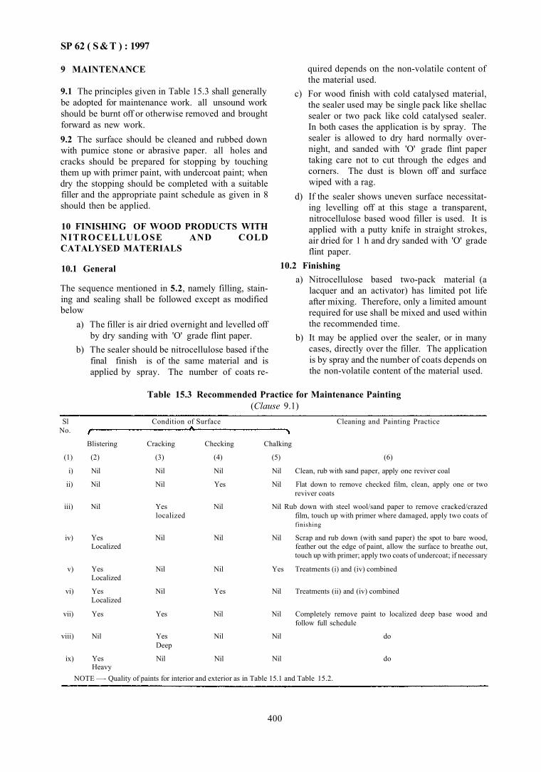
SP 62 ( S&T ) : 1997
9 MAINTENANCE
9.1 The principles given in Table 15.3 shall generally be adopted for maintenance work. all unsound work should be burnt off or otherwise removed and brought forward as new work. 9.2 The surface should be cleaned and rubbed down with pumice stone or abrasive paper. all holes and cracks should be prepared for stopping by touching them up with primer paint, with undercoat paint; when dry the stopping should be completed with a suitable filler and the appropriate paint schedule as given in 8 should then be applied.
10 FINISHING OF WOOD PRODUCTS WITH NITROCELLULOSE AND COLD CATALYSED MATERIALS
10.1 General
The sequence mentioned in 5.2, namely filling, staining and sealing shall be followed except as modified below
a) The filler is air dried overnight and levelled off by dry sanding with 'O' grade flint paper.
b) The sealer should be nitrocellulose based if the final finish is of the same material and is applied by spray. The number of coats re
quired depends on the non-volatile content of the material used.
c) For wood finish with cold catalysed material, the sealer used may be single pack like shellac sealer or two pack like cold catalysed sealer. In both cases the application is by spray. The sealer is allowed to dry hard normally overnight, and sanded with 'O' grade flint paper taking care not to cut through the edges and corners. The dust is blown off and surface wiped with a rag.
d) If the sealer shows uneven surface necessitating levelling off at this stage a transparent, nitrocellulose based wood filler is used. It is applied with a putty knife in straight strokes, air dried for 1 h and dry sanded with 'O' grade flint paper.
10.2 Finishing a) Nitrocellulose based two-pack material (a
lacquer and an activator) has limited pot life after mixing. Therefore, only a limited amount required for use shall be mixed and used within the recommended time.
b) It may be applied over the sealer, or in many cases, directly over the filler. The application is by spray and the number of coats depends on the non-volatile content of the material used.
Table 15.3 Recommended Practice for Maintenance Painting (Clause 9.1)
Sl No.
Condition of Surface Cleaning and Painting Practice
Blistering Cracking Checking Chalking
(1) (2) (3) (4) (5) (6)
i) Nil Nil Nil Nil Clean, rub with sand paper, apply one reviver coal
ii) Nil Nil Yes Nil Flat down to remove checked film, clean, apply one or two reviver coats
iii) Nil Yes Nil Nil Rub down with steel wool/sand paper to remove cracked/crazed localized film, touch up with primer where damaged, apply two coats of
finishing
iv) Yes Nil Nil Nil Scrap and rub down (with sand paper) the spot to bare wood, Localized feather out the edge of paint, allow the surface to breathe out,
touch up with primer; apply two coats of undercoat; if necessary
v) Yes Nil Nil Yes Treatments (i) and (iv) combined Localized
vi) Yes Nil Yes Nil Treatments (ii) and (iv) combined Localized
vii) Yes Yes Nil Nil Completely remove paint to localized deep base wood and follow full schedule
viii) Nil Yes Nil Nil do Deep
ix) Yes Nil Nil Nil do Heavy
NOTE —- Quality of paints for interior and exterior as in Table 15.1 and Table 15.2.
400
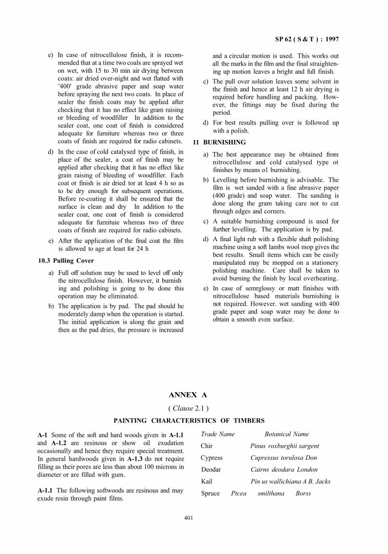
SP 62 ( S & T ) : 1997
e) In case of nitrocellulose finish, it is recommended that at a time two coals are sprayed wet on wet, with 15 to 30 min air drying between coats: air dried over-night and wet flatted with '400' grade abrasive paper and soap water before spraying the next two coats. In place of sealer the finish coats may be applied after checking that it has no effect like gram raising or bleeding of woodfiller In addition to the sealer coat, one coat of finish is considered adequate for furniture whereas two or three coats of finish are required for radio cabinets.
d) In the case of cold catalysed type of finish, in place of the sealer, a coat of finish may be applied after checking that it has no effect like grain raising of bleeding of woodfiller. Each coat ot finish is air dried tor at least 4 h so as to be dry enough for subsequent operations. Before re-coating it shall be ensured that the surface is clean and dry In addition to the sealer coat, one coat of finish is considered adequate for furnituie whereas two of three coats of finish are required for radio cabinets.
e) After the application of the final coat the film is allowed to age at least for 24 h
10.3 Pulling Cover
a) Full off solution may be used to level off only the nitrocellulose finish. However, it burnish ing and polishing is going to be done this operation may be eliminated.
b) The application is by pad. The pad should he moderately damp when the operation is started. The initial application is along the grain and then as the pad dries, the pressure is increased
and a circular motion is used. This works out all the marks in the film and the final straightening up motion leaves a bright and full finish.
c) The pull over solution leaves some solvent in the finish and hence at least 12 h air drying is required before handling and packing. However, the fittings may be fixed during the period.
d) For best results pulling over is followed up with a polish.
11 BURNISHING
a) The best appearance may be obtained from nitrocellulose and cold catalysed type ot finishes by means o1 burnishing.
b) Levelling before burnishing is advisable. The film is wet sanded with a fine abrasive paper (400 grade) and soap water. The sanding is done along the gram taking care not to cut through edges and corners.
c) A suitable burnishing compound is used for further levelling. The application is by pad.
d) A final light rub with a flexible shaft polishing machine using a soft lambs wool mop gives the best results. Small items which can be easily manipulated may be mopped on a stationery polishing machine. Care shall be taken to avoid burning the finish by local overheating.
e) In case of semrglossy or matt finishes with nitrocellulose based materials burnishing is not required. However. wet sanding with 400 grade paper and soap water may be done to obtain a smooth even surface.
ANNEX A
( Clause 2.1 ) PAINTING CHARACTERISTICS OF TIMBERS
A-1 Some of the soft and hard woods given in A-1.1 and A-1.2 are resinous or show oil exudation occasionally and hence they require special treatment. In general hardwoods given in A-1.3 do not require filling as their pores are less than about 100 microns in diameter or are filled with gum.
A-1.1 The following softwoods are resinous and may exude resin through paint films.
Trade Name Botanical Name
Chir Pinus roxburghii sargent
Cypress Cupressus torulosa Don
Deodar Cairns deodara London
Kail Pin us wallichiana A B. Jacks
Spruce Ptcea smilthana Borss
401
SP 62 ( S & T ) : 1997
A-1.2 The following hardwoods may show oil exudation occasionally:
Trade Name Botanical Name Gurjan Dipterocarpus spp Hollong Dipterocarpus macrocarpus
vesque Piney Kingiodendron pinnatum
(Roxb.) Harms White cedar Dysoxyhun malabaricum — Bedd
A-1.3 The following hardwoods do not require filling because their pores are less than about 100 microns in diameter or are filled with gum:
Trade Name Axelwood Birch Boxwood Gardenia Haldu Kaim
Red sanders Satin wood
Botanical Name Anogeissus latifolia wall Betula spp Buzus spp Gardenia spp Adina cardifolia Hook F Mitragyna parvifolia (Roxb.) Korth Pterocarpus Santalinus Linn. F Chloroxylon Swietenia DC
ANNEX B (Tables 15.1 and 15.2)
MERGING TYPE GLAZE AND STAINS
B-1 MERGING TYPE GLAZE
B-1.1 Merging type glaze, which faciltates the blending ol various colours after application is a transparent pigment bound with a medium having good flowing properties, thinned with volatile solvent.
B-2 STAINS
B-2.1 Stains are soluble fast dyes or transparent pigments, dissolved or suspended in an oil, water or spirit medium. The consistency shall be such as to ensure complete penetration. B-2.2 Stains are supplied either in liquid or as powders to be dissolved in the suitable medium as mentioned in B-2.1. II the medium is in oil, driers and thinners may be needed. B-2.3 Water stains are solutions of vegetable dyes in water. Solution of certain chemicals in water,
although not normally classed as water stains, are often used to darken wood, such as floor boards. Potassium permanganate is a well known example.
B-2.4 Spirit stains are solutions of spirit soluble dyes in industrial methylated spirit.
B-2.5 Oil stains may be solutions of oil-soluble dyes in linseed oil but usually to give a wider range of colours, they consist of insoluble, transparent semi-pigments ground in linseed oil and thinned with turpentine or other solvents. Sometimes, wax is added to make stain less penetrating.
B-2.6 Oil stains are sometimes supplied mixed with varnish and sold as varnish stains, but where it is desired to enhance and not conceal the appearance of wood, better results can be obtained by staining and varnishing separately.
PART 2 PAINTING OF FERROUS METALS IN BUILDINGS
1 GENERAL
1.1 Painting of ferrous surfaces is preceded by pretreatment at the factory or at site. Steel is normally supplied covered with oil and grease cither as a protective layer to prevent corrosion or as a left over from machining and handling. The customary procedure of
applying the so called 'shop coat' of paint after fabrication which consists of wiping the surface with oily rag or cotton waste left over from other operations, defeats the purpose of painting at the start. Any paint coat applied on greasy or oily steel surfaces will lack proper adhesion and will lead to the failure of paint film. It is therefore necessary to have pretreatment which
402
SP 62 ( S & T ) : 1997
eludes removal of oil, grease, dirt, rust, scale, swarf, etc, from the steel surfaces before painting is commenced.
2 FACTORY PRETREATMENT 2.1 General
Pretreatment and priming of ferrous metals under controlled conditions at the factory gives the best results and it is therefore advisable to adopt this method Wherever possible. The object of such a treatment is to preserve and maintain metal surface during transport, storage and erection and to minimize the 'on-site' preparation for final painting. Application of a priming coat should follow pretreatment without delay. Subsequent coats of paint may be applied on the site after cleaning down any damaged parts and touching up with the primer paint.
2.2 Removal of Oil, Grease, Dirt and Swarf
Generally, the application of any coating, lining material, adhesive or paint, requires as its first essential a clean surface, while dealing with painting of ferrous metals. Grease removal shall be carried out either with solvent type or alkali type degreasing agents.
2.2.1 Solvent Cleaning
A number of proprietary brands of solvent, alkaline and emulsion cleaners are available; whenever these are used, manufacturers instructions shall be followed. Some of the processes arc petroleum-solvent cleaning. trichloroethylcne cleaning, alkaline cleaning, etc. For details of procedure for carrying out these processes. IS 6(X)5 : 1970 may be referred to.
2.3 Removal of Rust and Scale
When steel leaves a rolling mill it has a firmly-adhering skin known as 'mill-scale'. On exposure to the atmosphere, the mill-scale absorbs moisture, works itself loose allowing moisture to penetrate between scale and steel resulting in rusting. Therefore, derust-ing and descaling are essential prior to application of paint. The problem is much worse for old steel compared to new steel surfaces. Generally, derusting and descaling may be carried out mechanically or chemically.
a) Mechanical Cleaning — This may be done by scraping, chipping, wire brushing, rubbing with abrasive paper or steel wool, by flame cleaning and sand or shot-blasting. For complete removal of all types of mill-scale, the only really efficient mechanical method is sand- blasting or shot-blasting. Flame cleaning is carried out with the help of a special oxy-acetylene torch; but it is not suitable for use in confined spaces due to fire risk.
b) Chemical Cleaning — Where descaling is required to be done chemically, pickling with sulphuric or hydrochloric or phosphoric acids is necessary. Pickling shall be carried out as per IS 6005: 1970.
2.4 Phosphate Treatment The most widely used pretreatments, for preparing metal surfaces for painting, are the numerous hot-tank phosphating processes. Details of phosphating are covered in IS 6005 : 1970. 2.5 Intermediate Protective Pretreatments After the preparation of surfaces and prior to application of paint finishes, a number of intermediate treatments such as red oxide or zinc rich primer may be applied to give additional protection against corrosion. Etching or wash primers may be used; this is based on a deposition of acid-bound resinous film on ferrous surface which would enhance the adhesion of subsequent paint coatings. 3 ON-SITE PRETREATMENT 3.1 Untreated Surface
a) Temporary protective materials applied to steel sheets to protect during storage, transport and erection should be removed with suitable solvent as a preliminary to other preparatory treatments.
b) Lubricants used during the rolling of steel sheets may be particularly tenacious and may have undesirable effects on paint adhesion. The use of abrasive paper with suitable solvent, is effective in removing the worst effects of these materials. Where joints are welded, soldered or brazed, care should be taken to remove fluxing material before painting. This may be effected with a 10 percent solution of formic acid followed by thorough washing or with suitable solvents.
c) In case of heat hardened alloys, the surface shall be treated by mechanical roughening combined by dcgreasing. Such work should be carried out as thoroughly as possible to ensure that the paint will adhere well and give protection and durability. The surface should be well scraped or swabbed with a suitable solvent and then abrased with an abrasive paper and finally rinsed with successive portions of clean solvent on clean swabs.
d) Proprietary compositions may be used as recommended by the manufacturer to degrease and passivate or degrease and etch the surface; but care should be taken unless specified otherwise, to remove all residues by wiping or washing where possible and to ensure that the compositions do not contaminate other parts of the structure
403
SP 62 ( S & T ) : 1997
3.2 Surfaces Containing Temporary Protective Treatment Temporary rust protective treatment shall be removed. Descaling may be done by mechanical means such as hand-scraping or shot-blasting or flame cleaning. Where only derusting is to be done, the mechanical or chemical method may be followed. 3.3 Surfaces Already Pretreated and/or Primed in Factory They should be inspected and damaged areas should be thoroughly degreased by clean solvent swabbing; corrosion products should be removed and touched up with a coat of wash or etching primer on suitable chemical pretreatment solutions. The rectified areas should be brought forward with appropriate primer, putty, finish coats, etc.
3.4 Brush Derusting with Phosphoric Acid Apply phosphoric acid with a brush or swab, rubbing where needed with a steel wool pad, to assist rust removal. Keep the surface well wetted with phosphoric acid. 3.5 Solvent Cleaning, etc Solvent cleaning, mechanical cleaning, etching with primers shall be done as in 2.2.1. 4 APplICATION OF PAINTS 4.1 General Immediately alter the pretreatment process, the first primer coat shall be applied within the shortest possible interval, unless rust proofing or other interior process is employed. This is particularly important in areas with high humidity. 4.2 Painting
a) Primer coats may be applied by spray ot brush, preferably the latter working in the paint into the fine dents and ensuring a continuous film without 'holidays'. After the first coat is dry apply the second coat.
b) Filler Coats — After the second primer coat is hard and dry, sand the surface without scratching or in anyway damaging the primer coats. Till the deep dents with paste filler using good putty knife pressing firmly into the dents. allow to hard dry and cut down by wet rubbing to a smooth finish. Apply as many coats of filler as required,
c) Undercoats may be applied by brush or spray after rubbing down the entire surface. allow it to hard dry and rub down cutting to a smooth finish.
d) Finishing coat may be applied by brush or spray. Gently remove the gloss of the entire surface.
4.3 Schedules The selection of paints and painting system shall be in accordance with Table 15.4. 4.4 Maintenance
Maintenance schedule shall be as in Table 15.5. 4.4.1 Renovation
a) Where specification of painting is known 1) If the paint film is only chalking and other
wise the film is in good condition wipe oft chalked film with wet rag or wash with water, remove gloss, allow the water to dry off and apply one coat of finishing all over the surface. If the chalking is in patches, apply one coat at the chaiked areas and after it is dry, apply another coat all over the surface.
2) If fine chalking and/or hair line cracking have appeared and the film underneath is firm, without symptoms of rust, cut the paint film by wet rubbing, remove all the cracked film, wash, allow water to evaporate and apply one or two coats oi finishing paint or enamel. If the defects arc noticed as patches, after cutting down the film in these patches, apply one coat of the finishing painl/enamel on this area and then follow with a coat all over the surface.
3) If the cracking is deeper, with or without flaking, reaching up to the primer, without symptoms of rust and the primer coat is in good condition then proceed as follows. 11 the defect is all over the surface, cut down the top two coats to the primer by wet rubbing, allow water to dry off. touch up the primer coat and build up the entire film by applying fillers, undercoating and finishing coat as required. If the defect is only in patches, cut down the lop coat only in these areas feathering the top coat, build up film in these patches ending with one finishing coal and apply a coat of finish all over the surface.
4) If blistering with or without flaking is noticed and the primer coat is sound, follow the procedure in 4.4.1 (a)(3).
5) If rust spots are noticed in certain areas only with or without any other symptoms of breakdown, cut down the film in those spots to metal, feathering off the top coats, apply two coats of primer and build up the film following the schedules. Rough sand the entire surface, wash off if necessary and apply a finishing coat.
404
SP 62 (S & T) : 1997
Table 15.4 Painting Schedules for Ferrous Surface (Clause 4.3)
6) Fresh painting should be done after scrap ing off the entire old paint film if - the rusting is noticed off over the sur
face or — the tusting is severe, or
- cracking and blistering has damaged the punier coat exposing the metls ana is noticed all over the surface, or
— the paint film has eroded badly b) Where the specification of paintins is not
known — follow the procedure given in 4.4.1 (a) Renovate with best quality materials to perform under the conditions of exposure
4 4 2 Removal of Old Paint for Repainting
a) Caution should be cxerersed while icmoving old paint Paint rcmov ers of the alkali based or solvent type aie available and if proper cate is not taken they may do more harm th in good While wishing down after using alkali type other structures such as wood may be adver sely affectedted For the solvent type the fume and fire hazard is to be counted They contain waxes and removal ol last traces of wax is essential as other wise adhesion ot paint coats may be adversely affected

SP 62 ( S & T ) : 1997
Table 15.5 Recommended Painting Practice for Maintenance Work (Clause 4.4)
Sl No.
Conditions of Service Cleaning and Painting Procedure
(1)
i)
ii)
iii)
iv)
v)
vi)
Rusting
(2)
Nil
Nil
Nil
Yes
a) Localized
b) Localized
c) Localized
Heavy rusting
Cracking
(3) Nil
Nil
Yes, not reached the surface
Nil
Nil
Nil
Yes
—
Checking
(4)
Nil
Yes, fine checking
Nil
Nil
Nil
Yes
—
—
Chalking
(5)
Yes
Nil
Yes
Yes
Nil
-
-
(6) Clean, rub down with sand paper, apply one reviver coat
Rat down to remove checked film; clean; apply one or two reviver coats
Treat as in 4.4.1 (a)(2)
Treat as in 4.4.1.(a)(5)
Tieat asm 4.4.1 (a)(5)
Treat as in 4.4.1 (a)(5)
Completely remove paint to bare metal and paint to full schedule
do
b) Burning off old paint carried out with caution is better than using paint removers.
c) Removal of old paint by mechanical method of chipping and scraping is the best.
4.4.3 Removal of Fungi Exterior paint surfaces may develop fungi which shall be removed and ammontacal copper solution
(see Note) shall be applied to the surface and allowed to dry thoroughly before repainting
NOTE - A recommended composition and concentration of ammoniacal wash shall consist of 7 g of copper carbonate dissolved in 80 ml of liquor ammonia and diluted to 1 1 with water Alternatively. 2 5 percent of magnesium silicofluonde solution may be used
PART 3 PAINTING OF NON-FERROUS METALS IN BUILDINGS
1 GENERAL
1.1 The increasing importance and use of non-ferrous metals as structural materials in variety of conditions and envitonments had led to an increase in the forms which require painting. Zinc, copper and lead when used in sheet form for roof coverings are rarely painted and in other forms, such as pipes and fittings the areas to be painted are small. The development and extension of the use of non-ferrous metals in the form of claddings and linings for frame buildings and in. light gauge sections as structural members call for an appreciation of their painting requirements. Zinc, copper, lead, pure aluminium and some aluminium alloys require painting only when in contact with corrosive materials or atmospheres or for decoration. The original bright metallic appearance of the non-ferrous metals, may be preserved by the use of clear finishes, but frequent renewal and maintenance of the coating is necessary.
There has also been an increase in the use of non-ferrous metals, particularly zinc and aluminium in various ways as protective coating on steel. If un-painted, such metallic coatings afford protection of the steel under most conditions for periods related to the thickness applied. If properly painted and adequately maintained even greater protection is conferred. Zinc in sheet form or galvanized steel, when new, always requires degreasing before painting, and to ensure adequate adhesion of the paint film, the surface should be modified by pretreatment, or by about three months weathering in a clean atmosphere or as alternative, a special primer may be used.
2 SURFACE PREPARATION AND PRETREATMENT
2.1 General
Pretreatment and priming of non-ferrous metals under controlled conditions at the factory gives the best
406
S P 6 2 ( S & T ) : 1 9 9 7
results and it is, therefore, advisable to adopt this method wherever possible. Application of suitable priming coat should follow the pretreatment without delay Subsequent coats of paint may be applied on-site after cleaning down the primer and touching up with the primer paint any damaged parts. Pretreatment processes are dealt with under two heads for each substrates, namely factory treatment and on-site treatment.
For surfaces already factory pretreated, primed, application of further coats of paint should be followed in the usual manner after suitable rectification of damaged areas, if any, arising out of during storage and/or handling.
2.2 Aluminium and Aluminium alloys
2.2.1 Factory Pretreatment
This covers the following: a) Mechanical treatment — Mechanical treat
ment can be done by hand or power wire brushing or other abrasive treatment or sand blasting.
b) Solvent cleaning — Solvent cleaning, where possible, should be followed by chemical treatment or anodic treatment.
c) Chemical treatment— The chemical treatment could include alkaline etching, sulphuric acid etching, phosphoric acid cleaners, acid flouride deoxidizer, crystalline phosphate treatment, amorphous phosphate treatment, carbonate chromate treatment, amorphous chromate treatment, etching or wash pinners
d) Anodid treatment— This includes treatment in either chromic or sulphuric acid electrolyte. Anodic treatment should not be used on assemblies of dissimilar metals.
2.2.2 On-Site Pretreatment
This is applicable to surfaces untreated or protected with a temporary protection and details are as below:
a) Temporary protective materials applied to aluminium should be removed with a suitable solvent.
b) Lubricants used in rolling of aluminium sheet should also be removed. The use of abrasive paper wetted with a suitable solvent is effective in removing the effects of these materials. Flux of welded joints should be removed with 10 percent solution of formic acid followed by thorough washing or with suitable solvents.
c) In the case of heat hardened alloys, the surface shall be treated by mechanical roughening combined with degreasing.
d) Casting in aluminium alloys may often be painted without any pretreatment other than degreasing.
e) For unpainted aluminium surfaces, when they acquire a surface layer of corrosion products, it shall be removed.
2.3 Zinc 2.3.1 Factory Treatment
The surface should be freed of oil, grease or any foreign contaminant by means of solvent-cleaning method before applying any of the treatments recommended below:
a) Crystalline zinc phosphating treatment, b) Chromate treatment, c) Aqueous chromic organic treatment, and d) Etching or wash primers.
2.3.2 On-Site Pretreatment — Surfaces Untreated a) The surface should be thoroughly degreased.
The use of mordants containing copper is not recommended.
b) If the zinc sheet or galvanized steel is allowed to weather up till the bright spangles disappear before painting, it attains a condition suitable to receive paint without the necessity of degreasing or etching. Galvanizing alone, of reasonable thickness, is sufficient to protect the steel from corrosion for some years under normal exposures.
2.4 Magnesium Chemical treatment at site is not easy and, therefore, factory treatment is preferted.
2.4.1 Fat tory Pretreatment
a) For metal exposed to indoor (mildly corrosive) conditions, mechanical (abrasive) treatment, solvent cleaning, alkaline solution treatment land acid pickling are suitable.
b) For exposure to higher degree of corrosion (outdoot), surface preparation by a suitable conversion coating treatment such as dichromate method shall be adopted. Certain anoidic treatments may also be considered.
c) Wash or etching primers may also be applied on previously cleaned surfaces.
2.4.2 On-Site Pretreatment The most satisfactory method is to apply an etching primer after degreasing by solvent cleaner or preferably an etch cleaner based on phosphoric acid. The combination of etching piimer and etching pretreatment gives better results than if cither of them were used alone.
407
SP 62 ( S & T ) : 1997
2.5 Cadmium
Similar to zinc except that weathering is not required.
2.6 Copper and Copper alloys
The surface should he thoroughly cleaned with an organic solvent and then roughened with fine abrasive paper and applied with one coat of etching primer. Where factory preparation is possible, an electro-deposited coating of tin is useful in preparation for painting.
2.7 Lead
New lead surface should be weathered or pretreated before painting, the latter being preferable because of interaction between lead and many conventional paints. The application of etching primer is satisfactory as a pretreatment of bright lead. An alternative is to treat the surface with dilute solution of orthophos-phoric acid (about 20 percent by volume) followed by thorough washing and drying.
2.8 Lead Tin (Including Terne plate)
The main preparation required for these surfaces is through degreasing with white spirit or other suitable solvent, followed by a washing with hot water. An etching process recommended tor maximum adhesion is to swab with a solution of 5 parts of concentrated hydrochloric acid with 95 parts methylated spirit until a crystalline pattern is seen (about 10) s) and washed in hot water.
2.9 Tin
The painting of tin applied by methods other than hot dipping present no difficulties, but adhesion may be defective on hot dip coating which should be roughened or treated with etch primerprior to painting.
3 PAINTING
3.1 General
a) Certain non-ferrous metals, for example, aluminium, zinc, cadmium, copper, lead and tin are capable of resisting corrosion without painting under natural exposures. Anodized aluminium is quite resistant to corrosion.
b) Jointing compound is needed to insulate metal to metal contact, specially if they are exposed to damp conditions and the metals are dissimilar. Jointing materials are usually paste-like materials. When dissimilar metals are used in conjunction, a jointing compound containing chromates are preferred where aluminium or magnesium' is one of the metals. A typical jointing compound consists of equal parts by
weight of barium chromate or kaolin in an oil varnish medium, the content being between 50 to 60 percent by weight and free from water-soluble sulphates and chlorides. Bitumen or bituminous pastes and rubber based jointing compounds are used for other metals. In all cases the joint should be made while the jointing compound is still wet, the metal having been previously prepared and primed.
3.2 Painting Schedule a) Where metals are to come into contact with
alkaline materials like concrete, etc. they should be given one or two coats of bituminous paint, and where the conditions are persistently damp, even thicker coatings are desirable. Similar treatment is necessary if the metals are to come into contact with hardwoods. Only copper appears not to require this protection.
b) For aluminium, zinc chrome or a modified zinc chrome paint even with an etch primer, should be used. For subsequent coats, normal types of oil, oleoresinous or synthetic resinous paints may be used provided that they are compatible with the priming paint. Bituminous paints may also be used.
c) Copper. Lead - The first coating or primer may he unpigmented resin varnish or an etch ing primer. If a light coloured finish is required a coat of aluminium paint over the resin varnish may be applied. The finishing coats are as given for aluminium.
d) Zinc and Zinc Coated Metals — After pretreat-ment, the subsequent coatings are as given tor aluminium.
e) Magnesium -— The medium for painting magnesium should be highly resistant to water and alkali; for example, a stoving or air-drying medium, such as that based on oil/phenolic resin varnish. The primer should not contain graphite, lead pigments or metallic lead, bronze or aluminium; it should however contain zinc chromate in appropriate percentages suitable to the exposure conditions; for normal exposure 20 percent by weight ot the dry paint film.
3.2.1 Painting systems could be by ordinary or sophisticated methods; like roller coat, electrostatic spraying, air drying, force drying or stoving. 3.2.2 Maintenance painting should be done after removing the old paint; for this organic solvent type paint remover is preferred. If paint has flaked only in certain patches, only such patches may be removed. After renuwal of old paint, priming and finishing should be done its in 3.2.
408

CHAPTER 16
WATER SUPPLY AND DRAINAGE
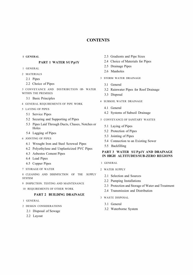
CONTENTS
1 GENERAL
PART 1 WATER SUPplY
1 GENERAL
2 MATERIALS
2.1 Pipes 2.2 Choice of Pipes
3 CONVEYANCE AND DISTRIBUTION OF- WATER WITHIN THE PREMISES
3.1 Basic Principles 4 GENERAL REQUIREMENTS OF PIPE WORK
5 LAYING OF PIPES
5.1 Service Pipes 5.2 Securing and Supporting of Pipes 5.3 Pipes Laid Through Ducts, Chases, Notches or
Holes 5.4 Lagging of Pipes
6 JOINTING OF PIPES
6.1 Wrought Iron and Steel Screwed Pipes 6.2 Polyethylene and Unplasticized PVC Pipes 6.3 Asbestos Cement Pipes 6.4 Lead Pipes 6.5 Copper Pipes
7 STORAGE OF WATER
8 CLEANING AND DISINFECTION OF THE SUPPLY SYSTEM
9 INSPECTION. TESTING AND MAINTENANCE
10 REQUIREMENTS OF OTHER WORK
PART 2 BUILDING DRAINAGE
1 GENERAL
2 DESIGN CONSIDERATIONS
2.1 Disposal of Sewage 2.2 Layout
2.3 Gradients and Pipe Sizes 2.4 Choice of Materials for Pipes 2.5 Drainage Pipes 2.6 Manholes
3 STORM WATER DRAINAGE
3.1 General 3.2 Rainwater Pipes for Roof Drainage 3.3 Disposal
4 SUBSOIL WATER DRAINAGE
4.1 General 4.2 Systems of Subsoil Drainage
5 CONVEYANCE OF SANITARY WASTES
5.1 Laying of Pipes 5.2 Protection of Pipes 5.3 Jointing of Pipes 5.4 Connection to an Existing Sewer 5.5 Backfilling
PART 3 WATER SUPplY AND DRAINAGE IN HIGH ALTITUDES/SUB-ZERO REGIONS
1 GENERAL
2 WATER SUPPLY
2.1 Selection and Sources 2.2 Pumping Installations 2.3 Protection and Storage of Water and Treatment 2.4 Transmission and Distribution
3 WASTE DISPOSAL
3.1 General 3.2 Waterborne System
SP 62 ( S & T ) : 1997
CHAPTER 16
WATER SUPPLY AND DRAINAGE 1 GENERAL
1.1 plumbing system shall include water supply and distribution pipes; plumbing fittings and traps; soil, waste, vent pipes, antisphonagc pipes: building drains and building sewers including their respective connections, devices, appurtenances within the property lines of the premises. 1.2 This Chapter deals with water supply, plumbing connected to public water supply systems, principles of conveyance and distribution of water within the premises; it also covers water supply systems in high altitudes and/or sub-zero temperatures. 1.3 This Chapter also covers the drainage and sanitation requirements of buildings. Construction and
1 GENERAL 1.1 This Part deals with general requirements of plumbing connected to public water supply and instal-lation of Water s'upply system consisting of water service pipe, water distribution pipe, connecting pipes, fittings, valves and all related appurtenances in or adjacent to buildings.
1.2 The water supply requirments of buildings and design of distribution systems shall be as per IS 1172 : 1993 and IS 2065 : 1983 respectively. 1.3 Figure 16.1 is a typical sketch of the different types of water supply pipes in buildings. 1.4 Excavation, if required, shall be as per Chapter 2. 2 MATERIALS 2.1 Pipes Pipes may be of any of the following materials:
a) Cast iron, vertically cast or centrifugally (spun) cast to IS 1536 : 1989 or IS 1537 : 1976.
b) Mild steel tubes and tubulars to IS 1239 (Part 1): 1990.
c) Asbestos cement to IS 1626 (Part 1) : 1991 and IS 1592 : 1989.
d) Polyethylene to IS 3076 : 1985 and IS 4984 : 1987.
e) Unplasticized PVC to IS 4985 : 1988. 0 Copper to IS 1545 : 1982. g) Brass to IS 407: 1981.
maintenance of drains inside buildings and from the buildings up to the connection to public sewer, cesspool or other water course.
1.4 For convenience, the Chapter is divided into three Parts, Part 1 Water supply, Part 2 Drainage and Part 3 Water supply and drainage at high altitudes and/or sub-zero temperature regions.
1.5 SP 35 (S & T) : 1987 which has been already prepared is taken note of in preparing this Chapter.
1.6 Local municipal byelaws should also be consulted and work carried out after their approval.
h) Lead to IS 404 (Part 1): 1993 2.2 Choice of Pipes The materials for piping and fittings, shall be resistant to corrosion both inside and outside or shall be suitably protected. Lead piping shall not be used for conveying domestic water supply; they may however be used for Hushing and overflow pipes. Copper piping may be used for hot water supply systems, provided water is not capable of dissolving an undue amount ot copper. In using asbestos cement pipes adequate precaution shall be taken while laying backfilling. Mild steel tubes used in plumbing shall be of medium class to IS 1230 (Part 1) : 1990. Polyethylene and PVC pipes should not be laid on hot surfaces or in too close a proximity to the hot water pipes. Care should also be taken to avoid locations where they are likely to be exposed to atmosphere charged with coal gas. 3 CONVEYANCE AND DISTRIBUTION OF WATER WITHIN THE PREMISES 3.1 Basic Principles Some of the details of plumbing which are considered necessary for properly designed, acceptably installed and adequately maintained plumbing systems are given below from (a) to (k). Though the details of a construction may vary, the basic sanitary and safety principles are the same, and they merit serious study. Furthermore in the event of any unforseen situation not covered here, the principles enumerated may serve as useful guides.
PART 1 WATER SUPPLY
411
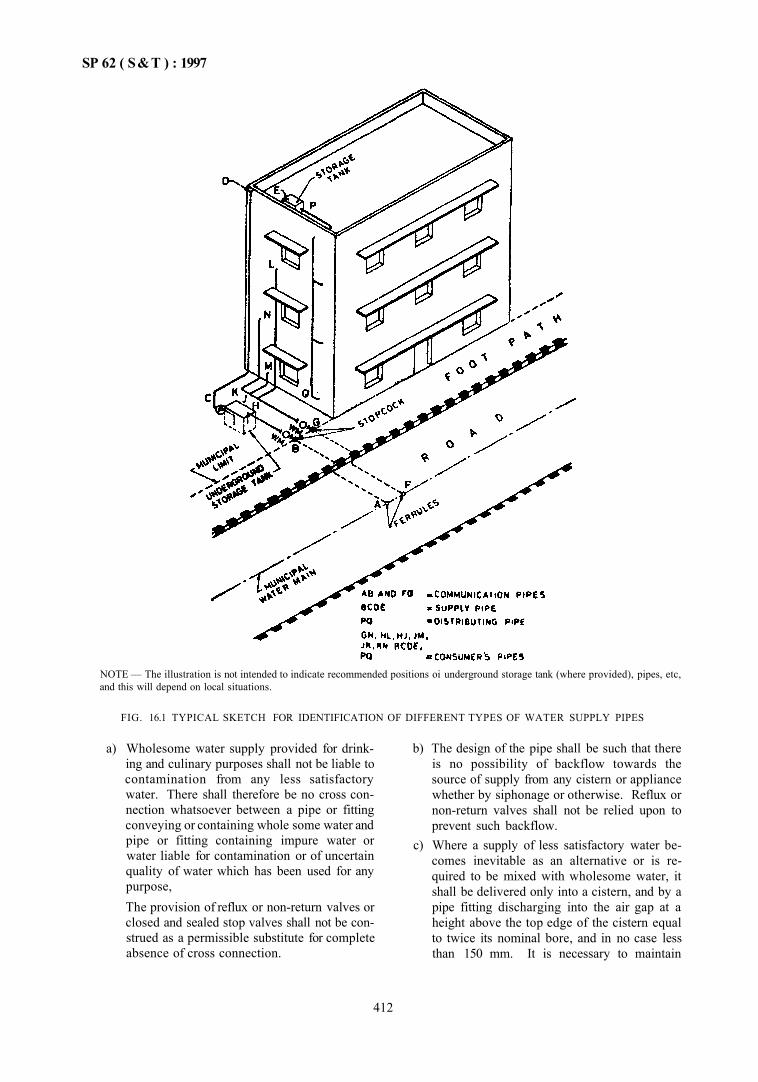
SP 62 ( S&T ) : 1997
NOTE — The illustration is not intended to indicate recommended positions oi underground storage tank (where provided), pipes, etc, and this will depend on local situations.
FIG. 16.1 TYPICAL SKETCH FOR IDENTIFICATION OF DIFFERENT TYPES OF WATER SUPPLY PIPES
a) Wholesome water supply provided for drinking and culinary purposes shall not be liable to contamination from any less satisfactory water. There shall therefore be no cross connection whatsoever between a pipe or fitting conveying or containing whole some water and pipe or fitting containing impure water or water liable for contamination or of uncertain quality of water which has been used for any purpose, The provision of reflux or non-return valves or closed and sealed stop valves shall not be construed as a permissible substitute for complete absence of cross connection.
b) The design of the pipe shall be such that there is no possibility of backflow towards the source of supply from any cistern or appliance whether by siphonage or otherwise. Reflux or non-return valves shall not be relied upon to prevent such backflow.
c) Where a supply of less satisfactory water becomes inevitable as an alternative or is required to be mixed with wholesome water, it shall be delivered only into a cistern, and by a pipe fitting discharging into the air gap at a height above the top edge of the cistern equal to twice its nominal bore, and in no case less than 150 mm. It is necessary to maintain
412
SP 62 ( S & T ) : 1997
definite air gap in all appliances or taps used in water closets.
d) all pipe work shall be so designed laid or fixed, and maintained as to he and to remain completely watertight, thereby avoiding waste of water, damage to property and risk of contamination of the water conveyed
e) No piping shall be laid or fixed so as to pass into, through or adjoining any sewet, scour outlet or drain or any manhole connected therewith nor through any ash pit or manure pit 01 any material of such nature that would be likely to cause undue deterioration of the pipe, except as permitted in 3.1(f). Where lines have to be laid in close proximity to electric cables or in corrosive soils, adequate precautions should be taken to avoid electrical accidents and corrosion.
(f) Where the laying of any pipe through conosrve soil or previous material is unavoidable, the piping shall be properly protected from contact with such soil or material. Any exrsting pipe or fitting laid or fixed, which does not comply with the above requirements, shall be removed immediately and relaid in confommily with the above requirements
g) To reduce friction losses, piping shall be as smooth as possible inside. Methods of jointing shall be such as to avoid internal roughness and projection at the joints, whether of the joining materials or otherwise
h) Change in diameter and in direction shall he gradual rather tnan abrupt to avoid undue loss of head. No bend or curve in piping shall be made which is likely to materially diminish, or alter the cross-section.
j) Underground piping shall be laid at such a depth that it is unlikely to be damaged by frost or traffic loads and vibrations. It shall not be lard in ground liable to subsidence, but where such ground cannot be avoided, special precau lions shall be taken to avoid damage to the piping. Where piping has to be laid across recently disturbed ground, the ground shall he thoroughly consolidated so as to provide a continuous and even support
k) No boiler for generating steam 01 closed boilers of any description 01 any machinery shall be supplied direct from a service or supply pipe. Every such boiler or equipment shall be supplied from a feed cistern.
4 GENERAL REQUIREMENTS OF PIPE WORK 4.1 The following general principles shall comply in the layout and planning of the pipe work
4.1.1 Communication Pipes
a) Every premises shall have its own separate communication pipe for supply of water to the Authority. In the case of a group or blocks of premises, the same communication pipe may supply water to more than one premises.
b) The communication pipe between the water main and the stopcock at the boundary of the premises shall be laid by the Authority,
c) Connection up to 50 mm dia may be made on the water main by means of screwed ferrules, provided the size of the connection does not exceed one-third the size of the water mam. In all other cases, the connection shall be made by a T-branch off the water main (see 5.1).
d) As far as possible, the communication pipe and the underground service pipe shall be laid at right angles to the main and in approximately straight lines to facilitate location lor repairs.
e) Every communication pipe shall have a stopcock and meter inserted in it. The waterway of such fitting shall not be less than the internal sectional area of the communicating pipe and the fittings shall be located within the premises at a conspicuous place accessible to the Authority which shall have exclusive control over it.
4.1.2 Consumer Pipes
a) No consumer pipe shall be laid in the premises to connect the communication pipe without the permission of the Authority.
b) The consumer pipe within the premises shall he laid underground with a suitable cover to safeguard against damage from traffic and extremes of weather.
c) To control the branch pipe to each separately occupied part of a building a stop valve shall be fixed to minimize the interruption of supply during repairs. all such stop valves shall be fixed in accessible positions and properly protected. To provide for drinking or culinary purposes, direct taps shall be provided on the branch pipes connected directly to the consumer pipe. In case of multistoreyed buildings, down take pipes shall be supplied from overhead tanks.
d) Pumps shall not be allowed on the service pipe, as they cause a drop in pressure on the suction side, thereby affecting the supply to the adjoining properties In cases where pumping is required, a properly protected storage tank of adequate capacity shall be provided to feed the pump.
413
SP 62 ( S & T ) : 1997
e) No direct boosting (by booster pumps) shall be allowed from the service pipes (communication and consumer pipes).
0 Consumer pipes shall be so designed and constructed as to avoid air locks. Draining taps shall be provided at the lowest points from which the piping shall rise continuously to the drain off taps.
g) Consumer pipes shall be so designed as to reduce the production and transmission of noise as much as possible.
h) Consumer pipes in roof spaces, unventilated air spaces, underfloors or in basements shall be protected against corrosion.
j) Consumer pipes shall be so located that they arc not unduly exposed to accidental damage and shall be fixed in such positions as to facilitate cleaning and avoid accumulations of dirt.
k) all consumer pipes shall be so laid as to permit expansion and contraction or other movements.
4.1.3 Prohibited Connections
a) A service pipe shall not be connected to a distribution pipe, since such connection may permit baekflow of water from a cistern into the service pipe, in certain circumstances, with subsequent damages 6f contamination and depletion of storage capacity. It might result in pipes and fittings being subjected to a pressure higher than that for which they are designed and in flooding from overflowing cisterns.
b) No pipe for conveyance or in connection with water supplied by the Authority shall communicate with any other receptacle used or capable of being used for conveyance other than water supplied by the Authority.
c) Where storage tanks are provided, no person shall connect or be permitted to connect any service pipe with any distribution pipe.
d) No service pipe shall be connected directly to any water closet or a urinal. all such pipes shall be from flushing cisterns which shall be supplied from storage tank.
e) No service or supply pipe shall be connected directly to any hot water system or to any other appartus used for heating water other than through a feed cistern thereof.
5 LAYING OF PIPES 5.1 Service Pipes
a) Service pipes less than 50 mm bore may be connected to mains by means of a right angled
screwed down ferrule of non-ferrous metal conforming to IS 2692 : 1989, but the ferrule itself shall not be more than 25 mm bore. Ferrules of 20 mm and above shall not be used on mains of less than 100 mm bore. The main is drilled and tapped and the ferrule screwed irr. In case of large-sized trunk mains, this may be done by a tapping under pressure machine, which will obviate any interference with the use of the main.
b) Service pipes of 50 mm and above shall be connected to special T-branehes which have to be inserted into the line of the main. Special branch pipes shall also be used for service pipes of less than 50 mm bore where the bore of the main is not greater than thrice that of the service pipe.
c) Precautions against contamination of the mains shall be taken when making a connection, and where risk exists, the main shall be subsequently disinfected. The underground water service pipe and the building sewer or drain shall be kept at a sufficient distance apart to the satisfaction of the Authority so as to prevent contamination of water. Water service pipes or any underground water pipes shall not be run or laid in the same trench as the building sewer or drainage pipe. Where this is unavoidable, the following conditions shall be fulfilled: 1) The bottom of the service pipe, at all
points, shall be at least 30 cm above the top of the sewer line at its highest point.
2) The water service pipe shall be placed on a solid shelf excavated at one side of the common trench.
3) The number of joints in the service pipe shall be kept to a minimum.
4) The materials and joints of sewer and water service pipe shall be installed in such a manner and shall possess the necessary strength and durability so as to prevent the escape of solids, liquids and gases there from due to temperature changes, settlement, vibrations and superimposed loads.
d) The service pipe shall pass into or beneath the building at a depth below the external ground level of not less than 0.75 m (provided the foundation is deeper than 0.75 m) and at its point of entry through the structure should be accomodated in a sleeve which should have been solidly built in. The space between the pipe and sleeve shall be filled with bituminous or other suitable material for a minimum length of 15 cm at both ends.
414
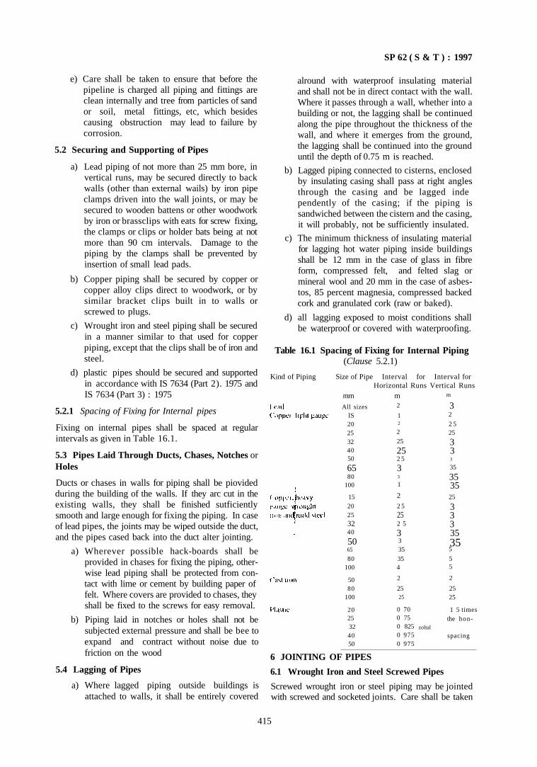
SP 62 ( S & T ) : 1997
e) Care shall be taken to ensure that before the pipeline is charged all piping and fittings are clean internally and tree from particles of sand or soil, metal fittings, etc, which besides causing obstruction may lead to failure by corrosion.
5.2 Securing and Supporting of Pipes
a) Lead piping of not more than 25 mm bore, in vertical runs, may be secured directly to back walls (other than external wails) by iron pipe clamps driven into the wall joints, or may be secured to wooden battens or other woodwork by iron or brassclips with eats for screw fixing, the clamps or clips or holder bats being at not more than 90 cm intervals. Damage to the piping by the clamps shall be prevented by insertion of small lead pads.
b) Copper piping shall be secured by copper or copper alloy clips direct to woodwork, or by similar bracket clips built in to walls or screwed to plugs.
c) Wrought iron and steel piping shall be secured in a manner similar to that used for copper piping, except that the clips shall be of iron and steel.
d) plastic pipes should be secured and supported in accordance with IS 7634 (Part 2). 1975 and IS 7634 (Part 3) : 1975
5.2.1 Spacing of Fixing for Internal pipes
Fixing on internal pipes shall be spaced at regular intervals as given in Table 16.1.
5.3 Pipes Laid Through Ducts, Chases, Notches or Holes
Ducts or chases in walls for piping shall be piovided during the building of the walls. If they arc cut in the existing walls, they shall be finished sutficiently smooth and large enough for fixing the piping. In case of lead pipes, the joints may be wiped outside the duct, and the pipes cased back into the duct alter jointing.
a) Wherever possible hack-boards shall be provided in chases for fixing the piping, otherwise lead piping shall be protected from contact with lime or cement by building paper of felt. Where covers are provided to chases, they shall be fixed to the screws for easy removal.
b) Piping laid in notches or holes shall not be subjected external pressure and shall be bee to expand and contract without noise due to friction on the wood
5.4 Lagging of Pipes
a) Where lagged piping outside buildings is attached to walls, it shall be entirely covered
alround with waterproof insulating material and shall not be in direct contact with the wall. Where it passes through a wall, whether into a building or not, the lagging shall be continued along the pipe throughout the thickness of the wall, and where it emerges from the ground, the lagging shall be continued into the ground until the depth of 0.75 m is reached.
b) Lagged piping connected to cisterns, enclosed by insulating casing shall pass at right angles through the casing and be lagged inde pendently of the casing; if the piping is sandwiched between the cistern and the casing, it will probably, not be sufficiently insulated.
c) The minimum thickness of insulating material for lagging hot water piping inside buildings shall be 12 mm in the case of glass in fibre form, compressed felt, and felted slag or mineral wool and 20 mm in the case of asbestos, 85 percent magnesia, compressed backed cork and granulated cork (raw or baked).
d) all lagging exposed to moist conditions shall be waterproof or covered with waterproofing.
Table 16.1 Spacing of Fixing for Internal Piping (Clause 5.2.1)
Kind of Piping Size of Pipe Interval for Interval for Horizontal Runs Vertical Runs
mm
All sizes IS 20 25 32 40 50
65 80
100
15 20 25 32 40
50 65
80 100
50 80
100
20 25 32 40 50
m 2
1 2
2
25
25 2 5
3 3
1
2 2 5
25 2 5
3 3 35
35 4
2
25 25
0 70 0 75 0 825 0 975 0 975
m
3 2
2 5 25
3 3 3
35
35 35 25
3 3 3 35 35 5
5 5
2
25 25
1 5 times the hon-
zoltal
spacing
6 JOINTING OF PIPES
6.1 Wrought Iron and Steel Screwed Pipes
Screwed wrought iron or steel piping may be jointed with screwed and socketed joints. Care shall be taken
415
SP 62 ( S & T ) : I997
to remove any burrs from the end of the pipes after screwing. Any jointing compound, approved by the Authority may be used together with a grummet of a lew strands of fine yarn; but the compound shall contain no red lead. Any threads exposed after jointing shall be painted, or in case of underground piping thickly coated with bituminous or other suitable composition to prevent corrosion. Screwed wrought iron or steel piping may also be jointed with screwed flanges.
6.2 Polyethylene and Unplasticized PVC Pipes
These pipes shall be joined in accordance with the recommendations of IS 7634 (Part 2) : 1975 and IS 7634 (Part 3) : 1975 respectively.
6.3 Asbestos Cement Pipes
Asbestos cement pipes are jointed with flexible joints supplied by the manufacturer.
6.4 Lead Pipes
Lead and lead alloy pipes shall be jointed with wiped solder joints or by other suitable methods. Lead and lead alloy piping shall be jointed to cast iron, wiought iron, steel or copper piping by the use of copper alloy screwed unions or ferrules.
6.5 Copper Pipes
Screwed copper piping shall be jointed with screwed copper-alloy fittings after treating the clean screw threads with raw linseed oil or other suitable jointing compound. Alternatively, the screw threads ot the pipe and fittings may be tinned, and the joint heated to the melting point of the solder when being screwed.
a) plain copper piping shall be jointed with compression (manipulative or non-manipulative) or with capillary joints in each case using copper-alloy fittings, or by welding. Only manipulative compression joints, that is, joints in which the pipe ends are Hanged, belled or swaged, are suitable for use with fully annealed copper piping.
b) In the case of the capillary joint, the pipe and the interior of the socket oi the fitting shall be cleaned with steel wool, fluxed and fitted together and the joint heated to just above melting point of the solder, which is either piovided in the fitting or is touched into the joint with a solder stick, and which then flows by capillary' to fill the joint space. If the pipe
416
is of fully annealed copper, its ends shall be made truly round before jointing.
c) Copper piping may be autogenous welded or bronze welded, the latter giving the stronger joint . Copper to be welded shall be 'deoxidized copper' and not 'tough pitch copper'.
d) Copper piping of small diameter shall be jointed to cast iron, wrought iron or steel piping by the use of copper-alloy screwed unions or ferrules. For screwed copper piping of diameter, larger than 40 mm, a flange joint shall be used. The copper pipe shall have a copper-alloy flange screwed, brazed or welded on, and this shall be jointed to the iron or steel flange by alloy bolts or nuts.
7 STORAGE OF WATER
7.1 Details of materials for use of storage tanks, grouping of storage tanks, fitments, etc, shall be as described in IS 2065: 198 V
8 CLEANING AND DISINFECTION OF THE SUPplY SYSTEM
8.1 All water mains, communication pipes, service and distribution pipes used lor water for domestic purposes shall be thoroughly and efficiently disinfected before being taken into use and also after every major repair. The method of disinfection shall be subject to the approval of the Authority. Similarly storage tanks and down take distribution pipes shall also be disinfected.
9 INSPECTION, TESTING AND MAINTENANCE
9.1 Inspection, testing and maintenance shall be according to IS 2065 : 1983.
10 REQUIREMENTS OF OTHER WORK
10.1 Sanitary Installations
The selection, installation and maintenance of sanitary appliances shall be according to IS 2064: 1993.
10.2 plumbing Installations in Multistoreyed Buildings
plumbing in multistoreyed buildings shall conform to IS 12183 (Part 1): 1987.
10.3 Domestic Hot Water Installations
This shall conform to IS 7558 : 1974.
SP 62 ( S & T ) : 1997
PART 2 BUILDING DRAINAGE
1 GENERAL
1.1 This Part covers with construction or drains for waste water, surface water and subsoil water and sewage together with all ancillary works used within the building and from the building to the connection to a public sewer or to treatment works, a cesspool or a water course. 1.2 Excavation shall be as per Chapter 2
2 DESIGN CONSIDERATIONS
2.1 Disposal of Sewage
a) Drainage may be connected to a public sewer. b) Where discharge into a public sewer is not
possible, the drainage of the building shall be on a separate system. Foul water shall be disposed of by adequate treatment approved by the Authority at the site. The effluent from the plant shall be discharged into a natural water course or on the surface of the ground or disposed of by subsoil dispersion, preferably draining to a suitable outlet channel.
c) In the case of dilution into a natural stream course, the quality of effluent shall conform to the requirements of Authority controlling the prevention of pollution of stream. For guidance IS 4733 : 1972 may be followed.
d) In the case of subsoil dispersion, the requirements of the Authority of water supply shall be observed to avoid any possible pollution of local Water supplies or wells.
e) Wher no other method of disposal is possible, foul water may be collected and stored in impervious covered cesspool and arrangements made with the Authority for satisfactory periodical removal and conveyance to disposal works.
f) Under the separate system, the drainage of the building shall be done through septic tank or by destabilization ponds or by any method approved by the Authority.
2.2 layout
a) General -- Generally, rain water shall be dealt with separately from sewage and sullage. Sewage and sullage shall be connected to sewers. Storm water from the courtyard may be connected to the sewer where it is not possible to drain otherwise after obtaining permission from the Authority.
b) Protection Against Vermin and Dirt — Instal lation of sanitary appliances and fittings shall
not introduce crevices which are not possible to inspect and clean readily. Pipes if not embedded shall be run well clear off the wall. Holes through walls to take pipes shall be made good on both sides to prevent entry of insects. Materials used for embedding pipes shall be rodent proof. Passage of rodents from room to room or from floor to floor shall be prevented by suitable sealing. The intermediate length of ducts and chases shall be capable of easy inspection. Any unused drains, sewers, etc, shall be demolished or filled in to keep them free from rodents.
c) Alignment of Pipes — The pipes shall be laid in straight lines as far as possible and with uniform gradients. Anything that is likely to cause irregularity of flow, such as, abrupt changes of directions shall be avoided. No bends or junctions whatsoever shall be permitted in sewers except at manholes and inspection chambers. 1) Where it is not possible to avoid a change
of direction in case of drains, access shall be provided through manholes and inspection chambers. Necessary terminal bends at junctions shall be 1/8 or preferably 1/16 bends,
2) all junctions shall be oblique and the contained angle shall be not more than 60°.
3) Drains may be laid under buildings only when unavoidable and when it is not possible to obtain otherwise a sufficient fall in the drain.
4) Where it is necessary to lay a drain under a building or exposed locations within the building, the following conditions shall be observed: — Pipes shall be of cast iron to IS 1536 :
1989 and IS 1537 : 1976. — The drains shall be laid in straight line
and at a uniform gradient — Means of access like manholes/in
spection chambers shall be provided at each end, immediately outside the building.
— In case the pipe or any part of it is laid above the natural surface of the ground, it shall be laid on concrete supports the bottom ot which goes, at least 150 mm, below the ground surface.
- Drains should be preferably taken under a staircase or passage and not under a living room or kitchen
417
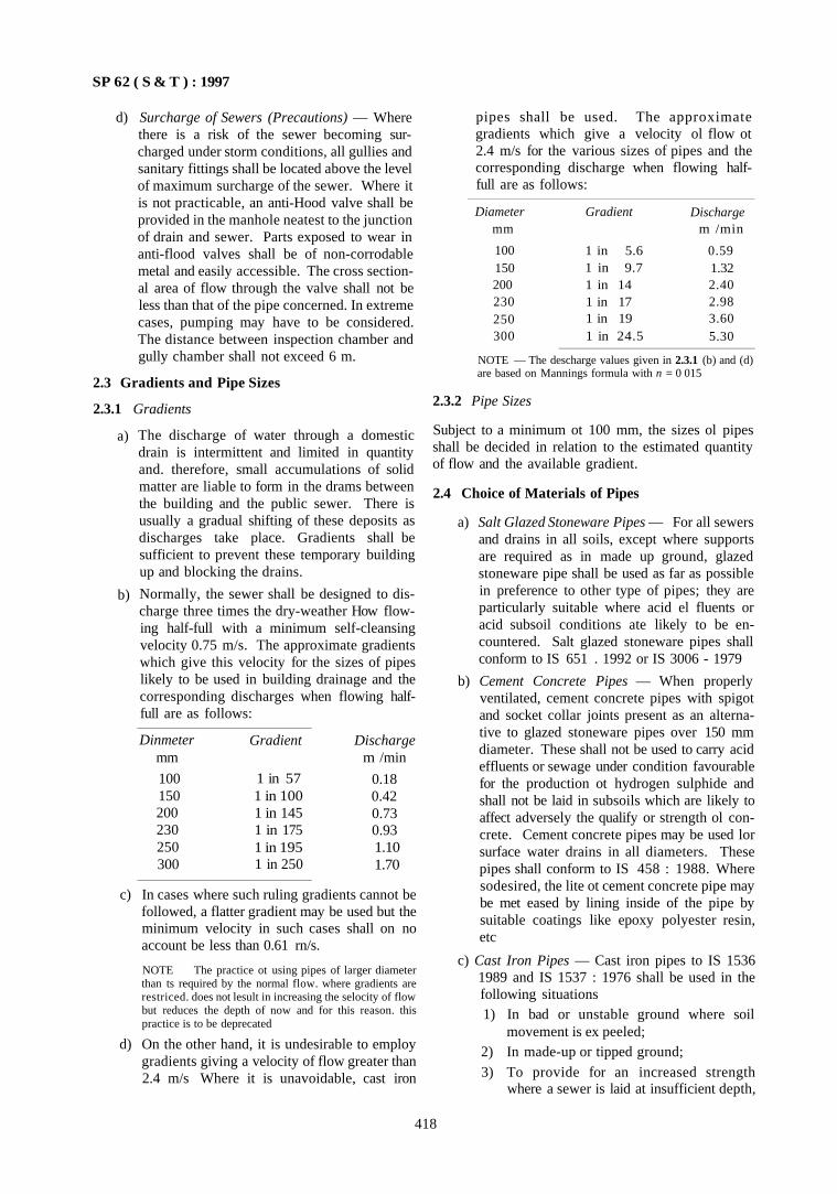
SP 62 ( S & T ) : 1997
d) Surcharge of Sewers (Precautions) — Where there is a risk of the sewer becoming surcharged under storm conditions, all gullies and sanitary fittings shall be located above the level of maximum surcharge of the sewer. Where it is not practicable, an anti-Hood valve shall be provided in the manhole neatest to the junction of drain and sewer. Parts exposed to wear in anti-flood valves shall be of non-corrodable metal and easily accessible. The cross sectional area of flow through the valve shall not be less than that of the pipe concerned. In extreme cases, pumping may have to be considered. The distance between inspection chamber and gully chamber shall not exceed 6 m.
2.3 Gradients and Pipe Sizes
2.3.1 Gradients
a)
b)
The discharge of water through a domestic drain is intermittent and limited in quantity and. therefore, small accumulations of solid matter are liable to form in the drams between the building and the public sewer. There is usually a gradual shifting of these deposits as discharges take place. Gradients shall be sufficient to prevent these temporary building up and blocking the drains.
Normally, the sewer shall be designed to discharge three times the dry-weather How flowing half-full with a minimum self-cleansing velocity 0.75 m/s. The approximate gradients which give this velocity for the sizes of pipes likely to be used in building drainage and the corresponding discharges when flowing half-full are as follows:
Dinmeter mm
100 150 200 230 250 300
Gradient
1 in 57 1 in 100 1 in 145 1 in 175 1 in 195 1 in 250
Discharge m /min
0.18 0.42 0.73 0.93 1.10 1.70
c) In cases where such ruling gradients cannot be followed, a flatter gradient may be used but the minimum velocity in such cases shall on no account be less than 0.61 rn/s.
NOTE The practice ot using pipes of larger diameter than ts required by the normal flow. where gradients are restriced. does not lesult in increasing the selocity of flow but reduces the depth of now and for this reason. this practice is to be deprecated
d) On the other hand, it is undesirable to employ gradients giving a velocity of flow greater than 2.4 m/s Where it is unavoidable, cast iron
pipes shall be used. The approximate gradients which give a velocity ol flow ot 2.4 m/s for the various sizes of pipes and the corresponding discharge when flowing half-full are as follows:
Diameter mm
100 150 200 230 250 300
Gradient
1 in 5.6 1 in 9.7 1 in 14 1 in 17 1 in 19 1 in 24.5
Discharge m /min
0.59 1.32 2.40 2.98 3.60 5.30
NOTE — The descharge values given in 2.3.1 (b) and (d) are based on Mannings formula with n = 0 015
2.3.2 Pipe Sizes
Subject to a minimum ot 100 mm, the sizes ol pipes shall be decided in relation to the estimated quantity of flow and the available gradient.
2.4 Choice of Materials of Pipes
a) Salt Glazed Stoneware Pipes — For all sewers and drains in all soils, except where supports are required as in made up ground, glazed stoneware pipe shall be used as far as possible in preference to other type of pipes; they are particularly suitable where acid el fluents or acid subsoil conditions ate likely to be encountered. Salt glazed stoneware pipes shall conform to IS 651 . 1992 or IS 3006 - 1979
b) Cement Concrete Pipes — When properly ventilated, cement concrete pipes with spigot and socket collar joints present as an alternative to glazed stoneware pipes over 150 mm diameter. These shall not be used to carry acid effluents or sewage under condition favourable for the production ot hydrogen sulphide and shall not be laid in subsoils which are likely to affect adversely the qualify or strength ol concrete. Cement concrete pipes may be used lor surface water drains in all diameters. These pipes shall conform to IS 458 : 1988. Where sodesired, the lite ot cement concrete pipe may be met eased by lining inside of the pipe by suitable coatings like epoxy polyester resin, etc
c) Cast Iron Pipes — Cast iron pipes to IS 1536 1989 and IS 1537 : 1976 shall be used in the following situations 1) In bad or unstable ground where soil
movement is ex peeled; 2) In made-up or tipped ground; 3) To provide for an increased strength
where a sewer is laid at insufficient depth,
418
SP 62 ( S & T ) : 1997
where it is exposed or where it has to be carried on pipes above ground;
4) Under buildings and where pipes are suspended in basements and like situations;
5) In reaches where the velocity is more than 2.4 m/s; and
6) For crossings of water courses. It may be noted that cast iron pipes, even when given a protectve coating are liable to severe corrosion in certain soils; among such soils are soils primeated by peaty waters, and soils which contain appreciable concentration of sulphates Local data may be obtained for this purpose.
d) Asbestos Cement Pipes -- Asbestos cement pipes are commonly used for house diamage system and they shall conform to IS 1626 (Part 1) : 1991. They are not recommended tot-underground situations. flowever. asbestos cement pressure pipes conforming to IS 1592 . 1989 may be used in underground situations also, provided they are not subjected to heavy superimposed loads These shall not be used to catry acid effluents or sewage under conditions favourable lor the production of hydrogen sulphide and shall not be laid in those subsoils which are likely to at feet adver sel v the quality or strength ot asbestos cement pipes. Where so desired, life of asbestos cement pipes may lie increased by lrning inside ot the pipe by suitable coatings like epoxy, polyester tesms, etc.
e) Lead Pipes — Branch soil pipes form lutings to main soil pipes and branch waste pipes from fittings to branch anti-siphonage pipes may be of lead and shall conform to IS 404 (Part 1) . 1993.
f) PVC Pipes — Unplasticized PVC pipes may be used lor drainage purposes, however where hot water discharge is anticipated, the wall thickness should at least be 3 mm nrespective of the size and flow load UPVC pipe shall conform to IS 4985. 1988. NOTE — Where possible high density polyethy lene pipe's (HDPE) and UPVC pipes may be used foi dramage and sanitation purposes, depending on suitabitly) HDPE pipes shall conform to IS 4984 . 1987.
g) Roof gutters shall be of galvanized iron sheets 1.25 mm thick conforming to IS 277 1992. The gutter shall be semicircular in section with a width at top equal to about twice the diameter of the down pipe. The gutters shall be fixed 25 mm below the edge of roof. The gutter shall be supported by mild steel brackets at about 1-2 m intervals. all junctions of gutters shall
be watertight, overlap shall be in the direction of fall. The minimum fall shall be 1 in 120.
2.5 Drainage Pipes a) Drainage pipes shall be kept clear of all other
services. Provision shall be made during the construction of the building for the entry of the drainage pipes. In most cases, this may be done conveniently by building sleeves on conduit pipes into or under the structure m appropriate positions. This will facilitate the installation and maintenance of the services.
b) Where soil and ventilating pipes are accomodated in ducts, access to cleaning eyes shall be provided. Any connection to drain shall be through gully with sealed cover to guard against ingress of sewer gas, vermin or backflow. Trenches and subway shall be ventilated preferably to the open air.
c) all vertical, waste ventilating and anti-siphonage pipes shall be covered on top with a coppei or heavily galvanized iron wire dome or cast iron terminal guards. all cast iron pipes which are to be painted periodically shall be fixed to the wall to give a minimum clearance ot 50 mm. NOTE Asbeslos cement cowls may be used in ease asbestos cement sod pipes are used.
d) Drainage pipes shall be carried to a height above the buildings as specified for ventilating pipe (sec IS 5329 : 1983)
2.6 Manholes a) At every change of alignment gradient or
diametcr of drain, there shall be a manhole or inspection chamber. Bends and junctions in
drains shall be grouped together in manholes, as far as possible. The spacing of manhole pipe may be in accordance with IS -1111 (Part 1)
1980. b). Where the diameter of the dram is increased,
the crown of the pipe shall be fixed at the same level and necessaty slope given in the invert of the manhole chamber In exceptional cases and where unavoidable the crown of the branch sewer may be fixed at a lower level but in such cases the peak flow level of the two sewers should be kept the same.
c) Chambers shall be of such size as will allow necessary examination or clearance of drains. The size of manholes shall be adjusted to lake into account any increase in the number of entries to the manhole. The minimum internal sizes of chambeis (between masonry faces) shall be as follows:
1) For depth ot 1 m or 0.8 m × 0.8 in less
419

SP 62 ( S&T ) : 1997
2) For depth between 1.2 m x 0.9 in 1 in and 1.5 m
3) For depths more Circular chambers than 1.5 m with a minimum dia of
1.4 m or rectangular chambers with minimum internal dimension of 1.2 m × 0.9 m.
NOTES 1 In adopting those sizes of chambers, it would be ensured that these sizes accord full with or half-brieks with standard thickness of mortar joints so as to avoid wasteful cutting of the brick.
2 The sizes of the chambers may be adjusted to suit the availability of local building materials and economics oi con-sti action.
d) The access shaft shall be corbelled inwards on three sides at the top to reduce its size to that of the cover frame to be fitted or alternatively the access shaft shall be covered over by a reinforced concrete slab of suitable dimensions with an opening for manhole cover and frame.
e) The manhole shall be built on a base of concrete of a thickness of at least 150 mm for manholes up to 1 m depth, at least 200 mm for manholes from 1 to 2 m in depth and 300 mm (or one and half brick) for depths greater than 1.5 m. The actual thickness in any case shall be calculated on the basis of engineering design.
Typical sections of the manholes are illustrated in Fig. 16.2, 16.3, and 16.4.
f) Drop Manholes — Where it is uneconomic or impracticable to arrange the connection with 600 mm height above the invert of the manhole, the connection shall be made by constructing a vertical shaft outside the manhole chamber as shown in Fig. 16.5. If the difference in level between the incoming drain and the sewer does not exceed 600 mm and there is sufficient room in the manhole, the connecting pipe may be directly brought through the manhole wall and the fall accommodated by constructing a ramp in the benching of the manhole.
g) Channels -- These shall be semicircular in the bottom halt and of diameter equal to that ot the sewer. Above the horizontal diameter, the sides shall be extended vertically to the same level as the crown of the outgoing pipe and the top edge shall be suitably rounded off The branch channel shall also be similarly constructed with respect to the benching but at theit junction with the main channel an appropriate fall suitably rounded off in the direction of flow in the main channel shall be given
NOTE Wall thicknesses have been indicated in brick lengths to provide for use of modular bricks (see IS 1077 1992) 01 tradititional bricks In the figure, B = one brick length. 15B= one and a hall brick length, etc
FIG. 16.2 DETAIIS or MANHOLE (DEPTHS 1 m AND BELOW)
420
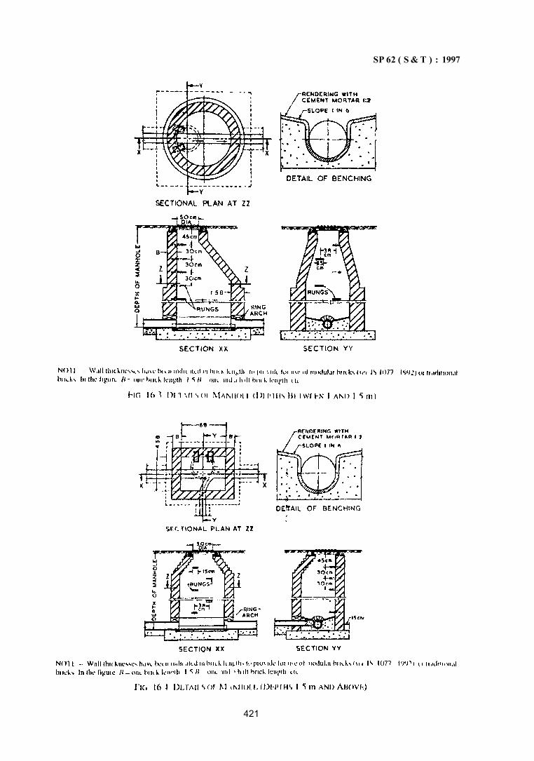
SP 62 ( S & T ) : 1997
421
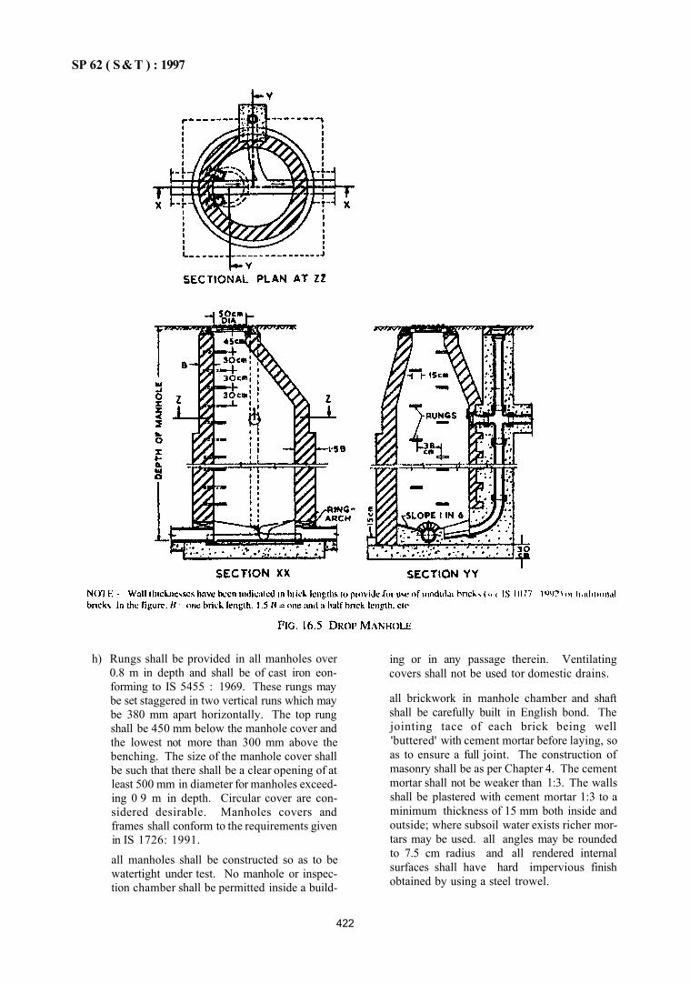
SP 62 ( S&T ) : 1997
h) Rungs shall be provided in all manholes over 0.8 m in depth and shall be of cast iron eon-forming to IS 5455 : 1969. These rungs may be set staggered in two vertical runs which may be 380 mm apart horizontally. The top rung shall be 450 mm below the manhole cover and the lowest not more than 300 mm above the benching. The size of the manhole cover shall be such that there shall be a clear opening of at least 500 mm in diameter for manholes exceeding 0 9 m in depth. Circular cover are considered desirable. Manholes covers and frames shall conform to the requirements given in IS 1726: 1991.
all manholes shall be constructed so as to be watertight under test. No manhole or inspection chamber shall be permitted inside a build
ing or in any passage therein. Ventilating covers shall not be used tor domestic drains.
all brickwork in manhole chamber and shaft shall be carefully built in English bond. The jointing tace of each brick being well 'buttered' with cement mortar before laying, so as to ensure a full joint. The construction of masonry shall be as per Chapter 4. The cement mortar shall not be weaker than 1:3. The walls shall be plastered with cement mortar 1:3 to a minimum thickness of 15 mm both inside and outside; where subsoil water exists richer mortars may be used. all angles may be rounded to 7.5 cm radius and all rendered internal surfaces shall have hard impervious finish obtained by using a steel trowel.
422
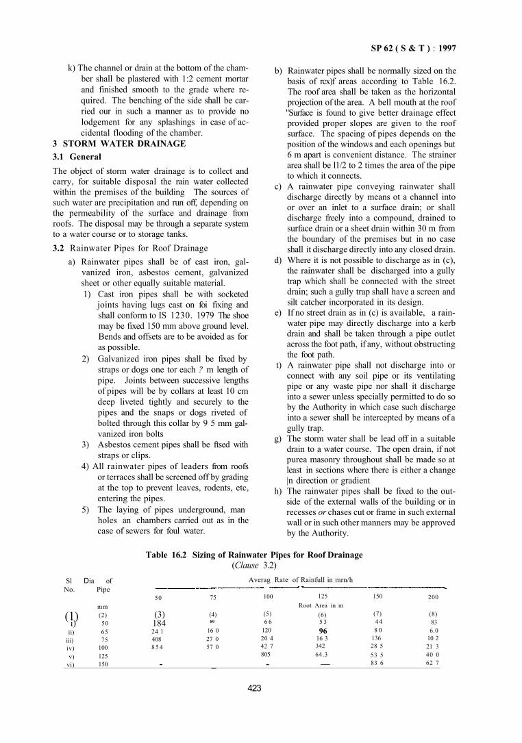
SP 62 ( S & T ) : 1997
k) The channel or drain at the bottom of the chamber shall be plastered with 1:2 cement mortar and finished smooth to the grade where required. The benching of the side shall be carried our in such a manner as to provide no lodgement for any splashings in case of accidental flooding of the chamber.
3 STORM WATER DRAINAGE 3.1 General The object of storm water drainage is to collect and carry, for suitable disposal the rain water collected within the premises of the building The sources of such water are precipitation and run off, depending on the permeability of the surface and drainage from roofs. The disposal may be through a separate system to a water course or to storage tanks. 3.2 Rainwater Pipes for Roof Drainage
a) Rainwater pipes shall be of cast iron, galvanized iron, asbestos cement, galvanized sheet or other equally suitable material. 1) Cast iron pipes shall be with socketed
joints having lugs cast on foi fixing and shall conform to IS 1230. 1979 The shoe may be fixed 150 mm above ground level. Bends and offsets are to be avoided as for as possible.
2) Galvanized iron pipes shall be fixed by straps or dogs one tor each ? m length of pipe. Joints between successive lengths of pipes will be by collars at least 10 cm deep liveted tightly and securely to the pipes and the snaps or dogs riveted of bolted through this collar by 9 5 mm galvanized iron bolts
3) Asbestos cement pipes shall be ftsed with straps or clips.
4) All rainwater pipes of leaders from roofs or terraces shall be screened off by grading at the top to prevent leaves, rodents, etc, entering the pipes.
5) The laying of pipes underground, man holes an chambers carried out as in the case of sewers for foul water.
b) Rainwater pipes shall be normally sized on the basis of rcx)f areas according to Table 16.2. The roof area shall be taken as the horizontal projection of the area. A bell mouth at the roof "Surface is found to give better drainage effect provided proper slopes are given to the roof surface. The spacing of pipes depends on the position of the windows and each openings but 6 m apart is convenient distance. The strainer area shall be l1/2 to 2 times the area of the pipe to which it connects.
c) A rainwater pipe conveying rainwater shall discharge directly by means ot a channel into or over an inlet to a surface drain; or shall discharge freely into a compound, drained to surface drain or a sheet drain within 30 m from the boundary of the premises but in no case shall it discharge directly into any closed drain.
d) Where it is not possible to discharge as in (c), the rainwater shall be discharged into a gully trap which shall be connected with the street drain; such a gully trap shall have a screen and silt catcher incorporated in its design.
e) If no street drain as in (c) is available, a rainwater pipe may directly discharge into a kerb drain and shall be taken through a pipe outlet across the foot path, if any, without obstructing the foot path.
t) A rainwater pipe shall not discharge into or connect with any soil pipe or its ventilating pipe or any waste pipe nor shall it discharge into a sewer unless specially permitted to do so by the Authority in which case such discharge into a sewer shall be intercepted by means of a gully trap.
g) The storm water shall be lead off in a suitable drain to a water course. The open drain, if not purea masonry throughout shall be made so at least in sections where there is either a change |n direction or gradient
h) The rainwater pipes shall be fixed to the out-side of the external walls of the building or in recesses or chases cut or frame in such external wall or in such other manners may be approved by the Authority.
Table 16.2 Sizing of Rainwater Pipes for Roof Drainage (Clause 3.2)
Sl Dia of No. Pipe
Averag Rate of Rainfull in mrn/h
(1) i)
ii) iii) iv) v)
vi)
mm (2) 50 65 75
100 125 150
50
(3) 184 24 1 408 8 5 4
-
75
(4) 89
16 0 27 0 57 0
_
100
(5) 6 6
120 20 4 42 7 805
-
125 Root Area in m
(6) 5 3 96
16 3 342 64.3
—
150
(7) 44 8 0
136 28 5 53 5 83 6
200
(8) 83 6.0
10 2 21 3 40 0 62 7
423
S P 6 2 ( S & T ) : 1 9 9 7
3.2.1 Size and (Gradient of Pipes
The pipes shall be so designed as to give a velocity of flow not less than 1 m/s when running half-full; the maximum velocity shall not exceed 2.4 m/s.
3.3 Disposal
a) General — Surface water may be disposed off in one or more ways as described below but preferably by the method given in(b).
b) Separate System -- all courtyards shall be provided with one or more outlets through which rainwater shall be diverted into the storm water drains and away from any opening connecting with any sewer. Usually each separate plot shall have a separate drain connection made to a covered or open public drain. Such connection to a covered drain shall be made through a pipe at least 3.5 m in length, laid at a gradient of not less than that of the connecting dram. The storm water from the plot should discharge into the storm water drain directly and not through a trap.
c) Combined or Partially Separate System — Where levels do not permit connection to a public storm water drain, storm water from courtyard may be connected to a public sewer provided it is designed to convey combined discharge. In such cases, the surface water shall be admitted to the soil sewer through trapped gullies in order to prevent the escape of sewer air.
d) To a Water Course — It may be often convenient to discharge surface water to a nearby stream or water course. The invert level of the out-fall shall be about the same as the normal water level in the water course. The out-tall shall be protected against floating debris by a screen.
e) To Storage Tanks — Water from the roof of a building may be led straight from the pipes to one or more watertight storage tanks. Such storage tanks shall be raised to a convenient height above ground and shall always be provided with ventilating covers, and have draw off taps suitably placed so that the rainwater may be drawn off tor domestic washing purposes or for garden water. A large impervious storage tank is sometimes constructed underground, from which rain water is pumped as required to the house. all storage tanks shall be provided with an overflow.
f) An arrangement shall be provided in a rainwater pipe or leader to divert.the first washings from the roof of terrace catchment as they
would contain much undesirable material. The mouth of all pipes and openings shall be covered with mosquito-insect proof wire net.
g) French drains or shallow rubble drains, filled with coarse rubble, clinker or similar material, with or without field drain pipes may be employed as surface water drains and are useful in the drainage of unpaved surface, such as playfields and certain types of roads. When used for this purpose in addition to drain being filled with rubble, it is often advisable to include a field pipe drain in the trench bottom.
4 SUBSOIL WATER DRAINAGE
4.1 General
a) Subsoil water is that portion of the rain-fall which is absorbed into the ground and drainage of subsoil water may be necessary for the following reasons: 1) to increase the stability of the surface; 2) to avoid surface flooding; 3) to alleviate or to avoid causing dampness
in the building, especially in the cellars; 4) to reduce the humidity in the immediate
vicinity of the building; and 5) to increase the workability of soil.
b) The general direction of subsoil water may usualy be judged by the general inclination ot the land surface and the main lines of the subsoil drains shall follow the natural talls wherever possible.
c) Subsoil drains shall be sited so as not to endanger the stability of the buildings or earthwork. In some portions of the drain, it may be necessary to use non- porous jointed pipes. No field pipe shall be laid in such a manner or in such a position as to communicate directly with any drain constructed or adapted to be used for conveying sewage except where absolutely unavoidable and in that case a suitable efficient trap shall be pros ided between subsoil drain and such sewer.
4.2 Systems of Subsoil Drainage
4.2.1 Field Drain Pipes
Clay or concrete porous pipes may be used and shall be laid in one of the following ways, depending on site conditions.
a) Natural — The pipes are laid to follow the natural depressions, or valleys of the site, branches discharging into the main.
b) Herringbone — A system consisting of a number of main drains into which discharge from both sides, smaller subsidiary branches parallel
424
S P 6 2 ( S & T ) : 1997
to each other but at an angle to the mains forming a series of herringbone patterns
e) Grid— A main or mains near the houndaries of a site into which branches discharge horn one side only.
d) Fan shaped — The drains are lard converging to a single outlet at one point on the boundary
of a site, without the use of main or collecting drains.
e) Moat or cut off system — Sometimes drains are laid on one or more sides of a building to intercept the flow of subsoil water and thereby protect the foundations.
4.2.2 Laying of Pipes
a) For building sites the mains shall not he less than 75 mm in diameter and the branches not less than 63 mm in diameter The normal practice is to use 100 mm dia for mains and 75 mm dia for branches.
b) The pipes shall generally laid at depth ot 600 to 900 mm or to such a depth to which it is desirable to lower water table and the gradients are determined rather by the fall oi laud than by considerations of self cleansing velocity
c) The connecting of the branch drain to the main drain is best made by means ot a clay ware of concrete junction pipe.
d) The outlet ot a subsoil system may discharge into a soak way or through a catchpit into the nearest ditch or watercourse. Where these are not available, the subsoil chains may be connected, with the approval of the Authority, through an intercepting trap to the surface water drainage system
NOTE: Care shall be taken that there is no backflow from sub-surface dimters dummy heavy lams
5 CONVEYANCE OF SANITARY WAS IKS
5.1 Laying of Pipes
The pipes shall be laid with sockets leading uphill and shall rest on solid and even foundations for the lull length of the barrel Socket holes shall be formed in the foundation sufficiently deep, to allow sufficient space for the pipe jointer to work right round the pipes and as short as possible to accommodate the socket in proper position and allow the joint to be made
a) Where the pipes are not bedded in concrete, the trench floor shall be left slightly high ami carefully bottomed up as pipe lay ing proceeds that pipe barrels rest on firm and undisturbed ground. If the excavation is carried too low, any packing clone shall be in concrete.
b) If the floor of the trench consists of hard rock oi very hard ground that cannot be easily ex
cavated to a smooth surfaces, the pipes shall be laid in a cradle of fine concrete floor or a floor of gravel and crushed stone overlaid with con cietc or on a well consolidated gravel and crushed stone bed only so as to ensure even bearing.
c) Each separate pipe shall be individually set tor line and for level using one of the following methods:
1) Where long lengths ot sewer or drain are to be constructed in trench with glazed earthenware or concrete pipes, properly painted sight rails shall be fixed across the trench at a height, equal to the length of boning rod to be used, above the requned invert level of the drain or sewer at the point where the sight rad is fixed There shall be a minimum of three sight rails in position on each length of sewer of diain under construction at a particular gradient.
Pioperly cut wooden of iron pegs shall be driven into the floor of the trenches at intei valsof at least 1 m less than the length ot the straight-edge. which is to be used With the aid of boning rod, equal in length to the height of the sight rad above the lequired invert level, each peg shall be driven until its top is at the exact level lequired for the invert of the pipeline at that point; this will occur when a true bone is obtained over boning rod and sight tails. The underside of a straight edge resting on taps of those pegs will give level and gradient of the invert. The pegs shall be withdrawn as pipe laying proceeds
To obtain a true line along the grade, a side line shall be used strung tautly at halt pipe level between mm pins tumly driven in the floor of the excavation lor the man-hole at each end of the purposed pipeline. and the pipes shall be laid in such a way that the sockets are fixed just tree ot this side line. For long lengths of dram, the side line may require intermediate support. The practice of laying to a top line is not recommended.
2) In case of short lengths of branch drain, where it is inconvenient to fix sight rails, pegs shall he driven into the floor ot the trench and then tops boned in with the. "id of three equal boning rods, one of which is used on the pegs to be driven and the other two held at the invert level of the pipes tor fittings to be connected. A side line shall be used to obtain a true line m the horizontal plane.
425
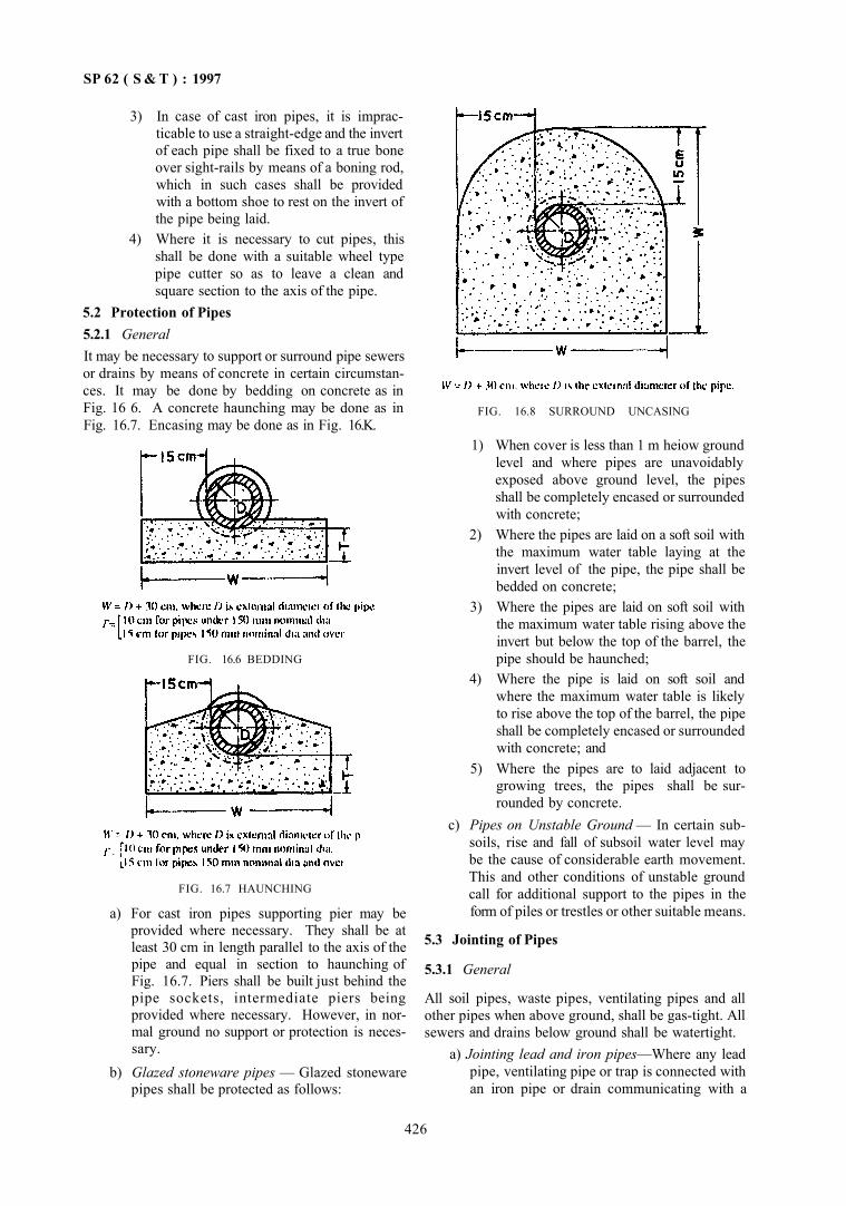
SP 62 ( S & T ) : 1997
3) In case of cast iron pipes, it is impracticable to use a straight-edge and the invert of each pipe shall be fixed to a true bone over sight-rails by means of a boning rod, which in such cases shall be provided with a bottom shoe to rest on the invert of the pipe being laid.
4) Where it is necessary to cut pipes, this shall be done with a suitable wheel type pipe cutter so as to leave a clean and square section to the axis of the pipe.
5.2 Protection of Pipes 5.2.1 General It may be necessary to support or surround pipe sewers or drains by means of concrete in certain circumstances. It may be done by bedding on concrete as in Fig. 16 6. A concrete haunching may be done as in Fig. 16.7. Encasing may be done as in Fig. 16.K.
FIG. 16.7 HAUNCHING
a) For cast iron pipes supporting pier may be provided where necessary. They shall be at least 30 cm in length parallel to the axis of the pipe and equal in section to haunching of Fig. 16.7. Piers shall be built just behind the pipe sockets, intermediate piers being provided where necessary. However, in normal ground no support or protection is necessary.
b) Glazed stoneware pipes — Glazed stoneware pipes shall be protected as follows:
FIG. 16.8 SURROUND UNCASING
1) When cover is less than 1 m heiow ground level and where pipes are unavoidably exposed above ground level, the pipes shall be completely encased or surrounded with concrete;
2) Where the pipes are laid on a soft soil with the maximum water table laying at the invert level of the pipe, the pipe shall be bedded on concrete;
3) Where the pipes are laid on soft soil with the maximum water table rising above the invert but below the top of the barrel, the pipe should be haunched;
4) Where the pipe is laid on soft soil and where the maximum water table is likely to rise above the top of the barrel, the pipe shall be completely encased or surrounded with concrete; and
5) Where the pipes are to laid adjacent to growing trees, the pipes shall be surrounded by concrete.
c) Pipes on Unstable Ground — In certain subsoils, rise and fall of subsoil water level may be the cause of considerable earth movement. This and other conditions of unstable ground call for additional support to the pipes in the form of piles or trestles or other suitable means.
5.3 Jointing of Pipes
5.3.1 General
All soil pipes, waste pipes, ventilating pipes and all other pipes when above ground, shall be gas-tight. All sewers and drains below ground shall be watertight.
a) Jointing lead and iron pipes—Where any lead pipe, ventilating pipe or trap is connected with an iron pipe or drain communicating with a
426
FIG. 16.6 BEDDING
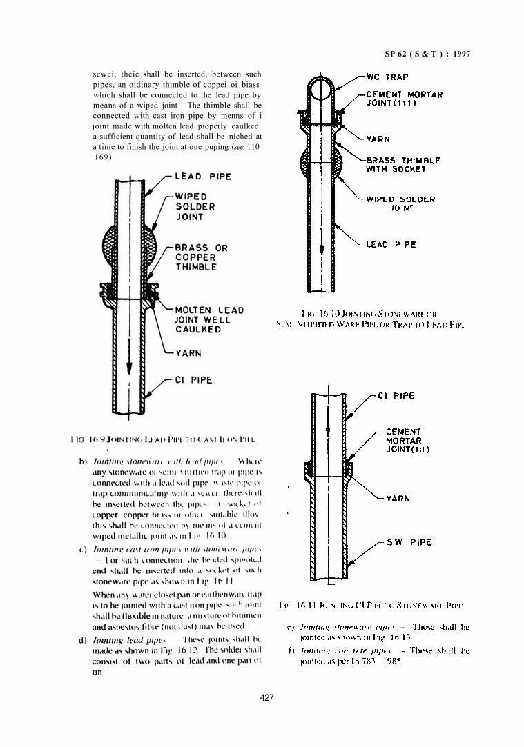
SP 62 ( S & T ) : 1997
sewei, theie shall be inserted, between such pipes, an oidinary thimble of coppei oi biass which shall be connected to the lead pipe by means of a wiped joint The thimble shall be connected with cast iron pipe by menns of i joint made with molten lead pioperly caulked a sufficient quantity of lead shall be niched at a time to finish the joint at one puping (see 110 169)
427
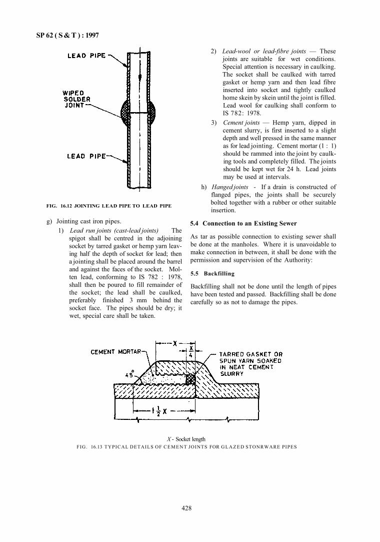
SP 62 ( S&T ) : 1997
FIG. 16.12 JOINTING LEAD PIPE TO LEAD PIPE
g) Jointing cast iron pipes. 1) Lead run joints (cast-lead joints) The
spigot shall be centred in the adjoining socket by tarred gasket or hemp yarn leaving half the depth of socket for lead; then a jointing shall be placed around the barrel and against the faces of the socket. Molten lead, conforming to IS 782 : 1978, shall then be poured to fill remainder of the socket; the lead shall be caulked, preferably finished 3 mm behind the socket face. The pipes should be dry; it wet, special care shall be taken.
2) Lead-wool or lead-fibre joints — These joints are suitable for wet conditions. Special attention is necessary in caulking. The socket shall be caulked with tarred gasket or hemp yarn and then lead fibre inserted into socket and tightly caulked home skein by skein until the joint is filled. Lead wool for caulking shall conform to IS 782: 1978.
3) Cement joints — Hemp yarn, dipped in cement slurry, is first inserted to a slight depth and well pressed in the same manner as for lead jointing. Cement mortar (1 : 1) should be rammed into the joint by caulking tools and completely filled. The joints should be kept wet for 24 h. Lead joints may be used at intervals.
h) Hanged joints - If a drain is constructed of flanged pipes, the joints shall be securely bolted together with a rubber or other suitable insertion.
5.4 Connection to an Existing Sewer
As tar as possible connection to existing sewer shall be done at the manholes. Where it is unavoidable to make connection in between, it shall be done with the permission and supervision of the Authority:
5.5 Backfilling
Backfilling shall not be done until the length of pipes have been tested and passed. Backfilling shall be done carefully so as not to damage the pipes.
X - Socket length FIG. 16.13 TYPICAL DETAILS OF C E M E N T JOINTS FOR G L A Z E D STONRWARE PIPES
428
SP 62 ( S & T ) : 1997
PART 3 WATER SUPplY AND DRAINAGE IN HIGH ALTITUDE/ SUB-ZERO TEMPERATURE REGIONS
1 GENERAL
1.1 The broad principles of water supply and drainage covered in Parts 1 and 2 are generally applicable at high altitudes/sub-zero temperature regions with some modifications. These are elaborated here.
1.2 High altitude/sub-zero conditions may be sum marized as low temperature, that is, below 4°C and/or low barometric pressures, that is, below 0.86 N/mm2.
1.3 Effects of low temperature are described below:
a) Physical — Water is at its maximum density at 4°C, At 0°C it solidifies and turns into ice having expanded approximately one-twelth ol its volume. The velocity ol water and liquids increases with tailing ot temperatures thus affecting the settling velocities of particles carried in suspension. Information on Kinematic viscosities and density of water at low temperature is given in IS 6295 : 1986.
b) Chemical — In general most chemicals reaet much slower at temperatuies neai fieezing than they do at normal temperatures Consequently, longer reaction times are required for satisfactory performance of chemical used in treatment units.
c) Biological — Low t e m p e r a t u r e s re tard biological activity. Thus sewage treatment process depending on biological activities are affected.
1.4 Effect of Low Barometric Pressures
Low barometric pressures limit pump suction head. Normal barometric pressures met at high altitudes are given in IS 6295 : 1986.
2 WATER SUPPLY
2.1 Selection and Sources
The source selected shall be such as to minimize the length of transmission line so as to reduce the inspection and maintenance. Attempts shall also be made to locate the source near the discharge of waste heat, such as power plants provided that it does not affect the potability of water.
2.1.1 The sources may be melted ice or snow, ground water or surface water. Ground water is warmer than surface water in winter. Well casings for ground water shall be properly insulated along the front penetiation
depth of the soil, where necessary. Protection be given to these casing pipes in case they are likely to be disjointed, crushed of damaged due to freezing of surrounding soils, the protection may be an additional casing or other suitable means.
Surface water from tanks are likely to freeze in winter, forming an ice cover. The freezing action tends to concentrate mineral and organic content in the unfrozen water and for this reason, the unfrozen water shall be analysed periodically for potability.
Springs and livers, which do not freeze completely after a continuous supply of water, should be perferred. Intake for river sources shall be placed well below the depth of ice cover, if any, formed during the worst periods. A deep pool ol water should be created over the intake High intake velocities without surface turbulence shall be used for drawing out water when the atmospheric temperature is below 0°C
2.2 Pumping Installations
Pumps and pumping machinery shall be housed in well insulated chambers. Where necessary, inside of pump houses shall be heated. Pump house shall, as far as possible, he built directly above intake structures.
a) Pump Selection - -The use of centrifugal pump shall be preferred to reciprocating pumps because of the fact that gland packings soaked in water are likely to freeze when the pumps are idle and the icciprocating pump cannot work unless warmed up Self priming pumps shall be used to avoid provision of tool valves, which help formation of ice which, in turn, clog the impeller and damages it. For high altitude regions it is always advisable to use submer-sible pumps in view of low suction heads avail-able in such places.
b) Suction Heads — Pump suction heads are affected on account ol reduced atmospheric pressures in high altitudes. A rate of decrease of 1.15 m, in the allowable suction head shall be made for every 1 000 m in elevation above MSL.
c) Efficiency of Pumping Set — A rate of fall of over all efficiency of 2 percent shall be allowod in case of electric prime movers and up to 4 percent in case of other types of prime movers for every 300 m elevation in altitude. Electric prime movers shall be preferred.
d) Pump Drainage — W h e r e the a m b i e n t temperature conditions warrant, provision
429
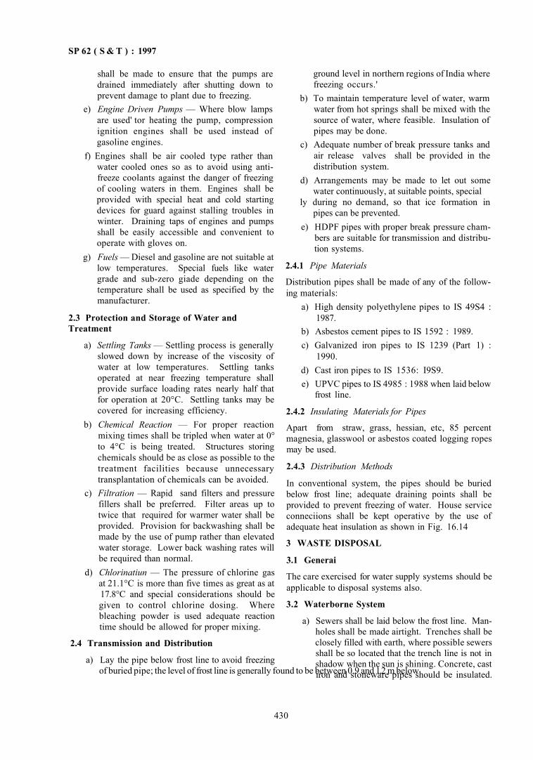
SP 62 ( S & T ) : 1997
shall be made to ensure that the pumps are drained immediately after shutting down to prevent damage to plant due to freezing.
e) Engine Driven Pumps — Where blow lamps are used' tor heating the pump, compression ignition engines shall be used instead of gasoline engines.
f) Engines shall be air cooled type rather than water cooled ones so as to avoid using antifreeze coolants against the danger of freezing of cooling waters in them. Engines shall be provided with special heat and cold starting devices for guard against stalling troubles in winter. Draining taps of engines and pumps shall be easily accessible and convenient to operate with gloves on.
g) Fuels — Diesel and gasoline are not suitable at low temperatures. Special fuels like water grade and sub-zero giade depending on the temperature shall be used as specified by the manufacturer.
2.3 Protection and Storage of Water and Treatment
a) Settling Tanks — Settling process is generally slowed down by increase of the viscosity of water at low temperatures. Settling tanks operated at near freezing temperature shall provide surface loading rates nearly half that for operation at 20°C. Settling tanks may be covered for increasing efficiency.
b) Chemical Reaction — For proper reaction mixing times shall be tripled when water at 0° to 4°C is being treated. Structures storing chemicals should be as close as possible to the treatment facilities because unnecessary transplantation of chemicals can be avoided.
c) Filtration — Rapid sand filters and pressure fillers shall be preferred. Filter areas up to twice that required for warmer water shall be provided. Provision for backwashing shall be made by the use of pump rather than elevated water storage. Lower back washing rates will be required than normal.
d) Chlorinatiun — The pressure of chlorine gas at 21.1°C is more than five times as great as at 17.8°C and special considerations should be given to control chlorine dosing. Where bleaching powder is used adequate reaction time should be allowed for proper mixing.
2.4 Transmission and Distribution
a) Lay the pipe below frost line to avoid freezing of buried pipe; the level of frost line is generally found to be between 0.9 and 1.2 m below
ground level in northern regions of India where freezing occurs.'
b) To maintain temperature level of water, warm water from hot springs shall be mixed with the source of water, where feasible. Insulation of pipes may be done.
c) Adequate number of break pressure tanks and air release valves shall be provided in the distribution system.
d) Arrangements may be made to let out some water continuously, at suitable points, special
ly during no demand, so that ice formation in pipes can be prevented.
e) HDPF pipes with proper break pressure chambers are suitable for transmission and distribution systems.
2.4.1 Pipe Materials
Distribution pipes shall be made of any of the following materials:
a) High density polyethylene pipes to IS 49S4 : 1987.
b) Asbestos cement pipes to IS 1592 : 1989. c) Galvanized iron pipes to IS 1239 (Part 1) :
1990. d) Cast iron pipes to IS 1536: I9S9. e) UPVC pipes to IS 4985 : 1988 when laid below
frost line.
2.4.2 Insulating Materials for Pipes
Apart from straw, grass, hessian, etc, 85 percent magnesia, glasswool or asbestos coated logging ropes may be used.
2.4.3 Distribution Methods
In conventional system, the pipes should be buried below frost line; adequate draining points shall be provided to prevent freezing of water. House service conneciions shall be kept operative by the use of adequate heat insulation as shown in Fig. 16.14
3 WASTE DISPOSAL
3.1 Generai
The care exercised for water supply systems should be applicable to disposal systems also.
3.2 Waterborne System
a) Sewers shall be laid below the frost line. Manholes shall be made airtight. Trenches shall be closely filled with earth, where possible sewers shall be so located that the trench line is not in shadow when the sun is shining. Concrete, cast iron and stoneware pipes should be insulated.
430
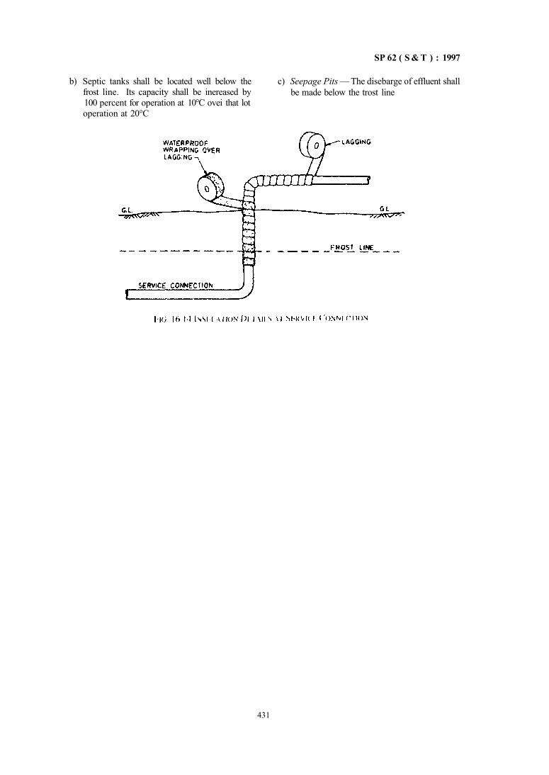
SP 62 ( S & T ) : 1997
b) Septic tanks shall be located well below the frost line. Its capacity shall be inereased by 100 percent for operation at 10°C ovei that lot operation at 20°C
c) Seepage Pits — The disebarge of effluent shall be made below the trost line
431


CHAPTER 17
SPECIAL CONSTRUCTION PROCEDURES — EARTHQUAKE EFFECTS, ETC
CONTENTS
1 GENERAL
PART 1 EARTHQUAKE RESISTANCE OF NORMAL BUILDINGS
1 GENERAL
2 EARTHQUAKE RESISTANT CONSTRUCTION OF NORMAL BUILDINGS
2.1 Types of Construction 3 GENERAL PRINCIPLES OF SEISMIC RESISTANCE CONSTRUCTION
3.1 Lightness 3.2 Continuity of Construction 3.3 Projecting or Suspended Parts 3.4 Building Configuration 3.5 Strength in Various Directions 3.6 Foundation 3.7 Ductility 3.8 Non-Structural Parts
4 MASONRY STRUCTURES — SPECIAL CONSTRUC TION FEATURES
4.1 General 4 2 Mortars 4 3 Cover
4.4 Seismic Strengthening Arrangements 4.5 Framing of Thin Load Bearing Walls 4.6 Hollow Block Masonry
5 SPECIAL CONSTRUCTION FEATURES - - FLOORS AND ROOFS WITH SMALL PRECAST COMPONENTS
6 TIMBER STRUCTURES — SPECIAL ARRANGEMENTS
6.1 Foundation 6.2 Studwall or Brick Nogging Construction
ANNEX A BUILDING CATEGORIES B A S E D ON EARTHQUAKE RESISTING FEATURES
ANNEX B OPENINGS IN LOAD BEARING WALLS
PART 2 EARTHQUAKE RESISTANCE OF WEAKER BUILDINGS
1 Low STRENGTH MASONRY BUILDINGS
1.1 General 2 BRICKWORK IN WEAK MORTAR
3 STONE MASONRY (RANIX)M RUBBLE OR SEMI-DRESSED)
4 IMPROVING EARTHQUAKE RESISTANCE OF EARTHEN BUILDINGS
5 REPAIR AND SEISMIC STRENGTHENING OF BUILDINGS
SP 62 ( S & T ) : 1997
CHAPTER 17
SPECIAL CONSTRUCTION PROCEDURES EARTHQUAKE EFFECTS, ETC
1 GENERAL
1.1 This Chapter deals with construction procedures required to take care of effects of forcrs the
earthquake blast or othet effects which would ensure saf ty of the structure As a first step earthquake teststant structures are covered in Parts 1 and 2
PART 1 EARTHQUAKE RESISTANCE OF NORMAL BUILDINGS
4 ^
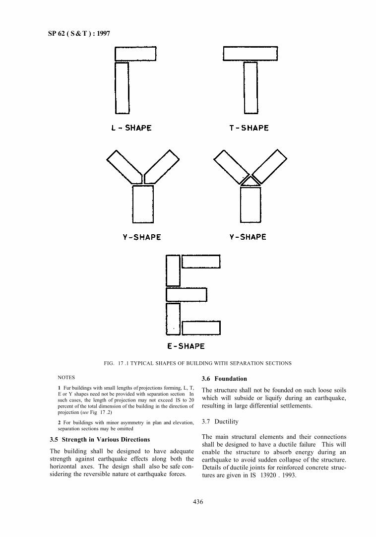
SP 62 ( S&T ) : 1997
FIG. 17 .1 TYPICAL SHAPES OF BUILDING WITH SEPARATION SECTIONS
NOTES
1 Fur buildings with small lengths of projections forming, L, T, E or Y shapes need not be provided with separation section In such cases, the length of projection may not exceed IS to 20 percent of the total dimension of the building in the direction of projection (see Fig 17 .2)
2 For buildings with minor asymmetry in plan and elevation, separation sections may be omitted
3.5 Strength in Various Directions
The building shall be designed to have adequate strength against earthquake effects along both the horizontal axes. The design shall also be safe considering the reversible nature ot earthquake forces.
3.6 Foundation
The structure shall not be founded on such loose soils which will subside or liquify during an earthquake, resulting in large differential settlements.
3.7 Ductility
The main structural elements and their connections shall be designed to have a ductile failure This will enable the structure to absorb energy during an earthquake to avoid sudden collapse of the structure. Details of ductile joints for reinforced concrete structures are given in IS 13920 . 1993.
436
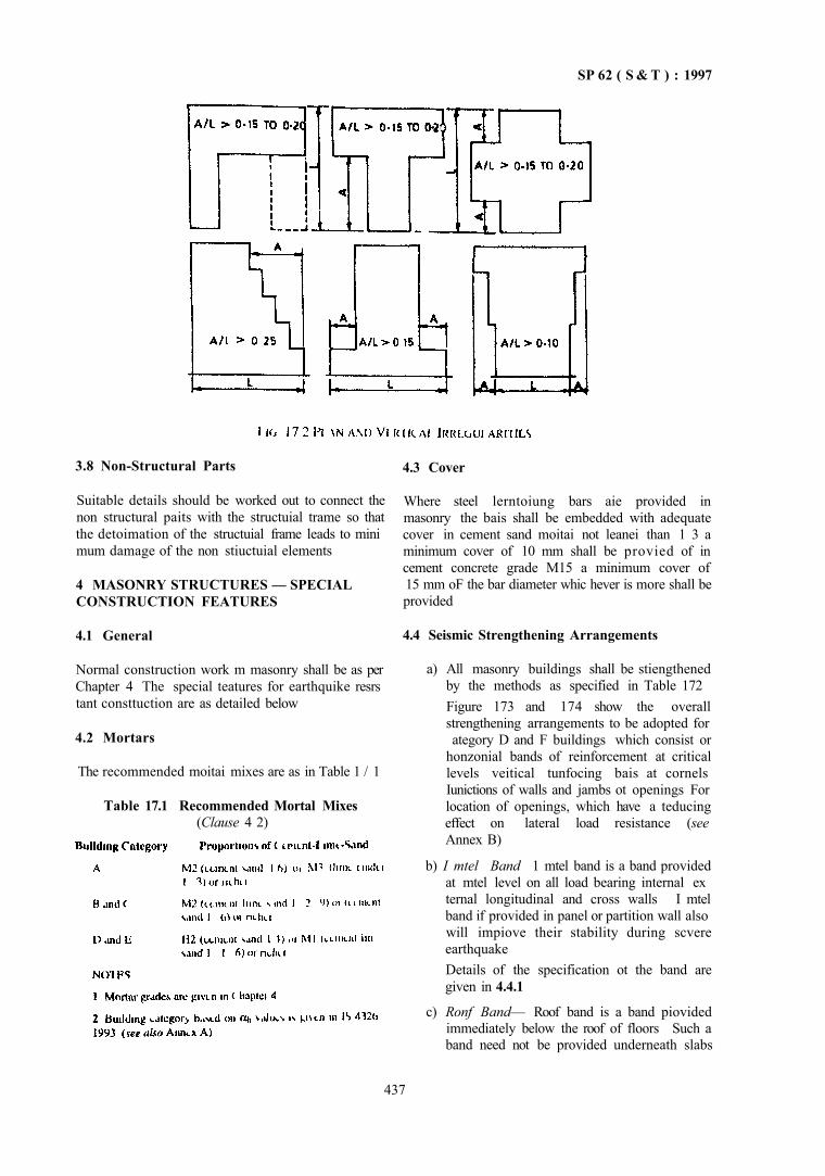
SP 62 ( S & T ) : 1997
3.8 Non-Structural Parts
Suitable details should be worked out to connect the non structural paits with the structuial trame so that the detoimation of the structuial frame leads to mini mum damage of the non stiuctuial elements
4 MASONRY STRUCTURES — SPECIAL CONSTRUCTION FEATURES
4.1 General
Normal construction work m masonry shall be as per Chapter 4 The special teatures for earthquike resrs tant consttuction are as detailed below
4.2 Mortars
The recommended moitai mixes are as in Table 1 / 1
Table 17.1 Recommended Mortal Mixes (Clause 4 2)
4.3 Cover
Where steel lerntoiung bars aie provided in masonry the bais shall be embedded with adequate cover in cement sand moitai not leanei than 1 3 a minimum cover of 10 mm shall be provied of in cement concrete grade M15 a minimum cover of 15 mm oF the bar diameter whic hever is more shall be provided
4.4 Seismic Strengthening Arrangements
a) All masonry buildings shall be stiengthened by the methods as specified in Table 172 Figure 173 and 174 show the overall strengthening arrangements to be adopted for ategory D and F buildings which consist or
honzonial bands of reinforcement at critical levels veitical tunfocing bais at cornels Iunictions of walls and jambs ot openings For location of openings, which have a teducing effect on lateral load resistance (see Annex B)
b) I mtel Band 1 mtel band is a band provided at mtel level on all load bearing internal ex ternal longitudinal and cross walls I mtel band if provided in panel or partition wall also will impiove their stability during scvere earthquake Details of the specification ot the band are given in 4.4.1
c) Ronf Band— Roof band is a band piovided immediately below the roof of floors Such a band need not be provided underneath slabs
437
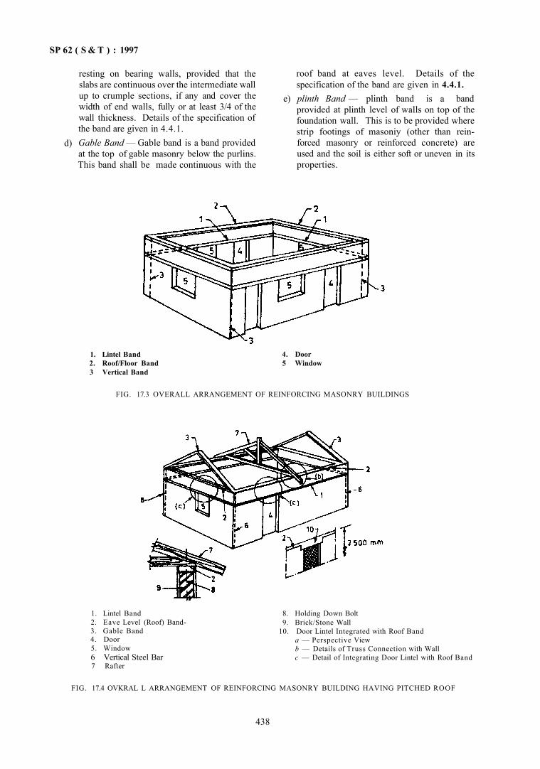
SP 62 ( S & T ) : 1997
d)
resting on bearing walls, provided that the slabs are continuous over the intermediate wall up to crumple sections, if any and cover the width of end walls, fully or at least 3/4 of the wall thickness. Details of the specification of the band are given in 4.4.1. Gable Band — Gable band is a band provided at the top of gable masonry below the purlins. This band shall be made continuous with the
roof band at eaves level. Details of the specification of the band are given in 4.4.1.
e) plinth Band — plinth band is a band provided at plinth level of walls on top of the foundation wall. This is to be provided where strip footings of masoniy (other than reinforced masonry or reinforced concrete) are used and the soil is either soft or uneven in its properties.
1. Lintel Band 2. Roof/Floor Band 3 Vertical Band
4. Door 5 Window
FIG. 17.3 OVERALL ARRANGEMENT OF REINFORCING MASONRY BUILDINGS
1. Lintel Band 2. Eave Level (Roof) Band-3. Gable Band 4. Door 5. Window 6 Vertical Steel Bar 7 Rafter
8. Holding Down Bolt 9. Brick/Stone Wall
10. Door Lintel Integrated with Roof Band a — Perspective View b — Details of Truss Connection with Wall c — Detail of Integrating Door Lintel with Roof Band
FIG. 17.4 OVKRAL L ARRANGEMENT OF REINFORCING MASONRY BUILDING HAVING PITCHED ROOF
438
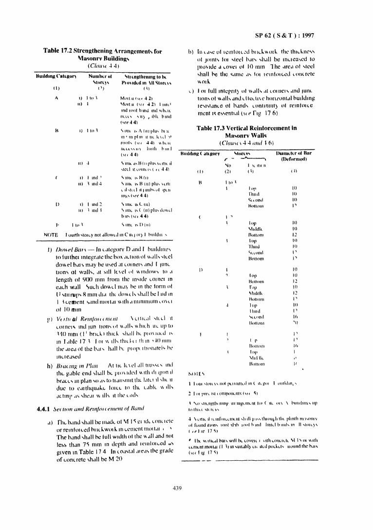
SP 62 ( S & T ) : 1997
439
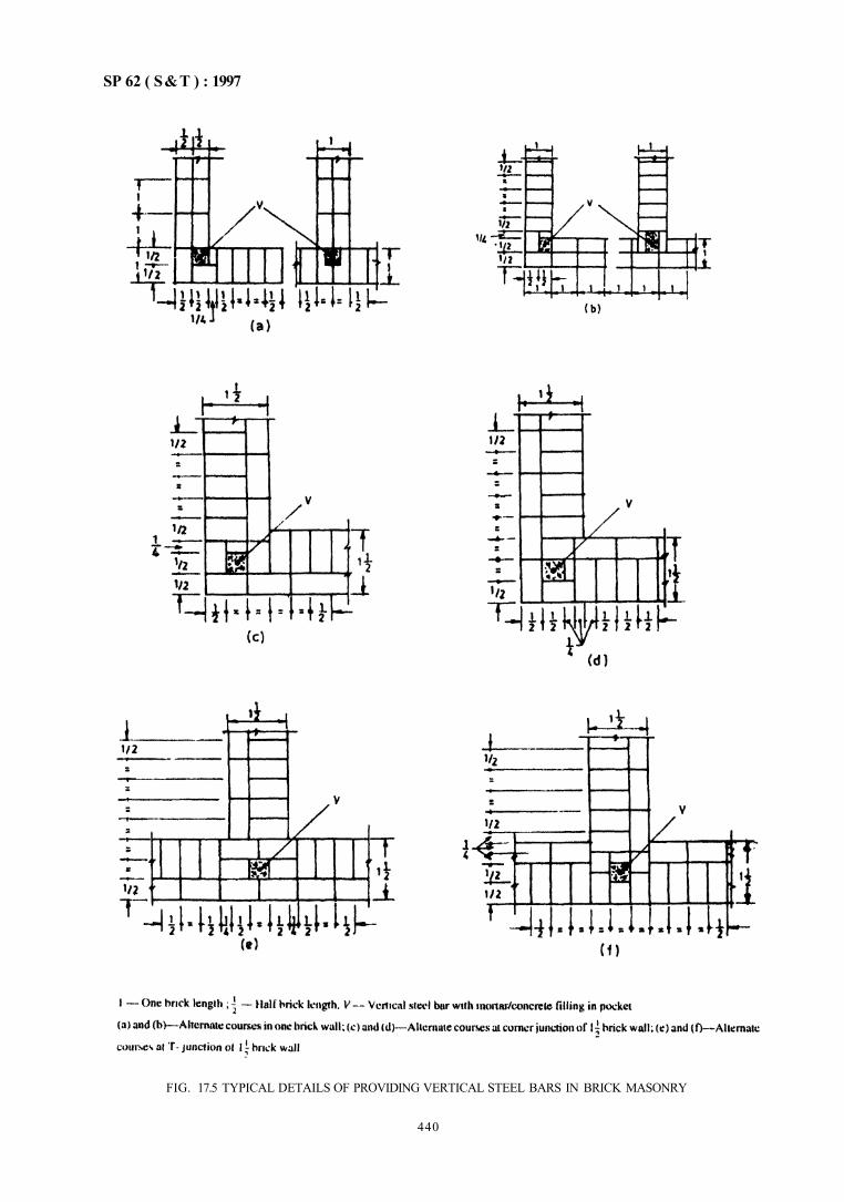
SP 62 ( S&T ) : 1997
FIG. 17.5 TYPICAL DETAILS OF PROVIDING VERTICAL STEEL BARS IN BRICK MASONRY
440
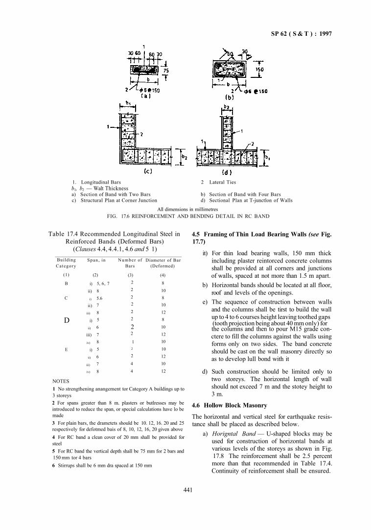
SP 62 ( S & T ) : 1997
1. Longitudinal Bars 2 Lateral Ties b1, b2 — Walt Thickness a) Section of Band with Two Bars b) Section of Band with Four Bars c) Structural Plan at Corner Junction d) Sectional Plan at T-junctlon of Walls
All dimensions in millimetres FIG. 17.6 REINFORCEMENT AND BENDING DETAIL IN RC BAND
Table 17.4 Recommended Longitudinal Steel in Reinforced Bands (Deformed Bars)
(Clauses 4.4, 4.4.1, 4.6 and 5 1) Building Category
(1)
B
C
D
E
Span , in
i) ii)
i)
ii) iii)
i) ii)
iii)
iv)
i) ii)
iii)
iv)
(2)
5, 6, 7 8 5.6 7
8 5
6 7 8 5
6 7
8
Number of Bars
(3) 2 2
2 2
2 2
2 2
1 2
2
4
4
Diameter of Bar (Deformed)
(4)
8
10 8 10 12 8
10 12 10
10 12 10 12
NOTES 1 No strengthening anangement tor Category A buildings up to 3 storeys 2 For spans greater than 8 m. plasters or butlresses may be introduced to reduce the span, or special calculations have lo be made 3 For plain bars, the drametets should be 10. 12, 16. 20 and 25 respectively for defotmed bais of 8, 10, 12, 16, 20 given above 4 For RC band a clean cover of 20 mm shall be provided for steel 5 For RC band the vertical depth shall be 75 mm for 2 bars and 150 mm tor 4 bars 6 Stirrups shall be 6 mm dra spaced at 150 mm
4.5 Framing of Thin Load Bearing Walls (see Fig. 17.7)
it) For thin load bearing walls, 150 mm thick including plaster reintorced concrete columns shall be provided at all corners and junctions of walls, spaced at not more than 1.5 m apart.
b) Horizontal bands should be located at all floor, roof and levels of the openings.
e) The sequence of construction between walls and the columns shall be tirst to build the wall
the columns and then to pour M15 grade con-ctere to fill the columns against the walls using forms only on two sides. The band concrete should be cast on the wall masonry directly so as to develop lull bond with it
d) Such construction should be limited only to two storeys. The horizontal length of wall should not exceed 7 m and the stotey height to 3 m.
4.6 Hollow Block Masonry
The horizontal and vertical steel for earthquake resistance shall be placed as described below.
a) Horigntal Band — U-shaped blocks may be used for construction of horizontal bands at various levels of the storeys as shown in Fig. 17.8 The reinforcement shall be 2.5 percent more than that recommended in Table 17.4. Continuity of reinforcement shall be ensured.
441
up to 4 to 6 courses height leaving toothed gaps (tooth projection being about 40 mm only) for
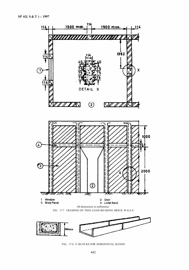
SP 62( S & T ) : 1997
All dimensions in millimetres FIG 17.7 FRAMING OF THIN LOAD-BEARING BRICK WALLS
FIG. 17.8 U-BLOCKS FOR HORIZONTAL BANDS
442
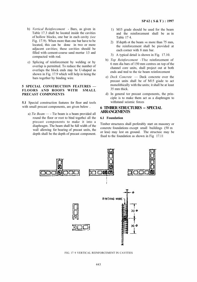
SP 62 ( S & T ) : 1997
b) Vertical Reinforcement - Bars, as given in Table 17.3 shall be located inside the cavities of hollow blocks, one bar in each cavity (see Fig. 17.9). When more than one bar have to be located, this can be done in two or more adjacent cavities; these cavities should be filled with cement-coarse sand mortar 1:3 and compacted with rod.
c) Splicing of reinforcement by welding or by overlap is permitted. To reduce the number of overlaps the block ends may be U-shaped as shown in Fig. 17.9 which will help in tieing the bars together by binding wire.
5 SPECIAL CONSTRUCTION FEATURES — FLOORS AND ROOFS WITH SMALL PRECAST COMPONENTS
5.1 Special construction features for floor and tools with small precast components, are given below .
a) Tie Beam — - Tie beam is a beam provided all round the floor or root to bind togethci all the ptecast components to make it into a diaphragm. The beam shall be full width of the wall allowing for bearing of precast units, the depth shall be the depth of precast component.
1) Ml5 grade should be used for the beam and the reinforcement shall be as in Table 17 4.
2) If depth ot the beam »s more than 75 mm, the reinforcement shall be piovided at each corner with 8 mm bar.
3) A typical detail is shown in Fig. 17.10. b) Top Reinforcement -The reinforcement of
6 mm dia bars of 150 mm centres on top of the channel core units, shall project out at both ends and tred to the tie beam reinforcement
e) Deck Concrete — Deck concrete over the precast units shall be of M15 giade to act monolithically with the units; it shall be at least 35 mm thick.
d) In general tor precast components, the principle is to make them act as a diaphragm to withstand seismic forces
6 TIMBER STRUCTURES -- SPECIAL ARRANGEMENTS 6.1 Foundation
Timber structures shall preferably start on masonry or coneretc foundations except small buildings (50 m or less) may lest on ground. The structuic may be fixed to the foundation as shown in Fig 17.11
FIG. 17 9 VERTICAL REINFORCEMENT IN CAVITIES
443
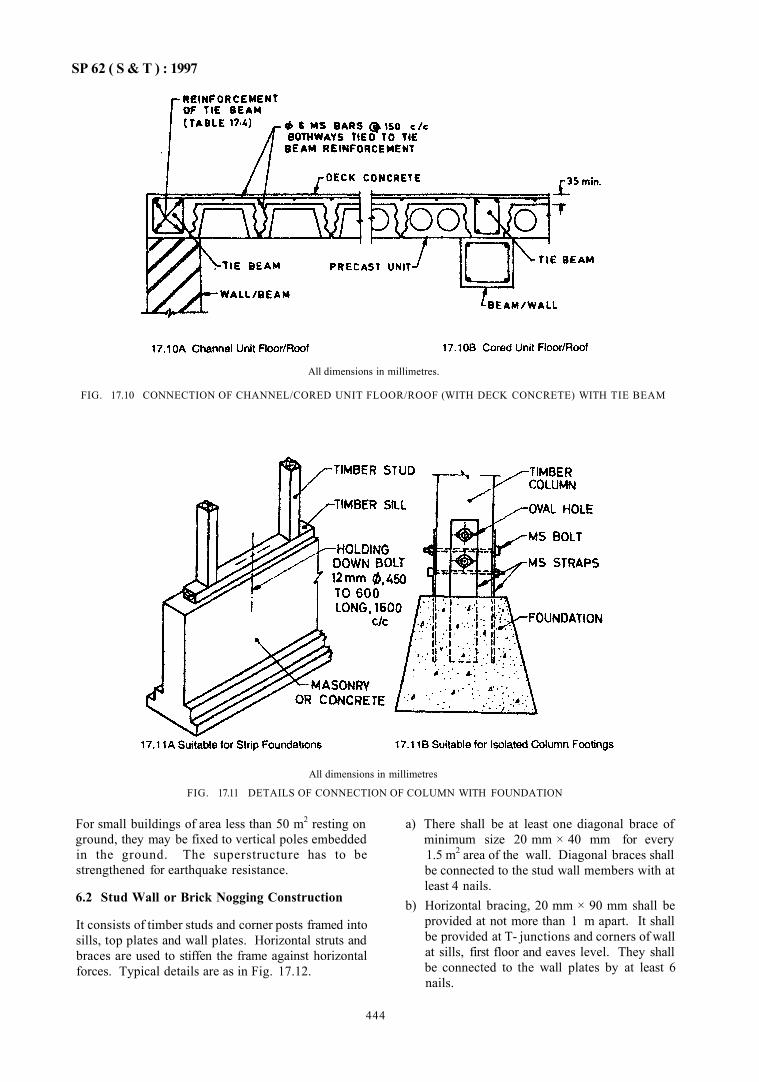
SP 62 ( S & T ) : 1997
All dimensions in millimetres.
FIG. 17.10 CONNECTION OF CHANNEL/CORED UNIT FLOOR/ROOF (WITH DECK CONCRETE) WITH TIE BEAM
All dimensions in millimetres
FIG. 17.11 DETAILS OF CONNECTION OF COLUMN WITH FOUNDATION
For small buildings of area less than 50 m2 resting on ground, they may be fixed to vertical poles embedded in the ground. The superstructure has to be strengthened for earthquake resistance.
6.2 Stud Wall or Brick Nogging Construction
It consists of timber studs and corner posts framed into sills, top plates and wall plates. Horizontal struts and braces are used to stiffen the frame against horizontal forces. Typical details are as in Fig. 17.12.
a) There shall be at least one diagonal brace of minimum size 20 mm × 40 mm for every 1.5 m2 area of the wall. Diagonal braces shall be connected to the stud wall members with at least 4 nails.
b) Horizontal bracing, 20 mm × 90 mm shall be provided at not more than 1 m apart. It shall be provided at T- junctions and corners of wall at sills, first floor and eaves level. They shall be connected to the wall plates by at least 6 nails.
444
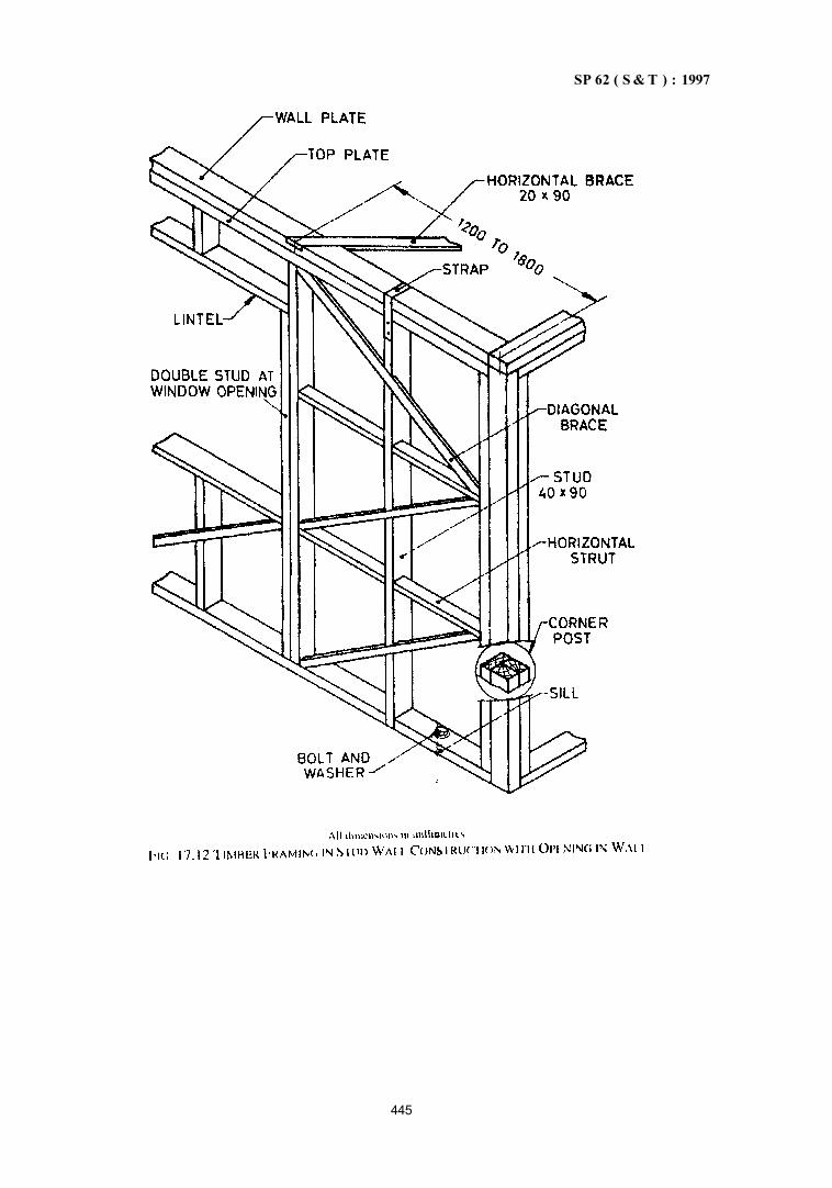
SP 62 ( S & T ) : 1997
445
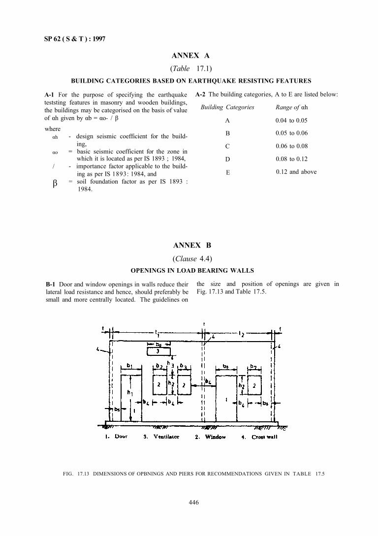
SP 62 ( S & T ) : 1997
ANNEX A (Table 17.1)
BUILDING CATEGORIES BASED ON EARTHQUAKE RESISTING FEATURES
A-1 For the purpose of specifying the earthquake teststing features in masonry and wooden buildings, the buildings may be categorised on the basis of value of αh given by αb = αo- / β
where αh
αo
/
β
- design seismic coefficient for the building,
= basic seismic coefficient for the zone in which it is located as per IS 1893 ; 1984,
- importance factor applicable to the building as per IS 1893: 1984, and
= soil foundation factor as per IS 1893 : 1984.
A-2 The building categories, A to E are listed below:
Building Categories
A
B
C
D
E
Range of αh
0.04 to 0.05
0.05 to 0.06
0.06 to 0.08
0.08 to 0.12
0.12 and above
ANNEX B
(Clause 4.4) OPENINGS IN LOAD BEARING WALLS
B-1 Door and window openings in walls reduce their lateral load resistance and hence, should preferably be small and more centrally located. The guidelines on
the size and position of openings are given in Fig. 17.13 and Table 17.5.
FIG. 17.13 DIMENSIONS OF OPBNINGS AND PIERS FOR RECOMMENDATIONS GIVEN IN TABLE 17.5
446
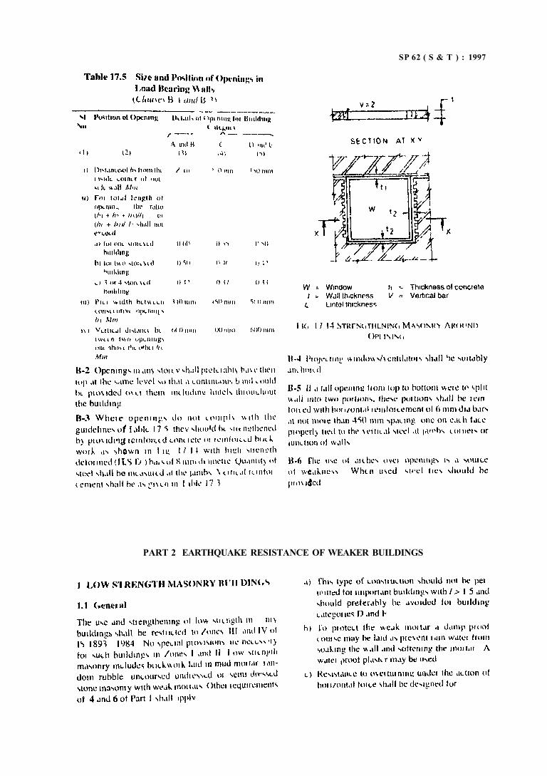
SP 62 ( S & T ) : 1997
PART 2 EARTHQUAKE RESISTANCE OF WEAKER BUILDINGS
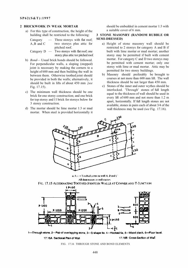
S P 6 2 ( S & T ) : 1 9 9 7
2 BRICKWORK IN WEAK MORTAR a) For this type of construction, the height of the
huilding shall be restricted to the following: Category A,B and C
Category D
— Three storeys with flat roof; two storeys plus attic for pitched roof.
— Two storeys with flat roof; one storey plus attic tor pitched roof.
b) Bond— Usual brick bonds should be followed. For perpendicular walls, a sloping (stepped) joint is necessary by making the corners to a height of 600 mm and then building the wall in between them. Otherwise toothed joint should be provided in both the walls; alternatively, it should be built in lifts of about 450 mm {see Fig. 17.15).
c) The minimum wall thickness should be one brick for one storey construction; and one brick for top storey and 11 brick for storeys below for 3 storey construction.
d) The mortar should be lime mortar 1:3 or mud mortar. When steel is provided horizontally it
FIG. 17.16 THROUGH STONE AND BOND ELEMENTS
448
should be embedded in cement mortar 1:3 with a suitable cover of 6 mm.
3 STONE MASONRY (RANDOM RUBBLE OR SEMI-DRESSED)
a) Height of stone masonry wall should be restricted to 2 storeys for category A and B if built with lime mortar or mud mortar; another storey may be permitted if built with cement mortar. For category C and D two storeys may be permitted with cement mortar; only one storey with lime or mud mortar. Attic may be permitted for two storey buildings.
b) Masonry should preferably be brought to courses at not more than 600 mm lift. The wall thickness should be not larger than 450 mm.
c) Stones of the inner and outer wythes should be interlocked. 'Through' stones of full length equal to the thickness of wall should be used in every lift of 600 mm and not more than 1.2 m apart, horizontally. If full length stones are not available, stones in pairs each of about 3/4 of the wall thickness may be used (see Fig. 17.16).
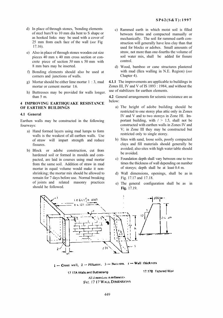
S P 6 2 ( S & T ) : 1 9 9 7
d) In place of through stones, 'bonding elements of steel bars'8 to 10 mm dia bent to S shape or as hooked links may be used with a cover of 25 mm from each face of the wall (see Fig 17.16).
e) Also in place of through stones wooden cut size pieces 40 mm x 40 mm cross section or concrete piece of section 50 mm x 50 mm with 8 mm bars may be inserted.
f) Bonding elements should also be used at corners and junctions of walls.
g) Mortar should be either lime mortar 1 : 3, mud mortar or cement mortar 1:6.
h) Buttresses may be provided for walls longer. than 5 m.
4 IMPROVING EARTHQUAKE RESISTANCE OF EARTHEN BUILDINGS
4.1 General
Earthen walls may be constructed in the following fourways:
a) Hand formed layers using mud lumps to form walls is the weakest of all earthen walls. Use of straw will impart strength and reduce fissures.
b) Block or adobe construction, cut from hardened soil or formed in moulds and compacted, are laid in courses using mud mortar from the same soil. Addition of straw in mud mortar in equal volume would make it non-shrinking; the mortar mix should be allowed to remain for 7 days before use. Normal breaking of joints and related masonry practices should he followed.
c) Rammed earth in which moist soil is filled between forms and compacted manually or mechanically. The soil for rammed earth construction will generally have less clay than that used for blocks or adobes. Small amounts of straw, not more than one-fourths the volume of soil water mix, shall be added for fissure control.
d) Wood, bamboo or cane structures plastered with mud (Ikra walling in N.E. Region) (see Chapter 4).
4.1.1 The improvements are applicable to buildings in Zones III, IV and V of IS 1893 : 1984, and without the use of stabilizers for earthen elements. 4.2 General arrangements for seismic resistance are as below:
a) The height of adobe building should be restricted to one storey plus attic only in Zones IV and V and to two storeys in Zone HI. Important building, with / > 1.5, shall not be constructed with earthen walls in Zones IV and V; in Zone III they may be constructed but restricted only to single storey.
b) Sites with sand, loose soils, poorly compacted clays and fill materials should generally be avoided; also sites with high water table should be avoided.
c) Foundation depth shall vary between one to two times the thickness of wall depending on number of storeys; depth shall be at least 0.4 m.
d) Wall dimensions, openings, shall be as in Fig. 17.17 and 17.18.
e) The general configuration shall be as in Fig. 17.19.
449
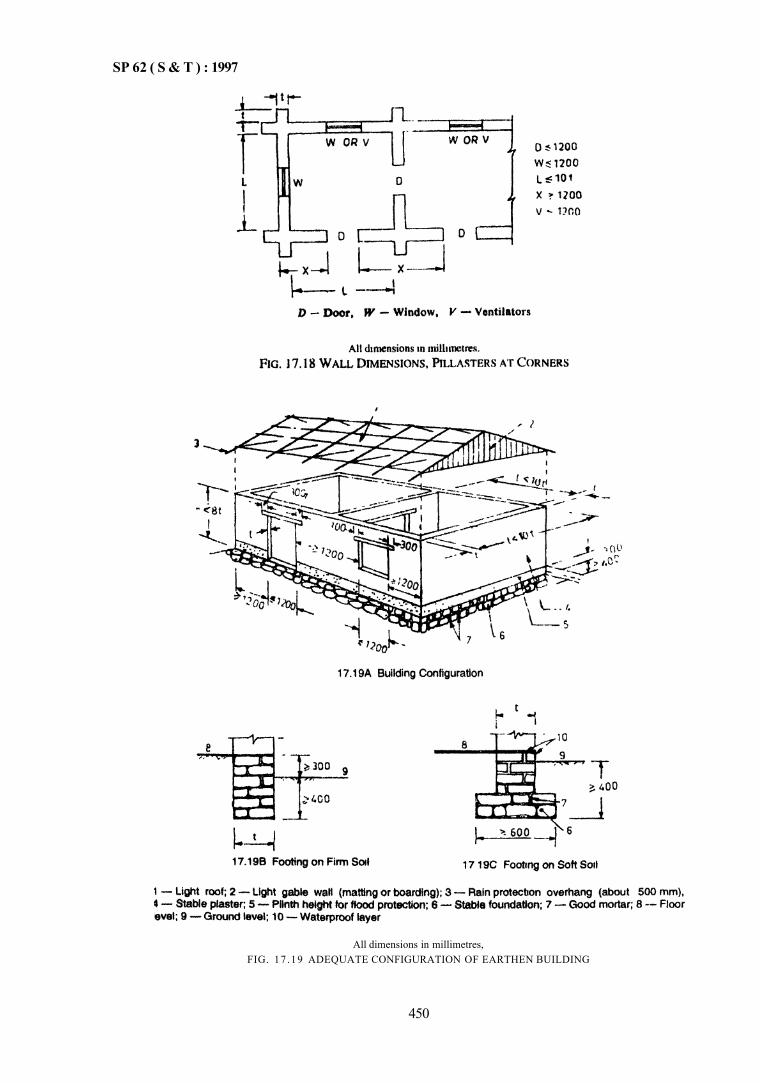
SP 62 ( S & T ) : 1997
All dimensions in millimetres, FIG. 17 .19 ADEQUATE CONFIGURATION OF EARTHEN BUILDING
450
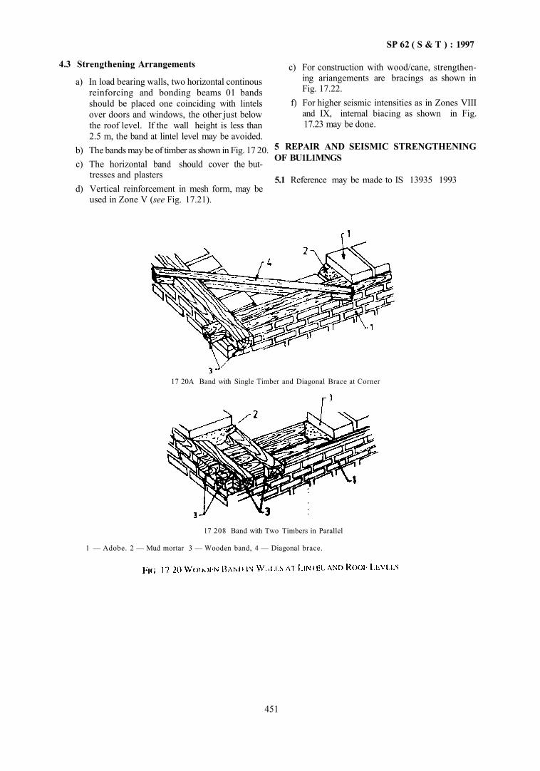
SP 62 ( S & T ) : 1997
4.3 Strengthening Arrangements
a) In load bearing walls, two horizontal continous reinforcing and bonding beams 01 bands should be placed one coinciding with lintels over doors and windows, the other just below the roof level. If the wall height is less than 2.5 m, the band at lintel level may be avoided.
b) The bands may be of timber as shown in Fig. 17 20. c) The horizontal band should cover the but
tresses and plasters d) Vertical reinforcement in mesh form, may be
used in Zone V (see Fig. 17.21).
c) For construction with wood/cane, strengthening ariangements are bracings as shown in Fig. 17.22.
f) For higher seismic intensities as in Zones VIII and IX, internal biacing as shown in Fig. 17.23 may be done.
5 REPAIR AND SEISMIC STRENGTHENING OF BU1L1MNGS
5.1 Reference may be made to IS 13935 1993
17 20A Band with Single Timber and Diagonal Brace at Corner
)
17 208 Band with Two Timbers in Parallel
1 — Adobe. 2 — Mud mortar 3 — Wooden band, 4 — Diagonal brace.
451
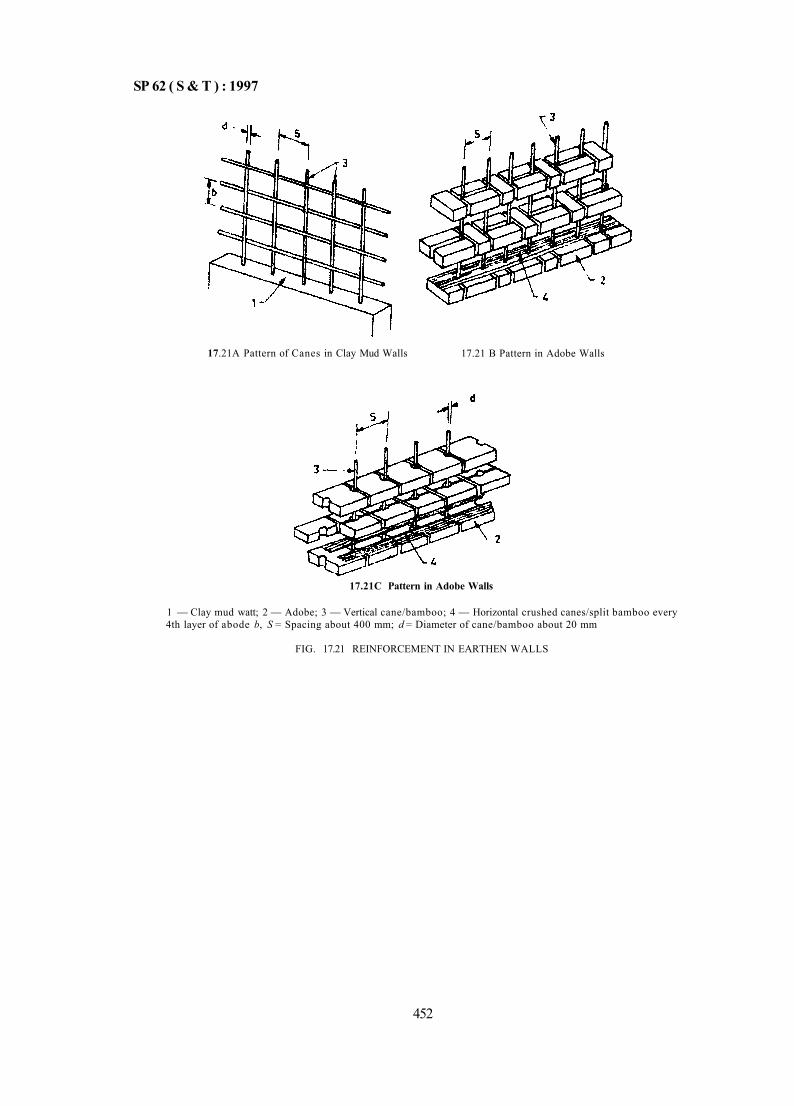
SP 62 ( S & T ) : 1997
17.21A Pattern of Canes in Clay Mud Walls 17.21 B Pattern in Adobe Walls
17.21C Pattern in Adobe Walls
1 — Clay mud watt; 2 — Adobe; 3 — Vertical cane/bamboo; 4 — Horizontal crushed canes/split bamboo every 4th layer of abode b, S = Spacing about 400 mm; d = Diameter of cane/bamboo about 20 mm
FIG. 17.21 REINFORCEMENT IN EARTHEN WALLS
452
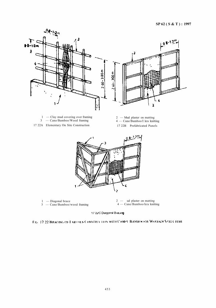
SP 62 ( S & T ) : 1997
1 — Clay mud covering over framing 3 — Cano/Bamboo/Wood framing
17 22A Elementary On Site Construction
2 — Mud plaster on matting 4 — Cane/Bamboo/I kra knitting 17 22B Prefabricated Panels
1 — Diagonal brace 3 — Cane/Bamboo/wood framing
2 — ud plaster on matting 4 — Cane/Bamboo/kra knitting
453
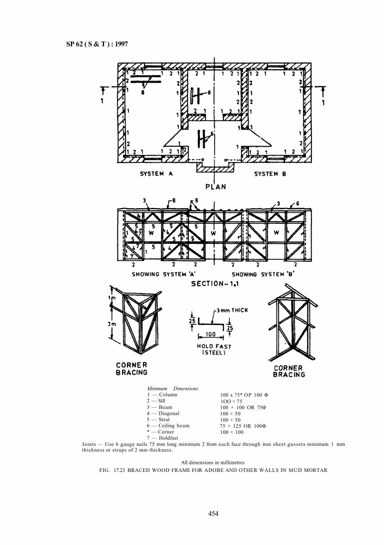
SP 62 ( S & T ) : 1997
Mintmum Dimensions 1 — Column 2 — Sill 3 — Beam 4 — Diagonal 5 — Strut 6 — Ceiling beam * — Corner 7 — Holdfast
100 x 75* OP 100 Φ 1OO × 75 100 × 100 OR 75Φ 100 × 50 100 × 50 75 × 125 OR 100Φ 100 × 100
Joints — Use 6 gauge nails 75 mm long minimum 2 from each face through iron sheet gussets minimum 1 mm thickness or straps of 2 mm thickness.
All dimensions in millimetres FIG. 17.23 BRACED WOOD FRAME FOR ADOBE AND OTHER WALLS IN MUD MORTAR
454

CHAPTER 18
DEMOLITION OF BUILDINGS
CONTENTS
1 GENERAL
2 PLANNING
3 PRECAUTIONS AND PROTECTIVE MEASURES BEFORE STARTING DEMOLITION WORK
4 PROTECTION OF THE PUBLIC
5 SEQUENCE OF DEMOLITION OPER AT IONS
6 DEMOLITION OF FLOORS
7 DEMOLITION OF WALL S
7 1 Procedure 7 2 Catch platforms
8 DEMOLI I ION OF DIFFERENT TYPES OF STRUPTURES AND ELEMENTS
8.2 Masonry Structures 8.3 Reinforced Concrete 8.4 Precast Reinforced Concrete 8.5 Prestressed Concrete 8.6 Steel 8 7 Other Elements
9 REMOVAL OF MATERIALS
9.1 General 9.2 Through Chutes 9.3 Through Openings
10 REFERENCES
8 1 General
SP 62 ( S & T ) :1997
CHAPTER 18
DEMOLITION OF BUILDINGS
1 GENERAL
1.1 Demolition of any structure is, inherently, more hazardous than the construction or erection of the same. From the point of view of safety, the conditions usually encountered while dismantling a structure, whatever its magnitude, do not lend themselves to the degree of control possible in the construction operations, where more stable conditions are generally obtainable. It is all the more imperative, therefore, that adequate attention is paid to planning and execution of demolition work, in its various stages, so as to minimize the risk of accidents and injuries to the personnel engaged in demolition operations.
It has therefore become necessary to laydown certain safety procedures which along with a planned programme could ensure adequate safety, particularly with the involvement of management, supervisors and workers.
1.2 The demolition work shall be proceeded in such a way that:
a) it causes least damage and nuisance to the adjoining building and the members of the public; and
b) it satisfies all safety requirements to avoid accidents.
1.3 A separate handbook on all aspects construction safety is under preparation by the Bureau oi Indian Standards, this Chapter will therefore confine itself to procedures and safety precautions for demolition and dismantling of buildings.
2 PLANNING
2.1 Before beginning the actual work of demolition, a careful study shall be made of the structure which is to be pulled down and also of its surroundings. This shall include the following:
a) The manner in which the various parts of buildings are supported and how far the stage by stage demolition would affect the safety of the adjoining structure;
b) A definite plan and procedure of demolition work shall be prepared, taking into account the loads on various structural parts and their supports;
c) Before commencement of each stage of demolition, the supervisor shall brief the workmen in detail regarding the safety aspects to be kept in view;
d) Ensure that the demolition conditions do not, at any stage, enhance the nuisance value of demolition work on the use of adjacent buildings;
e) No structure or part of the structure or any floor or temporary support or scaffold, side wall or any device for equipment shall be loaded in excess of the safe load bearing capacity, in its then existing condition; and
f) Stairs and stair railings, passage ways and ladders shall be left in place as long as possible. These should be maintained in a safe condition.
3 PRECAUTIONS AND PROTECTIVE MEASURES BEFORE STARTING DEMOLITION WORK
3.1 The following precautions and protective measures shall be taken before commencement of demolition work:
a) On every demolition job, danger signals shall be conspicuously posted all around the structure and all doors, openings giving access to structures shall be kept barricaded or manned except during the actual passage of workmen or equipment. However provision shall be made for at least two independent exits for escape of workmen during any emergency.
b) Walkways and passageways shall be provided for the use of the workmen who shall be
instructed to use them and all such walkways and passageways shall be kept adequately lighted, free from all debris and other materials.
c) Where in any work of demolition it is imperative, because of existing danger, to ensure that no unauthorized person shall enter the site of demolition outside working hours, a watchman shall be employed. In addition to watching the site he shall also be responsible for maintaining all signs, notices, lights, barricades, etc. During nights, red lights shall be placed on or about the barricades.
d) The power on all electrical service lines shall be shutoff and all such lines cut or disconnected at or outside the property line. The only exception would be any powerlines required for the demolition work itself. Prior to cutting of such lines, the necessary approval of the Authority shall be obtained.
457
SP 62 ( S & T ) : 1997
e) all mains and meters of the building shall be removed or protected from damage.
f) all gas. water, steam and other service lines shall be shutoff and capped or otherwise controlled at or outside the property line.
g) If a structure to be demolished has been partially wrecked by fire, explosion or other catastrophe. the walls and damaged roofs shall be shored and braced suitably.
h) Construction sheds and tool boxes should be so located as to protect workers from injuries ot falling objects, wall, etc.
j) A warning device should be installed in the area to be used to warn the workers, in case ot danger.
k) Screens shall be placed, where necessary, to prevent flying pieces from injuring the fellow workmen.
m) No demolition work shall be carried out during storm or heavy rain.
n) No demolition work shall be carried out at night specially when the building or structure to be demolished in an inhabited area.
p) all necessary safety appliances shall be issued to the workmen and their use explained. It shall be ensured that the workers are using all the safety appliances while at work. The safety appliances should be as follows: 1) Safety helmets as per IS 2925 : 1984: 2) Goggles made of celluloid lens to be worn
at the time of demolition of floors, walls, tearing of plaster, etc, specially when equipment like jack hammers are used tor demolition work, to protect the eyes from flying pieces, dust, dirt, etc, that may be blown up by wind.
3) Leather or rubber gloves worn during demolition of RCC work or removing steel work, where the hands of workers aie likely to be injured.
4) Safety belts while working at higher level to prevent falling from the structure.
q) First-aid equipment shall be available at all demolition works of any magnitude. Also, by prior arrangement, a qualified doctor be available at call.
r) When there is a possibility of fire breaking out, appropriate portable first-aid fire appliances (see IS 2190 : 1992) shall be kept at hand
s) The removal of a member may weaken the side wall of an adjoining structure and to prevent possible damage, these walls shall be sup ported until such lime as permanent protection is provided. In case of any danger is
anticipated to the adjoining structure, the same shall be got vacated to avoid any danger to human life.
t) Ladders, when used, shall conform to IS 3696 (Part 2): 1991. Ladders or their side rails shall extend not less than 1.0 m above the floor or platform to which the ladder gives access. all ladders shall be secured against slipping out at the bottom and against movement in any direction at the top.
u) all exterior wall openings which extend down to the floor level shall be barricaded to a height not less than 1 m above the floor level. all floor openings and shafts not meant as material chutes shall be floored over and endorsed with ground rails and toe boards.
v) all existing fixtures/services required during demolition operations shall be well protected with substantial covering to the satisfaction of the Authority.
w) When demolition is to be done by mechanical means such as weight ball and power showels, the following additional precautions are necessary. 1) The area shall be barricaded for a mini
mum distance of 11/2 times the height of the wall;
2) While the mechanical device is in operation no workmen shall be allowed to enter the building being demolished;
3) The device shall be so located as to avoid falling debris: and
4) The device when being used shall not cause any damage to adjacent structure, powerline. other services, etc.
4 PROTECTION OF THE PUBLIC 4.1 Protection of the public before and during demolition is important and the following points should be kept in mind:
a) Every sidewalk or road adjacent to the work shall be closed or protected. all main roads, which are open to the public shall be kept open to the public clear and unobstructed at all times.
b) Children and public shall be kept out of the building and the adjoining yards.
c) If the structure to be demolished is more than two- storeyed or 7.5 m high, measured from the sidewalk or street which cannot be closed or safely diverted, and the horizontal distance from the inside edge of the side walk to the structure is 4.5 m or less, a substantial side walk shed (see Fig. 18.1) [see also (k)] shall be constructed over the entire length of the
458
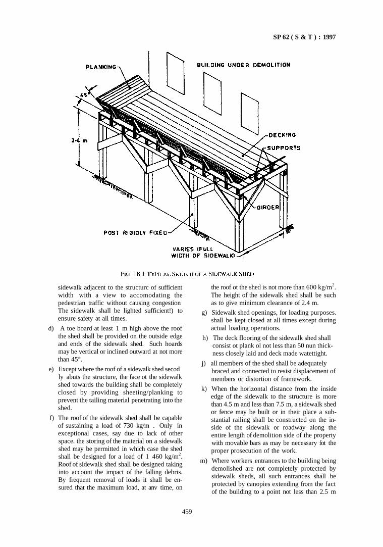
SP 62 ( S & T ) : 1997
sidewalk adjacent to the structurc of sufficient width with a view to accomodating the pedestrian traffic without causing congestion The sidewalk shall be lighted sufficient!) to ensure safety at all times.
d) A toe board at least 1 m high above the roof the shed shall be provided on the outside edge and ends of the sidewalk shed. Such hoards may be vertical or inclined outward at not more than 45°.
e) Except where the roof of a sidewalk shed secod ly abuts the structure, the face ot the sidewalk shed towards the building shall be completely closed by providing sheeting/planking to prevent the tailing material penetrating into the shed.
f) The roof of the sidewalk shed shall be capable of sustaining a load of 730 kg/m . Only in exceptional cases, say due to lack of other space. the storing of the material on a sidewalk shed may be permitted in which case the shed shall be designed for a load of 1 460 kg/m2. Roof of sidewalk shed shall be designed taking into account the impact of the falling debris. By frequent removal of loads it shall be ensured that the maximum load, at anv time, on
the roof ot the shed is not more than 600 kg/m2. The height of the sidewalk shed shall be such as to give minimum clearance of 2.4 m.
g) Sidewalk shed openings, for loading purposes. shall be kept closed at all times except during actual loading operations.
h) The deck flooring of the sidewalk shed shall consist ot plank ol not less than 50 nun thick- ness closely laid and deck made watettight.
j) all members of the shed shall be adequately braced and connected to resist displacement of
members or distortion of framework.
k) When the horizontal distance from the inside edge of the sidewalk to the structure is more than 4.5 m and less than 7.5 m, a sidewalk shed or fence may be built or in their place a substantial railing shall be constructed on the inside of the sidewalk or roadway along the entire length of demolition side of the property with movable bars as may be necessary fot the proper prosecution of the work.
m) Where workers entrances to the building being demolished are not completely protected by sidewalk sheds, all such entrances shall be protected by canopies extending from the fact of the building to a point not less than 2.5 m
459
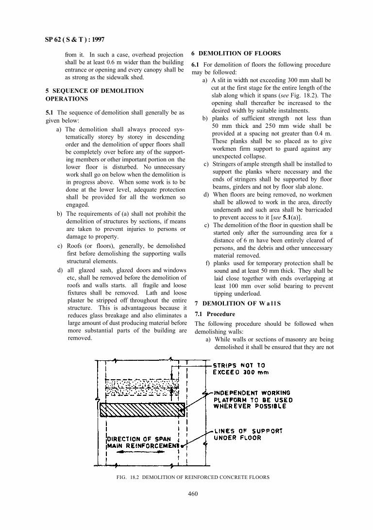
SP 62 ( S & T ) : 1997
from it. In such a case, overhead projection shall be at least 0.6 m wider than the building entrance or opening and every canopy shall be as strong as the sidewalk shed.
5 SEQUENCE OF DEMOLITION OPERATIONS
5.1 The sequence of demolition shall generally be as given below:
a) The demolition shall always proceed systematically storey by storey in descending order and the demolition of upper floors shall be completely over before any of the supporting members or other important portion on the lower floor is disturbed. No unnecessary work shall go on below when the demolition is in progress above. When some work is to be done at the lower level, adequate protection shall be provided for all the workmen so engaged.
b) The requirements of (a) shall not prohibit the demolition of structures by sections, if means are taken to prevent injuries to persons or damage to property.
c) Roofs (or floors), generally, be demolished first before demolishing the supporting walls structural elements.
d) all glazed sash, glazed doors and windows etc, shall be removed before the demolition of roofs and walls starts. all fragile and loose fixtures shall be removed. Lath and loose plaster be stripped off throughout the entire structure. This is advantageous because it reduces glass breakage and also eliminates a large amount of dust producing material before more substantial parts of the building are removed.
6 DEMOLITION OF FLOORS
6.1 For demolition of floors the following procedure may be followed:
a) A slit in width not exceeding 300 mm shall be cut at the first stage for the entire length of the slab along which it spans (see Fig. 18.2). The opening shall thereafter be increased to the desired width by suitable instalments.
b) planks of sufficient strength not less than 50 mm thick and 250 mm wide shall be provided at a spacing not greater than 0.4 m. These planks shall be so placed as to give workmen firm support to guard against any unexpected collapse.
c) Stringers of ample strength shall be installed to support the planks where necessary and the ends of stringers shall be supported by floor beams, girders and not by floor slab alone.
d) When floors are being removed, no workmen shall be allowed to work in the area, directly underneath and such area shall be barricaded to prevent access to it [see 5.1(a)].
c) The demolition of the floor in question shall be started only after the surrounding area for a distance of 6 m have been entirely cleared of persons, and the debris and other unnecessary material removed.
f) planks used for temporary protection shall be sound and at least 50 mm thick. They shall be laid close together with ends overlapping at least 100 mm over solid bearing to prevent tipping underload.
7 DEMOLITION OF W a l l S 7.1 Procedure The following procedure should be followed when demolishing walls:
a) While walls or sections of masonry are being demolished it shall be ensured that they are not
FIG. 18.2 DEMOLITION OF REINFORCED CONCRETE FLOORS
460
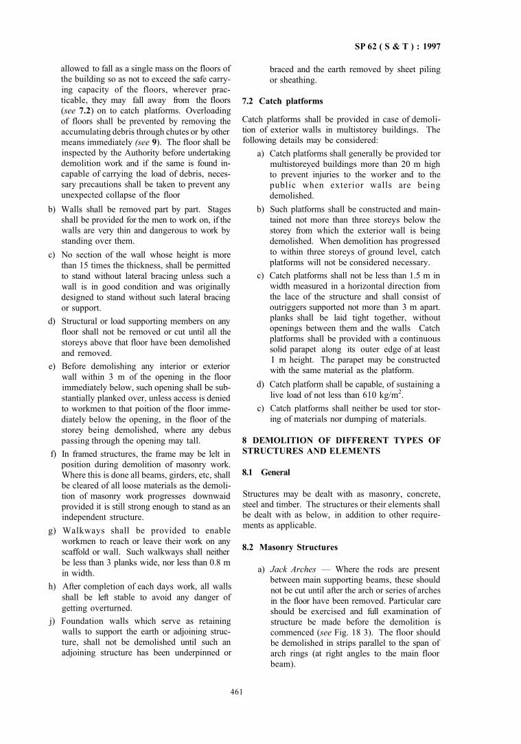
SP 62 ( S & T ) : 1997
allowed to fall as a single mass on the floors of the building so as not to exceed the safe carrying capacity of the floors, wherever practicable, they may fall away from the floors (see 7.2) on to catch platforms. Overloading of floors shall be prevented by removing the accumulating debris through chutes or by other means immediately (see 9). The floor shall be inspected by the Authority before undertaking demolition work and if the same is found incapable of carrying the load of debris, necessary precautions shall be taken to prevent any unexpected collapse of the floor
b) Walls shall be removed part by part. Stages shall be provided for the men to work on, if the walls are very thin and dangerous to work by standing over them.
c) No section of the wall whose height is more than 15 times the thickness, shall be permitted to stand without lateral bracing unless such a wall is in good condition and was originally designed to stand without such lateral bracing or support.
d) Structural or load supporting members on any floor shall not be removed or cut until all the storeys above that floor have been demolished and removed.
e) Before demolishing any interior or exterior wall within 3 m of the opening in the floor immediately below, such opening shall be substantially planked over, unless access is denied to workmen to that poition of the floor immediately below the opening, in the floor of the storey being demolished, where any debus passing through the opening may tall.
f) In framed structures, the frame may be lelt in position during demolition of masonry work. Where this is done all beams, girders, etc, shall be cleared of all loose materials as the demolition of masonry work progresses downwaid provided it is still strong enough to stand as an independent structure.
g) Walkways shall be provided to enable workmen to reach or leave their work on any scaffold or wall. Such walkways shall neither be less than 3 planks wide, nor less than 0.8 m in width.
h) After completion of each days work, all walls shall be left stable to avoid any danger of getting overturned.
j) Foundation walls which serve as retaining walls to support the earth or adjoining structure, shall not be demolished until such an adjoining structure has been underpinned or
braced and the earth removed by sheet piling or sheathing.
a) Jack Arches — Where the rods are present between main supporting beams, these should not be cut until after the arch or series of arches in the floor have been removed. Particular care should be exercised and full examination of structure be made before the demolition is commenced (see Fig. 18 3). The floor should be demolished in strips parallel to the span of arch rings (at right angles to the main floor beam).
7.2 Catch platforms
Catch platforms shall be provided in case of demolition of exterior walls in multistorey buildings. The following details may be considered:
a) Catch platforms shall generally be provided tor multistoreyed buildings more than 20 m high to prevent injuries to the worker and to the public when exterior walls are being demolished.
b) Such platforms shall be constructed and maintained not more than three storeys below the storey from which the exterior wall is being demolished. When demolition has progressed to within three storeys of ground level, catch platforms will not be considered necessary.
c) Catch platforms shall not be less than 1.5 m in width measured in a horizontal direction from the lace of the structure and shall consist of outriggers supported not more than 3 m apart. planks shall be laid tight together, without openings between them and the walls Catch platforms shall be provided with a continuous solid parapet along its outer edge of at least I m height. The parapet may be constructed with the same material as the platform.
d) Catch platform shall be capable, of sustaining a live load of not less than 610 kg/m2.
c) Catch platforms shall neither be used tor storing of materials nor dumping of materials.
8 DEMOLITION OF DIFFERENT TYPES OF STRUCTURES AND ELEMENTS
8.1 General
Structures may be dealt with as masonry, concrete, steel and timber. The structures or their elements shall be dealt with as below, in addition to other requirements as applicable.
8.2 Masonry Structures
461
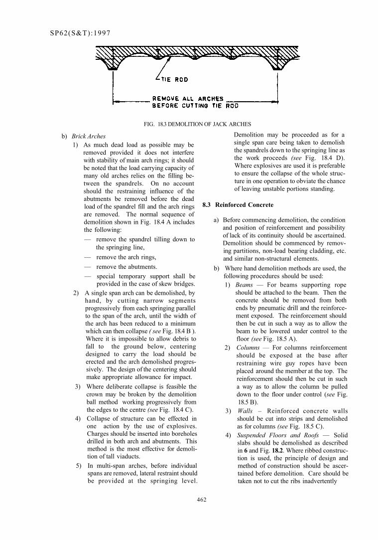
SP62(S&T):1997
FIG. 18.3 DEMOLITION OF JACK ARCHES
b) Brick Arches 1) As much dead load as possible may be
removed provided it does not interfere with stability of main arch rings; it should be noted that the load carrying capacity of many old arches relies on the filling between the spandrels. On no account should the restraining influence of the abutments be removed before the dead load of the spandrel fill and the arch rings are removed. The normal sequence of demolition shown in Fig. 18.4 A includes the following: — remove the spandrel tilling down to
the springing line, — remove the arch rings, — remove the abutments. — special temporary support shall be
provided in the case of skew bridges. 2) A single span arch can be demolished, by
hand, by cutting narrow segments progressively from each springing parallel to the span of the arch, until the width of the arch has been reduced to a minimum which can then collapse ( see Fig. 18.4 B ). Where it is impossible to allow debris to fall to the ground below, centering designed to carry the load should be erected and the arch demolished progressively. The design of the centering should make appropriate allowance for impact.
3) Where deliberate collapse is feasible the crown may be broken by the demolition ball method working progressively from the edges to the centre (see Fig. 18.4 C).
4) Collapse of structure can be effected in one action by the use of explosives. Charges should be inserted into boreholes drilled in both arch and abutments. This method is the most effective for demolition of tall viaducts.
5) In multi-span arches, before individual spans are removed, lateral restraint should be provided at the springing level.
Demolition may be proceeded as for a single span care being taken to demolish the spandrels down to the springing line as the work proceeds (see Fig. 18.4 D). Where explosives are used it is preferable to ensure the collapse of the whole structure in one operation to obviate the chance of leaving unstable portions standing.
8.3 Reinforced Concrete
a) Before commencing demolition, the condition and position of reinforcement and possibility of lack of its continuity should be ascertained. Demolition should be commenced by removing partitions, non-load bearing cladding, etc. and similar non-structural elements.
b) Where hand demolition methods are used, the following procedures should be used: 1) Beams — For beams supporting rope
should be attached to the beam. Then the concrete should be removed from both ends by pneumatic drill and the reinforcement exposed. The reinforcement should then be cut in such a way as to allow the beam to be lowered under control to the floor (see Fig. 18.5 A).
2) Columns — For columns reinforcement should be exposed at the base after restraining wire guy ropes have been placed around the member at the top. The reinforcement should then be cut in such a way as to allow the column be pulled down to the floor under control (see Fig. 18.5 B).
3) Walls – Reinforced concrete walls should be cut into strips and demolished as for columns (see Fig. 18.5 C).
4) Suspended Floors and Roofs — Solid slabs should be demolished as described in 6 and Fig. 18.2. Where ribbed construction is used, the principle of design and method of construction should be ascertained before demolition. Care should be taken not to cut the ribs inadvertently
462
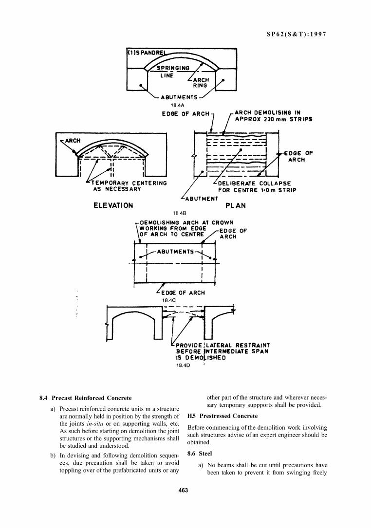
S P 6 2 ( S & T ) : 1 9 9 7
8.4 Precast Reinforced Concrete
a) Precast reinforced concrete units m a structure are normally held in position by the strength of the joints in-situ or on supporting walls, etc. As such before starting on demolition the joint structures or the supporting mechanisms shall be studied and understood.
b) In devising and following demolition sequences, due precaution shall be taken to avoid toppling over of the prefabricated units or any
other part of the structure and wherever necessary temporary suppports shall be provided.
H.5 Prestressed Concrete
Before commencing of the demolition work involving such structures advise of an expert engineer should be obtained.
8.6 Steel
a) No beams shall be cut until precautions have been taken to prevent it from swinging freely
463
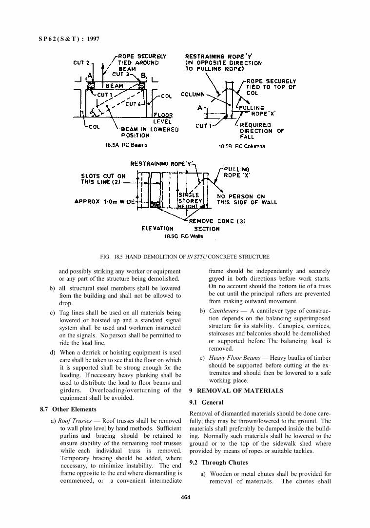
S P 6 2 ( S & T ) : 1997
FIG. 18.5 HAND DEMOLITION OF IN STTU CONCRETE STRUCTURE
and possibly striking any worker or equipment or any part of the structure being demolished.
b) all structural steel members shall be lowered from the building and shall not be allowed to drop.
c) Tag lines shall be used on all materials being lowered or hoisted up and a standard signal system shall be used and workmen instructed on the signals. No person shall be permitted to ride the load line.
d) When a derrick or hoisting equipment is used care shall be taken to see that the floor on which it is supported shall be strong enough for the loading. If necessary heavy planking shall be used to distribute the load to floor beams and girders. Overloading/overturning of the equipment shall be avoided.
8.7 Other Elements
a) Roof Trusses — Roof trusses shall be removed to wall plate level by hand methods. Sufficient purlins and bracing should be retained to ensure stability of the remaining roof trusses while each individual truss is removed. Temporary bracing should be added, where necessary, to minimize instability. The end frame opposite to the end where dismantling is commenced, or a convenient intermediate
frame should be independently and securely guyed in both directions before work starts. On no account should the bottom tie of a truss be cut until the principal rafters are prevented from making outward movement.
b) Cantilevers — A cantilever type of construction depends on the balancing superimposed structure for its stability. Canopies, cornices, staircases and balconies should be demolished or supported before The balancing load is removed.
c) Heavy Floor Beams — Heavy baulks of timber should be supported before cutting at the ex-tremites and should then be lowered to a safe working place.
9 REMOVAL OF MATERIALS
9.1 General
Removal of dismantled materials should be done carefully; they may be thrown/lowered to the ground. The materials shall preferably be dumped inside the building. Normally such materials shall be lowered to the ground or to the top of the sidewalk shed where provided by means of ropes or suitable tackles.
9.2 Through Chutes
a) Wooden or metal chutes shall be provided for removal of materials. The chutes shall
464
S P 6 2 ( S & T ) : 1997
preferably be provided at the centre of the building for efficient disposal of debris.
b) Chutes if provided at an angle of more than 45° from the horizontal shall be entirely enclosed on all sides, except for opening at or about the floor level for receiving materials.
c) Opening for chutes shall not exceed 1.20 m in height measured along the wall of the chute and in all storeys below the top floor such opening shall be kept closed when not in use.
d) To prevent the descending material attaining a dangerous speed, the chute shall not extend in an unbroken line for more than two storeys. A gate or step shall be provided with suitable means of closing at the bottom of each chute to stop the flow of materials.
c) Chutes at an angle less than 45° to the horizontal may be left open on the upperside provided that at the point where such chute discharges into the chute steeper than 45° to the horizontal, the top of the steeper chute shall be boarded over to prevent the escape of materials.
f) Any opening into which workmen dump debris at the top of the chute shall be guarded by a substantial guard rail extending at least 1 m above the level of the floor or other surface on which men stand to dump the materials, into the chute.
g) A toe board or bumper not less than 50 mm thick and 150 mm high shall be provided at each chute opening, if the required material is dumped from the wheel barrows. Any space between the chute and the edge of the opening in the, floor through which it passes shall be solidly planked over.
9.3 Through Openings
a) Debris may also be dropped through holes in the floor without the use of chutes. In such a case the total area of the hole cut in the intermediate floor, one which lies between floor that is being demolished and the storage floor shall not exceed 25 percent of such floor area. It shall be ensured that the storage floor is of adequate strength to withstand the impact of the falling material.
b) Openings in all floors below the floor from which materials are being removed, shall be
protected by standard railings and toe boards (see IS 4912 : 1978) or preferably planked over if the holes are not being used for dumping materials [see 3.1(s)].
c) all intermediate floor openings for passage of materials shall be completely closed with barricades or guard rails not less than I m high and at a distance of not less than 1 m from the edge of the general opening. No barricades or guard rails shall be removed until the storey immediately above has been demolished down to the floor line and all debris cleared from the floor.
d) When cutting a hole in an intermediate floor. between the storage floor and the floor which is being demolished, makes the intermediate floor or any portion of it unsafe, then such intermediate floor shall be properly shored. It shall also be ensured that the supporting walls are not kept without adequate lateral restraints.
10 REFERENCES
Other Indian Standards on the subject of safety of workers, in addition to the handbook under preparation are as follows:
IS No. Title
3696 (Part I) : Safety code of scaffolds and 1987 ladders: Part 1 Scaffolds
4014 (Part 2): Code of practice for steel tubular 1967 scaffolding: Part 2 Safety regula
tions for scaffolding 3764: 1992 Code of safety for excavation
work (first revision) 7969: 1975 Safety code for handling and
storage of building materials 13415 : 1992 Code of safety for protective bar
riers in and around buildings 13416 (Part 1). Recommendations for preven-
I992 tive measures against hazards at workplaces: Part I Falling material hazards prevention
13416 ( Part 2) : Recommendations for preven-1982 live measures against hazards at
workplaces : Part 2 Fall prevention
13430 : 1992 Code of practice for safety during additional construction and alteration to existing buildings
465
466
SP 62 (S&T):1997
LIST OF REFERRED INDIAN STANDARDS (+ Indicates Indian Standards Used in the Chapter)
CHAPTER 1 CONSTRUCTION PLANNING AND STORAGE OF MATERIALS
IS No. Title 1141 ; 1993 Seasoning of timber — Code of practice (second revision) *4082 : 1977 Recommendation on stacking and storage of construction materials at site
(first revision) (Reaffirmed 1990) 7969 : 1975 Safety code for handling and storage of building materials (Amendment 1)
(Reaffirmed 1991)
CHAPTER 2 EARTHWORK
883 : 1970 Design of structural timber in building — Code of practice (third revision) 1498 : 1970 Classification and identification of soils for general engineering purposes
(first revision) (Amendments 2) (Reaffirmed 1992) 2682: 1984 Chlordane emulsifiable concentrates (second revision) (Amendment 1)
(Reaffirmed 1994) *3764 : 1992 Excavation work — Code of safety (first revision) 4081 : 1986 Safety code for blasting and related drilling operations (Reaffirmed 1991) 5878 (Part 2/Sec 1): 1970 Code of practice for construction of tunnel conveying water : Part 2
Underground excavation in rock, Section 1 Drilling and blasting (Amendment 1) (Reaffirmed 1990)
6313 (Part 2 ) : 1981 Code of practice for anti-termite measures in buildings : Part 2 Pre-constructional chemical treatment measures (first revision) (Amendments 3) (Reaffirmed 1991)
6439: 1978 Heptachlor emulsifiable concentrates (first revision) (Amendments 2) (Reaffirmed 1993)
8944 : 1978 Chlorpyrifos emulsifiable concentrates (Amendments 2) (Reaffirmed 1993)
CPWD 1991-92 Specifications
CHAPTER 3 FOUNDATIONS
269 : 1989 33 grade ordinary Portland cement (fourth revision) (Amendments 3) 401 : 1982 Code of practice for preservation of timber (third revision) (Amendments
2) (Reaffirmed 1990) 432 (Part 1): 1982 Mild steel and medium tensile steel bars and hard-drawn steel wire for
concrete reinforcement : Part 1 Mild steel and medium tensile steel bars (third revision) (Reaffirmed 1995)
455 : 1989 Portland slag cement (fourth revision) (Amendments 3) 456 : 1978 Code of practice for plain and reinforced concrete (third revision) (Amend
ments 2) (Reaffirmed 1991) 1080: 1986 Code of practice for design and construction of shallow foundations on soils
(other than raft, ring and shell) (second revision) (Reaffirmed 1990) 1489 (Part 1): 1991 Portland pozzolana cement: Part 1 Fly ash based (third revision) 1489 (Part 2) : 1991 Portland pozzolana cement: Part 2 Calcined clay based (third revision)
(Amendment 1) 1786 : 1985 High strength deformed steel bars and wires for concrete reinforcement
(third revision) (superseding IS 1139: 1966) (Amendment 1) (Reaffirmed 1990)
SP62(S&T):1997
IS No. Title *1904: 1986 Code of practice for design and construction of foundations in soils :
General requirements (third revision) 2062 : 1992 Steel for general structural purposes {fourth revision) (supersedes IS 226 :
1975) (Amendment 1) 2911 (Part 1/Sec I) : 1979 Code of practice for design and construction of pile foundations : Part 1
Concrete piles, Section I Driven case in-situ concrete piles (jirst revision) (Amendments 2) (Reaffirmed 1987)
2911 (Part I/Sec 2) : 1979 Code of practice for design and construction of pile foundations : Part 1 Concrete piles, Section 2 Bored cast in-situ piles {first revision) (Amendments 3) (Reaffirmed 1987)
2911 (Part 1/Sec 3): 1979 Code of practice for design and construction of pile foundations : Part 1 Concrete piles. Section 3 Driven precast conciete piles (first revision) (Amendments 3) (Reaffirmed 1987)
2911 (Part 1/Sec 4): 1984 Code of practice for design and construction of pile foundations : Pan 1 Concrete piles, Section 4 Bored precast concrete piles (Amendment 1)
2911 (Part 2) : 1980 Code oi practice for design and construction of pile foundations . Part 2 Timber piles {first revision) (Amendment I) (Reaffirmed 1987)
2911 (Part 3) • 1980 Code of practice for design and construction of pile foundations : Part 3 Under reamed piles {first revision) (Amendments 3)
2911 (Part 4) • 1985 Code of practice for design and construction of pile foundations : Part 4 Load test on piles (first revision) (Amendment 1)
2950 (Part I) : 1981 Code ot practice for design and construction of raft foundations . Pari I Design {second revision) (Amendment I) (Reaffirmed 1993)
2974 (Part i) : 1982 Code of practice for design and construction of machine foundations : Part I Foundations for reciprocating type machines (second revision) (Amendment I) (Realfirmed 1993)
2974 (Part 2): 1980 Code o( practice for design and construction of machine foundations : Part 2 Foundations for impact type machine (hammer foundations) (first revision) (Amendment 1) (Reaffirmed 1993)
2974 (Part 3) : 1992 Design and construction of machine foundations - - Code of practice : Part 3 Foundations for rotary type machines (medium and high frequency) (second revision)
2974 (Part 4) : 1979 ('ode of practice for design and eonstrucrtion of machine Inundations -Part 4 Foundations for rojary type machines of low frequency (Jtrst revision) (Amendment I) (HJeaffirmed 1987)
2974 (Part 5): 1987 Code of practice for desibn and constrution of machine foundations Part 5 Foundations lor i m p i t machines other than hammers (forging and stamping press, pig breakers, drop trusher and joltei) [fust revision) (Reaffirmed 1993)
3629 : 1986 Specification tor structural timber in building (first revision) (Reaffirmed 1991)
4091 : 1979 Code of practice for design and construction of foundations for transmission line towers and poles (first revision) (Reaffirmed 1987)
6403 : 1981 Code of practice for determination of bearing capacity of shallow foundations (first revision) (Amendment 1) (Reaffirmed 1990)
6909 : 1990 Specification for supersulphated cement (Amendments 2) 8009 (Part 1): 1976 Code of practice for calculation of settlement of foundations: Part I Shallow
foundations subject to symmetrical static vertical loads (Amendments 2) (Reaffirmed 1993)
8009 (Part 2) : 1980 Code of practice for calculation of settlement of foundations : Part 2 Deep foundations subjected to symmetrical static vertical loading (Amendment I) (Reaffirmed 1987)
467
SP 62 (S & T): 1997
AS' No.
8041 • 1990 9456: 1980
*9556' 1980
11089- 1984
11233: 1985
12269: 1987 13094. 1992
SP 36 (Part 2): 1988
269: 1989 383: 1970
455 . 1989 456: 1978
712 1984 1344- 1981
1489 (Part 1)* 1991 1489 (Part 2): 1991
1635 1992
2116- 1980 2250. 1981
2686: 1977
MS: 1986
<SI2. 19XJ 4098- 1983
6452 1989 <v/Oy |09o 8041 : 1990 8043- 1991 8112 1989 12269: 1987 12600. 1989 H077: 1991
Title Rapid hardening Portland cement (second revision) (Amendments 2) Code of practice for design and cohstruction of conical and hyperbolic paraboloidal type* of shell foundations (Amendment 1) (Reaffirmed 1993) Code of practice for design and construction of diaphragm walls (Amendment !) (Reaffirmed 1993) Code of practice for design and construction of ring foundation (Amendment I) (Reaffirmed 1990) Code of practice for design and construction of radar antenna, microwave and TV tower foundations (Reaffirmed 1990) 53 grade ordinary Portland cement (Amendments 3) (Reaffirmed 1992) Guidelines for selection of ground improvement techniques for foundation in weak soils Compendium of Indian Standards on soil engineering : Part 2 Field testing
CHAPTER 4 MASONRY
Part 1 Mortars
33 grade ordinary Portland cement (fourth revision) (Amendments 3) Coarse and fine aggregates from natural sources for concrete (second revision) (Reaffirmed 1990) Portland slag cement (fourth revision) (Amendments 3) Code of practice for plain and reinforced concrete (third revision) (Amendments 2) (Reaffirmed 1991) Building limes (third revision) (Reaffirmed 1991) Calcined clay pozzolana (second revision) (Amendment 1) (Reaffirmed 1990) Portland pozzolana cement: Part 1 Fly ash based (third revision) Portland posftolana cement: Part 2 Calcined clay based (third revision) (Amendment I) Code of practice for field slaking of building lime and preparation of putty (second revision) Sand for masonry mortars (first revision) (Reaffirmed 1992) Code of practice for preparation and use of masonry mortars (first revision) (Reaifirmed 1990) Cinder as fine aggregates for use in lime concrete (first revision) (Amendment 1) (Reaffirmed 1992) Broken brick (burnt clay) fine aggregates for use in lime mortar (second revision) (Reaffirmed 1991) Fly ash for use as pozolana and admixture (first revision) (Reaffirmed 1992) Lime-pozzolana mixture (first revision) (Amendments 2) (Reaffirmed 1989) Specification for high alumina cement for structural use (Amendment I) Specification for supersulphated cement (Amendments 2) Rapid hardening Portland cement (second revision) (Amendments 2) Hydrophobic Portland cement (second revision) (Amendments 2) 43 grade ordinary Portland cement (first revision) (Amendments 3) 53 grade ordinary Portland cement (Amendments 3) (Reaffirmed 1992) Low heat Portland cement (Amendments 3) Guide for preparation and use of mud mortar in masonry
468
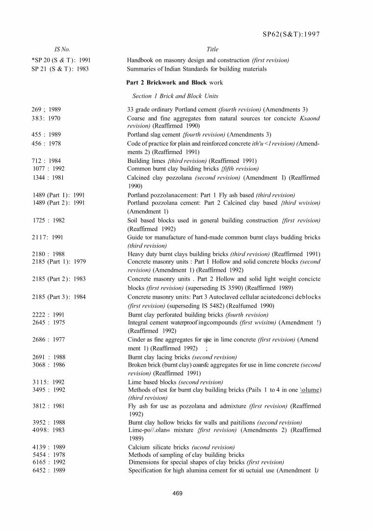
SP62(S&T):1997
IS No. Title
*SP 20 (S & T) : 1991 Handbook on masonry design and construction (first revision) SP 21 (S & T) : 1983 Summaries of Indian Standards for building materials
Part 2 Brickwork and Block work
Section 1 Brick and Block Units
269 ; 1989 33 grade ordinary Portland cement (fourth revision) (Amendments 3) 383: 1970 Coarse and fine aggregates from natural sources tor concicte Ksaond
revision) (Reaffirmed 1990) 455 : 1989 Portland slag cement {fourth revision) (Amendments 3) 456 : 1978 Code of practice for plain and reinforced concrete ith'u <l revision) (Amend
ments 2) (Reaffirmed 1991) 712 : 1984 Building limes {third revision) (Reaffirmed 1991) 1077 : 1992 Common burnt clay building bricks {fifth revision) 1344 : 1981 Calcined clay pozzolana (second revision) (Amendment I) (Reaffirmed
1990) 1489 (Part I ) : 1991 Portland pozzolanacement: Part 1 Fly ash based (third revision) 1489 (Part 2): 1991 Portland pozzolana cement: Part 2 Calcined clay based {third wvision)
(Amendment 1) 1725 : 1982 Soil based blocks used in general building construction {first revision)
(Reaffirmed 1992) 2117: 1991 Guide tor manufacture of hand-made common burnt clays budding bricks
(third revision) 2180 : 1988 Heavy duty burnt clays building bricks (third revision) (Reaffirmed 1991) 2185 (Part 1): 1979 Concrete masonry units : Part I Hollow and solid concrete blocks (second
revision) (Amendment 1) (Reaffirmed 1992) 2185 (Part 2): 1983 Concrete masonry units . Part 2 Hollow and solid light weight concicte
blocks (first revision) (superseding IS 3590) (Reaffirmed 1989) 2185 (Part 3): 1984 Concrete masonry units: Part 3 Autoclaved cellular aciatedconci deblocks
(first revision) (superseding IS 5482) (Realfumed 1990) 2222 : 1991 Burnt clay perforated building bricks (fourth revision) 2645 : 1975 Integral cement waterproof ingcompounds (first wvisitm) (Amendment !)
(Reaffirmed 1992) 2686 : 1977 Cinder as fine aggregates for ujse in lime concrete (first revision) (Amend
ment 1) (Reaffirmed 1992) ; 2691 : 1988 Burnt clay lacing bricks (second revision) 3068 : 1986 Broken brick (burnt clay) coarsfc aggregates for use in lime concrete (second
revision) (Reaffirmed 1991) 3115: 1992 Lime based blocks (second revision) 3495 : 1992 Methods of test for burnt clay building bricks (Pails 1 to 4 in one \olume)
(third revision) 3812 : 1981 Fly ash for use as pozzolana and admixture (first revision) (Reaffirmed
1992) 3952 : 1988 Burnt clay hollow bricks for walls and paitilions (second revision) 4098: 1983 Lime-po//.olan« mixture {first revision) (Amendments 2) (Reaffirmed
1989) 4139 : 1989 Calcium silicate bricks (ucond revision) 5454 : 1978 Methods of sampling of clay building bricks 6165 : 1992 Dimensions for special shapes of clay bricks (first revision) 6452 : 1989 Specification for high alumina cement for sti uctuial use (Amendment I)
469
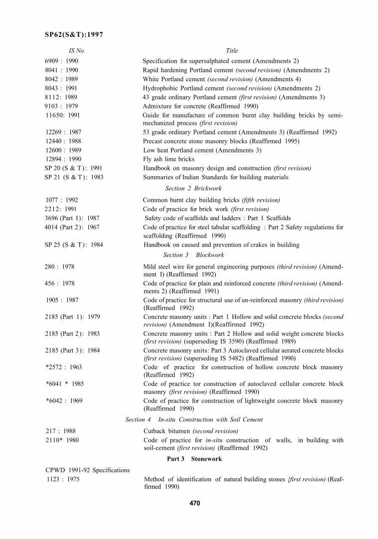
SP62(S&T):1997
IS No. Title 6909 : 1990 Specification for supersulphated cement (Amendments 2) 8041 : 1990 Rapid hardening Portland cement (second revision) (Amendments 2) 8042 : 1989 White Portland cement (second revision) (Amendments 4) 8043 : 1991 Hydrophobic Portland cement (second revision) (Amendments 2) 8112: 1989 43 grade ordinary Portland cement (first revision) (Amendments 3) 9103 : 1979 Admixture for concrete (Reaffirmed 1990) 11650: 1991 Guide for manufacture of common burnt clay building bricks by semi-
mechanized process (first revision) 12269 : 1987 53 grade ordinary Portland cement (Amendments 3) (Reaffirmed 1992) 12440 : 1988 Precast concrete stone masonry blocks (Reaffirmed 1995) 12600 : 1989 Low heat Portland cement (Amendments 3) 12894 : 1990 Fly ash lime bricks SP 20 (S & T) : 1991 Handbook on masonry design and construction (first revision) SP 21 (S & T ) : 1983 Summaries of Indian Standards for building materials
Section 2 Brickwork
1077 : 1992 Common burnt clay building bricks (fifth revision) 2212: 1991 Code of practice for brick work (first revision) 3696 (Part I ) : 1987 Safety code of scaffolds and ladders : Part I Scaffolds 4014 (Part 2) : 1967 Code of practice for steel tabular scaffolding : Part 2 Safety regulations for
scaffolding (Reaffirmed 1990) SP 25 (S & T) : 1984 Handbook on caused and prevention of crakes in building
Section 3 Blockwork
280 : 1978 Mild steel wire for general engineering purposes (third revision) (Amendment I) (Reaffirmed 1992)
456 : 1978 Code of practice for plain and reinforced concrete (third revision) (Amendments 2) (Reaffirmed 1991)
1905 : 1987 Code of practice for structural use of un-reinforced masonry (third revision) (Reaffirmed 1992)
2185 (Part 1): 1979 Concrete masonry units : Part 1 Hollow and solid concrete blocks (second revision) (Amendment I)(Reaffirmed 1992)
2185 (Part 2) : 1983 Concrete masonry units : Part 2 Hollow and solid weight concrete blocks (first revision) (superseding IS 3590) (Reaffirmed 1989)
2185 (Part 3): 1984 Concrete masonry units: Part 3 Autoclaved cellular aerated concrete blocks (first revision) (superseding IS 5482) (Reaffirmed 1990)
*2572 : 1963 Code of practice for construction of hollow concrete block masonry (Reaffirmed 1992)
*6041 * 1985 Code of practice tor construction of autoclaved cellular concrete block masonry (first revision) (Reaffirmed 1990)
*6042 : 1969 Code of practice for construction of lightweight concrete block masonry (Reaffirmed 1990)
Section 4 In-situ Construction with Soil Cement
217 : 1988 Cutback bitumen (second revision) 2110* 1980 Code of practice for in-situ construction of walls, in building with
soil-cement (first revision) (Reaffirmed 1992)
Part 3 Stonework
CPWD 1991-92 Specifications 1123 : 1975 Method of identification of natural building stones {first revision) (Reaf
firmed 1990)
470
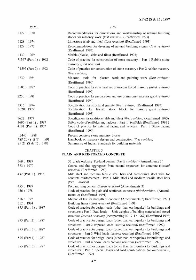
SP 62 (S & T) : 1997
*
IS No. Title
1127 : 1970 Recommendations for dimensions and workmanship of natural building stones for masonry work (first revision) (Reaffirmed 1993)
1128 : 1974 Limestone (slab and tiles) (first revision) (Reaffirmed 1993) 1129 : 1972 Recommendation for dressing of natural building stones (first revision)
(Reaffirmed 1993) 1130 : 1969 Marble (blocks, slabs and tiles) (Reaffirmed 1993) *I597 (Part 1) : 1992 Code of practice for construction of stone masonry : Part 1 Rubble stone
masonry (first revision) 1597 (Part 2) : 1992 Code of practice tor construction of stone masonry : Part 2 Ashlar masonry
(first revision) 1630 : 1984 Masons tools for plaster work and pointing work (first revision)
(Reaffirmed 1990) 1905 : 1987 Code of practice for structural use of un-rein forced masonry (third revision)
(Reaffirmed 1992) 2250 : 1981 Code of practice for preparation and use of masonry mortars (first revision)
(Reaffirmed 1990) 3316 : 1974 Specification for structural granite (first revision) (Reaffirmed 1993) 3620: 1979 Specification for laterite stone block for masonry (first revision)
(Reaffirmed 1993) 3622 : 1977 Specification for sandstone (slab and tiles) (first revision) (Reaffirmed 1993) 3696 (Part 1) : 1987 Safety code of scaffolds and ladders : Part 1 Scaffolds (Reaffirmed 1991 ) 4101 (Part 1): 1967 Code ol practice for external facing and veneers : Part 1 Stone facing
(Reaffirmed 1990) 12440 : 1988 Precast concrete stone masonry blocks *SP 20 (S & T) : 1991 Handbook on masonry design and construction (first revision) SP 21 (S & T) : 1983 Summarise of Indian Standards for building materials
CHAPTER 5 PLAIN AND REINFORCED CONCRETE
269 : 1989 33 grade ordinary Portland cement (fourth revision) (Amendments 3 ) 383 : 1970 Coarse and fine aggregates from natural resources for concrete (second
revision) (Reaffirmed 1990) 432 (Part 1). 1982 Mild steel and medium tensile steel bars and hard-drawn steel wire for
concrete reinforcement : Part 1 Mild steel and medium tensile steel bars (third revision)
455 : 1989 Portland slag cement (fourth revision) (Amendments 3) 456 : 1978 ( 'ode of practice for plain aftd reinforced concrete (third revision) (Amend
ments 2) (Reaffirmed 1991) 516 : 1959 Method of test for strength of concrete (Amendments 2) (Reaffirmed 1991) 712 : 1984 Building limes (third revision) (Reaffirmed 1991) 875 (Part 1) : 1987 Code of practice for design loads (othet than earthquake) for buildings and
structures : Part 1 Dead loads — Unit weights of building material and stored materials (second revision) (incorporating IS 1911 : 1967) (Reaffirmed 1992)
875 (Part 2) : 1987 Code of practice for design loads (other than earthquake) for buildings and structures : Part 2 Imposed loads (second revision) (Reaffirmed 1992)
875 (Part 3) : 1987 Code of practice for design loads (other than earthquake) for buildings and structures : Part 3 Wind loads (second revision) (Reaffirmed 1992)
875 (Part 4) : 1987 Code of practice for design loads (other than earthquake) for buildings and structures : Part 4 Snow loads (second revision) (Reaffirmed 1992)
875 (Part 5) : 1987 Code of practice for design loads (other than earthquake) for buildings and structures : Part 5 Special loads and load combinations (second revision) (Reaffirmed 1992)
471
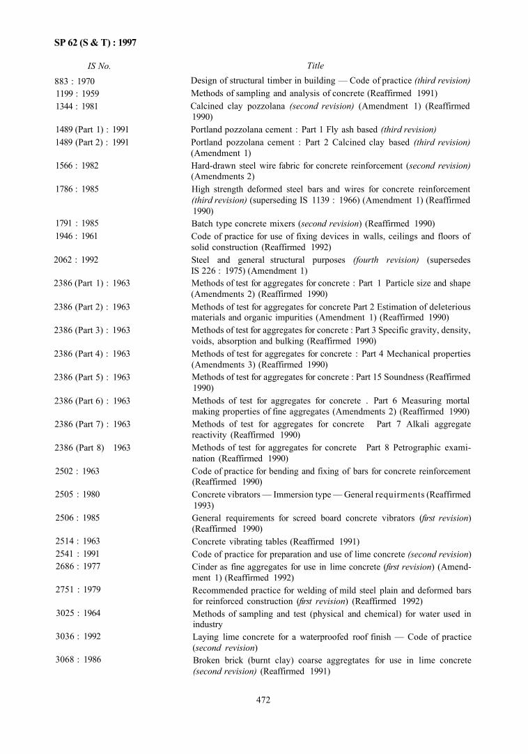
IS No. 883 : 1970 1199 : 1959 1344 : 1981
1489 (Part 1) : 1991 1489 (Part 2) : 1991
1566 : 1982
1786 : 1985
1791 : 1985 1946 : 1961
2062 : 1992
2386 (Part 1) : 1963
2386 (Part 2) : 1963
2386 (Part 3) : 1963
2386 (Part 4) : 1963
2386 (Part 5) : 1963
2386 (Part 6) : 1963
2386 (Part 7) : 1963
2386 (Part 8) 1963
2502 : 1963
2505 : 1980
2506 : 1985
2514 : 1963 2541 : 1991 2686 : 1977
2751 : 1979
3025 : 1964
3036 : 1992
3068 : 1986
Title Design of structural timber in building — Code of practice (third revision) Methods of sampling and analysis of concrete (Reaffirmed 1991) Calcined clay pozzolana (second revision) (Amendment 1) (Reaffirmed 1990) Portland pozzolana cement : Part 1 Fly ash based (third revision) Portland pozzolana cement : Part 2 Calcined clay based (third revision) (Amendment 1) Hard-drawn steel wire fabric for concrete reinforcement (second revision) (Amendments 2) High strength deformed steel bars and wires for concrete reinforcement (third revision) (superseding IS 1139 : 1966) (Amendment 1) (Reaffirmed 1990) Batch type concrete mixers (second revision) (Reaffirmed 1990) Code of practice for use of fixing devices in walls, ceilings and floors of solid construction (Reaffirmed 1992) Steel and general structural purposes (fourth revision) (supersedes IS 226 : 1975) (Amendment 1) Methods of test for aggregates for concrete : Part 1 Particle size and shape (Amendments 2) (Reaffirmed 1990) Methods of test for aggregates for concrete Part 2 Estimation of deleterious materials and organic impurities (Amendment 1) (Reaffirmed 1990) Methods of test for aggregates for concrete : Part 3 Specific gravity, density, voids, absorption and bulking (Reaffirmed 1990) Methods of test for aggregates for concrete : Part 4 Mechanical properties (Amendments 3) (Reaffirmed 1990) Methods of test for aggregates for concrete : Part 15 Soundness (Reaffirmed 1990) Methods of test for aggregates for concrete . Part 6 Measuring mortal making properties of fine aggregates (Amendments 2) (Reaffirmed 1990) Methods of test for aggregates for concrete Part 7 Alkali aggregate reactivity (Reaffirmed 1990) Methods of test for aggregates for concrete Part 8 Petrographic examination (Reaffirmed 1990) Code of practice for bending and fixing of bars for concrete reinforcement (Reaffirmed 1990) Concrete vibrators — Immersion type — General requirments (Reaffirmed 1993) General requirements for screed board concrete vibrators (first revision) (Reaffirmed 1990) Concrete vibrating tables (Reaffirmed 1991) Code of practice for preparation and use of lime concrete (second revision) Cinder as fine aggregates for use in lime concrete (first revision) (Amendment 1) (Reaffirmed 1992) Recommended practice for welding of mild steel plain and deformed bars for reinforced construction (first revision) (Reaffirmed 1992) Methods of sampling and test (physical and chemical) for water used in industry Laying lime concrete for a waterproofed roof finish — Code of practice (second revision) Broken brick (burnt clay) coarse aggregtates for use in lime concrete (second revision) (Reaffirmed 1991)
472
SP 62 (S & T) : 1997
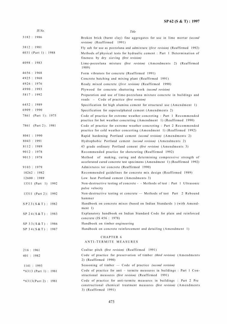
SP 62 (S & T) : 1997
IS No.
3 1 8 2 : 1986
3812 : 1981
4 0 3 1 (Pa r t 1) : 1988
4 0 9 8 : 1983
4 6 5 6 : 1968
4 9 2 5 : 1968
4 9 2 6 : 1976
4 9 9 0 : 1993
5 8 1 7 : 1992
6 4 5 2 : 1989
6 9 0 9 : 1990
7861 (Part 1 ) : 1975
7861 (Part 2 ) . 1981
8041 : 1990
8043 : 1991
8112 : 1989
9 0 1 2 : 1978
9 0 1 3 : 1978
9 1 0 3 : 1979
10262 : 1982
12600 : 1989
13311 (Part 1) 1992
13311 (Part 2 ) : 1992
S P 2 3 ( S & T ) : 1982
SP 2 4 ( S & T ) : 1983
SP 3 3 ( S & T ) : 1986
SP 3 4 ( S & T ) : 1987
216 : 1961
401 : 1982
1141 : 1993
* 6 3 1 3 (Part 1) : 1981
* 6 3 1 3 ( P a r t 2) : 1981
Title
Broken brick (burnt clay) fine aggregates for use in l ime mor ta r (second revision) (Reaffirmed 1991)
Fly ash for use as pozzolana and admixture (first revision) (Reaffirmed 1992)
Methods of physical tests for hydraulic cement : Part 1 De te rmina t ion of fineness by dry sieving (first revision)
Lime-pozzolana mixture (first revision) ( A m e n d m e n t s 2) (Reaff i rmed 1989)
Form vibrators for concrete (Reaffirmed 1991)
Concrete batching and mixing plant (Reaffirmed 1991)
Ready mixed concrete (first revision) (Reaffirmed 1990)
P lywood for concrete shuttering work (second revision)
Preparat ion and use of l ime-pozzolana mixture concre te in bui ld ings and roads – Code of practice (first revision)
Specification for high alumina cement for structural use ( A m e n d m e n t 1)
Specification for supersulphated cement ( A m e n d m e n t s 2)
Code of pract ice for ex t reme weather concre t ing : Part 1 R e c o m m e n d e d pract ice for hot weather concret ing (Amendmen t 1) (Reaff i rmed 1990)
C o d e of practice for ex t reme weather concre t ing : Part 2 R e c o m m e n d e d practice for cold weather concer t ing (Amendmen t 1) (Reaff i rmed 1992)
Rapid hardening Portland cement (second revision) ( A m e n d m e n t s 2) Hydrophobic Portland cement (second revision) ( A m e n d m e n t s 2)
43 grade ordinary Portland cement (first revision) ( A m e n d m e n t s 3)
Recommended practice for shotcret ing (Reaff irmed 1992)
Method of making, curing and de te rmining compress ive s t rength of accelerated cured concrete test specimens (Amendment 1) (Reaffirmed 1992) Admixtures tor concrete (Reaffirmed 1990)
R e c o m m e n d e d guidelines for concrete mix design (Reaff i rmed 1989)
Low heat Portland cement (Amendmen t s 3)
Non-destruct ive testing of concrete - - Methods of test : Part 1 Ultrasonic pulse velocity
Non-dest ruct ive testing ot concrete — Methods of test Part 2 Rebound h a m m e r
Handbook on concrete mixes (based on Indian S tandards ) (with A m e n d ment 1)
Explanatory handbook on Indian Standard Code for plain and reinforced concrete (IS 456 : 1978)
Handbook on t imber engineer ing
Handbook on concrete reinforcement and detai l ing ( A m e n d m e n t 1)
C H A P T E R 6 A N T I - T E R M I T E M E A S U R E S
Coal tar pitch (first revision) (Reaff irmed 1991)
Code of practice for preservat ion of t imber (third revision) ( A m e n d m e n t s 2) (Reaffirmed 1990)
Seasoning of t imber — C o d e of pract ice (second revision)
Code of practice for anti – termite measures in bui ldings : Part 1 C o n structional measures (first revision) (Reaff irmed 1991)
Code of pract ice for ant i- termite measures in bui ld ings : Part 2 Pre construct ional chemical t reatment measures (first revision) ( A m e n d m e n t s 3) (Reaffirmed 1991)
473
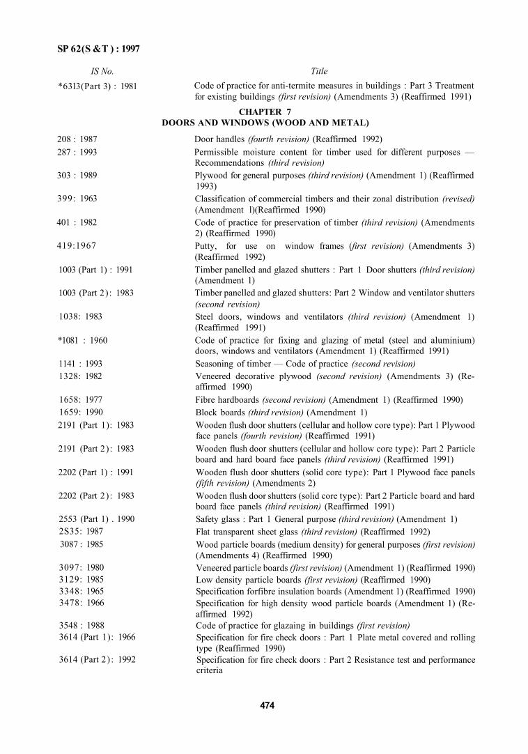
SP 62(S &T ) : 1997
IS No. *63l3(Part 3) : 1981
208 : 1987 287 : 1993
303 : 1989
399: 1963
401 : 1982
419:1967
1003 (Part 1) : 1991
1003 (Part 2) : 1983
1038: 1983
*1081 : 1960
1141 : 1993 1328: 1982
1658: 1977 1659: 1990 2191 (Part 1): 1983
2191 (Part 2) : 1983
2202 (Part 1) : 1991
2202 (Part 2) : 1983
2553 (Part 1) . 1990 2S35: 1987 3087 : 1985
3097: 1980 3129: 1985 3348: 1965 3478: 1966
3548 : 1988 3614 (Part 1): 1966
3614 (Part 2) : 1992
Title Code of practice for anti-termite measures in buildings : Part 3 Treatment for existing buildings (first revision) (Amendments 3) (Reaffirmed 1991)
CHAPTER 7 DOORS AND WINDOWS (WOOD AND METAL)
Door handles (fourth revision) (Reaffirmed 1992) Permissible moisture content for timber used for different purposes — Recommendations (third revision) Plywood for general purposes (third revision) (Amendment 1) (Reaffirmed 1993) Classification of commercial timbers and their zonal distribution (revised) (Amendment l)(Reaffirmed 1990) Code of practice for preservation of timber (third revision) (Amendments 2) (Reaffirmed 1990) Putty, for use on window frames (first revision) (Amendments 3) (Reaffirmed 1992) Timber panelled and glazed shutters : Part 1 Door shutters (third revision) (Amendment 1) Timber panelled and glazed shutters: Part 2 Window and ventilator shutters (second revision) Steel doors, windows and ventilators (third revision) (Amendment 1) (Reaffirmed 1991) Code of practice for fixing and glazing of metal (steel and aluminium) doors, windows and ventilators (Amendment 1) (Reaffirmed 1991) Seasoning of timber — Code of practice (second revision) Veneered decorative plywood (second revision) (Amendments 3) (Reaffirmed 1990) Fibre hardboards (second revision) (Amendment 1) (Reaffirmed 1990) Block boards (third revision) (Amendment 1) Wooden flush door shutters (cellular and hollow core type): Part 1 Plywood face panels (fourth revision) (Reaffirmed 1991) Wooden flush door shutters (cellular and hollow core type): Part 2 Particle board and hard board face panels (third revision) (Reaffirmed 1991) Wooden flush door shutters (solid core type): Part 1 Plywood face panels (fifth revision) (Amendments 2) Wooden flush door shutters (solid core type): Part 2 Particle board and hard board face panels (third revision) (Reaffirmed 1991) Safety glass : Part 1 General purpose (third revision) (Amendment 1) Flat transparent sheet glass (third revision) (Reaffirmed 1992) Wood particle boards (medium density) for general purposes (first revision) (Amendments 4) (Reaffirmed 1990) Veneered particle boards (first revision) (Amendment 1) (Reaffirmed 1990) Low density particle boards (first revision) (Reaffirmed 1990) Specification forfibre insulation boards (Amendment 1) (Reaffirmed 1990) Specification for high density wood particle boards (Amendment 1) (Reaffirmed 1992) Code of practice for glazaing in buildings (first revision) Specification for fire check doors : Part 1 Plate metal covered and rolling type (Reaffirmed 1990) Specification for fire check doors : Part 2 Resistance test and performance criteria
474
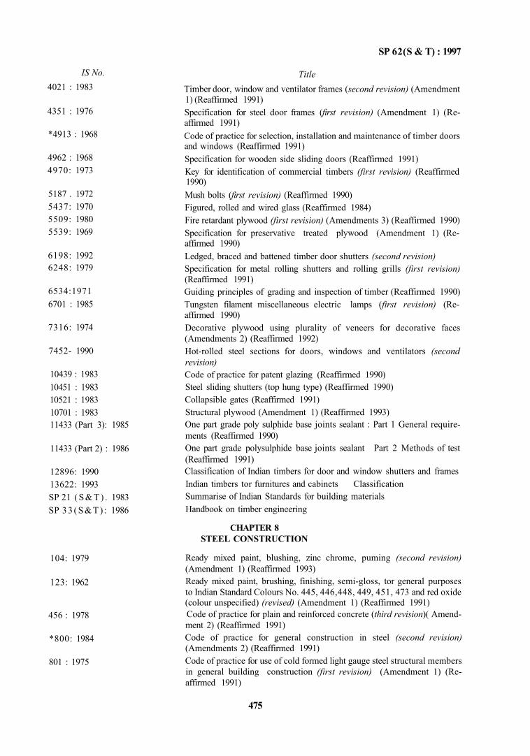
SP 62(S & T) : 1997
IS No. 4021 : 1983
4351 : 1976
*4913 : 1968
4962 : 1968 4970: 1973
5187 . 1972 5437: 1970 5509: 1980 5539: 1969
6198: 1992 6248: 1979
6534:1971 6701 : 1985
7316: 1974
7452- 1990
10439 : 1983 10451 : 1983 10521 : 1983 10701 : 1983 11433 (Part 3): 1985
11433 (Part 2) : 1986
12896: 1990 13622: 1993 SP 21 ( S & T ) . 1983 SP 3 3 ( S & T ) : 1986
104: 1979
123: 1962
456 : 1978
*800: 1984
801 : 1975
Title Timber door, window and ventilator frames (second revision) (Amendment 1) (Reaffirmed 1991) Specification for steel door frames (first revision) (Amendment 1) (Reaffirmed 1991) Code of practice for selection, installation and maintenance of timber doors and windows (Reaffirmed 1991) Specification for wooden side sliding doors (Reaffirmed 1991) Key for identification of commercial timbers (first revision) (Reaffirmed 1990) Mush bolts (first revision) (Reaffirmed 1990) Figured, rolled and wired glass (Reaffirmed 1984) Fire retardant plywood (first revision) (Amendments 3) (Reaffirmed 1990) Specification for preservative treated plywood (Amendment 1) (Reaffirmed 1990) Ledged, braced and battened timber door shutters (second revision) Specification for metal rolling shutters and rolling grills (first revision) (Reaffirmed 1991) Guiding principles of grading and inspection of timber (Reaffirmed 1990) Tungsten filament miscellaneous electric lamps (first revision) (Reaffirmed 1990) Decorative plywood using plurality of veneers for decorative faces (Amendments 2) (Reaffirmed 1992) Hot-rolled steel sections for doors, windows and ventilators (second revision) Code of practice for patent glazing (Reaffirmed 1990) Steel sliding shutters (top hung type) (Reaffirmed 1990) Collapsible gates (Reaffirmed 1991) Structural plywood (Amendment 1) (Reaffirmed 1993) One part grade poly sulphide base joints sealant : Part 1 General requirements (Reaffirmed 1990) One part grade polysulphide base joints sealant Part 2 Methods of test (Reaffirmed 1991) Classification of Indian timbers for door and window shutters and frames Indian timbers tor furnitures and cabinets Classification Summarise of Indian Standards for building materials Handbook on timber engineering
CHAPTER 8 STEEL CONSTRUCTION
Ready mixed paint, blushing, zinc chrome, puming (second revision) (Amendment 1) (Reaffirmed 1993) Ready mixed paint, brushing, finishing, semi-gloss, tor general purposes to Indian Standard Colours No. 445, 446,448, 449, 451, 473 and red oxide (colour unspecified) (revised) (Amendment 1) (Reaffirmed 1991) Code of practice for plain and reinforced concrete (third revision)( Amendment 2) (Reaffirmed 1991) Code of practice for general construction in steel (second revision) (Amendments 2) (Reaffirmed 1991) Code of practice for use of cold formed light gauge steel structural members in general building construction (first revision) (Amendment 1) (Reaffirmed 1991)
475
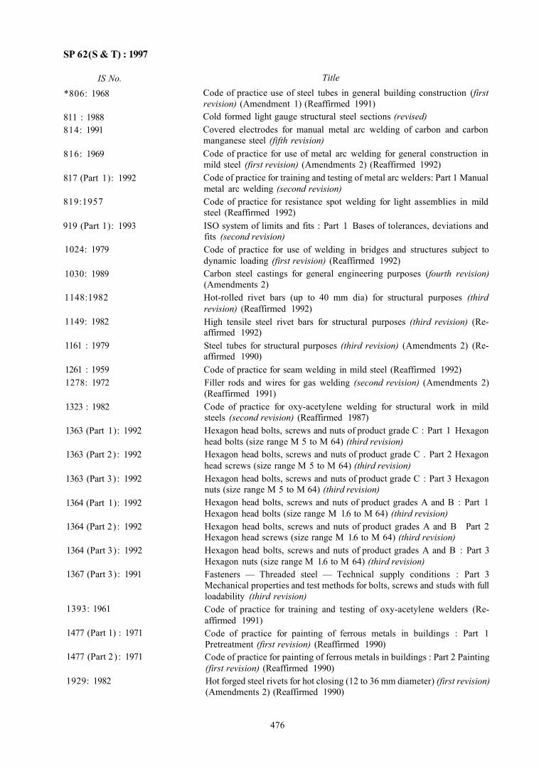
SP 62(S & T) : 1997
IS No. *806: 1968
811 : 1988 814: 1991
816: 1969
817 (Part 1): 1992
819:1957
919 (Part 1): 1993
1024: 1979
1030: 1989
1148:1982
1149: 1982
1161 : 1979
1261 : 1959 1278: 1972
1323 : 1982
1363 (Part 1): 1992
1363 (Part 2) : 1992
1363 (Part 3) : 1992
1364 (Part 1): 1992
1364 (Part 2) : 1992
1364 (Part 3) : 1992
1367 (Part 3): 1991
1393: 1961
1477 (Part 1) : 1971
1477 (Part 2 ) : 1971
1929: 1982
Title Code of practice use of steel tubes in general building construction (first revision) (Amendment 1) (Reaffirmed 1991) Cold formed light gauge structural steel sections (revised) Covered electrodes for manual metal arc welding of carbon and carbon manganese steel (fifth revision) Code of practice for use of metal arc welding for general construction in mild steel (first revision) (Amendments 2) (Reaffirmed 1992) Code of practice for training and testing of metal arc welders: Part 1 Manual metal arc welding (second revision) Code of practice for resistance spot welding for light assemblies in mild steel (Reaffirmed 1992) ISO system of limits and fits : Part 1 Bases of tolerances, deviations and fits (second revision) Code of practice for use of welding in bridges and structures subject to dynamic loading (first revision) (Reaffirmed 1992) Carbon steel castings for general engineering purposes (fourth revision) (Amendments 2) Hot-rolled rivet bars (up to 40 mm dia) for structural purposes (third revision) (Reaffirmed 1992) High tensile steel rivet bars for structural purposes (third revision) (Reaffirmed 1992) Steel tubes for structural purposes (third revision) (Amendments 2) (Reaffirmed 1990) Code of practice for seam welding in mild steel (Reaffirmed 1992) Filler rods and wires for gas welding (second revision) (Amendments 2) (Reaffirmed 1991) Code of practice for oxy-acetylene welding for structural work in mild steels (second revision) (Reaffirmed 1987) Hexagon head bolts, screws and nuts of product grade C : Part 1 Hexagon head bolts (size range M 5 to M 64) (third revision) Hexagon head bolts, screws and nuts of product grade C . Part 2 Hexagon head screws (size range M 5 to M 64) (third revision) Hexagon head bolts, screws and nuts of product grade C : Part 3 Hexagon nuts (size range M 5 to M 64) (third revision) Hexagon head bolts, screws and nuts of product grades A and B : Part 1 Hexagon head bolts (size range M 1.6 to M 64) (third revision) Hexagon head bolts, screws and nuts of product grades A and B Part 2 Hexagon head screws (size range M 1.6 to M 64) (third revision) Hexagon head bolts, screws and nuts of product grades A and B : Part 3 Hexagon nuts (size range M 1.6 to M 64) (third revision) Fasteners — Threaded steel — Technical supply conditions : Part 3 Mechanical properties and test methods for bolts, screws and studs with full loadability (third revision) Code of practice for training and testing of oxy-acetylene welders (Reaffirmed 1991) Code of practice for painting of ferrous metals in buildings : Part 1 Pretreatment (first revision) (Reaffirmed 1990) Code of practice for painting of ferrous metals in buildings : Part 2 Painting (first revision) (Reaffirmed 1990) Hot forged steel rivets for hot closing (12 to 36 mm diameter) (first revision) (Amendments 2) (Reaffirmed 1990)
476
SP 62(S & T) : 1997
IS No. 1977: 1975
2062 : 1992
2074: 1992
2155: 1982
3502: 1981 3615:1974
3640: 1982 3757 : 1985
5369: 1975
5370: 1969 5374: 1975 6419: 1971
6560: 1972
6610: 1972 6623: 1985
6649: 1985
7205: 1974 7215: 1974
7280: 1974
7307 (Part 1): 1974
7310 (Part 1) 1974
7318 (Part 1): 1974
8500. 1992
9595 1980
12843: 1989 SP 6(5): 1980
77:1976 269: 1989 303 : 1989
Title Structural steel (ordinary quality) (second revision) (Amendments 4) (Reaffirmed 1992) Steel for general structural purposes (fourth revision) (supersedes IS 226 : 1975) (Amendment 1) Ready mixed paint, air drying, red oxide-zinc chrome, priming (second revision) Cold forged solid steel rivets for hot closing (6 to 16 mm diameter) (first revision) (Amendment l) (Reaffirmed 1990) Steel chequered plates (first revision) Acceptance tests for wire flux combination ior submerged arc welding (first revision) (Amendment 1) (Reaffirmed 1987) Hexagon fit bolts (first revision) (Reaffirmed 1991) High strength structural bolts (second revision) (Amendment 1) (Reaffirmed 1992) General requirements for plain washers and lock washers (first revision) (Reaffirmed 1991) Plain washers with outside diameter = 3 × inside diameter (Reaffirmed 1991) Taper washers for I-beams (ISMB) (first revision) (Reaffirmed 1991) Welding rods and bare electrodes for gas shielded arc welding of structural steel (Reaffirmed 1991) Molybdenum and chromium-molybdenum low alloy steel welding rods and bare electrodes for gas shielded arc welding (Reaffirmed 1991) Heavy washers for steel structures (Reaffirmed 1991) High strength structural nuts (first revision) (Amendment 1) (Reaffirmed 1992) Hardened and tempered washers for high strength structural bolts and nuts (first revision) (Amendment 1) (Reaffirmed 1988) Safety code for crection of structural steel work (Reaffirmed 1991) Tolerances for fabrication of steel structures (Amendment I) (Reaffirmed 1991) Bare wire electrodes for submerged arc welding of structural steels (Reaffirmed 1991) Approval tests for welding procedures : Part 1 Fusion welding of steel (Reaffirmed 1991) Approval tests for welders working to approved welding procedures : Part 1 Fusion welding of steel (Reaffirmed 1987) Approval tests for welders when welding procedure approval is not required : Part 1 Fusion welding of steel (Reaffirmed 1991) Structural steel — Microalloyed (medium and high strength qualities) (first revision) (Amendment 1) Recommendations for metal arc welding of carbon and carbon manganese steel (Amendment 1) (Reaffirmed 1992) Tolerances for erection of steel structures Cold-formed, light-gauge steel structures (first revision)
CHAPTER 9 FLOORS AND FLOOR COVERINGS
Linseed oil, boiled for paints (see and revision) (Reaffirmed 1993) 33 grade ordinary Portland cement (fourth revision) (Amendments 3) Plywood for general purposes (third revision) (Amendment 1) (Reaffirmed 1993)
477
SP 62 (S & T) : 1997
IS No. 383: 1970
401 : 1982
455 : 1989 456: 1978
533 : 1973
651 : 1992 653 : 1992 657: 1982
658: 1982
712: 1984 723: 1972
809: 1992 1077: 1992 1141 : 1993 1195: 1978 1196: 1978
1197: 1970
1198: 1982
1237:1980 1322:1993 *1443: 1972
1489 (Part 1): 1991 1489 (Part 2) : 1991
1580: 1991
1609: 1991
1661 : 1972
*2114: 1984
2116: 1980 2180: 1988 2386 (Part 4 ) : 1963
*257l : 1970
3384 : 1986
Title Coarse and fine aggregates from natural sources for concrete (second revision) (Reaffirmed 1990) Code of practice for preservation of timber (third revision) (Amendments 2) (Reaffirmed 1990) Portland slag cement (fourth revision) (Amendments 3) Code of practice for plain and reinforced concrete (third revision) (Amendment 2) (Reaffirmed 1991) Gum spirit of turpentine (oil of turpentine) (first revision) (Reaffirmed 1990) Salt glazed stoneware pipes and fittings (fifth revision) Linoleum sheets and tiles (third revision) Materials for use in the manufacture of magnesium oxychloride flooring compositions (second revision) (Reaffirmed 1990) Code of practice for magnesium oxychloride composition floors (second revision) (Reaffirmed 1990) Building limes (third revision) (Reaffirmed 1991) Steel countersunk head wire nails (first revision) (Amendments 3) (Reaffirmed 1990) Rubber flooring materials for general purposes (second revision) Common burnt clay building bricks (fifth revision) Seasoning of timber — Code of practice (second revision) Bitumen mastic for flooring (second revision) (Reaffirmed 1990) Code of practice for laying bitumen mastic flooring (second revision) (Reaffirmed 1990) Code of practice for laying of rubber floors (first revision) (Reaffirmed 1990) Code of practice for laying, fixing and maintenance of linoleum floor (first revision) (Reaffirmed 1990) Cement concrete flooring tiles (first revision) (Reaffirmed 1990) Bitumen felts for waterproofing and damp-proofing (fourth revision) Code of practice for laying and finishing of cement concrete flooring tiles (first revision) (Reaffirmed 1991) Portland pozzolana cement: Part 1 Fly ash based (third revision) Portland pozzolana cement : Part 2 Calcined clay based (third revision) (Amendment 1) Bituminous compounds for waterproofing and caulking purposes (second revision) Code of practice for laying damp-proofing treatment using bitumen felts (second revision) Code of practice for application of cement and cement-lime plaster finishes (first revision) (Reaffirmed 1991) Code of practice for laying in-situ terrazo floor finish (first revision) (Amendment 1) (Reaffirmed 1990) Sand for masonry mortars (first revision) (Reaffirmed 1992) Heavy duty burnt clay building bricks (third revision) (Reaffirmed 1991) Methods of test for aggregates for concrete : Part 4 Mechanical properties (Amendments 3) (Reaffirmed 1990) Code of practice for laying in-situ cement concrete flooring (first revision) (Reaffirmed 1991) Specification for bitumen primer for use in waterproofing and damp-proofing (first revision) (Reaffirmed 1991)
478
SP 62(S & T) : 1997
IS No.
3 4 1 4 : 1 9 6 8
3461 : 1980
3 4 6 2 : 1986
3 5 0 2 : 1981
3583 : 1988
3 6 2 2 : 1977
3 6 2 9 : 1986
3 6 7 0 : 1989
4441 : 1980
4 4 4 2 : 1980
4 4 4 3 : 1980
4 4 5 6 (Part 1): 1967
4 4 5 6 (Part 2 ) : 1967
4 4 5 7 : 1982
4631 : 1986
4 8 3 2 (Part 1 ) : 1 9 6 9
4 8 3 2 (Part 2 ) . 1 9 6 9
4 8 3 2 (Part 3 ) . 1968
4 8 6 0 : 1968 4971 . 1968
5318 . 1969
5 3 8 9 : 1969
5491 : 1969
* 5 7 6 0 : 1983
5 7 6 6 : 1970
6 7 2 7 : 1972
6 9 0 9 : 1990
7 1 9 3 : 1974
7 9 5 6 : 1975
8 0 4 2 : 1989
8 3 7 4 : 1977
Title
Code of practice for design and installation of joints in bu i ld ings (Re affirmed 1990)
Specification for PVC-asbes tos floor tiles (first revision) ( A m e n d m e n t s 2) (Reaffirmed 1990)
Speci f ica t ion for unbacked f lexible P V C f looring (second revision) ( A m e n d m e n t 1) (Reaffirmed 1991)
Steel chequered plates (first revision)
Specification of burnt clay paving bricks (second revision)
Specification for sandstone (slabs and tiles) (first revision) (Reaff i rmed 1993)
Specification for structural t imber in building (first revision) (Reaff i rmed 1991)
Code of practice for construction of t imber floors (first revision)
Code of practice for use of silicate type chemica l resistant mor ta rs (first revision) (Amendment 1) (Reaffirmed 1990)
Code of practice for use of sulphur type chemical resistant mor tars (first revision) (Reaffmncd 1990)
Code of practice for use of resin type chemical resistant mor tars (first revision) (Amendment 1) (Reaffirmed 1990)
Methods of test tor chemical resistant mortars : Part 1 Sil icate type and resin type (Amendment 1) (Reaffirmed 1990)
Methods of test tor chemical resistant mor tars : Part 2 Su lphur type (Reaffirmed 1990)
Ceramic unglazed vitreous acid resisting tile (first revision) (Reaff i imed 1990)
C o d e of practice for laying of epoxy resin floor toppings (first revision) (Reaffi imed 1991)
Specification for chemical resistant mor tars : Part 1 Sil icate type (Reaffirmed 1990)
Specification tor chemical resistant mortars . Part 2 Resin type ( A m e n d ment 1) (Reaffirmed 1990)
Specification for chemical resistant mortars . Part 3 Su lphur type (Reaffirmed 1990)
Acid resistant bricks (Reaffirmed 1991)
Recommenda t ions for selection of industrial floor finishes (Reaff i rmed 1990)
Code of practice for laying of flexible P V C sheet and tile f looring (Re affirmed 1990) Code of practice for laying of ha rdwood parquet and wood block floors (Reaffirmed 1992)
Code of practice for laying of in-situ granol i thic concre te flooring topping (Reaffirmed 1990)
Compressed argon (first revision) (Reaff i rmed 1991)
C o d e of practice for laying of burnt c lays brick flooring (Reaff i rmed 1991)
Fireclay checker bricks for open hearth furnace (Reaff irmed 1992)
Specification for supersulphated cemen t ( A m e n d m e n t s 2)
Glass fibre base coaltar pitch and b i tumen felts
Recommenda t ions for selection of dairy floor finishes (Reaff i rmed 1990)
Whi te Port land cement (second revision) ( A m e n d m e n t s 4)
Bi tumen mast ic , anti-static and electrically conduc t ing grade (Reaff i rmed 1990)
479
SP 62(S & T) : 1997
IS No. 9077: 1979
9197: 1979
9472: 1980 10440: 1983
13026: 1991
13074: 1991
269: 1989 303 : 1989
383: 1970
451 : 1972
455 . 1989 459 . 1992 710:1976 712:1984 723: 1972
733 : 1983
737 : 1986
777: 1988
883 : 1970 1130: 1969 1237:1980 1328. 1982
1344: 1981
1414:1989 1489 (Part 1): 1489 (Part 2) :
1542: 1992 1635: 1992
1658: 1977 1659: 1990 1661 : 1972
Title Code of practice for corrosion protection of steel reinforcement in RB and RCC construction (Reaffirmed 1991) Epoxy resin, hardness and epoxy resin compositions for floor topping (Reaffirmed 1990) Code of practice for laying mosaic parquet flooring (Reaffirmed 1992) Code of practice for construction of RB and RBC floors and roofs (Reaffirmed 1990) Bitumen mastic for flooring for industries handling LPG and other light hydrocarbon products (Amendment 1) Laying of bitumen mastic flooring for industries handling LPG and other light hydrocarbon products — Code of practice
CHAPTER 10 WALL AND CEILING FINISHES AND COVERINGS AND WALLING
33 grade ordinary Portland cement (fourth revision) (Amendments 3) Plywood for general purposes (third revision) (Amendment 1) (Reaffirmed 1993) Coarse and fine aggregates from natural sources for concrete (second revision) (Reaffirmed 1990) Technical supply conditions for wood screws (second revision) (Amendment 1) (Reaffirmed 1991) Portland slag cement (fourth revision) (Amendments 3) Corrugated and semi-corrugated asbestos cement sheets (third revision) Marine plywood (first revision) (Amendments 3) (Reaffirmed 1989) Building limes (third revision) (Reaffirmed 1991) Steel countersunk head wire nails (first revision) (Amendments 3) (Reaffirmed 1990) Wrought aluminium and aluminium alloy bars, rods and sections for general engineering purposes (third revision) (Reaffirmed 1991) Wrought aluminium and aluminium alloy sheet and strip for general engineering purposes (third revision) (Reaffirmed 1991) Glazed earthenware wall tiles (second revision) (Superseded by IS 13753, 13754, 13755, 13756) Design of structural timber in building — Code of practice (third revision) Marble (blocks, slabs and tiles) (Reaffirmed 1993) Cement concrete flooring tiles (first revision) (Reaffirmed 1990) Veneered decorative plywood (second revision) (Amendments 3) (Reaffirmed 1990) Calcined clay pozzolana (second revision) (Amendment I) (Reaffirmed 1990) Code of practice for fixing wall covering
1991 Portland pozzolana cement: Part 1 Fly ash based (third revision) 1991 Portland pozzolana cement: Part 2 Calcined clay based (third revision)
(Amendment 1) Sand of plaster (second revision) Code of practice for field slaking of building lime and preparation of putty (second revision) Fibre hardboards (second revision) (Amendment 1) (Reaffirmed 1990) Block boards (third revision) (Amendment 1) Code of practice for application of cement and cement-lime plaster finishes (first revision) (Reaffirmed 1991)
480
SP 62(S & T) : 1997
IS No. 1946: 1961
2095: 1982 2098: 1964 2114: 1984
2116: 1980 2185 (Part 1): 1979
2185 (Part 2) : 1983
2185 (Part 3) : 1984
2394 : 1984
2402: 1963 2441 : 1984
2547 (Part 1): 1976
2547 (Part 2) : 1976
2691 : 1988 2818 (Part 1): 1990 2849: 1983
3087: 1985
3097:1980
3129: 1985 3348:1965 3466: 1988 3478 : 1966
3629: 1986
3630: 1992
3677:1985
3812: 1981
4101 (Part 1): 1967
4101 (Part 2) : 1967
4101 (Part 3) : 1985
4407: 1967
Title Code of practice for use of fixing devices in walls, ceilings and floors of solid construction (Reaffirmed 1992) Gypsum plaster hoards (first revision) (Amendment 1) (Reaffirmed 1991) Asbestos cement building boards (Amendments 2) (Reaffirmed 1992) Code of practice for laying in-situ terrazzo floor finish (first revision) (Amendment 1) (Reaffirmed 1990) Sand for masonry mortar (first revision) (Reaffirmed 1992) Concrete masonry units : Part 1 Hollow and solid concrete blocks (second revision) (superseding IS 3590) (Reaffirmed 1992) Concrete masonry units : Part 2 Hollow and solid light weight concrete blocks (first revision) (superseding IS 3590) (Reaffirmed 1989) Concrete masonry units: Part 3 Autoclaved cellular aerated concrete blocks (first revision) (superseding IS 5482) (Reaffirmed 1990) Code of practice for application of lime plaster finish (first revision) (Reaffirmed 1990) Code of practice for external rendered finishes (Reaffirmed 1990) Code of practice for fixing ceiling covering (first revision) (Reaffirmed 1990) Gypsum building plaster : Part 1 Excluding premixed lightweight plaster (first revision) (Amendment 1) (Reaffirmed 1990) Gypsum building plaster: Part 2 Premixed lightweight plaster (first revision) (Reaffirmed 1992) Burnt day facing bricks (second revision) Indian hessian : Part 1 General (second revision) Specification for non-load bearing gypsum partition blocks (solid and hollow types) (Amendment 1) (Reaffirmed 1990) Wood particle boards (medium density) for general purposes (first revision) (Amendments 4) (Reaffirmed 1990) Veneered particle boards (first revision) (Amendment 1) (Reaffirmed 1990) Low density particle boards (first revision) (Reaffirmed 1990) Specification for fibre insulation boards (Amendment 1) (Reaffirmed 1990) Specification for masonry cement (second revision) (Amendment 1) Specification for high density wood particle boards (Amendment 1) (Re affirmed 1992) Specification for structural timber in building (first revision) (Reaffirmed 1991) Code of practice for construction of non-load bearing gypsum block partitions (first revision) Unbonded rock and slag wool for thermal insulation (second revision) (superseding IS 5696) (Reaffirmed 1990) Fly ash for use as pozzolana and admixture (first revision) (Reaffirmed 1992) Code of practice for external facing and veneers : Part 1 Stone facing (Reaffirmed 1990) Code of practice for external facing and veneers : Part 2 Cement concrete facing (Reaffirmed 1990) Code of practice for external facing and veneers : Part 3 Wall tiling and mosaics (first revision) (Reaffirmed 1990) Code of practice for reed walling (Reaffirmed 1992)
481
SP 62(S & T) : 1997
IS No. 4671 : 1984
5390: 1984
5509: 1980 6730: 1972 6738: 1972 6760: 1972 7316: 1974
8041 : 1990 12727: 1989
158:1981
217: 1988 269 : 1989 277 : 1992
280 : 1978
383 : 1970
432 (Part 1): 1982
451 :1972
455: 1989 456: 1978
459 : 1992 654: 1992 712: 1984 723 : 1972
725: 1961 730: 1978
805 : 1968 808: 1989
883: 1970 1077 : 1992 1120: 1975 1190: 1990
1199 : 1959
Title Expanded polystyrene for thermal insulation purposes (first revision) (Reaffirmed 1990) Code of practice for construction of timber ceiling (first revision) (Reaffirmed 1991) Fire retardant plywood (first revision) (Amendments 3) (Reaffirmed 1990) Felt nails (Reaffirmed 1990) Panel pins and lost head nails (Amendment 1) (Reaffirmed 1990) Slotted countersunk head wood screws (Amendments 2) (Reaffirmed 1988) Decorative plywood using plurality of veneers for decorative faces (Amendments 2) (Reaffirmed 1992) Rapid hardening Portland cement (second revision) (Amendments 2) Code of practice for no fines cast in-situ cement concrete
CHAPTER 11 ROOFS AND ROOFING
Ready mixed paint, brushing, bituminous, black lead-free, acid alkali and heat resisting (third revision) (Amendment 1) (Reaffirmed 1988) Cutback bitumen (second revision) 33 grade ordinary Portland cement (fourth revision) (Amendments 3) Galvanized steel sheet (plain and corrugated) (fifth revision) (Amendments 2) Mild steel wire for general engineering purposes (third revision) (Amendment 1) (Reaffirmed 1992) Coarse and fine aggregates from natural sources for concrete (second revision) (Reaffirmed 1990) Mild steel and medium tensile steel bars and hard-drawn steel wire for concrete reinforcement: Part 1 Mild steel and medium tensile steel bars (third revision) Technical supply conditions for wood screws (second revision) (Amendment 1) (Reaffirmed 1991) Portland slag cement (fourth revision) (Amendments 3) Code of practice for plain and reinforced concrete (third revision) (Amendments 2) (Reaffirmed 1991) Corrugated and semi-corrugated asbestos cement sheets (third revision) Clay roofing tiles, Mangalore pattern (third revision) Building limes (third revision) (Reaffirmed 1991) Steel countersunk head wire nails (first revision) (Amendments 3) (Reaffirmed 1990) Copper wire nails (revised) (Reaffirmed 1990) Hook bolts for corrugated sheet roofing (second revision) (Amendments 2) (Reaffirmed 1988) Code of practice for use of steel in gravity water tanks (Reaffirmed 1991) Dimensions for hot-rolled steel beam, column channel and angle sections (third revision) (Amendment 1) Design of structural timber in building — Code of practice (third revision) Common burnt clay building bricks (fifth revision) Coach screws (first revision) (Reaffirmed 1990) Textile machinery — Healds twin wire for weaving — Specification (third revision) Methods of sampling and analysis of concrete (Reaffirmed 1991)
482
SP 62(S & T) : 1997
IS No. 1254: 1991 1322: 1993 1343: 1980
1344: 1981
1464: 1992 1489 (Part 1): 1991 1489 (Part 2): 1991
2098: 1964 *2115: 1980
*2118 . 1980
*2119: 1980
2204. 1962
2527 . 1984
2690 (Part 1) . 1993 2690 (Part 2): 1992 *2788 : 1987
*2792: 1964
*2858- 1984
3007 (Part 1): 1964
3007 (Part 2): 1965
3068 . 1986
3182. 1986
3629 . 1986
3951 (Part 1) - 1975
3951 (Part 2) : 1975
*5119(Part 1): 1968
*6061 (Part 1) : 1971
*6061(Part 2) : 1981
Title Corrugated aluminium sheet (third revision) Bitumen felts for waterproofing and damp-proofing (fourth revision) Code of practice for prestressed concrete (first revision) (Amendment 1) (Reaffirmed 1990) Calcined clay pozzolana (second revision) (Amendment 1) (Reaffirmed 1990) Clay ridge and ceiling tiles (second revision) Portland pozzolana cement: Part 1 Fly ash based (third revision) Portland pozzolana cement: Part 2 Calcined clay based (third revision) (Amendment 1) Asbestos cement building boards (Amendments 2) (Reaffirmed 1992) Code of practice for flat-roof finish, mud phuska (second revision) (Reaffirmed 1992) Code of practice for construction of jack-arch type of building floor or roof (first revision) (Reaffirmed 1992) Code of practice for construction of brick-cam-concrete composite (Madras terrace) floor or roof (first revision) (Reaffirmed 1992) Code of practice for construction of reinforced concrete shell roof (Reaffirmed 1990) Code of practice for fixing rainwater gutters and downpipes for roof drainage (first revision) (Reaffirmed 1990) Burnt clay flat terracing tiles : Part 1 Machine made (second revision) Burnt clay fiat terracing tiles : Part 2 Hand-made (second revision) Code of practice for roofing with wooden shingles (first revision) (Reaffirmed 1991) Code of practice for design and construction of stone slab over joist floor (Reaffirmed 1990) Code of practice for rooting with Mangalore tiles (first revision) (Reaffirmed 1990) Code of practice for laying of asbestos cement sheets . Pan 1 Corrugated sheets (Reaffirmed 1991) Code of practice for laying of asbestos cement sheets : Part 2 Semi-corrugated sheets (Reaffirmed 1991) Broken brick (burnt clay) coarse aggregates for use in lime concrete (second revision) (Reaffirmed 1991 ) Broken brick (burnt clay) fine aggregates for use in lime mortar (second revision) ( Reaffirmed 1991 ) Specification for structural timber in building (first revision) (Reaffirmed 1991) Specification for hollow clay tiles for floors and roofs : Part 1 Filler type (first revision) (Reaffirmed 1991) Specification for hollow clay tiles for floors and roofs : Part 2 Structural type (first revision) (Reaffirmed 1991) Code of practice for laying and fixing of sloped roof coverings : Part 1 Slating (Reaffirmed 1990) Code of practice for construction of floor and roof with joists and filler blocks : Part 1 With hollow concrete filler blocks (Reaffirmed 1992) Code of practice for construction of floor and roof with joists and filler blocks : Part 2 With hollow clay filler blocks (first revision) (Reaffirmed 1990)
483
IS No. *6061 (Part 3) : 1981
*6061 (Part 4 ) : 1981
6332: 1984
8869: 1978 *12093 : 1987
*12506: 1988
73 . 1992 269 : 1989 383 : 1970
702: 1988 712: 1984 1195: 1978 1203: 1978 1322: 1993 1346: 1991
1580: 1991
1609: 1991
1635: 1992
1834: 1984
2116. 1980 2508 : 1984
252 7:1984
2541 1991 2645 : 1975
2690 (Part 1)' 1993 2690 (Part 2): 1992 3036: 1992
3037: 1986
3067 . 1988
Title Code of practice for construction of floor and roof with joists and filler blocks : Part 3 Precast hollow clay blocks joints and hollow clay filler blocks (Reaffirmed 1992) Code of practice for construction of floor and roof with joists and filler blocks : Part 4 With precast hollow clay blocks slab panels (Reaffirmed 1992) Code of practice for construction of floor and roofs using precast doubly-curved shell units (first revision) (Reaffirmed 1990) Washers for corrugated sheet roofing (Reaffirmed 1990) Code of practice for laying and fixing of sloped roof coverings using plain and corrugated galvanized steel sheet (ISO 6589-1983)(Reaffirmed 1993) Code of practice for improved thatching of roof with rot and fire retardant treatment
CHAPTER 12 DAMP-PROOFING AND WATERPROOFING
Paving bitumen (second revision) 33 grade ordinary Portland cement (fourth revision) (Amendments 3) Coarse and fine aggregates from natural sources for concrete (second revision) (Reaffirmed 1990) Industrial bitumen (second revision) (Amendment 1) Building limes (third revision) (Reaffirmed 1991) Bitumen mastic for flooring (second revision) (Reaffirmed 1990) Determination of penetration (Amendments 3) (Reaffirmed 1990) Bitumen felts for waterproofing and damp-proofing (fourth revision) Code of practice for waterproofing of loots with bitumen felts (third revision) Bituminous compounds for waterproofing and caulking purposes (second revision) Code of practice for laying damp-proofing treatment using bitumen felts (second revision) Code of practice for field slaking of building lime and preparation of putty (second revision) Hot applied sealing compund for joint in concrete (first revision) (Reaffirmed 1990) Sand for masonry mortars (first revision) (Reaffirmed 1992) Low density polyethylene films (second revision) (Amendment 1) (Reaffirmed 1991) Code of practice for fixing rainwater gutters and downpipes for roof drainage (first revision) (Reaffirmed 1990) Code of practice for preparation and use ot lime concrete (second revision) Integral cement waterproofing compounds (first revision) (Amendment 1) (Reaffirmed 1992) Burnt clay flat terracing tiles : Part 1 Machine made (second revision) Burnt clay flat terracing tiles : Part 2 Handmade (second revision) Laying lime concrete for a waterproofed roof finish - Code of practice (second revision) Bitumen mastic for use in waterproofing of roots (first revision) (Reaffirmed 1991) Code of practice for general design details and preparatory work for damp-proofing and waterproofing of buildings (first revision)
484
SP 62 (S & T) : 1997
SP 62 (S & T) : 1997
485
IS No.
3 0 6 8 : 1986
3 3 7 0 (Part 1 ) : 1065
3 3 8 4 : 1986
4 0 9 8 : 1983
4 3 6 5 : 1967
5871 . 1987
6 4 9 4 : 1988
7 1 9 3 : 1974
7 1 9 8 : 1974
7 2 9 0 - 1979
9 7 5 9 : 1981
9 9 1 8 : 1981
1 2 0 2 7 : 1987
1 2 0 5 4 : 1987
1 3 1 8 2 : 1991
Title
Broken brick (burnt c lay) coarse aggrega tes for use in l ime conc re t e (second revision) (Reaff irmed 1991)
C o d e of pract ice for conc re t e s t ructures for the s torage of l iquids Part 1 Genera l requi rements ( A m e n d m e n t 1) (Reaff i rmed 1991)
Specification for b i tumen pr imer for use in waterproof ing and d a m p -proofing (first revision) (Reaffirmed 1991)
L ime-pozzo lana mixture (first revision) ( A m e n d m e n t s 2) (Reaff i rmed 1989)
C o d e of pract ice for application of b i tumen mast ic for waterproof ing of roofs (Reaffirmed 1990)
Bi tumen mastic for tanking and d a m p proofing (first revision) (Reaff i rmed 1991)
C o d e of practice for waterproofing of underground water reservoi rs and s w i m m i n g pools (first revision) (Reaff i rmed 1994)
Glass fibre base coal tar pitch and b i tumen felts
C o d e of practice for damp-proof ing using b i tumen mas t ic (Reaff i rmed 1990)
Recommenda t ions for use of polye thylene film for waterproof ing of roo t s (first revision) (Reaffirmed 1990)
Guide l ines for de-water ing dur ing cons t ruc t ion ( A m e n d m e n t 1) (Reaffirmed 1987)
C o d e of practice for in-situ waterproof ing and damp-proof ing t r ea tmen t s with glass fibre tissue reinforced bi tumen (Reaff i rmed 1990)
Si l icone-based water repellents (Reaffirmed 1992)
C o d e of practice tor application of s i l icone based water t epe l len t (Re affirmed 1992)
W a t e r p r o o f i n g a n d d a m p - p r o o f i n g o f w e t a r e a s i n b u i l d i n g - -Recommenda t ions
CHAPTER 13 J O I N T S I N B U I L D I N G S ( C O N T R O L O F C R A C K S I N B U I L D I N G S )
1 8 3 4 : 1984
1838 (Part 1) . 1983
1838 (Part 2 ) . 1984
3 4 1 4 : 1968
1 0 9 5 8 : 1984 11433 (Part 1 ) : 1985 1 1 8 1 7 : 1986
1 1 8 1 8 : 1986
12118 (Par t 1): 1987
Hot applied scaling compound for joint in concre te (first revision) (Re affirmed 1990) Preformed fillers for expansion joint in concre te payemen t s and s t ructures (non extruding and resilient t y p e ) : Part 1 Bitumen impregna ted fibre (first revision) (Reaffirmed 1990) Preformed fillers for expansion joint in concre te payemen t s and s t ructures (non extruding and resilient type) : Part 2 C N S L A l d e h y d e resin and coconut pith C o d e of pract ice for design and installation of jo in ts in bui ld ings (Re affirmed 1990)
Genera l check list of functions of joints in bui ld ings (Reaff i rmed 1992) One part grade polysulphide based joint sea lant : Part 1 General requirements Classification of jo in t s in bui ld ings for accomoda t ion of d imens iona l devia t ions dur ing cons t ruc t ion (Reaff irmed 1992) Method of test for laboratory de te rmina t ion of air permeabi l i ty of joints in bui ld ings (Reaffirmed 1992) T w o parts polysulphide based sealant : Part 1 Genera l r equ i rements (Re affirmed 1992)
SP 62(S & T) : 1997
IS No.
44: 1991 55 : 1970
109: 1968
133: 1993 158- 1981
168 : 1993 253 : 1985 261 : 1982 427 : 1965
428 : 1969
702: 1988 712: 1984 797: 1982
*2395(Part 1): 1966
*2395 (Part 2) : 1967
2547 (Part 1): 1976
2547 (Part 2)- 1976
2932: 1993 2933: 1975
*3140: 1965
3384: 1986
5410:1992 5411 (Part 1): 1974
5411 (Part 2) . 1972
*6278: 1971 9862: 1981
Title
Iron oxide pigments for paints (second revision) Ultramarine blue for paints (first revision) (Amendments 2) (Reaffirmed 1991) Ready mixed paint, brushing, priming, plaster, to Indian Standard Colour No, 361 and 631 White and off white (first revision) (Amendments 3)(Re-affirmed 1993) Enamel, interior : (a) undercoating, (b) finishing (third revision) Ready mixed paint, brushing, bituminous, black, lead-free, acid, alkali and heat resisting (third revision) (Amendment 1) (Reaffirmed 1988) Ready mixed paint, air drying, for general purpose (third revision) Edible common salt (third revision) (Reaffirmed 1990) Copper sulphate (second revision) (Amendment 1) (Reaffirmed 1988) Distemper, dry, colour as required (revised) (Amendments 4) (Reaffirmed 1993) Distemper, oil emulsion, colour as required (first revision) (Amendments 3) (Reaffirmed 1993) Industrial bitumen (second revision) (Amendment 1) Building limes (third revision) (Reaffirmed 1991) Common salt for chemical industries (third revision) (Amendment I) (Reaffirmed 1992) Code of practice for painting concrete masonry and plaster surfaces Part 1 Operation and workmanship (Reaffirmed 1990) Code of practice for painting concrete masonry and plaster surfaces : Part 2 Schedule (Reaffirmed 1990) Gypsum building plaster : Part 1 Excluding premixed lightweight plaster (first revision) (Amendment 1) (Reaffirmed 1990) Gypsum building plaster : Part 2 Premixed lightweight plaster (first revision) (Reaffirmed 1992) Enamel, synthetic, exterior (a) undercoating, (b) finishing (second revision) Enamel exterior (a) undercoating, (b) finishing (first revision) (Amendments 2) (Reaffirmed 1991) Code of practice for painting asbestos cement building products (Reaffirmed 1990) Specification for bitumen primer for use in waterproofing and damp-proofing (first revision) (Reaffirmed 1991) Cement paint (first revision) (Amendment 1) Plastic emulsion paint: Part 1 For interior use (first revision) (Amendments 4) (Reaffirmed 1991) Plastic emulsion paint : Part 2 For exterior use (Amendments 5) (Reaffirmed 1991) Code of practice for whitewashing and colour washing (Reaffirmed 1991) Ready mixed paint, brushing, bituminous, black, lead-free, acid, alkali, water and chlorine resisting (Amendment 1) (Reaffirmed 1988)
486
CHAPTER 14 WHITEWASHING, COLOUR WASHING AND PAINTING OF MASONRY, CONCRETE
AND PLASTER SURFACES (CALCAREOUS SURFACES)
SP 62(S & T) : 1997
IS No.
102: 1962
110: 1983
117: 1964
124 (Part 3): 1979
127: 1962
128: 1962
133: 1993 137. 1965
144: 1950
158: 1981
198: 1978 207: 1964
287. 1993 -
337: 1975 348: 1968 401 : 1982
423: 1961 524: 1983
525 : 1968
1141 : 1993 *1477 (Part 1): 1971
*1477 (Part 2): 1971
2338 (Part 1): 1967
2338 (Part 2 ) : 1967
2339: 1963
Title
Ready mixed paint, brushing, red lead, non-settling, priming (revised) (Amendments 2) (Reaffirmed 1991) Ready mixed paint, brushing, grey filler, for enamels for use over primers (first revision) (Reaffirmed 1990) Ready mixed paint, brushing, finishing exterior, semi-gloss for general purposes to Indian Standard Colours No. 101 to 104, 169, 174, 216, 217, 219, 275, 278, 280, 281, 283, 352 to 354, 358 to 365, 384 to 388, 397, 410, 442 to 444 (revised) (Amendments 2) (Reaffirmed 1988) Ready mixed paint, brushing, finishing, semi-gloss for general purposes : Part 3 (superseding IS 119) (Reaffirmed 1991) Ready mixed paint, brushing, finishing exterior, semi-gloss for general purposes, white (revised) (Amendments 3) (Reaffirmed 1988) Ready mixed paint, brushing, finishing, semi-gloss for general purposes, black (revised) (Amendments 4) (Reaffirmed 1988) Enamel, interior : (a) undercoating, (b) finishing (third revision) Ready mixed paint, brushing, matt or eggshell flat, finishing, interior to Indian Standard colour as required (revised) (Amendments 3) (Reaffirmed 1993) Ready mixed paint, brushing, petrol resisting, air-drying, for interior painting of tanks and container, red oxide (colour unspecified) (Amendments 3) (Reaffirmed 1988) Ready mixed paint, brushing, bituminous, black, lead-free, acid, alkali and heat resisting (third revision) (Amendment 1) (Reaffirmed 1988) Varnish gold size (first revision) (Amendment 1) (Reaffirmed 1991) Gale and shutter hooks and eyes (first revision) (Amendment 1) (Reaffirmed 1990) Permissible moisture content for timber used for different purposes Recommendations (third revision) Varnish, finishing interior (first revision) (Reaffirmed 1991) French polish (first revision) (Amendment 1) (Realfirmed 1991) Code of practice for preservation of timber (third revision) (Amendments 2) (Reaffirmed 1990) Plastic wood for joiners filter (revised) (Amendment 1)(Reaffirmed 1991) Varnish, finishing, exterior, synthetic, air drying (second revision) (Reaffirmed 1990) Varnish, finishing, exterior and general purposes (first revision) (Amendment 1) (Reaffirmed 1991) Seasoning of timber — Code of practice (second revision) Code of practice for painting of ferrous metals in buildings : Part 1 Pretreatment (first revision) (Reaffirmed 1990) Code of practice for painting of ferrous metals in buildings : Part 2 Painting (first revision) (Reaffirmed 1990) Code of practice for finishing of wood and wood based materials : Part 1 Operations and workmanship (Reaffirmed 1990) Code of practice for finishing of wood and wood based materials : Part 2 Schedules (Reaffirmed 1990) Aluminium paint for general purposes, in dual container (Amendments 2) (Reaffirmed 1993)
487
CHAPTER 15 PAINTING, VARNISHING AND ALLIED FINISHES (WOOD AND METALS)
IS No. *2524(Part 1): 1968
*2524(Part 2) : 1968
2932 1993 2933 : 1975
3531 : 1983
3536: 1966
3537: 1966
3539: 1966
3585 : 1966
4597: 1968
6005 : 1970
404 (Part 1): 1993 407 : 1981 1172 : 1993
1239 (Part 1): 1990
1536: 1989
1537: 1976
1545- 1982
1592 : 1989 1626 (Part 1): 1991
2064: 1993
2065 : 1983
*2692 : 1989 3076:1985
4984: 1987
Title Code of practice for painting of non-ferrous metals in buildings : Part 1 Pretreatment (Reaffirmed 1990) Code of practice for painting of non-ferrous metals in buildings : Part 2 Painting (Reaffirmed 1990) Enamel, synthetic, exterior (a) undercoating, (b) finishing (second revision) Enamel exterior (a) undercoating, (b) finishing (first revision) (Amendments 2) (Reaffirmed 1991) Glossary of terms relating to corrosion of metals (first revision) (Reaffirmed 1991) Ready mixed paint, brushing, wood primer, pink (Amendments 4) (Reaffirmed 1988) Ready mixed paint, finishing, interior, for general purposes, to Indian Standard Colours No. 101, 216, 217, 219, 275, 281, 352, 353, 358 to 361, 363, 364, 388, 410, 442, 444, 628, 631, 632, 634, 693, 697, white and black (Amendment 1) (Reaffirmed 1991) Ready mixed paint, undercoating, for use under oil finishes to Indian Standard Colours, as required (Amendments 3) (Reaffirmed 1988) Ready mixed paint, aluminium, brushing priming, water resistant, for woodwork (Amendments 2) (Reaffirmed 1988) Code of practice for finishing of wood and wood based products with nitrocellulose and cold catalysed materials (Reaffirmed 1990) Code of practice for phosphating of iron and steel (Reaffirmed 1991)
CHAPTER 16 WATER SUPPLY AND DRAINAGE
Part 1 Water Supply
Lead pipes : Part I For other than chemical purposes (third revision) Brass tubes for general purposes (third revision) (Reaffirmed 1991) Code of basic requirements for water supply, drainage and sanitation (fourth revision) Mild steel tubes, tubulars and other wrought steel fittings : Part 1 Mild steel tubes (fifth revision) (Amendments 3) Centrifugally cast (spun) iron pressure pipes for water, gas and sewage (third revision) (Amendments 2) (Reaffirmed 1993) Vertically cast iron pressure pipes for water, gas and sewage (first revision) (Amendments 5) (Reaffirmed 1991) Solid drawn copper and copper alloy tubes for condenser and heat exchangers (second revision) (Reaffirmed 1991) Asbestos cement pressure pipes (third revision) Asbestos cement building pipes and pipe fittings, gutters and gutter fittings and roofing fittings : Part 1 Pipe and pipe fittings (second revision) Selection, installation and maintenance of sanitary appliances — Code of practice (second revision) Code of practice for water supply in buildings (second revision) (Reaffirmed 1990) Ferrules for water services (second revision) (Amendment 1) Low density polyethylene pipes for potable water supplies (second revision) (Amendment 1)(Reaffirmed 1991) Specification for high density polyethylene pipes for potable water supplies; sewage and industrial effluents (third revision)
488
SP 62 (S & T) : 1997
SP 62 (S & T) : 1997
IS No.
4985 : 1988
7558 : 1974 7634 (Part 2 ) : 1975
7634 (Part 3 ) : 1975
12183 (Part 1) : 1987
NBC. 1983 SP 3 5 ( S & T ) : 1987
2 7 7 : 1992 404 (Part 1): 1993 458 . 1988
651 : 1992 782 . 1978 783 . 1985
1230- 1979
1536 : 1989
1537 . 1976
1592 . 1989 1626 (Part 1): 1991
1726 . 1991 1742 : 1983
3006 . 1979
4111 (Part 1): 1986
4733 . 1972
4984 1987
4985 : 1988
5329 . 1983
5455 : 1969
Part 3
6295 . 1986
Title
Specification lor unplasticised PVC pipes tor potable water supplies (second revision) (Amendment 1) Code of practice for domestic hot water installations (Reaffirmed 1990) Code ol practice for plastics pipe work for potable water supplies : Part 2 Laying and jointing polyethylene (PE) pipes (Amendment 1) (Reaffirmed 1992.) Code of practice for plastics pipe work for potable water supplies Part 3 Laying and jointing of UPVC pipes (Amendments 2) (Reaffirmed 1992) Code of practice for plumbing in multi-storeyed buildings ; Part 1 Water supply (Reaffirmed 1992) National Building Code of India, 1983 Handbook on water supply and drainage with special emphasis on plumbing
Part 2 Building Drainage
Galvanized steel sheet (plain and corrugated) (fifth revision) (Amendments 2) Lead pipes : Part 1 For other than chemical purposes (third revision) Precast concrete pipes (with and without reintorcement) (third revision) (Amendments 2) Salt glazed stoneware pipes and fittings (fifth revision) Caulking lead (third revision) (Reaffirmed 1992) Code of practice (or laying ol concrete pipes (first revision) (Amendment 1) (Reaffirmed 1990) Cast iron rainwater pipes and fittings (second revision) (Amendment 1) (Reaffirmed 1991) Centritugally cast (spun) non pressure pipes for water, gas and sewage (third revision) (Amendments 2) (Reaffirmed 1993) Vertically cast iron pressure pipes for water, gas and sewage (first revision) (Amendments 5) (Reaffirmed 1991) Asbestos cement piessure pipes (third revision) Asbestos cement building pipes and pipe fittings, gutters and gutter fittings and rooting fittings : Parr 1 Pipe and pipe fittings (first revision) Cast non manhole covers and frames (third revision) Code of practice for building drainage (second revision) (Reaffirmed 1990) Specification for chemically resistant glazed stoneware pipes and fittings (first revision) (Reaffirmed 1992) Code of practice for ancillary structures in sewerage system Part 1 Manholes (first revision) (Reaffirmed 1991) Methods of sampling and test for sewage effluents (first revision) (Re affirmed 1992) Specification for high density polyethylene pipes for potable water supplies; sewage and industrial effluents (third revision) Specification for unplasticised PVC pipes for potable water supplies (second revision) (Amendment 1) Code of practice for sanitary pipe work above ground tor buildings (first revision) (Reaffirmed 1990) Cast-iron steps for manholes (Reaffirmed 1992)
Water Supply and Drainage in High Altitudes/Sub-Zero Regions
Code of practice for water supply and drainage in high altitudes and/or sub-zero temperature regions (first revision) (Reaffirmed 1991)
489
SP 62 (S & T) : 1997
CHAPTER 17 SPECIAL CONSTRUCTION PROCEDURES EARTHQUAKE EFFECTS, Etc
IS No.
1893 . 1984
4326 . 1993
*13827: 1993 *13828: 1993
13920: 1993
13935: 1993
2190: 1992
2925 : 1984
3696 (Part 2 ) : 1991 *4130: 1991 4912: 1978
Title
Criteria for earthquake resistant design of structures (fourth revision) (Amendment 1) (Reaffirmed 1991) Earthquake resistant design and construction of buildings — Code of practice (second revision) Improving earthquake resitance of earthen buildings — Guidelines Improving earthquake resistance of low strength masonry buildings — Guidelines Ductile detailing of reinforced concrete structures subjected to seismic forces — Code of practice Repair and seismic strengthening of buildings - Guidelines
CHAPTER 18 DEMOLITION OF BUILDINGS
Selection, installation and maintenance of first-aid fire extinguishers — Code of practice (second revision) (Amendment 1) (Reaffirmed 1990) Specification for industrial safety helmets (second revision) (Amendment 1) (Reaffirmed 1990) Safety code of scaffolds and ladders : Part 2 Ladders Demolition of buildings — Code of safety (second revision) Safety requirements for floor and wall openings, railings and toe boards (first revision) (Reaffirmed 1991)
490
