iron oxide nanoparticles as multimodal imaging tools - rsc
TRANSCRIPT
RSC Advances
REVIEW
Ope
n A
cces
s A
rtic
le. P
ublis
hed
on 0
6 D
ecem
ber
2019
. Dow
nloa
ded
on 6
/4/2
022
9:05
:30
AM
. T
his
artic
le is
lice
nsed
und
er a
Cre
ativ
e C
omm
ons
Attr
ibut
ion
3.0
Unp
orte
d L
icen
ce.
View Article OnlineView Journal | View Issue
Iron oxide nanop
aParis Sorbonne Universite, Museum Nation
IRD, Institut de Mineralogie, de Physique de
75005 Paris, FrancebNanobacterie SARL, 36 Boulevard FlandrincInstitute of Anatomy, UZH Universit
Winterthurerstrasse 190, CH-8057,
[email protected]; Tel: +41
Cite this: RSC Adv., 2019, 9, 40577
Received 21st October 2019Accepted 25th October 2019
DOI: 10.1039/c9ra08612a
rsc.li/rsc-advances
This journal is © The Royal Society of C
articles as multimodal imagingtools
Edouard Alphandery abc
In medicine, obtaining simply a resolute and accurate image of an organ of interest is a real challenge. To
achieve this, it has recently been proposed to use combined methods in which standard imaging (MRI, PAI,
CT, PET/SPEC, USI, OI) is carried out in the presence of iron oxide nanoparticles, thus making it possible to
image certain tissues/cells through the specific targeting of these nanoparticles, hence resulting in
improved imaging contrast and resolution. Here, the advantages and drawbacks of these combined
methods are presented as well as some of their recent medical applications.
Introduction
Iron oxide nanoparticles (IONP) can be used to image organs/cells, which capture or accumulate them, such as the liver,1
spleen,2 lymph nodes,3,4 bone marrow, and those of the mono-nuclear phagocytic system, whether these organs/cells aretumorigenic or not.5,6 Other examples of IONP imaging appli-cations include the detection of apoptosis,7 inammation,8
angiography,9 ruptured atherosclerotic plaque,10 multiple scle-rosis,5 integrity of the blood–brain barrier,11 and vasculature,e.g. coronary arteries12 (Fig. 1). The development of IONP forthese applications stems from their advantages compared withnon-nanoparticle based systems such as: (i) their longerresidence/circulation time,13 (ii) their faculty to act as a contrastagent for several imaging methods simultaneously,14 (iii) theirability to specically target an organ/tissue of interest viapassive, active or magnetic targeting with an efficacy that variesdepending on studies and leads to a percentage of IONPs thattarget the tumor relative to the quantity of injected IONP that isbetween 4 � 10�4% and 7%,15 and (iv) their use as ‘theranostic’probes, where IONP therapeutic activity comes from localizedROS or heat production, exposure of IONP to various excitationsources, or conjugation of drugs to IONP.16 Furthermore, sinceIONP are already used on humans for therapeutic applicationseither to treat iron anemia disease or to carry out magnetichyperthermia treatment of cancer,15 one could easily foreseetheir clinical use for imaging applications.
Here, I review the use of IONP as imaging tools in variousimaging methods, i.e. magnetic resonance imaging (MRI),
al d'Histoire Naturelle, UMR CNRS7590,
s Materiaux et deCosmochimie, IMPMC,
, 75116, Paris, France
y of Zurich, Instiute of Anatomy,
Zurich, Switzerland. E-mail:
33632697020
hemistry 2019
magnetic particle imaging (MPI), photo-acoustic imaging (PAI),computing tomography (CT), positron emission tomography(PET)/single photon emission computed tomography (SPECT),ultrasound imaging (USI), and optical imaging (OI). IONPappeal comes from the fact that they enable:
� Adjustment of IONP T1/T2 contrasting strength by tuningthe properties of these nanoparticles (size, charge, assembly,surface) for MRI;17
� Use of a device generating a magnetic eld that can bothimage and heat IONP through magnetic hyperthermia forMPI;18
� Improved imaging resolution using common diagnosticdevices for most imaging methods;19
� Localized functional imaging for PET/SPECT;20
� A broad spectrum of different types of detections, e.g. drugrelease and intracellular imaging, for optical imaging.21
The review presented here is broader in scope than previousones since it covers more imaging techniques and is notrestricted to IONP synthesized by a specic method.22–25
INOP advantages/drawbacks and parameters inuencingIONP their imaging power in these various imaging methodsare summarized in Table 1 and Fig. 2.
Magnetic resonance imaging (MRI)
Since human body is mainly composed of water, specic waterproperties could be measured to image all parts of theorganism. MRI was developed to measure proton relaxationtimes of water molecules following a two-steps excitationprocess in which a static magnetic eld (B0) rst produceslongitudinal magnetization, i.e. alignment of proton nuclearspins parallel to B0, and then a radiofrequency pulse yieldstransverse magnetization, i.e. alignment of proton nuclear spinsperpendicular to B0. Upon removal of the radiofrequency pulse,the proton nuclear spins relax longitudinally and transverselywith relaxation times of T1 and T2, respectively. IONP can beused as contrast agents to improve the quality of MRI images by
RSC Adv., 2019, 9, 40577–40587 | 40577
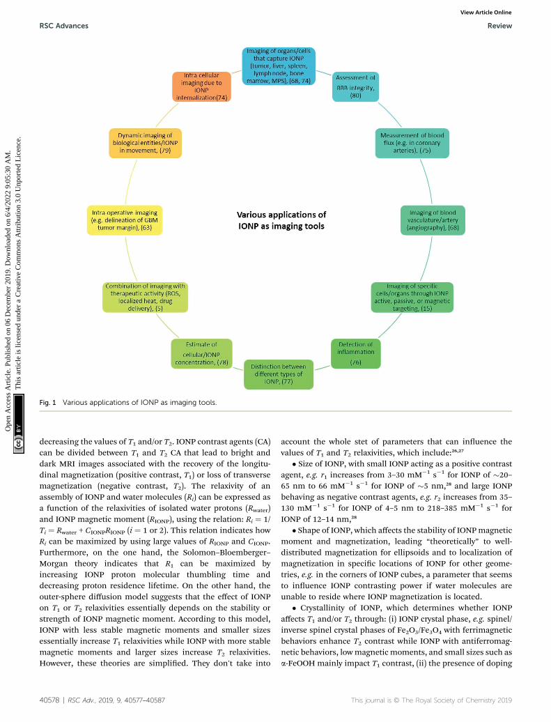
Fig. 1 Various applications of IONP as imaging tools.
RSC Advances Review
Ope
n A
cces
s A
rtic
le. P
ublis
hed
on 0
6 D
ecem
ber
2019
. Dow
nloa
ded
on 6
/4/2
022
9:05
:30
AM
. T
his
artic
le is
lice
nsed
und
er a
Cre
ativ
e C
omm
ons
Attr
ibut
ion
3.0
Unp
orte
d L
icen
ce.
View Article Online
decreasing the values of T1 and/or T2. IONP contrast agents (CA)can be divided between T1 and T2 CA that lead to bright anddark MRI images associated with the recovery of the longitu-dinal magnetization (positive contrast, T1) or loss of transversemagnetization (negative contrast, T2). The relaxivity of anassembly of IONP and water molecules (Ri) can be expressed asa function of the relaxivities of isolated water protons (Rwater)and IONP magnetic moment (RIONP), using the relation: Ri ¼ 1/Ti ¼ Rwater + CIONPRIONP (i ¼ 1 or 2). This relation indicates howRi can be maximized by using large values of RIONP and CIONP.Furthermore, on the one hand, the Solomon–Bloemberger–Morgan theory indicates that R1 can be maximized byincreasing IONP proton molecular thumbling time anddecreasing proton residence lifetime. On the other hand, theouter-sphere diffusion model suggests that the effect of IONPon T1 or T2 relaxivities essentially depends on the stability orstrength of IONP magnetic moment. According to this model,IONP with less stable magnetic moments and smaller sizesessentially increase T1 relaxivities while IONP with more stablemagnetic moments and larger sizes increase T2 relaxivities.However, these theories are simplied. They don't take into
40578 | RSC Adv., 2019, 9, 40577–40587
account the whole stet of parameters that can inuence thevalues of T1 and T2 relaxivities, which include:26,27
� Size of IONP, with small IONP acting as a positive contrastagent, e.g. r1 increases from 3–30 mM�1 s�1 for IONP of �20–65 nm to 66 mM�1 s�1 for IONP of �5 nm,28 and large IONPbehaving as negative contrast agents, e.g. r2 increases from 35–130 mM�1 s�1 for IONP of 4–5 nm to 218–385 mM�1 s�1 forIONP of 12–14 nm,28
� Shape of IONP, which affects the stability of IONPmagneticmoment and magnetization, leading “theoretically” to well-distributed magnetization for ellipsoids and to localization ofmagnetization in specic locations of IONP for other geome-tries, e.g. in the corners of IONP cubes, a parameter that seemsto inuence IONP contrasting power if water molecules areunable to reside where IONP magnetization is located.
� Crystallinity of IONP, which determines whether IONPaffects T1 and/or T2 through: (i) IONP crystal phase, e.g. spinel/inverse spinel crystal phases of Fe2O3/Fe3O4 with ferrimagneticbehaviors enhance T2 contrast while IONP with antiferromag-netic behaviors, lowmagnetic moments, and small sizes such asa-FeOOH mainly impact T1 contrast, (ii) the presence of doping
This journal is © The Royal Society of Chemistry 2019
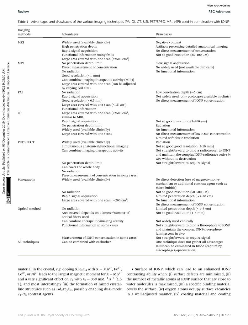
Table 1 Advantages and drawbacks of the various imaging techniques (PA, OI, CT, USI, PET/SPEC, MRI, MPI) used in combination with IONP
Imagingmethods Advantages Drawbacks
MRI Widely used (available clinically) Negative contrastHigh penetration depth Artifacts preventing detailed anatomical imagingRapid signal acquisition No direct measurement of concentrationFunctional information using fMRI Not so good resolution (25–100 mM)Large area covered with one scan (>2500 cm2)
MPI No penetration depth limit Slow signal acquisitionDirect measurement of concentration No widely used (not available clinically)No radiation No functional informationGood resolution (�1 mm)Can combine imaging/therapeutic activity (MPH)Large area covered with one scan (can be adjustedby varying coil size)
PAI No radiation Low penetration depth (�5 cm)Rapid signal acquisition Not widely used (only prototypes available in clinic)Good resolution (�0.5 nm) No direct measurement of IONP concentrationLarge area covered with one scan (�15 cm2)Functional information
CT Large area covered with one scan (>2500 cm2,similar to MRI)Rapid signal acquisition Not so good resolution (5–200 mm)No penetration depth limit RadiationWidely used (available clinically) No functional informationLarge area covered with one scan? No direct measurement of low IONP concentration
Limited so tissue resolutionPET/SPECT Widely used (available clinically) Radiation
Simultaneous anatomical/functional imaging Not so good good resolution (2-10 mm)Can combine imaging/therapeutic activity Not straightforward to bind a radiotreacer to IONP
andmaintain the complex IONP-radiotrace active invivo without its destruction
No penetration depth limit Not straightforward to acquire signalCan cover the whole bodyNo radiationDirect measurement of concentration in some cases
Sonography Widely used (available clinically) No direct detection (use of magneto-motivemechanism or additional contrast agent such asmicro-bubble)
No radiation Not so good resolution (50–500 mM)Rapid signal acquisition Limited penetration depth (�5–20 cm)Large area covered with one scan (�200 cm2) No functional information
No direct measurement of IONP concentrationOptical method No radiation Limited penetration depth (�1–5 cm)
Area covered depends on diameter/number ofoptical bers used
Not so good resolution (1–5 mm)
Can combine therapeutic/imaging activity Not widely used clinicallyFunctional information in some cases Not straightforward to bind a uorophore to IONP
and maintain the complex IONP-uorophoreluminescent in vivo
Measurement of IONP concentration in some cases Not straightforward to acquire signalAll techniques Can be combined with eachother One technique does not gather all advantages
IONP can be eliminated in blood (capture bymacrophages/opsonization)
Review RSC Advances
Ope
n A
cces
s A
rtic
le. P
ublis
hed
on 0
6 D
ecem
ber
2019
. Dow
nloa
ded
on 6
/4/2
022
9:05
:30
AM
. T
his
artic
le is
lice
nsed
und
er a
Cre
ativ
e C
omm
ons
Attr
ibut
ion
3.0
Unp
orte
d L
icen
ce.
View Article Online
material in the crystal, e.g. doping XFe2O4 with X ¼ Mn2+, Fe2+,Co2+, or Ni2+ leads to the largest magnetic moment for X¼Mn2+
and a very signicant effect on T2 with r2 ¼ 358 mM�1 s�1 (1.5T), and most interestingly (iii) the formation of mixed crystal-line structures such as GdxFeyOz, possibly enabling dual-modeT1–T2 contrast agents.
This journal is © The Royal Society of Chemistry 2019
� Surface of IONP, which can lead to an enhanced IONPcontrasting ability when: (i) surface defects are minimized, (ii)the number of metallic atoms at IONP surface that are close towater molecules is maximized, (iii) a specic binding materialcovers the surface, (iv) oxygen atoms occupy surface vacanciesin a well-adjusted manner, (iv) coating material and coating
RSC Adv., 2019, 9, 40577–40587 | 40579
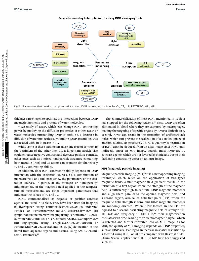
Fig. 2 Parameters that need to be optimized for using IONP as imaging tools in PA, OI, CT, USI, PET/SPEC, MRI, MPI.
RSC Advances Review
Ope
n A
cces
s A
rtic
le. P
ublis
hed
on 0
6 D
ecem
ber
2019
. Dow
nloa
ded
on 6
/4/2
022
9:05
:30
AM
. T
his
artic
le is
lice
nsed
und
er a
Cre
ativ
e C
omm
ons
Attr
ibut
ion
3.0
Unp
orte
d L
icen
ce.
View Article Online
thickness are chosen to optimize the interactions between IONPmagnetic moments and protons of water molecules.
� Assembly of IONP, which can change IONP contrastingpower by modifying the diffusion properties of either IONP orwater molecules surrounding IONP or both, e.g. a decrease indiffusion of water molecules surrounding IONP assemblies wasassociated with an increase in T2.
While some of these parameters favor one type of contrast tothe detriment of the other one, e.g. a large nanoparticle sizecould enhance negative contrast and decrease positive contrast,other ones such as a mixed nanoparticle structure containingboth metallic (Iron) and Gd atoms can promote simultaneouslyT1 and T2 contrasting ability.
In addition, since IONP contrasting ability depends on IONPinteraction with the excitation sources, i.e. a combination ofmagnetic eld and radiofrequency, the parameters of the exci-tation sources, in particular the strength or homogeneity/inhomogeneity of the magnetic eld applied or the tempera-ture of measurement, are other important parameters thatinuence the values of T1 and T2.
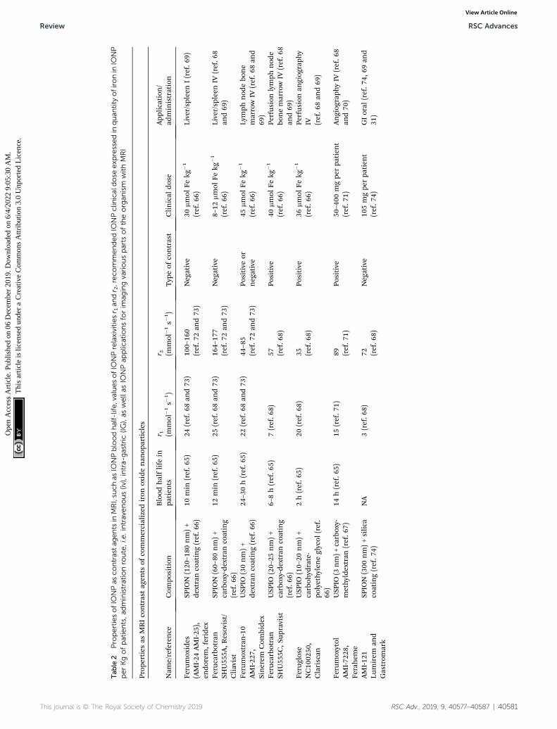
IONP, commercialized as negative or positive contrastagents, are listed in Table 2. They have been used for imaging:(i) liver/spleen using Ferumoxides/AMI-24/AMI-25/Endorem/Feridex or Ferucarbotran/SHU555A/Resovist/Cliavist,29 (ii)lymph node/bone marrow imaging using Ferumoxtran-10/AMI-227/Sinerem/Combidex or Ferucarbotran/SHU555C/Supravist,30
(iii) angiography using Feruglose/NC100250/Clariscan orFerumoxytol/AMI-7228/Feraheme (231), (iv) delineation of thebowel from adjacent organs and tissues, using AMI-121/Lumi-rem/Gastromark,32
40580 | RSC Adv., 2019, 9, 40577–40587
The commercialization of most IONP mentioned in Table 2has stopped for the following reasons.33 First, IONP are oeneliminated in blood where they are captured by macrophages,making the targeting of specic organs by IONP a difficult task.Second, IONP can result in the formation of artifacts/blackholes, which can prevent the realization of a detailed image ofanatomical/tissular structures. Third, a quantity/concentrationof IONP can't be deduced from an MRI image since IONP onlyindirectly affect an MRI image. Fourth, most IONP are T2contrast agents, which are not favored by clinicians due to theirdarkening contrasting effect on an MRI image.
MPI (magnetic particle imaging)
Magnetic particle imaging (MPI)34,35 is a new appealing imagingtechnique, which relies on the application of two typesmagnetic elds. A rst magnetic eld gradient results in theformation of a rst region where the strength of the magneticeld is sufficiently high to saturate IONP magnetic momentsand align them parallel to the applied magnetic eld, anda second region, also called eld free point (FFP), where themagnetic eld strength is zero, and IONP magnetic momentsare randomly oriented. When IONP located in the FFP areexposed to a second oscillating magnetic eld of strength 10–100 mT and frequency 10–100 KHz,36 their magnetizationoscillates with time, leading to an electromagnetic signal, whichis detected and further converted into an MPI image. As forMRI, the quality of MPI imaging depends on IONP properties,such as IONP size, leading to an increase in spatial resolution bya factor 4 using IONP of 20 nm compared with Resovist of 45–60 nm. Several applications of IONP inMPI have been suggestedsuch as:
This journal is © The Royal Society of Chemistry 2019
Tab
le2
PropertiesofIO
NPas
contrastag
entsin
MRI,su
chas
IONPbloodhalf-life,valuesofIONPrelaxivitiesr 1an
dr 2,reco
mmendedIO
NPclinicaldose
exp
ressedin
quan
tity
ofironin
IONP
perKgofpatients,a
dministrationroute,i.e.intravenous(iv),intra-gastric
(IG),as
wellas
IONPap
plic
ationsforim
agingvariousparts
oftheorgan
ism
withMRI
Prop
erties
asMRIcontrastag
ents
ofcommercialized
iron
oxidenan
oparticles
Nam
e/reference
Com
position
Blood
halflife
inpa
tien
tsr 1 (m
mol
�1s�
1)
r 2 (mmol
�1s�
1 )Typ
eof
contrast
Clinical
dose
App
lication
/ad
ministration
Ferumoxides
(AMI-24
AMI-25
),en
dorem
,feridex
SPIO
N(120
–180
nm)+
dextran
coating(ref.6
6)10
min
(ref.6
5)24
(ref.6
8an
d73
)10
0–16
0(ref.7
2an
d73
)Negative
30mmol
Fekg
�1
(ref.6
6)Liver/sp
leen
I(ref.6
9)
Ferucarbotran
SHU55
5A,R
esovist/
Cliavist
SPIO
N(60–80
nm)+
carboxy-de
xtrancoating
(ref.6
6)
12min
(ref.6
5)25
(ref.6
8an
d73
)16
4–17
7(ref.7
2an
d73
)Negative
8–12
mmol
Fekg
�1
(ref.6
6)Liver/sp
leen
IV(ref.6
8an
d69
)
Ferumoxtran
-10
AMI-22
7,Sinerem
Com
bidex
USP
IO(30nm)+
dextran
coating(ref.6
6)24
–30h(ref.6
5)22
(ref.6
8an
d73
)44
–85
(ref.7
2an
d73
)Po
sitive
ornegative
45mmol
Fekg
�1
(ref.6
6)Lymph
nod
ebo
ne
marrowIV
(ref.6
8an
d69
)Fe
rucarbotran
SHU55
5C,S
upravist
USP
IO(20–25
nm)+
carboxy-de
xtrancoating
(ref.6
6)
6–8h(ref.6
5)7(ref.6
8)57 (ref.6
8)Po
sitive
40mmol
Fekg
�1
(ref.6
6)Pe
rfus
ionlymph
nod
ebo
nemarrowIV
(ref.6
8an
d69
)Fe
ruglose
NC10
0250
,Clariscan
USP
IO(10–20
nm)+
carboh
ydrate-
polyethylen
eglycol
(ref.
66)
2h(ref.6
5)20
(ref.6
8)35 (ref.6
8)Po
sitive
36mmol
Fekg
�1
(ref.6
6)Pe
rfus
ionan
giog
raph
yIV (ref.6
8an
d69
)
Ferumoxytol
AMI-72
28,
Ferahem
e
USP
IO(3
nm)+
carboxy-
methyldextran
(ref.6
7)14
h(ref.6
5)15
(ref.7
1)89 (ref.7
1)Po
sitive
50–400
mgpe
rpa
tien
t(ref.7
1)Angiog
raph
yIV
(ref.6
8an
d70
)
AMI-12
1Lu
mirem
and
Gastrom
ark
SPIO
N(300
nm)+silica
coating(ref.7
4)NA
3(ref.6
8)72 (ref.6
8)Negative
105mgpe
rpa
tien
t(ref.7
4)GIoral
(ref.7
4,69
and
31)
This journal is © The Royal Society of Chemistry 2019 RSC Adv., 2019, 9, 40577–40587 | 40581
Review RSC Advances
Ope
n A
cces
s A
rtic
le. P
ublis
hed
on 0
6 D
ecem
ber
2019
. Dow
nloa
ded
on 6
/4/2
022
9:05
:30
AM
. T
his
artic
le is
lice
nsed
und
er a
Cre
ativ
e C
omm
ons
Attr
ibut
ion
3.0
Unp
orte
d L
icen
ce.
View Article Online
RSC Advances Review
Ope
n A
cces
s A
rtic
le. P
ublis
hed
on 0
6 D
ecem
ber
2019
. Dow
nloa
ded
on 6
/4/2
022
9:05
:30
AM
. T
his
artic
le is
lice
nsed
und
er a
Cre
ativ
e C
omm
ons
Attr
ibut
ion
3.0
Unp
orte
d L
icen
ce.
View Article Online
� Cell concentration measurement, i.e. it is possible toobtain a relation between the MPI signal and the cellularconcentration,37 with a high resolution, down to �250 cells and7.8 ng of Fe. It however necessitates knowing on the one handthe quantity of IONP internalized in each cell and on the otherhand how IONP internalization affects MPI signal. Whereas thequantity of IONP nanoparticles internalized in each cell caneasily be determined in vitro, it seems more difficult to evaluateit in vivo without extracting a tissue sample from the organismfor analysis, restricting the use of this method. In addition,whereas the MPI signal of some IONP is relatively independentof their environment and of the fact that they are internalized ornot, due to a minor Brownian contribution to their MPI signal,other IONP display a MPI signal that strongly depends on IONPenvironment,38 making the judicious choice of IONP crucial foraccurate MPI measurement.
� Imaging of several different types of IONP, since IONP withdifferent sizes yield different MPI signals. This can enable thedetection of various biological entities if each IONP of differentsize targets a different entity.39
� Measurement of blood ux, which can on the one handenable evaluating the displacement speed of IONP in blood byMPI and on the other hand certain specic blood trajectorysuch as that resulting from bleeding, i.e. IONP leakage outsideof blood vessels.40
� Imaging of some organs or tissues (tumors), which areeither targeted by IONP following different targeting methods,i.e. passive through the EPR effect, magnetic via the applicationof a magnetic eld gradient, or active using an antibody boundto IONP that targets a specic cell receptor, or directly injectedwith IONP, yielding imaging of organ, e.g. lung41 or brain,42 orvasculature,37 imaging without facing the same hurdle as inMRI in which IONP can leads to a hypo-intense signal that issimilar to that of air inside lung.
� MPI combined with MHT, which can be foreseen since theproperties of the applied oscillating magnetic eld (strengthand frequency) are similar in MPI and MHT (magnetic hyper-thermia), possibly enabling combining imaging and thera-peutic methods with IONP.18
MPI present a series of advantages such as: (i) a highpenetration depth due to a theoretical unlimited propagationof the magnetic eld, (ii) a direct measurement of IONPconcentration, (iii) a positive contrast, (iv) an operatingmechanism that does not rely on the use of toxic radiations,(v) a signal that should not be strongly affected by back-ground tissue, (vi) a signal that can be acquired quickly ina spatially selective manner, (vii) a high resolution (sub-mm).However, MPI also suffers from a series of drawbacks such as:(i) the absence of anatomic imaging (MPI only images IONP),(ii) possible formation of eddy currents that can yield over-heating if the strength/frequency of the oscillating magneticeld is too high, (iii) the necessity to use IONP whosemagnetic moment couples with the external oscillatingmagnetic eld without depending on IONP environment, (iv)the absence of a MPI equipment that can be used in theclinic.
40582 | RSC Adv., 2019, 9, 40577–40587
Photo-acoustic imaging (PAI)
The mechanism of photo-acoustic imaging relies on the exci-tation of a tissue with a nanosecond pulsed laser of 680–970 nmemission wavelength, 10 Hz frequency, and 10–100 mJ cm�2
power, resulting in a slight temperature increase and thermo-elastic expansion of the tissue, which further generates anacoustic wave that provides an image of tissue followingdetection and processing of the signal by an echograph oftypical ultrasound frequency 5–50 MHz.43–45 Chromophoressuch as melanin and hemoglobin that are strong opticalabsorbers can act as intrinsic PAI contrast agents. However, insome cases they are not available, e.g. in some cancer cells, thenrequiring the use of other extrinsic PAI contrast agents such asIONP. IONP can behave as PAI contrast agents without thepresence of another substance. In this case, the couplingmechanism between the incident laser light and IONP caninvolve surface plasmon waves.46 IONP can also be conjugatedto a uorophore such as Indocyanine Green,21 which enhancelaser light absorption. An important number of applications ofPAI has been described,45 such as the imaging of certain cancers(breast, prostate, bladder, melanoma, ovarian), lymph nodespossibly containing metastasis, circulating tumor cells, as wellas neonatal brain, gastrointestinal, thyroid, or intra-operativeimaging. PAI displays a number of advantages such as: (i) anoperating mechanism that does not use radiation, (ii) fastimaging acquisition, i.e. typically less than 1 minute,47 (iii)a relatively good resolution, e.g.�0.5 mmwas reached for breastimaging,48 which can be increased by increasing the ultrasoundfrequency, (iv) the relatively large area that can be covered withone scan, e.g. a surface of 10–50 cm2 of a breast tumor can beimaged,48 (v) the possibility to obtain functional informationderived from a variation in hemoglobin or melanin concentra-tion, (vi) the ability to combine PAI with other imaging tech-niques such as MRI or CT. However, this technique also suffersfrom a relatively low penetration depth (typically of the order ofa few cm), which is due to the use of laser light and to theultrasound frequency when it is too high, and to a too smallnumber of PAI equipment that can be used in the clinic. As anexample, the Twente Photoacoustic Mammoscope (PAM) wasbuilt at the University of Twente (Enschede, the Netherlands) toimage breast tumor cells in the clinic, but this type of equip-ment remains a prototype.49 It needs to be more widely devel-oped andmade available in different hospitals to spread out theuse of the PAI imaging technique.
Scanner, computing tomography (CT)
X-ray scanners, also designated as computing tomography (CT),expose patients to an X-ray beam, resulting in a non-uniformabsorption of X-rays by the patients, i.e. the absorption isdifferent parts for various parts of the organism depending ontheir consistency (Z-number). Then the transmitted (non-absorbed) X-rays are detected, providing an image of thesedifferent parts with various contrasts. In fact, the interactionbetween X-rays and the organism is due to the photo-electric effect,whose strength is mainly proportional to Z3 (Z: atomic number),and Compton scattering, which is enhanced at high electron and
This journal is © The Royal Society of Chemistry 2019
Review RSC Advances
Ope
n A
cces
s A
rtic
le. P
ublis
hed
on 0
6 D
ecem
ber
2019
. Dow
nloa
ded
on 6
/4/2
022
9:05
:30
AM
. T
his
artic
le is
lice
nsed
und
er a
Cre
ativ
e C
omm
ons
Attr
ibut
ion
3.0
Unp
orte
d L
icen
ce.
View Article Online
mass density.50 The unit of attenuation measurement obtained inCT is Hounseld unit (HU), leading to low CT number (HU value)for weakly absorbing material (�1000 HU for air and 0 HU forwater), to intermediate HU values for slightly absorbing material(40 to 80 HU for tissue), and to larger HU values for strongerabsorbing material (400 to 1000 HU for bone).51 Substances withhigh HU values (strongly attenuating X-ray) appear white or lightgray, while those with low HU values (weakly attenuating X-ray)appear dark gray or black. The photoelectric and Comptoneffects suggest that material with high Z and large mass densitywould be the best contrast agent. Although the Z value of iron, i.e.26, and the density of maghemite comprised in most IONP formedical application, i.e. 5 g cm�3, are not the largest values thatcan be reached with nanomaterials, and are larger than those ofwater (Z ¼ 1 for hydrogen, and Z ¼ 8 for oxygen, r ¼ 1 g cm�3 forwater) that constitutes the majority of organic living material, theyseem sufficient to provide. They seem are sufficient to providea contrast with CT. Indeed, IONP were shown to act as CT contrastagent, leading to CT number that increases with increasing IONPconcentration, i.e. from 27 HU at 2.5 mg mL�1 of IONP to 113 HUat 25 mg mL�1 of IONP.52 However, compared with iodine, IONPwere shown to absorb �5–6 times less X-ray.52 The advantages ofCT lie in: (i) the acquisition of large scans (typically 10–20 cm)quickly (under 5 seconds) with image reconstruction within lessthan one minute, (ii) its non-invasiveness, (iii) high contrastresolution, (iv) no depth penetration limit, (v) a relatively low cost,(vi) quantitative information on contrast agents can be obtained,(vii) its wide availability in hospitals. Disadvantages of CT comefrom: (i) its low sensitivity compared with other imaging tech-niques, i.e.CT detection limit is�10�3M,51 compared with 10�5Mfor Gd chelates in MRI and 10�9 M for nuclear techniques about,51
(ii) the exposure of patient to relatively high dose of ionizingradiation, (iii) limited so tissue resolution.
Positron emission tomography (PET)/single photon emissioncomputed tomography (SPECT)
The mechanism of PET and SPECT relies on the use of a radio-tracer, which targets a specic part of the organism such asa tumor, then emits a signal made of positrons (PET) or gammarays (SPECT) that is measured, hence enabling the detection ofthis part of the organism. PET and SPECT are functionalimaging methods mimicking a substance of interest such asglucose for 18F-FDG, which gets xed on a specic tissue, e.g.a tumor in case of 18F-FDG that consumes more glucose thana healthy tissue.53 Using IONP, it was possible to bring severalimprovement to the standard PET/SPECT imaging method by:(i) binding different radio-tracers to IONP [18F]uorodeox-yglucose (FDG), copper-61/64, gallium-66/68, zirconium-89, andiodine-124 for PET,54 and 99mTc, 125I, 111I, 125I and 131I forSPECT,54–56 that increase radio-tracer lifetime and targetingefficacy,55 (ii) enabling simultaneous anatomical and functionalimaging by combining PET/SPEC with MRI, taking advantage ofthe MRI contrasting ability of IONP, (iii) enlarging the SPECT/PET imaging capacity to a therapeutic activity through the useof a theranostic IONP probe that can trigger drugs delivery,immunotherapy, hyperthermia, or photodynamic therapy.19,57
This journal is © The Royal Society of Chemistry 2019
In addition, PET/SPECT lead to high detection sensitivity, e.g.PET was shown to be 200 times more sensitive than MRI usingnanoparticles, the possibility to image the whole organismwithout limitation in depth of penetration, and the acquisitionof quantitative information since in optimal operating condi-tions PET/SPECT signal should be proportional to the number/concentration of radiotracer in the targeted region.54 For thesereasons, the development of PET/SPECT can be foreseen invarious medical elds such as disease detection or the assess-ment of the efficacy of a medical treatment.
Ultrasound imaging/sonography
It was reported that IONP could be used in ultrasound (sonography)imaging. On the one hand, IONP could be inserted within a mate-rial that is already an ultrasound contrast agent such as a micro-bubble or liposomes, then enabling a combination between USIand another imaging modality such as MRI that is made possibleby the presence of IONP.58 On the other hand, although a directdetection of IONP by ultrasound was not reported to the authorknowledge, IONP presence could be detected indirectly bymeasuring tissue resistance resulting from IONP motion/vibrationunder the application of a high intensity pulsed magnetic eldthrough a technique cold magneto-motive ultrasound whose effi-cacy essentially depends on IONP susceptibility and could becombined with ultrasound imaging to provide both anatomicaltissue information and estimate the quantity of IONP or photo-acoustic imaging to improve the resolution of PAI imaging.Magneto-motive approaches could be used to carry out dynamicimaging, i.e. imaging of moving biological systems, such as circu-lating tumor cells, metastases diffusing in/out of lymph nodes orstem cells, to determine viscoelastic property of so tissues, andcould easily be combined with other imaging modalities.59
Optical imaging methods
Optical imaging can be carried out with IONP-uorophorecomplexes, essentially using NIR uorophores such as organicuorochromes, e.g. cyanine dyes such as Cy5.5. Such complexesare either made of IONP surrounded by various coatings such assilica shell, spacer, lipid bilayer, polymer, which contain or arelabeled with uorophores or of IONP directly coated witha uorescent semiconducting material. Such methods presentthe advantages of being relatively easy to implement, of yieldingunder optimized conditions a high spatial/temporal resolution,and of being complementary to other imaging techniques suchas MRI. In order for this method to be efficient, absorption bythe organism/tissue/water/hemoglobin/melanin/proteins thatoccurs between 200 and 650 nm shall be avoided by choosinguorescent probes with absorption/emission within the rangeof 650–1450 nm. Furthermore, uorophores should not beprone to photo-bleaching, not be quenched by iron oxide, bestable in biological media, i.e. have a long life-time in suchenvironment, and display well-separated emission andabsorption spectra to be to distinguishable them. The use ofthis method is facilitated by the existence of numerous systemsthat can excite/detect uorescence in different conditions, i.e. inreal time, in vitro, in vivo, such as: optical scanners, e.g.
RSC Adv., 2019, 9, 40577–40587 | 40583
RSC Advances Review
Ope
n A
cces
s A
rtic
le. P
ublis
hed
on 0
6 D
ecem
ber
2019
. Dow
nloa
ded
on 6
/4/2
022
9:05
:30
AM
. T
his
artic
le is
lice
nsed
und
er a
Cre
ativ
e C
omm
ons
Attr
ibut
ion
3.0
Unp
orte
d L
icen
ce.
View Article Online
uorescence mediated tomography, uorescence reectancetomography, optical coherence tomography, a large number ofuorescence microscopies, ow cytometry, spectrophotometry,intra-vital microscopy, intravascular non-invasive near-infrared(NIRF) imaging, clinical endoscopy, and equipment for uo-rescence detection during surgery. Suchmethod can be used formonitoring magnetofection efficacy,60 for multi-modal imagingwith MPI, MRI and PAI,61,62 for detecting various biologicalentities such as tumors,16,56 apoptotic cells,7 and sentinel lymphnodes,4 and for delineating inltrating tumors such asglioblastoma.63
Multimodal imaging
Since IONP can be used with various imaging methods, theycould be considered for multimodal imaging. The latter pres-ents the advantage of enabling the combination of informationcoming from different imaging methods.64 For example, in PET/MRI, MRI is used for anatomical imaging while PET offersmolecular information.
Conclusion/perspectives
From the author's point of view, the challenges ahead lie in:� Improving both IONP (better targeting, size control,
fabrication process) and imaging methods (better resolution,miniaturization, lower cost, more limited use of hospitalinfrastructure);
� Yielding a sufficiently large percentage of IONP in theorgan of interest so that IONP can act as contrast agents;
� Developing a single imaging method that brings togetherthe maximum benet of the different imaging techniques withthe minimum of their drawbacks;
� Building a device/platform that gathers all the differentimaging techniques in one unit;
� Identifying the specic medical need upstream and thenproviding the imaging method best suited to this need, anapproach that seems appropriate when medical needs remainglobally unchanged, which may be the case within a limitedtime period in specialized hospital units.
� IONP present the advantage of being compatible and evenimproving a large series of different imaging techniques,making them appealing for multimodal imaging.64
Abbreviations
BBB
40584 | RSC Adv., 2019
Blood brain barrier
CA Contrast agent CT Computing tomography IONP Iron oxide nanoparticles MRI Magnetic resonance imaging MPI Magnetic particle imaging MPH/MHT Magnetic particle hyperthermia MPS Mononuclear phagocytic system MS Multiple sclerosis OI Optical imaging PAI Photo-acoustic imaging, 9, 40577–40587
ROS
T
Radical oxygen species
US Ultrasounds USI Ultrasound imaging (sonography)Conflicts of interest
EA has been working in the company Nanobacterie.
Acknowledgements
I would like to thank the BPI (‘banque publique d'investisse-ment, France’), the region of Paris (‘Parris Region Entreprise,France’), the French Research Tax Credit program (‘creditd'impot recherche’), the incubator Paris Biotech Sante, theANRT (CIFRE 2014/0359, CIFRE 2016/0747, CIFRE 2013/0364,CIFRE 2015/976), the Eurostars programs (Nanoneck-2 E9309and Nanoglioma E11778), the AIR program (‘aide a l'innovationresponsable’) from the region of Paris (A1401025Q), the ANR(‘Agence Nationale de la Recherche’) Mesto, as well as theUniversities Paris 6 and Paris 11. We also would like to thankthe Nomis Foundation and Markus Reinhard for their support.
References
1 J. Lu, J. Sun, F. Li, J. Wang, D. Kim, C. Fan, T. Hyeon andD. Ling, Highly Sensitive Diagnosis of Small HepatocellularCarcinoma Using pH-Responsive Iron Oxide NanoclusterAssemblies, J. Am. Chem. Soc., 2018, 140, 10071–10074.
2 K. El-Boubbou, Magnetic iron oxide nanoparticles as drugcarriers: preparation conjugation and delivery,Nanomedicine, 2018, 13, 929–952.
3 R. M. Clauson, M. Chen, L. M. Scheetz, B. Berg andB. Chertok, Size-Controlled Iron Oxide Nanoplatforms withLipidoid-Stabilized Shells for Efficient Magnetic ResonanceImaging-Trackable Lymph Node Targeting and High-Capacity Biomolecule Display, ACS Appl. Mater. Interfaces,2018, 10, 20281–20295.
4 S. Mehralivand, H. Van der Poel, A. Winter, P. L. Choyke,P. A. Pinto and B. Turkbey, Sentinel lymph node imagingin urologic oncology, Transl. Androl. Urol., 2018, 7, 887–902.
5 S. M. Dadfar, K. Roemhild, N. I. Drude, S. Von Stillfried,R. Knuchel, F. Kiessling and T. Lammers, Iron oxidenanoparticles: Diagnostic, therapeutic and theranosticapplications, Adv. Drug Delivery Rev., 2019, 138, 302–325.
6 Y. Hu, S. Mignani, J.-P. Majoral, M. Shen and W. Shi,Construction of iron oxide nanoparticle-based hybridplatforms for tumor imaging and therapy, Chem. Soc. Rev.,2018, 47, 1874–1900.
7 M. M. Mekawya, A. Saito, A. Sumiyoshic, J. J. Riera,H. Shimizud, R. Kawashima and T. Tominagaa, Hybridmagneto-uorescent nano-probe for live apoptotic cellsmonitoring at brain cerebral ischemia, Mater. Sci. Eng., C,2019, 100, 485–492.
8 S. Hedgire, C. Krebill, G. R. Wojtkiewicz, I. Oliveira,B. B. Ghoshhajra, U. Hoffmann and M. G. Harisinghani,Ultrasmall superparamagnetic iron oxide nanoparticle
his journal is © The Royal Society of Chemistry 2019
Review RSC Advances
Ope
n A
cces
s A
rtic
le. P
ublis
hed
on 0
6 D
ecem
ber
2019
. Dow
nloa
ded
on 6
/4/2
022
9:05
:30
AM
. T
his
artic
le is
lice
nsed
und
er a
Cre
ativ
e C
omm
ons
Attr
ibut
ion
3.0
Unp
orte
d L
icen
ce.
View Article Online
uptake as noninvasive marker of aortic wall inammation onMRI: proof of concept study, Br. J. Radiol., 2018, 1092,20180461.
9 Y. Cai, Y. Wang, H. Xu, C. Cao, R. Zhu, X. Tang, T. Zhang andY. Pan, Positive magnetic resonance angiography usingultrane ferritin-based iron oxide nanoparticles, Nanoscale,2019, 11, 2644–2654.
10 J. M. S. Chan, C. Monaco, M. Wylezinska-Arridge,J. L. Tremoleda, J. E. Cole, M. Goddard, M. S. H. Cheung,K. K. Bhakoo and R. G. J. Gibbs, Imaging vulnerableplaques by targeting inammation in atherosclerosis usinguorescent-labeled dual-ligand microparticles of iron oxideand magnetic resonance imaging, J. Vasc. Surg., 2018, 67,1571–1548e3.
11 A. Ivask, E. H. Pilkington, T. Blin, A. Kakinen, H. Vija,M. Visnapuu, J. F. Quinn, M. R. Whittaker, R. Qiao,T. P. Davis, P. C. Ke and N. H. Voelcker, Uptake andtranscytosis of functionalized superparamagnetic ironoxide nanoparticles in an in vitro blood brain barriermodel, Biomater. Sci., 2018, 6, 314–323.
12 E. D. Lehrman, A. N. Plotnik, T. Hope and D. Saloner,Ferumoxytol-enhanced MRI in the peripheral vasculature,Clin. Radiol., 2019, 74, 37–50.
13 H. Arami, A. P. Khandhar, A. Tomitaka, E. Yu,P. W. Goodwill, S. M. Conolly and K. M. Krishnan, In vivomultimodal magnetic particle imaging (MPI) with tailoredmagneto/optical contrast agents, Biomaterials, 2015, 52,251–261.
14 T. H. Shin, Y. Choi, S. Kim and J. C. Shin, Recent advances inmagnetic nanoparticle-based multi-modal imaging, Chem.Soc. Rev., 2015, 44, 4501–4516.
15 E. Alphandery, Biodistribution and targeting properties ofiron oxide nanoparticles for treatments of cancer and ironanemia disease, Nanotoxicology, 2019, 13, 573–596.
16 C. Song, W. Sun, Y. Xiao and X. Shi, Ultrasmall iron oxidenanoparticles: synthesis, surface modication, assembly,and biomedical applications, Drug Discovery Today, 2019,24, 835–844.
17 D. Bonvin, D. T. L. Alexander, A. Millan, R. Pinol, B. Sanz,G. F. Goya, A. Martınez, J. A. M. Bastiaansen, M. Stuber,K. J. Schenk, H. Hofmann and M. M. Ebersold, TuningProperties of Iron Oxide Nanoparticles in AqueousSynthesis without Ligands to Improve MRI Relaxivity andSAR, Nanomaterials, 2017, 7, 225.
18 Z. W. Tay, P. Chandrasekharan, A. Chiu-Lam, D. W. Hensley,R. Dhavalikar, X. Y. Zhou, E. Y. Yu, P. W. Goodwill, B. Zheng,C. Rinaldi and S. M. Conolly, Magnetic Particle Imaging-Guided Heating in vivo Using Gradient Fields for ArbitraryLocalization of Magnetic Hyperthermia Therapy, ACS Nano,2018, 12, 3699–3713.
19 N. V. S. Vallabani and S. Singh, Recent advances and futureprospects of iron oxide nanoparticles in biomedicine anddiagnostics, 3 Biotech, 2018, 8, 279.
20 H. Yuan, M. Q. Wilks, M. D. Normandin, G. E. Fakhri,C. Kaittanis and L. Josephson, Heat-induced radiolabelingand uorescence labeling of Feraheme nanoparticles for
This journal is © The Royal Society of Chemistry 2019
PET/SPECT imaging and ow cytometry, Nat. Protoc., 2018,13, 392–412.
21 H. Wang, X. Li, B. W. C. Tse, Y. Yang, C. A. Thorling, Y. Liu,M. Touraud, J. B. Chouane, X. Liu, M. S. Roberts andX. Liang, Indocyanine green-incorporating nanoparticlesfor cancer theranostics, Theranostics, 2018, 8, 1227–1242.
22 Z. Shen, A. Wu and X. Chen, Iron Oxide Nanoparticle BasedContrast Agents for Magnetic Resonance Imaging, Mol.Pharmaceutics, 2017, 14, 1352–1364.
23 I. Fernandez-Barahona, M. Munoz-Hernando andF. Herranz, Microwave-Driven Synthesis of Iron-OxideNanoparticles for Molecular Imaging, Molecules, 2019, 24,1224, DOI: 10.3390/molecules24071224.
24 J. Dulinska-Litewka, A. Łazarczyk, P. Hałubiec, O. Szafranski,K. Karnas and A. Karewicz, Superparamagnetic Iron OxideNanoparticles—Current and Prospective MedicalApplications, Materials, 2019, 12, 617, DOI: 10.3390/ma12040617.
25 C. Song, W. Sun, Y. Xiao and X. Shi, Ultrasmall iron oxidenanoparticles: synthesis, surface modication, assembly,and biomedical applications, Drug Discovery Today, 2019,24, 835–844.
26 W. Zhang, L. Liu, H. Chen, K. Hu, I. Delahunty, S. Gao andJ. Xie, Surface impact on nanoparticle-based magneticresonance imaging contrast agents, Theranostics, 2018, 8,2521–2548.
27 Z. Zhou, L. Yang, J. Gao and X. Chen, Structure–RelaxivityRelationships of Magnetic Nanoparticles for MagneticResonance Imaging, Adv. Mater., 2019, 31, 1804567.
28 C. Blanco-Andujar, A. Walter, G. Cotin, C. Bordeianu,D. Mertz, D. Felder-Flesch and S. Begin-Colin, Design ofiron oxide-based nanoparticles for MRI and magnetichyperthermia, Nanomedicine, 2019, 11, 1889–1910.
29 Z. R. Stephen, F. M. Kievit and M. Zhang, MagnetiteNanoparticles for Medical MR Imaging, Mater. Today,2011, 14, 330–338.
30 R. Dinniwell, P. Chan, G. Czarnota, et al., Pelvic lymph nodetopography for radiotherapy treatment planning fromferumoxtran-10 contrast-enhanced magnetic resonanceimaging, Int. J. Radiat. Oncol., Biol., Phys., 2009, 74, 844–851.
31 S. Stoumpos, M. Hennessy, A. T. Vesey, A. Radjenovic,R. Kasthuri, D. B. Kingsmore, P. B. Mark and G. Roditi,Ferumoxytol magnetic resonance angiography: a dose-nding study in patients with chronic kidney disease, Eur.J. Radiol., 2019, 29, 3543–3552.
32 Y. Xiang, J. Wang and J.-M. Idee, A comprehensive literaturesupdate of clinical researches of superparamagneticresonance iron oxide nanoparticles for magnetic resonanceimaging, Quant. Imaging Med. Surg., 2017, 7, 88–122.
33 S. Tong, H. Zhu and G. Bao, Magnetic iron oxidenanoparticles for disease detection and therapy, Mater.Today, 2019, DOI: 10.1016/j.mattod.2019.06.003.
34 J. W. M. Bulte, Superparamagnetic iron oxides as MPItracers: A primer and review of early applications, Adv.Drug Delivery Rev., 2019, 138, 293–301.
35 N. Panagiotopoulos, R. L. Duschka, M. Ahlborg, G. Bringout,C. Debbeler, M. Graeser, M. Kaethner, K. Ludtke-Buzug,
RSC Adv., 2019, 9, 40577–40587 | 40585
RSC Advances Review
Ope
n A
cces
s A
rtic
le. P
ublis
hed
on 0
6 D
ecem
ber
2019
. Dow
nloa
ded
on 6
/4/2
022
9:05
:30
AM
. T
his
artic
le is
lice
nsed
und
er a
Cre
ativ
e C
omm
ons
Attr
ibut
ion
3.0
Unp
orte
d L
icen
ce.
View Article Online
H. Medimagh, J. Stelzner, T. M. Buzug, J. Barkhausen,F. M. Vogt and J. Haegele, Magnetic particle imaging:current developments and future directions, Int. J.Nanomed., 2015, 10, 3097–3114.
36 A. Meola, J. Rao, N. Chaudhary, G. Song, X. Zheng andS. D. Chang, Magnetic Particle Imaging in Neurosurgery,2019, 125, 261–270.
37 X. Y. Zhou, Z. W. Tay, P. Chandrasekharan, E. Y. Yu,D. W. Hensley, R. Orendorff, K. E. Jeffris, D. Mai, B. Zheng,P. W. Goodwill and S. M. Conolly, Magnetic particleimaging for radiation-free, sensitive and high-contrastvascular imaging and cell tracking, Curr. Opin. Chem. Biol.,2018, 45, 131–138.
38 H. Arami, R. M. Ferguson, A. P. Khandhar andK. M. Krishnan, Size-dependent ferrohydrodynamicrelaxometry of magnetic particle imaging tracers indifferent environments, Med. Phys., 2013, 40, 071904.
39 H. Kratz, M. Taupitz, A. A. de Schellenberger, O. Kosch,D. Eberbeck, S. Wagner, L. Trahms, B. Hamm andJ. Schnorr, Novel magnetic multicore nanoparticlesdesigned for MPI and other biomedical applications: fromsynthesis to rst in vivo studies, PLoS One, 2018, 13,e0190214.
40 M. G. Kaul, J. Salamon, T. Knopp, H. Ittrich, G. Adam,H. Weller and C. J. Wegner, Magnetic particle imaging forin vivo blood ow velocity measurements in mice, Phys.Med. Biol., 2018, 63, 064001.
41 F. Wegner, T. M. Buzug and J. Barkhausen, Take a DeepBreath–Monitoring of Inhaled Nanoparticles with MagneticParticle Imaging, Theranostics, 2018, 8, 3691–3692.
42 L. C. Wu, Y. Zhang, G. Steinberg, H. Qu, S. Huang, M. Cheng,T. Bliss, F. Du, J. Rao, G. Song, L. Pisani, T. Doyle, S. Conolly,K. Krishnan, G. Grant and M. Wintermark, A Review ofMagnetic Particle Imaging and Perspectives onNeuroimaging, Am. J. Neuroradiol., 2019, 40, 206–212.
43 P. Armanetti, A. Flori, C. Avigoa, L. Conti, B. Valtancoli,D. Petroni, S. Doumett, L. Cappiello, C. Ravagli, G. Baldi,A. Bencini and L. Menichetti, Spectroscopic andphotoacoustic characterization of encapsulated iron oxidesuper-paramagnetic nanoparticles as a new multiplatformcontrast agent, Spectrochim. Acta, Part A, 2018, 199, 248–253.
44 J. P. Thawani, A. Amirshaghaghi, L. Yan, J. M. Stein, J. Liuand A. Tsourkas, Photoacoustic-Guided Surgery withIndocyanine Green-Coated Superparamagnetic Iron OxideNanoparticle Clusters, Small, 2017, 13, 1701300.
45 S. Zackrisson, S. M. W. Y. van de Ven and S. S. Gambhir,Light In and Sound Out: Emerging Translational Strategiesfor Photoacoustic Imaging, Cancer Res., 2014, 74, 979–1004.
46 H. Chen, Z. Yuan and C. Wu, Nanoparticle Probes forStructural and Functional Photoacoustic MolecularTomography, BioMed Res. Int., 2015, 2015, 757101.
47 P. Beard, Biomedical photoacoustic imaging, Interface Focus,2011, 1, 602–631.
48 S. Manohar and M. Dantuma, Current and Future Trends inPhotoacoustic Breast Imaging, Photoacoustics, 2019, DOI:10.1016/j.pacs.2019.04.004.
40586 | RSC Adv., 2019, 9, 40577–40587
49 K. S. Valluru, K. E. Wilson and J. K. Willmann, PhotoacousticImaging in Oncology: Translational Preclinical and EarlyClinical Experience, Radiology, 2016, 280, 332–349.
50 J. Kim, P. Chhour, J. Hsu, H. I. Litt, V. A. Ferrari, R. Popovtzerand D. P. Cormode, Use of Nanoparticle Contrast Agents forCell Tracking with Computed Tomography, BioconjugateChem., 2017, 28, 1581–1597.
51 D. P. Cormode, P. C. Naha and Z. A. Fayad, NanoparticleContrast Agents for Computed Tomography: A Focus onMicelles, Contrast Media Mol. Imaging, 2014, 9, 37–52.
52 S. Goel, C. G. England, F. Chen and W. Cai, PositronEmission Tomography and Nanotechnology: A DynamicDuo for Cancer Theranostics, Adv. Drug Delivery Rev., 2017,113, 157–176.
53 A. L. Dias, R. Kunzel, R. S. Levenhagen and E. Okuno,Application of computed tomography images in theevaluation of magnetic nanoparticles biodistribution, J.Magn. Magn. Mater., 2010, 322, 2405–2407.
54 F. Ai, A. Ferreira, F. Chen and W. Cai, Engineering ofRadiolabeled Iron Oxide Nanoparticles for Dual-ModalityImaging, Wiley Interdiscip. Rev.: Nanomed. Nanobiotechnol.,2016, 8, 619–630.
55 J. Pellico, J. Llop, I. Fernandez-Barahona, R. Bhavesh, J. Ruiz-Cabello and F. Herranz, Iron Oxide Nanoradiomaterials:Combining Nanoscale Properties with Radioisotopes forEnhanced Molecular Imaging, Contrast Media Mol.Imaging, 2017, 2017, 1549580.
56 M. De Simone, D. Panetta, E. Bramanti, C. Giordano,M. C. Salvatici, L. Gherardinia, A. Menciassie,S. Burchiellif, C. Cintia and P. A. Salvadoria, Magneticallydriven nanoparticles: 18FDGradiolabelling and positronemission tomography biodistribution study, ContrastMedia Mol. Imaging, 2016, 11, 561–571.
57 R. A. Revia and M. Zhang, Magnetite nanoparticles forcancer diagnosis, treatment, and treatment monitoring:recent advances, Mater. Today, 2016, 19, 157–158.
58 X. Qian, X. Han and Y. Chen, Insights into the uniquefunctionality of inorganic micro/nanoparticles for versatileultrasound theranostics, Biomaterials, 2017, 142, 13–30.
59 M. Evertsson, P. Kjellman, M. Cinthio, R. Andersson,T. A. Tran, R. Zandt, G. Grafstrom, H. Toevall,S. Fredriksson, C. Ingvar, S. E. Strand and T. Jansson,Combined Magnetomotive ultrasound, PET/CT, and MRimaging of 68Ga-labelled superparamagnetic iron oxidenanoparticles in rat sentinel lymph nodes in vivo, Sci. Rep.,2017, 7, 4824.
60 M. Zuvin, E. Kuruoglu, V. O. Kaya, O. Unal, O. Kutlu,H. Y. Acar, D. Gozuacik and A. Kosar, Magnetofection ofGreen Fluorescent Protein Encoding DNA BearingPolyethyleneimine-Coated Superparamagnetic Iron OxideNanoparticles to Human Breast Cancer Cells, ACS Omega,2019, 4, 12366–12374.
61 L. Meng, X. Ma, S. Jiang, G. Ji, W. Han, B. Xu, J. Tian andW. Tian, High-efficiency uorescent and magneticmultimodal probe for long-term monitoring and deeppenetration imaging of tumors, J. Mater. Chem. B, 2019, 7,5345–5351.
This journal is © The Royal Society of Chemistry 2019
Review RSC Advances
Ope
n A
cces
s A
rtic
le. P
ublis
hed
on 0
6 D
ecem
ber
2019
. Dow
nloa
ded
on 6
/4/2
022
9:05
:30
AM
. T
his
artic
le is
lice
nsed
und
er a
Cre
ativ
e C
omm
ons
Attr
ibut
ion
3.0
Unp
orte
d L
icen
ce.
View Article Online
62 C. Song, W. Sun, Y. Xiao and X. Shi, Ultrasmall iron oxidenanoparticles : synthesis, surface modication, assembly,and biomedical applications, Drug Discovery Today, 2019,24, 835–844.
63 C. Lee, G. R. Kim, J. Yoon, S. E. Kim, J. S. Yoo and Y. Piao, Invivo delineation of glioblastoma by targeting tumor-associated macrophages with near-infrared uorescentsilica coated iron oxide nanoparticles in orthotopicxenogras for surgical guidance, Sci. Rep., 2018, 8, 11122.
64 J. Lemaster, F. Chen, T. Kim, A. Hariri and J. V. Jokerst,Development of a Trimodal Contrast Agent for Acousticand Magnetic Particle Imaging of Stem Cells, ACS Appl.Nano Mater., 2018, 1, 1321–1331.
65 H. E. Daldrup-Link, Ten Things You Might Not Know aboutIron Oxide Nanoparticles, Radiology, 2017, 284, 616–629.
66 J. S. Weinstein, C. G. Varallyay, E. Dosa, S. Gahramanov,B. Hamilton, W. D. Rooney, L. L. Muldoon andE. A. Neuwelt, Superparamagnetic iron oxidenanoparticles: diagnostic magnetic resonance imaging andpotential therapeutic applications in neurooncology andcentral nervous system inammatory pathologies, a review,J. Cereb. Blood Flow Metab., 2010, 30, 15–35.
67 J. P. Bullivant, S. Zhao, B. J. Willenberg, B. Kozissnik,C. D. Batich and J. Dobson, Materials Characterization ofFeraheme/Ferumoxytol and Preliminary Evaluation of ItsPotential for Magnetic Fluid Hyperthermia, Int. J. Mol. Sci.,2013, 14, 17501–17510.
68 Y. X. J. Wang, S. H. Hussain and G. P. Krestin,Superparamagnetic iron oxide contrast agents:physicochemical characteristics and applications in MRimaging, Eur. Radiol., 2001, 11, 2319–2331.
69 J. Lodhia, G. Mandarano, N. J. Ferris and S. F. Cowell,Development and use of iron oxide nanoparticles (Part 1):Synthesis of iron oxide nanoparticles for MRI, Biomed.Imaging Intervention J., 2010, 6(2), e12.
70 G. B. Toth, C. G. Varallyay, A. Horvath, et al., Current andPotential Imaging Applications of Ferumoxytol forMagnetic Resonance Imaging, Kidney Int., 2017, 92(1), 47–66.
This journal is © The Royal Society of Chemistry 2019
71 L. H. Deddens, G. A. F. Van Tilborg, W. J. M. Mulder, H. E. DeVries and R. M. Dijkhuizen, Imaging Neuroinammationaer Stroke: Current Status of Cellular and Molecular MRIStrategies, Cerebrovasc. Dis., 2012, 33, 392–402.
72 Notice of Lumirem, Guerbet laboratory.73 Y. X. Wang, Superparamagnetic iron oxide based MRI
contrast agents: Current status of clinical application,Quant. Imaging Med. Surg., 2011, 1, 35–40.
74 F. Bertorelle, C. Wilhelm, J. Roger, F. Gazeau, C. Menagerand V. Cabuil, Fluorescence-Modied SuperparamagneticNanoparticles: Intracellular Uptake and Use in CellularImaging, Langmuir, 2006, 22, 5385–5391.
75 C. G. Varallyay, E. Nesbit, R. Fu, S. Gahramanov, B. Moloney,E. Earl, L. L. Muldoon, X. Li, W. D. Rooney and E. A. Neuwelt,High-resolution steady-state cerebral blood volume maps inpatients with central nervous system neoplasms usingferumoxytol, a superparamagnetic iron oxide nanoparticle,J. Cereb. Blood Flow Metab., 2013, 33, 780–786.
76 E. A. Vermeij, M. I. Koenders, M. B. Bennink, et al., The In-Vivo Use of Superparamagnetic Iron Oxide Nanoparticlesto Detect Inammation Elicits a Cytokine Response butDoes Not Aggravate Experimental Arthritis, PLoS One, 2015,10(5), e0126687.
77 J. Chatterjee, Y. Haik and C.-H. Chen, Size dependentmagnetic properties of iron oxide nanoparticles, J. Magn.Magn. Mater., 2003, 257, 113–118.
78 Q. Feng, Y. Liu, J. Huang, K. Chen, J. Huang and K. Xiao,Uptake, distribution, clearance, and toxicity of iron oxidenanoparticles with different sizes and coatings, Sci. Rep.,2018, 8, 2082.
79 F. Li, Z. Liang, J. Liu, J. Sun, X. Hu, et al., DynamicallyReversible Iron Oxide Nanoparticle Assemblies forTargeted Amplication of T1-Weighted MagneticResonance Imaging of Tumors, Nano Lett., 2019, 19, 4213–4220.
80 E. Tysiak, P. Asbach, O. Aktas, et al., Beyond blood brainbarrier breakdown – in vivo detection of occultneuroinammatory foci by magnetic nanoparticles in higheld MRI, J. Neuroinammation, 2009, 6, 20.
RSC Adv., 2019, 9, 40577–40587 | 40587