investigating the performance of thermal spray coatings on
TRANSCRIPT
Investigating the performance of thermal spray coatings on
agriculture equipment
by George Frederick Linde
Thesis presented in partial fulfilment of the requirements for the degree of Master of Engineering in the Faculty Engineering at
Stellenbosch University
Supervisor: Dr GA Oosthuizen Faculty of Engineering
March 2016
i
Declaration
By submitting this thesis, I, the undersigned, hereby declare that the work contained in this
thesis is my own, original work, that I am the sole author thereof (save to the extent explicitly
otherwise stated), that reproduction and publication thereof by Stellenbosch University will
not infringe any third party rights and that I have not previously in its entirety or in part
submitted it for obtaining any qualification.
___________________________ _________________________
G F Linde Date
Copyright © 2016 Stellenbosch UniversityAll rights reserved
Stellenbosch University https://scholar.sun.ac.za
ii
Abstract
In the agricultural industry there are different wear problems that need to be managed in
order to extend the operating life of equipment. The agricultural industry is a great asset to all
South Africans in terms of food production and employment. Purchasing and maintaining
agricultural machines and equipment are major cost items for agri businesses. There are many
problem areas in this industry and the people carrying the consequences include farm
equipment manufacturers, farm contractors, farmers and organisations that process the
harvested crops in agro-processing. Equipment used in various applications is subject to
different kinds of wear caused by different materials in different operating conditions.
The focus of this research is limiting wear, mainly caused by grain (maize and wheat), during
agro-processing and transformation in storages, such as silos. Wear problems occur in mills
and silos where grain is stored in large quantities and moved through the process of agro-
processing. There are different ways and methods of limiting wear and increasing the
performance of the equipment used in the agricultural industry.
Different thermal spray coatings were tested to evaluate their ability to limit the wear that
may causes a decrease in the performance of the equipment in agro-processing. Different
coatings of tungsten carbides and chrome oxides and carbides were sprayed onto five
specimens using different thermal coating processes. The behaviour of these different
coatings was tested by objecting them to constant wear. The constant wear was applied using
silicon carbide grinding stone that was mounted to a Dremel tool. The Dremel tool was
mounted to a CNC machine to control the grinding parameters. The experiment tested the
coatings under constant conditions before they were installed into a silo, to test the coatings
in a real world application. The objective of the research was to find the balance between the
cost and performance of the different coatings.
Stellenbosch University https://scholar.sun.ac.za
iii
Opsomming
In die lanboubedryf is daar ‘n groot behoefte om wrywingsprobleme te beperk en sodoende
die lewensduur van die toerusting te verleng. Die landboubedryf is ‘n groot aanwins vir Suid-
Afrika in term van voedsel produksie werkskepping wat van die mees algemene probleme in
die land is. Aankoop en onderhoudskostes van masjiene en toerusting wat gebruik word is
van die duurste kostes in die lanboubedryf. Daar is verskeie probleem areas in die bedryf en
sluit die vervaardigers van lanndbou toerusting, plaas kontrakteurs, boere en organisasies wat
graan verwerk na dit geoes word in. Toerusting wat gebruik word in verskillende toepassings,
ervaar verskillende tipes wrywing wat veroorsaak word deur verskillende faktore in
verskillende werksomstandighede.
Die studie het hoofsaaklik gefokus om die problem, wat ondervind word by graansilo’s en
meulens waar graan in groothoeveelhede gestoor en vervoer word, te beperk. Daar is menigte
plekke, soos die graan vanaf die aflaai punt tot binnekant die silo beweeg, waar wrywing
voorkom tussen metaal en die bewegende graan. Daar is veskillende maniere en metodes om
wrywing te beperk en die werksverrigting, van die toerusting gebruik in die landboubedryf, te
optimiseer.
Verskillende termiese sproei bedekkings is getoets om die wrywing, wat die werksverrigting
van die toerusting verminder en verkort tydens die verwerking van graan, te beperk.
Verskillende bedekkings van wolfram- en chroom oksied en karbiedes is deur termiese sproei
prosesse toegepas om vyf toetsplate. Die gedrag van die bedekkings is geoets teen konstante
weerstand. ‘n Silikon karbied slypsteun was monteer aan die onderkant van ‘n Dremel
gereedskap om wrywing toe te pas op die bedekkings. Die Dremel gereedskap met die
slypsteun gemonteer was installeer op ‘n CNC masjien om die wrywingsproses toegas deur
die slypsteun te beheer. Die eksperiment was gebruik om die bedekkings te toets in konstante
toestande voordat dit installeer was by ‘n silo waar wrywing en onderhoudskostes ‘n groot
probleem is, om die bedekkings te toets in ‘n regte-wereld toepassing. Die doelstelling van
die studie was om die middelpunt te kry tussen die koste en weerstand teen wrywing van die
verskillende bedekkings.
Stellenbosch University https://scholar.sun.ac.za
iv
Acknowledgements
I would like to thank Dr GA Oosthuizen for the guidance he has given me throughout this
project.
A special thank you to Mr Jacques Willmot, operational manager at Nova Foods in
Malmesbury for the opportunity to run this project at Nova Foods and for the supply of the
equipment.
This study would not have been possible without the work done by Dr Jan Lourens,
managing director and Paul Young, production manager of the spray workshop at
Thermaspray in Johannesburg, for the supply of the coatings during this project.
Finally, I would like to thank my family, especially my parents, for all the support, love and
guidance through the past few years. If it was not for your belief in me I would not be where I
am today.
Stellenbosch University https://scholar.sun.ac.za
v
Table of Contents
Declaration ....................................................................................................................................... i Abstract ........................................................................................................................................... ii Opsomming ..................................................................................................................................... iii Acknowledgements ......................................................................................................................... iv Table of Contents ............................................................................................................................ v List of Figures .................................................................................................................................vii List of Tables ...................................................................................................................................ix Nomenclature .................................................................................................................................. x Chapter 1 Introduction............................................................................................................... 1 1.1 Background ............................................................................................................................. 1 1.2 Problem statement ................................................................................................................... 1 1.3 Research objectives ................................................................................................................. 2 1.4 Limitations and assumptions .................................................................................................... 2 1.5 Research approach ................................................................................................................... 2 1.6 Reading this document ............................................................................................................ 3 Chapter 2 Problem Areas of Wear Corrosion in the Agriculture Industry .............................. 4 2.1 Introduction ............................................................................................................................. 4 2.2 Soil cultivation ........................................................................................................................ 4 2.3 Roller bearings ........................................................................................................................ 6 2.3.1 Tractors ................................................................................................................................... 6 2.3.2 Balers ................................................................................................................................... 7 2.3.3 Combines/Harvesters .............................................................................................................. 7 2.4 Tribology in bulk solids handling............................................................................................. 8 2.4.1 Transportation pipes at storage centres .................................................................................... 8 2.4.2 Transportation system at production centres ............................................................................ 9 2.5 Corrosion caused by agricultural chemicals............................................................................ 11 2.5.1 Fertilisers .............................................................................................................................. 11 2.5.2 Silage ................................................................................................................................. 12 Chapter 3 Wear ........................................................................................................................ 15 3.1 Background ........................................................................................................................... 15 3.2 Abrasive wear........................................................................................................................ 16 3.3 Adhesive wear ....................................................................................................................... 17 3.4 Erosive wear .......................................................................................................................... 18 Chapter 4 Methods of Wear Testing ........................................................................................ 20 4.1 Traditional methods ............................................................................................................... 20 4.2 Wear of engineering material ................................................................................................. 20 4.3 Wear test methods ................................................................................................................. 21 4.3.1 Abrasive and adhesive test equipment .................................................................................... 21 4.3.2 Pin-on-disc ............................................................................................................................ 22 4.3.3 Rubbing tests ......................................................................................................................... 22 4.3.4 Taber tests ............................................................................................................................. 22
Stellenbosch University https://scholar.sun.ac.za
vi
4.4 Experiment theory ................................................................................................................. 23 Chapter 5 Performance Enhancement Strategies .................................................................... 24 5.1 Opportunities in plastic .......................................................................................................... 24 5.1.1 Stanyl wear and friction applications...................................................................................... 24 5.2 Rubber and urethane .............................................................................................................. 25 5.2.1 Tuff-Tube spout lining ........................................................................................................... 25 5.2.2 Spray urethane ....................................................................................................................... 26 5.3 Rubber sheets ........................................................................................................................ 27 5.4 Thermal spray coating technology ......................................................................................... 28 5.4.1 Coating processes ................................................................................................................. 28 5.4.2 Coating selections on different types of wear ........................................................................ 30 Chapter 6 Research Problem Statement and Research Objectives ......................................... 31 6.1 Problem statement ................................................................................................................. 31 6.2 Research objective ................................................................................................................. 32 6.3 Importance of the research study ............................................................................................ 33 6.4 Limitations and assumptions of the study ............................................................................... 33 Chapter 7 Research Methodology ............................................................................................ 34 7.1 Background ........................................................................................................................... 34 7.2 Applying thermal spray coating technology ........................................................................... 34 7.2.1 Tungsten Carbide, Cobalt Chrome and fine carbides .............................................................. 34 7.2.1.1 1350VM (WC-Co-Cr) Tungsten Carbide Cobalt Chrome................................................ 35 7.2.1.2 3652FC (WC-Co-Cr) Tungsten carbide cobalt chrome with fine carbide distribution ........ 36 7.2.2 Chromium oxide .................................................................................................................... 36 7.2.2.1 6156 (Cr2O3) Chrome oxide powder ................................................................................ 37 7.2.3 Chromium carbide ................................................................................................................. 37 7.2.3.1 5241 (CrC) Chrome carbide – Nickel Chrome powder ...................................................... 38 7.2.4 140MXC Nano composite wire sprayed with the arc spray system and polished to remove high
spots, the wire contains iron, chrome, molybdenum, tungsten and other trace elements .......... 39 Chapter 8 Experimental Setup and Design .............................................................................. 41 8.1 Experiment setup ................................................................................................................... 41 8.2 Grinding setup ....................................................................................................................... 41 8.3 Measurement of wear ............................................................................................................ 45 Chapter 9 Results and Discussion ............................................................................................ 50 9.1 Wear performance in the form of volume loss ........................................................................ 50 9.2 Wear performance versus costs .............................................................................................. 52 9.3 Discussion ............................................................................................................................. 53 Chapter 10 Industrial Application ............................................................................................. 55 10.1 Installation............................................................................................................................. 55 10.2 Results ................................................................................................................................. 56 Chapter 11 Conclusion ............................................................................................................... 57 Appendix A G-code Use in CNC Machining with Dremel Tool ................................................. 60 Appendix B Dremel 4000 Rotary Tool Overview ...................................................................... 61 Appendix C Specifications of the Mitutoyo Surface Tester ....................................................... 62
Stellenbosch University https://scholar.sun.ac.za
vii
List of Figures
Figure 2.1 Typical wear in soil cultivation. a) Ripper to break hard soil. b) Plough used to prepare a
decent seeding bed (Soil Cultivation-Ploughing) ............................................................................... 4
Figure 2.2 Roller bearings on tracks that are used in place of tyres on tractors with high
horsepower (Tracklayers ................................................................................................................... 6
Figure 2.3: a) Cutting drum with counter blade and b) a round baler ................................................ 7
Figure 2.4: a) Wearing parts in the crop flow area and b) a self-propelled harvester.......................... 8
Figure 2.5: Curve-sectioned chute of rectangular cross..................................................................... 9
Figure 2.6: Result of the transport of bulk materials in a coal fired power station ............................. 9
Figure 2.7: Typical bins on bulk production and storage plants ...................................................... 10
Figure 3.1: Two and three-body modes of abrasive wear ................................................................. 16
Figure 3.2: Schematic illustration of adhesive wear ........................................................................ 18
Figure 3.3: Illustration of the different types of erosive wear .......................................................... 19
Figure 4.1: Schematic diagram of the Taber abrasion apparatus ..................................................... 23
Figure 5.1: Applications of Tuff-Tube Spout Lining (Urethane Spout Liner to Protect Equipment
from Extreme Spouting Wear) ......................................................................................................... 26
Figure 5.2: a) 40 ton dump truck with urethane for increased load release b) Lined steel hopper
(Urethane Spout Liner to Protect Equipment from Extreme Spouting Wear, n.d) .............................. 27
Figure 5.3: Assorted rubber plates (Rubber & Urethane Products Extend the Life of Equipment in
the Agricultural Industry) ................................................................................................................ 27
Figure 6.1: Diagram of processes at a silo for grain storage: 1 Checking; 2 Hopper; 3 Vertical
handling; 4 Cleaning; 5 Weighing; 6 Insecticide treatment; 7 Horizontal handling; 8 Temperature
control .................................................................................................................................... 32
Figure 7.1: Flowchart of the research methodology ........................................................................ 34
Figure 8.1: Five different research coatings on the testing specimens ............................................. 41
Figure 8.2: Dremel mounted to CNC machine ............................................................................... 42
Figure 8.3: a) Aluminium oxide and silicon carbide cylindrical stone b) Schematic drawing of the
grinding stone with dimensions ....................................................................................................... 44
Figure 8.4: a) The grinding process on the coatings b) Schematic drawing of the grinding process . 45
Figure 8.5: The three surface roughness components that exist simultaneously (Tool Design) ........ 46
Figure 8.6: The Mitutoyo Surftest: 211 surface roughness tester..................................................... 47
Figure 8.7: Schematic presentation of the coated specimen with ground grove ............................... 47
Figure 8.8: Schematic presentation of where the surface roughness test was done .......................... 48
Figure 8.9: The surface roughness profile of the samples after the experiment with grinding .......... 49
Stellenbosch University https://scholar.sun.ac.za
viii
Figure 9.1: Graph of performance vs cost ...................................................................................... 53
Figure 10.1: The eroded metal guide relaced at Nova Foods with different coatings ......................... 55
Figure 10.2: Five different coatings on the different platesmounted to the grain guide ready for
installation .................................................................................................................................... 56
Figure 10.3: The eroded plates after 4 000 tons of grain was guided through them .......................... 56
Stellenbosch University https://scholar.sun.ac.za
ix
List of Tables
Table 7.1: Different researched coatings used ............................................................................... 40
Table 8.1: Grinding parameters .................................................................................................... 43
Table 9.1: The Rt surface roughness values of the research coatings [µm] ..................................... 50
Table 9.2: Volume loss calculated per pass for the different coatings [mm3] ................................. 51
Table 9.3: The percentage volume loss per pass of the total coating on the ground area................. 51
Table 9.4: Summarise all the factors considered to test the performance of the coatings ................ 52
Stellenbosch University https://scholar.sun.ac.za
x
Nomenclature
Acronyms
APS Atmospheric plasma spraying
GDP Gross Domestic Product
Ha Hectares
HVOF High Velocity Oxy-Fuel Spray
RH Relative Humidity
PPA Polyphthalamide
PA6T Polyamide 6T
PA9T Polyamide 9T
PPS Polyphenylene sulphide
LCP Liquid Crystal Polymer
FAOSTAT The Food and Agriculture Organization Corporate Statistical Database
ASAE/ASABE American Society of Agricultural and Biological Engineers
VPS Vacuum plasma spraying
SPE Solid particle erosion
Terminology
Agro-processing The process grain is going through from when it is harvested to be processed
Glossary
Spindle speed, RPM [ Revolutions per minute]
Cutting speed, Vc [mm / min]
Temperature, ˚C [Degrees Celsius]
µm micron meter
Stellenbosch University https://scholar.sun.ac.za
1
Chapter 1 Introduction
1.1 Background
Agriculture contributes around 10 percent of South Africa’s formal employment; it provides
work for casual labourers and contributes around 2.6 percent of gross domestic product
(GDP) for the nation. According to the Food and Agriculture Organization Corporate
Statistical Database (FAOSTAT), South Africa is the world's fourth highest producer of
chicory roots and grapefruit; the fifth highest producer of cereals; the seventh highest
producer of green maize and maize; the ninth highest producer of castor oil seed and pears;
and the world’s tenth highest producer of sisal and fibre crops. The South African dairy
industry has about 4 300 milk producers providing employment for 60 000 farm workers and
contributing to the livelihoods of around 40 000 others. (AgriSeta, 2010)
Grains and cereals are South Africa's most important crops and in the 1990s already occupied
more than 60 percent of hectares under cultivation. Maize is the country's most important
crop and approximately eight million tons of maize grain is produced in South Africa
annually on almost 3.1 million ha of land. Half of the production consists of white maize, for
human food consumption. It is a dietary staple, a source of livestock feed and an export crop.
Generous financial and extension services from government programmes are crucial to the
country's self-sufficiency in this enterprise. Maize is grown commercially on big farms, and
on more than 12 000 small farms, primarily in the North West Province, Mpumalanga, the
Free State and KwaZulu-Natal. Maize production generates at least 150 000 jobs in years
with good rainfall and uses almost one-half of the inputs of the modern agricultural sector
(Plessis, 2003).
1.2 Problem statement
Machinery, equipment and the maintenance of machinery and equipment are major cost items
in the agricultural industry. Purchasing and maintaining agricultural machines are two of the
most substantial costs in the agricultural industry, which includes farm equipment
manufacturers, farm contractors, farmers and organisations who handle the harvested crops
through agro-processing. An important consideration in farm management is the optimal
production time lost during equipment replacement. (Aldo Calcante, 2013)
Stellenbosch University https://scholar.sun.ac.za
2
The problem this research focuses on is mainly wear caused by grain (maize and wheat)
during agro-processing and transformation in storages like silos. Wear problems occur in
mills and silos where grain is stored and moved in large quantities through the process of
agro- processing.
1.3 Research objectives
The main objective of the project was to identify a coating which will increase the operating
life and decrease the maintenance cost of equipment in the agricultural industry. Different
thermal spray coatings were tested to limit the wear that mainly causes a decrease in
performance of equipment in agro-processing. Different coatings of tungsten carbides and
chrome oxides and carbides were sprayed onto five specimens by different thermal coating
processes. The behaviour of these different coatings were tested against constant wear. The
different coatings were compared mainly on wear resistance against cost.
1.4 Limitations and assumptions
As stated in the research objective, five different coatings were tested. These coatings were
applied by a service provider that has all the necessary equipment, tools, machines and
coating materials. The coatings, experiment and application used to test the performance of
the coatings in the research study, and the results obtained, should be applicable to other
applications in the industry. It would be too expensive to test each application separately and
draw conclusions from each individual application. The chosen application had to be one that
could be relevant to other equipment and other sections of the agricultural industry.
1.5 Research approach
In order to complete the research objective, a specified approach was followed during this
study. This approach needs a comprehensive literature review concerning all the aspects that
need to be considered for the testing and evaluation of different coatings to resist wear in the
agricultural industry. The problem areas in the industry must be thoroughly investigated. The
type of wear that occurs in each problem area must be identified to select the suitable coating
for the right application. The coatings have different mechanical properties and respond
differently to different types of wear. The working conditions in which the coating should
operate must also be investigated and they will have an effect on choosing the right coating
for the application.
Stellenbosch University https://scholar.sun.ac.za
3
To pilot a real world application in an experiment, all the factors in the real world application,
must correspond to the factors in the experiment. The best coating according to the objective
must be installed where the most extreme conditions will occur.
1.6 Reading this document
Chapter 2 discusses the literature dealing with problem areas of wear and the type of wear
that occurs. In chapter 3, the different types of wear occurring in the agriculture industry are
described in more detail in order to understand the type of wear that occurs in specific
problem areas in the industry. Different methods of testing wear are investigated in chapter 4.
Chapter 5 describes the different enhancement strategies that can be applied to limit wear in
equipment, and extend the operating life of the equipment. The problem statement and
research objective are explained in more detail in chapter 6. Chapter 7 describes the research
plan and methodology that were used in this study. The experimental design and setup are
described in detail with the help of some figures to explain the experiment in Chapter 8. The
results, as well as the discussion and interpretation of the results, can be seen in chapter 9.
Chapter 10 provides a short description of an industrial installation and the actual results
obtained during the real world industrial testing. Chapter 11 sums up the research and
presents the main conclusions from the experiment and results.
Stellenbosch University https://scholar.sun.ac.za
4
Chapter 2 Problem Areas of Wear Corrosion in the Agriculture Industry
2.1 Introduction
In this chapter different wear and corrosion related problem areas in the agricultural industry
are investigated through research and review of previous studies. Agricultural machinery and
tools must endure stressful working conditions of continuous wear and tear, with field work
exposing equipment to severe abrasion. In agriculture the two main reasons for replacing
machinery or equipment are upgrading old equipment and replacing equipment due to wear
and corrosion. Corrosion is the deterioration of material by chemical interaction with its
environment. Failures of various kinds and the need for expensive replacements may occur
even though the amount of metal destroyed due to corrosion is quite small.
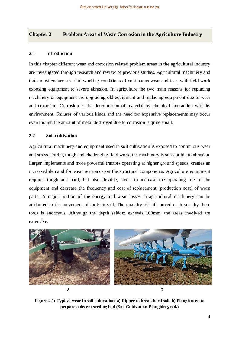
2.2 Soil cultivation
Agricultural machinery and equipment used in soil cultivation is exposed to continuous wear
and stress. During tough and challenging field work, the machinery is susceptible to abrasion.
Larger implements and more powerful tractors operating at higher ground speeds, creates an
increased demand for wear resistance on the structural components. Agriculture equipment
requires tough and hard, but also flexible, steels to increase the operating life of the
equipment and decrease the frequency and cost of replacement (production cost) of worn
parts. A major portion of the energy and wear losses in agricultural machinery can be
attributed to the movement of tools in soil. The quantity of soil moved each year by these
tools is enormous. Although the depth seldom exceeds 100mm, the areas involved are
extensive.
Figure 2.1: Typical wear in soil cultivation. a) Ripper to break hard soil. b) Plough used to prepare a decent seeding bed (Soil Cultivation-Ploughing, n.d.)
a b
Stellenbosch University https://scholar.sun.ac.za
5
During ploughing, farm implements are worn down by the abrasive action of sand and stone
particles present in the soil. This is the most common cause of damage of agricultural
machinery. Dry lands cause the wear and tear to be more severe than in irrigated land.
(Kumar & Gupta, 1995)
The wear of agricultural tools in the majority of the publications reviewed, was defined
simply as a process of abrasion. No additional factors, other than mechanical ones, were
taken into account. Only a few researchers have taken the acidity of soil into account. The
considerable content of salt, acids, and hydrocarbons at a significant degree in moist soil,
accelerates the processes of the wear and corrosion on tools working in moist soil.
During contact with soil agricultural tools such as shares, mouldboards or the teeth of
harrows, undergo abrasion, mainly by friction. Soil is a mixture of mineral particles as well as
organic and inorganic compounds of hydrogen with very varied composition and tribological
proprieties. With regard to variable composition, the moisture and temperature of soil, the
investigation of wear processes is difficult. The process of wear, which is a mechanical
abrasion intensified by the chemical influence of the environment, can be treated. The
intensity of mechanical abrasion of the tool by sharp grains of sand depends on their
geometry and the difference of hardness between the abrasive medium and the material of the
tool (Stabryla, 2007).
Metal wear in agriculture tools is an old, but ongoing problem. Wear is the main element
which determines the lifespan of a soil engaging tool. The efficiency of the tool and its work
capacity are also determined by the soil’s response to the tool. The research on wear has
mainly been concentrated on industrial materials related to large industries. In the agriculture
sector, however, the soil engaging tools have received little attention (Kushwaha & Shi,
1989).
Farmers and equipment operators often complain about the high wear rate of ground
engaging tools in some dry land agricultural areas. Farmers face problems with recurring
labour, downtime and the replacement costs of exchanging the worn down ground engaging
components like ploughshares. Worn out tools results in poor tillage and seeding efficiency
and higher fuel costs. Carbon or low alloy steels are generally preferred to make tillage tools
that are under low stress abrasive wear. Tillage having composites with alumina ceramics and
Stellenbosch University https://scholar.sun.ac.za
6
boron, medium and high carbon heat treated steels, offers great potential for the severity of
abrasive wear in soil-engaging components. The hardness of the tillage tool, grain structure
and its chemical composition are also influential factors in determination of the wear rate.
Wear due to highly abrasive soils has surface damage characterised by scoring, cutting, deep
grooving and gauging, and micro machining caused by soil constituents moving on a metal
surface (Parvinkal & Navjeet, 2015).
2.3 Roller bearings
2.3.1 Tractors
There is an increased reliability and more horsepower to the ground in tractors with the new
track treads used as tyres on tractors with high horsepower. Roller bearings used in critical
areas such as driveline positions, gear cases, and wheel shafts are required to have greater
power densities, and an ability to operate longer at higher loads. Roller friction and shock
loads transmitted from the track chain create heat in the interior of rollers and on the roller
surface and this can cause wear. Track treads will show increased wear rates, compared to
machines running on tyres, when operated on hard surface roads. Tracks, however, show
much reduced wear rates when operating in the field (Hill, 2008).
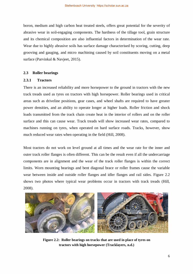
Most tractors do not work on level ground at all times and the wear rate for the inner and
outer track roller flanges is often different. This can be the result even if all the undercarriage
components are in alignment and the wear of the track roller flanges is within the correct
limits. Worn mounting bearings and bent diagonal brace or roller frames cause the variable
wear between inside and outside roller flanges and idler flanges and rail sides. Figure 2.2
shows two photos where typical wear problems occur in tractors with track treads (Hill,
2008).
Figure 2.2: Roller bearings on tracks that are used in place of tyres on tractors with high horsepower (Tracklayers, n.d.)
Stellenbosch University https://scholar.sun.ac.za
7
2.3.2 Balers
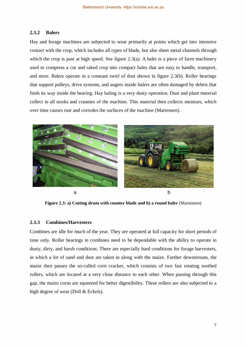
Hay and forage machines are subjected to wear primarily at points which get into intensive
contact with the crop, which includes all types of blade, but also sheet metal channels through
which the crop is past at high speed. See figure 2.3(a). A baler is a piece of farm machinery
used to compress a cut and raked crop into compact bales that are easy to handle, transport,
and store. Balers operate in a constant swirl of dust shown in figure 2.3(b). Roller bearings
that support pulleys, drive systems, and augers inside balers are often damaged by debris that
finds its way inside the bearing. Hay baling is a very dusty operation. Dust and plant material
collect in all nooks and crannies of the machine. This material then collects moisture, which
over time causes rust and corrodes the surfaces of the machine (Martensen).
Figure 2.3: a) Cutting drum with counter blade and b) a round baler (Martensen)
2.3.3 Combines/Harvesters
Combines are idle for much of the year. They are operated at full capacity for short periods of
time only. Roller bearings in combines need to be dependable with the ability to operate in
dusty, dirty, and harsh conditions. There are especially hard conditions for forage harvesters,
in which a lot of sand and dust are taken in along with the maize. Further downstream, the
maize then passes the so-called corn cracker, which consists of two fast rotating toothed
rollers, which are located at a very close distance to each other. When passing through this
gap, the maize corns are squeezed for better digestibility. These rollers are also subjected to a
high degree of wear (Doll & Eckels).
a b
Stellenbosch University https://scholar.sun.ac.za
8
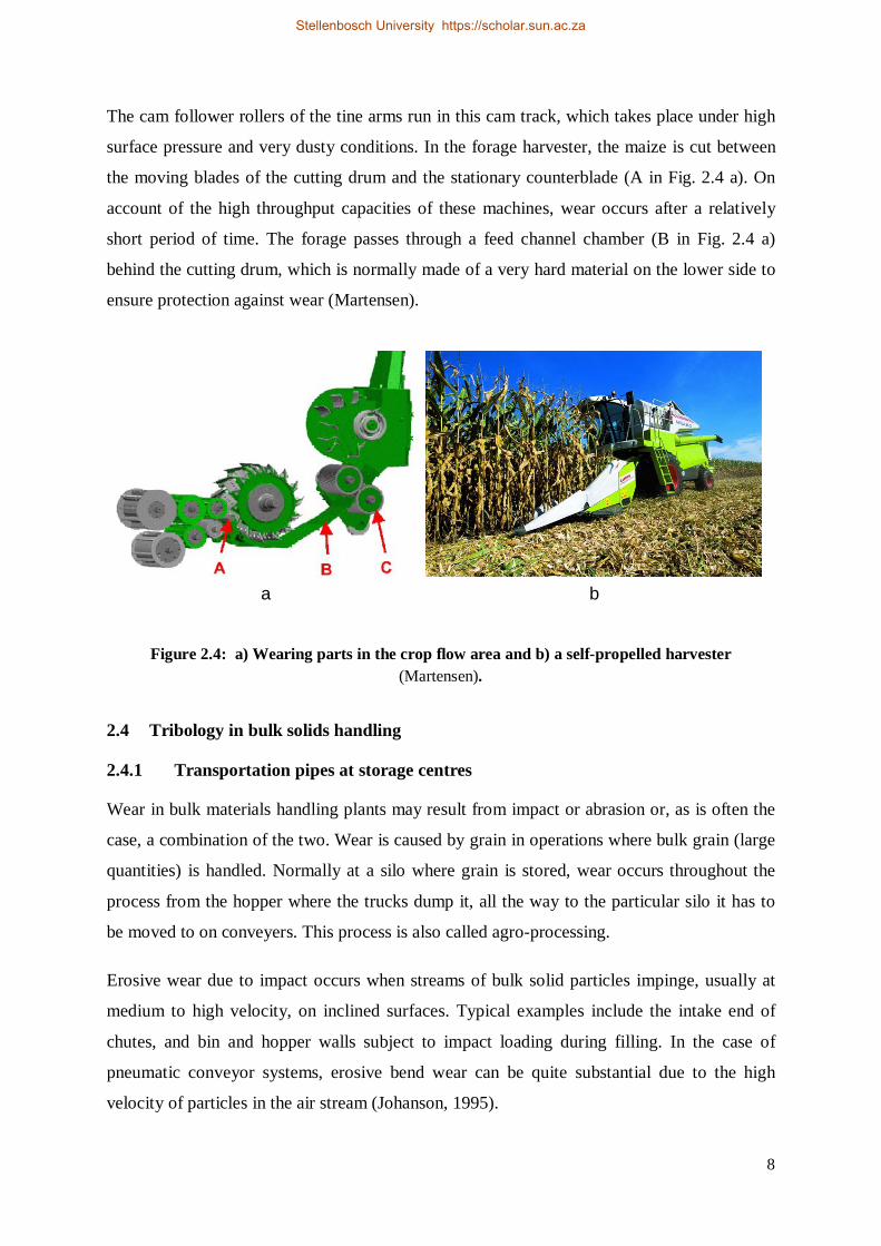
The cam follower rollers of the tine arms run in this cam track, which takes place under high
surface pressure and very dusty conditions. In the forage harvester, the maize is cut between
the moving blades of the cutting drum and the stationary counterblade (A in Fig. 2.4 a). On
account of the high throughput capacities of these machines, wear occurs after a relatively
short period of time. The forage passes through a feed channel chamber (B in Fig. 2.4 a)
behind the cutting drum, which is normally made of a very hard material on the lower side to
ensure protection against wear (Martensen).
Figure 2.4: a) Wearing parts in the crop flow area and b) a self-propelled harvester (Martensen).
2.4 Tribology in bulk solids handling
2.4.1 Transportation pipes at storage centres
Wear in bulk materials handling plants may result from impact or abrasion or, as is often the
case, a combination of the two. Wear is caused by grain in operations where bulk grain (large
quantities) is handled. Normally at a silo where grain is stored, wear occurs throughout the
process from the hopper where the trucks dump it, all the way to the particular silo it has to
be moved to on conveyers. This process is also called agro-processing.
Erosive wear due to impact occurs when streams of bulk solid particles impinge, usually at
medium to high velocity, on inclined surfaces. Typical examples include the intake end of
chutes, and bin and hopper walls subject to impact loading during filling. In the case of
pneumatic conveyor systems, erosive bend wear can be quite substantial due to the high
velocity of particles in the air stream (Johanson, 1995).
a b
Stellenbosch University https://scholar.sun.ac.za
9
Abrasive or rubbing wear occurs when the bulk solid flows along the walls of bins and
chutes. Wear in this case is a combination of pressure and rubbing velocity. Abrasive wear
assumes that the wear results from a direct relation between the normal pressure, the friction
coefficient and the rubbing velocity (Roberts & Oomsm, 1985).
Figure 2.5: Curve-sectioned chute of rectangular cross
(Ghadban, 2010)
2.4.2 Transportation system at production centres
Throughout the world bulk materials handling operations perform a key function in a great
number and variety of industries. While the nature of the handling tasks and scale of
operation vary from one industry to another and, on the international scene from one country
to another, according to the industrial and economic base, the relative costs of storing,
handling and transporting bulk materials are, in the majority of cases, very significant. It is
important, therefore, that handling systems be designed and operated with a view to
achieving maximum efficiency and reliability (Roberts, 1990).
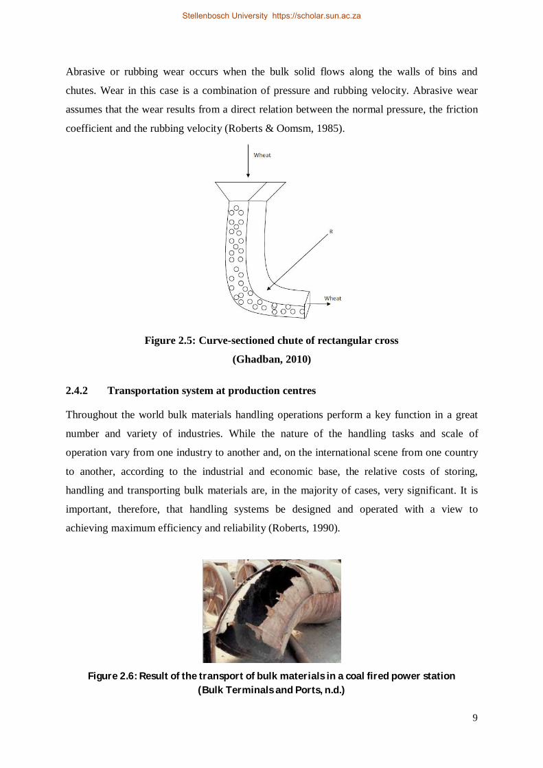
Figure 2.6: Result of the transport of bulk materials in a coal fired power station
(Bulk Terminals and Ports, n.d.)
Stellenbosch University https://scholar.sun.ac.za
10
Over the past three decades much progress has been made in the theory and practice of bulk
solids handling. Reliable test procedures for determining the strength and flow properties of
bulk solids have been developed and analytical methods have been established to aid the
design of bulk solids storage and discharge equipment. There has been wide acceptance by
industry of these tests and design procedures and, as a result, there are numerous examples
throughout Australia of modern industrial bulk solids handling installations which reflect the
technological developments that have taken place (Roberts, 1990).
Notwithstanding the current situation, the level of sophistication required by industry
demands, in many cases, a better understanding of the behaviour of bulk solids and the
associated performance criteria for handling plant design. In particular, reliability and
equipment life are important considerations and, in this respect, the study of tribology as it
relates to handling plant design and performance is of great significance. In view of the
importance of friction, adhesion and wear in the flow of bulk materials in bins, feeders and
chutes there is a need for greater attention to be focused on this area of tribology (Roberts,
1990).
The efficient operation of bulk solids handling plant depends, to a significant extent, on the
smooth flow and handling of the bulk solids without blockages occurring in bins and chutes.
See figure 2.6 for a typical example of the effect of wear on a section of equipment used in
bulk solids handling. It is important, therefore, that handling plants are designed taking into
account the relevant flow properties of the bulk solids being handled. In this respect it is
important that the significant influence of wall friction, cohesion and adhesion be understood
and taken into account when designing bins and chutes (Roberts, 1990).
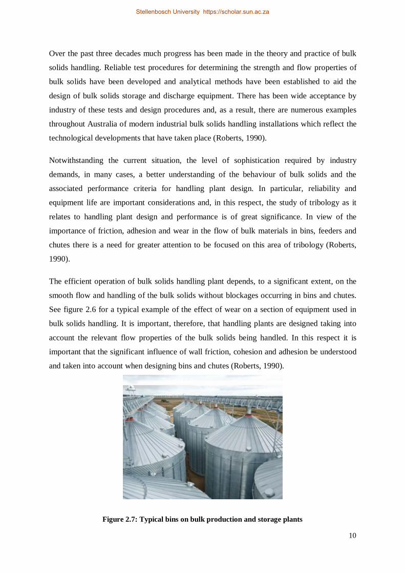
Figure 2.7: Typical bins on bulk production and storage plants
Stellenbosch University https://scholar.sun.ac.za
11
Procedures for determining these parameters are well established and documented in several
articles. The selection of appropriate lining materials for bins and chutes, in addition to the
need for favourable frictional properties, should also provide long wear life. The role of
accelerated wear tests to evaluate lining materials as an adjunct to the established procedures
for flow property determination is an important one (Roberts, 1990).
2.5 Corrosion caused by agricultural chemicals
Corrosion is the deterioration of materials by chemical interaction with their environment.
The consequences of corrosion are many and varied. The effects of these on the safe, reliable
and efficient operation of equipment or structures are often more serious than the simple loss
of a mass of metal. The two main reasons for replacing machinery or equipment include
upgrading old equipment and replacing it because of wear and corrosion (Oki & Anawe,
2015).
Furthermore, there are many commercial chemicals used on farmlands. These include: grain
and silage preservatives; pest and weed control; and proprietary acid solutions for cleaning
dairy equipment. In addition to these, farm wastes and slurries contain many chemicals which
can also be particularly corrosive. The aim of this discussion is to proffer suitable solutions to
corrosion occurring due to the actions of these agricultural chemicals (Oki & Anawe, 2015).
Agricultural buildings and facilities largely differ from the common ones in the enormously
aggressive environment (animal production facilities) or in the fact that they are used to store
aggressive chemicals (stores of chemical fertilizers) and satisfactory results cannot be
achieved even by preventing the access of outer atmosphere. Here it is worth pointing out that
hardly any agricultural enterprise is concerned with the protection of their machines and
equipments against corrosion and it is therefore adviced to consider whether their untimely
damage or devaluation cannot be prevented by proper storage and conservation. The costs of
preserving agents are negligible as compared with the costly machines and considerable
savings can be made on repairs. (M. AUGUSTIN, 2003)
2.5.1 Fertilisers
Fertilisers are chemicals given to plants in order to promote growth. They are usually applied
either via the soil or by foliar spraying. Fertilisers typically provide, in varying proportions,
the three major plant nutrients (nitrogen, phosphorus and potassium) and secondary plant
Stellenbosch University https://scholar.sun.ac.za
12
nutrients such as calcium, sulphur, magnesium and iron. Some fertilisers are more corrosive
than others, especially if they decompose or react to produce aggressive substances such as
ammonia or hydrogen sulfide; if chloride ions are present (including potassium or ammonium
chloride), or if acidic conditions prevail. For example, dihydrogen ammonium phosphate or
ammonium nitrate can lead to increased corrosion via hydrolysis to acids (Corrosion control
of Agricultural Equipment and Buildings, 2010).
The relative ratios of the essential plant nutrients can influence the corrosiveness of
compound liquid fertilisers, there being some evidence that the greatest effects occur with
fertiliser solutions containing about 15% nitrogen, especially when half the free nitrogen is
derived from urea and half from ammonium nitrate. If fertilisers are kept dry, then no
corrosion occurs, but being hygroscopic they can pick up moisture and hence may become
corrosive. The hygroscopic point is the relative humidity at and above which moisture is
absorbed, and varies from one compound to another, and the lower its value, the more
corrosive the fertiliser is likely to be. Ammonium nitrate starts to absorb moisture at 60%
RH, while certain phosphates absorb moisture only above 90% RH. Moisture initially causes
caking of the fertiliser, which can increase its abrasive properties (Corrosion control of
Agricultural Equipment and Buildings, 2010).
2.5.2 Silage
Silage is fermented, high moisture forage that is fed to ruminants, cud-chewing animals like
cattle and sheep. It is fermented and stored in a structure called a silo. Silage undergoes
anaerobic fermentation, typically beginning about 48 hours after the silo is filled. The
fermentation is essentially complete in about two weeks. The fermentation process releases a
liquid. The amount of liquid can be excessive if there is too much moisture in the crop when
it is ensiled. Silo effluent contains nitric acid (HNO3) making it corrosive. It also can be a
contaminant of lakes and streams, because of the high nutrient content, and could lead to
algae blooms. Silage effluent is potentially one of the most damaging effluents produced by
agriculture. There are specific storage instructions to prevent silage leakage. Silage effluent is
also very acidic and therefore the storage structures must be resistant to corrosion and acid
attack (B.Eker, 2005).
Modern steel silos, both galvanised and glass-coated, are virtually always designed for silage
and grain storage. Their adaptation is primarily one of installing aeration equipment,
modifying unloading if necessary, and making provision for aeration air discharge in the top
Stellenbosch University https://scholar.sun.ac.za
13
of normally sealed units. Older style steel silos, especially those that show severe corrosion in
the lower sections and/or those that have not been used for a number of years, should be
viewed with extreme caution as safe grain or silage storages. Corrosion on a very thin metal
wall can markedly reduce the metal area remaining to sustain the storage load (B.Eker, 2005).
Furthermore, tower silos are prone to corrosion damage, primarily by the organic acids that
are produced during the process of ensilage. The most acidic and corrosive environment is
claimed to exist within silos containing whole crop maize silage, which ferments readily and
rapidly to produce acids with typical concentrations in solution of 2% lactic acid and 0.5%
acetic acid and with the pH as low as 3.6. Lactic acid is regarded as the stronger acid and, if
oxygen is present also, then secondary fermentation can occur, giving silage, which is
predominantly butyric acid, thus yielding a higher pH value (B.Eker, 2005).
In addition, temperatures inside silos can be as high as 30˚C, so corrosion rates inside tend to
be higher than those on the external walls. In practice, the contact time for acids on
machinery like augers and balers is low, therefore, corrosion rates are usually less than 1 mm
per year (on mild steel) (Corrosion control of Agricultural Equipment and Buildings, 2010).
Materials that have given good service for silos are aluminium (over 10 year’s life), and
vitreous enamelled steel, which is particularly easy to clean and maintain. Plastic coatings are
liable to surface damage, and crevice corrosion can occur if adhesion is lost. Galvanised steel
may deteriorate in contact with silage juices and slurries, but is resistant to silage vapours
(Corrosion control of Agricultural Equipment and Buildings, 2010).
The order of preference for metals of construction for storage vessels is: aluminium (best),
followed by galvanised steel, and mild steel. The combination of abrasion and acid attack is
also especially destructive to concrete because acids react with lime. Covering floors with
plastic sheeting, or with an acid resisting coating such as chlorinated rubber or epoxy paint,
provides protection (Corrosion control of Agricultural Equipment and Buildings, 2010).
All agriculture equipment requires coating that resists wear and corrosion in their
applications. For this reason corrosion must be prevented by adopting some reusable friendly
methods. Besides, certain inhibitors can be used for corrosion protection in agricultural
applications. Corrosion control and prevention can be accomplished by keeping equipment
clean and dry after each use, applying corrosion-resistant materials or materials with a
Stellenbosch University https://scholar.sun.ac.za
14
corrosion allowance, applying external coatings (paints) or internal lining systems, or using
cathodic protection. Strategies for maintaining and optimising inspection programmes for
agriculture equipment with a high corrosion risk need to be developed. Development of new
and improved inspection techniques is required to ensure the integrity of agricultural
equipment (Eker, 2005).
In practice, the contact time for acids on machinery, augers and balers, is low, so corrosion
rates are usually small. During storage, acid-treated grain has little effect, the major
precaution needed being to minimise the risk of concentration in local areas such as crevices,
or where stagnant pools of liquid can collect. Propionic acid is highly corrosive, but little
damage should occur if correct precautions are taken, such as the complete removal of the
acid-treated grain from the silo after use, washing with water, and avoidance of contact of
treated grain with unprotected machinery. (Corrosion control of Agricultural Equipment and
Buildings, 2010)
Stellenbosch University https://scholar.sun.ac.za
15
Chapter 3 Wear
3.1 Background
Dorfman and Mitchell define wear, in an article, as “The unwanted removal of material from
a surface as a result of mechanical action. Mastering the wear process means controlling a
complex set of system and process variables.” This starts with a clear understanding of the
component, its material history (grain size, processing, alloy chemistry, surface hardness), the
type of wear the component will see, and the type of environment. Each type of wear has a
corresponding specific wear mechanism (Dorfman, 2002).
Wear is a determined service condition in many engineering applications with important
economic and technical consequences. The effect of abrasion wear is particularly evident in
the industrial areas of agriculture, mining, mineral processing, and earth moving. Wear is a
critical concern in many types of machine components and is often a major factor in defining
or limiting the suitable lifetime of a component.
Wear results from contact between a surface and a body or substance that is moving relative
to it. Wear is progressive and increases with usage or increasing amounts of motion. It results
in the loss of material from a surface or the transfer of material between surfaces (Bayer,
n.d.).
Wear failures occur because of the sensitivity of a material or system to the surface changes
caused by wear. It is the geometrical aspects of these changes, such as a dimensional change,
a change in shape, or residual thickness of a coating, that cause failure. Changes in
appearance and the nature of the wear damage can be causes for failure as well. The same
amount or degree of wear may or may not cause a wear failure; it is a function of the
application. For example, dimensional changes in the range of several centimetres may not
cause wear failure on excavator bucket teeth, but wear of a few micrometres might cause
failure in some electromechanical devices. As a consequence of these differences, there is no
universal wear condition that can be used to define failure. The specific nature of the failure
condition generally is an important factor in resolving or avoiding wear failures. It can affect
not only the solutions to a wear problem but also the details of the approaches used to obtain
a solution (Bayer, n.d.).
Stellenbosch University https://scholar.sun.ac.za
16
3.2 Abrasive wear
Abrasive wear occurs when a hard rough surface slides across a softer surface. ASTM
International (formerly the American Society for Testing and Materials) defines it as the loss
of material due to hard particles or hard protuberances that are forced against and move along
a solid surface.
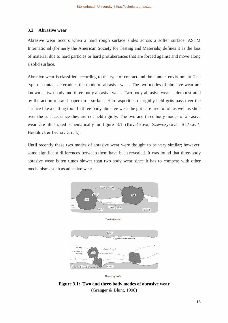
Abrasive wear is classified according to the type of contact and the contact environment. The
type of contact determines the mode of abrasive wear. The two modes of abrasive wear are
known as two-body and three-body abrasive wear. Two-body abrasive wear is demonstrated
by the action of sand paper on a surface. Hard asperities or rigidly held grits pass over the
surface like a cutting tool. In three-body abrasive wear the grits are free to roll as well as slide
over the surface, since they are not held rigidly. The two and three-body modes of abrasive
wear are illustrated schematically in figure 3.1 (Kovaříková, Szewczyková, Blaškoviš,
Hodúlová & Lechovič, n.d.).
Until recently these two modes of abrasive wear were thought to be very similar; however,
some significant differences between them have been revealed. It was found that three-body
abrasive wear is ten times slower than two-body wear since it has to compete with other
mechanisms such as adhesive wear.
Figure 3.1: Two and three-body modes of abrasive wear
(Granger & Blunt, 1998)
Stellenbosch University https://scholar.sun.ac.za
17
In many engineering applications, such as mining, metallurgy and agriculture, equipment
fails because of abrasive wear. According to the ministry of Research and Technology, the
percentage cost of abrasive wear in the metallurgy industry in the Federal Republic of
German is 40 percent, with 30 percent in the mining industry, 20 percent in agriculture and
10 percent in production engineering.
The material that is most being used in India in metallurgical mining and agriculture
industries is a plain carbon steel. Particularly mild steel is widely used in agriculture agro
machinery industries for the fabrication of agricultural equipment and critical parts, and
therefore which wears fast when subjected to high load and abrasive conditions. The present
work has been devoted to assessing the suitability of adequate material properties and
structure for agriculture industries (Kumar Jain & Singh, 2012).
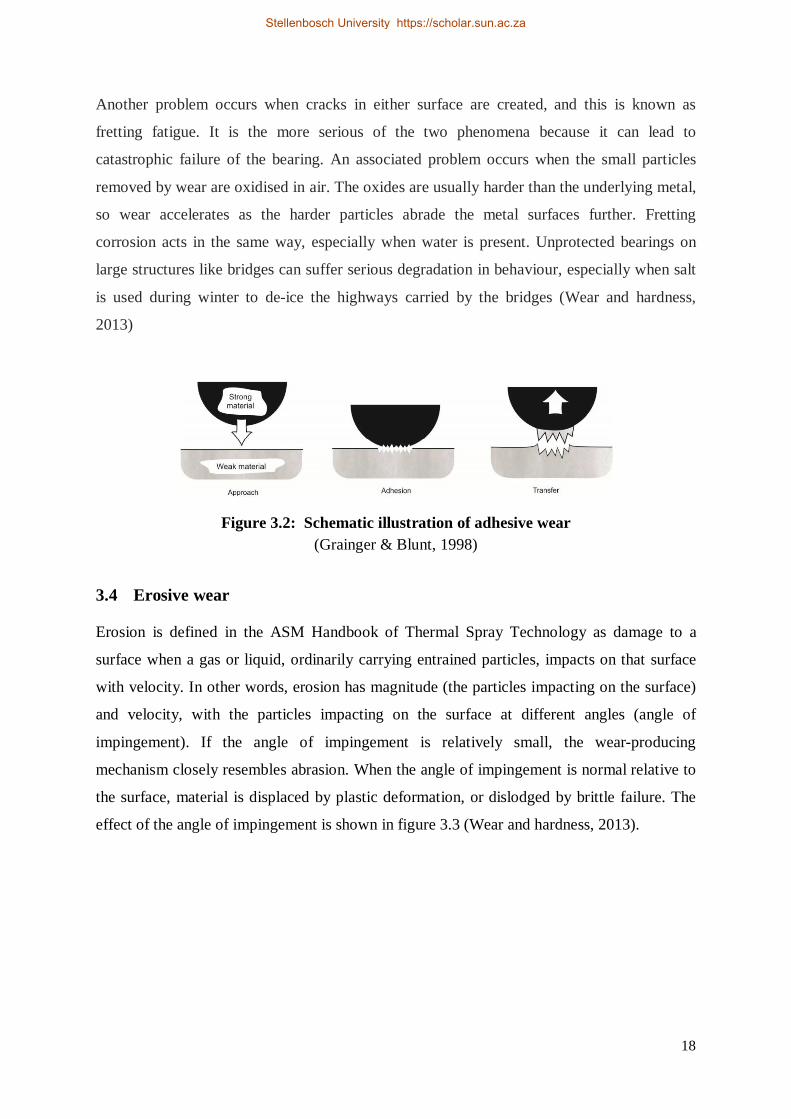
3.3 Adhesive wear
This type of wear is synonymous with galling, fretting, scuffing or surface fatigue, and is
described as the interaction and adhesion between surface irregularities. It is shown in figure
3.3 that if the strength of the adhesion junction is more than that of either one of the
materials, material transfer and the production of wear particles will occur. The interaction
between the materials is complex due to the high strain rates and temperatures being
generated (Wear and hardness, 2013).
Adhesion in metals can be classified as mild or severe. Mild adhesion includes visible
oxidation, wear of non-metallic debris, and low loads and velocities. Severe adhesion is
characterised by damage to the oxide film so that there is direct interaction of the metal with
the environment, larger wear particles, and higher loads and velocities. Adhesive wear
generally occurs when inadequate lubrication leads to metal transfer (Wear and hardness,
2013).
Adhesive wear thus occurs due to the differences in hardness of the two interacting surfaces.
In order to design for adhesive wear-resistance, dissimilar materials that are tribologically
compatible should be considered (Wear and hardness, 2013).
Fretting wear is the repeated cyclical rubbing between two surfaces. Over a period of time
this will remove material from one or both of the surfaces in contact. Fretting typically occurs
in bearings, although most bearings have their surfaces hardened to resist the problem (Wear
and hardness, 2013).
Stellenbosch University https://scholar.sun.ac.za
18
Another problem occurs when cracks in either surface are created, and this is known as
fretting fatigue. It is the more serious of the two phenomena because it can lead to
catastrophic failure of the bearing. An associated problem occurs when the small particles
removed by wear are oxidised in air. The oxides are usually harder than the underlying metal,
so wear accelerates as the harder particles abrade the metal surfaces further. Fretting
corrosion acts in the same way, especially when water is present. Unprotected bearings on
large structures like bridges can suffer serious degradation in behaviour, especially when salt
is used during winter to de-ice the highways carried by the bridges (Wear and hardness,
2013)
Figure 3.2: Schematic illustration of adhesive wear
(Grainger & Blunt, 1998)
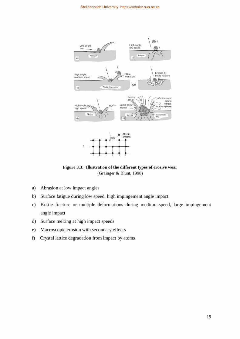
3.4 Erosive wear
Erosion is defined in the ASM Handbook of Thermal Spray Technology as damage to a
surface when a gas or liquid, ordinarily carrying entrained particles, impacts on that surface
with velocity. In other words, erosion has magnitude (the particles impacting on the surface)
and velocity, with the particles impacting on the surface at different angles (angle of
impingement). If the angle of impingement is relatively small, the wear-producing
mechanism closely resembles abrasion. When the angle of impingement is normal relative to
the surface, material is displaced by plastic deformation, or dislodged by brittle failure. The
effect of the angle of impingement is shown in figure 3.3 (Wear and hardness, 2013).
Stellenbosch University https://scholar.sun.ac.za
19
Figure 3.3: Illustration of the different types of erosive wear (Grainger & Blunt, 1998)
a) Abrasion at low impact angles
b) Surface fatigue during low speed, high impingement angle impact
c) Brittle fracture or multiple deformations during medium speed, large impingement
angle impact
d) Surface melting at high impact speeds
e) Macroscopic erosion with secondary effects
f) Crystal lattice degradation from impact by atoms
Stellenbosch University https://scholar.sun.ac.za
20
Chapter 4 Methods of Wear Testing
4.1 Traditional methods
Most of the previous wear studies have focused mainly on surface damage in terms of
material-removal mechanisms, including transfer film, plastic deformation and brittle
fracture. This chapter describes the methods of wear testing on coated material. Most of the
research in this chapter refers to coatings applied to cutting tools and the performance of the
different materials being cut.
The need to evaluate the properties of new raw materials and substrate-coating combinations
is important in view of developments in surface engineering design. Recently, experiments
and testing on coated materials have been done, and some standardised and experimental test
equipment has been produced to meet wear resistance specifications. Standard test methods
such as pin-on disc are used extensively to simulate rubbing action in which plastic yielding
occurs at the tip of individual sharpness. This testing is carried out mainly on a microscopic
scale. Coatings such as those formed in thermal spraying seldom experience penetration
during the carrying out of some of the standard wear tests that are available. It is unclear
whether behavioural models developed for thin, hard coatings necessarily apply to thicker
coatings. Very few research papers could be found that investigate the type of wear occurring
under combined impact and sliding wear which suggests that it has hardly been studied.
4.2 Wear of engineering material
There are many types of wear, as indicated in chapters two and three, which are of concern to
the user of coatings, including sliding wear and friction, low- and high-stress abrasion, dry
particle erosion, and slurry erosion. Reducing the coefficient of friction has many advantages
in machining processes. In practice it is possible for a coating to wear and the substrate to be
unaffected. Also, the substrate may deform without any noticeable wear of the coating. It is
claimed and confirmed from practice, that hard coatings applied to cutting tools increase tool
life by two to ten times that of uncoated tools. Hard coatings have some disadvantages, which
include porosity, insufficient bonding to the substrate and, in some cases have limited
thickness. Coatings experience shear, tensile and compressive stresses which may lead to
failure by cracking. In applications of material wear, one or more of the following will be
Stellenbosch University https://scholar.sun.ac.za
21
operational: abrasive wear, adhesive wear, erosive wear, fretting wear and surface fatigue
(Kennedy & Hashmi, 1998).
4.3 Wear test methods
In selecting a suitable wear test, there are a few points that should be considered. First, ensure
that the test selected is measuring the desired properties of a material. Second, confirm
whether the material is in bulk form or is a thick or thin coating. Third, establish whether the
forces and stress limits are suitable for the test. Fourth, confirm whether abrasives are present
and consider the abrasive size, form and velocity. Fifth, check whether the contact between
the components is rolling, sliding, impact or erosion only, or a combination of these, bearing
in mind that the surface finish of the test samples should be similar to that of the actual
components. Then lastly, establish whether temperature and humidity factors are important
and whether the test environment is similar to the actual working environment.
Tests are used for quality control functions such as thickness, porosity, adhesion, strength,
hardness, ductility, chemical composition, stress and wear resistance. Many tests for coated
and uncoated cutting tools are conducted on machine tools, including lathes, mills, drills,
punches and saws. These test methods provide almost identical conditions to those
experienced in manufacturing. Machining tests subject cutting tools to many wear
parameters, including impact and shock, abrasion, adhesion and hot corrosion. The
limitations of these tests depend on the machine power available and the quality of the
machine tool (Kennedy & Hashmi, 1998).
4.3.1 Abrasive and adhesive test equipment
Hardness is often used as an initial guide to the suitability of coating materials for
applications requiring a high degree of wear resistance. The effect of the hardness of a
wearing material however is complicated, as different wear mechanisms can prevail in
service. Scratch hardness is the oldest form of hardness measurement. Mohs in 1822
categorised materials using this process, giving diamond a maximum scratch hardness of ten.
Most scratch type tests developed from this simple technique. In indentation adhesion tests, a
mechanically stable crack is introduced into the interface of the coating and substrate. The
resistance to propagation of the crack along the interface is used as a measure of adhesion. In
scratch-adhesion tests, a stylus is drawn over the surface under a continually increasing
normal load until the coating fails (Ludema, 1994).
Stellenbosch University https://scholar.sun.ac.za
22
4.3.2 Pin-on-disc
Pin-on-disc was the most widely used wear test processes, followed by pin-on-flat, according
research conducted by Glaeser and Ruff. Other applications of pin-on-disc include material
wear and friction properties at elevated temperatures and in controlled atmospheres. In a two-
body abrasion test, a coated pin is pressed against a rotating abrasive paper making a spiral
path to avoid overlapping. This test process is very common for thin coatings. There is also
some research done on using a diamond tip as the abrading tool in a pin-on-disc test to
operate within the chamber of a Scanning Electron Microscope (SEM) to examine abrasion
effects. Scratch testing in conjunction with SEM provides a useful method of analysing
single-point wear mechanisms of coated systems through an assessment of the deformation
and fracture produced (Ludema, 1994).
4.3.3 Rubbing tests
An ASTM standard uses a crossed-cylinder apparatus for testing similar and dissimilar metals
and alloys and coated systems under unlubricated conditions. A rotating cylinder is forced at
right angles against a stationary cylinder. The volume of material loss is determined by
means of an appropriate equation (Kennedy & Hashmi, 1998)
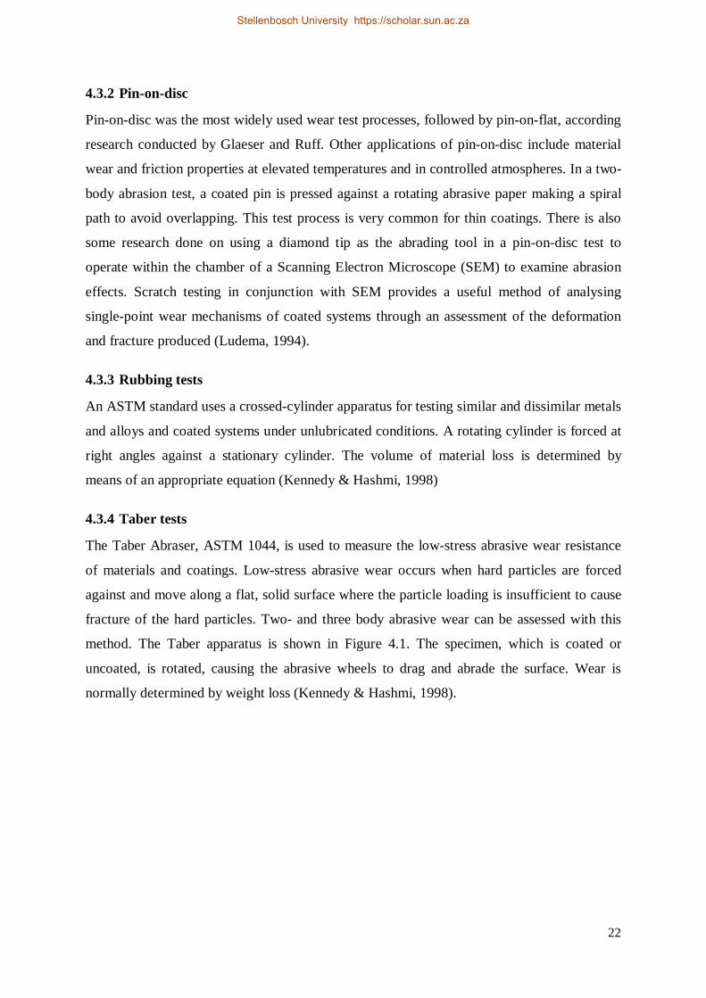
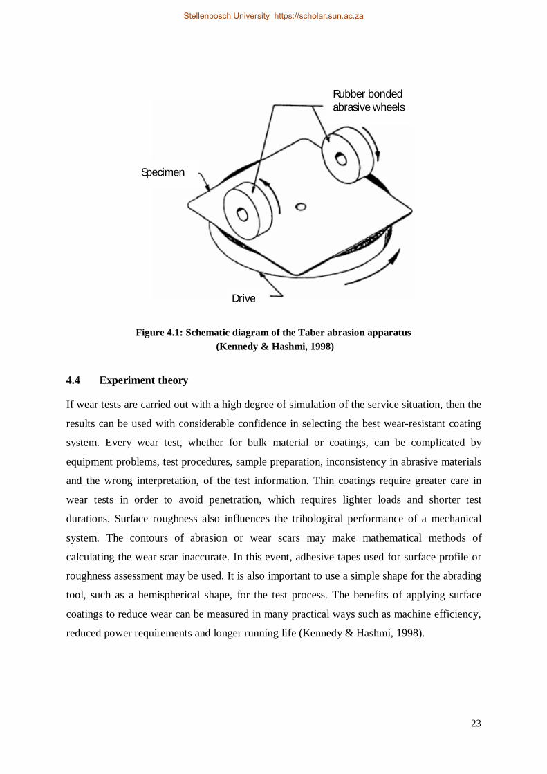
4.3.4 Taber tests
The Taber Abraser, ASTM 1044, is used to measure the low-stress abrasive wear resistance
of materials and coatings. Low-stress abrasive wear occurs when hard particles are forced
against and move along a flat, solid surface where the particle loading is insufficient to cause
fracture of the hard particles. Two- and three body abrasive wear can be assessed with this
method. The Taber apparatus is shown in Figure 4.1. The specimen, which is coated or
uncoated, is rotated, causing the abrasive wheels to drag and abrade the surface. Wear is
normally determined by weight loss (Kennedy & Hashmi, 1998).
Stellenbosch University https://scholar.sun.ac.za
23
Figure 4.1: Schematic diagram of the Taber abrasion apparatus (Kennedy & Hashmi, 1998)
4.4 Experiment theory
If wear tests are carried out with a high degree of simulation of the service situation, then the
results can be used with considerable confidence in selecting the best wear-resistant coating
system. Every wear test, whether for bulk material or coatings, can be complicated by
equipment problems, test procedures, sample preparation, inconsistency in abrasive materials
and the wrong interpretation, of the test information. Thin coatings require greater care in
wear tests in order to avoid penetration, which requires lighter loads and shorter test
durations. Surface roughness also influences the tribological performance of a mechanical
system. The contours of abrasion or wear scars may make mathematical methods of
calculating the wear scar inaccurate. In this event, adhesive tapes used for surface profile or
roughness assessment may be used. It is also important to use a simple shape for the abrading
tool, such as a hemispherical shape, for the test process. The benefits of applying surface
coatings to reduce wear can be measured in many practical ways such as machine efficiency,
reduced power requirements and longer running life (Kennedy & Hashmi, 1998).
Specimen
Drive
Rubber bonded abrasive wheels
Stellenbosch University https://scholar.sun.ac.za
24
Chapter 5 Performance Enhancement Strategies
5.1 Opportunities in plastic
The standards for agriculture and construction equipment are constantly rising. Tighter
emissions standards are stipulated, and longer durability and serviceability are required.
Balancing the demands of the application with cost and styling considerations has led to an
increased use of engineering thermoplastics which is where the strong, tough, durable and
lightweight materials give engineers the ability to design products that meet their
expectations.
Farming and construction equipment represent a huge investment which increasingly needs to
be maximised. For manufacturers, the quest continues to find materials that can contribute to
the increasing sophistication and functionality of modern farming and construction equipment
while being able to withstand the harsh demands of the application and keeping systems costs
as low as possible.
In the case of harvesters and planters where high fatigue and abrasive wear are issues, in
some cases plastics have been shown to outperform metal. In many applications in the
agriculture and construction equipment market, when compared to metal, engineering
thermoplastics offer the advantage of design freedom, corrosion resistance and weight
reduction. Stanyl is an extremely hard-wearing, heat-resistant PA46 thermoplastic used for
friction reduction in outdoor power equipment applications.
5.1.1 Stanyl wear and friction applications
Agriculture and construction equipment must operate efficiently in some of the most
demanding environments on earth, from the Arctic Circle to the deserts, and the tropics. In all
these environments one of the greatest challenges is minimising the wear and friction on
moving parts. Wear, and especially abrasive wear, is the cause of failure of many moving
parts in agriculture and construction equipment. Stanyl polyamide-46 is best-in-class among
engineering thermoplastics in its resistance to abrasion. Using Stanyl in the critical moving
parts for agriculture and construction equipment can lead to extended life, improved
performance, weight reduction, reduced emissions and lower total cost.
Stellenbosch University https://scholar.sun.ac.za
25
Stanyl is a high-performance polyamide-46 that retains its mechanical properties at long term
temperatures of up to 230˚C. It offers excellent stiffness at elevated temperatures, plus
extended fatigue endurance and outstanding wear resistance which are perfect for friction
reduction applications as well as harsh agriculture and construction environments (Stanyl,
n.d).
Increasingly, outdoor power equipment components need to perform at a high level and at
higher temperatures (in excess of 230˚C). Stanyl is ideal therefore for under-the-hood
components because of its ability to outlast metal and other traditional materials. It also
provides excellent wear and friction resistance in timing chain tensioners and equally good
abrasion resistance for moving parts such as harvester forks. All of which makes it an ideal
replacement for Polyphthalamide (PPA), Polyamide 6T (PA6T), Polyamide 9T (PA9T) and
often Polyphenylene sulfide (PPS) and Liquid Crystal Polymer (LCP) (Stanyl, n.d).
Products in this sector take tremendous punishment and need to be tough and durable with
great wear and friction properties. These next-generation plastics are robust and lighter than
metal. This means that less material is needed and fuel consumption is lower. They are robust
and operate well under stress and at extreme temperatures, especially in and around the
engine. In fact plastics like Stanyl and polyamide 6 can last up to three times longer than
metals in some applications (Stanyl, n.d).
5.2 Rubber and urethane
Rubber and urethane application can significantly reduce wear and tear on agricultural
machinery and livestock equipment. Rubber sheets and matting can be used for livestock
stalls, trailers, veterinary rooms or other areas to protect assets. Urethane lining is applied to
metal tanks, farm equipment, piping and spouts to reduce the abrasion and corrosion that
limits the life of the equipment (Rubber & Urethane Products Extend the Life of Equipment
in the Agricultural Industry, n.d).
5.2.1 Tuff-Tube spout lining
The Tuff-Tube lining system is a patented urethane spout liner that significantly reduces the
abrasion of grain, seed and fertiliser handling and extends the life of agriculture equipment.
In a season or less grain will cause extreme wear in spouting which can ruin the spouting.
The Tuff-Tube lining system is an excellent answer to high maintenance costs and the
constant replacement of steel spouts. The Tuff-Tube spouting liner can be rotated 120° to
Stellenbosch University https://scholar.sun.ac.za
26
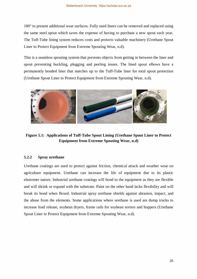
180° to present additional wear surfaces. Fully used liners can be removed and replaced using
the same steel spout which saves the expense of having to purchase a new spout each year.
The Tuff-Tube lining system reduces costs and protects valuable machinery (Urethane Spout
Liner to Protect Equipment from Extreme Spouting Wear, n.d).
This is a seamless spouting system that prevents objects from getting in between the liner and
spout preventing buckling, plugging and peeling issues. The lined spout elbows have a
permanently bonded liner that matches up to the Tuff-Tube liner for total spout protection
(Urethane Spout Liner to Protect Equipment from Extreme Spouting Wear, n.d).
Figure 5.1: Applications of Tuff-Tube Spout Lining (Urethane Spout Liner to Protect Equipment from Extreme Spouting Wear, n.d)
5.2.2 Spray urethane
Urethane coatings are used to protect against friction, chemical attack and weather wear on
agriculture equipment. Urethane can increase the life of equipment due to its plastic
elastomer nature. Industrial urethane coatings will bond to the equipment as they are flexible
and will shrink or expand with the substrate. Paint on the other hand lacks flexibility and will
break its bond when flexed. Industrial spray urethane shields against abrasion, impact, and
the abuse from the elements. Some applications where urethane is used are dump trucks to
increase load release, soybean dryers, frame rails for soybean sorters and hoppers (Urethane
Spout Liner to Protect Equipment from Extreme Spouting Wear, n.d).
Stellenbosch University https://scholar.sun.ac.za
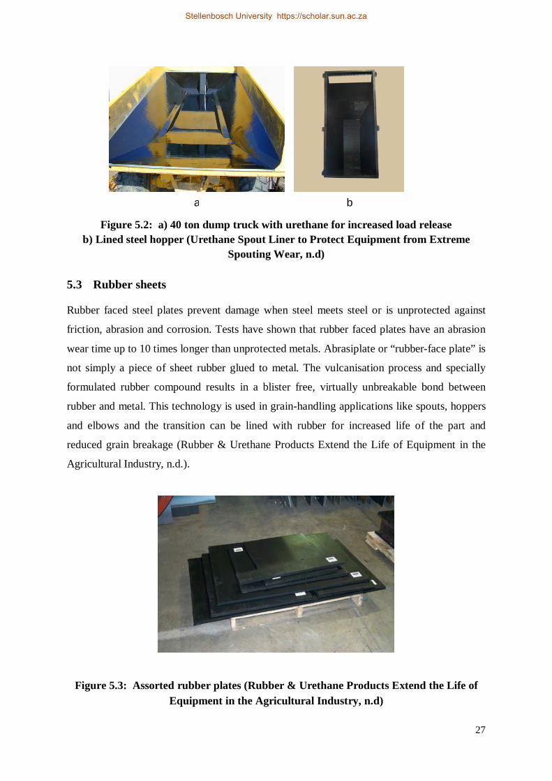
27
Figure 5.2: a) 40 ton dump truck with urethane for increased load release
b) Lined steel hopper (Urethane Spout Liner to Protect Equipment from Extreme Spouting Wear, n.d)
5.3 Rubber sheets
Rubber faced steel plates prevent damage when steel meets steel or is unprotected against
friction, abrasion and corrosion. Tests have shown that rubber faced plates have an abrasion
wear time up to 10 times longer than unprotected metals. Abrasiplate or “rubber-face plate” is
not simply a piece of sheet rubber glued to metal. The vulcanisation process and specially
formulated rubber compound results in a blister free, virtually unbreakable bond between
rubber and metal. This technology is used in grain-handling applications like spouts, hoppers
and elbows and the transition can be lined with rubber for increased life of the part and
reduced grain breakage (Rubber & Urethane Products Extend the Life of Equipment in the
Agricultural Industry, n.d.).
Figure 5.3: Assorted rubber plates (Rubber & Urethane Products Extend the Life of Equipment in the Agricultural Industry, n.d)
a b
Stellenbosch University https://scholar.sun.ac.za
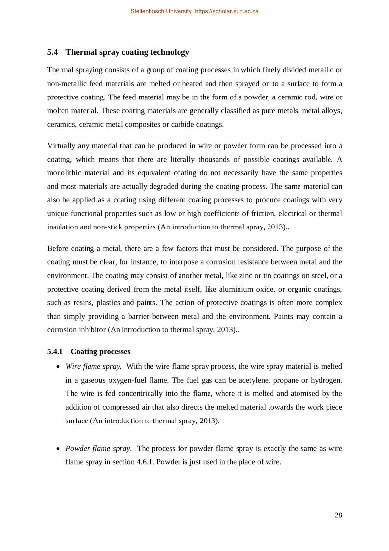
28
5.4 Thermal spray coating technology
Thermal spraying consists of a group of coating processes in which finely divided metallic or
non-metallic feed materials are melted or heated and then sprayed on to a surface to form a
protective coating. The feed material may be in the form of a powder, a ceramic rod, wire or
molten material. These coating materials are generally classified as pure metals, metal alloys,
ceramics, ceramic metal composites or carbide coatings.
Virtually any material that can be produced in wire or powder form can be processed into a
coating, which means that there are literally thousands of possible coatings available. A
monolithic material and its equivalent coating do not necessarily have the same properties
and most materials are actually degraded during the coating process. The same material can
also be applied as a coating using different coating processes to produce coatings with very
unique functional properties such as low or high coefficients of friction, electrical or thermal
insulation and non-stick properties (An introduction to thermal spray, 2013)..
Before coating a metal, there are a few factors that must be considered. The purpose of the
coating must be clear, for instance, to interpose a corrosion resistance between metal and the
environment. The coating may consist of another metal, like zinc or tin coatings on steel, or a
protective coating derived from the metal itself, like aluminium oxide, or organic coatings,
such as resins, plastics and paints. The action of protective coatings is often more complex
than simply providing a barrier between metal and the environment. Paints may contain a
corrosion inhibitor (An introduction to thermal spray, 2013)..
5.4.1 Coating processes
Wire flame spray. With the wire flame spray process, the wire spray material is melted
in a gaseous oxygen-fuel flame. The fuel gas can be acetylene, propane or hydrogen.
The wire is fed concentrically into the flame, where it is melted and atomised by the
addition of compressed air that also directs the melted material towards the work piece
surface (An introduction to thermal spray, 2013).
Powder flame spray. The process for powder flame spray is exactly the same as wire
flame spray in section 4.6.1. Powder is just used in the place of wire.
Stellenbosch University https://scholar.sun.ac.za
29
Electric Arc Wire Spray. With electric arc wire spray, an arc is formed by the contact
of two oppositely charged metallic wires, usually of the same composition. This leads
to melting at the tip of the wire material. Air atomises the melted spray material and
accelerates onto the substrate. The rate of spray is adjusted by appropriate regulation
of the wire feed as it is melted, so a constant arc can be maintained. Electric arc
thermal spraying is one of the most economic techniques to apply to corrosion
resistant metal coatings with high-quality adherence and chemical composition. Low
energy costs and high production rates make this technique competitive, compared
with other projection systems such as plasma and some thermal sprays (An
introduction to thermal spray, 2013)..
Plasma Spray. A high frequency arc is ignited between an anode and a tungsten
cathode. The gas flowing through between the electrodes (i.e., He, H2, N2 or mixtures)
is ionised such that a plasma plume several centimetres in length develops. The
temperature within the plume can reach as high as 16000°K. The spray material is
injected as a powder outside of the gun nozzle into the plasma plume, where it is
melted, and hurled by the gas onto the substrate surface. For specialised applications, a
variant of the process is to plasma spray in a controlled, low pressure atmosphere. In
contrast to coating in air (atmospheric plasma spraying, or APS), the melted particles
oxidise far less with vacuum plasma spraying (VPS), resulting in coatings of
considerably higher quality (An introduction to thermal spray, 2013).
High Velocity Oxy-Fuel Spray (HVOF). The high velocity oxy-fuel spray (HVOF)
process is a relatively recent addition to the family of thermal spray processes. As it
uses a supersonic jet, setting it apart from conventional flame spray, the speed of
particle impact on the substrate is much higher, resulting in improved coating
characteristics. The mechanism differs from flame spraying by having an expansion of
the jet at the exit of the gun. Fuel gases consisting of propane, propylene, acetylene,
hydrogen and natural gas can be used, as well as liquid fuels such as kerosene.
(An introduction to thermal spray, 2013).
Stellenbosch University https://scholar.sun.ac.za
30
5.4.2 Coating selections on different types of wear
Abrasive wear: The coating selection for this wear mechanism is based on the operating
temperature and surface finish requirements. One would typically use the plasma and
HVOF processes to apply a chrome oxide, chrome carbide or tungsten carbide coating.
Adhesive wear:
Soft bearing coatings allow for the embedding of abrasive particles and the
deformation of bearing surface alignment; adequate lubrication is required.
Typically one would apply an arc sprayed aluminium bronze coating for this
purpose.
Hard bearing coatings are highly resistant to adhesive wear and are used where
embed ability, self-alignment and lubrication are not requirements. Plasma-
sprayed molybdenum or Ni-Cr-B-Si blend coatings are typically applied for this
purpose.
Erosive wear:
For an angle of impingement < 45°: coatings selected should be harder and more
abrasion-resistant, typically such as HVOF tungsten carbide coatings.
For an angle of impingement > 45°: coatings selected should be softer and more
ductile / tougher, such as HVOF chrome carbide coatings.
At high service temperatures (temperatures ranging from 540°C to 815°C):
coatings should have high hot hardness and oxidation-resistance. Typical coatings
can include the HVOF chrome carbide coatings, as well as the plasma transfer arc
welded stellite 6 coatings.
When a corrosive medium is present, the corrosion resistance of the coatings
should also be taken into consideration.
(Grainger & Blunt, 1998)
Stellenbosch University https://scholar.sun.ac.za
31
Chapter 6 Research Problem Statement and Research Objectives
6.1 Problem statement
From the literature, it is clear that grain has causes many problem areas of wear in bulk
storage centres (silos). At any silo, numerous metal guides guide the grain through the agro-
processing process. An example of where these guides are normally used in agro-processing
is indicated with red circles in figure 6.1.
When abrasive and corrosive bulk solids are being handled, the thickness of the metal guides
is reduced by erosion and corrosion wear or a cyclic combination of both. Walls that have
been thinned by these processes are less capable of resisting applied loads. Combining the
effects of abrasion with corrosion, such as can occur when an abrasive and moist bulk solid is
stored in a silo with carbon steel walls, significantly accelerates the problem. Accelerated
wear also takes place when using special aging steels for the wall construction of the path the
grain follows in the process from the hopper to the point where it leaves the silo. Abrasive
wear causes the surface layer to be removed and exposes new material.
The insert in figure 6.1 shows the metal guide, which was installed at one of Nova Foods’
silos in Malmesbury. That specific guide operated for six months before eroded material had
to be replaced. Replacing these guides cost a lot of money and the whole plant must come to
a complete stop when a new guide is installed and a lot of production time gets lost. Normally
these guides are installed in places that are not easy to access and it takes several hours to
replace them.
There are different coatings that protect materials from different wear mechanisms. This
research aims to introduce coatings to more applications in the agricultural industry and find
the best coating for those applications to decrease life cycle cost (cost of down time and
replacing cost) and increase the operating life of equipment.
Stellenbosch University https://scholar.sun.ac.za
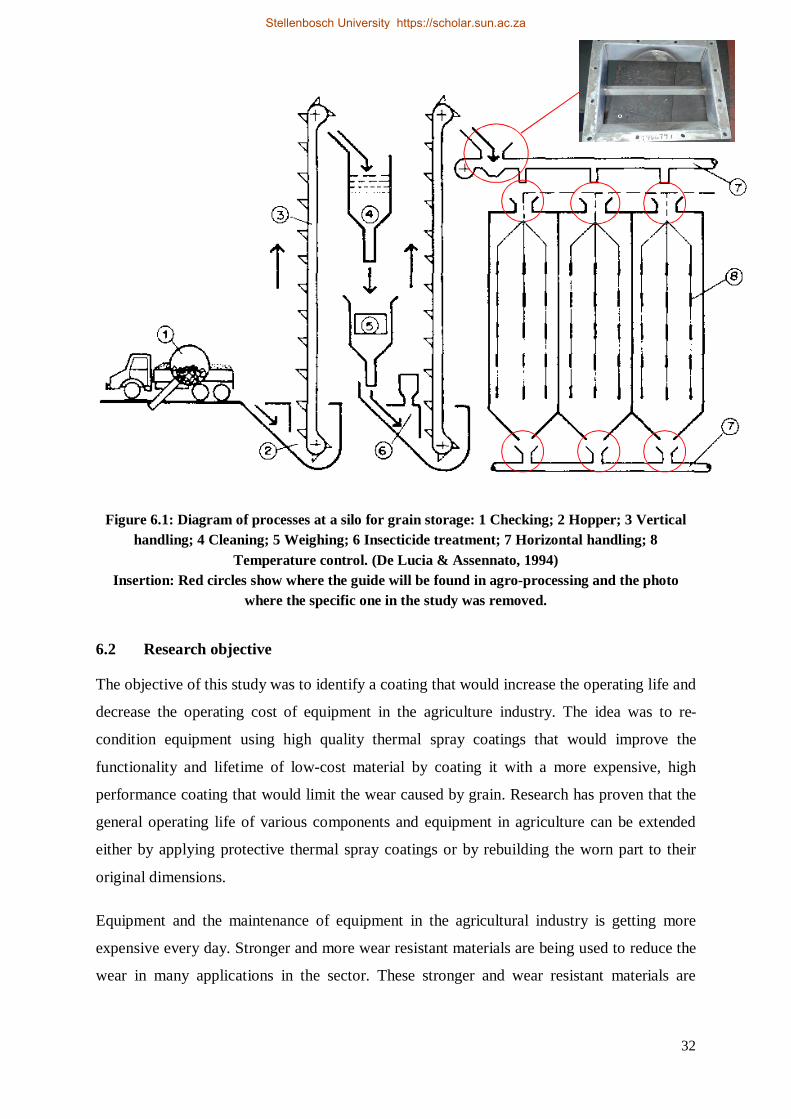
32
Figure 6.1: Diagram of processes at a silo for grain storage: 1 Checking; 2 Hopper; 3 Vertical handling; 4 Cleaning; 5 Weighing; 6 Insecticide treatment; 7 Horizontal handling; 8
Temperature control. (De Lucia & Assennato, 1994) Insertion: Red circles show where the guide will be found in agro-processing and the photo
where the specific one in the study was removed.
6.2 Research objective
The objective of this study was to identify a coating that would increase the operating life and
decrease the operating cost of equipment in the agriculture industry. The idea was to re-
condition equipment using high quality thermal spray coatings that would improve the
functionality and lifetime of low-cost material by coating it with a more expensive, high
performance coating that would limit the wear caused by grain. Research has proven that the
general operating life of various components and equipment in agriculture can be extended
either by applying protective thermal spray coatings or by rebuilding the worn part to their
original dimensions.
Equipment and the maintenance of equipment in the agricultural industry is getting more
expensive every day. Stronger and more wear resistant materials are being used to reduce the
wear in many applications in the sector. These stronger and wear resistant materials are
Stellenbosch University https://scholar.sun.ac.za
33
expensive and increase the production costs. The operating life of cheaper materials is
generally short and a lot of time is wasted when the equipment must be replaced or repaired.
From the research, it is clear that a balance needs to be found between low-cost base
materials and coating with a long operating lifetime which will provide the best solution to a
specific problem area.
6.3 Importance of the research study
The study focuses on problem areas in the agricultural industry where high maintenance costs
occur. The focus and benefactors of the research study will not only be farmers.
Manufacturers of agriculture, mining and industrial equipment will also benefit if they can
improve their products and increase the operating life of their products and equipment with
less life cycle costs.
The study must identify the most cost effective coating that shows the best resistance to wear
caused by grain. This coating should be widely applicable in the agricultural industry.
6.4 Limitations and assumptions of the study
The coatings were applied by an oragnisation that specializes in thermal spray coatings. They
have all the necessary equipment, tools, machines and coating material available. The
experiment and applications used to test the performance of the coatings in the research study
and the results obtained had to be applicable to other applications in the agricultural industry.
It would be too expensive to test each application separately and draw a conclusion from each
application. The application chosen needed to be broadly relevant to other equipment and
applications in the agricultural industry. It was not possible to experiment different coatings
with different processes and neither to create new coatings, because of the costs involved.
The selection of different coatings and the processes was done by the company who
specializes in thermal spray coatings and did all the coating work for this research .
Stellenbosch University https://scholar.sun.ac.za
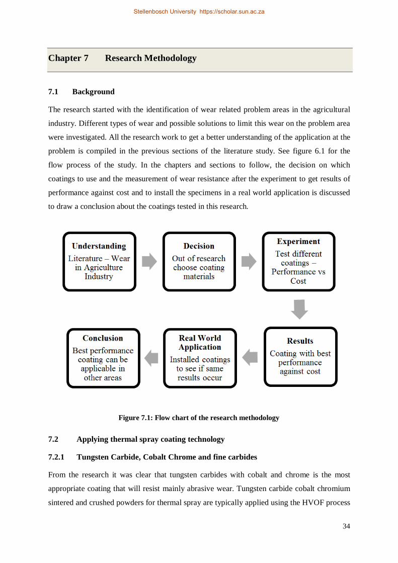
34
Chapter 7 Research Methodology
7.1 Background
The research started with the identification of wear related problem areas in the agricultural
industry. Different types of wear and possible solutions to limit this wear on the problem area
were investigated. All the research work to get a better understanding of the application at the
problem is compiled in the previous sections of the literature study. See figure 6.1 for the
flow process of the study. In the chapters and sections to follow, the decision on which
coatings to use and the measurement of wear resistance after the experiment to get results of
performance against cost and to install the specimens in a real world application is discussed
to draw a conclusion about the coatings tested in this research.
Figure 7.1: Flow chart of the research methodology
7.2 Applying thermal spray coating technology
7.2.1 Tungsten Carbide, Cobalt Chrome and fine carbides
From the research it was clear that tungsten carbides with cobalt and chrome is the most
appropriate coating that will resist mainly abrasive wear. Tungsten carbide cobalt chromium
sintered and crushed powders for thermal spray are typically applied using the HVOF process
Stellenbosch University https://scholar.sun.ac.za
35
to produce dense, abrasion and erosion resistant coatings. The sintered and crushed
morphology generally produces coatings with a higher as-sprayed coating density compared
to agglomerated and sintered powders. This allows the usage of these coatings on high
pressure gate valves and other high pressure components. Tungsten carbide acts as the wear-
resistant hard phase component. The cobalt chromium matrix improves corrosion and erosion
resistance, compared with carbides having a cobalt-only matrix. This class of thermal spray
powders is particularly suitable for applications where both wear and corrosion resistance is
needed. They also offer better corrosion and cavitation resistance than tungsten-carbide-
cobalt coatings. These materials also produce excellent thermal sprayed coating alternatives
to hard chromium plating (Material Product Data Sheet, 2014).
Fine carbide solution products are spheroidal, agglomerated and sintered powders for thermal
spraying containing 86% tungsten carbide as hard material and a cobalt-chromium matrix,
which functions as a binder material for the carbide particles. The products are particularly
suitable for applications where both wear and corrosion resistance is required. Chromium in
the matrix improves corrosion resistance while the fine carbide grains provide the abrasive,
erosive and fretting wear properties of a tungsten carbide-cobalt based material. Two
different tungsten carbide coatings were selected to be tested in this study. The two coatings
were applied by two different spray processes and different distributions. The 3652 FC has
the fine carbide distribution. See table 7.1 for the properties of the coatings (Material Product
Data Sheet, 2014).
7.2.1.1 1350VM (WC-Co-Cr) Tungsten Carbide Cobalt Chrome
1350 VM has excellent low temperature wear properties and is very useful up to 900°F
(482°C). This tungsten carbide powder has a densified structure with fine carbide dispersion
that promotes finer microstructure and denser, smoother coatings with high bond strengths.
This coating is sprayed with the Tafa JP-5000 system's Model 5120. The control console is a
semi-automatic, rotometer-controlled console that is engineered for ease of use and
consistency and has proven itself to be unequalled in coating reproducibility and robustness
for long-term use. A single unit controls all the operating parameters including cooling water,
powder, carrier gas, oxygen, and fuel flows. Clear, easily readable gauges, rotometers, and
digital meters let you set consistent spray parameters that yield repeatable results (Material
Product Data Sheet, 2014).
Stellenbosch University https://scholar.sun.ac.za
36
7.2.1.2 3652FC (WC-Co-Cr) Tungsten carbide cobalt chrome with fine carbide distribution
FC products have fine grained carbides that increase hardness and produce very smooth
sprayed surfaces. This tungsten carbide shows good resistance against both corrosion and
wear. The 3652FC tungsten carbide cobalt with chrome is also agglomerated and sintered. It
is known as one of the best thermal spray powders for use in wear applications at service
temperatures below 500 °C (930 °F) in aqueous corrosive media. It has the same chemical
composition as 1350VM with WC = 86, Co = 10, Cr=4 (Material Product Data Sheet, 2014).
This product is particularly suitable for applications where both wear and corrosion resistance
is required. Chromium in the matrix improves corrosion resistance while the fine carbide
grains provide the abrasive, erosive and fretting wear properties of a tungsten carbide cobalt
based material (Material Product Data Sheet, 2014).
HVOF coatings of these materials are dense, and show good bond strength. They also exhibit
smooth, as-sprayed surfaces that are useful in applications where grinding cannot be done or
is not required (Material Product Data Sheet, 2014).
This coating is sprayed with a diamond jet gun that exhibits high density, low oxide content,
superior micro-hardness and high adhesion with excellent machinability. Diamond Jet guns
offer efficient operation, using less process gas compared to other HVOF spray guns. This
material is an excellent choice for coatings on machine parts such as pump seals, valves,
polished rods and shafts (Material Product Data Sheet, 2014).
7.2.2 Chromium oxide
Chromium oxide is the hardest oxide that also exhibits low friction coefficient, high wear and
corrosion resistance. Many techniques have been developed to deposit chromium oxide
coatings, including thermal plasma spraying, chemical vapour deposition, and ion
implantation. Chromium oxide produces the most chemically inert and wear resistant thermal
spray coating of all the oxides. Typically, these materials are chosen for applications where a
hard, wear resistant and chemically inert surface is needed. The coatings can be used at
service temperatures of 540 °C (1000 °F) or higher. Excellent coatings are achieved using the
atmospheric plasma process. Addition of titanium oxide in some of these products results in
coatings with improved cohesive strength and higher fracture toughness. Compared to
zirconia-based ceramic coatings, chromium oxide coatings have higher micro hardness and
Stellenbosch University https://scholar.sun.ac.za
37
macro hardness; however, they exhibit higher thermal conductivity and are, therefore, not as
thermally isolative (Material Product Data Sheet, 2014).
Amdry 6415, Amdry 6420, Metco 6156 and Metco 106NS are all pure chrome oxide powders
but they differ in their particle sizes and size distributions. In general, the coatings made with
these powders can withstand temperatures up to approximately 815 °C (1500 °F) depending
on the substrate and the operating conditions. Amdry 6415 and Metco 6156 have tightly
controlled particle size distributions. Their relatively fine size allows for coatings with
smoother surface finishes whereas Metco 106NS, with its coarser particle size, should be
selected if thicker coatings are desired. Amdry 6420 is suitable for coatings of intermediate
thicknesses. In addition, Amdry 6420 and Metco 6156 are products with somewhat higher
purity with nearly no free chromium. This makes them particularly suitable for applications
such as anilox rolls where laser engraving is required. (Material Product Data Sheet, 2014)
7.2.2.1 6156 (Cr2O3) Chrome oxide powder
The chrome oxide powder 6156(Cr2O3) can withstand temperatures up to approximately
815 C (1500°F) depending on the substrate and the operating conditions. This chrome oxide
powder has tightly controlled particle size distributions. The relatively fine size allows for
coatings with smoother surface finishes. This material is an excellent choice for coatings on
large roller coverings for the paper and pulp industry, pump seals, shafts and wear rings
(Material Product Data Sheet, 2014).
7.2.3 Chromium carbide
Chrome carbides in a nickel-chromium alloy are very oxidation and corrosion resistant. They
are rated at the highest temperature of all carbides and maintain hardness to 870 °C (1600
°F). Above this temperature, in the presence of oxygen, the chrome carbides will start to
oxidise and soften (Material Product Data Sheet, 2014).
These chromium carbide materials are blends of chromium carbide and nickel-chromium
powders. The nickel-chromium alloy serves as a matrix that improves overall coating
integrity and corrosion resistance, while the chromium carbide constituent serves as a hard
phase that assures wear resistance. Coatings of these materials effectively combat solid
particle erosion (SPE), high temperature wear (abrasion, erosion, fretting and cavitation) and
hot corrosion. Coatings applied using the HVOF process are dense and very well-bonded,
with a more homogeneous structure than can be obtained using conventional atmospheric
Stellenbosch University https://scholar.sun.ac.za
38
plasma spray. Coatings applied using a TriplexPro series plasma gun using high-energy
conditions result in coatings that are similar to HVOF coatings in terms of density and
homogeneous structure; however, HVOF coatings have higher bond strength and more
favourable residual coating stresses. Postspray annealing of Cr3C2-(Ni 20Cr) HVOF coatings
at temperatures up to 725°C (1340 °F) for approximately 1 h leads to supersaturating of the
matrix as a result of carbide dissolution into the matrix (Material Product Data Sheet, 2014).
5241 coatings have lower oxide-content, and lower carbon loss during spraying, with
excellent erosion and oxidation properties up to 900 ºC (1650 ºF), good wear properties and
corrosion resistance, and can be superfinished to 0.25 μm (Material Product Data Sheet,
2014).
Chrome carbide coatings are notable for several uses; one of its most significant benefits is its
wear resistance in higher temperature environments. Chrome carbide can be an excellent
choice as an alternative to tungsten carbide, depending on operating conditions. While
chrome carbide has less wear resistance then tungsten carbide, chrome carbide coatings along
with nickel/chrome binder chemistry has heat resistance and oxide resistance characteristics
at higher temperatures and under corrosive or oxidising conditions. The properties of chrome
carbide coatings can be further enhanced when the metal alloy matrix is made from nichrome
alloy, which has high corrosion resistance. Coatings with chrome carbide are appropriate for
applications ranging from 1,000F to 1,500F or 540 C to 815C approximately (Material
Product Data Sheet, 2014).
7.2.3.1 5241 (CrC) Chrome carbide – Nickel Chrome powder
The feedstock powder is Cr39i7C. This consists of fine particles that are obtained by melting
a material having a composition of Cr:Ni:C = 54:39:7 (% by mass) and rapidly solidifying the
melt with Cr and C forming chromium carbide and Ni and Cr forming a Ni-Cr alloy by
melting and rapid solidification. 5241 has a structure in which crystallised chromium carbide
particles are dispersed. This coating is also sprayed with a diamond jet gun (Material Product
Data Sheet, 2014).
Hardface coatings, particularly HVOF (High Velocity Oxygen Fuel) chrome carbide
coatings, have multiple applications in all types of turbo machinery. HVOF chrome carbide
coatings are effective in combatting most wear such as solid particle erosion, fretting,
Stellenbosch University https://scholar.sun.ac.za
39
abrasion, and cavitation, as well as potentially reducing repair intervals for your coated
component Material Product Data Sheet, 2014).
7.2.4 140MXC Nano composite wire sprayed with the arc spray system and polished to remove high spots, the wire contains iron, chrome, molybdenum, tungsten and other trace elements
The use of wire arc spraying technology as a coating deposition method has been previously
studied. It has been found that this deposition method is useful for the coating of large areas
in a short time. Additionally, wire arc spray coatings can be applied to different materials, in
different thicknesses and with a significant variety of filler materials. One filler material is a
Fe-Cr-W-Nb alloy, which is commercially known as 140MXC and is recommended for the
protection of materials from corrosive environments and from the risk of abrasive wear
(Material Product Data Sheet, 2014).
Varieties of powder compositions for different deposition processes are known and described
in publications. Mainly, the powders comprise particles of a non-metallic/ceramic compound
like tungsten carbide, chromium combined with a metal such as Ni, Cr, Co or an alloy
containing such a metal as a binder, to form a ceramic/metal composite material (Material
Product Data Sheet, 2014).
In Table 7.1, all the different coatings used and seen on figure 8.1 are listed below with the
different processes applied to coat the plates. A short description is given in the last column
in Table 7.1.
Stellenbosch University https://scholar.sun.ac.za
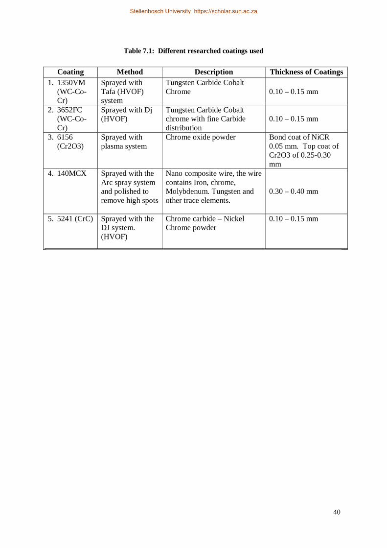
40
Table 7.1: Different researched coatings used
Coating Method Description Thickness of Coatings 1. 1350VM
(WC-Co-Cr)
Sprayed with Tafa (HVOF) system
Tungsten Carbide Cobalt Chrome
0.10 – 0.15 mm
2. 3652FC (WC-Co-Cr)
Sprayed with Dj (HVOF)
Tungsten Carbide Cobalt chrome with fine Carbide distribution
0.10 – 0.15 mm
3. 6156 (Cr2O3)
Sprayed with plasma system
Chrome oxide powder Bond coat of NiCR 0.05 mm. Top coat of Cr2O3 of 0.25-0.30 mm
4. 140MCX Sprayed with the Arc spray system and polished to remove high spots
Nano composite wire, the wire contains Iron, chrome, Molybdenum. Tungsten and other trace elements.
0.30 – 0.40 mm
5. 5241 (CrC) Sprayed with the DJ system. (HVOF)
Chrome carbide – Nickel Chrome powder
0.10 – 0.15 mm
Stellenbosch University https://scholar.sun.ac.za
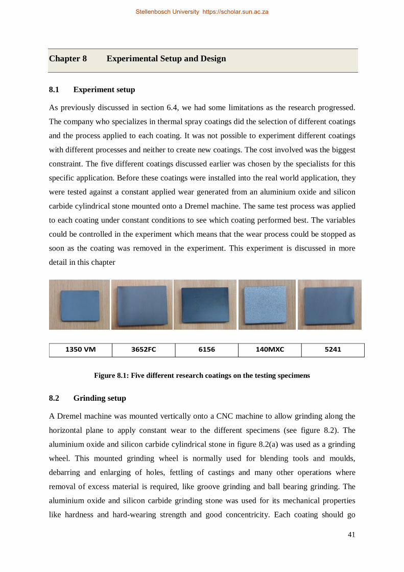
41
Chapter 8 Experimental Setup and Design
8.1 Experiment setup
As previously discussed in section 6.4, we had some limitations as the research progressed.
The company who specializes in thermal spray coatings did the selection of different coatings
and the process applied to each coating. It was not possible to experiment different coatings
with different processes and neither to create new coatings. The cost involved was the biggest
constraint. The five different coatings discussed earlier was chosen by the specialists for this
specific application. Before these coatings were installed into the real world application, they
were tested against a constant applied wear generated from an aluminium oxide and silicon
carbide cylindrical stone mounted onto a Dremel machine. The same test process was applied
to each coating under constant conditions to see which coating performed best. The variables
could be controlled in the experiment which means that the wear process could be stopped as
soon as the coating was removed in the experiment. This experiment is discussed in more
detail in this chapter
Figure 8.1: Five different research coatings on the testing specimens 8.2 Grinding setup
A Dremel machine was mounted vertically onto a CNC machine to allow grinding along the
horizontal plane to apply constant wear to the different specimens (see figure 8.2). The
aluminium oxide and silicon carbide cylindrical stone in figure 8.2(a) was used as a grinding
wheel. This mounted grinding wheel is normally used for blending tools and moulds,
debarring and enlarging of holes, fettling of castings and many other operations where
removal of excess material is required, like groove grinding and ball bearing grinding. The
aluminium oxide and silicon carbide grinding stone was used for its mechanical properties
like hardness and hard-wearing strength and good concentricity. Each coating should go
Stellenbosch University https://scholar.sun.ac.za
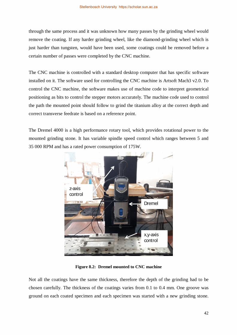
42
through the same process and it was unknown how many passes by the grinding wheel would
remove the coating. If any harder grinding wheel, like the diamond-grinding wheel which is
just harder than tungsten, would have been used, some coatings could be removed before a
certain number of passes were completed by the CNC machine.
The CNC machine is controlled with a standard desktop computer that has specific software
installed on it. The software used for controlling the CNC machine is Artsoft Mach3 v2.0. To
control the CNC machine, the software makes use of machine code to interpret geometrical
positioning as bits to control the stepper motors accurately. The machine code used to control
the path the mounted point should follow to grind the titanium alloy at the correct depth and
correct transverse feedrate is based on a reference point.
The Dremel 4000 is a high performance rotary tool, which provides rotational power to the
mounted grinding stone. It has variable spindle speed control which ranges between 5 and
35 000 RPM and has a rated power consumption of 175W.
Figure 8.2: Dremel mounted to CNC machine Not all the coatings have the same thickness, therefore the depth of the grinding had to be
chosen carefully. The thickness of the coatings varies from 0.1 to 0.4 mm. One groove was
ground on each coated specimen and each specimen was started with a new grinding stone.
Dremel
z-axis control
x,y-axis control
Stellenbosch University https://scholar.sun.ac.za
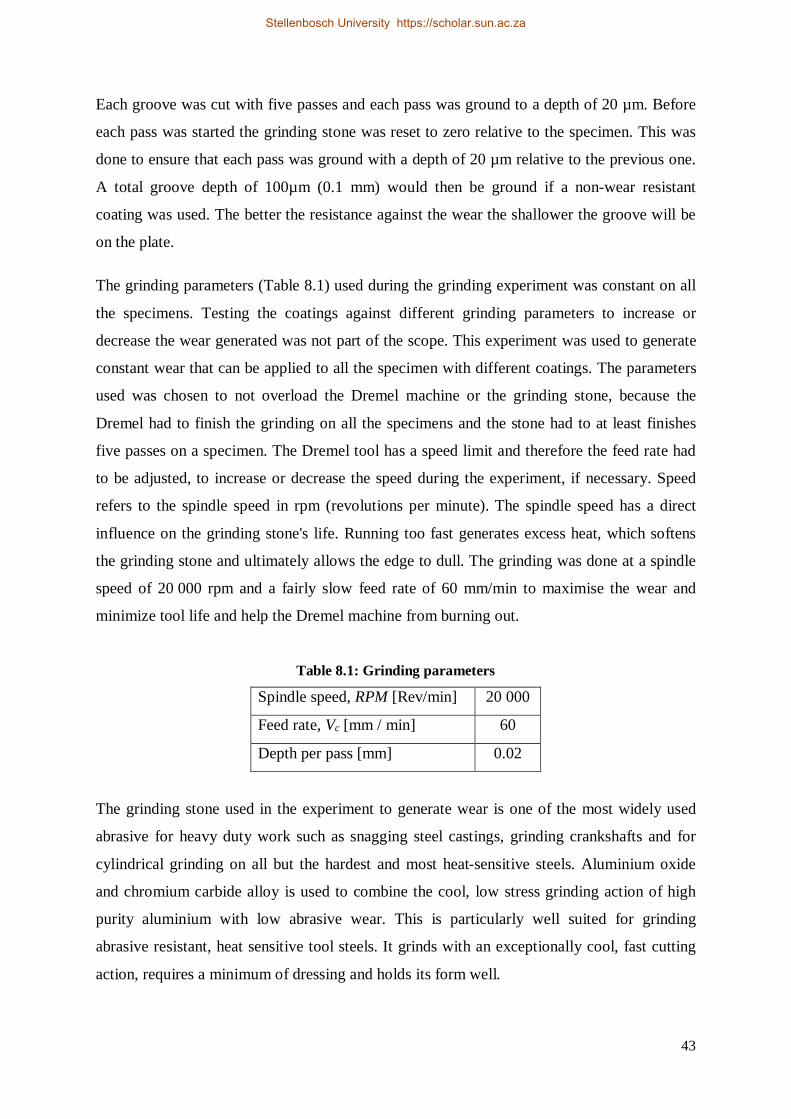
43
Each groove was cut with five passes and each pass was ground to a depth of 20 µm. Before
each pass was started the grinding stone was reset to zero relative to the specimen. This was
done to ensure that each pass was ground with a depth of 20 µm relative to the previous one.
A total groove depth of 100µm (0.1 mm) would then be ground if a non-wear resistant
coating was used. The better the resistance against the wear the shallower the groove will be
on the plate.
The grinding parameters (Table 8.1) used during the grinding experiment was constant on all
the specimens. Testing the coatings against different grinding parameters to increase or
decrease the wear generated was not part of the scope. This experiment was used to generate
constant wear that can be applied to all the specimen with different coatings. The parameters
used was chosen to not overload the Dremel machine or the grinding stone, because the
Dremel had to finish the grinding on all the specimens and the stone had to at least finishes
five passes on a specimen. The Dremel tool has a speed limit and therefore the feed rate had
to be adjusted, to increase or decrease the speed during the experiment, if necessary. Speed
refers to the spindle speed in rpm (revolutions per minute). The spindle speed has a direct
influence on the grinding stone's life. Running too fast generates excess heat, which softens
the grinding stone and ultimately allows the edge to dull. The grinding was done at a spindle
speed of 20 000 rpm and a fairly slow feed rate of 60 mm/min to maximise the wear and
minimize tool life and help the Dremel machine from burning out.
Table 8.1: Grinding parameters
Spindle speed, RPM [Rev/min] 20 000
Feed rate, Vc [mm / min] 60
Depth per pass [mm] 0.02
The grinding stone used in the experiment to generate wear is one of the most widely used
abrasive for heavy duty work such as snagging steel castings, grinding crankshafts and for
cylindrical grinding on all but the hardest and most heat-sensitive steels. Aluminium oxide
and chromium carbide alloy is used to combine the cool, low stress grinding action of high
purity aluminium with low abrasive wear. This is particularly well suited for grinding
abrasive resistant, heat sensitive tool steels. It grinds with an exceptionally cool, fast cutting
action, requires a minimum of dressing and holds its form well.
Stellenbosch University https://scholar.sun.ac.za
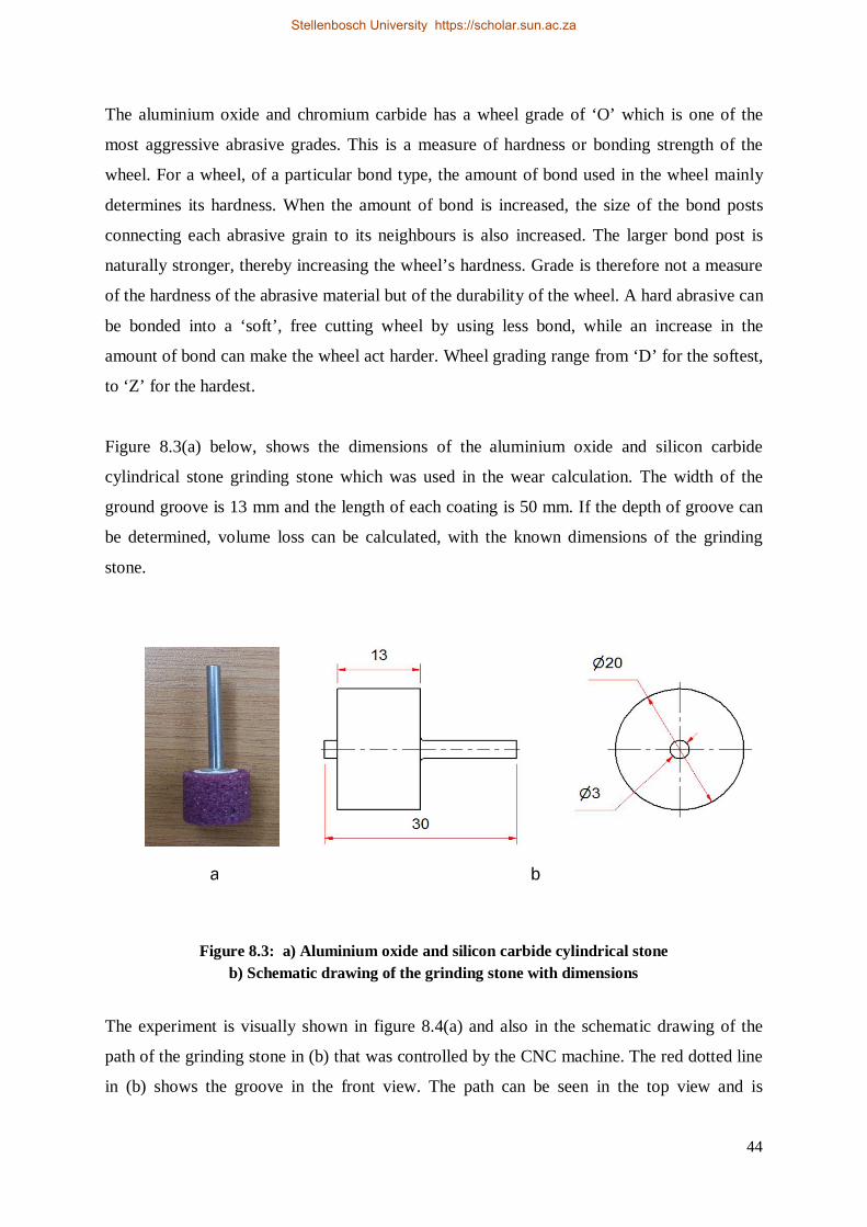
44
The aluminium oxide and chromium carbide has a wheel grade of ‘O’ which is one of the
most aggressive abrasive grades. This is a measure of hardness or bonding strength of the
wheel. For a wheel, of a particular bond type, the amount of bond used in the wheel mainly
determines its hardness. When the amount of bond is increased, the size of the bond posts
connecting each abrasive grain to its neighbours is also increased. The larger bond post is
naturally stronger, thereby increasing the wheel’s hardness. Grade is therefore not a measure
of the hardness of the abrasive material but of the durability of the wheel. A hard abrasive can
be bonded into a ‘soft’, free cutting wheel by using less bond, while an increase in the
amount of bond can make the wheel act harder. Wheel grading range from ‘D’ for the softest,
to ‘Z’ for the hardest.
Figure 8.3(a) below, shows the dimensions of the aluminium oxide and silicon carbide
cylindrical stone grinding stone which was used in the wear calculation. The width of the
ground groove is 13 mm and the length of each coating is 50 mm. If the depth of groove can
be determined, volume loss can be calculated, with the known dimensions of the grinding
stone.
Figure 8.3: a) Aluminium oxide and silicon carbide cylindrical stone b) Schematic drawing of the grinding stone with dimensions
The experiment is visually shown in figure 8.4(a) and also in the schematic drawing of the
path of the grinding stone in (b) that was controlled by the CNC machine. The red dotted line
in (b) shows the groove in the front view. The path can be seen in the top view and is
a b
Stellenbosch University https://scholar.sun.ac.za
45
indicated with the blue line. As the groove was ground deeper with each pass, the resistance
from the material could be seen through the heat on the grinding stone as it started to turn red,
especially with the last two passes.
Figure 8.4: a) The grinding process on the coatings b) Schematic drawing of the grinding process.
8.3 Measurement of wear
A surface roughness tester was used to measure the wear generated by the grinding wheel.
Roughness is commonly calculated using one of four methods: Ra (roughness average), RMS
(root mean square), Rz (a 10 point average), and Rt or Rmax (maximum between peak and valley).
Different methods can be combined to give more detail on roughness. All four methods measure
some combination of peak and valley distances in the surface texture and give results in micro-
Stellenbosch University https://scholar.sun.ac.za
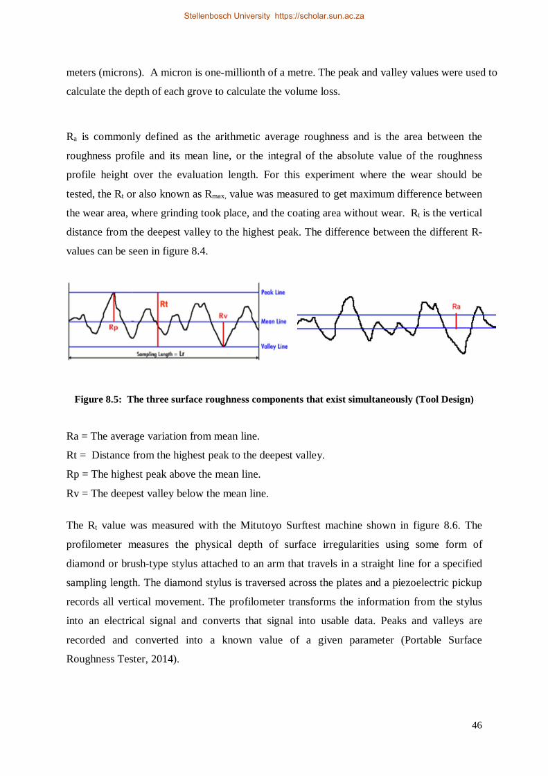
46
meters (microns). A micron is one-millionth of a metre. The peak and valley values were used to
calculate the depth of each grove to calculate the volume loss.
Ra is commonly defined as the arithmetic average roughness and is the area between the
roughness profile and its mean line, or the integral of the absolute value of the roughness
profile height over the evaluation length. For this experiment where the wear should be
tested, the Rt or also known as Rmax, value was measured to get maximum difference between
the wear area, where grinding took place, and the coating area without wear. Rt is the vertical
distance from the deepest valley to the highest peak. The difference between the different R-
values can be seen in figure 8.4.
Figure 8.5: The three surface roughness components that exist simultaneously (Tool Design)
Ra = The average variation from mean line.
Rt = Distance from the highest peak to the deepest valley.
Rp = The highest peak above the mean line.
Rv = The deepest valley below the mean line.
The Rt value was measured with the Mitutoyo Surftest machine shown in figure 8.6. The
profilometer measures the physical depth of surface irregularities using some form of
diamond or brush-type stylus attached to an arm that travels in a straight line for a specified
sampling length. The diamond stylus is traversed across the plates and a piezoelectric pickup
records all vertical movement. The profilometer transforms the information from the stylus
into an electrical signal and converts that signal into usable data. Peaks and valleys are
recorded and converted into a known value of a given parameter (Portable Surface
Roughness Tester, 2014).
Stellenbosch University https://scholar.sun.ac.za
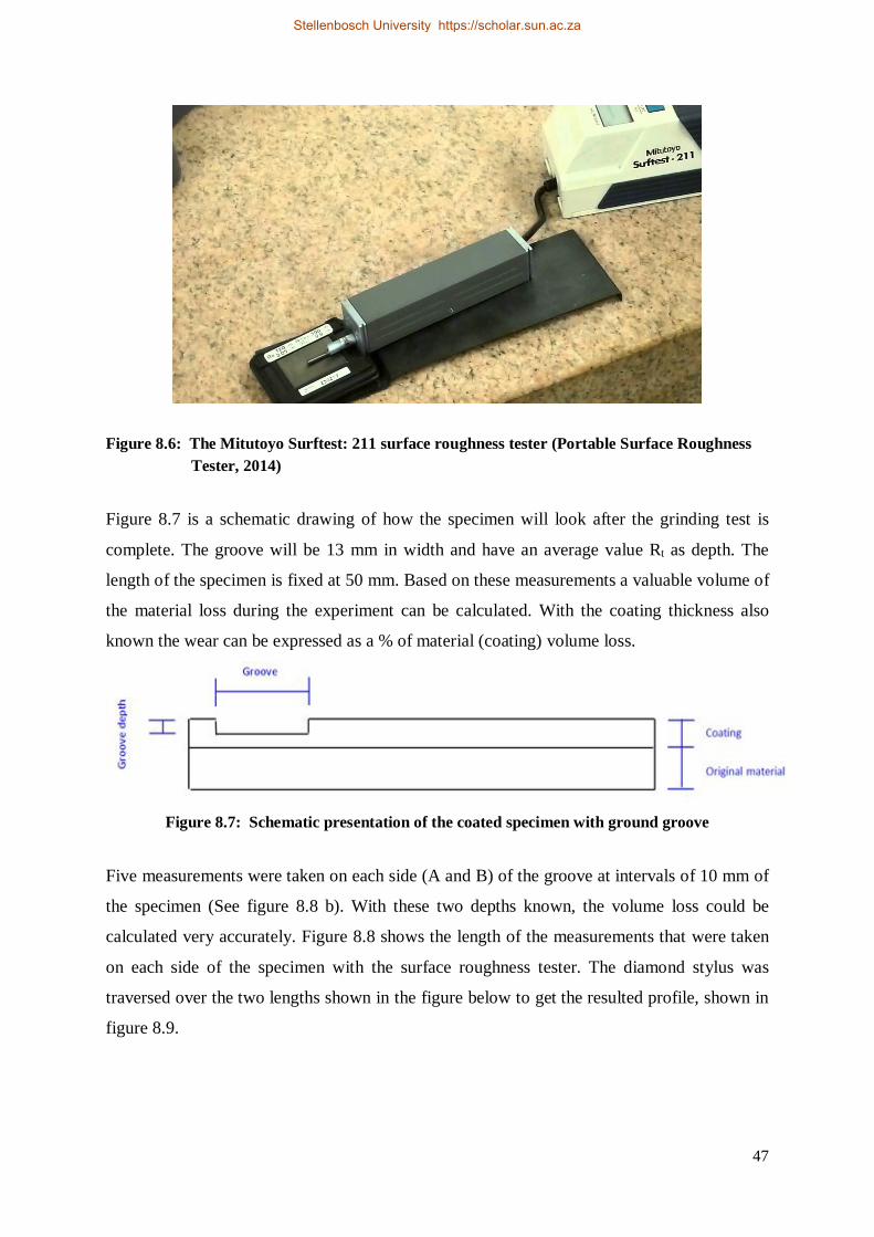
47
Figure 8.6: The Mitutoyo Surftest: 211 surface roughness tester (Portable Surface Roughness Tester, 2014)
Figure 8.7 is a schematic drawing of how the specimen will look after the grinding test is
complete. The groove will be 13 mm in width and have an average value Rt as depth. The
length of the specimen is fixed at 50 mm. Based on these measurements a valuable volume of
the material loss during the experiment can be calculated. With the coating thickness also
known the wear can be expressed as a % of material (coating) volume loss.
Figure 8.7: Schematic presentation of the coated specimen with ground groove
Five measurements were taken on each side (A and B) of the groove at intervals of 10 mm of
the specimen (See figure 8.8 b). With these two depths known, the volume loss could be
calculated very accurately. Figure 8.8 shows the length of the measurements that were taken
on each side of the specimen with the surface roughness tester. The diamond stylus was
traversed over the two lengths shown in the figure below to get the resulted profile, shown in
figure 8.9.
Stellenbosch University https://scholar.sun.ac.za
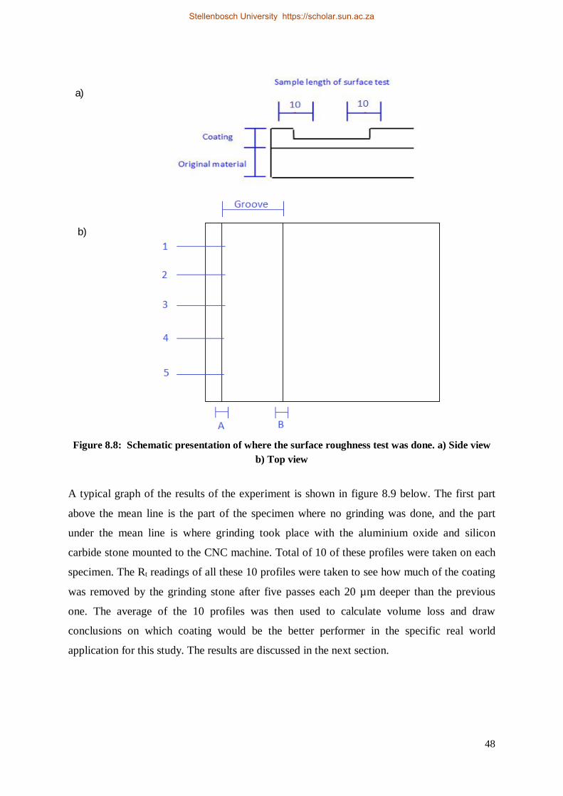
48
Figure 8.8: Schematic presentation of where the surface roughness test was done. a) Side view
b) Top view
A typical graph of the results of the experiment is shown in figure 8.9 below. The first part
above the mean line is the part of the specimen where no grinding was done, and the part
under the mean line is where grinding took place with the aluminium oxide and silicon
carbide stone mounted to the CNC machine. Total of 10 of these profiles were taken on each
specimen. The Rt readings of all these 10 profiles were taken to see how much of the coating
was removed by the grinding stone after five passes each 20 µm deeper than the previous
one. The average of the 10 profiles was then used to calculate volume loss and draw
conclusions on which coating would be the better performer in the specific real world
application for this study. The results are discussed in the next section.
a)
b)
Stellenbosch University https://scholar.sun.ac.za
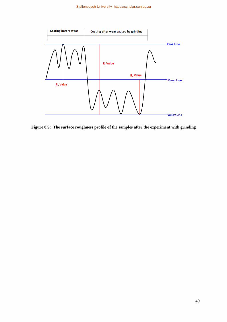
49
Figure 8.9: The surface roughness profile of the samples after the experiment with grinding
Stellenbosch University https://scholar.sun.ac.za
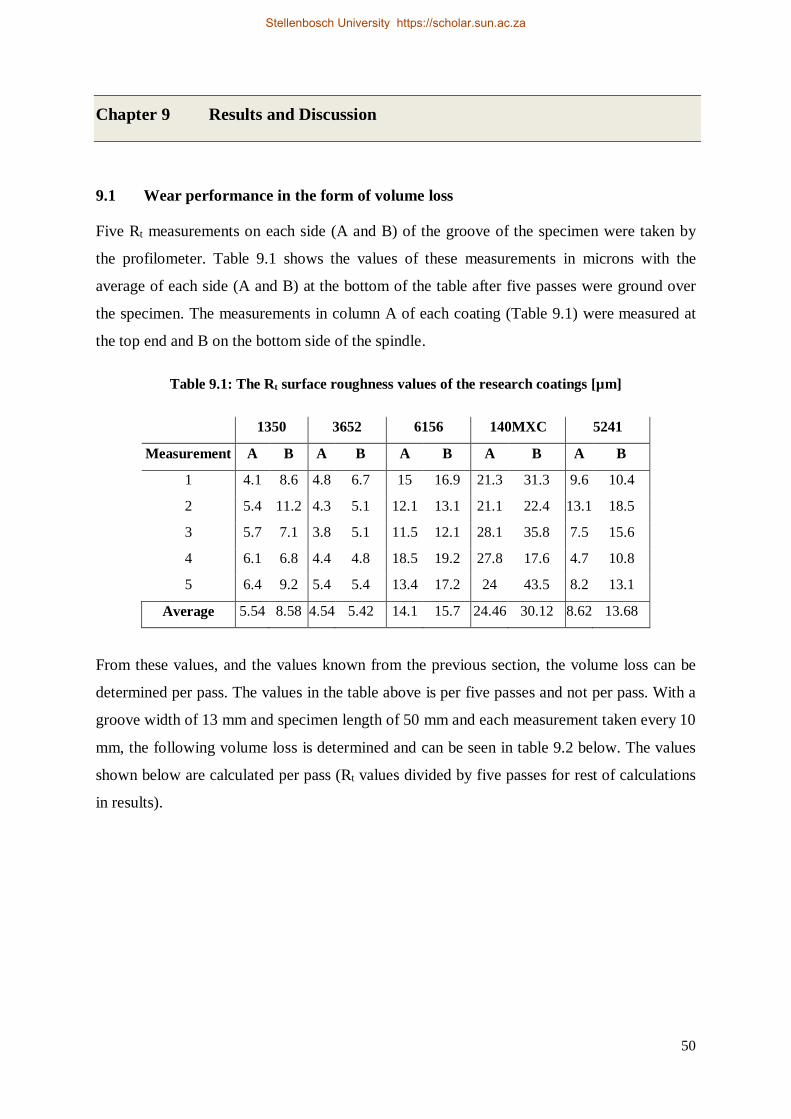
50
Chapter 9 Results and Discussion
9.1 Wear performance in the form of volume loss
Five Rt measurements on each side (A and B) of the groove of the specimen were taken by
the profilometer. Table 9.1 shows the values of these measurements in microns with the
average of each side (A and B) at the bottom of the table after five passes were ground over
the specimen. The measurements in column A of each coating (Table 9.1) were measured at
the top end and B on the bottom side of the spindle.
Table 9.1: The Rt surface roughness values of the research coatings [µm]
1350 3652 6156 140MXC 5241
Measurement A B A B A B A B A B
1 4.1 8.6 4.8 6.7 15 16.9 21.3 31.3 9.6 10.4
2 5.4 11.2 4.3 5.1 12.1 13.1 21.1 22.4 13.1 18.5
3 5.7 7.1 3.8 5.1 11.5 12.1 28.1 35.8 7.5 15.6
4 6.1 6.8 4.4 4.8 18.5 19.2 27.8 17.6 4.7 10.8
5 6.4 9.2 5.4 5.4 13.4 17.2 24 43.5 8.2 13.1
Average 5.54 8.58 4.54 5.42 14.1 15.7 24.46 30.12 8.62 13.68
From these values, and the values known from the previous section, the volume loss can be
determined per pass. The values in the table above is per five passes and not per pass. With a
groove width of 13 mm and specimen length of 50 mm and each measurement taken every 10
mm, the following volume loss is determined and can be seen in table 9.2 below. The values
shown below are calculated per pass (Rt values divided by five passes for rest of calculations
in results).
Stellenbosch University https://scholar.sun.ac.za
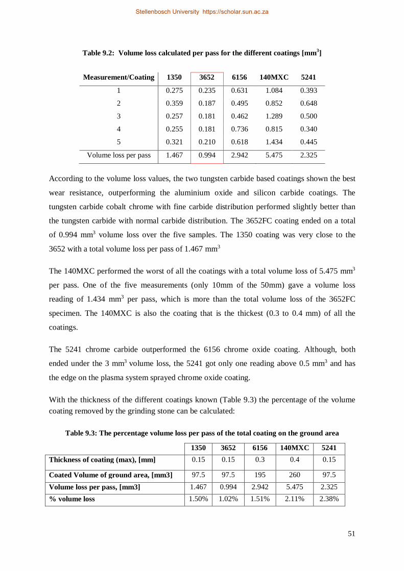
51
Table 9.2: Volume loss calculated per pass for the different coatings [mm3]
According to the volume loss values, the two tungsten carbide based coatings shown the best
wear resistance, outperforming the aluminium oxide and silicon carbide coatings. The
tungsten carbide cobalt chrome with fine carbide distribution performed slightly better than
the tungsten carbide with normal carbide distribution. The 3652FC coating ended on a total
of 0.994 mm3 volume loss over the five samples. The 1350 coating was very close to the
3652 with a total volume loss per pass of 1.467 mm3
The 140MXC performed the worst of all the coatings with a total volume loss of 5.475 mm3
per pass. One of the five measurements (only 10mm of the 50mm) gave a volume loss
reading of 1.434 mm3 per pass, which is more than the total volume loss of the 3652FC
specimen. The 140MXC is also the coating that is the thickest (0.3 to 0.4 mm) of all the
coatings.
The 5241 chrome carbide outperformed the 6156 chrome oxide coating. Although, both
ended under the 3 mm3 volume loss, the 5241 got only one reading above 0.5 mm3 and has
the edge on the plasma system sprayed chrome oxide coating.
With the thickness of the different coatings known (Table 9.3) the percentage of the volume coating removed by the grinding stone can be calculated:
Table 9.3: The percentage volume loss per pass of the total coating on the ground area
1350 3652 6156 140MXC 5241 Thickness of coating (max), [mm] 0.15 0.15 0.3 0.4 0.15
Coated Volume of ground area, [mm3] 97.5 97.5 195 260 97.5 Volume loss per pass, [mm3] 1.467 0.994 2.942 5.475 2.325 % volume loss 1.50% 1.02% 1.51% 2.11% 2.38%
Measurement/Coating 1350 3652 6156 140MXC 5241
1 0.275 0.235 0.631 1.084 0.393
2 0.359 0.187 0.495 0.852 0.648
3 0.257 0.181 0.462 1.289 0.500
4 0.255 0.181 0.736 0.815 0.340
5 0.321 0.210 0.618 1.434 0.445
Volume loss per pass 1.467 0.994 2.942 5.475 2.325
Stellenbosch University https://scholar.sun.ac.za
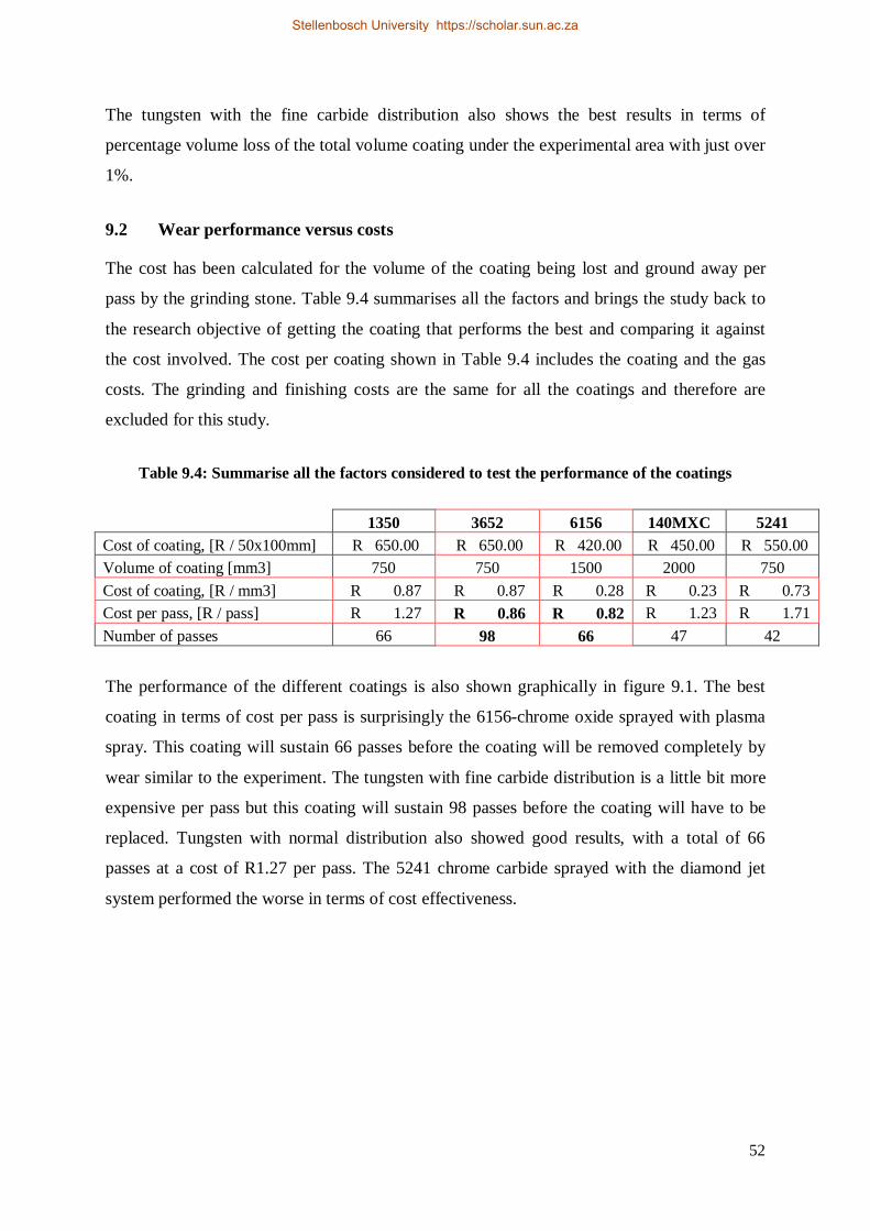
52
The tungsten with the fine carbide distribution also shows the best results in terms of
percentage volume loss of the total volume coating under the experimental area with just over
1%.
9.2 Wear performance versus costs
The cost has been calculated for the volume of the coating being lost and ground away per
pass by the grinding stone. Table 9.4 summarises all the factors and brings the study back to
the research objective of getting the coating that performs the best and comparing it against
the cost involved. The cost per coating shown in Table 9.4 includes the coating and the gas
costs. The grinding and finishing costs are the same for all the coatings and therefore are
excluded for this study.
Table 9.4: Summarise all the factors considered to test the performance of the coatings
1350 3652 6156 140MXC 5241 Cost of coating, [R / 50x100mm] R 650.00 R 650.00 R 420.00 R 450.00 R 550.00 Volume of coating [mm3] 750 750 1500 2000 750 Cost of coating, [R / mm3] R 0.87 R 0.87 R 0.28 R 0.23 R 0.73 Cost per pass, [R / pass] R 1.27 R 0.86 R 0.82 R 1.23 R 1.71 Number of passes 66 98 66 47 42
The performance of the different coatings is also shown graphically in figure 9.1. The best
coating in terms of cost per pass is surprisingly the 6156-chrome oxide sprayed with plasma
spray. This coating will sustain 66 passes before the coating will be removed completely by
wear similar to the experiment. The tungsten with fine carbide distribution is a little bit more
expensive per pass but this coating will sustain 98 passes before the coating will have to be
replaced. Tungsten with normal distribution also showed good results, with a total of 66
passes at a cost of R1.27 per pass. The 5241 chrome carbide sprayed with the diamond jet
system performed the worse in terms of cost effectiveness.
Stellenbosch University https://scholar.sun.ac.za
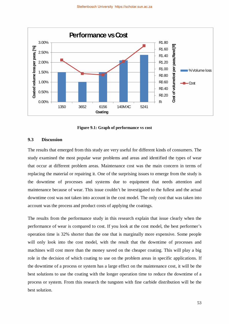
53
Figure 9.1: Graph of performance vs cost
9.3 Discussion
The results that emerged from this study are very useful for different kinds of consumers. The
study examined the most popular wear problems and areas and identified the types of wear
that occur at different problem areas. Maintenance cost was the main concern in terms of
replacing the material or repairing it. One of the surprising issues to emerge from the study is
the downtime of processes and systems due to equipment that needs attention and
maintenance because of wear. This issue couldn’t be investigated to the fullest and the actual
downtime cost was not taken into account in the cost model. The only cost that was taken into
account was the process and product costs of applying the coatings.
The results from the performance study in this research explain that issue clearly when the
performance of wear is compared to cost. If you look at the cost model, the best performer’s
operation time is 32% shorter than the one that is marginally more expensive. Some people
will only look into the cost model, with the result that the downtime of processes and
machines will cost more than the money saved on the cheaper coating. This will play a big
role in the decision of which coating to use on the problem areas in specific applications. If
the downtime of a process or system has a large effect on the maintenance cost, it will be the
best solutions to use the coating with the longer operation time to reduce the downtime of a
process or system. From this research the tungsten with fine carbide distribution will be the
best solution.
R-
R0.20
R0.40
R0.60
R0.80
R1.00
R1.20
R1.40
R1.60
R1.80
0.00%
0.50%
1.00%
1.50%
2.00%
2.50%
3.00%
1350 3652 6156 140MXC 5241
Cost
of v
olum
elos
t per
pas
s,Ra
nd [R
]
Coat
ed v
olum
e lo
ss p
er p
ass,
[%]
Coating
Performance vs Cost
% Volume loss
Cost
Stellenbosch University https://scholar.sun.ac.za
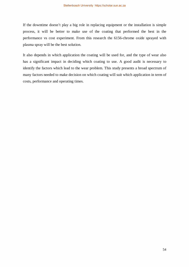
54
If the downtime doesn’t play a big role in replacing equipment or the installation is simple
process, it will be better to make use of the coating that performed the best in the
performance vs cost experiment. From this research the 6156-chrome oxide sprayed with
plasma spray will be the best solution.
It also depends in which application the coating will be used for, and the type of wear also
has a significant impact in deciding which coating to use. A good audit is necessary to
identify the factors which lead to the wear problem. This study presents a broad spectrum of
many factors needed to make decision on which coating will suit which application in term of
costs, performance and operating times.
Stellenbosch University https://scholar.sun.ac.za
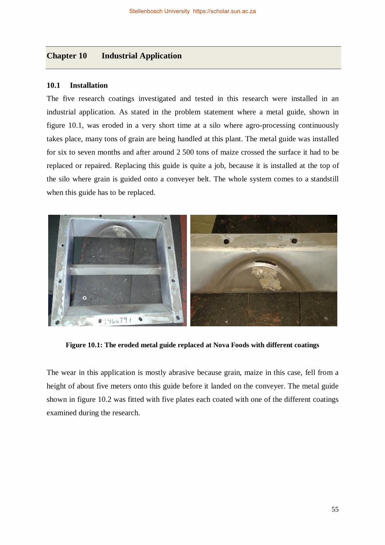
55
Chapter 10 Industrial Application
10.1 Installation
The five research coatings investigated and tested in this research were installed in an
industrial application. As stated in the problem statement where a metal guide, shown in
figure 10.1, was eroded in a very short time at a silo where agro-processing continuously
takes place, many tons of grain are being handled at this plant. The metal guide was installed
for six to seven months and after around 2 500 tons of maize crossed the surface it had to be
replaced or repaired. Replacing this guide is quite a job, because it is installed at the top of
the silo where grain is guided onto a conveyer belt. The whole system comes to a standstill
when this guide has to be replaced.
Figure 10.1: The eroded metal guide replaced at Nova Foods with different coatings The wear in this application is mostly abrasive because grain, maize in this case, fell from a
height of about five meters onto this guide before it landed on the conveyer. The metal guide
shown in figure 10.2 was fitted with five plates each coated with one of the different coatings
examined during the research.
Stellenbosch University https://scholar.sun.ac.za
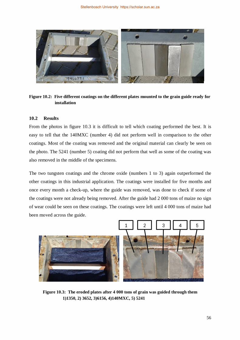
56
Figure 10.2: Five different coatings on the different plates mounted to the grain guide ready for installation
10.2 Results
From the photos in figure 10.3 it is difficult to tell which coating performed the best. It is
easy to tell that the 140MXC (number 4) did not perform well in comparison to the other
coatings. Most of the coating was removed and the original material can clearly be seen on
the photo. The 5241 (number 5) coating did not perform that well as some of the coating was
also removed in the middle of the specimens.
The two tungsten coatings and the chrome oxide (numbers 1 to 3) again outperformed the
other coatings in this industrial application. The coatings were installed for five months and
once every month a check-up, where the guide was removed, was done to check if some of
the coatings were not already being removed. After the guide had 2 000 tons of maize no sign
of wear could be seen on these coatings. The coatings were left until 4 000 tons of maize had
been moved across the guide.
Figure 10.3: The eroded plates after 4 000 tons of grain was guided through them 1)1350, 2) 3652, 3)6156, 4)140MXC, 5) 5241
1 2 3 4 5
Stellenbosch University https://scholar.sun.ac.za
57
Chapter 11 Conclusion
The agricultural industry is a great asset to all South Africans in terms of food production and
employment. The influence of wear in this industry is greater than is generally recognised,
and wear presents many wear related problem areas. All agriculture equipment that is
exposed to harsh operating conditions and environments could benefit from a coating that
resists wear and corrosion.
The wear mechanisms must be established exactly when identifying an appropriate and
effective solution. The fact that there is not always a single wear mechanism acting on a
surface, but usually a multitude of wear mechanisms, makes it difficult to identify the
appropriate solution.
Thermal spray coatings can significantly extend the operating life of agriculture equipment
that is susceptible to mechanical wear. A thermal spray coating can be applied and will offer
numerous benefits like prevention of oxidation (rust), longer equipment life and higher
productivity.
Through the careful selection and application of an appropriately selected thermal spray
coating, the wear resistance of basis materials can be extended to provide a material that will
have the required mechanical properties in the base material without sacrificing wear
resistance on the surface. From the research it was found that coatings with finer carbides
show higher hardness and lower indentation fracture toughness.
From this study it is clear that the best solution is not always the least expensive one. The
selection of which coating to used, must consider all factors of the problem area, the
objective of the coated material and the operating life of the coating.
Stellenbosch University https://scholar.sun.ac.za
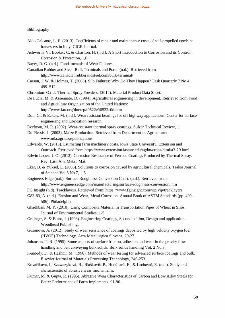
58
Bibliography Aldo Calcante, L. F. (2013). Coefficients of repair and maintenance costs of self-propelled combine
harvesters in Italy. CIGR Journal. Ashworth, V., Booker, C. & Charlton, H. (n.d.). A Short Introduction to Corrosion and its Control .
Corrosion & Protection, 1,6. Bayer, R. G. (n.d.). Fundamentals of Wear Failures. Canadian Rubber and Steel. Bulk Terminals and Ports. (n.d.). Retrieved from
http://www.canadianrubberandsteel.com/bulk-terminal/ Carson, J. W. & Holmes, T. (2003). Silo Failures: Why Do They Happen? Task Quarterly 7 No 4,
499–512. Chromium Oxide Thermal Spray Powders. (2014). Material Product Data Sheet. De Lucia, M. & Assennato, D. (1994). Agricultural engineering in development. Retrieved from Food
and Agriculture Organization of the United Nations: http://www.fao.org/docrep/t0522e/t0522e0d.htm
Doll, G., & Eckels, M. (n.d.). Wear resistant bearings for off highway applications. Center for surface engineering and lubrication research.
Dorfman, M. R. (2002). Wear-resistant thermal spray coatings. Sulzer Technical Review, 1. Du Plessis, J. (2003). Maize Production. Retrieved from Department of Agriculture:
www.nda.agric.za/publications Edwards, W. (2015). Estimating farm machinery costs. Iowa State University, Extension and
Outreach. Retrieved from https://www.extension.iastate.edu/agdm/crops/html/a3-29.html Edwin Lopez, J. O. (2013). Corrosion Resistance of Ferrous Coatings Produced by Thermal Spray.
Rev. LatinAm. Metal. Mat. Eker, B. & Yuksel, E. (2005). Solutions to corrosion caused by agricultural chemicals. Trakia Journal
of Science Vol.3 No.7, 1-6. Engineers Edge (n.d.). Surface Roughness Conversion Chart. (n.d.). Retrieved from:
http://www.engineersedge.com/manufacturing/surface-roughness-conversion.htm FG Insight (n.d). Tracklayers. Retrieved from: https://www.fginsight.com/vip/vip/tracklayers. G83-83, A. (n.d.). Erosion and Wear, Metal Corrosion. Annual Book of ASTM Standards (pp. 499–
506). Philadelphia. Ghadhban, M. Y. (2010). Using Composite Material in Transportation Pipes of Wheat in Silos.
Journal of Environmental Studies, 1-5. Grainger, S. & Blunt, J. (1998). Engineering Coatings, Second edition, Design and application.
Woodhead Publishing. Guzanova, A. (2012). Study of wear resistance of coatings deposited by high velocity oxygen fuel
(HVOF) Technology. Acta Metallurgica Slovaca, 20-27. Johanson, T. R. (1995). Some aspects of surface friction, adhesion and wear in the gravity flow,
handling and belt conveying bulk solids. Bulk solids handling Vol. 2 No.3. Kennedy, D. & Hashmi, M. (1998). Methods of wear testing for advanced surface coatings and bulk.
Elsevier:Journal of Materials Processing Technology, 246-253. Kovaříková, I., Szewczyková, B., Blaškoviš, P., Hodúlová, E., & Lechovič, E. (n.d.). Study and
characteristic of abrasive wear mechanisms. Kumar, M. & Gupta, R. (1995). Abrasive Wear Characteristics of Carbon and Low Alloy Steels for
Better Performance of Farm Implements. 91-96.
Stellenbosch University https://scholar.sun.ac.za
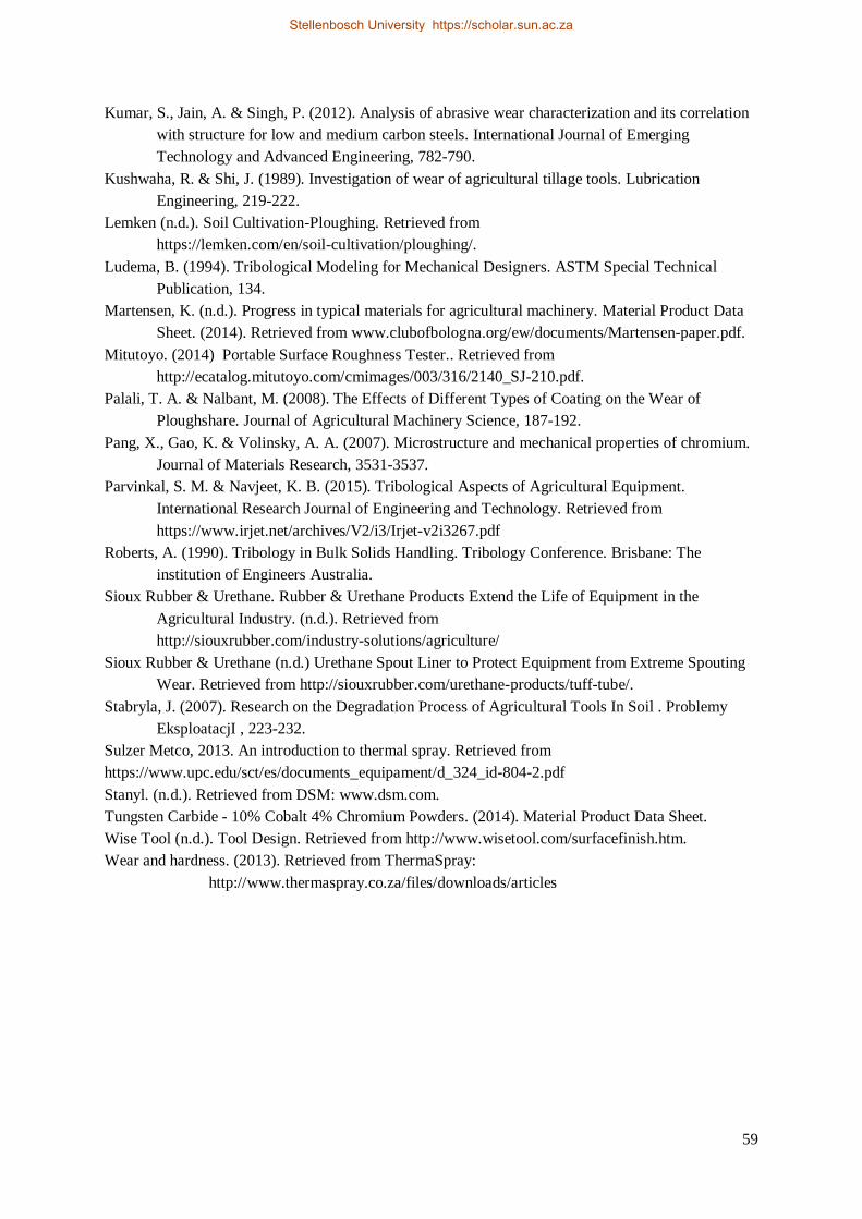
59
Kumar, S., Jain, A. & Singh, P. (2012). Analysis of abrasive wear characterization and its correlation with structure for low and medium carbon steels. International Journal of Emerging Technology and Advanced Engineering, 782-790.
Kushwaha, R. & Shi, J. (1989). Investigation of wear of agricultural tillage tools. Lubrication Engineering, 219-222.
Lemken (n.d.). Soil Cultivation-Ploughing. Retrieved from https://lemken.com/en/soil-cultivation/ploughing/.
Ludema, B. (1994). Tribological Modeling for Mechanical Designers. ASTM Special Technical Publication, 134.
Martensen, K. (n.d.). Progress in typical materials for agricultural machinery. Material Product Data Sheet. (2014). Retrieved from www.clubofbologna.org/ew/documents/Martensen-paper.pdf.
Mitutoyo. (2014) Portable Surface Roughness Tester.. Retrieved from http://ecatalog.mitutoyo.com/cmimages/003/316/2140_SJ-210.pdf.
Palali, T. A. & Nalbant, M. (2008). The Effects of Different Types of Coating on the Wear of Ploughshare. Journal of Agricultural Machinery Science, 187-192.
Pang, X., Gao, K. & Volinsky, A. A. (2007). Microstructure and mechanical properties of chromium. Journal of Materials Research, 3531-3537.
Parvinkal, S. M. & Navjeet, K. B. (2015). Tribological Aspects of Agricultural Equipment. International Research Journal of Engineering and Technology. Retrieved from https://www.irjet.net/archives/V2/i3/Irjet-v2i3267.pdf
Roberts, A. (1990). Tribology in Bulk Solids Handling. Tribology Conference. Brisbane: The institution of Engineers Australia.
Sioux Rubber & Urethane. Rubber & Urethane Products Extend the Life of Equipment in the Agricultural Industry. (n.d.). Retrieved from http://siouxrubber.com/industry-solutions/agriculture/
Sioux Rubber & Urethane (n.d.) Urethane Spout Liner to Protect Equipment from Extreme Spouting Wear. Retrieved from http://siouxrubber.com/urethane-products/tuff-tube/.
Stabryla, J. (2007). Research on the Degradation Process of Agricultural Tools In Soil . Problemy EksploatacjI , 223-232.
Sulzer Metco, 2013. An introduction to thermal spray. Retrieved from https://www.upc.edu/sct/es/documents_equipament/d_324_id-804-2.pdf Stanyl. (n.d.). Retrieved from DSM: www.dsm.com. Tungsten Carbide - 10% Cobalt 4% Chromium Powders. (2014). Material Product Data Sheet. Wise Tool (n.d.). Tool Design. Retrieved from http://www.wisetool.com/surfacefinish.htm. Wear and hardness. (2013). Retrieved from ThermaSpray:
http://www.thermaspray.co.za/files/downloads/articles
Stellenbosch University https://scholar.sun.ac.za
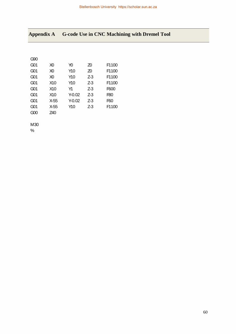
60
Appendix A G-code Use in CNC Machining with Dremel Tool
G90
G01 X0 Y0 Z0 F1100 G01 X0 Y10 Z0 F1100 G01 X0 Y10 Z-3 F1100 G01 X10 Y10 Z-3 F1100 G01 X10 Y1 Z-3 F600 G01 X10 Y-0.02 Z-3 F80 G01 X-55 Y-0.02 Z-3 F60 G01 X-55 Y10 Z-3 F1100 G00 Z40
M30
%
Stellenbosch University https://scholar.sun.ac.za
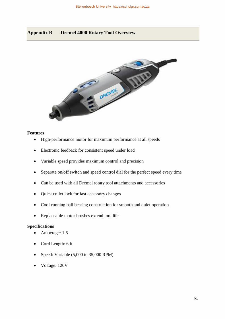
61
Appendix B Dremel 4000 Rotary Tool Overview
Features
High-performance motor for maximum performance at all speeds
Electronic feedback for consistent speed under load
Variable speed provides maximum control and precision
Separate on/off switch and speed control dial for the perfect speed every time
Can be used with all Dremel rotary tool attachments and accessories
Quick collet lock for fast accessory changes
Cool-running ball bearing construction for smooth and quiet operation
Replaceable motor brushes extend tool life
Specifications Amperage: 1.6
Cord Length: 6 ft
Speed: Variable (5,000 to 35,000 RPM)
Voltage: 120V
Stellenbosch University https://scholar.sun.ac.za
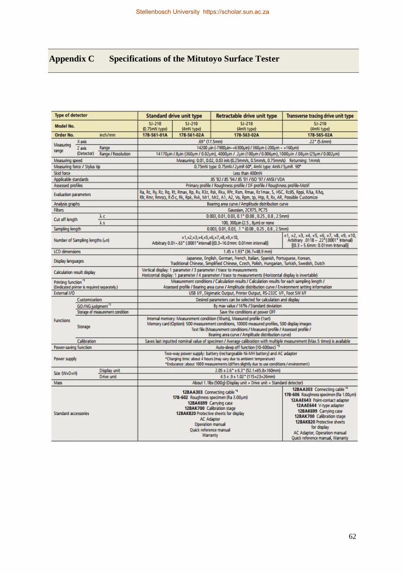
62
Appendix C Specifications of the Mitutoyo Surface Tester
Stellenbosch University https://scholar.sun.ac.za