introduction to the ampex 350-2, revision 1.11
TRANSCRIPT

1
Introduction to the Ampex 350-2, Revision 1.11
Unlike later stereo Ampex recorders (such as the 351-2 and later machines), the 350-2 stereo machines
used full-track erase heads and a unique bias-coupling arrangement between master and slave electronics.
The master electronics was essentially unchanged from 1953 to 1957 (the years when the mono 350 and
the stereo 350-2 were produced) but there were various issues of the 350-2 slave electronics (including
early ones with a bias buffer amplifier and later ones without this buffer amp).
Keep in mind that no factory-issued Ampex 350-2 recorders had independent bias oscillator linked
together (as did the later 351-2 and AG-350-2 recorders). But many technicians in the 1950s, 1960s, and
1970s made their own 350-2 recorders by taking two 350 master electronics and coupling the two bias
oscillators together (normally such modified machines will have a stereo erase head). This works well if
done correctly. One method was to tie the two bias-oscillator grids together; this was often done with a
two-conductor (plus shield) cable going from one master electronics to the other.
Note also that the early multichannel mastering recorders (such as the 300-3 and 300-4) used the 300
transport but with 350 mono slave units and a special master bias oscillator (built in on a chassis the same
size as a 350 power supply) that was not used in 350-2 stereo recorders.
Unless you understand the unique bias-coupling arrangement of the 350-2, setup will be very confusing
because there is no erase current meter indication on the master unit (because the erase head is plugged
into the slave, not the master).
Identifying master and slave units
The master unit has the ac mains input connector, two fuse holders, and normally a female 4-pin Cinch-
Jones transport power connector. Typical catalog numbers are 5701 or 5701-1.
The slave unit has a blank plate instead of the mains input connector. It has one fuse holder and normally
a male 4-pin Cinch-Jones connector. Catalog numbers for slave electronics varied and are often different
than those shown in documentation. Early 350 slaves have a single-ended bias buffer amplifier using a
6F6 tube (in place of the 6SN7 used in the master); later slaves do not have a bias buffer amp and will
have a blank plate at this chassis location.
Sometimes you will find a slave unit with a push-pull bias-buffer amplifier (used to reduce bias
distortion). These units use a 6SN7 bias buffer tube and can be identified by the presence of two toroidal
transformers under the chassis. This 350 slave was generally only used with 300-3 or 300-4 recorders—
and only then until these recorders were supplied with special versions of the Ampex 351 slave
electronics (typically catalog 30960-11) around 1958.
There is a special power interconnect cable (used only with 350-2 setups) with two female Cinch-Jones
connectors (one for the 350 transport and the other for the slave electronics) and a male Cinch-Jones
connector for the master electronics.
Note that very late model 350-2 electronics used a 6-pin transport interconnect cable but these are rather
uncommon.
1 Prepared by David Dintenfass, Full-Track Productions, Seattle, Washington © 2020 by David Dintenfass
2
Cable connections
Note that these connections apply only to the model Ampex 350-2.
1. Connect playback head cables (3-pin connectors) to LEFT (master) and RIGHT (slave)
electronics.
2. Connect record head cables (2-pin connectors) to LEFT (master) and RIGHT (slave) electronics.
3. Connect erase head cable (1-pin connector) to the connector marked ERASE HEAD on the
RIGHT (slave) electronics.
4. Connect the short interconnect cable from the ERASE HEAD connector on the LEFT (master) to
the BIAS connector on the RIGHT (slave) electronics. This is how the master receives the bias
signal, which is required for both erase and record functions.
Playback Alignment
1. Make sure you have good rubber on the pinch-wheel and that all mechanical adjustments have
been made. Ensure that tape is pulling correctly that there are no unusual noises.
2. Make sure the VU meters are in good repair; if any of the internal Germanium diodes are
defective, you will not get accurate readings.2 Using the VU meter is fine for most procedures.
3. Remove the head cover (note that the playback head is the rightmost head). Clean tape path and
visually inspect transport. Demagnetize heads and tape path if you have the proper equipment
and knowledge.
4. Put the rear-panel termination switch in ON position unless you have terminated externally.
5. Using an alignment tape (7.5 or 15 ips), adjust playback-head azimuth for best phase-tracking
between left and right channels. It is easiest to do this while comparing phase of left and right
channels on a dual-trace oscilloscope as test frequencies step from 1 kHz up to 20 kHz. If you
don’t have an oscilloscope, adjust playback azimuth (left elastomeric nut on the playback head)3
gradually while test tones increase in frequency for peak output on both left and right VU meter.
6. Rewind the test tape and adjust the playback equalization pots (on the rear top of each electronics
chassis) for flattest response; adjust both channels for best flatness between 1 kHz and 12 kHz
to avoid peaks in the most audible range. Note that playback response (for the NAB curve) is the
same for both 7.5 and 15 ips so there is only one EQ pot per electronics to move (and the front-
panel high/low EQ switch can be in either position while adjusting playback equalization).
7. Lastly, set the playback controls on both channels so that that VU meters both read 0 VU at the
reference fluxivity level on the test tape. Using a permanent marker, put a dot on the front
panel to line up with the pointer of the playback level knob.
2 To test, disconnect one lead from the VU meter and put a low-voltage adjustable dc source on them (or a penlight battery with a
potentiometer wired as a rheostat in series with the battery). Set for 0 VU indication and reverse polarity. If the meter’s diode
bridge is not working correctly, one polarity will read nothing or differently than the other.
3 This assumes your head assembly has been set up correctly. The screws that go into the heads must be locked with adhesive
(such as LOCTITE® 222 Low Strength Threadlocker) so they do not turn when you adjust the elastomeric azimuth nut.
3
Erase and Record Adjustments
The following steps may seem complicated at first but they will work out just fine if you do them slowly,
carefully, and in the correct order.
The adjustment steps are as follows:
• Erase current
• Erase meter indication (to permit quick verification of erase/bias oscillator output)
• Bias current
• Bias meter indication (to permit quick verification of bias circuit)
• Record level calibration (to ensure accurate recording levels)
• Record head azimuth
• Record equalization
• Noise Balance (not required for electronics that have been properly upgraded to remove the now-
obsolete noise-balance circuit)
Erase current
1. Thread a new blank tape on the machine.
2. On the LEFT channel (master electronics), turn the Meter and Output Switch to ERASE.
3. Press PLAY and the RECORD button to start moving tape in the record mode (this turns on the
bias/erase oscillator). Read the erase current indication of the VU meter. The reading should be
approximately 0 VU.
Normal variation in mains voltage does affect erase current so deviation within 1 dB of 0 VU is
normal. Therefore, do not the adjust the erase unless the VU meter indication of erase current
deviates more than 1 dB from 0 VU. For the 350-2, the erase current trimmer (C438) is on top of
the chassis on the LEFT (master) electronics—this is because the bias oscillator is in the master
electronics even though it is routed to the slave electronics to power the full-track erase head.
4. If you do need to adjust the erase current, carefully back off C438 to minimum (clockwise) and
then increase the capacity until the VU meter reads zero.
5. There is no need to repeat this procedure for the RIGHT (slave electronics) since the erase current
is supplied only by the LEFT (master) electronics. This is why the VU meter on the RIGHT
(slave electronics) reads no indication when it is switched to the ERASE position. This is entirely
normal operation.
IMPORTANT
The erase adjustment has a direct effect on bias current and should not be
changed after you adjust the bias in the following steps.
Bias adjustment has minimal effect on erase current since most
of the bias oscillator output is routed to the erase head.
4
Bias Adjustment
1. Set the transport speed to HIGH (15 ips).
2. On the LEFT (master) electronics, turn the Meter and Output Switch (S405) to the RECORD
LEVEL position. Turn the Transfer Switch (5401) to the UNBALANCED BRIDGE position.
3. Set the equalization switch to HIGH.
4. Connect an audio oscillator to the line input XLR (normally Pin 3 is hot on the Ampex 350 unless
later rewired Pin 2 hot) and connect the oscillator output (if unbalanced) to Pin 3 and the
oscillator ground to Ampex 350 input pins 1 and 2.
5. Make sure the Meter and Output Switch is in RECORD so you can set the oscillator level. Now
set the oscillator frequency to 1 kHz and adjust the input level to approximately 0 on the VU
meter.
6. Start the tape moving and press RECORD.
7. Set the Meter and Output Switch to PLAYBACK so you can monitor off the playback head.
8. Adjust playback gain to 0 VU. Now adjust the Bias Control (R460, on top of chassis) for peak
indication on the VU meter and adjust the input level so that the VU meter indicates 0 VU.
9. Increase the bias control slightly (clockwise) until the output falls by 0.25 to 0.5 dB on the VU
meter. This is the optimum bias point and will provide enough bias current should the main
voltage sag slightly.
10. Repeat for the RIGHT (slave) channel.
Bias Meter Calibration
1. On the LEFT (master) electronics, move the Meter and Output Switch (S405) to the RECORD
BIAS position.
2. Note the VU meter indication. This provides a refence level so that you can verify proper bas
current while recording.
3. Stop the recorder first so that there’s no voltage on this tapped wirewound resistor (on top of
chassis). Then carefully move the slide on the Bias Meter Calibration resistor (R459) and put the
machine into record again and check the meter. Repeat this procedure until the meter indicates 0
VU.
4. Repeat the above procedure for the RIGHT (slave) channel.
5
Record Level Meter Calibration
1. On the LEFT (master) electronics, move the playback level control so that the pointer on the knob
lines up with the dot you marked earlier (see Step 7 in Playback Alignment).
2. Set the Meter and Output Switch to the PLAYBACK LEVEL and set the oscillator to 500 Hz and
put the machine in record mode.
3. Move the Record Level Control until the meter reads 0 VU. Make sure the Meter and Output
Switch is still set to the PLAYBACK LEVEL position.
4. Now move the Meter and Output Switch to RECORD LEVEL.
5. While looking at the VU meter, adjust the Record Level Meter Calibration resistor (R428, on top
of chassis) until the meter reads 0 VU. This ensures that recording level at 0 VU will ensure
conformance to the standard reference fluxivity (normally 250 nW/m).
6. Repeat the above procedure for the RIGHT (slave) channel.
Record Head Alignment
1. Make a splitter cable so that you can connect the output of your oscillator to both left and right
electronics at the same time.
2. Set the audio oscillator at 1 kHz and adjust the input level to –10 VU on the meter.
3. Set the Meter and Output Switch to PLAYBACK LEVEL.
4. Put the machine into record mode (operate at 15 ips).
5. Carefully adjust record-head azimuth (left elastomeric nut on the record head) for best phase-
tracking between left and right channels while monitoring off the play head. Start a 1 kHz and
slowly increase frequency up to 15 kHz to ensure you are not reading false peaks as you adjust
the record-head azimuth.
You can increase playback gain (equally for both channels) to move the level closer to 0 VU for
more accurate azimuth observation but do not increase record level.4
As with playback azimuth, it is easiest to do this while comparing phase of left and right channels
on a dual-trace oscilloscope as you increase the test frequency from 1 kHz up to 20 kHz. If you
don’t have an oscilloscope, adjust record azimuth for maximum output consistent with increasing
frequency. Typically, output level drops above 10 kHz as record equalization is not yet adjusted.
6. Keep the oscillator connected as you will need it for the next procedure (record equalization).
4 Keeping record level below 0 VU reduces gain compression which occurs when recording to magnetic tape at elevated levels
IMPORTANT
Even though you are adjusting the RECORD level in this procedure, you must
monitor off the playback head to set the record calibration.
The Meter and Output Switch must be in the PLAYBACK LEVEL position for STEP 3.
6
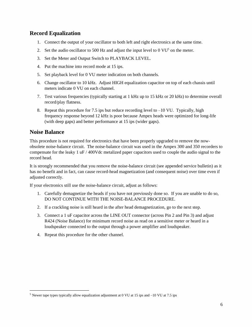
Record Equalization
1. Connect the output of your oscillator to both left and right electronics at the same time.
2. Set the audio oscillator to 500 Hz and adjust the input level to 0 VU5 on the meter.
3. Set the Meter and Output Switch to PLAYBACK LEVEL.
4. Put the machine into record mode at 15 ips.
5. Set playback level for 0 VU meter indication on both channels.
6. Change oscillator to 10 kHz. Adjust HIGH equalization capacitor on top of each chassis until
meters indicate 0 VU on each channel.
7. Test various frequencies (typically starting at 1 kHz up to 15 kHz or 20 kHz) to determine overall
record/play flatness.
8. Repeat this procedure for 7.5 ips but reduce recording level to –10 VU. Typically, high
frequency response beyond 12 kHz is poor because Ampex heads were optimized for long-life
(with deep gaps) and better performance at 15 ips (wider gaps).
Noise Balance
This procedure is not required for electronics that have been properly upgraded to remove the now-
obsolete noise-balance circuit. The noise-balance circuit was used in the Ampex 300 and 350 recorders to
compensate for the leaky 1 uF / 400Vdc metalized paper capacitors used to couple the audio signal to the
record head.
It is strongly recommended that you remove the noise-balance circuit (see appended service bulletin) as it
has no benefit and in fact, can cause record-head magnetization (and consequent noise) over time even if
adjusted correctly.
If your electronics still use the noise-balance circuit, adjust as follows:
1. Carefully demagnetize the heads if you have not previously done so. If you are unable to do so,
DO NOT CONTINUE WITH THE NOISE-BALANCE PROCEDURE.
2. If a crackling noise is still heard in the after head demagnetization, go to the next step.
3. Connect a 1 uF capacitor across the LINE OUT connector (across Pin 2 and Pin 3) and adjust
R424 (Noise Balance) for minimum record noise as read on a sensitive meter or heard in a
loudspeaker connected to the output through a power amplifier and loudspeaker.
4. Repeat this procedure for the other channel.
5 Newer tape types typically allow equalization adjustment at 0 VU at 15 ips and –10 VU at 7.5 ips
Bulletin Removing the Noise-Balance circuit from early Ampex tape recorders
Applies to Ampex models 300, 400, 350
Date 2018 August 10
Revision 1
Total pages 3
Problem
Ampex 300, 400, and 350 recorders used a dc noise-balance adjustment circuit that is no longer required now that modern low-leakage coupling capacitors are available. If you do not remove this noise-balance circuit, it is possible to introduce low-frequency noise if you do not adjust the noise-balance control correctly.
Background
In the Ampex 300, 400, and 350 electronics, the record signal is coupled to the record head through a 1 uF / 400 volt metalized paper capacitor. Until the late 1950s, Ampex used metalized paper coupling capacitors since they had gen-erally good performance and were small enough to fit under the typical electronics chassis of that era. According to former Ampex engineer Jay McKnight, the small amount of leakage current contributed by metalized-paper capaci-tors was not identified as a concern when the earliest of these recorders (the Ampex model 300) was designed in the late 1940s.
Today we know that metalized paper capacitors have much higher leakage than modern polyester or polypropylene capacitors. In the older Ampex machines, a small amount of dc plate voltage from the record amplifier would leak into the record head though this 1 uF coupling capacitor—this would add noise and over time, magnetize the record head (which further contributed to noise). Additionally, record heads often became magnetized if they were tested with an ohmmeter.
Once the record head becomes magnetized, then minor irregularities in the recording sensitivity of the blank tape cause low-frequency noise—often called rocks, lumps and bumps, crackling, or grumbling (or more precisely, dc noise or modulation noise). (1)
Beginning with the Ampex 300, the workaround to this problem was the addition of a circuit to inject a small dc-offset into the record head (after the 1 uF coupling capacitor) to compensate for any dc leakage and record-head mag-netization. The noise-balance pot controlled the amount (and polarity) of the introduced dc offset. Adjustment was made by first demagnetizing the tape heads, then recording a tape (with no input) and listening to the playback output with a sensitive speaker and setting the noise-balance pot for minimum crackling noise.
Ampex began using low-leakage coupling capacitors beginning in the mid-to-late 1950s with the introduction of the model 600 and model 351. Consequently, there was no longer a need to introduce a dc offset using the older type of noise-balance circuit. Instead, the later machines used a balance adjustment in the push-pull bias oscillator circuit to adjust for the most symmetrical bias waveform.
Fix
The problem may be fixed by removing the noise-balance potentiometer and associated components. See specific instructions for various models.
Acknowledgments
Full-Track Productions would like to thank Jay McKnight (Magnetic Reference Laboratory, Inc. San Jose, California) for technical suggestions and review of the procedures outlined in this bulletin.
(1) This explanation courtesy of former Ampex engineer Jay McKnight (see http://mrltapes.com/mcknight_demag.pdf).
IMPORTANT NOTICE AND TERMS OF USE Full-Track Productions is not liable for any damage or injury that may result from inappropriate use of information in this document—always
refer service to qualified personnel. Contents of this document copyright © 2005-2018 by Full-Track Productions, all rights reserved. This bulletin may be distributed only if reproduced in its entirety (including this notice) without any alteration whatsoever. No fee may be
charged for this bulletin nor for any information detailed here.
2 Removing Record-Noise Balance circuit from Ampex 300, 400, and 350 recorders / 2018 August 10
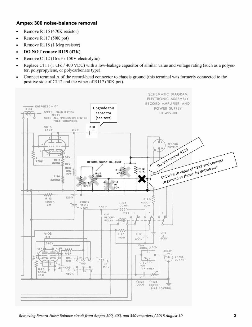
Ampex 300 noise-balance removal
• Remove R116 (470K resistor)
• Remove R117 (50K pot)
• Remove R118 (1 Meg resistor)
• DO NOT remove R119 (47K)
• Remove C112 (16 uF / 150V electrolytic)
• Replace C111 (1 uFd / 400 VDC) with a low-leakage capacitor of similar value and voltage rating (such as a polyes-ter, polypropylene, or polycarbonate type).
• Connect terminal A of the record-head connector to chassis ground (this terminal was formerly connected to the positive side of C112 and the wiper of R117 (50K pot).
3
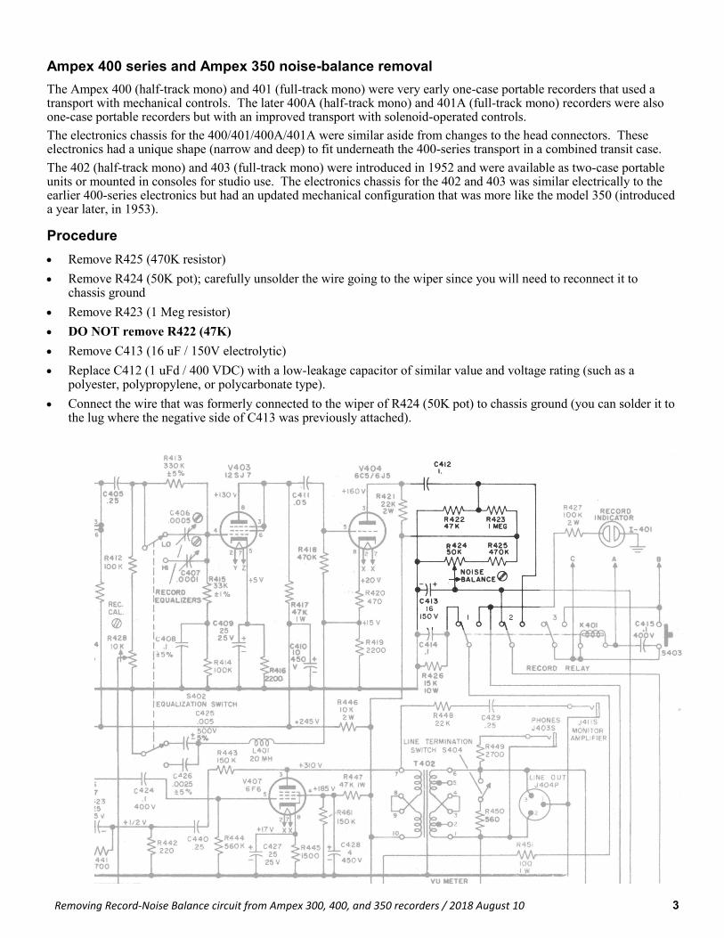
Ampex 400 series and Ampex 350 noise-balance removal
The Ampex 400 (half-track mono) and 401 (full-track mono) were very early one-case portable recorders that used a transport with mechanical controls. The later 400A (half-track mono) and 401A (full-track mono) recorders were also one-case portable recorders but with an improved transport with solenoid-operated controls.
The electronics chassis for the 400/401/400A/401A were similar aside from changes to the head connectors. These electronics had a unique shape (narrow and deep) to fit underneath the 400-series transport in a combined transit case.
The 402 (half-track mono) and 403 (full-track mono) were introduced in 1952 and were available as two-case portable units or mounted in consoles for studio use. The electronics chassis for the 402 and 403 was similar electrically to the earlier 400-series electronics but had an updated mechanical configuration that was more like the model 350 (introduced a year later, in 1953).
Procedure
• Remove R425 (470K resistor)
• Remove R424 (50K pot); carefully unsolder the wire going to the wiper since you will need to reconnect it to chassis ground
• Remove R423 (1 Meg resistor)
• DO NOT remove R422 (47K)
• Remove C413 (16 uF / 150V electrolytic)
• Replace C412 (1 uFd / 400 VDC) with a low-leakage capacitor of similar value and voltage rating (such as a polyester, polypropylene, or polycarbonate type).
• Connect the wire that was formerly connected to the wiper of R424 (50K pot) to chassis ground (you can solder it to the lug where the negative side of C413 was previously attached).
Removing Record-Noise Balance circuit from Ampex 300, 400, and 350 recorders / 2018 August 10
Bulletin Removing the high frequency record boost from early Ampex tape recorders
Applies to Ampex models 300, 400, 350, and 351 (early versions)
Date 2018 August 2
Revision 1
Total pages 5
Problem
Ampex 300, 400, and 350 (and very early 351) record electronics used a 20 mH air-core inductor to form a resonant circuit used to provide the additional high-frequency boost required when using older types of magnetic tapes.
Ampex machines manufactured after 1959 (approximately) did not use this inductor since it was no longer needed with tape formulations introduced around that time.
Fix
The problem may be fixed by either disconnecting or removing this inductor. See specific instructions for various models.
Note that this modification is for the record circuit only; it does not change playback response. Playback of recordings made with older tape formulations will remain unchanged.
Acknowledgments
Full-Track Productions would like to thank Jay McKnight (Magnetic Reference Laboratory, Inc. San Jose, California) for technical suggestions and review of the procedures outlined in this bulletin.
IMPORTANT NOTICE AND TERMS OF USE Full-Track Productions is not liable for any damage or injury that may result from inappropriate use of information in this document—always
refer service to qualified personnel. Contents of this document copyright © 2005-2018 by Full-Track Productions, all rights reserved. This bulletin may be distributed only if reproduced in its entirety (including this notice) without any alteration whatsoever. No fee may be charged
for this bulletin nor for any information detailed here.
2
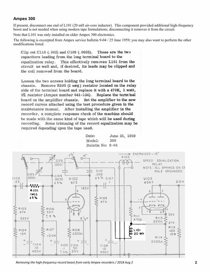
Ampex 300
If present, disconnect one end of L101 (20 mH air-core inductor). This component provided additional high-frequency boost and is not needed when using modern tape formulations; disconnecting it removes it from the circuit.
Note that L101 was only installed on older Ampex 300 electronics.
The following is excerpted from Ampex service bulletin 9-04 / 25 June 1959; you may also want to perform the other modifications listed.
Removing the high-frequency record boost from early Ampex recorders / 2018 Aug 2
3 Removing the high-frequency record boost from early Ampex recorders / 2018 Aug 2
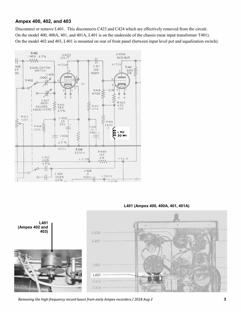
Ampex 400, 402, and 403
Disconnect or remove L401. This disconnects C423 and C424 which are effectively removed from the circuit.
On the model 400, 400A, 401, and 401A, L401 is on the underside of the chassis (near input transformer T401).
On the model 402 and 403, L401 is mounted on rear of front panel (between input level pot and equalization switch).
L401 (Ampex 402 and
403)
L401 (Ampex 400, 400A, 401, 401A)
4
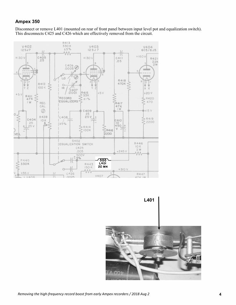
Ampex 350
Disconnect or remove L401 (mounted on rear of front panel between input level pot and equalization switch). This disconnects C425 and C426 which are effectively removed from the circuit.
L401
Removing the high-frequency record boost from early Ampex recorders / 2018 Aug 2
5
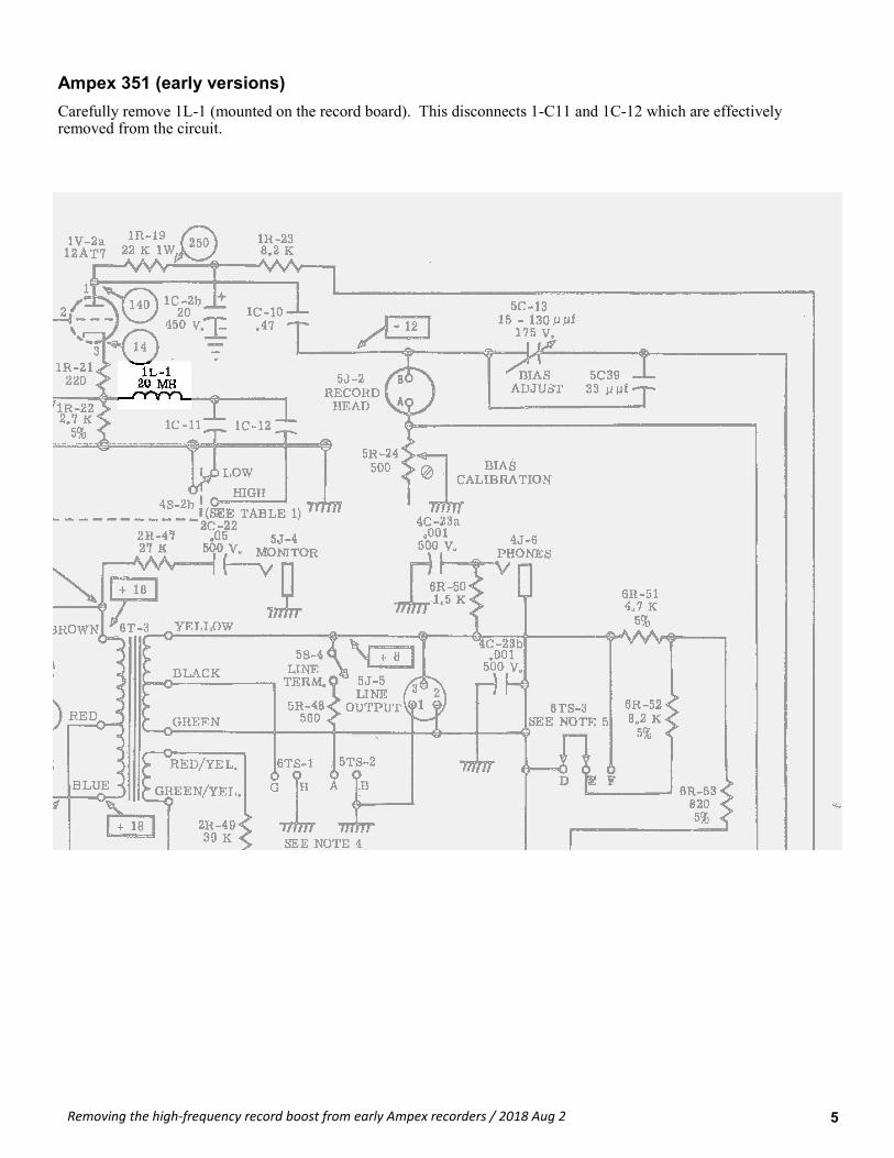
Ampex 351 (early versions)
Carefully remove 1L-1 (mounted on the record board). This disconnects 1-C11 and 1C-12 which are effectively removed from the circuit.
Removing the high-frequency record boost from early Ampex recorders / 2018 Aug 2
Bulletin Replacing capstan idler core for Ampex 300-, 35x-, and 440-series recorders
Date 2018 Dec 21
Revision 2
Total pages 2
IMPORTANT NOTICE AND TERMS OF USE Full-Track Productions is not liable for any damage or injury that may result from inappropriate use of information in this document—always
refer service to qualified personnel. Contents of this document copyright © 2005-2018 by Full-Track Productions, all rights reserved. This bulletin may be distributed only if reproduced in its entirety (including this notice) without any alteration whatsoever. No fee may be charged
for this bulletin nor for any information detailed here.
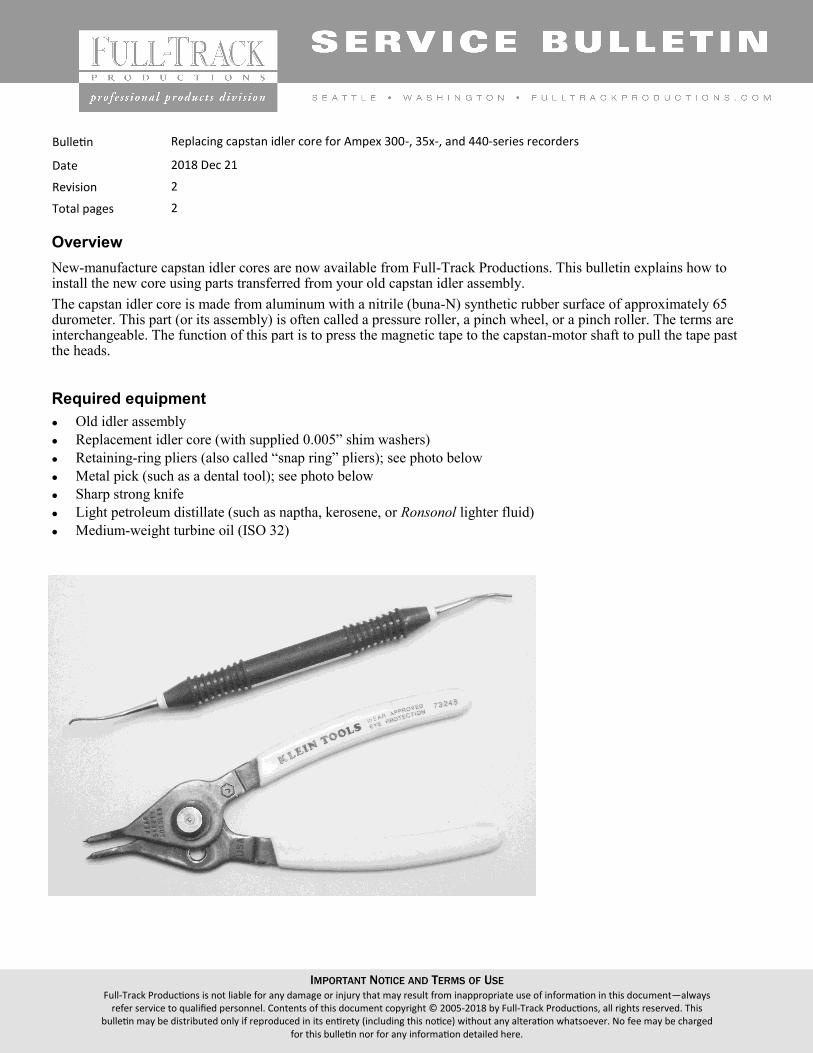
Overview
New-manufacture capstan idler cores are now available from Full-Track Productions. This bulletin explains how to install the new core using parts transferred from your old capstan idler assembly.
The capstan idler core is made from aluminum with a nitrile (buna-N) synthetic rubber surface of approximately 65 durometer. This part (or its assembly) is often called a pressure roller, a pinch wheel, or a pinch roller. The terms are interchangeable. The function of this part is to press the magnetic tape to the capstan-motor shaft to pull the tape past the heads.
Required equipment
⚫ Old idler assembly
⚫ Replacement idler core (with supplied 0.005” shim washers)
⚫ Retaining-ring pliers (also called “snap ring” pliers); see photo below
⚫ Metal pick (such as a dental tool); see photo below
⚫ Sharp strong knife
⚫ Light petroleum distillate (such as naptha, kerosene, or Ronsonol lighter fluid)
⚫ Medium-weight turbine oil (ISO 32)
2 Replacing capstan idler core for Ampex 300-, 35x-, and 440-series recorders / 2018 Dec 21 / Rev 2
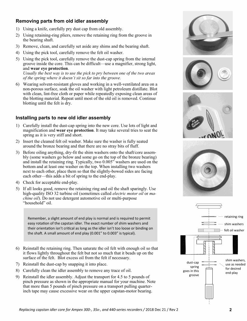
Removing parts from old idler assembly
1) Using a knife, carefully pry dust cap from old assembly.
2) Using retaining-ring pliers, remove the retaining ring from the groove in the bearing shaft.
3) Remove, clean, and carefully set aside any shims and the bearing shaft.
4) Using the pick tool, carefully remove the felt oil washer.
5) Using the pick tool, carefully remove the dust-cap spring from the internal groove inside the core. This can be difficult—use a magnifier, strong light, and wear eye protection. Usually the best way is to use the pick to pry between one of the two areas of the spring where it doesn’t sit so far into the groove.
6) Wearing solvent-resistant gloves and working in a well-ventilated area on a non-porous surface, soak the oil washer with light petroleum distillate. Blot with clean, lint-free cloth or paper while repeatedly exposing clean areas of the blotting material. Repeat until most of the old oil is removed. Continue blotting until the felt is dry.
Installing parts to new old idler assembly
1) Carefully install the dust-cap spring into the new core. Use lots of light and magnification and wear eye protection. It may take several tries to seat the spring as it is very stiff and short.
2) Insert the cleaned felt oil washer. Make sure the washer is fully seated around the bronze bearing and that there are no stray bits of fluff.
3) Before oiling anything, dry-fit the shim washers onto the shaft/core assem-bly (some washers go below and some go on the top of the bronze bearing) and install the retaining ring. Typically, two 0.005” washers are used on the bottom and at least one washer on the top. When installing two washers next to each other, place them so that the slightly-bowed sides are facing each other—this adds a bit of spring to the end-play.
4) Check for acceptable end-play.
5) If all looks good, remove the retaining ring and oil the shaft sparingly. Use high-quality ISO 32 turbine oil (sometimes called electric motor oil or ma-chine oil). Do not use detergent automotive oil or multi-purpose “household” oil.
6) Reinstall the retaining ring. Then saturate the oil felt with enough oil so that it flows lightly throughout the felt but not so much that it beads up on the surface of the felt. Blot excess oil from the felt if necessary.
7) Reinstall the dust-cap by snapping it into place.
8) Carefully clean the idler assembly to remove any trace of oil.
9) Reinstall the idler assembly. Adjust the transport for 4.5 to 5 pounds of pinch pressure as shown in the appropriate manual for your machine. Note that more than 5 pounds of pinch pressure on a transport pulling quarter-inch tape may cause excessive wear on the upper capstan-motor bearing.
Remember, a slight amount of end play is normal and is required to permit easy rotation of the capstan idler. The exact number of shim washers and their orientation isn’t critical as long as the idler isn’t too loose or binding on the shaft. A small amount of end play (0.001” to 0.003” is typical).
felt oil washer
shim washers, use as needed for desired end-play
shim washers
retaining ring
dust-cap spring
goes in this groove
Bulletin Ampex 350 15 in/s NAB recording equalization
Date 15 Sept 05 (original issue)
Revision Rev 2 (revised 5 Jan 2012 to fix wiring error in Figure 2 and update photos)
Total pages 4
Problem
The Ampex 350 record/play electronics cannot be adjusted to provide proper record equalization when using modern tape types with 15 ips NAB equalization.
Background
Modern tape formulations have improved high-frequency response; consequently, the 15 ips NAB record equalization as implemented in the Ampex 350 record/play electronics now has too much high-frequency boost on record and cannot be adjusted for flat response.
There is no need to modify the 7.5 ips NAB record circuit as C406 should have enough adjust-ment range to set the record equalization properly during routine alignment.
Fix
The problem may be fixed by doing the following:
⚫ Disconnecting the high-frequency record resonance circuit (if not previously disconnected)
⚫ Rewiring the record EQ switch
⚫ Installing an extra RC filter to flatten the record EQ response
⚫ Removing extra plates in the record EQ trimmer capacitor (optional)
Required Parts
To perform this modification, you will need the following parts:
⚫ 68K half-watt 5% resistor (preferably carbon film)
• 680 pF/500V 5% dipped silvered-mica capacitor (such as Cornell Dubilier 68PF500VJ)
IMPORTANT NOTICE AND TERMS OF USE Full-Track Productions is not liable for any damage or injury that may result from inappropriate use of information in this document—
always refer service to qualified personnel. Contents of this document copyright © 2005 by Full-Track Productions, all rights re-served. This bulletin may be distributed only if reproduced in its entirety (including this notice) without any alteration whatsoever.
No fee may be charged for this bulletin nor for any information detailed here.
Procedure
Note that the following procedures assume familiarity with basic electronics repair and knowledge of standard safety proto-cols. They also require some mechanical dexterity and access to appropriate tools (such as temperature-controlled soldering irons). Do not undertake the following procedures if you are unqualified to do so.
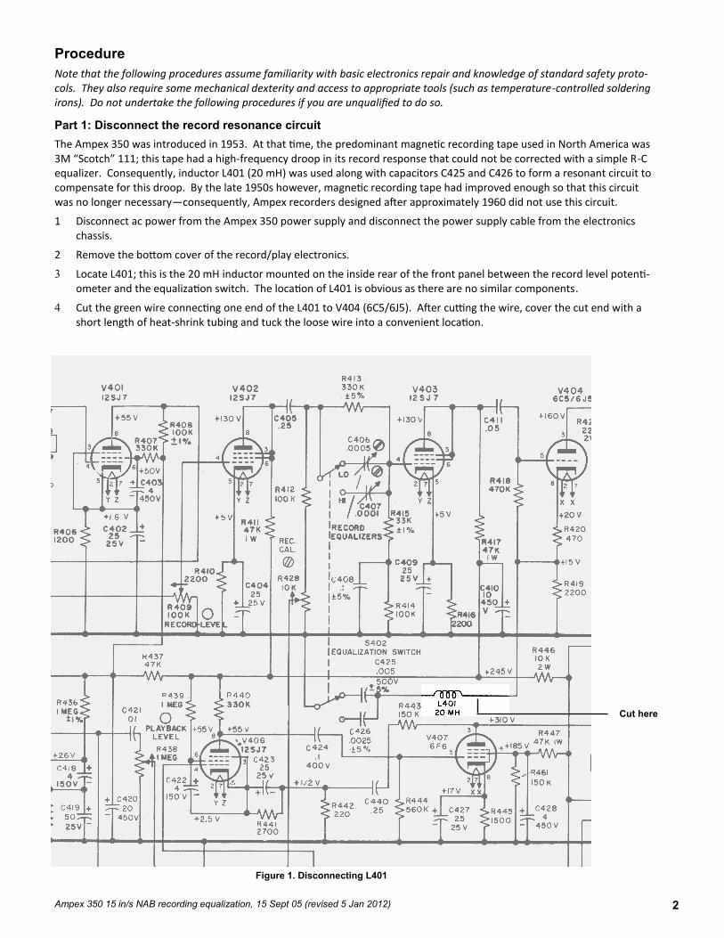
Part 1: Disconnect the record resonance circuit
The Ampex 350 was introduced in 1953. At that time, the predominant magnetic recording tape used in North America was 3M “Scotch” 111; this tape had a high-frequency droop in its record response that could not be corrected with a simple R-C equalizer. Consequently, inductor L401 (20 mH) was used along with capacitors C425 and C426 to form a resonant circuit to compensate for this droop. By the late 1950s however, magnetic recording tape had improved enough so that this circuit was no longer necessary—consequently, Ampex recorders designed after approximately 1960 did not use this circuit.
1 Disconnect ac power from the Ampex 350 power supply and disconnect the power supply cable from the electronics chassis.
2 Remove the bottom cover of the record/play electronics.
3 Locate L401; this is the 20 mH inductor mounted on the inside rear of the front panel between the record level potenti-ometer and the equalization switch. The location of L401 is obvious as there are no similar components.
4 Cut the green wire connecting one end of the L401 to V404 (6C5/6J5). After cutting the wire, cover the cut end with a short length of heat-shrink tubing and tuck the loose wire into a convenient location.
Figure 1. Disconnecting L401
Cut here
2 Ampex 350 15 in/s NAB recording equalization, 15 Sept 05 (revised 5 Jan 2012)
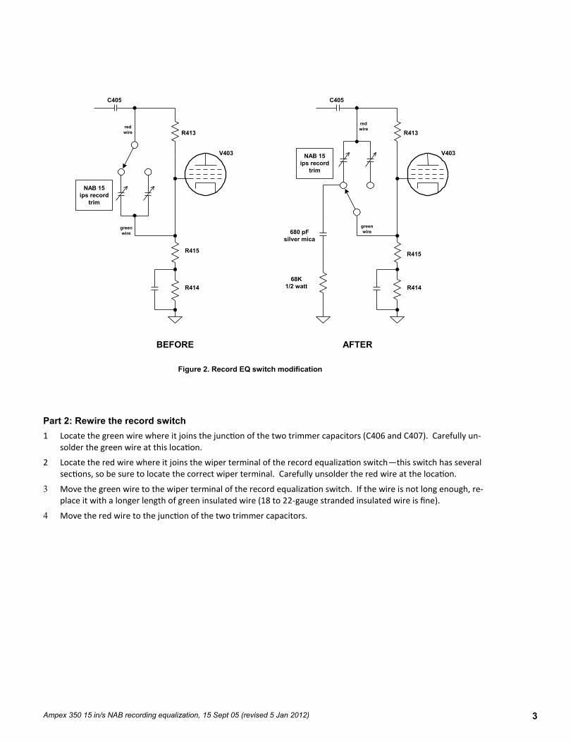
Part 2: Rewire the record switch
1 Locate the green wire where it joins the junction of the two trimmer capacitors (C406 and C407). Carefully un-solder the green wire at this location.
2 Locate the red wire where it joins the wiper terminal of the record equalization switch—this switch has several sections, so be sure to locate the correct wiper terminal. Carefully unsolder the red wire at the location.
3 Move the green wire to the wiper terminal of the record equalization switch. If the wire is not long enough, re-place it with a longer length of green insulated wire (18 to 22-gauge stranded insulated wire is fine).
4 Move the red wire to the junction of the two trimmer capacitors.
Figure 2. Record EQ switch modification
C405
green
wire
R413
V403
red
wire
NAB 15
ips record
trim
R415
R414
BEFORE
C405
green
wire
R413
V403
red
wire
NAB 15
ips record
trim
R415
680 pF
silver mica
68K
1/2 watt R414
AFTER
3 Ampex 350 15 in/s NAB recording equalization, 15 Sept 05 (revised 5 Jan 2012)
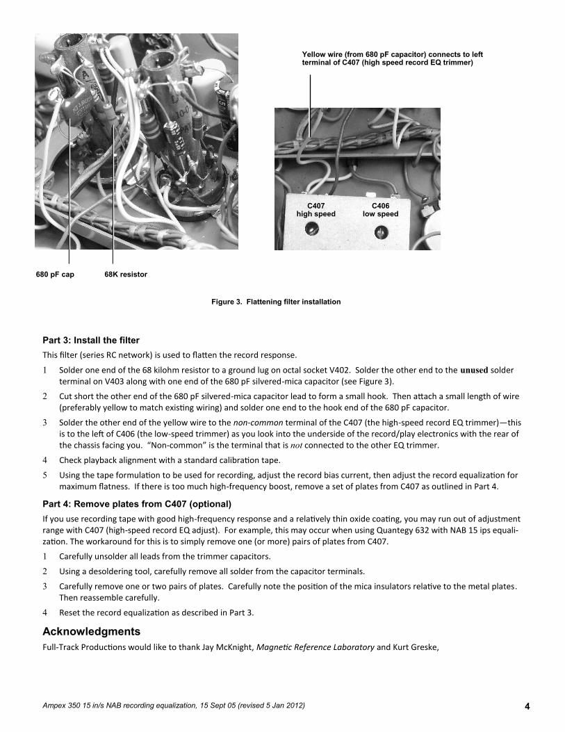
Part 3: Install the filter
This filter (series RC network) is used to flatten the record response.
1 Solder one end of the 68 kilohm resistor to a ground lug on octal socket V402. Solder the other end to the unused solder terminal on V403 along with one end of the 680 pF silvered-mica capacitor (see Figure 3).
2 Cut short the other end of the 680 pF silvered-mica capacitor lead to form a small hook. Then attach a small length of wire (preferably yellow to match existing wiring) and solder one end to the hook end of the 680 pF capacitor.
3 Solder the other end of the yellow wire to the non-common terminal of the C407 (the high-speed record EQ trimmer)—this is to the left of C406 (the low-speed trimmer) as you look into the underside of the record/play electronics with the rear of the chassis facing you. “Non-common” is the terminal that is not connected to the other EQ trimmer.
4 Check playback alignment with a standard calibration tape.
5 Using the tape formulation to be used for recording, adjust the record bias current, then adjust the record equalization for maximum flatness. If there is too much high-frequency boost, remove a set of plates from C407 as outlined in Part 4.
Part 4: Remove plates from C407 (optional)
If you use recording tape with good high-frequency response and a relatively thin oxide coating, you may run out of adjustment range with C407 (high-speed record EQ adjust). For example, this may occur when using Quantegy 632 with NAB 15 ips equali-zation. The workaround for this is to simply remove one (or more) pairs of plates from C407.
1 Carefully unsolder all leads from the trimmer capacitors.
2 Using a desoldering tool, carefully remove all solder from the capacitor terminals.
3 Carefully remove one or two pairs of plates. Carefully note the position of the mica insulators relative to the metal plates. Then reassemble carefully.
4 Reset the record equalization as described in Part 3.
Acknowledgments
Full-Track Productions would like to thank Jay McKnight, Magnetic Reference Laboratory and Kurt Greske,
Figure 3. Flattening filter installation
4
Yellow wire (from 680 pF capacitor) connects to left terminal of C407 (high speed record EQ trimmer)
Ampex 350 15 in/s NAB recording equalization, 15 Sept 05 (revised 5 Jan 2012)
C407 high speed
C406 low speed
68K resistor 680 pF cap